Banking permits: Economic efficiency and distributional effects
Upload
khangminh22Category
view
0download
0
Per SEPA, WAC 197-11-800 and TMC Chapter 13.12, the Environmental Official has reviewed this project and determined the project is exemptfrom SEPA provisions.
Environmental Review:
PUBLIC NOTICE
3/3/2016Date of Notification:
2/19/2016Application Received:
2/19/2016Application Complete:
To request this information in an alternative format or a reasonable accommodation, please call 253-591-5030 (voice). TTY or STS users please dial 711 to connect to Washington Relay Services.
Charla Kinlow, Associate Planner, 747 Market St, Room 345, (253) 594-7971, [email protected] Contact:
A final decision on the proposal will be made following the comment period. A summary of the final decision will be sent to those parties who receive this notice. A complete copy of the final decision will be mailed to those parties who request a copy or to those who have commented on the project. Appeal provisions will be included with both the summary and the complete copy of the final decision.
Public Meeting: A public meeting may be requested by the area neighborhood council, a qualified neighborhood group, or by written request of the owners of five or more properties who receive this notice.
Tacoma Municipal Code and Comprehensive PlanDocuments to Evaluate the Proposal:
Traffic Memo and Lighting PlanStudies Requested:D.A. Hogan and AssociatesApplicant:
2112 South Tyler Street, Parcel 0220122012Location:
LU16-0029Application No:
A Conditional Use Permit Major Modification for installation of athletic field lighting and ascoreboard at Foss High School.
Proposal:
Building PermitsOther Required Permits:
TMC 13.06 ZoningApplicable Regulations of the Tacoma Municipal Code:
For further information regarding the proposal, log onto the website at http://tacomapermits.org and select "Message Board". The case file may be viewed in Planning and Development Services, 747 Market Street, Room 345.
3/17/2016Comments Due:
City of TacomaPlanning and Development Services Department747 Market St, Room 345Tacoma, WA 98402

City of TacomaPlanning and Development Services Department747 Market St, Room 345Tacoma, WA 98402
NOTICE OF LAND USE APPLICATION

Table of Contents
Applicant’s Response to Criteria
Page 4
Site Plan and Electrical Details
Page 5
Lighting Plan (Demonstrating Light Spill)
Page 12
Traffic Memo
Page 13
Geotech
Page 14
Structural Plans
Page 44
Lighting Calculations
Page 46
Previously Approved Special Use Permit (1972)
Page 84

A conditional use permit shall be subject to the following criteria: 1. There shall be a demonstrated need for the use within the community at large which shall not be contrary to the public interest. The proposal would provide the school district the opportunity to increase activities for its students. More available hours would be provided to enhance the availability of the all-weather synthetic fields that were constructed in 2015. 2. The use shall be consistent with the goals and policies of the comprehensive plan and applicable ordinances of the City of Tacoma. Lighted playfields are consistent with City of Tacoma ordinances and the proposed lighting system will be in compliance with the code with regards to setbacks, light dispersal, and height. 3. The use shall be located, planned, and developed in such a manner that it is not inconsistent with the health, safety, convenience, or general welfare of persons residing or working in the community. The following shall be considered in making a decision on a conditional property use: a. The generation of noise, noxious or offensive emissions, or other nuisances which may be injurious or to the detriment of a significant portion of the community. Floodlight poles will be installed as outside fencing on each field but as close to the field as possible so as to not compromise the safety of the spectators and to allow for pedestrian access. b. Availability of public services which may be necessary or desirable for the support of the use. These may include, but shall not be limited to, availability of utilities, transportation systems (including vehicular, pedestrian, and public transportation systems), education, police and fire facilities, and social and health services. All services currently available to the school will be maintained. New electrical distribution circuits will be provided from an existing electrical switchboard located inside the school. The increased availability of the fields during the evening hours may increase the need for medical services. c. The adequacy of landscaping, screening, yard setbacks, open spaces, or other development characteristics necessary to mitigate the impact of the use upon neighboring properties. Floodlights will utilize the latest technology in reflector and shielding design for metal halide floodlights used in lighting athletic fields. Floodlights are designed to reduce the amount of spill light and glare produced.

COM
MO
NFI
NIS
H
100
M S
TART
110
M S
TART
370'
414'
GENERAL NOTES:LEGEND: FLAG NOTES:
ELECTRICAL SITE PLAN - DEMO
ELECTRICALSITE
PLAN-DEMO
E-1.0
NORTH
0SCALE: 1" = 30'
DATE
DRAWN
CHECKED
SCALE
SHEET
REVISION DATE
COPYRIGHT c D.A. HOGAN & ASSOCIATES
119 1st Avenue South, Suite 110Seattle, Washington 98104
p. 206.285.0400f. 206.285.0480
2016
FOSSHIGH SCHOOL
FIELD LIGHTING
4100 194th Street SW Suite 400Lynnwood Washington 98036-4613
(206) 677-0555
CHRI S
TOPHER B. FOTE
01/13/16
1" = 30'
CJS
CBF
30' 60'
PERMIT SET

COM
MO
NFI
NIS
H
100
M S
TART
110
M S
TART
370'
414'COM
MO
NFI
NIS
H
100
M S
TART
110
M S
TART
370'
414'
ELECTRICAL SITE PLAN
MATCHLINE
POLE AND FLOOD LIGHT
SCHEDULE
GENERAL NOTES:LEGEND: FLAG NOTES:
ELECTRICALSITE
PLAN
E-1.1
NORTH
0SCALE: 1" = 30'
DATE
DRAWN
CHECKED
SCALE
SHEET
REVISION DATE
COPYRIGHT c D.A. HOGAN & ASSOCIATES
119 1st Avenue South, Suite 110Seattle, Washington 98104
p. 206.285.0400f. 206.285.0480
2016
FOSSHIGH SCHOOL
FIELD LIGHTING
4100 194th Street SW Suite 400Lynnwood Washington 98036-4613
(206) 677-0555
CHRI S
TOPHER B. FOTE
01/13/16
1" = 30'
CJS
CBF
30' 60'
PERMIT SET

330'
305' 330'
305'
LEGEND:
MATCHLINE
FLAG NOTES:
ELECTRICAL SITE PLAN
POLE AND FLOOD LIGHT
SCHEDULE
GENERAL NOTES:
ELECTRICALSITE
PLAN
E-1.2
NORTH
0SCALE: 1" = 30'
DATE
DRAWN
CHECKED
SCALE
SHEET
REVISION DATE
COPYRIGHT c D.A. HOGAN & ASSOCIATES
119 1st Avenue South, Suite 110Seattle, Washington 98104
p. 206.285.0400f. 206.285.0480
2016
FOSSHIGH SCHOOL
FIELD LIGHTING
4100 194th Street SW Suite 400Lynnwood Washington 98036-4613
(206) 677-0555
CHRI S
TOPHER B. FOTE
01/13/16
1" = 30'
CJS
CBF
30' 60'
PERMIT SET

FLOODLIGHT POLE DETAIL
FLAG NOTES:
LED FLOODLIGHT POLE DETAIL
FIELD HOUSE PANEL SCHEDULE - NEW
FIELD HOUSE PANEL SCHEDULE - EXISTING ELECTRICALDETAILS
E-2.1
NORTH
0SCALE: 1" = 30'
DATE
DRAWN
CHECKED
SCALE
SHEET
REVISION DATE
COPYRIGHT c D.A. HOGAN & ASSOCIATES
119 1st Avenue South, Suite 110Seattle, Washington 98104
p. 206.285.0400f. 206.285.0480
2016
FOSSHIGH SCHOOL
FIELD LIGHTING
4100 194th Street SW Suite 400Lynnwood Washington 98036-4613
(206) 677-0555
CHRI S
TOPHER B. FOTE
01/13/16
1" = 30'
CJS
CBF
30' 60'
PERMIT SET

FIELD HOUSE PLAN
SCHOOL ELECTRICAL/STORAGE ROOM
FLAG NOTES:
LEGEND
PARTIAL ONE-LINE DIAGRAM
FOOTBALL LIGHTING CONTROL LOGIC
ELECTRICALDETAILS
E-2.2
NORTH
0SCALE: 1" = 30'
DATE
DRAWN
CHECKED
SCALE
SHEET
REVISION DATE
COPYRIGHT c D.A. HOGAN & ASSOCIATES
119 1st Avenue South, Suite 110Seattle, Washington 98104
p. 206.285.0400f. 206.285.0480
2016
FOSSHIGH SCHOOL
FIELD LIGHTING
4100 194th Street SW Suite 400Lynnwood Washington 98036-4613
(206) 677-0555
CHRI S
TOPHER B. FOTE
01/13/16
1" = 30'
CJS
CBF
30' 60'
PERMIT SET

BASEBOLD FIELD PEDESTAL PANEL
LEGEND:
BASEBALL FIELD CONTROL LOGIC
SCOREBOARD DETAIL
BASEBALL FIELD CONTROL LOGIC
ELECTRICALDETAILS
E-2.3
NORTH
0SCALE: 1" = 30'
DATE
DRAWN
CHECKED
SCALE
SHEET
REVISION DATE
COPYRIGHT c D.A. HOGAN & ASSOCIATES
119 1st Avenue South, Suite 110Seattle, Washington 98104
p. 206.285.0400f. 206.285.0480
2016
FOSSHIGH SCHOOL
FIELD LIGHTING
4100 194th Street SW Suite 400Lynnwood Washington 98036-4613
(206) 677-0555
CHRI S
TOPHER B. FOTE
01/13/16
1" = 30'
CJS
CBF
30' 60'
PERMIT SET

EXISTING ONE-LINE DIAGRAM
FLAG NOTES:
ONE-LINE
SCHOOL
E-2.4
NORTH
0SCALE: 1" = 30'
DATE
DRAWN
CHECKED
SCALE
SHEET
REVISION DATE
COPYRIGHT c D.A. HOGAN & ASSOCIATES
119 1st Avenue South, Suite 110Seattle, Washington 98104
p. 206.285.0400f. 206.285.0480
2016
FOSSHIGH SCHOOL
FIELD LIGHTING
4100 194th Street SW Suite 400Lynnwood Washington 98036-4613
(206) 677-0555
CHRI S
TOPHER B. FOTE
01/13/16
1" = 30'
CJS
CBF
30' 60'
PERMIT SET
SCHOOLELECTRICAL
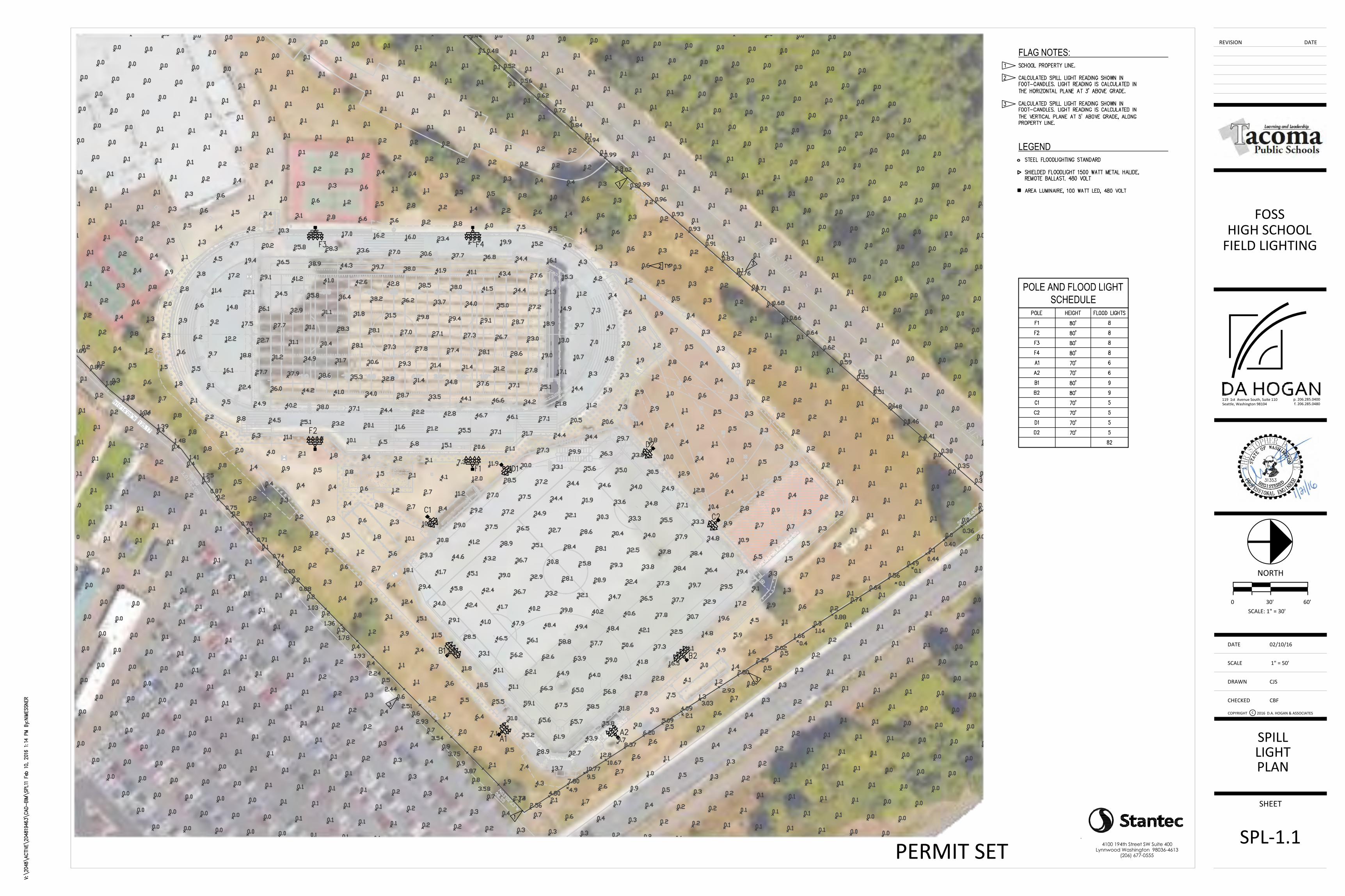
SPILLLIGHTPLAN
SPL-1.1
NORTH
0SCALE: 1" = 30'
DATE
DRAWN
CHECKED
SCALE
SHEET
REVISION DATE
COPYRIGHT c D.A. HOGAN & ASSOCIATES
119 1st Avenue South, Suite 110Seattle, Washington 98104
p. 206.285.0400f. 206.285.0480
2016
FOSSHIGH SCHOOL
FIELD LIGHTING
4100 194th Street SW Suite 400Lynnwood Washington 98036-4613
(206) 677-0555
02/10/16
1" = 50'
CJS
CBF
30' 60'
PERMIT SET

Foss High School Field Lighting
Page 1 of 1
MEMORANDUM
Date: February 17, 2016
To: City of Tacoma, Planning and Development Services
From: Jeff Burke
Re: Foss High School Field Lighting - Traffic Memo The Tacoma School district is proposing to install athletic field lighting to extend the useable hours available on the synthetic turf fields. The lighting systems would be installed on the track and field area and also at the baseball field. There would not be any change in the peak number of vehicle trips generated during the day, however field availability during evening hours and the improved reliability of the facility during wet weather may result in more frequent use. During school hours there are no trips generated as the facility is not open to the public and only utilized by the school. Peak volumes are between 7:30am-8:00am and 2:00pm-2:30pm. The majority of new trips created by these proposed improvements would not be happening during the typical peak traffic hours that occur on weekday afternoons. Events such as boys and girls soccer, boys and girls lacrosse, and junior varsity football all happen after the peak afternoon school traffic volumes. The increased traffic levels associated with these events is much lower than the normal school traffic that occurs during the day, however the additional volume is considered new to the adjacent streets. Given the smaller level of traffic with these events, increased congestion is not expected since the roadway system already handles larger peak volumes in the morning and afternoons. The parking requirements for these events occurring later in the day would be accommodated by existing parking stalls already serving the school site, therefore an increase in parking is not required and the existing system has already been adequately serving the athletic fields. There are not any bleachers adjacent to the field and track area and approximately only 250 existing seats at the baseball backstop area. Crowd sizes are expected to remain at current levels and not increase however there may be crowds later into the evening hours as a result of the lighting system. The school district is seeking approval of this proposal in order to increase the opportunity for more activities its students.
Jeffrey Burke, PE


FIGURE 1
DATE 7/13
PROJ. NO. TE130258A
FEET
1000 20000
VICINITY MAPHENRY FOSS HIGH SCHOOL FIELDS
TACOMA, WASHINGTON
130258
Henry
Foss
HS
Fie
lds
\130258
Vic
inity.
cdr
REFERENCE: USGS TOPO!
Associated Earth Sciences, Inc.
NOTE: BLACK AND WHITE REPRODUCTION OF THIS COLOR ORIGINAL MAYREDUCE ITS EFFECTIVENESS AND LEAD TO INCORRECT INTERPRETATION.
SITE
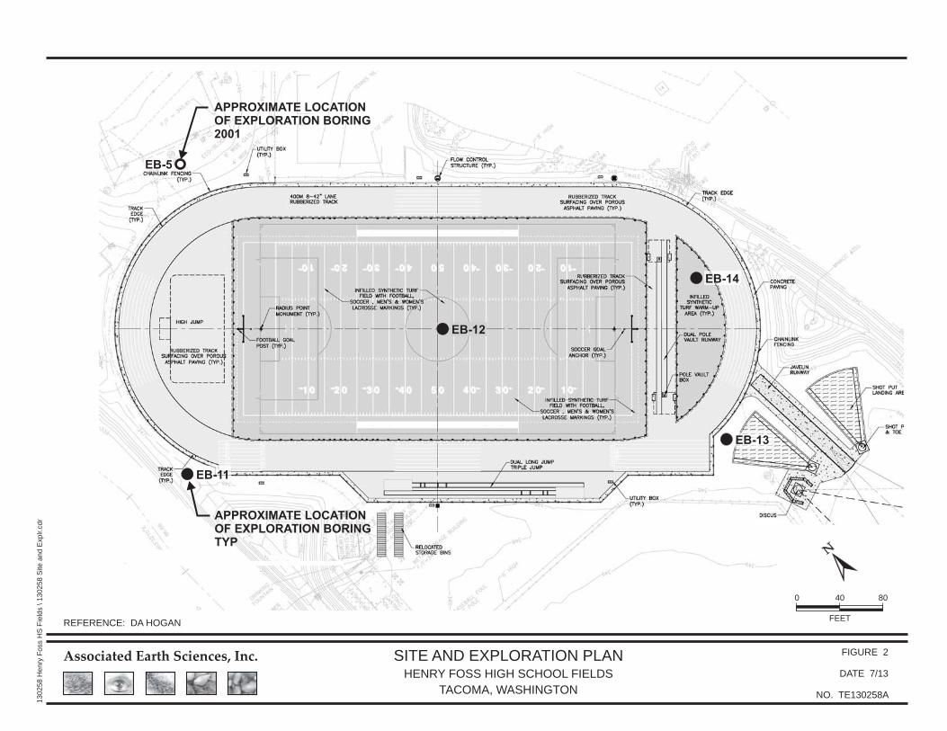
APPROXIMATE LOCATION
OF EXPLORATION BORING
2001
EB-5
EB-12
EB-11
EB-14
EB-13
FIGURE 2
DATE 7/13
PROJ. NO. TE130258A
SITE AND EXPLORATION PLANHENRY FOSS HIGH SCHOOL FIELDS
TACOMA, WASHINGTON
130258
Henry
Foss
HS
Fie
lds
\130258
Site
and
Explr.c
dr
REFERENCE: DA HOGAN
Associated Earth Sciences, Inc.
FEET
40 800
APPROXIMATE LOCATION
OF EXPLORATION BORING
TYP


Casing may be necessary to prevent soil flow. The Contractor shall take necessaryprecautions to prevent excessive soil movement during excavation and shall be preparedto immediately case the foundation excavations if excessive soil movement is observed.
Soft or organic soils shall not be used as bearing surface. Overexcavation may berequired to reach competent soil noted in the Geotechnical Report. Length offoundation shaft noted on the drawings must bear on and against undisturbed andcompetent soils. Existing soil borings indicate lodgement till which may containboulders and cobbles requiring light pole locations to be modified if encountered.Coordinate with lighting consultant prior to relocation if location is to be modified.
REINFORCING STEELDeformed Bars
DESIGN LOADS
GENERAL NOTES
CONCRETE
2
ASTM A 615, Grade 60
SUBMITTALS: Shop drawings shall be submitted to the Engineer of Record prior toany fabrication or construction for all foundation items.
If the shop drawings differ from or add to the design of the structural drawings,they shall bear the seal and signature of the Washington State RegisteredProfessional Engineer who is responsible for the design.
DEFERRED SUBMITTALS: Per IBC Section 107.3.4.2, drawings and calculations for thedesign and fabrication of items that are designed by others shall bear the seal andsignature of the Washington State Registered Professional Engineer who is responsible forthe design and shall be submitted to the Engineer of Record and the building departmentfor review prior to fabrication. Submitted calculations are for cursory review only and willgenerally not be returned. Deferred submittals include but are not limited to the following:
INSPECTION: Special inspection per IBC Chapter 17 shall be performed by anapproved testing agency as outlined in the Special Inspection Schedule and as indicatedin the project specifications. All prepared soil-bearing surfaces shall be inspected by theGeotechnical Engineer prior to placement of reinforcing steel. Soils compaction shall besupervised by an approved testing agency or Geotechnical Engineer.
SPECIAL CONDITIONS: Contractor shall verify all levels, dimensions, and existingconditions in the field before proceeding. Contractor shall notify the Engineer ofRecord of any discrepancies or field changes prior to installation or fabrication. Incase of discrepancies between the existing conditions and the drawings, theContractor shall obtain direction from the Engineer of Record before proceeding.Dimensions noted as plus or minus (Ñ) indicate unverified dimensions and areapproximate. Notify Engineer of Record immediately of conflicts or excessivevariations from indicated dimensions. Noted dimensions take precedence overscaled dimensions--DO NOT SCALE DRAWINGS. Dimensions of existing conditionsmay be based on record drawings and are to be field-verified by the Contractor.
Contractor shall verify all existing conditions before commencing any demolition.Contractor shall provide adequate shoring and bracing of all structural members,existing construction and soil excavations, as required, and in a manner suitable tothe work sequence. Temporary shoring and bracing shall not be removed until allfinal connections have been completed in accordance with the drawings and materialshave achieved design strength. No reinforcing bars in existing construction shall becut unless directed to by the Engineer of Record or as shown on the drawings.
Contractor shall be responsible for all safety precautions and the methods,techniques, sequences or procedures required to perform the work.
SOILS: See the Geotechnical Letter by Associated Earth Sciences, Inc., dated March10, 2014, for more complete information. Earthwork material, backfill and compactionshall be in accordance with the recommendations of the Geotechnical Report. Alltopsoil organics and loose soil shall be removed.
Concrete work shall conform to all requirements of Chapter 19 of the InternationalBuilding Code.
CONCRETE MIXES: Concrete mixes shall conform to the following requirements:
Water-reducing admixtures may be incorporated in concrete mix designs, but shallconform to ASTM C 494, and be used in strict accordance with the manufacturer'srecommendations. CaCl or other water-soluble chloride admixtures shall not be used.
Water/cement ratio shall be measured by weight and shall be based on the totalcementitious material. Water/cement ratio and water content shall be determined bythe supplier based on strength requirements and shall not exceed the maximumwater/cement ratio and/or water content if shown above.
Field-measured slump shall conform to the submitted concrete mix design.Tolerance of slump shall conform to ASTM C 94.
An air-entraining agent conforming to ASTM C 260 shall be used in all concrete mixes.The amount of entrained air shall be 5 percent Ñ1 1/2 percent by volume. The amountof entrained air shall be measured in the field at the discharge from the truck.
The Contractor shall submit concrete mix designs for approval 2 weeks prior toplacing any concrete. The mix design shall be in conformance with IBC 1905. Thesubmittal shall indicate where each concrete mix is to be used on the project, as wellas the maximum aggregate size of each mix.
Reinforcing shall be supported as specified by the CRSI Manual of StandardPractice, 28th Edition. Reinforcing steel shall be detailed in accordance with ACIstandard of practice as outlined in "Details and Detailing of ConcreteReinforcement, ACI 315."
V
Exposure Category C
Allowable Lateral Soil-Bearing Pressure
All design and construction shall conform to the requirements of theInternational Building Code, 2012 Edition, as amended by the City of Tacoma.
SEISMIC LOADS: Earthquake design is based on the equivalent lateral forceprocedure in ASCE 7-10 Chapter 12.8 with the following factors:
WIND LOADS: Wind load is determined using Chapter 26-31 of ASCE7-10 in accordance with IBC Section 1609 with the following factors:
Design wind pressures for determining forces on components shall be determinedusing Chapter 30 of ASCE 7-10 in accordance with IBC Section 1609 by theWashington State Registered Professional Engineer who is responsible for thedesign of such elements, unless noted otherwise on the drawings.
S gs = 1.30S1 = g0.51SDS = g0.87
= 1.0IE
SD1 = g0.51=Cs
= Base Shear =
= 1.00I wV3S =
pcf 265
= 0.95Kd
SOIL LOADS:
110 mph
R = 1.5
Kzt = 1.0
Prestressed/Precast Concrete Pole BasesEquipment Anchorage
T = 6 secondsL
Steel Poles
(70ft pole)0.17
0.3k (70ft and 80 ft poles), 0.94k (Scoreboard)
= 2.28 seconds (80ft pole)
FOUNDATION NOTES
FLOODLIGHTS(METAL HALIDEOR LED) ANDBRACKETS
REMOTE BALLASTENCLOSURE
1
S-1.1
2
V M P
3.4k 190.6k-ft -
0.3k 13.7k-ft 0.6k
- - 3.5k
1
P
M
V
70'-0" POLE
2
2
2
1
2
3
0
S-1.1
2
3
GROUNDWATER TABLE - CONCRETESHALL BE PLACED BY TREMIE METHODWHERE STANDING WATERTABLE ISABOVE BOTTOM OF FOUNDATION
NOTES:1. EMBEDMENT DEPTH SHALL BE MEASURED FROM LOWEST ADJACENT GRADE. AT LOCATIONS ADJACENT TO SLOPES
(WITHIN THE LENGTH OF EMBEDMENT) LESS THAN OR EQUAL TO 2H:1V, THIS SHALL BE MEASURED AT A DISTANCEOF THE EMBEDMENT DEPTH FROM THE FOUNDATION ON THE SLOPE. AT VERTICAL GRADE STEPS THIS SHALL BEMEASURED AT THE LOWER GRADE UNLESS APPROVED BY THE GEOTECHNICAL ENGINEER.
Foundations are precast concrete pole or steel post foundations installed inconcrete filled shaft excavations.
Allowable Compressive Soil-Bearing Pressure psf 4,000
= (Scoreboard)0.35
= 0.26 seconds (Scoreboard)
AREA LIGHT
NOTE:70'-0" POLE SHALL HAVE NO MORE THAN (8) METALHALIDE FLOODLIGHTS AT 70' OR (12) LED FLOODLIGHTSAT 70' W/ (2) LED UPLIGHTS AT 15' AND (1) AREA LIGHTAT 30'
4 MINIMUM EMBEDMENT DEPTH SHOWN. COORDINATE WITH POLESUPPLIER AS ADDITIONAL DEPTH MAY BE REQUIRED FOR PRECAST BASE.
4
STRUCTURAL STEEL
STEEL MATERIALS
Lap all reinforcing bars as noted on the drawings.
AISC 360 - Specification for StructuralSteel Buildings
Structural steel design, fabrication and erection shall conform to the requirements ofIBC Chapter 22. All members are to be erected with natural mill camber or inducedcamber up, unless otherwise noted on the plans. Substitution of member sizes orsteel grade will not be allowed without prior approval.
The Contractor shall be responsible for all erection aids and joint preparations thatinclude, but are not limited to, erection angles, lift holes and other aids, weldingprocedures, required root openings, root face dimensions, groove angles, backingbars, copes, surface roughness values, and unequal parts.
WELDING: All welding shall be in conformance with AISC and AWS Standards, andshall be performed by AWS-WABO-certified welders using 70 ksi electrodes and lowhydrogen processes. Only welds that are prequalified, as defined by AWS, orqualified by testing shall be used. Shop drawings shall show all welding with AWSA2.4 symbols. Welds shown on the drawings are minimum sizes. Increase weld sizeto AWS minimum sizes based on thickness. Minimum weld size shall be 3/16-inch,unless noted otherwise. The welds shown are for the final connections. Field weldsymbols are shown where field welds are required by the structural design. Wherefield weld is not indicated, the Contractor is responsible for determining if a weldshould be shop- or field-welded in order to facilitate the structural steel erection.Where field welds are used, any damaged protective coatings shall be repaired.
WIND
SEISMIC
DEAD
GOVERNING UNFACTORED FOUNDATION DESIGN LOADS
SEE LOAD SCHEDULE.
STRUCTURAL DESIGN BY OTHERS. SEE DEFERREDSUBMITTAL REQUIREMENTS IN GENERAL NOTES
THE CONTRACTOR SHALL BE PREPARED TO IMMEDIATELY CASE THEFOUNDATION EXCAVATION IF EXCESSIVE SOIL MOVEMENT IS OBSERVED.
70'-0" OR 80'-0"POLE PER
ELECTRICAL
30'-0"
STEEL TO PRECASTCONCRETE SPLICE
LOCATION
3"
12'-0"SEE NOTE 1
EX
PE
CTE
D D
EP
TH P
ER
GE
OTE
CH
,V
AR
IES
SE
AS
ON
ALL
Y
SLOPE AWAYFROM POLE
30"ÏMIN
PRECAST CONCRETEPOLE FOUNDATION,CENTER INCONCRETE SHAFT
CONCRETE
GALVANIZEDSTEEL POLE
Site Class DRisk Category IISeismic Design Category D
Reinforcing steel shall have protection as follows, unless noted otherwise:
AWS D1.1, typicalAWS prequalified joint details
American Welding Society (AWS)Washington Association of BuildingOfficials (WABO)
Connection material, embeddeditems, channels, angles, baseplates, and misc. steel
ASTM A 36, unless noted otherwiseASTM A 992Structural Steel
Welding Electrodes 70 ksi, low hydrogen, typical
f'c(psi)
Test Age(days) Use
3,000 28 Drilled Pier Foundations
Use Cover3"Pile Bars:
REFERENCE SPECIFICATIONS
Structural Steel
Welding
Welder Certification
Soil bearing acts across two pier diameter widths. The uppermost 2'-0" of soilisneglected regarding lateral bearing resistance.
DRILLED PIERS
Concrete work shall be placed in one continuous operation with no cold orconstruction joints. Water shall be removed from place of deposit before theconcrete is placed unless a tremie is to be used. Prevent concrete or tremie tubefrom hitting sides of excavation and loosening soil. Place concrete immediatelyafter excavation and geotechnical inspections. Do not leave excavationunprotected or open.
Notify engineer and Geotechnical Engineer if foundations are near any retainingwalls or within or near any slopes greater than 2H:1V for additional direction priorto fabrication and installation as additional foundation embedment may berequired.
Max. Agg.Size (in.)
1 0.45
Max. w/cRatio
V M P
3.4k 193k-ft -
0.3k 18.6k-ft 0.7k
- - 3.8k
80'-0" POLE
NOTE:80'-0" POLE SHALL HAVE NO MORE THAN (8) METALHALIDE FLOODLIGHTS AT 80' OR (13) LED FLOODLIGHTSAT 80' W/ (2) LED UPLIGHTS AT 15' AND (1) AREA LIGHTAT 30'
WIND
SEISMIC
DEAD
GOVERNING UNFACTORED FOUNDATION DESIGN LOADS
LED UPLIGHT(LED OPTIONONLY)
15'-0"
T = 1.89 seconds (70ft pole)
= (80ft pole)0.14
3
S-1.1
30"Ï DRILLED PIER
(3) #3 HOOPS - AT 6"SPACING, LOCATE FIRSTHOOP 3" FROM T/CONC
3"CLR
PLA
NE
OF
SC
OR
EB
OA
RD
AB
OV
E
EMBEDDED POSTPER ELEVATION
LAP 21
" MIN
25'-0", NOTE 3
8'-0
" MA
X, N
OTE
312
'-0"
9'-0
" MIN
14'-0" MIN, 16'-0" MAXNOTE 3
EQEQ
SCOREBOARD PERELECTRICAL(25'-0"Lx8'-0"H MAXPROJECTED AREA).MAX WT: 1100 LBS
W12x40 POST, TYPSTRONG AXIS PERPTO SCOREBOARD
EX
PE
CTE
D D
EP
TH P
ER
GE
OTE
CH
, VA
RIE
S S
EA
SO
NA
LLY
3/S-1.1TYP
FINISHED GRADE,NOTE 5
30"Ï DRILLED CONCRETEPOST FOUNDATION,CONTRACTOR SHALLPROVIDE CASING ASNECESSARY PER THEGEOTECHNICAL ENGINEER
NOTES:1. ALL STEEL MEMBERS TO BE PRIME COATED AND PAINTED.2. PROVIDE 5/16" CAP PLATE AT TOP OF COLUMN.3. VERIFY DIMENSIONS WITH DISPLAY PRIOR TO FABRICATION.4. ATTACHMENT OF DISPLAY TO POSTS IS PER SCOREBOARD INSTALLER.5. ACCEPTABLE TO PROVIDE MOW STRIP OR CONCRETE SLAB ABOVE TOP OF FOUNDATION.6. PROVIDE ADEQUATE POST LENGTH TO ACCOUNT FOR DIFFERING GRADE ELEVATIONS.
6" TYP
SLOPE TOP OFCONCRETE 1/4"/FT MINAWAY FROM POST
2
S-1.1
GROUNDWATER TABLE-CONCRETE SHALL BE PLACED BY TREMIE METHODWHERE STANDING WATERTABLE IS ABOVE BOTTOM OF FOUNDATION
1'-0
" MA
X
S-1.1
DRAWING INDEX
S-1.1 SCOREBOARD AND FIELD LIGHTING STRUCTURAL NOTES AND DETAILSS-1.2 STATEMENT OF SPECIAL INSPECTIONS AND TESTING
STRUCTURAL
AND DETAILSNOTES
SCOREBOARD ANDFIELD LIGHTING
DATE
DRAWN
CHECKED
SCALE
SHEET
REVISION DATE
COPYRIGHT c D.A. HOGAN & ASSOCIATES
119 1st Avenue South, Suite 110Seattle, Washington 98104
p. 206.285.0400f. 206.285.0480
2016
FOSSHIGH SCHOOL
FIELD LIGHTING
02/12/16
KSA
TSW
PERMIT SET 1601 5th Avenue, Suite 1600Seattle, WA 98101206.622.5822www.kpff.com
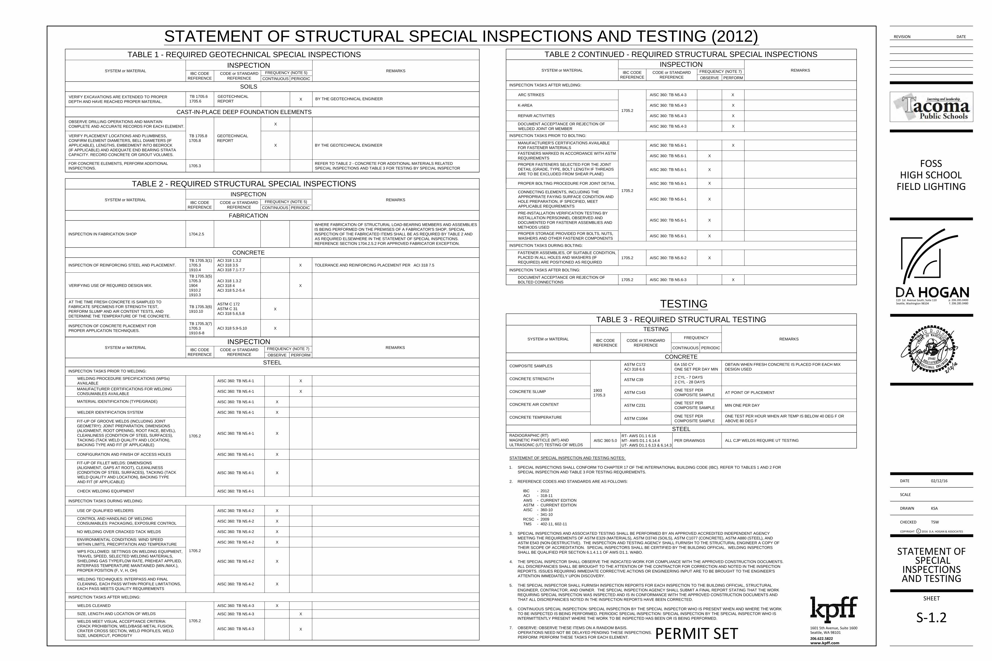
STATEMENT OF STRUCTURAL SPECIAL INSPECTIONS AND TESTING (2012)
TABLE 1 - REQUIRED GEOTECHNICAL SPECIAL INSPECTIONS
SYSTEM or MATERIAL
INSPECTION
REMARKS
IBC CODE
REFERENCE
CODE or STANDARD
REFERENCE
FREQUENCY (NOTE 5)
CONTINUOUS PERIODIC
SOILS
TB 1705.6
1705.6
GEOTECHNICAL
REPORT
BY THE GEOTECHNICAL ENGINEER
VERIFY EXCAVATIONS ARE EXTENDED TO PROPER
DEPTH AND HAVE REACHED PROPER MATERIAL.
X
CAST-IN-PLACE DEEP FOUNDATION ELEMENTS
OBSERVE DRILLING OPERATIONS AND MAINTAIN
COMPLETE AND ACCURATE RECORDS FOR EACH ELEMENT.
TB 1705.8
1705.8
GEOTECHNICAL
REPORT
X
VERIFY PLACEMENT LOCATIONS AND PLUMBNESS,
CONFIRM ELEMENT DIAMETERS, BELL DIAMETERS (IF
APPLICABLE), LENGTHS, EMBEDMENT INTO BEDROCK
(IF APPLICABLE) AND ADEQUATE END BEARING STRATA
CAPACITY. RECORD CONCRETE OR GROUT VOLUMES.
X BY THE GEOTECHNICAL ENGINEER
FOR CONCRETE ELEMENTS, PERFORM ADDITIONAL
INSPECTIONS.
1705.3
REFER TO TABLE 2 - CONCRETE FOR ADDITIONAL MATERIALS RELATED
SPECIAL INSPECTIONS AND TABLE 3 FOR TESTING BY SPECIAL INSPECTOR
TABLE 2 - REQUIRED STRUCTURAL SPECIAL INSPECTIONS
SYSTEM or MATERIAL
INSPECTION
REMARKS
IBC CODE
REFERENCE
CODE or STANDARD
REFERENCE
FREQUENCY (NOTE 5)
CONTINUOUS PERIODIC
FABRICATION
INSPECTION IN FABRICATION SHOP 1704.2.5
WHERE FABRICATION OF STRUCTURAL LOAD-BEARING MEMBERS AND ASSEMBLIES
IS BEING PERFORMED ON THE PREMISES OF A FABRICATOR'S SHOP, SPECIAL
INSPECTION OF THE FABRICATED ITEMS SHALL BE AS REQUIRED BY TABLE 2 AND
AS REQUIRED ELSEWHERE IN THE STATEMENT OF SPECIAL INSPECTIONS.
REFERENCE SECTION 1704.2.5.2 FOR APPROVED FABRICATOR EXCEPTION.
CONCRETE
INSPECTION OF REINFORCING STEEL AND PLACEMENT.
TB 1705.3(1)
1705.3
1910.4
ACI 318 1.3.2
ACI 318 3.5
ACI 318 7.1-7.7
X TOLERANCE AND REINFORCING PLACEMENT PER ACI 318 7.5
VERIFYING USE OF REQUIRED DESIGN MIX.
TB 1705.3(5)
1705.3
1904
1910.2
1910.3
ACI 318 1.3.2
ACI 318 4
ACI 318 5.2-5.4
X
AT THE TIME FRESH CONCRETE IS SAMPLED TO
FABRICATE SPECIMENS FOR STRENGTH TEST,
PERFORM SLUMP AND AIR CONTENT TESTS, AND
DETERMINE THE TEMPERATURE OF THE CONCRETE.
TB 1705.3(6)
1910.10
ASTM C 172
ASTM C 31
ACI 318 5.6,5.8
X
INSPECTION OF CONCRETE PLACEMENT FOR
PROPER APPLICATION TECHNIQUES.
TB 1705.3(7)
1705.3
1910.6-8
X
TABLE 2 CONTINUED - REQUIRED STRUCTURAL SPECIAL INSPECTIONS
SYSTEM or MATERIAL
INSPECTION
REMARKS
IBC CODE
REFERENCE
CODE or STANDARD
REFERENCE
ACI 318 5.9-5.10
STEEL
SYSTEM or MATERIAL
INSPECTION
REMARKS
IBC CODE
REFERENCE
CODE or STANDARD
REFERENCE
FREQUENCY (NOTE 7)
OBSERVE PERFORM
INSPECTION TASKS PRIOR TO WELDING:
WELDING PROCEDURE SPECIFICATIONS (WPSs)
AVAILABLE
AISC 360: TB N5.4-1 X
1705.2
MANUFACTURER CERTIFICATIONS FOR WELDING
CONSUMABLES AVAILABLE
AISC 360: TB N5.4-1 X
MATERIAL IDENTIFICATION (TYPE/GRADE)
AISC 360: TB N5.4-1 X
WELDER IDENTIFICATION SYSTEM AISC 360: TB N5.4-1 X
FIT-UP OF GROOVE WELDS (INCLUDING JOINT
GEOMETRY): JOINT PREPARATION, DIMENSIONS
(ALIGNMENT, ROOT OPENING, ROOT FACE, BEVEL),
CLEANLINESS (CONDITION OF STEEL SURFACES),
TACKING (TACK WELD QUALITY AND LOCATION),
BACKING TYPE AND FIT (IF APPLICABLE)
AISC 360: TB N5.4-1 X
CONFIGURATION AND FINISH OF ACCESS HOLES AISC 360: TB N5.4-1 X
FIT-UP OF FILLET WELDS: DIMENSIONS
(ALIGNMENT, GAPS AT ROOT), CLEANLINESS
(CONDITION OF STEEL SURFACES), TACKING (TACK
WELD QUALITY AND LOCATION), BACKING TYPE
AND FIT (IF APPLICABLE)
AISC 360: TB N5.4-1 X
CHECK WELDING EQUIPMENT AISC 360: TB N5.4-1
INSPECTION TASKS PRIOR TO BOLTING:
MANUFACTURER'S CERTIFICATIONS AVAILABLE
FOR FASTENER MATERIALS
AISC 360: TB N5.6-1 X
FASTENERS MARKED IN ACCORDANCE WITH ASTM
REQUIREMENTS
AISC 360: TB N5.6-1 X
PROPER FASTENERS SELECTED FOR THE JOINT
DETAIL (GRADE, TYPE, BOLT LENGTH IF THREADS
ARE TO BE EXCLUDED FROM SHEAR PLANE)
AISC 360: TB N5.6-1 X
PROPER BOLTING PROCEDURE FOR JOINT DETAIL AISC 360: TB N5.6-1X
CONNECTING ELEMENTS, INCLUDING THE
APPROPRIATE FAYING SURFACE CONDITION AND
HOLE PREPARATION, IF SPECIFIED, MEET
APPLICABLE REQUIREMENTS
AISC 360: TB N5.6-1 X
PRE-INSTALLATION VERIFICATION TESTING BY
INSTALLATION PERSONNEL OBSERVED AND
DOCUMENTED FOR FASTENER ASSEMBLIES AND
METHODS USED
AISC 360: TB N5.6-1 X
PROPER STORAGE PROVIDED FOR BOLTS, NUTS,
WASHERS AND OTHER FASTENER COMPONENTS
AISC 360: TB N5.6-1 X
1705.2
INSPECTION TASKS DURING BOLTING:
FASTENER ASSEMBLIES, OF SUITABLE CONDITION,
PLACED IN ALL HOLES AND WASHERS (IF
REQUIRED) ARE POSITIONED AS REQUIRED
AISC 360: TB N5.6-2 X1705.2
INSPECTION TASKS AFTER BOLTING:
DOCUMENT ACCEPTANCE OR REJECTION OF
BOLTED CONNECTIONS
AISC 360: TB N5.6-3 X1705.2
FREQUENCY (NOTE 7)
OBSERVE PERFORM
STATEMENT OF SPECIAL INSPECTION AND TESTING NOTES:
1. SPECIAL INSPECTIONS SHALL CONFORM TO CHAPTER 17 OF THE INTERNATIONAL BUILDING CODE (IBC). REFER TO TABLES 1 AND 2 FOR
SPECIAL INSPECTION AND TABLE 3 FOR TESTING REQUIREMENTS.
2. REFERENCE CODES AND STANDARDS ARE AS FOLLOWS:
IBC - 2012
ACI - 318-11
AWS - CURRENT EDITION
ASTM - CURRENT EDITION
AISC - 360-10
- 341-10
RCSC - 2009
TMS - 402-11, 602-11
3. SPECIAL INSPECTIONS AND ASSOCIATED TESTING SHALL BE PERFORMED BY AN APPROVED ACCREDITED INDEPENDENT AGENCY
MEETING THE REQUIREMENTS OF ASTM E329 (MATERIALS), ASTM D3740 (SOILS), ASTM C1077 (CONCRETE), ASTM A880 (STEEL), AND
ASTM E543 (NON-DESTRUCTIVE). THE INSPECTION AND TESTING AGENCY SHALL FURNISH TO THE STRUCTURAL ENGINEER A COPY OF
THEIR SCOPE OF ACCREDITATION. SPECIAL INSPECTORS SHALL BE CERTIFIED BY THE BUILDING OFFICIAL. WELDING INSPECTORS
SHALL BE QUALIFIED PER SECTION 6.1.4.1.1 OF AWS D1.1. WABO.
4. THE SPECIAL INSPECTOR SHALL OBSERVE THE INDICATED WORK FOR COMPLIANCE WITH THE APPROVED CONSTRUCTION DOCUMENTS.
ALL DISCREPANCIES SHALL BE BROUGHT TO THE ATTENTION OF THE CONTRACTOR FOR CORRECTION AND NOTED IN THE INSPECTION
REPORTS. ISSUES REQUIRING IMMEDIATE CORRECTIVE ACTIONS OR ENGINEERING INPUT ARE TO BE BROUGHT TO THE ENGINEER'S
ATTENTION IMMEDIATELY UPON DISCOVERY.
5. THE SPECIAL INSPECTOR SHALL FURNISH INSPECTION REPORTS FOR EACH INSPECTION TO THE BUILDING OFFICIAL, STRUCTURAL
ENGINEER, CONTRACTOR, AND OWNER. THE SPECIAL INSPECTION AGENCY SHALL SUBMIT A FINAL REPORT STATING THAT THE WORK
REQUIRING SPECIAL INSPECTION WAS INSPECTED AND IS IN CONFORMANCE WITH THE APPROVED CONSTRUCTION DOCUMENTS AND
THAT ALL DISCREPANCIES NOTED IN THE INSPECTION REPORTS HAVE BEEN CORRECTED.
6. CONTINUOUS SPECIAL INSPECTION: SPECIAL INSPECTION BY THE SPECIAL INSPECTOR WHO IS PRESENT WHEN AND WHERE THE WORK
TO BE INSPECTED IS BEING PERFORMED. PERIODIC SPECIAL INSPECTION: SPECIAL INSPECTION BY THE SPECIAL INSPECTOR WHO IS
INTERMITTENTLY PRESENT WHERE THE WORK TO BE INSPECTED HAS BEEN OR IS BEING PERFORMED.
7. OBSERVE: OBSERVE THESE ITEMS ON A RANDOM BASIS.
OPERATIONS NEED NOT BE DELAYED PENDING THESE INSPECTIONS.
PERFORM: PERFORM THESE TASKS FOR EACH ELEMENT.
TABLE 3 - REQUIRED STRUCTURAL TESTING
SYSTEM or MATERIAL
TESTING
REMARKS
IBC CODE
REFERENCE
CODE or STANDARD
REFERENCE
FREQUENCY
CONTINUOUS PERIODIC
CONCRETE
CONCRETE STRENGTH
1903
1705.3
ASTM C39
CONCRETE SLUMP
ASTM C143
CONCRETE AIR CONTENT
ASTM C231
CONCRETE TEMPERATURE
ASTM C1064
STEEL
RADIOGRAPHIC (RT)
MAGNETIC PARTICLE (MT) AND
ULTRASONIC (UT) TESTING OF WELDS
RT- AWS D1.1 6.16
MT- AWS D1.1 6.14.4
UT- AWS D1.1 6.13 & 6.14.3
PER DRAWINGS ALL CJP WELDS REQUIRE UT TESTING
COMPOSITE SAMPLES
ASTM C172
ACI 318 6.6
EA 150 CY
ONE SET PER DAY MIN
OBTAIN WHEN FRESH CONCRETE IS PLACED FOR EACH MIX
DESIGN USED
2 CYL - 7 DAYS
2 CYL - 28 DAYS
ONE TEST PER
COMPOSITE SAMPLE
AT POINT OF PLACEMENT
ONE TEST PER
COMPOSITE SAMPLE
MIN ONE PER DAY
ONE TEST PER
COMPOSITE SAMPLE
ONE TEST PER HOUR WHEN AIR TEMP IS BELOW 40 DEG F OR
ABOVE 80 DEG F
AISC 360 5.0
TESTING
INSPECTION TASKS DURING WELDING:
USE OF QUALIFIED WELDERS AISC 360: TB N5.4-2
1705.2
X
CONTROL AND HANDLING OF WELDING
CONSUMABLES: PACKAGING, EXPOSURE CONTROL
AISC 360: TB N5.4-2 X
NO WELDING OVER CRACKED TACK WELDS AISC 360: TB N5.4-2 X
ENVIRONMENTAL CONDITIONS: WIND SPEED
WITHIN LIMITS, PRECIPITATION AND TEMPERATURE
AISC 360: TB N5.4-2 X
WPS FOLLOWED: SETTINGS ON WELDING EQUIPMENT,
TRAVEL SPEED, SELECTED WELDING MATERIALS,
SHIELDING GAS TYPE/FLOW RATE, PREHEAT APPLIED,
INTERPASS TEMPERATURE MAINTAINED (MIN./MAX.),
PROPER POSITION (F, V, H, OH)
AISC 360: TB N5.4-2 X
WELDING TECHNIQUES: INTERPASS AND FINAL
CLEANING, EACH PASS WITHIN PROFILE LIMITATIONS,
EACH PASS MEETS QUALITY REQUIREMENTS
AISC 360: TB N5.4-2 X
INSPECTION TASKS AFTER WELDING:
ARC STRIKES AISC 360: TB N5.4-3 X
K-AREA AISC 360: TB N5.4-3 X
REPAIR ACTIVITIES AISC 360: TB N5.4-3 X
DOCUMENT ACCEPTANCE OR REJECTION OF
WELDED JOINT OR MEMBER
AISC 360: TB N5.4-3 X
1705.2
INSPECTION TASKS AFTER WELDING:
WELDS CLEANED AISC 360: TB N5.4-3 X
SIZE, LENGTH AND LOCATION OF WELDSAISC 360: TB N5.4-3 X
WELDS MEET VISUAL ACCEPTANCE CRITERIA:
CRACK PROHIBITION, WELD/BASE-METAL FUSION,
CRATER CROSS SECTION, WELD PROFILES, WELD
SIZE, UNDERCUT, POROSITY
AISC 360: TB N5.4-3
X
1705.2
AND TESTING
S-1.2
SPECIALSTATEMENT OF
INSPECTIONS
DATE
DRAWN
CHECKED
SCALE
SHEET
REVISION DATE
COPYRIGHT c D.A. HOGAN & ASSOCIATES
119 1st Avenue South, Suite 110Seattle, Washington 98104
p. 206.285.0400f. 206.285.0480
2016
FOSSHIGH SCHOOL
FIELD LIGHTING
02/12/16
KSA
TSW
PERMIT SET 1601 5th Avenue, Suite 1600Seattle, WA 98101206.622.5822www.kpff.com

Stantec
Foss High School Field Lighting Tacoma, Washington
Structural Calculations
CALCULATIONS INCLUDED:
Pages 1 through 38
These Calculations cover the design of the light pole foundations and the scoreboard foundations. The light
pole design is provided per the light pole supplier.
1601 Fifth Avenue, Suite 1600 Seattle, WA 98101
KPFF Project No. 160038.10
February 12, 2016

1

2

Foss High School BML
02/01/16
Scoreboard 16038
Seismic Base Shear Calculation
2012 IBC (Ch. 16) & ASCE 7-10 (Ch. 11, 12, 15, & 22)
Lateral System
Occupancy Category II [Tab. 1604.5]
Site Class D [Tab. 1613.5.2]
Design Category D [Sec. 1613.5.6; Tab. 16.13.5.6(1) & (2)]
Ss 1.303 [Geotechnical Report]
S1 0.511 [Geotechnical Report]
Fa 1.00 [Tab. 1613.5.3(1)]
Fv 1.37 [Tab. 1613.5.3(2)]
SMS 1.30 [Eqn. 16-37]
SM1 0.70 [Eqn. 16-38]
SDS 0.87 [Eqn. 16-39]
SD1 0.47 [Eqn. 16-40]
I 1.00 [Tab. 11.5-1] T 0.26 sec [Eqn. 15.4-6]
R 2.5 [Tab. 15.4-2] TL 6 sec [Fig. 22-15]
t
Scoreboard
Pole: Steel
project
location
client
by
date
sheet no.
job no.
t
SDS / (R/I) = Cs 0.347 [Eqn. 12.8-2]
SD1 / T (R/I) = Cs 0.719 [Eqn. 12.8-3]
SD1 TL / T2 (R/I) = Cs N/A [Eqn. 12.8-4]
Cs (min) 0.030 [Eqn. 15.4-1]
0.5S1 / (R/I) = Cs N/A [Eqn. 12.8-6]
Cs (design) 0.347
Vertical Distribution of Forces
ASCE 7-10, Sec. 12.8.3
exponent related to structural period
k 1
Mass Name Weight, wi Height, hi wihik
Fi Vi Mi
Scoreboard 1 1100 lb 16 ft 17600 lb-ft 491 lb 491 lb 7863 lb-ft
Steel Pole 2 1600 lb 10 ft 16000 lb-ft 447 lb 938 lb 4467 lb-ft0 lb 0 ft 0 lb-ft 0 lb 938 lb 0 lb-ft Centroid
2700 lb 33600 lb-ft 938 lb 12330 lb-ft 13.1 ft
Load Combination Using Allowable Stress Design
IBC 2012, Sec. 1605.3.1
applied lateral force P 657 lb [Eqn. 16-12]
centroid of force h 13.1 ft
Note: Wind forces govern over seismic forces.
3

4

5

6
7

project Foss High School by BML sheet no.
location Tacoma, WA date 2/12/16
client job no.
Nonconstrained Pole Foundation 16038
Foundation Design Employing Lateral Bearing
IBC 2012 (Per Geotech Recommendation)
Depth of top soil to be ignored
Nonconstrained for passive resistance = 2.0 ft
Sec. 1807.3.2.1 Limit for Passive Pressure = 8.0 ft
allowable lateral passive resistance1
Sa 530 psf/ft
applied lateral force (allowable) P 2973 lb Pw (nominal) 4955 lb lbs
centroid of force h 16.0 ft
diameter of footing b 2.5 ft
d 6.8 ft
soil-bearing pressure at d/32 S1 1546 psf
point of max pressure A 1.8 ft
minimum embedment (Eq. 18-1) dmin 6.6 ft [Eqn. 18-1]
d > dmin TRUE
Total Depth 8.8 ft
1. Pressure per geotech recommendation
2. pressure profile S1 is limited to 8' per geotech recomentation
3. Assumes passive pressure acts on 2x the diameter of the pile
Foundation Design Vertical Bearing
Applied Vertical Stress
Scoreboard 1100 lb
W12x40 (h=20') 800 lb
Base Plate 0 lb
Weight of Foundation (150 pcf) 6657 lb 761 lbs/ft
Total 8557 lb
Bearing Capacity
Allowable vertical unit end bearing resistance 4000 psf
Foundation cross-sectional area 4.91 sf
Allowable vertical shaft resistance 250 psf
Foundation surface area 53 sf
Total 32889 lb
Demand / Capacity 0.26 < 1 OK
Pile Demand CapacityMu = 100.3 k-ft Beam Size = W12x40
φMn = 193.125 k-ft S = 51.5 in3
I = 307.0 in4
∆ = 0.197 in
∆max = 0.533 in = L/360
Post Size OK
W12x40 adequate for post
8

Foss High School Field BMLTacoma, WA 2/10/16
70 ft. Pole (Halide Floodlights) 16038
Wind LoadsASCE 7-10, Chapters 26,29
Directional Procedure
Sec. 29.1.1 , Table 29.1-1
Basic Wind Speed Topographic Effects
Sec. 26.5.1 Sec. 26.8
basic wind speedV 110 mph (Fig. 26.5-1)
wind directionality factor height of hill or excarpmentKd 0.95 (Tab. 26.6-1) H 0 ft
distance from crest to half-way downExposure Lh -Sec. 26.7.3 distance from crest to siteexposure category x -
C topographic shape factorK1 0.00 (Fig. 26.8-1)
Velocity pressure exposure coeficient distance to crest factor
mean roof height K2 0.00 (Fig. 26.8-1)
h 70.0 ft height above terrain factorKh 1.17 (Table 29.3-1) K3 1.00 (Fig. 26.8-1)
topographic factorKzt 1.00
none
project
location
client
by
date
sheet no.
job no.
topo effects only occur when H>15 ft
Gust Effect Factor background responseSec. 26.9 Q 0.921 (Eq. 26.9-8)
fundamental period from seismic analysis terrain exposure constants from Tab. 26.9-1T 1.987 sec (Eq. 15.4-6) zmin 15 ft
natural frequency c 0.2n1 0.50 Hz l 500 ft
critical damping ratio epsilonbar 1/5.0
β 1.5% bbar 0.65equivalent height alphabar 1/6.5
42.0 ft 0.6h > z min peak factor for wind response
building width normal to wind gR 4.0 (Eq. 26.9-11)
B 0.78 ft mean hourly windspeed at zbuilding length parallel to wind 109 mph (Eq. 26.9-16)
L 0.78 ft reduced frequencypeak factors N1 2.426 (Eq. 26.9-14)
gQ, gv 3.4 resonant response factors
turbulence intensity Rn 0.079 (Eq. 26.9-13)
0.192 (Eq. 26.9-7) Rh 0.458 (Eq. 26.9-15)
integral length scale of turbulence RB 0.989 (Eq. 26.9-15)
525 ft (Eq. 26.9-9) RL 0.964 (Eq. 26.9-15)
R 1.535 (Eq. 26.9-12)
z
∈
zL
zI
b
α
zV
9

Foss High School Field BMLTacoma, WA 2/10/16
0 70 ft. Pole (Halide Floodlights)
gust effect factor, rigid structures gust effect factor, flexible structuresG 0.887 (Eq. 26.9-7) Gf 1.429 (Eq. 26.9-10)
structure defined as flexible per Sec. 26.2
governing gust effect factorG 1.429
Velocity Pressure Pressure and Force Coefficients
Sec. 29.3.2 Sec. 29.5
velocity pressure at h (70. ft) cross-section, surfaceqh 34.5 psf (Eq. 29.3-1) round, smooth (Fig. 6-21)
height to diameterh/D see below (Fig. 6-21)
net force coefficientCf see below (Fig. 6-21)
design wind forceF/Af see below [G*q h *C f ]
pole dia. (Tab 29.3-1) (Eq. 29.3-1) (Fig. 29.5-1) (Eqn. 6-28)
z D h/D Kz qz D√(qz) Cf F/Af
70 ft 5.00 in 168.0 1.17 34.5 psf 2.4 1.20 59.3 psf67.2 ft 5.3 in 157.0 1.16 34.3 psf 2.6 0.70 34.3 psf
64.4 ft 5.7 in 147.4 1.15 33.9 psf 2.8 0.70 34.0 psf
project
location
client
by
date
sheet no.
job no.
61.6 ft 6.0 in 138.9 1.14 33.6 psf 2.9 0.70 33.7 psf58.8 ft 6.4 in 131.3 1.13 33.3 psf 3.1 0.70 33.3 psf56.0 ft 6.7 in 124.5 1.12 33.0 psf 3.2 0.70 33.0 psf53.2 ft 7.1 in 118.3 1.11 32.6 psf 3.4 0.70 32.6 psf50.4 ft 7.4 in 112.8 1.10 32.2 psf 3.5 0.70 32.3 psf47.6 ft 7.8 in 107.7 1.08 31.9 psf 3.7 0.70 31.9 psf44.8 ft 8.1 in 103.1 1.07 31.5 psf 3.8 0.70 31.5 psf42.0 ft 8.5 in 98.9 1.05 31.0 psf 3.9 0.70 31.0 psf39.2 ft 8.8 in 95.0 1.04 30.6 psf 4.1 0.70 30.6 psf36.4 ft 9.2 in 91.4 1.02 30.1 psf 4.2 0.70 30.1 psf33.6 ft 9.5 in 88.0 1.01 29.6 psf 4.3 0.70 29.6 psf30.8 ft 9.9 in 84.9 0.99 29.1 psf 4.4 0.70 29.1 psf28.0 ft 10.2 in 82.0 0.97 28.5 psf 4.6 0.70 28.5 psf25.2 ft 10.6 in 79.3 0.95 27.9 psf 4.7 0.70 27.9 psf22.4 ft 10.9 in 76.8 0.92 27.2 psf 4.8 0.70 27.2 psf19.6 ft 11.3 in 74.4 0.90 26.4 psf 4.8 0.70 26.4 psf16.8 ft 11.6 in 72.2 0.87 25.6 psf 4.9 0.70 25.6 psf14.0 ft 12.0 in 70.0 0.85 25.0 psf 5.0 0.70 25.0 psf11.2 ft 12.3 in 68.1 0.85 25.0 psf 5.1 0.70 25.0 psf8.4 ft 12.7 in 66.2 0.85 25.0 psf 5.3 0.70 25.0 psf5.6 ft 13.0 in 64.4 0.85 25.0 psf 5.4 0.70 25.0 psf2.8 ft 13.4 in 62.7 0.85 25.0 psf 5.6 0.70 25.0 psf0.0 ft 13.74 in 61.1 0.85 25.0 psf 5.7 0.70 25.0 psf
10

project Foss High School by BML sheet no.
location Tacoma, WA date 2/10/16
client job no.
70' Poles Halide
Loadingpole Af
z Kz qz Cf F/Af Af pole zn-zm luminaries EPA luminaries F M
70.0 ft 1.17 34.5 psf 1.20 59.3 psf 0.417 2.8 ft 8 2.8 sf 22 sf 1396.7 lb 97769 lb-ft
67.2 ft 1.16 34.3 psf 0.70 34.3 psf 0.446 2.8 ft 42.8 lb 2875 lb-ft
64.4 ft 1.15 33.9 psf 0.70 34.0 psf 0.475 2.8 ft 45.2 lb 2909 lb-ft
61.6 ft 1.14 33.6 psf 0.70 33.7 psf 0.504 2.8 ft 47.5 lb 2926 lb-ft
58.8 ft 1.13 33.3 psf 0.70 33.3 psf 0.533 2.8 ft 49.8 lb 2926 lb-ft
56.0 ft 1.12 33.0 psf 0.70 33.0 psf 0.562 2.8 ft 51.9 lb 2908 lb-ft
53.2 ft 1.11 32.6 psf 0.70 32.6 psf 0.591 2.8 ft 54.0 lb 2875 lb-ft
50.4 ft 1.10 32.2 psf 0.70 32.3 psf 0.621 2.8 ft 56.1 lb 2825 lb-ft
47.6 ft 1.08 31.9 psf 0.70 31.9 psf 0.650 2.8 ft 58.0 lb 2760 lb-ft
44.8 ft 1.07 31.5 psf 0.70 31.5 psf 0.679 2.8 ft 59.8 lb 2680 lb-ft
42.0 ft 1.05 31.0 psf 0.70 31.0 psf 0.708 2.8 ft 61.5 lb 2585 lb-ft
39.2 ft 1.04 30.6 psf 0.70 30.6 psf 0.737 2.8 ft 63.2 lb 2476 lb-ft
36.4 ft 1.02 30.1 psf 0.70 30.1 psf 0.766 2.8 ft 64.6 lb 2353 lb-ft
33.6 ft 1.01 29.6 psf 0.70 29.6 psf 0.795 2.8 ft 66.0 lb 2217 lb-ft
30.8 ft 0.99 29.1 psf 0.70 29.1 psf 0.825 2.8 ft 1 ft 2 sf 2 sf 125.3 lb 3860 lb-ft
28.0 ft 0.97 28.5 psf 0.70 28.5 psf 0.854 2.8 ft 68.1 lb 1908 lb-ft
25.2 ft 0.95 27.9 psf 0.70 27.9 psf 0.883 2.8 ft 68.9 lb 1737 lb-ft
22.4 ft 0.92 27.2 psf 0.70 27.2 psf 0.912 2.8 ft 69.4 lb 1556 lb-ft
19.6 ft 0.90 26.4 psf 0.70 26.4 psf 0.941 2.8 ft 69.7 lb 1366 lb-ft
16.8 ft 0.87 25.6 psf 0.70 25.6 psf 0.970 2.8 ft 69.5 lb 1168 lb-ft
14.0 ft 0.85 25.0 psf 0.70 25.0 psf 0.999 2.8 ft 69.9 lb 979 lb-ft
11.2 ft 0.85 25.0 psf 0.70 25.0 psf 1.028 2.8 ft 72.0 lb 806 lb-ft
8.4 ft 0.85 25.0 psf 0.70 25.0 psf 1.058 2.8 ft 74.0 lb 622 lb-ft8.4 ft 0.85 25.0 psf 0.70 25.0 psf 1.058 2.8 ft 74.0 lb 622 lb-ft
5.6 ft 0.85 25.0 psf 0.70 25.0 psf 1.087 2.8 ft 76.1 lb 426 lb-ft
2.8 ft 0.85 25.0 psf 0.70 25.0 psf 1.116 2.8 ft 78.1 lb 219 lb-ft
0.0 ft 0.85 25.0 psf 0.70 25.0 psf 1.145 0.0 ft 0.0 lb 0 lb-ft Centroid
Sum: 9 5 sf 24 sf 2958 lb 147730 lb-ft 49.9 ft
Foundation Designs Employing Lateral BearingIBC 2012
Nonconstrained
Sec. 1807.3.2.1
Soil Profile Limits
Soil Depth Limit for Passive Pressure 8.0 ft
Soil Depth to neglect at top of pole 2.0 ft
Embedded Pole Calculation
applied lateral force P 1775 lb ASD Load (0.6*P)
centroid of force h 49.9 ft
diameter of footing b 2.5 ft
depth of footing d 8.00 ft
point of max pressure A 0.9 ft
allowable soil bearing pressure1
Sa 530 psf/ft
soil-bearing pressure at d/3 S1 1767 psf
minimum embedment (Eq. 18-1) dmin 7.64 ft
d > dmin TRUE
dpole 9.64 ft minimum
1. Assumes soil load acts over two times the pile diameter. 2. The maximum
allowable soil bearing pressure is limited to 8' per the Geotechnical Report. 3. The
upper 2' of soil is neglected as providing passive resistance but is included in
allowable soil pressure profile.
11

70 ft. Pole (Halide Floodlights)
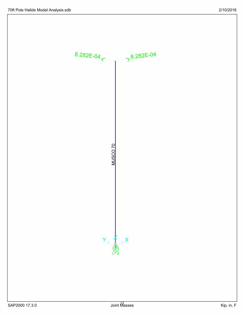
Seismic Massing and Periods
Seismic Weights
Per Musco MFR:40 per floodlight16 lightpole averaged weight
Floodlight Assembly# Lights wt/light total wt total mass
8 x 40 lb = 320 lb 8.282E-04 kip-sec^2/in
Steel Lightpole Sections
SAP Approximation of Musco MFR Data
70 ft Pole Height
Foss High School
Tacoma, WA
project by BML
location
client
date 2/10/2016
sheet no.
job no.
Steel Cross Sections
Periods
Calculated per SAP Modal Analysis -- See Attached Output
Seismic Massing and Periods.xlsx Page 1 of 112
MU
SC
O 7
0
8.282E-048.282E-04
XY XZY Z
70ft Pole Halide Modal Analysis.sdb 2/10/2016
SAP2000 17.3.0 Joint Masses Kip, in, F13

XY XZY Z
70ft Pole Halide Modal Analysis.sdb 2/10/2016
SAP2000 17.3.0 Deformed Shape (MODAL) - Mode 1; T = 1.97814; f = 0.50552 lb, ft, F14
Foss High School BML
02/10/16
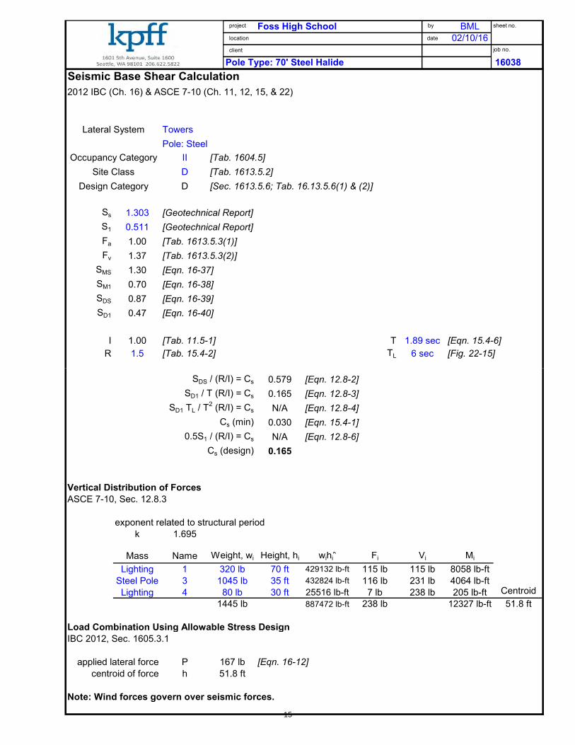
Pole Type: 70' Steel Halide 16038
Seismic Base Shear Calculation
2012 IBC (Ch. 16) & ASCE 7-10 (Ch. 11, 12, 15, & 22)
Lateral System
Occupancy Category II [Tab. 1604.5]
Site Class D [Tab. 1613.5.2]
Design Category D [Sec. 1613.5.6; Tab. 16.13.5.6(1) & (2)]
Ss 1.303 [Geotechnical Report]
S1 0.511 [Geotechnical Report]
Fa 1.00 [Tab. 1613.5.3(1)]
Fv 1.37 [Tab. 1613.5.3(2)]
SMS 1.30 [Eqn. 16-37]
SM1 0.70 [Eqn. 16-38]
SDS 0.87 [Eqn. 16-39]
SD1 0.47 [Eqn. 16-40]
I 1.00 [Tab. 11.5-1] T 1.89 sec [Eqn. 15.4-6]
R 1.5 [Tab. 15.4-2] TL 6 sec [Fig. 22-15]
Towers
Pole: Steel
project
location
client
by
date
sheet no.
job no.
SDS / (R/I) = Cs 0.579 [Eqn. 12.8-2]
SD1 / T (R/I) = Cs 0.165 [Eqn. 12.8-3]
SD1 TL / T2 (R/I) = Cs N/A [Eqn. 12.8-4]
Cs (min) 0.030 [Eqn. 15.4-1]
0.5S1 / (R/I) = Cs N/A [Eqn. 12.8-6]
Cs (design) 0.165
Vertical Distribution of Forces
ASCE 7-10, Sec. 12.8.3
exponent related to structural period
k 1.695
Mass Name Weight, wi Height, hi wihik
Fi Vi Mi
Lighting 1 320 lb 70 ft 429132 lb-ft 115 lb 115 lb 8058 lb-ft
Steel Pole 3 1045 lb 35 ft 432824 lb-ft 116 lb 231 lb 4064 lb-ft
Lighting 4 80 lb 30 ft 25516 lb-ft 7 lb 238 lb 205 lb-ft Centroid
1445 lb 887472 lb-ft 238 lb 12327 lb-ft 51.8 ft
Load Combination Using Allowable Stress Design
IBC 2012, Sec. 1605.3.1
applied lateral force P 167 lb [Eqn. 16-12]
centroid of force h 51.8 ft
Note: Wind forces govern over seismic forces.
15

Foss High School Field BMLTacoma, WA 2/10/16
70 ft. Pole (LED Floodlights) 16038
Wind LoadsASCE 7-10, Chapters 26,29
Directional Procedure
Sec. 29.1.1 , Table 29.1-1
Basic Wind Speed Topographic Effects
Sec. 26.5.1 Sec. 26.8
basic wind speedV 110 mph (Fig. 26.5-1)
wind directionality factor height of hill or excarpmentKd 0.95 (Tab. 26.6-1) H 0 ft
distance from crest to half-way downExposure Lh -Sec. 26.7.3 distance from crest to siteexposure category x -
C topographic shape factorK1 0.00 (Fig. 26.8-1)
Velocity pressure exposure coeficient distance to crest factor
mean roof height K2 0.00 (Fig. 26.8-1)
h 70.0 ft height above terrain factorKh 1.17 (Table 29.3-1) K3 1.00 (Fig. 26.8-1)
topographic factorKzt 1.00
none
project
location
client
by
date
sheet no.
job no.
topo effects only occur when H>15 ft
Gust Effect Factor background responseSec. 26.9 Q 0.921 (Eq. 26.9-8)
fundamental period from seismic analysis terrain exposure constants from Tab. 26.9-1T 2.311 sec (Eq. 15.4-6) zmin 15 ft
natural frequency c 0.2n1 0.43 Hz l 500 ft
critical damping ratio epsilonbar 1/5.0
β 1.5% bbar 0.65equivalent height alphabar 1/6.5
42.0 ft 0.6h > z min peak factor for wind response
building width normal to wind gR 4.0 (Eq. 26.9-11)
B 0.78 ft mean hourly windspeed at zbuilding length parallel to wind 109 mph (Eq. 26.9-16)
L 0.78 ft reduced frequencypeak factors N1 2.086 (Eq. 26.9-14)
gQ, gv 3.4 resonant response factors
turbulence intensity Rn 0.087 (Eq. 26.9-13)
0.192 (Eq. 26.9-7) Rh 0.500 (Eq. 26.9-15)
integral length scale of turbulence RB 0.991 (Eq. 26.9-15)
525 ft (Eq. 26.9-9) RL 0.969 (Eq. 26.9-15)
R 1.682 (Eq. 26.9-12)
z
∈
zL
zI
b
α
zV
16

Foss High School Field BMLTacoma, WA 2/10/16
0
gust effect factor, rigid structures gust effect factor, flexible structuresG 0.887 (Eq. 26.9-7) Gf 1.497 (Eq. 26.9-10)
structure defined as flexible per Sec. 26.2
governing gust effect factorG 1.497
Velocity Pressure Pressure and Force Coefficients
Sec. 29.3.2 Sec. 29.5
velocity pressure at h (70. ft) cross-section, surfaceqh 34.5 psf (Eq. 29.3-1) round, smooth (Fig. 6-21)
height to diameterh/D see below (Fig. 6-21)
net force coefficientCf see below (Fig. 6-21)
design wind forceF/Af see below [G*q h *C f ]
pole dia. (Tab 29.3-1) (Eq. 29.3-1) (Fig. 29.5-1) (Eqn. 6-28)
z D h/D Kz qz D√(qz) Cf F/Af
70 ft 5.00 in 168.0 1.17 34.5 psf 2.4 1.20 62.1 psf67.2 ft 5.3 in 157.0 1.16 34.3 psf 2.6 0.70 35.9 psf
64.4 ft 5.7 in 147.4 1.15 33.9 psf 2.8 0.70 35.6 psf
project
location
client
by
date
sheet no.
job no.
61.6 ft 6.0 in 138.9 1.14 33.6 psf 2.9 0.70 35.2 psf58.8 ft 6.4 in 131.3 1.13 33.3 psf 3.1 0.70 34.9 psf56.0 ft 6.7 in 124.5 1.12 33.0 psf 3.2 0.70 34.5 psf53.2 ft 7.1 in 118.3 1.11 32.6 psf 3.4 0.70 34.2 psf50.4 ft 7.4 in 112.8 1.10 32.2 psf 3.5 0.70 33.8 psf47.6 ft 7.8 in 107.7 1.08 31.9 psf 3.7 0.70 33.4 psf44.8 ft 8.1 in 103.1 1.07 31.5 psf 3.8 0.70 33.0 psf42.0 ft 8.5 in 98.9 1.05 31.0 psf 3.9 0.70 32.5 psf39.2 ft 8.8 in 95.0 1.04 30.6 psf 4.1 0.70 32.0 psf36.4 ft 9.2 in 91.4 1.02 30.1 psf 4.2 0.70 31.6 psf33.6 ft 9.5 in 88.0 1.01 29.6 psf 4.3 0.70 31.0 psf30.8 ft 9.9 in 84.9 0.99 29.1 psf 4.4 0.70 30.5 psf28.0 ft 10.2 in 82.0 0.97 28.5 psf 4.6 0.70 29.9 psf25.2 ft 10.6 in 79.3 0.95 27.9 psf 4.7 0.70 29.2 psf22.4 ft 10.9 in 76.8 0.92 27.2 psf 4.8 0.70 28.5 psf19.6 ft 11.3 in 74.4 0.90 26.4 psf 4.8 0.70 27.7 psf16.8 ft 11.6 in 72.2 0.87 25.6 psf 4.9 0.70 26.8 psf14.0 ft 12.0 in 70.0 0.85 25.0 psf 5.0 0.70 26.2 psf11.2 ft 12.3 in 68.1 0.85 25.0 psf 5.1 0.70 26.2 psf8.4 ft 12.7 in 66.2 0.85 25.0 psf 5.3 0.70 26.2 psf5.6 ft 13.0 in 64.4 0.85 25.0 psf 5.4 0.70 26.2 psf2.8 ft 13.4 in 62.7 0.85 25.0 psf 5.6 0.70 26.2 psf0.0 ft 13.74 in 61.1 0.85 25.0 psf 5.7 0.70 26.2 psf
17

project Foss High School by BML sheet no.
location Tacome, WA date 2/10/16
client job no.
70' Poles LED
Loadingpole Af
z Kz qz Cf F/Af Af pole zn-zm luminaries EPA luminaries F M
70.0 ft 1.17 34.5 psf 1.20 62.1 psf 0.417 2.8 ft 12 2.5 sf 30 sf 1934.5 lb 135415 lb-ft
67.2 ft 1.16 34.3 psf 0.70 35.9 psf 0.446 2.8 ft 44.8 lb 3011 lb-ft
64.4 ft 1.15 33.9 psf 0.70 35.6 psf 0.475 2.8 ft 47.3 lb 3047 lb-ft
61.6 ft 1.14 33.6 psf 0.70 35.2 psf 0.504 2.8 ft 49.7 lb 3064 lb-ft
58.8 ft 1.13 33.3 psf 0.70 34.9 psf 0.533 2.8 ft 52.1 lb 3064 lb-ft
56.0 ft 1.12 33.0 psf 0.70 34.5 psf 0.562 2.8 ft 54.4 lb 3046 lb-ft
53.2 ft 1.11 32.6 psf 0.70 34.2 psf 0.591 2.8 ft 56.6 lb 3011 lb-ft
50.4 ft 1.10 32.2 psf 0.70 33.8 psf 0.621 2.8 ft 58.7 lb 2959 lb-ft
47.6 ft 1.08 31.9 psf 0.70 33.4 psf 0.650 2.8 ft 60.7 lb 2891 lb-ft
44.8 ft 1.07 31.5 psf 0.70 33.0 psf 0.679 2.8 ft 62.7 lb 2807 lb-ft
42.0 ft 1.05 31.0 psf 0.70 32.5 psf 0.708 2.8 ft 64.5 lb 2707 lb-ft
39.2 ft 1.04 30.6 psf 0.70 32.0 psf 0.737 2.8 ft 66.1 lb 2593 lb-ft
36.4 ft 1.02 30.1 psf 0.70 31.6 psf 0.766 2.8 ft 67.7 lb 2464 lb-ft
33.6 ft 1.01 29.6 psf 0.70 31.0 psf 0.795 2.8 ft 69.1 lb 2322 lb-ft
30.8 ft 0.99 29.1 psf 0.70 30.5 psf 0.825 2.8 ft 1 2.0 sf 2 sf 131.2 lb 4042 lb-ft
28.0 ft 0.97 28.5 psf 0.70 29.9 psf 0.854 2.8 ft 71.4 lb 1998 lb-ft
25.2 ft 0.95 27.9 psf 0.70 29.2 psf 0.883 2.8 ft 72.2 lb 1819 lb-ft
22.4 ft 0.92 27.2 psf 0.70 28.5 psf 0.912 2.8 ft 72.7 lb 1629 lb-ft
19.6 ft 0.90 26.4 psf 0.70 27.7 psf 0.941 2.8 ft 73.0 lb 1430 lb-ft
16.8 ft 0.87 25.6 psf 0.70 26.8 psf 0.970 2.8 ft 2 3 sf 6 sf 244.4 lb 4106 lb-ft
14.0 ft 0.85 25.0 psf 0.70 26.2 psf 0.999 2.8 ft 73.3 lb 1026 lb-ft
11.2 ft 0.85 25.0 psf 0.70 26.2 psf 1.028 2.8 ft 75.4 lb 844 lb-ft
8.4 ft 0.85 25.0 psf 0.70 26.2 psf 1.058 2.8 ft 77.5 lb 651 lb-ft8.4 ft 0.85 25.0 psf 0.70 26.2 psf 1.058 2.8 ft 77.5 lb 651 lb-ft
5.6 ft 0.85 25.0 psf 0.70 26.2 psf 1.087 2.8 ft 79.7 lb 446 lb-ft
2.8 ft 0.85 25.0 psf 0.70 26.2 psf 1.116 2.8 ft 81.8 lb 229 lb-ft
0.0 ft 0.85 25.0 psf 0.70 26.2 psf 1.145 0.0 ft 0.0 lb 0 lb-ft Centroid
Sum: 15 8 sf 38 sf 3741 lb 190622 lb-ft 50.9 ft
Foundation Designs Employing Lateral BearingIBC 2012
Nonconstrained
Sec. 1807.3.2.1
Soil Profile Limits
Soil Depth Limit for Passive Pressure 8.0 ft
Soil Depth to neglect at top of pole 2.0 ft
Embedded Pole Calculation
applied lateral force P 2245 lb ASD Load (0.6*P)
centroid of force h 50.9 ft
diameter of footing b 2.5 ft
depth of footing d 9.00 ft
point of max pressure A 1.1 ft
allowable soil bearing pressure1
Sa 530 psf/ft
soil-bearing pressure at d/3 S1 1943 psf
minimum embedment (Eq. 18-1) dmin 8.31 ft
d > dmin TRUE
dpole 10.31 ft minimum
1. Assumes soil load acts over two times the pile diameter. 2. The maximum
allowable soil bearing pressure is limited to 8' per the Geotechnical Report. 3. The
upper 2' of soil is neglected as providing passive resistance but is included in
allowable soil pressure profile.
18

70 ft. Pole (LED Floodlights)
Seismic Massing and Periods
Seismic Weights
Per Musco MFR:40 per floodlight16 lightpole averaged weight
Floodlight Assembly# Lights wt/light total wt total mass
12 x 50 lb = 600 lb 1.553E-03 kip-sec^2/in @ full height2 x 50 lb = 100 lb 2.588E-04 kip-sec^2/in @ 15'
Steel Lightpole Sections
SAP Approximation of Musco MFR Data
70 ft Pole Height
Foss High School
Tacoma, WA
project by BML
location
client
date 2/10/2016
sheet no.
job no.
Steel Cross Sections
Periods
Calculated per SAP Modal Analysis -- See Attached Output
Seismic Massing and Periods.xlsx Page 1 of 119

2.588E-0
42.588E-04
MU
SC
O 7
0
1.553E-031.553E-03
XY XZY Z
70ft Pole LED Modal Analysis.sdb 2/10/2016
SAP2000 17.3.0 Joint Masses Kip, in, F20

XY XZY Z
70ft Pole LED Modal Analysis.sdb 2/10/2016
SAP2000 17.3.0 Deformed Shape (MODAL) - Mode 1; T = 2.31063; f = 0.43278 Kip, in, F21

Foss High School BML
02/10/16
Pole Type: 70' Steel LED 16038
Seismic Base Shear Calculation
2012 IBC (Ch. 16) & ASCE 7-10 (Ch. 11, 12, 15, & 22)
Lateral System
Occupancy Category II [Tab. 1604.5]
Site Class D [Tab. 1613.5.2]
Design Category D [Sec. 1613.5.6; Tab. 16.13.5.6(1) & (2)]
Ss 1.303 [Geotechnical Report]
S1 0.511 [Geotechnical Report]
Fa 1.00 [Tab. 1613.5.3(1)]
Fv 1.37 [Tab. 1613.5.3(2)]
SMS 1.30 [Eqn. 16-37]
SM1 0.70 [Eqn. 16-38]
SDS 0.87 [Eqn. 16-39]
SD1 0.47 [Eqn. 16-40]
I 1.00 [Tab. 11.5-1] T 2.31 sec [Eqn. 15.4-6]
R 1.5 [Tab. 15.4-2] TL 6 sec [Fig. 22-15]
Towers
Pole: Steel
project
location
client
by
date
sheet no.
job no.
SDS / (R/I) = Cs 0.579 [Eqn. 12.8-2]
SD1 / T (R/I) = Cs 0.135 [Eqn. 12.8-3]
SD1 TL / T2 (R/I) = Cs N/A [Eqn. 12.8-4]
Cs (min) 0.030 [Eqn. 15.4-1]
0.5S1 / (R/I) = Cs N/A [Eqn. 12.8-6]
Cs (design) 0.135
Vertical Distribution of Forces
ASCE 7-10, Sec. 12.8.3
exponent related to structural period
k 1.9055
Mass Name Weight, wi Height, hi wihik
Fi Vi Mi
Lighting 1 600 lb 70 ft 1967821 lb-ft 157 lb 157 lb 10986 lb-ft
Steel Pole 3 1045 lb 35 ft 914825 lb-ft 73 lb 230 lb 2554 lb-ft
Lighting 4 100 lb 30 ft 65261 lb-ft 5 lb 235 lb 156 lb-ft Centroid
1745 lb 2947907 lb-ft 235 lb 13696 lb-ft 58.3 ft
Load Combination Using Allowable Stress Design
IBC 2012, Sec. 1605.3.1
applied lateral force P 165 lb [Eqn. 16-12]
centroid of force h 58.3 ft
Note: Wind forces govern over seismic forces.
22

Foss High School Field BMLTacoma, WA 2/10/16
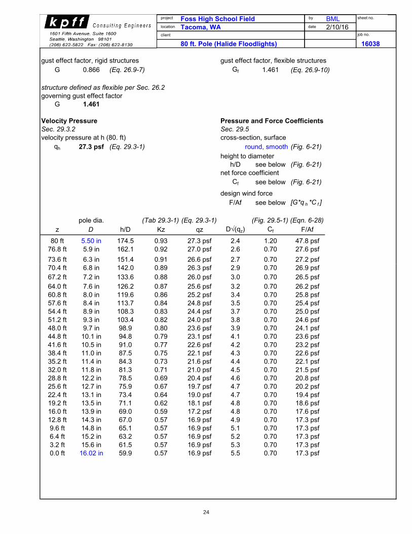
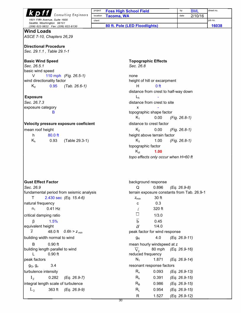
80 ft. Pole (Halide Floodlights) 16038
Wind LoadsASCE 7-10, Chapters 26,29
Directional Procedure
Sec. 29.1.1 , Table 29.1-1
Basic Wind Speed Topographic Effects
Sec. 26.5.1 Sec. 26.8
basic wind speedV 110 mph (Fig. 26.5-1)
wind directionality factor height of hill or excarpmentKd 0.95 (Tab. 26.6-1) H 0 ft
distance from crest to half-way downExposure Lh -Sec. 26.7.3 distance from crest to siteexposure category x -
B topographic shape factorK1 0.00 (Fig. 26.8-1)
Velocity pressure exposure coeficient distance to crest factor
mean roof height K2 0.00 (Fig. 26.8-1)
h 80.0 ft height above terrain factorKh 0.93 (Table 29.3-1) K3 1.00 (Fig. 26.8-1)
topographic factorKzt 1.00
none
project
location
client
by
date
sheet no.
job no.
topo effects only occur when H>60 ft
Gust Effect Factor background responseSec. 26.9 Q 0.896 (Eq. 26.9-8)
fundamental period from seismic analysis terrain exposure constants from Tab. 26.9-1T 2.275 sec (Eq. 15.4-6) zmin 30 ft
natural frequency c 0.3n1 0.44 Hz l 320 ft
critical damping ratio epsilonbar 1/3.0
β 1.5% bbar 0.45equivalent height alphabar 1/4.0
48.0 ft 0.6h > z min peak factor for wind response
building width normal to wind gR 4.0 (Eq. 26.9-11)
B 0.90 ft mean hourly windspeed at zbuilding length parallel to wind 80 mph (Eq. 26.9-16)
L 0.90 ft reduced frequencypeak factors N1 1.999 (Eq. 26.9-14)
gQ, gv 3.4 resonant response factors
turbulence intensity Rn 0.089 (Eq. 26.9-13)
0.282 (Eq. 26.9-7) Rh 0.374 (Eq. 26.9-15)
integral length scale of turbulence RB 0.985 (Eq. 26.9-15)
363 ft (Eq. 26.9-9) RL 0.951 (Eq. 26.9-15)
R 1.462 (Eq. 26.9-12)
z
∈
zL
zI
b
α
zV
23
Foss High School Field BMLTacoma, WA 2/10/16
0 80 ft. Pole (Halide Floodlights) 16038
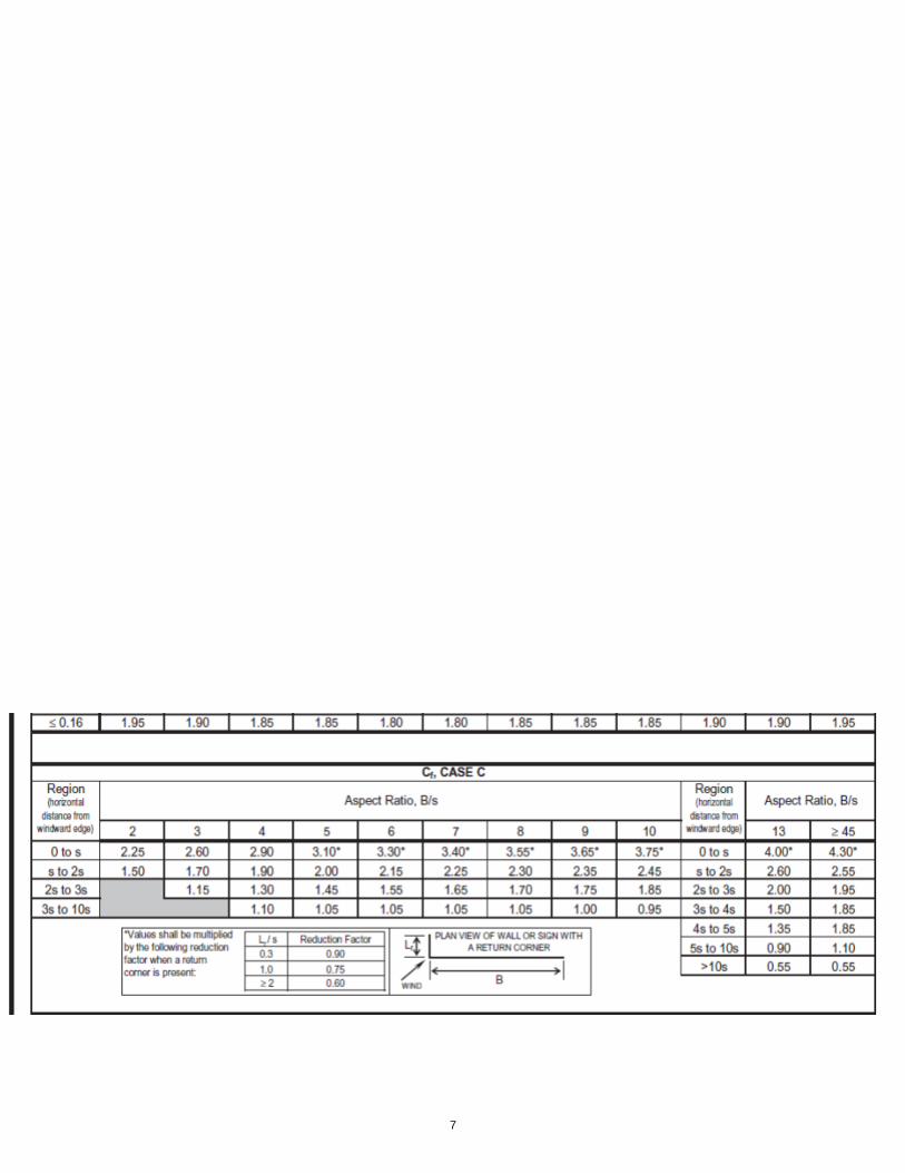
gust effect factor, rigid structures gust effect factor, flexible structuresG 0.866 (Eq. 26.9-7) Gf 1.461 (Eq. 26.9-10)
structure defined as flexible per Sec. 26.2
governing gust effect factorG 1.461
Velocity Pressure Pressure and Force Coefficients
Sec. 29.3.2 Sec. 29.5
velocity pressure at h (80. ft) cross-section, surfaceqh 27.3 psf (Eq. 29.3-1) round, smooth (Fig. 6-21)
height to diameterh/D see below (Fig. 6-21)
net force coefficientCf see below (Fig. 6-21)
design wind forceF/Af see below [G*q h *C f ]
pole dia. (Tab 29.3-1) (Eq. 29.3-1) (Fig. 29.5-1) (Eqn. 6-28)
z D h/D Kz qz D√(qz) Cf F/Af
80 ft 5.50 in 174.5 0.93 27.3 psf 2.4 1.20 47.8 psf76.8 ft 5.9 in 162.1 0.92 27.0 psf 2.6 0.70 27.6 psf
73.6 ft 6.3 in 151.4 0.91 26.6 psf 2.7 0.70 27.2 psf
project
location
client
by
date
sheet no.
job no.
70.4 ft 6.8 in 142.0 0.89 26.3 psf 2.9 0.70 26.9 psf67.2 ft 7.2 in 133.6 0.88 26.0 psf 3.0 0.70 26.5 psf64.0 ft 7.6 in 126.2 0.87 25.6 psf 3.2 0.70 26.2 psf60.8 ft 8.0 in 119.6 0.86 25.2 psf 3.4 0.70 25.8 psf57.6 ft 8.4 in 113.7 0.84 24.8 psf 3.5 0.70 25.4 psf54.4 ft 8.9 in 108.3 0.83 24.4 psf 3.7 0.70 25.0 psf51.2 ft 9.3 in 103.4 0.82 24.0 psf 3.8 0.70 24.6 psf48.0 ft 9.7 in 98.9 0.80 23.6 psf 3.9 0.70 24.1 psf44.8 ft 10.1 in 94.8 0.79 23.1 psf 4.1 0.70 23.6 psf41.6 ft 10.5 in 91.0 0.77 22.6 psf 4.2 0.70 23.2 psf38.4 ft 11.0 in 87.5 0.75 22.1 psf 4.3 0.70 22.6 psf35.2 ft 11.4 in 84.3 0.73 21.6 psf 4.4 0.70 22.1 psf32.0 ft 11.8 in 81.3 0.71 21.0 psf 4.5 0.70 21.5 psf28.8 ft 12.2 in 78.5 0.69 20.4 psf 4.6 0.70 20.8 psf25.6 ft 12.7 in 75.9 0.67 19.7 psf 4.7 0.70 20.2 psf22.4 ft 13.1 in 73.4 0.64 19.0 psf 4.7 0.70 19.4 psf19.2 ft 13.5 in 71.1 0.62 18.1 psf 4.8 0.70 18.6 psf16.0 ft 13.9 in 69.0 0.59 17.2 psf 4.8 0.70 17.6 psf12.8 ft 14.3 in 67.0 0.57 16.9 psf 4.9 0.70 17.3 psf9.6 ft 14.8 in 65.1 0.57 16.9 psf 5.1 0.70 17.3 psf6.4 ft 15.2 in 63.2 0.57 16.9 psf 5.2 0.70 17.3 psf3.2 ft 15.6 in 61.5 0.57 16.9 psf 5.3 0.70 17.3 psf0.0 ft 16.02 in 59.9 0.57 16.9 psf 5.5 0.70 17.3 psf
24

project Foss High School by BML sheet no.
location Tacome, WA date 2/10/16
client job no.
80' Poles Halide
Loadingpole Af
z Kz qz Cf F/Af Af pole zn-zm luminaries EPA luminaries F M
80.0 ft 0.93 27.3 psf 1.20 47.8 psf 0.458 3.2 ft 9 2.8 sf 25 sf 1275.7 lb 102056 lb-ft
76.8 ft 0.92 27.0 psf 0.70 27.6 psf 0.493 3.2 ft 43.5 lb 3345 lb-ft
73.6 ft 0.91 26.6 psf 0.70 27.2 psf 0.528 3.2 ft 46.1 lb 3392 lb-ft
70.4 ft 0.89 26.3 psf 0.70 26.9 psf 0.564 3.2 ft 48.5 lb 3416 lb-ft
67.2 ft 0.88 26.0 psf 0.70 26.5 psf 0.599 3.2 ft 50.9 lb 3418 lb-ft
64.0 ft 0.87 25.6 psf 0.70 26.2 psf 0.634 3.2 ft 53.1 lb 3398 lb-ft
60.8 ft 0.86 25.2 psf 0.70 25.8 psf 0.669 3.2 ft 55.2 lb 3357 lb-ft
57.6 ft 0.84 24.8 psf 0.70 25.4 psf 0.704 3.2 ft 57.2 lb 3296 lb-ft
54.4 ft 0.83 24.4 psf 0.70 25.0 psf 0.739 3.2 ft 59.1 lb 3215 lb-ft
51.2 ft 0.82 24.0 psf 0.70 24.6 psf 0.774 3.2 ft 60.8 lb 3115 lb-ft
48.0 ft 0.80 23.6 psf 0.70 24.1 psf 0.809 3.2 ft 62.4 lb 2997 lb-ft
44.8 ft 0.79 23.1 psf 0.70 23.6 psf 0.844 3.2 ft 63.9 lb 2861 lb-ft
41.6 ft 0.77 22.6 psf 0.70 23.2 psf 0.879 3.2 ft 65.1 lb 2709 lb-ft
38.4 ft 0.75 22.1 psf 0.70 22.6 psf 0.914 3.2 ft 66.2 lb 2542 lb-ft
35.2 ft 0.73 21.6 psf 0.70 22.1 psf 0.949 3.2 ft 67.0 lb 2360 lb-ft
32.0 ft 0.71 21.0 psf 0.70 21.5 psf 0.984 3.2 ft 1 2.0 sf 2 sf 110.6 lb 3540 lb-ft
28.8 ft 0.69 20.4 psf 0.70 20.8 psf 1.019 3.2 ft 68.0 lb 1958 lb-ft
25.6 ft 0.67 19.7 psf 0.70 20.2 psf 1.054 3.2 ft 68.0 lb 1741 lb-ft
22.4 ft 0.64 19.0 psf 0.70 19.4 psf 1.090 3.2 ft 67.6 lb 1515 lb-ft
19.2 ft 0.62 18.1 psf 0.70 18.6 psf 1.125 3.2 ft 66.8 lb 1283 lb-ft
16.0 ft 0.59 17.2 psf 0.70 17.6 psf 1.160 3.2 ft 65.4 lb 1046 lb-ft
12.8 ft 0.57 16.9 psf 0.70 17.3 psf 1.195 3.2 ft 66.1 lb 846 lb-ft
9.6 ft 0.57 16.9 psf 0.70 17.3 psf 1.230 3.2 ft 68.1 lb 653 lb-ft9.6 ft 0.57 16.9 psf 0.70 17.3 psf 1.230 3.2 ft 68.1 lb 653 lb-ft
6.4 ft 0.57 16.9 psf 0.70 17.3 psf 1.265 3.2 ft 70.0 lb 448 lb-ft
3.2 ft 0.57 16.9 psf 0.70 17.3 psf 1.300 3.2 ft 72.0 lb 230 lb-ft
0.0 ft 0.57 16.9 psf 0.70 17.3 psf 1.335 0.0 ft 0.0 lb 0 lb-ft Centroid
Sum: 10 5 sf 27 sf 2797 lb 158736 lb-ft 56.7 ft
Foundation Designs Employing Lateral BearingIBC 2012
Nonconstrained
Sec. 1807.3.2.1
Soil Profile Limits
Soil Depth Limit for Passive Pressure 8.0 ft
Soil Depth to neglect at top of pole 2.0 ft
Embedded Pole Calculation
applied lateral force P 1678 lb ASD Load (0.6*P)
centroid of force h 56.7 ft
diameter of footing b 2.5 ft
depth of footing d 8.00 ft
point of max pressure A 0.9 ft
allowable soil bearing pressure1
Sa 530 psf/ft
soil-bearing pressure at d/3 S1 1767 psf
minimum embedment (Eq. 18-1) dmin 7.87 ft
d > dmin TRUE
dpole 9.87 ft minimum
1. Assumes soil load acts over two times the pile diameter. 2. The maximum
allowable soil bearing pressure is limited to 8' per the Geotechnical Report. 3. The
upper 2' of soil is neglected as providing passive resistance but is included in
allowable soil pressure profile.
25

80 ft. Pole (Halide Floodlights)
Seismic Massing and Periods
Seismic Weights
Per Musco MFR:40 per floodlight16 lightpole averaged weight
Floodlight Assembly# Lights wt/light total wt total mass
9 x 40 lb = 360 lb 9.317E-04 kip-sec^2/in
Steel Lightpole Sections
SAP Approximation of Musco MFR Data
80 ft Pole Height
Foss High School
Tacoma, WA
project by BML
location
client
date 2/10/2016
sheet no.
job no.
Steel Cross Sections
Periods
Calculated per SAP Modal Analysis -- See Attached Output
Seismic Massing and Periods.xlsx Page 1 of 126

MU
SC
O 8
0
9.317E-049.317E-04
XY XZY Z
80ft Pole Halide Modal Analysis.sdb 2/10/2016
SAP2000 17.3.0 Joint Masses Kip, in, F27

XY XZY Z
80ft Pole Halide Modal Analysis.sdb 2/10/2016
SAP2000 17.3.0 Deformed Shape (MODAL) - Mode 1; T = 2.27502; f = 0.43956 Kip, in, F28

Foss High School BML
02/10/16
Pole Type: 80' Steel Halide 16038
Seismic Base Shear Calculation
2012 IBC (Ch. 16) & ASCE 7-10 (Ch. 11, 12, 15, & 22)
Lateral System
Occupancy Category II [Tab. 1604.5]
Site Class D [Tab. 1613.5.2]
Design Category D [Sec. 1613.5.6; Tab. 16.13.5.6(1) & (2)]
Ss 1.303 [Geotechnical Report]
S1 0.511 [Geotechnical Report]
Fa 1.00 [Tab. 1613.5.3(1)]
Fv 1.37 [Tab. 1613.5.3(2)]
SMS 1.30 [Eqn. 16-37]
SM1 0.70 [Eqn. 16-38]
SDS 0.87 [Eqn. 16-39]
SD1 0.47 [Eqn. 16-40]
I 1.00 [Tab. 11.5-1] T 2.28 sec [Eqn. 15.4-6]
R 1.5 [Tab. 15.4-2] TL 6 sec [Fig. 22-15]
Towers
Pole: Steel
project
location
client
by
date
sheet no.
job no.
SDS / (R/I) = Cs 0.579 [Eqn. 12.8-2]
SD1 / T (R/I) = Cs 0.137 [Eqn. 12.8-3]
SD1 TL / T2 (R/I) = Cs N/A [Eqn. 12.8-4]
Cs (min) 0.030 [Eqn. 15.4-1]
0.5S1 / (R/I) = Cs N/A [Eqn. 12.8-6]
Cs (design) 0.137
Vertical Distribution of Forces
ASCE 7-10, Sec. 12.8.3
exponent related to structural period
k 1.8875
Mass Name Weight, wi Height, hi wihik
Fi Vi Mi
Lighting 1 360 lb 80 ft 1407294 lb-ft 123 lb 123 lb 9813 lb-ft
Steel Pole 3 1490 lb 40 ft 1574253 lb-ft 137 lb 260 lb 5488 lb-ft
Lighting 4 80 lb 30 ft 49108 lb-ft 4 lb 264 lb 128 lb-ft Centroid
1930 lb 3030655 lb-ft 264 lb 15430 lb-ft 58.4 ft
Load Combination Using Allowable Stress Design
IBC 2012, Sec. 1605.3.1
applied lateral force P 185 lb [Eqn. 16-12]
centroid of force h 58.4 ft
Note: Wind forces govern over seismic forces.
29
Foss High School Field BMLTacoma, WA 2/10/16
80 ft. Pole (LED Floodlights) 16038
Wind LoadsASCE 7-10, Chapters 26,29
Directional Procedure
Sec. 29.1.1 , Table 29.1-1
Basic Wind Speed Topographic Effects
Sec. 26.5.1 Sec. 26.8
basic wind speedV 110 mph (Fig. 26.5-1)
wind directionality factor height of hill or excarpmentKd 0.95 (Tab. 26.6-1) H 0 ft
distance from crest to half-way downExposure Lh -Sec. 26.7.3 distance from crest to siteexposure category x -
B topographic shape factorK1 0.00 (Fig. 26.8-1)
Velocity pressure exposure coeficient distance to crest factor
mean roof height K2 0.00 (Fig. 26.8-1)
h 80.0 ft height above terrain factorKh 0.93 (Table 29.3-1) K3 1.00 (Fig. 26.8-1)
topographic factorKzt 1.00
none
project
location
client
by
date
sheet no.
job no.
topo effects only occur when H>60 ft
Gust Effect Factor background responseSec. 26.9 Q 0.896 (Eq. 26.9-8)
fundamental period from seismic analysis terrain exposure constants from Tab. 26.9-1T 2.430 sec (Eq. 15.4-6) zmin 30 ft
natural frequency c 0.3n1 0.41 Hz l 320 ft
critical damping ratio epsilonbar 1/3.0
β 1.5% bbar 0.45equivalent height alphabar 1/4.0
48.0 ft 0.6h > z min peak factor for wind response
building width normal to wind gR 4.0 (Eq. 26.9-11)
B 0.90 ft mean hourly windspeed at zbuilding length parallel to wind 80 mph (Eq. 26.9-16)
L 0.90 ft reduced frequencypeak factors N1 1.871 (Eq. 26.9-14)
gQ, gv 3.4 resonant response factors
turbulence intensity Rn 0.093 (Eq. 26.9-13)
0.282 (Eq. 26.9-7) Rh 0.391 (Eq. 26.9-15)
integral length scale of turbulence RB 0.986 (Eq. 26.9-15)
363 ft (Eq. 26.9-9) RL 0.954 (Eq. 26.9-15)
R 1.527 (Eq. 26.9-12)
z
∈
zL
zI
b
α
zV
30

Foss High School Field BMLTacoma, WA 2/10/16
0 80 ft. Pole (LED Floodlights)
gust effect factor, rigid structures gust effect factor, flexible structuresG 0.866 (Eq. 26.9-7) Gf 1.496 (Eq. 26.9-10)
structure defined as flexible per Sec. 26.2
governing gust effect factorG 1.496
Velocity Pressure Pressure and Force Coefficients
Sec. 29.3.2 Sec. 29.5
velocity pressure at h (80. ft) cross-section, surfaceqh 27.3 psf (Eq. 29.3-1) round, smooth (Fig. 6-21)
height to diameterh/D see below (Fig. 6-21)
net force coefficientCf see below (Fig. 6-21)
design wind forceF/Af see below [G*q h *C f ]
pole dia. (Tab 29.3-1) (Eq. 29.3-1) (Fig. 29.5-1) (Eqn. 6-28)
z D h/D Kz qz D√(qz) Cf F/Af
80 ft 5.50 in 174.5 0.93 27.3 psf 2.4 1.20 49.0 psf76.8 ft 5.9 in 162.1 0.92 27.0 psf 2.6 0.70 28.2 psf
73.6 ft 6.3 in 151.4 0.91 26.6 psf 2.7 0.70 27.9 psf
project
location
client
by
date
sheet no.
job no.
70.4 ft 6.8 in 142.0 0.89 26.3 psf 2.9 0.70 27.6 psf67.2 ft 7.2 in 133.6 0.88 26.0 psf 3.0 0.70 27.2 psf64.0 ft 7.6 in 126.2 0.87 25.6 psf 3.2 0.70 26.8 psf60.8 ft 8.0 in 119.6 0.86 25.2 psf 3.4 0.70 26.4 psf57.6 ft 8.4 in 113.7 0.84 24.8 psf 3.5 0.70 26.0 psf54.4 ft 8.9 in 108.3 0.83 24.4 psf 3.7 0.70 25.6 psf51.2 ft 9.3 in 103.4 0.82 24.0 psf 3.8 0.70 25.2 psf48.0 ft 9.7 in 98.9 0.80 23.6 psf 3.9 0.70 24.7 psf44.8 ft 10.1 in 94.8 0.79 23.1 psf 4.1 0.70 24.2 psf41.6 ft 10.5 in 91.0 0.77 22.6 psf 4.2 0.70 23.7 psf38.4 ft 11.0 in 87.5 0.75 22.1 psf 4.3 0.70 23.2 psf35.2 ft 11.4 in 84.3 0.73 21.6 psf 4.4 0.70 22.6 psf32.0 ft 11.8 in 81.3 0.71 21.0 psf 4.5 0.70 22.0 psf28.8 ft 12.2 in 78.5 0.69 20.4 psf 4.6 0.70 21.3 psf25.6 ft 12.7 in 75.9 0.67 19.7 psf 4.7 0.70 20.6 psf22.4 ft 13.1 in 73.4 0.64 19.0 psf 4.7 0.70 19.9 psf19.2 ft 13.5 in 71.1 0.62 18.1 psf 4.8 0.70 19.0 psf16.0 ft 13.9 in 69.0 0.59 17.2 psf 4.8 0.70 18.0 psf12.8 ft 14.3 in 67.0 0.57 16.9 psf 4.9 0.70 17.7 psf9.6 ft 14.8 in 65.1 0.57 16.9 psf 5.1 0.70 17.7 psf6.4 ft 15.2 in 63.2 0.57 16.9 psf 5.2 0.70 17.7 psf3.2 ft 15.6 in 61.5 0.57 16.9 psf 5.3 0.70 17.7 psf0.0 ft 16.02 in 59.9 0.57 16.9 psf 5.5 0.70 17.7 psf
31

project Foss High School by BML sheet no.
location Tacome, WA date 2/10/16
client job no.
80' Poles LED
Loadingpole Af
z Kz qz Cf F/Af Af pole zn-zm luminaries EPA luminaries F M
80.0 ft 0.93 27.3 psf 1.20 49.0 psf 0.458 3.2 ft 13 2.5 sf 33 sf 1663.9 lb 133111 lb-ft
76.8 ft 0.92 27.0 psf 0.70 28.2 psf 0.493 3.2 ft 44.6 lb 3425 lb-ft
73.6 ft 0.91 26.6 psf 0.70 27.9 psf 0.528 3.2 ft 47.2 lb 3473 lb-ft
70.4 ft 0.89 26.3 psf 0.70 27.6 psf 0.564 3.2 ft 49.7 lb 3498 lb-ft
67.2 ft 0.88 26.0 psf 0.70 27.2 psf 0.599 3.2 ft 52.1 lb 3500 lb-ft
64.0 ft 0.87 25.6 psf 0.70 26.8 psf 0.634 3.2 ft 54.4 lb 3479 lb-ft
60.8 ft 0.86 25.2 psf 0.70 26.4 psf 0.669 3.2 ft 56.5 lb 3437 lb-ft
57.6 ft 0.84 24.8 psf 0.70 26.0 psf 0.704 3.2 ft 58.6 lb 3375 lb-ft
54.4 ft 0.83 24.4 psf 0.70 25.6 psf 0.739 3.2 ft 60.5 lb 3292 lb-ft
51.2 ft 0.82 24.0 psf 0.70 25.2 psf 0.774 3.2 ft 62.3 lb 3190 lb-ft
48.0 ft 0.80 23.6 psf 0.70 24.7 psf 0.809 3.2 ft 63.9 lb 3069 lb-ft
44.8 ft 0.79 23.1 psf 0.70 24.2 psf 0.844 3.2 ft 65.4 lb 2930 lb-ft
41.6 ft 0.77 22.6 psf 0.70 23.7 psf 0.879 3.2 ft 66.7 lb 2774 lb-ft
38.4 ft 0.75 22.1 psf 0.70 23.2 psf 0.914 3.2 ft 67.8 lb 2603 lb-ft
35.2 ft 0.73 21.6 psf 0.70 22.6 psf 0.949 3.2 ft 68.7 lb 2417 lb-ft
32.0 ft 0.71 21.0 psf 0.70 22.0 psf 0.984 3.2 ft 1 2.0 sf 2 sf 113.3 lb 3624 lb-ft
28.8 ft 0.69 20.4 psf 0.70 21.3 psf 1.019 3.2 ft 69.6 lb 2005 lb-ft
25.6 ft 0.67 19.7 psf 0.70 20.6 psf 1.054 3.2 ft 69.6 lb 1782 lb-ft
22.4 ft 0.64 19.0 psf 0.70 19.9 psf 1.090 3.2 ft 69.3 lb 1551 lb-ft
19.2 ft 0.62 18.1 psf 0.70 19.0 psf 1.125 3.2 ft 68.4 lb 1313 lb-ft
16.0 ft 0.59 17.2 psf 0.70 18.0 psf 1.160 3.2 ft 2 3 sf 6 sf 182.4 lb 2919 lb-ft
12.8 ft 0.57 16.9 psf 0.70 17.7 psf 1.195 3.2 ft 67.7 lb 867 lb-ft
9.6 ft 0.57 16.9 psf 0.70 17.7 psf 1.230 3.2 ft 69.7 lb 669 lb-ft9.6 ft 0.57 16.9 psf 0.70 17.7 psf 1.230 3.2 ft 69.7 lb 669 lb-ft
6.4 ft 0.57 16.9 psf 0.70 17.7 psf 1.265 3.2 ft 71.7 lb 459 lb-ft
3.2 ft 0.57 16.9 psf 0.70 17.7 psf 1.300 3.2 ft 73.7 lb 236 lb-ft
0.0 ft 0.57 16.9 psf 0.70 17.7 psf 1.335 0.0 ft 0.0 lb 0 lb-ft Centroid
Sum: 16 8 sf 41 sf 3338 lb 192996 lb-ft 57.8 ft
Foundation Designs Employing Lateral BearingIBC 2012
Nonconstrained
Sec. 1807.3.2.1
Soil Profile Limits
Soil Depth Limit for Passive Pressure 8.0 ft
Soil Depth to neglect at top of pole 2.0 ft
Embedded Pole Calculation
applied lateral force P 2003 lb ASD Load (0.6*P)
centroid of force h 57.8 ft
diameter of footing b 2.5 ft
depth of footing d 8.75 ft
point of max pressure A 1.0 ft
allowable soil bearing pressure1
Sa 530 psf/ft
soil-bearing pressure at d/3 S1 1899 psf
minimum embedment (Eq. 18-1) dmin 8.40 ft
d > dmin TRUE
dpole 10.40 ft minimum
1. Assumes soil load acts over two times the pile diameter. 2. The maximum
allowable soil bearing pressure is limited to 8' per the Geotechnical Report. 3. The
upper 2' of soil is neglected as providing passive resistance but is included in
allowable soil pressure profile.
32
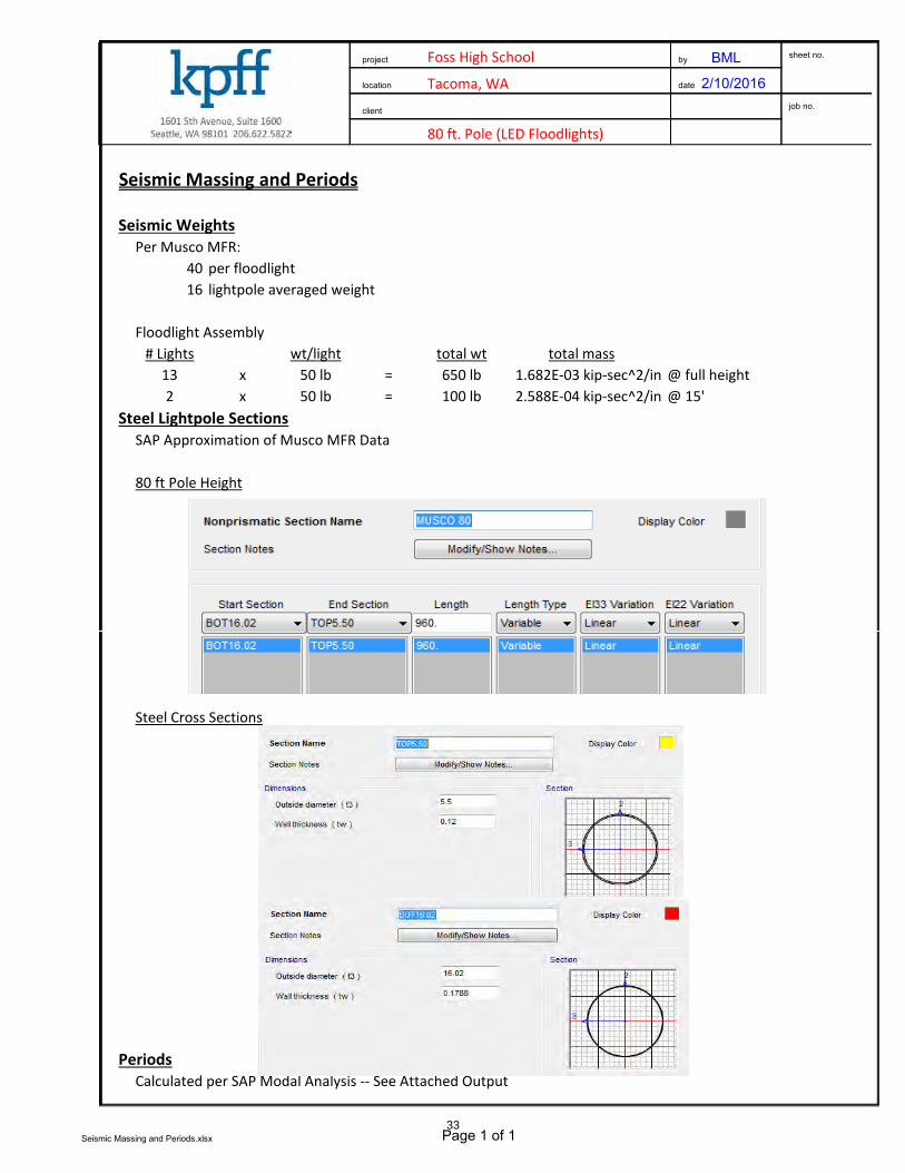
80 ft. Pole (LED Floodlights)
Seismic Massing and Periods
Seismic Weights
Per Musco MFR:40 per floodlight16 lightpole averaged weight
Floodlight Assembly# Lights wt/light total wt total mass
13 x 50 lb = 650 lb 1.682E-03 kip-sec^2/in @ full height2 x 50 lb = 100 lb 2.588E-04 kip-sec^2/in @ 15'
Steel Lightpole Sections
SAP Approximation of Musco MFR Data
80 ft Pole Height
Foss High School
Tacoma, WA
project by BML
location
client
date 2/10/2016
sheet no.
job no.
Steel Cross Sections
Periods
Calculated per SAP Modal Analysis -- See Attached Output
Seismic Massing and Periods.xlsx Page 1 of 133

2.588E-0
42.588E-04
MU
SC
O 8
0
1.682E-031.682E-03
XY XZY Z
80ft Pole LED Modal Analysis.sdb 2/10/2016
SAP2000 17.3.0 Joint Masses Kip, in, F34

XY XZY Z
80ft Pole LED Modal Analysis.sdb 2/10/2016
SAP2000 17.3.0 Deformed Shape (MODAL) - Mode 1; T = 2.42969; f = 0.41158 Kip, in, F35

Foss High School BML
02/10/16
Pole Type: 80' Steel LED 16038
Seismic Base Shear Calculation
2012 IBC (Ch. 16) & ASCE 7-10 (Ch. 11, 12, 15, & 22)
Lateral System
Occupancy Category II [Tab. 1604.5]
Site Class D [Tab. 1613.5.2]
Design Category D [Sec. 1613.5.6; Tab. 16.13.5.6(1) & (2)]
Ss 1.303 [Geotechnical Report]
S1 0.511 [Geotechnical Report]
Fa 1.00 [Tab. 1613.5.3(1)]
Fv 1.37 [Tab. 1613.5.3(2)]
SMS 1.30 [Eqn. 16-37]
SM1 0.70 [Eqn. 16-38]
SDS 0.87 [Eqn. 16-39]
SD1 0.47 [Eqn. 16-40]
I 1.00 [Tab. 11.5-1] T 2.43 sec [Eqn. 15.4-6]
R 1.5 [Tab. 15.4-2] TL 6 sec [Fig. 22-15]
Towers
Pole: Steel
project
location
client
by
date
sheet no.
job no.
SDS / (R/I) = Cs 0.579 [Eqn. 12.8-2]
SD1 / T (R/I) = Cs 0.128 [Eqn. 12.8-3]
SD1 TL / T2 (R/I) = Cs N/A [Eqn. 12.8-4]
Cs (min) 0.030 [Eqn. 15.4-1]
0.5S1 / (R/I) = Cs N/A [Eqn. 12.8-6]
Cs (design) 0.128
Vertical Distribution of Forces
ASCE 7-10, Sec. 12.8.3
exponent related to structural period
k 1.965
Mass Name Weight, wi Height, hi wihik
Fi Vi Mi
Lighting 1 650 lb 80 ft 3568496 lb-ft 178 lb 178 lb 14266 lb-ft
Steel Pole 3 1490 lb 40 ft 2095242 lb-ft 105 lb 283 lb 4188 lb-ft
Lighting 4 100 lb 30 ft 79899 lb-ft 4 lb 287 lb 120 lb-ft Centroid
2240 lb 5743637 lb-ft 287 lb 18574 lb-ft 64.7 ft
Load Combination Using Allowable Stress Design
IBC 2012, Sec. 1605.3.1
applied lateral force P 201 lb [Eqn. 16-12]
centroid of force h 64.7 ft
Note: Wind forces govern over seismic forces.
36
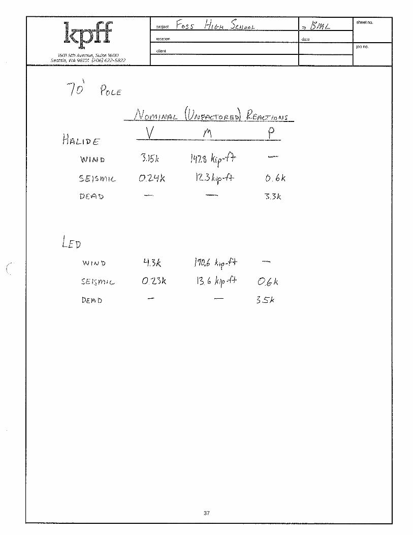
37

38


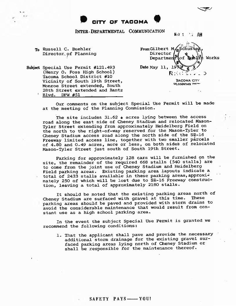

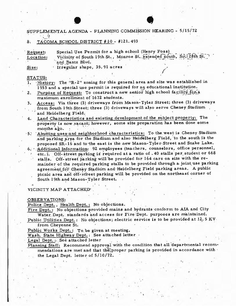


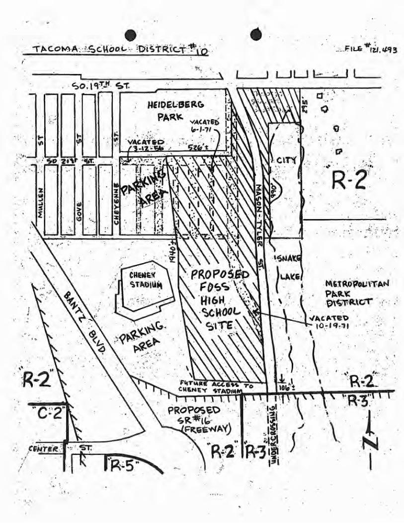
Copyright © 2022 FDOKUMEN