PTS-1 controller - Technotrade LLC
187
PTS-1 controller over fuel dispensers and ATG systems for petrol stations TECHNICAL GUIDE (PCB board modification: PTS-1, revision: PTS-U5-v7) Review date: 10 October, 2021
-
Upload
khangminh22 -
Category
Documents
-
view
0 -
download
0
Transcript of PTS-1 controller - Technotrade LLC

PTS-1 controller over fuel dispensers and ATG systems
for petrol stations
TECHNICAL GUIDE (PCB board modification: PTS-1, revision: PTS-U5-v7)
Review date: 10 October, 2021
PTS-1 CONTROLLER OVER FUEL DISPENSERS AND ATG SYSTEMS FOR PETROL STATIONS (PTS-1, rev. PTS-U5-v7) Revision: R07 Review date: 10 October, 2021
www.technotrade.ua page 2 from 187
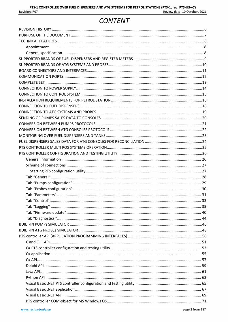
CONTENT REVISION HISTORY ................................................................................................................................................ 6
PURPOSE OF THE DOCUMENT .............................................................................................................................. 7
TECHNICAL FEATURES ........................................................................................................................................... 8
Appointment ................................................................................................................................................. 8
General specification ..................................................................................................................................... 8
SUPPORTED BRANDS OF FUEL DISPENSERS AND REGISTER METERS ................................................................... 9
SUPPORTED BRANDS OF ATG SYSTEMS AND PROBES ........................................................................................ 10
BOARD CONNECTORS AND INTERFACES ............................................................................................................. 11
COMMUNICATION PORTS ................................................................................................................................... 12
COMPLETE SET .................................................................................................................................................... 13
CONNECTION TO POWER SUPPLY ....................................................................................................................... 14
CONNECTION TO CONTROL SYSTEM................................................................................................................... 15
INSTALLATION REQUIREMENTS FOR PETROL STATION ...................................................................................... 16
CONNECTION TO FUEL DISPENSERS ................................................................................................................... 18
CONNECTION TO ATG SYSTEMS AND PROBES .................................................................................................... 19
SENDING OF PUMPS SALES DATA TO CONSOLES ............................................................................................... 20
CONVERSION BETWEEN PUMPS PROTOCOLS .................................................................................................... 21
CONVERSION BETWEEN ATG CONSOLES PROTOCOLS ....................................................................................... 22
MONITORING OVER FUEL DISPENSERS AND TANKS ........................................................................................... 23
FUEL DISPENSERS SALES DATA FOR ATG CONSOLES FOR RECONCILIATION ...................................................... 24
PTS CONTROLLER MULTI POS SYSTEMS OPERATION .......................................................................................... 25
PTS CONTROLLER CONFIGURATION AND TESTING UTILITY ................................................................................ 26
General information .................................................................................................................................... 26
Scheme of connections ............................................................................................................................... 27
Starting PTS configuration utility ............................................................................................................. 27
Tab “General” .............................................................................................................................................. 28
Tab “Pumps configuration” ......................................................................................................................... 29
Tab “Probes configuration” ......................................................................................................................... 30
Tab “Parameters” ........................................................................................................................................ 31
Tab “Control” ............................................................................................................................................... 33
Tab “Logging” .............................................................................................................................................. 35
Tab “Firmware update” ............................................................................................................................... 40
Tab “Diagnostics ”........................................................................................................................................ 44
BUILT-IN PUMPs SIMULATOR ............................................................................................................................. 46
BUILT-IN ATG PROBEs SIMULATOR ..................................................................................................................... 48
PTS controller API (APPLICATION PROGRAMMING INTERFACES) ...................................................................... 50
C and C++ API ............................................................................................................................................... 51
C# PTS controller configuration and testing utility...................................................................................... 53
C# application .............................................................................................................................................. 55
C# API ........................................................................................................................................................... 57
Delphi API .................................................................................................................................................... 59
Java API ........................................................................................................................................................ 61
Python API ................................................................................................................................................... 63
Visual Basic .NET PTS controller configuration and testing utility .............................................................. 65
Visual Basic .NET application ....................................................................................................................... 67
Visual Basic .NET API .................................................................................................................................... 69
PTS controller COM-object for MS Windows OS ......................................................................................... 71

PTS-1 CONTROLLER OVER FUEL DISPENSERS AND ATG SYSTEMS FOR PETROL STATIONS (PTS-1, rev. PTS-U5-v7) Revision: R07 Review date: 10 October, 2021
www.technotrade.ua page 3 from 187
Visual Basic 6.0 application ......................................................................................................................... 72
PTS controller UniPump communication protocol ...................................................................................... 74
PTS CONTROLLER SOFTWARE DEVELOPMENT KIT (SDK) .................................................................................... 75
PTS controller SDK appointment ................................................................................................................. 75
PTS controller SDK structure ....................................................................................................................... 75
PTS controller SDK technical features ......................................................................................................... 76
Specification ............................................................................................................................................ 76
PTS controller SDK connections scheme ..................................................................................................... 77
UniPump pumps software simulator........................................................................................................... 78
Purpose .................................................................................................................................................... 78
Main view ................................................................................................................................................ 78
Configuration ........................................................................................................................................... 79
UniProbe ATG probes software simulator .................................................................................................. 81
Purpose .................................................................................................................................................... 81
Main view ................................................................................................................................................ 81
Configuration ........................................................................................................................................... 82
Open source PTS controller .NET application (C# and VB.NET) .................................................................. 84
Purpose .................................................................................................................................................... 84
Start ......................................................................................................................................................... 85
Configuration of PTS controller ............................................................................................................... 85
Main view ................................................................................................................................................ 87
Settings of fuel point icons ...................................................................................................................... 88
Reading of fuel point total counters ........................................................................................................ 89
Settings .................................................................................................................................................... 90
Displaying ATG systems probes states .................................................................................................... 91
Settings of ATG probe icons .................................................................................................................... 92
TiT.PTS classes help file ........................................................................................................................... 93
PumpDemo utility ........................................................................................................................................ 94
PTS controller test utilities .......................................................................................................................... 96
Purpose .................................................................................................................................................... 96
PTS terminal utility ...................................................................................................................................... 97
Purpose .................................................................................................................................................... 97
Step-by-step configuration of the PTS controller SDK ................................................................................ 98
Purpose .................................................................................................................................................... 98
Step 1. Downloading of PTS controller SDK software ............................................................................. 98
Step 2. Assembling PTS controller SDK cabling and connection to PC .................................................... 98
Step 3. Starting of the PTS controller configuration utility Pts_config.exe ........................................... 101
Step 4. Configuration of pump ports ..................................................................................................... 102
Step 5. Configuration of probes ports ................................................................................................... 103
Step 6. Configuration of PTS controller parameters ............................................................................. 104
Step 7. Configuration of pumps parameters ......................................................................................... 105
Step 8. Configuration of pumps software simulator ............................................................................. 106
Step 9. Configuration of ATG probes software simulator ..................................................................... 108
Step 10. Control over pumps and ATG probes in PTS controller configuration and testing utility ....... 109
Step 11. Configuration of PTS controller .NET application for control over pumps and ATG probes ... 111
EXAMPLES OF FUEL DISPENSERS CONNECTION SCHEMES ............................................................................... 117
Gilbarco dispenser connection scheme..................................................................................................... 118
Wayne Dresser dispenser connection scheme (RS-485 interface) ........................................................... 121
Wayne Dresser dispenser connection scheme (current loop interface) ................................................... 122

PTS-1 CONTROLLER OVER FUEL DISPENSERS AND ATG SYSTEMS FOR PETROL STATIONS (PTS-1, rev. PTS-U5-v7) Revision: R07 Review date: 10 October, 2021
www.technotrade.ua page 4 from 187
Tatsuno (Japan) dispenser connection scheme ........................................................................................ 123
Tatsuno Europe (former Benc) dispenser connection scheme ................................................................. 124
Tokheim dispenser connection scheme .................................................................................................... 125
Tokheim dispenser connection scheme (RS-485 interface) ...................................................................... 128
Tokheim India dispenser connection scheme ........................................................................................... 130
Nuovo Pignone dispenser connection scheme (RS-485 interface) ........................................................... 131
Nuovo Pignone dispenser connection scheme (4-wire current loop interface) ....................................... 132
Logitron dispenser connection scheme (3-wire current loop interface) .................................................. 133
Bennett dispenser connection scheme (RS-485 interface) ....................................................................... 134
Bennett dispenser connection scheme (2-wire current loop interface) ................................................... 135
Batchen Email dispenser connection scheme ........................................................................................... 136
Scheidt & Bachmann T20 dispenser connection scheme .......................................................................... 137
Coptron dispenser connection scheme ..................................................................................................... 138
Midco dispenser connection scheme ........................................................................................................ 139
Petrotec dispenser connection scheme .................................................................................................... 140
Galileo dispenser connection scheme ....................................................................................................... 141
Prowalco dispenser connection scheme ................................................................................................... 142
Emgaz Dragon / Fornovo LPG dispenser with EsiWelma pumphead connection scheme........................ 143
Maser dispenser connection scheme ........................................................................................................ 144
Petposan-S4 / Meksan-S4 / Europump-S4 / Yenen dispensers connection scheme ................................ 145
Yenen dispensers connection scheme ...................................................................................................... 146
Petposan-Beta / Europump-Beta dispensers connection scheme ............................................................ 147
EuroPump dispenser connection scheme ................................................................................................. 148
Mekser dispenser connection scheme ...................................................................................................... 149
Fuelsis dispenser connection scheme ....................................................................................................... 150
Mepsan Unimep dispenser connection scheme ....................................................................................... 151
Meksan / Wayne SU86 dispenser connection scheme ............................................................................. 152
Baransay dispenser connection scheme ................................................................................................... 153
2A LPG dispenser connection scheme ....................................................................................................... 154
Falcon dispenser connection scheme........................................................................................................ 155
Korea EnE (LG EnE) dispenser connection scheme ................................................................................... 156
Dong Hwa Prime dispenser connection scheme ....................................................................................... 157
Gallagher (PEC) dispenser connection scheme ......................................................................................... 158
Compac dispenser connection scheme ..................................................................................................... 159
Safe dispenser connection scheme ........................................................................................................... 160
MS Gas dispenser connection scheme ...................................................................................................... 161
Shibata dispenser connection scheme ...................................................................................................... 162
Aspro Develco dispenser connection scheme ........................................................................................... 163
HongYang dispenser connection scheme .................................................................................................. 164
Lanfeng dispenser connection scheme ..................................................................................................... 165
Sanki dispenser connection scheme ......................................................................................................... 166
Datian Machines dispenser connection scheme ....................................................................................... 168
Eaglestar dispenser connection scheme ................................................................................................... 169
Blue Sky dispenser connection scheme..................................................................................................... 170
Topaz dispenser connection scheme ........................................................................................................ 171
Shelf dispenser connection scheme .......................................................................................................... 172
UniCon dispenser connection scheme ...................................................................................................... 173
EXAMPLES OF ATG SYSTEMS CONNECTION SCHEMES ..................................................................................... 174
Gilbarco Veeder Root TLS consoles connection scheme ........................................................................... 175

PTS-1 CONTROLLER OVER FUEL DISPENSERS AND ATG SYSTEMS FOR PETROL STATIONS (PTS-1, rev. PTS-U5-v7) Revision: R07 Review date: 10 October, 2021
www.technotrade.ua page 5 from 187
Start Italiana console connection scheme ................................................................................................. 175
Start Italiana wired probes connection scheme ........................................................................................ 176
Start Italiana wireless probes connection scheme .................................................................................... 176
Alisonic wired probes connection scheme ................................................................................................ 177
Alisonic wireless probes connection scheme ............................................................................................ 177
Struna ATG system connection scheme .................................................................................................... 178
OPW Site Sentinel ATG system connection scheme ................................................................................. 178
Colibri ATG system connection scheme .................................................................................................... 179
Fafnir ATG system connection scheme ..................................................................................................... 179
Hectronic ATG probes connection scheme ............................................................................................... 180
Vega radar level meters ............................................................................................................................. 180
Windbell magnetostrictive probes connection scheme ............................................................................ 181
North Falcon wired probes connection scheme ....................................................................................... 182
North Falcon wireless probes connection scheme.................................................................................... 182
PTS CONTROLLER PCB BOARD .......................................................................................................................... 183
PCB board top view ................................................................................................................................... 183
PCB board bottom view ............................................................................................................................. 183
Board dimensions ...................................................................................................................................... 184
RS-232 PORT CABLE CONNECTOR ..................................................................................................................... 185
CERTIFICATES .................................................................................................................................................... 186
ORDER INFORMATION ...................................................................................................................................... 187

PTS-1 CONTROLLER OVER FUEL DISPENSERS AND ATG SYSTEMS FOR PETROL STATIONS (PTS-1, rev. PTS-U5-v7) Revision: R07 Review date: 10 October, 2021
www.technotrade.ua page 6 from 187
REVISION HISTORY
REV DATE BY SECTIONS DESCRIPTION
R01 2017.11.21 Evgeniy
Vasyliev
All First release of PTS-1 board revision
R02 2018.06.09 Evgeniy
Vasyliev
All Minor fixes
R03 2018.08.15 Evgeniy
Vasyliev
All Modification of PTS PCB board
R04 2018.11.17 Evgeniy
Vasyliev
Supported communication protocols,
examples of connection schemes
Updated list of supported communication
protocols of fuel dispensers and ATG systems,
added examples of connection to fuel dispensers
and ATG systems
R05 2019.03.01 Evgeniy
Vasyliev
Supported input communication protocols Communication with PTS controller using pump
and ATG consoles protocols
R06 2020.03.21 Evgeniy
Vasyliev
General information update Regular document review
R07 2020.07.18 Evgeniy
Vasyliev
General information update Regular document review

PTS-1 CONTROLLER OVER FUEL DISPENSERS AND ATG SYSTEMS FOR PETROL STATIONS (PTS-1, rev. PTS-U5-v7) Revision: R07 Review date: 10 October, 2021
www.technotrade.ua page 7 from 187
PURPOSE OF THE DOCUMENT
This Technical Guide is intended for studying of PTS controller over fuel dispensers and ATG systems for
petrol stations. It contains basic information regarding its
− technical characteristics
− supported communication protocols of fuel dispensers and ATG systems
− board interfaces and connectors
− configuration
− supplied application programming interfaces (API)
− description, configuration and connection of PTS controller software development kit (SDK)
− schemes of connection to fuel dispensers and ATG systems
− board schematics
− cabling
Information regarding connection to specific fuel dispensers and correspondent configuration of PTS
controller can be received upon request to Technotrade LLC company.
Given technical manual describes the latest hardware version of the PTS controller board (PTS controller
PCB board modification PTS-1). Technical manuals of older versions of the PTS controller board (PTS-U5,
PTS-U3, PTS-U2 and PTS-U) with their corresponding connection schemes can be downloaded from PTS
controller web-page: http://www.technotrade.ua/fuel-pump-controller.html.
Due to a reason that PTS controller firmware is constantly being developed in direction of improvement of
its possibilities, changes are possible in final version, which are not described in given Technical Guide.
During the system development process given Technical Guide is also expanded and updated and new
chapters are added. Latest version of this Technical Guide can be downloaded from the PTS controller web-
page: http://www.technotrade.ua/fuel-pump-controller.html.
Technotrade LLC hereby permits reproduction of this document as may be required by any of the
customers or OEMs wishing to use it.
This document has been carefully prepared and is believed to be accurate. However, Technotrade LLC, its
employees and its agents do not assume responsibility for its use either directly or indirectly. Technotrade
LLC shall not be liable for technical or editorial errors or omissions which may appear in this document.
Technotrade LLC reserves a right to make changes to this document at any time without notice. Prospective
users of this document should contact Technotrade LLC at the time they wish to use PTS controller together
with their products to become aware of any updates that may apply.
In case if you find any mistakes, omissions in this document or have any suggestions on improvements to
this document, please feel free to e-mail them to our support mailbox: [email protected]. We
will be grateful to you for this valuable information.
All technical questions regarding the PTS controller are welcome to be asked on support mailbox:
[email protected]. Our support team will be glad to help you.
Also, you can call to us or visit us on:
Technotrade LLC
Ukraine, 04114 Kiev, Priorska str. 10, office 1
Tel: +38-044-502-46-55, +38-044-502-46-77
Web: www.technotrade.ua
Mail: [email protected]

PTS-1 CONTROLLER OVER FUEL DISPENSERS AND ATG SYSTEMS FOR PETROL STATIONS (PTS-1, rev. PTS-U5-v7) Revision: R07 Review date: 10 October, 2021
www.technotrade.ua page 8 from 187
TECHNICAL FEATURES
Appointment
PTS-1 controller over fuel dispensers and ATG (automatic tank gauge) systems for petrol stations serves
as a protocols converter. It knows communication protocols of a great variety of fuel dispensers and ATG
probes and allows control over any of them in exactly the same way using its own input communication
protocol or popular pumps and ATG systems communication protocols. POS system (cash register, payment
terminal) should not matter what is the brand of fuel dispenser or ATG system connected – it simply
communicates to the PTS controller the same way regardless the brand of fuel dispensers and ATG systems
used, PTS controller undertakes all work on communication with fuel dispensers and ATG systems using
their native communication protocol and takes into account all their peculiarities.
This completely simplifies work for a POS system developer: by having implemented input common
communication protocol of PTS controller the POS becomes able to provide control over any of fuel
dispensers and ATG systems supported by PTS controller. PTS controller itself converts input
communication protocol into proprietary communication protocols of fuel dispensers and ATG systems.
Thus, the time required for development of POS system for petrol stations is significantly reduced.
PTS controller can be called a forecourt controller and can be used together with POS systems, cash
registers, OPTs (outdoor payment terminals) and other control systems for petrol stations in order to
provide control over fuel dispensers, LPG (liquified petroleum gas) dispensers, CNG (compressed natural
gas) dispensers and various brands of ATG systems at petrol stations and storage depots.
PTS controller is supplied with a rich set of APIs (application programming interfaces) developed under
most popular programming languages and environments in order to provide comfortable and quick
implementation of the PTS controller into control systems for petrol stations (POS system, cash register,
OPT terminal, etc).
General specification
## PARAMETER VALUE
1 Power supply voltage 12 V DC
2 Current consumption 400 mA max
3 Temperature range -40°C ÷ +80°C
4 Weight 120 g
5 Overall dimensions 85 x 58 x 30 mm

PTS-1 CONTROLLER OVER FUEL DISPENSERS AND ATG SYSTEMS FOR PETROL STATIONS (PTS-1, rev. PTS-U5-v7) Revision: R07 Review date: 10 October, 2021
www.technotrade.ua page 9 from 187
SUPPORTED BRANDS OF FUEL DISPENSERS AND REGISTER METERS
1. 2A 2. ACTRONIC 3. ADAST (ADAMOV SYSTEMS) 4. AG WALKER 5. AGIRA 6. ANGI International 7. ARIEL 8. ASPRO 9. ASSYTECH 10. ASTRON 11. AZT 12. BARANSAY 13. BATCHEN 14. BENNETT 15. BLUE SKY 16. CENSTAR 17. CFT Clean Fuel 18. CHANGLONG 19. COMPAC 20. COPTRON 21. CORITEC 22. DATIAN MACHINES 23. DEM G. SPYRIDES 24. DEVELCO 25. DIGITAL FLOW 26. DINT 27. DONG HWA PRIME 28. DURULSAN 29. EAGLESTAR 30. EKOSIS 31. EMGAZ DRAGON 32. EPCO 33. ESIWELMA 34. EUROPUMP 35. FALCON LPG 36. FLOW 37. FORNOVO GAS 38. FUELQUIP 39. FUELSIS 40. FUREN HIGHTECH 41. GALILEO 42. GASLIN
43. GERKON 44. GILBARCO 45. GREENFIELD 46. HAKO 47. HITACHI 48. HONG YANG 49. IFSF (dispensers) 50. IMW 51. INTERMECH 52. IPT 53. JAPAN ENERJUMP 54. KAISAI 55. KALVACHA 56. KIEVNIIGAZ 57. KOREA ENE 58. KPG-2 59. KRAUS 60. KRIPFLOW 61. KWANGSHIN 62. LANFENG 63. LIQUID CONTROLS 64. LG ENE 65. LOGITRON 66. MAIDE 67. MASER 68. MEKSAN / WAYNE SU86 69. MEKSER 70. MEPSAN 71. MIDCO 72. MM PETRO (ZAP) 73. MOTOGAZ 74. MOUNTAIN CHINA 75. MRT 76. MS GAS 77. NARA 78. NUOVA MIGAS 79. NUOVO PIGNONE 80. ORCA 81. PEC (GALLAGHER FUEL
SYSTEMS) 82. PECO 83. PEGASUS
84. PETPOSAN 85. PETROEQUIP 86. PETROMECCANICA 87. PETROTEC 88. PROWALCO 89. PUMP CONTROL 90. PUMPTRONICS 91. REAL-TECH 92. RIX 93. SAFE 94. SALZKOTTEN 95. SANKI 96. SATAM EQUALIS S 97. SEA BIRD 98. SHELF 99. SCHEIDT&BACHMANN 100. SHIBATA 101. SLAVUTICH 102. SOMO PETRO 103. STABILIZING 104. STAR 105. TATSUNO (JAPAN) 106. TATSUNO EUROPE
(FORMER BENC) 107. TEKSER 108. TIGER 109. TOKHEIM 110. TOKHEIM INDIA 111. TOKICO 112. TOMINAGA 113. TOPAZ 114. TOTAL CONTROL SYSTEMS 115. TRANSPONDER 116. TRUE TECH 117. UCAR ELEKTRIC 118. UNICON-TIT 119. VANZETTI 120. WAYNE DRESSER 121. WAYNE PIGNONE 122. WELLDONE MACHINES 123. YENEN 124. ZCHENG GENUINE
MACHINES
* Some dispensers may demand using interface converter boards to RS-485 interface (depends on electronics of used pumphead in dispenser).

PTS-1 CONTROLLER OVER FUEL DISPENSERS AND ATG SYSTEMS FOR PETROL STATIONS (PTS-1, rev. PTS-U5-v7) Revision: R07 Review date: 10 October, 2021
www.technotrade.ua page 10 from 187
SUPPORTED BRANDS OF ATG SYSTEMS AND PROBES
1. ACCU 2. ALISONIC 3. ASSYTECH 4. BLUESKY 5. DUT-E 6. EAGLESTAR 7. EBW 8. EMERSON ROSEMOUNT 9. ENRAF 10. ESCORT FD 11. FAFNIR 12. FRANKLIN FUELING 13. GAMICOS 14. GILBARCO VEEDER ROOT 15. HECTRONIC
16. HOLYKELL 17. HONG YANG 18. HUMANENTEC 19. IFSF (ATG systems) 20. INCON 21. KANGYU 22. KUNLUN 23. LABKO 24. LIGO 25. MECHATRONICS 26. MTS ATG SENSORS 27. ND 28. NORTH FALCON 29. O.L.E. 30. OMNICOMM 31. OMNTEC
32. OPW 33. PHOENIX 34. QINGDAO GUIHE 35. RCS EPSILON 36. SENSOR 37. SKE LEVEL GAUGE 38. START ITALIANA 39. STRUNA 40. TECHNOTON 41. UNIPROBE 42. VEGA 43. VEPAMON 44. WINDBELL 45. XT SENSORS 46. ZCHENG GENUINE
MACHINES
* Communication parameters (baud rate, parity control, data and stop bits) are configured for probe ports in PTS controller independently from used communication protocol

PTS-1 CONTROLLER OVER FUEL DISPENSERS AND ATG SYSTEMS FOR PETROL STATIONS (PTS-1, rev. PTS-U5-v7) Revision: R07 Review date: 10 October, 2021
www.technotrade.ua page 11 from 187
BOARD CONNECTORS AND INTERFACES
PTS controller is supplied together with terminal blocks for each of the connectors for screwing of
connection wires.

PTS-1 CONTROLLER OVER FUEL DISPENSERS AND ATG SYSTEMS FOR PETROL STATIONS (PTS-1, rev. PTS-U5-v7) Revision: R07 Review date: 10 October, 2021
www.technotrade.ua page 12 from 187
COMMUNICATION PORTS
PORT NAME INTERFACE APPOINTMENT
PC PORT RS-232 (3 wires: TxD, RxD, Gnd)
Connection with control system (POS system, cash register, OPT terminal, etc). It is recommended to use shielded cable.
PU
MP
PO
RTS
Pump port 1 RS-485 (2 wires: line A, line B)
Connection with fuel dispensers using configurable proprietary communication protocol (up to 16 fuel dispensers). It is required to use shielded cable, which shield
is connected to ground on the side of connected pump.
Pump port 2 RS-485 (2 wires: line A, line B)
Connection with fuel dispensers using configurable proprietary communication protocol (up to 16 fuel dispensers). It is required to use shielded cable, which shield is connected to ground on the side of connected pump.
Pump port 3 RS-485 (2 wires: line A, line B)
Connection with fuel dispensers using configurable proprietary communication protocol (up to 16 fuel dispensers). It is required to use shielded cable, which shield is connected to ground on the side of connected pump.
Pump port 4 RS-485 (2 wires: line A, line B)
Connection with fuel dispensers using configurable proprietary communication protocol (up to 16 fuel dispensers). It is required to use shielded cable, which shield is connected to ground on the side of connected pump.
DISP port (RS-485)
RS-485 (2 wires: line A, line B)
1. PTS controllers interconnection (up to 16 PTS controllers) for simultaneous control over the same fuel dispensers and ATG systems
2. Connection with ATG systems (probes) using configurable proprietary com. protocol (up to 16 ATG probes)
It is required to use shielded cable, which shield is connected to ground on the side of connected ATG system (probe).
PR
OB
E P
OR
TS
DISP port (RS-232)
RS-232 (3 wires: TxD, RxD, Gnd)
Connection with ATG system (console) using configurable proprietary communication protocol (up to 16 ATG probes).
LOG port RS-232 (3 wires: TxD, RxD, Gnd)
1. Connection with ATG system (console) using configurable proprietary communication protocol (up to 16 ATG probes)
2. Writing of operation log of PTS controller interaction with fuel dispensers, ATG systems, PTS interconnection
USER port RS-232 (3 wires: TxD, RxD, Gnd)
Connection with ATG system (console) using configurable proprietary communication protocol (up to 16 ATG probes).
NOTE!
It is strictly prohibited to connect any of the cables’ shields to ports of PTS controller.
Manufacturer reserves a right to bring in modifications in construction of controller for improving of its
technical and functional characteristics, so supplied version of controller may differ from described in given
technical guide.
Warning! This is a class A product. In a domestic environment this product may cause radio interference in
which case the user may be required to take adequate measures.

PTS-1 CONTROLLER OVER FUEL DISPENSERS AND ATG SYSTEMS FOR PETROL STATIONS (PTS-1, rev. PTS-U5-v7) Revision: R07 Review date: 10 October, 2021
www.technotrade.ua page 13 from 187
COMPLETE SET
Depending on the order code (see section “Order information”) PTS-1 controller can be supplied either in a
view of electrical board (variant of controller supply PTS1-PCB-z), or installed in a mounting box with cables
inputs and a power switching button (variant of controller supply PTS1-BOX-z).
Variant of controller supply in a view of electrical board (PTS1-PCB-z)
Variant of controller supply installed in a plastic box with cables inputs and a power switching button
(variant of controller supply PTS1-BOX-z)

PTS-1 CONTROLLER OVER FUEL DISPENSERS AND ATG SYSTEMS FOR PETROL STATIONS (PTS-1, rev. PTS-U5-v7) Revision: R07 Review date: 10 October, 2021
www.technotrade.ua page 14 from 187
CONNECTION TO POWER SUPPLY
It is recommended to use non-shielded cable at connection to power supply. It is recommended to install a
ferrite ring core TDK ZCAT 2235-1030 on the power supply cable with 1 coil inside (as shown on image
below).
Ferrite ring coil should be located on the power supply cable nearby (up to 3 cm) the power supply
connector of controller board (in case if controller is supplied in a view of electrical board, variant of supply
PTS1-PCB-z) or nearby the power supply cable input of box (in case if controller is supplied in plastic box,
variant of supply PTS1-BOX-z). After placing a ferrite ring on the power supply cable, it is required to check
correctness of its installation, it is possible to check it by moving ferrite ring along the power supply cable
by pushing power supply cable into it from one side and pulling the cable from another side of the ferrite
ring.

PTS-1 CONTROLLER OVER FUEL DISPENSERS AND ATG SYSTEMS FOR PETROL STATIONS (PTS-1, rev. PTS-U5-v7) Revision: R07 Review date: 10 October, 2021
www.technotrade.ua page 15 from 187
CONNECTION TO CONTROL SYSTEM
Connection to the control system (POS system, cash register, OPT terminal, etc) is made through a PC port,
which has RS-232 interface (3 wires: TxD, RxD, Gnd).
Scheme of connections:
In case if the control system does not have a COM-port – it is possible to use any type of converter to COM-
port (like USB-to-COM, Ethernet-to-COM, Bluetooth-to-COM, other converters).
Communication with PTS controller is made using commands and responses described in UniPump
communication protocol (own proprietary protocol of Technotrade LLC) – see document “UniPump
communication protocol specification for PTS controller over fuel dispensers and ATG systems” for more
information. Thus, PTS controller provides conversion of the common communication protocol UniPump
into various proprietary communication protocols of fuel dispensers and ATG systems.

PTS-1 CONTROLLER OVER FUEL DISPENSERS AND ATG SYSTEMS FOR PETROL STATIONS (PTS-1, rev. PTS-U5-v7) Revision: R07 Review date: 10 October, 2021
www.technotrade.ua page 16 from 187
INSTALLATION REQUIREMENTS FOR PETROL STATION
WARNING! Manufacturer guarantees reliable and stable operation of products only at compliance with
below requirements. In case of absence of uninterruptible power supply or incorrect wiring of products
to it any claims to malfunction of software are not accepted.
1. Requirements to power supply
The described products come into structure of control system (POS) for petrol station. Power supply of the
products should be done from a separate power supply with built-in filter of radio frequency interferences
and limiter of high voltage pulse interferences. Power supply should have a safety factor of 1.5.
At emergency switching off the power supply or in case of power voltage exceeding its permitted ranges
the products can switch off with loss or corruption of data and possible damage of hardware and software.
Power supply of all electronic blocks of POS and electronic pumpheads of dispensers, which are connected
through information lines, should be made from single common uninterruptible power supply source (UPS).
Connection of other devices to given UPS is strictly prohibited. UPS should be of continuous action (online)
and work with double conversion with output voltage regulation. UPS should have a safety factor of 1.5.
Filter of radio frequency interferences and limiter of high voltage pulse interferences should be used for
feeding equipment from UPS.
Supply of electronic pumpheads of dispensers should be made from the UPS unit using 3-wires scheme
with isolated neutral through dedicated two-pole breaker for each dispenser. Connection of other parts of
dispenser to UPS unit (expect electronic pumpheads) is strictly prohibited.
UPS unit should be connected to a separate three-pole socket fed through the three-wire feeder (phase,
neutral, ground wires) with insulated neutral from a dedicated circuit breaker of switchboard. Feeder
coming from the switchboard to the socket should located not closer than 0.3 meters to other feeders. The
socket should be located at a distance of not more than 1 meter away from the POS. Phase wire of the
feeder should not have any other consumer, which are sources of interferences (for example motors).
For protection of POS and UPS from secondary effects of atmospheric electricity it is required to install
high-voltage arresters (dischargers) at the transformer substation or on poles of power lines.
2. Requirements to grounding
In the switchboard the ground wire of feeder socket should be connected to the grounding screw, which
should be connected by means of welding with a protection grounding circuit of petrol station by steel wire
with a diameter of not less than 5 mm.
Protection grounding circuit of petrol station should correspond to safety requirements and be separated
from the station lightning protection circuit. Distance from the nearest electrode of protection grounding
circuit to electrode of lightning protection circuit must be at least 10 meters. Resistance of the protection
grounding circuit should be not more than 4 Ohms and must be confirmed by the test report. Length of
wires from the switchboard to the nearest electrode of protection grounding circuit should not exceed 15
meters.
3. Requirements to laying of cable communications
Laying of power and information wires to dispensers should be done in separate pipes with distance of not
less than 0.3 meters between each other. For informational wires (current loops, RS-485, other interfaces)

PTS-1 CONTROLLER OVER FUEL DISPENSERS AND ATG SYSTEMS FOR PETROL STATIONS (PTS-1, rev. PTS-U5-v7) Revision: R07 Review date: 10 October, 2021
www.technotrade.ua page 17 from 187
it is recommended to use shielded twisted-pair cables (recommended type – FTP CAT 5E). The cable shield
must be connected to the ground connector on one side only – on the side of the dispenser.

PTS-1 CONTROLLER OVER FUEL DISPENSERS AND ATG SYSTEMS FOR PETROL STATIONS (PTS-1, rev. PTS-U5-v7) Revision: R07 Review date: 10 October, 2021
www.technotrade.ua page 18 from 187
CONNECTION TO FUEL DISPENSERS
PTS controller can simultaneously control up to 16 fueling places (16 sides of 1-sided dispensers or 8 sides
of 2-sided fuel dispensers or mixture of 1-sided and 2-sided dispensers) that use up to 4 various
communication protocols (each of the pump ports can be adjusted to a separate communication protocol
and baud rate and can connect up to 16 fueling places) (see section “Examples of connection to fuel
dispensers”).
So, you can connect in total 16 pumps to the same pump port or you can distribute all the 16 pumps
between the any of the pump ports.
NOTE: if there are less than 4 various types of fuel dispensers at petrol station (which use various
communication protocols) then it is recommended to distribute fuel dispensers between 4 PTS controller
ports in approximately equal quantities in order to minimize delays between fuel dispensers querying in the
same pump port.

PTS-1 CONTROLLER OVER FUEL DISPENSERS AND ATG SYSTEMS FOR PETROL STATIONS (PTS-1, rev. PTS-U5-v7) Revision: R07 Review date: 10 October, 2021
www.technotrade.ua page 19 from 187
CONNECTION TO ATG SYSTEMS AND PROBES
PTS controller can simultaneously control up to 16 ATG probes (gauges) (separate probes or probes
connected to ATG systems / consoles) that use up to 3 various communication protocols (each of the probe
ports can be adjusted to a separate communication protocol and baud rate and connect up to 16 ATG
probes) (see section “Examples of connection to ATG systems”).
NOTE: DISP port provides a possibility to connect ATG system (probes) over either RS-485 or RS-232
interfaces – interface is selected using a configuration parameter in PTS controller.

PTS-1 CONTROLLER OVER FUEL DISPENSERS AND ATG SYSTEMS FOR PETROL STATIONS (PTS-1, rev. PTS-U5-v7) Revision: R07 Review date: 10 October, 2021
www.technotrade.ua page 20 from 187
SENDING OF PUMPS SALES DATA TO CONSOLES
At communication to ATG consoles PTS controller can be used for sending fuel dispensers sales data to
consoles in order to make console provide tanks reconciliation reports and automatic tanks calibration:

PTS-1 CONTROLLER OVER FUEL DISPENSERS AND ATG SYSTEMS FOR PETROL STATIONS (PTS-1, rev. PTS-U5-v7) Revision: R07 Review date: 10 October, 2021
www.technotrade.ua page 21 from 187
CONVERSION BETWEEN PUMPS PROTOCOLS
In case if POS system already knows some open communication protocol of dispensers then it can use PTS
controller for its conversion to any other pump protocols without any additional integration.
Communication of PTS controller with control system (POS system, cash register, OPT terminal, etc) for
provision of control over dispensers can be done using popular open pump protocols. At this connection is
made through one of the pump ports, which has RS-485 interface (2 wires: A, B). Any of the pump ports can
be configured to work as input port for communication with control system.
Scheme of connections:
In this case the control system should know pump communication protocol. PTS controller in this case
serves as a protocols converter: converts input pump protocol into any other supported pump protocols.
At this control over pumps can be done in parallel from control systems connected through pump port and
PC port, PTS controller internally tracks which control system locks control over dispensers:

PTS-1 CONTROLLER OVER FUEL DISPENSERS AND ATG SYSTEMS FOR PETROL STATIONS (PTS-1, rev. PTS-U5-v7) Revision: R07 Review date: 10 October, 2021
www.technotrade.ua page 22 from 187
CONVERSION BETWEEN ATG CONSOLES PROTOCOLS
In case if POS system already knows some open communication protocols of ATG consoles then it can use
PTS controller for its conversion to any other ATG console or probe protocols without any additional
integration.
Communication of PTS controller with control system (POS system, cash register, OPT terminal, etc) for
getting measurement data from probes can be done using popular open ATG console protocols. At this
connection is made through one of the probe ports, which has RS-232 interface (3 wires: TxD, RxD, Gnd) or
RS-485 interface (2 wires: A, B). Any of the probe ports can be configured to work as input port for
communication with control system.
Scheme of connections:
In this case the control system should know communication protocol of ATG console. PTS controller in this
case serves as a protocol’s converter: converts input ATG console protocol into any other supported ATG
consoles and probe protocols.

PTS-1 CONTROLLER OVER FUEL DISPENSERS AND ATG SYSTEMS FOR PETROL STATIONS (PTS-1, rev. PTS-U5-v7) Revision: R07 Review date: 10 October, 2021
www.technotrade.ua page 23 from 187
MONITORING OVER FUEL DISPENSERS AND TANKS
In case if there is an existing POS system already installed on the station PTS controller allows to monitor
operation of the fuel dispensers and tanks (and optionally to make sales when required). At this PTS
controller is connected between existing POS system and fuel dispensers and ATG console (tank probes),
PTS controller communicates with fuel dispensers and ATG console (probes) using their proprietary
communication protocols and with POS system – using open communication protocols for pumps and ATG
console. Monitoring system can connect to PC port of PTS controller and get all data of fuel dispensers sales
and tanks real time, at this it can also provide control over the dispensers when required.
Scheme of connections:

PTS-1 CONTROLLER OVER FUEL DISPENSERS AND ATG SYSTEMS FOR PETROL STATIONS (PTS-1, rev. PTS-U5-v7) Revision: R07 Review date: 10 October, 2021
www.technotrade.ua page 24 from 187
FUEL DISPENSERS SALES DATA FOR ATG CONSOLES FOR RECONCILIATION
PTS controller can be applied for listening of communication exchange between POS system and dispensers
and sending of dispensers’ transactions to the ATG console for provision of tanks’ reconciliation and
automatic calibration. Installation of the PTS controller between POS system and dispensers solves this
problem without any additional integration from the side of POS system.
Additionally, it is possible to apply PTS controller inside the casing of the ATG console. At this a scheme of
connection specified on the above image is saved, but at some extra development of the console GUI it is
possible to make a completely new function of the console – provision of monitoring and control over
dispensers from the console in parallel with POS system. As a result, the console becomes a common
system of control, monitoring and account providing:
- connection of console to any POS system, OPT terminal for provision of control over dispensers
- possibility to connect various brands of probes, which communication protocols are not supported by
the console
- transmission from PTS controller to console data on sales transaction of dispensers for formation of
reconciliation reports and automatic tanks calibration
- additional possibility to monitor and control fuel dispenser operation from the console display in
parallel to POS system already installed at petrol station (needs update of console software)
Scheme of connections:

PTS-1 CONTROLLER OVER FUEL DISPENSERS AND ATG SYSTEMS FOR PETROL STATIONS (PTS-1, rev. PTS-U5-v7) Revision: R07 Review date: 10 October, 2021
www.technotrade.ua page 25 from 187
PTS CONTROLLER MULTI POS SYSTEMS OPERATION
PTS controller allows a possibility to lead management over the same fuel dispensers from several POS
systems and share ATG probes measurement values between several interconnected PTS controllers. Thus
every interconnected PTS controller is able to provide control over any of the connected fuel dispensers
and know ATG system measurement data of every other interconnected PTS controller.
NOTE! In order to enable PTS controller interconnection interface of DISP port should be configured to RS-
485 in configuration parameters of PTS controller and DISP port should not be configured for any ATG
system (see section “PTS controller configuration”).
Configuration:
At necessity to organize several working places at petrol station (several POS systems) each of the POS
systems should have its own PTS controller connected. PTS controllers should be interconnected with each
other through a dispatcher PTS port (DISP port on RS-485 interface) and also connected with fuel
dispensers. Thus control over each fuel dispenser at petrol station can be made from every POS system and
each PTS controller will know measurement data of every ATG probe connected to any of the
interconnected PTS controllers. At authorization of a fuel dispenser from one POS system the fuel dispenser
becomes locked by PTS controller of this POS system and while it is locked all other POS systems can not
control over given fuel dispenser, they can only monitor current state of the fuel dispenser. When
operation of given POS system is finished with given fuel dispenser, PTS controller of this POS system
unlocks the fuel dispenser and it becomes commonly available for all other PTS controllers, which makes it
possible to be controlled (locked) by any of the PTS controllers connected to other POS systems.
NOTE! In order to provide control over same fuel dispensers from several PTS controllers locking and
unlocking of dispensers is required. For this reason in configuration of PTS controller in parameters for PTS
controller “Lock” and “Unlock” commands should be set to be used (see section “Configuration of
parameters for PTS controller”).
NOTE! In order to provide correct exchange of ATG systems measurement data between interconnected
PTS controllers logical addresses of connected ATG probes in configuration of interconnected PTS
controllers should not intersect (have various values in different PTS controllers).

PTS-1 CONTROLLER OVER FUEL DISPENSERS AND ATG SYSTEMS FOR PETROL STATIONS (PTS-1, rev. PTS-U5-v7) Revision: R07 Review date: 10 October, 2021
www.technotrade.ua page 26 from 187
PTS CONTROLLER CONFIGURATION AND TESTING UTILITY
General information
PTS controller configuration and testing utility Pts_config.exe serves for configuration and testing of the PTS
controller. This utility is open source, which allows developers to use its source code in their development.
Currently utility is developed under Visual Studio using C# and Visual Basic .NET languages under Windows
OS. Development of the utility is also done in other programming languages under other operating systems.
For direct communication with PTS controller the utility uses UniPump communication protocol (own
proprietary protocol of Technotrade LLC) – see document “UniPump communication protocol specification
for PTS controller over fuel dispensers and ATG systems” for more information.
PTS controller configuration and testing utility Pts_config.exe is a multipurpose utility for PTS controller. It
provides the following possibilities:
- provision of control over the connected pumps and probes
- configuration of pumps (fuel dispensers) ports and probes (ATG systems) ports
- configuration of PTS controller parameters
- update of the PTS controller firmware
- logging of PTS controller communication exchange with connected equipment
- self-diagnostics of PTS controller communication ports and switches

PTS-1 CONTROLLER OVER FUEL DISPENSERS AND ATG SYSTEMS FOR PETROL STATIONS (PTS-1, rev. PTS-U5-v7) Revision: R07 Review date: 10 October, 2021
www.technotrade.ua page 27 from 187
Scheme of connections
NOTE! On some PCs for correct operation COM-port FIFO settings should be adjusted to Tx: 1, Rx: 1. This
may also apply to situations when a PC does not have a native COM-port and external COM-port converter
are applied (like USB-to-COM, PCI-to-COM, Ethernet-to-COM, Bluetooth-to-COM etc).
Starting PTS configuration utility
Run Pts_config.exe utility. Make sure that in main menu in tab “Connection” type of PTS controller
connection “Direct connection to COM-port” is selected (other types of connection serve for connection of
PTS controller through fiscal modules). Set up a correct COM-port number and press “Connect” button.

PTS-1 CONTROLLER OVER FUEL DISPENSERS AND ATG SYSTEMS FOR PETROL STATIONS (PTS-1, rev. PTS-U5-v7) Revision: R07 Review date: 10 October, 2021
www.technotrade.ua page 28 from 187
Tab “General”
Tab “General” serves for 3 main purposes:
- reading of PTS controller firmware version information: firmware date and a list of supported
communication protocols of pumps and ATG systems (probes)
- saving of all PTS controller configuration to a file on PC and restoring of all PTS controller configuration
from a file on PC
- resetting of PTS controller configuration
NOTE! Pay attention that the PTS controller is using latest version of the firmware. Latest version of
firmware can be received upon request from Technotrade LLC company or downloaded from Technotrade
LLC company website. Normally new firmware for PTS controller is issued together with PTS configuration
utility update having latest features of PTS controller, so updated version of the PTS controller
configuration utility Pts_config.exe should be also requested and downloaded. Information on how to
update PTS controller firmware please find below in section “Tab ‘Firmware update’”.
In case if firmware version used in PTS controller is older than required for Pts_config.exe utility – then a
warning message about it will appear in Events review field.
A list of all supported communication protocols and baud rates by PTS controller as well as description and
settings of all parameters are described in file pts_config_en.xml (file may have other name depending on
the used language).

PTS-1 CONTROLLER OVER FUEL DISPENSERS AND ATG SYSTEMS FOR PETROL STATIONS (PTS-1, rev. PTS-U5-v7) Revision: R07 Review date: 10 October, 2021
www.technotrade.ua page 29 from 187
Tab “Pumps configuration”
Tab “Pumps configuration” is used for reading and writing of configuration of pump ports in PTS controller.
Configuration of pump ports includes setting of communication protocol and baud rate for each of the
pump ports and also assigning of pumps to each of the pump ports. Each of the pumps can be assigned to
any of the pump ports and requires specification of the pump physical address.
Logical address of the pump means the address on which the control system (POS system, cash register,
OPT, etc) will see given fueling place. Physical address of the pump means address of the real fueling place,
which is programmed or set in configuration of the fuel dispenser fueling place.
For some pump protocols it is also necessary to configure parameters, which is to be done on tab
“Parameters” of the utility. Button “Param.” is used to transfer to “Parameters” tab to configure
parameters for the selected pump. Button “Configure pump parameters now” is used to transfer to
“Parameters” tab to configure parameters for all pumps.
After configuration is finished it is necessary to click a button “Set pumps configuration”, which will write
current pump ports configuration to controller. Information about result of operation of writing of
configuration to controller (whether it is made successfully or there was some problem) will be written in
the events review field on the form.

PTS-1 CONTROLLER OVER FUEL DISPENSERS AND ATG SYSTEMS FOR PETROL STATIONS (PTS-1, rev. PTS-U5-v7) Revision: R07 Review date: 10 October, 2021
www.technotrade.ua page 30 from 187
Tab “Probes configuration”
Tab “Probes configuration” is used for reading and writing of configuration of probe ports in PTS controller.
Configuration of probe ports includes setting of communication protocol and baud rate for each of the
probe ports and also assigning of probes to each of the probe ports. Each of the probes can be assigned to
any of the probe ports and requires specification of the probe physical address.
Logical address of the probe means the address on which the control system (POS system, cash register,
OPT, etc) will see given probe. Physical address of the probe means address of the ATG system probe,
which is programmed or set in configuration of the ATG system console or probe.
For some probe protocols it is also necessary to configure parameters, which is to be done on tab
“Parameters” of the utility. Button “Param.” is used to transfer to “Parameters” tab to configure
parameters for the selected probe. Button “Configure pump parameters now” is used to transfer to
“Parameters” tab to configure parameters for all probes.
After configuration is finished it is necessary to click a button “Set probes configuration”, which will write
current probe ports configuration to controller. Information about result of operation of writing of
configuration to controller (whether it is made successfully or there was some problem) will be written in
the events review field on the form.

PTS-1 CONTROLLER OVER FUEL DISPENSERS AND ATG SYSTEMS FOR PETROL STATIONS (PTS-1, rev. PTS-U5-v7) Revision: R07 Review date: 10 October, 2021
www.technotrade.ua page 31 from 187
Tab “Parameters”
Tab “Parameters” serves for:
- configuration of parameters for PTS controller
- configuration of parameters for pumps protocols
- configuration of parameters for probes protocols
All parameters are listed in a table with detailed description. Default parameters values are specified in a
separate column. To get a current value of the parameter it is necessary to read them from PTS controller.
Configuration of PTS controller parameters includes various adjustments for PTS controller operation.
Some of the pumps and probes communication protocols also require setting of parameters. These
parameters are set for the specified logical address of the pump (or probe) and do not refer to other pumps
(or probes) in the PTS controller.
Description and settings of all parameters as well as a list of all supported communication protocols and
baud rates by PTS controller are described in file pts_config_en.xml (file may have other name depending
on the used language).

PTS-1 CONTROLLER OVER FUEL DISPENSERS AND ATG SYSTEMS FOR PETROL STATIONS (PTS-1, rev. PTS-U5-v7) Revision: R07 Review date: 10 October, 2021
www.technotrade.ua page 32 from 187
Examples of the device protocol parameters:
Parameters for pump - Dart communication protocol parameters for pump 1
Parameters for probe – Gilbarco Veeder Root communication protocol parameters for probe 1

PTS-1 CONTROLLER OVER FUEL DISPENSERS AND ATG SYSTEMS FOR PETROL STATIONS (PTS-1, rev. PTS-U5-v7) Revision: R07 Review date: 10 October, 2021
www.technotrade.ua page 33 from 187
Tab “Control”
Tab “Control” serves for provision of control over connected pumps and probes.
Section “Pumps” is used for displaying state of all 16 pumps of PTS controller, current taken up nozzle, state
whether the pump is locked by PTS controller, currently executed command and also volume, money
amount and price of dispensed fuel. Selection of the pump is made by selecting a pumps row in a table.
Section “Pump order” is made for provision of control over the pumps:
- selection of pump
- field for setting a dose to be dispensed by selected pump
- selection of operation mode: volume preset, money amount preset, full tank
- commands to be given to selected pump: authorize, stop, suspend, resume, get total counters, get and
set price, get tag ID, turn lights on or off.
- fields for getting/setting prices of each nozzle of the selected pump
Section “Probes” is used for displaying measurement data of each of 16 probes of PTS controller.

PTS-1 CONTROLLER OVER FUEL DISPENSERS AND ATG SYSTEMS FOR PETROL STATIONS (PTS-1, rev. PTS-U5-v7) Revision: R07 Review date: 10 October, 2021
www.technotrade.ua page 34 from 187
Section “Settings” includes the following settings:
- “Use extended commands” sets if communication with PTS controller should be doe using general
commands of extended (extended commands are to be used instead of general commands when there
is necessity to get/set values to PTS controller, which size is biger than provided by general UniPump
protocol format)
- “Use Lock/Unlock commands” – if this option is selected then PTS controller will try to lock the pump
before giving command to it and unlock it after the command is performed, it this option is not set
then PTS controller will not send LockRequest and UnlockRequest commands. This option should be
equal to PTS parameter “Use command LockRequest and UnlockRequest”.
- “Automatically authorize pump in full tank mode at nozzle up” – if this option is set then PTS controller
will automatically authorize the pump with volume on 999999 liters automatically at once when the
nozzle is up. This is made to set dispensing in completely automatic mode without any actions to be
performed on computer to start dispensing.
- “Automatically request total counters in end of dispensing” – I this optionis set then PTS controlle will
automatically request total counters from the pump at the end of dispensing (after a transaction is
closed).
- “Quantity of decimal digits”: these options set number of decimal places used in pump in fields of
volume, money amount, price, volume and money amount total counters. The quantity of decimal
digits in these fields should correspond to their quantity in the pump in order to make numbers
displays in pump same as in this PTS configuration utility.
Events review fields displays results of all performed operations.

PTS-1 CONTROLLER OVER FUEL DISPENSERS AND ATG SYSTEMS FOR PETROL STATIONS (PTS-1, rev. PTS-U5-v7) Revision: R07 Review date: 10 October, 2021
www.technotrade.ua page 35 from 187
Tab “Logging”
Tab “Logging” serves for logging of communication exchange between the PTS controller and connected
pumps or probes.
With a reason to quickly locate and remove possible bugs in PTS controller communication with connected
equipment (fuel dispensers and ATG systems) PTS controller has a possibility of logging of its exchange with
connected equipment. Use Pts_config.exe utility to save in a control system exchange logs of PTS controller
with connected equipment.
Configuration of PTS controller to get a log
In order to get the log it is necessary first to set a port to be logged. For this connect PTS controller to PC
and run Pts_config utility.
In Pts_config utility go to tab “Parameters” and there set a parameter for PTS controller named “Port to
log” for the PTS controller port, from which a log should be taken (see below screenshot). Save this
configuration.

PTS-1 CONTROLLER OVER FUEL DISPENSERS AND ATG SYSTEMS FOR PETROL STATIONS (PTS-1, rev. PTS-U5-v7) Revision: R07 Review date: 10 October, 2021
www.technotrade.ua page 36 from 187

PTS-1 CONTROLLER OVER FUEL DISPENSERS AND ATG SYSTEMS FOR PETROL STATIONS (PTS-1, rev. PTS-U5-v7) Revision: R07 Review date: 10 October, 2021
www.technotrade.ua page 37 from 187
Procedure to get a log
For taking a log it is necessary to connect the PC to PTS controller port LOG as shown on the scheme below.
At this PTS controller should be working with connected equipment and control system. Log is taken online
– all current actions on the selected port are written to the log-file (no log is stored inside PTS).
On the tab “Logging” it is necessary to select a folder, where the log-file is to be stored and press “Start
log” button. Log process will be displayed in the “Log verification” section and size of the log-file capture
will be displayed on the form.
“Log verification” section displays log process by indicating the direction of currently taken log:
1. Control system transfers data to PTS
2. PTS transfers data to Control system
3. PTS transfers data to Slave device
4. Slave device transfers data to PTS

PTS-1 CONTROLLER OVER FUEL DISPENSERS AND ATG SYSTEMS FOR PETROL STATIONS (PTS-1, rev. PTS-U5-v7) Revision: R07 Review date: 10 October, 2021
www.technotrade.ua page 38 from 187
In case if there is no data transferred – the “Log verification” section displays a message “Log is not taken,
please recheck log parameters in PTS controller and connections!”. If you see this message – you need to
recheck all the configuration and connections to get a log.
Each of the boxes in “Log verification” section display a direction of messages sent in PTS controller
communication.
NOTE! At taking a log make sure that the red boxes on the right side blink indicating exchange between the
PTS and Slave device. If they do not blink – it means that the log of exchange on selected port is not
written, at this you should recheck your logging port parameter in PTS controller parameter or check
communication between the PTS controller and connected device on the specified port.
Log is accumulated to a file, size of file should be growing during the logging process, if it does not grow –
then the log is not taken, you will probably see a message “Log is not taken, please recheck log parameters
in PTS controller and connections!” in “Log verification” section as described above.
Log-file has a name with indication of the time of log taken, for example: log_2014_07_04_12_14_58.bin,
which means that the log was taken on 4th of July, 2014 at 12:14:58.
In case if log process is switched on – a new log-file with a new name is created each 30 minutes (old log-
file is saved). This allows to avoid log-file overfilling when its size comes to critical to the operating system.

PTS-1 CONTROLLER OVER FUEL DISPENSERS AND ATG SYSTEMS FOR PETROL STATIONS (PTS-1, rev. PTS-U5-v7) Revision: R07 Review date: 10 October, 2021
www.technotrade.ua page 39 from 187
Thus, you can switch on logging and wait until any problem happens. When it happens and you
approximately know time of this problem – you can take appropriate (by name) log-file and send to
Technotrade LLC for analysis.
Log in accumulated in the encrypted form. After a log of exchange is taken it is required to pass a
received bin file to Technotrade LLC company for examining and elimination of possible problems, for
reasons of which it was taken.

PTS-1 CONTROLLER OVER FUEL DISPENSERS AND ATG SYSTEMS FOR PETROL STATIONS (PTS-1, rev. PTS-U5-v7) Revision: R07 Review date: 10 October, 2021
www.technotrade.ua page 40 from 187
Tab “Firmware update”
Tab “Firmware update” servers for updating of firmware of PTS controller and other interface converters.
PTS controller firmware is constantly being improved and new versions of firmware with new added
communication protocols and fixed bugs of the previous firmware versions are proposed to be applied.
New versions of PTS controller's firmware are always available for downloading for customers.
For update of firmware update it is necessary to make one of 2 possible actions:
1. Set 4th DIP-switch SA1 in position ON:
4th DIP-switch SA1
set to position ON

PTS-1 CONTROLLER OVER FUEL DISPENSERS AND ATG SYSTEMS FOR PETROL STATIONS (PTS-1, rev. PTS-U5-v7) Revision: R07 Review date: 10 October, 2021
www.technotrade.ua page 41 from 187
2. Set a PTS controller parameter “ALLOW FIRMWARE UPDATE” to enable firmware update of PTS
controller:
Connection of the PTS controller is done directly to COM-port of PC.

PTS-1 CONTROLLER OVER FUEL DISPENSERS AND ATG SYSTEMS FOR PETROL STATIONS (PTS-1, rev. PTS-U5-v7) Revision: R07 Review date: 10 October, 2021
www.technotrade.ua page 42 from 187
On tab “Firmware update” it is necessary select the COM-port number of the PC, check that connection is
not opened (COM-port is closed) and select the firmware file before starting the firmware update process.
Firmware update process will start upon clicking on button “Start update”. In case if the firmware is not
being updated – power off the PTS controller, click to start firmware update and power on the PTS
controller. At this the firmware update process should start.
NOTE! In order to prevent PTS controller firmware from accidental update it is strictly recommended to
keep 4th DIP-switch SA1 in OFF position and disable PTS controller parameter “ALLOW FIRMWARE UPDATE”
in any moment of time except for firmware update needs.
NOTE! Pay attention that your PTS controller is using latest version of the firmware. Latest version of
firmware can be received upon request from Technotrade LLC company or downloaded from Technotrade
LLC company website. Normally new firmware for PTS controller is issued together with PTS configuration
utility update having latest features of PTS controller, so updated version of the PTS controller
configuration utility Pts_config.exe should be also requested and downloaded. Information on the present
firmware version of PTS controller can be checked on tab “General” (mentioned above).
Due to a reason that some firmware versions may erase all configuration of the PTS controller it
recommended to save all configuration of PTS controller to file before making an update (see on tab
“General” section “Save current configuration to file”) and in case if after the update the PTS controller
configuration turns out to be erased – restore all the configuration from the previously saved file (see on
tab “General” section “Restore configuration from file”).

PTS-1 CONTROLLER OVER FUEL DISPENSERS AND ATG SYSTEMS FOR PETROL STATIONS (PTS-1, rev. PTS-U5-v7) Revision: R07 Review date: 10 October, 2021
www.technotrade.ua page 43 from 187
NOTE! In case if an error happened during the firmware update process and PTS-1 controller became
unresponsive please make the following procedure:
1. Power off the PTS controller and wait until all the LEDs on the PTS controller board stop blinking or
shining.
2. In PTS controller board set DIP-4 switch to ON position.
3. Connect PTS controller to PC with PTS configuration utility.
4. In PTS configuration utility select the firmware update file, COM-port number and click on “Start
update” button.
5. Power on the PTS-1 controller – at this firmware update process should start automatically.
6. After the firmware update process is completed set DIP-4 switch back to OFF position.

PTS-1 CONTROLLER OVER FUEL DISPENSERS AND ATG SYSTEMS FOR PETROL STATIONS (PTS-1, rev. PTS-U5-v7) Revision: R07 Review date: 10 October, 2021
www.technotrade.ua page 44 from 187
Tab “Diagnostics ”
Tab “Diagnostics” servers for self-diagnostics of PTS controller ports and DIP-switches.
Scheme of connections of the PTS controller should be the following:
Lines “RS-485 A” in of each pump port and DISP port (RS-485) should be interconnected with each other,
also lines “RS-485 B” in of each pump port and DISP port (RS-485) should be interconnected with each
other as shown on the picture.
In LOG, USER and DISP (RS-232) ports pin TxD should be shortened with pin RxD as shown on the picture.

PTS-1 CONTROLLER OVER FUEL DISPENSERS AND ATG SYSTEMS FOR PETROL STATIONS (PTS-1, rev. PTS-U5-v7) Revision: R07 Review date: 10 October, 2021
www.technotrade.ua page 45 from 187
Diagnostics of port with RS-485 interfaces
In section “Diagnostics of RS-485 interface channels” results of diagnostics will be shown by color of labels.
Green color means that correspondent channel is working correctly (OK), red color – correspondent
channel is working incorrectly (BAD). In case if the error counter increases its value – then the errors are
taking place.
For PTS controller of version PTS-U5 area RTS channel 1 – 4 should not be taken into account cause is used
with previous versions of PTS controller (PTS-U, PTS-U2, PTS-U3).
Diagnostics of port with RS-232 interfaces
In section “Diagnostics of RS-232 interface channels” results of diagnostics will be shown by color of labels.
Green color means that correspondent channel is working correctly (OK), red color – correspondent
channel is working incorrectly (BAD). In case if the error counter increases its value – then the errors are
taking place.
Diagnostics of DIP-switch SA1
In section “Diagnostics of DIP-switches” current position of switches in SA1 DIP-switch on PTS board is
displayed. If displayed position of switches correspond to real position of switches in DIP-switch SA1 on PTS
board after checking them in various positions – then DIP-switch SA1 is working correctly.

PTS-1 CONTROLLER OVER FUEL DISPENSERS AND ATG SYSTEMS FOR PETROL STATIONS (PTS-1, rev. PTS-U5-v7) Revision: R07 Review date: 10 October, 2021
www.technotrade.ua page 46 from 187
BUILT-IN PUMPS SIMULATOR
PTS controller firmware between its pump protocols has a protocol “37. PUMP SIMULATOR”, which allows
to simulate presence of connected pumps. Baud rate at this can be set to any possible.
It allows to make easy debugging of control over dispensers through PTS controller without real fuel
dispensers connected.
Purpose of the pump simulator protocols is to help developers in debugging of the control system software
over PTS controller at absence of real dispenser pumphead for connection or software simulators of fuel
dispenser.
When protocol “37. PUMP SIMULATOR” is selected – then it is possible to debug dispensing of the pumps
without any pumphead or simulator connected to PTS controller. Using parameters for this pump protocol
it is possible to set the number of taken up nozzle for every pump and also set whether the dispensing
should be done immediately or in full process.

PTS-1 CONTROLLER OVER FUEL DISPENSERS AND ATG SYSTEMS FOR PETROL STATIONS (PTS-1, rev. PTS-U5-v7) Revision: R07 Review date: 10 October, 2021
www.technotrade.ua page 47 from 187
Pump simulators allow to:
− authorize a dispenser with preset volume or amount values
− simulate dispensing of fuel through this dispenser and stop it at necessity
− set prices to dispenser and get prices from dispenser
− read total counters values (both amount and volume) (total counters are lead on each of the
nozzles separately and are dropped to zero at restart of the PTS controller)
− set pause during dispensing and release (continue) dispensing after pause

PTS-1 CONTROLLER OVER FUEL DISPENSERS AND ATG SYSTEMS FOR PETROL STATIONS (PTS-1, rev. PTS-U5-v7) Revision: R07 Review date: 10 October, 2021
www.technotrade.ua page 48 from 187
BUILT-IN ATG PROBES SIMULATOR
PTS controller firmware between its ATG probes protocols has a protocol “7. ATG SIMULATOR”, which
allows to simulate presence of connected ATG probe. Baud rate at this can be set to any possible.
At this depending on the selected address of the ATG probe output measurement values will be the
following.

PTS-1 CONTROLLER OVER FUEL DISPENSERS AND ATG SYSTEMS FOR PETROL STATIONS (PTS-1, rev. PTS-U5-v7) Revision: R07 Review date: 10 October, 2021
www.technotrade.ua page 49 from 187
For ATG probes with logical address 1 – dynamically changing all measurement parameters looping in the
following sequence (measurement numbers coming from 1 to 9 and back from 9 to 1):
Measurement number 1 2 3 4 5 6 7 8
Me
asu
rem
en
t p
ara
me
ter
Product level, mm 100 120 150 160 200 222.5 250 300
Water level, mm 1 1.2 1.5 1.6 2 2.2 2.5 3
Product volume, l 8000 9600 12000 12800 16000 17800 20000 24000
Water volume, l 80 96 120 128 160 176 200 240
Temperature, deg. C +11.0 +11.1 +11.3 +11.6 +12.0 +12.5 +13.1 +14.0
Product temperature compensated volume, l
6400 7680 9600 10240 12800 14240 16000 19200
Product ullage, l 17000 15400 13000 12200 9000 7200 5000 1000
Product density, kg/m3 759 758.8 758.5 758.4 758 757.8 757.5 757
Product mass, kg 6072 6829.2 9102 9100.8 12128 12882.6 15150 18168
For ATG probes with logical addresses 2-16 there are statically fixed measurement values:
− product level – logical address + 123.4 mm (example - for address 6: 6123.4 mm)
− water level – logical address + 56.7 mm (example - for address 9: 956.7 mm)
− temperature – logical address + 0.8 deg. C (example - for address 12: 12.8 deg. C)
There are parameters for “7. ATG SIMULATOR” probes protocol allowing to simulate reception of automatic
in-tank deliveries reports from ATG systems.

PTS-1 CONTROLLER OVER FUEL DISPENSERS AND ATG SYSTEMS FOR PETROL STATIONS (PTS-1, rev. PTS-U5-v7) Revision: R07 Review date: 10 October, 2021
www.technotrade.ua page 50 from 187
PTS CONTROLLER API (APPLICATION PROGRAMMING INTERFACES)
PTS controller for developers is supplied together with rich set of API (application programming interfaces)
for mostly used programming languages and operation platforms:
− C and C++: API for communication with a PTS controller through a COM-port, documentation and
examples of application in source codes under Windows OS and Linux operation systems
− C#:
o open source library, which includes classes, methods and properties for communication
with PTS controller for provision of control over dispensers and ATG systems and
configuration of PTS controller
o open-source utility for testing and indication of all operations provided by the PTS
controller, allows to perform all operations with the PTS controller
o open source fully-functional application for provision of control over up to 8 pumps and 4
ATG systems by the PTS controller, allows to perform all operations with the PTS controller
o open source PTS controller configuration and testing utility
− Delphi: API for communication with a PTS controller through a COM-port, documentation and
examples of application in source codes
− Java:
o open source library, which includes classes, methods and properties for communication
with PTS controller for provision of control over dispensers and ATG systems and
configuration of PTS controller
o open-source utility for testing and indication of all operations provided by the PTS
controller, allows to perform all operations with the PTS controller
− Python: API for communication with a PTS controller through a COM-port, documentation and
examples of application in source codes
− Visual Basic .NET:
o open source library, which includes classes, methods and properties for communication
with PTS controller for provision of control over dispensers and ATG systems and
configuration of PTS controller
o open-source utility for testing and indication of all operations provided by the PTS
controller, allows to perform all operations with the PTS controller
o open source fully-functional application for provision of control over up to 8 pumps and 4
ATG systems by the PTS controller, allows to perform all operations with the PTS controller
o open source PTS controller configuration and testing utility
− COM-object for PTS controller:
o open-source COM-object (written in Microsoft Visual C++ 6.0 IDE in C++ programming
language) with methods and properties for communication with PTS controller for
provision of control over dispensers and ATG systems and configuration of PTS controller
o open-source application in Microsoft Visual Basic 6.0 for testing and indication of all
operations provided by the PTS controller, allows to perform all operations with the PTS
controller
− Description of communication protocol of PTS controller: describes communication parameters,
messages structure, commands and responses of communication between POS management
system and PTS controller, typical flowchart and diagram of interoperation

PTS-1 CONTROLLER OVER FUEL DISPENSERS AND ATG SYSTEMS FOR PETROL STATIONS (PTS-1, rev. PTS-U5-v7) Revision: R07 Review date: 10 October, 2021
www.technotrade.ua page 51 from 187
C and C++ API
API represents a set of for communication with a PTS controller through a COM-port, documentation and
examples of application in source codes under Windows OS and Linux operation systems
API can be compiled as a static or dynamic library. The library can be compiled by different compilers for
different operating systems: POSIX compatible (tested with GNU Linux only) and Microsoft Windows.
Source code of library are located in ./src directory.
Headers of library located in ./include directory.
Directoty ./examples contains several examples of using library functions.
Directoty ./doc contains html documentation generated by ccdoc programm.
Conditionally, API functions can be divided into groups:
− Manage API: Open/close, receiving error, set/get API options
o pts_open
o pts_open_dev
o pts_close
o pts_last_error
o pts_option_get
o pts_option_set
− Handle of a controller configuration
o pts_pump_config_get
o pts_atg_config_get
o pts_pump_config_set
o pts_atg_config_set
o pts_version_get
− Functions of a read and write parameters of the controller or filling places
o pts_param_get
o pts_param_set
− Functions of management by filling places
o pts_authorize
o pts_pts_authorize_by_amount
o pts_halt
o pts_lock
o pts_unlock
o pts_preset_prices
o pts_prices_request
o pts_status_request
o pts_total_request
o pts_trans_close
− Functions of reading measurements of Automatic Tank Gauge (ATG)
o pts_atg_measure_request
Library functions (except for : pts_open, pts_open_dev, pts_close) have common features:
− return value: functions return 0 (FM_OK) if no error and error code if error (see
include/pts_errors.h for
− determine the type of error)

PTS-1 CONTROLLER OVER FUEL DISPENSERS AND ATG SYSTEMS FOR PETROL STATIONS (PTS-1, rev. PTS-U5-v7) Revision: R07 Review date: 10 October, 2021
www.technotrade.ua page 52 from 187
− first of parameter - pts_api_descriptor - integer obtained by the open function: pts_open or
pts_open_dev
− last parameter - pointer to PTS response structure - see include/pts_data.h for determine the data
type.
All commands in protocol involve getting a response.
PS: If you want use *.bat files for call make, please edit it for set true path to your favorite language
installation.

PTS-1 CONTROLLER OVER FUEL DISPENSERS AND ATG SYSTEMS FOR PETROL STATIONS (PTS-1, rev. PTS-U5-v7) Revision: R07 Review date: 10 October, 2021
www.technotrade.ua page 53 from 187
C# PTS controller configuration and testing utility
PTS controller configuration and testing utility is written in C# programming language in Visual Studio 2010
Express and requires .NET Framework 2.0.
Given application includes 2 projects:
− PtsLib - project of PtsLib.dll library for operation with a PTS controller. Includes classes, methods
and properties for communication with PTS controller using requests and responses described in
UniPump communication protocol for communication with PTS controller for provision of control
over dispensers and ATG systems and configuration of PTS controller.
− Open source utility for configuration of PTS controller, provision of control over pumps and probes,
logging of operation, firmware update, self-diagnostics, others (uses classes and methods of
PtsLib.dll library).
PTS controller configuration and testing utility: tab “Control”
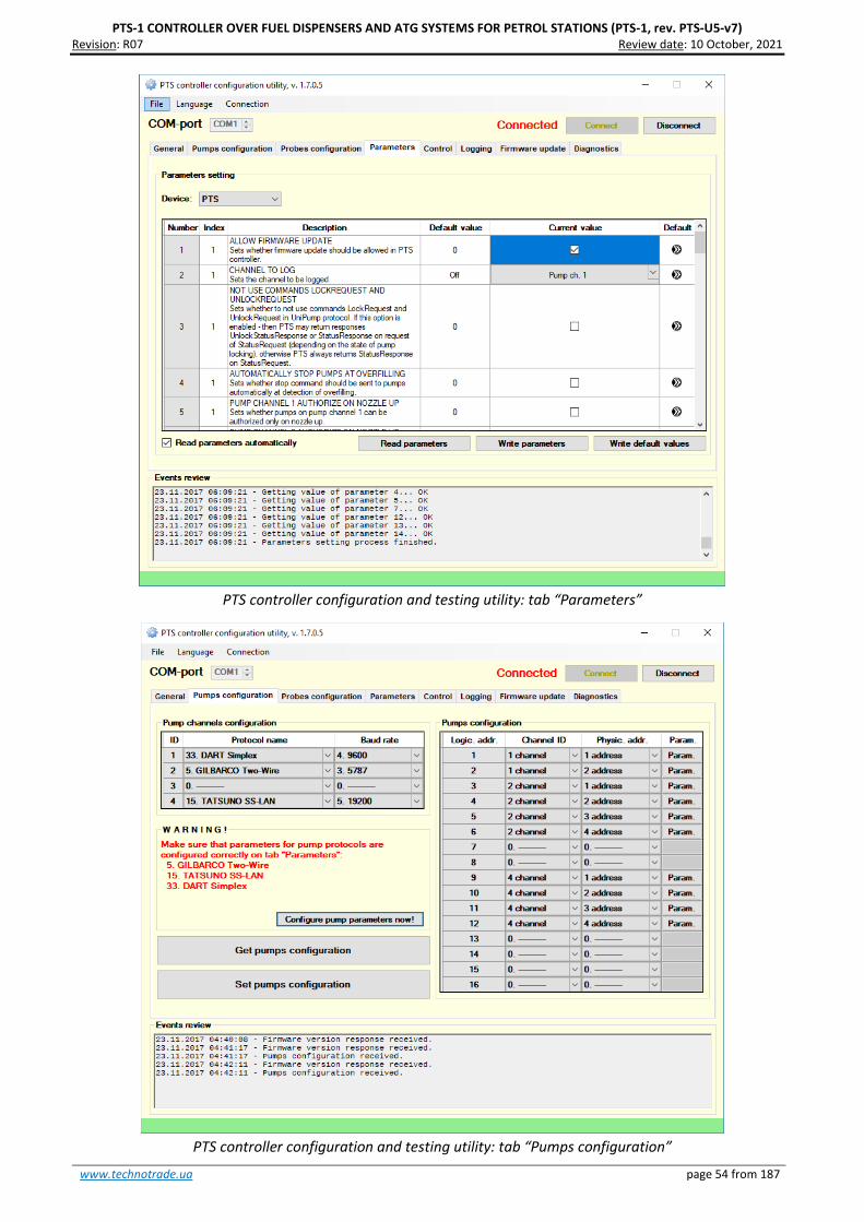
PTS-1 CONTROLLER OVER FUEL DISPENSERS AND ATG SYSTEMS FOR PETROL STATIONS (PTS-1, rev. PTS-U5-v7) Revision: R07 Review date: 10 October, 2021
www.technotrade.ua page 54 from 187
PTS controller configuration and testing utility: tab “Parameters”
PTS controller configuration and testing utility: tab “Pumps configuration”

PTS-1 CONTROLLER OVER FUEL DISPENSERS AND ATG SYSTEMS FOR PETROL STATIONS (PTS-1, rev. PTS-U5-v7) Revision: R07 Review date: 10 October, 2021
www.technotrade.ua page 55 from 187
C# application
The application for PTS controller is written in C# programming language in Visual Studio 2010 Express and
requires .NET Framework 2.0.
Given application includes 2 projects:
− PtsLib - project of PtsLib.dll library for operation with a PTS controller. Includes classes, methods
and properties for communication with PTS controller using requests and responses described in
UniPump communication protocol for communication with PTS controller for provision of control
over dispensers and ATG systems and configuration of PTS controller.
− Fully-functional open source application for provision of control over up to 8 pumps and 4 ATG
systems by the PTS controller, allows to perform all operations with the PTS controller (uses classes
and methods of PtsLib.dll library).
General view of the application: allows to provide control over up to 8 pumps

PTS-1 CONTROLLER OVER FUEL DISPENSERS AND ATG SYSTEMS FOR PETROL STATIONS (PTS-1, rev. PTS-U5-v7) Revision: R07 Review date: 10 October, 2021
www.technotrade.ua page 56 from 187
Form of ATG systems monitoring: allows to monitor up to 4 ATG systems
Form of PTS controller configuration: allows to set configuration for pumps and ATG systems ports
and also set parameters

PTS-1 CONTROLLER OVER FUEL DISPENSERS AND ATG SYSTEMS FOR PETROL STATIONS (PTS-1, rev. PTS-U5-v7) Revision: R07 Review date: 10 October, 2021
www.technotrade.ua page 57 from 187
C# API
The API for PTS controller is written in C# programming language in Visual Studio 2010 Express and requires
.NET Framework 2.0.
Given API includes 2 projects:
− PtsLib - project of PtsLib_CSharp.dll library for operation with a PTS controller. Includes classes,
methods and properties for communication with PTS controller using requests and responses
described in UniPump communication protocol for communication with PTS controller for provision
of control over dispensers and ATG systems and configuration of PTS controller.
− Open-source utility for testing and indication of all operations provided by the PTS controller,
allows to perform all operations with the PTS controller (uses classes and methods of
PtsLib_CSharp.dll library).
Form for testing and indication of all operations provided by the PTS controller

PTS-1 CONTROLLER OVER FUEL DISPENSERS AND ATG SYSTEMS FOR PETROL STATIONS (PTS-1, rev. PTS-U5-v7) Revision: R07 Review date: 10 October, 2021
www.technotrade.ua page 58 from 187
Form for configuration of pumps ports of PTS controller
Form for configuration of ATG systems ports of PTS controller

PTS-1 CONTROLLER OVER FUEL DISPENSERS AND ATG SYSTEMS FOR PETROL STATIONS (PTS-1, rev. PTS-U5-v7) Revision: R07 Review date: 10 October, 2021
www.technotrade.ua page 59 from 187
Delphi API
Delphi API implements shared library libpts.dll calls.
Library libpts.dll was build with Borland compiler C PTS API (source C files you can find in libpts.zip).
Source code of library are located in ./src directory. Directoty ./examples contains several examples of
using library functions.
Graphical form for testing API for PTS controller written in Delphi
Conditionally, API functions can be divided into groups:
− Manage API: Open/close, receiving error, set/get API options
o pts_open
o pts_open_dev
o pts_close
o pts_last_error
o pts_option_get
o pts_option_set
− Handle of a controller configuration
o pts_pump_config_get
o pts_atg_config_get
o pts_pump_config_set
o pts_atg_config_set
o pts_version_get
− Functions of a read and write parameters of the controller or filling places
o pts_param_get
o pts_param_set
− Functions of management by filling places

PTS-1 CONTROLLER OVER FUEL DISPENSERS AND ATG SYSTEMS FOR PETROL STATIONS (PTS-1, rev. PTS-U5-v7) Revision: R07 Review date: 10 October, 2021
www.technotrade.ua page 60 from 187
o pts_authorize
o pts_pts_authorize_by_amount
o pts_halt
o pts_lock
o pts_unlock
o pts_preset_prices
o pts_prices_request
o pts_status_request
o pts_total_request
o pts_trans_close
− Functions of reading measurements of Automatic Tank Gauge (ATG)
o pts_atg_measure_request
Library functions (except for : pts_open, pts_open_dev, pts_close) have common features:
− return value: functions return 0 (FM_OK) if no error and error code if error (see
include/pts_errors.h for
− determine the type of error)
− first of parameter - pts_api_descriptor - integer obtained by the open function: pts_open or
pts_open_dev
− last parameter - pointer to PTS response structure - see include/pts_data.h for determine the data
type.
All commands in protocol involve getting a response.

PTS-1 CONTROLLER OVER FUEL DISPENSERS AND ATG SYSTEMS FOR PETROL STATIONS (PTS-1, rev. PTS-U5-v7) Revision: R07 Review date: 10 October, 2021
www.technotrade.ua page 61 from 187
Java API
Java API for PTS controller is written in Java programming language in NetBeans IDE 7.2.1.
Given API includes:
− JavaPtsLib: library for operation with a PTS controller. Includes classes, methods and properties for
communication with PTS controller using requests and responses described in UniPump
communication protocol for communication with PTS controller for provision of control over
dispensers and ATG systems and configuration of PTS controller.
− JavaPtsApp: open-source utility for testing and indication of all operations provided by the PTS
controller, allows to perform all operation with the PTS controller (uses classes and methods of
JavaPtsLib).
Communication over the COM-port (RS-232 interface) is done using RXTX Java library (visit
www.rxtx.qbang.org for downloads and information): RXTX is a Java library, using a native implementation
(via JNI), providing serial and parallel communication for the Java Development Toolkit (JDK). It is based on
the specification for Sun's Java Communications API, though while many of the class descriptions are the
same the package used it not, since gnu.io is used instead. For more information please visit the rxtx wiki at
http://rxtx.qbang.org/wiki (latest releases of the library can be downloaded there).
Form for testing and indication of all operations provided by the PTS controller

PTS-1 CONTROLLER OVER FUEL DISPENSERS AND ATG SYSTEMS FOR PETROL STATIONS (PTS-1, rev. PTS-U5-v7) Revision: R07 Review date: 10 October, 2021
www.technotrade.ua page 62 from 187
Form for configuration of pumps ports of PTS controller
Form for configuration of ATG systems ports of PTS controller

PTS-1 CONTROLLER OVER FUEL DISPENSERS AND ATG SYSTEMS FOR PETROL STATIONS (PTS-1, rev. PTS-U5-v7) Revision: R07 Review date: 10 October, 2021
www.technotrade.ua page 63 from 187
Python API
Before installation of this package it is necessary to install PySerial (http://pyserial.sourceforge.net/).
To install PTS module, run python setip.py install, Where python = your desired python version executable.
Graphical form for testing API for PTS controller written in Python
The protocol of exchange is realized in the pts.protocol module.
The exchange through a serial port is realized with use PySerial module (http://pyserial.sourceforge.net/)
(therefore, before installation of this package it is necessary to install PySerial).
The package was tested with python of versions 2.7 and 3.0
The pts.constants module contains values of various constants
The pts.config module - structures of data, for a controler configuration
The pts.response module - structures of the data returned by the controler
The pts.protocol module - protocol commands
Conditionally, API functions can be divided into groups:
− Manage API: Open/close, receiving error, set/get API options
o pts_open
o pts_open_dev

PTS-1 CONTROLLER OVER FUEL DISPENSERS AND ATG SYSTEMS FOR PETROL STATIONS (PTS-1, rev. PTS-U5-v7) Revision: R07 Review date: 10 October, 2021
www.technotrade.ua page 64 from 187
o pts_close
o pts_last_error
o pts_option_get
o pts_option_set
− Handle of a controller configuration
o pts_pump_config_get
o pts_atg_config_get
o pts_pump_config_set
o pts_atg_config_set
o pts_version_get
− Functions of a read and write parameters of the controller or filling places
o pts_param_get
o pts_param_set
− Functions of management by filling places
o pts_authorize
o pts_pts_authorize_by_amount
o pts_halt
o pts_lock
o pts_unlock
o pts_preset_prices
o pts_prices_request
o pts_status_request
o pts_total_request
o pts_trans_close
− Functions of reading measurements of Automatic Tank Gauge (ATG)
o pts_atg_measure_request
Work with the protocol can be set for work without exceptions (when error occured), and with generation
of exceptions (PtsException). Parameter of initialization of use_exceptions is responsible for it.

PTS-1 CONTROLLER OVER FUEL DISPENSERS AND ATG SYSTEMS FOR PETROL STATIONS (PTS-1, rev. PTS-U5-v7) Revision: R07 Review date: 10 October, 2021
www.technotrade.ua page 65 from 187
Visual Basic .NET PTS controller configuration and testing utility
PTS controller configuration and testing utility is written in VB.NET programming language in Visual Studio
2010 Express and requires .NET Framework 2.0.
Given application includes 2 projects:
− PtsLib - project of PtsLib.dll library for operation with a PTS controller. Includes classes, methods
and properties for communication with PTS controller using requests and responses described in
UniPump communication protocol for communication with PTS controller for provision of control
over dispensers and ATG systems and configuration of PTS controller.
− Open source utility for configuration of PTS controller, provision of control over pumps and probes,
logging of operation, firmware update, self-diagnostics, others (uses classes and methods of
PtsLib.dll library).
PTS controller configuration and testing utility: tab “Control”

PTS-1 CONTROLLER OVER FUEL DISPENSERS AND ATG SYSTEMS FOR PETROL STATIONS (PTS-1, rev. PTS-U5-v7) Revision: R07 Review date: 10 October, 2021
www.technotrade.ua page 66 from 187
PTS controller configuration and testing utility: tab “Parameters”
PTS controller configuration and testing utility: tab “Pumps configuration”

PTS-1 CONTROLLER OVER FUEL DISPENSERS AND ATG SYSTEMS FOR PETROL STATIONS (PTS-1, rev. PTS-U5-v7) Revision: R07 Review date: 10 October, 2021
www.technotrade.ua page 67 from 187
Visual Basic .NET application
The Visual Basic .NET application for PTS controller is written in VB.NET programming language in Visual
Studio 2010 Express and requirs .NET Framework 2.0.
Given application includes 2 projects:
− PtsLib: project of PtsLib.dll library for operation with a PTS controller. Includes classes, methods and
properties for communication with PTS controller using requests and responses described in
UniPump communication protocol for communication with PTS controller for provision of control
over dispensers and ATG systems and configuration of PTS controller.
− PTS: fully-functional open source application for provision of control over up to 8 pumps and 4 ATG
systems by the PTS controller, allows to perform all operations with the PTS controller (uses classes
and methods of PtsLib.dll library).
General view of the application: allows to provide control over up to 8 pumps

PTS-1 CONTROLLER OVER FUEL DISPENSERS AND ATG SYSTEMS FOR PETROL STATIONS (PTS-1, rev. PTS-U5-v7) Revision: R07 Review date: 10 October, 2021
www.technotrade.ua page 68 from 187
Form of ATG systems monitoring: allows to monitor up to 4 ATG systems
Form of PTS controller configuration: allows to set configuration for pumps and ATG systems ports
and also set parameters

PTS-1 CONTROLLER OVER FUEL DISPENSERS AND ATG SYSTEMS FOR PETROL STATIONS (PTS-1, rev. PTS-U5-v7) Revision: R07 Review date: 10 October, 2021
www.technotrade.ua page 69 from 187
Visual Basic .NET API
Visual Basic .NET API for PTS controller is written in VB.NET programming language in Visual Studio 2010
Express and requirs .NET Framework 2.0.
Given API includes 2 projects:
− PtsLib - project of PtsLib_VBNET.dll library for operation with a PTS controller. Includes classes,
methods and properties for communication with PTS controller using requests and responses
described in UniPump communication protocol for communication with PTS controller for provision
of control over dispensers and ATG systems and configuration of PTS controller.
− PTS - open-source utility for testing and indication of all operations provided by the PTS controller,
allows to perform all operations with the PTS controller (uses classes and methods of
PtsLib_VBNET.dll library).
Form for testing and indication of all operations provided by the PTS controller

PTS-1 CONTROLLER OVER FUEL DISPENSERS AND ATG SYSTEMS FOR PETROL STATIONS (PTS-1, rev. PTS-U5-v7) Revision: R07 Review date: 10 October, 2021
www.technotrade.ua page 70 from 187
Form for configuration of pumps ports of PTS controller
Form for configuration of ATG systems ports of PTS controller

PTS-1 CONTROLLER OVER FUEL DISPENSERS AND ATG SYSTEMS FOR PETROL STATIONS (PTS-1, rev. PTS-U5-v7) Revision: R07 Review date: 10 October, 2021
www.technotrade.ua page 71 from 187
PTS controller COM-object for MS Windows OS
COM-object for PTS controller is written in Microsoft Visual C++ 6.0 IDE in C++ programming language.
Project is located in PTSDriver folder. It builds PTSDriver.dll on output.
For communication with a PTS controller it uses API (application programming interface), written in C
language (located in C_API folder).
In order to provide control over PTS controller and simplify work of developers, who are working in
Windows OS in implementation of UniPump communication protocol of PTS controller, a COM-object with
methods and properties for operation with PTS controller is provided.
COM-object is compiled on Visual C++ 6.0 and is supplied together with a test application, written on Visual
Basic 6.0.
Documentation of COM-object describes all methods and properties of the COM-object and its application.
To register PTSDriver.dll library in Windows OS perform command
REGSVR32 PTSDriver.dll
from folder
PTS_SDK\API TOOLS\COM_object_API_plus_VB6.0_appilcation.rar\PTSDriver\ReleaseMinDependency\

PTS-1 CONTROLLER OVER FUEL DISPENSERS AND ATG SYSTEMS FOR PETROL STATIONS (PTS-1, rev. PTS-U5-v7) Revision: R07 Review date: 10 October, 2021
www.technotrade.ua page 72 from 187
Visual Basic 6.0 application
For testing of the COM-object an open-source application in Microsoft Visual Basic 6.0 is written (located in
VB_6.0_app folder). It provides GUI form for testing and indication of all operations provided by the PTS
controller, allows to perform all operation with the PTS controller (uses classes and methods of PTSDriver).
Form for testing and indication of all operations provided by the PTS controller

PTS-1 CONTROLLER OVER FUEL DISPENSERS AND ATG SYSTEMS FOR PETROL STATIONS (PTS-1, rev. PTS-U5-v7) Revision: R07 Review date: 10 October, 2021
www.technotrade.ua page 73 from 187
Form for configuration of pumps ports of PTS controller
Form for configuration of ATG systems ports of PTS controller
PTS-1 CONTROLLER OVER FUEL DISPENSERS AND ATG SYSTEMS FOR PETROL STATIONS (PTS-1, rev. PTS-U5-v7) Revision: R07 Review date: 10 October, 2021
www.technotrade.ua page 74 from 187
PTS controller UniPump communication protocol
PTS controller is intended to be used in connection with control systems for petrol stations (POS systems,
cash registers, OPT terminals, etc) to provide simultaneous control over various types of electronic fuel
delivery dispensers and ATG systems of various manufactures using the single common communication
protocol UniPump. PTS controller provides conversion of the common communication protocol UniPump
into various proprietary communication protocols of manufacturers.
UniPump communication protocol covers a list of commands and responses for communication with PTS
controller for provision of control over dispensers and ATG systems and configuration of PTS controller.

PTS-1 CONTROLLER OVER FUEL DISPENSERS AND ATG SYSTEMS FOR PETROL STATIONS (PTS-1, rev. PTS-U5-v7) Revision: R07 Review date: 10 October, 2021
www.technotrade.ua page 75 from 187
PTS CONTROLLER SOFTWARE DEVELOPMENT KIT (SDK)
PTS controller SDK appointment
PTS controller SDK (Software Development Kit) is intended for developers of POS management software
for petrol stations that needs to provide control fuel dispensers and ATG systems.
PTS controller SDK includes a PTS controller and RS485-4 interface converter board, which allow to run
software simulators of fuel dispensers and ATG systems on personal computer and debug operation of
control systems software with PTS controller on it without a necessity to connect to real fuel dispensers
and ATG systems. Thus it is convenient to work in office or at home rather than on a working petrol station
being connected to real equipment.
PTS controller SDK allows developers to:
1. Study operation with the PTS controller.
2. Implement the PTS controller into own developed POS system or software application for control over
fuel dispensers and ATG level measurement systems for petrol stations.
3. Debug own software application to correctly provide control over various popular fuel dispensers
locally (on the workplace) without a necessity to go to the petrol station and connect to real fuel
dispensers using supplied with PTS SDK fuel dispensers software simulators, which simulate operation
of various popular fuel dispensers. Through an interface converter RS-485 / RS-232, supplied together
with PTS SDK, connect a PTS controller output RS-485 to a PC COM-port with fuel dispensers software
simulators.
PTS controller SDK structure
HARDWARE:
1. PTS controller over fuel dispensers and ATG systems for petrol stations: 1 pcs
2. Interface converter RS485-4 (RS-485 / RS-232): 1 pcs
3. Cabling (RS-232 to PC): 3 pcs

PTS-1 CONTROLLER OVER FUEL DISPENSERS AND ATG SYSTEMS FOR PETROL STATIONS (PTS-1, rev. PTS-U5-v7) Revision: R07 Review date: 10 October, 2021
www.technotrade.ua page 76 from 187
SOFTWARE:
1. Software simulator of fuel dispensers
2. Software simulator of ATG systems (probes
3. API for developers in various programming languages
4. Useful utilities and applications for debugging of communication with PTS controller
PTS controller SDK technical features
Specification
## PARAMETER VALUE
1 Voltage 12 V DC
2 Current consumption 550 mA max
3 Temperature range -40°C ÷ +80°C
4 Weight 600 g
5 Overall dimensions 160 x 160 x 85 mm

PTS-1 CONTROLLER OVER FUEL DISPENSERS AND ATG SYSTEMS FOR PETROL STATIONS (PTS-1, rev. PTS-U5-v7) Revision: R07 Review date: 10 October, 2021
www.technotrade.ua page 77 from 187
PTS controller SDK connections scheme
PTS-1 controller SDK box includes 2 boards mounted inside of a plastic case:
- PTS-1 controller board
- RS485-4 (RS-485/RS-232) interface converter board
Also, it includes cablings for communication and jack for connection to power supply.
Control systems software, which uses UniPump communication protocol, connects to the PTS controller PC
port.
RS-232/RS-485 interface converter board is used in order to convert signals coming from PTS-1 controller
pump ports in RS-485 interface into signals of RS-232 interface for the fuel dispenser software simulator,
which runs on personal computer and communicates through a COM-port 2.
Connection to ATG software simulators is made through USER port of PTS-2 controller (RS-232 interface),
which is connected to personal computer through a COM-port 3.
Thus, it is possible to debug a correct operation of software, being developed, with the PTS-1 controller
without a necessity to connect to real fuel dispensers and ATG systems, but using fuel dispenser’s software
simulators and ATG system’s software simulators.
More technical information regarding RS485-4 dispenser interface converter (RS-485 to RS-232) can be
found in technical guide on: http://www.technotrade.ua/rs485-to-rs232-converter.html.

PTS-1 CONTROLLER OVER FUEL DISPENSERS AND ATG SYSTEMS FOR PETROL STATIONS (PTS-1, rev. PTS-U5-v7) Revision: R07 Review date: 10 October, 2021
www.technotrade.ua page 78 from 187
UniPump pumps software simulator
Purpose
PTS controller SDK includes a pumps software simulator with a purpose to enable debugging of PTS
controller implementation in third party software. Purpose of software simulators is to debug operation of
control system software (cash register, POS system, OPT, etc) over fuel dispensers through PTS controller
without a necessity to connect to real fuel dispensers.
Main view
Pumps software simulator main view
Selection and
opening/closing
of a COM-port
Volume and money
total counters
Selection of nozzle to
take up/down and its
trigger state
State of
pump
Pump mode of
operation
Dispensed volume,
money amount and price
total counters
Log of simulator operation with specification
of all transmitted commands and their data
operation
Simulation of
presence
Pump physical
address
Pump mode of operation

PTS-1 CONTROLLER OVER FUEL DISPENSERS AND ATG SYSTEMS FOR PETROL STATIONS (PTS-1, rev. PTS-U5-v7) Revision: R07 Review date: 10 October, 2021
www.technotrade.ua page 79 from 187
In pumps simulator it is possible to add up to 99 pumps giving each a unique physical address. Each of the
pumps leads separately its total counters (volume and money amount) and prices for each of its 6 nozzles.
Total counter values as well as prices are stored in Windows system register. Each of the nozzles has a
trigger.
Each of the pumps can be transferred to automatic mode of operation (controlled from the control system)
or manual mode of operation (controlled manually and does not response to control system).
Pump control in pumps software simulator
In right-click mouse menu it is possible to preset the pump with money amount or volume value, stop the
pump, reset, pause and change volume:
Pump right-button mouse menu
Volume preset menu for pump
Configuration
Configuration of the pumps simulator includes configuration of:
− communication settings, which include setting of baud rate, number of data bits and stop bits,
parity control
− quantity of pumps (physical address is set on each pump control independently)
− technical characteristics of the pumps in simulator (flow rate, slow flow rate (when flowdown valve
is on), quantity of pulses before the flowdown valve is switched on
− protocol type: selection between standard UniPump communication protocol and extended
UniPump communicatin protocol for PTS controller
− setting quantity of digits in values of volume, money amount, price and total counters
− selection of graphical skin
Pumps simulator can simulate presence at the pumps – take up nozzles and make dispensing in random
way thus making it possible to debug control system software as if it was operating on real petrol station.
Log window of the pumps simulator enables to see all the requests and responses in communication and
their respective data.


PTS-1 CONTROLLER OVER FUEL DISPENSERS AND ATG SYSTEMS FOR PETROL STATIONS (PTS-1, rev. PTS-U5-v7) Revision: R07 Review date: 10 October, 2021
www.technotrade.ua page 81 from 187
UniProbe ATG probes software simulator
Purpose
PTS controller SDK includes a ATG probes software simulator with a purpose to enable debugging of PTS
controller implementation in third party software. Purpose of software simulators is to debug operation of
control system software (cash register, POS system, OPT, etc) over ATG systems through PTS controller
without a necessity to connect to real ATG systems or probes.
Main view
ATG probes software simulator main view
In ATG probes simulator it is possible to set measurements of the following parameters:
− Products height
− Water height
− Temperature
− Product volume
Selection and
opening/closing
of a COM-port
ATG probe measurements
(allows enable/disable any of the
measured parameters)
Tank height
Connection state
Log of simulator operation with specification
of all transmitted commands and their data
operation
Simulation of
presence
Probe physical
address

PTS-1 CONTROLLER OVER FUEL DISPENSERS AND ATG SYSTEMS FOR PETROL STATIONS (PTS-1, rev. PTS-U5-v7) Revision: R07 Review date: 10 October, 2021
www.technotrade.ua page 82 from 187
− Water volume
− Product ullage
− Product temperature compensated volume
− Product density
− Product mass
Any of the specified parameters can be switched on or off.
Also it is possible to set height of tank in the system.
Each of the ATG probes can be transferred to connected (responses to PTS controller) or disconnected
(does not response to PTS controller) state.
Probe control in ATG probes software simulator
Configuration
Configuration of the pumps simulator includes configuration of:
− communication settings, which include setting of baud rate, number of data bits and stop bits,
parity control
− quantity of ATG probes (physical address is set on each probe control independently)
− selection of graphical skin
Settings of probes simulator
PTS-1 CONTROLLER OVER FUEL DISPENSERS AND ATG SYSTEMS FOR PETROL STATIONS (PTS-1, rev. PTS-U5-v7) Revision: R07 Review date: 10 October, 2021
www.technotrade.ua page 83 from 187
Probes simulator can simulate presence of liquids in tanks – change height and volume of fuel, temperature
mass in random way thus making it possible to debug control system software as if it was operating on real
petrol station.
Log window of the probes simulator enables to see all the requests and responses in communication and
their respective data.
For communication of the PTS controller with UniProbe ATG probes software simulator it is necessary to
select in PTS controller configuration of the probe port communication protocol “9. UNIPROBE” and select
appropriate baud rate (equal to set in simulator (9600 baud rate by defaults) and set probes physical
addresses equal to those, which are set for probes in simulator.

PTS-1 CONTROLLER OVER FUEL DISPENSERS AND ATG SYSTEMS FOR PETROL STATIONS (PTS-1, rev. PTS-U5-v7) Revision: R07 Review date: 10 October, 2021
www.technotrade.ua page 84 from 187
Open source PTS controller .NET application (C# and VB.NET)
Purpose
In order to provide control over PTS controller and simplify work of developers, writing on Microsoft .NET
Framework in implementation of UniPump communication protocol of PTS controller and give an open
source example of application for control over fuel dispensers and ATG systems at petrol station a .NET
library (with open source in C# and VB.NET languages and documentation on methods and properties) and
PTS controller .NET application (with open source in C# and VB.NET languages) are provides.
Given application includes 2 projects:
− PtsLib - project of PtsLib.dll library for operation with a PTS controller. Includes classes, methods
and properties for communication with PTS controller using requests and responses described in
UniPump communication protocol for communication with PTS controller for provision of control
over dispensers and ATG systems and configuration of PTS controller.
− Fully-functional open source application for provision of control over up to 8 pumps and 4 ATG
systems by the PTS controller, allows to perform all operations with the PTS controller (uses classes
and methods of PtsLib.dll library).
PTS controller .NET application is provided on both C# and VB.NET languages and requires .NET Framework
2.0 for operation.

PTS-1 CONTROLLER OVER FUEL DISPENSERS AND ATG SYSTEMS FOR PETROL STATIONS (PTS-1, rev. PTS-U5-v7) Revision: R07 Review date: 10 October, 2021
www.technotrade.ua page 85 from 187
Start
To launch PTS controller .NET application run PtsApplication.exe, select from a dropdown list a COM port
name, to which PTS controller is connected, and press a button to open a selected COM port.
Note: connection with PTS controller is made through a 3-wire realization of RS-232 interface, an
asynchronous half-duplex port, baud rate 57600 baud without a parity check. This configuration is hardly
coded inside a program.
Configuration of PTS controller
To open configuration form go on the main form to menu item “Configuration” → “Fuel point configuration
settings”.
Configuration allows to set pump ports, probe ports, parameters in PTS controller. It is quite convenient to
use and open source code helps to understand better how the PTS controller works.
Pumps configuration tab allows to configure pumps ports of PTS controller (like Pts_config.exe utility):

PTS-1 CONTROLLER OVER FUEL DISPENSERS AND ATG SYSTEMS FOR PETROL STATIONS (PTS-1, rev. PTS-U5-v7) Revision: R07 Review date: 10 October, 2021
www.technotrade.ua page 86 from 187
ATGs configuration tab allows to configure probe ports of PTS controller (like Pts_config.exe utility):
Parameters tab allows to read/write parameters in PTS controller (like Pts_config.exe utility):

PTS-1 CONTROLLER OVER FUEL DISPENSERS AND ATG SYSTEMS FOR PETROL STATIONS (PTS-1, rev. PTS-U5-v7) Revision: R07 Review date: 10 October, 2021
www.technotrade.ua page 87 from 187
Tab “Version information” allows to receive information about date and version of PTS controller firmware
release and also a list of supported communication protocols of pumps and ATG systems (like
Pts_config.exe utility):
Main view

PTS-1 CONTROLLER OVER FUEL DISPENSERS AND ATG SYSTEMS FOR PETROL STATIONS (PTS-1, rev. PTS-U5-v7) Revision: R07 Review date: 10 October, 2021
www.technotrade.ua page 88 from 187
In main view 8 fuel point icons are shown on the screen, which are to be linked to physical fuel points and
show its state.
Each of the displayed fuel point icons contains information about:
− Fuel point ID - a logical number of a fuel point in PTS controller (number displayed in top left
corner, displaying with a symbol “-” means a fuel point not set)
− Status – status of a fuel point (displayed in a top line)
− Mode – selection between Preset mode (required to specify money amount or volume of fuel to be
dispensed) and Manual mode (does not require to specify money amount or volume of fuel to be
dispensed)
− Amount – money amount for which a fuel dispensing should be made (in a range 0,00 – 9999,99)
− Volume – fuel volume for which a fuel dispensing should be made (in a range 0,00 – 9999,99)
− Price – price per 1 liter/gallon of fuel
− Nozzle – number of an active nozzle that is taken up (displaying with a symbol “-” means no nozzle
is taken up)
Possible statuses of fuel points:
− OFFLINE – fuel point is not active, is not set or is controlled in a manual mode
− IDLE – fuel point is in idle state (all nozzles are hang down)
− NOZZLE – nozzle is taken up, waiting for allowance on fuel dispensing
− READY – fuel dispensing is allowed, test of indicator is running
− WORK – fuel dispensing is in process
− TransactionCompleted – transaction is finished normally, waiting for a nozzle to be hang down
− TransactionStopped b
− ERROR – Status of an error
Each of the fuel point icons contains the following buttons:
1. Start – start of fuel dispense/MCID 22/Lang (en-US

PTS-1 CONTROLLER OVER FUEL DISPENSERS AND ATG SYSTEMS FOR PETROL STATIONS (PTS-1, rev. PTS-U5-v7) Revision: R07 Review date: 10 October, 2021
www.technotrade.ua page 89 from 187
Given window contains a dropdown list with all 4 pump ports of the PTS controller, selecting each of which
leads to displaying of all fuel points’ IDs and corresponding fuel points’ addresses configured to given pump
port for a PTS controller in a field below. Selecting one of the fuel point IDs and pressing OK button leads to
linking given fuel point icon to selected fuel point ID and displaying its status. Selecting of a PTS pump port
with value 0 will lead to switching off a fuel point icon.
Given window for each of the fuel points also contains a list of 6 nozzles for setting of prices per 1
liter/gallon of fuel, dispensed through these nozzles, in a range 0,00 – 999,99. If a fuel point has less than 6
nozzles – prices will be set only for first number of nozzles, which a fuel point has.
Clicking “Set prices” button leads to updating prices on selected fuel point. Clicking “Get prices” leads to
receiving of prices from selected fuel point.
Clicking OK button leads to updating a fuel point icon and updating (creating) a file “Config.xml” in root
folder with configuration of fuel point icons. At launching of a PTS controller .NET application next time
configuration of fuel point icons will be read from this file “Config.xml” in root folder.
Reading of fuel point total counters
In the end of every dispensing application itself reads total counters from the pump on the nozzle, whih
was dispensing. At this a sign of totals reading appears in the left top corner of the pump icon (and under
the header of the “T” command is displayed, which means that currently PTS controller processes
TotalInfoRequest command).
Total counters can be updated at any moment from any of the pumps. Selecting of a button “Totals” on a
fuel point icon and clicking a button Update in it leads to reading of total counters:

PTS-1 CONTROLLER OVER FUEL DISPENSERS AND ATG SYSTEMS FOR PETROL STATIONS (PTS-1, rev. PTS-U5-v7) Revision: R07 Review date: 10 October, 2021
www.technotrade.ua page 90 from 187
Settings
Selection from top menu “Configuration” an item “Settings” leads to opening a new window, which allows
adjustment of
Settings include the following:
1. Authorization type of fuel dispensers:
− Authorization by fuel volume – dispensers are to be authorized with volume
− Authorization by money amount – dispensers are to be authorized with money amount
2. Authorization polling:
− Keep polling when pump is in READY state – after the Start button is clicked to authorize a
dispenser, but nozzle is not taken up on the dispenser, the fuel point displays READY state; this
option enables to keep constantly sending authorization command in READY state (until nozzle is
taken up of fuel point and it is authorized)
− Do not poll when pump is in READY state – after the Start button is clicked to authorize a
dispenser, but nozzle is not taken up on the dispenser, the fuel point displays READY state; this
option enables to send authorization command only once at clicking on a “Start” button of fuel
point icon
3. Extended commands:
− Use general commands – PTS controller can work with general commands (for prices containing up
to 4 digits) and also with extended commands (for more quantity of digits in price values); this
option sets to use general commands in communication with PTS controller (prices containing with
up to 4 digits)
− Use extended commands – PTS controller can work with general commands (for prices containing
up to 4 digits) and also with extended commands (for prices containing with up to 9 digits); this
option sets to use extended commands in communication with PTS controller (prices containing
with up to 9 digits)
4. Request total counters:
− Request total counters – this option sets that application should automatically request total
counters after each dispensing on dispenser is performed
− Do not request total counters – this option sets that application should not automatically request
total counters after each dispensing on dispenser is performed

PTS-1 CONTROLLER OVER FUEL DISPENSERS AND ATG SYSTEMS FOR PETROL STATIONS (PTS-1, rev. PTS-U5-v7) Revision: R07 Review date: 10 October, 2021
www.technotrade.ua page 91 from 187
5. Manual mode settings:
− Authorize automatically at nozzle up – this option sets that once a nozzle is taken up on the
dispenser – application should at once authorize it with a value set in field “Dose to authorize”; this
options enables the application to set in a way, when order is preset from dispenser keyboard and
application simply monitors the dispensers operation; in order this feature to work a fuel point
should be switched to Manual mode of operation (see above), in Preset mode this feature does not
work (preset is supposed to be given from application)
− Authorize manually at nozzle up – this option sets that dispensers are to be controlled fully from
the application by clicking on Start and Stop buttons both in preset and Manual modes of operation
6. Quantity of digits:
Setting of quantity of digits in money, volume, price and total counters (volume and money
amount) - this option is required in cases when dispensers may have non-standard quantity of
digits (for example 3 digits in volume and 0 digits in money amount)
Displaying ATG systems probes states
In ATG view 4 ATG icons are shown on the screen, which are to be linked to physical ATG systems (probes)
and show its state.
Each of the displayed ATG icons contains information about measured by ATG system (probe) parameters
of petroleum product inside tanks. Depending on the type (communication protocol) of ATG system (probe)
the following data may be displayed:
- Product level (accuracy 0.1 mm)
- Product volume (accuracy 1 liter)
- Product temperature compensated volume (accuracy 1 liter)
- Product ullage (volume) (accuracy 1 liter)
- Water level (accuracy 0.1 mm)
- Water volume (accuracy 1 liter)
- Temperature (accuracy 0.1 degree Celcium)
- Product density (accuracy 0.1 kg/m3)
- Product mass (accuracy 0.1 kg)

PTS-1 CONTROLLER OVER FUEL DISPENSERS AND ATG SYSTEMS FOR PETROL STATIONS (PTS-1, rev. PTS-U5-v7) Revision: R07 Review date: 10 October, 2021
www.technotrade.ua page 92 from 187
If ATG system does not support any the parameters – a correspondent value label on ATG icon stays
disabled. Picture of a tank on the ATG icon shows visually level of product in tank compared to tank height
(which should be equal to ATG probe height). If ATG icon is linked with an ATG system – its state is
“ACTIVE”, else – “NOT ACTIVE”.
Settings of ATG probe icons
Given window contains a dropdown list with all 3
probe ports of the PTS controller, selecting each of
which leads to displaying of all ATG probes’ IDs and
corresponding ATG probes’ addresses configured to
given probe port for a PTS controller in a field
below. Selecting one of the ATG probe IDs and
pressing OK button leads to linking given ATG probe
icon to selected ATG probe ID and displaying its
state. Selecting of a PTS probe port with value 0 will
lead to switching off a ATG probe icon.
Given window for each of the ATG probes also
contains a field for entering height of a tank with
installed probe (which is considered to be a
maximum level of product allowed for given tank).

PTS-1 CONTROLLER OVER FUEL DISPENSERS AND ATG SYSTEMS FOR PETROL STATIONS (PTS-1, rev. PTS-U5-v7) Revision: R07 Review date: 10 October, 2021
www.technotrade.ua page 93 from 187
TiT.PTS classes help file
PTS controller .NET application is based on a number of classes which documentation describing methods and properties is supplied together with it. Documentation is generated in a form of html-files.

PTS-1 CONTROLLER OVER FUEL DISPENSERS AND ATG SYSTEMS FOR PETROL STATIONS (PTS-1, rev. PTS-U5-v7) Revision: R07 Review date: 10 October, 2021
www.technotrade.ua page 94 from 187
PumpDemo utility
PumpDemo utility is a contracted version of NaftaPOS software (http://technotrade.ua/petrol-station-software.html) used for debugging purposes. It does not require installation. Configuration of the system is done by running a setup.bat file. Configuration is similar to configuration of NaftaPOS software for operation with PTS controller (see NaftaPOS software user manual):
This allows to set configuration for communicating with PTS controller. Graphical user interface is adjusted in a file AZSDemo.dat, where all information is stored in a view of text.
Operation of the PumpDemo utility is made same as operation of NaftaPOS software.

PTS-1 CONTROLLER OVER FUEL DISPENSERS AND ATG SYSTEMS FOR PETROL STATIONS (PTS-1, rev. PTS-U5-v7) Revision: R07 Review date: 10 October, 2021
www.technotrade.ua page 95 from 187
As a confirmation of the fuel dispensing
ordered in preset mode or performed in
manual or full tank modes a correspondent
window is shown:
Pump state IDLE: all nozzles are
down
Pump icon
number
Pump state Nozzle: specified
nozzle is taken up
Pump state READY: the
dispenser is authorized
Pump state WORK: the
dispenser is currently
dispensing fuel
Pump state NOZZLE: error on
dispenser (taken up not the
nozzle authorized)
Button
“Start”
Button
“Stop”
Fuel grade
(nozzle)
Order in
liters / galons
Order in
money amount
Price on
fuel grade
Selection a mode of operation:
preset, manual or full tank
Selection of a
payment form
Selection of a
discount
Dispensing
progress bar
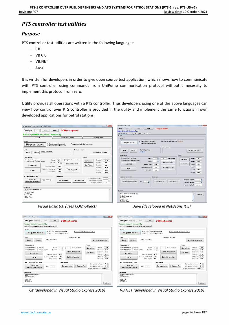
PTS-1 CONTROLLER OVER FUEL DISPENSERS AND ATG SYSTEMS FOR PETROL STATIONS (PTS-1, rev. PTS-U5-v7) Revision: R07 Review date: 10 October, 2021
www.technotrade.ua page 96 from 187
PTS controller test utilities
Purpose
PTS controller test utilities are written in the following languages:
− C#
− VB 6.0
− VB.NET
− Java
It is written for developers in order to give open source test application, which shows how to communicate
with PTS controller using commands from UniPump communication protocol without a necessity to
implement this protocol from zero.
Utility provides all operations with a PTS controller. Thus developers using one of the above languages can
view how control over PTS controller is provided in the utility and implement the same functions in own
developed applications for petrol stations.
Visual Basic 6.0 (uses COM-object)
Java (developed in NetBeans IDE)
C# (developed in Visual Studio Express 2010)
VB.NET (developed in Visual Studio Express 2010)

PTS-1 CONTROLLER OVER FUEL DISPENSERS AND ATG SYSTEMS FOR PETROL STATIONS (PTS-1, rev. PTS-U5-v7) Revision: R07 Review date: 10 October, 2021
www.technotrade.ua page 97 from 187
PTS terminal utility
Purpose
PTS terminal is used in order to provide debugging of PTS controller operation. It allows to send to PTS
controller requests formed with bytes in accordance with UniPump communication protocol commands
without a necessity to add framing bytes and CRC.
This utility can be useful during development of own control software, when developers can test sending of
commands to PTS controller and receive its responses using this utility and in such a way compare then
with responses processed in own developed control software.
Selection of COM-port
and a button for open/close
Selection of the logical address,
to which request is addressed
Commands to be sent to the
specified logical address
Log of communication (shows
commands and responses)

PTS-1 CONTROLLER OVER FUEL DISPENSERS AND ATG SYSTEMS FOR PETROL STATIONS (PTS-1, rev. PTS-U5-v7) Revision: R07 Review date: 10 October, 2021
www.technotrade.ua page 98 from 187
Step-by-step configuration of the PTS controller SDK
Purpose
This step-by-step instruction is provided in order to simplify understanding of PTS controller SDK operation
and assembling. It describes basic steps to be made with PTS controller SDK to assemble it correctly and
also to install and configure software coming in its structure.
Step 1. Downloading of PTS controller SDK software
Using a link for download of PTS controller SDK software it is necessary to get all files from it. The files
should include:
- API tools:
- Open source application programming interfaces, libraries, test utilities, applications and
documentation for development the third party software for communication with PTS
controller using various programming languages and environments
- UniPump communication protocol description for PTS controller
- Software tools
- PumpDemo util
- PTS controller configuration tool Pts_config.exe
- PTS terminal utility
- Latest stable PTS controller firmware
- Software simulators
- Fuel dispensers software simulators
- ATG systems (probes) software simulators
- Documentation
- User manuals
- Technical guides
Step 2. Assembling PTS controller SDK cabling and connection to PC
For connection of PTS controller SDK cabling it is necessary to have at least 2 COM-ports available in PC
(one COM-port – for control system, other COM-port – for fuel dispenser software simulator or ATG probe
software simulator). In case of absence of native COM-ports in the PC motherboard it is possible to use any
standard interface converters to RS-232 interface: USB-to-COM, Ethernet-to-COM, PCI-to-COM,
Bluetooth-to-COM, other possible. Visit this link for possible solution: http://www.technotrade.ua/usb-to-
rs-232-interface-converter.html.
USB-to-COM interface converter cable

PTS-1 CONTROLLER OVER FUEL DISPENSERS AND ATG SYSTEMS FOR PETROL STATIONS (PTS-1, rev. PTS-U5-v7) Revision: R07 Review date: 10 October, 2021
www.technotrade.ua page 99 from 187
PTS controller SDK is generally supplied in a plastic box, in which the PTS controller and RS-485/RS-232
interface converter boards are mounted. All cables inside the PTS controller SDK are already connected. In
order to start operation it is necessary to connect interfaces to PC COM-ports and power on the PTS
controller SDK. So, it is necessary to make all the cablings connections correctly for the system to start
operation.
In this step-by-step instruction we will connect 1 pump simulator and 1 ATG probes simulator. Scheme of
connections should be the following:
1. Connection of PC with PTS controller: connect cable coming from PC port of PTS controller to COM-port
1 of PC (where the control software is to be launched).
2. Connection of RS-485/RS-232 interface converter to PC: connect cable coming from PUMP PORT 1 of RS-
485/RS-232 interface converter to COM-port 2 of PC, on which the pump software simulator is to be
launched.
3. Make sure that PUMP PORT 1 of PTS controller is connected to DATA PORT (RS-485) of RS-485/RS-232
interface converter.
4. Make sure that all switches of DIP-switch SA1 are set into position OFF.
5. Make sure that power supply cable is connected to POWER connector of PTS controller and POWER
connector of RS-485/RS-232 interface converter.
6. (Optional, may be skipped) In order to use software simulator of ATG system connect USER port of PTS
controller to COM-port 3 of PC, on which the ATG system software simulator is to be launched.

PTS-1 CONTROLLER OVER FUEL DISPENSERS AND ATG SYSTEMS FOR PETROL STATIONS (PTS-1, rev. PTS-U5-v7) Revision: R07 Review date: 10 October, 2021
www.technotrade.ua page 100 from 187
7. Switch on (power on) the PTS controller SDK (requires 12 V DC power supply source).
It is worth to mention that only 1 application can work with a specific COM-port at the time, 2 applications
can not share the same COM-port.

PTS-1 CONTROLLER OVER FUEL DISPENSERS AND ATG SYSTEMS FOR PETROL STATIONS (PTS-1, rev. PTS-U5-v7) Revision: R07 Review date: 10 October, 2021
www.technotrade.ua page 101 from 187
Step 3. Starting of the PTS controller configuration utility Pts_config.exe
Run Pts_config.exe and from the main menu select connection type to be “Direct connection to PC COM-
port”, select COM-port with connected PTS controller and click on the “Connect” button. Make sure that
the port is opened (red inscription “COM-port opened” should appear).
Click on button “Request firmware version” to get firmware information from PTS controller.


PTS-1 CONTROLLER OVER FUEL DISPENSERS AND ATG SYSTEMS FOR PETROL STATIONS (PTS-1, rev. PTS-U5-v7) Revision: R07 Review date: 10 October, 2021
www.technotrade.ua page 103 from 187
Step 5. Configuration of probes ports
Go to tab “Probes configuration” and set probes ports configuration as shown on below screenshot. Set
protocol “9. UniProbe” for probe port USER and baud rate “4. 9600”. Assign this probe port to probes 1 - 3,
set the physical addresses of these probes also 1 – 3.
Click the button “Set pumps configuration” to save configuration in PTS controller.

PTS-1 CONTROLLER OVER FUEL DISPENSERS AND ATG SYSTEMS FOR PETROL STATIONS (PTS-1, rev. PTS-U5-v7) Revision: R07 Review date: 10 October, 2021
www.technotrade.ua page 104 from 187
Step 6. Configuration of PTS controller parameters
Go to tab “Parameters” and select from a device list item “PTS”, click on a button “Write default
parameters”.

PTS-1 CONTROLLER OVER FUEL DISPENSERS AND ATG SYSTEMS FOR PETROL STATIONS (PTS-1, rev. PTS-U5-v7) Revision: R07 Review date: 10 October, 2021
www.technotrade.ua page 105 from 187
Step 7. Configuration of pumps parameters
On tab “Parameters” select from a device list item “Pump”, in a field “Number” select pump 1, in a protocol
list – “2. UniPump” (which means configuration of UniPump protocol parameters for pump 1).
Click on a button “Write default parameters” to write default values. Change the parameter with index 2
“Protocol type” to value “1. UniPump protocol for PTS” as it is shown on below screenshot.
Save current configuration for each of 4 pumps (select pumps one by one using field “Number”).
At this step configuration of the PTS controller is finished.

PTS-1 CONTROLLER OVER FUEL DISPENSERS AND ATG SYSTEMS FOR PETROL STATIONS (PTS-1, rev. PTS-U5-v7) Revision: R07 Review date: 10 October, 2021
www.technotrade.ua page 106 from 187
Step 8. Configuration of pumps software simulator
Run SimUniPump.exe and go to configuration of its properties. Set properties as shown on screenshot:
After properties are set click OK and on the main form select a COM-port, to which pump port of RS-
485/RS-232 interface converter board is connected, and click “Open” button:
After COM-port is opened in case if there is communication between the PTS controller and pump
simulator – you should see blinking of red squares located in left top corner of pump icons in pump
simulator, and communication will be logged in log window of the simulator.

PTS-1 CONTROLLER OVER FUEL DISPENSERS AND ATG SYSTEMS FOR PETROL STATIONS (PTS-1, rev. PTS-U5-v7) Revision: R07 Review date: 10 October, 2021
www.technotrade.ua page 107 from 187
At this in PTS controller on pump port 1 green and red LEDs will begin to blink. Blinking of the green LED
means that PTS controller is sending requests to the pump, blinking of the red LED means that the PTS
controller receives responses from the pump.
In case if only green LED is blinking on pump port 1 – there is a mistake in wiring connection or
configuration of the equipment (PTS controller or pump).

PTS-1 CONTROLLER OVER FUEL DISPENSERS AND ATG SYSTEMS FOR PETROL STATIONS (PTS-1, rev. PTS-U5-v7) Revision: R07 Review date: 10 October, 2021
www.technotrade.ua page 108 from 187
Step 9. Configuration of ATG probes software simulator
Run SimUniProbe.exe and go to configuration of its properties. Set properties as shown on screenshot:
After properties are set click OK and on the main form select a COM-port, to which USER port of PTS
controller is connected, and click “Open” button.
After COM-port is opened in case if there is communication between the PTS controller and ATG probes
simulator – you should see blinking of red squares located in left top corner of ATG probes icons in ATG
probes simulator, and communication will be logged in log window of the simulator.
At this in PTS controller on USER port green and red LEDs will begin to blink once per second. Blinking of the
green LED means that PTS controller is sending requests to the ATG, blinking of the red LED means that the
PTS controller receives responses from the ATG.
In case if only green LED is blinking on USER port – there is a mistake in wiring connection or configuration
of the equipment (PTS controller or ATG).

PTS-1 CONTROLLER OVER FUEL DISPENSERS AND ATG SYSTEMS FOR PETROL STATIONS (PTS-1, rev. PTS-U5-v7) Revision: R07 Review date: 10 October, 2021
www.technotrade.ua page 109 from 187
Step 10. Control over pumps and ATG probes in PTS controller configuration and
testing utility
Go to tab “Control” in Pts_config.exe and click on the button “TURN ON”.
Now it is necessary to set initial values in the pump simulator and ATG probes simulator to display them in
the utility. Take up nozzles on the pumps and also set values for the ATGs (there is a possibility to emulate
presence in the simulators to make them work if there was really process going on). In the Pts_config.exe
utility you will see these changes.

PTS-1 CONTROLLER OVER FUEL DISPENSERS AND ATG SYSTEMS FOR PETROL STATIONS (PTS-1, rev. PTS-U5-v7) Revision: R07 Review date: 10 October, 2021
www.technotrade.ua page 110 from 187
Now you are able to provide full control over the pumps and read receive data from the ATG probes:
Pumps software simulator
Try to make different operations with pumps: set/get prices, take up/down nozzles, get total counters,
authorize a dispenser, others. Plays with decimal digits number to make them equal to used at your petrol
stations (Note! Number of decimal digits should be also changed in pumps software simulator).
ATG probes software simulator
Try to change the measured values of fuel in tanks and see how soon they are updated in Pts_config.exe
utility.

PTS-1 CONTROLLER OVER FUEL DISPENSERS AND ATG SYSTEMS FOR PETROL STATIONS (PTS-1, rev. PTS-U5-v7) Revision: R07 Review date: 10 October, 2021
www.technotrade.ua page 111 from 187
Step 11. Configuration of PTS controller .NET application for control over pumps
and ATG probes
The open-source application written in C# and VB.NET is a good place to start development of new control
software for petrol stations. In this section we will see how it is easy to configure and run it.
Compile “PTS application” project or simply run PtsApplication.exe (application is located in PTS SDK
software kit and is located in API TOOLS folder for C# and VB.NET languages):
Go to main menu item “Configuration” → “Settings” and set configuration as shown below:

PTS-1 CONTROLLER OVER FUEL DISPENSERS AND ATG SYSTEMS FOR PETROL STATIONS (PTS-1, rev. PTS-U5-v7) Revision: R07 Review date: 10 October, 2021
www.technotrade.ua page 112 from 187
In main form of the application for each of the fuel point icons go to setting (“Settings” button) and set a
correspondent fuel point number (from fuel point port 1) and prices for each of the nozzles:
− Fuel point icon #1 → FuelPoint ID = 1, Address = 1
− Fuel point icon #2 → FuelPoint ID = 2, Address = 2
− Fuel point icon #3 → FuelPoint ID = 3, Address = 3
− Fuel point icon #4 → FuelPoint ID = 4, Address = 4
Also here set prices for each of the nozzles:
Now the main form of the application allows to provide control over pumps in pump software simulator
(see configuration of the pumps simulator in step 7 above):

PTS-1 CONTROLLER OVER FUEL DISPENSERS AND ATG SYSTEMS FOR PETROL STATIONS (PTS-1, rev. PTS-U5-v7) Revision: R07 Review date: 10 October, 2021
www.technotrade.ua page 113 from 187
To view the measurement by the ATGs in PTS application go to main menu item “ATG” → “ATG
measurement data”, where for each of the ATG icons in settings set configuration of ATG to get
measurement values and also set tank’s height:

PTS-1 CONTROLLER OVER FUEL DISPENSERS AND ATG SYSTEMS FOR PETROL STATIONS (PTS-1, rev. PTS-U5-v7) Revision: R07 Review date: 10 October, 2021
www.technotrade.ua page 114 from 187
Now PTS application is able to indicate current level measurement data from ATG system:

PTS-1 CONTROLLER OVER FUEL DISPENSERS AND ATG SYSTEMS FOR PETROL STATIONS (PTS-1, rev. PTS-U5-v7) Revision: R07 Review date: 10 October, 2021
www.technotrade.ua page 115 from 187

PTS-1 CONTROLLER OVER FUEL DISPENSERS AND ATG SYSTEMS FOR PETROL STATIONS (PTS-1, rev. PTS-U5-v7) Revision: R07 Review date: 10 October, 2021
www.technotrade.ua page 116 from 187
Now the PTS application correctly works with pumps and ATGs software simulators.

PTS-1 CONTROLLER OVER FUEL DISPENSERS AND ATG SYSTEMS FOR PETROL STATIONS (PTS-1, rev. PTS-U5-v7) Revision: R07 Review date: 10 October, 2021
www.technotrade.ua page 117 from 187
EXAMPLES OF FUEL DISPENSERS CONNECTION SCHEMES
Below sections show examples of connection to various brands of fuel dispensers. This information is
provided as an example. For reception of detailed information on connection to various brands of fuel
dispensers, configuration of the fuel dispensers and configuration of PTS controller please refer to our
support mailbox [email protected].
As it is seen from below connection examples some brands of fuel dispensers have RS-485 interface on
board and thus are directly connected to PTS controller, others do not have RS-485 interface and thus
require additional interface converter for connection to PTS controller. In some cases, various models of
same brand of fuel dispensers have RS-485 interface, others – no. In such a way the best way to check how
your fuel dispenser is connected is to take its mainboard photos and send to us on our support mailbox
[email protected]. Mainboard is normally located inside the fuel dispenser pumphead behind
the displays.

PTS-1 CONTROLLER OVER FUEL DISPENSERS AND ATG SYSTEMS FOR PETROL STATIONS (PTS-1, rev. PTS-U5-v7) Revision: R07 Review date: 10 October, 2021
www.technotrade.ua page 118 from 187
Gilbarco dispenser connection scheme
Connection to Gilbarco dispenser is made through 2-wire GB interface converter
(http://www.technotrade.ua/gilbarco-interface-converter.html), which provides connection of RS-232/RS-
485 interfaces to 2-wire current loop interface.
Configuration of PTS controller pump port: protocol “5. GILBARCO Two-Wire”, baud rate “3. 5787”.
Gilbarco Encore 500 dispenser board
Gilbarco dispenser ASSY
M06104A001 rev. B board
- +
- +

PTS-1 CONTROLLER OVER FUEL DISPENSERS AND ATG SYSTEMS FOR PETROL STATIONS (PTS-1, rev. PTS-U5-v7) Revision: R07 Review date: 10 October, 2021
www.technotrade.ua page 119 from 187
Gilbarco dispenser board Gilbarco Euroline dispenser board
Gilbarco Endeavor dispenser board
+ -
+ -
Gilbarco Highline / Dimension Assy dispenser board
+ -
+ -
- +
Gilbarco 3202 series dispenser board
Gilbarco Endeavor dispenser board
- +
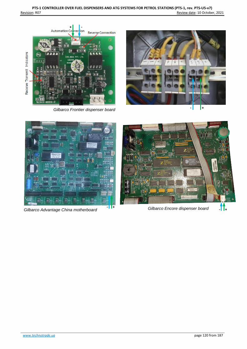
PTS-1 CONTROLLER OVER FUEL DISPENSERS AND ATG SYSTEMS FOR PETROL STATIONS (PTS-1, rev. PTS-U5-v7) Revision: R07 Review date: 10 October, 2021
www.technotrade.ua page 120 from 187
+ -
Gilbarco Frontier dispenser board
- + Gilbarco Advantage China motherboard
- +
Gilbarco Encore dispenser board - +

PTS-1 CONTROLLER OVER FUEL DISPENSERS AND ATG SYSTEMS FOR PETROL STATIONS (PTS-1, rev. PTS-U5-v7) Revision: R07 Review date: 10 October, 2021
www.technotrade.ua page 121 from 187
Wayne Dresser dispenser connection scheme (RS-485 interface)
Connection to Wayne Dresser dispenser is made directly without any interface converter.
Configuration of PTS controller pump port: protocol “3. WAYNE Dart”, baud rate “4. 9600”.
Wayne Dresser iGEM2 dispenser board
Wayne Dresser STMTAX Duplex dispenser
board
Line B
Line A
Line A
Line B
Line A Line B
Wayne Dresser x2000/x2003 dispenser interface board
Wayne Dresser Global Vista CNG dispenser
interface board
Line A Line B
Line A
Line B
Wayne Dresser iGEM dispenser board
Line B
Line A
Line A
Line B
Wayne Dresser V387 dispenser board

PTS-1 CONTROLLER OVER FUEL DISPENSERS AND ATG SYSTEMS FOR PETROL STATIONS (PTS-1, rev. PTS-U5-v7) Revision: R07 Review date: 10 October, 2021
www.technotrade.ua page 122 from 187
Wayne Dresser dispenser connection scheme (current loop interface)
Connection to Wayne Dresser dispenser is made through 2-wire GB interface converter
(http://www.technotrade.ua/gilbarco-interface-converter.html), which provides connection of RS-232/RS-
485 interfaces to 2-wire current loop interface.
Configuration of PTS controller pump port: protocol “23. WAYNE USCL”, baud rate “4. 9600”.
Wayne Dresser V387 dispenser board Wayne Dresser dispenser iGEM board
+
-
- +
Wayne Dresser STMTAX Duplex dispenser
board
-
+
Wayne Dresser iGEM2 dispenser board
-
+

PTS-1 CONTROLLER OVER FUEL DISPENSERS AND ATG SYSTEMS FOR PETROL STATIONS (PTS-1, rev. PTS-U5-v7) Revision: R07 Review date: 10 October, 2021
www.technotrade.ua page 123 from 187
Tatsuno (Japan) dispenser connection scheme
Connection to TATSUNO (Japan) dispenser is made directly without any interface converter.
Configuration of PTS controller pump port: protocol “15. TATSUNO SS-LAN”, baud rate “5. 19200”.
TATSUNO POS joint box
Lin
e A
Lin
e B

PTS-1 CONTROLLER OVER FUEL DISPENSERS AND ATG SYSTEMS FOR PETROL STATIONS (PTS-1, rev. PTS-U5-v7) Revision: R07 Review date: 10 October, 2021
www.technotrade.ua page 124 from 187
Tatsuno Europe (former Benc) dispenser connection scheme
Connection to TATSUNO Benc (Europe) dispenser is made directly without any interface converter.
Configuration of PTS controller pump port: protocol “7. TATSUNO Benc PDE”, baud rate “5. 19200”.
TATSUNO Benc pumphead
Lin
e A
Lin
e B

PTS-1 CONTROLLER OVER FUEL DISPENSERS AND ATG SYSTEMS FOR PETROL STATIONS (PTS-1, rev. PTS-U5-v7) Revision: R07 Review date: 10 October, 2021
www.technotrade.ua page 125 from 187
Tokheim dispenser connection scheme
Connection to Tokheim dispenser is made through 3-wire TH interface converter
(http://www.technotrade.ua/tokheim-interface-converter.html), which provides connection of RS-232/RS-
485 interfaces to 3-wire current loop interface.
Configuration of PTS controller pump port: protocol “6. TOKHEIM”, baud rate “4. 9600”.
Tokheim dispenser board
TT
D
DC
C
TT
C
TT
C
TT
D
DC
C
Tokheim dispenser board

PTS-1 CONTROLLER OVER FUEL DISPENSERS AND ATG SYSTEMS FOR PETROL STATIONS (PTS-1, rev. PTS-U5-v7) Revision: R07 Review date: 10 October, 2021
www.technotrade.ua page 126 from 187
Tokheim dispenser interface board Tokheim dispenser interface board
Tokheim dispenser calculator with interface board
Tokheim dispenser interface board
DC
C
TT
C
TT
D
DC
C
TT
C
TT
D
DC
C
TT
C
TT
D
TT
C
TT
D
DC
C

PTS-1 CONTROLLER OVER FUEL DISPENSERS AND ATG SYSTEMS FOR PETROL STATIONS (PTS-1, rev. PTS-U5-v7) Revision: R07 Review date: 10 October, 2021
www.technotrade.ua page 127 from 187
Tokheim Q320T dispenser calculator

PTS-1 CONTROLLER OVER FUEL DISPENSERS AND ATG SYSTEMS FOR PETROL STATIONS (PTS-1, rev. PTS-U5-v7) Revision: R07 Review date: 10 October, 2021
www.technotrade.ua page 128 from 187
Tokheim dispenser connection scheme (RS-485 interface)
Connection to Tokheim dispenser through RS-485 interface is made directly without any interface
converter.
Configuration of PTS controller pump port: protocol “6. TOKHEIM”, baud rate “4. 9600”.
Tokheim dispenser motherboard
Lin
e B
Lin
e A

PTS-1 CONTROLLER OVER FUEL DISPENSERS AND ATG SYSTEMS FOR PETROL STATIONS (PTS-1, rev. PTS-U5-v7) Revision: R07 Review date: 10 October, 2021
www.technotrade.ua page 129 from 187
Line B
Line A
Tokheim dispenser motherboard

PTS-1 CONTROLLER OVER FUEL DISPENSERS AND ATG SYSTEMS FOR PETROL STATIONS (PTS-1, rev. PTS-U5-v7) Revision: R07 Review date: 10 October, 2021
www.technotrade.ua page 130 from 187
Tokheim India dispenser connection scheme
Connection to Tokheim India dispenser is made directly without any interface converter. Configuration of
PTS controller pump port: protocol “59. Tokheim TQCL”, baud rate “4. 9600”.
Lin
e A
Lin
e B

PTS-1 CONTROLLER OVER FUEL DISPENSERS AND ATG SYSTEMS FOR PETROL STATIONS (PTS-1, rev. PTS-U5-v7) Revision: R07 Review date: 10 October, 2021
www.technotrade.ua page 131 from 187
Nuovo Pignone multiproduct dispenser board
Nuovo Pignone dispenser connection scheme (RS-485 interface)
Connection to Nuovo Pignone dispensers with RS-485 interface is made directly without any interface
converter. At this Nuovo Pignone dispenser should have an interface board for RS-485 interface and should
be adjusted to have Wayne Dart protocol.
Configuration of PTS controller pump port: protocol “3. WAYNE Dart”, baud rate “4. 9600”.
Nuovo Pignone interface boards for RS-485 interface
for monoproduct and multiproducts dispensers
More info can be found on:
http://www.technotrade.ua/nuovo_pignone_interface_converter.html
Lin
e B
Lin
e A
Nuovo Pignone monoproduct dispenser board
Lin
e B
Lin
e A

PTS-1 CONTROLLER OVER FUEL DISPENSERS AND ATG SYSTEMS FOR PETROL STATIONS (PTS-1, rev. PTS-U5-v7) Revision: R07 Review date: 10 October, 2021
www.technotrade.ua page 132 from 187
Nuovo Pignone dispenser board
Nuovo Pignone dispenser board
Nuovo Pignone dispenser connection scheme (4-wire current loop interface)
Connection to Nuovo Pignone dispensers with 4-wire current loop interface is made through 4-wire NP
interface converter (http://www.technotrade.ua/nuovo_pignone_interface_converter.html), which
provides connection of RS-232/RS-485 interfaces to 4-wire current loop interface.
Configuration of PTS controller pump port: protocol “24. NUOVO PIGNONE CL”, baud rate “1. 2400”.
Tx-
Tx+
Rx-
R
x+
Tx-
Tx+
R
x-
Rx+

PTS-1 CONTROLLER OVER FUEL DISPENSERS AND ATG SYSTEMS FOR PETROL STATIONS (PTS-1, rev. PTS-U5-v7) Revision: R07 Review date: 10 October, 2021
www.technotrade.ua page 133 from 187
PUMA Logitron computer
Logitron dispenser connection scheme (3-wire current loop interface)
Connection to Logitron dispensers with 3-wire current loop interface is made through 3-wire LP interface
converter (http://www.technotrade.ua/logitron-interface-converter.html), which provides connection of
RS-232/RS-485 interfaces to 3-wire current loop interface.
Configuration of PTS controller pump port: protocol “19. PUMALAN Marconi”, baud rate “1. 4800”.
TxD Gnd RxD

PTS-1 CONTROLLER OVER FUEL DISPENSERS AND ATG SYSTEMS FOR PETROL STATIONS (PTS-1, rev. PTS-U5-v7) Revision: R07 Review date: 10 October, 2021
www.technotrade.ua page 134 from 187
Bennett dispenser connection scheme (RS-485 interface)
Connection to Bennett dispensers with RS-485 interface is made directly without any interface converter.
Configuration of PTS controller pump port: protocol “22. BENNETT 485”, baud rate “2.4800”.
Bennett dispenser board
Line B Line A

PTS-1 CONTROLLER OVER FUEL DISPENSERS AND ATG SYSTEMS FOR PETROL STATIONS (PTS-1, rev. PTS-U5-v7) Revision: R07 Review date: 10 October, 2021
www.technotrade.ua page 135 from 187
Bennett dispenser connection scheme (2-wire current loop interface)
Connection to Bennett dispensers with 2-wire current loop interface is made through 2-wire GB interface
converter (http://www.technotrade.ua/gilbarco-interface-converter.html), which provides connection of
RS-232/RS-485 interfaces to 2-wire current loop interface. Configuration of PTS controller pump port:
protocol “21. BENNETT”, baud rate “2.4800”.
-
+
Bennett dispenser board

PTS-1 CONTROLLER OVER FUEL DISPENSERS AND ATG SYSTEMS FOR PETROL STATIONS (PTS-1, rev. PTS-U5-v7) Revision: R07 Review date: 10 October, 2021
www.technotrade.ua page 136 from 187
Batchen Email dispenser connection scheme
Connection to Batchen dispenser is made through 2-wire GB interface converter
(http://www.technotrade.ua/gilbarco-interface-converter.html), which provides connection of RS-232/RS-
485 interfaces to 2-wire current loop interface.
Configuration of PTS controller pump port: protocol “18. BATCHEN Electroline” (for single-product
dispensers) or “39. BATCHEN MPP” (for multi-product dispensers), baud rate “2. 4800”.
Batchen dispenser board
+ -
+
-
Batchen dispenser board

PTS-1 CONTROLLER OVER FUEL DISPENSERS AND ATG SYSTEMS FOR PETROL STATIONS (PTS-1, rev. PTS-U5-v7) Revision: R07 Review date: 10 October, 2021
www.technotrade.ua page 137 from 187
Scheidt & Bachmann T20 dispenser connection scheme
Connection to Scheidt&Bachmann T20 dispenser is made through S&B T20 interface converter board.
Configuration of PTS controller pump port: protocol “2. UniPump”, baud rate “4. 9600”.
Address setting on S&B T20 interface converter board using a DIP-switch
Address 1 & 2 3 & 4 5 & 6 7 & 8 9 & 10 11 & 12 13 & 14 15 & 16 DIP 1 OFF OFF OFF OFF ON ON ON ON DIP 2 OFF OFF ON ON OFF OFF ON ON DIP 3 OFF ON OFF ON OFF ON OFF ON DIP 4 OFF OFF OFF OFF OFF OFF OFF OFF
DIP-switch for
address setting
Line A
Line B

PTS-1 CONTROLLER OVER FUEL DISPENSERS AND ATG SYSTEMS FOR PETROL STATIONS (PTS-1, rev. PTS-U5-v7) Revision: R07 Review date: 10 October, 2021
www.technotrade.ua page 138 from 187
Coptron dispenser connection scheme
Connection to Coptron pumphead is made directly without any interface converter. Configuration of PTS
controller pump port: protocol “33. DART Simplex”, baud rate “4. 9600”.
Lin
e B
Lin
e A
Li
ne
B
Lin
e A
Coptron pumphead

PTS-1 CONTROLLER OVER FUEL DISPENSERS AND ATG SYSTEMS FOR PETROL STATIONS (PTS-1, rev. PTS-U5-v7) Revision: R07 Review date: 10 October, 2021
www.technotrade.ua page 139 from 187
Midco dispenser connection scheme
Connection to Midco pumphead is made directly without any interface converter. Configuration of PTS
controller pump port: protocol “49. Midco”, baud rate “4. 9600”.
Midco pumphead

PTS-1 CONTROLLER OVER FUEL DISPENSERS AND ATG SYSTEMS FOR PETROL STATIONS (PTS-1, rev. PTS-U5-v7) Revision: R07 Review date: 10 October, 2021
www.technotrade.ua page 140 from 187
Petrotec dispenser connection scheme
Connection to Petrotec dispenser is made through 2-wire GB interface converter
(http://www.technotrade.ua/gilbarco-interface-converter.html), which provides connection of RS-232/RS-
485 interfaces to 2-wire current loop interface.
Configuration of PTS controller pump port: protocol “5. Gilbarco Two-Wire”, baud rate “3. 5787”.
+ -
Petrotec dispenser board
- +

PTS-1 CONTROLLER OVER FUEL DISPENSERS AND ATG SYSTEMS FOR PETROL STATIONS (PTS-1, rev. PTS-U5-v7) Revision: R07 Review date: 10 October, 2021
www.technotrade.ua page 141 from 187
Galileo dispenser connection scheme
Connection to Galileo dispenser is made through 2-wire GB interface converter
(http://www.technotrade.ua/gilbarco-interface-converter.html), which provides connection of RS-232/RS-
485 interfaces to 2-wire current loop interface.
Configuration of PTS controller pump port: protocol “10. GALILEO PumpControl”, baud rate “2. 4800”.
+ -
Galileo dispenser board
- +

PTS-1 CONTROLLER OVER FUEL DISPENSERS AND ATG SYSTEMS FOR PETROL STATIONS (PTS-1, rev. PTS-U5-v7) Revision: R07 Review date: 10 October, 2021
www.technotrade.ua page 142 from 187
Prowalco dispenser connection scheme
Connection to Prowalco dispenser is made through 2-wire GB interface converter
(http://www.technotrade.ua/gilbarco-interface-converter.html), which provides connection of RS-232/RS-
485 interfaces to 2-wire current loop interface.
Configuration of PTS controller pump port: protocol “27. PROWALCO”, baud rate “2. 4800”.
+ -
Prowalco dispenser board

PTS-1 CONTROLLER OVER FUEL DISPENSERS AND ATG SYSTEMS FOR PETROL STATIONS (PTS-1, rev. PTS-U5-v7) Revision: R07 Review date: 10 October, 2021
www.technotrade.ua page 143 from 187
Emgaz Dragon / Fornovo LPG dispenser with EsiWelma pumphead
connection scheme
Connection to EsiWelma pumphead is made through 3-wire LP interface converter
(http://www.technotrade.ua/logitron-interface-converter.html), which provides connection of RS-232/RS-
485 interfaces to 3-wire current loop interface.
Configuration of PTS controller pump port: protocol “19. PUMALAN Marconi”, baud rate “2. 4800”.
RxD TxD Gnd
EsiWelma pumphead

PTS-1 CONTROLLER OVER FUEL DISPENSERS AND ATG SYSTEMS FOR PETROL STATIONS (PTS-1, rev. PTS-U5-v7) Revision: R07 Review date: 10 October, 2021
www.technotrade.ua page 144 from 187
Maser dispenser connection scheme
Connection to Maser dispenser is made directly without any interface converter.
Configuration of PTS controller pump port: protocol “45. MASER GMS”, baud rate “4. 9600”.
Lin
e A
Lin
e B
Maser dispenser computer connections label

PTS-1 CONTROLLER OVER FUEL DISPENSERS AND ATG SYSTEMS FOR PETROL STATIONS (PTS-1, rev. PTS-U5-v7) Revision: R07 Review date: 10 October, 2021
www.technotrade.ua page 145 from 187
Petposan-S4 / Meksan-S4 / Europump-S4 / Yenen dispensers connection
scheme
Connection to S4 computer is made through 2-wire GB interface converter
(http://www.technotrade.ua/gilbarco-interface-converter.html), which provides connection of RS-232/RS-
485 interfaces to 2-wire current loop interface.
Configuration of PTS controller pump port: protocol “33. Dart Simplex”, baud rate “4. 9600”.
S4 computer
- +

PTS-1 CONTROLLER OVER FUEL DISPENSERS AND ATG SYSTEMS FOR PETROL STATIONS (PTS-1, rev. PTS-U5-v7) Revision: R07 Review date: 10 October, 2021
www.technotrade.ua page 146 from 187
Yenen dispensers connection scheme
Connection to S4s computer is made either directly from the PTS controller using RS-485 interface (no
additional interface converter is required) or through 2-wire GB interface converter
(http://www.technotrade.ua/gilbarco-interface-converter.html), which provides connection of RS-232/RS-
485 interfaces to 2-wire current loop interface.
Configuration of PTS controller pump port: protocol “33. Dart Simplex”, baud rate “4. 9600”.
- +
Lin
e A
Lin
e B
S4s computer

PTS-1 CONTROLLER OVER FUEL DISPENSERS AND ATG SYSTEMS FOR PETROL STATIONS (PTS-1, rev. PTS-U5-v7) Revision: R07 Review date: 10 October, 2021
www.technotrade.ua page 147 from 187
Petposan-Beta / Europump-Beta dispensers connection scheme
Connection to Beta computer is made through 2-wire GB interface converter
(http://www.technotrade.ua/gilbarco-interface-converter.html), which provides connection of RS-232/RS-
485 interfaces to 2-wire current loop interface.
Configuration of PTS controller pump port: protocol “33. Dart Simplex”, baud rate “4. 9600”.
Petposan-Beta CPU
IntBox

PTS-1 CONTROLLER OVER FUEL DISPENSERS AND ATG SYSTEMS FOR PETROL STATIONS (PTS-1, rev. PTS-U5-v7) Revision: R07 Review date: 10 October, 2021
www.technotrade.ua page 148 from 187
EuroPump dispenser connection scheme
Connection to EuroPump dispenser is made through 2-wire GB interface converter
(http://www.technotrade.ua/gilbarco-interface-converter.html), which provides connection of RS-232/RS-
485 interfaces to 2-wire current loop interface.
Configuration of PTS controller pump port: protocol “33. Dart Simplex”, baud rate “4. 9600”.
EuroPump EUROSTAR E2-SL dispenser computer EuroPump dispenser computer
+ -

PTS-1 CONTROLLER OVER FUEL DISPENSERS AND ATG SYSTEMS FOR PETROL STATIONS (PTS-1, rev. PTS-U5-v7) Revision: R07 Review date: 10 October, 2021
www.technotrade.ua page 149 from 187
Mekser dispenser connection scheme
Connection to Mekser dispenser is made through 2-wire GB interface converter
(http://www.technotrade.ua/gilbarco-interface-converter.html), which provides connection of RS-232/RS-
485 interfaces to 2-wire current loop interface.
Configuration of PTS controller pump port: protocol “33. Dart Simplex”, baud rate “4. 9600”.
Mekser dispenser board
- +

PTS-1 CONTROLLER OVER FUEL DISPENSERS AND ATG SYSTEMS FOR PETROL STATIONS (PTS-1, rev. PTS-U5-v7) Revision: R07 Review date: 10 October, 2021
www.technotrade.ua page 150 from 187
Fuelsis dispenser connection scheme
Connection to Fuelsis dispenser is made directly without any interface converter.
Configuration of PTS controller pump port: protocol “33. Dart Simplex”, baud rate “4. 9600”.
Lin
e B
Lin
e A
Fuelsis dispenser pumphead computer

PTS-1 CONTROLLER OVER FUEL DISPENSERS AND ATG SYSTEMS FOR PETROL STATIONS (PTS-1, rev. PTS-U5-v7) Revision: R07 Review date: 10 October, 2021
www.technotrade.ua page 151 from 187
Mepsan Unimep dispenser calculator
Mepsan Unimep dispenser calculator
Mepsan Unimep dispenser connection scheme
Connection to Mepsan dispenser is made directly without any interface converter.
Configuration of PTS controller pump port: protocol “33. Dart Simplex”, baud rate “4. 9600”.
Mepsan dispenser board
Lin
e A
Lin
e B
Lin
e A
Lin
e B
Line B
Line A
Line B
Line A

PTS-1 CONTROLLER OVER FUEL DISPENSERS AND ATG SYSTEMS FOR PETROL STATIONS (PTS-1, rev. PTS-U5-v7) Revision: R07 Review date: 10 October, 2021
www.technotrade.ua page 152 from 187
Meksan / Wayne SU86 dispenser connection scheme
Connection to Meksan / Wayne SU86 dispenser is made directly without any interface converter.
Configuration of PTS controller pump port: protocol “33. Dart Simplex”, baud rate “4. 9600”.
MEKSAN / WAYNE SU86 dispenser board
Lin
e A
Lin
e B

PTS-1 CONTROLLER OVER FUEL DISPENSERS AND ATG SYSTEMS FOR PETROL STATIONS (PTS-1, rev. PTS-U5-v7) Revision: R07 Review date: 10 October, 2021
www.technotrade.ua page 153 from 187
Baransay dispenser connection scheme
Connection to Baransay dispenser is made directly without any interface converter.
Configuration of PTS controller pump port: protocol “33. Dart Simplex”, baud rate “4. 9600”.
Baransay dispenser board
Lin
e B
Lin
e A

PTS-1 CONTROLLER OVER FUEL DISPENSERS AND ATG SYSTEMS FOR PETROL STATIONS (PTS-1, rev. PTS-U5-v7) Revision: R07 Review date: 10 October, 2021
www.technotrade.ua page 154 from 187
2A LPG dispenser connection scheme
Connection to 2A dispenser is made directly without any interface converter.
Configuration of PTS controller pump port: protocol “33. Dart Simplex”, baud rate “4. 9600”.
Lin
e B
Lin
e A
2A dispenser computer

PTS-1 CONTROLLER OVER FUEL DISPENSERS AND ATG SYSTEMS FOR PETROL STATIONS (PTS-1, rev. PTS-U5-v7) Revision: R07 Review date: 10 October, 2021
www.technotrade.ua page 155 from 187
Falcon dispenser connection scheme
Connection to Falcon dispenser is made through 2-wire GB interface converter
(http://www.technotrade.ua/gilbarco-interface-converter.html), which provides connection of RS-232/RS-
485 interfaces to 2-wire current loop interface.
Configuration of PTS controller pump port: protocol “43. FALCON LPG”, baud rate “3. 5787”.
+
-
+
-
Falcon dispenser computer E11
Falcon dispenser computer E22

PTS-1 CONTROLLER OVER FUEL DISPENSERS AND ATG SYSTEMS FOR PETROL STATIONS (PTS-1, rev. PTS-U5-v7) Revision: R07 Review date: 10 October, 2021
www.technotrade.ua page 156 from 187
Korea EnE (LG EnE) dispenser connection scheme
Connection to Korea EnE (LG EnE) dispenser is made directly without any interface converter.
Configuration of PTS controller pump port: protocol “20. EnE Korea”, baud rate “4. 9600”.
Korea EnE / LG EnE dispenser board
Lin
e B
Lin
e A

PTS-1 CONTROLLER OVER FUEL DISPENSERS AND ATG SYSTEMS FOR PETROL STATIONS (PTS-1, rev. PTS-U5-v7) Revision: R07 Review date: 10 October, 2021
www.technotrade.ua page 157 from 187
Dong Hwa Prime dispenser connection scheme
Connection to Dong Hwa dispenser is made directly without any interface converter.
Configuration of PTS controller pump port: protocol “31. DONG HWA Prime”, baud rate “4. 9600”.
Line A
Line B
Line A
Line B
Dong Hwa dispenser board
Dong Hwa dispenser board
Dong Hwa dispenser board

PTS-1 CONTROLLER OVER FUEL DISPENSERS AND ATG SYSTEMS FOR PETROL STATIONS (PTS-1, rev. PTS-U5-v7) Revision: R07 Review date: 10 October, 2021
www.technotrade.ua page 158 from 187
Gallagher (PEC) dispenser connection scheme
Connection to PEC dispenser is made through 2-wire NZ interface converter
(http://technotrade.kiev.ua/compac-interface-converter.html), which provides connection of RS-232/RS-
485 interfaces to 2-wire current loop interface.
Configuration of PTS controller pump port: protocol “25. GALLAGHER (PEC)”, baud rate “6. 1200”.
-
+
Retron 80 dispenser board connection

PTS-1 CONTROLLER OVER FUEL DISPENSERS AND ATG SYSTEMS FOR PETROL STATIONS (PTS-1, rev. PTS-U5-v7) Revision: R07 Review date: 10 October, 2021
www.technotrade.ua page 159 from 187
Compac dispenser junction box
Compac dispenser connection scheme
Connection to Compac dispenser is made through 2-wire NZ interface converter
(http://technotrade.kiev.ua/compac-interface-converter.html), which provides connection of RS-232/RS-
485 interfaces to 2-wire current loop interface.
Configuration of PTS controller pump port: protocol “25. GALLAGHER (PEC)”, baud rate “6. 1200”.
+
-

PTS-1 CONTROLLER OVER FUEL DISPENSERS AND ATG SYSTEMS FOR PETROL STATIONS (PTS-1, rev. PTS-U5-v7) Revision: R07 Review date: 10 October, 2021
www.technotrade.ua page 160 from 187
SAFE Graf electronic head PMII
Safe dispenser connection scheme
Connection to SAFE dispenser is made directly without any interface converter.
Configuration of PTS controller pump port: protocol “9. SAFE Graf”, baud rate “4. 9600”.
Lin
e B
Lin
e A

PTS-1 CONTROLLER OVER FUEL DISPENSERS AND ATG SYSTEMS FOR PETROL STATIONS (PTS-1, rev. PTS-U5-v7) Revision: R07 Review date: 10 October, 2021
www.technotrade.ua page 161 from 187
MS GAS dispenser WLD-4 motherboard
MS Gas dispenser connection scheme
Connection to MS GAS dispenser is made directly without any interface converter.
Configuration of PTS controller pump port: protocol “53. KOREA CNG”, baud rate “4. 9600”.
Line B
Line A

PTS-1 CONTROLLER OVER FUEL DISPENSERS AND ATG SYSTEMS FOR PETROL STATIONS (PTS-1, rev. PTS-U5-v7) Revision: R07 Review date: 10 October, 2021
www.technotrade.ua page 162 from 187
Shibata dispenser connection scheme
Connection to SHIBATA dispenser is made directly without any interface converter.
Configuration of PTS controller pump port: protocol “15. SS-LAN”, baud rate “5. 19200”.
SHIBATA dispenser motherboard
Line B
Line A

PTS-1 CONTROLLER OVER FUEL DISPENSERS AND ATG SYSTEMS FOR PETROL STATIONS (PTS-1, rev. PTS-U5-v7) Revision: R07 Review date: 10 October, 2021
www.technotrade.ua page 163 from 187
Aspro Develco dispenser connection scheme
Connection to Aspro Develco dispenser is made directly without any interface converter.
Configuration of PTS controller pump port: protocol “8. DEVELCO”, baud rate “2. 4800”.
Line A
Line B
Develco dispenser motherboard

PTS-1 CONTROLLER OVER FUEL DISPENSERS AND ATG SYSTEMS FOR PETROL STATIONS (PTS-1, rev. PTS-U5-v7) Revision: R07 Review date: 10 October, 2021
www.technotrade.ua page 164 from 187
HongYang dispenser connection scheme
Connection to HongYang dispenser dispenser is made through 4-wire HY interface converter
(http://www.technotrade.ua/hongyang-interface-converter.html), which provides connection of RS-
232/RS-485 interfaces to 4-wire current loop interface.
Configuration of PTS controller pump port: protocol “38. HongYang 886” (in case of single-product
dispenser) or “42. HongYang MPD 886” (in case of multi-product dispenser), baud rate “1. 2400”.
Tx-
Rx-
Tx
+
Rx+
Tx-
Rx-
Tx
+
Rx+
Tx-
Rx-
Tx+
Rx+
Tx- Rx- Tx+ Rx+
HongYang
dispenser boards

PTS-1 CONTROLLER OVER FUEL DISPENSERS AND ATG SYSTEMS FOR PETROL STATIONS (PTS-1, rev. PTS-U5-v7) Revision: R07 Review date: 10 October, 2021
www.technotrade.ua page 165 from 187
Lanfeng dispenser connection scheme
Connection to Lanfeng dispenser can be made either directly using RS-485 interface or using RS-232
interface through RS-485/RS-232 interface converter (http://www.technotrade.ua/rs485-to-rs232-
converter.html) (depending on the model of Lanfeng dispenser motherboard).
Configuration of PTS controller pump port: protocol “30. LANFENG”, baud rate “4. 9600”.
Lanfeng RS-232 dispenser board
Gnd TxD RxD +5V
Lanfeng RS-485 dispenser board
Line A
Line B
Line A
Line B
Lanfeng RS-485 dispenser board

PTS-1 CONTROLLER OVER FUEL DISPENSERS AND ATG SYSTEMS FOR PETROL STATIONS (PTS-1, rev. PTS-U5-v7) Revision: R07 Review date: 10 October, 2021
www.technotrade.ua page 166 from 187
Sanki dispenser board
Sanki dispenser board
Sanki dispenser connection scheme
Connection to Sanki dispenser is made directly without any interface converter.
Configuration of PTS controller pump port: protocol “52. SANKI NG”, baud rate “4. 9600”.
Lin
e A
Lin
e B
Lin
e B
Lin
e A
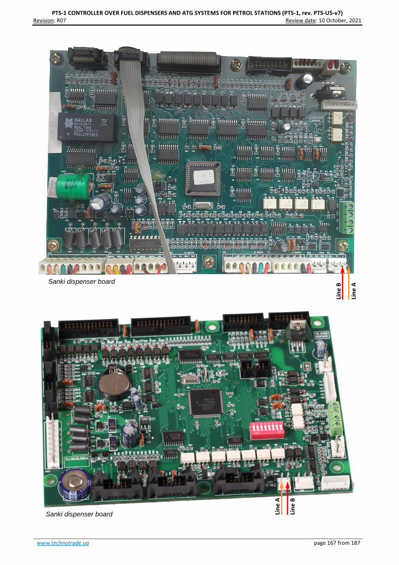
PTS-1 CONTROLLER OVER FUEL DISPENSERS AND ATG SYSTEMS FOR PETROL STATIONS (PTS-1, rev. PTS-U5-v7) Revision: R07 Review date: 10 October, 2021
www.technotrade.ua page 167 from 187
Sanki dispenser board
Sanki dispenser board
Lin
e A
Lin
e B
Lin
e B
Lin
e A

PTS-1 CONTROLLER OVER FUEL DISPENSERS AND ATG SYSTEMS FOR PETROL STATIONS (PTS-1, rev. PTS-U5-v7) Revision: R07 Review date: 10 October, 2021
www.technotrade.ua page 168 from 187
Datian Machines dispenser interface board
Datian Machines dispenser connection scheme
Connection to Datian Machines dispenser is made directly without any interface converter.
Configuration of PTS controller pump port: protocol “52. SANKI NG”, baud rate “4. 9600”.
Line A
Line B

PTS-1 CONTROLLER OVER FUEL DISPENSERS AND ATG SYSTEMS FOR PETROL STATIONS (PTS-1, rev. PTS-U5-v7) Revision: R07 Review date: 10 October, 2021
www.technotrade.ua page 169 from 187
Eaglestar dispenser mainboard
Eaglestar dispenser connection scheme
Connection to Eaglestar dispenser is made directly without any interface converter.
Configuration of PTS controller pump port: protocol “52. SANKI NG”, baud rate “4. 9600”.
Lin
e A
Lin
e B

PTS-1 CONTROLLER OVER FUEL DISPENSERS AND ATG SYSTEMS FOR PETROL STATIONS (PTS-1, rev. PTS-U5-v7) Revision: R07 Review date: 10 October, 2021
www.technotrade.ua page 170 from 187
Blue Sky dispenser connection scheme
Connection to Blue Sky dispenser is made directly without any interface converter.
Configuration of PTS controller pump port: protocol “26. Blue Sky”, baud rate “2. 4800”.
Blue Sky LT-B dispenser board
Line A
Line B
Blue Sky LT-C/LT-H dispenser board
Line A
Line B
Lin
e A
Lin
e B
Blue Sky LT-L/LT-LG dispenser board

PTS-1 CONTROLLER OVER FUEL DISPENSERS AND ATG SYSTEMS FOR PETROL STATIONS (PTS-1, rev. PTS-U5-v7) Revision: R07 Review date: 10 October, 2021
www.technotrade.ua page 171 from 187
Topaz dispenser connection scheme
Connection to TOPAZ dispenser is made directly without any interface converter.
Configuration of PTS controller pump port: protocol “41. TOPAZ”, baud rate “2. 4800”.
Topaz dispenser system board
Lin
e B
Lin
e A

PTS-1 CONTROLLER OVER FUEL DISPENSERS AND ATG SYSTEMS FOR PETROL STATIONS (PTS-1, rev. PTS-U5-v7) Revision: R07 Review date: 10 October, 2021
www.technotrade.ua page 172 from 187
Shelf dispenser connection scheme
Connection to SHELF dispenser is made directly without any interface converter.
Configuration of PTS controller pump port: protocol “16. SHELF”, baud rate “4. 9600”.
Shelf dispenser system board
Lin
e B
Lin
e A

PTS-1 CONTROLLER OVER FUEL DISPENSERS AND ATG SYSTEMS FOR PETROL STATIONS (PTS-1, rev. PTS-U5-v7) Revision: R07 Review date: 10 October, 2021
www.technotrade.ua page 173 from 187
UniCon dispenser connection scheme
Connection to UniCon dispenser is made directly without any interface converter.
Configuration of PTS controller pump port: protocol “16. UniPump”, baud rate “4. 9600”.
UniCon dispenser system board
Line A
Line B

PTS-1 CONTROLLER OVER FUEL DISPENSERS AND ATG SYSTEMS FOR PETROL STATIONS (PTS-1, rev. PTS-U5-v7) Revision: R07 Review date: 10 October, 2021
www.technotrade.ua page 174 from 187
EXAMPLES OF ATG SYSTEMS CONNECTION SCHEMES
Below sections show examples of connection to various brands of probes and ATG systems. This
information is provided as an example. For reception of detailed information on connection to various
brands of probes and ATG systems, configuration of the probes and ATG systems and configuration of PTS
controller please refer to our support mailbox [email protected].

PTS-1 CONTROLLER OVER FUEL DISPENSERS AND ATG SYSTEMS FOR PETROL STATIONS (PTS-1, rev. PTS-U5-v7) Revision: R07 Review date: 10 October, 2021
www.technotrade.ua page 175 from 187
Gilbarco Veeder Root TLS consoles connection scheme
Connection to Gilbarco Veeder Root TLS system is made directly to one of probe ports of PTS controller (RS-
232 interface).
Configuration of PTS controller probe port: protocol “1. GILBARCO Veeder Root”, baud rate is selected to be
equal to set in TLS ATG system.
Start Italiana console connection scheme
Connection to Start Italiana console is made directly to one of probe ports of PTS controller (RS-232
interface).
Configuration of PTS controller probe port: protocol “1. GILBARCO Veeder Root”, baud rate is selected to be
equal to set in Start Italiana console.
Gilbarco Veeder Root TLS ATG console
RS-232 port
Gnd TxD
RxD
RS-232 port
Gnd TxD RxD
Start Italiana ATG console

PTS-1 CONTROLLER OVER FUEL DISPENSERS AND ATG SYSTEMS FOR PETROL STATIONS (PTS-1, rev. PTS-U5-v7) Revision: R07 Review date: 10 October, 2021
www.technotrade.ua page 176 from 187
Start Italiana wired probes connection scheme
Connection to Start Italiana wired probes is made directly to DISP (RS-485) port of PTS controller (RS-485
interface).
Configuration of PTS controller probe port: protocol “2. START ITALIANA SMT-XMT”, baud rate “4. 9600”.
Start Italiana wireless probes connection scheme
Connection to Start Italiana wireless probes is made through wireless receiver to one of probe ports of PTS
controller (RS-232 interface or RS-485 interface).
Configuration of PTS controller probe port: protocol “2. START ITALIANA SMT-XMT”, baud rate “4. 9600”.
Start Italiana probe (RS-485)
Line A
Line B
RS-232 port
Gnd TxD RxD
Start Italiana wireless repeater

PTS-1 CONTROLLER OVER FUEL DISPENSERS AND ATG SYSTEMS FOR PETROL STATIONS (PTS-1, rev. PTS-U5-v7) Revision: R07 Review date: 10 October, 2021
www.technotrade.ua page 177 from 187
Alisonic wired probes connection scheme
Connection to Alisonic wired probes is made directly to DISP (RS-485) port of PTS controller (RS-485
interface).
Configuration of PTS controller probe port: protocol “22. Alisonic Delphi”, baud rate “4. 9600”.
Alisonic wireless probes connection scheme
Connection to Alisonic wireless probes is made through Alisonic wireless receiver to DISP (RS-485) port of
PTS controller (RS-485 interface).
Configuration of PTS controller probe port: protocol “22. Alisonic Delphi”, baud rate “4. 9600”.
Alisonic probe (RS-485)
Alisonic wireless receiver
Line A
Line B
Line A
Line B

PTS-1 CONTROLLER OVER FUEL DISPENSERS AND ATG SYSTEMS FOR PETROL STATIONS (PTS-1, rev. PTS-U5-v7) Revision: R07 Review date: 10 October, 2021
www.technotrade.ua page 178 from 187
Struna ATG system connection scheme
Connection to Struna system is made directly to one of probe ports of PTS controller (RS-232 interface).
Configuration of PTS controller probe port: protocol “4. STRUNA Kedr spec. 1.4”, baud rate is selected to be
equal to set in Struna ATG system.
OPW Site Sentinel ATG system connection scheme
Connection to OPW system is made directly to one of probe ports of PTS controller (RS-232 interface).
Configuration of PTS controller probe port: protocol “3. Petrovend4”, baud rate is selected to be equal to
set in OPW ATG system.
Struna ATG calculation unit
OPW ATG console
STRUNA ATG calculation unit
RS-232 port
Gnd TxD RxD
RS-232 port
Gnd TxD RxD

PTS-1 CONTROLLER OVER FUEL DISPENSERS AND ATG SYSTEMS FOR PETROL STATIONS (PTS-1, rev. PTS-U5-v7) Revision: R07 Review date: 10 October, 2021
www.technotrade.ua page 179 from 187
Colibri ATG system connection scheme
Connection to Colibri system is made directly to one of probe ports of PTS controller (RS-232 interface).
Configuration of PTS controller probe port: protocol “1. Gilbarco Veeder Root”, baud rate is selected to be
equal to set in Colibri ATG system.
Fafnir ATG system connection scheme
Connection to FAFNIR system is made directly to one of probe ports of PTS controller (RS-232 interface).
Configuration of PTS controller probe port: protocol “5. Fafnir Visy-Quick”, baud rate is selected to be equal
to set in FAFNIR ATG system.
Colibri ATG console
STRUNA ATG
calculation unit
RS-232 port
Gnd TxD RxD
FAFNIR-Command ATG console
STRUNA ATG calculation unit
RS-232 port
Gnd TxD RxD

PTS-1 CONTROLLER OVER FUEL DISPENSERS AND ATG SYSTEMS FOR PETROL STATIONS (PTS-1, rev. PTS-U5-v7) Revision: R07 Review date: 10 October, 2021
www.technotrade.ua page 180 from 187
Hectronic ATG probes connection scheme
Connection to Hectronic probes is made directly to one of probe ports of PTS controller (RS-232 interface)
to Hectronic OptiLevel Supply box.
Configuration of PTS controller probe port: protocol “8. Hectronic HLS”, baud rate “4. 9600”.
Vega radar level meters
Connection to VEGA meters is made through a VEGAMET probes is made directly to one of probe ports of
PTS controller (RS-232 interface) to Hectronic OptiLevel Supply box.
Configuration of PTS controller probe port: protocol “10. Vega”, baud rate “4. 9600”.
Hectronic OptiLevel Supply box
STRUNA ATG calculation unit
RS-232 port
Gnd TxD RxD
VEGAMET signal
conditioning instrument
RS-232 port
Gnd TxD RxD
VEGAPULS
radar meter

PTS-1 CONTROLLER OVER FUEL DISPENSERS AND ATG SYSTEMS FOR PETROL STATIONS (PTS-1, rev. PTS-U5-v7) Revision: R07 Review date: 10 October, 2021
www.technotrade.ua page 181 from 187
Windbell magnetostrictive probes connection scheme
Connection to Windbell probes is made directly to DISP (RS-485) port of PTS controller (RS-485 interface).
Configuration of PTS controller probe port: protocol “11. Windbell”, baud rate “4. 9600”.
Lin
e B
Lin
e A

PTS-1 CONTROLLER OVER FUEL DISPENSERS AND ATG SYSTEMS FOR PETROL STATIONS (PTS-1, rev. PTS-U5-v7) Revision: R07 Review date: 10 October, 2021
www.technotrade.ua page 182 from 187
North Falcon wired probes connection scheme
Connection to North Falcon wired probes is made directly to DISP (RS-485) port of PTS controller (RS-485
interface).
Configuration of PTS controller probe port: protocol “22. Alisonic Delphi”, baud rate “4. 9600”.
North Falcon wireless probes connection scheme
Connection to North Falcon wireless probes is made through North Falcon wireless receiver to DISP (RS-
485) port of PTS controller (RS-485 interface).
Configuration of PTS controller probe port: protocol “22. Alisonic Delphi”, baud rate “4. 9600”.
North Falcon probe (RS-485)
North Falcon wireless receiver
Line A
Line B
Line A
Line B

PTS-1 CONTROLLER OVER FUEL DISPENSERS AND ATG SYSTEMS FOR PETROL STATIONS (PTS-1, rev. PTS-U5-v7) Revision: R07 Review date: 10 October, 2021
www.technotrade.ua page 183 from 187
PTS CONTROLLER PCB BOARD
PCB board top view
PCB board bottom view

PTS-1 CONTROLLER OVER FUEL DISPENSERS AND ATG SYSTEMS FOR PETROL STATIONS (PTS-1, rev. PTS-U5-v7) Revision: R07 Review date: 10 October, 2021
www.technotrade.ua page 184 from 187
Board dimensions

PTS-1 CONTROLLER OVER FUEL DISPENSERS AND ATG SYSTEMS FOR PETROL STATIONS (PTS-1, rev. PTS-U5-v7) Revision: R07 Review date: 10 October, 2021
www.technotrade.ua page 185 from 187
RS-232 PORT CABLE CONNECTOR
Pinout of cable used for connection RS-232 ports of PTS controller to PC:
To pin TxD
To pin RxD
To pin GND
Pin 2
Pin 3
Pin 5
DB-9F connector
STRUNA ATG
calculation unit
To PTS RS-232 port
STRUNA ATG
calculation unit
To COM-port of PC
STRUNA ATG
calculation unit

PTS-1 CONTROLLER OVER FUEL DISPENSERS AND ATG SYSTEMS FOR PETROL STATIONS (PTS-1, rev. PTS-U5-v7) Revision: R07 Review date: 10 October, 2021
www.technotrade.ua page 186 from 187
CERTIFICATES
PTS controller over fuel dispensers and ATG systems for petrol stations complies with the essential
requirements of the European Directive:
- Electromagnetic Compatibility (EMC) Directive 2004/108/EC
Conformity is assessed in accordance to the following standards:
1. Radio disturbance characteristics – EN 55022:2010 (IEC CISPR 22:2008), Class A
2. Immunity characteristics – EN 55024:2010 (IEC CISPR 24:2010)
We hereby declare that the apparatus named above has been designed to comply with the relevant
sections of the above referenced specifications. The unit complies with all applicable Essential
Requirements of the Directive.
The conducted tests are documented in the test reports No. 1047/1-5-2014 and 1047/2-5-2014 and are
maintained at the corporate headquarters of Technotrade LLC as an evidence of conformity.

PTS-1 CONTROLLER OVER FUEL DISPENSERS AND ATG SYSTEMS FOR PETROL STATIONS (PTS-1, rev. PTS-U5-v7) Revision: R07 Review date: 10 October, 2021
www.technotrade.ua page 187 from 187
ORDER INFORMATION
Variant of PTS controller supply is marked with PTS1-y-z, where
- y – type of supply:
o “PCB” in case if PTS controller is supplied in a view of electric board;
o “BOX” in case if PTS controller is supplied installed in plastic box with hermetic inputs for
connection of wires and a button for power supply switching;
o “SDK” in case if PTS controller SDK is supplied installed in plastic box with hermetic inputs for
connection of wires and a button for power supply switching;
- z – variant of supply:
o 001 – variant of supply with installed terminal blocks for controller ports
o 002 – variant of supply without terminal blocks for controller ports (connection is made using
connectors for stubs)
Examples of order:
- order of PTS-1 controller in a view of electric board: PTS1-PCB-001;
- order of PTS-1 controller installed in a plastic box: PTS1-BOX-001;
- order of PTS-1 controller SDK: PTS1-SDK-001