Protein Purification to Produce Edible Soybean Protein
217
University of Pennsylvania University of Pennsylvania ScholarlyCommons ScholarlyCommons Senior Design Reports (CBE) Department of Chemical & Biomolecular Engineering 4-20-2021 Protein Purification to Produce Edible Soybean Protein Protein Purification to Produce Edible Soybean Protein Miyu Ono University of Pennsylvania Gracelynn Soesanto University of Pennsylvania Alia Wallenstrom University of Pennsylvania Follow this and additional works at: https://repository.upenn.edu/cbe_sdr Part of the Biochemical and Biomolecular Engineering Commons Ono, Miyu; Soesanto, Gracelynn; and Wallenstrom, Alia, "Protein Purification to Produce Edible Soybean Protein" (2021). Senior Design Reports (CBE). 130. https://repository.upenn.edu/cbe_sdr/130 This paper is posted at ScholarlyCommons. https://repository.upenn.edu/cbe_sdr/130 For more information, please contact [email protected].
-
Upload
khangminh22 -
Category
Documents
-
view
2 -
download
0
Transcript of Protein Purification to Produce Edible Soybean Protein

University of Pennsylvania University of Pennsylvania
ScholarlyCommons ScholarlyCommons
Senior Design Reports (CBE) Department of Chemical & Biomolecular Engineering
4-20-2021
Protein Purification to Produce Edible Soybean Protein Protein Purification to Produce Edible Soybean Protein
Miyu Ono University of Pennsylvania
Gracelynn Soesanto University of Pennsylvania
Alia Wallenstrom University of Pennsylvania
Follow this and additional works at: https://repository.upenn.edu/cbe_sdr
Part of the Biochemical and Biomolecular Engineering Commons
Ono, Miyu; Soesanto, Gracelynn; and Wallenstrom, Alia, "Protein Purification to Produce Edible Soybean Protein" (2021). Senior Design Reports (CBE). 130. https://repository.upenn.edu/cbe_sdr/130
This paper is posted at ScholarlyCommons. https://repository.upenn.edu/cbe_sdr/130 For more information, please contact [email protected].

Protein Purification to Produce Edible Soybean Protein Protein Purification to Produce Edible Soybean Protein
Abstract Abstract This project recommends a design for a soy processing facility to produce soy protein concentrates (SPC), soy oil and soy molasses from dehulled soybeans. Utilities were minimized, wherever possible by evaluating whether streams within the system had the capacity to heat or cool other processes. The plant has a production capacity of 170 MM lb soy protein concentrate/year and will be located in Decatur, IL. The proposed design also yields 114 MM lb soy oil/year and 62 MM lb soy molasses/year. The SPC, soy oil and soy molasses have less than 2 PPM residual solvent concentrations and comply with FDA regulations. The plant is running with an uptime of 80% and economic analysis shows an estimated IRR of 41% with an ROI of 59%.
Disciplines Disciplines Biochemical and Biomolecular Engineering | Chemical Engineering | Engineering
This working paper is available at ScholarlyCommons: https://repository.upenn.edu/cbe_sdr/130

1
University of Pennsylvania School of Engineering and Applied Science Department of Chemical and Biomolecular Engineering 220 South 33rd Street Philadelphia, PA 19104
April 20, 2021 Dear Dr. Allen, Professor Vrana and Dr. P.C. Gopalratnam,
Enclosed you will find a proposed design for the soybean processing facility, specified in the problem statement provided by Dr. Gopalratnam. The proposed plant is for the industrial production of 170 MM lb/year of food-grade soy protein concentrate (163 MM lb/year on a dry basis), as well as 114 MM lb/yr of soy molasses, and 62 MM lb/yr unrefined soybean oil from dehulled soybeans in Decatur, Illinois. The process implements both hexane solvent extraction technology and ethanol solvent extraction technology. Dehulled soybeans are processed via conditioning and grinding. The soybeans are then taken through hexane extraction and ethanol extraction as well as desolventization. Production was assumed at 80% uptime, and rigorous profitability analysis was performed to determine plant feasibility. The proposed plant is found to be economically feasible given a permanent investment of the plant of $170 MM, with an expected NPV of $395 MM by 2038. It has an estimated IRR of 41% and ROI of 58%.
The following report contains a detailed process design and profitability analysis of the
proposed plant, including rationale for key design decisions. It is recommended to pursue plant production using the outlined process design, but continue to research into other potential solvent extraction methods. Sincerely, Miyu Ono ________________________
Gracelynn Soesanto ________________________
Alia Wallenstrom ________________________

2
Protein Purification to Produce Edible Soybean Protein
Miyu Ono | Gracelynn Soesanto | Alia Wallenstrom
Project Proposed by: Dr. P.C. Gopalratnam
Project Submitted to:
Prof. Bruce Vrana
Advised By: Dr. Sue Ann Bidstrup Allen
University of Pennsylvania School of Engineering and Applied Sciences
Department of Chemical and Biomolecular Engineering
April 20, 2021

3
Contents Section 1: Abstract .......................................................................................................................... 5
Section 2: Introduction and Objective ............................................................................................ 6
2.1 Introduction ........................................................................................................................... 6
2.2 Objective Time Chart ............................................................................................................ 8
Section 3: Market and Competitive Assessment ............................................................................ 9
3.1 Market Analysis .................................................................................................................... 9
3.2 Competitive Analysis .......................................................................................................... 11
3.3 Value Proposition................................................................................................................ 12
Section 4: Customer Requirements ............................................................................................... 13
4.1 Customer Requirements ...................................................................................................... 13
Section 5: Preliminary Process Synthesis ..................................................................................... 16
5.1 Preliminary Process Synthesis ............................................................................................ 16
5.2 Assembly of Database......................................................................................................... 22
Section 6: PFDs and Material Balances ........................................................................................ 25
Section 6.1 Pre-Treatment ........................................................................................................ 26
Section 6.2 Hexane Extraction .................................................................................................. 30
Section 6.3 Hexane Recycle ..................................................................................................... 33
Section 6.4 Ethanol Extraction ................................................................................................. 37
Section 6.5 Ethanol Recycle ..................................................................................................... 41
Section 7: Energy Balance and Utility Requirements................................................................... 44
7.1 Heat Integration Strategy .................................................................................................... 44
7.2 Process Utilities .................................................................................................................. 44
Section 8: Equipment List and Unit Description .......................................................................... 48
8.1 Unit Descriptions ................................................................................................................ 48
8.2 Unit Specification Sheets .................................................................................................... 65
Section 9: Cost Summary............................................................................................................ 104
9.1 Equipment Costs ............................................................................................................... 104
9.2 Operating Cost - Cost of Manufacture .............................................................................. 106
Section 10: Profitability Analysis - Business Case ................................................................. 107
10.1 Sensitivity Analysis ........................................................................................................ 107
10.2 Economic Analysis ......................................................................................................... 109
Section 11: Other Important Considerations ............................................................................... 119
11.1 Process Safety Concerns ................................................................................................. 119

4
11.2 Environmental Considerations ........................................................................................ 121
11.3 Global, Cultural, Social and Ethical Concerns ............................................................... 121
Section 12: Conclusions and Recommendations ........................................................................ 124
Section 13: Acknowledgements .................................................................................................. 125
Section 15: References ................................................................................................................ 126
Section 15: Appendices ............................................................................................................... 131
Appendix 1: Hexane Recovery ............................................................................................... 131
A.1.1. Hexane Recovery Flow Diagram ............................................................................. 131
A.1.2. Input Summary ......................................................................................................... 132
A.1.3. Block Summary........................................................................................................ 136
A.1.4. Binary Interactions ................................................................................................... 162
Appendix 2: Ethanol Recovery ............................................................................................... 163
A.2.1. Ethanol Recovery Flow Diagram ............................................................................. 163
A.2.2 Input Summary .......................................................................................................... 164
A.2.3. Block Summaries ..................................................................................................... 167
Appendix 3: Extraction Hexane Technical Parameters .......................................................... 182
Appendix 4: Typical Composition of Soy Molasses on a Dry Matter Basis .......................... 185
Appendix 5: Equipment Quotes .............................................................................................. 185
Appendix 5.1 Vertical Seed Conditioner Quote ................................................................. 185
Appendix 5.2 Flaker Quote ................................................................................................. 186
Appendix 5.3 Extractor Quote ............................................................................................ 188
Appendix 5.4. Miscella Tank Quote ................................................................................... 193
Appendix 5.5. N&T Engitech DT Quote ............................................................................ 194
Appendix 6: Safety Data Sheets ............................................................................................. 197
Appendix 6: Safety Data Sheets ............................................................................................. 198
Appendix 6.1: Hexane SDS ................................................................................................ 199
Appendix 6.2: Ethanol SDS ................................................................................................ 206

5
Section 1: Abstract This project recommends a design for a soy processing facility to produce soy protein
concentrates (SPC), soy oil and soy molasses from dehulled soybeans. Utilities were minimized,
wherever possible by evaluating whether streams within the system had the capacity to heat or
cool other processes. The plant has a production capacity of 170 MM lb soy protein
concentrate/year and will be located in Decatur, IL. The proposed design also yields 114 MM lb
soy oil/year and 62 MM lb soy molasses/year. The SPC, soy oil and soy molasses have less than
2 PPM residual solvent concentrations and comply with FDA regulations. The plant is running
with an uptime of 80% and economic analysis shows an estimated IRR of 41% with an ROI of
59%.

6
Section 2: Introduction and Objective 2.1 Introduction
Soybean meal flakes are the high protein product of oil-extracted soybeans. While it has
long been used for animal feed, due to problems in flavor and texture, this product had not been
widely used in human foods. However, recent advances have developed an alcohol extraction
process to extract carbohydrates and render the meal palatable. These soy protein products are
typically available as soy protein concentrates (SPCs) or soy protein isolates (SPIs), as shown in
the figure below. While dehulled beans are composed of 42.8% protein, 22.0% oil, and 28.2%
carbohydrate on a dry basis, SPCs typically have >70.5% protein, <.4% oil, and <21.2%
carbohydrate.
Figure 1: Various soybean processing flow diagram (Preece, 2017)
This project proposes a soybean processing plant to produce solvent-extracted high
protein, low carbohydrate, low fat SPC using hexane and ethanol extraction processes based in
Decatur, Illinois. The proposed plant will produce 170 MM lb/yr sold at a competitive price. The
soybeans will be sourced from Illinois soy growers, who planted a total of 10,500 acres of
soybeans in 2020 and rank second nationally in soybean exports (Hubbs, 2020). The process will

7
be run continuously over the course of the year and beans are assumed to be available year-
round. The process begins with a common soy processing section, consisting of industrial scale
conditioning and flaking units to heat, dry, and grind the seeds to the correct temperature,
moisture, and size for optimal oil extraction. A hexane extraction and recycle section is then
needed to extract excess soy oil and increase protein concentration. This process includes a
countercurrent extractor, desolventizer-toaster-dryer-cooler (DTDC), evaporator, condenser,
stripper, and centrifuge. Crude soy oil will be produced as a side product.
The ethanol extraction section that comes after the hexane extraction step removes a
majority of the carbohydrate content in the soymeal, and outputs SPC as the main final product.
This section involves a centrifuge to separate the solids from the ethanol-soluble components of
the soymeal and a beer column to recover the ethanol to be sent to recycle. The ethanol
extraction process utilizes a similar countercurrent extractor and DTDC unit to that in the hexane
extraction step, and brings the percent protein composition of the soymeal to 70% on a dry basis.

8
2.2 Objective Time Chart
Project Name Soy Protein Purification
Project Advisors
Dr. Sue Bidstrup-Allen, Professor Bruce Vrana
Project Author
Dr. P. C. Gopalratnam
Project Leaders
Miyu Ono, Gracelynn Soesanto, Alia Wallenstrom
Specific Goals
Design a commercial plant to produce a minimum of 50 MM lb/year of Soy Protein Concentrate based on aqueous ethanol solvent extraction technology.
Project Scope In-scope: 1. Manufacturing process for soy protein concentrate beginning from
prepared dehulled soybeans 2. Final product must be of Food Grade quality, fit for human
consumption, and meet all FDA and other regulatory standards 3. Maintain process integrity and by adhering to current good
manufacturing practices, minimizing environmental impacts, and, and meeting all government regulations
4. Determine if process is best when compared to cost and production value of older processing methods
Out-of-scope: 1. Downstream processing of soy co-products 2. Emerging technology in soy processing
Deliverables Business opportunity assessment: 1. What is the market for soy protein concentrate? 2. What is the economic return on a processing plant using aqueous
ethanol extraction technology? Manufacturing capability assessment:
1. Can the plant be built and the process utilized with reasonable capital investment and return?
Product life-cycle assessment: 1. Will the final product be of Food Grade Quality and meet FDA
standards for a safe and consumable product?
Timeline Complete design and economic analysis by April 20, 2021

9
Section 3: Market and Competitive Assessment 3.1 Market Analysis
Soybeans are a dominant oilseed worldwide. The United States emerged as the world’s
biggest soybean exporter in the 1950s (Seven, 2018). Over the last four decades, U.S. soybean
production has increased by 130.1%, and in 2016, the United States produced 4.3 billion bushels
of soybeans (130 million tons), or approximately one-third of total worldwide production
(Stanford & Keener, 2018).
Soybeans are processed into three main categories of products: oil, whole soybean, and
protein products. Within soy protein products, SPCs and SPIs have both industrial uses such as
adhesives, cosmetics, and plastics, as well as edible uses such as in bakery ingredients, cereals,
diet food etc. This project will be focused on the edible uses of SPCs (Guo, 2013).
Compared to other protein sources, SPCs have a higher nutritional value and are less
expensive. For example, soybeans are one of the few complete protein vegetable based foods
with nine essential amino acids. However, soybeans are approximately 35% by weight
carbohydrates such as glucose, sucrose, raffinose, stachyose, arabinan, arabinogalactan, and
acidic polysaccharides. These carbohydrates are not processed into products for human
consumption as humans lack the enzymes necessary to break some of these carbohydrates. Thus,
85% of soybean cultivation is used as animal feed (Stanford & Keener, 2018). In human
consumption, soy oil is the second most common cooking oil
The overall soybean industry globally in 2017 had a total market value of ~ 146.23
billion USD. Soybean is a major export good: 150.1 million tons were exported in 2017 at a
value of ~58 billion USD, or nearly 44% of all soybeans produced that year. The soybean
industry is highly concentrated in Brazil, and Argentina who together accounted for nearly 80%
10
of total production in 2017. Brazil leads the pack by value of exports, which amounted to 26.1
billion USD compared to the US at 22.8 billion USD. In the US, soybean cultivation is projected
to overtake wheat and corn in the area of agricultural land (Voora et al., 2020).
Demand for soybeans is projected to continue to increase over the coming years. First,
the direct consumption of soy-based health products is on the rise. Second, global meat
consumption is also projected to rise with increasing population, indicating a correlated strong
demand for animal feed. Finally, policy-makers are becoming more supportive of biodiesel as a
fuel alternative. Asia is expected to drive soybean demand growth, led by China who has
recently accounted for almost two thirds of global demand growth due to increased animal feed
needs (Voora et al., 2020).
Soy protein products specifically have been used at an increasing rate. For example, baby
foods, cereals, dry food mixes, milk replacers, pet foods, and snacks are just a few more
examples where powdered soy protein concentrates may be used. However, the majority of soy
protein products are used in processed meat systems. 55% of the ~1 million metric tons of
functional soy proteins produced annually are used in processed muscle foods, including meat,
poultry, and seafood. For example, they are found in emulsified meats for stabilization, coarsely
chopped meats for texture, canned meats for absorption, and whole meats for brining among
other uses.
The edible soy protein product industry has grown significantly since the late 1950s.
Human consumption of these products is estimated at 1.68 billion kg per year, or 1500 metric
tons of soy flour, 90000 metric tons of SPC, and 70000 metric tons of SPI. The demand for SPCs
has been growing at the fastest rate among food processors looking for economic, efficient
proteins. A report published by Transparency Market Research (TMR) estimates that the soy

11
protein concentrate market will advance at an average CAGR of ~5% during 2019-2029 and that
sales of these concentrates as nutritional additives will close at ~2 billion USD by the end of
2029. While pet food and specialty feed markets have been identified as the single largest
markets, other fast‐growing areas include soymilk, imitation cheeses, ground meat blends and
extenders, and commercial bakery and confectionery ingredients. Currently soy proteins appear
to be the only possible large-volume commercial plant-based protein ingredient as other plant
proteins, such as pea protein, are still in development and show no signs of becoming a serious
commercial reality in the near future. In the US specifically, demand for meat products is
declining while consumer interest in “healthy” foods is increasing, creating new opportunities for
the use of soy proteins in low‐calorie, low‐cholesterol, and high‐density protein items (Singh et
al., 2008).
3.2 Competitive Analysis
Soy processing facilities exist globally. Archer Daniels Midland Company (ADM),
Cargill, and COFCO are the largest processing companies with a global presence, purchasing
15.9 million, 14.6 million, and 12.1 million tons annually respectively. Within Illinois, there are
seven soy-processing facilities that use solvent extraction to produce various grades of soy oil
with a total combined processing capacity of approximately 23,500 tons per day. Approximately
5.9 million tons of soybean meal produced annually in Illinois, of which 87% percent is shipped
to other states or exported overseas. However, currently, most plants seem to focus on oilseed
extraction rather than SPC production, indicating that there is a potential gap to be filled (Illinois
Soybean Association; Voora et al, 2020).

12
3.3 Value Proposition
Currently, the majority of US soybeans are grown in the Upper Midwest and the Corn
Belt of which over 40 percent was exported each year, relying on barge and rail transportation to
be shipped to port. Specifically, the largest soybean-growing states are Illinois, Iowa, Minnesota,
Indiana, Nebraska, and Ohio, each of which produced over 200 million bushels, and together
accounted for 57% of U.S. soybean production. Soybeans are then typically shipped from the
growing regions to areas with crushing facilities and areas of concentrated pork and poultry
operations located in the South and Southeast.
Recently the US lost world market share to South America which has lower cost of
production, increasing the importance of U.S. transportation efficiency for competitiveness.
Further, while demand for US soybeans over the past 10 years has been driven mostly by Asia,
the USDA projects that most of the growth in demand for U.S. soybeans will occur in the
domestic demand categories over the next 10 years. The plant that this project proposes in
Decatur, Illinois will be located central to soy crop fields and specifically focused on producing
SPCs, which will decrease the transportation necessary and increase efficiency of fulfilling
demand. The resulting soy protein concentrate product as well as soy oil and soy molasses
product can be used to fulfill either domestic or international appetite.
The key stakeholders for this project will be the soybean producers/farmers providing
raw beans, the agricultural companies buying SPC for food products, transportation firms to
distribute raw materials and products, and the USDA for quality and inspection purposes
(Denicoff et al, 2014).

13
Section 4: Customer Requirements 4.1 Customer Requirements
The Federal Grain Inspection Service (FGIS), a division of the USDA, regulates soybean
quality through the U.S. Grain Standards Act which imposes standards which grades U.S.
soybean crop. Soybeans are given a grade between one and four according to their bulk density,
split fraction, total damaged soybeans, heat damage, and foreign material. In order to produce
high quality soy protein concentrate and market-ready by products such as soy oil, we will utilize
grade #1 soybeans with low foreign material content. Furthermore, it is important to source
dehulled beans from producers with low heat damage as this can impact the quality of the soy oil
by increasing the oil acidity, peroxide content, and non-hydratable phosphatide content, thereby
reducing the crude soybean oil’s market value.
In this report it is assumed that the dehulled soybean feed has a moisture content of
12.5% by weight. A moisture content of 12.5-14% is recommended for solvent extraction
however a moisture level above 13% requires thorough aeration and shorter storage life. To
ensure that the supplied soybeans maintain their grade #1 quality throughout the storage,
transportation, and preparation processes, it is recommended to use a soybean supply with 12.5%
moisture. Moisture content can however be adjusted in the Vertical Seed Conditioner (VSC) if
the dehulled feed has a higher or lower water composition. Soybean feeds above or below 12.5%
moisture will require more energy input to the conditioner and are at a greater risk of spoilage
during transportation and storage.
Soybean by-products such as oil, meal, and protein are not regulated by the FGIS
however the National Oilseed Processors Association (NOPA) has established trading quality
standards as a guideline for oilseed processors (U.S. Soybean Export Council, 2015). In practice,

14
essentially all U.S. oilseed processors abide by these trading “rules”. Soybean flakes, the solvent-
rich material leaving the extractor, are required to contain at minimum, 47.5-49% protein and
0.5% fat while maintaining a maximum of 12% moisture and 3-3.5% fiber. Soybean oil is
typically traded as degummed crude soybean oil and must contain no more than 0.5% moisture
and volatile matter or 1.5% unsaponifiable matter, must have flash point above 250˚F, and
exhibit a color lighter than 6.0 Red with neutral oil loss below 7.5%. Currently quality standards
do not exist for soy protein products, but manufacturers are required to provide product
specifications upon request.
The leading SPC customers are Archer Daniels Midland, Cargill Inc., and Wilmar
International amongst others. Their needs for SPC will depend on the type of food products they
sell.
In human consumption, with customers becoming increasingly informed and health-
conscious, most food processors have adopted formulas and recipes that meet the changing
marketplace demands. The solvent extraction process for soybeans includes a number of FDA
and taste requirements. Currently, the FDA does not currently impose a ceiling on hexane
residue in soy foods following hexane extraction, but the European Union prohibits levels of
hexane residues greater than 10 ppm in soy products (Palmer, 2010). SPC is typically in dried
form of defatted soy flour devoid of water-soluble carbohydrates, and comprises 70% soy protein
while retaining the majority of the original fiber content. In addition to nutrition, manufacturers
are also emphasizing on their products’ appearance, texture, and taste.
Cost is an important concern as animal feed, with large growth from aquaculture
segments, is expected to remain the most lucrative application of soy protein concentrate.

15
Additionally, maintaining a high protein content for this customer segment will also be critical
(Transparency Market Research, 2015).

16
Section 5: Preliminary Process Synthesis 5.1 Preliminary Process Synthesis
Hexane Extraction
Oilseed extraction is typically conducted by either solvent extraction or an extruding
expelling process. The different methods result in varying oil extraction efficiencies and energy
demands. A thorough analysis of potential extraction technologies was conducted to determine
the more efficient method of soybean oil removal.
Organic solvent extraction uses the solubility of oil and non-polar organic solvents to
extract oil from the soybean flakes. Hexane and heptane were analyzed as potential solvents for
the oil extraction process. Both solvents have been successfully used for oil extraction in pilot
plants as well as industrial scale operations. Hexane is the most commonly used solvent in
oilseed extraction due to its low boiling point and non-polar nature which allow for efficient
separation in the downstream oil processing.
Heptane extraction was first introduced to the oilseed extraction industry as a way to
reduce health and safety concerns associated with hexane’s toxicity. Studies confirm that heptane
solvent extraction results in comparable separation efficiency but requires a higher operating
temperature and increases soybean flake retention time. In food processing, especially grain
processing, temperature must be carefully monitored to ensure that food products retain their
quality. Increased temperature and retention times in high temperature units introduces the risk
of burning or charring the soy flakes, which can reduce the protein content of the extracted
soymeal and increase the acidity of soybean oil. Since heptane extraction is a relatively new
practice, industrial-scale data is limited. While lab-scale designs show promising oil extraction
efficiency, there is little supporting evidence for a scaled-up facility. Both hexane and heptane

17
are highly flammable and would require gas-tight and spark-proof equipment to address safety
concerns (NFPA, 2001). Due to the increased temperature and retention time required of heptane
extraction and the risk it poses on soymeal and soybean oil quality with limited environmental
benefit, hexane was selected for the oil extraction process. Proper air-tight sealing of equipment
and the installation of vapor scrubbing systems will address the environmental and safety
concerns associated with hexane (Keneni et al, 2020; Small, 2013).
The use of supercritical CO2 for oil extraction was also analyzed. Supercritical CO2 shows
promising extraction potential due to its low viscosity and virtually no surface tension which
allow it to diffuse easily through the soybean flakes. Its volatile nature allows it to be easily
separated from oil for later downstream processing. More importantly, supercritical CO2 is
nonflammable therefore eliminating the flammability safety concern associated with hexane and
the need for leak- and spark-proof equipment with vapor scrubbing systems. While supercritical
CO2 may be an effective extraction method in the future, it has yet to be used in any industrial, or
even pilot size plant. Currently only lab data is available which is not enough to design a full-
capacity soy protein purification plant. Further progress and industrial application of this high
pressure solvent extraction technology should be monitored (Roque et al., 2015).
Mechanical extruding expelling removes oil from soybeans using pressure and heat to
disrupt the oleosome structure of the bean. This process does not introduce any new material or
solvent therefore eliminating the need for downstream processing of the extracted soy oil.
Mechanical extruding-expelling is best used for small scale applications and is typically used at
farms to create soymeal feed for livestock. The extruding-expelling process is only able to
recover 70% of the oil in soybeans which is unsuitable for human consumption and can only be
consumed by livestock. (For reference, hexane extraction is able to recover 99.5% of the oil.)

18
Due to the low oil recovery and capacity of extruding-expelling systems, this extraction method
was not further analyzed. Enzymatic Assisted Aqueous Extraction (EAAE) has also been used
for oilseed extraction however it simultaneously removes protein from the soymeal. Since the
goal of this project is to recover as much protein as possible in the final product, this extraction
method was quickly eliminated from our analysis.
The above discussion explains the decision to use organic solvent extraction using hexane
as the solvent. Once the extraction method had been selected, a preliminary profitability analysis
was conducted to determine the required scale of our plant. The problem statement specified a
production rate of 50 MM lb/year of soy protein concentrate which would correspond to roughly
17.5 MM lb/year of soybean oil production as a byproduct. Profitability studies show that in
order for solvent extraction processes to be economical, 76.21 MM lb/year soy oil must be
produced while a production rate of only 9.02 MM lb/year soy oil is required for an economical
mechanical extruder-expeller process. In order to achieve the necessary oil recovery and generate
revenue, the plant was scaled up to process roughly 500 metric tons per day (MTPD) of dehulled
soybeans.
Solvent extraction is classified by 3 main stages: 1) solvent enters the porous, flaked food
particle; 2) the solvent dislodges and dissolves the oil from soybean flake creating a solvent-oil
mixture called miscella; 3) the miscella travels out of the soybean flake and into the bulk solvent.
The extraction process relies heavily on the solubility of the solvent and the temperature of
extraction. Higher solubility allows more oil to be removed from the soybean flakes and
transferred to the miscella while higher temperatures enable faster diffusion of the solvent into
the soybean flake pores. A faster solvent flow rate lowers the boundary layer of concentrated
solute which can also lead to faster oil extraction (Fellows, 2017).
19
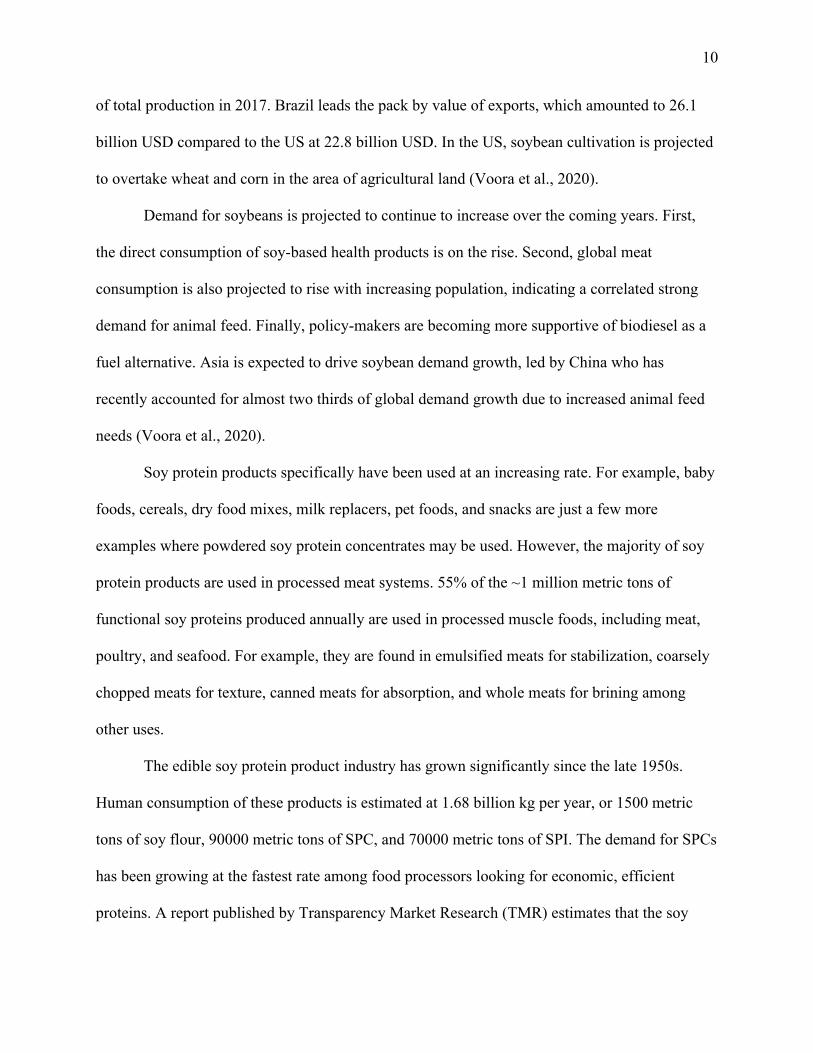
There are three primary solvent extractor designs used in industry, continuous loop
extractors, rotary reactors, and belt extractors (see figure 5.1). Each design uses countercurrent
flow of the solvent through concentric “cells” filled with the soybean flakes or soymeal. Fresh
solvent meets the soybean meal about the exit of the extractor while the soy flakes entering the
extractor are met with concentrated miscella. As the soybean flakes travel through the extractor,
they come into contact with decreasingly concentrated miscella to recover as much oil as
possible. All three extraction methods result in soymeal containing 55-77% dry soybean solids,
25-35% residual solvent, 5-10% moisture, and less than 1% oil (Anderson & Crown Iron Works,
2021).
Figure 5.1. Flow diagrams of the 3 Major Extractor Models
Rotary, or deep bed extractors have the longest retention time as their deep beds require
more time for the solvent to come into contact and disperse throughout the soybean meal in each
stage. Most rotary extractors contain 16-24 cells with 1.6-2.9 meter bed depths. Some beds can
be as deep as 5 meters which increases the extractor capacity but also can require more frequent

20
cleaning due to clumping of the bulk soymeal in the deep rotary beds. Manufactures of rotary
extractors include the Rotocel® Reactor sold by Davy Corporation, French Oil Mill Machinery
Co. 's Stationary Basket Extractor, Extraktions’ Technik “Carousel”, and the Krupp extractor.
Horizontal belt extractors consist of a conveyor belt on rollers in an air-tight horizontal
vessel. The flaked soybeans travel along the conveyor in a shallow bed (0.9-1.8 meters deep) and
are washed with successive sprays of hexane flowing countercurrent to the soybean. The
effective length of the bed is about 15 times the bed depth. Miscella is collected in a hopper
below the soybean conveyor bed and transported for solvent recovery processing.
Continuous loop extractors contain shallow beds (0.3-1 meter deep) for the soybean
flakes to travel through the extractor, allowing for much shorter retention times and faster
percolation than rotary extractors. The effective “length” of the bed is roughly 50 time as long as
the depth allowing for maximum surface area with the fresh solvent. Flaked soybeans are carried
through the vertical loop in an air-tight vessel and met with decreasing concentrations of miscella
for oil recovery. These extractors have the largest capacity and are able to process up to 4000
MTPD of flaked soybeans. Continuous loop extractor manufacturers include Crown Iron Works,
Desmet Ballestra, and N&T Engitech.
Ethanol Extraction
Downstream of the hexane extraction process is the ethanol extraction process used to
remove soluble carbohydrates from the defatted soybean meals. As per normal industry
practices, this facility utilizes a similar ethanol extraction unit as the hexane extraction process.
The solvent used is 60% aqueous ethanol, and it has been shown in literature that this is an
optimal concentration to perform sugar extraction (Erickson, 1995). The resulting slurry coming
out of the ethanol extractor is then centrifuged to separate the solids from the soluble

21
macronutrients. Low fat, low carbohydrate soymeal is transported to the DTDC unit and
subsequent dryer to obtain SPC as the final product, with a moisture content of less than 8%. On
a dry basis, the SPC is composed of >70% protein. Meanwhile, the liquid drained from the
centrifuge is fed into a beer column instead of the typical evaporator. This is to increase the
efficiency of solvent removal from the soy molasses, which is sold as a side-product.
Traditionally used in a corn-to-ethanol plant, a beer column separates ethanol from water
and solids (Karuppiah et al, 2008). For this soybean processing facility, the beer column
separates ethanol from soy molasses. Additionally, since there are trace amounts of hexane in the
stream coming into the ethanol extraction process, partial removal of hexane is required so that it
does not build up in the recycle loop. Initially, the use of molecular sieves downstream of the
beer column was considered to separate the hexane from both ethanol and water, but it was
quickly realized that the molecular sieve would be preferential to water molecules and would not
be able to separate hexane out of the mixture as desired (Al-Asheh et al., 2004).
As such, it is proposed that there will be a pasteurization section within the beer column
that will remove the hexane. Ethanol and water vapors will be siphoned out of the column, and
condensed to be recycled and reused in the ethanol extractor unit. The aforementioned soy
molasses will come out in the bottoms stream as an aqueous liquid with a syrupy consistency at
53% dry matter (Long & Gibbons, 2013). The composition of soy molasses on a dry matter basis
can be found in Appendix 4.
Byproduct and Product Storage Mechanisms
The storing of soy oil will be in steel cargo tanks with zinc silicate coating. The unrefined
nature of crude soybean oil indicates a high free fatty acid content, requiring a more resistant
coating system.
22
The coproduct and product created in the ethanol extraction step require specific storage
conditions for commercial viability. The soy molasses will be in the form of a viscous liquid and
has a shelf life of six months when stored properly. It is recommended to transport this coproduct
in clean, dry tanks made of acid resistant material with heaters. Exposure to low temperatures
will firm the product (LetCo.). This requires a steel tank with zinc silicate coating (Ackermann,
1998). The product of SPC will be stored in flat steel storage due to the product’s tendency to
compact and for ease of unloading (Dry Cargo International, 2013).
5.2 Assembly of Database
Thermophysical and Kinetic Property Data
Thermophysical and kinetic property data for the materials involved in the solvent
extraction processes in this facility were obtained from Aspen Plus V11. The NRTL method was
selected for the hexane recovery simulation due to the thorough activity coefficient data
available for the given components of soybean oil and extraction hexane. The NRTL method had
the most binary interaction data available and therefore provided the most accurate separation
modelling (see Appendix 1.4). The composition of extraction hexane was assumed to be 50% n-
hexane, 25% cyclohexane, and 25% isohexane for simplicity (Shell Chemicals, 2016). Industrial
extraction hexane is composed of various hexane isomers with very minimal impurities so this
assumption is valid (see Appendix 3). Oil composition was broken down into the individual fatty
acids assuming that linoleic acid (51% naturally) accounted for the 5% of unspecified fatty acids,
making linoleic acid 56% of soybean oil followed by oleic acid (23%), palmitic acid (10%),
linolenic acid (7%), and stearic acid (4%) (Anderson, G. E., & Crown Iron Works, n.d.).
For the ethanol recovery process simulation, the NRTL thermodynamic model was
selected because the process involves non-electrolyte polar liquids and operates at a low

23
pressure. It is important to note that this process not only recovers the ethanol for recycling, iit
also produces soy molasses that exits the separation column through the bottoms stream.
Appendix 4 contains detailed information about the typical composition of soy molasses, but
slightly different percent compositions were used when running the simulation. This is due to the
assumptions made in performing the mass balance calculations for this project. As such, it is
assumed that the soy molasses will contain 26.2% stachyose, 4.5% raffinose, 30.8% sucrose,
1.5% fructose, 1.1% glucose, 12.3% proteins, 0.6% fiber, and 23.0% ash by weight. After
converting the percent compositions to the required mass flows, the simulation was then run with
a feed containing ethanol, water, trace hexane, and the components of soy molasses.
Iron was chosen as a pseudo-component with no vapor pressure, and used to represent the
protein, fiber and ash. Amongst the soluble carbohydrates, it was also decided to lump raffinose
and stachyose together since the Aspen simulation produced an error and would not run with
raffinose included during property analysis. Doing so had negligible impact on the overall
simulation results as all the carbohydrates do not evaporate with the ethanol and exit completely
in the bottoms stream of the beer column.
Raw Material Costs
The cost of soybeans for this facility was obtained from the daily price listing as of April
09, 2021 for $14.0300/bushel or 23.4 cents/lb (Macrotrends, 2021). China’s demand heavily
influences US prices, and prices are expected to rise as high as $15 per bushel to curb domestic
demand as China imports more and American stocks decline (Hertzer et al., 2021).
Hexane was priced using EcoLink drums, used in industrial purposes like extracting oil
from vegetables at 72.3 cents/lb. A price estimate for bulk ethanol was obtained from the US

24
grains Council at 19.4 cents/lb. The extraction hexane requirement assumes that an additional
0.5% of hexane is lost through vapor leakage in the hexane recovery system and DTDC.
Utility and process water costs were also obtained from Dr. Warren Seider’s textbook and
are discussed in Section 7 below.

25
Section 6: PFDs and Material Balances
The overall process diagrams for the proposed soybean processing facility are shown
below in Sections 6.1-6.5. All processes are continuous. Section 6.1 summarizes the bean
storage and the initial bean cleaning processes including conditioning and flaking. Section 6.2
shows the hexane extraction process, as well as desolventizing. Section 6.3 describes the hexane
recovery process to recycle the solvent using evaporation and stripping methods. Section 6.4
demonstrates the aqueous ethanol extraction step including centrifugation, counter-current
extraction and desolventizing to produce the final SPCs. Finally, section 6.5 contains the ethanol
recovery process to recycle the alcohol solvent using evaporation and a beer column. The
following tables additionally show the material balance flows for all process streams.
Component flows, stream temperatures, and pressures are also indicated.

26
Section 6.1 Pre-Treatment
Dehulled soybeans are supplied with a moisture content of 12.5% and stored in stainless
steel cone roof silos (S-101 and S-102). Dehulled soybeans are transported to the project site via
train and conveyed directly from the rail to the silos via rail receiving conveyors rated at 400
TPH (Todd & Sargent, 2021). A 400 TPH bucket elevator feeds the dehulled beans into the top
of the silo (American Soybean Association, 2017). Due to the moisture content of the dehulled
beans and potential condensation buildup through the silo walls, thorough aeration will be
essential in maintaining feed quality and preventing mold, mildew, or insect infestation. As a
general rule of thumb, dehulled soybeans should be stored at approximately 20˚C to avoid insect
infestation and mold (Silos Cordoba, 2020).
Stored dehulled soybeans are transferred to a vertical seed conditioner (CN-101) via a flat
conveyor and L-path conveyor. Soybeans are fed into the top of the vertical seed conditioner at a
flow rate of 46469.61 lb/hr. The Vertical Seed Conditioner is a stacked heater design with
elliptical tubes containing low pressure steam at 15 psi to heat the dehulled soybean feed from
21˚C to 70˚C (Crown Iron Works, 2018). The heat exchanger tubes are 304L stainless steel tubes
welded into a 304L stainless tube sheet to allow for uniform heat transfer (Allegheny Ludlum,
2021). A rotary style discharge is used to create an even flow throughout the conditioner with all
soybeans experiencing a residence time of about 30 minutes. Air is fed to the conditioner at
about 0.2 ft3/min per bushel of soybeans (Crown Iron Works, 2018). The aeration removes free
moisture created from heating the soybeans and pulls the moisture away from the seeds. Air is
pulled through the unit by cyclone CC-101.
The conditioned soybeans are sent via conveyor to two flakers in parallel. Each flaker
consists of two smooth-surface rollers which are driven at differential speeds. An output flake

27
thickness of 0.25 mm to 0.3 mm must be maintained for effective solvent extraction (Crown Iron
Works, 2018). Outlet soybean flake thickness is measured every 2 hours to maintain quality
control before they are sent to the extractor (section 200).

28
Figure 6.1: Process Flow Diagram for Pre-treatment process

29
Table 6.1 Mass and Energy Flow for Pre-treatment process

30
Section 6.2 Hexane Extraction
The flaked soybeans are fed by a belt conveyor directly to the countercurrent solvent
extractor with a hexane to soybean input ratio of 10:1 (Crown Iron Works, 2018). The soymeal
exiting the extractor (EX-201) contains roughly 65% dry soybean solids, 27% residual solvent,
8% moisture, and about 0.12% oil (Anderson & Crown Iron Works, 2021). The extractor
operates at 63˚C and 15 psi. The miscella (oil and hexane mixture) exiting the extractor is carried
by pipe to a miscella holding tank (S-201) before being sent to the solvent recovery process
(section 300). Extracted soybean meal is fed to the Desolventizer Toaster Dryer Cooler (DTDC-
201) via a belt conveyor and elevator conveyor where the remaining solvent is removed from the
soymeal. The DTDC is 14.2 meters tall with a 3 meter diameter and reduces soymeal solvent
content to 200 ppm with 14 stages, 7 for the desolventizing-toasting trays , and 7 for the drying
and cooling trays. The DTDC has various pressure and temperature drops throughout the column
but soymeal exits at 38˚C, 15 psi and 12.3% moist. Soymeal exiting the DTDC is carried by
conveyor CY-203 to section 400.

31
Figure 6.2: Process Flow Diagram for Hexane extraction process
32
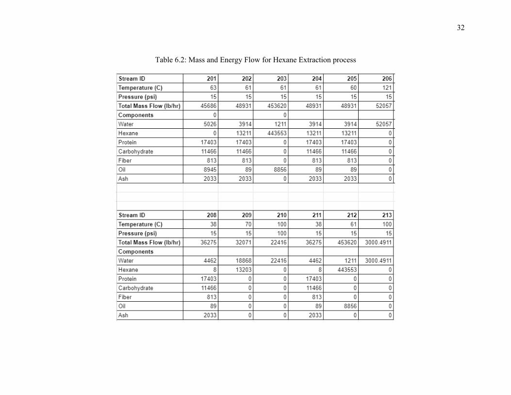
Table 6.2: Mass and Energy Flow for Hexane Extraction process

33
Section 6.3 Hexane Recycle
Hexane is removed from the miscella leaving the extractor through the solvent recovery
section. Miscella is pumped out of the holding tank by P-301 which increases it’s pressure to 30
psi before passing through a valve control that lowers the pressure back down to 15 psi. The
miscella is preheated to economize this section via HX-301. HX-301 is a counter current heat
exchanger that uses the water and hexane vapors leaving the DTDC to heat the miscella to 63˚C
based on recommendations from Professor Fabiano of the University of Pennsylvania. The
miscella is heated to 67˚C in HX-302, a counter-current steam heat exchanger. About 99% of the
solvent is removed in the first flash evaporator which operates at a temperature of 70˚C and
pressure of 7 psia. Hexane recovery equipment operates under partial vacuum to reduce vapor
leakage for environmental and safety purposes. It is recommended that a vapor recovery system
(VRS) is installed to mitigate hexane emissions (Alfa Laval, 2003). The VRS was outside the
scope of this project however it can be purchased from or designed after the Alfa Laval VRS.
The hexane and water vapors leaving this first stage evaporator (EV-301) are condensed by CO-
302 while the remaining miscella is sent to the second stage flash evaporator. This flash column
operates at 5 psia and 110˚C and removes 83% of the hexane in the miscella entering the second
flash evaporator (EV-302). The hexane and water vapors leave the top of EV-302 and are
condensed by CO-303 while the miscella is sent to the stripping column to remove the final
traces of solvent.
Crude oil leaving the stripper should contain no more than 500 ppm of hexane (U.S.
Soybean Export Council, 2015). Hexane concentrations of 200 ppm were obtained through the
Aspen simulation (results included in Appendix 1). It is important to note that Aspen was not
able to model the stripping column (Cl-301) properly. Operating temperatures outside the safe oil

34
storage range were obtained (335˚C). This can be explained by the lack of binary interaction data
included in Aspen’s NRTL model. Examples from both literature and industry however show
that this stripping process is indeed possible why maintaining oil temperature below 150˚C. The
column is operated near vacuum conditions to facilitate the separation of hexane and oil and
prevent hexane leakage to the atmosphere. Crude oil is sent to a storage tank before being sold to
an oil refinery where it is degummed and processed for consumption. Due to its degummed
nature, oil should not be stored for more than one month before being sent to the oil refinery to
prevent buildup of gums in the storage tank. All hexane and water vapor leaving the three
columns are sent to a decanter where the water is sent to a wastewater processing plant and the
hexane is recycled for use in the extractor (EX-201).

35
Figure 6.3: Process Flow Diagram for Hexane recovery process

36
Table 6.3: Mass and Energy Flow for Hexane recovery process

37
Section 6.4 Ethanol Extraction
The defatted soy meal is transported via a conveyor (CY-401) to the countercurrent
extractor (EX-401) for the removal of carbohydrates. The total feed flow rate into the extractor is
354,300 lb/hr, with an ethanol to soymeal ratio of 10:1. The preferred ethanol concentration for
this process is 60% by weight since soy protein solubility increases on either side of this
concentration.
The countercurrent extractor outputs a slurry that is centrifuged (CE-401) to separate the
solids from the alcohol-soluble macronutrients. The supernatant in stream 404 contains solubles,
and is sent to section 500 for the recovery of ethanol. The solids coming out of the extractor in
stream 403 contain low fat, low carbohydrate soymeal that is transported to the DTDC unit (DT-
401) via an elevator (E-401) to remove up to 85% of the remaining ethanol. The evaporated
ethanol in stream 408 is condensed (HX-501) and mixed with stream 403 before it is sent to the
column for ethanol recovery.
The desolventized soymeal is then sent to a subsequent dryer (HX-401) to bring the
moisture down to <8% for appropriate storing conditions. At this point, the soymeal reaches a
protein content of 70% on a dry basis, meeting the requirements of food grade SPC. The final
SPC product is transported to a silo (S-401) at 25,900 lb/hr by a conveyor (CY-402).

38

39
Figure 6.4: Process Flow Diagram for Ethanol extraction process

40
Table 6.4: Mass and Energy Flow for Ethanol extraction process

41
Section 6.5 Ethanol Recycle
Streams 503 and 404 are combined in a mixer to obtain 330,000 lb/hr of material that is
fed to the beer column (CL-501). For our project, the column separates ethanol from soy
solubles, as well as removes up to 73% of the trace hexane that enters the recycle loop.
Hexane is the main component in the overhead of the column. It comes out of the
pasteurizing section, which has a smaller diameter than the main column. Ethanol and water
vapors are condensed in the stage prior to the pasteurizing section, and is siphoned out (P-502) to
be sent to an ethanol work tank (S-502) where the concentration is adjusted to 60% before it is
reused in the ethanol extraction process. The bottoms of the column will contain soy molasses,
an viscous aqueous mixture composed mostly of carbohydrates. The soy molasses will be
pumped (P-501) and stored in a heated storage tank (S-501) before it is sold as a side-product of
this process, and transported in a specialized truck.

42
Figure 6.5: Process Flow Diagram for Ethanol recovery process

43
Table 6.5: Mass and Energy Flow for Ethanol recovery process

44
Section 7: Energy Balance and Utility Requirements 7.1 Heat Integration Strategy
Utilities were minimized, wherever possible by evaluating whether streams within the
system had the capacity to heat or cool other processes. In some cases, adding a pre-heater was
helpful to minimize utility costs. For example, in section 300, the stream containing hexane and
water vapor from the DTDC unit (209) was utilized to heat the miscella from the hexane
extractor unit before it went through additional evaporation stages. This reduced the need for
additional steam or electricity to separate the hexane from water.
Most other streams were not able to be used in a heating or cooling capacity due to the
close boiling points of the Hexane-water mixture, and Ethanol-water azeotrope. Thus, there is a
significant steam requirement to produce the SPC.
7.2 Process Utilities
Table 7.1-7.3 summarizes the utilities and electricity needed for each equipment item.
Table 7.4 summarizes the net utilities needed per lb of soy protein concentrate produced.

45
Table 7.1: Steam Utility Requirements

46
Table 7.2: Electricity Utility Requirements

47
Table 7.3: Wastewater Treatment Requirements
Table 7.4: Utility costs per lb of SPC product

48
Section 8: Equipment List and Unit Description 8.1 Unit Descriptions
Silos
Two stainless steel cone roof silos, each with a maximum working volume of 4138
gallons, are used to store soybeans when they are initially delivered in bulk to the processing
facility every hour. The soybeans storage conditions are 21 C and 3 psig, and meet Food Grade
standards. The combined bare module cost for the silos is $37,054.
Conditioners
A Vertical Seed Conditioner (VSC) is used to clean the dehulled soybean feed. Soybeans
are heated to 70˚C which reduces the moisture content from about 12.5% to 11% (Allegheny
Ludlum, 2021). Soybeans are fed into the top of the vertical seed conditioner at a flow rate of
46469.61 lb/hr and heated by 304L stainless steel tube sheets. The heating sheets provide
uniform heat transfer through multiple elliptical tubes containing steam at 15 psi and 120˚C
(Buhler). The Vertical Seed Conditioner is a stacked heater design composed of multiple square
heating layers and can have anywhere from 1 to 12 heating units per VSC (Crown Iron Works,
2018). In this VSC, 8 heating units are required with dimensions of 0.9 meters high, 4.3 meters
long, and 3.9 meters wide (Buhler).
49
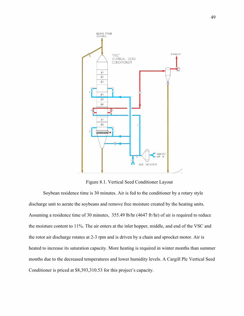
Figure 8.1. Vertical Seed Conditioner Layout
Soybean residence time is 30 minutes. Air is fed to the conditioner by a rotary style
discharge unit to aerate the soybeans and remove free moisture created by the heating units.
Assuming a residence time of 30 minutes, 355.49 lb/hr (4647 ft3/hr) of air is required to reduce
the moisture content to 11%. The air enters at the inlet hopper, middle, and end of the VSC and
the rotor air discharge rotates at 2-3 rpm and is driven by a chain and sprocket motor. Air is
heated to increase its saturation capacity. More heating is required in winter months than summer
months due to the decreased temperatures and lower humidity levels. A Cargill Plc Vertical Seed
Conditioner is priced at $8,393,310.53 for this project’s capacity.

50
Flakers
The flaker is made up of two smooth-surface rolls that are 6.5 ft long with a 2.6 foot
diameter. Pressure between the rollers is generated mechanically by a 100 hp 6-pole motor in
order to achieve a flake thickness of 0.25 mm. The thickness is measured with a micrometer at
the center and edges of the roller hourly to obtain proper control (Anderson, G. E., & Crown Iron
Works, n.d.). Thick flakes make it challenging for the solvent to diffuse through the soybean to
extract oil while thin flakes can result in excessive splitting and breakage which can reduce the
protein content of the soybean flakes. Two flakers in parallel are required because significant
wear occurs on the center of the rollers resulting in frequent maintenance requirements for this
piece of equipment. By installing two flakers in parallel, continuous operation can occur while
maintaining flaker quality control. It is recommended that extra rollers are stored on site for
quick repair and replacement.
A Marathon 3 phase, 100 hp motor with 1200 RPM, 230/460 V, and a 444T frame is
priced at $17,023.00 (Regal Beloit, 2021). A 500 MTPD Roskamp Champion Oilseed Flaking
Mill is priced at $800,174.29 (quote provided by Nicholas Hyland, CPM contact and Kyle
Bannon, Sales Rep on 3/11/2021) making total flaking equipment cost $817,197.29. The price
for two Roskamp Oilseed Flakers and accompanying Marathon motor is $1,634,394.58.
Extractor
This project utilizes a continuous horizontal belt conter-current solvent extractor from
N&T Engitech. The extractor has a capacity of 500 MTPD of conditioned, flaked, and dehulled
soybeans. Hexane is used as the solvent due to its low boiling point and oil-soluble nature. The
N&T Engitech extractor is characterized by shallow beds to allow for quick percolation of the
solvent through the flaked soybeans while extracting over 99% of the soybean oil (Crown Iron

51
Works, 2018). The extractor operates with a 10:1 feed ratio of hexane to soybean flakes.
Soybeans are carried through the extractor by an articulated band conveyor and washed with
success sprays of solvent flowing in the opposite direction of the soy flakes. The countercurrent
flow allows for increasing oil removal at each stage of the extractor. Soybeans enter the extractor
and are first met with oil-rich solvent (miscella). The flaked soybeans contact increasingly
“clean” solvent as they travel through the extractor and more oil is removed. At the final stage,
soy flakes are met with pure solvent and their oil content is reduced to 0.1% (Crown Iron Works,
2018). Oil is removed from the soybean flakes due to its solubility in hexane. The solvent first
enters the porous, thin soybean flake and dislodges the oil from the flake creating a hexane-oil
mixture called miscella. This miscella then travels to the surface of the soy flake where it enters
the bulk of the solvent flow. The composition of the defatted soy flakes leaving the extractor is
8% water, 27% solvent, 0.18% oil, and 35% soybean solids (carbohydrate, protein, fiber, and
ash). Defatted soy meal leaves the extractor and is sent to the DTDC while miscella is sent to a
storage tank.
Figure 8.2 shows the general layout of the N&T Engitech extractor. Flaked soybeans are
fed through the upper right side of the extractor through the hopper before being introduced with
solvent. Hexane is fed in the left hand side of figure X to introduce the countercurrent flow.
There are 9 total sprayers, meaning the flaked soybeans travel through 9 sequential “stages” in
the extractor. Each stage is 6 feet wide and 7.5 feet long making the total extractor dimensions
6’x68’x10’. A 5 hp motor with 20,000 Nm torque is required to power the extractor but is not
included in the quoted extractor price of $85,578.00. The AC Gearmotor 230/460 Nameplate
RPM 19 RPM Max. Torque 13,721.0 in-lb Enclosure TEFC motor could be used to power the

52
extractor and is priced at $2,641.80 (N&T Engitech, 2021). Including the motor, the total
extractor price is $88219.80.
Figure 8.2: X N&T Engitech Extractor and DT Layout (N&T Engitech, 2021)
Miscella Tank
The miscella tank is used to temporarily store miscella leaving the extractor before is it
processed in the solvent recovery section. The tank is made of welded mild steel and contains
manholes to draw out the clear miscella and ensure quality control. The tank is 5.7 ft in diameter
and 13 ft high with a ¼ inch thickness. The miscella tank can be provided by N&T Engitech for
$18,212.00 (see Appendix 5.4).
Desolventizer-Toaster-Dryer-Cooler

53
The Desolventizer-Toaster-Dryer-Cooler (DTDC) is used to remove the remaining
solvent from the extracted soybean meal. Soymeal leaves the solvent extractor with a hexane
composition of approximately 30% but must be reduced to 200-500 ppm in order to meet health
and safety requirements (Fao.org, n.d.). Many soybean processing plants use separate equipment
for the dryer-cooler and desolventizer-toaster however Crown Iron Works’ DTDC reduces steam
consumption and solvent loss (Crown Iron Works, 2018). Lower steam demand significantly
reduces operational costs and fewer hexane emissions reduces the environmental impact while
greatly improving plant safety.
The DTDC is a vertical cylindrical vessel containing trays to gradually toast and remove
residual solvent from the soymeal. The solvent-rich soymeal leaves the extractor, travels along
an L-path conveyor, and enters the top of the DTDC. Meal passes through the DTDC with
agitating sweeps powered by a central rotating shaft to move the soymeal through the various
stages. A 30-minute residence time is maintained to ensure meal quality and prevent burning of
the soymeal flakes (Crown Iron Works, 2018). Since there is a considerable amount of hexane
present in the DTDC and high temperatures of 185˚C, all equipment in and near the DTDC must
be spark proof for safety concerns (NFPA, 2001).
There are 6 types of trays within the DTDC: pre-desolventizing, counter-current trays,
sparge trays, steam drying trays, air drying trays, and air-cooling trays. The pre-desolventizing
and counter-current trays heat the extracted soymeal via conductive heat from the tray surface.
Trays are heated by steam fed into structural members between the upper and lower layer of the
tray at 10 barg (Desmet Ballestra, 2017). The steam partially condenses within the tray and
transfers its latent heat to the metal surface. Table 8.1 gives an overview of each section of a
typical DTDC. See figure 8.3 for reference.

54
Figure 8.3. Crown Iron Works DTDC Layout (Crown Iron Works, 2018)
Desmet Ballestra, 2017 specifies that depending on the processing capacity of the DTDC,
there can be one to seven pre-desolventizing trays. These stages are disk-shaped to allow for
ascending steam to pass along the side of the column. The meal is fed into the counter-current
desolventizing-toasting trays which are heated by steam flowing between the top and bottom
layers of the tray. The counter-current DT trays contain apertures that make up 10% of the tray’s
surface area to allow for ascending steam to uniformly flow through the 1 meter of soymeal
above. The first countercurrent tray desolventizes the soymeal by heating it to to 99˚C. This
stage removes 99% of the solvent and increases the moisture content to 20%. The remaining

55
counter current trays toast the soymeal by gradually raising the temperature to 110˚C which
reduces the solvent and moisture concentrations to below 500 ppm and 19% respectively.
The sparge tray introduces direct steam to the DTDC which makes up 75% of the heat
transfer necessary to heat the soymeal in the DT. Direct steam is fed into the DTDC at 10 barg
and 185˚C before passing through a control valve which reduces the pressure and temperature to
9.5 barg and 160˚C.
The drying and toasting process begins after the sparge tray. Steam drying trays are
maintained at 185˚C and each tray removes 0.5% of the soymeal moisture while maintaining a
100˚C meal temperature. Soymeal moisture is reduced by conductive heat transfer from both the
tray surface and soymeal temperature drop. The evaporated water is pumped out by an ejector.
The soymeal is passed to the air-drying trays by the agitating sweeper. Air is filtered to remove
dust and pressurized using a spark-proof centrifugal blower before being fed through circular
apertures in the tray to evenly distribute hot air through the soymeal. The air heater must be
adjusted according to ambient temperatures thereby increasing operational costs in the winter
months to increase the saturation capacity. Soymeal is cooled a final time in the air cooling trays
where cool air is injected at a nominal velocity of 14-21 m/min through the apertures of the trays.
Soymeal is cooled both evaporatively and convectively by the ambient air resulting in a final
moisture content of 12.3% and an outlet temperature within 10˚C of ambient air.
Table 8.1: DTDC Tray Specifications (Desmet Ballestra, 2017)
Pre- Desolventizing
Counter Current (1st
tray)
Counter Current (remaining trays)
Sparge Steam Drying
Air Drying
Air Cooling

56
# trays 1-7 1 1-4 1 1-5 1-6 1
Solvent Evaporated
10-20% 99% ~100% - - - -
Meal Depth (m) 0.5-0.3 1-1.2 1 1 0.25 0.6 0.6
Temperature Increase (˚C)
57 → 66 66 → 99 99 → 110 110 → 108
108 → 100
100 → 63
63 → 38
Tray Surface Temperature (˚C)
185 185 185 155 185 100 26
Moisture (%) 8 → 12 17 → 22 22 → 20 20 20 → 18
18 → 13
13 → 12.3
For a processing capacity of 530 MTPD of solvent-rich soymeal, an N&T Engitech
DTDC column with a height of approximately 14.2 meters and 3 meter diameter will be used
(see Appendix X). The DT section will require 2 pre-desolventizing trays, 4 counter-current DT
trays, and a sparge tray to introduce the direct steam. The DC section will require 4 steam drying
trays, 2 air drying trays, and a single air-cooling tray. Assuming 50% of the steam is condensed
within the tray, approximately 76.3 MTPD of indirect steam is fed to the supporting structures in
each tray in order to heat its surface to 185˚C. Table 8.2 shows the direct steam and air
requirements of each section of the DT. The 349 MTPD of steam and hexane leaving the top of
the DT (pre-desolventizing) is fed to a counter current heat exchanger to heat the miscella
leaving the extractor (section 300). The 37.2 MTPD of water and air are fed to a cyclone
collector to remove any dust particles before being ejected into the atmosphere. The bare module
cost of the DTDC is $8,025,000.

57
It should be noted that the exact steam, air, and tray requirements will vary depending on
the manufacturer and capacity. A thorough steam, air, tray, and utilities quote will be provided
by the manufacturer upon purchase of the DTDC (Crown Iron Works is recommended).
Table 8.2. 530 MTPC Capacity DTDC Steam, Air, and Tray Specifications
Tray Type # Trays
Steam In (MTPD)
Air In (m/s)
Hexane Evaporated
(MTPD)
Water Evaporated
(MTPD)
Steam Out (MTPD)
Hexane Out
(MTPD)
Pre-Desolventizing
2 225.7 - 28.8 -20.3 205.4 143.7
Counter-Current (1st)
1 260.8 - 113.9 -35.1 225.7 115.0
Counter-Current (remaining)
3 244.0 - 1.1 16.7 260.8 1.1
Sparge 1 244.0 - - - 244.0 -
Steam Drying 4 - - - 5.2 - -
Air Drying 2 - 17.5 - 24.3 - -
Air Cooling 1 - 17.5 - 3.2 - -
*Negative values indicate that the substance was condensed rather than evaporated.
Heat Exchangers
Two heat exchangers are placed before the first evaporator in the solvent recovery
process in order to economize and preheat the miscella feed and lower the power load of the
evaporators. HX-301 uses the discharged hexane and steam mixture from the DTDC to

58
economize the process. The DTDC effluent is able to increase the miscella temperature to 63˚C.
The second heat exchanger, HX-302 is used to heat the incoming miscella to 66˚C. Steam is
passed through the shell of the heat exchanger at 100,000 lb/hr. Both heat exchangers have a
shell and tube geometry with countercurrent flow. HX-301 has 528 ft2 of heat exchange area
while HX-302 has 843 ft2 of heat exchange area. The heat exchanger purchase costs were
calculated from the heat exchange area calculated in Aspen, the material factor, and the tube
length using the equations in Seider et al., 2017. The purchase costs of heat exchanger 301 and
302 are $54,099 and $64,629.36 respectively while the bare module costs are $173,659 and
$207,459.
Evaporators
Two flash evaporators are needed to reduce the hexane composition in the oil down to
3.8%. The first flash evaporator (EV-301) removes 99% of the solvent in the miscella leaving the
extractor. This evaporator operates under partial vacuum conditions (7 psia) and 70˚C to assist
with the hexane-oil separation and reduce hexane loss and leakage to the atmosphere (Desmet
Ballestra, 2017). About 1 lb/hr of oil is lost to the distillate. The first evaporator diameter is 14.7
feet and 51.4 feet high. Evaporators are spark proof due to the low boiling point of hexane and
the potential to cause flames in these low pressure conditions (NFPA, 2001). Purchase costs were
calculated from the column diameter, thickness, operating pressure, and material using the
equations in Seider et al., 2017. The first flash evaporator purchase cost is $342,614 and its bare
module cost is $1,099,794. The power requirement is 23650 hp.
The second flash evaporator, EV-302, removes 83% the solvent exiting the first
evaporator (Desmet Ballestra, 2017). This evaporator operates under a slightly lower pressure
than EV-301 as a closer separation is needed. Pressure is maintained at 5 psia and the

59
temperature rises to 110˚C. Essentially no oil is lost to the distillate due to the lower operating
pressure and higher temperature. The column diameter is 1 foot while the height is 3.7 feet.
Since both evaporators are flash evaporators, the purchase cost was calculated in the same
manner as EV-301. The purchase cost of the second stage evaporator is $9,751.32 and the bare
module cost is $31,301. 264 hp are required to power EV-302.
Stripper
The stripping column removes the remaining hexane from the oil. Health and safety
standards mandate that hexane composition remains lower than 500 ppm (U.S. Soybean Export
Council, 2015). The stripping column was modeled in aspen to achieve a final solvent
concentration of 200 ppm in oil. The column is operated near vacuum conditions to facilitate the
separation of hexane and oil and prevent hexane leakage to the atmosphere. The distillate
product (hexane and water) is at 4 psia and 26˚C while the bottoms pressure is at 9 psia. 12
stages are required to complete the separation including the reboiler and condenser. The column
height, including the 10 internal trays, is 14 feet and the diameter is 4.4 feet. While the proper
separation is achieved, and a solvent concentration in oil leaving the stripper is 200ppm, the
column reaches temperatures outside of the safety requirements when working with hexane and
oil. 867 hp are required to operate the stripping column. The purchase cost was calculated from
the column diameter, thickness, material, pressure, and number of trays using the equations
provided in Seider et al., 2017. The column’s purchase price is $71,241 and its bare module cost
is $228,684.
The Aspen V11 simulation resulted in a bottoms temperature of 336˚C which is above the
spark point of hexane making operation at this temperature unsafe. Furthermore, if oil is exposed
to this temperature, it will burn and the quality will be significantly diminished. Maintaining oil
60
quality is essential to making this process profitable as soybean oil is a valuable byproduct of the
soy protein purification process. Literature and industry examples show that the separation of oil
and hexane is indeed possible while maintaining a column temperature below 150˚ (Desmet,
Ballestra, 2017; Crown Iron Works, 2018). The unsafe bottoms temperature reflected in the
simulation can be explained by the lack of binary interaction data included in Aspen’s NRTL
model. Column temperatures and pressures should be modeled at lab scale and scaled up
carefully before installation of this column as the Aspen simulation does not provide an accurate
model of this process.
Decanter
The decanter is used to separate hexane and water from the condensed distillate leaving
the three separation columns (EV-301, EV-302, and CL-301) and DTDC. The decanter was
modeled in Aspen with an operating temperature and pressure of 55˚C and 7 psia respectively.
Water is sent to the waste water processing facility for further purification due to the small
concentrations of hexane and oil remaining in this stream. The decanter removes all of the
hexane from the water due to its low boiling point and solubility in water however 6 lb/hr of oil
remains in the water stream accounting for 0.1% of stream composition and must be removed in
the downstream wastewater processing facility. The hexane leaving the decanter is 99.9% pure.
The remaining 0.1% of the stream is water and there is no oil in it. The hexane stream is recycled
to the extractor to minimize the cost of fresh hexane.
The decanter material is 304L stainless steel and requires 4855 hp. Its diameter is 2.4’
and height is 8.5’. The decanter purchase cost was calculated from similar equations to the
evaporators but the horizontal column equations were used instead of the vertical column
equations in Seider et al., 2017. Using the decanter diameter, thickness, operating pressure, and

61
material, the purchase cost was calculated at $16,442 and the resulting bare module cost is
$52,779.
Condensers
Condensers 302 and 303 completely condense the vapor streams leaving evaporators 301
and 302 respectively. Vapors must be condensed completely in order to be fed to the decanter
which is a liquid-liquid separation unit. Cold water is fed at 21˚C and 15 psia into the shell of the
condenser while the evaporated hexane and water mixture is fed in the tube side. The condenser
operates counter-currently. CO-302 requires 2000000 lb/hr of cold water while CO-303 requires
20000 lb/hr of cold water. CO-302 has 26988 ft2 of heat exchange area and a 33439 hp
requirement while CO-303 has 97 ft2 of heat exchange area and a 168 hp requirement. Cost was
calculated from the power requirement of each condenser using the equations in Seider et al.,
2017. The purchase costs of CO-302 and CO-303 are $19,276,032 and $685,866 respectively
resulting in a total bare module cost of $64,077,693 for the two condensers.
Centrifuge
The centrifuge is located immediately downstream of the ethanol extractor in Section 6.4.
It takes on a total load of 354,300 lb/hr - of which 31,800 lb/hr is solids - and is used to separate
the low fat, low carbohydrate soymeal from the solvent. The centrifuge is run at 15°C to reduce
the protein solubility, and with a centrifugation g force of 14,000 × g (Wang et al., 2004). The
solids that exit the centrifuge with a flow rate of 31,250 lb/hr have a 94% protein yield and a
moisture content of 12%. The supernatant has a flow rate of 323,050 lb/hr, and contains ethanol,
water, trace hexane, and soluble macronutrients. The purchase cost was obtained using the

62
equation for a continuous scroll solid bowl, as given in Seider, et al., and the bare module cost
for the centrifuge comes down to $550,756.
Beer Column
For the purpose of this project, it is proposed that the typical design of the beer column is
modified to include a pasteurization section. While the main function of the beer column is to
separate the ethanol from soy molasses, the pasteurization section allows for the removal of up to
73% of the trace hexane as demonstrated by the Aspen simulation shown in Appendix
2. Regular sieve trays are used in the pasteurization section, whereas fixed valve trays are used
in the main column to minimize fouling and resistance to flow due to the viscous nature of the
soy molasses.
The beer column is fed with 330,000 lb/hr of material primarily composed of ethanol,
water and soluble carbohydrates. The column was modeled as two carbon-steel multistage
towers, operating at condenser pressures of 26 and 22 psia, with 11 and 8 theoretical trays for the
pasteurization and main sections respectively. 313,500 lb/hr of ethanol at a concentration of
60.7% by weight is condensed and siphoned out to be recycled. 16,200 lb/hr of soy molasses
comes out in the bottoms stream.
A tray efficiency of 70% was assumed. This resulted in 16 actual trays for the
pasteurization section, and 12 actual trays for the main section. Since the diameter of the
pasteurization section is found to be smaller than that of the main section at 1.63 ft compared to
18.4 ft, outside of the simulation setting, the tower will be designed with a swage. The total
height of the tower is 84 ft. With this in mind, the bare module cost of the beer column was
calculated to be $1,716,566.

63
Dryer
The low fat, low carbohydrate soymeal that exits the DTDC is at a moisture content of
11.5% by weight. However, industry standards require that the meal is brought down to a
moisture content of <8% before it can be stored (Erickson, 1995; Liu, 2004). To allow
continuous drying of the meal to occur and to prevent contamination, an indirect-heat rotary
dryer was chosen (Applied Chemical Technology, 2021; Seider et al., 2017). Heat transfer is
accomplished via conduction as the soymeal comes in contact with the steam-carrying tubes that
are arranged along the inner periphery of the rotating shell. The rotary dryer also has internal
flighting that gently rolls the soymeal and allows for more uniform heat distribution and transfer
(Louisville Dryer Company, 2021).
Mixer
Mixers are utilized throughout the process to ensure a uniform concentration gradient in
process streams that are joined together. M-301 is installed before the decanter in the hexane
recovery section to collect the various hexane streams condensed from each evaporator/heat
exchanger. M-501 is installed before the beer column in the ethanol recovery section to collect
aqueous ethanol runoff from the ethanol extraction process. All mixers are constructed using
food-grade stainless steel and operating at atmospheric pressure. Costs were calculated using the
6/10 scaling rule of a similar process. The total combined bare module cost is $77,676.
Pumps
Four centrifugal pumps were needed for this process to move liquid feeds through the
process and maintain adequate pressure/height. All pumps were assumed to be operating at 3600
rpm and 75 hp. The purchase and bare module costs of the pumps were calculated based on flow

64
rate as a size factor, and with the equations given in Seider et al., 2017. The total combined bare
module cost is $1,178,743.
Conveyors
There are 5 drag conveyors, 3 L-path conveyors, and 2 bucket elevators required in this
process design. Drag conveyors were chosen due to the delicate nature of the solids handling. It
was assumed that the drag conveyors would be operating at 75 FPM with a max capacity of 1555
CFH based on specifications from the KWS manufacturing company. The L-path conveyors
were also assumed to be operating at 75 FPM based on specifications from the Thomas
Conveyor Company 610 Series. Based on the moisture content of the material, bucket elevators
were also used. The bare module cost of all the transport systems totaled $141,640.

65
8.2 Unit Specification Sheets
Section 100

66

67

68

69
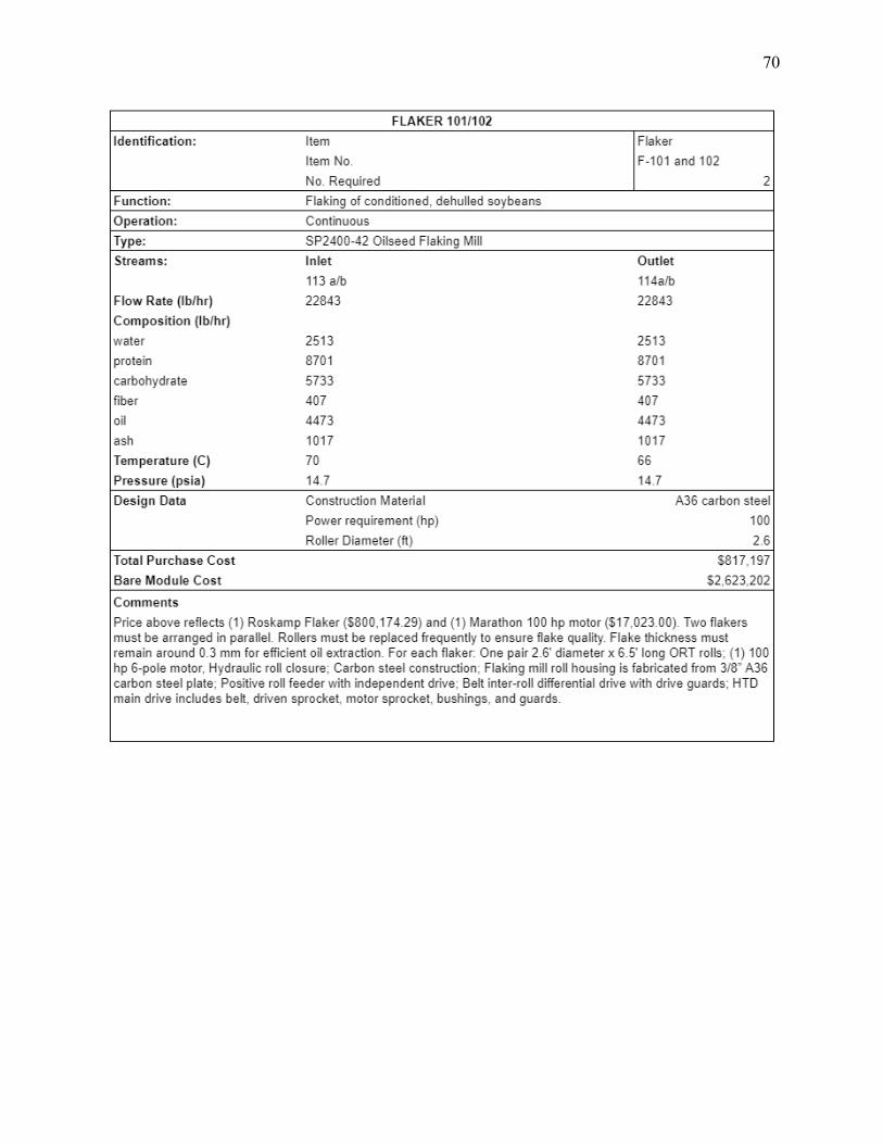
70

71

72

73

74
Section 200

75

76

77

78

79

80

81

82

83

84

85

86

87

88

89

90

91

92

93
Section 400

94

95

96

97

98
Section 500

99
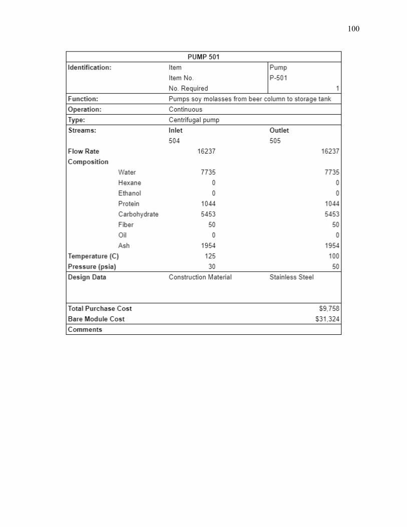
100

101

102

103

104
Section 9: Cost Summary 9.1 Equipment Costs
The table below details the itemized and total bare module costs for all equipment units
in the plant. The total bare module cost for this soybean processing facility is $30.4M. The
DTDC units were the greatest equipment costs in the process, and are essential to ensuring the
food grade quality of the final product.
Table 9.1: Equipment Costs for Section 100
Table 9.2: Equipment Costs for Section 200

105
Table 9.3: Equipment Costs for Section 300
Table 9.4: Equipment Costs for Section 400
Table 9.5: Equipment Costs for Section 500

106
9.2 Operating Cost - Cost of Manufacture
The plant’s variable costs can be broken down into raw materials, utility costs, labor
costs, and other general expenses that scale with production. The general summary of all costs
and investments is shown in the following section 10: Profitability Analysis.

107
Section 10: Profitability Analysis - Business Case
10.1 Sensitivity Analysis
A sensitivity analysis was conducted based on the potential changing price and variable
costs of the final SPC product. This is critical because as mentioned in earlier sections, raw
soybean prices are dependent on Chinese demand, as well as growing conditions during the year
and can be quite volatile.

108
Table 10.1: Sensitivity table based on changing SPC selling price and variable costs per lb of product

109
10.2 Economic Analysis
Figure 10.1: Input Summary

110
Figure 10.2: Input Summary

111
Figure 10.3: Input Summary
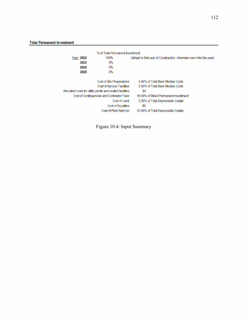
112
Figure 10.4: Input Summary

113
Figure 10.5: Cost Summary

114
Figure 10.6: Cost Summary

115
Figure 10.7: Cost Summary

116
Figure 10.8: Cost Summary

117
Figure 10.9: Profitability Analysis

118
Figure 10.10: Cash Flow Analysis

119
Section 11: Other Important Considerations 11.1 Process Safety Concerns
Hexane Handling
Due to safety concerns related to the flammability of hexane, the NFPA specifies a
“restricted area of 15.3 m and additional controlled zone of 15.3 meters around the extraction
process area” meaning that all extraction process equipment must be 100 feet away from the
property line of any ignition source. The plant design included in this report places all units
containing significant amounts of hexane 100 feet away from another of plant equipment. The
flaked soybean feed and exiting soymeal and soy oil are transported 100 feet by conveyor for
further processing (NFPA, 2001).
The desolventizing section of the extraction process also presents another safety concern.
Here, the hexane-wet soymeal leaves the enclosed solvent handling area, i.e. the extractor, and
enters a process area not designed for solvent vapors. According to a safety data sheet released
by NIST in December 2019, the lower explosive limit (LEL) of hexane is 1.1% by volume. This
means that hexane vapors that escape from the DTDC apparatus may represent a fire and
explosion hazard if present in such concentration. The same data sheet states that the
recommended exposure limit (REL) for hexane is 50 ppm on a 10-hour time weighted average
since at levels higher than this, the vapors may pose a health threat to onsite engineers.
Within the DTDC apparatus, fires may start because of two reasons: If a significant
amount of hexane remains in the soymeal coming out of the toaster section of the DTDC, a fire
might potentially occur in the dryer section when the hexane forms a hazardous mixture with the
hot air. Fires may also start in areas where there is stagnant dust, which dries out and might

120
ignite when coming into contact with hot air. These fires pose an extremely hazardous situation
because of its proximity to the hexane wet flakes. Thus, it is important to take necessary
prevention steps, such as utilizing an efficient cyclone collector that can clean up the stagnant
dust, or setting up mitigative control valves that can inject steam into the air ducts in order to cut
off available oxygen supply when fires do occur (Erickson, 1995).
Ethanol Handling
Fires and explosions can occur when ethanol vapor combines with air in the presence of
an ignition source. In a safety data sheet published by Sigma-Aldrich in 2020, an LEL of 2.5%
by volume is specified for pure ethanol. The REL for ethanol is at 1000 ppm on a time weighted
average.
According to OSHA, factors that can contribute to the provision of ethanol as a fuel for
fire include improper storage, accidental releases, undetected leaks and inadequate venting of
gases. Detailed equipment designs must incorporate control systems to prevent the unintentional
escape of ethanol and its vapors into the open workspace, and to minimize the quantity of
material that escapes in the event that an it occurs. Overfill protection devices can also be
employed to minimize ethanol spills from tanks such as the ethanol work tank shown in Section
6.5 of this report. In addition, the installation of ethanol vapor monitoring devices as well as
automatic fire detection and suppression systems can also be helpful in maintaining safety within
the facility
In either case, the OSHA HCS states that in facilities working with hazardous chemicals,
a written hazard communication program according to CGMP must be developed, implemented

121
and maintained. This includes employee training and the use of personal protective equipment
when handling both hexane and ethanol.
11.2 Environmental Considerations
Maximum Permissible Hexane to be Released into the Atmosphere
For this facility, the amount of hexane lost per hour is around 2280 lb hexane/40660 lb
soybean, equivalent to 55 kg hexane/ton of soybean. The maximum permissible amount for
hexane to be released to the atmosphere is 0.8 kg solvent/ton of soybean (Roque et al., 2015).
While this is outside the scope of this project, the installation of a scrubber is necessary to bring
the number down to the required amount.
Wastewater Treatment
Based on preliminary economic analysis, it was determined that outsourcing the
treatment of wastewater was more feasible than building a wastewater treatment facility on site.
By outsourcing to a specialized outsourcing partner, it can be assured that this facility will
comply with local water regulations, and not to mention resources could instead be used to
support the core operations of this facility.
11.3 Global, Cultural, Social and Ethical Concerns
The US Halal Food Market
The US Halal food market was valued at USD 10 billion in 2014 (Latif, 2016). It has
seen an annual growth rate of about 5% since, and has been projected to grow USD 8 billion
between 2020 and 2024 (Technavio, 2021). Despite the potential of entering this market by
producing SPC that meets Halal standards by switching ethanol to isopropanol (Liu, 2004), we

122
have decided to forgo this option for two reasons. They are as follows: According to Islam, any
food or beverage that contains ethanol or that comes into contact with ethanol during its
processing is considered non-Halal (Al-Absy, 2019). This goes against the project statement that
requires ethanol to be used in the carbohydrate extraction process. Moreover, having to use a
different extraction solvent to remove carbohydrates requires significant cleaning of the process
equipment. This might affect plant uptime, and also increase operating costs related to cleaning.
The US Kosher Food Market
The US market for kosher food generates an annual revenue of over USD 12 billion, and
is projected to grow at a CAGR of 11.3% from 2017 to 2025 (Good Food Institute, 2021; OU
Kosher, 2021). Over 12 million American consumers purchase Kosher food products for reasons
related to dietary restrictions and food safety amongst others. Since Kosher certification
represents a more rigorous food testing process, it is not surprising that it is held to a high regard,
with increasing demand from the food industry. Manufacturers are becoming Kosher certified
not only in response to the growing consumer demand, but also to keep up with other
competitors. This creates a domino effect, since suppliers will also be incentivized to apply for
Kosher certification as well. Not to mention, the increased transparency through becoming
Kosher certified strengthens buyers’ trust in food manufacturers.
Due to the sensitivity of the Jewish dietary laws, constant supervision of a manufacturing
facility is usually required. To ensure that a product is in compliance with the strict guidelines, a
rabbinic auditor must approve of the entire process, from the sourcing of the raw materials to the
packaging and transportation of the final product. In the context of this project, Kosher
certification would mean monitoring the mechanics of extraction, the solvents used, and the
vehicles for transporting the final products (OU Kosher, 2021).

123
The ideal scenario is that a plant would be an all-Kosher site. However, food
manufacturers continue to sell their products to some customers who require non-Kosher product
specifications. In these situations, the certification can still be achieved if the plant capacity
allows for a Kosher certified production line. Otherwise, it may also be possible with weekly
production planning that a certain process is run under Kosher-certified conditions on some days
of the week (The Society of Food Hygiene and Technology, 2016). The analysis as to whether or
not this is feasible for the proposed soybean processing facility is outside of the scope of this
project.

124
Section 12: Conclusions and Recommendations The proposed soybean processing plant should undergo further research and development
based on the economic analysis. The return on investment was calculated to be 59% with an
internal rate of return of 41%, which exceeds the initial 15% IRR goal. Sensitivity analysis
showed that the ROI is very sensitive to commodity prices of SPC. This is an important
consideration given that soybean prices are very dependent on external demand factors.As
designed, this process has a throughput of 170 MM lb/year of SPC, 114 MM lb soy oil/year and
62 MM lb soy molasses/year. The net present value of this project is expected to turn positive by
2027, and projected to reach $396 MM by the end of 2038.
There are several opportunities to consider for increased profitability. Decatur, Illinois is
a promising location due to proximity to US soybean product supply, but other areas could be
investigated as well. Further research could also be conducted regarding larger capacity
equipment, as throughput is positively correlated with profitability. Additional research on
refining or degumming co-products like soy oil could also increase the overall profitability of the
system. Finally, additional market research on domestic vs. international demand could be
conducted to target the ideal buyer of our products.
With these potential next steps in mind, it is recommended that this process undergo
further investigation, with extensive research into the potential for scaling up the extraction
process.
125
Section 13: Acknowledgements We would like to thank Dr. Sue Ann Bidstrup Allen, our faculty advisor for her constant
guidance and support throughout the design, calculation, modeling, and writing of this report.
We thank Dr. P.C. Gopalratnam for creating the problem statement, and advising us throughout
the project. We thank Dr. Leonard Fabiano for his generous support with the ethanol and hexane
recovery Aspen V11 simulations. We also thank Bruce Vrana for organizing this class and the
live presentation of our work. Finally, we would like to thank Dr. Richard Bockrath, Dr. Arthur
Etchells, III, Brain Downey, Deborah De Genova, Dr. Jeffrey Cohen, Adam Brostow, Dr.
Michael Grady, Dr. Daniel Green, Mariella Juhasz, David Kolesar, Dr. Stijn Koshari, Dr. Robert
Luo, Dr. Alex Marchut, Dr. Shaibal Roy, Gary Sawyer, Russel Shnitser, Matthew Targett,
Stephen Tieri, and Nnemarie Weist for consulting us along the way and providing valuable
industry perspective and experience.
126
Section 15: References Ackermann, N. (1998, April). Choosing the Correct Coatings for Cargo Tanks. PCE.
Adm.com. (2021, April 20). ADM Investing in Vegetable-Oil Refining Facility at Decatur, Ill., Processing Complex. Retrieved April 20, 2021, from https://www.adm.com/news/news-releases/adm-investing-in-vegetable-oil-refining-facility-at-decatur-ill-processing-complex
Al-Absy, J. (2019, October 4). Keys to Successful Halal Food & Beverage Manufacturing. Prospector. Retrieved April 14, 2021 from https://knowledge.ulprospector.com/9922/fb-keys-to-successful-halal-food-beverage-manufacturing-ingredient-and-processing-concerns/#:~:text=According%20to%20the%20strictest%20views,ethanol%2C%20such%20as%20all%20vinegar
Al-Asheh, S., Banat, F., & Al-Lagtah, N. (2004). Separation of Ethanol–Water mixtures using
molecular sieves and biobased adsorbents. Chemical Engineering Research and Design, 82(7), 855-864. doi: https://doi-org.proxy.library.upenn.edu/10.1205/0263876041596779
Alfa Laval. (2003). Laying down the right combination [Pamphlet]. Lund, Swededn: Alfa Laval. Allegheny Ludlum. (n.d.). Technical Data Blue Sheet. Stainless Steels Chromium-Nickel Types
302 (S30200), 304 (S30400), 304L (S30403), 305 (S30500). Retrieved April 18, 2021, from https://ncsx.pppl.gov/NCSX_Engineering/Materials/StainlessSteel/302_305data.pdf
American Soybean Association. (2017). 2017 Soy Statistics: A Reference Guide to Important
Soybean Facts and Figures (pp. 1-36, Rep.). St Louis, MO: American Soybean Association.
Anderson, G. E., & Crown Iron Works. (n.d.). Solvent extraction. Retrieved April 14, 2021, from
https://lipidlibrary.aocs.org/edible-oil-processing/solvent-extraction Applied Chemical Technology. (2021, April 14). Directt-Fired vs. Indirect-Fired Rotary Dryers
Retrieved April 20, 2021 from https://appliedchemical.com/equipment/rotary-drums/directly-heated-vs-indirectly-heated-rotary-dryers/
Crown Iron Works. (2018). Vertical Seed Conditioner.
http://www.crowniron.com/wp-content/uploads/2018/01/VSC_Brochure.pdf
Crown Iron Works. (2018, March 20). Model III Extractor. Retrieved April 20, 2021, from https://www.crowniron.com/oilseed-extraction/model-iii-extractor/#1514310489144-488c1399-3593

127
Crown Iron Works. (2018). Desolventizer-Toaster-Dryer-Cooler. http://www.crowniron.com/wp-content/uploads/2018/01/DTDC.pdf
Denicoff, Marina R., Marvin Prater, and Pierre Bahizi, Soybean Transportation Profile. U.S.
Department of Agriculture, Agricultural Marketing Service, October 2014. Web http://dx.doi.org/10.9752/TS203.10-2014
Desmet Ballestra. (2017). Solvent Extraction: Alfa Laval. (2003). Laying down the right
combination [Pamphlet]. Lund, Swededn: Alfa Laval. [Brochure]. Orlando, FL: Author.
Dijkstra, D. J., & Crown Iron Works. (n.d.). Introduction to Degumming. Retrieved April 20, 2021, from https://lipidlibrary.aocs.org/edible-oil-processing/introduction-to-degumming
Dry Cargo International. (2013, July 18). Bulk knowledge: Soybean meal handling. Retrieved
April 14, 2021, from https://www.drycargomag.com/bulk-knowledge-soybean-meal-handling
Erickson, D.R. (1995). Practical Handbook of Soybean Processing and Utilization (Vol. III). St.
Louis, MO: American Oil Chemists' Society. doi: https://doi-org.proxy.library.upenn.edu/10.1002/food.19970410524
Fao.org. (n.d.). Chapter 5 : Processing and refining edible oils. Retrieved April 20, 2021, from http://www.fao.org/3/V4700E/V4700E0a.htm
Fellows, P. (2017). Food processing technology: Principles and practice. In Food processing technology: Principles and practice (4th ed., Food Science, Technology and Nutrition Book, pp. 235-289). Kent: Woodhead Publishing/Elsevier Science. doi:https://doi.org/10.1016/B978-0-08-100522-4.00003-1
Grainger. (n.d.). AC gearmotor 230/460 NAMEPLATE RPM 19 RPM MAX. Torque 13,721.0
in-lb ENCLOSURE TEFC. Retrieved April 20, 2021, from https://www.grainger.com/product/39RK80?ef_id=Cj0KCQjw1PSDBhDbARIsAPeTqrcFvW5twrShQOIZ376WgHSOXKuwVuEzNs7pJMkHdLygaFHE5iQkagAaAsvHEALw_wcB%3AG%3As&s_kwcid=AL%212966%213%21496359973618%21%21%21g%21439044419978%21&gucid=N%3AN%3APS%3APaid%3AGGL%3ACSM-2295%3A4P7A1P%3A20501231&gclid=Cj0KCQjw1PSDBhDbARIsAPeTqrcFvW5twrShQOIZ376WgHSOXKuwVuEzNs7pJMkHdLygaFHE5iQkagAaAsvHEALw_wcB&gclsrc=aw.ds
Guo, M. (2013). Functional foods: principles and technology. Elsevier. Hertzer, M., Chipman, K., & Almeida, I. (2021, January 27). China Is So Thirsty for Soy That
America Could Soon Be Importing. Bloomberg. Retrieved April 18, 2021 from
128
https://www.bloomberg.com/news/articles/2021-01-27/china-is-so-thirsty-for-soy-that-america-could-soon-be-importing
Hubbs, T. (2020, June 15). Soybean Exports, Acreage, and Yield. FarmDocDaily. Retrieved
April 14, 2021 from https://farmdocdaily.illinois.edu/2020/06/soybean-exports-acreage-and-yield.html
Karuppiah, R., Peschel, A., Grossmann, I.E., Martín, M., Martinson, W. and Zullo, L. (2008),
Energy optimization for the design of corn‐based ethanol plants. AIChE J., 54: 1499-1525. https://doi.org/10.1002/aic.11480
Latif, H. (2016, January 20). Overview - The $10 bln U.S. halal food market. Salaam Gateway.
Retrieved April 14, 2021 from https://www.salaamgateway.com/story/overview-the-10-bln-us-halal-food-market
LetCo. (n.d.). Products & Analyses: Soybean Molasses min. 55% dry matter. Retrieved April 14,
2021, from https://www.liquid-energy.ch/en/products-analyses/ Liu, K. (2004). Soybeans as Functional Foods and Ingredients. AOCS Press. Long, C.C., & Gibbons, W. (2013). Conversion of soy molasses, soy solubles, and dried soybean
carbohydrates into ethanol. International Journal of Agricultural and Biological Engineering, 6, 62-68.
Louisville Dryer Company. (n.d.). How the indirect heat dryer works. Retrieved April 20, 2021,
from https://louisvilledryer.com/how-indirect-heat-dryers-work/ Marchetti, J. (2020). Effects of Different Extraction Solvents on Oil Extracted from Jatropha
Seeds and the Potential of Seed Residues as a Heat Provider. BioEnergy Research. https://doi.org/10.1007/s12155-020-10217-5
National Fire Protection Agency (NFPA). (2001). Standard for Solvent Extraction Plants.
Retrieved April 18, 2021 from http://www.inv.icta.efn.uncor.edu/wp-content/uploads/2014/03/36-2001.pdf
N&T Engitech. (n.d.). Solvent Extraction Plant. Retrieved April 20, 2021, from
https://www.nandtengitech.com/Projectdetail/316215/Solvent-Extraction-Plant Palmer, B. (2010, April 26). Is Your Veggie Burger Killing You? The risks of hexane in soy
products. Retrieved April 14, 2021, from https://slate.com/news-and-politics/2010/04/a-study-found-hexane-in-soy-protein-should-you-stop-eating-veggie-burgers.html#:~:text=The%20FDA%20does%20not%20currently,spice%20resins%20(25%20ppm)

129
Preece, K. E., Hooshyar, N., & Zuidam, N. J. (2017). Whole soybean protein extraction processes: A review. Innovative Food Science & Emerging Technologies, 43, 163-172.
Regal Beloit. (2021). Marathon 100 HP General Purpose Motor, 3 phase, 1200 RPM, 230/460 V,
444T Frame, TEFC - GT1047A. Retrieved April 20, 2021, from https://www.regalbeloit.com/products/motors/low-voltage-nema-motors/general-purpose-low-voltage-nema-motors/nema-general-purpose-three-phase-motors/three-phase-tefc-motors/100-hp-general-purpose-motor-3-phase-1200-rpm-230-460-v-444t-frame-tefc-444ttfcd6086
Roque, T.V., Correia, M., & Carvalho, R. (2015). Analysis of the Hexane Loss in a Vegetable Oil
Extraction Unit. Seider, W.D., Lewin, D.R., Seader, J.D., Widagdo, S., Gani, R., & Ng, K.M. (2017). Product and
Process Design Principles: Synthesis, Analysis, and Evaluation, Fourth Edition, Wiley. Seven, J. (2018, September 25). How a Chinese Crop Became an American Winner. History.
Retrieved April 14, 2021 from https://www.history.com/news/soybean-china-american-crop-tariffs
Shell Chemicals. (2016, April). Hexane Extraction. Retrieved April 20, 2021, from
https://www.shell.com/business-customers/chemicals/our-products/solvents-hydrocarbon/special-boiling-point-solvents/_jcr_content/par/tabbedcontent/tab/textimage.stream/1519802470652/c034e7a5b169797a6d8c0e3f2368a70e6c37d5d6/hexane-extraction-q1252.pdf.
Silos Cordoba. (2020). Soybeans and soybean meal storage: Recommendations for the storage of soybeans and soybean meal in a metal silo (pp. 1-8, Rep.). Cordoba, Spain: Silos Cordoba.
Singh, P., Kumar, R., Sabapathy, S.N. and Bawa, A.S. (2008), Functional and Edible Uses of Soy
Protein Products. Comprehensive Reviews in Food Science and Food Safety, 7: 14-28. https://doi.org/10.1111/j.1541-4337.2007.00025.x
Small, D. (2013). Heptane as a less toxic option than hexane for the separation of vitamin E from
food products using normal phase HPLC. RSC Advances., 3(46), 24063–24068. https://doi.org/10.1039/C3RA44442B
Soybean Prices - 45 Year Historical Chart. (n.d.) Macrotrends. Retrieved April 9, 2021 from
https://www.macrotrends.net/2531/soybean-prices-historical-chart-data Stanford, J. P., & Keener, K. M. (2018). Cedar Rapids Food and Bioprocessors Manufacturing
Report. Iowa State University.
130
http://www.economicdevelopmentcr.com/wp-content/uploads/2018/04/2018-ISU-Report.pdf
Technavio. (2021, March 15). Halal Food Market in the US to Grow over $ 8 Billion During
2020-2024 | Increasing REtail Channel Sales to Boost Growth | Technavio. PR Newswire.
Retrieved April 14, 2021 from https://www.prnewswire.com/news-releases/halal-food-market-in-the-us-to-grow-over--8-billion-during-2020-2024--increasing-retail-channel-sales-to-boost-growth--technavio-301246224.html
Todd & Sargent. (n.d.) Soybean Meal Storage Silo. Retrieved April 18, 2021 from
https://www.tsargent.com/projects/detail/bunge-north-america Transparency Market Research. (2015). Soy Protein Concentrate Market (2019-2029, pp. 1-220,
Rep.). Albany, NY: Transparency Market Research. Retrieved April 14, 2021, from https://www.transparencymarketresearch.com/soy-protein-concentrate-market.html
U.S. Soybean Export Council. (2015). Chapter 2: Quality Standards for U.S. Soybeans and Soy
Products. In U.S. Soy: International Buyers’ Guide. Voora, V., Larrea, C., & Bermudez, S. (2020). Global Market Report: Soybeans (Sustainable
Commodities Marketplace ed., Ser. 2019, pp. 1-20, Rep.) (1310447335 963482600 S. Baliño, Ed.). Winnipeg, Manitoba: International Institute for Sustainable Development.
Wang, H., Johnson, L.A., & Wang, T. (2004). Preparation of soy protein concentrate and isolat
from extruded-expelled soybean meals. Journal of the American Oil Chemists' Society, 81(7):713-717. doi:10.1007/s11746-004-966-8

131
Section 15: Appendices Appendix 1: Hexane Recovery
The following sections outline the results of the hexane recovery and oil purification process simulated in Aspen V11. Two flash evaporators, a distillation column and decanter were used to separate oil, hexane, and water. The water will be outsourced for further processing and removal of hexane and remaining toxins. Hexane will be recycled to the countercurrent extractor. It is important to note that this simulation achieves essentially 100% recovery of the inlet hexane however additional hexane loss can be expected due to leaks in the equipment. Vapor scrubbing equipment installation for all units processing hexane is recommended for health and safety purposes. Finally, the crude oil will be sold as a by-product (for $X). Degumming, deacidification, decolorization, and deodorizing downstream processing will be necessary for the buyer to produce refined soybean oil.
A.1.1. Hexane Recovery Flow Diagram See the flow diagram below. For more information, see section 6.3.
Figure A.1. Hexane recovery Aspen simulation flow diagram part 1

132
Figure A.2. Hexane recovery Aspen simulation flow diagram part 2
A.1.2. Input Summary ;Input Summary created by Aspen Plus Rel. 37.0 at 02:04:02 Wed Apr 14, 2021 ;Directory \\nestor\awally\aspen\senior design\hexaneDONE$backup Filename C:\Users\awally\AppData\Local\Temp\~ap403f.txt ;
DYNAMICS DYNAMICS RESULTS=ON IN-UNITS ENG SHORT-LENGTH=in DEF-STREAMS CONVEN ALL MODEL-OPTION DATABANKS 'APV110 PURE37' / 'APV110 AQUEOUS' / 'APV110 SOLIDS' & / 'APV110 INORGANIC' / 'APESV110 AP-EOS' / & 'NISTV110 NIST-TRC' / 'APV110 HYSYS' / NOASPENPCD PROP-SOURCES 'APV110 PURE37' / 'APV110 AQUEOUS' / & 'APV110 SOLIDS' / 'APV110 INORGANIC' / 'APESV110 AP-EOS' & / 'NISTV110 NIST-TRC' / 'APV110 HYSYS'

133 COMPONENTS LINOL-01 C18H32O2 / OLEIC-01 C18H34O2 / WATER H2O / N-HEX-01 C6H14-1 / CYCLO-01 C6H12-1 / 2-MET-01 C6H14-2 / N-HEX-02 C16H32O2 / STEAR-01 C18H36O2 / LINOL-02 C18H30O2 SOLVE RUN-MODE MODE=SIM FLOWSHEET BLOCK EVAP IN=HEATED OUT=HEXWAT1 MISCEL1 BLOCK DECANTER IN=MIXED OUT=RECYCLE WATER BLOCK OILSTRIP IN=7PSIMISC OUT=HEXWAT3 CRUDEOIL BLOCK 2NDSTAGE IN=MISCEL1 OUT=HEXWAT2 MISCEL2 BLOCK MIXER IN=C2 C1 DTCOOLED HEXWAT3 OUT=MIXED BLOCK PUMP1 IN=EXTRACT OUT=TOVALVE BLOCK VALVE IN=TOVALVE OUT=FEED BLOCK DTHEAT IN=DTIN FEED OUT=DTCOOLED ECONOMIZ BLOCK PUMP2 IN=MISCEL2 OUT=7PSIMISC BLOCK COND1 IN=HEXWAT1 CWIN1 OUT=C1 CWOUT1 BLOCK COND2 IN=HEXWAT2 CWIN2 OUT=C2 CWOUT2 BLOCK PREHEAT IN=STEAMIN ECONOMIZ OUT=STEAMOUT HEATED PROPERTIES NRTL PROPERTIES HYSPR PROP-DATA HPRKIJ-1 IN-UNITS MET PRESSURE=bar TEMPERATURE=C DELTA-T=C PDROP=bar & INVERSE-PRES='1/bar' SHORT-LENGTH=mm PROP-LIST HPRKIJ BPVAL N-HEX-01 CYCLO-01 -3.0000000E-3 BPVAL CYCLO-01 N-HEX-01 -3.0000000E-3 PROP-DATA NRTL-1 IN-UNITS ENG SHORT-LENGTH=in PROP-LIST NRTL BPVAL OLEIC-01 N-HEX-01 0.0 -187.5639600 .3000000000 0.0 & 0.0 0.0 113.0000000 113.0000000 BPVAL N-HEX-01 OLEIC-01 0.0 955.7937000 .3000000000 0.0 & 0.0 0.0 113.0000000 113.0000000 BPVAL WATER N-HEX-01 0.0 5472.000000 .2000000000 0.0 0.0 & 0.0 32.00000000 131.0000000 BPVAL N-HEX-01 WATER 0.0 2721.600000 .2000000000 0.0 0.0 & 0.0 32.00000000 131.0000000 BPVAL WATER CYCLO-01 13.14280000 -1920.557520 .2000000000 & 0.0 0.0 0.0 50.00000000 127.4000000 BPVAL CYCLO-01 WATER -10.45850000 8918.814600 .2000000000 & 0.0 0.0 0.0 50.00000000 127.4000000 BPVAL WATER 2-MET-01 12.88480000 -1038.630960 .2000000000 & 0.0 0.0 0.0 32.00000000 77.00000000 BPVAL 2-MET-01 WATER -5.412000000 6418.066140 .2000000000 & 0.0 0.0 0.0 32.00000000 77.00000000 BPVAL N-HEX-01 CYCLO-01 -.9898000000 302.3002800 .3000000000 & 0.0 0.0 0.0 68.00000000 177.4400000 BPVAL CYCLO-01 N-HEX-01 1.263700000 -364.1466600 .3000000000 & 0.0 0.0 0.0 68.00000000 177.4400000

134 BPVAL N-HEX-01 2-MET-01 0.0 -359.3196000 .3000000000 0.0 & 0.0 0.0 50.00000000 104.0000000 BPVAL 2-MET-01 N-HEX-01 0.0 470.0692800 .3000000000 0.0 & 0.0 0.0 50.00000000 104.0000000 STREAM CWIN1 SUBSTREAM MIXED TEMP=21. <C> PRES=1. <atm> & MASS-FLOW=2000000. MASS-FRAC WATER 1. STREAM CWIN2 SUBSTREAM MIXED TEMP=21. <C> PRES=1. <atm> MASS-FLOW=20000. MASS-FRAC WATER 1. STREAM DTIN SUBSTREAM MIXED TEMP=100.5886282 <C> PRES=10. <barg> & MASS-FLOW=31827.95 MOLE-FLOW WATER 18624.61 / N-HEX-01 6601.670698 / & CYCLO-01 3300.835349 / 2-MET-01 3300.835349 STREAM EXTRACT SUBSTREAM MIXED TEMP=61. <C> PRES=15. MASS-FLOW=453619.85 MASS-FLOW LINOL-01 4959.329782 / OLEIC-01 2036.867589 / & WATER 1211.27 / N-HEX-01 221776.32 / CYCLO-01 & 110888.16 / 2-MET-01 110888.16 / N-HEX-02 885.5946039 / & STEAR-01 354.2378416 / LINOL-02 619.9162228 STREAM STEAMIN SUBSTREAM MIXED TEMP=121. <C> PRES=1. <atm> MASS-FLOW=10000. MASS-FRAC WATER 1. BLOCK MIXER MIXER PARAM NPHASE=1 PHASE=L BLOCK-OPTION FREE-WATER=NO BLOCK 2NDSTAGE FLASH2 PARAM TEMP=110. <C> PRES=5. BLOCK EVAP FLASH2 PARAM TEMP=77.920593015 <C> PRES=7.000000000 BLOCK DECANTER DECANTER PARAM TEMP=55. <C> PRES=7. <psi> L2-COMPS=WATER L2-CUTOFF=1. SEP-EFF WATER 0.92 / N-HEX-01 0.99995 / CYCLO-01 0.99995 / & 2-MET-01 0.99995 BLOCK COND1 HEATX PARAM VFRAC-HOT=0. TYPE=COUNTERCURRE MIN-TAPP=1. FEEDS HOT=HEXWAT1 COLD=CWIN1 OUTLETS-HOT C1 OUTLETS-COLD CWOUT1 HOT-SIDE DP-OPTION=CONSTANT DPPARMOPT=NO COLD-SIDE DPPARMOPT=NO TQ-PARAM CURVE=YES BLOCK COND2 HEATX PARAM VFRAC-HOT=0. MIN-TAPP=1. FEEDS HOT=HEXWAT2 COLD=CWIN2 OUTLETS-HOT C2

135 OUTLETS-COLD CWOUT2 HOT-SIDE DPPARMOPT=NO COLD-SIDE DPPARMOPT=NO TQ-PARAM CURVE=YES BLOCK DTHEAT HEATX PARAM T-HOT=64. <C> CALC-TYPE=DESIGN PRES-HOT=6. <barg> & MIN-TAPP=1. <C> U-OPTION=PHASE F-OPTION=CONSTANT & CALC-METHOD=SHORTCUT FEEDS HOT=DTIN COLD=FEED OUTLETS-HOT DTCOOLED OUTLETS-COLD ECONOMIZ HOT-SIDE DP-OPTION=CONSTANT DPPARMOPT=NO COLD-SIDE DP-OPTION=CONSTANT DPPARMOPT=NO TQ-PARAM CURVE=YES BLOCK PREHEAT HEATX PARAM T-COLD=67. <C> MIN-TAPP=1. FEEDS HOT=STEAMIN COLD=ECONOMIZ OUTLETS-HOT STEAMOUT OUTLETS-COLD HEATED HOT-SIDE DPPARMOPT=NO COLD-SIDE DPPARMOPT=NO TQ-PARAM CURVE=YES BLOCK OILSTRIP RADFRAC SUBOBJECTS INTERNALS = CS-1 PARAM NSTAGE=12 ALGORITHM=SUM-RATES INIT-OPTION=STANDARD & HYDRAULIC=NO MAXOL=25 DAMPING=NONE PARAM2 STATIC-DP=YES COL-CONFIG CONDENSER=PARTIAL-V-L REBOILER=KETTLE & CA-CONFIG=INT-1 RATESEP-ENAB CALC-MODE=EQUILIBRIUM FEEDS 7PSIMISC 6 PRODUCTS HEXWAT3 1 L / CRUDEOIL 12 L P-SPEC 1 4. <psi> COL-SPECS DP-COL=5. MASS-RDV=0. MASS-D=429.94 MASS-L1=3. SC-REFLUX OPTION=1 SPEC 1 TEMP 37.4 STAGE=12 & SPEC-DESCRIP="Stage temperature, 37.4, 12" VARY 1 MASS-L1 1. 7. 0.5 REPORT NOHYDRAULIC INTERNALS CS-1 STAGE1=2 STAGE2=11 INTERNAL=PACKING & P-UPDATE=NO PACKTYPE=FLEXIPAC PACK-MAT=METAL & PACK-SIZE="700Y" PACK-HT=14. DPMETH=WALLIS PACK-SIZE 1 2 11 FLEXIPAC BLOCK PUMP1 PUMP PARAM PRES=30. NPHASE=2 BLOCK-OPTION FREE-WATER=NO BLOCK PUMP2 PUMP PARAM PRES=7. BLOCK VALVE VALVE PARAM P-OUT=15. DESIGN-SPEC 1STSTAGE DEFINE MISCEL1 MASS-FLOW STREAM=MISCEL1 SUBSTREAM=MIXED & COMPONENT=N-HEX-01 UOM="lb/hr" SPEC "MISCEL1" TO "1003.98"

136 TOL-SPEC "5" VARY BLOCK-VAR BLOCK=EVAP VARIABLE=TEMP SENTENCE=PARAM UOM= & "C" LIMITS "40" "130" STEP-SIZE=1. MAX-STEP-SIZ=0.5 DESIGN-SPEC 2STAGE DEFINE MISCEL2 MASS-FLOW STREAM=MISCEL2 SUBSTREAM=MIXED & COMPONENT=N-HEX-01 UOM="lb/hr" SPEC "MISCEL2" TO "137" TOL-SPEC "1" VARY BLOCK-VAR BLOCK=2NDSTAGE VARIABLE=TEMP SENTENCE=PARAM & UOM="C" LIMITS "70" "110" STEP-SIZE=0.5 DESIGN-SPEC CONDENS1 DEFINE CONDENS1 STREAM-VAR STREAM=C1 SUBSTREAM=MIXED & VARIABLE=VFRAC SPEC "vfrac" TO "0" TOL-SPEC "0.0001" VARY MASS-FLOW STREAM=CWIN1 SUBSTREAM=MIXED COMPONENT=WATER & UOM="lb/hr" LIMITS "1000" "1000000000" EO-CONV-OPTI STREAM-REPOR MOLEFLOW PROPERTY-REP PCES
A.1.3. Block Summary See below for information regarding each block shown in figure A.1.
A.1.3.1 Block Summary - First Stage Evaporator
BLOCK: EVAP MODEL: FLASH2 ------------------------------ INLET STREAM: HEATED OUTLET VAPOR STREAM: HEXWAT1 OUTLET LIQUID STREAM: MISCEL1 PROPERTY OPTION SET: NRTL RENON (NRTL) / IDEAL GAS *** MASS AND ENERGY BALANCE *** IN OUT RELATIVE DIFF. TOTAL BALANCE MOLE(LBMOL/HR) 5276.86 5276.86 0.00000 MASS(LB/HR ) 453620. 453620. 0.939289E-13 ENTHALPY(BTU/HR ) -0.409830E+09 -0.353417E+09 -0.137650 *** CO2 EQUIVALENT SUMMARY *** FEED STREAMS CO2E 0.00000 LB/HR PRODUCT STREAMS CO2E 0.00000 LB/HR NET STREAMS CO2E PRODUCTION 0.00000 LB/HR UTILITIES CO2E PRODUCTION 0.00000 LB/HR TOTAL CO2E PRODUCTION 0.00000 LB/HR

137
*** INPUT DATA *** TWO PHASE TP FLASH SPECIFIED TEMPERATURE F 159.549 SPECIFIED PRESSURE PSIA 7.00000 MAXIMUM NO. ITERATIONS 30 CONVERGENCE TOLERANCE 0.000100000 *** RESULTS *** OUTLET TEMPERATURE F 159.55 OUTLET PRESSURE PSIA 7.0000 HEAT DUTY BTU/HR 0.56413E+08 VAPOR FRACTION 0.98898
V-L PHASE EQUILIBRIUM : COMP F(I) X(I) Y(I) K(I) LINOL-01 0.33511E-02 0.30400 0.25799E-06 0.84863E-06 OLEIC-01 0.13665E-02 0.12397 0.97196E-07 0.78403E-06 WATER 0.12742E-01 0.35122E-02 0.12844E-01 3.6566 N-HEX-01 0.48769 0.20022 0.49090 2.4518 CYCLO-01 0.24969 0.16365 0.25065 1.5316 2-MET-01 0.24385 0.85586E-01 0.24561 2.8698 N-HEX-02 0.65447E-03 0.59371E-01 0.58260E-07 0.98128E-06 STEAR-01 0.23597E-03 0.21408E-01 0.36629E-08 0.17110E-06 LINOL-02 0.42192E-03 0.38276E-01 0.23247E-07 0.60734E-06
A.1.3.2. Block Summary - Second Stage Evaporator
BLOCK: 2NDSTAGE MODEL: FLASH2 ------------------------------ INLET STREAM: MISCEL1 OUTLET VAPOR STREAM: HEXWAT2 OUTLET LIQUID STREAM: MISCEL2 PROPERTY OPTION SET: NRTL RENON (NRTL) / IDEAL GAS *** MASS AND ENERGY BALANCE *** IN OUT RELATIVE DIFF. TOTAL BALANCE MOLE(LBMOL/HR) 58.1639 58.1639 0.00000 MASS(LB/HR ) 11092.7 11092.7 0.163981E-15 ENTHALPY(BTU/HR ) -0.115662E+08 -0.108935E+08 -0.581600E-01 *** CO2 EQUIVALENT SUMMARY *** FEED STREAMS CO2E 0.00000 LB/HR PRODUCT STREAMS CO2E 0.00000 LB/HR NET STREAMS CO2E PRODUCTION 0.00000 LB/HR UTILITIES CO2E PRODUCTION 0.00000 LB/HR TOTAL CO2E PRODUCTION 0.00000 LB/HR *** INPUT DATA *** TWO PHASE TP FLASH SPECIFIED TEMPERATURE F 230.000 SPECIFIED PRESSURE PSIA 5.00000 MAXIMUM NO. ITERATIONS 30 CONVERGENCE TOLERANCE 0.000100000

138
*** RESULTS *** OUTLET TEMPERATURE F 230.00 OUTLET PRESSURE PSIA 5.0000 HEAT DUTY BTU/HR 0.67269E+06 VAPOR FRACTION 0.38171
V-L PHASE EQUILIBRIUM : COMP F(I) X(I) Y(I) K(I) LINOL-01 0.30400 0.49167 0.24804E-04 0.50448E-04 OLEIC-01 0.12397 0.20050 0.84141E-05 0.41966E-04 WATER 0.35122E-02 0.12234E-02 0.72198E-02 5.9016 N-HEX-01 0.20022 0.44102E-01 0.45310 10.274 CYCLO-01 0.16365 0.52646E-01 0.34346 6.5238 2-MET-01 0.85586E-01 0.17311E-01 0.19618 11.333 N-HEX-02 0.59371E-01 0.96021E-01 0.64668E-05 0.67348E-04 STEAR-01 0.21408E-01 0.34624E-01 0.59633E-06 0.17223E-04 LINOL-02 0.38276E-01 0.61905E-01 0.24157E-05 0.39022E-04
A.1.3.3. Block Summary - Oil Stripper
BLOCK: OILSTRIP MODEL: RADFRAC ------------------------------- INLETS - 7PSIMISC STAGE 6 OUTLETS - HEXWAT3 STAGE 1 CRUDEOIL STAGE 12 PROPERTY OPTION SET: NRTL RENON (NRTL) / IDEAL GAS
*********************************************************************** * * * ERRORS IN BLOCK CALCULATIONS * * * * COLUMN DRIES UP OR COLUMN FLOWS VIOLATE BUILT-IN LIMITS * * * ***********************************************************************
*** MASS AND ENERGY BALANCE *** IN OUT RELATIVE DIFF. TOTAL BALANCE MOLE(LBMOL/HR) 35.9622 35.9622 0.395161E-15 MASS(LB/HR ) 9205.50 9205.50 0.395196E-15 ENTHALPY(BTU/HR ) -0.954221E+07 -0.733673E+07 -0.231129 *** CO2 EQUIVALENT SUMMARY *** FEED STREAMS CO2E 0.00000 LB/HR PRODUCT STREAMS CO2E 0.00000 LB/HR NET STREAMS CO2E PRODUCTION 0.00000 LB/HR UTILITIES CO2E PRODUCTION 0.00000 LB/HR TOTAL CO2E PRODUCTION 0.00000 LB/HR

139
********************** **** INPUT DATA **** ********************** **** INPUT PARAMETERS **** NUMBER OF STAGES 12 ALGORITHM OPTION SUM-RATES ABSORBER OPTION NO INITIALIZATION OPTION STANDARD HYDRAULIC PARAMETER CALCULATIONS NO INSIDE LOOP CONVERGENCE METHOD SCHUBERT DESIGN SPECIFICATION METHOD SIMULT MAXIMUM NO. OF OUTSIDE LOOP ITERATIONS 25 MAXIMUM NO. OF INSIDE LOOP ITERATIONS 10 MAXIMUM NUMBER OF FLASH ITERATIONS 30 FLASH TOLERANCE 0.000100000 OUTSIDE LOOP CONVERGENCE TOLERANCE 0.000100000 **** COL-SPECS **** MASS VAPOR DIST / TOTAL DIST 0.0 MASS REFLUX RATE LB/HR 3.00000 MASS DISTILLATE RATE LB/HR 429.940 **** PROFILES **** P-SPEC STAGE 1 PRES, PSIA 4.00000 ******************* **** RESULTS **** *******************
*** COMPONENT SPLIT FRACTIONS *** OUTLET STREAMS -------------- HEXWAT3 CRUDEOIL COMPONENT: LINOL-01 .91459E-02 .99085 OLEIC-01 .68298E-02 .99317 WATER 1.0000 .10615E-13 N-HEX-01 1.0000 .25896E-13 CYCLO-01 1.0000 .49717E-12 2-MET-01 1.0000 .27242E-13 N-HEX-02 .15566E-01 .98443 STEAR-01 .47659E-02 .99523 LINOL-02 .73650E-02 .99264 *** SUMMARY OF KEY RESULTS *** TOP STAGE TEMPERATURE F 78.5228 BOTTOM STAGE TEMPERATURE F 636.476

140 TOP STAGE LIQUID FLOW LBMOL/HR 0.11861 BOTTOM STAGE LIQUID FLOW LBMOL/HR 31.5293 TOP STAGE VAPOR FLOW LBMOL/HR 0.0 BOILUP VAPOR FLOW LBMOL/HR 73.0184 MOLAR REFLUX RATIO 0.026758 MOLAR BOILUP RATIO 2.31589 CONDENSER DUTY (W/O SUBCOOL) BTU/HR -144,640. REBOILER DUTY BTU/HR 2,350,060.
**** MANIPULATED VARIABLES **** BOUNDS CALCULATED LOWER UPPER VALUE MASS REFLUX RATE LB/HR 1.0000 7.0000 11.499 **** DESIGN SPECIFICATIONS **** NO SPEC-TYPE QUALIFIERS UNIT SPECIFIED CALCULATED VALUE VALUE 1 TEMP STAGE: 12 F 37.400 636.48 **** MAXIMUM FINAL RELATIVE ERRORS **** DEW POINT 0.24648 STAGE= 2 BUBBLE POINT 0.10405 STAGE= 2 COMPONENT MASS BALANCE 0.39887E-15 STAGE= 1 COMP=OLEIC-01 ENERGY BALANCE 0.71531E-02 STAGE= 6
**** PROFILES **** **NOTE** REPORTED VALUES FOR STAGE LIQUID AND VAPOR RATES ARE THE FLOWS FROM THE STAGE INCLUDING ANY SIDE PRODUCT. ENTHALPY STAGE TEMPERATURE PRESSURE BTU/LBMOL HEAT DUTY F PSIA LIQUID VAPOR BTU/HR 1 78.523 4.0000 -92921. -79529. -.14464+06 2 434.00 4.4545 -0.25518E+06 -61142. 4 445.69 5.3636 -0.25293E+06 -61373. 5 447.60 5.8182 -0.25238E+06 -60808. 6 449.44 6.2727 -0.25185E+06 -60305. 7 608.57 6.7273 -0.22552E+06 -0.18757E+06 10 627.92 8.0909 -0.22105E+06 -0.19000E+06 11 632.20 8.5455 -0.22018E+06 -0.18900E+06 12 636.48 9.0000 -0.21963E+06 -0.18823E+06 .23501+07 STAGE FLOW RATE FEED RATE PRODUCT RATE LBMOL/HR LBMOL/HR LBMOL/HR LIQUID VAPOR LIQUID VAPOR MIXED LIQUID VAPOR 1 4.551 0.000 4.4328 2 0.3861E-01 4.551 4 0.1164E-01 4.458 5 0.1474E-03 4.444 6 52.20 4.433 35.9621 7 96.41 20.67 10 103.5 70.77

141 11 104.5 71.93 12 31.53 73.02 31.5293 **** MASS FLOW PROFILES **** STAGE FLOW RATE FEED RATE PRODUCT RATE LB/HR LB/HR LB/HR LIQUID VAPOR LIQUID VAPOR MIXED LIQUID VAPOR 1 441.3 0.000 429.7576 2 10.62 441.3 4 3.198 436.6 5 0.4046E-01 433.0 6 0.1432E+05 429.8 9205.5031 7 0.2671E+05 5540. 10 0.2872E+05 0.1960E+05 11 0.2906E+05 0.1995E+05 12 8776. 0.2028E+05 8775.7454 **** MOLE-X-PROFILE **** STAGE LINOL-01 OLEIC-01 WATER N-HEX-01 CYCLO-01 1 0.36481E-01 0.11109E-01 0.99247E-02 0.35778 0.42710 2 0.55509 0.20189 0.13053E-03 0.42732E-02 0.77636E-02 4 0.55303 0.20392 0.13836E-03 0.46264E-02 0.84487E-02 5 0.55319 0.20204 0.14744E-03 0.49556E-02 0.90460E-02 6 0.55326 0.20036 0.15619E-03 0.52754E-02 0.96252E-02 7 0.57006 0.18825 0.16393E-05 0.64578E-04 0.17849E-03 10 0.57152 0.20269 0.36801E-12 0.23377E-10 0.22716E-09 11 0.56666 0.21284 0.23171E-14 0.17331E-12 0.25794E-11 12 0.55567 0.22712 0.14812E-16 0.13026E-14 0.29854E-13 **** MOLE-X-PROFILE **** STAGE 2-MET-01 N-HEX-02 STEAR-01 LINOL-02 1 0.14044 0.12126E-01 0.13387E-02 0.36988E-02 2 0.16256E-02 0.13459 0.30563E-01 0.64076E-01 4 0.17684E-02 0.13219 0.31509E-01 0.64375E-01 5 0.18934E-02 0.13401 0.30754E-01 0.63955E-01 6 0.20146E-02 0.13564 0.30092E-01 0.63576E-01 7 0.24746E-04 0.15609 0.24186E-01 0.61150E-01 10 0.92137E-11 0.13390 0.27106E-01 0.64782E-01 11 0.69642E-13 0.12228 0.31144E-01 0.67079E-01 12 0.53788E-15 0.10782 0.39304E-01 0.70089E-01 **** MOLE-Y-PROFILE **** STAGE LINOL-01 OLEIC-01 WATER N-HEX-01 CYCLO-01 1 0.14494E-09 0.45511E-10 0.35283 0.28175 0.21607 2 0.36481E-01 0.11109E-01 0.99247E-02 0.35778 0.42710 4 0.39361E-01 0.12191E-01 0.98701E-02 0.35581 0.42476 5 0.37833E-01 0.11614E-01 0.98991E-02 0.35686 0.42600 6 0.36498E-01 0.11115E-01 0.99244E-02 0.35777 0.42709 7 0.54959 0.15953 0.39442E-03 0.13322E-01 0.24307E-01 10 0.58046 0.18164 0.86130E-10 0.46513E-08 0.29645E-07 11 0.57847 0.19198 0.52933E-12 0.33624E-10 0.32673E-09 12 0.57141 0.20667 0.33113E-14 0.24758E-12 0.36803E-11 **** MOLE-Y-PROFILE **** STAGE 2-MET-01 N-HEX-02 STEAR-01 LINOL-02 1 0.14935 0.46860E-10 0.52640E-12 0.92252E-11 2 0.14044 0.12126E-01 0.13387E-02 0.36988E-02 4 0.13966 0.12787E-01 0.15095E-02 0.40389E-02 5 0.14007 0.12440E-01 0.14177E-02 0.38577E-02 6 0.14043 0.12130E-01 0.13397E-02 0.37008E-02

142 7 0.50875E-02 0.17809 0.16039E-01 0.53642E-01 10 0.18088E-08 0.15906 0.18870E-01 0.59972E-01 11 0.13252E-10 0.14534 0.21759E-01 0.62456E-01 12 0.99481E-13 0.12852 0.27620E-01 0.65780E-01 **** K-VALUES **** STAGE LINOL-01 OLEIC-01 WATER N-HEX-01 CYCLO-01 1 0.39754E-08 0.40993E-08 35.571 0.78763 0.50587 2 0.52525E-01 0.43769E-01 82.207 93.906 62.086 4 0.57349E-01 0.47932E-01 77.088 85.976 56.573 5 0.55233E-01 0.46194E-01 72.565 80.417 52.936 6 0.53428E-01 0.44713E-01 68.668 75.643 49.808 7 0.92480 0.81071 244.64 212.27 139.95 10 1.0159 0.89640 234.02 198.93 130.48 11 1.0212 0.90235 228.41 193.96 126.64 12 1.0288 0.91037 223.52 190.00 123.24 **** K-VALUES **** STAGE 2-MET-01 N-HEX-02 STEAR-01 LINOL-02 1 1.0633 0.38667E-08 0.39347E-09 0.24956E-08 2 97.336 0.73073E-01 0.34190E-01 0.45793E-01 4 88.804 0.79208E-01 0.37816E-01 0.50196E-01 5 83.113 0.76191E-01 0.36493E-01 0.48374E-01 6 78.218 0.73611E-01 0.35365E-01 0.46821E-01 7 211.82 1.1036 0.63757 0.84040 10 196.27 1.1881 0.69631 0.92601 11 190.24 1.1890 0.69890 0.93143 12 184.89 1.1925 0.70303 0.93896 **** MASS-X-PROFILE **** STAGE LINOL-01 OLEIC-01 WATER N-HEX-01 CYCLO-01 1 0.10553 0.32367E-01 0.18442E-02 0.31803 0.37077 2 0.56626 0.20744 0.85537E-05 0.13395E-02 0.23767E-02 4 0.56451 0.20965 0.90723E-05 0.14511E-02 0.25880E-02 5 0.56520 0.20792 0.96765E-05 0.15558E-02 0.27736E-02 6 0.56579 0.20636 0.10260E-04 0.16577E-02 0.29538E-02 7 0.57716 0.19196 0.10661E-06 0.20091E-04 0.54229E-04 10 0.57734 0.20623 0.23881E-13 0.72565E-11 0.68865E-10 11 0.57180 0.21631 0.15019E-15 0.53737E-13 0.78107E-12 12 0.55989 0.23049 0.95868E-18 0.40332E-15 0.90271E-14 **** MASS-X-PROFILE **** STAGE 2-MET-01 N-HEX-02 STEAR-01 LINOL-02 1 0.12483 0.32073E-01 0.39283E-02 0.10623E-01 2 0.50959E-03 0.12554 0.31627E-01 0.64896E-01 4 0.55468E-03 0.12337 0.32625E-01 0.65239E-01 5 0.59444E-03 0.12520 0.31874E-01 0.64875E-01 6 0.63306E-03 0.12683 0.31215E-01 0.64548E-01 7 0.76985E-05 0.14449 0.24839E-01 0.61466E-01 10 0.28601E-11 0.12368 0.27776E-01 0.64972E-01 11 0.21593E-13 0.11282 0.31878E-01 0.67200E-01 12 0.16654E-15 0.99330E-01 0.40172E-01 0.70114E-01 **** MASS-Y-PROFILE **** STAGE LINOL-01 OLEIC-01 WATER N-HEX-01 CYCLO-01 1 0.65891E-09 0.20838E-09 0.10303 0.39357 0.29477 2 0.10553 0.32367E-01 0.18442E-02 0.31803 0.37077 4 0.11271 0.35160E-01 0.18155E-02 0.31308 0.36500 5 0.10892 0.33677E-01 0.18307E-02 0.31569 0.36805 6 0.10557 0.32384E-01 0.18441E-02 0.31800 0.37073 7 0.57512 0.16814 0.26513E-04 0.42838E-02 0.76332E-02

143 10 0.58779 0.18525 0.56027E-11 0.14473E-08 0.90087E-08 11 0.58502 0.19555 0.34388E-13 0.10449E-10 0.99160E-10 12 0.57695 0.21017 0.21477E-15 0.76815E-13 0.11151E-11 **** MASS-Y-PROFILE **** STAGE 2-MET-01 N-HEX-02 STEAR-01 LINOL-02 1 0.20862 0.19478E-09 0.24274E-11 0.41636E-10 2 0.12483 0.32073E-01 0.39283E-02 0.10623E-01 4 0.12289 0.33480E-01 0.43847E-02 0.11482E-01 5 0.12392 0.32747E-01 0.41403E-02 0.11026E-01 6 0.12482 0.32082E-01 0.39310E-02 0.10628E-01 7 0.16359E-02 0.17040 0.17026E-01 0.55731E-01 10 0.56282E-09 0.14727 0.19383E-01 0.60293E-01 11 0.41183E-11 0.13440 0.22322E-01 0.62709E-01 12 0.30865E-13 0.11865 0.28289E-01 0.65940E-01
******************************** ***** HYDRAULIC PARAMETERS ***** ********************************
*** DEFINITIONS *** MARANGONI INDEX = SIGMA - SIGMATO FLOW PARAM = (ML/MV)*SQRT(RHOV/RHOL) QR = QV*SQRT(RHOV/(RHOL-RHOV)) F FACTOR = QV*SQRT(RHOV) WHERE: SIGMA IS THE SURFACE TENSION OF LIQUID FROM THE STAGE SIGMATO IS THE SURFACE TENSION OF LIQUID TO THE STAGE ML IS THE MASS FLOW OF LIQUID FROM THE STAGE MV IS THE MASS FLOW OF VAPOR TO THE STAGE RHOL IS THE MASS DENSITY OF LIQUID FROM THE STAGE RHOV IS THE MASS DENSITY OF VAPOR TO THE STAGE QV IS THE VOLUMETRIC FLOW RATE OF VAPOR TO THE STAGE
TEMPERATURE F STAGE LIQUID FROM VAPOR TO 1 78.523 434.00 2 434.00 443.47 4 445.69 447.60 5 447.60 449.44 6 449.44 608.57 7 608.57 618.99 10 627.92 632.20 11 632.20 636.48 12 636.48 636.48
MASS FLOW VOLUME FLOW MOLECULAR WEIGHT LB/HR CUFT/HR STAGE LIQUID FROM VAPOR TO LIQUID FROM VAPOR TO LIQUID FROM VAPOR TO 1 441.26 441.26 9.8980 9798.9 96.949 96.949 2 10.615 440.37 0.22786 8827.9 274.91 98.485 4 3.1980 432.96 0.69163E-01 7437.5 274.75 97.414

144 5 0.40459E-01 429.80 0.87630E-03 6894.7 274.49 96.954 6 14315. 5539.7 310.50 35224. 274.24 268.00 7 26707. 17931. 645.22 0.10458E+06 277.00 276.35 10 28722. 19946. 704.99 98623. 277.62 277.31 11 29057. 20282. 715.80 95437. 277.93 277.76 12 8775.7 0.0000 216.98 0.0000 278.34
DENSITY VISCOSITY SURFACE TENSION LB/CUFT CP DYNE/CM STAGE LIQUID FROM VAPOR TO LIQUID FROM VAPOR TO LIQUID FROM 1 44.581 0.45031E-01 0.61878 0.10670E-01 22.019 2 46.586 0.49884E-01 0.70544 0.10728E-01 17.322 4 46.239 0.58212E-01 0.66239 0.10806E-01 16.848 5 46.170 0.62338E-01 0.65445 0.10840E-01 16.754 6 46.104 0.15727 0.64691 0.85614E-02 16.664 7 41.393 0.17146 0.33552 0.85172E-02 10.797 10 40.741 0.20224 0.31456 0.86141E-02 10.115 11 40.594 0.21251 0.31116 0.86397E-02 9.9774 12 40.445 0.30871 9.8492
MARANGONI INDEX FLOW PARAM QR REDUCED F-FACTOR STAGE DYNE/CM CUFT/HR (LB-CUFT)**.5/HR 1 0.31782E-01 311.59 2079.4 2 -4.6975 0.78877E-03 289.03 1971.7 4 -.10548 0.26208E-03 264.06 1794.5 5 -.93997E-01 0.34589E-05 253.51 1721.4 6 -7.5908 0.15093 2060.8 13969. 7 -5.8670 0.95859E-01 6744.9 43305. 10 -.14653 0.10146 6966.0 44352. 11 -.13712 0.10366 6923.4 43995. 12 -.12824 0.0000 0.0000
*************************************** ***** PACKING SIZING CALCULATIONS ***** ***************************************
******************* *** SECTION 1 *** ******************* STARTING STAGE NUMBER 2 ENDING STAGE NUMBER 11 CAPACITY CALCULATION METHOD WALLIS PRESSURE DROP CALCULATION METHOD WALLIS LIQUID HOLDUP CALCULATION METHOD STICHL PRESSURE PROFILE UPDATED NO DESIGN PARAMETERS ----------------- OVERDESIGN FACTOR 1.00000 SYSTEM FOAMING FACTOR 1.00000 FRAC. APP. TO MAXIMUM CAPACITY 0.80000 MAXIMUM CAPACITY FACTOR FT/SEC MISSING DESIGN CAPACITY FACTOR FT/SEC MISSING

145 PRESSURE DROP FOR THE SECTION PSI MISSING PRESSURE DROP PER UNIT HEIGHT IN-WATER/FT MISSING PACKING SPECIFICATIONS ---------------------- PACKING TYPE FLEXIPAC PACKING MATERIAL METAL PACKING SIZE 700Y VENDOR KOCH PACKING FACTOR 1/FT 112.112 PACKING SURFACE AREA SQFT/CUF 220.980 PACKING VOID FRACTION 0.92000 FIRST STICHLMAIR CONSTANT 7.56736 SECOND STICHLMAIR CONSTANT 0.82284 THIRD STICHLMAIR CONSTANT 0.0 HETP FT 1.40000 PACKING HEIGHT FT 14.0000
***** SIZING RESULTS ***** COLUMN DIAMETER FT 4.35412 MAXIMUM FRACTIONAL CAPACITY 0.80000 MAXIMUM CAPACITY FACTOR FT/SEC 0.13166 PRESSURE DROP FOR THE SECTION PSI 0.19860 AVERAGE PRESSURE DROP/HEIGHT IN-WATER/FT 0.39266 MAXIMUM LIQUID HOLDUP/STAGE CUFT 1.46678 MAX LIQ SUPERFICIAL VELOCITY GPM/SQFT 5.99354
**** RATING PROFILES AT MAXIMUM COLUMN DIAMETER **** HEIGHT FROM TOP FRACTIONAL PRESSURE PRESSURE LIQUID STAGE OF SECTION CAPACITY DROP DROP/HEIGHT HOLDUP HETP FT PSI IN-WATER/FT CUFT FT 2 0.000 0.1823E-01 0.11082E-02 0.12321E-01 0.6567E-02 1.400 3 1.400 0.1723E-01 0.11380E-02 0.12107E-01 0.4915E-02 1.400 4 2.800 0.1622E-01 0.11705E-02 0.11953E-01 0.2966E-02 1.400 5 4.200 0.1506E-01 0.12035E-02 0.11812E-01 0.1612E-03 1.400 6 5.600 0.2629 0.53529E-02 0.75603E-01 0.8073 1.400 7 7.000 0.7614 0.34678E-01 0.65267 1.359 1.400 8 8.400 0.7998 0.38609E-01 0.72842 1.423 1.400 9 9.800 0.8000 0.38535E-01 0.72499 1.438 1.400 10 11.20 0.7999 0.38440E-01 0.72113 1.453 1.400 11 12.60 0.8000 0.38364E-01 0.71766 1.467 1.400 LIQUID SUPERFICIAL STAGE VELOCITY GPM/SQFT 2 0.1908E-02 3 0.1235E-02 4 0.5791E-03 5 0.7337E-05 6 2.600 7 5.402 8 5.714 9 5.811 10 5.903 11 5.994

146
A.1.3.4. Block Summary - Decanter BLOCK: DECANTER MODEL: DECANTER -------------------------------- INLET STREAM: MIXED FIRST LIQUID OUTLET: RECYCLE SECOND LIQUID OUTLET: WATER PROPERTY OPTION SET: NRTL RENON (NRTL) / IDEAL GAS *** MASS AND ENERGY BALANCE *** IN OUT RELATIVE DIFF. TOTAL BALANCE MOLE(LBMOL/HR) 5936.01 5936.01 0.00000 MASS(LB/HR ) 476672. 476672. -0.414819E-07 ENTHALPY(BTU/HR ) -0.500448E+09 -0.488091E+09 -0.246923E-01 *** CO2 EQUIVALENT SUMMARY *** FEED STREAMS CO2E 0.00000 LB/HR PRODUCT STREAMS CO2E 0.00000 LB/HR NET STREAMS CO2E PRODUCTION 0.00000 LB/HR UTILITIES CO2E PRODUCTION 0.00000 LB/HR TOTAL CO2E PRODUCTION 0.00000 LB/HR *** INPUT DATA *** LIQUID-LIQUID SPLIT, TP SPECIFICATION SPECIFIED TEMPERATURE F 131.000 SPECIFIED PRESSURE PSIA 7.00000 CONVERGENCE TOLERANCE ON EQUILIBRIUM 0.10000E-03 MAXIMUM NO ITERATIONS ON EQUILIBRIUM 30 EQUILIBRIUM METHOD EQUATION-SOLVING KLL COEFFICIENTS FROM OPTION SET OR EOS KLL BASIS MOLE KEY COMPONENT(S): WATER *** RESULTS *** OUTLET TEMPERATURE F 131.00 OUTLET PRESSURE PSIA 7.0000 CALCULATED HEAT DUTY BTU/HR 0.12357E+08 MOLAR RATIO 1ST LIQUID / TOTAL LIQUID 0.92278 L1-L2 PHASE EQUILIBRIUM : COMP F X1 X2 K LINOL-01 0.275623-04 0.277177-04 0.257054-04 0.92740 OLEIC-01 0.841284-05 0.817081-05 0.113050-04 1.38359 WATER 0.079413 0.0023798 0.99994 420.171 N-HEX-01 0.45767 0.49597 0.761058-05 0.153448-04 CYCLO-01 0.23403 0.25361 0.211631-05 0.834465-05 2-MET-01 0.22884 0.24799 0.594709-06 0.239815-05 N-HEX-02 0.913068-05 0.918216-05 0.851556-05 0.92740 STEAR-01 0.100518-05 0.101085-05 0.937461-06 0.92740 LINOL-02 0.279166-05 0.280740-05 0.260359-05 0.92740

147
A.1.3.5. Block Summary - Heat Exchangers
BLOCK: DTHEAT MODEL: HEATX ----------------------------- HOT SIDE: --------- INLET STREAM: DTIN OUTLET STREAM: DTCOOLED PROPERTY OPTION SET: NRTL RENON (NRTL) / IDEAL GAS COLD SIDE: ---------- INLET STREAM: FEED OUTLET STREAM: ECONOMIZ PROPERTY OPTION SET: NRTL RENON (NRTL) / IDEAL GAS *** MASS AND ENERGY BALANCE *** IN OUT RELATIVE DIFF. TOTAL BALANCE MOLE(LBMOL/HR) 5967.54 5967.54 0.00000 MASS(LB/HR ) 485448. 485448. 0.00000 ENTHALPY(BTU/HR ) -0.489131E+09 -0.489131E+09 -0.243717E-15 *** CO2 EQUIVALENT SUMMARY *** FEED STREAMS CO2E 0.00000 LB/HR PRODUCT STREAMS CO2E 0.00000 LB/HR NET STREAMS CO2E PRODUCTION 0.00000 LB/HR UTILITIES CO2E PRODUCTION 0.00000 LB/HR TOTAL CO2E PRODUCTION 0.00000 LB/HR *** INPUT DATA *** FLASH SPECS FOR HOT SIDE: TWO PHASE FLASH MAXIMUM NO. ITERATIONS 30 CONVERGENCE TOLERANCE 0.000100000 FLASH SPECS FOR COLD SIDE: TWO PHASE FLASH MAXIMUM NO. ITERATIONS 30 CONVERGENCE TOLERANCE 0.000100000 FLOW DIRECTION AND SPECIFICATION: COUNTERCURRENT HEAT EXCHANGER SPECIFIED HOT OUTLET TEMP SPECIFIED VALUE F 147.2000 LMTD CORRECTION FACTOR 1.00000 PRESSURE SPECIFICATION: HOT SIDE OUTLET PRESSURE PSIA 101.7186 COLD SIDE PRESSURE DROP PSI 0.0000 HEAT TRANSFER COEFFICIENT SPECIFICATION: HOT LIQUID COLD LIQUID BTU/HR-SQFT-R 149.6937 HOT 2-PHASE COLD LIQUID BTU/HR-SQFT-R 149.6937 HOT VAPOR COLD LIQUID BTU/HR-SQFT-R 149.6937 HOT LIQUID COLD 2-PHASE BTU/HR-SQFT-R 149.6937 HOT 2-PHASE COLD 2-PHASE BTU/HR-SQFT-R 149.6937 HOT VAPOR COLD 2-PHASE BTU/HR-SQFT-R 149.6937 HOT LIQUID COLD VAPOR BTU/HR-SQFT-R 149.6937
148 HOT 2-PHASE COLD VAPOR BTU/HR-SQFT-R 149.6937 HOT VAPOR COLD VAPOR BTU/HR-SQFT-R 149.6937 *** OVERALL RESULTS *** STREAMS: -------------------------------------- | | DTIN ----->| HOT |-----> DTCOOLED T= 2.1306D+02 | | T= 1.4720D+02 P= 1.5973D+02 | | P= 1.0172D+02 V= 0.0000D+00 | | V= 0.0000D+00 | | ECONOMIZ <-----| COLD |<----- FEED T= 1.4571D+02 | | T= 1.4247D+02 P= 1.5000D+01 | | P= 1.5000D+01 V= 5.8135D-02 | | V= 4.2853D-02 -------------------------------------- DUTY AND AREA: CALCULATED HEAT DUTY BTU/HR 1846937.6535 CALCULATED (REQUIRED) AREA SQFT 523.2350 ACTUAL EXCHANGER AREA SQFT 523.2350 PER CENT OVER-DESIGN 0.0000 HEAT TRANSFER COEFFICIENT: AVERAGE COEFFICIENT (DIRTY) BTU/HR-SQFT-R 149.6937 UA (DIRTY) BTU/HR-R 78324.9589 LOG-MEAN TEMPERATURE DIFFERENCE: LMTD CORRECTION FACTOR 1.0000 LMTD (CORRECTED) F 23.5804 NUMBER OF SHELLS IN SERIES 1 PRESSURE DROP: HOTSIDE, TOTAL PSI 58.0151 COLDSIDE, TOTAL PSI 0.0000 *** ZONE RESULTS *** TEMPERATURE LEAVING EACH ZONE: HOT ------------------------------------------------------------- | | HOT IN | LIQ | HOT OUT ------> | |------> 213.1 | | 147.2 | | COLDOUT | BOIL | COLDIN <------ | |<------ 145.7 | | 142.5 | | ------------------------------------------------------------- COLD ZONE HEAT TRANSFER AND AREA: ZONE HEAT DUTY AREA LMTD AVERAGE U UA

149 BTU/HR SQFT F BTU/HR-SQFT-R BTU/HR-R 1 1846937.654 523.2350 23.5804 149.6937 78324.9589 HEATX COLD-TQCU DTHEAT TQCURV INLET ------------------------------------- PRESSURE PROFILE: CONSTANT2 PRESSURE DROP: 0.0 PSI PROPERTY OPTION SET: NRTL RENON (NRTL) / IDEAL GAS ----------------------------------------------------- ! DUTY ! PRES ! TEMP ! VFRAC ! ! ! ! ! ! ! ! ! ! ! ! ! ! ! ! ! BTU/HR ! PSIA ! F ! ! ! ! ! ! ! !============!============!============!============! ! 0.0 ! 15.0000 ! 145.7076 ! 5.8135-02 ! ! 8.7949+04 ! 15.0000 ! 145.5717 ! 5.7335-02 ! ! 1.7590+05 ! 15.0000 ! 145.4340 ! 5.6541-02 ! ! 2.6385+05 ! 15.0000 ! 145.2945 ! 5.5755-02 ! ! 3.5180+05 ! 15.0000 ! 145.1531 ! 5.4976-02 ! !------------+------------+------------+------------! ! 4.3975+05 ! 15.0000 ! 145.0100 ! 5.4204-02 ! ! 5.2770+05 ! 15.0000 ! 144.8650 ! 5.3439-02 ! ! 6.1565+05 ! 15.0000 ! 144.7182 ! 5.2682-02 ! ! 7.0360+05 ! 15.0000 ! 144.5695 ! 5.1932-02 ! ! 7.9154+05 ! 15.0000 ! 144.4190 ! 5.1190-02 ! !------------+------------+------------+------------! ! 8.7949+05 ! 15.0000 ! 144.2666 ! 5.0454-02 ! ! 9.6744+05 ! 15.0000 ! 144.1124 ! 4.9727-02 ! ! 1.0554+06 ! 15.0000 ! 143.9563 ! 4.9006-02 ! ! 1.1433+06 ! 15.0000 ! 143.7984 ! 4.8293-02 ! ! 1.2313+06 ! 15.0000 ! 143.6386 ! 4.7588-02 ! !------------+------------+------------+------------! ! 1.3192+06 ! 15.0000 ! 143.4769 ! 4.6889-02 ! ! 1.4072+06 ! 15.0000 ! 143.3134 ! 4.6198-02 ! ! 1.4951+06 ! 15.0000 ! 143.1480 ! 4.5515-02 ! ! 1.5831+06 ! 15.0000 ! 142.9808 ! 4.4838-02 ! ! 1.6710+06 ! 15.0000 ! 142.8117 ! 4.4169-02 ! !------------+------------+------------+------------! ! 1.7590+06 ! 15.0000 ! 142.6408 ! 4.3507-02 ! ! 1.8469+06 ! 15.0000 ! 142.4680 ! 4.2853-02 ! ----------------------------------------------------- HEATX HOT-TQCUR DTHEAT TQCURV INLET ------------------------------------- PRESSURE PROFILE: CONSTANT2 PRESSURE DROP: 0.0 PSI PROPERTY OPTION SET: NRTL RENON (NRTL) / IDEAL GAS ----------------------------------------------------- ! DUTY ! PRES ! TEMP ! VFRAC ! ! ! ! ! ! ! ! ! ! ! ! ! ! ! ! ! BTU/HR ! PSIA ! F ! ! ! ! ! ! ! !============!============!============!============! ! 0.0 ! 159.7337 ! 213.0595 ! 0.0 ! ! 8.7949+04 ! 159.7337 ! 210.0595 ! 0.0 ! ! 1.7590+05 ! 159.7337 ! 207.0467 ! 0.0 !

150 ! 2.6385+05 ! 159.7337 ! 204.0212 ! 0.0 ! ! 3.5180+05 ! 159.7337 ! 200.9826 ! 0.0 ! !------------+------------+------------+------------! ! 4.3975+05 ! 159.7337 ! 197.9309 ! 0.0 ! ! 5.2770+05 ! 159.7337 ! 194.8661 ! 0.0 ! ! 6.1565+05 ! 159.7337 ! 191.7878 ! 0.0 ! ! 7.0360+05 ! 159.7337 ! 188.6961 ! 0.0 ! ! 7.9154+05 ! 159.7337 ! 185.5908 ! 0.0 ! !------------+------------+------------+------------! ! 8.7949+05 ! 159.7337 ! 182.4716 ! 0.0 ! ! 9.6744+05 ! 159.7337 ! 179.3385 ! 0.0 ! ! 1.0554+06 ! 159.7337 ! 176.1913 ! 0.0 ! ! 1.1433+06 ! 159.7337 ! 173.0297 ! 0.0 ! ! 1.2313+06 ! 159.7337 ! 169.8537 ! 0.0 ! !------------+------------+------------+------------! ! 1.3192+06 ! 159.7337 ! 166.6631 ! 0.0 ! ! 1.4072+06 ! 159.7337 ! 163.4576 ! 0.0 ! ! 1.4951+06 ! 159.7337 ! 160.2370 ! 0.0 ! ! 1.5831+06 ! 159.7337 ! 157.0012 ! 0.0 ! ! 1.6710+06 ! 159.7337 ! 153.7499 ! 0.0 ! !------------+------------+------------+------------! ! 1.7590+06 ! 159.7337 ! 150.4829 ! 0.0 ! ! 1.8469+06 ! 159.7337 ! 147.2000 ! 0.0 ! ----------------------------------------------------- BLOCK: PREHEAT MODEL: HEATX ----------------------------- HOT SIDE: --------- INLET STREAM: STEAMIN OUTLET STREAM: STEAMOUT PROPERTY OPTION SET: NRTL RENON (NRTL) / IDEAL GAS COLD SIDE: ---------- INLET STREAM: ECONOMIZ OUTLET STREAM: HEATED PROPERTY OPTION SET: NRTL RENON (NRTL) / IDEAL GAS *** MASS AND ENERGY BALANCE *** IN OUT RELATIVE DIFF. TOTAL BALANCE MOLE(LBMOL/HR) 5831.95 5831.95 0.00000 MASS(LB/HR ) 463620. 463620. 0.00000 ENTHALPY(BTU/HR ) -0.474740E+09 -0.474740E+09 0.251104E-15 *** CO2 EQUIVALENT SUMMARY *** FEED STREAMS CO2E 0.00000 LB/HR PRODUCT STREAMS CO2E 0.00000 LB/HR NET STREAMS CO2E PRODUCTION 0.00000 LB/HR UTILITIES CO2E PRODUCTION 0.00000 LB/HR TOTAL CO2E PRODUCTION 0.00000 LB/HR *** INPUT DATA *** FLASH SPECS FOR HOT SIDE: TWO PHASE FLASH MAXIMUM NO. ITERATIONS 30 CONVERGENCE TOLERANCE 0.000100000 FLASH SPECS FOR COLD SIDE: TWO PHASE FLASH

151 MAXIMUM NO. ITERATIONS 30 CONVERGENCE TOLERANCE 0.000100000 FLOW DIRECTION AND SPECIFICATION: COUNTERCURRENT HEAT EXCHANGER SPECIFIED COLD OUTLET TEMP SPECIFIED VALUE F 152.6000 LMTD CORRECTION FACTOR 1.00000 PRESSURE SPECIFICATION: HOT SIDE PRESSURE DROP PSI 0.0000 COLD SIDE PRESSURE DROP PSI 0.0000 HEAT TRANSFER COEFFICIENT SPECIFICATION: HOT LIQUID COLD LIQUID BTU/HR-SQFT-R 149.6937 HOT 2-PHASE COLD LIQUID BTU/HR-SQFT-R 149.6937 HOT VAPOR COLD LIQUID BTU/HR-SQFT-R 149.6937 HOT LIQUID COLD 2-PHASE BTU/HR-SQFT-R 149.6937 HOT 2-PHASE COLD 2-PHASE BTU/HR-SQFT-R 149.6937 HOT VAPOR COLD 2-PHASE BTU/HR-SQFT-R 149.6937 HOT LIQUID COLD VAPOR BTU/HR-SQFT-R 149.6937 HOT 2-PHASE COLD VAPOR BTU/HR-SQFT-R 149.6937 HOT VAPOR COLD VAPOR BTU/HR-SQFT-R 149.6937 *** OVERALL RESULTS *** STREAMS: -------------------------------------- | | STEAMIN ----->| HOT |-----> STEAMOUT T= 2.4980D+02 | | T= 2.1203D+02 P= 1.4696D+01 | | P= 1.4696D+01 V= 1.0000D+00 | | V= 1.9610D-01 | | HEATED <-----| COLD |<----- ECONOMIZ T= 1.5260D+02 | | T= 1.4571D+02 P= 1.5000D+01 | | P= 1.5000D+01 V= 1.5267D-01 | | V= 5.8135D-02 -------------------------------------- DUTY AND AREA: CALCULATED HEAT DUTY BTU/HR 7977494.1422 CALCULATED (REQUIRED) AREA SQFT 844.5627 ACTUAL EXCHANGER AREA SQFT 844.5627 PER CENT OVER-DESIGN 0.0000 HEAT TRANSFER COEFFICIENT: AVERAGE COEFFICIENT (DIRTY) BTU/HR-SQFT-R 149.6937 UA (DIRTY) BTU/HR-R 126425.6735 LOG-MEAN TEMPERATURE DIFFERENCE: LMTD CORRECTION FACTOR 1.0000 LMTD (CORRECTED) F 63.1003 NUMBER OF SHELLS IN SERIES 1 PRESSURE DROP: HOTSIDE, TOTAL PSI 0.0000 COLDSIDE, TOTAL PSI 0.0000 *** ZONE RESULTS ***

152
TEMPERATURE LEAVING EACH ZONE: HOT ------------------------------------------------------------- | | | HOT IN | VAP | COND | HOT OUT ------> | | |------> 249.8 | 212.0| | 212.0 | | | COLDOUT | BOIL | BOIL | COLDIN <------ | | |<------ 152.6 | 152.5| | 145.7 | | | ------------------------------------------------------------- COLD ZONE HEAT TRANSFER AND AREA: ZONE HEAT DUTY AREA LMTD AVERAGE U UA BTU/HR SQFT F BTU/HR-SQFT-R BTU/HR-R 1 170806.801 14.8536 76.8190 149.6937 2223.4971 2 7806687.341 829.7090 62.8547 149.6937 124202.1764 HEATX COLD-TQCU PREHEAT TQCURV INLET ------------------------------------- PRESSURE PROFILE: CONSTANT2 PRESSURE DROP: 0.0 PSI PROPERTY OPTION SET: NRTL RENON (NRTL) / IDEAL GAS ----------------------------------------------------- ! DUTY ! PRES ! TEMP ! VFRAC ! ! ! ! ! ! ! ! ! ! ! ! ! ! ! ! ! BTU/HR ! PSIA ! F ! ! ! ! ! ! ! !============!============!============!============! ! 0.0 ! 15.0000 ! 152.6000 ! 0.1527 ! ! 1.7081+05 ! 15.0000 ! 152.5241 ! 0.1504 ! ! 3.7988+05 ! 15.0000 ! 152.4288 ! 0.1475 ! ! 7.5976+05 ! 15.0000 ! 152.2484 ! 0.1424 ! ! 1.1396+06 ! 15.0000 ! 152.0581 ! 0.1374 ! !------------+------------+------------+------------! ! 1.5195+06 ! 15.0000 ! 151.8572 ! 0.1324 ! ! 1.8994+06 ! 15.0000 ! 151.6448 ! 0.1274 ! ! 2.2793+06 ! 15.0000 ! 151.4199 ! 0.1225 ! ! 2.6592+06 ! 15.0000 ! 151.1816 ! 0.1176 ! ! 3.0390+06 ! 15.0000 ! 150.9287 ! 0.1128 ! !------------+------------+------------+------------! ! 3.4189+06 ! 15.0000 ! 150.6601 ! 0.1081 ! ! 3.7988+06 ! 15.0000 ! 150.3746 ! 0.1034 ! ! 4.1787+06 ! 15.0000 ! 150.0708 ! 9.8777-02 ! ! 4.5586+06 ! 15.0000 ! 149.7474 ! 9.4257-02 ! ! 4.9384+06 ! 15.0000 ! 149.4029 ! 8.9823-02 ! !------------+------------+------------+------------! ! 5.3183+06 ! 15.0000 ! 149.0358 ! 8.5480-02 ! ! 5.6982+06 ! 15.0000 ! 148.6446 ! 8.1234-02 ! ! 6.0781+06 ! 15.0000 ! 148.2278 ! 7.7092-02 ! ! 6.4580+06 ! 15.0000 ! 147.7837 ! 7.3059-02 ! ! 6.8379+06 ! 15.0000 ! 147.3110 ! 6.9142-02 !

153 !------------+------------+------------+------------! ! 7.2177+06 ! 15.0000 ! 146.8083 ! 6.5346-02 ! ! 7.5976+06 ! 15.0000 ! 146.2742 ! 6.1676-02 ! ! 7.9775+06 ! 15.0000 ! 145.7076 ! 5.8135-02 ! ----------------------------------------------------- HEATX HOT-TQCUR PREHEAT TQCURV INLET ------------------------------------- PRESSURE PROFILE: CONSTANT2 PRESSURE DROP: 0.0 PSI PROPERTY OPTION SET: NRTL RENON (NRTL) / IDEAL GAS ----------------------------------------------------- ! DUTY ! PRES ! TEMP ! VFRAC ! ! ! ! ! ! ! ! ! ! ! ! ! ! ! ! ! BTU/HR ! PSIA ! F ! ! ! ! ! ! ! !============!============!============!============! ! 0.0 ! 14.6959 ! 249.8000 ! 1.0000 ! ! 1.7081+05 ! 14.6959 ! 212.0321 ! DEW>1.0000 ! ! 3.7988+05 ! 14.6959 ! 212.0321 ! 0.9785 ! ! 7.5976+05 ! 14.6959 ! 212.0321 ! 0.9394 ! ! 1.1396+06 ! 14.6959 ! 212.0321 ! 0.9002 ! !------------+------------+------------+------------! ! 1.5195+06 ! 14.6959 ! 212.0321 ! 0.8611 ! ! 1.8994+06 ! 14.6959 ! 212.0321 ! 0.8220 ! ! 2.2793+06 ! 14.6959 ! 212.0321 ! 0.7829 ! ! 2.6592+06 ! 14.6959 ! 212.0321 ! 0.7438 ! ! 3.0390+06 ! 14.6959 ! 212.0321 ! 0.7046 ! !------------+------------+------------+------------! ! 3.4189+06 ! 14.6959 ! 212.0321 ! 0.6655 ! ! 3.7988+06 ! 14.6959 ! 212.0321 ! 0.6264 ! ! 4.1787+06 ! 14.6959 ! 212.0321 ! 0.5873 ! ! 4.5586+06 ! 14.6959 ! 212.0321 ! 0.5482 ! ! 4.9384+06 ! 14.6959 ! 212.0321 ! 0.5091 ! !------------+------------+------------+------------! ! 5.3183+06 ! 14.6959 ! 212.0321 ! 0.4699 ! ! 5.6982+06 ! 14.6959 ! 212.0321 ! 0.4308 ! ! 6.0781+06 ! 14.6959 ! 212.0321 ! 0.3917 ! ! 6.4580+06 ! 14.6959 ! 212.0321 ! 0.3526 ! ! 6.8379+06 ! 14.6959 ! 212.0321 ! 0.3135 ! !------------+------------+------------+------------! ! 7.2177+06 ! 14.6959 ! 212.0321 ! 0.2743 ! ! 7.5976+06 ! 14.6959 ! 212.0321 ! 0.2352 ! ! 7.9775+06 ! 14.6959 ! 212.0321 ! 0.1961 ! ----------------------------------------------------- BLOCK: COND1 MODEL: HEATX ----------------------------- HOT SIDE: --------- INLET STREAM: HEXWAT1 OUTLET STREAM: C1 PROPERTY OPTION SET: NRTL RENON (NRTL) / IDEAL GAS COLD SIDE: ---------- INLET STREAM: CWIN1 OUTLET STREAM: CWOUT1 PROPERTY OPTION SET: NRTL RENON (NRTL) / IDEAL GAS

154 *** MASS AND ENERGY BALANCE *** IN OUT RELATIVE DIFF. TOTAL BALANCE MOLE(LBMOL/HR) 116236. 116236. 0.00000 MASS(LB/HR ) 0.244253E+07 0.244253E+07 0.00000 ENTHALPY(BTU/HR ) -0.139969E+11 -0.139969E+11 0.136270E-15 *** CO2 EQUIVALENT SUMMARY *** FEED STREAMS CO2E 0.00000 LB/HR PRODUCT STREAMS CO2E 0.00000 LB/HR NET STREAMS CO2E PRODUCTION 0.00000 LB/HR UTILITIES CO2E PRODUCTION 0.00000 LB/HR TOTAL CO2E PRODUCTION 0.00000 LB/HR *** INPUT DATA *** FLASH SPECS FOR HOT SIDE: TWO PHASE FLASH MAXIMUM NO. ITERATIONS 30 CONVERGENCE TOLERANCE 0.000100000 FLASH SPECS FOR COLD SIDE: TWO PHASE FLASH MAXIMUM NO. ITERATIONS 30 CONVERGENCE TOLERANCE 0.000100000 FLOW DIRECTION AND SPECIFICATION: COUNTERCURRENT HEAT EXCHANGER SPECIFIED HOT VAPOR FRACTION SPECIFIED VALUE 0.0000 LMTD CORRECTION FACTOR 1.00000 PRESSURE SPECIFICATION: HOT SIDE PRESSURE DROP PSI 0.0000 COLD SIDE PRESSURE DROP PSI 0.0000 HEAT TRANSFER COEFFICIENT SPECIFICATION: HOT LIQUID COLD LIQUID BTU/HR-SQFT-R 149.6937 HOT 2-PHASE COLD LIQUID BTU/HR-SQFT-R 149.6937 HOT VAPOR COLD LIQUID BTU/HR-SQFT-R 149.6937 HOT LIQUID COLD 2-PHASE BTU/HR-SQFT-R 149.6937 HOT 2-PHASE COLD 2-PHASE BTU/HR-SQFT-R 149.6937 HOT VAPOR COLD 2-PHASE BTU/HR-SQFT-R 149.6937 HOT LIQUID COLD VAPOR BTU/HR-SQFT-R 149.6937 HOT 2-PHASE COLD VAPOR BTU/HR-SQFT-R 149.6937 HOT VAPOR COLD VAPOR BTU/HR-SQFT-R 149.6937 *** OVERALL RESULTS *** STREAMS: -------------------------------------- | | HEXWAT1 ----->| HOT |-----> C1 T= 1.5955D+02 | | T= 7.6896D+01 P= 7.0000D+00 | | P= 7.0000D+00 V= 1.0000D+00 | | V= 0.0000D+00 | | CWOUT1 <-----| COLD |<----- CWIN1 T= 1.1271D+02 | | T= 6.9800D+01 P= 1.4696D+01 | | P= 1.4696D+01

155 V= 0.0000D+00 | | V= 0.0000D+00 -------------------------------------- DUTY AND AREA: CALCULATED HEAT DUTY BTU/HR 85084546.7307 CALCULATED (REQUIRED) AREA SQFT 26987.6613 ACTUAL EXCHANGER AREA SQFT 26987.6613 PER CENT OVER-DESIGN 0.0000 HEAT TRANSFER COEFFICIENT: AVERAGE COEFFICIENT (DIRTY) BTU/HR-SQFT-R 149.6937 UA (DIRTY) BTU/HR-R 4039881.6847 LOG-MEAN TEMPERATURE DIFFERENCE: LMTD CORRECTION FACTOR 1.0000 LMTD (CORRECTED) F 21.0611 NUMBER OF SHELLS IN SERIES 1 PRESSURE DROP: HOTSIDE, TOTAL PSI 0.0000 COLDSIDE, TOTAL PSI 0.0000 *** ZONE RESULTS *** TEMPERATURE LEAVING EACH ZONE: HOT ------------------------------------------------------------- | | HOT IN | COND | HOT OUT ------> | |------> 159.5 | | 76.9 | | COLDOUT | LIQ | COLDIN <------ | |<------ 112.7 | | 69.8 | | ------------------------------------------------------------- COLD ZONE HEAT TRANSFER AND AREA: ZONE HEAT DUTY AREA LMTD AVERAGE U UA BTU/HR SQFT F BTU/HR-SQFT-R BTU/HR-R 1 85084546.731 26987.6613 21.0611 149.6937 4039881.6847 HEATX COLD-TQCU COND1 TQCURV INLET ------------------------------------- PRESSURE PROFILE: CONSTANT2 PRESSURE DROP: 0.0 PSI PROPERTY OPTION SET: NRTL RENON (NRTL) / IDEAL GAS ----------------------------------------------------- ! DUTY ! PRES ! TEMP ! VFRAC ! ! ! ! ! ! ! ! ! ! ! ! ! ! ! ! ! BTU/HR ! PSIA ! F ! ! ! ! ! ! !

156 !============!============!============!============! ! 0.0 ! 14.6959 ! 112.7059 ! 0.0 ! ! 4.0516+06 ! 14.6959 ! 110.6862 ! 0.0 ! ! 8.1033+06 ! 14.6959 ! 110.6862 ! 0.0 ! ! 1.2155+07 ! 14.6959 ! 108.6640 ! 0.0 ! ! 1.6207+07 ! 14.6959 ! 106.6394 ! 0.0 ! !------------+------------+------------+------------! ! 2.0258+07 ! 14.6959 ! 104.6122 ! 0.0 ! ! 2.4310+07 ! 14.6959 ! 102.5827 ! 0.0 ! ! 2.8362+07 ! 14.6959 ! 100.5507 ! 0.0 ! ! 3.2413+07 ! 14.6959 ! 98.5164 ! 0.0 ! ! 3.6465+07 ! 14.6959 ! 96.4797 ! 0.0 ! !------------+------------+------------+------------! ! 4.0516+07 ! 14.6959 ! 94.4406 ! 0.0 ! ! 4.4568+07 ! 14.6959 ! 92.3993 ! 0.0 ! ! 4.8620+07 ! 14.6959 ! 90.3556 ! 0.0 ! ! 5.2671+07 ! 14.6959 ! 88.3098 ! 0.0 ! ! 5.6723+07 ! 14.6959 ! 86.2616 ! 0.0 ! !------------+------------+------------+------------! ! 6.0775+07 ! 14.6959 ! 84.2113 ! 0.0 ! ! 6.4826+07 ! 14.6959 ! 82.1589 ! 0.0 ! ! 6.8878+07 ! 14.6959 ! 80.1043 ! 0.0 ! ! 7.2930+07 ! 14.6959 ! 78.0475 ! 0.0 ! ! 7.6981+07 ! 14.6959 ! 75.9887 ! 0.0 ! !------------+------------+------------+------------! ! 8.1033+07 ! 14.6959 ! 73.9278 ! 0.0 ! ! 8.5085+07 ! 14.6959 ! 69.8000 ! 0.0 ! ----------------------------------------------------- HEATX HOT-TQCUR COND1 TQCURV INLET ------------------------------------- PRESSURE PROFILE: CONSTANT2 PRESSURE DROP: 0.0 PSI PROPERTY OPTION SET: NRTL RENON (NRTL) / IDEAL GAS ----------------------------------------------------- ! DUTY ! PRES ! TEMP ! VFRAC ! ! ! ! ! ! ! ! ! ! ! ! ! ! ! ! ! BTU/HR ! PSIA ! F ! ! ! ! ! ! ! !============!============!============!============! ! 0.0 ! 7.0000 ! 159.5494 ! 1.0000 ! ! 4.0516+06 ! 7.0000 ! 137.5842 ! 1.0000 ! ! 8.1033+06 ! 7.0000 ! 117.8866 ! 0.9922 ! ! 1.2155+07 ! 7.0000 ! 117.6599 ! 0.9334 ! ! 1.6207+07 ! 7.0000 ! 117.4318 ! 0.8746 ! !------------+------------+------------+------------! ! 2.0258+07 ! 7.0000 ! 117.1988 ! 0.8158 ! ! 2.4310+07 ! 7.0000 ! 116.9594 ! 0.7570 ! ! 2.8362+07 ! 7.0000 ! 116.7115 ! 0.6982 ! ! 3.2413+07 ! 7.0000 ! 116.4525 ! 0.6394 ! ! 3.6465+07 ! 7.0000 ! 116.1785 ! 0.5806 ! !------------+------------+------------+------------! ! 4.0516+07 ! 7.0000 ! 115.8840 ! 0.5219 ! ! 4.4568+07 ! 7.0000 ! 115.5607 ! 0.4632 ! ! 4.8620+07 ! 7.0000 ! 115.1958 ! 0.4046 ! ! 5.2671+07 ! 7.0000 ! 114.7684 ! 0.3463 ! ! 5.6723+07 ! 7.0000 ! 114.2415 ! 0.2883 ! !------------+------------+------------+------------! ! 6.0775+07 ! 7.0000 ! 113.5448 ! 0.2308 !

157 ! 6.4826+07 ! 7.0000 ! 112.5286 ! 0.1745 ! ! 6.8878+07 ! 7.0000 ! 110.8323 ! 0.1206 ! ! 7.2930+07 ! 7.0000 ! 107.5116 ! 7.2553-02 ! ! 7.6981+07 ! 7.0000 ! 100.6636 ! 3.7029-02 ! !------------+------------+------------+------------! ! 8.1033+07 ! 7.0000 ! 89.6034 ! 1.6018-02 ! ! 8.5085+07 ! 7.0000 ! 76.8964 ! 2.5008-08 ! ----------------------------------------------------- BLOCK: COND2 MODEL: HEATX ----------------------------- HOT SIDE: --------- INLET STREAM: HEXWAT2 OUTLET STREAM: C2 PROPERTY OPTION SET: NRTL RENON (NRTL) / IDEAL GAS COLD SIDE: ---------- INLET STREAM: CWIN2 OUTLET STREAM: CWOUT2 PROPERTY OPTION SET: NRTL RENON (NRTL) / IDEAL GAS *** MASS AND ENERGY BALANCE *** IN OUT RELATIVE DIFF. TOTAL BALANCE MOLE(LBMOL/HR) 1132.37 1132.37 0.00000 MASS(LB/HR ) 21887.2 21887.2 0.166215E-15 ENTHALPY(BTU/HR ) -0.137901E+09 -0.137901E+09 0.216114E-15 *** CO2 EQUIVALENT SUMMARY *** FEED STREAMS CO2E 0.00000 LB/HR PRODUCT STREAMS CO2E 0.00000 LB/HR NET STREAMS CO2E PRODUCTION 0.00000 LB/HR UTILITIES CO2E PRODUCTION 0.00000 LB/HR TOTAL CO2E PRODUCTION 0.00000 LB/HR *** INPUT DATA *** FLASH SPECS FOR HOT SIDE: TWO PHASE FLASH MAXIMUM NO. ITERATIONS 30 CONVERGENCE TOLERANCE 0.000100000 FLASH SPECS FOR COLD SIDE: TWO PHASE FLASH MAXIMUM NO. ITERATIONS 30 CONVERGENCE TOLERANCE 0.000100000 FLOW DIRECTION AND SPECIFICATION: COUNTERCURRENT HEAT EXCHANGER SPECIFIED HOT VAPOR FRACTION SPECIFIED VALUE 0.0000 LMTD CORRECTION FACTOR 1.00000 PRESSURE SPECIFICATION: HOT SIDE PRESSURE DROP PSI 0.0000 COLD SIDE PRESSURE DROP PSI 0.0000 HEAT TRANSFER COEFFICIENT SPECIFICATION: HOT LIQUID COLD LIQUID BTU/HR-SQFT-R 149.6937
158 HOT 2-PHASE COLD LIQUID BTU/HR-SQFT-R 149.6937 HOT VAPOR COLD LIQUID BTU/HR-SQFT-R 149.6937 HOT LIQUID COLD 2-PHASE BTU/HR-SQFT-R 149.6937 HOT 2-PHASE COLD 2-PHASE BTU/HR-SQFT-R 149.6937 HOT VAPOR COLD 2-PHASE BTU/HR-SQFT-R 149.6937 HOT LIQUID COLD VAPOR BTU/HR-SQFT-R 149.6937 HOT 2-PHASE COLD VAPOR BTU/HR-SQFT-R 149.6937 HOT VAPOR COLD VAPOR BTU/HR-SQFT-R 149.6937 *** OVERALL RESULTS *** STREAMS: -------------------------------------- | | HEXWAT2 ----->| HOT |-----> C2 T= 2.3000D+02 | | T= 7.1108D+01 P= 5.0000D+00 | | P= 5.0000D+00 V= 1.0000D+00 | | V= 0.0000D+00 | | CWOUT2 <-----| COLD |<----- CWIN2 T= 9.1446D+01 | | T= 6.9800D+01 P= 1.4696D+01 | | P= 1.4696D+01 V= 0.0000D+00 | | V= 0.0000D+00 -------------------------------------- DUTY AND AREA: CALCULATED HEAT DUTY BTU/HR 426777.1824 CALCULATED (REQUIRED) AREA SQFT 96.8633 ACTUAL EXCHANGER AREA SQFT 96.8633 PER CENT OVER-DESIGN 0.0000 HEAT TRANSFER COEFFICIENT: AVERAGE COEFFICIENT (DIRTY) BTU/HR-SQFT-R 149.6937 UA (DIRTY) BTU/HR-R 14499.8214 LOG-MEAN TEMPERATURE DIFFERENCE: LMTD CORRECTION FACTOR 1.0000 LMTD (CORRECTED) F 29.4333 NUMBER OF SHELLS IN SERIES 1 PRESSURE DROP: HOTSIDE, TOTAL PSI 0.0000 COLDSIDE, TOTAL PSI 0.0000 *** ZONE RESULTS *** TEMPERATURE LEAVING EACH ZONE: HOT ------------------------------------------------------------- | | HOT IN | COND | HOT OUT ------> | |------> 230.0 | | 71.1 | | COLDOUT | LIQ | COLDIN <------ | |<------ 91.4 | | 69.8 | | -------------------------------------------------------------

159 COLD ZONE HEAT TRANSFER AND AREA: ZONE HEAT DUTY AREA LMTD AVERAGE U UA BTU/HR SQFT F BTU/HR-SQFT-R BTU/HR-R 1 426777.182 96.8633 29.4333 149.6937 14499.8214 HEATX COLD-TQCU COND2 TQCURV INLET ------------------------------------- PRESSURE PROFILE: CONSTANT2 PRESSURE DROP: 0.0 PSI PROPERTY OPTION SET: NRTL RENON (NRTL) / IDEAL GAS ----------------------------------------------------- ! DUTY ! PRES ! TEMP ! VFRAC ! ! ! ! ! ! ! ! ! ! ! ! ! ! ! ! ! BTU/HR ! PSIA ! F ! ! ! ! ! ! ! !============!============!============!============! ! 0.0 ! 14.6959 ! 91.4460 ! 0.0 ! ! 2.0323+04 ! 14.6959 ! 90.4207 ! 0.0 ! ! 4.0645+04 ! 14.6959 ! 90.4207 ! 0.0 ! ! 6.0968+04 ! 14.6959 ! 89.3948 ! 0.0 ! ! 8.1291+04 ! 14.6959 ! 88.3684 ! 0.0 ! !------------+------------+------------+------------! ! 1.0161+05 ! 14.6959 ! 87.3414 ! 0.0 ! ! 1.2194+05 ! 14.6959 ! 86.3138 ! 0.0 ! ! 1.4226+05 ! 14.6959 ! 85.2857 ! 0.0 ! ! 1.6258+05 ! 14.6959 ! 84.2571 ! 0.0 ! ! 1.8290+05 ! 14.6959 ! 83.2279 ! 0.0 ! !------------+------------+------------+------------! ! 2.0323+05 ! 14.6959 ! 82.1981 ! 0.0 ! ! 2.2355+05 ! 14.6959 ! 81.1678 ! 0.0 ! ! 2.4387+05 ! 14.6959 ! 80.1370 ! 0.0 ! ! 2.6420+05 ! 14.6959 ! 79.1056 ! 0.0 ! ! 2.8452+05 ! 14.6959 ! 78.0737 ! 0.0 ! !------------+------------+------------+------------! ! 3.0484+05 ! 14.6959 ! 77.0413 ! 0.0 ! ! 3.2516+05 ! 14.6959 ! 76.0084 ! 0.0 ! ! 3.4549+05 ! 14.6959 ! 74.9749 ! 0.0 ! ! 3.6581+05 ! 14.6959 ! 73.9410 ! 0.0 ! ! 3.8613+05 ! 14.6959 ! 72.9065 ! 0.0 ! !------------+------------+------------+------------! ! 4.0645+05 ! 14.6959 ! 71.8715 ! 0.0 ! ! 4.2678+05 ! 14.6959 ! 69.8000 ! 0.0 ! ----------------------------------------------------- HEATX HOT-TQCUR COND2 TQCURV INLET ------------------------------------- PRESSURE PROFILE: CONSTANT2 PRESSURE DROP: 0.0 PSI PROPERTY OPTION SET: NRTL RENON (NRTL) / IDEAL GAS ----------------------------------------------------- ! DUTY ! PRES ! TEMP ! VFRAC ! ! ! ! ! ! ! ! ! ! ! ! ! ! ! !

160 ! BTU/HR ! PSIA ! F ! ! ! ! ! ! ! !============!============!============!============! ! 0.0 ! 5.0000 ! 230.0000 ! 1.0000 ! ! 2.0323+04 ! 5.0000 ! 206.2467 ! 1.0000 ! ! 4.0645+04 ! 5.0000 ! 181.6486 ! 0.9999 ! ! 6.0968+04 ! 5.0000 ! 156.1161 ! 0.9999 ! ! 8.1291+04 ! 5.0000 ! 129.5394 ! 0.9999 ! !------------+------------+------------+------------! ! 1.0161+05 ! 5.0000 ! 104.9158 ! 0.9922 ! ! 1.2194+05 ! 5.0000 ! 104.4451 ! 0.9249 ! ! 1.4226+05 ! 5.0000 ! 104.1858 ! 0.8570 ! ! 1.6258+05 ! 5.0000 ! 103.9300 ! 0.7890 ! ! 1.8290+05 ! 5.0000 ! 103.6705 ! 0.7210 ! !------------+------------+------------+------------! ! 2.0323+05 ! 5.0000 ! 103.4043 ! 0.6530 ! ! 2.2355+05 ! 5.0000 ! 103.1282 ! 0.5850 ! ! 2.4387+05 ! 5.0000 ! 102.8377 ! 0.5169 ! ! 2.6420+05 ! 5.0000 ! 102.5260 ! 0.4489 ! ! 2.8452+05 ! 5.0000 ! 102.1814 ! 0.3810 ! !------------+------------+------------+------------! ! 3.0484+05 ! 5.0000 ! 101.7828 ! 0.3131 ! ! 3.2516+05 ! 5.0000 ! 101.2863 ! 0.2456 ! ! 3.4549+05 ! 5.0000 ! 100.5878 ! 0.1787 ! ! 3.6581+05 ! 5.0000 ! 99.3739 ! 0.1136 ! ! 3.8613+05 ! 5.0000 ! 96.3632 ! 5.4502-02 ! !------------+------------+------------+------------! ! 4.0645+05 ! 5.0000 ! 87.0785 ! 1.6527-02 ! ! 4.2678+05 ! 5.0000 ! 71.1078 ! 0.0 ! -----------------------------------------------------
A.1.3.6. Block Summary - Pumps, Mixers, and Valves
BLOCK: MIXER MODEL: MIXER ----------------------------- INLET STREAMS: C2 C1 DTCOOLED HEXWAT3 OUTLET STREAM: MIXED PROPERTY OPTION SET: NRTL RENON (NRTL) / IDEAL GAS *** MASS AND ENERGY BALANCE *** IN OUT RELATIVE DIFF. TOTAL BALANCE MOLE(LBMOL/HR) 5936.01 5936.01 0.00000 MASS(LB/HR ) 476672. 476672. -0.244225E-15 ENTHALPY(BTU/HR ) -0.500448E+09 -0.500448E+09 0.596979E-09 *** CO2 EQUIVALENT SUMMARY *** FEED STREAMS CO2E 0.00000 LB/HR PRODUCT STREAMS CO2E 0.00000 LB/HR NET STREAMS CO2E PRODUCTION 0.00000 LB/HR UTILITIES CO2E PRODUCTION 0.00000 LB/HR TOTAL CO2E PRODUCTION 0.00000 LB/HR *** INPUT DATA *** ONE PHASE FLASH SPECIFIED PHASE IS LIQUID MAXIMUM NO. ITERATIONS 30 CONVERGENCE TOLERANCE 0.000100000 OUTLET PRESSURE: MINIMUM OF INLET STREAM PRESSURES BLOCK: PUMP1 MODEL: PUMP

161 ---------------------------- INLET STREAM: EXTRACT OUTLET STREAM: TOVALVE PROPERTY OPTION SET: NRTL RENON (NRTL) / IDEAL GAS *** MASS AND ENERGY BALANCE *** IN OUT RELATIVE DIFF. TOTAL BALANCE MOLE(LBMOL/HR) 5276.86 5276.86 0.00000 MASS(LB/HR ) 453620. 453620. 0.00000 ENTHALPY(BTU/HR ) -0.419986E+09 -0.419654E+09 -0.789774E-03 *** CO2 EQUIVALENT SUMMARY *** FEED STREAMS CO2E 0.00000 LB/HR PRODUCT STREAMS CO2E 0.00000 LB/HR NET STREAMS CO2E PRODUCTION 0.00000 LB/HR UTILITIES CO2E PRODUCTION 0.00000 LB/HR TOTAL CO2E PRODUCTION 0.00000 LB/HR *** INPUT DATA *** OUTLET PRESSURE PSIA 30.0000 DRIVER EFFICIENCY 1.00000 FLASH SPECIFICATIONS: 2 PHASE FLASH MAXIMUM NUMBER OF ITERATIONS 30 TOLERANCE 0.000100000 *** RESULTS *** VOLUMETRIC FLOW RATE CUFT/HR 102,693. PRESSURE CHANGE PSI 15.0000 NPSH AVAILABLE FT-LBF/LB -26.8610 FLUID POWER HP 112.029 BRAKE POWER HP 130.361 ELECTRICITY KW 97.2100 PUMP EFFICIENCY USED 0.85938 NET WORK REQUIRED HP 130.361 HEAD DEVELOPED FT-LBF/LB 488.994 NEGATIVE NPSH MAY BE DUE TO VAPOR IN THE FEED OR UNACCOUNTED SUCTION HEAD. BLOCK: PUMP2 MODEL: PUMP ---------------------------- INLET STREAM: MISCEL2 OUTLET STREAM: 7PSIMISC PROPERTY OPTION SET: NRTL RENON (NRTL) / IDEAL GAS *** MASS AND ENERGY BALANCE *** IN OUT RELATIVE DIFF. TOTAL BALANCE MOLE(LBMOL/HR) 35.9622 35.9622 0.00000 MASS(LB/HR ) 9205.50 9205.50 0.00000 ENTHALPY(BTU/HR ) -0.954242E+07 -0.954221E+07 -0.222783E-04 *** CO2 EQUIVALENT SUMMARY *** FEED STREAMS CO2E 0.00000 LB/HR PRODUCT STREAMS CO2E 0.00000 LB/HR NET STREAMS CO2E PRODUCTION 0.00000 LB/HR UTILITIES CO2E PRODUCTION 0.00000 LB/HR TOTAL CO2E PRODUCTION 0.00000 LB/HR

162 *** INPUT DATA *** OUTLET PRESSURE PSIA 7.00000 DRIVER EFFICIENCY 1.00000 FLASH SPECIFICATIONS: LIQUID PHASE CALCULATION NO FLASH PERFORMED MAXIMUM NUMBER OF ITERATIONS 30 TOLERANCE 0.000100000 *** RESULTS *** VOLUMETRIC FLOW RATE CUFT/HR 181.836 PRESSURE CHANGE PSI 2.00000 NPSH AVAILABLE FT-LBF/LB 0.0 FLUID POWER HP 0.026449 BRAKE POWER HP 0.083551 ELECTRICITY KW 0.062304 PUMP EFFICIENCY USED 0.31656 NET WORK REQUIRED HP 0.083551 HEAD DEVELOPED FT-LBF/LB 5.68886 BLOCK: VALVE MODEL: VALVE ----------------------------- INLET STREAM: TOVALVE OUTLET STREAM: FEED PROPERTY OPTION SET: NRTL RENON (NRTL) / IDEAL GAS *** MASS AND ENERGY BALANCE *** IN OUT RELATIVE DIFF. TOTAL BALANCE MOLE(LBMOL/HR) 5276.86 5276.86 0.00000 MASS(LB/HR ) 453620. 453620. 0.00000 ENTHALPY(BTU/HR ) -0.419654E+09 -0.419654E+09 -0.195666E-09 *** CO2 EQUIVALENT SUMMARY *** FEED STREAMS CO2E 0.00000 LB/HR PRODUCT STREAMS CO2E 0.00000 LB/HR NET STREAMS CO2E PRODUCTION 0.00000 LB/HR UTILITIES CO2E PRODUCTION 0.00000 LB/HR TOTAL CO2E PRODUCTION 0.00000 LB/HR *** INPUT DATA *** VALVE OUTLET PRESSURE PSIA 15.0000 VALVE FLOW COEF CALC. NO FLASH SPECIFICATIONS: NPHASE 2 MAX NUMBER OF ITERATIONS 30 CONVERGENCE TOLERANCE 0.000100000 *** RESULTS *** VALVE PRESSURE DROP PSI 15.0000
A.1.4. Binary Interactions
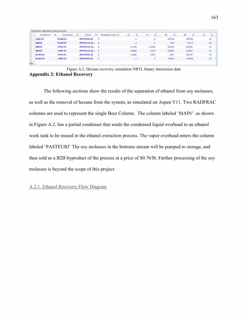
163
Figure A.2. Hexane recovery simulation NRTL binary interaction data
Appendix 2: Ethanol Recovery
The following sections show the results of the separation of ethanol from soy molasses,
as well as the removal of hexane from the system, as simulated on Aspen V11. Two RADFRAC
columns are used to represent the single Beer Column. The column labeled ‘MAIN’ as shown
in Figure A.2. has a partial condenser that sends the condensed liquid overhead to an ethanol
work tank to be reused in the ethanol extraction process. The vapor overhead enters the column
labeled ‘PASTEURI’ The soy molasses in the bottoms stream will be pumped to storage, and
then sold as a B2B byproduct of the process at a price of $0.76/lb. Further processing of the soy
molasses is beyond the scope of this project.
A.2.1. Ethanol Recovery Flow Diagram

164
Figure A.2. Ethanol recovery Aspen simulation flow diagram
A.2.2 Input Summary ; ;Input Summary created by Aspen Plus Rel. 37.0 at 09:56:05 Tue Apr 20, 2021 ;Directory C:\Users\gs2000\Downloads Filename C:\Users\gs2000\AppData\Local\Temp\~apc0c5.txt ;
DYNAMICS DYNAMICS RESULTS=ON IN-UNITS ENG SHORT-LENGTH=in DEF-STREAMS CONVEN ALL MODEL-OPTION DATABANKS 'APV110 PURE37' / 'APV110 AQUEOUS' / 'APV110 SOLIDS' & / 'APV110 INORGANIC' / 'APESV110 AP-EOS' / & 'NISTV110 NIST-TRC' / NOASPENPCD PROP-SOURCES 'APV110 PURE37' / 'APV110 AQUEOUS' / & 'APV110 SOLIDS' / 'APV110 INORGANIC' / 'APESV110 AP-EOS' & / 'NISTV110 NIST-TRC' COMPONENTS WATER H2O / ETHANOL C2H6O-2 / HEXANE C6H14-1 / PROTEIN FE / FIBER FE / ASH FE /

165 FRUCTOSE C6H12O6-N1 / GLUCOSE C6H12O6-N4 / SUCROSE C12H22O11 / STACHYOS C18H32O16 SOLVE RUN-MODE MODE=SIM FLOWSHEET BLOCK PASTEURI IN=TOPAST OUT=HEXOUT TOMAIN BLOCK MAIN IN=TOMAIN SOLUBIN OUT=TOPAST RECYCLE MOLASSES BLOCK PUMP1 IN=MOLASSES OUT=TOS501 BLOCK PUMP2 IN=RECYCLE OUT=TOS502 PROPERTIES NRTL PROP-DATA PCES-1 IN-UNITS ENG SHORT-LENGTH=in PROP-LIST RKTZRA / VLSTD PVAL FRUCTOSE .2895308900 / 2.328319773 PVAL GLUCOSE .2729276560 / 2.109140036 PVAL STACHYOS .1159583660 / 1.864081830 PROP-LIST VLSTD PVAL SUCROSE 3.620781424 PROP-DATA DHVLWT-1 IN-UNITS ENG SHORT-LENGTH=in PROP-LIST DHVLWT PVAL STACHYOS 37794.77055 1201.771400 .3800000000 0.0 & 204.9065600 PROP-DATA MULAND-1 IN-UNITS ENG SHORT-LENGTH=in PROP-LIST MULAND PVAL FRUCTOSE 68.45637493 -9037.816830 -8.749892190 & 710.0096000 1439.942000 PVAL GLUCOSE 93.94650282 -13435.37377 -11.84850500 & 811.2452000 1513.004000 PVAL SUCROSE 131.0439151 -19680.67098 -16.32127340 & 892.1300000 1475.582000 PVAL STACHYOS 916.7143782 -1.7210783E+5 -109.9016170 & 1201.771400 1390.046000 PROP-DATA SIGDIP-1 IN-UNITS ENG SHORT-LENGTH=in PROP-LIST SIGDIP PVAL FRUCTOSE 100.0717660 1.222222220 2.5317682E-10 & -2.794559E-10 1.1281207E-10 710.0096000 1420.754000 PVAL GLUCOSE 66.22410120 1.222222220 3.3098206E-10 & -3.679063E-10 1.4808090E-10 811.2452000 1493.078000 PVAL STACHYOS 117.2911300 1.222222160 1.95699485E-7 & -2.1289610E-7 7.79696079E-8 1201.771400 1371.362000 PROP-DATA NRTL-1 IN-UNITS ENG SHORT-LENGTH=in PROP-LIST NRTL BPVAL WATER ETHANOL 3.457800000 -1054.945620 .3000000000 & 0.0 0.0 0.0 76.98200000 212.0000000 BPVAL ETHANOL WATER -.8009000000 443.1240000 .3000000000 & 0.0 0.0 0.0 76.98200000 212.0000000

166 BPVAL WATER HEXANE 0.0 5472.000000 .2000000000 0.0 0.0 & 0.0 32.00000000 131.0000000 BPVAL HEXANE WATER 0.0 2721.600000 .2000000000 0.0 0.0 & 0.0 32.00000000 131.0000000 BPVAL ETHANOL HEXANE 0.0 896.0549400 .4700000000 0.0 0.0 & 0.0 104.0000000 172.9400000 BPVAL HEXANE ETHANOL 0.0 1329.552360 .4700000000 0.0 0.0 & 0.0 104.0000000 172.9400000 STREAM SOLUBIN SUBSTREAM MIXED TEMP=15. <C> PRES=28.7 MASS-FLOW WATER 130707.53 / ETHANOL 190825.01 / HEXANE & 7.86 / PROTEIN 1044.17 / FIBER 50.42 / ASH 1954.48 / & FRUCTOSE 124.1310569 / GLUCOSE 97.53154472 / SUCROSE & 2615.618699 / STACHYOS 2615.618699 BLOCK MAIN RADFRAC SUBOBJECTS INTERNALS = CS-1 PARAM NSTAGE=10 ALGORITHM=STANDARD HYDRAULIC=NO MAXOL=25 & DAMPING=NONE PARAM2 STATIC-DP=YES COL-CONFIG CONDENSER=PARTIAL-V-L CA-CONFIG=INT-1 FEEDS TOMAIN 2 / SOLUBIN 7 ON-STAGE PRODUCTS MOLASSES 10 L / RECYCLE 1 L / TOPAST 1 V P-SPEC 1 26. COL-SPECS DP-STAGE=0.14 MASS-RDV=0.014 MASS-D=318000. & MASS-RR=1. DP-COND=2. REPORT NOHYDRAULIC INTERNALS CS-1 STAGE1=2 STAGE2=9 P-UPDATE=NO & TRAYTYPE=FLEX-TO VALVE-THICK=0.074 <IN> TRAY-SIZE 1 2 9 FLEXI BLOCK PASTEURI RADFRAC SUBOBJECTS INTERNALS = CS-1 PARAM NSTAGE=12 ALGORITHM=STANDARD HYDRAULIC=NO MAXOL=100 & DAMPING=NONE PARAM2 STATIC-DP=YES COL-CONFIG CONDENSER=TOTAL REBOILER=NONE CA-CONFIG=INT-1 FEEDS TOPAST 12 ON-STAGE-VAP PRODUCTS HEXOUT 1 L / TOMAIN 12 L P-SPEC 1 22. COL-SPECS DP-STAGE=0.14 MASS-RR=20. DP-COND=2. REPORT NOHYDRAULIC INTERNALS CS-1 STAGE1=2 STAGE2=8 P-UPDATE=NO TRAYTYPE=SIEVE TRAY-SIZE 1 2 8 SIEVE BLOCK PUMP1 PUMP PARAM PRES=50. BLOCK PUMP2 PUMP PARAM PRES=45. EO-CONV-OPTI STREAM-REPOR MOLEFLOW PROPERTY-REP PCES ; ; ;

167 ; ;
A.2.3. Block Summaries
A.2.3.1. Block Summary - Main Column
BLOCK: MAIN MODEL: RADFRAC ------------------------------- INLETS - TOMAIN STAGE 2 SOLUBIN STAGE 7 OUTLETS - TOPAST STAGE 1 RECYCLE STAGE 1 MOLASSES STAGE 10 PROPERTY OPTION SET: NRTL RENON (NRTL) / IDEAL GAS
*********************************************************************** * * * FEED PRESSURE IS LOWER THAN STAGE PRESSURE. * * * ***********************************************************************
*** MASS AND ENERGY BALANCE *** IN OUT RELATIVE DIFF. TOTAL BALANCE MOLE(LBMOL/HR) 11587.4 11587.4 -0.313961E-15 MASS(LB/HR ) 334237. 334237. -0.115422E-08 ENTHALPY(BTU/HR ) -0.141905E+10 -0.137619E+10 -0.302020E-01 *** CO2 EQUIVALENT SUMMARY *** FEED STREAMS CO2E 0.00000 LB/HR PRODUCT STREAMS CO2E 0.00000 LB/HR NET STREAMS CO2E PRODUCTION 0.00000 LB/HR UTILITIES CO2E PRODUCTION 0.00000 LB/HR TOTAL CO2E PRODUCTION 0.00000 LB/HR
********************** **** INPUT DATA **** ********************** **** INPUT PARAMETERS **** NUMBER OF STAGES 10 ALGORITHM OPTION STANDARD ABSORBER OPTION NO INITIALIZATION OPTION STANDARD HYDRAULIC PARAMETER CALCULATIONS NO INSIDE LOOP CONVERGENCE METHOD BROYDEN DESIGN SPECIFICATION METHOD NESTED MAXIMUM NO. OF OUTSIDE LOOP ITERATIONS 25

168 MAXIMUM NO. OF INSIDE LOOP ITERATIONS 10 MAXIMUM NUMBER OF FLASH ITERATIONS 30 FLASH TOLERANCE 0.000100000 OUTSIDE LOOP CONVERGENCE TOLERANCE 0.000100000 **** COL-SPECS **** MASS VAPOR DIST / TOTAL DIST 0.014000 MASS REFLUX RATIO 1.00000 MASS DISTILLATE RATE LB/HR 318,000. **** PROFILES **** P-SPEC STAGE 1 PRES, PSIA 26.0000 ******************* **** RESULTS **** *******************
*** COMPONENT SPLIT FRACTIONS *** OUTLET STREAMS -------------- TOPAST RECYCLE MOLASSES COMPONENT: WATER .68738E-02 .93435 .58778E-01 ETHANOL .18243E-01 .98175 .17914E-05 HEXANE .73442 .26558 0.0000 PROTEIN 0.0000 0.0000 1.0000 FIBER 0.0000 0.0000 1.0000 ASH 0.0000 0.0000 1.0000 FRUCTOSE 0.0000 0.0000 1.0000 GLUCOSE 0.0000 0.0000 1.0000 SUCROSE 0.0000 0.0000 1.0000 STACHYOS 0.0000 0.0000 1.0000 *** SUMMARY OF KEY RESULTS *** TOP STAGE TEMPERATURE F 204.663 BOTTOM STAGE TEMPERATURE F 257.272 TOP STAGE LIQUID FLOW LBMOL/HR 11,117.8 BOTTOM STAGE LIQUID FLOW LBMOL/HR 498.019 TOP STAGE VAPOR FLOW LBMOL/HR 127.155 BOILUP VAPOR FLOW LBMOL/HR 24,870.0 MOLAR REFLUX RATIO 1.00257 MOLAR BOILUP RATIO 49.9379 CONDENSER DUTY (W/O SUBCOOL) BTU/HR -0.383380+09 REBOILER DUTY BTU/HR 0.426231+09 **** MAXIMUM FINAL RELATIVE ERRORS **** BUBBLE POINT 0.45364E-04 STAGE= 2 COMPONENT MASS BALANCE 0.55524E-06 STAGE= 10 COMP=ASH ENERGY BALANCE 0.17584E-04 STAGE= 10
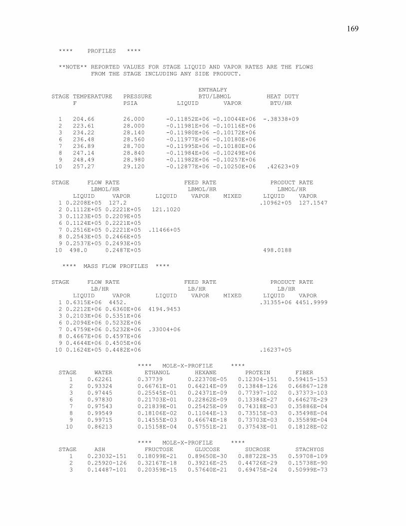
169 **** PROFILES **** **NOTE** REPORTED VALUES FOR STAGE LIQUID AND VAPOR RATES ARE THE FLOWS FROM THE STAGE INCLUDING ANY SIDE PRODUCT. ENTHALPY STAGE TEMPERATURE PRESSURE BTU/LBMOL HEAT DUTY F PSIA LIQUID VAPOR BTU/HR 1 204.66 26.000 -0.11852E+06 -0.10044E+06 -.38338+09 2 223.61 28.000 -0.11981E+06 -0.10116E+06 3 234.22 28.140 -0.11980E+06 -0.10172E+06 6 236.48 28.560 -0.11977E+06 -0.10180E+06 7 236.89 28.700 -0.11995E+06 -0.10180E+06 8 247.14 28.840 -0.11984E+06 -0.10249E+06 9 248.49 28.980 -0.11982E+06 -0.10257E+06 10 257.27 29.120 -0.12877E+06 -0.10250E+06 .42623+09 STAGE FLOW RATE FEED RATE PRODUCT RATE LBMOL/HR LBMOL/HR LBMOL/HR LIQUID VAPOR LIQUID VAPOR MIXED LIQUID VAPOR 1 0.2208E+05 127.2 .10962+05 127.1547 2 0.1112E+05 0.2221E+05 121.1020 3 0.1123E+05 0.2209E+05 6 0.1124E+05 0.2221E+05 7 0.2516E+05 0.2221E+05 .11466+05 8 0.2543E+05 0.2466E+05 9 0.2537E+05 0.2493E+05 10 498.0 0.2487E+05 498.0188 **** MASS FLOW PROFILES **** STAGE FLOW RATE FEED RATE PRODUCT RATE LB/HR LB/HR LB/HR LIQUID VAPOR LIQUID VAPOR MIXED LIQUID VAPOR 1 0.6315E+06 4452. .31355+06 4451.9999 2 0.2212E+06 0.6360E+06 4194.9453 3 0.2103E+06 0.5351E+06 6 0.2094E+06 0.5232E+06 7 0.4759E+06 0.5232E+06 .33004+06 8 0.4667E+06 0.4597E+06 9 0.4644E+06 0.4505E+06 10 0.1624E+05 0.4482E+06 .16237+05 **** MOLE-X-PROFILE **** STAGE WATER ETHANOL HEXANE PROTEIN FIBER 1 0.62261 0.37739 0.22370E-05 0.12304-151 0.59415-153 2 0.93324 0.66761E-01 0.64214E-09 0.13848-126 0.66867-128 3 0.97445 0.25545E-01 0.24371E-09 0.77397-102 0.37373-103 6 0.97830 0.21703E-01 0.22862E-09 0.13384E-27 0.64627E-29 7 0.97543 0.21839E-01 0.25425E-09 0.74318E-03 0.35886E-04 8 0.99549 0.18106E-02 0.11044E-13 0.73515E-03 0.35498E-04 9 0.99715 0.14555E-03 0.46674E-18 0.73703E-03 0.35589E-04 10 0.86213 0.15158E-04 0.57551E-21 0.37543E-01 0.18128E-02 **** MOLE-X-PROFILE **** STAGE ASH FRUCTOSE GLUCOSE SUCROSE STACHYOS 1 0.23032-151 0.18099E-21 0.89650E-30 0.88722E-35 0.59708-109 2 0.25920-126 0.32167E-18 0.39216E-25 0.44726E-29 0.15738E-90 3 0.14487-101 0.20359E-15 0.57640E-21 0.69475E-24 0.50999E-73

170 6 0.25052E-27 0.45516E-07 0.15620E-08 0.21279E-08 0.86727E-21 7 0.13911E-02 0.27417E-04 0.21520E-04 0.30373E-03 0.20610E-03 8 0.13761E-02 0.27124E-04 0.21287E-04 0.30045E-03 0.20388E-03 9 0.13796E-02 0.29069E-04 0.21416E-04 0.30133E-03 0.20440E-03 10 0.70273E-01 0.13835E-02 0.10870E-02 0.15343E-01 0.10412E-01 **** MOLE-Y-PROFILE **** STAGE WATER ETHANOL HEXANE PROTEIN FIBER 1 0.39488 0.60458 0.53330E-03 0.12291-176 0.59351-178 2 0.62130 0.37869 0.52778E-05 0.12234-151 0.59075-153 3 0.77889 0.22111 0.41287E-05 0.69729-127 0.33670-128 6 0.80251 0.19749 0.41065E-05 0.12160E-52 0.58719E-54 7 0.80251 0.19749 0.41069E-05 0.67742E-28 0.32710E-29 8 0.97772 0.22279E-01 0.25938E-09 0.72823E-28 0.35164E-29 9 0.99815 0.18464E-02 0.11264E-13 0.73828E-28 0.35649E-29 10 0.99985 0.14816E-03 0.47607E-18 0.43541E-26 0.21025E-27 **** MOLE-Y-PROFILE **** STAGE ASH FRUCTOSE GLUCOSE SUCROSE STACHYOS 1 0.23007-176 0.52519E-25 0.97485E-35 0.69490E-41 0.15839-128 2 0.22900-151 0.17996E-21 0.89136E-30 0.88214E-35 0.59366-109 3 0.13052-126 0.16206E-18 0.19747E-25 0.22521E-29 0.79249E-91 6 0.22762E-52 0.38056E-10 0.56960E-13 0.74666E-14 0.17647E-38 7 0.12680E-27 0.23037E-07 0.79060E-09 0.10770E-08 0.43896E-21 8 0.13631E-27 0.30547E-07 0.11190E-08 0.16338E-08 0.15511E-20 9 0.13819E-27 0.33782E-07 0.11725E-08 0.17209E-08 0.18227E-20 10 0.81501E-26 0.19469E-05 0.76725E-07 0.11874E-06 0.25265E-18 **** K-VALUES **** STAGE WATER ETHANOL HEXANE PROTEIN FIBER 1 0.63425 1.6020 238.38 0.25411E-47 0.25411E-47 2 0.66576 5.6716 8215.9 0.93382E-46 0.93382E-46 3 0.79931 8.6553 16941. 0.64663E-45 0.64663E-45 6 0.82031 9.0997 17962. 0.94464E-45 0.94464E-45 7 0.82272 9.0431 16153. 0.10089E-44 0.10089E-44 8 0.98215 12.305 23487. 0.58876E-44 0.58876E-44 9 1.0010 12.686 24134. 0.73602E-44 0.73602E-44 10 1.1597 9.7776 828.79 0.30283E-43 0.30283E-43 **** K-VALUES **** STAGE ASH FRUCTOSE GLUCOSE SUCROSE STACHYOS 1 0.25411E-47 0.29017E-03 0.10874E-04 0.78321E-06 0.26523E-19 2 0.93382E-46 0.55940E-03 0.22728E-04 0.19721E-05 0.37708E-18 3 0.64663E-45 0.79600E-03 0.34258E-04 0.32414E-05 0.15534E-17 6 0.94464E-45 0.83609E-03 0.36465E-04 0.35088E-05 0.20346E-17 7 0.10089E-44 0.84024E-03 0.36738E-04 0.35459E-05 0.21297E-17 8 0.58876E-44 0.11262E-02 0.52567E-04 0.54379E-05 0.76081E-17 9 0.73602E-44 0.11621E-02 0.54747E-04 0.57111E-05 0.89174E-17 10 0.30283E-43 0.14072E-02 0.70580E-04 0.77385E-05 0.24264E-16 **** MASS-X-PROFILE **** STAGE WATER ETHANOL HEXANE PROTEIN FIBER 1 0.39215 0.60785 0.67398E-05 0.24025-151 0.11601-152 2 0.84535 0.15465 0.27824E-08 0.38886-126 0.18777-127 3 0.93717 0.62825E-01 0.11212E-08 0.23075-101 0.11142-102 6 0.94632 0.53684E-01 0.10579E-08 0.40134E-27 0.19379E-28 7 0.92895 0.53185E-01 0.11582E-08 0.21941E-02 0.10595E-03 8 0.97724 0.45451E-02 0.51860E-13 0.22372E-02 0.10803E-03 9 0.98130 0.36629E-03 0.21972E-17 0.22485E-02 0.10857E-03 10 0.47637 0.21418E-04 0.15212E-20 0.64307E-01 0.31052E-02

171 **** MASS-X-PROFILE **** STAGE ASH FRUCTOSE GLUCOSE SUCROSE STACHYOS 1 0.44969-151 0.11400E-20 0.56467E-29 0.10618E-33 0.10530-107 2 0.72786-126 0.29139E-17 0.35524E-24 0.76980E-28 0.39919E-89 3 0.43192-101 0.19581E-14 0.55436E-20 0.12696E-22 0.13734E-71 6 0.75122E-27 0.44029E-06 0.15110E-07 0.39110E-07 0.23490E-19 7 0.41069E-02 0.26112E-03 0.20495E-03 0.54961E-02 0.54961E-02 8 0.41875E-02 0.26628E-03 0.20898E-03 0.56041E-02 0.56040E-02 9 0.42087E-02 0.28608E-03 0.21076E-03 0.56345E-02 0.56324E-02 10 0.12037 0.76448E-02 0.60066E-02 0.16109 0.16109 **** MASS-Y-PROFILE **** STAGE WATER ETHANOL HEXANE PROTEIN FIBER 1 0.20318 0.79550 0.13126E-02 0.19605-176 0.94668-178 2 0.39082 0.60916 0.15881E-04 0.23856-151 0.11520-152 3 0.57939 0.42059 0.14691E-04 0.16079-126 0.77643-128 6 0.61375 0.38624 0.15023E-04 0.28830E-52 0.13921E-53 7 0.61375 0.38624 0.15025E-04 0.16060E-27 0.77551E-29 8 0.94494 0.55063E-01 0.11992E-08 0.21818E-27 0.10535E-28 9 0.99529 0.47082E-02 0.53729E-13 0.22821E-27 0.11020E-28 10 0.99960 0.37878E-03 0.22768E-17 0.13494E-25 0.65160E-27 **** MASS-Y-PROFILE **** STAGE ASH FRUCTOSE GLUCOSE SUCROSE STACHYOS 1 0.36697-176 0.27024E-24 0.50161E-34 0.67937E-40 0.22820-127 2 0.44654-151 0.11320E-20 0.56072E-29 0.10543E-33 0.10456-107 3 0.30097-126 0.12056E-17 0.14690E-24 0.31832E-28 0.16507E-89 6 0.53964E-52 0.29105E-09 0.43564E-12 0.10850E-12 0.37790E-37 7 0.30062E-27 0.17619E-06 0.60466E-08 0.15651E-07 0.94002E-20 8 0.40839E-27 0.29523E-06 0.10815E-07 0.30002E-07 0.41977E-19 9 0.42716E-27 0.33686E-06 0.11691E-07 0.32605E-07 0.50891E-19 10 0.25259E-25 0.19464E-04 0.76707E-06 0.22555E-05 0.70726E-17
******************************** ***** HYDRAULIC PARAMETERS ***** ********************************
*** DEFINITIONS *** MARANGONI INDEX = SIGMA - SIGMATO FLOW PARAM = (ML/MV)*SQRT(RHOV/RHOL) QR = QV*SQRT(RHOV/(RHOL-RHOV)) F FACTOR = QV*SQRT(RHOV) WHERE: SIGMA IS THE SURFACE TENSION OF LIQUID FROM THE STAGE SIGMATO IS THE SURFACE TENSION OF LIQUID TO THE STAGE ML IS THE MASS FLOW OF LIQUID FROM THE STAGE MV IS THE MASS FLOW OF VAPOR TO THE STAGE RHOL IS THE MASS DENSITY OF LIQUID FROM THE STAGE RHOV IS THE MASS DENSITY OF VAPOR TO THE STAGE QV IS THE VOLUMETRIC FLOW RATE OF VAPOR TO THE STAGE
TEMPERATURE F STAGE LIQUID FROM VAPOR TO

172 1 204.66 223.61 2 223.61 234.22 3 234.22 235.81 6 236.48 236.89 7 236.89 247.14 8 247.14 248.49 9 248.49 257.27 10 257.27 257.27
MASS FLOW VOLUME FLOW MOLECULAR WEIGHT LB/HR CUFT/HR STAGE LIQUID FROM VAPOR TO LIQUID FROM VAPOR TO LIQUID FROM VAPOR TO 1 0.63155E+06 0.63600E+06 12917. 0.58155E+07 28.603 28.639 2 0.22125E+06 0.53505E+06 4064.0 0.58462E+07 19.888 24.218 3 0.21030E+06 0.52410E+06 3790.7 0.58576E+07 18.732 23.614 6 0.20935E+06 0.52316E+06 3769.4 0.57845E+07 18.624 23.556 7 0.47591E+06 0.45967E+06 8499.0 0.64856E+07 18.917 18.640 8 0.46674E+06 0.45050E+06 8272.6 0.65388E+07 18.352 18.067 9 0.46439E+06 0.44815E+06 8227.8 0.65709E+07 18.306 18.020 10 16237. 0.0000 222.01 0.0000 32.604
DENSITY VISCOSITY SURFACE TENSION LB/CUFT CP DYNE/CM STAGE LIQUID FROM VAPOR TO LIQUID FROM VAPOR TO LIQUID FROM 1 48.893 0.10936 0.30963 0.12583E-01 42.687 2 54.440 0.91521E-01 0.26306 0.13000E-01 54.173 3 55.478 0.89474E-01 0.24653 0.13052E-01 54.783 6 55.540 0.90441E-01 0.24342 0.13076E-01 54.701 7 55.995 0.70875E-01 0.25143 0.13326E-01 57.679 8 56.420 0.68896E-01 0.23762 0.13341E-01 57.367 9 56.442 0.68203E-01 0.23596 0.13524E-01 57.295 10 73.137 1.2087 206.62
MARANGONI INDEX FLOW PARAM QR REDUCED F-FACTOR STAGE DYNE/CM CUFT/HR (LB-CUFT)**.5/HR 1 0.46963E-01 0.27535E+06 0.19232E+07 2 11.582 0.16954E-01 0.23991E+06 0.17686E+07 3 0.60937 0.16114E-01 0.23543E+06 0.17521E+07 6 -.28889E-01 0.16148E-01 0.23362E+06 0.17396E+07 7 -2.3032 0.36834E-01 0.23089E+06 0.17266E+07 8 -.31188 0.36204E-01 0.22864E+06 0.17163E+07 9 -.72002E-01 0.36021E-01 0.22855E+06 0.17160E+07 10 149.33 0.0000 0.0000
************************************ ***** TRAY SIZING CALCULATIONS ***** ************************************
******************* *** SECTION 1 *** *******************

173 STARTING STAGE NUMBER 2 ENDING STAGE NUMBER 9 FLOODING CALCULATION METHOD B960-1 DESIGN PARAMETERS ----------------- PEAK CAPACITY FACTOR 1.00000 SYSTEM FOAMING FACTOR 1.00000 FLOODING FACTOR 0.80000 MINIMUM COLUMN DIAMETER FT 1.00000 MINIMUM DC AREA/COLUMN AREA 0.100000 DOWNCOMER DESIGN BASIS EQUAL FLOW PATH LENGTH TRAY SPECIFICATIONS ------------------- TRAY TYPE FLEXI NUMBER OF PASSES 1 TRAY SPACING FT 2.00000
***** SIZING RESULTS @ STAGE WITH MAXIMUM DIAMETER ***** STAGE WITH MAXIMUM DIAMETER 7 COLUMN DIAMETER FT 18.3654 DC AREA/COLUMN AREA 0.100000 DOWNCOMER VELOCITY FT/SEC 0.089120 FLOW PATH LENGTH PER PANEL FT 12.6180 SIDE DOWNCOMER WIDTH FT 2.87374 SIDE WEIR LENGTH FT 13.3445 CENTER DOWNCOMER WIDTH FT 0.0 CENTER WEIR LENGTH FT MISSING OFF-CENTER DOWNCOMER WIDTH FT 0.0 OFF-CENTER SHORT WEIR LENGTH FT MISSING OFF-CENTER LONG WEIR LENGTH FT MISSING TRAY CENTER TO OCDC CENTER FT 0.0
**** SIZING PROFILES **** STAGE DIAMETER TOTAL AREA ACTIVE AREA SIDE DC AREA FT SQFT SQFT SQFT 2 18.365 264.91 211.93 26.491 3 18.365 264.91 211.93 26.491 4 18.365 264.91 211.93 26.491 5 18.365 264.91 211.93 26.491 6 18.365 264.91 211.93 26.491 7 18.365 264.91 211.93 26.491 8 18.365 264.91 211.93 26.491 9 18.365 264.91 211.93 26.491
**** ADDITIONAL SIZING PROFILES **** FLOODING DC BACKUP/ STAGE FACTOR PRES. DROP DC BACKUP (TSPC+WHT) PSI FT 2 71.54 0.5682 2.701 124.7 3 69.72 0.5579 2.601 120.0 4 69.47 0.5551 2.585 119.3 5 69.33 0.5527 2.575 118.8

174 6 69.20 0.5504 2.565 118.4 7 80.00 0.5614 2.805 129.5 8 78.87 0.5550 2.749 126.9 9 78.74 0.5547 2.744 126.7 HEIGHT DC REL TR LIQ REL FRA APPR TO STAGE OVER WEIR FROTH DENS FROTH DENS SYS LIMIT FT 2 0.4767 0.6080 0.8337E-01 39.49 3 0.4505 0.6081 0.8424E-01 38.81 4 0.4478 0.6081 0.8449E-01 38.69 5 0.4470 0.6081 0.8470E-01 38.61 6 0.4462 0.6081 0.8491E-01 38.54 7 0.8014 0.6081 0.8563E-01 37.58 8 0.7811 0.6081 0.8620E-01 37.32 9 0.7778 0.6081 0.8622E-01 37.31
A.2.3.2. Block Summary - Pasteurizing Section
BLOCK: PASTEURI MODEL: RADFRAC ------------------------------- INLETS - TOPAST STAGE 12 OUTLETS - HEXOUT STAGE 1 TOMAIN STAGE 12 PROPERTY OPTION SET: NRTL RENON (NRTL) / IDEAL GAS *** MASS AND ENERGY BALANCE *** IN OUT RELATIVE DIFF. TOTAL BALANCE MOLE(LBMOL/HR) 127.155 127.158 -0.254021E-04 MASS(LB/HR ) 4452.00 4452.05 -0.123142E-04 ENTHALPY(BTU/HR ) -0.127719E+08 -0.149233E+08 0.144163 *** CO2 EQUIVALENT SUMMARY *** FEED STREAMS CO2E 0.00000 LB/HR PRODUCT STREAMS CO2E 0.00000 LB/HR NET STREAMS CO2E PRODUCTION 0.00000 LB/HR UTILITIES CO2E PRODUCTION 0.00000 LB/HR TOTAL CO2E PRODUCTION 0.00000 LB/HR
********************** **** INPUT DATA **** ********************** **** INPUT PARAMETERS **** NUMBER OF STAGES 12 ALGORITHM OPTION STANDARD ABSORBER OPTION NO INITIALIZATION OPTION STANDARD HYDRAULIC PARAMETER CALCULATIONS NO INSIDE LOOP CONVERGENCE METHOD BROYDEN

175 DESIGN SPECIFICATION METHOD NESTED MAXIMUM NO. OF OUTSIDE LOOP ITERATIONS 100 MAXIMUM NO. OF INSIDE LOOP ITERATIONS 10 MAXIMUM NUMBER OF FLASH ITERATIONS 30 FLASH TOLERANCE 0.000100000 OUTSIDE LOOP CONVERGENCE TOLERANCE 0.000100000 **** COL-SPECS **** MOLAR VAPOR DIST / TOTAL DIST 0.0 REBOILER DUTY BTU/HR 0.0 MASS REFLUX RATIO 20.0000 **** PROFILES **** P-SPEC STAGE 1 PRES, PSIA 22.0000 ******************* **** RESULTS **** *******************
*** COMPONENT SPLIT FRACTIONS *** OUTLET STREAMS -------------- HEXOUT TOMAIN COMPONENT: WATER .17434E-01 .98257 ETHANOL .66522E-01 .93348 HEXANE .98338 .16623E-01 *** SUMMARY OF KEY RESULTS *** TOP STAGE TEMPERATURE F 183.800 BOTTOM STAGE TEMPERATURE F 200.551 TOP STAGE LIQUID FLOW LBMOL/HR 121.120 BOTTOM STAGE LIQUID FLOW LBMOL/HR 121.099 TOP STAGE VAPOR FLOW LBMOL/HR 0.0 BOILUP VAPOR FLOW LBMOL/HR 128.310 MOLAR REFLUX RATIO 20.0000 CONDENSER DUTY (W/O SUBCOOL) BTU/HR -2,150,970. REBOILER DUTY BTU/HR 0.0 **** MAXIMUM FINAL RELATIVE ERRORS **** DEW POINT 0.10522E-06 STAGE= 1 BUBBLE POINT 0.28150E-04 STAGE= 1 COMPONENT MASS BALANCE 0.17277E-05 STAGE= 9 COMP=HEXANE ENERGY BALANCE 0.50078E-05 STAGE= 1
**** PROFILES **** **NOTE** REPORTED VALUES FOR STAGE LIQUID AND VAPOR RATES ARE THE FLOWS FROM THE STAGE INCLUDING ANY SIDE PRODUCT.

176 ENTHALPY STAGE TEMPERATURE PRESSURE BTU/LBMOL HEAT DUTY F PSIA LIQUID VAPOR BTU/HR 1 183.80 22.000 -0.11616E+06 -94652. -.21510+07 2 195.49 24.000 -0.11618E+06 -99244. 3 196.26 24.140 -0.11621E+06 -99567. 4 196.58 24.280 -0.11623E+06 -99602. 5 196.89 24.420 -0.11626E+06 -99624. 11 199.39 25.260 -0.11696E+06 -99978. 12 200.55 25.400 -0.11742E+06 -0.10015E+06 STAGE FLOW RATE FEED RATE PRODUCT RATE LBMOL/HR LBMOL/HR LBMOL/HR LIQUID VAPOR LIQUID VAPOR MIXED LIQUID VAPOR 1 127.2 0.000 6.0559 2 123.4 127.2 3 123.5 129.5 4 123.5 129.6 5 123.5 129.5 11 122.3 128.8 12 121.1 128.3 127.1547 121.1020 **** MASS FLOW PROFILES **** STAGE FLOW RATE FEED RATE PRODUCT RATE LB/HR LB/HR LB/HR LIQUID VAPOR LIQUID VAPOR MIXED LIQUID VAPOR 1 5399. 0.000 257.1094 2 5167. 5399. 3 5147. 5424. 4 5122. 5404. 5 5092. 5379. 11 4546. 4995. 12 4195. 4803. 4451.9999 4195.0023 **** MOLE-X-PROFILE **** STAGE WATER ETHANOL HEXANE 1 0.14455 0.84444 0.11011E-01 2 0.15080 0.84856 0.63684E-03 3 0.15671 0.84322 0.62861E-04 4 0.16363 0.83634 0.31355E-04 5 0.17194 0.82803 0.28791E-04 11 0.31668 0.68331 0.14996E-04 12 0.40740 0.59259 0.93085E-05 **** MOLE-Y-PROFILE **** STAGE WATER ETHANOL HEXANE 1 0.12267 0.71642 0.16091 2 0.14455 0.84444 0.11011E-01 3 0.15051 0.84837 0.11220E-02 4 0.15615 0.84328 0.57462E-03 5 0.16274 0.83672 0.54465E-03 11 0.26064 0.73883 0.53590E-03 12 0.30855 0.69091 0.53401E-03 **** K-VALUES **** STAGE WATER ETHANOL HEXANE 1 0.84858 0.84840 14.616 2 0.95853 0.99514 17.292 3 0.96042 1.0061 17.850

177 4 0.95428 1.0083 18.325 5 0.94648 1.0105 18.916 11 0.82304 1.0812 35.738 12 0.75736 1.1659 57.367 **** MASS-X-PROFILE **** STAGE WATER ETHANOL HEXANE 1 0.61339E-01 0.91631 0.22351E-01 2 0.64895E-01 0.93379 0.13109E-02 3 0.67744E-01 0.93213 0.12999E-03 4 0.71066E-01 0.92887 0.65142E-04 5 0.75100E-01 0.92484 0.60154E-04 11 0.15342 0.84655 0.34752E-04 12 0.21188 0.78810 0.23157E-04 **** MASS-Y-PROFILE **** STAGE WATER ETHANOL HEXANE 1 0.45026E-01 0.67244 0.28253 2 0.61339E-01 0.91631 0.22351E-01 3 0.64727E-01 0.93297 0.23082E-02 4 0.67439E-01 0.93137 0.11872E-02 5 0.70601E-01 0.92827 0.11303E-02 11 0.12108 0.87772 0.11909E-02 12 0.14849 0.85028 0.12293E-02
******************************** ***** HYDRAULIC PARAMETERS ***** ********************************
*** DEFINITIONS *** MARANGONI INDEX = SIGMA - SIGMATO FLOW PARAM = (ML/MV)*SQRT(RHOV/RHOL) QR = QV*SQRT(RHOV/(RHOL-RHOV)) F FACTOR = QV*SQRT(RHOV) WHERE: SIGMA IS THE SURFACE TENSION OF LIQUID FROM THE STAGE SIGMATO IS THE SURFACE TENSION OF LIQUID TO THE STAGE ML IS THE MASS FLOW OF LIQUID FROM THE STAGE MV IS THE MASS FLOW OF VAPOR TO THE STAGE RHOL IS THE MASS DENSITY OF LIQUID FROM THE STAGE RHOV IS THE MASS DENSITY OF VAPOR TO THE STAGE QV IS THE VOLUMETRIC FLOW RATE OF VAPOR TO THE STAGE
TEMPERATURE F STAGE LIQUID FROM VAPOR TO 1 183.80 195.49 2 195.49 196.26 3 196.26 196.58 4 196.58 196.89 5 196.89 197.20 11 199.39 200.55 12 200.55 204.66

178
MASS FLOW VOLUME FLOW MOLECULAR WEIGHT LB/HR CUFT/HR STAGE LIQUID FROM VAPOR TO LIQUID FROM VAPOR TO LIQUID FROM VAPOR TO 1 5399.3 5399.3 117.92 37256. 42.455 42.455 2 5167.3 5424.4 113.66 37757. 41.864 41.892 3 5147.1 5404.2 113.20 37580. 41.675 41.712 4 5122.3 5379.4 112.59 37377. 41.480 41.526 5 5092.0 5349.1 111.85 37171. 41.247 41.303 11 4546.1 4803.2 98.211 35791. 37.186 37.434 12 4194.9 4452.0 89.431 35690. 34.640 35.012
DENSITY VISCOSITY SURFACE TENSION LB/CUFT CP DYNE/CM STAGE LIQUID FROM VAPOR TO LIQUID FROM VAPOR TO LIQUID FROM 1 45.787 0.14492 0.38770 0.11072E-01 23.197 2 45.464 0.14367 0.35638 0.11136E-01 22.813 3 45.471 0.14381 0.35411 0.11156E-01 23.027 4 45.493 0.14392 0.35283 0.11176E-01 23.310 5 45.524 0.14390 0.35153 0.11199E-01 23.654 11 46.289 0.13420 0.33708 0.11558E-01 29.808 12 46.907 0.12474 0.32948 0.11810E-01 33.676
MARANGONI INDEX FLOW PARAM QR REDUCED F-FACTOR STAGE DYNE/CM CUFT/HR (LB-CUFT)**.5/HR 1 0.56260E-01 2099.4 14183. 2 -.38465 0.53549E-01 2125.8 14311. 3 0.21472 0.53562E-01 2116.7 14251. 4 0.28246 0.53558E-01 2105.6 14180. 5 0.34450 0.53521E-01 2093.2 14101. 11 2.1491 0.50962E-01 1929.9 13111. 12 3.8680 0.48591E-01 1842.9 12605.
************************************ ***** TRAY SIZING CALCULATIONS ***** ************************************
******************* *** SECTION 1 *** ******************* STARTING STAGE NUMBER 2 ENDING STAGE NUMBER 8 FLOODING CALCULATION METHOD GLITSCH6 DESIGN PARAMETERS ----------------- PEAK CAPACITY FACTOR 1.00000 SYSTEM FOAMING FACTOR 1.00000 FLOODING FACTOR 0.80000 MINIMUM COLUMN DIAMETER FT 1.00000 MINIMUM DC AREA/COLUMN AREA 0.100000

179 HOLE AREA/ACTIVE AREA 0.100000 DOWNCOMER DESIGN BASIS EQUAL FLOW PATH LENGTH TRAY SPECIFICATIONS ------------------- TRAY TYPE SIEVE NUMBER OF PASSES 1 TRAY SPACING FT 2.00000
***** SIZING RESULTS @ STAGE WITH MAXIMUM DIAMETER ***** STAGE WITH MAXIMUM DIAMETER 2 COLUMN DIAMETER FT 1.62586 DC AREA/COLUMN AREA 0.100000 DOWNCOMER VELOCITY FT/SEC 0.15207 FLOW PATH LENGTH PER PANEL FT 1.11704 SIDE DOWNCOMER WIDTH FT 0.25441 SIDE WEIR LENGTH FT 1.18137 CENTER DOWNCOMER WIDTH FT 0.0 CENTER WEIR LENGTH FT MISSING OFF-CENTER DOWNCOMER WIDTH FT 0.0 OFF-CENTER SHORT WEIR LENGTH FT MISSING OFF-CENTER LONG WEIR LENGTH FT MISSING TRAY CENTER TO OCDC CENTER FT 0.0
**** SIZING PROFILES **** STAGE DIAMETER TOTAL AREA ACTIVE AREA SIDE DC AREA FT SQFT SQFT SQFT 2 1.6259 2.0761 1.6609 0.20761 3 1.6259 2.0761 1.6609 0.20761 4 1.6259 2.0761 1.6609 0.20761 5 1.6259 2.0761 1.6609 0.20761 6 1.6259 2.0761 1.6609 0.20761 7 1.6259 2.0761 1.6609 0.20761 8 1.6259 2.0761 1.6609 0.20761
**** ADDITIONAL SIZING PROFILES **** FLOODING DC BACKUP/ STAGE FACTOR PRES. DROP DC BACKUP (TSPC+WHT) PSI FT 2 80.00 0.1360 0.7847 36.22 3 79.66 0.1352 0.7804 36.02 4 79.24 0.1341 0.7751 35.77 5 78.77 0.1330 0.7692 35.50 6 78.24 0.1318 0.7626 35.20 7 77.61 0.1304 0.7549 34.84 8 76.84 0.1287 0.7457 34.42 HEIGHT DC REL TR LIQ REL FRA APPR TO STAGE OVER WEIR FROTH DENS FROTH DENS SYS LIMIT FT 2 0.1973 0.6063 0.1735 53.70 3 0.1965 0.6063 0.1738 53.34 4 0.1956 0.6063 0.1741 52.91 5 0.1945 0.6064 0.1745 52.41
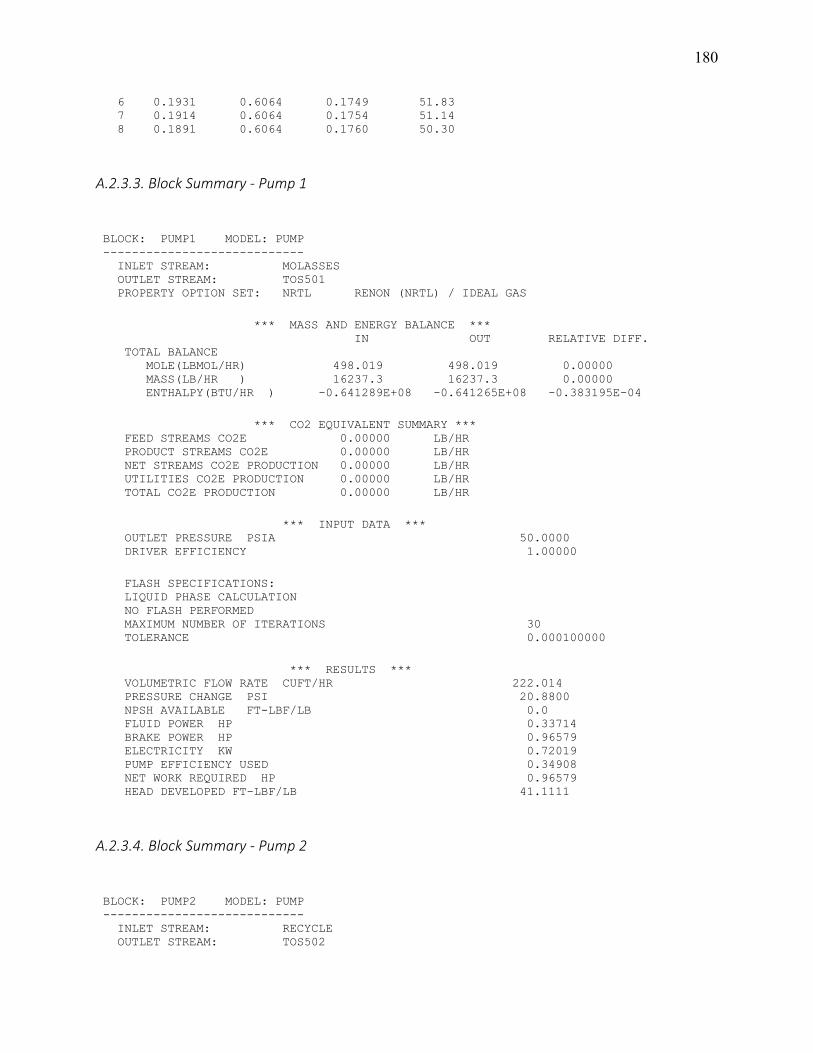
180 6 0.1931 0.6064 0.1749 51.83 7 0.1914 0.6064 0.1754 51.14 8 0.1891 0.6064 0.1760 50.30
A.2.3.3. Block Summary - Pump 1
BLOCK: PUMP1 MODEL: PUMP ---------------------------- INLET STREAM: MOLASSES OUTLET STREAM: TOS501 PROPERTY OPTION SET: NRTL RENON (NRTL) / IDEAL GAS *** MASS AND ENERGY BALANCE *** IN OUT RELATIVE DIFF. TOTAL BALANCE MOLE(LBMOL/HR) 498.019 498.019 0.00000 MASS(LB/HR ) 16237.3 16237.3 0.00000 ENTHALPY(BTU/HR ) -0.641289E+08 -0.641265E+08 -0.383195E-04 *** CO2 EQUIVALENT SUMMARY *** FEED STREAMS CO2E 0.00000 LB/HR PRODUCT STREAMS CO2E 0.00000 LB/HR NET STREAMS CO2E PRODUCTION 0.00000 LB/HR UTILITIES CO2E PRODUCTION 0.00000 LB/HR TOTAL CO2E PRODUCTION 0.00000 LB/HR *** INPUT DATA *** OUTLET PRESSURE PSIA 50.0000 DRIVER EFFICIENCY 1.00000 FLASH SPECIFICATIONS: LIQUID PHASE CALCULATION NO FLASH PERFORMED MAXIMUM NUMBER OF ITERATIONS 30 TOLERANCE 0.000100000 *** RESULTS *** VOLUMETRIC FLOW RATE CUFT/HR 222.014 PRESSURE CHANGE PSI 20.8800 NPSH AVAILABLE FT-LBF/LB 0.0 FLUID POWER HP 0.33714 BRAKE POWER HP 0.96579 ELECTRICITY KW 0.72019 PUMP EFFICIENCY USED 0.34908 NET WORK REQUIRED HP 0.96579 HEAD DEVELOPED FT-LBF/LB 41.1111
A.2.3.4. Block Summary - Pump 2
BLOCK: PUMP2 MODEL: PUMP ---------------------------- INLET STREAM: RECYCLE OUTLET STREAM: TOS502

181 PROPERTY OPTION SET: NRTL RENON (NRTL) / IDEAL GAS *** MASS AND ENERGY BALANCE *** IN OUT RELATIVE DIFF. TOTAL BALANCE MOLE(LBMOL/HR) 10962.2 10962.2 0.00000 MASS(LB/HR ) 313548. 313548. 0.00000 ENTHALPY(BTU/HR ) -0.129929E+10 -0.129926E+10 -0.230375E-04 *** CO2 EQUIVALENT SUMMARY *** FEED STREAMS CO2E 0.00000 LB/HR PRODUCT STREAMS CO2E 0.00000 LB/HR NET STREAMS CO2E PRODUCTION 0.00000 LB/HR UTILITIES CO2E PRODUCTION 0.00000 LB/HR TOTAL CO2E PRODUCTION 0.00000 LB/HR *** INPUT DATA *** OUTLET PRESSURE PSIA 45.0000 DRIVER EFFICIENCY 1.00000 FLASH SPECIFICATIONS: LIQUID PHASE CALCULATION NO FLASH PERFORMED MAXIMUM NUMBER OF ITERATIONS 30 TOLERANCE 0.000100000 *** RESULTS *** VOLUMETRIC FLOW RATE CUFT/HR 6,412.91 PRESSURE CHANGE PSI 19.0000 NPSH AVAILABLE FT-LBF/LB 0.0 FLUID POWER HP 8.86147 BRAKE POWER HP 11.7639 ELECTRICITY KW 8.77233 PUMP EFFICIENCY USED 0.75328 NET WORK REQUIRED HP 11.7639 HEAD DEVELOPED FT-LBF/LB 55.9586

182
Appendix 3: Extraction Hexane Technical Parameters

183

184
x

185
Appendix 4: Typical Composition of Soy Molasses on a Dry Matter Basis
Appendix 5: Equipment Quotes
Appendix 5.1 Vertical Seed Conditioner Quote

186
Appendix 5.2 Flaker Quote

187

188
Appendix 5.3 Extractor Quote
Appendix 5.3.1 1997 Crown Iron Works Extractor Quote
Appendix 5.3.2 Desmet Ballestra Extractor Quote
Appendix 5.3.3 N&T Engitech 500 TPD Continuous Extractor
Quotation

189
Quotation No.- NTEPL-P4038-2021-22 Date: 09.04.2021
To, Alia Wallenstrom USA Tel No. : +1 808 366 9077
From, Mr. Riyaz Tunvar N & T Engitech Pvt. Ltd. Cell No: +91-90998 69951
Sr. No. Description Quantity Unit Unit Rate US $
Total US $
1 500 TPD Continuous Extractor 1 No. $85,578.00 $85,578.00
Technical Specification :
(Direct Drive Type)
Size: 1800mm X 2300mm x 8mm Thk.
Number Of Sprayers: 9
Miscella Receiving Hopper SS304: 11 No
Direct Drive With Suitable Gear Box, Motor, and
Safety Device& Jet Spray. Horizontal Model
Comprising Of Articulated Band Conveyor
Assembly Which Receives The Material From The
Feed Hopper And Transports It at Avery Slow
Predetermined Speed From The Feed To The
Discharge End. The Conveyor Moves Over The
Rails Suitably Located Inside The Extractor And
The Rides On Specially Constructed Sprocket At
Either End, Series Of Sprays Of The Solvent On The
Moving Bed With Liberal Provision For Light Sight
Glasses.
Motor 5 hp/1440 with vfd,
Gear box ratio 1800 : 1

190
Type : Planetary
Torque : 20,000 Nm
Extractor drum shaft : 3 hp / 6 rpm
Without Gearbox & Motor
Packing & Forwarding Charges Extra
Freight Charges Extra
Round Figure + --
0
( Eighty Five Thousand Five Hundred Seventy Eight US Dollar Only ) TOTAL $85,578.00
Terms and Conditions
1. Payment: 40% Advance & Balance Before Dispatch. 2. Tax : As per Goverment Export Rules 3. Validity : 10 Days 4. Ex- Rate : Ex-Work Sidhpur/Indore (India). 5. Good Ready for Export : Within 14-16 Weeks. 6. Subject to Palanpur,Gujarat, India jurisdiction 7. Above All Material as per Indian Engineering Standard & best Quality. 8. Final settlement of weight variation will be after work completion. 9. Kindly revert back a signed copy of this document as a token of acceptance.
Thanks and Regards, N & T Engitech Pvt. Ltd., 315-317, 3rd Floor, Diamond Complex, SH-41 Industrial Area, Chhapi - 385210 Gujarat (India).
This is a computer generated copy and hence it is not signed.
Appendix 5.3.4 N&T Engitech DT Quote

191
Quotation
Quotation No.- NTEPL-P4037-2021-22 Date: 09.04.2021
To, From, Alia Wallenstrom
Mr. Riyaz Tunvar USA
N & T Engitech Pvt. Ltd. Tel No. : +1 808 366 9077
Cell No: +91-90998 69951
Sr. No. Description Quantity Unit Unit Rate US $
Total US $
1 500 TPD Desolventizer-Toaster 1 No. $55,500.00 $55,500.00
Technical Specification :
Diameter of DT : 3000 mm.
Number of Stages : 7 Nos.
Overall Shell Height will be : 7100 mm approx.
Thickness of Shell Plate and Top Plate 12 mm.
Thickness of Double bottom plates will be 16 mm (Top Plate) /
14 mm (Bottom Plate).
Stay pipe Seamless 2.5”NB Sch-80 in all compartments.
Centre Shaft will be Seamless Pipe of 219 OD x 23 mm thickness.
Bottom Housing will have Spherical Roller thrust bearing with
Gland Assembly.
Top Housing will Gun Metal Bush and Gland Assembly.
MS Blades 25 mm thk.

192
Hubs of Steel Casting.
Vapour drum in top three compartments.
Mechanical Door and Flot Assembly.
Man Hole and Sight Glass in each compartment.
Material Specification:
Material used for Shell and Double Bottom Plates will be of Grade
IS 2062 Gr-B ( Make- Sail / Jindal)
Stay Pipe for Double Bottom will be of grade A106 Seamless
Sch-80 (Make-ISMT/MSL)
Without Gearbox & Motor
Packing & Forwarding Charges Extra
Freight Charges Extra
Round Figure + --
0
( Fifty Five Thousand Five Hundred US Dollar Only ) TOTAL $55,500.00
Terms and Conditions
1. Payment: 40% Advance & Balance Before Dispatch. 2. Tax : As per Goverment Export Rules 3. Validity : 10 Days 4. Ex- Rate : Ex-Work Sidhpur/Indore (India). 5. Good Ready for Export : Within 14-16 Weeks. 6. Subject to Palanpur,Gujarat, India jurisdiction 7. Above All Material as per Indian Engineering Standard & best Quality. 8. Final settlement of weight variation will be after work completion. 9. Kindly revert back a signed copy of this document as a token of acceptance.
Thanks and Regards, N & T Engitech Pvt. Ltd., 315-317, 3rd Floor, Diamond Complex, SH-41 Industrial Area, Chhapi - 385210 Gujarat (India).

193
This is a computer generated copy and hence it is not signed.
Appendix 5.4. Miscella Tank Quote
Quotation
Quotation No.- NTEPL-P4039-2021-22 Date: 09.04.2021
To, From, Alia Wallenstrom
Mr. Riyaz Tunvar USA
N & T Engitech Pvt. Ltd. Tel No. : +1 808 366 9077
Cell No: +91-90998 69951
Sr. No. Description Quantity Unit Unit Rate US $
Total US $
1 Miscella Tank 1 No. $18,212.00 $18,212.00
Technical Specification :
Made Of Welded Mild Steel Construction With
Manholes to Draw Out Clear Miscella.
Dia 1750 x 4000 length x 6 thk
Packing & Forwarding Charges Extra
Freight Charges Extra
Round Figure + --
0
( Seventy Thousand Four Hundred Seventy Eight US Dollar Only ) TOTAL $18,212.00

194
Terms and Conditions
1. Payment: 40% Advance & Balance Before Dispatch. 2. Tax : As per Goverment Export Rules 3. Validity : 10 Days 4. Ex- Rate : Ex-Work Sidhpur/Indore (India). 5. Good Ready for Export : Within 14-16 Weeks. 6. Subject to Palanpur,Gujarat, India jurisdiction 7. Above All Material as per Indian Engineering Standard & best Quality. 8. Final settlement of weight variation will be after work completion. 9. Kindly revert back a signed copy of this document as a token of acceptance.
Thanks and Regards, N & T Engitech Pvt. Ltd., 315-317, 3rd Floor, Diamond Complex, SH-41 Industrial Area, Chhapi - 385210 Gujarat (India).
This is a computer generated copy and hence it is not signed.
Appendix 5.5. N&T Engitech DT Quote
Quotation
Quotation No.- NTEPL-P4037-2021-22 Date: 09.04.2021
To, From, Alia Wallenstrom
Mr. Riyaz Tunvar USA
N & T Engitech Pvt. Ltd. Tel No. : +1 808 366 9077
Cell No: +91-90998 69951
Sr. No. Description Quantity Unit Unit Rate US $
Total US $
1 500 TPD Desolventizer-Toaster 1 No. $55,500.00 $55,500.00
Technical Specification :

195
Diameter of DT : 3000 mm.
Number of Stages : 7 Nos.
Overall Shell Height will be : 7100 mm approx.
Thickness of Shell Plate and Top Plate 12 mm.
Thickness of Double bottom plates will be 16 mm (Top Plate) /
14 mm (Bottom Plate).
Stay pipe Seamless 2.5”NB Sch-80 in all compartments.
Centre Shaft will be Seamless Pipe of 219 OD x 23 mm thickness.
Bottom Housing will have Spherical Roller thrust bearing with
Gland Assembly.
Top Housing will Gun Metal Bush and Gland Assembly.
MS Blades 25 mm thk.
Hubs of Steel Casting.
Vapour drum in top three compartments.
Mechanical Door and Flot Assembly.
Man Hole and Sight Glass in each compartment.
Material Specification:
Material used for Shell and Double Bottom Plates will be of Grade
IS 2062 Gr-B ( Make- Sail / Jindal)
Stay Pipe for Double Bottom will be of grade A106 Seamless
Sch-80 (Make-ISMT/MSL)
Without Gearbox & Motor
Packing & Forwarding Charges Extra
Freight Charges Extra
Round Figure + --
0
( Fifty Five Thousand Five Hundred US Dollar Only ) TOTAL $55,500.00

196
Terms and Conditions
1. Payment: 40% Advance & Balance Before Dispatch. 2. Tax : As per Goverment Export Rules 3. Validity : 10 Days 4. Ex- Rate : Ex-Work Sidhpur/Indore (India). 5. Good Ready for Export : Within 14-16 Weeks. 6. Subject to Palanpur,Gujarat, India jurisdiction 7. Above All Material as per Indian Engineering Standard & best Quality. 8. Final settlement of weight variation will be after work completion. 9. Kindly revert back a signed copy of this document as a token of acceptance.
Thanks and Regards, N & T Engitech Pvt. Ltd., 315-317, 3rd Floor, Diamond Complex, SH-41 Industrial Area, Chhapi - 385210 Gujarat (India).
This is a computer generated copy and hence it is not signed.

197
Appendix 6: Safety Data Sheets
The following sections contain the safety data sheets (SDS) for hexane and ethanol,
published by the NIST and Sigma-Aldrich respectively. The SDS attached in Appendix 6.2 is
specified for pure ethanol, since a complete SDS for 60% aqueous ethanol was not available.

198
Appendix 6: Safety Data Sheets
The following sections contain the safety data sheets (SDS) for hexane and ethanol,
published by the NIST and Sigma-Aldrich respectively. The SDS attached in Appendix 6.2 is
specified for pure ethanol, since a complete SDS for 60% aqueous ethanol was not available.

199
Appendix 6.1: Hexane SDS

200
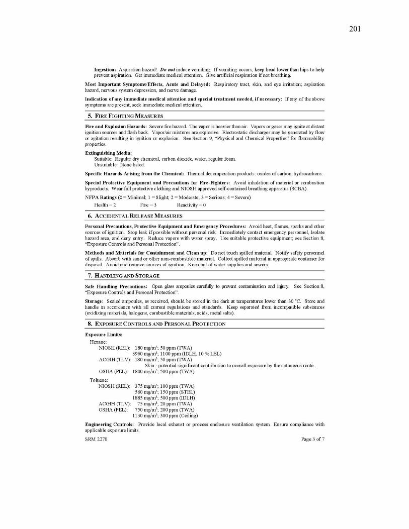
201

202

203

204

205

206
Appendix 6.2: Ethanol SDS

207

208

209

210

211

212

213

214

215