Project shelter, Part 2: Structural Verification - SciELO Chile
19
68 Project shelter, Part 2: Structural Verification Proyecto Vivienda de Emergencia, Parte 2, Verificación Mecánica Rose Marie Garay (Main and Corresponding Author) Departamento de Ingeniería de la Madera y Biomateriales, Facultad de Ciencias Forestales y Conservación de la Naturaleza, Universidad de Chile; Programa de Reducción de Riesgo de Desastre (CITRID) Postal Code 9206, Santiago (Chile) [email protected] Ricardo Herrera Departamento de Ingeniería Civil, Facultad de Ciencias Físicas y Matemáticas, Universidad de Chile; Programa de Reducción de Riesgo de Desastre (CITRID) Postal Code 2283, Santiago (Chile) [email protected] Claudio Mejías Departamento de Ingeniería Civil, Facultad de Ciencias Físicas y Matemáticas, Universidad de Chile Postal Code 2283, Santiago (Chile) [email protected] Manuscript Code: 1095 Date of Acceptance/Reception: 26.03.2019/05.04.2018 DOI: 10.7764/RDLC.18.1.68 Abstract As part of the Fondef D09I1058 project, an emergency housing solution was developed and five prototypes constructed. The prototypes solved mechanical, thermal, water tightness and airtightness problems common to emergency housing, achieving a minimum durability of five years. Emergency housing does not fall under the jurisdiction of permanent housing codes, hence, there are no requirements that these houses must meet. A first step towards establishing minimum requirements is the evaluation of the current emergency housing solutions. This paper presents the structural evaluation of these prototypes. The prototypes were fabricated with "structural insulated panels" (SIPs), which provide structural strength and thermal insulation, for four thermal zones of the country. All the prototypes presented adequate structural performance. Out of all the locations considered, only two houses presented minor strength problems in the roof structure, but almost satisfied the requirements indicated by the codes for permanent social housing. In the case of the floor diaphragms, only one prototype fell short 97.5% of the required strength, which was considered acceptable this emergency housing. For the walls, laboratory tests, performed applying lateral and out-of-plane loads on the panels that compose the prototypes, established that they could withstand the design earthquake loads and wind loads. Keywords: emergency house, shelter, habitability, technical and normative standards for emergency houses, SIP panel, structural timber frame. Resumen Como parte del proyecto Fondef D09I1058, cinco prototipos de vivienda temporal ubicados en cuatro zonas térmicas de Chile fueron diseñados, construidos y evaluados para establecer estándares mínimos para viviendas de emergencia transitorias de bajo costo. Estos prototipos resolvieron problemas mecánicos, térmicos, de estanqueidad al agua y al aire comunes en viviendas de emergencia, logrando una durabilidad mínima de 5 años. Las viviendas de emergencia no están reguladas por las normativas de las viviendas definitivas; por lo tanto, no hay requisitos exigibles que deban cumplir. Esta ausencia de requisitos mínimos es inaceptable, considerando que las familias afectadas por desastres a menudo permanecen en albergues transitorios años hasta acceder a una solución permanente. Un primer paso en la dirección de establecer requisitos mínimos es la evaluación de las viviendas de emergencia existentes. En un artículo anterior se abordó los requisitos de resistencia al fuego y aislación térmica de los prototipos derivados del proyecto Fondef D09I1058. Este artículo presenta la evaluación estructural de estos prototipos. Los prototipos fueron fabricados con paneles "Structural Insulated Panel"(SIP), ofreciendo resistencia estructural y aislación térmica para 4 zonas térmicas del país. Los resultados indicaron que todos los prototipos lograron un desempeño estructural adecuado. De todas las localidades consideradas, en solo dos de ellas se presentaron problemas de resistencia menores en el techo, pero casi logrando cumplir con los requisitos de la normativa para viviendas sociales de uso permanente. Para el diafragma de piso, solo un prototipo no satisfizo los requisitos de resistencia de las normas nacionales, aunque alcanzo el 97.5% de la carga de uso exigida. Por el carácter de vivienda de emergencia, este valor se consideró aceptable. Para los muros, ensayos de laboratorio, realizados aplicando carga lateral y fuera del plano en los paneles que componen el prototipo de vivienda de emergencia, establecieron que los prototipos pueden soportar el sismo de diseño y las máximas cargas de viento establecidas en la normativa nacional. Palabras clave: vivienda de emergencia, refugio, estándares y normativa técnica para viviendas de emergencia, panel SIP, tabiques de madera estructural.
-
Upload
khangminh22 -
Category
Documents
-
view
0 -
download
0
Transcript of Project shelter, Part 2: Structural Verification - SciELO Chile
68
Project shelter, Part 2: Structural Verification Proyecto Vivienda de Emergencia, Parte 2, Verificación Mecánica Rose Marie Garay (Main and Corresponding Author)
Departamento de Ingeniería de la Madera y Biomateriales, Facultad de Ciencias Forestales y Conservación de la Naturaleza, Universidad de Chile; Programa de Reducción de Riesgo de Desastre (CITRID) Postal Code 9206, Santiago (Chile) [email protected]
Ricardo Herrera Departamento de Ingeniería Civil, Facultad de Ciencias Físicas y Matemáticas, Universidad de Chile; Programa de Reducción de Riesgo de Desastre (CITRID) Postal Code 2283, Santiago (Chile) [email protected]
Claudio Mejías Departamento de Ingeniería Civil, Facultad de Ciencias Físicas y Matemáticas, Universidad de Chile Postal Code 2283, Santiago (Chile) [email protected]
Manuscript Code: 1095 Date of Acceptance/Reception: 26.03.2019/05.04.2018 DOI: 10.7764/RDLC.18.1.68
Abstract As part of the Fondef D09I1058 project, an emergency housing solution was developed and five prototypes constructed. The prototypes solved mechanical, thermal, water tightness and airtightness problems common to emergency housing, achieving a minimum durability of five years. Emergency housing does not fall under the jurisdiction of permanent housing codes, hence, there are no requirements that these houses must meet. A first step towards establishing minimum requirements is the evaluation of the current emergency housing solutions. This paper presents the structural evaluation of these prototypes. The prototypes were fabricated with "structural insulated panels" (SIPs), which provide structural strength and thermal insulation, for four thermal zones of the country. All the prototypes presented adequate structural performance. Out of all the locations considered, only two houses presented minor strength problems in the roof structure, but almost satisfied the requirements indicated by the codes for permanent social housing. In the case of the floor diaphragms, only one prototype fell short 97.5% of the required strength, which was considered acceptable this emergency housing. For the walls, laboratory tests, performed applying lateral and out-of-plane loads on the panels that compose the prototypes, established that they could withstand the design earthquake loads and wind loads. Keywords: emergency house, shelter, habitability, technical and normative standards for emergency houses, SIP panel, structural timber frame. Resumen Como parte del proyecto Fondef D09I1058, cinco prototipos de vivienda temporal ubicados en cuatro zonas térmicas de Chile fueron diseñados, construidos y evaluados para establecer estándares mínimos para viviendas de emergencia transitorias de bajo costo. Estos prototipos resolvieron problemas mecánicos, térmicos, de estanqueidad al agua y al aire comunes en viviendas de emergencia, logrando una durabilidad mínima de 5 años. Las viviendas de emergencia no están reguladas por las normativas de las viviendas definitivas; por lo tanto, no hay requisitos exigibles que deban cumplir. Esta ausencia de requisitos mínimos es inaceptable, considerando que las familias afectadas por desastres a menudo permanecen en albergues transitorios años hasta acceder a una solución permanente. Un primer paso en la dirección de establecer requisitos mínimos es la evaluación de las viviendas de emergencia existentes. En un artículo anterior se abordó los requisitos de resistencia al fuego y aislación térmica de los prototipos derivados del proyecto Fondef D09I1058. Este artículo presenta la evaluación estructural de estos prototipos. Los prototipos fueron fabricados con paneles "Structural Insulated Panel"(SIP), ofreciendo resistencia estructural y aislación térmica para 4 zonas térmicas del país. Los resultados indicaron que todos los prototipos lograron un desempeño estructural adecuado. De todas las localidades consideradas, en solo dos de ellas se presentaron problemas de resistencia menores en el techo, pero casi logrando cumplir con los requisitos de la normativa para viviendas sociales de uso permanente. Para el diafragma de piso, solo un prototipo no satisfizo los requisitos de resistencia de las normas nacionales, aunque alcanzo el 97.5% de la carga de uso exigida. Por el carácter de vivienda de emergencia, este valor se consideró aceptable. Para los muros, ensayos de laboratorio, realizados aplicando carga lateral y fuera del plano en los paneles que componen el prototipo de vivienda de emergencia, establecieron que los prototipos pueden soportar el sismo de diseño y las máximas cargas de viento establecidas en la normativa nacional. Palabras clave: vivienda de emergencia, refugio, estándares y normativa técnica para viviendas de emergencia, panel SIP, tabiques de madera estructural.
69
Introduction Emergency housing is a provisional and rapid housing solution for catastrophes and natural disasters, which provides lodging for a family until procurement of a definitive solution. This type of housing is considered a temporary solution whose design and implementation does not have to comply with requirements of the General Urbanism and Building Ordinance (OGUC), (Ministerio de la Vivienda y Urbanismo, 2009). However, the provision of a definitive solution often exceeds the short term, and emergency houses become quasi-permanent shelters. Multiple examples exist at the national level of camps built with houses of this type, which have existed for many years, maintaining precarious life conditions for their occupants. The most common emergency house in Chile is the “mediagua”, which consists of a low-cost prefabricated wooden house with a surface area of 18.3 m2. This type of house does not satisfy minimum habitability standards (Fernández, 2013), and reports of permanent leaking and dampness problems during adverse weather and rain are abundant. In Chile, mediagua have been installed in significant numbers after every major natural disaster, including the 2010 Maule earthquake (Escorcia et al., 2013). Hence, there is a need for a low cost emergency housing solution that can provide adequate habitability and structural safety. The Fondef D09I1058 project proposed a solution to this problem using modular wood panel construction. The evaluation of the solution included architectural, habitability, and structural considerations. Garay et al. (2017) explored the fire resistance and thermal insulation of the proposed solution. This paper presents the results of the structural performance evaluation of five modular house prototypes in equal number of locations in the country, corresponding to four thermal zones, to quantify the level at which they satisfy the applicable construction codes and suggest possible improvements to the current design. The roof and floor structures were analyzed using models generated in SAP 2000, using a load level determined according to the current code requirements. For the case of the panels, a numerical model was constructed using also SAP 2000 and laboratory tests were conducted to determine the structural response of the connectors to model adequately the panel response. The resulting model was validated against laboratory tests of the panels subjected to lateral load. In addition, panels were also tested under a load perpendicular to their plane in order to evaluate the out-of-plane strength of the panel. The strength obtained for roof, floor, panels and the complete house was compared with the code specified demands. In general, it was found that the prototype house was able to withstand most of the code specified loads, hence making it suitable for use as an extended emergency housing unit.
State of the Art The safety and durability of wood frame construction under extreme conditions has been the subject of several studies. The costliest natural disaster in U.S. history to date was Hurricane Katrina. Katrina made landfall on August 29, 2005 at 7:10 a.m. EDT (Eastern Daylight Time) causing widespread damage and loss of life, but it also provided an opportunity to collect data on wood-frame construction which will be useful for design engineers and building code officials in order to design safer and stronger buildings in the future. According to Gopu & Levitan (2010) “Post-storm assessment of the wood frame residential structures in the coastal areas revealed that failure to construct in accordance with the prevailing building codes contributed to a significant portion of the structural damage that was witnessed”. After the hurricane, Van de Lindt et al. (2007) conducted a study to collect data on wood-frame construction affected by the strong winds, but not the floods, in regions of Mississippi. These data would provide information to the research and design code development community to improve the performance of wood-frame structures subjected to strong wind loading. A total of 27 case studies, ranging from entire subdivisions to individual wood-frame structures, were examined in detail. It was generally found that most residential wood-frame construction in the regions inspected were built using conventional construction practices, when engineered or prescriptive construction should be used. In Chile, until now, there is no study that provides information regarding the behavior of wooden houses. The study reported in this article seeks to show the need to establish minimum requirements for emergency housing due to the high vulnerability of those who occupy them. Considering that the house prototypes are built of panels, the response of an isolated panel under lateral loads is of interest. The problem of determining the lateral load capacity of a panel has been extensively explored by various authors (Anderson et al., 2007; Easley et al., 1982; Gupta & Kuo, 1985; Kirkham et al., 2014; Muñoz Toro et al., 2007; Rainer & Karacabeyli, 2000; Silva & Gesualdo, 2007; Toumi & McCutcheon, 1978; Veloso, 2003). An examination of the seismic behavior of wood-frame construction (Rainer & Karacabeyli, 2000) in a number of recent earthquakes has shown that the life-safety objective of building codes has largely been satisfied for peak ground accelerations (PGA) of 0.6 g and sometimes higher, except for buildings where the soft-storey phenomenon was present. Furthermore, various degrees of damage control have also been demonstrated. Research efforts are under way in many parts of the world in
70
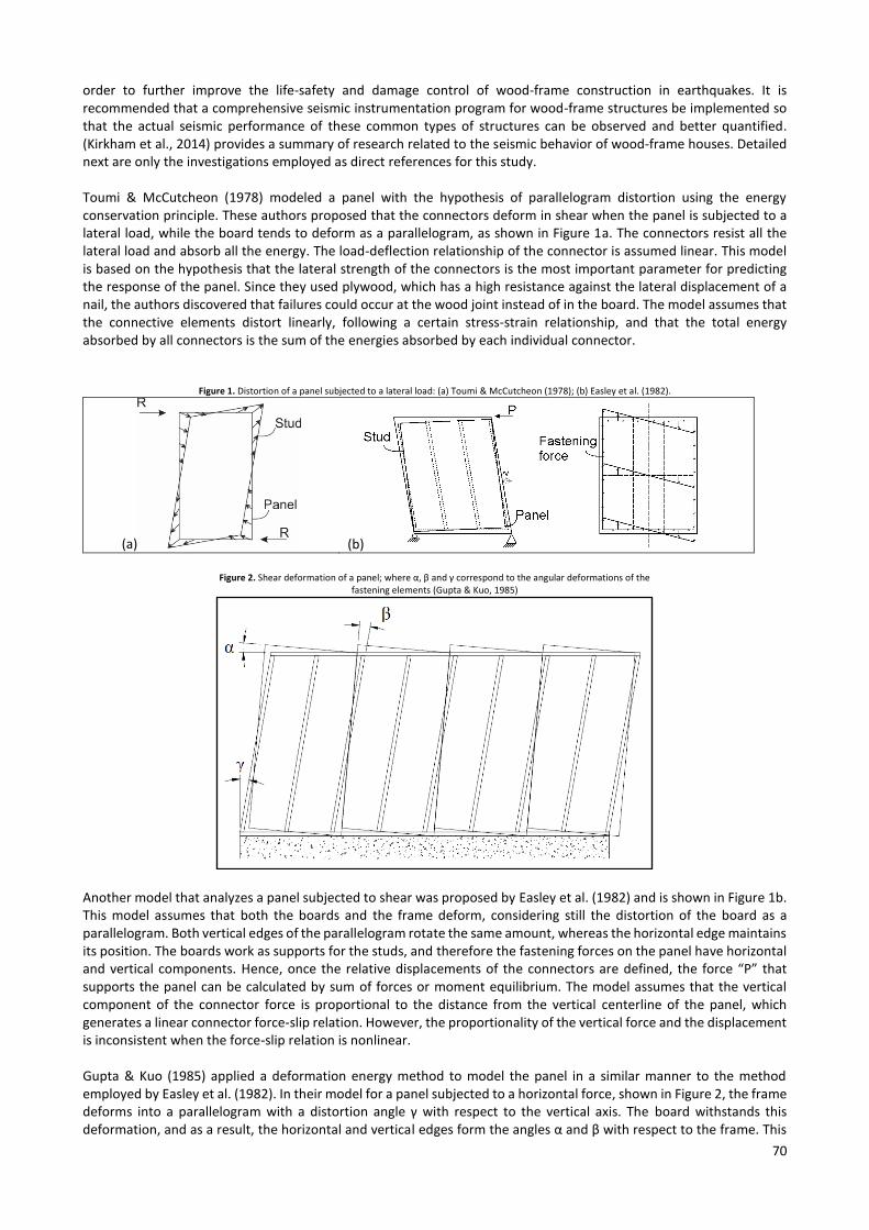
order to further improve the life-safety and damage control of wood-frame construction in earthquakes. It is recommended that a comprehensive seismic instrumentation program for wood-frame structures be implemented so that the actual seismic performance of these common types of structures can be observed and better quantified. (Kirkham et al., 2014) provides a summary of research related to the seismic behavior of wood-frame houses. Detailed next are only the investigations employed as direct references for this study. Toumi & McCutcheon (1978) modeled a panel with the hypothesis of parallelogram distortion using the energy conservation principle. These authors proposed that the connectors deform in shear when the panel is subjected to a lateral load, while the board tends to deform as a parallelogram, as shown in Figure 1a. The connectors resist all the lateral load and absorb all the energy. The load-deflection relationship of the connector is assumed linear. This model is based on the hypothesis that the lateral strength of the connectors is the most important parameter for predicting the response of the panel. Since they used plywood, which has a high resistance against the lateral displacement of a nail, the authors discovered that failures could occur at the wood joint instead of in the board. The model assumes that the connective elements distort linearly, following a certain stress-strain relationship, and that the total energy absorbed by all connectors is the sum of the energies absorbed by each individual connector.
Figure 1. Distortion of a panel subjected to a lateral load: (a) Toumi & McCutcheon (1978); (b) Easley et al. (1982).
(a) (b)
Figure 2. Shear deformation of a panel; where α, β and γ correspond to the angular deformations of the
fastening elements (Gupta & Kuo, 1985)
Another model that analyzes a panel subjected to shear was proposed by Easley et al. (1982) and is shown in Figure 1b. This model assumes that both the boards and the frame deform, considering still the distortion of the board as a parallelogram. Both vertical edges of the parallelogram rotate the same amount, whereas the horizontal edge maintains its position. The boards work as supports for the studs, and therefore the fastening forces on the panel have horizontal and vertical components. Hence, once the relative displacements of the connectors are defined, the force “P” that supports the panel can be calculated by sum of forces or moment equilibrium. The model assumes that the vertical component of the connector force is proportional to the distance from the vertical centerline of the panel, which generates a linear connector force-slip relation. However, the proportionality of the vertical force and the displacement is inconsistent when the force-slip relation is nonlinear. Gupta & Kuo (1985) applied a deformation energy method to model the panel in a similar manner to the method employed by Easley et al. (1982). In their model for a panel subjected to a horizontal force, shown in Figure 2, the frame deforms into a parallelogram with a distortion angle γ with respect to the vertical axis. The board withstands this deformation, and as a result, the horizontal and vertical edges form the angles α and β with respect to the frame. This
71
model reduces to the model by Easley et al. (1982) if β = 0, and to the model by Toumi & McCutcheon (1978) if α and β are limited such that the relative displacement of the corners is along the diagonal. In this model, the angles α and β are non-zero and independent, and the stresses generated at the connectors are due to the relative displacements between the frame and the board. Silva & Gesualdo (2005) developed a finite element model of a panel using the software “ANSYS”. In this study, the studs and joists were modeled using three-dimensional (3D) solid elements, the panels were modeled with shell elements, and each screw was modeled as a nonlinear spring. The model was validated using the experimental results of Veloso (2003). Regarding the state of the art of design of wooden structures in Chile, the OGUC (Ministerio de la Vivivenda, 2017) provides the legal framework for all construction in the country. This ordinance cites national norms to determine the loads to which the buildings are exposed: Snow Loads (Instituto Nacional de Normalización, 2010); Wind Loads (Instituto Nacional de Normalización, 2010b); Earthquake Loads (Instituto Nacional de Normalización, 1996); Dead and live loads (Instituto Nacional de Normalización, 1986); General dispositions and combinations of loads (Instituto Nacional de Normalización, 2010a). The ordinance also establishes the norms that have to be used to determine the mechanical properties (Instituto Nacional de Normalización, 2014) and resistance of the wooden pieces (Instituto Nacional de Normalización, 1991) employed in the fabrication of wooden buildings.
Prototype description
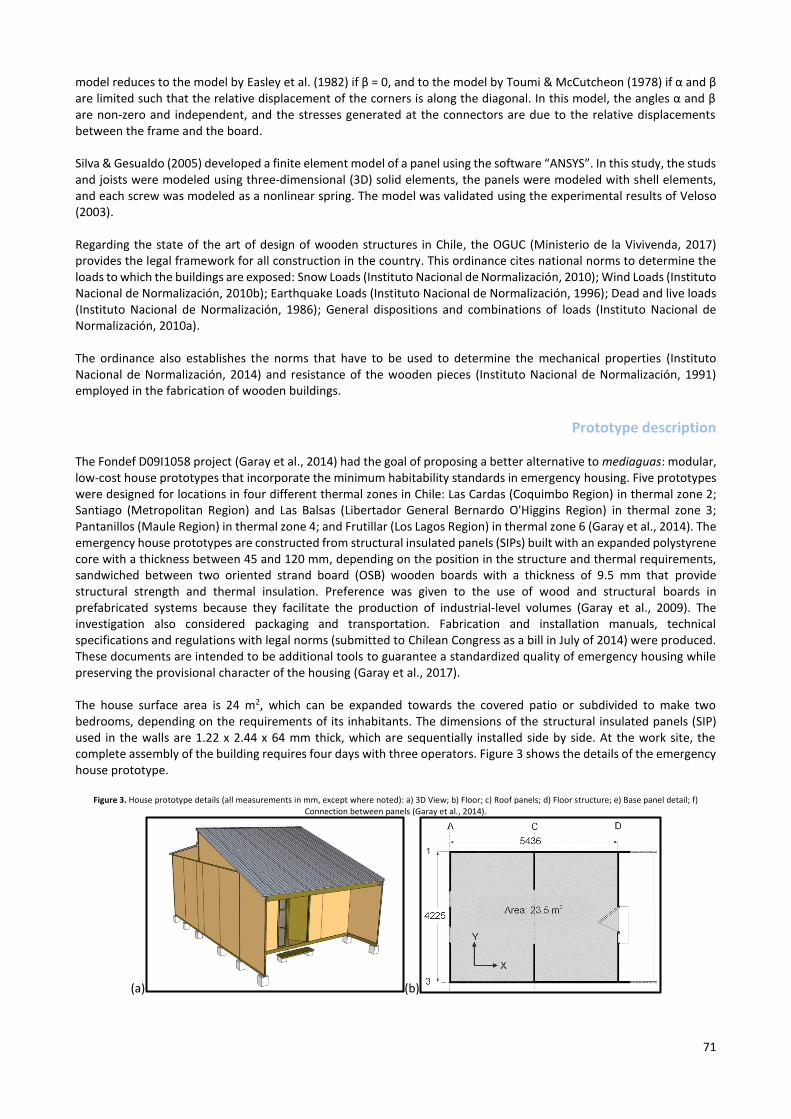
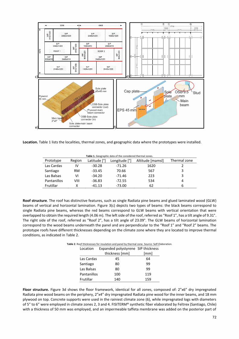
The Fondef D09I1058 project (Garay et al., 2014) had the goal of proposing a better alternative to mediaguas: modular, low-cost house prototypes that incorporate the minimum habitability standards in emergency housing. Five prototypes were designed for locations in four different thermal zones in Chile: Las Cardas (Coquimbo Region) in thermal zone 2; Santiago (Metropolitan Region) and Las Balsas (Libertador General Bernardo O'Higgins Region) in thermal zone 3; Pantanillos (Maule Region) in thermal zone 4; and Frutillar (Los Lagos Region) in thermal zone 6 (Garay et al., 2014). The emergency house prototypes are constructed from structural insulated panels (SIPs) built with an expanded polystyrene core with a thickness between 45 and 120 mm, depending on the position in the structure and thermal requirements, sandwiched between two oriented strand board (OSB) wooden boards with a thickness of 9.5 mm that provide structural strength and thermal insulation. Preference was given to the use of wood and structural boards in prefabricated systems because they facilitate the production of industrial-level volumes (Garay et al., 2009). The investigation also considered packaging and transportation. Fabrication and installation manuals, technical specifications and regulations with legal norms (submitted to Chilean Congress as a bill in July of 2014) were produced. These documents are intended to be additional tools to guarantee a standardized quality of emergency housing while preserving the provisional character of the housing (Garay et al., 2017). The house surface area is 24 m2, which can be expanded towards the covered patio or subdivided to make two bedrooms, depending on the requirements of its inhabitants. The dimensions of the structural insulated panels (SIP) used in the walls are 1.22 x 2.44 x 64 mm thick, which are sequentially installed side by side. At the work site, the complete assembly of the building requires four days with three operators. Figure 3 shows the details of the emergency house prototype.
Figure 3. House prototype details (all measurements in mm, except where noted): a) 3D View; b) Floor; c) Roof panels; d) Floor structure; e) Base panel detail; f) Connection between panels (Garay et al., 2014).
(a) (b)
72
c) d)
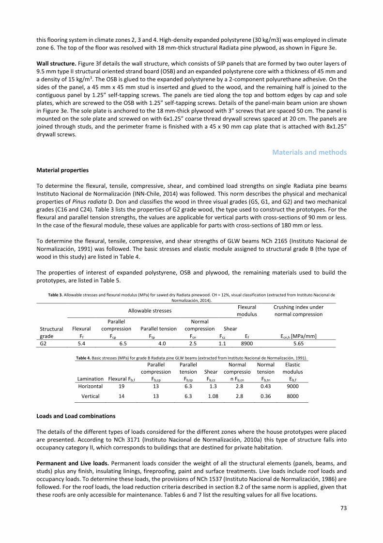
e) f) Location. Table 1 lists the localities, thermal zones, and geographic data where the prototypes were installed.
Table 1. Geographic data of the considered thermal zones.
Prototype Region Latitude [°] Longitude [°] Altitude [mamsl] Thermal zone
Las Cardas IV -30.28 -71.26 1620 2
Santiago RM -33.45 70.66 567 3
Las Balsas VI -34.20 -71.46 223 3
Pantanillos VIII -36.83 -72.55 534 4 Frutillar X -41.13 -73.00 62 6
Roof structure. The roof has distinctive features, such as single Radiata pine beams and glued laminated wood (GLW) beams of vertical and horizontal lamination. Figure 3(c) depicts two types of beams: the black beams correspond to single Radiata pine beams, whereas the red beams correspond to GLW beams with vertical orientation that were overlapped to obtain the required length (4.06 m). The left side of the roof, referred as “Roof 1”, has a tilt angle of 9.31°. The right side of the roof, referred as “Roof 2”, has a tilt angle of 23.09°. The GLW beams of horizontal lamination correspond to the wood beams underneath the panel and are perpendicular to the “Roof 1” and “Roof 2” beams. The prototype roofs have different thicknesses depending on the climate zone where they are located to improve thermal conditions, as indicated in Table 2.
Table 2. Roof thicknesses for insulation and panel by thermal zone. Source: Self-Elaboration.
Location Expanded polystyrene thickness [mm]
SIP thickness [mm]
Las Cardas 45 64
Santiago 80 99
Las Balsas 80 99
Pantanillos 100 119
Frutillar 140 159
Floor structure. Figure 3d shows the floor framework, identical for all zones, composed of: 2”x6” dry impregnated Radiata pine wood beams on the periphery, 2”x4” dry impregnated Radiata pine wood for the inner beams, and 18 mm plywood on top. Concrete supports were used in the rainiest climate zone (6), while impregnated logs with diameters of 5” to 6” were employed in climate zones 2, 3 and 4. FISITERM® synthetic fiber elaborated by Feltrex (Santiago, Chile) with a thickness of 50 mm was employed, and an impermeable taffeta membrane was added on the posterior part of
73
this flooring system in climate zones 2, 3 and 4. High-density expanded polystyrene (30 kg/m3) was employed in climate zone 6. The top of the floor was resolved with 18 mm-thick structural Radiata pine plywood, as shown in Figure 3e. Wall structure. Figure 3f details the wall structure, which consists of SIP panels that are formed by two outer layers of 9.5 mm type II structural oriented strand board (OSB) and an expanded polystyrene core with a thickness of 45 mm and a density of 15 kg/m3. The OSB is glued to the expanded polystyrene by a 2-component polyurethane adhesive. On the sides of the panel, a 45 mm x 45 mm stud is inserted and glued to the wood, and the remaining half is joined to the contiguous panel by 1.25” self-tapping screws. The panels are tied along the top and bottom edges by cap and sole plates, which are screwed to the OSB with 1.25” self-tapping screws. Details of the panel-main beam union are shown in Figure 3e. The sole plate is anchored to the 18 mm-thick plywood with 3” screws that are spaced 50 cm. The panel is mounted on the sole plate and screwed on with 6x1.25” coarse thread drywall screws spaced at 20 cm. The panels are joined through studs, and the perimeter frame is finished with a 45 x 90 mm cap plate that is attached with 8x1.25” drywall screws.
Materials and methods
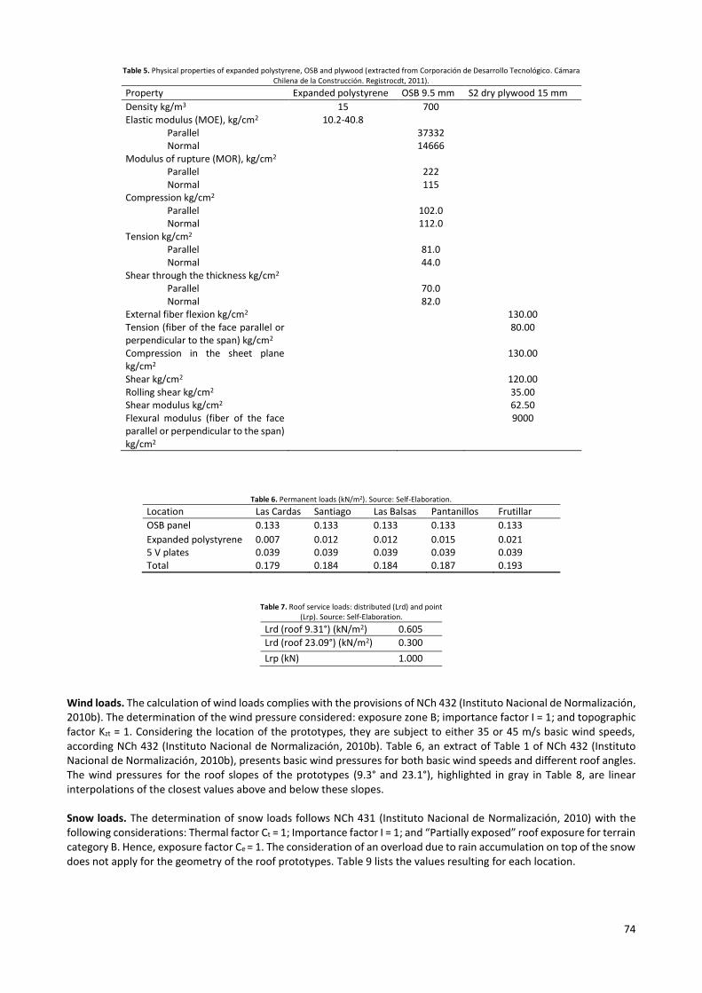
Material properties To determine the flexural, tensile, compressive, shear, and combined load strengths on single Radiata pine beams Instituto Nacional de Normalización (INN-Chile, 2014) was followed. This norm describes the physical and mechanical properties of Pinus radiata D. Don and classifies the wood in three visual grades (GS, G1, and G2) and two mechanical grades (C16 and C24). Table 3 lists the properties of G2 grade wood, the type used to construct the prototypes. For the flexural and parallel tension strengths, the values are applicable for vertical parts with cross-sections of 90 mm or less. In the case of the flexural module, these values are applicable for parts with cross-sections of 180 mm or less. To determine the flexural, tensile, compressive, and shear strengths of GLW beams NCh 2165 (Instituto Nacional de Normalización, 1991) was followed. The basic stresses and elastic module assigned to structural grade B (the type of wood in this study) are listed in Table 4. The properties of interest of expanded polystyrene, OSB and plywood, the remaining materials used to build the prototypes, are listed in Table 5.
Table 3. Allowable stresses and flexural modulus (MPa) for sawed dry Radiata pinewood. CH = 12%, visual classification (extracted from Instituto Nacional de Normalización, 2014).
Structural grade
Allowable stresses Flexural modulus
Crushing index under normal compression
Flexural Parallel
compression Parallel tension Normal
compression Shear
Ff Fcp Ftp Fcn Fcz Ef Ecn,h [MPa/mm]
G2 5.4 6.5 4.0 2.5 1.1 8900 5.65
Table 4. Basic stresses (MPa) for grade B Radiata pine GLW beams (extracted from Instituto Nacional de Normalización, 1991).
Lamination Flexural Fb,f
Parallel compression
Fb,cp
Parallel tension
Fb,tp Shear Fb,cz
Normal compressio
n Fb,cn
Normal tension
Fb,tn
Elastic modulus
Eb,f
Horizontal 19 13 6.3 1.3 2.8 0.43 9000
Vertical 14 13 6.3 1.08 2.8 0.36 8000
Loads and Load combinations The details of the different types of loads considered for the different zones where the house prototypes were placed are presented. According to NCh 3171 (Instituto Nacional de Normalización, 2010a) this type of structure falls into occupancy category II, which corresponds to buildings that are destined for private habitation. Permanent and Live loads. Permanent loads consider the weight of all the structural elements (panels, beams, and studs) plus any finish, insulating linings, fireproofing, paint and surface treatments. Live loads include roof loads and occupancy loads. To determine these loads, the provisions of NCh 1537 (Instituto Nacional de Normalización, 1986) are followed. For the roof loads, the load reduction criteria described in section 8.2 of the same norm is applied, given that these roofs are only accessible for maintenance. Tables 6 and 7 list the resulting values for all five locations.
74
Table 5. Physical properties of expanded polystyrene, OSB and plywood (extracted from Corporación de Desarrollo Tecnológico. Cámara Chilena de la Construcción. Registrocdt, 2011).
Property Expanded polystyrene OSB 9.5 mm S2 dry plywood 15 mm
Density kg/m3 15 700 Elastic modulus (MOE), kg/cm2 Parallel Normal Modulus of rupture (MOR), kg/cm2 Parallel Normal
10.2-40.8 37332 14666
222 115
Compression kg/cm2 Parallel Normal
102.0 112.0
Tension kg/cm2 Parallel Normal
81.0 44.0
Shear through the thickness kg/cm2 Parallel Normal
70.0 82.0
External fiber flexion kg/cm2 130.00 Tension (fiber of the face parallel or perpendicular to the span) kg/cm2
80.00
Compression in the sheet plane kg/cm2
130.00
Shear kg/cm2 120.00 Rolling shear kg/cm2 35.00 Shear modulus kg/cm2 62.50 Flexural modulus (fiber of the face parallel or perpendicular to the span) kg/cm2
9000
Table 6. Permanent loads (kN/m2). Source: Self-Elaboration.
Location Las Cardas Santiago Las Balsas Pantanillos Frutillar
OSB panel 0.133 0.133 0.133 0.133 0.133
Expanded polystyrene 0.007 0.012 0.012 0.015 0.021 5 V plates 0.039 0.039 0.039 0.039 0.039 Total 0.179 0.184 0.184 0.187 0.193
Table 7. Roof service loads: distributed (Lrd) and point (Lrp). Source: Self-Elaboration.
Lrd (roof 9.31°) (kN/m2) 0.605
Lrd (roof 23.09°) (kN/m2) 0.300
Lrp (kN) 1.000
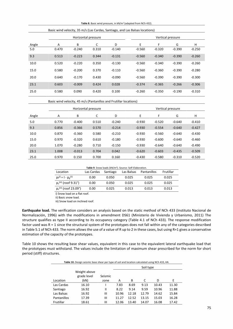
Wind loads. The calculation of wind loads complies with the provisions of NCh 432 (Instituto Nacional de Normalización, 2010b). The determination of the wind pressure considered: exposure zone B; importance factor I = 1; and topographic factor Kzt = 1. Considering the location of the prototypes, they are subject to either 35 or 45 m/s basic wind speeds, according NCh 432 (Instituto Nacional de Normalización, 2010b). Table 6, an extract of Table 1 of NCh 432 (Instituto Nacional de Normalización, 2010b), presents basic wind pressures for both basic wind speeds and different roof angles. The wind pressures for the roof slopes of the prototypes (9.3° and 23.1°), highlighted in gray in Table 8, are linear interpolations of the closest values above and below these slopes. Snow loads. The determination of snow loads follows NCh 431 (Instituto Nacional de Normalización, 2010) with the following considerations: Thermal factor Ct = 1; Importance factor I = 1; and “Partially exposed” roof exposure for terrain category B. Hence, exposure factor Ce = 1. The consideration of an overload due to rain accumulation on top of the snow does not apply for the geometry of the roof prototypes. Table 9 lists the values resulting for each location.
75
Table 8. Basic wind pressure, in kN/m2 (adapted from NCh 432).
Basic wind velocity, 35 m/s (Las Cardas, Santiago, and Las Balsas locations)
Angle
Horizontal pressure Vertical pressure
A B C D E F G H
5.0 0.470 -0.240 0.310 -0.140 -0.560 -0.320 -0.390 -0.250
9.3 0.513 -0.223 0.344 -0.131 -0.560 -0.340 -0.390 -0.260
10.0 0.520 -0.220 0.350 -0.130 -0.560 -0.340 -0.390 -0.260
15.0 0.580 -0.200 0.370 -0.110 -0.560 -0.360 -0.390 -0.280
20.0 0.640 -0.170 0.430 -0.090 -0.560 -0.390 -0.390 -0.300
23.1 0.603 -0.009 0.424 0.028 -0.374 -0.365 -0.266 -0.306
25.0 0.580 0.090 0.420 0.100 -0.260 -0.350 -0.190 -0.310
Basic wind velocity, 45 m/s (Pantanillos and Frutillar locations)
Angle
Horizontal pressure Vertical pressure
A B C D E F G H
5.0 0.770 -0.400 0.510 -0.240 -0.930 -0.520 -0.640 -0.410
9.3 0.856 -0.366 0.570 -0.214 -0.930 -0.554 -0.640 -0.427
10.0 0.870 -0.360 0.580 -0.210 -0.930 -0.560 -0.640 -0.430
15.0 0.970 -0.320 0.610 -0.180 -0.930 -0.600 -0.640 -0.460
20.0 1.070 -0.280 0.710 -0.150 -0.930 -0.640 -0.640 -0.490
23.1 1.008 -0.013 0.704 0.042 -0.620 -0.603 -0.435 -0.509
25.0 0.970 0.150 0.700 0.160 -0.430 -0.580 -0.310 -0.520
Table 9. Snow loads (kN/m2). Source: Self-Elaboration.
Location Las Cardas Santiago Las Balsas Pantanillos Frutillar
pf(i)
= I · pg(ii) 0.00 0.050 0.025 0.025 0.025
ps(iii) (roof 9.31°) 0.00 0.050 0.025 0.025 0.025
ps(iii) (roof 23.09°) 0.00 0.025 0.013 0.013 0.013
i) Snow load on a flat roof. ii) Basic snow load. iii) Snow load on inclined roof.
Earthquake load. The verification considers an analysis based on the static method of NCh 433 (Instituto Nacional de Normalización, 1996) with the modifications in amendment DS61 (Ministerio de Vivienda y Urbanismo, 2011) The structure qualifies as type II according to its occupancy category (Table 4.1 of NCh 433). The response modification factor used was R = 1 since the structural system of the prototypes does not fall within any of the categories described in Table 5.1 of NCh 433. The norm allows the use of a value of R up to 2 in these cases, but using R=1 gives a conservative estimation of the capacity of the prototypes. Table 10 shows the resulting base shear values, equivalent in this case to the equivalent lateral earthquake load that the prototypes must withstand. The values include the limitation of maximum shear prescribed for the norm for short period (stiff) structures.
Table 10. Design seismic base shear per type of soil and location calculated using NCh 433, kN.
Soil type
Location
Weight above grade level
(kN) Seismic
zone A B C D E
Las Cardas 16.10 I 7.83 8.69 9.13 10.43 11.30 Santiago 16.92 II 8.22 9.14 9.59 10.96 11.88 Las Balsas 16.92 III 10.96 12.18 12.79 14.62 15.84 Pantanillos 17.39 III 11.27 12.52 13.15 15.03 16.28 Frutillar 18.61 III 12.06 13.40 14.07 16.08 17.42
76
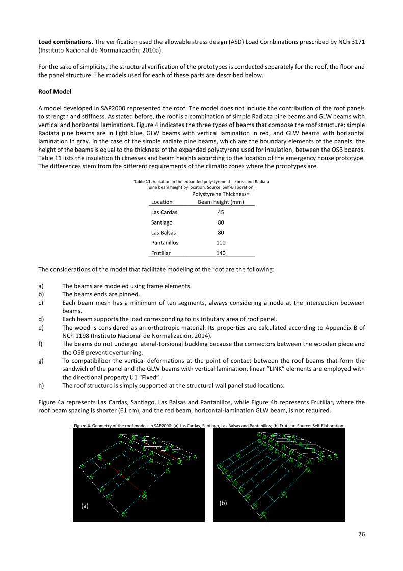
Load combinations. The verification used the allowable stress design (ASD) Load Combinations prescribed by NCh 3171 (Instituto Nacional de Normalización, 2010a). For the sake of simplicity, the structural verification of the prototypes is conducted separately for the roof, the floor and the panel structure. The models used for each of these parts are described below. Roof Model A model developed in SAP2000 represented the roof. The model does not include the contribution of the roof panels to strength and stiffness. As stated before, the roof is a combination of simple Radiata pine beams and GLW beams with vertical and horizontal laminations. Figure 4 indicates the three types of beams that compose the roof structure: simple Radiata pine beams are in light blue, GLW beams with vertical lamination in red, and GLW beams with horizontal lamination in gray. In the case of the simple radiate pine beams, which are the boundary elements of the panels, the height of the beams is equal to the thickness of the expanded polystyrene used for insulation, between the OSB boards. Table 11 lists the insulation thicknesses and beam heights according to the location of the emergency house prototype. The differences stem from the different requirements of the climatic zones where the prototypes are.
Table 11. Variation in the expanded polystyrene thickness and Radiata pine beam height by location. Source: Self-Elaboration.
Location Polystyrene Thickness=
Beam height (mm)
Las Cardas 45
Santiago 80
Las Balsas 80
Pantanillos 100
Frutillar 140
The considerations of the model that facilitate modeling of the roof are the following: a) The beams are modeled using frame elements. b) The beams ends are pinned. c) Each beam mesh has a minimum of ten segments, always considering a node at the intersection between
beams. d) Each beam supports the load corresponding to its tributary area of roof panel. e) The wood is considered as an orthotropic material. Its properties are calculated according to Appendix B of
NCh 1198 (Instituto Nacional de Normalización, 2014). f) The beams do not undergo lateral-torsional buckling because the connectors between the wooden piece and
the OSB prevent overturning. g) To compatibilizer the vertical deformations at the point of contact between the roof beams that form the
sandwich of the panel and the GLW beams with vertical lamination, linear “LINK” elements are employed with the directional property U1 “Fixed”.
h) The roof structure is simply supported at the structural wall panel stud locations. Figure 4a represents Las Cardas, Santiago, Las Balsas and Pantanillos, while Figure 4b represents Frutillar, where the roof beam spacing is shorter (61 cm), and the red beam, horizontal-lamination GLW beam, is not required.
Figure 4. Geometry of the roof models in SAP2000: (a) Las Cardas, Santiago, Las Balsas and Pantanillos; (b) Frutillar. Source: Self-Elaboration.
(a) (b)
77
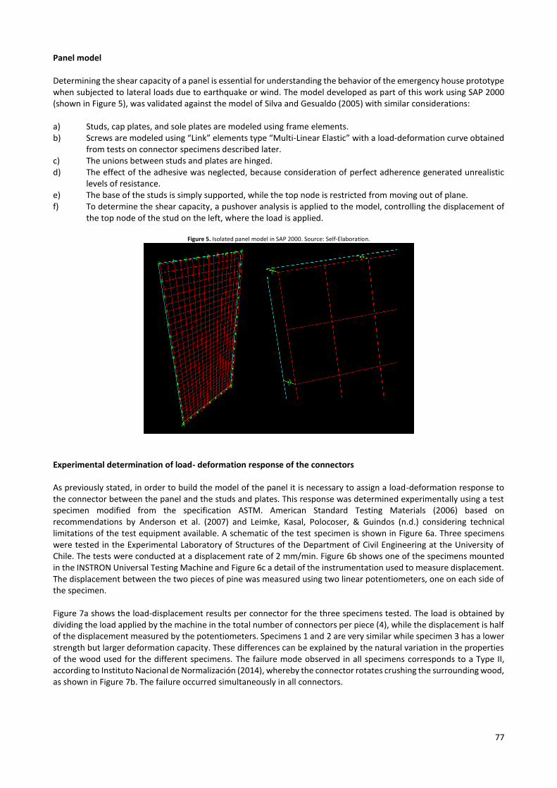
Panel model Determining the shear capacity of a panel is essential for understanding the behavior of the emergency house prototype when subjected to lateral loads due to earthquake or wind. The model developed as part of this work using SAP 2000 (shown in Figure 5), was validated against the model of Silva and Gesualdo (2005) with similar considerations: a) Studs, cap plates, and sole plates are modeled using frame elements. b) Screws are modeled using “Link” elements type “Multi-Linear Elastic” with a load-deformation curve obtained
from tests on connector specimens described later. c) The unions between studs and plates are hinged. d) The effect of the adhesive was neglected, because consideration of perfect adherence generated unrealistic
levels of resistance. e) The base of the studs is simply supported, while the top node is restricted from moving out of plane. f) To determine the shear capacity, a pushover analysis is applied to the model, controlling the displacement of
the top node of the stud on the left, where the load is applied.
Figure 5. Isolated panel model in SAP 2000. Source: Self-Elaboration.
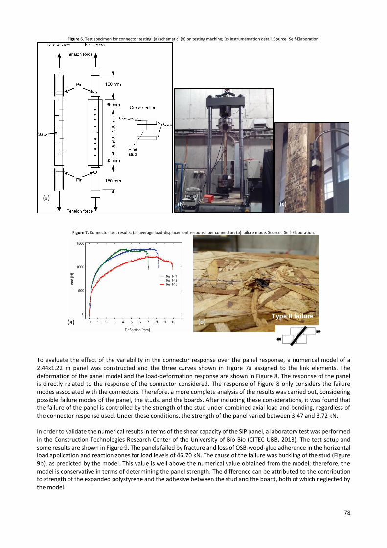
Experimental determination of load- deformation response of the connectors As previously stated, in order to build the model of the panel it is necessary to assign a load-deformation response to the connector between the panel and the studs and plates. This response was determined experimentally using a test specimen modified from the specification ASTM. American Standard Testing Materials (2006) based on recommendations by Anderson et al. (2007) and Leimke, Kasal, Polocoser, & Guindos (n.d.) considering technical limitations of the test equipment available. A schematic of the test specimen is shown in Figure 6a. Three specimens were tested in the Experimental Laboratory of Structures of the Department of Civil Engineering at the University of Chile. The tests were conducted at a displacement rate of 2 mm/min. Figure 6b shows one of the specimens mounted in the INSTRON Universal Testing Machine and Figure 6c a detail of the instrumentation used to measure displacement. The displacement between the two pieces of pine was measured using two linear potentiometers, one on each side of the specimen. Figure 7a shows the load-displacement results per connector for the three specimens tested. The load is obtained by dividing the load applied by the machine in the total number of connectors per piece (4), while the displacement is half of the displacement measured by the potentiometers. Specimens 1 and 2 are very similar while specimen 3 has a lower strength but larger deformation capacity. These differences can be explained by the natural variation in the properties of the wood used for the different specimens. The failure mode observed in all specimens corresponds to a Type II, according to Instituto Nacional de Normalización (2014), whereby the connector rotates crushing the surrounding wood, as shown in Figure 7b. The failure occurred simultaneously in all connectors.
78
Figure 6. Test specimen for connector testing: (a) schematic; (b) on testing machine; (c) instrumentation detail. Source: Self-Elaboration.
Figure 7. Connector test results: (a) average load-displacement response per connector; (b) failure mode. Source: Self-Elaboration.
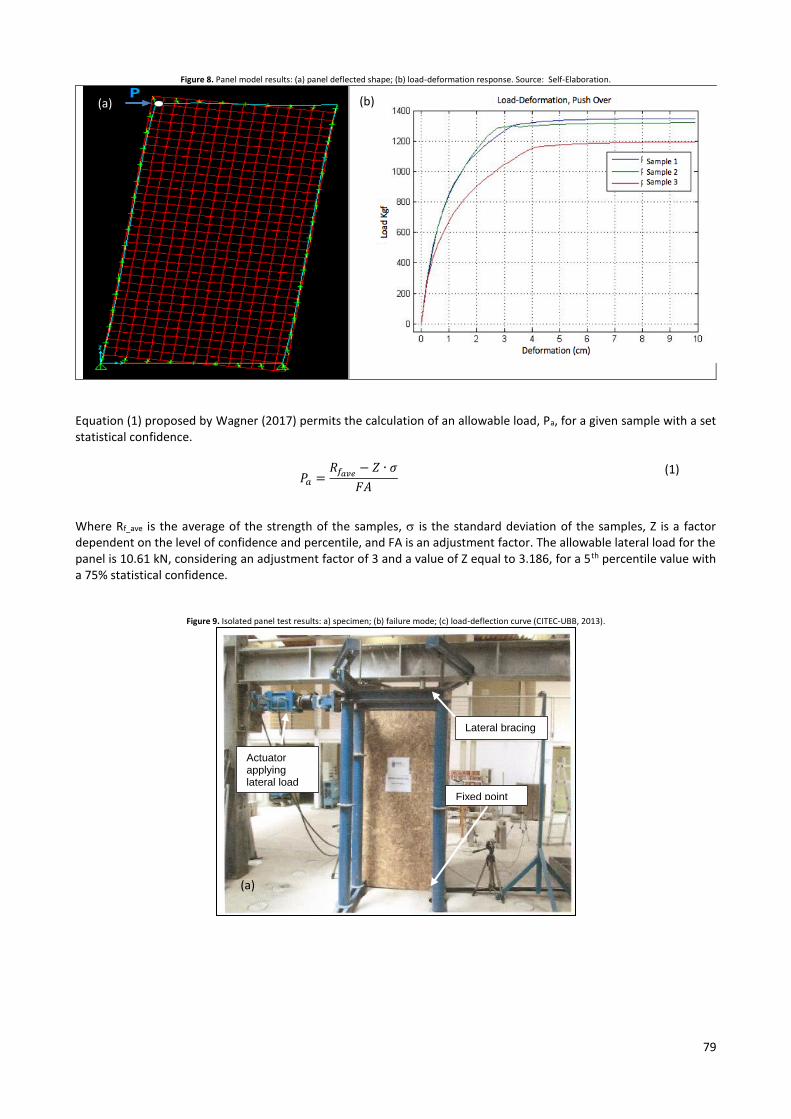
To evaluate the effect of the variability in the connector response over the panel response, a numerical model of a 2.44x1.22 m panel was constructed and the three curves shown in Figure 7a assigned to the link elements. The deformation of the panel model and the load-deformation response are shown in Figure 8. The response of the panel is directly related to the response of the connector considered. The response of Figure 8 only considers the failure modes associated with the connectors. Therefore, a more complete analysis of the results was carried out, considering possible failure modes of the panel, the studs, and the boards. After including these considerations, it was found that the failure of the panel is controlled by the strength of the stud under combined axial load and bending, regardless of the connector response used. Under these conditions, the strength of the panel varied between 3.47 and 3.72 kN. In order to validate the numerical results in terms of the shear capacity of the SIP panel, a laboratory test was performed in the Construction Technologies Research Center of the University of Bío-Bío (CITEC-UBB, 2013). The test setup and some results are shown in Figure 9. The panels failed by fracture and loss of OSB-wood-glue adherence in the horizontal load application and reaction zones for load levels of 46.70 kN. The cause of the failure was buckling of the stud (Figure 9b), as predicted by the model. This value is well above the numerical value obtained from the model; therefore, the model is conservative in terms of determining the panel strength. The difference can be attributed to the contribution to strength of the expanded polystyrene and the adhesive between the stud and the board, both of which neglected by the model.
Type II failure (a)
(a) (b) (c)
(b)
79
Figure 8. Panel model results: (a) panel deflected shape; (b) load-deformation response. Source: Self-Elaboration.
Equation (1) proposed by Wagner (2017) permits the calculation of an allowable load, Pa, for a given sample with a set statistical confidence.
𝑃𝑎 =𝑅𝑓𝑎𝑣𝑒 − 𝑍 ∙ 𝜎
𝐹𝐴
(1)
Where Rf_ave is the average of the strength of the samples, is the standard deviation of the samples, Z is a factor dependent on the level of confidence and percentile, and FA is an adjustment factor. The allowable lateral load for the panel is 10.61 kN, considering an adjustment factor of 3 and a value of Z equal to 3.186, for a 5th percentile value with a 75% statistical confidence.
Figure 9. Isolated panel test results: a) specimen; (b) failure mode; (c) load-deflection curve (CITEC-UBB, 2013).
(a)
(a) (b)
Actuator applying lateral load
Fixed point
Lateral bracing
80
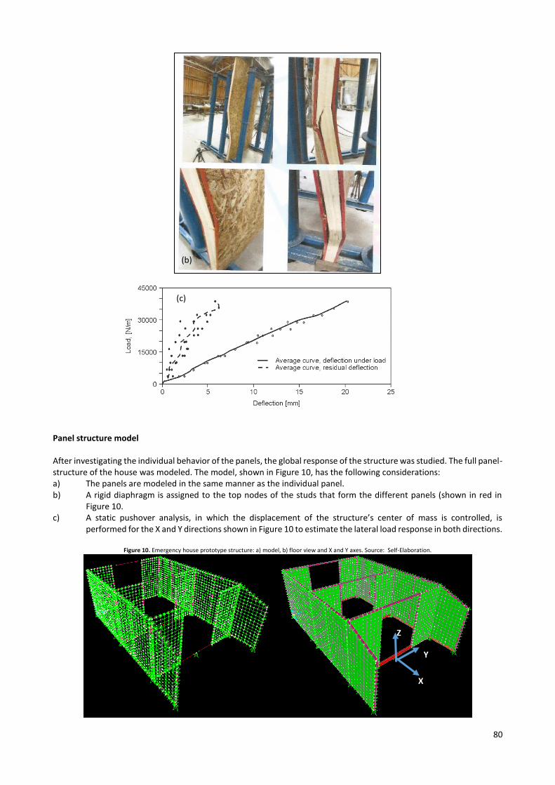
Panel structure model After investigating the individual behavior of the panels, the global response of the structure was studied. The full panel-structure of the house was modeled. The model, shown in Figure 10, has the following considerations: a) The panels are modeled in the same manner as the individual panel. b) A rigid diaphragm is assigned to the top nodes of the studs that form the different panels (shown in red in
Figure 10. c) A static pushover analysis, in which the displacement of the structure’s center of mass is controlled, is
performed for the X and Y directions shown in Figure 10 to estimate the lateral load response in both directions.
Figure 10. Emergency house prototype structure: a) model, b) floor view and X and Y axes. Source: Self-Elaboration.
(c)
(b)
X
Y
Z
81
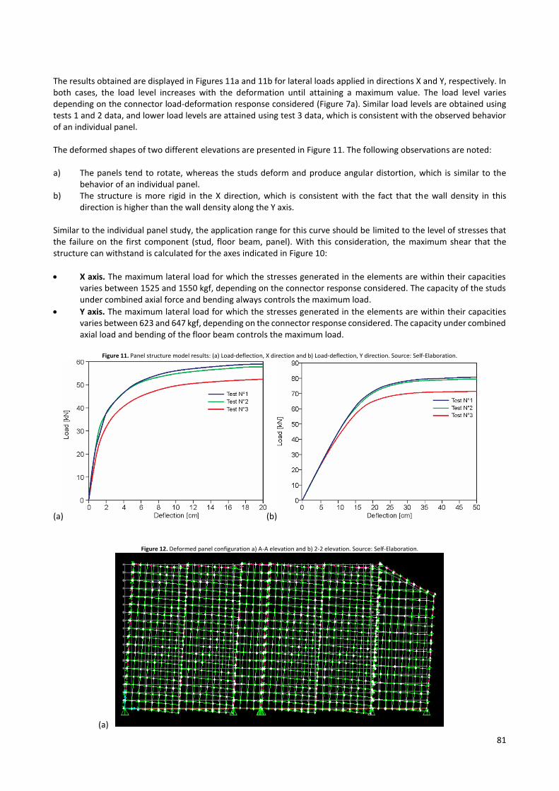
The results obtained are displayed in Figures 11a and 11b for lateral loads applied in directions X and Y, respectively. In both cases, the load level increases with the deformation until attaining a maximum value. The load level varies depending on the connector load-deformation response considered (Figure 7a). Similar load levels are obtained using tests 1 and 2 data, and lower load levels are attained using test 3 data, which is consistent with the observed behavior of an individual panel. The deformed shapes of two different elevations are presented in Figure 11. The following observations are noted: a) The panels tend to rotate, whereas the studs deform and produce angular distortion, which is similar to the
behavior of an individual panel. b) The structure is more rigid in the X direction, which is consistent with the fact that the wall density in this
direction is higher than the wall density along the Y axis. Similar to the individual panel study, the application range for this curve should be limited to the level of stresses that the failure on the first component (stud, floor beam, panel). With this consideration, the maximum shear that the structure can withstand is calculated for the axes indicated in Figure 10:
X axis. The maximum lateral load for which the stresses generated in the elements are within their capacities varies between 1525 and 1550 kgf, depending on the connector response considered. The capacity of the studs under combined axial force and bending always controls the maximum load.
Y axis. The maximum lateral load for which the stresses generated in the elements are within their capacities varies between 623 and 647 kgf, depending on the connector response considered. The capacity under combined axial load and bending of the floor beam controls the maximum load.
Figure 11. Panel structure model results: (a) Load-deflection, X direction and b) Load-deflection, Y direction. Source: Self-Elaboration.
(a) (b)
Figure 12. Deformed panel configuration a) A-A elevation and b) 2-2 elevation. Source: Self-Elaboration.
(a)
82
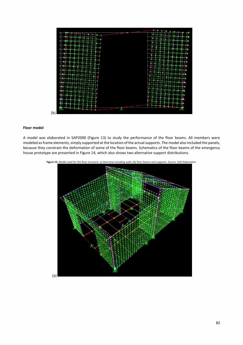
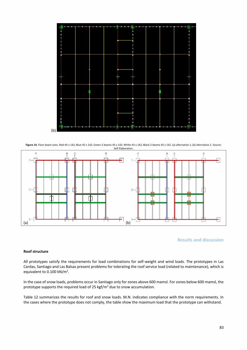
(b) Floor model A model was elaborated in SAP2000 (Figure 13) to study the performance of the floor beams. All members were modeled as frame elements, simply supported at the location of the actual supports. The model also included the panels, because they constrain the deformation of some of the floor beams. Schematics of the floor beams of the emergency house prototype are presented in Figure 14, which also shows two alternative support distributions.
Figure 13. Model used for the floor structure: a) Overview including walls; (b) floor beams and supports. Source: Self-Elaboration.
(a)
83
(b)
Figure 14. Floor beam sizes: Red-45 x 142; Blue-45 x 142; Green-2 beams 45 x 142; White-45 x 142; Black-2 beams 45 x 142. (a) alternative 1; (b) alternative 2. Source: Self-Elaboration.
(a) (b)
Results and discussion
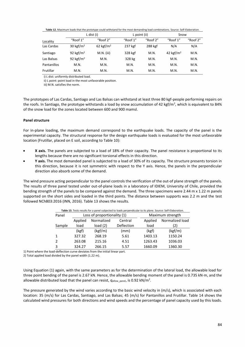
Roof structure All prototypes satisfy the requirements for load combinations for self-weight and wind loads. The prototypes in Las Cardas, Santiago and Las Balsas present problems for tolerating the roof service load (related to maintenance), which is equivalent to 0.100 kN/m2. In the case of snow loads, problems occur in Santiago only for zones above 600 mamsl. For zones below 600 mamsl, the prototype supports the required load of 25 kgf/m2 due to snow accumulation. Table 12 summarizes the results for roof and snow loads. M.N. indicates compliance with the norm requirements. In the cases where the prototype does not comply, the table show the maximum load that the prototype can withstand.
84
Table 12. Maximum loads that the prototype could withstand for the most demanding load combinations. Source: Self-Elaboration.
Locality
L dist (i) L point (ii) Snow
“Roof 1” “Roof 2” “Roof 1” “Roof 2” “Roof 1” “Roof 2”
Las Cardas 30 kgf/m2 62 kgf/m2 237 kgf 288 kgf N/A N/A
Santiago 92 kgf/m2 M.N. (iii) 328 kgf M.N. 42 kgf/m2 M.N.
Las Balsas 92 kgf/m2 M.N. 328 kg M.N. M.N. M.N.
Pantanillos M.N. M.N. M.N. M.N. M.N. M.N.
Frutillar M.N. M.N. M.N. M.N. M.N. M.N.
i) L dist: uniformly distributed load. ii) L point: point load in the most unfavorable position. iii) M.N. satisfies the norm.
The prototypes of Las Cardas, Santiago and Las Balsas can withstand at least three 80 kgf-people performing repairs on the roofs. In Santiago, the prototype withstands a load by snow accumulation of 42 kgf/m2, which is equivalent to 84% of the snow load for the zones located between 600 and 900 mamsl.
Panel structure For in-plane loading, the maximum demand correspond to the earthquake loads. The capacity of the panel is the experimental capacity. The structural response for the design earthquake loads is evaluated for the most unfavorable location (Frutillar, placed on E soil, according to Table 10):
X axis. The panels are subjected to a load of 18% of their capacity. The panel resistance is proportional to its lengths because there are no significant torsional effects in this direction.
Y axis. The most demanded panel is subjected to a load of 30% of its capacity. The structure presents torsion in this direction, because it is not symmetric with respect to the Y axis. Hence, the panels in the perpendicular direction also absorb some of the demand.
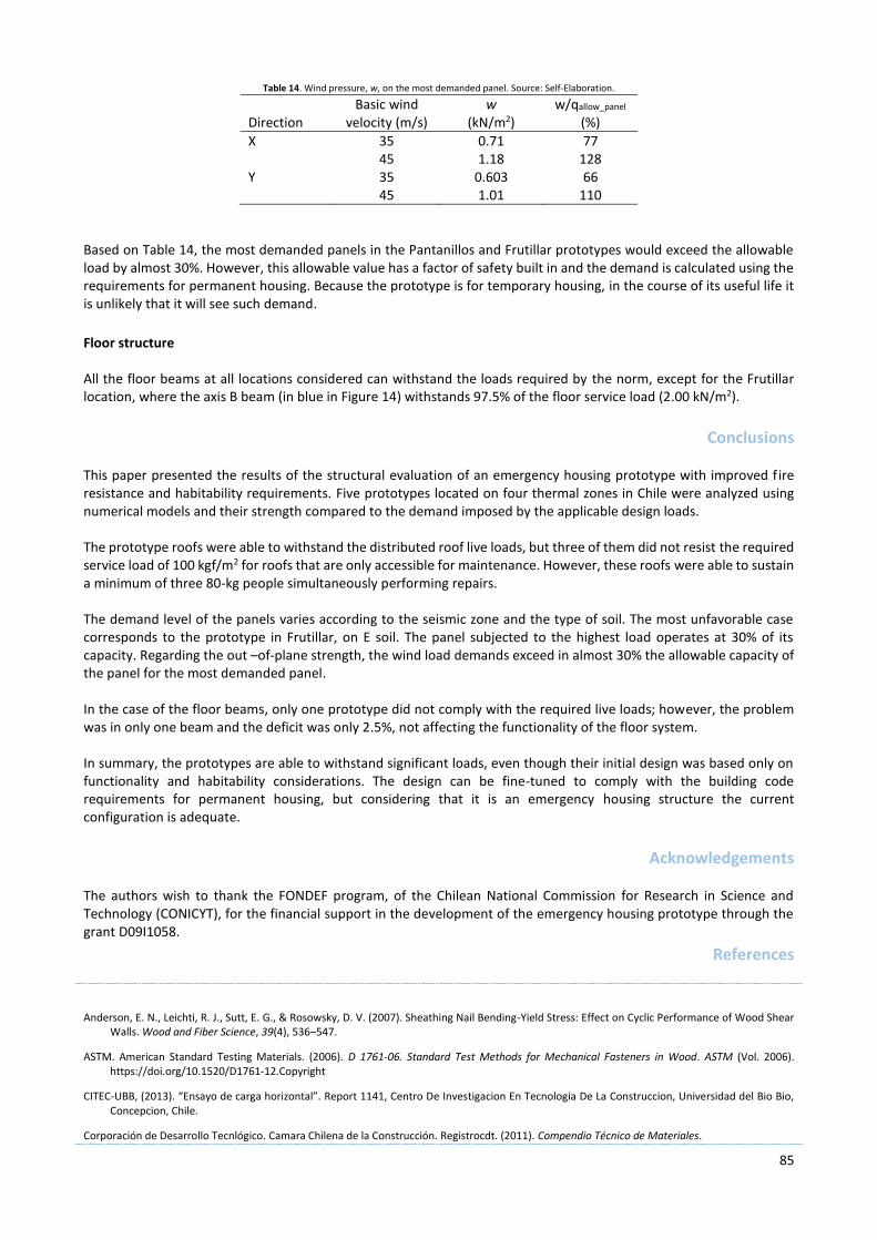
The wind pressure acting perpendicular to the panel controls the verification of the out-of plane strength of the panels. The results of three panel tested under out-of-plane loads in a laboratory of IDIEM, University of Chile, provided the bending strength of the panels to be compared against the demand. The three specimens were 2.44 m x 1.22 m panels supported on the short sides and loaded in the third points. The distance between supports was 2.2 m and the test followed NCh803:2016 (INN, 2016). Table 13 shows the results.
Table 13. Tests results for a panel subjected to loads perpendicular to its plane. Source: Self-Elaboration.
Panel Loss of proportionality (1) Maximum strength
Sample Applied
load Normalized
load (2) Central
Deflection Applied
load Normalized load
(2)
(kgf) (kgf/m) (mm) (kgf) (kgf/m)
1 327.32 268.19 5.61 1403.13 1150.24
2 263.08 215.16 4.51 1263.43 1036.03
3 324.27 266.15 5.57 1660.09 1360.30 1) Point where the load-deflection curve deviates from the initial linear part. 2) Total applied load divided by the panel width (1.22 m).
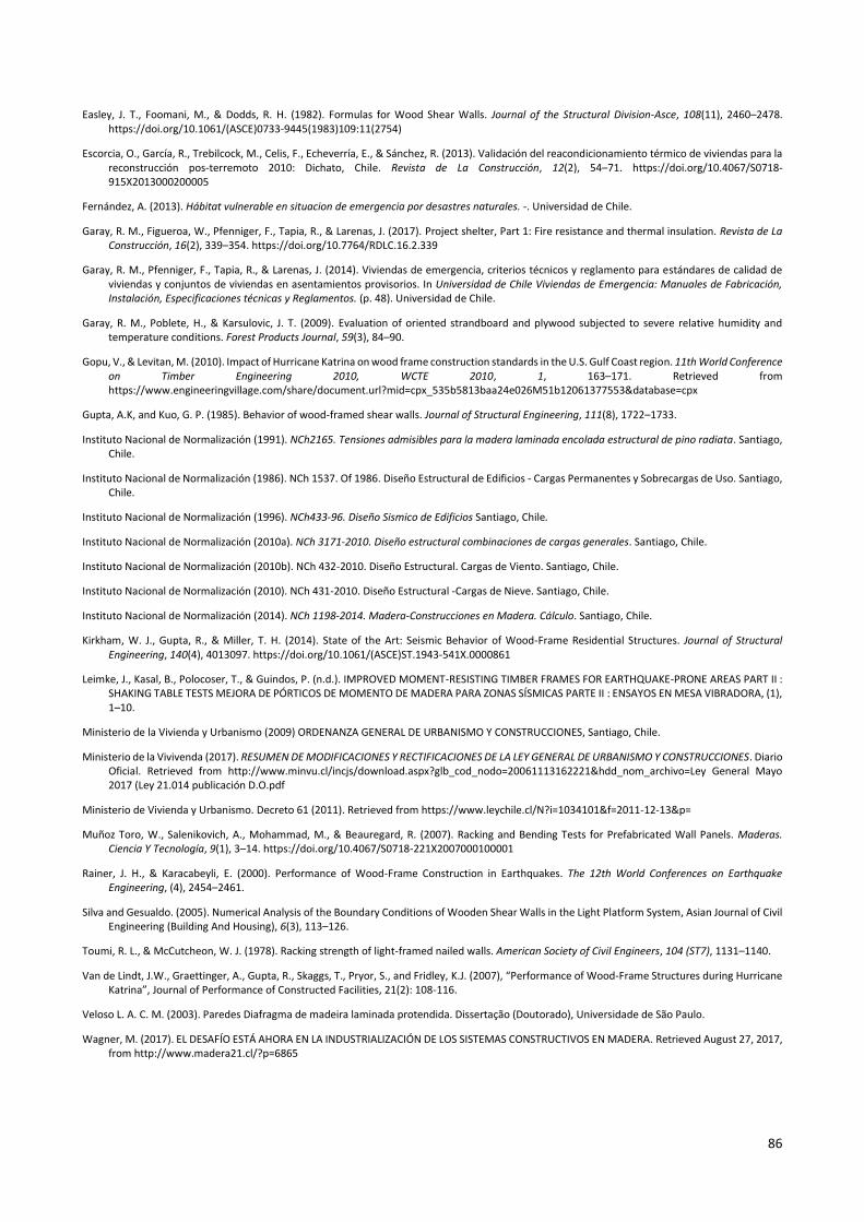
Using Equation (1) again, with the same parameters as for the determination of the lateral load, the allowable load for three point bending of the panel is 2.67 kN. Hence, the allowable bending moment of the panel is 0.735 kN∙m, and the allowable distributed load that the panel can resist, qallow_panel, is 0.92 kN/m2. The pressure generated by the wind varies according to the basic wind velocity in (m/s), which is associated with each location: 35 (m/s) for Las Cardas, Santiago, and Las Balsas; 45 (m/s) for Pantanillos and Frutillar. Table 14 shows the calculated wind pressures for both directions and wind speeds and the percentage of panel capacity used by this loads.
85
Table 14. Wind pressure, w, on the most demanded panel. Source: Self-Elaboration.
Direction Basic wind
velocity (m/s) w
(kN/m2) w/qallow_panel
(%)
X 35 0.71 77 45 1.18 128 Y 35 0.603 66 45 1.01 110
Based on Table 14, the most demanded panels in the Pantanillos and Frutillar prototypes would exceed the allowable load by almost 30%. However, this allowable value has a factor of safety built in and the demand is calculated using the requirements for permanent housing. Because the prototype is for temporary housing, in the course of its useful life it is unlikely that it will see such demand.
Floor structure All the floor beams at all locations considered can withstand the loads required by the norm, except for the Frutillar location, where the axis B beam (in blue in Figure 14) withstands 97.5% of the floor service load (2.00 kN/m2).
Conclusions This paper presented the results of the structural evaluation of an emergency housing prototype with improved fire resistance and habitability requirements. Five prototypes located on four thermal zones in Chile were analyzed using numerical models and their strength compared to the demand imposed by the applicable design loads. The prototype roofs were able to withstand the distributed roof live loads, but three of them did not resist the required service load of 100 kgf/m2 for roofs that are only accessible for maintenance. However, these roofs were able to sustain a minimum of three 80-kg people simultaneously performing repairs. The demand level of the panels varies according to the seismic zone and the type of soil. The most unfavorable case corresponds to the prototype in Frutillar, on E soil. The panel subjected to the highest load operates at 30% of its capacity. Regarding the out –of-plane strength, the wind load demands exceed in almost 30% the allowable capacity of the panel for the most demanded panel. In the case of the floor beams, only one prototype did not comply with the required live loads; however, the problem was in only one beam and the deficit was only 2.5%, not affecting the functionality of the floor system. In summary, the prototypes are able to withstand significant loads, even though their initial design was based only on functionality and habitability considerations. The design can be fine-tuned to comply with the building code requirements for permanent housing, but considering that it is an emergency housing structure the current configuration is adequate.
Acknowledgements
The authors wish to thank the FONDEF program, of the Chilean National Commission for Research in Science and Technology (CONICYT), for the financial support in the development of the emergency housing prototype through the grant D09I1058.
References
Anderson, E. N., Leichti, R. J., Sutt, E. G., & Rosowsky, D. V. (2007). Sheathing Nail Bending-Yield Stress: Effect on Cyclic Performance of Wood Shear Walls. Wood and Fiber Science, 39(4), 536–547.
ASTM. American Standard Testing Materials. (2006). D 1761-06. Standard Test Methods for Mechanical Fasteners in Wood. ASTM (Vol. 2006). https://doi.org/10.1520/D1761-12.Copyright
CITEC-UBB, (2013). “Ensayo de carga horizontal”. Report 1141, Centro De Investigacion En Tecnologia De La Construccion, Universidad del Bio Bio, Concepcion, Chile.
Corporación de Desarrollo Tecnlógico. Camara Chilena de la Construcción. Registrocdt. (2011). Compendio Técnico de Materiales.
86
Easley, J. T., Foomani, M., & Dodds, R. H. (1982). Formulas for Wood Shear Walls. Journal of the Structural Division-Asce, 108(11), 2460–2478. https://doi.org/10.1061/(ASCE)0733-9445(1983)109:11(2754)
Escorcia, O., García, R., Trebilcock, M., Celis, F., Echeverría, E., & Sánchez, R. (2013). Validación del reacondicionamiento térmico de viviendas para la reconstrucción pos-terremoto 2010: Dichato, Chile. Revista de La Construcción, 12(2), 54–71. https://doi.org/10.4067/S0718-915X2013000200005
Fernández, A. (2013). Hábitat vulnerable en situacion de emergencia por desastres naturales. -. Universidad de Chile.
Garay, R. M., Figueroa, W., Pfenniger, F., Tapia, R., & Larenas, J. (2017). Project shelter, Part 1: Fire resistance and thermal insulation. Revista de La Construcción, 16(2), 339–354. https://doi.org/10.7764/RDLC.16.2.339
Garay, R. M., Pfenniger, F., Tapia, R., & Larenas, J. (2014). Viviendas de emergencia, criterios técnicos y reglamento para estándares de calidad de viviendas y conjuntos de viviendas en asentamientos provisorios. In Universidad de Chile Viviendas de Emergencia: Manuales de Fabricación, Instalación, Especificaciones técnicas y Reglamentos. (p. 48). Universidad de Chile.
Garay, R. M., Poblete, H., & Karsulovic, J. T. (2009). Evaluation of oriented strandboard and plywood subjected to severe relative humidity and temperature conditions. Forest Products Journal, 59(3), 84–90.
Gopu, V., & Levitan, M. (2010). Impact of Hurricane Katrina on wood frame construction standards in the U.S. Gulf Coast region. 11th World Conference on Timber Engineering 2010, WCTE 2010, 1, 163–171. Retrieved from https://www.engineeringvillage.com/share/document.url?mid=cpx_535b5813baa24e026M51b12061377553&database=cpx
Gupta, A.K, and Kuo, G. P. (1985). Behavior of wood-framed shear walls. Journal of Structural Engineering, 111(8), 1722–1733.
Instituto Nacional de Normalización (1991). NCh2165. Tensiones admisibles para la madera laminada encolada estructural de pino radiata. Santiago, Chile.
Instituto Nacional de Normalización (1986). NCh 1537. Of 1986. Diseño Estructural de Edificios - Cargas Permanentes y Sobrecargas de Uso. Santiago, Chile.
Instituto Nacional de Normalización (1996). NCh433-96. Diseño Sismico de Edificios Santiago, Chile.
Instituto Nacional de Normalización (2010a). NCh 3171-2010. Diseño estructural combinaciones de cargas generales. Santiago, Chile.
Instituto Nacional de Normalización (2010b). NCh 432-2010. Diseño Estructural. Cargas de Viento. Santiago, Chile.
Instituto Nacional de Normalización (2010). NCh 431-2010. Diseño Estructural -Cargas de Nieve. Santiago, Chile.
Instituto Nacional de Normalización (2014). NCh 1198-2014. Madera-Construcciones en Madera. Cálculo. Santiago, Chile.
Kirkham, W. J., Gupta, R., & Miller, T. H. (2014). State of the Art: Seismic Behavior of Wood-Frame Residential Structures. Journal of Structural Engineering, 140(4), 4013097. https://doi.org/10.1061/(ASCE)ST.1943-541X.0000861
Leimke, J., Kasal, B., Polocoser, T., & Guindos, P. (n.d.). IMPROVED MOMENT-RESISTING TIMBER FRAMES FOR EARTHQUAKE-PRONE AREAS PART II : SHAKING TABLE TESTS MEJORA DE PÓRTICOS DE MOMENTO DE MADERA PARA ZONAS SÍSMICAS PARTE II : ENSAYOS EN MESA VIBRADORA, (1), 1–10.
Ministerio de la Vivienda y Urbanismo (2009) ORDENANZA GENERAL DE URBANISMO Y CONSTRUCCIONES, Santiago, Chile.
Ministerio de la Vivivenda (2017). RESUMEN DE MODIFICACIONES Y RECTIFICACIONES DE LA LEY GENERAL DE URBANISMO Y CONSTRUCCIONES. Diario Oficial. Retrieved from http://www.minvu.cl/incjs/download.aspx?glb_cod_nodo=20061113162221&hdd_nom_archivo=Ley General Mayo 2017 (Ley 21.014 publicación D.O.pdf
Ministerio de Vivienda y Urbanismo. Decreto 61 (2011). Retrieved from https://www.leychile.cl/N?i=1034101&f=2011-12-13&p=
Muñoz Toro, W., Salenikovich, A., Mohammad, M., & Beauregard, R. (2007). Racking and Bending Tests for Prefabricated Wall Panels. Maderas. Ciencia Y Tecnología, 9(1), 3–14. https://doi.org/10.4067/S0718-221X2007000100001
Rainer, J. H., & Karacabeyli, E. (2000). Performance of Wood-Frame Construction in Earthquakes. The 12th World Conferences on Earthquake Engineering, (4), 2454–2461.
Silva and Gesualdo. (2005). Numerical Analysis of the Boundary Conditions of Wooden Shear Walls in the Light Platform System, Asian Journal of Civil Engineering (Building And Housing), 6(3), 113–126.
Toumi, R. L., & McCutcheon, W. J. (1978). Racking strength of light-framed nailed walls. American Society of Civil Engineers, 104 (ST7), 1131–1140.
Van de Lindt, J.W., Graettinger, A., Gupta, R., Skaggs, T., Pryor, S., and Fridley, K.J. (2007), “Performance of Wood-Frame Structures during Hurricane Katrina”, Journal of Performance of Constructed Facilities, 21(2): 108-116.
Veloso L. A. C. M. (2003). Paredes Diafragma de madeira laminada protendida. Dissertação (Doutorado), Universidade de São Paulo.
Wagner, M. (2017). EL DESAFÍO ESTÁ AHORA EN LA INDUSTRIALIZACIÓN DE LOS SISTEMAS CONSTRUCTIVOS EN MADERA. Retrieved August 27, 2017, from http://www.madera21.cl/?p=6865