DISASTER RELIEF SHELTER - Humanitarian Library |
115
DISASTER RELIEF SHELTER Team 05 Walta Asfaw, David Headley, Nick Liza, Dan Nederhoed Engr339/340 Senior Design Project Calvin College Engineering 6 May 2013
-
Upload
khangminh22 -
Category
Documents
-
view
4 -
download
0
Transcript of DISASTER RELIEF SHELTER - Humanitarian Library |

DISASTER RELIEF
SHELTER
Team 05 Walta Asfaw, David Headley, Nick Liza, Dan Nederhoed
Engr339/340 Senior Design Project
Calvin College Engineering 6 May 2013

2
COPYRIGHT ©2013 Team 05: DRS
All rights reserved. Printed in Grand Rapids, MI by the Calvin College Engineering Department.

3
Executive Summary The Disaster Relief Shelter, known as DRS, is designed to serve as a responsive but also a transitional shelter for victims of natural disasters in Indonesia. Natural disasters such as earthquakes, tsunamis, and hurricanes are frequent to Indonesia, leaving countless families homeless and separated from their families.
Currently, emergency shelters comprised of bamboo, wood panels, and other local materials are used to create quick housing, however, many times they do not stand up to post disaster events. Despite their low cost, many of these shelters end up being blown away, dismantled, or experience deterioration of essential structural members. Families are left to rebuilding their homes multiple times a year.
The World Vision Disaster Shelter Design Competition hosted by John Brown University have set the constraints and requirements for the development of the shelter. The DRS defies the normal by using a frame comprised of 99% Polyvinyl Chloride (PVC). The shelter is 5x3x2.2 meters, accommodating up to 4 family members, withstands wind speeds of 75kph and up to 7.0 on the Richter scale earthquakes. Analysis and design were performed using Autodesk Simulation Multiphysics for wind loads and repeating load events. The DRS has a uni-body polyethylene canvas cover, including four windows and a zipper-stitched door. Electrical installation is also available for quick connection to a generator or other power source. A Sawyer PointONE filtration system, comprised of a membrane with pores and size efficient, filters and purifies water. This filtration feeds from a water tank through PEX hoses and a manual pump. Removing 99% of bacteria and viruses and a life span of 1,000,000 gallons, victims will have access to clean drinkable water. The DRS is shipping efficient, fitting 57 units in an 8’ by 40’ shipping container and requires about 50-60 minutes to assemble with 4 people. The DRS unit costs under $600 to manufacture, and has a payback period of 9 years when sold at MRSP $1,595 per unit.

4
Table of Contents Executive Summary ........................................................................................................................ 3!
1! Introduction ........................................................................................................................... 11!
2! Project Management .............................................................................................................. 12!
2.1! Team Structure ............................................................................................................... 12!
2.1.1! Walta Asfaw ............................................................................................................ 12!
2.1.2! David Headley ........................................................................................................ 12!
2.1.3! Nick Liza ................................................................................................................. 12!
2.1.4! Dan Nederhoed ....................................................................................................... 12!
2.2! Team Dynamics .............................................................................................................. 12!
2.3! Schedule ......................................................................................................................... 13!
2.4! Method of Approach ...................................................................................................... 14!
3! Requirements ......................................................................................................................... 14!
3.1! Deliverables .................................................................................................................... 14!
4! Background ............................................................................................................................ 15!
4.1! Post-Disaster Events ....................................................................................................... 16!
5! Current Emergency Shelter Designs ...................................................................................... 16!
5.1! Indonesia ........................................................................................................................ 17!
5.1.1! West Java ................................................................................................................ 17!
5.1.2! Aceh ........................................................................................................................ 17!
5.1.3! Padang ..................................................................................................................... 18!
5.2! Pakistan .......................................................................................................................... 19!
5.3! Peru ................................................................................................................................. 19!
5.4! Haiti ................................................................................................................................ 20!
5.5! Vietnam .......................................................................................................................... 21!
6! Design Norms ........................................................................................................................ 22!
6.1! Transparency .................................................................................................................. 22!
6.2! Trust ............................................................................................................................... 22!
6.3! Cultural Appropriateness ................................................................................................ 22!
7! Structure Framing .................................................................................................................. 23!
7.1! Polymer and Fiberglass over Metal and Wood .............................................................. 23!

5
7.2! Load Criteria .................................................................................................................. 25!
7.2.1! Wind Loads ............................................................................................................. 25!
7.2.2! Seismic Loads ......................................................................................................... 27!
7.3! Design Alternatives ........................................................................................................ 29!
7.3.1! Material Selection Based Loading .......................................................................... 29!
7.3.2! The Geodesic “Pill” ................................................................................................ 31!
7.4! Design Decisions ............................................................................................................ 32!
7.4.1! Frame Members ...................................................................................................... 32!
7.4.2! Roofing ................................................................................................................... 39!
7.4.3! Bolt Design ............................................................................................................. 40!
7.4.4! Plate Design ............................................................................................................ 41!
7.4.5! Interior Divisions .................................................................................................... 42!
8! Structural Cover ..................................................................................................................... 43!
8.1! Fabric Material Selection ............................................................................................... 43!
8.2! Window Screen Selection and Placement ...................................................................... 44!
8.3! Seaming .......................................................................................................................... 45!
9! Structural Anchor .................................................................................................................. 46!
9.1! Design Criteria ............................................................................................................... 46!
9.2! Design Alternatives ........................................................................................................ 46!
9.3! Design Decision ............................................................................................................. 47!
9.3.1! Bio-Anchor ............................................................................................................. 47!
9.3.2! Internal Stakes ......................................................................................................... 48!
10! Heat Analysis ..................................................................................................................... 48!
10.1! Design Criteria ............................................................................................................... 48!
10.2! Design Alternatives ........................................................................................................ 49!
10.3! Design Decision ............................................................................................................. 49!
11! Electrical Wiring ................................................................................................................ 50!
11.1! Design Criteria ............................................................................................................... 50!
11.2! Design Alternatives ........................................................................................................ 51!
11.3! Receptacle Design .......................................................................................................... 52!
11.4! Design Decision ............................................................................................................. 53!

6
11.4.1! Electrical Wiring Selection ..................................................................................... 53!
11.4.2! Electrical Fixtures Selection ................................................................................... 54!
11.4.3! Electrical Circuit Breaker Selection ........................................................................ 54!
12! Water System ..................................................................................................................... 55!
12.1! Water Tank and Purification .......................................................................................... 55!
12.2! Suspended Tank ............................................................................................................. 56!
12.2.1! Loads ....................................................................................................................... 56!
12.2.2! Piping for Suspended Tank ..................................................................................... 58!
12.3! Non-Suspended Tank ..................................................................................................... 59!
12.4! Filtration ......................................................................................................................... 60!
12.5! Piping for Water Supply ................................................................................................. 61!
12.6! Design Decisions ............................................................................................................ 62!
13 ! Shipping ............................................................................................................................. 62!
14! Shelter Design Competition Results .................................................................................. 64!
14.1! Shelter Requirements and Performance ......................................................................... 64!
14.2! Cascade Design Business Case Analysis ....................................................................... 65!
15! Improving for the Future .................................................................................................... 66!
15.1! Structural Reinforcement ............................................................................................... 66!
15.1! From Emergency Shelter to Transitional Shelter ........................................................... 66!
15.2! Ventilation ...................................................................................................................... 67!
15.3! Composting Toilet .......................................................................................................... 67!
Acknowledgements ....................................................................................................................... 69!
Work Cited .................................................................................................................................... 70!
Appendix A – Wind Load Information ........................................................................................ 73!
Pressure Velocity ................................................................................................................... 73!
Appendix B – Seismic Load Information .................................................................................... 75!
Modified Spectral Response Acceleration ............................................................................ 75!
Design Spectral Response Acceleration ................................................................................ 75!
Shear Force ............................................................................................................................ 75!
Seismic Design Coefficient ................................................................................................... 75!
Maximum and Minimum Seismic Design Coefficient .......................................................... 76!

7
Fundamental Period ............................................................................................................... 76!
Vertical Distribution Factors ................................................................................................. 76!
Lateral Force .......................................................................................................................... 76!
Appendix C – Mathematical Calculations of Finite Element Analysis ........................................ 77!
Appendix D – Schematics ............................................................................................................. 80!
Appendix E – World Vision Business Case Analysis .................................................................. 87!
Appendix F – Gantt Chart of Project ............................................................................................ 90!
Appendix G – Heat Analysis ........................................................................................................ 91!
Appendix H – Builder’s Manual ................................................................................................... 93!

8
Table&of&Figures&Figure 1: DRS Structure ................................................................................................................ 11!Figure 2: World Map with Indonesia Highlighted ........................................................................ 15!Figure 3: Bamboo Frame Shelter used in West Java .................................................................... 17!Figure 4: Steel Frame Shelter used in Aceh .................................................................................. 18!Figure 5: Timber Frame Shelter used in Padang .......................................................................... 18!Figure 6: Triangular Timber Frame Shelter used in Northern Pakistan ....................................... 19!Figure 7: Bolaina Timber Frame Shelter ...................................................................................... 20!Figure 8: Eucalyptus Timber Frame Shelter ................................................................................. 20!Figure 9: Steel Frame Shelter used in Haiti .................................................................................. 21!Figure 10: Steel Frame Shelter used in Vietnam .......................................................................... 21!Figure 11: Wind Load Distribution around the Main Frame ........................................................ 26!Figure 12: Seismic Load Distribution ........................................................................................... 29!Figure 13: Geodesic "Pill" Concept .............................................................................................. 32!Figure 14: Stress Results for 1.5" Diameter PVC Structure ......................................................... 33!Figure 15: Stress results for 1.5” diameter ABS Structure ........................................................... 34!Figure 16: Deflection Results for 1.5" Diameter PVC Structure .................................................. 35!Figure 17: Deflection results for 1.5” diameter ABS Structure .................................................... 36!Figure 18: Stress-Strain Diagram for Polyvinyl Chloride (PVC). Yield strength = 55MPa at 273K. ............................................................................................................................................. 37!Figure 19: Graph 1-1 from "The Effects of UV Light and Weather". Deterioration for ABS when exposed to UV radiation. .............................................................................................................. 38!Figure 20: Deterioration of PVC exposed to UV radiation. ......................................................... 38!Figure 21: Frame Design of Shelter .............................................................................................. 39!Figure 22: Figure 5-20 from Riley’s Mechanics of Materials. Stress concentration curve for hole based on diameter and width. ........................................................................................................ 40!Figure 23: Design for Angle Plates ............................................................................................... 41!Figure 24: Design for Flat Plates .................................................................................................. 42!Figure 25: Divisions Available adding Curtains. .......................................................................... 42!Figure 26: Airflow through the Structure ..................................................................................... 45!Figure 27: Internal Stake ............................................................................................................... 48!Figure 28: Plug Types ................................................................................................................... 52!Figure 29: Preliminary frame design with electrical wires, lights, and outlets. ............................ 53!Figure 30: Lamp Fixtures - heavy duty, light duty, and exposed bulb fixtures ............................ 54!Figure 31: Pacific Cemetery Casket Lowering System ............................................................... 57!Figure 32: Sawyer PointONE all in One Package ........................................................................ 60!Figure 33: Hydraid Biosand Filter ................................................................................................ 61!Figure 34: Shipping box for DRS ................................................................................................. 63!Figure 35: 8' by 40' shipping container with 57 DRS units. ......................................................... 63!Figure 36: Example of a Bio Drum ............................................................................................... 68!

9
Figure 37: 100N point load at the end of the beam. ...................................................................... 79!Figure 38: 100N distributed edge load over length of beam. ....................................................... 79!Figure 39: 100N force distributed over 566 nodes over length of beam. ..................................... 79!& &

10
Table&of&Tables Table 1: Decision Matrix for Materials Used for Shelter Frame .................................................. 24!Table 2: Structure Dimension for Surface and Roof Load Calculations ...................................... 25!Table 3: Calculated Wind Loads for the Walls ............................................................................. 26!Table 4: Calculated Wind Loads for the Roof .............................................................................. 26!Table 5: Spectral Response Acceleration Values ......................................................................... 27!Table 6: Seismic Design Coefficient Results ................................................................................ 28!Table 7: Seismic Load Results ...................................................................................................... 28!Table 8: Deflection Results for Framing ...................................................................................... 30!Table 9: Stress Results for Framing .............................................................................................. 31!Table 10: Decision Matrix for Material Fabric ............................................................................. 44!Table 11: Decision Matrix for Window Screen ............................................................................ 44!Table 12: Anchor Force Required ................................................................................................. 46!Table 13: Tent Stake Testing ........................................................................................................ 46!Table 14: Decision Matrix for hard-flooring. ............................................................................... 49!Table 15: Appliance Power Requirements ................................................................................... 51!Table 16: Wire Gauges and Uses .................................................................................................. 52!Table 17: Fixture Decision Matrix ................................................................................................ 54!Table 18: Circuit Breaker Decision Matrix .................................................................................. 55!Table 19: Components for Different Piping Material ................................................................... 58!Table 20: Water Piping Material Decision Matrix ....................................................................... 59!Table 21: External Pressure Coefficients for Wall Surfaces ........................................................ 73!Table 22: External Pressure Coefficients for Arced Roofs ........................................................... 74!& &

11
1 Introduction
Figure 1: DRS Structure
The transition from student to practicing engineer is achieved through the Senior Design course. Senior Design allows engineering students to learn about project identification, feasibility, and teamwork. Similar to the work force, these projects require large time investment. Within the two-semester duration of the project, teams also experience conflicts and resolutions as part of the maturing process that Senior Design forces students to experience. The design process and preliminary product validation are essential parts of Senior Design. Upon completion of feasibility studies, cost analysis, and scheduling, the preliminary stages of design can be initiated. These tasks prepare students for the workforce supplementing concepts and professional experiences offered in lectures. Preliminary designs face review boards and criticism similar to the feedback given by professors and industrial consultants. The experience of redesigning components that fail to meet criteria brings appreciation of well-designed products as well as revealing the process required to bring a product to market. The prototype process requires students to analyze the need and produce a product. Unforeseen problems will likely occur in many prototypes constructed. The prototypes will allow students to think of ways to fine-tune their designs before presenting them to classmates, parents, professors, and judges. The presentations, aimed to prepare students for the workforce, model those given to supervisors and other employers within a company. The World Vision Disaster Shelter Design Competition inspires the Disaster Relief Shelter, known as DRS shown in Figure 1. This competition is hosted by John Brown University in Siloam Springs, AR. The competition sets design criteria for the shelter, including wind and seismic activity, living accommodations, and a Business Case Analysis discussed throughout this report. The project requires four students to work as one team for two semesters in order to complete the project. Feasibility studies, cost analysis, and scheduling are all integral parts of

12
completing the project. This report starts by discussing the current temporary structures used for disaster relief. In transition, it covers the design norms which were crucial to developing a culturally appropriate design. Once our design norms are presented, the report moves into the different aspects of designing the structure such as the structural framing, canvas cover, anchoring, heat analysis, electrical circuitry, and future improvements. Our report concludes with summery of the project followed by detailed calculations that support our results.
2 Project Management
2.1 Team Structure Team 5 is comprised of four civil engineering students.
2.1.1 Walta Asfaw Walta is from Addis Ababa, Ethiopia. His interests in structural engineering led him to take wind and seismic design criteria and interpret them into loads. He was also in charge of researching the feasibility of a composting toilet for the shelter. During the second semester, he spent time in the metal shop trimming and designing prototype and final design parts.
2.1.2 David Headley David is from Chesterland, Ohio. With prior experience with electrical wiring, his responsibilities included researching and incorporating the appropriate electrical components into the shelter. During the second semester, he was responsible for the anchoring system for the shelter, both designing and testing different methods, and selection of adequate flooring.
2.1.3 Nick Liza Nick is from Campinas, Brazil but has lived in Grand Rapids, MI and Quito, Ecuador. His responsibilities included the frame analysis and design, a business cost analysis, and heat analysis of the shelter. Using Finite Element Analysis in Autodesk Simulation Multiphysics, he constructed different frame models and analyzed different load conditions supplied by Walta.
2.1.4 Dan Nederhoed Dan is from Grand Rapids, MI but has also spent some years in Peru. His responsibilities included the water system and water filtration, internal divisions, and shipping. He also partnered with David on the anchoring design for the shelter.
2.2 Team Dynamics Decisions are made by the entire team or the person whose part of the project is most affected. The majority of decisions are minor and the group is in agreement. When disagreement arises over a decision, the members disagreeing bring their reasons to the entire team. The team then makes a decision based upon what will be best for the project. This process takes more time than if there was one assigned group leader, but our approach ensures a good overall project,

13
successful communication and decision, as well as team unity. The process keeps all members involved and aware of the overall project instead of narrowly focusing on their assigned part. Even with this process, some decisions are made based upon consultation with outside sources, especially the faculty advisors. Advisors for our team have allowed us to gain expertise in fields we had little knowledge about prior to our project. Our main faculty advisor, Professor Wunder, has assisted in guiding our thought process along with revealing a different perspective on our project. Our industrial consultant, Roger Lamer, has also provided us with useful sources. We have also consulted with Don Winkle, an electrician who works at Calvin College as part of the Physical Plant, regarding current electrical practices and standards. The Engineering 339 professors have been very helpful throughout the course of the project. The course is taught by Professor Nielsen (ME), Professor VanderLeest (ECE), Professor Wentzheimer (ChE), and Professor Wunder (CvE). Each Professor has assisted in different ways. In particular, Professor VanderLeest explained the effects of the different power grid frequencies of 50Hz and 60Hz. As well as answering questions, each professor led several 50 minute lectures pertinent to designing a product. These topics range from Professor Nielsen speaking on the patent process, to Professor Wentzheimer speaking about engineering ethics. These different topics influenced our decisions and goals for the project.
2.3 Schedule The schedule was developed based upon completion of deadlines. We started with the given due dates posted by the professors and competition. From those dates, we back planned intermediate due dates. The intermediate dates each composed small parts of the project. Combined, these small parts composed the larger project deadlines. The schedule was constructed using Microsoft Project 2010. Each part has an estimated time to complete, deadline, and team member assigned to complete the part. With Microsoft Project, we were able to assign predecessors to show how each part was linked to the overall project. From the schedule, we created and printed a Gantt chart. This chart was posted next to the schedule on the work board in the assigned group area. The visibility of the schedule kept each team member informed about their due dates along with those of the rest of the team. The complete schedule can be seen in the Appendix. The schedule and Gantt chart were a visual representation of the necessary work to be completed. As a team, progress was verified every Wednesday afternoon with advisor, Prof. Wunder. This accountability kept team members working and encouraged those falling behind to ask for assistance. This project has taken many work hours to complete. Team members are responsible for charting their own hours. Some members used a Google Spreadsheet to continually track their hours

14
while others maintained a log in their notebook. Each team member averaged 6 hours per week. The hour log for each team member can be found in the Appendix.
2.4 Method of Approach Team 5 entered the World Vision Disaster Shelter Design Competition with the desire to provide a housing solution for victims of natural disasters. The hosts for the competition did not release the guidelines for the April 2013 competition until late October 2012. In the meantime, competition guidelines from the previous year were used as a starting point for the project. Communication was maintained via email with the competition director, Prof. Mark Terrill, who shared information regarding constraints that were likely to change or stay the same from the previous year. After gathering data, several group meetings were held to brainstorm designs for the structure. The group listed components outside of the competition guidelines and components to be included in the design. The additional components include water and electricity. After creating the preliminary design, several materials were analyzed in order to find the most suitable for the framing of the structure. The list of materials is not only based on strength and durability but also availability and cost. Once details for the new constraints were released, the current data were adjusted to meet these new requirements. Since this year’s competition focused on natural disasters in Indonesia, all the electrical and water components were adjusted to meet Indonesian use. Research included the country’s topography, climate, and the standard practice of living to ensure that the structure would fulfill social and geographic norms.
3 Requirements
3.1 Deliverables A full scale prototype of the DRS was on display at two locations. The first display was at the World Vision Disaster Shelter Design Competition from April 19, 2013 to April 20, 2013 hosted by John Brown University in Siloam Springs, Arkansas. At this event, the prototype was placed on a horizontally shaking table to test the prototype’s resistance to earthquake loads. Afterwards, the prototype’s ability to handle the required wind load was tested using a 68” diameter fan, which produced 75kph wind speeds. The DRS prototype was also on display at Calvin College’s Senior Design Banquet and Projects Night on May 4, 2013. Guests had the opportunity to walk through and see the inside of the shelter. The shelter was equipped with a cot, curtains, a table with two chairs, a computer and

15
monitor showing an assembly video, and properly functioning lights. The shipping container and descriptive posters also sat next to the DRS, providing graphical results of the concept shelter. A Builder’s Manual was generated and included with the shelter. The manual was onsite with the structure at both display sites. A website was created by and published online. This website contains a detailed description and goal of the project, a description of the team, information about the shelter competition at John Brown University, links to essential resources such as multimedia and sponsors, and links to the Project Proposal & Feasibility Study and Final Design Report. This website can be viewed at: http://www.calvin.edu/academic/engineering/2012-13-team5. The Final Report was submitted upon completion.
4 Background The target area for the DRS is Indonesia, shown in Figure 2. Indonesia is made up of many islands with an accumulated area of 1,904,569 square kilometers along a divergent tectonic plate. Its geographical location combined with its tropical climates allows vulnerability to natural disasters1.
Figure 2: World Map with Indonesia Highlighted2
Indonesia has experienced many severe earthquakes over the past century. Southern Sumatera has the most frequent earthquakes with magnitudes ranging from 7.6 to 9.1 in magnitude. Other areas of Indonesia have also been affected with similar magnitude earthquakes3. 1 “Geography: Indonesia”. Central Intelligence Agency. 2012. https://www.cia.gov/library/publications/the-world-factbook/geos/id.html 2 “Tropic Islands.” http://about-indonesia123.blogspot.com/ 3 Historic World Earthquakes. USGS, n.d. Web. 16 Oct. 2012. <http://earthquake.usgs.gov/earthquakes/world/historical_country.php#indonesia>.

16
The international disaster database recorded an average of 1 earthquake per year, which kills 301 people and affects 85,000 people in Indonesia.4 Landslides, floods, volcanoes, wildfires, tsunamis, and tropical storms also affect the nation. Indonesia is the world’s most populous Muslim-majority nation, with 86% of its 238 million people as Muslims. Even with this high Muslim percentage, the country stipulates religious freedom in its constitution. Along with its religious diversity, Indonesia records 300 distinct native ethnic groups and 742 languages and dialects.
4.1 Post-Disaster Events Because of these natural disasters, many Indonesian citizens are victims of watching their homes and cities crumble to the ground or wash away from resulting tsunamis or landslides, losing loved ones in the process. These victims are left with nothing and nowhere to go. This shelter satisfies the second and third step for Maslow’s Hierarchy of Needs.5 First, the shelter offers protection and security. This is not the type of security where no intruder can enter, but privacy, order, and stability in one’s home. Secondly, the shelter provides a place for belonging and the foundation of a family. Inside the shelter, families are able to remain together and provide support for one another as they begin to build their new lives together.
5 Current Emergency Shelter Designs With over 43 million people displaced from their homes due to natural disasters or political violence, temporary displacement is becoming a growing issue for the UN, Red Cross, and other charity organizations to find homes for all these victims. Various individuals and organizations have created what they might believe as the ideal shelter that could accommodate victims of natural disasters. The drive to create the perfect home resulted in some of the most innovative ideas. Examples include shipping container homes, earthen shelters, quadror (i.e. poles held together by “well-angled joints”), decadome, and hexaurt homes.6 Cost, quality, durability, and safety are important parameters which must be accounted for when designing a shelter. Discussed below are eight existing shelters constructed by the Red Cross and Red Crescent in response to natural disasters which have displaced victims from their homes in over five countries.
4 The International Disaster Database. EM-DAT. Accessed November 7, 2012. http://www.emdat.be/natural-disasters-trends. 5 Boeree, Dr. C. George. "Abraham Maslow." Accessed November 2, 2012. http://webspace.ship.edu/cgboer/maslow.html. 6 Goodier, Rob. "Ten Great Emergency Shelter Designs."Engineering for Change, October 30, 2011.

17
5.1 Indonesia
5.1.1 West Java About 430 Bamboo Frame Shelters were built in Indonesia following the earthquake that struck West Java in 2009. The shelter has a life span between 1-5 years, requires 3-4 days to construct, and costs about $350 per shelter. It consists of bamboo frames with woven bamboo matting walls and a length of bamboo cast-in which connects the four main columns. The hipped roof is made from terracotta roof tiles and includes a truss in the center. The floor, made from bamboo joists and paneling, is elevated to create a raised floor away from flooding. A low masonry wall surrounding the floor void creates a confined space which is filled with rubble. Nails are used to fix the floor and roof connections while bamboo pegs and rope are used to pin the frame connections. The structure is supported by five concrete bucket foundations.
Figure 3: Bamboo Frame Shelter used in West Java
The Bamboo Frames Shelter has few benefits and many drawbacks. Bamboo has the advantage of being flexible and therefore unlikely to fail, but the material which makes up the roof is heavy and runs the risk of collapsing when supported by the lightweight bamboo. The bamboo would also need to be treated to prevent decay. Overall, the Bamboo Frame structure is susceptible to damage during seismic activity due to the heavy weight of the roof tiles. Strengthening the roof and floor edge beams would prevent the roof from collapsing under wind loads. 7
5.1.2 Aceh In response to the Tsunami that struck Indonesia in 2004 twenty thousand Steel Framed shelters were constructed. The shelter consists of a galvanized steel frame with a 24.3 degree pitched roof with metal sheets screwed to steel purlins. The structure has six columns fixed to a base plate and an elevated floor made from timber planks connected to steel joists. Each shelter costs more than $5,000 for the material and takes four people three days to construct. The design life span of these shelters is five years.
7 Transitional Shelters - Eight Designs, (Geneva: International Federation of Red Cross and Red Crescent Societies, 2011), 27-30.

18
Figure 4: Steel Frame Shelter used in Aceh
The foundation needs to be altered to prevent uplift, sliding, and settlement of the column bases into the soil. The structure is relatively lightweight and flexible therefore posing little threat of collapse, but bracing in the walls and roof is required to resist lateral loads from earthquakes and wind loads.8
5.1.3 Padang After the earthquake that shook Padang, Indonesia in 2009, roughly seven thousands Timber Framed shelters were constructed. The cost for constructing one unit, which takes 2 days, is about $530. The estimated life span of one of these shelters is only 6-12 months The shelter consists of a timber frame and a 23.6 degree pitched roof made from palm fiber. Three portable frames and a roof truss provide stability to the structure while corner bracings in the frame add lateral stiffness. The floor, made from coconut wood boarding, is elevated to prevent flooding of the structure. The shelter is supported by concrete bucket foundations, which provide rigidity for the structure.
Figure 5: Timber Frame Shelter used in Padang
The structure lacks lateral stability since bracings are not used in the walls. Even with poor lateral stability, the frame is lightweight and flexible; therefore, there will be minor damage due to seismic loads. The shelter should be improved by adding bracing to the frames which would make the shelter more resistant to wind loads.9
8 Transitional Shelters - Eight Designs, (Geneva: International Federation of Red Cross and Red Crescent Societies, 2011), 63-66. 9 Transitional Shelters - Eight Designs, (Geneva: International Federation of Red Cross and Red Crescent Societies, 2011), 33-36.

19
5.2 Pakistan Flooding in Northern Pakistan caused the displacement of thousands of flood victims resulting in the construction of ten thousand Triangular Timber shelters. The cost for constructing one unit, which takes about one day, is approximately $530. The average life span of these shelters is two years. The shelter consists of 7 triangular frames and a 44 degree pitched roof made of corrugated steel nailed to purlins between the frames. A ridge pole supported by a column at each end is connected to the frame. Plastic sheeting is used to cover the roof and provide insulation inside the shelter. Rafters and columns buried into the ground make up the foundation.
Figure 6: Triangular Timber Frame Shelter used in Northern Pakistan
The many drawbacks of the Triangular Timber shelter make it unsustainable in many environments. The timber rots when buried in moist ground unless pre-treated. Although guide ropes over the roof sheets are used to resist uplift forces, the A-bracing in the frames require the rafters and purlins to completely resist wind loads. Also, the masonry walls do not perform well under seismic conditions. Even with the rigidity of the structure, the frame experiences only minor damage caused by earthquakes due to its lightweight profile.10
5.3 Peru Two types of shelter were constructed in response to the 2007 earthquake in Peru. The first shelter is a Bolaina Timber braced frame with a four degree pitched roof made of corrugated fiber cement sheet. Also included are six metal panels nailed together using connecting plates and wooden members. A beam at the center of the roof with purlins nailed on top is attached to the panels to support the roof. Roughly two-thousand of these shelters were constructed during the 2007 earthquake in Peru. One unit costs $600 and requires one day to assemble with four people. The average life span is 2 years but can be much less if the timber is untreated and rots.
10 Transitional Shelters - Eight Designs, (Geneva: International Federation of Red Cross and Red Crescent Societies, 2011), 39-42.

20
Figure 7: Bolaina Timber Frame Shelter
Although lightweight and flexible, this shelter requires a stronger roof and bracing in the wall to ensure that it can withstand lateral loads. Wire ties cast in the slab are not sufficient to prevent uplift and sliding from wind and earthquake loads. These deficiencies make the structure unsafe in high wind areas.11 The second shelter used in Peru is comprised of a rigid box braced with eucalyptus timber frames, bent nails for connection between members, and a flat roof covered in plastic sheeting. A concrete slab with cast in wire ties is used for both the foundation and floor. Three thousand of these shelters were built in response to the 2007 earthquake that devastated the Ica Province of Peru. The shelter, which costs $360 per unit, uses local material and takes 4 people about two days to construct. Each unit has a design life of one year.
Figure 8: Eucalyptus Timber Frame Shelter
The lightweight and flexible timber frames cause the structure to be unaffected by seismic loads. In order to prevent uplift and sliding caused by high winds, the structure must be tied down securely and the foundation increased in size.
5.4 Haiti The devastating earthquake of 2010 displaced thousands resulting in over five thousand Steel Framed shelters to be constructed. The structure includes three primary galvanized rectangular steel frames, corrugated steel sheets nailed to steel roof members, six rectangular hollow section
11 Transitional Shelters - Eight Designs, (Geneva: International Federation of Red Cross and Red Crescent Societies, 2011), 45-48.

21
columns fixed to a rectangular reinforced concrete foundation, and an elevated floor supported by an additional thirteen columns. Aside from the steel frames, which were imported from Spain, all other materials used are local. Each shelter, which costs $1800 for the material, takes two days to construct, and has an average life span of two years.
Figure 9: Steel Frame Shelter used in Haiti
The Steel Framed structure has many drawbacks due to seismic and wind load problems. Bracing, which is required in the walls and roofs, prevents the structure from properly resisting seismic loads. This failure to resist seismic loads can result in the collapse of the structure. In addition, the foundation should also be altered. The column spacing’s decreased, and the roof beams and purlins strengthened to handle lateral and uplift forces from wind loads.12
5.5 Vietnam Steel Framed shelters have been constructed for victims of typhoons and floods in Vietnam since 1997 until present day. The total cost of material and construction of one shelter is $1,580 and has a life span of 5 years. With six people, it takes roughly three days to construct one shelter. The shelter consists of plywood walls around twelve columns and a galvanized steel frame with a 16.5 degree pitched roof comprised of steel bracing under corrugated steel sheets. The structure also includes a concrete slab base with tie beams in the floor and a low brick wall for protection against flooding.
Figure 10: Steel Frame Shelter used in Vietnam
12 Transitional Shelters - Eight Designs, (Geneva: International Federation of Red Cross and Red Crescent Societies, 2011), 57-60.

22
The height of the structure increases the chance of collapse due to wind loads. The height of the shelter and the lack of braces in the frame pose a potential risk of damage to the shelter during high winds. The shear capacity of the structure would also need to be improved by strengthening the foundation. 13
6 Design Norms C.S. Lewis, in The Abolition of Man, states: “Education without moral values, as useful as it is, seems rather to make man a more clever devil.” As Christian Engineers, we wanted to use our education to benefit our society at a personal level. We chose transparency, trust, and cultural appropriateness as the design norms of this project, focusing on end users rather than simply designing a marketable product.
6.1 Transparency The disaster relief shelter is designed so that erection requires less than an hour, and technical experience and power tools are not needed. A screw driver, mallet, and ratchet are the only tools required to screw the outlets to the wall and bolt pipes together. This allows disaster survivors to build the shelter themselves. The simplicity to erect also influences the time taken to dismantle the structure upon completion of its use.
6.2 Trust Safety and comfort are incorporated into the structure. The safety factors in calculations and material tests ensure that the shelter can resist the majority of natural forces the country frequently faces. These calculations, however, are irrelevant to the families who will live in it. The families, after seeing their homes destroyed, need to feel secure in order to step forward with their lives. Although temporary, the shelter gives a warm feel to families who use it.
6.3 Cultural Appropriateness Indonesia is the world’s most populous Muslim-majority nation, with 86% of its 238 million people as Muslims. Even with this high Muslim percentage, the country stipulates religious freedom in its constitution. Along with its religious diversity, Indonesia records 300 distinct native ethnic groups and 742 languages and dialects14. Throughout the world, Muslim families and tribes practice different traditions varying from one region to another. Within certain countries, small villages practice specific traditions, while its
13 Transitional Shelters - Eight Designs, (Geneva: International Federation of Red Cross and Red Crescent Societies, 2011), 69-72. 14 CIA The World Factbook. "Indonesia." https://www.cia.gov/library/publications/the-world-factbook/geos/id.html

23
neighboring village may not. One practice of Islam that will be addressed in the design of the structure is that of gender roles, specifically in respect to space in a home. A common example is where a woman is not allowed to enter an area designated only for the man. Such spaces and traditions exist because the woman is not seen as an equal to the man; therefore among a group of men, women are not allowed. Similarly, a man, other than the husband, brother, or father, cannot enter a space where a woman will remove traditional attire such as veils. In order for the women to keep themselves from being exposed, a designated room must exist so that she may change her attire. Another example of gender role issues rooted from Islam is seen in Ferghana Valley, Uzbekistan. Women, usually confined at home while the husband is at work, have chosen to make their homes a space for Muslim practices and increasing their piety. To achieve this, women in this area have adapted a small area of their home for this purpose15. The structure is designed to accommodate the social, cultural, and religious preferences of the survivors. For example, the shelter kit includes curtains for privacy to create separate rooms based gender or other cultural norms. The separate spaces allow individuals to conduct any religious activities without interruption. Religious activities are very important as survivors find a way to cope with the destruction which surrounds them.
7 Structure Framing
7.1 Polymer and Fiberglass over Metal and Wood As mentioned above, the common practice in history has been to build quick and sturdy shelters primarily out of wood because of its abundance in most parts of the world. Unfortunately wood is heavy and sometimes stronger than needed. This over design results in more open space and less ability to create small sections. Wood also needs to be cut to specific dimensions whether it is raw from the forest or picked up from the lumberyard. Metal would be ideal for the design due to its strength. Unfortunately, metal is very corrosive. Though many options and procedures are available to protect metal from corrosion, they add to the costs of the material and often require retreatment. Indonesia has many locations where salty air from the ocean would cause corrosion. Along with salty air, if the shelter is built near salt water, the metal frame is susceptible to being splashed, even though a water resistant tarp would protect it. Of the many options of metals, aluminum would be the ideal choice among the metals because of its high resistance to corrosion. Its high resistance, however, does not imply it does corrode. Aluminum has a natural characteristic known as Aluminum Passive Oxide Layer. When 15 Peshkova, Svetlana. “Bringing the mosque home and talking politics:women, domestic space, and the state in the Ferghana Valley (Uzbekistan).” Springer Science + Business Media (2009): 251-273.

24
exposed to corrosive agents, the aluminum itself creates a thin exterior film, known as the Passive Oxide Layer, protecting the aluminum core of the sample. This is one of the main contributing factors for the high choice of aluminum in many outdoor applications. Despite this protective film, when exposed to a salty environment such as tropical countries, even aluminum is susceptible to corrosion. Sea salt, primarily comprised of sodium chloride, destabilizes the film through localized attacks. This process is known as “pitting”. Once the Aluminum starts pitting, the internal aluminum begins to corrode16. Another reason metal is not ideal for this shelter is because the connections of each pipe usually require precision welding. In many rural locations in Indonesia, there are no skilled welder available or welding materials and fuels. Polymers and fiberglass are ideal for this shelter because of its flexibility and high strength. Though both do not have a strength or rigidity compared to metal, they will not rust, are easy to work with, and are much more cost effective. Polymers such as Acrylonitrile Butadiene Styrene (ABS) and Polyvinyl Chloride (PVC) are rigid and lightweight. They do not rust and are commonly used for underground piping, constantly being exposed to minerals and other nutrients that would otherwise corrode metals. Another characteristic of polymers is that when deformed, they will bend back, unlike metal which stays deformed. Fiberglass is known for being very flexible and resisting high stress. It is commonly used in outdoor tents. Although fiberglass is not ideal for the frame, it is ideal for the roof. The flexibility of fiberglass allows it to be arched for long periods of time without deformation. Table 1 shows the decision matrix for material possibilities to be used in the shelter. With 4 being the best, categories such as weight, deflection and stress, cost, and workability were considered. The decision matric shows PVC and ABS as the top two materials due to their low costs and ease of joining. These two materials were then put computer simulations to test their strength.
Table 1: Decision Matrix for Materials Used for Shelter Frame
16 National Metal and Materials Technology Center. "Understanding How Metals Corrode Can Help Build Better Structures." http://www2.mtec.or.th/th/research/famd/corro%5Chowmetals.htm.

25
7.2 Load Criteria Two load constraints are specified for the shelter: seismic and wind loads. The structure will need to withstand a 75 kph (45.6 mph) wind load, and a seismic load with an earthquake spectral response acceleration at 0.2 (Ss) and 1 second (S1) periods of 1.24 and 0.56, respectively. This seismic load mimics the Earthquake that devastated Haiti.
7.2.1 Wind Loads The wind loads are divided into surface and roof loads. The surface wind load depends on the ratio of the wall height to the width of the structure. Since the roof is arced, the wind loads will depend on the height to span ratio of the roof. Table 2 combines the dimensions used to calculate the ratios for the surface and roof load.
Table 2: Structure Dimension for Surface and Roof Load Calculations Dimension( Value(Length,(L((m)( 5!
Width,(W((m)( 3!
L/W(( 1.67!
B/L( 0.6!
Roof(Span,(s((m)( 3!
Roof(height,(h((m)( 0.5!
h/s( 0.167!
Appendix A lists the information and equations used to calculate the surface and roof wind loads. The pressure velocity must first be calculated before the design pressure can be calculated. It is important to note is the internal pressure coefficient applies to air-tight solid structures such as concrete or metal. The windows cut in the polyethylene canvas will allow some airflow for cooling. Therefore, the structure is considered to be open so that there is no internal pressure. Table 3 and 4 show the calculated loads based on the wind direction. The distribution of the wind loads is shown in Figure 11.

26
Table 3: Calculated Wind Loads for the Walls
Wind(Direction(
Wind(Towards((3(meter((Pa)(
Wind(Towards((
5(meter((Pa)(
Windward(Wall( 133.78! 133.78!
Leeward(Wall( *61.20! *83.61!
Sides(Walls( *117.05! *117.05!
Table 4: Calculated Wind Loads for the Roof
Wind(Direction(
Wind(Towards((Side(Walls(
Windward(Roof( *2.67!
Leeward(Roof( *1.49!
Center(Roof( *2.57!
Wind towards Side Walls
Wind towards Front/Rear Walls
Figure 11: Wind Load Distribution around the Main Frame

27
7.2.2 Seismic Loads Although no movement due to inertia is a structure’s first response during an earthquake, the sudden acceleration of the ground will cause sideways movement and shear forces at the base of the structure. The result is a lateral force causing the structure to sway. The forces acting on the shelter will be considerably smaller than a building or house because of the advantage of being lightweight. A structure will avoid collapsing if it successfully transfers these forces through it into the ground while absorbing the energy from the earthquake17. Forces calculated on the structure can be simplified as a shear force on the base of the structure. Calculations for seismic loads depend on S1 and Ss which are acceleration parameters for an earthquake at 1 and 0.2 seconds. Seismic loads also depend on the site coefficient values, Fa and Fv, which are derived from the soil class in the surrounding area. Since this shelter is not designed for a specific area in Indonesia, site coefficient values for all site classes were examined. Using the site coefficient and the acceleration parameters the modified spectral response accelerations were calculated.18 Next, the design spectral response accelerations were calculated. Table 5 highlights the calculated acceleration values based on the site coefficient corresponding with the particular site class.
Table 5: Spectral Response Acceleration Values
(( ((Site((
Coefficient(
Modified((Spectral((Response(
Acc.(
Design((Spectral((Response(
Acc.(Site(Class(
Soil(Profile(Name( Fa( Fv( SMS( SM1( SDs( SD1(
A( Hard!Rock! 0.8! 0.8! 0.99! 0.45! 0.66! 0.30!
B( Rock! 1! 1! 1.24! 0.56! 0.83! 0.37!
C( Very!Dense!Soil!
and!Soft!Rock! 1! 1.3! 1.24! 0.73! 0.83! 0.49!
D( Stiff!Soil!Profile! 1! 1.5! 1.24! 0.84! 0.83! 0.56!
E( Soft!Soil!Profile! 0.9! 2.4! 1.12! 1.34! 0.74! 0.90!
The seismic importance factor depends on the Seismic Hazard Exposure Group. This structure would be classified under Group I because it is neither highly occupied nor an essential facility for post- earthquake recovery. The importance factor corresponding to this group is 1.
17 Professional Publication,Inc, "Lateral Forces-Earthquakes." http://www.ironwarrior.org/ARE/General_Structures/structural ARES5ch14.pdf. 18 Matthewson, Philip. A Comparative Study of International Building Code Seismic Analysis Methods with Case Studies. N.p.: ProQuest Information and Learning Company, 2003.

28
As mentioned above, a structure avoids collapsing based on how well it absorbs the energy from the earthquake. The response modification factor, which is based on the frame system of the structure, determines the absorptivity of the material. The absorptivity increases with the material’s ductility .The response factor for light frame walls was used because plastic frame systems do not have a corresponding response factor. The range in which the seismic design coefficient calculated in Equation 8 must fall between is given by Equations 9 and 10. For the minimum seismic design coefficient, the fundamental period is calculated (Equation 11 and 12). Table 6 shows the results for the seismic design coefficient for each site class and that each coefficient falls between the maximum and minimum values for its group.
Table 6: Seismic Design Coefficient Results Site(Class( Cs(
Must(be((between(Max(
(an(Min(
Cs((min)( Cs((max)(A( 0.102!
0.043!
0.328!
B( 0.127! 0.410!
C( 0.127! 0.533!
D( 0.127! 0.615!
E( 0.114! 0.985!
Using the overall weight of the structure (i.e. 67.4 Kg or 660 N), the design coefficient was calculated and confirmed. Next, the seismic shear force was calculated. Since this structure is one story, the lateral force will equal to the shear force. Table 7 provides the values for the lateral and shear forces for each site class. Since Class B has the largest resultant shear forces, the shelter will be designed to handle this force. Figure 12 shows the distribution of the shear force along the structure’s wall.
Table 7: Seismic Load Results
Lateral Force
(Pa) - Fx Site
Class V (Pa) Ffloor Froof
A 87! 0 87!
B 109! 0 109!
C 109! 0 109!
D 109! 0 109!
E 98! 0 98!

29
Figure 12: Seismic Load Distribution
7.3 Design Alternatives
7.3.1 Material Selection Based Loading Based on the horizontal wind, the materials selected for this shelter must withstand a design wind load minimum of 134 N/m2 over a 1.25m catch, resulting in 167.5 N/m on the pipe. The exposed side will experience the heaviest impact of wind, and the lowest member attached to the ground will experience the most bending stress. The material must also be able to properly absorb the energy produced by the earthquake. Table 8 shows the deflection for a selection of most readily available materials, both metal and nonmetal. This case is designed with a cantilever pipe fixed to the ground and a wind load of 134 N/m2 was applied to a 2.2m beam and a catch of 1.25m to ensure meeting the yield stress constraint.

30
Table 8: Deflection Results for Framing
Each of these materials must also withstand the flexural stress due to the wind loads. Stress is not based on the physical properties of each material but based on the geometric features of the pipe such as diameter size, thickness, length, and the moment at the center of the pipe. Table 9 shows the stress results for each material with 134N/m2 for a beam 2.2m long.

31
Table 9: Stress Results for Framing
7.3.2 The Geodesic “Pill” An alternative design was the geodesic “pill”, which consists of a two quarters of a 2v geodesic dome with a 1.5 meter extension, shown in Figure 13 below. This results in half of a standard medical pill that we see today.

32
Figure 13: Geodesic "Pill" Concept
Similar to a geodesic dome, this structure retains much of its structural integrity. Unfortunately this concept idea was disregarded due to inefficiency of overhead clearance with respect to floor area. With a 2.2m radius and extension of 1.5m on the sides, the total overhead area of 2m is only 30% of the floor space. Another reason to disregard this concept frame is that it does not resemble a new start to life. Unfortunately this shape has the potential to remind victims of the situation they are currently in. In order for victims to rebuild their lives, they must be constantly reassured of normality, which a geodesic pill does not assure.
7.4 Design Decisions
7.4.1 Frame Members Two polymers were simulated: ABS and PVC. Figure 14 below shows the stress results for the 1.5in diameter PVC structure with a wind load of 50mph coming from the right onto the 5m side. This case is the design case, creating the highest stress across the frame. This loading is higher than what a 75kph wind would create, but this combines some of the seismic accelerations and vibrations to the model. With simulating 140MPa, the maximum flexural stress the PVC structure experiences is 46MPa at the base of the member. This is below fracturing and yielding, 55MPa, meaning the structure will not experience plastic deformation. When an ABS structure went through the same analysis, the maximum stress at the base was 43MPa. The yielding stress of ABS is 48.26MPa, so the shelter will not experience plastic deformation with this material either19.
19 Povolo, F., G. Schwartz, and Elida B. Hermida. "Stress Relaxation of PVC Below the Yield Point." Journal of Polymer Science34, no. 7 (May 1996): 1257-67.

33
Unfortunately, this case creates a stress of 86MPa at the four way joints, indicating the PVC material begins necking and enters plastic deformation. The model simulates the pipe with fittings as a fixed connection, where realistically, they are pinned connections. With this in mind, the pipes experience a little more stress than predicted by the model. Unfortunately the model cannot accurately simulate pinned connections and relieve the joints. The simulation results can be seen in Figure 14 and Figure 15 below.
Figure 14: Stress Results for 1.5" Diameter PVC Structure

34
Figure 15: Stress results for 1.5” diameter ABS Structure
The resulting deflection for 1.5in diameter PVC is 657mm under the same conditions. ABS deflected about 728mm under the same conditions. Though very little difference, the less deflection within the structure, the most stability the families living in it will experience. The deflections of the shelter are shown in Figure 16 and Figure 17 below. The resulting image is an exaggeration of the deflection; however, Autodesk Simulation Multiphysics displays what it potentially looks like. Most of the deflection is experienced in the middle two cross beams.

35
Figure 16: Deflection Results for 1.5" Diameter PVC Structure

36
Figure 17: Deflection results for 1.5” diameter ABS Structure
The frame material chosen for this shelter is 1.5in diameter PVC pipe. This decision is based on results from an analysis on Autodesk Simulation Multiphysics. The most contributing factor for choosing PVC is because of its strength compared to other plastics, its springback behavior unlike metals that will stay deformed, lightweight, and common availability. After simulating the structure on Autodesk Simulation Multiphysics, the results showed that PVC performed well due to its material properties, shown in Figure 18.

37
Figure 18: Stress-Strain Diagram for Polyvinyl Chloride (PVC). Yield strength = 55MPa at
273K20. Another reason for this decision is because ABS polymers also deteriorate under Ultraviolet Radiation. Because of the location in Indonesia, the pipes, even though covered by a UV resistant tarp, could experience some UV radiation. In order to provide security with no deteriorating factors, PVC was the choice. In Massey’s publication “The Effect of UV Light and Weather: On Plastics and Elastomers”, the impact strength and tensile strength is reduced by 80%, shown in Figure 19 below21.
20 Figure 2. Povolo, F., G. Schwartz, and Elida B. Hermida. "Stress Relaxation of PVC Below the Yield Point." Journal of Polymer Science34, no. 7 (May 1996): 1257-67. 21 Massey, Liesl L. The Effects of UV Light and Weather: On Plastics and Elastomers. 2nd ed. N.p.: William Andrew, 2007.

38
Figure 19: Graph 1-1 from "The Effects of UV Light and Weather". Deterioration for ABS
when exposed to UV radiation. PVC properties does not deteriorate as quickly under UV radiation. In a report by Uni-Bell PVC Pipe Association, PVC showed that it retains its tensile strength and modulus of elasticity, however, the impact strength reduced about 20% over the course of 2 years, unlike ABS. Their collective data is shown in Figure 20 below22.
Figure 20: Deterioration of PVC exposed to UV radiation.
22 The Effects of Ultraviolet Radiation on PVC Pipe. Dallas: Uni-Bell PVC Pipe Association, 2002.

39
7.4.2 Roofing The roof is in the shape of an arc allowing wind to easily pass over the shelter and no collection or pooling of water or sediments. The arc length is 3.2m as shown in Figure 20 below. It consists of three fiberglass sections, two 4ft sections for the ends and one 2ft sections for the center. The fiberglass rods are joined with steel tubes. The fiberglass rod will go through the 0.5m PVC, 5cm from the peak of the arc to prevent vertical and horizontal displacement. The fiberglass rods are 9.53mm (3/8in) outer diameter with a 5.38mm inner diameter. The fiberglass is pultruded, meaning the fibers are parallel to the length of the bar. This allows greater deflection with low force, yet high stress resistance due to the proprietary properties of the fiberglass material. The proprietary material properties of Goodwinds fiberglass tubes consist of 690MPa yield stress23. The fiberglass rods will be attached through a 3/8in hole in the horizontal roof pipes on both ends of the 3m side of the shelter. When a generic fiberglass rod was simulated in Autodesk Simulation Multiphysics, the maximum reaction loads the PVC pipes experience is 35N. The structural frame with the roofing arcs is shown in Figure 21 below.
Figure 21: Frame Design of Shelter
23 Phone Interview with Paul de Bakker – Chief Engineer of Composites. Goodwinds. Mount Vernon, WA. March, 18, 2013.

40
7.4.3 Bolt Design In order to keep the frame together, bolts were used where the joints and fittings overlap each other. The bolts will prevent the pipes from sliding out of the joints and constrain rotation in one direction. In the current setup, the bolts constrain rotation in the vertical direction, mimicking a fixed scenario similar to how Autodesk Multiphysics Simulation had previously modeled. When bolts are used in a designed, the hole in the material creates a stress concentration relative to the rest of the part. In the case of the joints and pipes, the material between the holes has a higher stress than the remained of the material with no holes. In order to account for this stress concentration, a stress concentration curve was used to determine the stress concentration factor24. Figure 22 below describes the stress concentration relationship for holes.
Figure 22: Figure 5-20 from Riley’s Mechanics of Materials. Stress concentration curve for hole
based on diameter and width. The bolts chosen for DRS are ¼-20 hex head steel bolt with a length of 2.5in. The stress factor is 2.5 for the surroundings of the hole. When tested, no plastic deformation was observed around the edges of the holes.
24 Riley, William, Leroy Sturges, and Don Morris. Mechanics of Materials. 6th ed. Danvers, MA: John Wiley and Sons, 2007.
2!
2.1!
2.2!
2.3!
2.4!
2.5!
2.6!
2.7!
2.8!
2.9!
3!
0! 0.1! 0.2! 0.3! 0.4! 0.5! 0.6! 0.7! 0.8! 0.9!
Stress(Con
centraNo
n(Factor(Kt(
RaNo(d/w(
Hole(Stress(ConcentraNon(Curve(

41
7.4.4 Plate Design As previously mentioned, the 75kph wind creates a high load on the frame that all 4-way joints experience high stress of 65-90MPa, causing the PVC to enter plastic deformation. In order to protect these joints, an angle plate was design to take the stress. This plate is made of Aluminum 2024-T4 with tensile yield strength of 324MPa25. The plates will prevent the joint from bending and along with the bolts, relieve the PVC joint of the high stress, and relocate it onto itself and some onto the PVC pipe. Because the PVC pipe with the bolt only has about 12-15MPa of flexural stress, they are able to take some stress so that the fitting won’t fail. A hole-stress concentration analysis was also performed on these plates to guarantee their performance. The angle plate is shown in Figure 23.
Figure 23: Design for Angle Plates
Another plate was designed for the three horizontal crossbeams in the middle of the frame. This plate serves three functions: prevent sagging due to the self-weight of the roof, prevent the roof frame to arch upwards due to the fiberglass rods on the roof, and to provide and attachment for light fixtures. The plate is also Aluminum 2024-T4. The plate is shown in assembly in Figure 24. .
25 MatWeb. "Aluminum 2024-T4 ASM Material Data Sheet." http://asm.matweb.com/search/SpecificMaterial.asp?bassnum=MA2024T4.

42
Figure 24: Design for Flat Plates
7.4.5 Interior Divisions The disaster relief shelter must accommodate unique cultural demands to Indonesia by allowing divisions inside the structure. An example of a demand due to religion based practices as stated above. Families will have the option to designate a sleeping, storage, and main visitation area using curtains that will hang from the top cross beams, shown in Figure 25.
Figure 25: Divisions Available adding Curtains.

43
8 Structural Cover
8.1 Fabric Material Selection The list of fabric materials was narrowed down to four: cotton, polyester, poly-cotton (65 percent polyester and 35 percent cotton), and nylon. The selection for the cover material was based on a list of criteria which the material had to meet. Cotton, which is biodegradable, is cheaper because synthetic fabrics are more expensive to manufacture. Cotton threads are heavier and therefore the most durable and abrasion resistant. The threads also prevent any tears in the fabric from growing while a sewing patch will easily mend any tears which occur.26 Heat transfer is slower for cotton because not enough ventilation is allowed when completely closed. Since the annual temperature fluctuates between 71-81o F in Indonesia, cotton would provide a cooler interior in this warm weather.27 The disadvantage of cotton is that it is not UV resistant causing it to discolor after a period of time in direct sunlight. Cotton also absorbs moisture causing the weaves to swell and tighten. This increases the weight of the fabric due to the thick fibers. Absorbed moisture will make cotton susceptible to rotting, especially if it is not completely dried before storing.28 Polyester is much lighter than cotton and has tightly bound fibers which make it resistant to tear and stretching. Polyester doesn’t degrade and can be stored wet because the fibers do not absorb water but allow water to slide off. The disadvantage of tightly bound fibers is they lack breathability. Heat transfer occurs much faster through a structure made from polyester causing the inside to be warmer than the outside. Another disadvantage is that any tear is very difficult to repair. Nylon (rip-stop) shares similar properties to polyester since it is also a synthetic. It is lightweight and a natural water resistant which is quick to dry and allows water to condense on its surface before it runs off29. Tears are also harder to patch but unlike polyester, the net pattern in rip-stop nylon prevent any tears from growing. Nylon, however, is not resistant to UV radiation and its weather ability decreases with increased exposure to sunlight. The fabric will also weaken when it gets damp.30
26 Davies, Martyn. Expedition Portal, "Rooftop Tent Fabrics and Care." Last modified 2012. http://www.expeditionportal.com/resources/rooftop-tent-fabrics-an-care.html 27 Encyclopedia of the Nations. Advameg, Inc., 2013. s.v. "Indonesia - Climate." http://www.nationsencyclopedia.com/Asia-and-Oceania/Indonesia-CLIMATE.html 28 Soltesz, Deborah Lee. LiveStrong, "Canvas vs. Nylon Tents." Last modified June 7, 2010. Accessed March 30, 2013. http://www.livestrong.com/article/142557-canvas-vs-nylon-tents/ 29Machine Design, "Basics of Design Engineering," Nylon, http://machinedesign.com/BDE/materials/bdemat2/bdemat2_29.html 30The Camping and Caravanning Club, "Tent Fabrics." Last modified 2013. http://www.campingandcaravanningclub.co.uk/helpandadvice/gettingstarted/newtotents/tentfabrics/

44
Poly-cotton (i.e. 65 percent polyester and 35 percent cotton) combines the advantages of both cotton and polyester. It is still heavy and will absorb some moisture due to the thick cotton fibers making it susceptible to rotting. Table 10 is a decision matrix indicating how well four chosen fabric materials meet ten criteria, with four being the best. Based off the matrix, polyester tarp was selected for the shelter cover.
Table 10: Decision Matrix for Material Fabric
8.2 Window Screen Selection and Placement Windows were added to increase the breathability of the structure that polyethylene fails to provide. Materials commonly used for window screens are fiberglass and aluminum. Based on the decision matrix in Table 11, fiberglass screen was chosen because it won’t corrode or discolor under sunlight, is about half the cost of aluminum, easier to install, and more flexible.
Table 11: Decision Matrix for Window Screen
A major problem in many tropical countries, including Indonesia, is insects. These tiny and blood thirsty insects have painful bits. They are able to get through standard 270 holes per square inch fiberglass and aluminum screens. No-see-um fiberglass screens with 800 holes per square inch are available, however, these screens were not selected for the following reasons: they are more than four times the cost of fiberglass for the same amount of sheet, the smaller holes reduce breathability, and they don’t allow as much light through. An alternative to using no-see-um fiberglass is to provide window covers so that occupants can control which windows to leave open.31 A 71.1cm x 45.7cm window screen is added on each side of the shelter. The window placement is key to provide proper airflow through the structure. The windows were placed on opposite
31 Davies, Martyn. Expedition Portal, "Rooftop Tent Fabrics and Care." Last modified 2012. http://www.expeditionportal.com/resources/rooftop-tent-fabrics-an-care.html

45
sides of parallel walls for optimum airflow. The additions of screens allow potential risk of water entering the structure. To prevent this problem, the window cover may be lowered to keep out splashing rainwater. A Computational Fluid Dynamic analysis was performed to model the airflow over and through the inside of the shelter. The CFD analysis was done using SolidWorks 2012 and is shown in Figure 26.
Figure 26: Airflow through the Structure
8.3 Seaming The polyethylene tarp is treated as a uni-body tarp, meaning it is one piece that covers the roof and four walls of the frame. The two 3meter walls with arch are sown on directly onto the main 5m piece. This decision was made in order to stretch the tarp and allow minimal caving of the tarp in between vertical members. This uni-body design also allows extra tarp material to be sown at the precise locations each vertical member. Sleeves were sown how house the vertical members, resulting the tarp and vertical members to efficiently transfer the energy and stress.

46
9 Structural Anchor
9.1 Design Criteria The main requirement for the structural anchor is to prevent the structure from tipping over during high wind scenarios. The design wind velocity is 75kph. As determined, the wind velocity is distributed as a pressure over the area of the structure. This pressure causes the structure to topple if left unsecured. The force needed to anchor the 5 meter side and the 3 meter side can be seen below in Table 12.
Table 12: Anchor Force Required Anchor
Force Anchor Weight
Soil Volume Cylinder Diameter
Long Side 1785 N 182 kg 0.149 m^3 0.19 m
Front 297 N 30 kg 0.025 m^3 0.10 m
9.2 Design Alternatives Three distinct methods for anchoring the structure were considered. The first method incorporated the use of a standard tent stake. This method was tested by measuring the maximum tension of the string prior to the stake being pulled from the ground. The required resisting tension in the string was 357 N. The distance from the base of the structure was varied to determine the optimum placement for the stakes. The test results can be seen below in Table 13.
Table 13: Tent Stake Testing Tent(Stake(Testing(
( Topsoil( Clay( Outdoors(Base(
Distance(Max(Resisting(Force( Max(Resisting(
Force(Max(Resisting(Force(
1( ft! 31 N 71 N 489! N!
2( ft! 36 N 67 N 258! N!
3( ft! 31 N 71 N 267! N!
4( ft! 42 N 71 N 222! N!
5( ft! 38 N 76 N 280! N!
As seen from the results, the stake will not withstand much tension. The two control sample of clay and topsoil were saturated with water which caused a large decrease from the outdoor condition. The outdoor condition was measured during the winter causing the resisting force to

47
be greater than typical thawed soil. Even with the increased resisting force, the outdoor resisting force only met the minimum at the 1ft base distance. The remaining base distances suggest that the 1ft resisting force was an anomaly. The second possible anchoring device was a 1in diameter screw stake. The screw take was tested on the same soil as the tent stake with similar results. The topsoil and clay tests were far below the required amount. The difference was in the outdoor test. Outdoors, the screw stakes held over 489 N. We were unable to determine the exact amount of tension because the scale’s maximum value is 489 N. The third possible anchoring device is a bio-anchor. The bio-anchor would provide appropriate resisting force by attaching the structure to a soil filled anchor. The anchor size was determined using the force required to prevent tipping. The anchor weight, soil volume needed, and cylinder diameter can be seen above in Table 13. The soil density used to determine the volume needed was 1220 kg/m3. This value was found as a minimum for soil density at Engineering Toolbox32
9.3 Design Decision
9.3.1 Bio-Anchor The best design to anchor the structure was found to be the bio-anchor. There were three key factors that were considered in the decision. The first decision was whether or not the proposed anchoring system would be able to prevent the structure from toppling. The tent stake failed in all but one trial case. The screw stake was able to prevent toppling in hard frozen soil, but it failed in saturated clay and topsoil. The bio-anchor calculations showed that given the appropriate amount of soil, the structure would not be toppled. The second key factor was safety. The design must be safe for a family environment. The tent stake and the screw stake both create a tripping hazard for children and adults. The bio-anchor would be attached to the base of the structure which would prevent it from becoming a tripping hazard. The third and final key factor was ease of setup. The tent stake and screw stake would be quick and easier to set up than the bio-anchor, but the advantages outweigh the disadvantages. The bio-anchor would also act as a seal to prevent bugs from getting under the covering and as a berm for directing water away from the shelter in the event of a flood.
32 Soil Density found at Engineering Toolbox. http://www.engineeringtoolbox.com/soil-rock-bulking-factor-d_1557.html

48
9.3.2 Internal Stakes Despite the anchoring and weights from the bio-anchor, the shelter had no feature that prevents sliding along the ground. If the shelter was built on a surface such as low cut grass or concrete, it was susceptible to slide from its original position and colliding with other neighboring shelters or other obstacles. To solve this problem, a custom stake was inserted into the pipe. This two-piece stake consists of a #3 steel rebar 24in long and a wooden cylinder roughly 12in in length and 1.61in in diameter, the dimension of the inner diameter of the pipe. The cylinder houses the rebar, and the pipe houses the cylinder. Figure 27 shows the design of this stake.
Figure 27: Internal Stake
This stake will be placed inside all 12 vertical columns for maximum prevention of the shelter. With the 8in wooden cylinder, the shelter’s columns will not have too much freedom to rotate, preventing the pipe from vertically slipping out of the stake.
10 Heat Analysis
10.1 Design Criteria Despite Indonesia’s tropical climate, the flooring must not allow too much heat to escape during the night, nor allow too much heat inside during the day. A hard floor prevents mud, rainwater runoff, and other harmful substances from entering the shelter. Though there is no restriction on how much heat is allowed to go in and out of the shelter, the temperature should not fluctuate creating an uncomforting environment for the family inside.

49
10.2 Design Alternatives Many options are available for hard flooring; however, not all of them are ideal for his shelter. Hard flooring is classified into four categories: wood, concrete, polymer, and metal. With each of the categories, each of them offer a good form of stability, but not always the best way to ship or exposure to weathering. Table 14 shows the decision matrix for the type of flooring ideal for this shelter.
Table 14: Decision Matrix for hard-flooring. Material( Comfort( Sturdy( Mobility( Size( Weather( Total(
(( (( (( (( Availability( Proof( ((Importance( 20( 20( 20( 20( 20( ((Plywood( 3! 4! 2! 4! 1! 280!
Concrete( 1! 4! 1! 3! 3! 240!
Polymer( 3! 3! 3! 3! 4! 320!
Metal( 1! 3! 2! 2! 2! 200!
Wood would be an ideal type because of its availability in most areas, sturdiness, and can be easily replaced. Concrete requires excessive work for the user having to mix aggregates and cement. Concrete also has a higher conductive coefficient, meaning it can quickly change temperatures based on its surroundings. Polymer is another great option. The drawback with polymer floorings is costs and availability in large sizes. Metal is not ideal for this shelter because it also has a very high conductive coefficient, therefore fluctuating between temperatures. Another factor to consider with flooring is rainwater runoff. Depending on physical characteristic of the location site, rainwater may enter through the sides and over the flooring. In order for rainwater not to enter the shelter, the floor must be lifted slightly so that the water can run under without flooding the inside.
10.3 Design Decision The ideal choice is a polymer floor, in this case, propylene garage tile sections to be the floor. The tiles are fully enclosed so that minimal water will come up through the cracks. Opened sections underneath the tiles create a path for water to flow under and around the flooring. With the highest thermal coefficient for the polypropylene material, the about of conductive heat loss through the floor is about 192Watts per degree Celsius. Plywood conducts 158Watts per degree Celsius. Though plywood is ideal for heat purposes, packing a 15m2 into a contained is not ideal.

50
11 Electrical Wiring
11.1 Design Criteria The electrical demands for the circuit are based on normal use in a typical home. Table 15 shows many different appliances along with the power and current required. The current in Table 15 is based upon a 120 volt power source. A 120 volt source was chosen over a 220 volt source because the current in a 120 volt source would be greater than the current in a 220 volt source. The current from the 120 volt source is a better model because current will be equal or less in any conventional 120 or 220 power grid. The design category has two different answers: “Yes” and “Yes (only)”. The category making up “Yes” identifies appliances that use very little current to run. The low demand for current allows for many of these appliances to run simultaneously without tripping the circuit breaker. The “Yes (only)” category identifies appliances that can be run with any of the appliances labeled “Yes”, but no other appliances labeled “Yes (only)” can simultaneously be running. Any excess of electrical current trips the circuit breaker. The circuit trips whenever 15 or more amps are being drawn through the breaker. A 14 gauge wire can carry the current without risk to damaging the wire. The circuit breaker ensures that the current does not exceed the wire’s capacity.

51
Table 15: Appliance Power Requirements33
Appliance Power
(Watts) Design Current (Amps)
Microwave 1,500 Yes
(only) 13
Hot Plate 1,200 Yes
(only) 10 Computer 120 Yes 1 Portable Fan 100 Yes 0.83 Standard TV 188 Yes 1.6 Cable Box 20 Yes 0.17
Incandescent Light Bulb 100 / 60 / 40 Yes 0.83 / 0.50 /
0.33 Compact Fluorescent < 20 Yes < 0.17
Portable Heater 1,500 Yes
(only) 13 LED Lighting 8 Yes 0.07
Small Air Conditioner 1,100 Yes
(only) 9.2 Window Air Conditioner 1,300
Yes (only) 12
11.2 Design Alternatives The electrical design had many possible alternatives. The use of 12 gauge wires instead of 14 gauge wires was a feasible design alternative. 12 gauge wires provided 20 amps of current compared to the 15 amps from the 14 gauge wires. The 12 gauge was a possibility, but would be more costly, harder to work with, and unnecessary for the expected electrical loads. The use of many electrical appliances may cause the circuit breaker to trip occasionally, but an infrequent trip of the breaker will not cause those living in the house to attempt to remove the breaker. It also allows for the use of multiple power tools that may be required in the rebuilding process. 12 gauge wires for areas where electrical usage is greater is an option to consider in upgrading the structure. A summary of wire gauge and the common uses can be seen in Table 16.
33 Consumer Guide to Home and General Electric. Wholesale Solar. Accessed November 4, 2012. http://www.wholesalesolar.com/StartHere/HowtoSaveEnergy/PowerTable.html

52
Table 16: Wire Gauges and Uses34
Wire Use Rated
Ampacity Wire
Gauge
Low-Voltage Lighting and Lamp Cord 10 18
Extension Cords 13 16 Light fixtures, Lamps, Lighting Runs, Receptacles 15 14 Receptacles, 110-volt Air Conditioners, Sump Pumps, Kitchen Appliances 20 12 Electric Clothes Dryers, 220-volt Window Air Conditioners, Built-in Ovens, Electric Water Heaters 30 10
Cooktops 45 8
Electric Furnaces, Large Electric Heaters 60 6
11.3 Receptacle Design
The type of outlet depends on the country the temporary house is being sent to. Figure 28 shows the different plug types. The United States uses plug types A and B. Indonesia uses Types C, E, and F. Many of the different plugs are not compatible with each other.
Figure 28: Plug Types35
The types of plugs dictate the type of outlet. To make the structure useful in many different countries, we decided to incorporate many different types of outlets. In the order process, the buyer indicates the country for which the structure would be sent. Those constructing the easily buildable structure would match the outlet with that used in the country or area the structure would be sent to. A secondary, but more expensive, option for purchase would be a standard
34 Thiele, Timothy. About.com. Accessed November 12, 2012. http://electrical.about.com/od/wiringcircuitry/a/electwiresizes.htm. 35 Travel Images.com. Accessed November 12, 2012. http://www.travel-images.com/electric-plugs.html.

53
outlet and plug adapters. Both are reasonable solutions, but cost and availability drove the decision to specific outlets for the targeted area. Ground Fault Safety is important, but not always easy to provide. Ground Fault Circuit Interrupter, known as GFCI, outlets are available for many types of outlets. The most common exception is Plug Type C; this plug does not have a ground. The design of the outlet, as seen above, only has two prongs, a positive and negative. There are variations of Plug Type C that have grounding capabilities, but the appliances being used must match the outlet otherwise the grounding capability is useless.
11.4 Design Decision
11.4.1 Electrical Wiring Selection The wiring selection was based upon durability, cost, and availability. The wire gauge chosen was 14 gauge wires. Type B GFCI outlets, US style, were chosen for the prototype to show functionality for common appliances. The wires will be installed inside the PVC piping, as shown in Figure 29, and a plug will connect to a power grid outside the shelter.
Figure 29: Preliminary frame design with electrical wires, lights, and outlets.

54
11.4.2 Electrical Fixtures Selection The electrical fixture was chosen based upon performance in four categories. The durability of the fixture is important due to the many environments the structure will be placed in. Bulb protection is also important because a broken bulb will give no light. The bulb protection was of less importance due to the natural durability of LED bulbs. Unlike standard incandescent bulbs, LED bulbs are known for their durability. Aesthetics is of moderate importance. The light should feel like it was meant for family use instead of industrial applications, but it should not look gaudy and out of place in a temporary structure. The final factor was the price of the fixture. Each fixture was rated on a scale from 0 to 10, and each category was weighted based upon importance. As seen in Table 17, the Leviton standard A19 fixture matched the important design criteria better than the other two fixtures.
Figure 30: Lamp Fixtures - heavy duty, light duty, and exposed bulb fixtures36
Table 17: Fixture Decision Matrix
Fixture((Name( Durability( Bulb(Protection( Aesthetics( Price( Total([weighting]( 8! 5! 3! 8! !!
Lithonia((heavy(duty)( 10! 9! 5! 2! 156!
Aspects(Farm((light(duty)( 8! 7! 5! 5! 154!
Leviton((((((exposed(bulb)( 9! 0! 7! 10! 173!
11.4.3 Electrical Circuit Breaker Selection The different circuit breakers were selected in a similar manner to the bulb fixtures. The four categories for circuit breakers were ease of reset, bypass, aesthetics, and price. The category called "Bypass" is the most important for safety reasons. If the occupants bypass the circuit
36 Images courtesy of The Home Depot http://www.homedepot.com/

55
breaker, the electrical system can fail causing fire or electrocution. Ease of reset was important because the occupants need to be able to reset the breaker if they trip it. Price was important to create an affordable structure. Aesthetics was also important because the structure should have feeling of safety while being a home. As seen in Table 18, the Overload Guard inline breaker was selected due to its price, ease of reset, and aesthetics. The difficulty in bypassing the breaker needs to be improved. This can be done by securing the end of the inline breaker cord inside the structural members of the shelter. By increasing the difficulty of bypass, the structure is safe and cost effective with respect to the electrical components.
Table 18: Circuit Breaker Decision Matrix
Breaker(Name( Ease(of(Reset( Bypass( Aesthetics( Price( Total([weighting]( 7! 8! 3! 7! !!
Furman( 10! 3! 8! 7! 167!
Overload(Guard( 10! 3! 7! 9! 178!
Breaker(Box( 8! 9! 4! 3! 161!
12 Water System
12.1 Water Tank and Purification The shelter resembles more of a home by adding a water system for the occupants since the design living duration is a one-year minimum and water is an essential every day need. This system includes a water tank that has enough volume to accommodate for a family of four for about three days and water purification system. For a full week’s supply, the water tank is too large and expensive. Also, if the occupants are traveling long distances for water, they don’t want to retrieve a full week’s worth due to the amount of work required and the tanks capacity may be wasted. Three days is a good median number to split the week in half. The occupants only need to retrieve water twice a week, and the amount of water moved is a tolerable amount. The provided water tank connects to a faucet and sink, which is set up along a wall of the structure. The sink’s outflow falls into a five gallon bucket and disposed by the occupants when full. Along with a tank and sink, a water purification system was added to address the health risks unpurified water poses on those who consume it. Half of the hospital beds in the world are occupied by patients suffering from diseases associated with lack of access to safe drinking water, inadequate sanitation and poor hygiene. 37 With these contamination risks and constraints made for the water system, solutions two solutions were considered for the water system.
37Disease. N.p., n.d. Web. 16 Dec. 2012. <http://water.org/water-crisis/water-facts/disease/>.
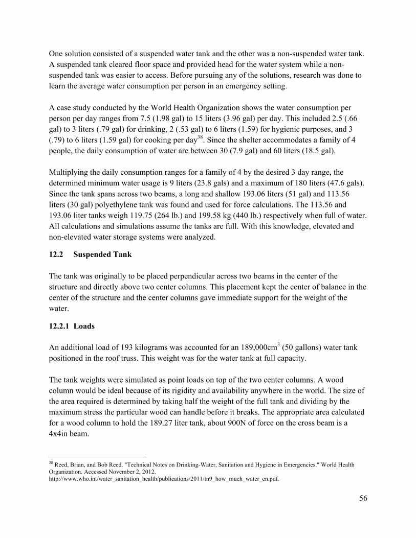
56
One solution consisted of a suspended water tank and the other was a non-suspended water tank. A suspended tank cleared floor space and provided head for the water system while a non-suspended tank was easier to access. Before pursuing any of the solutions, research was done to learn the average water consumption per person in an emergency setting. A case study conducted by the World Health Organization shows the water consumption per person per day ranges from 7.5 (1.98 gal) to 15 liters (3.96 gal) per day. This included 2.5 (.66 gal) to 3 liters (.79 gal) for drinking, 2 (.53 gal) to 6 liters (1.59) for hygienic purposes, and 3 (.79) to 6 liters (1.59 gal) for cooking per day38. Since the shelter accommodates a family of 4 people, the daily consumption of water are between 30 (7.9 gal) and 60 liters (18.5 gal). Multiplying the daily consumption ranges for a family of 4 by the desired 3 day range, the determined minimum water usage is 9 liters (23.8 gals) and a maximum of 180 liters (47.6 gals). Since the tank spans across two beams, a long and shallow 193.06 liters (51 gal) and 113.56 liters (30 gal) polyethylene tank was found and used for force calculations. The 113.56 and 193.06 liter tanks weigh 119.75 (264 lb.) and 199.58 kg (440 lb.) respectively when full of water. All calculations and simulations assume the tanks are full. With this knowledge, elevated and non-elevated water storage systems were analyzed.
12.2 Suspended Tank The tank was originally to be placed perpendicular across two beams in the center of the structure and directly above two center columns. This placement kept the center of balance in the center of the structure and the center columns gave immediate support for the weight of the water.
12.2.1 Loads An additional load of 193 kilograms was accounted for an 189,000cm3 (50 gallons) water tank positioned in the roof truss. This weight was for the water tank at full capacity. The tank weights were simulated as point loads on top of the two center columns. A wood column would be ideal because of its rigidity and availability anywhere in the world. The size of the area required is determined by taking half the weight of the full tank and dividing by the maximum stress the particular wood can handle before it breaks. The appropriate area calculated for a wood column to hold the 189.27 liter tank, about 900N of force on the cross beam is a 4x4in beam. 38 Reed, Brian, and Bob Reed. "Technical Notes on Drinking-Water, Sanitation and Hygiene in Emergencies." World Health Organization. Accessed November 2, 2012. http://www.who.int/water_sanitation_health/publications/2011/tn9_how_much_water_en.pdf.

57
Along with the vertical forces put on the structure due to the water tanks, the seismic force also increased. The seismic gyrations caused problems in the members supporting it and, potentially, could have caused the tank to fall. The tank was thought to be filled in two ways: pump the water up to the tank or bring the tank down and fill manually. To pump the water up a user needed either a gas pump, electrical pump, or manual pump. The gas pump was not feasible due to the expected lack of funds for gas and the high cost for the gas pump itself. The most inexpensive pump found was a $140, 1.86kW (2.5 HP), 4 stroke pump. It delivered over 94.63 lpm (25 gpm). The electrical pump was not feasible due to the predicted electrical outages caused to the natural disaster affecting the area. Having these issues with the two previous pumps, manual pumps were examined. Lever action and rotary hand pumps were found. These pumps had maximum flow rates of 34.07lpm (9gpm) and 30.28lpm (8gpm) respectively. If used the hand pumps would need to be fastened to the wooden columns and be fitted with piping to connect to the tank and to the portable water containers. The cost of the lever action and rotary pump are between $30 and $70. After examining pumping possibilities, the decision was to lower the tank to the ground. A single point pulley system was the first option for lowering the water tank. This means the tank would no longer sitting on top of the two center columns and would be free to move vertically. The tank would be placed in between two columns on either side to keep from any rotation. A sling design similar to the slings used in dolphin rescue would be used to hold up the tank. This design requires two rigid poles/pipes where rope, cable, or band can be connected, ran through a pulley and down to a ratchet system and lever system. The second option for lowering the tank to be filled was a casket lowering system, shown in Figure 31. This system required two straps to support the tank and two rotatable beams to lower and raise tank. A Pacific Cemetery Supply casket-lowering device was the idea that uses a patented safety lock and crank system to move caskets.
Figure 31: Pacific Cemetery Casket Lowering System

58
Both lowering options posed major potential problems with the tank falling. If the ratchet systems failed and a full water tank fell on a family member, physical injury was highly probable. The cost for a lowering system was also predicted to be high, especially in comparison to the $30 lever action hand pump.
12.2.2 Piping for Suspended Tank Material for the piping was decided between copper, PVC, rubber hose, and cross-linked polyethylene (PEX).Copper and PVC are both commonly used in houses for plumbing. PEX is coming out as the new standard in home plumbing. Rubber hose was selected as an option because of its flexibility and durability. To decide between the piping options, three qualities were considered: cost, health, and ease of assembly. Cost was important due to the price limit given by John Brown University and the future possibility of selling the shelter in the world market. The other two factors affect the team’s design norms of trust and transparency. The cost assessment is based on the prices for different copper, PVC, rubber hose, and PEX piping components that are essential for the respective plumbing, shown in Table 19. PVC was the most inexpensive option, followed by PEX, rubber hose, and copper.
Table 19: Components for Different Piping Material Copper( PVC( PEX( Rubber(Hose(Pipe! Pipe! Pipe! Hose!
Elbows! Elbow! Junctions! Junction!
Junctions! Junction! !! !!
Flux! Glue! !! !!
Solder! !! !! !!
Blowtorch! !! !! !!
Health was assessed by reported health concerns with the piping material. Rubber hoses can contaminate the water if the water has been in contact with the hose for an extended amount of time while exposed to high heat39. PVC also had relatively high contamination issues. Copper plumbing has a 15-year life expectancy in which no health concerns should arise40. The use of lead free solder also lowers the health risk of copper plumbing. No health problems were found for PEX.
39 Baue, Bill. "Safe Pipes Mean Safe Water." N.p., 23 June 2007. Web. 12 Nov. 2012. <http://healthychild.org/blog/comments/safe_pipes_mean_safe_water/>. 40 Mercola. "Copper Pipes in Your Home May Cause Heart Disease and Alzheimer's." 1996. www.mercola.com

59
Ease of assembly was assessed on the amount of specific skills needed and the estimated time to install the specific plumbing system. Copper and PVC both needed specific skills to install and seal the various pipes, elbows and junctions. Copper plumbing required the most skill and time since soldering would be needed for every joint while PVC only uses sealing glue. PEX and rubber hose both can be assembled quickly since only one line will be needed in between the inlet and outlet points. Rubber hose and PEX are both very easy to install since they both only needed one pipe per run and have engineered junctions for ease of assembly. Because of this, the two options were considered to have the same rank in ease of assembly. The decision matrix, Table 20, quantifies the importance of each factor considered and shows the best choice for plumbing material. The importance factors on the top row sum up to 100 and were broken up based on the team judgment. Health and cost were considered highly important to the decision of plumbing material since health concerns directly affected the inhabitants of the structure and cost directly affected the financial constraints of the team. Each quality was then given the same weight, 40, since it was a reasonable number that left some weight for ease of assembly. Each option was ranked from 1 to 4 (i.e. 4 being the best and 1 being the worst) in its respective categories, multiplied by its factor, and then summed. The option with the highest score, PEX, was chosen.
Table 20: Water Piping Material Decision Matrix
Material Cost Health Ease of Assembly Total Importance 40 40 20 100
Copper 1 3 1 180 PVC 4 2 2 280
Rubber Hose 2 1 3 180 PEX 3 4 3 340
12.3 Non-Suspended Tank A 35-gallon cylindrical polyethylene water tank was selected. The water tank is 23in height, 29in length, 20in diameter, and has a 5in twistable fill cap located at the top of the tank. A 50-gallon tank was considered and ruled out due to the ineffective fitting into the floor space and under the sink as well as the high cost, proximately $130. No tanks were found in between these two sizes that suited our structure. A 46 gallon water tank intended for concession trailers was found but not considered since the fill hole was 2in in diameter. The best location for the non-suspended water tank is deemed to be underneath the sink with the fill cap unblocked. This location wastes the least amount of floor space and use the least amount of piping, since the tank is directly below the water output.

60
PEX will be connected to the built in output at the bottom of the tank and ran to a lever action pump, which outflows into a purification system and into the sink. A rotary pump was also considered but ruled out since the lever action pump was deemed easier to use by the team members.
12.4 Filtration Selection for the water purification system was narrowed down to two options. The first option for a purification system was the Sawyer PointONE™. The Sawyer PointONE™ is a small water filter that has a removal rate of “0.10 Micron Absolute, at a 7 log (99.99%) rate, exceeding EPA and NSF recommendations.”41 The purification unit is assembled at the outlet of the water system with the ability to be removed easily for cleaning. Sawyer guarantees a filter life of 100 million gallons. To set up the purification system, one must simply force water though the purifier. This can be done via tubing or squeeze pouch, both of which will be provided. Filter cleaning is recommended two times per year and is very easy. To clean, the filter is detached backwashed with clean water using a syringe provided with the purchase of the Sawyer PointONE all in one package. Figure 32 shows the Sawyer filter to the left of the cleaning syringe along with a squeeze pouch, tubes, and fitting.
Figure 32: Sawyer PointONE all in One Package
The Hydraid BioSand filter was the second option and uses filter media (sand) and a biolayer to remove bacteria, parasites and viruses.The filter, however, does not remove heavy metals and is not approved by the U.S. Environmental Protection Agency for drinking water in the U.S. The water filter has to be set up on a flat surface by certified personnel and tied in to the water tank with PEX piping. The Hydraid system calls for at least 18927cm3 (5 gallons) of water flow per day to ensure the biolayer remains alive and able to consume bacteria; however, constant flow for extended periods of time may harm the biolayer. If the Hydraid filter was selected, the occupants would have to be conscious of these issues and care for the system accordingly. Only a certified volunteer may assemble the Hydraid to endure the filtration process works properly. Figure 33 shows the Hydraid along with its filter media and components.
41 Sawyer. "Water Solutions." 1996. http://www.sawyer.com/water.html.

61
Figure 33: Hydraid Biosand Filter
12.5 Piping for Water Supply As stated above, PVC, copper, and rubber hoses were the considered alternatives for the piping system in the structure. Copper piping was the most expensive of the alternatives and required specific skills to assemble. This option was then ruled out due to these issues. Rubber hoses seemed to be a good fit since no specific skill set was needed to assemble a piping system of hoses. This option was also cost effective since joints or elbows are not needed, but health concerns ruled it out. When rubber hose is exposed to high heat for a long period of time, lead and other contaminants may pollute water that is sitting in the hose42. PVC also had lead contamination issues, and installation was very time consuming when compared to the PEX. The health issue was the main drawback for this option. Metallic compounds called organotins are used in PVC to guard against heat degradation and have been linked to birth defects and nervous system damage.43
42 McGregor, Ellen. "Study finds Silent Killers Lurking in your Garden Hose." newsnet5. N.p., 19 June 2012. Web. 12 Nov. 2012. <http://www.newsnet5.com/dpp/news/health/study-finds-silent-killers-lurking-in-your-garden-hose>. 43 Baue, Bill. "Safe Pipes Mean Safe Water." N.p., 23 June 2007. Web. 12 Nov. 2012. <http://healthychild.org/blog/comments/safe_pipes_mean_safe_water/>.

62
12.6 Design Decisions The non-suspended water tank and Sawyer PointONE are the optimal choices for the water system. The non-suspended water tank is easier to assemble and fill than the suspended water tank since placing it on flat ground and unscrewing a cap is all that is needed. The cost for the non-suspended water tank is significantly less than the elevated tank since the elevated tank needed wooden beams for support. The need for wooden beams also helped decide against the elevated tank since the shelter has a weight limit. The elevate tank applies high vertical stress on the structure, needing stronger and heavier material. Pumping water up to the tank and then back down to the user is inefficient. Head can be provided to the water system by using the pump, so elevation is not needed. The high potential of injury caused by a falling tank was another reason for opting against the elevated tank. The Sawyer PointONE was chosen because it is, least expensive, a better purifier, easily assembled, and requires less upkeep than the Hydraid. The cost for the Sawyer PointONE and the Hydraid are $57.00 plus shipping and $60.00 plus shipping respectively. The non-suspended tank fulfills the team’s goal of providing a water system that can sustain a family of four for about 3 days. The tank provides easy access for filling and cleaning. It uses less material to transport water than the elevated tank and does not overstress the structure.
13 Shipping The DRS also includes a shipping box. Effective shipping is ideal in order to send the maximum order of DRS units per 8’ by 40’ shipping container, as required by the competition. This shipping box is currently made from 1/4in plywood. This shipping container is a standard rectangle box 7’5” in length, 2’ by 2’2” height and width. This shipping box has multiple purposes. The first purpose is to house the contents of an individual DRS unit and ensure what is shipped out is what the victims receive. The second purpose is for continued use of the box. Because of its large dimensions and rigidity, the box serves as options such as a closet, storage unit, table, and other creative functions a family may have. The box is shown in Figure 34 below.

63
Figure 34: Shipping box for DRS
This box is efficient for large quantity shipping. In an 8’ by 40’ shipping container, 57 DRS units equipped with the frame, tarp, bolts, plates, curtains, flooring, sand bags, ground stakes, mallet, ratchet, and builder’s manual fit utilizing most of the available space. A full container is shown in Figure 35.
Figure 35: 8' by 40' shipping container with 57 DRS units.

64
14 Shelter Design Competition Results On April 18, Team DRS traveled to Siloam Springs, AR to compete in the World Vision Disaster Shelter Design Competition. A total of five schools competed including John Brown University, LaTourneau University, University of Louisiana at Monroe, and Judson University. Competitors consisted of students studying Engineering, Construction Management, or Architecture. As results, the DRS placed first among all five teams.
14.1 Shelter Requirements and Performance As stated above, the criteria and design guidelines for this shelter came primarily from the World Vision Disaster Shelter Design Competition. The first test was the weight limit for shipping purposes and land transportation. With a maximum weight of 440lbs, the total weight of the DRS and shipping container was 398lbs. This weight excludes electrical components and water supplies. To perform the seismic shake table test, the shelter was built on the shake table’s platform with stakes through the platform and bio-anchor filled with sandbags. The shake table was set to output 3in strokes at 3 cycles per second. The flexibility property of PVC combined with its frame design transferred the energy down to the ground and allowed the DRS to sway back and forth. The one-piece characteristic of the tarp kept the members together and also swayed with the columns. After 30 seconds of shaking, an assessment was performed, and no structural damaged was found. The DRS met the 1-hour assembly criteria. During the timed assembly test, the DRS was built in 48 minutes by the four members. If built by four individuals relying on the builder’s manual, the assembly time would change. Finally, the DRS went through a hurricane test. The hurricane test consisted of a 50mph wind spraying 8 gallons of water per minute. The hurricane test was simulated by a 68in diameter wind generating machine known as WOLF. This machine has a three-blade propeller mounted on a 95hp gasoline engine44. The WOLF was placed in front of the door as well as on the 5m side of the shelter. During the door testing, the front of the roof frame lifted off the vertical columns. This lifting was due to the uneven stitching of the prototype tarp at the door, allowing the wind to enter and build up internal pressure in the DRS. With the wind blowing and the internal pressure building, the front of the shelter shifted about 4in from its original location. Unfortunately the internal pressure
44 Field and Mock Up Testing Services. York, PA: Architectural Testing http://www.archtest.com/testing/brochures/Applicable%20Lab%20and%20Field%20Testing.pdf

65
lifted the frame high enough to slip out from the 2 front concept stakes. When the WOLF ceased, the front of the roof frame lowered to its position back onto the vertical columns. The three vertical columns did not blow away from the frame because the stitched sleeves on the tarp guided the columns back to their designed location. During the 5m side testing, the frame did not deflect as much as the computer model had simulated. The frame withstood the wind for 2 minutes and returned to its original position with no sliding. In conclusion, the 3meter side with the door was the worst case scenario for wind loading.
14.2 Cascade Design Business Case Analysis A Business Case Analysis (BCA) was provided by Cascade Designs to implement fabrication of the shelter. This BCA template includes Bill of Materials, Bill of Labor, Sales price, and projection statements for fabricating 12,500 units per year and determining the length of payback period. The BCA also includes calculations for purchasing raw materials, labor hours invested in customizing to the product’s specific requirements, initial capital expenditures, and shipping expenses. The raw materials included in this template are both stock items and custom manufactured parts such as the metal plates for reinforcing the joints. Materials available out of the United States are quoted with their respected companies, while other materials are quoted from locations in the United States. This BCA also serves to aid an investing company to determine the priority in their investment. A company with the goal of a low payback period must sell these units at a higher unit price. If the company agrees to a longer pay back period, the unit price decreases. It is the company’s choice to determine if it is important to serve a region in need or to make a profit as fast as possible. A DRS model with no electricity or water components is the best choice in price and availability because of the fewer parts and less weight. A company wishing to make a profitable return with a payback period of 3 years will have a wholesale price of $1,785( MRSP of $2,588.55). The investment is then paid off in the last month of the third year. In the case the investing company doesn’t mind holding off a return, the company can offer a wholesale price of $1,000 (MSRP $1,450) and expect a return in the middle of the 9th year. If the shelter is sold at $1,300 (MSRP $1,885) per unit, the return is expected in the middle of the 4th year.

66
15 Improving for the Future
15.1 Structural Reinforcement Unfortunately the shelter did fail the criteria at the door. With the frame of the roof lifting off the vertical columns, the proposed solution is to put bolts into the vertical columns of the 3m sides. With the roof and columns together, and the longer stake as described above, the shelter will be allowed to lift slightly, but not enough to clear the stakes on the ground. The bolts also constrain rotation in one direction, keeping the structural frame from wobbling.
15.1 From Emergency Shelter to Transitional Shelter A common practice for humanitarian relief organizations such as United Nations High Commissioner for Refugees (UNHCR) and World Vision after a natural disaster where people’s homes are destroyed is to use temporary housing. Temporary housing is quick to set up and gives the displaced victims a structure to protect them from natural elements like rain, wind, and sun before relocating them to a permanent home. The ability to set up housing quickly is essential to the relief process, but the temporary aspect of these homes causes relief organizations to build completely new structures for the displaced families. The families then spend extended periods of time in these temporary structures and communities. A transitional disaster relief structure is aimed at fixing this problem. World Vision’s Shelter and Reconstruction Specialist Brett Moore, who is part of many disaster relief operations, defined a transitional shelter as one with the ability to become permanent. Taking the shelter’s frame, localized materials such as clay, straw, twigs, and wood are added to make walls or roofs obtain this permanency. This process creates a sense of ownership and cultural pride with the newly upgraded homes. Instead of living in a structure that is foreign to the occupants, they are now living in a home they built. The use of localized materials places the occupants’ culture directly on their home as well as creating a more efficient home. As Mr. Moore mentioned, the use of mud or wood in the upgrading of a structure will serve as insulation and a more rigid protection from the elements. These materials will protect them from the heat of the sun better than canvas material that is sent with first response tents. All of the shelters previously mentioned did not have insulation integrated into the design and the addition of mud or clay substances to the exterior of a structure will increase the thermal resistance creating a cooler home. DRS’s current structural design is currently that of a temporary relief structure. It was designed to be light and quick to set up while strong enough to withstand 75 kph wind gusts and magnitude 7 earthquakes. The frame, mainly PVC with some aluminum plates, gives the structure enough strength to withstand the specified wind and seismic loading along with some ductility. The flexibility of PVC in DRS’s design is vital with the sustainability of the structure,

67
but this quality inhibits the user from using rigid options, such as clay and mud, to construct more permanent walls. When the PVC frame is exposed to external forces that causes bending and deflection in the frame, a dried mud wall will crack and fail. Screwing into the plastic to attach siding also render some problems with the structural integrity of the pipes. With movement caused by external forces, the holes may become loose and no longer be able to support the load of the added siding. Although the current design is temporary, some features were implemented to make the structure upgradeable, satisfying the transitional definition. The use of off the shelf PVC piping and junctions gives the user the ability to purchase more material and add to or change the floor space. Also, the user may remove the current PVC columns and insert more permanent columns or walls and place the roof atop the additions or simply use the materials for other functions. The users can take the PVC from the framing and use it as electrical conduits, pipes for plumbing, or irrigation tubes in the permanent structure.
15.2 Ventilation Four windows and a door currently allow for ventilation inside the shelter. Despite having four windows, ventilation was ranked poor. In order to provide more airflow, two more windows will be added on both 5m sides for crossing airflow. Unfortunately, hot air collects at the roof, creating an unpleasant environment near the top. In order to solve this issue, a small window with cover is currently the idea to be placed near the peak of the roof for hot air to escape. A simple cord system is the ideal preference for opening and closing the flap to the vents. This is currently a concept idea and requires further developing.
15.3 Composting Toilet One of the most challenging tasks in setting up an emergency relief shelter is the development of a sanitary treatment system. This section describes one possible solution to dealing with human waste: composting toilets. Since the budget for this project was not sufficient for creating a prototype, a brief description is provided instead. Rather than building toilet units for each shelter, a community toilet would be faster to construct and maintain. From the toilet, waste would flow into a bio drum. The bio drum is a cylindrically shaped chamber, rotating fasces to allow complete mixture. A drain is present in the bio drum for the removal of any urine. The bio drum is set to a high enough temperature so that excess liquid will be evaporated. This is more advantageous over exposing the bio drum to sunlight because sunlight will cause the fasces to dry up, preventing micro-bacteria organisms, which breaks down waste from carrying out their task. Figure 36 is an example of a bio drum manufactured by Sun Mar, a company which produces composting toilets.45
45 Sun-Mar. 2009. Accessed November 12, 2012. http://www.sun-mar.com/.

68
Figure 36: Example of a Bio Drum46
46 Sun-Mar. "How Composting Works." http://www.sun-mar.com/tech_how.html.

69
Acknowledgements Mr. Allen Weber: Etna Supple – Municipal Division Manager Dr. David Wunder: Calvin College – Civil Engineering Professor and Team Advisor Mr. Mark Terrill: John Brown University – Assistant Professor and Competition Host Mr. Jim Caldwell: John Brown University – Assistant Professor and Competition Host Dr. Richard DeJong: Calvin College – Professor of Mechanical Engineering Mr. Leonard De Rooy: Calvin College – Professor of Civil and Environmental Engineering Mr. Donald Winkle: Calvin College – Electrician Dr. April Si: Calvin College – Interdisciplinary Professor of Engineering. Ms. Nel Postedwald – Seamstress

70
Work Cited ASCE 7-10 Minimum Design Loads for Buildings and Other Structures, (Reston: American Society of Civil Engineers, 2010), chap. 26. Baue, Bill. "Safe Pipes Mean Safe Water." N.p., 23 June 2007. Web. 12 Nov. 2012. <http://healthychild.org/blog/comments/safe_pipes_mean_safe_water/>. Boeree, Dr. C. George. "Abraham Maslow." Accessed November 2, 2012. http://webspace.ship.edu/cgboer/maslow.html The Camping and Caravanning Club, "Tent Fabrics." Last modified 2013. http://www.campingandcaravanningclub.co.uk/helpandadvice/gettingstarted/new tents/tentfabrics/ CIA The World Factbook. "Indonesia." https://www.cia.gov/library/publications/the worldfactbook/geos/id.html Consumer Guide to Home and General Electric. Wholesale Solar. November 4,2012. http://www.wholesalesolar.com/StartHere/HowtoSaveEnergy/PowerTable.html Davies, Martyn. Expedition Portal, "Rooftop Tent Fabrics and Care." Last modified 2012.http://www.expeditionportal.com/resources/rooftop-tent-fabrics-an care.html Disease. N.p., n.d. Web. 16 Dec. 2012. <http://water.org/water-crisis/water facts/disease/>. The Effects of Ultraviolet Radiation on PVC Pipe. Dallas: Uni-Bell PVC Pipe Association,2002. Encyclopedia of the Nations. Advameg, Inc., 2013. s.v. "Indonesia - Climate." http://www.nationsencyclopedia.com/Asia-and-Oceania/Indonesia CLIMATE.html Field and Mock Up Testing Services. York, PA: Architectural Testing http://www.archtest.com/testing/brochures/Applicable%20Lab%20and%20Fiel ia.gov/library/publications/the-world-factbook/geos/id.html Goodier, Rob. "Ten Great Emergency Shelter Designs."Engineering for Change, October 30, 2011.

71
Historic World Earthquakes. USGS, n.d. Web. 16 Oct. 2012. <http://earthquake.usgs.gov/earthquakes/world/historical_country.php#indonesia> The Home Depot http://www.homedepot.com/ The International Disaster Database. EM-DAT. Accessed November 7, 2012. http://www.emdat.be/natural-disasters-trends. Machine Design, "Basics of Design Engineering," Nylon, http://machinedesign.com/BDE/materials/bdemat2/bdemat2_29.html Massey, Liesl L. The Effects of UV Light and Weather: On Plastics and Elastomers. 2nd
ed.N.p.: William Andrew, 2007. Matthewson, Philip. A Comparative Study of International Building Code Seismic AnalysisMethods with Case Studies. N.p.: ProQuest Information and Learning Company, 2003. MatWeb. "Aluminum 2024-T4 ASM Material Data Sheet." http://asm.matweb.com/search/SpecificMaterial.asp?bassnum=MA2024T4 McGregor, Ellen. "Study finds Silent Killers Lurking in your Garden Hose." newsnet5.N.p.,19 June 2012. Web. 12 Nov. 2012<http://www.newsnet5.com/dpp/news/health/study-finds silent-killers-lurking-inyour-garden-hose>. Mercola. "Copper Pipes in Your Home May Cause Heart Disease and Alzheimer's."1996. www.mercola.com National Metal and Materials Technology Center. "Understanding How Metals Corrode CanHelp Build Better Structures." http://www2.mtec.or.th/th/research/famd/corro%5Chowmetals.htm Peshkova, Svetlana. “Bringing the mosque home and talking politics:women, domestic space,and the state in the Ferghana Valley (Uzbekistan).” Springer Science + Business Media (2009): 251-273. Phone Interview with Paul de Bakker – Chief Engineer of Composites. Goodwinds. Mount Vernon, WA. March, 18, 2013. Povolo, F., G. Schwartz, and Elida B. Hermida. "Stress Relaxation of PVC Below the Yield
Point." Journal of Polymer Science34, no. 7 (May 1996): 1257-67.

72
Professional Publication,Inc, "Lateral Forces-Earthquakes." http://www.ironwarrior.org/ARE/General_Structures/structural ARES5ch14.pdf. Reed, Brian, and Bob Reed. "Technical Notes on Drinking-Water, Sanitation an Hygiene in Emergencies." World Health Organization. Accessed November 2, 2012. http://www.who.int/water_sanitation_health/publications/2011/tn9_how_much_ ater_en.pdf. Riley, William, Leroy Sturges, and Don Morris. Mechanics of Materials. 6th ed. Danvers, MA: John Wiley and Sons, 2007.
Sawyer. "Water Solutions." 1996. http://www.sawyer.com/water.html.
Soil Density found at Engineering Toolbox. http://www.engineeringtoolbox.com/soil rock bulking-factor-d_1557.html
Soltesz, Deborah Lee. LiveStrong, "Canvas vs. Nylon Tents." Last modified June 7, 2010. Accessed March 30, 2013. http://www.livestrong.com/article/142557 canvas-vs nylon-tents/
Sun-Mar. "How Composting Works." http://www.sun-mar.com/tech_how.html
Thiele, Timothy. About.com. Accessed November 12, 2012. http://electrical.about.com/od/wiringcircuitry/a/electwiresizes.htm Transitional Shelters - Eight Designs, (Geneva: International Federation of Red Cross and
Red Crescent Societies, 2011). Travel Images.com. Accessed November 12, 2012. http://www.travel images.com/electricplugs.html
“Tropic Islands.” http://about-indonesia123.blogspot.com/ &

73
Appendix A – Wind Load Information 47
Pressure Velocity ! = 0.613!!!"# !!!!!!(!/!!) (Equation 1)
where, V = velocity (mph) of a 3-second gust of wind which is 45.6 mph for this case. I = importance factor. A factor of 0.97 is used because the shelter will have a low hazard
to human life since it is meant to hold just a family of up to four. Kz= velocity pressure exposure coefficient which is based on the ground terrain of the
area and the height of the structure. For heights that are below 4.6 meters, the exposure coefficient is 0.85.
Kzt= topographic factor. The area for the relief center in Indonesia is assumed to be flat ground. The factor is therefore 1.
Kd= directional wind factor which is based on other loads acting on the structure. Until seismic loads are calculated, the wind is assumed to be 1.
Design Pressure ! = !"!! − !!(!!!") (Equation 2)
q = velocity pressure calculated above. G = wind-gust effect factor which is 0.85 because the structure is rigid. Cp = a wall or roof external pressure coefficient. See Table A1 and Table A2 for external
pressure coefficient values for wall surfaces and arced roofs, respectively. GCpi= internal pressure coefficient. Since the shelter is considered open, the coefficient is
zero. Table 21: External Pressure Coefficients for Wall Surfaces
Surface( L/B(or(B/L(
External(Pressure((
Coefficients((Cp)(
Use(with(
Windward(Wall( All!values! 0.8! qz!
Leeward(Wall(
0*1! *0.5!
qh!1.67! *0.366!
2! *0.3!
≥4! *0.2!
Side(Walls( All!values! *0.7! qh!
47 ASCE 7-10 Minimum Design Loads for Buildings and Other Structures, (Reston: American Society of Civil Engineers, 2010), chap. 26.

74
Table 22: External Pressure Coefficients for Arced Roofs
!! (( External(Roof(Pressure(Coefficient,(Cp(
Conditions(Rise^to^span(
ratio,(r(Windward(quarter(
Center(half(
Leewards(quarter(
Roof(on(elevated(structure(
0!<!r!!<!0.2! *0.9! *0.867! *0.5!
0.2!≤!r!<!0.3! *0.05! *0.867! *0.5!
0.3!≤!r!≤!0.6! *0.24! *0.867! *0.5!

75
Appendix B – Seismic Load Information 48
Modified Spectral Response Acceleration !!" = !!!! (Equation 3)
and !!! = !!!! (Equation 4)
where,
SM1 = modified spectral response accelerations at 1 second
SMS = modified spectral response accelerations at 0.2 seconds
Design Spectral Response Acceleration !!" = !
! !!" (Equation 5)
and !!! = !
! !!! (Equation 6) where,
SD1 = design spectral response accelerations at 1 second
SDS = design spectral response accelerations at 0.2 seconds
Shear Force ! = !!! (Equation 7)
where, V = equivalent shear force acting on the base Cs= seismic design coefficient W = total dead load of the structure
Seismic Design Coefficient !! = !!"
! !! (Equation 8)
where, 48 ASCE 7-05 Minimum Design Loads for Buildings and Other Structures, (Reston: American Society of Civil Engineers, 2010), chap. 11.

76
R = response modification factor. For light-framed walls, R is equal to 5. IE= seismic importance factor which is based on the Seismic Hazard Exposure Group discussed under Seismic Loads.
Maximum and Minimum Seismic Design Coefficient !!"#$ = 0.5 !!
! !! (Equation 9)
!!"#$ = !!!! !! !
(Equation 10)
where, T = the fundamental period of the structure
Fundamental Period ! = !!!! (Equation 11)
where, Ta = approximate fundamental period. For structures less than twelve stories with at least a 10 foot story height, Ta is 0.1 Newton.
Cu = upper limit coefficient. For SD1 values greater than 0.3, Cu is equal to 1.4.
Vertical Distribution Factors !!"##$ =
!!""#!!""#!!""#!!""#!!!"##$!!"##$
(Equation 13)
!!"#$$% =!!"##$!!"##$
!!""!!!""#!!!"##$!!"##$ (Equation 14)
where,
Cvroof = vertical distribution factor for the roof Cvfloor = vertical distribution factor for the floor
Hroof = roof height Wroof = roof weight Hfloor = floor height Hfloor = floor weight
Lateral Force !! = !!"! (Equation 15)
where, x = the floor or roof

77
Appendix C – Mathematical Calculations of Finite Element Analysis

78

79
Case 1
Figure 37: 100N point load at the end of the beam.
Case 2
Figure 38: 100N distributed edge load over length of beam.
Case 3
Figure 39: 100N force distributed over 566 nodes over length of beam.

80
Appendix D – Schematics Sheet #1 – Structure Plan Sheet #2 – Lengths of PVC Pipes Sheet #3 – Flat Plate Design Sheet #4 – Angle Plate Design Sheet #5 – Location for Holes in PVC Pipes Sheet #6 – Stake Design Sheet #7 – Shipping Container

73
Appendix A – Wind Load Information 47
Pressure Velocity
= 0.613 (/) (Equation 1)
where,
V = velocity (mph) of a 3-second gust of wind which is 45.6 mph for this case.
I = importance factor. A factor of 0.97 is used because the shelter will have a low hazard
to human life since it is meant to hold just a family of up to four.
Kz= velocity pressure exposure coefficient which is based on the ground terrain of the
area and the height of the structure. For heights that are below 4.6 meters, the
exposure coefficient is 0.85.
Kzt= topographic factor. The area for the relief center in Indonesia is assumed to be flat
ground. The factor is therefore 1.
Kd= directional wind factor which is based on other loads acting on the structure. Until
seismic loads are calculated, the wind is assumed to be 1.
Design Pressure
= − () (Equation 2)
q = velocity pressure calculated above.
G = wind-gust effect factor which is 0.85 because the structure is rigid.
Cp = a wall or roof external pressure coefficient. See Table A1 and Table A2 for external
pressure coefficient values for wall surfaces and arced roofs, respectively.
GCpi= internal pressure coefficient. Since the shelter is considered open, the coefficient is
zero.
Table 21: External Pressure Coefficients for Wall Surfaces
Surface L/B or B/L
External Pressure
Coefficients (Cp)
Use with
Windward Wall All values 0.8 qz
Leeward Wall
0-1 -0.5
qh 1.67 -0.366 2 -0.3
≥4 -0.2
Side Walls All values -0.7 qh
47 ASCE 7-10 Minimum Design Loads for Buildings and Other Structures, (Reston: American Society of Civil Engineers, 2010), chap. 26.

74
Table 22: External Pressure Coefficients for Arced Roofs
External Roof Pressure Coefficient, Cp
Conditions Rise-to-span
ratio, r Windward
quarter Center
half Leewards quarter
Roof on elevated structure
0 < r < 0.2 -0.9 -0.867 -0.5 0.2 ≤ r < 0.3 -0.05 -0.867 -0.5 0.3 ≤ r ≤ 0.6 -0.24 -0.867 -0.5

75
Appendix B – Seismic Load Information 48
Modified Spectral Response Acceleration
= (Equation 3)
and
= (Equation 4)
where,
SM1 = modified spectral response accelerations at 1 second
SMS = modified spectral response accelerations at 0.2 seconds
Design Spectral Response Acceleration
= (Equation 5)
and
= (Equation 6)
where,
SD1 = design spectral response accelerations at 1 second
SDS = design spectral response accelerations at 0.2 seconds
Shear Force
= (Equation 7)
where,
V = equivalent shear force acting on the base
Cs= seismic design coefficient
W = total dead load of the structure
Seismic Design Coefficient
=
(Equation 8)
where,
48 ASCE 7-05 Minimum Design Loads for Buildings and Other Structures, (Reston: American Society of Civil Engineers, 2010), chap. 11.

76
R = response modification factor. For light-framed walls, R is equal to 5.
IE= seismic importance factor which is based on the Seismic Hazard Exposure Group discussed under Seismic Loads.
Maximum and Minimum Seismic Design Coefficient
= 0.5
(Equation 9)
=
(Equation 10)
where,
T = the fundamental period of the structure
Fundamental Period
= (Equation 11)
where,
Ta = approximate fundamental period. For structures less than twelve stories with at least a 10 foot story height, Ta is 0.1 Newton.
Cu = upper limit coefficient. For SD1 values greater than 0.3, Cu is equal to 1.4.
Vertical Distribution Factors
=
(Equation 13)
=
(Equation 14)
where,
Cvroof = vertical distribution factor for the roof
Cvfloor = vertical distribution factor for the floor
Hroof = roof height
Wroof = roof weight
Hfloor = floor height
Hfloor = floor weight
Lateral Force
= (Equation 15)
where,
x = the floor or roof

77
Appendix C – Mathematical Calculations of Finite Element Analysis

78

79
Case 1
Figure 37: 100N point load at the end of the beam.
Case 2
Figure 38: 100N distributed edge load over length of beam.
Case 3
Figure 39: 100N force distributed over 566 nodes over length of beam.

80
Appendix D – Schematics
Sheet #1 – Structure Plan
Sheet #2 – Lengths of PVC Pipes
Sheet #3 – Flat Plate Design
Sheet #4 – Angle Plate Design
Sheet #5 – Location for Holes in PVC Pipes
Sheet #6 – Stake Design
Sheet #7 – Shipping Container


87
Appendix E – World Vision Business Case Analysis

88
- - - Confidential - - -
Sales Quantity & Revenues (weighted average)
2014 2015 2016
Minimum quantity sold1 12,500 12,500 12,500
Maximum quantity sold215,000 15,000 15,000
Likely quantity sold3 13,500 13,500 13,500Expected Qty sold4 13,575 13,575 13,575
Wholesale Price (weighted average) 1,100.00$ MSRP (weighted average) 1,595.00$ This indicates what the shelter might sell for in the Retail Market based on the Wholesale Price above. Use as a "Reality Check".
Expected Revenue $ 14,932,500.00$ 14,932,500.00$ 14,932,500.00$ (Feeds to BCA Template Cell D76, 77, 78)
Sales Assumptions
1 We have a 90% probability of achieving at least the minimum quantity2 We have less than a 10% probability of exceeding the maxmum quantity3 Likely quantity is the best guess working from the dealer base up and the marketplace down4 Expected quantity gives 15% weighting each to minimum and maximum, and 70% weighting to likely
List your key assumptions that drive your sales estimates here. Add lines as necessary.
- Confidential - - -
Bill of Materials Cost per Unit (weighted average)
Product Part Qty UM Cost Extd Price % Dwg # Rev Status/notes Material type Tooling type Tool est. Supplier1-1/2" X 20FT PVC PIPE 204 ft 0.120$ 24.48$ 6% SCHEDULE 40 PVC ROTARY SAW 50$ Jianshan Sanfa Plastic Co. LTDSPEARS 420-015 1-1/2 PVC CROSS 2 each 1.920$ 3.84$ 1% SCHEDULE 80 PVC NONE Jianshan Sanfa Plastic Co. LTDSPEARS 420-015 1-1/2 PVC CROSS 2 each 0.450$ 0.90$ 0% SCHEDULE 40 PVC NONE Jianshan Sanfa Plastic Co. LTDSPEARS 801-015 1-1/2 PVC TEE 5 each 5.169$ 25.84$ 7% SCHEDULE 40 PVC NONE Zhejiang shunanghuan Plastic Valve Enterprise1-1/2" SLIP SLING TEE FITTING 6 each 0.400$ 2.40$ 1% FURNITURE GRADE PVC NONE FORMUFIT-KS1-1/2" 3WAY ELBOW FITTING 4 each 1.120$ 4.48$ 1% FURNITURE GRADE PVC NONE FORMUFIT-KS1-1/2" 4WAY TEE FITTING 6 each 1.240$ 7.44$ 2% FURNITURE GRADE PVC NONE FORMUFIT-KS0.394" x 0.212" X 48" TUBE 54 ft 0.790$ 42.66$ 11% PULTRUTED TUBE FIBERGLASS ROTARY SAW 50$ GOODWINDS-WAHEAVY DUTY TARP 20X30FT 6OZ 58 sqm 0.700$ 40.60$ 11% WHITE, QTY IN SQ METERS, ALREADY WITH DOORS AND WINDOWS POLYESTER SEWING AND CUTTER 100$ FEICHENG HAICHENG PLASTIC PACKAGE CO. LTD1FT ZIPPER 9 ft 0.345$ 3.11$ 1% 75FT ROLLS $36.75 NYLON COIL CUTTER 50$ BEACONFABRIC3/4" VELCRO LOOP 54.5 ft 0.364$ 19.84$ 5% 75FT ROLLS $38.95 STANDARD CUTTER 50$ BEACONFABRIC3/4" VELCRO HOOK 54.5 ft 0.364$ 19.84$ 5% 75FT ROLLS $38.95 STANDARD CUTTER 50$ BEACONFABRIC1/4-20 X 2 HEX HEAD SCREW 31 each 0.040$ 1.24$ 0% US STANDARD SIZE, 1000+ UNITS STEEL NONE HOME DEPOT1/4-20 WING NUT 25 each 0.020$ 0.50$ 0% US STANDARD SIZE, 1000+ UNITS STEEL NONE HOME DEPOTLIGHT FIXTURE BOX 2 each 1.561$ 3.12$ 1% PLASTIC STANDARD NONE KENDALL ELECTRICOCTANE TILES FLOORING 170 each 0.850$ 144.50$ 38% SQUARE FLOOR TILES, BLACK POLYPROPYLENE NONE RUBBER FLORING INFLAT PLATE 3 each 1.800$ 5.40$ 1% 1 ESTIMATE PREFABRICATED, SHIPPING INCLUDED ALUMINUM 2024-T4 NONE MECHANIC MACHINING (SHENZHEN) CO. LTDANGLE PLATE 25 each 1.200$ 30.00$ 8% 2 ESTIMATE PREFABRICATED, SHIPPING INCLUDED ALUMINUM 2024-T4 NONE MECHANIC MACHINING (SHENZHEN) CO. LTD3/8" X 18" STEEL REBAR 9 ft 0.200$ 1.80$ 0% STEEL CUTTER 30$ 1.61" X 6" WOOD CYLINDER 3 each 0.100$ 0.30$ 0% Wood CUTTER 30$
-$ 0%-$ 0%-$ 0%-$ 0%-$ 0%-$ 0%-$ 0%-$ 0%-$ 0%-$ 0%-$ 0%
Total Product RM Cost: 382.29$ 100%
Packaging Part Qty UM Cost Extd Price % Dwg # Rev Status/notes Material Type Tooling type Tool est. SupplierTELESCOPIC BULK CARGO CONTAINER 1 each 19.150$ 19.15$ 100% COMES PRESCUT TO CORRECT DIMENSIONS WOOD NONE ULINE
-$ 0%-$ 0%-$ 0%-$ 0%-$ 0%-$ 0%-$ 0%-$ 0%
Total Packaging RM Cost: 19.15$ 100%

89
Project Title: Disaster Relief Shelter
Bill of Labor Minutes Per Unit (weighted average)
Production Step Minutes % of Total CommentsPVC PIPE MODIFICATION 20.000 19% CUTTING PVC PIPES TO APPROPRIATE LENGTHSFIBERGLASS TUBE MODIFICATION 5.000 5% CUTTING FIBERGLASS TO APPROPRIATE LENGTHSHOLES FOR BOLTS 30.000 29% DRILLING HOLES IN PVC PIPES AND FITTINGS FOR BOLTS - SEE SHEET 3SEW SEAMS 30.000 29% SIZING, MACHINE SEWING, AND CUTTING SECTIONS OF TARPPREINSTALL SOME PIPES AND FITTINGS 15.000 14% PREASSEMBLE CC1, CC2, AND CC3 AND C80S TO RCR MEMBERS TO PREVENT CONFUSIONPREASSEMBLE FLOOR SECTIONS 5.000 5% PREASSEMBLE TILES INTO 1X5 TILES FOR ARRANGEMENT INTO SHIPPING BOX
0%0%0%0%0%0%0%0%0%0%0%0%0%0%0%0%0%0%0%0%
Total Production Labor Minutes: 105.000 100%
Packaging Step Minutes % of Total CommentsASSMEBLING PACKAGING BOX 30.000 75% USING GLUE AND NAIL GUNPACKING INTO SHIPPING BOX 10.000 25% PLACING FINISHED AND PREASSEMBLED PARTS INTO BOX
0%0%0%0%0%
Total Pkg Labor Minutes: 40.000 100%
Total Minutes per Unit: 145.000
Labor Rate per Minute: 0.167$ (This rate is based on an average of $10.00/hour)
Labor Cost per Unit: 24.17$ Overheads:Direct Labor Benefits Rate-% 0.0% -$
24.17$ Manufacturing Overhead on Labor-% 0.0% -$
Total Labor Cost with Overheads: 48.33$ (Feeds BCA Template, Projected Cash Inflows)

90
Appendix F – Gantt Chart of Project

IDTask N
ame
Duration
StartFinish
Deadline
1W
ater Tank Volum
e5 hrs
Mon 10/8/12
Mon 10/8/12
Wed 10/17/12
2G
ray Water Tank V
olume
2 hrsM
on 10/22/12Mon 10/22/12
Fri 10/26/123
Wind Loading
8 hrsTue 10/16/12
Tue 10/16/12Fri 10/19/12
4Seism
ic Loading9 hrs
Tue 10/23/12W
ed 10/24/12Fri 10/26/12
5W
iring Options
10 hrsFri 10/12/12
Mon 10/15/12
Fri 10/19/126
Check Wiring Code
10 hrsThu 10/11/12
Fri 10/12/12Fri 10/19/12
7D
etermine # outlets
2 hrsThu 10/25/12
Thu 10/25/12Fri 10/26/12
8Pow
er Requirements
2 hrsW
ed 10/17/12Wed 10/17/12
Fri 10/19/129
Lighting6 hrs
Tue 10/16/12Tue 10/16/12
Fri 10/19/1210
Sink6 hrs
Mon 10/29/12M
on 10/29/12Fri 11/2/12
11Pum
p Required4 hrs
Mon 10/22/12M
on 10/22/12Fri 10/26/12
12W
ater Tank Location3 hrs
Tue 10/16/12Tue 10/16/12
Wed 10/17/12
13Structural Fittings
4 hrsTue 10/23/12
Tue 10/23/12Fri 10/26/12
14M
aterial Covering for Shelter8 hrs
Wed 10/24/12W
ed 10/24/12W
ed 10/31/1215
Doorw
ays3 hrs
Thu 11/8/12Thu 11/8/12
Fri 11/16/1216
Possible Reuse of Structure5 hrsM
on 10/29/12Tue 10/30/12Fri 11/2/12
17H
ydraulic Requirements
8 hrsTue 10/16/12
Tue 10/16/12Fri 10/19/12
18Structural Beam
Material
6 hrsFri 10/19/12
Fri 10/19/12Fri 10/26/12
19Structural Colum
n Material6 hrs
Fri 10/19/12Fri 10/19/12
Fri 10/26/1220
# faucets2 hrs
Mon 10/29/12M
on 10/29/12Fri 11/2/12
21Potable w
ater pipe or hose4 hrsM
on 10/29/12Mon 10/29/12
Fri 11/2/1222
Design of Structure
9 hrsW
ed 11/7/12Thu 11/8/12
Fri 11/16/12
100%100%100%100%
100%100%100%100%100%100%100%
100%100%100%100%100%
100%100%100%100%
100%100%
TF
SS
MT
WT
FS
Aug 19, '12
Oct 21, '12
Dec 23, '12
Feb 24, '13A
pr 28, '13
Critical
Critical Split
Critical Progress
Task
Split
Task Progress
Manual Task
Start-only
Finish-only
Duration-only
Baseline
Baseline Split
Baseline Milestone
Milestone
Summ
ary Progress
Summ
ary
Manual Sum
mary
Project Summ
ary
External Tasks
External Milestone
Inactive Task
Inactive Milestone
Inactive Summ
ary
Deadline
Team05_W
BS_May 12.m
pp
Page 1

IDTask N
ame
Duration
StartFinish
Deadline
23G
ray water tank location
2 hrsM
on 10/22/12Mon 10/22/12
Fri 10/26/1224
Wire G
auge10 hrs
Thu 10/18/12Fri 10/19/12
Fri 10/19/1225
Model Structure in CA
D5 hrs
Thu 11/8/12Thu 11/8/12
Fri 11/9/1226
Model H
ydraulic5 hrs
Fri 11/2/12Fri 11/2/12
Fri 11/9/1227
Model Electric
5 hrsW
ed 11/21/12Wed 11/21/12
Fri 11/23/1228
Combine M
odels to Master2 hrs
Wed 11/21/12W
ed 11/21/12Fri 11/23/12
29Cost analysis of m
aterial5 hrs
Fri 11/2/12Fri 11/2/12
Fri 11/9/1230
Ghant Chart
8 hrsM
on 9/24/12Fri 10/5/12
Mon 10/15/12
31W
BS2 hrs
Fri 10/5/12Fri 10/5/12
Mon 10/15/12
32Project Proposal
3 hrsW
ed 9/12/12Thu 9/13/12
NA
33N
otification of Facility Needs1 hr
Mon 9/17/12
Tue 9/18/12N
A34
Project Scope3 hrs
Fri 9/28/12Fri 9/28/12
NA
35Library Cunsultation
1 hrTue 10/9/12
Tue 10/9/12Tue 10/9/12
36Project Poster
2 hrsM
on 11/12/12Mon 11/12/12
Wed 11/14/12
37PPFS O
utline5 hrs
Fri 10/19/12Fri 10/19/12
Mon 10/22/12
38Initial W
eb Page3 hrs
Mon 10/22/12M
on 10/22/12W
ed 10/24/1239
Verbal Presentation 1
1 day?Thu 10/18/12
Thu 10/18/12Fri 10/19/12
40Project Brief for Industrial consultant
1 day?W
ed 10/17/12Wed 10/17/12
Wed 10/17/12
41Industrial Consultant Review1 day?
Wed 10/24/12W
ed 10/24/12Sun 10/28/12
42Final W
ebsite Publishing8 hrs
Fri 11/30/12Fri 11/30/12
Fri 12/7/1243
Verbal Presentation 2
1 day?Fri 11/30/12
Fri 11/30/12M
on 12/3/1244
Final PPFS4 hrs
Wed 12/5/12
Wed 12/5/12
Fri 12/7/12
100%100%
100%100%
100%100%
100%100%100%
100%0%
100%100%100%
100%100%100%100%100%
100%100%100%
TF
SS
MT
WT
FS
Aug 19, '12
Oct 21, '12
Dec 23, '12
Feb 24, '13A
pr 28, '13
Critical
Critical Split
Critical Progress
Task
Split
Task Progress
Manual Task
Start-only
Finish-only
Duration-only
Baseline
Baseline Split
Baseline Milestone
Milestone
Summ
ary Progress
Summ
ary
Manual Sum
mary
Project Summ
ary
External Tasks
External Milestone
Inactive Task
Inactive Milestone
Inactive Summ
ary
Deadline
Team05_W
BS_May 12.m
pp
Page 2

IDTask N
ame
Duration
StartFinish
Deadline
45Project Report for JBU
Competition
10 hrsFri 10/5/12
Mon 10/8/12
Fri 3/29/1346
Competition Check in
8 hrsFri 10/5/12
Mon 10/8/12
Thu 4/18/1347
Competition Registration
Day
1 hrFri 10/5/12
Fri 10/5/12W
ed 1/9/13
48Purchase M
aterials10 days
Thu 11/8/12Thu 11/22/12
Mon 2/4/13
49Build Structure
1 wk
Tue 2/5/13M
on 2/11/13Fri 2/15/13
50Evaluate Structure
2 wks
Tue 2/12/13M
on 2/25/13Sun 3/3/13
51Revam
p Structure1 w
kTue 2/26/13
Mon 3/4/13
Thu 3/7/1352
Install Wiring and W
ater Tank1 w
kM
on 4/22/13Fri 4/26/13
Sat 5/4/1353
Evaluate Structure1 w
kTue 3/12/13
Tue 4/30/13Sat 3/23/13
54Final Report
9 daysM
on 4/22/13M
on 5/13/13W
ed 5/15/1355
Senior Design N
ight8 hrs
Sat 5/4/13Sat 5/4/13
Sat 5/4/1356
Composting Toilet Feasibility4 days
Fri 10/5/12W
ed 10/10/12M
on 10/22/1257
Cleanup after Design
Night
1 daySat 5/4/13
Mon 5/6/13
NA
50%100%100%
100%100%100%
100%100%100%42%50%
100%25%
TF
SS
MT
WT
FS
Aug 19, '12
Oct 21, '12
Dec 23, '12
Feb 24, '13A
pr 28, '13
Critical
Critical Split
Critical Progress
Task
Split
Task Progress
Manual Task
Start-only
Finish-only
Duration-only
Baseline
Baseline Split
Baseline Milestone
Milestone
Summ
ary Progress
Summ
ary
Manual Sum
mary
Project Summ
ary
External Tasks
External Milestone
Inactive Task
Inactive Milestone
Inactive Summ
ary
Deadline
Team05_W
BS_May 12.m
pp
Page 3

Material k)Coeff.thickness)(m) 0.0127 Section)I (W/mK)Length)(m) 5.05 ABSWidth)(m) 3.05 Aluminum 205Material polypropylene)(max) *select)from Balsa)Wood 0.048k)Coeff.)(W/mK) 0.22 table Concrete 0.1T2)(K) 1 Hardwood 0.16T1)(K) 0 Insulation)(min) 0.035Q)floor)(W) 266.8149606 out)from)shelter Insulation)(max) 0.16
Polyethylene 0.51Polypropylene)(min) 0.1
N)of)beams 10 Polypropylene)(max) 0.22thickness)(m) 0.1016 Polyurethane)Foam 0.03Length)(m) 1 Plywood 0.13Width)(m) 0.1016 PVC 0.19Material plywood *select)from Soft)Wood 0.12k)Coeff.)(W/mK) 0.13 table Soil 0.15T2)(K) 1 Section)IIT1)(K) 0 Carpet)(max) 0.08Q)beams)(W) 1.3 out)from)shelter Carpet)(min) 0.03
Polystyrene)Foam 0.05Polyester 0.05
thickness)(m) 0.01016 Neoprene 0.15Length)(m) 0.33Width)(m) 0.33 Section)I)W)Selection)from:N)of)Openings 961 Engineering)ToolBox
Section)II)W)Selection)from:Dia.)Per)Hole)(m) The)Physics)HypertextbookArea)per)Hole 0Total)Area)(m2) 0
Side)of)Tile)(m) 0.00635Area)of)Tile)(m) 4.03225EW05Total)Area)(m2) 0.108859678
Cond.)Area)(m2) 4.03225EW05Material polypropylene)(max)k)Coeff.)(W/mK) 0.22T2)(K) 1T1)(K) 0Q)per)Tiles)(W) 0.000873125 out)from)shelter
Appendix G - Conductive Heat AnalysisFloor)Inside
Circle)Openings
Bottom)Beams)Outside
Floor)Tile)Seperator)Outside
Square)Openings
Solid)Tile

N)of)Tiles 10Q)of)System)(W) 0.00873125
Medium h)Coeff.Air (W/m2K)
h)Coeff.)(W/m2K) 5 Min 5T2)(K) 1 Max 25T1)(K) 0Q)(W) 77.0125
Floor)Area)(m2) 15.4025Conv.)Area)(m2) 14.3865Q)(W) 71.9325
Bottom)Beams)Outside
Convection)Heat)AnalysisFloor)Inside

93
Appendix H – Builder’s Manual

Builder’s Manual
D R SISASTER ELIEF HELTER

We are glad to provide you with a Disaster Relief Shelter. Your shelter,
designed by four Civil engineering students from Calvin College, is very
well made and centered on susatinability, protection, and ease of assembly.
Our hope is to give disaster victims relief from environmental events such as
rain, wind, and contaminated water. With these essential needs satisfied,
the users will be able to further rebuild their community. This Disaster Relief
Shelter is backed by engineering testing for frame design, electrical circuitry,
and filtration system.
We are committed to developing products and homes that empower the
populous to help themselves in times when disaster strikes. We are confident
you will be comfortable and happy with your Disaster Relief Shelter.
Thank you again from the student engineers at Calvin College.
Thank You for Choosing aDisaster Relief Shelter
Page 2

Disaster relief Shelter: Builder’s Manual
Calvin College Engineering Page 3
1
FBVE
RCL3
RCR3CC3
ELVT (x2)
Electrical wires through pipe members.
RCR1
RCR3
RCL1
ELVT
ELVT
FVBE
RR2
RR3
CC1
CC3
FWR1
FWR2
FWR3
FWL1
RR1
Insert Electrical wires through appropriate poles prior to installation.
In-Sure Push-InWire Connection
*SEE NEXT PAGE FOR PROPER CIRCUIT INSTALLATION*

Disaster relief Shelter: Builder’s Manual
Calvin College Engineering Page 4
2Ground
Positive ( + )
Negative ( - )
RR3RCR3 ELVT
RR3RCR3 ELVT
RR3RCR3 ELVT
LightRCL1 RCR1
RCL1 RCR1
LightRCL1 RCR1 RCR1
RR1RR2
RCR1RR1
RR2
RCR1RR1
RR2RR1
RR2
RR3
RCR3
RCR1RCL1
ELVT
ELVT
FBVE
Connect wires prior to joining pipes with fittings.Each In-Sure clip uses the same colored wire.
LightRCR3
RCR1
LightRCR3

Disaster relief Shelter: Builder’s Manual
Calvin College Engineering Page 5
3 Tiles are 10x17. Color designation must be placed correctly for proper alignment of shelter.
Insert tile at an angle and rotate down.
Repeat for all tiles until they are allsecured and flat.

Disaster relief Shelter: Builder’s Manual
Calvin College Engineering Page 6
RL1
RL2
RL3
RL4
RR1
RR2
RR3
RR4
RCR0
RCR1
RCR2
RCR3
RCR4
RCL0
RCL1
RCL2
RCL3
RCL4
C80
CC1
CC2
CC3
C80
FWL1
FWL2
FWL3
FWR1
FWR2
FWR3
4
CC1 & CC3
Align and connect poles together as shown below. Secure with bolts with plates where needed.
FWL1 FWR1FWL2 FWR2FWL3 FWR3

Disaster relief Shelter: Builder’s Manual
Calvin College Engineering Page 7
CONFBS
5
Insert roof rod into roof members.
FBSFBMCON
CON
FBS FBS
Insert FBM through RVC members and center.
6
7
FBM
RVC
Join 2 FBS with one FBM using 2 CON connections as shown below.
Assembled roof shown below.Insert top cap after fiber is trhough FBM.

Disaster relief Shelter: Builder’s Manual
Calvin College Engineering Page 8
8
Set tarp next to roof frame and lay verticalmembers in proper location.
Secure columns with bolts and set them in proper location on flooring.
Roll tarp over frame. Tuck in corners and side walls under frame.
Prior to raising the roof, setup should lookas shown above.
Two people lift 5m side from the outside,while two others enter and lift from the inside.
Raise one side at a time. Insert vertical polesin correct location and through sleeves.

Disaster relief Shelter: Builder’s Manual
Calvin College Engineering Page 9
RCR4
9
FVBE
ELVT
HVRT
FVB
FVB
FVB
FVB
FVB
HVRT
HVRT
HVRTFVB
FVB
C40
SLP
SLPSLP
SLP
SLP
ELVT
Lift one side at a time and insert vertical poles into place.Insert appropriate throught sleeves before connecting into roof.

Disaster relief Shelter: Builder’s Manual
Calvin College Engineering Page 10
BWR1
BWR2
BWL1
BWL2
BWF
BWR
Final setup of frame with bracing.
11 Collect soil from nearby and fill bags. Tarp has velcro on the floor to secure sandbags.Insert stakes into ground and through wood cylinder. Insert cylinder into vertical membersto ensure from sliding.
10