Project No. S9850-03-21A August 2, 2017 John Muegge ...
540
Project No. S9850-03-21A August 2, 2017 John Muegge Hazardous Substances Engineer Hazardous Waste Management Program Department of Toxic Substances Control P.O. Box 806 Sacramento, California 95812-0806 Subject: SAMPLING AND ANALYSIS PLAN AIR MONITORING AT LANDFILLS RECEIVING METAL SHREDDING WASTE STATEWIDE VASCO ROAD LANDFILL 4001 N VASCO ROAD LIVERMORE, CALIFORNIA SIMI VALLEY LANDFILL AND RECYCLING CENTER 2801 MADERA SIMI VALLEY, CALIFORNIA CONTRACT NUMBER 16-T4278 Dear Mr. Muegge: In accordance with the above-referenced contract, Geocon has prepared this Sampling and Analysis Plan (SAP) for air monitoring at the above-referenced landfills that receive metal shredding waste. The California Department of Toxic Substances Control (DTSC) requested this SAP for the investigation of off-site migration of airborne particulates from facilities using metal shredding waste. The SAP summarizes the methodologies and rationale for proposed investigative activities and provides guidance for field activities, sample collection, laboratory analysis, data quality assurance and control, data management/review/analysis, and reporting to ensure that the results of the assessment satisfy predefined project objectives and performance criteria. We appreciate the opportunity to work with the DTSC on this project. Please let us know if you have questions concerning the SAP or we may be of further service. Sincerely, GEOCON CONSULTANTS, INC. Josh Ewert, PG Jim Brake, PG Senior Project Geologist Senior Geologist
-
Upload
khangminh22 -
Category
Documents
-
view
0 -
download
0
Transcript of Project No. S9850-03-21A August 2, 2017 John Muegge ...

Project No. S9850-03-21A August 2, 2017 John Muegge Hazardous Substances Engineer Hazardous Waste Management Program Department of Toxic Substances Control P.O. Box 806 Sacramento, California 95812-0806 Subject: SAMPLING AND ANALYSIS PLAN
AIR MONITORING AT LANDFILLS RECEIVING METAL SHREDDING WASTE STATEWIDE VASCO ROAD LANDFILL 4001 N VASCO ROAD LIVERMORE, CALIFORNIA SIMI VALLEY LANDFILL AND RECYCLING CENTER 2801 MADERA SIMI VALLEY, CALIFORNIA CONTRACT NUMBER 16-T4278
Dear Mr. Muegge: In accordance with the above-referenced contract, Geocon has prepared this Sampling and Analysis Plan (SAP) for air monitoring at the above-referenced landfills that receive metal shredding waste. The California Department of Toxic Substances Control (DTSC) requested this SAP for the investigation of off-site migration of airborne particulates from facilities using metal shredding waste. The SAP summarizes the methodologies and rationale for proposed investigative activities and provides guidance for field activities, sample collection, laboratory analysis, data quality assurance and control, data management/review/analysis, and reporting to ensure that the results of the assessment satisfy predefined project objectives and performance criteria. We appreciate the opportunity to work with the DTSC on this project. Please let us know if you have questions concerning the SAP or we may be of further service. Sincerely, GEOCON CONSULTANTS, INC. Josh Ewert, PG Jim Brake, PG Senior Project Geologist Senior Geologist

i
IDENTIFICATION FORM
Document Title: Sampling and Analysis Plan
Air Monitoring at Landfills Receiving Metal Shredding Waste Statewide
Site Locations: Vasco Road Landfill
4001 N Vasco Road, Livermore, CA, 94550 Simi Valley Landfill and Recycling Center 2801 Madera, Simi Valley, CA 93065
Contract No.: 16-T4278
Prepared by: Geocon Consultants, Inc. 3160 Gold Valley Drive, Suite 800 Rancho Cordova, California 95742 916.852.9118
Geocon Project Number: S9850-03-21A
Geocon Contract Manager: Jim Brake, PG [email protected] 916.852.9118
Geocon Contract Manager:
Approval: Date: August 2, 2017 Jim Brake, PG No. 5753
Geocon Project Manager:
Approval: Date: August 2, 2017 Josh Ewert, PG No. 9096 This document has been prepared for the California Environmental Protection Agency (CalEPA), DTSC. The material herein is not to be disclosed to, discussed with, or made available to any person(s) for any reason without prior express approval of the appropriate responsible DTSC officer.

ii
APPROVAL FORM
Document Title: Sampling and Analysis Plan
Air Monitoring at Landfills Receiving Metal Shredding Waste Statewide
Site Locations: Vasco Road Landfill
4001 N Vasco Road Livermore, California 94550 Simi Valley Landfill and Recycling Center 2801 Madera Simi Valley, California 93065
Contract No.: 16-T4278
Prepared by: Geocon Consultants, Inc. 3160 Gold Valley Drive, Suite 800 Rancho Cordova, California 95742 916.852.9118 Geocon Project Number: S9850-03-21A
DTSC Contract Manager: John Muegge [email protected] 916.322.0471
DTSC Contract Manager:
Approval: Date: John Muegge
DTSC Project Manager:
Approval: Date: Megan Cambridge

iii
DISTRIBUTION LIST
John Muegge, Contract Manager (1 hard-copy, e-copy) California Environmental Protection Agency Department of Toxic Substances Control Hazardous Waste Management Program Megan Cambridge, Project Manager (1 hard-copy, e-copy) California Environmental Protection Agency Department of Toxic Substances Control Hazardous Waste Management Program Josh Ewert, PG and Jim Brake, PG (project file) Geocon Consultants, Inc.

iv
TABLE OF CONTENTS
SAMPLING AND ANALYSIS PLAN AIR MONITORING AT LANDFILLS RECEIVING METAL SHREDDING WASTE STATEWIDE PAGE
IDENTIFICATION FORM …………………………………………………………………….…….. i APPROVAL FORM …………………………………………………………………………….…….ii DISTRIBUTION LIST ………………………………………………………………………….…….iii TABLE OF CONTENTS …………………………………………………………………….……….iv ACRONYMS AND ABBREVIATIONS………………………………………………….………….vi
1.0 INTRODUCTION .................................................................................................................... 1 1.1 Background .................................................................................................................. 1 1.2 Responsible Agency ..................................................................................................... 2 1.3 Project Contact Information ......................................................................................... 2
2.0 SITE DESCRIPTIONS ............................................................................................................. 3 2.1 Description of Facilities ............................................................................................... 3
2.1.1 VRL ................................................................................................................. 3 2.1.2 SVLRC ............................................................................................................ 4
3.0 PROJECT AND DATA QUALITY OBJECTIVES ................................................................. 5 3.1 Project Task and Problem Definition ........................................................................... 5 3.2 Data Quality Objectives ............................................................................................... 5 3.3 Data Quality Indicators ................................................................................................ 9
3.3.1 Precision .......................................................................................................... 9 3.3.2 Accuracy ....................................................................................................... 10 3.3.3 Representativeness ........................................................................................ 10 3.3.4 Completeness ................................................................................................ 10 3.3.5 Comparability ............................................................................................... 10
3.4 Data Review and Validation ...................................................................................... 11 3.5 Data Management ...................................................................................................... 11 3.6 Assessment Oversight ................................................................................................ 12
4.0 SAMPLING DESIGN AND RATIONALE ........................................................................... 13
5.0 LABORATORY ANALYSIS ................................................................................................. 14 5.1 Analyses Narrative ..................................................................................................... 14 5.2 Analytical Laboratories .............................................................................................. 14
6.0 FIELD METHODS AND PROCEDURES............................................................................. 16 6.1 TSP ............................................................................................................................. 16
6.1.1 TSP Sampling Equipment ............................................................................. 16 6.1.2 TSP Sampling Method .................................................................................. 16
6.2 PM10 ........................................................................................................................... 19 6.2.1 PM10 Sampling Equipment ........................................................................... 19 6.2.2 PM10 Sampling Method ................................................................................. 20
6.3 PM2.5 ........................................................................................................................... 26 6.3.1 PM2.5 Sampling Equipment ........................................................................... 26 6.3.2 PM2.5 Sampling Method ................................................................................ 27
6.4 Meteorological Data ................................................................................................... 27 6.4.1 Meteorological Monitoring Equipment ......................................................... 27

TABLE OF CONTENTS (Continued)
v
6.4.2 Meteorological Monitoring Equipment Calibration Procedures ................... 27 6.4.3 Meteorological Monitoring Procedures ........................................................ 27
7.0 SAMPLE CONTAINERS, PRESERVATION AND STORAGE .......................................... 28
8.0 DISPOSAL OF RESIDUAL MATERIALS ........................................................................... 29
9.0 SAMPLE DOCUMENTATION ............................................................................................. 30 9.1 Field Notes ................................................................................................................. 30
9.1.1 Field Logbook ............................................................................................... 30 9.1.2 Photographs ................................................................................................... 31
9.2 Labeling ..................................................................................................................... 32 9.3 Sample COC Forms ................................................................................................... 32 9.4 Packaging and Shipping ............................................................................................. 32
10.0 QUALITY CONTROL ........................................................................................................... 34 10.1 Field QC Samples ...................................................................................................... 34 10.2 Laboratory QC Samples ............................................................................................. 34
11.0 FIELD VARIANCES.............................................................................................................. 35
12.0 HEALTH AND SAFETY PROCEDURES ............................................................................ 36
13.0 REPORT PREPARATION ..................................................................................................... 37
14.0 ANTICIPATED SCHEDULE ................................................................................................ 38
15.0 REFERENCES ........................................................................................................................ 39
FIGURES 1. Project Location Map 2. Vicinity Map – Vasco Road Landfill 3. Site Plan – Vasco Road Landfill 4. Rose Diagram - Vasco Road Landfill 5. Vicinity Map – Simi Valley Landfill and Recycling Center 6. Site Plan – Simi Valley Landfill and Recycling Center 7. Rose Diagram - Simi Valley Landfill and Recycling Center
TABLES 1. Summary of Data Quality Objectives 2. Summary of Data Quality Indicators 3. Calibration and Sampling Frequency and Analysis 4. Sample Container, Preservation, and Holding Time Requirements 5. Summary of Laboratory Reporting Limits
APPENDICES A. CHESTER LabNet Quality Assurance Management Plan and Standard Operating Procedures
and Example Chain-of-Custody Form B. Copy of Tisch Environmental’s Operations Manual TE-5170V Volumetric Flow Controlled
Total Suspended Particulate High Volume Air Sampler C. Copy of Tisch Environmental’s TE-Wilbur Operations Manual Rev 002.2, 01/07/2016 D. Health and Safety Plan (Pending) E. Copy of Davis Instruments’ Vantage Pro2 Console Manual and User Manual : Integrated Sensor
Suite

vi
ABBREVIATIONS AND ACRONYMS
aka also known as AQMD Air Quality Management District ARB Air Resources Board CCV continuing calibration verification CFR Code of Federal Regulations CLN CHESTER LabNet COC chain-of-custody COPC chemical of potential concern DQI cata quality indicators DQO cata quality objectives DTSC Department of Toxic Substances Control HSP Health and Safety Plan ICAL initial calibration L/min liters per minute LCS/LCSD laboratory control sample/laboratory control sample duplicate MDL method detection limit MS/MSD matrix spike/matrix spike duplicate NELAP National Environmental Laboratory Accreditation Program NIST National Institute of Standards and Technology NVLAP National Voluntary Laboratory Accreditation Program ORELAP Oregon Environmental Laboratory Accreditation Program OSHA Occupational Safety and Health Administration
PARCCS precision, accuracy, representativeness, completeness, comparability, and sensitivity
pdf portable document format PM10 particulate matter less than 10 µm PM2.5 particulate matter less than 2.5 µm PPE personal protective equipment PTFE polytetrafluoroethylene PUF polyurethane foam QAMP Quality Assurance Management Plan QC quality control RCRA Resource Conservation and Recovery Act RPD relative percent difference RSD relative standard deviation SAP Sampling and Analysis Plan SB Senate Bill SD standard deviation SOP standard operating procedures SVLRC Simi Valley Landfill and Recycling Center

vii
ABBREVIATIONS AND ACRONYMS SWIS Solid Waste Information System Tisch Tisch Environmental TSP total suspended particulates USEPA United States Environmental Protection Agency VRL Vasco Road Landfill XRF x-ray fluorescence °C degrees Celsius

Sampling and Analysis Plan Landfills Receiving Metal Shredding Waste, DTSC Geocon Project No. S9850-03-21A - 1 - August 2, 2017
SAMPLING AND ANALYSIS PLAN AIR MONITORING AT LANDFILLS RECEIVING METAL SHREDDING WASTE
STATEWIDE CONTRACT NO. 16-T4278
_____________________________________________________
1.0 INTRODUCTION
Geocon Consultants, Inc. prepared this Sampling and Analysis Plan (SAP) in accordance with California Department of Toxic Substances Control (DTSC) Contract Number 16-T4278, Start Work Order #1. This SAP describes air monitoring to be performed at the following facilities that receive metal shredding waste (collectively referred to as “the Sites”):
Vasco Road Landfill (VRL) at 4001 N Vasco Road, Livermore, California, 94550, and
Simi Valley Landfill and Recycling Center (SVLRC) at 2801 Madera, Simi Valley, California 93065.
1.1 Background
Metal shredding facilities process end-of-life vehicles, appliances, and other forms of scrap metal to recover iron, steel, aluminum, and copper for re-use in new metal products. The metal shredding process generates large amounts of metal shredder waste, which consists of plastics, rubber, glass, foam, fabrics, automobile fluids, dirt, and residual metals. The metal shredding process can also potentially create significant amounts of environmental contamination in the forms of stormwater runoff, contaminated soil, contaminated groundwater, and fugitive air emissions. The focus of the scope of services described in this SAP is on fugitive air emissions from facilities receiving metal shredding waste.
Although metal shredding waste typically does not exceed the federal regulatory levels established by the Resource Conservation and Recovery Act (RCRA), metal shredder waste has been regulated as a California-only, non-RCRA hazardous waste since 1984 because residual levels of copper, lead, and zinc often exceed California’s more stringent regulatory thresholds. Six large metal shredding facilities are currently authorized by DTSC to conduct metal shredding operations. Five of the facilities treat the metal shredding waste with a cement product which is intended to reduce the solubility of the metals and render the waste less hazardous. The sixth facility transfers their waste out of state for further processing. The treated waste is then disposed of in Class II or Class III landfills, where it is largely used as alternative daily cover.
Senate Bill (SB) 1249 (Hill, Chapter 756, Statutes of 2014) became law on January 1, 2015 and requires the DTSC to evaluate the risks and threats posed by the production and management of metal shredding waste. SB 1249 authorizes the DTSC to develop alternative management standards for metal shredding facilities. The DTSC has developed a 3-year plan to conduct the evaluation required by SB 1249, which includes an assessment of the potential impacts of off-site migration of air emissions.

Sampling and Analysis Plan Landfills Receiving Metal Shredding Waste, DTSC Geocon Project No. S9850-03-21A - 2 - August 2, 2017
1.2 Responsible Agency
DTSC is the lead regulatory agency overseeing this air monitoring program. DTSC regulates hazardous waste, and oversees clean-up of hazardous wastes on contaminated properties in California, primarily under the authority of the federal RCRA of 1976 and the California Health and Safety Code. Geocon prepared and will implement the SAP for the DTSC. Geocon is a consulting firm that specializes in environmental and geotechnical engineering and materials testing services. Summary information about Geocon is available at http://www.geoconinc.com.
1.3 Project Contact Information
The title/responsibility, name, phone numbers, and email address of personnel associated with the air monitoring events are summarized in the following table:
Agency/Company Name Title/Responsibility Phone
Number Email Address
DTSC Megan Cambridge Project Manager 916.322.4233 [email protected]
Geocon Jim Brake Program/Quality Assurance Manager 916.852.9118 [email protected]
Geocon Josh Ewert Project/Technical Manager 916.852.9118 [email protected]
CHESTER LabNet Sheri Meldstab Inorganic Lab
Manager and QA/QC Coordinator
503.624.2183 [email protected]

Sampling and Analysis Plan Landfills Receiving Metal Shredding Waste, DTSC Geocon Project No. S9850-03-21A - 3 - August 2, 2017
2.0 SITE DESCRIPTIONS
Geocon staff will conduct air monitoring at the two Sites that represent examples of larger metal shredding waste disposal facilities in different geographical regions of the state (Figure 1) that operate under different local Air Quality Management Districts (AQMD). This section provides additional information about the Sites.
2.1 Description of Facilities
2.1.1 VRL
Site Name: Vasco Road Landfill Site Address: 4001 N Vasco Road, Livermore, CA, 94550 (Figures 2
and 3) County: Alameda Site Operator: Republic Services Local AQMD: Bay Area Air Quality Management District Local AQMD Contact: Eric Stevenson (415) 749-4695 VRL is located approximately 5 miles northeast of downtown Livermore, on the east side of Vasco Road. According to the CalRecycle Solid Waste Information System (SWIS) webpage, VRL is permitted as an active solid waste disposal facility that can receive “contaminated soil, industrial, mixed municipal, other designated, green materials, and construction/demolition” waste types. The disposal and total acreages of the landfill are 246 and 323 acres respectively (SWIS website, 2017). Monthly average temperatures range from the high-30s degrees Fahrenheit (°F) in January to the high-80s °F in July. Annual average precipitation for Livermore is 14.18 inches per year, with the lowest precipitation occurring between June and September (WRCC, 2016). Wind direction data is obtained from the Livermore Municipal Airport, located approximately 6 miles west of VRL (http://mesonet.agron.iastate.edu, 2017). The average wind speed ranges from 5.2 miles per hour (mph) in November to 9.7 mph in June and July. Higher wind speeds typically occur from May to August. The most common wind directions throughout the year are from the west and west-southwest (Figure 4). During the month of August (the anticipated sampling month), the average wind speed is 9.6 mph with a predominant wind direction of west.

Sampling and Analysis Plan Landfills Receiving Metal Shredding Waste, DTSC Geocon Project No. S9850-03-21A - 4 - August 2, 2017
2.1.2 SVLRC
Site Name: Simi Valley Landfill and Recycling Center Site Address: 2801 Madera, Simi Valley, CA 93065 (Figures 5 and 6) County: Ventura Site Operator: Waste Management Local AQMD: Ventura County Air Pollution Control District Local AQMD Contact: Michael Villegas (805) 645-1440
SVLRC is located just outside the Simi Valley city limits to the northwest and on the north side of California State Route 118. According to SVLRC’s webpage, the landfill accepts trash, recycling, and yard waste from residents of Simi Valley (SVLRC website, 2017). According to the CalRecycle SWIS webpage, SVLRC is permitted as an active solid waste disposal facility that can receive “construction/demolition, industrial, mixed municipal, and sludge (biosolids)” waste types. The disposal and total acreages of the landfill are 368 and 887 acres respectively (SWIS website, 2017). Monthly average temperatures range from the high-30s °F in December to the mid-90s °F in September (weather.com, 2017). Annual average precipitation for Simi Valley is 15.56 inches per year, with the lowest precipitation occurring from May through August (WRCC, 2017). Wind direction data is obtained from the meteorological station at SVLRC (Station Identifier OKPC1, Station Name Simi Valley Raws) (http://mesonet.agron.iastate.edu, 2017). The average wind speed ranges from 4.0 mph in September to 5.7 mph in January. Higher wind speeds typically occur from November to February. The most common wind direction throughout the year is west-northwest (Figure 7). During the month of August, the average wind speed is 4.1 mph with a predominant wind direction of west-northwest.

Sampling and Analysis Plan Landfills Receiving Metal Shredding Waste, DTSC Geocon Project No. S9850-03-21A - 5 - August 2, 2017
3.0 PROJECT AND DATA QUALITY OBJECTIVES
This section describes the data quality objectives (DQO) for the air monitoring program. Laboratory sample handling and analysis methods and procedures are provided in the Quality Assurance Management Plans (QAMP) provided by CHESTER LabNet (CLN) and will be followed for all analytical testing. CLN is an Oregon Environmental Laboratory Accreditation Program (ORELAP) and National Environmental Laboratory Accreditation Program (NELAP)-certified laboratory in Tigard, Oregon, accredited for PM10 and PM2.5 analyses. CLN’s ORELAP certificate number is OR100051-008, which expires on June 22, 2017.
3.1 Project Task and Problem Definition
The project task is to assess the concentrations of the following chemicals of potential concern (COPCs) from the perimeters of a cross-section of landfills receiving metal shredding waste in a variety of geographic conditions across the state of California:
particulate matter (PM) in the form of total suspended particulates (TSP);
PM less than 10 micrograms (µm) (PM10);
PM less than 2.5 µm (PM2.5); and
metals including aluminum, cadmium, chromium, copper, iron, lead, manganese, nickel, tin, and zinc (metals will be run for each TSP, PM10, and PM2.5 sample).
The DTSC intends to use the data generated from air monitoring to determine the potential for emissions from landfills receiving metals shredding waste and evaluate the risk to sensitive populations using the criteria developed for the California Air Resources Board (ARB) Air Toxic Hot Spots Program Air Toxics “Hot Spot” Program (the Air Toxics Hot Spots Information and Assessment Act, Assembly Bill 288 [Connelly] as amended by SB 1731 [Calderon]).
3.2 Data Quality Objectives
DQOs for air monitoring, summarized in Table 1, represent the general and technical quality criteria that the analytical data should achieve to meet the objective of air monitoring. Rationale for proposed sampling locations and analytical suites are provided in Section 4 – Sampling Design and Rationale. Physical and temporal study boundaries of the DQOs are based on the following assumptions:
Air samples will be collected from three locations at each Site with one upwind, one downwind, and one cross-wind sample. The samples will be representative of a 24-hour duration and will be performed over three consecutive days at each Site.

Sampling and Analysis Plan Landfills Receiving Metal Shredding Waste, DTSC Geocon Project No. S9850-03-21A - 6 - August 2, 2017
Additional spatial considerations will be in accordance with the sampling placement requirements listed in 40 CFR Appendix E to Part 58 - Probe and Monitoring Path Siting Criteria for Ambient Air Quality Monitoring and comments provided by the Bay Area Air Quality Management District. As such, requirements for sampler spacing are relative to the sampling unit inlet (edge) and must conform to the following criteria:
Parameter Flow Rate
Inlet Above Ground Level
Height Requirement
Horizontal Collocation
Requirement
Vertical Collocation
Requirement
TSP Metals High-volume c (~ 1,100 L/min) 2-7 m 2-4 m ≤ 3 m
PM10 Metals Low-volume (~16.7 L/min) 2-7 m 1-4 m ≤ 3 m
PM2.5 Metals Low-volume (~16.7 L/min) 2-7 m 1-4 m ≤ 3 m
As an example, per the table above, an inlet to a PM2.5 sampler must be no less than 2 m and no more than 7 m above the ground and it may be no closer than 2 m to any high-volume sampler. Moreover, the inlets of collocated samplers may be no less than 1 m and no more than 4 m in the horizontal direction, and no more than 3 m apart vertically.
Additionally, inlets will be greater than 2 m away from supporting structures (like walls, parapets, or penthouses), greater than 10 m from trees, and between 2 and 10 m from roadways.
Inlets will have unrestricted airflow and be located away from obstacles so that the distance from the obstacle to the inlet is at least twice the height that the obstacle protrudes above the inlet. For instance, if a corrugated steel perimeter fence is 4 m above the inlet of a PM10 metals sampling unit, the inlet must be minimally 8 m from the fence. If obstacles are sufficiently large that identifying sample locations at least twice the height difference from the obstacle is impractical, then the inlet may be elevated above the maximum height requirement of 7 m.
Traditional ambient air quality studies have longer durations and include collecting samples in all types of weather. However, because the timeframe of this project is very short, meteorological conditions like rain and strong breezes (25 to 31 miles per hour winds per the Beaufort Wind Scale [http://www.spc.noaa.gov/faq/tornado/beaufort.html, 2017]) during our sampling events would have a greater impact on the overall representativeness of the data. Therefore, modifications to the proposed sampling schedule may be necessary to avoid inclement weather. The Project/Technical Manager will review forecasted meteorological conditions prior to and throughout the sampling events at each facility. If inclement weather is expected, the Project/Technical Manager will contact the DTSC and discuss the potential need to postpone sampling. Written approval for postponing the sampling due to inclement weather will be obtained from the DTSC prior to implementing the change in schedule.

Sampling and Analysis Plan Landfills Receiving Metal Shredding Waste, DTSC Geocon Project No. S9850-03-21A - 7 - August 2, 2017
Control of decision errors will be tracked using quality control (QC) samples collected during each monitoring round. Field-based QC parameters used for this study and associated frequency criteria are derived from USEPA guidance (USEPA, 2004) and are as follows:
Collocated samples: analysis of collocated samples (sometimes referred to as duplicate samples for air sampling) is used to check for sampling and analysis error, reproducibility, and homogeneity. Collocated samples will be obtained from two identically configured samplers operating simultaneously in one sample location. One collocated sample per 10 primary samples for TSP, PM10, and PM2.5 will be collocated samples, as shown in Table 3.
Filter blanks: analysis of filter blanks (sometimes referred to as trip blanks for air sampling) is used to assess the contamination of samples from the native presence of target analytes in the filters used for air sample collection. A filter blank consists of a clean filter that is transported with associated primary samples, but is never taken out of its protective sleeve. One filter blank per facility will be collected and analyzed for TSP, PM10, and PM2.5 as shown in Table 3.
Field blanks: analysis of field blanks is used to assess the possible contamination of samples before, during, and after sample collection. A field blank consists of a clean filter that is placed onto the air sampler and then taken off without running the sampler. One field blank sample per 10 primary samples for TSP, PM10, and PM2.5 will be collocated samples, as shown in Table 3.
Laboratory-based QC parameters to be used for this study are described in the selected laboratories’ standard operating procedures (SOPs) and/or QAMPs (Appendix A) as follows:
CLN
o CLN QA/QC measures for gravimetric analysis include:
Reweighing 10% of the filters a minimum of 20 hours following the initial weighing. For tare weighing, the second weights must be within ± 0.01 mg for Teflon filters and ± 0.04 mg for quartz filters, of their initial weights. For 47 mm Teflon filters, the second gross weights must be within ± 10 ug or within ± 2% of the net weight, whichever is greater.
Daily calibration of balance using National Institute of Standards and Technology (NIST) calibration verification weight. Control limits are ± 0.1 mg from the NIST certified mass weight.
Annual balance certification by a third party company.
Continuous monitoring of temperature and humidity readings of the weigh room.
If control limits are exceeded, the CLN Project Manager will notify Geocon that constant weight cannot be achieved using normal equilibrium methods. Corrective action can include scheduling a maintenance visit by the balance service technician.
o CLN QA/QC measures for the x-ray fluorescence (XRF) analysis include:
Performance of a quality assurance standard with control limits of 90-110%;

Sampling and Analysis Plan Landfills Receiving Metal Shredding Waste, DTSC Geocon Project No. S9850-03-21A - 8 - August 2, 2017
Performance of a laboratory replicate with control limits where the average analyte score for the sample must exceed 1.5. Calculations for the scoring of the replicate samples are provided in CLN’s SOPs in Appendix A.;
Weekly NIST accuracy check using a thin film standard prepared and certified by NIST.
Corrective actions could include re-analysis of the samples, and recalibration of equipment
o CLN QA/QC measures for the metals analysis include:
Performance of triplicate readings for all standards and samples with control limits of ± 20%;
Performance of a calibration correlation coefficient once per run with control limits of greater than 0.995;
Performance of an initial calibration verification standard once per run with control limits of 90-110%;
Performance of an initial calibration blank once per run with control limits of no analyte result above detection limits;
Performance of low-level calibration recovery ICP Standard, once per run with control limits of 70-130%;
Performance of a preparation blank once per run with control limits where the analyte result is less than the method blank results, within ± the detection limit for the method blank result, or less than the method blank result;
Performance of a method blank once per run where analytes should be less than the lowest sample results, within either ± 20% relative standard deviation (RSD) of the lowest sample result, or ± detection limit of the lowest sample result;
Performance of a laboratory control sample once per digestion batch of 20 samples with control limits of 80-120%;
Performance of a continuing calibration verification standard (CCV) after every 10 analyses and at the end of the run with control limits of 90-110%;
Performance of continuing calibration blank immediately after every CCV with control limits where no analytes are above the detection limit;
Performance of supplicate samples once per every 20 digestion samples with control limits of ±20%;
Performance of a laboratory replicate once per every 20 digestion samples, with control limits of ±20% RPD;
Performance of a matrix (pre-digestion) spike, once per every 20 digestion samples, with control limits of 75-125%;
Performance of an analytical (post-digestion) spike, once per every 20 digestion samples, with control limits of 75-120%; and
Corrective actions can include termination of analysis, recalibration of equipment using the same standards, review instrument operating parameters, recalibration using freshly prepared standards, and re-analysis of affecting samples.

Sampling and Analysis Plan Landfills Receiving Metal Shredding Waste, DTSC Geocon Project No. S9850-03-21A - 9 - August 2, 2017
3.3 Data Quality Indicators
Data quality indicators (DQI) are criteria established to assess the quality and therefore the usability of data. These are based on both field and laboratory protocols that examine whether the DQIs (i.e., precision, accuracy, representativeness, completeness, comparability, and sensitivity [PARCCS]) meet criteria established for various aspects of data gathering, sampling, or analysis activity. Quantitative DQIs include precision, accuracy, completeness, and sensitivity (Table 2). Qualitative DQIs include representativeness and comparability. Sections 3.3.1 through 3.3.6 summarize information regarding the DQIs associated with the air monitoring program. Sample analytical results and laboratory QC data from air monitoring will be assessed for compliance with the DQIs.
3.3.1 Precision
Precision is the degree of mutual agreement between or among independent measures of a similar property (usually reported as a standard deviation [SD] or RPD) and relates to the analysis of duplicate laboratory or field samples. Laboratory analysis precision is usually assessed using laboratory duplicates. Precision related to sample collection in the field is typically assessed by collection and analysis of field duplicate samples. The precision of laboratory analysis will be assessed by comparing the analytical results with MS/MSD results and/or laboratory duplicate results. For laboratory precision, performance goals will be:
RPD between duplicate blank spikes less than or equal to 20%.
RPD between laboratory duplicate samples less than or equal to 30% for analyte concentrations greater than or equal to five times the method detection limit (MDL), and the absolute concentration difference less than or equal to the MDL for analyte concentrations less than five times the MDL.
RPD between MSDs less than or equal to 40%.
If these criteria are exceeded, the laboratory will investigate why and will include a discussion of the impact on data usability in the case narrative. If the cause of the exceedance is determined to be laboratory error, the laboratory will reanalyze the sample, as appropriate. Precision related to sample collection in the field will be monitored as the difference between field duplicates. The RPD between field duplicates for samples with analyte concentrations greater than the MDL should be less than or equal to 40 percent. The absolute concentration difference between duplicate samples with concentrations less than five times the MDL will be less than or equal to the corresponding MDL.

Sampling and Analysis Plan Landfills Receiving Metal Shredding Waste, DTSC Geocon Project No. S9850-03-21A - 10 - August 2, 2017
3.3.2 Accuracy
Accuracy is the degree of agreement with a measurement of a known or true value and is generally determined by QC indicators such as MS, surrogate spikes, LCS and performance samples. The accuracy of laboratory results will be assessed using method blank, reagent and preparation blank, and/or MS/MSD results.
3.3.3 Representativeness
Representativeness expresses the degree to which sample data accurately and precisely represent the characteristics of a population, variations in parameters at a sampling point, or an environmental condition that they are intended to represent. Representativeness of data will be ensured through the consistent application of established field and laboratory procedures. To aid in the evaluation of the representativeness of the sample, field duplicate and laboratory blank samples will be evaluated for the presence of contaminants. Data determined by comparison with the existing data to be non-representative will be used only if accompanied by appropriate qualifiers and limits of uncertainty.
3.3.4 Completeness
Completeness is a measure of the amount of valid data obtained from a measurement system compared to the amount expected to be obtained under normal conditions. The completeness objective for field and laboratory data is 90%. Field measurements are expected to provide 90% or more data that meet the QC acceptance criteria and the laboratories will provide 95% or more data that meet the QC acceptance criteria. If 95% of the laboratory data meet these criteria, the data sets are considered complete. If completeness is less than 90%, an evaluation of potential causes of data failure will occur. These causes may include field issues (e.g., inadequate sample recovery due to electrical power problems, etc.), sample handling issues (broken or compromised sample containers, inadequately preserved samples, etc.), or laboratory issues (equipment failure, matrix interference, etc.). Geocon staff will determine whether the degree of data failure significantly compromises the DQOs for the project. Factors influencing this decision may include the number of samples, the size of the Sites, the sampling objective, and the nature of potential contamination. If it is determined that corrective action is necessary, the laboratory may be requested to reanalyze samples and report both results. Re-collection of samples may also be appropriate in some cases.
3.3.5 Comparability
Comparability determines whether analytical conditions are sufficiently uniform for each analytical run to ensure that all reported data will be consistent. Comparability is ensured by using similar analytical methods from one Site to the next. Comparability will be maintained by adhering to consistent field sample collection and handling methods between sampling locations and using consistent laboratory procedures.

Sampling and Analysis Plan Landfills Receiving Metal Shredding Waste, DTSC Geocon Project No. S9850-03-21A - 11 - August 2, 2017
3.4 Data Review and Validation
Field and laboratory data will be reviewed to ensure that the type, quantity and quality of data used in decision-making are appropriate for intended applications. The Project/Technical Manager will be responsible for review of field data and final laboratory reports. Analytical laboratory department managers will be responsible for review of analytical activities and data. Field data verification by the Project/Technical Manager may be based on, but not limited to, communication with field personnel and review of personnel timesheets, field notes, sample chain-of-custody (COC) forms, and other documentation associated with field activities. The field personnel will be responsible for implementing the sampling and documentation procedures summarized herein and for appropriately communicating information obtained in the field to the Project/Technical Manager. If possible, any inconsistencies with this SAP will be resolved immediately by the Project/Technical Manager based on consultation with field personnel. Our Project/Technical Manager will be responsible for review, evaluation, and use of field and laboratory data with respect to qualitative and quantitative DQIs. Suspect data or data failing to meet acceptance criteria will be “flagged” with a qualifier identifying the associated problem. Based on their data review and evaluation results, the Project/Technical Manager will make judgments whether rejection of data, re-analysis of some samples, re-sampling, or other actions are appropriate to support project DQOs. Our Project/Technical Manager will be responsible for review and approval of draft and final versions of investigative reports prepared by project staff. He will be responsible for ensuring that data presented in draft/final reports (e.g., in tables, on figures, and summarized in text) are compatible with accumulated field and laboratory data based on review of field documentation and laboratory reports. The Project/Technical Manager will be responsible for ensuring that the project findings reported are technically accurate. Laboratory analysts will be responsible for preparation of data packages in accordance with laboratory SOPs that require the analyst to submit a data package to a department supervisor for review and verification of the analysis. A data package will be approved by a department supervisor prior to sending it to client services for reporting. If there are problems or questions, the supervisor will send the entire data package back to the analyst for review.
3.5 Data Management
Our Project/Technical Manager will be responsible for the collection, storage, review, and use of field and laboratory data. Field personnel will be responsible for field data accumulation and documentation (e.g., in field logbooks) as summarized in this SAP and for appropriately transmitting data obtained in the field to the Project/Technical Manager.

Sampling and Analysis Plan Landfills Receiving Metal Shredding Waste, DTSC Geocon Project No. S9850-03-21A - 12 - August 2, 2017
Analytical laboratory department managers will be responsible for management of analytical data as specified in their document control and data storage procedures. The analytical laboratory’s Project Manager will be responsible for transmittal of laboratory reports to the Project/Technical Manager. Field and laboratory data will be archived in Geocon’s files in hard-copy form and/or electronically as portable document format or another appropriate format. Files and individual documents will be designated and dated according to a consistent convention to facilitate retrieval and review. Analytical data may be transferred to a spreadsheet or word processing program for analysis and/or presentation. Activities and responsibilities associated with data use and review are summarized in Section 3.4.
3.6 Assessment Oversight
Our field personnel will be responsible for completion of field sampling activities under the assessment oversight of the Project/Technical Manager as indicated in Section 3.4. To ensure rapid identification of potential problems or inconsistencies associated with this SAP or anomalous findings that could require revision of project objectives or activities, assessment oversight will be conducted as soon as possible after data become available and information will be transmitted from one level of oversight responsibility to another (e.g., from field technician to Project/Technical Manager and vice-versa) as soon as possible. Inconsistencies with this SAP or anomalous findings will be evaluated and addressed immediately by the Project/Technical Manager based on consultation with field personnel. With regard to their respective responsibilities, the field technicians and Project/Technical Manager will have authority to ensure that judgments regarding rejection of data, re-analysis of some samples, re-sampling, or other corrective actions appropriate to support project DQOs are implemented. Analytical laboratory department managers will be responsible for oversight of analysts, analytical data management, and QA processes. The Laboratory Director and the Laboratory QA Director, with concurrence of the laboratory department managers, will direct corrective actions when problems that affect product or service quality are identified. Our Project/Technical Manager will be responsible for assessment oversight of draft and final versions of air monitoring reports. He will be responsible for ensuring that the data presented in draft/final reports are compatible with accumulated field and laboratory data based on review of field documentation and laboratory reports. The Project/Technical Manager will be responsible for ensuring that the air monitoring findings reported are technically accurate and that the associated conclusions and recommendations are technically justifiable.

Sampling and Analysis Plan Landfills Receiving Metal Shredding Waste, DTSC Geocon Project No. S9850-03-21A - 13 - August 2, 2017
4.0 SAMPLING DESIGN AND RATIONALE
The objective of the work described in this SAP is to assess concentrations of COPCs, including various PM populations and metals, in air emissions from landfills receiving metal shredding waste in a variety of geographic conditions across the state of California. The DTSC intends to use the air monitoring data to determine the potential for emissions from facilities receiving metals shredding waste and evaluate the risk to sensitive populations using the criteria developed for the California ARB Air Toxic Hot Spots Program Air Toxics “Hot Spot” Program [the Air Toxics Hot Spots Information and Assessment Act, Assembly Bill 288 (Connelly) as amended by SB 1731 (Calderon)]. Geocon staff will perform three consecutive 24-hour air monitoring events at each of the two landfills. At each Site, samples will be collected from three locations including upwind, cross-wind and downwind. Upwind samples will indicate the conditions of the air coming onto the facilities and serve as ambient or background levels. Downwind samples will indicate the condition of the air leaving the facilities and are anticipated to contain the highest concentrations of COPCs. Cross-wind samples will serve to assess potential lateral dispersion of COPCs or may also serve as downwind locations as wind directions change. The proposed sample locations for VRL and SVLRC are shown on Figure 3, and 6, respectively. Because these are active landfills, we expect the location of the working face of the landfill (i.e., the area where received materials is being buried) to change, which may require us to modify our proposed sample locations. Written approval for changing sample locations will be obtained from the DTSC prior to sampling from the modified sampling locations.

Sampling and Analysis Plan Landfills Receiving Metal Shredding Waste, DTSC Geocon Project No. S9850-03-21A - 14 - August 2, 2017
5.0 LABORATORY ANALYSIS
This section summarizes the laboratory analytical plans for air samples collected during implementation of this SAP. Specifically described are analytical parameters and methods, laboratory reporting limits, and sample hold times.
5.1 Analyses Narrative
The COCs will be analyzed by the following methods:
TSP - 40 CFR Part 50, Appendix B to Part 50 Reference Method for the Determination of Suspended Particulate Matter in the Atmosphere (USEPA, 1998);
PM10 - 40 CFR Part 50, Appendix J to Part 50 Reference Method for the Determination of Particulate Matter as PM10 in the Atmosphere (USEPA, 1998), 40 CFR Part 50, Appendix L to Part 50 Reference Method for the Determination of Particulate Matter as PM2.5 in the Atmosphere (USEPA, 1998) and Quality Assurance Guidance Document 2.12 – Monitoring PM2.5 in Ambient Air Using Designated Reference or Class I Equivalent Methods (USEPA, 2016); and
PM2.5 - 40 CFR Part 50, Appendix L to Part 50 Reference Method for the Determination of Particulate Matter as PM2.5 in the Atmosphere (USEPA, 1998) and Quality Assurance Guidance Document 2.12 – Monitoring PM2.5 in Ambient Air Using Designated Reference or Class I Equivalent Methods (USEPA, 2016).
Sample container, preservation, and holding time requirements associated with the COPCs are summarized in Table 4. The laboratory reporting limits for the analyses planned for each air monitoring event are summarized in Table 5.
At each location a sufficient volume of sample will be collected for analysis and laboratory QC as specified in Section 10 – Quality Control. PM10 and PM2.5 filters sample cartridges will be placed in sample coolers, preserved at approximately 4 degrees Celsius (°C) with ice and shipped by courier to the laboratory under standard COC protocol. Unless the observations, experience, and judgment of supervisory field personnel in concurrence with the Project/Technical Manager determine otherwise based on unanticipated field conditions (i.e., emergency conditions that potentially threaten human health or the environment), samples will be analyzed on a standard 2-week turnaround time.
5.2 Analytical Laboratories
Samples to be analyzed for TSP, PM10, PM2.5 and metals will be submitted to CLN of Tigard, Oregon. CLN’s QAMP and SOPs are in Appendix A and summarize the policies, practices, and procedures for ensuring that the quality of laboratory measurement data generated by CLN meets requirements of the NELAP.

Sampling and Analysis Plan Landfills Receiving Metal Shredding Waste, DTSC Geocon Project No. S9850-03-21A - 15 - August 2, 2017
CLN will document laboratory data in written reports that will include sample results and copies of COCs. In addition, they will provide laboratory QC reports for surrogate recoveries, MS/MSD samples, and laboratory control sample/laboratory control sample duplicate LCS/LCSD samples as applicable. Activities and responsibilities associated with laboratory data review, data management, and assessment oversight processes are summarized in Section 3.4 (Data Review and Validation) and Section 3.5 (Data Management), as well as in their SOPs and QAMP in Appendix A.

Sampling and Analysis Plan Landfills Receiving Metal Shredding Waste, DTSC Geocon Project No. S9850-03-21A - 16 - August 2, 2017
6.0 FIELD METHODS AND PROCEDURES
This section describes the air monitoring design and describes the rationale for the sampling locations and approach.
6.1 TSP
6.1.1 TSP Sampling Equipment
Tisch Environmental Inc.’s (Tisch) TE-5170V high-volume air sampler will be used to collect TSP samples. The TE-5170V is a volume flow-controlled, high-volume air sampler for TSP. The system components are housed in an anodized aluminum shelter that supports the vertically symmetrical TSP inlet. A blower assembly draws air through a quartz fiber filter which is held in place by a filter paper cartridge. According to CLN, quartz fiber filters typically have less background metal contamination and generate more representative data compared to the standard glass fiber filters. A continuous flow/pressure recorder verifies the sample duration and ensures the target volume is achieved. Additional specifications for the TE-5170V are summarized in the following table:
High-Volume TSP Sampler Specifications
Manufacturer Tisch Environmental, Inc. Model TE-5170V Construction Anodized aluminumFilter Media 8”x10” Quartz fiber filter Flow Rate 0 - 44 cubic feet per minute (1,245 liters per minute)Motor Blower Brush-style motor assembly Flow Indicator Continuous flow/pressure recorder Timer 10-day mechanical timer/elapsed time indicator Electrical Supply 110/220VAC, 50/60 Hz, 8/4 Amps
6.1.2 TSP Sampling Method
TSP sampling will be conducted in accordance with 40 CFR Part 50, Appendix B to Part 50 Reference
Method for the Determination of Suspended Particulate Matter in the Atmosphere (USEPA, 1998). The sampling will involve collecting an integrated (i.e., continuous) 24-hour air sample on the specified sampling days. Although the sampling equipment has a digital timer and mass flow controller, actual sample durations and flow rates may differ from targeted values. The actual laboratory detection limits achieved are dependent upon the laboratory instrument detection limit and sample volume obtained in the field. Note that sample volumes less than targeted values may result in higher than targeted detection limits.

Sampling and Analysis Plan Landfills Receiving Metal Shredding Waste, DTSC Geocon Project No. S9850-03-21A - 17 - August 2, 2017
The following sub-sections describe methods for: pre-sampling activities; calibration; and operation of the sampling equipment.
6.1.2.1 TSP Pre-Sampling Activities
The following activities will be conducted prior to sampling:
Procure equipment from manufacturer or supplier which is anticipated to take up to 5 business days;
Assemble the high-volume air sampler and become familiar with its operation;
Calibrate the high-volume air sampler and enter calibration data into Sample Volume Calculation Sheet;
Establish monitoring locations (e.g., upwind, cross-wind, and downwind) by reviewing data from the nearest meteorological station or by using dispersion modeling;
Procure electrical generators and scissor lifts, as necessary; and
Procure pre-weighted sample filters from laboratory.
6.1.2.1 TSP Calibration Activities
Each high-volume TSP air sampler will be calibrated upon installation and prior to first use at each facility, in accordance with the calibration and sampling schedule in Table 3. The TE-5170V will be calibrated using the following step-by-step calibration procedures from the Operations Manual TE-5170V Volumetric Flow
Controlled Total Suspended Particulate High Volume Air Sampler (Appendix B).
1. Mount the calibrator orifice and top loading adapter plate to the sampler. A sampling filter is generally not used during this procedure. Tighten the top loading adapter hold-down nuts securely for this procedure to assure that no air leaks are present.
2. Turn on the sampler and allow it to warm up to its normal operating temperature.
3. Conduct a leak test by covering the holes on top of the orifice and pressure tap on the orifice with your hands. Listen for a high-pitched squealing sound made by escaping air. If this sound is heard, a leak is present and the top loading adapter hold-down nuts need to be re-tightened.
Avoid running the sampler for longer than 30 seconds at a time with the orifice blocked. This will reduce the chance of the motor overheating. Also, never try this leak test procedure with a manometer connected to the pressure tap on the calibration orifice or the pressure tap on the side of the sampler. Liquid from either manometer could be drawn into the system and cause motor damage.
4. Connect one side of a water manometer or other type of flow measurement device to the pressure tap on the side of the orifice with a rubber vacuum tube. Leave the opposite side of the manometer open to the atmosphere.
5. Connect a water manometer to the quick disconnect located on the side of the aluminum outdoor shelter (this quick disconnect is connected to the pressure tap on the side of the filter holder).

Sampling and Analysis Plan Landfills Receiving Metal Shredding Waste, DTSC Geocon Project No. S9850-03-21A - 18 - August 2, 2017
6. Make sure the TE-5028A orifice is all the way open (turn the black knob counter clockwise). Record both manometer readings, the one from the orifice and the other from the side of the sampler. To read a manometer one side goes up and the other side goes down, you add both sides, this is your inches of water. Repeat this process for the other four points by adjusting the knob on the variable orifice (just a slight turn) to four different positions and taking four different readings. You should have five sets of numbers, ten numbers in all.
7. Remove the variable orifice and the top loading adapter and install a clean filter. Set your timer.
8. Record the ambient air temperature, the ambient barometric pressure, the sampler serial number, the orifice serial number, the orifice Qactual slope and intercept with date last certified, today's date, site location and the operator’s initials.”
An example of the calibration sheet to be used is included in the Appendix B.
6.1.2.1 TSP Sampling Activities
TSP samples will be collected using the following step-by-step sampling procedures from the Operations Manual TE-5170V Volumetric Flow Controlled Total Suspended Particulate High Volume
Air Sampler (Appendix B)
1. After performing calibration procedure, remove filter holder frame by loosening the four wing nuts allowing the brass bolts and washers to swing down out of the way. Shift frame to one side and remove.
2. Don clean gloves and carefully center a new filter, rougher side up, on the supporting screen. Properly align the filter on the screen so that when the frame is in position the gasket will form an airtight seal on the outer edges of the filter. Note: Any filter that is noticeably torn or has a hole in it should immediately be invalidated and investigated on what caused the problem.
3. Secure the filter with the frame, brass bolts, and washers with sufficient pressure to avoid air leakage at the edges (make sure that the plastic washers are on top of the frame). IMPORTANT: make sure the filter cassette cover is removed.
4. Wipe any dirt accumulation from around the filter holder with a clean cloth.
5. Close shelter lid carefully and secure with the "S" hook.
6. Make sure all cords are plugged into their appropriate receptacles and the rubber tubing between the blower motor pressure tap and the TE-5009 continuous flow recorder is connected (be careful not to pinch tubing when closing door).
7. Prepare TE-5009 continuous flow recorder as follows:
a. Clean any excess ink and moisture on the inside of recorder by wiping with a clean cloth.
b. Depress pen arm lifter to raise pen point and carefully insert a fresh chart.
c. Carefully align the tab of the chart to the drive hub of the recorder and press gently with thumb to lower chart center onto hub. Make sure chart is placed under the chart guide clip and the time index clip so it will rotate freely without binding. Set time by rotating the drive hub clockwise until the correct time on chart is aligned with time index pointer.
d. Make sure the TE-160 pen point rests on the chart with sufficient pressure to make a visible trace.

Sampling and Analysis Plan Landfills Receiving Metal Shredding Waste, DTSC Geocon Project No. S9850-03-21A - 19 - August 2, 2017
8. Prepare the 7-Day Timer as instructed below.
a. To set the "START" time, attach a (bright) "ON" tripper to the dial face on the desired "START" time. Tighten tripper screw securely.
b. To set the "STOP" time, attach a (dark) "OFF" tripper to the dial face on the desired "STOP" time. Tighten tripper screw securely.
c. To set current time and day, grasp dial and rotate clockwise only until correct time and day appear at time pointer.
9. At the end of the sampling period, remove the frame to expose the filter. Don new gloves and carefully remove the exposed filter from the supporting screen by holding it gently at the ends (not at the corners). Fold the filter lengthwise so that sample touches sample.
10. Place the folded filter in the protective manila folder. Apply a sample label to the manila folder. CAUTION: do not write on the filter or attach a sample label.
11. Place the filter/manila folder in a large Zip-lock bag. Keep filters out of sunlight and maintain at room temperature. CAUTION: do not chill samples.
12. Fill out the COC and place in a small FedEx box with the samples. Include any field QC samples as necessary. It is critical to ship the samples in a rigid container such as a cardboard FedEx box for protection. The box should not be so large that the samples move around. Add padding as necessary.
13. Typical sample hold times prior to laboratory analysis are 6 months for gravimetric TSP and most metals (mercury analysis is 28 days). However, for the sake of consistency, the more conservative hold times from the PM2.5 guidance will be applied to the TSP samples. Therefore, the TSP samples will be analyzed within a 30 day hold time.
6.2 PM10
6.2.1 PM10 Sampling Equipment
Tisch’s TE-Wilbur10 low-volume air samplers will be used to collect the PM10 samples. The TE-Wilbur10 sampler is housed in an anodized aluminum shelter that supports the vertically symmetric PM10 inlet. A blower assembly draws air through the 46.2-millimeter-diameter polytetrafluoroethylene (PTFE) Teflon™ filter. The system monitors and records all system sensors such as flow, temperatures and barometric pressure, and also records the system pressure, filter temperature variation, and flow total which provides the operator or laboratory technician additional information on the sample if warnings or alarms occurred during the sample run. Additional specifications for the TE-Wilbur10 sampler are summarized in the following table:

Sampling and Analysis Plan Landfills Receiving Metal Shredding Waste, DTSC Geocon Project No. S9850-03-21A - 20 - August 2, 2017
Low-Volume PM10 Sampler Specifications
Manufacturer Tisch Environmental, Inc. Model TE-Wilbur10 Construction Anodized aluminum Filter Media 46.2 mm-diameter PTFE Teflon™ with integral
support ring with a pore size of 10 µm Inlet 10-micron particulate fractionator (TE-PM10) Flow Rate 0 – 25 liters per minute
Low-Volume PM10 Sampler Specifications
Motor Blower Brushless 24 VDC motor with a diaphragm-type pump
Flow Indicator Thermal mass-type ranged from 0-25 liters per minute (TE-W-150)
Timer Digital timer/elapsed time indicator Electrical Supply 120/240 VAC, 50/60 Hz, 5 Amps
6.2.2 PM10 Sampling Method
PM10 sampling will be conducted in accordance with 40 CFR Part 50, Appendix J to Part 50 Reference
Method for the Determination of Particulate Matter as PM10 in the Atmosphere (USEPA, 1998). The sampling will involve collecting an integrated (i.e., continuous) 24-hour air sample from on the specified sampling days.
Although the sampling equipment has a digital timer and mass flow controller, actual sample durations and flow rates may differ from targeted values. The actual laboratory detection limits achieved are dependent upon the laboratory instrument detection limit and sample volume obtained in the field. Note that sample volumes less than targeted values may result in higher than targeted detection limits.
The following sub-sections describe methods for: pre-sampling activities; calibration, and operation of the sampling equipment.
6.2.2.1 PM10 Pre-Sampling Activities
The following activities will be conducted prior to sampling:
Procure equipment from manufacturer or supplier which is anticipates to take up to 5 business days; Assemble the air sampler and become familiar with its operation; Calibrate the air sampler and enter calibration data into Sample Volume Calculation Sheet; Establish monitoring locations (e.g., upwind, cross-wind, and downwind) by reviewing data
from the nearest meteorological station or by using dispersion modeling; Procure electrical generators and scissor lifts, as necessary; and Procure pre-weighted sample filters from laboratory.

Sampling and Analysis Plan Landfills Receiving Metal Shredding Waste, DTSC Geocon Project No. S9850-03-21A - 21 - August 2, 2017
6.2.2.2 PM10 Calibration Activities
Each low-volume PM10 air sampler will be calibrated upon installation and prior to first use at each facility, in accordance with the calibration and sampling schedule in Table 3. Calibration activities will follow the procedures from the TE-Wilbur Operations Manual Rev 002.2, 01/07/2016 (Appendix C).
Ambient Temperature Calibration
1. Obtain a Tisch FRM-CAL low-volume calibration system, which includes a calibrated temperature device.
2. Allow the calibrated temperature device to reach equilibrium with the ambient air and take a reading on the calibrated temperature device.
3. The temperature calibration can be performed by following these keystrokes:
Main Menu CalibrationAmbient Temperature Calibration
4. Press the box and enter the temperature reading from the calibrator.
5. Press Update to update the temperature.
Filter Temperature Calibration
1. Obtain a Tisch FRM-CAL low-volume calibration system, which includes a calibrated temperature device.
2. Allow the calibrated temperature device to reach equilibrium with the ambient air.
3. Place the temperature device into the filter holder holding it at the tip of the filter temperature RTD.
4. The temperature calibration can be performed by following these keystrokes:
Main Menu CalibrationFilter Temperature Calibration
5. Press the box and enter the temperature reading from the calibrator.
6. Press Update to update the temperature.
Barometric Pressure Calibration
1. Obtain a Tisch FRM-CAL low-volume calibrator, which includes a calibrated barometric device.
2. Allow the calibrated barometric pressure device to reach equilibrium with the ambient air.
3. The barometric calibration can be performed by following these keystrokes:
Main Menu CalibrationBarometric Press Calibration
4. Press the box and enter the pressure reading from the calibrator.
5. Press Update to update the barometric pressure.

Sampling and Analysis Plan Landfills Receiving Metal Shredding Waste, DTSC Geocon Project No. S9850-03-21A - 22 - August 2, 2017
Flow Calibration
1. Flow calibration can be performed by following these keystrokes:
Main Menu Calibration Flow Calibration
2. Place the Tisch FRM-CAL low-volume calibrator, a known, calibrated flow standard, onto the downtube of the TE-Wilbur unit. This calibrator should be within its certification period.
3. Place a filter cassette with a screen and filter into the filter holder and close the filter holder. NOTE: this filter cannot be used for subsequent sampling per USEPA Quality Assurance Guidance Document 2.12.
4. Proceed to the setpoint screen where the user can change the setpoint of the flow calibration. 16.67 Liters per minute (L/min) is the default setpoint and should only be changed under abnormal operations.
5. Press Start and the Calibration Point 1 screen will be displayed and the flow system will start and will achieve the first setpoint. The setpoint and flow is shown on the left.
6. After the flow stabilizes, take a reading from the calibrator and press the blue box to enter the calibrator’s reading.
7. Press the green Accept box to accept that reading and continue to setpoint number two.
8. 蘁erform setpoints two, three and four. After the fourth setpoint the final flow calibration screen will appear.
9. The user is presented with the slope, intercept and R coefficient of the four-point linear regression formula. If the R coefficient is less than 0.98 the user is notified that the calibration needs attention.
10. If the R coefficient is greater than 0.98 and the user feels that the calibration was successful they can save the calibration values by pressing the Yes Save button. If the user does not want to save the calibration settings, they can press No Quit and the last calibration values will be used for flow adjustment.
Flow Calibration Audit / Verification
1. Each flow setpoint has a corresponding START button below it. Press each start button to have the flow system reach that flow setpoint.
2. Let the flow stabilize at that setpoint and compare the reading with a calibrated flow device such as a Tisch FRM-CAL low-volume calibrator.
3. Press the STOP button or press the Calibration Main Menu return button to stop the flow verification.
External Leak Check
1. Insert a clean filter (designated the “leak check filter”) into a filter cassette with a screen and insert the cassette into the sampler filter holder.
2. NOTE: Leak check filters will not be used for subsequent sampling. The same filter may be used for the leak check that was used for the flow rate verification check.
3. Close the filter holder
4. Remove the PM10 inlet and install the TE-L30 flow rate adapter on the top of the downtube.

Sampling and Analysis Plan Landfills Receiving Metal Shredding Waste, DTSC Geocon Project No. S9850-03-21A - 23 - August 2, 2017
5. Close the valve on the flow rate adapter to plug the air flow.
6. Press the Select External Leak Check button on the Leak check selection screen.
7. At the Perform External Leak Check Next Steps screen, the screen will show the TE-L30 adapter closed and the filter holder closed. Press next step and then press the Final Step button.
8. You will now be at the Leak Check Control Screen. Press the Start Leak Check button.
9. The system will start the pump and pull a vacuum on the system. NOTE:if the TE-L30 adapter is not closed and the vacuum does not reach 50” H2O, after 60 seconds the system will stop and fail.
10. Once the system pulls a vacuum of 50” H2O, the solenoid will close, isolating the system from the solenoid to the TE-L30 adapter. The final ending pressure will be much greater than 50” H2O since the system will stabilize to a final ending pressure.
11. After 20 seconds to allow the system to stabilize, the leak check timer of 60 seconds will start and the system will calculate the final ending pressure in order to pass an external leak check of less than 80mL/min.
12. If the external leak check passes, a green box will appear after the leak check timer expires indicating the external leak check has passed.
13. If the external leak check fails, meaning the vacuum pressure has dropped below the final ending pressure, meaning a leak of more than 80mL/min is present, a red box will appear after the leak check timer expires indicating the external leak check has failed.
14. To cancel the external leak check, press the Cancel Leak Check button at any point or press the return to main menu button.
15. After the external leak check is completed, open the TE-L30 adapter slowly to prevent any damage from the inrush of air into the system.
Internal Leak Check
1. Place the TE-W-004 Solid internal leak check disk into the filter holder.
2. Close the filter holder.
3. Press the Perform Internal Leak Check at the leak check select screen.
4. At the step 1 screen press next step to go to the step 2 screen.
5. At the step 2 screen press Final Step to go to the leak check control screen.
6. Press the Start Leak Check button.
7. The system will start the pump and pull a vacuum on the system. Note: if the system vacuum does not reach 50” H2O, after 60 seconds the system will stop and fail.
8. Once the system pulls a vacuum of 50” H2O, the solenoid will close, isolating the system from the solenoid to the bottom half of the filter cassette. The final ending pressure will be greater than 50” H2O since the system will stabilize to a final ending pressure.
9. After 20 seconds to allow the system to stabilize, the leak check timer of 60 seconds will start and the system will calculate the final ending pressure in order to pass an internal leak check of less than 80mL/min.

Sampling and Analysis Plan Landfills Receiving Metal Shredding Waste, DTSC Geocon Project No. S9850-03-21A - 24 - August 2, 2017
9. If the internal leak check passes, a green box will appear after the leak check timer expires indicating the leak check has passed.
10. If the internal leak check fails, meaning the vacuum pressure has dropped below the final ending pressure, a red box will appear after the leak check timer expires indicating the internal leak check has failed.
11. To cancel the internal leak check, press the Cancel Leak Check button at any point or press the return to main menu button.
12. After the internal leak check is completed, remove the internal leak check disk and return unit back to normal operation.
6.2.2.3 PM10 Sampling Activities
The following procedures will be used to operate the TE-Wilbur10 air sampler:
1. Annotate the following information on the sampler run data sheet, in the sampler logbook, and/or on the sample COC making note of the following:
a. Date and time of sampler setup visit,
b. Site identification and location,
c. Sampler model, unique sample ID number (this may be the cassette and/or filter ID number, or some other tracking number),
d. Scheduled sample start date and time, unusual conditions that may affect samples (e.g., subjective evaluation of pollution on that day, construction activity, weather conditions), and
e. Setup operator’s signature or initials.
An example of the data sheet to be used is in Appendix C. Because sampler data are electronically downloaded and archived, table entry of data relative to the run start and end operating conditions may not need to be made, so long as the information is properly documented in electronic format and appropriately stored.
2. Ensure the sampler is not operating. If the sampler is set to automatically begin operation, ensure that enough time is available to complete these setup procedures before it starts.
3. Open the filter holder assembly according to the manufacturer’s instructions. Visually inspect the O-rings inside the filter holder to ascertain that they are present, secure and not cracked. Do not sample without these O-rings installed because the system will no longer be leak-free. Install the uniquely identified filter cassette containing the pre-weighed filter. Never remove the filter from the cassette. This is done only at the filter weighing facility. Reinstall the filter cassette holder and ensure that the fittings around the impactor housing and the filter assembly are secure.
4. Set up the TE-Wilbur10 for a custom sample by following these keystrokes
Main Menu Sample Setup Set Custom Sample

Sampling and Analysis Plan Landfills Receiving Metal Shredding Waste, DTSC Geocon Project No. S9850-03-21A - 25 - August 2, 2017
5. Enter a start month /day / year / hour / minute and duration of 24 hours. The sampler will then start on the date entered and run for the duration of the runtime entered. When multiple TE-Wilbur10 are sampling at a Site, the samplers will be coordinated so that they each start and the same time. All alarms associated with shutting down a sample, data logging and all features of the USEPA standard samples are associated with the custom sample.
6. When a custom sample is engaged, all screens will show a blue box indicating that a custom sample has been setup and engaged. When a custom sample is running a green box will show on all screens that a sample is running.
7. The sampler is now ready to sample. If the sampler is not already set to turn on automatically for the next sampling period, program the controls to do so. Check clock on sampler to make certain it is accurate to within 1 minute of an atomic clock and set to local standard time.
8. Visually inspect the monitoring site and its equipment to ensure that all sampling components are ready for the next run day(s). Note any changes in the site surroundings, especially dust-producing activities.
9. Visually inspect the records of the sampler. If it is time for the monthly/every 4 weeks’ check, measure and record independent measurements of ambient temperature and pressure, and ensure that the ambient temperature (i.e., inlet temperature) and pressure readings taken by the sampler are within 2.0 °C and 10 mmHg of the independent readings, respectively. Be certain that the independent temperature sensor (thermometer or thermistor probe) is located side-by-side with the sampler’s ambient temperature sensor. This will require that the sensor be placed in the louvers of the sampler’s radiation shield and kept out of direct sunlight. Also check the sampler’s display for the filter temperature and ensure this value is reasonable compared to the ambient temperature display.
10. At the end of the sampling run, visually inspect the sampler readouts to ensure that the sampler is operating properly. Sequential samplers require manipulation of a number of display screens to retrieve all data. Consult the operating manual. Also check the sampler for any other obvious problems, such as a full water collection jar. If problems are identified, describe them on the sample run data sheet and take corrective actions before starting another run. If the weather is bad, provide a temporary shelter to facilitate data transfer and to protect exposed parts of the sampler. A small work table may be useful.
11. Record the following information on the sampler run data sheet, in the sampler logbook, and/or on the sample COC making note of the following:
a. Date and sample pick-up time,
b. Stop time and total elapsed time of the sample run,
c. Average flow rate, coefficient of variation of the flow rate, and total volume sampled,
d. Average temperature and pressure measured by the sampler during the sampling event,
e. Conditions at the site or of the collector that may have affected the sample,
f. Any flags triggered by the sampler (e.g., power outage, flow rate variation),
g. Explanations for questionable or voided samples,
h. Collecting operator’s signature or initials.

Sampling and Analysis Plan Landfills Receiving Metal Shredding Waste, DTSC Geocon Project No. S9850-03-21A - 26 - August 2, 2017
12. Download the runtime data (e.g., sampler filter, interval, and input data files) for the completed run using a laptop computer or another data transfer device.
13. Carefully open the sampler’s filter holder assembly according to the manufacturer’s instructions. If the filter cassette comes apart or sticks to the upper housing during this process, close and gently reopen the assembly. Do not allow the filter to be shaken, dropped, or touched by any foreign object (fingers, rain, and so on). Visually examine the filter and cassette for damage or unusual appearance. Make notes and then immediately place the filter cassette inside an appropriately marked protective container (see Figure 4.2) for storage and later transport to the weighing laboratory.
14. Inspect the interior of the filter housing and the sampler itself. Note any abnormalities on the sampler run data sheet.
15. Conduct any scheduled maintenance activities.
16. If another sampling run will be performed, install a filter cassette according to the aforementioned instructions.
17. Observe conditions around the monitoring site; note any activities that may affect filter particle loading (e.g., paving, mowing, fire) and record this information on the run data sheet. Retrieve equipment and applicable documentation. Secure the site.
6.3 PM2.5
6.3.1 PM2.5 Sampling Equipment
Tisch’s TE-Wilbur2.5 low-volume air samplers will be used to collect the PM2.5 samples. The TE-Wilbur2.5 is the same sampling equipment as the TE-Wilbur10 with the exception that the TW-Wilbur2.5 has a TE-PM2.5C cyclone or WINS impactor installed downstream of the PM10 size inlet. Additional specifications for the TE-Wilbur2.5 samplers are summarized in the following table:
Low-Volume PM2.5 Sampler Specifications
Manufacturer Tisch Environmental, Inc. Model TE-Wilbur2.5 Construction Anodized aluminum Filter Media 46.2 mm-diameter PTFE Teflon with integral support
ring with a pore size of 10 µm Inlet 10-micron particulate fractionator with a PM2.5
Cyclone (TE-PM2.5C) Flow Rate 0 – 25 liters per minute Motor Blower Brushless 24 VDC motor with a diaphragm-type
pump Flow Indicator Thermal mass-type ranged from 0-25 liters per minute
(TE-W-150) Timer Timer Digital timer/elapsed time indicator Electrical Supply 120/240 VAC, 50/60 Hz, 5 Amps

Sampling and Analysis Plan Landfills Receiving Metal Shredding Waste, DTSC Geocon Project No. S9850-03-21A - 27 - August 2, 2017
6.3.2 PM2.5 Sampling Method
PM2.5 sampling will be conducted in accordance with 40 CFR Part 50, Appendix L to Part 50
Reference Method for the Determination of Particulate Matter as PM2.5 in the Atmosphere. (USEPA, 1998) and Quality Assurance Guidance Document 2.12 – Monitoring PM2.5 in Ambient Air Using
Designated Reference or Class I Equivalent Methods (USEPA, 2016). The sampling will involve collecting an integrated (i.e., continuous) 24-hour air sample on the specified sampling days. The same pre-sampling activities, calibration, and operations steps used for the PM10 sampling, as described in Section 4.2.2., will be used for the PM2.5 sampling.
6.4 Meteorological Data
6.4.1 Meteorological Monitoring Equipment
Meteorological data will be collected at the Sites using a Davis Vantage Pro2 weather monitoring station mounted on a 20-foot-long telescoping pole. The Vantage Pro2 will be located within 15-20 feet of the anticipated downwind sampling location and will record site-specific data for wind direction, speed, temperature, relative humidity, and pressure. Weatherlink® software and a data logger will allow continuous monitoring and downloading of the site-specific data. Operations manuals for the Davis Vantage Pro2 console and sensor are in Appendix E.
6.4.2 Meteorological Monitoring Equipment Calibration Procedures
The weather monitoring station will be installed oriented towards true north using a compass in the field and magnetic declination data from National Oceanic and Atmospheric Administration’s Magnetic Field Calculators (https://www.ngdc.noaa.gov/geomag-web/#declination, 2017). An adjustable declination compass will be used in the field and corrected by 13°26’E for VRL and 12°10’E for SVLRC. The weather monitoring station will then be installed with the wind vane correctly oriented to true north.
6.4.3 Meteorological Monitoring Procedures
Meteorological data will be collected by reading the screen of the Davis Vantage Pro2 at the beginning and the end of each 24-hour sampling period. Also, at the end of each 24-hour sampling period, the highs and lows for the preceding 24 hours will be recorded in the field log book. The Davis Vantage Pro2 will collect wind direction and wind speed readings once every 2.5 to 3 seconds, and collect temperature, relative humidity, and barometric pressure readings once every minute. The readings collected by the Davis Vantage Pro 2 will be downloaded to a computer at the completion of sampling at each facility. A copy of each Site’s weather station data will also be requested, as each Site operates their own onsite weather station.

Sampling and Analysis Plan Landfills Receiving Metal Shredding Waste, DTSC Geocon Project No. S9850-03-21A - 28 - August 2, 2017
7.0 SAMPLE CONTAINERS, PRESERVATION AND STORAGE
Information regarding sample container, preservation, and storage requirements for these air monitoring events is addressed in the laboratory QAMP, which is in Appendix A. Table 3, Sampling Frequency and Analysis, lists the analyses that are planned to assess the presence and concentration of the COCs in air onsite. Sample container, preservation, and holding time requirements associated with the COCs are summarized in Table 4.

Sampling and Analysis Plan Landfills Receiving Metal Shredding Waste, DTSC Geocon Project No. S9850-03-21A - 29 - August 2, 2017
8.0 DISPOSAL OF RESIDUAL MATERIALS
Based on the proposed scope of services, very minimal residual materials are anticipated to be generated. Used sampling materials and disposable personal protective equipment, such as filters and gloves, will be placed in garbage bags and disposed of as municipal refuse.

Sampling and Analysis Plan Landfills Receiving Metal Shredding Waste, DTSC Geocon Project No. S9850-03-21A - 30 - August 2, 2017
9.0 SAMPLE DOCUMENTATION
This section summarizes the procedures regarding sample documentation. Geocon Field Supervisors will be responsible for implementing the documentation procedures summarized in this SAP and for appropriately communicating information obtained in the field to Geocon’s Project/Technical Manager. If possible, any problems or inconsistencies regarding sample documentation procedures will be resolved immediately by the Project/Technical Manager based on consultation with Field Supervisors.
9.1 Field Notes
Record-keeping procedures for field activities are summarized in the following sub-sections.
9.1.1 Field Logbook
A field logbook will be maintained to document where, when, how, and from whom pertinent project information was obtained. The field logbook will be a bound notebook with a sufficient number of divided sections and pages for anticipated daily entries so that all field notes associated with the proposed investigation are maintained together in one volume. For appropriate data management, separate sections of the logbook will be maintained for record of daily activities/observations, sample dates/times, equipment maintenance and calibration activities, and other information deemed appropriate by field personnel and the Project Manager. Logbook sections will be appropriately titled and each page within sections will be consecutively numbered (e.g., “page 15/30”). Entries will be made in the logbook each day of field work for the duration of the project. Logbook entries will be made with factual, objective language and will be legible, written in black ink, and signed or initialed by field personnel making the entries. To preserve information in case of logbook loss or damage, backup copies of logbook pages will be made daily or as practical and deemed appropriate by supervisory field personnel and the Project/Technical Manager. At a minimum, the following information will be recorded in the field logbook:
Field technician and project management/supervisory personnel names, responsibilities, and cell phone numbers;
Names, responsibilities, and phone numbers for DTSC and laboratory representatives;
Name and affiliation of site visitors (if any) and the purpose for their visit;
Times that the personnel and site visitors (if any) arrive and depart;
Summary of conversations with DTSC and laboratory representatives, site visitors, and others;
General morning/afternoon weather conditions during daily field activities and as conditions significantly change;

Sampling and Analysis Plan Landfills Receiving Metal Shredding Waste, DTSC Geocon Project No. S9850-03-21A - 31 - August 2, 2017
Summary of daily activities and significant events;
Problems encountered, deviations from this workplan, and the reason/rationale for workplan modifications;
General descriptions of field conditions;
GPS coordinates of sampling locations;
Photograph dates/times;
The receipt logs for the landfill stating the total number of loads and weights of metal shredding waste received by the landfills each day (to be provided by the landfill operator);
Equipment types and model numbers, as appropriate; and
Sample packaging and shipping information.
At a minimum, the following information will be recorded during the collection of each sample:
Sample location and description; Site plan or sampling area sketch showing sample locations; GPS coordinates for the sample location, meteorological station, and active face of the landfill; Sampler’s name(s); Date and time of sample collection; Designation of the sample as composite or discrete; Type of sampling equipment used; Sample preservation; Average flow rate, coefficient of variation of the flow rate, and total volume sampled; Average temperature and pressure measured by the sampler during the sampling event; Conditions at the site or of the collector that may have affected the sample; Any flags triggered by the sampler (e.g., power outage, flow rate variation); and Shipping arrangements and recipient laboratory.
9.1.2 Photographs
Color photographs will be taken with a digital camera during field activities at the discretion of field personnel. Photographs will serve to verify information entered in logbooks. Photographs will be uploaded to and saved in the computer file for the project on a daily basis or as soon as practical and deemed appropriate by field personnel and the Project/Technical Manager. A separate section of the field logbook will include a photographic log that will include the camera model, photographer name, photograph date/time, and brief photographic description. At a minimum, photographs will be taken to be representative of and document the following:

Sampling and Analysis Plan Landfills Receiving Metal Shredding Waste, DTSC Geocon Project No. S9850-03-21A - 32 - August 2, 2017
Equipment used and field conditions at each sample location;
Each sample location and its location relative to surrounding facilities and structures;
Evidence of conditions at the site or of the collector that may have affected the sample; and
Sampling equipment, sample containers, and the sampling process.
9.2 Labeling
An appropriate self-adhesive sample label will be affixed to each sample container. Sample container labels will indicate the unique sample number, sample date and time, sample location, sampler name or initials, requested analysis, and preservation used. Information recorded on labels will be written legibly with permanent black ink in a clear and precise manner for proper identification in the field and subsequent tracking in the laboratory and at the disposal facility.
9.3 Sample COC Forms
Sample COC forms will be completed as sampling activities progress to record unique sample numbers, sample collection dates and times, and requested analyses and to provide sample tracking documentation in the field and laboratory. Each sample shipment cooler sent to the laboratory for analyses will be accompanied by an original COC specific for the shipment contents that bears the original signatures of sample custodians. A sample COC form is in Appendix A. Information recorded on COC forms will be written legibly with permanent black ink in a clear and precise manner for proper identification in the field and subsequent tracking in the laboratory and/or at the disposal facility. The Field Supervisors will be responsible for completing/maintaining chain-of-custodies until samples are shipped to the laboratory. Laboratory procedures and personnel responsibilities with respect to sample receipt, log-in, storage, and tracking in the laboratory are summarized in SOPs and QAMPs (Appendix A).
9.4 Packaging and Shipping
Sample containers will be transported by courier (e.g., Golden State Overnight, FedEx, etc.) in sturdy hard-sided ice chests for overnight delivery to the laboratory. Samples will be shipped the day of or the day after the last 24-hour sampling event at each facility, whichever is most practical based on workday limitations. The following summarizes the sample packaging procedures for the proposed investigation:
Blue ice used to chill sample coolers will be double-bagged in re-useable plastic bags that will be securely sealed. Cooler drain plugs will be sealed with tape.

Sampling and Analysis Plan Landfills Receiving Metal Shredding Waste, DTSC Geocon Project No. S9850-03-21A - 33 - August 2, 2017
Sample coolers will be lined with a large plastic bag and shipping material (e.g., bubble wrap) will be placed in the interior of the bottom of the coolers as necessary to prevent movement and damage to the sample containers during transportation.
Screw caps on sample containers and temperature blank containers will be checked for tightness. If a sample container is not full, the volume level of the sample will be marked on the outside of the container with permanent black ink.
Sample and QA/QC containers will be placed into re-sealable plastic storage bags that will be put into the sample coolers. Blue ice bags will be packed on top and around the samples to maintain an appropriate temperature in the cooler.
Empty space in sample coolers will be filled with bubble wrap or other appropriate cushioning material to prevent sample container shifting during transportation to the laboratory.
The appropriate COC(s) associated with the sample cooler will be double-bagged in re-sealable plastic bags and placed inside the cooler.
Sample cooler lids will be securely sealed shut with clear packing tape and custody seals will be affixed to the front, right, and back of the cooler lids.

Sampling and Analysis Plan Landfills Receiving Metal Shredding Waste, DTSC Geocon Project No. S9850-03-21A - 34 - August 2, 2017
10.0 QUALITY CONTROL
This section summarizes the QC procedures for each monitoring event to ensure that the type, quantity, and quality of data used in decision-making are useful for intended applications and will support project objectives. The Project/Technical Manager will be responsible for overall QC for all monitoring events. Analytical laboratory department managers will be responsible for laboratory QC as specified in the laboratory-specific QAMPs. The following sections summarize QC procedures with respect to field QC samples, background samples, field screening and confirmation samples, and laboratory QC samples.
10.1 Field QC Samples
Field sampling and laboratory precision will be assessed through the collection and analysis of field duplicates, which provide an assessment of the impact on sample integrity posed by collection, shipment, preparation, and analysis. Field duplicates will be collected at a rate of 1 for every 10 normal samples (10%). A summary of the proposed locations for the duplicate samples and their sampling frequency is presented in Table 3. Variability will be assessed through the collection and analysis of field duplicate sample pairs. The two samples will be analyzed for identical contaminants, and will be submitted to the laboratory "blind." The sample locations of the field duplicates for each sampling event will be adjacent to the anticipated downwind locations, where concentrations are expected to be greatest. An assessment of the RPD between the results of each COC will be made to check if variability is within limits set by the DQIs.
10.2 Laboratory QC Samples
LCSs will be generated, analyzed, and reported in accordance with the requirements specified in the laboratory-specific QAMPs. MS/MSDs are scheduled for collection for each monitoring event at the rates specified in Section 3.2. MS/MSD samples may require double the normal sample volume. All air samples will be associated with the applicable MS pair for each analytical batch of 20 samples. Batch QC samples will also include method blanks, control samples, and calibration samples for each analytical method.

Sampling and Analysis Plan Landfills Receiving Metal Shredding Waste, DTSC Geocon Project No. S9850-03-21A - 35 - August 2, 2017
11.0 FIELD VARIANCES
Based on the knowledge of the Sites, it is unlikely that field conditions will be significantly different than anticipated. However, it may be necessary to implement some minor modifications to the sampling activities described in this SAP such as utilizing different sampling methods (disposable bailers versus peristaltic pumps). Recommendations for significant SAP modifications (if any) will be based on the observations, judgment, and experience of the Field Supervisors and the Project/Technical Manager following consultation with the DTSC, analytical laboratory, and others, as appropriate. Our Project/Technical Manager will contact the DTSC as soon as practical to communicate significant unanticipated field conditions and significant problems or inconsistencies with this SAP that would potentially require modification of the proposed activities. Written approval of significant SAP modifications will be obtained from the DTSC prior to implementing changes. The summary report following monitoring events will document SAP modifications and the factors/rationale that made them necessary.

Sampling and Analysis Plan Landfills Receiving Metal Shredding Waste, DTSC Geocon Project No. S9850-03-21A - 36 - August 2, 2017
12.0 HEALTH AND SAFETY PROCEDURES
Our field personnel have completed Occupational Safety and Health Administration (OSHA) –approved 40-hour health and safety (Hazardous Waste Operations and Emergency Response) training course and appropriate 8-hour annual refresher courses. Field supervisory and sampling personnel will read and understand the air monitoring program and sampling procedures described in this SAP and the health/safety requirements and procedures for this project that are documented in the site-specific HSP in Appendix D. Our field personnel will acknowledge familiarity with, and understanding of, the elements of the HSP by signing the final page of the HSP prior to site work. The Project/Technical Manager and Field Supervisors will conduct an onsite meeting prior to the start of field activities to communicate project roles and responsibilities, discuss key elements of the HSP, and coordinate activities. A copy of the HSP will be maintained at the Sites by supervisory field personnel for the duration of the field operations and will be available to affected personnel. The risk of significant exposure to contaminants is considered to be low to moderate while performing tasks required during air monitoring. Sampling methods and work practices to be employed will reduce the potential for significant exposure to potential contaminants. On that basis, it is anticipated that Level D protection will be appropriate for field activities. Level D PPE includes Class 2 safety vests, hard hats, safety boots, and safety glasses as appropriate. Samplers will wear appropriate disposable gloves. If field conditions warrant upgrading to a higher protection level, all work will cease and the health and safety officer will be notified.

Sampling and Analysis Plan Landfills Receiving Metal Shredding Waste, DTSC Geocon Project No. S9850-03-21A - 37 - August 2, 2017
13.0 REPORT PREPARATION
Following receipt and review of laboratory analytical reports, a summary report will be prepared documenting the results of air monitoring. At a minimum, the report will include:
Meteorological conditions.
Site and adjacent property descriptions.
Site location map and a site plan that depicts sample locations.
Summary of the field investigation and sampling procedures implemented. A copy of the field logbook will be included in an appendix.
A summary table for Field Equipment/Instrument Calibration, Maintenance, Testing, and Inspection showing when the calibrations were completed and the results of the tests.
Qualitative summary of conditions observed.
Summary of and rationale for variances to this SAP, if any.
Tabulated analytical results. Laboratory reports will be included in an appendix.
QA/QC procedures that were implemented for field and laboratory work and an evaluation whether project DQOs were satisfied.

Sampling and Analysis Plan Landfills Receiving Metal Shredding Waste, DTSC Geocon Project No. S9850-03-21A - 38 - August 2, 2017
14.0 ANTICIPATED SCHEDULE
The anticipated schedule for the SAP is summarized below:
Geocon submits Draft SAP to DTSC: May 19, 2017.
DTSC review of Draft SAP: May 26, 2017.
Access agreements obtained from landfills, sampling dates confirmed, and ordering of sampling equipment: July 25, 2017.
DTSC approval of Final SAP: August 11, 2017.
Geocon conducts SAP field work at VRL: August 21-25, 2017.
Geocon conducts SAP field work at SVLRC: August 28-September 1, 2017.
Geocon submits Draft Summary Report for VRL: September 29, 2017.
DTSC review of Draft Summary Report for VRL: October 6, 2017.
Geocon submits Draft Summary Report for SVLRC: October 6, 2017.
DTSC review of Draft Summary Report for SVLRC: October 13, 2017.
Geocon submits revised Summary Reports for SVLRC and VRL to DTSC: October 27, 2017.

Sampling and Analysis Plan Landfills Receiving Metal Shredding Waste, DTSC Geocon Project No. S9850-03-21A - 39 - August 2, 2017
15.0 REFERENCES
Beaufort Wind Scale webpage, http://www.spc.noaa.gov/faq/tornado/beaufort.html Solid Waste Information System Database,
http://www.calrecycle.ca.gov/SWFacilities/Directory/Default.htm Iowa Environmental Mesonet Database, http://mesonet.agron.iastate.edu/ Magnetic Field Calculators webpage, https://www.ngdc.noaa.gov/geomag-web/#declination, 2017 Tisch Environmental, Operations Manual TE-5170V Volumetric Flow Controlled Total Suspended
Particulate High Volume Air Sampler,
Tisch Environmental, TE-Wilbur Operations Manual, Revised January 2016
United States Environmental Protection Agency, 40 CFR Part 50, Appendix B to Part 50 Reference Method for the Determination of Suspended Particulate Matter in the Atmosphere, 1998.
United States Environmental Protection Agency, 40 CFR Appendix E to Part 58 - Probe and
Monitoring Path Siting Criteria for Ambient Air Quality Monitoring, 2015. United States Environmental Protection Agency, 40 CFR Part 50, Appendix J to Part 50 Reference
Method for the Determination of Particulate Matter as PM10 in the Atmosphere, 1998. United States Environmental Protection Agency, 40 CFR Part 50, Appendix L to Part 50 Reference
Method for the Determination of Particulate Matter as PM2.5 in the Atmosphere, 1998. United States Environmental Protection Agency, Quality Assurance Guidance Document 2.12 –
Monitoring PM2.5 in Ambient Air Using Designated Reference or Class I Equivalent Methods, 2016.
Weather Channel webpage, http://www.weather.com/.
Western Regional Climate Center webpage, http://www.wrcc.dri.edu/.

Various Landfills ReceivingMetal Shredding Waste Statewide
Multiple Locations, California
Project Location Map
August 2017 Figure 1 S9850-03-21A
P H O N E 9 1 6 . 8 5 2 . 9 11 8 – FA X 9 1 6 . 8 5 2 . 9 1 3 23 1 6 0 G O L D VA L L E Y D R – S U I T E 8 0 0 – R A N C H O C O R D O VA , C A 9 5 7 4 2
N
10
15
15
15
8
40
101
101
101
101
50
99
99
99
58
14
5
5
5
5
5
0 100
Scale in Miles
80
80
5
Fresno
Sacramento
OaklandSan
Francisco
Bakersfield
LosAngeles
SanDiego
San Jose
Fresno
Sacramento
OaklandSan
Francisco
Bakersfield
LosAngeles
SanDiego
San Jose
Simi ValleyLandfill and
Recycling Center
Vasco RoadLandfill
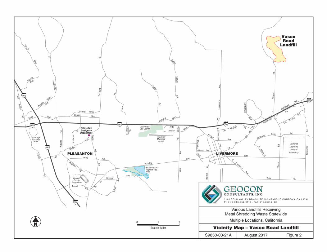
N.
Hol
mes
Isab
elAv
e.
St.
Murrietta
Blvd.Blvd.
Stanley
Olivina Ave.
PortolaAve.
Las Positas Rd.
Blvd.
Springtown
1st
St.
1st
St.
East
S.Livermore
Ave.
Livermore
Ave.
N.Li
verm
ore
Ave.
LawrenceLivermoreNational
Laboratory
84
Northfront
Southfront
Rd.
Rd.
Las Positas
PattersonPass Rd.
Rd.Tesla
Vasc
o
Vasc
o
Rd.
Rd.
N.M
inesRd.
Airway Blvd.Kitty H
awk
Rd.
El C
harr
o
Fallo
n
Rd.
Rd.
Rd.Canyon
Las PositasGolf Course
LivermoreMunicipal
Airport
580
580Canyons Pkwy.
Doolan
Rd.
Rd.
Gre
envi
lleR
d.
LIVERMORELIVERMORE
Hac
iend
a
Dr.
PLEASANTON
VineyardAve.
Las
Positas
Blvd.
SantaRita
Rd.
Valley
Central
Ave.Hopyard
Rd.
1st
St.
BernalAve.
Bern
alAv
e.
Shadow CliffsRegional Rec.Area
AlamedaCounty
Fairgrounds
StoneridgeShopping
Center
Valley CareEmergencyDepartment
Dublin
Dublin Blvd.Blvd.
Tass
ajar
aR
d.Rd.
Rd.
Rd.
Hop
yard
Rd.
Foothill
SanRam
on
Doug
herty
Pkwy.
580 580
680
680
680
Alcosta
Blvd.
Blvd.
Valley
Amador
Alcosta
Blvd.
Collier
VascoRoad
Landfill
N 0 1 2
Scale in Miles
Various Landfills ReceivingMetal Shredding Waste Statewide
Multiple Locations, California
Vicinity Map – Vasco Road Landfill
August 2017 Figure 2S9850-03-21A
P H O N E 9 1 6 . 8 5 2 . 9 11 8 – FA X 9 1 6 . 8 5 2 . 9 1 3 23 1 6 0 G O L D VA L L E Y D R – S U I T E 8 0 0 – R A N C H O C O R D O VA , C A 9 5 7 4 2

N
0 800
Scale in Feet
Various Landfills ReceivingMetal Shredding Waste Statewide
Multiple Locations, California
Site Plan – Vasco Road Landfill
August 2017 Figure 3S9850-03-21A
P H O N E 9 1 6 . 8 5 2 . 9 11 8 – FA X 9 1 6 . 8 5 2 . 9 1 3 23 1 6 0 G O L D VA L L E Y D R – S U I T E 8 0 0 – R A N C H O C O R D O VA , C A 9 5 7 4 2
LEGEND:
Proposed Air Sampling LocationVRL3
VRL3
VRL2
VRL1
NO
RTH
VA
SC
O R
OA
D
VRL3
VRL2
VRL1
NO
RTH
VA
SC
O R
OA
D

Various Landfills ReceivingMetal Shredding Waste Statewide
Multiple Locations, California
Rose Diagram – Vasco Road Landfill
August 2017 Figure 4S9850-03-21A
P H O N E 9 1 6 . 8 5 2 . 9 11 8 – FA X 9 1 6 . 8 5 2 . 9 1 3 23 1 6 0 G O L D VA L L E Y D R – S U I T E 8 0 0 – R A N C H O C O R D O VA , C A 9 5 7 4 2

N0 1
Scale in Miles
118
118 118
118
23
MoorparkCollege
HappyCamp
CanyonRegional
Park
RusticCanyon
GolfCourse
Rd.
Rd.
Syca
mor
e
Edin
ger
St.
St.Alamo
Cochran
Firs
t
Mad
era
Campus Park Dr.
Angeles Ave.
Simi ValleyHospital
MoorparkCollege
HappyCamp
CanyonRegional
Park
RusticCanyon
GolfCourse
Rd.Rd.
Spring
Sprin
g
Tierra
Rejada
Rd.
Rd.
Rd.
Dr.
Syca
mor
e
Edin
ger
St.
St.
St.Alamo
Cochran
Firs
t
Mad
era
Spring
MoorparkMoorpark
Campus Park Dr.
W.
LosAngeles
Ave.
Los Angeles Ave.
Lost
CanyonsDr.
Simi ValleyLandfill andRecycling
Center
Simi ValleyHospital
SimiValleySimi
Valley
Various Landfills ReceivingMetal Shredding Waste Statewide
Multiple Locations, CaliforniaVicinity Map –
Simi Valley Landfill and Recycling CenterAugust 2017 Figure 5S9850-03-21A
P H O N E 9 1 6 . 8 5 2 . 9 11 8 – FA X 9 1 6 . 8 5 2 . 9 1 3 23 1 6 0 G O L D VA L L E Y D R – S U I T E 8 0 0 – R A N C H O C O R D O VA , C A 9 5 7 4 2

Various Landfills ReceivingMetal Shredding Waste Statewide
Multiple Locations, CaliforniaSite Plan –
Simi Valley Landfill and Recycling CenterAugust 2017 Figure 6S9850-03-21A
P H O N E 9 1 6 . 8 5 2 . 9 11 8 – FA X 9 1 6 . 8 5 2 . 9 1 3 23 1 6 0 G O L D VA L L E Y D R – S U I T E 8 0 0 – R A N C H O C O R D O VA , C A 9 5 7 4 2
N
0 700
Scale in Feet
LEGEND:
Proposed Air Sampling LocationSVLRC3
SVLRC1
SVLRC3
SVLRC2
SVLRC1
Working Faceof Landfill
Working Faceof Landfill
SVLRC3
SVLRC2

Various Landfills ReceivingMetal Shredding Waste Statewide
Multiple Locations, CaliforniaRose Diagram –
Simi Valley Landfill and Recycling CenterAugust 2017 Figure 7S9850-03-21A
P H O N E 9 1 6 . 8 5 2 . 9 11 8 – FA X 9 1 6 . 8 5 2 . 9 1 3 23 1 6 0 G O L D VA L L E Y D R – S U I T E 8 0 0 – R A N C H O C O R D O VA , C A 9 5 7 4 2

Geocon Project No. S9850-03-21AAugust 2, 2017Page 1 of 2
Stakeholders: The DTSC.Problem: To provide credible data that can be used to characterize the risks and hazardsassociated with off-site migration of air emissions impacted by metals (i.e., the COPCs) resultingfrom the handling of metal shredding waste.Tasks: Collect TSP, PM10, PM2.5, metals (aluminum, cadmium, chromium, copper, iron, lead,manganese, nickel, tin, and zinc) from preselected upwind, downwind, and cross wind locationssamples at pre-selected locations (Figures 3 and 6) at two landfills that receive metal shreddingwaste, analyze the samples for the COPCs, and report the results.Questions to Resolve and Potential Actions to Take:
Is air at the metal shredding facilities impacted by COPCs at concentrations that could potentiallybe detrimental to human health and/or the environment?
If so, recommendations for additional investigation and/or remediation will be made, asappropriate.
Information Inputs:
1. Goals and plans for the Facilites 2. Operational history of the Facilities 3. Findings of previous investigations associated with the Facilities (if any)4. Regulatory agency decisions regarding the Facilities (if any)5. Potential environmental and/or human impacts of the Site6. Observations and monitoring/screening results during field activities7. Analytical results of air samples8. Potential exposure scenarios and pathways for receptors of concern9. Laboratory QC results and overall project QC evaluations.
Spatial Boundaries: Each facility's property boundaries will define the maximum lateral extent ofinvestigation activities with a focus on collecitng samples from the perimeter of the facilities. Toassess if activities occuring at the landfills receiving metal shredding waste are contributing to theCOPC impacted air, we will collect samples from upwind, downwind, and cross wind locations ateach landfill. Additonal spatial considerations will be needed to be in compliance with the samplingplacement requirements listed in 40 CFR Appendix E to Part 58 - Probe and Monitoring Path SitingCriteria for Ambient Air Quality Monitoring. As such, sampler inlets are required to be between 2and 7 meters above ground level, greater than 2 meters away from supporting structures (like walls,parapets, or penthouses, greater than 10 meters from trees, and between 2 and 10 meters fromroadways. Furthermore, because each of these sampling locations will have multiple collocatedsampling devices present, the sampler inlets for any high volume samples (>200 liters per minute)must be at least 2 meters apart and the sampling inlets for low volume samplers (<200 L/min) willbe spaced at least 1 meter apart, they must be spaced no greater than 4 meters apart, and the inletsshould be within 1 meter of each of the vertically.
Temporal Boundaries: The temporal limits of the field activities are defined by contractualbudgeted resources for the proposed investigation, which includes up to three separate 24-hoursampling durations at each of the three landfills receiving metals shredding waste.
TABLE 1SUMMARY OF DATA QUALITY OBJECTIVES
VARIOUS LANDFILLS RECEIVING METAL SHREDDING WASTE STATEWIDEMULTIPLE LOCATIONS, CALIFORNIA
CONTRACT NO. 16-T4278
Step 1 State the Problem and
Project Tasks
Step 2 Identify the Goal of
the Study
Step 3 Identify Information
Inputs
Step 4 Define Boundaries of
the Study

Geocon Project No. S9850-03-21AAugust 2, 2017Page 2 of 2
TABLE 1SUMMARY OF DATA QUALITY OBJECTIVES
VARIOUS LANDFILLS RECEIVING METAL SHREDDING WASTE STATEWIDEMULTIPLE LOCATIONS, CALIFORNIA
CONTRACT NO. 16-T4278
High volume TSP equipment will sample an 8-in by 10-in quartz fiber filter which will be analyzedoff-site for TSP and selected metals. Low volume PM10 equipment will sample 47-mm Teflonfilter which will be analyzed off-site for PM10 and selected metals. Low volume PM2.5 equipmentwill sample 47-mm Teflon filter which will be analyzed off-site for PM2.5 and selected metals.
Step 6 Specify Performance
or Acceptance Criteria
Acceptance of the chemical analytical results will be based on verification and validation criteriaspecified in the data quality indicators in Table 2.
Basic Data Collection Design: Collection and analysis of air quality samples at the facilities is in accordance with USEPA’s 40 CFR Part 50, Appendix B to Part 50 Reference Method for the Determination of SuspendedParticulate Matter in the Atmosphere, 40 CFR Part 50, Appendix J to Part 50 Reference Methodfor the Determination of Particulate Matter as PM 10 in the Atmosphere , and 40 CFR Part 50,
Appendix L to Part 50 Reference Method for the Determination of Particulate Matter as PM 2.5
in the Atmosphere and will evaluate the air along the perimeter of the facilities for potential impactby the COPCs. Data collection is designed to characterize air upwind, corsswind and downwind ofthe current metal shredding facilities to provide data useful to evaluate potential impacts andmanage risk associated with the Site (if any).
Design Flexibility: If concentrations of COPCs reported in soil, sediment, groundwater and soilvapor samples exceed respective screening levels, then additional investigation or appropriateremediation measures may be recommended DTSC to characterize the distribution and/or limits ofpotentially hazardous substances so that appropriate mitigation measures can be developed (if any).
Notes:COPCs = Chemicals of potential concern
DTSC = Department of Toxic Substances Control
USEPA = U.S. Environmental Protection Agency
TSP = Total suspended particulatesPM10 = Particulate matter > 10 µgPM2.5 = Particulate matter > 2.5 µgµg = micrograms
Step 7 Develop the Detailed Plan for Obtaining
Data
Step 5 Develop the Analytic
Approach

Geocon Project No. S9850-03-21AAugust 2, 2017Page 1 of 1
INDICATOR MEANS OF ASSESSMENT QUALITY CONTROL ELEMENT(S) ASSESSED ACCEPTANCE CRITERIA
Precision RPD
Field and lab duplicate samples; LCS/LCSD and
MS/MSD samples; laboratory control samples
CLN:Field duplicates: 20% RPDLab duplicates: 20% RPD;LCS/LCSD : 25% RPD;
Lab replicate: ±20% RPD;Reweighing filters: ±0.01 mg
(Teflon) and ±0.04 mg (quartz)
%RField; LCS and MS/MSD
samples; laboratory control samples
CLN:CCC : 0.995;
ICV: 90-110%;LCR: 70-130%LCS: 80-120%;CCV: 90-110%MS: 75-125%;AS: 75-125%
Blanks Laboratory control samplesCLN:
ICB: < detection limits;CCB: < detection limits
Completeness Percent of complete data Analytical data reports by method and event > 95%
RepresentativenessLateral and vertical extent of
COCs defined by data gathered
Comparability Trend analysis
Notes:
RPD - relative percent differenceMS/MSD - matrix spike/matrix spike duplicateLCS/LCSD - laboratory control sample/laboratory control sample duplicateCCC - calibration correlation coefficientIC/ICV - initial calibration/ initial calibration verificationLCR - low-level calibration recoveryAS - analytical spikeCCV - continuing calibration verification%R - percent recoveryCOCs - contaminants of concernCLN - CHESTER LabNet
Overview of investigation data Analytical data reports; all applicable elements
TABLE 2DATA QUALITY INDICATORS
VARIOUS LANDFILLS RECEIVING METAL SHREDDING WASTE STATEWIDEMULTIPLE LOCATIONS, CALIFORNIA
CONTRACT NO. 16-T4278
Accuracy

Geocon Project No. S9850-03-21AAugust 2, 2017Page 1 of 4
TSP/Metals PM10/Metals
PM2.5/Metals QA/QC Sample ID
Calibrate Equipment Prior to First Test Yes Yes Yes
VRL1-T1-TSP 1VRL1-T1-PM10 1VRL1-T1-PM2.5 1
VRL1-T2-TSP 1 + FB VRL1-T2-TSP-FBVRL1-T2-PM10 1 + FB VRL1-T2-PM10-FBVRL1-T2-PM2.5 1 + FB VRL1-T2-PM2.5-FB
VRL1-T3-TSP 1VRL1-T3-PM10 1VRL1-T3-PM2.5 1
Calibrate Equipment Prior to First Test Yes Yes Yes
VRL2-T1-TSP 1 + DUP VRL5-T1-TSPVRL2-T1-PM10 1 + DUP VRL5-T1-PM10VRL2-T1-PM2.5 1 + DUP VRL5-T1-PM2.5
VRL2-T2-TSP 1VRL2-T2-PM10 1VRL2-T2-PM2.5 1
VRL2-T3-TSP 1 + DUP VRL5-T3-TSPVRL2-T3-PM10 1 + DUP VRL5-T3-PM10VRL2-T3-PM2.5 1 + DUP VRL5-T3-PM2.5
Calibrate Equipment Prior to First Test Yes Yes Yes
VRL3-T1-TSP 1VRL3-T1-PM10 1VRL3-T1-PM2.5 1
Number of Filters/Samplers Needed
TABLE 3CALIBRATION AND SAMPLING FREQUENCY AND ANALYSIS
VARIOUS METAL SHREDDING FACLITIES STATEWIDEMULTIPLE LOCATIONS, CALIFORNIA
CONTRACT NO. 15-T4124
Sample ID

Geocon Project No. S9850-03-21AAugust 2, 2017Page 2 of 4
TSP/Metals PM10/Metals
PM2.5/Metals QA/QC Sample ID
Number of Filters/Samplers Needed
TABLE 3CALIBRATION AND SAMPLING FREQUENCY AND ANALYSIS
VARIOUS METAL SHREDDING FACLITIES STATEWIDEMULTIPLE LOCATIONS, CALIFORNIA
CONTRACT NO. 15-T4124
Sample ID
VRL3-T2-TSP 1VRL3-T2-PM10 1VRL3-T2-PM2.5 1
VRL3-T3-TSP 1 + FB VRL3-T3-TSP-FBVRL3-T3-PM10 1 + FB VRL3-T3-PM10-FBVRL3-T3-PM2.5 1 + FB VRL3-T3-PM2.5-FB
Trip Blank Samples 1 VRL-TB-TSP1 VRL-TB-PM10
1 VRL-TB-PM2.5
Lab Blank Samples 2 Held by lab, not 2 shipped to Site.
2
Sampling Breakdown for VRLPrimary Samples 9 9 9Duplicate Samples 2 2 2Trip Blank Samples 1 1 1Field Blank Samples 2 2 2Lab Blank Samples 2 2 2Total Number of Samples at VRL 16 16 16
Calibrate Equipment Prior to First Test Yes Yes Yes
SVLRC1-T1-TSP 1SVLRC1-T1-PM10 1SVLRC1-T1-PM2.5 1

Geocon Project No. S9850-03-21AAugust 2, 2017Page 3 of 4
TSP/Metals PM10/Metals
PM2.5/Metals QA/QC Sample ID
Number of Filters/Samplers Needed
TABLE 3CALIBRATION AND SAMPLING FREQUENCY AND ANALYSIS
VARIOUS METAL SHREDDING FACLITIES STATEWIDEMULTIPLE LOCATIONS, CALIFORNIA
CONTRACT NO. 15-T4124
Sample ID
Calibrate Equipment Prior to First Test Yes Yes Yes
SVLRC1-T2-TSP 1SVLRC1-T2-PM10 1SVLRC1-T2-PM2.5 1
SVLRC1-T3-TSP 1SVLRC1-T3-PM10 1SVLRC1-T3-PM2.5 1
Calibrate Equipment Prior to First Test Yes Yes Yes
SVLRC2-T1-TSP 1 + DUP SVLRC5-T1-TSPSVLRC2-T1-PM10 1 + DUP SVLRC5-T1-PM10SVLRC2-T1-PM2.5 1 + DUP SVLRC5-T1-PM2.5
SVLRC2-T2-TSP 1 + DUP SVLRC5-T2-TSPSVLRC2-T2-PM10 1 + DUP SVLRC5-T2-PM10SVLRC2-T2-PM2.5 1 + DUP SVLRC5-T2-PM2.5
SVLRC2-T3-TSP 1 + FB SVLRC2-T3-TSP-FBSVLRC2-T3-PM10 1 + FB SVLRC2-T3-PM10-FBSVLRC2-T3-PM2.5 1 + FB SVLRC2-T3-PM2.5-FB

Geocon Project No. S9850-03-21AAugust 2, 2017Page 4 of 4
TSP/Metals PM10/Metals
PM2.5/Metals QA/QC Sample ID
Number of Filters/Samplers Needed
TABLE 3CALIBRATION AND SAMPLING FREQUENCY AND ANALYSIS
VARIOUS METAL SHREDDING FACLITIES STATEWIDEMULTIPLE LOCATIONS, CALIFORNIA
CONTRACT NO. 15-T4124
Sample ID
Calibrate Equipment Prior to First Test Yes Yes Yes
SVLRC3-T1-TSP 1SVLRC3-T1-PM10 1SVLRC3-T1-PM2.5 1
SVLRC3-T2-TSP 1SVLRC3-T2-PM10 1SVLRC3-T2-PM2.5 1
SVLRC3-T3-TSP 1SVLRC3-T3-PM10 1SVLRC3-T3-PM2.5 1
Trip Blank Samples1 SVLRC-TB-TSP
1 SVLRC-TB-PM101 SVLRC-TB-PM2.5
Lab Blank Samples 2 Held by lab, not 2 shipped to Site.
2Sampling Breakdown for SVLRCPrimary Samples 9 9 9Duplicate Samples 2 2 2Trip Blank Samples 1 1 1Field Blank Samples 2 2 2Lab Blank Samples 2 2 2Total Number of Samples at SVLRC 16 16 16
Notes: TSP = Total suspended particulatesPM10 = Particulate matter > 10 µgPM2.5 = Particulate matter > 2.5 µgµg = microgramsVRL = Vasco Road Landfill SVLRC = Simi Valley Landfill and Recycling CenterFB = Field blank. Filter is loaded into sampling equipment but not run.DUP = Duplicate sample. Samples collected from identically configured sampler located adjacent to the primary sample location.

Geocon Project No. S9850-03-21AAugust 2, 2017Page 1 of 1
ANALYTES ANALYTICAL METHOD
SAMPLE CONTAINERS PRESERVATION HOLDING TIME
TSP
Gravimeteric methods listed in
Title 40 CFR Part 50 Appendix B
One 8-inch by 10-inch quartz filter None 6 Months
PM10
Gravimeteric methods listed in
Title 40 CFR Part 50 Appendix J
One 47-millimeter PTFE Teflon filter with support ring
Cool 4°C (+/- 2°C) 30 Days
PM2.5
Gravimeteric methods listed in
Title 40 CFR Part 50 Appendix L
One 47-millimeter PTFE Teflon filter with support ring
Cool 4°C (+/- 2°C) 30 Days
Aluminum, cadmium, chromium, copper, iron, lead, manganese, nickel,
tin, and zinc
EPA IO3.3 One 8-inch by 10-inch quartz filter None 6 Months
Aluminum, cadmium, chromium, copper, iron, lead, manganese, nickel,
tin, and zinc
EPA IO3.3One 47-millimeter PTFE Teflon filter with support ring
Cool 4°C (+/- 2°C) 30 Days
Notes:
°C – degrees Celsius
CFR = Code of Federal RegulationsEPA – United States Environmental Protection Agency
TABLE 4SAMPLE CONTAINER, PRESERVATION, AND HOLDING TIME REQUIREMENTS
VARIOUS METAL SHREDDING FACLITIES STATEWIDEMULTIPLE LOCATIONS, CALIFORNIA
CONTRACT NO. 16-T4278

Geocon Project No. S9850-03-21AAugust 2, 2017Page 1 of 1
Chemical of ConcernReporting Limits
(mass per filter in µg)Reporting Limits (concentration
in µg/m3)*
Aluminum 0.09 0.00376506Cadmium 0.088 0.003681392Chromium 0.011 0.000460174Copper 0.01 0.00041834Iron 0.014 0.000585676Lead 0.045 0.00188253
Manganese 0.018 0.000753012Nickel 0.01 0.00041834Tin 0.154 0.006442436Zinc 0.011 0.000460174
Notes:N/A = Not applicable µg = microgramsµg/m3 = micrograms per cubic meter
EPA Method IO 3.3
TABLE 5SUMMARY OF LABORATORY REPORTING LIMITS
VARIOUS METAL SHREDDING FACLITIES STATEWIDEMULTIPLE LOCATIONS, CALIFORNIA
CONTRACT NO. 16-T4278

APPENDIX A

Uncon
trolle
d Cop
y

Uncon
trolle
d Cop
y

Uncon
trolle
d Cop
y

Uncon
trolle
d Cop
y

Uncon
trolle
d Cop
y

Uncon
trolle
d Cop
y

Uncon
trolle
d Cop
y

Uncon
trolle
d Cop
y

Uncon
trolle
d Cop
y

Uncon
trolle
d Cop
y

Uncon
trolle
d Cop
y

Uncon
trolle
d Cop
y

Uncon
trolle
d Cop
y

Uncon
trolle
d Cop
y

Uncon
trolle
d Cop
y

Uncon
trolle
d Cop
y

Uncon
trolle
d Cop
y

Uncon
trolle
d Cop
y

Uncon
trolle
d Cop
y

Uncon
trolle
d Cop
y

Uncon
trolle
d Cop
y

Uncon
trolle
d Cop
y

Uncon
trolle
d Cop
y

Uncon
trolle
d Cop
y

Uncon
trolle
d Cop
y

Uncon
trolle
d Cop
y

Uncon
trolle
d Cop
y

Uncon
trolle
d Cop
y

Uncon
trolle
d Cop
y

Quality Assurance Management Plan
CHESTER LabNet 12242 S.W. Garden Place, Bldg. 1
Tigard, Oregon 97223 P: 503.624.2183 F: 503.624.2653
www.chesterlab.net
Paul Duda – President, Laboratory Director, LIMS Administrator, Client Services Technical
Director
Sheri Heldstab – QA Officer, Conventional Chemistry Laboratory Technical Director, Chemist
Richard Sarver - XRF Laboratory Technical Director, XRF Analyst
Lisa Ball – Project Manager, Sample Custodian
Jennifer (Jen) Schleis – Gravimetry Laboratory Technical Director & Technician, XRF
Technician, Chemist
Katie Hawks - Chemist, Gravimetry Laboratory Technician
Julie Delarue – Chemist, Gravimetry Laboratory Technician, XRF Technician
Theodore (Ted) Perry – Chemist, Gravimetry Laboratory Technician
This document supplants any previous versions. Revision Number: February, 2016 Effective Date: February 1, 2016
Document Number: QAMP February 2016
Uncon
trolle
d Cop
y

Section 1 – Rev. February, 2016 Effective: February 1, 2016 Quality Assurance Management Plan Page 2 of 190
Property of CHESTER LabNet This copy is uncontrolled unless the signatures are original (in blue ink)
or the title page is clearly stamped “copy” in red ink.
Review History
Review Date
Changes Author
1/25/16 Updated changes in staffing, equipment, and SOP lists.
Typographical and grammatical errors corrected. S. Heldstab
1/28/15 Updated changes in staffing, equipment, floorplan and SOP lists. Typographical and grammatical errors corrected.
S. Heldstab
1/15/14 Updated changes in accredited methods, staffing, equipment, SOP lists. Typographical and grammatical errors corrected.
S. Heldstab
2/21/13 Updated changes in accredited methods, staffing, equipment, SOP lists. Typographical and grammatical errors corrected.
S. Heldstab
1/8/12 Updated to NELAC template. Updated Personnel and Organizational Structure to reflect current staffing, capital equipment and manuals lists. Updated floor plan to reflect current floor plan; build-out is on-going.
S. Heldstab
6/14/11 Updated to NELAC template. Updated Personnel and Organizational Structure to reflect current staffing, capital equipment and manuals lists. (Revision incomplete)
S. Heldstab
2/17/11 Updated equipment and manuals lists. Changed client surveys section.
S. Heldstab
2/26/10 Changed Personnel and Organizational Structure to reflect current staffing. Minor clarifications to text.
S. Heldstab
2/12/09 Minor changes to text. S. Heldstab 12/16/08 Changed Personnel and Organizational Structure to reflect current
staffing. Minor clarifications to text. S. Heldstab
2/19/08 Changed Personnel Organizational Structure to reflect staffing, incorporated new equipment to Capital Equipment Inventory, added section to ‘Backup of LIMS System’ to include other computers containing essential information, updated final data report page, minor changes to text for clarification.
J. Schleis
2/15/07 Changed Corrective Action Report documentation system, minor change to quality policy statement to include metric reviewable goals, moved ‘Traceability of Measurements’ section to section 7, added section on client surveys, merged client complaints & corrective action documentation into a single system, added appendices “Listing of Document Locations” and “Glossary & Definitions of Terminology”
S. Heldstab
2/5/07 Changed references to staffing where staffing has changed, added text on handling of PE samples to section 10.6, added section on detection limits (7.8), added details for clarification throughout.
S. Heldstab
2/7/06 Definition of “basic laboratory skills” added to Personnel qualifications, SOP formatting elements changed to reflect new NELAC-compliant format, acceptance/rejection criteria for non-standard methods added, section added on documentation of customer inquiries/complaints, updated staff resumes, updated SOP listing, added ‘failure to report’ to the list of breaches of ethical behavior in Appendix D.
S. Heldstab
Uncon
trolle
d Cop
y

Section 1 – Rev. February, 2016 Effective: February 1, 2016 Quality Assurance Management Plan Page 3 of 190
Property of CHESTER LabNet This copy is uncontrolled unless the signatures are original (in blue ink)
or the title page is clearly stamped “copy” in red ink.
Review Date
Changes Author
7/8/05 Expanded section 7.7, revised section 10.4 and 10.5 to reflect new internal audit process, updated staff references.
S. Heldstab
1/5/05 Added Appendix D (Ethics training). S. Heldstab 10/21/04 Major updating to incorporate elements of NELAC/ORLAP
requirements. Sections 3.3.2.1, 7.3–7.7, 8.2.4-8.2.7, 8.3, 8.3.1–8.3.5, 8.4, 9.4, 10.6–10.8, 11.8–11.10 added.
S. Heldstab
1/23/04 Updated floor plan and Capital inventory table. Minor grammatical changes.
S. Heldstab
3/10/03 Changes in organization of Section 3. No changes to content, only to formatting.
S. Heldstab
12/10/02 Minor changes to text, some text rearranged for clarity and conciseness.
S. Heldstab
11/8/01 This document has been in existence since at least 1988. The number and types of revisions are unknown. As of this date, the document is being revised to standardize the formatting of CHESTER LabNet documents.
S. Heldstab
Unknown No Changes - date of origination. C.R. Lytle
Controlled Copy #1: This document Controlled Copy #2: Sent to ORELAP
Uncon
trolle
d Cop
y

Uncon
trolle
d Cop
y

Section 2 – Rev. February, 2016 Effective: February 1, 2016 Quality Assurance Management Plan Page 5 of 190
Property of CHESTER LabNet This copy is uncontrolled unless the signatures are original (in blue ink)
or the title page is clearly stamped “copy” in red ink.
Table of Contents
Section Title Page Effective
Date 1 TITLE PAGE 1 Feb., 2016 Review History 1 Concurrences 4 2 TABLE OF CONTENTS 5 Feb., 2016 Table of Tables 8 Table of Figures 9 Disclaimer 10 3 INTRODUCTION AND SCOPE 12 Feb., 2016 3.1 Scope of Testing 13 3.2 Table of Contents, References and Appendices 13 3.3 Glossary and Acronyms Used 14 3.4 Management of the Quality Assurance Management
Plan 21
3.5 Data Quality Objectives 21 4 ORGANIZATION 24 Feb., 2016 4.1 Organization 24 4.2 Conflict of Interest and Undue Pressure 26 5 MANAGEMENT 27 Feb., 2016 5.1 Management Requirements 27 5.2 Management Roles and Responsibilities 28 5.3 Quality Policy 32 5.4 Ethics and Data Integrity System 32 5.5 Documentation of Management/Quality System 33 6 DOCUMENT CONTROL 35 Feb., 2016 6.1 Controlled Documents 36 6.2 Obsolete Documents 38 7 REVIEW OF REQUESTS, TENDERS AND CONTRACTS 39 Feb., 2016 7.1 Procedure for the Review of Work Requests 39 7.2 Documentation of Review 40 8 SUBCONTRACTING OF ENVIRONMENTAL TESTS 42 Feb., 2016 8.1 Procedure 42 9 PURCHASING SERVICES AND SUPPLIES 43 Feb., 2016 9.1 Procedure 43 9.2 Approval of Suppliers 44 9.3 Reagent (De-Ionized) Water 44
10 SERVICE TO THE CLIENT 46 Feb., 2016 10.1 Client Confidentiality 46 10.2 Client Support 47 10.3 Client Feedback 47
Uncon
trolle
d Cop
y

Section 2 – Rev. February, 2016 Effective: February 1, 2016 Quality Assurance Management Plan Page 6 of 190
Property of CHESTER LabNet This copy is uncontrolled unless the signatures are original (in blue ink)
or the title page is clearly stamped “copy” in red ink.
Section Title Page Effective
Date
11 COMPLAINTS 48 Feb., 2016
12 CONTROL OF NON-CONFORMING ENVIRONMENTAL TESTING WORK
50 Feb., 2016
12.1 Exceptionally Permitting Departures from Documented Policies and Procedures
50
12.2 Non-conforming Work 50 12.3 Stop Work Procedures 51
13 IMPROVEMENT 52 Feb., 2016
14 CORRECTIVE ACTION 53 Feb., 2016 14.1 General Procedure 53 14.2 Additional Audits 54 14.3 Technical Corrective Action 55
15 PREVENTATIVE ACTION 56 Feb., 2016
16 CONTROL OF RECORDS 57 Feb., 2016 16.1 Records Maintained 57 16.2 Records Management and Storage 59 16.3 Legal Chain of Custody Records 65
17 AUDITS 66 Feb., 2016 17.1 Internal Audits 66 17.2 External Audits 66 17.3 Performance Audits 67 17.4 System Audits 67 17.5 Handling Audit Findings 67
18 MANAGEMENT REVIEWS 68 Feb., 2016 18.1 Management Review Topics 68 18.2 Procedure 68
19 DATA INTEGRITY INVESTIGATIONS 70 Feb., 2016 19.1 Ethics and Data Integrity Procedures 70 19.2 Training 70 19.3 Confidential Reporting of Ethics and Data Integrity
Issues 71
19.4 Investigations 72
20 PERSONNEL 73 Feb., 2016 20.1 Overview 73 20.2 Job Descriptions 73 20.3 Training 82
21 ACCOMODATIONS AND ENVIRONMENTAL CONDITIONS 83 Feb., 2016 21.1 Environmental 83 21.2 Work Areas 83 21.3 Floor Plan 84 21.4 Building Security 84
Uncon
trolle
d Cop
y

Section 2 – Rev. February, 2016 Effective: February 1, 2016 Quality Assurance Management Plan Page 7 of 190
Property of CHESTER LabNet This copy is uncontrolled unless the signatures are original (in blue ink)
or the title page is clearly stamped “copy” in red ink.
Section Title Page Effective
Date
22 ENVIRONMENTAL METHODS AND METHOD VALIDATION 85 Feb., 2016 22.1 Method Selection 85 22.2 Laboratory-Developed Methods 86 22.3 Method Validation 87 22.4 Estimation of Analytical Uncertainty 87 22.5 Control of Data 88
23 CALIBRATION REQUIREMENTS 91 Feb., 2016 23.1 General Equipment Requirements 91 23.2 Support Equipment 101 23.3 Analytical Equipment 111
24 MEASUREMENT TRACEABILITY 115 Feb., 2016 24.1 Reference Standards 115 24.2 Reference Materials 116 24.3 Transport and Storage of Reference Standards and
Materials 116
24.4 Labeling of Reference Standards, Reagents and Reference Materials
117
25 COLLECTION OF SAMPLES 120 Feb., 2016
25.1 Sampling Containers 120 25.2 Sampling Plan 127 25.3 Sampling Records 127
26 HANDLING SAMPLES AND TEST ITEMS 128 Feb., 2016 26.1 Sample Receipt 128 26.2 Sample Acceptance 128 26.3 Sample Identification 130 26.4 Sample Aliquots / Subsampling 131 26.5 Sample Storage 131 26.6 Sample Disposal 132 26.7 Sample Transport 132
27 QUALITY ASSURANCE FOR ENVIRONMENTAL TESTING 136 Feb., 2016 27.1 Essential Quality Control Procedures 136 27.2 Internal Quality Control Practices 137 27.3 Proficiency Test Samples or Interlaboratory
Comparisons 144
27.4 Data Review 147
28 REPORTING THE RESULTS 150 Feb., 2016 28.1 Test Reports 150 28.2 Supplemental Test Report Information 152 28.3 Environmental Testing Obtained from Subcontractors 153 28.4 Electronic Transmission of Results 153 28.5 Amendments to Test Reports 153 28.6 Exceptions 153
Uncon
trolle
d Cop
y

Section 2 – Rev. February, 2016 Effective: February 1, 2016 Quality Assurance Management Plan Page 8 of 190
Property of CHESTER LabNet This copy is uncontrolled unless the signatures are original (in blue ink)
or the title page is clearly stamped “copy” in red ink.
Section Title Page Effective
Date Appendix A Ethics and Data Integrity Policy 155 Feb., 2016 A.1 Introduction 155 A.2 Management Responsibilities 155 A.3 Employee Responsibilities 156 A.4 Ramifications of Unethical Behavior 158 A.5 Summary
158
Appendix B
CHESTER LabNet Standard Operating Procedures 160 Feb., 2016
Appendix C
Laboratory Floor Plan 163 Feb., 2016
Appendix D CHESTER LabNet Utilized Methods (by Issuing Authority and Method Number)
164 Feb., 2016
Appendix E Laboratory Accreditation / Certification / Recognition
167 Feb., 2016
Appendix F
Data Qualifiers 168 Feb., 2016
Appendix G
Employee Resumes 171 Feb., 2016
Appendix H Chemistry 180 Feb., 2016 H.1 Method Validation 180 H.2 Demonstration of Capability 184 H.3 Calibration
185
Appendix I References
189 Feb., 2016
Table of Tables
Table Title Page Effective
Date Table 5-1
Key Personnel Deputies 32 Feb., 2016
Table 23-1
Laboratory Equipment 94 Feb., 2016
Table 23-2
Summary of Support Equipment Calibration and Maintenance
102 Feb., 2016
Table 23-3
Calibration Acceptance Criteria for Support Equipment
107 Feb., 2016
Table 23-4
Acceptance Criteria for Support Equipment 110 Feb., 2016
Table 23-5
Analytical Equipment Maintenance 112 Feb., 2016
Table 24-1
Standard Storage and Preparation 117 Feb., 2016
Table 25-1 Summary of Sampling Container, Preservation and Holding Time Requirements
122 Feb., 2016
Table 27-1 Essential Quality Control Elements for Chemistry 139 Feb., 2016
Uncon
trolle
d Cop
y

Section 2 – Rev. February, 2016 Effective: February 1, 2016 Quality Assurance Management Plan Page 9 of 190
Property of CHESTER LabNet This copy is uncontrolled unless the signatures are original (in blue ink)
or the title page is clearly stamped “copy” in red ink.
Table of Figures
Figure Title Page Effective
Date Figure 4-1
Corporate Organization Chart 25 Feb., 2016
Figure 26-1
Example Chain of Custody 133 Feb., 2016
Figure 26-2
Example Sample Acceptance Policy 134 Feb., 2016
Uncon
trolle
d Cop
y

Section 2 – Rev. February, 2016 Effective: February 1, 2016 Quality Assurance Management Plan Page 10 of 190
Property of CHESTER LabNet This copy is uncontrolled unless the signatures are original (in blue ink)
or the title page is clearly stamped “copy” in red ink.
Disclaimer
In 2011, ORELAP, the accrediting body for the state of Oregon, requested that the laboratory use the 2009 TNI Standard QAMP template in creating its QAMP to make it easier for auditors to find information. The 2009 TNI Standard and its associated QAMP template are designed for water/soil analysis. CHESTER LabNet specializes in inorganic air quality analyses, both ambient and source emissions. Volume 1, Module 1, Section 1.3.2 of the 2009 TNI Standard states “This Standard does not apply to fields of accreditation that are not designated as Field of Proficiency Testing (FoPT) by the TNI Proficiency Testing (PT) Board.” As of this writing, only a few source sampling methods and no ambient air methods have FoPT’s; thus, according to the 2009 TNI Standard, CHESTER LabNet is not eligible for accreditation for any ambient air methods and many source sampling methods. However, ORELAP has accredited the laboratory for some ambient methods since 2005, despite their ineligibility for accreditation. The state of Texas has listed SW-846 Method 6010 as an accreditable method for the determination of metals in source emissions even though the quality matrix defined in 6010 is waters/solids not air source emissions. Texas also lists Method 202 as an accreditable method, despite the utter lack of availability of PEs, the impossibility of utilizing the method as written, the impossibility of performing an LOD, LOQ, DoC or Precision and Bias study for that method – all requirements for accreditation of a method. Many states are doing similar things. Due to the significant differences between sampling gaseous samples and sampling water/soil samples, there are some requirements of the 2009 TNI Standard which are unachievable based on the nature of the methods utilized. Throughout this document, the original requirements as set forth in the 2009 TNI QAMP template have been included. Also included are the reasons those requirements are not applicable to our field of work as well as explanations of how the laboratory attempts to meet the intent, if not the letter, of the requirement. Below is a short list of issues which may be found throughout various sections of the document:
1. “Media”: This term is used throughout the 2009 TNI QAMP template in reference to microbiological testing. For the purposes of air quality testing, media is generally comprised of either filters (various sizes/compositions) or sorbent tubes. Most media used by the laboratory has some form of contamination present from the manufacturing process and is considered a routine part of analysis.
2. Sampling: The laboratory performs no sampling. Most air quality methods, source or ambient, involve quite complex sampling equipment and procedures. The laboratory’s clients perform the sampling, from collection to shipment. The laboratory has no control over the actions or inactions of the clients in the field. Many requirements of the 2009 TNI standard make reference to sampling, sample containers and sample rejection. These requirements are not well suited to the nature of air quality sampling or analysis.
3. Sample containers: To capture a gaseous sample, either a filter, an absorbing solution or a sorbent material of some sort must be used. Thus, the primary
Uncon
trolle
d Cop
y

Section 2 – Rev. February, 2016 Effective: February 1, 2016 Quality Assurance Management Plan Page 11 of 190
Property of CHESTER LabNet This copy is uncontrolled unless the signatures are original (in blue ink)
or the title page is clearly stamped “copy” in red ink.
container for the sample is either “filter,” “solution,” or “sorbent.” Secondary containers are then used for containing the sample containers. Filters may or may not be provided by the laboratory in a variety of secondary containers. Containers for liquids are nearly always provided by the client as the laboratory has no idea how much liquid will be collected. The absorbing solution acts as a preservative by its nature, thus, no preservatives are added to any secondary container.
4. Method selection: Air Quality methods, particularly the Code of Federal Regulations (CFR) methods, tend to not be regularly updated to incorporate technological improvements. 40 CFR 60 Method 12 requires hand-plotting a calibration curve from a Flame AA. 40 CFR 60 Method 26/26A requires the use of a manual integrator (as opposed to computer software). 40 CFR 61 Method 101 requires the use of a PerkinElmer 300 model AA, an instrument that was last supported in 1972. CHESTER LabNet has no control over the selection of methods used during analysis. Frequently, our clients have no control over method selection either. The client is responsible to their client (the “ultimate” client), who, in turn, is usually responsible to a regulator at some governmental level (e.g., federal, state, county, city). The regulator for the particular facility or project being monitored is the body responsible for method selection. The laboratory and the laboratory’s clients have little sway over the decisions of these regulators. In addition, some methods are in conflict with the laws of physics and are, therefore, not possible to perform as written. 40 CFR 51 Method 202 was updated in 2010, becoming effective on 1 January, 2011. This method requires the analyst, during a biphase separatory funnel extraction, to “drain the bottom organic fraction” from the separatory funnel. The solvent required by the method was changed from Dichloromethane to Hexane. Hexane has a lower density than water and consequently floats, making draining this layer first impossible. In January of 2012, a “suggested update” was published in the CFR, changing the method to “pour off the top organic fraction,” a technique not ideally suited to separatory funnels. The 2009 TNI Standard has many requirements pertaining to the selection of methods to be used by the laboratory. These sections cannot be applied to the type of work performed at CHESTER LabNet.
5. Rejection of Samples: The 2009 TNI Standard has many requirements pertaining to the rejection of samples. Due to the highly complex nature of air sampling, the laboratory does not reject any sample unless requested to do so by the client, or the sample is suspected of being fraudulent. Many air quality samples are time sensitive, and thus re-sampling is often impossible. Hence, these requirements are not well suited to the nature of work performed by CHESTER LabNet or its clients.
CHESTER LabNet will make every effort to meet the intent of the requirements as given in the 2009 TNI Standard, just as it makes every effort to meet the intent and chemistry of archaic or contradictory methods.
Uncon
trolle
d Cop
y

Section 3 – Rev. February, 2016 Effective: February 1, 2016 Quality Assurance Management Plan Page 12 of 190
Property of CHESTER LabNet This copy is uncontrolled unless the signatures are original (in blue ink)
or the title page is clearly stamped “copy” in red ink.
Section 3
INTRODUCTION AND SCOPE (TNI V1:M2 – Sections 1, 2, 3)
The purpose of this Quality Assurance Management Plan is to outline the management system for CHESTER LabNet. The Quality Assurance Management Plan defines the policies, procedures and documentation that assure analytical services continuously meet a defined standard of quality. That standard is designed to provide clients with data of known and documented quality and, where applicable, demonstrate regulatory compliance. CHESTER LabNet is proud of having specialized in the inorganic analysis of ambient particulates and source emission samples since its inception as NEA, Inc. in the late 1970’s. The laboratory as an organization, its management, and its personnel are committed to the production of the highest quality data achievable with current methodologies and instrumentation; and to compliance with contractual, regulatory and accreditation standards and requirements. This QAMP is written using the template produced by TNI. The Oregon accrediting body for NELAP is ORELAP, who has requested that laboratories use this template. The template is designed for water, wastewater and soil/sludge samples, and does not work well for air quality samples. As a result, many sections have been significantly modified in an effort to meet accrediting requirements. In addition, many of the requirements of the 2009 TNI Standard also do not apply to air quality sampling (ambient or source) and have been significantly modified. The Quality Assurance Management Plan sets the standard under which all laboratory operations are performed, including the laboratory's organization, objectives and operating philosophy. The Quality Assurance Management Plan has been prepared to assure compliance with the 2009 TNI Environmental Laboratory Sector Standard – Volume 1 – Management and Technical Requirements for Laboratories Performing Environmental Analysis (EL-V1-M1 through M7-ISO-2009). This Standard is consistent with ISO/IEC 17025:2005 requirements that are relevant to the scope of environmental testing services and thus, the laboratory operates a quality system in conformance with ISO/IEC 17025:2005(E). In addition, the policies and procedures outlined are compliant with the various accreditation and certification programs listed in Appendix E. For any activity involving a service or the creation of an analytical result, quality may be defined as conformity to a given set of requirements. To ensure acceptable quality, three conditions must be met: (1) requirements and objectives must be clearly delineated before work begins; (2) the major steps in the production of the service or analytical result must have a component that allows for the control of quality, based on the end-result objectives; (3) the components of quality control must include control limits and corrective actions designed to both effectively monitor quality and modify procedures if quality is compromised. Quality Assurance (QA) comprises the overall program elements designed to maintain any activity within the stated objectives. Examples of such program elements are: clearly stated precision and accuracy targets; written standard operating procedures for all laboratory and instrumental protocols; the selection of sample preparation and analytical methods that are most appropriate for the matrices and analytes to be encountered; etc.
Uncon
trolle
d Cop
y

Section 3 – Rev. February, 2016 Effective: February 1, 2016 Quality Assurance Management Plan Page 13 of 190
Property of CHESTER LabNet This copy is uncontrolled unless the signatures are original (in blue ink)
or the title page is clearly stamped “copy” in red ink.
Quality Control (QC) comprises the individual checks used to monitor laboratory procedures, the precision and accuracy statistical control limits for each individual check, and the specific corrective actions to be followed when QC results are outside control limits. An example of a QC element is the matrix spike. Good quality control would set the frequency of analysis, the particular QC statistic to be used (e.g., percent recovery), the control limit (based on published statistics for the particular analysis or on QC charts developed in house), and the corrective action for QC results that are out of control. 3.1 Scope of Testing
CHESTER LabNet specializes in Inorganic Air Quality Analysis of ambient air and source emissions, including analysis of PM10 and PM2.5 samples. The laboratory’s scope of analytical testing services includes those listed in Appendix D. At present, the six methods accredited are:
• Hexavalent Chromium in ambient air (modified CARB SOP MLD039 and modified ASTM D7614-12);
• 40CFR60 Method 202, “Condensable Particulate Matter, Rev. 12/1/2010”; • NIOSH 5040 “ELEMENTAL CARBON (DIESEL PART.)”; DRI SOP#2-216r2 (not
a promulgated method, Organic & Elemental Carbon by Improve_A parameters);
• PM10 40CFR50 Appendix J, • PM2.5 40CFR50 Appendix L, and • 40CFR60 Method 26A, “Hydrogen Halides and Halides in Stationary Sources”.
Note that the 2009 NELAC standard, Volume 1, Module 1, Section 1.3.2 states “This Standard does not apply to fields of accreditation that are not designated as fields of proficiency testing (FoPT) by the TNI Proficiency Testing (PT) Board.” At present, only Method 26 is contained within any field of proficiency testing.
3.2 Table of Contents, References and Appendices
The Table of Contents is in Section 2 and Appendices are at the end of this document. This Quality Assurance Management Plan uses the references included in the 2009 TNI Environmental Laboratory Sector Standard, Volume 1:Modules 1,2 and 4, “Management and Technical Requirements for Laboratories Performing Environmental Analysis,” where applicable to air quality analyses. Unlike Water and Soils methods, promulgated Air Quality methods can be difficult to locate and, in some cases, a promulgated method may not exist for the analysis requested by the client. The majority of methods utilized at CHESTER LabNet are promulgated in 40 CFR 50, 40 CFR 60, 40 CFR 61, NIOSH Methods Compendium, OSHA Methods Compendium, US EPA IO Methods Compendium, US EPA “Other Test Methods,” US EPA “Conditional Test Methods,” published peer-reviewed papers, and a variety of methods developed in-house to satisfy the needs of our clients. See
Uncon
trolle
d Cop
y

Section 3 – Rev. February, 2016 Effective: February 1, 2016 Quality Assurance Management Plan Page 14 of 190
Property of CHESTER LabNet This copy is uncontrolled unless the signatures are original (in blue ink)
or the title page is clearly stamped “copy” in red ink.
Appendix D for a listing of promulgated methods commonly used at CHESTER LabNet and Appendix B for a listing of all CHESTER LabNet SOPs.
3.3 Glossary and Acronyms Used
Quality control terms are generally defined within the Section that describes the activity.
3.3.1 Glossary
Accreditation: The process by which an agency evaluates and recognizes a laboratory as meeting certain predetermined qualifications or standards, thereby accrediting the laboratory. Accuracy: The degree of agreement between an observed value and an accepted reference value. Analyst: The designated individual who performs the “hands-on” method and who is the one responsible for applying required laboratory practices and other pertinent quality controls to meet the required level of quality. Archaic: A method that requires the use of equipment that is no longer available, no longer in use, or that has become obsolete by virtue of technological advancements (e.g., requiring the use of instrumentation that has not been supported since 1972, requiring hand-injection where autosamplers are commonly available). Audit: A systematic evaluation to determine the conformance to quantitative and qualitative specifications of some operation, function, or activity. Batch:
Batch: environmental samples that are prepared and/or analyzed together with the same process and personnel, using the same lot(s) of reagents. Analytical Batch: a group of prepared samples (extracts, digests, etc.) that are analyzed together as a group, although they may have been prepared separately. Preparation Batch: a group of one to 20 samples of the same matrix which are prepared together as a group, and which share common QC samples.
Blank: (note: “clean” for most Air Quality matrices is defined as a matrix that has had no sampling performed on it. Many sampling matrices, including filters, sorbents materials, and some impinger solutions, are not “analyte free”)
Blank: a clean aliquot of the same or similar matrix as the samples. A blank is subjected to the usual analytical and measurement processes.
Uncon
trolle
d Cop
y

Section 3 – Rev. February, 2016 Effective: February 1, 2016 Quality Assurance Management Plan Page 15 of 190
Property of CHESTER LabNet This copy is uncontrolled unless the signatures are original (in blue ink)
or the title page is clearly stamped “copy” in red ink.
Calibration Blank: An unspiked clean matrix of similar constitution as the sample extracts or digests (e.g., DI Water, 5% HNO3, etc.) used to establish the zero intercept of the calibration curve. Instrument Blank: a clean sample (e.g., deionized water) processed through the instrumental steps of a method, used to determine instrument contamination. Laboratory Blank: (Gravimetric analysis) A clean non-sampled filter or container that has been subjected to the same physical handling in the laboratory as the samples. Method Blank (“MB”): An unspiked clean sampling media aliquot, taken through the entire preparation and analytical processes associated with a method. This blank determines if the sampling media may be contributing any analyte of interest to the samples. Preparation Blank (“PB”): All reagents involved in the preparation, without sampling media (if any), taken through the entire preparation and analytical processes associated with a method. This blank demonstrates cleanliness of reagents and of the preparation process itself. Reagent Blank (“RB”): All reagents, mixed in correct proportion, used in the preparation of samples, however, not taken through the preparation process. In the laboratory, this blank is rarely used, and usually only used when some question arises as to the source of contamination (reagents vs. process). Clients submit reagents blanks routinely, and these reagent blanks are treated as a sample. Field Blank (“FB”): A blank prepared by the client in the field. This blank is treated as a sample by the laboratory. Train Blank (“FTRB”): A blank prepared by the client in the field. This blank is treated as a sample by the laboratory. Proof Blank (“FTPB”): A blank prepared by the client in the field. This blank is treated as a sample by the laboratory. Trip Blank (“TB”): A container with necessary clean media that is shipped from the lab to the field and back again, or from the field to the lab, without ever having been opened. This blank is treated as a sample by the laboratory.
Calculation: The mathematical process of transforming raw data into a more useable form. Calibrate: To determine, by measurement or comparison with a standard, the correct value of each reading of the instrument. Calibration Curve: The graphical relationship between the known values, such as concentrations, of a series of calibration standards and their instrument response.
Uncon
trolle
d Cop
y

Section 3 – Rev. February, 2016 Effective: February 1, 2016 Quality Assurance Management Plan Page 16 of 190
Property of CHESTER LabNet This copy is uncontrolled unless the signatures are original (in blue ink)
or the title page is clearly stamped “copy” in red ink.
The levels of the applied calibration standard should bracket the range of planned or expected sample measurements where possible. Calibration Standard: A substance or reference material used to calibrate an instrument. Chain of Custody (CoC): A record that documents the possession and identification of the samples from the time of collection to receipt by the laboratory. Continuing Calibration Blank (CCB): A blank “standard” analyzed at the end of an analytical batch and at least every 10 samples during an analytical batch to verify that the lower end of the calibration curve remains valid during the course of the analytical run. See ICB. Continuing Calibration Verification Standard (CCV): A second source standard, of a different lot or manufacturer from the calibration standards, analyzed at the end of an analytical batch and at least every 10 samples during an analytical batch to verify that the calibration curve remains valid during the course of the analytical run. See ICV. Control Limit: A mathematical representation of acceptable limits for a given Quality Control Metric such as percent recovery or percent difference. Limits may be in the form of an absolute number or represented as a percentage. Corrective Action: The action taken to address and/or eliminate, where possible, the causes of a non-conformity, such as exceeding a control limit. Corrective Action Report (CAR): A document, filled in by the person or persons finding a non-conformity, which documents the non-conformity and actions taken to correct it. Correlation Coefficient: The statistical representation of how closely a set of x, y coordinates approaches the line of best fit. A correlation coefficient of 1.000 is considered a perfectly straight line of data points. Correlation coefficients above 0.995 are usually attainable by most instruments. Demonstration of Capability (DoC): A procedure to establish the ability of an analyst to generate acceptable accuracy and precision. Detection Limit: The lowest concentration of an analyte of interest that can be identified, measured and reported with confidence that the analyte concentration is not a false positive value.
Instrument Detection Limit (IDL): The detection limit statistically determined at the instrument using a clean matrix and no preparation. Limit of Detection (LOD) or Method Detection Limit (MDL): The detection limit determined by processing clean matrix through the entire method, including all preparatory steps. Note: not all matrices are amenable to MDL’s due to contamination from manufacturing (e.g., Mg levels above the calibration standard in glass fiber filters). Sampling is a key component of
Uncon
trolle
d Cop
y

Section 3 – Rev. February, 2016 Effective: February 1, 2016 Quality Assurance Management Plan Page 17 of 190
Property of CHESTER LabNet This copy is uncontrolled unless the signatures are original (in blue ink)
or the title page is clearly stamped “copy” in red ink.
the method, over which the laboratory has no control. For most air quality methods, IDLs are used in lieu of MDLs. Limit of Quantitation (LOQ) or Practical Quantitation Limit (PQL): The limit at which, not only is the laboratory confident that the concentration is not a false positive, but that the concentration reported is within acceptable limits from the true value. Commonly set at five times the LOD/IDL.
Duplicate: A second aliquot of a sample, taken through all steps of the method, including digestion/preparatory stages. Frequency: The number of occurrences of a specified event within a given interval. The number of samples or analytical runs with which a given QC sample or metric must be analyzed or verified. Holding Time: The maximum time that samples may be held prior to analysis while still being considered valid or non-compromised. Initial Calibration Blank (ICB): A blank “standard” analyzed at the beginning of an analytical batch immediately after calibration to verify that the calibration curve is valid at the beginning of the analytical run. Initial Calibration Verification Standard (ICV): A second source standard analyzed at the beginning of an analytical batch immediately after calibration that verifies that the calibration curve is valid at the beginning of the analytical run. This standard must be of a different source than the standards used to calibrate the instrument. Laboratory Control Standard (LCS): Unsampled sample matrix (e.g., filter, sorbent, solution), spiked with verified known amounts of analytes or a material containing known and verified amounts of analytes; generally used to establish analyst specific precision and bias, or to assess the performance of the method. Laboratory Control Standard Duplicate (LCS-D): A duplicate unsampled sample matrix, (e.g., filter, sorbent, solution), spiked with verified known amounts of analytes or a material containing known and verified amounts of analytes; generally used to establish analyst specific precision and bias or to assess the performance of the method. Laboratory Information Management System (LIMS): A comprehensive computerized database system that the laboratory uses for sample tracking and data management, from sample receipt to reporting and disposal. Matrix/Matrices: The component or substrate that contains the analyte of interest. For the purposes of NELAP, this is comprised of “aqueous,” “solid,” or “air” matrices. For the purposes of CHESTER LabNet, the matrix is more specifically designated as size/type of filter, chemical composition of impinger solution, type of sorbent tube or other descriptor of the substance used to capture the analyte of interest. Proficiency Testing (or Proficiency Evaluation or Audit) sample (PT or PE): a blind sample used to evaluate a method’s capability to meet accuracy control limits,
Uncon
trolle
d Cop
y
Section 3 – Rev. February, 2016 Effective: February 1, 2016 Quality Assurance Management Plan Page 18 of 190
Property of CHESTER LabNet This copy is uncontrolled unless the signatures are original (in blue ink)
or the title page is clearly stamped “copy” in red ink.
or the analysis used in determining the result for the sample. Not all air methods have PT/PE/audit samples commercially available. It is not possible to create PT/PE/audit samples for some air methods. In June, 2013, the EPA required all source emission samples for which a NELAC approved audit sample was available to be analyzed in tandem with an audit if the testing was for compliance or regulatory purposes. As of this writing, the methods performed by the laboratory for which PE samples are available are: Method 26/26A, Method 29, Method 6 & 8, and Method 13B. In 2015, the laboratory analyzed 96 PE samples for Method 26/26A alone. Quality Assurance/Quality Control (QA/QC): A series of samples or metrics designed to show precision, accuracy and bias of the procedure are within acceptable limits. QC Statistic: Any of a number of statistical permutations performed on raw data to generate a metric capable of being subjected to control limits and corrective actions. Reagent: A single chemical, combination of chemicals, or a chemical solution used in the preparation or analysis of samples. Replicate: A second aliquot of a single preparation (digest, extract, etc.) analyzed in tandem with the primary aliquot. Usually a replicate is analyzed only when a true duplicate is not possible, which normally occurs with very small sample quantities, or when the entirety of the sample is reduced to a single digestate. Spike: To add verified known amounts of analytes or a material containing known and verified amounts of analytes to a sample or matrix prior to analysis.
Analytical (Post-Digestion) Spike: an aliquot of prepared sample to which verified known amounts of analytes or a material containing known and verified amounts of analytes are added to a sample prior to analysis. Usually analyzed only when a true spike is not possible which normally occurs with very small sample quantities, or when the entirety of the sample is reduced to a single digestate. Matrix Spike: a sample prepared by adding verified known amounts of analytes or a material containing known and verified amounts of analytes to a second aliquot of sample or matrix prior to preparation for analysis.
Standard (analytical): A solution or matrix (solid or liquid, prepared in the laboratory or purchased from a vendor such as a standard weight for balances) of a known amount of analyte(s).
Stock standard: a standard received from a vendor with NIST or equivalent traceability. Working standard: any standard created when mixing, diluting or otherwise manipulating aliquots of primary standards; may be called “working standards” or “intermediate standards.”
Uncon
trolle
d Cop
y

Section 3 – Rev. February, 2016 Effective: February 1, 2016 Quality Assurance Management Plan Page 19 of 190
Property of CHESTER LabNet This copy is uncontrolled unless the signatures are original (in blue ink)
or the title page is clearly stamped “copy” in red ink.
Primary Standard: A standard typically used for calibration and no other purpose, received from a vendor with NIST or equivalent traceability. Secondary Standard: A standard typically used to verify calibration of a different lot or manufacturer from the primary standard, received from a vendor with NIST or equivalent traceability.
Standard (NELAP): A set of requirements and recommendations which must be met to be accredited by NELAP. Standard (adjective): usual or typical; as in “The standard way to extract a solid for metals is with a hot acid digestion.” Standard (ambiguous): use of the word “standard” more than once in a sentence without enough context to make the meaning comprehensible, as in “The standard must be in keeping with the standard standard.” Standard Operating Procedure (SOP): A written document detailing the method of an operation, analysis or action, in which techniques and procedures are thoroughly prescribed, that is the accepted method for performing certain routine or repetitive tasks. SOPs are not training manuals and thus may not contain all of the fine details a trained analyst should know.
For further definitions, please refer to The Terms and Definitions Section of Modules 1, 2 and 4 in the 2009 TNI Environmental Laboratory Sector Standard – Volume 1 – Management and Technical Requirements for Laboratories Performing Environmental Analysis.
3.3.2 Acronyms
A list of acronyms used in this document and their definitions are:
AB – Accrediting Body ANSI – American National Standards Institute ASQC – American Society for Quality Control ASTM – American Society for Testing and Materials Blk – Blank °C – degrees Celsius cal – calibration CARB – California Air Resources Board CAR – Corrective Action Report CAS – Chemical Abstract Service CFR – Code of Federal Regulations CCV – Continuing calibration verification CLP – Contract Laboratory Program (US EPA) CoA – Certificate of Analysis CoC – Chain of custody CVAA – Cold Vapor Atomic Absorption Spectrophotometer DI – De-ionized water dscf – dry standard cubic feet dscm – dry standard cubic meters DoC – Demonstration of Capability
Uncon
trolle
d Cop
y

Section 3 – Rev. February, 2016 Effective: February 1, 2016 Quality Assurance Management Plan Page 20 of 190
Property of CHESTER LabNet This copy is uncontrolled unless the signatures are original (in blue ink)
or the title page is clearly stamped “copy” in red ink.
DQO – Data Quality Objective EPA – Environmental Protection Agency FoPT – Field of Proficiency Table g/L – grams per liter IC – Ion Chromatograph ICP – Inductively Coupled Plasma (Atomic Emission Spectrophotometer) ICV – Initial calibration verification IDL – Instrument Detection Limit (see LOD) IO – Inorganics Air Compendium ISO/IEC – International Organization for Standardization/International
Electrochemical Commission LCS – Laboratory control sample LOD – Limit of Detection (formerly “detection limit”, see “IDL”) LOQ – Limit of Quantitation (formerly “Quantitation limit” or “Practical
Quantitation Limit) MDL – method detection limit (See “LOD”) mg/Kg – milligrams per kilogram mg/L – milligrams per liter mg/Sx – milligrams per sample MS – matrix spike MSD – matrix spike duplicate NELAC – National Environmental Laboratory Accreditation Conference NELAP – National Environmental Laboratory Accreditation Program NIOSH – National Institute of Safety and Health NIST – National Institute of Standards and Technology OC/EC – Organic Carbon/Elemental Carbon OSHA – Occupational Safety and Health Administration PM – Particulate Matter PM2.5 – Particulate Matter 2.5µm or smaller PM10 – Particulate Matter 10µm or smaller PQL Practical Quantitation Limit (see “LOQ”) PT (or PE) – Proficiency Test(ing) (or Proficiency Evaluation or Audit) sample PTP – Proficiency Testing Provider PTPA – Proficiency Testing Provider Accreditor QA – Quality Assurance QAO – Quality Assurance Officer QC – Quality Control QAMP – Quality Assurance Management Plan RL – Reporting level (See “LOQ”) RO – Reverse Osmosis RPD – Relative percent difference RSD – Relative standard deviation SOPs – Standard operating procedures spk – spike std – standard TNI – The NELAC Institute TSP – Total Suspended Particulate µg/L – micrograms per liter (air or liquid volume, context matters) µg/m3 – micrograms per cubic meter µg/Sx – micrograms per sample UV – Ultraviolet XRF – X-ray Fluorescence spectrophotometer
Uncon
trolle
d Cop
y

Section 3 – Rev. February, 2016 Effective: February 1, 2016 Quality Assurance Management Plan Page 21 of 190
Property of CHESTER LabNet This copy is uncontrolled unless the signatures are original (in blue ink)
or the title page is clearly stamped “copy” in red ink.
3.4 Management of the Quality Assurance Management Plan
The Quality Assurance Officer (QA Officer) or their designated alternate is responsible for maintaining the currency of the Quality Assurance Management Plan (QAMP). The Quality Assurance Management Plan is reviewed annually by the QA Officer and laboratory personnel to ensure that it reflects current practices and meets the requirements of any applicable regulations or client specifications. The manual is updated and the revision number is changed to the month and calendar year of the revision. If more than one revision in a given month/year is required, a letter is added after the year to indicate the new revision (e.g., “February, 2012B”). The cover sheet of the Quality Assurance Management Plan is then signed and the Table of Contents is updated. The Quality Assurance Management Plan is considered confidential and proprietary, and may not be altered in any way except by approval of the QA Officer. If it is distributed to external users, it is for the purpose of reviewing CHESTER LabNet’s management system for accreditation or contractual purposes and may not be used for any other purpose without the written consent of the laboratory.
3.5 Data Quality Objectives (DQOs)
For environmental laboratory activities, data quality objectives (DQO) may be defined as qualitative and quantitative statements that specify the quality of the data required to support defined analytical requirements (U.S. EPA 1987). Data quality objectives provide the driving force for the level of quality control (QC) required for any analytical task. For example, a field laboratory providing only screening data would have DQOs much less stringent than a laboratory providing data to be used in enforcement actions. Thus the Quality Assurance Management Plan (QAMP) must be written to provide the level of quality control demanded by the end use of the data. The paramount analytical requirement for CHESTER LabNet is that all measurement data be of the quality required to withstand the scrutiny of litigation. To meet this DQO, the CHESTER LabNet QAMP is structured to enable the laboratory to provide data of known and acceptable quality. The quality of data is considered known when all components associated with its derivation are thoroughly documented. Data are of acceptable quality when a QA/QC program is carried out and the QC indicators fall within predefined limits of acceptability. One of the primary functions of the QAMP is to detail the methods of documentation and to define the mechanisms to be used in attaining data of acceptable quality. QA/QC requirements vary widely depending on the task being performed and the methodology utilized in performing said task. As such, it is the responsibility of the analysts performing the work to be familiar with the QA/QC requirements of each analytical test performed and to ensure that work they are performing meet these requirements.
Uncon
trolle
d Cop
y

Section 3 – Rev. February, 2016 Effective: February 1, 2016 Quality Assurance Management Plan Page 22 of 190
Property of CHESTER LabNet This copy is uncontrolled unless the signatures are original (in blue ink)
or the title page is clearly stamped “copy” in red ink.
3.5.1 QA Mechanisms for Attaining DQOs
The quality assurance mechanisms used to attain predefined data quality objectives fall with five broad categories: precision, accuracy, comparability, representativeness, and completeness. The characteristics of these mechanisms are defined below.
3.5.1.1 Precision.
Precision is a measure of mutual agreement among repetitive measurements of the same property. For two measurements (duplicates), the relative percent difference (RPD) will be used to estimate precision. For more than two measurements, the percent relative standard deviation (%RSD, also known as the coefficient of variation or CV) will be used to estimate precision. The precision targets for measurement data are summarized in Section 3.5.2.
3.5.1.2 Accuracy
Accuracy is the agreement of a measurement (or the average of two or more measurements) with an accepted or “true” value. Accuracy can only be determined from the results of measurements of samples of known composition. The accuracy estimate will be the percent recovery (%R).
3.5.1.3 Comparability
Comparability is defined as the confidence with which one data set can be compared to another. Comparability in laboratory operations is important in analyzing samples for large projects where sample analysis may occur continuously over many days or may occur sporadically over a long period of time. Comparability will be evaluated primarily on the basis of accuracy and precision estimates. There are no quality control estimators specific to comparability, and comparability must be approached as a data assessment task at a level above that of simply compiling QC statistics. In order to ensure data comparability, CHESTER LabNet will use standard operating procedures and accepted analytical methods, and data will be reported in generally accepted units of measurements.
3.5.1.4 Representativeness
Representativeness can be defined both qualitatively and quantitatively, and is dependent upon the selection of sampling site and choice of sampling methods. The degree of representativeness is important in planning for the collection of samples and has significant ramifications in the subsequent uses of the data. Sample collection methodology is the most significant contributor to sample representativeness. Unless the laboratory is directly involved in the sampling process, this element of representativeness is beyond the laboratory’s control. CHESTER LabNet will provide assistance to clients to ensure that the sample collection procedures lead to representative data. For air sampling, the laboratory can assist in the collection of representative data by minimizing spurious results caused by defective and/or contaminated filter and sorbent media. This is accomplished by acceptance testing filter
Uncon
trolle
d Cop
y

Section 3 – Rev. February, 2016 Effective: February 1, 2016 Quality Assurance Management Plan Page 23 of 190
Property of CHESTER LabNet This copy is uncontrolled unless the signatures are original (in blue ink)
or the title page is clearly stamped “copy” in red ink.
media and by conducting pre-sampling operations (e.g., tare weighing, labeling, packaging, shipping, etc.) in a controlled environment designed to prevent media contamination.
3.5.1.5 Completeness
Completeness is the amount of valid data actually obtained compared to the amount of data that was expected to be obtained under anticipated sampling/analytical conditions. As in the case for representativeness, the laboratory can assist in sampling completeness by providing air sampling media that have been acceptance tested, and have been prepared and shipped to ensure that samples are not lost due to physical deficiencies or contamination. The analytical component of completeness is controlled by employing qualified, experienced analysts; by adhering to stringent training protocols; and by using written standard operating procedures. The completeness targets for laboratory data are discussed in section 3.5.2.
3.5.2 Targets for the DQO Mechanisms
The basis for the targets for the quantifiable DQO mechanisms is that of the U.S. EPA Contract Laboratory Program (U.S. EPA 1990). The default targets are as follows: Matrix Sampling Medium Precision Accuracy Completeness
Solid N/A 20% 75 - 125% 99% Water N/A 20% 75 - 125% 99% Air Impinger solution 20% 75 - 125% 99% Air Filter 20% 75 - 125% 99% Air Sorbent Tube 20% 75 - 125% 99% Complete directives for all Precision and Accuracy limits may be found in the QA/QC section of the Standard Operating Procedure for each analytical technique. DQOs vary widely from one analytical methodology to another; the table shown above is to be considered a general guideline. DQOs may also vary from project to project, client to client, and from one analytical technique to another. CHESTER LabNet works closely with the client to ensure that the quality of data generated is of a caliber suitable for the client’s purposes. Unc
ontro
lled C
opy

Section 4 – Rev. February, 2016 Effective: February 1, 2016 Quality Assurance Management Plan Page 24 of 190
Property of CHESTER LabNet This copy is uncontrolled unless the signatures are original (in blue ink)
or the title page is clearly stamped “copy” in red ink.
Section 4
ORGANIZATION (TNI V1:M2 – Section 4.1)
The laboratory is a legally identifiable organization. The laboratory is responsible for carrying out testing activities that meet the requirements of the 2009 TNI Standard and the ISO/IEC 17025 Standard, and that meet the needs of the client, their client or their client’s regulatory agency. Through application of the policies and procedures outlined in this Section and throughout the Quality Assurance Management Plan, the laboratory assures that:
• It is impartial, and that personnel are free from undue commercial, financial, or other undue pressures that might influence their technical judgment.
• Management and technical personnel have the authority and resources to carry out their duties, and the procedures to identify and correct departures from the laboratory’s management system.
• Personnel understand the relevance and importance of their duties as related to the maintenance of the laboratory’s management system.
• Ethics and data integrity procedures ensure personnel do not engage in activities that diminish confidence in the laboratory’s capabilities (see Appendix A, Section 5, “Management” and Section 19, “Data Integrity Investigations”).
• Confidentiality is maintained.
4.1 Organization
CHESTER LabNet is an independent commercial laboratory, incorporated in the state of Oregon as LabCor, Inc. DBA CHESTER LabNet. The laboratory is owned by 2 private individuals and one large organization (Duquesne Light, Pittsburgh, PA) in a 30-30-40 split, and has no legal ties to any other entity that might have any influence over or conflict of interest with the testing performed on site. The federal tax identification number is available upon request, solely on an as-needed basis. The laboratory operates in Tigard, Oregon.
Uncon
trolle
d Cop
y

Section 4 – Rev. February, 2016 Effective: February 1, 2016 Quality Assurance Management Plan Page 25 of 190
Property of CHESTER LabNet This copy is uncontrolled unless the signatures are original (in blue ink)
or the title page is clearly stamped “copy” in red ink.
Figure 4-1. Chester LabNet Organizational Chart
Additional information regarding responsibilities, authority and interrelationship of personnel who manage, perform or verify testing is included in Section 5, “Management” and Section 20, “Personnel”. These Sections also include information on supervision, training, technical management, job descriptions, quality personnel and appointment of deputies for key managerial personnel.
Chester LabNet Board of Directors
Paul Duda, B.S. Hired 1989 President
Laboratory Director
Sheri Heldstab, B.S Hired 1992
Conventional Chem. Lab.
Technical Director
Sheri Heldstab, B.S. Hired 1992
Lead Chemist
Katie Hawks, B.S. Hired 2014
Chemist
Julie Delarue, B.S. Hired 2015
Chemist
Ted Perry, B.S. Hired 2015
Chemist
Paul Duda, B.S. Hired 1989
Customer Service Technical Director
LIMS Administrator
Lisa Ball, B.S. Hired 1997
Project Manager
Sample Custodian
Rick Sarver, A.S. Hired 1986
XRF Lab. Technical Director Senior XRF Scientist
Jen Schleis, B.S. Hired 2007
XRF Technician
Julie Delarue, B.S. Hired 2015
XRF Technician
Jen Schleis, B.S. Hired 2007
Gravimetry Lab. Technical Director, Weighroom
Technician
Katie Hawks, B.S. Hired 2014
Weighroom Technician
Julie Delarue, B.S. Hired 2015
Weighroom Technician
Ted Perry, B.S Hired 2015
Weighroom Technician
Sheri Heldstab, B.S. Hired 1992
QA/QC Officer
Uncon
trolle
d Cop
y

Section 4 – Rev. February, 2016 Effective: February 1, 2016 Quality Assurance Management Plan Page 26 of 190
Property of CHESTER LabNet This copy is uncontrolled unless the signatures are original (in blue ink)
or the title page is clearly stamped “copy” in red ink.
The laboratory has the resources and authority to operate a management system that is capable of identifying departures from that system and from procedures during testing; and initiates actions to minimize or prevent departures.
4.2 Conflict of Interest and Undue Pressure The organizational structure minimizes the potential for conflicting or undue interests that might influence the technical judgment of analytical personnel. In addition, procedures are in place to prevent outside pressures or involvement in activities that may affect competence, impartiality, judgment, operational integrity, or the quality of the work performed at the laboratory. Due to the small size of the laboratory, some conflicts of interest are inevitable. For instance, the QA Officer and Chemist may be the same person. In some situations, it may be necessary for a person to audit an area of the laboratory in which they perform analysis or to verify their own data. The corporate culture of CHESTER LabNet is such that this is not considered by Management to be a significant conflict of interest. CHESTER LabNet’s motto is “Good Data, On Time.” All employees understand the need for ethical integrity and perform their current task without regard for any previous or future tasks they may be performing. In other words, when the QA Officer puts on her QA Officer hat, she is acting as a QA Officer, not as a chemist. All employees, from the time they begin working at CHESTER LabNet are imbued with the understanding that a failure to uphold CHESTER LabNet’s ethics will result in an investigation and possible termination of the employee. See Section 5.4, “Ethics and Data Integrity” and Appendix A, “Ethics and Data Integrity Policy.” Policies and procedures to prevent commercial, financial or other influences that may negatively affect the quality of the work or negatively reflect on the competence, impartiality, judgment or operational integrity are described in Personal Ethics and Data Integrity Policy.
Uncon
trolle
d Cop
y

Section 5 – Rev. February, 2016 Effective: February 1, 2016 Quality Assurance Management Plan Page 27 of 190
Property of CHESTER LabNet This copy is uncontrolled unless the signatures are original (in blue ink)
or the title page is clearly stamped “copy” in red ink.
Section 5
MANAGEMENT (TNI V1:M2 – Section 4.2)
The laboratory maintains a management system that is appropriate to the scope of its activities. 5.1 Management Requirements
Top management includes the Laboratory Director, Technical Directors, and the QA Officer. Management’s commitment to good professional practice and to the quality of its products is defined in the Quality Policy statement, Section 5.3. Management has overall responsibility for the technical operations and the authority needed to generate the required quality of laboratory operations. Management ensures communication within the organization to maintain an effective management system and to communicate the importance of meeting customer, statutory and regulatory requirements. Management assures that the system documentation is known and available so that appropriate personnel can implement their part. When changes to the management system occur or are planned, managers ensure that the integrity of the system is maintained. Management is responsible for carrying out testing activities that meet the requirements of the 2009 TNI Standard and ISO/IEC 17025 Standard, and that meet the needs of the client. Managers implement, maintain and improve the management system, and identify non-compliance with the management system of procedures. Managers initiate actions to prevent or minimize non-compliance. Management ensures technical competence of personnel operating equipment, performing tests, evaluating results or signing reports, and limits authority to perform laboratory functions to those appropriately trained and/or supervised. Competence is ensured via review of previous experience/education, signed training documentation, and DoC’s. See Section 20, “Personnel.” All personnel performing work at CHESTER LabNet possess the necessary knowledge, skills and abilities to perform the work required. No duties or activities will be assigned to staff members not having the qualifications, training and experience to conduct such work. Where possible, training will be provided as needed by a senior analyst to each employee (this excludes method development, which shall be performed by a Technical Director or designated alternate). Refer to SOP QA-001 “Laboratory Training” for further detail. All personnel performing work at CHESTER LabNet are degreed professionals. See Appendix G for resumes of all personnel. Each employee’s QC file contains a copy of
Uncon
trolle
d Cop
y

Section 5 – Rev. February, 2016 Effective: February 1, 2016 Quality Assurance Management Plan Page 28 of 190
Property of CHESTER LabNet This copy is uncontrolled unless the signatures are original (in blue ink)
or the title page is clearly stamped “copy” in red ink.
their diploma or university transcripts and résumé as evidence of their educational background and laboratory skills. All personnel performing non-gravimetric analytical duties possess basic laboratory skills such as the ability to use an analytical balance, to properly read a meniscus line for volumetric work, to use both autopipets and glass fixed volume pipets, to use a burette, to perform basic mathematical calculations including proper canceling of units, and to properly identify glassware and its functions. In addition, these personnel possess knowledge of general laboratory vocabulary (e.g., “buffer”, “titrant”, “reflux”, etc.), fundamental computer skills (e.g., saving files, opening software applications, finding files on a computer, etc.), and general laboratory safety. Management is responsible for defining the minimal level of education, qualifications, experience and skills necessary for all positions in the laboratory, and assuring that technical staff have demonstrated capabilities in their tasks. Training is kept up to date as described in Section 20, “Personnel” by periodically reviewing training records, examining QC data from each analysis, and reviewing employee performance annually. Management bears specific responsibility for maintenance of the management system. This includes defining roles and responsibilities for personnel, approving documents, providing required training, providing a procedure for confidential reporting of data integrity issues, and periodically reviewing data, procedures and documentation. The assignment of responsibilities, authorities and interrelationships of the personnel who manage, perform, or verify work affecting the quality of environmental tests is documented in Section 20, “Personnel.” Management ensures that audit findings and corrective actions are completed within required time frames. Designated deputies may be appointed by management during the absence of the Laboratory Director, Technical Director(s) or the QA Officer, and are always appointed if the absence is more than 15 days.
5.2 Management Roles and Responsibilities 5.2.1 Laboratory Director
The Laboratory Director is responsible for the financial, human resource and service performance of the laboratory. The Laboratory Director provides the resources necessary to implement and maintain an effective quality and data integrity program.
5.2.1.1 Responsibilities The Laboratory Director is responsible for:
Uncon
trolle
d Cop
y

Section 5 – Rev. February, 2016 Effective: February 1, 2016 Quality Assurance Management Plan Page 29 of 190
Property of CHESTER LabNet This copy is uncontrolled unless the signatures are original (in blue ink)
or the title page is clearly stamped “copy” in red ink.
• ensuring that personnel are free from any commercial, financial and other undue pressures that might adversely affect the quality of their work;
• oversight of company financials, to include the purchase of new instrumentation and equipment;
• review of all tenders and contracts;
• oversight of accreditation(s);
• ensuring adequate staffing (in tandem with Technical Directors);
• engagement in management reviews of laboratory systems; and
• oversight of client specific analytical requirements.
5.2.2 Quality Assurance Officer
The QA Officer (or designee) is responsible for the oversight and review of quality control data. Due to the small size of the laboratory, the QA Officer is not free from other obligations in the laboratory. Refer to section 4.2 for a description of CHESTER LabNet’s resolution of conflicts of interest. The QA Officer’s training and proof of experience in QA/QC procedures, knowledge of analytical methods, and the laboratory’s management system may be found in the QA Officer’s resume in Appendix G, “Staff Resumes.”
5.2.2.1 Responsibilities The QA Officer is responsible for:
• serving as a focal point for QA/QC;
• arranging or conducting annual internal audits without outside (e.g., managerial) influence;
• oversight of accreditation(s);
• notifying management of deficiencies and monitoring corrective actions;
• oversight and review of quality control data;
• monitoring corrective actions;
• ensuring that the management system related to quality is implemented and followed at all times;
• monitoring and maintaining laboratory certifications;
• keeping this Quality Assurance Management Plan current;
• ensuring all SOPs are reviewed annually and keeping them current;
• ensuring that all analysts and supervisors have the appropriate education and training to properly carry out the duties assigned to them and that this training has been documented;
• ensuring that appropriate corrective actions are taken to address analyses identified as requiring such actions by internal and external
Uncon
trolle
d Cop
y

Section 5 – Rev. February, 2016 Effective: February 1, 2016 Quality Assurance Management Plan Page 30 of 190
Property of CHESTER LabNet This copy is uncontrolled unless the signatures are original (in blue ink)
or the title page is clearly stamped “copy” in red ink.
performance or procedural audits - procedures that do not meet the standards set forth in the Quality Manual, laboratory SOPs or laboratory policies may be temporarily suspended by the QA Officer;
• reviewing all logbooks for completeness and correct usage (in tandem with Technical Directors);
• ensuring all project specific data quality objectives and QA/QC targets are satisfied;
• ensuring all mandated systems requirements are met;
• issuing and archiving laboratory logbooks; and
• reviewing and approving all SOPs and policies prior to their implementation, and ensuring availability of and adherence to all approved SOPs and policies.
5.2.3 Technical Director
The Technical Directors are full-time laboratory staff members, and supervise laboratory operations and data reporting. The Technical Directors’ proof of experience in the fields of accreditation may be found in their resumes in Appendix G. If a Technical Director is absent for fifteen (15) calendar days or more, a deputy (see Table 5-1 below) with appropriate qualifications will perform the Technical Director’s duties. If no employee has “appropriate qualifications,” the most senior analyst will become the deputy or work will cease in that department until such time as the Technical Director returns. Beyond a thirty-five (35) calendar day absence, management will notify the primary accreditation body in writing of the absence of the Technical Director and the appointment of the deputy. The Technical Director is not the Technical Director of more than one accredited environmental laboratory. Due to the wide variation in Air Quality methods and analytical techniques, each department has its own Technical Director.
5.2.3.1 Responsibilities
The Technical Director is responsible for:
• meeting the general and education requirements and qualifications found in Sections 4.1.7.2 and 5.2.6.1 of the 2009 TNI Standard - EL-V1M2-2009 (note: no requirements are given for gravimetry laboratories);
• monitoring performance data and the validity of the analyses for the laboratory;
• providing technical direction to staff and clients;
• overseeing instrument and equipment maintenance and repairs;
• monitoring data compilation and interpretation;
Uncon
trolle
d Cop
y

Section 5 – Rev. February, 2016 Effective: February 1, 2016 Quality Assurance Management Plan Page 31 of 190
Property of CHESTER LabNet This copy is uncontrolled unless the signatures are original (in blue ink)
or the title page is clearly stamped “copy” in red ink.
• training new employees (or delegating training to a qualified analyst);
• assessing qualifications of employees (education, experience, training, and performance);
• ensuring training records are completed for employees;
• where feasible, ensuring completion of a primary DoC before newly trained analyst may be released from training;
• officially releasing newly trained analyst(s) from training;
• coordinating operations within the laboratory to ensure smooth flow of samples through the analytical process (may need to be done in tandem with other Technical Directors); and
• supervision of all analysts to ensure compliance with all accreditations, regulations and client specific requirements.
5.2.4 Current Technical Directors and qualifications:
Rick Sarver: XRF Laboratory Technical Director A.S. Science, 1980 (Chemekta Community College) College Credit Hours in Chemistry: 33 Year hired at CHESTER LabNet: 1986 Paul Duda: Customer Service Technical Director B.S. Engineering Management, 1987 (University of Portland) College Credit Hours in Chemistry: N/A Year hired at CHESTER LabNet: 1989 Sheri Heldstab: Conventional Chemistry Laboratory Technical Director B.S. Biology, 1990 (University of Oregon) College Credit Hours in Chemistry (B.S.): 37 Year hired at CHESTER LabNet: 1992 Jennifer Schleis: Gravimetry Laboratory Technical Director B.S. Environmental Management, 2003 (University of Georgia) College Credit Hours in Chemistry: 4 Continuing Education – Portland Community College College Credit Hours in Chemistry: 5 Year hired at CHESTER LabNet: 2007 Note that 2009 TNI Volume 1, Section 5.2.6.1 does not make reference to any requirements for the Technical Director of a laboratory or laboratory department in which only gravimetric analysis is performed. CHESTER LabNet’s Laboratory Director and QA Officer have, together and in unison, agreed that 2 years of work experience in the Gravimetry Laboratory, coupled with a thorough understanding of the QA/QC requirements given in the various appendices of 40 CFR 50 and other promulgated
Uncon
trolle
d Cop
y

Section 5 – Rev. February, 2016 Effective: February 1, 2016 Quality Assurance Management Plan Page 32 of 190
Property of CHESTER LabNet This copy is uncontrolled unless the signatures are original (in blue ink)
or the title page is clearly stamped “copy” in red ink.
methods plus their guidance documents are grounds for promoting a person into the Gravimetry Laboratory Technical Director position.
5.2.5 Laboratory Key Personnel Deputies
The following table defines who assumes the responsibilities of key personnel in their absence:
Table 5-1 Key Personnel Deputies
Key Personnel Deputy Comment
Laboratory Director QA Officer/Project Manager
QA Officer Laboratory Director
Technical Director – Conventional Chemistry Most Experienced Chemist
Technical Director – XRF Most senior XRF technician
Technical Director – Gravimetry
Most senior Gravimetry Laboratory technician
5.3 Quality Policy
Management’s commitment to quality and to the management system is stated in the Quality Policy below, which is upheld through the application of related policies and procedures described in the laboratory’s Quality Assurance Management Plan, SOPs and policies. Quality Policy Statement: Our goal is to provide the most informed and accurate inorganic analyses of air quality samples available from a commercial laboratory by supplying our clients with data of known and documented quality. CHESTER LabNet’s management is committed to good professional practice and to the quality of its environmental testing in servicing its clients. This policy is implemented and enforced through the unequivocal commitment of management, at all levels, to the Quality Assurance (QA) principles and practices outlined in this manual. All personnel concerned with environmental testing within the laboratory are familiar with the quality documentation requirements, and implement the policies and procedures in their work as attested to by their signatures on the Concurrences page of this document. The laboratory and its management are committed to complying with all requirements of any accreditations, contracts and governmental mandates. CHESTER LabNet is proud of having specialized in the inorganic analysis of ambient particulates and source emission samples since its inception (as NEA, Inc.) in the late 1970’s. The laboratory as an organization, its management and its personnel are all committed to the production of the highest quality data achievable with current methodologies and instrumentation, as well being committed to complying with contractual, regulatory and accreditation standards and requirements.
5.4 Ethics and Data Integrity System
Uncon
trolle
d Cop
y

Section 5 – Rev. February, 2016 Effective: February 1, 2016 Quality Assurance Management Plan Page 33 of 190
Property of CHESTER LabNet This copy is uncontrolled unless the signatures are original (in blue ink)
or the title page is clearly stamped “copy” in red ink.
The laboratory has an Ethics and Data Integrity policy that is included in Appendix A. The laboratory’s Ethics and Data Integrity program, training and investigations are discussed in Section 19, “Data Integrity Investigations”.
5.5 Documentation of Management/Quality System
The management system is defined through the policies and procedures provided in this Quality Assurance Management Plan and written laboratory Standard Operating Procedures (SOPs) and policies.
5.5.1 Quality Assurance Management Plan
The Quality Assurance Management Plan contains the following required items: 5.5.1.1 document title;
5.5.1.2 laboratory's full name and address;
5.5.1.3 identification of all major organizational units which are to be covered by this Quality Assurance Management Plan and the effective date of the version;
5.5.1.5 identification of the laboratory's approved signatories;
5.5.1.6 the signed and dated concurrence (with appropriate names and titles) of all responsible parties including the QA Officer, Technical Director(s) and the Laboratory Director;
5.5.1.7 the objectives of the management system and references to the laboratory’s policies and procedures (where not explicitly contained herein);
5.5.1.8 the laboratory’s official quality policy statement including the management system objectives and management’s commitment to ethical laboratory practices and to upholding the requirements of all contractual, regulatory and accreditation standards and requirements; and
5.5.1.9 a table of contents and applicable lists of references, glossaries and appendices.
This Quality Assurance Management Plan contains or references all required elements as defined by the 2009 TNI Standard - V1:M2, Section 4.2.8.4.
5.5.2 Standard Operating Procedures (SOPs)
Standard operating procedures (SOPs) represent all phases of current laboratory operations and include an effective date, revision number and signature of the approving authorities as described in SOP QA-003, “Implementation, distribution and control of Standard Operating Procedures.” SOPs are available to all personnel, and contain sufficient detail such that someone with similar qualifications could perform the procedures. There are two types of SOPs used in the laboratory: 1) test method SOPs, which have specific requirements as outlined below, and 2) general use SOPs which document general procedures.
Uncon
trolle
d Cop
y

Section 5 – Rev. February, 2016 Effective: February 1, 2016 Quality Assurance Management Plan Page 34 of 190
Property of CHESTER LabNet This copy is uncontrolled unless the signatures are original (in blue ink)
or the title page is clearly stamped “copy” in red ink.
Each accredited analyte or method has an SOP. The laboratory’s test method SOPs include the following topics: i. identification of the method; ii. applicable matrix or matrices; iii. limits of detection and quantitation; iv. scope and application, including parameters to be analyzed; v. summary of the method; vi. definitions; vii. interferences; viii. safety; ix. equipment and supplies; x. reagents and standards; xi. sample collection, preservation, shipment and storage; xii. quality control; xiii. calibration and standardization; xiv. procedure; xv. data analysis and calculations; xvi. method performance; xvii. pollution prevention; xviii. data assessment and acceptance criteria for quality control measures; xix. corrective actions for out-of-control data; xx. contingencies for handling out-of-control or unacceptable data; xxi. waste management; xxii. references; xxiii. any tables, diagrams, flowcharts and validation data; and xxiv. Deviations from promulgated methods and technical justifications for those
deviations.
Refer to SOP QA-003, “Implementation, distribution and control of Standard Operating Procedures” for more detail on the written structure of each SOP.
5.5.3 Order of Precedence
In the event of a conflict or discrepancy between policies, the order of precedence is as follows unless otherwise noted:
• Client Directives (“client trumps all”)
• Quality Assurance Management Plan
• SOPs and Policies
• Promulgated methods and associated QA Guideline documentsUncon
trolle
d Cop
y

Section 6 – Rev. February, 2016 Effective: February 1, 2016 Quality Assurance Management Plan Page 35 of 190
Property of CHESTER LabNet This copy is uncontrolled unless the signatures are original (in blue ink)
or the title page is clearly stamped “copy” in red ink.
Section 6
DOCUMENT CONTROL (TNI V1:M2 – Section 4.3)
This Section describes how the laboratory establishes and maintains a process for document management. Procedures for document management include controlling, distributing, reviewing and accepting modifications. The purpose of document management is to preclude the use of invalid and/or obsolete documents. Documents can be SOPs, policy statements, specifications, calibration tables, charts, textbooks, posters, notices, memoranda, software, drawings, plans, etc. These may be on various media, whether hard copy or electronic, and they may be digital, analog, photographic or written. The laboratory manages four major types of documents: 1) controlled and approved, 2) suspended, 3) deactivated and 4) obsolete. In addition, they fall into three broad categories: Program documents (e.g., QAMP, Chemical Hygiene Plan), SOPs, and laboratory logbooks. A controlled document is one that is uniquely identified, issued, tracked and kept current as part of the management system. Controlled documents are always internal and, consequently, must be approved. An approved document means it has been reviewed, signed and dated by the issuing and approving authorities. A suspended document is one which has not been used for an extended period of time, typically three to five years. These documents could be unsuspended at any time and brought back into use if there was a request requiring it. For example, CHESTER LabNet did not analyze pH using an electrode for over a decade, during which time the SOP for pH by electrode was suspended. A massive change to a promulgated method required the use of a pH electrode, and the method was unsuspended, updated and brought back into use again. The suspension of a document is not permanent. While suspended, the document does not go through the annual review cycle. Once unsuspended, the document resumes its place in the annual review cycle. The purpose of this designation is to avoid the loss of time in reviewing a method which isn’t being actively utilized. A deactivated document is one which the laboratory believes will never be used again. Frequently, these are project or client specific documents required for a single project which has come to an end or documents for an instrument no longer in use. Deactivation of a document may also be the result of merging that document with another (e.g., combining two SOPs into one). Deactivated documents are not reviewed annually and are retained for evidentiary purposes only. By definition, a deactivated document is also an obsolete document. Obsolete documents are documents that have been superseded by more recent versions or are no longer needed. These documents have an “effective until:” date noted at the bottom of the Cover Page and are retained in the QA Officer’s files. In addition to the “effective until:” date, these documents are stapled together along the right-hand margin to indicate that it is not to be used.
Uncon
trolle
d Cop
y

Section 6 – Rev. February, 2016 Effective: February 1, 2016 Quality Assurance Management Plan Page 36 of 190
Property of CHESTER LabNet This copy is uncontrolled unless the signatures are original (in blue ink)
or the title page is clearly stamped “copy” in red ink.
6.1 Controlled Documents
Documents will be reviewed, revised (as appropriate) and approved for use by the QA Officer and the Technical Director most familiar with the document requirements prior to issue. In cases where the QA Officer is the person most familiar with the document contents, a second person with or without the same degree of knowledge shall read and sign the document. Documents are reviewed annually by all pertinent staff to ensure the contents are suitable, in compliance with the current management systems and requirements, and accurately describe current operations. A master list of SOPs is maintained electronically by the QA officer to ensure annual review. Internal documents are uniquely identified with: 1) a unique name or number identification 2) date of issue, 3) revision identification. All documents are fully paginated in the form of “Page X of Y.” Original, signed SOPs are kept in 3-ring binders in the main office area of the laboratory. The obsolete versions are stapled along the right margin and retained in the archived SOPs file drawers. Deactivated or suspended SOPs are kept in the binders, are clearly marked as being deactivated or suspended, and are stapled along their right-hand edge. The production of new SOPs and the revision of existing SOPs are under the supervision and control of the QA Officer. Each SOP must be approved, signed and dated by a minimum of two people. Within the laboratory, original SOPs are always used as references. Copies are only made for submission to outside authorities and only on specific contractual request. Any physical copies of SOPs used for submission materials for new projects or for proposals must be stamped “COPY” in red ink across the title page. Electronic copies in .pdf format are watermarked on each page with “Uncontrolled Copy.” “Controlled copies” do not exist for SOPs within the confines of the laboratory. Originals of the general laboratory QAMP, project-specific Quality Assurance Management Plans, and the general laboratory Chemical Hygiene Plan are kept with the original SOPs in the main office area of the laboratory. Production of new QA Manuals and revision of existing QA Manuals is under the supervision and control of the QA Officer. Each QA Manual must be signed and dated by the author. In addition, QA Manuals must be read, signed and dated by all affected laboratory personnel. This process is conducted annually for the general laboratory QA Manual and for all project-specific QA Manuals where an annual review is required. The date of issue is clearly marked on the title page. As copies are only made for submission to outside authorities, CHESTER LabNet does not allow for a controlled copy within the laboratory. This makes the need to trace dispersed documents moot. A master list of controlled copies is also maintained by the Laboratory Director that includes, by reference, the title, author, copyright date, date of publication and location. The controlled copy list is maintained electronically in a spreadsheet by the Laboratory Director and is updated each time a new document is sent to a requesting entity.
Uncon
trolle
d Cop
y

Section 6 – Rev. February, 2016 Effective: February 1, 2016 Quality Assurance Management Plan Page 37 of 190
Property of CHESTER LabNet This copy is uncontrolled unless the signatures are original (in blue ink)
or the title page is clearly stamped “copy” in red ink.
6.1.1 Document Changes to Controlled Documents
6.1.1.1 Paper Document Changes
Document changes are approved by the QA Officer or pertinent Technical Director during the annual review cycle. The document management process allows for handwritten modifications to documents. As no controlled copies are distributed throughout the laboratory, and as analysts must always refer to the original document, there is no need to track the changes (changes are “tracked” by their existence in the one master copy). Changes must be written in the original document in non-black ink, and dated and initialed by the person making the change. All document modifications are approved by the personnel making the change. Changes that are not process modifications but clarifications may be performed without revision, but must still be dated and initialed. Process amendments/modifications to documents are incorporated into a new revision. The document is reissued when it has been reviewed, and updated on or before its scheduled review cycle. Approval of changes by the QA Officer or pertinent Technical Director is required for the issuance of a new version or clean copy of the document. A reason for the modification or change is provided as historical information in the revised document. All internal documents have a Cover Page and a Review History Page. The Review History Page tabulates the changes made over time to the document. Any major changes to the document content will be noted in this table (see Review History Page of this document).
6.1.1.2 Electronic Document Changes
CHESTER LabNet does not maintain electronically available documents. All documents, including SOPs and quality manuals, whether laboratory or project specific, are used by personnel in hardcopy form only. The QA Officer is responsible for maintaining the electronic versions of the documents. No other personnel are involved in the electronic maintenance or use of documents. Anytime a new electronic version of a document is created, such as during annual reviews, the QA Officer will rename the electronic version of the document by appending a year, or if necessary, a month and year, to the electronic file name of the document. Changes to the document are tracked by comparing the obsolete document to the current hardcopy document in use. Scanned versions of the original hardcopy are in .pdf format, and, aside from the “uncontrolled version” watermark, are unchanged from the original.
Uncon
trolle
d Cop
y

Section 6 – Rev. February, 2016 Effective: February 1, 2016 Quality Assurance Management Plan Page 38 of 190
Property of CHESTER LabNet This copy is uncontrolled unless the signatures are original (in blue ink)
or the title page is clearly stamped “copy” in red ink.
6.2 Obsolete Documents
All invalid or obsolete documents are prevented from unintended use. Obsolete documents retained for legal use or historical knowledge preservation are appropriately marked and retained. The obsolete versions have an “effective until:” date noted at the bottom of the Cover Page and are retained in the QA Officer’s files. In addition to the “effective until:” date, these documents are stapled together along the right-hand margin to indicate that it is not to be used. Deactivated, suspended, or obsolete documents are retained for a minimum of five years.
Uncon
trolle
d Cop
y

Section 7 – Rev. February, 2016 Effective: February 1, 2016 Quality Assurance Management Plan Page 39 of 190
Property of CHESTER LabNet This copy is uncontrolled unless the signatures are original (in blue ink)
or the title page is clearly stamped “copy” in red ink.
Section 7
REVIEW OF REQUESTS, TENDERS AND CONTRACTS (TNI V1:M2 – Section 4.4)
The review of all new work assures that oversight is provided so that requirements are clearly defined, the laboratory has adequate resources and capability, and the test method is applicable to the customer's needs or requirements. If the test method is mandated by a regulator despite being archaic or contradictory, the laboratory will follow that method as closely as possible and in keeping with the chemistry or intent of the method. This process assures that all work will be given adequate attention without shortcuts that may compromise data quality. Note: Air Quality methods that are not applicable to the needs of the client may be stipulated by a regulatory body. In such cases, the regulatory body has the final decision in methodology, even if the methodology is not suitable to the process being regulated. Contracts for new work may be in the form of formal bids, signed documents, or verbal or electronic agreement. The client’s requirements, including the methods to be used, must be clearly defined, documented and understood. Requirements might include target analyte lists, project specific reporting limits (if any), project specific quality control requirements (if any), turnaround time, and requirements for data deliverables. The review must also cover any work that will be subcontracted by the laboratory. 7.1 Procedure for the Review of Work Requests
The Laboratory Director and the appropriate Technical Director(s) for the area(s) being affected determine if the laboratory has the necessary accreditations, resources (including schedule), equipment, deliverables and personnel to meet the work request. The review for most work is documented in email exchanges between the Laboratory Director and the client. Note that many samples may arrive without forewarning. This process only applies to work requests made in advance of the receipt of samples. A notice of impending receipt of samples is not considered to be a contractual request (e.g., an email received from a client saying “we shipped the samples today, you should receive them tomorrow” does not qualify as a work request made in advance). The Laboratory Director, Project Manager or Technical Director informs the client of the results of the review if it indicates any potential conflict, deficiency, lack of accreditation, or inability of the lab to complete the work satisfactorily. The client is informed of any deviation from the contract including the test method or sample handling processes. All differences between the request and the final contract are resolved and recorded before any work begins. It is necessary that the contract be acceptable to both the laboratory and the client. This information is recorded in email exchanges between the client and the personnel listed above. For large or ongoing projects, the Laboratory Director prints email exchanges and retains them in a project/contract specific file.
Uncon
trolle
d Cop
y

Section 7 – Rev. February, 2016 Effective: February 1, 2016 Quality Assurance Management Plan Page 40 of 190
Property of CHESTER LabNet This copy is uncontrolled unless the signatures are original (in blue ink)
or the title page is clearly stamped “copy” in red ink.
The review process is repeated when there are amendments to the original contract by the client. The participating personnel are notified, verbally or by email, of the amendments. For small projects or one time only projects (e.g., one sampling event) the amendments are maintained in email exchanges between the client and the laboratory. For large or ongoing contracts requiring more stringent documentation, a contract specific hardcopy file is maintained by the Laboratory Director. For routine projects and other simple tasks, a review by the Laboratory Director, Project Manager or Technical Director is considered adequate. The aforementioned person confirms that: the laboratory has all required certifications, it can meet the client’s data quality and reporting requirements, and the lab has the capacity to meet the client’s turn around needs. For new, complex, or large projects, the proposed work contract is given to the Laboratory Director and the Technical Director(s) whose area(s) will be affected by the contract. The Laboratory Director in tandem with the QA Officer and relevant Technical Director(s) will evaluate such items as:
• contractual obligations, bonding issues and payment terms;
• method capabilities, analyte lists, reporting limits and quality control limits;
• turnaround time feasibility;
• QA/QC issues, including certification/accreditation;
• formal laboratory quote;
• final report formatting and electronic deliverable documents;
• time required to store samples in house after analysis;
• final sample disposal requirements; and
• review of PT sample results, if any.
The Laboratory Director submits the bid and formal quote to the client, and maintains copies of all signed contracts.
Note: For repetitive routine tasks, the review may be made only at the initial inquiry stage or on granting of a contract for on-going routine work performed under a general agreement with the client, provided the client’s requirements don’t change.
7.2 Documentation of Review
Records are maintained for every contract or work request, when appropriate. This includes pertinent discussions with a client relating to the client's requirements or the results of the work during the period of execution of the contract. Refer to section 7.1 of this document for record keeping procedures. Records of all project-related communication with the client (including e-mails, fax, telephone conversations, etc.) are generally kept in the Laboratory Director’s or
Uncon
trolle
d Cop
y

Section 7 – Rev. February, 2016 Effective: February 1, 2016 Quality Assurance Management Plan Page 41 of 190
Property of CHESTER LabNet This copy is uncontrolled unless the signatures are original (in blue ink)
or the title page is clearly stamped “copy” in red ink.
Project Manager’s email client or handwritten notes in each project file. Refer to section 7.1 of this document for record keeping procedures.
Uncon
trolle
d Cop
y

Section 8 – Rev. February, 2016 Effective: February 1, 2016 Quality Assurance Management Plan Page 42 of 190
Property of CHESTER LabNet This copy is uncontrolled unless the signatures are original (in blue ink)
or the title page is clearly stamped “copy” in red ink.
Section 8
SUBCONTRACTING OF ENVIRONMENTAL TESTS (TNI V1:M2 – Section 4.5)
A subcontract laboratory is defined as a laboratory external to this laboratory, or at a different location than the address indicated on the front cover of this manual, that performs analyses for this laboratory. When subcontracting analytical services, the laboratory assures work is placed with a laboratory that meets applicable statutory and regulatory requirements for performing the tests. 8.1 Procedure
CHESTER LabNet very rarely subcontracts work, and never subcontracts work requiring ORELAP/NELAP accreditation. The Laboratory Director maintains a list of subcontractors. For the rare occasions that the laboratory does subcontract work, CHESTER LabNet operates only as a middle-man. CHESTER LabNet may sub-sample or send the samples in their entirety to the subcontracted lab(s) or the client may ship samples directly to the subcontracted lab(s). The subcontracted laboratory’s report is included in toto in the final report issued by CHESTER LabNet. Billing is then performed by CHESTER LabNet. CHESTER LabNet reports do not contain data generated by another laboratory, unless that data is clearly indicated to have originated from another laboratory.
Uncon
trolle
d Cop
y

Section 9 – Rev. February, 2016 Effective: February 1, 2016 Quality Assurance Management Plan Page 43 of 190
Property of CHESTER LabNet This copy is uncontrolled unless the signatures are original (in blue ink)
or the title page is clearly stamped “copy” in red ink.
Section 9
PURCHASING SERVICES AND SUPPLIES (TNI V1:M2 – Section 4.6)
The laboratory ensures that purchased supplies and services that affect the quality of environmental tests are of the required or specified quality, by using approved suppliers and products. The laboratory has procedures for purchasing, receiving and storage of supplies that affect the quality of environmental tests. 9.1 Procedure
The Laboratory Director reviews and approves the supplier of services and supplies, and verifies or approves technical content of purchasing documents prior to ordering. Most frequently used services are provided by companies with known reputations and are procured from the manufacturers when possible. For servicing of instruments where the analyst cannot repair the failure on site, the instrument manufacturer’s field service technician is called. For the ICP servicing, this is primarily performed by Perkin-Elmer. IC servicing is performed by a Thermo-Electron (formerly Dionex) field technician. OC/EC servicing is performed by Sunset Laboratories. The CVAA is serviced by a Nippon field representative. XRF’s are serviced by Thermo-Electron. Balances are serviced annually by Quality Control Services, which is also the company responsible for recertifying all weights used in the calibration and verification of the balances. The HVAC system is serviced and repaired by Specialty Heating and Cooling. Fume hoods are serviced by USA Mechanical. Evaluation of suppliers is accomplished by reviewing the packing slips, Certificates of Analysis, or other supply receipt documents to ensure the supplier has shipped the product or material ordered and that the material is of the appropriate quality, then stamping the packing slips and any accompanying Certificates of Analysis “received [date of receipt].” The purchasing documents, including Certificates of Analysis, contain the data that adequately describe the services and supplies ordered. The description may include type, class, grade, identification, specifications or other technical information. The supplies received are inspected for breakage, leaks or any other damage. Where necessary, the supplies and chemicals are checked for expiration dates, then are marked “rec’d [date and initials of person receiving the supply]”. They are stored according to manufacturer’s recommendations, laboratory SOPs or test method specifications. Consumable non-perishable supplies such as gloves, pipet tips, paper towels, etc., do not have a received date noted on the container. Any documents received with the supplies and services including specifications, certificates of analyses, warranties, maintenance records, calibration records, etc., are kept on file. For further information, refer to SOP AD-005, “Reagent Procurement and Control.”
Uncon
trolle
d Cop
y

Section 9 – Rev. February, 2016 Effective: February 1, 2016 Quality Assurance Management Plan Page 44 of 190
Property of CHESTER LabNet This copy is uncontrolled unless the signatures are original (in blue ink)
or the title page is clearly stamped “copy” in red ink.
The Conventional Chemistry Laboratory maintains 3-ring binders for the retention of certificates of analysis for: 1) dry chemicals, 2) inorganic liquids, 3) organic liquids, 4) standards, and 5) conventional chemistry laboratory support equipment calibrations. The person who writes the “rec’d” date on the container is responsible for obtaining the certificate of analysis, recording the received date (and their initials) on the certificate of analysis, verifying the expiration date (if any) on the certificate of analysis, and placing the certificate in the appropriate 3-ring binder.
The Gravimetry Laboratory maintains a 3-ring binder containing all the certifications of all NIST traceable weights, as well as balance maintenance and servicing records for all balances and NIST traceable weights. NIST traceability certificates for all NIST traceable electronic thermometers and hygrometers are maintained in the same binder. Note that the laboratory does not recertify electronic NIST traceable thermometers or hygrometers, as it is less expensive to simply purchase new ones with accompanying certifications. NIST traceable glass bodied thermometer certificates are retained in the Conventional Chemistry Laboratory’s Support Equipment binder. The purchased supplies and reagents that affect the quality of the tests are not used until they are inspected or otherwise verified as complying with requirements defined in the test method.
9.2 Approval of Suppliers
The Laboratory Director maintains a list of approved suppliers. Suppliers with a history of acceptable evaluations are approved as a supplier. As previously detailed (see section 9.1), evaluation of suppliers is accomplished by reviewing the packing slips or other supply receipt documents to ensure the supplier has shipped the product or material ordered, that the material is of the appropriate quality, and then stamping the packing slips or other supply receipt documents “received [date of receipt]”. The purchasing documents contain the data that adequately describes the services and supplies ordered. The description may include type, class, grade, identification, specifications or other technical information.
9.3 Reagent (De-ionized) Water Reagent water is manufactured onsite using a Millipore Milli-Q RO/DI system. The manufacture of Reagent or De-ionized (DI) water is discussed thoroughly in SOP AD-006. Briefly, water is generated using the system noted above. At the time of production, the resistivity of the water is measured by the De-ionizing system, and, once per day of use, the resultant measurement is recorded in a DI Water Control Chart kept near the system. Some methods specify the ASTM Type rating of water to be used during analysis. The ASTM specifications for reagent water include total matter, electrical conductivity, electrical resistivity, minimum color retention, soluble silica, method of preparation and intended use. For the intended uses at CHESTER LabNet, both Type I and Type II are applicable:
Uncon
trolle
d Cop
y

Section 9 – Rev. February, 2016 Effective: February 1, 2016 Quality Assurance Management Plan Page 45 of 190
Property of CHESTER LabNet This copy is uncontrolled unless the signatures are original (in blue ink)
or the title page is clearly stamped “copy” in red ink.
• ASTM Type I: “…shall be used where maximum accuracy and precision is indicated, provided dissolved organic matter is not a possible interference.”
• ASTM Type II: “…shall be used for most analytical procedures and all procedures requiring water low in organics.”
The difference in method of preparation between ASTM Type I and Type II are as follows:
• ASTM Type I: distillation of feed water followed by mixed bed ion exchange polishing followed by a 0.2 µm finishing filter (feed water must have a conductivity ≤ 20 µmhos/cm at 25 ºC)
• ASTM Type II: distillation of feed water such that the distillate has a conductivity ≤ 1.0 µmho/cm at 25 ºC, recognizing that to meet this criterion the feed water may have to be treated by distillation (essentially making it a two stage distillation process), ion-exchange, or reverse osmosis (there is NO feed water criterion and NO requirement for a finishing filter).
Of the measure specifications, only resistivity is monitored at CHESTER LabNet:
• ASTM Type I: ≥ 16.67 MΩ/cm at 25 ºC
• ASTM Type II: ≥ 1.0 MΩ /cm at 25 ºC
Technically speaking, the DI water prepared at CHESTER LabNet is not strictly either ASTM Type I or Type II, but rather a hybrid missing the specification of distillation. Typically, the resistivity of DI Water at CHESTER LabNet is greater than 18.0 MΩ at the time of production.
Uncon
trolle
d Cop
y

Section 10 – Rev. February, 2016 Effective: February 1, 2016 Quality Assurance Management Plan Page 46 of 190
Property of CHESTER LabNet This copy is uncontrolled unless the signatures are original (in blue ink)
or the title page is clearly stamped “copy” in red ink.
Section 10
SERVICE TO THE CLIENT (TNI V1:M2 – Section 4.7)
The laboratory collaborates with clients and/or their representatives on clarifying their requests and monitoring laboratory performance related to their work. Each request is reviewed to determine the nature of the request and the laboratory's ability to comply with the request within the confines of prevailing statutes and/or regulations and without risk to the confidentiality of other clients. 10.1 Client Confidentiality
The laboratory confidentiality policy is to not divulge or release any information to a third party without proper authorization. A “third party” is defined as a person or entity who did not pay for the data generated, and therefore has no legal rights of ownership to the data. Third party requests for data and information are referred to the client. Data and records are not disclosed to third parties without permission from the owner (client), except in the case of subpoena. All subpoenas shall be sent to the company attorney prior to being acted upon. All electronic data (storage or transmissions) are kept confidential, based on technology and laboratory limitations, as required by client or regulation. All data produced by CHESTER LabNet is the property of the client. As such, CHESTER LabNet will not and does not release data to any other person, agency or business without prior verbal or written consent of the client. Verbal consent is documented and maintained in the data report. In cases where data is subpoenaed, CHESTER LabNet will contact the laboratory’s attorney prior to submitting data. In these rare instances, only the data directly mentioned in the subpoena shall be released to the subpoenaing authority. Data which may be related to the subpoena but was generated for a different client must be subpoenaed independently. Any situations that arise involving legal action shall be brought to the attention of the Laboratory Director and shall involve CHESTER LabNet’s representing attorney to ensure the subpoena is correct, pertinent, legally viable and that any actions taken by CHESTER LabNet in releasing data are legally defensible. In a situation where the laboratory goes out of business or changes ownership, each client shall be contacted and their wishes regarding what they would like the laboratory to do with any data shall be carried out. The laboratory will not release any data to any organization who is not the client without the client’s permission. The laboratory will follow the client’s wishes in regards to all data, be it hardcopy, electronic, data packages, or electronic raw data.
Uncon
trolle
d Cop
y

Section 10 – Rev. February, 2016 Effective: February 1, 2016 Quality Assurance Management Plan Page 47 of 190
Property of CHESTER LabNet This copy is uncontrolled unless the signatures are original (in blue ink)
or the title page is clearly stamped “copy” in red ink.
10.2 Client Support
Communication with the client, or their representative, is maintained to provide proper instruction and modification for testing. Technical staff are available to discuss any technical questions or concerns the client may have.
The client, or their representative, may be provided reasonable access to laboratory areas for witnessing testing or for auditing purposes.
Delays or major deviations to the testing are communicated to the client immediately by phone or email. Communication may be made by the Project Manager, applicable Technical Director or analyst, depending on the nature of the communication. Major deviations may also be documented in the Case Narrative of the report. The laboratory will provide the client with all requested information pertaining to the analysis of their samples. An additional charge may apply for additional data/information that was not requested prior to the time of sample analysis or not previously agreed upon.
10.3 Client Feedback
The laboratory seeks both negative and positive feedback following the completion of projects and periodically for ongoing projects. Feedback provides acknowledgement, corrective actions, where necessary, and opportunities for continuous improvement. Negative customer feedback is documented as a customer complaint (see Section 11, “Complaints”). For the duration of one month per year, CHESTER LabNet sends customer surveys out to every client receiving a data report that month. The highest rate of return of these surveys has been 40%. CHESTER LabNet’s clients tend to be highly brand-loyal, and thus it is the laboratory’s experience that customer surveys always yield positive responses for the surveys returned. Historically, clients have verbally reported that they found the surveys annoying. The laboratory now emails links to online surveys, allowing clients to either complete or ignore the links. This has decreased the number of client complaints about receiving surveys.
Uncon
trolle
d Cop
y

Section 11 – Rev. February, 2016 Effective: February 1, 2016 Quality Assurance Management Plan Page 48 of 190
Property of CHESTER LabNet This copy is uncontrolled unless the signatures are original (in blue ink)
or the title page is clearly stamped “copy” in red ink.
Section 11
COMPLAINTS (TNI V1:M2 – Section 4.8)
The purpose of this Section is to ensure that customer complaints are addressed and corrected. This includes requests to verify results or analytical data. Complaints provide the laboratory an opportunity to improve laboratory operation and client satisfaction. Complaints by customers or other parties are reviewed by management and an appropriate action is determined. All customer complaints are documented by the person receiving the complaint and addressed to the appropriate member of Management. If it is determined that a complaint is without merit, it is documented and the client is contacted by the person receiving the complaint, the appropriate project manager or the appropriate Technical Director. While inquiries into data are not uncommon, actual complaints by clients are rare. In either case, once contacted by the client, the project manager notifies the appropriate Technical Director or the QA Officer of the nature of the issue. That person locates the original data report and investigates the client’s concern. If it is determined that the complaint has merit, the procedures outlined in Section 14, “Corrective Action” are utilized. Errors Made by the Laboratory: While rare, errors do occasionally occur. If the issue at hand is the result of an error made by the laboratory (i.e., miscalculation, transposed numbers, decimal point errors, incorrect sample IDs, etc.), the laboratory will correct the error and issue a revised report to the client. In some cases, the client may request that the samples be re-analyzed. Where possible, this is performed. Issues resulting from sample characteristics: Air Quality sampling is not a simple matter. Issues may arise over which the laboratory has little or no control (e.g., filter deposits not adhering to the filter, source emission samples having interfering analytes, impinger solutions with large quantities of particulate matter, etc.). In these cases and where possible, the client is notified prior to work being performed, and client agreement as to how to reconcile the matter is noted in the report. Where the client had been previously notified of such issues, the client complaints are referred back to the client’s original statements. In cases where the issue could not be detected until after analysis (such as interfering compounds), the client will be notified prior to receiving the data if the problem is severe, otherwise the issue will be documented in the Case Narrative of the data report. The laboratory will explain the cause of the problem to the client, as well as what, if any, other courses of action may be taken to resolve the issue. In some cases, the client may request that the samples be re-analyzed or analyzed following a different method. Where possible, this is performed. Unethical or Illegal requests by clients: On very rare occasions, client complaints take the form of the laboratory refusing to commit unethical or illegal actions. Requests made by clients to perform such actions are declined and an explanation given as to why the request is declined. Such requests have taken the form of asking the laboratory to analyze Sample A, but report the results as Sample B due to the loss of Sample B during shipping; requesting that re-analysis be performed until the number desired by the client is obtained; or requesting that the laboratory take legal liability for actions performed in the field.
Uncon
trolle
d Cop
y

Section 11 – Rev. February, 2016 Effective: February 1, 2016 Quality Assurance Management Plan Page 49 of 190
Property of CHESTER LabNet This copy is uncontrolled unless the signatures are original (in blue ink)
or the title page is clearly stamped “copy” in red ink.
CHESTER LabNet does not and will not report false data or make false claims to any client. Samples from clients who persist in making such requests shall be refused in the future. CHESTER LabNet will not knowingly, directly or indirectly, participate in fraudulent activity. Any indications that the client may be using the laboratory’s data in a fraudulent manner are documented in the case narrative and/or other areas of the data report. Requests for the laboratory to oversee or otherwise assume legal liability for actions occurring outside the laboratory’s control are summarily refused, to include development of sampling plans and monitoring of field activities. Billing Complaints: Client complaints regarding billing errors are directed to the Laboratory Director, who also executes all accounting functions for the company. The laboratory President will investigate the billing in question. Where errors are found, a revised invoice or credit memo to rectify the financial records will be issued. Media and Supplies Complaints: Complaints regarding sampling media are referred to either the Project Manager or the Technical Director responsible for that particular media. In instances where the incorrect media was shipped to a client, the error will be corrected and appropriate media sent in a timely fashion to the client. It is CHESTER LabNet’s policy that media, once sent to a client, cannot be returned unused as the laboratory cannot vouch for the integrity of the media once outside of its control. Complaints about the inability to return unused media are explained by this policy, with which most clients agree once they understand the logic behind it. A complaint such as a concern that data is repeatedly late should be reviewed for preventative action (see Section 15, “Preventative Action”) to minimize a future occurrence.
Uncon
trolle
d Cop
y

Section 12 – Rev. February, 2016 Effective: February 1, 2016 Quality Assurance Management Plan Page 50 of 190
Property of CHESTER LabNet This copy is uncontrolled unless the signatures are original (in blue ink)
or the title page is clearly stamped “copy” in red ink.
Section 12
CONTROL OF NON-CONFORMING ENVIRONMENTAL TESTING WORK (TNI V1:M2 – Section 4.9)
Non-conforming work is work that does not meet acceptance criteria or requirements. Non-conformances can include departures from standard operating procedures or test methods, or unacceptable quality control results (see Section 27, “Quality Assurance for Environmental Testing”). Identification of non-conforming work can come through various means including customer complaints, quality control, instrument calibration, consumable materials evaluation, staff observation, final report review, management reviews, and internal and external audits. 12.1 Exceptionally Permitting Departures from Documented Policies and
Procedures Requests for departures from laboratory procedures are approved by the Technical Director for the department in which the departure occurs and documented in the Case Narrative of the report to the client. Planned departures from procedures or policies do not require audits or investigations, and are also documented in the Case Narrative of the report to the client. In the field of Air Quality testing, departures at the request of the client or as a result of sample characteristics are quite common.
12.2 Non-Conforming Work The lab policy for control of non-conforming work is to identify the non-conformance, determine if it will be permitted, and take appropriate action. All employees have the authority to stop work on samples when any aspect of the process does not conform to laboratory requirements. The responsibilities and authorities for management of non-conforming work are as follows: The Technical Director or analyst is responsible for notifying their Technical Director, Project Manager or the Laboratory Director of the occurrence of a non-conformance. If the non-conformance affects data either in process or already reported, the client will be contacted by the Technical Director, Project Manager or Laboratory Director. The client is responsible for making the decision as to what to do with the non-conforming work (proceed, stop, change methodology, etc.), particularly if the non-conformance is a result of the client’s actions (e.g., DI water used instead of Acetone in probe rinses). The procedure for investigating and taking appropriate corrective actions of non-conforming work are described in Section 14, “Corrective Actions”. Section 14.3 describes procedures for Technical Corrective Actions. Formal corrective action procedures must be followed for non-conforming work that could recur (beyond expected random QC failures) or where there is doubt about the laboratory’s compliance with its own policies and procedures. The investigation of and associated corrective actions for non-conforming work involving alleged violations of the company’s Ethics and Data Integrity policies must follow the procedures outlined in Section 19, “Data Integrity Investigations”.
Uncon
trolle
d Cop
y

Section 12 – Rev. February, 2016 Effective: February 1, 2016 Quality Assurance Management Plan Page 51 of 190
Property of CHESTER LabNet This copy is uncontrolled unless the signatures are original (in blue ink)
or the title page is clearly stamped “copy” in red ink.
The laboratory evaluates the significance of the non-conforming work and takes corrective action immediately. The customer is notified if their data has been impacted. The laboratory allows the release of non-conforming data only with approval by the appropriate Technical Director in tandem with the client on a case-by-case basis. Non-conforming data is clearly identified in the Case Narrative of the final report (see Section 28, “Reporting the Results”). The discovery of a non-conformance for results that have already been reported to the customer must be immediately evaluated for significance of the non-conformance, its acceptability to the customer, and determination of the appropriate corrective action. Corrective action for routine, non-recurring exceedances can be documented on raw data worksheets, logbooks, e-mail, a database or other documents. More serious corrective actions (non-conforming work that could recur or where there is doubt that the laboratory is in compliance with its own policies and procedures) will require a more formal corrective action process that usually includes the use of a corrective action report.
12.3 Stop Work Procedures Personnel notify the appropriate Technical Director of any non-conformance not addressed in the SOP for that method. The Technical Director reviews the significance of the non-conformance and develops a course of action. If data are questionable, the QA Officer may be involved in the review and clients are notified. When an investigation of non-conformance indicates that the cause of the non-conformance requires a method be restricted or not used until modifications are implemented, the Laboratory Director and Technical Director will immediately notify all personnel of the suspension/restriction. The lab will hold all relevant reports to clients pending review. The QA Officer must be involved in resolution of the issue and must verify that the issue is resolved before work may resume. Personnel are notified by the Technical Director when resumption of work is authorized. The Technical Director and QA Officer will document the issue, root cause and resolution using the corrective action procedures described in Section 14, “Corrective Action”. The Technical Director for the affected department authorizes resumption of work after it has been stopped. The reporting of non-conforming work involving alleged violations of the company’s Ethics and Data Integrity policies must be reported to the QA Officer and applicable Technical Director. Procedures described in Section 19, “Data Integrity Investigations” are followed.
Uncon
trolle
d Cop
y

Section 13 – Rev. February, 2016 Effective: February 1, 2016 Quality Assurance Management Plan Page 52 of 190
Property of CHESTER LabNet This copy is uncontrolled unless the signatures are original (in blue ink)
or the title page is clearly stamped “copy” in red ink.
Section 13
IMPROVEMENT (TNI V1:M2 – Section 4.10)
Improvement in the overall effectiveness of the laboratory management system is a result of the implementation of the various aspects of the laboratory’s management system: quality policy and objectives (Section 5, “Management”); internal auditing practices (Section 17, “Internal Audits”); the review and analysis of data (Section 27, “Quality Assurance for Environmental Testing”); the corrective action (Section 14, “Corrective Action”) and preventative action (Section 15, “Preventative Action”) processes; and the annual management review of the quality management system (Section 18, “Management Reviews”) in which the various aspects of the management/quality system are summarized and evaluated, and plans for improvement are developed. The resulting Annual Managerial Report is the primary means by which Management monitors and works to improve laboratory systems (Section 18, “Management Reviews”). The Annual Managerial Review includes a detailed summary of the previous twelve months’ records (see Section 18.1, “Management Review Topics”). Based on the Annual Managerial Review, Management may make changes to improve overall systems. When the Annual Managerial Review is completed, a staff meeting is held, the results are discussed, and input from all employees is taken for means of improving the laboratory’s performance and client service. All staff are expected to share ideas for improvement with their Technical Director or QA Officer. Most improvements implemented are the result of employees seeing novel approaches to various systems and methods. If an employee has an idea that is approved by the pertinent Technical Director or QA Officer, that idea is communicated to all affected personnel either verbally or by email. All employee-generated improvement schemes must be approved by either the pertinent Technical Director or QA Officer prior to being implemented on a regular basis.
Uncon
trolle
d Cop
y

Section 14 – Rev. February, 2016 Effective: February 1, 2016 Quality Assurance Management Plan Page 53 of 190
Property of CHESTER LabNet This copy is uncontrolled unless the signatures are original (in blue ink)
or the title page is clearly stamped “copy” in red ink.
Section 14
CORRECTIVE ACTION (TNI V1:M2 – Section 4.11)
Corrective action is the action taken to eliminate the causes of an existing non-conformity, defect, or other undesirable situation in order to prevent recurrence. Deficiencies cited in external assessments, internal quality audits, data reviews, customer feedback/complaints, control of non-conforming work or managerial reviews are documented and require corrective action. Corrective actions taken are appropriate for the magnitude of the problem and the degree of risk. 14.1 General Procedure
All corrective actions not specified in method SOPs or other in-house documents are documented using a Corrective Action Report (CAR). This includes corrective actions by analysts, client services personnel, findings from internal audits, customer inquiries and complaints, etc. The first section of the CAR is completed by the person who discovers the issue. The second section is completed by the person who investigates the issue, determines the root cause and causes the corrective action to be carried out (may be a Technical Director or analyst). The third and fourth sections are completed by the QA Officer, with the fourth section being completed after a check to ensure that the corrective action has been effective. Completed Corrective Action Reports are retained in a 3-ring binder with a copy of the CAR placed in the client’s job file, if applicable. The person who discovers the non-conformity is responsible for initiating the corrective action where a non-conformance is found that could recur (beyond expected random QC failures) or where there is doubt about the compliance of the laboratory with its own policies and procedures. The QA Officer is responsible for monitoring and recording the corrective action. All deficiencies are investigated and a corrective action plan is developed and implemented, when determined necessary. The implementation is monitored for effectiveness.
14.1.1 Cause Analysis
When failures due to systematic errors have been identified, the first step of the corrective action process starts with the initial investigation and determination of root cause(s) of the problem. Records of non-conformances requiring corrective action are maintained in a 3-ring binder of Corrective Action Reports including the results of the investigation to show that the root cause(s) was investigated. Where there may be non-systematic errors, the initial cause is readily identifiable, or the failure is an expected random event (e.g., failed quality control), a formal
Uncon
trolle
d Cop
y

Section 14 – Rev. February, 2016 Effective: February 1, 2016 Quality Assurance Management Plan Page 54 of 190
Property of CHESTER LabNet This copy is uncontrolled unless the signatures are original (in blue ink)
or the title page is clearly stamped “copy” in red ink.
root cause analysis is not performed. In this case, the process begins with selection and implementation of corrective action (also see Section 14.3, “Technical Corrective Actions”).
14.1.2 Selection and Implementation of Corrective Actions
Where uncertainty arises regarding the best approach for analysis of the cause of exceedances that require corrective action, involved personnel will recommend corrective actions that are appropriate to the magnitude and risk of the problem and will most likely eliminate the problem and prevent recurrence. The QA Officer, in tandem with affected personnel, ensures that corrective actions are discharged within the agreed upon time frame. It is not uncommon for the corrective action to have been implemented immediately upon discovery of the non-conformance.
14.1.3 Monitoring of Corrective Action
The QA Officer will monitor implementation and documentation of the corrective action to ensure that the corrective actions were effective. After a Corrective Action Report (CAR) has been initiated and the root cause determined and addressed, the report is given to the QA Officer. The QA Officer allows the CAR to “age” for a period of 30 to 60 days. The QA Officer then interviews the involved personnel to ensure that the corrective action was both taken and effective, and that no recurrences of the problem have occurred. At this point, the QA Officer signs off on the Corrective Action Report and places it in the 3-ring binder. A copy of the CAR is also placed in the affected job file, where applicable, for traceability purposes.
14.2 Additional Audits
Where the identification of non-conformances or departures from normal lab procedures cast doubt on the laboratory's compliance with its own policies and procedures or on its compliance with the 2009 TNI Standard, the laboratory ensures that the appropriate areas of activity are audited in accordance with Section 17, “Internal Audits” as soon as possible. These additional audits are follow-ups after the corrective action has been implemented to ensure that it was effective. These are rare and done only when a serious issue or risk to the laboratory has been identified. Since 1994, there has not been a single need to implement this policy.
Uncon
trolle
d Cop
y

Section 14 – Rev. February, 2016 Effective: February 1, 2016 Quality Assurance Management Plan Page 55 of 190
Property of CHESTER LabNet This copy is uncontrolled unless the signatures are original (in blue ink)
or the title page is clearly stamped “copy” in red ink.
14.3 Technical Corrective Action
Sample data associated with a failed quality control parameter are evaluated for the need to be re-analyzed or qualified. Unacceptable quality control results are documented in the data report and, if the evaluation requires cause analysis, the cause and solution are recorded on a Corrective Action Report (also see Section 12, “Control of Non-conforming Environmental Testing Work”). Analysts routinely implement corrective actions for data with unacceptable QC measures. First level correction may include re-analysis without further assessment. If the test method SOP addresses the specific actions to take, they are followed. Otherwise, corrective actions start with assessment of the cause of the problem. Corrective actions for non-systematic errors or expected random failures are documented in the Case Narrative of the data report. Depending on the severity of the non-conformance, documentation may be noted in the raw data or the non-conformance may be discussed in the Case Narrative of the report. Corrective actions for non-conformances that may recur (beyond expected random QC failures) or where there is concern that the laboratory is not in compliance with its own policies and procedures require that a Corrective Action Report be completed (see Section 14.1). The QA Officer, in tandem with the Technical Directors and analysts, reviews the Corrective Action Reports and suggest improvements, alternative approaches and procedures where needed. If the data reported are affected adversely by the non-conformance, the affected data is clearly identified in the Case Narrative of the report and the customer is notified. It is common to contact the client for direction prior to the issuance of a report.
Uncon
trolle
d Cop
y

Section 15 – Rev. February, 2016 Effective: February 1, 2016 Quality Assurance Management Plan Page 56 of 190
Property of CHESTER LabNet This copy is uncontrolled unless the signatures are original (in blue ink)
or the title page is clearly stamped “copy” in red ink.
Section 15
PREVENTATIVE ACTION (TNI V1:M2 – Section 4.12)
Preventative action is a pro-active process to identify opportunities for improvement rather than a reaction to the identification of problems or complaints. Preventative actions include, but are not limited to: encouraging staff to discuss any ideas they may have for improving processes with the appropriate Technical Director, review of QC data to identify quality trends, review of client feedback to look for improvement opportunities, review of proficiency testing data to look for analytes that were nearly missed, annual managerial reviews, scheduled instrument maintenance, and other actions taken to prevent problems. When improvement opportunities are identified or if preventative action is required, action plans are developed by the pertinent Technical Director, implemented and monitored to reduce the likelihood of the occurrence of non-conformities. Procedures for preventative actions include initiation of the actions and subsequent monitoring to ensure that they are effective. All personnel have the authority to offer suggestions for improvements and to recommend preventative actions. Management is responsible for implementing and monitoring preventative action.
Uncon
trolle
d Cop
y

Section 16 – Rev. February, 2016 Effective: February 1, 2016 Quality Assurance Management Plan Page 57 of 190
Property of CHESTER LabNet This copy is uncontrolled unless the signatures are original (in blue ink)
or the title page is clearly stamped “copy” in red ink.
Section 16
CONTROL OF RECORDS (TNI V1:M2 – Section 4.13)
Records are a subset of documents, usually data recordings, that include annotations such as daily refrigerator temperatures posted to a laboratory form, lists, spreadsheets, or analyst notes on a chromatogram. Records may be on any form of media including electronic and hard copy. Records allow for the historical reconstruction of laboratory activities related to sample-handling and analysis. The laboratory maintains a record system appropriate to its needs, documents all laboratory activities, and complies with applicable standards or regulations as required. Records of original observations and derived data are retained to establish an audit trail. Records help establish factors affecting the uncertainty of the test and enable test repeatability under conditions as close as possible to the original. 16.1 Records Maintained
Records (or copies of records) are kept of all procedures to which a sample is subjected while in the possession of the laboratory. The laboratory retains all original observations, calculations and derived data (with sufficient information to produce an audit trail), calibration records, personnel records and a copy of the test report for a minimum of five years from generation of the last entry in the records. At a minimum, the following records are maintained by the laboratory to provide the information needed for historical reconstruction:
i) all raw data, whether hard copy or electronic, for calibrations, samples and
quality control measures, including analysts’ worksheets and data output records (chromatograms and other instrument response readout records);
ii) a written description of, or reference to, the specific method(s) used,
including a description of the specific computational steps used to translate parametric observations into reportable analytical values (a copy of all pertinent Standard Operating Procedures);
iii) laboratory sample ID code; iv) date of analysis; v) time of analysis, required when the holding time is seventy-two (72) hours
or less, or when time-critical steps are included in the analysis (e.g., extractions);
vi) instrument identification and operating conditions/parameters (or reference
to such data); vii) all manual calculations (including manual integrations); viii) analyst's or operator's initials/signature or electronic identification;
Uncon
trolle
d Cop
y

Section 16 – Rev. February, 2016 Effective: February 1, 2016 Quality Assurance Management Plan Page 58 of 190
Property of CHESTER LabNet This copy is uncontrolled unless the signatures are original (in blue ink)
or the title page is clearly stamped “copy” in red ink.
ix) sample preparation, ID codes, volumes, weights, filter deposit area,
instrument printouts, and reagents; x) test results (including a copy of the final report); xi) standard and reagent origin, receipt, preparation and use; xii) calibration criteria, frequency and acceptance criteria; xiii) data and statistical calculations, review, confirmation, interpretation,
assessment and reporting conventions; xiv) quality control protocols and assessment; xv) electronic data security, software documentation and verification, software
and hardware audits, backups and records of any changes to automated data entries;
xvi) method performance criteria including expected quality control
requirements; xvii) proficiency test results; xviii) records of demonstration of capability for each analyst; xix) a record of names, initials and signatures for all individuals who are
responsible for signing or initialing any laboratory record; xx) correspondence relating to laboratory activities for a specific project; xxi) corrective action reports; xxii) preventative action records; xxiii) copies of internal and external audits including audit responses; xxiv) copies of all current and historical laboratory SOPs, policies and Quality
Manuals; xxv) sample receiving records; xxvi) sample storage records; xxvii) data review and verification records; xxviii) personnel qualification, experience and training records; xxix) archive records; and xxx) management reviews.
Uncon
trolle
d Cop
y

Section 16 – Rev. February, 2016 Effective: February 1, 2016 Quality Assurance Management Plan Page 59 of 190
Property of CHESTER LabNet This copy is uncontrolled unless the signatures are original (in blue ink)
or the title page is clearly stamped “copy” in red ink.
16.2 Records Management and Storage
Program Documents: Process, Approval and Distribution Currently, CHESTER LabNet has two program documents: Laboratory Quality Assurance Management Plan (QAMP) and the Chemical Hygiene Plan (CHP). All program documents are written and polished to a draft condition by the QA Officer prior to being submitted to the Laboratory Director as a draft version for review. The Laboratory Director makes comments on the draft version and resubmits it to the QA Officer for revision. After making the requested revisions, program documents are circulated to the rest of the staff for comments. Once all comments have been addressed, the final copy is read and signed by all CHESTER LabNet personnel. The documents are stored in the main office area of the premises and are reviewed annually by all original signatories where possible, or their replacements, if any. Document Control All original program documents and SOPs are stored in a bookcase in the main office area. Original finalized copies of these documents or binders containing documents may not be removed from the premises under any circumstances. Photocopies, electronic copies and/or draft copies of documents may only be removed from the premises with the approval of the QA Officer or Laboratory Director. Due to the small size of CHESTER LabNet, the laboratory has no formal document control system, nor does the laboratory have an SOP describing document control within the company. As no controlled copies of documents are permissible, the need to trace dispersed copies is null and void. SOP QA-003 does include a thorough description of the processes the laboratory uses to govern document generation, control and archiving of old documents. The QA Officer maintains a master list of all in-house written documents on the QA Officer's computer. Technical Directors and analysts are responsible for maintaining control of instrument specific manuals and literature. All laboratory employees have access to the original documents at all times. All laboratory documents are reviewed on an annual basis by the QA Officer, the appropriate Technical Director or an alternate designated by them, and the employee(s) performing the procedure on a regular basis. The QA Officer is also responsible for the preparation, approval and issuance of new documents. Copies are not allowed to be made, except for submission to the client for the purposes of meeting contractual or proposal obligations. Any photocopy must be approved by either the Laboratory Director or the QA Officer. No copies of client specific documents (QAMP or any SOP) will be submitted to any other client. All original SOPs or laboratory documents must be signed on their Cover Page by at least two laboratory employees in BLUE ink. The Review History Page is signed by the appropriate Technical Director or QA Officer. Any physical copy of a document will be clearly stamped with the word "COPY" on the Cover Page and can be distinguished from the original by a lack of signatures in blue ink. Electronic copies
Uncon
trolle
d Cop
y

Section 16 – Rev. February, 2016 Effective: February 1, 2016 Quality Assurance Management Plan Page 60 of 190
Property of CHESTER LabNet This copy is uncontrolled unless the signatures are original (in blue ink)
or the title page is clearly stamped “copy” in red ink.
may be distinguished by a watermark reading “uncontrolled copy” on each page of the document. Instrument Manuals are kept in a location near the instrument to which they apply, with the exception of support instrumentation/equipment, which may be kept in a binder in the laboratory where the support instrumentation/equipment is used. Instrument manuals are available at all times to all personnel. A listing of all manuals and their locations may be found in Section 23.1, “General Equipment Requirements,” of this document. Standard Operating Procedures (SOPs) Original, signed SOPs are kept in 3-ring binders in the main office area of the laboratory. The retired versions are stapled along the right margin and retained in the archived SOPs file drawers. The production of new SOPs and the revision of existing SOPs are under the supervision and control of the QA Officer. Each SOP must be approved, signed, and dated by a minimum of two people. In cases where the author is the person most familiar with the technique, a second person with or without the same degree of technical knowledge shall read and sign the SOP. Within the laboratory, originals are always used as references. Copies are only made for submission to outside authorities and only by specific contractual request. Any physical copies of SOPs (e.g., to be used for submission materials for new projects or for proposals) must be stamped "COPY" in red ink across the title page. All SOPs are reviewed annually and a master list of SOPs is maintained electronically by the QA Officer to ensure annual review. Electronic copies in .pdf format are notable by a watermark reading “uncontrolled copy” on each page of the document. QC Guidance Manuals Originals of the general laboratory Quality Assurance Management Plan, project-specific Quality Assurance Management Plans, and the general laboratory Chemical Hygiene Plan are kept along with the original SOPs in the main office area of the laboratory. The production of new QC guidance manuals and the revision of existing QC guidance manuals are under the supervision and control of the QA Officer. Each QC guidance manual must be signed and dated by the author. In addition, Quality Assurance Management Plans must be read, signed and dated by all affected laboratory personnel. This process is conducted annually for the general laboratory Quality Assurance Management Plan and for all project-specific Quality Assurance Management Plans where an annual review is required. The date of issue is clearly marked on the title page and the total number of pages is clearly marked at the top of each page, next to the specific page number. Laboratory Notebooks Bound laboratory notebooks are assigned numbers and dispensed by the QA Officer who maintains a bound book containing the dispensed logbook number, date of origination, use, and date the logbook is retired. The master logbook tracking book is kept in the main office area of the laboratory. Filled logbooks are decommissioned by the QA Officer. The decommission date and archive location are noted in the same bound book and the decommissioned logbooks are kept in a series of labeled banker's boxes in the SPM lab archive area.
Uncon
trolle
d Cop
y

Section 16 – Rev. February, 2016 Effective: February 1, 2016 Quality Assurance Management Plan Page 61 of 190
Property of CHESTER LabNet This copy is uncontrolled unless the signatures are original (in blue ink)
or the title page is clearly stamped “copy” in red ink.
Document Production and Maintenance All internal documents have a Cover Page and a Review History Page. The Review History Page tabulates the changes made over time to the document. Any major changes to the document content will be noted in this table (see Review History Page of this document). Minor changes can be noted in the original document in NON-BLACK ink, as long as those changes are dated and initialed by the person making the change. Upon the introduction of a newly revised program document, the newly retired version is retained in the QA Officer’s files. Upon introduction of a newly revised SOP, the newly retired version is marked with an “effective until” date, stapled along its right-hand margin, and retained in the archived SOPs file drawer. The production of new documents and the revision of existing documents are under the supervision and control of the QA Officer. Each document is approved, signed, and dated by the QA Officer and at least one other laboratory employee. Any copies of documents (e.g., to be used for submission materials for new projects or for proposals) must be stamped "COPY" in red ink across the title page. Electronic copies in .pdf format are notable by a watermark reading “uncontrolled copy” on each page of the document. All documents are reviewed annually by the QA Officer and all pertinent employees for currency, accuracy and clarity. Any revisions are noted in the Review History table at the front of the document. If no significant changes are needed, the review is documented by signing and dating the annual review line of the Review History Page. The Review History Page is signed by the pertinent Technical Director or QA Officer. Program documents are signed by, at a minimum, the QA Officer. All electronic versions of documents are maintained on the QA Officer's computer. Changes to documents are performed by the QA Officer, or, rarely, by the Laboratory Director. Handwritten corrections may be made to the original hardcopy by any employee, as long as that change is dated and initialed. If there are numerous significant changes to content, the document is re-issued as soon as practicable. If the changes are minor, such as typographical errors, re-issuance may be delayed until such time as a major change requires it. The review history of each document notes changes made to the document and the name of the person making the changes. Due largely to the undesirable nature of document maintenance, as well as to the personal integrity of the employees, employees other than the QA Officer do not make changes to the original electronic copy of the document, therefore stringent control of access to the electronic copies of the documents is not undertaken. Analytical Record Keeping Data are recorded immediately and legibly in permanent ink. Data generated by automated data collections systems are recorded electronically. Corrections are initialed and dated with the reason noted for corrections other than transcription errors. A single line strikeout is used to make corrections such that the original record is not obliterated.
Uncon
trolle
d Cop
y

Section 16 – Rev. February, 2016 Effective: February 1, 2016 Quality Assurance Management Plan Page 62 of 190
Property of CHESTER LabNet This copy is uncontrolled unless the signatures are original (in blue ink)
or the title page is clearly stamped “copy” in red ink.
Analytical records associated with analysis are retained in varying formats and locations such as to create a documentation trail sufficient to create a historical account of the analysis of any given sample. These records and their locations are listed in the table below:
Record Location Client/Laboratory Sample ID LIMS and final data report Date/time of analysis Raw data (final data report) Instrument ID (may be in the form of analysis type – e.g., only one IC is used for the determination of Anions.)
Header of the instrumental printout or data sheets (final data report), LIMS
Instrument operating conditions Instrumental method is usually noted in the header of the instrumental printout (final data report)
Analysis type Final data report (data sheets or case narrative)
Manual calculations Raw data (final data report) Analyst’s initials Raw data (final data report) Sample Preparation Logs Raw data (final data report) Sample Analysis Raw data (final data report) Standard and reagent origin, receipt, preparation and use;
Prep logs, standards/reagents logs, SOPs (for reagents needing preparation immediately prior to use), Ordering and Receipt files, Certificate of Analysis logbooks
Calibration Criteria, frequency and acceptance criteria
Applicable SOPs
Data and statistical calculations, review, confirmation, interpretation, assessment and reporting conventions
Final data report, applicable SOPs
Quality control protocols and assessment Protocols contained in applicable instrumental SOPs. Assessment found in raw data and final report.
Method performance criteria Applicable SOPs
The following records are maintained in the finalized hard copy or electronic data report, which is retained for a period of at least 5 years:
• all original data, in hard copy format, or a record of where that data may be found;
• reference to the specific test method used;
• Cover Page, case narrative and copies of final data sheets;
• correspondence relating to the specific project;
• the identity of the personnel involved in sample receipt and log in;
• the identity of the personnel involved in sample preparation;
Uncon
trolle
d Cop
y

Section 16 – Rev. February, 2016 Effective: February 1, 2016 Quality Assurance Management Plan Page 63 of 190
Property of CHESTER LabNet This copy is uncontrolled unless the signatures are original (in blue ink)
or the title page is clearly stamped “copy” in red ink.
• the identity of the personnel involved in sample analysis;
• the identity of the instrumentation used during analysis;
• original observations;
• derived data;
• calibration records;
• staff records; and
• the identity of the person who QC checks the data prior to reporting.
In addition to the above, the record keeping system allows for the retrieval of all working files and archived records via run logs, dates, data file names, preparation logs, etc. All handwritten changes to any logs are lined out using a single line so as not to obscure the original entry, then dated and initialed, and the reason for the change is noted. All data recorded manually are recorded directly, promptly and in indelible black ink. Erasures or intentional overwriting of files are not permissible. Observations, data and calculations are labeled so as to link them unequivocally to the specific task and are recorded at the time they are made. Changes to electronic files are rare and are usually performed by a project manager during the final data file production stage. The person making the change is evident by which project manager is working with that data package. Entries to electronic records are made in such a way as to not erase or overwrite files. Reasonable measures are taken to avoid loss or change of original data in electronic records; however, unforeseen catastrophic electronic failures can occur, resulting in loss of electronic records. Control of Data Reports SOPs AD-007 and AD-008 document the production of data reports. Each data report will have all associated hard copy documents necessary for the historical reconstruction of data contained within it, or within appropriate bound logbooks. This includes, but is not limited to: final data report pages, case narratives, chains of custody, raw data, digestion logs, any notes concerning client directives, observations of the samples, QC summary pages and any other documentation required by verbal or written contract with the client. All software generated data are stored in hard copy format within the data report. Hard copy data reports of all documentation not easily regenerated by the LIMS are retained for a period of no less than 5 years (e.g., raw data, CoC’s, correspondence, Case Narratives, etc.). Copies of all hard copy reports, including documentation easily regenerated by the LIMS, is retained in .pdf format. Disposal of old records is carried out per client specifications (e.g., shredded, recycled, returned, etc.). Archived hardcopy reports are stored on-site in banker’s boxes on ventilated shelves in a location with fire suppression devices. Active hardcopy reports are stored in lateral file cabinets. All documents pertaining to data generation are stored in a safe and secure environment, and held in confidence to the client.
Uncon
trolle
d Cop
y

Section 16 – Rev. February, 2016 Effective: February 1, 2016 Quality Assurance Management Plan Page 64 of 190
Property of CHESTER LabNet This copy is uncontrolled unless the signatures are original (in blue ink)
or the title page is clearly stamped “copy” in red ink.
Electronic Data Control Primary control of electronic data occurs at the physical security level, by preventing any non-authorized persons access to the premises without an escort. Secondary control of electronic data is achieved by employing only personnel with proven ethical understanding of data integrity. Tertiary data control at the instrument level is controlled by the software auditing mechanisms built into the major instrumental software utilized by the laboratory. Quaternary electronic data control is achieved by retaining hard copy records of all electronic data produced by the laboratory in appropriate project files. The laboratory backs up electronic data including instrument data files, company data files, data reports, company financials, accreditation information, Standard Operating Procedures and administrative documents, detection limit studies and spreadsheets used for data reduction (for non-electronically generated data). This backup is performed daily, first to a different hard drive and then again to cloud storage. Contract or Accreditation Specific Records Contract or accreditation specific records shall be maintained for a period of time in keeping with the contractual- or accreditation-specific requirements. These documents are stored safely and securely, as are all other documents, and are available at all times to the accrediting authority or contract representative. Records, including electronic records, are easy to retrieve, legible and protected from deterioration or damage; held secure and in confidence; and are available to accrediting bodies for a minimum of five years or as required by regulation or contract. Records that are stored only on electronic media are supported by the hardware and software necessary for their retrieval. To prevent unauthorized access or amendment, access to protected records is limited to employees in the department in which the records were generated. Additional information regarding control of data is included in Section 22.5, “Control of Data”. The QA Officer or pertinent Technical Director notes when repositories of Quality and Technical records need archiving. The responsible person collects and, if necessary, binds the records. Records are then archived by the QA Officer using the logbook tracking logbook. Archived information and access logs are protected against fire, theft, loss, environmental deterioration, vermin and, in the case of electronic records, electronic or magnetic sources. Archived records have limited access, and are checked out through an access log. Both hardcopy and electronic archived information is stored onsite. In the event that the laboratory transfers ownership or goes out of business, records will be maintained or transferred according to client instructions. Appropriate regulatory and state legal requirements concerning laboratory records shall be followed.
Uncon
trolle
d Cop
y

Section 16 – Rev. February, 2016 Effective: February 1, 2016 Quality Assurance Management Plan Page 65 of 190
Property of CHESTER LabNet This copy is uncontrolled unless the signatures are original (in blue ink)
or the title page is clearly stamped “copy” in red ink.
16.3 Legal Chain of Custody Records
Evidentiary sample data are used as legal evidence. CHESTER LabNet does not knowingly analyze data for evidentiary purposes. To establish the documentation necessary to trace sample possession, a chain of custody record should be filled out at the time of collection and accompany every sample. The record should contain the following minimum information:
• sample identification (CHESTER LabNet laboratory identification number or client sample ID);
• sample tag number (if separate tag present);
• site (client sample ID or site location identifier);
• signature of sampler;
• date and time of sample collection;
• type of sample or referenced method number;
• signatures of all persons involved in the chain of custody;
• inclusive dates of possession; and
• analyses requested.
Each person who has custody must sign the chain of custody form. Samples must not be left unattended unless secured and sealed. Note that CHESTER LabNet has no control over whether or not a client submits a legally defensible chain of custody. Due to its small and secured facilities, CHESTER LabNet does not utilize internal chains of custody. Samples are kept in a secured part of the facilities at all times, and visitors are not allowed within the confines of the facilities without an escort.
Uncon
trolle
d Cop
y

Section 17 – Rev. February, 2016 Effective: February 1, 2016 Quality Assurance Management Plan Page 66 of 190
Property of CHESTER LabNet This copy is uncontrolled unless the signatures are original (in blue ink)
or the title page is clearly stamped “copy” in red ink.
Section 17
AUDITS (TNI V1:M2 – Section 4.14)
Audits measure laboratory performance and verify compliance with accreditation/ certification and project requirements. Audits specifically provide management with an on-going assessment of the management system. They are also instrumental in identifying areas where improvement in the management/quality system will increase the reliability of data. Audits are of four main types: internal, external, performance and system. Section 17.5 discusses the handling of audit findings.
17.1 Internal Audits
Annually, the laboratory prepares a schedule of internal audits to be performed during the year. These audits verify compliance with the requirements of the management/quality system, including analytical methods, SOPs, the Quality Assurance Management Plan, ethics policies, data integrity, other laboratory policies and the 2009 TNI Standard. It is the responsibility of the QA Officer to plan and organize audits as required by the schedule and requested by management. These audits are carried out by trained and qualified personnel who are, wherever resources permit, independent of the activity to be audited. In addition to the scheduled internal audits, it may sometimes be necessary to conduct special audits as a follow-up to corrective actions, PT results, complaints, regulatory audits or alleged data integrity issues. These audits address specific issues. The area audited, the audit findings, and corrective actions are recorded. Audits are reviewed after completion to assure that corrective actions were implemented and effective.
17.2 External Audits It is the laboratory’s policy to cooperate and assist with all external audits, whether performed by clients or an accrediting body. Management ensures that all areas of the laboratory are accessible to auditors as applicable and that appropriate personnel are available to assist in conducting the audit.
17.2.1 Confidential Business Information (CBI) Considerations
During on-site audits, on-site auditors may come into possession of information claimed as business confidential. A business confidentiality claim is defined as “a claim or allegation that business information is entitled to confidential treatment for reasons of business confidentiality or a request for a determination that such information is entitled to such treatment.” When information is claimed as business confidential, the laboratory includes the word “proprietary” in the title
Uncon
trolle
d Cop
y

Section 17 – Rev. February, 2016 Effective: February 1, 2016 Quality Assurance Management Plan Page 67 of 190
Property of CHESTER LabNet This copy is uncontrolled unless the signatures are original (in blue ink)
or the title page is clearly stamped “copy” in red ink.
page of the document. Confidential portions of documents otherwise non-confidential must be clearly identified. CBI may be purged of references to client identity by the responsible laboratory official at the time of removal from the laboratory, however, sample identifiers may not be obscured from the information.
17.3 Performance Audits Performance audits may be Proficiency Test Samples, internal single-blind samples, double-blind samples through a provider or client, or anything that tests the performance of the analyst and method. Proficiency Test Samples are discussed in Section 27, “Quality Assurance for Environmental Testing”.
17.4 System Audits The Laboratory’s management system is audited though annual management reviews. Refer to Section 18, “Management Reviews” for further discussion of management reviews.
17.5 Handling Audit Findings Internal or external audit findings are responded to within the time frame agreed upon at the time of the audit. The response may include action plans that could not be completed within the response time frame. A completion date is established by management for each action item and included in the response. Development and implementation of corrective actions to findings is the responsibility of the QA Officer in tandem with affected personnel. Corrective actions are documented through the corrective action process described in Section 14, “Corrective Actions”. If the corrective action reports described in Section 14 are unmanageable due to the size of the document required, a separate response to audit findings shall be created by the QA Officer. The response to audit findings shall be retained by the Laboratory Director in a file pertinent to the auditing body. Audit findings that cast doubt on the ability of the laboratory to produce data of known and documented quality or that question the correctness or validity of sample results must be investigated. Corrective action procedures described in Section 14, “Corrective Action” must be followed. Clients must be notified in writing if the investigation shows the laboratory results have been negatively affected and the client’s requirements have not been met. The client must be notified within five business days after the laboratory discovers the issue. Laboratory management will ensure that this notification is carried out within the specified time frame. All investigations resulting in findings of inappropriate activity are documented and include any disciplinary actions involved, corrective actions taken, and all appropriate notifications of clients. See Section 19, “Data Integrity Investigation,” for additional procedures for handling inappropriate activity.
Uncon
trolle
d Cop
y

Section 18 – Rev. February, 2016 Effective: February 1, 2016 Quality Assurance Management Plan Page 68 of 190
Property of CHESTER LabNet This copy is uncontrolled unless the signatures are original (in blue ink)
or the title page is clearly stamped “copy” in red ink.
Section 18
MANAGEMENT REVIEWS (TNI V1:M2 – Section 4.15)
Top management reviews the management system on an annual basis and maintains records of review findings and actions. 18.1 Management Review Topics
The following are reviewed to ensure their suitability and effectiveness:
• policies and procedures;
• reports from managerial and supervisory personnel;
• the outcome of recent internal audits;
• corrective and preventative actions;
• assessments by external bodies;
• the results of interlaboratory comparisons or proficiency tests;
• changes in the volume and type of the work;
• customer feedback;
• complaints;
• recommendations for improvement;
• completeness record; and
• other relevant factors, such as quality control activities, resources and staff training.
18.2 Procedure
Once annually, the QA Officer, with the help of the Laboratory Director, shall gather records pertinent to the topics listed in section 18.1. An annual Managerial Review document compiles a detailed analysis of those items. This review is then presented to the entire company during a company meeting for input and discussion. Managerial reviews are part of the annual internal audit/review process. If needed, at the end of the annual audit cycle, an annual audit summary report is written. This report summarizes the findings, corrective actions, follow-up procedures and any other items of note found during the annual audit. The report is retained by the QA Officer in that year's internal audit file. The managerial review shall take account of:
• the suitability of policies and procedures including a review of the QAMP to verify that all elements are being followed;
Uncon
trolle
d Cop
y

Section 18 – Rev. February, 2016 Effective: February 1, 2016 Quality Assurance Management Plan Page 69 of 190
Property of CHESTER LabNet This copy is uncontrolled unless the signatures are original (in blue ink)
or the title page is clearly stamped “copy” in red ink.
• reports from managerial and supervisory personnel;
• the outcome of the annual internal audits;
• corrective and preventative actions;
• assessments by external bodies;
• the results of PE tests;
• changes in the volume and type of work;
• summary of client surveys;
• completeness record;
• quality control activities;
• resources: facilities and equipment;
• resources: staff and training; and
• goals, objectives and corrective action plans.
Findings and follow-up actions from management reviews are recorded. Management will determine appropriate completion dates for action items and ensure they are completed within the agreed upon time frame.
Uncon
trolle
d Cop
y
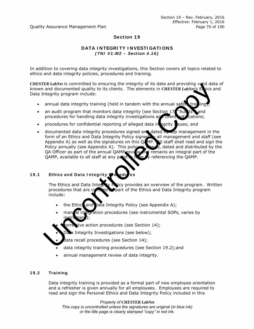
Section 19 – Rev. February, 2016 Effective: February 1, 2016 Quality Assurance Management Plan Page 70 of 190
Property of CHESTER LabNet This copy is uncontrolled unless the signatures are original (in blue ink)
or the title page is clearly stamped “copy” in red ink.
Section 19
DATA INTEGRITY INVESTIGATIONS (TNI V1:M2 – Section 4.16)
In addition to covering data integrity investigations, this Section covers all topics related to ethics and data integrity policies, procedures and training. CHESTER LabNet is committed to ensuring the integrity of its data and providing valid data of known and documented quality to its clients. The elements in CHESTER LabNet’s Ethics and Data Integrity program include:
• annual data integrity training (held in tandem with the annual safety training);
• an audit program that monitors data integrity (see Section 17, “Audits”) and procedures for handling data integrity investigations and client notifications;
• procedures for confidential reporting of alleged data integrity issues; and
• documented data integrity procedures signed and dated by top management in the form of an Ethics and Data Integrity Policy signed by all management and staff (see Appendix A) as well as the signatures on this QAMP. All staff shall read and sign the Policy annually (see Appendix A). This policy is signed, dated and distributed by the QA Officer as part of the annual QAMP review and remains an integral part of the QAMP, available to all staff at any point in time by referencing the QAMP.
19.1 Ethics and Data Integrity Procedures
The Ethics and Data Integrity Policy provides an overview of the program. Written procedures that are considered part of the Ethics and Data Integrity program include:
• the Ethics and Data Integrity Policy (see Appendix A);
• manual integration procedures (see instrumental SOPs, varies by instrument);
• corrective action procedures (see Section 14);
• Data Integrity Investigations (see below);
• data recall procedures (see Section 14);
• data integrity training procedures (see Section 19.2);and
• annual management review of data integrity.
19.2 Training
Data integrity training is provided as a formal part of new employee orientation and a refresher is given annually for all employees. Employees are required to read and sign the Personal Ethics and Data Integrity Policy included in this
Uncon
trolle
d Cop
y

Section 19 – Rev. February, 2016 Effective: February 1, 2016 Quality Assurance Management Plan Page 71 of 190
Property of CHESTER LabNet This copy is uncontrolled unless the signatures are original (in blue ink)
or the title page is clearly stamped “copy” in red ink.
document (see Appendix A) during orientation and again annually. This policy clearly states that any infractions of the laboratory data integrity procedures shall result in a detailed investigation that could lead to very serious consequences including immediate termination or civil/criminal prosecution. Attendance for required training is documented through the signatures and accompanying dates on the Data Integrity and Ethics Policy. Data integrity training emphasizes the importance of proper written narration on the part of the analyst in those cases where analytical data may be useful, but are in one sense or another partially deficient. All topics contained in the Personal Ethics and Data Integrity Policy are covered, and employees are given the opportunity to ask questions at the end of the training session. The following topics and activities are covered:
• the organizational mission and its relationship to the critical need for honesty and full disclosure in all analytical reporting;
• how and when to report data integrity issues;
• record keeping;
• training, including discussion regarding all data integrity procedures;
• data integrity training documentation;
• in-depth data monitoring and data integrity procedure documentation; and
• specific examples of breaches of ethical behavior such as improper data manipulations, adjustments of instrument time clocks, and inappropriate changes in concentrations of standards.
When contracted technical or support personnel are used, the QA Officer is responsible for ensuring that they are trained in the laboratory’s management system and data integrity procedures, competent to perform the assigned tasks, and appropriately supervised. These personnel are treated in the same manner as a regular employee and often become regular employees. Topics covered are provided to all trainees in writing in the form of the Personal Ethics and Data Integrity Policy located in Appendix A of this document.
19.3 Confidential Reporting of Ethics and Data Integrity Issues
Confidential reporting of data integrity issues is assured through the following procedure: All staff members have the authority and responsibility to bring any problems, discrepancies, or concerns to the attention of their appropriate Technical Director. In situations where privacy is of concern, all staff have access to all other staff members’ phone numbers. It is understood and encouraged that when needed, employees contact each other via their private phone numbers.
Uncon
trolle
d Cop
y

Section 19 – Rev. February, 2016 Effective: February 1, 2016 Quality Assurance Management Plan Page 72 of 190
Property of CHESTER LabNet This copy is uncontrolled unless the signatures are original (in blue ink)
or the title page is clearly stamped “copy” in red ink.
19.4 Investigations
All investigations resulting from data integrity issues are conducted confidentially. They are documented and notifications are made to clients who received any negatively affected data that did not meet the client’s data quality requirements. The first stage of investigation is data inspection including, but not limited to: all associated documentation including reagents logbooks, calibrations, run logbooks, computer clocks and/or date/time stamps on the raw data, computer controlled environmental monitoring, etc. The inspection is conducted by the appropriate Technical Director, in conjunction with the Laboratory Director/President and QA Officer. If the inspection results raise concerns, those results and the concerns they raised, along with copies of the associated documentation shall be retained in the employee’s personnel file. If, in their opinion, a breach of ethical conduct has occurred (as opposed to an honest mistake or oversight), the same Management staff member shall then interview the employee. If the interview raises concerns, other employees may be interviewed and the results of the interviews shall be documented. If the situation is deemed to be a breach of ethics by Management, documentation from both the records inspection and any subsequent interviews, along with a record of any actions taken, shall be placed in the employee’s personnel file maintained by the Laboratory Director/President. The employee will be informed of the outcome of the investigation. CHESTER LabNet does not tolerate unethical behavior of any sort by its employees, whether said behavior is related or unrelated to data production. If a breach of ethics is found to be supported by evidence, the employee may expect to be terminated.
Uncon
trolle
d Cop
y

Section 20 – Rev. February, 2016 Effective: February 1, 2016 Quality Assurance Management Plan Page 73 of 190
Property of CHESTER LabNet This copy is uncontrolled unless the signatures are original (in blue ink)
or the title page is clearly stamped “copy” in red ink.
Section 20
PERSONNEL (TNI V1:M2 – Section 5.2)
CHESTER LabNet employs competent personnel based on education, training, experience and demonstrated skills as required. The laboratory’s organization chart can be found in Section 4, “Organization,” of this document. 20.1 Overview
All personnel are responsible for complying with all quality and data integrity policies and procedures that are relevant to their area of responsibility. All personnel who are involved in activities related to sample analysis, evaluation of results, or who sign test reports must demonstrate competence in their area of responsibility. Appropriate supervision is given to any personnel in training and the trainer is accountable for the quality of the trainee’s work. Personnel are qualified to perform the tasks they are responsible for based on education, training, experience and demonstrated skills as required for their area of responsibility. The laboratory provides goals with respect to education, training and skills of laboratory staff. These goals are outlined in the specific job descriptions in section 20.2. Training needs are identified at the time of employment and when personnel are moved to a new position or new responsibilities are added to their job responsibilities. Ongoing training, as needed, is also provided to personnel in their current jobs. The effectiveness of the training must be evaluated before the training is considered complete. Contracted personnel, when used, must meet the same competency standards and follow the same policies and procedures that laboratory employees must meet.
20.2 Job Descriptions
Job descriptions are available for all positions that manage, perform, or verify work affecting data quality, and are located in the table below. Job descriptions include the specific tasks, minimum education, qualifications, skills and experience required for each position. An overview of top Managements’ responsibilities is included in Section 5, “Management.”
Uncon
trolle
d Cop
y

Section 20 – Rev. February, 2016 Effective: February 1, 2016 Quality Assurance Management Plan Page 74 of 190
Property of CHESTER LabNet This copy is uncontrolled unless the signatures are original (in blue ink)
or the title page is clearly stamped “copy” in red ink.
Title Job Description
President Goal:
• Ensure the business operates within compliance of all local, state, federal laws, including financial tracking and reporting;
• Communicate with board of directors.
Area of Responsibility: Corporate Affairs
Minimum education required: Higher degree in a hard science
Training required: Minimum 5 years as an employee of CHESTER LabNet. Training, by necessity, may be autodidactic.
Minimum experience required: 5 years project management with CHESTER LabNet or 2 years equivalent Presidential job duties at another laboratory (environmental or other).
Qualifications: • Knowledge of legal requirements of running a business; • knowledge of bookkeeping and legal financial reporting;
and • knowledge of submission of Requests for Proposals (RFPs).
Brief description (including Managerial Duties):
• Oversees marketing and sales; • performs legal financial reporting including calculating and
disbursing dividend checks to owners, ensuring all taxes are paid in a timely manner, and managing payroll and pay rates for employees; and
• where possible, performs no functions related to testing, reporting or method development/modification.
Laboratory Director
Goal: • Ensure human resource and service performance of the
laboratory. • Provide the resources necessary to implement and
maintain an effective quality and data integrity program.
Area of Responsibility: Laboratory Management
Minimum education required: Higher degree in a hard science
Training required: Minimum 5 years as an employee of CHESTER LabNet. Training, by necessity, may be autodidactic.
Minimum experience required: 3 years project management or Technical Director experience with CHESTER LabNet or 1 year
Uncon
trolle
d Cop
y

Section 20 – Rev. February, 2016 Effective: February 1, 2016 Quality Assurance Management Plan Page 75 of 190
Property of CHESTER LabNet This copy is uncontrolled unless the signatures are original (in blue ink)
or the title page is clearly stamped “copy” in red ink.
Title Job Description equivalent Laboratory Director job duties at another laboratory (environmental or other).
Qualifications: • Knowledge of legal requirements of human resource
management; and • knowledge of submission of Requests for Proposals (RFPs).
Brief description (including Managerial Duties):
• Ensures that personnel are free from any commercial, financial and other undue pressures that might adversely affect the quality of their work;
• oversees company financials, to include the purchase of new instrumentation and equipment;
• reviews all tenders and contracts; • oversees accreditation(s); • ensures adequate staffing (in tandem with Technical
Directors); • engages in management reviews of laboratory systems; • oversees client specific analytical requirements; and • where possible, performs no functions related to testing,
reporting or method development/modification.
Quality Assurance Officer (QA Officer)
Goal: • Review all data prior to reporting; • write/maintain all Quality documents including SOPs and
this document; • ensure compliance with this Quality Assurance
Management Plan; and • ensure compliance with Data Integrity and Ethics Policy.
Area of Responsibility: Laboratory Management
Minimum education required: Higher degree in a hard science
Training required: Minimum 5 years as an analyst with CHESTER
LabNet. Training, by necessity, may be autodidactic.
Minimum experience required: 5 years chemist/analyst experience with CHESTER LabNet or 1 year equivalent QA Officer job duties at another laboratory (environmental or other).
Qualifications: • Knowledge of current TNI Standard requirements; • knowledge of all QC requirements associated with methods
performed; and • knowledge of the general chemistry and techniques of all
methods performed.
Brief description (including Managerial Duties):
Uncon
trolle
d Cop
y

Section 20 – Rev. February, 2016 Effective: February 1, 2016 Quality Assurance Management Plan Page 76 of 190
Property of CHESTER LabNet This copy is uncontrolled unless the signatures are original (in blue ink)
or the title page is clearly stamped “copy” in red ink.
Title Job Description • Serves as a focal point for QA/QC; • arranges or conducts annual internal audits without
outside (e.g., managerial) influence; • notifies management of deficiencies and monitors
corrective actions; • oversees and reviews quality control data; • monitors corrective actions; • ensures that the management system related to quality is
implemented and followed at all times; • monitors and maintains laboratory certifications; • maintains currency of this Quality Assurance Management
Plan; • ensures all SOPs are reviewed annually and maintains
currency; • ensures that all analysts and supervisors have the
appropriate education and training to properly carry out the duties assigned to them and ensures that this training has been documented;
• ensures that appropriate corrective actions are taken to address analyses identified as requiring such actions by internal and external performance or procedural audits - procedures that do not meet the standards set forth in the Quality Manual, laboratory SOPs or laboratory policies may be temporarily suspended by the QA Officer;
• reviews all logbooks for completeness and correct usage; • ensures all project-specific data quality objectives and
specific QA/QC targets are satisfied; • ensures compliance with mandated systems requirements; • issues and archives laboratory logbooks; • reviews and approves all SOPs and policies prior to their
implementation, and ensures availability of and adherence to all approved SOPs and policies;
• evaluates all results based upon QA elements described above and QC requirements for the pertinent testing;
• ensures new methods brought online meet QC criteria for Precision and Bias studies as required;
• ensures new methods brought online meet QC requirement for detection limit studies as required; and
• reports opinions and interpretations of data, where applicable.
Technical Director (all departments)
Goal: Supervise laboratory department operations, data generation and reporting.
Area of Responsibility: Laboratory Management
Minimum education required: Higher degree in a hard science. In addition, the Technical Director must have a minimum of 24 credit hours of college level chemistry for departments where
Uncon
trolle
d Cop
y

Section 20 – Rev. February, 2016 Effective: February 1, 2016 Quality Assurance Management Plan Page 77 of 190
Property of CHESTER LabNet This copy is uncontrolled unless the signatures are original (in blue ink)
or the title page is clearly stamped “copy” in red ink.
Title Job Description chemical analysis occurs. (Does not apply to gravimetry or customer service)
Training required: Minimum 3 years as an employee of CHESTER LabNet. At the discretion of the QA Officer and Laboratory Director, an employee’s past work experience may be substituted for 2 of the 3 years. Training, by necessity, may be autodidactic.
Minimum experience required: 2 years chemist/analyst/technician experience with CHESTER LabNet or 1 year equivalent Technical Director job duties at another laboratory (environmental or other).
Qualifications: • Knowledge of the general chemistry and techniques of all
methods performed in respective department; • knowledge of all instruments used in respective
department; • knowledge of all QC requirements associated with methods
performed in respective department; • knowledge of reporting requirements associated with
methods performed in respective department; and • meeting the general and education requirements and
qualifications found in Sections 4.1.7.2 and 5.2.6.1 of the 2009 TNI Standard - EL-V1M2-2009 unless not specified.
Brief description (including Managerial Duties):
• Monitors performance data and the validity of the analyses for the laboratory;
• provides technical direction to staff and clients; • oversees instrument and equipment installation,
maintenance and repairs; • monitors data compilation and interpretation; • trains new employees (or delegates training to a qualified
analyst); • assesses qualifications of employees (education,
experience and training); • ensures training records are completed for employees; • ensures completion of initial DoC before newly trained
analyst may be released from training, where feasible; • officially releases newly trained analyst from training; • coordinates operations within the laboratory to ensure
smooth flow of samples through the analytical process (may need to be done in tandem with other Technical Directors);
• supervises all analysts to ensure compliance with all accreditations, regulations and client specific requirements;
• plans tests and ensures adequate flow of work through the department;
• evaluates results against QC criteria as required;
Uncon
trolle
d Cop
y

Section 20 – Rev. February, 2016 Effective: February 1, 2016 Quality Assurance Management Plan Page 78 of 190
Property of CHESTER LabNet This copy is uncontrolled unless the signatures are original (in blue ink)
or the title page is clearly stamped “copy” in red ink.
Title Job Description • reports opinions and performs data interpretation, where
applicable; • oversees all method development, modifications and
validation in the department; and • coordinates day to day operations of the department
including: flow of work, resource allocations, sample disposal, laboratory hygiene, supplies procurement and instrument maintenance and repair.
LIMS Administrator
Goal: Ensure proper functioning, configuration and use of the LIMS.
Area of Responsibility: Administrative
Minimum education required: Higher degree in a hard science
Training required: Minimum 2 years as an employee of CHESTER LabNet. Training, by necessity, may be autodidactic.
Minimum experience required: 2 years LIMS usage at CHESTER LabNet or 1 year equivalent job duties at another laboratory using NWA LIMS software (environmental or other).
Qualifications: • Computer literate, and • a general understanding of database operations.
Brief description (including Managerial Duties):
• Operates and maintains (hardware/software) Laboratory Information Management System (LIMS);
• creates/edits/validates report scripts and worklists in tandem with the appropriate Technical Director; and
• where possible, performs no functions related to testing, reporting or method development/modification.
Project Manager & Senior Project Manager
Goal: Coordinate sample receipt, log-in, analysis and reporting to suit the clients’ needs.
Area of Responsibility: Administrative
Minimum education required: Higher degree in a hard science
Training required: Minimum 2 years as an employee of CHESTER LabNet. Training by LIMS Administrator in all functions of the LIMS.
Minimum experience required:
Uncon
trolle
d Cop
y

Section 20 – Rev. February, 2016 Effective: February 1, 2016 Quality Assurance Management Plan Page 79 of 190
Property of CHESTER LabNet This copy is uncontrolled unless the signatures are original (in blue ink)
or the title page is clearly stamped “copy” in red ink.
Title Job Description • Senior Project Manager: 2 years Project Management at
CHESTER LabNet • Project Manager: none
Qualifications:
• Computer literate; • professional demeanor, both written and spoken; and • good communication skills.
Brief description (including Managerial Duties):
• Functions as primary contact person for client interactions; • receives samples; • performs chain of custody procedures; • interfaces with client and Laboratory on corrective actions; • packages and ships sample media to clients; • performs data entry in LIMS; • reports data; • coordinates sample receipt, sample analysis and data
reporting activities to ensure project turnaround times; and
• performs no functions related to testing or method development/modification.
• Additionally, the Senior Project manager acts as a resource to other project managers, may act as another layer of Quality Control prior to submission of reports, and is responsible for adequate flow of work through the department.
Chemist/Senior Chemist
Goal: Produce the most accurate data possible that meets QC and documentation requirements of all applicable methods, accreditations and contracts.
Area of Responsibility: Analytical
Minimum education required: Higher degree in a hard science
Training required: Must be trained in all areas, including the Quality System and Technical/Analytical procedures by a lead analyst. For the Lead Chemist, training may, by necessity, be autodidactic.
Minimum experience required: • Lead Chemist: 2 years as a Chemist at CHESTER LabNet. • Chemist: none.
Qualifications:
• Computer literate; • professional demeanor, both written and spoken;
Uncon
trolle
d Cop
y

Section 20 – Rev. February, 2016 Effective: February 1, 2016 Quality Assurance Management Plan Page 80 of 190
Property of CHESTER LabNet This copy is uncontrolled unless the signatures are original (in blue ink)
or the title page is clearly stamped “copy” in red ink.
Title Job Description • good communication skills; • mathematical skills at the algebraic level or higher; and • 1 year college level general chemistry OR 1 year
experience in performing laboratory analysis at another laboratory.
Brief description (including Managerial Duties):
• Lead Chemist/Analyst is defined as the person with the most experience with a given method or analysis;
• Analyzes samples under the direction/coordination of either the Technical Director or Senior Chemist in compliance with requirements of this document, pertinent SOPs, contracts or guideline documents;
• keeps records in compliance with requirements of this document, pertinent SOPs, contracts or guideline documents;
• enters data into LIMS; • safely handles chemicals and laboratory equipment; • troubleshoots, maintains and repairs instrumentation, with
or without input from the Technical Director or Lead Chemist;
• evaluates data against pertinent QC requirements; and • reports opinions and performs data interpretation, where
applicable. • Additionally, the Lead Chemist acts as a resource to other
chemists and may act as another layer of Quality Control prior to submission of data.
XRF Analyst/ Senior XRF Analyst
Goal: Produce the most accurate data possible that meets QC and documentation requirements of all applicable methods, accreditations and contracts.
Area of Responsibility: Analytical
Minimum education required: Higher degree in a hard science
Training required: Must be trained in all areas, including the Quality System and Technical/Analytical procedures by a senior analyst. For the Senior analyst, training may, by necessity, be autodidactic.
Minimum experience required:
• Senior XRF Analyst: 2 years as an XRF Analyst at CHESTER LabNet.
• XRF Analyst: none.
Uncon
trolle
d Cop
y

Section 20 – Rev. February, 2016 Effective: February 1, 2016 Quality Assurance Management Plan Page 81 of 190
Property of CHESTER LabNet This copy is uncontrolled unless the signatures are original (in blue ink)
or the title page is clearly stamped “copy” in red ink.
Title Job Description Qualifications:
• Computer literate; • professional demeanor, both written and spoken; • good communication skills; • mathematical skills at the algebraic level or higher; and • 1 year college physics or 1 year experience operating an
XRF (experience may include on-the-job training).
Brief description (including Managerial Duties): • Analyzes samples under the direction/coordination of
either the Technical Director or Senior Analyst in compliance with requirements of this document, pertinent SOPs, contracts or guideline documents;
• keeps records in compliance with requirements of this document, pertinent SOPs, contracts or guideline documents;
• performs data compilation and spectral interpretation; • enters data into LIMS; • troubleshoots, maintains and repairs instrumentation,
under the supervision of the Technical Director or Senior Analyst;
• evaluates data against pertinent QC requirements; and • reports opinions and performs data interpretation, where
applicable. • Additionally, the Senior Analyst acts as a resource to other
analysts and may act as another layer of Quality Control prior to submission of data.
Gravimetry Laboratory Technician
Goal: Produce the most accurate data possible that meets QC and documentation requirements of all applicable methods, accreditations and contracts.
Area of Responsibility: Analytical
Minimum education required: High School diploma
Training required: Must be trained in all areas, including the Quality System and Technical/Analytical procedures by a senior analyst.
Minimum experience required: none
Qualifications: • Computer literate; • professional demeanor, both written and spoken; and • good communication skills.
Brief description (including Managerial Duties):
• Performs all Gravimetry Laboratory operations and QA/QC,
Uncon
trolle
d Cop
y

Section 20 – Rev. February, 2016 Effective: February 1, 2016 Quality Assurance Management Plan Page 82 of 190
Property of CHESTER LabNet This copy is uncontrolled unless the signatures are original (in blue ink)
or the title page is clearly stamped “copy” in red ink.
Title Job Description including acceptance testing and gravimetry;
• maintains appropriate inventory levels of filters and supplies;
• archives analyzed samples; • follows all QA/QC protocols; and • evaluates data against pertinent QC requirements.
20.3 Training All personnel are appropriately trained and competent in their assigned tasks before they contribute to functions that can affect data quality. It is Management’s responsibility to ensure personnel are trained. Training records are used to document Management’s approval of personnel competency. The date on which authorization and/or competence is confirmed is included. Training records are generated by the person who performs the training and are maintained by the QA Officer. Records include the dates that training occurred and a brief description of what the training was, along with a “training completed” date.
20.3.1 Training for New Staff New staff members are trained in the following:
• requirements of the Quality Assurance Management Plan;
• requirements of the Chemical Hygiene Plan;
• relevant methods or SOPs which they will be performing;
• LIMS operation to the extent necessary for their job requirements; and
• administrative tasks to the extent necessary for their job requirements.
For further detail, refer to SOP QA-001, “Laboratory Training.”
20.3.2 Ongoing Training
Refer to SOP QA-001, “Laboratory Training.”Uncon
trolle
d Cop
y

Section 21 – Rev. February, 2016 Effective: February 1, 2016 Quality Assurance Management Plan Page 83 of 190
Property of CHESTER LabNet This copy is uncontrolled unless the signatures are original (in blue ink)
or the title page is clearly stamped “copy” in red ink.
Section 21
ACCOMODATIONS AND ENVIRONMENTAL CONDITIONS (TNI V1:M2 – Section 5.3)
21.1 Environmental
The laboratory facility is designed and organized to facilitate testing of environmental samples. Environmental conditions are monitored to ensure that conditions do not invalidate results or adversely affect the required quality of any measurement, such as the temperature and humidity in the Gravimetry Laboratory. If the laboratory environment is required to be controlled by a method or regulation, the adherence is recorded. Gravimetry Laboratory temperature and humidity are recorded using a combination temperature and humidity digital data logger, and the balances are placed upon marble slabs to avoid problems with vibration. Environmental tests are stopped when the environmental conditions jeopardize the results. Relevant temperature/humidity readings are recorded in the raw data for methods that are not performed in the Gravimetry Laboratory but that have specific temperature/humidity requirements.
21.2 Work Areas
Work areas include access and entryways to the laboratory, the administrative area (which may serve as a sample receipt area also), sample storage areas, sample processing and analysis areas, and chemical and waste storage areas. Access to and use of areas affecting the quality of the environmental tests is controlled by restriction of areas to authorized persons only. See Section 21.4 below. Due to the small size of the laboratory, all employees are, by default, authorized personnel in all areas of the laboratory. Unauthorized persons could be people such as plumbers, field service technicians, visitors, etc. The laboratory work spaces are adequate for their use, and appropriately clean to support environmental testing and ensure an unencumbered work area. Laboratory space is arranged to minimize cross-contamination between incompatible areas of the laboratory. The Gravimetry Laboratory is on a separate HVAC system from the rest of the laboratory areas to ensure proper temperature and humidity control. Areas with high mineral acid usage are located in a different part of the conventional chemistry laboratory from where ion chromatography is performed. Sulfuric acid is not utilized near areas where the currently promulgated Method 202 is being performed. Resuspension of particulates onto filters is performed in a separate area to prevent particulate contamination of other samples. Testing occurs only within the laboratory’s analytical areas (e.g., Conventional Chemistry laboratory, XRF Laboratory or Gravimetry Laboratory). Adequate laboratory space is maintained for the testing performed in each area. Electronic
Uncon
trolle
d Cop
y

Section 21 – Rev. February, 2016 Effective: February 1, 2016 Quality Assurance Management Plan Page 84 of 190
Property of CHESTER LabNet This copy is uncontrolled unless the signatures are original (in blue ink)
or the title page is clearly stamped “copy” in red ink.
balances are located away from drafts and doorways, and mounted on marble slabs in areas where their use is affected by vibrations. Neighboring test areas of incompatible activities are effectively separated. Specific work areas are defined and access is controlled. (Only authorized laboratory personnel and escorted visitors may enter the work area.) Good housekeeping measures are employed to avoid the possibility of contamination. Smoking is prohibited. All equipment and reference materials required for accredited tests are available in the laboratory (no equipment is kept off-site). Records are maintained for all equipment, reference measurement materials and services used by the laboratory. Reference materials traceable to national standards of measurement (NIST) or to national standard reference materials (SRM’s) are stored away from heavy use areas or major equipment that may affect the proper operation of the materials. Certificates of Traceability are available for NIST traceable thermometers and hygrometers, for the Class 1 weights, and for all pre-prepared aqueous standards. The reference materials are used only for calibration or calibration verification in order to maintain the validity of performance. Certificates of Analysis are available for all standards and reagents.
21.3 Floor Plan A floor plan can be found in Appendix C. 21.4 Building Security
The laboratory is kept secure during off hours by the use of locks and an alarm system. Access to the facilities is by cardlock during non-business hours, seven days a week. During business hours, the main door is unlocked and is monitored personnel. Visitors are taken into the main laboratory under escort only.
Uncon
trolle
d Cop
y

Section 22 – Rev. February, 2016 Effective: February 1, 2016 Quality Assurance Management Plan Page 85 of 190
Property of CHESTER LabNet This copy is uncontrolled unless the signatures are original (in blue ink)
or the title page is clearly stamped “copy” in red ink.
Section 22
ENVIRONMENTAL METHODS AND METHOD VALIDATION (TNI V1:M2 – Section 5.4 and Sections 1.4, 1.5 and
1.6 of Technical Modules TNI V1:M 3-7) Methods and/or procedures are available for all activities associated with the analysis of the sample including preparation and testing. For purposes of this Section, “method” refers to both the sample preparation and determinative methods. See Appendix B for a listing of all CHESTER LabNet SOPs. See Section 25, “Collection of Samples,” and Appendix D, “CHESTER LabNet utilized methods” for a listing of the most common promulgated methods in use at CHESTER LabNet. Before being put into use, a test method is confirmed by a demonstration of capability or method validation process, where possible. All methods are published or documented. Deviations from the methods are allowed only if the deviation is documented, technically justified, authorized by management and accepted by the customer. Note that most source sampling methods (CFR methods) are extremely outdated and archaic, and CHESTER LabNet’s clients are well aware of this. The laboratory does not notify clients of changes to methods necessitated either by the EPA’s failure to update methods to reflect current technology or by the laws of chemistry and physics. Every SOP has an appendix which lists all of the differences between the laboratory’s SOP and the promulgated method. Examples include using a computer to gather and process data from an IC rather than a strip chart recorder, and not draining “the bottom organic layer” from a separatory funnel when the organic fraction has a lower density than water. 22.1 Method Selection
A reference method is a method issued by an organization generally recognized as competent to do so. (When ISO refers to a “standard method”, that term is equivalent to “reference method”.) When a laboratory is required to analyze a parameter by a specified method due to a regulatory requirement, the parameter/method combination is recognized as a reference method. The laboratory will use methods that meet the needs of the customer. Such methods will be based on the latest edition of the method unless it does not meet the needs of the customer. Generally speaking, the customer has little room for guesswork as there are a very limited number of methods promulgated for the analysis of either ambient air or source emissions. Both the client and the laboratory may be forced by a regulatory agency to use a method that is not appropriate to the ultimate client’s needs. When the regulatory authority mandates a specific method, the laboratory will follow that method as closely as possible and in keeping with the chemistry of the method. This statement is most commonly applicable to archaic methods found in the CFR for source emission testing. CHESTER LabNet does not inform the client when a method is considered to be inappropriate or out-of-date, as our clients are already aware of those issues.
Uncon
trolle
d Cop
y

Section 22 – Rev. February, 2016 Effective: February 1, 2016 Quality Assurance Management Plan Page 86 of 190
Property of CHESTER LabNet This copy is uncontrolled unless the signatures are original (in blue ink)
or the title page is clearly stamped “copy” in red ink.
If a method is not specified by the client, the client shall be contacted and clarification shall be obtained prior to proceeding with any analytical work. Air quality methods (ambient or source) have two major components to them: sampling and analytical. CHESTER LabNet only performs the analytical portion of the method. The client will be aware of what method/analytes are needed. Typically, the omission of an analytical method request is a simple documentation error. All communications between the laboratory and the client are documented via printed email correspondence or notes on the Chain of Custody that have been dated and initialed by the laboratory agent contacting the client.
22.2 Laboratory-Developed Methods
If the laboratory develops a method, the process of designing and validating the method is carefully planned and documented. One person, usually the Technical Director of the affected department, will be responsible for developing the method. In some cases, methods may be developed to fill in gaps found in other published or promulgated methods. On rare occasions, a method will be developed due to a lack of a promulgated method (e.g., Alkalinity in Teflon Filters). All methods developed in house, for whatever reason, will have an associated SOP. The in-house methods will undergo the same annual review cycle as all other SOPs. Laboratory-developed methods are only used if they are validated by a demonstration of capability study (where possible) and only if they are appropriate for the intended use. As with other new methods, the Technical Director is responsible for ensuring that the laboratory is capable of performing the method in such a manner as to meet all applicable QC requirements. This is achieved via a Demonstration of Capability Study and a Precision and Bias Study where possible. Where not possible, other method specific QC criteria may be utilized to demonstrate capability. The development of new methods will always be assigned to the staff member with the greatest knowledge relating to that method and the ability to obtain all the resources needed to carry out the method. When an occasion arises in which the employment of a non-standard method is needed, the method will be developed in conjunction with the client. These methods are almost never used by any other client or for any other project, and tend to fall into one of two categories: contingency and contractual. Contractual methods are usually developed based on a method or methods supplied by the client. These may or may not be publicly published methods. Method development then proceeds until such time as the laboratory can demonstrate method proficiency and Precision and Bias, where possible (see SOP QA-006). Methods developed for contractual reasons must meet the client’s approval prior to samples being analyzed. As method development may generate large quantities of documentation, most documentation is kept in a 3-ring binder in chronological order with notes as to what changes were being made during the maturation of the method.
Uncon
trolle
d Cop
y

Section 22 – Rev. February, 2016 Effective: February 1, 2016 Quality Assurance Management Plan Page 87 of 190
Property of CHESTER LabNet This copy is uncontrolled unless the signatures are original (in blue ink)
or the title page is clearly stamped “copy” in red ink.
Contingency methods tend to be utilized on a one-time basis, for engineering purposes or for the purposes of testing obscure/difficult/non-regulated matrices. As such, full validation of the method may not be possible and presents an undue burden on the laboratory. Such analyses will be documented fully, all directives issued by the client will be noted in the data file, and attempts are always made to get written confirmation from the client as to the acceptance of the proposed methodology. Documentation by the analyst will include specifics, where not obvious, pertaining to the analysis. The acceptance/rejection criteria for non-standard methods default to methods of similar chemistries or to CLP guidelines, if at all possible. When not possible, acceptance/rejection criteria may be based upon Precision and Bias studies and/or IDL/MDL studies, or other method specific QC where IDL/MDL and Precision and Bias Studies are not applicable (e.g., Method 202, filter impregnation, etc.).
22.3 Method Validation
Validation is the confirmation, by examination and objective evidence, that the particular requirements for a specific intended use are fulfilled. At a minimum, reference methods are validated by performing an initial demonstration of capability, where possible. Additional requirements are discussed for each technology. All non-reference methods are validated before use, where possible. The validation is designed to enable the laboratory to demonstrate that the method is appropriate for its intended use. All records (e.g., planning, method procedure, raw data and data analysis) shall be retained while the method is in use. Based on the validation process, the method’s SOP will contain a statement of the intended use of the method and whether or not the validated method meets the use requirements. Method validation and Demonstration of Capability procedures for methods in use at CHESTER LabNet can be found in Appendix H, “Chemistry.”
22.4 Estimation of Analytical Uncertainty
Analytical Uncertainty is a subset of Measurement Uncertainty that includes all laboratory activities performed as part of the analysis. When requested and where possible, the laboratory will provide an estimate of the analytical uncertainty (reported as a percent) determined by calculating three times the standard deviation of a statistically significant set of recovery values for known standards analyzed by the same method. Due to the unique analytical requirements for air testing, this may not always be possible, as is the case with all gravimetric analyses (e.g., particulate measurements). Two methods utilized at the laboratory issue uncertainties as part of standard reporting formats: analysis of metals by XRF and analysis of Carbon by OC/EC. A
Uncon
trolle
d Cop
y

Section 22 – Rev. February, 2016 Effective: February 1, 2016 Quality Assurance Management Plan Page 88 of 190
Property of CHESTER LabNet This copy is uncontrolled unless the signatures are original (in blue ink)
or the title page is clearly stamped “copy” in red ink.
full explanation of determination of uncertainty for measurements by XRF is contained within SOP XR-005. Determination of uncertainties for OC/EC is performed by the instrument software.
22.5 Control of Data
To ensure that data are protected from inadvertent changes or unintentional destruction, the laboratory uses procedures to check calculations and data transfers (both manual and automated).
22.5.1 Computer and Electronic Data Requirements
The laboratory assures that computers, user-developed computer software, automated equipment, or microprocessors used for the acquisition, processing, recording, reporting, storage, or retrieval of environmental test data are:
• documented in sufficient detail and validated as being adequate for use;
• protected for integrity and confidentiality of data entry or collection, data storage, data transmission and data processing;
• maintained to ensure proper functioning and are provided with the environmental and operating conditions necessary to maintain the integrity of environmental test data; and
• held secure including the prevention of unauthorized access to, and the unauthorized amendment of, computer records. Data archive security is addressed in Section 16, “Control of Records” and building security is addressed in Section 21, “Accommodations and Environmental Conditions”.
Primary control of electronic data occurs at the physical security level, by preventing any non-authorized persons access to the premises without an escort. Secondary control of electronic data is achieved by employing only personnel with proven ethical understanding of data integrity. Tertiary data control at the instrument level is controlled by the software auditing mechanisms built into the major instrumental software utilized by the laboratory. Quaternary electronic data control is achieved by retaining hard copy records in appropriate job files of all electronic data produced by the laboratory. Note that due to the small staff size of the laboratory, all employees are considered “authorized users” on all computers. For analytical computers, the user’s initials will appear on the electronic files and in the associated run logs for that instrument. The laboratory uses spreadsheets to calculate final results from the raw data for some analyses. Before reporting any results derived from these spreadsheets, the laboratory validates the underlying calculations by performing a sample calculation on at least 10% of the total data, selected at random throughout the spreadsheet. All mathematical steps from raw data to final reported data are verified manually. If a new calculation is created within the LIMS, the procedure for verifying spreadsheets is used.
Uncon
trolle
d Cop
y

Section 22 – Rev. February, 2016 Effective: February 1, 2016 Quality Assurance Management Plan Page 89 of 190
Property of CHESTER LabNet This copy is uncontrolled unless the signatures are original (in blue ink)
or the title page is clearly stamped “copy” in red ink.
After a spreadsheet has been developed and verified, subsequent use of the spreadsheet is verified by testing each set of cells used for input and output of the calculation. Any changes made to the spreadsheet are revalidated manually as described above. Some spreadsheets may be used only rarely; any spreadsheet that has not been used in more than 3 months will be revalidated as described above. Data from all electronic media, including the LIMS, company financials, client contracts, SOPs and program documents, and any computer governing an instrument used for NELAC accredited methods, are backed up to both a separate hard drive and to the cloud daily. See SOP AD-007 for further details.
22.5.2 Data Reduction
In cases where the analyst calculates final results manually from raw data, all manual calculations will be verified by a second individual. The second individual shall document their verification by writing out the formula/e they used to determine the final results on the raw data, then placing a tick or check mark next to each calculation they verified and, finally, writing “QC OK” at the top right corner of the raw data sheet along with their initials and the date they verified the data. In addition and wherever possible, 100% of all manual data transfers (e.g., hand transcription, data entry into the LIMS) will be checked for accuracy by a different analyst than the one performing the transfer. The second individual shall document their verification by placing a tick or check mark next to each entry they verified, and writing their initials and the date they verified the data at the top right corner of the page. Appropriate computer programs may provide the results in a reportable format, although that is not typical for air quality methods. Usually, several different data sets are entered into the LIMS and the LIMS reports the data in the units as requested by the client. Typical units requested by the client include: mg/Sample or µg/Sample; mg/m³ or µg/m³; and µg/L (gas volume, not liquid volume). The test methods may provide required concentration units, calculation formulae and any other information required to obtain final analytical results, but do not always do so in a manner that meets the clients’ needs. The clients’ requests shall always be honored above any calculations given in any method. For example: 40 CFR 60, Appendix A, Method 8 requires reporting units of meq SOx/m³, with an intermediary calculation of meq SOx/sample. Most clients request results in mg H2SO4/sample or mg SO2/sample. In these cases, the client’s requested reporting units shall be the units reported, regardless of the calculations in the method. Some promulgated methods, particularly CFR methods, have errors in the promulgated calculations. In such cases, the laboratory calculates the data using correct formulae, regardless of that contained in the promulgated method. The laboratory has manual integration procedures that must be followed when integrating peaks during data reduction. These procedures are taught to new analysts by the Technical Director/Senior analyst chemist/analyst overseeing the instrument that the trainee is learning to operate. The manual integration procedures are in the associated instrument SOPs in the section on data reduction.
Uncon
trolle
d Cop
y

Section 22 – Rev. February, 2016 Effective: February 1, 2016 Quality Assurance Management Plan Page 90 of 190
Property of CHESTER LabNet This copy is uncontrolled unless the signatures are original (in blue ink)
or the title page is clearly stamped “copy” in red ink.
The laboratory reports data to the lowest numerical place of the detection limit (e.g., if the detection limit is 0.05, undiluted samples will be reported to the hundredths place); however, the maximum number of significant figures reported is four. Thus, if a result is 975.53 with a detection limit of 0.02, the reported result will be 975.5 (four significant figures). If a result is 1452.86 with a detection limit of 10, the reported result will be 1450 (reported to the tens place, per the detection limit). If the detection limit is 0.05 and the instrument result is 0.0623, the reported result will be 0.06 (two significant figures, not four, reported to the hundredths place, per the detection limit). A result lower than the detection limit shall not be reported as a number, except for instruments where uncertainty, rather than hard detection limits, are utilized (i.e., XRF and OC/EC). Gravimetric analyses have no detection limits and therefore the actual results are reported, even when negative values are obtained. In cases of dilutions to remove matrix interferences (not for samples over the calibration range), the same rules apply; however, the detection limit will be multiplied by the dilution factor as well. Thus, for a ten-fold dilution of a sample with a detection limit of 10 and a raw data result of 14528.6, the reported result will be 14500. For a ten-fold dilution of a sample with a detection limit of 0.02 and a raw data result of 975.53, the reported result will be 975.5. All raw data are retained in hardcopy form in the report folder and in the form in which it was generated (e.g., computer files, logbooks, spreadsheets, etc.). It is maintained as described in Section 16, “Control of Records”.
22.5.3 Confidentiality, Storage, Transmission and Processing
Data confidentiality is discussed in Section 10.1, “Client Confidentiality,” and applies to all stages of data production. Data storage is described in Section 16, “Control of Records” and Section 22.5, “Control of Data.” Data transmission is described in Section 28, “Reporting the Results.” Data processing is described in Section 22.5, “Control of Data.”
22.5.4 Data Review Procedures
Data review procedures are located in Section 27.4, “Data Review”. Uncon
trolle
d Cop
y

Section 23 – Rev. February, 2016 Effective: February 1, 2016 Quality Assurance Management Plan Page 91 of 190
Property of CHESTER LabNet This copy is uncontrolled unless the signatures are original (in blue ink)
or the title page is clearly stamped “copy” in red ink.
Section 23
CALIBRATION REQUIREMENTS (TNI V1:M2 – Sect 5.5 and Section 1.7 of
Technical Modules TNI V1:M 3-7)
23.1 General Equipment Requirements The laboratory provides all the necessary equipment required for the correct performance of the scope of environmental testing performed by the laboratory. All equipment and software used for testing and sampling are capable of achieving the accuracy required for complying with the specifications of the environmental test methods as specified in the laboratory SOPs. Equipment is operated only by authorized and trained personnel (see Section 20, “Personnel”). The laboratory has procedures for the use, maintenance, handling and storage of equipment, and they are readily available to laboratory personnel. Manuals received from the manufacturer of the equipment provide information on use, maintenance, handling and storage of the equipment. Below is an equipment manual table that includes additional information on storage location:
Document Title Location OC/EC Manual Sunset Laboratory OC/EC
Instruction Manual Drawer below instrument
ICP Manual Perkin Elmer Optima 8300 Hardware Guide
Drawer below instrument
WinLab32 software guide
Perkin Elmer WinLab32 for ICP software CD-ROM
Drawer below instrument
XRF Manual XRF Instruction Manual Cabinet in center island near XRFs
Sartorius Manual (B120S)
Sartorius 120 Basic Series Instrument Manual & Operating Instructions
Drawer in center island in XRF room
CAHN Manual CAHN C30/31 Instruction Manual Drawer in center island in XRF room.
Sartorius Manual (ME5)
Sartorius ME & SE Series Operating Instructions
Drawer in center island in XRF room
Sartorius Manual (CPA224S)
Sartorius GemPlus Series Drawer under balance in conventional chemistry lab
Sartorius Manual (MSA225S)
Sartorius Cubis Series Drawer under balance in SPM laboratory
Uncon
trolle
d Cop
y

Section 23 – Rev. February, 2016 Effective: February 1, 2016 Quality Assurance Management Plan Page 92 of 190
Property of CHESTER LabNet This copy is uncontrolled unless the signatures are original (in blue ink)
or the title page is clearly stamped “copy” in red ink.
Document Title Location Dehumidifier Manual
Kenmore Dehumidifier Manual Drawer in center island in XRF room.
Dehumidifier Manual
Whirlpool Dehumidifier Manual Drawer in center island in XRF room.
Humidifier Manual LASKO Recirculating Console Humidifier Model 1128
Drawer in center island in XRF room.
Humidifier Manual Duracraft Moisture Humidifier Owner’s Manual
Drawer in center island in XRF room.
IC Manual Dionex ICS3000 User Manual and CD-ROM
Black bookcase in laboratory and drawer under IC computer
DI system manual User Manual Milli-Q Direct 8/16 System
Countertop next to DI system cartridges
Air compressor dryer
Hankison Compressed Air Dryer Instruction Manual
Black bookcase in laboratory
CVAA Manual Nippon 3320A Instruction Manual Drawer under CVAA computer
UV/Vis Manual Spectronic UV/Vis Model 20D Owner’s Manual and Bench Manual
Black bookcase in laboratory
Hot Plate manuals Cimarec Hot Plate/Stirrer Operating Instructions
Thermolyne Hot Plate Operating Instruction
Black bookcase in laboratory
Sonicator Manual Branson Model 8510 Operator’s Manual
Black bookcase in laboratory
Heated Sonicator Manual
ElmaSonic P Ultrasonic Cleaning Units
Black bookcase in laboratory
Hot bath Manual Precision Water Bath 280 Series Installation and Service Manual
Black bookcase in laboratory
Oven Manual (VWR) VWR Utility Oven Operating Instructions
Drawer near muffle furnace
Oven Manual (Binder)
Binder Operating Manual Heating Oven with Forced Convection
Drawer near muffle furnace
Muffle furnace manual
Thermolyne Furnace Owner’s Manual
Drawer near muffle furnace
pH/mV meters (2) VWR SympHony benchtop model Center drawer, titration desk The laboratory also has a policy for planned equipment maintenance. A summarized plan for equipment maintenance can be found in table 23.5. These procedures ensure proper functioning of the equipment and prevent contamination or deterioration.
Uncon
trolle
d Cop
y

Section 23 – Rev. February, 2016 Effective: February 1, 2016 Quality Assurance Management Plan Page 93 of 190
Property of CHESTER LabNet This copy is uncontrolled unless the signatures are original (in blue ink)
or the title page is clearly stamped “copy” in red ink.
Each instrument has a bound maintenance logbook in which all problems, repairs and service visits are documented. Support equipment for each department has one common maintenance logbook. The maintenance logbooks are stored next to the appropriate instrument or in the department in which they are used. Every entry in a maintenance logbook shall have the following elements:
• date and initials of the analyst making the entry;
• name of the person performing the repair or maintenance, if different than the analyst;
• a complete description of the nature of the problem, symptoms or preventative maintenance;
• a description of the parts repaired/replaced/realigned; and
• proof that equipment is functioning properly after service.
The description of the maintenance/repair shall be thorough enough that another person reading the entry can identify what the symptoms were (if any), what the suspect parts were (if any), and what steps were taken to repair or maintain the instrument. Also, any hardware or software upgrades will be noted in the maintenance logbook. Preventative maintenance is scheduled based on guidance from the manufacturer and analyst familiarity with their respective instruments. Preventative maintenance is noted in each instrument’s maintenance logbook. All Technical Directors are responsible for scheduling/performing preventative maintenance on their instruments. Corrective maintenance can be performed either by the primary analyst or by a field service technician, depending on the complexity of the repair needed. All corrective maintenance is noted in the maintenance logbook and the name of the field service technician (if any) is included in the description of the repair. These procedures ensure proper functioning of the equipment and prevent contamination or deterioration. All equipment is calibrated or verified before being placed in use to ensure that it meets laboratory specifications and relevant standard specifications. Records are maintained by the QA Officer in tandem with the Laboratory Director for each major item of equipment and its software used for testing. The records include checks that equipment complies with the specifications; dates, results and copies of reports; and certificates of all calibrations, adjustments, acceptance criteria and the due date of next calibration where applicable; and the date received and date placed in service (if available). This record is the same record as described below. Test equipment, including hardware and software, are safeguarded from adjustments that would invalidate the test result measurements by limiting access to the equipment to authorized personnel only (see Section 22.5, “Control of Data”). Equipment that has been subject to overloading, mishandling, given suspect results, or shown to be defective or outside specifications is taken out of service. The equipment is isolated to prevent its use or clearly labeled as being out of service until it has been shown to function properly. In addition, it is the Technical
Uncon
trolle
d Cop
y

Section 23 – Rev. February, 2016 Effective: February 1, 2016 Quality Assurance Management Plan Page 94 of 190
Property of CHESTER LabNet This copy is uncontrolled unless the signatures are original (in blue ink)
or the title page is clearly stamped “copy” in red ink.
Director’s job to verbally or electronically notify all people within their domain, and all project managers, of the condition of the equipment. If it is shown that previous tests are affected, then procedures for non-conforming work are followed and results are documented (see Section 12, “Control of Non-conforming Environmental Testing Work” and Section 14, “Corrective Action”). No equipment outside of the permanent control of the laboratory is used. Each item of equipment and software used for testing, and significant to the results, is uniquely identified. Records of equipment and software are maintained. This information includes the following:
a) identity of the equipment and its software;
b) manufacturer’s name, type identification, serial number or other unique identifier;
c) checks that equipment complies with specifications of applicable tests;
d) current location;
e) manufacturer’s instructions, if available, or a reference to their location;
f) dates, results and copies of reports and certificates of all calibrations, adjustments, acceptance criteria and the due date of next calibration;
g) maintenance plan, where appropriate, and maintenance carried out to date;
h) documentation on all routine and non-routine maintenance activities and reference material verifications;
i) any damage, malfunction, modification or repair to the equipment;
j) date received and date placed into service (if available); and
k) condition when received, if available (new, used, reconditioned).
Table 23-1 Laboratory Equipment
Name - Unique
Identifier
Location
Brand/Model
Serial Number (Italicized
numbers are capital equipment
inventory numbers)
Month/Year Placed into
Service
Gravimetry Laboratory/Gravimetry Laboratory
Cahn 1 microbalance
Gravimetry Laboratory Cahn C31 73139 2/1988
ME5 microbalance
Gravimetry Laboratory Sartorius ME5 22006645 9/2007
Sartorius B120S balance
Gravimetry Laboratory Sartorius B120S 38070080 6/1990
Uncon
trolle
d Cop
y

Section 23 – Rev. February, 2016 Effective: February 1, 2016 Quality Assurance Management Plan Page 95 of 190
Property of CHESTER LabNet This copy is uncontrolled unless the signatures are original (in blue ink)
or the title page is clearly stamped “copy” in red ink.
Table 23-1 Laboratory Equipment
Name - Unique
Identifier
Location
Brand/Model
Serial Number (Italicized
numbers are capital equipment
inventory numbers)
Month/Year Placed into
Service
100 mg Class 1 Daily weight
Gravimetry Laboratory unknown 2008014
Date put into service changes
annually
500 mg Class 1 Daily weight
Gravimetry Laboratory unknown 1000100661
Date put into service changes
annually
3.0000g Class 1 Daily weight
Gravimetry Laboratory unknown 10139
Date put into service changes
annually
5.0000g Class 1 Daily weight
Gravimetry Laboratory unknown 10139
Date put into service changes
annually 100.0000g
Class 1 Daily weight
Gravimetry Laboratory unknown 27853
Date put into service changes
annually 100 mg Class
1 Monthly weight
Gravimetry Laboratory unknown 21386
Date put into service changes
annually 500 mg Class
1 Monthly weight
Gravimetry Laboratory unknown 1000085970
Date put into service changes
annually 3.0000g Class
1 Monthly weight
Gravimetry Laboratory unknown 10147
Date put into service changes
annually 5.0000g Class
1 Monthly weight
Gravimetry Laboratory unknown 10147
Date put into service changes
annually Computer tracked
thermometer/hygrometer
Gravimetry Laboratory Dickson TP125 (unreadable) 2/2007
Secondary thermometer/hygrometer
Gravimetry Laboratory
VWR 36934-164
Serial number changes with
expiration date
Date put into service changes
annually
Max/Min thermometer OC/EC Freezer VWR 89094-
770
Serial number changes with
expiration date
Date put into service changes
annually
Max/Min thermometer
Standards Refrigerator
VWR 89094-770
Serial number changes with
expiration date
Date put into service changes
annually
Max/Min thermometer
Conventional Lab Fridge/Freezer
VWR 89094-770
Serial number changes with
expiration date
Date put into service changes
annually
Uncon
trolle
d Cop
y

Section 23 – Rev. February, 2016 Effective: February 1, 2016 Quality Assurance Management Plan Page 96 of 190
Property of CHESTER LabNet This copy is uncontrolled unless the signatures are original (in blue ink)
or the title page is clearly stamped “copy” in red ink.
Table 23-1 Laboratory Equipment
Name - Unique
Identifier
Location
Brand/Model
Serial Number (Italicized
numbers are capital equipment
inventory numbers)
Month/Year Placed into
Service
Max/Min thermometer SPM Freezer VWR 89094-
770
Serial number changes with
expiration date
Date put into service changes
annually
Max/Min thermometer SPM Freezer VWR 89094-
770
Serial number changes with
expiration date
Date put into service changes
annually
IR thermometer Sample Receiving VWR 36934-
176
Serial number changes with
expiration date
Date put into service changes
annually Cabinet
Desiccator (small)
Weigh Room Boekel None 3/2011
Humidifier Gravimetry Laboratory
LASKO 1128 225651 3/2013
Humidifier SPM Laboratory Holmes HM3650 unknown Pre-1992
Humidifier SPM Laboratory DuroCraft DH-836/837 unknown Pre-1992
Humidifier SPM Laboratory Kenmore 758.154120 08128 Pre-1992
Dehumidifier Gravimetry Laboratory
Kenmore 106.57500790 QG1104204 8/1997
Dehumidifier SPM Laboratory Whirlpool AD5OUSLI QM1328295 8/2002
Dehumidifier SPM Laboratory Whirlpool AD5OUSLI QM3743639 8/2002
Dehumidifier Gravimetry Laboratory
HISENCE IKD070
0113Z0PKK69Y5A0174 6/2015
Laminar flow hood
Gravimetry Laboratory
ATMOSTECH Industries 436 Pre-1992
XRF & Resuspension Laboratory
XRF 770 XRF Laboratory Kevex 770 80000647A665 2/1997 Pulse
Processor for 770
XRF Laboratory IXRF/4461 9004-A1-0375 11/2014
Vacuum pump for 770 XRF Laboratory Leroy/Somer 110946 2015
X-ray tube chiller for 770 XRF Laboratory Kevex 1402 4/2015
XRF 772 XRF Laboratory Kevex 770 8003407A1327 8/2001 Pulse
Processor for 772
XRF Laboratory IXRF/4460 128 8/2001
Uncon
trolle
d Cop
y

Section 23 – Rev. February, 2016 Effective: February 1, 2016 Quality Assurance Management Plan Page 97 of 190
Property of CHESTER LabNet This copy is uncontrolled unless the signatures are original (in blue ink)
or the title page is clearly stamped “copy” in red ink.
Table 23-1 Laboratory Equipment
Name - Unique
Identifier
Location
Brand/Model
Serial Number (Italicized
numbers are capital equipment
inventory numbers)
Month/Year Placed into
Service
Vacuum pump for 772 XRF Laboratory Alcatel 164208 9/2015
X-ray tube chiller for 772 XRF Laboratory Kevex 1349 8/2001
Quant’X XRF XRF Laboratory Thermo 1111540
(1/2012) Data generation started in 8/2012
Vacuum pump for Quant’X XRF Laboratory Edwards RV8 119493083 1/2012
Refrigerator (dorm sized) XRF Laboratory Sanyo 960825190 Pre-1992
Sieve Catch Pans (3)
Compressor Room USA Standard None Pre-1986
#400 Sieve Pans (3)
Compressor Room USA Standard 38 µm Pre-1986
#200 Sieve Pans (3)
Compressor Room USA Standard 75 µm Pre-1986
#80 Sieve Pans (2)
Compressor Room USA Standard 180 µm Pre-1986
#60 Sieve Pans (3)
Compressor Room USA Standard 250 µm Pre-1986
#40 Sieve Pans (4)
Compressor Room USA Standard 425 µm Pre-1986
#18 Sieve Pans (3)
Compressor Room USA Standard 1 mm Pre-1986
#10 Sieve Pans (3)
Compressor Room USA Standard 2 mm Pre-1986
#6 Sieve Pans (2)
Compressor Room USA Standard 3.35 mm Pre-1986
#5 Sieve Pans (3)
Compressor Room USA Standard 4 mm Pre-1986
Sieve Pan Lids (2)
Compressor Room USA Standard None Pre-1986
Dichot inlet SPM room Sierra/Anderson 165 Pre-1986 Dichot pump SPM room 11/244 165 Pre-1986
Pump SPM room Gast/0322-V103-G8DX 0784 Pre-1986
Digital flow meter SPM room Kurz/545-1-SP NE2243 Pre-1986
Resuspension apparatus
SPM room In-house In-house Pre-1986
Uncon
trolle
d Cop
y

Section 23 – Rev. February, 2016 Effective: February 1, 2016 Quality Assurance Management Plan Page 98 of 190
Property of CHESTER LabNet This copy is uncontrolled unless the signatures are original (in blue ink)
or the title page is clearly stamped “copy” in red ink.
Table 23-1 Laboratory Equipment
Name - Unique
Identifier
Location
Brand/Model
Serial Number (Italicized
numbers are capital equipment
inventory numbers)
Month/Year Placed into
Service
Conventional Chemistry Laboratory Air
compressor for ICP
Compressor room
PowerEx OTS015242
(H) 6/24/2002 1860271-02 8/2002
Microwave oven
Conventional Chemistry Lab
Magic Chef MCM1110B 288500200168 11/2012
200mg Class 1 Weight SPM Laboratory Unknown 5316
Date put into service changes
annually
100.0000g Class 1 weight SPM Laboratory unknown 14091
Date put into service changes
annually Cabinet
Desiccator 1 SPM Laboratory Boekel None Pre-1992
Cabinet Desiccator 2 SPM Laboratory Unknown None 4/2011
Cabinet Desiccator 3 SPM Laboratory Fisher None 6/2011
Cabinet Desiccator 4 SPM Laboratory Boekel None 10/2011
Cabinet Desiccator 5 SPM Laboratory Fisher None 10/2011
Combination thermometer/ hygrometers
SPM Laboratory Desiccators
VWR 36934-164
Serial numbers change with
expiration date
Dates put into service change when expired
Freezer/ Refrigerator
#5
Conventional Chemistry Lab Amana TR18KW 8810077163
467 Pre-1992
Freezer #10 SPM Laboratory GE FP21DSCRWH
SL163859 901 11/1994
Freezer #11 SPM Laboratory GE FP21DSCRWH
TL162281 902 11/1994
Freezer/ Refrigerator
#6
Conventional Chemistry Lab
Frigidaire FFHT1814QW1 BA52800708 8/2015
AND static eliminator
Conventional Chemistry Lab AND AD1688 None 7/2009
Lab balance Conventional Chemistry Lab
Sartorius CPA 224S 25650404 12/2010
SPM balance SPM Laboratory Sartorius MSA 225S 33503396 12/2015
Milli-Q RO/DI Unit
Conventional Chemistry Lab Millipore F2KA41704D 1/2013
Uncon
trolle
d Cop
y

Section 23 – Rev. February, 2016 Effective: February 1, 2016 Quality Assurance Management Plan Page 99 of 190
Property of CHESTER LabNet This copy is uncontrolled unless the signatures are original (in blue ink)
or the title page is clearly stamped “copy” in red ink.
Table 23-1 Laboratory Equipment
Name - Unique
Identifier
Location
Brand/Model
Serial Number (Italicized
numbers are capital equipment
inventory numbers)
Month/Year Placed into
Service
ICS-3000 (Anion &
Cation IC)
Conventional Chemistry Lab
Dionex ICS-3000 07080408 1/2008
AS Autosampler (ICS-3000)
Conventional Chemistry Lab Dionex AS 07080663 1/2008
pH/mV meter SPM Laboratory VWR SympHony D04910 1/2011
pH/mV meter Conventional Chemistry Lab Orion 3 Star B43712 2012
pH electrode SPM Laboratory Orion 8107UWMMD (lot code) QX1 2/2013
Small sonicator SPM Laboratory AmericanBrand 48L5287 Pre-1992
Big Sonicator Conventional Chemistry Lab Branson RPA02112447G 2/2011
Heated Sonicator
Conventional Chemistry Lab Elmasonic P 102048034 4/2014
ICS-1100 (Cr6 IC)
Conventional Chemistry Lab Dionex 11050922 8/2011
Cr6 autosampler
Conventional Chemistry Lab Dionex AS-DV 11050840 8/2011
Cr6 detector Conventional Chemistry Lab Dionex VWD 11050494 8/2011
OC/EC analyzer
Conventional Chemistry Lab Sunset Labs 141A 1/2002
CVAA Conventional Chemistry Lab
Nippon Instruments
3320A 08400784 8/2010
CVAA autosampler
Conventional Chemistry Lab SC-3 09410401 8/2010
CVAA Reagent Dispenser
Conventional Chemistry Lab RD-3 08420583 8/2010
Waterbath Conventional Chemistry Lab
Thermo 280 Series 206799-339 1/2009
Thermometer – waterbath (electronic)
Conventional Chemistry Lab VWR 140774934 9/2015
Oven – Forced Air SPM room Baxter DIV48 198002 Pre-1992
Oven – Forced Air
Conventional Chemistry Lab Binder 13-21559 10/2014
Uncon
trolle
d Cop
y

Section 23 – Rev. February, 2016 Effective: February 1, 2016 Quality Assurance Management Plan Page 100 of 190
Property of CHESTER LabNet This copy is uncontrolled unless the signatures are original (in blue ink)
or the title page is clearly stamped “copy” in red ink.
Table 23-1 Laboratory Equipment
Name - Unique
Identifier
Location
Brand/Model
Serial Number (Italicized
numbers are capital equipment
inventory numbers)
Month/Year Placed into
Service
Oven – muffle Conventional Chemistry Lab
American Scientific
Products FP-41 132028 Pre-1992
Centrifuge Conventional Chemistry Lab Thermo CL2 42620462 4/2011
ICP Conventional Chemistry Lab
PerkinElmer Optima 8300 078S1401204 4/2014
Chiller for ICP Conventional Chemistry Lab PolyScience 2F1411787 4/2014
ICP Autosampler
Conventional Chemistry Lab
PerkinElmer AS S10 102513020605 4/2014
ISE: fluoride Conventional Chemistry Lab Thermo 249030-A01 9/2008
Thermometers – Fluoride distillation
Conventional Chemistry Lab Various
Various (considered consumable)
Various (considered consumable)
5mg Class 1 weight
Conventional Chemistry Lab Troemer 1000085970
Dates put into service change when expired
50g Class 1 weight
Conventional Chemistry Lab Troemer 1000085970
Dates put into service change when expired
500mg Class 1 weight
Conventional Chemistry Lab Troemer 1000085970
Dates put into service change when expired
Separatory funnel shaker
Conventional Chemistry Lab In-house In-house Pre-1994
Stirplate 663 Conventional Chemistry Lab
Thermolyne Syborn 30708171 Pre-1992
Stirplate 652 Conventional Chemistry Lab
Thermo Cimarec 1 46402186 Pre-1992
Stirplate Conventional Chemistry Lab
Thermo Cimarec 2
63891800366 1006 1/2011
Stirring Hotplate
(Hotplate no longer
functional)
Conventional Chemistry Lab
Thermo Cimarec 3 Unreadable Pre-1992
Hotplate, 12” yellow
Conventional Chemistry Lab
Thermo Cimarec 3 Unreadable Pre-1992
Hotplate, 12” yellow
Conventional Chemistry Lab
Thermo Cimarec 3 1073990872646 Pre-2006
Hotplate, 10” gray
Conventional Chemistry Lab Corning Unknown 948 5/2005
Uncon
trolle
d Cop
y

Section 23 – Rev. February, 2016 Effective: February 1, 2016 Quality Assurance Management Plan Page 101 of 190
Property of CHESTER LabNet This copy is uncontrolled unless the signatures are original (in blue ink)
or the title page is clearly stamped “copy” in red ink.
Table 23-1 Laboratory Equipment
Name - Unique
Identifier
Location
Brand/Model
Serial Number (Italicized
numbers are capital equipment
inventory numbers)
Month/Year Placed into
Service
Hotplate, 10” yellow digital
Conventional Chemistry Lab
Thermo Cimarec
C1757110206628 1012 4/2011
Hotplate, 10” yellow digital
Conventional Chemistry Lab
Thermo Cimarec
C1757110104596 1008 4/2011
Hotplate, 12” Gray
Conventional Chemistry Lab
Cole-Parmer HP11C-P 50002174 11/2015
UV/Vis Spectrometer
Conventional Chemistry Lab
MiltonRoy Spec 20D 3321025001 Pre-1992
Orbital Shaker Conventional Chemistry Lab LabLine 3520 Pre-1992
Laminar Hood Conventional Chemistry Lab
LabConco (unreadable
model#) 195468 Pre-1992
23.2 Support Equipment
Support Equipment includes but is not limited to: balances, ovens, refrigerators, freezers, water baths, chillers, temperature/humidity measuring devices, humidifiers, dehumidifiers, vacuum pumps where needed by instrumentation, and volumetric dispensing devices. All support equipment is maintained in proper working order. Records are kept for all repair and maintenance activities including service calls. For NIST-traceable items (including weights, thermometers and hygrometers), certifications are maintained near their point of use. For the DI water system, cartridge replacement is noted on the daily control chart. All refrigerators containing samples are monitored with a max/min thermometer and recorded on each business day. As water baths, ovens and sonicators tend to fail catastrophically, the equipment is usually replaced rather than repaired. One common maintenance log is maintained for the water bath, ovens, heated ultrasonicator, muffle furnace and lab thermometers (glass body) and other support equipment. All raw data records are retained to document equipment performance where performance is an integral part of the method being performed. These records include primarily logbooks. Some records however, may take the form of certificates by certifying laboratories or invoices retained by the Laboratory Director.
23.2.1 Support Equipment Maintenance
Regular maintenance of support equipment, such as balances, ovens, water baths, furnaces, class 1 weights and fume hoods, is conducted at least annually.
Uncon
trolle
d Cop
y

Section 23 – Rev. February, 2016 Effective: February 1, 2016 Quality Assurance Management Plan Page 102 of 190
Property of CHESTER LabNet This copy is uncontrolled unless the signatures are original (in blue ink)
or the title page is clearly stamped “copy” in red ink.
Maintenance of other support equipment, especially those with manufacturer’s expiration dates, such as thermometers, thermometer/hygrometers, is conducted on an as-needed basis. Records of maintenance to support equipment are documented in various locations depending on the department, as follows:
• For the gravimetry lab, maintenance is documented in the NIST certificates three ring binder.
• For the XRF laboratory, maintenance is documented in the run log for each instrument or the QS control charts.
• For the Conventional Chemistry laboratory, maintenance is documented in the Support Equipment Maintenance Log.
Table 23-2 includes a summary of support equipment maintenance.
Table 23-2 Summary of Support Equipment Calibration And Maintenance
Instrument Activity Frequency Documentation
Gravimetry Laboratory
100 mg Class 1 Daily Weight
Accuracy determined by A2LA-accredited weights and measurement laboratory
Annually Keep certificate
500 mg Class 1 Daily Weight
Accuracy determined by A2LA-accredited weights and measurement laboratory
Annually Keep certificate
3.0000 g Class 1 Daily Weight
Accuracy determined by A2LA-accredited weights and measurement laboratory
Annually Keep certificate
5.0000 g Class 1 Daily Weight
Accuracy determined by A2LA-accredited weights and measurement laboratory
Annually Keep certificate
100.0000 g Class 1 Daily Weight
Accuracy determined by A2LA-accredited weights and measurement laboratory
Annually Keep certificate
100 mg Class 1 Monthly Weight
Accuracy determined by A2LA-accredited weights and measurement laboratory
Annually Keep certificate
Uncon
trolle
d Cop
y

Section 23 – Rev. February, 2016 Effective: February 1, 2016 Quality Assurance Management Plan Page 103 of 190
Property of CHESTER LabNet This copy is uncontrolled unless the signatures are original (in blue ink)
or the title page is clearly stamped “copy” in red ink.
Table 23-2 Summary of Support Equipment Calibration And Maintenance
Instrument Activity Frequency Documentation
500 mg Class 1 Monthly Weight
Accuracy determined by A2LA-accredited weights and measurement laboratory
Annually Keep certificate
3.0000 g Class 1 Monthly Weight
Accuracy determined by A2LA-accredited weights and measurement laboratory
Annually Keep certificate
5.0000 g Class 1 Monthly Weight
Accuracy determined by A2LA-accredited weights and measurement laboratory
Annually Keep certificate
Computer Tracked thermometer/hygrometer
Calibrate for accuracy against NIST-traceable thermometer/hygrometer (see below)
Monthly or as needed
Spreadsheet Logbook
Secondary Thermometer/hygrometer
Buy new when NIST traceability expires
As needed Keep certificate
Max/Min thermometer(s)
Buy new when NIST traceability expires
As needed Keep certificate
Cabinet Desiccator (small)
Verify seal maintaining Day of use Record percent humidity in raw data
IR thermometer Buy new when NIST traceability expires
As needed Keep certificate
Humidifier Fill with water As needed N/A
Dehumidifiers Empty water As needed N/A
Laminar Flow Hood Check flow rate with vanometer
Annually Label on side of hood
XRF Laboratory
Pulse Processor for 770
Energy Calibration As needed QS control charts
Vacuum pump for 770
Maintain oil level As needed QS control charts
X-ray tube chiller for 770
Maintain water level Weekly Maintenance log
Pulse Processor for 772
Energy Calibration As needed QS control charts
Vacuum pump for 772
Maintain oil level As needed QS control charts
X-ray tube chiller for 772
Maintain water level Weekly Maintenance log
Vacuum pump for Quant’X
Maintain oil level As needed QS control charts
Uncon
trolle
d Cop
y

Section 23 – Rev. February, 2016 Effective: February 1, 2016 Quality Assurance Management Plan Page 104 of 190
Property of CHESTER LabNet This copy is uncontrolled unless the signatures are original (in blue ink)
or the title page is clearly stamped “copy” in red ink.
Table 23-2 Summary of Support Equipment Calibration And Maintenance
Instrument Activity Frequency Documentation
Refrigerator (dorm sized)
Check with IR gun thermometer
Day of use Control chart
Sieve Catch Pans (3) Clean with warm water and dry at 60 °C
After each use none
#400 Sieve Pans (3) Clean with warm water and dry at 60 °C
After each use none
#200 Sieve Pans (3) Clean with warm water and dry at 60 °C
After each use none
#80 Sieve Pans (2) Clean with warm water and dry at 60 °C
After each use none
#60 Sieve Pans (3) Clean with warm water and dry at 60 °C
After each use none
#40 Sieve Pans (4) Clean with warm water and dry at 60 °C
After each use none
#18 Sieve Pans (3) Clean with warm water and dry at 60 °C
After each use none
#10 Sieve Pans (3) Clean with warm water and dry at 60 °C
After each use none
#6 Sieve Pans (2) Clean with warm water and dry at 60 °C
After each use none
#5 Sieve Pans (3) Clean with warm water and dry at 60 °C
After each use none
Sieve Pan Lids (2) Clean with warm water and dry at 60 °C
After each use none
Dichot pump Calibrate with rotameters As needed None
Pump Calibrate with digital flow meter
Each use None
Digital flow meter N/A N/A N/A
Conventional Chemistry Laboratory
Microwave oven Verify working by determining if digestion bombs are hot to the touch
Each use none
200mg Class 1 weight
Accuracy determined by A2LA-accredited weights and measurement laboratory
Annually Keep certificate
100.0000g Class 1 weight
Accuracy determined by A2LA-accredited weights and measurement laboratory
Annually Keep certificate
Cabinet Desiccator 1 Verify seal maintaining Day of use Record percent humidity in raw data
Cabinet Desiccator 2 Verify seal maintaining Day of use Record percent humidity in raw data
Uncon
trolle
d Cop
y

Section 23 – Rev. February, 2016 Effective: February 1, 2016 Quality Assurance Management Plan Page 105 of 190
Property of CHESTER LabNet This copy is uncontrolled unless the signatures are original (in blue ink)
or the title page is clearly stamped “copy” in red ink.
Table 23-2 Summary of Support Equipment Calibration And Maintenance
Instrument Activity Frequency Documentation
Cabinet Desiccator 3 Verify seal maintaining Day of use Record percent humidity in raw data
Cabinet Desiccator 4 Verify seal maintaining Day of use Record percent humidity in raw data
Cabinet Desiccator 5 Verify seal maintaining Day of use Record percent humidity in raw data
Combination thermometer/ Hygrometers
Buy new when NIST traceability expires
As needed Keep certificate
Millipore RO/DI Unit Verify MΩ within control Day of use Control chart
Freezer #10 check temperature with NIST-traceable max/min thermometer
Daily control chart
Freezer #11 check temperature with NIST-traceable max/min thermometer
Daily control chart
Refrigerator #4 check temperature with NIST-traceable max/min thermometer
Daily control chart
Freezer #4 check temperature with NIST-traceable max/min thermometer
Daily control chart
Refrigerator #6 check temperature with NIST-traceable max/min thermometer
Daily control chart
Freezer #6 check temperature with NIST-traceable max/min thermometer
Daily control chart
Waterbath
Accuracy determined by A2LA-accredited weights and measurement laboratory
Annually Keep certificate
Thermometer – waterbath (electronic)
Accuracy determined by A2LA-accredited weights and measurement laboratory
Annually Keep certificate
Ovens – Forced Air
Accuracy determined by A2LA-accredited weights and measurement laboratory
Annually Keep certificate
Oven – muffle
Accuracy determined by A2LA-accredited weights and measurement laboratory
Annually Keep certificate
Chiller for ICP Keep fins clean of dust/debris
As needed None
Uncon
trolle
d Cop
y

Section 23 – Rev. February, 2016 Effective: February 1, 2016 Quality Assurance Management Plan Page 106 of 190
Property of CHESTER LabNet This copy is uncontrolled unless the signatures are original (in blue ink)
or the title page is clearly stamped “copy” in red ink.
Table 23-2 Summary of Support Equipment Calibration And Maintenance
Instrument Activity Frequency Documentation Air compressor for ICP
Drain water from tank Weekly none
Thermometers – Fluoride distillation
Accuracy determined by A2LA-accredited weights and measurement laboratory
Annually Keep certificate
5mg Class 1 weight
Accuracy determined by A2LA-accredited weights and measurement laboratory
Annually Keep certificate
50g Class 1 weight
Accuracy determined by A2LA-accredited weights and measurement laboratory
Annually Keep certificate
500mg Class 1 weight
Accuracy determined by A2LA-accredited weights and measurement laboratory
Annually Keep certificate
Laminar Hood Check flow rate with vanometer
Annually Label on side of hood
Fume Hoods Check flow rate with vanometer
Annually Label on side of hood
23.2.2 Support Equipment Calibration
Calibration requirements for analytical support equipment are found in Tables 23-3 and 23-4. All support equipment is calibrated or verified annually, across the entire range of use, using NIST traceable references where available. If the results of the calibration of support equipment are not within specifications: (1) the equipment is removed from service until repaired or (2) records are maintained of correction factors to correct all measurements. If correction factors are used, this information is clearly marked on or near the equipment. Each day prior to use, support equipment such as balances, refrigerators and freezers are verified with an NIST traceable reference if available to ensure operation is within the expected range for the application for which the equipment is to be used. Ovens, analytical thermometers (e.g., Fluoride distillation thermometers), and water baths are verified annually by an A2LA certified laboratory Volumetric dispensing devices (except Class A glassware) are checked for accuracy on a monthly basis.
Uncon
trolle
d Cop
y

Section 23 – Rev. February, 2016 Effective: February 1, 2016 Quality Assurance Management Plan Page 107 of 190
Property of CHESTER LabNet This copy is uncontrolled unless the signatures are original (in blue ink)
or the title page is clearly stamped “copy” in red ink.
Table 23-3 Calibration Acceptance Criteria for Support Equipment
Equipment Type of Calibration/ Number of Standards Frequency Acceptance
Limits Corrective
Action
Gravimetric Laboratory (Gravimetry Laboratory)
100 mg Class 1 Daily Weight
Inspected and calibrated by A2LA accredited laboratory annually.
Annually ± 0.003 mg Send back for recertification
500 mg Class 1 Daily Weight
Inspected and calibrated by A2LA accredited laboratory annually.
Annually ± 0.003 mg Send back for recertification
3.0000 g Class 1 Daily Weight
Inspected and calibrated by A2LA accredited laboratory annually.
Annually ± 0.0005 g Send back for recertification
5.0000 g Class 1 Daily Weight
Inspected and calibrated by A2LA accredited laboratory annually.
Annually ± 0.0005 g Send back for recertification
100.0000 g Class 1 Daily Weight
Inspected and calibrated by A2LA accredited laboratory annually.
Annually ± 0.0000 g (used for calibration, must be exact)
Send back for recertification
100 mg Class 1 Monthly Weight
Inspected and calibrated by A2LA accredited laboratory annually.
Annually ± 0.005 mg Send back for recertification
500 mg Class 1 Monthly Weight
Inspected and calibrated by A2LA accredited laboratory annually.
Annually ± 0.005 mg Send back for recertification
3.0000 g Class 1 Monthly Weight
Inspected and calibrated by A2LA accredited laboratory annually.
Annually ± 0.0005 g Send back for recertification
5.0000 g Class 1 Monthly Weight
Inspected and calibrated by A2LA accredited laboratory annually.
Annually ± 0.0005 g Send back for recertification
Computer Tracked thermometer/hygrometer
Calibrated against secondary NIST-traceable thermometer/hygrometer
Monthly or as needed N/A replace
Secondary Thermometer/ hygrometer(s)
Purchased newly certified
When NIST traceability expires
Per manufacturer replace
Uncon
trolle
d Cop
y

Section 23 – Rev. February, 2016 Effective: February 1, 2016 Quality Assurance Management Plan Page 108 of 190
Property of CHESTER LabNet This copy is uncontrolled unless the signatures are original (in blue ink)
or the title page is clearly stamped “copy” in red ink.
Table 23-3 Calibration Acceptance Criteria for Support Equipment
Equipment Type of Calibration/ Number of Standards Frequency Acceptance
Limits Corrective
Action
Max/Min thermometer(s)
Purchased newly certified
When NIST traceability expires
Per manufacturer replace
IR thermometer Purchased newly certified
When NIST traceability expires
Per manufacturer replace
Humidifier Adjust controller When humidity is out of acceptance
Refer to Gravimetry Laboratory SOPs
Adjust controller or replace unit.
Dehumidifier Adjust controller When humidity is out of acceptance
Refer to Gravimetry Laboratory SOPs
Adjust controller or replace unit.
Conventional Chemistry Laboratory
Freezer #10 Adjust thermostat When temperature is out of acceptance
≤0 °C (as verified by NIST traceable thermometer)
Adjust thermostat or replace
Freezer #11 Adjust thermostat When temperature is out of acceptance
≤0 °C (as verified by NIST traceable thermometer)
Adjust thermostat or replace
Refrigerator #4 Adjust thermostat When temperature is out of acceptance
≤4 °C (as verified by NIST traceable thermometer)
Adjust thermostat or replace
Freezer #4 Adjust thermostat When temperature is out of acceptance
≤0 °C (as verified by NIST traceable thermometer)
Adjust thermostat or replace
Freezer #6 Adjust thermostat When temperature is out of acceptance
≤0 °C (as verified by NIST traceable thermometer)
Adjust thermostat or replace
Refrigerator #6 Adjust thermostat When temperature is out of acceptance
≤4 °C (as verified by NIST traceable thermometer)
Adjust thermostat or replace
Uncon
trolle
d Cop
y

Section 23 – Rev. February, 2016 Effective: February 1, 2016 Quality Assurance Management Plan Page 109 of 190
Property of CHESTER LabNet This copy is uncontrolled unless the signatures are original (in blue ink)
or the title page is clearly stamped “copy” in red ink.
Table 23-3 Calibration Acceptance Criteria for Support Equipment
Equipment Type of Calibration/ Number of Standards Frequency Acceptance
Limits Corrective
Action
5mg, 500mg, 50g; 200mg, 100g Class 1 weights
Inspected and calibrated by A2LA accredited laboratory annually.
Annually ± 0.00010 g Send back for recertification
Combination thermometer/ hygrometers
Purchased newly certified
When NIST traceability expires
Per manufacturer replace
Waterbath
Inspected and calibrated by A2LA accredited laboratory annually.
Annually
± 2.0°C from set value
Have re-inspected and recalibrated by A2LA accredited laboratory.
Thermometer – waterbath (electronic)
Inspected and calibrated by A2LA accredited laboratory annually.
Annually
± 2.0°C from 100 °C
Have re-inspected and recalibrated by A2LA accredited laboratory.
Ovens – Forced Air
Inspected and calibrated by A2LA accredited laboratory annually.
Annually ± 2.0°C from set value in range of 95 – 105 °C
Have re-inspected and recalibrated by A2LA accredited laboratory.
Oven – muffle
Inspected and calibrated by A2LA accredited laboratory annually.
Annually ± 50°C from set value in range of 550 – 600 °C
Have re-inspected and recalibrated by A2LA accredited laboratory.
Thermometers – Fluoride distillation
Inspected and calibrated by A2LA accredited laboratory annually.
Annually ± 2.0°C from 180 °C
Have re-inspected by A2LA accredited laboratory.
Fume Hoods
N/A
Annually
100 fpm with sash in marked position
Service as needed.
Unc
ontro
lled C
opy

Section 23 – Rev. February, 2016 Effective: February 1, 2016 Quality Assurance Management Plan Page 110 of 190
Property of CHESTER LabNet This copy is uncontrolled unless the signatures are original (in blue ink)
or the title page is clearly stamped “copy” in red ink.
Table 23-4 Acceptance Criteria for Support Equipment
Equipment Identification Use Acceptance Criteria
Gravimetric Laboratory (Gravimetry Laboratory)
100 mg Class 1 Daily Weight Verification of ME5 balance ± 0.003 mg
500 mg Class 1 Daily Weight Verification of ME5 balance ± 0.003 mg
3.0000 g Class 1 Daily Weight Verification of B120S balance
± 0.0005 g
5.0000 g Class 1 Daily Weight Verification of B120S balance
± 0.0005 g
100.0000 g Class 1 Daily Weight
Calibration of B120S balance
± 0.0000 g
100 mg Class 1 Monthly Weight Verification of ME5 balance ± 0.005 mg
500 mg Class 1 Monthly Weight Verification of ME5 balance ± 0.005 mg
3.0000 g Class 1 Monthly Weight
Verification of B120S balance
± 0.0005 g
5.0000 g Class 1 Monthly Weight
Verification of B120S balance
± 0.0005 g
Computer Tracked thermometer/hygrometer
Daily verification of room temperature and humidity; weekly compilation of environmental data
Matches secondary thermometer/hygrometer
Secondary Thermometer/hygrometer
Verification of computer tracked thermometer/hygrometer
Within NIST expiry date
Max/Min thermometers Daily monitoring of freezer Within NIST expiry date
IR thermometer Daily freezer/refrigerator monitoring; Sample receipt temperature
Within NIST expiry date
Cabinet Desiccator (small) Desiccating M5/M201/M202 samples
Maintains humidity ≤10%
Conventional Chemistry Laboratory
Freezer #6 Sample storage ≤0 °C
Refrigerator #6 Sample storage ≤4 °C
Freezer #10 Sample storage ≤0 °C
Freezer #11 Sample storage ≤0 °C
Uncon
trolle
d Cop
y

Section 23 – Rev. February, 2016 Effective: February 1, 2016 Quality Assurance Management Plan Page 111 of 190
Property of CHESTER LabNet This copy is uncontrolled unless the signatures are original (in blue ink)
or the title page is clearly stamped “copy” in red ink.
Table 23-4 Acceptance Criteria for Support Equipment
Equipment Identification Use Acceptance Criteria
Refrigerator #4 Sample storage ≤4 °C
Freezer #4 Sample storage ≤0 °C
5mg, 500mg, 50g; 200mg, 100g Class 1 weights
Verification of Lab balance calibration
± 0.00010 g or as given on certification
Cabinet Desiccator 1 Desiccating M5/M201/M202 samples
Maintains humidity ≤10%
Cabinet Desiccator 2 Desiccating M5/M201/M202 samples
Maintains humidity ≤10%
Cabinet Desiccator 3 Desiccating M5/M201/M202 samples
Maintains humidity ≤10%
Cabinet Desiccator 4 Desiccating M5/M201/M202 samples
Maintains humidity ≤10%
Cabinet Desiccator 5 Desiccating M5/M201/M202 samples
Maintains humidity ≤10%
Combination thermometer/ hygrometers
Monitoring desiccators Within NIST expiry date
Waterbath Digesting Hg and other metals (range 90 – 95 °C)
Within NIST certification expiry date
Thermometer – waterbath (glass)
Monitoring electronic readout on waterbath
Within NIST certification expiry date
Ovens – Forced Air Drying/Evaporating (range 30 – 300 °C)
Within NIST certification expiry date
Oven – muffle
Pre-firing quartz filters to remove carbon; Sodium fusion for M13B (range 500 – 600 °C)
Within NIST certification expiry date
Thermometers – Fluoride distillation
Monitoring distillation temperature (range 180°C)
Within NIST certification expiry date
Fume Hoods Exhausts fumes from laboratory air
100 fpm draw when sash is at mark
RO/DI water unit (Millipore) Making DI water ≥16.7 MΩ
23.3 Analytical Equipment 23.3.1 Maintenance for Analytical Equipment
All equipment is properly maintained, inspected and cleaned. Maintenance of analytical instruments and other equipment may include regularly scheduled preventative maintenance or maintenance on an as-needed basis.
Uncon
trolle
d Cop
y

Section 23 – Rev. February, 2016 Effective: February 1, 2016 Quality Assurance Management Plan Page 112 of 190
Property of CHESTER LabNet This copy is uncontrolled unless the signatures are original (in blue ink)
or the title page is clearly stamped “copy” in red ink.
Instrument malfunction is documented in the pertinent instrument maintenance log, which becomes part of the laboratory’s permanent records. A description of the problem, what was done to repair the malfunction, and proof of return to control are also documented in the log.
Table 23-5 Analytical Equipment Maintenance
Instrument Procedure Frequency
Gravimetry Laboratory (Gravimetry Laboratory)
Cahn 1 microbalance (currently not in use, not certified)
Clean inside of chamber with Ethanol Calibrate Verify calibration Serviced and certified by A2LA lab
Day of use Day of use Day of use (Instrument Suspended)
ME5 microbalance Check level of balance Clean surrounding area with air and Ethanol Clean inside chamber with air and Ethanol Calibrate Verify calibration Service and certify by A2LA lab
Day of use Day of use As needed Day of use Day of use Annually
B120S balance Check level of balance Clean inside chamber and surrounding area with air and Ethanol Calibrate Verify calibration Service and certify by A2LA lab
Day of use Day of use Day of use Day of use Annually
XRF Laboratory
XRF 770 Fill liquid Nitrogen dewer Clean excitation chamber
Weekly Weekly
XRF 772 Fill liquid Nitrogen dewer Clean excitation chamber
Weekly Weekly
Quant’X XRF Perform energy calibration Clean excitation chamber
Weekly Weekly
Dichot inlet Disassemble and clean After each use
Resuspension apparatus
Disassemble and clean After each use
Conventional Chemistry Laboratory
Lab balances Clean Check level Calibrate Verify calibration Service and certify by A2LA lab
As needed Day of use Day of use Day of use annually
Uncon
trolle
d Cop
y

Section 23 – Rev. February, 2016 Effective: February 1, 2016 Quality Assurance Management Plan Page 113 of 190
Property of CHESTER LabNet This copy is uncontrolled unless the signatures are original (in blue ink)
or the title page is clearly stamped “copy” in red ink.
Table 23-5 Analytical Equipment Maintenance
Instrument Procedure Frequency
ICS-3000 Anion/Cation IC
Check background pressure Check suppressor flow Check background conductivity Check all fluid levels (eluent & regenerant) Check autosampler water level Calibrate Replace columns Replace suppressors Rebuild injector switches
Day of use Day of use Day of use Day of use Day of use As needed Annually or as needed Bi-annually or as needed Annually or as needed
pH/mV meter Calibrate Day of use
pH electrode Inspect frit for build-up Calibrate with minimum of 2 standards Verify Nernst slope
Day of use Day of use Day of use
ICS-1100 (Cr6 IC) Clean UV/Vis cell Prime AXP Clean colorimetric reagent carboy with acetone Check waste container level Check background pressure Check all fluid levels (eluent & colorimetric) Calibrate Replace columns Rebuild injector switches Replace UV lamp
Once per week of use Day of use Once per week of use Day of use Day of use Day of use As needed Annually or as needed Annually or as needed As needed
OC/EC analyzer Clean oven by pre-firing Monitor temperature steps during pre-fire Clean surrounding area with ethanol Record calibration area, psig, and transmittance for trend comparison
Day of use Day of use Day of use Day of use
CVAA Check reagent delivery tubing Prime reagent delivery tubing three times Rinse/drain tubing after use Check level of 1% HCl rinse solution
Annually or as needed Day of use Day of use Day of use
ICP Check torch for debris/dirt Rebuild torch assembly Check waste container level Clean/replace windows Check tubing Replace tubing Check Argon level in tank Drain compressor Replace nebulizer Replace spray chamber
Day of use As needed Day of use As needed Day of use As needed Day of use End of week of use As needed As needed
Uncon
trolle
d Cop
y
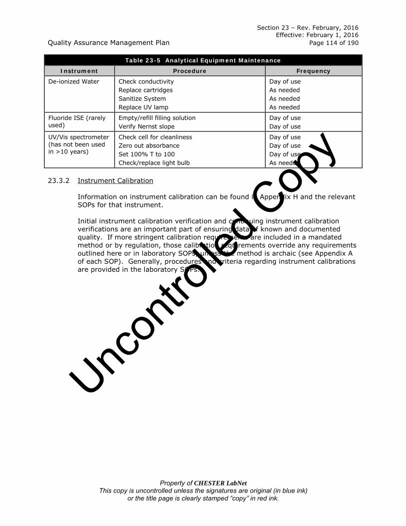
Section 23 – Rev. February, 2016 Effective: February 1, 2016 Quality Assurance Management Plan Page 114 of 190
Property of CHESTER LabNet This copy is uncontrolled unless the signatures are original (in blue ink)
or the title page is clearly stamped “copy” in red ink.
Table 23-5 Analytical Equipment Maintenance
Instrument Procedure Frequency
De-ionized Water Check conductivity Replace cartridges Sanitize System Replace UV lamp
Day of use As needed As needed As needed
Fluoride ISE (rarely used)
Empty/refill filling solution Verify Nernst slope
Day of use Day of use
UV/Vis spectrometer (has not been used in >10 years)
Check cell for cleanliness Zero out absorbance Set 100% T to 100 Check/replace light bulb
Day of use Day of use Day of use As needed
23.3.2 Instrument Calibration
Information on instrument calibration can be found in Appendix H and the relevant SOPs for that instrument. Initial instrument calibration verification and continuing instrument calibration verifications are an important part of ensuring data of known and documented quality. If more stringent calibration requirements are included in a mandated method or by regulation, those calibration requirements override any requirements outlined here or in laboratory SOPs, unless the method is archaic (see Appendix A of each SOP). Generally, procedures and criteria regarding instrument calibrations are provided in the laboratory SOPs.
Uncon
trolle
d Cop
y

Section 24 – Rev. February, 2016 Effective: February 1, 2016 Quality Assurance Management Plan Page 115 of 190
Property of CHESTER LabNet This copy is uncontrolled unless the signatures are original (in blue ink)
or the title page is clearly stamped “copy” in red ink.
Section 24
MEASUREMENT TRACEABILITY (TNI V1:M2 – Section 5.6)
Measurement quality assurance comes in part from traceability of standards to certified materials. All equipment used affecting the quality of test results are calibrated prior to being put into service and on a continuing basis (see Section 23, “Calibration Requirements”). These calibrations are traceable to national standards of measurement where available. If traceability of measurements to NIST is not possible or not relevant, evidence for correlation of results through inter-laboratory comparisons, proficiency testing, or independent analysis is provided, if possible. 24.1 Reference Standards
Reference standards are standards of the highest quality available at a given location, from which measurements are derived. These standards are used to verify standards used on a daily basis such as weights used to check balance calibrations, or thermometers used to verify other thermometers. They are the standards by which other standards are verified.
Reference Standards, such as NIST Class 1 weights, are used for calibration and to verify other standards, unless it is shown that their performance as reference standards does not become invalidated by use. Where possible, reference standards are calibrated typically by an A2LA certified reference lab that can provide traceability to national or international standards. An example of a situation in which this is not possible is the NIST thin film standards for XRF analysis. NIST no longer manufactures these standards and, although they are “expired,” there is no other NIST traceable provider, and it is highly unlikely that the standard will degrade without visible signs of deterioration due to the physical nature of the standard and the limited use to which the standards are put. The following reference standards are calibrated to a national standard as indicated in Section 23:
• Class 1 weights;
• NIST traceable reference thermometers;
• balances; and
• NIST traceable combination thermometer/hygrometers.
Note: For cost efficiency purposes, some thermometers and combination thermometer/hygrometers are simply replaced rather than recalibrated as
Uncon
trolle
d Cop
y

Section 24 – Rev. February, 2016 Effective: February 1, 2016 Quality Assurance Management Plan Page 116 of 190
Property of CHESTER LabNet This copy is uncontrolled unless the signatures are original (in blue ink)
or the title page is clearly stamped “copy” in red ink.
recalibration is more expensive than replacing the unit with a new NIST traceable one. (See Table 23-3.)
24.2 Reference Materials
Reference materials are substances that have concentrations that are sufficiently well established to use for calibration or as a frame of reference.
Reference materials, where commercially available, are traceable to national standards of measurement, or to Certified Reference Materials, usually by a Certificate of Analysis. Purchased reference materials require a Certificate of Analysis. Internal reference materials, such as working standards or intermediate stock solutions, are checked as far as is technically and economically practical.
Where possible, working standards or intermediate stock solutions are checked against a second source at first time of use. When a second source is not available, a vendor-certified different lot is accepted as a second source. In most cases, the analysis of an Initial Calibration Verification (ICV) standard or a Laboratory Control Sample (LCS) can be used as a second source confirmation. Working standards and intermediate stock solutions are given unique IDs and expiration dates when they are prepared based on method requirements, regulatory requirements, Technical Director’s knowledge of the method, or, where none exist, the earliest expiration date of the primary standards from which the working standards are prepared. These standards are used in their entirety or disposed of by the expiration date. Additional working standards such as working Class 1 weights or internal thermometers are checked using the frequency summarized in Table 23-3.
24.3 Transport and Storage of Reference Standards and Materials
The laboratory handles and transports reference standards and materials in a manner that protects the integrity of the materials. Reference standards and material integrity is protected by separation from incompatible materials and/or minimizing exposure to degrading environments or materials. Reference standards and materials are stored according to manufacturer’s recommendations, method SOP requirements and separately from samples. See Table 24-1 below.
Unc
ontro
lled C
opy

Section 24 – Rev. February, 2016 Effective: February 1, 2016 Quality Assurance Management Plan Page 117 of 190
Property of CHESTER LabNet This copy is uncontrolled unless the signatures are original (in blue ink)
or the title page is clearly stamped “copy” in red ink.
Table 24-1 Standard Storage and Preparation
Instrument Stock Storage Preparation
Intermediate Stock Solution
or Working Standard Storage
Frequency of
Preparation
ICP Room
Temperature, metals cabinet
Working Standards from Stock
Room Temperature As needed
IC – Anions and Cations
Standards Refrigerator
Working Standards from Stock
Room Temperature As needed
IC-PCR (Cr6) Room
Temperature, metals cabinet
Working Standards from Stock
Room Temperature As needed
CVAA Room
Temperature, Hg hood
Working Standards from Stock
Room Temperature Every 5 days
OC/EC Room
Temperature (dry chemical)
Working Standard from dry chemical
Standards Refrigerator
Every 6 months
pH meter Room
Temperature, pH supplies
N/A N/A N/A
All Class 1 weights
Room Temperature, gravimetric
areas
N/A N/A N/A
XRF Room
Temperature, XRF laboratory
N/A N/A N/A
24.4 Labeling of Reference Standards, Reagents and Reference Materials
The laboratory has procedures for purchase, receipt and storage of standards, reagents and reference materials. Purchase procedures are described in Section 9, “Purchasing Services and Supplies”. All standards and reagents are disposed of after their expiration date. Reagent quality is verified upon receipt by examination of the Certificate of Analysis and again upon use for blank analysis.
24.4.1 Stock Standards, Reagents, Reference Materials and Media
Records, in the form of Certificates of Analysis, for all standards, reagents, reference materials and media* include:
• the manufacturer/vendor name and lot number (or traceability to purchased stocks or neat compounds);
• the manufacturer’s Certificate of Analysis or purity (if available);
Uncon
trolle
d Cop
y

Section 24 – Rev. February, 2016 Effective: February 1, 2016 Quality Assurance Management Plan Page 118 of 190
Property of CHESTER LabNet This copy is uncontrolled unless the signatures are original (in blue ink)
or the title page is clearly stamped “copy” in red ink.
• the date of receipt (stamped or hand-written on the CoA and container); and
• recommended storage conditions (if available).
*Note: It is assumed that “media” here is referring to microbiological media. However, as the term is not well defined, CHESTER LabNet is defining the term to mean “air filters and sorbent tubes.” Most media for Air Quality do not have Certificates of Analysis available. If the original container does not have an expiration date provided by the manufacturer or vendor either on the container or on the Certificate of Analysis, the analyst will write “X NG” on the label to indicate that the expiration date was “none given”. If an expiration date is provided on the Certificate of Analysis but not printed on the label, the receiving analyst must label the container with the expiration date as provided by the manufacturer.
In methods where the purity of reagents is not specified, analytical reagent grade or better is used. If the purity is specified, that is the minimum acceptable grade. Purity is verified and documented according to Section 9, “Purchasing Services and Supplies”. Certificates of Analysis are maintained in appropriate binders throughout the laboratory.
24.4.2 Prepared Standards, Reagents, Reference Materials and Media
Prepared standards and reagents are recorded in the applicable bound standards and reagents logbook. Records for standards and reagents preparation include:
• traceability to purchased stock compounds;
• reference to or description of the method of preparation;
• date of preparation;
• an expiration date after which the material shall not be used;
• preparer’s initials; and
• unique standard ID.
Reagents used NEAT have the following information recorded with the raw data at time of usage:
• manufacturer and lot number; and
• expiration date.
All containers of prepared standards, reagents or materials are labeled with a unique ID and an expiration date. The unique ID is in the format of LLL-PPP-SS where:
LLL = laboratory logbook number as issued from the QA Officer; PPP = page number within the logbook; and SS = sequential number on the page.
Uncon
trolle
d Cop
y

Section 24 – Rev. February, 2016 Effective: February 1, 2016 Quality Assurance Management Plan Page 119 of 190
Property of CHESTER LabNet This copy is uncontrolled unless the signatures are original (in blue ink)
or the title page is clearly stamped “copy” in red ink.
Prepared reagents are verified to meet the requirements of the test method through the blank analysis performed with each run (e.g., Cal blank, ICB, etc.). If the blank results are suspect, an investigation into the cause of the suspect results will be undertaken and the reagent shall be made fresh if deemed necessary, even if it is still within its expiry date. Prepared standards are verified against existing non-expired standards where possible.
Uncon
trolle
d Cop
y

Section 25 – Rev. February, 2016 Effective: February 1, 2016 Quality Assurance Management Plan Page 120 of 190
Property of CHESTER LabNet This copy is uncontrolled unless the signatures are original (in blue ink)
or the title page is clearly stamped “copy” in red ink.
Section 25
COLLECTION OF SAMPLES (TNI V1:M2 – Section 5.7)
CHESTER LabNet does not provide sampling services and has no control over the actions or inactions of the client in the field or the reagents used by the client, unless the reagents are purchased directly from the laboratory (atypical). The laboratory does not supply the sampler with the necessary coolers, reagent water, sample containers, preservatives, sample labels, custody seals, ice or packing materials. The nature of most air quality methods (ambient or source) makes doing so prohibitively expensive to the laboratory and the client. The laboratory does, upon request, supply clients with Chain of Custody forms and filter or sorbent media. 25.1 Sampling Containers
The 2009 TNI Standard QAMP Template states, “…The laboratory’s responsibility in the sample collection process lies in supplying the sampler with the necessary coolers, reagent water, sample containers, preservatives, sample labels, custody seals, COC forms, ice, and packing materials required to properly preserve, pack, and ship samples to the laboratory.” The nature of air quality sampling generally requires clients to provide their own coolers, reagent water, sample containers (as defined in the disclaimer at the beginning of this document), secondary sample containers, custody seals (if needed), ice and packing materials. The laboratory does not offer clean bottles for use by clients unless specifically requested by the client. For ambient sampling, the laboratory may or may not be asked to provide filters or sorbent tubes in appropriate secondary containers. The laboratory does offer filters of various types and cassette rental for filters loaded in cassettes (not all filters are loaded prior to shipment, this occurs at the request of the client). The laboratory also offers shipment of sorbent media, but makes no guarantees as to the cleanliness of the media (e.g., Anasorb tubes, acidified silica gel tubes). For sorbent media, the laboratory is acting as a middle-man and not a supplier. The quality of the media rests solely on the manufacturer.
25.1.1 Preparing Container Orders
Filters and sorbent tubes are provided to the client upon request. The Gravimetry Laboratory Technical Director is informed of the request by the project manager or personnel who took the order (verbally or by email). The request is filled as soon as possible based upon availability, the type of analysis the client is performing, the need or lack thereof for cassettes, and the client’s sampling schedule. Once ready to be shipped, the media are given to the project manager. The project manager packages the media in a suitable shipping container (suitability
Uncon
trolle
d Cop
y

Section 25 – Rev. February, 2016 Effective: February 1, 2016 Quality Assurance Management Plan Page 121 of 190
Property of CHESTER LabNet This copy is uncontrolled unless the signatures are original (in blue ink)
or the title page is clearly stamped “copy” in red ink.
depends upon the type of media). Shipping is by common carrier (e.g., USPS, UPS, FedEx, DHL) and often performed using the client’s account number. Media is packaged and shipped in such a manner as to prevent harm or breakage of the media under typical shipping conditions. The laboratory will ship to any address specified by the client and in the manner specified by the client. For example, shipping filters to Antarctica involves following very specific instructions from the client. Shipping to foreign countries involves following the customs regulations of that country carefully. All factors involving receipt of the media by the client must be taken into account during the shipping process.
25.1.2 Sampling Containers, Preservation Requirements, Holding Times
Sampling container, preservation and holding time requirements can be found in the promulgated methods. CHESTER LabNet has no control over the activities of clients in the field, the sample containers used, impinger solutions used, whether or not the clients keep the samples at the temperature specified in the method, or any other activity which occurs prior to the samples being received at the laboratory. For instance, a client may request sodium bicarbonate impregnated acid hardened cellulose filters for the purposes of sampling for Hexavalent Chromium in air. The laboratory will impregnate the filters, load them in cassettes, and store the filters (loaded or unloaded) frozen. The client then may take the filters out to the field where sampling may take 24 hours at ambient temperatures, and the samples may not be retrieved from the sampler for up to 3 days after the sampler has shut off, thereby allowing the sample 4 days at ambient outdoor temperatures (ranging from below freezing to over 100 °F). After the samples are collected, they may or may not be stored frozen prior to the samples being returned to the laboratory, where the samples will again be stored frozen. CHESTER LabNet has no control over the actions or inactions of the clients once the filters are in their possession. The same lack of control is true for all filters, impinger solutions and sorbent media. Since air samples cannot be collected in the same manner as water or soil samples (e.g., scooping some up and putting it in a bottle), “containers” becomes a rather inappropriate term for sample collection devices and solutions; and the collection itself is an integral part of the “preservation”. Below is a table listing the Analyte(s), Promulgated Method, type of “container”, “Preservation” and Holding Time as given in the promulgated method. If preservation or holding time requirements are not met, the procedures in Section 12, “Control of Non-conforming Environmental Testing Work” are followed.
Uncon
trolle
d Cop
y

Section 25 – Rev. February, 2016 Effective: February 1, 2016 Quality Assurance Management Plan Page 122 of 190
Property of CHESTER LabNet This copy is uncontrolled unless the signatures are original (in blue ink)
or the title page is clearly stamped “copy” in red ink.
Table 25-1 Summary of Sampling Container, Preservation and Holding Time Requirements
Analyte(s) Promulgated Method
Method specified “Container” Preservation Holding Time
Ambient Air (note: filters or sorbent tubes are the “container” for ambient air samples)
TSP 40 CFR 50, Appendix B
8”x10” Glass Fiber or Quartz Filter None Given None Given
PM10 40 CFR 50, Appendix J
8”x10” Glass Fiber or Quartz Filter None Given None Given
PM10 Dichotomous IO 2.2 37mm Teflon or Quartz Filter None Given None Given
PM2.5 40 CFR 50, Appendix L 47mm Teflon filter None OR <4 °C
10 days with no refrigeration, OR 30 days if stored at <4
°C
Total Metals (ambient air)
40 CFR 50, Appendix G;
IO 3.2; IO 3.4
8”x10” Glass Fiber;
IO 3.0 specifies a filter “meeting
specifications” but not the actual matrix or size
None Given None Given
Mercury EPA 7471, by
reference in other methods
Any type of filter the client uses
None Given for ambient air samples
None Given for ambient air
Total Metals IO 3.3 (XRF)
IO 3.0 specifies a filter “meeting
specifications” but not the actual matrix or size
None Given None Given
Anions & Cations IO 4.2 Teflon filter & denuder rinses None Given
“analyze as soon as possible after
collection”; also “analyze on day of
extraction” Organic
Carbon/Elemental Carbon
NIOSH 5040; IMPROVE A Method
Pre-fired Quartz filters (37mm or
47mm) ”frozen” None Given
Hexavalent Chromium
CARB SOP MLD 039 (not promulgated)
Bicarb impregnated cellulose ”frozen”
90 days prior to extraction, 24 hours
after extraction
Total Nuisance Dust NIOSH 0500 37mm Teflon or PVC filter None Given None Given
Respirable Particles NIOSH 0600 37mm Teflon or PVC filter None Given None Given
Arsine NIOSH 6001 Coconut Charcoal sorbent Tube None Given 6 days
Phosphine NIOSH 6002 (Hg(CN)2-coated silica gel sorbent
tube None Given 7 days
SO2 NIOSH 6004
0.8µm cellulose ester membrane
filter FOLLOWED BY bicarb impregnated cellulose fiber filter
None Given None Given
Uncon
trolle
d Cop
y

Section 25 – Rev. February, 2016 Effective: February 1, 2016 Quality Assurance Management Plan Page 123 of 190
Property of CHESTER LabNet This copy is uncontrolled unless the signatures are original (in blue ink)
or the title page is clearly stamped “copy” in red ink.
Table 25-1 Summary of Sampling Container, Preservation and Holding Time Requirements
Analyte(s) Promulgated Method
Method specified “Container” Preservation Holding Time
Diborane NIOSH 6006
PTFE membrane filter, 13-mm
diameter, 1-μm pore size FOLLOWED BY
oxidizer-impregnated
charcoal sorbent tube
None Given 7 days
Mercury NIOSH 6009 Hopcalite Tube (no
longer manufactured)
None Given 30 days
Br2 & Cl2 NIOSH 6011
Teflon filter with 0.5-μm pore size FOLLOWED BY a
25mm silver membrane filter
with 0.45-μm pore size
None Given 30 days
NO2 NIOSH 6014
7mm sorbent tube containing 400 mg
TEA-coated molecular sieve
(type 13x, 30-40 mesh) FOLLOWED BY 7mm sorbent
tube containing 800 mg oxidizer (chromate)
FOLLOWED BY 7mm sorbent tube
containing 400 mg TEA-coated
molecular sieve (type 13x, 30-40
mesh)
None Given 7 days
Ammonia NIOSH 6016 Acidified silica gel sorbent tube None Given 35 days
Ammonia OSHA ID188 H2SO4 acidified carbon bead sorbent tube
None Given 29 days
Multi-elements [metals] NIOSH 7300 37mm cellulose
ester or Teflon filter None Given None Given
Chromium (VI) NIOSH 7605 37mm PVC filter [unimpregnated] None Given
14 days at room temp;
28 days “refrigerated”
Fluorides NIOSH 7902
37mm cellulose ester membrane filter 0.8-μm pore size FOLLOWED BY bicarb impregnated
cellulose pad
None Given None Given
Uncon
trolle
d Cop
y

Section 25 – Rev. February, 2016 Effective: February 1, 2016 Quality Assurance Management Plan Page 124 of 190
Property of CHESTER LabNet This copy is uncontrolled unless the signatures are original (in blue ink)
or the title page is clearly stamped “copy” in red ink.
Source Emissions Sampling (note: impinger solutions are the “container” for source emission gases)
Particulates 40 CFR 60, Appendix A,
Methods 5 – 5F
Glass or polyethylene petri
dishes for filter (filter type not
specified); 500 or 100mL glass bottles
for Acetone
None Given None Given
SO2 40 CFR 60,
Appendix A, Method 6
100 mL polyethylene bottles
for H2O2 solution None Given None Given
NOx 40 CFR 60,
Appendix A, Method 7A
Polyethylene bottles for H2SO4/H2O2
solution None Given None Given
NOx 40 CFR 60,
Appendix A, Method 7D
Polyethylene bottles for NaOH/KMnO4
solution None Given None Given
H2SO4 & SO2 40 CFR 60,
Appendix A, Method 8
1L polyethylene bottles, 1 each for IPA solution and
H2O2 solution
None Given None Given
Pb 40 CFR 60,
Appendix A, Method 12
1000 mL borosilicate glass bottles for 0.1N HNO3 solution
None Given None Given
Total Fluoride 40 CFR 60,
Appendix A, Method 13B
1L wide mouth HDPE bottles for
impinger water and filter
None Given None Given
HX & X2 40 CFR 60,
Appendix A, Method 26
100- or 250-mL HDPE bottles with Teflon screw cap liners for both
H2SO4 and NaOH fractions
None Given None Given
HX & X2 40 CFR 60,
Appendix A, Method 26A
1L HDPE bottles with Teflon screw cap liners for both H2SO4 and NaOH
fractions
None Given None Given
Multi-metals 40 CFR 60,
Appendix A, Method 29
500 - 1000 mL glass for
KMnO4/H2SO4 impinger solution;
HDPE or glass for all
other solutions;
Glass or plastic petri dishes for filter.
None Given
None given for any metal except Hg. Hg
has a “suggested maximum” hold
time of 28 days by reference to SW-
846 method 7470.
Hg 40 CFR 61,
Appendix B, Method 101
100 mL & 1000 mL glass with Teflon-lined caps for ICl
solution
None Given None Given
Hg 40 CFR 61,
Appendix B, Method 101A
100 mL & 1000 mL glass with Teflon-
lined caps for KMnO4/H2SO4
solution
None Given
“suggested maximum” hold
time of 28 days by reference to SW-846 method 7470
Uncon
trolle
d Cop
y

Section 25 – Rev. February, 2016 Effective: February 1, 2016 Quality Assurance Management Plan Page 125 of 190
Property of CHESTER LabNet This copy is uncontrolled unless the signatures are original (in blue ink)
or the title page is clearly stamped “copy” in red ink.
Hg 40 CFR 61,
Appendix B, Method 102
100 mL & 1000 mL glass with Teflon-lined caps for ICl
solution
None Given None Given
Be 40 CFR 61,
Appendix B, Method 103
Glass bottles for filter and acetone
washes None Given None Given
Be 40 CFR 61,
Appendix B, Method 104
1L glass bottles with Teflon-lined lids for
water impinger solution combined
with acetone rinses;
Glass or plastic petri dishes for filter
None Given None Given
As 40 CFR 61,
Appendix B, Method 108
500mL – 1000mL polyethylene or
polypropylene for water impinger
solution combined with NaOH rinse
solutions
None Given None Given
Particulates 201A 40 CFR 51,
Appendix M, Method 201A
Any leak-proof container for
acetone rinses;
Glass or plastic petri dishes for filter
None Given None Given
Particulates 202 40 CFR 51,
Appendix M, Method 202
500 mL amber glass bottles for water
impinger solutions; and
Hexane/Acetone rinses
None Given None Given
Hexavalent and Total Chromium
40 CFR 63, Appendix A, Method
306
250 mL, 500 mL or 1,000 mL
polyethylene, with leak-free screw cap for 0.1N NaOH or
0.1N NaHCO3 impinger solution
4 °C for Cr6;
None Given for total Cr
14 days at 4 °C for Cr6;
60 days at room temperature for
total Cr
Hexavalent Chromium
SW-846, Method 0061
250 mL, 500 mL or 1,000 mL
polyethylene, with leak-free screw cap
for 0.1M KOH impinger solution
None Given 14 days
H2SO4 & SO2 (Titration)
CTM-013 (aka NCASI 8A)
None Given for water rinse or H2O2
impinger solution None Given None Given
H2SO4 & SO2 (IC) CTM-013A
125 mL Nalgene bottles for water
rinse or H2O2
impinger solution
None Given None Given
Ammonia
EPA CTM-027 (“draft” as of 1997,
not yet given promulgated
method status)
250mL – 500 mL HDPE bottles for
0.1N H2SO4 impinger solutions
4 °C “2 weeks”
Uncon
trolle
d Cop
y

Section 25 – Rev. February, 2016 Effective: February 1, 2016 Quality Assurance Management Plan Page 126 of 190
Property of CHESTER LabNet This copy is uncontrolled unless the signatures are original (in blue ink)
or the title page is clearly stamped “copy” in red ink.
HF/F2 & HCl/Cl2 CARB 421
“…borosilicate glass bottles for impinger
solutions and washes, 1000 mL.
Teflon or high-density
polyethylene or polypropylene bottles may be
used. Use screw-cap liners that are
either rubber-backed Teflon or
leak-free” for impinger solution of
1.7 mM Sodium Bicarbonate and 1.8
mM Sodium Carbonate.
None Given None Given
Total and Hexavalent Chromium
CARB 425
500 ml or 1000 ml borosilicate glass bottles, screw cap
liners shall either be rubber-backed
Teflon or shall be constructed so as to
be leak-free. Alternatively,
polyethylene bottles may be used for
0.1N NaOH impinger solutions.
None Given None Given
Multi-metals CARB 436
Glass or polyethylene petri dishes for Quartz
fiber or glass fiber filters without organic binders;
500 ml or 1000 ml borosilicate glass bottles, screw cap
liners shall either be rubber-backed
Teflon or shall be constructed so as to
be leak-free. Alternatively,
polyethylene bottles may be used for
HNO3/H2O2 impinger solutions,
KMnO4/H2SO4 impinger solutions, 0.1N HNO3 rinse solutions and 8N
HCl rinse solutions.
None Given None Given
Uncon
trolle
d Cop
y

Section 25 – Rev. February, 2016 Effective: February 1, 2016 Quality Assurance Management Plan Page 127 of 190
Property of CHESTER LabNet This copy is uncontrolled unless the signatures are original (in blue ink)
or the title page is clearly stamped “copy” in red ink.
Particulates Oregon DEQ 5
[By reference to EPA Method 5]
Glass or polyethylene petri
dishes for filter (filter type not
specified);
500 or 100mL glass bottles each for Acetone rinse, water impinger
solution and Dichloromethane
None Given None Given
Particulates Oregon DEQ 8
Acetone or Methanol is given as the rinse
solution;
Glass fiber filters are given as the
filter matrix;
No guidance is given for containers
for the rinse solution or filters.
None Given None Given
25.2 Sampling Plan
The laboratory does not perform sampling. For purposes of remaining independent from the sampling group and the ultimate client, the laboratory does not act as a consultant for determining sampling plans.
25.3 Sampling Records
Sampling records are maintained by the client. If sampling records are given to the laboratory, they will be used as directed by the client and retained in the client’s job folder.
Uncon
trolle
d Cop
y

Section 26 – Rev. February, 2016 Effective: February 1, 2016 Quality Assurance Management Plan Page 128 of 190
Property of CHESTER LabNet This copy is uncontrolled unless the signatures are original (in blue ink)
or the title page is clearly stamped “copy” in red ink.
Section 26
HANDLING SAMPLES AND TEST ITEMS (TNI V1:M2 – Section 5.8 and Section 1.7
of Technical Modules TNI V1:M 3-7) 26.1 Sample Receipt
When samples are received at the laboratory, chain-of-custody is reviewed, condition is documented, samples are given unique identifiers, and they are logged into the sample tracking system.
26.1.1 Chain of Custody
The chain of custody is reviewed. The chain of custody form provides information on what type of testing is being requested and can act as an order for laboratory services in the absence of a formal contract. An example chain of custody form can be found in Figure 26-1. Chain of custody and any additional records received at the time of sample submission are maintained by the laboratory in each client’s job file. 26.1.1.1 Legal Chain of Custody
The laboratory does not knowingly receive samples for evidentiary purposes.
26.2 Sample Acceptance
Procedures for opening shipping containers and examining samples are provided in SOP AD-008. Samples received outside normal business hours are handled in the same manner as those received during normal business hours. The 2009 TNI Standard QAMP template states, “The laboratory has a sample acceptance policy that is made available to sample collection personnel. An example is provided in Figure 26-2. It emphasizes the need for use of water resistant ink, providing proper documentation (to include sample ID, location, date and time of collection, collector’s name, preservation type, sample type and any special remarks about the sample), labeling of sample containers to include a unique sample ID, use of appropriate containers, adherence to holding times, and sample volume requirements. In addition the laboratory has nonconformance/corrective action procedures to handle samples that don’t meet the requirements above or show signs of damage, contamination or inadequate preservation. Data will be appropriately qualified where samples are reported that do not meet sample acceptance requirements.” Note that this list is a required element of the QAMP by the 2009 TNI Standard, although is not particularly applicable to air quality samples.
The laboratory has a sample acceptance policy provided in SOP AD-008 and below in Figure 26-2. As the laboratory does not perform sampling, the policy is not provided to sample collection personnel.
Uncon
trolle
d Cop
y

Section 26 – Rev. February, 2016 Effective: February 1, 2016 Quality Assurance Management Plan Page 129 of 190
Property of CHESTER LabNet This copy is uncontrolled unless the signatures are original (in blue ink)
or the title page is clearly stamped “copy” in red ink.
The incompatibilities between air/source sampling and water/soil sampling encountered with the above requirements are as follows:
• water resistant ink is rarely needed as the vast majority of samples are filters, and these samples are destroyed if they become wet;
• sample location may not be provided to the laboratory by the client;
• date of sampling is usually known and often provided to the laboratory; however, many samples may have a collection “time” of 2 hours to 14 days and this timing is rarely reported to the laboratory;
• collector’s name is rarely reported to the laboratory, and more than one person may be involved in collecting the sample, particularly if the sample has a long collection time;
• samples do not have “preservation” except in a few cases where thermal preservation is called for. Preservation is typically achieved by the media on/in which the sample is collected;
• sample type is usually identified by method number and is understood within the air quality industry;
• filters sent to clients for ambient air sampling will have unique IDs assigned to them prior to leaving the laboratory, however, source samples rarely have a unique ID as each project/job site constitutes a unique identifying characteristic and the laboratory has no control over the actions, including identification of containers, of the client in the field;
• appropriate containers are the responsibility of the client, and as they often must travel to extremely remote locations, by necessity, they may be forced to use what they have on-hand;
• very few methods utilized by the laboratory have holding times promulgated with the method; and,
• sample “volume” may mean either the gas volume pulled during sampling or the liquid volume of impinger contents post-sampling and is dictated by the amount of gas volume pulled by the clients in the field, the method utilized to capture said gasses, and in the case of source emission samples, the moisture content of the source.
The laboratory has non-conformance/corrective action procedures to handle samples that don’t meet the requirements of the promulgated method, or that show signs of damage or contamination. Data will be appropriately qualified where samples are reported that do not meet sample acceptance requirements.
The laboratory checks samples for the following, to evaluate sample acceptance:
• samples are intact;
• samples are not damaged; and
Uncon
trolle
d Cop
y

Section 26 – Rev. February, 2016 Effective: February 1, 2016 Quality Assurance Management Plan Page 130 of 190
Property of CHESTER LabNet This copy is uncontrolled unless the signatures are original (in blue ink)
or the title page is clearly stamped “copy” in red ink.
• samples submitted appear to be submitted in good faith and are not, to the laboratory’s knowledge, fraudulent.
Criteria regarding holding time, sample matrix, and sample containers can be found in Table 25-1 of this document. If these conditions are not met, the client is contacted prior to any further processing, then 1) the sample is rejected as agreed with the client, 2) the decision to proceed is documented and agreed upon with the client, 3) the condition is noted on the Chain of Custody form and/or lab receipt documents, and/or 4) the data are qualified in the Case Narrative of the report.
26.2.1 Preservation Checks
The following preservation checks are performed and documented upon receipt:
26.2.1.1 Thermal preservation:
a) For temperature preservation, the temperature must be within the guidelines specified by the promulgated method. Note that some methods merely say “ship with blue ice” and do not specify a temperature.
b) This 2009 TNI Standard QAMP template states, “Samples that are delivered to the lab the same day as they are collected are likely not to have reached a fully chilled temperature. This is acceptable if the samples were received on ice and the chilling process has begun.” The laboratory, however, never receives samples on the same day they are collected due to the complexity of sample collection for air quality methods.
c) Where necessary, record the received temperature on the Chain of Custody and note if ice is present.
Chlorine checks:
CHESTER LabNet performs no methods requiring Chlorine checks. pH checks:
CHESTER LabNet performs no methods requiring pH checks; however, a few select methods have pH checks performed on them for the laboratory’s benefit. These checks are usually performed after analysis of the samples to prevent contamination of the sample.
26.3 Sample Identification
The 2009 TNI Standard QAMP Template states, “Samples, including subsamples, extracts and digestates, are uniquely identified in a permanent chronological record … to prevent mix-up and to document receipt of all sample containers.”
Uncon
trolle
d Cop
y

Section 26 – Rev. February, 2016 Effective: February 1, 2016 Quality Assurance Management Plan Page 131 of 190
Property of CHESTER LabNet This copy is uncontrolled unless the signatures are original (in blue ink)
or the title page is clearly stamped “copy” in red ink.
Due to the wide variety of matrices an air sample may include, it is not practicable, nor is it clear to the client, nor unambiguous during reporting, to assign each container, digestate, extract or combined fractions of samples a unique ID. Samples (in their entirety) are uniquely identified in the laboratory’s LIMS, which can generate a chronological record. Depending on the method, digests, subsamples, and multi-fraction samples may or may not be given a unique ID. Samples are assigned sequential numbers that reference more detailed information kept in the LIMS. Refer to SOPs AD-007 and AD-008 for the laboratory’s sample identification procedure. The following information is included in the LIMS:
• client and, where known, project name;
• date and time of receipt at the lab;
• unique laboratory identification number; and
• signature or initials of the person making the entries.
In addition, the following information, where known, is maintained and linked to the log-in record:
• date and time of sampling linked to the date and time of laboratory receipt;
• unique field identification number linked to the laboratory sample ID (note: the laboratory has no control over the Field ID. Field ID’s may not be unique. Assignation of Field ID’s is the responsibility of the client);
• analyses requested (including applicable approved method numbers) linked to the laboratory sample ID; and
• comments regarding rejection or other issues (if any).
All documentation received regarding the sample, such as memos or chain of custody, are retained in the job file.
26.4 Sample Aliquots / Subsampling
In order for analysis results to be representative of the sample collected in the field, the laboratory has subsampling procedures. Note that the vast majority of subsampled samples consist of 8” x 10” filters. Refer to SOP ME-008 for subsampling of 8” x 10” filters. Nearly all other samples are either consumed in their entirety during analysis or not subsampled.
26.5 Sample Storage
Storage conditions are monitored for any required criteria, verified and the verification recorded in logbooks where appropriate.
Uncon
trolle
d Cop
y

Section 26 – Rev. February, 2016 Effective: February 1, 2016 Quality Assurance Management Plan Page 132 of 190
Property of CHESTER LabNet This copy is uncontrolled unless the signatures are original (in blue ink)
or the title page is clearly stamped “copy” in red ink.
Samples that require thermal preservation are stored in a manner compliant with the promulgated method. For samples with a specified storage temperature of 4°C, storage at a temperature above the freezing point of water to 6°C is acceptable. For samples required to be kept “frozen”, any temperature below 0 °C is acceptable. Samples are held secure, as required. Samples are accessible only to laboratory personnel. Samples are stored apart from standards, reagents, food or potentially contaminating sources, and in a manner that minimizes cross-contamination. All portions of samples, including extracts, digestates, leachates or any product of the sample is maintained according to the required conditions. The majority of samples, based upon promulgated method requirements, are stored at room temperature, or in a temperature and humidity controlled room.
26.6 Sample Disposal
Samples are retained for a minimum of 60 days after the report is sent out unless other arrangements have been made with the client.
Samples are disposed of according to Federal, State and local regulations. Procedures are described in SOP AD-002 for the disposal of samples, digestates, leachates and extracts.
26.7 Sample Transport
Samples that are transported under the responsibility of the laboratory, where necessary, are done so safely and according to storage conditions. This includes moving bottles within the laboratory. Specific safety operations are addressed outside of this document in method specific SOPs and the laboratory’s Chemical Hygiene Plan. Samples are not shipped by the laboratory. Sample media (e.g. filters and sorbent tubes) are shipped in a manner consistent with client request.
Uncon
trolle
d Cop
y

Section 26 – Rev. February, 2016 Effective: February 1, 2016 Quality Assurance Management Plan Page 133 of 190
Property of CHESTER LabNet This copy is uncontrolled unless the signatures are original (in blue ink)
or the title page is clearly stamped “copy” in red ink.
Figure 26-1
Example Chain-of-Custody
Uncon
trolle
d Cop
y

Section 26 – Rev. February, 2016 Effective: February 1, 2016 Quality Assurance Management Plan Page 134 of 190
Property of CHESTER LabNet This copy is uncontrolled unless the signatures are original (in blue ink)
or the title page is clearly stamped “copy” in red ink.
Figure 26-2
Example Sample Acceptance Policy
Disclaimer: The 2009 TNI Standard has a number of requirements for sample acceptance. When all of the requirements are not met, the sample is to be rejected. As these requirements are designed for water or soil samples, most are not generally applicable to the analysis of ambient air or source samples. Meeting the requirements of the 2009 TNI Standard would require the laboratory to contact nearly every client or reject their samples for every project. CHESTER LabNet will not reject any sample except at the request of the client, unless the acceptance of the sample would be fraudulent. The laboratory will note its opinion if the data are suspected to be of dubious usefulness to the client or to the client’s client or regulator. The laboratory will notify clients if their samples are received in such a state as to make analysis impracticable or lead to suspect data. Notification will occur, wherever possible, upon receipt of the samples. Ultimately, it is the client’s directives that will determine acceptance of samples. To demonstrate the laboratory’s good-faith effort to fulfill the 2009 TNI requirements, a checklist is completed at the time of sample receipt. The checklist shall be maintained with the job file. It will not, however, be reported to the client.
Client Method Date
Archaic methods or methods that can't be analyzed as written: M26/26A; M202; M12; M101/101A/102 (This is not a complete listing)
NELAC Required Sample Condition (circle one) Chain of Custody (circle one)Received in condition required by method? ¹ Y N N/A Chain of Custody present? Y N N/A !!Samples in appropriate containers? ¹ Y N N/A Client contact information present on CoC? ¹ Y N N/ACorrect temperature? Y N N/A * All requested analyses definitively identified? ² Y N N/A !!Within hold time? Y N N/A * If no, is this a long-standing project Broken/damaged? Y N N/A !! with understood analyses? Y N N/ASufficient sample present to perform analysis? ¹ Y N N/A !!Preserved appropriately? ¹ Y N N/A
Additional NELAC Requirements NELAC required Method informationAll samples identified uniquely? ¹ Y N N/A !! Method requested the latest valid edition? ³ Y N N/ALabels water resistant? ¹ Y N N/A Method appropriate for the analyses requested? ³ Y N N/AIndelible ink used on labels? ¹ Y N N/A Is it possible to use the method requested? ³ Y N N/ALocation of Sample collection listed? ¹ Y N N/A Method out of date (wrong revision number)? ³ Y N N/ASample collector's name listed? ¹ Y N N/A Is the method archaic? ³ Y N N/APreservation type listed? ¹ Y N N/A Can the method be performed as written? ³ Y N N/ASample type listed? ¹ Y N N/A¹ CHESTER LabNet will not notify clients of these "deficiencies" to avoid alienating clients by perpetual contact.² may be identified by Method number if method contains no room for doubt as to analytes of interest.³ Many Air Quality/Soure Emission methods are archaic, contradict themselves or are inappropriate. Some regulators require the use of
older versions of a method. CHESTER will follow, to the best of their ability, the method requested by the client.!! address prior to any analytical work being started . * note in case narrative upon reporting of results to client.
Signed
NotesNote: NELAC requirements are designed for Water/Soils, and are often incompatible with Ambient or Source Air Promulgated Methods.
CHESTER LABNETSAMPLE RECEIPT CHECKLIST COR NELAC REQUIREMENTS
Uncon
trolle
d Cop
y

Section 26 – Rev. February, 2016 Effective: February 1, 2016 Quality Assurance Management Plan Page 135 of 190
Property of CHESTER LabNet This copy is uncontrolled unless the signatures are original (in blue ink)
or the title page is clearly stamped “copy” in red ink.
For Source Sampling, a second, more specific and applicable checklist (below) was created prior to the advent of TNI or ORELAP and has been in use by the laboratory for many years. This checklist is reported to the client.
CHESTER LABNETSOURCE SAMPLE RECEIPT CHECKLIST
Client Date
# Runs Time
Custody Seals Inspected, If Present
Chain-of-Custody Form InspectedCoC present with samples? *CoC indicate analytical methodology to be used? (eg M29 etc) !!CoC indicate if compliance testing? (esp. M26) !!M26 samples have Thiosulfate added in field? !!M29 indicate FH/BH separate or combined? !!Has Form Been Signed?Have Date and Time Custody Released Been Noted on Form?
All Sample Containers InspectedDoes Number of Samples Match Number on CoC Form? !!Do All Sample ID Numbers Match Those on the CoC Form? !!Did client mark sample volumes prior to shipment? *If required by method, did client vent samples prior to shipment?Are the Sample Containers Intact? !!Are signs of leakage present? *
Chain-of-Custody Form Signed and Dated by CLN
Corrective ActionsClient Contacted Due to Mismatching Sample ID NumbersClient Contacted Due to Broken Sample Container(s)Client Contacted Due to Leaking Sample Container(s)Client contacted for verification of methodology?Corrective Actions Documented?Corrective Actions Accomplished?
Items marked !! shall be addressed prior to any analytical work being started .Items marked * shall be noted in case narrative upon reporting of results to client.
Signed
Notes
Uncon
trolle
d Cop
y

Section 27 – Rev. February, 2016 Effective: February 1, 2016 Quality Assurance Management Plan Page 136 of 190
Property of CHESTER LabNet This copy is uncontrolled unless the signatures are original (in blue ink)
or the title page is clearly stamped “copy” in red ink.
Section 27
QUALITY ASSURANCE FOR ENVIRONMENTAL TESTING(TNI V1:M1, V1:M2 – Section 5.9 and Section 1.7
of Technical Modules TNI V1:M 3-7) CHESTER LabNet has procedures for monitoring the validity of the testing it performs. The qualities of test results are recorded in such a way that trends are detectable, and where practicable, are statistically evaluated. To evaluate the quality of test results, the laboratory utilizes certified reference materials, PT samples (where available), interlaboratory comparisons (where available), replicate testing using different methods (e.g., Methods 6 and 8) and results for non-sample-based QC elements (e.g., ICVs, LCS’s, etc.).
In addition to procedures for calibration, the laboratory monitors quality control measurements such as blanks, laboratory control samples (LCS), matrix spikes (MS), duplicates and certified Class 1 weights to assess precision and accuracy. Proficiency Testing samples are required by the 2009 TNI Standard, however there are none available from a Proficiency Testing Provider Accreditor Approved Proficiency Test Provider for any accredited method performed by CHESTER LabNet. Quality control data are analyzed and, when found to be outside pre-defined criteria, action is taken to correct the problem and to prevent incorrect results from being reported. Data associated with quality control data outside of criteria and still deemed reportable will be qualified such that the end user of the data may make a determination of the usability of the data (see Section 28, “Reporting of Results”).
27.1 Essential Quality Control Procedures
When not archaic, the quality control procedures specified in test methods are followed by laboratory personnel. The most stringent of control procedures is used in cases where multiple controls are offered. If it is not clear which is the most stringent, that mandated by test method or listed in the 2009 TNI Standard (Appendix H) is followed. Often a hybrid of the TNI, CLP and method specific QC elements and control limits is used. The 2009 TNI Standard requires that “If it is not clear which is the most stringent, that mandated by test method or regulation” be followed. The laboratory rarely knows what the applicable regulation is for any set of samples, as each source and project may have different regulatory limits, regulatory agencies and QC requirements. In such situations, the laboratory defaults to its own internally-generated quality control procedures or defers to client request. For test methods that do not provide acceptance criteria for an essential quality control element or where no regulatory criteria exist, acceptance criteria are developed. The criteria used vary from method to method and may be found in the method-specific SOPs. For the Gravimetry Laboratory, criteria are set based upon the narrowest ranges of quality control which meet all of the methods being utilized in that department.
Uncon
trolle
d Cop
y

Section 27 – Rev. February, 2016 Effective: February 1, 2016 Quality Assurance Management Plan Page 137 of 190
Property of CHESTER LabNet This copy is uncontrolled unless the signatures are original (in blue ink)
or the title page is clearly stamped “copy” in red ink.
For the XRF lab, criteria are set based upon the determination of uncertainties for the instruments. Static limits are set for the percent recovery of the quality control standard analyzed with each run and the replicate analyses of samples. The conventional chemistry lab generally relies on CLP guidelines for static limits on most quality control elements. Where CLP guidelines are not applicable, other means of determining limits for quality control elements are defined.
Written procedures to monitor routine quality controls, including acceptance criteria, are located in the test method SOPs, except where noted, and include such procedures as:
• use of laboratory control samples and blanks to serve as positive and
negative controls for chemistry methods;
• use of laboratory control samples, where possible, to monitor test variability of laboratory results;
• use of calibrations, continuing calibrations, certified reference materials and/or PT samples to monitor accuracy of the test method;
• measures to monitor test method capability, such as limit of detection, limit of quantitation and/or range of test applicability, such as linearity;
• use of regression analysis, internal/external standards, or statistical analysis to reduce raw data to final results;
• use of reagents and standards of appropriate quality, and use of second source materials as appropriate;
• measures to assure constant and consistent test conditions, such as temperature, humidity, etc., when required by test method; and
• “procedures to ensure the selectivity of the test method for its intended use” as required by the 2009 TNI Standard. However, it is rare that the laboratory has any discretion when it comes to the method utilized. Method selection lies with the laboratory’s clients, their clients and/or their clients’ regulatory agencies. The laboratory attempts to follow the method chosen by the aforementioned entities to achieve results which are, at a minimum, useable, and preferably accurate.
27.2 Internal Quality Control Practices
Analytical data generated with QC samples that fall within all prescribed acceptance limits indicate that the test method is deemed to be in control. QC samples that fall outside QC limits indicate that the test method is out of control (non-conforming) and corrective action is required, and/or that the data need to be qualified (see Section 12, “Control of Non-conforming Environmental Testing Work” and Section 14, “Corrective Actions”). Detailed QC procedures and QC limits are included in test method standard operating procedures (SOPs).
Uncon
trolle
d Cop
y

Section 27 – Rev. February, 2016 Effective: February 1, 2016 Quality Assurance Management Plan Page 138 of 190
Property of CHESTER LabNet This copy is uncontrolled unless the signatures are original (in blue ink)
or the title page is clearly stamped “copy” in red ink.
All QC measures are assessed and evaluated on an on-going basis so that trends are detected.
27.2.1 General Controls
The following general controls are used, where possible:
27.2.1.1 Positive and Negative Controls such as:
a) blanks (negative) and b) laboratory control samples (positive).
27.2.1.2 Selectivity is assured through:
a) absolute and relative retention times in chromatographic analyses;
b) use of the correct method according to its scope assessed during method validation;
c) use of qualitative spikes where sample matrices may “push” peaks around;
d) use of element specific wavelengths for analysis by IC;
e) use of element specific KeV excitation lines for analysis by XRF; and,
f) use of temperature and transmittance/reflectance for analysis by OCEC.
27.2.1.3 Consistency, Variability, Repeatability and Accuracy are assured
through:
a) proper installation and operation of instruments according to manufacturer’s recommendations or the processes used during method validation;
b) monitoring and controlling environmental conditions (temperature, access and proximity to potential contaminants);
c) selection and use of reagents and standards of appropriate quality;
d) cleaning glassware appropriate to the level required by the analysis as demonstrated with preparation blanks (See SOP AD-004);
e) following SOPs and documenting any deviation, assessing for impact, and treating data appropriately;
f) testing to define the variability and/or repeatability of the laboratory results, such as replicates; and
g) use of measures to assure the accuracy of the test method, including calibration and/or continuing calibrations, use of certified reference materials, proficiency test samples, or other measures.
27.2.1.4 Test Method Capability (also see Section 22, “Environmental Methods
and Method Validation”) is assured through:
Uncon
trolle
d Cop
y

Section 27 – Rev. February, 2016 Effective: February 1, 2016 Quality Assurance Management Plan Page 139 of 190
Property of CHESTER LabNet This copy is uncontrolled unless the signatures are original (in blue ink)
or the title page is clearly stamped “copy” in red ink.
a) establishment of the limit of detection where applicable;
b) establishment of the limit of quantitation or reporting level where applicable; and/or
c) establishment of the range of applicability where applicable, such as linearity.
27.2.1.5 Data reduction is assured to be accurate by:
a) selection of appropriate formulae to reduce raw data to final results, such as regression;
b) following specific procedures for data reduction, such as manual integration procedures; and
c) periodic review of data reduction processes to assure applicability.
27.2.1.6 Sample specific controls are used to evaluate the effect of sample matrix
on the performance of the selected analytical method (not a measure of laboratory performance). For example:
• Matrix Spike and Matrix Spike Duplicate (MS/MSD)
• Sample Duplicates
27.2.1.7 The following tables summarize the key elements of a quality control
system for a laboratory performing chemical testing. Note that many air methods are “one shot” and do not allow for redigestion or reanalysis. Many also are not compatible with some of the elements listed below (e.g., Method 5 and Method 202 cannot have an LCS). Some instrumentation used in air quality analyses does not lend itself to all of the elements listed below (e.g., LCS or blanks for XRF analysis, spikes for PM2.5 analysis). All QC elements defined in Table 27-1 are understood to be “where applicable.”
Table 27-1 Essential Quality Control Elements for Chemistry
Item Frequency Acceptance Criteria Corrective action
Negative Control (Laboratory Blank)
1/batch Laboratory defined Note in Report.
Negative Control (Preparation Blank)
1/batch Method specific, client specific, regulatory specific, contract specific or as determined by the laboratory
Reprocess, reanalyze, or qualify data.
Negative Control (Method Blank)
1/batch Method specific, client specific, regulatory specific, contract specific or as determined by the laboratory
Reprocess, reanalyze, or qualify data.
Uncon
trolle
d Cop
y

Section 27 – Rev. February, 2016 Effective: February 1, 2016 Quality Assurance Management Plan Page 140 of 190
Property of CHESTER LabNet This copy is uncontrolled unless the signatures are original (in blue ink)
or the title page is clearly stamped “copy” in red ink.
Table 27-1 Essential Quality Control Elements for Chemistry
Item Frequency Acceptance Criteria Corrective action
Positive Control (Laboratory Control Sample - LCS)
1/batch Method specific or determined by laboratory
Reprocess, reanalyze, or qualify data.
Matrix Spike; Matrix Spike Duplicates (pre- or post-digestion) Note : Spiked samples are designed as data quality indicators for a specific sample using the designated method. These controls alone are not used to judge a laboratory’s performance.
Per method requirement, client request, or laboratory discretion. Minimum of 1/batch where possible.
Method specific or determined by laboratory
Reprocess, reanalyze, or qualify data.
Matrix Duplicates/Replicates See note above.
Per method requirement, client request, or laboratory discretion. Minimum of 1/batch where possible.
Method specific or determined by laboratory
Reprocess, reanalyze, or qualify data.
Continuing Calibration Verification - CCV
Per method requirement or laboratory discretion
Method specific or determined by the laboratory
Corrective action as given in SOP
Initial Calibration Verification - ICV
Per method requirement or laboratory discretion
Method specific or determined by laboratory
Corrective action as given in SOP
Continuing Calibration Blank - CCB
Per method requirement or laboratory discretion
Method specific or determined by the laboratory
Corrective action as given in SOP
Initial Calibration Blank - ICB
Per method requirement or laboratory discretion
Method specific or determined by laboratory
Corrective action as given in SOP
27.2.2 Specific Controls
27.2.2.1 Blanks
Laboratory blanks (Lab Blanks) are used for Air Quality Methods requiring evaporation and/or gravimetry (Appendix B, J and L; Methods 5, 5A – 5F, 201A, 202 and similar). Laboratory blanks consist of an empty weighing vessel (e.g., beaker, pan, or filter) which follows the other weighing vessels through the process, to the extent possible, and are then gross weighed with the rest of the weighing vessels. A lab blank must be analyzed at a minimum of one per sampling batch, which
Uncon
trolle
d Cop
y

Section 27 – Rev. February, 2016 Effective: February 1, 2016 Quality Assurance Management Plan Page 141 of 190
Property of CHESTER LabNet This copy is uncontrolled unless the signatures are original (in blue ink)
or the title page is clearly stamped “copy” in red ink.
may exceed 20 samples although it rarely does. For Appendices B, J and L analyses, a lab blank is a blank filter which has been tare weighed, but has never left the confines of the laboratory. It is gross weighed along with its associated samples and must meet the same QC criteria as those samples. Control limits exist only for PM2.5 Lab Blanks (± 15µg). The other gravimetric methods have no controls for blank filters. The data is reported “as-is” since even negative numbers have interpretive value to the client. Filter Laboratory Blanks are only performed at the request of the client. Preparation Blanks are processed along with and under the same conditions as the associated samples to include all steps in the method and all reagents used. They do not, however, contain any of the matrices on or in which a sample is captured (e.g., no filter or sorbent material). A preparation blank must be analyzed at a minimum of one per preparation batch. When no separate preparation method is used, the batch is defined as the environmental samples that are analyzed with the same method and personnel, using the same lots of reagents, not to exceed the analysis of twenty environmental samples, not including method blanks, LCS, matrix spikes and matrix duplicates. In the case of no separate preparation method, an ICB or CCB is considered equivalent. Due to the complex nature of many source sampling methods, preparation blanks may have detectable levels of analytes of interest present. Preparation blank results should be lower than any sample result, or within 20% RPD of the sample result in cases where the result is greater than five times the detection limit.
Method blanks are processed along with and under the same conditions as the associated samples to include all steps and matrices (e.g., filter type, sorbent material) in the method. A method blank must be analyzed at a minimum of one per preparation batch. The matrix of the method blank must be as similar to the associated samples as possible, including matching lots numbers of filters where possible. Nearly all matrices used in the sampling of ambient or source air have some background contamination from either the manufacturing or the sampling process. The Method Blank results should be lower than the lowest sample result, or within 20% of the sample result in cases where the result is greater than five times the detection limit. In some cases, such as OC/EC analysis, the Preparation Blank and the Method blank will be the same blank. Method blanks are not required for some analyses such as XRF analysis and pH.
Contaminated blanks are identified according to the acceptance limits in the test method SOPs or laboratory documentation. Note that all filter matrices are not created equal and all will have some form of contamination on them. The laboratory has no control over filter manufacturing or the choice of filter matrix and, thus, it is expected that some filters for some analyses will show detectable quantities for some analytes.
Uncon
trolle
d Cop
y

Section 27 – Rev. February, 2016 Effective: February 1, 2016 Quality Assurance Management Plan Page 142 of 190
Property of CHESTER LabNet This copy is uncontrolled unless the signatures are original (in blue ink)
or the title page is clearly stamped “copy” in red ink.
The laboratory identifies a blank as contaminated based upon the method being used. For Method 29 Mercury analysis, for example, a preparation blank is considered contaminated if the result is higher than the detection limit. For Glass Fiber filter analysis, the list of commonly seen contaminants is quite long, thus the performance of the laboratory would not be considered insufficient if the method blank were to have analytes of interest present. For Quartz filters, the list is somewhat shorter. Cellulose filters will always be very high in Organic Carbon if analyzed for OC/EC as cellulose is very high in Carbon. Teflon filters are generally very clean for most analytes, but if used for Method 13B, will yield high amounts of fluoride. Each matrix, analyte and test method must be taken into account when determining if a method blank is considered contaminated enough to induce corrective actions. When a blank is determined to be contaminated, the cause must be investigated and measures taken to minimize or eliminate the problem. Data that are unaffected by the blank contamination (non-detects or other analytes) are reported unqualified. Sample data that are suspect due to the presence of a contaminated blank are reanalyzed if possible, or the client is contacted for further instruction. If the blank results are less than the sample results and the contaminant is common in the media being analyzed, no notation is made in the report. Method Blank results are reported to the client. It is the policy of the laboratory to never blank subtract. Client provided Field Blanks, Trip Blanks, Train Blanks and Reagent Blanks have no control limits and are treated as samples.
27.2.2.2 Laboratory Control Samples
Laboratory Control Samples (LCS) are prepared from analyte-free water or the matrix upon which the sample was collected, and spiked with verified and known amounts of analytes for the purpose of establishing precision or bias measurements. Not all methods are amenable to LCS’s (e.g., OCEC, XRF, PM10, PM2.5, Method 202, etc.). Laboratory control samples are analyzed at a frequency mandated by method, regulation, laboratory discretion or client request, whichever is more stringent. The standard frequency of LCS preparation and analysis is one per preparation batch of 20 or fewer samples, or as otherwise stated in a laboratory SOP. Exceptions would be for those analytes or methods where no spiking solution is available, such as Method 202, OCEC and XRF analysis, PM10 or PM2.5 analysis, etc. When no separate preparation method is used, the batch is defined as the environmental samples that are analyzed with the same method and personnel, using the same lots of reagents, not to exceed the analysis of twenty environmental samples, not including method blanks, LCS, matrix spikes and matrix duplicates. In the case of no separate preparation method, an ICV or CCV is considered equivalent.
Uncon
trolle
d Cop
y

Section 27 – Rev. February, 2016 Effective: February 1, 2016 Quality Assurance Management Plan Page 143 of 190
Property of CHESTER LabNet This copy is uncontrolled unless the signatures are original (in blue ink)
or the title page is clearly stamped “copy” in red ink.
The analytes to be spiked in the LCS are the same as the analytes specified by the client or in the test method SOP. The client’s requests take priority over the published method (e.g., for Method 29, if the client requests 5 elements, the laboratory does not spike the sample with all 17 analytes mentioned in the method). The results of laboratory control samples (LCS) are calculated in percent recovery. The calculation for percent recovery is given below: %R = (AV – MV)*100 KV
Where: AV = Analyzed Value MV = Method Blank Value (where method blanks are performed) KV = “known value” (True Value Spiked)
The individual LCS percent recovery is compared to the acceptance criteria as published in the mandated test method, or the laboratory established limits when there are no established criteria, as described above. Where no established criteria exist, the laboratory defaults to ±20% of the known value, per CLP guidelines.
27.2.2.3 Matrix Spikes and Matrix Spike Duplicates
Matrix Spikes and Matrix Spike Duplicates (MS/MSD) are a second/third aliquot of an environmental sample fortified with a known amount of analyte to help assess the effect of the matrix on method performance. CHESTER LabNet rarely performs Matrix Spike Duplicates. In some cases, a second aliquot of the sample may not be possible, in which case a second aliquot of the extract/digestate will be utilized (called a Post-Digestion Spike or “post spike” to differentiate it from a true spiked analysis). The laboratory procedure for a matrix spike includes spiking appropriate analytes at appropriate concentrations, calculating percent recoveries, and evaluating and reporting the results. The procedure can be found in the appropriate test method SOPs. The calculation for percent recovery is given below: %R = (AV – SV)*100 KV
Where: AV = Analyzed Value SV = Sample Value KV = “known value” (True Value Spiked)
The individual spike percent recovery is compared to the acceptance criteria as published in the mandated test method, or the laboratory established limits when there are no established criteria. Where there
Uncon
trolle
d Cop
y

Section 27 – Rev. February, 2016 Effective: February 1, 2016 Quality Assurance Management Plan Page 144 of 190
Property of CHESTER LabNet This copy is uncontrolled unless the signatures are original (in blue ink)
or the title page is clearly stamped “copy” in red ink.
are no established criteria, the laboratory defaults to the CLP guidelines of ±25% off of the true value. For spike results outside established criteria, the data are reported with annotations in the report. For some methods, such as Fluoride by Method 26, it is common to have matrix interferences which cause the spike to fall out of control. For other methods, it is not possible to spike the sample at all (e.g., OCEC, XRF, Method 202, PM2.5, PM10).
27.2.2.4 Matrix Duplicates
Matrix Duplicates (“dups”) are a second aliquot of an environmental sample processed along with and under the same conditions as the associated sample to include all steps in the method. In some cases, a second aliquot of the sample may not be possible, in which case a second aliquot of the extract/digestate will be utilized (called a Replicate or “rep” to differentiate it from a true duplicate analysis). The laboratory procedure for a matrix duplicate includes calculating the relative percent difference (RPD) and evaluating and reporting the results. The calculation for percent recovery is given below: %RPD= (SV – DV) *100 XSV,DV
Where: SV = Sample Value DV = Duplicate Value XSV,DV = average of sample and duplicate values
Some methods, notably Method 26/26A and most Source Mercury methods, require all samples to be analyzed in duplicate. These methods stipulate that the RPD of a given sample analysis be within 5% RPD or 3% RPD (method dependent). Method 12 requires triplicate analyses, with no more than 5% relative standard deviation (RSD) between data points for the same sample. That calculation is not shown here. Where no established criteria exist, the laboratory defaults to ±20% RPD, per CLP guidelines.
27.3 Proficiency Test Samples or Interlaboratory Comparisons
27.3.1 Compliance with Accreditation Requirements
The 2009 TNI Standard QAMP template states, “The laboratory analyzes at least two TNI-compliant PT samples per calendar year for each accreditation Fields of Proficiency Testing (FoPT) for which the laboratory is accredited. An exception is made for analytes where there is no PT available from any PTPA approved PT provider at least twice per year. In these cases the lab will run the PTs in the minimum time frame the PTs are available and not at all if they are not available.”
Uncon
trolle
d Cop
y

Section 27 – Rev. February, 2016 Effective: February 1, 2016 Quality Assurance Management Plan Page 145 of 190
Property of CHESTER LabNet This copy is uncontrolled unless the signatures are original (in blue ink)
or the title page is clearly stamped “copy” in red ink.
The laboratory specializes in air quality analysis and, as yet, there are no Fields of Proficiency Testing (FoPT) for ambient air. An FoPT does exist for source sampling. At this time, the only method for which the laboratory is accredited and for which a PT sample exists is 40CFR60 Method 26A. For accredited methods, the laboratory, where possible, analyzes a third party PT sample at least twice per calendar year. If that is not possible, the laboratory analyzes an in-house PT sample twice per calendar year. If that is not possible, no PT samples are analyzed. Note that of the seven methods for which the laboratory is accredited, only Method 26/26A has commercially available PT samples, and only Cr6 has the ability to create an in-house PT sample. The successive PTs are analyzed at least five months apart and no more than 7 months apart unless the PT is being used for corrective action to maintain or reinstate accreditation, in which case the dates of successive PT samples for the same accredited method is at least fifteen days apart.
27.3.2 PT Sample Handling, Analysis and Reporting
The 2009 TNI Standard QAMP template states that “The laboratory does not share PT samples with other laboratories, does not communicate with other laboratories regarding current PT sample results, and does not attempt to obtain the assigned value of any PT sample from the PT provider.” PT samples are obtained by the client and sent to the laboratory with the client’s associated samples. The laboratory does not share PT samples with other laboratories and does not communicate with other laboratories regarding current PT sample results. In cases where PT/PE or interlaboratory samples are provided by the client, the laboratory does not attempt to obtain the assigned value of any PT sample from the PT provider prior to submission of results. The results are reported to the client or PE provider, not directly to the regulator. To determine whether the laboratory’s method is in control, the laboratory must find out the assigned value of the PT sample from the PT provider (agency, client or manufacturer). If the assigned value cannot be obtained, the laboratory makes a good faith effort to determine, at the very least, whether the laboratory passed or failed the PE sample. When requesting a PT from a third party provider, the laboratory may give the PT provider a concentration range to ensure that the PT samples are neither higher than the high end of the calibration curve nor below the detection limit. The laboratory may request a “trip blank” PE sample, in addition to the usual PT samples requested, to prove that no contamination occurred during the shipping and handling of the sample media. It is highly unusual for the laboratory to request a PE sample from a third party. Proficiency Testing (PT) samples are treated in the same manner as typical samples in the normal production process where possible, including the same analysts, preparation, calibration, quality control and acceptance criteria, sequence of analytical steps, number of replicates, and sample log-in. PT samples are not
Uncon
trolle
d Cop
y

Section 27 – Rev. February, 2016 Effective: February 1, 2016 Quality Assurance Management Plan Page 146 of 190
Property of CHESTER LabNet This copy is uncontrolled unless the signatures are original (in blue ink)
or the title page is clearly stamped “copy” in red ink.
analyzed multiple times unless routine environmental samples are analyzed multiple times. Where PT samples present special problems in the analysis process, they will be treated as laboratory samples where samples present special problems. The type, composition, concentration and frequency of quality control samples analyzed with the PT samples are the same as with typical samples. Prior to the reporting of a PT sample, laboratory personnel do not:
• subcontract analysis of a PT sample to another laboratory being run for
accreditation purposes;
• knowingly receive and analyze a PT for another laboratory being run for accreditation purposes;
• communicate with an individual from another laboratory concerning the analysis of the PT sample; or
• attempt to find out the assigned value of a PT from the PT Provider (see paragraph 3, this section – above - for exception).
The laboratory’s procedure for handling low level PT samples is to treat the PT sample in exactly the same manner as it would treat any other sample of low concentration. This may include the reporting of “< [LOD]” as a result. As there are no FoPT PT samples available for ambient air sampling methods, the laboratory cannot participate in the TNI FoPT PT study for ambient air methods. Per the SSAS program, which is functionally parallel to the water/soil programs, PT samples for source samples are to be reported directly to the PT Provider and the client. When requested, the PT results for source samples are also reported directly to the regulator associated with the compliance testing. In June, 2013, the US EPA required all source samples analyzed for the purposes of compliance with permits or regulatory purposes to be analyzed with a PE sample, where a PE sample is available. In 2015, the laboratory analyzed 96 PE samples for Method 26/26A compliance sampling events, or approximately two PE samples per week. At the request of the current ORELAP administrator (Gary Ward), only two of these 96 PE samples are reported to the laboratory’s accrediting body, one in January and one in July of the calendar year. For some reason, he felt that having 96 PE results per year was excessive. Air is not water. For interlaboratory comparison samples submitted with other samples (e.g., “Round Robin” samples), the laboratory reports the data alongside the data for the samples received in conjunction with the interlaboratory comparison. For in-house PT samples, the QA Officer documents the passing or failing of each analyst’s PT performance on a PT form which is kept in the QA Officers files. Any result at or above the detection limit is reported as the resultant value. Any result less than the detection limit is reported as < [LOD].
Uncon
trolle
d Cop
y

Section 27 – Rev. February, 2016 Effective: February 1, 2016 Quality Assurance Management Plan Page 147 of 190
Property of CHESTER LabNet This copy is uncontrolled unless the signatures are original (in blue ink)
or the title page is clearly stamped “copy” in red ink.
The laboratory institutes corrective action procedures for failed PT samples following the guidelines in Section 14, “Corrective Action”. Retention of PT records is similar to that maintained for typical analytical records. Note: It has been the laboratory’s experience to date that most PT providers do not understand the methods for which the PT is supplied, and consequently, it is very common for the laboratory to need to heavily modify the instructions and calculations in order to meet the criterion of treating the PT sample in the same manner as the samples. For example, a Method 12 (Pb in Source Emissions) PT sample’s instructions may say “dilute 1 mL to 1000 mL and analyze by ICP” where the method requires the entire impinger catch to be evaporated down to 50 mL at sub-boiling temperatures. The PT instructions to ‘dilute and shoot’ do not come anywhere near the amount of sample preparation/manipulation that the actual samples undergo. The laboratory will, to the best of its ability, treat the PT sample as closely as possible to the promulgated method and will document these changes in a case narrative specific to samples analyzed with the PT.
27.4 Data Review
The laboratory reviews all data generated in the laboratory for compliance with method, laboratory and, where appropriate, client requirements. Three levels of data validation are performed. Levels 0 and I are performed on all samples received by CHESTER LabNet. Level II data validation is only performed when required by contractual obligation. The purpose of data validation is to ensure that the reported data are free from transcription and calculation errors (manual or electronic), and that all quality control measures are reviewed and evaluated prior to data being reported.
27.4.1 Level 0
Level 0 validation occurs at the sample receipt and log in stage of sample analysis. Elements of Level 0 validation include:
• examining the integrity of custody seals, if present;
• taking the temperature of a transit temperature bottle or samples, if required;
• examining the integrity of shipping bottles or containers;
• examining the chain of custody (CoC) form(s) for the presence of all required information and signatures;
• verifying sample ID numbers against those listed on the CoC form(s); and
• contacting the appropriate authority upon finding irregularities, then documenting and carrying out corrective actions.
For projects requiring additional documentation of the level 0 validation process, CHESTER LabNet provides a written checklist covering the above
Uncon
trolle
d Cop
y

Section 27 – Rev. February, 2016 Effective: February 1, 2016 Quality Assurance Management Plan Page 148 of 190
Property of CHESTER LabNet This copy is uncontrolled unless the signatures are original (in blue ink)
or the title page is clearly stamped “copy” in red ink.
steps. This checklist is filled out, signed, and dated by the Sample Custodian or designated alternate. The completed checklist is added to the project file.
27.4.2 Level I
Level I data validation begins during sample analysis and is carried out at the instrument by the analyst. This phase of level I validation involves performing and maintaining instrument calibration and assessing precision and accuracy of the data via the analysis of all of the appropriate QC checks, as discussed in Section 27.1 and 27.2. The analyst ensures that the QC statistics are within control limits and takes appropriate corrective actions during analysis, if needed. For projects requiring additional documentation of the level I validation process, the laboratory provides a written analyst's checklist. This checklist is filled out, signed and dated by the analyst. The completed checklist is added to the project file. The second phase of level I data validation is performed by the QA Officer or Technical Director for that particular department. During this phase, raw data is verified as being in control with the appropriate QC parameters, worklists are checked for accuracy against the raw data, raw data is checked for any discrepancies which may have been missed by the analyst (e.g., spike lot numbers or expiration dates) and any corrective actions are taken to remedy deficiencies prior to the data being submitted to the project manager. The third phase of level I data validation is performed by the QA Officer or Project Manager, who confirms all keyboard entries and electronic data entries into the LIMS, then confirms that the correct analyses have been completed on the correct samples. The Project Manager then reviews all of the data and QC results for a given project or report and, for certain clients, prepares QC summary tables and data assessments. Problem data discovered during this review are annotated in the report. If any analytical errors are found in any of these stages of data review, and there is enough sample extract remaining, and holding times have not been exceeded, the preparation and/or analysis will be repeated and the new results will be subjected to the same QC/validation. The final report is reviewed by the Laboratory Director, who signs the report prior to its release to the client. SOPs QA-002 and AD-007 are relevant to this stage of review.
27.4.3 Level II (by client request only)
Level II data validation is only performed for CLP style reports, is carried out by the QA Officer, and occurs after the data package has been correctly assembled. The first step is to recalculate, by hand, the final result for a randomly chosen sample. This is accomplished by first taking the raw calibration data and recalculating the appropriate calibration statistics (i.e., slope, intercept and correlation coefficient). Next, using the raw instrument response, the instrument concentration result is recalculated. Finally, the
Uncon
trolle
d Cop
y

Section 27 – Rev. February, 2016 Effective: February 1, 2016 Quality Assurance Management Plan Page 149 of 190
Property of CHESTER LabNet This copy is uncontrolled unless the signatures are original (in blue ink)
or the title page is clearly stamped “copy” in red ink.
sample preparation data (i.e., digestate volume, filter aliquot size, etc.) are used to recalculate the final result as reported to the client. All of these steps are documented on a Sample Calculation form, which is signed and dated by the reviewer and included in the final data report. The second step is to review all QC statistics and raw data for compliance with control limits, frequency of application, and correct sequences. In addition, flagging is checked as well as reporting units, holding times and the correct use of significant figures. Finally, corrective actions (if applied) are noted. The review is aided by following a preprinted checklist, which is signed and dated by the QA Officer and placed in the data report. Results for all data review, verification and cross checking procedures are documented within each data package, to the extent that is required for each particular client’s needs. At a very minimum, documentation shall consist of at least one person’s signature or initials attesting to the performance of data review.
Uncon
trolle
d Cop
y

Section 28 – Rev. February, 2016 Effective: February 1, 2016 Quality Assurance Management Plan Page 150 of 190
Property of CHESTER LabNet This copy is uncontrolled unless the signatures are original (in blue ink)
or the title page is clearly stamped “copy” in red ink.
Section 28
REPORTING THE RESULTS (TNI V1:M2 – Section 5.10)
The result of each test performed is reported accurately, clearly, unambiguously and objectively, and complies with all specific instructions contained in the test method and/or required by client or regulator. The 2009 TNI Standard QAMP template states, “Laboratory results are reported in a test report that includes all the information requested by the client and necessary for the interpretation of the test results and all information required by the method used.” For Aqueous samples, this usually includes both sampling and analysis. As the laboratory’s clients perform the sampling from collection to shipment (see Disclaimer prior to Section 3), the laboratory has no knowledge of the sampling methods nor control over the actions or inactions of the clients in the field. Accordingly, the laboratory cannot include in its report information for which it is neither responsible nor privy to. Thus, if a method requires samples be reported in µg/dscm, but the client does not provide air volumes, temperature or humidity data, it is impossible for the laboratory to report all information required by the method used. The laboratory reports do include all the information requested by the client and necessary for the interpretation of the test results where possible. Data are reported without qualification if they are greater than the lowest calibration standard, lower than the highest calibration standard, and without compromised sample or method integrity. 28.1 Test Reports
The report formats have been designed to accommodate each type of test performed and to minimize the potential for misunderstanding or misuse. The laboratory does not issue multiple reports for the same samples where there is different information on each report unless requested to do so by the client (e.g., one report for regulatory purposes, a second report for engineering purposes). A typical test report contains the following elements:
• a Cover Page/Title Page;
• a Case Narrative page;
• qualification of results with values outside the calibration range as appropriate (usually in the case narrative);
• data summary sheets;
• a QA/QC summary section;
• a Chain of Custody form; and,
• a page stating that raw data are available upon request.
Uncon
trolle
d Cop
y

Section 28 – Rev. February, 2016 Effective: February 1, 2016 Quality Assurance Management Plan Page 151 of 190
Property of CHESTER LabNet This copy is uncontrolled unless the signatures are original (in blue ink)
or the title page is clearly stamped “copy” in red ink.
Note that raw data is not included in a report unless specifically requested by the client. Raw data are reported as an Appendix. Each test report generated, electronic or hardcopy, contains the following information: a) a title, in the format of [Client Name; Project Name or Number*, Client
Number, Report Number] (*if the project name or number has been provided by the client);
b) the name and address of the laboratory, the phone number and name of a
contact person;
c) unique identification of the test report, in the form of a report number, on each page and a pagination system that ensures that each page is recognized as part of the test report and a clear identification of the end of the report, such as “3 of 10”;
d) the name and address of the client, where provided by the client;
e) the identification of the method used, including any modifications;
f) the date of sampling for each sample, where provided by the client;
g) a description of, the condition of, and unambiguous identification of the
sample(s) tested, including the client identification code;
h) the date of sample receipt, date and time of sample collection (where provided), the time of sample preparation and analysis if the required holding time for either activity is less than or equal to 72 hours and, when requested, dates the tests were performed; Note that depending on the method and client, a sampling “date and time” may cover two or more days and range from 2 hours to 14 days in length. The entry will be as reported to the laboratory by the client, if the client provides the laboratory with the information. If the client reports a “start time” and “end time”, that information will be provided.
i) procedures used by the laboratory where these are relevant to the validity or
application of the results; The 2009 TNI Standard requires the reports to include a reference to the sampling plan as well. As the client - not the laboratory - performs sampling, the laboratory does not include this in test reports. It is the responsibility of the client collecting the samples to have a copy of their own sampling plan. It is exceedingly rare that the laboratory has ever seen the sampling plan for any set of samples, let alone been in possession of a copy of it or able to reference it in any way. For some samples, a sampling plan may not even exist, and the laboratory would have no means of discerning this fact based upon the samples at time of receipt.
Uncon
trolle
d Cop
y

Section 28 – Rev. February, 2016 Effective: February 1, 2016 Quality Assurance Management Plan Page 152 of 190
Property of CHESTER LabNet This copy is uncontrolled unless the signatures are original (in blue ink)
or the title page is clearly stamped “copy” in red ink.
j) the test results, units of measurement, failures identified (See Appendix F for a list of laboratory qualifiers or note where this can be found.); The 2009 NELAC Standard QAMP template states, “an indication of when results are reported on any basis other than as received (e.g., dry weight).” Many of the methods require results to be reported “on any basis other than received.” In those cases (e.g., Method 202 or Method 29), no notation is given since the “basis other than received” is an integral part of the promulgated method.
k) the name, function and signature or an equivalent electronic identification of
the person authorizing the test report and the date of issue;
l) where relevant, a statement to the effect that the results relate only to the samples;
m) any non-accredited tests or parameters shall be clearly identified as such to the
client when claims of accreditation to this Standard are made in the analytical report or in the supporting electronic or hardcopy deliverables; and
n) A statement that the report shall not be reproduced, except in full, without
written approval of the laboratory. 28.2 Supplemental Test Report Information
When necessary for interpretation of the results or when requested by the client, test reports include the following additional information, usually found in the Case Narrative:
a) deviations from, additions to, or exclusions from the test method, information
on specific test conditions such as environmental conditions, any non-standard conditions that may have affected the quality of the results, and any information on the use and definitions of data qualifiers;
b) a statement of compliance/non-compliance when requirements of the management system are not met, including identification of test results that did not meet the laboratory and regulatory sample acceptance requirements, such as holding time, preservation, etc.;
c) a statement on the estimated uncertainty of the measurement, where applicable and when requested by the client;
d) opinions and interpretations, where appropriate and needed (When opinions and interpretations are included, the basis of those opinions and interpretations is documented. Opinions and interpretations are clearly marked as such in the test report.);
e) additional information which may be required by specific methods or client; and
f) qualification of results with values outside the calibration range as appropriate.
Uncon
trolle
d Cop
y

Section 28 – Rev. February, 2016 Effective: February 1, 2016 Quality Assurance Management Plan Page 153 of 190
Property of CHESTER LabNet This copy is uncontrolled unless the signatures are original (in blue ink)
or the title page is clearly stamped “copy” in red ink.
28.3 Environmental Testing Obtained from Subcontractors
Test results obtained from tests performed by subcontractors are most commonly sent directly to the client by the subcontractor and are not included in the laboratory’s test report. Where the laboratory submits subcontracted data to the client, the entire subcontractor’s report is submitted to the client.
28.4 Electronic Transmission of Results
All test results transmitted by telephone, fax, telex, e-mail, or other electronic means comply with the requirements of the 2009 TNI Standard and associated procedures to protect the confidentiality and proprietary rights of the client (see Section 22, “Environmental Methods and Method Validation”).
28.4.1 Electronic Data Deliverables
CHESTER LabNet provides electronic data deliverables in a variety of formats on a client specific basis. E-reports are most commonly sent as email attachments. Files have been formatted as: CSV files, MS Excel files, fixed width column files, Adobe Acrobat files (.pdf), spreadsheet files, text files or proprietary client software files. CHESTER LabNet works closely with the client to ensure that e-reports are in a useable and acceptable format, to include the use of password protected delivery where requested by client. Preparation of electronic deliverables is highly specific to the client and/or project (some clients may have more than one project in progress, and each project may have a different electronic reporting format requirement).
28.5 Amendments to Test Reports
Material amendments to a test report after it has been issued are made only in the form of another document or data transfer. All supplemental reports meet all the requirements for the initial report and the requirements of this Quality Manual. Amended test reports are re-issued and the re-issuance is documented by appending a chronological revision number to the report number (i.e., “Report #12-421 revision 1”). When it is necessary to issue a complete new report, the new report is uniquely identified and contains a reference to the original that it replaces, using the same nomenclature as above (i.e., “Report #12-421 revision 1”). One exception to this is minor changes to a single page in the report. Often, the client is already in possession of the hardcopy report and the client is then responsible for replacing the corrected page(s).
28.6 Exceptions
Due to the highly complex nature of air quality testing, the wide variances between each regulatory jurisdiction, the wide variances between each individual client’s
Uncon
trolle
d Cop
y

Section 28 – Rev. February, 2016 Effective: February 1, 2016 Quality Assurance Management Plan Page 154 of 190
Property of CHESTER LabNet This copy is uncontrolled unless the signatures are original (in blue ink)
or the title page is clearly stamped “copy” in red ink.
preferences, attempting to list exceptions to the reporting procedures above would be a monumental undertaking. Reporting shall meet the needs of the client first, then, whenever possible, the requirements of the 2009 TNI standard.
Uncon
trolle
d Cop
y

Section 29 – Rev. February, 2016 Effective: February 1, 2016 Quality Assurance Management Plan Page 155 of 190
Property of CHESTER LabNet This copy is uncontrolled unless the signatures are original (in blue ink)
or the title page is clearly stamped “copy” in red ink.
Appendix A
Personal Ethics and Data Integrity Policy
A.1 Introduction CHESTER LabNet’s goal is to provide the most informed and accurate inorganic analysis of air quality samples possible from a commercial laboratory. CHESTER LabNet’s management is committed to good professional practice and to the quality of its environmental testing in servicing its clients. To achieve this goal, it is critical that all employees understand: the need for honesty and full disclosure of variances in all areas of analyses performed; when and how to report data integrity issues; and the documentation of such issues when they arise. Data integrity is defined as data of known quality, analyzed by documented procedures, fulfilling all Quality Control standards established by those procedures, and meeting the requirements of the client. Inherent in the concept of data integrity is that no false manipulations of data or samples or omissions of pertinent information be performed to meet the Quality Control criteria. This inherent need is governed by the personal ethics of each employee and the overall corporate culture of CHESTER LabNet. The personal ethics of each and every employee results in the laboratory’s ability to:
• Produce accurate results, which include QA/QC information that meets the client’s or method’s pre-defined Data Quality Objectives (DQOs);
• Present services in a confidential, honest and forthright manner;
• Provide employees with guidelines and an understanding of the ethical and quality standards of our industry;
• Obey all pertinent federal, state and local laws and regulations and encourage other members of our industry to do the same;
• Educate clients as to the extent and kinds of services available;
• Assert competency only for work for which adequate personnel and equipment are available and for which adequate preparation has been made; and
• Promote the status of environmental laboratories, their employees and the value of services rendered by them.
A.2 Management Responsibilities
Management responsibilities are many and begin with creating a culture of trust and honesty within the organization. Technical directors of each department understand that employees are human and do make mistakes. Honest mistakes are corrected and addressed to the employee. Technical Directors are charged with upholding the intent of this policy and implementing the specific requirements not only of this policy, but also of each documented procedure practiced by the laboratory. In addition, Technical Directors must perform their oversight duties with a positive attitude, maintaining focus on the goal of producing high quality data, and without personal attacks or negative attitudes which might lower morale or decrease the likelihood of employees being open and honest.
Uncon
trolle
d Cop
y

Section 29 – Rev. February, 2016 Effective: February 1, 2016 Quality Assurance Management Plan Page 156 of 190
Property of CHESTER LabNet This copy is uncontrolled unless the signatures are original (in blue ink)
or the title page is clearly stamped “copy” in red ink.
Managers and Technical Directors must do their utmost to encourage a corporate culture of honesty and security for each employee, such that no employee is ever afraid to bring forth issues or problems they might encounter. Technical Directors monitor the adherence of this document by supervising their employees and the data and/or reports produced by their employees. Evidence of unethical behavior such as improper manipulations of data, clock rolling, inappropriate changes in concentrations of standards, failure to follow written procedures to bypass Quality Control checks, insufficient documentation, etc., are addressed to the employee and are documented via the annual review or addenda to the annual review, which are kept in the employee’s personnel file. Technical Directors are charged with monitoring the breach after such a discussion to ensure that the employee’s behavior has changed. If no change has occurred, the Technical Director and Laboratory Director shall decide upon the appropriate action to be taken. Actions may include termination of the employee, moving the employee to a different department, revoking some of the employee’s duties or other actions to resolve the issue and prevent its further occurrence. The worst-case scenario may result in criminal or civil prosecution of the individual employee, fines or possible prison sentences. The laboratory does not and will not defend any employee charged in a court of law who, despite management’s best efforts, knowingly submits false, incomplete or undocumented flawed data. The QA Officer is responsible for initial data integrity and ethics training for all new personnel. In addition, the QA Officer performs annual refresher training for all staff. The QA Officer is responsible for maintaining documentation of the training of all personnel in the form of signatures in this appendix. In addition, the QA Officer is responsible for performing in depth data monitoring on a regular basis. This monitoring occurs during data review, periodic and random logbook checks, periodic and random standards checks, the internal audit process, review of corrective action reports, and investigations of any issues brought up by other employees. Management has a zero tolerance policy for unethical behavior. CHESTER LabNet does not tolerate unethical behavior of any sort by its employees, whether said behavior is related or unrelated to data production. If a breach of ethics is found to be supported by evidence, the employee may expect to be terminated. A.3 Employee Responsibilities
“Employees” include both managerial and non-managerial staff. Employee responsibilities include following written procedures and known scientific principles to produce data of the highest degree of scientific defensibility possible within the limitations of the sample matrices and currently available instrumentation. Each employee is responsible for ensuring that the data and/or reports they produce are accurate and complete, and meet the Quality Control criteria described in the method or written procedure for the task. An employee’s personal ethics play a large role in maintaining data integrity. While ethics are more difficult to define and certainly more difficult to instill and enforce, for the purposes of this document, the most fundamental ethic required by CHESTER LabNet is honesty. Lying, either by data manipulation, verbal falsification of procedures followed, or by omission, is not supported in any way by CHESTER LabNet.
Uncon
trolle
d Cop
y

Section 29 – Rev. February, 2016 Effective: February 1, 2016 Quality Assurance Management Plan Page 157 of 190
Property of CHESTER LabNet This copy is uncontrolled unless the signatures are original (in blue ink)
or the title page is clearly stamped “copy” in red ink.
If the issue is not addressed in the relevant SOP, all employees are charged with reporting any data integrity issue, be it their own or that of others to their Technical Director or supervisor in a timely manner. If that person seems unresponsive, employees should report their concern to the QA Officer or to the Laboratory Director. Non-reporting of known breaches of ethics is considered equally as damaging as having performed the breach oneself, and is subject to the same consequences as described in section A.4. A Corrective Action Report shall be initiated by the person discovering the issue. Breaches of ethical behavior include, but are not limited to:
• blatant falsification of data;
• improper data manipulations, such as questionable hand integrations, peak shaving, undocumented blank subtractions, not following established rounding rules in order to meet quality control criteria, etc.;
• changing computer clocks to show a different time in order to meet holding time criteria;
• changing standard or QC sample concentrations to force them to meet QC criteria (e.g., diluting or spiking LCSs);
• intentional failure to record information as described in the relevant SOPs (e.g., not recording balance calibration data or temperature/humidity during gravimetric analysis, etc.); and
• intentional failure to record information which may be of value to the client in interpreting results (e.g., “filter corner missing” for negative mass filters, “Acetone fraction shipped in plastic bottles” for gravimetric analysis, “non-homogenous sample deposit” for chemical analysis of filters, etc.).
Given the wide variety of matrices, sampling methods, background contaminants and physical states of samples analyzed at CHESTER LabNet, it is to be expected that Quality Control criteria will occasionally fail. It is the responsibility of the employee to properly document the failure, attempt to meet the Quality Control criteria, where possible, and ensure the client is informed of such deviations from normal protocol. Any errors must be lined out with a single line, such that the original entry is still legible. The line out must be dated and initialed by the employee correcting the mistake. With the exception of obvious typographical or handwritten errors, the reason for the correction or redaction of the entry shall be noted. In cases where non-conforming data is submitted to a client anyway, the client must be notified, usually in the case narrative, as to the nature of the non-conformance and the reason(s) and/or opinions as to why the non-conformances could not be rectified. In addition, any opinions about the possible value of the data are included in the case narrative. Other observations of samples, such as possible interfering peaks, mass changes as a result of filter defects, precipitation occurring during sample preparation which are out of the norm for a given method or any other observance which is not typical for a particular method must be noted in the raw data and/or the case narrative. Any opinions of the laboratory concerning data quality, integrity, accuracy or legal defensibility must be clearly
Uncon
trolle
d Cop
y

Section 29 – Rev. February, 2016 Effective: February 1, 2016 Quality Assurance Management Plan Page 158 of 190
Property of CHESTER LabNet This copy is uncontrolled unless the signatures are original (in blue ink)
or the title page is clearly stamped “copy” in red ink.
documented, and must be noted to be the opinion of the laboratory. This documentation must be contained in the case narrative or conveyed to the client by some written means. A.4 Ramifications of Unethical Behavior
All employees of CHESTER LabNet understand the ramifications of unethical behavior, and by their signatures on this document, attest to knowing the possible outcomes of such behavior. By their signatures on this document, the employees also attest that they are free from any undue pressures or influences which may adversely affect the quality of their work, and will avoid involvement in activities that would diminish confidence in their competency, impartiality, judgment or operational integrity. A.5 Summary CHESTER LabNet endeavors to foster an open and non-retaliative corporate atmosphere where all employees are not only encouraged, but also expected, to bring any data integrity issues to the notice of the appropriate personnel. All employees understand the need to produce the highest quality data possible. While management holds the ultimate responsibility for data integrity issues, it is the personal ethics of every employee that supports the production of high quality data, and, thereby, the reputation of the company as a laboratory interested in providing the best data possible to their clients.
Uncon
trolle
d Cop
y

Uncon
trolle
d Cop
y

Section 30 – Rev. February, 2016 Effective: February 1, 2016 Quality Assurance Management Plan Page 160 of 190
Property of CHESTER LabNet This copy is uncontrolled unless the signatures are original (in blue ink)
or the title page is clearly stamped “copy” in red ink.
Appendix B
CHESTER LabNet Standard Operating Procedures
SOP # SOP Title
AD-001.05 General Administrative Procedures AD-002.03 Waste and Sample Disposal AD-003.04 Refrigerated Storage Monitoring AD-004.03 Glassware Cleaning for Inorganics Laboratory AD-005.04 Reagent Procurement and Control AD-006.06 Laboratory Deionized Water Supply AD-007.04 Laboratory Information Management System (LIMS) AD-008.06 Sample Receipt and Log In
GR-001.07 8x10 Quartz & Glass Fiber Filter Inspection and Gravimetry GR-001a.02 Punching of Exposed 8x10" Quartz or Glass Fiber Filters (renamed ME-008) GR-002.06 80-125 mm Filter Inspection and Gravimetry **DEACTIVATED 7/14**
GR-003.02 Gravimetric Processing of 25-47mm Quartz Filters **DEACTIVATED 2/02**
GR-004.04 Chemical Impregnation of Cellulose Filters
GR-005.02 Impregnation of Cellulose Filters with Sodium Carbonate **DEACTIVATED 1/02**
GR-006.07 Filter Cassette Loading and Unloading
GR-007.02 Inspection & Preparation of 25-47mm Teflon Filters **MERGED W/GR-010, 5/03**
GR-008.03 Oil Coating of Teflon Filters
GR-009.01 Inspection & Preparation of 82.6-125mm Quartz & Glass Fiber Filters **DEACT 3/02**
GR-010.05 Teflon & Quartz Fiber Filter … Cahn I - **SUSPENDED 1/2013 **
GR-011.02 Inspection and Preparation of ... Carbon Impregnated Filters **SUSPENDED 6/05**
GR-012.01 Inspection & Preparation of 102mm Teflon Filters **DEACTIVATED 3/02**
GR-013.02 Inspection & Preparation of 8x10" Pallflex Weave Filters **DEACTIVATED 1/02**
GR-014.01 Gross Weighing of 25-47mm Teflon Filters **DEACTIVATED 3/02** GR-015.03 Quartz Filter Preparation for Carbon Analysis GR-016.06 Preparation & Use of Control Charts for Gravimetric Analysis
GR-017.02 Acceptance Testing of 47mm Teflon Filters, CFR 50 Part 50 App. L (Drop Test)
GR-018.02 Dickson Temperature and Humidity Data Logger
GR-019.04 Sartorius ME5 Microbalance: Teflon and Quartz fiber filter preparation and gravimetry.
GR-020.02 Use of Balance Run Logbooks and Filter Tracking Logbooks
IC-001.02 Borate Eluant Anions ** DEACTIVATED 4/00 ** IC-002.02 Preparation of Air Filters for Fluoride Analysis ** DEACTIVATED 4/00 ** IC-003.05 Extraction of Media for Ion Chromatographic Analysis IC-004.02 Clean-Up of Anion Columns **DEACTIVATED 1/02**
Uncon
trolle
d Cop
y

Section 30 – Rev. February, 2016 Effective: February 1, 2016 Quality Assurance Management Plan Page 161 of 190
Property of CHESTER LabNet This copy is uncontrolled unless the signatures are original (in blue ink)
or the title page is clearly stamped “copy” in red ink.
SOP # SOP Title IC-005.04 Ion Chromatography: Anions **DEACTIVATED 4/08** IC-006.04 Ion Chromatography: Cations **DEACTIVATED 4/08** IC-007.02 Clean-Up of Cation Columns **DEACTIVATED 1/02** IC-008.04 Hexavalent Chromium by IC-PCD (Air filters) **DEACTIVATED 8/2011** IC-009.02 Ion Chromatography: Anions & Cations IC-010.03 Hexavalent Chromium by IC-PCD (Dionex ICS-1100)
ME-001.03 Analysis of Elements by ICP-AES (P40) **DEACTIVATED 3/03** ME-002.05 Analysis of Elements by Graphite Furnace **DEACTIVATED 10/2014** ME-003.05 Sample Digestion for Analysis of Elements by ICP (EPA Method 3050) ME-004.02 Analysis of Mercury in Aqueous Samples **DEACTIVATED 9/10** ME-005.02 Analysis of Mercury in Solid Samples **DEACTIVATED 9/10** ME-006.03 Analysis of Mercury in Hopcalite Sorbent Tubes **DEACTIVATED 9/10** ME-007.02 Analysis of Elements by ICP (Optima 2000) **DEACTIVATED 4/7/14** ME-008.03 Subsectioning of Exposed 8x10" ... Filters Modified 40CFR50 Appendix G
ME-009.02 Analysis of Mercury in Aqueous and Solid Samples EPA 7470 & 7471 (Nippon 3320A)
ME-010.01 Analysis of Mercury by NIOSH 6009 (Nippon 3320A)
ME-011.01 Analysis of Elements by Inductively-Coupled Plasma Emission (Optima 8300)
ME-012.01 Digestion of Filters for Metals Analysis (Appendix G - Hot Sonication)
OC-001.05 Organic & Elemental Carbon by the Thermal-Optical Method (NIOSH5040 & IMPROVE_A)
XR-001.02 Resuspension of Particulate Matter onto Filter Media
XR-002.05 Analysis of Elements in Air Particulates by X-Ray Fluorescence (Kevex 770 & 772)
XR-003.02 Preparation of Samples for Resuspension XR-004.02 Kevex XRF Spectrometer Calibration XR-005.02 Kevex Spectrometer Data Generation, Interpretation and Reporting XR-006.02 X-Ray Fluorescence (Kevex-771) **SUSPENDED 1/09**
XR-007.02 Analysis of Elements in Air Particulates by X-Ray Fluorescence (Thermo ARL QUANT’X)
QA-001.06 Laboratory Training QA-002.04 Laboratory Data and Report Validation QA-003.05 Implementation, Distribution, & Control of Std. Operating Procedures QA-004.04 Distribution and Control of Laboratory Logbooks QA-005.02 Control of Laboratory QA/QC Records **DEACTIVATED 9/11/01** QA-006.04 Determination of Detection Limits, Precision & Bias, & DoC QA-007.04 Calibration of Laboratory Pipettes
QA-008.04 Assembly and Preparation of Data Reports (Original QA-008 merged with QA-002)
QA-009.02 Internal Auditing QA-010.01 Laboratory Balance Calibration and Verification QA-011.01 Control and Handling of Standards and Reference Materials
ST-001.03 Halide & Hydrogen Halide Emissions from Stationary Sources (M26/26a)
Uncon
trolle
d Cop
y

Section 30 – Rev. February, 2016 Effective: February 1, 2016 Quality Assurance Management Plan Page 162 of 190
Property of CHESTER LabNet This copy is uncontrolled unless the signatures are original (in blue ink)
or the title page is clearly stamped “copy” in red ink.
SOP # SOP Title
ST-002.02 Particulate Emissions from Stationary Sources (M5-5F, ODEQ M5, "old" M202))
ST-003.03 Sulfur Dioxide Emissions from Stationary Sources (M6) ST-004.03 Nitrogen Oxide (NOx) Emissions from Stationary Sources (M7D) ST-005.02 Sulfuric Acid Mist & Sulfur Dioxide Emissions from Stationary Sources (M8) ST-006.02 Elements by EPA Method 29 or CARB Method 436 (M29) ST-007.01 Hydrogen Sulfide Content of Fuel Gas Streams **SUSPENDED 3/06** ST-008.02 Inorganic Lead Emissions from Stationary Sources (M12) ST-009.03 Total Fluoride Emissions (From Source Samples) (M13B) ST-010.04 Total Reduced Sulfur Emissions (M15/16) **DEACTIVATED 5/2015**
ST-011.02 Total Reduced Sulfur ** DEACTIVATED** 6/05 (merged w/ ST010 6/14/05)
ST-012.01 Sulfur Dioxide Emissions **DEACTIVATED** 8/05 ST-013.03 Particulate & Gaseous Mercury (M101, 101A, 102) ST-014.03 Beryllium Screening (M103) ST-015.02 Beryllium Emissions from Stationary Sources (M104) ST-016.01 Mercury in Sewage Sludge **SUSPENDED** 6/05 ST-017.01 Particulate & Gaseous Arsenic Emissions **SUSPENDED** 6/05 ST-018.02 Ammonia in Stationary Sources (CTM027) ST-019.04 Condensable Particulate Matter Method 202 & NCASI modification (M202) ST-020.03 Determination of PM10 & PM2.5 from Stationary Sources (M201A)
WC-001.01 Chemical Oxygen Demand (COD) **DEACTIVATED** 9/11/09 WC-002.01 Specific Conductance **DEACTIVATED 9/11/09** WC-003.02 Fluoride by Ion Selective Electrode WC-004.01 Ammonia-Nitrogen by Ion Selective Electrode **DEACTIVATED** 10/05 WC-005.01 Gravimetric Oil & Grease in Liquids ** DEACTIVATED ** 4/05 WC-006.01 Soil pH **SUSPENDED** 1/05 WC-007.01 Gravimetric TPH. ** DEACTIVATED ** 4/00 WC-008.01 Alkalinity. **SUSPENDED** 1/05 WC-009.01 Cation Exchange Capacity. **SUSPENDED** 1/05 WC-010.01 Redox Potential (eH). **DEACTIVATED**9/11/09 WC-011.01 Hardness. **SUSPENDED** 1/05 WC-012.01 Nitrite-Nitrogen. **SUSPENDED** 1/05 WC-013.01 Organic Matter. Walkley-Black Method **DEACTIVATED** 9/11/09 WC-014.04 pH in Aqueous Solutions. (Unsuspended 1/11/10) WC-015.01 Phosphorous/Phosphate, All Species **SUSPENDED** 1/05 WC-016.01 Total Dissolved Solids. **SUSPENDED** 1/05 WC-017.01 Total Kjeldahl Nitrogen. **DEACTIVATED** 10/05 WC-018.01 Total Suspended Solids. **SUSPENDED** 1/05 WC-019.01 Turbidity. **DEACTIVATED** 9/11/09 WC-020.01 Hexavalent Chromium. **SUSPENDED** 1/05 WC-021.02 Alkalinity in Teflon Filters
Uncon
trolle
d Cop
y

Section 31 – Rev. February, 2016 Effective: February 1, 2016 Quality Assurance Management Plan Page 163 of 190
Property of CHESTER LabNet This copy is uncontrolled unless the signatures are original (in blue ink)
or the title page is clearly stamped “copy” in red ink.
Appendix C
Laboratory Floor Plan
Uncon
trolle
d Cop
y
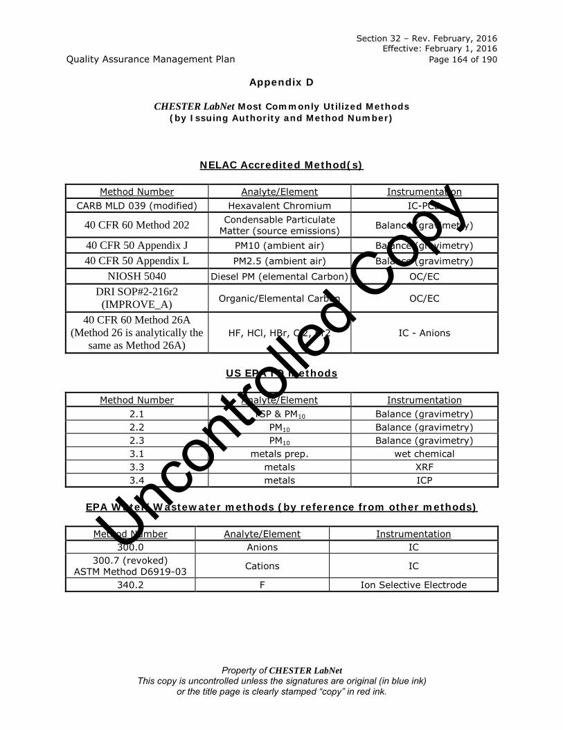
Section 32 – Rev. February, 2016 Effective: February 1, 2016 Quality Assurance Management Plan Page 164 of 190
Property of CHESTER LabNet This copy is uncontrolled unless the signatures are original (in blue ink)
or the title page is clearly stamped “copy” in red ink.
Appendix D
CHESTER LabNet Most Commonly Utilized Methods (by Issuing Authority and Method Number)
NELAC Accredited Method(s)
Method Number Analyte/Element Instrumentation CARB MLD 039 (modified) Hexavalent Chromium IC-PCD
40 CFR 60 Method 202 Condensable Particulate Matter (source emissions) Balance (gravimetry)
40 CFR 50 Appendix J PM10 (ambient air) Balance (gravimetry) 40 CFR 50 Appendix L PM2.5 (ambient air) Balance (gravimetry)
NIOSH 5040 Diesel PM (elemental Carbon) OC/EC DRI SOP#2-216r2
(IMPROVE_A) Organic/Elemental Carbon OC/EC
40 CFR 60 Method 26A (Method 26 is analytically the
same as Method 26A) HF, HCl, HBr, Cl2, Br2 IC - Anions
US EPA IO methods
Method Number Analyte/Element Instrumentation 2.1 TSP & PM10 Balance (gravimetry) 2.2 PM10 Balance (gravimetry) 2.3 PM10 Balance (gravimetry) 3.1 metals prep. wet chemical 3.3 metals XRF 3.4 metals ICP
EPA Water/Wastewater methods (by reference from other methods)
Method Number Analyte/Element Instrumentation 300.0 Anions IC
300.7 (revoked) ASTM Method D6919-03 Cations IC
340.2 F Ion Selective Electrode
Uncon
trolle
d Cop
y

Section 32 – Rev. February, 2016 Effective: February 1, 2016 Quality Assurance Management Plan Page 165 of 190
Property of CHESTER LabNet This copy is uncontrolled unless the signatures are original (in blue ink)
or the title page is clearly stamped “copy” in red ink.
EPA SW-846 methods (by reference from other methods)
Method Number Analyte/Element Instrumentation 3050 metals prep. wet chemical 6010 metals ICP
7470/7471 Hg CVAA
ODEQ methods
Method Number Analyte/Element Instrumentation 5 Particulates Balance (gravimetry) 8 Particulates Balance (gravimetry)
40 CFR 50, 51 & 60 Source Testing methods
Method Number Analyte/Element Instrumentation 5 Particulates Balance (gravimetry) 6 SO2 titrimetric
7 (A & D) NOx IC 8 H2SO4/SO2 titrimetric 12 Pb ICP 13B F IC or ISE 14 F IC or ISE 26 HX, HX & X2 IC 29 Multi-metals ICP 101 Hg CVAA 101A Hg CVAA 102 Hg CVAA 103 Be ICP 104 Be ICP 105 Hg CVAA 108 As ICP 201A Particulates Balance (gravimetry) 202 Particulates Balance (gravimetry) 306 Cr & CrVI ICP and IC-PCD
CTM 027 NH4 IC CTM 013 & 013A H2SO4/SO2 IC or titration
Uncon
trolle
d Cop
y

Section 32 – Rev. February, 2016 Effective: February 1, 2016 Quality Assurance Management Plan Page 166 of 190
Property of CHESTER LabNet This copy is uncontrolled unless the signatures are original (in blue ink)
or the title page is clearly stamped “copy” in red ink.
NIOSH methods
Method Number Analyte/Element Instrumentation 0500 Particulates Balance (gravimetry) 0600 Particulates Balance (gravimetry) 5040 Elemental Carbon OC/EC 6004 SO2 IC 6006 Diborane ICP 6009 Hg CVAA 6011 Br2 & Cl2 IC 6014 NO2 IC 6016 NH3 IC 7300 metals ICP 7902 F IC
CARB methods
Method Number Analyte/Element Instrumentation 005 As ICP 421 HF & HCl IC 423 As ICP 425 Total Cr ICP 436 multiple metals ICP
SOP MLD039 Hexavalent Cr (CrVI) IC-PCD
40 CFR 50, Ambient Air Methods
Method Number Analyte/Element Instrumentation Appendix B TSP Balance (gravimetry) Appendix J PM10 Balance (gravimetry) Appendix L PM2.5 Balance (gravimetry) Appendix Q Pb XRF
Uncon
trolle
d Cop
y

Section 33 – Rev. February, 2016 Effective: February 1, 2016 Quality Assurance Management Plan Page 167 of 190
Property of CHESTER LabNet This copy is uncontrolled unless the signatures are original (in blue ink)
or the title page is clearly stamped “copy” in red ink.
Appendix E
Laboratory Accreditation/Certification/Recognition
CHESTER LabNet maintains the following certifications and accreditations:
Organization Certificate Number Parameter List
ORELAP OR100051-010 PM10; PM2.5;
CrVI (ambient air); Carbon (Improve_A);
Carbon (NIOSH 5040); Condensable PM (Method
202); Hydrogen Halides and Halides
(Method 26/26A).
The certificates and parameter lists (which may differ) for each organization may be found in files maintained by the Laboratory Director.
If accreditation is terminated or suspended, the laboratory will immediately cease to use the certificate number reference in any way and inform clients impacted by the change. Unc
ontro
lled C
opy

Section 34 – Rev. February, 2016 Effective: February 1, 2016 Quality Assurance Management Plan Page 168 of 190
Property of CHESTER LabNet This copy is uncontrolled unless the signatures are original (in blue ink)
or the title page is clearly stamped “copy” in red ink.
Appendix F
Data Qualifiers
List of CHESTER LabNet Data Qualifiers Location Qualifier Meaning
Standard Reports Data Summary (on request) U Non-detect Data Summary (on request) B Greater than LOD, less than LOQ QC Summary N/C Duplicate RPD can’t be calculated
as one or both data points are less than the LOD
QC Summary # Duplicate RPD control limits do not apply as one or both of the data points is less than the LOQ
QC Summary * Spike recovery limits do not apply where spiked amount is less than ¼ sample result.
Special “CLP-like” Reports
Data Summary (Form I) J Concentration greater than LOD but
less than contract required detection limit
Data Summary (Form I) U Concentration less than LOD Data Summary (Form I) E Concentration is estimated based
upon interferents Data Summary (Form I) N Spike recovery not in control Data Summary (Form I) * Duplicate analysis not in control Data Summary (Form I) D Reported value is from a dilution Data Summary (Form I) P Analyzed by ICP-AES Data Summary (Form I) MS Analyzed by ICP-MS Data Summary (Form I) CV Analyzed by CVAAS Data Summary (Form I) C Analyzed by manual
spectrophotometric equipment Data Summary (Form I) “ “ Where no data has been entered Data Summary (Form I) NR Analyte is not required QC Summary (Form II – ICV/CCV) M Analyzed for analyte QC Summary (Form II – ICV/CCV) NR Analyte is not required QC Summary (Form II – CRI/CRA) J Concentration greater than LOD but
less than contract required detection limit
QC Summary (Form II – CRI/CRA) U Concentration less than LOD QC Summary (Form III – blanks) J Concentration greater than LOD but
less than contract required
Uncon
trolle
d Cop
y

Section 34 – Rev. February, 2016 Effective: February 1, 2016 Quality Assurance Management Plan Page 169 of 190
Property of CHESTER LabNet This copy is uncontrolled unless the signatures are original (in blue ink)
or the title page is clearly stamped “copy” in red ink.
List of CHESTER LabNet Data Qualifiers Location Qualifier Meaning
detection limit QC Summary (Form III – blanks) U Concentration less than LOD QC Summary (Form III – blanks) P Analyzed by ICP-AES QC Summary (Form III – blanks) MS Analyzed by ICP-MS QC Summary (Form III – blanks) CV Analyzed by CVAAS QC Summary (Form III – blanks) C Analyzed by manual
spectrophotometric equipment QC Summary (Form V – spikes) N Spike amount is less than ¼
sample result QC Summary (Form V – spikes) P Analyzed by ICP-AES QC Summary (Form V – spikes) MS Analyzed by ICP-MS QC Summary (Form V – spikes) CV Analyzed by CVAAS QC Summary (Form V – spikes) C Analyzed by manual
spectrophotometric equipment QC Summary (Form V – spikes) NR Analyte is not required QC Summary (Form V – post-spikes) P Analyzed by ICP-AES QC Summary (Form V – post MS Analyzed by ICP-MS QC Summary (Form V – post CV Analyzed by CVAAS QC Summary (Form V – post C Analyzed by manual
spectrophotometric equipment QC Summary (Form V – post NR Analyte is not required QC Summary (Form VI – duplicates) * Both sample results are greater
than the LOQ, AND the RPD is out of control
QC Summary (Form VI – duplicates) P Analyzed by ICP-AES QC Summary (Form VI – duplicates) MS Analyzed by ICP-MS QC Summary (Form VI – duplicates) CV Analyzed by CVAAS QC Summary (Form VI – duplicates) C Analyzed by manual
spectrophotometric equipment QC Summary (Form VII – LCS) J Concentration greater than LOD but
less than contract required detection limit
QC Summary (Form VII – LCS) U Concentration less than LOD QC Summary (Form VIII – Serial Dilutions) E RPD greater than 10% and original
sample concentration is greater than 50 times the LOD.
QC Summary (Form VIII – Serial Dilutions) P Analyzed by ICP-AES QC Summary (Form VIII – Serial Dilutions) MS Analyzed by ICP-MS QC Summary (Form VIII – Serial Dilutions) CV Analyzed by CVAAS QC Summary (Form VIII – Serial Dilutions) C Analyzed by manual
spectrophotometric equipment
Uncon
trolle
d Cop
y

Section 34 – Rev. February, 2016 Effective: February 1, 2016 Quality Assurance Management Plan Page 170 of 190
Property of CHESTER LabNet This copy is uncontrolled unless the signatures are original (in blue ink)
or the title page is clearly stamped “copy” in red ink.
Note: many of the larger projects will have their own reporting guidelines, Contract Required Quantitation Limits, Action Limits and Data Qualifier Codes. The laboratory will use the guidelines issued by the client in all regards when reporting data, to include reported Quantitation limits and Qualifier Codes.
Uncon
trolle
d Cop
y

Section 35 – Rev. February, 2016 Effective: February 1, 2016 Quality Assurance Management Plan Page 171 of 190
Property of CHESTER LabNet This copy is uncontrolled unless the signatures are original (in blue ink)
or the title page is clearly stamped “copy” in red ink.
Appendix G
Employee Resumés
Uncon
trolle
d Cop
y

Section 35 – Rev. February, 2016 Effective: February 1, 2016 Quality Assurance Management Plan Page 172 of 190
Property of CHESTER LabNet This copy is uncontrolled unless the signatures are original (in blue ink)
or the title page is clearly stamped “copy” in red ink.
Paul D. Duda President, Laboratory Director, Lead Project Manager, LIMS Administrator
Background: Hire date: 1989. Experience in air quality filter analysis by X-Ray Fluorescence; experience as project manager; experience with SAS and CLP data package requirements. Experience as Laboratory Information Management System (LIMS) administrator, coordinating all LIMS activities; special expertise in interfacing laboratory data to client-specific databases and end-user data programs. Career Chronology:
Employment Information Responsibilities and Duties
President; Laboratory Director; Lead Project Manager; LIMS Administrator; CHESTER LabNet, Tigard, OR 2001 – Present
Corporate affairs for laboratory, including proposal writing, marketing and sales, program and project management, overall profit/loss for company, all accounting/payroll and purchasing; report production for all projects requiring EPA, CLP deliverables. Oversee all procedures, QA/QC and corrective actions associated with sample receipt, log-in, chain-of-custody and storage; project management, and general and specialized report production; client management; oversees operation and maintenance of laboratory information management system (LIMS), including all software and hardware, general data entry, QA/QC, coordination with other project managers and technical staff, training of new users.
Project Manager, LIMS Administrator, Sample Custodian, CHESTER LabNet, Tigard, OR 1992 - 2001.
Project management, all accounting/payroll and purchasing; report production for all projects requiring EPA, CLP deliverables. Oversees all procedures, QA/QC and corrective actions associated with sample receipt, log-in, chain-of-custody and storage; project management, and general and specialized report production; client management; oversees operation of laboratory information management system (LIMS), including all software and hardware, general data entry, QA/QC, coordination with other project managers and technical staff, training of new users.
Gravimetry Laboratory and XRF Analyst,
CHESTER LabNet, Tigard, OR 1989 - 1992.
Performed all operations of the filter gravimetry laboratory, including maintaining supplies, filter media acceptance testing, gravimetric analysis of filter media following EPA protocols, all QA/QC and corrective actions, maintenance of log books and QC documentation. Also served as XRF technician, including preparation of samples for analysis, instrument operation, interpretation of spectral results, QA/QC.
1987 - 1988 Miscellaneous employment. Education:
• Graduate Studies, Business Administration, Portland State University, Portland, OR, 1991-1992.
• B.S., Engineering Management, University of Portland, Portland, OR, 1987.
Uncon
trolle
d Cop
y

Section 35 – Rev. February, 2016 Effective: February 1, 2016 Quality Assurance Management Plan Page 173 of 190
Property of CHESTER LabNet This copy is uncontrolled unless the signatures are original (in blue ink)
or the title page is clearly stamped “copy” in red ink.
Sheri Heldstab Conventional Chemistry Laboratory Technical Director, QA Officer, Senior Chemist,
Health & Safety Officer Background: Hire date: 1992. Experience in inorganic analysis of environmental samples, method development of unusual sample matrices, data interpretation and validation; experience with SAS and CLP data package preparation and requirements; experience in technical writing of Standard Operating Procedures, QA/QC project plans, experience with ORELAP accreditation requirements and documentation (QAMP). Career Chronology:
Employment Information
Responsibilities and Duties
Conventional Chemistry Technical Director,
QA/QC Officer, Senior Chemist, Health & Safety Officer CHESTER LabNet, Tigard, OR 1999 - Present
Oversee all operations of the conventional chemistry laboratory; analyze samples; ensure data meets QA/QC requirements; general technical guidance for clients and staff; manage the flow of samples and data through the laboratory; oversee and train other chemists; oversee day to day operation of the laboratory; manage flow of samples and data through the laboratory; ensure meeting of due dates, and proper maintenance of instruments, and adherence to all QA/QC protocols. Oversight of standard operating procedure and program document production and implementation, oversight of accreditation specific requirements, QC review of data reporting, technical guidance on general QA issues, report production for all projects requiring EPA CLP deliverables.
Account Manager, Lab Support, Portland, OR 1998 - 1999
Performed all duties required to run a one person branch office, including service calls, resolution of client disputes, marketing to new clients, filling of orders and recordkeeping.
Chemist, ChemTrace, Portland, OR 1997 – 1998
Primary operator for IC and GFAA. Performed analysis on high purity water for various nutrients, microbiological testing and silica content.
Senior Chemist, CHESTER LabNet, Tigard, OR 1994 – 1997
Primary operator for IC, ICP, GFAA, CVAA. Analyzed variety of air quality samples using primarily CFR methods. Supervised one Chemist. Generated CLP QC reports. Managed sample throughput and Level I data validation of laboratory.
Associate Chemist, CHESTER LabNet, Tigard, OR 1992 – 1994
Primary operator for IC and performance of bench methods. Analyzed variety of environmental samples using CFR, SW846, DW, SM, NIOSH, OSHA and a variety of other methods.
Laboratory Technician, ASiMI, Washougal, WA 1991 – 1992
Analyzed high purity raw silicon for contaminants utilizing specialized equipment. Generated QC reports to be used in the preparation of Certificates of Lot Analysis.
Chemist, Coffey Laboratories, Portland, OR 1990 - 1991
Analyzed a variety of environmental samples for inorganic constituents using DW, SW846 and SM methods.
Education:
• B.S., Biology (Chemistry minor), University of Oregon, 1989 • Secondary Teaching Certification, University of Oregon School of Education, 1990
Uncon
trolle
d Cop
y

Section 35 – Rev. February, 2016 Effective: February 1, 2016 Quality Assurance Management Plan Page 174 of 190
Property of CHESTER LabNet This copy is uncontrolled unless the signatures are original (in blue ink)
or the title page is clearly stamped “copy” in red ink.
Richard H. Sarver XRF Technical Director, Senior XRF Analyst
Background: Hire date: 1986. Experience in analytical chemistry, including biochemical applications and environmental air quality analysis, specializing in the analysis of air particulates by x-ray fluorescence. Career Chronology:
Employment Information Responsibilities and Duties
XRF Technical Director, Senior XRF Analyst, CHESTER LabNet, Tigard, OR 1986 - Present.
Coordinate all XRF activities with project managers as needed; train XRF technicians and oversee all XRF operations; market XRF capabilities to outside clients; responsible for maintenance and repair of instruments, supervise sample flow, data interpretation, QA/QC and report generation from XRF analysis; perform highly specialized sample preparation for non-deposit samples, including size fraction and resuspension; technical guidance for clients and in-house staff. Perform XRF analysis and provide technical assistance for state and federal agencies, industrial, consulting and university clients. Ensure adherence to all QA/QC protocols. Awarded EPA equivalency method EQL-0589-072, "Determination of Lead Concentration in Ambient Particulate Matter by EDXRF Spectrometry in May 1989. Principal scientist for the XRF analysis of air particulates for the U.S. EPA national PM2.5 Chemical Speciation Program. Developed XRF method of analysis for the Hazardous Element Sampling Train (HEST), which used activated carbon to trap volatile metals. Continues to participate in the ongoing effort to obtain equivalent method status to EPA Method 29.
Analytical Chemist, Pioneer Hi-Bred International Portland, OR 1980-1986.
Utilized FID/GC analysis to determine metabolic pathways of resident microorganisms in the digestive tract of stressed mice. Handled animals and performed analytical work. Developed SOPs for in house use.
Education: A.A.S., Chemical Technology, Chemeketa Community College, Salem, OR 1980.
Selected Publications and Presentations:
Sarver, R. H. 1996. Aerosolization as a Means of Sample Preparation of Geological Materials for XRF Analysis and its Validity Compared to EPA Method 3050A Digestion. Journal of the Air & Waste Management Association. 46: 234-240. Sarver, R.H. and Lytle, C.R. 2000. Parameter optimization for the analysis of PM2.5 by energy dispersive x-ray fluorescence (EDXRF). Presented at PM2000: Particulate Matter and Health, Air & Waste Management Association Specialty Conference, Charleston, SC, January 24-28, 2000. Sarver, R.H., Mace, J.C. and Duda, P.D. 2002. XRF: Inter-Excitation Quality Assurance and Deposit Uniformity. Presented at Symposium on Air Quality Measurement Methods & Technology, Air & Waste Management Association Conference, San Francisco, CA, November 13–15, 2002.
Uncon
trolle
d Cop
y

Section 35 – Rev. February, 2016 Effective: February 1, 2016 Quality Assurance Management Plan Page 175 of 190
Property of CHESTER LabNet This copy is uncontrolled unless the signatures are original (in blue ink)
or the title page is clearly stamped “copy” in red ink.
Jennifer Schleis Gravimetry Laboratory Technical Director, Senior Gravimetry Laboratory
Technician, XRF Analyst, Chemist Background: Hire date: 2007. General laboratory experience. Prior experience in NELAC accredited laboratory. Experience in filter weighing using CFR methods. Instrument experience including IC-PCR, ICP, IC, OC/EC, CVAA. Experience with inorganic analytical methods including CFR, NIOSH, and OSHA methods. Career Chronology:
Employment Information Responsibilities and Duties
Gravimetry Laboratory Technical Director;
Chemist; Senior Gravimetry Laboratory
Technician; XRF Analyst CHESTER LabNet, Tigard, OR 2010 - Present
Oversees and performs all operations of the filter gravimetry laboratory to include acceptance testing, QA/QC, inventory and archives. Performs all operations of the filter gravimetry laboratory. Ensures data meets QA/QC requirements; provides general technical guidance for clients and staff; manages the flow of samples and data through the laboratory; oversees and trains other technicians; oversees day to day operation of the laboratory; manages flow of samples and data through the laboratory; ensures meeting of due dates, proper maintenance of instruments and adherence to all QA/QC protocols. Performs XRF analyses, ensures adherence to all QA/QC protocols. Performs other analytical duties in the Conventional Chemistry lab for those methods for which she has active DOCs.
Chemist; Gravimetry Laboratory Technician CHESTER LabNet, Tigard, OR 2007 - 2010
Analyzed a variety of air quality samples using primarily CFR methods, performed level I data review in real time. Analyzed samples for metal constituents by ICP, CVAA; analyzed samples by IC, IC-PCR and wet chemical methods. Performed all operations of the filter gravimetry laboratory, including filter media acceptance testing, gravimetric analysis of filter media following CFR protocols, all QA/QC and corrective actions, maintenance of log books and QC documentation.
Laboratory Technician Aquatic Biotech & Environmental Lab, Athens, GA 2005 – 2006
Analyzed mutant strains of transgenic fish via specialized assays, gel electrophoresis, PCR, sequencing, DNA isolation; performed in-vitro fertilization and dissections; maintained aquaria and stocks of fresh and saltwater fish.
Laboratory Technician University of Georgia, Athens, GA 2004 – 2005
Performed high-throughput DNA sequencing; maintained and operated all laboratory equipment; provided weekly presentation of data summaries and quality assurance; provided technical assistance to students and research staff.
Education: B.S. Environmental Economics and Management, University of Georgia, 2003 Continuing Education, Portland Community College, 2015 (Chemistry)
Uncon
trolle
d Cop
y

Section 35 – Rev. February, 2016 Effective: February 1, 2016 Quality Assurance Management Plan Page 176 of 190
Property of CHESTER LabNet This copy is uncontrolled unless the signatures are original (in blue ink)
or the title page is clearly stamped “copy” in red ink.
Lisa Ball Project Manager, Sample Custodian
Background: Hire date: 1997. Experience as Project Manager. Experience as environmental analytical chemist. Career Chronology:
Employment Information Responsibilities and Duties
Project Manager, Sample Custodian, CHESTER LabNet, Tigard, OR 2003 - Present.
Project management. Performs all procedures, QA/QC and corrective actions associated with sample receipt, log-in and chain-of-custody, project management and general and specialized report production; client management; general data entry; coordination with other project managers and technical staff; training of new users. Provides technical guidance to clients.
Project Manager, Sample Custodian, Gravimetry Laboratory Coordinator, CHESTER LabNet, Tigard, OR 2001 - 2003.
Project management. Performs all procedures, QA/QC and corrective actions associated with sample receipt, log-in and chain-of-custody, project management and general and specialized report production; client management; general data entry; coordination with other project managers and technical staff; training of new users. Provides technical guidance to clients. Oversee and perform all operations of the filter gravimetry laboratory.
Chemist, Gravimetry Laboratory Coordinator, CHESTER LabNet, Tigard, OR 1997 - 2001.
Performed all operations of the filter gravimetry laboratory, including maintaining supplies, filter media acceptance testing, gravimetric analysis of filter media following EPA protocols, all QA/QC and corrective actions, maintenance of log books and QC documentation. Analyzed air quality samples using primarily CFR methods, including: sample preparation, and digestion and analysis of samples. Principal Operator of IC, ICP, CVAA. Responsible for Level I data review and reporting.
Extraction Chemist, Oregon Analytical Laboratory, Beaverton, OR, 1997 (full-time, temporary).
Performed extractions for total petroleum hydrocarbons (TPH and TPHD), hydrocarbon identification (HCID), PAHs and oil and grease. Extractions included separatory agitation as well as distillations. Digested, extracted and analyzed water and soil samples for a variety of inorganic constituents including: CODs, pHs, alkalinity, open-cup flashpoints, Total Kjeldahl Nitrogen analysis, Cyanide distillation and analysis.
Chemist, American Environmental Network, Durham, OR, 1996-1997.
Primary wet chemist. Brought new wet chemistry methods on line and wrote corresponding SOPs for wet chemistry methods.
Education: B.S., Integrated Science, Portland State University, 1996. OSHA 1910.120: 24-hour, 1996.
Uncon
trolle
d Cop
y

Section 35 – Rev. February, 2016 Effective: February 1, 2016 Quality Assurance Management Plan Page 177 of 190
Property of CHESTER LabNet This copy is uncontrolled unless the signatures are original (in blue ink)
or the title page is clearly stamped “copy” in red ink.
Katie Hawks Chemist, Gravimetry Laboratory Technician
Background: Hire date: 2014. Prior experience as an analytical chemist for production facility. General laboratory experience. Instrumental experience including ICP. Experience with inorganic analytical methods including CFR, NIOSH, and OSHA methods. Career Chronology:
Employment Information Responsibilities and Duties
Chemist Gravimetry Laboratory Technician CHESTER LabNet, Tigard, OR 2014 - Present
Analyzes a variety of air quality samples using conventional chemistry techniques utilizing primarily CFR methods; performs instrumental analysis using ICP and CVAA; performs level I data review in real time. Performs all operations of the filter gravimetry laboratory, including filter media acceptance testing, gravimetric analysis of filter media following CFR protocols, all QA/QC and corrective actions, maintenance of log books and QC documentation.
Sales Associate Shane Company, Tigard, OR 2012 - 2014
Administered Clientele Liaison Program; trained associates on updated software; tracked clientele data; resolved difficult customer situations.
Beauty Consultant Mary Kay, Beaverton, OR 2010 - 2013
Achieved top 5 in sales for national area; recruited and mentored 25 team members; built client base of over 400 customers; earned multiple bonuses.
Chemist Wah-Chang, Albany, OR 2007 - 2010
Analyzed samples by ICP and ICP-MS; designed experiments; advised and communicated with outside departments, co-workers, and students; constructed and executed streamlining procedures; handled various samples, chemicals, and acids, including HF safely; trained students on instrumentation and lab safety.
Medical Technician OHSU, Portland, OR 2006 - 2007
Assisted doctors during sampling; made slides for specimens; logged in and prepared samples; made reagents and standards.
Volunteer Intern Portland Crime Lab, Portland, OR 2005 - 2006
Validated new equipment and trained users; analyzed samples; performed detection limit studies; created analyte list using FTIR-ATR.
Education: B.S., Chemistry, Western Oregon University, 2006
Uncon
trolle
d Cop
y

Section 35 – Rev. February, 2016 Effective: February 1, 2016 Quality Assurance Management Plan Page 178 of 190
Property of CHESTER LabNet This copy is uncontrolled unless the signatures are original (in blue ink)
or the title page is clearly stamped “copy” in red ink.
Julie Delarue
Chemist, Gravimetry Laboratory Technician, XRF Analyst
Background: Hire date: 2015. Prior experience as an analytical chemist for production facility. General laboratory experience, instrumental experience including ICP, UV/Vis and IR spectrophotometer, GC, and XRF. Career Chronology:
Employment Information Responsibilities and Duties
Chemist Gravimetry Laboratory Technician CHESTER LabNet, Tigard, OR 2015 - Present
Analyzes a variety of air quality samples using conventional chemistry techniques utilizing primarily CFR methods; performs instrumental analysis using IC-PCR; performs level I data review in real time. Performs all operations of the filter gravimetry laboratory, including filter media acceptance testing, gravimetric analysis of filter media following CFR protocols, all QA/QC and corrective actions, maintenance of log books and QC documentation.
Laboratory Technologist, Husky Energy, Lloydminster, SK (CAN) 2010 – 2014
Performed troubleshooting and method development; analyzed solid, liquid and gaseous samples by GC and XRF; prepared diesel fuel certification for sale. Responsible for all analytical documentation.
QA Laboratory Technologist, Nestle Purina Petcare, Innisfail, AB (CAN) 2009 - 2010
Performed Protein, Moisture and Fat analyses on pet food; responsible for formal release of product. Responsible for all analytical documentation.
Analytical Laboratory Technologist,
Nova Chemicals, Calgary, AB (CAN) 2008 - 2009
Analyzed solid, liquid and gas samples by GC; performed troubleshooting and method development. Responsible for all analytical documentation.
Education:
• B.S., Environmental Sciences, University of Alberta (CAN), 1999 • A.S., Chemical Technology, SAIT Polytechnic (CAN), 2009
Uncon
trolle
d Cop
y

Section 35 – Rev. February, 2016 Effective: February 1, 2016 Quality Assurance Management Plan Page 179 of 190
Property of CHESTER LabNet This copy is uncontrolled unless the signatures are original (in blue ink)
or the title page is clearly stamped “copy” in red ink.
Theodore (“Ted”) Perry
Chemist, Gravimetry Laboratory Technician
Background: Hire date: 2015. Prior experience as an analytical chemist for independent testing laboratories. Sample preparation and analysis for N content in Fertilizer using bench chemistry techniques; instrumental experience with GFAA, FAA and FTIR. Career Chronology:
Employment Information Responsibilities and Duties
Chemist Gravimetry Laboratory Technician CHESTER LabNet, Tigard, OR 2015 - Present
Analyzes a variety of air quality samples using conventional chemistry techniques utilizing primarily CFR methods; performs instrumental analysis using IC-PCR; performs level I data review in real time. Performs all operations of the filter gravimetry laboratory, including filter media acceptance testing, gravimetric analysis of filter media following CFR protocols, all QA/QC and corrective actions, maintenance of log books and QC documentation.
Chemist, Thornton Laboratory, Tampa, FL 2013 - 2015
Prepared and analyzed fertilizer samples for Nitrogen content, including TKN, Ammonium content, insoluble nitrogen, Nitrate and slow release nitrogen. Responsible for all analytical documentation.
Chemist Mission Mountain Labs Arlee, MT 2012 – 2013
Prepared and analyzed primarily nutraceutical samples for metals analysis by GFAA, FAA and FTIR. Responsible for all analytical documentation.
Work Study, Surplus Dept. Oregon State University Corvallis, OR 2011 -2012
Moved surplus supplies and equipment from buildings or storage into other buildings or storage.
Work Study, Physical Science Dept.
Linn-Benton Community College
Albany, OR 2008 - 2010
Cleaned and prepared laboratory glassware, Inventoried chemical stocks and set up and prepared laboratory space and equipment for students.
Education: B.S., Chemistry (Environmental Chemistry option), Oregon State University, 2012
Uncon
trolle
d Cop
y

Section 36 – Rev. February, 2016 Effective: February 1, 2016 Quality Assurance Management Plan Page 180 of 190
Property of CHESTER LabNet This copy is uncontrolled unless the signatures are original (in blue ink)
or the title page is clearly stamped “copy” in red ink.
Appendix H
Chemistry
H.1 Method Validation
Reference methods are validated using the following criteria where possible:
• LOD study; • Precision and Bias study; and • Evaluation of Selectivity.
The 2009 TNI Standard QAMP template states, “In addition, the action level (compliance level, project decision level etc.) is used to establish the LOQ and/or LOD.” The laboratory is rarely aware of “the action level (compliance level, project decision level)…” for any given set of samples. The laboratory is not always aware of who the regulatory agency is governing any given set of samples. It is the client’s responsibility to ensure that the laboratory’s LODs are sufficient to meet their project’s reporting/regulatory limits.
a) Limit of Detection (LOD)
The Limit of Detection (LOD) is the laboratory's estimate of the minimum amount of an analyte in a given matrix that an analytical process can reliably detect in their facility. None of the promulgated methods performed at CHESTER LabNet require LOD studies. LODs are not required for any component for which spiking solutions or quality control samples are not available. These include XRF analysis, gravimetric analysis (both Gravimetry Laboratory and Conventional Chemistry), and OC/EC analysis. At this writing, no PE/PT samples are available for any ambient air quality method and very few are available for source emission methods. 40CFR60 Method 26A (and Method 26) and 40CFR60 Method 29 are the two most common Source Emissions methods for which PT samples are available. The 2009 TNI Standard QAMP template states, “The laboratory will select methods with LODs that are expected to meet the intended data use.” The laboratory has no control over method selection, regardless of the intended use. The laboratory will conduct instrumental LOD studies for the instruments where an LOD study is possible. The 2009 TNI Standard QAMP template states, “LODs are determined in samples that represent the quality system matrices to be evaluated. All sample processing/preparation steps and all determinative steps are used to validate the method for all targeted analytes. The representative quality system matrix will be free from the target analytes of interest or interfering analytes that impact the LOD.” The quality system matrix is “Air”, in the case of all work performed at CHESTER LabNet. Due to the fact that sampling is part of the promulgated method, it is not
Uncon
trolle
d Cop
y

Section 36 – Rev. February, 2016 Effective: February 1, 2016 Quality Assurance Management Plan Page 181 of 190
Property of CHESTER LabNet This copy is uncontrolled unless the signatures are original (in blue ink)
or the title page is clearly stamped “copy” in red ink.
possible for the laboratory to perform an LOD study using “All sample processing/preparation steps…” Also, due to the need for sampling media (filters, sorbent tubes, chemical solutions) it is not possible to find a quality system matrix “free from the target analytes of interest or interfering analytes that impact the LOD.” The laboratory determines the LOD for each determinative step (e.g. instrument) where an LOD is possible to be determined, using a matrix free from the target analytes of interest or interfering analytes that impact the LOD. Briefly, these matrices are:
• IC (Anion/Cation) – DI Water;
• IC-PCR (Cr6) – dilute bicarbonate solution or DI Water (method dependent);
• CVAA – DI water followed by digestion listed in SW-846 Method 7470; and
• ICP – 7% HNO3.
• [Note: XRF and OCEC results are reported with uncertainties in lieu of an absolute detection limit.]
The 2009 TNI Standard QAMP template states, “When the method or applicable regulation specifies an LOD study, only the specified method will be used. The laboratory will document the process used to derive the LOD and will retain all the supporting data.” No method performed at CHESTER LabNet requires an LOD study. LOD studies are performed annually on the instruments listed above, and raw data is retained. Refer to SOP QA-006 for further details. In brief, the laboratory uses the following procedure to determine the LOD for the method:
1. Three sets of seven standards set at 2 – 4 times the expected LOD are analyzed on non-consecutive days.
2. The standard deviation of the three sets is determined, averaged, and multiplied by three (yielding a three-sigma value).
3. This is compared to previous LOD studies and historical blank data (ICB’s/CCB’s) for reasonableness. Analyst experience with the particular instrument is also used when setting LODs. A reported LOD will never be lower than the calculated LOD, but may be made higher than the calculated LOD based on blank data and/or analyst experience.
Once the LOD has been determined, the validity of the LOD is verified by a detection (value above zero) for each target analyte in a quality control sample in the same matrix as the LOD study was performed. This is most commonly performed by examining the results of the LOD study data. As the LOD standard is made at 2 to 4-times the LOD, each analyte of interest should have a detectable response. The concentration of the analytes in the quality control sample will be no more than 3 times the derived LOD unless the test contains multiple analytes. In the latter case, the concentration of the target analytes will
Uncon
trolle
d Cop
y

Section 36 – Rev. February, 2016 Effective: February 1, 2016 Quality Assurance Management Plan Page 182 of 190
Property of CHESTER LabNet This copy is uncontrolled unless the signatures are original (in blue ink)
or the title page is clearly stamped “copy” in red ink.
be no greater than 4 times the LOD. This verification will be performed on each instrument that is used for the test. LODs are performed/repeated:
• before reporting the LOD for a given analyte;
• any time there is a change that affects how the method is performed; or
• when there is a change in instrumentation that affects the sensitivity of the analysis.
LODs are repeated or verified annually for each quality system matrix/technology/analyte combination.
b) Limit of Quantitation
The Limit of Quantitation (LOQ) is an estimate of the minimum amount of a substance that can be reported with a specified degree of confidence. LOQs are not required for components or properties for which spiking solutions or QC samples are not available. These include XRF analysis, gravimetric analysis (both Gravimetry Laboratory and Conventional Chemistry), and OC/EC analysis. Based on CLP guidelines, the LOQ is set at five times the accepted LOD result from the LOD study described above. The laboratory will verify the LOQ by the analysis of a QC sample containing the analytes of concern at a concentration 1 - 2 times the derived (claimed) LOQ. The LOQ is considered verified if recovery of each analyte is within the laboratory’s acceptance limits, or the client’s data quality objectives. The LOQ will be verified annually for each quality system matrix, technology and analyte unless the LOD was determined or verified. Since the laboratory performs an LOD study for each instrument annually, verification is rarely performed.
c) Precision and Bias
Precision is the degree to which a set of observations or measurements of the same property, obtained under similar conditions, conform to themselves. Precision is usually expressed as standard deviation, variance, or range, in either absolute or relative terms. Bias is the systematic error that contributes to the difference between the mean of a significant number of test results and the accepted reference value. Precision and bias using non-reference, modified reference or laboratory-developed methods are established using the procedure outlined below and compared to the criteria established by the laboratory. The Precision and Bias study is only performed when the method is first brought online or when a change in instrumentation gives cause to believe that precision and bias of the method may have changed.
Uncon
trolle
d Cop
y

Section 36 – Rev. February, 2016 Effective: February 1, 2016 Quality Assurance Management Plan Page 183 of 190
Property of CHESTER LabNet This copy is uncontrolled unless the signatures are original (in blue ink)
or the title page is clearly stamped “copy” in red ink.
The 2009 TNI Standard QAMP template states, “Precision and bias are determined by processing samples through all phases of the method (e.g., sample preparation, cleanup, analysis, etc.) and are evaluated across the analytical calibration range of the method. This study is performed for all quality system matrices for which the test is to be used.” Due to the fact that sampling is part of the promulgated method, it is not possible for the laboratory to perform a Precision and Bias study “by processing samples through all phases of the method ….” The laboratory uses the same matrices as described in subsection “a” above (LOD’s) in performing Precision and Bias studies. Refer to SOP QA-006 for further detail. Briefly, the Precision and Bias study is as follows:
• Prepare the method blank and standards following all preparatory steps contained in the method (if any). In instances where no preparation is performed on the samples (samples are run as received), prepare a standard in the same matrix (e.g., DI water). Following the steps in the appropriate standard operating procedure, measure the method blank and one standard at each concentration level together in one analytical run.
• Calculate the mean recovery for each of the three results.
• On a second, non-consecutive day, repeat above.
• On a third, non-consecutive day, repeat steps above.
• Calculate mean recovery for each level over the three days, and for all nine samples.
• Calculate the relative standard deviation for each of the separate means obtained.
• Compare the standard deviations for the different days and for the different concentrations; compare the overall mean and standard deviation with established criteria.
d) Selectivity
Selectivity is the capability of a test method or instrument to respond to a target substance or constituent in the presence of non-target substances (EPA-QAD). The laboratory evaluates selectivity through the use of method spikes. With many source emissions samples, the chemistry occurring in the source being sampled can be wildly different from another source. Often, the chemistry occurring in the gas stream of the source includes pollution control device emissions containing non-target substances specifically designed to remove the target substance. Selectivity using any substance other than a sample from the source is moot. Some methods are incompatible with Selectivity tests. Gravimetric analyses, both on filters and source emission samples, do not lend themselves to selectivity. Either the sample and its container have mass, or they don’t exist. By virtue of existence, the target analyte (mass) has been responded to. Non-
Uncon
trolle
d Cop
y

Section 36 – Rev. February, 2016 Effective: February 1, 2016 Quality Assurance Management Plan Page 184 of 190
Property of CHESTER LabNet This copy is uncontrolled unless the signatures are original (in blue ink)
or the title page is clearly stamped “copy” in red ink.
target substances do not exist, however, some physical characteristics of the sample (e.g. static) may have an effect on the reading.
H.2 Demonstration of Capability
Demonstration of Capability (DoC): A procedure to establish the ability of the analyst to generate analytical results of acceptable accuracy and precision. Before reporting any data with a given method, a satisfactory DoC is performed. Thereafter, each analyst demonstrates continuing proficiency through the procedures outlined in Ongoing Demonstration of Capability. a) Initial Demonstration of Capability (IDoC)
An IDoC is performed:
• before using any method;
• when an analyst learns a method new to the analyst;
• each time there is a change in instrument type, personnel or method; and
• if the laboratory or analyst has not performed the method in a twelve-month period.
The IDoC(s) for each analyst is documented on a DoC form retained in the analyst’s DoC folder maintained by the QA Officer. The document identifies the analyst(s) involved in preparation and/or analysis; matrix; analyte(s); the method(s) performed; the laboratory-specific SOP used for analysis (including revision number); the date(s) of analysis; and a summary of the results used to calculate the mean recovery and standard deviations. All raw data, preparation records and calculations for each IDoC are retained either in hardcopy or electronically and are available for review. When the method specifies a DoC procedure to be followed, only those procedures will be used. If no procedures are specified, the laboratory uses its own procedure. The laboratory uses the same matrices as described in subsection (a) above (LOD’s) in performing IDoC studies. Refer to SOP QA-006 for further detail. Briefly, the IDoC study is as follows:
• Prepare four samples in a clean matrix following the entire procedure
described in the associated SOP (including any preparatory steps), spiking the clean matrix at a level 1-4 times the LOQ.
• Following the steps in the appropriate standard operating procedure, measure the method blank and the low level standards.
• Using all the results, calculate the mean recovery and the standard deviation of the samples in the same units as the reporting units for samples.
• Compare the recovery and standard deviation to the corresponding acceptance criteria in the method.
Uncon
trolle
d Cop
y

Section 36 – Rev. February, 2016 Effective: February 1, 2016 Quality Assurance Management Plan Page 185 of 190
Property of CHESTER LabNet This copy is uncontrolled unless the signatures are original (in blue ink)
or the title page is clearly stamped “copy” in red ink.
• Complete the Demonstration of Capability Certification Statement and place in the appropriate employee's QA file.
b) Ongoing Demonstration of Capability
After the demonstration of capability is completed, on-going proficiency is maintained and demonstrated at least annually. Each analyst is expected to consistently meet the QC requirements of the method, the laboratory SOP, client requirements and/or the 2009 TNI Standard. Ongoing DoCs for each analyst are documented on a DoC form retained in the analyst’s DoC folder maintained by the QA Officer, and all records related to the demonstration are retained.
The laboratory uses SOP QA-006 to demonstrate ongoing DOC. The same process as IDoC is used for ongoing DoC’s with the exception that ongoing DoCs usually utilize the most recent four consecutively-run second source standards (e.g., ICV’s, LCS’s) in the calculation of the statistics, rather than a low level standard. Note that these standards must only be consecutive, not necessarily on the same day or in the same run.
H.3 Calibration
Section 23.2.2 includes information on calibration of support equipment. This Section covers calibration of analytical equipment. Initial instrument calibration and continuing instrument calibration verification are an important part of ensuring data of known and documented quality. If more stringent calibration requirements are included in a mandated method or by regulation, those calibration requirements override any requirements outlined here or in laboratory SOPs. Generally, procedures and criteria regarding instrument calibrations are provided in the SOPs governing the instruments. The XRFs have a separate SOP discussing calibration of the instruments due to the complexity of the calibration.
H.3.1 Initial Instrument Calibration
• Records:
Initial instrument calibration includes calculations, integrations, acceptance criteria and associated statistics referenced in the test method SOP. Sufficient raw data records are collected to allow reconstruction of the initial instrument calibration. These include, at a minimum, calibration date, instrument, analysis date, analyte names, analyst’s signature or initials, concentration and response, calibration curve or response factor, or unique equation or coefficient used to reduce instrument responses to concentration. Calibration date and expiration date (when recalibration is due) is documented for equipment requiring calibration, where practicable (see Section 23.1).
• Number of Standards and Concentrations:
Uncon
trolle
d Cop
y

Section 36 – Rev. February, 2016 Effective: February 1, 2016 Quality Assurance Management Plan Page 186 of 190
Property of CHESTER LabNet This copy is uncontrolled unless the signatures are original (in blue ink)
or the title page is clearly stamped “copy” in red ink.
If the reference or mandated method does not specify the number of calibration standards to use, the minimum number is three, not including blanks or a zero standard, except as noted below. The lowest calibration standard is the lowest concentration for which quantitative results can be reported without qualification. The lowest calibration standard is at or below the Limit of Quantitation (LOQ) and is greater than the Limit of Detection. Results that are less than the LOQ are considered to have increased uncertainty, and are reported with a qualifier code if requested to do so by the client.
The highest calibration standard is the highest concentration for which quantitative results can be reported. Data reported exceeding the highest calibration standard without dilutions is considered to have increased uncertainty and are reported with an explanation of the reason for the reporting of said data in the case narrative (e.g., “one shot” sample where re-analysis is not possible).
For instrumentation where single point calibration is recommended by manufacturer’s instructions, such as with ICP (with a zero and single point calibration), the following apply:
a) For single point plus zero blank calibrations, the zero point and the single
point standard are analyzed prior to the analysis of samples and the linear range of the instrument is established by analyzing a series of standards, one of which is at the lowest quantitation level.
b) Zero blank and single point calibration standards are analyzed with each analytical batch.
c) A standard corresponding to the limit of quantitation is analyzed with each analytical batch and must meet established acceptance criteria when using single point plus zero blank calibrations.
d) The linearity of single point plus zero blank calibrations is verified at a frequency established by the method or the manufacturer. Linearity may also be verified with each analytical batch by not reporting any data higher than the calibration standard.
Note that the 2009 TNI Standard does not address either thin-film XRF or OC/EC analyses, both of which are used almost solely for air quality analyses. Both of these instrumentations also retain their calibrations for extended periods of time (over 12 months, sometimes several years), and both do not have detection limits, reporting, rather, to their uncertainties.
• Evaluation, Verification and Corrective Action:
All initial instrument calibrations are verified with a standard obtained from a second source traceable to a national standard when commercially available. If a second source is not available, a standard prepared from a different lot may be used. If no standard is commercially available at all, the laboratory will attempt to make a standard in-house, or find alternate means of ensuring the accuracy of the calibration.
Uncon
trolle
d Cop
y

Section 36 – Rev. February, 2016 Effective: February 1, 2016 Quality Assurance Management Plan Page 187 of 190
Property of CHESTER LabNet This copy is uncontrolled unless the signatures are original (in blue ink)
or the title page is clearly stamped “copy” in red ink.
Criteria for the acceptance of an initial instrument calibration is established (e.g., correlation coefficient or relative percent difference) and defined in the instrumental SOPs. The criteria used are appropriate to the calibration technique. Where appropriate, the laboratory has manual integration procedures that are adhered to when evaluating calibration data. These procedures are also documented in the instrumental SOPs. Any samples that are analyzed after an unacceptable initial calibration are re-analyzed where possible, or the data are reported with qualifiers appropriate to the scope of the unacceptable condition (see Section 12, “Control of Non-conforming Environmental Testing”).
Quantitation is always determined from the initial calibration unless the test method or applicable regulations require quantitation from the continuing instrument calibration verification, except in the case of OC/EC analysis. OC/EC analysis includes an internal single point standard with every sample analysis which is used to adjust the calibration constant for minor fluctuations in gas flows/furnace temperatures/FID functioning. Corrective actions are performed when the initial calibration results are outside acceptance criteria. Calibration points are not dropped from the middle of the curve unless the cause is determined and documented. If the cause cannot be determined, the calibration curve is re-prepared. If the low or high calibration point is dropped from the curve, the working curve is adjusted and sample results outside the curve are qualified.
H.3.2 Continuing Instrument Calibration Verification
• Records:
The calculations and associated statistics for continuing instrument calibration are included or referenced in the instrumental SOP. Sufficient raw data records are retained to allow reconstruction of the continuing instrument calibration verification. Continuing instrument calibration verification records connect the continuing verification date to the initial instrument calibration. Where appropriate, the laboratory has manual integration procedures that are adhered to when evaluating calibration verification data. These procedures are also documented in the instrumental SOPs.
• Frequency:
Calibration is verified for each compound, element, or other discrete chemical species being reported. Calibration verifications are performed:
Uncon
trolle
d Cop
y

Section 36 – Rev. February, 2016 Effective: February 1, 2016 Quality Assurance Management Plan Page 188 of 190
Property of CHESTER LabNet This copy is uncontrolled unless the signatures are original (in blue ink)
or the title page is clearly stamped “copy” in red ink.
o at the beginning and end of each analytical batch, except instances when an internal standard is used. For methods employing internal standards, one verification is performed at the beginning of the analytical batch. Many inorganic methods require the CCV to be analyzed after every 10 samples. Some methods have more frequent CCV requirements (see specific SOPs).
o whenever it is expected that the analytical system may be out of calibration or might not meet verification acceptance criteria.
o when the time period for calibration or the most recent calibration verification has expired.
o for all analytical systems that have a calibration verification requirement. Requirements can be found in the instrumental method SOPs. Many inorganic methods require the CCV to be analyzed after every 10 samples.
• Evaluation, Verification and Corrective Actions:
The validity of the initial calibration is verified prior to sample analysis by use of an initial instrument calibration verification (ICV) standard, and throughout the run by use of a continuing calibration verification standard (CCV). The acceptance criteria and corrective actions may be found in the instrumental SOPs. Corrective action is initiated for ICV/CCV results that are outside of acceptance criteria (see Section 12, “Control of Non-conforming Environmental Testing”).
H.3.3 Unacceptable Continuing Instrument Calibration Verifications If routine corrective action for continuing instrument calibration verification fails to produce a second consecutive (immediate) calibration verification within acceptance criteria, then a new calibration is performed or acceptable performance is demonstrated after corrective action with two consecutive calibration verifications. For any samples analyzed on a system with an unacceptable calibration, some results may be useable if qualified and under the following conditions: a) If the acceptance criteria are exceeded high (high bias) and the associated
samples are below detection, then those sample results that are non-detects may be reported as non-detects.
b) If the acceptance criteria are exceeded low (low bias) and there are samples that
exceed the maximum regulatory limit, then those exceeding the regulatory limit may be reported.
CHESTER LabNet will only report data associated with failed ICVs/CCVs/ICBs/CCBs if they have no other option; the data reported under such conditions will be heavily annotated.
Uncon
trolle
d Cop
y

Section 37 – Rev. February, 2016 Effective: February 1, 2016 Quality Assurance Management Plan Page 189 of 190
Property of CHESTER LabNet This copy is uncontrolled unless the signatures are original (in blue ink)
or the title page is clearly stamped “copy” in red ink.
Appendix I
References
National Environmental Laboratory Accreditation Program (NELAP, 2009). 2009 TNI Standard, Volume 1, “Volume 1: Management and Technical Requirements for Laboratories Performing Environmental Analysis”. National Environmental Laboratory Accreditation Conference (NELAC, 2003). Program Policy and Structure National Environmental Laboratory Accreditation Conference (NELAC, 2002). Program Policy and Structure. Oregon DEQ (1992). Source Sampling Manual. Volume I. Air Quality Division, Oregon Department of Environmental Quality, Portland, OR. U.S. EPA. 1976. Quality Assurance Handbook for Air Pollution Measurement Systems, Volume I - Principles. EPA-600/9-76-005. U.S. Environmental Protection Agency, Environmental Monitoring and Support Laboratory, Research Triangle Park, NC. U.S. EPA. 1977. Quality Assurance Handbook for Air Pollution Measurement Systems, Volume II - Ambient Air Specific Methods. EPA-600/4-77-027a. U.S. Environmental Protection Agency, Environmental Monitoring and Support Laboratory, Research Triangle Park, NC. U.S. EPA. 1978a (revised 1983). National Enforcement Investigation Center (NEIC) Policies and Procedures. U.S. Environmental Protection Agency, Office of Legal and Enforcement Counsel, Denver, CO. U.S. EPA 1979a. Handbook for Analytical Quality Control in Water and Wastewater Laboratories. EPA-600/4-79-019. U.S. Environmental Protection Agency, Environmental Monitoring and Support Laboratory, Cincinnati, OH. U.S. EPA 1979b (revised 1983). Methods for Chemical Analysis of Water and Wastes. EPA-600/4-79-020. U.S. Environmental Protection Agency, Environmental Monitoring and Support Laboratory, Cincinnati, OH. U.S. EPA 1980. Interim Guidelines and Specifications for Preparing Quality Assurance Project Plans. QAMS-005/80. U.S. Environmental Protection Agency, Office of Monitoring Systems and Quality Assurance, Washington, DC. U.S. EPA. 1984. Guidelines Establishing Test Procedures for the Analysis of Pollutants under the Clean Water Act; Final Rule and Interim Final Rule and Proposed Rule. 40 CFR Part 136. Federal Register, Friday, October 26, 1984, pps. 1-210. U.S. EPA. 1986. User's Guide to the Contract Laboratory Program. U.S. Environmental Protection Agency, Office of Emergency and Remedial Response, Washington, DC.
Uncon
trolle
d Cop
y

Section 37 – Rev. February, 2016 Effective: February 1, 2016 Quality Assurance Management Plan Page 190 of 190
Property of CHESTER LabNet This copy is uncontrolled unless the signatures are original (in blue ink)
or the title page is clearly stamped “copy” in red ink.
U.S. EPA. 1987. Data Quality Objectives for Remedial Response Activities. Vol. 1 - Development Process. U.S. Environmental Protection Agency, Office of emergency and Remedial Response and Office of Waste Programs Enforcement, Washington, DC. U.S. EPA. 1991. Contract Laboratory Program Statement of Work for Analysis of Ambient Air. Revision IAIR01.2, July, 1991. U.S. Environmental Protection Agency, Washington, DC. U.S. EPA. 1994. Contract Laboratory Program Statement of Work for Inorganics Analysis. SWO ILMO4.0. U.S. Environmental Protection Agency, Washington, DC. U.S. EPA. 1995. Guidance for the Preparation of Standard Operating Procedures (SOPs) for Quality-Related Documents. EPA QA/G-6. U.S. Environmental Protection Agency, Office of Research and Development, Washington, DC. U.S. EPA. 1998b. EPA Requirements for Quality Management Plans. EPA QA/R-2. U.S. Environmental Protection Agency, Quality Assurance Division, Washington, DC.
Uncon
trolle
d Cop
y

Uncon
trolle
d Cop
y

Uncon
trolle
d Cop
y

Uncon
trolle
d Cop
y

Uncon
trolle
d Cop
y

Uncon
trolle
d Cop
y

Uncon
trolle
d Cop
y

Uncon
trolle
d Cop
y

Uncon
trolle
d Cop
y

Uncon
trolle
d Cop
y

Uncon
trolle
d Cop
y

Uncon
trolle
d Cop
y

Uncon
trolle
d Cop
y

Uncon
trolle
d Cop
y

Uncon
trolle
d Cop
y

Uncon
trolle
d Cop
y

Uncon
trolle
d Cop
y

Uncon
trolle
d Cop
y
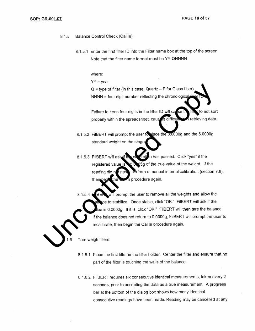
Uncon
trolle
d Cop
y

Uncon
trolle
d Cop
y

Uncon
trolle
d Cop
y

Uncon
trolle
d Cop
y

Uncon
trolle
d Cop
y

Uncon
trolle
d Cop
y

Uncon
trolle
d Cop
y

Uncon
trolle
d Cop
y

Uncon
trolle
d Cop
y

Uncon
trolle
d Cop
y
Uncon
trolle
d Cop
y

Uncon
trolle
d Cop
y

Uncon
trolle
d Cop
y

Uncon
trolle
d Cop
y

Uncon
trolle
d Cop
y

Uncon
trolle
d Cop
y

Uncon
trolle
d Cop
y

Uncon
trolle
d Cop
y

Uncon
trolle
d Cop
y

Uncon
trolle
d Cop
y

Uncon
trolle
d Cop
y

Uncon
trolle
d Cop
y

Uncon
trolle
d Cop
y

Uncon
trolle
d Cop
y

Uncon
trolle
d Cop
y

Uncon
trolle
d Cop
y

Uncon
trolle
d Cop
y

Uncon
trolle
d Cop
y

Uncon
trolle
d Cop
y

Uncon
trolle
d Cop
y

Uncon
trolle
d Cop
y

Uncon
trolle
d Cop
y

Uncon
trolle
d Cop
y

Uncon
trolle
d Cop
y

Uncon
trolle
d Cop
y

Uncon
trolle
d Cop
y

Uncon
trolle
d Cop
y

Uncon
trolle
d Cop
y

Uncon
trolle
d Cop
y

Uncon
trolle
d Cop
y

Uncon
trolle
d Cop
y

Uncon
trolle
d Cop
y

Uncon
trolle
d Cop
y

Uncon
trolle
d Cop
y

Uncon
trolle
d Cop
y

Uncon
trolle
d Cop
y

Uncon
trolle
d Cop
y

Uncon
trolle
d Cop
y
Uncon
trolle
d Cop
y

Uncon
trolle
d Cop
y

Uncon
trolle
d Cop
y

Uncon
trolle
d Cop
y

Uncon
trolle
d Cop
y

Uncon
trolle
d Cop
y

Uncon
trolle
d Cop
y

Uncon
trolle
d Cop
y

Uncon
trolle
d Cop
y

Uncon
trolle
d Cop
y

Uncon
trolle
d Cop
y

Uncon
trolle
d Cop
y

Uncon
trolle
d Cop
y

Uncon
trolle
d Cop
y

Uncon
trolle
d Cop
y

Uncon
trolle
d Cop
y - P
roprie
tary

Uncon
trolle
d Cop
y - P
roprie
tary

Uncon
trolle
d Cop
y - P
roprie
tary

Uncon
trolle
d Cop
y - P
roprie
tary

Uncon
trolle
d Cop
y - P
roprie
tary

Uncon
trolle
d Cop
y - P
roprie
tary

Uncon
trolle
d Cop
y - P
roprie
tary

Uncon
trolle
d Cop
y - P
roprie
tary

Uncon
trolle
d Cop
y - P
roprie
tary

Uncon
trolle
d Cop
y - P
roprie
tary

Uncon
trolle
d Cop
y - P
roprie
tary

Uncon
trolle
d Cop
y - P
roprie
tary

Uncon
trolle
d Cop
y - P
roprie
tary

Uncon
trolle
d Cop
y - P
roprie
tary

Uncon
trolle
d Cop
y - P
roprie
tary

Uncon
trolle
d Cop
y - P
roprie
tary

Uncon
trolle
d Cop
y - P
roprie
tary

Uncon
trolle
d Cop
y - P
roprie
tary

Uncon
trolle
d Cop
y - P
roprie
tary
Uncon
trolle
d Cop
y - P
roprie
tary

Uncon
trolle
d Cop
y - P
roprie
tary

Uncon
trolle
d Cop
y - P
roprie
tary
Uncon
trolle
d Cop
y - P
roprie
tary

Uncon
trolle
d Cop
y - P
roprie
tary

Uncon
trolle
d Cop
y - P
roprie
tary

Uncon
trolle
d Cop
y - P
roprie
tary

Uncon
trolle
d Cop
y - P
roprie
tary

Uncon
trolle
d Cop
y - P
roprie
tary

Uncon
trolle
d Cop
y - P
roprie
tary

Uncon
trolle
d Cop
y - P
roprie
tary

Uncon
trolle
d Cop
y - P
roprie
tary

Uncon
trolle
d Cop
y - P
roprie
tary

Uncon
trolle
d Cop
y - P
roprie
tary

Uncon
trolle
d Cop
y - P
roprie
tary

Uncon
trolle
d Cop
y - P
roprie
tary

Uncon
trolle
d Cop
y - P
roprie
tary

Uncon
trolle
d Cop
y - P
roprie
tary

Uncon
trolle
d Cop
y - P
roprie
tary

Uncon
trolle
d Cop
y - P
roprie
tary

Uncon
trolle
d Cop
y - P
roprie
tary

Uncon
trolle
d Cop
y - P
roprie
tary

Uncon
trolle
d Cop
y - P
roprie
tary

Uncon
trolle
d Cop
y - P
roprie
tary

Uncon
trolle
d Cop
y - P
roprie
tary

Uncon
trolle
d Cop
y - P
roprie
tary

Uncon
trolle
d Cop
y - P
roprie
tary

Uncon
trolle
d Cop
y

Uncon
trolle
d Cop
y

Uncon
trolle
d Cop
y

Uncon
trolle
d Cop
y

Uncon
trolle
d Cop
y

Uncon
trolle
d Cop
y

Uncon
trolle
d Cop
y

Uncon
trolle
d Cop
y

Uncon
trolle
d Cop
y

Uncon
trolle
d Cop
y

Uncon
trolle
d Cop
y

Uncon
trolle
d Cop
y

Uncon
trolle
d Cop
y

Uncon
trolle
d Cop
y

Uncon
trolle
d Cop
y

Uncon
trolle
d Cop
y

Uncon
trolle
d Cop
y

Uncon
trolle
d Cop
y

Uncon
trolle
d Cop
y

Uncon
trolle
d Cop
y

Uncon
trolle
d Cop
y

Uncon
trolle
d Cop
y

Uncon
trolle
d Cop
y

Uncon
trolle
d Cop
y

Uncon
trolle
d Cop
y

Uncon
trolle
d Cop
y

Uncon
trolle
d Cop
y

Uncon
trolle
d Cop
y

Uncon
trolle
d Cop
y

Uncon
trolle
d Cop
y

Uncon
trolle
d Cop
y

Uncon
trolle
d Cop
y

Uncon
trolle
d Cop
y

Uncon
trolle
d Cop
y

Uncon
trolle
d Cop
y

Uncon
trolle
d Cop
y

Uncon
trolle
d Cop
y

Uncon
trolle
d Cop
y

Uncon
trolle
d Cop
y

Uncon
trolle
d Cop
y

Uncon
trolle
d Cop
y

Uncon
trolle
d Cop
y

Uncon
trolle
d Cop
y

Uncon
trolle
d Cop
y

Uncon
trolle
d Cop
y

Uncon
trolle
d Cop
y

Uncon
trolle
d Cop
y

Uncon
trolle
d Cop
y
Uncon
trolle
d Cop
y

Uncon
trolle
d Cop
y

Uncon
trolle
d Cop
y

Uncon
trolle
d Cop
y

Uncon
trolle
d Cop
y

Uncon
trolle
d Cop
y

Uncon
trolle
d Cop
y

Uncon
trolle
d Cop
y

Uncon
trolle
d Cop
y

Uncon
trolle
d Cop
y

Uncon
trolle
d Cop
y
Uncon
trolle
d Cop
y

Uncon
trolle
d Cop
y

Uncon
trolle
d Cop
y

Uncon
trolle
d Cop
y

Uncon
trolle
d Cop
y
Uncon
trolle
d Cop
y
Uncon
trolle
d Cop
y

Uncon
trolle
d Cop
y

Uncon
trolle
d Cop
y

Uncon
trolle
d Cop
y

Uncon
trolle
d Cop
y

Uncon
trolle
d Cop
y

Uncon
trolle
d Cop
y

Uncon
trolle
d Cop
y

Uncon
trolle
d Cop
y

Uncon
trolle
d Cop
y

Uncon
trolle
d Cop
y

Uncon
trolle
d Cop
y

Uncon
trolle
d Cop
y

Uncon
trolle
d Cop
y

Uncon
trolle
d Cop
y
Uncon
trolle
d Cop
y

Uncon
trolle
d Cop
y

Uncon
trolle
d Cop
y

Uncon
trolle
d Cop
y

Uncon
trolle
d Cop
y

Uncon
trolle
d Cop
y

Uncon
trolle
d Cop
y

Uncon
trolle
d Cop
y

Uncon
trolle
d Cop
y

Uncon
trolle
d Cop
y

Uncon
trolle
d Cop
y

Uncon
trolle
d Cop
y

Uncon
trolle
d Cop
y

Uncon
trolle
d Cop
y

Uncon
trolle
d Cop
y

Uncon
trolle
d Cop
y

Uncon
trolle
d Cop
y

Uncon
trolle
d Cop
y

Uncon
trolle
d Cop
y

Uncon
trolle
d Cop
y

Uncon
trolle
d Cop
y

Uncon
trolle
d Cop
y

Uncon
trolle
d Cop
y

Uncon
trolle
d Cop
y

Uncon
trolle
d Cop
y

Uncon
trolle
d Cop
y

Uncon
trolle
d Cop
y

Uncon
trolle
d Cop
y

Uncon
trolle
d Cop
y

Uncon
trolle
d Cop
y

Uncon
trolle
d Cop
y

Uncon
trolle
d Cop
y

Uncon
trolle
d Cop
y

Uncon
trolle
d Cop
y

Uncon
trolle
d Cop
y

Uncon
trolle
d Cop
y

Uncon
trolle
d Cop
y

Uncon
trolle
d Cop
y

Uncon
trolle
d Cop
y

Uncon
trolle
d Cop
y

Uncon
trolle
d Cop
y

Uncon
trolle
d Cop
y

Uncon
trolle
d Cop
y

Uncon
trolle
d Cop
y

Uncon
trolle
d Cop
y

Uncon
trolle
d Cop
y

Uncon
trolle
d Cop
y

Uncon
trolle
d Cop
y

Uncon
trolle
d Cop
y

Uncon
trolle
d Cop
y

Uncon
trolle
d Cop
y