
PROJECT MANAGEMENT CONSULTANCY FOR ...
180
APPOINTMENT OF PROJECT MANAGEMENT CONSULTANTS FOR IMPLEMENTATION OF SMART CITY MISSION PROJECTS IN MANGALURU CITY DETAILED PROJECT REPORT – Smart Road Package 5 | Page Mangaluru Smart City Limited (MSCL) MANGALORE SMART CITY PROJECT Lalbaug, M.G. Road, Mangalore – 575003 4/23/2019 PROJECT MANAGEMENT CONSULTANCY FOR IMPLEMENTATION OF SMART CITY MISSION PROJECTS FOR MANGALURU CITY SMART ROAD PACKAGE - 05 DETAILED PROJECT REPORT - VOLUME I The purpose of the Detailed Project Report is to provide details of various considerations made towards the elements proposed for the project as mentioned in the title above. It aims to give a basic design idea to all the stakeholders before proceeding for final design and estimates.
-
Upload
khangminh22 -
Category
Documents
-
view
0 -
download
0
Transcript of PROJECT MANAGEMENT CONSULTANCY FOR ...

APPOINTMENT OF PROJECT MANAGEMENT CONSULTANTS FOR IMPLEMENTATION OF SMART CITY MISSION PROJECTS IN MANGALURU CITY
DETAILED PROJECT REPORT – Smart Road Package 5
| P a g e Mangaluru Smart City Limited (MSCL)
M A N G A L O R E S M A R T C I T Y P R O J E C T
L a l b a u g , M . G . R o a d , M a n g a l o r e – 5 7 5 0 0 3
4 / 2 3 / 2 0 1 9
PROJECT MANAGEMENT CONSULTANCY FOR IMPLEMENTATION OF SMART CITY MISSION PROJECTS FOR MANGALURU CITY SMART ROAD PACKAGE - 05 DETAILED PROJECT REPORT - VOLUME I
The purpose of the Detailed Project Report is to provide details of various considerations made towards the elements proposed for the project as mentioned in the title above. It aims to give a basic design idea to all the stakeholders before proceeding for final design and estimates.

APPOINTMENT OF PROJECT MANAGEMENT CONSULTANTS FOR IMPLEMENTATION OF SMART CITY MISSION PROJECTS IN MANGALURU CITY
DETAILED PROJECT REPORT – SMART ROAD PACKAGE 5
i | P a g e
Mangaluru Smart City Limited (MSCL)
ISSUE AND REVISION RECORD
Revision Date Originator Checker Approver Description Standard
1 23/04/2019 WTESL/LBI/ CDAC
MANI NARAYAN
URVI BHATT/ KAVITA WAKADE
DETAILED PROJECT REPORT
This document is issued for the party which commissioned it and for specific purposes connected with the above-captioned project only. It should not be relied upon by any other party or used for any other purpose.
We accept no responsibility for the consequences of this document being relied upon by any other party, or being used for any other purpose, or containing any error or omission which is due to an error or omission in data supplied to us by other parties. This document contains confidential information and proprietary intellectual property. It should not be shown to other parties without consent from us and from the party which commissioned it.

APPOINTMENT OF PROJECT MANAGEMENT CONSULTANTS FOR IMPLEMENTATION OF SMART CITY MISSION PROJECTS IN MANGALURU CITY
DETAILED PROJECT REPORT – SMART ROAD PACKAGE 5
ii | P a g e
Mangaluru Smart City Limited (MSCL)
CONTENTS
LIST OF FIGURES ........................................................................................................................ vii
LIST OF TABLES ........................................................................................................................... ix
ABBREVIATIONS ......................................................................................................................... xi
LIST OF REFERENCE CODES, STANDARDS, AND GUIDELINES ..................................................... xiii
EXECUTIVE SUMMARY ............................................................................................................... 1
A) INTRODUCTION OF SMART CITIES MISSION ............................................................ 1
B) BACKGROUND OF MANGALURU CITY ...................................................................... 1
C) DESCRIPTION OF ABD REGION ................................................................................ 1
D) PROPOSED PROJECTS IN SCP ............................................................................... 2
E) SMART ROAD PROJECT WITHIN ABD ....................................................................... 4
F) SELECTED ROADS IN THE PRESENT DPR (Package – 05) ........................................... 9
G) EXISTING AND PROPOSED COMPONENTS IN THE PRESENT DPR ........................ 10
H) COST (WITH COMPONENT WISE PIE CHART), ..................................................... 12
I) PROJECT FUNDING ................................................................................................ 13
Chapter 1 PROJECT BACKGROUND ............................................................................................ 14
1.1. Mangaluru Smart City Proposal ...................................................................................... 14
1.1.1. The Objective .................................................................................................... 14
1.2. Approach towards implementation of Smart Components ............................................. 14
1.2.1. Need for Intervention ........................................................................................ 14
1.2.1. Proposed Interventions ..................................................................................... 15
1.2.2. Expected Benefits .............................................................................................. 16
1.2.3. Assumptions/Prerequisites ................................................................................ 17
1.2.4. Stakeholders/ Organizations involved ................................................................ 17
1.2.5. Target Beneficiaries ........................................................................................... 17
1.2.6. Objective of the Report ..................................................................................... 18
1.2.7. Structure of the Report...................................................................................... 18
1.3. Area Description ............................................................................................................. 19
1.4. Comprehensive plan ....................................................................................................... 21
Chapter 2 FIELD INVESTIGATIONS & ANALYSIS .......................................................................... 22
2.1 Site Reconnaissance and Situation Analysis .................................................................... 22
2.1.1 Arya Samaj Road................................................................................................ 22

APPOINTMENT OF PROJECT MANAGEMENT CONSULTANTS FOR IMPLEMENTATION OF SMART CITY MISSION PROJECTS IN MANGALURU CITY
DETAILED PROJECT REPORT – SMART ROAD PACKAGE 5
iii | P a g e
Mangaluru Smart City Limited (MSCL)
2.1.2 Balmatta Road ................................................................................................... 23
2.1.3 Milagres Cross Road .......................................................................................... 25
2.1.4 Attavar Nandigudda Road .................................................................................. 26
2.1.5 New Balmatta Road ........................................................................................... 27
2.1.6 Kudumbi Garden (DBS) Road ............................................................................. 29
2.1.7 Azizuddin Road .................................................................................................. 30
2.1.8 Jumma Masjid Road .......................................................................................... 32
2.1.9 Bengre Ferry Road ............................................................................................. 33
2.2 Road Inventory Survey .................................................................................................... 35
2.3 Trial pits ......................................................................................................................... 35
2.4 Survey Introduction ........................................................................................................ 36
2.4.1 Project Background ........................................................................................... 36
2.4.2 Scope of Work ................................................................................................... 36
2.4.3 Survey Types and Locations ............................................................................... 37
2.4.4 TRAFFIC ANALYSIS ............................................................................................. 39
2.4.4.1 Methodology ................................................................................................. 39
2.4.4.2 Classified Traffic Volume Counts .................................................................... 39
2.4.4.3 Annual Average Daily Traffic (AADT) .............................................................. 40
2.4.4.4 Hourly Variation ............................................................................................. 41
2.4.4.5 Traffic Composition ........................................................................................ 45
2.4.4.6 Peak Hour Analysis ......................................................................................... 46
2.4.5 Traffic Forecast .................................................................................................. 50
2.4.6 Capacity Analysis ............................................................................................... 53
2.4.6.1 Road Standards .............................................................................................. 53
2.4.6.2 Junction Standards ......................................................................................... 54
2.4.6.3 Pedestrian facilities ........................................................................................ 54
2.4.6.4 Lane Configuration Analysis ........................................................................... 55
A) Roads ....................................................................................................................... 55
B) Junctions .................................................................................................................. 56
2.4.6.5 Pedestrian facilities ........................................................................................ 56
2.5 CARRIAGEWAY, JUNCTION IMPROVEMENT AND PAVEMENT DESIGN ............................. 57

APPOINTMENT OF PROJECT MANAGEMENT CONSULTANTS FOR IMPLEMENTATION OF SMART CITY MISSION PROJECTS IN MANGALURU CITY
DETAILED PROJECT REPORT – SMART ROAD PACKAGE 5
iv | P a g e
Mangaluru Smart City Limited (MSCL)
2.5.1 Carriageway Improvement ................................................................................ 57
2.5.1.1 Right of Way (ROW) ....................................................................................... 57
2.5.1.2 Design Speed ................................................................................................. 58
2.5.1.3 Cross Sections ................................................................................................ 58
2.5.1.4 Camber / Cross Fall ........................................................................................ 59
2.5.1.5 Geometry / Alignment ................................................................................... 59
2.5.2 Intersection Improvement ................................................................................. 59
2.5.2.1 Function of Intersection Design...................................................................... 60
2.5.2.2 Classification of Intersections types ............................................................... 60
2.5.2.3 Objectives for Intersection Design ................................................................. 61
2.5.2.4 Consideration for Intersection Design ............................................................ 61
2.5.2.5 Design Traffic Volumes:.................................................................................. 62
2.5.2.6 Capacity of Intersections: ............................................................................... 62
2.5.2.7 Traffic Calming Techniques ............................................................................ 62
2.5.3 Pavement Design ............................................................................................... 63
2.5.3.1 Arya Samaj Road ............................................................................................ 63
2.5.3.2 Arya Smaj Road 2 ........................................................................................... 71
2.5.3.3 Bengre Ferry Road 1 ....................................................................................... 79
2.5.3.4 Milagres Cross Road ....................................................................................... 87
2.5.3.5 Nadigudda Road- 1 ........................................................................................ 95
2.5.3.6 Nadiguda Road- 2......................................................................................... 103
2.5.3.7 New Balmatta Road ..................................................................................... 111
2.6 INFRASTRUCTURE AND UTILITIES PLANNING ................................................................ 119
2.6.1 Planned Utilities .............................................................................................. 119
2.6.2 Electrical Infrastructure ................................................................................... 119
2.6.3 Street Light ...................................................................................................... 122
2.6.4 Lighting Poles: ................................................................................................. 123
2.6.5 Centralized street lighting control ................................................................... 123
2.6.6 Wet Utilities .................................................................................................... 124
2.7 STUDY FINDINGS AND OBSERVATIONS ......................................................................... 134
2.7.1 Future Strategies as per Traffic Analysis .......................................................... 134
APPOINTMENT OF PROJECT MANAGEMENT CONSULTANTS FOR IMPLEMENTATION OF SMART CITY MISSION PROJECTS IN MANGALURU CITY
DETAILED PROJECT REPORT – SMART ROAD PACKAGE 5
v | P a g e
Mangaluru Smart City Limited (MSCL)
2.7.2 Summary of Findings ....................................................................................... 135
2.7.3 Trial Pit Reports ............................................................................................... 136
Chapter 3 PROPOSED DESIGN COMPONENTS .......................................................................... 139
3.1 Smart Road Components – Urban Design, Landscape and ITMS ................................... 139
3.1.1 Urban Design and Landscape ........................................................................... 139
3.1.2 Proposed Design Considerations ..................................................................... 140
3.1.3 Urban Design Features .................................................................................... 140
3.1.4 Landscaping ..................................................................................................... 144
3.1.5 Centralized street lighting control ................................................................... 145
3.1.6 IT/ICT Elements ............................................................................................... 145
3.2 Intelligent Traffic Management and Road Surveillance ................................................. 146
3.2.1 Intelligent Transport System (ITS) .................................................................... 146
3.2.2 Road Surveillance ............................................................................................ 146
3.3 TRAFFIC MANAGEMENT PLAN ...................................................................................... 147
3.3.1 Traffic Management during Construction and Upgradation Works .................. 147
3.3.2 Milagres Cross Road ........................................................................................ 148
3.3.3 New Balmatta Road ......................................................................................... 148
3.3.4 Jumma Masjid Port Road ................................................................................. 148
3.3.5 Attavara Road, Jumma Masjid Road, Balmatta Road, Azizuddin Road, Bengre Ferry Road, Arya Samaj Road ......................................................................................... 149
3.3.6 Safety Measure during Construction ............................................................... 149
3.3.7 Conclusion ....................................................................................................... 150
Chapter 4 TIMELINE FOR EXECUTION ...................................................................................... 151
4.1 Construction Phase ........................................................................................................... 151
4.2 Defect Liability................................................................................................................... 151
4.3 Maintenance Period .......................................................................................................... 151
Chapter 5 MONITORING AND EVALUATION ............................................................................ 152
Chapter 6 COST ESTIMATES ..................................................................................................... 154
6.1 Assumptions ...................................................................................................................... 154
6.2 Summary of Estimate ........................................................................................................ 154
6.3 Detailed BOQ .................................................................................................................... 154

APPOINTMENT OF PROJECT MANAGEMENT CONSULTANTS FOR IMPLEMENTATION OF SMART CITY MISSION PROJECTS IN MANGALURU CITY
DETAILED PROJECT REPORT – SMART ROAD PACKAGE 5
vi | P a g e
Mangaluru Smart City Limited (MSCL)
ANNEXURES I – LIST OF DRAWINGS ......................................................................................... 155
ANNEXURES II – SPECIFICATIONS ............................................................................................ 157
ANNEXURES III – DESIGN CALCULATIONS FOR STORM WATER DRAINAGE............................... 162
ANNEXURE IV - SUMMARY OF PAVEMENT THICKNESS – DPR 5 ............................................... 166

APPOINTMENT OF PROJECT MANAGEMENT CONSULTANTS FOR IMPLEMENTATION OF SMART CITY MISSION PROJECTS IN MANGALURU CITY
DETAILED PROJECT REPORT – SMART ROAD PACKAGE 5
vii | P a g e
Mangaluru Smart City Limited (MSCL)
LIST OF FIGURES
Figure 1 ABD area considered under Mangaluru Smart City and Priority Roads Identified for Development as Smart roads .................................................................................................................. 2
Figure 2 Selected Roads to be developed as smart roads ...................................................................... 8
Figure 3 Pie Chart Showing Major Components ................................................................................... 12
Figure 4 Vision methodology for Smart Roads in the city .................................................................... 15
Figure 5 Proposed interventions for the Selected Roads to be developed as smart roads ................. 16
Figure 6 Benefits of developing Smart roads ........................................................................................ 17
Figure 7 MANGALURU ABD AREA SHOWING IDENTIFIED PROJECT AS PER SMART CITY PROPOSAL ... 19
Figure 8 Smart Road Packaging ............................................................................................................. 20
Figure 9 Major Project Components of ABD Area under Smart City .................................................... 21
Figure 10 Master Plan Details – Aruya Samaj Road .............................................................................. 22
Figure 11 Existing Situation – Arya Samaj Road .................................................................................... 22
Figure 12 Existing Cross Section Arya Samaj Road ............................................................................... 23
Figure 13 Master Plan – MUDA Details – Balmatta Road ..................................................................... 24
Figure 14 Existing Situation – Balmatta Road ....................................................................................... 24
Figure 15 Existing Cross Section, Site Photographs and MUDA Master Plan layout of Milagres Cross Road ...................................................................................................................................................... 25
Figure 16Existing Cross Section, Site Photographs and MUDA Master Plan layout of Attavar Nandigudda Road .................................................................................................................................. 27
Figure 17 Existing Cross Sections, Site Photographs and MUDA Master Plan layout of New Balmatta Road ...................................................................................................................................................... 28
Figure 18 Existing Cross Sections, Site Photographs and MUDA Master Plan layout of Kudumbi Garden (DBS) Road................................................................................................................................ 30
Figure 19 Existing Cross Sections, Site Photographs and MUDA Master Plan layout of Azizuddin Road .............................................................................................................................................................. 31
Figure 20 Existing Cross Sections, Site Photographs and MUDA Master Plan layout of Jumma Masjid Road ...................................................................................................................................................... 32
Figure 21 Existing Cross Sections, Site Photographs and MUDA Master Plan layout of Bengre Ferry Road ...................................................................................................................................................... 34
Figure 22 Trial Pits Survey Site Photographs Traffic Surveys and Analysis ........................................... 35
Figure 23 Survey work in progress ........................................................................................................ 36
Figure 24 Traffic Survey Location .......................................................................................................... 38
Figure 25 Hourly Variation Graphs of Traffic on DPR-5 Smart roads .................................................... 44
Figure 26 Hourly Variation Graphs of Traffic on DPR-5 Smart roads .................................................... 45
Figure 27: Milagres Cross Road Junction .............................................................................................. 48
Figure 28: Anand Shetty Circle .............................................................................................................. 48
Figure 29: Avery Junction ...................................................................................................................... 49
Figure 30: Arya Samaj Road Junction .................................................................................................... 49
Figure 31: Bombay Lucky Junction ........................................................................................................ 50
Figure 32: Intersection selection based on criteria .............................................................................. 54
Figure 33 Mark-up showing the UGD lines proposed in Roads along Road 8 .................................... 125

APPOINTMENT OF PROJECT MANAGEMENT CONSULTANTS FOR IMPLEMENTATION OF SMART CITY MISSION PROJECTS IN MANGALURU CITY
DETAILED PROJECT REPORT – SMART ROAD PACKAGE 5
viii | P a g e
Mangaluru Smart City Limited (MSCL)
Figure 34 Mark-up showing the UGD lines proposed in Roads along Road 19 .................................. 125
Figure 35 Mark-up showing the UGD lines proposed in Roads 15a, 15b & 20 ................................... 126
Figure 36 Storm water drainage on the considered roads ................................................................. 127
Figure 37 Existing drain and newly constructed drain along 7a ......................................................... 127
Figure 38 Existing drains along 7c ....................................................................................................... 128
Figure 39 Drains in New Balmatta Road-8 .......................................................................................... 128
Figure 40New drains being constructed along Road-10 ..................................................................... 128
Figure 41 Existing drains along 15a ..................................................................................................... 129
Figure 42 Existing drains along 15b .................................................................................................... 129
Figure 43 Existing drains along 19 ....................................................................................................... 129
Figure 44 Existing drain along Road 20 & No drain along Port area ................................................... 130
Figure 45 Typical Proposed Model of Pedestrian Crossing and Smart Elements ............................... 142
Figure 48 Traffic Control System along the road during Construction ............................................... 150
Figure 49 Traffic Control System along the road during Construction ............................................... 150

APPOINTMENT OF PROJECT MANAGEMENT CONSULTANTS FOR IMPLEMENTATION OF SMART CITY MISSION PROJECTS IN MANGALURU CITY
DETAILED PROJECT REPORT – SMART ROAD PACKAGE 5
ix | P a g e
Mangaluru Smart City Limited (MSCL)
LIST OF TABLES
Table 1 Smart City Project Details 3
Table 2 Smart Road Packages 4
Table 3 Package -05 Road Details 5
Table 4 Mangaluru Smart City: Smart Roads Package- I to V 7
Table 5 Existing Component of Smart Road Package – 05 10
Table 6 Proposed Components Smart Road Package -05 11
Table 7 Summary of Cost – Smart Road Package - 05 12
Table 8 Smart Road Packages – Cost as per SCP and DPR 13
Table 10 Traffic Surveys and Investigations conducted along the DPR-5 Roads 37
Table 11 Traffic Surveys - Vehicle Classification system 37
Table 12 PCU Factors Adopted for Study 39
Table 13 Average Daily Traffic 40
Table 14 Composition of Passenger and Commercial Vehicles 45
Table 15 Composition of Public and Private modes of transport 46
Table 16 Peak Hour Volume and Peak %age 47
Table 17 Projected Peak hour volumes in PCU 50
Table 18 Detailed Analysis of Junction Traffic for Present condition and Future Predictions (As per IRC -92) 51
Table 19:Detailed Analysis of Junction as per SP-41 52
Table 20: Pedestrian Vehicular Conflict at Major Arm 53
Table 21 Recommended Design Service Volumes (PCU/Hr) 53
Table 22 Existing Lane Configuration of Roads 55
Table 23 Unconstrained Capacity Requirement Based on Traffic (Lanes) 55
Table 24 Plan and Profile for DPR 5 roads 57
Table 25 Pros and Cons of Signalized Intersection and Roundabout 61
Table 26 Axial load Spectrum assumed – Arya Samaj Road 63
Table 27 Fatigue Cracking Analysis 65
Table 28 Pavement Composition 70
Table 29 Axle Load Spectrum (Assumed) – Arya Samaj Road 2 71
Table 30 fatigue cracking analysis – Arya Samaj Road 2 74
Table 31 Fatigue Damage Analysis – Arya Samaj Road 2 75
Table 32 Pavement Composition: Arya Samaj Road 2 78
Table 33 Axle Load Spectrum (Assumed): Bengre Ferry Road 1 79
Table 34 Fatigue Cracking Analysis Axle -Bengre Ferry Road 1 82
Table 35 Fatigue Damage Analysis: Bengre Ferry Road 1 83
Table 36 Pavement Composition: Bengre Ferry Road 1 86
Table 37 Axle Load Spectrum (Assumed): Milegres Cross Road 87
Table 38 Fatigue cracking analysis 90
Table 39 Fatigue Damage Analysis 91
Table 40 Pavement Composition: 94

APPOINTMENT OF PROJECT MANAGEMENT CONSULTANTS FOR IMPLEMENTATION OF SMART CITY MISSION PROJECTS IN MANGALURU CITY
DETAILED PROJECT REPORT – SMART ROAD PACKAGE 5
x | P a g e
Mangaluru Smart City Limited (MSCL)
Table 41 Axle Load Spectrum (Assumed): Nadiguda road 1 95
Table 42 fatigue cracking analysis – Nadiguda Road 1 98
Table 43 Fatigue Damage Analysis 99
Table 44 Pavement Composition: 102
Table 45 Axle Load Spectrum (Assumed): Nadiguda road 2 103
Table 46 Fatigue cracking analysis 106
Table 47 Fatigue Damage Analysis 107
Table 48 Pavement Composition: 110
Table 49 Axle Load Spectrum (Assumed): 111
Table 50 Fatigue Crack Analysis 114
Table 51 Fatigue Damage Analysis 115
Table 52 Pavement Composition: 118
Table 53 Existing Transformer locations 120
Table 54 Existing Electric Cable/Pipes locations 122
Table 55 Classification of lighting installation 123
Table 2.6-4 Details of Utilities along DPR-5 Roads 131
Table 57 Overall Summary of UGD Package-4 132
Table 58 Cost Abstract-UGD Package-4 132
Table 59 Components of UGD Package-4 DPR 133
Table 60 Cost Abstract-UGD Package-2 133
Table 61 Cost Abstract-UGD Package-2 133
Table 62 Components of UGD Package-2 DPR 134
Table 63 List of Cross Sections 142
Table 64 Proposed Pedestrian Facilities 143
Table 65 Road Upgradation Features 147
Table 66 Modal Split of Milagres Cross Road 148
Table 67 Modal Split of New Balmatta Road 148
Table 69 Modal Split of Port Road 148
Table 70 Risks Mitigation Strategies 152
Table 71 Smart Road Package- 5 – Summary of Estimate 154
Table 0-1: Tactile Paving 161

APPOINTMENT OF PROJECT MANAGEMENT CONSULTANTS FOR IMPLEMENTATION OF SMART CITY MISSION PROJECTS IN MANGALURU CITY
DETAILED PROJECT REPORT – SMART ROAD PACKAGE 5
xi | P a g e
Mangaluru Smart City Limited (MSCL)
ABBREVIATIONS
ABD
Area Based Development
ATM Automated Teller Machine
MCC Mangaluru City Corporation
MSCL Mangaluru Smart City Limited
GoI Government of India
GoK Government of Karnataka
SCP Smart City Proposal
SPV Special Purpose Vehicle
IRC Indian Road Congress
IUT Institute of Urban Transport
KUIDFC Karnataka Urban Infrastructure Development & Finance Corporation Limited
SCP Smart City Proposal
SLNA State Level Nodal Agency
ROW Right of Way
MESCOM Mangalore Electricity Supply Company Limited
KSRTC Karnataka State Road Transport Corporation
LED Light Emitting Diode
CCTV Closed-circuit Television
GCP Ground Control Points
DTM Digital Terrain Model
LCV Light Commercial Vehicle
ADT Average Daily Traffic
PCU Passenger Car Units
MoUD Ministry of Urban Development
IT Information Technology
ICT Information and Communication Technology
ITS Intelligent Transport System
ITMS Intelligent Traffic Management System
OFC Optical Fiber Cable
O&M Operation and Maintenance
DPR Detailed Project Report
RFP Request for Proposal

APPOINTMENT OF PROJECT MANAGEMENT CONSULTANTS FOR IMPLEMENTATION OF SMART CITY MISSION PROJECTS IN MANGALURU CITY
DETAILED PROJECT REPORT – SMART ROAD PACKAGE 5
xii | P a g e
Mangaluru Smart City Limited (MSCL)
SOR Schedule of Rates
PWD Public Works Department
RTO Regional Transport Office

APPOINTMENT OF PROJECT MANAGEMENT CONSULTANTS FOR IMPLEMENTATION OF SMART CITY MISSION PROJECTS IN MANGALURU CITY
DETAILED PROJECT REPORT – SMART ROAD PACKAGE 5
xiii | P a g e
Mangaluru Smart City Limited (MSCL)
LIST OF REFERENCE CODES, STANDARDS, AND GUIDELINES
The following Codes and Standards have been referred in preparing the document
1. Indian Roads Congress (IRC) Codes & Standards • IRC: 86-1983 - Geometric Design Standards for Urban Roads in Plains • IRC: 106-1990 - Guidelines for Capacity of Urban Roads in Plain Areas • IRC: 58-2015 - Guidelines for the Design of Plain Jointed Rigid Pavements for
Highways (Fourth Revision) • IRC: 15-2017 - Code of Practice for Construction of Jointed Plain Concrete
Pavements (Fifth Revision) • IRC: SP:23-1983 - Vertical Curves for Highways • IRC: 65-2017 - Guidelines for Planning and Design of Roundabouts (First Revision) • IRC: 69-1977 - Space Standards for Roads in Urban Areas • IRC: 99-2018 - Guidelines for Traffic Calming Measures in Urban and Rural Areas
(First Revision) • IRC: 103-2012 - Guidelines for Pedestrian Facilities • IRC: SP:12-2015 - Guidelines for Parking Facilities in Urban Roads • IRC: SP:41-1994 - Guidelines on Design of At-Grade Intersections in Rural & Urban
Areas • IRC: 35-2015 - Code of Practice for Road Markings • IRC: 67-2012 - Code of Practice for Road Signs
2. Documents prepared by Institute of Urban Transport, Ministry of Urban Development • Code of Practice Part I – Cross Section • Code of Practice Part II – Intersections • Code of Practice Part III – Road Marking • Code of Practice Part IV – Signage • Code of Practice Part V – Traffic Calming

APPOINTMENT OF PROJECT MANAGEMENT CONSULTANTS FOR IMPLEMENTATION OF SMART CITY MISSION PROJECTS IN MANGALURU CITY
DETAILED PROJECT REPORT – Smart Road Package 5
1 | P a g e Mangaluru Smart City Limited (MSCL)
EXECUTIVE SUMMARY
A) INTRODUCTION OF SMART CITIES MISSION
The Smart City Mission aims at driving economic growth and improving the quality of life of the people by enabling local government and harnessing technology as a means to create smart outcomes for citizens.
The focus is on achieving sustainable and inclusive development in compact arrears and to replicate their success in other aspiring cities
The program strategizes to undertake implementation through area based development approach through Retrofitting (City Improvement), Redevelopment (City Renewal), Greenfield Development (City Extension) and Pan City Initiatives
B) BACKGROUND OF MANGALURU CITY
Mangalore, officially known as Mangaluru, is the chief port city of the Indian state of Karnataka located about 352 km west of the state capital, Bangalore. It is the second major city in Karnataka state in all aspects after the capital city Bangalore. It is the only city in Karnataka to have all modes of transport — Air, Road, Rail and Sea along with 5 other major cities in India and is also known as the Gateway of Karnataka. It is the largest city in the Tulu Nadu region of Karnataka. Mangalore is the second best business destination in Karnataka after Bangalore & 13th best in India. The population of the urban agglomeration was 623,841, according to the provisional results of the 2011 national census of India.
Mangalore is one of the major portsin India which handles 75 per cent of India's coffee and cashew exports. Mangalore is the largest city and administrative headquarters of the Dakshina Kannada district, and is one of the most multicultural non-metro cities of India. The city's landscape is characterised by rolling hills, coconut palms, freshwater streams and hard red-clay tiled-roof buildings.
Mangalore is also included in the Smart Cities Mission list and one among the 100 smart cities to be developed in India. The city has an average elevation of 22 m (72 ft) above mean sea level. Mangalore has a tropical monsoon climate, and is under the influence of the Southwest monsoon.
C) DESCRIPTION OF ABD REGION
Mangaluru Smart City Proposals (SCP) is considered as Area Based Development Proposals (ABD) and Pan City Proposals. The SCP has identified 65 projects/sub projects to be taken up under ABD and Pan City Proposal. Figure 1-1 shows the ABD area considered under Mangaluru Smart City Proposal and the priority roads for development as smart roads

APPOINTMENT OF PROJECT MANAGEMENT CONSULTANTS FOR IMPLEMENTATION OF SMART CITY MISSION PROJECTS IN MANGALURU CITY
DETAILED PROJECT REPORT – SMART ROAD PACKAGE 5
2 | P a g e Mangaluru Smart City Limited (MSCL)
Figure 1 ABD area considered under Mangaluru Smart City and Priority Roads Identified for Development as Smart roads
D) PROPOSED PROJECTS IN SCP
Sr. No. Name of the Project
Value of the Project (in INR Cr)
1 Improvements to Nehru Maidan Road from Clock Tower to AB Shetty Circle 7.560 2 Development of MLCP with retail space near Hampankatta Junction 94.000
3 Construction of Under Ground Drainage in zone-4 (Part-1) in ABD area Package -01 4.995
4 100% Underground Drainage network in ABD Area - Package 3 3.000 5 Conversion of all the lighting in government building into LED 2.230 6 Installation of Rooftop Solar on Government Buildings in ABD area - Phase 1 7.080 7 Implementation of Command and Control Center Components 38.790 8 Construction of Smart Bus shelter and E-Toilets in PAN City - Phase 1 4.800 9 Construction of Smart Bus shelter and E-Toilets in PAN City - Phase 2 4.600
10 Construction of Under Ground Drainage in Zone IV part 2 and Zone III part 1 in ABD Area Package -02 9.500
11 Redevelopment of Central Market along with Fish Market 145.000 12 LED Street Lights 69.350 13 Smart Road Package 2 12.500 14 Smart Road Package 3 42.060
ABD AREA:
1628 ACRES identified in Central Business District around Hampankatta, Bunder and Car Street is proposed for Retrofitting and Redevelopment
CENTRAL NODE HAS BEEN IDENTIFIED AS PRIORITY FOR DEVELOPMENT AS SMART ROADS

APPOINTMENT OF PROJECT MANAGEMENT CONSULTANTS FOR IMPLEMENTATION OF SMART CITY MISSION PROJECTS IN MANGALURU CITY
DETAILED PROJECT REPORT – SMART ROAD PACKAGE 5
3 | P a g e Mangaluru Smart City Limited (MSCL)
15 Smart Road Package 4 48.000 16 Smart Road Package 5 49.000 17 Smart Road Package 6 48.000 18 Smart Road Package 7 40.520 19 Smart Road Package 9 – Pedestrian Plaza Underpass near Clock Tower Circle 5.310
20 100% water supply coverage along with residential meters, water quality monitoring and SCADA 10.000
21 Implementation of rain water harvesting in all building having area more than 1000 sqft. 2.000
22 100% Underground Drainage network in ABD Area - Package 4 25.200 23 100% Underground Drainage network in ABD Area - Package 5 49.000 24 100% Underground Drainage network in ABD Area - Package 6 46.010 25 Retrofit Car Street & areas of Sri Venkatramana Temple as Religious Zone 14.590
26 Redevelopment of Vacant Premises of DC office into Hotel, Retail Shops and Speciality Restaurants 10.000
27 Upgradation of Wenlock & Lady Goshen Hospital- Package 1 8.040 28 Skill Development and Safety Training Centre 3.300
29 Implementation of E-smart schools in all government schools - Package 1 - Infrastructure 11.000
30 Implementation of E-smart schools in all government schools - Package 2 – ICT 5.000 31 Waterfront Area Development- Package 1 49.000 32 Waterfront Area Development- Package 2 49.000 33 Waterfront Area Development- Package 3 49.000 34 Waterfront Area Development- Package 4 48.000 35 Waterfront Area Development- Package 5 40.000
36 Retrofitting of tile and Brick factories into Hotel, Auditorium, Convention Centre, Museum, Marina with retail and Speciality Restaurants- Package 1 6.000
37 Retrofitting of tile and Brick factories into Hotel, Auditorium, Convention Centre, Museum, Marina with retail and Speciality Restaurants- Package 2 8.000
38 Retrofitting of tile and Brick factories into Hotel, Auditorium, Convention Centre, Museum, Marina with retail and Speciality Restaurants- Package 3 10.050
39 Development of Green Area along Connector Road 7.020 40 Solar and Recreational Island 86.740 41 Installation of Roof Top Solar on Government Buildings - Package 2 10.000 42 Installation of Roof Top Solar on Government Buildings - Package 3 10.000 43 IPDS Proposals - Package 1 15.000 44 IPDS Proposals - Package 2 15.000 45 Redevelopment of Old Bus Stand Area 25.000 46 Construction of Command and Control Center Building 3.000 47 Command and Control Center - Stage 2 49.000 48 Command and Control Center - Stage 3 23.690 49 Construction of Smart Bus shelter and E-Toilets in PAN City - Phase 3 3.560
Total Project Cost 1327.495 Table 1 Smart City Project Details

APPOINTMENT OF PROJECT MANAGEMENT CONSULTANTS FOR IMPLEMENTATION OF SMART CITY MISSION PROJECTS IN MANGALURU CITY
DETAILED PROJECT REPORT – SMART ROAD PACKAGE 5
4 | P a g e Mangaluru Smart City Limited (MSCL)
E) SMART ROAD PROJECT WITHIN ABD
Transforming existing roads into Smart Roads has been envisaged under the Smart City Mission. In this regard, Mangaluru Smart City Ltd (MSCL) intends to develop world class road infrastructure that is efficient mode of transport and inclusive to all strata of society. This entails comprehensive upgrading of the public Right of Way (ROW) of the streets which includes refurbishment of existing carriageway, laying of new footpaths and cycle tracks, creating utility corridors, developing pedestrian facilities, development works for landscape, hardscape, street furniture, signage, lighting, etc.
The following projects proposed under Mangaluru SCP have been clubbed together and considered under Design and Development of Smart Roads.
As per sanctioned SCP earlier, the projects combined to be taken for smart roads package 3 are listed below:
As per As per the revised SCP, sanctioned recently the smart road Packages are listed below:
Sr. No. Name of the Project Value of the
Project (in INR Cr)
1 Improvements to Nehru Maidan Road from Clock Tower to AB Shetty Circle 7.560
2 Smart Road Package 2 12.500 3 Smart Road Package 3 42.060 4 Smart Road Package 4 48.000 5 Smart Road Package 5 49.000 6 Smart Road Package 6 48.000 7 Smart Road Package 7 40.520
Table 2 Smart Road Packages
Smart Roads under Mangaluru Smart City
The development of smart roads has been perceived in phased manner:
Package 1 included Maidan road (from Clock Tower Circle to AB Shetty Circle
Package 2 included Maidan road II (from AB Shetty Circle to Hamilton Circle), 4th Cross road, Mission Street Road and Nellikai road.
SMART ROADS
S NO. 19 ABD COMPONENT
S NO. 21 ABD COMPONENT
S NO. 23 ABD COMPONENT
S NO. 25 ABD COMPONENT

APPOINTMENT OF PROJECT MANAGEMENT CONSULTANTS FOR IMPLEMENTATION OF SMART CITY MISSION PROJECTS IN MANGALURU CITY
DETAILED PROJECT REPORT – SMART ROAD PACKAGE 5
5 | P a g e Mangaluru Smart City Limited (MSCL)
Package 3 included Balmatta road (two way), Balmatta road (one way), Light house hill road, Rosario Church road, Pandeshwar road and Bunder road.
Package 4 included the following roads:
1. Mother Theresa Road: Hampankatta to Milagres cross road 2. Attavar Road : Mother Theresa road to Nandigudda road 3. Sturrock Road : Avery Junction –Anand Shetty Circle 4. Bunts Hostel road: Jyoti Circle to Bunts hostel junction 5. KudmalRanga Rao Road part A: Arya Samaj Road Junction to PVS Circle 6. KudmalRanga Rao Road part B: PVS Circle to Hampankatta junction
Package -05 Road Details are tabulated below:
1. Milagres Cross Road (KMC Marcara Road – Mother Theresa Road Junction) 2. Nandigudda Attavara Road (Wenlock Railway Node – Attavara KMC Hospital Jn.) 3. New Balmatta Road (Jyothi Circle – Avery Junction) 4. Don Bosco School Road (KMC Marcara – Avery Junction) 5. Azizuddin Road (Lower Car Street – Bunder Police Station) 6. Jumma Masjid Road (Lower Car Street – Bombay Lucky Junction) 7. Arya Samaj Road (Arya Samaj KRR Rd Jn – Collector’s Gate Circle) 8. Balmatta Road (Jyothi Circle – Collector’s Gate Circle) 9. Bengre Ferry Road (Port Rd Ansari Rd Jn – BMS Ferry Line)
Table 3 Package -05 Road Details
Other Roads to be developed in future phase(s) include Mangaladevi Road, Car Street (from Sri Venkatramana Temple to Tile Factory), Bibi Alabi Road (from Junction with Nellikai Road to Bengre Ferry), Bunder Road (from Junction with Old Port Road to Hoige Bazaar), Marnamikatta Road. Junction Improvements are considered as integral part of smart roads design and development. Figure below shows the Roads considered for development as Smart Roads for DPR 1, 2, 3, 4, 5, 6A, 6B & 7.
Phase Rd. no. Name of Rd. From To Road
Length I - Pilot 1 Nehru Maidan Rd. AB Shetty Circle Clock Tower 545.00
II - Loop Rd 1 Maidan Rd.-II AB Shetty Circle Hamilton Circle 248.00 II - Loop Rd 2 4th Cross Rd. Hamilton Circle Rao & Rao Circle 266.00
II - Loop Rd 4 Nellikai Rd. Hamilton Circle Missn. St - Nellikai Jn 352.00
II - Loop Rd 3 Mission St. Rd Misn. St-Nellikai Jn Rao & Rao Circle 206.00
III 1 Rosario Church Rd. Hamilton Circle Bunder Railway Gate 898.81
III 2 Pandeshwar Rd. AB Shetty Circle Rosario Church Rd. 479.96
III 3 Bunder Police Station Bombay Lucky Jn. Railway Gate Bus Stop 1336.57
III 4 KMC Mercara Trunk Hampankatta Jn. Jyoti circle 984.24

APPOINTMENT OF PROJECT MANAGEMENT CONSULTANTS FOR IMPLEMENTATION OF SMART CITY MISSION PROJECTS IN MANGALURU CITY
DETAILED PROJECT REPORT – SMART ROAD PACKAGE 5
6 | P a g e Mangaluru Smart City Limited (MSCL)
Rd. III 5 Light house hill Rd. Hampankatta Jn. Jyoti circle 961.14 III 6 Mohd. Ali Rd. Nellikai Jn. Bombay Lucky Jn. 100.00 IV 1 Balmatta Rd. Clock Tower Hampankatta 365.32 IV 2 Mother Theresa Rd. Hampankatta Jn. Milagres Church Jn. 224.06
IV 3 Milagres Nandigudda Rd. Milagres Church Nandigudda Rd. 322.96
IV 4 KSR Rao Rd. PVS Circle- KSR Rd. Hampankatta Jn. 1123.23
IV 5 KRR Rd. ( Kudmal Ranga Rao Rd.) PVS Jn. Arya Samaj Rd. Jn. 1118.88
IV 6 Bunts Hostel Rd. Bunts Hostel Jn. Jyothi Circle 961.14
V 1 Milagres Cross Rd. KMC Central Library Jn Milagres Church Jn 183.00
V 2 Attavara-Nandigudda Rd.
Nandigudda Wenlock Jn KMC Hospital 1021.00
V 3 Kudumbi Garden (DBS) Road
KMC Mercara Trunk Rd. Avery Juction 375.00
V 4 New Balmatta Rd. Jyoti circle Avery Juction 577.00
V 5 Arya Samaj Rd. KRR Rd - Arya Samaj Rd Jn. Balmatta Road Jn. 595.00
V 6 Balmatta Road Jyoti circle Arya Samaj Road Jn. 330.00
V 7 Azizuddin Road Car Street Bunder Police Station 717.00
V 8 Jumma Masjid-Old Port Rd. Car Street Badria School Jn. 966.00
V 9 Bendre Ferry Rd. Jumma Masjid BMS Ferry Lane 1103.00
VI 1 OLD PORT ROAD Hamilton Circle Bendre Ferry - Old Fort Jn 465.00
VI 2 OLD KENT ROAD Old Kent Rd. Mangaladaevi Rd Jn. 820.00
VI 3 PANDESHWARA NEW ROAD Rosario Church Rd. Pandeshwar New
Rd. 280.00
VI 4 BOLAR FISHERIES COLLEGE RD
Hoigebazar Rd. (KFDC Ltd)
Sea Face (Mangaluru Old
Port) 150.00
VI 5 MULIHITHLU ROAD Mangaladevi Temple Mulihithlu Rd. 920.00
VI 6 MANGALADEVI TEMPLE ROAD
Mangaladevi Temple Marnamikatta Circle 830.00
VI 7 MONKEYSTAND NEW ROAD
Mangaladevi Rd (Ramakrishna Math
Jn) Jaihind Circle 539.01
VI 8 JEPPU MARKET ROAD Abhaya Limbs Center Jeppu Market Jn. 225.00
VI 9 GUJJARKERE ROAD Jeppu Market Jn. Jappina Mogaru 645.00
VII 1 G.H.S ROAD (Footpath Only) Balmatta Road Sharavu Temple Jn 370.00
VII 2 P.M RAO ROAD KSR Road GHS Road Jn (Srinivas College) 145.00

APPOINTMENT OF PROJECT MANAGEMENT CONSULTANTS FOR IMPLEMENTATION OF SMART CITY MISSION PROJECTS IN MANGALURU CITY
DETAILED PROJECT REPORT – SMART ROAD PACKAGE 5
7 | P a g e Mangaluru Smart City Limited (MSCL)
VII 3 SHARAVU TEMPLE
ROAD KSR Road GHS Road Jn (Ganapathi Mandir) 185.00
VII 4 G.H.S CROSS ROAD (Jewellery Ln) GHS Road Jn Flower Market Rd 180.00
VII 5 VITOBHA TEMPLE ROAD
KSR Road (Karnataka Bank)
Venkataramana Temple Sq. 490.00
VII 6 MAIDAN 1st CROSS
ROAD
Mangala College (via Central Market
Rd) Car Street Cross Rd. 375.00
VII 7 CENTRAL MARKET BACK SIDE RD Clock Tower Circle Market Road Jn 150.00
VII 8 MAIDAN 3rd CROSS
ROAD Bibi Alabi Rd Bibi Alabi Rd-Kandak Rd Jn 180.00
VII 9 BIBI ALABI ROAD Clock Tower Circle Rao & Rao Circle 470.00 VII 10 BIBI ALABI - KANDAK
ROAD Central Market
Parking MPT Road Jn 460.00
VII 11 MAIDAN 4TH CROSS ROAD - EXTN Rao & Rao Circle Kandak Road Jn 195.00
VII 12 MPT ROAD Car Street (Viswakarma Bank) Mohd Ali Road Jn 715.00
VII 13 KASSAIGALLI MASJID SIDE ROAD Kassaigalli Masjid JM Road 200.00
VII 14 J.M 1st CROSS ROAD Ramachandra Mandir Jumma Masjid Rd 235.00
VII 15 MISSION STREET ROAD - EXTN
Mission Street Azizuddin Jn Bendre Ferry Rd 245.00
VIII 1 ARYA SAMAJ RD - KADRI JN
KRR Rd - Arya Samaj Rd Jn. Kadri Jn
881.77
VIII 2 COLLECTORS GATE - PUMPWELL Collector's Gate Jn Pumpwell Jn 1459.36
VIII 3 FALNIR RD (AVERY - KANKANADY) Avery Jn Kankanady Jn
1207.23
VIII 4 S.L MATHIAS ROAD Sturrock Road Jn Bendoor Well Jn (MT Road Jn) 976.38
VIII 5 ATTAVARA KATTE ROAD KMC Hospital Kotichennaya Jn 811.01
VIII 6 MPHASIS ROAD Marnamikatte Jn Jeppu Market Jn. 545.23
VIII 7 JEPPU MORGANS GATE ROAD Jeppu Market Jn. Mphasis Jn
334.34 VIII 8 DONGERKERY ROAD Navbharat Circle Chitra Jn 721.19 SP1 1 Car Street Road Chitra Jn Lower Car Street 797.92 SP1 2 Connector Road Yemmekere Jn Bolar Sea Face 934.88 SP1 3 Mahakali Padpu Road Mphasis Jn Jeppina Mogaru Jn 926.02
Table 4 Mangaluru Smart City: Smart Roads Packages

APPOINTMENT OF PROJECT MANAGEMENT CONSULTANTS FOR IMPLEMENTATION OF SMART CITY MISSION PROJECTS IN MANGALURU CITY
DETAILED PROJECT REPORT – Smart Road Package 5
Mangaluru Smart City Limited (MSCL)
Figure
FOR IMPLEMENTATION
Figure 2 Selected Roads to be developed as smart roads
8 | P a g e

APPOINTMENT OF PROJECT MANAGEMENT CONSULTANTS OF SMART CITY MISSION PROJECTS IN MANGALURU CITY
DETAILED PROJECT REPORT – Smart Road Package 5
Mangaluru Smart City Limited (MSCL)
F) SELECTED ROADS IN THE PRESENT DPR
The present DPR consist detailed working of
7a Milagres Cross Road (KMC Marcara Road
7c Nandigudda Attavara Road (Wenlock Railway Node
8 New Balmatta Road (Jyothi Circle
10 Don Bosco School Road (KMC Marcara
15a Azizuddin Road (Lower Car Street
15b Jumma Masjid Road (Lower Car Street
19a Arya Samaj Road (Arya Samaj
19b Balmatta Road (Jyothi Circle
20 Bengre Ferry Road (Port Rd Ansari Rd Jn
The Figure 1-2 shows the roads considered for DPR 5 package.
15a
15b
20
PROJECT MANAGEMENT CONSULTANTS FOR IMPLEMENTATION OF SMART CITY MISSION PROJECTS IN MANGALURU CITY
Smart Road Package 5
Mangaluru Smart City Limited (MSCL)
SELECTED ROADS IN THE PRESENT DPR (Package – 05)
working of 9 number of roads namely
Milagres Cross Road (KMC Marcara Road – Mother Theresa Road Junction)
Nandigudda Attavara Road (Wenlock Railway Node – Attavara KMC Hospital Jn.)
Road (Jyothi Circle – Avery Junction)
Don Bosco School Road (KMC Marcara – Avery Junction)
Azizuddin Road (Lower Car Street – Bunder Police Station)
Jumma Masjid Road (Lower Car Street – Bombay Lucky Junction)
Arya Samaj Road (Arya Samaj KRR Rd Jn – Collector’s Gate Circle)
Balmatta Road (Jyothi Circle – Collector’s Gate Circle)
Bengre Ferry Road (Port Rd Ansari Rd Jn – BMS Ferry Line)
considered for DPR 5 package.
7c
7a
8 10
19b
19a
9 | P a g e
Mother Theresa Road Junction)
Attavara KMC Hospital Jn.)

APPOINTMENT OF PROJECT MANAGEMENT CONSULTANTS FOR IMPLEMENTATION OF SMART CITY MISSION PROJECTS IN MANGALURU CITY
DETAILED PROJECT REPORT – Smart Road Package 5
10 | P a g e Mangaluru Smart City Limited (MSCL)
G) EXISTING AND PROPOSED COMPONENTS IN THE PRESENT DPR
Rd. no. Name of Rd.
Rd. Length Pavement Median SWD
Details Footpath Street Light From To Mts Type
7a Milagres Cross Rd.
KMC Central Library Jn.
Milagres Church Jn 183.00 Flexible No No No No
7c Nandigudda Rd. Attavar Rd. Mglr. Railway Rd. 1021.00 Rigid No No One side One Side
8 New Balmatta Rd. Jyoti circle Ivory
Junction 577.00 Flexible No One-side One side One Side
10 Don Bosco hall cross Rd.
KMC Mercara Trunk Rd.
Ivory Junction 375.00 Rigid No One-side One side No
15a Jumma Masjid Rd. Car Street Bunder
Police Station 595.00 Rigid No Two-side Yes - Both Side No
15b Port Rd. Bunder Rd. Badriya School Jn. 330.00 Rigid No One-side One side No
19a Arya Samaj Rd. Balmatta Circle Mangalore Hospital 717.00 Paver No Two-side One side One Side
19b Balmatta Road Jyoti circle Arya Samaj Road Jn. 966.00 Rigid Yes Two-side Two-side Two-side
20 Bendre Ferry Rd. Jumma Masjid BMS Ferry Lane 1103.00 Flexible No One-side No No
Total - V 5867.00 Table 5 Existing Component of Smart Road Package – 05

APPOINTMENT OF PROJECT MANAGEMENT CONSULTANTS FOR IMPLEMENTATION OF SMART CITY MISSION PROJECTS IN MANGALURU CITY
DETAILED PROJECT REPORT – SMART ROAD PACKAGE 5
11 | P a g e Mangaluru Smart City Limited (MSCL)
Rd no
Name of Rd.
Rd. Length Pavement Proposed
Median SWD Footpath Utility Conduits
Bus Shelt
er
Street Light UGD
From To Mts Type
7a Milagres Cross Rd.
KMC Central
Library Jn.
Milagres Church Jn 183.00 Rigid No
Both Side
Both Side Both Side No Yes Yes
7c Nandigudda Rd. Attavar Rd. Mglr.
Railway Rd. 1021.00 Rigid No Both Side
Both Side Both Side No Yes Existing UGD
8 New
Balmatta Rd.
Jyoti circle Ivory Junction 577.00 Rigid No
Both Side
Both Side Both Side No Yes Existing UGD
10 Don Bosco hall cross
Rd.
KMC Mercara
Trunk Rd.
Ivory Junction 375.00 Rigid No
Both Side
Both Side Both Side No Yes Existing UGD
15a Jumma Masjid Rd. Car Street
Bunder Police
Station 595.00 Rigid No
Both Side
Both Side Both Side No Yes Existing UGD
15b Port Rd. Bunder Rd. Badria School Jn. 330.00 Rigid No Both
Side Both Side Both
Side No Yes Existing UGD
19a Arya Samaj Rd.
Balmatta Circle
Mangalore Hospital 717.00 Rigid No Both
Side Both Side Both
Side No Yes Existing UGD
19b Balmatta Road Jyoti circle Arya Samaj
Road Jn. 966.00 Rigid Median No Both Side Both Side Yes Yes Existing UGD
20 Bendre Ferry Rd.
Jumma Masjid
BMS Ferry Lane 1103.00 Rigid No Both
Side Both Side Both
Side No Yes Existing UGD
Total 5867.00 Table 6 Proposed Components Smart Road Package -05

APPOINTMENT OF PROJECT MANAGEMENT CONSULTANTS OF SMART CITY MISSION PROJECTS IN MANGALURU CITY
DETAILED PROJECT REPORT – Smart Road Package 5
Mangaluru Smart City Limited (MSCL)
H) COST (WITH COMPONENT WISE PIE CHART),
Summary of the works broadly summarized below:
Table 7 Summary of Cost
Sr. No. 1 Road and Other Works
2 Street Lighting 3 Landscape Work
Construction Cost Sub Total
GST @ 12% -Civil Construction
Provision for Third Party Damages and Maintenance at 1 st Year(DLP-
GST @12% on DLP Cost Items (Refer 5.1 Abstract)
Maintenance Cost of 2nd,3rd and 4th Year
GST @12% on Maintenance
Escalation and Tender Premium @10%
Add 3% Contingency Miscellaneous and Rounding off
Grand Total
Figure
Lanscape Work
64,63,562
PROJECT MANAGEMENT CONSULTANTS FOR IMPLEMENTATION OF SMART CITY MISSION PROJECTS IN MANGALURU CITY
Smart Road Package 5
Mangaluru Smart City Limited (MSCL)
COST (WITH COMPONENT WISE PIE CHART),
broadly summarized below:
Summary of Cost – Smart Road Package – 05
Description Cost In INRRoad and Other Works 37,34,90,066
64,63,562
22,38,546Construction Cost Sub Total 38,21,92,174
Construction Cost (Refer 1.0 Abstract) 4,40,83,122
Provision for Third Party Damages and Maintenance at 1 st 28,83,930
GST @12% on DLP Cost Items (Refer 5.1 Abstract)
Maintenance Cost of 2nd,3rd and 4th Year 1,21,84,243
Maintenance Cost 11,81,659
Escalation and Tender Premium @10% 382,19,217Contingency 114,65,765
Miscellaneous and Rounding off 49,25,00,000
Figure 3 Pie Chart Showing Major Components
Roads and Other Works37,34,90,066
Lanscape Work
64,63,562Steet Lighting
22,38,546
Road and Other Works
Street Lighting
Landscape Work
12 | P a g e
Cost In INR 37,34,90,066
64,63,562 22,38,546
38,21,92,174
4,40,83,122
28,83,930
2,65,467
1,21,84,243
11,81,659
382,19,217 114,65,765
24,423 49,25,00,000

APPOINTMENT OF PROJECT MANAGEMENT CONSULTANTS FOR IMPLEMENTATION OF SMART CITY MISSION PROJECTS IN MANGALURU CITY
DETAILED PROJECT REPORT – SMART ROAD PACKAGE 5
13 | P a g e Mangaluru Smart City Limited (MSCL)
I) PROJECT FUNDING
A matrix of the details in the DPR shall be shown as mentioned below for existing situation and proposed components in the executive summary:
Sr. No. Name of the Project
Value of the Project (in
INR Cr)
DPR COST (in INR Cr)
1 Improvements to Nehru Maidan Road from Clock Tower to AB Shetty Circle
7.560 7.560
2 Smart Road Package 2 12.500 13.76 3 Smart Road Package 3 42.060 47.40 4 Smart Road Package 4 48.000 48.00 5 Smart Road Package 5 49.000 49.25 6 Smart Road Package 6 48.000 7 Smart Road Package 7 40.520
Table 8 Smart Road Packages – Cost as per SCP and DPR

APPOINTMENT OF PROJECT MANAGEMENT CONSULTANTS FOR IMPLEMENTATION OF SMART CITY MISSION PROJECTS IN MANGALURU CITY
DETAILED PROJECT REPORT – Smart Road Package 5
14 | P a g e Mangaluru Smart City Limited (MSCL)
Chapter 1 PROJECT BACKGROUND 1.1. Mangaluru Smart City Proposal
Karnataka Urban Infrastructure Development & Finance Corporation Limited (KUIDFC) is the State Level Nodal Agency (SLNA) for the Smart Cities Mission in Karnataka. Mangaluru was a proud Participant in second round of this Challenge and now aspires to translate the vision i.e. the broad components across both ‘area-based’ and ‘pan-city’ heads identified in the Smart City Proposal (SCP) into Reality.
The implementation of the Mission at the City level will be done by a Special Purpose Vehicle (SPV) i.e. Mangaluru Smart City Limited (MSCL) constituting of board of directors from State Government as well as Mangaluru Municipal Corporation and nominees from the Government of India
M/s Wadia Techno-Engineering Services Limited (Lead Member) in consortium with M/s Louis Berger Consulting Private Limited & Centre for Development of Advanced Computing has been appointed as the Project Management Consultant (PMC) for Implementation of the Smart City Mission Projects in Mangaluru City.
The expected time of completion of the assignment is 60 months.
1.1.1. The Objective
The objective of the assignment is to provide direct assistance to Mangaluru Smart City Limited of the Mangaluru City to realize the vision of the city, contemplated in the SCP, by designing developing, managing and implementing the Smart City Projects of Smart City Mission Guidelines on the following two outputs:
Output1: Area Based Development (ABD) Output2: Pan-city Initiative
1.2. Approach towards implementation of Smart Components
1.2.1. Need for Intervention
The existing road infrastructure and transport facilities in Mangalore are proving to be inadequate to meet the requirements of the city. 63% of the roads have speeds below 30 kmph as noted during the Comprehensive Traffic and Transportation Study of Mangalore. The delay is both due to traffic signals and interference of traffic movements, such as turning vehicles, parking and un-parking vehicles, pedestrians etc. Due to substantial increase in the number of city buses in operation in addition to mixed flow of heavy traffic, the city is facing many traffic problems.

APPOINTMENT OF PROJECT MANAGEMENT CONSULTANTS FOR IMPLEMENTATION OF SMART CITY MISSION PROJECTS IN MANGALURU CITY
DETAILED PROJECT REPORT – SMART ROAD PACKAGE 5
15 | P a g e Mangaluru Smart City Limited (MSCL)
Further, with the increase in the commercial activity in some of the important areas like Hampankatta, Bejai, etc., there is an increased demand for better pedestrian facilities. The increase in vehicular traffic has given rise to widening the carriageway width to accommodate the vehicles resulting in reduction in the size of the foot paths. This in turn has given room for pedestrians to spill over to the carriageway, thereby affecting the flow of vehicles. Considering the present scenario the main arterial roads and junctions require up gradation to improve the traffic and transport facilities for the citizens. There is hence a need to transform the existing roads with above concerns into smart roads as depicted in diagram below
Figure 4 Vision methodology for Smart Roads in the city
1.2.1. Proposed Interventions
The proposed intervention aims to achieve the following:
Seamless mobility for citizens of Mangaluru To eliminate traffic congestion and facilitate smooth
flow of traffic To create inclusive road infrastructure for all strata
of society Promote environmentally sustainable means of transport
Low Traffic Speeds
Lack of Pedestrian
facilities
Increased Congestion due to
Private Bus Operators
Seamless mobility for citizens of Mangaluru
To eliminate traffic congestion and facilitate smooth flow of traffic
To create inclusive road infrastructure for all strata of society
Promote environmentally sustainable means of transport
Pedestrian Centric Road
Design
Intelligent Traffic Management for Safety
and Security/CCTV, Variable Sign Boards, Solar and LET Street
lights
EXISTING SMART
Dedicated Utility
Corridors and planned
execution
Enhanced streetscape through providing
necessary street furniture, Landscape
and Soft scape
Smart Facilities like Bus shelter, E Toilet,
Wifi
Junction Improvement and
planned design
EFFICIENT AND SAFE
STREET RESILIENT STREETS
INCLUSIVE STREETS
STREETS AS PUBLIC SPACES

APPOINTMENT OF PROJECT MANAGEMENT CONSULTANTS OF SMART CITY MISSION PROJECTS IN MANGALURU CITY
DETAILED PROJECT REPORT – SMART ROAD
Mangaluru Smart City Limited (MSCL)
Smart Roads include Four Broad Objectives, namely:
1) EFFICIENT AND SAFE STREETSwidth of the carriageway is reduced in order to achieve systemic improvements. Roads with clearly demarcated spaces foto minimize conflicts between vehicular and pedestrian traffic.
2) RESILIENT STREETS: Streets with defined utility corridor including undergrounding overhead utilities where upgraded utilitiesStreets that provide infrastructure allowing safe walking experience in night through pedestrian lighting and clean public space through dustbins at regular intervals.
3) INCLUSIVE STREETS: Universal accesshaded walkways to all citizens and specific facilities for elderly and people with special needs.
4) STREETS AS PUBLIC SPACES: Streets that provide spaces outside our homes for social, cultural or intellectual interactions, to walk or to just breathe fresh air.
Figure 5 Proposed interventions for the
The Smart Road proposal would consist of the following specific
Details of proposed smart elements along the Road are covered in subsequent sections.
1.2.2. Expected Benefits
The proposed up gradation of Mangaluru city:
PROJECT MANAGEMENT CONSULTANTS FOR IMPLEMENTATION OF SMART CITY MISSION PROJECTS IN MANGALURU CITY
SMART ROAD PACKAGE 5
Mangaluru Smart City Limited (MSCL)
Smart Roads include Four Broad Objectives, namely:
EFFICIENT AND SAFE STREETS: This involves road re-channelization whereby the effective width of the carriageway is reduced in order to achieve systemic improvements. Roads with clearly demarcated spaces for vehicles, pedestrians, cyclists and dedicated on-to minimize conflicts between vehicular and pedestrian traffic.
: Streets with defined utility corridor including undergrounding overhead utilities where upgraded utilities can withstand severe natural and man-made disasters. Streets that provide infrastructure allowing safe walking experience in night through pedestrian lighting and clean public space through dustbins at regular intervals.
: Universal accessible design that allow safe walking experience with shaded walkways to all citizens and specific facilities for elderly and people with special
: Streets that provide spaces outside our homes for social, cultural tual interactions, to walk or to just breathe fresh air.
Proposed interventions for the Selected Roads to be developed as smart roads
The Smart Road proposal would consist of the following specific interventions:
Details of proposed smart elements along the Road are covered in subsequent sections.
Expected Benefits
The proposed up gradation of roads to Smart Roads would provide the following benefits to
16 | P a g e
channelization whereby the effective width of the carriageway is reduced in order to achieve systemic improvements. Roads with
-street parking
: Streets with defined utility corridor including undergrounding overhead made disasters.
Streets that provide infrastructure allowing safe walking experience in night through pedestrian lighting and clean public space through dustbins at regular intervals.
sible design that allow safe walking experience with shaded walkways to all citizens and specific facilities for elderly and people with special
: Streets that provide spaces outside our homes for social, cultural
Selected Roads to be developed as smart roads
Details of proposed smart elements along the Road are covered in subsequent sections.
to Smart Roads would provide the following benefits to

APPOINTMENT OF PROJECT MANAGEMENT CONSULTANTS FOR IMPLEMENTATION OF SMART CITY MISSION PROJECTS IN MANGALURU CITY
DETAILED PROJECT REPORT – SMART ROAD PACKAGE 5
17 | P a g e Mangaluru Smart City Limited (MSCL)
Figure 6 Benefits of developing Smart roads
1.2.3. Assumptions/Prerequisites
The assumptions for implementation of the Smart road are:
There is no land acquisition involved and the selected road stretches are free of unauthorized encroachments
The information about location of underground utilities and their alignment is available with the local authority
Mangaluru City Corporation will facilitate the development of this project through facilitation of various statutory approvals and consultation with stakeholders
30% of median lighting poles to be replaced by new lighting poles.
1.2.4. Stakeholders/ Organizations involved
Citizens Mangaluru Smart City Limited (MSCL) Mangaluru City Corporation (MCC) Mangaluru Smart City PMC Karnataka Public Works Department – Mangalore Division Traffic Police / RTO Karnataka Urban Infrastructure Development and Finance Corporation (KUIDFC) Mangalore Electricity Supply Company Limited (MESCOM) Karnataka State Road Transport Corporation (KSRTC) Private Bus Operators Association City Level Advisory Forum (CLAF)
1.2.5. Target Beneficiaries
The proposed up gradation of roads to Smart Roads would benefit the following:
Citizens: The citizens would get better transport facilities for their mobility needs. The road improvement project would reduce traffic congestion; thereby result in travel time savings for the citizens. Smart roads also offer multiple mobility options such as walking, cycling, and public transport or through private vehicles. The upgraded roads would be

APPOINTMENT OF PROJECT MANAGEMENT CONSULTANTS FOR IMPLEMENTATION OF SMART CITY MISSION PROJECTS IN MANGALURU CITY
DETAILED PROJECT REPORT – SMART ROAD PACKAGE 5
18 | P a g e Mangaluru Smart City Limited (MSCL)
inclusive to all citizens, i.e. would have facilities that would make them accessible to elderly or physically challenged persons.
Local Authority/ MCC: The municipal corporation would get upgraded roads with more traffic handling capacity, smooth traffic flow and lesser congestion. Roads upgraded with state-of-the-art technology would result in fuel savings and lesser maintenance costs. Smart Roads would also help the local government in energy saving through energy efficient LED street lighting.
Local Economy: The improved mobility and reduced travel times would result in improving the productivity of the citizens and thus benefit the local business and the city’s economy.
1.2.6. Objective of the Report
The purpose of the Detailed Project Report is to provide details of various considerations and the elements proposed for the DPR-5 Smart Road. It aims to give a basic design idea to all the stakeholders before proceeding for final design and estimates.
1.2.7. Structure of the Report
This report is organized as follows:
EXECUTIVE SUMMARY Chapter 1 – Introduction Chapter 2 – Project Background Chapter 3 – Proposed Design Chapter 4 – Timeline for Execution Chapter 5 – Monitoring and Evaluation Chapter 6 – Cost Estimates Chapter 7 – Drawings Annexures

APPOINTMENT OF PROJECT MANAGEMENT CONSULTANTS FOR IMPLEMENTATION OF SMART CITY MISSION PROJECTS IN MANGALURU CITY
DETAILED PROJECT REPORT – Smart Road Package 5
19 | P a g e Mangaluru Smart City Limited (MSCL)
1.3. Area Description
The details in Nutshell for the ABD area planning as well as few important components are graphically shown below:
Figure 7 MANGALURU ABD AREA SHOWING IDENTIFIED PROJECT AS PER SMART CITY PROPOSAL

APPOINTMENT OF PROJECT MANAGEMENT CONSULTANTS FOR IMPLEMENTATION OF SMART CITY MISSION PROJECTS IN MANGALURU CITY
DETAILED PROJECT REPORT – SMART ROAD PACKAGE 5
Mangaluru Smart City Limited (MSCL)
Phasing of Road Packages:
The Entire Road Packages
considered are based on the ABD
area development to improve the
mobility. The Packages initiated
with the central part and heart of
the city called Maidan road, hence
the first package included the
Maidan road- starting from Clock
Tower to AB Shetty Circle.
Package – 02 included the roads
surround to the Maidan road as
the Maidan is point of attraction
and inviting lots of social and
cultural activities. However
considering one of the important
project of Redevelopment of
Central market, the Bibi Alabi road
and few other roads around
Central Market were planned for
later packages as the construction
of Central Market can affect the
roads. The Package -03, 04 and
all other projects are conceived in
the same fashion, connecting
these roads.
FOR IMPLEMENTATION
Figure 8 Smart Road Packaging
20 | P a g e
Smart Road Packaging

APPOINTMENT OF PROJECT MANAGEMENT CONSULTANTS FOR IMPLEMENTATION OF SMART CITY MISSION PROJECTS IN MANGALURU CITY
DETAILED PROJECT REPORT – Smart Road Package 5
21 | P a g e Mangaluru Smart City Limited (MSCL)
1.4. Comprehensive plan
Mangalore occupies a fertile backwater condition at the meeting of the Netravati and Gurupura rivers, and it was from here that the fisheries and port triggered the development of the city core. However, counter to its Tulu name ‘Kudla’ (confluence), the city currently adopts as introverted condition, turning its back on the vibrant possibilities of its natural economic and economic assets. The Area Based Development reverts this, by weaving ribbons of civic life from the current retail core, through a new cultural core and updated religious precinct, connecting to the revitalized area of the Fishing Harbour, Old Port and Tile Factories to a riverfront, newly enlivened with commercial and public activity. The major aim is to connect the Water Front with the city
Figure 9 Major Project Components of ABD Area under Smart City

APPOINTMENT OF PROJECT MANAGEMENT CONSULTANTS FOR IMPLEMENTATION OF SMART CITY MISSION PROJECTS IN MANGALURU CITY
DETAILED PROJECT REPORT – Smart Road Package 5
22 | P a g e Mangaluru Smart City Limited (MSCL)
Chapter 2 FIELD INVESTIGATIONS & ANALYSIS 2.1 Site Reconnaissance and Situation Analysis
Detailed Site Reconnaissance was carried out along the selected roads to assess the existing situation in terms of pavement condition, traffic situation/movements, existing facilities/structures, smart elements that can be proposed along DPR-5 Smart Road. Section below describes brief of existing condition of DPR-5 Smart Road
2.1.1 Arya Samaj Road
It stretches from KRR Road-Arya Samaj Rd Jn to Balmatta Rd.
Road Details:
Total length of road = 595 m Min. width = 6.495m Max. Width = 15.735 m Slope: 0.25% Type of Carriageway: Rigid at junction and later paver
blocks. Road condition is good. Lane configuration: 2 Lane carriageway two way. No
Median.
Existing Utilities:
The electrical lines are present above ground Storm water drains is existing on one side of the road. Waterline is present on one side of the carriage way.
Figure 10 Master Plan Details – Aruya Samaj Road
Figure 11 Existing Situation – Arya Samaj Road

APPOINTMENT OF PROJECT MANAGEMENT CONSULTANTS FOR IMPLEMENTATION OF SMART CITY MISSION PROJECTS IN MANGALURU CITY
DETAILED PROJECT REPORT – Smart Road Package 5
23 | P a g e Mangaluru Smart City Limited (MSCL)
Figure 12 Existing Cross Section Arya Samaj Road
OBSERVATIONS:
On the northern and southern sides of the road, Commercial land use is observed while to the Eastern and Western sides of the road, residential landuse is observed.
No on-street parking is observed on the street as there is no ample space on the road.
The proposed ROW as per MUDA master plan is 9 m.
2.1.2 Balmatta Road
It stretches from Jyoti circle to Arya Samaj Road jn.
Road Details:
Total length of road = 330 m Min. width = 23.402 m Max. Width = 28.750 m Slope: 0.25% Type of Carriageway: mostly Rigid road but at junction paver blocks. Road condition is
good. Lane configuration: 4 Lane carriageway two way. Median present.
Existing Utilities:
The electrical lines are present above ground Storm water drains are existing on both sides of road. Waterline is present on one side of the carriage way.

APPOINTMENT OF PROJECT MANAGEMENT CONSULTANTS FOR IMPLEMENTATION OF SMART CITY MISSION PROJECTS IN MANGALURU CITY
DETAILED PROJECT REPORT – Smart Road Package 5
24 | P a g e Mangaluru Smart City Limited (MSCL)
Figure 13 Master Plan – MUDA Details – Balmatta Road
Figure 14 Existing Situation – Balmatta Road
Existing Cross Sections – Balmatta Road
OBSERVATIONS:
Surrounding the road, mostly commercial and institutional landuse is prevalent. Near junctions and footpaths, paver blocks are laid. On-street parking is observed on the street.
The proposed ROW as per MUDA master plan is 24 m.

APPOINTMENT OF PROJECT MANAGEMENT CONSULTANTS FOR IMPLEMENTATION OF SMART CITY MISSION PROJECTS IN MANGALURU CITY
DETAILED PROJECT REPORT – Smart Road Package 5
25 | P a g e Mangaluru Smart City Limited (MSCL)
2.1.3 Milagres Cross Road
It stretches from KMC Central Library Jn to Mother Theresa Church jn.
Road Details:
Total length of road = 183 m Min. width = 8.083 m Max. Width = 10.556 m Slope: 0.25% Type of Carriageway: Flexible road. Road condition is poor. Lane configuration: 2 Lane carriageway two way. Median not present.
Existing Utilities:
The electrical lines are present above ground Storm water drain line is not present. Waterline is present on one side of the carriage way.
Figure 15 Existing Cross Section, Site Photographs and MUDA Master Plan layout of Milagres Cross Road

APPOINTMENT OF PROJECT MANAGEMENT CONSULTANTS FOR IMPLEMENTATION OF SMART CITY MISSION PROJECTS IN MANGALURU CITY
DETAILED PROJECT REPORT – Smart Road Package 5
26 | P a g e Mangaluru Smart City Limited (MSCL)
OBSERVATIONS:
Surrounding the road, mostly commercial landuse is prevalent. Near junctions, rigid pavement is present. On-street parking is observed on the street despite narrow road. Road condition is poor
2.1.4 Attavar Nandigudda Road
It stretches from Wenlock Junction to KmC hospital.
Road Details:
Total length of road = 1021 m Min. width = 8.78 m Max. Width = 23.80 m Slope: 0.25% Type of Carriageway: Rigid road. Road condition is Good. Lane configuration: 2 Lane carriageway two way. Median not present.
Existing Utilities:
The electrical lines are present above ground Storm water drain line is not present. Waterline is present on both sides for a portion of the road. Later only on one side of the
carriage way.

APPOINTMENT OF PROJECT MANAGEMENT CONSULTANTS FOR IMPLEMENTATION OF SMART CITY MISSION PROJECTS IN MANGALURU CITY
DETAILED PROJECT REPORT – Smart Road Package 5
27 | P a g e Mangaluru Smart City Limited (MSCL)
Figure 16Existing Cross Section, Site Photographs and MUDA Master Plan layout of Attavar Nandigudda Road
OBSERVATIONS:
Surrounding the road, mostly commercial landuse is prevalent. On-street parking is observed and for most part, paver are provided for authorised
parking.
The proposed ROW as per MUDA master plan is 18 m.
2.1.5 New Balmatta Road
It stretches from Avery Junction to near Jyoti Circle.
Road Details:
Total length of road = 577 m Min. width = 6.19 m Max. Width = 17.86 m Slope: 0.25% Type of Carriageway: Flexible road. Road condition is poor at few places but rest is Good. Lane configuration: 2 Lane carriageway two way. Median not present.
Existing Utilities:
The electrical lines are present above ground Storm water drain line is present on one side. Waterline is present on one side of carriageway

APPOINTMENT OF PROJECT MANAGEMENT CONSULTANTS FOR IMPLEMENTATION OF SMART CITY MISSION PROJECTS IN MANGALURU CITY
DETAILED PROJECT REPORT – Smart Road Package 5
28 | P a g e Mangaluru Smart City Limited (MSCL)
Figure 17 Existing Cross Sections, Site Photographs and MUDA Master Plan layout of New Balmatta Road
OBSERVATIONS:
Surrounding the road, mostly residential landuse is prevalent. No On-street parking is observed.
The proposed ROW as per MUDA master plan is 9 m.

APPOINTMENT OF PROJECT MANAGEMENT CONSULTANTS FOR IMPLEMENTATION OF SMART CITY MISSION PROJECTS IN MANGALURU CITY
DETAILED PROJECT REPORT – Smart Road Package 5
29 | P a g e Mangaluru Smart City Limited (MSCL)
2.1.6 Kudumbi Garden (DBS) Road
It stretches from Avery Junction to near KmC Marcera Road.
Road Details:
Total length of road = 375 m Min. width = 8.54 m Max. Width = 12.19 m Slope: 0.25% Type of Carriageway: Rigid road. Road condition is Good. Lane configuration: 2 Lane carriageway two way. Median not present.
Existing Utilities:
The electrical lines are present above ground Storm water drain line is present on one side. Waterline is present on one side of carriageway.

APPOINTMENT OF PROJECT MANAGEMENT CONSULTANTS FOR IMPLEMENTATION OF SMART CITY MISSION PROJECTS IN MANGALURU CITY
DETAILED PROJECT REPORT – Smart Road Package 5
30 | P a g e Mangaluru Smart City Limited (MSCL)
Figure 18 Existing Cross Sections, Site Photographs and MUDA Master Plan layout of Kudumbi Garden (DBS) Road
OBSERVATIONS:
Surrounding the road, mostly commercial and residential landuse is prevalent. No much On-street parking observed. Most space beside C/w is earthern.
The proposed ROW as per MUDA master plan is 9 m.
2.1.7 Azizuddin Road
It stretches from Lower Carstreet Road to Bunder Police Station Jn.
Road Details:
Total length of road = 717 m Min. width = 8.67 m Max. Width = 11.10 m Slope: 0.25% Type of Carriageway: Rigid road. Condition is poor at few places but mostly is Good. Lane configuration: 2 Lane carriageway two way. Median not present.
Existing Utilities:
The electrical lines are present above ground Storm water drain line is present on both sides. Waterline is present on one side of carriageway.

APPOINTMENT OF PROJECT MANAGEMENT CONSULTANTS FOR IMPLEMENTATION OF SMART CITY MISSION PROJECTS IN MANGALURU CITY
DETAILED PROJECT REPORT – Smart Road Package 5
31 | P a g e Mangaluru Smart City Limited (MSCL)
Figure 19 Existing Cross Sections, Site Photographs and MUDA Master Plan layout of Azizuddin Road
OBSERVATIONS:
Surrounding the road, mostly commercial and residential landuse is prevalent. On-street parking is observed as te road houses lots of automobile repair shops.
The proposed ROW as per MUDA master plan is 24 m.

APPOINTMENT OF PROJECT MANAGEMENT CONSULTANTS FOR IMPLEMENTATION OF SMART CITY MISSION PROJECTS IN MANGALURU CITY
DETAILED PROJECT REPORT – Smart Road Package 5
32 | P a g e Mangaluru Smart City Limited (MSCL)
2.1.8 Jumma Masjid Road
It stretches from Lower Carstreet Road to Bombay Lucky Jn.
Road Details:
Total length of road = 966 m Min. width = 5.49 m Max. Width = 9.29 m Slope: 0.25% Type of Carriageway: Rigid and flexible road. Condition is poor at most places. Lane configuration: 2 Lane carriageway two way. Median not present.
Existing Utilities:
The electrical lines are present above ground Storm water drain line is present on both sides. Waterline is present on one side of carriageway.
Figure 20 Existing Cross Sections, Site Photographs and MUDA Master Plan layout of Jumma Masjid Road

APPOINTMENT OF PROJECT MANAGEMENT CONSULTANTS FOR IMPLEMENTATION OF SMART CITY MISSION PROJECTS IN MANGALURU CITY
DETAILED PROJECT REPORT – Smart Road Package 5
33 | P a g e Mangaluru Smart City Limited (MSCL)
OBSERVATIONS:
Surrounding the road, mostly commercial landuse is prevalent. On-street parking is observed as the road houses lots of automobile repair shops. Very congested road, due to movement of trucks and HOVs Mix of Rigid and flexible roads creating potholes at junctions.
The proposed ROW as per MUDA master plan is 18 m.
2.1.9 Bengre Ferry Road
It stretches from Jumma Masjid to BMS Ferry Lane.
Road Details:
Total length of road = 1103 m Min. width = 5.01 m Max. Width = 33.73 m Slope: 0.25% Type of Carriageway: Flexible road. Road Condition is Good. Lane configuration: 2 Lane carriageway two way. Median not present.
Existing Utilities:
The electrical lines are present above ground Storm water drain line is present on one side of the road. Waterline is present on both sides of carriageway.

APPOINTMENT OF PROJECT MANAGEMENT CONSULTANTS FOR IMPLEMENTATION OF SMART CITY MISSION PROJECTS IN MANGALURU CITY
DETAILED PROJECT REPORT – Smart Road Package 5
34 | P a g e Mangaluru Smart City Limited (MSCL)
Figure 21 Existing Cross Sections, Site Photographs and MUDA Master Plan layout of Bengre Ferry Road
OBSERVATIONS:
Surrounding the road, mostly commercial and institutional landuse is prevalent. On-street parking is observed i.e. mostly trucks and HOVs. Very congested road, due to movement of trucks and HOVs Mix of Rigid and flexible roads creating potholes at junctions creating traffic blocks.

APPOINTMENT OF PROJECT MANAGEMENT CONSULTANTS FOR IMPLEMENTATION OF SMART CITY MISSION PROJECTS IN MANGALURU CITY
DETAILED PROJECT REPORT – Smart Road Package 5
35 | P a g e Mangaluru Smart City Limited (MSCL)
2.2 Road Inventory Survey
A detailed road inventory was done along the selected roads. At onset, the Ground Control Points (GCPs) were established using precision DGPS at appropriate intervals which shall be captured during DTM (Digital Terrain Model) for further geo referencing and Traversing using Total Station.
All the existing and proposed features, such as land-use, limits of right-of-way, embankment, structures, intersecting roads, existing utilities, electric and telephone installations (both O/H as well as underground), access roads, connectors, wayside amenities, safety structures, buildings, fencing and trees, street lights along the median/road side, oil and gas lines etc. falling within the extent of survey complete and levels were picked up (using Auto Level) at an interval of 10m X 10m grid.
2.3 Trial pits
The Cement Concrete roads are proposed to be retained as they are constructed recently about 3-5 years back. The bituminous roads are proposed to be replaced with Cement Concrete roads. For this purpose samples are taken for investigations and are being analysed. The photographs are provided below:
Figure 22 Trial Pits Survey Site Photographs Traffic Surveys and Analysis

APPOINTMENT OF PROJECT MANAGEMENT CONSULTANTS FOR IMPLEMENTATION OF SMART CITY MISSION PROJECTS IN MANGALURU CITY
DETAILED PROJECT REPORT – Smart Road Package 5
36 | P a g e Mangaluru Smart City Limited (MSCL)
2.4 Survey Introduction
2.4.1 Project Background
This chapter presents the traffic surveys, analysis and future strategy for Smart Roads under Package 5, referred to as DPR-5.
Mangalore Smart City Limited (MSCL) is implementing the Smart City Proposals with the help of the Project Management Consultant. Development of Smart Roads is one of important projects in the Smart City Proposal. Safe pedestrian movement along with smart features is key in the development of the Smart Roads.
Based on the roads and junction identified under DPR-5, detailed primary surveys and investigation were carried out. Table 3-1 below defines various Traffic surveys and investigations carried out along the identified Road
The overall objective was to capture traffic flow characteristics, travel pattern; speed characteristics, on traffic passing through the project road and other characteristics related to miscellaneous requirements on the project road.
2.4.2 Scope of Work
The scope of the work comprises of development of the following roads:
1. Milagres Cross Road (KMC Marcara Road – Mother Theresa Road Junction) 2. Nandigudda Attavara Road (Wenlock Railway Node – Attavara KMC Hospital Jn.) 3. New Balmatta Road (Jyothi Circle – Avery Junction) 4. Don Bosco School Road (KMC Marcara – Avery Junction) 5. Azizuddin Road (Lower Car Street – Bunder Police Station) 6. Jumma Masjid Road (Lower Car Street – Bombay Lucky Junction) 7. Arya Samaj Road (Arya Samaj KRR Rd Jn – Collector’s Gate Circle) 8. Balmatta Road (Jyothi Circle – Collector’s Gate Circle) 9. Bengre Ferry Road (Port Rd Ansari Rd Jn – BMS Ferry Line)
The Traffic Volume Counts were conducted as per guidelines illustrated in IRC: SP: 19 – 2001, ‘Manual for Survey, Investigation and Preparation of Road Projects’.
The Figure attached here shows the traffic survey in progress at the Project site. For carrying out the counts, the vehicles were grouped under the categories given in Table below in Table 10.
Figure 23 Survey work in progress

APPOINTMENT OF PROJECT MANAGEMENT CONSULTANTS FOR IMPLEMENTATION OF SMART CITY MISSION PROJECTS IN MANGALURU CITY
DETAILED PROJECT REPORT – Smart Road Package 5
37 | P a g e Mangaluru Smart City Limited (MSCL)
2.4.3 Survey Types and Locations
Surveys were conducted at 8 different locations on these roads and the schedule of these traffic surveys is given in table below:
Table 9 Traffic Surveys and Investigations conducted along the DPR-5 Roads
S.No. Location Survey Schedule 1 Milagres Cross Road TMC 04-Dec-18
2 Nandigudda Road TMC 04-Dec-18
3 New Balmatta Road TMC 30-Nov-18
4 Don Bosco Hall Cross Road TMC 30-Nov-18
7 Arya Samaj Road TMC 28-Nov-18
5 Jama Masjid Road TVC 19-22 Mar 18
6 Port Road TMC 01-Dec-18
8 Bengre Ferry Road TVC 19-21 Mar 18
(*TMC – Turning Movement Count, TVC – Traffic Volume Count)
Table 10 Traffic Surveys - Vehicle Classification system
Category Examples of Vehicle Types Two Wheelers Scooters, Bikes, Motor cycles and Mopeds Three Wheelers Auto Rickshaw Car Car, Jeep, Taxi, and Vans Bus Mini Bus, Government Bus, Private Bus Trucks Light Commercial Vehicle (LCV), 2, 3, 4, 5, 6 and >6 Axle Trucks Other Tractor, Tractor & Trailer Non-Motorized Bicycle, Cycle Rickshaw, Animal drawn vehicles, Hand Cart
Intersection turning movement surveys have been carried out at all the major intersection locations. Classified traffic volume counts of all types of vehicles have been made separately for each direction including left and right turning traffic. The surveys have been conducted for successive 15 minutes interval for a period 24 hours.
The complete details of above mentioned primary Traffic Survey and Investigations have been enclosed as Annexure-I to the Report

APPOINTMENT OF PROJECT MANAGEMENT CONSULTANTS OF SMART CITY MISSION PROJECTS IN MANGALURU CITY
DETAILED PROJECT REPORT – Smart Road Package 5
Mangaluru Smart City Limited (MSCL)
Figure
PROJECT MANAGEMENT CONSULTANTS FOR IMPLEMENTATION PROJECTS IN MANGALURU CITY
Smart Road Package 5
Mangaluru Smart City Limited (MSCL)
Figure 24 Traffic Survey Location
38 | P a g e
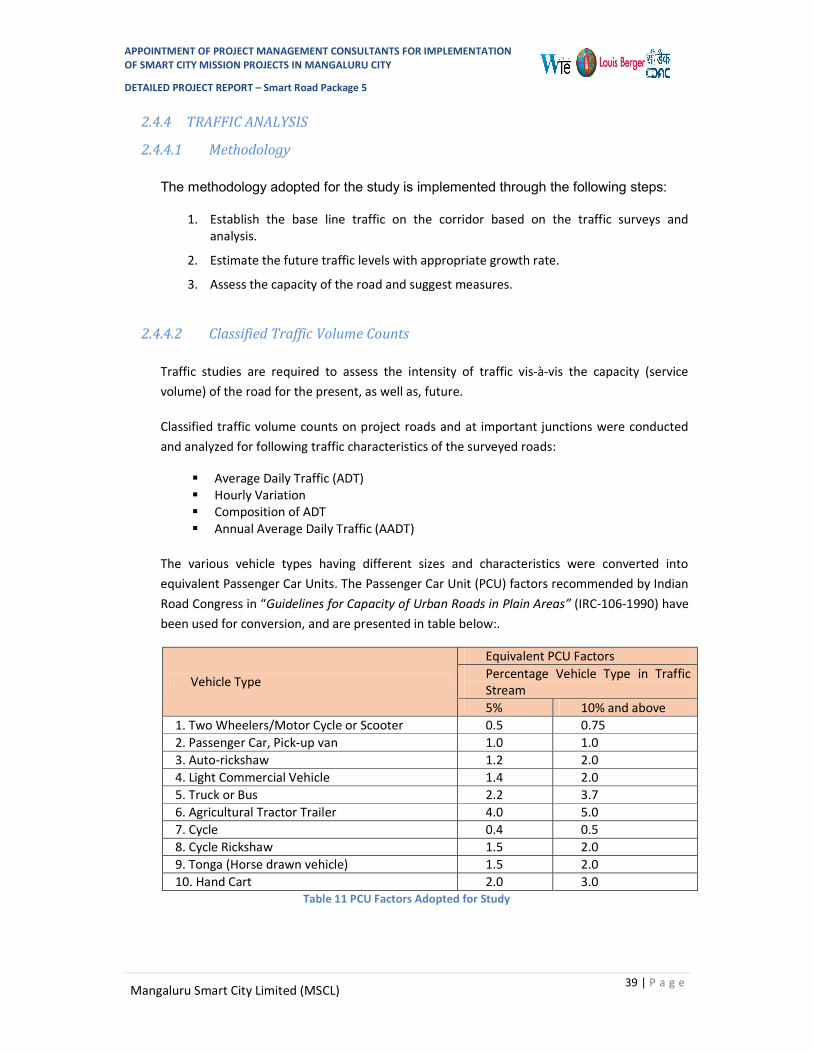
APPOINTMENT OF PROJECT MANAGEMENT CONSULTANTS FOR IMPLEMENTATION OF SMART CITY MISSION PROJECTS IN MANGALURU CITY
DETAILED PROJECT REPORT – Smart Road Package 5
39 | P a g e Mangaluru Smart City Limited (MSCL)
2.4.4 TRAFFIC ANALYSIS
2.4.4.1 Methodology
The methodology adopted for the study is implemented through the following steps:
1. Establish the base line traffic on the corridor based on the traffic surveys and analysis.
2. Estimate the future traffic levels with appropriate growth rate.
3. Assess the capacity of the road and suggest measures.
2.4.4.2 Classified Traffic Volume Counts
Traffic studies are required to assess the intensity of traffic vis-à-vis the capacity (service volume) of the road for the present, as well as, future.
Classified traffic volume counts on project roads and at important junctions were conducted and analyzed for following traffic characteristics of the surveyed roads:
Average Daily Traffic (ADT) Hourly Variation Composition of ADT Annual Average Daily Traffic (AADT)
The various vehicle types having different sizes and characteristics were converted into equivalent Passenger Car Units. The Passenger Car Unit (PCU) factors recommended by Indian Road Congress in “Guidelines for Capacity of Urban Roads in Plain Areas” (IRC-106-1990) have been used for conversion, and are presented in table below:.
Vehicle Type
Equivalent PCU Factors Percentage Vehicle Type in Traffic Stream 5% 10% and above
1. Two Wheelers/Motor Cycle or Scooter 0.5 0.75 2. Passenger Car, Pick-up van 1.0 1.0 3. Auto-rickshaw 1.2 2.0 4. Light Commercial Vehicle 1.4 2.0 5. Truck or Bus 2.2 3.7 6. Agricultural Tractor Trailer 4.0 5.0 7. Cycle 0.4 0.5 8. Cycle Rickshaw 1.5 2.0 9. Tonga (Horse drawn vehicle) 1.5 2.0 10. Hand Cart 2.0 3.0
Table 11 PCU Factors Adopted for Study

APPOINTMENT OF PROJECT MANAGEMENT CONSULTANTS FOR IMPLEMENTATION OF SMART CITY MISSION PROJECTS IN MANGALURU CITY
DETAILED PROJECT REPORT – Smart Road Package 5
40 | P a g e Mangaluru Smart City Limited (MSCL)
2.4.4.3 Annual Average Daily Traffic (AADT)
The traffic survey data is analyzed and the Average Daily Traffic (ADT) is presented below
Table 12 Average Daily Traffic
Mode Milagres
Cross Road
Attavara-Nandigudda
rd 1
Attavara Nandigudda
rd 2
Don Bosco Hall Cross
Road
New Balmatta
Road
2w 2,991 13,481 10,720 4,935 4,913 3w 3,083 6,884 4,611 2,262 4,321 Car/Van 1,598 4,486 4,667 2,666 3,257 Mini Bus 24 69 93 19 40 Bus 50 273 51 12 - MLCV 72 329 258 120 136 LCV 4 49 32 16 3 2 Axle Truck 11 43 26 7 1 3 Axle Truck - - - - - MAV - - - - - Tractor - - 1 - - Tractor+Trailer - - - - - Cycle 4 57 50 10 16 Cycle rickshaw - - - - - Animal Drawn - - - - - Hand Cart - - - - -
Total Veh 7,837 25,671 20,509 10,047 12,687
Total PCU 10,254 29,577 22,555 11,106 15,789
Mode Milagres
Cross Road
Attavara-Nandigudda
rd 1
Attavara Nandigudda
rd 2
Don Bosco Hall Cross
Road
New Balmatta
Road
2w 2,991 13,481 10,720 4,935 4,913 3w 3,083 6,884 4,611 2,262 4,321 Car/Van 1,598 4,486 4,667 2,666 3,257 Mini Bus 24 69 93 19 40 Bus 50 273 51 12 - MLCV 72 329 258 120 136 LCV 4 49 32 16 3 2 Axle Truck 11 43 26 7 1 3 Axle Truck - - - - - MAV - - - - - Tractor - - 1 - - Tractor+Trailer - - - - - Cycle 4 57 50 10 16

APPOINTMENT OF PROJECT MANAGEMENT CONSULTANTS FOR IMPLEMENTATION OF SMART CITY MISSION PROJECTS IN MANGALURU CITY
DETAILED PROJECT REPORT – Smart Road Package 5
41 | P a g e Mangaluru Smart City Limited (MSCL)
Cycle rickshaw - - - - - Animal Drawn - - - - - Hand Cart - - - - -
Total Veh 7,837 25,671 20,509 10,047 12,687
Total PCU 10,254 29,577 22,555 11,106 15,789
Traffic volume is highest on Jyoti Circle to Arya Samaj Junction at 87,138 PCU followed by Attavar-Nandigudda road 1 at 29,577 PCU followed by Attavar-Nandigudda Road 2 at 22,555 PCU. The detail of rest of the roads is given in the above table. Port road is carrying least traffic at 2,034 PCU.
Since these are urban roads seasonal variations are minimal and, hence, ADT is considered as AADT.
2.4.4.4 Hourly Variation
The hourly variation of traffic at survey locations is presented in following Figure .

APPOINTMENT OF PROJECT MANAGEMENT CONSULTANTS FOR IMPLEMENTATION OF SMART CITY MISSION PROJECTS IN MANGALURU CITY
DETAILED PROJECT REPORT – Smart Road Package 5
42 | P a g e Mangaluru Smart City Limited (MSCL)

APPOINTMENT OF PROJECT MANAGEMENT CONSULTANTS FOR IMPLEMENTATION OF SMART CITY MISSION PROJECTS IN MANGALURU CITY
DETAILED PROJECT REPORT – Smart Road Package 5
43 | P a g e Mangaluru Smart City Limited (MSCL)

APPOINTMENT OF PROJECT MANAGEMENT CONSULTANTS FOR IMPLEMENTATION OF SMART CITY MISSION PROJECTS IN MANGALURU CITY
DETAILED PROJECT REPORT – Smart Road Package 5
44 | P a g e Mangaluru Smart City Limited (MSCL)
Figure 25 Hourly Variation Graphs of Traffic on DPR-5 Smart roads

APPOINTMENT OF PROJECT MANAGEMENT CONSULTANTS FOR IMPLEMENTATION OF SMART CITY MISSION PROJECTS IN MANGALURU CITY
DETAILED PROJECT REPORT – Smart Road Package 5
45 | P a g e Mangaluru Smart City Limited (MSCL)
2.4.4.5 Traffic Composition
The composition of traffic at the survey locations is presented in Following Figures.
Error! Reference source not found.
Figure 26 Hourly Variation Graphs of Traffic on DPR-5 Smart roads
Traffic composition in terms of Passenger vehicles and Commercial vehicles is also analyzed to understand the impact of commercial vehicles and is presented in following tables.
Table 13 Composition of Passenger and Commercial Vehicles
Mode Milagres
Cross Road
Attavara-Nandigudda rd
1
Attavara Nandigudda rd
2
Don Bosco Hall Cross
Road
New Balmatta
Road
Passenger 99% 98% 98% 98% 99%
Commercial 1% 2% 2% 1% 1%

APPOINTMENT OF PROJECT MANAGEMENT CONSULTANTS FOR IMPLEMENTATION OF SMART CITY MISSION PROJECTS IN MANGALURU CITY
DETAILED PROJECT REPORT – Smart Road Package 5
46 | P a g e Mangaluru Smart City Limited (MSCL)
Mode Arya Samaj
Road Jyothi Circle to Arya Samaj jn
Jumma Masjid Road
Port Road
Bengre Ferry Road
Passenger 99% 98% 94% 92% 89%
Commercial 1% 2% 3% 8% 10%
Mode Milagres
Cross Road
Attavara-Nandigudda rd
1
Attavara Nandigudda rd
2
Don Bosco Hall Cross
Road
New Balmatta
Road
Passenger 99% 99% 99% 100% 100%
Commercial 1% 1% 1% 0% 0%
Mode Arya Samaj
Road Jyothi Circle to Arya Samaj jn
Jumma Masjid Road
Port Road
Bengre Ferry Road
Passenger 100% 93% 99% 100% 100%
Commercial 0% 7% 1% 0% 0%
Table 14 Composition of Public and Private modes of transport
The observations on the traffic and composition are:
Passenger vehicles comprise about 92-99% of the total vehicles and commercial vehicles are meagre 1-2% except Port road and Bengre Ferry Road where the commercial vehicles are higher at 8-10%..
Private vehicles are occupying the major portion of the urban road space. About 99%-100% of the vehicles except Jyothi Circle to Arya Samaj Junction are private vehicles and balance are public transport vehicles (mini bus+bus).
2.4.4.6 Peak Hour Analysis
In urban context, the roads are designed to cater to the requirements of peak hour volume. Hence, peak hour traffic analysis is done and presented in following tables

APPOINTMENT OF PROJECT MANAGEMENT CONSULTANTS FOR IMPLEMENTATION OF SMART CITY MISSION PROJECTS IN MANGALURU CITY
DETAILED PROJECT REPORT – Smart Road Package 5
47 | P a g e Mangaluru Smart City Limited (MSCL)
Table 15 Peak Hour Volume and Peak %age
Description Milagres
Cross Road
Attavara-Nandigudda
rd 1
Attavara Nandigudda
rd 2
Don Bosco Hall Cross
Road
New Balmatta
Road
Peak Hour 8:00-9:00
am 06:00-07:00
pm 03:00-04:00
pm 12:00-01:00
pm 12:00-01:00
pm
Peak, Vol 692 1,903 1,634 856 1,020
Peak,% (Vol) 8.83% 7.41% 7.97% 8.52% 8.04%
Peak, PCU 944 2,244 1,930 962 1,345
Peak,% (pcu) 9.20% 7.59% 8.56% 8.66% 8.52%
Description Arya
Samaj Road
Jyothi Circle to Arya
Samaj jn
Jumma Masjid Road
Port Road
Bengre Ferry Road
Peak Hour 11:00-
12:00 pm 06:00 – 07:00
pm 04:00 - 05:00
pm 10:00-
11:00 am 09:00-
10:00 am
Peak, Vol 5,335 839 177 713 713
Peak,% (Vol) 7.32% 8.52% 7.84% 10.04% 10.04%
Peak, PCU 6,638 875 173 723 723
Peak,% (pcu) 7.62% 8.40% 8.39% 9.88% 9.88%
The main junctions are falling on these selected roads, viz.,
1. Milagres Cross Road Junction
2. Anand Shetty Circle
3. Avery Junction
4. Arya Samaj Road Junction
5. Bombay Lucky Junction
Analysis of these junctions is carried out. The daily turning traffic volumes and PCU are presented at Figure 5-9.

APPOINTMENT OF PROJECT MANAGEMENT CONSULTANTS FOR IMPLEMENTATION OF SMART CITY MISSION PROJECTS IN MANGALURU CITY
DETAILED PROJECT REPORT – Smart Road Package 5
48 | P a g e Mangaluru Smart City Limited (MSCL)
Figure 27: Milagres Cross Road Junction
Figure 28: Anand Shetty Circle

APPOINTMENT OF PROJECT MANAGEMENT CONSULTANTS FOR IMPLEMENTATION OF SMART CITY MISSION PROJECTS IN MANGALURU CITY
DETAILED PROJECT REPORT – Smart Road Package 5
49 | P a g e Mangaluru Smart City Limited (MSCL)
Figure 29: Avery Junction
Figure 30: Arya Samaj Road Junction

APPOINTMENT OF PROJECT MANAGEMENT CONSULTANTS FOR IMPLEMENTATION OF SMART CITY MISSION PROJECTS IN MANGALURU CITY
DETAILED PROJECT REPORT – Smart Road Package 5
50 | P a g e Mangaluru Smart City Limited (MSCL)
Figure 31: Bombay Lucky Junction
2.4.5 Traffic Forecast
Traffic Forecast in an Urban scenario is generally done through 4 stage travel demand modelling, which is an intensive exercise and is beyond the scope of this project. It is proposed to use growth rate to assess the capacity requirement of the selected roads. 3% growth rate is considered for the passenger vehicles and 2% is considered for the commercial vehicles. The projected peak hour PCU in different years is presented in Following tables:
Table 16 Projected Peak hour volumes in PCU
Year Milagres
Cross Road
Attavara-Nandigudda
rd 1
Nandigudda Road 2
Don Bosco Hall Cross
Road
New Balmatta
Road
2018 944 2,244 1,930 962 1,345 2020 1,000 2,379 2,046 1,020 1,427 2025 1,157 2,753 2,370 1,180 1,653 2030 1,340 3,186 2,743 1,366 1,915 2035 1,551 3,686 3,177 1,582 2,218 2038 1,693 4,024 3,469 1,727 2,423
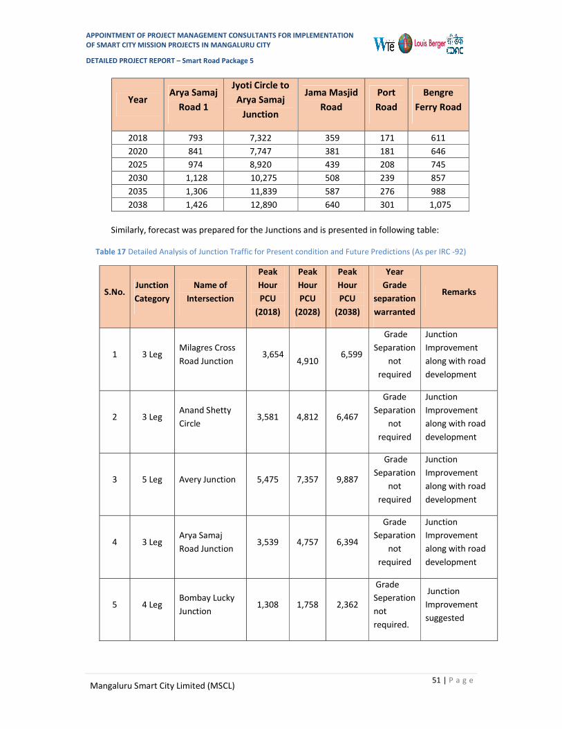
APPOINTMENT OF PROJECT MANAGEMENT CONSULTANTS FOR IMPLEMENTATION OF SMART CITY MISSION PROJECTS IN MANGALURU CITY
DETAILED PROJECT REPORT – Smart Road Package 5
51 | P a g e Mangaluru Smart City Limited (MSCL)
Year Arya Samaj
Road 1
Jyoti Circle to Arya Samaj
Junction
Jama Masjid Road
Port Road
Bengre Ferry Road
2018 793 7,322 359 171 611 2020 841 7,747 381 181 646 2025 974 8,920 439 208 745 2030 1,128 10,275 508 239 857 2035 1,306 11,839 587 276 988 2038 1,426 12,890 640 301 1,075
Similarly, forecast was prepared for the Junctions and is presented in following table:
Table 17 Detailed Analysis of Junction Traffic for Present condition and Future Predictions (As per IRC -92)
S.No. Junction Category
Name of Intersection
Peak Hour PCU
(2018)
Peak Hour PCU
(2028)
Peak Hour PCU
(2038)
Year Grade
separation warranted
Remarks
1 3 Leg Milagres Cross Road Junction
3,654
4,910 6,599
Grade Separation
not required
Junction Improvement along with road development
2 3 Leg Anand Shetty Circle
3,581 4,812 6,467
Grade Separation
not required
Junction Improvement along with road development
3 5 Leg Avery Junction 5,475 7,357 9,887
Grade Separation
not required
Junction Improvement along with road development
4 3 Leg Arya Samaj Road Junction
3,539 4,757 6,394
Grade Separation
not required
Junction Improvement along with road development
5 4 Leg Bombay Lucky Junction
1,308 1,758 2,362
Grade Seperation not required.
Junction Improvement suggested

APPOINTMENT OF PROJECT MANAGEMENT CONSULTANTS FOR IMPLEMENTATION OF SMART CITY MISSION PROJECTS IN MANGALURU CITY
DETAILED PROJECT REPORT – Smart Road Package 5
52 | P a g e Mangaluru Smart City Limited (MSCL)
Table 18:Detailed Analysis of Junction as per SP-41
Junction Traffic Analysis IRC SP 41 Criteria ( Vehicle Per Day)
S.NO.
Jn. Catego
ry
Name of Intersection
2018 2020 2025
Major Rd
Minor Rd
Major Rd
Minor Rd
Major Rd
Minor Rd
1 3 Leg Milagres Cross Road Junction
29,034 8,600 30,772 9,120 35,590 10,564
2 3 Leg Anand Shetty Circle 27,217 12,528 28,858 13,285 29,716 13,681
3 5 Leg Avery Junction 44,011 7,844 46,653 8,319 53,978 9,636
4 3 Leg Arya Samaj Road Junction
32,104 9,851 34,025 10,448 39,347 12,104
5 4 Leg Bombay Lucky Junction
7,742 4,392 8,203 4,655 9,481 5,384
Junction Traffic Analysis IRC SP 41 Criteria ( Vehicle Per Day)
S. NO.
Jn. Catego
ry
Name of Intersection
2028 2035 2038
Major Rd
Minor Rd
Major Rd
Minor Rd
Major Rd
Minor Rd
1 3 Leg Milagres Cross Road Junction
38,837 11,537 47,620 14,173 51,971 15,480
2 3 Leg Anand Shetty Circle 30,599 14,088 31,509 14,508 32,445 14,940
3 5 Leg Avery Junction 58,916 10,525 72,277 12,930 78,897 14,123
4 3 Leg Arya Samaj Road Junction
42,934 13,221 52,636 16,246 57,443 17,746
5 4 Leg Bombay Lucky Junction
10,342 5,876 12,669 7,205 13,822 7,864
Similarly pedestrian vehicular conflict is analyzed and presented at Table 19.

APPOINTMENT OF PROJECT MANAGEMENT CONSULTANTS FOR IMPLEMENTATION OF SMART CITY MISSION PROJECTS IN MANGALURU CITY
DETAILED PROJECT REPORT – Smart Road Package 5
53 | P a g e Mangaluru Smart City Limited (MSCL)
Table 19: Pedestrian Vehicular Conflict at Major Arm
S.No. Name of
Intersection Peak Hour Arm PV2X108 Proposal
1 Milagres Cross Road
08:00 - 09:00 am
Milagres Cross Road 0.36 Control Measure
Hampankatta Road 5.28 Control Measure
Mother Theresa Road 10.72 Control Measure
2 Anand Shetty Circle
15:00-16:00 am
Railway Station Road 13.41 Control Measure
Sturrock Road 5.91 Control Measure
Attavar Road 23.93 Control Measure
3 Arya Samaj Junction
18:00 - 19:00 pm
Bunts Hostel Road 14.26 Control Measure
Kadri Road 12.60 Control Measure
Arya Samaj Road 1.10 Control Measure
4 Bomaby Lucky
Junction 15:00-16:00
Bengre Ferry Road 0.24 Control Measure
Jumma Masjid Road 0.16 Control Measure
Bombay Lucky Road 0.38 Control Measure
Old Port Road 0.02 Control Measure
2.4.6 Capacity Analysis 2.4.6.1 Road Standards
IRC:SP:106-1990– “Guidelines for Capacity of Urban Roads in Plains” specifies Design Service Volume of different urban roads and is given in following table:
Table 20 Recommended Design Service Volumes (PCU/Hr)
S.No. Type of Carriageway
Total Design Service volumes for Different Catetories of Urban Roads
Arterial Sub-arterial Collector
1 2 Lane (One Way) 2,400 1,900 1,400 2 2 Lane (Two Way) 1,500 1,200 900 3 3 Lane (One Way) 3,600 2,900 2,200 4 4 Lane Undivided (Two Way) 3,000 2,400 1,800

APPOINTMENT OF PROJECT MANAGEMENT CONSULTANTS FOR IMPLEMENTATION OF SMART CITY MISSION PROJECTS IN MANGALURU CITY
DETAILED PROJECT REPORT – Smart Road Package 5
54 | P a g e Mangaluru Smart City Limited (MSCL)
5 4 Lane Divided (Two Way) 3,600 2,900 - 6 6 Lane Undivided (Two Way) 4,800 3,800 - 7 6 Lane Divided (Two Way) 5,400 4,300 - 8 8 Lane Divided (Two Way) 7,200 - -
2.4.6.2 Junction Standards
IRC SP:41-1994, provides a graph for selection of intersection type based on traffic volumes which is reproduced in Figure 32for ready reference.
Figure 32: Intersection selection based on criteria
IRC-92-1985: An interchange may be justified when an at-grade intersection fails to handle the volume of traffic resulting in serious congestion and frequent choking of the intersection. This situation may arise when the total traffic of all the arms of the intersection isin excess of 10,000 PCU/ hours.
2.4.6.3 Pedestrian facilities
Intensity of pedestrians crossing the project road will decide the grade separators in the form of RUB, pedestrian crossing.
Pedestrian – vehicular conflict can be effectively studied through the indicator suggested in IRC:103-1988, Guidelines for Pedestrian facilities.
The code suggests some form of control measures at mid-blocks and intersections where the indicator PV2 is greater than or equal to 2x10⁸ and for Zebra crossing PV2 should be greater than 1x10⁸ where ‘P’ is the Peak hour pedestrian volume and ‘V’ is the number of vehicles in that peak hour.

APPOINTMENT OF PROJECT MANAGEMENT CONSULTANTS FOR IMPLEMENTATION OF SMART CITY MISSION PROJECTS IN MANGALURU CITY
DETAILED PROJECT REPORT – Smart Road Package 5
55 | P a g e Mangaluru Smart City Limited (MSCL)
2.4.6.4 Lane Configuration Analysis A) Roads
The existing lane configuration of roads and capacity is presented at table below.
Table 21 Existing Lane Configuration of Roads
Milagres Cross Road
Attavara-Nandigudda
rd 1
Nandigudda Road 2
Don Bosco Hall Cross
Road
New Balmatta
Road
No of Lanes 2 2 2 2 2
Capacity 1,900 1,200 1,200 1,200 1,200
Arya Samaj Road 1
Jyoti Circle to Arya Samaj
Junction
Jama Masjid Road
Port Road Bengre Ferry
Road
No of Lanes 1,2 4 2 1,2 1,2
Capacity 1,200 3,600 1,200 1200 1200
The unconstrained capacity (lanes) requirement based on traffic analysis is given in table below. Please note that this is with the assumption that capacity enhancement is possible. Development strategy would be based on this capacity requirement and the feasibility of expansion, if possible.
Table 22 Unconstrained Capacity Requirement Based on Traffic (Lanes)
Year Milagres
Cross Road
Attavara-Nandigudda
rd 1
Nandigudda Road 2
Don Bosco Hall
Cross Road
New Balmatta
Road
2018 2 L 4 L 4 L 2 L 4 L
2020 2 L 4 L 4 L 2 L 4 L
2025 2 L 4 L 4 L 2 L 4 L

APPOINTMENT OF PROJECT MANAGEMENT CONSULTANTS FOR IMPLEMENTATION OF SMART CITY MISSION PROJECTS IN MANGALURU CITY
DETAILED PROJECT REPORT – Smart Road Package 5
56 | P a g e Mangaluru Smart City Limited (MSCL)
2030 2 L > 4 L 4 L 4 L 4 L
2035 2 L > 4 L > 4 L 4 L 4 L
2038 2 L > 4 L > 4 L 4 L 4 L
Year Arya
Samaj Road 1
Jyoti Circle to Arya Samaj
Junction
Jama Masjid Road
Port Road
Bengre Ferry Road
2018 2 L > 4 L 2 L 2 L 2 L
2020 2 L > 4 L 2 L 2 L 2 L
2025 2 L > 4 L 2 L 2 L 2 L
2030 2 L > 4 L 2 L 2 L 2 L
2035 > 2 L > 4 L 2 L 2 L 2 L
2038 > 2 L > 4 L 2 L 2 L 2 L
From the above analysis, it can be seen that Milagres Cross Road, Jumma Masjid can operate with their existing lane configuration without any capacity augmentation in the horizon period. Rest of the roads are getting saturated and need capacity augmentation. However, this being a developed town space is a constraint.
B) Junctions
As per IRC 92 grade separation is not warranted as traffic at all the junctions is not more than 10,000 PCU/hr.
However as per IRC 41, grade separation is warranted if the traffic on major road crosses more than 45,000 vehicles and minor road traffic crosses more than 12,000 vehicles per day. Milagres Cross Road, Avery junction and Arya Samaj Road Junction get qualified for grade separation. However, space is a constraint. Considering this grade separation is recommended as and when space is available at these locations and for the time being improvement of the junctions is suggested.
2.4.6.5 Pedestrian facilities
Based on the analysis, at many locations the PV2 values are higher than 2x10⁸ and hence mid-block and at junction control measures are suggested.

APPOINTMENT OF PROJECT MANAGEMENT CONSULTANTS FOR IMPLEMENTATION OF SMART CITY MISSION PROJECTS IN MANGALURU CITY
DETAILED PROJECT REPORT – Smart Road Package 5
57 | P a g e Mangaluru Smart City Limited (MSCL)
2.5 CARRIAGEWAY, JUNCTION IMPROVEMENT AND PAVEMENT DESIGN
2.5.1 Carriageway Improvement 2.5.1.1 Right of Way (ROW)
There are total of nine roads being improved in this phase namely:
1. Milagres Cross Rd.– From KMC Central Library Jn. to Milagres Church Jn.,
2. Attavara Nandigudda Rd.- From Nandigudda Wenlock Jn. to KMC Hospital,
3. New Balmatta Rd. – From Jyoti Circle to Avery Jn.,
4. Kudumbi Garden (DBS) Rd.- From KMC Mercara Trunk Rd to Avery Jn.,
5. Arya Samaj Rd. – From KRR Rd – Arya Samaj Rd Jn., and Balmatta Rd. Jn.,
6. Balmatta Rd. – From Jyoti Circle to KRR Rd – Arya Samaj Rd Jn.,
7. Azizuddin Rd. – From Car Street to Bunder Police Station,
8. Jumma Masjid-Old Port Rd. - From Car Street to Badria School Jn.
9. Bengre Ferry Rd. – From Jumma Masjid to BMS Ferry Lane.
Details of existing ROW are as follows:
1. Milagres Cross Rd. – Varies from 7.80m to 11.20m.
2. Attavara Nandigudda Rd. - Varies from 9.80m to 16.70m.
3. New Balmatta Rd. – Varies from 6.00m to 12.50m.
4. Kudumbi Garden (DBS) Rd.- Varies from 8.00m to 12.50m.
5. Arya Samaj Rd. – Varies from 6.40m to 10.60m.
6. Balmatta Rd. – Varies from 22.80m to 26.10m.
7. Azizuddin Rd. – Varies from 8.23m to 11.30m.
8. Jumma Masjid-Old Port Rd. - Varies from 4.51m to 6.75m.
9. Bengre Ferry Rd. – Varies from 5.61m to 12.95m.
MCC proposes to widen the streets, but it is not clear when this will happen. As per the discussion and confirmation with MSCL, the Consultants have prepared the proposals as per the existing RoW.
The following drawings enclosed in Annexure the Report provides details of Plan and Profile for DPR 5 roads
Table 23 Plan and Profile for DPR 5 roads
SN Drawing no Drawing Title No of Sheets
1 WTE_2292_04_R_2.01 PLAN AND PROFILE OF MILAGRES CROSS ROAD. (ROAD NO. 7a) 1

APPOINTMENT OF PROJECT MANAGEMENT CONSULTANTS FOR IMPLEMENTATION OF SMART CITY MISSION PROJECTS IN MANGALURU CITY
DETAILED PROJECT REPORT – Smart Road Package 5
58 | P a g e Mangaluru Smart City Limited (MSCL)
2 WTE_2292_04_R_2.02 PLAN AND PROFILE OF NEW BALMATTA ROAD (ROAD NO. 8) 1 3 WTE_2292_04_R_2.03 PLAN AND PROFILE OF ARYA SAMAJ ROAD (ROAD NO. 19a) 1
4 WTE_2292_04_R_2.04 PLAN AND PROFILE OF JUMMA MASJID OLDPORT ROAD (ROAD NO.15b) 1
5 WTE_2292_04_R_2.05 PLAN AND PROFILE OF BENGRE FERRY ROAD (ROAD NO.20) 1
2.5.1.2 Design Speed
Design speed is related to the function of a road. Keeping in view the type of functions expected on these roads, design speed has been considered as 40 to 50 Kmph for sub arterial roads & 30 km/h for distributor / Collector roads.
2.5.1.3 Cross Sections
Based on the traffic analysis and available ROW, it is proposed to develop these roads as follows:
1. Milagres Cross Road from KMC Central Library Junction to Milagres Church Junction is being developed as “2 Lane undivided carriageway which is being directed as one way traffic from KMC Central Library to Milagres Church Jn. (North to South)”. Lane width has been considered as 3.1 m. Raised footpaths are proposed on both sides wherever width of 1.00m or more is available.
2. Attavara Nandigudda Road from Nandigudda Wenlock Junction to KMC Hospital is being developed as "7.0m wide carriageway for bi-directional traffic with 3.5m lane width”. Raised footpaths are proposed on both sides considering the space availability; however the width of footpath varies depending on site constraints.
3. New Balmatta Road from Jyoti Circle to Avery Junction is being developed as “2 Lane two way single carriageway”. Lane width varies between 2.5m and 3.1 m. Raised footpaths are proposed on both sides wherever width of 1.00m or more is available.
4. Kudumbi Garden (DBS) Road from KMC Mercara Trunk Rd to Avery Junction is being developed as “2 Lane undivided carriageway with bi-directional traffic”. Lane width has been considered as 2.75 m. Raised footpaths are proposed on both sides wherever width of 1.00m or more is available.
5. Arya Samaj Road from KRR Road to Arya Samaj Road Junction and Balmatta Road Junction is being developed as “2 Lane undivided carriageway with 2.75m lane width has been proposed". Raised footpaths are proposed on both sides wherever width of 1.00m or more is available.
6. Balmatta Road from Jyoti Circle to KRR Road to Arya Samaj Road Junction is being developed as "4 lane two directional divided carriageway". Lane width has been considered as 3.5m. Raised footpath is proposed on both sides considering the space availability.
7. Azizuddin Road from Car Street to Bunder Police Station is being developed as "2 lane undivided carriageway with bi-directional traffic". Lane width has been considered as 2.75m. Raised footpath is proposed on both sides considering the space availability.

APPOINTMENT OF PROJECT MANAGEMENT CONSULTANTS FOR IMPLEMENTATION OF SMART CITY MISSION PROJECTS IN MANGALURU CITY
DETAILED PROJECT REPORT – Smart Road Package 5
59 | P a g e Mangaluru Smart City Limited (MSCL)
8. Jumma Masjid-Old Port Road from Car Street to Badria School Junction is being developed as "2 lane undivided carriageway with bi-directional traffic". Lane width has been considered as 2.75m. No Raised footpath has been proposed due to minimal space availability.
9. Bengre Ferry Road from Jumma Masjid to BMS Ferry Lane including 4 different sections as below
Two lane undivided carriageway with bi-directional traffic from CH. KM. 0+000 to 0+100 and 0+210 to 0+250" with lane width of 2.75m. Raised footpath is proposed on one side of the carriageway.
From CH. KM. 0+100 to 0+210 the road is being developed as "2 lane undivided carriageway with bi-directional traffic" with lane width of 2m. No Raised footpath has been proposed due to minimal space availability.
From CH. KM. 0+250 to 0+700 the road is being developed as "2 lane undivided carriageway with bi-directional traffic" with lane width of 3.5m. Raised footpath is proposed on one side of the carriageway.
From CH. KM 0+700 to 1+050 the road is being developed as "2 lane undivided carriageway with bi-directional traffic" with lane width of 5.0m. Raised footpath is proposed on one side of the carriageway.
2.5.1.4 Camber / Cross Fall
The existing camber is retained for the CC roads and where new CC roads are being developed a camber of 2.5% is being provided.
2.5.1.5 Geometry / Alignment
Geometric design & Alignment design has been done in accordance with MoUD and IRC guidelines.
2.5.2 Intersection Improvement
Road intersections are critical element of road section. They are normally a major bottleneck to smooth flow of traffic and a major accident spot. Function of a designed intersection is to control conflicting and merging streams of traffic, to minimize the delay including pedestrian traffic.
Intersection design influences the capacity of the corridor and the safe movement of conflicting directions. The pattern of the traffic movements at the intersection and the volume of traffic on each approach, during peak period of the day determine the lane widths required.
The general design principles of intersection design are the approach speeds, restriction on available land, sight distance available and the presence of the larger volume of all the road users in urban areas.

APPOINTMENT OF PROJECT MANAGEMENT CONSULTANTS FOR IMPLEMENTATION OF SMART CITY MISSION PROJECTS IN MANGALURU CITY
DETAILED PROJECT REPORT – Smart Road Package 5
60 | P a g e Mangaluru Smart City Limited (MSCL)
2.5.2.1 Function of Intersection Design
The function of an intersection is to enable safe interchange between two directions or two modes.
The aim of the design of an intersection is to achieve with a minimum number of conflict points while following the basic principle to limit the number of conflict points between cars, buses, trucks, bicycles and the pedestrians as much as possible.
2.5.2.2 Classification of Intersections types
Intersection functions to control conflicting and merging traffic and to achieve this, intersections are designed on certain geometric parameters and are broadly classified into three main heads and are as follows:
Un signalized intersection, Signalized Intersection and Roundabouts
A) Un-signalized intersection: There are two types of un-signalized intersections:
Uncontrolled Intersection: These are the intersections between any two roads with relatively lower volume of traffic and traffic of neither road has precedence over the other.
Intersection with Primary Control: In this type there are theoretically no delay occurring on the major road and vehicles on the minor road are controlled by ‘GIVE WAY’ or ‘STOP’ signs and marking
B) Signalized Intersection:
Signalization is applied at junctions where higher motorized vehicle volumes require control by traffic lights. Traffic movement of different arms entering the intersection is controlled by traffic lights.
C) Roundabouts:
A roundabout is an intersection with a central island around which traffic must travel clockwise and in which entering traffic must ‘GIVE WAY’ to circulating traffic.
Table below depicts the Pros and Cons of type of Intersection Lane Requirement

APPOINTMENT OF PROJECT MANAGEMENT CONSULTANTS FOR IMPLEMENTATION OF SMART CITY MISSION PROJECTS IN MANGALURU CITY
DETAILED PROJECT REPORT – Smart Road Package 5
61 | P a g e Mangaluru Smart City Limited (MSCL)
Table 24 Pros and Cons of Signalized Intersection and Roundabout
Signalized Intersection Roundabout
Pros
Signalized intersection can handle high traffic volumes
Reduces number of conflicts
Safety is ensured by eliminating conflicts through signalization
Ensures safety through speed reduction by design
Minimum delays for all road users
Cons
Higher delays for all road users Roundabouts are not very effective for more than two circulatory lanes
Roundabouts have capacity limitations and may not be able to handle a very high volume of traffic.
2.5.2.3 Objectives for Intersection Design
The main objective of intersection design is to facilitate the convenience, ease and comfort of people traversing the intersection while enhancing the efficient movement of passenger cars, buses, trucks, bicycles and pedestrians. The need for flexibility dictates the choice of the most suitable intersection type.
2.5.2.4 Consideration for Intersection Design
Design of a safe intersection depends on following major factors:
Design and actual capacities Design hourly traffic turning movements Variety of movements Vehicle Speeds Pedestrian movements Geometric features Traffic control devices Cost of improvements Energy consumption

APPOINTMENT OF PROJECT MANAGEMENT CONSULTANTS FOR IMPLEMENTATION OF SMART CITY MISSION PROJECTS IN MANGALURU CITY
DETAILED PROJECT REPORT – Smart Road Package 5
62 | P a g e Mangaluru Smart City Limited (MSCL)
2.5.2.5 Design Traffic Volumes:
Intersections are normally designed for peak hour flows. Turning movement count has been carried out and the data has been used after estimation of future traffic for intersection design.
2.5.2.6 Capacity of Intersections:
Intersection capacity is the maximum hourly rate at which vehicles can reasonably be expected to pass through the intersection under prevailing traffic, roadway and signalized conditions. Capacity is influenced by traffic and roadway conditions. Traffic conditions includes volumes on each approach, the distribution of vehicles on each arm of intersection, the vehicle types distribution within each movement, pedestrian traffic flows and parking movements on approaches to the intersection.
Traffic control at intersections limits the capacity of the intersecting roadways, defined as the number of users that can be accommodated within a given time period. Capacity of an intersection depends on the following factors:
Physical and operating conditions like width of approach, one way or two way operation and parking conditions etc.
Traffic characteristics like turning movements, number of commercial vehicles including buses, peak hour factors, number of pedestrians and geometry.
As per IRC: SP: 41-1994 “Guidelines on Design of At-Grade Intersections in Rural & Urban Areas”, the intersection capacity is 700 to 1200 PCU’s per hour per lane for one way traffic and 450 to 750 PCU’s for two way traffic.
2.5.2.7 Traffic Calming Techniques
Traffic calming and speed management measures such as road humps are considered to discouraging traffic from entering intersection areas with high speed. These measures are always backed up by speed limits of 30 km/hr or less. Management of speed by engineering the road with the purpose to bring the design of the road in accordance with the desired speed is called speed management by design or traffic calming.
Trapezoidal Humps and Raised Pedestrian Crossing (Table Top)
A hump, which constitutes 150 mm, raised, flat section of a carriageway with ramps on both sides is called a trapezoidal hump. Trapezoidal humps can be used as pedestrian crossings.
Since there is no negotiation in change of level, it improves walking and makes it more comfortable and convenient to the pedestrians.
Makes the pedestrian alert and safe from entering and exiting vehicles. It gives the utmost comfort to people with disability and follows the concept of universal
design.

APPOINTMENT OF PROJECT MANAGEMENT CONSULTANTS FOR IMPLEMENTATION OF SMART CITY MISSION PROJECTS IN MANGALURU CITY
DETAILED PROJECT REPORT – Smart Road Package 5
63 | P a g e Mangaluru Smart City Limited (MSCL)
2.5.3 Pavement Design 2.5.3.1 Arya Samaj Road
Road Type: Four lanes Two Way Single Carriageway
Design Life: 30 Years
Lane Width: 3.1m with 0.25m shyness width on both sides of carriageway edge.
Transverse joint spacing: 4.5 m
Traffic (as per TVC): 6270 Commercial Vehicles per Day (CVPD)
CBR of Existing Soil: Two samples collected and tested and are 8.0% and 7.0%.
CBR (Considered) of Proposed Subgrade: 8%
CBR (Assumed) of Embankment below subgrade: 8%
Effective CBR of Subgrade: 8% (As per Figure 2 of IRC 58-2015)
Axle load Survey (Assumed): Single Axle 98% and Tandem Axle 2%
Table 25 Axial load Spectrum assumed – Arya Samaj Road
Sr. No.
Rear Single Axle Rear Tandem Axle Axle Load KN Frequency (% of
single Axles) Axle Load KN Frequency (% of
tandem Axles) 1 115-125 20 220-240 90 2 105-115 10 200-220 10 3 95-105 20 4 < 85 50
Total 98% 2%
Design:
A. Modulus of Subgrade Reaction: Effective CBR of compacted subgrade = 8%. Modulus of subgrade reaction = 50.3 MPa/m (from
Table 2 of IRC 58-2015) Provide 150mm thick Granular Sub-Base as drainage layer (Grading VI of Table 400-1 of MoRTH
Specifications Fifth Revision) Provide a Dry Lean Concrete (DLC) sub-base of thickness 100mm with a minimum 7 day
compressive strength of 10 MPa. Effective modulus of subgrade reaction of combined foundation of subgrade, granular sub-base
and DLC sub-base is 231.3 MPa/m (from Table 4 of IRC 58-2015 by interpolation)

APPOINTMENT OF PROJECT MANAGEMENT CONSULTANTS FOR IMPLEMENTATION OF SMART CITY MISSION PROJECTS IN MANGALURU CITY
DETAILED PROJECT REPORT – Smart Road Package 5
64 | P a g e Mangaluru Smart City Limited (MSCL)
Provide a de-bonding layer of polythene sheet of 125 micron thickness between DLC and concrete slab.
B. Flexural Strength of Concrete 28 day compressive strength of cement concrete ≥ 40 MPa 90 day compressive strength of cement concrete ≥ 48 MPa 28 day Flexural strength of cement concrete = 4.5 MPa (minimum) 90 day Flexural strength of cement concrete = 4.5 X 1.1 = 4.95 MPa C. Design Traffic for Fatigue Analysis Design Period – 30 years Assumed Annual rate of growth of commercial traffic = 5 % Total commercial vehicles during design period
C = 365 X A ((1 + r)n – 1) / r
Where,
C –Cumulative number of commercial vehicles during the design period
A – Initial number of commercial vehicles per day in the year when the road is opened to traffic
r – Annual rate of growth of commercial traffic volume (in decimal)
n – Design period in years
C = 365 X 6270((1+0.05)30-1)/0.05
C= 152048624
Average number of axles (steering / single / tandem) per commercial vehicle =2.35 Total two way axle load repetitions during the design period –
= 152048624 X 2.35
= 357314267
No. of axles in predominant direction
= 357314267 X 0.5
= 178657134
Design traffic after adjusting for lateral placement of axles (25 per cent of predominant direction traffic for multilane highways) –
= 21740892 X 0.25

APPOINTMENT OF PROJECT MANAGEMENT CONSULTANTS FOR IMPLEMENTATION OF SMART CITY MISSION PROJECTS IN MANGALURU CITY
DETAILED PROJECT REPORT – Smart Road Package 5
65 | P a g e Mangaluru Smart City Limited (MSCL)
= 44664283
Night time (12 hour) design axles repetitions (Assumed 60% traffic at night time)
= 44664283 X 0.6
= 26798570
Day time (12 hour) design axles repetitions (100% - 60% = 40%)
= 44664283 X 0.4
=17865713
Day time six hour axle load repetitions
= 17865713 X 0.5
= 8932857
Hence, design number of axle load repetitions for bottom-up cracking analysis
= 8932857
Night time six hour axle load repetitions
= 26798570 X 0.5
= 13399285
% of commercial vehicles having the spacing between the front (steering) axle and the first axle of the rear axle unit less than 4.5m is 55%
Hence, the six hour night time design axle load repetitions for top-down cracking analysis (wheel base < 4.5m)
= 13399285 X 0.55
= 7369607
The axle load category wise design axle load repetitions for bottom up and top down fatigue cracking analysis are given in the following Table
Table 26 Fatigue Cracking Analysis
Axle Category Proportion of the Axle Category
Category wise axle repetitions for Bottom-up cracking analysis
Category wise axle repetitions for Top-down cracking analysis
Front (Steering) single 0.45 3316323 4019786
Rear single 0.53 3905892 4734414
Tandem 0.02 147392 178657

APPOINTMENT OF PROJECT MANAGEMENT CONSULTANTS FOR IMPLEMENTATION OF SMART CITY MISSION PROJECTS IN MANGALURU CITY
DETAILED PROJECT REPORT – Smart Road Package 5
66 | P a g e Mangaluru Smart City Limited (MSCL)
D. Cumulative Fatigue Damage (CFD) analysis for Bottom-Up Cracking (BUC) and Top-Down Cracking (TDC) and Selection of Slab Thickness
Effective modulus of subgrade reaction of foundation, k – 231 MPa/m Elastic Modulus of concrete, E – 30000 MPa Poisson’s ratio of concrete, µ - 0.15 Unit weight of concrete, γ – 24 kN/m3 Design flexural strength of concrete – 4.95 MPa Max. day-time Temperature Differential in slab (for bottom-up cracking) – 17.00C Night-time Temperature Differential in slab (for top-down cracking) – day-time diff/2 + 5 =
13.500C Trial thickness of slab, h = 235 mm Radius of relative stiffness, l = (Eh3/(12k(1- µ2))0.25
Where,
l – radius of relative stiffness, m
E – Elastic modulus of concrete, MPa
h – concrete slab thickness, m
k – modulus of subgrade reaction, MPa/m
µ - Poisson’s ratio of concrete
= 0.55556
‘Beta’ factor in the stress equations will be 0.66 for doweled transverse joints for carrying out TDC analysis.
Computation of bottom-up and top-down cumulative fatigue damage is illustrated in following tables.

APPOINTMENT OF PROJECT MANAGEMENT CONSULTANTS FOR IMPLEMENTATION OF SMART CITY MISSION PROJECTS IN MANGALURU CITY
DETAILED PROJECT REPORT – Smart Road Package 5
67 | P a g e Mangaluru Smart City Limited (MSCL)
Fatigue Damage Analysis
Bottom-up Cracking Fatigue Analysis for Day-time (6 hour) traffic and Positive Temperature Differential
Rear Single Axle
Rear Single Axles Rear
Tandem Axle
Rear Tandem Axles
Load Group (kN)
Expected Repetitions
(ni)
Flex Stress MPa
Stress Ratio (SR)
Allowable Repetitions
(Ni)
Fatigue Damage (ni/Ni)
Load Group (kN)
Expected Repetitions
(ni)
Flex Stress MPa
Stress Ratio (SR)
Allowable Repetitions
(Ni)
Fatigue Damage (ni/Ni)
115-125 781178 2.41 0.487 1534711 0.509 220 - 240 132653 1.94 0.391 Infinite 0.000
105-115 390589 2.29 0.462 1177418 0.332 200 - 220 14739 1.82 0.368 Infinite 0.000
95-105 781178 2.16 0.460 Infinite 0.00
< 85 1952946 1.91 0.386 Infinite 0.000
489170 Fat Dam from Sing. Axles = 0.841 21741 Fat Dam from Tand Axles = 0.000

APPOINTMENT OF PROJECT MANAGEMENT CONSULTANTS FOR IMPLEMENTATION OF SMART CITY MISSION PROJECTS IN MANGALURU CITY
DETAILED PROJECT REPORT – Smart Road Package 5
68 | P a g e Mangaluru Smart City Limited (MSCL)
Top-Down Cracking Fatigue Analysis for Night-time (6 hour) traffic and Negative Temperature Differential
Rear Single Axle
Rear Single Axles Rear
Tandem Axle
Rear Tandem Axles
Load Group (kN)
Expected Repetition
s (ni)
Flex Stress MPa
Stress Ratio (SR)
Allowable Repetitions
(Ni)
Fatigue Damage (ni/Ni)
Load Group (kN)
Expected Repetitions
(ni)
Flex Stress MPa
Stress Ratio (SR)
Allowable Repetitions
(Ni)
Fatigue Damage (ni/Ni)
115-125 946883 2.31 0.466 7279255 0.000 220 - 240 160791 2.27 0.458 19180086 0.000
105-115 473441 2.22 0.449 Infinite 0.000 200 - 220 17866 2.18 0.440 Infinite 0.000
95-105 946883 2.14 0.432 Infinite 0.000
< 85 2367207 1.96 0.397 Infinite 0.000
475310 Fat Dam from Sing. Axles = 0.130 21741 Fat Dam from Tand Axles = 0.008

APPOINTMENT OF PROJECT MANAGEMENT CONSULTANTS FOR IMPLEMENTATION OF SMART CITY MISSION PROJECTS IN MANGALURU CITY
DETAILED PROJECT REPORT – Smart Road Package 5
69 | P a g e Mangaluru Smart City Limited (MSCL)
It can be seen from the calculations given in the tables above that for the slab thickness of 235mmthe total fatigue damage for bottom-up cracking is 0.841 + 0.000 = 0.841. Total fatigue damage for top-down cracking is 0.130 + 0.008 = 0.138 and total cumulative fatigue damage (CFD) = 0.979 which is less than 1.0.
Hence, the trial thickness of 235mm is adequate.30mm thickness is added considering two retexturing in 30 years and 15mm for rounding off and hence a thickness of 280mm is appropriate.
Design of Dowel Bars
As per Table5 ‘Recommended Dimensions of Dowel Bars’ of IRC: 58-2015,
Diameter in mm - 32 Length in mm – 450 Spacing in mm - 300
Design of Tie Bars
Input Data:
Slab Thickness – 0.280 m Lane width, b – 3.1 m Coefficient of friction, f – 1.5 Density of concrete, kN/m3 – 24 Allowable tensile stress in deformed bars, MPa -200(As per IRC:15-2017) Allowable bond stress for deformed tie bars, MPa – 2.46(As per IRC: 15-2017)
Design for Deformed Bars:
Select diameter of tie bar, dt – 12 mm Area of plain steel bar required per meter width of joint to resist the frictional force at slab
bottom, As
As= bfW / Sst
Where,
As – area of steel in mm2, required per m length of joint
b – Lane width in meters
f – Coefficient of friction between pavement and the sub-base/base (usually taken as 1.5)
W – Weight of slab in kN/m2 and
Sst – allowable working stress of steel in MPa
=3.1X1.5X0.280X24000/200
=156.2 mm2/m

APPOINTMENT OF PROJECT MANAGEMENT CONSULTANTS FOR IMPLEMENTATION OF SMART CITY MISSION PROJECTS IN MANGALURU CITY
DETAILED PROJECT REPORT – Smart Road Package 5
70 | P a g e Mangaluru Smart City Limited (MSCL)
Cross Sectional Area of Tie Bar A = π/4 X (12)2
= 113 mm2
Perimeter of Tie Bar = πd = 37.7mm
Spacing of tie bars, = A/As
= 113/156.2X1000
= 723 mm
Say 750mm
Provide spacing of 750mm c/c
Length of tie bar
L = 2SstAcs / BXPptb
Where,
L –Length of tie bar, mm
Sst – allowable working stress in steel, MPa
Acs – cross sectional area of one tie bar, mm2
Pptb – perimeter of the tie bar, mm and
B – Permissible bond stress of concrete, 2.46 MPa
= 2 X 200 X 113 / (2.46 X 37.7)
= 487.80 mm
Increase length by 100mm for loss of bond due to painting and another 50mm for tolerance in placement
Therefore the required length of tie bar is 640mm
Table 27 Pavement Composition
Sr. No. Description Thickness in mm
1 Pavement Quality Concrete (PQC) 280
2 Dry Lean Concrete (DLC) 100
3 Granular Sub-Base (GSB) (as Drainage Layer) 150
4 Selected Subgrade (CBR ≥ 8%) 500

APPOINTMENT OF PROJECT MANAGEMENT CONSULTANTS FOR IMPLEMENTATION OF SMART CITY MISSION PROJECTS IN MANGALURU CITY
DETAILED PROJECT REPORT – Smart Road Package 5
71 | P a g e Mangaluru Smart City Limited (MSCL)
2.5.3.2 Arya Smaj Road 2
Design of Plain Jointed Rigid Pavement
Design of Slab Thickness
Input Data:
Road Type: Two lanes Two Way Single Carriageway
Design Life: 30 Years
Lane Width: 3.1m with 0.25m shyness width on both sides of carriageway edge.
Transverse joint spacing: 4.5 m
Traffic (as per TVC): 144 Commercial Vehicles per Day (CVPD)
CBR of Existing Soil: Two samples collected and tested and are 5.0% and 6.0%.
CBR (Considered) of Proposed Subgrade: 8%
CBR (Assumed) of Embankment below subgrade: 8%
Effective CBR of Subgrade: 8% (As per Figure 2 of IRC 58-2015)
Axle load Survey (Assumed): Single Axle 98% and Tandem Axle 2%
Table 28 Axle Load Spectrum (Assumed) – Arya Samaj Road 2
Sr. No.
Rear Single Axle Rear Tandem Axle Axle Load KN Frequency (% of
single Axles) Axle Load KN Frequency (% of
tandem Axles) 1 115-125 20 220-240 90 2 105-115 10 200-220 10 3 95-105 20 4 < 85 50
Total 98% 2%
Design:
E. Modulus of Subgrade Reaction: Effective CBR of compacted subgrade = 8%. Modulus of subgrade reaction = 50.3 MPa/m (from
Table 2 of IRC 58-2015) Provide 150mm thick Granular Sub-Base as drainage layer (Grading VI of Table 400-1 of MoRTH
Specifications Fifth Revision) Provide a Dry Lean Concrete (DLC) sub-base of thickness 100mm with a minimum 7 day
compressive strength of 10 MPa.

APPOINTMENT OF PROJECT MANAGEMENT CONSULTANTS FOR IMPLEMENTATION OF SMART CITY MISSION PROJECTS IN MANGALURU CITY
DETAILED PROJECT REPORT – Smart Road Package 5
72 | P a g e Mangaluru Smart City Limited (MSCL)
Effective modulus of subgrade reaction of combined foundation of subgrade, granular sub-base and DLC sub-base is 231.3 MPa/m (from Table 4 of IRC 58-2015 by interpolation)
Provide a de-bonding layer of polythene sheet of 125 micron thickness between DLC and concrete slab.
F. Flexural Strength of Concrete 28 day compressive strength of cement concrete ≥ 40 MPa 90 day compressive strength of cement concrete ≥ 48 MPa 28 day Flexural strength of cement concrete = 4.5 MPa (minimum) 90 day Flexural strength of cement concrete = 4.5 X 1.1 = 4.95 MPa G. Design Traffic for Fatigue Analysis Design Period – 30 years Assumed Annual rate of growth of commercial traffic = 5 % Total commercial vehicles during design period
C = 365 X A ((1 + r)n – 1) / r
Where,
C –Cumulative number of commercial vehicles during the design period
A – Initial number of commercial vehicles per day in the year when the road is opened to traffic
r – Annual rate of growth of commercial traffic volume (in decimal)
n – Design period in years
C = 365 X 144((1+0.05)30-1)/0.05
C= 3492026
Average number of axles (steering / single / tandem) per commercial vehicle =2.35 Total two way axle load repetitions during the design period –
= 6062545 X 2.35
= 8206261
No. of axles in predominant direction
= 8206261 X 0.5
= 4103130

APPOINTMENT OF PROJECT MANAGEMENT CONSULTANTS FOR IMPLEMENTATION OF SMART CITY MISSION PROJECTS IN MANGALURU CITY
DETAILED PROJECT REPORT – Smart Road Package 5
73 | P a g e Mangaluru Smart City Limited (MSCL)
Design traffic after adjusting for lateral placement of axles (25 per cent of predominant direction traffic for multilane highways) –
=4103130X 0.25
= 1025783
Night time (12 hour) design axles repetitions (Assumed 60% traffic at night time)
= 1025783 X 0.6
= 615470
Day time (12 hour) design axles repetitions (100% - 60% = 40%)
= 1025783 X 0.4
=410313
Day time six hour axle load repetitions
= 410313 X 0.5
= 205157
Hence, design number of axle load repetitions for bottom-up cracking analysis
= 205157
Night time six hour axle load repetitions
= 615470 X 0.5
= 307735
% of commercial vehicles having the spacing between the front (steering) axle and the first axle of the rear axle unit less than 4.5m is 55%
Hence, the six hour night time design axle load repetitions for top-down cracking analysis (wheel base < 4.5m)
= 307735 X 0.55
= 169254
The axle load category wise design axle load repetitions for bottom up and top down fatigue cracking analysis are given in the following Table

APPOINTMENT OF PROJECT MANAGEMENT CONSULTANTS FOR IMPLEMENTATION OF SMART CITY MISSION PROJECTS IN MANGALURU CITY
DETAILED PROJECT REPORT – Smart Road Package 5
74 | P a g e Mangaluru Smart City Limited (MSCL)
Table 29 fatigue cracking analysis – Arya Samaj Road 2
Axle Category Proportion of the Axle Category
Category wise axle repetitions for Bottom-up cracking analysis
Category wise axle repetitions for Top-down cracking analysis
Front (Steering) single 0.45 92321 76164
Rear single 0.53 108733 89705
Tandem 0.02 4103 3385
H. Cumulative Fatigue Damage (CFD) analysis for Bottom-Up Cracking (BUC) and Top-Down Cracking (TDC) and Selection of Slab Thickness
Effective modulus of subgrade reaction of foundation, k – 231 MPa/m Elastic Modulus of concrete, E – 30000 MPa Poisson’s ratio of concrete, µ - 0.15 Unit weight of concrete, γ – 24 kN/m3 Design flexural strength of concrete – 4.95 MPa Max. day-time Temperature Differential in slab (for bottom-up cracking) – 17.00C Night-time Temperature Differential in slab (for top-down cracking) – day-time diff/2 + 5 =
13.500C Trial thickness of slab, h = 205 mm Radius of relative stiffness, l = (Eh3/(12k(1- µ2))0.25
Where,
l – radius of relative stiffness, m
E – Elastic modulus of concrete, MPa
h – concrete slab thickness, m
k – modulus of subgrade reaction, MPa/m
µ - Poisson’s ratio of concrete
= 0.55556
‘Beta’ factor in the stress equations will be 0.66 for doweled transverse joints for carrying out TDC analysis.
Computation of bottom-up and top-down cumulative fatigue damage is illustrated in following tables.
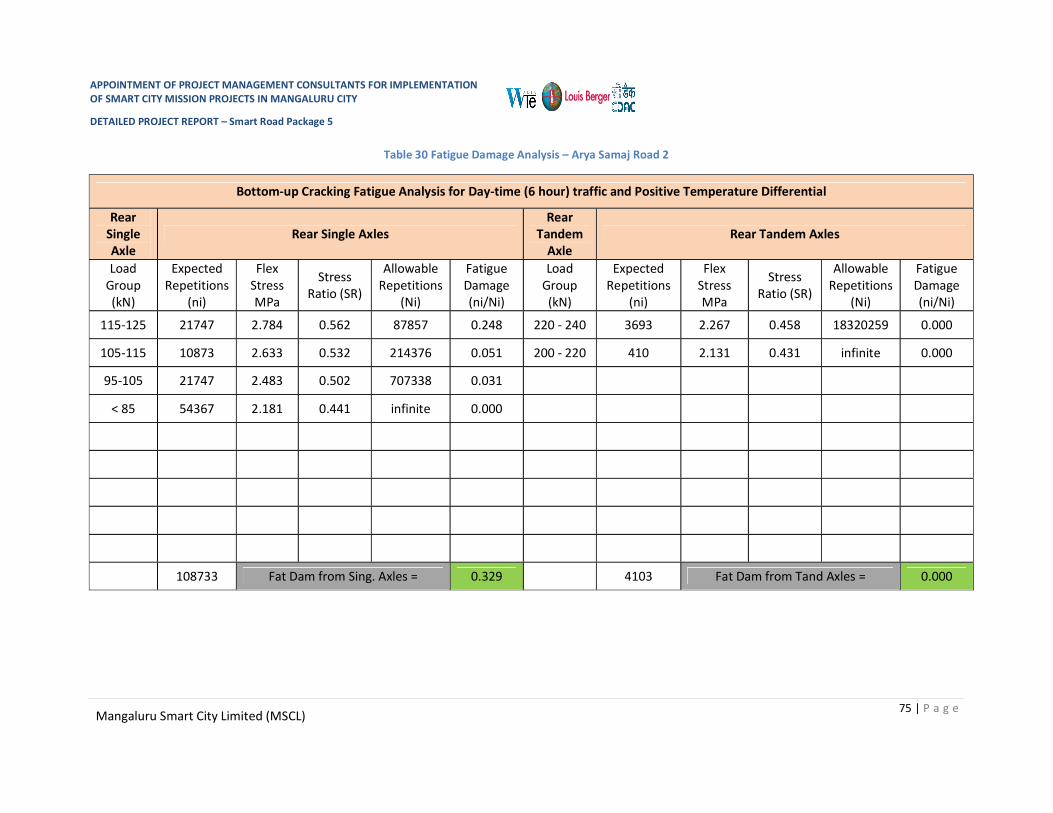
APPOINTMENT OF PROJECT MANAGEMENT CONSULTANTS FOR IMPLEMENTATION OF SMART CITY MISSION PROJECTS IN MANGALURU CITY
DETAILED PROJECT REPORT – Smart Road Package 5
75 | P a g e Mangaluru Smart City Limited (MSCL)
Table 30 Fatigue Damage Analysis – Arya Samaj Road 2
Bottom-up Cracking Fatigue Analysis for Day-time (6 hour) traffic and Positive Temperature Differential
Rear Single Axle
Rear Single Axles Rear
Tandem Axle
Rear Tandem Axles
Load Group (kN)
Expected Repetitions
(ni)
Flex Stress MPa
Stress Ratio (SR)
Allowable Repetitions
(Ni)
Fatigue Damage (ni/Ni)
Load Group (kN)
Expected Repetitions
(ni)
Flex Stress MPa
Stress Ratio (SR)
Allowable Repetitions
(Ni)
Fatigue Damage (ni/Ni)
115-125 21747 2.784 0.562 87857 0.248 220 - 240 3693 2.267 0.458 18320259 0.000
105-115 10873 2.633 0.532 214376 0.051 200 - 220 410 2.131 0.431 infinite 0.000
95-105 21747 2.483 0.502 707338 0.031
< 85 54367 2.181 0.441 infinite 0.000
108733 Fat Dam from Sing. Axles = 0.329 4103 Fat Dam from Tand Axles = 0.000

APPOINTMENT OF PROJECT MANAGEMENT CONSULTANTS FOR IMPLEMENTATION OF SMART CITY MISSION PROJECTS IN MANGALURU CITY
DETAILED PROJECT REPORT – Smart Road Package 5
76 | P a g e Mangaluru Smart City Limited (MSCL)
Top-Down Cracking Fatigue Analysis for Night-time (6 hour) traffic and Negative Temperature Differential
Rear Single Axle
Rear Single Axles Rear
Tandem Axle
Rear Tandem Axles
Load Group (kN)
Expected Repetition
s (ni)
Flex Stress MPa
Stress Ratio (SR)
Allowable Repetitions
(Ni)
Fatigue Damage (ni/Ni)
Load Group (kN)
Expected Repetitions
(ni)
Flex Stress MPa
Stress Ratio (SR)
Allowable Repetitions
(Ni)
Fatigue Damage (ni/Ni)
115-125 17941 2.593 0.524 284225 0.063 220 - 240 3047 2.541 0.513 423020 0.007
105-115 8970 2.489 0.503 665309 0.013 200 - 220 339 2.437 0.492 1125609 0.000
95-105 17941 2.386 0.482 2107060 0.009
< 85 44852 2.179 0.440 infinite 0.000
155737 Fat Dam from Sing. Axles = 0.085 5877 Fat Dam from Tand Axles = 0.007

APPOINTMENT OF PROJECT MANAGEMENT CONSULTANTS FOR IMPLEMENTATION OF SMART CITY MISSION PROJECTS IN MANGALURU CITY
DETAILED PROJECT REPORT – Smart Road Package 5
77 | P a g e Mangaluru Smart City Limited (MSCL)
It can be seen from the calculations given in the tables above that for the slab thickness of 205mmthe total fatigue damage for bottom-up cracking is 0.329 + 0.000 = 0.329. Total fatigue damage for top-down cracking is 0.085 + 0.007 = 0.092 and total cumulative fatigue damage (CFD) = 0.421 which is less than 1.0.
Hence, the trial thickness of 205mm is adequate.30mm thickness is added considering two retexturing in 30 years and 15mm for rounding off and hence a thickness of 250mm is appropriate.
Design of Dowel Bars
As per Table5 ‘Recommended Dimensions of Dowel Bars’ of IRC: 58-2015,
Diameter in mm - 32 Length in mm – 450 Spacing in mm - 300
Design of Tie Bars
Input Data:
Slab Thickness – 0.205 m Lane width, b – 3.1 m Coefficient of friction, f – 1.5 Density of concrete, kN/m3 – 24 Allowable tensile stress in deformed bars, MPa - 200(As per IRC:15-2017) Allowable bond stress for deformed tie bars, MPa – 2.46(As per IRC: 15-2017)
Design for Deformed Bars:
Select diameter of tie bar, dt – 12 mm Area of plain steel bar required per meter width of joint to resist the frictional force at slab
bottom, As
As= bfW / Sst
Where,
As – area of steel in mm2, required per m length of joint
b – Lane width in meters
f – Coefficient of friction between pavement and the sub-base/base (usually taken as 1.5)
W – Weight of slab in kN/m2 and
Sst – allowable working stress of steel in MPa
=3.1X1.5X0.205X24000/200
=114.39 mm2/m

APPOINTMENT OF PROJECT MANAGEMENT CONSULTANTS FOR IMPLEMENTATION OF SMART CITY MISSION PROJECTS IN MANGALURU CITY
DETAILED PROJECT REPORT – Smart Road Package 5
78 | P a g e Mangaluru Smart City Limited (MSCL)
Cross Sectional Area of Tie Bar A = π/4 X (12)2
= 113 mm2
Perimeter of Tie Bar = πd = 37.7mm
Spacing of tie bars, = A/As
= 113/114.39X1000
= 989 mm
Say 950mm
Provide spacing of 950mm c/c
Length of tie bar
L = 2SstAcs / BXPptb
Where,
L –Length of tie bar, mm
Sst – allowable working stress in steel, MPa
Acs – cross sectional area of one tie bar, mm2
Pptb – perimeter of the tie bar, mm and
B – Permissible bond stress of concrete, 2.46 MPa
= 2 X 200 X 113 / (2.46 X 37.7)
= 487.80 mm
Increase length by 100mm for loss of bond due to painting and another 50mm for tolerance in placement
Therefore the required length of tie bar is 640mm
Table 31 Pavement Composition: Arya Samaj Road 2
Sr. No. Description Thickness in mm
1 Pavement Quality Concrete (PQC) 250
2 Dry Lean Concrete (DLC) 100
3 Granular Sub-Base (GSB) (as Drainage Layer) 150
4 Selected Subgrade (CBR ≥ 8%) 500

APPOINTMENT OF PROJECT MANAGEMENT CONSULTANTS FOR IMPLEMENTATION OF SMART CITY MISSION PROJECTS IN MANGALURU CITY
DETAILED PROJECT REPORT – Smart Road Package 5
79 | P a g e Mangaluru Smart City Limited (MSCL)
2.5.3.3 Bengre Ferry Road 1
Design of Plain Jointed Rigid Pavement
Design of Slab Thickness
Input Data:
Road Type: Four lanes Two Way Single Carriageway
Design Life: 30 Years
Lane Width: 3.1m with 0.25m shyness width on both sides of carriageway edge.
Transverse joint spacing: 4.5 m
Traffic (as per TVC): 741 Commercial Vehicles per Day (CVPD)
CBR of Existing Soil: Two samples collected and tested and are 8.0% and 7.0%.
CBR (Considered) of Proposed Subgrade: 8%
CBR (Assumed) of Embankment below subgrade: 8%
Effective CBR of Subgrade: 8% (As per Figure 2 of IRC 58-2015)
Axle load Survey (Assumed): Single Axle 98% and Tandem Axle 2%
Table 32 Axle Load Spectrum (Assumed): Bengre Ferry Road 1
Sr. No.
Rear Single Axle Rear Tandem Axle Axle Load KN Frequency (% of
single Axles) Axle Load KN Frequency (% of
tandem Axles) 1 115-125 20 220-240 90 2 105-115 10 200-220 10 3 95-105 20 4 < 85 50
Total 98% 2%
Design:
I. Modulus of Subgrade Reaction: Effective CBR of compacted subgrade = 8%. Modulus of subgrade reaction = 50.3 MPa/m (from
Table 2 of IRC 58-2015) Provide 150mm thick Granular Sub-Base as drainage layer (Grading VI of Table 400-1 of MoRTH
Specifications Fifth Revision) Provide a Dry Lean Concrete (DLC) sub-base of thickness 100mm with a minimum 7 day
compressive strength of 10 MPa.

APPOINTMENT OF PROJECT MANAGEMENT CONSULTANTS FOR IMPLEMENTATION OF SMART CITY MISSION PROJECTS IN MANGALURU CITY
DETAILED PROJECT REPORT – Smart Road Package 5
80 | P a g e Mangaluru Smart City Limited (MSCL)
Effective modulus of subgrade reaction of combined foundation of subgrade, granular sub-base and DLC sub-base is 231.3 MPa/m (from Table 4 of IRC 58-2015 by interpolation)
Provide a de-bonding layer of polythene sheet of 125 micron thickness between DLC and concrete slab.
J. Flexural Strength of Concrete 28 day compressive strength of cement concrete ≥ 40 MPa 90 day compressive strength of cement concrete ≥ 48 MPa 28 day Flexural strength of cement concrete = 4.5 MPa (minimum) 90 day Flexural strength of cement concrete = 4.5 X 1.1 = 4.95 MPa K. Design Traffic for Fatigue Analysis Design Period – 30 years Assumed Annual rate of growth of commercial traffic = 5 % Total commercial vehicles during design period
C = 365 X A ((1 + r)n – 1) / r
Where,
C –Cumulative number of commercial vehicles during the design period
A – Initial number of commercial vehicles per day in the year when the road is opened to traffic
r – Annual rate of growth of commercial traffic volume (in decimal)
n – Design period in years
C = 365 X 741((1+0.05)30-1)/0.05
C= 17969383
Average number of axles (steering / single / tandem) per commercial vehicle =2.35 Total two way axle load repetitions during the design period –
= 18502887 X 2.35
= 42228050
No. of axles in predominant direction
= 42228050 X 0.5
= 21114025

APPOINTMENT OF PROJECT MANAGEMENT CONSULTANTS FOR IMPLEMENTATION OF SMART CITY MISSION PROJECTS IN MANGALURU CITY
DETAILED PROJECT REPORT – Smart Road Package 5
81 | P a g e Mangaluru Smart City Limited (MSCL)
Design traffic after adjusting for lateral placement of axles (25 per cent of predominant direction traffic for multilane highways) –
= 21114025 X 0.25
= 5278506
Night time (12 hour) design axles repetitions (Assumed 60% traffic at night time)
= 5278506 X 0.6
=3167104
Day time (12 hour) design axles repetitions (100% - 60% = 40%)
=5278506X 0.4
=2111403
Day time six hour axle load repetitions
= 2111403 X 0.5
= 1055701
Hence, design number of axle load repetitions for bottom-up cracking analysis
= 1055701
Night time six hour axle load repetitions
= 1055701 X 0.5
= 527850
% of commercial vehicles having the spacing between the front (steering) axle and the first axle of the rear axle unit less than 4.5m is 55%
Hence, the six hour night time design axle load repetitions for top-down cracking analysis (wheel base < 4.5m)
= 527850 X 0.55
= 290317
The axle load category wise design axle load repetitions for bottom up and top down fatigue cracking analysis are given in the following Table

APPOINTMENT OF PROJECT MANAGEMENT CONSULTANTS FOR IMPLEMENTATION OF SMART CITY MISSION PROJECTS IN MANGALURU CITY
DETAILED PROJECT REPORT – Smart Road Package 5
82 | P a g e Mangaluru Smart City Limited (MSCL)
Table 33 Fatigue Cracking Analysis Axle -Bengre Ferry Road 1
Axle Category Proportion of the Axle Category
Category wise axle repetitions for Bottom-up cracking analysis
Category wise axle repetitions for Top-down cracking analysis
Front (Steering) single 0.45 475065 130643
Rear single 0.53 559522 153868
Tandem 0.02 21114 5806
L. Cumulative Fatigue Damage (CFD) analysis for Bottom-Up Cracking (BUC) and Top-Down Cracking (TDC) and Selection of Slab Thickness
Effective modulus of subgrade reaction of foundation, k – 231 MPa/m Elastic Modulus of concrete, E – 30000 MPa Poisson’s ratio of concrete, µ - 0.15 Unit weight of concrete, γ – 24 kN/m3 Design flexural strength of concrete – 4.95 MPa Max. day-time Temperature Differential in slab (for bottom-up cracking) – 17.00C Night-time Temperature Differential in slab (for top-down cracking) – day-time diff/2 + 5 =
13.500C Trial thickness of slab, h = 225 mm Radius of relative stiffness, l = (Eh3/(12k(1- µ2))0.25
Where,
l – radius of relative stiffness, m
E – Elastic modulus of concrete, MPa
h – concrete slab thickness, m
k – modulus of subgrade reaction, MPa/m
µ - Poisson’s ratio of concrete
= 0.574
‘Beta’ factor in the stress equations will be 0.66 for doweled transverse joints for carrying out TDC analysis.
Computation of bottom-up and top-down cumulative fatigue damage is illustrated in following tables.

APPOINTMENT OF PROJECT MANAGEMENT CONSULTANTS FOR IMPLEMENTATION OF SMART CITY MISSION PROJECTS IN MANGALURU CITY
DETAILED PROJECT REPORT – Smart Road Package 5
83 | P a g e Mangaluru Smart City Limited (MSCL)
Table 34 Fatigue Damage Analysis: Bengre Ferry Road 1
Bottom-up Cracking Fatigue Analysis for Day-time (6 hour) traffic and Positive Temperature Differential
Rear Single Axle
Rear Single Axles Rear
Tandem Axle
Rear Tandem Axles
Load Group (kN)
Expected Repetitions
(ni)
Flex Stress MPa
Stress Ratio (SR)
Allowable Repetitions
(Ni)
Fatigue Damage (ni/Ni)
Load Group (kN)
Expected Repetitions
(ni)
Flex Stress MPa
Stress Ratio (SR)
Allowable Repetitions
(Ni)
Fatigue Damage (ni/Ni)
115-125 111904 2.55 0.516 385306 0.290 220 - 240 19003 2.06 0.416 Infinite 0.000
105-115 55952 2.42 0.488 1446409 0.039 200 - 220 2111 1.94 0.391 Infinite 0.000
95-105 111904 2.28 0.460 13839398 0.008
< 85 279761 2.00 0.405 Infinite 0.000
559522 Fat Dam from Sing. Axles = 0.337 21114 Fat Dam from Tand Axles = 0.000

APPOINTMENT OF PROJECT MANAGEMENT CONSULTANTS FOR IMPLEMENTATION OF SMART CITY MISSION PROJECTS IN MANGALURU CITY
DETAILED PROJECT REPORT – Smart Road Package 5
84 | P a g e Mangaluru Smart City Limited (MSCL)
Top-Down Cracking Fatigue Analysis for Night-time (6 hour) traffic and Negative Temperature Differential
Rear Single Axle
Rear Single Axles Rear
Tandem Axle
Rear Tandem Axles
Load Group (kN)
Expected Repetition
s (ni)
Flex Stress MPa
Stress Ratio (SR)
Allowable Repetitions
(Ni)
Fatigue Damage (ni/Ni)
Load Group (kN)
Expected Repetitions
(ni)
Flex Stress MPa
Stress Ratio (SR)
Allowable Repetitions
(Ni)
Fatigue Damage (ni/Ni)
115-125 30774 2.40 0.486 1653498 0.068 220 - 240 5226 2.36 0.476 3144238 0.001
105-115 15387 2.31 0.467 7003190 0.008 200 - 220 581 2.26 0.457 20274736 0.000
95-105 30774 2.22 0.448 Infinite 0.000
< 85 76934 2.03 0.410 Infinite 0.000
153868 Fat Dam from Sing. Axles = 0.076 5806 Fat Dam from Tand Axles = 0.001

APPOINTMENT OF PROJECT MANAGEMENT CONSULTANTS FOR IMPLEMENTATION OF SMART CITY MISSION PROJECTS IN MANGALURU CITY
DETAILED PROJECT REPORT – Smart Road Package 5
85 | P a g e Mangaluru Smart City Limited (MSCL)
It can be seen from the calculations given in the tables above that for the slab thickness of 225mmthe total fatigue damage for bottom-up cracking is 0.337 + 0.000 = 0.337. Total fatigue damage for top-down cracking is 0.076 + 0.001 = 0.077 and total cumulative fatigue damage (CFD) = 0.414 which is less than 1.0.
Hence, the trial thickness of 225mm is adequate.30mm thickness is added considering two retexturing in 30 years and 15mm for rounding off and hence a thickness of 270mm is appropriate.
Design of Dowel Bars
As per Table5 ‘Recommended Dimensions of Dowel Bars’ of IRC: 58-2015,
Diameter in mm - 32 Length in mm – 450 Spacing in mm - 300
Design of Tie Bars
Input Data:
Slab Thickness – 0.280 m Lane width, b – 3.1 m Coefficient of friction, f – 1.5 Density of concrete, kN/m3 – 24 Allowable tensile stress in deformed bars, MPa -200(As per IRC:15-2017) Allowable bond stress for deformed tie bars, MPa – 2.46(As per IRC: 15-2017)
Design for Deformed Bars:
Select diameter of tie bar, dt – 12 mm Area of plain steel bar required per meter width of joint to resist the frictional force at slab
bottom, As
As= bfW / Sst
Where,
As – area of steel in mm2, required per m length of joint
b – Lane width in meters
f – Coefficient of friction between pavement and the sub-base/base (usually taken as 1.5)
W – Weight of slab in kN/m2 and
Sst – allowable working stress of steel in MPa
=3.1X1.5X0.270X24000/200
=151.07 mm2/m

APPOINTMENT OF PROJECT MANAGEMENT CONSULTANTS FOR IMPLEMENTATION OF SMART CITY MISSION PROJECTS IN MANGALURU CITY
DETAILED PROJECT REPORT – Smart Road Package 5
86 | P a g e Mangaluru Smart City Limited (MSCL)
Cross Sectional Area of Tie Bar A = π/4 X (12)2
= 113 mm2
Perimeter of Tie Bar = πd = 37.7mm
Spacing of tie bars, = A/As
= 113/151.0X1000
= 748 mm
Say 750mm
Provide spacing of 750mm c/c
Length of tie bar
L = 2SstAcs / BXPptb
Where,
L –Length of tie bar, mm
Sst – allowable working stress in steel, MPa
Acs – cross sectional area of one tie bar, mm2
Pptb – perimeter of the tie bar, mm and
B – Permissible bond stress of concrete, 2.46 MPa
= 2 X 200 X 113 / (2.46 X 37.7)
= 487.80 mm
Increase length by 100mm for loss of bond due to painting and another 50mm for tolerance in placement
Therefore the required length of tie bar is 640mm
Table 35 Pavement Composition: Bengre Ferry Road 1
Sr. No. Description Thickness in mm
1 Pavement Quality Concrete (PQC) 270
2 Dry Lean Concrete (DLC) 100
3 Granular Sub-Base (GSB) (as Drainage Layer) 150
4 Selected Subgrade (CBR ≥ 8%) 500

APPOINTMENT OF PROJECT MANAGEMENT CONSULTANTS FOR IMPLEMENTATION OF SMART CITY MISSION PROJECTS IN MANGALURU CITY
DETAILED PROJECT REPORT – Smart Road Package 5
87 | P a g e Mangaluru Smart City Limited (MSCL)
2.5.3.4 Milagres Cross Road
Design of Plain Jointed Rigid Pavement
Design of Slab Thickness
Input Data:
Road Type: Two lanesOne Way Single Carriageway
Design Life: 30 Years
Lane Width: 3.1m with 0.25m shyness width on both sides of carriageway edge.
Transverse joint spacing: 4.5 m
Traffic (as per TVC): 161 Commercial Vehicles per Day (CVPD)
CBR of Existing Soil: Two samples collected and tested and are 9.0% and 8.0%.
CBR (Considered) of Proposed Subgrade: 8%
CBR (Assumed) of Embankment below subgrade: 8%
Effective CBR of Subgrade: 8% (As per Figure 2 of IRC 58-2015)
Axle load Survey (Assumed): Single Axle 98% and Tandem Axle 2%
Table 36 Axle Load Spectrum (Assumed): Milegres Cross Road
Sr. No.
Rear Single Axle Rear Tandem Axle Axle Load KN Frequency (% of
single Axles) Axle Load KN Frequency (% of
tandem Axles) 1 115-125 20 220-240 90 2 105-115 10 200-220 10 3 95-105 20 4 < 85 50
Total 100% 100%
Design:
M. Modulus of Subgrade Reaction: Effective CBR of compacted subgrade = 8%. Modulus of subgrade reaction = 50.3 MPa/m (from
Table 2 of IRC 58-2015) Provide 150mm thick Granular Sub-Base as drainage layer (Grading VI of Table 400-1 of MoRTH
Specifications Fifth Revision) Provide a Dry Lean Concrete (DLC) sub-base of thickness 100mm with a minimum 7 day
compressive strength of 10 MPa.

APPOINTMENT OF PROJECT MANAGEMENT CONSULTANTS FOR IMPLEMENTATION OF SMART CITY MISSION PROJECTS IN MANGALURU CITY
DETAILED PROJECT REPORT – Smart Road Package 5
88 | P a g e Mangaluru Smart City Limited (MSCL)
Effective modulus of subgrade reaction of combined foundation of subgrade, granular sub-base and DLC sub-base is 231.3 MPa/m (from Table 4 of IRC 58-2015 by interpolation)
Provide a de-bonding layer of polythene sheet of 125 micron thickness between DLC and concrete slab.
N. Flexural Strength of Concrete 28 day compressive strength of cement concrete ≥ 40 MPa 90 day compressive strength of cement concrete ≥ 48 MPa 28 day Flexural strength of cement concrete = 4.5 MPa (minimum) 90 day Flexural strength of cement concrete = 4.5 X 1.1 = 4.95 MPa O. Design Traffic for Fatigue Analysis Design Period – 30 years Assumed Annual rate of growth of commercial traffic = 5 % One way commercial traffic volume per day =169 CVPD Total commercial vehicles during design period
C = 365 X A ((1 + r)n – 1) / r
Where,
C –Cumulative number of commercial vehicles during the design period
A – Initial number of commercial vehicles per day in the year when the road is opened to traffic
r – Annual rate of growth of commercial traffic volume (in decimal)
n – Design period in years
C = 365 X 161((1+0.05)30-1)/0.05
C= 3904279
Average number of axles (steering / single / tandem) per commercial vehicle =2.35 Total two way axle load repetitions during the design period –
= 4098280 X 2.35
=9175055
No. of axles in predominant direction
= 9175055 X 1 ( One Way Traffic)
= 9175055
APPOINTMENT OF PROJECT MANAGEMENT CONSULTANTS FOR IMPLEMENTATION OF SMART CITY MISSION PROJECTS IN MANGALURU CITY
DETAILED PROJECT REPORT – Smart Road Package 5
89 | P a g e Mangaluru Smart City Limited (MSCL)
Design traffic after adjusting for lateral placement of axles (25 per cent of predominant direction traffic for multilane highways) –
= 9175055 X 0.25
= 1146882
Night time (12 hour) design axles repetitions (Assumed 60% traffic at night time)
= 1146882 X 0.6
= 688129
Day time (12 hour) design axles repetitions (100% - 60% = 40%)
= 1146882 X 0.4
=458753
Day time six hour axle load repetitions
= 458753 X 0.5
= 229376
Hence, design number of axle load repetitions for bottom-up cracking analysis
= 229376
Night time six hour axle load repetitions
= 688129 X 0.5
= 344065
% of commercial vehicles having the spacing between the front (steering) axle and the first axle of the rear axle unit less than 4.5m is 55%
Hence, the six hour night time design axle load repetitions for top-down cracking analysis (wheel base < 4.5m)
= 344065 X 0.55
= 189236
The axle load category wise design axle load repetitions for bottom up and top down fatigue cracking analysis are given in the following Table

APPOINTMENT OF PROJECT MANAGEMENT CONSULTANTS FOR IMPLEMENTATION OF SMART CITY MISSION PROJECTS IN MANGALURU CITY
DETAILED PROJECT REPORT – Smart Road Package 5
90 | P a g e Mangaluru Smart City Limited (MSCL)
Table 37 Fatigue cracking analysis
Axle Category Proportion of the Axle Category
Category wise axle repetitions for Bottom-up cracking analysis
Category wise axle repetitions for Top-down cracking analysis
Front (Steering) single 0.45 103219 85156
Rear single 0.53 121569 100295
Tandem 0.02 4588 3785
P. Cumulative Fatigue Damage (CFD) analysis for Bottom-Up Cracking (BUC) and Top-Down Cracking (TDC) and Selection of Slab Thickness
Effective modulus of subgrade reaction of foundation, k – 231 MPa/m Elastic Modulus of concrete, E – 30000 MPa Poisson’s ratio of concrete, µ - 0.15 Unit weight of concrete, γ – 24 kN/m3 Design flexural strength of concrete – 4.95 MPa Max. day-time Temperature Differential in slab (for bottom-up cracking) – 17.00C Night-time Temperature Differential in slab (for top-down cracking) – day-time diff/2 + 5 =
13.500C Trial thickness of slab, h = 205 mm Radius of relative stiffness, l = (Eh3/(12k(1- µ2))0.25
Where,
l – radius of relative stiffness, m
E – Elastic modulus of concrete, MPa
h – concrete slab thickness, m
k – modulus of subgrade reaction, MPa/m
µ - Poisson’s ratio of concrete
= 0.55556
‘Beta’ factor in the stress equations will be 0.66 for doweled transverse joints for carrying out TDC analysis.
Computation of bottom-up and top-down cumulative fatigue damage is illustrated in following tables.

APPOINTMENT OF PROJECT MANAGEMENT CONSULTANTS FOR IMPLEMENTATION OF SMART CITY MISSION PROJECTS IN MANGALURU CITY
DETAILED PROJECT REPORT – Smart Road Package 5
91 | P a g e Mangaluru Smart City Limited (MSCL)
Table 38 Fatigue Damage Analysis
Bottom-up Cracking Fatigue Analysis for Day-time (6 hour) traffic and Positive Temperature Differential
Rear Single Axle
Rear Single Axles Rear
Tandem Axle
Rear Tandem Axles
Load Group (kN)
Expected Repetitions
(ni)
Flex Stress MPa
Stress Ratio (SR)
Allowable Repetitions
(Ni)
Fatigue Damage (ni/Ni)
Load Group (kN)
Expected Repetitions
(ni)
Flex Stress MPa
Stress Ratio (SR)
Allowable Repetitions
(Ni)
Fatigue Damage (ni/Ni)
115-125 20644 2.784 0.562 87857 0.23 220 - 240 4129 2.267 0.458 18320259 0.001
105-115 10322 2.633 0.532 214376 0.05 200 - 220 458 2.131 0.431 infinite 0.000
95-105 20644 2.483 0.502 707338 0.03
< 85 51610 2.181 0.441 infinite 0.000
103220 Fat Dam from Sing. Axles = 0.380 9631 Fat Dam from Tand Axles = 0.001

APPOINTMENT OF PROJECT MANAGEMENT CONSULTANTS FOR IMPLEMENTATION OF SMART CITY MISSION PROJECTS IN MANGALURU CITY
DETAILED PROJECT REPORT – Smart Road Package 5
92 | P a g e Mangaluru Smart City Limited (MSCL)
Top-Down Cracking Fatigue Analysis for Night-time (6 hour) traffic and Negative Temperature Differential
Rear Single Axle
Rear Single Axles Rear
Tandem Axle
Rear Tandem Axles
Load Group (kN)
Expected Repetition
s (ni)
Flex Stress MPa
Stress Ratio (SR)
Allowable Repetitions
(Ni)
Fatigue Damage (ni/Ni)
Load Group (kN)
Expected Repetitions
(ni)
Flex Stress MPa
Stress Ratio (SR)
Allowable Repetitions
(Ni)
Fatigue Damage (ni/Ni)
115-125 20059 2.784 0.562 87857 0.23 220 - 240 3406 2.267 0.458 18320259 0.000
105-115 10030 2.633 0.532 214376 0.05 200 - 220 378 2.131 0.431 infinite 0.000
95-105 20059 2.483 0.502 707338 0.03
< 85 50148 2.181 0.441 infinite 0.000
100295 Fat Dam from Sing. Axles = 0.310 5877 Fat Dam from Tand Axles = 0.000

APPOINTMENT OF PROJECT MANAGEMENT CONSULTANTS FOR IMPLEMENTATION OF SMART CITY MISSION PROJECTS IN MANGALURU CITY
DETAILED PROJECT REPORT – Smart Road Package 5
93 | P a g e Mangaluru Smart City Limited (MSCL)
It can be seen from the calculations given in the tables above that for the slab thickness of 205mmthe total fatigue damage for bottom-up cracking is 0.380 + 0.001 = 0.381. Total fatigue damage for top-down cracking is 0.310 + 0.000 = 0.310 and total cumulative fatigue damage (CFD) = 0.690 which is less than 1.0.
Hence, the trial thickness of 205mm is adequate.30mm thickness is added considering two retexturing in 30 years and 15mm for rounding off and hence a thickness of 250mm is appropriate.
Design of Dowel Bars
As per Table5 ‘Recommended Dimensions of Dowel Bars’ of IRC: 58-2015,
Diameter in mm - 32 Length in mm – 450 Spacing in mm - 300
Design of Tie Bars
Input Data:
Slab Thickness – 0.205 m Lane width, b – 3.1 m Coefficient of friction, f – 1.5 Density of concrete, kN/m3 – 24 Allowable tensile stress in deformed bars, MPa - 200(As per IRC:15-2017) Allowable bond stress for deformed tie bars, MPa – 2.46(As per IRC: 15-2017)
Design for Deformed Bars:
Select diameter of tie bar, dt – 12 mm Area of plain steel bar required per meter width of joint to resist the frictional force at slab
bottom, As
As= bfW / Sst
Where,
As – area of steel in mm2, required per m length of joint
b – Lane width in meters
f – Coefficient of friction between pavement and the sub-base/base (usually taken as 1.5)
W – Weight of slab in kN/m2 and
Sst – allowable working stress of steel in MPa
=3.1X1.5X0.205X24000/200
=114.39 mm2/m

APPOINTMENT OF PROJECT MANAGEMENT CONSULTANTS FOR IMPLEMENTATION OF SMART CITY MISSION PROJECTS IN MANGALURU CITY
DETAILED PROJECT REPORT – Smart Road Package 5
94 | P a g e Mangaluru Smart City Limited (MSCL)
Cross Sectional Area of Tie Bar A = π/4 X (12)2
= 113 mm2
Perimeter of Tie Bar = πd = 37.7mm
Spacing of tie bars, = A/As
= 113/114.39X1000
= 989 mm
Say 950mm
Provide spacing of 950mm c/c
Length of tie bar
L = 2SstAcs / BXPptb
Where,
L –Length of tie bar, mm
Sst – allowable working stress in steel, MPa
Acs – cross sectional area of one tie bar, mm2
Pptb – perimeter of the tie bar, mm and
B – Permissible bond stress of concrete, 2.46 MPa
= 2 X 200 X 113 / (2.46 X 37.7)
= 487.80 mm
Increase length by 100mm for loss of bond due to painting and another 50mm for tolerance in placement
Therefore the required length of tie bar is 640mm
Table 39 Pavement Composition:
Sr. No. Description Thickness in mm
1 Pavement Quality Concrete (PQC) 250
2 Dry Lean Concrete (DLC) 100
3 Granular Sub-Base (GSB) (as Drainage Layer) 150
4 Selected Subgrade (CBR ≥ 8%) 500

APPOINTMENT OF PROJECT MANAGEMENT CONSULTANTS FOR IMPLEMENTATION OF SMART CITY MISSION PROJECTS IN MANGALURU CITY
DETAILED PROJECT REPORT – Smart Road Package 5
95 | P a g e Mangaluru Smart City Limited (MSCL)
2.5.3.5 Nadigudda Road- 1
Design of Plain Jointed Rigid Pavement
Design of Slab Thickness
Input Data:
Road Type: Four lanes Two Way Single Carriageway
Design Life: 30 Years
Lane Width: 3.1m with 0.25m shyness width on both sides of carriageway edge.
Transverse joint spacing: 4.5 m
Traffic (as per TVC): 763 Commercial Vehicles per Day (CVPD)
CBR of Existing Soil: Two samples collected and tested and are 8.0% and 7.0%.
CBR (Considered) of Proposed Subgrade: 8%
CBR (Assumed) of Embankment below subgrade: 8%
Effective CBR of Subgrade: 8% (As per Figure 2 of IRC 58-2015)
Axle load Survey (Assumed): Single Axle 98% and Tandem Axle 2%
Table 40 Axle Load Spectrum (Assumed): Nadiguda road 1
Sr. No.
Rear Single Axle Rear Tandem Axle Axle Load KN Frequency (% of
single Axles) Axle Load KN Frequency (% of
tandem Axles) 1 115-125 20 220-240 90 2 105-115 10 200-220 10 3 95-105 20 4 < 85 50
Total 98% 2%
Design:
Q. Modulus of Subgrade Reaction: Effective CBR of compacted subgrade = 8%. Modulus of subgrade reaction = 50.3 MPa/m (from
Table 2 of IRC 58-2015) Provide 150mm thick Granular Sub-Base as drainage layer (Grading VI of Table 400-1 of MoRTH
Specifications Fifth Revision) Provide a Dry Lean Concrete (DLC) sub-base of thickness 100mm with a minimum 7 day
compressive strength of 10 MPa.

APPOINTMENT OF PROJECT MANAGEMENT CONSULTANTS FOR IMPLEMENTATION OF SMART CITY MISSION PROJECTS IN MANGALURU CITY
DETAILED PROJECT REPORT – Smart Road Package 5
96 | P a g e Mangaluru Smart City Limited (MSCL)
Effective modulus of subgrade reaction of combined foundation of subgrade, granular sub-base and DLC sub-base is 231.3 MPa/m (from Table 4 of IRC 58-2015 by interpolation)
Provide a de-bonding layer of polythene sheet of 125 micron thickness between DLC and concrete slab.
R. Flexural Strength of Concrete 28 day compressive strength of cement concrete ≥ 40 MPa 90 day compressive strength of cement concrete ≥ 48 MPa 28 day Flexural strength of cement concrete = 4.5 MPa (minimum) 90 day Flexural strength of cement concrete = 4.5 X 1.1 = 4.95 MPa S. Design Traffic for Fatigue Analysis Design Period – 30 years Assumed Annual rate of growth of commercial traffic = 5 % Total commercial vehicles during design period
C = 365 X A ((1 + r)n – 1) / r
Where,
C –Cumulative number of commercial vehicles during the design period
A – Initial number of commercial vehicles per day in the year when the road is opened to traffic
r – Annual rate of growth of commercial traffic volume (in decimal)
n – Design period in years
C = 365 X 763((1+0.05)30-1)/0.05
C= 18502887
Average number of axles (steering / single / tandem) per commercial vehicle =2.35 Total two way axle load repetitions during the design period –
= 18502887 X 2.35
= 43481784
No. of axles in predominant direction
= 43481784 X 0.5
= 21740892

APPOINTMENT OF PROJECT MANAGEMENT CONSULTANTS FOR IMPLEMENTATION OF SMART CITY MISSION PROJECTS IN MANGALURU CITY
DETAILED PROJECT REPORT – Smart Road Package 5
97 | P a g e Mangaluru Smart City Limited (MSCL)
Design traffic after adjusting for lateral placement of axles (25 per cent of predominant direction traffic for multilane highways) –
= 21740892 X 0.25
= 5435223
Night time (12 hour) design axles repetitions (Assumed 60% traffic at night time)
= 5435223 X 0.6
= 3261134
Day time (12 hour) design axles repetitions (100% - 60% = 40%)
= 5435223 X 0.4
=2174089
Day time six hour axle load repetitions
= 2174089 X 0.5
= 1087045
Hence, design number of axle load repetitions for bottom-up cracking analysis
= 1087045
Night time six hour axle load repetitions
= 3261134 X 0.5
= 1630567
% of commercial vehicles having the spacing between the front (steering) axle and the first axle of the rear axle unit less than 4.5m is 55%
Hence, the six hour night time design axle load repetitions for top-down cracking analysis (wheel base < 4.5m)
= 1630567 X 0.55
= 896811
The axle load category wise design axle load repetitions for bottom up and top down fatigue cracking analysis are given in the following Table

APPOINTMENT OF PROJECT MANAGEMENT CONSULTANTS FOR IMPLEMENTATION OF SMART CITY MISSION PROJECTS IN MANGALURU CITY
DETAILED PROJECT REPORT – Smart Road Package 5
98 | P a g e Mangaluru Smart City Limited (MSCL)
Table 41 fatigue cracking analysis – Nadiguda Road 1
Axle Category Proportion of the Axle Category
Category wise axle repetitions for Bottom-up cracking analysis
Category wise axle repetitions for Top-down cracking analysis
Front (Steering) single 0.45 489170 403565
Rear single 0.53 576134 475310
Tandem 0.02 21741 17936
T. Cumulative Fatigue Damage (CFD) analysis for Bottom-Up Cracking (BUC) and Top-Down Cracking (TDC) and Selection of Slab Thickness
Effective modulus of subgrade reaction of foundation, k – 231 MPa/m Elastic Modulus of concrete, E – 30000 MPa Poisson’s ratio of concrete, µ - 0.15 Unit weight of concrete, γ – 24 kN/m3 Design flexural strength of concrete – 4.95 MPa Max. day-time Temperature Differential in slab (for bottom-up cracking) – 17.00C Night-time Temperature Differential in slab (for top-down cracking) – day-time diff/2 + 5 =
13.500C Trial thickness of slab, h = 225 mm Radius of relative stiffness, l = (Eh3/(12k(1- µ2))0.25
Where,
l – radius of relative stiffness, m
E – Elastic modulus of concrete, MPa
h – concrete slab thickness, m
k – modulus of subgrade reaction, MPa/m
µ - Poisson’s ratio of concrete
= 0.574
‘Beta’ factor in the stress equations will be 0.66 for doweled transverse joints for carrying out TDC analysis.
Computation of bottom-up and top-down cumulative fatigue damage is illustrated in following tables.

APPOINTMENT OF PROJECT MANAGEMENT CONSULTANTS FOR IMPLEMENTATION OF SMART CITY MISSION PROJECTS IN MANGALURU CITY
DETAILED PROJECT REPORT – Smart Road Package 5
99 | P a g e Mangaluru Smart City Limited (MSCL)
Table 42 Fatigue Damage Analysis
Bottom-up Cracking Fatigue Analysis for Day-time (6 hour) traffic and Positive Temperature Differential
Rear Single Axle
Rear Single Axles Rear
Tandem Axle
Rear Tandem Axles
Load Group (kN)
Expected Repetitions
(ni)
Flex Stress MPa
Stress Ratio (SR)
Allowable Repetitions
(Ni)
Fatigue Damage (ni/Ni)
Load Group (kN)
Expected Repetitions
(ni)
Flex Stress MPa
Stress Ratio (SR)
Allowable Repetitions
(Ni)
Fatigue Damage (ni/Ni)
115-125 115227 2.55 0.516 385306 0.299 220 - 240 19567 2.06 0.416 Infinite 0.000
105-115 57613 2.42 0.488 1446409 0.040 200 - 220 2174 1.94 0.391 Infinite 0.000
95-105 115227 2.28 0.460 13839398 0.008
< 85 288067 2.00 0.405 Infinite 0.000
576134 Fat Dam from Sing. Axles = 0.347 21741 Fat Dam from Tand Axles = 0.000

APPOINTMENT OF PROJECT MANAGEMENT CONSULTANTS FOR IMPLEMENTATION OF SMART CITY MISSION PROJECTS IN MANGALURU CITY
DETAILED PROJECT REPORT – Smart Road Package 5
100 | P a g e Mangaluru Smart City Limited (MSCL)
Top-Down Cracking Fatigue Analysis for Night-time (6 hour) traffic and Negative Temperature Differential
Rear Single Axle
Rear Single Axles Rear
Tandem Axle
Rear Tandem Axles
Load Group (kN)
Expected Repetition
s (ni)
Flex Stress MPa
Stress Ratio (SR)
Allowable Repetitions
(Ni)
Fatigue Damage (ni/Ni)
Load Group (kN)
Expected Repetitions
(ni)
Flex Stress MPa
Stress Ratio (SR)
Allowable Repetitions
(Ni)
Fatigue Damage (ni/Ni)
115-125 95062 2.40 0.486 1653498 0.057 220 - 240 16143 2.36 0.476 3144238 0.005
105-115 47531 2.31 0.467 7003190 0.007 200 - 220 1794 2.26 0.457 20274736 0.000
95-105 95062 2.22 0.448 Infinite 0.000
< 85 237655 2.03 0.410 Infinite 0.000
475310 Fat Dam from Sing. Axles = 0.064 21741 Fat Dam from Tand Axles = 0.005

APPOINTMENT OF PROJECT MANAGEMENT CONSULTANTS FOR IMPLEMENTATION OF SMART CITY MISSION PROJECTS IN MANGALURU CITY
DETAILED PROJECT REPORT – Smart Road Package 5
101 | P a g e Mangaluru Smart City Limited (MSCL)
It can be seen from the calculations given in the tables above that for the slab thickness of 225mmthe total fatigue damage for bottom-up cracking is 0.347 + 0.000 = 0.347. Total fatigue damage for top-down cracking is 0.064 + 0.005 = 0.069 and total cumulative fatigue damage (CFD) = 0.416 which is less than 1.0.
Hence, the trial thickness of 225mm is adequate.30mm thickness is added considering two retexturing in 30 years and 15mm for rounding off and hence a thickness of 270mm is appropriate.
Design of Dowel Bars
As per Table5 ‘Recommended Dimensions of Dowel Bars’ of IRC: 58-2015,
Diameter in mm - 32 Length in mm – 450 Spacing in mm - 300
Design of Tie Bars
Input Data:
Slab Thickness – 0.280 m Lane width, b – 3.1 m Coefficient of friction, f – 1.5 Density of concrete, kN/m3 – 24 Allowable tensile stress in deformed bars, MPa -200(As per IRC:15-2017) Allowable bond stress for deformed tie bars, MPa – 2.46(As per IRC: 15-2017)
Design for Deformed Bars:
Select diameter of tie bar, dt – 12 mm Area of plain steel bar required per meter width of joint to resist the frictional force at slab
bottom, As
As= bfW / Sst
Where,
As – area of steel in mm2, required per m length of joint
b – Lane width in meters
f – Coefficient of friction between pavement and the sub-base/base (usually taken as 1.5)
W – Weight of slab in kN/m2 and
Sst – allowable working stress of steel in MPa
=3.1X1.5X0.270X24000/200
=151.07 mm2/m

APPOINTMENT OF PROJECT MANAGEMENT CONSULTANTS FOR IMPLEMENTATION OF SMART CITY MISSION PROJECTS IN MANGALURU CITY
DETAILED PROJECT REPORT – Smart Road Package 5
102 | P a g e Mangaluru Smart City Limited (MSCL)
Cross Sectional Area of Tie Bar A = π/4 X (12)2
= 113 mm2
Perimeter of Tie Bar = πd = 37.7mm
Spacing of tie bars, = A/As
= 113/151.0X1000
= 748 mm
Say 750mm
Provide spacing of 750mm c/c
Length of tie bar
L = 2SstAcs / BXPptb
Where,
L –Length of tie bar, mm
Sst – allowable working stress in steel, MPa
Acs – cross sectional area of one tie bar, mm2
Pptb – perimeter of the tie bar, mm and
B – Permissible bond stress of concrete, 2.46 MPa
= 2 X 200 X 113 / (2.46 X 37.7)
= 487.80 mm
Increase length by 100mm for loss of bond due to painting and another 50mm for tolerance in placement
Therefore the required length of tie bar is 640mm
Table 43 Pavement Composition:
Sr. No. Description Thickness in mm
1 Pavement Quality Concrete (PQC) 270
2 Dry Lean Concrete (DLC) 100
3 Granular Sub-Base (GSB) (as Drainage Layer) 150
4 Selected Subgrade (CBR ≥ 8%) 500

APPOINTMENT OF PROJECT MANAGEMENT CONSULTANTS FOR IMPLEMENTATION OF SMART CITY MISSION PROJECTS IN MANGALURU CITY
DETAILED PROJECT REPORT – Smart Road Package 5
103 | P a g e Mangaluru Smart City Limited (MSCL)
2.5.3.6 Nadiguda Road- 2
-Design of Plain Jointed Rigid Pavement
Design of Slab Thickness
Input Data:
Road Type: Two lanes Two Way Single Carriageway
Design Life: 30 Years
Lane Width: 3.1m with 0.25m shyness width on both sides of carriageway edge.
Transverse joint spacing: 4.5 m
Traffic (as per TVC): 461 Commercial Vehicles per Day (CVPD)
CBR of Existing Soil: Two samples collected and tested and are 8.0% and 7.0%.
CBR (Considered) of Proposed Subgrade: 8%
CBR (Assumed) of Embankment below subgrade: 8%
Effective CBR of Subgrade: 8% (As per Figure 2 of IRC 58-2015)
Axle load Survey (Assumed): Single Axle 98% and Tandem Axle 2%
Table 44 Axle Load Spectrum (Assumed): Nadiguda road 2
Sr. No.
Rear Single Axle Rear Tandem Axle Axle Load KN Frequency (% of
single Axles) Axle Load KN Frequency (% of
tandem Axles) 1 115-125 20 220-240 90 2 105-115 10 200-220 10 3 95-105 20 4 < 85 50
Total 98% 2%
Design:
U. Modulus of Subgrade Reaction: Effective CBR of compacted subgrade = 8%. Modulus of subgrade reaction = 50.3 MPa/m (from
Table 2 of IRC 58-2015) Provide 150mm thick Granular Sub-Base as drainage layer (Grading VI of Table 400-1 of MoRTH
Specifications Fifth Revision) Provide a Dry Lean Concrete (DLC) sub-base of thickness 100mm with a minimum 7 day
compressive strength of 10 MPa.

APPOINTMENT OF PROJECT MANAGEMENT CONSULTANTS FOR IMPLEMENTATION OF SMART CITY MISSION PROJECTS IN MANGALURU CITY
DETAILED PROJECT REPORT – Smart Road Package 5
104 | P a g e Mangaluru Smart City Limited (MSCL)
Effective modulus of subgrade reaction of combined foundation of subgrade, granular sub-base and DLC sub-base is 231.3 MPa/m (from Table 4 of IRC 58-2015 by interpolation)
Provide a de-bonding layer of polythene sheet of 125 micron thickness between DLC and concrete slab.
V. Flexural Strength of Concrete 28 day compressive strength of cement concrete ≥ 40 MPa 90 day compressive strength of cement concrete ≥ 48 MPa 28 day Flexural strength of cement concrete = 4.5 MPa (minimum) 90 day Flexural strength of cement concrete = 4.5 X 1.1 = 4.95 MPa W. Design Traffic for Fatigue Analysis Design Period – 30 years Assumed Annual rate of growth of commercial traffic = 5 % Total commercial vehicles during design period
C = 365 X A ((1 + r)n – 1) / r
Where,
C –Cumulative number of commercial vehicles during the design period
A – Initial number of commercial vehicles per day in the year when the road is opened to traffic
r – Annual rate of growth of commercial traffic volume (in decimal)
n – Design period in years
C = 365 X 461((1+0.05)30-1)/0.05
C= 11179333
Average number of axles (steering / single / tandem) per commercial vehicle =2.35 Total two way axle load repetitions during the design period –
= 11179333 X 2.35
= 26271432
No. of axles in predominant direction
=26271432 X 0.5
= 13135716
APPOINTMENT OF PROJECT MANAGEMENT CONSULTANTS FOR IMPLEMENTATION OF SMART CITY MISSION PROJECTS IN MANGALURU CITY
DETAILED PROJECT REPORT – Smart Road Package 5
105 | P a g e Mangaluru Smart City Limited (MSCL)
Design traffic after adjusting for lateral placement of axles (25 per cent of predominant direction traffic for multilane highways) –
= 13135716 X 0.25
= 3283929
Night time (12 hour) design axles repetitions (Assumed 60% traffic at night time)
= 3283929 X 0.6
= 1970357
Day time (12 hour) design axles repetitions (100% - 60% = 40%)
= 3283929 X 0.4
=1313572
Day time six hour axle load repetitions
= 1313572 X 0.5
= 656786
Hence, design number of axle load repetitions for bottom-up cracking analysis
= 656786
Night time six hour axle load repetitions
=1970357X 0.5
= 985178
% of commercial vehicles having the spacing between the front (steering) axle and the first axle of the rear axle unit less than 4.5m is 55%
Hence, the six hour night time design axle load repetitions for top-down cracking analysis (wheel base < 4.5m)
= 985178 X 0.55
= 541848
The axle load category wise design axle load repetitions for bottom up and top down fatigue cracking analysis are given in the following Table

APPOINTMENT OF PROJECT MANAGEMENT CONSULTANTS FOR IMPLEMENTATION OF SMART CITY MISSION PROJECTS IN MANGALURU CITY
DETAILED PROJECT REPORT – Smart Road Package 5
106 | P a g e Mangaluru Smart City Limited (MSCL)
Table 45 Fatigue cracking analysis
Axle Category Proportion of the Axle Category
Category wise axle repetitions for Bottom-up cracking analysis
Category wise axle repetitions for Top-down cracking analysis
Front (Steering) single 0.45 295554 243832
Rear single 0.53 348096 287180
Tandem 0.02 13136 10837
X. Cumulative Fatigue Damage (CFD) analysis for Bottom-Up Cracking (BUC) and Top-Down Cracking (TDC) and Selection of Slab Thickness
Effective modulus of subgrade reaction of foundation, k – 231 MPa/m Elastic Modulus of concrete, E – 30000 MPa Poisson’s ratio of concrete, µ - 0.15 Unit weight of concrete, γ – 24 kN/m3 Design flexural strength of concrete – 4.95 MPa Max. day-time Temperature Differential in slab (for bottom-up cracking) – 17.00C Night-time Temperature Differential in slab (for top-down cracking) – day-time diff/2 + 5 =
13.500C Trial thickness of slab, h = 215 mm Radius of relative stiffness, l = (Eh3/(12k(1- µ2))0.25
Where,
l – radius of relative stiffness, m
E – Elastic modulus of concrete, MPa
h – concrete slab thickness, m
k – modulus of subgrade reaction, MPa/m
µ - Poisson’s ratio of concrete
= 0.55556
‘Beta’ factor in the stress equations will be 0.66 for doweled transverse joints for carrying out TDC analysis.
Computation of bottom-up and top-down cumulative fatigue damage is illustrated in following tables.
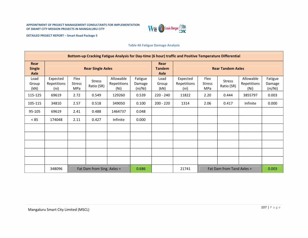
APPOINTMENT OF PROJECT MANAGEMENT CONSULTANTS FOR IMPLEMENTATION OF SMART CITY MISSION PROJECTS IN MANGALURU CITY
DETAILED PROJECT REPORT – Smart Road Package 5
107 | P a g e Mangaluru Smart City Limited (MSCL)
Table 46 Fatigue Damage Analysis
Bottom-up Cracking Fatigue Analysis for Day-time (6 hour) traffic and Positive Temperature Differential
Rear Single Axle
Rear Single Axles Rear
Tandem Axle
Rear Tandem Axles
Load Group (kN)
Expected Repetitions
(ni)
Flex Stress MPa
Stress Ratio (SR)
Allowable Repetitions
(Ni)
Fatigue Damage (ni/Ni)
Load Group (kN)
Expected Repetitions
(ni)
Flex Stress MPa
Stress Ratio (SR)
Allowable Repetitions
(Ni)
Fatigue Damage (ni/Ni)
115-125 69619 2.72 0.549 129260 0.539 220 - 240 11822 2.20 0.444 3855797 0.003
105-115 34810 2.57 0.518 349050 0.100 200 - 220 1314 2.06 0.417 Infinite 0.000
95-105 69619 2.41 0.488 1464737 0.048
< 85 174048 2.11 0.427 Infinite 0.000
348096 Fat Dam from Sing. Axles = 0.686 21741 Fat Dam from Tand Axles = 0.003

APPOINTMENT OF PROJECT MANAGEMENT CONSULTANTS FOR IMPLEMENTATION OF SMART CITY MISSION PROJECTS IN MANGALURU CITY
DETAILED PROJECT REPORT – Smart Road Package 5
108 | P a g e Mangaluru Smart City Limited (MSCL)
Top-Down Cracking Fatigue Analysis for Night-time (6 hour) traffic and Negative Temperature Differential
Rear Single Axle
Rear Single Axles Rear
Tandem Axle
Rear Tandem Axles
Load Group (kN)
Expected Repetition
s (ni)
Flex Stress MPa
Stress Ratio (SR)
Allowable Repetitions
(Ni)
Fatigue Damage (ni/Ni)
Load Group (kN)
Expected Repetitions
(ni)
Flex Stress MPa
Stress Ratio (SR)
Allowable Repetitions
(Ni)
Fatigue Damage (ni/Ni)
115-125 57436 2.52 0.508 525380 0.109 220 - 240 11822 2.41 0.487 1513165 0.007
105-115 28718 2.41 0.487 1513165 0.019 200 - 220 1314 2.36 0.477 3026279 0.000
95-105 57436 2.31 0.466 7302230 0.008
< 85 143590 2.10 0.424 Infinite 0.000
475310 Fat Dam from Sing. Axles = 0.136 21741 Fat Dam from Tand Axles = 0.007

APPOINTMENT OF PROJECT MANAGEMENT CONSULTANTS FOR IMPLEMENTATION OF SMART CITY MISSION PROJECTS IN MANGALURU CITY
DETAILED PROJECT REPORT – Smart Road Package 5
109 | P a g e Mangaluru Smart City Limited (MSCL)
It can be seen from the calculations given in the tables above that for the slab thickness of 235mmthe total fatigue damage for bottom-up cracking is 0.686 + 0.003 = 0.689. Total fatigue damage for top-down cracking is 0.136 + 0.007 = 0.043 and total cumulative fatigue damage (CFD) = 0.732 which is less than 1.0.
Hence, the trial thickness of 215mm is adequate.30mm thickness is added considering two retexturing in 30 years and 15mm for rounding off and hence a thickness of 260mm is appropriate.
Design of Dowel Bars
As per Table5 ‘Recommended Dimensions of Dowel Bars’ of IRC: 58-2015,
Diameter in mm - 32 Length in mm – 450 Spacing in mm - 300
Design of Tie Bars
Input Data:
Slab Thickness – 0.260 m Lane width, b – 3.1 m Coefficient of friction, f – 1.5 Density of concrete, kN/m3 – 24 Allowable tensile stress in deformed bars, MPa - 200(As per IRC:15-2017) Allowable bond stress for deformed tie bars, MPa – 2.46(As per IRC: 15-2017)
Design for Deformed Bars:
Select diameter of tie bar, dt – 12 mm Area of plain steel bar required per meter width of joint to resist the frictional force at slab
bottom, As
As= bfW / Sst
Where,
As – area of steel in mm2, required per m length of joint
b – Lane width in meters
f – Coefficient of friction between pavement and the sub-base/base (usually taken as 1.5)
W – Weight of slab in kN/m2 and
Sst – allowable working stress of steel in MPa
=3.1X1.5X0.260X24000/200
=145.1 mm2/m

APPOINTMENT OF PROJECT MANAGEMENT CONSULTANTS FOR IMPLEMENTATION OF SMART CITY MISSION PROJECTS IN MANGALURU CITY
DETAILED PROJECT REPORT – Smart Road Package 5
110 | P a g e Mangaluru Smart City Limited (MSCL)
Cross Sectional Area of Tie Bar A = π/4 X (12)2
= 113 mm2
Perimeter of Tie Bar = πd = 37.7mm
Spacing of tie bars, = A/As
= 113/145.1X1000
= 778 mm
Say 780mm
Provide spacing of 750mm c/c
Length of tie bar
L = 2SstAcs / BXPptb
Where,
L –Length of tie bar, mm
Sst – allowable working stress in steel, MPa
Acs – cross sectional area of one tie bar, mm2
Pptb – perimeter of the tie bar, mm and
B – Permissible bond stress of concrete, 2.46 MPa
= 2 X 200 X 113 / (2.46 X 37.7)
= 487.80 mm
Increase length by 100mm for loss of bond due to painting and another 50mm for tolerance in placement
Therefore the required length of tie bar is 640mm
Table 47 Pavement Composition:
Sr. No. Description Thickness in mm
1 Pavement Quality Concrete (PQC) 260
2 Dry Lean Concrete (DLC) 100
3 Granular Sub-Base (GSB) (as Drainage Layer) 150
4 Selected Subgrade (CBR ≥ 8%) 500

APPOINTMENT OF PROJECT MANAGEMENT CONSULTANTS FOR IMPLEMENTATION OF SMART CITY MISSION PROJECTS IN MANGALURU CITY
DETAILED PROJECT REPORT – Smart Road Package 5
111 | P a g e Mangaluru Smart City Limited (MSCL)
2.5.3.7 New Balmatta Road
Design of Plain Jointed Rigid Pavement
Design of Slab Thickness
Input Data:
Road Type: Two lanes Two Way Single Carriageway
Design Life: 30 Years
Lane Width: 3.1m with 0.25m shyness width on both sides of carriageway edge.
Transverse joint spacing: 4.5 m
Traffic (as per TVC): 196 Commercial Vehicles per Day (CVPD)
CBR of Existing Soil: Two samples collected and tested and are 6% and 5%.
CBR (Considered) of Proposed Subgrade: 6%
CBR (Assumed) of Embankment below subgrade: 6%
Effective CBR of Subgrade: 8% (As per Figure 2 of IRC 58-2015)
Axle load Survey (Assumed): Single Axle 98% and Tandem Axle 2%
Table 48 Axle Load Spectrum (Assumed):
Sr. No.
Rear Single Axle Rear Tandem Axle Axle Load KN Frequency (% of
single Axles) Axle Load KN Frequency (% of
tandem Axles) 1 115-125 20 220-240 90 2 105-115 10 200-220 10 3 95-105 20 4 < 85 50
Total 98% 2%
Design:
Y. Modulus of Subgrade Reaction: Effective CBR of compacted subgrade = 8%. Modulus of subgrade reaction = 50.3 MPa/m (from
Table 2 of IRC 58-2015) Provide 150mm thick Granular Sub-Base as drainage layer (Grading VI of Table 400-1 of MoRTH
Specifications Fifth Revision) Provide a Dry Lean Concrete (DLC) sub-base of thickness 100mm with a minimum 7 day
compressive strength of 10 MPa.

APPOINTMENT OF PROJECT MANAGEMENT CONSULTANTS FOR IMPLEMENTATION OF SMART CITY MISSION PROJECTS IN MANGALURU CITY
DETAILED PROJECT REPORT – Smart Road Package 5
112 | P a g e Mangaluru Smart City Limited (MSCL)
Effective modulus of subgrade reaction of combined foundation of subgrade, granular sub-base and DLC sub-base is 231.3 MPa/m (from Table 4 of IRC 58-2015 by interpolation)
Provide a de-bonding layer of polythene sheet of 125 micron thickness between DLC and concrete slab.
Z. Flexural Strength of Concrete 28 day compressive strength of cement concrete ≥ 40 MPa 90 day compressive strength of cement concrete ≥ 48 MPa 28 day Flexural strength of cement concrete = 4.5 MPa (minimum) 90 day Flexural strength of cement concrete = 4.5 X 1.1 = 4.95 MPa AA. Design Traffic for Fatigue Analysis Design Period – 30 years Assumed Annual rate of growth of commercial traffic = 5 % Total commercial vehicles during design period
C = 365 X A ((1 + r)n – 1) / r
Where,
C –Cumulative number of commercial vehicles during the design period
A – Initial number of commercial vehicles per day in the year when the road is opened to traffic
r – Annual rate of growth of commercial traffic volume (in decimal)
n – Design period in years
C = 365 X 196((1+0.05)30-1)/0.05
C= 4753035
Average number of axles (steering / single / tandem) per commercial vehicle = 2.35
Total two way axle load repetitions during the design period –
= 4753035 X 2.35
= 11169633
No. of axles in predominant direction
= 11169633 X 0.5
= 5584816

APPOINTMENT OF PROJECT MANAGEMENT CONSULTANTS FOR IMPLEMENTATION OF SMART CITY MISSION PROJECTS IN MANGALURU CITY
DETAILED PROJECT REPORT – Smart Road Package 5
113 | P a g e Mangaluru Smart City Limited (MSCL)
Design traffic after adjusting for lateral placement of axles (25 per cent of predominant direction traffic for multilane highways) –
=5584816X 0.25
= 1396204
Night time (12 hour) design axles repetitions (Assumed 60% traffic at night time)
= 1396204 X 0.6
= 837722
Day time (12 hour) design axles repetitions (100% - 60% = 40%)
= 1396204 X 0.4
=558482
Day time six hour axle load repetitions
= 558482 X 0.5
= 279241
Hence, design number of axle load repetitions for bottom-up cracking analysis
= 279241
Night time six hour axle load repetitions
= 837722 X 0.5
= 418861
% of commercial vehicles having the spacing between the front (steering) axle and the first axle of the rear axle unit less than 4.5m is 55%
Hence, the six hour night time design axle load repetitions for top-down cracking analysis (wheel base < 4.5m)
= 418861 X 0.55
= 230373
The axle load category wise design axle load repetitions for bottom up and top down fatigue cracking analysis are given in the following Table

APPOINTMENT OF PROJECT MANAGEMENT CONSULTANTS FOR IMPLEMENTATION OF SMART CITY MISSION PROJECTS IN MANGALURU CITY
DETAILED PROJECT REPORT – Smart Road Package 5
114 | P a g e Mangaluru Smart City Limited (MSCL)
Table 49 Fatigue Crack Analysis
Axle Category Proportion of the Axle Category
Category wise axle repetitions for Bottom-up cracking analysis
Category wise axle repetitions for Top-down cracking analysis
Front (Steering) single 0.45 103668 125658
Rear single 0.53 122098 147998
Tandem 0.02 4607 5585
BB. Cumulative Fatigue Damage (CFD) analysis for Bottom-Up Cracking (BUC) and Top-Down Cracking (TDC) and Selection of Slab Thickness
Effective modulus of subgrade reaction of foundation, k – 231 MPa/m Elastic Modulus of concrete, E – 30000 MPa Poisson’s ratio of concrete, µ - 0.15 Unit weight of concrete, γ – 24 kN/m3 Design flexural strength of concrete – 4.95 MPa Max. day-time Temperature Differential in slab (for bottom-up cracking) – 17.00C Night-time Temperature Differential in slab (for top-down cracking) – day-time diff/2 + 5 =
13.500C Trial thickness of slab, h = 205 mm Radius of relative stiffness, l = (Eh3/(12k(1- µ2))0.25
Where,
l – radius of relative stiffness, m
E – Elastic modulus of concrete, MPa
h – concrete slab thickness, m
k – modulus of subgrade reaction, MPa/m
µ - Poisson’s ratio of concrete
= 0.55556
‘Beta’ factor in the stress equations will be 0.66 for doweled transverse joints for carrying out TDC analysis.
Computation of bottom-up and top-down cumulative fatigue damage is illustrated in following tables.

APPOINTMENT OF PROJECT MANAGEMENT CONSULTANTS FOR IMPLEMENTATION OF SMART CITY MISSION PROJECTS IN MANGALURU CITY
DETAILED PROJECT REPORT – Smart Road Package 5
115 | P a g e Mangaluru Smart City Limited (MSCL)
Table 50 Fatigue Damage Analysis
Bottom-up Cracking Fatigue Analysis for Day-time (6 hour) traffic and Positive Temperature Differential
Rear Single Axle
Rear Single Axles Rear
Tandem Axle
Rear Tandem Axles
Load Group (kN)
Expected Repetitions
(ni)
Flex Stress MPa
Stress Ratio (SR)
Allowable Repetitions
(Ni)
Fatigue Damage (ni/Ni)
Load Group (kN)
Expected Repetitions
(ni)
Flex Stress MPa
Stress Ratio (SR)
Allowable Repetitions
(Ni)
Fatigue Damage (ni/Ni)
115-125 24420 2.784 0.562 87857 0.278 220 - 240 4146 2.267 0.458 18320259 0.000
105-115 12210 2.633 0.532 214376 0.057 200 - 220 461 2.131 0.431 infinite 0.000
95-105 24420 2.483 0.502 707338 0.035
< 85 61049 2.181 0.441 infinite 0.000
188772 Fat Dam from Sing. Axles = 0.369 7123 Fat Dam from Tand Axles = 0.000

APPOINTMENT OF PROJECT MANAGEMENT CONSULTANTS FOR IMPLEMENTATION OF SMART CITY MISSION PROJECTS IN MANGALURU CITY
DETAILED PROJECT REPORT – Smart Road Package 5
116 | P a g e Mangaluru Smart City Limited (MSCL)
Top-Down Cracking Fatigue Analysis for Night-time (6 hour) traffic and Negative Temperature Differential
Rear Single Axle
Rear Single Axles Rear
Tandem Axle
Rear Tandem Axles
Load Group (kN)
Expected Repetition
s (ni)
Flex Stress MPa
Stress Ratio (SR)
Allowable Repetitions
(Ni)
Fatigue Damage (ni/Ni)
Load Group (kN)
Expected Repetitions
(ni)
Flex Stress MPa
Stress Ratio (SR)
Allowable Repetitions
(Ni)
Fatigue Damage (ni/Ni)
115-125 29600 2.593 0.524 284225 0.104 220 - 240 5027 2.541 0.513 423020 0.011
105-115 14800 2.489 0.503 665309 0.022 200 - 220 559 2.437 0.492 1125609 0.001
95-105 29600 2.386 0.482 2107060 0.014
< 85 73999 2.179 0.440 infinite 0.000
155737 Fat Dam from Sing. Axles = 0.140 5877 Fat Dam from Tand Axles = 0.012

APPOINTMENT OF PROJECT MANAGEMENT CONSULTANTS FOR IMPLEMENTATION OF SMART CITY MISSION PROJECTS IN MANGALURU CITY
DETAILED PROJECT REPORT – Smart Road Package 5
117 | P a g e Mangaluru Smart City Limited (MSCL)
It can be seen from the calculations given in the tables above that for the slab thickness of 205mmthe total fatigue damage for bottom-up cracking is 0.369 + 0.000 = 0.369. Total fatigue damage for top-down cracking is 0.140 + 0.012 = 0.152 and total cumulative fatigue damage (CFD) = 0.521 which is less than 1.0.
Hence, the trial thickness of 205mm is adequate.30mm thickness is added considering two retexturing in 30 years and 15mm for rounding off and hence a thickness of 250mm is appropriate.
Design of Dowel Bars
As per Table5 ‘Recommended Dimensions of Dowel Bars’ of IRC: 58-2015,
Diameter in mm - 32 Length in mm – 450 Spacing in mm - 300
Design of Tie Bars
Input Data:
Slab Thickness – 0.205 m Lane width, b – 3.1 m Coefficient of friction, f – 1.5 Density of concrete, kN/m3 – 24 Allowable tensile stress in deformed bars, MPa - 200(As per IRC:15-2017) Allowable bond stress for deformed tie bars, MPa – 2.46(As per IRC: 15-2017)
Design for Deformed Bars:
Select diameter of tie bar, dt – 12 mm Area of plain steel bar required per meter width of joint to resist the frictional force at slab
bottom, As
As= bfW / Sst
Where,
As – area of steel in mm2, required per m length of joint
b – Lane width in meters
f – Coefficient of friction between pavement and the sub-base/base (usually taken as 1.5)
W – Weight of slab in kN/m2 and
Sst – allowable working stress of steel in MPa
=3.1X1.5X0.205X24000/200
=114.39 mm2/m

APPOINTMENT OF PROJECT MANAGEMENT CONSULTANTS FOR IMPLEMENTATION OF SMART CITY MISSION PROJECTS IN MANGALURU CITY
DETAILED PROJECT REPORT – Smart Road Package 5
118 | P a g e Mangaluru Smart City Limited (MSCL)
Cross Sectional Area of Tie Bar A = π/4 X (12)2
= 113 mm2
Perimeter of Tie Bar = πd = 37.7mm
Spacing of tie bars, = A/As
= 113/114.39X1000
= 989 mm
Say 950mm
Provide spacing of 950mm c/c Length of tie bar
L = 2SstAcs / BXPptb
Where,
L –Length of tie bar, mm
Sst – allowable working stress in steel, MPa
Acs – cross sectional area of one tie bar, mm2
Pptb – perimeter of the tie bar, mm and
B – Permissible bond stress of concrete, 2.46 MPa
= 2 X 200 X 113 / (2.46 X 37.7)
= 487.80 mm
Increase length by 100mm for loss of bond due to painting and another 50mm for tolerance in placement
Therefore the required length of tie bar is 640mm
Table 51 Pavement Composition:
Sr. No. Description Thickness in mm
1 Pavement Quality Concrete (PQC) 250
2 Dry Lean Concrete (DLC) 100
3 Granular Sub-Base (GSB) (as Drainage Layer) 150
4 Selected Subgrade (CBR ≥ 8%) 500

APPOINTMENT OF PROJECT MANAGEMENT CONSULTANTS FOR IMPLEMENTATION OF SMART CITY MISSION PROJECTS IN MANGALURU CITY
DETAILED PROJECT REPORT – Smart Road Package 5
119 | P a g e Mangaluru Smart City Limited (MSCL)
2.6 INFRASTRUCTURE AND UTILITIES PLANNING
2.6.1 Planned Utilities
Dedicated and planned utilities are one of the key features of smart roads. Various utilities planned under DPR-5 Smart Road include wet utilities include Water Supply, sewerage and storm water drainage system as well as dry utilities like Street Lights, Power Distribution and OFC.
Water Supply Distribution lines are proposed under ADB funding as a separate Project and funding. Necessary coordination with the Consultants working on ADB project and MCC has been carried out to ensure integration of proposals in a holistic manner.
Similarly; UGD (Underground sewerage network) and LED Street lighting are proposed as separate Project under Mangaluru Smart City. The proposal under UGD and LED project have been integrated while planning the utility corridor along DPR-5 Smart Road.
2.6.2 Electrical Infrastructure
The detailed survey of existing electrical utilities has been carried out along with MESCOM officials and same is included in drawings along with the report. The space planning for electrical services in the proposed utility corridor is based on the assessment and requirement of MESCOM Following details are as per assessment.

APPOINTMENT OF PROJECT MANAGEMENT CONSULTANTS FOR IMPLEMENTATION OF SMART CITY MISSION PROJECTS IN MANGALURU CITY
DETAILED PROJECT REPORT – Smart Road Package 5
120 | P a g e Mangaluru Smart City Limited (MSCL)
Table 52 Existing Transformer locations
Road no
Name of Road Road
Road Length in Mtr
Transformer number
Location of transformer
Transformer pole
number/MESCOM
Identification number
From To
7a Milagres Cross Rd.
KMC Central Library
Jn.
Milagres Church Jn 183
0
7c Nandigudda Rd.
Attavar Rd.
Mglr.Railway Rd. 1021
TR-1 Rotary Physiotherapy Center -
TR-2 Hotel Residency Park 20030261245 DTC
TR-3 IMA House Bldg. 20030261268
8 New
Balmatta Rd.
Jyoti circle
Ivory Juction 577
TR-1 G+ 12 Bldg. 20030315408
DTC 20030315407
TR-2 Smart Tower Bldg. -
TR-3 G+4 Bldg. 20030315399 DTC
TR-4 G+4 Ramanik Bldg. 200315370
TR-5 G+6 Crescent Manor Bldg. 20030315366
TR-6 Near Shops 20030315357 DTC
10 Don Bosco hall cross
Rd.
KMC Mercara Trunk
Rd.
Ivory Juction 375
TR-1 Behind GI Bakery Bldg.
2003015352 DTC
TR-2 Opp : Falnir Lab 20030263299
DTC 20030263298
TR-3 Opp : Falnir Lab 20030263296 TR-4 Ashok Palace Bldg. 20030263513 TR-5 Land Trades Bldg. 200326381 DTC
19 Arya Samaj Rd.
Balmatta Circle
Mangalore Hospital 925
TR-1A G+3 Bldg. Maco Co-Op.
TR-1 Presidency Avenue Bldg.
20030262548 DTC
20030262549
TR-2 Opp: PRESIDENCY AVENUE BLDG.
TR-3 20030262545
DTC 20030262544
TR-4 Mothisham Oasis 20030262541
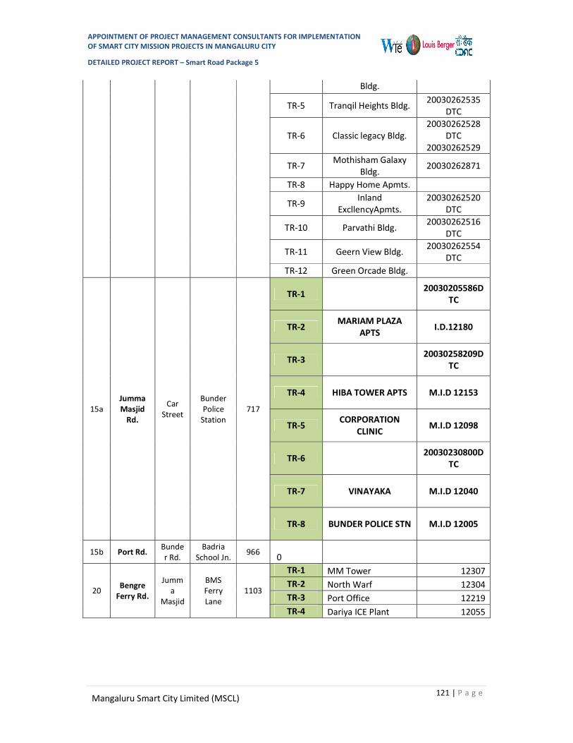
APPOINTMENT OF PROJECT MANAGEMENT CONSULTANTS FOR IMPLEMENTATION OF SMART CITY MISSION PROJECTS IN MANGALURU CITY
DETAILED PROJECT REPORT – Smart Road Package 5
121 | P a g e Mangaluru Smart City Limited (MSCL)
Bldg.
TR-5 Tranqil Heights Bldg. 20030262535 DTC
TR-6 Classic legacy Bldg. 20030262528
DTC 20030262529
TR-7 Mothisham Galaxy Bldg. 20030262871
TR-8 Happy Home Apmts.
TR-9 Inland ExcllencyApmts.
20030262520 DTC
TR-10 Parvathi Bldg. 20030262516 DTC
TR-11 Geern View Bldg. 20030262554 DTC
TR-12 Green Orcade Bldg.
15a Jumma Masjid
Rd.
Car Street
Bunder Police
Station 717
TR-1
20030205586DTC
TR-2 MARIAM PLAZA APTS I.D.12180
TR-3
20030258209DTC
TR-4 HIBA TOWER APTS M.I.D 12153
TR-5 CORPORATION CLINIC M.I.D 12098
TR-6
20030230800DTC
TR-7 VINAYAKA M.I.D 12040
TR-8 BUNDER POLICE STN M.I.D 12005
15b Port Rd. Bunder Rd.
Badria School Jn.
966 0
20 Bengre Ferry Rd.
Jumma
Masjid
BMS Ferry Lane
1103
TR-1 MM Tower 12307 TR-2 North Warf 12304 TR-3 Port Office 12219 TR-4 Dariya ICE Plant 12055

APPOINTMENT OF PROJECT MANAGEMENT CONSULTANTS FOR IMPLEMENTATION OF SMART CITY MISSION PROJECTS IN MANGALURU CITY
DETAILED PROJECT REPORT – Smart Road Package 5
122 | P a g e Mangaluru Smart City Limited (MSCL)
Base on existing survey and discussion with MESCOM, space requirement for Electrical cables were finalized as per below mentioned table which is also included space for spare pipe for HT cable as per MESCOM recommendation and the same is accommodated in Road sections.
Table 53 Existing Electric Cable/Pipes locations
Rd. no.
Name of Rd. Road
No of pipe require
(Left Side)
No of pipe require
(Right side)
From To 415V 11kV 415V 11kV
7a Milagres Cross Rd. KMC Central
Library Jn. Milagres Church Jn 1
1 2
7c Nandigudda Rd. Attavar Rd. Mglr.Railway Rd. 2
2 4
8 New Balmatta Rd. Jyoti circle Ivory Juction 2 4
10 Don Bosco hall cross Rd. KMC Mercara
Trunk Rd. Ivory Juction 4 4 2 4
15a Jumma Masjid Rd. Car Street Bunder Police Station 2 2 2 2
15b Port Rd. Bunder Rd. Badria School Jn. 1
1 2
19 Arya Samaj Rd. Balmatta Circle Mangalore Hospital
2 2 4
20 Bengre Ferry Rd. Jumma Masjid BMS Ferry Lane 2 2 2 2
2.6.3 Street Light
Location of lighting poles are considering base on following requirement to achieve desire lux level.
1. Total ROW
2. Type or category of roads
a. Main roads carrying mixed traffic like city main roads/streets, arterial roads, throughways
b. Secondary roads with considerable traffic like local traffic routes, shopping streets c. Secondary roads with light traffic
3. Visibility of Roads and surroundings.
4. Visual guidance of the shape of the road. Motorist should be able to identify bends and curves and change in roads
5. The visual comfort of the driver/pedestrian.
6. Uniformity of lighting

APPOINTMENT OF PROJECT MANAGEMENT CONSULTANTS FOR IMPLEMENTATION OF SMART CITY MISSION PROJECTS IN MANGALURU CITY
DETAILED PROJECT REPORT – Smart Road Package 5
123 | P a g e Mangaluru Smart City Limited (MSCL)
Lighting design is considered based on standard lux level as per the BIS standards & BEE guidelines as per below mention table
Table 54 Classification of lighting installation
Classification of lighting installation Type of Road Average level of illumination
on road surface Group A1 Important traffic roads carrying traffic/ 30
Group A2 Other main road carrying mixed traffic likes main city stations, arterial road, throughways etc
15
Group B1 Secondary road with considerable traffic like principle local traffic routes, shopping street etc.
8
Group B2 Secondary road with light traffic 4
All roads in this package is falls under Group A2 classification so while placing of light fixtures minimum Average lux level considered 15 Lux.
2.6.4 Lighting Poles:
In existing scenario, majorly light fixtures are installed on Electrical poles and some of the light fixtures are installed on 7 meter high poles. Existing 7 meter poles area retain and only location will be shifted as per Road plan and width and in addition to existing poles new poles are used base on requirement. Locations of poles are marked in drawing.
2.6.5 Centralized street lighting control
“Conversion of Conventional Street Lights into LED with
Smart Lighting Solutions” is one of the projects under MSC with an objective of reducing energy consumption as well as to reduce impact on environment by conventional lamps. The existing street lights are proposed to be converted into LED on PPP basis under a separate project. Smart LED street lighting system adopts centralized control system which will result in further saving of electrical energy. This system offers following Merits –
1. Central control, fault detection 2. Generation of burn hours reports 3. Automatic operation with astronomical timers 4. Manual operation from a central location through GPRS / GSM system 5. Remote metering 6. Voltage stabilization
Energy consumed by the LED lighting is much less as compared to the sodium vapour lighting. This will reduce the energy bill of street lights to great extent.
SMART STREET LIGHTING SOLUTIONS PROPOSED UNDER SMART ROADS WILL BE TAKEN UP UNDER SEPARATE TENDER FOR LED STREET LIGHTS PPP PROJECT COMPONENTS.

APPOINTMENT OF PROJECT MANAGEMENT CONSULTANTS FOR IMPLEMENTATION OF SMART CITY MISSION PROJECTS IN MANGALURU CITY
DETAILED PROJECT REPORT – Smart Road Package 5
124 | P a g e Mangaluru Smart City Limited (MSCL)
2.6.6 Wet Utilities
The wet utilities include Water Supply, sewerage and storm water drainage system.
Majority of the underground drainage system in the ABD area had been executed under the 1961 scheme by Public Health Department. The underground drainage system is exhausted/lived its design life and a necessity has arisen to replace the existing lines with the new pipelines. Considering the above conditions, the Government of Karnataka has decided to take up underground drainage system for the ABD area of Mangalore under Smart city.
In order to achieve this objective, GoI / GoK in its Smart city program, has approved a underground drainage project to Mangaluru Municipal Corporation for an estimated cost of 37.5 crores to meet the intended objective.
The aim of the UGD DPR is to perform a detailed analysis and design of UGD network. The detailed Sewerage network design has been carried out for ABD area. The proposed sewerage system consist lateral and branch networks from Sewerage Zones draining into respective wetwells.
The sewerage system is designed using Bentley Sewer Gems V8i version software.
The sewage from the individual properties will be collected and conveyed to the wet well by gravity sewers. In the proposed system, laterals are proposed along the roads to connect sewage from Individual property chambers and it is connected to branch sewers. Branch sewers are joined to main sewers and which is connected to existing Trunk sewer which is connected to the Wetwell. The Sewage from the Wetwells in ABD Area are pumped to the 43.5MLD Sewage Treatment Plant at Kavoor. Proposed sewers are of UPVC pipes.
Considering the economics of the repair of concrete roads, the sewerage network is not planned for concrete roads. So the existing sewerage network is retained in Roads 7a, 7c, 10, 15a, 15b and 20. New Sewer network is proposed along the roads 8, 10 , 19. 200mm diameter upvc pipe is provided for laterals and circular RCC manholes with SFRC cover and frame ranging from 1.2m to 1.5m in diameter has been provided in the proposed scheme

APPOINTMENT OF PROJECT MANAGEMENT CONSULTANTS FOR IMPLEMENTATION OF SMART CITY MISSION PROJECTS IN MANGALURU CITY
DETAILED PROJECT REPORT – Smart Road Package 5
125 | P a g e Mangaluru Smart City Limited (MSCL)
Figure 33 Mark-up showing the UGD lines proposed in Roads along Road 8
Figure 34 Mark-up showing the UGD lines proposed in Roads along Road 19

APPOINTMENT OF PROJECT MANAGEMENT CONSULTANTS FOR IMPLEMENTATION OF SMART CITY MISSION PROJECTS IN MANGALURU CITY
DETAILED PROJECT REPORT – Smart Road Package 5
126 | P a g e Mangaluru Smart City Limited (MSCL)
Figure 35 Mark-up showing the UGD lines proposed in Roads 15a, 15b & 20
Mangaluru city has a well planned water distribution network. Several augmentation works have been proposed under various infrastructure development schemes to improve the transmission and distribution of water supply in the city. The details of the same have been incorporated during the planning of smart roads so that all the utilities shall be implemented in co-ordination.
Storm water drains are provided along the road side to collect the runoff during rainfall. The drains are designed for a rainfall intensity of 80mm/hr as obtained from the IDF-curve using Manning’s equation for flow through open channels. Rectangular RCC drains 600mm to 1200mm in width has been proposed to collect storm water by gravity. The existing storm water drains in good condition and newly constructed drains shall be retained. The existing drains shall be desilted and refurbished to enhance the carrying capacity of the drain. The following figure shows the output of the design for storm water drainage.

APPOINTMENT OF PROJECT MANAGEMENT CONSULTANTS FOR IMPLEMENTATION OF SMART CITY MISSION PROJECTS IN MANGALURU CITY
DETAILED PROJECT REPORT – Smart Road Package 5
127 | P a g e Mangaluru Smart City Limited (MSCL)
Figure 36 Storm water drainage on the considered roads
The details of storm water drainage network along these roads are provided in the proposed cross-sections of the road prepared in co-ordination with all the other utilities.
Figure 37 Existing drain and newly constructed drain along 7a

APPOINTMENT OF PROJECT MANAGEMENT CONSULTANTS FOR IMPLEMENTATION OF SMART CITY MISSION PROJECTS IN MANGALURU CITY
DETAILED PROJECT REPORT – Smart Road Package 5
128 | P a g e Mangaluru Smart City Limited (MSCL)
Figure 38 Existing drains along 7c
Figure 39 Drains in New Balmatta Road-8
Figure 40New drains being constructed along Road-10

APPOINTMENT OF PROJECT MANAGEMENT CONSULTANTS FOR IMPLEMENTATION OF SMART CITY MISSION PROJECTS IN MANGALURU CITY
DETAILED PROJECT REPORT – Smart Road Package 5
129 | P a g e Mangaluru Smart City Limited (MSCL)
Figure 41 Existing drains along 15a
Figure 42 Existing drains along 15b
Figure 43 Existing drains along 19

APPOINTMENT OF PROJECT MANAGEMENT CONSULTANTS FOR IMPLEMENTATION OF SMART CITY MISSION PROJECTS IN MANGALURU CITY
DETAILED PROJECT REPORT – Smart Road Package 5
130 | P a g e Mangaluru Smart City Limited (MSCL)
Figure 44 Existing drain along Road 20 & No drain along Port area

APPOINTMENT OF PROJECT MANAGEMENT CONSULTANTS FOR IMPLEMENTATION OF SMART CITY MISSION PROJECTS IN MANGALURU CITY
DETAILED PROJECT REPORT – Smart Road Package 5
131 | P a g e Mangaluru Smart City Limited (MSCL)
Table 2.6-55 Details of Utilities along DPR-5 Roads
S.NO Road ID Sewer Water Supply SWD
Length(m) Diameter (mm)
Manhole Size(m) Qty(Nos) Dia(mm) Qty(Nos)
Sluice Valve Qty
(Nos) Width(mm) Orientation Retain
1 7a 123.6 200 1.2 4 90 1 1 600 Retain
2 7c Existing Network to be retained
300 1 1
Retain 63 2 160 1 1 110 1
3 8 497.1 200 1.2 13
110 1 600 one side 1.5 6
4 10 Existing Network to be retained 110 1 one side Retain
63 1
5 15a Existing Network to be retained 110 1 5 600 both sides
63 1
6 15b
Trunk Main for Zone -4 under AMRUT Scheme ( Bombay Lucky Hotel to MG Cross
Road) Existing Network to be retained on Concrete
Part
160 1
600 both sides 110 1 3
63 1
7 19a Existing Network to be retained
250 1
600 one side 160 1 110 1
543.1 200 1.2 22 63 2
8 20 227.1 200 1.2 10 110 1 3
600 one side 90 1 63 2

APPOINTMENT OF PROJECT MANAGEMENT CONSULTANTS FOR IMPLEMENTATION OF SMART CITY MISSION PROJECTS IN MANGALURU CITY
DETAILED PROJECT REPORT – Smart Road Package 5
132 | P a g e Mangaluru Smart City Limited (MSCL)
Majority of the Sewer lines in the present DPR has been taken up under UGD Package -4 which includes Zone-5 & Zone-6 in ABD area. The Overall Summary of UGD Package -4 is mentioned in the following table
Table 56 Overall Summary of UGD Package-4
PACKAGE ZONE LENGTH (KM)
COST (CRORES)
WETWELL LOCATION
HOUSE SERVICE CONNECTIONS(Nos)
DPR-5 Zone-5(Road Width >6m)
7.01 8 Pandeshwar-WW-5
748
Zone-5(Road Width <6m)
10.67 11.5
Zone-6 5.29 5.7 Mulihitlu-WW-6
Total 22.9 24.5
The total cost of UGD Package -4 is 24.50 Crores. The cost abstract of this package is mentioned in following table
Table 57 Cost Abstract-UGD Package-4
Sr.No. Description Estimate cost in Rs.
A Underground Drainage i Zone 5 (Road width >6m) 5,66,39,402.00 ii Zone 5 (Road width <6m) 8,32,19,273.00 iii Zone 6 (Road width <6m) 3,62,86,901.00 B Utility Shifting – Compound Wall, Culvert and RCC Drain i Zone 5 (Road width >6m) 16,21,728.00 ii Zone 5 (Road width <6m) 23,80,523.00 iii Zone 6 (Road width <6m) 10,81,089.00 C Electrical Pole Shifting i Zone 5 (Road width >6m) 19,94,179.00 ii Zone 5 (Road width <6m) 33,26,214.00 iii Zone 6 (Road width <6m) 12,87,912.00 Total Rs. 18,78,37,220.00 Escalation 1,87,83,722.00 Contingency at 3% 56,35,117.00 Tax as applicable , 2,25,40,466.00 Administrative charges, Miscellaneous and rounding off (LS) 1,02,03,475.00 Grand Total Rs. 24,50,00,000.00
The following table provides the cost of different components and their percentage contribution to the total cost of the UGD Package-4 DPR.

APPOINTMENT OF PROJECT MANAGEMENT CONSULTANTS FOR IMPLEMENTATION OF SMART CITY MISSION PROJECTS IN MANGALURU CITY
DETAILED PROJECT REPORT – Smart Road Package 5
133 | P a g e Mangaluru Smart City Limited (MSCL)
Table 58 Components of UGD Package-4 DPR
DESCRIPTION COST IN INR % CONTRIBUTION
Excavation 1,60,29,900.00 10%
Pipe 1,66,63,764.00 10%
Manholes 4,70,14,640.00 30%
House Service Connections 55,56,233.00 4%
Inspection Chambers 86,95,792.00 5%
Road Restoration 5,30,51,706.00 33%
Utility Shifting 1,16,91,645.00 7%
The roads 15a, 15b, 19 & 20 are a part of Zone-4 & Zone-3. The concrete portions along these roads are not considered for this package. This Package has been technically sanctioned by KUIDFC and Work order has been issued. Construction is yet to be started along these roads. The total cost of the package is 9.5 crores. This package includes a part of Zone-4 and a part of Zone-3. The overall Summary of Package 02 is provided in the Table below.
Table 59 Cost Abstract-UGD Package-2
PACKAGE ZONE LENGTH (KM)
COST (CRORES)
WETWELL LOCATION
HOUSE SERVICE CONNECTIONS(Nos)
STATUS
DPR-2 Zone-4(Part) & Zone-3(Part)
8.04 (6.37 & 1.67)
9.5 Kandathpalli-WW-4 & Kudroli –WW-3
1260 Work order issued
The cost abstract of this package is provided in the Table below.
Table 60 Cost Abstract-UGD Package-2
Sr.No. Description Estimate cost in Rs.
I Underground Drainage 68,619,965.00 II Utility Shifting – Compound Wall, Culvert and RCC Drain 1,811,827.00 III Electrical Pole Shifting 2,242,472.00 Total Rs. 72,674,264.00 Escalation 72,67,426.00 Contingency at 3% 2,180,228.00 Tax as applicable , 8,720,912.00 Administrative charges, Miscellaneous and rounding off (LS) 4,157,170.00
Grand Total Rs. 95,000,000.00

APPOINTMENT OF PROJECT MANAGEMENT CONSULTANTS FOR IMPLEMENTATION OF SMART CITY MISSION PROJECTS IN MANGALURU CITY
DETAILED PROJECT REPORT – Smart Road Package 5
134 | P a g e Mangaluru Smart City Limited (MSCL)
Table 61 Components of UGD Package-2 DPR
DESCRIPTION COST IN INR % CONTRIBUTION
Excavation 23,27,238.00 10%
Pipe 19,32,973 8%
Manholes 70,71,534 30%
House Service Connections 7,71,019 3%
Inspection Chambers 16,06,154 7%
Road Restoration 75,33,870 32%
Utility Shifting 20,70,106 9%
Thus the utilities shall be planned and coordinated in conjunction with the design and construction of smart roads.
2.7 STUDY FINDINGS AND OBSERVATIONS
2.7.1 Future Strategies as per Traffic Analysis
1. Milagres Cross Road and Jumma Masjid road can operate with their existing lane configuration without any capacity augmentation during the horizon period. Rest of the roads are getting saturated and need capacity augmentation. However, this being a developed town space is a constraint.
2. However, this being already developed town, expansion of the width of the roads is not possible due to development on both ends right now. Based on Master Plan proposals, Mangalore City Corporation has approved certain road widths. As and when the road widening is taken up, capacity augmentation of these roads can be taken up.
3. Moreover, the Design Service Volumes refer to Level of Service (LoS) C, which is, generally, at 0.7 of the Capacity. Further, traffic volume greater than capacity is often observed in Urban areas with lower Level of Service.
4. Considering the above, it is suggested to deploy traffic management strategies, coupled with promotion of the Public Transport System to reduce the number of vehicles on the road.
5. However as per IRC 41, grade separation is warranted if the traffic on major road crosses more than 45,000 vehicles and minor road traffic crosses more than 12,000 vehicles per day. Milagres Cross Road, Avery junction and Arya Samaj Road Junction get qualified for grade separation. However, space is a constraint. Considering this grade separation is recommended as and when space is available at these locations and for the time being improvement of the junctions is suggested.

APPOINTMENT OF PROJECT MANAGEMENT CONSULTANTS FOR IMPLEMENTATION OF SMART CITY MISSION PROJECTS IN MANGALURU CITY
DETAILED PROJECT REPORT – Smart Road Package 5
135 | P a g e Mangaluru Smart City Limited (MSCL)
6. Mid block and at junction control measures are proposed for the pedestrians as the PV2 values are higher than 2x10⁸ at many locations.
2.7.2 Summary of Findings
1. Mangalore Smart City Limited (MSCL) is implementing the Smart City Proposals with the help of the Project Management Consultants. Development of Smart Roads is one of important projects in the Smart City Proposal. Safe pedestrian movement along with smart features is key in the development of the Smart Roads.
2. This report deals with the DPR 5 for the Smart roads. Eight roads are considered under DPR 5 and are: Milagres Cross Road, Nandigudda Road, New Balmatta Road, Don-Bosco Hall Road, Arya Samaj Road, Jumma Masjid Road, Port Road and Bengre Ferry Road.
3. Traffic surveys are conducted on these roads to get the base year mode wise traffic statistics. These are analyzed and the peak hour traffic volumes both in terms of number of vehicles and PCU are worked out. Projections for future are made applying appropriate growth rates.
4. Capacity Analysis shows Milagres Cross Road and Jumma Masjid road can operate with their existing lane configuration without any capacity augmentation during the horizon period. Rest of the roads are getting saturated and need capacity augmentation. However, this being a developed town space is a constraint.
5. Based on Master Plan proposals, Mangalore City Corporation has approved certain road widths. As and when the road widening is taken up, capacity augmentation of these roads can be taken up.
6. Moreover, the Design Service Volumes refer to Level of Service (LOS) C, which is, generally, at 0.7 of the Capacity. Further, traffic volume greater than capacity is often observed in Urban areas with lower Level of Service.
7. Considering the above, it is suggested to deploy traffic management strategies, coupled with promotion of the Public Transport System to reduce the number of vehicles on the road.
8. Grade separation is warranted at Milagres Cross road junction, Avery Junction and Arya Samaj Road Junctions. Once again space constraints are there. In view of this, signalization of these junctions is proposed as and when the capacity of uncontrolled junctions are reached.
9. Mid block and at junction control measures are proposed for the pedestrians as the PV2 values are higher then 2x10⁸ at most of the locations.

APPOINTMENT OF PROJECT MANAGEMENT CONSULTANTS FOR IMPLEMENTATION OF SMART CITY MISSION PROJECTS IN MANGALURU CITY
DETAILED PROJECT REPORT – Smart Road Package 5
136 | P a g e Mangaluru Smart City Limited (MSCL)
2.7.3 Trial Pit Reports

APPOINTMENT OF PROJECT MANAGEMENT CONSULTANTS FOR IMPLEMENTATION OF SMART CITY MISSION PROJECTS IN MANGALURU CITY
DETAILED PROJECT REPORT – Smart Road Package 5
137 | P a g e Mangaluru Smart City Limited (MSCL)

APPOINTMENT OF PROJECT MANAGEMENT CONSULTANTS FOR IMPLEMENTATION OF SMART CITY MISSION PROJECTS IN MANGALURU CITY
DETAILED PROJECT REPORT – Smart Road Package 5
138 | P a g e Mangaluru Smart City Limited (MSCL)

APPOINTMENT OF PROJECT MANAGEMENT CONSULTANTS OF SMART CITY MISSION PROJECTS IN MANGALURU CITY
DETAILED PROJECT REPORT – Smart Road Package 5
Mangaluru Smart City Limited (MSCL)
Chapter 3 PROPOSED DESIGN
3.1 Smart Road Components
3.1.1 Urban Design and Landscape
Transforming existing roads into Smart Roads has been envisaged under the Smart City Mission. The design of Smart roads intends to develop world class road inclusive to all strata of society with consideration for pedestrian safety and security as a prime importance. This entails comprehensive upgrading of the public Right of Way (ROW) of the streets which includes refurbishment of existing carcycle tracks, creating utility corridors, developing pedestrian facilities, development works for landscape, hardscape, street furniture, signage, lighting, etc.
The proposed intervention aims to achieve the following:
Seamless mobility for citizens of Mangaluru To eliminate traffic congestion and facilitate smooth flow of traffic To create inclusive road infrastructure for all strata of society Promote environmentally sustainable means of transport
The Smart Road proposal would consist of the following specific interventions:
Proposals for Carriageway Improvement, Roads and Signage’s, have been covered under Chapter 4 and 5 of the Report. The provide details of other Junctions.
PROJECT MANAGEMENT CONSULTANTS FOR IMPLEMENTATION PROJECTS IN MANGALURU CITY
Smart Road Package 5
Mangaluru Smart City Limited (MSCL)
DESIGN COMPONENTS
Smart Road Components – Urban Design, Landscape and ITMS
Urban Design and Landscape
Transforming existing roads into Smart Roads has been envisaged under the Smart City Mission. The design of Smart roads intends to develop world class road inclusive to all strata of society with consideration for pedestrian safety and security as a prime importance. This entails comprehensive upgrading of the public Right of Way (ROW) of the streets which includes refurbishment of existing carriageway, laying of new footpaths and cycle tracks, creating utility corridors, developing pedestrian facilities, development works for landscape, hardscape, street furniture, signage, lighting, etc.
The proposed intervention aims to achieve the following:
Seamless mobility for citizens of Mangaluru To eliminate traffic congestion and facilitate smooth flow of traffic To create inclusive road infrastructure for all strata of society Promote environmentally sustainable means of transport
sal would consist of the following specific interventions:
Proposals for Carriageway Improvement, Roads and Signage’s, Junction Improvement have been covered under Chapter 4 and 5 of the Report. The Subsequent Sections
other proposed smart elements, mentioned above
139 | P a g e
Transforming existing roads into Smart Roads has been envisaged under the Smart City Mission. The design of Smart roads intends to develop world class road infrastructure inclusive to all strata of society with consideration for pedestrian safety and security as a prime importance. This entails comprehensive upgrading of the public Right of Way (ROW) of
riageway, laying of new footpaths and cycle tracks, creating utility corridors, developing pedestrian facilities, development works for
Junction Improvement Subsequent Sections
mentioned above, including
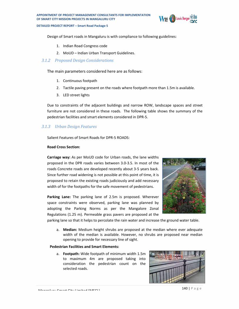
APPOINTMENT OF PROJECT MANAGEMENT CONSULTANTS FOR IMPLEMENTATION OF SMART CITY MISSION PROJECTS IN MANGALURU CITY
DETAILED PROJECT REPORT – Smart Road Package 5
140 | P a g e Mangaluru Smart City Limited (MSCL)
Design of Smart roads in Mangaluru is with compliance to following guidelines:
1. Indian Road Congress code
2. MoUD – Indian Urban Transport Guidelines.
3.1.2 Proposed Design Considerations
The main parameters considered here are as follows:
1. Continuous footpath
2. Tactile paving present on the roads where footpath more than 1.5m is available.
3. LED street lights
Due to constraints of the adjacent buildings and narrow ROW, landscape spaces and street furniture are not considered in these roads. The following table shows the summary of the pedestrian facilities and smart elements considered in DPR-5.
3.1.3 Urban Design Features
Salient Features of Smart Roads for DPR-5 ROADS:
Road Cross Section:
Carriage way: As per MoUD code for Urban roads, the lane widths proposed in the DPR roads varies between 3.0-3.5. In most of the roads Concrete roads are developed recently about 3-5 years back. Since further road widening is not possible at this point of time, it is proposed to retain the existing roads judiciously and add necessary width of for the footpaths for the safe movement of pedestrians.
Parking Lane: The parking lane of 2.5m is proposed. Wherever space constraints were observed, parking lane was planned by adopting the Parking Norms as per the Mangalore Zonal Regulations (1.25 m). Permeable grass pavers are proposed at the parking lane so that it helps to percolate the rain water and increase the ground water table.
a. Median: Medium height shrubs are proposed at the median where ever adequate width of the median is available. However, no shrubs are proposed near median opening to provide for necessary line of sight.
Pedestrian Facilities and Smart Elements:
a. Footpath: Wide footpath of minimum width 1.5m to maximum 4m are proposed taking into consideration the pedestrian count on the selected roads.

APPOINTMENT OF PROJECT MANAGEMENT CONSULTANTS FOR IMPLEMENTATION OF SMART CITY MISSION PROJECTS IN MANGALURU CITY
DETAILED PROJECT REPORT – Smart Road Package 5
141 | P a g e Mangaluru Smart City Limited (MSCL)
b. Barrier free design: Tactile paving is proposed at the centre of the footpath on all the DPR-5 Smart Roads. Curb ramps are present at the property entrances and parking bays for wheel chair access. Audio visual signals for blind people at the junctions.
c. Bollards:Bollards are proposed at the property entrances and parking bays in order to avoid two wheeler movements on the footpath.
d. Footpath lighting: Pole lights are proposed at a distance of 10m c/c for illumination of footpath for pedestrian safety and security. The pole lights are incorporated with the advertisement panels which is one of the means for
revenue generation.
e. Street furniture: Street Furniture includes some interactive seating spaces, benches along the footpath. Dustbins, SIGNAGE like parking sign, stop sign, pedestrian crossing, bus stop are proposed at proper locations.
f. Table top crossing: Table top crossing is proposed at junctions so as to have a smooth pedestrian movement and subsequently resulting into reduction of speed of the vehicles at the junction.
g. Other smart features included are LED street lights to illuminate the carriage way, smart poles at the junction and audio-visual signals at the pedestrian crossings for differently-abled people.
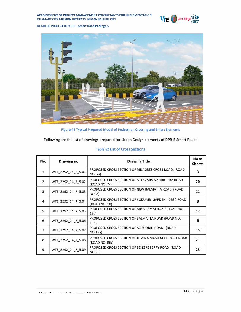
APPOINTMENT OF PROJECT MANAGEMENT CONSULTANTS FOR IMPLEMENTATION OF SMART CITY MISSION PROJECTS IN MANGALURU CITY
DETAILED PROJECT REPORT – Smart Road Package 5
142 | P a g e Mangaluru Smart City Limited (MSCL)
Figure 45 Typical Proposed Model of Pedestrian Crossing and Smart Elements
Following are the list of drawings prepared for Urban Design elements of DPR-5 Smart Roads
Table 62 List of Cross Sections
No. Drawing no Drawing Title No of Sheets
1 WTE_2292_04_R_5.01 PROPOSED CROSS SECTION OF MILAGRES CROSS ROAD. (ROAD NO. 7a) 3
2 WTE_2292_04_R_5.02 PROPOSED CROSS SECTION OF ATTAVARA NANDIGUDA ROAD (ROAD NO. 7c)
20
3 WTE_2292_04_R_5.03 PROPOSED CROSS SECTION OF NEW BALMATTA ROAD (ROAD NO. 8) 11
4 WTE_2292_04_R_5.04 PROPOSED CROSS SECTION OF KUDUMBI GARDEN ( DBS ) ROAD (ROAD NO. 10)
8
5 WTE_2292_04_R_5.05 PROPOSED CROSS SECTION OF ARYA SAMAJ ROAD (ROAD NO. 19a) 12
6 WTE_2292_04_R_5.06 PROPOSED CROSS SECTION OF BALMATTA ROAD (ROAD NO. 19b) 6
7 WTE_2292_04_R_5.07 PROPOSED CROSS SECTION OF AZIZUDDIN ROAD (ROAD NO.15a) 15
8 WTE_2292_04_R_5.08 PROPOSED CROSS SECTION OF JUMMA MASJID-OLD PORT ROAD (ROAD NO.15b)
21
9 WTE_2292_04_R_5.09 PROPOSED CROSS SECTION OF BENGRE FERRY ROAD (ROAD NO.20) 23

APPOINTMENT OF PROJECT MANAGEMENT CONSULTANTS FOR IMPLEMENTATION OF SMART CITY MISSION PROJECTS IN MANGALURU CITY
DETAILED PROJECT REPORT – Smart Road Package 5
143 | P a g e Mangaluru Smart City Limited (MSCL)
Table 63 Proposed Pedestrian Facilities
Road no Road Name
Smart Features Pedestrian Facilities
MUBs (trench)
Bus Shelter with E-Toilet
LED lights
Street furniture like signage,
dustbins, benches, advt
boards
Audi-visual signals
Road side plantation with tree
grates
Pedestrian Crossing
Tactile paving
and wheel chair
access
Spaces for informal
commercials
Subways or FOBs
Parking for Auto
rickshaws
7a Milagres Cross Rd.
√ x √ √ x x √ √ x x x
7c Attavara-
Nandigudda Rd.
√ x √ √ x x √ √ x x x
8 New Balmatta Rd.
√ x √ √ x x √ √ x x x
10 Kudumbi
Garden (DBS) Road
√ x √ √ x √ √ √ x x x
15a Azizuddin Road
√ x √ √ x x x √ x x x
15b Jumma
Masjid-Old Port Rd.
√ x √ √ x x x √ x x x
19a Arya Samaj Rd.
√ x √ √ x x x √ x x x
19b Balmatta Road
√ √ √ √ x √ √ √ x x x
20 Bengre Ferry Rd.
√ x √ √ x x x √ x x x

APPOINTMENT OF PROJECT MANAGEMENT CONSULTANTS FOR IMPLEMENTATION OF SMART CITY MISSION PROJECTS IN MANGALURU CITY
DETAILED PROJECT REPORT – Smart Road Package 5
144 | P a g e Mangaluru Smart City Limited (MSCL)
3.1.4 Landscaping
Roads like the any other transportation hub gives an identity to the place. It plays a vital role in visual experience of user. Mangaluru city has a composition of terrain from plains towards the coastal region to undulating topography toward the Western Ghats on the east. Owing to which the road also has varying gradient and character.
The Road side landscape would enhance the experience of the commuter in terms of microclimate and aesthetics along with ensuring safety. Further it would enrich the experience of the commuters with the natural seasonal dynamism of the plant species
Roads in Central node are one of the prominent roads in the city and encircle the eminent open space along the Town hall. This road also has some of the very old and huge rain trees which give it an identity.
Landscape design has been deliberated with understanding the complex nature of the site, the dynamic relationship between the natural and built environment and overlaying cultural context.
Landscape intervention has been proposed considering the above principle; consequently, have carved out green spaces between the carriage way and footpath to refrain and restrict pedestrian crossing at random locations. This would ensure systematic and swift pedestrian and vehicular circulation.
The median has been designed with a thick green hedge with appropriate height to ensure sight of vehicle in the adjacent lane and cut the glare. This would also restrict pedestrian movement to cross at vulnerable spots.
Further, following aspects should be considered while proposing landscape design
Use landscape and aesthetics tools to reduce the visual complexity at intersections Focus on the use of visual contrasts in material textures and colours to make the
functional components of the highway intersection visually prominent. Accessibility for maintenance must also be considered Select plant materials that will not obstruct critical views as they mature Provide a neutral visual background to the intersection where possible Shall have distinct
features than the adjacent to mark the entrance Plants should help focus the view on the intersection Shrubs should be avoided within the appropriate sight triangle at an intersection
The roads considered under DPR-5 have very little open space to properly landscape. And many of the roads are having less RoW. In view of this only shrubs are proposed in the medians where possible.
The details of various Landscape Proposals along Proposed Roads is provided at Section 11

APPOINTMENT OF PROJECT MANAGEMENT CONSULTANTS FOR IMPLEMENTATION OF SMART CITY MISSION PROJECTS IN MANGALURU CITY
DETAILED PROJECT REPORT – Smart Road Package 5
145 | P a g e Mangaluru Smart City Limited (MSCL)
3.1.5 Centralized street lighting control
“Conversion of Conventional Street Lights into LED with Smart Lighting Solutions” is one of the projects under MSC with an objective of reducing energy consumption as well as to reduce impact on environment by conventional lamps. The existing street lights are proposed to be converted into LED on PPP basis under a separate project.
Smart LED street lighting system adopts centralized control system which will result in further saving of electrical energy. This system offers following Merits –
Central control, fault detection Generation of burn hours reports Automatic operation with astronomical timers Manual operation from a central location through GPRS / GSM system Dimming operation Remote metering Voltage stabilization
Energy consumed by the LED lighting is much less as compared to the sodium vapour lighting. This will reduce the energy bill of street lights to great extent.
The 9 m lighting poles are provided only in the median. To illuminate the footpaths, 4 m high lighting poles with 40 w LED lighting fixtures has been considered at an interval of 10 m
SMART STREET LIGHTING SOLUTIONS PROPOSED UNDER SMART ROADS WILL BE TAKEN UP UNDER SEPARATE TENDER FOR LED STREET LIGHTS PPP PROJECT COMPONENTS. FOOTPATH LIGHTING IS PART OF THIS TENDER
3.1.6 IT/ICT Elements
The following IT/IC Elements are considered along the Bus Shelter and Smart Pole
IT/ICT components in Smart Bus Shelter o CCTV (dome camera) o Wifi Access Point o Display units
IT/ICT component in Smart Pole at Traffic Junction
o Wifi Access Point o Environment Sensor o Possible push button for the
pedestrian crossing PTZ CCTV at Junction

APPOINTMENT OF PROJECT MANAGEMENT CONSULTANTS FOR IMPLEMENTATION OF SMART CITY MISSION PROJECTS IN MANGALURU CITY
DETAILED PROJECT REPORT – Smart Road Package 5
146 | P a g e Mangaluru Smart City Limited (MSCL)
3.2 Intelligent Traffic Management and Road Surveillance
ITMS is distributed across / coupled with mainly, Intelligent Transport System and Road Surveillance:
3.2.1 Intelligent Transport System (ITS)
The Intelligent Transport along the proposed roads will have the following features
1. Vehicle Tracking (Buses) System
The Buses with mounted GPS will be tracked by the Vehicle Tracking System so that their movement data can be fed to the ITS and the information can be disseminated to the Public Mobility App and Display at the Bus Shelters
2. Information on Bus Transport
The Vehicle Tracking System + Road Surveillance System + the Schedule fed in the Database of ITS will relay the information for the Public on the next scheduled buses on the particular route, the delay in the buses running, next available bus to arrive, traffic congestion on particular routes etc.
3. Portable Ticketing
The bus tickets can be purchased either online or at bus-shelters. Online payment to be availed as well
4. Public Mobility App
The bus schedule, the buses actual movements and available buses on the routes, to be made available for the passengers in the app or in the bus-shelter
5. Synchronized Signaling
Green Corridor Creation for Disaster Mitigation / Emergency Response Team / Medical Emergency
3.2.2 Road Surveillance
1. Traffic Rule Violation Detection
- Red Light Violation - Speed Violation - e-Challan (if integrated with RTO Database)
The traffic violation detection by the Camera's to be analysed by the Video Analytics Software in the CCC and the ANPR to detect the vehicle number of the vehicles that violate the traffic rule. The identified vehicle number details then to be fetched from the RTO / Vahan -Sarathi

APPOINTMENT OF PROJECT MANAGEMENT CONSULTANTS FOR IMPLEMENTATION OF SMART CITY MISSION PROJECTS IN MANGALURU CITY
DETAILED PROJECT REPORT – Smart Road Package 5
147 | P a g e Mangaluru Smart City Limited (MSCL)
systems and e-Challan to be sent to the contact details of the person against whose name the vehicle is registered.
2. Automatic Number Plate Recognition
3. Object Detection (for suspicious objects)
If any object is detected to be static / suspicious (based on the rules configured in the Video Analytics Software system) then the alert to be sent to the competent authority defined in the Standard Operating Procedure for such events.
4. Road Disaster Alert
If any accident is detected by the camera or sensitive situation is SOSed by citizen(s) then the alert to be sent to the competent authority defined in the Standard Operating Procedure for such events. The subsequent alert to Emergency Response Team to receive as well
ITMS AND IT/ICT COMPONENTS PROPOSED UNDER SMART ROADS WILL BE TAKEN UP UNDER SEPARATE TENDER FOR ICT COMPONENTS
3.3 TRAFFIC MANAGEMENT PLAN
3.3.1 Traffic Management during Construction and Upgradation Works
The basic upgradation of roads are considered for development which are listed below
Table 64 Road Upgradation Features
Rd. No Road Type of
Pavement Quality of Pavement Road Upgradation
7a Milagres Cross Rd. Flexible Good Conversion to Rigid Pavement, Utility development
7c Attavara-Nandigudda Rd. Rigid Good Utility development Only
8 New Balmatta Rd. Flexible Good Conversion to Rigid Pavement, Utility development
10 Kudumbi Garden (DBS) Road Rigid Poor Utility development only
15a Azizuddin Road Rigid Good Utility development Only
15b Jumma Masjid - Old Port Rd. Rigid, Flexible Poor
Utility development and in some portion Conversion Flexible to
Rigid Pavement
19a Arya Samaj Rd. Paver Good Conversion to Rigid Pavement, Utility development
19b Balmatta Road Rigid Good Utility development Only
20 Bengre Ferry Rd. Flexible Good Conversion to Rigid Pavement, Utility development

APPOINTMENT OF PROJECT MANAGEMENT CONSULTANTS FOR IMPLEMENTATION OF SMART CITY MISSION PROJECTS IN MANGALURU CITY
DETAILED PROJECT REPORT – Smart Road Package 5
148 | P a g e Mangaluru Smart City Limited (MSCL)
3.3.2 Milagres Cross Road
At present, 7837 vehicles (10254 PCUs) ply on Milagres Cross Road. Northward traffic can be diverted towards Avery Jn (Falnir Road) from Mother Theresa Road..
Following table gives the composition of peak traffic of Mother Theresa Road Section A.
Table 65 Modal Split of Milagres Cross Road
2 Wheeler
3 Wheeler Car LCV Bus/Truck
Other (MT)
Other (NMT)
Total Vehicles
Total PCUs
2,991 3,083 1,598 76 85 0 4 7,837 10,254
3.3.3 New Balmatta Road
At present, 12687 vehicles (15789 PCUs) ply on New Balmatta Road. Northward traffic can be diverted towards DBS Road and Southward traffic can also be diverted towards DBS Road.
Following table gives the composition of peak traffic of Mother Theresa Road Section A.
Table 66 Modal Split of New Balmatta Road
2 Wheeler
3 Wheeler Car LCV Bus/Truck
Other (MT)
Other (NMT)
Total Vehicles
Total PCUs
4,913 4,321 3,257 139 41 0 16 12,687 15,789
3.3.4 Jumma Masjid Port Road
At present, 1962 vehicles (1741 PCUs) ply on DBS Road. Northward traffic can be diverted towards Azizuddin Road and Southward traffic can be diverted towards MPT Road or Bunder Road or the vice versa.
Following table gives the composition of peak traffic of Mother Theresa Road Section A.
Table 67 Modal Split of Port Road
2 Wheeler
3 Wheeler Car LCV Bus/Truck
Other (MT)
Other (NMT)
Total Vehicles
Total PCUs
1,302 367 139 125 24 0 5 1,962 1,741

APPOINTMENT OF PROJECT MANAGEMENT CONSULTANTS FOR IMPLEMENTATION OF SMART CITY MISSION PROJECTS IN MANGALURU CITY
DETAILED PROJECT REPORT – Smart Road Package 5
149 | P a g e Mangaluru Smart City Limited (MSCL)
3.3.5 Attavara Road, Jumma Masjid Road, Balmatta Road, Azizuddin Road, Bengre Ferry Road, Arya Samaj Road
The above mentioned roads are already concrete roads and are not needed for any pavement development. Even the quality of the roads are in good condition so mostly repairing works are also minimal. As part of up gradation to make smart roads, it is proposed to carry joint filling and utility development improvements in carriageway of these roads.
For Masjid Road and Ferry Road, Utility development is proposed and in some portions conversion of surface from Flexible to Rigid Pavement is proposed.
Since these roads are predominantly busy, repairs works will be done at night time with proper safety and barricades. These roads will be open for public use in daytime.
3.3.6 Safety Measure during Construction
Lanes Closure is the operation in which one or more traffic lanes and any adjacent shoulder are closed to traffic, in case of a multi-lane Roads, for carrying out the necessary repair/up gradation works. Guidelines provided by (IRC: SP55 GUIDELINES ON TRAFFIC MANAGEMENT IN WORK ZONES) needed to be followed for safe traffic movement during construction.
For road, having less than 20 trucks per hour and speed limit less 50 km/h or less, following figure gives the arrangement required at construction zone.
Length of the works from the start of the lead-in taper to the end of the exit taper should not be more than 50 meters .Drivers approaching from either direction can see both the ends of the site.
Subsequent paragraphs and figure explain the arrangement can be applicable at Junction during Construction
The regulatory signs to be used in work zones are subdivided as normal regulatory signs and Work zones specific regulatory sign. Regulatory signs are to instruct road users of traffic laws or regulations and to indicate the applicability of legal requirements that would not otherwise be apparent.
For ensuring legibility and emphasis at night, the signs shall be retro-reflective of at least Grade Type III, i.e. high intensity grade conforming to 801 of Specifications for Roads & Bridges, Ministry of Road Transport and Highways.
The material shall be smooth, sealed outer surface or illuminated to depict the same shape and similar color for both day and night. Sign illumination may be either internal or external and the signboards may be made of rigid or flexible material.

APPOINTMENT OF PROJECT MANAGEMENT CONSULTANTS FOR IMPLEMENTATION OF SMART CITY MISSION PROJECTS IN MANGALURU CITY
DETAILED PROJECT REPORT – Smart Road Package 5
150 | P a g e Mangaluru Smart City Limited (MSCL)
Figure 46 Traffic Control System along the road during Construction
Figure 47 Traffic Control System along the road during Construction
3.3.7 Conclusion
As mentioned above lane closure alternately can adequately handle traffic at on these roads during construction period. Nighttime construction is preferred alternative for up gradation works at other road on the loop.
IRC 55 guideline diagrams as given in this section need to be adhered for safe traffic movement.

APPOINTMENT OF PROJECT MANAGEMENT CONSULTANTS FOR IMPLEMENTATION OF SMART CITY MISSION PROJECTS IN MANGALURU CITY
DETAILED PROJECT REPORT – Smart Road Package 5
151 | P a g e Mangaluru Smart City Limited (MSCL)
Chapter 4 TIMELINE FOR EXECUTION
The Total timeline for project are divided into 3 broad categories:
4.1 Construction Phase
The construction phase is considered as 18 months
4.2 Defect Liability
The Defect Liability period is considered as 12months
4.3 Maintenance Period
The Maintenance Period is considered as 36 months from date of construction completion
Note: Detailed schedule shall be during the final DPR and RFP Stage

APPOINTMENT OF PROJECT MANAGEMENT CONSULTANTS FOR IMPLEMENTATION OF SMART CITY MISSION PROJECTS IN MANGALURU CITY
DETAILED PROJECT REPORT – Smart Road Package 5
152 | P a g e Mangaluru Smart City Limited (MSCL)
Chapter 5 MONITORING AND EVALUATION
The key components under smart road to be monitored are listed below:
Development and strengthening of carriage way with uniform lane widths and geometric designs of roads and junctions as per street design standards.
Development of footpath and cycle lanes wherever feasible - with uniform footpath widths, pedestrian friendly ways and barrier-free designs.
Construction of utility ducts for water, sewerage, drainage, power, gas and optical fibre cables (OFC), wherever essential – with suitable provision for O&M.
Construction bus bays, auto bays and on-street parking wherever essential. Beautification and landscaping including greenery and carbon sinking, Provision of smart street furniture and public utilities such as including communicative
signage, lane marking. (passenger shelters, bus stops, parking, green toilets, first aid care, traffic police booth etc), public leisure spaces etc.
Smart street-poles with LED lights, CCTV and various sensors as per city requirement. Accessibility standards as prescribed by the MoUD, etc. Particular focus on safety of women, children, elderly, etc
Risk assessment and mitigation strategy: Any project development is averse to various types of risks during the life cycle of the project. Identifying these risks and allocating them to the stakeholders who are able to address them the best is the most acceptable form of mitigation.
In this context, key risk associated with the project along with assessment is presented below:
Table 68 Risks Mitigation Strategies
Sl. No
Risk Type Degree (High/ Moderate/ Low)
Mitigation Strategy
1 Construction Phase Risks 1a Land Acquisition Delay Low Upgradation of roads does not involve any
land acquisition. Therefore there is no land acquisition risk for this sub-project
1b Delay in receipt of statutory approvals to the project
Moderate The statutory requirements of the project would include approval of traffic management plan and for utility shifting. MCC can provide the requisite facilitation to MSCL for obtaining the necessary approvals for the proposed project.
1c Time and Cost Over runs during construction
Moderate The project involves upgradation of urban roads wherein no engineering or structural challenges are foreseen. PMC would monitor the overall progress of the project and suggest appropriate remedies/ actions to be taken by MSCL.
2 Regulatory risk Change in law/ policy Low Change in policies leading to material adverse

APPOINTMENT OF PROJECT MANAGEMENT CONSULTANTS FOR IMPLEMENTATION OF SMART CITY MISSION PROJECTS IN MANGALURU CITY
DETAILED PROJECT REPORT – Smart Road Package 5
153 | P a g e Mangaluru Smart City Limited (MSCL)
impact on the urban infrastructure sector is not envisaged. The present policies in force are expected to pave the way for Smart City development over the long term.
3 Force Majeure. Act of God (Fire,
earthquake, etc) Low Such risks shall be mitigated through
insurance cover. The contractor would be mandated to keep in force insurance covering all project assets during the construction and contract liability phase for insurable events.

APPOINTMENT OF PROJECT MANAGEMENT CONSULTANTS FOR IMPLEMENTATION OF SMART CITY MISSION PROJECTS IN MANGALURU CITY
DETAILED PROJECT REPORT – Smart Road Package 5
154 | P a g e Mangaluru Smart City Limited (MSCL)
Chapter 6 COST ESTIMATES
The section of the report deals with the Cost Estimates for DPR-5 Smart Roads
6.1 Assumptions
SOR rates as per Karnataka PWD SOR-Mangalore Circle (SOR 2018-19) 10% weightage has been added to SOR rates of Mangalore Circle PWD Circle Non SOR Items based on Rate Analysis OR on Vendor Quotations Landscaping rates as per Karnataka PWD and As per EOI. Water Supply Package are to be executed under ADB Project and as separate
package, hence cost not to be considered in smart road tender cost UGD (sewer network) Package will be floated as separate tender, hence cost not to
be considered in smart road tender cost LED Street Light Package will be floated as separate tender, hence cost not to be
considered in smart road tender cost ICT Package will be floated as separate tender, hence not to be considered in smart
road tender cost
6.2 Summary of Estimate
Summary of the estimate is as stated in table below:
Table 69 Smart Road Package- 5 – Summary of Estimate
Sr. No. Description Cost In INR 1 Road and Other Works 37,34,90,066 2 Street Lighting 64,63,562 3 Landscape Work 22,38,546
Construction Cost Sub Total 38,21,92,174
GST @ 12% -Civil Construction Cost (Refer 1.0 Abstract) 4,40,83,122
Provision for Third Party Damages and Maintenance at 1st Year(DLP- 28,83,930
GST @12% on DLP Cost Items (Refer 5.1 Abstract) 2,65,467 Maintenance Cost of 2nd,3rd and 4th Year 1,21,84,243 GST @12% on Maintenance Cost 11,81,659 Escalation and Tender Premium @10% 382,19,217 Add 3% Contingency 114,65,765 Miscellaneous and Rounding off 24,423 Grand Total 49,25,00,000
6.3 Detailed BOQ
Detailed BOQ has been enclosed as Volume III of the Detailed Project Report

APPOINTMENT OF PROJECT MANAGEMENT CONSULTANTS FOR IMPLEMENTATION OF SMART CITY MISSION PROJECTS IN MANGALURU CITY
DETAILED PROJECT REPORT – Smart Road Package 5
155 | P a g e
Mangaluru Smart City Limited (MSCL)
ANNEXURES I – LIST OF DRAWINGS
No. Drawing no Drawing Title No of Sheets
1 WTE_2292_04_R_2.01 PLAN AND PROFILE OF MILAGRES CROSS ROAD. (ROAD NO. 7a) 1 2 WTE_2292_04_R_2.02 PLAN AND PROFILE OF NEW BALMATTA ROAD (ROAD NO. 8) 1 3 WTE_2292_04_R_2.03 PLAN AND PROFILE OF ARYA SAMAJ ROAD (ROAD NO. 19b) 1
4 WTE_2292_04_R_2.04 PLAN AND PROFILE OF JUMMA MASJID OLDPORT ROAD (ROAD NO.15b) 1
5 WTE_2292_04_R_2.05 PLAN AND PROFILE OF BENGRE FERRY ROAD (ROAD NO.20) 1
6 WTE_2292_04_R_3.01 ROAD SIGNAGES - PLAN AND ROAD MARKING OF MILAGRES CROSS ROAD. (ROAD NO. 7a) 1
7 WTE_2292_04_R_3.02 ROAD SIGNAGES - PLAN AND ROAD MARKING OF ATTAVARA NANDIGUDA ROAD (ROAD NO. 7c)
5
8 WTE_2292_04_R_3.03 ROAD SIGNAGES - PLAN AND ROAD MARKING OF NEW BALMATTA ROAD (ROAD NO. 8) 3
9 WTE_2292_04_R_3.04 ROAD SIGNAGES - PLAN AND ROAD MARKING OF KUDUMBI GARDEN ( DBS ) ROAD (ROAD NO. 10)
2
10 WTE_2292_04_R_3.05 ROAD SIGNAGES - PLAN AND ROAD MARKING OF ARYA SAMAJ ROAD (ROAD NO. 19a) 3
11 WTE_2292_04_R_3.06 ROAD SIGNAGES - PLAN AND ROAD MARKING OF BALMATTA ROAD (ROAD NO. 19b) 2
12 WTE_2292_04_R_3.07 ROAD SIGNAGES - PLAN AND ROAD MARKING OF AZIZUDDIN ROAD (ROAD NO.15a) 3
13 WTE_2292_04_R_3.08 ROAD SIGNAGES - PLAN AND ROAD MARKING OF JUMMA MASJID-OLD PORT ROAD (ROAD NO.15b)
4
14 WTE_2292_04_R_3.09 ROAD SIGNAGES - PLAN AND ROAD MARKING OF BENGRE FERRY ROAD (ROAD NO.20) 5
15 WTE_2292_04_R_4.01 ROAD SIGNAGES AND MARKING DETAILS 1
16 WTE_2292_04_R_5.01 PROPOSED CROSS SECTION OF MILAGRES CROSS ROAD. (ROAD NO. 7a) 3
17 WTE_2292_04_R_5.02 PROPOSED CROSS SECTION OF ATTAVARA NANDIGUDA ROAD (ROAD NO. 7c) 20
18 WTE_2292_04_R_5.03 PROPOSED CROSS SECTION OF NEW BALMATTA ROAD (ROAD NO. 8) 11
19 WTE_2292_04_R_5.04 PROPOSED CROSS SECTION OF KUDUMBI GARDEN ( DBS ) ROAD (ROAD NO. 10) 8
20 WTE_2292_04_R_5.05 PROPOSED CROSS SECTION OF ARYA SAMAJ ROAD (ROAD NO. 19a) 12 21 WTE_2292_04_R_5.06 PROPOSED CROSS SECTION OF BALMATTA ROAD (ROAD NO. 19b) 6 22 WTE_2292_04_R_5.07 PROPOSED CROSS SECTION OF AZIZUDDIN ROAD (ROAD NO.15a) 15
23 WTE_2292_04_R_5.08 PROPOSED CROSS SECTION OF JUMMA MASJID-OLD PORT ROAD (ROAD NO.15b) 21
24 WTE_2292_04_R_5.09 PROPOSED CROSS SECTION OF BENGRE FERRY ROAD (ROAD NO.20) 23
25 WTE_2292_05_R_6.01 PROPOSED UTILITY SERVICES OF MILAGRES CROSS ROAD. (ROAD NO. 7a) 1
26 WTE_2292_05_R_6.02 PROPOSED UTILITY SERVICES OF ATTAVARA NANDIGUDDA ROAD (ROAD NO. 7c) 5
27 WTE_2292_05_R_6.03 PROPOSED UTILITY SERVICES OF NEW BALMATTA ROAD (ROAD NO. 8) 3

APPOINTMENT OF PROJECT MANAGEMENT CONSULTANTS FOR IMPLEMENTATION OF SMART CITY MISSION PROJECTS IN MANGALURU CITY
DETAILED PROJECT REPORT – Smart Road Package 5
156 | P a g e Mangaluru Smart City Limited (MSCL)
28 WTE_2292_05_R_6.04 PROPOSED UTILITY SERVICES OF KUDUMBI GARDEN ( DBS ) ROAD (ROAD NO. 10) 2
29 WTE_2292_05_R_6.05 PROPOSED UTILITY SERVICES OF ARYA SAMAJ ROAD (ROAD NO. 19a) 3 30 WTE_2292_05_R_6.06 PROPOSED UTILITY SERVICES OF BALMATTA ROAD (ROAD NO. 19b) 2 31 WTE_2292_05_R_6.07 PROPOSED UTILITY SERVICES OF AZIZUDDIN ROAD (ROAD NO.15a) 3
32 WTE_2292_05_R_6.08 PROPOSED UTILITY SERVICES OF JUMMA MASJID-OLD PORT ROAD (ROAD NO.15b) 4
33 WTE_2292_05_R_6.09 PROPOSED UTILITY SERVICES OF BENGRE FERRY ROAD (ROAD NO.20) 5

APPOINTMENT OF PROJECT MANAGEMENT CONSULTANTS FOR IMPLEMENTATION OF SMART CITY MISSION PROJECTS IN MANGALURU CITY
DETAILED PROJECT REPORT – Smart Road Package 5
157 | P a g e
Mangaluru Smart City Limited (MSCL)
ANNEXURES II – SPECIFICATIONS
ALL THE WORKS TO BE EXECUTED AS PER RELEVANT MORTH, IRC, KSRB DETAILED SPECIFICATION & NATIONAL BUILDING CODE & AS PER RELEVANT BUREAU OF INDIAN STANDARD SPECIFICATIONS
LANDSCAPE DETAILS AS PER SPECIFICATIONS MENTIONED IN DRWINGS FOR PLANTING DETAIL
SOME SPECIFIC SPECIFICATIONS CONSIDERED ARE AS MENTIONED BELOW
LIGHT FIXTURE FOR FOOTPATH
Make : K-LITE
MODEL : VICENT LIGHTING POLE
Code : KP-450
HT : 4270MM

APPOINTMENT OF PROJECT MANAGEMENT CONSULTANTS FOR IMPLEMENTATION OF SMART CITY MISSION PROJECTS IN MANGALURU CITY
DETAILED PROJECT REPORT – Smart Road Package 5
158 | P a g e Mangaluru Smart City Limited (MSCL)
PERMEABLE ECO-FRIENDLY PAVERS DETAILS
PAVER OPTION FOR CAR PARK AREA: UNILOCK - ECO-OPTILOC
Description:
This paver has gained world-wide acceptance as the paver-of-choice for performance, and as an environmental solution for drainage. Only the patented “L” shaped design allows you to achieve a superior lock-up that can withstand even the heaviest of loads residentially and commercially. The innovative design creates small voids between the pavers providing drainage into the sub-base.
Standard size: 26 cm x 26 cm x 8 cm i.e. 10.25" X 10.25" X 3.125".
Handling and Installation
A protective pad is recommended when doing the final paver compaction. These products canbe installed mechanically or by hand.
Jointing Material and Joint Stabilization Use only select graded stone chips for void filling UnilockEasyPro Product may be sealed but it is not absolutely requiredUnilock, Unicare, Surebond, BP
Pro and Techniseal sealers can be used. Select type for desired aesthetics. Product must be cleaned before sealing Cleaners – Any paver cleaner may be used for colour restoration or general cleaning.
Follow manufacturer’s dilution rates and application procedures.
PAVER OPTION FOR FOOTPATHS: BASANT BETONS - ECOLOC
Description:
Ecoloc permeable interlocking concrete pavers are aimed to reduce storm water runoff. It is an ideal choice for driveways & parking lots. They can also be used for heavy duty applications for ports and storage yards. They form good usage for pavement in all sorts of landscapes including residential dwellings for water harvesting, as these offer great environmental benefits of being able to infiltrate water through the pavement surface into the ground below.
Maximizes ground water recharge enabling water harvesting for reuse.
Figure 1 washed finish

APPOINTMENT OF PROJECT MANAGEMENT CONSULTANTS FOR IMPLEMENTATION OF SMART CITY MISSION PROJECTS IN MANGALURU CITY
DETAILED PROJECT REPORT – Smart Road Package 5
159 | P a g e Mangaluru Smart City Limited (MSCL)
Reduces nonpoint source pollutants in storm water thereby mitigating impact on surrounding surface waters and also would reduce downstream flooding and earth erosion.
Facilitates efficient land use planning and productive use of land for greater financial benefits offering great help where land prices are high.
To lessen project costs by reducing or eliminating retention and drainage systems. Useful in designing variety of storm water management requirements.
Dimensions: Thickness: 3 1/8 inches (80mm) Outside Length : 8 7/8 inches (225mm) Inside Length : 4 ½ inches (112.5mm) Pavers Per Sft: 2.41 Percentage of drainage “opening” area per sft : 12.18%
Figure 2 Terracotta 70%-grey 30%

APPOINTMENT OF PROJECT MANAGEMENT CONSULTANTS OF SMART CITY MISSION PROJECTS IN MANGALURU CITY
DETAILED PROJECT REPORT – Smart Road Package 5
Mangaluru Smart City Limited (MSCL)
PEDESTRIAN SIGNAL:
ROADSIDE DUSTBIN:
Product Name Outdoor Dustbin Steel 55L
Size
Capacity 55L /75L /100L
Material SS 304 Steel
BOLLARDS:
304/ 316 grade polished stainless steel Machined flat cap Optional cover skirts available Versatile products for decorative covers, removable traffic parking
control, bike parking and safety
Features 1. Higher resistance to corrosion 2. Greater resistance to pitting and staining3. Low Maintenance 4. Recyclable
PROJECT MANAGEMENT CONSULTANTS FOR IMPLEMENTATION PROJECTS IN MANGALURU CITY
Smart Road Package 5
Mangaluru Smart City Limited (MSCL)
Outdoor Dustbin Steel 55L
55liters
55L /75L /100L
SS 304 Steel
304/ 316 grade polished stainless steel
Versatile products for decorative covers, removable traffic parking control, bike parking and safety security
2. Greater resistance to pitting and staining
160 | P a g e

APPOINTMENT OF PROJECT MANAGEMENT CONSULTANTS FOR IMPLEMENTATION OF SMART CITY MISSION PROJECTS IN MANGALURU CITY
DETAILED PROJECT REPORT – Smart Road Package 5
161 | P a g e Mangaluru Smart City Limited (MSCL)
TACTILE PAVING
Table 0-1: Tactile Paving
Parameter Specification Area Photo
Directional Tile Size: 300x 300 x 60 mm Colour: Yellow Grade of Concrete: M-30
356 sq.m.
Stop tile Size: 300x 300 x 60 mm Colour: Yellow Grade of Concrete: M-30
100 sq.m.

APPOINTMENT OF PROJECT MANAGEMENT CONSULTANTS FOR IMPLEMENTATION OF SMART CITY MISSION PROJECTS IN MANGALURU CITY
DETAILED PROJECT REPORT – Smart Road Package 5
162 | P a g e
Mangaluru Smart City Limited (MSCL)
ANNEXURES III – DESIGN CALCULATIONS FOR STORM WATER DRAINAGE
ROAD-7a
Label Road Name
Start Node
Invert (Start)
(m)
Stop Node
Invert (Stop)
(m)
Length (Scaled)
(m)
Slope (Calculated)
(1/S)
Manning's n Width(m) Velocity
(m/s)
Capacity (Full
Flow) (L/s)
Flow / Capacity (Design)
(%)
Elevation Ground (Start)
(m)
Elevation Ground (Stop)
(m)
Depth (Start)m
Depth (Stop)m
CO-504 7a MH-527 29.89 MH-528 28.37 26.4 40 0.013 0.6 2.8 1101.66 40.4 30.49 29.85 0.6 1.48 CO-505 7a MH-528 28.37 MH-30 22.87 137.5 25 0.013 0.6 3.3 1381.01 32.1 29.85 24.21 1.48 1.34
ROAD-7C
Label Road Name
Start Node
Invert (Start)
(m)
Stop Node
Invert (Stop)
(m)
Length (Scaled)
(m)
Slope (Calculated)
(1/S)
Manning's n
Width(m) Velocity (m/s)
Capacity (Full
Flow) (L/s)
Flow / Capacity (Design)
(%)
Elevation Ground (Start)
(m)
Elevation Ground (Stop)
(m)
Depth (Start)m
Depth (Stop)m
CO-64 7c MH-67 15.14 MH-68 12.82 127.7 55 0.013 0.6 2.8 1101.66 40.4 17.65 15.43 2.51 2.61 CO-65 7c MH-68 12.82 MH-69 9.23 125.6 35 0.013 0.6 3.3 1381.01 32.1 15.43 11.8 2.61 2.57 CO-66 7c MH-69 9.23 MH-70 5.84 67.9 20 0.013 0.6 4.03 1826.9 24.2 11.8 8.69 2.57 2.85 CO-67 7c MH-70 5.84 MH-71 5.26 34.8 60 0.013 0.6 2.71 1054.76 41.9 8.69 7.05 2.85 1.79 CO-68 7c MH-71 5.26 MH-72 4.76 29.4 60 0.013 0.6 2.71 1054.76 41.8 7.05 5.69 1.79 0.93 CO-69 7c MH-72 4.76 MH-73 3.97 39.8 50 0.013 0.6 2.89 1155.43 38.1 5.69 4.61 0.93 0.64 CO-70 7c MH-73 3.97 O-9 3.24 36.5 50 0.013 0.6 2.89 1155.43 38.1 4.61 3.85 0.64 0.61 CO-80 7c MH-85 17.12 MH-86 16.79 73.8 225 0.013 0.6 1.48 544.68 51.9 18.29 17.96 1.17 1.17 CO-81 7c MH-86 16.79 MH-87 15.89 40.5 45 0.013 0.6 2.65 1217.93 23.1 17.96 17.06 1.17 1.17 CO-82 7c MH-87 15.89 MH-81 15.1 31.7 40 0.013 0.6 2.76 1291.81 21.7 17.06 15.71 1.17 0.61 CO-78 7c MH-82 13.22 MH-83 12.85 22.3 60 0.013 0.6 3 1054.76 63.3 14.93 13.95 1.71 1.1 CO-77 7c MH-81 13.61 MH-82 13.22 23.6 60 0.013 0.6 3 1054.76 63.4 15.71 14.93 2.1 1.71 CO-79 7c MH-83 12.85 O-10 12.4 33.6 75 0.013 0.6 2.75 943.41 70.8 13.95 13.01 1.1 0.61
ROAD-8
Label Road Name
Start Node
Invert (Start)
(m)
Stop Node
Invert (Stop)
(m)
Length (Scaled)
(m)
Slope (Calculated)
(1/S) Width (m) Manning's
n Velocity
(m/s)
Capacity (Full
Flow) (L/s)
Flow / Capacity (Design)
(%)
Elevation Ground (Start)
(m)
Elevation Ground (Stop)
(m)
Depth (Start)m
Depth (Stop)m
CO-35 8 MH-38 36.58 MH-39 31.54 75.6 15 0.6 0.013 3.28 2109.52 8.2 38.81 32.15 2.23 0.61 CO-36 8 MH-39 31.54 MH-40 30.58 33.5 35 0.6 0.013 2.47 1381.01 12.4 32.15 31.24 0.61 0.66 CO-37 8 MH-40 30.58 MH-41 30.33 31 125 0.6 0.013 1.6 730.76 23.5 31.24 30.99 0.66 0.66 CO-38 8 MH-41 30.33 MH-42 30.01 48.9 150 0.6 0.013 1.5 667.09 25.7 30.99 30.63 0.66 0.62

APPOINTMENT OF PROJECT MANAGEMENT CONSULTANTS FOR IMPLEMENTATION OF SMART CITY MISSION PROJECTS IN MANGALURU CITY
DETAILED PROJECT REPORT – Smart Road Package 5
163 | P a g e Mangaluru Smart City Limited (MSCL)
CO-39 8 MH-42 30.01 MH-43 29.67 99.9 300 0.6 0.013 1.17 471.7 36.2 30.63 32.21 0.62 2.54 CO-40 8 MH-43 29.67 MH-44 29.36 95.4 300 0.6 0.013 1.16 471.7 35.9 32.21 31.67 2.54 2.31 CO-41 8 MH-44 29.36 MH-45 29.26 28 300 0.6 0.013 1.16 471.7 35.7 31.67 30.65 2.31 1.39 CO-42 8 MH-45 28.68 MH-46 27.15 46.1 30 0.6 0.013 2.58 1491.66 11.3 30.65 29.08 1.97 1.93 CO-43 8 MH-46 27.15 MH-47 27.09 17 300 0.6 0.013 1.16 471.7 35.6 29.08 28.52 1.93 1.43 CO-44 8 MH-47 27.09 MH-48 26.98 34.7 300 0.6 0.013 1.16 471.7 35.5 28.52 28.04 1.43 1.06 CO-45 8 MH-48 26.98 MH-37 26.86 34.8 300 0.6 0.013 1.16 471.7 35.5 28.04 27.47 1.06 0.61 CO-46 8 MH-37 24.09 MH-49 24.08 9.3 1000 0.6 0.013 0.9 434.6 76 27.47 27.49 3.38 3.41 CO-47 8 MH-49 24.08 MH-50 23.73 14.2 40 0.6 0.013 2.98 1291.81 28.3 27.49 27.12 3.41 3.39
ROAD-15a
Label Road Name
Start Node
Invert (Start)
(m)
Stop Node
Invert (Stop)
(m)
Length (Scaled)
(m)
Slope (Calculated)
(1/S)
Manning's n Width(m) Velocity
(m/s)
Capacity (Full
Flow) (L/s)
Flow / Capacity (Design)
(%)
Elevation Ground (Start)
(m)
Elevation Ground (Stop)
(m)
Depth (Start)m
Depth (Stop)m
CO-182 15a MH-177 3.01 MH-178 2.74 27.2 100 0.013 0.6 1.52 817.01 13.2 4.92 4.06 1.91 1.32 CO-192 15a MH-178 2.74 O-19 2.14 59.8 100 0.013 0.6 1.52 817.01 13.1 4.06 2.75 1.32 0.61 CO-481 15a MH-494 3.01 MH-495 2.73 28.1 100 0.013 0.6 0.89 817.01 2.8 4.92 4.06 1.91 1.33 CO-482 15a MH-495 2.73 O-48 2.14 58.7 100 0.013 0.6 0.88 817.01 2.8 4.06 2.75 1.33 0.61 CO-190 15a MH-186 6.98 MH-180 5.41 62.8 40 0.013 0.6 2.89 1291.81 25.5 8.27 6.62 1.29 1.21 CO-184 15a MH-180 5.41 MH-179 2.05 151.1 45 0.013 0.6 2.77 1217.93 27 6.62 3.33 1.21 1.28 CO-195 15a MH-179 2.05 O-20 1.55 170 -340 0.013 0.6 1.31 443.09 73.7 3.33 2.83 1.28 1.28 CO-187 15a MH-182 7.55 MH-183 7.22 80.5 240.274 0.013 0.6 1.29 527.08 32.6 8.16 8.34 0.61 1.12 CO-188 15a MH-183 7.22 MH-184 6.78 43.1 100 0.013 0.6 1.75 817.01 20.9 8.34 8.01 1.12 1.23 CO-189 15a MH-184 6.78 O-21 5.81 97.4 100 0.013 0.6 1.75 817.01 20.8 8.01 6.42 1.23 0.61 CO-483 15a MH-497 4.88 MH-498 4.23 64.4 100 0.013 0.6 1.48 817.01 12.1 8.27 6.62 3.39 2.39 CO-484 15a MH-498 4.23 MH-499 3.03 120.6 100 0.013 0.6 1.47 817.01 12 6.62 3.85 2.39 0.82 CO-485 15a MH-499 3.03 MH-500 2.72 30.5 100 0.013 0.6 1.46 817.01 11.6 3.85 3.33 0.82 0.61 CO-486 15a MH-500 2.72 O-49 2.22 169.2 335.671 0.013 0.6 0.96 445.94 21.2 3.33 2.83 0.61 0.61
ROAD-15b
Label Road Name
Start Node
Invert (Start)
(m)
Stop Node
Invert (Stop)
(m)
Length (Scaled)
(m)
Slope (Calculated)
(1/S)
Manning's n Width(m) Velocity
(m/s)
Capacity (Full
Flow) (L/s)
Flow / Capacity (Design)
(%)
Elevation Ground (Start)
(m)
Elevation Ground (Stop)
(m)
Depth (Start)m
Depth (Stop)m
CO-467 15b MH-480 1.23 O-46 0.87 79.8 226.136 0.013 0.6 1.32 543.31 32.1 1.84 1.48 0.61 0.61 CO-469 15b MH-485 0.82 MH-486 0.58 23.8 100 0.013 0.6 1.67 817.01 17.9 2.19 1.19 1.37 0.61 CO-470 15b MH-486 0.58 MH-487 0.52 62.6 1000 0.013 0.6 0.73 258.36 56.4 1.19 1.23 0.61 0.71

APPOINTMENT OF PROJECT MANAGEMENT CONSULTANTS FOR IMPLEMENTATION OF SMART CITY MISSION PROJECTS IN MANGALURU CITY
DETAILED PROJECT REPORT – Smart Road Package 5
164 | P a g e Mangaluru Smart City Limited (MSCL)
CO-473 15b MH-487 0.52 MH-489 0.49 30.4 1000 0.013 0.6 0.72 258.36 55.3 1.23 1.62 0.71 1.13 CO-474 15b MH-489 0.49 MH-488 0.42 62 1000 0.013 0.6 0.72 258.36 54.9 1.62 1.42 1.13 1 CO-472 15b MH-488 0.42 MH-483 0.39 32 1000 0.013 0.6 0.72 258.36 53.9 1.42 1.46 1 1.07 CO-468 15b MH-483 0.39 O-47 0.36 28.4 -1000 0.013 0.6 0.72 258.36 53.4 1.46 1.53 1.07 1.17 CO-495 15b MH-514 2.9 MH-515 2.19 88.4 439.377 0.013 0.6 0.61 389.77 7.8 3.51 3 0.61 0.81 CO-496 15b MH-515 2.19 MH-365 1.19 76.4 410.613 0.013 0.6 0.61 403.19 7.2 3 2.33 0.81 1.14 CO-499 15b MH-365 1.19 MH-518 1.34 4.2 100 0.013 0.6 2.04 817.01 35.7 2.33 2.3 1.14 0.96 CO-497 15b MH-516 -0.61 MH-517 -0.7 87.6 1000 0.013 0.6 0.87 434.6 67.6 0 0 0.61 0.7 CO-498 15b MH-517 -0.7 MH-518 -0.96 75.9 294.161 0.013 0.6 1.37 476.36 62.2 0 0 0.7 0.96 CO-494 15b MH-512 3.48 O-53 2.89 77.3 131.935 0.013 0.6 0.63 711.3 1.6 4.09 3.5 0.61 0.61 CO-503 15b MH-524 3.48 O-56 2.89 76.6 130.74 0.013 0.6 1.58 714.54 22.8 4.09 3.5 0.61 0.61 CO-501 15b MH-521 3.62 MH-522 3.42 32.5 164.914 0.013 0.6 1.14 636.21 11.6 4.23 4.06 0.61 0.64 CO-502 15b MH-522 3.42 O-55 2.86 56.2 100 0.013 0.6 1.34 817.01 8.9 4.06 3.47 0.64 0.61 CO-492 15b MH-509 3.62 MH-510 3.35 30.9 113.882 0.013 0.6 0.81 765.6 2.6 4.23 3.96 0.61 0.61 CO-493 15b MH-510 3.35 O-52 2.86 56.5 115.83 0.013 0.6 0.8 759.13 2.6 3.96 3.47 0.61 0.61 CO-500 15b MH-519 2.96 O-54 2.86 32.4 323.98 0.013 0.6 1.13 453.91 35 3.57 3.47 0.61 0.61 CO-491 15b MH-507 2.96 O-51 2.86 32 319.572 0.013 0.6 0.38 457.03 1.4 3.57 3.47 0.61 0.61 CO-490 15b MH-526 2.15 MH-505 1.9 24.8 -100 0.013 0.6 2.01 817.01 33.8 2.84 2.51 0.69 0.61 CO-488 15b MH-504 1.56 MH-503 1.39 39 -232.638 0.013 0.6 1.47 535.66 51 2.17 2.02 0.61 0.63 CO-489 15b MH-505 1.9 MH-504 1.56 44.3 -130.427 0.013 0.6 1.83 715.39 38.5 2.51 2.17 0.61 0.61 CO-487 15b MH-503 1.39 O-57 1.16 23.2 -100 0.013 0.6 2 817.01 33.2 2.02 1.77 0.63 0.61 CO-221 15b MH-215 16.34 MH-216 15.98 101.3 280 0.013 0.6 0.72 488.26 7 17.57 17.21 1.23 1.23
ROAD-19
Label Road Name
Start Node
Invert (Start)
(m)
Stop Node
Invert (Stop)
(m)
Length (Scaled)
(m)
Slope (Calculated)
(1/S)
Manning's n Width(m) Velocity
(m/s)
Capacity (Full
Flow) (L/s)
Flow / Capacity (Design)
(%)
Elevation Ground (Start)
(m)
Elevation Ground (Stop)
(m)
Depth (Start)m
Depth (Stop)m
CO-163 19 MH-160 39.47 MH-161 37.04 24.3 10 0.013 0.6 4.44 2583.63 11 41.01 38.35 1.54 1.31 CO-164 19 MH-161 37.04 MH-162 35.84 29.9 25 0.013 0.6 3.26 1634.03 17.4 38.35 37.01 1.31 1.17 CO-165 19 MH-162 35.84 MH-163 34.6 43.4 35 0.013 0.6 2.9 1381.01 20.6 37.01 35.73 1.17 1.13 CO-166 19 MH-163 34.6 MH-164 33.56 20.9 20 0.013 0.6 3.52 1826.9 15.5 35.73 34.67 1.13 1.11 CO-167 19 MH-164 33.56 MH-165 31.88 33.5 20 0.013 0.6 3.51 1826.9 15.5 34.67 32.94 1.11 1.06 CO-168 19 MH-165 31.88 MH-166 29.52 47.3 20 0.013 0.6 3.51 1826.9 15.5 32.94 30.28 1.06 0.76 CO-169 19 MH-166 29.52 MH-167 28.92 68.4 115 0.013 0.6 1.89 761.87 37.1 30.28 29.69 0.76 0.77 CO-170 19 MH-167 28.92 MH-168 27.88 120.2 115 0.013 0.6 1.89 761.87 37 29.69 28.65 0.77 0.77 CO-171 19 MH-168 27.88 MH-169 25.86 70.8 35 0.013 0.6 2.88 1381.01 20.2 28.65 26.57 0.77 0.71

APPOINTMENT OF PROJECT MANAGEMENT CONSULTANTS FOR IMPLEMENTATION OF SMART CITY MISSION PROJECTS IN MANGALURU CITY
DETAILED PROJECT REPORT – Smart Road Package 5
165 | P a g e Mangaluru Smart City Limited (MSCL)
CO-172 19 MH-169 25.86 O-15 20.7 103.2 20 0.013 0.6 3.49 1826.9 15.2 26.57 21.7 0.71 1
ROAD-20
Label Road Name
Start Node
Invert (Start)
(m)
Stop Node
Invert (Stop)
(m)
Length (Scaled)
(m)
Slope (Calculated)
(1/S)
Manning's n Width(m) Velocity
(m/s)
Capacity (Full
Flow) (L/s)
Flow / Capacity (Design)
(%)
Elevation Ground (Start)
(m)
Elevation Ground (Stop)
(m)
Depth (Start)m
Depth (Stop)m
CO-455 20 MH-363 -1.05 MH-469 -0.18 87 -100 0.013 0.6 2.41 1374.34 41.3 1.36 1.38 2.41 1.56 CO-456 20 MH-469 -0.18 MH-470 -0.05 95.8 -711.462 0.013 0.6 1.14 742.12 69.3 1.38 1.33 1.56 1.38 CO-457 20 MH-470 -0.05 MH-471 0.03 82.7 -1000 0.013 0.6 1.01 625.97 83.4 1.33 1.35 1.38 1.32 CO-458 20 MH-471 0.03 MH-472 0.14 105.2 -1000 0.013 0.6 1.02 625.97 85 1.35 1.61 1.32 1.47 CO-459 20 MH-472 0.14 MH-473 0.2 62.5 -1000 0.013 0.6 1.02 625.97 86 1.61 1.55 1.47 1.35 CO-460 20 MH-473 0.2 MH-474 0.25 48.1 -1000 0.013 0.6 1.02 625.97 86.8 1.55 1.39 1.35 1.14 CO-461 20 MH-474 0.25 MH-475 0.3 47.8 -1000 0.013 0.6 1.03 625.97 87.6 1.39 1.61 1.14 1.31 CO-462 20 MH-475 0.3 MH-476 0.32 18.3 -1000 0.013 0.6 0.94 434.6 89.6 1.61 1.61 1.31 1.29 CO-463 20 MH-476 0.32 MH-477 0.34 19.9 -1000 0.013 0.6 0.94 434.6 90 1.61 1.61 1.29 1.27 CO-464 20 MH-477 0.34 MH-478 0.35 15.8 -1000 0.013 0.6 0.94 434.6 90.3 1.61 1.57 1.27 1.22 CO-479 20 MH-478 0.35 MH-492 0.6 244.3 -1000 0.013 0.6 0.83 434.6 95.9 1.57 1.21 1.22 0.61 CO-480 20 MH-492 0.6 MH-479 0.89 170.7 -572.746 0.013 0.6 1.07 341.39 92.4 1.21 1.55 0.61 0.66 CO-477 20 MH-479 0.89 MH-491 0.97 74.2 -1000 0.013 0.6 0.67 258.36 40.7 1.55 1.58 0.66 0.61 CO-348 20 MH-354 -0.11 MH-355 -0.12 15.4 1000 0.013 0.6 0.85 434.6 66.3 1.59 1.59 1.7 1.71 CO-349 20 MH-355 -0.12 O-37 -0.2 75.2 1000 0.013 0.6 0.85 434.6 66.2 1.59 1.5 1.71 1.7

APPOINTMENT OF PROJECT MANAGEMENT CONSULTANTS FOR IMPLEMENTATION OF SMART CITY MISSION PROJECTS IN MANGALURU CITY
DETAILED PROJECT REPORT – Smart Road Package 5
166 | P a g e Mangaluru Smart City Limited (MSCL)
ANNEXURE IV - SUMMARY OF PAVEMENT THICKNESS – DPR 5
Item Pavement Quality Concrete (PQC) Dry Lean Concrete (DLC) Granular Sub-Base (GSB)
(as Drainage Layer) Selected Subgrade (CBR
≥ 8%)
Arya Samaj Road-1 280 100 150 500
Arya Samaj Road-2 250 100 150 500
Bandar Ferry Road 260 100 150 500
Milagress Cross Road 250 100 150 500
Nadiguda Road-1 260 100 150 500
Nadiguda Road-2 260 100 150 500
New Balmatta Road 250 100 150 500