
Project Documentation for Application for Passivhaus Designer
46
Project Documentation for Application for Passivhaus Designer 7 Convent Lane, Emsworth, UK Photograph of building from entrance
-
Upload
khangminh22 -
Category
Documents
-
view
1 -
download
0
Transcript of Project Documentation for Application for Passivhaus Designer
Project Documentation for Application for Passivhaus Designer
7 Convent Lane, Emsworth, UK
Photograph of building from entrance
azieba
Stempel
azieba
Stempel

Building Data
Year of Construction 2015
Space heating
8.0 kWh/(m2a)
U Value external wall 0.081 W/m2K
U value basement ceiling
0.79 W/m2K Primary Energy 95.8 kWh/(m2a)
U value roof 0.129 W/m2K Generation of
renewable energy 11.5 kWh/(m2a)
U value window 0.83 W/m2K avg Mechanical Primary
Energy Demand 62.2 kWh/(m2a)
Heat Recovery 82.4% Pressure test n50 0.55 /h
Special features Solar collectors for hot water generation, solar electric array for electricity generation, high form factor, green roof for water management, cladding
designed to create natural habitat for insects, solar shade sail
7 Convent Lane is a new build home for Julian, his Architect wife and family. It is a 4 bedroom
detached dwelling in Emsworth on the south coast of England. It is built on a tight urban brownfield
site with multiple neighbours. The project comprises the main house and a detached garage. The
design and construction team include:
Architect – Ruth Butler Architects
MEP Engineering – Julian Sutherland
Passivhaus Designer – Julian Sutherland
Contractor – Nicolas Coppin Limited
Passivhaus Certification – Warm Low Energy Building Practise
The project timeline is as follows:
• Jan 2014 - Planning Consent
• Jan 2014 to Jul 2014 - Detail Design and Tender
• August 2014 – Start on site
• May 2015 – Completion and move in

The Site
The site is constrained with neighbours to the west, a block of garages on the north and Convent
Lane to the east and south. The site is approximately 300sqm and only 12m wide. The previous
building was demolished and the site cleared prior to construction.
The location of the dwelling was carefully considered:
• to maximise south facing living spaces and access to outdoors and light
• with minimum glazing to east and west to avoid overlooking and low sun solar gains
• with shaded glazing with eyebrow detail to prevent overlooking and to shade glazing
• to minimise north facing garden spaces which are seldom used and poor quality
• to provide living spaces on the ground floor with garden access and sleeping spaces on first
floor.
• to create a private courtyard garden
• to provide space for the garage and vehicle turning requirements
Google view of site

7 Convent Lane Project Model

Performance Criteria and Project Data
The dwelling was designed to the following performance criteria:
• Passivhaus 2015
• Code for Sustainable Homes Level 4 (72 points)
• Building Regulations Part L 2013 with 26% improvement
• 17% of regulated energy from renewables
• EPC A rated
Passivhaus Project ID - 11764_WARM_PH_20151009_PW
Passive House Database ID – not yet registered
Building Data
Responsible Project participant
Julian Sutherland
Signature

The Building Design
Following are a series of images of the dwelling from each elevation.
Photograph of South Elevation showing private courtyard, primary glazed elements and main living
spaces.

Photograph of East Elevation showing boundary with Convent Lane and solid east wall
Photograph of North Elevation showing boundary with neighbouring garages, minimal glazing and
small courtyards.

Photograph of Internal Dining Space showing exposed timber walls, stair to first floor and high mass
floor
Photograph of internal living space showing exposed timber surfaces and roof light to west for
evening light.

Project Section
The building section is very simple with a clear line for the airtightness line (shown in red), continuous
insulation (shaded in grey) and weatherproofing.
All the renewable technology is located on the highest roof to avoid overshadowing and ensure
maximum solar access.
The timber frame, upper floor and roofs are all cross laminated timber (CLT). The CLT is self-
finished with minimal plasterboard linings and ceilings. It forms the primary airtightness line. The
ground floor slab is low carbon concrete with a quarry tile finish throughout.
Photo of completed CLT frame
All roofs are a Bauder Duo membrane system with additional green roof on the lower living room roof.
The external cladding is non-structural in either brick or slatted Siberian Larch timber rainscreen.
The building is fully insulated on all surfaces.

East West Cross Section showing structure and airtightness line
North South Cross Section showing structure and airtightness line

Floor Plans
The building floor plans are simple with minimal compartmentation. The ground floor living, dining
and kitchen spaces are all open plan. The ground floor also includes the utility room, with plant room,
a guest WC and 2 study spaces. One study space is used as a guest bedroom.
The first floor has 3 bedrooms, an ensuite and a family bathroom.
Following are the building floor plans
Ground Floor Plan

First Floor Plan

Ground Slab Construction
The ground floor slab is a ground bearing concrete slab with formed insulation below. The concrete is
a low carbon concrete using PFA cement replacement. The slab build up comprises, mass concrete
foundations, DPC, insulation, concrete slab and quarry tile finish. Insulation is typically Kooltherm K3
(pink material) with Foam Glas (black material) in high load areas under the strip foundations.
Piped services drop through the slab and pass under the insulation.
The slab was poured in a single pour to very tight tolerances (±10mm) to suit the CLT installation
above.
Photo of ground slab insulation prior to concrete pour.

Ground slab Detail with brick wall above

External Wall Construction
The external walls have 2 versions. Both use the same primary construction with either a timber or
brick rain screen cladding. From inside to out the walls are constructed as follows:
• 91mm CLT timber panel
• 140mm Kingspan K15 insulation board on vertical battens
• 140mm Kingspan K15 on horizontal battens
• OSB board to compress insulation
• External Solitex breather membrane (taped and battened)
Then either:
• Vertical and horizontal battens in void with vertical larch timber cladding
Or:
• 225mm cavity brick wall with ties back to OSB
The batten configuration has been included in the wall U value calculations in the PHPP analysis.
Window openings are formed within the walls using a marine plywood box. Refer to window section
for window installation details.
Drawing of typical wall detail

Photograph of roof light and wall external insulation

Roof Construction
The roof construction is not dissimilar to the walls. From inside to out the construction is:
• 140mm to 250mm CLT timber panel
• Bauder Duo roof system lower membrane
• Tapered PUR insulation
• Bauder Duo upper membrane and wear layer
• Either green roof or direct exposed
Aluminium flashings are fitted over the parapets to protect the waterproofing and to cap the timber or
brick
Photo of completed roof prior to flashings being installed

Drawing of roof construction with parapet

Window Selection and Installation
Window product
Internorm Passivhaus certified window and door systems were installed. These had superior
performance to many commercially available products with frame performance being very similar to
the glazing. Internorm provided full technical details for all windows.
Photograph of Internorm window frame sample

Window details:
• Internorm HF310 timber/aluminium home pure range
• Timber/foam/aluminium construction
• Triple gasket system
• Fully concealed locking systems with tilt and turn
• Thermal insulation range 0.69 to 0.72 W/m2K
• U frame 0.86 W/m2K
• PSI value 0.033W/mK as certified by DIN No B13.203.016.482EN
Sliding door details:
• Internorm HS330 timber/aluminium range
• Timber/foam/aluminium construction
• Glass fibre insulating threshold
• Triple gasket system
• Fully concealed locking systems with tilt and turn
• Thermal insulation 0.73 W/m2K
• U frame 1.468 W/m2K
• PSI value ranges from 0.034 to 0.042 W/mK depending on frame location, as certified by DIN
No B14.203.004.489EN
• Glazing by St Gobain U = 0.5 W/m2K and G = 0.50
Typical glazing and door installation detail

Rooflights
Rooflights have been used to provide daylight to internal rooms like the utility room and family
bathroom, as well as to get late afternoon light into living spaces along the western boundary.
The roof lights are provided by Vitral. They are a well performing product with low visual profile. The
number of rooflights has been kept to a minimum and are used along the western edge of the
building, in internal rooms and at the top of the stair to bring in daylight. They are also a key part of
the summer time ventilation system.
Technical details:
• Thermally broken aluminium triple glazed mono pitch rooflight
• Uf = 2.36 W/m2K
• Psi 0.047 W/mK
• Uw = 0.79 W/m2K
• Data provided by the Danish Technological Institute
• Glazing by St Gobain U = 0.5 W/m2K and G = 0.49
Glazing performance has been factored for orientation and derated for rooflights.
Photograph of Living room rooflight
Glazing performance
All glazing in doors, windows and rooflights is St Gobain triple glazing with the following performance:
Windows U Value 0.5
G Value 0.5
Rooflights U Value 0.5
G Value 0.49
The glass unit was Planilux /4/4/4 with 90% Argon fill and IBE Light low E coating
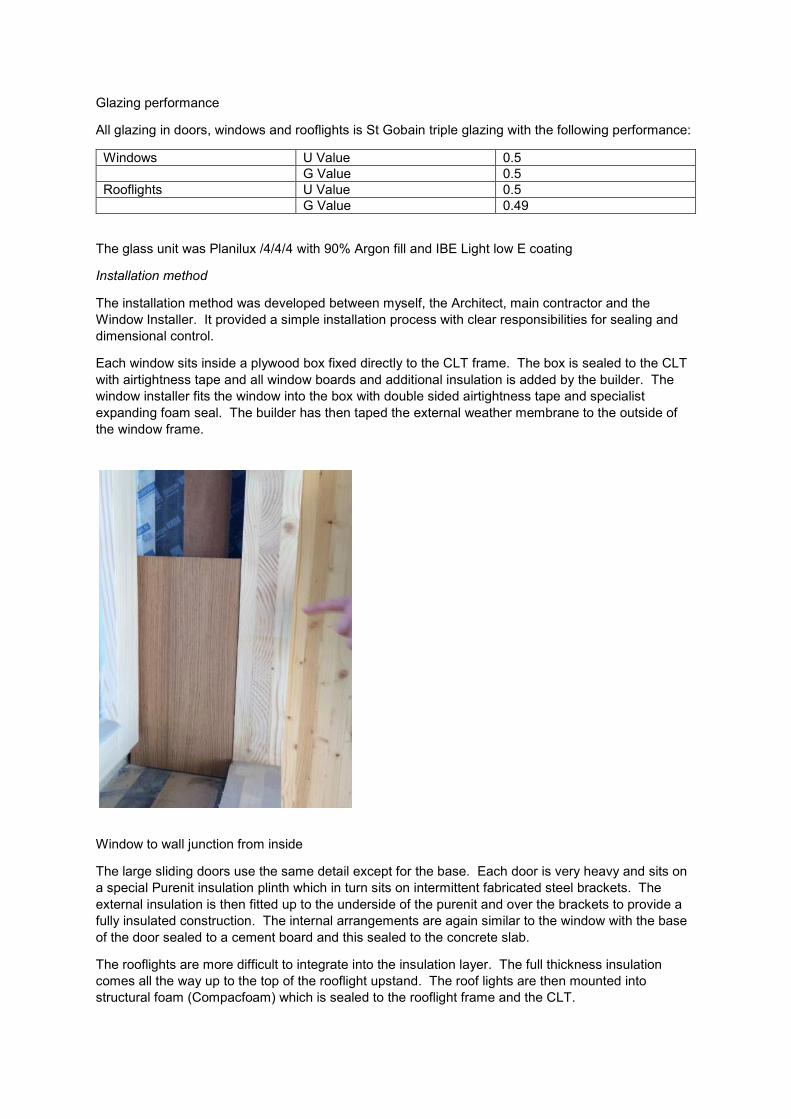
Installation method
The installation method was developed between myself, the Architect, main contractor and the
Window Installer. It provided a simple installation process with clear responsibilities for sealing and
dimensional control.
Each window sits inside a plywood box fixed directly to the CLT frame. The box is sealed to the CLT
with airtightness tape and all window boards and additional insulation is added by the builder. The
window installer fits the window into the box with double sided airtightness tape and specialist
expanding foam seal. The builder has then taped the external weather membrane to the outside of
the window frame.
Window to wall junction from inside
The large sliding doors use the same detail except for the base. Each door is very heavy and sits on
a special Purenit insulation plinth which in turn sits on intermittent fabricated steel brackets. The
external insulation is then fitted up to the underside of the purenit and over the brackets to provide a
fully insulated construction. The internal arrangements are again similar to the window with the base
of the door sealed to a cement board and this sealed to the concrete slab.
The rooflights are more difficult to integrate into the insulation layer. The full thickness insulation
comes all the way up to the top of the rooflight upstand. The roof lights are then mounted into
structural foam (Compacfoam) which is sealed to the rooflight frame and the CLT.

Front Door
The front door is a high performance unit for RK doors. This has triple seals and is fully insulated with
a triple glazed vision panel. Installation is as per the door units.
Technical data for door:
• RK Exclusive profile
• 75mm tick
• 44mm triple glazing Ug 0.7W/m2K
• Door U value 0.72 W/m2K
• Roll hinges by Dr Hann
Photograph of front door

Description of the Airtight Envelope
Airtightness system and method of sealing junctions
The CLT timber frame is the primary air tightness layer for the walls and roof. CLT is a multi layer
timber panel with polyethylene resin making it airtight. All joints within the CLT panels are taped with
airtightness tape.
The concrete slab is sealed to the CLT by a grout and externally applied tape.
As described in the window section the windows, doors and rooflights are taped to the CLT via a
marine ply box connecting frame to CLT.
The design has kept all the material junctions as simple as possible with rectilinear connections.
Clima brand airtightness tapes have been used throughout.
All services penetrations and there are very few are sleeved, fitted with a grommet and fully foam
sealed.
Air pressure testing
During the construction process 3 air tests were undertaken. Each was at a key milestone to test the
progression of the airtightness.
The final air permeability result was as follows:
Test 3 Pressurisation 0.51
Depressurisation 0.6
Average 0.55
Test 1 was just after the CLT frame had been completed and the window openings fitted with
temporary plastic panels.
Test 2 was just after the windows had been installed, sealed and taped in place.
Test 3 was at completion of the works, following installation of the front door and sealing of the
services penetrations.

Photograph of test fan installed in window opening and during air/smoke test
All air pressure testing was carried out by the Building Research Establishment based in Watford, UK.
Full copies of the test results are available on request.

Air Test certificates


Ventilation System Selection and Design
A full MVHR system has been installed. This provides supply air to all occupied rooms and removes
extract air from all wet and utility rooms. The supply and extract rates are balanced and the system
operates at speed 2 on the plant. The system is set up with a reduced volume on speed 1 for when
the home is not occupied and speed 3 is a boost for rapid ventilation. The ventilation rates are in
accordance with or exceed UK Building Regulations Part F, Passivhaus guidance and industry
guidance.
The primary plant is a Paul Novus 300 with built in frost protection and a remote control adjacent the
kitchen.
Ventilation Unit Details
effective heat recovery efficiency ηHR,eff ≥ 75%
electrical efficiency (in Wh/m³) Pel ≤ 0.45 Wh/m³
Image of fan curve and system operating point
The ventilation unit is mounted in the plant space at the back of the utility room with excellent access
for servicing and filter replacement
The ventilation ductwork is spiral wound galvanised steel, slightly oversized to keep pressure drop to
a minimum. There is no flexible ductwork in the system. Air inlet and exhaust are through the ground
floor roof on the western side of the house. The 2 ducts have been kept apart to avoid recirculation
with the air inlet upwind for the prevailing UK wind direction. Both inlet and exhaust ducts are
insulated between the building thermal envelope and the ventilation unit with 50mm continuous
Armaflex insulation.
Primary attenuators are fitted to the room side supply and extract directly off the main plant to control
noise levels. The system is fully balanced and commissioned in accordance with UK Building
Regulations. In duct attenuators are fitted between bedrooms as well as an offset branch duct
configuration to prevent cross talk noise transfer between rooms.
The ductwork route is coordinated across the ground floor ceiling and rises up to the first floor in the
bathroom risers, keeping ductwork to a minimum.

The entire system was checked for pressure drop (using a bespoke excel spreadsheet) and the
system operating point plotted on the unit fan curve to check fan efficiency and noise levels. This was
done using standard and specific fitting loss coefficients. Additional volume control dampers were
fitted to the system to allow balancing independent of the supply and exhaust grilles.
The system is very quiet and barely audible even on boost mode.
Photograph of ventilation Plant and primary ductwork

Photograph of typical grille details in ceilings and walls
Return air is via door under and overcuts. These exceed 15mm in all cases and were checked by the
MVHR installer.
Outdoor air inlet and exhaust are on the lower western roof with adequate separation (in excess of
2m) to avoid recirculation.

Ground Floor ductwork layout
First Floor ductwork layout

Summer Time Ventilation
Early calculations showed that overheating was possible in summer due to the glazing design. To
control overheating shading is applied to the upper floor windows with the wrap around blinkers. A
fabric shade canopy will be fitted to the south courtyard to protect the larger glass areas. This shade
will be removable to allow solar gain in during winter.
To ensure adequate ventilation in summer the house was designed to achieve excellent levels of
cross flow ventilation.
The building is fitted with a range of openable elements:
• Large sliding doors to the living and dining room
• Large tilt and turn windows to all occupied rooms
• Motorised rooflights to living room, utility room, family bathroom and central stair
The primary method of cross flow vent is between windows/doors and rooflights. Typically all
windows, doors and rooflights are manual operation but an automatic sensor controlled function was
fitted to the rooflight above the stair. This is set to open the rooflight if the internal space temperature
reaches 22 degC. The setpoint is variable and is lowered in summer to precool the space or disabled
during winter when the heating is on.
In addition to the cross flow vent each habitable room has an openable window with a tilt open free
area in excess of 5% of the nett floor area.
A full shading analysis and cross flow ventilation model was done using the PHPP worksheets.
Photographs of 1st floor windows in minimum vent position

Heating Systems
Heat Generation
A Viessmann 242F integrated gas fired boiler, domestic hot water cycling and thermal solar system
has been installed. This provided a fully developed and optimised thermal energy generation system.
External weather compensation and a wireless internal thermostat is fitted.
The compensation slope and setpoint have been tuned over the winter months with much reduced
operating temperatures.
Heating System
A conventional low temperature hot water system was installed with 2 radiators on the ground floor
and 1 radiator in the common lobby at first floor. Each radiator is fitted with a thermostatic radiator
valve.
All pipework is continuously insulated from source to the radiator tails.
Image of heating unit

Image of heating system controller and primary radiator
An electric towel radiator is fitted in each bathroom and these are fitted with timers to minimise energy
use. To date these are seldom used.

Ground floor heating installation drawing
First floor heating installation drawing

Domestic Hot Water System
Domestic hot water is provided by the integrated hot water cylinder in the Viessman 242 F unit. This
is heated firstly by a solar thermal circuit and topped up by the gas boiler.
The array is generating typically 4kWh of thermal energy on a clear day.
A DHW circulation pump is fitted to reduce pipework losses and to ensure fast flow of hot water.
All pipework is continuously insulated from the source to point of use.
Photograph of Viessmann Vitosol Solar thermal array
Pipework Insulation
A bespoke pipework insulation method was developed for the project. This allowed continuous 19mm
armaflex insulation from boiler to fitting. The pipework was fabricated at low level, the insulation
sleeve fitted and then plastic support rings fitted before using electrical plastic ties to secure the
pipework to the timber soffit.

Photograph of the pipework fixing and insulation method

Electrical Installation
The electrical installation is to UK wiring regulations and is very standard for a house of this size.
There is a standard 100Amp incoming single phase supply from the local utility company and this
terminates in 2x15 way consumer units.
Individual circuits are run for most pieces of equipment to allow individual metering of installed
equipment in the future.
A 1.6kW peak solar electric array is fitted to the house. This generates up to 8kWh on a clear
summer day. The inverter is fitted in the utility room and connected for use in the house or grid
export.
Photograph of 1.6kWp PV array

PHPP Results
Verification worksheet and discussion.
The PHPP spreadsheet was a very useful design tool. The direct feedback of different input
parameters was extremely helpful during design and allowed us to confirm window system
performance and building U values very effectively.
The solar gains calculations were very useful to check for overheating and to understand the heating
design options and solar control strategy.
The pipework heat losses were easily modelled with and without return loop and confirmed a DHW
circulator was the best solution.
When it came to choosing appliances the tool again helped us see the impacts of different energy
ratings. The subtle differences in appliances had a significant impact on the annual energy
consumption.
Ventilation design was modelled well in the tool but the design was a result of many years of
experience with natural ventilation design and rules of thumb. The tool provided good feedback on
the design parameters.
Construction Costs
Net construction cost for the occupied dwelling including green roofs, renewable technology and
internal fitout.
Overall construction cost for the total development, which includes a 40sqm garage, landscaping,
boundary walls, consents, consultants, enabling works and all project elements
Construction costs Net building cost £4,000 /sqm

Post Occupancy Feedback
Comfort
The house has been super comfortable at either extreme of season. The summer of 2015 was
deemed pretty average by the UK met office and winter saw temperatures below zero on numerous
occasions. The internal temperatures are very even and no cold draughts are evident.
Air quality has been very good during winter and summer.
Daylight levels are high due to the careful placement of glazing and lighting use is very low.
The cross flow ventilation has been very effective in summer and no overheating has been observed.
Energy Consumption figures
The dwelling has now been in use for 12 months and following meter readings , the performance is
confirmed.
This shows a reduction in energy consumption over the design targets for final energy and a little over
the target for primary energy.
Jun-2015
May-2016 In Use Actual kWh/sqm annum
kWh Final Energy Primary Energy
Elec Meter 4422 9241 kWh 4819 36 2.6 94
Gas Meter 36 274 m3 2535 19 1.1 21
55 114
PV generation 0 642 kWh 642 5
-2.6 -12
Solar Thermal 0 650 kWh 650 5
-1.1 -5
Electricity consumption is higher than predicted and gas lower. We are in the process of investigating
this, with a view to optimising energy consumption, PV energy use and timer based electrical loads.
Domestic metering equipment does not allow consumers to see exactly how much energy they are
actually consuming. The utility company meter records imported electricity less PV generated power
use, rather than energy used. Typical home energy monitors only reflect this figure and do not have
the internal processing to identify the true energy use.
Controls
Simple controls have been very effective. User instigated, manual control has been the most effective
way to moderate internal temperature and energy consumption.
It has taken some time to get used to how to live in the house, how to manage the heating and
operate the MVHR and well as summer natural ventilation systems.

The automatic rooflight internal temperature sensor has a 4 deg dead band which is too wide to react
quickly enough to increasing internal temperatures. We have resorted to reducing the setpoint to get
the rooflight to operate early with a degree of precooling.
Typical domestic equipment control bands are too wide for a Passivhaus. It is worth considering
industrial sensors with increased accuracy.
Heating System
2 of the 3 radiators have been turned off and have not been necessary to keep the house warm even
at very low external temperatures. These will be removed in due course.
We have also found the thermal inertia of the wet based heating is too slow to react to rapid winter
solar gains during sunny periods and causes internal temperatures to rise above setpoint despite the
boiler shutting down. Electric heating panels would be more suitable.
The heating compensation control slope and end point have now been adjusted to suit the thermal
properties of the house, providing very stable internal temperatures in winter.
The minimal heating requirements make electrical based heating very attractive. Electrical heating
will also be more responsive to solar gains and prevent winter setpoint overshoot. Although there is a
primary energy conversion factor penalty in the UK for an electric based system, final energy use will
be reduced by more use of PV generated power.
With electric space heating a simple solar thermal domestic hot water system with electric top up is
possible.
Solar electric can then be used to offset all energy consumption. This combined with an electrical
energy store would minimise energy use and utility energy import.

Appendix 1 – Copy of PHPP verification Sheet

PHPP, Verification PHPP_EN_V8.4_convent_lane As Built.xlsm
Passive House verification
Photo or Drawing
Building: 7 Convent LaneStreet:Postcode / City: EmsworthCountry: UKBuilding type: Residential DwellingClimate: [UK] - South England (Efford) Altitude of building site (in [m] above sea level): 8
Home owner / Client: Ruth Butler and Julian SutherlandStreet:Postcode/City:
Architecture: Ruth Butler ArchitectsStreet: 7 The Green, Rowlands CastlePostcode / City: Hampshire PO9 6BW
Mechanical system: Julian SutherlandStreet: 7 The Green, Rowlands CastlePostcode / City: Hampshire PO9 6BW
Year of construction: 2014 Interior temperature winter: 20.0 °C Enclosed volume Ve m³: 352.0No. of dwelling units: 1 Interior temperature summer: 25.0 °C Mechanical cooling:No. of occupants: 4.0 Internal heat sources winter: 2.1 W/m²Spec. capacity: 84 Wh/K per m² TFA Ditto summer: 3.4 W/m²
Specific building demands with reference to the treated floor area
Treated floor area 133.7 m² Requirements Fulfilled?*
Space heating Heating demand 8 kWh/(m2a) 15 kWh/(m²a) yes
Heating load 10 W/m2 10 W/m² yes
Space cooling Overall specif. space cooling demand kWh/(m2a) - -
Cooling load W/m2 - -Frequency of overheating (> 25 °C) 1.7 % - -
Primary energy Heating, cooling, auxiliary electricity,
dehumidification, DHW,lighting, electrical appliances 96 kWh/(m2a) 120 kWh/(m²a) yes
DHW, space heating and auxiliary electricity 62 kWh/(m2a) - -Specific primary energy reduction through solar electricity 11 kWh/(m2a) - -
Airtightness Pressurization test result n50 0.6 1/h 0.6 1/h yes* empty field: data missing; '-': no requirement
Passive House? yes
PHPP Version 8.4We confirm that the values given herein have Name: Registration number PHPP:been determined following the PHPP methodology and based on the characteristic values of the building. Surname: Issued on:The PHPP calculations are attached to this application.
Company: Signature:

Appendix 2 – Compliance Certificate


Appendix 3 – Design statement by the project Architect
I confirm that the applicant was responsible for the parts of the planning that were relevant for
the Passive House Standard and that they delivered the PHPP calculations and MEP design
Signed
Ruth Butler
Ruth Butler Architects
Courtyard Studio
Seven Convent Lane
Emsworth Hampshire
PO10 7JJ