Programming and Testing of Railway Controllers for Varying ...
21
Μίνθα: A Framework for Auto- Programming and Testing of Railway Controllers for Varying Clients Jörn Guy Süß University of Queensland, Australia Neil Robinson RGB Assurance, Australia David Carrington University of Queensland, Australia Paul Strooper University of Queensland, Australia ABSTRACT Implementation of railway controller application logic is a highly safety-critical and time-consuming task carried out individually for each client and station by specialised signalling engineers, with cor- responding high costs. Μίνθα is a software development framework designed to create code genera- tors for application logic for the client railway companies of Ansaldo STS that use the Microlok II controller to lower the cost and increase repeatability. This chapter describes the evolution of Μίνθα from prototype to framework, and introduces the software engineering approaches of object-oriented meta-modelling and framework development along the way. It also presents known limitations and further application areas of the framework. INTRODUCTION Many advances in the development of rail technology have been accompanied by an increase in risk to the passenger. Shared track use meant an increased number of trains, but carried the risk of rear collisions; points brought an increase in route flexibility, but at the cost of potential derailment and head-on collisions; higher train speeds allow passengers to travel faster than small planes, and metro rail trains accelerate and decelerate in shortest distances, but these types of trains cannot be driven by sight alone any more. Each increase in risk has been managed by signalling engineers through the in- troduction of corresponding increasingly sophisticated control machinery. The safe conduct of today’s rail traffic relies on computer-based interlocking controllers. The programs that these controllers ex- ecute reflect the whole complexity scope of signal engineering. Since interlocking controllers are specialised computer devices, the creation of application logic for these controllers is essentially a software-programming task. The professional discipline that ex- amines and develops methods and tools for the production of software is software engineering. The Mint project is a software engineering project that investigates the process of writing interlocking controller logic to suggest ways to improve the process. The Mint project applies three software engi- neering techniques to deal with the complexity of the domain: object-oriented modelling to capture and describe the artefacts and terminology of signal engineering, feature modelling to describe the varying aspects among different clients, and framework development to reduce the cost of construc- tion by providing a common infrastructure. This chapter introduces the software engineering approach of the Mint project in detail to show how it derives client-specific tools that automate the process of generating controller application logic as far as safely possible.
-
Upload
khangminh22 -
Category
Documents
-
view
1 -
download
0
Transcript of Programming and Testing of Railway Controllers for Varying ...
Μίνθα: A Framework for Auto-Programming and Testing of Railway
Controllers for Varying Clients Jörn Guy Süß University of Queensland, Australia Neil Robinson RGB Assurance, Australia David Carrington University of Queensland, Australia Paul Strooper University of Queensland, Australia ABSTRACT Implementation of railway controller application logic is a highly safety-critical and time-consuming task carried out individually for each client and station by specialised signalling engineers, with cor-responding high costs. Μίνθα is a software development framework designed to create code genera-tors for application logic for the client railway companies of Ansaldo STS that use the Microlok II controller to lower the cost and increase repeatability. This chapter describes the evolution of Μίνθα from prototype to framework, and introduces the software engineering approaches of object-oriented meta-modelling and framework development along the way. It also presents known limitations and further application areas of the framework.
INTRODUCTION Many advances in the development of rail technology have been accompanied by an increase in risk to the passenger. Shared track use meant an increased number of trains, but carried the risk of rear collisions; points brought an increase in route flexibility, but at the cost of potential derailment and head-on collisions; higher train speeds allow passengers to travel faster than small planes, and metro rail trains accelerate and decelerate in shortest distances, but these types of trains cannot be driven by sight alone any more. Each increase in risk has been managed by signalling engineers through the in-troduction of corresponding increasingly sophisticated control machinery. The safe conduct of today’s rail traffic relies on computer-based interlocking controllers. The programs that these controllers ex-ecute reflect the whole complexity scope of signal engineering.
Since interlocking controllers are specialised computer devices, the creation of application logic for these controllers is essentially a software-programming task. The professional discipline that ex-amines and develops methods and tools for the production of software is software engineering. The Mint project is a software engineering project that investigates the process of writing interlocking controller logic to suggest ways to improve the process. The Mint project applies three software engi-neering techniques to deal with the complexity of the domain: object-oriented modelling to capture and describe the artefacts and terminology of signal engineering, feature modelling to describe the varying aspects among different clients, and framework development to reduce the cost of construc-tion by providing a common infrastructure.
This chapter introduces the software engineering approach of the Mint project in detail to show how it derives client-specific tools that automate the process of generating controller application logic as far as safely possible.
BACKGROUND The Mint project is a joint project of Ansaldo STS and The University of Queensland. In the follow-ing section, we introduce Ansaldo and its business requirements. After that, we turn to Ansaldo’s Mi-crolok system that forms the target platform of the Mint project, and describe its functionality in de-tail.
Ansaldo STS – International Railway Engineering Ansaldo STS is a global railway engineering service provider that specializes in automation and turn-key delivery of passenger and freight rail systems. Ansaldo STS was created through a merger be-tween Union Switch and Signal and Ansaldo Trasporti Sistemi Ferroviari, and US-American and Eu-ropean technologies determine its offerings. In 2009, Ansaldo STS achieved revenue of €1.176 billion and an operating income of €125.0 million, with 4,340 employees worldwide. Ansaldo's clients vary considerably by their operational objectives and implementation of railway principles. Clients range from metropolitan rail operators to mining rails, and stock spans from electrified high-speed locos to double-traction diesels. Communication may be by coded track, radio, or GSM-R; signals may be physical installations at trackside, or console indicators in the driver’s cabin. Ansaldo’s task is to manage these variations to provide safe signalling systems that respect the clients’ existing customs and requirements.
The Microlok System One of Ansaldo’s most successful products is the system of Microlok integrated controllers, designed by Union Switch and Signal. Before the arrival of the Microlok system, signalling controllers were usually custom-built devices that were programmed in machine language. The Microlok I controller introduced a language that signalling engineers found easy to adopt, because it modelled the wiring logic of the relay grids that they were familiar with. The Microlok II controller expanded the approach by applying the principle of the IBM personal computer to the signalling system: a Microlok system consists of a powered case that holds a central-processing unit and several interface cards on separate plug-in boards that connect to the CPU via a common bus. While the Microlok architecture was de-signed to serve as a platform for vital controllers, the standardisation also allowed Ansaldo to build a non-vital controller as a parallel product to share the components.
The CPU of the Microlok II is built on the well-established and understood Motorola 68000 series of microprocessors. The bus between CPU and cards follows the VME Bus standard [IEEE, 1987], which enables the use of standardised electronics testing and design facilities.
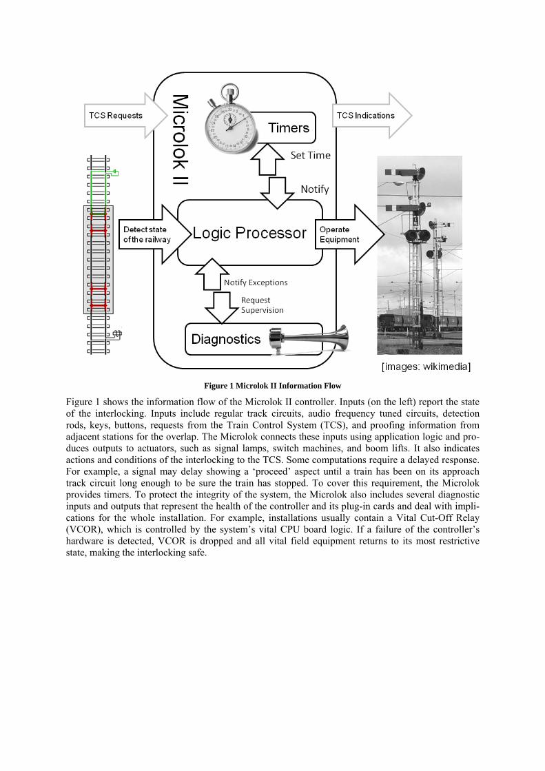
Figure 1 Microlok II Information Flow
Figure 1 shows the information flow of the Microlok II controller. Inputs (on the left) report the state of the interlocking. Inputs include regular track circuits, audio frequency tuned circuits, detection rods, keys, buttons, requests from the Train Control System (TCS), and proofing information from adjacent stations for the overlap. The Microlok connects these inputs using application logic and pro-duces outputs to actuators, such as signal lamps, switch machines, and boom lifts. It also indicates actions and conditions of the interlocking to the TCS. Some computations require a delayed response. For example, a signal may delay showing a ‘proceed’ aspect until a train has been on its approach track circuit long enough to be sure the train has stopped. To cover this requirement, the Microlok provides timers. To protect the integrity of the system, the Microlok also includes several diagnostic inputs and outputs that represent the health of the controller and its plug-in cards and deal with impli-cations for the whole installation. For example, installations usually contain a Vital Cut-Off Relay (VCOR), which is controlled by the system’s vital CPU board logic. If a failure of the controller’s hardware is detected, VCOR is dropped and all vital field equipment returns to its most restrictive state, making the interlocking safe.
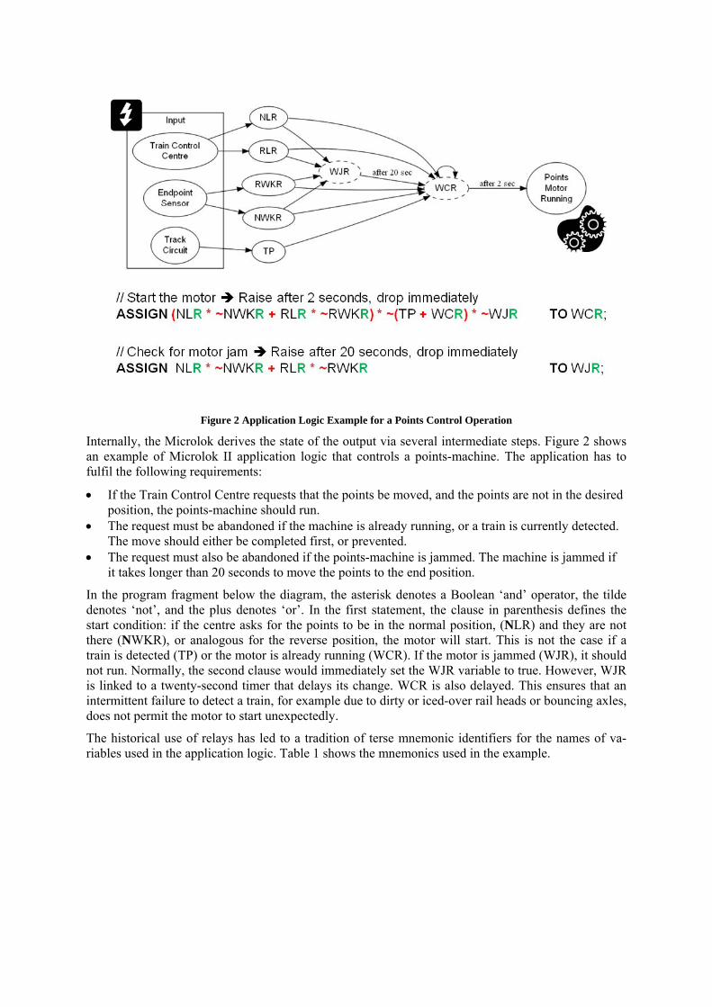
Figure 2 Application Logic Example for a Points Control Operation
Internally, the Microlok derives the state of the output via several intermediate steps. Figure 2 shows an example of Microlok II application logic that controls a points-machine. The application has to fulfil the following requirements:
• If the Train Control Centre requests that the points be moved, and the points are not in the desired position, the points-machine should run.
• The request must be abandoned if the machine is already running, or a train is currently detected. The move should either be completed first, or prevented.
• The request must also be abandoned if the points-machine is jammed. The machine is jammed if it takes longer than 20 seconds to move the points to the end position.
In the program fragment below the diagram, the asterisk denotes a Boolean ‘and’ operator, the tilde denotes ‘not’, and the plus denotes ‘or’. In the first statement, the clause in parenthesis defines the start condition: if the centre asks for the points to be in the normal position, (NLR) and they are not there (NWKR), or analogous for the reverse position, the motor will start. This is not the case if a train is detected (TP) or the motor is already running (WCR). If the motor is jammed (WJR), it should not run. Normally, the second clause would immediately set the WJR variable to true. However, WJR is linked to a twenty-second timer that delays its change. WCR is also delayed. This ensures that an intermittent failure to detect a train, for example due to dirty or iced-over rail heads or bouncing axles, does not permit the motor to start unexpectedly.
The historical use of relays has led to a tradition of terse mnemonic identifiers for the names of va-riables used in the application logic. Table 1 shows the mnemonics used in the example.
Code Meaning
W Switch – from the air points look like a ‘W’
N Normal – Trains pass straight over the switch
R Reverse – Trains are diverted to the other line
L Call (from train control system)
C Command (to the points machine) – “Move the points”
K “OK” – Operation Complete, points detected in desired position
J The points motor has run too long without successfully moving the points (a poss-ible “Jam”)
TP Track Proven (to be occupied) – There is a train on this track Table 1 Relay naming conventions
CHALLENGES OF APPLICATION LOGIC DEVELOPMENT Three major issues make the development of Microlok application logic difficult:
Tests of the software require installation on controller hardware. This leads to long turn-around times between software tests.
The procedures used to derive application logic code from track layouts and control tables are given by example, they are often incomplete and may change during the course of the project.
The way in which control tables, track layouts and procedures for development are defined varies for every client, making reuse challenging.
The following sections describe the current process and discuss how the issues arise.
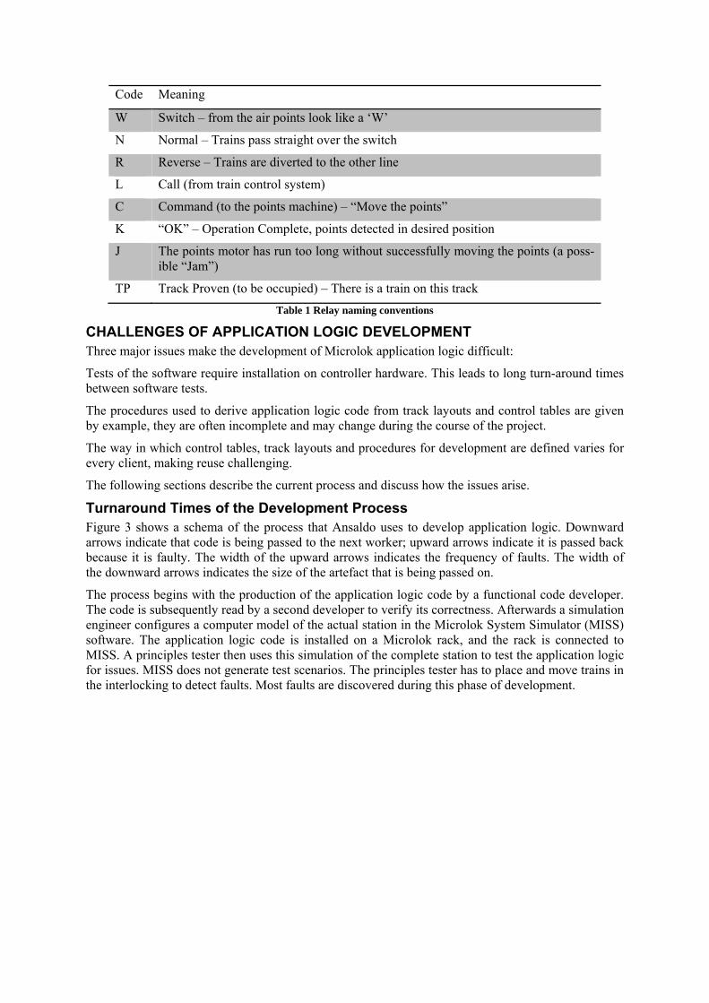
Turnaround Times of the Development Process Figure 3 shows a schema of the process that Ansaldo uses to develop application logic. Downward arrows indicate that code is being passed to the next worker; upward arrows indicate it is passed back because it is faulty. The width of the upward arrows indicates the frequency of faults. The width of the downward arrows indicates the size of the artefact that is being passed on.
The process begins with the production of the application logic code by a functional code developer. The code is subsequently read by a second developer to verify its correctness. Afterwards a simulation engineer configures a computer model of the actual station in the Microlok System Simulator (MISS) software. The application logic code is installed on a Microlok rack, and the rack is connected to MISS. A principles tester then uses this simulation of the complete station to test the application logic for issues. MISS does not generate test scenarios. The principles tester has to place and move trains in the interlocking to detect faults. Most faults are discovered during this phase of development.
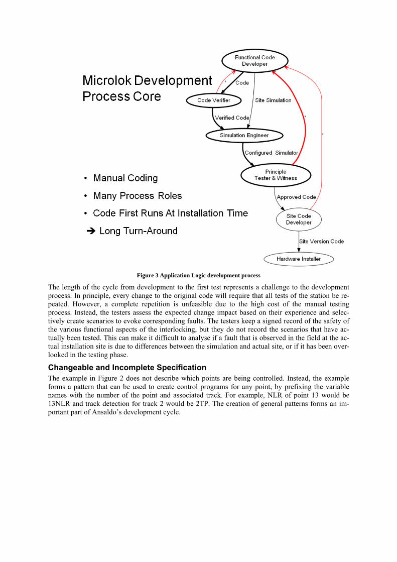
Figure 3 Application Logic development process
The length of the cycle from development to the first test represents a challenge to the development process. In principle, every change to the original code will require that all tests of the station be re-peated. However, a complete repetition is unfeasible due to the high cost of the manual testing process. Instead, the testers assess the expected change impact based on their experience and selec-tively create scenarios to evoke corresponding faults. The testers keep a signed record of the safety of the various functional aspects of the interlocking, but they do not record the scenarios that have ac-tually been tested. This can make it difficult to analyse if a fault that is observed in the field at the ac-tual installation site is due to differences between the simulation and actual site, or if it has been over-looked in the testing phase.
Changeable and Incomplete Specification The example in Figure 2 does not describe which points are being controlled. Instead, the example forms a pattern that can be used to create control programs for any point, by prefixing the variable names with the number of the point and associated track. For example, NLR of point 13 would be 13NLR and track detection for track 2 would be 2TP. The creation of general patterns forms an im-portant part of Ansaldo’s development cycle.
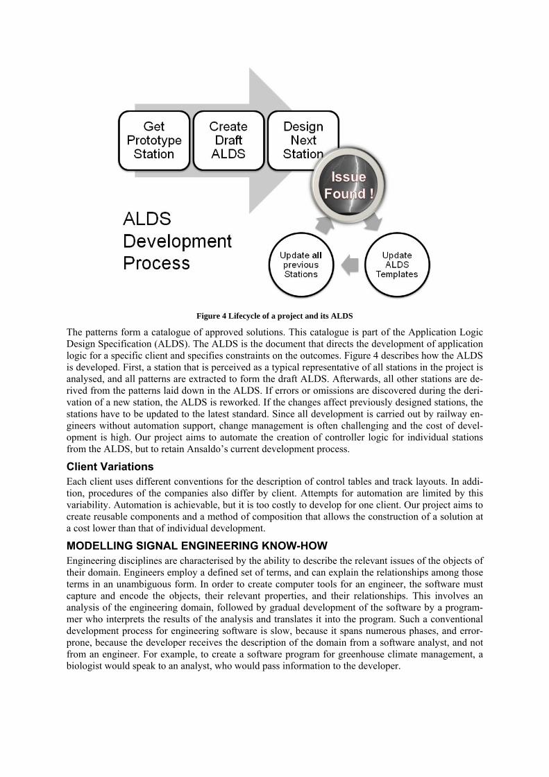
Figure 4 Lifecycle of a project and its ALDS
The patterns form a catalogue of approved solutions. This catalogue is part of the Application Logic Design Specification (ALDS). The ALDS is the document that directs the development of application logic for a specific client and specifies constraints on the outcomes. Figure 4 describes how the ALDS is developed. First, a station that is perceived as a typical representative of all stations in the project is analysed, and all patterns are extracted to form the draft ALDS. Afterwards, all other stations are de-rived from the patterns laid down in the ALDS. If errors or omissions are discovered during the deri-vation of a new station, the ALDS is reworked. If the changes affect previously designed stations, the stations have to be updated to the latest standard. Since all development is carried out by railway en-gineers without automation support, change management is often challenging and the cost of devel-opment is high. Our project aims to automate the creation of controller logic for individual stations from the ALDS, but to retain Ansaldo’s current development process.
Client Variations Each client uses different conventions for the description of control tables and track layouts. In addi-tion, procedures of the companies also differ by client. Attempts for automation are limited by this variability. Automation is achievable, but it is too costly to develop for one client. Our project aims to create reusable components and a method of composition that allows the construction of a solution at a cost lower than that of individual development.
MODELLING SIGNAL ENGINEERING KNOW-HOW Engineering disciplines are characterised by the ability to describe the relevant issues of the objects of their domain. Engineers employ a defined set of terms, and can explain the relationships among those terms in an unambiguous form. In order to create computer tools for an engineer, the software must capture and encode the objects, their relevant properties, and their relationships. This involves an analysis of the engineering domain, followed by gradual development of the software by a program-mer who interprets the results of the analysis and translates it into the program. Such a conventional development process for engineering software is slow, because it spans numerous phases, and error-prone, because the developer receives the description of the domain from a software analyst, and not from an engineer. For example, to create a software program for greenhouse climate management, a biologist would speak to an analyst, who would pass information to the developer.
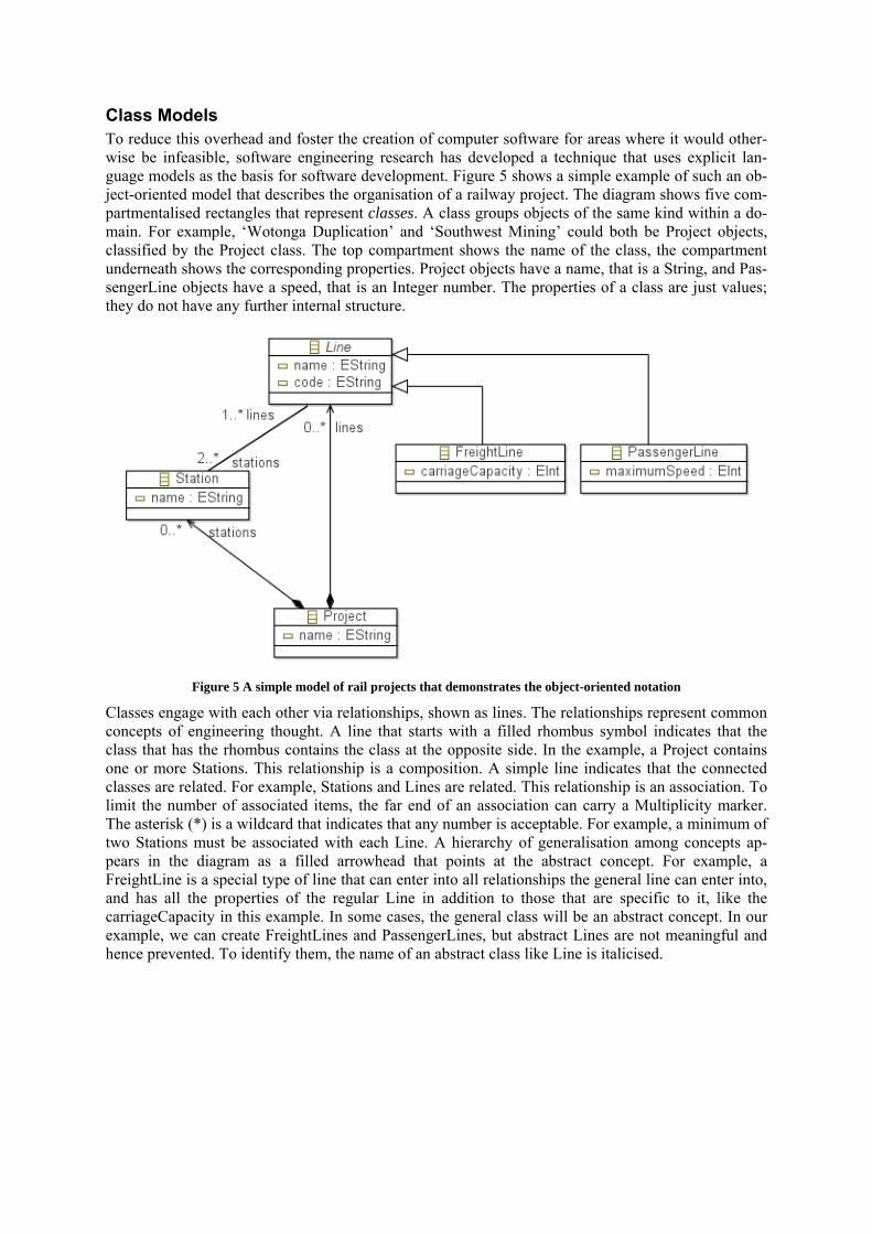
Class Models To reduce this overhead and foster the creation of computer software for areas where it would other-wise be infeasible, software engineering research has developed a technique that uses explicit lan-guage models as the basis for software development. Figure 5 shows a simple example of such an ob-ject-oriented model that describes the organisation of a railway project. The diagram shows five com-partmentalised rectangles that represent classes. A class groups objects of the same kind within a do-main. For example, ‘Wotonga Duplication’ and ‘Southwest Mining’ could both be Project objects, classified by the Project class. The top compartment shows the name of the class, the compartment underneath shows the corresponding properties. Project objects have a name, that is a String, and Pas-sengerLine objects have a speed, that is an Integer number. The properties of a class are just values; they do not have any further internal structure.
Figure 5 A simple model of rail projects that demonstrates the object-oriented notation
Classes engage with each other via relationships, shown as lines. The relationships represent common concepts of engineering thought. A line that starts with a filled rhombus symbol indicates that the class that has the rhombus contains the class at the opposite side. In the example, a Project contains one or more Stations. This relationship is a composition. A simple line indicates that the connected classes are related. For example, Stations and Lines are related. This relationship is an association. To limit the number of associated items, the far end of an association can carry a Multiplicity marker. The asterisk (*) is a wildcard that indicates that any number is acceptable. For example, a minimum of two Stations must be associated with each Line. A hierarchy of generalisation among concepts ap-pears in the diagram as a filled arrowhead that points at the abstract concept. For example, a FreightLine is a special type of line that can enter into all relationships the general line can enter into, and has all the properties of the regular Line in addition to those that are specific to it, like the carriageCapacity in this example. In some cases, the general class will be an abstract concept. In our example, we can create FreightLines and PassengerLines, but abstract Lines are not meaningful and hence prevented. To identify them, the name of an abstract class like Line is italicised.
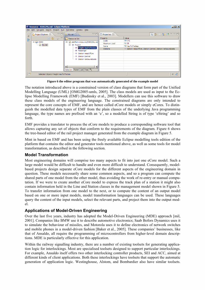
Figure 6 the editor program that was automatically generated of the example model
The notation introduced above is a constrained version of class diagrams that form part of the Unified Modelling Language (UML) [OMG2005-umls, 2005]. The class models are used as input to the Ec-lipse Modelling Framework (EMF) [Budinsky et al., 2003]. Modellers can use this software to draw these class models of the engineering language. The constrained diagrams are only intended to represent the core concepts of EMF, and are hence called eCore models or simply eCores. To distin-guish the mod programming
rmation, as described in the following section.
voiding the work of re-entry or manual compu-nother eCore model to express the track plan of a station it might also
of Ansaldo, all require the programming of microcontrollers from higher-level domain descrip-
generation of application logic. Westinghouse, Alstom, and Bombardier also have similar toolsets.
elled data types of EMF from the plain classes of the underlying Java language, the type names are prefixed with an ‘e’, so a modelled String is of type ‘eString’ and so forth.
EMF provides a translator to process the eCore models to produce a corresponding software tool that allows capturing any set of objects that conform to the requirements of the diagram. Figure 6 shows the tree-based editor of the rail project manager generated from the example diagram in Figure 5.
Mint in based on EMF and has been using the freely available Eclipse modelling tools edition of the platform that contains the editor and generator tools mentioned above, as well as some tools for model transfo
Model Transformation Most engineering domains will comprise too many aspects to fit into just one eCore model. Such a large model would be difficult to handle and even more difficult to understand. Consequently, model-based projects design separate eCore models for the different aspects of the engineering domain in question. These models necessarily share some common aspects, and so a program can compute the shared parts of one model from the other model, thus atation. If we were to create acontain information held in the Line and Station classes in the management model shown in Figure 5. To transfer information from one model to the next, or to compute the content of an output model based on one or more input models, model transformation languages can be used. These languages query the content of the input models, select the relevant parts, and project them into the output mod-el.
Applications of Model-Driven Engineering Over the last five years, industry has adopted the Model-Driven Engineering (MDE) approach [mil, 2001]. Companies like BMW use it to describe automotive electronics; Saab Bofors Dynamics uses it to simulate the behaviour of missiles, and Motorola uses it to define electronics of network switches and mobile phones in a model-driven fashion [Baker et al., 2005]. These companies’ businesses, like thattions. MDE is particularly effective for this application.
Within the railway signalling industry, there are a number of existing toolsets for generating applica-tion logic for interlockings. Most are specialised toolsets designed to support particular interlockings. For example, Ansaldo itself offers two other interlocking controller products, SEI and ACC, aimed at different kinds of client applications. Both these interlockings have toolsets that support the automatic
Prover Technology AB specialises in providing toolsets for signalling applications and provides cus-tomisable tools for design, proofing and testing – from our survey of such tools, the Prover Technolo-
approach on the other hand offers the po-
pe was specific to Queensland Rail Regional (QRR) signalling requirements. It
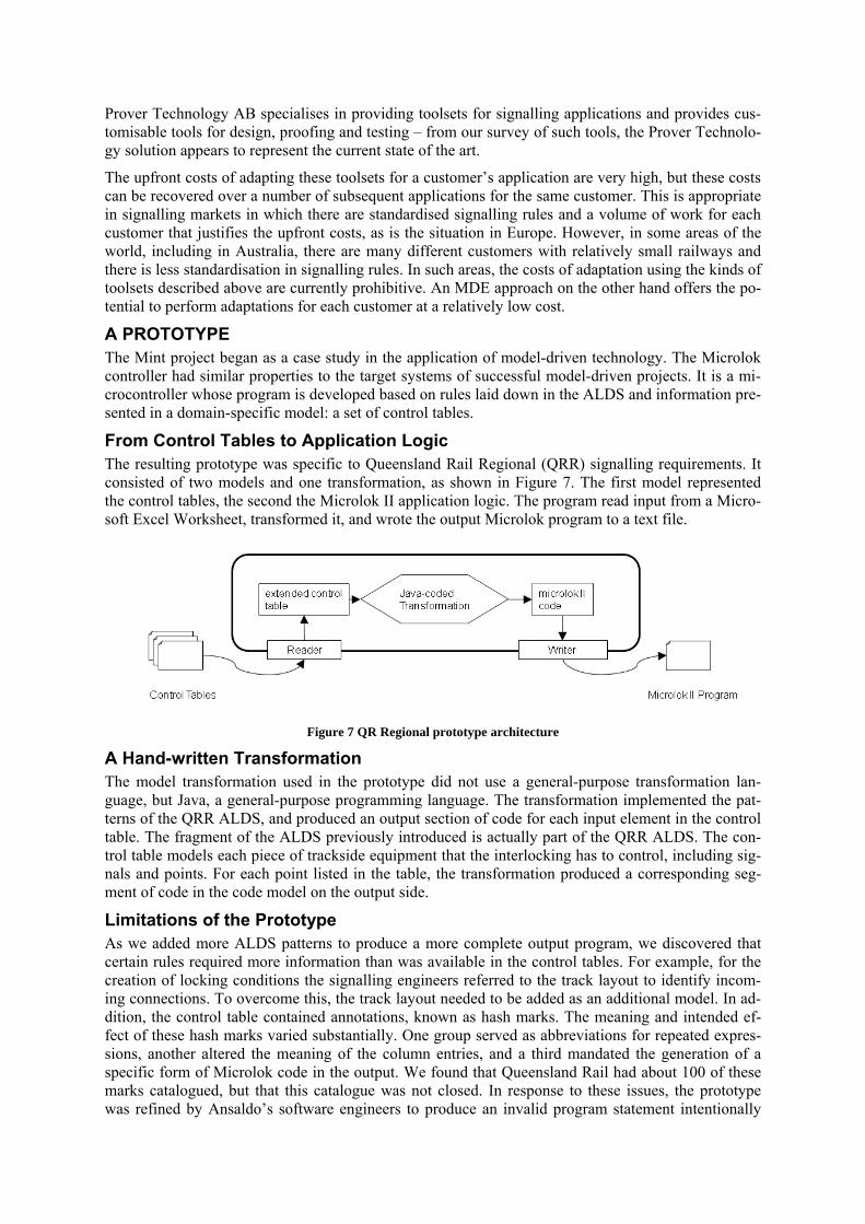
Figure 7 QR Regional prototype architecture
A Hand-written Transformation The model transformation used in the prototype did not use a general-purpose transformation lan-guage, but Java, a general-purpose programming language. The transformation implemented the pat-terns of the QRR ALDS, and produced an output section of code for each input element in the control table. The fragment of the ALDS previously introduced is actually part of the QRR ALDS. The con-trol table models each piece of trackside equipment that the interlocking has to control, including sig-nals and points. For each poin roduced a corresponding seg-
tput side.
roup served as abbreviations for repeated expres-f the column entries, and a third mandated the generation of a
gy solution appears to represent the current state of the art.
The upfront costs of adapting these toolsets for a customer’s application are very high, but these costs can be recovered over a number of subsequent applications for the same customer. This is appropriate in signalling markets in which there are standardised signalling rules and a volume of work for each customer that justifies the upfront costs, as is the situation in Europe. However, in some areas of the world, including in Australia, there are many different customers with relatively small railways and there is less standardisation in signalling rules. In such areas, the costs of adaptation using the kinds of toolsets described above are currently prohibitive. An MDEtential to perform adaptations for each customer at a relatively low cost.
A PROTOTYPE The Mint project began as a case study in the application of model-driven technology. The Microlok controller had similar properties to the target systems of successful model-driven projects. It is a mi-crocontroller whose program is developed based on rules laid down in the ALDS and information pre-sented in a domain-specific model: a set of control tables.
From Control Tables to Application Logic The resulting prototyconsisted of two models and one transformation, as shown in Figure 7. The first model represented the control tables, the second the Microlok II application logic. The program read input from a Micro-soft Excel Worksheet, transformed it, and wrote the output Microlok program to a text file.
t listed in the table, the transformation pment of code in the code model on the ou
Limitations of the Prototype As we added more ALDS patterns to produce a more complete output program, we discovered that certain rules required more information than was available in the control tables. For example, for the creation of locking conditions the signalling engineers referred to the track layout to identify incom-ing connections. To overcome this, the track layout needed to be added as an additional model. In ad-dition, the control table contained annotations, known as hash marks. The meaning and intended ef-fect of these hash marks varied substantially. One gsions, another altered the meaning ospecific form of Microlok code in the output. We found that Queensland Rail had about 100 of these marks catalogued, but that this catalogue was not closed. In response to these issues, the prototype was refined by Ansaldo’s software engineers to produce an invalid program statement intentionally
whenever more information was needed, augmented with an explanatory comment to explain the re-quirement. The invalid statement prevented unintentional use of the automatically generated code and ensured that a signalling engineer would inspect and adapt the program as necessary.
Ansaldo was interested in the original prototype, produced a refined version in-house, and tested it. However, the high production time of six months made the software costly. At this point, Ansaldo and UQ initiated the Mint project to investigate how the approach could be accelerated and what other benefits, particularly in the testing area, could be provided. While Ansaldo repeated the development for other clients, using the development cycle and architecture of the prototype as a template, the re-search project at UQ looked at the creation of a method and set of reusable pieces to build a product line of code generators.
Managing Product Variability Product line engineering is a management approachthat optimises the utilisation of a company’s capa-bilities. A product line is a set of related offerings created by configuring a set of variation points. For example, a washing machine company may produce a range of machines with varying drum-types, machine controls, displays, and an optional automated shut-off valve. In this scenario, the product is a washing machine, and the feature variations are in the drum, control, display, and valve. In principle, any combination of these features can be manufactured as a product. This combinatorial scope is only
the case of the washing-machine example, a digital , and is incompatible with mechanical control. Marketing and
f product lines. NASA is adopting this ap-ission software [Pasetti, 2002].
the frame, there is usually a defini-or the example of the washing ma-
n the diagram are the varying features of the top
limited where features have interdependencies. In display may require computer controlcustomer relationship management can subsequently examine the market requirements and configure the products in the product line to suit the customer base.
Models of Product Lines Product lines have been used in areas that involve mechatronic systems, where a hardware component is driven by an embedded controller running a built-in firmware [Weiss, 2008]. For every product variation of the hardware, the corresponding firmware has to be different. Control systems for wind-shield wipers or fuel injection pumps are typical examples of this class of products. To produce the various driver programs without error, the programming task has to be automated. The design of space probes and spacecraft is a more exotic application oproach for the configuration of m
SOFTWARE PRODUCT LINES AND FRAMEWORKS The idea of product lines can also be applied to software without any physical component [Eisenecker and Czarnecki, 2000]. In the Mint project, Ansaldo’s clients vary in the way they describe projects and stations, and translate the requirements into Microlok application logic.
In physical products, a number of product factors are fixed and cannot be changed. These elements constitute an invariant frame into which the varying components have to be installed. As a rule, the fixed parts substantially outnumber the varying parts. Along withtion of defaults to be used in case no explicit variant is specified. Fchine, this would mean that the outer metal housing of the machine might be a common frame into which the variant drum is installed. By default, a ‘standard’ type washer may include a punch-hole medium-size drum, and a mechanical motor control.
The idea of frameworks as a base for construction has also been adopted for the construction of soft-ware alongside product lines. In the Mint project, the parts of the tool that define the user interface, help system, and execution of the workflow are all part of a common software framework called Μίνθα, which is filled in with the variant parts required by the clients.
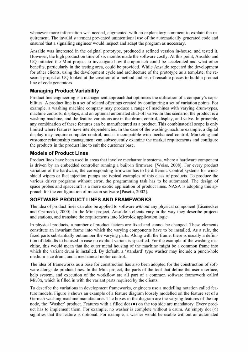
To describe the variations in development frameworks, engineers use a modelling notation called fea-ture models. Figure 8 shows an example of a feature diagram loosely modelled on the feature set of a German washing machine manufacturer. The boxes inode, the ‘Washer’ product. Features with a filled dot (●) on the top side are mandatory. Every prod-uct has to implement them. For example, no washer is complete without a drum. An empty dot (○) signifies that the feature is optional. For example, a washer would be usable without an automated
detergent advisor. An empty arc or bow under a feature means that its sub-features represent a choice. For example, every washer needs a fascia, and it can be mounted with either a straight or angular
Figure 8 Example of a Feature Model for Washing Machines
In the following section, we will use the feature model notation to describe the design of the Μίνθα framework.
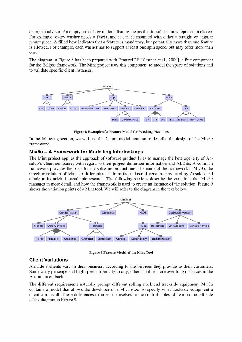
Μίνθα – A Framework for Modelling Interlockings The Mint project applies the approach of software product lines to manage the heterogeneity of An-saldo’s client companies with regard to their project definition information and ALDSs. A common framework provides the basis for the software product line. The name of the framework is Μίνθα, the Greek translation of Mint, to differentiate it from the industrial versions produced by Ansaldo and allude to its origin in academic research. The following sections describe the variations that Μίνθα manages in more detail, and how the framework is used to create an instance of the solution. Figure 9 shows the variation points of a Mint tool. We will refer to the diagram in the text below.
Figure 9 Feature Model of the Mint Tool
Client Variations Ansaldo’s clients vary in their business, according to the services they provide to their customers. Some carry passengers at high speeds from city to city; others haul iron ore over long distances in the Australian outback.
The different requirements naturally prompt different rolling stock and trackside equipment. Μίνθα contains a model that allows the developer of a Μίνθα-tool to specify what trackside equipment a client can install. These differences manifest themselves in the control tables, shown on the left side of the diagram in Figure 9.
mount piece. A filled bow indicates that a feature is mandatory, but potentially more than one feature is allowed. For example, each washer has to support at least one spin speed, but may offer more than one.
The diagram in Figure 8 has been prepared with FeatureIDE [Kastner et al., 2009], a free component for the Eclipse framework. The Mint project uses this component to model the space of solutions and to validate specific client instances.
Control tables describe how the interlocking controller should operate each piece of trackside equip-ment. All clients will use signals, so this feature must always be defined. The presence of other tables depends on the presence of the corresponding piece of hardware. The model in Figure 9 provides for clients to use any or all of the following devices: (motor-driven) points, (manual) releases, or cross-ings.
The entries within the columns of the equipment control tables are rarely just plain data, such as num-bers or text strings. More often, they are short notations that express conditions or instructions. Sig-nalling engineers design these notations to keep the tables concise. Using notations, the conditions that need to be specified for a specific type of trackside equipment can fit on a single large sheet of paper, rather than being spread out over several pages. If the client uses notations, these notations first have to be defined in the tool. Μίνθα incorporates two kinds of notations for different purposes: ex-pressions and grammars.
Expressions are simple formatting templates that do not contain nested elements. For example, track identifiers may be constructed in the following way:
1. Uppercase Initials of Station Name 2. Track Number 3. The letter ‘T’
Consequently, track 22 of ‘Example Junction’ could be denoted by ‘EJ22T’ in the control table. The strings ‘22T’, ‘E22T,’ or ‘EJ22’should be rejected by the framework. Expressions can be defined by signalling engineers using a simple editor. In technical terms, expressions use regular expressions, a standardised notation for selecting parts of a text string.
Grammars are a more powerful mechanism that allows the definition of structures that include nested constructs. For example, a lock condition can have the form ‘17BT (27AT w 12R)’. Grammars need to be designed by a modeller. Technically, the parts of the framework that later recognise grammars are produced by a parser generator, a software engineering tool used to produces analysers for com-plex languages that allow nesting [Gagnon, 1998].
Figure 1 schematically shows the track status input and control output of the Microlok II in an inter-locking. The relation between inputs and outputs is rarely direct. Usually it involves a computation with numerous intermediate steps. In the examples we analysed for the project, hierarchies of eight levels of evaluation were the norm.
To describe the items of the computation, a signalling engineer has a vocabulary of concepts. For ex-ample, there are a number of defined locks and locking strategies like Route locking, Sectional route locking, Approach locking, and Check locking. Signalling engineers understand the operational mean-ing of each of those defined concepts and can describe how they are derived in terms of the original input. For each of the locks mentioned in the example, a signalling engineer can name the conditions required to establish such a lock in a specific track layout of a station.
To separate the description of the signal-engineering matter from their implementation in Microlok II application logic, Μίνθα first translates the control tables entered as text into representations of the signal-engineering concepts. In the second step, Μίνθα transforms the concepts into code using ALDS rules.
The translation of the requirements into Microlok code varies with the ALDS that is used. Μίνθα con-tains a model that describes the rules of the ALDS. A rule defines the concepts that it is based on, and the concepts it produces. Each rule is implemented by a programmer as a small program fragment. Where one rule requires ework infers the depen-
lines of code and the names of the variables used in the code do not influence the beha-fer to the source code listing of a Mi-his secondary use of the source code
another rule to be executed as a prerequisite, the framdency and backtracks as necessary.
The order ofviour of the Microlok program, but signalling engineers often recrolok application logic program as a specification document. Tmakes coding conventions important for the Mint project.
The programming language for Microlok application logic models and mimics a grid of electrical re-lays. Hence, the names of the program variables follow naming conventions for relays, and the order of the lines of code mimics the arrangement of electrical wires in a relay grid. Signalling engineers use these conventions to read the program and locate information pertinent to specific issues. There-fore, the source code must comply with these conventions for typesetting, ordering, and naming. In Figure 9 these elements are shown under the CodingConvention feature. Conventions have to be de-fined for each client and project, as there are no common standards. Each company has its own prac-tice in arranging and labelling relays and lines.
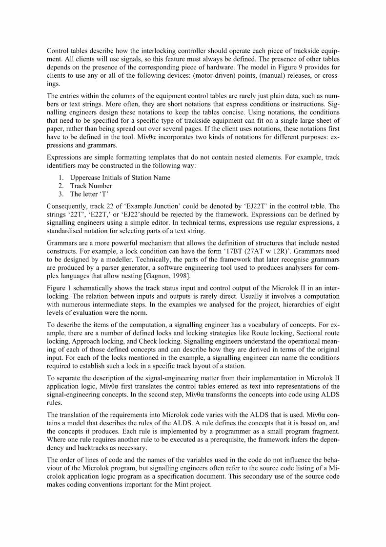
Users, Roles and Responsibilities Up to this point, we have discussed strategies that can manage variability and reuse, but we have not defined who would actually carry out the necessary work. Figure 10 shows the three levels of abstrac-tion of the Μίνθα framework, and the corresponding roles and responsibilities.
Figure 10 User roles in the Mint project
The software engineer works on the framework itself, including the features it offers as choices for the definition of clients and the process it enforces on the signalling engineer via the tool. For exam-ple, if a new type of trackside equipment, for example an "Eurobalise" transceiver, as used in the Eu-ropean Train Control System, is introduced, the feature model has to be extended, so that this type can be chosen in the development of a tool. This leads to a new release of the framework.
The domain engineer works by making choices in the feature space set out by the software engineer, and by filling in the internals of an empty copy of the framework, to complete it into a product for a specific client of Ansaldo: a client-specific Mint tool. For example for Queensland Rail Regional, the domain engineer would select the features that the regional control table contains, select the notations used in the table, and encode the rules of the QRR ALDS, in terms of the framework's ALDS model.
The signalling engineer uses the client specific tool provided as the result of the domain engineer’s work to generate Microlok application logic from control tables and track layouts. For example, the signalling engineer could enter the Broadlea, Mallawa, and Wotonga stations for the QRR’s line dup-lication project on the high-demand coal line into the QRR-specific Mint tool.
Roles are not rigidly mapped to users. Frequently, the skill-sets of an engineer will allow her or him to work on two levels of the framework. For example, the role of the software engineer needs to be filled with someone who has substantial experience in the development of model-driven software. This per-son also models the choices available in defining a tool. From that experience, a software engineer will usually work as a domain engineer when there is no maintenance to be done. A domain engineer will initially be a person trained in the application of modelling tools and programming. However, as the framework matures, programming tasks will become less frequent. Consequently, it will become feasible for signalling engineers to work in this role. Finally, signalling engineers are currently the intended users of the client-specific tools. However, with improved user guidance, it may eventually become feasible to allow clients to prepare their station definitions themselves, while Ansaldo audits them.
Defining a Tool Product To create a Mint tool for a new client, a domain engineer needs to obtain the ALDS that should in-clude a sample of a fully modelled station complete with track layout, control table, and resulting ap-plication logic.
The domain engineer then analyses the control table for the types of sheets and columns it contains. The domain engineer uses an editor that edits an import specification model. Each column in each sheet is imported in two steps. First, the syntax of an entry is checked. Syntaxes are defined using a notation, as explained above. A number of notations are built into the framework, but if the client re-quires new ones, these need to be defined at this time. The syntax check ensures that all entries are lexically and orthographically correct so that they can be meaningfully interpreted. The syntax check is followed by a semantic translation to concepts. Semantic translation ensures that the items can be interpreted as a set of requirements for generating code for an interlocking. This phase reveals omis-sions and inconsistencies. For example, if a locking condition requires a set of points to be normal, but the points are not listed in the points table, this constitutes a semantic error.
In some cases, the conditions for locks can be derived from the track layout using a program. For ex-ample, all tracks on the approach side of the signal contribute to the locking condition for an approach lock. In the control table this condition is often defined using a signal-engineering expression. For example ‘17BT (27AT w 12R)’ in the Queensland Rail signalling language defines that the described signal is approach locked if track segment 17B is occupied, or if track segment 27A is occupied while point 12 is set to reverse. The semantic import does not analyse such conditions. It accepts the defini-tions of the signalling engineers. However, validation of such conditions is possible with the infra-structure provided in Μίνθα.
For each column of the control table, a mapping to concepts has to take place. To achieve this, each column has a small translation program associated with it. These programs are written in the Java programming language. As with notations, ready-made programs can be chosen for a number of col-umn types. A schema model defines which types of translation programs are acceptable to which types of notations.
The domain engineer can now test the import producer by entering the sample station into an Excel worksheet and running the translation to concepts. If an entry is not accepted syntactically, the syntac-tic conditions may be defined too tightly or the entry needs to be corrected. For the semantic test, the domain engineer has to consult a signalling engineer and validate the concepts that have been pro-duced by hand. The programs that translate the entries produce a log, so inaccurate translation can be traced back to the originating component.
After establishing the concepts, they can be translated to Microlok code. For this, the domain engineer analyses the dependency rules that the ALDS describes. For example, the computation of an approach lock for a signal usually depends on the computation of proved track information, which in turn de-pends on information from the track circuits. The domain engineer describes the dependencies and the corresponding code that implements the production of output Microlok code lines. It is common for rules to offer production behaviour that is conditional on inputs. These cases deserve special attention and need to be discussed with a signalling engineer.
To test the process, the domain ts that were computed from the e pieces of track-side equipment that the interlocking should control, and a list
the inputs. If that is not the case, it looks for a rule that can produce the prere-
, each derivation trace is reviewed with a signalling engineer. In case the
the source code, the rules to be used to sort the equations, and the boilerplate into which they
is model and a corresponding parser for a textual notation are part of the
t-description model. This model is defined by the domain ibes the format of the control table Excel file, the
information into the control table, and the rules of code generation applied. It
the control table file (instance). The
non, 1998].
licitly governs which parser is used to analyse the cell content.
ck that is not defined, the input
engineer provides the set of concepcontrol table, a list of thof available control inputs like track circuits and train control system route calls. The generation algo-rithm then seeks the rule that produces the control output. If it finds it, it checks if the existing pro-gram already contains a representation of the prerequisites of the rule, or if the prerequisites can be satisfied directly fromquisite. Either the process is repeated until all requirements are satisfied, or the program runs out of rules it could attempt. The result is a viable but raw program that consists of unsorted lines of code that use arbitrary variable names and does not have the required header and footer comment sections.
To test the generation systemsystem has chosen a different rule than anticipated by the signalling engineer, the rule system is ambi-guous and has to be made more specific. If the system fails to derive a solution, the partial traces indi-cate where rules will have to be added.
For the last step, the domain engineer has to define the rules that determine the names of variables for use inare to be inserted. The Μίνθα framework currently only includes a facility for the naming of variables.
Architecture of the Framework From a technical point of view, the Μίνθα framework consists of a set of Eclipse plugins, that are grouped into features. Features are packages of related functionality for installation purposes.
All clients require a model of the track layout and the equipment installation. The scope of equipment and layout is finite, so thframework and included in every client. The track layout information is imported as the first step in the transformation process.
The specifics of a client are stored in a clien resource in the tool. It descrengineer and stored as a
erules that transcribe this used to control the varying aspects of the client workflow, loading varying models and process steps, as described in the following paragraphs. Currently, this model is interpreted at runtime of the client tool, but it could be compiled.
To input the control table from excel, the client description model defines the format of an excel file (schema), while another model stores the content retrieved frommodel that stores the content does not vary; it describes a list of tables, which express the cells of the sheets in the workbook. Most cells will contain simple data types, but others contain expressions in a signal engineering language. To describe these languages, a library is provided, that contains a parser and storage model for each expression, and the library is included with each client. The model is an EMF model and the parser is a SableCC parser [Gag
To build these modules quickly, we have developed a tool that translates SableCC grammar defini-tions to eCore models, and generates a transcription program that imports the text from the data struc-ture of the parser to the structure of EMF. The client description model governs which internal model is allocated for each cell, which imp
The import into the content model of the control table prevents syntactical errors. Contents that cannot interpreted in the way the column requires are rejected. The second step is a transcription from the import model. It invokes a transcription handler on each column. Here, a Java class is used to iterate over the model and transcribes the information to the model. The domain modeller defines these han-dlers based on a library of default implementations. During the transcription, simple semantic checks are performed. For example, if an expression references a signal or trais rejected.
The target of this transcription is the intermediate model of the control table. The model is defined in two pieces: a core model of common concepts is pre-built as part of the framework libraries and a
client-specific extension that is specified by the domain engineer to express any requirements that the core does not cover.
After this phase, the semantic code generation is carried out. For each client, a set of rules defines how to produce outputs for controls, like signal settings and points motor controls. The transformation works backwards from the required outputs towards the inputs. Each rule is listed as an entry in the
code reordered to conform to the client’s
f challenges. Μίνθα addresses these challenges in the
• The definition of transformation rules for the ALDS requires a slightly higher degree formalisa-tion of the rules. This helps to consider cases that the example-based approach may not have cov-ered. If the resulting code is not altered after the generation, a change in the ALDS rules can be accommodated by regenerating the software for all stations, reducing the cost for rework.
• The framework explicitly models the variability between clients, with a view to a homogenous approach to projects in the business.
Framework Reuse The Μίνθα framework implementation is quite large because it models aspects of signalling at a fun-damental level. While it enables the generation of Microlok application logic, this single application purpose is probably not sufficient to justify the cost of construction and upkeep of the framework. This section provides three reuse applications of Μίνθα components: to automate the drawing of track layout schematics, to simulate the movement of trains in a station for testing purposes, and to generate code for other controllers than the Microlok II.
Track Layout Diagrams Track layouts are currently produced using Computer Aided Design (CAD) drawing programs. The diagrams show the full detail of the installation and the layout is organised around the physical ar-rangements of the tracks in the station. These diagrams are important in the physical design of the sta-tion, but they are not ideal for analysis and design of application logic, because they contain too much information. For example, to analyse the interplay of main signals with points and tracks, the presence of derailers, the number of detection rods per point, variable speed indicators and releases are not ne-cessary. Μίνθα is able to produce track layouts for stations from its track-layout model. The projec-tions are selective, so they only show specific parts of the network or specific features. The layout is performed by the automated graph-drawing package Graphviz [Gansner, 2003]. This program does not draw the track pieces to scale. It spaces them evenly so they can be easily analysed. The drawing tool is experimental and it lacks t owever, these constraints can be
ALDS model, which is referenced from the client-description model. The implementations of the rules are provided by the domain modeller in the form of Java classes. The outputs of the rules are stored in a model of a Microlok II program that is part of the framework.
After this, variables need to be renamed and the lines ofconventions for source code presentation. This step does not change the semantics of the program and the framework currently does not implement it. However, the client-description model is already de-signed to express the conventions.
Finally, the Microlok II program model is written out to text form. This is done using the Java Emitter Templates technology that is part of EMF.
Addressing the Domain’s Challenges The section on page 5 introduced a number ofollowing ways:
• The number of turn-around loops for tests is reduced, as the machine-generated code eliminates errors of oversight. The framework allows testing the transformation earlier in the process and with more and more varied inputs.
he ability to bind items to a grid. Hintroduced as future work.
Train Animator Interlockings are tested in practice by simulating the movement of trains in a model of the interlock-ing. Ansaldo uses the Microlok Interlocking Simulator System (MISS) for this purpose. MISS con-
sists of a screen simulation of the interlocking, a physical Microlok card-file that includes the Micro-lok CPU board and any other periphery boards, and interface software that interprets the information returned from the Microlok. Signalling engineers working as principles testers place trains in the sta-tion simulation and methodically observe the response of the Microlok controller. This approach takes substantial time and is expensive to repeat in case a fault is discovered in the application logic.
The animation is designed along the principles of a game. The animator tries to cause a hazardous situation while the application logic tries to prevent it. The animator works with a maximum of two trains that stand, move, or disappear. A train has to enter from the edges of the layout. In the current version, trains do not make shunting moves or split. The animator uses the track-layout model to de-
checkers.
rs for short, identify an assignment of variables of a Boolean formula
ave been used successfully on specific examples, but not as general strategy
pproaches and replace
estinghouse and Smartlock by Alstom, which are all descendants of the
termine the possible directions of moves, and a simulation state model to store the state of the game. The animator is driven by the ModelJUnit MBT tool [Utting and Legeard, 2006]. ModelJUnit accepts a description of the current state – in this case, the occupation of tracks and setting of the signals and points – and a description of operations – stand, move, appear and disappear – and their enabling con-ditions – for example, a train will not move past a danger signal. ModelJUnit selects a legal move ac-cording to a strategy and then waits for the interlocking to respond.
A drawback of the approach is its inability to function without a corresponding MISS installation. This connection is not trivial due to the technical complexities of the protocols that still need to be implemented. Currently we are simulating the responses of the interlocking by hand.
An alternative to the approach above is the use of boolean logic tools such as satisfiability solvers and model
Satisfiability solvers, SAT solvethat will render that formula true. In the rail domain, a SAT solver can be used to ensure that the Boo-lean logic formulae implemented in the controller program can never produce a hazardous outcome. SAT solvers h[Haxthausen and Peleska, 2007]. One of the leading verification companies in the field, Prover Tech-nology AB, has based their service around a SAT solver [pro, 2007].
Model checkers unfold a state space and can show that specific conditions hold. In the rail domain, a model checker can be used to ensure that all state transitions of the station will result in corresponding computations of the interlocking. Our group has previously applied model checkers to this problem with good success. However, the model checker has to be adapted to the problem and the interpreta-tion of counterexamples can be challenging [van den Berg et al., 2007]. In addition, the approach has size limitations.
Both approaches rely on modelling of the interlocking, which requires substantial expertise and is fur-ther away from the established testing protocols. Mint aims to support existing athem gradually. Further, both approaches gain additional complexity when the time-based aspects of the controller program are included in the proofs. This usually requires the use of a form of temporal logic to express the constraints, and temporal logic constructs are more difficult to prove than regular Boolean logic.
Code Generation for Other Controllers The language used to express the Microlok application logic is quite similar to that of other popular controllers like Westlock by Woriginal Solid State Interlocking jointly developed by British Rail, GEC-General Signal, and Wes-tinghouse Signals Ltd in the UK in the 1980s. Since Μίνθα is being developed in partnership with Ansaldo, the focus of our work lies with Ansaldo’s components. However, the code generation facili-ty can be adapted to generated relay-based code for other interlocking products.
FUTURE RESEARCH DIRECTIONSThe current version of the Μίνθα framework addresses the requirements of an automated approach from models to application-logic code. To the signalling engineer that uses a Mint tool, the process appears as one atomic step with no intermediate products. This design leads to several challenges to the approach, which still require solutions.
Back-End Synchronisation Without access to and information about the intermediate products of the tool chain, signalling engi-
single alteration can affect the behaviour of the
ements, but other parts of the definition of the tool may also
version
us tools and issues are tracked sepa-
neers have to make changes either to the control table that serves as input or to the application logic that serves as the output. While signalling engineers often complain about a lack of quality in control tables, the usual response to the discovery of an issue is to update the application logic directly. These alterations pose safety threats as they do not necessarily have the safety properties of code generated from the patterns of the ALDS that have been reviewed by several parties with special care. The al-tered code may or may not perform in an identical or even improved manner over the automatically generated version. As with other software systems, a whole system voiding all safety properties. This would not be an issue if it were possible to prove the functional equivalence of two application logic programs. However, this is a very hard problem, due to the temporal and interleaving nature of the logic introduced by the timers in the system. Further, the computation time required for finding the match between two programs, even if a solver is available, grows exponentially with the length of the program.
Regardless of these limitations, signalling engineers will often prefer the application logic to have a specific form that does not follow from the rules of the ALDS. In these cases, the minimal service that Μίνθα can render is to manage changes to the output, so they are at least repeatable. We intend to ex-amine an approach that parses the changed output provided by the signalling engineer and subse-quently applies the changes as patches to the output on every subsequent generation run. Since the effect of the patch on the behaviour of the application code cannot be understood by looking at the rules of the ALDS, it will be essential to mark such passages in a way that ensures that they are re-viewed by a signalling engineer before they are used further in the development process.
Version Management of Models The Μίνθα framework uses a number of models to define the requirements of a Mint tool: the control table schema, the set of import rules, ALDS dependencies, ALDS rules, and coding conventions. The tool is then used on models of the track layout and control table. In the course of a project, the ALDS is usually updated to include new requirchange. The control tables of stations also change over the course of a project. This leads to a combi-natorial version management problem. Which version of the station was compiled with whichof the tool to produce the application code? Intensive use of Mint tools will require a strategy that identifies the models involved in the production of an output. Current research in model-based com-parison tools may provide assistance with this issue.
Impact Analysis Each step of the generation process of the Mint tool transforms the original input information pro-vided by the signalling engineer. In the section above, we have described the limitations of patching the output of the process. Signalling engineers prefer patching to re-generation because they feel that it is easy to verify its impact. To convince signalling engineers to alter the control table input instead of the application logic output, the engineers must be provided with information that simplifies the task of change verification. In other words, the Mint tool must be capable of describing the impact of a change in terms of changes to the output. While it is possible to trace the execution of the various transformation rules, it would be necessary to present the output to the signalling engineer, as de-scribed at the of the section on Back-End Synchronisation.
CONCLUSION Today’s signal-engineering processes are still often based on paper documents produced by a variety of unconnected computer-supported tools like CAD programs, word processors, and code compilers. Artefact descriptions are transcribed by hand between the variorately by the tools. Where software support has been developed for signal engineering, the software is bespoke. The framework described in this chapter applies model-based techniques to the problem of signalling application logic development. This kind of framework supports the integration of these currently disparate tools and processes into a common flexible framework that contains and serves all phases of the signal-engineering process. Μίνθα is a demonstration of how this can work.
Beyond the open research issues, Μίνθα needs validation in industrial application. For our partner this implies training of the software-engineering staff in order to manage, support, and expand the frame-work, and to inform signalling engineers to explain the operation of the tool. To ease adoption in the workplace, Μίνθα itself would benefit from more documentation and should be expanded by process guides known as wizards and cheat sheets that support the users in the process.
From this perspective, it is beneficial for signalling engineers and the organisations they work for to increase their awareness of software-based signal-engineering frameworks and consider how and
aker, P., Loh, S., and Weil, F. (2005). Model-driven engineering in a large in-
2000). Generative Program-
E. and Peleska, J. (2007). A domain-oriented, model-of railway control systems. In Formal Methods and
EEE (1987). IEEE Standard for a Versatile Backplane Bus: VMEbus.
d oc.
re (ver-
eworks and Embedded Control Systems, volume Computer Science. Springer.
les. Electron. Notes Theor. Comput. Sci., 174(4).
008). The product line hall of fame. In SPLC ’08: Proceedings of the
when they can be adopted into their processes.
REFERENCES [Baker et al., 2005] Bdustrial context — motorola case study. In Briand, L. and Williams, C., editors, Model Driven Engi-neering Languages and Systems, volume 3713 of Lecture Notes in Computer Science, pages 476–491. Springer Berlin / Heidelberg. 10.1007/11557432_36.
[Budinsky et al., 2003] Budinsky, F., Steinberg, D., Merks, E., Ellersick, R., and Grose, T. (2003). Eclipse Modeling Framework. Addison Wesley Professional.
[Eisenecker and Czarnecki, 2000] Eisenecker, U. W. and Czarnecki, K. (ming: Methods, Tools, and Applications. Addison-Wesley.
[Gagnon, 1998] Gagnon, E. (1998). SableCC, an object-oriented compiler framework. PhD thesis, McGill University.
[Gansner, 2003] Gansner, E. R. (2003). Drawing graphs with GraphViz. Technical report, AT&T Bell Laboratories, Murray Hill, NJ, USA.
[Haxthausen and Peleska, 2007] Haxthausen, A. based approach for construction and verification Hybrid Real-Time Systems, pages 320–348.
[IEEE, 1987] I
[Kastner et al., 2009] Kastner, C., Thum, T., Saake, G., Feigenspan, J., Leich, T., Wielgorz, F., anApel, S. (2009). Featureide: A tool framework for feature-oriented software development. In Pr
EE 31st Int. Conf. Software EngineeriIE ng ICSE 2009, pages 611–614.
[OMG, 2001] Object Management Group, (2001). Model Driven Architecture (MDA). Technicalreport, Object Management Group, Framingham, MA.
[OMG, 2005] Object Management Group, (2005). Unified Modeling Language: Superstructusion 2.0). Technical report, Object Management Group, Framingham, MA.
[Pasetti, 2002] Pasetti, A. (2002). Software Fram2231 of Lecture Notes in
[Prover, 2007] Prover Technology AB, (2007). Prover iLock. Company Whitepaper.
[Utting and Legeard, 2006] Utting, M. and Legeard, B. (2006). Practical Model-Based Testing: A Tools Approach. Morgan-Kaufmann.
[van den Berg et al., 2007] van den Berg, L., Strooper, P., and Johnston, W. (2007). An automated approach for the interpretation of counter-examp
[Weiss, 2008] Weiss, D. M. (22008 12th International Software Product Line Conference, page 395, Washington, DC, USA. IEEE Computer Society.
ADDITIONAL READING SECTION Allan, J.; Arias, E.; Brebbia, C. A.; Goodman, C. J.; Rumsey, A. F.; Sciutto, G. & Tomii, N. (2008), Computers in Railways XI, WIT Press.
Banci, M. & Fantechi, A. (2005), Instantiating generic charts for railway interlocking systems, in 'FMICS '05', ACM Press, New York.
Berkenkötter, K. (2007), OCL-based validation of a railway domain profile, in 'MoDELS'06', Sprin-ger-Verlag, Berlin, Heidelberg.
Chevillat, C.; CarrinGeneration of Interl
gton, D. A.; Strooper, P. A.; Süß, J. G. & Wildman, L. (2008), Model-Based ocking Controller Software from Control Tables, in 'ECMDA-FA', Springer-
ocking
Railway In-
delberg.
Verlag, Berlin, Heidelberg.
Endresen, J.; Carlson, E.; Moen, T.; Alme, K.-J.; Haugen, Øy.; Olsen, G. K. & Svendsen, A. (2008), Train Control Language - Teaching Computers Interlocking' , Computers in Railways XI, WIT Press.
Gjaldbæk, T. (2002), 'Modelling railway interlocking systems', Master's thesis, Informatics and Ma-thematical Modelling, Technical University of Denmark, DTU.
Hon, Y. M. & Kollmann, M. (2006), Simulation and Verification of UML-based Railway InterlDesigns, in 'Automatic Verification of Critical Systems', INRIA.
Magyla, T. (2001), Evaluation of EBILOCK 950 interlocking system implementation using analytic hierarchy process in 'Transport', Technika, Vilnius.
Majzik, I.; Micskei, Z. & Pintér, G. (2007), Development of Model Based Tools to Support the De-sign of Railway Control Applications, in 'SAFECOMP', Springer-Verlag, Berlin, Heidelberg.
Petersen, J. L. (1998), Automatic Verification of Railway Interlocking Systems: A Case Study, in 'FMSP-98', ACM Press, New York.
Rástocný, K.; Janota, A. & Zahradnk, J. (2004), The Use of UML for Development of a terlocking System, in 'SoftSpez Final Report', Springer-Verlag, Berlin, Heidelberg.
Svendsen, A.; Olsen, G. K.; Endresen, J.; Moen, T.; Carlson, E.; Alme, K.-J. & Шystein Haugen (2008), The Future of Train Signaling, in 'MoDELS'07', Springer-Verlag, Berlin, Hei
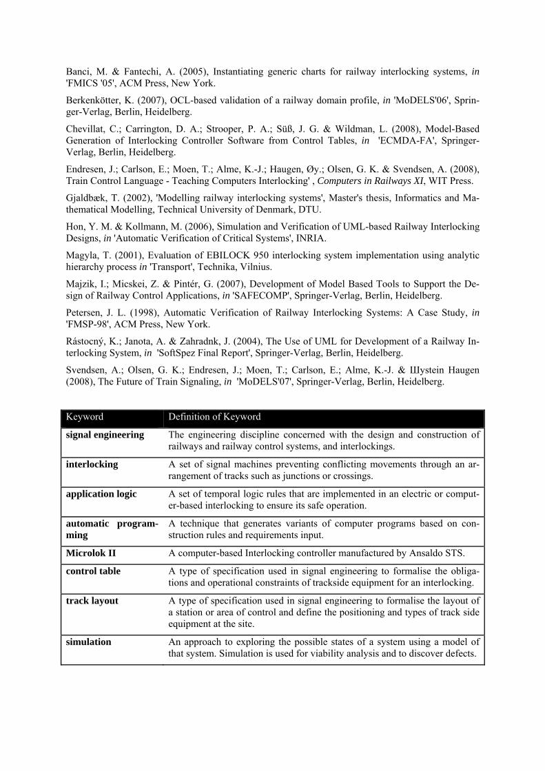
Keyword Definition of Keyword
signal engineering The engineering discipline concerned with the design and construction of railways and railway control systems, and interlockings.
interlocking A set of signal machines preventing conflicting movements through an ar-rangement of tracks such as junctions or crossings.
application logic A set of temporal logic rules that are implemented in an electric or comput-er-based interlocking to ensure its safe operation.
automatic program-ming
A technique that generates variants of computer programs based on con-struction rules and requirements input.
Microlok II A computer-based Interlocking controller manufactured by Ansaldo STS.
control table A type of specification used in signal engineering to formalise the obliga-tions and operational constraints of trackside equipment for an interlocking.
track layout A type of specification used in signal engineering to formalise the layout of a station or area of control and define the positioning and types of track side equipment at the site.
simulation An approach to exploring the possible states of a system using a model of used for viability analysis and to discover defects. that system. Simulation is