profitable use of information technology in the design of ships ...
432
PROFITABLE USE OF INFORMATION TECHNOLOGY IN THE DESIGN OF SHIPS AND OIL PLATFORMS COPENHAGEN MARCH 3 - 5 1993 COURSE PROGRAMME Wedenesday 2 March 1993 Recent CAD Developments in a Research Environemnt (Jan Baatrup and J. Juncher Jensen) 09.30-12.15 The importance of user-friendliness in the use of CAD/CAE systems. Efficient compartment layout in accordance-with new IMO rules for probabilistic damage stability analysis of dry cargo ships. A case study: Design of a rescue vessel using a CAD/CAE system - Demonstration. CAD/CAE/CAM In The Ship and Offshore Industries (George Snaith) 13.30-16.15 The Concept of a Product Database (PDB) PDB using traditional tools and media. 2-D drafting of 3-D physical models. 2-D vs 3-D interactive graphic systems. Integration vs interfacing. Shipbuilding CAD/CAM Systems Integrated database. Topological modelling. Thusday 4 March 1993 08.30-11.30 Technology & Practical Application of NURB Splines Creating novel hull forms. Mapping (fitting & fairing) of empirical offsets.. Intrinsic geometric fairness. Measuring/assessing geometric fairness/unfairness. Good/bad practices.
-
Upload
khangminh22 -
Category
Documents
-
view
3 -
download
0
Transcript of profitable use of information technology in the design of ships ...

PROFITABLE USE OF INFORMATION TECHNOLOGY IN THE DESIGN
OF SHIPS AND OIL PLATFORMS
COPENHAGEN
MARCH 3 - 5 1993
COURSE PROGRAMME
Wedenesday 2 March 1993
Recent CAD Developments in a Research Environemnt (Jan Baatrup and J. JuncherJensen)
09.30-12.15 The importance of user-friendliness in the use of CAD/CAE systems.
Efficient compartment layout in accordance-with new IMO rules forprobabilistic damage stability analysis of dry cargo ships.
A case study: Design of a rescue vessel using a CAD/CAEsystem - Demonstration.
CAD/CAE/CAM In The Ship and Offshore Industries (George Snaith)
13.30-16.15 The Concept of a Product Database (PDB)
PDB using traditional tools and media.2-D drafting of 3-D physical models.2-D vs 3-D interactive graphic systems.Integration vs interfacing.
Shipbuilding CAD/CAM Systems
Integrated database.Topological modelling.
Thusday 4 March 1993
08.30-11.30 Technology & Practical Application of NURB Splines
Creating novel hull forms.Mapping (fitting & fairing) of empirical offsets..Intrinsic geometric fairness.Measuring/assessing geometric fairness/unfairness.Good/bad practices.

Practicing Concurrent Engineering
Product/production/producibility engineeringVirtual project teams using IT networks.
New Systems for Managing the OperationalDocumentation of Ships & Offshore Platforms
Digital imaging.Document management systems.Classification/yards/suppliers.
11.30-14.30 Information Logistics (Tor Olav Kristoffersen)
Objectives of IL and controlling information.Databases and competitive information processing.
14.30-16.15 Cals and Concurrent Engineering (Mike Potter)
ILS/LSA Overview - Optimising Programme & Design Processes.
Computer-aided Acquisition and Logistical Support (CALS) andwhat it has to offer.
Friday 5 March 1993
08.30-11.15 LSA (Logistic Support Analysis.CALS - Overview - US Initiative and its application to commercial projects.Integrated Logistic Support - Optimising programme planning anddesign.processes.CALS Applications and Organisations in Europe.CALS Future Development in Concurrent Engineering and its Relationshipto CALS and ILS/LSA.
11.30-15.15 (Tor G. Syvertsen)
New technologies - open and distributed systems, communications.Product data modelling and marine applications.Perspectives in information management.
15.30-16.00 Summary Conclusions.
K

PROFITABLE USE OF INFORMATION TECHNOLOGY
IN THE DESIGN AND FABRICATION OF SHIPS AND OIL PLATFORMS
COPENHAGEN
MARCH 3 - 5 1993
List of Delegates Country
Mr. K. AlsOdense Steel Shipyard Ltd. Denmark
Mr. B. BangsvigBurmeister & Wain Skibsvarft A/S Denmark
Mr. G. BjomssonBurmeister & Wain Skibsvrrft A/S Denmark
Mr. E. BoasBurmeister & Wain Skibsvrrft A/S Denmark
Mrs. M. BradleyLloyd's Register of Shipping United Kingdom
Mrs. E.A. BusLOGOS Industrial Automation The Netherlands
Mr. G. FiksdalMARINTEK
Norway
Ms. A. FritzenBurmeister & Wain Skibsvzrft A/S Denmark
Ms. M. HansenBurmeister & Wain Skibsvrrft A/S Denmark
Mr. E. HansenOdense Steel Shipyard Ltd. Denmark
Mr. N.B. MortensenBurmeister & Wain Skibsvwerft A/S Denmark
Mr. N.C. NielsenBurmeister & Wain Skibsverft A/S Denmark
Mr. Ole Norskov-LauritsenBurmeister & Wain Skibsvzrft A/S Denmark
Mr. J.L. RomeroIntergraph European Headquarters The Netherlands
Mr. H. S0rensenEngineering College of Elsinore Denmark
Mr. J. StamnesfetBurmeister & Wain Skibsvrrft A/S Denmark
Mr. J. ThomsenDet Norske Veritas as Norway
Mr. B. TrasboOdense Steel Shipyard Ltd. Denmark
Mr. P. VaagenesTotal Transportation Systems International A/S Norway
List of Presenters
Mr. J. BaatrupDepartment of Ocean EngineeringThe Technical University of Denmark Denmark
Dr. J. Juncher JensenDepartment of Ocean EngineeringThe Technical University of Denmark Denmark
Mr. T. 0. KristoffersenAker Engineering Norway
Mr. M.J. PotterTechnical Support International United Kingdom
Mr. G. SnaithPi-Sigma United Kingdom
Mr. T.G. SyvertsenInstitutt for Konstruksjonsteknikk, Trondheim Norway
(V

Short course onProfitable use of information technology in the design
and fabrication of ships and oil platformxs
Copenhagen 3-5 March 1993
Development or a CAD system for Ship Designin a University Environment
by
Jan Baatrup, Jacob Michelsen and Jorgen Juncher Jensen
Department of Ocean Engineering
The Technical University of Denmark
Building 101 E, DK-2800 Lyngby, Denmark
AbstractBased on 15 years of experience in developing computer aided design packages for ship design,
work is now in progress on our third generation system. The first system dated back to the late
seventies was implemented on the Hewlett Packard HP 9845 desktop computer. Then came the
HP 9000/520 computers on which our individual CAD programs were merged into an
integrated package involving ship definition, propulsion characteristics, hydrostatics and strength
assessments.
These earlier programs were all written in BASIC. The user was guided through the
calculations by selecting items from menu's.
Our new package consists of a completely rewritten code in FORTRAN for use on mainly
workstations with the UNIX operating system. Care has been taken to include the well-received
parts in the older BASIC versions in the new code. Especially, the new packages will also be
menu-driven.
Presently, the new system includes modules for hull design, compartment layout, loading
conditions, hydrostatics and intact and damage stability assessment according to the current
IMO rules.

1. Introduction
Since the late 1970s the department has developed computer programs for design of marine
structures. From the very beginning these programs were aimed at three purposes.,,~
Education
Due to the complexities of ships and offshore structures all practical problems must be solved
numerically even if the basic theory is simple, e.g. hydrostatics and linear elasticity. The
students must then have access to computer programs covering these items. When we started
our system development very few commercial programs were available for ship design. We
therefore felt that the development of individual programs based on theories taught in the
classroom were the most convenient way for the students to learn how to design a ship. Byimplementing the programs ourselves we also avoided the feeling of using "black boxes" in
which the relations between the input and output are somewhat obscure.
Industry
When the students have got experience and confidence in using these programs it was obvious
that they wanted to use them also after leaving the university for the industry. If the programs
should be beneficial for the industry they should, however, satisfy some requirements not
normally considered that important in a university environment:
- Completeness. The software should contain modules for all the pertinent analysesnecessary in the design phase.
- User-Friendliness. The package should be interactive with menus and includeautomatic check of indata with extensive warnings and error messages.
- Documentation. The theoretical background for the various modules should bedescribed in manuals including test examples. Also the results should be given in aself-explanatory output format making additional comments unnecessary.
- Common data base. The different programs should use as much as possible a commondata base for the ship in question. Thereby data need to be entered only once, and asource of error is thereby elimidnated.
- Reliability. The best way to get a reliable software package is to choose a systemalready in use in many different environments. It is also of great importance that thesystem is being kept updated regularly by the software developer with due considera-tion given to suggestions from the users.
- Portability. The problem of system portability from one computer to another is notof serious concern for the user as long as the system is being kept up to date. Often
2

systems made for a specificcornputcr work better, especially with respect to graphicalrepresentation than systems made without any use of special hardware requirements.
- Price. This is normally not a problem as university developed programs are rather in-expensive both in purchase and maintenance.
We put some serious effort in satisfying these items and the first version [1], [2] of our CADprograms for use on the Hewlett Packard HP 9845 was actually purchased by more than 60
clients of which about 40 were from Denmark. We believe that the main reason for this successwas the very close cooperation between the programmers and the industry in making
modifications and improvements in the programs.
Since about 1984 the number of commercially available CAD package has increased drastically[3]. These packages range from smaller versions with only line definition and hydrostatics to
very large programs covering nearly all parts of the design phase from preliminary lines to
system design and working drawings. A university department will seldom, if ever, have themanpower required nor the objective to develop very large and complete CAD systems. Rather
the university department will focus on areas which are important from a teaching or researchpoint-of-view. At our department the second version of our CAD system [4] therefore becomescentred around preliminary design including hull surface design [5], hydrostatics, resistance and
propulsion and hull structural design [6]. Compared to the first version the second version
became a real integrated system using the file magement system of the Hewlett Packard HP
9000/520. Although a lot of improvements was added to the programs the code was still writtenin BASIC. Thereby, the tests of the new system became much less time-consuming than if thecode was completely rewritten. The number of users of this system became only 8 mainly
because of the high hardware cost.
Preliminary design programs are very well suited for desktop computers as the above mentioned
HP computers. However, with the advent of PC and UNIX-based workstations the market for
desktop computers changed radically. Our programs written in BASIC became somehow
outdated although they can run on PC with a special HT-BASIC operating system. After some
serious thoughts we decided to use our experience in the field to develop a completely new
system, now implemented in FORTRAN 77. The code should be fully portable with thehardware-dependent routines kept as few as possible. The first version of this system is now
fairly well tested. In the following chapters its overall architecture as well as the individual
modules will be described and exemplified.
Research. T'he final reason for a university department for developing a user-friendly CAD
system is chat it forms the skeleton on which new research results easily can be communicated
3

to the inlustry. In the first two BASIC versions such examples are stochastic predictions oflinear sea loads, offshore pipelaying, rational design of ship sections, torsional-horizontal hull
vibrations and various hull surface definition and transformation procedures. In the newFORTRAN version a non-linear, stochastic sea load module will be included, able to predictthe difference between the extreme wave-induced sagging and hogging stresses. Anothermodule is concerned with the structural design of sandwich structures. This could be an
interesting design tool considering the increased focus on fast ferries and cargo vessels.
This way of transferring research results tothe industry is very important, we think, both forthe university and the industry. For the university, it give a fast feed-back on the usefulness and
applicability of new research results or design procedures. Thereby modifications, alternationsor new point-of-views can rapidly been considered for solving the common goal: to obtain thebest possible ship taking the available technical knowledge and the economical andenvironmental constraints into account.
2. System layout
To be able to handle the development of an integrated system for preliminary design of ships
in a university environment a very modular layout is used. The preliminary design system I-
ship is developed around a main executive which controls the execution of and the data
exchange between a number of individual programs. These individual programs are henceforward refered to as modules. The reason to select this modular layout is that in this way asmall workgroup, often only one person, is able to develop and test the modules according tosome general specifications. The modules available in the I-ship system can be divided into five
groups: geometry definition, hydrostatic calculations, strip theory, midship section design, hullgirder response plus modules for structural analysis by the use of the finite element method.Below is given a very short description of the functionality of the major modules in the first
four of the five groups.
Geometry definitionFMDA Definition of ship hulls from standard shapes
LINE Ship hull definition
APDG Definition of appendagesHFIF Export ship hull using IGES and DXF file format
CPDF Compartment definition
Hydrostatic calculations
CAPA Capacity calculations
4
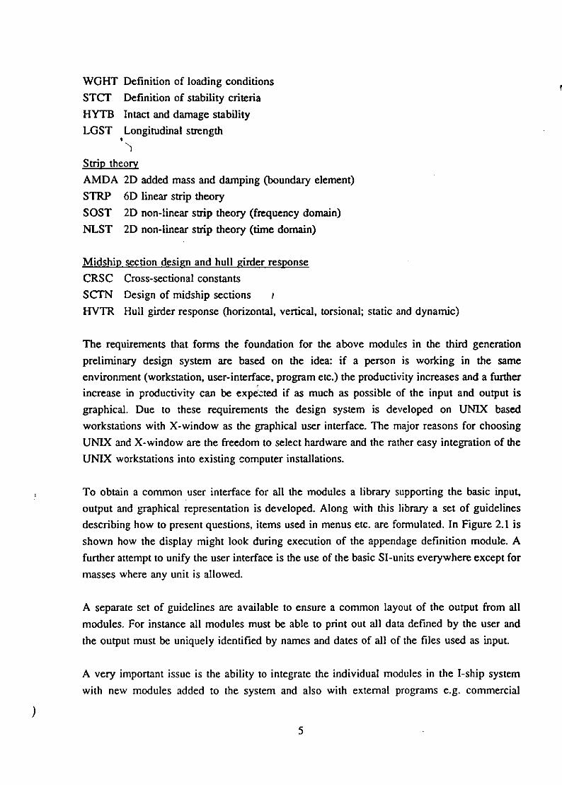
WGHT Definition of loading conditions
STCr Definition of stability criteria
HYTB Intact and damage stability
LOST Longitudinal strength
Strip theoryAMDA 2D added mass and damping (boundary element)
STRP 6D linear strip theory
SOST 2D non-linear strip theory (frequency domain)NLST 2D non-linear strip theory (time domain)
Midship section design and hull girder response
CRSC Cross-sectional constants
SCTN Design of midship sections ?
HVTR Hull girder response (horizontal, vertical, torsional; static and dynamic)
The requirements that forms the foundation for the above modules in the third generation
preliminary design system are based on the idea: if a person is working in the same
environment (workstation, user-interface, program etc.) the productivity increases and a furtherincrease in productivity can be expected if as much as possible of the input and output is
graphical. Due to these requirements the design system is developed on UNIX based
workstations with X-window as the graphical user interface. The major reasons for choosing
UNIX and X-window are the freedom to select hardware and the rather easy integration of the
UNIX workstations into existing computer installations.
To obtain a common user interface for all the modules a library supporting the basic input,
output and graphical representation is developed. Along with this library a set of guidelines
describing how to present questions, items used in menus etc. are formulated. In Figure 2.1 is
shown how the display might look during execution of the appendage definition module. Afurther attempt to unify the user interface is the use of the basic SI-units everywhere except for
masses where any unit is allowed.
A separate set of guidelines are available to ensure a common layout of the output from all
modules. For instance all modules must be able to print out all data defined by the user and
the output must be uniquely identified by names and dates of all of the files used as input.
A very important issue is the ability to integrate the individual modules in the I-ship system
with new modules added to the system and also with external programs e.g. commercial
5

IVCW S(TiU•1 APtO/t. 030t I
C ..L m .*.o. .. ............
. ............
31.ct is nber I-il)
"I /off I
Figure 2.1 Display during definition of appendages.
available CAD systems, FEA systems etc. The I-ship system offers this integration in two levelseither as a set of subroutines/functions to access the data created by each module or by usingstandard file formates. For most of the modules a set of subroutines/functions are available toaccess and manipulate the data usually defined in the module. On the basis of thesesubroutines/functions is it possible to develope new modules expeditely that are completely
integrated with the already existing modules. Figure 2.2 illustrates how it is possible to createa complete definition of all the compartments in a ship from an externally developed module
by the use of the subroutines/functions developed to support the integration of the compartment
definition module.
Another advantage of using these subroutines/functions is that external programs are able toexecute most of the features within a module without having to invoke the module. The otherway to integrate the I-ship modules with other programs are by the use of standard files. The
modules dealing with geometric representations are able to write the geometry to files usingthe IGES, DXF and to some extent the SDRC Universal file format.
6

CPDF
deiiIo funcion
•subroprigram
Compartment External
Figure 2.2 Accessing compartment data using subroutines/functions.
3. Hull definition
The hull definition is done in the LINE program. It is the purpos, of this program to create and
modify the geometry of the outer hull of ships. A complete mathematical description of the hull
surface should of course encompass a mathematical surface definition like B-spline surfaces.
But for many purposes it is sufficient to use a curve definition and therefore it has been
decided to split the hull definition into two parts: one part is the definition of a wireframe of
curves (LINE) and the other part is the definition of B-spline surfaces based on these curves
(BSRF). It has been the intention to put as few restrictions as possible on the feasible shapes
but at the same time stick to the well proven traditions for ship design. This means that the use
of perpendicular intersections also forms the basis for this program.
A simplified layout of the data structure in LINE is shown in Figure 3.1.
The data structure can handle multiple hulls in the same hull definition. Each of the hulls holds
data for its symmetry plane and thresholds used to distinguish ambiguities among offset points
and intersections. A number of curves can be referenced by each hull. These curves has a type
and some information about its definition plane used for plane curves. Furthermore one or more
subcurves constitute a curve, thereby enabling multiple parts of a hull to be treated as one
curve. A good example could be a station curve in the bulbous bow part of a ship. Here one
subcurve could form the bow and another the stem. If this station were to be moved both
7

and.
Hull Symmetry and planeThresholds
Curve Curve type- Definition
plane
Subcurve Symmetry and planePoint type Closedness
Tangent vectors
Semn yeOffset point Coordinates
Figure 3.1 Simplified data structure for the hull definition program.
subcurves would be moved equally when belonging to the same curve. The subcurves points
on to the offset points holding the coordinates (x,yz). A subcurve can have its own symmetryplane and can be open or closed as well. The offset points of a subcurve is given a point type
(described later) which affects the shape of the subcurve. Each point-to-point segment alsoholds a corresponding type which is inherited to future curves that intersect the segment. Theindividual point types is shown in Figure 3.2 along with its influence on the spline. It is seenthat there are four different ways to control tangent vectors at an offset point. The spline
formulation used is a cubic non-rational Hermite spline evaluated in 3 coordinates for allcurves. The reason for not using a rational spline in spite of its advantage when dealing with
conic sections is the difficulty in assigning suitable weights for intersection points added to acurve. Rendering and intersection of the spline is done by recursive subdivision which is a fast
dependable method.
The different curves are connected to form a wireframe in 3D space. This means that the offsetpoints are often shared by more than one curve and modification of such a common offset pointwill influence all the curves sharing it. There are some restrictions though. An offset point
shared by one or more plane curves can not be moved in directions that would violate those
curves. Also it is not possible to join or split curves at an offset point if plane curves are notkept plane. If these modification are necessary the type of the curves in question must be
changed to the general type which is not affected by the restrictions.
8

curvature continuous knuckle pointpoint
3 3
2I 2
1 1
tangent point (I) tangent point (II)
two tangents equal tangents
sheer point (1) sheer point (11)1
(I),,3' ' (II } ,)•
3
G) 2 2
sOheer determines the (oi) determines the
tangent on(fl) in#2 tangent on(I) in #2
Figure. 3.2 Point types for cubic Hermite spline.
The curves forming the hull definition are divided into the types given in Table 3.1.
It is a necessity to distinguish the curves by their type, because they behave different and it
enables the program to display the curves using different colours for each type. Plane curves
can be modified easily in a 2D graphics environment, where curve types having no planar
behaviour can only be dealt with in a 3D projection. Another difference is the restrictions put
on the plane curves in order to keep them plane. Apart from the curve types shown in table 3.1
three of the types representing the main coordinate planes are also available as so called
pseudo cun'es. These are slave curves that can be added to the hull to aid inspection during the
9

modification but they are not part of the hull definition itself. The user could at an early stage
where only the contour and some of the stations were present in the definition, add some
pseudo waterlines to evaluate the smoothness of the hull. Curve types are normally fixed butcan be changed for special purposes. If for instance the hull is rotated all pl1ane curves will
become of the generic 2D curve type.
Curves type Behaviour Pseudo type availabe
Station curve YZ-plane yes
Waterline XY-plane yes
Contour XZ-plane __________
Buttock XZ-plane yes
Deckline
Knuckle line
Genenic 2D curve Any plane
Generic 3D curve
Table 3.1 Curve types used in the hull definition program.
Although the most common way to deal with a new ship design is to modify an existing one,
one must be able to create new hull definitions also. Several ways are implemented for the
input of the more or less raw data when creating a new hull. These are:
"Generation of hulls from form data is a fast way to create a new hull when thegeneral shape and the principal dimensions are known. Currently only the hull formsfrom the prior BASIC system is included. New and more modem sets of hull formsare presumably required for this to be a valuable tool.
" Some primitive geometries such as a rectangular box, a pyramid, an ellipsoid and aWigley hull can be generated very easily and modified into the desired shape. This
way simple hull forms can be established within a short time.
" When having sketches of plane intersection curves (stations, waterlines orcontour/buttocks) these can be placed on a digitizing tablet connected to the computer,and feed into the program after a scaling is done. A special graphical menu isavailable for that purpose, kept as simple as possible for ease of use.
10

* If tables of offset point coordinates are most appropriate these can either be keyedin or read in from formatted ASCII files when running the program.
* Profiles defined using the program PRFL can also be incorporated into the hulldefinition. The plane profiles can be translated, rotated and scaled and are typicallyused for keels and rudders of sailing yachts.
It should be mentioned that conversion of the prior version BASIC hull definition files into thepresent standard is also possible. In the BASIC definition the hull definition comprised bothhull curves and appendages. This information is converted into a wireframe of curves and
appendages and stored separately in two data files of the new formats. The appendage
definition program APDG will be dealt with later.
An important aspect in a hull definition program is the tools available for the manipulation andinspection of the hull wireframe. Essentially the program should enable the user to define and
correct the hull in an easy and understandable way. Being an often complex geometric andtopological description this can not be accomplished without extensive use of graphic
techniques. In Figure 3.3 is shown an example of the common graphical user-interface in I-ship
as it looks in the hull definition program.
To go through the complete functionality of the manipulation menues would not be appropriatein this context but a few of the mostly used can be mentioned. Hulls can be created, modified,
copied and deleted. When modifying a hull curves can be treated the same way plus some extrafacilities. For subcurves a lot of possibilities exist, like inserting and deleting offset points,
joining or splitting at offset points, controlling point and segment types etc. Divers printoutsof hull definition data and plots of the hull are possible in LINE. An example output plot is
shown below in Figure 3.4.
All or only a subset of the curves in the hull definition can be selected within the hull
definition module and exported to most commercial CAD-systems such as AutoCAD, IDEASor Pro-Engineer. This is done by converting the curves into either a B-spline or a cardinalspline formulation and writing this into standard IGES or DXF interface files. The upcomingSTEP-standard has been investigated and the relevant parts will most likely be incorporated alsowhen the standard is fixed. A typical use of this interface facility is to use the hull definitionas a basis for the general arrangement being done in a more suitable drafting systems. A
general arrangement of a VLCC made in AutoCAD based on LINE is shown in Figure 3.5.
At present there has not been a sufficient need to implement an interface that allows curves to
be imported into the hull definition module via standard interface files like IGES and DXF.
II

C0 0D C CX - 0
0 C L 00 0O
0 - 0 1N DN ILN 0 E 0 Z Z z w~L
x 0
L I
4i
a
-I-
* . .0
C0 0
:0:E
0Z Z O
L4 L
U. 0 0 0o
Figure 3.3 Screen dump of hull definition program.
12

00
Nw
ac
000U0
00
o 19
0. 0. U
X0
0
1 0 0
oiur 3.Cxm l upt lto L
a1

*..4%
¾ '7 1
FZ;-' '
Figre3. Gneal rrngmet f aVLC ad i A toC
14r

-- -- - -- -
MIDSHIP -CRS SECTION------
CROSS ~ ~ ~ -------- --TOS-T RS ETIN OWR
-------- :--- I
I -Z E
* I IDS CRS SETO
CROS SCTONSAFTCRSS ECION FORAR
15

4. Appendage definition
Appendages are defined and modified in the module APDG. Volumes such as superstructures,
rudders, bow-thruster tunnels, Iweches etc are suitable for modelling with appendages. Like the
hull definition appendages can b'c defined in a graphics environment and displayed with its
correct size and orientation along with the hull lines. The appendages can be defined from a
set of volume primitives, such as pyraxnide stub, circular cone, part of sphere or a volume
defined by a number of profile curves. A profile can be rectangular, ellipsoid, a NACA-foil
profile or a user defined profile from PRFL. An appendage can be placed anywhere in- oroutside the hull, and it is indicated if the volume should be treated as a positive (add-on) or
negative (cut-out) volume. The hydrostatic data is found by integrating over plane panels that
are automatically generated over the surface of the appendage.
5. Compartment definition
With knowledge of the shape of the outer hull the next step in the design process is to define
the internal subdivision of the ship into compartments. The compartments will later be used for
capacity calculations, definition of loading conditions, intact-and damage stability calculationsand longitudinal strength. The definition of the compartments is strictly hierarchical. Figure 5.1
shows this hierarchical definition of the compartments starting with transverse bulkheads and
transverse polygons over longitudinal surfaces and volumes to the compartments.
The lowest entity, the transverse bulkhead, is used to define the longitudinal extension of the
volumes. Figure 5.2 illustrates the transverse bulkheads.
To form the transverse boundaries between the compartments transverse polygons are used. Atransverse polygon is composed of straight lines with the intersections between these lines
formning the vertices on the transverse polygon as shown in Figure 5.3. Each of the lines in atransverse polygon is defined by two arbitrary located points on the line.
With the transverse polygons almost all of the oblique transverse boundaries between
compartments can be described. The transverse polygons are only representing the boundary
between compartments in 2D. To obtain a 3D representation of the boundaries the transverse
polygons are given a longitudinal position and "skinned" in the longitudinal direction to forma longitudinal surface. A longitudinal surface is defined using linear interpolation between thetransverse polygons. Figure 5.4 shows the surface representing the inner side in a double hull
tanker.
16

S...........wireframe
Transverse bul eads Longitudinal surfaces Longitudinalpositions (X)
X-coordinate Transverse polygons YZ-coordinates
Figure 5.1 Hierarchical definition of compartments.
Figure 5.2 Hull with transverse bulkheads.
17

Transverse polygon
T Tr
~I
I
,\Vertex in transverse polygon. /
\ I
I / I
Figure 5.3 Straight lines forming a transverse polygon.
Figure 5.4 Longitudinal surface representing inner side in double hull tanker.
18

At this point the volumes can be defined. The longitudinal extension of a volume is limited bya transverse bulkhead at the aft and forward ends of the volume. The transverse extension ofa volume is limited by a number of longitudinal surfaces and the outer hull. To be able tocalculate the properties of a volume e.g. it's volume, center of gravity etc. between 3 and 10transfer intersection curves are established and used in combination with a longitudinalintegration procedure. The actual number of transverse intersection curves used depends on thelongitudinal extension of the volume and on user requirements. Figure 5.4 show twosymmetrical located volumes each represented by the corresponding transverse intersection
curves.
Finally compartments are defined. To form a compartment a number of volumes are added orsubtracted to/from each other. The idea of joining volumes together is to describe complicatedshapes and to model connections between volumes located in different pant of the ship.
For each compartment the intact and damage permeability are defined. To assist the user duringthe definition phase all volumes, center of gravity etc. are calculated when possible and
immuediately displayed.
Furthermore a great amount of work has been put into a graphical inspection procedure. Thisprocedure allows the user to make a visual check of all of the defined data from the transverse
bulkheads to the compartments.
6. Weight definition
Definition of weight conditions is done in the program WGHT. A strict hierarchic data structurewith three levels is used for this definition as shown in Figure 6. 1. The weight entities in thelowest level holds all the specific data, while the weight groups and conditions merely serve
to organize the data into manageable groups reflecting the real-life loading conditions to beanalyzed.
The above mentioned specific data covers entity mass, specific density, volume and fillingpercentage. Moreover corrections for free surfaces, center of gravity, radii of inertia andreferenced compartment number. Each entity has one of the four possible types:
*Fixed solid
*Fixed fluid
*Compartment containing solid content
*Compartment containing fluid content
19

Condition
Group
EntityMass
Specific density
Volume
Filling percentageFree surface correction
Center of gravity
Radii of inertia
Referenced compartment
Figure 6.1 Simplified data structure for the weight definition program.
The two first types are for fixed masses of either solid or fluid type. These can be used withoutany prior definition of compartments. On the other hand this is required by the two last typesbecause compartments are referenced for these types. The data input for the last types is inreturn less extensive because most properties can be found from evaluating the compartment
when the filling and density of the content is known.
In Figure 6.2 is shown the printout of part of the weight definition data for a VLCC, and inFigure 6.3 is shown a weight condition distribution curve for the same vessel.
20

Weight entity Outline
Eniy Co-- .! ----nti---*-e -ity -ntit ty-pe - ----!nizntecnwnber! identificatiofl
I Hashinery -Fixed, solid
3 Outit tFixed. solid
3 Steel Fixed, solid
Weight entity aestnd contentstag
--- -------
?Entity!Spec.deflsity! mass Volume Percentg
!number! (kg/m31 (kg! (i^3! !Of comp . vofl----- ------------ --- ---------------------
I! - 4.500E.06-!-
2 .230 3.607E.06 I408.31 .030
~~~~----------------------
-------
1 8.800E4.00 4.1603.
1 2 0.0 1 ! v.OO. 00 96 030
4 2 1-.025E.03 3.118E.06 4.018E030 9 .800E03. I2 430
5 102E-3 295E-6 288E -2 .900E01 1.6306 102E.3 .90E06 2.87.0 .2.003.01 1.630
06 2.97.0 2.900E.01 1.6
Weight entity free surface c.orrGton
SEntity! rhon Xma Ixo rhog * I
-number! (kgT' [! 1.)kgmlm
---------------- -----------------------------------------
I Cargo+0 Dear.16E0 2.2E0 !.0E0 9.60gh0SipE.000302~~ ~ 3?OOE0 Cargo-0 185E0 000.0 2.444E! .01 E0
3 -9.500EFel.00 3.0E,2 t 1.0E.2 000 30 1 1.511E'01
5 1 ? 53 ? Fre-h.watEr0 1000 68E/01.030. 11i0 slop 8 01 k 1.83 8E.000.0
Feigurentt 6.2e Exrampe porrciontotos egtdfnto o LC
22

9%
t
CII
S
A
a03
C
ao 1
4
4
o 0
0 _ 0
______________ ______________ - C
4J
VC
0U
4-,
C,
4,
V
a
4J
3
E0
4-,
0
0a
o Ca o
*0p
10a0It-, wN
Figure 6.3 Example plot of weight condition distribution for a VLCC.
22

7. Stability requirements
Two types of requirements can be specified in the module STCT, for use in the hydrostaticcalculations. The first type contains requirements to the metagentric height GM and the rightinglever GZ. In total 16 different demands can be specified, each 'with some free parameters to bechosen by the user, see Figure 7.1. Of course the standard IMO, SOLAS and MARPOL rulesfor intact and damage stability can be specified by these demands. Each of these rules are infact predefined as standard demand sets to be specified directly if appropriate. However, theuser can also define his own demand sets, each consisting of relevant demands chosen fromthe available 16 different ones.
The second type of requirements are related to down-flooding of deck edges, air pipes oropenings, see type 17 and 18 in Figure 7.1.
The coordinates of the down-flooding points must be specified in the coordinate system of theship. In addition, points defining air pipes or openings can be related to defined compartments.Thereby, these points will automatically be made inactive if the corresponding compartmentis damaged.
23

I-sbip/1.00 Department of Ocean Engineering STCT/ 1.0
Coupany ishUser JJJDirectory: ./Job TESTDate : 19-Feb-93 Time: 12:37:35
Demand type ....................................... : 1Description:Minimam 2 in upright conditionParameters:Metzcentric height GH ................... (default) : .150 (a]
Deband type ....................................... : 2Description:1.562(14): Wind heeling levers (GS) in steady andgust wind are given as 2. 1 3. inputParameters: IAngle-of-roll due to wave action ......... (default) : 20.000 (deg]GI ...................................... (default) : .200 [U]GZ ...................................... (default) : .200 [1]
Demand type ....................................... : 3Description:Maxiwm angle-of-heel (>0) with CX:o(deck-edge not imersed)Parameters:A•gle-of-heel ........................... (default) : 17.000 [degl
Demand type ....................................... : 4Description:Maximum angle-of-heel (>0) with GZ=O(deck-edge imersed)Parameters:Anqle-of-heel ........................... (default) : 15.000 (deg)
Demand type ....................................... 5Description:Maximnu angle-of-heel with a given value of G1Parameters:Angle-of-heel ........................... (default) : 10.000 (deg]G1 ...................................... (default) : .200 [U]
Figure 7.1 Available demands.
24

Nodule: STd; job: TE.';.; date: 19-Feb-93; time: 12:37:35; page: 2
Demand type ....................................... : 6Description:Minimum positive stability rangeParameters:Positive stability range ................ (default) : 20.000 (degj]
Demand type ....................................... : 7Description:Minimm area below positive Gl-curveParameters:Area below CS curve ..................... (default) : .090 [rad*mJ
Demand type ....................................... . 3Description:Minimum area below positive GZ-curve with a requiredminimum positive stability rangeParameters:Area below Gl curve ..................... (default) : .090 [rad*'mPositive stability range ................ (default) : 40.000 (deg)
Demand type ....................................... : 9Description:Minima area below positive Gl-curve between twogiven angles 10, Al (AO<Al)Parameters:Area below G% curie ..................... (default) : .055 [radim]Angle-of-heel (AO) ...................... (default) : .000 [deg]Angle-of-heel (Al) ......... ....... (default) : 30.000 [deg]
Demand type ....................................... : 10Description:Minimum area below positive Cl-curve between angleAO and uinimm(angle A2,down-flooding-anglParameters:Area below GC curve ..................... (default) : .090 (radio)Angle-of-heel (AO) ...................... (default) : .000 (deg)Angle-of-heel (A2) ...................... (default) : 40.000 [deg]
Demand type ....................................... I1Description:Minimum area below pos.GI-curve up to kangle(Glmar)(ACAl: Areal; A>A,2: Area2; linear in betParameters:Area (Areal) below GI curve ............. (default) : .055 [radialArea (Area2) below GI curve ............. (default) : .090 [rad*u]Angle-of-heel (Al) ...................... (default) : 30.000 [deg)Angle-of-heel (A2) ...................... (default) : 40.000 [deg]
25

M Nodule: STCT; job: TEST; date: 19-Feb-93; time: 12:37:35; page: 3
Demand type ....................................... 12Description:Minim angle for GlauParameters:Angle-of-heel ........................... (default) 25.000 [deg]
Demand type ....................................... 13Description:Minimu GClauParameters:G uar ................................... (default) : .200 (i]
Demand type ....................................... 14Description:Minimu GClar with a minimum positive stability rangeParameters:Gloat ................................... (default) : .200 [()Positive stability range ................ (default) : 40.000 (deg)
Demand type ....................................... : 15Description:Minimum CzmaC between two given angles Al, AL2Parameters:Glau ................................... (default) : .200 (s]Angle-of-heel (Al) ...................... (default) : 30.000 (deq].nqle-of-heel WA2) ......... ....... (default) : 40.000 (deg]
Demand type ....................................... : 16Description:Minimu GZmax between angle Al andminiu•z(angle A2,down-flooding-angle)Parameters:C at ................................... (default) : .200 (olAngle-of-heel (Al) ...................... (default) 30.000 (deg)Angle-of-heel (A2) ...................... (default) : 40.000 (deq)
Demand type ....................................... 17Description:Minimum freeboard measured from thedeck-edge-margin-lineParameters:Freeboard ............................... (default) : .200 (a)
Demand type ....................................... isDescription:Minimum freeboard measured from themargin-line-for-weather-tigbt-openinqsParameters:Freeboard ............................... (default) : .200 (s]
26

8. Hydrostatic calculations
Based on the hull, compartment and weight definitions described in the previous chapters,
hydrostatic calculations can be performed by the module HYTB and checked against demands
defined in the module STCT.
The main menu of the HYTB modules is shown in Figure 8. 1. In addition to the standard items
1, 11 and 12, two items (2,7) are related to retrieving the data defining the ship in question. For
some of the calculations, items 3 to 6, only the hull form and appendages are needed whereasfor items 8-10 also compartment and weight data must be available. In the following the
pertinent features of each of these items will be outlined.
1. .. Program manipulation2! ... Load hull definition
3. .. Hydrostatic tables4. .. Trim tables5. . Intact stability tables6. .. Sectional hydrostatic tables
7. .. Load weight and compartment definitions.8. .. Loading condition analysis%9. . Deterministic damage stability analysis10. .. Probabilistic damage stability analysis
11. -.. Reset module
12. .. RETURN
Figure 8.1 Main menu of module HYTH.
Hydrostatic tables.
Based on user-defined input of draught ranges and draught increments together with a fixed
trim and angle-of-heel, a large number of hydrostatic data are tabulated. These data are
displacement, LCF, BMmin, Moment to change trim, Mass to change immersion, Volume,Block coefficient, LCB, KB, Wetted surface, Water plane area, Water plane coefficient,
BMmax, TCB, TCF and KN. For this item as well as for the other items in the main menu
different printout levels can be chosen to obtain the desired amount of output. At present no
graphical presentations are available in the hydrostatic calculation module, but that will be
included in the next version.
27

Trim tablesFor a set of draughts at the for and aft perpendiculars, the corresponding displacements and
LCB's are printed. An angle-of-heel can be specified, if desired.
Intact stability tablesAs in the previous tables, the position of the ship is given by draught ranges and draughtincrements. The displacement is then kept fixed and the equilibrium of the hull is determined
for a user-defined set of angles-of-heel. The output is the corresponding KN and MS, defined
as
KN = GZ + KG sin (Angle-of-heel)
MS = GZ - GM sin (Angle-of-heel)
If stability criterias have been defined in the demand module STCT, described in Chapter 7,also the minimum metacentric height GM and the maximum KG will tabulated for each draught
used.
Sectional hydrostatic tablesFor specified sections the submerged area, girth length etc. are calculated and printed. This can
be useful in the preliminary design phase to for instance obtain a sectional area curve based ona few selected stations.
Loading condition analysis
Here the equilibrium of the ship is determined for given weight conditions. In the calculationsof the righting lever GZ for given angles-of-heel the exact free surface corrections are
determined and used.
The output consists of user-selected hydrostatic data for the equilibrium position and tables ofMS, KN and GZ as function of prescribed angles-of-heel.
If demands are specified, the minimum acceptable metacentric height GM is calculated for eachdemand set. Down-flooding points can be included in the demand check and in addition the
freeboard in the equilibrium position is determined.
Especially for this item and the next item, the amount of output can be substantial. Therefore,the user can select printout levels ranging from just one line for each loading condition yieldingdisplacement, draught AP, draught FP, GM (actual) and GM (minimum) to a rather complete
set of hydrostatic data, typically being several pages for each loading condition. An exampleof minimum output is shown in Figure 8.2.
28

I-sbip/1.0O Department of Ocean Engineering aE/1.00
Company ishUser : iiDirectory: ./Job : UtCC-TWPDate : 19-Feb-93 Time: 09:3,*:44
LOADING CONDITION ARAYSTS
Null file .................... : ./flC-TE(P.LIIStored ....................... : 1-Nov-92 at 13:08:13
Weight file .................. : ./ULC-TiEMP.GStored ....................... : 11-Jan-93 at 16:22:43
Intact stability criteria file : ./UUL-TER.STCTStored ....................... : 2-ul-92 at 17:26:53
Compartment file ............. : ./U=C-TW.CWVStored ....................... : 11-Jan-93 at 15:16:54
Density of sea water .............................. 1.025 [t/^3]Average shell plate thicftess ..................... .020 [iiSpecified non-volume refered correction to GH ..... .000 [(]
Number of demand sets used for the intact condition 1consisting of 1. demand(A): IXO Rules
(Note: stability check to both port and starboard side are performed)
Loadin, condition sunmarv
Weight cond. Displacement Draught AP Draught FP GX(actual) IAinimum GNo. It 1 [m} (a) IN) In
1 425811.334 22.952 23.254 5.819 .3212 425479.538 23.127 23.010 5.772 .3023 199884.920 14.130 8.581 17.266 .4964 185818.125 11.137 10.051 18.932 2.236
Figure 8.2 Minimum output from a loading condition analysis.
29

Deterministic damage stability analysisThe only additional input to the damage stability calculation as compared to the loadingcondition analysis are the compartment numbers for the damaged compartments and a possiblereduced water height in these compartments. If a damaged compartment originally containedliquid cargo, this cargo is replaced totally by ýsea water up to the specified level below the seasurface.
The output is the same as for the loading condition but supplemented with the damagedequilibrium position and the righting lever, lost buoyancy, draught AP, draught FP as functionof prescribed angles-of-heel. Damage stability criterias as SOLAS 90, MARPOL 73/78 etc. arechecked if included by the module STCT.
The calculations can be made for a set of loading conditions each with a set of damagedconditions which, in turn, can consist of a number of damaged compartment.,. Thus the amountof output can be enormous, but again the user can specify different output levels of which theminimum just gives equilibrium position and the minimum requirement to the intact metacentricheight to satisfy the damage stability criterias applied. An example of this summary table isshown in Figure 8.3.
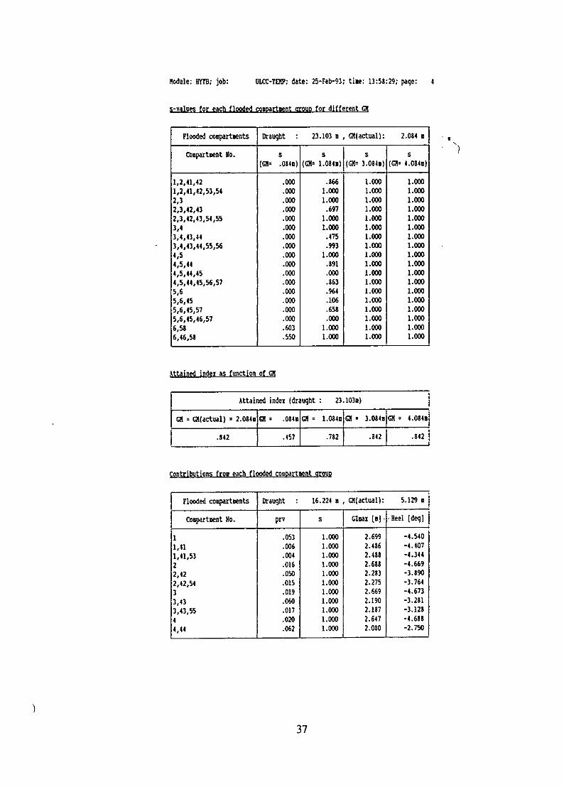
Probabilistic damage stability analysisThe analysis is carried out in accordance with the IMO resolution MSC.19(58) and theassociated explanatory notes given in resolution A.684(17).
The only data provided by the user is the loading conditions corresponding to the two draughtsrequired and the compartments which eventually can be damaged. Then the programautomatically considers all allowed damaged combination of these compartments and calculates
for each combination its contribution to the attained index.
The computations either terminate when the attained index becomes greater than the requiredindex or continue until all possible combinations have been treated.
The calculation sequence is based on an automatic subdivision of the ship into longitudinaldamage zones, based on the geometry of the compartments. First all single damage zones aretreated, subsequently longitudinal damages extending over 2,3,.... damage zones are considered.Due to the large number of possible combinations of damaged compartments, care has beentaken to optimize the calculations. An example of the output is given in Figure 8.4. The firsttable contains for each of the two draughts and each of the damage zones the contribution tothe attained index. Then for each of the two draughts three tables are printed. The first contains
30

I-ship/'>) Department of Ocean Engineering HFFN/1.00
Company : ishUser : iijDirectory: .Job = ULCC-TEMPDate : 19-Feb-93 Tine: 11:32:06
DnIn ISrTIC Dpa STAB rILITY ANASIS
Hull file .................... : ./ULX-TtNP.LIKEStored ....................... .18-Nov-92 at 13:08:13
Weight file .................. : ./U1O-TEMP.WWStored ....................... : 11-Jan-93 at 16:22:43
Intact stability criteria file : ./ULOC-TEP.S1rCStored ....................... : 2-Jul-92 at 17:26:53
Damage stability criteria file : ./UIAE-TEKP.STCTStored ....................... : 2-Jul-92 at 17:26:53
Compartment file ........... : ./U•-TE.CPIFStored ....................... : 11-Jan-93 at 15:16:54
Density of sea water .............................. : 1.025 [t/mA3lAverage shell plate thickness ..................... : .020 [a]Specified non-voluze refered correction to Gc ..... : .000 [1)
Number of demand sets used for the intact condition : 1consisting of 1. demand(A): IN Rules
(Note: stability check to both port and starboard side are performed)
Number of denand sets used for the damage conditions: Iconsisting of 1. denand(A): IO Rules
(Note: stability check to both port and starboard side are performed)
Damage stability summary for weight condition No. I
Flooded coapartsents Intact displ:425811.334 t, GN(actual): 5.889 a
Compartment Water level Draught .? Draught PP Heel Minimm CXNo. below WL [a] [(l (1i (deg] (a]
None 22.952 23.254 .000 .32159,60,!1,62 3.000 21.976 24,939 .941 1.148
Figure 8.3 Minimum output from a damaged condition analysis.
31

Module: H1; job: ULCC-TEMY; date: 19-Feb-93; tile: 11:32:06; page: 2
Dapae stability smeary for weight condition No. 1
Flooded Cmpartments Intact displ:425911.334 t, GE(actual): 5.889 I 1
Coupartment Water level Drauqgt AP Draught FP Heel Miniimm GNgo. below a [a] [uJ [1] [deg] [uJ
59,60,61,62 2.000 22.094 24.882 .617 1.05259,60,61,62 1.000 22.223 24.818 .262 .92759,60,61,62 22.365 24.746 -.137 1.099
Dame stability sunarv for weioht condition No. 2
Flooded coupartsents Intact displ:425479.539 t, GM(actual): 5.772 u
Coupartment Water level Draught AP Draught FP Heel Rinima G1No. below a (a] [a) [a' (deg] [(]
None 23.127 23.010 .000 .30259,60,61,62 3.000 22.082 24.911 .717 1.00459,60,61,62 2.000 22.200 24.753 .391 .89259,60,61,62 1.000 22.329 24.688 .031 .80059,60,61,62 22.471 24.615 -. 375 1.193
Danace stability sunarv for weicbt condition No. 3
Flooded corpartuents Intact displ:199884.920 t, GH(actual): 17.266 a
Conpartnent Water level Draught A? Draught F Heel eNinium GANo. below WL [a) [a] (a] [deg] [a)
None 14.130 8.581 .000 .49659,60,61,62 3.000 11.479 9.042 4.733 7.60359,60,61,62 2.000 11.466 9.133 4.660 7.49259,60,61,62 1.000 11.455 9.225 4.582 7.37159,60,61,62 11.446 9.319 4.498 7.240
IDamage stability sunmary for weight condition No. 4
Flooded coupartaents Intact displ:185818.125 t, C1(actual): 18.932 a
Conpartnent Water level Draught Ap Draught Fp Heel Miniaum GHNo. below a [a] [a] [a] [deg) [a]
None 11.137 10.051 .000 2.23659,60,61,62 3.000 9.909 9.916 2.475 5.12659,60,61,62 2.000 9.891 10.010 2.406 5.07059,60,61,62 1.000 9.876 10.105 2.330 4.992
32

for each combination of damage compartments the pry-value, the s-value, the maximum of therighting lever and the equilibrium heel angle. The second table contains the s-values for the
above combinations obtained if the intact metacentric height was changed by a given amount.As the pry-values are unchanged, the second table can be used to quickly see how much thecenter-of-gravity should be moved vertically in the intact condition to obtain the required index.Finally, the last table simply contains the attained index for different values of the intactmetacentric height GM.
The module is implemented such that updated probabilistic rules easily can be included, suchas for instance those discussed in IMO SLF 37/5, 15 October 1992. Also, is desired, the olderprobabilistic rules A.265 (VIII) for passenger ship can be covered.
)33

I-ship/1.00 Departaent of Ocean Engineering I aB/1.00
Company : ishUser:Directory: .1Job : 01.CC-TEKPDate : 25-Feb-93 Time: 13:58:29
PROBABILISTIC DA•f GE STAILITY AALYSIS (ASC.19(lg )l
Bull file .................... : ./ULCC-TEMP.LINEStored ....................... : 18-Nov-92 at 13:08:13
Weight tile .......... . /UOlf-TEMP.WGDTStored ....................... .23-Feb-93 at 10:44:05
Compartment file ............. : ./ULCC-TENp.CPDFStored ....................... : 11-Jan-93 at 15:16:54
Deepest subdivision load line: Weight cond. No... : 1Partial load line (NSC.19(5S)): Weight cond. No.. : 6Subdivision length of the ship (Ls) ............... : 371.700 il]X-coordinate for aft terminal for Ls .............. : -9.500 (B]Number of compartments which can be flooded ....... : 181, 2, 3, 4, 5, 6, 41, 42, 43, 44, 45, 46, 53, 54, 55
56, 57, 58Max. number of simultaneously flooded compartments : 19Max. number of simultaneously flooded damage zones : 2
Length overall (Loa) ............................. : 371.700 (alLength between perpendiculars (Lpp) .............. : 354.700 (a]Breadth moulded (ald) ........................... : 60.000 (n]
Depth ...................................... ..... .: 35.000 (a)Design draught ................................... : 23.00O ill
Density of sea water .............................. : 1.025 [t/u'3]Average shell plate thickness ..................... : .020 illSpecified non-volume refered correction to GM ..... : .000 il]
Number of he-ling angles to starboard side ........ : 41. angle ....................................... : -10.000 (deg)2. angle ....................................... : -20.000 [deg]3. angle ....................................... : -30.000 (deg]4. angle ....................................... : -40.000 [deqj
Figure 8.4 Output from a probabilistic damage stability analysis according to MSC.19(58).
34

Nodule: HYTB; job: ULCC-TEKP; date: 25-Feb-93; time: 13:58:29; page: 2
Main results for dasace to starboard side:
Required index acc. •SC.19(58) ................... : .696)Attained index act. NSC.19(58) for actual (G ...... : .833
Attained index Drys for each dance zone
Damage zone Draught : 23.103 u Draught : 16.224 a
starboard side a(actual): 2.084 m GX(actual): 5.129 .
I(aft) ['] I(for) [(] prvs prns(accus) prvs prs(accm)
50.750 68.830 .011 .011 .011 .01163.830 97.759 .030 .041 .030 .04197.758 144.766 .080 .121 .080 .121
144.766 191.775 .097 .218 .097 .218191.775 238.783 .100 .318 .100 .318238.783 285.792 .100 t .418 .100 .418285.792 332.00 .100 .519 .100 .519332.800 360.000 .018 .536 .0 .51950.750 97.758 .022 .559 .022 .54168.830 144.766 .035 .594 .035 .57697.758 191.775 .046 .639 .046 .622
144.766 238.783 .052 .691 .052 .673191.775 285.792 .052 .743 .052 .725238.783 332.800 .052 .794 .052 .776285.792 360.000 .047 .842 .047 .824
Contributions from each flooded compartment group
Flooded compartments Draught : 23.103 v , M(actual): 2.084 a
CoClataent No. prn s GZzax [I] HeL- (deg]
.053 1.000 1.188 -8.5591,41 .006 1.000 1.024 -6.3661,41,53 .004 1.000 1.076 -5.7422 .016 1.000 1.190 -8.8282,42 .050 1.000 .$90 -4.3642,42,54 .015 1.000 .923 -3.6483 .019 1.000 1.187 -8.9463,43 .060 1.000 .886 -4.4633,43,55 .017 1.0 .917 -3.7284 .020 1.000 1.185 -9.1124,44 .062 1.000 .813 -4.7704,44,56 .018 1.000 .898 -3.7645 .068 1.000 1.169 -9.5345,45 .022 1.000 .871 -5.7425,45,57 .018 1.00 .880 -4.1106 .122 1.000 1.075 -9.4446,46 .015 1.000 .965 -6.09258 .018 1.000 .939 .000
35

Module: BSTB; job: UOC-TE1P; date: 25-feb-93; tine: 13:58:29; page: 3 f,
Contributions from each flooded coneartent crouo
Flooded coarments Draught : 23.103 m , •(actual): 2.084 a
Coaparteent fo. pry s CGiax [a) Heel (deg]
1,2 .007 1.000 .956 -14.2501,2,42 .013 1.00 .747 -13.5191,2,41,42 .007 1.000 .614 -12.3651,2,41,42,53,54 .008 1.000 .839 -10.4872,3 .O09 1.(00 .949 -14.5232,3,42,43 .027 1.000 .547 -12.2102,3,42,43,54,55 .011 1.000 .760 -9.261
3,4 .010 1.000 .939 -14.7663,4,43;44 .030 1.000 .520 -13.0133,4,43,44,55,56 .012 1.000 .730 -9.6274,5 .010 1.000 .902 -15.2844,5,44 .019 1.000 .677 -15.1424,5,44,45 .011 1.000 .438 -15.366
4,!t44,45,56,57 .012 1.000 .633 -10.8085,6 .021 1.000 .753 -15.9955,6,45 .011 1.000 .505 -17.038
5,6,45,57 .005 1.000 .577 -16.0185,6,45,46,57 .007 1OW0 .460 -14.3536,58 .007 1 .• 1.047 -9.4466,46,5S .003 1.000 .941 -6.092
,s-values for each flooded comart•ent group for different Gi
Flooded coupartnents Draught : 23.103 a , Cf(actual): 2.084 m
Conpartnent No. s s s s(Gl= .084s) (GM= 1.034m) (CM= 3.084n) (GM= 4.084a)
1 .933 1.000 1000 1.000
1,41 .847 1.000 1.000 1.0001,41,53 .950 I.00 1.000 1.0002 .920 1.000 1.000 1.002,42 .703 1.00D0 1.000 1.0002,42,54 .892 1 .000 1 .000 1.0003 .912 1.000 1.000 h.0003,43 .638 1.000 1.OO 1.0003,43,55 .385 1.000 1.000 1.0004 .903 1.000 1.000 1.000
4,44 .431 1.000 1.000 1.0004,44,56 .849 1.000 1.000 1.0005 .866 1.000 1.000 1.000
5,45 .134 1.000 1.000 1.0005,45,57 .779 1.000 1.000 1.0006 .743 1.0D0 1.000 1.0006,46 .707 1.000 1.000 1.0005. 1.000 1 000 1.000 1.0001,2 .000 1.000 1.000 1.0001,2,42 .000 .990 1.000 1.000
36
Nodule: HYTB; job: ULCC-TEMP: date: 25-Feb-93; tine: 13:58:29; page: 4
s-values for each flooded compartment group for different GH
Flooded coupartbents Drauqbt : 23.103 , GE(actual): 2.084 B
Coupartient go. s s s s(GM= .084m) (Gilt 1.0841) (GM= 3.084s) (GM= 4.084a)
1,2,41,42 DO .866 10.00 1.0001,2,41,42,53,54 .000 1.000 1.000 1.0002,3 .000 1.000 1.000 1.0002,3,42,43 .000 .697 1.000 1.0002,3,42,43,54,55 .000 1.000 1.000 1.LOW3,4 .000 1.000 1.000 1.0003,4,43,44 .00 .475 1.000 1.0003,4,43,44,55,56 .000 .993 1.000 1.(004,5 .0 1000 1.0 1 1.0004,5,44 .000 .891 1 000 1.004,5,44,45 .000 .000 1.000 1.0004 ,5,44,45,56,57 .000 .863 1.000 1O(X
5,6 .000 .964 1.000 1.0005,6,45 .000 .106 1.000 1.0005,6,45,57 .000 .65 1.000 1.0005,6,45,46,57 .000 .000 1.000 1.0006,59 .603 1.000 1.000 1.0006,46,58 .550 1.000 1.000 1.000
Attained index as function of CM
G•(actual) =Attained index (drauqht : 23.103n)
: 2.084v G2 .084u GH z 1.084m)GH= 3.084a1M 4.084a1
.842 .457 .782 .842 .842
Contributions from each flooded comDartnent gnOuD
Flooded coparhtents Draught : 16.224 , GH(actual): 5.129 u
CompartMent NO. prv s GZuaX [a] Heel [deg]
1 .053 1.O 2.699 -4.540
1,41 .006 1.000 2.486 -4.407
1,41,53 .004 1.000 2.488 -4.344
2 .016 1.000 2.688 -4.6692,42 .050 1.000 2.283 -3.8902,42,54 .015 1.000 2.275 -3.764
3 .019 1.000 2.669 -4.673
3,43 .060 1.000 2.190 -3.281
3,43,55 .017 1.000 2.187 -3.128
4 .020 1.000 2.647 -4.688
4,44 .062 1.000 2.080 -2.750
37

Nodule: HMYT; job: ULCC-TEMP; date: 25-Feb-93; tine: 13:58:29; page: 5
Contributions from each flooded conartnent group
Flooded compartmuts Draught : 16.224 11, GM(actual): 5.129 a
Coipartzent No. pry s CGhax (al Heel (deq]
4,44,56 .018 1.000 2.076 -2.508
5 .068 1.000 2.622 -4.7355,45 .022 1.000 1.970 -2.162
5,45,57 .018 1.000 1.962 -1.7006 .130 1.00 2.40) -3.4316,46 .018 1.000 2.181 -1.6241,2 .007 1.00 3.028 -8.3491,2,42 .013 1.000 2.685 -8.6631,2,41;42 .007 1.OD 2.453 -9.711,2,41,42,53,54 .008 1.000 2.471 -8.9762,3 .009 l.OD 3.028 -8.5742,3,42,43 .027 1.0L0 2.245 -8.7302,3,42,43,54,55 .011 1.000 2.256 -8.2723,4 .010 1.000 3.011 -8.7643,4,43,44 .030 1.000 2.116 -7.9793,4,43,44,55,56 .012 1.000 2.091 -7.224
4,5 .010 1.000 2.992 -9.0814,5,44 .019 1.000 2.543 -8.8034,5,44,45 .011 1.000 1.921 -7.5344,5,44,45,56,57 .012 1.000 1.787 -5.665
5,6 .021 1.000 2.829 -8.5185,6,45 .011 1.000 2.283 -7.8205,6,45,57 .005 1.000 2.244 -7.242
5,6,45,46,57 .007 1.000 1.806 -4.388
s-values for each flooded copnoartment group for different CM
Flooded coupartrents Draught : 16.224 a , M(actual): 5.129 m
Comparbtent Nio. s s s(GX= 3.129m)) (G= 7.129a)
1 1.000 1.UO 1.000 1.0001,41 1.000 1.000 1.000 1.0001,41,53 1.000 1.000 1.000 1.0002 1.000 1.000 1.000 1.0002,42 1.000 1.000 1.000 1.000
2,42,54 1.000 1.000 1.000 1.0003 1.000 1.00 1.000 1.000
3,43 1.000 1.00 1.000 1.0003,43,55 1.000 1.000 1.000 1.0004 1.000 1.000 1.000 1.000
4,44 1OW0 10.0 1000 1.0004,44,56 1.000 1.000 1.000 1.0005 1.000 1.000 1.000 1.0005,45 1.000 1.000 1.000 1.0005,45,57 1.000 1.000 1.000 1.0006 1.000 1.000 1.000 1.000
38

Module: HMTh; job: CLC=-TEJP; date: 25-Feb-93; tine: 13:58:29; page: 6
s-values for each flooded coupartment group for different
Flooded cospartments Draught : 16.224 u , GM(actual): 5.129 s
CoqartBent No. s s s s(GM= 3.129m) (GM- 4.129z) (GI= 6.129a) (GM- 7.129u)
6,46 1.000 1.000 1.000 1.0001,2 1.000 1.000 1.000 I.0001,2,42 1.000 1.000 1.000 1.0001,2,41,42 1.000 1.000 1.000 1.0001,2,41,42,53,54 1L00 1.000 1.000 1.0002,3 1.000 1.000 1.000 1.0002,3,42,43 1000 1.000 1.000 1.0002,3,42,43,54,55 1.000 1.000 1.000 1.0003,4 1.000 1.000 1.000 1.0003,4,43,44 1.000 1.000 1.000 1.0003,4,43,44,55,56 1.000 1.000 1.000 1.0004,5 1.000 1.000 1.000 1.0004,5,44 1.000 1.000 1.000 1.0004,5,44,45 1.000 1.000 1.000 1.0004,5,44,45,56,57 1.000 1.000 1.000 1.0005,6 1.000 .1000 1.000 1.0005,6,45 1.000 1.0D0 1.000 1.0005,6,45,57 1.000 1000 1.000 1.0005,6,45,46,57 1000 1.000 1.000 1.WO
Attained index as function of GM
Attained index (draught : 16.224n)
GX = CI(actual) = 5.129a 0 = 3.129fiGH= 4.z29i(GX 6.129m1 ; 7.129a
.824 .324 .824 .824 .824
39

9. Conclusion
We have described the I-ship software package which we believe covers in a rational andconvenient way the basic hydrostatics needed in the preliminary ship design phase.
It
Although our main goal has been to provide the students of naval architecture with an efficienttool for designing their own ship-project, many of the features of the system could also be ofinterest for the professional naval architect.
Care has been taken to ensure that the program satisfy the requirements listed in theintroduction to the present paper.
Thus we are convinced that the system will form the basis for future program developmentsat our department for many years to come. These developments will also include suggestions
for improvements received from all the users.
10. References
[1] Pedersen, P. Temdrup, Jensen, J. Juncher (1979). "A Program System for Strength andVibration Calculation for Ship Structures". Proc. Computer Appl. in the Automation ofShipyard Operation and Ship Design III, Glasgow, North-Holland Publishing Company.
[2] Andersen, P. (1982). "A Program System for Basic Ship Design". Proc. Computer Appl.in the Automation of Shipyard Operation and Ship Design IV, Annapolis, North-HollandPublishing Company.
[3] Parker, M., Williams, A. (1984). "Choosing a Computer Design System". The Motor Ship,June 1984.
[4] Jensen, J. Juncher and Andersen, P. (1986). "ISH-SHIP DESIGN PACKAGE: anInteractive Preliminary Ship Design System". Proc. CADMO 86, Washington D.C., 16-19.September 1986.
[5] Jensen, J. Juncher and Baatrup, J. (1988). "Transformation of Ship Body Plans to a B-Spline Surface". ICCAS VI, Shanghai, China, 13-16. September 1988.
[6] Jingen, G., Jensen, J. Juncher (1982). "A Rational Approach to Automatic Design of ShipSections",. Proc. Computer Appl. in the Automation of Shipyard Operation and ShipDesign IV, Annapolis, North-Holland Publishing Company.
40

COMPUTER ,APPLICATIONS IN THE
AUTOMATION OFSHIPYARD OPERATIONAND SHIP DESIGN, VII
Proceedings of'the IFIP TC5/WG 5.6 Seventh International Conference onComputer Applications in the Automation of Shipyard Operation and Ship Design, VII
Rio de Janeiro, Brazil, 10-13 September, 1991
Edited by
CLAUDIO BARAIJNA VIEIRAPROTASIO MARTINS
Federal University of Rio de JaneiroBrazil
CHENGI KUOUniversity of Strathclyde
Scotland, UK
1992
NORTH-HOLLANDAMSTERDAM • LONDON • NEW YORK - TOKYO

Computer Applications in the Automation of Shipyard Operationand Ship Design. VII - C. Baradina Vicira et al. (Eds.)Elsevier Science Publishers BV. (North-Holland) 7©D 1992 IFIP. All rights reserved.
Rational Design of Ship Structures
J. Baatrup', J. Michelsena and J. Rasmussenb
aDept, of Ocean Engineering, Technical Univ. of Denmark, DK-2800 Lyngby, Denmark
bRockwool Product Development, DK-2640 Hedehusene, Denmark
Abstract
It is the purpose of this paper to present a comprehensive computer based procedurefor the design of ships and other maritime structures. The main issue is to obtain avery high degree of rationality and integrity between the main items: topology/geometry,hydrostatics, hydrodynamics and structural response. The overall concept of the systemcurrently under completion is presented including a profound treatment of the structuraldesign part of the system. The structural response is determined either by beam theory orby the finite element method. Important for this part is the purpose made pre- and post-processing facilities including material characterization of composite sandwich materials,and automatic mesh generation on the outer hull surface, superstructure and bulkheads.The applicability of the system is illustrated by an analysis of a rescue and pilot craftbuilt in composite materials.
1 Introduction
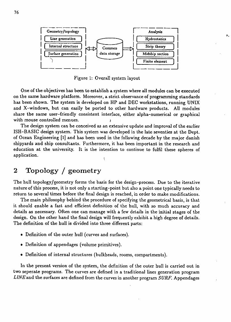
In the early stages of the design process, the naval architect needs tools that producesa fast preliminary estimation of stability, volumes of compartments etc. Later in theprocess, the needs are more exact calculations of the same properties, as well as tools forhydrodynamic loads, midship section design and possibly 3D finite element analysis. Thisway, not only the stability but also the strength and stiffness requirements of the designedstructure can be assured. The program system presented in this paper includes all of theabove mentioned tools and in addition modules for defining the geometric basis. Thelater consists of routines for the definition and manipulation of the model for the outerhull,1 the internal structures and appendages. The system comprises versatile modules forthe design and analysis of offshore platforms (e.g. jack-ups) which are not treated in thispaper. The layout of the system is outlined in fig. 1. An important quality is the rationaldata-flow due to the shared data-files which enables quick redesign cycles. Furthermore,the model geometry can be interfaced to other program systems (drafting) by means ofICES-files.
76
Geozetryto7oogy Analysis
I Line generation I [ Hydrostatics II Internal structure CO [Uo Strip theory II Surface generation storage Midship section II If ~ Finite elemen t Z
Figure 1: Overall system layout
One of the objectives has been to establish a system where all modules can be executedon the same hardware platform. Moreover, a strict observance of programming standardshas been shown. The system is developed on HP and DEC workstations, running UNIXand X-windows, but can easily be ported to other hardware products. All modulesshare the same user-friendly consistent interface, either alpha-numerical or graphicalwith mouse controlled menues. P
The design system can be conceived as an extensive update and improval of the earlierISH-BASIC design system. This system was developed in the late seventies at the Dept.of Ocean Engineering [1] and has been used in the following decade by the major danishshipyards and ship consultants. Furthermore, it has been important in the research andeducation at the university. It is the intention to continue to fulfil these spheres ofapplication.
2 Topology / geometry
The hull topology/geometry forms the basis for the design-process. Due to the iterativenature of this process, it is not only a starting-point but also a point one typically needs toreturn to several times before the final design is reached, in order to make modifications.
The main philosophy behind the procedure of specifying the geometrical basis, is thatit should enable a fast and efficient definition of the hull, with so much accuracy anddetails as necessary. Often one can manage with a few details in the initial stages of thedesign. On the other hand the final design will frequently exhibit a high degree of details.The definition of the hull is divided into three different parts:
" Definition of the outer hull (curves and surfaces).
* Definition of appendages (volume primitives).
* Definition of internal structures (bulkheads, rooms, compartments).
In the present version of the system, the definition of the outer hull is carried out intwo seperate programs. The curves are defined in a traditional lines generation programLINEand the surfaces are defined from the curves in another program SURF. Appendages

77
are defined in the lines generation part while the internal structures are currently defined
in an ;ndependent program ITST. In a later version the internal structure part will mostlikely also be incorporated in the lines generation program. All the programs mentionedmakes extensive use of computer graphics and digitizing methods.
Figure 2: Plot of hull lines and appendages for a container vessel
2.1 Outer hull
In the lines generation program LINE a wireframe net is established using the traditionalHermite cubic spline curves, which interpolates a set of control points. All curves arerepresented as generic 3D curves. A station curve, waterline or buttock curve will appearas a 2D curve to the user, while a knuckle line or a deck line curve may appear as a3D curve. Every curve is defined by one or more sub-curves, i.e. a station curve for a
catamaran consists of two disconnected sub-curves. All control points have types whichdetermines how the spline should perform the interpolation. Most points are "continous
curvature points", but some are "sheer points", "knuckle points" or tangent or curvaturecontrolled points. The same form of types is attached to the segments of the sub-curvesso new control points generated by intersections inherits these types.
The manipulation of the outer hull curves is done graphically, by moving, inserting,deleting and copying curves, sub-curves and control points around, in some cases usingauxiliary entities, such as points, lines and planes. Usually, the aft- and forebody of
an existing design is transformed and used as a starting point. In other cases there isno suitable existing design, and the start curves must be digitized from a sketch of thehull. As the design process continues more detail will be added and thereby more curvesinserted either manually or automatically.
Rectangular and triangular B-spline patches can be fitted to the hull curves in thesurface manipulation program SURF. This enables geometric fairing of the hull either byvisual aids or by optimizing a functional based on the surface curvature.

78
2.2 Appendages
Appendages are used to model volumes such as superstructures, rudders, bow-thrustertunnels, deck cargo etc where the application in hydrostatic analysis does not justify adefinition using curves, as for the outer hull. This would also leave the fairing of thehull surfaces very troublesome, and would be awkward because the preci!'e position anddimension of these volumes is not known in the early design stages.
The appendages can be defined from a set of volume primitives, such as pyramidestub, circular cone, part of sphere or a volume defined by a number of profile curves. Aprofile can be rectangular, ellipsoid, a NACA-foil profile or a user-defined profile. Anappendage can be placed anywhere in- or outside the hull, and it is indicated if the volumeshould be treated as a positive (add-on) or negative (cut-out) volume. The hydrostaticdata is found by integrating over plane panels that are automatically generated over thesurface of the appendage.
Figure 3: Plot of some of the internal structures for the container vessel
2.3 Internal structures
As it is the case with the outer hull, the internal structures is defined in a strict hierarchicaldata-structure. In the present procedure a compartment consists of a number of rooms.These are surrounded by longitudinal boundaries and a set of surfaces. The surfaces areagain defined by a set of curves. If for instance a deck needs to be moved vertically,typically only one curve must be altered. This is a simple way of defining the internalstructures, and it is sufficient for the hydrostatic calculations, but it is not suited forstructural analysis, where a more elaborate data-structure is needed [2]. Work is currentlycarried out in order to establish a definition that can be used in both the hydrostaticcalculations and in the structural analysis. This implies among other things automaticmesh generation of the outer hull and the internal structures seperately or as a whole foruse in the finite element strength analysis.
79
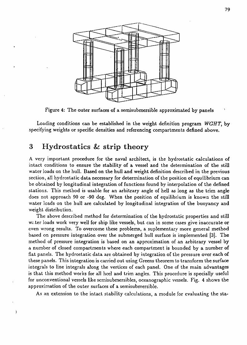
Figure 4: The outer surfaces of a semisubmersible approximated by panels
Loading conditions can be established in the weight definition program WGHT, byspecifying weights or specific densities and referencing compartments defined above.
3 Hydrostatics & strip theory
A very important procedure for the naval architect, is the hydrostatic calculations ofintact conditions to ensure the stability of a vessel and the determination of the stillwater loads on the hull. Based on the hull and weight definition described in the previoussection, all hydrostatic data necessary for determination of the position of equilibrium canbe obtained by longitudinal integration of functions found by interpolation of the definedstations. This method is usable for an arbitrary angle of hell as long as the trim angledoes not approach 90 or -90 deg. When the position of equilibrium is known the stillwater loads on the hull are calculated by longitudinal integration of the buoyancy andweight distribution.
The above described method for determination of the hydrostatic properties and stillwi.ter loads work very well for ship like vessels, but can in some cases give inaccurate oreven wrong results. To overcome these problems, a suplementary more general methodbased on pressure integration over the submerged hull surface is implemented [3]. Themethod of pressure integration is based on an approximation of an arbitrary vessel bya number of closed compartments where each compartment is bounded by a number offlat panels. The hydrostatic data are obtained by integration of the pressure over each ofthese panels. This integration is carried out using Greens theorem to transform the surfaceintegrals to line integrals along the vertices of each panel. One of the main advantagesis that this method works for all heel and trim angles. This procedure is specially usefulfor unconventional vessels like semisubmersibles, oceanographic vessels. Fig. 4 shows theapproximation of the outer surfaces of a semisubmersible.
As an extension to the intact stability calculations, a module for evaluating the sta-
80
..... ......... :+ : ...
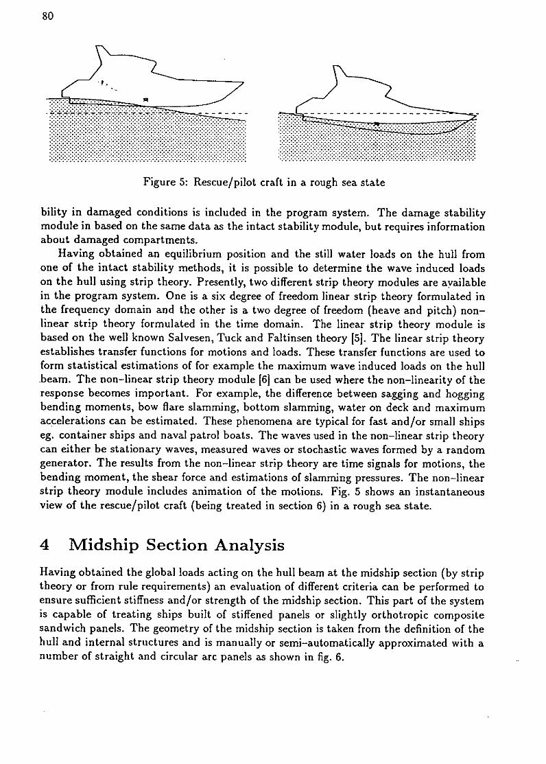
Figure 5: Rescue/pilot craft in a rough sea state
bitity in damaged conditions is included in the program system. The damage stabilitymodule in based on the same data as the intact stability module, but requires informationabout damaged compartments.
Having obtained an equilibrium position and the still water loads on the hull fromone of the intact stability methods, it is possible to determine the wave induced loadson the hull using strip theory. Presently, two different strip theory modules are ayailablein the program system. One is a six degree of freedom linear strip theory formulated inthe frequency domain and the other is a two degree of freedom (heave and pitch) non-linear strip theory formulated in the time domain. The linear strip theory module isbased on the well known Salvesen, Tuck and Faltinsen theory [5]. The linear strip theoryestablishes transfer functions for motions and loads. These transfer functions are used toform statistical estimations of for example the maximum wave induced loads on the hullteam. The non-linear strip theory module [6J can be used where the non-linearity of theresponse becomes important. For example, the difference between sagging and hoggingbending moments, bow flare slamming, bottom slamming, water on deck and maximumaccelerations can be estimated. These phenomena are typical for fast and/or small shipseg. container ships and naval patrol boats. The waves used in the non-linear strip theorycan either be stationary waves, measured waves or stochastic waves formed by a randomgenerator. The results from the non-linear strip theory are time signals for motions, thebending moment, the shear force and estimations of slamming pressures. The non-linearstrip theory module includes animation of the motions. Fig. 5 shows an instantaneousview of the rescue/pilot craft (being treated in section 6) in a rough sea state.
4 Midship Section Analysis
Having obtained the global loads acting on the hull beam at the midship section (by striptheory or from rule requirements) an evaluation of different criteria can be performed toensure sufficient stiffness and/or strength of the midship section. This part of the systemis capable of treating ships built of stiffened panels or slightly orthotropic compositesandwich panels. The geometry of the midship section is taken from the definition of thehull and internal structures and is manually or semi-automatically approximated with anumber of straight and circular arc panels as shown in fig. 6.

81
•.I J II I t I! I I I I I I I In IIII I Itt l * t I* I SItI *I I I II i "
Figure 6: Midship section of a tanker
An important feature of this module ips the use of libraries eg. material library, stiffenerlibrary, plate library etc. Each member in a library is named a type. A plate type iscomposed of a material type and a specification of the plate thickness, while a stiffenedpanel is composed of a plate type, a stiffener type and information about the stiffenerspacing.
Calculation of the stress distribution in the midship section is based on the assumptionthat the hull beam is prismatic in a zone near the midship section and is calculated usingtheories for thin-walled beams [4). Knowing the direct and shear stress distribution, anumber of failure criteria like panel buckling, stiffener tripping etc. can be evaluated.These criteria are of course different for stiffened panels and composite sandwich panels.
The possibility of semi-automatic design of the midship section by specifying all of therequirements necessary for obtaining a feasible design is included to some extent. Theserequirements can be geometric constraints, minimum values for the sectional moments,maximum allowable stress levels etc. The design variables considered are typical platethicknesses and stiffener dimensions for a stiffened panel. The semi-automatic designprocedure is based on a combined analytical and numerical sensitivity analysis to establisha linear programming problem. A Simplex algorithm is used to solve the problem leadingto an improved design. This strategy is repeated until a feasible and satisfactory designis obtained.
5 Finite Element Analysis
Finally, a general purpose 3D FEM analysis module forms a part of the program system.If results from the beam theory analysis of the midship section indicates that 3D FEManalysis of a larger part of the structure is required, or if the structure considered is
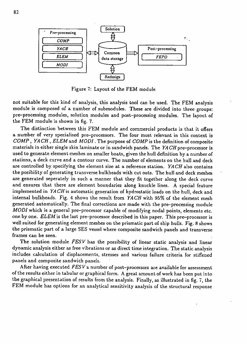
82
Pre-proceFssing 7o lutoi
p cYA CH s no n Post-processing[ ELEM } ra FEPO ]
[ MODI
Figure 7: Layout of the FEM module
not suitable for this kind of analysis, this analysis tool can be used. The FEM analysismodule is composed of a number of submnodules. These are divided into three groups:pre-processing modules, solution modules and post-processing modules. The layout of
the FEM module is shown in fig. 7.The distinction 'between this FEM module and commercial products is that it offers
a number of very specialised pre-processors. The four must relevant in this context isCOMP, YA CH, ELEM and MODI. The purpose of COMP is the definition of compositematerials in either single skin laminate or in sandwich panels. The YA CH pre-processor isused to generate element meshes on smaller boats, given the hull definition by a number ofstations, a deck curve and a contour curve. The number of elements on the hull and deckare controlled by. specifying the element size at a reference station. YA CH also containsthe posibility of generating transverse bulkheads with cut outs. The hull and deck meshesare generated seperately in such a manner that they fit together along the deck curveand ensures that there are element boundaries along knuckle lines. A special featureimplemented in YA CH is automatic generation of hydrostatic loads on the hull, deck andinternal bulkheads. Fig. 4 shows the result from YACH with 95% of the element meshgenerated automatically. The final corrections are made with the pre-processing moduleMODI which is a general pre-processor capable of modifying nodal points, elements etc.one by one. ELEM is the last pre-processor described in this paper. This pre-processor iswell suited for generating element meshes on the prismatic part of ship hulls. Fig. 8 showsthe prismatic part of a large SES vessel where composite sandwich panels and transverseframes can be seen.
The solution module FESV has the possibility of linear static analysis and lineardynamic analysis either as free vibrations or as direct time integration. The static analysisincludes calculation of displacements, stresses and various failure criteria for stiffenedpanels and composite sandwich panels.
After having executed FES V a number of post-processors are available for assessmentof the results either in tabular or graphical form. A great amount of work has been put intothe graphical presentation of results from the analysis. Finally, as illustrated in fig. 7, theFEM module has options for an analytical sensitivity analysis of the structural response

83
Figure 8: Structural model of SES vessel (symmetric part)
with respect to selected design variables. The results from the sensitivity analysis areused to form a linear programming problem. This problem is solved in the same manneras described in the previous section.
6 Example
To illustrate the applicability of the system, a global analysis of a small fast vessel willbe examined in this section. The vessel represents an early proposal for a combined res-cue/pilot craft in composite materials for the Royal Danish Administration of Navigationand Hydrography.
The structure is a monocoque FRP-sandwich construction without any stiffeningmembers except bulkheads, floors and engine supports. The length overall is 15.0 mn,the breadth overall is 3.9 in and the fully loaded displacement 12.0 t. The maximumspeed is expected to be 40 knots and the cruise speed 35 knots.
The definition of the basic geometry represented by a detailed body plan of the hull,superstructure and cockpit seen in fig. 9, follows the procedure treated in section 2.No appendages have been used to define the geometry in this example. Waterlines aregenerated and hydrostatics calculated.
Based on this body plan, the hydrodynamics of the vessel in a rough sea state at highspeed have been examined using non-linear strip theory as described in section 3. Theonly necessary extra input is the radius of inertia with respect to weight. In fig. 5, the

84
II
Figure 9: Perspective view of the lines defining the rescue/pilot craft
behaviour of the vessel according to the strip theory program can be seen.The results from the strip theory calculation are used to determine an approximate
design slamming pressure on the worst exposed part of the hull. The pressure distributionis shown in fig. 10. In a head sea with a wave height of 1.5 meters and a 20 knot speed it hasbeen determined to approx. 0.1 MPa Thr, pressure is scaled by a dynamic amplificationfactor of 2.
Figure 10: Distribution of the design slamming load
Many different load cases have to be taken into account for a structure like this. Butapart from the above mentioned case, only water pressure on freeboard and superstruc-tures ("green sea") and static water pressure on internal structures (flooding) are includedin the example. The later two are taken from the classification rules of Det norske Veritas.
For the FEM analysis, the element mesh on deck, hull and transverse bulkheads has

85
I
Figure 11: FEM mesh on half-structure generated by YACH
been generated semi-automatically by the YACH pre-processor based on the body plan.In this examle, more than 90 % of the elements are generated automatically by thispre-processor. Evidently, all three load cases consists of linear distributed pressures.
Due to symmetry with respect to both geometry and loading, only one-half of thestructure is modelled. In fig. 10 the final mesh of the 689 triangular parabolic sandwichelements in the model is shown. Engine supports and window-frames are modelled using57 two-node Timoshenko beam elements. The number of degrees of freedom adds up to8274.
Low weight is essential for this type of vessel. Therefore, it is important to fullyutilize the mechanical properties of the materials in the sandwich construction. TheFRP-laminates for the skins are mainly composed of layers of unidirectional S-glassreinforcement and epoxy resin. The bottom are reinforced by two layers of high strengthcarbon layers. Thin chopped strand mat layers of E-glass are acting as finish.
The sandwich panel cores are PVC foam of densities from 60 to 100 kg/m 3 and thick-nesses from 40 to 50 mm. These composite materials are all defined in a special module,COMP, where the mechanical properties are calculated by micro mechanics models. Theapplication of this module and the material subject of FRP-sandwich structures in generalare treated more profoundly in [7].
In a global analysis like the present, it is a huge problem to specify realistic boundaryconditions. Therefore, the external forces have been balanced with the inertia forces ineach of the three load cases. The module MODI includes the option of defining inertiaforces (i.e. gravity), generated as distributed loads on each element.
After generation of nodal point loads, the resulting external forces and moments aredetermined by the module MODI. Furthermore, the total mass including non-structuralmasses, the center of gravity in global coordinates and the mass moment of inertia, aredetermined by the same module.

86
Figure 12: Deformation of the structure due to slamming (top) and "green sea" (bottom)
Due to symmetry, only three resultant components has to be balanced in this example;the axial and vertical forces and the longitudinal bending moment. The accellerations atthe center of gravity corresponding to the resultant components are determined. Hereby,the inertia forces per area of each element are evaluated. Similarly, the contributionsfrom the non-structural masses are determined. The element contributions are generateddirectly as linear distributed loads with the respective directions, while the non-structuralmass contributions are imposed as nodal point forces. In the current example, the struc-tural weight of the model (half vessel) adds up to 1350 kg, while the non-structural masseshas been set to 1700 kg.
Y
Figure 13: Strength ratio with respect to strength failure in inner skin due to slamming
The total CPU consumption for the FEM analysis adds up to approx. 5 hours on a 2Mflops workstation, while the interactive pre- and post-processing takes an estimated 8

87
to 12 hours. In fig. 12, the deformations due to the slamming and the "green sea" loadcase respectively are shown. As expected, the slamming load implies large deformationsin the loaded area. But severe defor,-ations in the foredeck due to the large accelerationscan also be seen. Furthermore, the importance of the shear deformation in the sandwichelements is very clear in the deck over the slamming loaded bulkhead. The contributionsto the inertia forces from the engines can also be seen.
As mentioned in section 5, the failure assessments of the composite sandwich elementsare based on special local criteria. These are: local buckling (wrinkling) of each skinlaminate, strength failure of the core and each skin laminate evaluated using the Tsai/Wucriteria, and the first ply failure principle.
In fig. 13 the distribution of the strength ratios with respect to failure in the inner skindue to slamming is shown as a grey-tone plot. The darkest areas represents the worstloaded parts. Generally, the slamming load case has the highest strength ratios reaching88% of the allowable level.
7 Conclusion.
A comprehensive computer based design procedure has been presented. It is felt thatthis versatile system will be of great interest to the ship building industry, offering acomplete rational design and analysis tool on a single hardware platform. Almost alldesign procedures of major importance for the naval architect are included in the system,except those related to CIM techniques. At present, the few lacking components in thesystem are being implemented, as well as improvements to the existing modules.
Acknowledgement
The authors wish to thank M.Sc. Jacob Buus Petersen and M.Sc. Steffen Schalck fortheir contributions to this work. The work is partially supported by the Danish TechnicalResearch Council.
References
[1] Andersen, P. : A Program System for Basic Ship Design, Computer Applications inthe Automation of Shipyard Operation and Ship Design, pp 63-74, IFIP, 1982.
[2] Schurnann-Hindenberg, U. : Interactive Design of Ship Compartmentation, Com-puter Applications in the Automation of Shipyard Operation and Ship Design, V, pp343-352, IFIP, 1985.
[31 Schalck, S. & Baatrup, J. : Hydrostatic Stability by Pressure Integration, OceanEngn., Vol 17, No 1/2, pp 155-169, 1990.
[41 Hughes, O.F. : Ship Structural Design, A Rationally-Based, Computer-aided, Op-timization approach, John Wiley & Sons, New York, 1983.

88
[5] Salvesen, N. Tuck, E.O. & Faltinsen, 0. : Ship Motions and Sea Loads, Trans.SNAME, pp 250-287, 1970.
[6] Petersen, .j.B. & Marnaes, L. : Comparison of Non-linear Strip Theory Predictionsand Model Experiments, Proc. PRADS, Varna, Bulgaria, paper no 20. 1989.
[7] Rasmussen, J. & Baatrup, 3. : Structural Design of Composite Sandwich Vessels,
Composite Materials, Design and Analysis. Proceedings of the Second Int. Conferenceon Computer Aided Design in Composite Material Technology, The Free Universityof Brussels, april 1990.
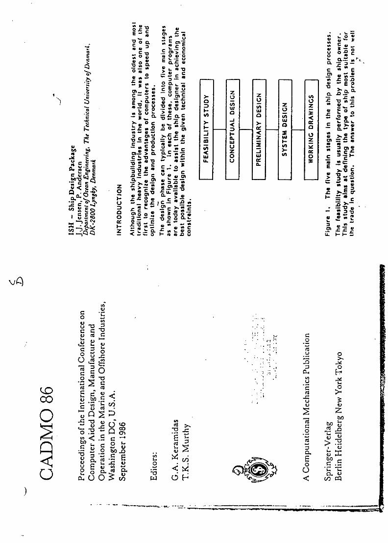
.0L
E~~ Zo c o 0 ~SC L LL E. a,--
C~~ L0 cfl0
0 0 V, 0 0c
0 E C§ 'Z-vw -L
LGO CLuCX70 vu
-cc
0 0 wo=&
0 CC 0.0
- CL v - E
0- .0- 0A zC~~Eu m
r'- Pc>i .- -.u
- 0 <-- sn
C-- -. b--
'00
C0 C -v w 0 .< ) ~ z C
>. - -,0, C
C.-. 0
( U Zc
w. 0-c4=CL -c .- 0
uu
Zbf00U
z 4)q ..Cdb.0u 0 0 o C.U 2~~ <0
"t OH0~~v -
b)not

C c01- m CL IM 7;; W 0 3 <0 C - M -0 0 0 E '0CL m 'o X z -- 3: - c c 0 c E 0 u E 'Dm E z c '0 M.- W W C3 c c z CID E CAW > M C M
0 c C c m m I CL E c0 u 0 v c W 0 0 - 0- .0> W m-C - CL E c C M I -- m 0 < c C 0 X cW .5 E 0 W > C c 3 E z 'D IOM 3 C ME u U- ý c W'D 0 W- - 0- 3 M C 0W E CL 3 a..- -n M - X 3: - CLW r > C W c c 0& E o 0 0 'a 0 c c E E -Ca-*- = 0.- 0 0. W 3c: .0 U< ýma 0c "-.D CD c 4m u u E ,a0 r - V IM cc C. M o' 'o-ow ou O.Coz u 0 CL 0--- E WL) r E E o C C ý m i , 0 <Z 0 a u W - oM CD -OL E.0 u 0.0 Z E CT-VC c 0 IMUim (x E X oz v C 0ee 0 Cý - 3 E c 0- CU w 0 0 <E E 1 0 Cl C M 0'&< W - 0 E --0* Cc > '0 >. E Eu CL c uz o W M - 0 0.0, 0ý.c - Z 0 m 0 W= 3 -V c m E W >.- E :3 - E:E u > 0 Z.0.0 m - - = E 0 lm>.. c a=CX= CL C a m 0 v m - 0 < c 0. m01 E W t c 0 V E W W- CL 0 0 X c 0 L) .- 0 IL U0 U.C X - ý'Ocr 4, , M C-ý,W= r W Z; L: 0 0 CL.C J3 c cn 0= - v C tA W 0Wx 0 wo 3: z W 0 C W- C'u LU -0 0 0-Z Cm 3 W - Z- Z 0- E0 0 W u m ý.c E CL 3ý0. 0 > r W 0-0 CX 3 2,0 < Ln0- E M C 0- C - -0 m Z.C C c C a & V , LU CL E0 a >.-(X u 0 0 V 3 .03 o C U 0z im >
tn00 0 C o- U W ool , V - , U m , c 0ý CL 3E; a-u v 0 > on.C < v c - 0 Z ex.0 0 c c Uc 0 0. 02 c-0 C .0 7E ex E c 0 .0 -E z a 0 - . -c -IM c 4;,2 6 A 0 0.2 < x:2 Ez o 0- E Z ý 0 E a - - w- ý: W,;,o C Vc 0C , v W CL 3- CL u X D . C e E u Ln >0. w fX M c m .0 -CL 0 CL- z v a ý 0 - u 3 C 4),o -0 x ua u 0 0 -,o13 0 IM W c - CL 3 C a 0 0CL W im 0 , CA 0 0 3::;,o o m W c 4; - 9L c c c a V--o 3 4 a 0w O'D m 0 4m C a 0 < r '0-c o al AV u - 010 Z 0 -W 3- U C >- , . Ma - U "a 0 'o WZ c m M La r0 0 w 0 m m - 0 3 r'D c -0 C .0 0 V 0 0 C 3: r >. ý m Xc c .. 0- 1 6 > E 0 cn M, E Mlo-ý- U W M U ý & 3 -0 w 0 u x Oc a -C M -0 0 a - Eu- im 3 E u'D -Ca. - r 3ý 0 0 a -7Im 31 c 03 >. E , IM 0 c CL. 0 > 10 0 u (n W OIZZ-. C 3: s C.E 3: a 3 -W 0 ý, 13 0 CL 4, r-Z I W t 0 0 D..! 0 U M w v 2 0 0-I- -M u m 0 ' Wc -0 -0 Ln r0
5 > 3 72 ý0 E :5 Z c Im Z - 0-
m 0 r -C 0 E ým.ý- 0- V < o-6 - 0 > CL 0 O-S 4; C .0'D CL 0 M 0.0 ý- >. -CL U m C ý - a 2! Z 0 *ý.c cr= :5 CL c O'D r C W0 0 W 2 , = -S , -E c =O:E 0 r.0 W m 'z CL '0 1- Z .. 2 <
r E CC.0 V o m m W-75 E VO W Z - ý 0 Im3 >o 3- r a m M3 W 0 E -- 2 x M, m 0 m x W0- > EE r Cm,- -CLm o oz 3tu -M c m c c >. - E z-6-u 0 c m CX W (T'D m-0 E 0 4 W I c A'a
V 0 0 > (A r 0 -. 0 0 CA .0 0 > c MOL r ft W W 0.0 ol 0 c "'o 0 x 0 0 . - 0 0r - -C W-0 .0 0 E u c u -C , - 0 r 0 C -t C m C'.2.0 C C - - < a- w2a -2 -c 0 E u W c.C E W 0 W m 3
-- -3 C 0
0 c - CL
0 0 m E CL -0 .0 3 M 06 r.Ur E A -C . 0- '0 r> - x 3-
cl, C 0 C C I0 0 W - CL .0 c 0 "DW W r - - 0 C 3t 10 :6 m -C 0 0 'kE 0, c.- M u c m V C E Im m75 - z Im- ý - -0 0 E c 'D U- "Z- cE W13 CL 0 C 0 3 CX m W E c 0 0 0 E 0 E c. cL- U 0.0
CA C E a-W 0 E 7C ý, r tL -'o W r a0- u u >ýv 0 0. M a 0 W E cum c .- o W , a M.2'00-c a 0 0 u u 0,10 C ýo Vr 34 0 E v c M W-0 0' >. C" - - -- W 0Z 0 (X 'acn (T 0 c ý U v 0 (X0 0 0 0 M 0 W W.C 0 w.X a 0.0 C m m75 0 D -m E31 ML - - - .. a
(X > c > -0(X 3t r= - U C 0- 0 W 0 CC.C C 01.C a Clt 0 'D E 0-. C ' - ' v u - 3,0-. Xo >. M'O0 X U r 0ri IX 0 u > Ic 41 u u v -MZ a 0 00 - M u Mm-a . -0 CX a W m -ý IM 41 0 w Cho u 3c E lm= E C c >. 0 0 c -C ucc u E C E 0 3 0 0 ý, o 0.0, ol 1 0 0.0 --0 ol.C CX v u .0 0 >ý C 4vp w v E r -0o Im 0 E'O W I m 0
r 'D - - -j C,- M.X ain c o E 0m 0 CL c W 0 0 - -ý :2z E 0 r . = - 7;; " a 'D aL C M 0 N- 0 , C 0 4 s ri " , 0 C0 ;,a 0 w M.C '0 E >. W 0 V .0 z 3 B.C C v Va m a Ve E 0 E0 tm o C m -6 .'Do C 41
Wý o X.0 -0 Im cr, I m V 0 m(x W m 8 CL - a 0 0 .0-Q, I - m .0 w -0 - 0 C 0 0 E x -C E 0-0< u cn- u E - . W m 3 u ý - I C M 3 .00 ý -. C c - 0-- 0 U U v E M:az r a.- m -. C EV-Z c >, C , a Vzo .. a*-ýa " , - ý CD- C 1 0. C C 0 0CM 0 m W'D C - cn- C, c .0 r -5'D 00 m m al E
V a E a' W c 0r o 0 C U r cw u .0 m mu E r CX 0 mM = -;:E . w 0 D E U m m cc c .0 0
>.'Z 2 'D E a-0 Us -C at], 0r , - 0 t:w- c .0 a :3 c - W - u : m t a> Eo- LL C Wr
-
c
cCL
On Eow m :3 cx Eo u , a- 0 -;, L -E
at 0 OL trc2, 'ov Q 75 E .-0 .D E 0 W 0.0 m -Z E , c ; go E u 0 ýD75 c 0 D 0c loc.0 M CL W w 0-0 v 75CL 'D u D E 0 E U E -0 WlEtr c:E 0 c a 0 WSM'Z Z c Z L Zou u m u u u 3 -Z v 0 CL -0 > - a V CL
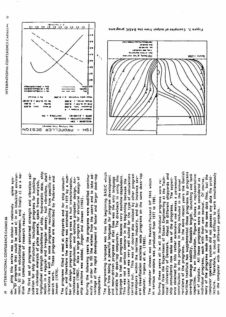
" ' " ' " C -swei~oid rnIsye a~l) woaj mndino Jo saidwex3 -Za6~
zN
W1.6
su, I's
"Mir
Z N,
'C N-m 0t E cW.r >
u c) 3 C0 c - .oi Czm - u 0 U Mo cn 0 v
Cx Xnl S - m o*% 0Is7; SU " m u CL 01C
-an 111 cI* Aft30 > -
NDISJQO 2~fjd d -;- H0 SI-( a, (
>. .U . - a ' ,- ~ c ~ -v~t Z C0- c- z-~ 4 C~ 0 mCa -CC0-=cQ,;0.
0,E 0r .'0 'c '0 0t. r.c C -CC.-~~' u 0) L 00ur .o
_Z - -~ - I-M: 0 a->.. cm.SE 'a ;.2 V- 7uL0-m Ec -'O k C E 00 :OQCc cn U z - % ..0O'v)~[ CL~ a C,( 0
.0 CL CC 0a- nV~o 4 ufo 2 xS m< 'E- 00 > 0CW
mL E- a E v0 u ~ E E -. C Ec. c. 4-0 E ' :6Z o=0M a 0 -a.~c 3 '0 ., -
0' Z -
r; . 0 co Ev CLm3 C 0C o or=~ -0mc C.f0> u -C- (2! W~ 'a,)>t4 C) :c3:c
a a,- <t- 0-r's.0 L aC c M U.
t. w~ . -VW'0 6 'j - ,L A E 0 E cat 's4
-~c, - - 3 0 = li- U M- r C' C --C 'a.- >t XO.~. S-g .c 06-ewt U-u(x0- '4)t Cv a1 svE X~1 r0'E 'a ' 01 U. o.- VEoc
o eL 9' r 0-' 0'- , 06 r -M.Xw w E ) 'a< z02 ca~t 0 E 3g; *0~D > IM u E .C - oL ,
cU 0~0 C. 0Ur=
ia -0 -a a-o' 1a. 3Qm.
, 0g0~~~~~~ ,30 ro =s - -E)~~ o W ~ t~a Ca .cnl>.4' C6t. r ,...CE A;
C -~ 2 &ma a. v.-
0.0 al a slo-)0 - L 0 oc a.Ez - ' .C0 - CS < - gaf x~c~. wc m r E gi
'- ... ocxc ' L n U* .rc a a.. uLAflac0 .0 mEC ... E' - 0' cl ab Ecrz ziE r ~ * * r c .C _ .60 a 2 .o
gw £0>.a.c a -
cm a0S cE o A c u' u -c .E! ES v

C *C,. c C E- . m 00
'c W LCC Z u, .Ec C~ . 2'o I
D ' o> C 0
L ban cl mlw
EC U cLc 0A .4Wc4
0S CX EF- 3
.; c- Mn Ct ZO 3: , -;E
<.c -0 < E. E ECoO I ~ m - *u * *
< -1 LC4,rcacIE 0
WC 'nE aC . o C -E -ý 'D
w,~ -C Q . *! 0 cD 3 0.- u u r-L~ u. :g EE .L c
4,-an 4 M0 E a
-90 1.-. .flCmm 0kR0 oQ-flM 0 0' CL E c i C;c 0ci 0. a. *.C a 0 uC LM
0L *Cc ... - . !.S% .0- -E . a 0*z
M M C ou fgo 0 W - -0 0:~E-~~ 0 .,c 0 ;M ,3 - L a m 0 C 20
a -. - < -m 4, C6:.0 0 >U 0 .. U-. . : - . .. . .. S
a-.- m U :U *, C~~l C -, w0E CW C M 3 C. -v 0- *aa.I . Zj0C I -> aI
=~ax o LX Aav 0 .. :.: B.2a
--wE CL>ý C L 0C we C !.2 > =.
-0 E *0 t a. 0 CbW ** 0 L 0%
<, (xe - E .r0 0 E3 a:.
> aE V.. L :: - oC>..0so -. Uj a. E.1-
0. a -- E
Oz 0 3
- o0 0 .- = £8' >.C02 .!tc U 0 m0 :EE z r ra C
0. 0 4 0 c W ,CL 0 .S M 3 Q.0 E -C E
w E C0 0 u a
5.2 -Dc 0o0 MC3cCIE 0. 'a u OL0 a m w 01CL - - L- F .S o
E.
CE
l1!j
13,L i ji

I~~ o
CC . C 8, a M4 ' C jj C C
c> E M o > 4a 0 "'
hi C0 -o ";om m3
ChAiL LE c -m E E O) >
C - C E,. 2sz Z Cu .
'Dl4 C'-L O C Cv 4 .... C o, 0 ~ CL
Em a- o 0 0 .1 C
Ct 0E' 0Cn'.C V a 2
V) Z~ uc c c C.- E - U
-9 U.I..Ici 0 0 m L CDC
a - 0 E D~~ &
nc >. L C C X2Uc u~ m t
C CL 0 cv hi> c 00 ,'o U 0 U LI
0~~~~hj -I-Z
c *L M= C~c. v C. 0 .
00 >.w o D
C' Ui 0C -g C 0'
30
4 i 'D c * C3 C*C..= c- t .0. Uz ~ 4
0 n '
0C C 4, U > ELa*h
C.E >.C M) a c v i V= mc am (- E O Un U w
07 - -ý 3E m u2;~ flo o IMC U 0C 0U '
~C 4)L 0o 0 U0U - V -
-C aowz0 '
~~a L cn C -. -C U
C >.c = ' )
h L U C 4 . . , E L c hmU . .
o41u m o v .rc Z C .0
r 0-M o .rC.m 1 0.D- I -
u - m - 2 a E z l- z a a .2-- EE ~ v- C C C ' . 0w Ct.0
- L C 0 > c ..Ea fl fl
,t _ V Uo U >-C
C CA j7 3 C ISm-cVE. C O dC,-
V U -
-34 >% m ct -AD vf - - In,~ .4 )
vi0 >t.C0 ~ ii > >L D C 0A Um 'oS4 .r C o ZL 0 WE
0 e
0
c ci L Us *20 rn
Uz E W-. 0 Or- c5 0 ' Z0CU o. z E u 0) m. mL L0 c 0
CU. L In~n 0 CL C u. U n o i-
0 'a
.2o £3 V.C *.. wm <a 0) >
-7-. I.. 0
1J...UE '>
- al.- a m co z * 'a = > CL -2
IV C - U-. f L wm ,8 mC l m ~ ~ ' w , U
~ncE 'D-v o 02 Z
- 0 .!n .2cr 'U ±C l vi . wCC <s a 0.E0 )
a'
4) -aU (m c. *-m,:- E
I ICl i nc t I u l flat j 1 C g0 0u h C=
- m E'X x In W C O t.0 D = -o V U L cU
a'->~~0 -c xw<S - . fr ! v r - 2 W U .LCUU
M -U mE U'r rm C i ~ 4 -
-0 M4 0 0. J . w A O n - - -o4 O v- 4'V U, 4)3 4m - 0
fl -c m c 0 40 E ~ 0 0n

0
c 0.E l- -L
m C Du CL .- 0
o 0
oo E..
o L 0U .
c CCa E CL
o fi
F- u e0i
u LL W
w X
( L.0 .0 XC
c' c au L
-C C; -I--L
1ý LCV 0 0
a' aa
0C 0
Cc n Ct>O CtW u o 0--<w
C 0i ~ E3a D.C. C ' - .CL~ >~' S - u- I- .- 0 2< Im.w > 0
CL 0 < -: m4 f aL z :E < U.L
0L : <C .CEL) <.- -.- .u m- v C .'a uE.SE IL x - UCo z E' C. u-, CV0
Coc "4C 5.. ca mLD.CO
o0 m C Z& tCw 3 Sac a0 M L C !00A.0-.o .3t0WCLi t& aac r 0.' Cnat L> < c
Ec .d 0 '-0 E 3' (L E~.~ ~ .E
no 1' - EV. gIt,. 0,-a -C ftOnL 5<1 0v u
:a2 C 0C > 1 at Cr <2X0 CC.3
a, *-f Eo m ~ 0- C3 tn >C. 0~ 3 -0 -0I C -
-xC cE= '0ý - cZCtO C 0 ULL0 V Nb>. '. 3- CL -CE3
;a. cm 2-Z --'0 I0 m'0. o 0.~~ - <. u .u in om C - ±'>. -0 E7 1o~~a.C oc. m. E ~ z Ea 8 0-0, -w ~ ¾0.. *Z
c< zMt CnW u 0 CLC 0 Z u~ <; .0-
ECmO -c . ,.EL- FC o - - 0.
,X C ixoU x.Q.aE c DJL or; M )5 Z MxO Vf0MM- . CL... 0Uu,5 o> < >mO
-' M- ' m-

Structural Design of Composite Sandwich VesselsJ. Rasmussen, J. BaatrupDepartment of Ocean Engineering, Technical University ofDenmark, Dk-2800 Lyngby, Denmark
ABSTRACT
A rational computer aided design procedure for large sandwich structures (e.g.maritime vessels) is discussed. The procedure deals with material characteriza-tion, structural response, failure assessment and sensitivity analysis. The struc-tural response is calculated by static and dynamic finite element (FEM) analysisand the failure assessment is based on various local strength and stability cri-teria. Sensitivity analysis with respect to design variables relevant to sandwichelements with skins of fibre reinforced plastic (FRP) is shortly discussed. The ap-plication of the design procedure is illustrated by an example concerning analysisof a proposed fast FRP-sandwich rescue and pilot craft.
INTRODUCTION
Although the stiffness and strength of FRY-sandwich panels (fig. 1) has beenutilized in the aeronautical and pleasure yacht industries for about three decades,the structural design of sandwich structures has mostly been performed by solvingspecific problems using a combination of detailed analysis and testing or, for theyachts, by "trial-and-error". However, none of these methods are acceptable inthe long run. Therefore, a more general applicable structural design procedureis needed. Due to lack of traditions, one has an opportunity to develop such aprocedure. The aim of the proposed design procedure is to obtain the same degreeof rationality in design of maritime FRP-sandwich structures or hybrid structuresas is presently possible in design of similar stiffened steel panel structures.
The basic issues for a design procedure is to be able to define, analyse andeventually modify and re-analyse the structure. Using FEM analysis, the lowestlevel of the mathematical model of the structure is the element mesh and theelements. At this stage, it is not necessary to distinguish between'a stiffened steelstructure and a similar FRP-sandwich structure except, that different elementtheories may be applied.
However, the modification and reanalysis facilities demand discretization tothe level of the smallest changeable constituents. In a stiffened steel structure,

102 Composite Materials: Design and Analysis
t - OSkin (FRP-laminate)- -,,- Adhesive
" " t . • C o r e
---- Adhesive
-- Skin
Figure 1: FRP-sand wich panel
these could be the flange and web dimensions of the stiffener profile, and for aFRP-sandwich structure they could be the thin orthotropic layers of the skins andthe thick orthotropic core. But the discretization could go further, because thelayers are composed of fibres and a resin material. Similarly, the core material canbe regarded as being composed of a cell geometry and a material. A comparisonbetween the discretization hierachy for a stiffened steel structure and a FRP-sandwich structure is illustrated in figure 2.
CELL MATERIAL REINORCEMENT
CORE [ LAYER MTRA
ELEMENT MESH
STRUCTURE
Figure 2: Design discretization of a FRP-sandwich structure and a stiffened steelstructure

Composite Materials: Design and Analysis 103
MATERIAL TOPOLOGY AND CHARACTERISTICS
Except for "Mesh" and "Structure" each box in figure 2 represents a library oftypes. A type is described by types from the level above and additional compo-sition information (thickness; reinforcement intensity, orientation, etc.) and alldata follow the specific type. Hence, changing a type implies a change of everytype on higher levels where this type appears.
Although this approach seems very simple, it is essential in order to handlethe numerous combinations of constituents on several levels in the structure. Ifevery small constituent of the structure was defined seperately, the procedurewould be impossible to overview, and in the case of automatic optimization itwould demand unnecessary computer capacity. Furthermore, the type providesan opportunity to control the number of different constituents in the structure. Itis indeed niot rational to use 50 different profiles in a small stiffened steel vessel,or, similarly, 50 different core materials and thicknesses in a sandwich vessel.Hence, the approach also has a purpose in production rationality.
It is necessary to know the connections between the mechanical and physicalcharacteristics (price, weight, stiffness, strength etc.) of types on neighbouringlevels. Between the two upper levels in the type hierachy (fig. 2), this connectionis usually referred to as determination of material characteristics. According tonormal practice it is carried out by measurements. However, reliable measure-ments for every relevant material combi'nation cannot be expected to be availableearly in the design procedure. To prevent the amount of available data fromg~etting influence on the design, simple micro mechanics models are needed toreplace the lack of experimental data. Later in the design procedure, when moreaccuracy is needed, measurements can be performed in order to verify or correctthe calculated data. In particular, it is important to verify the results of the an-alytical strength models which may differ considerably from experimental data.
Generally, a micro mechanics model is based on homogenity. Consequently,the characteristics of an arbitrary cut out of the material are identical to thoseof the entire material. By subjecting a control volume of simple geometry todifferent stress conditions, the corresponding characteristics for the volume andhence the entire material can be determined.
FR? layers and laminatesIt is easy to establish a micro mechanics model for a layer with a unidirectional(UD) fibre structure. The theory hias been refined in the early seventies by Tsai,Ilashin, Whitney among others. Tsai 3z Hahn [1] assembles all stiffness data, P,for a lID layer in the commonly knowvn expression often referred to as the rule ofmixture:
P P (Py+ 7?Pr(1 0< 7)
wvhere (p is the fibre volume fraction and 77 expresses the relation between thlemean stresses in fibre and resin. Pj and P, represent the stiffness data for fibre

104 Composite Materials: Design and Analysis
and resin, respectively. Furthermore, they put down a simple expression for thelongitudinal strength of a UD layer, assuming that layer strength is only governedby the fibre and resin strength modes and not by the debonding effect:
= + (1- (2)
Here, E, and E1 are the Youngs modulus for resin and fibres, respectively, andacu is the fibre strength. Neglecting the debonding effects, this equation tendsto over-estimate the layer strength. Still, interpolation within small intervals ofthe strength data for UD layers can be based on it.
Now, laminates of UD layers is not very common in large sandwich structures.Instead, mainly chopped strand mat (CSM) layers and woven rovings (WR) layersare used in the skins. One way to derive models for these kinds of reinforcementstructures is to use the results from an equivalent UD layer and combine it withknowledge about the current reinforcement structure. Basically, a WR layer ismodelled as two orthogonal UD layers with adequate reductions due to lowermicro crack level. CSM layers with short discontinous fibres tend to have aweighted but nevertheless randomly distributed orientationof the fibres.Providingthe number of fibres with the orientation 9 forms an ellipse as a function of 0,the fibre intensity can be written:
rn(9) = n +n CS2- , 0< 0 <2 (3)/m~.sin298 + mo2
with m, and my as the fibre intensity in the x and y directions, respectively.These directions are the orthotropic axis of the layer. Each fibre, i, with anorientation, 0, is modelled as a small UD layer (fig. 3). Thus, the contributionfrom this fibre to the plane stress constitutive matrix is defined by:
{oaX , P }=- Cx, {ExxtEyy,2Exy}T (4)
can be written:
Y/Y •Fiber i
e-he-
Figure 3: The fibre, i, with orientation, 0, in CSM layer

%.UIIAbl.ttI IVIkILCI ains: L.'csigii aaiu i-xdlaysas IVJ
C = Tr(9) Ci T(O) = TT(O) CUD T(B)
with LT referring to the directions of the single fibre and T denoting the angletransformation matrix. The contribution from all the fibres in the infinitesimalinterval [0 - IdO; 8 + 1d9] is found by multiplying C'- with the curve length:
dC8 = Cm(9) dO = TrT(O) CUD T(O) m(O) dOI
Using the approximate perimeter of an ellipsis, ir/2(m2 + m2), the constitutive
matrix for the entire CSM layer can be derived by inserting equation (3) andintegrating with respect to the orientations:
C=M -27 dC'= - mr My 2w 1TT CUDT dO (5)
10i 2(M.2 + M2)J 0 msin'B+~o 2
Specially, if mn, is equal to m. the layer is isotropic. In [2] examples are given.
Honeycomb and foam core materialsDue to the complicated and somewhat stochastic cell structure of plastic foamcore materials, it is difficult to write simple and accurate micro mechanics modelsfor these materials. Assuming, that open cell foams can be described by a framemodel and closed cell foams by the same model with membranes between theframes, Gibson & Ashby [3] manage to put down expressions for the linear elasticstiffness data.
EC Ck, 2 p() 2 + ( a-) p- po+ p (1 - 2pe)EwpPW ' Ew, (pw - pe)
(6)~c 3(-, + PC-
G -(- pp,
with c and w referring to the entire core material and the cell wall material.The gas pressure is called, Pa, and the ratio of the frame volume to the totalmaterial volume is called a. Usually, this ratio has a value between 0.6 and 0.8.Alternatively, the properties can be interpolated with respect to the density basedon the available data, which in the case of PVC foams are well documented.
The cells of honeycomb core materials have a more simple geometry, anda micro mechanics model is easy to derive. Often, the honeycomb structure ismodelled with hexagons with constant wall thickness, t,,, and hence an isotropicin-plane behavior. However, honeycomb for practical applications (e.g. aramidpaper honeycomb) consists of thin strips folded and glued together to form thecells. Thus, one third of the cell walls are twice as thick as the others. If the cellstructure is divided into hexagons each encircling one cell and dividing each of thesix neighbouring cells with two other hexagones (fig. I) a representative controlvolume appears. Based on this, expressions for the density, P,, and transverseYoungs modulus, E,_, for the core can be derived:

N)
x
Figure 4: Control volume and geometric quantities for honeycomb core
Pc • _c 81t•
where di,. is the inscrihed diameter (fig. 4). A shear force, T, is imposed to thehexagonal control area as shown in the figure. 'rthe transverse shear strain due tothis load, Ca_-, in the core considered as a hoinogenous material must be equal tothe in-plane shear strain, e••= in a wvall~parallcl to the xz-plane. Thus, the shearstiffness, Goa=, of the honeycomb core material in this plane can be expressed bythe in-plane shear stiffness, G•. of the particular wvail and the relation betweentile lnean shear stresses:
- (7)
Providing that the cell cross section remain undeformed, a theory for thfin walledbeams can be applied for determination of the in-plane shear stress in the currentcell wvall when a shear force, T, is imposed to the top plane of the control volume.The wvall in-plane shear stress, r•. is written:
r,•.,(s) =- .---Tfr[szi !s2(x _ to] + ro,=(0) ,0 < S < 1 (8)
where x1 and x2 refers to the start and end of the wall, and 4u is the moment ofinertia. The resulting shear stress flow to and fr'om a nodepoint must be zero.After some algebra, this requirement along wvith symmetry gives r•,•-(0), hencethe cell wvall shear stress yields:
•,t 2(s) = d/iT
The mean shear stress for the entire core material is easily determined as:
T _ 2TP-cx : - -
whr wi heisrbddimtr(i. ) ha fre ,i ipsdtAh

Composite Materials: Design and Analysis 107
and hence:
Gezt 68tw 17p (9)GWrz 75 dw 5P 1p
The shear stiffnesses in other directions are derived similarly. Assuming linearityuntil shear failure, the shear strength of the honeycomb core can also be expressedby this model.
-Ji/"/
a~ QM
Figure 5: Assumed stress distribution in the classical sandwich theory (top) anda more realistic stress distribution in sandwich element (bottom)
STRUCTURAL RESPONSE
In structural design of slender ships, theories for thin walled beams could beapplied for the global static and dynamic analysis. This method used for sandwichvessels is described by Rasmussen [4]. However, sandwich panels are mainlyinteresting for structures where local panel bending is dominant as comparedto global bending of the hull beam, and beam theories become less important.Instead, the finite element method (FEM) is a powerful tool for determinationof the static and dynamic response. Eventually, a beam model or a folded plateanalysis can be applied as some kind of super element method for the FEManalysis. In order to select the element theory to be used in the FEM analysis, itis necessary to specify the composition of a sandwich element. According to theclassical assumption illustrated in figure 5(top), a sandwich element is composedof skins and a core having:
* Constant transverse shear stresses in the core
* Zero direct stresses in the core
* Constant direct stresses in the skins
Still, this stress distribution is only valid for large skin to core stiffness ratios.For instance, a sandwich panel with 8 mm G RP- skins and an 80 mm core of 200kyg/i 3 PVC foam exposed to in-plane compression would absorb approximately

108 Composite Materials: Design and Analysis
17 % of the total deformation energy in the core. In this case, the stress dis-tribution is clearly inconsistent with the classical assumption, although, it is arealistic panel for large sandwich ships. Therefore, in order to deal with this typeof panel, it is necessary to generalize the definition similar to figure 5(bottom):
Figure 6: Degrees of freedom for 2-D sandwich element
* "Nearly" constant transverse shear strain in the core
* "Small" direct stress in the core
* Stepwise linear direct strains in the skins•
In the global FEM analysis, the word "nearly" in the first item is neglected,hence the core shear strain is assumed constant. With this assumption a 2-Dsandwich element has been formulated based on a Reissner-Mindlin type shellelement formulated by Ahmad [5]. Generally, element stiffness K and mass Mmatrices are:
K = JvBTCBdV
(10)M =f/PHTHdV
where H is the deformation interpolation matrix, B the strain interpolationmatrix and V the element volume. It is convenient to formulate the elementmatrices as the sum of contributions from the core and each of the nt layers in theskins. With j and k referring to the five degrees of freedom, u, v, wo, O,• and 0,,(fig. 6) and assuming constant thickness of each layer, tt, and the core, t¢, withinthe element the stiffness matrix can be written:
nKjk = tclkcjk + ~t1ICIk , j,k = 1,2,... ,5 (11)1=l
Unfortunately, element stiffness of Reissner-Mindlin type elements tends todiverge with decreasing thickness to span ratio. To avoid this, a reduced inte-gration technique as proposed by Pawsey & Clough [6] and Zienkiewicz &~ Taylor
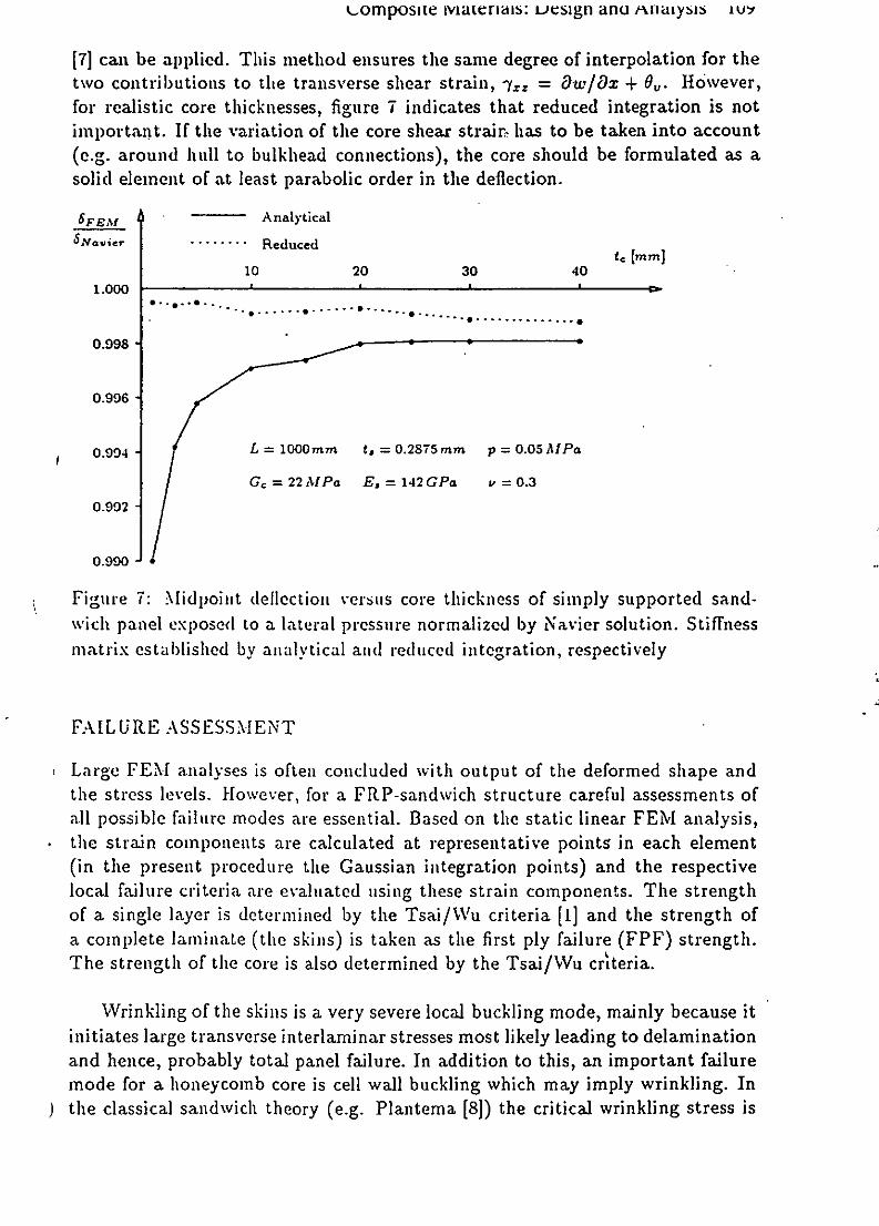
t-omposite vateriais: uesign anti -nLnyss iwu•
[7] can be applied. This method ensures the same degree of interpolation for thetwo contributions to the transverse shear strain, -y., = Ow/Ox + 0.. HoIwever,for realistic core thicknesses, figure 7 indicates that reduced integration is notimportant. If the variation of the core shear strain- has to be taken into account(e.g. around hull to bulkhead connections), the core should be formulated as asolid element of at least parabolic order in the deflection.
6 FE M Analytical6 Navie ......... Reduced te [Mn]
10 20 30 40
1.000 D
0.998
0.996
0.994 -L =1000mm ,= 0.2875 mm p = 0.05 Al Pa
Gc = 22 AlPa E, = 142 GPa P = 0.3
0.992
0.990
Figure 7: Midpoint deflection versus core thickness of simply supported sand-wich panel exposed to a lateral pressure normalized by Navier solution. Stiffnessmatrix established by analytical and reduced integration, respectively
FAILURE ASSESSMENT
Large FEM analyses is often concluded with output of the deformed shape andthe stress levels. However, for a FRP-sandwich structure careful assessments ofall possible failure modes are essential. Based on the static linear FEM analysis,the strain components are calculated at representative points in each element(in the present procedure the Gaussian integration points) and the respectivelocal failure criteria are evaluated using these strain components. The strengthof a single layer is determined by the Tsai/Wu criteria [1] and the strength ofa complete laminate (the skins) is taken as the first ply failure (FPF) strength.The strength of the core is also determined by the Tsai/Wu cr"eria.
Wrinkling of the skins is a very severe local buckling mode, mainly because itinitiates large transverse interlaminar stresses most likely leading to delaminationand hence, probably total panel failure. In addition to this, an important failuremode for a honeycomb core is cell wall buckling which may imply wrinkling. Inthe classical sandwich theory (e.g. Plantema [8]) the critical wrinkling stress is

110 Composite Materials: Design and Analysis
. .r.1.00 1- .: . . .- - .~o - . - - - I
I--L • I II4 7 1 aor 0 1
I I
E 142GPa ¾E = 1,12 GPa- 0,3 E 2 = ,17 GPa . I
0.5 0I 0.50 02 = 0,18-- ."". ,.l " IG.O m n• mnn
0.0 1 1 0.0- 1 110 - 4t ........ 1 110 - ....... 2 1I 1 10 ~2
10- 3 - - - 33 10- 3 - 4
10-2 6 6 , 10-2 - 6 91.0 65 65 1.0 - - 75
0.50 a22 1.00 0.50 a22 1.00
(a) ,o22 (b) 0022
Figure 8: Interaction curves for wrinkling (a) isotropic skins and (b) orthotropicskins
derived for the uniaxial isotropic case. If Plantema's derivation is extended toa biaxial loaded orthotropic sample with dimensions a x b of a sandwich plate,the critical stress in one of the orthotropy directions is found by minimizing theRayleigh coefficient with respect to the wave numbers, m and n:
1 (r.f C (11( ,+2D 3 ,2 ( ') + C2 2n4-2 = "- a (in)2 + 2
(12)
+ 2bv- min •M )2 + C•4l n 2 }i~r mn,n (fL)2 + 'm
with:
Ds1 = C812 + C366 t,
6
and the load ratio, length to breadth ratio and wrinkling strength ratio:
01322 = a R - 0 11 0"22 (13)
0sl b Osllcr 0s22c r
It is not possible to minimize equation (12) analytically with respect to the wavenumbers, m and n. Therefore, it does not fit into a rational design procedure.The expression has been evaluated for two examples, one with isotropic andone with orthotropic skins subjected to different combinations of biaxial loads.The critical loads in the two directions, normalized by the similar critical uniaxialloads, are plotted as interaction curves in figure 8 for a constant length to breadth

Composite Materials: Design and Analysis 111
ratio, -f = 1, and various core shear moduli, 10- 4 , 10- 3, 10-2 and 1 times Gorespectively. Go is the shear module for Divinycell H 60 PVC foam. Zero coreshear modulus corresponds to the well known thin homogenous plate solution.
It seems that interaction only occurs at extremely small core shear moduli.The maximum wave numbers in the two directions are also listed in the figure. InI
these examples, "wrinkling appears as many waves in the worst loaded directionand one wave in the orthogonal direction. For extremely soft cores, instabilityoccurs with very few waves, thus the solution converges to global buckling of athin homogenous plate. The examples suggest that, in practical calculation, itwould be sufficient to assess the criteria in the two principal directions separatelyusing equation (12) reduced to the uniaxial orthotropic case:
-- a 31 1 r = a' Y0C3 iEcCcs5 (14)
with a = 0.825. However, due to imperfections in material and geometry a = 0.5is recommendable in practical design. I
As mentioned above, also cell wall buckling modes can occur in a honeycombcore. From the model defined in figure 4, the critical transverse compressivepressure on a honeycomb sandwich panel is obtained from the elementary buck-ling expressions for thin plates. Assuming the cell walls to be simply supportedisotropic plates and the core thickness," tf, to be very large compared to theinscribed cell diameter, d., we get:
2wr2Ew•( twf•
Pcr-
where E. and v,. are the elastic data for the cell walls and t., is the thickness ofthe thin walls. With the same assumptions, a simple expression for the criticalshear stress transferred from the skin can be determined by evaluation of the cellwalls with respect to in-plane shear buckling:
r cr - 68 t1 , 1 _ 1 .2 1 rE- ( t
using (7) and (9). Furthermore, intra cell buckling of the skin (dimpling) canoccur if d4 is large compared to the skin thickness, t,.
SENSITIVITY
The essence of optimization or automatic re-design is improvement of a goalwith respect to a set of design variables within a set of constraints. This goal,formulated as an object function, can be the weight or price or a combinationof these. In the present procedure, the design variables can be material typequantities, but not structural geometry. Thus, changes can only occur from theelement level and upwards in figure 2.

112 Composite Materials: Design and Analysis
In a sandwich element, the design variables are related to the core type andeach layer type in the skins. For homogenous skin materials, it is obvious to usethickness and in case of orthotropy, the orientation as variables. In case of com-posite layers, however, the design variables can be divided into more fundamentalmicro mechanics parameters: fibre fraction, fibre intensity, density of fibres andresin and the void fraction. The void fraction must always be as low as possibleand the fibre fraction has to be as large as possible within a certain interval.Therefore, these variables can be assumed constant for given production condi-tions. The choices of resin and fibre material are assumed to be fixed within acertain layer type. At this point, the only remaining micro parameter is the fibreintensity which, consequently, will be connected explicitly to the thickness of thelayer. For a foam core, the thickness and density are obvious design variables,and for honeycomb, wall thickness and cell diameter should replace the density,while the wall material is fixed.
The constraints appear in two forms: failure criteria and direct restrictions onthe design variables. The failure criteria are written as strength ratios, which fora feasible design should be less than or equal to one. The optimization procedureneeds the gradients of the object function and the constraints with respect to allof the design variables. Basically, sensitivity analysis is the determination of thesegradients. The failure criteria are functions of the structural response. Neglectingthe geometry as design variable, the gradient of the strain vector yields:
DE = q(15)Oxi --BOxi (5
Here, xi denotes the design variables, q the nodal point deformations and Bthe interpolation matrix. The gradient of the nodal point deformations is easilyobtained from the equation:
Kq=Q K q aQ g KK-l - -- Ol iq
In case of loads independent of the design variables, 8Q/84x vanishes. Thederivatives of the stiffness matrix variables is found from equation (11):
OKjk _ 8tc kcax i 49x i k k Ox-----
+ z 2 kks+t,Žkl, j,k = 1,2,... ,5
With the thickness, ti, of layer I as the only variable, equation (16) becomes:
aKfk = ktjk + •t-k-- k = fOktjk , j,k = 1,2, ... 5
with:

Composite Materials: Design and Analysis 113
~12z-2 + 3,2 j, k = 4,5 t -at12z,2+tV , I LC + L+ + ti
± ; otherwise L ilJ
To illustrate the determination of the sensitivity of a failure criterion, thegradient of the wrinkling criteria is derived below. As mentioned earlier, thestrength ratio, R, for this criteria is the largest of the ratios with respect tounia.xial loading in the two principal directions, respectively. The derivatives ofeach of these are easily obtained:
DR _1 [Do0.r Oo"l-O(a 0 9, (17)
-x a2 89xi ~
The two stress components in the principal directions of the skins are written:
a = TTCsTA
where A = {A 1,A2} are the principal strains determined from the actual straincomponents, e = {efI 2 ,E 6 }, and T is the transformation matrix with respect tothe principal direction, 0, for the skin constitutive matrix, C,. The derivative ofa, become:
0" [ OTT TT CsT T OT] A' D-- CT + T T + TI X + TTC,T-T (18)
with:
CA i[a,,+'9 (,-I-E2) ( ' 3- 467)'
(e) 2 2x) +x 4e
&co 1 E [ 4cj t.j + ýtj (cj - c')]Dxj t0 9 L Ozi
Xl T0 E62 + (A, - EI) 2
With layer thickness as the design variable, the derivative of the constitutivematrix yields:
OCS CI C'
) The derivative of the critical stress is easily obtained from equation (14):
Os IIcr --- Ec3 Ccs5 + C 1c1 5 C C+ C-• ICsi Ec3Ox_ 6(,1 EL , Cz5 3

114 Composite Materials: Design and Analysis
SYSTEM ARCHITECTURE
The methods briefly described until this point have been implemented in an inter-active structural design system. The system is purpose-made for marine struc-tures and divided into separate program modules around a central data base asshown in figure 9. Depending on the type and complexity of the structure, thegeometry is defined in the pre-processors JACK, ELEM, SHIP or YAClc. WithJA C'', jacket support structures (e.g. an offshore plant) can be modelled and ex-posed to wave anid current-induced loads. ELEM is a more general pre-processor,suitable for simple geometries (e.g. refrigerator box for a truck [9]).
For analysis of ship structures, SHIP and YACII are the most applicablepre-processers. With SHIP, special boundary conditions created by a globalbeam model can be imposed on one section of a large ship structure (e.g. acargo hold). The use of YAGI1 will be demonstrated in the next section. Thematerial characteristics for FRP-sandwich structures are defined in the materialpre-processor, COMP, where the micro mechanics models described in the secondsection are implemented.
PRE PROCESS
BASEý
C SHIP *d rC O A D]
Gi)
Figure 9: Architecture of tRe structural design system, 1SI1-DESIGN
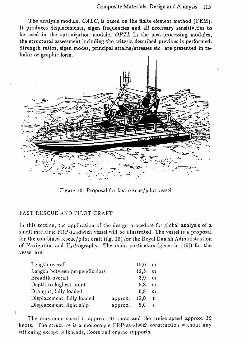
Composite Materials: Design and Analysis 115
The analysis module, CALC, is based on the finite element method (FEM).It produces displacements, eigen frequencies and all necessary sensitivities tobe used in the optimization module, OPTI. In the post-processing modules,the structural assessment including the criteria described previous is performed.Strength ratios, eigen modes, principal strains/stresses etc. are presented in ta-bular or graphic form.
, - . t-,. --r- - o -..-
Figure 10: Proposal for fast rescue/pilot vessel
FAST RESCUE AND PILOT CRAFT
In this section, the application of the design procedure for global analysis of asmall maritime FRP-sandwich vessel will be illustrated. The vessel is a proposalfor the combined rescue/pilot craft (fig. 10) for the Royal Danish Administrationof Navigation and ]lydrography. The main particulars (given in [10]) for thevessel are:
Length overall 15,0 inLength between perpendiculars 12,5 mBreadth overall 3,9 atDepth to highest point 5,8 mDraught, fully loaded 0,8 ?nDisplacement, fully loaded approx. 12,0 tDisplacement, light ship approx. 8,0 t
The maximum speed is approx. '10 knots and the cruise speed approx. 35knots. The Structure is a monocoque FRP-sandwich construction without anystifreitg except blIlk-heads, floors and engine supports.

11tt0 omposite Materials: Design and Analysis
Figure 11: Detailed body plan of the vessel
Geometrical modelVessels of this kind haLve to be assessed with respect to various loadcases and failurecriteria. The load cases should also include the inertia forces initiated by the largeaccelerations the structure is exposed to. Furthermore, the global eigen modeswould be relevant to determine, although, they are not treated in this example.For these reasons, it is not sufficient to analyse the structure through simplelocal models as often seen for larger ship structures. It has to be analysed usinga global model.
The element mesh on deck, hull and transverse bulkheads has been gene-rated semi-automatically by the YACH pre-processor using a detailed body planof the vessel including superstructure and cockpit (fig. 11). Depending on thecomplexity of the hull and deck surfaces, usually more than 90 % of the elementsare generated automatically by this pre-processor.The model is transferred tothe module, MODI (fig. 9), where the longitudinal bulkheads and the floors aredefined. In the same module the final corrections can also be done.
Due to symmetry with respect to both geometry and loading, only one-halfof the structure is modelled. In figure 12 the final mesh of the 689 triangularparabolic sandwich elements in the model is shown. Engine supports and window-friames are modelled using 57 two-node Timoshenko beam elements. The enginesupports are GRP-profiles while the window-frames are aluminum. The totalnumber of nodal points in the model adds up to 1379.

Composite Materials: Design and Analysis 117
Figure 12: FEM mesh onl half-structure generated by Y4ICII
MaterialsLow weight is essential, if the current type of vessel should be able to fulfilthe demands. In this example, the weight is reduced using materials with highstiffness and strength properties. Therefore, the properties has higher prioritythan the costs. The FR.P-laminates for the skins are mainly UD-layers withS-glass reinforcement and epoxy resin. In the bottom, they are furthermorereinforced by two layers of high strength carbon layers. The finish layers arethin CSM layers with E-glass rein'forcement. The panels are painted with epoxypaint modelled as a no-stiffness layer only including the weight calculation. Forthe core, PVC foam of densities from 60 to 100 kg/ni 3 and thicknesses from ,40to 50 mm has been chosen. The material types defined by the module, COMP,are listed in the tables 1-4. For reasons of simplicity, only four sandwich typeshave been specified for this example but in fact,a considerably larger number oftypes would probably be defined in the actual design of the vessel. The referenceorientation of the material types (0 = 00) are defined by YACH as natural curvesfor the skin laminates ("great circles").
LoadsAs previously stated, many different load cases have to be taken into account forthis kind of vessel, where the dimensions are close to the allowable. Still, onlythree load cases are treated in the current example. These are:
1. Slamming pressure on bottom at high speed
2. Water pressure on freeboard and superstructures ("green sea")
3. St.tic water nressut ro on internal] strii crHms (floondin-

I t) %.JIhVptJILC IVIULCI IdI1ý. LJCSMkAI caIIU /1IliIVýIS
TYPE Identification M! W Price Weightno. [kg/in21 [%] [dkr/m,2J [kg/rn 2 1
1 .S-glass/UD 0,40 60,0 83,5 0,522 HS-carbon/UD 0,50 60,0 656,6 0,723 E-glass/CSM 0,20 22,0 19,5 0,524 Epoxy paint - - 9,0 0,12
Table 1: Layer types applied for rescue/pilot craft (ýp: volume fraction)
TYPE Layer sequence Layer orientation
1 4;3;1;1;2;2;1;1;3;4 00; 00; 0O; 450; 90; 900; -4500; 00; 002 4;3;1;1;1;2;2;1;1;i;3;4 00;0o;0o;45; -450;900;90; -450; 450; O; 0; 0o3 4;3;1;1;1;1;3;4 00; 0o; 00; -450; 450; 900; 00; 0*4 4;3;1;1;i:1;1;3;4 00; 00; 00; -450; 450; 90o; 00; 00; 00
Table 2: Laminate types applied for rescue/pilot craft
The slamming pressure has been determined for a head sea with a wave heightof 1.5 meters and a 20 knot speed to be approximately 0.1 MPa, using a non-linear strip theory analysis (Petersen & Mariiws [11]). The slamming pressure hasbeen distributed as shown in figure 13. It is scaled by a a dynamic amplificationfactor of 2. Large water pressures on the freeboard, superstructures and internalstructures can occur on this kind of vessel. The design pressures for the secondand third load case iii the example are taken from the rules of the classificationsociety Det norske Veritas (DnV) [12]. Evidently, all three load cases consistof linear distributed pressures. In the pre-processor, YACII, it is possible togenerate such pressures on specified areas automatically.
Inertia forcesIn each load case, the external forces are balanced with the inertia forces. Themodule MODI facilitates the definition of inertia forces (i.e. gravity), generatedas distributed loads on each element. After generation of nodal point loads, the
TYPE Identification t. [m] Price [dkr/m 2J Weight [kg/m 2]1 Divinycell 11-60 40 x 10- 3 275,- 2,42 Divinycell H-60 50 x 10-3 320,- 3,03 Divinycell 11-80 50 x 10-3 400,- 4,04 Divinycell H-100 50 x 10- 3 650,- 5,0
Table 3: Core types applied for rescue/pilot craft

Composite Materials: Design and Analysis 119
TYPE Application Sk. I Core Sk. 2 Price Weight
no. [dkr/r j21 [kg/M 2 1]
1 Bottom 1 4 2 4226,- 15,62 Freeboard 3 3 4 1266,- 11,2
3 Deck & floors 3 2 4 1186,- 10,2
4 Miscellaneous 3 1 3 1057,- 9,1
Table ,4: Sandwich types applied for rescue/pilot craft
Pmax.=0.2 MPaIigir', 13: Distribution of the slamming load
rcsuilting (xtIrlal forces amd moiviats are determined by the module .fODL
Firtheritiore. the total IaV., 14", inchuding nion-strijctiral masses, the center ofgratvity il gloal cooirdiiiat.cs, (X.., V> Z. auth the LlaSS onoiuielit of inertia, Ip.
1rC dtlermiiili I)v the s;uItme 110od(le1. In the current ex;iaiple, oily the force andto1uziejnt cor poiten ts "., F]: ;LId M1y hatv, to be balanced with the inertia forces
(lie to the symmetry. These are defined with respect to the center of gravity.
The corresponding accelerations at the center of gravity are found:
" = 11' = : F..'•' = -I7
leading to the inertia force components per area of element i:
q(.(X, Z) = -7i (a, 9 + &,9 (Z - Z9))q2(X, Z) = - -f (a., - Qf9ý (X - X9 ))
with -ti as the element mass per area. Similarly, the contribution from the non-
structural mass tj located in the nodal point with coordinates (Xj, Yj, Zj):
fj = -wj (ag, + l.Z4y (Zi - Z79 ))
fLj = - oj ((a:2 - (:,/: (Xj - Xq))f 9 j = -,1j ,'u7
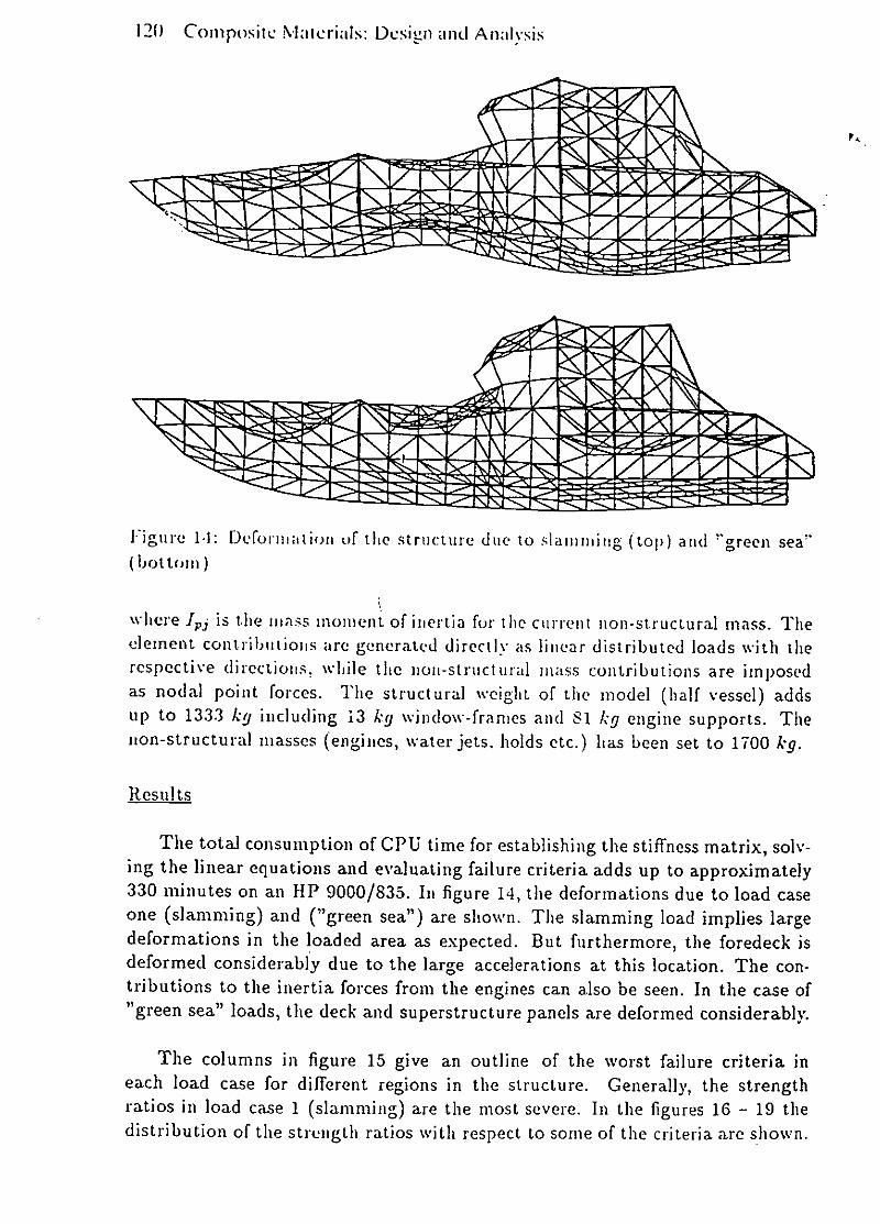
120 Compositc Nialcrials: Dcsign and Analysis
lYigire 1-1: Deformation of the structure due to slainiiiiig (top) and "green sea"
(bottonil)
where J,. is the lijass moment of inertia for the current iion-structural mass. Theclement contributions are generated directly as linear distributed loads with therespective directions, while the noni-structuird mass contributions are imposedas nodal point forces. The structural weight of the model (half vessel) addstip to 1333 kg including 13 kg window-frames and 81 kg engine supports. Thenon-structural masses (engines, water jets. holds etc.) has been set to 1700 kg.
Results
The total consumption of CPU time for establishing the stiffness matrix, solv-ing the linear equations and evaluating failure criteria adds up to approximately330 minutes on an iIP 9000/835. In figure 14, the deformations due to load caseone (slamming) and ("green sea") are shown. The slamming load implies largedeformations in the loaded area as expected. But furthermore, the foredeck isdeformed considerably due to the large accelerations at this location. The con-tributions to the inertia forces from the engines can also be seen. In the case of"green sea" loads, the deck and superstructure panels are deformed considerably.
The columns in figure 15 give an outline of the worst failure criteria ineach load case for different regions in the structure. Generally, the strengthratios in load case 1 (slamming) are the most severe. In the figures 16 - 19 thedistribution of the strength ratios with respect to some of the criteria are shown.

Composite Materials: Design and Analysis 121
R R
1,0 -- -------------- ------------- --------------- 1,0
0,8 -0,8I
0,6 0,6
0,4 :0,4
0,2 0,2
1 '2 3 1 '2 3 1 23 1 23 12 3Wrinkling Wrinkling Strength Strength Strength
skin 1 skin 2 skin 1 skin 2 core
Figure 15: Outline of worst strength ratios ini the three load cases. Filled columns:hull elements, (lotted columns: deck & superstructure, empty columns: bulkhead& floor elements areas represent the worst loaded parts of the structure.
The critical area with respect to the strengt h, iii the core is obviously theslamming area where large trativerse shear stresses occiiur. .\n earlier evaluation[2j of the same structure without tile floor and sears ini the cabin resulted in astrength ratio value of 1.2Sagainst the current O..SS. Thus. the internal structurecarries a con-.iderable part of I hlc loading.
Figure IS intlicatcs, thIat the worst lo;tdetd areas with respect to wrinkling ofthe outer skin are dist.ributcd over large parts of tile structure. Hfence. it wouldnot be possible to evl:uhate this 1rileri;L In slimple ioca dodels. Still. in loadcase three (floo'hin'4) tile struict ire seems to be loaded very local witdi resspect to
)Figure 16: Strength ratio with respect to strength failure in the core due to
sI a mil i ill

122 Composite Matcrials: Design and Analysis
Figure 17: Strenglth ratio with respect to strength failure ill skin 1 (inner skin)due to sladming
Figure 13: Strength ratio with respect to wrinkling of skin 2 (outer skin) due toa "nreen sea" load
the strength iln the outer skin. In this case, a local analysis would probably besufficient.
From the above evaluation, the structural design is feasible with respect tothe three load cases. However, only safety factors due to material fabricationshave been taken into account.Froni the evaluation, it seems that the design couldbe improved by reinforcing the floor support structure and by applying a stronger(heavier) core material in the slamming exposed area of the bottom. On the otherhand the scantlings could be reduced in other areas. However, such improvementsrequire an evaluation with a larger jitinuber of material types as mentioned earlier.
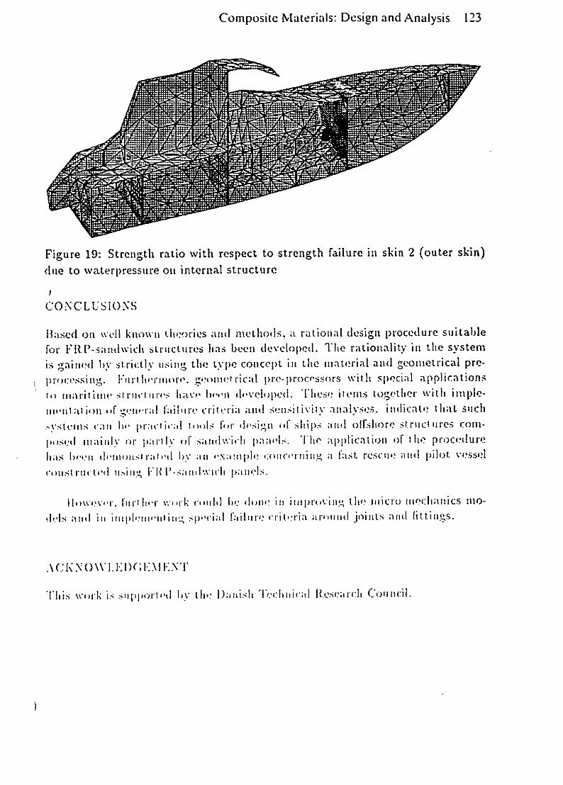
Composite Materials: Design and Analysis 123
Figure 19: Strength ratio with respect to strength failure in skin 2 (outer skin)
due to waterpressitre oil internal structure
C ONCL U.S ION S
13 flS ol on wd I k ["lOW 1. iii 'ori es andu met hod s. a rationiiat design procedure suiiitablefor F' ItP-.sandwich si-i rucinres has beent developed(. Tile rationlality ill tile svsteml
is gained bysrcl iig thle type conicept ill tIL miatrial and gconiiet rical pre-pri nwessi InIg. FTItI It, lrIIIo ro g-onivt ricalI I)N re- rocossnrs wvit It s pecialI a pp!I ic.at; onsill 1wanit[Inc iv srurl~inrls ll;ilv' lu'rn IldvCII)J)C(. [lleoics'ŽIICIs wgth-ter with iniiijlC-
tiiiu.;t jloltn c~~u 111 crici antji senisilivilv anialvses. izlicathat l tintsch
'v~steitis cran bo I cl mos For 'h'sigrt o 4ipi 511111aii olfsliorc, siruci 'res corn-
I)O('liiainl (or 1);11.1 of satilw~icli pan''l. TjI ;tpplication of the procedlureha;s bruitl (1.1ol.'zms At''ul bY anil Ilpl! *'c!I~ orIC"''min Ig fa st rCsclIi, midt pilot ve~sselcoutst rut, to'l tI.illUI-iiItlJ)R.'.
hut h~ ~'..k ii biiI do'! ilill iillj)Irivill.tU2 fluenlicit) iiincliaiuics mlo-sie-I anid ill iiitiplilri'iititill sp.ciaul fhilliro critoria anI)iIiiI(I joints anid fitting-s.
[hiis wor)k k• sipol~)Idl bY Owm l):Ilzisl: T-Jlcriiii;lI Itcsenrcl Counzcili

124 Composite Materials: Design and Analysis
NOMENCLATURE
Scalars:
a, b, d, 1, t ...... : geometrical dimensionsP.............. :fibre volume fractionP ............... function representing layer stiffnesses77 ............... . relation between stresses in fibre and resina, r, e ........... direct stress, shear stress and strainE, G, v .......... Youngs modulus, shear modulus and Poissons ratioF, M .......... external forces and moments.. : angle
m ............. : fibre intensityp .............. : densityIC, y ........... : non-dimensional load ratio and length to breadth ratioR1 .............. : stength ratioP .............. : pressureq .............. : inertia force per unit areau, v, w, Ou, Oý ... : degrees of freedom in sandwich element,V ............. : weight
Matrices:
T .............. angle transformation matrixC .............. plane stress constitutive matrixK,M ......... : stiffness and mass matricesH, B ........... deformation and strain interpolation matricesQ ............. load vectorA .............. principal strains in skin
Indices:
c, 1, s, w ....... : core, layer, skin and honeycomb cell wallf, r ............ : fibre and resinu .............. : ultim ateL, T, x, y ...... : fibre axes and orthotropy directions of layerUD, CSM .... : unidirectional and chopped strand mat lamina

Composite Materials: Design and Analysis 125
REFERENCES
[1] Tsai, S. W. &, Hahn, H. T. : Introduction to Composite iVater?'(Ls, TechnomicPublishing, 1980.
[2] Rasmussen, J. & Baatrup, J. : Rational Design of Large Sandwich Struc-tures, First Int. Conference on Sandwich Constructions, Dep. of Aeronauti-cal Structures & Materials, The Royal Institute of Technology, Stockholm,Sweden, 19-21 juni 1989.
[3] Gibson, L. J. & Ashby, M. F. : Cellular Solids. Structure V Properties,Pergamon Press, 1988.
[,I] Rasmussen, J. : Rational design of Ships using Sandwich Elements, Pro-ceedings of Mechanical Characterisation of Fibre Composite Materials Sym-posium, Aalborg, Denmark, pp 213-236, 1986.
[5] Ahmad S. , Irons, B. M. & Zienkiewicz, 0. C. : Analysis of thick and thinshell structures by curvcd finite clements, Int. Journal for Num. Methods inEngineering, vol 2, 1970.
[6] Pawsey, S. F. &: Clough, R. NV. : Improved Numerical Integration of ThickShell Finite Elements, Int. Journal for Num. Methods in Engineering, vol 3,1971:
[7] Zienkiewicz, o. C. & Taylor, It. L. : Rcduccd Integration technique in General.. 7nalysis of Plates and Shells, Int. Journal for Nurn. Mcitods in Engineering,vol 3, 1971.
[8] Plantema, F. J. : SandWich Constructions. The Bending and Buckling ofSandwich Beams, Platcs, and Shells, John Wiley & Sons, 1966.
[9] Rasmussen. J. & Baatrup, J. Strength Analysis of Transversely Stiffened
Sandwich Refrigerate Container, (in danish) DCAEG news 4, 1987.
[10] New lifeboats for Denmark, Small Craft, journal from RINA, sept. 1988.
[11] Petersen, J. B. & Marnes, L. : Comparison of Non-linear Strip Theory
Predictions and Model Experiments, Proceedings from PRADS 1989.
[12] Det norske Veritas: Rules for Classification of High Speed Light Craft, DnV,1985.

PROPOSED SEMINAR FOR SHIPBUILDERS
CREATING THE FAIR GEOMETRY
OF
FREE-FORM CURVES AND SURFACES
Copyright
George R SnaithPi-SigmaMorpethNorthumberland
April 1991

Sub Title
An introduction to the technology
and
practical use of the family of B-Splines
from Bezier to NURBS

1
INTRODUCTION
The target audience for this seminar are those members of ProductEngineering and Production Engineering teams, as well as theirsupervisors/managers who are responsible for creating andevaluating:
the geometric design-definition
and
the corresponding manufacturing definition
of the curved surfaces of industrial products in general and shipsin particular.
The emphasis is on:
illustrated explanations of the characteristics of B-splines
and
practical strategies for their efficient and effective use
plus
guidance on how to avoid bad practices.
The content of the seminar will be readily understood by those whohave completed:
a traditional training course in design-by-drafting orlofting
the mathematics part of a traditional ONC engineering course
or equivalent
and whose subsequent experience includes:
the drafting or lofting of curved surfaces using eithertraditional, manual or computer-based techniques.
It would be useful but not essential if they also had some initialexperience in the use of computer-based 2-D and 3-D interactivegraphic systems.
Almost all of the text books and the many hundreds of publishedpapers and articles which explain the technology and development ofB-splines do so by using very sophisticated mathematical methods.
)

2
These, c course, provide a very necessary basis for thetechnology, especially for those who develop the necessary computerprograms tor use in 2-D and 3-D interactive graphic systems;however, zn.ey are a very poor means of explanation for the vastmajority oi actual and potential users of such systems.
For potential users - such as the targetted attendees of thisseminar - easier-to-understand explanations of what the family ofB-splines are and how they can be used are given. These faithfullyreflect the rigorous mathematics referred to above, but are couchedin an easy-to-understand combination of:
easily constructed graphical methods
and
elementary, but nevertheless powerful algebra.
The seminar also sets B-splines and their uses in the context of thebasic characteristics of:
- french curves
and
weighted physical battens (splines)
and the traditional methods of using them to create the fairgeometry of individual plane curves and sets of intersectingcontours representing curved surfaces.
The information in the seminar about B-splines and their use will beindependent of any specific implementation of such technology by thevendors of particular interactive graphic systems.
Examples in the Seminar of the use of Bezier/B-splines will include:
range of surface ship types
- chined fast patrol boat- whale-backed destroyer
- submarines
aerofoil sections
- NACA type- high performance types used for propellers.

INTRODUCTION,
The target audiences for this paper are:
-primarily, senior product development managers and engineersof companies who are marketing, designing, manufacturing andsupporting in-service physical engineering products,
and
-secondarily, those who design, market and sell interactiveengineering graphic systems.
Hopefully, it will be of interest to those who are either:
-currently establishing their requirements for such systemsand evaluating the commercially available CAD/CAM systemsagainst these,
or
-evaluating their in-house use of such a system with a viewto making in-company changes in the way it is used to createand be a source of product information, so that bottom-linebenefits are increased.
The scope of the paper involves discussions and explanations of:
- the concept of a product database;
- the nature of traditional engineering drawings - what theyare, and what they are not;
- the complementary role and inherent limitations of varioustypes of physical models;
- the related notions of 2-D and 3-D graphical productmodelling,
and
-an outline of the basic user requirements for a modern, 3-D
CAD/CAM system.
Implicit in all of this is the need for:
-many current users of CAD/CAM systems,
plus
-those who are contemplating and assessing the needs of theircompany for such systems to think through carefully whatis:

SCOPE
The messages of this seminar will be largely expressed as answers toa structured set of questions. The latter include:
1. a) What are the 7 basic factors which need to be consideredwhen deciding the acceptance criteria for the curves andcurved surfaces of specific industrial products?
b) What are the implications of these for the practice ofconcurrent/simultaneous engineering?
2. a) What is meant by curves and surfaces being geometricallyfair?
b) How can geometric fairness be objectively measured?
c) What are the characteristics of intrinsically fair curvesand surfaces?
3. a) What are the principal geometric properties of:
- french curvesand- veighted, physical battens (splines)?
b) What are the basic rules for their effective manual use increating, graphically, the geometry of individual and setsof intersecting curves?
4. a) What are Bezier curves?
b) How can plane Bezier curves of any degree be constructedusing simple manual drafting techniques?
c) What are the inherent limitations of Bezier curves? How canthese be partially overcome to increase their flexibilityand hence be able to modify their local or global geometry?
d) How can Bezier curves/surfaces be used to create thegeometry of fair, free-form curves and surfaces?
e) What are the algebraic equations which can be used tocalculate the geometric coordinates of 2-D and 3-D Beziercurves?
5. a) What are the members of the family of B-splines?
b) What are the basic differences between them in terms of whatthey can and cannot be used to do?
c) What is the relationship between Bezier and B-spline curvesand surfaces?
)

4
d) How can the different members of the B-spline family be mosteffectively used to create and modify the fair geometricdefinition of curves and surfaces? What User strategies areequally applicable to all of them?
e) What parameters are or should be available to Users tomanage the use of B-splines effectively and efficiently?
6. a) What are the basic characteristics of:
- strings- bi-arcsand- B-splines?
b) How are these used to achieve continuity of:
- position- tangencyand- curvature
when joining curves end-to-end?
7. a) What are the basic characteristics of coordinates of pointsmeasured (or otherwise derived) from'curves whose geometrywas created using other methods in another media, (eg,manual drafting; physical modelling)?
b) How can unintended irregularities in the geometry implied bysuch sets of coordinates be identified?
c) What is meant by:
the interpolationand- the approximationof- the coordinates of points?
8. In what ways would it be possible to use B-splines to definesurface geometry such that it can be modified and enhancedat any time in the design and preparation-for-productionstages, without having to interpolate or approximate, atsome intermediate stage, the coordinates of points measuredand transferred from a definition established in anothermedia? Would this significantly help to eliminate thecurrent bottlenecks of achieving a satisfactory geometricdefinition of the moulded hull surface of any ship that issuitable for both design-evaluation and production?
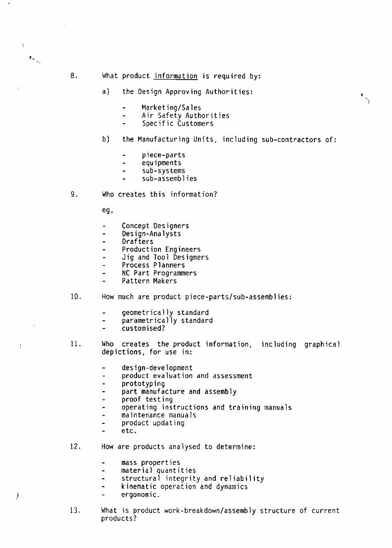
8. What product information is required by:
a) the Design Approving Authorities:
- Marketing/Sales- Air Safety Authorities- Specific Customers
b) the Manufacturing Units, including sub-contractors of:
- piece-parts- equipments- sub-systems- sub-assemblies
9. Who creates this information?
eg,
- Concept Designers- Design-Analysts- Drafters- Production Engineers- Jig and Tool Designers- Process Planners- NC Part Programmers- Pattern Makers
10. How much are product piece-parts/sub-assemblies:
- geometrically standard- parametrically standard- customised?
11. Who creates the product information, including graphicaldepictions, for use in:
- design-development- product evaluation and assessment- prototyping- part manufacture and assembly- proof testing- operating instructions and training manuals- maintenance manuals- product updating- etc.
12. How are products analysed to determine:
- mass properties- material quantities- structural integrity and reliability- kinematic operation and dynamics- ergonomic.
13. What is product work-breakdown/assembly structure of currentproducts?

Maritime Communications and Control1 -23 November 1990
New systems for use in managingoperational documents of ships andplatforms
G R Snaith, BSc, CEng, FRINAPi-Sigma
SYNOPSISThis..;per describes from a user's point of view, the range of media traditionally used to create and store information
9OtH engineering products, the largely paper-based document management problem associated with engineeringproduc:s, the scope of documents used in the maritime industries, the basic requirements for a document managementsystem. digital "mages, and the imaging based document management solution. It also provides a summary of publicinfornmtrion about some maritime uses of imaging-based systems. especially the British Petroleum Gyda project, andexamires thefactors to be considered when establishing the economic case.
INTRODUCTIONG R Snaith has previously worked as a Consultant
The :urpose cr this paper is to present some information on with Prime Computer (UK) Ltd. Computervision Inc; asthe technology of digital imaging, and to examine the practi- a Director of Research at the British Ship Researchcal uses of commercially available document management Association and British Shipbuilders; and as a Consult-systems which are based on this and other enabling technol- iIng Naval Architect with Burness Corlett and Partners.gies. He is currently Technology and Systems Advisor at Pi-Sigma, and is also a Visiting Professor at the Depart-The s•elected applications are taken mainly from the marl- ment of Marine Technology. University of Newcastletime industries, with special regard to military ships and upon Tyne.offshore platforms.
WHAT IS DIGITAL IMAGING? THE PAPER-BASED DOCUMENT
From the user's point of view, digital imaging is an MANAGEMENT PROBLEMelectronic-based means of unifying the disparate represen-taton ci the content of documents containing, for example: Many of the operational and management activities in allI. formally drafted graphics: industries are bedevilled to a greater or lesser extent by the need2. free-hand graphics; to manage large, (sometimes vast), quantities of paper-based3. all fornted texts and ideograms: documents, which are known or expected to contain the infor-4. apertre card images: marion required to satisfy specific requirements. Such siua-5. word processing files: tions rarely, if ever, function smoothly, promptly and effec-6. computer-aided design and dmfting database files; tively. They are, of course, forever trapped by the intrinsic7. coiour and black & white photographs; shortcomings of the technology they employ, such as:S. vicco frames: i. the different media used to create them;9. maos. 2. the differing indices created as referencing identifiers for
Whaicvcr form their original representation, all are urans- documents created in each media:formed by the process of scanning into a single form of 3. the different physical locations where each are stored:representation, ie raster (pixel based) images (see Fig 1). 4. the disruptive effects of authorised changes which result
Imaging separates paper-based information from its physi- in updated documentation, followed by its re-issue andcal medium, liberating it for rapid access and distribution. distribution and the time lags which all this implies:This enables itto be managed by computer-based techniques. 5. the effects of documents not being returned to their).us, paxr as a storage medium is jettisoned. correct storage location:
.\tarit•f.t C:-'vnu~tcs::os andl cntrol •165
Z Atortne .'.,L-tornta: Hoidinres 100

6. the effee•s of physical damage and detwrioration of paperdocuments. especiallv whIlere this dercades ,he quaizit ofthe information they contoa; Normg 2.:- -. aooe:•;# Zr;-
7. litde or no cross-linking. ti 11In short, there is little integration and many opportunities to
The direct and overhead costs of such ways of working canbe very Iarze" these are compounded when allied to the lost I asieeropportunity costs.
THE SCOPE OF DOCUMENTS USED INTHE MARITIME INDUSTRIES Vet!or
Typical documents available for use at various stages in thelife cycle of large engineering products typified by ships, semi-submersibles and production platforms, etc, include:
1. engineering drawings;2. specifications:3. operational and maintenance manuals: Drawing4. safetv and classification documents;5. systematic sets of photographs;6. refit drawings and specifications;7. correspondence and meeting reports.
During the design and construction stages of such enwincer- R ,,,n,ct are c:sayaved as individual o:rs on he SC;een. Eac.'
ing products there are often multiple versions of these docu- pixel is usually not associatec with c!s negnoouf.ments, many of which, in a paper-based system, remain incirculation and in use long after they have been superseded by mat.a when azstiea to the apsroohaies t atsnerr.3t algofltfl.cre .the latest approved, updated version. tne true sn.oe wilt be renoerec at ire ououLt Hc.ever. a
Also during these stages, owners/operators of large engzi- ocrnouier cis.1ay is a caster oevmce trnecre tne lineness Olthe renoering on screen will oe oete'mne, by :ne resotu.tor,
neering products begin to experience many of the difficulties a: the screen.associated with managing large volumes of paper-based prod-uct documentation, as they carry out. generally in paralilel with ,c : Otte-isare stored asmarksona mecium. ie Denoap-r.the statutory and classification authorities, the red-lint ni idei- n. air tree cases. iniervreialton is governed ov an ndividuars abiiity. sotification of changes which are required as a re;ult of the c.-ertmhne s.aoe ano contour oy nse Ieness c! Ine resomtit.on. she
process of design assessment and plan approval- cz..1nuity of the oxeis anl the rtagniicatic lact:or.
This is inevitably followed by the voluminous documenta-tion such as QA inspection records, etc, associated with con- Fig 1: Definition of raster, vector and drawingsuruction and commissioning.
Post-construction and hand-over large quantities of 'as-built' documentation, especially paper-based drawings andtraining, operational and maintenance manuals, are supplied to vessels where each must, of course, be treated separately forowners/operators for immediate availability and reference documentation purposes, even when they are nominally
during daily operations, for all the onboard engincering sys- identical.
tems and equipment. Duplicate copies are also held by shorebased support staff.
These documents are produced by many different equip- THE BASIC REQUIREMENTS FOR Ament supply companies, as well as the principal cor.~aciors: DOCUMENT MANAGEMENT SYSTEMgenerally they involve the use of different media to createthem, but all are supplied as paper documents.
The need to access efficiently relevant informatton :n this During the latter half of the 1980s, document managementmass of documentation is required when: systems based on imaging, etc have been used to great advan-
I. things go wrong; wage in what may be informally described as the A4 paper-2. operating crews change; based businesses, for example banking and insurance. The3. regulatory inspections are made: majority of these uses are static, ie the information contained4. planned and unscheduled maintenance is carr;cJ out: in them is not subject to change by those who access them.5. operational difficulties are reported: In the context of engineering type products, document6. refits are being planned, executed and re-commissioning management systems need to be dynamic, ic those users
takes place; accessing individual or related sets of stored documents need7. serious accidents occur, to be able to carry out a wide range of functions relative to them8. the product is sold on. and their content.
The importance of all of these is underscored as the onboard From the user's point of view, these functions include theengineering systems become more sophisticated. ability to:
For fleet owners/operators, the problem of documcntl/in- 1. browse;formation management is compounded by the number of 2. highlight recommended changes by red-lining;
166 9,1arur Ca vn,±cd:wns and LontOi

I... .S 1. 3
X, ! ,4304.
L fT
I -.- " ,4
The extraneous markings on the right-hand side clearly snow that the original scanned drawing was blemished, so mrat :.': claritywas seriously impaired: the left-hand side shows the effectol automatic clean~ing of the image underthe conlrci of trre user. Othertypes of unwanted blemishes, eg evidence of staining, damage and repair, can also be eliminated by t he user. c~rec:trg thesystem to do so.
Fig 2: Raster image of a typical engineering drawing
3. pan and zoom large documents: 2. dc-skewing of drawings;4. tile maps and other large continuous documents: 3. calibration of drawings as a basis or measurement:5. modifying the graphics of drawings and the assoc::ted 4. cl'aning up to remove signs of deterioration or uamage totext annotations; drawings (see Fig 2);6. rscale 5. erasin and re-c.7. compose new, purpose-designed, documents by r.atlinl ing uncl"ear gp hc: nmonuaging (electronic cut and paste); depende-ncies (see Figs 3 ,-4 and 5).S. add new documents; The last is the basis for carrying out directed. svs:emauc and9. hard copy; and wildeard searches.10. control access, changes, searches recording of rev ision
history, release, distribution, notification, archiving,backup and recovery.A principal requirement is to make the current approved THE IMIAGING-BASED DOCUMENTversions ofdocuments readily and. if necessaryConcurndA G N L
available at closely or widely spaced locations to indi% cuatsMA GE NTS L IOwith the coectracces credentgls so that they can carry ou tanaow the above functions for which they are authorisede Durin g the past few years. businessand industry ,.82,encra,Capturing engineering-type documents requires: have lo-ked to innovative electronic systems ngs pr:);.e Flw.). scanning; fre eri and reliable ways wvhich can eca :j ove-
.thraist Coryc 'Cases ndCtrol n i o 167

come the problems of document and, hence.information managemenL. The nettresultso DCCL 5, EN .far has been the development of various, DOC. ',N:E'"i L A::"N Gcommercially available, computer-based ....document management systems, some ofwhich fully satisfy the requirements listed -- '-above.' -. "Y.2,- I_
The underlying technologies which have v,:_.• S ,enabled the systems to be developed and -'_ J1 i -. v.marketed include: ,- u'c" .... ,ta, I,
I. raster type imaging by scanning - this, I LC
is the cornerstone technology; • Iiic,-.2. data compression of these raster im-ages to minimise the storage required;: -, ;C CO ,• e •"n'
3. relauional database management svs- 04 -I::1tems, eg ORACLE, INFORMIX,.. -LNGRES, used to manage the indexingc o.tcacse.and relationships of the raster images i cue•y i.e. hok\of the scanned documents; Ui cC.oICC , %.-f
4. compact, highcapacity, mediaforstor- XOJECT RNing large quantities of data, eg optical -o, ,\ -discs; Dcte ý I
5. full-text search and retrieval; t•- 7ooI' J W!6; high performance personal computers , r-' :s'zice-
(PCs) and work stations; irf-..-7. DOS, UNIX and AIX operating sys-
tems; r8. electronic networking, eg Ethernet, tl c est
etc. \'nmic cc.meM ;-.&sFor the most part. current commercially -. < ,,' '" - - . 2
available document management systems - nk c c.'ne .zare fastbecoming'open. modular systems'.rI :- "- -:. .. -c!,-:
Theirconstituentequipmentsandbasicsoft-ware are standard, off-the-shelf commodi- iLies. A suitableconfigured selection of these- I -,- , ' . .form a svstem tailored to the needs of a -c.' -... .- ... z -,specific situation. Increasingly, more atten-tion is being focussed on designing and e-,ce.zS -•. :c"' • vdeveloping solutions to satisfy the needs ofspecific application situations. Fig 3: Some of the features of document linking
A SUMMARY OF PUBLIC INFORMATION 4. British Petroleum (BP)JA.' used a Cimage DrP based docu-ABOUT SOME MARITIME APPLICATIONS ment management system during the design and construc-tion phase of their Gyda project. BP's objectives for thiswere as follows:
1. The US Department of Defence computer aided logistics a. provide a means of electronically storing all drawings.support (the CALS initiative). This will establish stand- (both current and previous revisions), with no manualards for the computer-based transfer of data between all backup;contractors, suppliers and to the Department of Defence. b. provide a fast means of retrieval of all drawings by
2. UK MoD(N) sponsorship of 'Bookworm: a technology simple input of a project document number;demonstrator for the storage and retrieval of technical c. provide a single central source of drawings for theinformation in ships'. 2 product that everyone has access to;
3. Amerada Hess Limited, in association with E ' Weston d. issue all drawings to fabrication sites and offshoreLimited, prototyped the use of a digital image processing electronically;(DIP) system to track the certification generated by the e. provide a method for fabrication sites and offshore to..strict testing programme carried out at the fabrication access and plot any drawing that maybe requested fromyard, where a semi-submersible vessel was converted document control at the remote location:from an oilfield support role to a floating production f. allowelcctroniceditingofdrawingsheldontheimagingfacility. This application of DIP was judged to be a system;success.' Amerada have published their intention to con- g. allow 'red-lining ofcommentson drawings to illustratesider including in their next offshore project: modifications recommended by offshore personnel;a. certification documentation; h. provide an efficient means of handing over drawings tob. correspondence filing; the operator at the end of the projcct:c. engineering drawings; i. provide a storage media that will not degrade with timed. vendor information. or use;
1 6S ,uune Corun.csusroc jnd Control

46-
-J r ' 7 Z.L> 0
*7 7LZ4ZZ
/ - I ~0
T. 5
C. a.-2F-tj~
-~ t~noN
-: - E- -I. - --- W 8 a 90 0
C-..Cel M 3~ 0Z
lz,I O0
cx4.- - - - - - - - - -- - -750
Z0
-n'0 169-n -= c

0i -.
-Js document has been composed by 'cutting and pasting' electronicatly from a photograph and a drawing previously stored- :he system.. zecial note should be taken of the automatically blown-up images of local regions, selecded by the user, of the raster imagesz' both the photograoh and the drawing.
Fig 5: Example of a composite document
to reduce document control manpower and mailing FACTORS TO BE CONSIDERED INtime/costs. ESTABLISHING THE ECONOMIC CASE
.he benefits BP are considered to have achieved arc, asfelzOwS:
a. reduced storage; The key factors, as in all such situations, include:b. right document at the right time: 1. What are the real costs of the present system of documentc. elimination of use of superseded drawings: management, including the lost opportunity costs and thed. speed-up of distribution; cost when delays, abortive work, etc, are incurred due toe. controlled distribution: the non-availability of the right information at the rightf. maintained drawing quality and improvement of pro- time?
duction; 2. What does an image-based document management sys-g. managed 'as-built' documentation; tern enable one to do, which is manifestly beneficial,h. indexed library- for further applications (cg disaster which could not be done before?
recovery); 3. Does the current 'system' have any potential for signifi-c maintained drawing quality for platform life span cant improvement?
reduced costs. 4. What benefits should one aim to achieve and why?is likely that BP have reconfigured theirCIMAGE system 5. What are the monetary values of these benefits?
an& transferred equipment from the yards used during the 6& What rules-of-the-game must be put in place to ensureconstruction phase, so that the emphasis of use is now on that targetted benefits are consistendy achieved?onboDard operations and communications between platform 7. What is the cost of an appropriate well-designed image-of'Jzudng personnel and onshore support staff, based document management system?
-. ,)~diil Ollr1/ildi,,$•,k •~lrl

CLOSING REMARKS 3, M H Owen. "?Žt lessons. 2rc ntcntior.s Ainr2da HessLimited.
. 'The image of efficient desien" in Document Image Process:'ŽFrom the user's point of view,. document management (October 1989)..vstems are relatively easy :o use. They hold out the promise 5. R B Liddeil. 'Use of elecronic imaging system on a matorof a unified reliable system for the storage. 3ccess and distri- offshore project'. international Technology Conference (,a-hbution of all forms or' documented informauon. 1990).Used correctly they can ensure that the right package of
information is made available at the night time to those whoneed it. without them having to cope with the traditional BIBLIOGRAPHYproblems of the paper dominated "systems' of the past. IO )
i. 'Implementing image processing systems strategies and solu.REFERENCES tions, Conference Proceedings (March 1990) (available fromthe Conference Organisers. Blenheim Online Ltd, Pinner, HA5
2AE. UK).1. 'BP - riding the tide of document control'. Fact Sheet. Cimage 2. 'Document image processing '90", Conference P:oceedingsInternational Limited. Bracknell. (March 1990) (available from the Conference Organisets,2. 1 R Thomas and D S B inks. 'Bookwormn: a technology demon. Blenheim Online Ltd. Pinner, HA5 2AE. UK).strator for the storage and retrieval of technical information in 3. 'Image Processing '90", Conference Proceedings (Octoberships'. Information Media and Technology, Vol 23, No 4. pp 1990) (available from the Conference Organisers, Blenheim164-167. Online Ltd. Pinner. HAS 2AE. UK).
171

PRODUCT DEFINITION STRATEGIES
Part I
Audience - Attendees of the "Technology forIntegration" Course, IntegratedGraduate Development Scheme
by the
Manufacturing Systems Engineering GroupUniversity of Warwick
George R Snaith
(Updated September 1990)

CONTENTS Page No
1. What are the principal commercial andtechnical challenges for ProductEngineering Teams? 1
2. What are some of the key issues of productdesign development? 2
3. What are the new abilities offered by CADInteractive 3-D Graphic Systems? 2
4. What are some of the key considerationswhen creating Product Definitions usingstate-of-the-art 3-D Interactive GraphicSystems? 4
5. What constitutes the variable scope ofProduct Definitions? 6
6. What type of difficulties usually arisewhich undermine the achievement oftargetted benefits? 6
7. What constitutes a good example of are-designed Product Definition Process? 8
8. What formal methods exist which are usefulin analysing existing and re-designing newProduct Definition Processes? 9

1
1. What are the principal commercial and technical challengesfor Product Engineering Teams?
I
The principal commercial challenge is:
to create new products which:
- fulfill latent, global market requirements
- are functionally reliable
- are brought to market in about half the timetraditionally taken
- have sustainable, differentiated features attractive toglobal markets
- incorporate most appropriate sub-systems, eg,
electronic in place of electro-mechanical
- are suitable for global sourcing
- are designed to enable low cost manufacture of partsand assembly.
The principal technical challenges are to understand and apply:
- the alternative technologies useable for productsub-systems, ie, those based on electronic, pneumatic,hydraulic, electro-mechanical or mechanical principles
- the alternative new materials which could be usedselectively in products
- the new analytical modelling methods used to assess theability of a product to maintain its physical integrityunder the spectrum of service conditions
- the new modelling methods whereby functional performancescan be predicted by simulation techniques
- the new piece-part manufacturing technologies and thecorresponding factory specific systems
- how to design for low cost piece-part manufacturing andassembly
- the new information technologies including interactiveengineering graphics, especially 3-D geometric surface,solidity and attribute modelling.

2
2. What are some of the key issues of Product designdevelopment?
Key issues include:
- identifying then reducing and eventually engineering-outuncertainties of:
- functionality- aesthetic acceptability- reliability- operational performance- low-cost producibility- operability
and
- easy maintainability
3. What are the new abilities offered by CAD Interactive 3-0
Graphic Systems?
The principal new abilities are:
-avoiding the limiting concepts of traditional, manualprojected-view drafting
-the ability to create, interactively, the accuratefull-scale 3-D geometry of a product in terms of:
- lines and vertices which represent the edges, surfacecontours and corners
- surfaces spanning between edges
- solidity contained by the surfaces
-the ability to associate with the graphics representing aproduct's physical geometry non-graphic attributes of twotypes, namely:
- derived
and
- assigned
- the ability to store electronically and manage the completeproduct definition by means of the CAD systems databasemanagement system
- the ability to derive from the Product Definition Modelstructured sets of information about the product; thencompose and communicate these formatted in terms of:

3
- sorted listings
- dimensioned and annotated drawings
- the ability to include in these -Communication drawings:
- arbitrary angled hidden-line views of the product whichbest reveal and communicate its complexities
-the ability to extend this 3-D Product Definition to includeall the materials procurement and other informationassociated with its production, eg, Numerical ControlTapes;
-the ability to use the CAD system to design standard/specialjigs and tools
-the ability to display colour shaded, spectrographicmultiple, arbitrary viewing-angle images
-the ability to process the various modern analytical modelsused to predict the parameters for assessing physicalintegrity and performance values.
4. What are some of 'the key considerations when creatingProduct Definitions using state-of-the-art 3-D InteractiveGraphic Systems?
These include:
-understand your present product definition process;highlight the critical path bottlenecks
- look for opportunities to change the sequence and some ofthe content of this definition process so that thebottlenecks are overcome
- avoid merely computerising your existing product definitionprocesses
- avoid needless definition
- avoid representing in detail those equipments and fittingswhich are supplied fully fabricated, eg, bought-out pumps,engines, fastenings
- keep product definition models to sizes which can beconveniently handled by the CAD system without noticeabledegradation of performance
- work within the limitations of the CAD system and develop aProduct Definition Strategy to suit

4
choosing whether to define the geometry of the product interms of:
- wire frames- surfaces- solids
or
- as a mixed combination of these.
Design the product Definition Strategy to cater for:
- how to start by creating an outline definition of theproduct then amplifying this definition in line withengineering-out product uncertainties aId adding anynecessary detail
- using the temporary status of input information
- managing the status updating of this input information
- creating alternative definitions in parallel
- reducing the usual timescales from concept toproduction
- using other contributing technologies appropriately
- establishing and using libraries of standardequipments, fittings, product sub-systemdiagrammatics, etc
- establishing libraries of parametric piece-parts,sub-systems/sub-assemblies
etc.
5. What constitutes the variable scope of Product Definitions?
Products have two principal but related definitions, these are:
the functional all-up arrangement and geometric definitionsincluding:
- the arrangement definition and geometry of allpiece-parts, including any associated features (eg,grooves, chamfers, recesses, holes, keyways)
- tolerances
- surface finishes
- material specification references

p. 5
plus derived attributes/properties, such as:
- mass properties
- structural responses due to static and dynamic loads,thermally induced loads, stochastic loads etc,including:
- stress/strain patterns
- deflections
- vibration frequency/amplitude patterns
- system and sub-system reliabilities and risk assessment
and
- operational performances, such as:
- sub-system outputs- power loadings- intended outputs- etc
-manufacturing definition including:
- numerical control tapes; mould and die geometries; jigand tool design to match machining and assemblysequences
- geometry of unmachined stock; graphical display ofgeometric simulation of rough and final machining
- automatic measurements of critical dimensions;comparison with intent
- drawings depicting stages and sequences of assembly andreflecting the methods engineering to be employed.
6. What type of difficulties usually arise which undermine theachievement of tarpetted benefits?
Typical difficulties include:
the reverse management syndrome
the "AhI but we are different" syndrome
difficulties in using the CAD system are often used asreasons for not achieving what is intended in terms ofProduct Definition, etc, rather than obstacles to beovercome permanently

6
needless delays in creating Product Definitions becauseinput information from others is incomplete or subject tochange
failure to engineer the information content of the:
- product definition model
and
- the packages of product information used to communicateto those who need to know
failure to specify the in-company operational changesnecessary to ensure that down-stream benefits are achieved
line supervisors and managers in the Product Definitionteams often feel alienated from the work of creating productdefinitions using CAD systems
guidance rules (check lists and the like) are not provided
to these line managers to help them:
- manage the process of creating Product Definitions
- manage the ownership and content of the electronicallystored database of the Product Definition
- re-design and manage the form and content of theproduct documentation derived from the ProductDefinition Model
- avoid the pitfalls of reverting back to using the CADsystems to mimic manual drafting methods
appropriate training is not given to these line managers tohelp them understand:
- how the CAD system can be used effectively andefficiently
- how to identify and rectify bad practices.
7. What constitutes a good example of a re-designed ProductDefinition Process?
The Author will present a Case Study based on the work of theindependent automobile design-development company MGA DevelopmentsLimited, of Coventry.
7
The presentation will consist of:
slides
video
MGA marketing brochures
plus
reprint of published illustrated article describing MGA's
- re-design of the product definition process
and
- the major benefits which have been aichieved to-date
The principal product definition strategy which forms the basis ofthis change in the product definition process involves:
using the sculptured mathematical surfacing facilities ofthe CAD System to create, ab initio, the geometricdefinition of the external surface of the proposedautomobile. This only involves a relatively small number ofconnected surface patches which are easy to modify to createalternatives so that stylists can have a choice
using smart computer-based visualisation and displaytechniques involving colour shaded, spectrographic methodsto show arbitrary angled images of the proposed automobile
using this geometric definition of the external surface toderive the NC tapes to drive a 5-axis cutting machine to cutthe clay model (initially small scale but finally full size)
- parallel sequencing of the remainder of thedefinition-development processes!
8. What formal methods exist which are useful in analysingexisting and re-designing new Product Definition Processes?
An important method for doing this is known as IDEFO. It was basedon the development of SADT (Structured Analysis and DesignTechnique) during the seventies by D Ross of Softech Inc.
Essentially, the analyses process consists of:
a top-down, hierarchical breakdown of a process
processes at any level in the hierarchy are represented inblack-box terms, by its inputs, intended outputs, controlsand resources.

8
Published information and appropriate training courses are availablein the UK.
See also "IDEFO Function Modelling" by R J Mayer, Editor, KnowledgeBased Systems Inc, 2746 Longmire Drive, College Station, Texas77845-5425.

DESCRIPTION
OF
PROJECT PROPOSAL
TO ESTABLISH
THE EFFECTIVE USE OF
THE MEDUSA SYSTEM
IN THE
DESIGN-DEVELOPMENT
OF
AIRCRAFT EJECTOR SEATS
George R Snaith
January 1989

BACKGROUND
The Company's product range of aircraft and helicopter seats arephysically complex;. they are composed of many piece-parts,equipments and sub-systems. This is well illustrated in themarketing brochures for:
- the high technology electronic ejection seat
- the compact ultra lightweight seat
and
-the helicopter crashworthy seat.
The design-development of these seats are largely based on the useof -
- traditional engineering drawings and conventions of 2-0graphics using projected orthogonal views
but also the use of:
- some physical full-scale block modelling especially for thearrangement design
plus:
-reference to seats in production.
In effect, best use is made of the conventions of manual 2-0drafting and the effectiveness of full-scale 3-D physical modelling.
To-date, the Company's staff largely use the Medusa applicationsoftware to emulate the conventions of 2-0 projective drafting andthe composition of traditional engineering drawings conforming tosuch national standards as BS308.
A separate team of graphic artists prepare the largely isometric,pull-apart illustrations for the maintenance documentation. Theseillustrations are prepared using conventional manual methods; theyare created independent of the Medusa computer-based interactivegraphics systems. A criticism, voiced by staff, of deriving suchillustrations directly from 3-0 Medusa solid model is that they aretoo detailed.
Those prepared by manual sketch/drafting show only that which isjudged to be essential - the graphic artists use some artisticlicence based on their experience. Whether or not this needs to bereflected in any direct use of a 3-0 Medusa graphical model willneed to be considered. Merely using the computer system to mimicthe outcome of manual based practices is usually not the mosteffective way to either use the system or communicate productinformation to third parties.

2
To-date, the Company has made one major attempt to create thedesign-definition of a proposed new seat by emulating graphicallyits detailed physical modelling using the interactive graphic 3-Dsoli1,piodelling facilities of Medusa.
This was carried out by one of the Company's leading productdesigners without any specific guidance or advice from the CustomerSupport Team of application engineers.
The net outcome of this prototype attempt to use the 3-D solidmodelling facilities to prepare the detailed design-definition ofsuch a complex product was judged by Martin-Baker to beunsatisfactory in the sense that:
- the database became very large and difficult to update andmanage
hence
- deriving arbitrary and other graphical views of the productwas much too slow.
This experience led to a brief investigation over a three day periodinto the Company's use of the Medusa System with a view torecommending how the company could improve the effectiveness in theway it uses the system.
This project proposal describes how detailed recommendations can beestablished.
Project Proposal - Description
The basic intent of this project proposal is to-
-develop a product modelling strategy whereby thedesign-definition of the ejection seats can be readilycreated
and
- the various packages of information about them can bereadily derived and updated.
In this, the full-range of derived documentation will be considered,ie, the annotated graphics required for:
- marketing and sales
- submission to product approving and safety authorities
- manufacturing and any sub-contracting
- proof testing
- operation

3
and
maintenance.
The net outcome of carrying out this proposed project will be:
a "How-to" report
and
recommendations on how-to-manage the beneficial changes inthe use of the Medusa system and thus ensure nett benefitsto the Company.
The report will detail the strategies and procedures of how bestto:
use the Medusa system to model, as a set of 3-D solidmodels, the Company's new products throughout the variousstages in their design-development
and
derive from these models and compose the full range ofproduct documentation required for all purposes
the partial definition of an ejector seat
examples of product documentation derived from the Medusaproduct model, plus an explicit rationale for their form andinformation content, eg, for product approval;manufacturing, assembly, etc
examples of the data/information and their use in thefollowing types of design analyses:
- mass properties of parts and assemblies
- assessments of structural integrity
- kinematic simulations
- etc.
Naturally, maximum advantage should be taken of:
standardisation of parts
effective use of Medusa facilities for defining parts andequipments parametrically.
To be most effective, the form and information content of:
the product model
and

4
- the derived documentation
should be carefully considered and changed as appropriate, ratherthan just slavishly copy that which has been usual in the context oftraditional drawings.
The product model should only contain that definition which isnecessary - needless elaboration should be avoided.
It is also preferable that the product information required by therecipients of any product documentation be formally established incollaboration with Martin-Baker staff. (It is not appropriate thatrecipients specify their requirements in terms o-f "Please send me adrawing of .......; this begs the question).
This is especially important for product information required by andsubmitted to outside agencies responsible for assessing productsafety.
The scope of the project should include Medusa applicationsoftware:
-already implemented at the Company
-currently available from PRIME
- likely to be available within 12 months
plus
-other product-definition and evaluation tools.
FACTORS NECESSARY FOR COMPLETING THE PROJECT SUCCESSFULLY
The degree of success of the project will depend on such key factorsas:
- the commitment of project staff to overcome problems ratherthan use difficulties (of any type) as a reason for notcompleting the intended outputs
- the visible, committed support by The Company management to:
- achieve the intended outputs
and
- support of the project team.
INTENDED BENEFITS
The medium to long term benefit to the Company of carrying-out thisproject and successfully completing the set of intended outputs willlargely depend on:

5
- the careful managed implementation of its recommendations
- the updating of the "How-to" strategies and procedures byincorporating improvements based on experience gained inapplying the current version of the "Now-to" procedures.
Suggested benefit parameters to be assessed when implementing thethe project recommendations include:
- reduced elapsed time for product development/modification
- reduction in the misinterpretation of design intent,geometric mistakes and ambiguities
- improved and earlier marketing documentation
- more effective presentation information to potentialcustomers
- more effective communication of intent to the DesignApproving Authorities
- better (error-free) product data transferred to MRPII system
- increased likelihood of sales
- etc.
The outcome of the project will provide the Company with:
-an enhanced enabling capability compared with presentpractice
- a nucleus of staff experienced in the use of the recommendedbeneficial changes in procedures
and
- recommendations on how-to-manage these beneficial changesand thus ensure nett benefits to the Company.
PROJECT STAFFING
In order that the outcome of the proposed project work be of maximumdirect experience and potential benefit to the Company it isrecommended that the project be undertaken -
- in-house with a small team selected from the Company's staff
assisted part time by:
- suitably experienced PRIME personnel.

APPENDIX
This is the oriQinal outline specification which formed the basis ofdiscussions over~a three day period with the Company's staff. Itwill be of use to the project team who will need to cover the samescope and more.
1. Focus on:
- the form and information content of:
- the outputs
and
- the inputs
of
- the individuals
and
- groups
who create
- the geometric/material definitions and associatedattributes/properties of a product at differentstages in its:
- design and production life-cycle.
2. Who specifies the information required by the recipients ofthe outputs?
3. To what extent, if any, are typical outputs:
- deficient of information required
or
- contain significant redundant information?
4. How are deficiencies of information rectified? Dorecipients generate further information locally?
5. How are geometrically standard components represented indrawings, etc?
6. To what extent could drawings of complex components,sub-systems assemblies or complete products containnon-orthogonal views to improve significantly theeffectiveness and efficiency of communication?
7. What are the reasons for the many changes toproduct-definition drawings introduced by the drafters?

14. Where are the currently perceived bottlenecks in creating:
- product information bated on its geometric-materialdefinition?
15. To what extent are products formally subject to:
- value engineering
to engineer-out needless product complexity and costs ofproduction without compromising functionality?
16. What are the range of outputs produced using the MedusaSystem? Eg, sub-system diagrammatics; arrangement geometry;parametric parts, etc.
17. What features of the Medusa application software, bougltt bythe Company have not been used to-date?
18. How are the product illustrations prepared for:
- marketing brochures- specific sales, especially of customised products- operational manuals- maintenance documentation- stages of assembly in production.
19. What data/information based on the production definition isinput to the MRPII system?
20. Are full-scale physical models (mock-ups) used:
- to evaluate ergonomic and other features of new designsor major variants of existing designs
- to communicate new seat proposals to potentialcustomers.
21. Are the variational geometry/parametric sizing techniquesavailable in Medusa used when initially configuring/sizingnew designs and variants?

SYNOPSIS
of
"The Role of CIM in Re-Shaping Traditional Industries"
presented to
an EEC Sponsored Conference
May 1987

"The Role of CIM in Re-Shaping Traditional Industries" by G RSnaith, Visiting Professor, University of Newcastle upon Tyne.
SYNOPSIS
The Author highlights some of the key enabling capabilities whichwill form part of the emerging CIM systems likely to contribute tothe future well-being of some of the traditional engineering,particularly construction industries such as:
- shipbuilding
-offshore construction
and
- power and process plant construction.
Most of the comments and examples are based on the Author'sexperience of the product design-development and constructionaspects of these industries - particularly in shipbuilding -including consultancy help provided to companies, especially in theimplementation and successful management of modern, state-of-the-artCAD/CAM systems.
Some of the key aspect discussed include:
-The large volumes of data/information associated with thelife-cycle of the complex products of those industries.
- The increasing use of relational database management systemsin the context of both CAD/CAM systems and manyLine-Management Information Systems
-The increased use of CAD/CAM systems whereby the 3-0geometric description of these products are defined directlyrather than as sets of projected, independent 2-0 viewswhich form the traditional basis of manual andcomputer-aided 2-0 drafting.
-The derivation of packages of information from the productdata which are given the form and content to match thereceiver's need for information, eg, for marketing,production assembly and design approval. This means thatthese are generally quite different from those traditionallyprepared using manual methods.
The implications of these features of good 3-0 CAD/CAM systems haveyet to be fully taken on-board by most companies, also:

3
This facility alone can radically change the approaches to productdesign and the hassle of updating when design changes are introducedat a late stage in Creating the design and construction definitionsof the product.
Other aspects of the gradually emerging technology of CIM which areessential if it is to be cost-effective if implemented and usedcorrectly include:
a construction strategy based on some rational schema, eg,one based on the notions of:
- product work breakdown structure
- specialised workstations
- group technology
- stable production processes.
Passing reference is made to the longer term use of so calledknowledge based systems in which the expert product and productionknowledge of individuals and teams is distilled and presented in aform which thereby makes this experience available to others. Itcould also form the basis of many of the necessary educational andtraining in post-experience courses.
Reference is made to the urgent need to provide help to industry nowon how to manage-for-success (including managing the avoidance offailure) their implementation of current new technologies ofCAD/CAM, FMS anmd Robotics.
All of the foregoing is illustrated with practical examples fromsome of the best of current practices.
References to key published papers are given.

THE CONCEPT OF A PRODUCT DATAIBASE
by
George R Snaith
Visiting Professor - University of Newcastle upon Tyne, UK
Consultant - Prime Computer (UK) Limited
Presented first at:
Ninth Isreali Convention on CAD/CAM and Robotics, Haifa and Tel-Aviv
Subsquently presented to Company Conference Audiences
in
Australia, Singapore, India, USA and UK

CONTENTS
Types of Engineering Products
The Basic Roles of Product Engineering Teams
The Notion of a Product Database
The Notion of Models and Modelling
Some Conventions of Manual Drafting
Some Conventions of Physical Models
Some of the Basic Concepts of Computer Aided 2-D and 3-DDesign-by-Drafting
Some of the Basic User Requirements for a Modern CAD/CAM System
Some Cautionary Remarks
Notes on Comparing Traditional v Modern Methods of Creating andUsing a Product Database
)

3
THE BASIC ROLES OF PRODUCT ENGINEERING TEAMS
The tasks of product engineering teams includes:
-conceiving novel products and/or significant improvements ofexisting products;
-creating the arrangement and detailed functional definitionsof product concepts plus the detailed information requiredfor the manufacture of piece-parts, procurement andassembly;
-establishing the limits of each product's ability to achievelevels of operational performance reliably, whilstmaintaining its physical integrity;
- reflecting in the product design features which make iteconomical to manufacture its piece-parts, assemble,operate and maintain.
Assessing the extent to which a proposed product definitionsatisfies a set of acceptability criteria is, of course, carriedout by various types of analysis. These often involve re-modellingthe product in different media, such as those required for:
- geometric simulation of kinematic linkages;
- testing of small scale physical models to assess fluiddynamic effects;
- processing mathematical models to predict structuralresponse to loads due to gravitation, inertia, thermalgradients, etc;
- simple physical modelling to assess ergonomic factors, easeof assembly and disassembly, etc;
- small- and full-scale physical modelling with variousdegrees of detailed faithfulness to represent thearrangement design;
- etc.
If any of these tests yield results which fail the criteria ofacceptability then the proposed product must be modified in terms ofconfiguration, sizing, etc, which are judged to be more likely tomeet the acceptance criteria. This inevitably involves muchre-creation and communication of the product definition includingits expression in the different media used in these analysistechniques.

4
Sometimes assessments also involve prototyping, le, making a firstversion of the product then assessing how well or badly it measuresup to the criteria of acceptability. Sucý assessments are made bysyvsternatically testing it under various ',controlled and measuredservice-type conditions. In this, the product is essentiallymodelled on a one-to-one basis and is subject to analyses byfunctional and physical testing.
To fulfil this set of tasks, product engineers create for a
product, not only:
-a definition of its physical form and material features,
but also
-an extensive range of necessary information.
TRADITIONAL METHODS USED TO CREATE PRODUCT INFORMATION
Traditionally, product information is created using:
-a variety of disparate media each with different filingprotocols, etc;
-much duplication and repetition
and
-error-prone data exchanges as product data is transferred
between media.
In all of this, there is much emphasis on traditional,
engineering-type drawings.
In the context of using a modern state-of-the-art CAD/CAM system,the task is still to create comprehensive sets of productinformation. However, this would now be done in a single mediawhere everything is defined and stored only once. Thedata/information filing protocols depend on the system's databasemanagement system.
The task is not to produce drawings per se - in the traditionalsense - but rather to create comprehensive product information whichcan be packaged and communicated to those who need to know in theformat and with the information content most appropriate to theirneeds.

5
THE ROLE OF GRAPHICS
The methods by which product engineers express and communicate theirproduct concepts and detailed product descriptions are heavilyconditioned by the media and the instruments used.
Graphics have an essential role in the description of engineeringproducts - as evidenced by their widespread use in the productengineering process from traditional engineering drawings, to theillustrations in operation and maintenance manuals.
The use of graphics is an effective idiom to communicate massdata/information. Thus:
-display graphics
are used to communicate
-the arrangement complexity of products; arbitrary angledviews are favoured by top management, shop floor personnel,maintainers, etc
-the detailed geometry of their constituent piece-partsand
-much of the outputs
of the specialist design-analyses and manufacturing preparation
functions listed below.
Analysis of Structural Behaviour
Displaying, for example,
-the finite elements representing the geometry and materialdefinition of a product,
then
-the predicted structural response in terms of:
- stress/strain distributions- deflections- vibration frequencies and patterns.
Analysis of Function and Performance
Display of:
-2-D and 3-0 kinematic properties of linkages, cam-operatedmechanisms, etc
- loci

6
velocities
accellerations/forces
operating ergonomics.
Use of Ancillary Manufacturing Aids
Design definition and use of:
- dies- moulds- patterns- templates- jigs- special tools.
Preparation for Manufacturing
- nesting of piece-parts to be cut from semi-fabricatedmaterial
- analysis of tool paths by simulating the process machiningas part of the process planning
- assembly sequences
- etc.
Operating Procedures for, say, Power Plants
Illustrations depicting:
- workstation layout
- operational mimic diagrams of sub-systems of the product
- operating sequences
- fault diagnostic routines
- safety procedures and actions
- etc.
Marketing Brochures
Illustrations depicting:
cut-a-way views
colour-shaded, angled, external views

7
used to communicate to potential customers the physical features,functions and the product-in-use.
THE NOTION OF A PRODUCT DATABASE (PDB)
A product database consists of all the technical data/informationcreated to support the life cycle of a product especially for:
- product designing- product marketing- product manufacturing
and, where appropriate:
product use §nd maintenance.
It is is traditionally:
expressed
and
stored
in
a variety of media
filed
using different conventions
in
distributed locations.
It is traditionally expressed and stored in the following media:
- engineering drawings- physical models- reports of design-analyses calculations- written specifications- process plans- manufacturing and assembly instructions- mould patterns, templates, etc- numerical control tapes- product marketing brochures- operational manuals- maintenance manuals- etc, etc.

8
Together the information content of these constitute:
- the functional description of the assembled product
- the detailed geometric and material definition of itsconstituent piece-parts
- its derived and assigned properties
- the detailed geometric and other information required ateach stage in the manufacture and assembly of itspiece-parts
and
the operating and maintenance instructions.
Some of the operational difficulties of managing such a PDB arethat:
it is difficult to keep consistent and up-to-date throughoutits life cycle
and
it is prone to transcription errors as data is copied ortransformed for use in deriving information for specificpurposes.
A company's transferable experience is typically contained in:
- the databases of its previous products
- the manuals describing standardised preferred methods ofdesigning, manufacturing, etc
- material specifications
- families of parts
- etc
and
- the unrecorded know-how of its employees.
The attributes/properties associated with a product's geometry areof two types:
those which are determined by design-analyses techniques,eg, mass properties; structural response to loadings;kinematic properties; etc,
and
9
those which are assigned arbitrarily, eg, part number;date when last changed; etc.
The former are intrinsic properties of the product, the latter arenot.
THE NOTION OF MODELS AND MODELLING
A brief discussion about some of the key notions of models andmodelling will focus our attention on the principal characteristicsof the traditional models used in engineering. These will be usefulpointers for some of the requirements for CAD/CAM systems.
In modern day parlance it has become the practice to speak of thq
simplified representation of anything be it in terms of:
- a concept
or
- some physically tangible representation
or
a behavioural phenomena
as models
and
the process of creating them as modelling.
Models may be:
- created
- expressed
- communicated
- manipulated
in terms of different media, such as:
- physical materials
- graphics
- mathematics
- logic
- topology (the logic of physical connectivity)

10
language
and
any appropriate combination of these.
In the simplified representation of:
- mechanical engineering products;
the principal traditional models used include:
- manually prepared engineering drawings;
- static physical models;
- small scale- full scale
- working physical models,
and
prototypes.
In the use of such models to describe and analyse products some
features are made:
explicit
while the others are:
implicit
and
inferred by interpretation.
Product models are essentially:
carriers
of
the total data/information
required by:
the design approving authorities;
customers;
manufacturing teams;

11
operators and maintainers.
The total data/information contained in these models constitute the"product database".
Models, in different media, are sometimes used to complement eachother in the type and quality of data and information they carry andtheir effectiveness in terms of:
communication;
ease of making changes;
ease with which data can be gleaned from them and then usedto derive further information.
The discussion in the following section concentrates on the use oftraditional, manually prepared engineering drawings, this isfollowed by a complementary discussion about the role of physicalmodels.
SOME CONVENTIONS OF MANUAL DRAFTING
In conventional manual drafting systems it is usual to use:
line graphics
to represent:
the geometry of edges
and to infer:
surfaces (2D and 3D)
and
solidity (3D).
Hints to aid interpretation are sometimes provided by the use of:
- contours on curved surfaces
- cross hatching
- line style
- erasure of hidden lines
- shading.

12
Some of the characteristics of engineering drawings are based onwell-established standardised conventions of:
expression
and
interpretation
both require:
training
practice
and
experience in their creation and use.
An important feature/characteristic of:
conventional engineering drawings
is that
the arrangement geometry of a product is defined indirectly
this is because it is expressed in
projected views of the product
which are
physically and geometrically independent.
Conventional, manually drafted drawings are the means by whichdrafters:
express their product intentions;
use graphical methods to establish the geometry of a product
store the product definition
and
communicate the product definition to others.
Thus, the product definition as contained in the drawings is acentral part of the product database.

13
Graphic artists interpret these highly stylised graphicdescriptions/definitions of products and create photo-graphic typeimages of this and whrat it will look like; each view is draftedindependently.
The output of graphic artists are, in this situation, basically nomore than either colour rendered views of the graphic model of theproduct or edge/profile line definitions with hidden lines removedof the same graphic model; views are generally from arbitrarypositions/angles.
In a 3-D CAD/CAM system drawing-type documents are only used tocommunicate information about the product; they do not fulfil any ofthe other roles of traditional engineering drawings as describedabove.
SOME CONVENTIONS OF PHYSICAL MODELS
Physical Models
- are 3-dimensional
- made from kits of coloured plastic, wood, plasticfoam, etc
- are complementary to the use of other media
- contain a limited amount of data/information
- associated attributes essentially limited to
labelling, and colour coding.
Typical Applications - Small Scale
Complex layouts such as:
- power/process plants
-offshore platforms
Made from kits of pre-formed plastic parts.
Typical Applications - Full Scale (Mock-ups)
Some consumer durables where:
-appearance
and
- ergonomic
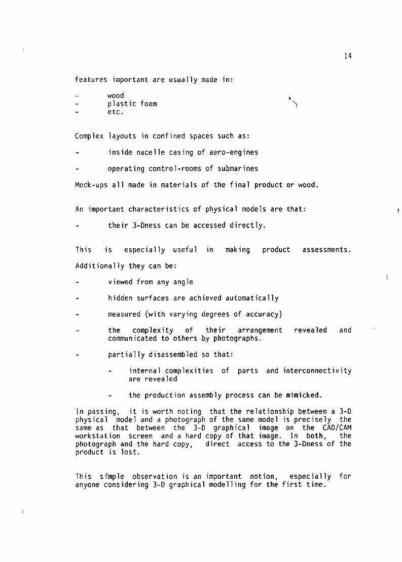
14
features important are usually made in:
- wood- plastic foam
etc.
Complex layouts in confined spaces such as:
inside nacelle casing of aero-engines
operating control-rooms of submarines
Mock-ups all made in materials of the final product or wood.
An important characteristics of physical models are that:
their 3-Dness can be accessed directly.
This is especially useful in making product assessments.
Additionally they can be:
- viewed from any angle
- hidden surfaces are achieved automatically
- measured (with varying degrees of accuracy)
- the complexity of their arrangement revealed andcommunicated to others by photographs.
- partially disassembled so that:
- internal complexities of parts and interconnectivityare revealed
- the production assembly process can be mimicked.
In passing, it is worth noting that the relationship between a 3-Dphysical model and a photograph of the same model is precisely thesame as that between the 3-D graphical image on the CAD/CAMworkstation screen and a hard copy of that image. In both, thephotograph and the hard copy, direct access to the 3-Dness of theproduct is lost.
This simple observation is an important notion, especially foranyone considering 3-D graphical modelling for the first time.
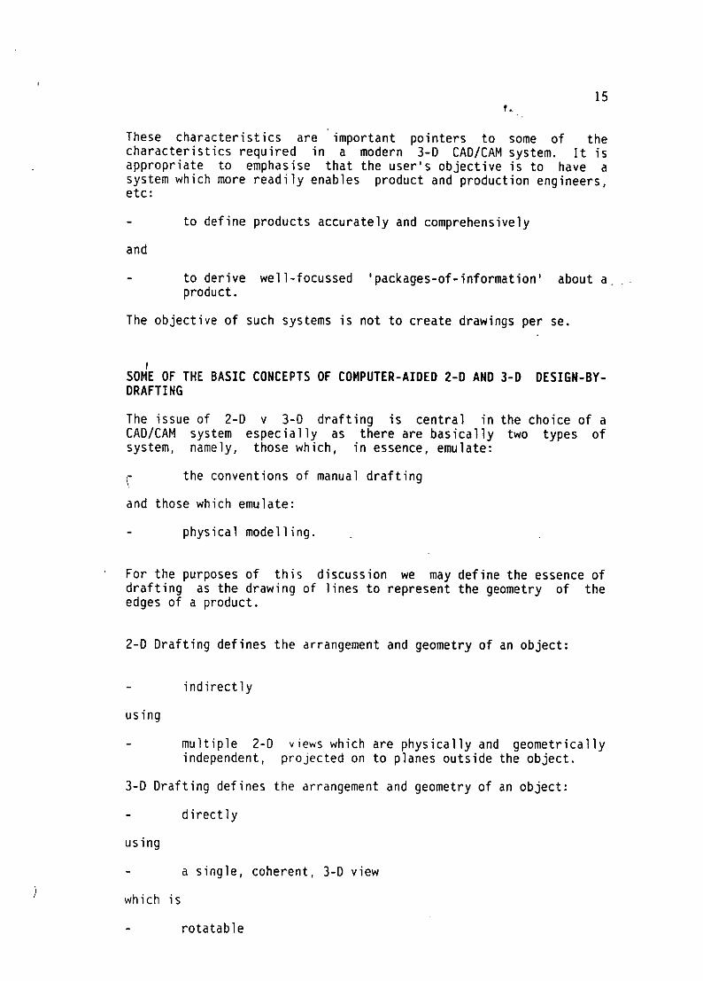
15
These characteristics are important pointers to some of thecharacteristics required in a modern 3-D CAD/CAM system. It isappropriate to emphasise that the user's objective is to have asystem which more readily enables product and production engineers,etc:
to define products accurately and comprehensively
and
to derive well-focussed 'packages-of-information' about aproduct.
The objective of such systems is not to create drawings per se.
SOME OF THE BASIC CONCEPTS OF COMPUTER-AIDED 2-D AND 3-D DESIGN-BY-DRAFTING
The issue of 2-D v 3-0 drafting is central in the choice of aCAD/CAM system especially as there are basically two types ofsystem, namely, those which, in essence, emulate:
the conventions of manual drafting
and those which emulate:
physical modelling.
For the purposes of this discussion we may define the essence ofdrafting as the drawing of lines to represent the geometry of theedges of a product.
2-0 Drafting defines the arrangement and geometry of an object:
- indirectly
using
multiple 2-D views which are physically and geometricallyindependent, projected on to planes outside the object.
3-D Drafting defines the arrangement and geometry of an object:
directly
using
a single, coherent, 3-D view
which is
rotatable

16
giving
-direct, simultaneous access to it's 3-Oness.
in computer-aided 3-D drafting the lines defining edges arecorrectly positioned relative to each other in the 3-0 model spaceprovided by the system's software. Thus they represent (ie, model)faithfully the 3-Dness of the object being defined; the object isthus defined directly.
In this 3-0 situation the surfaces spanning between the linesrepresenting edges and solidity bounded by the surfaces are allcreated automatically by the application software supplied with suchCAD/CAM systems.
Some CAD/CAM systems, targetted at the mechanical engineeringmarket, have been conceived from the beginning so that a productcan be represented in terms of:
-the solidity of its 3-Oness
- its topology (the logic of its connectivity).
It is explicitly recognised that product families share a common
topology. This applies to:
-piece-parts
-functional assemblies
This commonality enables products to be defined:
-parametrically.
Thus, a variety of specific product geometries can be created byassigning different sets of specific sizes to their common topology.
The richness of all possible geometries for a given topology isimmense - an important aspect of this is achieved when one or moreof the element of the topology are assigned a size of zero.
In this, and some other modern state-of-the-art systems, any viewsof such graphical 3-D models are automatically updated when theproduct model geometry is changed, ie, there is a logicalassociativity between the model and the views of that modelcontained in the drawing-type documents.

17
SOME OF THE BASIC USER REQUIREMENTS FOR A MODERN CAD/CAM SYSTEM
"~When product engineering and production engineering teams attempt tospecify their requirements for a CAD/CAM system, much reliance isusually placed on their interpretation of their experience of usingtraditional media involving drafting aids and methods with all theirinherent limitations. Some cognizance is also taken of what ispossible if specific CAD/CAM systems are used. Usually, theemphasis is on the former. It is arguably better if the emphasiswas on:
- what is possible with the current state-of-the-art open typesystems and current trends,
and, given this,
-what product information does a company really need.
Thus, those who both see and express their requirements in termsof:
- traditional engineering drawings
often fail to grasp 'fully the fact that in a modern CAD/CAM system,drawing-type documents are only used to communicate mosteffectively, information about the product by using annotatedprojected 2-D graphical views of the 3-0 graphical product model.Such 2-D views are generally more efficient and effective incommunicating the complexities of the arrangement of a product, ifthey are from arbitrary angles; orthogonal views are notoriouslypoor in this respect.
Some of the other principal requirements for a modern CAD/CAM system
are:
- the use of interactive, colour graphics
- the ability to represent (model) directly the 3-D geometryrepresenting edges, surfaces and solidity of a product
- the ability to display graphically and annotate arbitraryangled views of this product model
- the freedom to associate with this product model any numberand quantity of non-graphic attributes
- the electronic storage of the Product Database (PDB) in asingle, coherently structured database, managed by thesystem's database management facilities
- programs necessary for the design-analysis of function,performance, assessment of physical integrity, energyloadings, etc, etc

18
-the ability to selectively access, update and use anysub-set of the P08 as a basis for deriving data to be usedas inputs to the design-analysis programs
- the ability to 'walk-through' models of spatial engineeringproducts, eq, a process Plant; a submarine
-enables product prototyping to be effectively emulated
-includes comprehensive, useful sets of enhanceable,application program modules suitable for use for:
- all products
plus those which are
- applicable to specific product types
as well as facilities which enable the system and its use tobe customised to satisfy the special requirements andcompany preferences for use in design and manufacturing.
Generally, such systems are based on distributed computing power
involving:
- interactive graphic workstations each with its own computer
- communication networks whereby data and information may betransferred electronically between workstations
- an openess which enables the system to be enhanced to takeadvantage of the improvements in the technologies on whichit is based. (This should not invalidate the company'sproduct databases, etc, created using earlier versions ofthe system).
Such a CAD/CAM system should be:
- easy-to-learn' and 'easy-to-use'
by
-the 'community of users' - mainly product/productionengineering teams, drafters, graphic artists, etc,
responsible for
-the product related information required for specificpurposes.
The ease and efficiency which which any individual system typesatisfies these requirements can be difficult to determine. It is,and ought to be, a principal focus in the comparative evaluation ofcompeting systems. Other characteristics are also important.

19
Additionally, it should provide:a compatible, easily up-dateable archive,
whereby
a company's previous product databases (defined in the samemedia)
and its operational standards for product and productionengineering, etc
are
stored in the system
and
readily available to and accessible by authorised users.
Much of the foregoing will be illustrated with slides of screenimages of products designed and documented using currentstate-of-the-art systems.
SOME CAUTIONARY REMARKS
There are two major pitfalls which should be avoided when selectinga CAD/CAM system. These are to avoid opting for:
buying a computer then a miscellany of ' specialisedapplication programs
and
a 2-D drafting software package.
The former can lead to endless problems of data exchange betweenprograms by the 'magic glue' concept of interfacing. While, ofcourse, the concept of interfacing is important and useful it isnot a panacea solution in such situations.
Buying a 2-D drafting package can also lead to seemingly endlessproblems, mainly of maintaining up-to-dateness of the geometricdefinitions of the product contained in all the drawings and theircorresponding computer files.
The resulting systems (if they even qualify as such) will inevitablybe idiosyncratic to the company, difficult and expensive tomaintain as well as requiring expert staff to do so.

20
The adoption of either or both will frustrate any intention ofhaving a coherent, comprehensive, efficient Product Database withall the practical benefits that this can bring.
NOTES ON COMPARING TRADITIONAL v MODERN METHODS OF CREATING ANDUSING A PRODUCT DATABASE
A useful experimental way to help come to terms with the differentmeans of creating and managing product information is to have acomposite demonstration. In this, four databases of a product arepresented in the four different media used to create them. Theseare by:
manual drafting;
physical modelling;
a 2-D computer-aided drafting system,
and
a 3-D CAD/CAM system.
These alternatives can then be exhaustively exercised by comparingthe ease/difficulties of:
interrogating them to derive specific information, eg,flange-to-flange pipe geometry; mass properties;
making some major and minor changes to the product design,eg, re-routing pipes; re-configuring mechanisms.

Ninth Israeli Convention on CAD/CAM and Robotics - Tel-Aviv
Defining and Documenting
Engineering Products
using
3-D Interactive Graphic Systems
by
George R Snaith
Visiting Professor, University of Newcastle upon TyneConsultant, Prime Computer, Computervision Division
December 1987
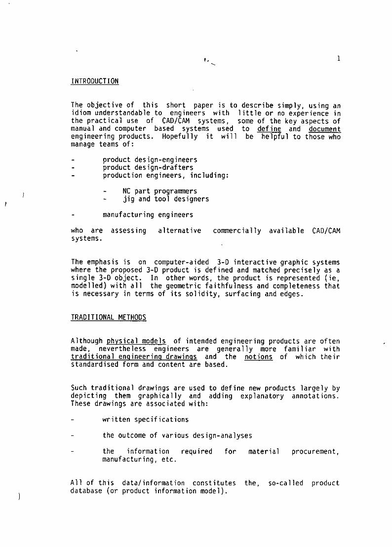
INTRODUCTION
The objective of this short paper is to describe simply, using anidiom understandable to engineers with little or no experience inthe practical use of CAD/CAM systems, some of the key aspects ofmanual and computer based systems used to define and documentengineering products. Hopefully it will be helpful to those whomanage teams of:
- product design-engineers- product design-drafters- production engineers, including:
- NC part programmers- jig and tool designers
- manufacturing engineers
who are assessing alternative commercially available CAD/CAM
systems.
The emphasis is on computer-aided 3-0 interactive graphic systemswhere the proposed 3-D product is defined and matched precisely as asingle 3-0 object. In other words, the product is represented (ie,modelled) with all the geometric faithfulness and completeness thatis necessary in terms of its solidity, surfacing and edges.
TRADITIONAL METHODS
Although physical models of intended engineering products are oftenmade, nevertheless engineers are generally more familiar withtraditional engineering drawings and the notions of which theirstandardised form and content are based.
Such traditional drawings are used to define new products largely bydepicting them graphically and adding explanatory annotations.These drawings are associated with:
-written specifications
- the outcome of various design-analyses
-the information required for material procurement,
manufacturing, etc.
All of this data/information constitutes the, so-called productdatabase (or product information model).
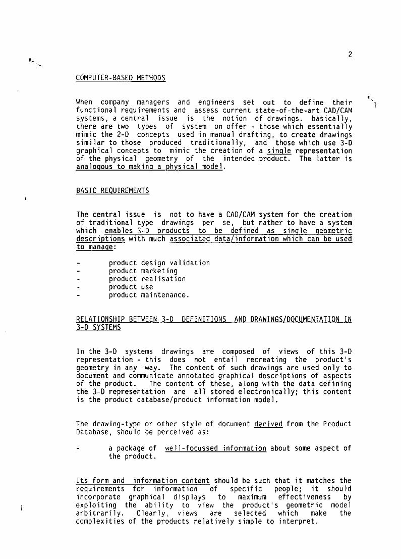
2
COMPUTER-BASED METHODS
When company managers and engineers set out to define theirfunctional requirements and assess current state-of-the-art CAD/CAMsystems, a central issue is the notion of drawings. basically,there are two types of system on offer - those which essentiallymimic the 2-D concepts used in manual drafting, to create drawingssimilar to those produced traditionally, and those which use 3-Dgraphical concepts to mimic the creation of a single representationof the physical geometry of the intended product. The latter isanalogous to making a physical model.
BASIC REOUIREMENTS
The central issue is not to have a CAD/CAM system for the creationof traditional type drawings per se, but rather to have a systemwhich enables 3-D products to be defined as single geometricdescriptions with much associated data/information which can be usedto manage:
- product design validation- product marketing- product realisation- product use- product maintenance.
RELATIONSHIP BETWEEN 3-0 DEFINITIONS AND DRAWINGS/DOCUMENTATION IN3-D SYSTEMS
In the 3-D systems drawings are composed of views of this 3-Drepresentation - this does not entail recreating the product'sgeometry in any way. The content of such drawings are used only todocument and communicate annotated graphical descriptions of aspectsof the product. The content of these, along with the data definingthe 3-D representation are all stored electronically; this contentis the product database/product information model.
The drawing-type or other style of document derived from the ProductDatabase, should be perceived as:
- a package of well-focussed information about some aspect ofthe product.
Its form and information content should be such that it matches therequirements for information of specific people; it shouldincorporate graphical displays to maximum effectiveness byexploiting the ability to view the product's geometric modelarbitrarily. Clearly, views are selected which make thecomplexities of the products relatively simple to interpret.

3
Some packages of information may be tabular listings without anygraphical displays.
This ability to create such arbitrary views is a major improvementover the limited range of specially drafted views used intraditional manual methods; the latter are much less effective incommunicating important information about the product.
Such views can be very helpful to:
- product engineers who need to assess the functionality,operability, etc, of their product proposals
- production engineers who need to assess the producibility ofthe pnoduct and select, sequence and schedule theappropriate production processes
- senior management who can become easily and quickly familiarwith their company's product developments
- potential customers, especially their senior decision makingmanagement and those responsible for assessing a product'ssuitability for its intended use
- external agencies responsible for assessing safety.
MAKING CHANGES TO 3-0 MODELS AND ASSOCIATED, DERIVED DOCUMENTATION
A major advantage of these CAD/CAM systems which enable the 3-Dnessof a product to be created to match precisely the intended productis that:
updates/changes are made only once
and
new copies of all associated drawings are automaticallyupdated.

49.,
Reference
"The Concept of a Product Database" by George R Snaith
Haifa, June 1987.
A FEW PERTINENT QUESTIONS AND ANSWERS
1. What are the key physical features of engineering products?
They are composed of:
- solids
bounded by
- a surface
which is sub-divided by
- edges
that intersect at
- corners.
Such products have many attributes/properties which are
either:
- derived, eg, mass properties, structural responses
- assigned, eg, part number; material spec
2. What are the traditional methods used to define and
communicate the physical characteristics of new products?
- manually drafted engineering drawings
- written specifications
- physical models
- prototypes
- illustrated operational/maintenance manuals.

5
3. How is the definition of a product handled traditionally?
The key data/information defining the product is defined,stored hnd communicated in a variety of media:
- engineering paper drawings
- physical model
- written specifications
- physical templates/patterns
- NC part-programs
- etc.
4. What are the principal features of engineering drawings?
- stylised good practice as enshrined innational/international standards BSI, ANSI, ISO, etc)
- based largely on orthogonal views
which are:
- geometrically and physically independent
but where:
- surfaces and solidity are inferred by interpretation
- annotations define non-graphical properties.
5. What are the principal roles of engineering drawinqs?
- means whereby the product design-engineer expressesdesign intent in terms of annotated graphics
- means of communicating to others
- means of structuring the product's geometry
- medium for storing the product definition (this, inmodern parlance, is the product database or productinformation model).

6
6. What are the key roles of physical models?
- complementary to the role of engineering drawings
- a more effective means of communicating the 3-Dcomplexities of a product especially to:
- product sponsors- potential customers- non-engineers.
7. What is the role of prototypes?
- test functionality ) under service- test physical integrity ) type conditions
- identify where changes could improve:
- functionality- operational performance- reliability- maintainability- operability.
8. What are the principal shortcomings of traditional
methods/media?
- geometric inaccuracy
- opportunities for error as geometric definition has tobe re-created, in part, many times for use in:
- design analyses
- preparing for manufacture (NC, Jig & Tool designetc)
- difficulties of incorporating and managing changes andkeeping all drawings etc, and hence the productdatabase, up-to-date
- difficulties of exploring alternative proposals for aproduct
- etc.

7
9. What is the basic characteristic of systems which areintegrated throughout the Design and ManufacturingProcesses?
The sharing of a:
- single
- approved
- up-to-date
comprehensive
product definition
is the basis of:
- Computer Integrated Engineering.
10. What is a Product Database/Product Information Model(PR IMO)?
This is the single comprehensive definition of anengineering product, which is:
- stored electronically
- accessed
- contributed to
and
- interrogated
by teams of
- Product Engineers
and
- Production Engineers.
11. What are the principal advantages of creating the Product
Database/Information Model?
All data/information is:
- defined and stored once.
It can be:
- readily maintained up-to-date.

8
All drawing and tabular type information derived from theProduct Database is therefore consistent.
12. What are the basic alternative, state-of-the-artcomputer-aided systems on offer?
These are systems which, in essence, visually:
- mimic manual drafting (especially by using independentorthogonal views)
- mimic creating a 3-D physical model.
13. How is the Product Definition handled in CAD/CAM?
The data/information defining an engineering product is:
- stored electronically according to the protocols of awell-structured schema, eg, a relational database
- managed by the system's daitabase management system.
14. How best can the Product Database be used to communicate theproduct definition?
The two basic methods are:
electronically between graphic workstations using LAN
or WAN network
and
- as hard copy in the form of
- drawing-type document (dimensioned and annotated)
- tabular listings
- highlighted colour shaded images.

4tL~ 915. What are somefeatures of 2-D interactive graphic
systems? I n
- essentially used to mimic 2-D manual drafting
- a product is defined as a set of 2-0 (plane) projected,independent views (generally orthoganal) using linegraphics to represent edges
- each time a view is copied to form part of anotherdrawing it is stored again in the product database
- the product database is composed of the content of allthe annotated drawings created about the product
- updating changes to the geometry have to be madeseparately to every view/drawing.
16. What are some of the principal features of 3-D Interactive
Graphic Systems?
- essentially used to mimic physical models
- a product's 3-D geometry is defined directly, initiallyby defining its principal edges and those of itsfeatures
- this is facilitated by rotating its 3-D graphical imageon the screen and being able to access its 3-Dnessdirectly
drawing-type documents (now useonly to communicateselected information about the p oduct) are composed ofarbitrary views of the 3-D representation of itsgeometry; these views are generally annotated withnotes and dimensions
- any changes, made to the 3-D geometric definition, areautomatically reflected in corresponding views includedin any drawing-type documents simply because there isonly one geometric definition of the product.

10
17. What are some of the essential differences between 2-D v 3-Dinteractive graphic systems?
2-0 systems define the geometry of engineering productsin terms of a set of 2-D (plane) independentprojections using line graphics to represent its edges- there is the usual duplication in the definition ofsome edges
in 2-D system, drawings composed of one or moregraphical views of the products; the latter are definedseparately
drawings exist and are stored in the product databaseas independent documents; they have to be updatedindividually
3-D systems define the 3-D geometry of edges, surfacesand solidity directly; the geometry and connectivitymatches precisely that of the product - all geometry isdefined only once
in 3-D systems drawings are composed of 2-D (plane)projected views of the single 3-D geometric definitiodnof the product.
(The latter is completely analogous to taking multiplephotographs of a 3-D physical model or prototype).

MANAGING AND MAINTAINING DRAWINGSELECTRONICALLY IN WARSHIP BUILDING
Jack ChanVickers Shipbuilding and Engineering Ltd
The first of a new class of strategic nuclearsubmarines, HM4S Vanguard rolled out of the VSEL buildfacilities at Barrow in March this year. Putting thePolitical and Defence issues aside, it a tremendousfeat of engineering. It has been said that a Tridentsubmarine is comparable in engineering complexity to aSpace Shuttle.
As a result of its complexity, and for reasons ofquality and safety, nothing is made or assembledwithout a drawing. For the first of class, there areover 130,000 drawings. These range from large generalarrangements and system drawings, which are about lmwide and up to 4m long, to A3 pipe isometrics and andcomponent details. The Royal Navy, like anyone else,likes to have the latest and best for their money.Consequently the follow-on vessels, in the plannedclass of 4, each incorporate changes which make themall unique. The latest estimate is that there will be350,000 drawings produced for the Trident classsubmarines when the 4th vessel leaves Barrow.
Up to about 1987, VSEL had relied on distributinghardcopy drawings to the shop floor. Several factorsmade this an inefficient process
Firstly, the build programme overlapped thedesign programme, but drawing production andissue did not match the build strategy.
Secondly, large shop floor areas andadministration effort is tied up in storing thedrawings until they are required. This is inaddition to the drawing masters kept in plansafes.
Thirdly, paper prints do not last long on theshop floor and production is often delayed bylost or damaged drawings.

Lastly, with multiple copies of the same drawingin circulation, it was difficult to recalldrawings when design modifications are made.This caused a high level of rework by thecontinued use of drawings which have beensuperceded by design changes. The fact that theprint room was a bottleneck in the drawingdistribution process contributed to this.
Apart from being slowly swamped by the sheer volume,the paper based drawing distribution system wasaffecting product quality which was increasing morecostly to maintain at the required standard.
From about 1987, V'SEL adopted the use of 35mm aperturecards as the distribution medium. With itsintroduction, the opportunity was also taken to imposegreater control ton how drawings are used inproduction. The biggest advantage of aperture cardsis that it is on average about 1/6th of thereproduction cost of paper drawings. Being a hardcopymedium, multiple copies are still required to servicethe different production departments and disciplines.However, aperture cards are now issued to cell knownas "Drawing Control units", which are strategicallylocated around the shipyard. The process of drawingdistribution changed from a push system, from thedrawing office to the shop floor, to a pull system,where the shop floor requested
drawings from the "Drawing Control Units". Now the"Drawing Control Unit" operators also had access to acomputerised drawing database, which informed them ofthe correct version of the drawing to issue. Moreoften than not, production staff only required a quickreference to specific information on the drawing,which is done on card readers before returning theaperture card for filing.
If hardcopy prints are required, these are veryquickly made on aperture card reader/printers. Thequality of the microfilming is such that an A2 sizereproduction is more than adequate, which is a muchhandier size to carry around the confines of asubmarine. The issue of copy prints are then recordedon computer to facilitate future recalls. In anycase, the prints are stamped valid only for a periodfor two weeks.
The CAD drawings when approved, would be plotted onpaper. These would then be taken to the microfilmdepartment where they are filmed and mounted onaperture cards. These cards would be punched codedwith the drawing attributes, the company drawingdatabase would then be updated to record that a newdrawing issue is in existence, before multiple copiesof the aperture are made and distributed to all thedepartments on the distribution list. As mentionedearlier, this process took on average 2 weeks.
By capturing all the existing Trident drawings on theimaging system, the opportunity was there to eliminatethis 2 week transition period before the new drawinginformation reached the end users. What was needed isthe means to modify the images and to manage thecreation of new drawings. New drawing issues couldthen be made immediately available on the network assoon as they are approved and released. Therequirements for the Document Image Processing wassubsequently expanded to include 2D drawingfacilities.
A functional specification was drawn up, and 16imaging vendors were invited to tender. Proposalswere received from 10 vendors, from which 4 wereshortlisted for the second phase of evaluation. Thiswas further narrowed down to 2, both of which wererigourously evaluated.
This final phase of evaluation was carried out by amulti -discipline project team from VSEL ShipbuildingDivision. Its members included representatives fromthe operators, users, IT and the analysis team.Reference sites were visited, product developmentplans were discussed, and the products wereextensively tested to verify the claimed functionalityand usability.
At the end of the evaluation, the product from Trimcowas selected as being most suited to the needs of VSELShipbuilding Division. The current IT policy withinVSEL is to implement a small number of strategicsystems, and Document Image Processing was recognised
as one of these systems. The system selected by theShipbuilding Division had to be endorsed by the otherdivisions of VSEL. After the other divisions reviewedtheir ,requirements, and had the functionality of thesystemrnemonstrated to them, Trimco was confirmed asthe preferred supplier of imaging products to VSEL.
When the potential benefits of imaging was quantifiedfor this application, it was calculated that theinitial investment, including the backscanning of allexisting Trident drawings, can be recovered in lessthan 2 years, from the elimination of the "DrawingControl Units" alone. The Document Image Processingsystem was justified based largely on these directsavings. Additionaly, there are numerous intangiblebenefits which will result from the system but cannotreadily be quantified at this stage, such as up todate drawings, document asscciations and reduction oftime spent looking for information.
The Shipbuilding Division is currently undergoing thefirst implementation phase. By the end of 1992, therewill be over 30 dedicated Document Image Processingworkstations linked to a secure network. Already,other document imaging applications have beenidentified in technical, commercial and support areaswithin the Shipbuilding Division alone. It isanticipated that there will be several subsequentimplementation phases once this initial system issuccessfully implemented.

INTERNATIONAL INFORMATION TECHNOLOGY
TECHNICAL CONFERENCE
ITTC - 90
USE OF AN ELECTRONIC IMAGING SYSTEM ON A MAJOROFFSHORE PROJECT
BY R.E. LIDDELL
Date: 6 March 1990

1. ABSTRACT
This paper highlights the experiences of introducing Electronic Imaging to a major offshore project inNorway, to store and distribute all drawing documentation. The paper describes the objectives andfeatures of the system and ultimately practical experiences with the system. The paper concludes byrecommending it as a powerful tool for future major projects.
2. INTRODUCTION It
Gydla is a S1.3 billion project to develop an integrated oil platform in the Norwegian sector of the NorthSea. I t has a production capacity of 60,000 HPSD and delivers oil to Teeside in the U3K and gas to Emdenin West Germany.
The purchase of an Electronic Imaging System arose as a result of a requirement for CAD facilities duringthe fabrication, installation and commissioning phases of the project. After a thorough investigation ofpossible alternatives it was considered that Electronic Imaging was the only method of accommodatingall the dissimilar drawing media inherited from the Norwegian design contractor (Figure 1 shows abreakdown of the media received from the contractor).
Prior to kilose-out" of the detailed design Contractor, 16,500 design and supplier drawings were scannedover a period of 4 weeks. As a temporary measure all scanned data was stored on magnetic tape prior todelivery of the system in April 1989.
One of the major justifications for making all drawings electronic on the pro ' ect was the fast transmissionof drawing documentation to the widely dispersed remote sites on the project (Figure 2 shows thegeographical locations of the remote sites accessing the Electronic Imaging System).
There are two alternative methods of storing drawing data on an Imaging System known as "Raster' and"Vector". Raster data is received directly from a document scanner and is rather like an electronic versionof a high resolution telefax image. The drawing, once scanned, is represented as a series of nion-intelligentdots at a density of 200 Dots/inch. Vector data is more intelligent and is made up of geometric entitiessuch as lines, arcs, circles, etc., the entities can be manipulated as self contained objects. CAD systemsexclusively use Vector data, but Imaging Systems can use a combination of both to fit the purpose. Theyalso have the capability to convert Raster data into Vector known as 'vectorisation".
Raster drawing data requires a lot of storage space, therefore it is necessary to use data compressiontechniques to reduce storage demands. On Gydla all drawing data is hield as highly compressed Rasterdata and no attempt has been made to convert this into Vector data. Since timescales were short and thecompressed image file sizes were slightly less than Vector, it was decided to edit and store drawings solelyin Raster.
3. OBJECTIVES OF SYSTEM
The objectives of the Electronic Imaging System are as follows:
1. To provide a compact means of electronically storing all drawings, bath current and previousrevisions, on the Gydla project. There is no manual backup for these drawings since this wouldeliminate the benefit of compact storage.
2. To provide a fast means of retrieval of all drawings by simple input of the project document number.
3. To provide a single central source of drawings for the product that everyone has access to. Thisreduces the possibility of personnel working to superseded revisions of drawings.
4. To issue all drawings to the fabrication sites and offshore electronically through data links to speedup the distribution of drawing documentation.

5. To provide a method for fabrication sites and offshore to access and plot any drawing that may berequested from document control at the remote location.
6. To allow electronic editing of drawings held on the Imagiw-, System so that drawingquality ismaintained and productivity improved.
7. To allow "Red-lUning" of comments on drawings to illustrate suggested modifications from offshorepersonnel.
S. To provide an efficient means of handing over drawings to the operator at the end of the project.
9. To provide a storage media that will not degrade with time or use so that drawings can be maintainedin a good condition for the remainder of the platforms life-span.
10. To reduce Document Control manpower and mailing costs.
4. TECHNICAL OVERVIEW OF SYSTEM
See Figure 3 for the overall system configuration.
4.1 The Fileservers
There are two fileservers at 'the heart' of the system. This is where all the drawing image data isstored as a central source for everyone to access. They both use the UNIX operating system whichis rapidly gaining favour in technical computing. For the purposes of Gyda only one fileserver isrequired, the second server is really a backup device should there be a problem with the main server.Both servers have powerful processors with a large amount of memory and provide a fast responseto large numbers of users.
4.2 Data Storage
All image data is stored on the fileservers. No image data is stored on the workstation local storage.
There are two types of storage media in use on the system:
magnetic for design drawing data which is being constantly modified
optical for supplier drawings and piping isometrics which are rarely modified by projectpersonnel
The image data is stored in a highly compressed data structure. An AO drawing which isuncompressed would require 9MBytes of storage, when compressed it requires only 300-500 KBytes(depending on the content of the drawing).
4.3 The Workstations
The workstations are based upon powerful 386 Personal Computers but that is where the similaritywith a PC ends. The inside of the PC has been completely "stripped" with exception of the processor.
Since image data is very large compared with conventional computer applications, the memory ofthe workstation has had to be greatly increased in order to accommodate an expanded AO sizedrawing. 10MB of memory is required to do this compared with 640K normally found in a PC.
A large high resolution colour graphics screen has been added to provide better visibility of thedrawing to the operator and a special graphics controller card added to control the image on thescreen. In order that the workstation can communicate with the fileserver a Network card has beenincluded.

Some of the workstations have specialised purposes such as the "scanning server workstation" andthe *plot server workstations". These are identical to the other workstations except they haveadditional electronic "cards" inside for their specific role.
4.4 The Plotters
There are five plotters in use on the system.
Three of them are 200 Dots/inch Electrostatic ploi:ers fitted with automatic sheet cutters. Theseare capable of plotting drawing sizes of up to a maxin.um of AO size.
There is one 200 Dots/inch Thermal plotter which is located offshore. This was specially selectedfor it's resistance to tilt and its freedom from fluids and chemicals.
One A3 size, 300 Dots/inch laser plotter located within Tanager. This is capable of plotting to ahigher resolution than the other larger plotters and is used for reduced sized prints of largerdrawings.
4.5 Communications
4.5.1 Local Area
The fileserver and the workstations are linked together via a high speed dataliak using Ethernet.NFS networking software is used to allow the workstations to transparently access image data onthe fileserver as if the data was located on the hard disks of their own workstations. The speed ofthe fileserver and Ethernet is so fast that it is actually quicker than accessing drawings from the localstorage of the PC. This means that the local storage is not used at all and this makes the managementof the drawing data a lot easier to control.
4.5.2 Fabrication Sites
Communication with the fabrication sites is via leased data lines from Televerket and BritishTelecom. The fabrication sites in Norway have 64Kb/sec links which allow a fast response fromTananger. They operate in a very similar matnrer to local users in Tananger. To allow them tocommunicate with Tananger, a network Bridge is mounted on the Ethernet which is then connectedto the modems on the ends of the datalinks provided by Televerker/BT. Due to the high cost of thedata link the line speed to Middlesbrough is restricted to 9.6Kb which means the response is quiteslow. It is therefore normally used in a batch transfer mode, whereby the drawings are firstdownloaded to the local storage prior to display on the screen.
As a backup to the communications failing, each fabrication site workstation is fitted with a 60MBcartridge tape drive to enable tapes of drawings to be mailed from Tananger. Each tape is capableof storing approximately 200-300 drawings.
4.5.3 Offshore
Datalinks have been set up offshore via a Satellite link (64Kb/sec). There is a land based link fromTananger to the Eik Satellite Ground Station where it is then transmitted by satellite to the existingBP Ula platform. From Ula to Gyda it is linked via a Microwave link. Ethernet bridges and modemsare placed at either end of the link to allow the workstations offshore to communicate with thefmeservers in Tananger. A tape drive has been installed as a backup to the communication failing.
5. THE DRAWING EDITOR
5.1 User Interface
The drawing editor provides the CAD functionality of the system, which allows the operator tomodify existing drawings and to create new drawings.

The drawing editor commands are activated from a colour screen menu with a "mouse" to controlthe position of the cursor on the screen. When a command has been selected from the top of thescreen a series of sub-commands appear in a "pull-down" menu. For more experienced users thecommands can be directly activated from the keyboard.
5.2 Drawing Mode
The operator can modify a drawing in a number of different ways:t\
* work totally in Raster mode i.e. the direct output from the scanner
work on Raster output direct from the scanner but making all modifications in Vector therebyproviding the drawing with more intelligence
vectorize theRaster output from the scanner and work totally in Vector/CAD mode
On Gyda all data was stored in compressed Raster mode for simplicity.
5.3 Drawing Functions
All the usual CAD type functions for lines, arcs, circles and text are provided in both Vector andRaster modes. Layering, different line styles and text fonts are also provided.
5.4 Editing
Existing image data can be erased, moved, copied and rotated. There is also a very useful "undo"command for reverting areas of the drawing to their original status prior to executing the command.
5.5 Cut and Paste
This allows areas of a drawing to be cut away and utilised for another drawing. This has been veryuseful for creating the large number of instrument schematic drawings on thc project.
5.6 Symbol Ubraries
Using the 'Cut and Paste" command existing drawings can be cutup electronically to produce symbollibraries very quickly. This has been used with great success on schematic drawings where a coversheet with the disciplines drawing nomenclature is scanned to create a complete symbol library in amatter of minutes.
5.7 Red-lining
This function utilises the Vector drawing capabilities of the system to add comments to a drawingin a red colour on a separate layer to the main drawing. The main drawing remains unchanged butthe suggested modifications or comments are clearly visible. It is intended to use this facility in theoffshore completion phase of the project.
6. DRAWING MANAGEMENT
6.1 Organisation of Image Data
6.1.1 Original Drawings
Original drawings are analogous to the drawing chests traditionally found in Document Control.Image data for the original drawings is stored in specially protected areas which only the SystemManager has direct access to from the fileserver. No workstation on the system has access to modifythis data. However every registered user of the system can view and plot these drawings withoutrestriction.

The image data has been structured by engineering discipline, with further segregation between
design and supplier drawings which are kept on different storage media.
6.1.2 Working Drawings
The working drawings are analogous to those found on a manual "stick file" traditionally found withinan engineering discipline. They are copies of the original image drawings which are in the processof being modified for the next formal revision. Only the engineering disciplines themselves haveaccess to modify these drawings. No other user of the system can view or plot these drawings sincethey have no formal status.
6.1.3 Symbols
Each major discipline has its own symbol area in which it can store commonly used drawingsymbology. This is also an area for storing the results of cut and paste activities for use on otherdrawings.
6.1.4 Mail Area
This is where all the "log" fies on the system are stored. These log files fulfil a number of purposes.
A. They inform the fabrication sites and offshore when drawings have been formally issued to them.
B. They log all activities by the users on a daily basis.
6.1.5 Redline Area
This is an area reserved for offshore users to return comments on drawings. The comments arehighlighted in red on a copy of the original drawing to indicate suggested modifications or comments.
6.1.5 Archived Drawings
In general only the latest revisions of drawings are stored on-line. Superseded revisions are archivedto optical media at regular intervals to economise on on-line storage requirements.
5.2 The Image Management System
The Image Management System is responsible for virtually all activities on the Imaging System. It'sfunctions are as follows:
* maintenance of a document index which references the image file and its location on the systemto its official document number
* a log of all activities on the system so full traceability is achieved
aan issuing procedure for new revisions of documents that have been developed electronically
* control of User Access to the various storage areas
* a site log for each remote site which lists drawing images that have been issued to a particularsite on a specific day
*a tbook out" procedure for revising existing drawings held on the system
* an interface to the document control database held on another computer system and database
* a procedure of inputting newly scanned drawings into the system

7.4 Offshore Users
Offshore users in document control operated in a similar manner to the fabrication site users whenreceiving newly issued drawings from Tananger and also in plotting ad-hoc requests for drawingsoffshore. Engineering personnel offshore used the system to check the latest revisions of drawings.
8. CONCLUSIONS FOR THE FUTURE
Oil and Chemical companies have always had problems with implementing totally electronic drawingdocumentation systems. Whilst it is often clear to their contractors that there are substantial benefits tobe gained from using CAD, this has not been the case for the Operators. For the first time Imagingresolves the problem of mixed drawing media, by allowing all drawing documentation to be madeelectronic, no matter what it's origin.
On the Gyda project Electronic Imaging has undoubtedly been a success and has shown substantialbenefits for drawing documentation. The next logical step forward is to make all A4 documentationelectronic, such as data sheets, material certificates, etc. This will be a worthwhile challenge as potentiallythere are large scale benefits to be gained.

7. USER EXPERIENCE
7.1 Design and Drafting PersonnelPA
These personnel use the drawing editor of the system to update design drawings ready for issue tothe fabrication sites and offshore. The initial intention was to train all drafting and design personnelto use the system so that modifications could be made directly by these personnel. To encouragethis strategy the edit workstations were dispersed throughout the design office rather than locatingthem in a central location. This ensured that each discipline would have easy access to their ownlocal workstation. Seven workstations were dedicated to editing purposes.
Very few of the design and draughting personnel had any direct experience of computers or CAD.Most of the personnel were assigned to the project for a limited period of time. Therefore the systempurchased was specially selected for its user-friendliness and its limited training requirements.Training on the system was limited to 1-2 days. After this time the operators would work directlyon their own drawings and gain further experience on the project in a productive manner.
7.2 Document Control Personnel
These personnel used the system rather like an electronic photocopier. They were responsible foroperating the plotters and distributing the plotted output. They were also responsible for operatingthe scanner for the input of new drawings to the system.
The traditional activities of document control on a project changed dramatically as a result of theImaging System.
In addition to the activities stated above, they also became responsible for the following additional
activities:
electronicaily preparing image drawing data for distribution to the remote sites
distributing the updated image management database by tape cartridge to remote sites
checking that the electronic image data corresponded with the transmittals raised
electronically editing supplier drawings where "clean-up" is required prior to storage on opticaldisks
7.3 Fabrication Site Users
There were three remote fabrication sites:
at Egersund in Norway (120 KIM from Tananger)
at Stavanger in Norway (12 KM from Tananger)
at Middlesbrough in the UK
The chief role of the fabrication site users was to receive and plot drawings issued to them fromTananger and then issue these to the fabrication contractor. Control of these issues is via atransmittal note which lists the drawings issued on a particular date.
The system provided the fabrication site users with a list of drawings issued on a particular day. Itwas then the responsibility of the fabrication site users to download the relevant drawings fromTananger and plot them out. Generally the fabrication site requires one full size print and onereduced size A3 print.

,-' ~
Co
-~ C-'-9
2:-,
Co
S
Vt..,
~2
C
0
C...,
2:
C
N-'
-CC...,
-C
0
C;2:
-C-- 9
-~ 0
- -N-
--. 9
- N-- 9
-'
- @17-.1.

½
Co(-5
0 CR-U-'- - c~5Ct -) -~
U -_
I,.
0~
4-
n , ,%
6-J
K C'
CoCRw
0
I;
FriF-AV2 I,z-

I p -
I I
I (1!
0:
Zi I
jNN
CI II " _
I C,.
m I
I I°
LJr
I LU
--
LJ 0
F-II --
U)1 d
i- -,<
YI N I0
LU I
~z~ ~ 0'
IL I
.........- FI' U
MyJJ >-4
I I <I
LiU
--------------------------- --------------

THE INTEGRATED CAD/CAE/CAM SYSTEM
Authort Dr. Ing. Manuel MeizosoSENERMAR. S.A., SPAIN
SUMMARYThe objectives in the development of an intergrated CAD/CAEiCAM system for shipbuilding must be thefollwing:
- To integrate all design activities.- To proceed from conceptual to detailed design.- To make the system as portable as possible to be able to use the most advanced hardware.- To facilitate the communication with the user.- To be able to design all types of ships.
FORAN is a CAD/CAE'CAM integrated system for ship design and manufacturing. SENER, SYSTEMASMARINOS, S.A. has been developing, to fulfill these objectives, FORAN for more than 20 years, based in its ownexperience as ship designers and in the experience of more than 100 licensed shipyards.At present. FORAN System covers the areas of Hull Form Design, Naval A/rchitecture calculations, Steel andOutfitt~ng Desigt and Manufacturinq and Drafting.The integration (Fig. 1) between the different modules has always been one of the main objectives. It wasachieved by:
- Avoiding the redundancy of data.- Using the same language and the same access procedures in the different modules.- Facilitating the communication by the use of a common database.- Making an intensive use of the topology in the definition of the ship model.- Avoiding interfaces.
One of the main objectives of FORAN is the definition of the three-dimensional model of the ship.
The model information includes:- Topulogy.- Geometry.- Relations between ship elements.- Manufacturing information.
The topological definition of the elements allows an easy update of all the information after changes.The geometrical information is also important, to assure an adequate response time in the graphic interactiveprpcesses.The only way of handling in an efficient way all the compact information contained in the ship model is throughthe use of database system, which characteristics are:
- It is transaction oriented.- Up to 50 users can access simultaneously the database.-The consistency of data is maintained automatically.- There is a control of the integrity of the stored information.- It maintains automatically the cross-reference between the stored elements.Existance of a set of management utilities.
The Basic Design Subsystem covers most of the areas related with ship design:Definition of hull form.
- Definition of decks and bulkheads.Drawings.Naval architecture calculations.
- Seakeeping analysis.
18

FORAN has two alternative methods for the definition of the hull form:
The hull form generation (Fig. 2) is based on the mathematical formulation of the hull surface by means of a
single equation that defines the halfbreadth of any point as a function of its abscissa and height.
This formulation, which generates intrinsically faired hull forms. produces the required lines, starting with the
snip main particulars. The hull forms obtained can also be fitted to a given block coefficient and centre of
buoyancy or to a specific curve of areas.
The hull form generation allows to study different alternatives in a short period of time.
Special attention has been paid to make all the definition of the hull surface in an interactive and graphic way
and to generalize the type of hull forms that can be obtained.
With the hull form fitting and tairing module, it is possible to fit or to fair an existing hull form by means of biarc
and spline techniques.
This is performed interactively on a graphic screen, working with the three main views.
All types of hull surface can be treated, including asymmetry, any number of knuckles. tunnels, etc.
Some of the features of the module are:
Automatic maintenance of the compatibility between the three projections.
-Opfional subdivision of the ship surface in different zones allowing to work incependently in each zone.
*S.Jrultaneous represenIdilon of the origina; and the updated hull form.
Facilities to edit and to loft lines.Numerical and graphical control (inflections and curvatures) of the smoothness of the surface.
* Visualitation of the fairness of the hull by intersecting the hull surface with planes parallel to the main
ones (Fig. 3).
- Definition of general lines over the surface (Fig. 3).
The topological definition of decks and bulkheads is made interactively with the display of the defined elements
in the three main views.
Decks can be defined with sheer and camber (polygonal or parabolic) as well as with any number of longitpidinal
discontinuities. Asymmetric decks can also be considered, as well as upper wing tanks. double bottom hoppers
and bulwarks.
The intersection of the decks with the hull form is automatically calculated.
Bulkheads are composed of flat surfaces of any orientation.
It is possible to obtain drawings at any scale, showing the geometry of the hull form, decks and bulkheads, such
as lines drawing, general arrangement drawing (Fig. 4), perspectives, body plan, etc.
Naval Architecture calculations are included:
Powering, Design of propeller, Rudder and manoeuvrability.Hydrostatics, Bonjean.Compartments definition.
Cross stability curves.Freeboard.Tonnage.Grain calculation.Capacity, sounding and uliage tables.
Floodable lenoths.Loading conditions: Trim, Stability and Longitudinal strength.Damage stability.
The definition of compartments is carried out interactively on a graphic terminal, to the hull form, decks and
':ulkheads. The compartments are displayed in the three main views or a perspective view.
Seakeeping analysis module (Fig. 5) studies the short term behaviour of a ship in irregular seas: Kinematic ship
responses, slamming and shipping of green water.
Ship transfer functions are calculated for six degrees of freedom and arbitrary speeds and headings.
19

The program allows to handle different wave spectra formulation and spreading functions.The date preparation is very simple, because the ship gemoetry and mass properties are taken from the previousgiven date.The obeictive of the Steel Production Subsystem is the definition of the ship structure and the generation ofworkshop information.IThe definition of elements is carried out ina fully interactive graphic environment, with special attention to theintegration of the System and the topological definition.
Standards of material and production methods module deals with interactive definition and updating of theshipyard Book of Standards, such as:- Quality and dimensions of steel gross plates and profiles.- Fabrication methods.- Parametric definition of construction details, i.e. man-holes cut-outs, brackets. etc.Rolled or fabricated profiles corresponding to shell and deck longitudinals, frames, beams and bulkhead stif-feners can be defined.
Standard cut-outs are associated to each prof ile, the cutting-ends and connection brackets.Shell and deck plating is defined interactively (Fig. 6) including:I
- Transverse butts.- Seams, non-transverse butts and landing of shell longitudinals. The layout of these lines can be definedas:
- Straight line in one of the three main projections.- Parallel to a deck, knuckle, seam or longitudinal." Any line on the shell.
Panels are defined by selecting boundary lines.Plate definition is carried out by selecting the two limiting seams.Plate development is performed on-line and the minimum rectangle of the developed plate and assignation ofgross material is immediately presented.Ship internal plate parts definition is obtained by using sections of the ship structure. (Fig. 7.)These sections, which are automatically calculated, include all the relevant information to complete the partouter contour definition (cut-outs automatically inserted.)The following information can be added: inner contours, marking contours, levels, drilling holes and bendinglines.Steel quality, plate thickness, subassembly, panel, etc. are associated to the part.The definition of equal and similar parts is carried out by using simple commands.
The nesting process is carried out according to the following steps:-Selection of the gross plate.-Setting up the menu of parts to nest, considering automatically the gross plate characteristics (thicknessand material quality).
- A powerful set of positioning commands allows to place the parts taking as main criterion the reductionof the scrap.- Insertion of cutting bridges.- Automatic or semiautomatic cutting path definition.- Cutting sequence for 3-axis machines.
A postprocessor module will produce the cutting information: either a 1:10 template or punched paper tape.Direct numerical control (DNC) and plasma cutting are also available.
Steel drawings of any part can be easily obtained by selecting the limits of the zone, scale, line type and colour ofthe different elements that will be represented on the drawings, which can be used as a basis to produce thefinal steel construction drawings.
20

These drawings can be completed by the Drafting Subsystem to introduce texts, dimensioning, symbols. etc.
Utility modules are those which retrieve data from the database. such as:List of patts. Bill of materials.
-Profile bending and end-cutting information.-Nesting of profiles.-Shell and deck plate development, bending and marking information.-Table of oft-sets of shell and deck lines layout.*Jig information.*Data base inquiry.Assembly weight and centre of gravity.
-Structure perspective (Fig. 8).-Punched paper tape verifier.
The Machinery and Outfitting Design Subsystem covers the basic design of distributed and non-distributed shipsystems.The information is stored in the database.The specification of an equipment unit or fitti Ing includes the identification, and several attributes.The specification of materials is used to extract the distributor and fitting properties. The piping standards arealso defined: material quality, schedule and thickness.The systems are classified according to two criteria, functional and by loc~tion, leading to the definition o! ser-ices and zones. wrnich are defined by means of an identification, and geometrical limits.
Creation of symbols and equipment views is carried out (Fig. 9) for future diagrams.Connection points, indicating the sense o 'f flow and points of editable text to label the diagram, are defined.Three scaled orthogonal views of each eqau'pment is defined, for doing layouts.The objective of the diagram design is to produce the drawing of the diagram (Fig.1O), and to define all the logiccontained in it.
Some facilities for the construction of the diagrams are:- Automatic control of the consistency of the connections between equipment units, fittings anddistributors.-Automatic assignment of technological properties to distributor lines and fittings.-Checking and display of flow direction.Automatic labelling of symbols and distributors.
-Automatic bridge insertion between intersecting distributors.The equipment layout is performed using the ship geometry and structure available database. Thus. the equip-ment views can be positioned relative to the elements of the ship structure (Fig. 11). The positioning is made inthe three main views simultaneously.½k automatic checking of interferences between equipment units is made in each projection, considering the.ismounting spaces.
Graphical commands are used to complete the drawings.
Material Reports can be obtained, according to the user requirements, 'based on information previously Stored,of the diagrams and equipment layouts, as for instance:
- List Of equipment units and fittings classified by services or zones.- rrom-to reports for the distributors of a diagram.-Bill of materials containing information for each individual equipment, fitting or distributor.-Weight and centre of gravity calculation for the equipments, fittings and distributors of a zone.- Listing of specifications of equipment units, fitting, materials and distributors.- Listing of piping standards.- Listing of drawings classified by zones.
The object of the Machinery and Outfitting Production Subsystem is the definition of the distributed and non-distributed ship services and the generation of workshop information, mainly for piping, cabling and ducting.
21

Objects are defined by a 3D geometric modeller, with the following characteristics:- -eoresentation by a boundary model.- Cefinition of objects by means of sweeo operations.• -oroximated representation of cylinders and cones.- Wire frame model for fast visualization.* Otiect drawing with hidden lines removal.• Shading.- Sectioning.- Ecolean ocerations.* Ocerations with groups of objects.
Interferences between equipment, piping, ducting and fitting and all of them with the hull structure can be ob-tained.All the work is performed interactively.The objective of the equipment definition is the generation of li~brary of 30 objects.Each equioment (Fig. 12) is mainly defined as a set of objects and each object can be obtained from a library ofparametric objects (Fig. 13) giving values to the parameters. Parametric objects have associated connection vec-tors to make easy the joining of objects.The equipment layout is performed positioning the equipment units as regards structural elements, or otherequipment already positioned.The objecie of the piping lhyout is the definition of pipes and fittings in 3D.A pipe line s generated by defining the corners of its polygonal. Elbows are automatically inserted. Points arereferred either to the ship structure or to other element already defined (Fig. 14).Fittings are inserted in the line referred to equipment, other fittings or piping. Usually fittings are parametric ob-ject. anc rhe parameters are automatically calculated.
The objec:ive of the duct layout is the definition of ducts and cable trays in 3D.A duct lire is generated similarly to a pipe line.
Workshcz information can be classified in:- Documents for piping manufacturing (isometric, Fig. 15, and bill of materials).
Documents for piping mounting (orthogonal or perspective view including steel structure, equipment, fit-tincs. piping, cable trays and ducting and drawing of sections of piping, ducting and fittings). (Fig. 16).• Other documents (summary of fittings, piping, etc.).
The main objective of the interactive 2D drafting is the completion of the drawings produced by other modulesand the creation of new drawings (Fig. 17).Some-of :ne characteristics are:
- Creation and handling of drawings.Use of all types of units.
- Handling of any kind of geometry, text, standards and dimensioning.- Definition of libraries of standards.
Handling of drawings produced by any FORAN module in ship coordinates.Subdivision of the drawing in subdrawings, layers and groups according to user requirements.
A good communication with user is an important factor in the efficiency of a CAD/CAM System. All workingmodules are inieractive and a number of standard facilities have been implemented:
- On-line documentation.Prompting messages.
- Display of graphical information in several views.- Zoom and windowing of the displayed information.- On-;ine access to all the information required.
The most adequate way of communicating with the system has been achieved by the use of dynamic menus andsubmenus in comoination with tablet input.
22

FORAN is implemented on the complete series of VAX (Digital) or PRIME computers.
The use of dedicated workstations and small computers integrated in a Local Area Network has many advan-tages:
-Avoids the degradation of computer power when many users are working at the same time.*Allows a progressive expansion in accordance with the needs of the shipyard.-Minimizes the cost.-Facilitates the communication between departments.
Following this philosophy, the FORAN System has also been implementedow-Local Area Networks (Fig. 18)composed of autonomous workstations and minicomputers.
The introduction of an inte/grated CAD/CAM system, such as FORAN will improve the quality of the design, withan important reduction in the man hours and elapsed time necessary for the preparation of all the technicaldocumentation.
Important savings will also be obtained in the ship construction process, because of a better and accurate defini-tion of the ship.
Some of the benefits of the use of FORAN are:-Possibility of exploring quickly alternative designs.Increased reliability of the design.Time saving in the production of drawings and material reports.Time saving in obtaining information for fabrication.Change are kept to a minimum and coordination between the different departments is made easier.During construction, important savings can be made as a result of the better quality of the design (e.g.
reduction of scrap, reduction of production margins, etc.).- Very rapid management of design changes, and updating of technical documentation.
23

BASIC DESIGN
D POWER.M ANOE UVRABILITY,
E PROPELLER,RUDDER,STERNFRAME It O ER AA NS HYDROSTATICS
COMPART•MENT DEFINITIONCAPACITY,SOUNDING & ULLAGE
G CROSS STABILITY
N FREEBOARD & TONNAGEGRAIN HEELING MOIMENTSFLOODABLE LENGTHS LINES DEFINITIONLIGHT SHIP WEIGHT DISTRIBUTION FORM GENERATION
U LOADING CONDITIONS: FORM FITTING AND FAIRING
B -TRIMMING DECKS AND BULKHEADS DRAFTING:. -STATIC & DYNAMIC STABILITY. . .-- "S -DAMAGE STABILITY TABLE OF OFFSETS 2j D DRAMTING
Y -LONGITUDINAL STRENGTH LINES DRAWINGBODY,END PROFILES1 GRAPHIC POSTPROCESSORS
S SEAKEEPING ANALYSIS SCHEMATIC GENERAL ARRANGEMENT PLOTTER POSTPROCESSORS
T MACHINERY & OUTFITTING STEELE STANDARDS STANDARDS
m EQUIPMENT SPECIFICATIONS PROFILES DEFINITIONSYMBOLS & VIEWS SHELL'PLATING DEFINITIC
S P & I DIAGRAMS DECK PLATING DEFINITIOlZONE LAYOUTS INTERNAL SECTIONSMATERIAL MANAGEMENT INFORMATION PART DEFINITION
-- A Tik AT. ik NESTING OF PLATESMACHINERY & OUTFITTING DRAWINGS & PERSPECTIVES
3D EQUIPMENT DEFINITION BILL OF MATER;AL3D STRUCTURE FILE GENERATION PROFILE BENDING & END-CL3D EQUIPMENT & DUCT LAYOUT NESTING OF PROFILES3D PIPING DEFINITION SHELL PLATING INFORMATION
ISOMETRICS & LIST OF PIPES DECK PLATING INFORMATIONGENERAL CLASH DETECTION "JIG OF SHELL PANELSDRAWING GENERATION IN.C. POSTPROCESSORSBILL OF MATERIAL DATABASE ENQUIRY
PRODUCTION SUBSYSTEMS
FIG. 1
24

FIG. 2. Hull Form Generation
S1 CF
- - ----------12i
L M I.
94 71 1
* :e ff. *)S *
-- ---- * .. ....*...
....*..i
*IG. 3.~ *itn
ndFiig
*AIW *l 1 * *dfl *
* U l 442
aa 1.0411
* W4 dj
* 2nd SC25

I.---t ' F ----
FIG. -4. Schematic General ArrangementFIG. 5. Seakeeping. Helicopter operations.
WCUMMI
26 , c

FIG. 6. Shell Landing and~ 1.Plating Definition.
------- ----------- ------
-_____________________N___
FIG. 7.Part Definition.
sn7~ Tt!lf 0 L' !5 5.8 :~ i
-~. LII 5 - I....,2

FIG. 8. Assembly Block Persneczive.
28

• )
FIG. 9. Menu of Electrical Symbols.
S ELECTRICAL DIAGRAMS SYMBOLS
COHO jlFl SECT TRR E2018 E209 F209 G2109 1 E1 tE211
E2 12 e2 13 C2 14 £2 1 5 E2 16 (2 17 (2 18 £2 1 9 E22 0 (23 4SY Y' -0-• ýD =•7l
It(22) (226 (227 (228 (229 (230 (231 (232 (233• (2.55
-6 --- I DI E' n(236 (237 (238 t240 (24) (242 A274 A27 , A276 A,277
A278 A279 .A280 A2t) A282 A283 A284 A285 Ak86 A2?
i588 A2iR E243 (244 1929 1930 1931 1932 1933 1934
1935 1936 1937 1938 1939 1940 1Ig4 1944 1945 1946
19 48 1 1949 1950 1 9I1 LI10 L101 L104 L1t1 a 06
L107 L108 L109 L110 LIt L112 Ll 13
KILL KEYB ELEC
FIG. 10. Cargo Diagram.
II :, -i . ; , _ $itffl:zIII_ _ I .;
i < t..-._ I.... - 1 ____. .......
-. -. ---"-. -.-- I,7 - -" - '--- -"' -
29

-l I
ii i....... . .
I Td, /
Itc 40 1"~ ' 0..' II I1
F !:1:..... . ... ......-".--..'. ..."...."\• i~i . . . .• l" T - - - • "•• ''r ,-,• •- • I1 .. .• /'- "
. ... 77C
z,-
i..:• ...............•... .. ... .... , .________,________ __ I I
_ _'Ir -1
_ _
___ - . "- r ., ... , ,-- . . i ' ,•
... .... ..............
II=- - .. .
FIG. 1.1. Engin-e Room General1 Arrang'ement.
30

VMUMIJLA COME!J~
I ~ ~ E /,tJt -AOEEErRC
ZLI~R0 old 'JVVUSfIPLC PtSI tw
f-AAVESSEL P 40RDEC. RAP
I£ ST 0
cubm " 30
RECCOCOI T DECGW
3UCT A CitME
z :MUCTOACA
FIG. 13. Parametric objects.
FIG. 12. Screw Pump.
FIG. 14. Piping and Equipment Layout.
31
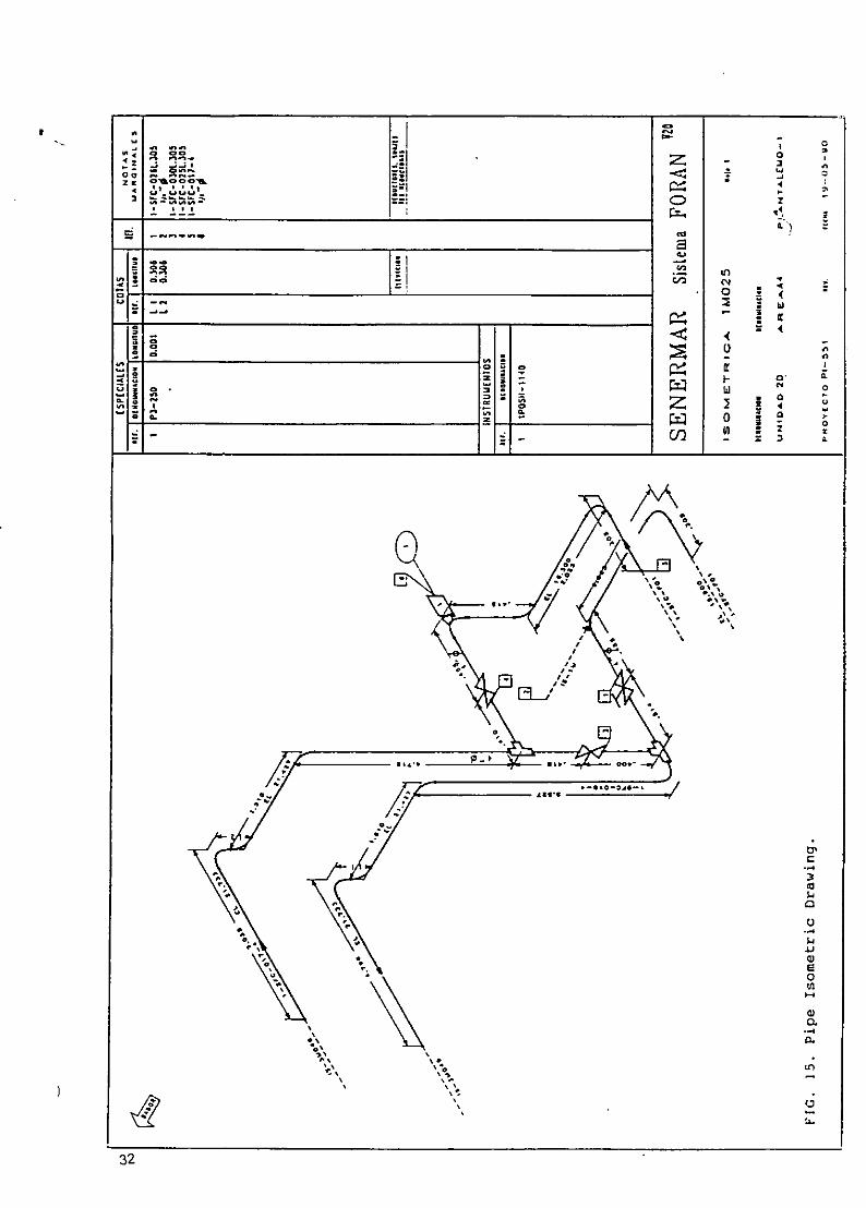
I 0-J n ne
"- I
O•~- 7 ~ o o-
Z CO C'.*
4 t -
0 z 3
* 2.

1=44
CJ
D0
03

FIG.17. Drawing Examples.
•.•••la[_ "-/ ,41- m ,-.•4""• ".-,l '',
. ............. ......
7 qI -- =7'-
LW1
, , ._,._ _,
, 2- ~ I. -- - --- - I. . I--
tiL ILI ... i7
,-f ro -..=,JEL HT -R i ..._=, -.... , •-
_.-___--_ I'"._ -
I,=-- -- In - I. --- , r• "3
=.::'r ' -,-.- -- - "
* L-- =_ .. . ... .. _- .,, < ,. "-*-- *V f-. +rL q ~..... . . -.'.'• .- ' -
" - :. .. .. . . . . .- . -. "-- - -.. .. ..- ~ . _-_--'_
- I -- ,,-

oo- ---
I m
C--.
Iii
CD
I =S
I C)
o3

Copia Sres.: AlonsoAz 6nCanadellG9 Bern6ldezMtnez-AbarcaMeizoso
-- Torroja
TOPOLOGICAL ASPECTS OF THE FORAN SYSTEM
0. GENERAL
Today CAD programs are being developed to handle the designof physical entities ranging from mechanical parts to ships.
In the shipbuilding field there are several CAD/CAM packages
which in their marketing pamphlets extensively use the"magic key-word" "topology" like a panacea, which guaranteesthe quality and performance of the product.
Too much emphasis is put on this concept, probably because
it is erroneousy considered the latest fashion.
On the other hand. none of the Systems clearly defines the
concept so profusely used.
The purpose of the following paragraphs is to try to clarify
the meaning of topology when used in the CAD/CAM environmentand to affirm that, to a certain extent, the topological
concept was being used even in the old versions of the FORAN
9• System.
It is also considered important to put this concept in itsproper context, to help people who, not having enough
experience in the CAD field, are faced with the evaluation
and selection of a system.
Page

1. TOPOLOGY
The infor-mation associated with the components of a 3-D
model can be considered in two parts:
- One is the geometry. including the physical dimensions and
location in space of each component.
- The other is the topology describing the connections
between the components.
(It should be noted that this use of the "topology" is some
what different from its conventional use in mathematics).
The geometric types point, plane and line, have an
equivalent topological element: vertex, face and edge.
In general, it is the topology that links together the
components for which the geometric information is also
necessary. So, both, geometry and topology are
complementary to define unambiguously a 3-D model.
J Depending on the intended use of the System, the stress
should be put on one or the other type of definition.
As mentioned before, the topology defines the
interconnection and relationship between the different
components of a model.
It is quite clear that the definition of the 'ship steel
structure matches very well with the concept of a
Page 2

')
topological definition.
But it has also been proved efficient to work simultaneously')
with both the geometry and the topology, specially when
handling, interactively the structure generation.
2. THE FORAN SYSTEM
The FORAN System considers three basic different types of
surfaces: hull, decks and bulkheads. To acomplish their
.) definition the System has specific modules which perform the
generation in an interactive environment, using graphic
workstations and a user-oriented language to facilitate and
shorten the lead time.
Most of the ship steel structure components are considered
as being limited by or forming part of these surfaces
The structure elements that can be defined by the System are
listed below:
- Hull members: longitudinals, frames, girders,
.) web-frames and plates.
- Deck members: longitudinal, beams, girders
and plates.
- Bulkhead members: stiffeners and plates.
- Internal parts (with holes and cut-outs included)
Page 3

Standard parts (brackets, collars, etc...).
All these elemnints are logically grouped with a certain
hierarchy when they are stored in the data base.
This hierarchy introduces into the System the concepts of
element, panel, subassembly and assembly.
The System uses a multi-access data base, oriented for
handling both, geometrical and non-geometrical information)in interactive mode.
The data base management software has been designed to
maintain at any moment data integrity and consistency.
The above mentioned structure elements are defined using
topology and geometry, but at the same time, the definition
includes material and planning information.
For example, to define a deck longitudinal part the
following input data is required
9NDECK Identification of the deck.
NLON Identification of the longitudinal.
AFTL After limit.
FORL Fore limit.
REFLON Identification of the reference element.
HALFB Halfbreadth from the reference element.
NOTCH Identification of the standard cut-out associated
with the part.
CUTEND Cutting-end standard name.
Page 4
).

BRKEND : End-connection standard name.
MARGINS: Aft and fore fabrication margins.
NPART : Part identification.
NBLOK : Assembly identification.
NSBLOK : Sub-assembly identification.
KSE : Standard material identification (Including
cross-section dimensions, physical properties,
steel quality and gross lengths).
KWO : Key indicating web orientation (vertical or normal
to the surface).
KFO : Key indicating flange orientation (thickness
orientation).
KA : Key indicating profile position (above or under
the deck surface).
KS ± Key indicating the part symmetry (port, starboard
or both).
The program automatically assigns to the part the
identification of the panel to which it belongs (NPAN).
This data can be classified as follows:
) TOPOLOGICAL DATA: NDECK, NLON, REFLON, NOTCH, CUTEND,
BRKEND, KWO, KFO, KA, KS.
GEOMETRIC DATA : AFTL, FORL, HALFB, MARGINS.
RELATIONAL DATA : NPART. NBLOK, NSBLOK, NPAN.
MATERIAL DATA : KSE.
Therefore the information stored in the data base for this
part contains various data types, which have been structured
in the most suitable way taking into account the application
Page 5

modules that will use this information and the optimal trade
off between computing time and memory space.
;N)

SENERMRR
The information associated with any component of the 3D shipmodel can be considered in two ways:
- One is the geometry including the physical dimensions andlocation in space of each component.
- The other is the topology describing the connections between~the components.
Usually the definition of the component is the description ofczoTnec:-cns netween the components. The result , f thisdJefinition is that geometry.
In the simplest way, it can be said that the mode of storingthis information in the computer stablishes the type of 3D modelthat is used.
When the system stores the definition of the component it is atonolocical model and the geometry is always recalculated whenretrieval (read) the model.
When the system only stores the final geometry it is a geometricmodel.
In the topological model the information stored, only tnedefinition, is smaller than that in the geometric mode! and as aconsequence less disk capacity is required.
However the most important achievement of the topological modelis during updating for modifications. A modification is oneelement defined with the FORAN System is applied to allsubsequent elements, because the definition is related to theprevious ones.
A simple example to clarify the ideas could be as follows:

SENERMFIR
A deck was defined with a deeper of 8.5 meter above base lineand polygonal shear and parabolic camber. Later the followingeiemencs were defined:
- The end of frame parts (steel profiles) was referred to thisdeck at each construction frame spacing at a distance of 50mm below deck (The other end was referred to other deck).
- Beams were defined below deck and referred to deck and to
frame parts.
- Plate decks to different seams and deck outer contour.
- Equipment units were placed on top of this deck at differentheights.
After all this definition a modification in the depth of thedeck from 8.5 to 8.3 m is required. This modification is carriedout in the corresponding module by changing the above mentionedheight.
Then, in the FORA/N System, because is a fully topological model,
all linked element are automatically updated when reading:
- Frames become shorter because they remain 50 mm below deck.With a geometric model the end would remain at its formercoordinates.
- Beams position is changed following the deck and endingagainst new frames.
- Outer contour of deck plates are modified as per newintersection of deck with hull, taking in consideration shearand camber.
-2-

SENERMAR
- Equipment units remain on top of this deck at the same heightover the deck.
- Etc.
To be sure that all elements affected by a modification areupdated after a change, FORAN System has a 'RECALCULATION'procedure that automatically reads and- re-stores theinformation.
r
-3-

Interactive smoothing of digitizedpoint dataWolfgang Renz
second divided differences are computed and displayedA new approach to the problem of smoothing digitized (Figure 2). Starting with the sequence (ti, xi), i = 1,..., npoints is presented. The smoothness of the input data is we evaluate the sequence (dti, ddi), i = 1,., n-Imode visible by displaying the first and second differences, where t i = t,1 - tiLocal corrections are performed on the first- and second- dti = (ti+ I + ti}/2difference curves. The improved original data points arethen computed by integration. ddi = (xi+I - Xi)/Ari
The second differences are computed analogously.computer-aided design, data nalysis, smoothing * Step 3 (correction). The diagram of the first (or second)
The first.step in generating smooth geometry in CAD 'is to differences can now be modified interactively (Figure 3).Thevfrtselop in gurvenering smooth passngneotrly i u CaD iThe user identifies two points of the diagram (eg withdevelop smooth curves in space passing nearly through a
given set of points. The usual approach to this problem is toapproximate the given set of points by special functionscontinuous in at least their second derivatives.
The broad field of CAD methods for approximation, -- o
interpolation and smoothing becomes narrower if we con-sider only the case of digitized point sets having a highaccuracy. Final differences between digitized points andsmoothed points can be expected to be less than 0.5 mm.An example may be the outer skin of a car body. Ir. thiscase it is possible first to smooth and then to interpolatethe given point set. If the point set is dense, the influenceof t9he interpolation algorithm used is less. -0-23
Smoothing by approximation is at a disadvantage becausethe variety of resulting shapes depends on the family ofspecial functions used. -095
HEURISTIC METHOD
The heuristic method for the smoothing process described , '00
here is as follows: to check the smoothness of a given Figure 1. Digitized point datafunction, it is very useful to look at the first and secondderivatives. Small bumps, and invisible points of inflexioncan easily be detected using the derivatives.
The method is to reverse this process: to smooth thederivatives and to compute the improved original function Second dtferences
by integration. As we only have a set of discrete points, wewill use divided differences instead of derivatives. The inte-gration part simplifies to simple addition of triangular areas.
PROCESS OF SMOOTHING
Using this method, interactive smoothing of digitized datais performed as follows:
* Step 1 (parametrization). The sequence of given pointsPi = (xi, Y, z;), i 1.., n is parametrized (Figure 1).This may be done using the length of the polygonP1, P, -. tn or by projection onto some fixed axis.The resulting parameters are called ti, i = 1,..., n.
* Step 2 (differentiation). For one arbitrarily chosen, butsubsequently fixed coordinate (eg x). the first and
OairirrScn AC D-03 ndcfinen.Figure 2. First aid selcond di-,ded difterences for the data4 ,i :,tB:n : A ;, D-7032 S indSi0ing0n. F-G i 0. Figure 1.
•,! ,•,14 : m,' : < ,:•' obr1S2 &00 --S:' -2 0 0 f7 0 0 .0 , 9 2B t•ro:;S C o ý :; ic• L:c, 267

subscriptsj, k) to fix the area of correction. The area ofcorrection will determine the area of integration. FromFigure 4, the area of integration will range from] to -o "k + I. Changing points can be done by various wellknown interactive techniques. Let us call the new valuesof the dd;: nddi,ti =j,...,k
*. Step 4 (integration). The new (t, x) diagram is computed. -._ -....-... . .. --.. .. . .. -The improved values nxi are evaluated as follows: -4-.nxj =xinxi+lp nxi + nddiA ti, i=],.., kNote that the user is completely free to modify deriva- D .enotives in the interior of his correction area. But on the jother hand the new part of the (t, x) curve has to fulfiltwo boundary conditions, on the right and left sides.Within the integration step there is only one constant,which can be chosen arbitrarily.In this case (Figure 4) the left boundary condition is ful-filled by the definition nx i = xi, but it is impossible tofulfil both boundary conditions a priori. Within Figure 4 ................. .. .
the gap at the right end of the integration area is obvious. Figure 5. Adding in the corrective functionTo solve this problem, we add a function to the correction
Secon dif ferences
knQrOved iMOuW cot,
F~is dmifevtces
Firs differences
Figure 3. Interactive correction of the first (or second)differences Figure 6. Final result of smoothing the data in Figure 1
area which is zero at ti and is xA+I - nxk,+ at t k÷1 SOthat the resulting improved curve will meet the boundarypoints by definition. Now it is guaranteed that nxk#1 =Xk+1 . In Figure 5 this 'corrective function' is chosen to belinear, but it is obvious that this function might be, say,a cubic hermite polynomial with horizontal tangents at
. . . ... -...-.->.i - -~ tthe start and end points to avoid edges in the (t, x) dia-. . ... .gram at tj and tk,. (which could appear in the linear case).
Finally the nxi, i =j, . .. , k are renamed x;, i =j, . . ., k.• Area o * Step 5. This step is identical with step 2. The (new)
correct,on divided differences are computed and displayed. Note:> that all values from x, up to xi and from Xk~l up to x,,e.t1n iand all parameters ti, i = 1,. f., n are the same as before.......... .. ------ Thus the condition of invariance outside the area of
correction is maintained.
If the user is satisfied with the graph of the firstderivative, he may continue and improve his point set,repeating the same procedure with the second derivative.
Figure 4. The ureu of integrction correspondina to the area The final result of the example beginning at Figure I isof correctior, shown in F:zure 6.
2 C S , .. . .. . . 6.1, dl o ' i . : '.n

ERROR ANALYSIS errors are visible. The improved point data (Figure 6) have
The main goal in developing this method was to make mis- been used for surface generation and NC-machining and are
takes visible on a graphic display. Therefore each graphic now realized in many car bodies.3) Since this method is simple to understand and easy torepresentation (Figures 1-3 is displayed together with a handle it was wveil accepted by the users.
scaling transformation (using different scale factors for
horizontal and ver tical data) in order to get optimal usage ofthe screen. For this reason error analysis must be done rela- CONCLUSIONStive to the minimax values of coordinates or divided differ-ences. * In general the assigning of parameterst' can be critical
We assume that the coordinate xj is changed by the (see Epstein' ). Therefore we prefer to evaluate para-meters using the projection of points onto one fixed axis
amount C: (provided the projection mapping is one-to-one and
nx= = + e monotone). In this case all parameters represent global
Then the divided differences ddi and ddi . change abso- geometric properties. Now the user can be sure that thelutely with first differences highlight irregularities in the point data
and not vagaries in the choice of t-s.4qtj and e/A tj.1 * Naturally the smoothing process in step 3 can be auto-
Consequently three second differences have to be recom- mated. The author has implemented polynomial approxi-puted. The maximum difference is now (letting _At = tAtj•1 ) mation up to degree 10 with fixed boundary values (using
2e(,Ati)2 Gauss' method and alternatively Remez' method, It seemshowever that when a user is familiar with derivatives he
If we now computexthe deviations relatve to the minimax often uses manual correction because he can modifyvalues, we get for our example (Figure =), settingj = 6, differences predicting changes to the original shape and
= 0.Q 2 5 ,Xmax -Xmin = 146 (mm): curvature.
deviation in coordinates: el(xmtx - Xmin) = 0.007Ce * Best results are obtained if the user always optimizes the
in first differences: j(c/Atj)/(ddmrix - ddmin)l = 0.06-, first differences as well as possible. Error analysis showed
in second differences: I(2e1(Attj) )I(sddnax - sddmln)l that the second difference curve shows up irregularitieseven better, but there are three problems in working with
=0.175 - e the second difference curve:These simple calculations show that divided differences arean efficient instrument for detecting irregularities in point 0 Changing one original point means that two firstda Ea. differences and three second differences are changed.
Note that in this example the error e in the original data Different single errors in the original curve may over-
is magnified by the factor 8.5 in the diagram of the first lap and give a diffuse graphic result.
differences and by the factor 25 for the second differences. 0 The user has to decide if he is correcting a localirregularity or a global disharmony. This is easier todo with the first differences.
EXPERIENCES 0 The zigzag in the second difference curve may be too
This smoothing method has been used successfully in car extensive. It is then difficult for the user to find the
body design for four years now. Car body design requires 'ideal line'.
the development of smooth surfaces at the outer skin of a -Therefore our users handle the second difference curvecar body. The area of application includes all the long, flat only to do final optimization.characteristic lines with small curvature and often no pointsor inflexion. REFERENCES
The example shown in Figures 1-3 and Figure 6 repre-
sents the vertical section in the middle of a motor hood. In 1 Epstein, M P 'On the influence of parametrization inFigure 1 the original point data is displayed with a large parametric interpolation' S/AMJ. Num. Anal. Vol 13
scale in the direction of the vertical axis. Nevertheless no No 2 (1976) pp 261-268
^= . .. 1I ,•;, .• . . . .I •'• 2-69

TBL - OffshoreOffshoreindustrlens Bransjeforenlng r • 9 FEB
GUIDELINES
ON
INFORMATION MANAGEMENT
IN CONNECTION WITH
THE DEVELOPMENT OF OIL AND GAS INSTALLATIONS
THE FEDERATION OF NORWEGIAN ENGINEERING INDUSTRIES
tNovemner 1992

-2-
TABLE OF CONTENTS
1 PURPOSE
2 DEFINITIONS
3 SCOPE
4 DISTRIBUTION OF INFORMATION RESPONSIBILITY
4.1 General4.2 Pre-engineering4.3 Detail Engineering4.4 Construction and Mechanical completion4.5 Hook-up and Commissioning4.6 Operation4.7 Suppliers4.8 EDP system responsibility4.9 EPC contracts
5 DOCUMENTATION REQUIREMENTS
5.1 The flow of information through the project phases5.2 Operation information5.3 Supplier information
6 TRACEABILITY
6.1 General6.2 Definition6.3 Basis for traceability requirements6.4 How to reduce the amount of documentation required for traceability
7 GENERAL GUIDELINES FOR THE TRANSFER OF DIGITAL DATA
7.1 Transfer of digital data7.2 Access from other Systems
8 USING CAD/CAM
8.1 Introduction8.2 3D CAD8.3 2D CAD8.4 Progress measurement
rbleng.ooc.:30. 1 '.92/'er

-3-
9 USING ENGINEERING DATABASES
9.1 The purpose of engineering databases9.2 Structure9.3 Communications, links
10 WORD PROCESSING SYSTEMS
10.1 General10.2 Administrative text10.3 Procedural text10.4 Suppliers' text10.5 The transferalf textual information
11 INFORMATION APPROVAL
11.1 Types of information11.2 Document approval11 .3 Digital information
12 INFORMATION MANAGEMENT STANDARDS
1 2.1 Documents12.2 Model/designi information12.3 Relevant standards
13 SPECIAL CONSIDERATIONS CONCERNING LONG-TERM STORAGE OF DIGITAL DATA
13.1 Data formats13.2 Program versions13.3 Storage medias and durability13.4 Reconstruction of stored data13.5 Contractual relations
14 CONTRACTUAL RELATIONS
14.1 The contractual standing of electronic information as compared to signeddocuments
14.2 Scope of documentation and storage responsibility
t~bleng.doc130.1 1.92/1er

-5-
PURPOSE
The purpose of these information management guidelines is to:
- make Norwegian engineering companies and fabrication yards improve theircompetitive edti~ against foreign companies.
- make each of the parties involved in the project profit from the proposalsthrough higher earnings and/or quality of deliveries.
- reduce the current amount of documentation.
The quality of information used in connection with major onshore and offshoredevelopment projects must be improved. An important premise for the quality of theinformation is that there is only ONE information source (Data in ONE place), andthat this source of information has gone through a reasonable approval andmaintenance process.
These guidelines also aim to contribute to a reductionhof the costs associated withinformation processing.
For the recommendation of working methods and cooperation models it has beenemphasized that the methods and models are logical and that all parties involved inthe development projects can agree on them.
We recognize that we are in a process of change characterized by the following mainelements:
* Drawings are no longer the primary source of information. Information isextracted from engineering and graphics databases. This requires re-thinkingwith regards to approval routines, progress measurement and methods ofcompensation.
* Open technical standards for hardware and software as well as improved datacommunication possibilities make it easier to use data that is stored in ONEplace (ONE source of information).
* It is currently impossible to transfer 3D CAD models with correspondingalphanumeric information between CAD systems of different manufacture ifthe logical links between graphs and data are to be preserved. There is littledevelopment within this area. If a project makes use of several different CADsystems. it may be necessary to build the models from scratch in each system.e.g. at the transfer from engineering to construction.
* During the operational period a possible alternative to the operationorganization "owning" all information and information technology, is to makepants of it accessible from one or more of the participating parties (e.g throughservice agreements).
zbteng.doc:30.I1 .S2ier

-6-
2 DEFINITIONS
CAD Computer Aided Design. A line is drawn between 3Dmodels (intelligent) and 2D CAD.
CAM Computer Aided Manufacturing.'>
ENGINEERING DATABASES These are databases that store technical informationabout components and processes. Engineeringdatabases are often linked to graphics databases.
GRAPHICS DATABASES These are databases/files that are used for storinggraphic information in connection with 3D and 2DCAD applications. Graphic data are often linked toinformation in engineering databases.
DOCUMENT A limited amount of information stored on variousmedias. such as paper, film, magnetic or opticmemory.
HOOK-UP All design and installation activities connected to theassembly of units, modules, decks, etc. (incl.commissioning).
COMMISSIONING Start-up and testing of components, sub systems andsystems.
,nieng.doc:30.11.92,/er

-7-
3 SCOPE
These guidelines will discuss the management of both paper based information anddigital data. Where it has been agreed that Norwegian or international standardsshould be used, these are referred to in chapter 12.
Information management throughout the entire project will be described, from detailengineering to construction, commissioning and operation. The problem concerninglong-term storage of information will also be discussed.
Traceability will be dealt with separately. This is in order to reduce the amount ofsuch documentation to what is required in order to maintain adequate safety.
tbleng.doc:30.11.92,/er
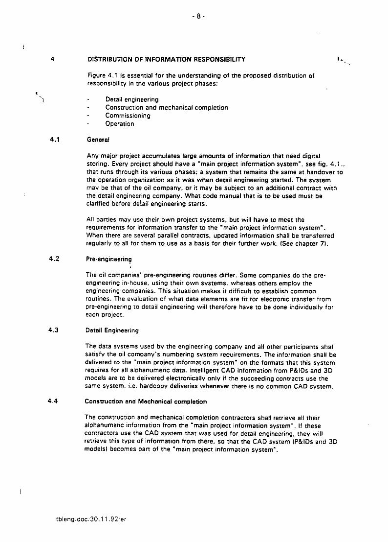
4 DISTRIBUTION OF INFORMATION RESPONSIBILITY
Figure 4.1 is essential for the understanding of the proposed distribution ofresponsibility in the various project phases:
-Detail engineering- Construction and mechanical completion- Commissioning- Operation
4.1 General
Any major project accumulates large amounts of information that need digitalstoring. Every project should have a *main project information system", see fig. 4.1..that runs through its various phases; a system that remains the same at handover tothe operation organization as it was when detail engineering started. The systemmay be that of the oil company, or it may be subject to an additional contract withthe detail engineering company. What code manual that is to be used must beclarified before dePaiI engineering starts.
All parties may use their own project systems, but will have to meet therequirements for information transfer to the "main project information system".When there are several parallel contracts, updated information shall be transferredregularly to all for them to use as a basis for their further work. (See chapter 7).
4.2 Pre-engineering
The oil companies' pre-engineering routines differ. Some companies do the pre-engineering in-house, using their own systems, whereas others employ theengineering companies. This situation makes it difficult to establish commonroutines. The evaluation of what data elements are fit for electronic transfer frompre-engineering to detail engineering will therefore have to be done individually foreach project.
4.3 Detail Engineering
The data systems used by the engineering company and all other participants shallsatisfy the oil company's numbering system requirements. The information shall bedelivered to the "main project information system" on the formats that this systemrequires for all alphanumeric data. Intelligent CAD information from P&lDs and 3Dmodels are to be delivered electronically only if the succeeding contracts use thesame system, i.e. hardcopy deliveries whenever there is no common CAD system.
4.4 Construction and Mechanical completion
The construction and mechanical completion contractors shall retrieve all theiralphanumeric information from the "main project information system". If thesecontractors use the CAD system that was used for detail engineering, they willretrieve this type of information from there, so that the CAD system (P&lDs and 3Dmodels) becomes pant of the "main project information system".
rbleng.doc;30.1 1.92/er

-9-
If the construction/mechanical completion contractors use CAD systems other thanthat employed by the detail engineering contractor, the P&lDs shall be delivered ashardcopies, and an update system must be agreed upon. The required drawings areextracted from the 3D model as a basis for the fabrication yards to make their own3D model. The detail engineering contractor should then stop 3D modelling as soonas possible. S
If different systems are used and the construction contractor chooses not to buildhis own model, the engineering company may agree with the oil company that allinformation is to be delivered from 3D model. This agreement must include aprocedure for the oil company's approval of changes after Oissued for Construction"(IFC). This kind of supplementary agreement is subject to the engineering company'scontractual responsibility for the "main project information system"
4.5 Hook-up and commissioning
Hook-up is normally subject to a separate contract. Commissioning, however, ismost often carried out by the oil companies themselves. Which EDP system that isto be used for hook-up and later for commissioning must be decided as early as inthe detail engineering contract. The build-up of the engineering registers, and the useand customization of the numbering system, must be thoroughly assessed andnecessary adjustments must be made. Consequently, the hook-up andcommissioning tools must be established in the beginning of the detail engineeringphase as a supporting part of the "main project information system", unless the oilcompany wants to use its own systems.
If the engineering company and the fabrication yard use different CAD systems, theyard's CAD system should be used to provide supplementary information such assystem isometric drawings.
4.6 Operation
When operation starts, the "main project information system" shall have beenupdated with all "as built" information so that the information needed for operationcan be handed over.
The requirements for handover of technical information to the operation organizationmust be clarified before detail engineering starts.
4.7 Suppliers
Information from various equipment suppliers should be delivered on floppy disk orhardcopy with input checked by the engineering company.
All information from equipment suppliers shall go through the engineering companyonly and be adjusted to the overall project and the "main project informationsystem".
If total responsibility has been established for a supplier of e.g. control systems,direct electronic transfer can be considered. Still, control and customnization to the.main project information system" shall be handled by the engineering company.
Such systems currently exist within the electrical and instrumentation disciplines.
tbleng.doc/3O.11.92/er

- 10-
4.8 EDP system responsibility
Any contractor is responsible for the EDP system he uses. He shall be at liberty tochoose the type of system and hardware that best fit his work and contract. (Thisalso goes for word processors.)
However, it must be possible to transfer all information that is to be used by asuccessor in a project to the "main project information system".
Unless the oil company delivers the system, it will be natural to include theresponsibility for the "main project information system* in the engineeringcompany's detail engineering contract, either as part of this contract or as asupplement under the same administration.
4.9 EPC contracts
Figure 4.2 illustrates the information flow for EPC contracts. The "main projectinformation system" remains, whereas detail engineering, manufacturing andcommissioning have been integrated. It is a prerequisite that the same systems arebeing used for all engineering, fabrication and hook-up activities.
If there is one EPC contract for an installation, the contractor should be responsiblefor the "main project information system" and hand over information to the operationorganization.
If the EPC contract is one of several parallel contracts for an installation, the oilcompany or the engineering company must be responsible.
Information that has been produced during pre-enigineering must be assessed in eachcase as to whether there are data elements fit for electronic transfer. The rest mustbe handed over on paper.
tbleng.doc:30.1 11.92/er

5 DOCUMENTATION REQUIREMENTS
This chapter discusses a study whose objective has bee n to find the minimumtechnical information required for building, operating and maintaining an oil and gasinstallation, while fulifilling all safety requirements.
Basically, there are two main reasons for producing a document or a drawing.
1I. It is required for engineering and construction.
2. It is required for stan-up, operation, mode monitoring and maintenance,
In order to find the minimum amount of documentation, drawings and specificationsthat satisfies the above requirements, the following questions can be asked:
- Why was The document made?
- What has been achieved by this document?
- Could this have been achieved in a simpler and less expensive way?
- Who needs the information?
- What would be the consequences if the document was to be eliminated?
- For what documents is quick access essential, and for what documents is asomewhat longer access time permissible?
In this report it has been impossible To evaluate the necessity of all specificationsThat are produced in connection with the construction of oil and gas installations.Experience shows that these specifications change little from project to project andthat they are all based on recognized standards such as ANSI. ES, APE, ISO, TEK,N'PF and DnV. Many requirements seem to be redundant in specifications that oughtonly to list requirements That supplement the standards referred to. Before producinga specification, one should therefore ask the questions listed above.
5.1 The flow of information through the project phases
An appendix. 'The flow of information through the project phases", presents theoutcome of the study that assessed each individual information element for allproject phases.
tbleng.doc:,30.1 1.92/er

-12
5.2 Operation information
Documentation that is to accompany an installation to the operation organizationsshall include documents required to:
Operate the installation properly, securely and efficiently.
* Maintain the installation and equipment when out in the field, and to makesound, efficient planning possible for these activities.
* Make modifications, major or minor, that the operation organizations choose tocarry out themselves, or that they choose to hand over to contractors such asthe engineering or fabrication contractor.
* Trace and document designs that the operator deems necessary forverification, or as a basis for maintenance and modifications.
The main objective is to reduce the amount of information to what is strictlynecessary. It must be possible to document intended usage for all information that isto be handed over, and it must be possible to decide which of the above-mentionedgroups it belongs to.
In order to obtain a uniform structure for the documentation, the various types ofdocuments must be organized and named consistently. This also helps to avoidmisunderstandings and unnecessary double documentation. NS 5820 "Supplier'sdocumentation of equipment" forms the basis for this structure.
The same structure should form the basis for engineering and fabricationdocumentation.
The various oil companies hold diverging views with regards to their owninvolvement during the operational phase, apart from the actual operation of theinstallation. Their views on what documents and information are required will reflectthis.
Independence involves handing over a larger number of documents. This involvesmore document administration and. accordingly, higher costs during operation start-up.
By letting the contractor keep most of the documentation which is not strictlynecessary for operation, the operation organization will have to accept:
* lower accessibility
* retrieval of documentation is going to cost
a certain dependence on the contractors
When the documentation is generated digitally, maintenance and updatingresponsibilities must be clear. The electronic system must be the master at any pointof time, and hardcopies must be regarded as working copies. In this way doubleinformation and error sources are avoided.
tbteng.doc:,30.1 11.92/'er

-13-
The digital system ought in these cases to be the valid documentation that is to behanded over to the operation organization.
OPERATION:
The oil company's project and operation orgaliizations must specify the requirementsfor final documentation as early as possible, preferably before the detail engineeringcontract has been awarded.
This is essential if the operation organizations' needs are to be taken intoconsideration with regards to requirements for suppliers' final documentation,engineering and fabrication documents.
It is important to settle the format, structure and media (paper or electronic) for thedocumentation.
In particular, the operation organization must approve the systems that are to beused for the electronic 2D and 3D design models, as well as all alphanumericinformation linked to these models (see separate chapter).
STRUCTURING:
NS 5820 clearly states the requirements with regards to suppliers' documentation ofequipment. It is therefore natural that the As-built-documentation adheres to thesame structure.
NS 5820 refers to two types of final documentation:
User's manuals (incl. drawings)
Manufacturing records and verifying documentation
The user's manuals include the drawings. Alternatively, drawings can form aseparate group:
a) User' manualsb) Drawingsc) Manufacturing records and verifying documentation
A detailed structure based on:
systems, for engineering and manufacturing documents, andtypes of equipment in relation to supplier documentation requirements.
The user of the system assumes that the coding defines:
Installation systemsEquipment typesDocument type. with a clear description of content and reference to NS 5820.
It is recommended that a common arrangement be set up, at least for the Norwegiansector.
zbleng.doc/30.1 1.92/er

-14-
DOCUMENTATION REDUCTION POTENTIALS
Double information and repetitions should be avoided:
- For standard components and off-the-shelf equipment, information should beprovided once only; not every time the conmponentlequipment is pant of'anequipment package.
- In order to have as much information as possible located in one place, thecreation of drawings intended for further information or verification should berestricted if they are based on drawing copies on the same or higher level.
- Traceability should be limited to requirements for verification and maintenance.The supplier or manufacturer should keep the original documents andcertificates unless otherwise agreed.
The operation organization's requirements may be as follows:
1 User's manual
2 Drawings
3 One certificate of compliance for the entire delivery
4 A material traceability list that includes materials and pants that require 3.1.8(DIN 50049) or stricter certificates.
5 Welding and NOT log. This log shall only include materials and pants mentionedin the above material traceability list.
The requirements should be considered reduced, for instance by not requiringtraceability for:
- structural steel, classes 4 and 5- pipes under I' and pressures below 10 bar- open drains and non-critical pipes
Other systems should also be considered.
During the start phase, the project and operation organizations must agree upon theareas for which to require material and welding traceability.
Documentation of standard materials and equipment that the operator's operationorganization already has, should be avoided. When engineering starts, the operationorganization should set up a list of all equipment and materials for which finaldocumentation is not required.
tbleng.doc:,30.1 1.92/er

-15-
5.3 Supplier information
The information/documentation that the fabrication yards receive from suppliers,increases the total amount of documentation considerably. As a rule, the fabricationyards ought only to receive the information required for installation andcommissioning. The rest of the documentation should be stored by the supplier for astipulated period of time. The fabrication yards must critically consider what theyactually need and then they must exert their influence on what they receive.
At this point it may be mentioned that the suppliers' standard equipment anddocumentation should be used more often. In particular, there is auxiliary systemequipment that has been type approved/certified by classing institutions such as DnVand Lloyd's.
The specification of type approved equipment will drastically reduce the amount ofdocumentation, as well as costs, without affecting the quality.
rbleng.doc/ý30.1 1.92/er

- 16-
6 TRACEABILITY
6.1 General
Traceability requirements are often exaggerated in connection with the constructionof oil and gas installations. The figures 4.1 and 4.2, "Flow of information", havebeen based on minimum requirements for traceability. This means that the "mainproject information system", with the various information elements, shall maintainminimum traceability requirements.
In 1989 the Norwegian Petroleum Directorate (NPO) issued a document called*Guidelines on selection of steels and fabrication of steel structures for thepetroleum activity". This document describes NPD's requirements for materialtraceability of steel structures in greater detail. NPD plans to issue similar guidelinesfor process pipes within 1992.
This chapter will first present the outcome of a meeting with NPD and then go on torender a more detailed interpretation of NPD's guidelines. This latter section givessome advice concerning WHERE traceability ought to be required, HOW traceabilityshould be maintalined in a sensible way, and WHAT should be done in order toreduce the amount of documentation related to traceability.
6.2 Definition
In fabrication projects, traceability chiefly means:
Material traceability
By material traceability is meant the possibility to trace back material certificateswith specifications of approved chemical composition and mechanic properties bymeans of the position numbers on the drawing.
Traceability of workmanship
By traceability of workmanship is meant the possibility to find out WHO performedthe work and HOW he performed it (which procedure) by means of the positionnumber on the drawing.
Documentation traceability
By documentation traceability is meant a reference between documents (document
numbers and revisions), that indicates which documents lead to the final product.
6.3 Basis for traceability requirements
These requirements shall be established by the oil companies themselves, based onthe principle of INTERNAL CONTROL. NPD lets the oil companies define thetraceability requirements based on the requirement for safety and operationalregularity.
rbleng.doci3O. 11.92/er

1'7-
6.4 How to reduce the amount of documentation required for taceability
Traceability should not be used in order to settle conflicts. The purpose must be totake sensible corrective measures at systematic nonconformities. For the steeldiscipline the above-mentioned Guidelines state that it is sufficient to specify onassembly drawings within which areas the variois classes of material have beenused.
For the piping discipline, traceability to materials or welded joints ought not to berequired from the position numbers on the drawing. Exceptions are considered forcritical systems.
However, the fabrication yards' routines must be good in order to make sure that thecorrect materials are used in the right places according to drawings andspecifications. There must be Material receiving inspections to check certificatesagainst delivered materials.
tbleng.doc:30.1 1.92/er

- 18-
7 GENERAL GUIDELINES FOR THE TRANSFER OF DIGITAL DATA
7.1 Transfer of digital data
When the project starts, the oil or engineering company establishes the "main projectinformation system", ref. fig. 4. 1. This system is based on a numbering system ;ýhatcan cover ala project phases from engineering up to and including operation, taking)engineering databases and 2D13D CAD into account as well as the interactionbetween these systems.
lIfthe equipment supplier (ref. fig. 4. 1) provides digital information, a controlledregistration system must be used.
The engineering company or the oil company shall operate the "main projectinformation system" and use it as its tool in the design process, recording currentdesign information later to be used for fabrication, commissioning and operation.
During fabrication and commissioning the workshops shall have access to on-linecommunication with the "main project information system". Agreements concerninginformation access shall be controlled by contract either with the engineeringcompany or the oil company.
When operation starts, the "main project information system" shall be handed overto the oil company's operation organization. Afterwards the main responsibility forthe system and the use/update of information lies with the operation organization. Ifdesirable, part responsibility can be agreed with the engineering company or thefabrication yard for the operational phase.
7.2 Access from other systems
The engineering company or the oil company has the main responsibility for theinformation in the "main project information System'. All parties with parallel partcontracts or succeeding fabrication/commissioning contracts shall, as a rule, begranted read access only. If these contractors need to enter information, they cannotdo this directly, but have to go through an approval procedure at the engineering oroil company.
When the fabrication yard is responsible for following~up 3D models with a CADsystem other than that used by the engineering company, contract and specialprocedures must be established for communication with the "main projectinformation system". At handover to the oil company's operation organization, thisorganization takes over total access control with regards to the information and thesystems.
tbleng.dociSO. 11.921er

8 USING CAD/CAM
8.1 Introduction
Today's CAD/CAM experience indicates great 'potentials for productivityimprovements within engineering and construction.
This experience mainly refers to multi-discipline collision checking, Production offabrication isometric drawings, incl. material take-off and connection of productmodels to CNC-machines for cutting steel plates and profiles, and for bending pipes.
The availability of CAD/CAM tools have forced the methods and organization ofwork to be reevaluated and transformed.
In this way CAD/CAM, and information technology generally, have becomeimportant strategic elements in the participants' constant effort to improve theircompetitive edge.
Consequently, guidelines for the use of CAD/CAM must be limited to requirementsfor the presentation of information elements, but it is essential that the target groupand purpose for the information exchange be defined.
Traditionally, engineering and construction of industrial plants are based on manualdrawings. Installations are presented by means of standardized drawings perdiscipline, such as General Arrangement drawings. With regards to the contents andquality of these drawings, our industry has seen clear requirements develop over thelatest 20 years. At the same time, they have developed into comprehensivedrawings whose contents are to cater for all purposes from design to operation. Thisapplies to parties such as operators, the authorities, pantners, contractors andpurposes such as verification, approval, basis for own design, inquiries.prefabrication and manufacturing, just to mention some examples.
Digital installation models, based on individual components, physical objects, withreferences to specifications and design basis, make way for a radically new way ofthinking - SUFFICIENT INFORMATION TO SERVE THE PURPOSE. However, thismeans that those who receive information must define the information elements theyneed and what time they need them.
In other words, the premises for sensible use of information technology lie in greaterdifferentiation of the problems. However, this requires a profound understanding ofwhat goes on at detail level, so that a sensible and efficient use of this technologycan be reflected in the oil company's contract strategy,
Information management in connection with the development of oil/gas installationscovers the entire value range from draft development to installation shut-down.Approximately 80-90% of the information required for operating the installation isgenerated during the engineering phase, by the operator, the equipment suppliersand by the engineering contractors.
In the engineering phase, schematic system designs are initially drafted on the basisof the oil company's design documentation and specifications. These aresuccessively transformed into a physical installation by means of fabrication design(shop drawings). 3D CAD is used for construction design: a digital model of the
tbleng.doc:30.1 1.902/er

- 20 -
installation is built on the scale of 1: 1 with an accuracy corresponding to thefabrication industry's requirements in millimetres.
Efficient use of 2D CAD requires a link to 3D CAD and vice versa. The onlydifference between 20 and 3D CAD is that one of the coordinates equals 0. It is anadv~itage if this link is based on a 1:1 relation in the same plane as the drawing'ssection' in such a way that platform references are identical in both environments forthe individual elements.
Intelligent schematic diagrams (P&IDs) are developing into presentations of theengineering databases' information contents.
8.2 3D CAD
8.2.1 7 he build-up of 3D CAD models
A 3 dimensional CAD model shall be a 1:1 representation of the physical installation.with a degree of detail that depends on the model's purpose.
This may be:
a) design verification, construction friendliness and collisionsb) isometric drawings and material take-offc) to use model information to feed digitally controlled machines - computer
based production equipmentd) detail prod. to be used during operation
Chapter 8.2.3 describes the degree of detail for a 3D deck and modules model for anoffshore installation. The model's purpose covers points a and b.
The model shall be configured in millimetres referenced to the platform grid systemthat is specified in the code manual, and that it shares with the 2D Drafting system.
The purpose of all graphic layers shall be specified, and whether they are projectspecific or discipline specific.
A 3D graphic model can be a combination of a number of design files, depending ondiscipline, plat-form area and design elements.
A graphic model must be configured to divide the platform logically in functionalareas for manufacturing, collision analysis, model approval, production of isometricpipe drawings, etc. This is an important aspect that the operating company musthave an opinion about, since the model later becomes one of the most importantinformation exchangers for downstream users, and may be of direct consequence forthe construction and hook-up processes.
8.2.2 Producing drawings
The established 3D Model shall represent the central medium for area engineeringand coordination and shall be the essential medium for the production of drawings.Principles for drawing premises can be produced, formats and contents shall bedocumented and agreement shall be reached with the operating company beforeproduction starts.
tbteng.doc:,30.1 1.92/er

-21
Typical 3D Model drawing products are:
- Arrangement drawings- Equipment lay-out- Isometric block drawings- Isometric pipe drawings such as
- system iso- stress iso. engineering iso
If more than the extractable drawing annotations are required, this shall be agreedseparately, taking the purpose for the issue into consideration.
The operating company must accept that 3D extracted drawings may deviate fromthe manual standard (ref. traditional pipe arrangement drawings). It is theengineering company's task to establish drawing formats or other methods toreplace the design media aspect of a previous manual drawing type.
8.2.3 The level of detail in a 3D graphic model for engineering purposes
The below description outlines the normal level of detail in Norwegian offshoreprojects. This detailing covers the need for design coordination, collision analysis andextraction for various documentation purposes, but only to a lesser extent the use ofnumerically controlled cutting robots for steel plates and profiles.
It is vital that the operating company and the engineering company agree on whatdegree of detail is required. Besides, it is important that both parties agree on howthe degree of detail can be increased at later phases without influencing the modelthat has already been established.
PIPE DESIGN
- Pipes, valves, accessories for all lines in carbon steel etc. larger than 050mm.- For "exotic" material all lines shall be modelled.- Valve gears and actuators, and manual valve actuator position- Pipe, accessory and valve insulation, if this is required
- Pipe supports, at least as reservation of volume- Tank, pressure vessel, heat exchanger outfitting
STEEL
All main and secondary steel structures, exclusive of inner "invisible" stiffeners.
All steel structures exposed to descaling by weathering, such as:- platforms and supports- internal and external stairs and walkways
- access ladders to equipment components- access platforms- equipment supports- wall supports- pipe rack structures
- penetrations and local sleeves
tbfeng.doc/30.1 1.92/er

-22-
Passive fire protection on steel structures.Minor brackets and stiffeners that are of no consequence to collision analyses will
not be modelled.
HEATING AND VENTILATION
All equipment purchased by the project, to be included as a permanentelement on the platform, and to receive its final position in the course of theengineering period.All ducts, flanges and penetrationsInspection hatches and outward door openingsMeasure points
ELECTRIC EQUIPMENT
- All equipment purchased by the project, to receive its final position in thecourse of the engineering period.
- Cable racks for electric and instrument cables down to 300mmLighting fixturesPenetrations
INSTRUMENTATION
All equipment purchased by the project, to receive its final position in thecourse of the engineering period
- All inline instruments such as:- Flow meters and elements
Thermowells- Boosters and bleeders- All instrument field valves with actuators and safety valves
Level gauges and transmittersJunction boxesLocal control panels
- AccumulatorsAnalysers
SAFETY
- All equipment purchased by the project, to receive its final position in thecourse of the engineering period
- Fire water stations and necessary valves- Sprinkler and deluge pipes and valves
Escape routes
Fire detectors with sectors
tbleng.doc/30.11.92/er
- 23 -
ARCHITECTURE
- External and internal walls- Louvres- Wall penetrations
'N' - Door and window openings in pre-fabricated wall panels- Doors with outward turns/or slide doors with operation gear- Lowered ceilings- Floating floors- Explosion panels
MECHANICAL
- All equipment purchased by the project, to receive its final position in thecourse of the engineering period
- Access routes, maintenance areas round equipment and volume reservationsfor lifting tackle, lifting beams, trolley beams, pad eyes, minimum distances forlifting. etc.
- Crane radiys
8.2.4 Using the 3D model for construction, commissioning and operation
With regards to construction, the digital model is specially used for shop drawing(engineering, fabrication drawings, material traceability, weight and MTO activities)installation planning activities.
With regards to commissioning, the 3D model today proves very useful. This isdirectly linked to the operator's increased experience in this area. However, weenvisage substantial potential for this technology within all operation areas: training,maintenance and modifications.
8.3 2D CAD
Logic diagrams
These are documents such as P&lDs. Instrument Loop Diagrams. etc.
Systems that produce such documents are all essentially associated with graphicdesign systems. Today's technical development moves towards alphanumeric designwith graphic reporting. This transition is better fit to secure data consistency inunderlying and downstream databases. In the future the industry will seesophisticated alphanumeric design systems, perhaps particularly within Instrumentdesign.
The requirement for alphanumeric and graphic data consistency will be unconditionalfor graphic design systems in which alphanumeric information is often based ongraphic information. The demand for correctness applies to graphic as well asalphanumeric information.
tbleng.doc.:30.1 11.92/er

- 24 -
2D drawings
If 20 CAD is to be used efficiently, it must be linked to 3D CAD. preferably as anextension of the 3D model. The only difference between these tools is that adrawing produced by means of a 2D CAD tool refers to one plane only, sucn as IX-Y. Z=O0). For reasons of consistency the 20 model's configuration must be identicalTo that of the 3D model;. on a 1: 1 scale, and so must the grid references and graphiclayer convention. The individual contractors must be free to choose font types andline thickness, provided fonts and lines are clearly visible after copying and providedthe font and line conventions are kept at a minimum.
8.4 Progress measurement
The 3D model is a product model which has been built by means of singlecomponents (equipment and materials).
The design process is an iterating process in which many professional disciplinescontinually adjust to each other in order to finally reach a product of adequatequality.
Consequently, this will be the question to ask:
How is the quality of the information that I use, at any time, and how good is myneighbour's design?
In order to increase design process productivity, all work on the model should bedone in real time mode. This means that multi-discipline users work simultaneouslywithin the same platform design volume. However, before this is possible, attributesmust be assigned to the model elements, i.e. the objects. The responsible cesignerprovides a status for these attributes at any time, so that other users can read it,and relate to it in their own design.
This attribute information is comparable to document milestones and must bedefined with regards to quality requirements and time schedule.
Using the 3D model as design medium, makes it possible to measure progressagainst physical model objects. This fact opens up substantial possibilities wvithregards to efficiency, controlled development and design process control.
Since this way of measuring progress radically deviates from the "classic" methodbased on document approval, it is important that these principles are clarified in abroad environment. Principles of this kind will also be of consequence to softwaresuppliers, and this is also one of the reasons why it is important that all parties useroughly the same method.
tbleng.doc. 30.1 1.92/er

-25 -
9 USING ENGINEERING DATABASES
9.1 The purpose of engineering databases
The engineering databases shall contain information that is necessary for theengineering and construction phases as well as for the stant-up, operation andmaintenance of the installation. The engineering databases shall contain theinformational basis for the systems that are to be built during the engineering phase.The criterion for including an information element in the engineering databases mustbe that it is to be used by more than one user. The engineering databases will formthe installation's pants list, a work of reference that provides correct information atany time and that will provide other connected registers with parameters.
9.2 Structure
The engineering databases are to be structured as special registers with internalcommunication lines for addressing elements. This can be visualized as a matrix thatspecifies the elements that have been used in the various applications, or functions,that are linked to the database. To the users, the database will look like theapplications that have been defined for entering or retrieving information. Thespecification of these applications will define the contents of the database.
In order to secure reliability it is important that information elements are stored inone place only, and that other functions retrieve the information every single timethey need it. In this way the individual register will consist of a set of informationelements that it "owns", and a set of addresses for the information that it needs butdoes not own.
The system configuration must give all users read access to all pant registers, butrestrict write and update access to the owner of the information.
A complete engineering database system will have points of intersection towardsmost activities that will be performed during the plant's life cycle from engineering tooperation. A minimum list of registers whose combination makes up the database,can be defined:
equipment listinstruments list including fire and gas indexcontrol systemelectrical informationline listinstrument data sheetsequipment data sheets
- junction boxes and termination racks- cables list with terminations- terminations
- safety equipment- spare pants fist
Other special stant-up and maintenance registers can be included or excluded, buttheir function and scope will be based on information from the above pants registers.
rbleng.doci;3O. I.92/er

-26-
The engineering databases must be constructed so that it is possible to move themfrom one nqchjne configuration to another. A database that has been establishedduring the engineering phase must meet all operational requirements and shall beupdated when it is handed aver to the operation organization. Please refer to chapter5 of this report for information relevant during the various phases.
Engineering databases must be produced so that it is possible to control and verifythe completion of the database. The database is a deliverble and will serve ascontractual basis for succeeding phases. The status and revision of the databasemust be made clear to all users, and information elements that are included in thedatabases must only be changed through formal update routines.
9.3 Communications, links
The condition for including an element in the engineering database must becontrolled by whether the element is to be used in more than one place. Thisphilosophy makes the link between the various registers essential. The engineeringdatabases will serve as the informational basis for drawings generated by the 2Ddrafting system. By means of a schematic capture tool it will be possible to presentthe information graphically and have it issued as drawings.
The maintenance of one element throughout the various phases is cost pushing, andit must be secured that updates are restricted to a single location and thatinformation automatically floats to other pant systems and registers. Thecommunication lines between the various databases must be unique and fast. Inprinciple, it is unacceptable to base the update routine on file updates of informationgroups. Users must rely on the database always to contain the latest approvedinformation. Running large validation reports between different databases should notbe necessary.
Links between the databases shall reflect the forms of contract and the distributionof work that will be established throughout the project. The build-up of theengineering databases shall be planned in such a way that they contain thenecessary elements at any time. rhis means that milestones must be establishedrelative to the elements from which the database has been built. Reports fromcontractor to client shall contain descriptions of the progress on the engineeringdatabases.
The link between databases and other calculation and drawing systems representsthe great challenge for further development within this part of informationtechnology. This link is essential for further development and increase of efficiency,but the system must also aim at the greatest possible user friendliness. Userfriendliness is necessary in order to secure that the systems will be used and that noinformal systems arise on the side of the established routine.
The engineering databases will not be complete until links have been establishedbetween the components listed in the engineering databases and the documents thathave been created in order to describe the same components. This means that itshall be possible to find the documents that describe a component via theengineering databases, and that the documentation administration refers to the samecomponent. However, one document for each component is not required. This linkshall therefore be established in both the engineering and the document controldatabases.
rbleng.doc:30.1 1.92/er

-27 -
10 WORD PROCESSING SYSTEMS
10.1 General
Word processing documents constitute a considerable part of the documents to beI N managed and brought from one phase of the project to another. These documentsconstitute an important factor in the "main project information system", not only innumbers, but in scope and amount of data as well. Word processing documentsmust be divided into 3 groups:
-Administrative text: letters, minutes, memos, etc.
Procedural text: official reports with links and extractions from EDP systems
Suppliers' text: manuals, etc.
It is recommended to use the same word processor for administrative and Proceduraltexts within the same project, in order to do away with the need for "translators" ofvarious quality 1with built-in error sources.
10.2 Administrative text
Administrative text is defined as the writing and storing of letters, minutes, memos,etc.; text that does not require a link to spreadsheets, graphics systems,presentation graphics etc. Neither is administrative text subject to normal revisionmanagement methods, only normal filing codes with in/out dates.
10.3 Procedural t ýxt
Procedural texts include the same text systems as do administrative texts, but theyare used for complex, intelligent reponts, specifications. etc. with active links totables and graphics in spreadsheets and calculation tools.
Procedural text is considered pant of the contractor's working methods and musttherefore be an integrated pant of the project execution philosophy. Word processorsfor procedural texts must have file and directory functions corresponding to whatyou find in normal document administration systems within the industry. Thesesystems shall manage revisions, ownership, the right to revision, registration ofofficial issues, etc.
10.4 Suppliers' text
Suppliers' text is defined as that pant of the equipment supplier's documentation thatincludes manuals of various types. Suppliers' text is normally transferred to theoperating company via the engineering company as pant of bound "FinalDocumentation".
tbleng.doc,3O.1 1I.92/er

-28-
10.5 The transfer of textual information
Text shall be transferred to clients in a controlled manner and at points of time thathave been agreed in advance. This particularly applies to procedural texts that arenormally registered as official project documents. The time of transfer shall be linkedto tie final completion milestone.
Most administrative texts can be converted between the various word processors via"translators'. Such translationiconvernion is less relevant since these texts generallycannot be reused.
Reports and specifications often form an important basis for new projects, and/orneed for revision at later project phases. Since this group of texts includes the*intelligent text" concept, it will be difficult to convert them to other text processors.Tables and graphics will then have to be handled as pictures. The contractor must beprepared to take on the responsibility for converting official text documents if hisword processor differs from that of the operating company.
In principle, all suppliers' texts should be transferred electronically, and thisrequirement should be specified in the inquiry. If the documentation is of such anature that direct electronic transfer is impracticable, the documents should bescanned and stored on optical disks. It must be ensured that such scanning is inaccordance with international standard CCITT GR. 4.
tbleng.doc;30.1 1.92/er

-29-
11 INFORMATION APPROVAL
11.1 Types of information
The approval routines/procedures are pant of the project's quality assurance systemsand are most often also pant of the coordination procedure between operator andcontractor.
The types of information that usually require approval are in short:
- Basic information such as design premises, principal philosophies etc.- Basic system information in the form of drawings and specifications (PFD,
P&ID, Single line diagrams)- Equipment specifications and data sheets for purchases- General arrangements and construction documents
The approval routines will often depend on type of document, and principaldocuments will obviously receive stricter treatment than secondary documents.
Moreover, the approval routines depend heavily on the operating company and/or thephilosophy of the individual project.
All information is currently still bound to 'A' format documents, independlant of itsrepresentation on lower levels, such as 3D graphic models. It is a fact that virtuallyall information in today's offshore projects is stored electronically on some mediumor other, be it text, alphanumerics or graphics.
The "A" format document can therefore often be regarded as an outcome of apredefinied extraction and representation process between information elements andthe link(s) between them.
11.2 Document approval
In current projects, approval routines are being used directly as a measure of projectprogress by linking the production of documents to specified milestones. Suchmilestones may be:
- Stant-up- Issued for interdliscipline control
- Issued/approved for InquiryIssued/approved for Purchase
- Issued/approved for Contract* Issued/approved for Construction- Issued/approved for End of Detailing
All such milestones will be characterised by its own revision code indicating numberof revisions.
These milestones define a life cycle for the individual documents which links them toa specific degree of completion.
rbleng.doc:130.1 1.92/er

-30-
Approving a specific document far a milestone means that the information contentsof the document correspond to predefined requirements, and that this can bedocunanted through check fists.
The direct visible result of checks and authorization will be seen in the document'ssignature block.
When a document has been approved, all information that the document contains isapproved, unless the document specifies otherwise.
11.3 Digital information
As mentioned above, mast project information is stared and processed electronicallyon a medium that makes simultaneous read and write access possible.
It is therefore important that approval routines can be activated on levels below thesummary "A" document (document sources).
J Current methods are partly independent of electronic medium, most often describedas referring to data files (in parallel to documents).
It is important to specify these methods, not least to the computer system supplierswho gradually will have to implement such routines in their systems.
The oil companies have a responsibility of their own in this respect, particularly withregards to how digital information may be transferred between parties without losingapproval traceability, and with regards to the potential contractual implications ofdirect use of information for purposes for which it has not been approved.
Today there are no commonly agreed routines for the approval of digital information.When the need arises procedures are set up after the project has started. A practiceshould be established for including a definition of digital information approvalroutines in the oil companies' contracts. All contracts are now based on approval ofinformation presented on paper.
tbleng.doc30. l1.92/er
-31 -
12 ~, INFORMATION MANAGEMENT STANDARDS
The use of information technology contributes to the efficiency of the production anddistribution of documents. Consequently, information management includes not onlydata processing but also information maintenance during the field phasesdevelopment.
Industrial offshore developments involve many different pantics: the operator, theengineering consultant (often more than one), fabrication yards, sub-contractors, andthe authorities. All of these participants have their own requirements and standardsfor internai development of documents and drawings, but information from thedifferent participants will be required by several users.
Since most participants are using EDP tools for the production of this information.the information exchange must be standardized, be it word processing documents.database information, drawings, article information, etc.
12.1 Documents
It is important to define "a document". The content of a document is more importantthan its form. Accordingly, it must be possible split form and content. The documentcontent will vary over time, depending on the project phases. A document can bestored and processed digitally and is not necessarily linked to paper.
International standards encourage a split between document format and contents.Standardization restricts the types of digital information that a document cancontain.
Typical document content is text, data, tables, graphic information, raster graphics,calculations and pictures.
Typical digital documents of technical type include:
- technical manuals- drawings- specifications- data sheets- maintenance manuals
The concept of technical documentation covers literature that describes technicalprocedures, equipment units, installations and operations, as well as training, serviceand maintenance manuals. All these documents are characterized by the following:
- Several writers, engineers and designers contribute to the document's finalform.
- The document is actively linked to databases.
- The document contains mathemnatic signs and symbols.
- Documents can range from 1 to 50.000 pages.
tbieng.doc:30.1 1.92.'er

- 32 -
- Merged documents are produced from a set of templates developed for theproject/company. 1
- The format is uniform throughout the document.
- A high degree of cross references between documents.
- The possibility for commenting on the document digitally, high degree ofrevision control for document objects.
- Generic marking of documents for reproduction in other data systems or forfuture revisions.
- It must be possible to reproduce the document according to futuretypographical standards.
- The distribution must be controlled.
12.2 Modelldesign informaiaon
There will be a need for managing design information as well as documentinformation. Like document information, design information is characterized byextended use of:
- Common article catalogues.
* Common numbering system.
- Common specifications.
- Active link to databases.
- Generic marking of models for reproduction in other data systems or for futurerevisions and updates.
- Several information users, and consequently a need for access control ondifferent elements in the same model.
- Ought to be able to communicate and be linked to automatic materialproduction.
- Full integration with document production systems.
In order to meet these requirements, standards are either being developed orinternational standards must be included in the national standards for informationexchange.
tbleng.doc130.1 1.92/er

-33-
12.3 Relevant standards
The following standards must be considered relevant:
- MIL STD 1840A CALS (Computer Aided Acquisition and Logistic Support)- ISO SGML (Standard Generalized Mark-up Language)
IEO ODA (Office Document Architecture)IGES (Initial Graphics Exchange System)ISO 8613 CCITT (Standard raster exchange)VDAFSNS 5820 (Supplier's documentation of equipment)Electronic Data Interchange (EDIANSI/IFFF std. 730 Software quality requirements
The following additional standards will come in the future:
ISO STEP
tbleng.doc;30.1 1.92/er

- 34 -
13 SPECIAL CONSIDERATIONS CONCERNING LONG-TERM STORAGE OF DIGITALDATA
Before deciding on long-term storage, it is important that we ask the followingquestion:
What is the purpose of long-term storage, and what should we storea?The answer to this question will influence the storage format. The requirements forusing the data will influence their form of representation.
As mentioned in section 5.2 *Operation information", there are four areas ofapplication for electronic information:
1 Daily operation2 Maintenance3 Modifications4 Documentation
An additional area of application is that of training.
A line must be drawn between active and passive storage of digital information. Thisis particularly relevant in connection with the three first areas of application.
Active storage is connected with extra costs as the maintenance requirements arerelatively high.
Another aspect of digital long-term storage is the limited possibilities for transferringintelligent 2D and 3D information electronically from one system to another.Intelligent information represents approximately 20% of all information to betransferred to the operator's operation organization.
The need is definitely most urgent for the system disciplines, and this fact isnormally independent of whether the installation is offshore or onshore. For 3Dmodels, the installation's accessibility, planning requirements and maintenance costswill be decisive. In this respect the operators' operation organizations will assess theneed and scope for active data storage according to type of installation. This meansthat e.g. subsea installations will be found to benefit from 2D13D modelmaintenance, whereas the operators most probably will be reluctant to take on theextra costs related to maintaining an active storage system when onshoreinstallations are concerned.
For the latter application, there are no strict demands concerning the model'sintelligence, but rather that its representation can generate pictures in an orderlysequence. The current data formats that are described in DAKFAB's user manualmay be used in most cases, but if the information is to be transferred to othersystems in the future, an effort is required when it comes to planning andadaptation. Key words are transformed "subsets" of existing standards.
As for the listed areas of application, the solutions will be found on another level.The description of the actual products must be transformed. The premises are foundin article and component standardization rather than in CAD.
rbleng.ooc/30.1 1.92/er
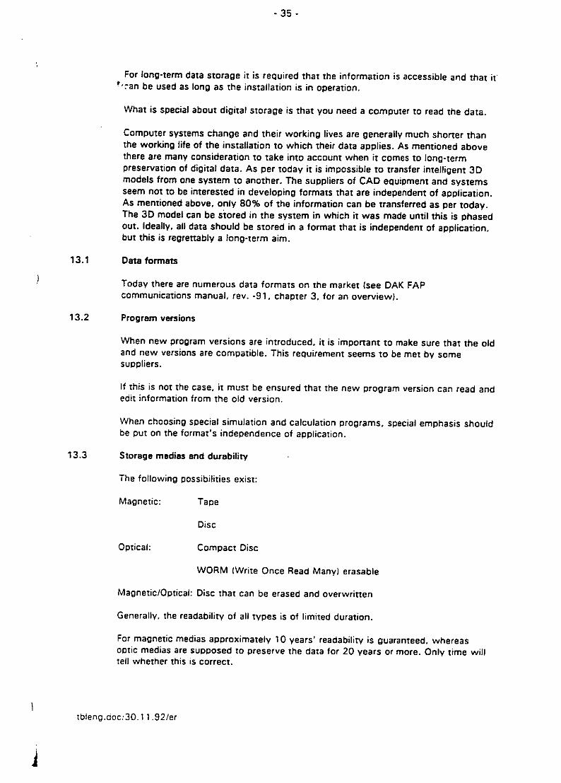
-35 -
For long-term data storage it is required that the information is accessible and that it.can be used as long as the installation is in operation.
What is special about digital storage is that you need a computer to read the data.
Computer systems change and their working lives are generally much shorter thanthe working life of the installation to which their data applies. As mentioned abovethere are many consideration to take into account when it comes to long-termpreservation of digital data. As per today it is impossible to transfer intelligent 3Dmodels from one system to another. The suppliers of CAD equipment and systemsseem not to be interested in developing formats that are independent of application.As mentioned above, only 80% of the information can be transferred as per today.The 3D model can be stored in the system in which it was made until this is phasedout. Ideally, all data should be stored in a format that is independent of application,but this is regrettably a long-term aim.
13.1 Data formats
Today there are numerous data formats on the market (see DAK FAPcommunications manual, rev. -91. chapter 3. for an overview).
13.2 Program versions
When new program versions are introduced, it is important to make sure that the oldand new versions are compatible. This requirement seems to be met by somesuppliers.
If this is not the case, it must be ensured that the new program version can read andedit information from the old version.
When choosing special simulation and calculation programs, special emphasis shouldbe put on the format's independence of application.
13.3 Storage medias and durability
The following possibilities exist:
Magnetic: Tape
Disc
Optical: Compact Disc
WORM IWrite Once Read Many) erasable
Magnetic/Optical: Disc that can be erased and overwritten
Generally, the readability of all types is of limited duration.
For magnetic medias approximately 10 years' readability is guaranteed, whereasoptic medias are supposed to preserve the data for 20 years or more. Only time willtell whether this is correct.
tbleng.ooc:30.11.92/er

- 36 -
13.4 Reconstruction of stored data
As a consequence of the storage medias' limited working life and the chance ofdeleting data due to errors and external influence, back-up copies are required. Also.the stores must be secured and the environment must be adjusted according to therequirements set by the storage medias and the suppliers. Furthermore, activestorage maintenance is vital, to make sure that no information is lost due to physicaiaging or the implementation of new software versions.
13.5 Contractual relations
There is no standard contract format that covers long-term storage of digitalinformation. This means that the individual user will have to prepare a customizedcontract.
tbleng.aoc/30. 11.92/er

- 3~7-
14 CONTRACTUAL RELATIONS
This chapter will sum up issues of special consequence to the content and phrasingof contracts.
14.1 The contractuidl standing of electronic information as compared to signed documents
Based on the recognition that drawings are no longer the primary source ofinformation, digital information should be made the basis of approval routines,progress measurements and methods of compensation.
An important consequence is that approval/progress information will have to beregistered for the data elements in the information systems. Moreover, it must beconfirmed that the information system to be used will be able to handle theseoperations if the replacement of signed paper documents is required.
Electronic data should replace signed paper documents more often, and a systemmust be set up for ensuring that the electronic documents are being safely handedover to another parry to the contract, by means of a transmittal system or otherofficial handover procedure.
14.2 Scope of documentation and storage responsibility
The appendix called FLOW OF INFORMATION THROUGH THE PROJECT PHASESrecommends which information to store where. These recommendation should betaken into consideration when setting up a contract.
The contract should establish the requirements for long-term storage of electronicdata, including the method for having them reactivated. The contract must alsoestablish the program versions to be used for data retrieval.
Distribution of information responsibilityThe contract should describe who is responsible for the MAIN PROJECTINFORMATION SYSTEM, both with regards to computer technology (HW/SW) andinformation elements. The party responsible for the MAIN PROJECT INFORMATIONSYSTEM should contribute to the requirements for system usage and communicationwith other parties to the contract.
Chapter 4 includes recommendations relevant to this field.
tbleng.doc/30.1 1.92/er

- 38 -
Whenever possible, the panties to a contract shall use their own computer systems,for which they are themselves responsible. This is because companies generally basetheir methods and procedures on their own computer systems. However, this mustnot interfere with the main project information system's requirements.
Ideally, the party responsible for entering the information, should be the parlyV thatwill use the data. This system will provide better internal control of work performed,as it is based on self interest.
DEGREE OF DETAIL in information elementsWhen a project requires a 3D CAD model, it is of particular importance that thecontract defines the required degree of detail. Such a definition is an importantpremise for the parry making the model as well as for the panties that are to retrieveinformation from the model later on.
Section 8.2.3 provides a basis for the decision makers in this field.
CONSISTENCY CHECKINGIt is important that parties responsible for an electronic information system arerequired to check the data in their systems for consistency. This is particularlyimportant with regards to 3D CAD models and collision checking. Collision checksand corrections on these systems must be carried out by the party supplying themodel, not by its receiver.
Information and systems to be used during the operation phaseAs an alternative to the transfer of information to the operation organization, theengineering company or the fabrication yard could offer their informationmanagement and maintenance services to be extended so as to include the operationphase. Such services would be covered by a framework agreement for additionalservices.
A framework agreement for additional services could be established as a contractoption.
Required standardsPlease comply with the recommendations contained in section 12.3.
tbleng.doc13O.1 1.92/er

2>
z cc
It0 >_'l
0I.02 0
oilo
ca
00
:0 CL
U >
__ _
I m-
>k 00 -Oil F o C>
0 cc 0 a0WC LL -
zP 0 0a ~Oil Za C
0! --j____I, Z0 0
ILLI

22
az
z z4z
00
'3 C
> z ).. 2
0 wI0I ~0E
01
0.
1 2L0i nl
Z o .22'. 0i
z2
I 0 0
z 4w
CC
zz-M
La a -z'a
o w w C
L co 0 . 4'n 2 :z ,5
0 0c
Z z 0
0 0u a- u 5L) LaU .i ,
CL CD 420Z 4
C~ -Z

APPENDIX
FLOW OF INFORMATION THROUGH THE PROJECT STAGES
The below matrix combination is an example that describes an information element's flowthrough the various project stages. The matrix has been split into the following projectstages:
ENGINEERING, FABRICATION BID, FASRICATION. SYSTEM TESTING and OPERATION
The first "X" indicates a recommendation as to where this information element should beestablished. The following "X~s indicate the receivers of the information and whether theywill be updated at succeding stages.
Some of the "X's have been given a code in order to indicate storage requirements. Thesecodes have the following meanings:
XES - (X Engineering company Storage) The engineering company created this informationand is required to store it for a specified period of time, but will not send it to thefabrication yard or the oil company.
XF - (X Fabrication) This documentation is produced in connection with i7abrication, butthere are no requirements for safekeeping or transfer to the operation organization.
XFS - (X Fabrication Storage) Documentation that the fabrication yard is required to storefor a specified period of time.
It has further been considered how new information technology can be applied to transferinformation from one phase of the project to the next in order to avoid as much doublework as possible. This includes CAD with other informational databases.
Iblenea I

x Z!S 0
CCof
21
0Li,
-l ý x LI X x XX XxLX x x LIXE X x Xm
L-
XX XXXU- xxxx
CNL
wI XX XX xx W XX xX X X
z co
> CD
u E-CE
CD C
_ 00
LU~~0 U)C 0_o E -E-V Ca 6
LI z - a..a olsCw- - 0 E
n 2 0 )(<~0 a0G3E ; - - '
u. z
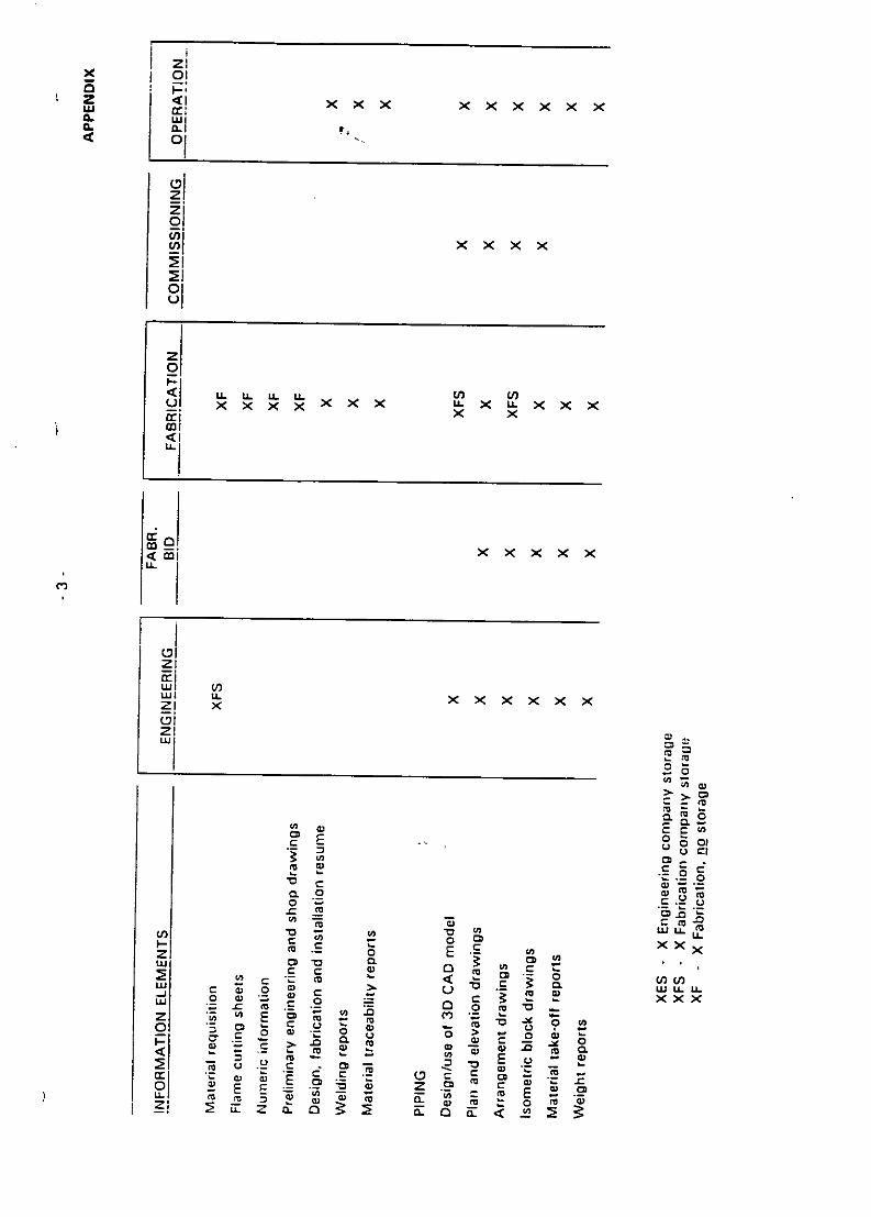
CI
zi
01
C)Lii
W< > x x x
010
F.CIS2,x xx x Wx xx
<1
aý=
o> >V CD
C 'c 0 o
U) - t ~ to LL'
CC 0 E Ct(fuoU 'D a 0Lc '0
S2 r 6. 4 0
w 0 ý E a u.uz U-'s sV c -M0 '
< r C -j u.
u 0LL@ 7 -@ '; = tmE .. Lm
to o f C w m FL ~ C tzi z .a3 F f 2

zix 01
2x x x xx xx
ol
oilx xxxx x
01±
P4'C 'C LL X xx x x 'Cx x xx
zi
V) U)
CC
r C
if~~~~ 0~: IJL IC 'DE, CD'.'~ S
to 9- .,2 -aCL x mA m.~ c c via x

0 I-
0.04 0:
x xCLcc
CL0 f U i
c) u xu xxxxxz
0
U)-(
LI)L
w V)124 X wX >C )Cx x
z 0
00
cl0 0
E
0
0 U
EE r'.o U .0
0 aL.2 -W 0)
-j -D aL- -w 0
- 0 0) V)
o C m
o022 U 0 0 o0= =)~~~~~u wLi,' n 00 U
V) >0. r 2 e 0CI COLfCLf>Z0.
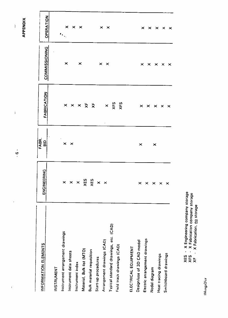
Xzx 0
3 j X x x x xxx0.0
zE05
0u
z
u xX~ Lxu xxx x X X)CX
xx x x
FZI
w x xxww X X X X XX
z x ,
olo
CD CD
E E
) .c -F
Li U C c. wu.0u
wZ < z E U L
EU-- -o C nE
z . (L U w C
AC C.o -00
2 2 c D E )0WJOCZMD,

z
0.
z0
Er xx x x
0a
wo xxxx xx ux x x-x xx x x ~xx x
CCU-L
CD
00
wO
CL cn cC
w aMMU.I- CD >
0 0 0D 0
W 0 0 o 0, 0D 0
Cli 01 a ~ - - SU.O -M > z Z Z

Zx 00 F-
'U
IC CL
(3
0z
0
0x '
C0
< LLU UL wI. wL U) nX EoY x< x x x x U. I. w.'Cx xx xx x
cmLL
ZO
w
CD~
.0 0 Ea 0.
- CDo c,
- 0
C c z
W . 0 0
CD 0 0 En(1r c w L
0 (0
2) 0 ml 0 CLrO 0
m~ ; ,- m m o - I- o -E - E
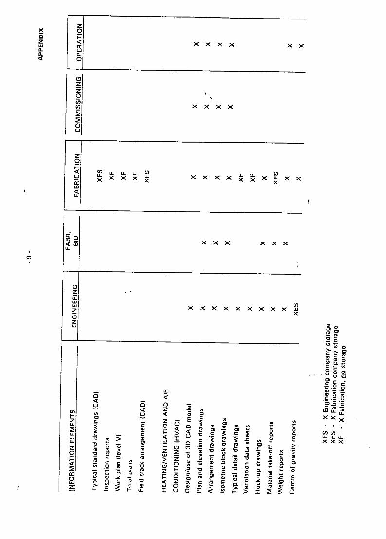
x 0E P
z < xx x xxwx0.IL0.0
zz0
x x xxx
0u I
z0p
< 0 u- u. uLCl "-LiL x x x x x x x XLXx
LAL
x xx xx x
zw cw x xx x x x x xx wz x(0w 0a
hCD
ComCL
0oCD
c c .2
0 ~ < 0 OL
Z c z - E -E - -
0) - < 0 C; , CD - I.
.12 < f C C 0 00 - >Z < * ()c
- 0 _ J~u .r o w u.a
Fjc m 3 = 0 2 E x *5Cz C;- a
-~~ 0., .6 a>o C~
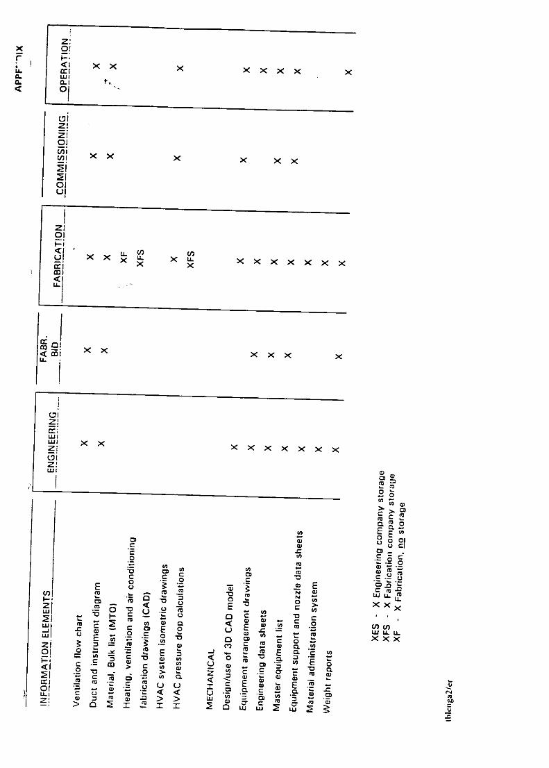
x ~C)
zrr
01
ESi
01XX Xxx xx
co x x xx Xx x
Z~to-5w 0
CC
0 0 a.)
c om a .2 C5 5 o .2ca Z
m C ' c Et s. :) a 0) - ! i
_a WLmJ.i < u E m xxx
C, E t2o mL
WI Q c
01 .2 c ) o
- Q > >o w
> 0 0 z> OC2I au cw

CL ccCL
0.
22
V-)
0
C-) XX XX X XX XX X
LI.
cri
z C
o Ol-
E E
0,00 C
C tiF
tco C m (a) w 0 a. 2 2 ~ . -. oM LLJU u
0~~ U) .2(n ~
0 c -o wr U M
tl .w CD mt O l a a m u
L co t C) Co

zX 0
CL I-
0.ii
0.a
0
2>
z
0
x Co
U o~ x XxX XX.X
w
U-
121
'cv
"Cl
2 E.2
E .2
a r Ml 0 .. !a2
( X w WLLC
Eo u xz cEn0
WCL 'a xx
0. a w c '
z C c c E-a 0) C )
±v C uw
u LIcm ca E

zx 0
3 F-z < x x xx
0.0
(Dzz-0U,
0Li
U.U. U
_ ~ xx x xxxx
z
CD2
E E0 21
cc
m 0
<W LI.
I- Li 00 < <XX><
c t r Ur U ~ CMu.Lz 04ý .- Ii ~ .- - 0) 0
u- 0 t aS Q l= l00 u 'r CD5 3. .2 C O M M.
0' 0
0) >.~ 3 Q 0ý Z 2 U - mýW &C a < 'v2 F

2x 0
* F-LU X x
0*
z20FnU3 x Xx
01u
20p<u L L LL
LL.
CoC
U-
(4x X
Fw
0 E0
z 0 E
< .v C
crCl C)C
3 0 u U. m
21 CD -
WlM- WU C (nU
o 0
a -r a <W uE U E
Z > . 0<t mI E

I
z \oLUI
Uo t c
oo _.>
r- --- --0)Co C LU
r) <• z
o a0 <
-j-
wo
_JJ
C)Z- I
LUJ z 0
a 0
F--C
0 In
0
w
00-0V
U-fL

C/)
F-CC C/)
Cc C
a. Cj
oo N
o CL O'
o. 'C_L H
o a.a;Ea.) i) 0
CD.
wL 0)H- 0
z -j

LIt
wU w00 I
02 cc
>c co H-a-.-CLHF z C/) HHO Cz < C, 0 Ha cccc
F- ~cc: a.a
cc z o.DaIW I z gC) io 0 c c c cwL 0 w, -- c
0< 0 0c <
-z H CF2wL c/)wLJC/½ w- L L ;
Dcw MCLw2- c2 0 dHca-wLco<o

02
cc-0
CL(n
z U
w) 0/ I c
Co 0wM >- -j I-
2ji L 2 W /
<2 OZ o c
CL LL 0 Lucc < cn
D < (cwc ccO
*m * ***
C. '¼L

0
C/
-LJ0 w zF- 0
I 00 woa. w/ C.)DL
o z lD 0.ci
C/) w.>- 0
0 = =W-D 2s F-
LL wUHa =
Zz 0 l
C.9woZ
>cHO.0

z ca cc D
0. a
I- 0wI--
cc U)o ýclw)Ua.D
cc
U),
Uf)a m
z U) Il)w accr
cc C)-f I 0wH cc cc I

z
at)
wý 0
Sj zH W h
C/)
o0 H-
50 2Cl)- H a ~
LOH
-J N WWLLc
- n u..cc Lj a. o C
LL >cc <C-J
C/) (D E-- LU L

z0
uj 0 LUcc:
am aJ C0 -J)(I) wuo <WL w,6 aZ a wu
LOQ _) UCY)C *0>-z000- TZj 50
0U > coHlwow> - C ) -... L
CD w DF,cFc 0 CD 11
L) 0) a. 0.j < -
3* * * *
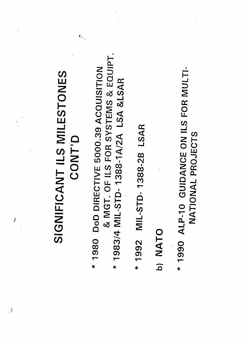
ClC)c 2o p
0 0Onuj < LL~c
o - 00,oH < wo 0< rn
oo ujo
H0 0I-L) cc 0
00. a.PZ0 a. 6
H<0 Co)
0 ) 0)

Co.OH U
UI) ~CO 3H2 >-LL, 0o
0 ~L~C/-0 L U
Dz a.
< 5L rr 2 O <C-C) -_JpL
-a 00<j
2U -
C0C/ /)J
- Z 0>. 0
LU00 0/ L UC
C LDDCl) E: DD
D COCOC/)Ci)o 0N0000 D F
*o OD * * D

IL
D c
cc m ) 0.0 I-i CCH -z COo
CL zrL z U0cc z0jc 2 /
cc ~ ~cc
LU
D) co ac_n w_j WCOZLJCU
cc- < C) -J
0 0F- LUWcC/ IHCCcc H 2o
cn F w0wnDD ccý 5LzoanD ;z2 0 S
C/) 2 2w
cUDO C3
jL

7,U
-j 0C/) CI LU )F- < Z -
z LwkLuciwjOC MrCCo
z~0 D
U)UF-J J L) J 4LEU
oLc
%5>~ OLJ
CC 002L.C<O

LU.-' 0 C/)
00F- Cl)
0 0o. ow LL c
Co W Z cc0 C00 HCL
o - CH jQ
wo z C C/0COD o = c
a.w Z
0u 0 L
L* 0
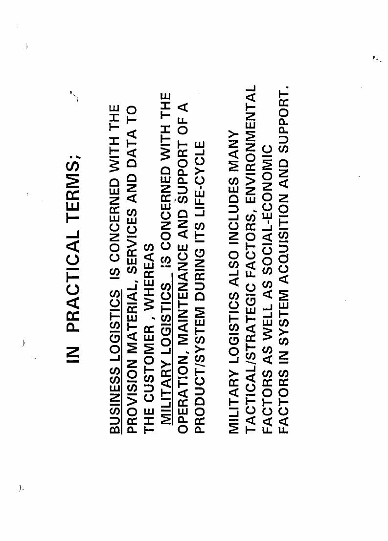
w 0HLL 2L Cw00
_ Zzo0-
H Z0co0i >
ZQ'CH0>)0 -r LoU Offi<C00o C JWU)Z
_ 0 0-1
CO' cW0 z < C/
Z -*>--- 2 0>u F-OF-
WLUH< <Yoo0>n~ oHHH.o-W cn0<o
cOOn oa H~L
pn

0 z >
LUOu6
U) cU.
(OH< I-a>
no > Wf= .
<C wo)r0
c D wU. w 5;
Wu uiE
OC.) C/) 0

z L0c H
z cl F
Z- w uZ W H0 CCZc cZOO-
o D Co ccC.aCW
0OwUZ 0QOOW
wU ZzaO Z -() >
o oZ ZuCDF wC i uc
C. Z~ Z0w
ZA <0D ~~Z >n z 5 ccc
WLj COL c Oz C))>
-7 -O cLo
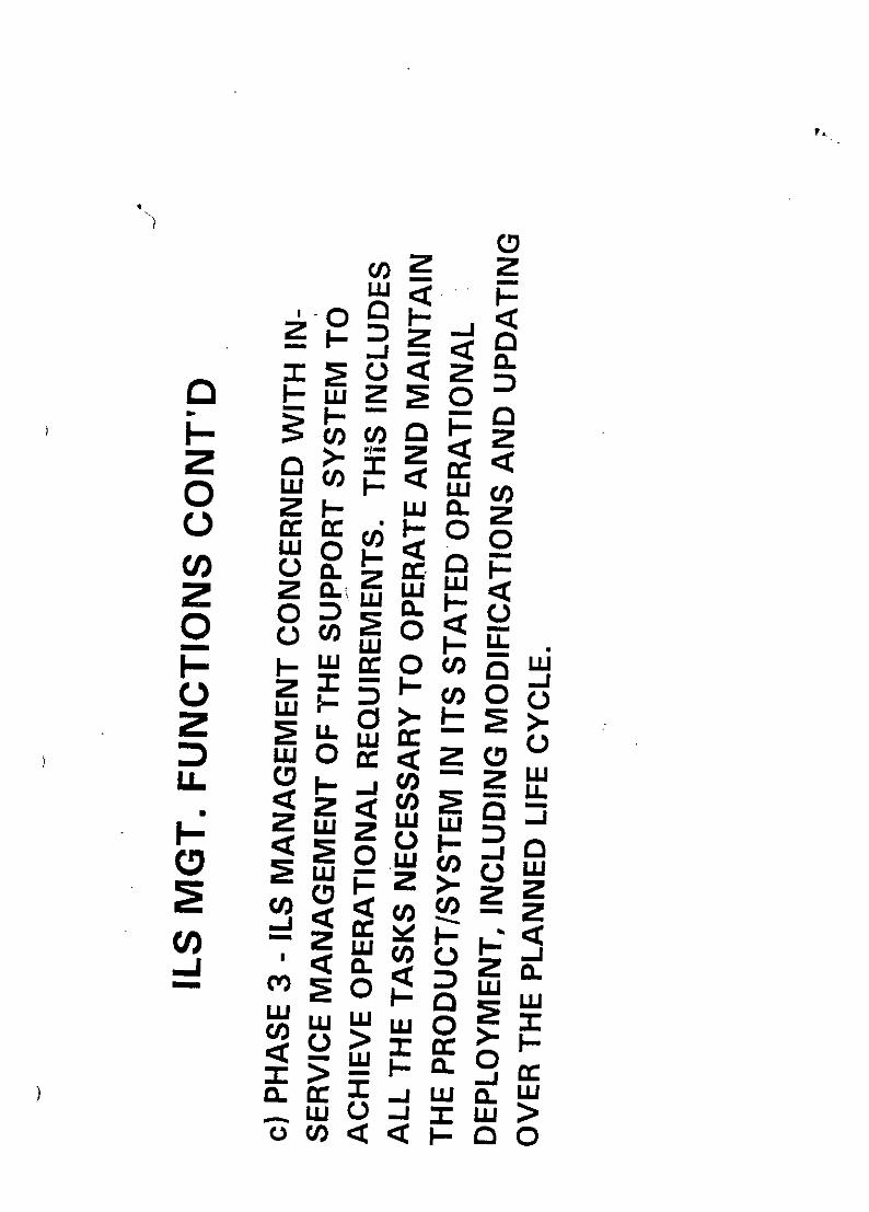
z~o 2L 0cc cc 0
Z L
on Zh- Wo <
ouc cn L
<I. zwcz CLJz ccg3u
CO zLUCo QW
w
ocL-CLo

00W z FH C.
o C.wOLC W vSLUU
cf)C/Zw)-/
F- <o LLQOOCC )
(0() ccZ Cj "
0W WzWz wct oLLDL O . or c(U

0
0L 0 D-
-~ < C/) )I-Cf) cc
z~ LU0 0o Wj C/) H
0 >. cc H zHW 2 C/) C
2< 0 LL 0 O-C/) 0 LU
_40 < LL LU cc C
F- _
C/) a 0'cCLw- OD ccr<
0W6c coZHcc
j C 1C/) C/*
rN CV) r-N ~CV)U) 0100000
Hr ) N N

Hz L0 0o o oW F
0 HO c
½U 0U c)w06Z I- >2L
0 M H<H a. cco22< M0 LSL LwCC z C/) a. H
0 E LI CCU) a.w~. 05<- -a~z
CJ HdL 0 cn -<wW O~ L L 0Clozj: H >zC/HQ z~<
>-mcn~Z <c <cc C
(60 CC.j >1-
cn Z C <wcncc co a
=)= > L <0 C =)
()0 0000 000cOY02t 0 0H-CV) Rt f
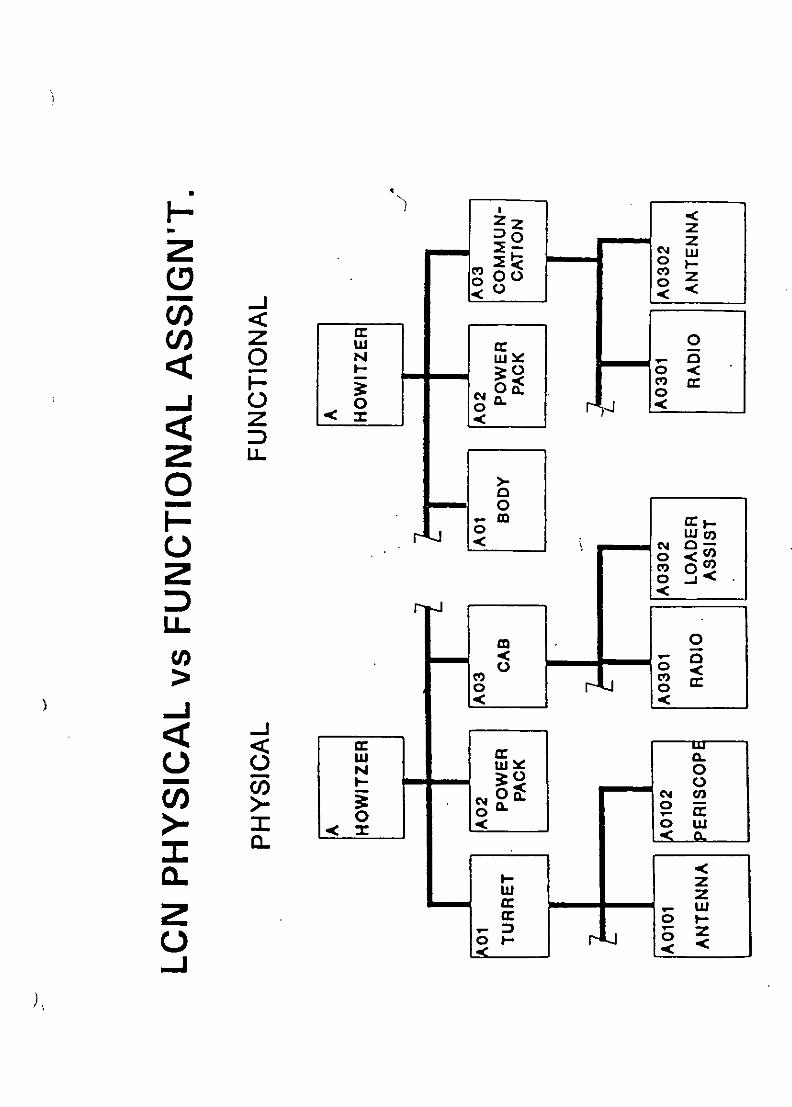
D 0 zzz
z1 0
NLL
0<
z <~<
ZLL.0
0 W0 0<
o4 0-0o<0)
0~< , a
0 <-0 rt 0
LUICL-Jw0 4 l
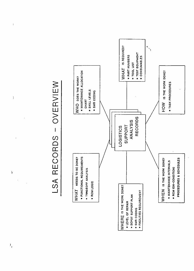
0~cc
cc O W w
:>:
2~ D ~
<S 0
0~ 0 y
I *w *D
0U0
a wD
0 C-
>a0. cc0z~
W W2 0 < wa-<C/) D~-
0r w CO Z
C zo
ms W o
a: 0
z~ ~ Lo z '
C/)~ 2 * *

C'T- r r00
0c Co)
0 coCO U)) CC
Co C
LU 0co Z~o
Cl) C Cl-J
Hi _
< .. JJ -2 COCo OS1%Oo0
0-J 2 j-NC0 mmwo06

N C)C 0 crN CV) 0 e NO
WL Y wLO '1-2V wo
-J I-LJ LC
QwI LLJA Z- HZ 0
z 0Hzo (POZ9YFCDo 0.Hi Cz Z
co Hý H H - -Y9Owo- p z
Cl)l_
D P zL) n :) 4
Zd Cn 0UCOCOCOZLL zcaLUuiuN>
w= wU W0OZ -j0 z0cl

zz
00
.4 U, Imam S
o a-
> 4
u' 2 2 fa c 0 wu~~ m -U0tU-
M 40 RI10
00
DI -CC
aa
C I
0 o0 m 21 ¶ u~
I1 I
03 IL%~ I j 5w
110 a 44 4 GI-,

W..
z
wL
44
wwH0
2 02ZLLI 0
w CC =3
2 mc'-
-wI mwc 00
CO m =3
wo 0W4 '
W-W Umt
L0 Z0 L
0Z ~ s
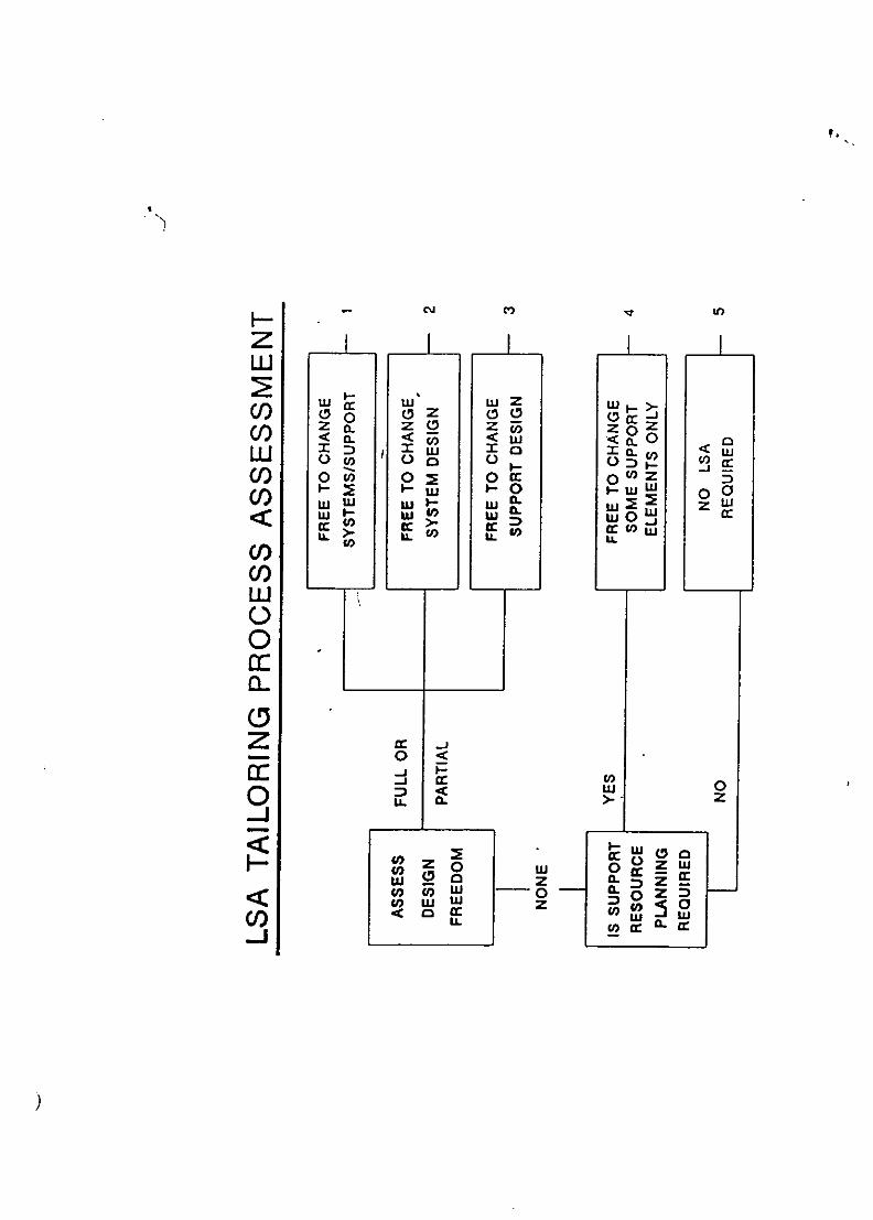
LO.
zuJ W
U)CCLDl o W C0V) <
U) oa wI- 0 0 co(a z WD2 a ). 0g 1- j 0
I-- LLt 0) IL tO0LL
0ILL
Ul)
0
00<
<0
V) u 0IL C. Z D
0l CCILc-I~Ic __ __ __ _

cc CD
CL 000
o 0t
C/) CD W
C)C/) 0-JJ D

ANNEX 1
LOGISTIC SUPPORT ANALYSIS (LSA)
TASK OVERVIEW
TASK 101
EARLY LSA STRATEGY
DEFINES LSA OBJECTIVES, LSA TASKS AND SUB-TASKS, LSA
CONTROL NUMBERING SYSTEM (LCN) TO BE USED AND DATA
REQUIREMENTS, ANY APPLICABLE SPECIFICATIONS AND DOCUMENTS
AND ORGANIZATIONAL AND PROJECT REQUIREMENTS.
NORMALLY PRODUCED BY THE CUSTOMER AND BECOMES A
CONTRACTUAL REQUIREMENT.
TASK 102
LSA PLAN
IS THE SUPPLIER'S PLAN TO IMPLEMENT THE LSA STRATEGY
DEFINED IN TASK 101. DELINEATES INTER-RELATIONSHIPS
WITH ILS ACTIVITIES.
THIS IS AN IMPORTANT BID DOCUMENT.
TASK 103
PROGRAMME AND DESIGN REVIEWS
ESTABLISHES THE CONTRACTUAL REQUIREMENTS AND TIMING FOR
DESIGN, PROGRAMME AND LSA REVIEWS.
CUSTOMER'S RESPONSIBILITY TO DEFINE.

TASK 201
USE STUDY
DEFINES OPERATIONAL ENVIRONMENT. QUANTITES, DEPLOYMENT,
USAGE RATES AND SUPPORTABILITY FACTORS.
CUSTOMER'S RESPONSIBILITY TO PRODUCE.
ESSENTIAL TASK FOR A SUCCESSFUL PROGRAMME.
TASK 202
MISSION HARDWARE. SOFTWARE & SUPPORT SYSTEM
STANDARDIZATION
DEFINES SUPPORT ENVIRONMENT FOR THE SYSTEM.
INDICATES CANDIDATES FOR STANDARDIZATION RELEVANT TO
SUPPORTABILITY.
CUSTOMER REQUIREMENTS TO BE ASSESSED AND INCORPORATED
IN THIS CONTRACTOR'S TASK.
TASK 203
COMPARATIVE ANALYSIS
) IS A KEY FRONT END TASK. ESTABLISHES A BASELINE
COMPARISON SYSTEM. USES HISTORICAL DATA TO PROJECT
FUTURE. IDENTIFIES HIGH COST DRIVERS AND POTENTIAL
SUPPORT PROBLEMS.
TASK 204
TECHNOLOGICAL OPPORTUNITIES
ANALYSES THE IMPACT OF NEW TECHNOLOGIES AND SOLVING
SUPPORT PROBLEMS BY THE APPLICATION OF NEW TECHNOLOGIES,
INCLUDING THE ASSESSMENT OF THE ASSOCIATED RISKS.
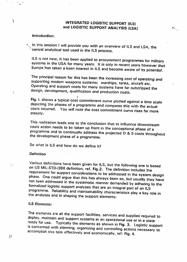
INTEGRATED LOGISTIC SUPPORT (ILS)and LOGISTIC SUPPORT ANALYSIS (LSA)
Introduction:
In this session I will provide you with an overview of ILS and LSA, thecentral analytical tool used in the ILS process.
ILS is not new, it has been applied to procurement programmes for militarysystems in the USA for many years. It is only in recent years however thatEurope has taken a keen interest in ILS and become aware of its potential.
The principal reason for this has been the increasing cost of operating andsupporting modern weapons systems; warships, tanks, aircraft etc.Operating and support costs for many systems have far outstripped thedesign, development, qualification and production costs.
Fig. 1. shows a typical cost commitment curve plotted against a time scaledepicting the phases of a programme and compares this with the actualcosts incurred. You will note the cost commitment curve rises far moresteeply.
This realization leads one to the conclusion that to influence downstreamcosts action needs to be taken up front in the conceptional phase of aprogramme and to continually address the projected 0 & S costs throughoutthe development phase of a programme:
So what is ILS and how do we define it?
Definition
Various definitions have been given for ILS, but the following one is basedon US MIL-STD-1388 definition, ref. Fig.2. The definition includes therequirement for support considerations to be addressed in the system designphase. One could argue that this has always been so, but usually they havenot been addressed in the systematic manner demanded by adhering to theformalized logistic support analyses that are an integral part of an ILSprogramme. Reliability and maintainability characteristics play a key role inthe analyses and in shaping the support elements.
ILS Elements:
The elements are all the support facilities, services and supplies required todeploy, maintain and support systems in an operational use or in a stateready for use. Typically the elements as shown in Fig. 3. Logistic supportis concerned with planning, organizing and controlling actions necessary toaccomplish this task effectively and economically, ref: Fig. 4.

A simplified military view of ILS is demonstrated in Fig. 5. This attempts toillustrate the co-ordination required to plan, acquire and implement a supportprogramme throughout a system's life.
ILS History:
ILS is not new, it was formalized in the USA by the military authorities in the1960's. ref. Fig.G. The significant milestones in its development andapplication can be traced by reference to the associated specifications.These are shown in Figs. 7 & 8.
The current principal specifications for ILS and LSA, the logistic supportanalysis, are listed in Fig. 9. There are many other specifications associatedwith these activities as we shall discover later.
Why ILS?
In the defence systems marketplace, ILS requirements are being stipulated ininvitations to tender (ITT's) for major systems defence contracts in mostEuropean countries and throughout the Western World. Increasingly, asstated in Fig. 1O, ILS and Reliability and Maintainability are collectivelycarrying the same rating in bid evaluation as performance and cost. Thisevaluation can only be carried out by following a rigorous routine.
ILS although instituted by the military authorities, first in the USA and nowin many other countries, ILS is adaptable to other systems, if the operatingand support costs are comparable with the initial acquisition costs, ref. Fig.II.
The ILS Process.
First, there are two kinds of logistics; business logistics and militarylogistics, ref. Figs. 12 & 13. Industry is mainly concerned with businesslogistics to fulfill the requirements of military logistics, in the case of defencecontracts.
The aims of an ILS programme, are set out in Fig. 14. It is an integratingprocess and an iterative process. Integrating in that it takes intoconsideration a number of other modelling processes and iterative, becauseto be effective one must start at the conceptional phase of a project andprogressively develop the support system, including all the support elementselements requirements in parallel with the system development.
ILS is a management activity, which extends over the life of a project. Thephases are set out in Figs. 15 & 16, whereas logistic support analysis (LSAIis an analytical tool used by systems engineers in the design process.
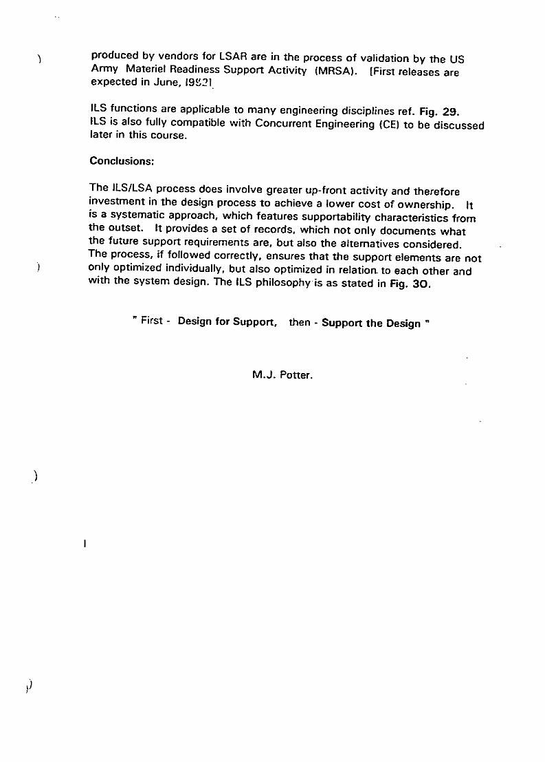
produced by vendors for LSAR are in the process of validation by the USArmy Materiel Readiness Support Activity (MRSA). [First releases areexpected in June, 19(,21
ILS functions are applicable to many engineering disciplines ref. Fig. 29.ILS is also fully compatible with Concurrent Engineering (CE) to be discussedlater in this course.
Conclusions:
The ILS/LSA process does involve greater up-front activity and thereforeinvestment in the design process to achieve a lower cost of ownership. Itis a systematic approach, which features supportability characteristics fromthe outset. It provides a set of records, which not only documents whatthe future support requirements are, but also the alternatives considered.The process, if followed correctly, ensures that the support elements are notonly optimized individually, but also optimized in relation- to each other andwith the system design. The ILS philosophy is as stated in Fig. 30.
First - Design for Support, then - Support the Design
M.J. Potter.

p.j
z CL
-J U
cc "a a
wU E a) a)L L JD C U ' co cc E ;0. LL WX A.
z o- 0 4
cc C6 FD n :o
U) L U 0 V
cc 2 cc 06
0 E1 0 0 M
to pu 0O C. J. z. a
<

F' 0
0-
> 0n0= C/
(%. 0
C -:0) C)
mc V00
C)0*0 0)
cc 00< ::3
c c 0 0a).-:3'
0) (D 00o 0- m
I.-
0. D))a Du0c c C
(I--. 3 U )-caC/T) -j.
C 0.Cc:CI W 2( oo c-

-D o a) aE ) WV)U 0
U) c) -
cCC -C Eeoo) 5ý .CCQ) ( C:30
Q. (1) -- 4-1 t C ooC ,0 a) C C0
0) -C_ a (o
aC.,) U)CQ C0
a o t -c C C
0~~ tCOOL0- QV .ýa
CL 0 a CL Q3 ) 1.6.;
coI C- 0a) 2
CC Iz E. a a) I

L- -
0flL.a 0
r a0 0
o~U)E-D 0Oc -a
Ca0)
>L C)
a)~ CU
ii: L:C - 0
0) ca
*n Eco() cc%
LL cc0l)0 0 c
*L r
o0~ C:-u~

t1 CL
0)CEE ot0%
Co CZ "0-r- 0)f CO
2EEC15 > Q 0 oE0 0> E0>-
to 4-0
0 0 C > Z oo00 > O 4-a co5 M: cos!
U0)
COE '0
0E-) o %-C
0 L :0a CoE
Cl) 0
m-J > 0 -0 CU - *a) -L 0 Z
0 U EiCf)0c a)~ =3 0
CC
ctOcoa) a) -0 =

-0r
CO C
cu *a_0 0.CU)
Ca 0 C
% + - I --
a) 0)- Do C:
0) 0 aZ
00 0 0 0c _0 +(ý 4- 0 C5
av ) MQCOa
-o 4-1 4-
a) 0)
4-0 a)cc
0) 0 0' 0a aL) o0 E t 4-c
( a 0) 0 (o
~at 00
cn aa
0)

OCo
0.0
(a. 0 1
00
o ca cc .
_- cc 0 .
Z) 0- .ccgcW 0 o0W
D a.lL (J . 0L.0) L 0 COOC) a)
0 wcnD): LJ L c))LM 0O
FCn cCI0 C- Q 51 L
0 0
Cr 0 *0 a)
W) co -) .0 CLUh. L C: Z cc 00zma
O t Ln sh
-Jz

_0 C,3o m)
-uoý- c (0CU1
0) C)0c) a)C: 1cu (Cu0 0
20 -0) U)
:cu0 0).(u 0at+
_0 0-
~0 a) 0(E(0E
a ) 0U)vCC) 'aC
(0 Cz 0 0)0) a)) ()
-D~~ C. )C'0 (P C- co E CCcU
CL dU "( L(0 >0 aL- ) '-
C 0)
U)-0& COO OOc = 4-4
Co <. VCU0 C 0 < 02
CC a570 0 4-
*- .a Cl) C. a)i Oc
0 0: -

z0
w CI-a ( n)
z C~
0 0
<O -- *0U-UQalf* JZWJ :z WOOz
<r LLO>Z
CP 0w - _o jW 0 = L
40<o 0o 0 g>Z~i 0u 0 w0 0 3

'cS
*0 0
.0
vcco
0L) 0Ir- Cu
0 0
00
E%.9 0
ý - a. EccM d. 0 0 (
W.. 0~ ra0) Cc-
c w< C 0.-~ '*
0 ) 0-cc cc0C
a ,~ W- t
00 ~C 00 3
-s O , oZ , -
00:3 COMN o0 caCC4 04i0 0).
0 m a~ R-
0.. cU IV E

I 0
I Z
< to"iI VC ;- m w
10*0
X-C U)
.cc
-3 ---- - - - - - - - - - - - - - - - -
ES Z
VZ-
C~ .0
0z aCDc aC
I~L VS Cv 6u 0 _3-loo -0
Soc Z0 0
1.5.
&~~~~ ý o u '
I.- 0-.
(D
* E E 0
@o I Co 0 <-
* 00
* xo -

00
wP
ozppRL)z
2l XL2
LU 2>
z 0 L

0 a-
>cn0 c~-'e (no
o 0 0) -C0)) 'D < ) a" F
7- (n 0
a)a 00 ' a) LCo) 00
CoC
0) a)cc
ci! CD g 3
0 CLzwC a a)1= wcc a))
-E 00
E 0 Z)0
00 w Fnw
2 P D-J
LI-
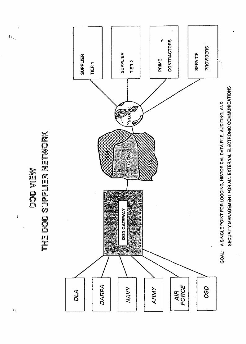
rcc0 U)
ccreq cc, >
IL c:2JEC 0 U.) ccD L D. cn a .U) (1-
z0
DO
I-<Li
Lii
-JwOw
cicc0.
CC
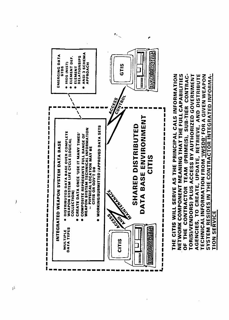
OW~ 2 1u fr0uU
00 2>2 Z
I& A.I
wL .0 'uI
z I 41--s...4 I
ilU O ZU >'~ ~ 2 -~>
-L2 ,c Z rr u
0 : wwa"0 anuWwonzu
sw2uw.. <OP OWZ2 a 2~ *6 Csu >Izo
gauu 3 2 0 Lc A. ** *L ILo IL wo
I. *c o UCC L6'U 03: I U30 = ýwO w-A
-Ic U, IUO w -
I-~~~i 3z~.C~>.-~~r Ij 1-0-4-f1 0xa L j>
_______________________________

U) U)
k4
00
-Iw4I
C') t1
*o

(00
CE0 4
)m. C.....
CCD00
N d) 0
E2 2 Er-00 ER
E 5 CCto.!: cc c
Df 4)-
0 0 In :I
9 U
CL C..
a. a.a) c
g.o0 40ý m- 0__ _ _ M c cE .-

U.,IC LL
0 0N z
cccCl) xcz C/)
00o -IJ
C/) 0
Ch-

dM
Z-
C))
00C:0<
o- 1- cztzj
1-Z
C)
C)- Cd> ..
- aw
0 Co ----- ->

wAgo
LU) 5 AL U '
-0a > EU >
-0 W > b
-J U
Dz
U) do0r
mc -U LU
2L) L) 8
0~ F z C>
I- 5u C CL .
CD)
0L L) >-
5:0 L) U .
Z L <E 5 o LO
cr. LC')
z-n0n U
cmw0 u UL

COMPUTER AIDED ACQUISITION AND LOGISTIC SUPPORT, (CALS).
Part I - CALS OVERVIEW - by M.J. Potter.
Introduction
CALS is a US DoD and industry initiative to:-- improve weapons systems quality- reduce lead-time and- reduce life cycle cost
by integrating digital technical data and improving processes for weaponssystems acquisition, design, manufacture and support. Reference Fig. 1.1
CALS can be viewed as a concept, just supported by half a dozenspecifications based on existing industry standards (simplistic approach), orit can be seen as an all embracing strategy, that will revolutionize processes,organizations and the whole conduct of business (believer's approach).
The purpose of CALS is to create a neutral non proprietary interfaceenvironment between digital functional processes, which do not constraininternal enterprise systems or achitectures, to facilitate the integration ofprocesses, virtually eliminating the need for paper and improving greatlyindustry's and US DoD's productivity, efficiency and asset management.
CALS, and its first cousin CE (concurrent engineering), are not ends inthemselves, but tools and enabling technologies to better achieve thoseobjectives.
Definitions
Fig. 1.2 defines CALS and CE together with their developmentconsequences.
What is CALS & Why
Essentially CALS is an integration programme to facilitate the access totechnical information and where required the transfer of information in digitalformat.
C
Fig. 1.3 schematically depicts the transition from todays environment,largely based on the transfer of technical information by paper andmicrofiche (left hand side). The shared data environment utilizing commonshared databases (shown schematically in the right-hand diagram) depicitsthe required environment. The diagram in the centre depicts the near termachievable solution oi transferring information digitally through the use ofneutral digital data standards.

So why GALS - and what are its solutions? These points are highlighted inFigs. 1.4 & 1.5.
From the users paint of view there are other good reasons. For example, theweight of the technical information carried by a modern warship, usingconventional methods, is equivalent to about 20 cms of water, and mast ofthis weight is carried above the waterline.
To achieve shared data, using the "write once, read many times" principle(WORM), across a complete integrated weapons (or civil) systems data base(IWSDB) throughout its life cycle, from conception to destruction, eliminatingduplication of effort, a phased, or incremental approach was adopted.
Scope
The scope of the GALS integration process is clearly illustrated in Fig. 1.6.The GALS integration target extends throughout the user, procurer - primecontractor - sub contractor - supplier chain; involving data from acquisitionthrough design, manufacture and support on a worldwide communicationsbasis, throughout a project's life-cycle. A formidable target, incorporatingeventually not only technical information as originally conceived, but alsoembracing electronic commerce (edi), tendering processes and projectmanagement information.
History
The GALS programme was launched in 1985, following an IDA Study in1984, to find better ways creating, storing, distributing, upkeeping andmanaging the vast quantities of information held on paper and film.
In 1985 William H. Taft 1V, Deputy Secretary of Defense, approved the2 GALS strategy for transitioning from the current paper-intensive weapons
systems support processes to a largely automated and integrated mode ofoperation, calling for substantial progress by the end of the decade (1990).
Strategy
A strategy was jointly developed by the US DoD and industry covering fourareas of activity , as set out in Fig. 1.7. Pilot programmes were selected totest aspects of GALS and close liaison was established between the USServices, DoD, NIST and industry to develop GALS.

In this lecture I have addressed CALS from its origins and a US defencepoint of view. In the next period, we will look at CALS from otherperspectives; US civil interests, Europe and further a field.

c 0)
00
LLIi04-
C13:
a-s(0 cobo
0 C

EU,>4->U) 0) U)
0)) a0.
C 00
00 4-'4
a0
cu au 0 aQ- 0 a
cu _0,
co (D-0, (D a-
S(a coFu 2- 75S
w CUE' a)C
(1 xca 0. a)
>0 E
E a)CU ) a)
.2a E-Cc 0<
cuc a)C
0 0.c o <

V)
0 0u
*0 0
cuu
a)] E
0) o(D 0 (D
co 2) a)m0u oo C. 0
0)U C C z4) 0 ca:
.0 C 0
-D CuU
'-o . (j Cu C04CU mi 0 0) C 0
a). 0 . .
cl) a) 0 0
CD < wa a
00W 40
00< Cucn C

p.0
0_
0) 0
o 0 Mc0o 2>9h 0 U
-o -0
U) C:) U)a
(1) -o -o
ICU) 0 i
U) 0 : - C/
a ) an -c C35
o0(1 (Of0 U) (1
CZ
.2 -o a a>o cu E oa 0 C(1)) 9 o C C o
L- 0 )
w a
cC0 E cz c 0o c ZO0C
z

U)I
C-)c'it+- 4 zr4
-45o
00S0CZ r
00
o rS-4 r04-) 0U
4-i
v c0 0 0 00
Q* 0 o :-I rU4-

5
jj _____ -!
C H0 a 4-SU
as) -, Ii 5.A-~ I1 ' 1 2 a
U 4I I
C0
* -
ci) 4= 1 in
C liiiCa0)
00
0I~
C)a.L.Co .. JU
ciia-C')-JNC06NCz

'C m
o 0 u
o- - o 0
L) 0
<1)0.L 40
C C -
C) -
0
00 .2~~
m0 Lm C0
0L.
-000 m
00*- C- C
LU 2 EC

co)
c a)
a) _
_0. 0 c
0 a)W- L- C
_0 CL -
to 0 m-c 0CU -0 0 a)
0 CLC:Cc/ o "0 0 _ co
0 o CU 0C 2CC
0 C Lcu- C 0 .0q
C.0 o ~
o c cEcC
(D a0) (Da
0LM
LL..
_0
(z4-
U) 0
<'4
-0)D (ZD
U)a

04-1OcCCac~u
Cl) >o"co 0 a):
0 a0 .z
o 0 -- a-.0. C/ - 0)
CL -o a)~ 0 00 C O CO*
C) Q_-o
0 00co) 0 cou< .(D C0(
0 0) _ _
5 0 o CCE -0 < 0
> E 0(D )"0 0 a)D:5)
cc CO 0 z 0 0ocn
0
w
C 0
4- cc 0)

LJ -J
0- -J0
F-U L - -
. Do
- 2 owL 0cU)N ccLU 5
cnuLC))
Ul) WL w
M EZ H 0

U)U
&U 20 ZWLIz wCL. 0 .
cc2 CDLC/) LI. cc0o NL 0-
CC
0D 0 -J0 W D
0 z D
cI DL D 0u
Z l Z I- W 2 L)
Lu - (L
co~~~ w ý m
on 0 2 o ) U) w S
D u w waU a > -c
U) (n-I0 0 ca0 SwuL LLI 0 u 0. 0 (D

Ct)
LL0z0
C-,
cC
-J WJcc 2 z C
WU - j -J o )
Dj C) m - L) C) W) zD
o C W I- u cc 0 - 0C.) o 0 cr z - C o cC/) F - wU Z 0
o al Sc CL CLc 0 0L)
)U

COMPUTER AIDED ACQUISITION AND LOGISTIC SUPPORT, (CALS).
Part 2 - OTHER NATIONAL AND INTERNATIONAL INFLUENCES.
Other US Interests
As stated in Part I, CALS is a US DoD/Industry initiative, but industry is alsoinvolved with civil projects and many of the defence contractors are alsoinvolved in the civil marketplace. In addition, many non-defence USGovernment Departments also need to transfer data digitally and these havealso declared an interest in CALS and initiated their own programmes.
As a consequence, the US Department of Commerce (DoC), to which theNational Institute of Standards and Technology (NIST) report, are becomingincreasingly interested and involved with CALS activities. As are manyindustrial companies and suppliers of CALS products Pnd services.
Computing and telecommunication architectures are often planned andmanaged corporately and therefore, requirements placed on one sector of acompany's business can affect the other sectors. Likewise, the knowledgeand benefits gained from one sector can be applied to the other businesssectors.
European Interests
CALS as a concept extends beyond national frontiers due to the internationalnature of defence procurement and support programmes. Therefore, bothUS DoD and industry have been involved in spreading the CALS messageand stimulating interest in CALS overseas. In Europe there is, as yet, nosingle government to discuss CALS with. Discussions have therefore beenheld with defence authorities and industry in the various nations, withNATO, the Commission for the European Communities (CEC) and with theAssociation Europeenne des Constructeurs de Materiel Aerospatial(AECMA).
Association Europeenne des Constructeurs do Materiel Aerospatial
AECMA is an association of the trade associations in the aerospace industrycovering 9 -European Countries (UK, Begium, Netherlands, France, Germany,Denmark, Sweden, Italy and Spain), ref. Fig. 2.1.
AECMA has taken an active interest in the CALS programme. They havesent representatives to the US to participate in the US Task and WorkingGroups and they have co-ordinated their own overall IT activities through aStanding Committee for EDI (SCEDI), with the prime objectives as set out inFig. 2.2.

In parallel with CALS developments in the USA, AECMA has on its owninitiative been responsible for generating some international aerospacespecifications on CALS-related subjects, in conjunction with EuropeanMilitary Authorities, ref Fig. 2.3. These are specifications;
2000M - Integrated Materiel Management (covering materiel support)1000D,- Integrated Specification for "ethnical Publications ( includinga Common Source Data Base [CSDBJ )
are now stipulated in major military European aerospace contracts.
The 2000M specification covers; initial provisioning, procurement planning,order adminstration, invoicing and information exchange data, in accordancewith a 2000M EDI specification and a 2000Mdata dictionary.
The 1000D specification uses the same technical standards as CALS e.g.SGML, CGM and raster graphics to the CCITT standard. The CSDB enablesdata modules to be stored with SGML tags to enable them to be accessed infault tree format for fault diagnosis purposes, or assembled in a work tasksequence for a work programme.
Another AECMA initiative has been the development of Simplified English(Document PSC -85-16598). SE is a controlled form of English that uses alimited vocabulary and a set of writing rules in compliance with thevocabulary. This restricts the application of a word to a single meaning(double or multiple meanings for words are thereby avoided). Words ýýincluded in the vocabulary were chosen for their simplicity and relationshipwith other languages. This reduces the risk of misunderstandinginstructions and simplifies the process of translation into other languages,
AECMA has also produced some guidelines, Aerospace BusinessCommunications (ABC), for the exchange of product data.
Five of the major European aerospace contractors have also established aEuropean Aerospace Network for the interchange of data on collaborativeprojects and a project called APEX, for advanced product data exchange.
These AECMA and aerospace company interests are CALS-like in concept,but they are not fully CALS complaint.
NATO
In 1990, NATO via the NATO Industrial Advisory Group (NIAG), instituted astudy of the applicability of CALS to NATO procurement programmes. Thebackground in this study is set out in Figs. 2.4 & 2.5 and the purpose andmethod in Fig. 2.6.
Fig. 2.7 outlines the NATO organization applicable to this study and
Fig. 2.8 the Study Group Structure. Representatives from Canada, Belgium,France, Netherlands, Norway, Italy, Spain, Germany, Denmark, USA and UKparticipated in parts of the'study. The study was completed in October,1991.
The study endorsed the concept of the US initiative and accepted most, ofwhat could be termed, the CALS Phase I programme. Some reservationswere placed on aspects of the developing Phase II programme, for whichfurther work, testing and demonstrations were deemed necessary. The studyalso recommended the adoption of international standards where everpossible e.g. EDIFACT for EDI, not ANSI X 12, which is a US nationalstandard. It also further recommended that AECMA brought their 2000Mstandard fully in-line with EDIFACT for data interchange standard.NATO were also recommended to undertake various actions to integrateEuropean requirements with US actions.
Time does not permit a full discussion on the many issues raised by the bythe NIAG CALS study, which is now being reviewed and acted upon byNATO AC301 Sub Group 'D', the NATO committee formed to deal withCALS, ref. Figs. 2.9 & 2.10. A subset of Sub Group 'D' has been formed byFrance, Germany, The UK and the USA, known as the the Four PowersAgreement to spearhead this activity
As a consequence of the first NIAG CALS study, a second study has beeninitiated to investigate aspects not covered by the first study. In particular,the second study will addess: the CITIS and the IWSDB; ElectronicCommerce and ED!; and some contractual and legal issues. This study isdue to report later this year.
National Interests
CALS organizations have been, or are in the process of being developed inmany countries; including the UK, France, Netherlands, Norway, Sweden,Australia and most recently in Italy, Germany and Japan. There are activemembers in Spain, Denmark, New Zealand and Canada and a CALS PolicyOffice in Canada works in close liaison with its US counterparts, althoughCanada being a bi-lingual country does have some requirements of its own.
European CALS Industry Group (EUCIG)
A European CALS Industry Group was formed last autumn, which bringstogether both National and Trans-National Sectorial industry groups toaddress CALS issues.
European Community
The Commission of the European Communities (CEC I providedrepresentation in the NIAG CALS Study and is playing a leading role in

Europe, with EFTA, in supporting the development of IT technology andbuilding up a European communications infrastructure.
Many CEC projects are supporting aspects of IT that have a directrelationship to the CALS initiative, The difference in application being, CALSwas initiated by the defence community (the US DoD'and industry), whereasthe CEC primarily addresses non defence business. There is close liaisonthrough the standards bodies on both sides of the Atlantic and a great dealof mutual interest in technological developments and the application of theseto business practices in both Europe and the USA. The way ahead pointstowards a convergence of both sets of interest into a common CALSprogramme to meet the needs of Government and industry for all nations.
M.J. Potter.

C14
E..
cQzo C')
0, 00
00
06 0
00
Q)U)L
0 0)

CO) z H-
Cl) 0 H 3z W >:
cf) w w HWC/) z) 2 1
H wCl) cc W H
LU < <z cc 0 CC
0LU U -C
H , cr ~c< w H COa< cc 00< w
LLLU LU -
0~~~C HO HL<(j
00 C: U)~
w) w cr U)U- wi ~CrO F
CO W -w 0 )
z. cc ccz
< a: w w-
w C) w CC

U-50
E 0
CLCl0 )
cc 0 c
(D &- E0)) a-cuc
C)0
(E w 0 a Uv c0) Cw 0E -om
o0 oW 0,0-
02 W
cn a) mC(E CD0 0 c Q.
z2 ca 0~ w owt 03 -c0 X cu--
a) 2' 4) Co C
c0 CD wU"! E0. ED
EE cdm "0 -0 o l) Cmc a) E ao UcEcc 0> 0 -
z :3 0) U) ca0)c I a Im I I Im

CrP*L
M,* 0 0
.Dj ca 0'QaON
,<w < 2 y. N
1-
...... .. ......
-.........
.. ... . .. ..
.. .. ...iii 'N
::::, 4-b.. ........: .........
Ct 10 C0
-n In
C3JuE)s

N$
H T1F- -- -- - - -
Ila II- 1 .31lo- : I I 11Vsf I I= O NIZ
i . . l IIkC I. yr I"<I 113 1 0 1 I,
. l ilifl°T r -- 6u.% .1-77/n I P
~A.? uto
n, ! ~ = jw 1 1. .-,=4..
EMl
html
i,-l ' ' / -• I I o11 1' '• I'
-- • t- - - - _ _I I III a11 i b i• I
L77i1- -- 1 L]zJ
F ý'l I 1
I'I I.l I a
,I ý-, a - C - -
5 11 JEI I 'A' I± I10 1
!. -.-
L-I
Ar n0 I
_ _ lb rn

-----------------
1; 0~ bt -
A-
- -1 - - - - - -l- -
-.- -
Lao

Att
ka
.3.3.
t - - I 09+<a .- 11 -I.+ I -,
I I,.b .. .. . ."z A+ + l lt". ., . m -- - C-- - , H ; -+ • -+
' - . , , _ + _ _ _ _. J ! =
•- +I i j+I • I..- - ,. .; .,Ip
I + + I 2!+ "A .- l I t"•
• T

0)c
cm ~C1
E00-
C 0 0. 0 C
-0 C: C
()ES 0 -C) 00
0 L.O
x ~ 00
30 .0 U7 0 03c 00
Co a) C.
Cl) Cc < 0 C2000
0C4-L
4-i
E0coS U C m) o
0 0
cn0 0000 0)

,,Pant 3 - CALS PROGRESS AND FUTURE.
CALS Developments
The GALS initiative is evolving through management direction, thedevelopment of standards, resolvement of problems, application to projectsand development of an infrastructure to facilitate real-time data interchange.
The evolving emphasis is moving towards integrated systems from filetransfer as depicted in Fig. 3.1. Associated with these developments are anumber of technology issues as shown in Fig. 3.2.
MIL-STD-1 840
Draft issue B13 to MI L-STD- 1840 has been circulated as a co-ordination draftfor comments. Proposed additions to this important GALS standard are setout in Fig. 3. 3.
IGES, besides its other inadequacies, is primarily appropriate only to thetransfer of mechanical information. The electrical/electronic, Class Ill, sectionof the standard has severe limitations and restricted use as a consequence.
In the draft revision to thel 1840 standard provision has been made to utilizethe following neutral electronic standards;" Interconnecting and Packaging of Electronic Circuits (PC) -350 series
.......... for printed circuit boards," Electronic Design Interchange Format (EDIF),
........... for electronic components," Very High-Speed Integrated Circuit Hardware Description Language
(VHDL),. ........ for very high-speed integrated circuit components.
These standards overlap and differ not only in scope, but also in take- up byindustry. The harmonization of electronic interchange standards is not onlya problem for the current GALS programme, but it is also a problem to beresolved in the ISO STEP programme.
The use of electronic data interchange (edi) for the transmission of electroniccommerce; order enquiries, quotations, orders, progress information,despatch details and invoicing is being included by reference to the ANSi x1 2 standards, including transaction set 841. This particular transaction setenables drawing information to be conveyed with commercial data throughthe same system. The problem here is the US DoD is currently specifyingthe ANSI standard, X1 2. whereas Europe is adopting the UN/ISO standard,EDIFACT, for electronic commerce. The US National standard is welldeveloped and has a large installed base of systems in North America, hence

there is some reluctance to change. Nevertheless, there has been somepressure applied by Europe to request the USA to adopt EDIFACT.Investigations are in progress and it is hoped that alignment/harmonizationwill be achieved in whole, or in part, by the mid-1 990's.
Another inclusion in MIL-STD-1 840B draft is the move to open systeminterconnection (OSI) using the US Government OSI Profile (GOSIP) asdefined in FIPS-146. The US GOSIP (Version 2) profile of communicationstandards differs from the UK GOSIP, which forms the basis for GOSIP'sused in other European countries. These differences are sometimes more aquestion of communication systems in use or planned and hence timing,rather than fundemental differences in standards as such. The USA usesconnectionless transmission to a far greater extent, whereas most Europeancountries use connect oriented communication systems more extensively.
Another inclusion in MIL-STD-1840B is information on ConfigurationManagement requirements. This is important in digital communicationsbecause not only do you need to know the configuration of item, by partnumber, type, model, modification status, etc., to define its physical make-up and characteristics, but you also need to know the status of the data youare looking at i.e. whether it is a working copy, submitted for approvalcopy, approved copy, or on change., ref. Fig. 3.4.
MIL-M-28001
MIL-M-28001 A is also being updated to issue B to include:-* enhancements to the output specification for page oriented documentation* SMGL tags for handling partial documents and change packages. and* SGML tags for implementing the electronic review of documents.The initial issue was only appropriate to US page-oriented pubications to USstandard MIL-M-38784B.
A US Tri-Service group has also developed a complementary set of 5- draftspecifications for interactive electronic technical manuals. These are all partof the evolving technologies as set out in Fig. 3.1. The IETM willincorporate the HyTime Standard (ISO 10744), which is a hypermedia/ time-based structuring language to enable time sequencing and the greaterfunctionality of hypermedia for video, audio and graphic sequences withtext. These specifications, although they are not yet formally approved,they have been referenced in work for new military programmes.
Other Standards
Other near term CALS standards are listed in Fig. 3.5.
Another important CALS activity is RAMP, Rapid Access to ManufacturedParts, a US Navy initiated programme to produce parts from an order requestin 30-days using CALS and CIM technology. This programme has been

redesignated FCIM as a joint service programme. FCIM stands for FlexibleComputer Integrated Manufacturing. FCIM aims to establish a paperlessenvironment to communicate parts requirements and specifications toautomated planning and scheduling resources using digital product definitiondata (STEP). The system uses commercial hardware and softwarepackages, it is modular in construction, flexible in application andexpana ble to meet target needs.
Although initiated as a Navy programme originally it is adaptable to smallbusinesses and it seen as a means to enable small businesses to obtain DoDorders.
CALS Architecture
The CALS architecture is being developed by a US Joint Services TaskGroup through various phases; the now or current phase is 1992-1996, thetransition phase 1996-2000 and the target phase 2000+. The joint USLogistics Commanders and Office 'of the Secretary of Defense/CALSEvaluation and Integration Office have defined a 3-component model asshown in Fig. 3.6, comprising an information architecture, controlarchitecture and computer systems architecture. The voids and deficienciesin the architecture, particularly the control architecture will be addressed inthe coming months. These architectures are planned to be developed in thefour year periods as shown in the diagrams, ref. Figs. 3.7, 3.8 and 3.9.
Other Central Standards
Central to the development of CALS will be the use of PDES/STEP for thetransfer of product definition data and the development of the informationresource dictionary system, IRDS. Eventually, data transmitted must bemachine interpretable as well as human interpretable, with the greatestpossible transparency in operation. Remote Data Access (RDA) and
,) Structured Query Language (SQL) will be used extensively.
Concluding Comments
CALS is an ambitious initiative, there are many unresolved issues anduntested operational features. Some of the key ones are set out inFig. 3.10. These have, and are, all being addressed in various quarters.
One might ask how effective and efficient will CALS be. This is verydifficult to answer. Substantial claims have been made with regard tobenefits arising through application of CALS. The costs however, havebeen difficult to calculate for a number of reasons; including the trueseparation of CALS costs from other computer and telecommunicationmodernization costs; improvements in the ways of doing business, not justby automation of existing processess; deficiencies in normal accountingmethods to assess accurately the impact of computer technology; and the

general impact of new techniques on attitudes and cultural change; and lastbut not least, the reluctance of companies to divulge their private financialdata.
Looked at another way, without a CALS-like programme what wouldhappen. There would be a myriad of non communicating systems,duplication in systems and processes, redundancy in data•',tc.
CALS in the USA is a very large scale information integration process. It isa strategy for improvement and is recommended to other industries for
consideration and application as appropriate to their business needs.
M.J Potter.
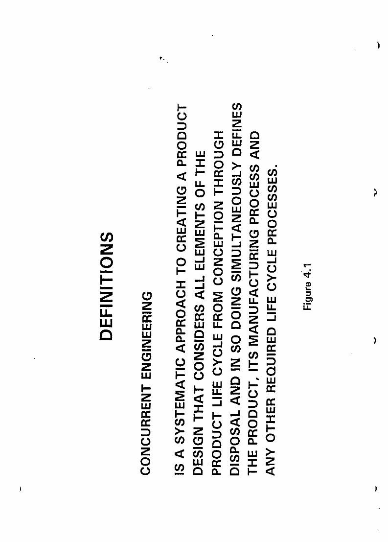
I- C/)o wIz
o (DrLiwz
cc HjoZcco
>z3C/)~C/)
Z Z <coLU LLJ cc
0 ~~LLD .
C.)o
ZI- a- a a w
>-ZD)C/) co ~ coc0n
0 )0o

zLL 00~ z
w<
0 < H2 2) -
a 0 <2oj 0 D-ccc
u-I 0NCJ cn Nr
LI HL
oJ cc 0
p >0 cc>0-000HH
CL 0

LUU
0 ucnz .I
Uz zCw
LU
zo n -I-
0jz r- Cz Lu z 0 -J
CHa= -Z0 0LU, u (n Z) E- <05
z ui5 u o -i cz) zo0 0 D z 0 : uj a -w
0 0 Z 0

U))Zw
z
0 L
P (1)<C]lL
uj -1 n LLI LLJ 4

C)
coo0. c o
CL)
0) 0- cz00
aa
COl
C)U
0 . . - oo~o ? -- ' - 0

C/)
00Scc
z
0 0
U) 0 wU- 0
U-J LL F-0C 0 <
'C/ z Z LLw CO
F- L)
CC C/) CO H
cc cc -
C/) ccL
<o L

CD :3
L . Q 0
C Co7E
LU- 0 c cU." Z > 0
rc- Go c E c)' -ac
M C 0c
-C3 0 0 E
Uo 1 0 m
0 o CL CU i)
w 0c, a r%
6 L
e.))
rz CL
i5 2
cac 0u.

Vs.I
00
Z 0
'C.
z wwoU'Cp z
z- -
0) L) cuJ
zL 2
zoc 0 Cl)D -*
0 ,0 0
0

z2koW L
o~wwI- 0W r IW
0c wzccw WU
C/) w< : a-0z
-I LL 0
-'U Z<i, C)cnCD
<LI.m mW
oU 0-u cn w o~w o~w
w. cowac-0z

U,)
oCz CDZ.j 0 LL
0. O-J cc
CD HW LLW
0 F-
0h Cl) rU
C)zC)
.. j cc wOco WLLc k-COC *U < <

ABBREVIATIONS LIST
FORCALS & ILS
AECMA Association Europeenne des Constructeurs de Materiel AerospatialAGE Aerospace Ground EquipmentANSI American National Standards InstituteAP Aviation PublicationASME American Society of Mechanical EngineersCALS Computer-Aided Acquisition and Logistic SupportCCC CALS Connectivity CenterCCITT Consultative Committee on International Telephone and TelegraphCDRL Contract Data Req-pirement ListCE Concurrent EngineeringCEC Commission of the European CommunitiesCGM Computer Graphics MetafileCIM Computer Integrated ManufacturingCITIS Contractor Integrated Technical Information ServiceCM Configuration ManagementCTN CALS Test NetvorkCSDB Common Source Data BaseDARPA Defense Advanced Research Projects AgencyDASD Deputy Assistant Secretary of DefenseDB Data BaseDDE Digital Data ExchangeDDN Defense Data NetworkDICE DARPA Initiative for CEDoC Department of CommerceDoD Department of DefenseDoDD Department of Defense DirectiveDSSSL Document Style Semantics Specification LanguageDTD Document Type DeclarationEDIFACT EDI Standard for Administration, Commerce & TransportEDI Electronic Data InterchangeEDIF Electronic Data Interchange FormatEFTA European Free Trade AssociationFCIM Flexible Computer Integrated ManufacturingFIPS Federal Information Processing StandardFMECA Failure Modes & Effects Criticality Analysis

FSCM Federal Supply Code for ManufacturersFTAM File Transfer Access and ManagementGOSIP Government Open System Interconnection ProfileGTIS Government Technical Information ServiceH / W HardwareIDA Instituwe for Defense AnalyseIDT Integratid Development TeamsIETM Interactive Electronic Technical ManualIGES Initial Graphics Exchange SpecificationILS Integrated Logistic SupportIPC Institute for Interconnecting and Packaging Electronic ComponentsIPD Integrated Product DevelopmentIRDS Information Resource Dictionary SystemISG Industry Steering GroupISDN Integrated Services Digital NetworkISO International Standards OrganisationISO-CD International Standards Organization - Committee DraftIT Information TechnologyITT Invitation To TenderIWSDB Integrated Weapon System Data BaseLAN Local Area NetworkLCN LSA Control NumberLOG.SUP. Logistic SupportLORA Level of Repair AnalysisLSA Logistic Support AnalysisLSAR LSA RecordMAN Metropolitan Area NetworkMAP Manufacturing Automation ProtocolMIL-HDBK Military HandbookMIL-STD Military StandardMoD Ministry of DefenceMRP Manufacturing Resource PlanningMRSA Materiel Readiness Support ActivityMTBF Mean Time Between FailuresMTTR Mean Time To RepairNATO North Atlantic Treaty OrganizationNIAG NATO Industrial Advisory GroupNIST National Institute of Standards and TechnologyODA Office Document Architecture

OSD Office of the Secretary of DefenseOSI Open System InterconnectionPDES Product Data Exchange using STEPPE Parallel EngineeringPUB PublicationRAMP Rapid Access to Manufactured PartsRCM Reliability Centered MaintenanceRDA Remote Access Data BaseR & D Research & DevelopmentRDBS Relational Data Base SystemRFP Request For ProposalR.M & T Reliability, Maintanability & TestabilitySCEDI Standing Committee for Electronic Data InterchangeSE Simultaneous EngineeringSERD Support Equipment Requirements DocumentsSGML Standard Generalised Markup LanguageSMR Source Maintenance & RecoverabilitySPDL Standard Page Description LanguageSQL Structured Query LanguageSTEP Standard for the Exchange of Product DataSAW SoftwareTM Technical ManualTOP Technical Office ProtocolUUT Unit Under TestVAN Value-Added NetworkVHSIC Very High Speed Integrated CircuitVHDL VHSIC Hardware Description Languagevs VersusWORM Write Once, Read Many Times
I;
CALS Cont'd
Besides many documents on the individual standards embraced byCALS and the offerings from manufacturers/suppliers the followinghandbook may provide a useful reference:-
An Introduction to CALSThe Strategy and Standardsby Joan Smith.ISBN 1 871802 04 0
Other useful source of information are in theConference Proceedings from CALS/CE EXPO's in the USA,from:
National Security Industrial Association,Connecticut Ave. NW Suite 300,Washington DC, 20036 USA.
07•
CQt/ I or. NhIcr
"Ti /J0 1I -ho ý-24,7-?6cor•, N0 +* / - t,_o •- 67 -..? Co)

"AIM
CALS/CE Information Center at NTIS
U.S. DEPARTMENT OF COMMERCE
*National Technical Information Service

CALS/CE Information Center
The Computer-aided Acquisition and videotapes in the CALS Education andLogistic Support (CALS)/Concurrent Training Library.Engineering (CE) Information Center atNTIS provides reliable, comprehensive, Each report entry shows:up-to-date information about CALS,concurrent engineering, PDES, STEP Title of report (in boldface)and related activities from U.S.Government, industry and foreign * ,.Corporate author (in italic)sources. sourcs. *Report date and number of pages
Established by the Departments of
Defense and Commerce as the central NTIS order numbersource for CALS information, thePCenter provides: Price code
An update service for CALS PC = paper copyspecifications and standards MF = microfiche
Introduction to CALS Kit for new Each videotape entry shows:usersus Pr i. (1) Title of videotape (in boldface)C ALS in Print, a quarterly () Sekro te etnnbibliography including abstracts, (2) Speaker or other pertinentof the latest additions to the CALS information (in italic)collection (3) NTIS order numberCALS on Disc, a quarterlysubscription to a CD-ROM (4) Price (in dollars)containing full text of selected To order:CALS documents includingpowerful search and retrieval (1) Locate the NTIS order numbersoftware and price or price code for the
CALS Education and Training selectionLibrary containing videotapes of (2) If necessary, convert the-pricethe all sessions of CALS EXPO code into dollar amounts using190. cd nodla mut sn
the conversion table at the back ofAnd much more. this publication
This publication lists, in alphabetical (3) Complete the order form or callorder, titles of CALS reports currently in NTIS at 703-487-4650.the NTIS collection followed by titles of
If your organization has technical reports or other material which it would like to sharewith the CALS community, please call the CALS/CE Information Center at 703-487-4721.
For additional information about CALS Products, call 703-487-4650 andask for the free publication, PR-898CCI.

T itles
CALS Test Network MIL.D-28000 CALS-Digital Representation for CGM (Computer GraphicsClass I reference Illustration Communication of Illustration Metalie) Registration for CALSpacket. Revision A Date - CGM Application Profile Requirements - A TechnicalLawrence Livermore National Labr,' (MIL D-28003) Irregular repts Study Completed for theCA. National Inst. of Standards and Computer.Aided Acquisition and19 Jan 90 80D Technology. Gaithersburg. MD. Logistic Support (CALS)Program - Fiscal Year 1987.Order number DE900103SCCi, 1991 open series Volume 3Price code PC AZS:,MF AC: Order number PB91-962400CCI. National Bureau of StandardsCALS Test Network Strateglc Standing Order (ICST). Gaithersburg. MD.Plan. Final Draft CALS-Digital Representation for Information Systems EngineeringLawrence Livermore Narior:al Lab.. Communication of Product Data Div.CA. - IGES Application Subsets Kemmerer, S. J.15 Sep 89 63p (MIL-D-003) Irregular repts Mar 88 298p1OrSer nue 63 National Inst. of Standards and Order number PB88-192778CCa.Order number PBg;-175729CC•. Technology. Gaithersburg, I. Prc cd C t.MPrice code PC A0./MF All ehoog.Gihrsug o Price code PC A,3IMF A011991 open series
CALS Training Criteria Order number P891-96210oCC. Challenges In Product DefinitionFormulated July 8-13. 1990 Standing Order ManagementCALS Industry Steering Group. Depar:ment of Energy, Washington.WAS hIndust Sei CALS-Markup Requirements and DC: Lawrence Livermore NationalWashingon. D9. Generic Style Specifications for Lab. CAJul 90 2 1p Electronic Printed Output andOrder number PBSJ-193829CCI. Exchange of Text (MIL-M Tros:. S. R.Price code PC A03.MF ACI 28001A)irregular repts 14 ADr 88 5p
National Inst of Standards and Order number DE98009050CCi.CALS-Automated Interchange of Technology. Gaithersburg. MD. Price code PC A02JMF A01Technical Information (MIL-STD.1840A) Irregular repts 1991 open seriesNational Inst. of S;a;ndards and Order number PB91-962200CCI, Completed for the Computer-Tecahnnlogy. Cairerstura. t.,c. Standing Order Aided Acquisition and LogisticSupport (CALS) Program - Fiscal199 open series CALS-Raster Graphics Year 1987. Volume 1Orcer numoer PB2S-9623-•CC: . Representation Binary Format National Bureau o StandardsStanding -Orcer Requirements (MIL-R-28002A)
Irregular repts (CST). Gaithersburg. MD.CALS-Contractor Integrated* National Inst. of Standards and Information Systems EncineeringTechnical Information Service Technology. Gaithersburg. MD. Div.(CITIS), FunctionalRequirements (MIL-C-CITIS) 1991 open series Kemnerer. S. J.Irregular repts Order number PB91-962300CCI. Mar 88 4 28 pNational Inst. of Standards and Standing Order Order number P888-192752CCI.Technology. Gaithersburg. MD. Catalog of Training andPC A/MF A011991 open series Education Sources In Collection of Technical Studiesbrder number P891-962600CiC. Concurrent Engineering Final Completed for the Computer-Standing Order rept Aided Acquisition and LogisticSaiO rnstiuep forDefnSupport (CALS) Program - FiscalInstitute for Defense Analyses. Year 1987. Volume 2CALS-Department ol Defense Alexandria. VA."SharedComputer Aided Acquisition Bibliographic Input; Institute lor National Bureau of StandardsLogistic Support (CALS) (MIL-HDBK.59A) Irregular repts Defense Analyses. Alexandria. VA. (ICST). Gaithersburg. MD.In formation Systems EngineeringNational Inst. of Standards and Nash. S. H. D ioETechnology. Gaithersburg. MD. Nov 89 129p Kemmerer. S. J.
1991 open series Order number AD-A220 493/1CCI, Mar 88 4 7 5pOrder number P891-962500CCI. Price code PC A07/MF A01Standing Order Order number P888-192760CCI.Price code PC A20/MF A01
2 CALS/CE Information Center
)4'

Titles
Collection of Technical Sludies Comparison of CCITT Group 4 Computer.Aided Acquislilon andCompleted for the Computer- Compression with Wrap-Around Logistic SupportAided Acquisition and Logistic and Standard CCITT Group 4 Telecommunications SecuritySupport (CALS) Program - Fiscal Compression Plan Final raptYear 1987. Volume 4 epLawrence Livermore National Lab.. Loý,%s'ics Management Inst.National Bureau of S:andards CA. Bethesda. MD.(ICSTJ. Gaithersburg. MD. Garner B. L Lammers M. Doby. J. S.
Information Systems Engineering 29 Le 8 Lmp Ja 91 j.pDiv. 29 Feb 88 66p Jan g1 39pWright. T. Order number P891-175711CCI. Order number AD-A234 5 5 8/5CCi.Mar 88 1 56p Price code PC A04/MF A01 Price code PC A03/MF A01Order number P688-192786CC1. Computer Aided Acquisition and Computer-Aided Acquisition AndPrice code PC A08/MF AOl Logistics Support (CALS). Logistic Support
December 1985. December 1989 Telecommunications Plan FinalCollection of Technical Studies (Citations from The Computer reptCompleted for the Computer- Database) Logistics Management Insi.Aided Acquisition and Logistic National Technical Information sethesda MD.Support (CALS) Program, Fiscal Service. Springfield. VA. BobyesJ. S.Year 1988. Volume 3 of 3. CGM Doby. J. S.Registration Rept. for Oct 87- Jan 90 3 2pSep 88 Ore ubrP9-5SC~. Aug 89 173pSe 8Order number P90-85636CC1. Order number AD-A214 042/4CCI.National Inst. of Standards and Price code PC NO1/MF No1 Price code PC A08/MF AoTechnology (NCSL), Gaithersburg. Computer Aided LogisticsM D . C o m p u te r Acde dsitionticd
RSupport - A Program Overview Logistic Support GatewayMorgan, R. S. Association of Scientists and Development Final raptApr g0 1 73p Engineers of the Naval Sea Systems Logistics Management Inst..Order numner PB•G-;78g05CCI, Command. Washington, DC. Bethesda. Mo.Price code PC AOB.'MP Alt Calogero. R.: DeTolia. J. Lycas. J.:Collection of Technical Studies Mar 87 22p Sep 89 4 2pCompleted for the Computer- Orcer number AD-A183 948/9CCI. Order number AD-A215 529/9CCi.Aided Acquisition and Logistic Price code PC AC2,MF AolSupport (CALS) Program, Fiscal Price cede PC AO3/MF A01Year 1988.; Volume 2 of 3. Computer Support for Computer-Aided Acquisition andGraphics, CGM MIL-SPEC Rept. Conducting Supportability Logistic Support. Benefitsfor Oct 87-Sep 88 Trade-Offs In a Team Setting Working Group ReportNational Ins- of Standards and Institute fot Defense Analyses. CALS Industry Steering Group.Technology (NCSL), Gaithersburg. Alexandria. VA. AShared Washington. DC.MD. Bibliographic Input. Institute for 8 Sep 89 66p
Morgan. R. S. Defense Analyses. Alexandria. VA. Orde r 8 b 66pOrder number P891-I75egscCCiMar 91 4 8 2p Cralley. W. E.: Dierolf, D.: Richter. Price code PC A04/MF A~lOrder number P891-178897CCI. K. J.Price code PC A21/MF A03 Jan 90 120p Computer-Aided Acquisition and
Logistic Support, DOD/industryCollection of Technical Studies Oroer number AD-A222 00./8CCI. Steering Group ProgramCompleted for the Computer. Price code PC A06IMF A01 Acquisition Manager'sAided Acquisition and Logistic Guidelines for implementingSuppor (Acqusitiogram. Loistca Computer-Aided Acquisition and CALS Communications Draft raptSupport (GALS) Program. Fiscal Logistic Support (CALS)Year 1988. Volume 1 of 3. Text, Lommunic at PlarSecurity and Data Management Telecommunications Planning CALS Industry Steering Group.Rept. for Oct 87-Sep 88 Concepts Final rapt Washington. DC.National Inst of Standards and Logistics Management InsL. Delaura. F. ; Heafner. J. : Lukasik.Technology (NCSL). Gaithersburg. Bethesda. MD. V. ; Ringer. D. : Weinman. M.MD. Lycas. J. : McEwen. M. P. 30 Nov 88 9 5pMorgan. R. S. Jan 91 g6p Order number PB9g-175844CCl.Apr 90 253p Order number AD-A234 564/3CCI Price code PC A05/MF A0lOrder number P891-178889CCI. Price code PC AOS/MF A01Price code PC A12IMF A02
CALSCE Information Cenier

Titles
Concurrent Engineering through Converting the AMRF Part Model Data Exchange Strategy. Part 1.Product Data Standards Report to a PDES/STEP Subset - Review of Digital Data ExchangeNational Inst. of Standards and A Preliminary Implementation Technology Final raptTechnology (NEL). Gaithersburg. National Bureau of Standards (NEL), David Taylor Research Center.MO. Factory Automation Systems Gaithersburg. MD. Machine Bethesda, MD. Computation.Div. Intelligence Group. Mathematics and Logistics Dept.Carver. G. P.; Bloom. H. M. Lee, Y. T.; Ressler, S. Brainin. J.; Deeds. L.: Chen, R.:May 91 77p Jul 88 4 2p McCarthy. M.: Batley, P.Order number PB91-193367CCI. Order number PB88-2397C9CCi, Sep89 t08pPrice code PC ADSMF A01 Price code PC A03/MF A01 Order number AD-A218 506;4CCI.Considerations for the Cost Considerations of anPrice code PC AD/M AolDevelopment and Integrated Design- Data Management Standards InImplementation of PDES Manufacturing-Supporl System Computer-Aided Acquisition and(Product Data Exchange Final rept Logistic Support (CALS) FinalSpecification) within a Institute for Defense Analyses, raptGovernment Environment Instite VA.eeSea ye s retInterim rept. 1 Jan-31 Dec 88 Alexandria. VA.AShared National Inst Of Standards andAir Force Wright Aeronautical Bibliographic Input; Institute for Technology (NCSL). Gaithersburg.LairsForc WrightAeronauiAlB OH Defense Analyses. Alexandria. VA. MD. Information SystemsUniversal Technology Corp.. Cheslow, R. T.: McCullough. J. D. Engineering Div.
Dayton. OH. Jun 89 918p Jefferson, D. K.Hrenghold. W. M.: Shumaker, G. C.: Order number AD-A211 18113CCI. 1990 30p,aker. L. PC A99iMF E04 Order number PB291l-58832CCI.
FeD 89 g0p DARPA Concurrent Not available NTISOrder number AD-A2z5 991/3CCI. Design/Concurrent Engineering Data Model and Test CriteriaPrice code PC AC5/MF AD: Workshop Held In Key West, Development for Context DrivenFlorida on December 6-8, 1988 Integrated Model Al Final raptContext Model for the Context Final raptDriven Integrated Model B3 Final Charles Stark Draper Lab.. Inc.. PdES. Inc., Charleston. SC.rept Cambridge. MA. Anderson, B3, Grou:. S.; Kimura.K.: Krisninaswami, R.; Langenbach,POES. Inc.. Chaules:on. SC. Dec 88 249p K. KR13 Feb go 6Op Order number AD-A225 128/8C0I. 26 Oct 89 216p
Order number PB90-228259CCI, Price code PC Ali/MF A02Price code PC A04/MF A01 Order number PB90-226;l84CC1DARPA Initiative In Concurrent Price code PC Al0,'MF A02Control System Software, Engineering (DICE). Phase 2Simulation, and Robotic Final technical rept. 15 May 89- Data Model Development andApplications 15 Feb 90 Validation for Product Data
National Aeronautics and Space General Electric Co., Cincinnati, OH. ExchangeAdministration. Greenbelt. MD. Aircraft Engines. National Inst of Standards andGoddard Space Flight Center. Singh, K. J. Technology (NEL). Gaithersburg.
sch. H. P. 31 Jul 90 357pMD. Factory Automation SystemsMar 9 P 7p uDiv.Mar 91 7p Order number AD-A226 39415CCI. Mitchell, M. J.; Yang. Y.: Ryan. S.:
Order number N91-23060/7CCI. Price code PC A16/MF A02(Order as Ng1-23021, Martin, B.
Feb 90 17pOrder number PB90-162108CCIPrice code PC A03/MF Aol
4
CALS/CE Information Center
),6

TitlesData Model Development for Development Plan - DSMC (Defense SystemsContext Driven integrated Model Conflguralion Management Management College 1 CALS(CDIM) Application 83 Final rapt Systems and Services ( ComurA e) AuSPDES. Inc.. Charleston SC. National InsL of Standards and and Logistics Support) BriefingBlaney. D_: Bloom. B.: Burkett. B.: Technology. Gaithersburg. MD. Program Manager Course FinalGoosen. T.: Ludwig. R. Ressler S.; Katz, S. rapt23 FO b ge 67p S ep 90 Evaluation Research Corp.,
Order number PB90-2 6 6 C / Sre r 90 be 2 p g -1 7 1 C ov 8 9123 Fee 9e 61 Arlington. VA.P89 0-2626C0, rdernumbr P8 1-ZICCL Nov 88 91p
Price code PC A04,MF A01 Price code PC A03/MF A03Order number AD-A207 533/1CCit
Data Model for the PDES, Inc., Development Plan - Product Price code PC A05/MF AolContext Driven Integrated Model Data Exchange Network.83, Exchange of 3-D Product National PDES Testbed Report DSMC (Defense SystemsData to NC Programming Series
Ma e C eg sSystems Final rapt Management College) CALS.National Inst Of Standards and (Computer.Alded Acquisition
Natinal/sL o Stadard
andand
Logistics
Support)
Briefing
PDES. Inc.. Charleston, SC. Technology. Gaithersburg MD. Managed nt of Acqussition13 Feb 90 722p
Frechette. S.; Jurrens, K. Logistics Course Final raptOrder number PB90.22 6 3 0 9 CC0 1 Sep 90 29p
Evaluation Research Corp..PC A99/MF A04
Order number P89I-i072 2 7 CCI. Arlington, VA.Data Model for the PDES, Inc. Price code PC A03/MF A03 Dec 88 146pContext-Driven
Integrated Model
Ai Exchange of 3-D Product Development Plan . Step Order number AD-A207 534/9CC0.Design Data In a Configuration Production Cell. National PDES Price code PC AO7/MF AolControlled Environment Final Testbad Report Series Electronic Delivery ofrapt
National InsL of Standards and Automated TechnicalPDES, Inc.. Charleston, SC. Technology, Gaithersburg, MD. Information for Logistics13 Feb 90 5 7 7p Fowler, J. E.
Support of Navy WeaponSystems
- Potential, System
Order number PB-22s317CCI, Sep 90 3Description and Slalus Final
Price code PC A25/MF A34 Order number PB9.i1072 4 3 CC0 . raptDecision Support Environment Price code PC A03/MF A03 David Taylor Research Center.for Concurrent Engineering Development PlanBethesda.
M.Requirements Final technicalPlnVldlopaper
Testing System. National PDES Rainey. S. C.: F,;er. J. j.;Testbed Report Series Jorgensen. E. L.Air Force Human Resources Lab.. National Inst. of Standards and Feb 89 125pVi4ght.Patterson AFB. ON. Technology. Gaithersburg. MD. Order number AD-A211 757/oCCi,
Jan 91 61p Mitchell. M. J.
Price code PC A06,MF A01Jan 91 Gip
Sep 90 39p Electronic Transfer of
Order number AD-A230 S99ZCCl Order number Psgi-10758tCCIc Information and Its Impact onPrice coce PC A04,MF Aol Price code PC AO3/MF A03 Aerospace and DefenceResearch and Development HeldDesign Knowledge Management DLA Preprovisioning Prototype In the Technical Information89-Aug 90
A Successful CALS (Computer. Panel Specialists' Meeting,Aided Acquisition and Logistic Brussels, Belgium on 17th-19thAir Force Human Resources Lab.. Support) Demonstration Project October 1989Brooks AFB. TX: Knowledge Based Final rapt. Advisory Group for AerospaceSystems, Inc., College Station, TX. Logistics Management Inst. Research and Development Neuilly.
Mayer, R. J. Bethesda, MD.
sur-Seine (France).Dec 90 14 3p Pincus. . A.
cMar 90 189pOrder number AD-A230 266/9CCf, Dec 88 53p
Order number AD.A221 596/0CCi,Price code PC A07/MF Aoi Order number AD-A206 985/4CCI1 Price code PC A09,MF A0l
Price code PC A04/MF A0l
CALS/CE Information
Center
4'5

Titles
Engineering Drawing Transfer Exchange Standards for Framework for Developing aTest with Douglas Aircraft Electronic Product Data Final CALS Data DictionaryCompany - MIL-D- 28000 Class rept. Sep 85-Aug 87II (IGES) (initial Graphics National Insf e of Standards andExchange Specifications) Institute for Defense Analyses Technology (NCSL). Gaithersburg.DprmnofEeg.Alexandria. VA. .Shared •"MD.Department of Energy. Washington. Bibliographic Input; Institute forDC: Lawrence Livermore National Defense Analyses Alexandria, VA. K.Lab.. CA.
Jul 90 25p2 May 89 56p Order number PB90-257585CiOrder number DE890128S0CCI, Oct 88 335p Price code PC A03IMP A0lPrice code PC A04IMF A0l Order number AD-A205 729/7CC, P
Price code PC A15/MF A01 Generic Architecture forEngineering drawing transfer Computer Integratedtest between Tracor and Fed-X - The NIST Express Manufacturing Software BasedNAVSEACOMBATSYSENGSTA Translator on the Product Data Exchange(Naval Sea Combat System National Inst of Standards and SpecificationEngineering Station) - MIL-D- Technology. Gaithersburg. MD. National Inst. of Standards and28000 Class 11 (IGES (initialGraphics Exchange Clark. S. N. Technology (NEL)% Gaithersburg,Grphcificchatonge AMD. Factory Automation SystemsSpecification)) Aug 9o lap Div.
Lawrence Livermore National Lab.. Order number PB90-269507CCI. FowlerD J. 2.CA. Price code PC A03/MF A0110Oct 89 59p Sep 89 29pFed-X . The NIST Express Order number PB90-112459CC1,Order number DEQ005754CCI. Translator. Revised, NovemberPrice cdde PC A04/MF A01 1990 Price code PC A031MF A01Engineering drawing transfer Nationa/ Inst of Standards and Geometry Model Version 1i fortest with the Air Force Ogden Air Technology. Gaithersburg. MD. the PDES, Inc., ConfigurationLogistics Center - MIL-D-28000 Ctark. S. N. Item Geometry Model Final raptClass I1 (IGES). Quick short Aug 90 18p PDES. Inc., Charleston, SC.test reportLawrence Livermore National Lab.. Order number PB91-132126CCI,. J.CA. Price code PC A03IMF A01 18 Jul 89 2 8 1p
Order number PB90-226200CCl.16 Feb90 4p Final NBS (National Bureau of Price code PC A13/MF A02Order number DEg0010180CCI. Standards) Report for CALSPrice code PC A020MF A01 (Computer Aided Logistic Geometry Model, Version 1A forSupport), FY86 the PDES, Inc., ConfigurationExamination of Various Methods National Bureau of Standards Item Geometry Model Final reptUsed In Support of Concurrent (ICST). Gaithersburg, MD. Center FOES. Inc.. Charleston. SC.Engineering Final rept for Programming Science and Ganus. F.: Ziolko. G.: Fremgen, D.:i.slsitute for Defense Analyses. Technology. Kiggans. B.: Yang. Y.Alexandria. VA./Shared Kemmerer. S. J. 24 Feb 89 181pBibliographic Input. Institute for,efense Analyses, Alexandria. VA. May 87 54 7p Order number P890-226218CCi.'Pennell, J. P.: Akin, W.E. Order number PB88-113394CCi. Price code PC A0/MF A01Mar 90 64p Price code PC A23/MF A01 Global Model for Building-Order number AD-A222 713/0CCI4 Framework for Concurrent Project Information - Analysis ofPrice code PC A04/MF A01 Engineering. Report of the Conceptual StructuresInformation Frameworks Task National Bureau of Standards (NEL),
Group of the CALS/CE Industry Gaithersburg. MD. Center forSteering Group Draft rept Building Technology.CALS Industry Steering Group. Danner W. F.Washington. DC.13 Mar 91 56p Apr 88 4 5p
Order number PB88-201546CCI.Order number P891-175752CCI, Price code PC A03/MF A01Price code PC A04/MF Aol
CALS/CE Information Center

Titles
Gr:, hlcs Application Incentives and Funding Integrated Document, Version 2Pr.ý. rammer's interface Mechanisms. CALS ORTO 1060. for the P22S, Inc. ConfigurationStandards and CALS (Computer. Final Report Item Integrated Model 2 FinalAided Acquisition and Logistic Science Applications International raptSupport)National Inst. of Standards and Corp.. McLean, VA. PDES. Inc., Charleston. SC. -
Technology (NCSL). Gaithersburg. Jun 90 84 p 15 Jun 89 SopMD. Order number PB91-.75786CC1, Order number PB90-226226CCi.Skali. M. W.: Kemmerer, S. J. Price code PC A05/MF A0o Price code PC A05/MF A0106eh89 17p Industrial Insights on the DoD Integration of R and M into theOrder number PB90-133091CCI, Concurrent Engineering Program Automated Design Process.Report of the CALS R andMPrice code PC A03/MF A01 Pyrnatuning Group, Inc., Arlington, Summer Study on Complex
VA. ElectronicsGraphics Standards In theComputer-Aided Acquisition and Oct 88 4 2p Joint DoD and CALS IndustryLogistic Support ( CALS) Order number AD-A204 715/7CCI, Steering CoMmittee. Washington.Program, Fiscal Year 1989. Price code PC A03/MF A01 DC. Reliability and MaintainabilityVolume 2. MIL-D-28003Revisions, CGM Registration Information Resource Dictionary Integration Task Group.Progress rept. Oct 88-Sep 89 System - An Integration 17 Mar 88 71pNational Inst. of Standards and Mechanism for Product Data Order number PB91-175703CCI.Technology (NCSL), Gaithersburg, Exchange Specification Price code PC A04/MF AolMD. National Inst. of Standards and
.Technology (NEL). Gaithersburg, Integration of R and M Into theBenIgni. D.R. Tenoy Mg. ginhersrg. Automated Design Process.MayMD. Center o Mg. Engineering. Report of the CALS R and MBloom. H.; Furlani. C.: Mitchell, M.: Summer Study on ComplexOrder number PB90-228016CCI, Tyler. J.: Jefferson, D. Electronics. Technical ReportPrice code PC A15/MF A02 Oct 88 lop CALS Indusry Steering Group,Graphics Standards In the Order number PB89-113559CCI. Washington. DC.Computer-Aided Acquisition and Price code PC A03/MF A01 25 Mar 88 5z•pLogistic Support ( CALS)Program, Fiscal Year 1989. Information Resources Order number P9t-:!75778CCI.Volume 1. Test Requirements Management . Systems Price code PC AOC,'MF A01Document, Extended CGM Communicating with Systems. A Integration of the Air Force(CGEM) Rapt. for Oct 88-Sep 89 Session Especially Designed by Content Data Model and MIL.National Inst. of Standards and Senior Managers for Senior STD.1388.28 Final rept. Jan.Management Officials. Sep 90Technology (NCSL), Gaithersburg. Viewgraphs and Presentations.MD. Intensive One-Day Symposium David Taylor Research Center.Benigni, D. R.; (Gaithersburg, Maryland, Bethesda. MD.May 90 3 4 0p December 3, 1987) Chen, R.Order number PB90-257759cci. General Services Administration. Oct 90 212pPrice code PC AI5/MF A02 Washington. DC.
22 Fb 88203pOrder number PBgt-175919CCI.22 Feb 88 203p Piecd CAOM oImplementation of OLTRS within Price conb PC A109MF A02DND. Business Case Order number ED-296 699CCI. NotRockwood Informatics Coavaiale NTIS Introduction to CALS Kit
rp•. (Training Manual) MultimediaOttawa (Ontario). Initiative In Concurrent National Technical Informationg Jul 91 104p Engineering (DICE). Phase iFinal rapt. 1 Jul 88- 30 Sep 89 Service, Springfield. VA.Order number PB91-227843CCI, General Electric Co.. Cincinnati. OH. Jun 91 1 VHS video. 1 diskette.Price code PC A06/MF A02 Aircraft Engines. plus 5 hard cop
Singh. K. J. Order number PB91o780148CCI,9 Feb 90 361p Price code Audio-Visual $40.00Order number AD-A219 638/4CCI,Price code PC Al6/MF A02
CALS/CE information Center
S7

Titles
Introduction to the NIST PDES Military Handbook - Computer. National PDES TestbedToolkit. National PDES Testbed Aided Acquisition and Logistic Strategic Plan 1990. NationalReport Series Support (CALS) Program PDES Testbed Report SeriesNational Inst. of Standards and Implementation Guide National Inst of Standards andTechnology. Gaithersburg. MD. Department of Defense, Technology, Gaithersburg, MD.Clark. S. N. Washington. DC. McLean, C. R.Jul 90 14 p 28 Sep 90 2 3 3p Oc 0go 83pOrder number P890-257734CC1. Order number PB91-962501CCI. Order number P891-107177CC1.Price code PC A03/MF A01 Price code PC Atl/MF A02 I Price code PC A05/MF A05Joint DoD/Industry Study on Military Handbook - Department Navy Acquisition StreamliningOpportunities In Integrated of Defense Computer-AidedDiagnostics Final Rept Acquisition and Logistic Support Course and Instructor's Guide
(CALS) Program Implementation Advanced Technology. Inc., Reston.Institute for Defense Analyses, Guide VA.Alexandria. VA.AShared Department of Defense, Jan 87 378pBibliographic Input; Institute for Washington. DCe. Jan 87mb78PDefense Analyses. Alexandria, VA. Order number P890-7ao2ssCci,Brown. H. FL: Rolfe, R.M. 20 Dec 88 1 4 9p Price code PC A17/MF A02
Order number AD-A206 369/1CCI, Neutral Format for HMAJan 90 1209p Price code PC A07/MF A01 Manufacturers NTIS Tech NoteOrder number AO-A221 939/2CCI,Price code PC A06/MF A01 Multidisciplinary Modeling and Department of Commerce,Design of a Space Structure Washington. DC: National Inst. ofLSAR Seminar. MIL-STD-1388- Master's thesis Standards and Technology.28 Air Force Inst. of Tech.. Wright. Gaithersburg. MD.National Inst. of Standards and Patterson AFB. OH. School of Mar 90 ipTechnology. Gaithersburg. MD. Engineering Order number NTN90-0263CCI.3 Aug 89 228p Cassicay. B. K.: Galschet. L. L.: Not Available NTISOsoer number P991-t 75737CCI. Tester. J. T.: Gaines. S. 0.: Moya,Price code PC AlI/MF A02 M. N. New 'Testbed* will Aid CAD/CAM,Management of Risk and Dec 90 263o Logistics NTIS Tech NoteUncertainty In Product OrDepartment of Commerce.UntOrder numoer AD-A230 6264CC. Washington. DC: Nationai Bureau ofDevelopment Processes Final Price code PC A12'MF A02rept. Apr-Sep 88 Standards. Gaithersburg. MD.Institute for Defense Analyses. National Institute of Standards Apr 89 1pIenstia.e fo esenalses. & Technology Establishes PDES Order number NTN89-02g3CCI,Alexandria. VA.Shared Testbed NTIS Tech NoteBibliographic Input: Institute for Department of Commerce. Not Available NTISDefense Analyses. Alexandria, VA. Washington. DC: National Bureau of NIST CGM Information Pack forTse. E.; Cralley. W. E. Standards. Gaithersburg. MD. Testing Conformance to the
FIPS 128 and CALS CGMJun 89 98p May 89 lo Application ProfileOrder number AD-A211 196/1CCI. Order nurroer NTN89-0382CCI, National InsL of Standards and)Price code PC A05/MF A01 Not Avatlane NTIS Technology (CSL). Gaithersburg.Meta-Design. An Approach to National PDES Testbed Mall MD.the Development of Design Server Usaer Guide. National 1991 lopMethodologies PDES Teitbed Report SeriesInsttuteforDefese nalyes.Order number PB91-193359CCI,Institute for Defense Analyses. National Inst of Standards and Price code PC A02/MF A01Alexandria. VA. Shared Technology. Garthersburg. MD.Bibliographic Input: Institute for Tecnlog. aDefense Analyses. Alexandria. VA. Ressier. S
31 Jan 91 :00Rogan. J. E.; Cralley. W. E. Od n pJan 90 170p Order numoer PB91-159756CCI,
Jan 9 170pPrice code PC AOZIMF AolOrder, number AD-A222 003/6CC'.
Price code PC A08iMF A01
8 CALS/CE information Center

Tit les
NIST Express Working Form NIST Stop Class Library (Step NIST Support of the CALSProgrammer's Reference. Into the Future) Program . 1990 SynopsisNational PDES Testbed Report National InsL of Standards and National Inst of Standards andSatios Technology (NEL). Gaithersburg, Technology (CSL), Gaithersburg.National Inst. of Standards and MD. Center for Mfg. Engineering. MD.Technology. Gaithersburg. MD. McLay. M. J.; Morris. K. C. Kemmerer. S. J.Clark, S. N. Sep go 24 p Jun 91 22p5 Sep 90 56p Order number PBQ1-107235CCl. Order number PB91-t93821CCI,Order number PB90-269531CC1. Price code PC A03/MF A03 Price codeA'C A03/MF AolPrice code PC A04/MF A01
NIST STEP Documents NIST Working Form for STEP -NIST Express Working Form Configuration Management National POES TestbedProgrammer's Reference System User's Guide(Revised November 1990). National InsL of Standards andNational POES Testbed Report National InsL of Standards and Technology, Gaithersburg, MD.Series Technology, Gaithersburg, MD. Clark. S. N.National Inst of Standards and Katz. S.: Rinaudot. G.; Ressler. S. 11 Jun 90 12pTechnology. Gaithersburg, MD. Apr 90 21p Order number PB90-250044CCa.Clark. S. N. Order number P290-207788CCl, Price code PC A03/MF A0lDec 90 52p Price code PC A03/MF A0l NIST Working Form for STEPOrder number PBQ1-157164CCI. NIST STEP Working Form National PDES Testbed ReportPrice code PC A04/MF A01 Programmer's Reference. Series (Revised)NIST PDES Toolkit - Technical National PDES Teatbed National Inst. of Standards andFundamentals. National PDES National InsL of Standards and Technology (NCSL). Gaithersburg.Testbed Report Series Technology. Gaithersburg. MD. MD.National Irns:. of Standards and Clark, S. N. Clark, S. N.Technology, Gaithersburg. MD. 11 Jun 90 31p 19 Nov 90 lipCak. S. N Order number PB90-250077CCi, Order number PBtS-l32183CCl.Jui 90 30S Price code PC A03/MF A01 Price code PC A03/MF A01Ocer number PB90-250093CCI. NIST STEP Working Form Overview of the IGESIPDESPrice coce PC A03/MF A01 Programmer's Reference. Testing Project. Version 1.0
National PDES Testbed ReportNIST PDES Toolkit . Technical Series (Revised) National InsL Of Standards andFundamentals. National PDES Technology (NEt). Gaithersburg.Testbed Report Series (Revised) National Inst. oo Standards andNational Inst. of Standards and Technology. Gaithersburg. MO. MO. Factory Automation Systems
Technology, Gaithersburg. MD. Clark, S. N. Div.
Clark. S. N. 29 Nov 90 27p Pearson, M. R.: Palmer. M. E.;
Nov 90 34p Order number P891-144378CCl. Mankins. L. A.
Order number PB91-132159CCI. Price code PC A03/MF A01 Dec 89 33pPrice code PC AO3/MF A0l NIST Support for the Computer- Order number PB90-150368CCl.
Aided Acquisition and Logistic Price code PC A03/MF AoiNIST SQL Database Loader - Support (CALS) Program In theSTEP Working Form to SQL. Area of Graphics Standards, Overview of the Product DataNational PDES Testbed Report Calendar Year 1990 Rapt. for HyperStandard CD-ROMSeries Oct 89-Dec 90 PrototypeNational Inst. of Standards and National Inst. of Standards and National Inst of Standards andTechnology. Gaithersburg, MD. Technology (CSL). Gaithersburg. Technology. Gaithersburg. MD.Nickerson. D. A. MD. Ressler. S.Jul 90 12p Benigni, D. R. Nov 90 l6pOrder number PB90-256868CCi. May 91 311p Order number PB91-132258CC1.Price code PC A03/MF A01 Order number PB91-194506CCI. Price code PC A03/MF AOl
Price code PC A14/MF A02
CALSICE Information Center 9
),S

Titles
Parser That Converts a Perspectives, Key Themes, and Presentations at CALSBoundary Representation Into a Remaining issues Deriving from Conference (Computer-Aidedi Features Representation the CALS Senior Strategy Forum Acquisition and Logistic
Catholic Univ. of America, Pymaruning Group. Inc., Arlington. Support). Phase 1.2.Washington. DC. VA. f. Conferences. A
DoD/industrylNIST (NationalKramer. T. R. Jun 88 71p Institute of StandardsFeb89 22p Order number AD-A215 081/ICCI, Technology) Conference. Held InOrder number PB89-160634CCl, Price code PC A04/MF A01 Philadelphia, Pennsylvania onOrdernumberPB- CiPrice code PC AC4/Apr 20, 1989, Anaheim,Price code PC AO3IMF A0l Planning Model for Unifying California on Apr 27, 1989 and
PDES (Product data Exchange Information Modeling Languages Ga2thersburg, Maryland on MayStandard) Logical Layer for Product Data Exchange 2, 1989Initiation Tasks. Final Report Specification (PDES) National Bureau of StandardsDepartment of Energy, Washington. National Inst. of Standards and (ICST), Gaithersburg, MD.DC; Sandia National Labs.. Technology (NEL). Gaithersburg, Computer Aided Logistics SystemAlbuquerque. NM. MD. Factory Automation Systems Support Office.
Kelly2 J.C. Div. 2 May 89 224p
28 Apr 86 684p Tyler, J. Order number AD-A213 937/6CCI,Orcer number DEBGC¶2289CCi PC Jan 90 12p Price code PC A1O/MF A02A99/MF A01 Order number P890-160375CCI, Presentations at the Institute
Price code PC A03/MF A0o for Defense AnalysesPD2S (Production Data Concurrent Engineering
'Exchange Specification) Poet Revealed - A Future for Workshops, May-June 1988Physiqal File Exchange Testing Human-Centered Design Final reptIn the PDES Validation System Technical paper itte for Defense Analyses.National Inst. of Standards and Air Force Human Resources Lab.. Alexandria. VA. 'S'.aredTecnnology (NEL). Gaithersburg. Brooks AFB. TX. Bibliographic Input; tns;zture forMD. Factory Automation Systems Boyle. E. Defense Analyses, Alexanc,;a. VA.Div. Sep 90 17p Slusarczuk. M. M.Fowter. J. E. Order number AD-A226 648/4CC1, Jun 89 558p8 Feb 90 3;p Price code PC A03/MF A01 Order number AD-A213 4:2./CCI.Orcer number P890-183294CCI0 Presentations at CALS Price code PC A2±"M.fF A03Price code PC A03/MF A01 Conference (Computer-AidedP0ES; FiPS Standard Data Acquisition and Logistic Proceedings of CALS EXPO '89.Encryption Algorithm Software Support). Phase 1.1. Core 'CALS Impact - A Changing
Requirements Held In Culture'. Held In Orlando,Lawrence Livermore National Lab.. Gaithersburg, Maryland on April Florida on December 5-7, 1989CA. 26,1988 CALS Industry Sreering Group.
.Nesseti, D. N. National Bureau of Standards Washington. DC.1985 mag tape (ICST). Gaithersburg. MD. Dec 89 908pOrder number DE86057839CCI. Computer Aided Logistics System Order number PBgt-i 75828CC1.
))Price code CP T12 Support Office. Price code PC $81..00:MF E06Performance Measurement InApr 88 211 Proceedings of the 'ManagingtheOrder number AD-A9 30/6CCi, the Industrial ModernizationMechanical Parts) Facility Price code PC A10/MF A01 Process' ConferenceMaster's thesis Defense Systems Management Coll..Naval Postgraduate School, Fort Belvoir, VA.Monterey. CA. 5 May 90 16 2pMartin, M. P. Order number AD-A228 737.:3CCI.Jun 89 129p Price code PC A08:MF A0!Order number AD-A218 185/7CCI.Price code PC A07/MF A01
10 CALS/CE Information Center
A#

Titles
Product Data Exchange - The Product Definition Initiative In Proposed Integration FrameworkP0ES Project-Status and the Department of Energy for Step (Standard for theObjectives Nuclear Weapons Complex Exchange of Product ModelNational Inst. of Standards and Department of Energy. Washington. Data)Technology (NE.). Gaithersburg. DC; Lawrence Livermore National National InsL of Standardo a ndMD. Factory Automation Systems Lab._ CA_ Technology (NEL), Gaithersburg.Div. Wapman. P. D. MD. Center for Building Technology.Smith. B. M. 17 Aug 88 lop Danner. W. F.
i Sep 89 12p Order number DE89001495CCI. Apr 90 29pOrder number P890-i 2426CCI. Price code PC AO2JMF A01 Order number P890-207358CCI.Price code PC A03/MF A01 Product Shape Interface Model Price code PC A03/MF A01Product Data Exchange for the PDES, Inc., Publishing Standard Allows forSpecification - First Working Configuration item Product the Transfer of Documents fromDraft Interim rapt. Shape Interface Model Author to Publisher NTIS TechNational InsL of Standards and PDES. Inc.. Charleston. SC. NoteTechnology (NE,). Gai:hersburg. Yang, Y. Department of Commerce,MD. Factory Automation Systems 13 Feb 89 23 0p Washington. DC: National Bureau ofDiv. Order number P890-226291CCI, Standards. Gaithersburg, Mo.Smith. B.; Rinaudot. G. Price code PC All/MF A02 May 89 tpDec 88 2513p Order number NTN89-0342CCI,Product Structure Configuration Not Available NTISOrder number PB89g.44794CCI, Management (PSCM) Model forPC A99/MF E16 the PDES, Inc.. Configuration Publishing Systems StructuredProduct Data Exchange Item PSCM Model Final rapt Test No. I - Summary ReportSpecification (PDES) PDES. Inc.. Charleston. SC. SYSCON Corp.. San Diego.Organization NTIS Tech Note 13 Feb go 88p CA.ADepartment of Energy.Department of Commerce. Order number P890-226234CCI. Washington. DC: LawrenceWashington. DC: National Inst. of Price code PC A05IMF A01 Livermore National Lab.. CA.Standards and Technoicgy. 10 Aug 89 59pGaithersburg. M,. Production and Logistics
Strategic Plan (Department of Order number DE89016683CCI.Jarn 91 p , Defense) Price code PC A04/MF A01Order number NTN9g-..,062CCI. Assistant Secretary of Defense ODES Administrative Guide -Not Available NTIS (Production and Logistics). National PDES TestbedProduct Data Exchange Washington. DC. National Inst. of Standards andStandard (PDES) May 89 35p Technology. Gaithersburg. MD.Department of Energy. Washington. Order number PB9-175653CCI, Clark, S. N.DC; Sandia National Labs.. , Pnce code PC A03/MF A0l 21 May g0 lgp"Albuquerque, NM. Proposed Draft Military Order number PBS0-250069CCI.Kelly, J. C. Specification for Revisable Data Price code PC A03/MF A011985 77p Base for Support of InteractiveElectronic Technical Manuals ODES User's Guide. NationalOrder number DE85017637CCI. (IETMs) Final rapt. Oct 89-May PDES Testbed Report SeriesPrice code PC A05/MF A01 90 National InsL of Standards andProduct Definition Data David Taylor Research Center. Technology. Gaithersburg. MD.Standards FY86 Final Progress Bethesda. MD. Clark. S. N.Report Rainey. S. C. Jorgense. E. L. : Jul 90 4 1pNational Bureau of Standards. Fuller. J. J.Gaitersurg.Mo.Order number PB90-250085CCI.Gaithersburg. MD, Jul 90 161p Price code PC AO3/MF Aol31 Oct 86 136p Order number AD-A227 279/7CCI.Order number P891-180224CC1, Price code PC A08/MF A01
-Price code PC A07/MF A01
CALS/CE information Center.11

T itles
Raster data transfer test using Relationship Between Computer- Report of the Joint Industry -optigraphics produced data . Aided Acquisition and Logistics DoD Task Force on ComputerMIL-R- 28002 Type 1 (Raster). Support ( CALS) and Concurrent Aided Logistic Support (CALS).Quick short test report Engineering Final rapt Volume 3. Report ofLawrence Livermore National Lab.. Institute for Defense Analyses. Architecture Subgroup FinalCA. Alexandria, VA. AShared rapt.14 Jun 90 20p Bibliographic Input; institute for Institute for Defense Analyses.Order number DE91007606CCI. Defense Analyses. Alexandria, VA. Alexandria. VA.-SharedPrice code PC AO3/MF Aoi Wood. J. D.; Winner, R. 1 Bibliographic Input: Institute for
R e dDefense Analyses. Alexandria. VA.Raster data transfer test using Nov 89 Sip Riddell, Frederick R.; Gunkel.Formtek produced data - MIL-R. Order number AD-A222 714/8CCl, Richard A.; Beiser. George:28002 Type 1 (Raster). Quick Price code PC A04/MF A01short test report Goldstein, Siegfried; Leptsto. BruceLawrence Livermore National Lab.. Report of the first annual Jun 85 327pCA. airborne weapons training Order number ,D-A161 779/40CICA. technology review Progress14 Jun 90 22p rapt Price code PC A15/MF A01Order number DE91007607CC1, Oak Ridge Gaseous Diffusion Plant Report of the Joint Industry -Price code PC A03/MF A01 TN. DoD Task Force on ComputerAided Logistic Support (CALS).Raster data transfer test using Snyder. C. E.: Payne, G.8.: Volume 4. Report of InformationGTX produced data . MIL-R- Treitier. I. E. Requirements Subgroup Final28002 Type 1 (Raster). Quick Jan 90 56p rept.short test report Order number DE90007189CCI. Institute for Defense Analysits,Lawrence Livermore National Lab.. Price code PC A04/MF A01 Alexandria. VA.-SharedCA.
Bibliographic Input: Institute for14 Jur. 90 2!p Report of the Joint Industry - Defense Analyses. Alexandria. VA.DoD Task Force on ComputerOrder number DE910076o8CCI. Aided Logistic Support (CALS). Riddell. Freoerick R.: Gunkel.Price code PC A03/MF Ali Volume 1. Summary Final rapt. Richard A.: Beiser. George:Raster Graphics Conformance Institute for Defense Analyses. Goldstein. Siegfried; Lepis:o. BruceTesting Alexandria. VA. Shared Jun 85 195pNationa! Ins:. o0 Standards and Bibliographic Input: Institute for Order number AD-A161 '80/2CCI.Technclogy (NCSL). Gaithersburg. Defense Analyses. Alexandria, VA. Price code PC AD9gMF A0lM.D. Riddell. Frederick R.: Gunkel,Soilma .F ERichard A.: Beiser. George: Report of the Joint Industry -Sielman. F. E. R:DoD Task Force on ComputerFeb gi 54 p Goldstein. Siegfried: Lepis:o. Bruce Aided Logistic Support (CALS).Order number PB9I-¶67296CCI Jun 85 182p Volume 5. Report of TechnicalPrice code PC A04/MF A0l Order number AD-A161 777(8CCI. Issues Subgroup Final rapt.
Price code PC A09MF A01 Institute for Defense Analyses.Relationship between CALS and Alexandria. VA. ASharedConcurrent Engineering Report of the Joint Industry - Bibliographic Input. Institute forDoD Task Force on Computer"pstitute for Defense Analyses, Aided Logistic Support (CALS). Defense Analyses. Alexandria. VA.Alexandria. VA. Volume 2. Report of Policy and Riddell, Frederick R.; GunkeliWood, J. D. ; Winner. R.8. Legal Constraints Subgroup Richard A.: Beiser. George:cl Mar 90 47p Final rapt. Goldstein. Siegfried: Lepiste. BruceOrder number P891 -1 73GCCi. Institute for Defense Analyses. Jun 85 264pPrice code PC A03/MF Aol Alexandria. VA. 4 Shared Order number AD-A16t 781/OCCi.
Bibliographic Input: Institute for Price code PC A12/MF A01Defense Analyses. Alexandria. VA.Riddell. Frederick R.: Gunkel.Richard A.; Beiser, George;G :'stein. Siegfried; Lepisto, Bruce.; . ý5 175p
C - number AD-A161 77816CCI,P" .: code PC A0d/MF A0o
12 CALS/CE Information Center
YA

Titles
Report on Standards and Role of Concurrent Engineering Soltware and ComputerSpecifications for the Rapid In Weapons System Acquisition Integrated ManulacturingAcquisition of Manufactured Final rapt.P a rts National Ins,. of Standards andInstitute for Defense Analyses. Technology (NEL). Gaithersburg.National Bureau of Standards (NEL). Alexandria. VA.AShared MD. Factory Automation SystemsGaithersburg. MD. Center for Mg. Bibliographic Input, Institute for Div.Engineering. Defense Analyses, Alexandria, VA. Bloom, H. M.14 Oct 85 13 3 p Winner, R. I.: Pennell. J. P.; Nov 00 11pOrder number P9•1-175687CCI, Bertrand, H. E.; Slusarczuk, M. M. Order •r~umber PB91-132142CCl,Price code PC A07/MF A01 Dec 88 186p Price code PC A03/MP A Cl
Report to the Committee on Order number AD-A203 615I0CCI.Appropriations of the United Price code PC A09/MF A01 Software-First Life Cycle FinalStates House of Definition for the SoftwareRepresentatives Role of the National Institute of Technology for Adaptable,Assistant Secretary of Defense Standards and Technology as It Reliable Systems Final reptAsscistant Secrtary Lof nse. Relates to Product Data Driven IBM Federal Sector Div.,(Production and Logistics).E n i e r gGat rs u . M DWashington. DC. EngineeringGatesugMDNational Inst. of Standards and Baumberg M.31 Jul 88 60p Technology (NEL), Gaithersburg. Blumberg, M.: Ward. M. C.Order number PB91-175679CC1, MD. Factory Automation Systems 15 Jan 90 gipPrice code PC A04/MF A01 Div. Order number AD-A228 483/4CC1,Report to the Committees on Bloom. H. M. Price code PC A05/MF A01Appropriations of the United Jul 89 39p Solid Modeling and ICESStates House of Order number PB90-161720CCI. Department of Energy, Washington.Represtenativesane. Automated Price code PC A03/MF A01 DC. Allied Corp.. Kansas City, Mo.Logistic Systems. Part 1 and Sample Tailoring of 2167A DIeS Bendix Kansas City Div.Part 2 for Software-First Life Cycle Christensen. N. C.Assistant Secretary of Defense Final rapt Sep 85 4p(Acquisition and Logistics). IBM Federal Sector Div.. Order number DE86000528CCi.Washingron. DC. Gaimersourg, MD. Price code PC A02JMF A01
26 Mar 86 !36o B um toerg. M.28Maer number iOSD Biur6er M SOL3 Support for CALSOrder number PB9I-I7S661CCI. 14 Aug 90 130p ApplicationsPrice code PC A06/MF A01 Order number AD-A228 487/5CCI. National InSL of Standards andResolving Inadequacies of the Price code PC AO7/MF A0o Technology (NCSL). Gaithersburg.Navy Industrial Fund Cost MO. Information SystemsAccounting System to Enable SGML Product Review for theIts Use In the RAMP SMP (Rapid Software Technology for Engineering Div.Acquisition of Manufactured Adaptable, Reliable Systems Gallagher, L.Parts Small Manufactured Parts) (STARS) Program Final rapt Feb 91 3 9pFacility Master's thesis IBM Federal Sector Div., Order number P9gi-167262CCI.Naval Postgraduate School, Gaithersburg. MD. Price code PC AO3/MF A012 Monterey. CA. Kutoroll. S.Murphy. J. W. 1 Jul 90 39p Standard Generalized Markup
Language - A New User'sDec 88 68p Order numDer AD-A228 476/8CCI. PerspectiveOrder number AD-A205 299/1CCi. Price coce PC A03/MF A01 Department of Energy. Washington.Price code PC AO4/MF A01 DC; Martin Marietta Energy
Systems. Inc.. Oak Ridge. TN.Dole. J.1988 6pOrder number DE89000658CCI.Price code PC A02IMF A0l
CALS/CE Information Center 13
'I

Titles
Status of PDES-Related Technical publication transfer Translating Express to SQL - AActivities (Standards and test with Vitro Corporation - User's Guide. National FOESTesting). National PDES MIL-M-28001 (SGML) and MIL-D- Testbad Report SeriesTestbad Report Series 28000 Class 1 (IGES). QuickNational Inst. of Standards and khort test report National InsL of Standards andTechnology. Gaithersburg. MD. Lawrence Livermore National Lab.. Technologyr Gaithersburg. M..
Fur~ani. C_: Wellinrgton. J.: CA. Morris. K. C.Kemmerer. S. 18 Sep 90 2op 8 May 90 23 pOcc 90 22p Order number DE91007609CCi. Order number PC90A265273CC1oOrder number P891-1 12888CCi. Price code PC A03/MF A01 Price code PC A03/MF A01Price code PC AC3/MF A03 Technical publication transfer TRW CALS COTS Product GuideSTEP On-Line Information test with McDonnell Aircraft TRW. Inc., Redondo Beach, CA,STeP nine User uin .ational Company - MIL-M-28001 (SGML) 31 Jan 91 2 1 0pService User's Guide. National and MiL-D-28000 Class 1 (IGES) Ore nu br P 9- 3 42 cPOES Testbed Report Series Order number PB91-193342CCl,National Inst. of Standards and Lawrence Livermore National Lab.. Price code PC A10/MF A02Technology. Gaithersburg, MD. CA.Ka~z. S. 25 Jun 90 37p United States Air Force
Computer-Aided Acquisition and2 Jan 91 25b Order number DE9g00761OCCI, Logistics Support ( CALS). AirOrder number P9-157;23CC1, Price code PC A03/MF Aol Force Tech Order ManagementSystem (AFTOMS). AutomationPrice coce PC A03/MF AC0 Test Report for Context Driven Plan Final raptSnIntegrated Model Al Final rept Transportation Systems Center,Strategic, Organizational and PDES. Inc.. Charleston. SC.Standardization Aspects of Cambridge. MA.Integrated Information Systems. Skeels, J.Volume 6 Final rapt. Sep 86-Jan Feb 90 6 8pO88 Fe 06pOroer number AD-A206 777/5CCI.Order number PB90-226242CC1, Price code PC A07/MF AOlMassachusetts Ins:. of Tech., Price code PC A04/MF A01Cambridge.-
United States Air ForceG'.n;a. A.: Madnick. S. Test Report for Context Driven Computer-Aided Acquisition andIntegrated Model (CDIM) Logistics Support ( CALS)Dec 87 259p Application B3 Final rept Technical Order SystemOrter numoer AD-AIg5 855:,2CCI. PDES. Inc.. Charleston. SC. Description Final technical rept.Price code PC A12IMF A30 Schachlner. S.; Marelta, M. Transportation Systems Center.Subject bibliography of the Feb 90 24 p Cambridge. MA.PMA2O5 Network Technical Order number PS90-226275CC1. LaPointe, J.Library at Oak Ridge NationalLaboratory Bibliography Price code PC AC3/MF A01 Oct 87 96;Order number AD-A206 842/7CCI.Oak Ridge National Lab.. TN. Tolerance Model Version 2 for Price code PC ACS/MF AOlAyers, M. V. the FOES, Inc., ConfigurationI May g0 lo9p Item Tolerance Model Final rapt Use of GMAP (Geometric•rPder number DE000 PDES. Inc.. Charleston. SC. Modeling Applications Interfaceorder nu Ce DE9000Au9988cC.
Program) Software as a FOESPrice Code PC AOSIMF A0l Bucken. W. C. (Product Data Exchange13 Feb 90 260p Specification) Environment InTechnical publication transfer Order number PB90-226283CCI, the National FOES Testbedtest with Pratt and Whitney - ProjectMIL-M-28001 (SGML) and MIL-D- Price code PC AI2/MF A02 National Inst of Standards and28000 Class I (IrES). Quick Topology Model Version 1A for Technology (NEL) Gairhersburg.short test report the PDES, Inc., Configuration MD. Factory Automation SystemsLawrence Livermore National Lab., Item Topology Model Final rept MD.CA. PDES, Inc., Charleston, SC.16 Feb 90 5p Genus, F.O. Perlotto, K, L.Order number DE90010186CCI 23 Oct 89 153p Jun 89 2 6 pPrice code PC A02JMF Aol Order number PB80.2,sco8CcPi
Order number P890-226I92CI O Price code PC A -35MF A01Price code PC A08/MF A0l
14 CALS/CE Information Center

Titles
Use of the IRDS (InformationResource Dictionary System)Standard In CALS ( Computer.Aided Acquisition and LogisticSupport)National Inst. of Standards andTechnology (NCSL). Gaithersburg.Mo.
Jefferson, 0. K.: Furlani. C. M.Sep 89 16p
Order number PB90-112467CCI.Price code PC A03/MF A01
Use of the IRDS Standard InCALS (Revised)
National Inst of Standards andTechnology (NCSL). Gaithersburg.MD.Jefferson. D. K. ; Furlani. C. M.
Sep 89 16pOrder number PB91-132209CCI.Price code PC A03/MF A01
Using the Logistics jAssessmentMethodology Prototype Modelfor Education In AcquisitionLogistics Master's thesisAir Force Inst of Tech., Wright-Patterson AFB. OH. School ofEngineering.Malott. D. N.
Sep 88 13 8pOrder number AD-A,201 465/2CC0.Price code PC A07/MF A01
VMS Uses PDES to IntegrateCAD/CAM NTIS Tech NoteDepartment of the Navy.Washington, DC.
Jun 90 lp
Order number NTN90-0508CCI.Not Available NTIS
WANTO 32 - Proceedings of the32nd Weapons AgenciesNondestructive TestingOrganization meeting. Summaryof meeting and technicalpresentationsWestinghouse Savannah River Co..Aiken.SC.
Majzlik. E. J.Feb 91 157p
Order number DE91009334CC1.Price code PC A08/MF A01
CALS/CE Information Center 15
,S
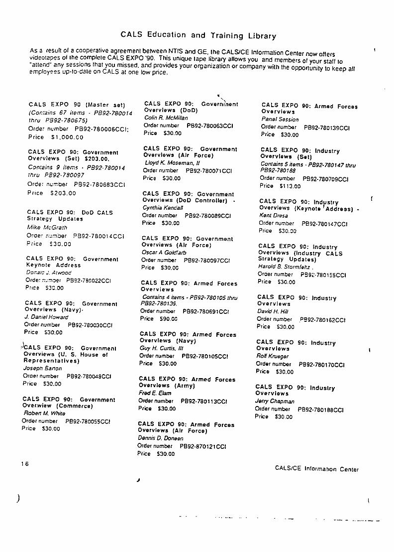
CALS Education and Training Library
AS a result of a cooperative agreement between NTIS and GE, the CALS/CE Information Center now offersvideotapes of the complete CALS EXPO '90. This unique tape library allows you and members of your staff to"atlend- any sessions that you missed, and provides your organization or company with the opportunity to keep allemployees up-to-date on CALS at one low price.
CALS EXPO 90 (Master set) CALS EXPO 90: Government CALS EXPO 90: Armed Forces(Contains 67 items - PB92-780014 Overviews (DoD) Overviewsthru P392.780675) Colin R. McMillan Panel SessionOrder number PB92-780063CCI Order number P892-780139CCIOrder number PB92-780006CCI: Price $30.00 Price $30.00Price S1.000.C0
CALS EXPO 90: Government CALS EXPO 90: IndustryCALS EXPO 90: Government Overviews (Air Force) Overviews (Set)Overviews (Set) $203.00. Lloyd K Mosernan, II Contains 5 items - P8 92-780147 thruCon;ains 9 items - P892-780014 Order number P892-780071CCi P892-780188rtru P892-780097 Price S30.00 Order number P892-780709CCIOrder number P892-7806830Ci Price $113.00Price £203.00 CALS EXPO 90: Government
Overviews (DoD Controller) - CALS EXPO 90: IndustryCynthia Kendall Overviews (Keynote Address)-CALS EXPO 90: coo CALS Order number P892-780089CCI Kent DresaStrategy Updates Price $30.00 Order number PB92-780147CCI
Mike McGrath Price $30.00Order nýmber PB92-780014CCI CALS EXPO 90: GovernmentPrice £30.00 Overviews (Air Force) CALS EXPO 90: Industry
Oscar A Goidfarb Overviews (industry CALSCALS EXPO 90: Government Order number PB92-780097CCI Strategy Updates)Keynote Address Price $30.00 Harold B. Stormfeltz .Do:arc J. Atwood Order number P892-780155CCIO'de: r:.:umoer PB92-780022CCI CALS EXPO 90: Armed Forces Price $30.00P.:ce $30.00 Overviews
Contains 4items -P892-780105thru CALS EXPO 90: IndustryCALS EXPO 90: Government PB92-780139. OverviewsOverviews (Navy)- Order number PB92-780691CC1 David H. HillJ. DanielHoward Price $90.00 Order number PB92-780162CClOrder number PB92-780030CCI Price S30.00Price S30.00 CALS EXPO 90: Armed Forces
Overviews (Navy) CALS EXPO 90: Industry'/CALS EXPO 90: Government Guy H. Curtis. iI OverviewsOverviews (U. S. House of Order number PB92-780105CCI Roll KruegerRepresentatives) Price $30.00 Order number PB92-780t70CCJJosep, Barton Price $30.00Orcer number PB92-7800480CI CALS EXPO 90: Armed ForcesPrice S30.00 Overviews (Army) CALS EXPO 90: Industry
Fred E. Elam OverviewsCALS EXPO 90: Government Ordernumber PB92-780113CCI Jerry ChapmanOverwiew (Commerce) Price $30.00 Order number PB92-780188CCIRobert M. White Price $30.00
Order number P892-780055CCI CALS EXPO 90: Armed ForcesPrice $30.00 Overviews (Air Force)
Dennis D. DoneenOrder number PB92-o870121CCiPrice $30.00
16 CALS/CE Information Center
)

CALS Education and Training Library
CALS EXPO 90: Today's Reality CALS EXPO 90: Detence CALS EXPO 90: Configurationand Tomorrow's Promise (Set) Logistics Management System Management Panel SessionContains 5 items -P892.780196 thru 21st Century Approach to Order number PB92-780352CCiP2892-780238. Logistics - MODELS/DTEDIOrder number PB92-780188CCI Order number P892-780279CC1 Price $30.00Price $113.00 Price $30.00 CALS EXPO 90: Concurrent
Engineerlng/PDES/STEPCALS EXPO 90: CALS Basic CALS EXPO 90: Navy's Grder number PB92-780360cCIBuilding Blocks Advanced IndustrialOrder number PB92-780196CCI Management (AIM) Program Prie $30.00."
Price $30.00 Order number PB92-780287CCIPrice $30.00 CALS EXPO 90: Electronic Data
Interchange (EDI) (Set)CALS EXPO 90: CALS Contains 9 items - PB92-780378 thruCommunclations - The Linchpin CALS EXPO 90: JUSTIS PB92-78O4sy.for Productivity Order number P892-780295CC1 Order number P892-780741CCIOrder number PB92-780204CCI Price $30.00 Price $203.00Price $30.00
CALS EXPO 90: Configuration CALS EXPO 90: EDI and CALSCALS EXPO 90: CALS Data Management (Set) Order number P892-78o378cciManagement - The Focus of Contains 6 items. PB92-780303 thru Prie £30.08Excellence P592-780352. Price 30.00Order number P892-780212CCI Order number PB92-780733CC1Price S30.00 Price $135.00 CALS EXPO 90: Bringing CALSand EDI Together
Order number PBS2-780386CciCALS EXPO 90: CALS Software . CALS EXPO 90: The Direction Orde $3P.80The Coal for the CALS Engine and Status of the CALS Industry Price $30.00Order number PB92.780220CCi CM Working GroupPrice $30.00 Order number PB92-780303CCi CALS EXPO 90: Electronic
Price s30.00 Commerce Project at LawrenceLivermore LaboratoriesCALS EXPO 90: CALS Initiative Order number PB92-780394CCIand Artificial intelligence CALS EXPO 90: The
Order number P892-780238CC1 Configuration Management of Price $30.00Price $30.00 Product Definition
Orderrnumber P892-780311CCl CALS EXPO 90: CALS TestCALS EXPO 90: DoD Price $30.00 NetworkInfrastructure Modernization Order number P892-7804-02CC(Set) CALS EXPO 90: Implementation Price £30.00Contains 6 items -P92-780246 thru of CALS ConfigurationP892-780295. Management - An Industry CALS EXPO 90: Details of CALSOrder number P892-780725CCI Perspective Test Data Using EDI FormatsPrice $135.00. Order number P892-780329CC1 Order number P892-7804100CC
Price $30.00 Price $30.00CALS EXPO 90: RepositoryModernization CALS EXPO 90: Implementation CALS EXPO 90: EDI andOrder number PB92-780246CCI of CALS Configuration Worldwide MessagingPrice $30.00 Management - A Government Order number P892-780429CCIPerspective Price $30.00
Order number P892-78o337CCICALS EXPO 90: EDMICS -rie $30.00 CASEPO9:EI nCLNavy/Marlne/DLA - Where we Price $30.00 CALS EXPO 90: EDI In CALSare, Where we are Going Engineering ChangeOrder number PBS92-780253CCI CALS EXPO 90: Automation of ManagementPrice $30.00 Configuration Management I the Order number PB92-780436CCICALS Environment Price $30.00
Order number P892-78034SCCICALS EXPO 90: Bringing CALS Price $30.00and EDI Together In DoDOrder number PB92-780261CCIPrice $30.00
CALS/CE Information Center 17
)S

CALS Education and Training Library
CALS EXPO 90: EDI In the CALS EXPO 90: The Roles of CALS EXPO 90: An Overview ofAerospace Industry NSA and NIST In Establishing Technical Manual DevelopmentOrder number PB92-780444CCI Security Policy, Guidelines and from Ink to Pixels (JohnPrice $30.00 Standards . Anderson)
Order number PB92-780519CCI Order number P892-780584CCICALS EXPO 90: A User's View Price $30.00 Price $30.ooof EDI and CALSOrcer number P892-780451CCI CALS EXPO 90: How Much CALS EXPO 90: An Overview ofPrice $30.00 Should We Spend on Security Technical Manual Developmentand Data Protection? from Ink to Pixels (RichardCALS EXPO 90: Logistic Order number P892-780527CCI Tyree)Support In the CALS Price $30.00 Order number P892-780592CCI
Environment (Set) CALS EXPO 90: Through the Looking Price $30.00Contains 4 items . PB92-780469 thru GlassPB32-780493. Order number PB92-780535CCI CALS EXPO 90: Lead ProgramOrder number PB92-780758CCI Price $30.00 Application of IETMPrice $90.00 Specifications
CALS EXPO 90: Spares Order number PB92-780600cCICALS EXPO 90: The Direction Acquisition (Set) Price $30.00of LSA as It Interacts with CALS Contains 3 items- PB92-780543thruOrder number P892-780469CCI PB92-78C568. CALS EXPO 90: Introduction toPrice $30.00 Order number P892-780774CCI IETM Generic FunctionPrice $68.00 SpecificationsCALS EXPO 90: The Order number P892-7806!8CCIDevelopment of the LSAR CALS EXPO 90: Spares Price $30.00through Modeling Acquisition Data CommitteeOrder number P892-730477CC; Order numcar P292-780543CCI CALS EXPO 90: Integration ofP:ice $30.00 Price $30.00 User Documentation In
Electronic Technical DataCALS EXPO 90: The Application CALS EXPO 90: Automated Systemsof LSA Spares Acquisition - No Longer Order number p5. 2.78034CCI0croer number P892-780485CCI a Future Requirement Price S30.00Price $30.00 Order number P892-7805SoCCI
Price 530.00 CALS EXPO 90: Training (Set)CALS EXPO 90: Logistic Contains 3 items - PS92-780634 thruSupport Analysis in the CALS CALS EXPO 90: Cashing In on PB92-78o659.Environment CALS - Buying Spares Better Order number P292-78079oCCIPanel Session Order number PB92-780568CCI Price $68.00Order number PB92-780493CCl Price 530.00Price S30.00 CALS EXPO 90: Blueprint for
CALS EXPO 90: Technical TrainingCALS EXPO 90: Security and Manuals (Set) Order number PB92-780634CCIData Protection (Set) Contains 6 cams . P892-780576 thru Price $30.00Contains 4 items -PB 92-780501 thnu P892-780634PE92-780535. Order number P892-780782CCI CALS EXPO 90: Tomorrow' aOrder number P892-780766CCl Price $135 00 Training Tools - Joint ServicesPrice $90.00 Instructional SystemsCALS EXPO 90: Synergy Development (ISD)/LogistIcCALSEXPO90: ynery -Support Analysis Record (LSAR)CALS EXPO 90: Security Improved Products Through Decision Support System (DSS)Issues In CALS Phase I Integration Decnuppor System0642C )Order number PB92-780642CCIOrder number PB92-780501CCI Order number P892-780576CCI Price $30.00Price $30.00 Price 530,00
CALS EXPO 90: Tomorrow'sTraining ToolsOrder number P892-780659CCIPrice $30.00
18 CALS/CE Information Center
),S

CALS Education and Training Library
CALS EXPO go: Tutorial/Introduction .to CALSOrder number P892.780675CCIPrice SJO.00-
CALS EXPO 90: CAtSEXPOSITION 1990Order number P892-780667CCIPic6) S3o.oo-
These items are pan of master satonly.
CALS/CE Information Center 1

NTIS Price Schedules-Effective October 1991NT15 generallv uses price codes to indicate the cost of items sold. The following schedules convert thesecodes into actual prices.
U.S., Canada & Mexico Other Countries
Printed Copy & Microfiche Printed Copy & 1W'icrorlchePrice •.zt ="
CoC Pne pnM PuA01 ........................ $ 9.00 E A.I ........ S m00 A01 ...................... $18.00 E 1. Sn .ooA02 ............... !2.50 202.A03 . ............ .00 0 . 1 .00 A ................... 25.00 E02 .......... 28.00........................ 17.00 E03 .......... 16.0 A03 ........................ 34.00 E . 32.00A04 ,nrotagn A05 . I9CS 0, .......... 19.00 AO4 throug A ....38.0 0.00A06 A04ou~ A09ug .A..2...0 =" • E04 .......... 38.00A06-:rounA .......... 2,.00 A06 through A09....52.00 205 .......... 42.00A 0 lnrougnA.3. 35.00 E26 .......... 24.00 Al0 througn A13....770,00 E 6 .......... 48.00AI14througn AlY7....c43.00 37...... 27.00 A14dthrougn A17....86.00 20 . 40AI,8 through A2:7.... 53.00 E07 .......... 54.00AtrOUg A2.50.0 .......... 30.00 A18 througn Ak2 .. 100.00 En7.. 00A221 throughi A21 ... 100.00 E3G .08 .......... 60.00A22 :r.cun A25 .... A .. c 33.00 . A22 t•hrougn A25.. 118.00 E09 .......... 66.00A9S CX~; ,!S 2E.00 A99 CauJ TIS E....72.00-or E,,o ....... ......... 000,=,
-12 3 ......... 39.00 Ell .......... 78.00=12 ......... 43.00 E12 .......... 86.00E13 .......... 46.00 E13 .......... 92.00.. 50.00 E14 ........ :00.00E 5 4 .......... 5 4.00-=,a . 0 E15 ........ :08 .00... ... .......... ... .. Ei6 ........ ::8 0cN O , .......................S E 0 .C 0 E 7 ....C8 0... .... . . N o0 ........... ........... S 7 5. 0 0 E 1 7 .. 2 8 .0 0N C 2 ...................... - C 0 ........ "..SA c0
N-3... . .0.......... N02 .......................75.00 . .. .. ..-.......2.1 NC3.........oio £1.....22.00. . . . . . . ... . .. . .. z . . . _ . .. ... .. .. . =. 0 N 3 .. . ... ... .. .... ... ... .. . . 0
E20 ........ :76.00N,., E99 CXi Wi1s
),
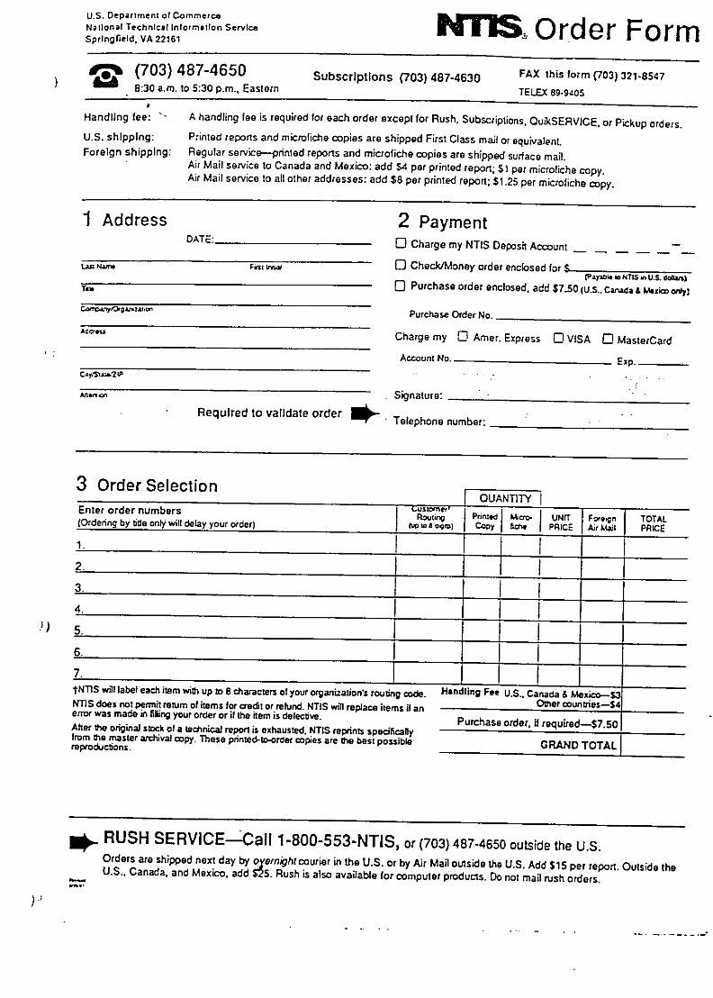
U.S. Departrnent of Commercetiona Technical InformationiO rder Form
Springfield, VA 22161
1 (703) 487-4650 Subscriptions (703) 487-4630 FAX this form (703) 321-85478:30 a.m. to 5:30 p.m.. Eastern TELEX 89-9405
Handling fee: A handling fee is required for each order except for Rush, Subscriptions, QuikSERVICE. or Pickup orders.U.S. shipping: Printed reports and microfiche copies are shipped First Class mail or equivalent.Foreign shipping: Regular service-printed reports and microfiche copies are shipped surface mail.
Air Mail service to Canada and Mexico: add S4 per printed report; $t per microfiche copy.Air Mail service to all other addresses: add $8 per printed report; $1.25 per microfiche copy.
1 Address 2 PaymentDATE: 0I Charge my NTIS Deposit Account
Lau= ru 0~l • [ Check/Money order enclosed for $
, Purchase order enclosed, add $7.50 (U.S.. Canada & hMzico o fl
Ca'reatfO,,.,co Purchase Order No.
A4V.• Charge my 0 Amer. Express 0 VISA U) MasterCard
Account No. Exp.
-*.ncn Signature:
Required to validate order Telephone number:
3 Order Selection 'OUANTITY
Enter order numbers PlSouT1W i I Fopn TOARou~ri I••I• U~ Feqn, E TOTAL(Ordering by •ide onl will delay your order) J ,c to 8 oen) Copy . PRICE Air k41 PACE
1.3._____ I I___ _____
4. L_____ ____
6I ___________ I _____ __________
tNTIS will label each item with up to 8 characters of your organization's routng code. Handling Fee U.S.. Canada & Mexico-S3NTIS does not permit return of items for creedt or refund. NTIS will replace items if an Other wounlbies-$4error was made in filling your order or if the item is defectve. Purchase order, i required-$7.soAfter the original stock of a technicaJ report is exhausted. NTIS reprints specficalyiffrom the master archiva copy. These printed-te-order copies are the best possible GRANDTOTALreproductons. GRAND TOTAL
RUSH SERVICE-Call 1-800-553-NTIS, or (703) 487-4650 outside the U.S.Orders are shipped next day by oyernrghtcourier in the U.S. or by Air Mail outside the U.S. Add $15 per report. Outside theU.S., Canada. and Mexico. add $25. Rush is also available for computer products. Do not mail rush orders.

Products Fact Sheet
CALS Automated Uodate ServiceCALS standards and specifications implement existing and emerging national and international standards.However, efficient implementation requires more than simply adopting an industry standard. All affectedparties must agree on an explicit, unambiguous implementation of the standard by choosing a set ofoptions and user conventions (subsets, profiles, etc.) that meet the technical requirements of bothGovernment and industry.
The CALS standards and specifications are the result of extensive coordination between the NationalInstitute of Standards and Technology, the agency responsible for technical development.government/industry working groups representing industry associations (such as NSIA^ AIA, EIA), usergroups (such as MAP/TOP and PDES) and interested individuals.
The documents listed below are pan of the CALS Automated Update Service. To establish a standingorder subscrition to receive the latest version of these standards and specifications as they are issued,NTIS requires that yqu open a Deposit Account.
To order, complete the attached Subscription Order form including the section on establishing an NTISDeposit Account. The minimum Deposit Account payment is $100 for three or fewer standing ordersubscriptions, and $200 for four or more. The amount shown below for a single copy will be deductedfrom your Deposit Account balance when the document is mailed to you. You will receive a monthlystatement showing your balance.
If you prefer, you may order a single copy of any document listed below. In that event, you do not needan NTIS Deposit Account. To Order, complete the attached Order Form.
MIL-STD-1840A. Automated Interchange of between dissimilar computer aided designTechnical Information is the parent document for systems.a family of military specifications through whichthe CALS standards will be published. It Subscription PB91-962100LFFprovides the "enveloping" rules for organizing Single copy PB91-962101LFF $17.00files of digital data into a complete document --for example, a technical manual composed of MIL-M-28001A. Marku4 Reauiremencs andMIL-M-28001 text, MIL-D-28003 vector Generic Style Snecifleatons for Electronicgraphics, and MIL-R-28001 raster graphics. Printed Outnut and Exchange of Text definesstandard DoD requirements for all of the stepsSubscription PB91-962000LFF involved in automated publishing of page-Single copy PB91-962001LFF $19.00 oriented (i.e., printed) technical publications.
For exchange of source data (prior to documentMIL-D-28000. Digital Representation for composition) it defines a commonCommunication of Product Data: IGES " implementation of the Standard GeneralizedAppicatin,ýS s defines subsets of the Initial Markup Language (SGML). For compositionGraphics Exchange Specification (IGES) for processing functions, it defines an Outputtechnical illustration, engineering drawings, Specification of typographic tags and formatelectrical/electronic applications, and numerical rules, and for display of the composedcontrol manufacturing. IGES is a neutral formatfor digital interchange of Product Definition Data
CALS/CE ormation Center
Pi

In addition to a complete summary of each new report, CALS in Print gives you the full title, author,sponsoring organization, order number, and price, making it easy to find the information you need. Youalso will find an easy-to-scan title listing for quick browsing.To establish a standing order subscription to CALS in Prinn is, you must open a Deposit Account with aminimum payment of $100.00. Each time CALS in Print is mailed to you, NTIS will deduct $15.00 fromyour Deposit Account balance. You will receive a quarterly statement showing your balance.To Order, complete the attached Subscription Order Form including the section on establishing an NTISDeposit Account.Order Number: PB9l-962700LFF
Introduction to CALS Kit
The Introduction to CALS Kit provides you with everything you need to get started. It contains:
* CALS for the 1990s: A videotape jointly produced by the Departments of Commerce andDefense. Experts from government and industry explain how your organization can benefit fromimplementing CALS. (VHS format)
* Electronic Blue Brochure: This hypertext "brochure" developed for IBM-PC compatiblecomputers leads you through the entire CALS strategy. Learn about CALS concepts, roles of DoDand industry, Contractor Integrated Technical Information System (CITIS), Electronic DataInterchange (EDT), PDES (Product Data Exchalige using STEP) Test Network, internationalactivities, and much more.
* CALS in Print: This complete bibliography lists more than 150 reports published by governmentand industry on all aspects of CALS. Much of this material is available only from the CALS/CEInformation Center at NTIS.
" Overview of CALS Standards: This document provides a top-down and bottom-up summaryof existing CALS standards and the foundation upon which they have been built.
Order Number: PB91-780148LFF; $40.00
GALS on Disco"
Get the full text of the latest CALS reports on compact disc together with powerful search software. Aquarterly subscription to CALS on Discm gives you access to over 200 CALS reports each year. Issue 1,to be released in the winter of 1992, will contain all the CALS Specifications and Standards, the completeCALS Architecture Study Report to the Joint Lopistics Commanders and the Office of the Secretary ofDefense/CALS Office as well as many others. These reports will provide insight to both Government andindustry users on CALS initiatives, programs and processes and assist in meeting new DoD requirementsfor acquisition and logistic support programs.
The search software allows rapid retrieval by topics of interest to users. In addition, users can print wholedocuments or selected sections. By "cutting and pasting", users can also incorporate sections of CALSreports into their own word processing documents.
Requirements include: IBM-PC or compatible; 512K RAM; Hercules compatible monochrome, MGA,CGA, EGA or VGA monitor, 1.2 Mb. 5 1/4" high density floppy; CD-ROM player-, Microsoft extensions.To Order: Complete the attached Order Form or call 703-487-4650. Be prepared to provide your creditcard number.Subscription PB92-592140LFF $595.00Single issue PB92-592141LFF $295.00
CALS/CE Information Center 3
) I,

U.S. Depari•mnen of Comm,,,eNational Technicl Inform.tionService O rder F-ormSpringfield, VA 22161
0 (703) 487-4650 Subscriptions (703) 487-4630 FAX this form (703) 321-85478:30 a.m. to 5:30 p.m.. Eastern TELEX 89-9405
, Handling fee: A handling fee is required for each order except for Rush. Subscriptions. OuiRSERVICE. or Pickup orders.U.S. shipping: Printed reports and microfiche copies are shipped First Class mail or equivalent.Foreign shipping: Regular service-printed reports and microfiche copies are shipped surface mail.Air Mail service to Canada and Mexico: add $4 per printed report; $1 per microfiche copy.
Air Mail service to all other addresses: add $8 per printed report; $1.25 per microfiche copy.
1 Address 2 PaymentDATE: C) Charge my NTIS Deposit Account
t.n ftw 0 C Check/Money order enclosed for !CPayaN. go NTIS A U.S. Cofln--
C, Purchase order enclosed, add $7.50 (U.S.. Canada & Mxxico ory)C."o' f zaz.o Purchase Order No.
Charge my 0 Amer. Express C VISA C1 MasterCard
Account No. Exp.c~lys a.? lP
Af.,1 Signature.
Required to validate order * - Telephone number:
3 Order SelectionF OUANTITY
Enter order numbers LustPner,oRoutvrig Prnnwd I==to- UNrT Foretgn TOTAL(Ordering by die only wil delay your order) (to to sdins Copy fict PRICE Ar Mail PRICE1. I-
2.
3.
4.
5.
6.
7.tNTIS will label each item with up to 8 characters of your organizationvs routing code. Handling F " U.S.. Canada & Mexico-S3NTIS does not permit rebjrn of items for aredt or refund. NTIS will replace items if an Other countries--$error was made in filling your order or if the item is detective. Purchase order. if required-$7.5sOAfter Ow original stock of a technical repopt is exhausted. NTIS reprints specificallyfrom the master archival copy. These printed-to-order copies are the best possible GRAND TOTALreproductions.
- RUSH SERVICE-Call 1-800-553-NTIS, or (703) 487-4650 outside the U.S.Orders are shipped next day by overnight courier in the U.S. or by Air Mail outside the U.S. Add $15 per report. Outside theU.S., Canada. and Mexico, add $25. Rush is also available for computer products. Do not mail rush orders.

Profitable use of information technology in thedesign and fabrication
of ships and oil platformsCopenhagen 3-5 March 1993
University Enterprise Training PartnershipMarine Science and Technology - MARTRAIN
New technologies -open and distributed systems,
communications
Tor G Syvertsen
The Norwegian Institute of TechnologyTrondheim, Norway
MARTRAIRIT31Cnha1e n1 I n.ý TocT. G s5,•.
OERVIEW
6Computers and Communications6 Object Technology
4CORBA
6 Reference Architecture
MARTTAIN1MVCop.nh.pn lO.o$IT.r GS•v.•,.n
Page I

Computers and\CO1"mmunications
MARTRAIN 1"I I ~CDp..klp 13OI Tw Syvcns-
<~pfwareTookFile Manager
Efi le ik 1ree Ylcý Qptlon. Wln 1wflip
Ct0- . ý t-.
Ct,0m0ý02-w
03.O -
Page 2

\ýOman Agent
Person searching files
\4VERVIEW
6 Computers andCommunications
6 Object Technology
6CORBA6 Reference Architecture
MARTP.IN 1fl1/Cop~nh~gn ]" WI3O 5Tcr G Syv.mnn
Page 3

\•hat is an Object?
6 Objects store information as internalstate
6 Objects perform operations6 Objects are organized in a type
hierarchy, according to commonalitiesof state and operations
6 Object state is encapsulated byoperations
6 Individual objects are instances oftheir types
. 0e OMG Object Hierarchy
i• meta-object
Fthing Literal characteristic Type
Attriute Relati onshi•,
MAR•TAIN 1T991 Copnhapn 1•m IOTot C Sya•aen
Page 4

x%,,,ýObject Classes
Person _____________
name Geometric objectbornchange-job color Attributeschange-address position
Z _ý OperationsFile move(delta: Vector)file name seiect(p; Point): Booleansize in bytes rotate(angle)last update
0 bect CommunicationClassical Object Model:
Messages
N4ARThAIN lw3C.pnh.s . ý. I T.,Z~ C Syvrn.,
Page 5
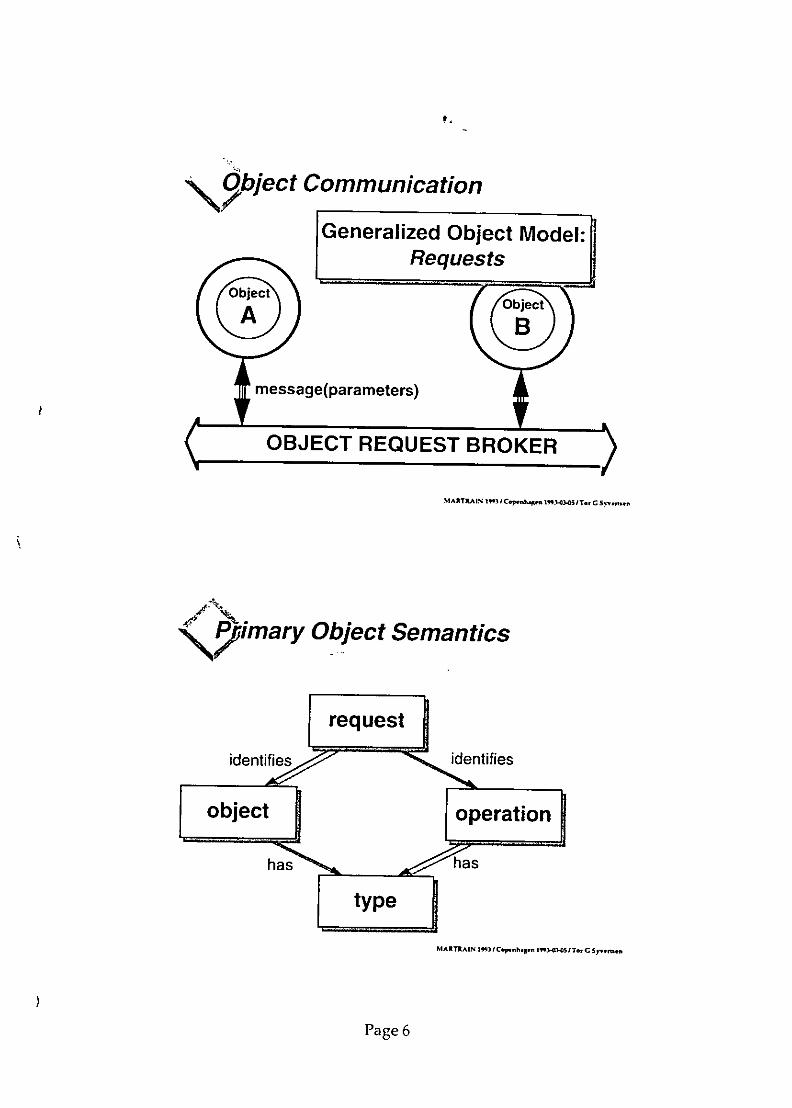
\ 2 blect Communication
Generalized Object Model:Requests
Tmessage(parameters)
OBJECT REQUEST BROKER
MARTRAIN 1"31CInh' 1ý ý Tor C $,.r
Smary Object Semantics
MANTRAIN 331 ICtpm nharn 'rIn-O'.OT~rcsyvtl~n,
Page 6

I \%VER VIEW
6 Computers andCommunications
6Object Technology6CORBA
6 Reference Architecture
MA*RTRAIN W3i I Co ýhlgn h•l.3O 017T C Sy.Msef,
' 0OMG-\OBJECT MANAGEMENT GROUP
6 Industry Consortium formed in 19896 Vision: to have an application development
environment for heterogenous applicationsacross all major hardware platforms andoperating systems
6 More than 200 members including: HP,Unisys, Data General, Apple, AT&T, DEC,Microsoft, American Airlines, Sun, NEC,Borland, IBM,...
6 Specifies an architectural framework andsupporting interfaces, facilities and services
MARTRAIN 193 I C.pm.n.. 1f 5 / T,. SyrIT.,%C
Page 7

\I/G Architecture
Application Oblects Common Facilities
GBJJAfqf 011FMuffif BftQJf k
Common Facilities
MARTRMAIN trV.'C) Iahs•en I•sr rcsy,.n.n
Application Objects
6 CAD models6 FEM and other analysis models6 Simple and compound documents6 Regulations and rules
MARTRAIN 13 Copfnh,.5 n •,o, I Tot CSyv G n..n •
Page 8

\5Pmmon Facilities
4 Class/object editors6 Printing/spooling
6 Error handling
6 Link management
4 Help Facility
MARTRAIN I")3 1 Copenh-1n 1t.-5 IT., G Sy,.In.,.
7 biect Services
6 Name Services
6 Request Dispatch6 Parameter encoding
6 Delivery and Activiation4 Persistent Objects4 Exception Handling
6 Security Mechanisms
MARThAIN fl91$C*,nh.A1. ý I• l TIw T $•, Sp en
Page 9

*\FJe quest Concepts
SCoputers and
Communicationsnam
6 Objectjechnlg
6 Referene arcitctr
MARThAIN lrn'Co.n.ha.n IYOOST., syvmn.,
Page 10

REFERENCE ARCHITECTURENy'Based on concepts from Esprit III MARITIAI'IE)
6 Data Integration: tools are able toshare common data and information
6 Control Integration: tools are able tointeract directly with each other
6 Presentation Integration: user interfaceprovide functional access in a uniformway
MAT•hrmX sIOCe,.sha., IT..G Syven,
« rmsof Integration
CAD Ax PRESENTATION
INTEGRATION
C x CONTROL
CAD FEM CAx INTEGRATION
Loca~ataDA TAINTEGRATION
MARTRAIN M3l ICopnha. 1 - I.T., c Synnhn
Page 11

.--
lIntegration PerspectivesIntegration Perspective
Group Process
Task
storage storage
MARTRAN 1" ~,,n*r 1ý SITr0S -
\qiefinitions
6 Information Repository6 Contains globally available information6 Contains information objects and relationships
6 Information Object6 Encapsulated information6 Generated and made available by an application
6 Relationship Object6 Describes the relationship between two information
objects
MARTRAIN 1") 1 C.p.nh.,n I IT•,5 TrC S•y.tn
Page 12

DXN -rbue Inform ation Repository
Application-generatedobject
* Global
fileserver
~~tA~~~TRMS~~ ~3Cpa~IfIST.,CSnG
NV~9 ing the Reference Architecture
Message sending,Information Information object exchange
Page 13
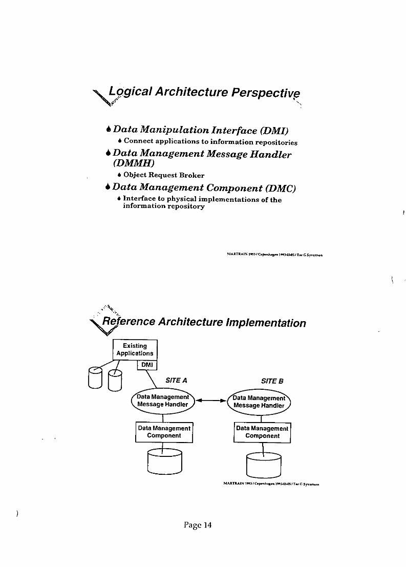
\LLogical Architecture Perspective
6 Data Manipulation Interface (DMI)& Connect applications to information repositories
6 Data Management Message Handler(DMMH)
6 Object Request Broker
6 Data Management Component (DMC)6 Interface to physical implementations of the
information repository
NIARTRAMNt/Cph 1lO33IT., G Sn-,.
Reference Architecture Implementation
Existing
Applicationsag
Data Management Data Management
Component Component
MARTRAIN IM 1 C.pSh.Ren I2" TerOGT CSVn
Page 14

\,!atabase Con tents
has relation to has relation to
~ SIEP Applcatonsibase on
Informatonj Appictine
Object RequestBoe
Page 15

, MARITIMEXIt.plementation Phase I
T
[ INTERGRAPH PIL....
Et
MARTRAIN •t pehleI -0 1T nl
/ MARITIMElnholementation Phase II
1MI Intgrated ....
{ Owne r Oter
DM1: Data Management Interface* control access" instance monitoring (where to find
information)* version monitoring
MARTRAIN Pa em ' Copmmhaglm l-O).O51T., C S16rne,
Page 16

w\ I0mmercial ORBs
6 Digital Equipment Corp6 Network Application Support (NAS)4 Applications Control Architecture (ACA)
6 SUN Microsystems6 Distributed Object Environment (DOE)6 ToolTalk Service6 Distributed Object Management Facility (with
Hewlett-Packard)
6 HyperDesk6 Dynamic Invocation Interface6 Distributed Object Exerciser
Page 17
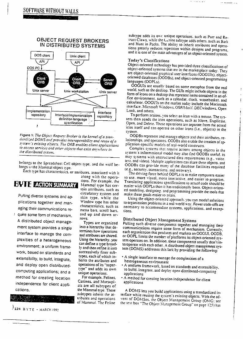
SOFTWARE WITHOUT WALLS
subtype adds its o,,: unique operations, such as Purr and Re-OBJECT REQUEST BROKERS tract Claws. while the (.,nine subtype adds others, such as Barkand Hunt in Packs. The ability to inherit attributes and opera-IN DISTRIBUTED SYSTEMS tions greatly reduces repetition within designs and programs,SUnix cient I and it is one of the main advantages of an object-oriented svstem.
AA Today's ClassificationsObject-oriented technology has provided three classifications ofDOS, PC , object-oriented systems that are in the marketplace today. Theyare object-oriented graphical user interfaces (OGGUls). object-oriented databases (OODBs). and object-oriented programminglanguages (OOPLs).
OOGUIs are usually based on some metaphor from the realworld, such as the desktop. The GUIs might include objects in theUnix server Unix workstation -Unix server form of icons on a desktop that represent items contained in an of-fice environment, such as a calendar, clock, wastebasket, andcalculator. OOGLU1s on the market today include the Macintoshinterface. Microsoft Windows. OSF/.otif. DECwvindows. OpenImplementation .InecntIon terace Look. and others.repository mplementIntre
To perform actions, you select an icon with a mouse. The sys-definition language r ttern then sends the icon operations, such as Move. Duplicate.snecification Open. and Delete. These operations are separate from the actualicon itself and can operate on other icons (i.e.. objects) in thesvsrem.Figure 1: The Object Reques, Broker is the kernel of a stan- OODBs represent and manage objects and their attributes. re-dardized DOMIS andpro -ides interopcrabilin' and reuse of a lationships. and operations. OOIBs also enable the creation of ap-systre,'s exisrine obiects. The ORB enables c/jient applications plicacion-specific mode-s of real-world constructs.to access ser'ices and other objects thlat eist anvwher'e in Complex systems that require actions among objects in the:he distributed sysenm. system s informational model may also find OODBs useful, asmay systems with uns:ruc:ured data requirements (e.g.. voice.text. and video). Multiple aoplications can share these objects. andbelongs to the Spreadsheet Cell object type, and the wolf be- OODBs can provide many of the database facilities requiredlongs to the NMammal object type. (e.g.. security, transactions, and recove:rv).Each type has characteristics. or attributes, associated with it The driving force behinrd OOPLs is to make computers easieralong with the opera- to use. more visual, more interactive, and easier to program.tions. For example. the Translating applications specifications to actual code should beE L Mammal type has cer- easier with OOPLs than it has traditionally been. Object-orient-tain attributes, such as ed modeling, designing. and programming provide the tools that
circulatory system and make these goals easier to attain.Pulling diverse systems and ap- skin type, while the Using the object-oriented approach, you can model solutionsplications together and man- Window type has other t°°ranization problems in a real-world vav. Fewer trade.offs arecharacteristics, such as necessary to accommodate systems, applications, and excep-aging their communications re- menu bars, scroll bars. tions.I quire some form of mechanism, and up and down ar-rows. Distributed Object Management SystemsA distributed object manage- Types are organized Pulling such diverse components together and managing theirment system provides a single into a hierarchy that de- communications require some form of mechanism. Currently.termines how operations each organization that produces and markets an OOGUI. 0ODB.interface to manage the com- and aetributes are shared. or OOPL limits the number of platforms its object-oriented sys-plexities of a heterogeneous Using the hierarchy, you tern operates on. In addition, these components usually don't in-can define a type broad- teroperate with each other. A distributed object management sys-environment; a uniform frame- ly and then refine it into tern (DOMS) addresses this lack by providing the following:
work, based on standards and successively finer sub-types, each of which in- • A single interface to manage the complexities of aextensibility, to build, integrate, herits the attributes and heterogeneous environmentand deploy open distributed- operations of its "super- * A uniform framework, based on standards and extensibility.type" and adds its own to build, integrate, and deploy open distributed-computingcomputing applications; and a unique operations, applicationsmethod for creating location For example. Felines, ' A method for creating location independence for clientCanines. and Marsupi- applicationsindependence for client appli- als are all subtypes ofcations. the Mammal type. These A DONIS lets you build applications using a standardized in-subtypes inherit the at- terface while reusing the svstem's existing objects. With the ad-tributes and operations vent of DONISes. the Object Management Group (OMG: seeof Mammal. The Feline the text box "The Object M-Ianagement Group" on page 125) has
)124 B YTE 2 MARCH 1992

FEATURE
SoftwareWithout Walls
Distributed object management systems can integrate diverseoperating systems and applications and optimize your current systems
HERBERT M. OSHERT say responsi e and Competitive. yOL. company needs access to the mostcurrent and accurate information available. However, most of today's com-puting environments include a complex patchwork of incompariblc main-framesm:nicomrputers personal computers, and systems sortware.Gaining transparent access to your information means coping with multiv.cndor -';:-net.vorks. "legacy- (i.e.. entrenched) applications. diverse operating systems, and " _competing standards. The open systems intended to fill these needs are too oftenwalled in by inflexible applications and complex environments.
Organizations today need to optimize their computing systems. They need an en-vironment that builds and integrates diverse operating systems and applications-essentially, software without walls. One solution is a new class of object-orientedtechnology called distributed object management (DOM) and provided by com-panies like HyperDesk. DEC, Hewlett-Packard. and Sun Microsystems.
%Vhy Object-Oriented Software?The basic components in an application change less frequently than do the functionsthat an application performs. For example, a spreadsheet cell can be an object.The functions this cell supports-Calculate. Move. Format. and so on-maychange over the application's lifetime, but the object itself-the cell-remainsconstant. The obiects are extensible, and. therefore. so are the applications.If you use predefined objects, you don't have to reinvent [hem each time a newservice or application comes along. For example. in developing an applicationthat uses word processing functionality, you can reuse the word processing objects.Reusability saves both design and de'velopment time and reduces the time tomarker for new products. In an object-oriented system, the software is modular in
design. so the pieces are reusable.
What Is an Object?Ev ery component in an object-oriented system hais data and o 'perations that defineit as ^ particular kind or' object. For ex.mple. a wvorkstation window, a spread-shee. ctli. and a %% ol can all be modeled as objec:s. Each object comprises ceraininformation (i.e.. the data) and can be used in certin ways.. its o. rations)
Obkic:s with ihe same data and operations are caegorized into ' pes.the wk orkstation w, indo,, belongs to the Window object type, the sPreadsheet cell
1.2"2 = . -, A'R \1Rr'P_-

SOFTWARE WITHOUT WIULS
The Object Management GroupCHRISTOPHER M. STONE
M he Object Management Group The OMG Role In essence, the work is bein? com-'(OMG) is unique. Let's face it, There is widespread agreement that the - pleted as OMG is helping to solvetrving to get computer zechnolo- OMG is trying to move an entire in- many of the discrepancies among oth-oists and marketers to agree to a dustry toward the development of in- er consortia. as we define applicationsset of rules for the future of software teroperable applications. There is not. development environments onto thedevelopment before economic en- however, agreement as to how this is to consortium-driven standards. Thetrenchment dictates direction is an be done. CORBA will be a fundamental en-anomaly. Like any democratic forum, the abling technologv for distributed com-Object technologv was born in the OMG needs the support and commit- pucing for independent software ven-basements of R&1D labs and has long ment of its membership. And as in dors. end users, and Standards groupshad their altruistic outlook stamped on other computer trade groups, jockey- alike.it. "Objecrphobia'" has been a disease in ing for position is a recreational sport.the ranks of middle and upper man- The vendor and user communities have Next Step?agement in vendor and user or-aniza- begun to put their trust and support be- The next OMG test will involve the de-tions for years. Object technologists hind Open Software Foundation. X/ velopment ofan object model that willwere the ones invited to present their Open. and Unix International. Object describe the formalism of an object andviews on the last day of the conference rechnolo.v needs to be raised tn that its use in data manaerement. There area: 4:30 p.m. level. academic and semicommercial objec:Armed with logic, mathematics. and
models everywhere that aulempr to de-analogies only a chemistry teacher Evidence: CORB.. scibe a specific function, such as min-could love, object technology suffered Object .Nlesslaging auing devices in network managemem.from a basic problem in the computer For the first time in the computer in- but no single group has attempted toindustry-too many people of above- dustrv, the consensus on the early spec- solve the whole problem: reaching anaverage intelligence trying to prove its ificat'ion for a technologv has become ag-reement on a data model with wide-worth. The computer industry suffers reality. Credit goes to Heewlert-Packard. spread applicability.from the tenet that theologv and meia- Sun Microsystems NCR. Object De- Just as we were confident that wephysics are the 1000 poincsof lioht and sign. DEC. and HyperDesk for recon- could produce an ORB. we're confi-that the consumers, or people that spend ciling what many had thought to be ir- dent that the OMG will produce an ob-money, are all test sires, reversibly warring factions-with the ject model within the next six months.winners being the software develop- In addition, object services for lan-What Is the 0MG? ment community. guages. databases, document-contentThe OMG is a technology-endorsement Building the Common Object Re- architectures, and windowing systemsgroup, not a standards body. What we quest Broker Architecture (CORBA) will also be starting shortly. lthou•ghcreate may become de facto standards, by combinin2 static binding with a dv- we don't believe that this list of tasksbut we are not accredited to enforce namic application programming inter- can be completed in 12 months, it isthem. We don't sell software. We dis- face may appear to be like mixing the begnning of tru sharing of librariestribute a specification derived from OSF/l and System V together, but at or objects among the developmentcommercially available technology that OMG there is the willingness to try. community and the eventual end user.has been selected through an arduous, OMG's mission from Day I was to fos- Detailed information concerningopen. well-documented process in the ter cooperation and create industry con- OMG membership, mission, and goalshope that the membership and indus- sensus in advance of the market. in do- is available. Please contact Elizabethtr' alike will clone it, develop to it, or ing so, interface specifications could Jewit. Member Relations. OMG Head-
buy source or binarsh code from an in- be areed to early on without econom- quarters, 492 Old Connecticut Path.stance of it. In short, we set down rules ic pressure. Framingham, MA 01701. (508) 820-for object technology that will make The Object Request Broker (ORB) is 4300; fax (508) 820-4303.software development easier, reusable, the most significant new approach tomodular, and high-quality, software standardization since consor- Christopher M. Stone is president andProblems? Nothing evangelism tium formin. came into vogue a few a founder of the Object Managementwon't cure. There is a fundamental years ago. The process of selection that Group (Framinghant MA). Priorto theproblem found in any industrv trying is used at OINlG. although it is not en- founding of OMG, he was group man-to lay down rules before money talks. tirely without flaw, has-demonstrated ager and director of software productsThe lack of applications interoperabil- that technical merit can overcome bu- at Data General. You can reach himity is the problem. Period. reaucracy. on BIX c/o "editors.'
MARCH 1992 - BYTE 125

SOFW E WITHOUT WAILS
sponsored the Object Request Broker. The ORB is?ý'.,- kernel of well as an ORB. So how are they provided? Simply by includinsa standardized DONMS and prov.ides interoperability (see figure I I. some primitive (root) templates (bahe cl2sses) a part of the b:-The ORB enables client applialions to s.anrlessly access ser- sic ORB. Built into these base classes are methods that pnovidev ices and other objects regardless of where they reside. To Un- the functionality of subclassin,.* inheritance. and polvmomhnism.derstand DaM more fully as the solution to open distributed In other words, you would use a cornmand line like.. -computing. you need more technical details. [baseclass namesubciassze-hod,*ara2-new_classname .... .The Technical View Using the same EXECUTE command to invoke the subclass or
In its simplest definition, an object would be the specific case substitute method now provides basic object-oriented functions.(or instance) of a generalized software template. This template is In fact. by addin' more of these intrinsic opertions to the basejust a mechanism for describing some emiy. Its forrm is open-end- classes, you can continue to enhance the system's capabiliiesed. so it's extremely flexible. and make them available through the same simple interface mech-When a template layout is def~ned in the system. it's called a anism.cIa.vs. When the fields within that template are filled in with spe- These built-in objects are predefined classes, or templates.cific information, that instance or instantiation of the class tern- manipulated by the same basic interface. Since you can chanee orplate is an object. Therefore, a class describes the set of specific replace these classes, even the svstem's basic c3pabilities canimplementations or instances called obiects. be modified and extended.For the purposes of this article. I'll assume that a class template This ability raises a couple of interes-ng questions:consists of a set of attributes and a set of methods. Attributescan be simple data items like in.ecers or character strings, or I. If the base classes provide the basic objecz-oriented fn-e-much more complex data like files Iin these cases, the attributes tionality and the ability to create. inhzrn. and override clasesare pointers to those items). and objects. how do you create the base classes in the first place?The metho•ds can be anvthing from compiled subroutines writ- Have a bootstrap process that loads an initial set of ciaes.ten in a conventional programming lanuage like C to code writ- This process exists and is easy to use %. i&h somcthing cal!ed theten in interpretive languages. or e. en to shell scripts. When these lnterface/lmplementation Definition Lang. uagj.te compiler.icnmplate fields are filled in tkith ,peciiic' data. the template be- 2. If You can redefine the system's bast:intionalit,. hcý,coies an object.
do yotu maintain compatibilit!?Develop a standard for these basic [eat:ions and classes !the
The ORB and DOM1 role the O.IG is expected to play). The base cla.sses and theirTihe ORB represent> the Icre ofDOM. It can he vie'%ed a, a net- object life-c.,cle methods are knowvn as w a .Vpcw r,,siu,,-,. ForV-'. ark operating s,.'s~em wiith ne basic comiand. EXECUTE compatibility and Irue interoperubili,, inonc iffcren iinoh.-The format of this command "out;d be somethinu like - mentations of an ORB. a standard fo r a heii Lmon -. d n:-- - - - ------ --_,- -• ---. ,o ds must be created.
The job of the ORB is to locIate the named template (the object). Dvynamic Integration,:art the specified operation ithe method. and pass it the pa- So now you have a mechanism for 'v.raping oor encaps.ula• nu,ramelers it needs. Since objects can exist aovywhere on a net- a template around any collection of data 'attribuies and Pro-%.ork. you can locate them via a name service or a unique iden- grams (methods) and treating it as a man:e-eahle enit, caledi•ter-a /umdh- an object. And you have the firsi def-inion of a specific [en-The ORB also needs to provide other capabilities associated plate format called a class. and all implementations of that tem-"% ith obiect-oriented sy'stems. While these concepts have fancy plate (with specific data and code filled in) called instances, or ob-names subclasine, inheritance. and p1, morphism), the, are jects. of that class.simple to understand in the conte.t of the software class tem- Data can be simple numbers or complex bit maps. Code can beplates. compiled language modules (e.g.. C) or interpreted scripts.Subclassing is when you tell the system oI make a copy of a Objects have names and can be anywhere on a network usinetemplate but give it another name. You can revise the behavior of a name service. You can build complex client-server applicationsuny of the copied ti.e.. inherited, methods and then add some bv creating servers that these templates describe, and clients cannewv methods and attributes of your own: this is called special- access these services by invokine their methods through the ORB.i:(tlimi.
If you build applications in this manner. you can move theIn specializing a template, you create a new version of the pieces around easily. make chances to services without affectingclass-it is similar to the original class but different. It lets you the clients, prototype using files and scripts. and replace themtake advantage of something preveloped. possibly for with more efficient implementations using compiled code.a different purpose, and modify it to suit the new function. This In addition, if you develop a class template, you should bemechanism provides the reusabilitv benefits of object orienta- -able to modify or add new code without bringing the systemtion and promotes cost-effective software systems that are easi- down or affecting already-running applications. This is known aser to develop, maintain, and enhance. dy.naim. .SM.A variation on this theme is to substitute a different method but The system should be able to select which of multiple methodsw% ith the same name as one in the original template. Since meth- (with the same name) to use based on user preferences (w'haie'-ods are invoked by name. this allo" s you to leave your applica- er machine you're running on that day. language preferences.lion unchanged yet still receiv.e the benefits of the modification, and other cultural or system preferences). This is referred to asThis process is know n as ewerridij,, conltei-sensitive imethod binding.The ability to override allows you to maintain a consistent in- You (or the client application) should be able to ask the objectlet(':ace while hiding the differences in implementation. This ce- to describe itself-its methods, the parameters required, and itspahbilit.v i's called po.1,mo ljhisn,. attributes. Thus. bv exploration. new capabilities and servicesAny, olhject-b•ased Sy stem needs to support these capabilities, as can be discovered and used at run time. This is a capability, of d'-
126 8 1 TE - MARCH 19tyv

S 0FT AR E M\ITHOU T WA LS
will be required in future advanced desktops. office-automation
ADVANCED INTERACTIVE systems, and workgroup applications.The system must be able to accept modifications and the cre-
CLIENTSERVER APPLICATIONS ation ofvmeta-applications" built ofcomponent objects without
Machine A Machine s affecting either the client code or its own ability to remain oper-
ational durin- the changes. Yet the system must also protect all
Motif OFjec::FOO objects and prevent or restrict changes if security so dictates.The ability to support user-centric applications is what differ-
, od Nl. Open Loo entiates a platform capable of dynamic operation from one that im-
aColicaStien _____________I plements a CORBA iCommon Object Request Broker Archi-
L02•2wStecture)-compliant dynamic invocation to static functionality.The HyperDesk DOM'S provides both dynamic invocation and dy-
Moti namic operation.
,.Advanced interactive chient-sen,er" applicationzs: ApplicationsMultiple need the ability to operate across a diverse mix of hardware and
implementations software platforms. For example. in figure 2. a client applica-_ _ _ of method:display lion is running on a particular CPU and operating system (e.g.. a
Sun Sparcstatiorl with SunOS and Motif) with some object ser-vices (maybe a CAD object) running on a different machine
Figure 2: ht thi's e.ipk.• of. c rcc ar~liwation, a cljelnt (e.g.. a Cray supercomputer). This type of applications architec-iira~ni 0.: oe Cture requires calculation services from objects and mechanisms
"iO c CP c es t his . vysL', to display the results of those calculations.:..:-A;. tithl: Some cC o ic; sellices (i? this case, Usin- a DONIS. it's tas. to seaarate the objecfs operations into:: c io ¢r:•u~n o:,: i.cre: machine Onachine B1. Tire
:.ie ,c:;•G:,O has derc :re: object handle of object those that are displa. -'.ndependent and those that are displav-de-
jy: cpzcc:xn has ý0 o e sdes no: objcthandeB.an pendent. oojtoreover. once this separation is made. the system's500. Tire inwX,:nteni:cars,: or FOC residcs on machine B. uind pnet y
r eknowledge of the client context makes it possible for the ORB to
SIQC ',u it ES .OiCtC T~e eticnt ajpplication is- select the correct display method. This eliminates the need to.•'. : :±' fO or o- ,: ca'lc. Tile ORB on i- wrie enviro'. ment-s.fic code.
c:,:.'•:" .4 t'-oe :cst rineaso : . to, :n t ORBon sli wtoine S. whi-h s- In this example. the ORB determines that the appropriate dis-c"-r': : .. u',tth : and c.:ion: tie results dispa t e -- nt play method is for the Motif environment on machine A and re-
-:.:1 . • FOO. the .itio, : napivii issia a dach - turns a IvMotif user-interface-description File to machine A for
.ce.s h"ý r FOO. :Oht-h is :utomattc "diV i-outed to machine B. execution. The class-definition object can have multiple display
:vhe:-it th hn .c ORB dlcrmwcieA-s the diappp method requtred methods stored with it- For instance, it can have one for each
ar :isplay of 500 on m::hi':c .4 and ret'rnsf the appropriate display environment eg.. Motif. Open Look. and NM icrosoft.:ie : c hn . r e.xeetion:. W indows).
narnism. And iý'ally. all this software should be portable across Software Without Walls
different hardware. operatinz systems, and networks. To create the type of open distributed computing described here.
you need a complete 1ONIS with an advanced suite of tools and
DOM Examples services that complements an OMG-compliant ORB. A com-
Ob,'ct queries: Data-intensive applications (e.g.. typical corn- plete DOMS bridges the operating-system. applications system.
mertial on-line or database applications) require efficient query and communications protocol void that exists today and enables
mechanisms to etieve attribute information about a particular ob- you to bring applications and systems together into a cohesive unit.
Ject or about every object in a group. Since the object types in a Some of the advantages of a complete DOMS are as follows:
system must be able to change dynamically, the DOMS supports
a auerv mechanism. - Your organization can retain its existing hardware and
Tbe'DOMS's query mechanisms let you specify the attributes software assets while integrating new applications and
desired at run time instead of having to code their names into solutions easily and seamlessly.
procedure calls. For example. if there are 50 objects of a certain * You can take advantage of the extensibility and reusability of
type and the application needs five attributes from each objecL one objects to cut down development time and deliver distributed
dynamically constructed DOMS survey call will return all the applications more easily.
data. You can integrate existing applications economically. Even
Lega'*cv e.xpansion: DOMSes should at least provide mecha- large legacy applications written in COBOL or FORTRAN
nimsr for building new applications. In addition. they should can be encapsulated within a single object. preserving past
provide a mechanism for integrating previously existing appli- software investments.
cations and data. The encapsulation of existing applications and
data as objects is known as legacy expansion. With DOM. building and integrating open distributed appli-
One wav to Drovide this functionality is through an encapsu- cations is practical. You can gain simplified access to information.
lation facility that uses inte.-preted scripts and languages. You \vherever it is-givin., your company a competitive advantage.
neet not write and compile code to encapsulate existing appli- Software without wa'is is no longer a promise: it's a reality. U
)cations."'Lser-cen:,", " ap/'/:caoi:s: Interactive. graphical applica- Herbert Al. Osher is president of HvperDesk Corp. (Westbor-
tion en! ironmnt:s e '.o customize and adapt the software with- otugh. MA, . '1hiCh deelops'if. disrribited-cuifptting sofJROrY based
outr nee 2:-'or, Such environments support incre- on oiet tltj,;,:"etilcS tt).-ohn i Wv, l OUtel reach hin oil onIX c/o
s n, ane and growth. This caDabilitv "t'ditOrs.
125 , Y T E -MARCH .c:

, Profitable use of information technology in thedesign and fabrication
of ships and oil platformsCopenhagen 3-5 March 1993
University Enterprise Training PartnershipMarine Science and Technology - MARTRAIN
Product Data Modeling andMarine Applications
Tor G Syvertsen
The Norwegian Institute of TechnologyTrondheim, Norway
MR.AI N 211"t• Cep~nh.8 n tf9 4l3.~O al. C Syvns•*n
at is a Product?
6 A product is a physical or abstractobject of a complexity that requirescareful definition, planning andcoordination in order to be realized
6 Typical products are buildings, ships,process plants, cars
6 Products may be one-of-a-kind (e goffshore platforms) or mass-produced(e g computers)
MAR TRAD lM I Csp Wnp 1n 4 I Te, G Syvnn
Page 1

Vt
xIhatis a Model?
6 "A model is a structure that a systemcan use to simulate or anticipate thebehavior of something else" w.ain Mink)
6 A diagram is not a model, but a picture(presentation) of a model
6 A dynamic model have more than onestate, and the transition from one stateto another is triggered by an event
6 A model can be used by a modelmachine (e g brain or computer)
MAg•lXIN 1rntCýp Vn 1" IT. G $S n
'44 me Purposes of a Model
6 Testing an entity before realizing it6 Communication between involved
parties (sharing concepts andunderstanding)
6 Reduction of complexity ("Everythingshould be made as simple as possible, but notsimpler" Albert Einstein)
6 The fitness of a model is alwaysrelative, according to the purpose
Page 2

7te Map as an Abstraction
MARý%AIM~ 1 ICv.nhagpn 1W2OýO It Cw Sy'n
C i and Bruno Concluded
The author of Alice in Wonderland, themathematician Lewis Caroll wrote aboutSylvie and Bruno Concluded.
In the story the narrator meets a personcalled Mein Herr, an they enter this dialogue:
MARTh .IN If3 CF,.n;h.$q•n, , !.O-I T- C Sytn.n
Page 3
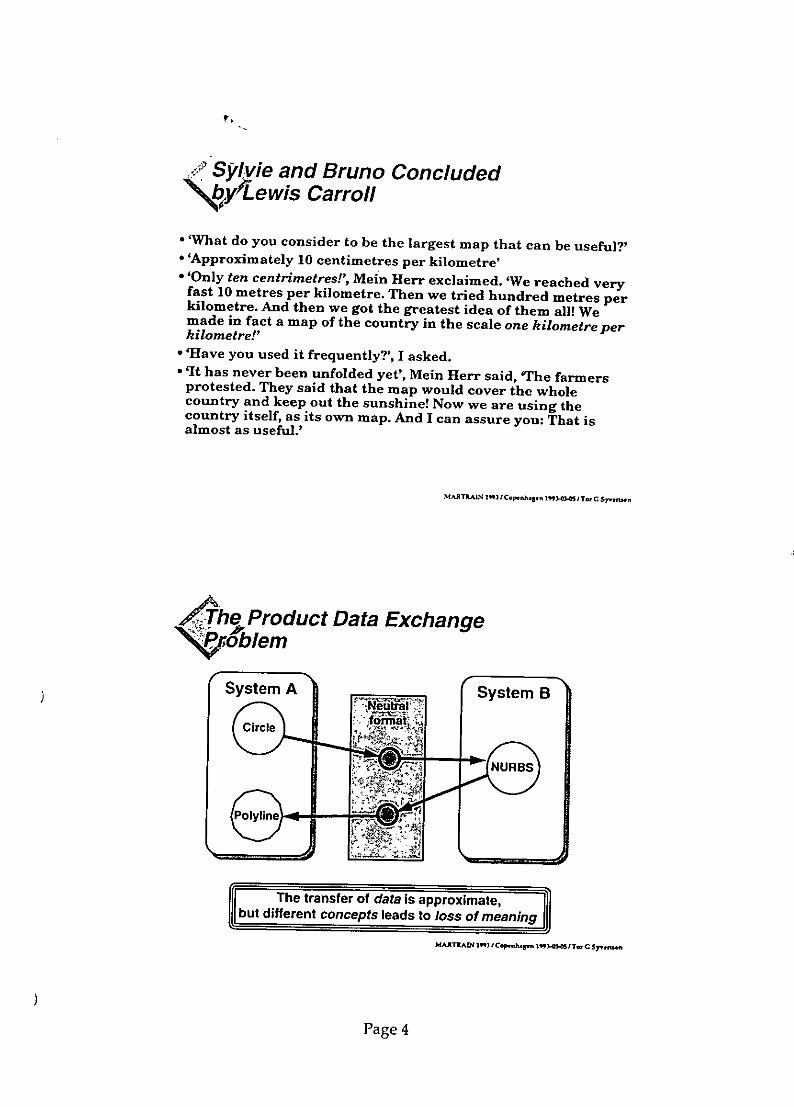
"I
Sylvie and Bruno Concludedby ewis Carroll
- 'What do you consider to be the largest map that can be useful?'*'Approximately 10 centimetres per kilometre'* 'Only ten centrimetres!', Mein Herr exclaimed. 'We reached veryfast 10 metres per kilometre. Then we tried hundred metres perkilometre. And then we got the greatest idea of them all! Wemade in fact a map of the country in the scale one kilometre perkilometre!'
* 'Have you used it frequently?', I asked.* qIt has never been unfolded yet', Mein Herr said, 'The farmersprotested. They said that the map would cover the wholecountry and keep out the sunshine! Now we are using thecountry itself, as its own map. And I can assure you: That isalmost as useful.'
MAR •TA• 1"3 r CenhJ Sn 1 ý I Trl t C 5 .•n
/The Product Data Exchange'NOblem
System A System B
The transfer of data is approximate,
but different concepts leads to loss of meaning
MARh fltIC.Ouýn l9,1436Twlh C S$ nn
Page 4

SS tandardization issues
4 Standardize the definition ofconcepts, not the representation
'6 Concepts are defined in terms ofbehavior, not in implementation
6 Concepts are expressed in avocabulary
6 A vocabulary is communicated by,symbols, syntax and semantics
MARTRAIN 3 1r Ccpenhmsen 1flflf I TnC Sy•rýn
43A0ata Model (OMG)
6 A set of primitive TYPES6 Mechanisms for defining NEW
TYPES (Abstract Data Types)6 Mechanisms to create, manipulate
and delete INSTANCES (objects) ofthese types
6 A LANGUAGE (verbal or graphical)to express the concepts
6 Mechanisms forREPRESENTATION of the model
MARXýAIN h 1"31 C .,.hýarn I T- C Sy.vna
Page 5

Database vs Engineering World
DATABASE WORLD ENGINEERING WORLDComplete Incomplete
Consistent InconsistentNon-redundant Redundant
MARThAIN 1"31Cp has Irnc-0 CJTt SyGntrern
<j5>4,agement vs Engineering World
MANAGEMENT WORLD ENGINEERING WORLDFew classes Many classes
Many instances Few instancesSimple relationships Complex relationships
Simple transformations Complex transformationsShort transactions Long transactions
4A R ThAIN 9 l C/Copnh n "lO3.OI.0Tw C Syvýmf
Page 6

PD-Vol. 47-4 *
* Proceedings of the1992 Engineering Systems Design and Analysis Conference
Volume 4
COMPUTERS INENGINEERING
presented atTHE FIRST EUROPEAN JOINT CONFERENCE ONENGINEERING SYSTEMS DESIGN AND ANALYSISISTANBUL, TURKEYJUNE 29- JULY 3, 1992
sponsored byTHE PETROLEUM DIVISION, ASME
edited byM. M. TANIK, SOUTHERN METHODIST UNIVERSITYA. DOGAC, MIDDLE EAST TECHNICAL UNIVERSITYA. LEHMANN, UNIVERSITAT DER BIW MUNCHENA. E. HARMANCI, ISTANBUL TECHNICAL UNIVERSITY
THE AMERICAN SOCIETY OF MECHANICAL ENGINEERS345 East 47th Street 0 United Engineering Center U New York, N.Y. 10017

PD-Vol. 47-4, Engineering Systems Design and AnalysisVolume 4
ASME 1992
INFORMATION MODELING OF OFFSORE STRUCTURESUSING AN OBJECT-ORIENTED METHODOLOGY
Morten LovstadA.S. Veritas Research
Hovik, Norway
Tor G. SyvertsenNorwegian Institute of Technology
Trondheim, Norway
ABSTRACT model, which is essential for more efficient communication
between individuals and organizations involved in the productThis paper describes an example of how an integrated, development.
distributed environment for engineering information andknowledge can be developed and implemented using object- So far, computers have been used for engineeringoriented concepts. A prototype information model for an analysis, drafting, geometric modeling, management supportoffshore jacket type platform has been developed, and it clearly and different sorts of automated manufacturing, i.e. dispersedemonstrates the benefits and huge potential of using a functions. The automation of individual tisks has lead to theconsistent object-oriented approach for definition and imple- present state of -islands of automation', providing limitedmentation of integrated information environments for structural benefit on the overall engineering process. Recent develop-systems. It is also evident that the traditional techniques for ments in graphical user interfaces. database technologies.data modeling by computer experts will become obsolete when telecommunications and networking now constitute a foun-creative designers and engineers are given the tools for dation for integration of separate information systems. Thisintegrated product development and information modeling have the potential to make the computer an efficient tool forbased on object-oriented principles. communication, cooperation and organization of engineering
processes.INTRODUCTION Although most engineering information is createdby com-
Concurrent engineering (CE) is a novel paradigm that is puterized means, the exchange of information between in-,.ential for reduced lead time, improved product quality and dividuals and organizations is still mainly oral or paper-based.reduced total costs of a product. Computer-based methodolo- The information is imprinted on drawings, specifications andgies and tools may alleviate the transition from traditional product catalogues, and is transferred by means of paper orengineering practice, and the object-oriented approach of electronic devices. Technical information presented this wayinformation modeling facilitates the utilization of recent develop- has very scarce semantics embedded, hence human inter-menits in computer technology, pretation, based on symbolic understanding, is necessary
Concurrent engineering is a systematic approach to the before the information can be received and used. Moreover,
integrated, concurrent design of products and their related the operation of two information systems in parallel - oneprocesses, including manufacture and support. CE is an electronic and one paperbased - is a costly business which
constitute a barrier to efficient use of the new informationapproach where the developers consider all aspects of the technologies [Morgt].product life-cycle from conception through disposal. includingquality, cost, schedule, and user requirements. The purpose of information modeling is to create digital
Adoption of CE implies 'fundamental, wrenching, far- product models with sufficient embedded semantics to enable
reaching transformations", including radical improvements of data exchange directly between different software systems
engineering processes, computer-based support and the use without human interaction and interpretation. The human's roleof formal methods [Woo9OJ. The integration of computer-based can then be changed from being an interpreting link in thetools will in general require the establishment of an information information-chain into controlling processes between and within
framework capable of handling all product data and associated diverse computerized activities, as illustrated in Figure 1.engineering processes during the entire product life-cycle. Thiskind of information framework is denoted a digital product
123

Abstraction Mechanisms- [~7 5 -Any product can be regarded as a collection of related
- objects forming systems. It is important here that the meaningof things are not found in the things themselves, but in the trelationships to other things. Hence, it is the structure ofa
'.... -4model that brings meaning, not the attribute values attached to~,5~I] the structure. A product model is an abstract representation (or
-t i structure) of relevant aspects of the product. The definition ofa product model follows certain abstraction mechanismsFig. 1 Humans role in the information process [Gie8B]. adopted from systems theory, namely specialization, decom-position, and characterization. These mechanisms are ot-tho-gonai, spanning a modeling space. In addition, a fourth mecha-
PRINCIPLES OF INFORMATION MODEUING nism is required for keeping track of the product life-cycle.Mental product models The specialization mechanism is used to categorize theobjects and items involved, and making class hierarchies, or is-Before any new kind of thing can be made, there must a-kind-of relationships. Examples of categories are structuralexist an idea or a model of what ii is going to be. Consider for members, loads and responses. The category members mayinstance the design of an offshore platform. At the design be specialized in beam, columns, slabs, and so on. Specializ-,tage. no physical product exist, but a mental model of the aini neteeyueu rnil hc eae ifrn,ilatlorm is created and maintained in the brains of the mem- kinds of objects and thereby provides meaning or semantics.bers of the design team. No single member holds the entire No object is meaningful in itself, it has only meaning whenmodel in detail. so it is a distributed model. Drawings and related to other things. Specialization leads to hierarchies ofspecifications (on paper or electronic media) are used for object-classes where properties are propagated down thecommunication between the team members, and for documen- hircybyneitc.tation and long-time memory. Common symbols and ter- hircybyneitc.minology constitute -transfer protocols- that enable sharing of The decomposition/composition mechanism is used toknowledge (semantics and product logic) between the in- define hierarchical assemblies of a product from basic parts,dividual keepers of the distributed, mental product model. In i.e. create a composition of object instances or decompose aorder to maintain such a product model during the entire life- system into subsystems and pans. The mechanism make usecycle of the platform, one could imagine just to keep the of consists-of or is-pant-of relations. The structural designdesign, engineering and construction organization intact over process is mainly a top-down procedure which is continuedthe whole life-time, but this approach has obvious short- down to the level of standard parts or standard procedures,comings. What is usually done, is to keep a very detailed and where a simple reference to that standard is sufficient.huge amount of documentation, in an attempt to transfer the The characterization mechanism allows us to defineknowledge and product logic to a new group of people. As different aspect models of the samte system or product. Typicalexperience has shown, this is practically impossible due to the aspects are capacity, safety, strength, durability, costs.sparse amount of knowledge contained in the documentation, appearance. etc. Characterization or aspect definition will
Establishing a dligital product model require that Most Of determine the attributes and methods for the objects classes,the product logic (or knowledge) that has previously been by introducing aspect-oftype relations. Mnother term commonlystored in the brains of people, is transferred and stored in the used for this mechanism is association.,memory of computers.
The creator of the C++ programming language - BiameStroustrup - has remarked that any software program is amodel of a relevant partf of the real wvd~d The task of -prog-ramming the wortcr has two different aspects. The first is to 'make a conceptual model of concepts, properties, behaviors,roles and relationships. The second is to program the model,which in essence is to make a binary representation of theconceptual model, build a structure from the two symbols 0and 1 (any programming can be done in assembly language -but the efficiency is low). The major challenge is not inprogramming, but in modeling - to capture the concepts andrelationships of the real world objects and processes.
The conceptual modeling is based on a set of object- Fig. 2 The product life-cycle (Dala9].oriented principles and guidelines that have dlose correspon-dence to the detailed formalism required for implementation. Telf-yl iwitoue eeec rm o hThe traditional semantic gap between model and implemen- thme life-cythcl view introiducsal riefces oframeformto thetation is narrowed, making both System development and tm set owihteidvda icso nomto amainenane muh eaier.be related. Information evolves and iterates continuously asmainenane muh eaierseveral disciplines of design engineers, planners and process
- - operators perform their tasks (LIl9Oj. The number and charac-teristics of the stages in a product life-cycle depesnd on the
124

engineering processes involved to create, maintain, and INFORMATION MODEL OF A JACKET PLATFORMoperate the product. Most life-cycle models can, however, be A prototype information model for offshore structures hasrelated to the very basic model with four essential stages been developed by Det norske Veritas in order to investigateshown in Figure 2. The distinction between the planning and and illustrate some of the concepts for information modelinqreai•c'tion stages is probably the most significant in a product's and use of digital product models. Further. the model waslife-cycle from an information point of view. Moreover, the main developed to demonstrate how modem information technologyflow of information is clockwise around the circle, which means can improve the information handling, by providing faster,that each sector gets input from its predecessors, and deliver safer. and easier access to various kinds of information. Theoutputs to the following sector. focus has been put on communication and integration of
The orthogonality of the abstraction mechanisms allows processes and application software. Therefore, the use of
us to apply characterization to build aspect models of sub- standards for data representation and standard software com-
systems, or to apply composition I decomposition on aspect ponents has been an important part of the information model.
models. on different levels of abstraction. Finally. the staged ISO/STEP (Standard for the Exchange of Product Model Data)lifemcde could be addedl providing a mile-stone reference has been used as a basis for the product structure in order to
model. The orthogonality concept is illustrated in Figure 3. gain insight and experiences with STEP.
ABS" C0 )Problem Description
The main structure part (the subsystem) of a jacket-typeoil platform has been modeled in detail, while the superstruc-
.1. 44 ture and the engineering and furnishing systems are viewed atwptý •a coarse level of granularity. A CAD drawing of the jacket is
:n ~shown in Figure 4.The main aspects included in the total information model
are:Structural analysis throughout the entire design phase, as
well as later on in the product life-cycle.
. Geometry, principal dimensions and support for top-downMgeometrical design.
Fig. 3 Orthogonality of abstraction mechanisms [Syv901. - Documentation of inspection procedures and experienc-es.
Oblect Representation Regulations and standard rules for offshore structures.
Object-oriented programming has become a buzzword - Document handling.that largely applies to programming languages like Smalltalk Also risk and reliability aspects are identified for inclusion inand C++, and related styles of programming [Fen90]. We future versions of the model.prefer, however, to regard object-orientation as a methodologyor a paradigm for making formal models of real world objects. Various kinds of software application systems were
identified for integration into the information model, this inclu-An object is an abstract or concrete entity which posses des:
both properties and behavior. Data abstraction is the keyconcept for capturing such real world objects in the implemen- 5ESAM a general purpose system for structural analysis.tation space. A beam may for example have properties like based on the Finite Element Method. The system also
length, cross-section and weight, and it behaves by deflecting includes verification of a variety of codes for offshore
under an imposed load. Objects of the same kind belong to the structures.
same object class, and object-classes may be specialized by PROBAMN a system for risk and reliability analysis, based
forming sub-classes. The object-oriented approach of software on probabilistic reliability methods.
development is centered around identification and definition ofthe object classes which become templates for the creation of SPRINT; a database system for document registrationobjects. Moreover, the relationship of an object belonging to a and handling.certain class provides a meaning or definition of what theobject is. This meaning can not be conveyed by the aftribute EUCLID; a CAD system for 2D and 3D modeling.
values that simply determine the quantity of the object, not thequality. The quality is determined by the object's class mem- Most of the product structure is based on the semantics
bership(s). defined by the STEP, more specific the Application Reference
The object-oriented approach makes it easierto develop Model for Ship Structural Systems [GergO].
reliable and reusable software that support the modeling ofreal-world objects.
125

-- * PtLA trou INFORHAT IONnIODEL
Wit N OUi tS
- QODo 00000
" --
.g. 4 CAD-drawing of the "Veslefrikk" jacket.
System Architecture Fig. 5 The layout for the Platform Information Model [Luv9Oj.
A common or neutral syntax and semantics across theapplication boundaries is required for exchange of engineeringdata between different application systems. However, to beable to capture the product logic, the information modelinghave to embrace both the information structures and theassociated transformation processes of the product data. tu ' -
The platform information model (abbreviated PIM) wascreated around a conceptual framework, or what is called the rw! •6TIlogical model. This model captures the conceptual structure ofthe product, and constitutes a backbone for integration of a -
various aspect models, e.g. analysis, geometry, manufacturing,construction, and operation. Also, images derived directly fromthe aspect models. e.g. drawings and documents, are con-nected to the logical model, usually via the aspect models theyare derived from. ~-, Fig. 6 System and model integration in the PIM [LsvO0].
The various aspect models and images are connected to,p logical model via relational links. This way all the aspect supporting area. which are deployed in a top-down manner.
.,odels and images are defined in accordance with the logicalmodel. This provides a means for sharing knowledge between The document model collects a wide range of images/-the various application systems connected to the aspect presentations, preferably derived directly from the aspectmodels. The total information model, the PIM, is comprised by models. Documents include specifications, drawings, letters.the collections of the logical model, the aspect models, the drawings and documentation checklists. Various images can beimage models, and the relations connecting the various linked together via specified relations.models. Figure 5 shows the layout for the objects and relations The regulation model contains various regulations andforming the compound information model. standard procedures. Presently, this model is implemented by
Figure 6 gives a schematic illustration of the various scanned documents, but in the future an hypertext implemen-models and the application systems connected to the struc- tation is anticipated.tures. STEP is indicated used as a means for data transfer The inspection model will contain collections of reportsbetween some of the models, whereas the reliability aspect from onboard inspections. The inspection procedures could bemodel is included as a possible future extension to the model. included via connections to an expert system, perhaps also a
The logical model contains enough information to multi-media system.integrate the entire family of aspect models and their images. The operational experience model will comprise aWhile the detailed geometric descriptions of parts and as- collection of expert hypertext cards providing a basis for thesemblies are to be kept in the CAD-system, the logical model generation of an experience base.keep a reference geometry for defining the overall geometrical The analysis model contains collections of computationallayout of the jacket. This is a parameterized platform geometry models for structural analysis purpose. An procedure extractsto which the structural components are attached. The r.Jerence information from the logical model, and generates a com-,peometry makes it easy to make global geometric changes putational model. Certain information will have to be added towhile maintaining integrity and consistency. The reference the model, such as loads, handling of analysis results. etc.geometry is in fact functional requirements for height and load
126

Also, the analysis model can p,"ovide input to the logical model, The visualization of the logical structure on the screen ise.g. flags that trigger execution cf the redesign functions, given a layout of parts (implemented as objects) that resemble
Detailed geometrical models are contained within the the platform geometry, see Figure 7. This gives a naturalgeometry model. These models are to be defined in accor- interface to the contents of the database, promoting an efficientdance with the models for shape, geometry and topologr human-computer interaction. Each "box" visualizes an object.danced with ThE melsfortai reanshap, geometres adto ngy that is an instance of a class. The lines between the boxesdefined by STEP. Certain relations and procedures extractinginformation from the reference geometry connect the logical visualizes the various relations.model to the geometry model. The classes and the objects are defined by means of a
The various relation types that make connections graphical language, and an example of a library object con-between the aspect models, images and the logical model, taining cross-sectional data is shown in figure 8.provide access to all kinds of information connected to each The use of aggregate objects has been simulated bycomponent of the offshore platform. This way one can navi- having the aggregate to refer by pointers to its components,gate, and have access to, all the information contained within which are implemented as independent objects.the PIM via the logical model. Letting the various application systems work on and
within the same logical model allows sharing of knowledge.Implementation Issues This enables communication between for example a CAD
Three different aspects of implementation were address- system and a Finite Element Analyzing system. The integrityed: and consistency will be taken care of by the logical model.
Definition and internal representation of the database-LLa
" Communication with user (user interface).-
* Communication with other systems (export/import) ,,,,fl,
The PIM has been implemented in the object-based infor- , =" . rmation modeling system METIS [Met9O]. The system is a * ,F-. , I
genedric platform for modeling of engineering objects, products :,r •t=-'and proces ss. METIS was chosen because it has explicit ,n• ,.,support for many of the concepts that are important for defining .-and representing information and product models. The systemallows frankly definition of object classes and types, to create Fig. 8 Example library object [Lmv90].and combine objects in a top-down or bottom-up manner, toestablish uni- or bi-directional links between disparate aspectmodels, and to derive and connect image objects at desire. Connecting the aspect models and images to the logicalProcedures for traversal of aggregate models for collection or model via relational links ensures that they are all defined indistribution of properties are directly supported by the system. accordance with the logical model. This provides integrity andOf particular importance is the possibility to define relations consistency, as well as a means for sharing knowledgewithout constraints on type-attributes or connectivity, between the various application systems connected to the
METIS has a graphical, multi-window user interface, with aspect models.rich functions for navigation, viewing and manipulation of the The analysis models are specialized into Finite Elementdatabase by means of a graphical language. The system Analysis Model (FEAM). Finite Element Analysis Control (FEA-
'ws information structures, data, procedures and user C). and Finite Element Analysis Results (FEAR). The proced-.jrfaces to be modeled interactively. This way, the database ure that extracts information from the logical model, and
and the supporting information system is created automatically generates a computational model, has to be triggered manuallyduring the modeling process. This provides a means for from the menu chart in the user interface. It will create a STEPbridging the gap between modeling and implementation. Physical File containing a complete FEAM, but will not support
MOL'EL creation of the FEAC or FEAR model, which will have to beLOG-AL - created manually as files in the internal SESAM Interface File
format. Export to the SESAM system has been partly impleme-nted, while import from SESAM to PIM still is not ac-complished. Images (e.g. model plots) can be derived from the
E9 computational models.The complex network of links between the models
facilitates tracking of all relevant information for a specific partin the jacket via the logical model. This is accomplished by theroutines traversing the information structures formed by theobjects and the relations. This means that for instance theprocedure for listing the relevant codes for a part of the jacket,
___.___ starts on the selected part of the logical model and follows therelations down to the regulation model, and further down this
Fig. 7 Layout for the logical model (Lov9O]. information structure to the relevant codes.
127

For external communication, a translator to map between The most important experience gair.sd during identifyingPIM and a STEP physical file has been partly implemented. the classes, was the importance of specifying the problemThis translator uses a STEP-toolkit developed in the IntSyS area, the required functionality of the system to operate on theproject [Bli90] and generates an ASCII-file conforming with the model, and the classification criteria, i.e. the use of taxonomy.STEP standard. However, this file is not able to capture all the The logical model constitutes a flexible and extensibleinformation contained in PIM, since no functionality or behavior trameworj for integrating the various processes and applicationare captured by the product structures defined by STEP. systems use integ desig and a nayss s e of apprdcts
systems used in the design and analysis stage of a products
Neutral Format (STEP) life-cycle.
The scope of the STEP is exchange of product model Oblect Orientationdata, i.e. it provides a common syntax and semantics. Theapplication models provides detailed, but static definitions of a The use of a logical model serving as a logical backboneset of low-level entities (i.e. parts). Regarding standardization for various aspect models and images, is a rather newthe semantics of the product structures and the electronic approach which is still at its infancy. However, the concept
formats of the representations should be standardized. This will seems to provide a 'clean* and structured way of integratingpromote the communication and human understanding of various information processes. Moreover it provides a meansproduct engineering [UIl0]. for knowledge sharing. This way the compound information
model is regarded as collections of related objects formingSTEP has proved to be useful in establishing a common systems with complex interrelated behavior. In general, these
intax and semantics within the compound information model, objects should be allowed to evolve and change during the life-out it is not able to capture tI e product logic. Consequently. cycle of the product. This is in accordance with the object-this paper has focused on establishing a conceptual framework oriented approach for design and analysis. The informationproviding a means for capturing the logical structure of the logistics is included in the information model by integrating theproduct. The resulting logical model has been used to integrate information structures and the processes acting on and withinvarious aspect and image models. the structures. This is realized from the fact that the infor-
STEP does not support the whole product life-cycle, since mation logistic monitor the processes and their access to theno functionality or behavior are captured by the product information structures.structures defined by STEP. To do so, one have to establish The object-oriented approach for information modelingrelational structures. This require a wide range of relationship and implementation seems to be a promising candidate fortypes, especially user- defined relations identified by applying establishing comprehensive information models. This givesthe association mechanism. In particular, STEP does not explicit support for a client/server architecture, and providesupport the requirement definition stage in the life-cycle, since extensible and flexible information structures. STEP has takenthis require a top-down approach, while STEP, and the a very traditional approach in specifying product data represen-Application Reference Model for Ship Structures [Ger9O], tations (static files) Therefore the standard will probably notsupports a bottom-up approach for detailed product description gain the full advantages of the rapid emerging object-orientedat the stage between detailed design and building, technology.
However. STEP is anticipated to have a large impact on The theory and methodology for establishing compre-data exchange in the near future. The main applications is hensive, logical product structures is still not matured forprobably for data storage (archival) and transfer between industrial applications. The rapid development of object-disparate application programs. oriented technology gives clear indications that implementation
will be reduced to a minor problem in few years. Our experien-EXPERIENCES AND CONCLUSIONS ces indicate that the lack of proper information models andModeling Relations organizational development will become the main obstacles for
The experiences from the modeling of PIM show that utilizing the potential of this technology.
there is a need for a standardized semantics for the productstructure. Moreover, to support the whole life-cycle the Communication Levels
modeling should focus on functionality and behavior. To do so, To be able to capture the semantics as well as theone will have to use a wide range of relationship types. product logic, we believe that the total information modelTherefore, establishing relational structures is fundamental to should be based on a conceptual framework, or what has beenproduct modeling, since the relations describe the functionality called the logical model within this paper. This model consti-and the semantics of the product. Relational structures are tutes a backbone for integration of all the aspect and imagecreated by applying the association mechanism to the classes, models, and evolves during the life-cycle of the product.This mechanism is poorly supported by STEP at present, and Using neutral formats for data transfer between differentthis is probably the main reason why the product structures in computer systems provides a common syntax. However, thereSTEP is not able to capture the functionality and behavior of is no semantical interpretation offered by the present represen-the products. tation formats. This meaning that the systems will not be able
The use of digital product models require new, sophis- to exchange information, only static transferof data is possible.ticated medias for information navigation and retrieval of Now, if we are able to work out a common semantics for theinformation. In general, this will demand a wide range of user systems to use, we will have a more intelligent "conversation"environments as well as a variety of information structures. between the systems involved. This semantical understandingmust be built on a common definition of the entities we want
to represent. This definition must be independent of thedifferent ways of representing it.
128

Consequently, a common definition of the semantics will and structures at the occurrence level. New experiencesnhance the benefits we get from using computerized tools, gained at the occurrence level should in turn be passed as anhis benefit will be enlarged by letting the systems include the up-stream process, allowing this new information to be)glc of the things they are to work on and within. While the collected as an experience base for future use. Today theyntax clarifies how things are described, and the semantics down-stream process is mainly supported by means of human,hat things mean, including the logic gives us an under- interaction, in that this knowledge is stored as paper-basedtanding of why things are as they are, i.e. the logic should specifications and mental models' The up-stream process isidude both semantics, context and functionality. At present, also mainly based on human interaction, and will in manyo system is able to capture this logic completely. cases not be supported at all. Introducing digital product
The concept of the different communication levels models as the backbone for Information Resource Manage-.escribed is illustrated in Figure 9. ment, both the down-stream processes and the up-stream
processes may be supported.
Lvsof
LOGIC Sharin of KlIAOWAEDGTE
GNRC esg *sned stad __SFMAM1C Exchang of INFOOMATIC*4
SYNTAX Trase of DA.TA SPEacR A MID of 9.Kb
1g. 9 Communication levels [Syv90]. o0ccJRREnCa =S e~ WS•.IIpzJr
tbstractlon Levels Fig. 10 Abstraction levels (Syv9O].A product model must be capable of managing know-
•dge and experience at different levels of abstraction, and to REFERENCES-ansfer information between the levels. In STEP three levelsas been identified (Gie88J: [Bli90] P Blindheim. 'Finite Element Application Activities* Instance; each individual product, say a steel structure, is IntSys-STEP", Document presented at the sem-
an instance, and its product model at instance level inar STEP: Data Exchange and beyond in thecomprise all information particular for that structure, e.g. _ Maritime Industries. Det norske Veritas, Hovik.the jacket platform WVeslefrikkt. Norway, 1990.
* Specific, a family of similar (near identical) products share [Da189J S Dale and T G Syvertsen, * Technology forinformation at the specific level, e.g. design specifications better structural design". Technical Report STF71.for jacket type platforms. F89003, SINTEF. Trondheim. Norway. 1989.
[Fen90 G L Fenves, "Object-Oriented Programming for" Generic; the overall level containing general rules and Engineering Software Development% Engineering
Jesign basis pertinent at all structures of a kind, e.g. with Computers. Vol.6, 1990, pp. 1-15.framed steel structures. [Ger90] M Gerardi, "Application Reference Model for ShipWhile all information could, in principle, be described at Structural Systems% Working draft. STEP part
the instance level, logically there is often a large amount of 102, June 1990.both required functionality and design solutions which is equalfor a series of products. This can be described at the specific [Gie88] W Gieling, "GARM - General AEC Referencelevel. Similar, overall functional characteristics and design may Model'. Technical Report BI-88-150. TNO-IBBC,be given at the generic level. Delft, The Netherlands, October 1988.
it is. however, at the instance level the experiences that [Law90] K.H Law, T Barsalou and G Wiederhold, "Man-may apply to both the specific level and the generic level are agement of Complex Structural Engineeringgained. Therefore, if the product model is to be useful as an Objects in a Relational Framework', Engineeringinformation carrier throughout the life-cycle, the possibility of with ComputersVol. 6. 1990, pp. 91-92.passing information between these levels is essential. This (U1901 F Ullehagen.'METIS - Concepts, Methods andaspect must be taken into consideration during the conceptual Industrial Solutions". Preliminary document, Metisdefinition of the product model. The chosen approach should A.S, Horten. Norway, September 1990.support the concept of information distribution. [Lmv9O] M Levstad, "Product Models for Ship and Of-
Fig 10 illustrates the concept of a level discriminator, and fshore Structures", Master Thesis, Division ofadds the feature of passing knowledge as a down-stream Structural Engineering, The Norwegian Instituteprocess, from the generic abstraction level to the occurrence of Technology, Trondheim, Norway 1990.level. Information and knowledge already gained can be used2' generic level, which in turn will influence the processes
129

[MetSO0 Metis A.S, 'ME1 IS EDBS - Reference Manuals%,Metis A.S. Horten, Norway, 1990.
[Mul89] M Mullin, "Object Oriented Program Design WithExamples in C++'. Addison-Wesley, Reading.Massachusetts, 1989.
(Syv90j T G Syvertsen, "Sketches for the CAESAR pro-ject", A.S Veritas Research, Hovik, Norway,1990.
JVer90] "CAESAR - Ship Information Model', Technicalreport no. 90-2057. A.S Veritas Research, Hovik,Norway, November 1990.
(Woo90) J D Wood and R I Winner, "The Relationshipbetween CALS and Concurrent Engineering".IDA Paper P-2306, Institute for Defense Analysis,Alexandria, Virginia. 1990.
[Mor9i] Michael S Scott Morton (ed). "The Corporationsof the 1990s." Information technology and or-ganizational transformation- Oxford UniversityPress. New York, 1991.
130
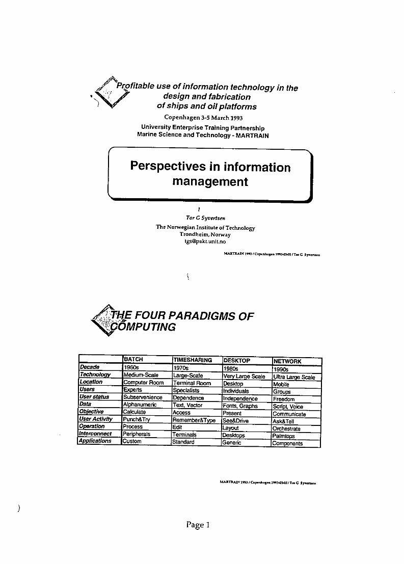
d7 tProfitable use of information technology in thedesign and fabrication
of ships and oil platformsCopenhagen 3-5 March 1993
University Enterprise Training PartnershipMarine Science and Technology - MARTRAIN
Perspectives in informationmanagement
Tor G Syvertsen
The Norwegian Institute of TechnologyTrondheim, Norway
MA•TRAIN 1I3 Ccpmahn 1Ca.flmo T C S nn,w
FOUR PARADIGMS OFNV 5OOMPUTING
'BATCH TIMESHARING IDESKTOP NETWORKDecade 1960s 1970s 1980s 1990sTechnol Medium-Scale e.Scale Very Lare Scale Ultra Larqe ScaleLocation Computer Room Terminal Room Desktop MobileUsers Experts q lndivduajs GrouUser status Subservenience Dependence Independence FreedomData Alphanumeric Text, Vector Fonts, Graphs Scr t, VoiceObjective Calculate Access Present CommunicateUserActivity Punch&Try Remember&Tvpe See&Drive Ask&Telloeration Process Edit Layout OrchestrateInterconnect Peripherals Terminals Desktops PalmtopsAplicatlons Custom Standard Generic Cornponents
PaARTeN 1l31Copn. •-g5n T., y.nr,
Page 1

Symposium on Building Systems Automation - IntegrationComputer Integration of the Building Industry
Dallas, Texas, June 10 - 12, 1992
The Building Industry~at a Crossroad -
Some Critical 'Issuesat the Threshold of the In formation Age
Tar Guttorm SyuertsenDivision of Structural Engineering
The Norwegian Institute of TechnologyN-7034 TRONDHEIM, Norway
Internet: [email protected]
0. INTRODUCTION
There is much turmoil under heaven, and we experience a strong turbulence on allthe political, economical and social arenas, at both the global and the local scales.This can be interpreted as omens of the emergence of a new kind of society.Of particular significance for trade and industry are three intertwined paradigmshifts') that are taking place:
1) The information technology is becoming a technology for communication.2) Organization and management are becoming a critical competitive factors.3) Information is taking over as primary resource, playing a role similar to
what energy has been for the *industrial era.These three key regions are mutually dependent, and the fundamental changesgoing on will no doubt have profound impacts on most social structures in the longterm. The actual time scale is not dlear, but it is momentous to have a dlearunderstanding of what is going on, to form a strategy for meeting the future, andto implement proper measures in due time.
1. THE NEW MEDIUM FOR COMMUNICATION (C&C)The Japanese electronics corporation NEC developed back in 1979 a strategy forwhat they denote C&C technology, where C&C stands for Computers & Com-munications. At that time only a few visionaries could point out the direction sodlearly as NEC did, but today the development trends have become evident to most
1) The term paradigm; means pattern or example, referring to the basic character-istics of a knowledgedomain. An example is the move from a ptolemaic, geocentric view of the universe with to theCopernican model to the planets orbiting the sun. These two different views could not coexist, theprevailing perceptions foundered, a new conception of the world emerged, and the seeds of science werelaid. The terms paradigm and paradigm shift were first used in this sense by Thomas Kuhn in the bookThe Structure of Scientific Revolution.

-2-
of us.
The table below summarizes the four different stages that the electronicinformation technology has undergone, and where the fourth stage has just begun.
The Four Paradigms of Computing
BATCH TIMESHARING DESKTOP NETWORK
DECADE 1960s 1970s 1980s 1990
TECHNOLOGY Medium-Scale Large-Scale Very Large Scale Ultra Large ScaleIntegration Integration
LOCATION Computer Room Terminal Room Desktop Mobile
USERS Experts Specialists Individuals Groups
USER STATUS Subservience Dependence Independence Freedom
DATA Alphanumeric Text, Vector Fonts, Graphs Script, Voice
OBJECTIVE Calculate Access Present Communicate
USER ACTIVITY Punch & Try Remember & See & Drive Ask & Tell(Submit) Type (Interact) (Point) (Delegate)
OPERATION Process Edit Layout Orchestrate
INTERCONNECT Peripherals Terminals Desktops Palmtops
APPUCATIONS Custom Standard Generic Components
LANGUAGES COBOL, PL/I, BASIC Pascal. C Object-orientedFORTRAN
(L G ToeD. Networked Cornputfr in the 199s. Scientfic American. September 1991)
The paradigms accidentally coincide with the decades; the desktop paradigm was, however,pioneered by Douglas C Engelbart in the late 60'ties, manufactured by IBM in 1981, andbrought to the people by Apple in 1984. From the table it becomes evident what the lastdecade has brought us; computers and software tools that enhance our individualcapabilities in doing the daily work like writing, drawing, calculations and so on. Wordprocessors, CAD, technical computations, databases, etc, are made easily available bypersonal computers and graphical user interfaces. This technology has already entailedprofound changes in the way work is organized; i e the horizontal integration where thefactual information actor (e g engineer or architect) herself handles tasks that previouslywere performed by assisting specialists like draftsmen, clerks or analysists who mastereda specialized field based on proficient skills in operating complicated tools like a draftingmachine, a typewriter or a finite element program.
Until now, the computer has been used either to replace routine work, or to enhance thecapabilities of individual knowledge workers like engineers, architects, researchers andwriters. The new paradigm of computing, based on networking, will enable anorganization to augment its capabilities and performance in a similar way. Some of thebasic characteristics of the new paradigm is as follows:
e The networked computer will enlarge the abilities and performance for groups andorganizations in a similar manner that the personal computer has enabled theindividuals.
* The electronic networks provide possibilities for acquiring information and solvingproblems in a new way, by broadcasting questions and problems and thereby gainingaccess to previously unknown or unaccessible knowledge sources.

-3-
* Distributed, multimedia operating systems enable the integration of infornalinfornation like speech, pictures and video with traditional, formalized data- andinformation types like numbers, text and structured data, thereby expanding the',communication bandwidth.
* Object-oriented information frameworks and meta-models give us a novelmedium for definition and sharing of knowledge about products and processes,where information and knowledge may be developed, cultivated and reused.
& The computers are becoming mobile, thus information and communication areavailable anywhere, everywhere, independent of time and space.
* Small and cheap electronic transponders can be attached as information carriersto any object we want current information about, providing a means for a true,distributed information base.
The existing paradigm is based on large, centralized computers for corporate tasks likeaccounting; and small, disconnected computers for individual tasks like word processingor drafting. The new paradigm is based on many computers, people and other resourceseffectively connected in a network enabling groups of persons and organizations toaugment their cooperative efforts.Electronic mail and conrerencing systems are in common use within the researchcommunity and at alert corporations, and new functionality is constantly added, likedecision support and coordination, including multimedia communication to support thesharing and cultivation of tacit knowledge.
3. EFFICIENT USE OF THE NEW TECHNVOLOGIES
A rule of thumb tells that th~e performance of computing equipment doubles while the pricehalves every two years. This trend has been stable over three decades, and is expected tocontinue into the next century. The figure shows the relation between a fixed amount ofcomputing power (say 100 MIPS) related to the cost of clerical manpower.The depicted development and thehuge investments made in infor- Relative cost of computing powermation technologies shouldpromise a significant productivity IDM
gain, but this has not occurred. laComprehensive research in USA as 1Amwell as i Europe, indicates that the 2investments in information tech-nologies have not entailed any jmmeasurable increase in efficiency,productivity or quality neither on Othe firm, industry, or national a0 2
level. 2W 101 M zZ
Surprising results from a large I =Io M eAmerican research program, con-ducted by MIT Sloan School ofManagement and with partici- Figure 1: Relative cost of computing powerpation from ten major amtericancorporations were reported in the book The Corporations of the 1990s - InformationTechnology and Organization Transformation. In the foreword of this book Lester CThin-ow, Dean of Sloan School of Management, points out:
"Organizations have invested enormous sums of money in the hardware and software of electronictechnologies. There are many examples of extraordinarily useful systems that now exist that could not haveexisted only a few years ago. Specific cases in which the new technologies have permitted huge increases

-4-
in output or decreases in cost can be cuted, but when it comes to the bottom line there is no clear evidencethat these new technologies have raised productivity or profitability.
"In fact, precisely the opposite is true. There is evidence, in the United States at least, that the investmentin the new technologies has coincided with lowered overall productivity and profitability. America'sproductivity growth rate is far below that of other countries whose investments in the new informationtechnologies have been much less, and those industries who have invested the most have some of the worstproductivity improvement performances in the United States - often negative. Sixnilar~v, profitability rateshave been falling in US industry in the last decade despite the new investments in thte new informationtechnologies.
* Out-of-date views of what information technologies are, and perhaps the word information itself, may liebehind what is a major economic mystery. Thinking of these new technologies as something that should beused to produce information have led them to be used wrongly.
* If one looks at the conventional explanations for the lack of payoff, they all point to the need for learninghow to change organizations faster than humans naturally wants to change. Analysis indicate that technologychange is simply moving much faster than humans arc changing, and as a consequence the benefits oftechnological change are not what they should be.
* Automate the office is a popular phrase, but to automate the office is to misuse the new informationtechnologies. The office in some very real sense needs to be reinvented and redesigned given what areradically new capabilities and needs. As MIT's Management of the 1990s Research Program has shown, justto automate what is today being done is grossly to misuse the potential of the new technologies. But nothingis more sensitive than changing today's office, with all of its inherited sociological relationships. Thoseskilled in organizational change know that satisfactory substitutes for today's relationships have to bedesigned into the new Systems if those working in our offices axe not to sabotage the potential of the newtechnologies. Judging by hardware and software investments, the American office has been automated, butthe productivity of white-collar office workers have fallen. Office workers have been added to theorganizations at a much faster rate than output is growing and are a major source of lower productivitygrowth and lower profitability" (my emphasizing).
The investigation indicates that there may be various reasons why the expected effects ofthe investments in information technologies have failed to appear. One reason may be thatthe effects can not be measured by the traditional, economic measures. Another reasonmay be that most companies in fact operate two information systems in parallel; theinformation is produced by means of computers, while the distribution (communication,archival, etc) still relies on the paper as the primary medium. The expenses bymaintaining the old system may outtancel the benefits of the new, digital system.Even totally electronic information systems may yield modest advantages if they only areimitations of the existing, manual and paperbased systems. What is essential is toconsider the entire information processes, and reshape them in a way where the potentialsof the new technologies can be really tapped.An example is transactions based on invoices, where an electronic equivalence of theinvoice (EDI) may speed up the transmission of the message, while the handling of theinvoice will remain unchanged (control that the goods is delivered according to the order,payment, bookkeeping, etc). A natural question may be why we have invoices at all? Whenpurchasing commodities in a shop, no invoice is issued - only a receipt, because paymentand goods delivery take place simultaneously. By electronic payment based on computer-readable coded information (e g bar-codes) on the goods, the invoice can be eliminated alsoin the delivery of ordered supplies. This kind of arrangement requires of course that thedata- and communication systems have embedded security and control mechanisms, butmore challenging is the development of a business culture based more on confidence thansuspicion between customer and supplier and between employers and employees in acompany.
4. RESPONSIVE INFORMATION AS A RESOURCE
The electronic information systems have to a large extent been imitations of the manualinformation processes based on paper as an information medium. Only a tiny fraction of

-5-
the new medium's capacities to represent has been utilized. A medium is used tocommunicate information between different systems (people or computers) holdingdifferent mdU:Pls, and the new medium is characterized by the flexibility, dynamics andresponsivity towards the user of the medium. A medium is the carrier of symbolsbetween the sender and receiver in a communication process, where effective communica-tion requires a common understanding of the syntax and semantics of the symbols. Theinterpretation of symbols is always done within a cultural framework, and the bodylanguage demonstrates how sharp the communication can be at the informal level(whereas the very formal communication via a database may be very fuzzy because thecontext is not shared between the sender and the receiver).
In a historical perspective have the symbolism been developed to match the medium (themedium and the symbols constitute an interface for communication between sender andreceiver):
" Clayboards (year 3000 BC): cuneiform writing was, the natural symbolism forimprinting of pins in wet clay.
* Papyrus (year 1000 BC); painted characters like the arabic or Japanese are naturalfor using a wet brush and ink on papyrus.
" The printing press (year 1500); Johann Gutenbergs invention of separated, moldedcharacters required a simple typography similar to the present one. The Venetianprinter Aldus Manutius invented this typography after years of struggle withimitations of the handwritten, monastery styles.
* Computers (year 1984): The Apple Macintosh represented the breakthrough for thefirst type of symbolism that were particularly developed to match the characteristicsof the computer as a medium. The icons are dynamic symbols that provide a responsewhen they are touched, by exploding into a document, visual feedback or movement.
The new medium is distinguished by the properties of being responsive, dynamic,flexible and plastic, and it may be used to simulate almost all other kinds of media.Until now, this incredible new medium has mainly been used to imitate a paperbasedsymbols like passive drawings, specifications and descriptions. These are based on two-dimensional projections of the world matching the capabilities of paper as a medium, andon a communication principle where the sender determines the information needs of thereceiver. Both these principles are absurd when considering the immense capabilities ofthe new medium for representation and conveyance of information and knowledge.
Moreover, the legal organization of the building process seems to be based on theassumption of the receiver being an idiot and/or a swindler so that everything has to bespecified down to the tiniest detail. A consequence is the ever increasing amount ofspecifications and documentation, and an information complexity that far surpasses thecomplexity of the actual product. The information process in the construction industry isdefinitely more adapted to lawyers than to contractors or workmen.
An evident dilemma is that the same documentation aims at serving several purposes withvarious need with respect to content and presentation. Organization, division of work andcontractual matters set forward different requirements for the documents involved:
" T)ransfer of knowledge; the builder, designers and planners have a comprehensionor a model of what the building is going to be, and produce a mapping or descriptionof this model in order to reproduce it in the perceptual domain of the contractor. Thiskind of communication may be significantly improved if the receiver of information candecide upon the amount and format of the information required to perform the task.
" Legal documnentation; the builder and his engaged consultants are imposedrequirements by the building authorities to provide legal and formal documentationthat the building is conforming to the prevailing regulations and rules.
* Basis for operations and maintenance; the documentation prepared for planning
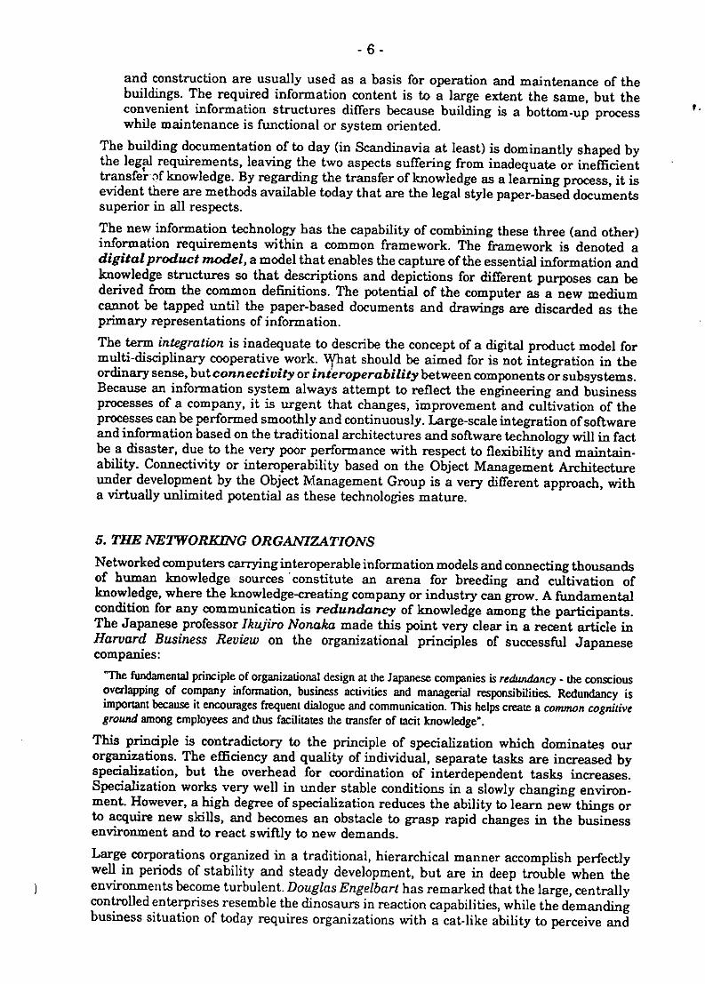
-6-
and construction are usually used as a basis for operation and maintenance of thebuildings. The required information content is to a large extent the same, but theconvenient information structures differs because building is a bottom-up process Vwhile maintenance is functional or system oriented.
The building documentation of to day (in Scandinavia at least) is dominantly shaped bythe legal requirements, leaving the two aspects suffering from inadequate or inefficienttransferoif knowledge. By regarding the transfer of knowledge as a learning process, it isevident there are methods available today that are the legal style paper-based documentssuperior in all respects.
The new information technology has the capability of combining these three (and other)information requirements within a common framework. The framework is denoted adigital prod act model, a model that enables the capture of the essential information andknowledge structures sa that descriptions and depictions for different purposes can bederived from the common definitions. The potential of the computer as a new mediumcannot be tapped until the paper-based documents and drawings are discarded as theprimary representations of information.The term integration is inadequate to describe the concept of a digital product model formulti-disciplinary cooperative work. What should be aimed for is not integration in theordinary sense, but connectivity or interoperability between components or subsystems.Because an information system always attempt to reflect the engineering and businessprocesses of a company, it is urgent that changes, improvement and cultivation of theprocesses can be performed smoothly and continuously. Large-scale integration of softwareand information based on the traditional architectures and software technology will in factbe a disaster, due to the very poor performance with respect to flexibility and maintain-ability. Connectivity or interoperability based on the Object Management Architectureunder development by the Object Management Group is a very different approach, witha virtually unlimited potential as these technologies mature.
5. THE NrETWORKING ORGANIZATIONS
Networked computers carrying interoperable information models and connecting thousandsof human knowledge sources 'constitute an arena for breeding and cultivation ofknowledge, where the knowledge-creating company or industry can grow. A fundamentalcondition for any communication is redundancy of knowledge among the participants.The Japanese professor Ikujiro Nonaka made this point very clear in a recent article inHarvard Business Review on the organizational principles of successful Japanesecompanies:
"The fundamental principle of organizational design at the Japanese companies is redundancy - the consciousoverlapping of company information, business activities and managerial responsibilities. Redundancy isimportant because it encourages frequent dialogue and communication. This helps create a common cognitiveground among employees and thus facilitates the transfer of tacit knowledge".
This principle is contradictory to the principle of specialization which dominates ourorganizations. The efficiency and quality of individual, separate tasks are increased byspecialization, but the overhead for coordination of interdependent tasks increases.Specialization works very well in under stable conditions in a slowly changing environ-ment. However, a high degree of specialization reduces the ability to learn new things orto acquire new skills, and becomes an obstacle to grasp rapid changes in the businessenvironment and to react swiftly to new demands.Large corporations organized in a traditional, hierarchical manner accomplish perfectlywell in periods of stability and steady development, but are in deep trouble when theenvironments become turbulent. Douglas Engelbart has remarked that the large, centrallycontrolled enterprises resemble the dinosaurs in reaction capabilities, while the demandingbusiness situation of today requires organizations with a cat-like ability to perceive and

-7-
react.
Within the single company theorganizational changes implies Cat or Dinosaur.more responsibility and authorityto the employees who are closest to a Sams the emnironment (Mlon)the customer or to the product, oUndenten todiwge(gy.
oiMakenthose cigeasajl j pa)and reward mechanisms based on ao %rw low wwork prooam "a t5performance more than behavior. epuing for ft nwa ww t(od
In the interplay between variouscompanies will the activedevelopment and use of knowledgenetworking based on the new com-munication technologies, enable rnnules to know ty were d•the building industry to turn the L & seLawtfragmentation into an advan- Figure 2: Organizational metaphorstage. Many, differentiated, smallcompanies networking efficiently will achieve a significantly better flexibility and reactioncapability than the large, homogenous giants. This kind of cooperation and partnershiprequire somewhat different business practices than are common today. Within theindustries of hard competition like automotive, civil aircraft or telecommunications, a newset of business practices and relationships is under development.The new kind of organizations has been described in this way:
"The capability-based environment is a multi-organizational, crossfunctional community that uses electronicinformation to design, sustain and manage work and to evolve its own capabilities to learn and to perform overtime. This is not a physical, not even formal, organizational entity, but a network of stakeholders defined byinterrelated valuegenerating activities toward common goals." (Quoted from Grenier and Metes: "EnterpriseNetworking - Working Together Apart")
The quoted statement expresses a radically new view of what an organization may becomein the not too far future. Enterprise Networking is the strategy, and CoordinationTechnology is the enabling foundation.
There are three elements in the new technology that have dominant importance for thedevelopment of the new organizations:
1) Mobility; hand-held, wireless networked computers provide access to information andknowledge sources from everywhere.
2) Bandwidth; multi-media technology facilitates an extremely rich communication byallowing informal information types like speech and video to be mixed with thetraditional text and data.
3) Responsivity; The object-oriented software technologies simplifies the utilization ofthe dynamic and responsive characteristics of the new medium, by encapsulating inobjects both the information and the environment needed to use and manipulate theinformation.
In the long-term range, and for the building industry as a whole, the employment ofinformation technologies is not a competitive factor, it is a necessity. Scott Morton statesit very clearly in the report on The Corporations of the 1990s:
"Benefits from information technologies often are not capturable by the organization making the investments;they end up in the consumer's hands. Competition does not allow a firm to keep the benefits; it becomes anecessity for doing business.Information technologies are used to respond to new demands that do not show up in current improvedeconomic returns: responding to new government regulations, adding significant new customer services, emc.Again, these are required for long-run viability.Information technologies do not provide sustainable competitive advantage. Rather, it is increasingly a

-8-
competitive necessity and/or a platform on which to base continuing innovations" (my emphasizing).
The benefits of increased quality and productivity during the enginepring and constructionof buildings, will in most cases end in the packets of the builder. Enterprises thatencompass the entire value chain can harvest far more than the actors in a traditional,separated building process. The incentives for effective use of the information technologiescould come from a redistribution of the benefits and profits;- where the partners arerewarded by their contribution of knowledge and skills to achieve the ultimate goals of thebuilder, and not by their mere production of paper.
6. THE NEW RESEARCH PARADIGM (MEETING THE FUTURE)It is evident that the future will appear quite different from today. It is also reason tobelieve that companies that do not succeed in transforming itself to meet the new situationwill fade away during this evolutionary process.A major complication for planning the future is that nobody can tell exactly what it willbe like, making long-term planning hard and uncertain. A reasonable strategy might beto create an organization that is capable of learning, to create new knowledge, and withinherent motive powers for continuous readjustment and actions; the cat-like organization.The backbone of this organization is skilful people with capabilities that no computer has;namely to ask the right questions, acquire the necessary information and make the correctdecisions. Efficient cooperative work involving many people and operating units requirea common perception of the goals, overlapping knowledge and information, socialconfidence and an appropniate coordination technology.At the global scale, a profound reshaping of entire industries are under way; withinaerospace, car industry, telecommunications, computers and electronics. The developmentof the new 777 aircraft at Boeing Commercial Airplane Group may serve as an example.The 777 is said to be the "first paperless airplane", with a 100% digital definition. AviationWeek & Space Technology reports:
"Boeing is developing the 777 transport in an atmosphere of sweeping changes in the way it designs and buildaircraft and in its corporate attitudes toward customers, suppliers and its own employees.The new umasport is coming to life in the midst of a corporate cultural change that is part technology, partconsciousnessraising and part evangelistic tenvor. It includes solemn pledges of quality, a bow toward Japanese-style management and a realization that teamwork in producing aircraft must be more than just a high-soundingconcepL.
Time wi] show how well Boeing will perform in the future. The building industry is inmany respects very different from the aircraft industry, and it would be neither wise norpossible to copy directly the way they are performing a profound change of the entirebusiness. However, lessons can be learned from the basic philosophy and the approachestaken in improvement of the coordination of numerous actors, activities andresources based on a common set of goals. This is a fundamental challenge also to thebuilding industry.
What distinguishes various enterprises is not what they are producing, but how they aredoing it. The working processes and procedures are cardinal, and a strategy forimprovement should focus on these. Because changes are steadily going on at a high paceand because knowledge is a crucial factor in facing the future, research and developmentare becoming even more important for the alert enterprise. The traditional R&D has,however, been relatively detached from the ongoing business, with marginal impact on theshort-term advancements of processes and products. A redefinition of research seems tobe appropriate, as proposed by Director John Seely Brown of the Xerox PARC:
"The most important invention that will come out of the corporate research lab in the future will be thecorporation itself. Redefinition of research is based on a set of new principles:
.Research on new work practices is as important as research on new producms

-9-
* Innovation is everywhere: the problem is learning from it.* Research can't just produce innovation; it must coproduce it.* The research department's ultimate innovation partner is the customer.
Besides improving the processes, Seely Brown paints out that innovation is foundeverywhere, the pro~blemn is to locate and understand them. A focal point here is thefeedback of experien6-ýs from construction, operation and maintenance, back to thedesigners and planners for improvement of technical solutions and working procedures.The new coordination technologies should be developed and applied to facilitate this kindof enterprise learning. Moreover, innovation should take place in cooperation betweenresearchers and practitioners, in order to facilitate the transfer of the fresh knowledge tothe application domain.
7. CRITICAL ISSUE S
At the threshold of the information age, there are some issues that deserve much moreattention than the transfer of data between different computer programs:
1) Rethink and redesign the entire building propess as essentially an informationprocess, employing the new information technologies to create new ways of working,not only imitating or automating the manual procedures.
2) Develop new ways for representation and conveyance of information andknowledge, adopted to the capabilities of the computer as a new medium. A crucialstep is to abandon the paper-imitated drawings and documents as the primaryinformation carriers.
3) Transform the building industry into a networked, networking community capableof creating and cultivating a digital knowledge repository that can augment thecapabilities of skiilful people.
4) Establish a new set of business practices that promote the efficient use of the newtechnologies throughout the industry, including the legal, regulatory andremuneration aspects.
5) Integra te research, development and education for the purpose of attractingbright, young people to create and deploy new kinds of knowledge and skills requiredto bootstrap the entire industry.
If these issues are addressed in a proper manner, the building industry may regain abelief in the words of Arnbroce Bierce:
'The future is the period of time in whichour affairs prosper, our friends are true, and happiness is assured."

- 10-
REFERENCES
Karen Wright: The Road to Global Village, Scientific American, March 1990, pp 57-66.Michael S Scott Morton (ed): The Corporation of the 1990s - Information Technolog'yand Organizational Transformation, Oxford University Press, New York 1990 (336pp)-Scientific American, September 1991, Special Issue on Communication, Computers andNetworks.Ikujiro Nonaka: The Knowledge-Creating Company, Harvard Business Review, Nov-Dec1991, pp 96-104.John Seely Brown: Research That Reinvents the Corporation, Harvard BusinessReview, Jan-Feb 1991, pp 102-111.Ray Grenier and George Metes: Enterprise Networking - Working Together Apart,Digital Press, 1992.Douglas C Engelbart: Knowledge-Domain Interoperability and an Open Hyper-document System, Proc Conference on Computer Supported Cooperative Work, LosAngeles, October 1990.
Thomas W Malone and Kevin Crowston: What is Coordination Theory and How CanIt Help Design Cooperative Work Systems, Proc Conference on Computer SupportedCooperative Work, Los Angeles, October 1990.Tor G Syvertsen: The Design Office of the Future, First International Symposium onBuilding Systems Automation - Integration, University of Wisconsin -Madison, June 1991.Object Management Group: Object Management Architecture Guide, OMG TCDocument 90.9.1, Framingham, MA, 1990.Tor G Syvertsen, Frank Lilehagen and Morten L.vstad: A Generic Object Model forEngineering Design, paper submitted for presentation at TOOLS Europe 92, Dortmund,March 30 - April 2, 1992.METIS: Information and Process Modeling Handbook, Metis A-S, Horten, 1992.Richard G O'Lone: 777Revolutionizes Boeing Aircraft Development Process, AviationWeek & Space Technology, June 3, 1991, pp 34-36.

PARTResearch Program on Applied Coordination Technology
University of Trondheim
PAKT is a five-year cross-disciplinary research program established in 1993.Founders of the program are Statoil, the Norwegian Telecom Research andthe University of Trondheim. More industrial partners are expected to jointhe program in the near future.
PART is intended to be an arena for creative cooperation between variousprofessionals from industry and academia, working out strategic solutions tourgent problems for industry and trade. The core activity is a doctorateprogram within a range of problems in applied coordination technology.
Coordination is an holistic approach to the management of) interdependencies between activities, actors, resources and responsibilities
in complex organisations striving to achieve a common sets of goals. A typicalexample is the development of offshore oil/gas fields.
Coordination -technology is the knowledge about methods, techniques andtools for coordination. Networked, multimedia computers are considered as anew medium for coordination, enabling improved coomunication across largeteams of people, and new ways of organizing the work.
Coordination technology comprises three basic components:
* Technology for information and communication
* The pro fessional content of meaning, related to engineering andother disciplines
* Organizational sociology joining people in work towards common) goals
PAKT puts the focus on problems, and strives to develop viable, holisticsolutions. Technology is a means, not a goal.

-2-
In the first phase, PART concentrates on engineering type of work, charac-terized by large projects involving many disciplines, with strong dependenciesbetween activities and actors, and relying on complex information andcommunication structures.
PAKT is not yet specified in detail, and still has ample room for involvementah'1 participation in developing the program. Industry partners are assumedto bring their own problems, and to organize a body for joint actions.
An important aspect of PAKT is to develop a novel concept for cross-disciplinary collaboration within the university. This assignment is itself acoordination problem, that cannot be solved within the traditional, academicways of work.
PAKT is developing a network of relations with faculty from variousdepartments of the university, and with professionals from industry, researchand other institutions. The professional network is based on personalrelationships and extended ruse of digital communication.
PAKT does also want to participate in the international community ofresearch and development in the variuos aspects of coordination technology,want to establish connections with universities and research institutesabroad.
Initially, PAKT is a five-year research program (1993-97), and the budget isexpected to reach'apprdxlimately NOK 10 mill per year (equivalent to USD 1.5mill).
,, Contact address: . -
Postal address: PAKT, N-7034 TRONDHEIM, Norway
Visiting address: Ovre Alle 11, Trondheim
Telephone: +47-759-6320, Telefax: +47-759-6330t:. Email: [email protected]
Preliminary / Tor G Syvertsen / 1993-02-01

Safety Docum'CentationA Strategic SolutionA "Living Safety Case" must form the basis of a submission to the respectiveregulatory body, whether it be HSE, NHl or HMIP. Data must be organised in a Partnermanageable form, making sure correct and up-to-date information is alwaysavailable. ProgrammeThe requirement to develop a systematic safety case for processing facilities raisesa number of problems - particularly for offshore installations, these include:
* Developing the content of the safety Cimage Corporation is a leadingcase. supplier of Technical Document Image
Management Systems ([DIMS). The* Integration of existing drawings ImageMastertand Document Man-
and documents into formal safety ager suite of products are designed forassessment, the capture, editing, maintenance,
management, storage and distribution* Managing and controlling the of high-volume technical documenta-
resulting documentation. tion. These products improve thequality of technical documents - and the
* Presentation to the regulatory body. operational efficiency and effectivenesswith which organisations manage them.
* Maintaining the quality of the safetycase throughout the operating life of Together we provide a potent blend ofthe facility. document management skills, and
integrated systems solutions that areNNC and Cimage Corporation offer an tailored to the requirements of theunparalleled service in establishing and corporate user and regulatory bodymaintaining a Safety Case. alike.
NNC, a member of the GEC group of Why now? In the light of the Cullencompanies, is one of the UK's leading Report, safety management systemsproject management and consultancy must provide an ongoing demonstra-organisations. Employing over 1500 tion of a "Living Safety Case". With astaff, 300 of which are employed in paper bound system, the collation andsafety and reliability work. This gives maintenance of this safety case presentsNNC the flexibility toprovide teams an enormous task for the fcility opera-dedicated to specific studies or much tor. By storing and relating theselarger detailed studies that may require records electronically, applying proc-project management or engineering esses and procedures for automaticinput in addition to safety assessment update and audit trail, the cost ofand their submission to the HSE and quality is significantly reduced.other regulatory bodies.
The Document Management Systems Company A member of the GEC group ol companies

When should the preparation of 9 Assessment of protection can offer the following benefits:the safety case begin? The earlier requirements to achieve thethe document capture process required level of perform- • Costbegins in the project life cycle, the ance or availability,
effective data capture,more complete will be the record,
collation and indexint eand the easier it will be to main- 0 Development of pragmatic and recommendationsand cost effecti;,e safety
ions.arguments to sab3fy licensing 2 Flexible implementation to
Many Petrochemical organisa- authority requirements. develop integrated systemat-tions are currently investigating These incle deterministic ic safety case documentationbo th "E lectronic D ocu m en t arg um e d ete ra in tiiManagement Systems" and arguments as well as quanti-reviewing their documentation tative assessment. a Quality control to BS 5750strategy with a view to safety". R Project management and 0 System maintenance toThese activities are often under- document control of overal ensure that the "Living
taken by different parts of thedouetonrlfoealorganisation with sparats osth safety case development to Safety Case" is sustainedbeneitsexpationwithsepara cosbi- meet HSE requirements. throughout the operating lifeing these two activities the costs Ciage provide completef the clity.are reduced and the benefits architecture, hardware inde- In summar the NCICiiageincreased.
pendent software solutions for partnership can provide youTechnical Document Image with a systematic solution to theDesign, fabrication and operator Management. With many instal- development and maintenance ofcontributing to the safety case by lations in the petrochei-cal, oil & safety case documentation. Thisthe addition of design, vendor gas, and nuclear markets, we can service combines documentand 'as-built' data. offer a proven track record of management and safety casemeeting the requirements of assessment and provides a costNNC is unique in offering not these exacting and heavily effe t on frosa coseonly detailed eniern xe- rgltdeffective
solut.ion for safety caseony etildengineering exper- regulated environments.The production.tise to design, build or refurbish Ciinage approach offers:process plant but also being ableto apply these technical disci- 2 An Open arcitectu-e productplines successfully within the that can make use of existingframework of an operation safety investments in computingcase. NNC has a trnk record of and networks, n NC ieproviding these services to B sNNC Limitedclients from the conceptual U A system that captures all KnutsfordIesign stage right through to fox-ns of documentation
Cheshirecommissionng and obtaining drawings, certificates, per- WA168 QZlicence to operate from the HSE. mits, reports, pictures, text in Tel: 0565 633800The NNC approach offers: a single, easily manageable2 Development of safety format.criteria against which to 2 A powerful document data- Iassess a facility, base that maintains the links = ...
and relationships between* Determining the functional documents to provide effi- Registered Office:
requirements of the compo- dent collation. Cimage Interational Limitednent systems including safety
Centennia l Courtmanagement systems and 0 A team of support consult- Easthampstead Roadprocedural controls, ants, having industry experi- Bracknell
ence, to develop systems to BerkshireHazard, reliabity and meet your requirements, R012 xAzhuman fctors assessments of integrate to existingplant, equipment and sys- line-of-business applications, Tel: 0344 860055ten-.s
and plan for future expan- Fax: 0344 861471sion. 1r8(!Mastr is a regisbered trademark of OmageCorporation. Cirngeýr and 'he C~nage logo...e
* Perform ing specific subsidi- tatar of Citniagi: Cr~rI{ lg r
a-ry studies such as fire risk T1ogether by providing the * To
'; l ""analysis or escape and evacu- means, the methodology and theation studies.
manpower in one package we

',. Aker Engineering
Troll Phase I
Production K >
Platform
PROJECT DESCRIPTION
Operator A/S Norske Shell(Development Phase) .-M'Statoil (Operator Phase) :"
Location Norwegian Block 31/6Platform Type PDQ concrete GBSWater Depth 303 metersCapacity 84 million m3 gas/dayNo. of Wells 40StartEngineering Primo 1991Tow Out - Mid 1995Onstream : October 1996. "': :
PROJECT SCOPE OF WORK tender/contract packages for Living Quarters and Flare.
Aker Engineering's responsibility also includes theThe scope of work comprises the complete engineering " interfaces towards the GBS (gravity base structure),and procurement sen'ices for the following three.stages: Drilling Modules and Living Quarters.;': Stage I Pre-engineering(14/1/91 - 13/10/91)
)- Stage II Detail Engineering (14/10/91 - 31/3/93) DESIGN CHALLENGESStage III : Follow-on Engineering (1/4/93 -31/3/94,
Norske Shell option) The technology as such for the Troll Platform is knownand proven through Aker Engineering's recent projects.
OBJECTIVE OF PRE-ENGINEERING However, the size of the platform and future operation is
beyond earlier demands. Some of the biggest designTo develop the design to a level where the concept can be challenges are:firn and fixed for future implementation into the Detail > 303 meters water depth, structural behavior hnd aEfigineering stage. fatigue life of 50 years.
Material specification of pipes and process equipmentOBJECTIVE OF DETAIL ENGINEERING for 50 years lifetime and extreme high pressure gas.
Operation and Maintenance demands for low manningTo complete th e detail design of the Tbthides s that and 50 years operation.contracts for deck fabrication, hook-up, marine transporta- . Continuous export of gas to the onshore plant throughtion andcommissioning can be awarded and then com- two 36" pipes, 84 million m, gas/day.pleted on time and. within the budget. -- Operation monitoring and control from a common
The work includes procurement services related to all onshore and offshore control room located onshore,equipment and materials, and also the preparation of 54 kilometers apart.
)inAker EngineeringHaldOff*ce Fjordall6en16 Tjuvholmen, N-0250Oslo, Norway Tel.:(472)945000 Telex:7944akengt Telefax:(472) 94 5357
Bergen London Aberdee.nAker Engineering Bergen a.s Aker Engineering pil . 1cer Engineering plcSandslimarka 251, P.O.Box1 Bedford House - ½ North Silver Street
N-5049 Sandsli, Norway 69 79 Fulham High Street GB-A-±:deenAB . IRL, ScotlandTel.: (47 5) 22 41 00 GB-London SW6 3JQ, England Te: (44 2241646 187Telex: 40 915 aeb n Tel.: (44 71) 371 9755 Telex: 537 180
Telefax: (47 5) 22 4105 Telex: 537180 T1-a-: (44 224) 646 230.Telefax: (44 71) 371 7870
Stavang"e HoustonAker Engineering a-s Newcastle Aker Omega Inc.
Badehusgt. 39 Aker Engineering pic 757 Kalv FreewayStromsteinen, P.O. Box 589 Unit 1I, Silver [Link Business Park Suite 1300 4N-4001 Stavanger, Norway GB-Tyne and Wear NE28 9ND, England liIs:-on, Texas 77079, USA
Tel.: (47 4) 89 80 00 Tel.: (44 91) 295 4341 Tel.: (713) 570 111Telex: 30 350 aes n Telex: 537180 Telex: 6568507
Telefax: (47 4) 53 02 40 Telefax: (44 91) 295 4344 ½eAefax: (713) 531 9306
In addition, Aker Engineering is represented in Canada and Australia.