
PROFILE AND LONGITUDINAL CORRECTIONS ON ...
25
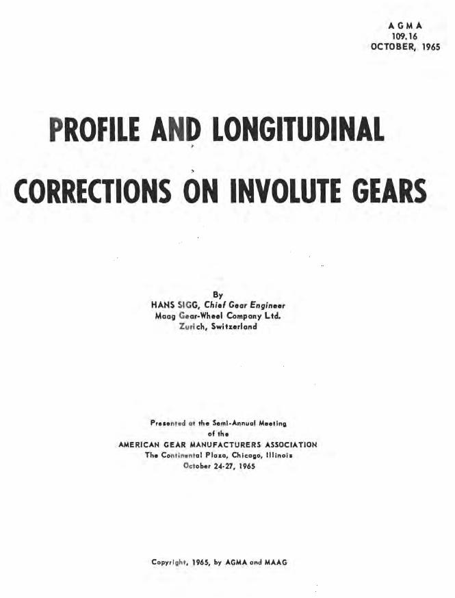
AGMA 109.16 OCTOBER, 1965 P ROFILE AND LONGITUDINAL CORRECTIONS ON INVOLUTE GEARS By HAHS SIGG, Chief Gear Engineer Maag Ge ar-Wheel Company Ltd. Zuri ch, Swlturland Pr ... nt.d at the Seml·Annual M •• tlng of the AMERICAN GEAR MANUFACTURERS ASSOCIATION Th. Co ntln.nt al Plaza, Chicago, illinois Oct ober 24·27, 1965 Copyr ight , 1965, by AGMA and MAAG
-
Upload
khangminh22 -
Category
Documents
-
view
0 -
download
0
Transcript of PROFILE AND LONGITUDINAL CORRECTIONS ON ...
AGMA 109.16
OCTOBER, 1965
PROFILE AND LONGITUDINAL
CORRECTIONS ON INVOLUTE GEARS
By HAHS SIGG, Chief Gear Engineer Maag Gear-Wheel Company Ltd.
Zuri ch, Swlturland
Pr ... nt.d at the Seml·Annual M •• tlng
of the
AMERICAN GEAR MANUFACTURERS ASSOCIATION
Th. Contln.ntal Plaza, Chicago, illinois
October 24·27, 1965
Copyr ight , 1965, by AGMA and MAAG

TABL E OF CONTENTS
Page
1. BASIC CONSIDERATIONS......... . ................................................................ 1
2. TOOTH LOADING CHARACTERISTICS ON TRUE-INVOLUTE SPUR GEARS.............................. 1
3. PREVENTION OF ENGAGEMENT SHOCKS. . . . . . . . • . . . . . . . • . . . . . . . . . . . . . . . . . • • • . • • . • . . . . . . • • . . . • . • • •. 2
4. PURPOSE AND PRINCIPLES OF PROFILE CORRECTION............................................. 2
5. RECOMMENDATIONS FOR THE PRACTICAL APPLICATION OF PROFILE CORRECTION ON SPUR AND HELICAL GEARS. . . . . . . . . . . . . . . . . . . . . . . . • . • . . . • . . . . . . • . . . • . • . • • • • • • . . • . • • • • . . • • . • . .• 3
6. FACTORS INFLUENCING THE LOAD DISTRIBUTION ACROSS THE F ACE OF A GEAR. • . • . • • . • • • • . . • • • •. 4
7. RECOMMENDATIONS FOR THE PRACTICAL APPLICATION OF LONGITUDINAL CORRECTION ON SPUR AND HELICAL GEARS .....•••..•......••••.•............•..••.•••.•••••.••. 4
FIELD EXP ERIENCE • . . . . . . . . • . . . . . . . . • • • • . . . . . . • . . • • . • • • . . . • • • • • . . . • . . . . . • • . • . . • • . • • • • • • • • • • • • • •• 6

Introduction Experiments on loaded gear drives show that as tooth
pairs move into and out of the field of mesh, shocks arise which cause f1uctuatiun '> ;i. angular velocities. Such shocks would occur even in perfectly accurately made gears, for they are partly due to the elastic deflec-. cion of the teeth. The strength of the shocks is dependent on the actual load being transmitted, and on the accuracy both of the teeth and of the mutual location of the gears in their housing. Other factors such <is pitch line velocity, the moment of inertia of the gears, the surface quality of the flanks, and lubrication etc., will also exert some influence.
These fluctuations of the gears produce noise by inducing vibrations in the gears themselves but also in the shafts and housing.
When gear manufacture was still in its infancy, the general aim was r.o produce teeth as near to the theoretical form as possible. It was not until demands for higher speeds and loading, together with qui eter running, became really acute, that the pro,spect of les sening engagement shock s by way of profile correction (tip and root relief) was entertained. As soon as the grinding of hardened gears was introduced, still higher specific loads could be transmitted which made the application of profile corrections even a necessity.
But with the increase in transmission loads, longitudinal corrections (or crowning) gained in significance also. As will be explained later in more detail, well designed crowning in connection with helical gears can also contribute to a reduction of engagement shocks, although the main object of crowning is to attain uniform load distribution across the facewidth under a given load; in other words, to counteract those various influences which are alien to good tooth bearing conditions.
Sc the considerations governing the application of the two types of flank correction - profile or longitudinal -are different. And for this reason they will be dealt with separately in this paper.
The actual degree of correction necessary, whether it is tip, root or end relief, is generally relatively small -usually between about 3 tenthousandths and 1 thousandth '
of an inch. But in spite of being so small, these corrections improve the load carrying capacity of a given gearing appreciably 1 providing they are designed and applied properly. However, if a tooth correction is to increase load capacity, it is only logical that a certain minimum manufacturing accuracy must be assured. In a case where tooth errers verge on the profile correction in order of magnirude, an improvement of the meshing conditions would be in doubt; particularly if error and corrections are additive.
It may generally be claimed that the certainty of improved loading capacity by way of profile and longitudinal corrections is only present if tooth errors are less in magnitude than the degree of correction.
The reconunendations made in this paper are based almost exclusively upon experience gained from harde~ and ground single helical gears. The tooth accuracy ~. ground tDothings corresponds to an AGMA quality 14 to 15. The profile accuracy, however, is even of a better quality.
1. Basic Considerations
A gear tooth moves into the field of mesh with such a high speed, that the nature of its load take-over will have the character of a damped vibration. In spur gears, the number of teeth carrying the load changes from two to one and back to two, which makes the elastic reaction even more complicated. In helical gears there are more tooth pairs in contact and the effect of the changing
number is less acute, although the situation is basically the same. For identical load, speed and tooth accuracy, corrections may be smaller on helical teeth than on spur 1 teeth. A further consideration is that a helical tooth does not make contact immediately with its full facewidth. The load is taken up first a~ the leading end of the helix, and spreads across the whole tooth gradually (Fig. 1). For this reason, a longitudinal correction (crowning or end relief)will also be effective in avoiding engagement shocks. In the following we shall examine the conditions prevailing in meshing spur gears, from th,. purely static point of view. It must be kept in mind d )) h
.. ~ t <; term engagement shock" refers to the dynamic process of meshing, and that the actual force will exceed the theoretic, static value, and assume a vibrational form governed by the speed and inertia of the gears.
2. Tooth Loading Characteristics on True-Involute Spur Gears
When spur gears mesh, contact is made by one pai ( \] and two pairs of teeth alternately. Taking the line 0'fL' action for an abscissa, as in Fig. 2, we can represent the force on the tooth at any point along the path of contact AD by an ordinate perpendicular to this axis. Two pairs of teeth make contact over the portions AB and CD, one pair only over the portion BC. The actual lengths of these paths are given by the gear dimensions, AC and BD being equal to the base pitch. For absolutely accurate, non-elastic gears, the load in the double contact regions would be exactly half of that in the single contact region; this is shown by curve AFGHIKLD. Due to surface deformation at the points of tooth contact, and to shear and bending deflection of the teeth themsel ves, th e division of load alters. From calculations one obtains a force curve AMNHIOPD. Roughly spea~ \ ing, engagement starts at A with 40% load, rising to 6~ at the point of transition from two-tooth contact to onetooth. After carrying 100% load alone over the central

)
gion, the receding tooth pair IS attributed 60%, sinking o 40% again on moving out of the field of mesh.
3. Preventing Engagement Shocks
As soon as the teeth under consideration have some sort of error, the loading characteristic will be different again; especially since gear teeth are comparatively stiff, and even slight errors have a great effect. .Of particular interest in our present investigation is the rotation of one gear relative to the other as a result of the elastic deflection of the te-!th. We can express this rotation as a displacement Os along the line of action (see Fig. 3). Its value for spur gears would be: 2
Os = approx. 5 x 10- 3 Wg in tenthousandths of an inch (Equation 1)
where Wg = the normal force along the line of action in lbs/in.
At the moment of moving into engagement, a driven tooth ZgO will find its mating profile shifted along the line of action by the stated amount Os in accordance with Fig. 3; this is the result of the elastic deflection of the tooth pair Z gland Z p 1 already in contact. Such lack
f correlation will lead to engagement shocks. As already mentioned. tooth errors can ha ve a similar effec t, since they al~() represent contact point displaceme nt.
Before devices for grinding flank corrections were incorporated in MAAG machines, the following practices were employed to aid the situation when manufacturing high power, high speed gears:
a) Close tolerances, particularly for profile form and ad; acen t pitch
b) Highest possible transverse contact ratio (one such measure was the introduction of addendum modification, based on a 15° cutter pressure angle - known since 1908 as MAAG-toothing)
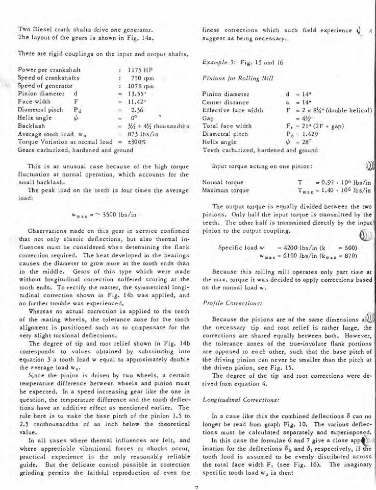
c) Slightly longer base pitch for the driving teeth as compared to the driven teeth, as shown in Fig. 4.
Provided that the difference between the base pitches of the driving and driven gears is greater than the sum of all errors and deflections, the tooth tip of the dri ven gear sweeps into the field of engagement without making contact. The load is subsequently taken up by this tooth gradually. Naturally the difference must not
be too great, or the ratio of the base circle diameters will no longer agree with the transmission ratio, an d new speed flucruations will be induced in frequency with the consecutive tooth engagement. In practice a base pitch
. fference of maximum 1.5 ten thousandths may be Howed.
By using helical gears with adequate overlap ratio (say between 3 and 4), the influence of tooth errors, especially of profile errors is less felt. There is also
2
less tendency for base pi tch differences to cause speed fluctuation.
4. Purpou and Principles of Profile Correction
To avoid shocks as gear teeth enter and leave the field of engagement, the flank profile can be eased back locally over a suitable distance - in the regions of the tip and root on the pinion for instance, familiar to all as "tip and root relief". Nowadays the form and degree of such corrections can be controlled accurlttely on MAAG grinding machines, and moreover the relieved areas can be blended smoothly into the remaining trueinvolute areas."
Various aspects dictate the character of the correction to be made; and those for spur gears differ from those for helical gears, so that different sets of corrective principles evolve. The final verdict concerning the worth of a given correction can only be passed on the strength of practical results.
To examine the problem as presented by spur gears, we shall refer again to the diagram of load in Fig. 2. We see that on true involute flanks, quite apart from initial and final contact in A and D, there is an abrupt change in loading at the change points Band C, where the load is suddenly transferred from two teeth to one tooth alone and vice versa. Since this can excite vibrations, such shocks must be suppressed as far as possible. In Fig. Sb an assumed specific loading is delineated, which should afford some success in this respect.
Neglecting manufacturing errors for the moment, we are faced with the question: What exact form must the correction take, in order to make the force of tooth contact follow the graph AHID in Fig. Sb instead of the graph AMNHIOPD which would apply if the flanks are not corrected?
In Fig. 5a the tip of a driven tooth is just making initial contact in A. Another tooth pair already makes contact in C. JUSt before point C, the full load is carried by the one tooth pair, causing the point of contact to be displaced along the line of action by the amount Os as per equation 1. If the newly contacting tooth tip is left uncorrected, the tooth would immediately take up a load represented in Fig. Sb by the point M. By easing back the profile of the said tip an amount equal to os, the load is reduced as desired from M to zero. The relief must finish at contact point Bl. Field R 1 in Fig. Sb represents the actual load of which the newly concacting tooth pair is relieved. Since the total load must remain unchanged, the preceding tooth pair already in contact is subjected to a correspondingly higher load, represented by field E 1. The appropriate geometric relief is plotted to an enlarged scale along the line of action in Fig. Sc, giving a diagram comparable to that obtained froril a tooth profile recording instrument.

On the tooth tip itself the correction will appear as
shown, highly enlarged, in Fig. Sa. By easing back the
tip of the receding, driving tooth tip, the load on the
latter IS reduced in a like manner as it moves out of
mesh. Applying practically the same geometric tip relief, we achieve a load reduction R2 and a load in-
. crease E 2. It is by such tip corrections on driving and
driven flanks that the contact forces are made to follow
the graph AHID of Fig. 5b. As can be seen, there are no abrupt load changes. Along the path Bl C2 transmission takes place via true-involute flanks. Distance BIC2 is equal to the base pitch. Based on these obs~rvations we arrive at the following general rules for determining
suitable involute corrections on spur gears:
a) Along the path of contact, a distance equal to the base pitch should be left void of any correction; and the correction should extend to both sides over more or less equal distances.
b) The correction can be applied to both gears in the form of tip relief, or to one gear alone in the form of tip and root relief. If tip and root relief is ap
plied to both gears, the amounts are simply addi
tive, which means that the individual corrections
on each gear are half the total amount. This
method is already practised in certain cases, and
often brings advantages from the point of view of
manufacture. c) The degree of correction will depend on the
specific tooth loading w g and the accuracy of the gears. For perfectly accurate gears the minimum degree would theoretically be equal to Os as per
equation I.
5. Recommendations for the Practical App licat ion of
Profile Correction on Spu r and Helical Gears
Profile and longitudinal corrections are genenilly only applied to one gear of a pair; to the pinion, that is, in the form of tip and root relief - and possible crowning. We differentiate between the profile corrections for driving and driven flanks. Along the path of contact, a distance equal to one transverse base pitch will almost invariably be left without correction. Similarly a certain
stretch of the facewidth will be left free from longitu
dinal correction. From the manufacturing aspect, this
practice has the important advantage of always leaving
a chance to measure directly the two most important
dimensions: the base pitch and the helix angle. From the operational aspect, it ensures that the tooth contact conditions of spur gears will still be kinematically correct also under light loads, since the transverse con
tact ratio is at least equal to 1. Helical gears with adequate overlap ratio are somewhat less sensitive in this respect, as correct kinematic transmission is guaranteed by the effect of the helix. In cases where
the specific tooth load is relatively high the tooth size this rule may be relaxed,
involute portion along the path of contact
In relation " ,I
and the true-
made shorter.
In extreme cases, as for example in aircraft gears, the
profile corrections may even extend along the entire tooth flank in order to ensure a smooth blending in of the corrections. 3
To make things easier for acceptance tests after manufacture, it is advisable to specify tolerance limits for the correction. The tolerance field will be positioned such that a deviation can only have a lessening effect on engagement shocks. For driving and driven
gears, then, the fields will lie in opposite directions, in
support of the previously described principle of decreasing the driven gear base pitch relative to that of the
driving gear. Taking the general case of a corrected pinion, of the ...
accuracy grade customary in ground gears, typical pro- .1 file diagrams, as recorded on the involute tester, are shown in Fig. 7 and Fig. 8. These diagrams refer to cases where the thermal influence is not large enough
as to require additional corrections. To attain a smoother profile form by lengthening the
the root relief slightly, the tip relief would have to be
shortened. This measure should only be resorted to if
root corrections are exceptionally short, as is the ca~~,,\,
with fine-pitched gears. \IJ.),
Degree 0/ Correction lor Spur Gears (Equation 3)
w == peripheral unit load in Ibs per one inch of face
width t-. = corrections in ten thousandths of an inch
At first point of tooth contact:
lower tol erance I imi t upper tolerance limit
At last poin t of tooth con tact:
lower tolerance limit upper tolerance limit
t. 1u = 3 + 3.5 w x 1O-3~ t.l0 = 6 + 3.5 w x 10- 3
t. 2u = 0 + 3.5 w x 10- 3 A -3 u20 = 3 + 3.5 w x 10
Degree 0/ Correction lor Helical Gears (Equation 4)
At first point of tooth contact:
lower tolerance limit
upper tolerance limi t
At last point of tooth contact:
lower tolerance limit
upper tolerance limit
-3 t. 1u =2+2.8wxI0 -3 t. 1o ",5+2.8wxI0
-3 t.2u = 0 + 2.8 w x 10
-3 t. 2o '" 3 + 2.8 w x 10

It is known that with high power high speed gears the nion will gain a higher average temperature than the
gear. This results in a difference in base pitch:
~Pb = Pb . ~ () • 0< (Equa tion 5)
~a Temperature diffe rence pinion/gear Thermal expansion coefficient
Corresponding corrections are made by changing the inclination of the tolerance zone of the unco rrec ted involute section BC, i.e. by correcting the base pitch of the pinion. '
In a speed reduction gear a pinion temperature h igher than at the gear produces a larger base pitch in the driving member. As described in section 3 and illustrated by Fig. 4 this effect helps, up to a cereain point, in reduc ing tooth en gage men t shoe k.
If the temperature difference is of significance, the base pitch difference must be reduced to an acc e ptable value. This corrective measure imposed on the pinion profile diagram has the effect of lifting point C in Fig. 7.
In a speed increasing gear the situation is reversed. It is the dri ven member (pinion) attaining a larger temperature and base pitch. This effect, like the tooth de flection, tends to increase the tooth engagement shock
ig. 3). In order to compensate this temperature in-uence, the tolerance zone BC on Fig. 8 is given a
different inclination again by lifting point C, which is equivalent to reducing the pinion base pitch. An example of such a case is illustrated by Fig. 14b.
For such cases where the average pinion temperature is larger than the gear temperature, the following should be noted:
In a ,reduction gear the effects of tooth deflection and temperature difference tend to compensate each other.
_ But with a speed increasing gear these two effects are additive. This means that the resultant base pitch correction in a speed increasing gear is larger than in a reducti on gear.
6. Factors Influencing the Loa d Distribution Acros s the Face of a Gear
Starting from an accurate gear which show s abso lu tely even load marking across the face width in the unloaded and cold condition we find that the load distribution wi ll not be uniform under service conditions. There are a number of factors responsible for this, which must be kept in mind when designing tooth corrections:
Every pinion under load suffers a certain amount of a stic deformation. The cylindrically shaped pinion
body bends and twists under the tooth load. Sh ear deflections are also present, but they are small and can be neglected.
4
In a gear which operates at high peripheral speed. it IS necessary to check on possible deflections due to centrifugal forces. Depending on the shape and design of the gear body, the toothed area might acquire a slight barrel or concave shape.
There is also a (hermal influence to be considered. The higher the power transmitted in one mesh the more pronounced it becomes. The gears get heated unevenly. In a spur gear the temperature is highest in the center of the toothing and drops towards the tooth ends provided the influence of the heat generated in the bearings is negligible. With helical gears the hottest pare of the toothing is mo ved somewhat because of the lube oil
being transported axially to one side. As mentioned above the average plOiOn temperature
is slightly higher than the gear temperature. With helical gears this has the following effect:
Because there are several pairs of teeth 10 contact simultaneously the temperature difference causing a difference in base pitch (equation 5) has the effect of producing unequal load sharing between the teeth in mesh. In a speed reducer it is the leading tooth pair which takes the highest load (see Fig. 6). The next following tooth pair gets a slightly reduced load. and at every following pair the load decreases. This results in heavier contact marks at one end of the teeth, and gi ves the impression that the helix angle of the pinion decreases with rising temperature. In actual fact the helix angle remains unchanged. Such one-sided loading is only caused by the base pitch differences, and it obviously becomes more pronounced, the more teeth there are in mesh simultaneously; or in other words, the larger the helix angle.
With single helical gears where the helix angles vary between 6° and 15° this effect is normally very slight. However, it is an advantage to choose the hand of the helix such, that this effect tends to reduce the effect of the pinion torsional deflection due to the tooth load. Fig. 6 shows that in a reduction gear the leading tooth ends of the pinion should be at the pinion coupling side. In a speed increasing gear the situation is reversed; the trailing tooth ends should be at the coupling side.
Other factors influencing the load distribution, like stiffness of the housing and foundation, bearing clearances, etc., must be weighed up for each individua) case. It is often an advantage and common practice to make an allowance for such influences when designing the longi tudinal corrections.
7. Recommendations for the Practical Application of Longitudinal Corrections on Spur and Helical Gears
In the majority of calls for longi tudinal pinion deflections.
all cases the main factor which tooth corrections are the elastic The determination of the bas ic

longitudinal corrections is therefore based on these. These deflections can be calculated exactly for a defini te transmi tted power for which uniform load is desired.
Any other influences on load distribution as mentioned above in section 6 are more difficult to anticipate. F or this reason the designer wi 11 generally try, in the initial stages of his work, to arrange for these indefinite factors to cancel each o ther as well as possible, i.e. that they are not additi ve throughout. The ' expected misalignment due to these factors is given consideration by superimposing respective corrections 'On those determined from tooth load deflections. A simple way of calculating elastic pinion deflections and the corrections necessary to ensure optimum load distribution is as follows:
The pinion deflections are determi ned in a plane tangential to a cylinder of pitch circle diameter (Fig. 9). The tooth load W, which is also acting in this plane, is assumed to be uniformly distributed across the face width. Its value corresponds to the operating load for which optimum load distribution is desired.
The total pinion deflection is composed of two ' parts, bending (curve 1) and torsion (curve 2). Both act in the same tangential plane. Therefore, the combined deflection (curve 3) is obtained by algebraic addition of the two curves 1 and 2.
In order to compensate elastic deflections under the predetermined load W, the longi tudinal correction must be of the shape of the dotted line 4 which is an exact inversion of the combined deflection 3.
'For a symmetrically mounted pinion as shown in Fig. 9, the equation for the calculation of the maximum bending deflection within the toothed section of face width F is:
2 4 7 8 = - • w • K (11 --) b Err 12
(Equation 6)
w specific load Ibs/in
K face width diameter ratio :
T} bearing span - face width ratio ~
The deflection curve is approximately of circular shape. The maximum value 8 b appears in the middle of the toothing. The influence of the pressure angle is small and can be neglected.
The maximum torsional deflection of the toothed section, again assuming uniform load distribution, is:
(Equation 7)
The torsional deflection curve is of parabolic shape; its vertex being at the tooth ends away from the coupling.
If the toothed part of the pinion has a bore of diamete d; the above values 8 b and 8 1 must be multiplied by:
(Equation 8)
For a quick determination of the combined pIniOn deflection 8 the curves of Fig. 10 can be applied. They are plotted as a function ot the face width diameter ratio K and are based on the following data:
Curve A:
Pinion in mesh with one gear Pinion symmetrically mounted as shown in fig. 9 Bearing span - face width ratio Tf = 1.7 Unit load Wo = 100 Ibs/in
The maximum combined deflection 8 for any load w is then:
w 8 = 8 1 0 0 ' 100 . in tenthousandths
(Equation 9)
Curve B:
Pinion in mesh with two gears, 1800 displaced as shown in Fig. 9. Unit load per mesh Wo = 100 Ibs/in The maximum combined deflection 8 is again obtained from equation 9. It must be noted that w is the unit load for one mesh only. If the piniOn engages three gears as for instance in an epicyclic gear, the values 8 10 0 given by curve Bare·:
simply multiplied by ; •
Manuf •. ducing and inspection techniques make it desirable to deviate somewhat from the theoretically determined form of correction according to curve 4 in Fig. 9. Practical experience supplies the necessary directives. As with profile corrections, part of the tooth is left uncorrected. This uncorrected portion assures adequate overlap ratio (~ 1 if possible) and hence smooth running when operating under light loads. It also permits a direct measurement of the helix angle. In such cases where loading and deformations are extreme, the above principle can no longer be applied, for the correction must extend across the full face width. ..,
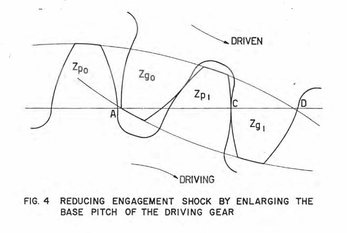
For combined pinion deflection /) not exceeding "'~ tenthousandths, it has become sound es~ablished practice to give the longitudinal correction the form as shown in Fig. 11 and Fig. 12.

The degree of correction is calculated from the comined deflection 0, and provided with suitable to lerance imits for manufacture and inspection.
Degree of Longitudinal Correction for Single Mesh (Equ ation 10)
Form of correction see Fig. 11.
Coupling end ten thousandths
Lower tolerance limit ~xu = 0 Upper tolerance limit ~ ::o '" 0 + 2
Blind end
For K ~ 1--------------- ~y '" 0
For K > 1 Lower tolerance limit ~YU = 0.3 0 Upper tolerance limit ~yo = 0.3 0 + 2
Degree of Longitudinal Correction for Double Mesh (Equation 11)
Form of correction see Fig. 12.
Coupling end
Lower tolerance limit ~xu = 0 Upper tolerance limit ~x o = 0 + 2
Blind end
~ 8. Field Experience
Tooth corrections have been successfully applied since pinion grinding machines equipped with correction facilities became available about 15 years ago.
These machines are capable of producing accurately controlled 'corrections within one ten thousandth of an inch.
Since then, this technique of finely controlled correction has been applied to a vast number of hardened and ground gears of various sizes and all kinds of application.
Observations on these gears in service have supplied adequate proof of the soundness of the principles of correction as described in this paper.
The following examples are presented as typical concrete cases of successfully applied tooth correc tion • . ,
Example 1: Fig. 13
6
Marine Reduction Gear between Diesel Engine and Screw Shaft
Max. power Speeds
3600 HP 1640/739 rpm
Pinion diameter d = 8.3" Face width F = 10.2" Spec. tooth load w = 3200 lbs/in ~~ctor 5~
Helix angle .;, = 10° Diametral pitch P d '" 3.85 Gears carburized, hardened and ground
Profile Corrections:
The degree of correction is evaluated from equation 4.
~ 1 u = 2 + 2.8 x 10- 3 . w = 11 tenthousandths ~lo = 5 + 2.8 x 10⁻³. w = 14 tenthousandths ~2u = 0 + 2.8 x 10⁻³ . w = 9 ten thousandths ~20 = 3 + 2.8 x 10⁻³ . w = 12 tenthousandths
The profile diagram of the pinion teeth is shown on Fig. 13b. It is based on the recommendations given by Fig. 7. The tolerance zone of the profile section between points Band C allows a deviation from the true involute of 1.2 tenthousandths. This is equivalent to a pinion base pitch being up to 1.4 tenthousandths larger, but never smaller, than the tneoretical value.
Longitudinal Corrections
Face width diameter ratio K c 10.2 = 1.23 8.3
From Fig. 10, curve A : 0100 = 0.2 tenthousandths
Combined deflections (equation 9)
o = .:!!.... • 0100 = 3200 . 0.2 = 6.4 tenthousandths 100 100
From equation 10 one obtains the degree and from Fig. 11 the form of the correction.
Coupling side: ilx u = 0 .. 6.4 tenthousandths ~xo = 2 + 8 = 8.4 tenthousandths
Blind siae: ~yu = 0.3 8 = 2 tenthousandths ~yo = 2 + 0.38 = 4 tenthousandths
The longitudinal diagram is plotted in Fig. I3c.
Example 2: Fig. 14
Speed Increasing Gear between Twin Diesel Engine and Generator /or Diesel Electric Locomotive
Two Diesel crank shahs drive one generator. The layout of the gears is shown in Fig. 14a.
There are rigid couplings on the input and Olltput shahs.
Power per crankshaft 1175 HP Speed of crankshafts 750 rpm Speed of generator 1078 rpm Pinion diameter d 13.55" F ace width F 11.42" Diametral pitch P d 2.36 Helix angle 0/1. 0° Backlash 3Yz -;. 4Yz thousandths Average tooth load Wo 873lbs/in Torque Variation at normal load ±300% Gears carburized, hardened and ground
This is an unusual case because of the high torque fluctuation at normal operation, which accounts for the sma!l backlash.
The peak load on the teeth is four times the average load:
W m a x = 'V 3500 lbs/in
Observations made on this gear in service confirmed that not only elastic deflections, but also thermal influences must be considered when determining the flank correction required. The heat developed in the bearings causes the diameter to grow more at the tooth ends than in the middle. Gears of this type which were made without longitudinal correction suffered scoring at the tooth ends. To rectify the matter, the symmetrical longitudinal correction shown in Fig. 14b was applied, and no further trouble was experienced.
Whereas no actual correction is applied to the teeth of the mating wheels, the tolerance zone for the tooth alignment is positioned such as to compensate for the very slight torsional deflections.
The degree of tip and root relief shown in Fig. 14b corresponds to values obtained by substituting into equation 3 a tooth load w equal to approximately double the ~ verage load Wo'
Sinc e the pinion is dri ven by two wheel s, a certain temperature' difference between wheels and pinion must be expected. In a speed increasing gear like the one in question, the temperature difference and the tooth deflections have an additive effect as mentioned earlier. The rule here is to make the base pitch of the pinion 1.5 to. 2.5 tenthousandths of an inch below the theoretical value.
In all cases where thermal influences are felt, and where appreciable vibrational forces or sho cks occur, practical experience is the only reasonably reliable guide. But the delicate control possible in correction gr inding permi tS th e fai th ful reproduction of even th e
finest corrections which such field experience suggest as being necessary.
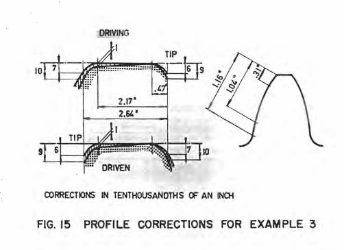
Example 3: Fig. 15 and 16
Pinions for Rolling Mill
Pinion diameter d = 14" Center distance a = 14" Effective face width F = 2 x 8~" (double helical)
Gap '" 4Yz" Total face width F I '" 21" (2F + gap) Diametral pitch P d '" 1.429 Helix angle If; = 28° Teeth carburized, hardened and ground
Input torque acting on one pinion: l))
Normal torque Maximum torque
T '" 0.97 . 106 lbs/in T max = 1.40 . 106 lbs/in
The output torque IS equally divided between the two pinions. Only half the input torque is transmitted by the teeth. The other half is transmitted directly by the input pinion to the output coupling.
Specific load w = 4200 lbs/in (k = 600) W max = 6100 lbs/in (k max '" 870)
Because this rolling mill operates only part time at the max. torque it was decided to apply corrections based on the normal load w.
Profile Corrections:
Because the pinions are of the same dimensions al the necessary tip and root relief is rather large, the corrections are shared equally between both. However, the tolerance zones of the uue-involute flank portions
. are opposed to ea ch other, such that the base pitch of the driving pinion can never be smaller than the pitch at the driven pinion, see Fig. 15.
The degree of the tip and root corrections were derived from equation 4.
Longitudinal Corrections:
In a case like this the combined deflections B can no longer be read from graph Fig. 10. The various deflections must be calculated separately and superimposed.
In this case the formulae 6 and 7 gi ve a close app.)),)
imation for the deflections Bb and Be respectively, if ~e tooth load is assumed to be evenly distri bu ted across the total face width F I (see Fig. 16). The imaginary speci fic tooth load w 0 is then:

2F 2· BY. . . - = 4200 --= 3300 lbs/IO F t 21
Th f 'dhd' . . K F t 21 e ace WI t lametp.r ratio IS = d = 14 = 1.5
Fig. 16 shows the combined deflection curves for the driving and driven pinion:
Driving: Combined deflection curve 4a = 1 + 2 :+- 3 Driv~C1: Combined deflection curve 4b = 1 + 2
Longitudinal correction is only applied to the driving pinion. The resultant of curves 4a and 4b supplies the total combined corrections at the helix ends. They are (compare Fig. 16):
Coupling side Ox = 15.5 + 2.7 = 18.2 Blind side Oy = 9 - 4 = 5
At the bottom of Fig. 16 is shown the longitudinal diagram, as it was executed for this particular case.
August 23, 1965 SG/dk
ACKNOWLEDGMENTS
This paper is published with the permission of Messrs. Maag Gear-Wheel Company, Zurich. The author wishes to thank Mr. R. Wydler, Dipl.lng., for his valuable contribution and assistance in accompli shing thi s paper.

100 o,{. LOAD "'T-------=,HF------i-------,
rA ___ ~B--_FC---~D
DRIVING
~
FIG.2 LOAD DISTRIBUTION ON TRUE-INVOLUTE SPUR GEARS

~DRIVEN
~DRIVING FIG. 3 TOOTH INTERFERENCE ON LOADED TRUE-INVOLUTE GEARS
~DRIVEN
','
~DRIVING FIG.4 REDUCING ENGAGEMENT SHOCK BY ENLARGING THE
BASE PITCH OF THE DRIVING GEAR

FIG. 5d PROFILE ~OI~AG::;;RA~M~-~---'~ OF DRIVING FLANK LL./~A~~~:L.L£L.~~~~~~-1D (TIP)
FIG. 5c ~~AwlL!P )~B~"77I7':'?'"7'TT,'ry7'T::l7777777'.t777:'"771;'T7777 PRex=-ILE DIAGRAM 6.~~/ ex=- DRIVEN FLANK
o
100 % LOAD-+---+--~-----'i..
FIG.5b _______ M
R p
FIG.5a
~DRIVING TIP REUEF
FIG. 5 LOAD DISTRI BUTION AND PROFILE CORRECTIONS

FIG.6 EFFECT OF TEMPERATURE DIFFERENCE BETWEEN PINIO~ AND GEAR

.6.10
TOlERANCE ZONE OF U~ECTED ING TOOTH FlANK Of GEAR
. IV 0.00012 •
TOLERANCE ZONE OF COORECTED TOOTH FLAN<
PINION DRIVING
a
Z - LENGTH OF CONTACT (CSTAINED FROM tlMENSlONS OF THE OEARS IN MESH)
Pb- TRANSVERSE BASE PITCH • _ ~ (~lP TO 20 "to SMALLER )
c _ ~ (~UP TO 20·/. lARGER)
FIG. 7 PROFILE CORRECTIONS ON A SPEED REDUCTION GEAR
TCURANC£ ZONE or UN~ECTED TOOTH rLANK or GEAR
:, ':, .
PIt-ION DRIVEN
c
Z • LENGTH ~ CONTACT (OBTAINED F'ROM DIMENSIONS or THE GEARS IN MESH)
Pb- TRANSVERSE BASE PITCH
.. Z-/b (OR UP TO 2O'"SMA/..l[R)
c • ~ (OR UP TO 201/, LARGER I
~IO
FIG.8 PROFILE CORRECTIONS ON A SPEED INCREASING GEAR

TOLERANCE ZONE OF U~ECTED NO TOOTH FLANK Of GEAR
PINION DRIVING
Z • LENGTH OF CONTACT (OOTAINED F~ DMENSIONS OF THE GEARS IN MESH)
Pba TRANSVERSE BASE PITCH
• a ~ (~lF TO 20 0/. SMALLER )
c a c.p.- (~UP TO 20% LARGER )
FIG. 7 PROFILE CORRECTIONS ON A SPEED REDUCTION GEAR
TCl..ERANCE ZONE or UNCOMECTED nNG TOOTH flANK or GEAR
~_IR~' ..•. : : .•. ~
Z - LENGTH or CONTACT (OB~INED FROM DIMENSIONS . Of THE GEARS IN MESH)
Pba TRANSVERSE BASE PITCH
• a Z -/b (OR UP TO 20',. SMAL.1.LR)
c • ~ (OR UP TO 20'" LARGER )
FIG.8 PROFILE CORRECTIONS ON A SPEED INCREASING GEAR

BENDING
TORSION
C~BINED DEFLECTION
THEORETICAL LONGITUDINAL CORRECTION
FIG. 9
w
TORQUE -- --r------ -
.: --+--+-- - --1:-;- ,--- -"1.... _____ _
L F w w--
F
y x
2
4 3
PINION DEFLECTIONS AND . LONGITUDINAL CORRECTIONS

15
'E14 ~13 C"
oX 12 0 S2 11 ..
010
~9 E 8 E ca 7 "- 6 0
'" 5 £; "t:J
4 c ca '" 3 ::l 0
.c:. 2 ...
c 1 .-
/ /
L V /
V If 1 )
V V w V /
,~--·t~ V L L_ I _ \,'''"'' V _ I I
~ / /V
\!I~'\ t1 V L~ , ~'-M~" ~ ~ lA
iii'" ,r /
t'--. ,~ W \V
~ V I?f i~j V~ V ~ ,,; I
, I
VV~~~ -'N-' r I .-~ ~~""""' W
J
0.2 0.4 0.6 0.8 1.0 1.2 1.4 1.6 1.8 2.0 ---------------IC--------------~.~
v ~
/ V
~
~
--
~
~
-~
0.98 ..-
O II
.8 o
0.7~ .c:. u
0.6 .S c
0.5 cu "o
0.4 ~ ~ c
0.3 ~ ::l o
~ 0.2 £
~
.:: ~
0.1 .:: o o ~
2.2 2.4 C/O
FIG. 10 COMBINED PINION DEFLECTION 8100 AT UNIT LOAD Wo = 100 Ibs/in

COUPLING SI[£ TOlERANCE ZONE
x
a b c
f
K~rv I K>rv I
a rv t f rvir b rv ! f
2 rv 1. r
3
c a rv t f
FIG. II LONGITUDI NAL PI NION CORRECTIONS FOR SINGLE MESH
COUPLING SIDE TOLERANCE ZONE
~xo
x '.'
FIG. 12 LONGITUDINAL PINION CORRECTIONS FOR DOUBLE MESH

PROFILE CORRECTION .
a
LONGITUDINAL CORRECTIONS
3.7-
c
I. L05·
CORRECTIONS IN ~ TENTHCXJSANOTHS OF AN INCH
12
COUPliNG SlOE
FIG. 13 PINION TOOTH CORRECTIONS FOR EXAMPLE 1

DRIVEN PINI~
DRIVING GEARS a
PINION COOPUNG SIDE
2.52-
c ACTIVE PRCFLE LENGTH
WHEEL TOOTH
8qJ6 ~~I.=~ =t:iX~~::~:::;::;:F::~:;~>;::~~~;;~:::EE::;~~:!;;;'~;,;,;,~:;; ~-
CORRECTIONS IN TENTHClJSANDTHS OF AN INCH
FIG. 14 TOOTH CORRECTIONS FOR EXAMPLE 2
DRIVING
ORIVEN
CORRECTIONS IN TENTHOUSANOTHS (F AN INOi
FIG. 15 PROFI LE CORRECTIONS FOR EXAM PLE 3

ch-S.3
OUTPUT 3 t-->'-----t
dy
_ 7 5 :~~~~~t~r\jt~ ~~1~1~~:~:~::::: y
"
t-8.3
x OEFLECTICtlS AND COORECTIONS IN TENTHOUSANDTHS OF AN INCH
01-16.6
.r;: T
CD BENDING
(3) TORISON DUE TO
TOOTH LOAD
0 TORISON DUE TO
TORQUE PASSING
THROUGH DRIVING PINOO
~ COMBINED lb DEFLECTIONS
INPUT
Ft
~ECTIONS ON DRIVING PINION. <DRIVEN PINION HAS NO LONGITUDINAL CORRs::nONS)
FIG. 16 LONGITUDINAL CORRECTIONS FOR EXAMPLE :3