Professional Water Systems Equipment - Submersible Pumps
158
Professional Water Systems Equipment 2005
-
Upload
khangminh22 -
Category
Documents
-
view
0 -
download
0
Transcript of Professional Water Systems Equipment - Submersible Pumps

Professional Water Systems Equipment
2005
12401 Interstate 30Little Rock, AR 72219-8903PH: 501.455.1234 FAX: 800.662.6044
www.franklinpumps.com
MS2009 9/05
Pro
fessio
nal W
ate
r Syste
ms E
quip
ment
2005

Table of Contents
SUBMERSIBLE PUMPS Legend 5 GPM ................................................................................................................. 2 Legend 7 GPM ................................................................................................................. 4 Legend 10 GPM ............................................................................................................... 6 Legend 18 GPM ............................................................................................................... 8 Legend 25 GPM ............................................................................................................. 10 Legend High Capacity 35 GPM ...................................................................................... 16 Legend High Capacity 45 GPM ...................................................................................... 18 Legend High Capacity 60 GPM ...................................................................................... 20 Legend High Capacity 90 GPM ...................................................................................... 22 Legacy 5 GPM................................................................................................................ 32 Legacy 8 GPM................................................................................................................ 34 Legacy 12 GPM.............................................................................................................. 36 Legacy 16 GPM.............................................................................................................. 38 Legacy 22 GPM.............................................................................................................. 40SUBMERSIBLE PUMP ACCESSORIES Franklin MonoDrive ........................................................................................................ 47 Franklin CP Water SubDrive 75 ..................................................................................... 48 Franklin CP Water SubDrive 150 ................................................................................... 50 Franklin Electric Control Boxes ...................................................................................... 52 Pumptec Motor Protection System ................................................................................. 53 Three-Phase Motor Protection ....................................................................................... 54 4” Single Phase Motors and Leads ................................................................................ 55 4” Three-Phase Motors .................................................................................................. 56 6” Single Phase Motors and Leads ................................................................................ 57 and Control Boxes ........................................................................................................ 57 6” Three-Phase Motors – Non-Subtrol ........................................................................... 58 6” Three Phase Motors – Subtrol Equipped ................................................................... 59 6” Three-Phase Motors – Super 90 Series ..................................................................... 60 8” Single Phase Motors and Leads ................................................................................ 61 Furnas ESP 100 ............................................................................................................. 62JET PUMPS SFCWJPRO-S ................................................................................................................ 63 SFCWJ-S Series ............................................................................................................ 67 SFC-S Series.................................................................................................................. 71 SFSWJ-S Series ............................................................................................................ 75 Jet Pump Accessories .................................................................................................... 77 AQ80 .............................................................................................................................. 79 225A Jet Charger............................................................................................................ 80EFFLUENT PUMPS 4 inch pump ................................................................................................................... 81SELF-PRIMING CENTRIFUGAL PUMP TY Series ........................................................................................................................ 82 TYCI Series .................................................................................................................... 84 HJ Series ........................................................................................................................ 86 DDD/DDS Series ............................................................................................................ 88BOOSTER PUMPS HB4 Series ..................................................................................................................... 91 H4 Series........................................................................................................................ 93 V6 Series ...................................................................................................................... 102REPLACEMENT MOTORS Small Frame ................................................................................................................. 103FRANKLIN ELECTRIC CONTROL BOX PARTS QD ................................................................................................................................ 104 Standard ....................................................................................................................... 105 Deluxe .......................................................................................................................... 106

Table of Contents
SERVICE PARTS KITS D Series Repair Kits ................................................................................................... 107 H-JM Service Kits ......................................................................................................... 108 Jet Pump Service Kits .................................................................................................. 109 Typhoon & H4 Booster Service Kits ............................................................................. 110SUBMERSIBLE PARTS 4”, 8-22 GPM .................................................................................................................111 4”, 5-25 GPM ................................................................................................................ 112 4”, 35-90 GPM .............................................................................................................. 113 6”, 50-75 GPM .............................................................................................................. 114JET PARTS Shallow Well Jet ........................................................................................................... 115 Deep Well Jet (SDEEP only) ........................................................................................ 116 Convertible Well Jet (SRP3 & CWJ) ............................................................................ 117 Convertible Well Jet (RD2) ........................................................................................... 118 Convertible Well Jet (RM2, PRM2, & CWJ Pro) ........................................................... 119 Convertible Well Jet (C) ............................................................................................... 121END SUCTION CENTRIFUGAL PARTS DDD Series .................................................................................................................. 122 D Series ........................................................................................................................ 123SELF-PRIMING CENTRIFUGAL PUMP & PARTS JM- 8-10M Kits ............................................................................................................. 129 HJM .............................................................................................................................. 130 Typhoon, TY, TYCI ....................................................................................................... 131BOOSTER PUMP PARTS H4 Booster ................................................................................................................... 132 V6 Booster.................................................................................................................... 133PORTABLE UTILITY PUMP PARTS GAS Contractors .......................................................................................................... 135 PHP .............................................................................................................................. 136SUMP PUMP PARTS PED .............................................................................................................................. 137 SPP & SPC .................................................................................................................. 138 APS & PBS................................................................................................................... 139 ABS .............................................................................................................................. 140NON-CORROSIVE PUMP PARTS Magnum ....................................................................................................................... 141 A Series ........................................................................................................................ 143 S Series ........................................................................................................................ 144ACCESSORIES Horizontal Check Valve ................................................................................................ 145 S0125 ........................................................................................................................... 145 Deep Well Injector ........................................................................................................ 146 Jet Charger................................................................................................................... 146 Aqua-Genie 80 & 400 .................................................................................................. 147APPLICATIONS Wire Size ...................................................................................................................... 148 Pipe Friction ................................................................................................................. 152 Lost or Damaged Goods .............................................................................................. 153 Limited Warranty .......................................................................................................... 154
Franklin Pump Systems, Inc. 12401 Interstate 30, Little Rock, AR 72209 Phone: 501/455-1234 FAX: 1-800-662-6044 www.franklin-electric.com

1
4” Submersible Pump
Features:
■ 5 performance ranges - 5, 7, 10, 18 & 25 GPM.
■ Ceramic shaft sleeve and rubber discharge
bearing protect shaft and eliminate sand wear.
■ Intermediate bearing included in 5-25 GPM units
greater than 24” in length and/or 2 HP and higher to
provide improved shaft stability.
■ Thermoplastic impellers and stages for
maximum effi ciency.
■ Thermoplastic and stainless steel models include
built-in Flomatic check valve.
■ Urethane Eye & Hub Seals are remarkably resistant
to abrasives, allowing sand and other abrasives to
pass through each stage without wear or damage.
■ Powered by Franklin corrosion-resistant
4” submersible motors
■ Maximum water temperature with proper fl ow-120˚ F. Consult
factory for further details.
■ Removable suction screen on both thermoplastic and
stainless steel units prevents debris from clogging impellers
and provides full fl ow performance.
2-Wire Example: T5L4D10P8-S1
T = Two wire5 = 1/2HPL = Legend4 = 4” SubmersibleD = 10 = 10 GPM8 = Number of stagesP = PlasticS1 = Single phase, 115 VoltsS2 = Single phase, 230 Volts
NRTL/C CSA 108
UL 778
Pump-end example: L4D7X25
L = Legend4 = 4” SubmersibleL =7 = 7 GPM25 = Number of stagesX = Stainless Steel
Model Number Explanation:

2
4” Submersible Pump
Legend 5 GPM Performance Curves
0
350
300
250
200
150
100
50
500
0
450
400
350
300
250
200
150
100
50
1200
0
1100
1000
900
800
700
600
500
400
300
200
100
0 81 2 3 4 5 6 7
0 1.5.5 1.0
ME
TE
RS
FE
ET
PS
I
GPM
M3PH
2HP
1-1/2HP
1HP
3/4HP
1/2HP
1/3HP

3
4” Submersible Pump
Legend 5 GPM Performance Charts
HP PSIDEPTH TO PUMPING WATER LEVEL, OR LIFT, IN FEET
SHADED AREAS INDICATE MOST EFFICIENT PERFORMANCE20 40 60 80 100 120 140 160 180 200 240 260 300 340 360 400 440 480 500 600 700 800 900 1000
1/3
0 - - - 8 7 6 6 5 5 420 - 7 7 6 6 5 4 4 230 - 7 6 6 5 4 3 240 7 6 5 5 4 3 250 6 5 5 4 3 260 5 5 4 3 180 4 2 1
Shut-off PSI 101 92 83 75 66 58 49 40 32 23
1/2
0 - - - - - 8 7 7 6 6 5 4 320 - - - 7 7 6 6 5 5 4 3 3 230 - - 7 7 6 6 5 5 4 4 3 240 - 7 7 6 6 5 5 4 4 3 250 7 7 6 6 5 5 4 4 3 260 7 6 6 5 5 4 4 3 280 6 5 5 4 4 3 2 1
Shut-off PSI 149 140 131 122 114 105 96 88 79 70 53 45 27
3/4
0 - - - - - - - - 7 7 7 6 6 5 5 4 320 - - - - - - 7 7 7 6 6 6 5 4 4 3 230 - - - - 8 7 7 7 6 6 6 5 5 4 4 240 - - - 8 7 7 7 6 6 6 5 5 4 3 350 - - 7 7 7 6 6 6 6 5 5 5 4 3 260 7 7 7 7 6 6 6 6 5 5 5 4 3 280 7 7 6 6 6 6 5 5 5 4 4 3 3
Shut-off PSI 220 211 203 194 185 177 168 159 151 142 125 116 99 81 73 55 38
1
0 - - - - - - - - - 8 7 7 6 6 6 5 5 4 420 - - - - - - - 7 7 7 6 6 6 5 5 5 4 3 230 - - - - - - 7 7 7 7 6 6 5 5 5 4 3 2 240 - - - - - 7 7 7 6 6 6 6 5 5 4 4 3 2 150 - - - - 7 7 7 6 6 6 6 5 5 4 4 3 2 160 - - - 7 7 7 6 6 6 6 5 5 5 4 4 3 180 7 7 7 7 6 6 6 6 6 5 5 5 4 3 3 2
Shut-off PSI 257 248 239 231 222 213 205 196 187 179 161 153 135 118 109 92 75 58 49
1-1/2
0 - - - - - - - - - - - - 7 7 7 6 6 6 6 5 320 - - - - - - - - - - 7 7 7 7 6 6 6 5 5 4 330 - - - - - - - - - 7 7 7 7 6 6 6 6 5 5 440 - - - - - - - - 7 7 7 7 6 6 6 6 6 5 5 450 - - - - - - - 7 7 7 7 7 6 6 6 5 5 5 4 360 - - - - - - 7 7 7 7 7 6 6 6 6 5 5 4 4 380 - - - - 7 7 7 7 7 6 6 6 6 5 5 5 4 4 3
Shut-off PSI 351 343 334 325 317 308 300 291 282 274 256 248 230 213 204 187 170 152 144 100 57
HP PSI 100 150 200 250 300 350 400 450 500 550 600 650 700 750 800 850 900 950 1000 1050 1100
2
0 - - - - 7 7 7 6 6 6 5 5 5 4 4 4 3 3 3 2 120 - - - 7 7 7 6 6 6 6 5 5 4 4 4 4 3 2 2 230 - - - 7 7 7 6 6 6 5 5 5 4 4 4 3 3 2 1 140 - - 7 7 7 6 6 6 6 5 5 5 4 4 4 3 2 2 150 - - 7 7 7 6 6 6 5 5 5 4 4 4 3 3 2 2 160 - 8 7 7 7 6 6 6 5 5 5 4 4 3 3 2 2 80 8 7 7 7 6 6 6 6 5 5 4 4 3 3 2 2 1
Shut-off PSI 450 429 407 385 364 342 320 299 277 255 234 212 191 169 147 126 104 82 61 39 17
Capacities in U.S. Gallons per Minute
1. Performance shown does not include friction loss in the drop pipe. 2. All performance data is based on rated motor nameplate voltage.
Notes:
Sh
ut-
off
255
ft.
Sh
ut-
off
364
ft.
Sh
ut-
off
528
ft.
Sh
ut-
off
614
ft.
Sh
ut-
off
833
ft.
Sh
ut-
off
113
8 ft
.

4
4” Submersible Pump
Legend 7 GPM Performance Curves
0
350
300
250
200
150
100
50
500
0
450
400
350
300
250
200
150
100
50
1100
0
1000
900
800
700
600
500
400
300
200
100
0 122 4 6 8 10
0 1.5.5 1.0 2.52.0
ME
TE
RS
FE
ET
PS
I
GPM
M3PH
3HP
2HP
1-1/2HP
1HP
3/4HP
1/2HP
1/3HP

5
4” Submersible Pump
Legend 7 GPM Performance Charts
HP PSI
DEPTH TO PUMPING WATER LEVEL, OR LIFT, IN FEET
SHADED AREAS INDICATE MOST EFFICIENT PERFORMANCE
20 40 60 80 100 120 140 160 180 200 240 260 300 340 360 400 440 480 500 600 700 800 900 1000
1/3
0 - - 11 10 9 8 7 6 420 10 9 9 8 7 5 130 9 9 8 7 5 140 9 8 6 5 150 8 6 4 260 6 4
Shut-off PSI 76 67 59 50 41 33 24 15 7
1/2
0 - - 12 11 10 10 9 9 8 7 6 420 11 11 10 9 9 8 8 7 6 530 11 10 9 9 8 8 7 6 5 340 10 9 9 8 8 7 6 5 350 9 9 8 7 7 6 5 360 9 8 8 7 6 5 380 7 6 5 3
Shut-off PSI 116 108 99 90 82 73 64 56 47 38 21 12
3/4
0 - - - 11 11 10 10 9 9 9 8 7 6 4 220 12 11 11 10 10 9 9 9 8 8 7 6 330 11 11 10 10 9 9 9 8 8 7 6 540 11 10 10 9 9 9 8 8 7 6 5 350 10 10 9 9 9 8 8 7 6 6 260 10 9 9 8 8 8 7 6 5 480 9 8 8 7 7 6 5 3
Shut-off PSI 154 146 137 129 120 111 103 94 85 77 59 51 33 16 7
1
0 - - - - 12 11 11 11 10 10 9 9 8 8 7 6 5 220 - - 12 11 11 10 10 10 10 9 9 8 7 7 6 4 130 - 12 11 11 10 10 10 9 9 9 8 8 7 6 5 340 12 11 11 10 10 10 9 9 9 9 8 7 6 5 450 11 11 10 10 10 9 9 9 8 8 7 7 6 460 11 10 10 10 9 9 9 8 8 8 7 6 5 380 10 9 9 9 9 8 8 7 7 6 5 4
Shut-off PSI 203 194 185 177 168 160 151 142 134 125 108 99 81 64 56 38 21 4
1-1/2
0 - - - - - 12 11 11 11 10 10 10 9 9 9 8 7 7 6 420 - - - 11 11 11 11 10 10 10 9 9 9 8 8 7 7 6 530 - - 11 11 11 11 10 10 10 10 9 9 8 8 7 7 6 5 540 - 11 11 11 11 10 10 10 10 9 9 9 8 8 7 7 6 4 350 11 11 11 11 10 10 10 10 9 9 9 8 8 7 7 6 5 3 260 11 11 11 10 10 10 10 9 9 9 8 8 7 7 6 6 4 2 180 10 10 10 10 9 9 9 9 8 8 8 7 7 6 5 4 2
Shut-off PSI 268 260 251 242 234 225 216 208 199 180 173 164 147 130 121 104 87 69 61 17
HP PSI 50 100 150 200 250 300 350 400 450 500 550 600 650 700 750 800 850 900 950 1000 1050 1100 1150
2
0 - - - 11 10 10 9 9 9 8 8 7 6 5 3 120 - - 11 11 10 9 9 9 8 8 7 6 5 3 130 - 12 11 10 10 9 9 9 8 8 7 6 4 240 - 12 11 10 9 9 9 8 8 7 6 5 3 150 12 11 10 10 9 9 9 8 8 7 6 4 260 12 11 10 9 9 9 8 8 7 7 5 4 170 11 10 10 9 9 9 8 8 7 6 5 380 11 10 9 9 9 9 8 8 7 5 4 1
Shut-off PSI 325 304 282 261 239 217 196 174 152 131 109 87 66 44 22
3
0 - - - - - 11 11 10 10 9 9 9 9 8 8 7 6 5 4 320 - - - 12 11 10 10 10 9 9 9 9 8 8 7 7 6 4 3 130 - - - 12 11 10 10 9 9 9 9 8 8 8 7 6 5 4 240 - - 12 11 11 10 10 9 9 9 9 8 8 7 7 6 4 3 150 - - 12 11 10 10 9 9 9 9 9 8 8 7 6 5 4 260 - 12 11 11 10 10 9 9 9 9 8 8 7 7 6 4 3 170 - 12 11 10 10 9 9 9 9 9 8 8 7 6 5 4 280 12 11 11 10 10 9 9 9 9 8 8 7 7 6 5 3 1
Shut-off PSI 436 415 393 371 350 328 306 285 263 241 220 198 177 155 133 112 90 68 47 25
Sh
ut-
off
197
ft.
Sh
ut-
off
29
0 ft
.S
hu
t-o
ff 3
78 f
t.S
hu
t-o
ff 4
89 f
t.S
hu
t-o
ff 6
41 f
t.S
hu
t-o
ff 8
03 f
t.S
hu
t-o
ff 1
080
ft.
Capacities in U.S. Gallons per Minute
1. Performance shown does not include friction loss in the drop pipe. 2. All performance data is based on rated motor nameplate voltage.
Notes:

6
4” Submersible Pump
Legend 10 GPM Performance Curves
0
350
300
250
200
150
100
50
400
500
0
450
400
350
300
250
200
150
100
50
550
600
0 122 4 6 8 10
1100
1000
900
800
700
600
500
400
300
200
100
0
1200
1300
1400
14 16
0 1.5.5 1.0 2.52.0 3.0 3.5
FE
ET
PS
I
ME
TE
RS
GPM
M3PH
5HP
3HP
2HP
1-1/2HP
1HP
3/4HP
1/2HP
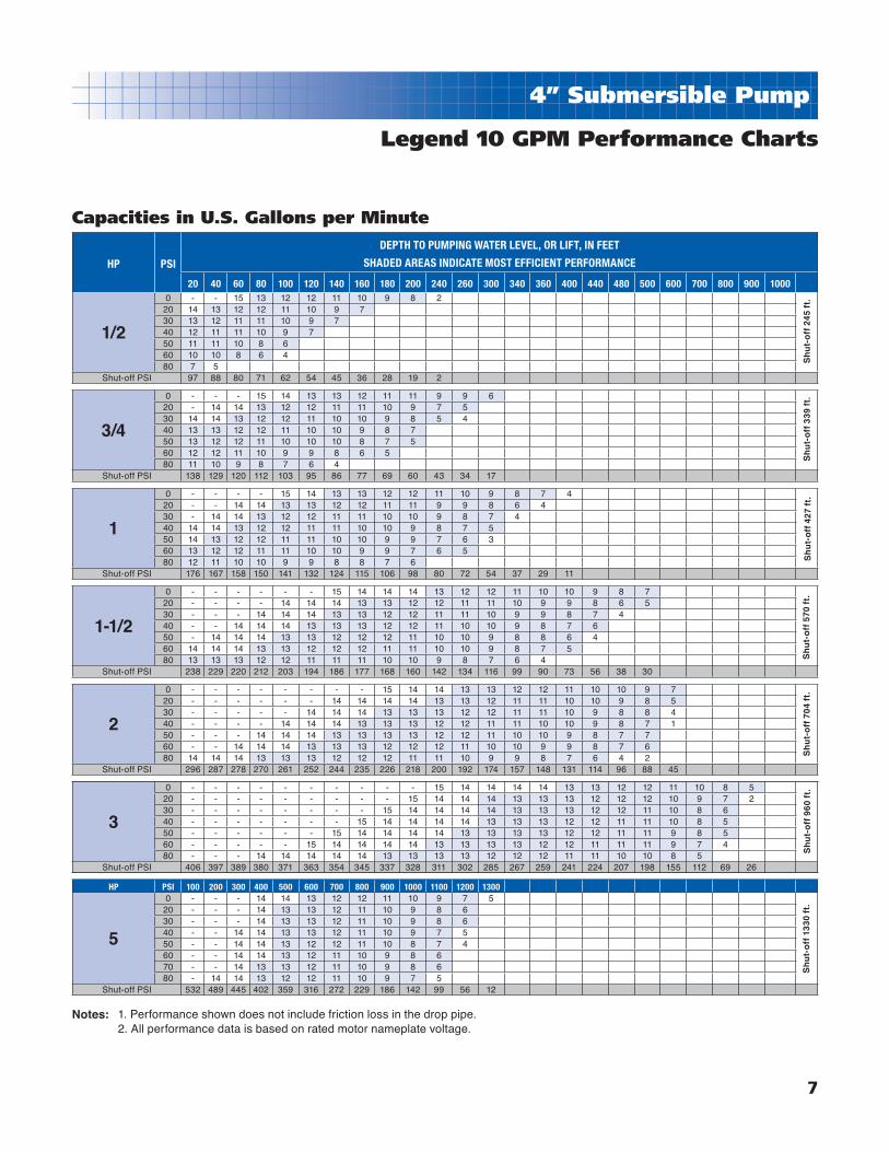
7
4” Submersible Pump
Legend 10 GPM Performance Charts
HP PSI
DEPTH TO PUMPING WATER LEVEL, OR LIFT, IN FEET
SHADED AREAS INDICATE MOST EFFICIENT PERFORMANCE
20 40 60 80 100 120 140 160 180 200 240 260 300 340 360 400 440 480 500 600 700 800 900 1000
1/2
0 - - 15 13 12 12 11 10 9 8 220 14 13 12 12 11 10 9 730 13 12 11 11 10 9 740 12 11 11 10 9 750 11 11 10 8 660 10 10 8 6 480 7 5
Shut-off PSI 97 88 80 71 62 54 45 36 28 19 2
3/4
0 - - - 15 14 13 13 12 11 11 9 9 620 - 14 14 13 12 12 11 11 10 9 7 530 14 14 13 12 12 11 10 10 9 8 5 440 13 13 12 12 11 10 10 9 8 750 13 12 12 11 10 10 10 8 7 560 12 12 11 10 9 9 8 6 580 11 10 9 8 7 6 4
Shut-off PSI 138 129 120 112 103 95 86 77 69 60 43 34 17
1
0 - - - - 15 14 13 13 12 12 11 10 9 8 7 420 - - 14 14 13 13 12 12 11 11 9 9 8 6 430 - 14 14 13 12 12 11 11 10 10 9 8 7 440 14 14 13 12 12 11 11 10 10 9 8 7 550 14 13 12 12 11 11 10 10 9 9 7 6 360 13 12 12 11 11 10 10 9 9 7 6 580 12 11 10 10 9 9 8 8 7 6
Shut-off PSI 176 167 158 150 141 132 124 115 106 98 80 72 54 37 29 11
1-1/2
0 - - - - - - 15 14 14 14 13 12 12 11 10 10 9 8 720 - - - - 14 14 14 13 13 12 12 11 11 10 9 9 8 6 530 - - - 14 14 14 13 13 12 12 11 11 10 9 9 8 7 440 - - 14 14 14 13 13 13 12 12 11 10 10 9 8 7 650 - 14 14 14 13 13 12 12 12 11 10 10 9 8 8 6 460 14 14 14 13 13 12 12 12 11 11 10 10 9 8 7 580 13 13 13 12 12 11 11 11 10 10 9 8 7 6 4
Shut-off PSI 238 229 220 212 203 194 186 177 168 160 142 134 116 99 90 73 56 38 30
2
0 - - - - - - - - 15 14 14 13 13 12 12 11 10 10 9 720 - - - - - - 14 14 14 14 13 13 12 11 11 10 10 9 8 530 - - - - - 14 14 14 13 13 13 12 12 11 11 10 9 8 8 440 - - - - 14 14 14 13 13 13 12 12 11 11 10 10 9 8 7 150 - - - 14 14 14 13 13 13 13 12 12 11 10 10 9 8 7 760 - - 14 14 14 13 13 13 12 12 12 11 10 10 9 9 8 7 680 14 14 14 13 13 13 12 12 12 11 11 10 9 9 8 7 6 4 2
Shut-off PSI 296 287 278 270 261 252 244 235 226 218 200 192 174 157 148 131 114 96 88 45
3
0 - - - - - - - - - - 15 14 14 14 14 13 13 12 12 11 10 8 520 - - - - - - - - - 15 14 14 14 13 13 13 12 12 12 10 9 7 230 - - - - - - - - 15 14 14 14 14 13 13 13 12 12 11 10 8 640 - - - - - - - 15 14 14 14 14 13 13 13 12 12 11 11 10 8 550 - - - - - - 15 14 14 14 14 13 13 13 13 12 12 11 11 9 8 560 - - - - - 15 14 14 14 14 13 13 13 13 12 12 11 11 11 9 7 480 - - - 14 14 14 14 14 13 13 13 13 12 12 12 11 11 10 10 8 5
Shut-off PSI 406 397 389 380 371 363 354 345 337 328 311 302 285 267 259 241 224 207 198 155 112 69 26
HP PSI 100 200 300 400 500 600 700 800 900 1000 1100 1200 1300
5
0 - - - 14 14 13 12 12 11 10 9 7 520 - - - 14 13 13 12 11 10 9 8 630 - - - 14 13 13 12 11 10 9 8 640 - - 14 14 13 13 12 11 10 9 7 550 - - 14 14 13 12 12 11 10 8 7 460 - - 14 14 13 12 11 10 9 8 670 - - 14 13 13 12 11 10 9 8 680 - 14 14 13 12 12 11 10 9 7 5
Shut-off PSI 532 489 445 402 359 316 272 229 186 142 99 56 12
Sh
ut-
off
24
5 ft
.S
hu
t-o
ff 3
39 f
t.S
hu
t-o
ff 4
27 f
t.S
hu
t-o
ff 5
70 f
t.S
hu
t-o
ff 7
04 f
t.S
hu
t-o
ff 9
60 f
t.S
hu
t-o
ff 1
330
ft.
Capacities in U.S. Gallons per Minute
1. Performance shown does not include friction loss in the drop pipe. 2. All performance data is based on rated motor nameplate voltage.
Notes:

8
4” Submersible Pump
Legend 18 GPM Performance Curves
0
350
300
250
200
150
100
50
500
0
450
400
350
300
250
200
150
100
50
1100
0
1000
900
800
700
600
500
400
300
200
100
0 31 2 54
0 122 4 6 8 10 2214 16 18 20 24 26
ME
TE
RS
FE
ET
PS
I
GPM
M3PH
5HP
3HP
2HP
1HP
1-1/2HP
3/4HP

9
4” Submersible Pump
Legend 18 GPM Performance Charts
HP PSIDEPTH TO PUMPING WATER LEVEL, OR LIFT, IN FEET
SHADED AREAS INDICATE MOST EFFICIENT PERFORMANCE20 40 60 80 100 120 140 160 180 200 240 260 300 340 360 400 440 480 500 600 700 800 900 1000
3/4
0 - - - 24 22 21 19 18 16 1220 - 23 22 20 18 18 15 1030 23 22 20 19 17 15 940 21 20 18 17 15 850 20 18 17 14 760 19 17 14
Shut-off PSI 84 75 67 58 49 41 32 23 15 6
1
0 - - - - 24 22 21 20 19 18 15 1120 - - 23 22 21 20 18 17 16 1430 - 23 22 21 20 18 17 16 13 840 23 22 21 20 18 17 16 13 750 22 21 19 18 17 16 1360 20 19 18 17 15 1280 17 16 13
Shut-off PSI 109 100 92 83 74 66 57 48 40 31 14 5
1-1/2
0 - - - - - - 23 22 22 21 19 18 16 13 1220 - - - 24 23 22 21 20 20 19 17 15 1330 - - 24 23 22 21 21 20 19 18 15 14 940 - 24 23 22 21 21 20 19 18 17 14 1350 24 23 22 21 20 19 19 18 16 15 13 860 23 22 21 20 19 18 17 16 15 14 880 20 20 19 18 17 15 14 13 9
Shut-off PSI 155 146 138 129 120 112 103 94 86 77 60 51 34 16 8
2
0 - - - - - - - 23 23 22 21 20 19 17 16 15 12 220 - - - - 24 23 22 22 21 21 19 19 17 15 14 1130 - - - 24 23 22 22 21 20 20 19 18 16 14 12 740 - - 24 23 22 22 21 20 20 19 18 17 15 12 1050 - 24 23 22 22 21 20 20 19 19 17 16 14 10 460 24 23 22 22 21 20 20 19 18 18 16 15 12 480 22 21 21 20 19 18 18 17 16 15 13 11
Shut-off PSI 198 189 181 172 163 155 146 137 129 120 103 94 77 59 51 33 16
3
0 - - - - - - - - - - 23 23 22 21 20 19 18 17 16 1220 - - - - - - - - 24 23 22 22 21 20 19 18 17 15 15 1230 - - - - - - - 24 23 22 22 21 20 19 18 17 16 15 1440 - - - - - - 24 23 22 22 21 20 19 18 18 17 15 14 1250 - - - - - 24 23 22 22 21 20 20 19 18 17 16 15 13 1260 - - - - 24 23 22 22 21 21 20 19 18 17 16 15 13 11 880 - 24 23 22 22 22 21 20 20 19 18 18 17 16 15 13 10
Shut-off PSI 272 263 255 246 237 229 220 211 203 194 177 168 151 133 125 107 90 73 64 21
5
0 - - - - - - - - - - - - - - 24 23 22 22 21 20 18 16 12 420 - - - - - - - - - - - - - 23 23 22 22 21 21 19 17 14 930 - - - - - - - - - - - - 23 23 22 22 21 21 20 19 17 13 740 - - - - - - - - - - - - 23 22 22 21 21 20 20 18 16 12 450 - - - - - - - - - - - 23 23 22 22 21 20 20 20 18 15 11 260 - - - - - - - - - - 23 23 22 22 21 21 20 20 19 18 14 1080 - - - - - - - - 23 23 22 22 22 21 21 20 19 19 18 16 12 5
Shut-off PSI 435 427 418 409 401 392 383 375 366 357 340 331 314 296 288 270 253 236 227 184 141 98 55 12
Capacities in U.S. Gallons per Minute
1. Performance shown does not include friction loss in the drop pipe. 2. All performance data is based on rated motor nameplate voltage.
Notes:
Sh
ut-
off
215
ft.
Sh
ut-
off
273
ft.
Sh
ut-
off
380
ft.
Sh
ut-
off
480
ft.
Sh
ut-
off
650
ft.
Sh
ut-
off
102
7 ft
.

10
4” Submersible Pump
Legend 25 GPM Performance Curves
0
175
225
125
200
150
100
50
75
25
0
350
300
250
200
150
100
50
0
800
700
600
500
400
300
200
100
0 305 10 15 20 25 35
0 31 2 54 6 7 8
GPM
M3PH
ME
TE
RS
FE
ET
PS
I
5HP
3HP
2HP
1-1/2HP
1HP

11
4” Submersible Pump
Legend 25 GPM Performance Charts
HP PSIDEPTH TO PUMPING WATER LEVEL, OR LIFT, IN FEET
SHADED AREAS INDICATE MOST EFFICIENT PERFORMANCE20 40 60 80 100 120 140 160 180 200 240 260 300 340 360 400 440 480 500 600 700 800 900 1000
1
0 - - - 34 31 29 26 23 16 620 - 33 31 28 25 22 1530 33 31 28 25 21 1440 30 27 24 19 1050 27 24 19 960 23 17 8
Shut-off PSI 81 72 64 55 46 38 29 20 12 3
1-1/2
0 - - - - 35 33 31 29 28 25 19 1320 - - 34 33 31 29 27 25 22 1830 - 34 32 31 29 27 24 22 18 940 33 32 30 28 26 24 21 15 650 32 30 28 26 24 20 15 460 30 28 26 23 20 15 280 25 22 18 11
Shut-off PSI 113104 96 87 78 70 61 52 44 35 18 9
2
0 - - - - - 35 33 32 30 29 26 24 19 720 - - - 35 33 32 30 28 27 25 21 18 530 - - 34 33 32 30 28 27 25 23 18 1340 - 34 32 31 29 28 26 24 23 20 1150 34 32 31 29 28 26 24 22 20 1660 34 32 29 28 26 24 22 19 16 980 28 27 25 23 21 18 14 5
Shut-off PSI 142133125 116 107 99 90 81 73 64 47 38 21
3
0 - - - - - - 34 34 33 32 30 29 28 26 25 22 17 620 - - - - 34 34 33 32 31 30 28 28 26 23 22 16 430 - - - 34 33 33 32 31 30 29 27 27 25 21 19 1140 - 35 34 33 32 31 31 30 29 28 26 25 23 18 1450 35 34 33 32 32 31 30 29 28 27 25 24 20 13 860 34 33 32 31 31 30 29 28 27 26 24 22 20 880 32 31 30 29 28 28 27 26 25 23 19 16 4
Shut-off PSI 205196188 179 170 162 153 144 136 127 110 101 84 66 58 40 23 6
5
0 - - - - - - - - - 35 34 33 32 31 30 29 28 27 26 23 1420 - - - - - - - 34 34 33 32 32 31 30 29 28 27 26 25 20 930 - - - - - - 34 34 33 33 32 31 30 29 29 28 26 25 24 1840 - - - - - 34 34 33 33 32 31 31 29 28 28 27 25 24 23 1550 - - - - 34 34 33 33 32 32 31 30 29 28 27 26 25 23 22 1360 - - - 34 34 33 33 32 32 31 30 29 28 27 27 25 24 22 21 1080 34 34 33 33 32 32 31 31 30 30 29 28 27 26 25 23 21 18 16
Shut-off PSI 321312304 295 286 278 269 260 252 243 226 217 200 182 174 156 139 122 113 70 26
Sh
ut-
off
350
ft.
Sh
ut-
off
283
ft.
Sh
ut-
off
208
ft.
Sh
ut-
off
49
6 ft
.S
hu
t-o
ff 7
63 f
t.
Capacities in U.S. Gallons per Minute
1. Performance shown does not include friction loss in the drop pipe. 2. All performance data is based on rated motor nameplate voltage.
Notes:
12
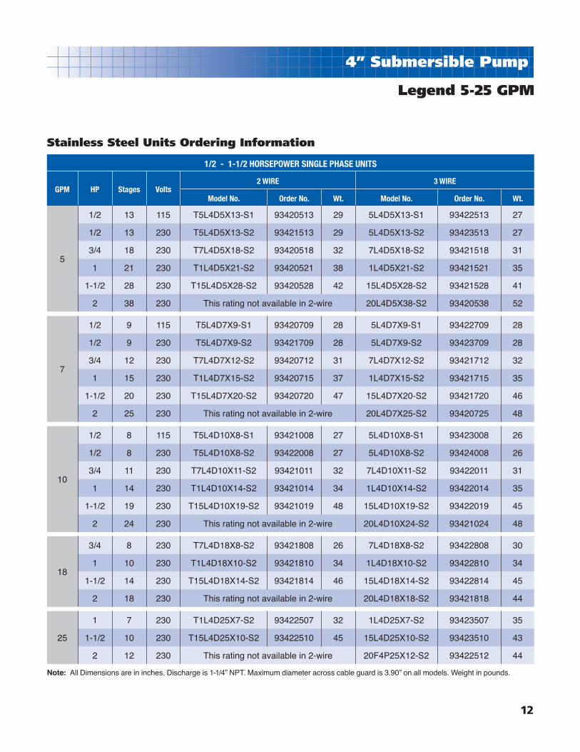
4” Submersible Pump
Legend 5-25 GPM
Stainless Steel Units Ordering Information
1/2 - 1-1/2 HORSEPOWER SINGLE PHASE UNITS
GPM HP Stages Volts2 WIRE 3 WIRE
Model No. Order No. Wt. Model No. Order No. Wt.
5
1/2 13 115 T5L4D5X13-S1 93420513 29 5L4D5X13-S1 93422513 27
1/2 13 230 T5L4D5X13-S2 93421513 29 5L4D5X13-S2 93423513 27
3/4 18 230 T7L4D5X18-S2 93420518 32 7L4D5X18-S2 93421518 31
1 21 230 T1L4D5X21-S2 93420521 38 1L4D5X21-S2 93421521 35
1-1/2 28 230 T15L4D5X28-S2 93420528 42 15L4D5X28-S2 93421528 41
2 38 230 This rating not available in 2-wire 20L4D5X38-S2 93420538 52
7
1/2 9 115 T5L4D7X9-S1 93420709 28 5L4D7X9-S1 93422709 28
1/2 9 230 T5L4D7X9-S2 93421709 28 5L4D7X9-S2 93423709 28
3/4 12 230 T7L4D7X12-S2 93420712 31 7L4D7X12-S2 93421712 32
1 15 230 T1L4D7X15-S2 93420715 37 1L4D7X15-S2 93421715 35
1-1/2 20 230 T15L4D7X20-S2 93420720 47 15L4D7X20-S2 93421720 46
2 25 230 This rating not available in 2-wire 20L4D7X25-S2 93420725 48
10
1/2 8 115 T5L4D10X8-S1 93421008 27 5L4D10X8-S1 93423008 26
1/2 8 230 T5L4D10X8-S2 93422008 27 5L4D10X8-S2 93424008 26
3/4 11 230 T7L4D10X11-S2 93421011 32 7L4D10X11-S2 93422011 31
1 14 230 T1L4D10X14-S2 93421014 34 1L4D10X14-S2 93422014 35
1-1/2 19 230 T15L4D10X19-S2 93421019 48 15L4D10X19-S2 93422019 45
2 24 230 This rating not available in 2-wire 20L4D10X24-S2 93421024 48
18
3/4 8 230 T7L4D18X8-S2 93421808 26 7L4D18X8-S2 93422808 30
1 10 230 T1L4D18X10-S2 93421810 34 1L4D18X10-S2 93422810 34
1-1/2 14 230 T15L4D18X14-S2 93421814 46 15L4D18X14-S2 93422814 45
2 18 230 This rating not available in 2-wire 20L4D18X18-S2 93421818 44
25
1 7 230 T1L4D25X7-S2 93422507 32 1L4D25X7-S2 93423507 35
1-1/2 10 230 T15L4D25X10-S2 93422510 45 15L4D25X10-S2 93423510 43
2 12 230 This rating not available in 2-wire 20F4P25X12-S2 93422512 44
Note: All Dimensions are in inches. Discharge is 1-1/4” NPT. Maximum diameter across cable guard is 3.90” on all models. Weight in pounds.

13
4” Submersible Pump
Legend 5-25 GPM
Stainless Steel Pump Ends Ordering Information
STAINLESS STEEL 1/3 - 5 HP PUMP ENDS
GPM HP Stages Model No. Order No. Wt.
5
1/3 9 L4D5X9 93430509 9
1/2 13 L4D5X13 93430513 11
3/4 18 L4D5X18 93430518 12
1 21 L4D5X21 93430521 15
1-1/2 28 L4D5X28 93430528 17
2 38 L4D5X38 93430538 20
7
1/3 6 L4D7X6 93430706 9
1/2 9 L4D7X9 93430709 10
3/4 12 L4D7X12 93430712 9
1 15 L4D7X15 93430715 12
1-1/2 20 L4D7X20 93430720 16
2 25 L4D7X25 93430725 16
3 33 L4D7X33 93430733 20
10
1/2 8 L4D10X8 93431008 9
3/4 11 L4D10X11 93431011 10
1 14 L4D10X14 93431014 12
1-1/2 19 L4D10X19 93431019 15
2 24 L4D10X24 93431024 16
3 31 L4D10X31 93431031 18
5 44 L4D10X44 93431044 21
18
3/4 8 L4D18X8 93431808 9
1 10 L4D18X10 93431810 10
1-1/2 14 L4D18X14 93431814 12
2 18 L4D18X18 93431818 12
3 24 L4D18X24 93431824 16
5 39 L4D18X39 93431839 27
25
1 7 L4D25X7 93432507 9
1-1/2 10 L4D25X10 93432510 10
2 12 L4D25X12 93432512 12
3 17 L4D25X17 93432517 14
5 27 L4D25X27 93432527 18
Note: All Dimensions are in inches. Discharge is 1-1/4” NPT. Maximum diameter across cable guard is 3.90” on all models. Weight in pounds.

14
4” Submersible Pump
Legend 5-25 GPMThermoplastic Units Ordering Information
1/2 - 1-1/2 HORSEPOWER SINGLE PHASE UNITS
GPM HP Stages Volts2 WIRE 3 WIRE
Model No. Order No. Wt. Model No. Order No. Wt.
5
1/2 13 115 T5L4D5P13-S1 93400513 26 5L4D5P13-S1 93402513 25
1/2 13 230 T5L4D5P13-S2 93401513 26 5L4D5P13-S2 93403513 25
3/4 18 230 T7L4D5P18-S2 93400518 29 7L4D5P18-S2 93401518 30
1 21 230 T1L4D5P21-S2 93400521 33 1L4D5P21-S2 93401521 34
7
1/2 9 115 T5L4D7P9-S1 93400709 24 5L4D7P9-S1 93402709 24
1/2 9 230 T5L4D7P9-S2 93401709 24 5L4D7P9-S2 93403709 24
3/4 12 230 T7L4D7P12-S2 93400712 28 7L4D7P12-S2 93401712 28
1 15 230 T1L4D7P12-S2 93400715 33 1L4D7P12-S2 93401715 32
1-1/2 20 230 T15L4D7P20-S2 93400720 44 15L4D7P20-S2 93401720 43
10
1/2 8 115 T5L4D10P8-S1 93401008 24 5L4D10P8-S1 93403008 24
1/2 8 230 T5L4D10P8-S2 93402008 24 5L4D10P8-S2 93404008 24
3/4 11 230 T7L4D10P11-S2 93401011 28 7L4D10P11-S2 93402011 28
1 14 230 T1L4D10P14-S2 93401014 31 1L4D10P14-S2 93402014 32
1-1/2 19 230 T15L4D10P19-S2 93401019 46 15L4D10P19-S2 93402019 42
18
3/4 8 230 T7L4D18P8-S2 93401808 28 7L4D18P8-S2 93402808 27
1 10 230 T1L4D18P10-S2 93401810 31 1L4D18P10-S2 93402810 30
1-1/2 14 230 T15L4D18P14-S2 93401814 40 15L4D18P14-S2 93402814 39
44 18 230 This rating not available in 2-wire 20L4D18P18-S2 93401818 43
25
1 7 230 T1L4D25P7-S2 93402507 30 1L4D25P7-S2 93403507 33
1-1/2 10 230 T15L4D25P10-S2 93402510 43 15L4D25P10-S2 93403510 39
2 12 230 This rating not available in 2-wire 20L4D25P12-S2 93402512 41
THERMOPLASTIC 1/3 - 2 HP PUMP ENDS
GPM HP Stages VoltsOrdering Info. Dimensions
Wt.Model No. Order No. PEA
5
1/3 9 n.a. L4D5P9 93410509 14.40 6
1/2 13 n.a. L4D5P13 93410513 17.56 8
3/4 18 n.a. L4D5P18 93410518 21.53 10
1 21 n.a. L4D5P21 93410521 23.90 11
7
1/2 9 n.a. L4D7P9 93410709 15.28 4
3/4 12 n.a. L4D7P12 93410712 17.96 7
1 15 n.a. L4D7P15 93410715 20.65 8
1-1/2 20 n.a. L4D7P20 93410720 25.09 10
10
1/2 8 n.a. L4D10P8 93411008 14.40 6
3/4 11 n.a. L4D10P11 93411011 17.09 7
1 14 n.a. L4D10P14 93411014 19.78 8
1-1/2 19 n.a. L4D10P19 93411019 26.34 12
18
3/4 8 n.a. L4D18P8 93411808 17.09 7
1 10 n.a. L4D18P10 93411810 19.53 7
1-1/2 14 n.a. L4D18P14 93411814 24.46 10
2 18 230 L4D18P18 93411818 31.46 11
25
1 7 n.a. L4D25P7 93412507 15.84 6
1-1/2 10 n.a. L4D25P10 93412510 19.53 8
2 12 230 L4D25P12 93412512 24.09 9
Note: All listed above have 1-1/4” NPT discharge and feature our removable Flomatic™ poppet assembly.
Note: All dimensions are in inches. Discharge is 1-1/4” NPT. Maximum diameter across cable guard is 3.90” on all models. Weight in pounds.

15
4” Submersible Pump
High Capacity
Model Number Explanation:Example: 15L4D35X8-S215 = 1-1/2 HPL = Legend4 = 4” SubmersibleD = 35 = 35 GPM8 = Number of stagesX = Stainless SteelS = Single Phase2 = 230V
Features:■ 4 performance ranges - 35, 45, 60 & 90 GPM
■ Stainless Steel discharge head and motor bracket
■ High fl ow impellers and stages are glass-fi lled Noryl for
maximum effi ciency.
■ Ceramic shaft sleeve and rubber discharge bearing eliminates
sand wear.
■ Intermediate bearing for increased shaft stability.
■ Floating eye and hub seals for improved performance
and effi ciency.
■ Stainless steel hex pump shaft, shell and shaft coupling
■ High capacity upthrust assembly for protection during start-up and operation (45, 60 and 90 GPM models)
■ Powered by Franklinʼs corrosion-resistant 4” submersible motors
■ 2” NPT Discharge Tapping
■ Check valve must be ordered separately. See page 46.
35, 45, 60 and 90GPM Models

16
4” Submersible Pump
Legend High Capacity 35 GPM Performance Curves
0
175
125
200
150
100
50
75
25
0
300
250
200
150
100
50
0
700
600
500
400
300
200
100
0 3010 20 40 50
0 62 4 108 12
ME
TE
RS
FE
ET
PS
I
GPM
M3PH
5HP
3HP
2HP
1-1/2HP
1HP
60
55
50
45 EF
FIC
IEN
CY
%
1. Performance shown does not include friction loss in the drop pipe. 2. All performance data is based on rated motor nameplate voltage.
Notes:

17
4” Submersible Pump
Legend High Capacity 35 GPM Performance Charts
HP PSIDEPTH TO PUMPING WATER LEVEL, OR LIFT, IN FEET
SHADED AREAS INDICATE MOST EFFICIENT PERFORMANCE20 40 60 80 100 120 140 160 180 200 220 240 260 280 300 320 340 360 380 400 450 500 550 600
1
0 - 48 44 39 34 28 21 1120 42 37 32 26 18 730 36 31 2540 30 24 1550 23 1460 127080
Shut-off PSI 65 57 48 39 31 22 13 5
1-1/2
0 - 49 46 43 40 36 32 27 22 16 820 45 42 39 35 31 26 20 1430 41 38 34 30 25 20 1340 37 33 29 24 18 1150 33 29 24 18 1060 28 23 17 970 22 16 780 14 3
Shut-off PSI 89 81 72 63 54 46 37 28 20 11 2
2
0 - 50 48 45 43 40 37 34 31 28 24 19 14 720 47 45 42 39 36 33 30 27 22 18 13 330 44 41 39 36 33 30 26 22 17 1240 41 38 35 32 29 25 21 16 1050 38 35 32 29 25 20 16 960 35 31 28 24 20 15 870 31 27 23 19 14 680 27 23 18 13 4
Shut-off PSI 116 107 99 90 81 73 64 55 47 38 29 21 12 3
3
0 - - 50 48 47 46 44 42 39 37 35 33 31 28 26 23 19 15 1020 49 48 47 45 43 41 39 37 35 33 30 28 25 22 18 14 830 48 46 45 43 41 39 37 35 32 30 27 25 21 17 13 740 46 44 42 40 38 36 34 32 29 27 24 20 17 12 550 44 42 40 38 36 34 31 29 26 24 20 16 12 460 42 40 38 36 33 31 29 26 23 19 15 11 270 39 37 35 33 31 28 26 22 19 15 1080 37 35 33 30 28 25 22 18 14 9
Shut-off PSI 165 156 148 139 130 122 113 104 96 87 78 70 61 52 44 35 26 18 9
5
0 - - - - 50 49 48 47 46 45 44 43 42 40 39 38 37 36 34 33 30 25 20 1220 - - 49 48 48 47 46 45 44 42 41 40 39 38 36 35 34 33 32 30 26 20 1330 - 49 48 47 46 45 44 43 42 41 40 39 38 36 35 34 33 31 30 28 23 17 840 49 48 47 46 45 44 43 42 41 40 39 37 36 35 34 32 31 30 28 26 21 1350 48 47 46 45 44 43 42 41 40 38 37 36 35 33 32 31 30 28 26 24 18 960 47 46 45 44 43 42 41 39 38 37 36 34 33 32 31 29 28 26 24 21 1470 46 45 44 43 42 40 39 38 37 35 34 33 32 31 29 27 25 23 21 18 1080 45 44 42 41 40 39 38 36 35 34 33 32 30 29 27 25 23 20 18 15 3
Shut-off PSI 268 259 251 242 233 225 216 207 199 190 181 173 164 155 147 138 129 121 12 103 82 60 38 17
Sh
ut-
off
288
ft.
Sh
ut-
off
226
ft.
Sh
ut-
off
171
ft.
Sh
ut-
off
49
6 ft
.S
hu
t-o
ff 6
38 f
t.
Capacities in U.S. Gallons per Minute

18
4” Submersible Pump
Legend High Capacity 45 GPM Performance Curves
0
175
125
200
150
100
50
75
25
225
250
300
350
350
400
450
300
250
200
150
100
50
0 0
100
200
300
400
500
600
700
800
900
1000
ME
TE
RS
FE
ET
PS
I
0 10 20 30 40 50 60 70 80
0 62 4 108 12 14 16 18
GPM
M3PH
60
40
50
EF
FIC
IEN
CY
%
7-1/2HP
5HP
3HP
2HP
1-1/2HP
1. Performance shown does not include friction loss in the drop pipe. 2. All performance data is based on rated motor nameplate voltage. 3. Performance for former XP models are the same as 45 GPM models.
Notes:

19
4” Submersible Pump
Legend High Capacity 45 GPM Performance Charts
HP PSIDEPTH TO PUMPING WATER LEVEL, OR LIFT, IN FEET
SHADED AREAS INDICATE MOST EFFICIENT PERFORMANCE20 40 60 80 100 120 140 160 180 200 240 260 280 300 320 340 360 380 400
1-1/2
0 68 62 57 52 46 39 3110 62 56 51 45 38 29 1920 55 50 44 36 28 17 530 49 42 35 26 16 340 41 34 25 1450 33 23 1260 22 10
Shut-off PSI 74 65 56 48 39 30 22 13 4
2
0 71 65 60 56 52 48 44 40 35 2910 64 59 55 51 48 44 40 34 28 2020 58 54 51 47 43 39 33 27 19 930 54 50 47 43 38 32 26 17 740 50 46 42 37 32 24 16 550 45 41 36 31 23 14 360 41 36 29 22 13 1.5
Shut-off PSI 104 95 87 78 69 61 52 43 35 26 9
3
0 72 68 65 62 59 56 53 50 47 43 36 31 26 2010 68 64 61 58 55 52 49 46 43 39 30 25 19 1220 64 61 58 55 52 49 46 42 38 34 2430 60 57 54 52 48 45 42 38 34 29 1740 57 54 51 48 45 41 37 33 28 22 1650 54 51 47 44 41 37 32 27 21 1560 50 47 44 40 36 31 26 20 1470 46 43 39 35 31 25 19 1380 43 39 35 30 24 18 1290 38 34 29 24 18 11100 33 28 23 16 9
Shut-off PSI 143 134 126 117 108 100 91 82 74 65 48 39 30 22 13 4
5
0 - - 69 66 63 61 59 57 55 53 50 48 46 44 42 40 38 36 3320 68 65 63 60 57 56 54 52 51 49 46 44 42 40 38 35 32 29 2640 62 60 57 56 54 52 50 48 48 47 45 39 37 34 32 28 25 2160 57 55 51 51 50 48 46 44 43 41 36 33 31 27 24 20 1680 53 51 49 47 46 44 42 40 38 35 30 26 23 19100 49 47 45 43 41 39 37 34 32 29 25 18120 45 43 41 39 36 34 31 28 24 20 16140 40 38 35 33 30 27 23 19160 35 32 29 26 22 18170 31 28 25 21 17
Shut-off PSI 236 227 219 210 201 193 184 175 167 158 141 132 123 115 106 97 89 80 71
HP PSIDEPTH TO PUMPING WATER LEVEL, OR LIFT, IN FEET
SHADED AREAS INDICATE MOST EFFICIENT PERFORMANCE50 100 150 200 250 300 350 400 450 500 550 600 650 700 750 800 850 900 950
7-1/2
0 - - - 57 54 50 47 44 40 36 32 28 24 18 11 320 - - 57 54 50 47 44 40 36 32 28 24 18 11 340 - 58 54 51 48 45 41 37 33 29 24 18 12 560 58 55 52 48 45 41 37 33 29 25 19 12 580 55 52 48 45 41 37 33 29 25 19 12 5100 52 48 45 42 38 34 30 25 20 14 6120 49 45 42 38 34 30 25 21 14 7140 45 42 38 35 30 26 21 15 7160 42 39 35 31 26 21 15 8180 39 35 31 27 22 16 8200 35 31 27 22 16 9220 32 27 22 17 10
Shut-off PSI 331 310 288 266 245 223 201 180 158 136 115 93 71 50 28 6
Sh
ut-
off
350
ft.
Sh
ut-
off
250
ft.
Sh
ut-
off
19
0 ft
.S
hu
t-o
ff 5
75 f
t.
Capacities in U.S. Gallons per Minute
Sh
ut-
off
815
ft.
20
4” Submersible Pump
60
40
50
EF
FIC
IEN
CY
%
0
175
125
200
150
100
50
75
25
225
250
275
300
350
400
450
300
250
200
150
100
50
0 0
100
200
300
400
500
600
700
800
900
1000
0 62 4 108 12 14 16 18 M3PH
0 10 20 30 40 50 60 70 80 GPM
ME
TE
RS
FE
ET
PS
I
10HP
7-1/2HP
5HP
3HP
2HP
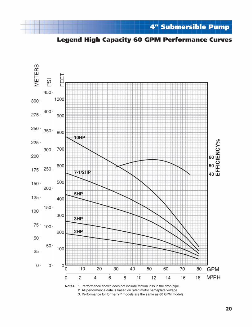
Legend High Capacity 60 GPM Performance Curves
1. Performance shown does not include friction loss in the drop pipe. 2. All performance data is based on rated motor nameplate voltage. 3. Performance for former YP models are the same as 60 GPM models.
Notes:

21
4” Submersible Pump
Legend High Capacity 60 GPM Performance Charts
HP PSIDEPTH TO PUMPING WATER LEVEL, OR LIFT, IN FEET
SHADED AREAS INDICATE MOST EFFICIENT PERFORMANCE20 30 40 50 60 70 80 90 100 110 120 130 140 150 160 170 180
2
0 87 84 81 78 75 72 69 66 62 58 54 4910 80 77 74 71 68 65 61 57 52 47 42 3620 74 70 67 64 60 56 51 46 40 34 26 1830 66 63 59 54 49 44 38 31 24 1640 57 53 48 42 36 29 21 1350 46 40 34 27 1960 32 24 16
Shut-off PSI 74 69 65 61 56 52 48 43 39 30 26 22 17 13 9 4
3
0 90 87 85 83 81 79 76 74 72 70 67 65 62 59 56 53 4910 84 82 80 78 76 74 71 69 67 64 61 58 55 51 47 43 3820 79 77 75 73 71 68 66 63 60 57 54 50 46 42 37 32 2630 74 72 70 68 65 59 56 53 49 45 40 35 30 2440 69 67 64 62 58 55 52 48 43 39 34 28 2250 63 61 58 54 50 46 42 37 32 2660 56 63 49 45 41 36 30 24
Shut-off PSI 108 104 100 95 91 87 82 78 74 69 65 61 56 52 48 43 39
HP PSI 20 40 60 80 100 120 140 160 180 200 220 240 260 280 300 320 340
5
0 85 85 80 80 75 75 70 70 65 65 60 55 50 45 45 35 3010 85 80 80 75 75 70 70 65 60 60 55 50 45 40 35 30 2520 80 80 75 75 70 70 65 60 60 55 50 45 40 35 30 25 1530 80 75 75 70 65 65 60 60 55 50 45 40 35 30 20 15 540 75 70 70 65 65 60 55 55 50 45 40 35 30 25 10 550 70 70 65 65 60 55 55 50 45 40 35 25 25 10 560 70 65 65 60 55 50 50 45 40 30 25 20 10 570 65 60 60 55 50 45 40 35 30 25 15 1080 60 60 55 50 45 40 35 30 25 15 1090 60 55 50 45 40 35 30 20 15 5100 55 50 45 40 35 30 20 15 5
Shut-off PSI 173 165 156 147 139 130 121 113 104 95 87 78 69 61 52 43 35
HP PSI 50 100 150 200 250 300 350 400 450 500 550 600 650 700 750 800 850
7-1/2
0 - 78 73 68 63 56 49 40 28 15 220 78 73 68 63 56 49 40 28 15 240 75 69 64 58 50 41 30 18 360 70 64 58 50 42 31 18 480 65 59 51 43 32 19 5100 59 52 43 32 20 6120 52 44 33 21 8140 44 34 21 8160 35 22 9
Shut-off PSI 221 199 177 156 134 113 91 69 48 26 4
10
0 - - 75 72 69 65 61 56 51 45 38 30 21 13 420 - 75 72 69 65 61 56 51 46 38 31 22 14 540 75 72 69 65 61 56 51 45 39 31 22 14 560 73 69 66 62 57 52 47 40 32 24 15 680 70 66 62 57 52 47 40 32 24 15 6100 66 62 58 53 48 41 34 25 16 7120 63 58 53 48 41 34 25 16 8140 58 53 48 42 34 26 17 8160 54 49 43 35 27 18 9
Shut-off PSI 312 290 269 247 225 204 182 161 139 117 96 74 52 31 9
Sh
ut-
off
425
ft.
Sh
ut-
off
265
ft.
Sh
ut-
off
195
ft.
Sh
ut-
off
555
ft.
Capacities in U.S. Gallons per Minute
Sh
ut-
off
772
ft.

22
4” Submersible Pump
Legend High Capacity 90 GPM Performance Curves
60
40
50
EF
FIC
IEN
CY
%
0
125
100
50
75
25
0
175
125
150
100
50
75
25
350
400
450
300
250
200
150
100
50
00 10 20 30 40 50 60 70 80 11010090 120 130
0 62 4 108 12 14 16 18 302826242220
ME
TE
RS
FE
ET
PS
I
M3PH
GPM
7-1/2HP
5HP
3HP
2HP
1. Performance shown does not include friction loss in the drop pipe. 2. All performance data is based on rated motor nameplate voltage.
Notes:
23
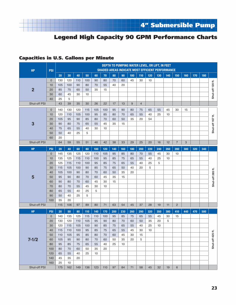
4” Submersible Pump
Legend High Capacity 90 GPM Performance Charts
HP PSI
DEPTH TO PUMPING WATER LEVEL, OR LIFT, IN FEETSHADED AREAS INDICATE MOST EFFICIENT PERFORMANCE
20 30 40 50 60 70 80 90 100 110 120 130 140 150 160 170 180
2
0 130 120 110 100 90 80 70 60 45 30 10
10 105 100 90 80 70 55 40 20
20 85 75 65 50 35 15
30 60 45 30 10
40 25 5
Shut-off PSI 43 39 35 30 26 22 17 13 9 4
3
0 140 130 120 115 105 100 95 90 80 75 65 55 45 30 15
10 120 110 105 100 95 85 80 70 65 55 40 25 10
20 105 95 90 85 80 70 60 50 35 20 54
30 90 80 75 65 55 45 35 15
40 75 65 55 40 30 10
50 50 40 25 5
60 20
Shut-off PSI 64 59 55 51 46 42 38 33 29 25 20 16 12 7 3
HP PSI 20 40 60 80 100 120 140 160 180 200 220 240 260 280 300 320 340
5
0 145 135 125 120 110 105 95 85 80 70 55 45 30 10
10 135 125 115 110 100 95 85 75 65 55 40 25 10
20 125 115 110 100 95 85 75 65 55 40 25 5
30 115 105 100 90 85 75 65 50 40 20 5
40 105 100 90 80 70 60 50 35 20
50 95 90 80 70 60 45 35 15
60 90 80 70 60 45 30 15
70 80 70 55 45 30 10
80 65 55 40 25 5
90 50 40 25 5
100 35 20
Shut-off PSI 115 106 97 89 80 71 63 54 45 37 28 19 11 2
HP PSI 20 50 80 110 140 170 200 230 260 290 320 350 380 410 440 470 500
7-1/2
0 140 135 125 115 110 100 95 85 75 65 55 45 30 15
20 130 120 110 105 95 90 80 70 60 50 35 20 5
30 120 115 105 100 90 85 75 65 55 40 25 10
40 115 110 100 95 85 75 65 55 45 30 10
50 110 105 95 85 80 70 60 45 30 15
60 105 95 90 80 70 60 50 35 20 5
80 95 85 75 65 55 40 25 10
100 80 70 60 50 35 20
120 65 55 40 25 10
140 45 35 20
160 25 10
Shut-off PSI 175 162 149 136 123 110 97 84 71 58 45 32 19 6
Sh
ut-
off
285
ft.
Sh
ut-
off
167
ft.
Sh
ut-
off
120
ft.
Sh
ut-
off
425
ft.
Capacities in U.S. Gallons per Minute
24
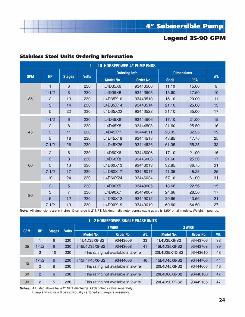
4” Submersible Pump
1 - 10 HORSEPOWER 4" PUMP ENDS
GPM HP Stages VoltsOrdering Info. Dimensions
Wt.Model No. Order No. Shell PEA
35
1 6 230 L4D35X6 93443506 11.10 15.00 9
1-1/2 8 230 L4D35X8 93443508 13.60 17.50 10
2 10 230 L4D35X10 93443510 16.10 20.00 11
3 14 230 L4D35X14 93443514 21.10 25.00 13
5 22 230 L4D35X22 93443522 31.10 35.00 17
45
1-1/2 6 230 L4D45X6 93444506 17.10 21.00 15
2 8 230 L4D45X8 93444508 21.60 25.50 16
3 11 230 L4D45X11 93444511 28.35 32.25 19
5 18 230 L4D45X18 93444518 43.85 47.75 25
7-1/2 26 230 L4D45X26 93444526 61.35 65.25 33
60
2 6 230 L4D60X6 93446006 17.10 21.00 15
3 8 230 L4D60X8 93446008 21.60 25.50 17
5 13 230 L4D60X13 93446013 32.85 36.75 21
7-1/2 17 230 L4D60X17 93446017 41.35 45.25 25
10 24 230 L4D60X24 93446024 57.10 61.00 31
90
2 5 230 L4D90X5 93449005 18.66 22.56 15
3 7 230 L4D90X7 93449007 24.66 28.56 17
5 12 230 L4D90X12 93449012 39.66 43.56 21
7-1/2 19 230 L4D90X19 93449019 60.60 64.50 27
Legend 35-90 GPM
Stainless Steel Units Ordering Information
1 - 2 HORSEPOWER SINGLE PHASE UNITS
GPM HP Stages Volts2 WIRE 3 WIRE
Model No. Order No. Wt. Model No. Order No. Wt.
35
1 6 230 T1L4D35X6-S2 93443606 33 1L4D35X6-S2 93443706 33
1-1/2 8 230 T15L4D35X8-S2 93443608 41 15L4D35X8-S2 93443708 39
2 10 230 This rating not available in 2-wire 20L4D35X10-S2 93443610 43
451-1/2 6 230 T15F4P45X6-S2 93444606 46 15L4D45X6-S2 93444706 44
2 8 230 This rating not available in 2-wire 20L4D45X8-S2 93444608 48
60 2 6 230 This rating not available in 2-wire 20L4D60X6-S2 93446106 47
90 2 5 230 This rating not available in 2-wire 20L4D90X5-S2 93449105 47
Note: All dimensions are in inches. Discharge is 2” NPT. Maximum diameter across cable guard is 3.90” on all models. Weight in pounds.
All listed above have 2” NPT discharge. Order check valve separately. Pump and motor will be individually cartoned and require assembly.
Notes:

25
6” Submersible Pump
High Capacity50 and 75 GPM Models
Model Number ExplanationExample: 15L6D50X4-S215 = 1-1/2 HPL = Legend6 = 6” SubmersibleD = 50 = 50 GPMX = Stainless Steel4 = 4 StagesS = Single Phase2 = 230V
Features:■ Heavy-duty stainless steel discharge head and motor bracket.
■ Stainless steel shaft, shell, intake screen and cable shield for
corrosion resistance and longer life.
■ Stainless steel wear ring and Urethane fl oating eye seal for
improved performance and effi ciency.
■ Glass-fi lled Noryl impeller stage assemblies for incredible strength
and durability.
■ Ceramic shaft sleeve and rubber discharge bearing minimizes
bearing wear and shaft misalignment without affecting
pump effi ciency.
■ 3” NPT tapping in heavy-duty stainless steel discharge head.
■ NEW fastener kit supplied for both 4” and 6” motors.
■ Enables 5 - 10 HP units to be mounted to either a 4" or 6"
submersible motor.
■ One year unconditional warranty against failure from sand locking
in abrasive well conditions.

8” Submersible Motors Hi-Temp 75
26
6” Submersible Pump
Legend High Capacity 50 GPM Performance Curves
70
50
60
EF
FIC
IEN
CY
%
0
175
125
200
150
100
50
75
25
225
250
275
300
350
400
450
300
250
200
150
100
50
0 0
100
200
300
400
500
600
700
800
900
1000
ME
TE
RS
PS
I
FE
ET
0 10 20 30 40 50 60 70 80
0 62 4 108 12 14 16 18 M3PH
GPM
10HP
7-1/2HP
5HP
2HP
3HP
1-1/2HP

8” Submersible Motors Hi-Temp 75
27
6” Submersible Pump
Legend High Capacity 50 GPM Performance Charts
HP PSIDEPTH TO PUMPING WATER LEVEL, OR LIFT, IN FEET
SHADED AREAS INDICATE MOST EFFICIENT PERFORMANCE40 60 80 100 120 140 160 180 200 250 300 350 400 450 500 550 600 650 700 750 800
1-1/2
0 73 65 57 48 39 26
20 54 46 36 20
30 45 34 18
40 32 13
50
2
0 75 69 63 57 50 43 34 23
20 62 55 48 41 32 18
30 54 47 39 30 15
40 46 38 28
50 37 26
60 24
3
0 - 78 73 68 63 58 52 46 40 13
20 71 66 61 56 50 44 37 29 16
30 66 61 55 49 43 36 27 14
40 60 54 48 42 35 25
50 53 47 41 34 23
60 46 40 32 22
5
0 - 0 0 78 75 72 69 66 63 55 46 36 21
20 - - 74 71 68 65 62 59 56 47 37 23
40 73 70 67 64 61 58 54 51 47 48 24
50 70 67 64 61 57 54 51 47 43 32
60 66 65 61 57 54 50 47 43 39 25
7-1/2
0 - - - - - 79 77 75 73 68 63 58 52 46 40 31 21
20 - - - - - 74 72 70 68 63 58 53 47 40 33 22
30 - - - - 74 72 70 68 66 61 56 50 44 37 28
40 - - - 74 72 70 68 66 64 59 53 47 41 33 23
50 - - 73 71 69 68 66 64 62 56 51 45 38 29 16
60 - 74 72 70 68 65 63 61 59 54 48 41 34 24
10
0 - - - - - - - - 78 74 70 67 63 59 55 51 46 41 36 30 21
20 - - - - - - - - 74 71 67 63 59 55 51 47 42 36 30 22 8
30 - - - - - - - 74 73 69 65 61 57 53 49 44 39 34 27 17
40 - - - - - - 74 72 71 67 63 59 55 51 47 42 37 30 22
50 - - - - 75 73 72 70 69 65 61 57 53 49 45 40 34 27 18
60 - - - - 74 72 71 69 67 63 59 55 51 47 43 37 31 12
Capacities in U.S. Gallons per Minute
Sh
ut-
off
158
ft.
Sh
ut-
off
198
ft.
Sh
ut-
off
260
ft.
Sh
ut-
off
434
ft.
Sh
ut-
off
650
ft.
Sh
ut-
off
865
ft.
Discharge tapping 3” FNPT. 1. Performance shown does not include friction loss in the drop pipe. 2. All performance data is based on rated motor nameplate voltage.
Notes:

8” Submersible Motors Hi-Temp 75
28
6” Submersible Pump
Legend High Capacity 75 GPM Performance Curves
70
50
60
EF
FIC
IEN
CY
%
0
200
150
100
50
250
300
350
350
400
450
300
250
200
150
100
50
0
500
0
100
200
300
400
500
600
700
800
900
1000
1200
1100
0 10 20 30 40 50 60 70 80 13012011010090
0 62 4 108 12 14 16 18 302826242220
ME
TE
RS
PS
I
FE
ET
M3PH
GPM
25HP
20HP
15HP
10HP
7-1/2HP
5HP
3HP

8” Submersible Motors Hi-Temp 75
29
6” Submersible Pump
Legend High Capacity 75 GPM Performance Charts
HP PSIDEPTH TO PUMPING WATER LEVEL, OR LIFT, IN FEET
SHADED AREAS INDICATE MOST EFFICIENT PERFORMANCE40 60 80 100 120 140 160 180 200 250 300 350 400 450 500 550 600 650 700 750 800 850 900 950 1000
3
0 110 104 94 84 72 57 2520 92 80 68 5230 78 65 4840 63 4450 39
5
0 - 115 109 104 98 92 86 79 72 4920 107 102 96 90 84 77 70 6230 101 95 89 83 76 69 6040 94 88 82 75 68 5950 87 80 73 66 5760 80 72 65 55
7-1/2
0 - - 110 108 105 101 98 94 90 80 68 54 2020 110 108 104 100 96 93 89 85 81 69 56 2830 107 104 100 96 92 88 84 80 76 64 4840 103 99 95 91 88 84 79 75 70 57 3350 99 95 91 87 83 79 74 70 65 4960 94 90 87 82 78 74 69 64 58 36
10
0 - - - - - - 109 107 104 96 89 81 72 62 4720 - - - 110 108 106 103 100 97 89 82 73 63 4930 - - 110 108 105 103 100 97 94 86 78 68 57 3840 - 110 108 105 102 99 96 93 90 82 73 64 5050 110 107 105 102 99 96 93 90 86 78 69 58 4060 107 104 101 98 95 92 89 86 83 74 64 52
15
0 - - - - - - - - - 109 104 99 94 89 84 78 72 66 58 48 2620 - - - - - - - - 109 104 100 95 90 84 79 73 66 58 48 2930 - - - - - - - - 107 102 97 92 87 82 76 70 63 54 4140 - - - - - - - - 105 100 95 90 85 79 73 67 59 50 3250 - - - - - - - - 103 98 93 87 82 76 70 63 55 4360 - - - - - - - - 100 95 90 85 80 74 67 60 50 33
20
0 - - - - - - - - - - 110 107 104 100 97 93 89 85 81 77 72 67 62 56 4820 - - - - - - - - - - 108 104 100 97 93 89 86 81 77 72 67 62 56 48 3830 - - - - - - - - - 110 106 103 99 95 91 88 84 79 75 70 65 60 53 44 2440 - - - - - - - - - 108 105 101 97 93 90 86 82 77 73 68 63 57 50 3950 - - - - - - - - 110 106 103 99 95 92 88 84 80 75 71 66 60 55 45 2660 - - - - - - - - 108 105 101 98 94 90 86 82 78 73 69 63 57 53 40
HP PSI 300 350 400 450 500 550 600 650 700 750 800 850 900 950 1000 1050 1100 1150 1200
25
0 - - 106 103 99 96 93 89 86 83 79 76 72 68 64 60 54 47 3620 - 106 103 99 96 93 89 86 83 79 76 72 68 64 60 54 48 3630 108 105 102 98 94 92 88 85 81 78 75 70 66 62 58 52 44 2440 106 103 100 96 92 89 86 83 79 76 72 68 64 60 54 48 3850 105 101 98 95 91 88 85 81 78 75 71 67 63 58 52 44 2660 103 100 96 93 90 86 83 79 76 73 69 65 61 56 49 39
Sh
ut-
off
161
ft.
Sh
ut-
off
253
ft.
Sh
ut-
off
404
ft.
Sh
ut-
off
540
ft.
Sh
ut-
off
810
ft.
Sh
ut-
off
108
0 ft
.S
hu
t-o
ff 1
220
ft.
Capacities in U.S. Gallons per Minute
Discharge tapping 3” FNPT. 1. Performance shown does not include friction loss in the drop pipe. 2. All performance data is based on rated motor nameplate voltage.
Notes:

8” Submersible Motors Hi-Temp 75
30
6” Submersible Pump
Stainless Steel Ordering Information
1-1/2 - 25 HP 6" PUMP ENDS
GPM HP StagesMotor
FitOrdering Info. Dimensions
Wt.Model No. Order No. Shell PEA
50
1-1/2 4 4" L6D50X4 93455004 8.57 14.69 32
2 5 4" L6D50X5 93455005 10.88 17.00 32
3 6 4" L6D50X6 93455006 12.51 18.63 33
5 10 4"& 6" L6D50X10 93455010 18.94 25.06 39
7-1/2 15 4"& 6" L6D50X15 93455015 26.88 33.00 46
10 20 4"& 6" L6D50X20 93455020 35.07 41.19 52
75
3 3 4" L6D75X3 93457503 7.57 13.69 32
5 5 4"& 6" L6D75X5 93457505 10.88 17.00 32
7-1/2 8 4"& 6" L6D75X8 93457508 15.69 21.81 36
10 10 4"& 6" L6D75X10 93457510 18.94 25.06 39
15 15 6" L6D75X15 93457515 26.88 33.00 46
20 20 6" L6D75X20 93457520 35.07 41.19 52
25 24 6" L6D75X24 93457524 41.57 47.69 57
Note: All dimensions are in inches. Discharge is 3” NPT. Maximum diameter across cable guard is 5.5” on all models. Weight in pounds.
Legend 50-75 GPM
31
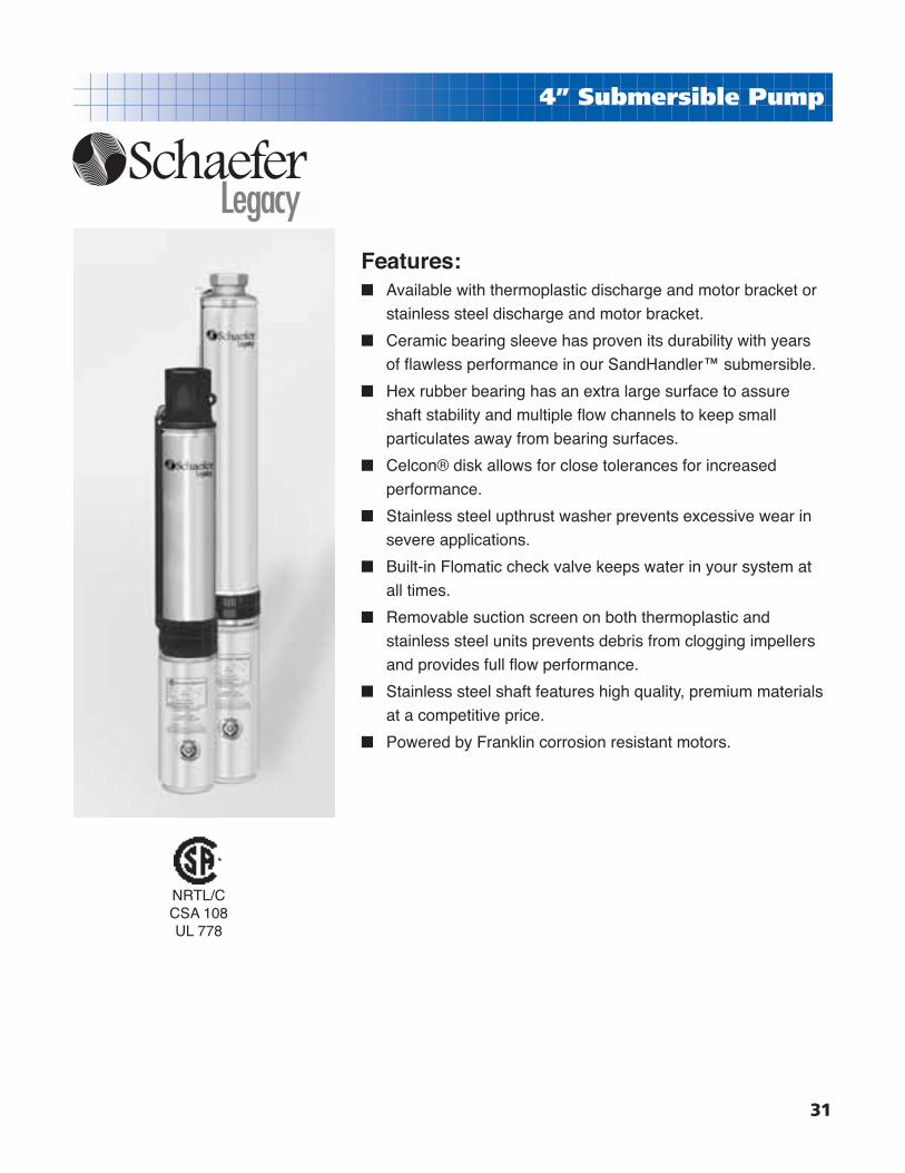
4” Submersible Pump
Features:■ Available with thermoplastic discharge and motor bracket or
stainless steel discharge and motor bracket.
■ Ceramic bearing sleeve has proven its durability with years
of fl awless performance in our SandHandler™ submersible.
■ Hex rubber bearing has an extra large surface to assure
shaft stability and multiple fl ow channels to keep small
particulates away from bearing surfaces.
■ Celcon® disk allows for close tolerances for increased
performance.
■ Stainless steel upthrust washer prevents excessive wear in
severe applications.
■ Built-in Flomatic check valve keeps water in your system at
all times.
■ Removable suction screen on both thermoplastic and
stainless steel units prevents debris from clogging impellers
and provides full fl ow performance.
■ Stainless steel shaft features high quality, premium materials
at a competitive price.
■ Powered by Franklin corrosion resistant motors.
NRTL/C CSA 108UL 778

32
4” Submersible Pump
0
200
150
100
50
250 350
400
300
250
200
150
100
0
200
300
400
500
600
700
800
900
ME
TE
RS
PS
I
FE
ET
04320 1 8765
0 .5 1.0 1.5 M3PHGPM
1-1/2HP
1HP
3/4HP
1/2HP
Legacy 5 GPM Performance Curves

33
4” Submersible Pump
Legacy 5 GPM Performance Charts
HP PSI
DEPTH TO PUMPING WATER LEVEL, OR LIFT, IN FEETSHADED AREAS INDICATE MOST EFFICIENT PERFORMANCE
20 40 60 80 100 120 140 160 180 200 240 260 300 340 360 400 440 480 500 600 700 800 900 1000
1/2
0 - - - - - 8 7 7 6 6 5 4 3
20 - - - 7 7 6 6 5 5 4 3 3 2
30 - - 7 7 6 6 5 5 4 4 3 2
40 - 7 7 6 6 5 5 4 4 3 2
50 7 7 6 6 5 5 4 4 3 2
60 7 6 6 5 5 4 4 3 2
80 6 5 5 4 4 3 2 1
Shut-off PSI 149 140 131 122 114 105 96 88 79 70 53 45 27
3/4
0 - - - - - - - - 7 7 7 6 6 5 5 4 3
20 - - - - - - 7 7 7 6 6 6 5 4 4 3 2
30 - - - - 8 7 7 7 6 6 6 5 5 4 4 2
40 - - - 8 7 7 7 6 6 6 5 5 4 3 3
50 - - 7 7 7 6 6 6 6 5 5 5 4 3 2
60 7 7 7 7 6 6 6 6 5 5 5 4 3 2
80 7 7 6 6 6 6 5 5 5 4 4 3 3
Shut-off PSI 220 211 203 194 185 177 168 159 151 142 125 116 99 81 73 55 38
1
0 - - - - - - - - - 8 7 7 6 6 6 5 5 4 4
20 - - - - - - - 7 7 7 6 6 6 5 5 5 4 3 2
30 - - - - - - 7 7 7 7 6 6 5 5 5 4 3 2 2
40 - - - - - 7 7 6 6 6 6 5 5 4 4 3 2 1
50 - - - - 7 7 7 6 6 6 6 5 5 4 4 3 2 1
60 - - - 7 7 7 6 6 6 6 5 5 5 4 4 3 1
80 7 7 7 7 6 6 6 6 6 5 5 5 4 3 3 2
Shut-off PSI 257 248 239 231 222 213 205 196 187 179 161 153 135 118 109 92 75 58 49
1-1/2
0 - - - - - - - - - - - - 7 7 7 6 6 6 6 5 3
20 - - - - - - - - - - 7 7 7 7 6 6 6 5 5 4 3
30 - - - - - - - - - 7 7 7 7 6 6 6 6 5 5 4
40 - - - - - - - - 7 7 7 7 6 6 6 6 6 5 5 4
50 - - - - - - - 7 7 7 7 7 6 6 6 5 5 5 4 3
60 - - - - - - 7 7 7 7 7 6 6 6 6 5 5 4 4 3
80 - - - - 7 7 7 7 7 6 6 6 6 5 5 5 4 4 3
Shut-off PSI 351 343 334 325 317 308 300 291 282 274 256 248 230 213 204 187 170 152 144 100 57
Sh
ut-
off
614
ft.
Sh
ut-
off
528
ft.
Sh
ut-
off
364
ft.
Sh
ut-
off
833
ft.
Capacities in U.S. Gallons per Minute
1. Performance shown does not include friction loss in the drop pipe. 2. All performance data is based on rated motor nameplate voltage.
Notes:

34
4” Submersible Pump
Legacy 8 GPM Performance Curves
0
175
125
150
100
50
75
25
250
200
150
100
50
0 0
100
200
300
400
500
600
ME
TE
RS
PS
I
FE
ET
0 62 4 108
0 .5 1.0 1.5 2.0 2.5 M3PH
GPM
1-1/2HP
1HP
3/4HP
1/2HP

35
4” Submersible Pump
Legacy 8 GPM Performance Charts
HP PSI
DEPTH TO PUMPING WATER LEVEL, OR LIFT, IN FEETSHADED AREAS INDICATE MOST EFFICIENT PERFORMANCE
20 40 60 80 100 140 180 200 240 280 300 340 380 400 440 480 500 600 700
1/2
0 - - - - - 11 10 9 6
10 - - - - 12 10 9 7 3
20 - - - 12 11 9 7 5
30 - - 12 11 10 8 5 2
40 - 11 10 10 9 7 1
50 11 10 10 9 8 4
60 10 10 9 8 6
70 10 9 8 6 3
80 9 7 5 2
Shut-off PSI 110 102 93 84 76 58 41 32 15
3/4
0 - - - - - - 11 10 10 9 8 4
10 - - - - - 12 10 10 9 7 6
20 - - - - - 11 10 9 8 5 3
30 - - - - 12 10 9 9 7 2
40 - - - 12 11 10 9 8 5
50 - - 11 11 10 9 8 6 1
60 12 11 10 10 10 9 6 4
70 11 10 10 10 9 7 4
80 10 10 9 9 8 6
Shut-off PSI 149 140 132 123 114 97 80 71 54 36 28 10
1
0 - - - - - - - 12 10 10 9 8 7 5 2
10 - - - - - - 11 11 10 9 9 7 5 4
20 - - - - - - 11 10 9 9 8 6 3 1
30 - - - - - 11 10 10 9 8 7 5 1
40 - - - - 12 11 10 9 8 7 6 3
50 - - - 12 11 10 9 9 8 6 4
60 - - 12 11 10 10 9 8 7 4 2
70 - 12 11 10 10 9 8 7 5 2
80 11 11 10 10 10 9 7 6 3
Shut-off PSI 188 180 171 162 154 136 119 110 93 76 67 50 32 24 6
1-1/2
0 - - - - - - - - - 11 11 10 9 9 9 8 7 2
10 - - - - - - - - 12 11 10 10 9 9 8 7 7
20 - - - - - - - - 11 10 10 9 9 9 8 6 6
30 - - - - - - - 12 11 10 10 9 9 8 7 5 4
40 - - - - - - 11 11 10 10 9 9 8 8 6 4 3
50 - - - - - - 11 10 10 9 9 8 8 7 5 3 1
60 - - - - - 11 10 10 10 9 9 8 7 6 4 1
70 - - - - 12 11 10 10 9 9 8 7 6 5 2
80 - - - 12 11 10 10 9 9 8 8 7 5 3
Shut-off PSI - - - 236 227 210 193 184 167 149 141 123 106 97 80 63 54 11
Sh
ut-
off
455
ft.
Sh
ut-
off
365
ft.
Sh
ut-
off
275
ft.
Sh
ut-
off
626
ft.
Capacities in U.S. Gallons per Minute
1. Performance shown does not include friction loss in the drop pipe. 2. All performance data is based on rated motor nameplate voltage.
Notes:

36
4” Submersible Pump
Legacy 12 GPM Performance Curves
0
175
125
150
100
50
75
25
0
175
125
150
100
50
75
25
250
225
200
0
100
200
300
400
500
50
150
250
350
450
600
550
ME
TE
RS
PS
I
FE
ET
0 62 4 108 18161412
0 .5 1.0 1.5 2.0 2.5 4.03.53.0 M3PHGPM
1-1/2HP
1HP
3/4HP
1/2HP

37
4” Submersible Pump
Legacy 12 GPM Performance Charts
HP PSI
DEPTH TO PUMPING WATER LEVEL, OR LIFT, IN FEETSHADED AREAS INDICATE MOST EFFICIENT PERFORMANCE
20 40 60 80 100 140 180 200 240 280 300 340 380 400 440 480 500
1/2
0 - 19 18 17 16 14 12 7
10 19 18 17 16 15 12 7 2
20 18 16 16 15 13 9 2
30 16 15 14 13 11 5
40 15 14 13 11 8
50 14 13 11 8 4
60 12 10 7 3
70 10 7 3
80 6 2
Shut-off PSI 91 82 74 65 56 39 22 13
3/4
0 - 20 19 18 17 15 14 13 9 3
10 20 19 18 17 16 15 13 11 6
20 18 17 17 16 15 14 11 8 2
30 17 17 16 15 14 12 8 5
40 16 16 15 14 13 10 5 1
50 16 15 14 13 12 7
60 15 14 13 11 9 4
70 14 13 11 9 6
80 12 11 9 6 3
Shut-off PSI 118 109 100 92 83 66 48 40 23 5
1
0 - - 20 19 18 17 16 15 14 12 10 7 3
10 - 20 19 18 17 16 15 14 12 10 9 5
20 20 19 18 17 17 16 14 13 11 8 7 2
30 19 18 17 17 16 15 13 1 10 6 4
40 18 17 17 16 15 14 12 11 8 4 1
50 17 16 16 15 15 13 11 9 6 1
60 16 16 15 14 14 12 9 7 3
70 16 15 14 13 13 10 7 5
80 15 14 13 12 11 8 5 2
Shut-off PSI 165 156 147 139 130 113 95 87 69 52 43 26 9
1-1/2
0 - - - 20 19 18 17 17 16 15 14 13 12 11 9 7 5
10 - - 20 19 18 17 16 16 15 14 14 13 11 10 8 5 3
20 - 20 19 18 18 17 16 16 15 14 13 12 10 9 6 3
30 20 19 18 18 17 16 16 15 14 13 12 11 9 7 4
40 19 18 18 17 17 16 15 15 14 12 12 10 7 6 2
50 18 18 17 17 16 15 15 14 13 11 10 8 5 4
60 17 17 17 16 16 15 14 13 12 10 9 7 3 1
70 17 16 16 16 15 14 13 13 11 9 8 5 1
80 16 16 16 15 15 14 13 12 10 8 6 3
Shut-off PSI 227 219 210 201 193 175 158 149 132 115 106 89 71 68 45 28 19
Sh
ut-
off
399
ft.
Sh
ut-
off
291
ft.
Sh
ut-
off
231
ft.
Sh
ut-
off
545
ft.
Capacities in U.S. Gallons per Minute
1. Performance shown does not include friction loss in the drop pipe. 2. All performance data is based on rated motor nameplate voltage.
Notes:

38
4” Submersible Pump
Legacy 16 GPM Performance Curves
0
175
125
150
100
50
75
25
0
150
100
50
250
200
0
100
200
300
400
500
600
ME
TE
RS
PS
I
FE
ET
0 105 15 20
0 1 2 43 5 M3PH
GPM
2HP
1-1/2HP
1HP
3/4HP

39
4” Submersible Pump
Legacy 16 GPM Performance Charts
HP PSI
DEPTH TO PUMPING WATER LEVEL, OR LIFT, IN FEETSHADED AREAS INDICATE MOST EFFICIENT PERFORMANCE
20 40 60 80 100 140 180 200 240 280 300 340 380 400 440 480 500
3/4
0 - - - - 23 20 17 13
10 - - - 22 21 18 12 6
20 - - 22 20 19 16 5
30 25 22 20 19 18 11
40 21 20 19 17 15 2
50 20 19 17 14 9
60 19 17 13 8
70 16 13 6
80 12 5
Shut-off PSI 91 82 74 65 56 39 22 13
1
0 - - - - - 21 19 18 15 5
10 - - - - 23 20 18 17 10
20 - - - 23 21 19 16 14 3
30 - - 22 21 20 18 13 9
40 25 22 20 20 19 16 8 1
50 22 20 19 19 17 12
60 20 19 18 17 15 6
70 19 18 17 14 11
80 18 17 14 10 4
Shut-off PSI 115 106 97 89 80 63 45 37 19 2
1-1/2
0 - - - - - - 22 21 19 18 17 14 7
10 - - - - - 23 21 20 18 17 15 10 1
20 - - - - - 21 20 19 17 15 13 6
30 - - - 25 23 20 19 18 16 13 9
40 - - 24 22 21 19 18 17 14 8 4
50 - 24 22 21 19 18 17 16 11 3
60 24 22 21 20 19 18 15 13 7
70 22 21 20 19 18 17 13 10 2
80 20 20 19 18 18 15 10 6
Shut-off PSI 165 156 147 139 130 113 95 87 69 52 43 26 9
2
0 - - - - - - 25 23 21 20 19 18 16 15 12 8 5
10 - - - - - - 23 22 20 19 19 17 15 14 10 4 1
20 - - - - - 24 22 21 20 18 18 16 13 12 7
30 - - - - - 23 21 20 19 18 17 15 11 9 3
40 - - - - 24 21 20 19 18 17 16 13 9 6
50 - - - 24 22 21 19 19 17 16 14 11 5 2
60 - 25 23 22 21 20 19 18 16 14 12 8 1
70 25 23 22 21 20 19 18 17 15 12 10 4
80 23 22 21 20 20 18 17 16 14 10 7
Shut-off PSI 214 206 197 188 180 162 145 136 119 102 93 76 58 50 32 15 6
Sh
ut-
off
399
ft.
Sh
ut-
off
284
ft.
Sh
ut-
off
231
ft.
Sh
ut-
off
515
ft.
Capacities in U.S. Gallons per Minute
1. Performance shown does not include friction loss in the drop pipe. 2. All performance data is based on rated motor nameplate voltage.
Notes:
40
4” Submersible Pump
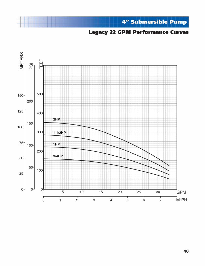
Legacy 22 GPM Performance Curves
0
125
150
100
50
75
25
0
150
100
50
200
0
100
200
300
400
500
ME
TE
RS
PS
I
FE
ET
0 5 10 15 20 25 30
0 654321 7 M3PH
GPM
2HP
1-1/2HP
1HP
3/4HP
41
4” Submersible Pump
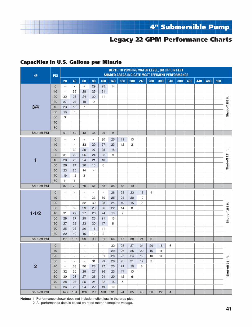
Legacy 22 GPM Performance Charts
HP PSI
DEPTH TO PUMPING WATER LEVEL, OR LIFT, IN FEETSHADED AREAS INDICATE MOST EFFICIENT PERFORMANCE
20 40 60 80 100 140 180 200 240 280 300 340 380 400 440 480 500
3/4
0 - - - 29 25 14
10 - 32 28 25 21
20 32 28 24 20 11
30 27 24 19 9
40 23 18 7
50 16 5
60 3
70
80
Shut-off PSI 61 52 43 35 26 9
1
0 - - - - 30 25 19 13
10 - - 33 29 27 23 12 2
20 - 32 29 27 25 18
30 31 28 26 24 22 9
40 28 26 24 21 16
50 26 24 20 15 6
60 23 20 14 4
70 19 12 3
80 11 1
Shut-off PSI 87 79 70 61 53 35 18 10
1-1/2
0 - - - - - 28 25 23 16 4
10 - - - 33 30 26 23 20 10
20 - - 32 30 28 24 19 15 2
30 - 32 29 28 26 22 14 8
40 31 29 27 26 24 18 7
50 29 27 25 23 21 13
60 27 25 23 20 17 5
70 25 23 20 16 11
80 22 19 15 10 2
Shut-off PSI 116 107 99 90 81 64 47 38 21 3
2
0 - - - - - 32 28 27 24 20 16 6
10 - - - - - 29 26 25 22 16 11
20 - - - - 31 28 25 24 19 10 3
30 - - - 31 29 26 23 21 17 2
40 - 33 30 28 27 25 21 18 8
50 32 30 28 27 26 23 17 13
60 30 28 27 26 24 20 12 6
70 28 27 25 24 22 16 5
80 26 25 24 22 19 10
Shut-off PSI 143 134 126 117 108 91 74 65 48 30 22 4
Sh
ut-
off
288
ft.
Sh
ut-
off
221
ft.
Sh
ut-
off
159
ft.
Sh
ut-
off
351
ft.
Capacities in U.S. Gallons per Minute
1. Performance shown does not include friction loss in the drop pipe. 2. All performance data is based on rated motor nameplate voltage.
Notes:

42
4” Submersible Pump
1/2 - 1-1/2 HORSEPOWER SINGLE PHASE UNITS
GPM HP Stages Volts2 WIRE 3 WIRE
Model No. Order No. Wt. Model No. Order No. Wt.
5
1/2 13 115 T5L4Y5P13-S1 93460513 26 5L4Y5P13-S1 93462513 25
1/2 13 230 T5L4Y5P13-S2 93461513 26 5L4Y5P13-S2 93463513 25
3/4 18 230 T7L4Y5P18-S2 93460518 29 7L4Y5P18-S2 93461518 30
1 21 230 T1L4Y5P21-S2 93460521 33 1L4Y5P21-S2 93461521 34
1-1/2 28 230 This rating not available in thermoplastic construction
8
1/2 9 115 T5L4Y8P9-S1 93460809 24 5L4Y8P9-S1 93462809 24
1/2 9 230 T5L4Y8P9-S2 93461809 24 5L4Y8P9-S2 93463809 24
3/4 12 230 T7L4Y8P12-S2 93460812 28 7L4Y8P12-S2 93461812 28
1 15 230 T1L4Y8P15-S2 93460815 33 1L4Y8P15-S2 93461815 33
1-1/2 21 230 T15L4Y8P21-S2 93460821 42 15L4Y8P21-S2 93461821 42
12
1/2 7 115 T5L4Y12P7-S1 93460127 24 5L4Y12P7-S1 93463207 24
1/2 7 230 T5L4Y12P7-S2 93461207 24 5L4Y12P7-S2 93464207 24
3/4 9 230 T7L4Y12P9-S2 93460129 28 7L4Y12P9-S2 93461209 28
1 12 230 T1L4Y12P12-S2 93461212 31 1L4Y12P12-S2 93462212 32
1-1/2 17 230 T15L4Y12P17-S2 93461217 38 15L4Y12P17-S2 93462217 39
16
3/4 8 230 T7L4Y16P8-S2 93461608 28 7L4Y16P8-S2 93462608 27
1 10 230 T1L4Y16P10-S2 93461610 31 1L4Y16P10-S2 93462610 30
1-1/2 14 230 T15L4Y16P14-S2 93461614 40 15L4Y16P14-S2 93462614 39
2 18 230 This rating not available in 2-wire 20L4Y16P18-S2 93461618 43
22
3/4 5 230 T7L4Y22P5-S2 93460225 27 7L4Y22P5-S2 93462205 27
1 7 230 T1L4Y22P7-S2 93460227 30 1L4Y22P7-S2 93462207 33
1-1/2 9 230 T15L4Y22P9-S2 93460229 40 15L4Y22P9-S2 93462209 39
2 11 230 This rating not available in 2-wire 20L4Y22P11-S2 93462211 42
Legacy 5-22 GPM
Thermoplastic Units Ordering Information
Note: All listed above have 1-1/4” NPT discharge and feature our removable FlomaticTM poppet assembly.

43
4” Submersible Pump
THERMOPLASTIC 1/2 - 1-1/2 HP PUMP ENDS
GPM HP Stages Volts Model No. Order No. Wt.
5
1/2 13 n.a. L4Y5P13 93470513 8
3/4 18 n.a. L4Y5P18 93470518 10
1 21 n.a. L4Y5P21 93470521 11
8
1/2 9 n.a. L4Y8P9 93470809 4
3/4 12 n.a. L4Y8P12 93470812 7
1 15 n.a. L4Y8P15 93470815 8
1-1/2 21 n.a. L4Y8P21 93470821 10
12
1/2 7 n.a. L4Y12P7 93471207 6
3/4 9 n.a. L4Y12P9 93471209 7
1 12 n.a. L4Y12P12 93471212 8
1-1/2 17 n.a. L4Y12P17 93471217 12
16
3/4 8 n.a. L4Y16P8 93471608 7
1 10 n.a. L4Y16P10 93471610 7
1-1/2 14 n.a. L4Y16P14 93471614 10
2 18 230 L4Y16P18 93471618 11
22
3/4 5 n.a. L4Y22P5 93472205 6
1 7 n.a. L4Y22P7 93472207 7
1-1/2 9 n.a. L4Y22P9 93472209 8
2 11 230 L4Y22P11 93472211 10
Legacy 5-22 GPM
Thermoplastic Pump Ends Ordering Information
Note: All listed above have 1-1/4” NPT discharge and feature our removable FlomaticTM poppet assembly.

44
4” Submersible Pump
Legacy 5-22 GPM
Stainless Steel Units Ordering Information
1/2 - 1-1/2 HORSEPOWER SINGLE PHASE UNITS
GPM HP Stages Volts2 WIRE 3 WIRE
Model No. Order No. Wt. Model No. Order No. Wt.
5
1/2 13 115 T5L4Y5X13-S1 93480513 26 5L4Y5X13-S1 93482513 25
1/2 13 230 T5L4Y5X13-S2 93481513 26 5L4Y5X13-S2 93483513 25
3/4 18 230 T7L4Y5X18-S2 93480518 29 7L4Y5X18-S2 93481518 30
1 21 230 T1L4Y5X21-S2 93480521 33 1L4Y5X21-S2 93481521 34
1-1/2 28 230 T15L4Y5X28-S2 93480528 43 15L4Y5X28-S2 93481528 44
8
1/2 9 115 T5L4Y8X9-S1 93480809 24 5L4Y8X9-S1 93482809 24
1/2 9 230 T5L4Y8X9-S2 93481809 24 5L4Y8X9-S2 93483809 24
3/4 12 230 T7L4Y8X12-S2 93480812 28 7L4Y8X12-S2 93481812 28
1 15 230 T1L4Y8X15-S2 93480815 33 1L4Y8X15-S2 93481815 33
1-1/2 21 230 T15L4Y8X21-S2 93480821 42 15L4Y8X21-S2 93481821 42
12
1/2 7 115 T5L4Y12X7-S1 93480127 24 5L4Y12X7-S1 93483207 24
1/2 7 230 T5L4Y12X7-S2 93481207 24 5L4Y12X7-S2 93484207 24
3/4 9 230 T7L4Y12X9-S2 93480129 28 7L4Y12X9-S2 93481209 28
1 12 230 T1L4Y12X12-S2 93481212 31 1L4Y12X12-S2 93482212 32
1-1/2 17 230 T15L4Y12X17-S2 93481217 38 15L4Y12X17-S2 93482217 39
16
3/4 8 230 T7L4Y16X8-S2 93481608 28 7L4Y16X8-S2 93482608 27
1 10 230 T1L4Y16X10-S2 93481610 31 1L4Y16X10-S2 93482610 30
1-1/2 14 230 T15L4Y16X14-S2 93481614 40 15L4Y16X14-S2 93482614 39
2 18 230 This rating not available in 2-wire 20L4Y16X18-S2 93481618 43
22
3/4 5 230 T7L4Y22X5-S2 93480225 27 7L4Y22X5-S2 93482205 27
1 7 230 T1L4Y22X7-S2 93480227 30 1L4Y22X7-S2 93482207 33
1-1/2 9 230 T15L4Y22X9-S2 93480229 40 15L4Y22X9-S2 93482209 39
2 11 230 This rating not available in 2-wire 20L4Y22X11-S2 93482211 42
Note: All listed above have 1-1/4" NPT discharge and feature our removable Flomatic™ poppet assembly.

45
4” Submersible Pump
Legacy 5-22 GPM
Stainless Steel Pump Ends Ordering Information
STAINLESS STEEL 1/2 - 2 HP PUMP ENDS
GPM HP Stages Volts Model No. Order No. Wt.
5
1/2 13 n.a. L4Y5X13 93490513 9
3/4 18 n.a. L4Y5X18 93490518 11
1 21 n.a. L4Y5X21 93490521 12
1-1/2 28 n.a. L4Y5X28 93490528 14
8
1/2 9 n.a. L4Y8X9 93490809 5
3/4 12 n.a. L4Y8X12 93490812 8
1 15 n.a. L4Y8X15 93490815 9
1-1/2 21 n.a. L4Y8X21 93490821 11
12
1/2 7 n.a. L4Y12X7 93491207 7
3/4 9 n.a. L4Y12X9 93491209 8
1 12 n.a. L4Y12X12 93491212 9
1-1/2 17 n.a. L4Y12X17 93491217 13
16
3/4 8 n.a. L4Y16X8 93491608 8
1 10 n.a. L4Y16X10 93491610 8
1-1/2 14 n.a. L4Y16X14 93491614 11
2 18 230 L4Y16X18 93491618 11
22
3/4 5 n.a. L4Y22X5 93492205 7
1 7 n.a. L4Y22X7 93492207 8
1-1/2 9 n.a. L4Y22X9 93492209 9
2 11 230 L4Y22X11 93492211 10
Note: All listed above have 1-1/4” NPT discharge and feature our removable FlomaticTM poppet assembly.

46
Submersible Accessories
Ordering Information
Check Valves Reducer BushingPoppet T-Handle Poppet Wrench
CHECK VALVES - SILICONE BRONZE
Description Inlet Outlet Case Qty. Order No. Weight
Flomatic 4221LEB 1-1/4" MNPT 1" FNPT 36 91980631 1.25
Flomatic 4242LEB 1-1/4" MNPT 1-/14" FNPT 36 91980649 1.75
CHECK VALVES - STAINLESS STEEL
Description Inlet Outlet Case Qty. Order No. Weight
Flomatic #4221LSS2 1-1/4" MNPT 1" FNPT 49 91985317 1.4
Flomatic #4242SS2 1-1/4" MNPT 1-/14" FNPT 49 91985309 1.5
CHECK VALVES - DUCTILE IRON
Description Inlet Outlet Carton Qty. Order No. Weight
Simmons #658SB 2" MNPT 2" FNPT 1 91982157 3.5
Simmons #660SB 3" MNPT 3" FNPT 1 91981266 10
Simmons #661SB 4" MNPT 4" FNPT 1 91980334 21
FLOMATIC™ POPPET with JACUZZI® REMOVABLE RING (Patent Pending)
Description Order No. Weight
Flomatic™ Poppet with Jacuzzi Removable Ring (Patent Pending) 91985259R 0.1
T-Handle Poppet Wrench 23498207 1
REDUCER BUSHING
Description Inlet Outlet PSI Rating Order No. Weight
White PVC Bushing 1-1/4" MNPT 1" FNPT 200 PSI 31031008R 0.2

47
Constant Pressure Systems
Features:■ Eliminates pressure cycling during long running
applications
■ Easy Installation - Remove the 3 wire control box and install
the MonoDrive
■ Provides constant pressure by continually adjusting pump
performance to meet water demand
■ Built-in diagnostics
■ Soft start feature prevents water hammer and reduces
stress on motor.
■ Can retrofi t existing systems - no need to pull the pump.
■ Select HP rating - 1/2, 3/4 and 1 HP.
Applications:■ Residential Water Systems • Constant water pressure • Smaller tank saves space■ Geothermal Systems • No need for large buried tanks • Eliminates pressure cycling■ Lawn Irrigation Systems • Even distribution of water in zones • Eliminates need for separate system■ Water Treatment Systems • More effi cient back fl ushing • No need for multiple pumps
PRESSURESENSER
PRESSURETANK
PUMP
MOTOR
MODEL NO. DRA DATE CODE
Franklin Electric MonoDrive
Description Franklin Model Order Number Wt.
MonoDrive Controller - NEMA 1 5870203110 5870203110 17
MonoDrive Controller - NEMA 3R 5870203113 5870203113 22
Note: For a complete variable speed system, controller above with any 1/2, 3/4 or 1 HP 4” single phase, 230 V., 3-wire pump unit.

48
Constant Pressure Systems
Franklin Electric SubDrive 75
Features:■ Eliminates pressure cycling during long running applications
■ Easy Installation
■ Provides constant pressure by continually adjusting pump
performance to meet water demand
■ Built-in diagnostics
■ Soft start feature prevents water hammer and reduces stress
on motor.
Applications:■ Residential Water Systems • Constant water pressure • Smaller tank saves space■ Geothermal Systems • No need for large buried tanks • Eliminates pressure cycling■ Lawn Irrigation Systems • Even distribution of water in zones • Eliminates need for separate system■ Water Treatment Systems • More effi cient back fl ushing • No need for multiple pumps
PRESSURESENSER
PRESSURETANK
PUMP
MOTOR
MODEL NO. DRA DATE CODE
Franklin Model Order Number Motor Weight
5870203383 5870203383 SubDrive 75 Controller - NEMA 3R 22
5870203380 9010-4225 SubDrive 75 Controller 17
Franklin Model Order Number HP Volts Thrust Rating Weight
23451492 90101460LEAD 1-1/2 230 650 24
Note: For a complete variable speed system, add any 3/4 HP 4” pump end to above control. For 5 - 18 GPM, use 3/4 HP pump end. For 25 and 35 GPM models, use 1 HP pump end.
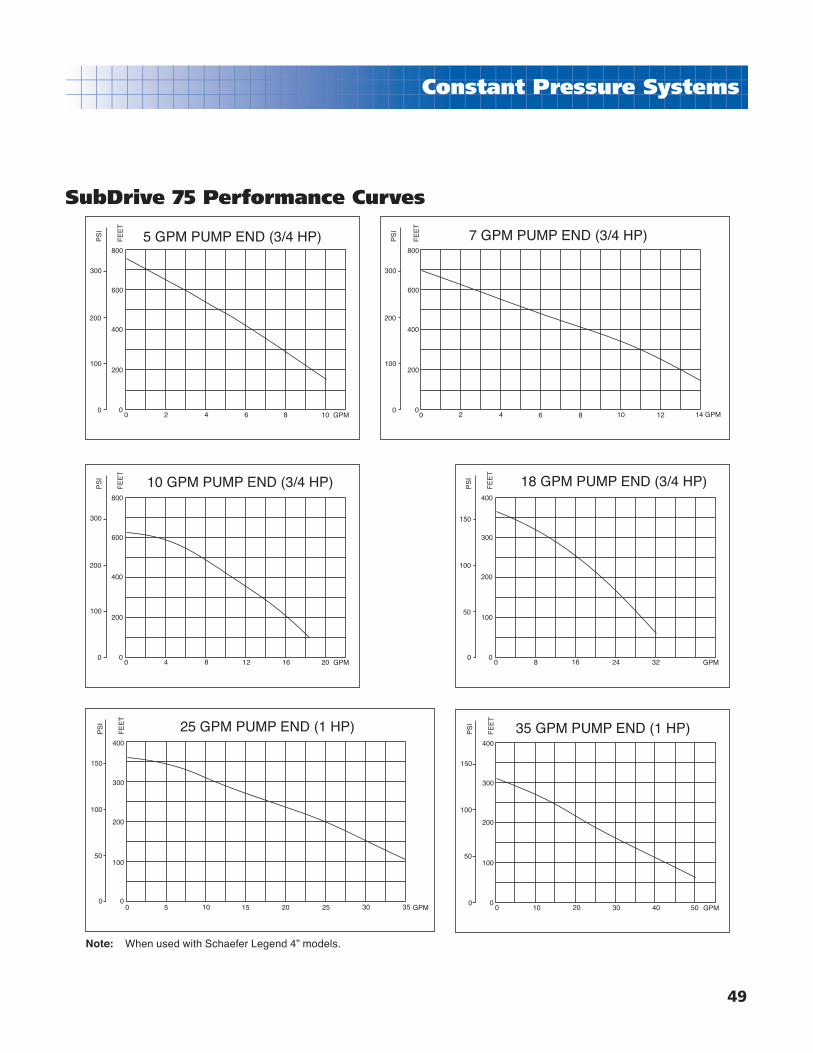
49
Constant Pressure Systems
SubDrive 75 Performance Curves
5 GPM PUMP END (3/4 HP) 7 GPM PUMP END (3/4 HP)
10 GPM PUMP END (3/4 HP) 18 GPM PUMP END (3/4 HP)
25 GPM PUMP END (1 HP) 35 GPM PUMP END (1 HP)
300
200
100
0
200
0
400
600
800
PS
I
FE
ET
0 8642 10 GPM
300
200
100
0
PS
I
200
0
400
600
800
FE
ET
0 8642 10 GPM1412
300
200
100
0
200
0
400
600
800
PS
I
FE
ET
0 161284 20 GPM
150
100
50
0
100
0
200
300
400
PS
I
FE
ET
0 3224168 GPM
150
100
50
0
100
0
200
300
400
PS
I
FE
ET
0 40302010 GPM50
150
100
50
0
100
0
200
300
400
PS
I
FE
ET
0 2015105 GPM25 30 35
Note: When used with Schaefer Legend 4” models.

50
Constant Pressure Systems
Franklin Electric SubDrive 150Features:■ Eliminates pressure cycling during long running applications
■ Easy Installation
■ Provides constant pressure by continually adjusting pump
performance to meet water demand
■ Built-in diagnostics
■ Soft start feature prevents water hammer and reduces stress
on motor.
Applications:■ Residential Water Systems • Constant water pressure • Smaller tank saves space■ Geothermal Systems • No need for large buried tanks • Eliminates pressure cycling■ Lawn Irrigation Systems • Even distribution of water in zones • Eliminates need for separate system■ Water Treatment Systems • More effi cient back fl ushing • No need for multiple pumps
PRESSURESENSER
PRESSURETANK
PUMP
MOTOR
MODEL NO. DRA DATE CODE
Franklin Model Order Number Motor Weight
5870204150 9010-9810 SubDrive 150 Controller 21
Franklin Model Order Number HP Volts Thrust Rating Weight
23431626 90101528LEAD 3 230 900 35
Notes: For a complete variable speed system, add any approved 4” pump end to above control. For 10-45 GPM, use 1-1/2 HP pump end. For 60 and 90 GPM models, use 2 HP pump end.

51
Constant Pressure Systems
SubDrive 150 Performance Curves
SUBDRIVE 150
SUBDRIVE 150SUBDRIVE 150
SUBDRIVE 150 SUBDRIVE 150
SUBDRIVE 150SUBDRIVE 150
10 GPM PUMP-END 1.5 HP
18 GPM 1.5 HP PUMP-END25 GPM 1.5 HP PUMP-END
35 GPM 1.5 HP PUMP-END 45 GPM 1.5 HP PUMP-END
60 GPM 2 HP PUMP-END90 GPM 2 HP PUMP-END
300
200
100
0
PS
I
350
250
150
50
450
400
600
400
200
0
FE
ET
700
500
300
100
900
800
1000
0 8642 10 GPM1412 16
300
200
100
0
PS
I
350
250
150
50
600
400
200
0
FE
ET
700
500
300
100
800
0 8642 10 GPM1412 16 2624222018
200
100
0
PS
I
150
50
400
200
0
FE
ET
500
300
100
0 2015105 25 GPM3530
100
0
PS
I
150
50
400
200
0
FE
ET
300
100
0 40302010 50 GPM
100
0
PS
I
150
50
400
200
0
FE
ET
300
100
0 40302010 50 GPM60
50
0
PS
I
75
25
400
200
0
FE
ET
300
100
0 40302010 50 GPM7060 80 13012011010090
50
0
PS
I
75
25
125
100
200
0
FE
ET
300
100
250
150
50
0 40302010 50 GPM7060 80
Note: When used with Schaefer Legend 4” models.

52
Control Boxes
Control Type HP Volts Franklin Model Order Number Weight
4" Control Boxes, Capacitor Start-Induction Run
(Standard)
1/3 115 28010249 91943845 3
1/3 230 28010349 91941476 3
1/2 115 28010449 91943852 3
1/2 230 28010549 91941492 3
3/4 230 28010749 91941773 3
1 230 28010849 91941781 3
4" Control Boxes, Capacitor Start-Capacitor Run
(C.R.C.)
1/2 230 28240550 91944348 5
3/4 230 28240750 91944306 5
1 230 28240850 91944314 5
1/1.5 230 28230081 91940650 7
2 230 28230181 91940668 7
3 230 28230281 91940676 7
5 230 28211381 91944280 8
4" DeluxeControl Boxes
2 230 28230183 91941591 7
3 230 28230283 91944223 8
5 230 28211393 91944298 12
Standard Control Box Features:
■ Rain-tight two piece enclosure.
■ 1/3 – 1HP quick disconnect control boxes are
equipped with a QD relay.
■ 1/1.5 –15 HP include overloads, relays and
capacitors.
Deluxe Control Box Features:
■ Rain-tight two piece enclosure.
■ 2 – 15 HP are equipped with magnetic starter.
■ Includes relays, overload and capacitors.
Franklin Electric Control Boxes

53
Motor Controls
FE Pumptec Motor Protection System
Q.D. PUMPTEC 1/3---1 115/230 58000701 91944983 1
PUMPTEC 1/2---1-1/2 230 58000201 91944264 3
PUMPTEC PLUS 1/2---5 230 58000601 91944371 6
Control Type HP Volts Franklin Model Order Number Weight
PumpTec Features: ■ For single phase motors 1/3 - 1 1/2 HP, 115/230V,
2 or 3 wire.
■ Protects against low-yield wells, drop in water level and low voltage.
■ Manual or Auto Reset (2 min. - 90 min.)
PumpTec Plus Features:
■ For single phase motors 1/2 - 5HP, 230V, 2 or 3 wire
■ Protects against low-yield wells, high or low
voltage, drop in water level, rapid cycling, water
logged tank.
■ Manual or Auto Reset (1 min. - 4 hrs.)
■ Run and Fault indicator lights.
QD PumpTec Features:
■ For Franklin 3-Wire single phase submersible
motors 1/3-1 HP, 230V.
■ Protects against low-yield wells, drop in water
level, clogged well screen, air or gas locked
pump, and low voltage.
■ Auto or manual reset
■ Surge resistant.
■ Moisture and insect resistant.
■ Solid state electronic circuitry.
■ Mounts in existing Franklin Control Box.

54
SubMonitors
Three-phase Motor ProtectionFeatures:■ Quick, menu-driven set-up■ Digital display shows voltage and current on all three
legs at once■ Fault messages in easily understandable text■ Rated for 190 to 600 volts■ No need for additional turns around the CT or to add
external CTs■ Password protection option■ DIN rail mounting option■ Stored fault, setting changes, and pump run-time
information easily accessed through display head■ Detachable NEMA 3R display unit easily mounted on
panel door■ Turn-and-push adjustment knob■ Base unit can operate independent of detachable head■ UL 508 Listed
Applications:Submonitor is designed to protect 3-phase pumps with service factor amp ratings (SFA) from 5 to 350A (approx. 3 to 200 HP). Current, voltage, and motor temperature are monitored using three integrated current transformers. A digital display provides current and voltage readings for all three legs and allows the user to set up the Submonitor quickly and easily.
Description Franklin Model Order Number WeightSubMonitor - Standard 58600050 58600050 17
SubMonitor - Premium* 58600051 58600051 22
Note: *Includes lightening arrestor and 3-year warranty
Protects Against:■ Under/Overload■ Under/Overvoltage■ Current Unbalance■ Phase Reversal■ False Start (Chattering)■ Overheated Motor (if equipped with Subtrol Heat sensor)
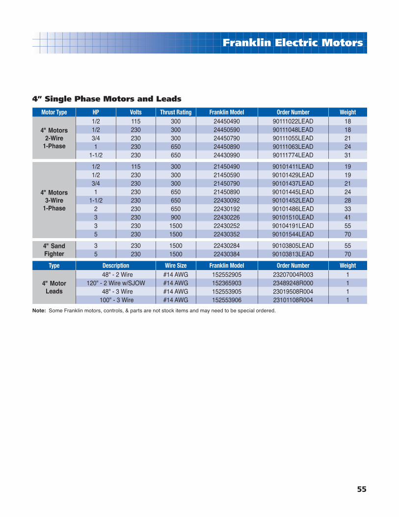
55
Franklin Electric Motors
Motor Type HP Volts Thrust Rating Franklin Model Order Number Weight
4" Motors2-Wire
1-Phase
1/2 115 300 24450490 90111022LEAD 181/2 230 300 24450590 90111048LEAD 183/4 230 300 24450790 90111055LEAD 211 230 650 24450890 90111063LEAD 24
1-1/2 230 650 24430990 90111774LEAD 31
4" Motors3-Wire
1-Phase
1/2 115 300 21450490 90101411LEAD 191/2 230 300 21450590 90101429LEAD 193/4 230 300 21450790 90101437LEAD 211 230 650 21450890 90101445LEAD 24
1-1/2 230 650 22430092 90101452LEAD 282 230 650 22430192 90101486LEAD 333 230 900 22430226 90101510LEAD 413 230 1500 22430252 90104191LEAD 555 230 1500 22430352 90101544LEAD 70
4" Sand Fighter
3 230 1500 22430284 90103805LEAD 555 230 1500 22430384 90103813LEAD 70
Type Description Wire Size Franklin Model Order Number Weight
4" Motor Leads
48" - 2 Wire #14 AWG 152552905 23207004R003 1120" - 2 Wire w/SJOW #14 AWG 152365903 23489248R000 1
48" - 3 Wire #14 AWG 152553905 23019508R004 1 100" - 3 Wire #14 AWG 152553906 23101108R004 1
Note: Some Franklin motors, controls, & parts are not stock items and may need to be special ordered.
4” Single Phase Motors and Leads

6” Submersible Motors Hi-Temp 90
56
Franklin Electric Motors
Motor Type HP Volts Thrust Rating Franklin Model Order Number Weight
4” Motors3-Phase
Standard Constr.
1/2 200 300 23450192 90109000LEAD 181/2 230 300 23451192 90109018LEAD 181/2 460 300 23452194 90109026LEAD 183/4 200 300 23450292 90119090LEAD 213/4 230 300 23451292 90109034LEAD 213/4 460 300 23452294 90109042LEAD 211 200 650 23450392 90109224LEAD 241 230 650 23451392 90100405LEAD 241 460 650 23452394 90107087LEAD 24
1-1/2 200 650 23450492 90111832LEAD 241-1/2 230 650 23451492 90101460LEAD 241-1/2 460 650 23452494 90111527LEAD 241-1/2 575 650 23453494 90178633LEAD 24
2 200 650 23430592 90111840LEAD 282 230 650 23431592 90101494LEAD 282 460 650 23432594 90101502LEAD 282 575 650 23433594 90109281LEAD 283 200 900 23430626 90111857LEAD 353 230 900 23431626 90101528LEAD 353 460 900 23432626 90101536LEAD 353 575 900 23433626 90109299LEAD 353 200 1500 23430652 consult factory 423 230 1500 23431652 90104209LEAD 423 460 1500 23432652 90107962LEAD 425 200 1500 23430752 90111873LEAD 555 230 1500 23431752 90101551LEAD 555 460 1500 23432752 90101569LEAD 555 575 1500 23433752 90109307LEAD 55
7-1/2 200 1500 23430852 90105313LEAD 707-1/2 230 1500 23431852 90105321LEAD 707-1/2 460 1500 23432852 90100389LEAD 707-1/2 575 1500 23433852 90177330LEAD 70
10 460 1500 23459534 90119363LEAD 75
4” Motors3-Phase
Sand Fighter
3 200 1500 23430684 90109059LEAD 423 230 1500 23431684 90103821LEAD 423 460 1500 23432684 90103839LEAD 425 200 1500 23430784 90109067LEAD 555 230 1500 23431784 90103847LEAD 555 460 1500 23432784 90103854LEAD 55
7-1/2 200 1500 23430884 90109075LEAD 707-1/2 230 1500 23431884 90103862LEAD 707-1/2 460 1500 23432884 90103870LEAD 70
10 460 1500 23459584 90103888LEAD 75
4” Motors3-Phase
CBM
3 200 1500 23430682 90102617LEAD 423 230 1500 23431682 90102625LEAD 423 460 1500 23432682 90102633LEAD 425 200 1500 23430782 90102658LEAD 555 230 1500 23431782 90102666LEAD 555 460 1500 23432782 90102674LEAD 55
7-1/2 200 1500 23430882 90102682LEAD 707-1/2 230 1500 23431882 90102690LEAD 707-1/2 460 1500 23432882 90102708LEAD 70
10 460 1500 23459582 90102716LEAD 75Note: Some Franklin motors, controls, & parts are not stock items and may need to be special ordered.
4” Three Phase Motors

57
6” Submersible Motors Hi-Temp 90 Franklin Electric Motors
6” Single Phase Motors
Motor Type HP Volts Thrust Rating Franklin Model Order Number Weight
6" Motors1-Phase
5 230 1500 22611090 90101577 110
7-1/2 230 1500 22611190 90101601 123
10 230 3500 22611290 90104845 141
15 230 3500 22611390 90104894 154
6" Motors1-Phase
Sand Fighter
5 230 1500 22611080 90103895 110
7-1/2 230 1500 22611180 90103904 123
10 230 3500 22611280 90103912 141
15 230 3500 22611380 90103920 154
Control Type HP Volts Franklin Model Order Number Weight
6" StandardControl Boxes
7-1/2 230 28220192 91940700 12
10 230 28220292 91942300 14
6" DeluxeControl Boxes
7-1/2 230 28220193 91944181 13
10 230 28220293 91944199 15
15 230 28220393 91944215 17
15 230 28220396 91945501 28
Type Description Wire Size Franklin Model Order Number Weight
6" Motor Leads 13' - 3 Wire (All HP) #8 AWG 305517901 23113202 4
6” Leads
6” Control Boxes
Item Type Rating Franklin Model Order Number
LightningArrestors
1-Phase 0-125 Volts to ground 150814902 99497729R
3-Phase 0-650 Volts to ground 155440901 99497737R
Lightning Arrestors
Note: Some Franklin motors, controls, & parts are not stock items and may need to be special ordered.

6” Submersible Motors Hi-Temp 90
58
Franklin Electric Motors
Motor Type HP Volts Thrust Rating Franklin Model Order Number Weight
6" Motors3-Phase
Standard Constr.
5 200 1500 23665090 90119298 1015 230 1500 23660090 90101585 1015 460 1500 23661090 90101593 1015 575 1500 23662090 90109315 101
7-1/2 200 1500 23665190 90101354 1087-1/2 230 1500 23660190 90101619 1087-1/2 460 1500 23661190 90101627 1087-1/2 575 1500 23662190 90109323 108
10 200 3500 23665290 90119306 11610 230 3500 23660290 90101635 11610 460 3500 23661290 90101643 11610 575 3500 23662290 90109331 11615 200 3500 23665390 90119314 12915 230 3500 23660390 90101650 12915 460 3500 23661390 90101668 12915 575 3500 23662390 90109349 12920 200 3500 23665490 90119322 14520 230 3500 23660490 90101676 14520 460 3500 23661490 90101684 14520 575 3500 23662490 90109356 14525 200 3500 23665590 90119330 15625 230 3500 23660590 90101692 15625 460 3500 23661590 90101700 15625 575 3500 23662590 90101718 15630 200 3500 23665690 90119348 17430 230 3500 23660690 90101726 17430 460 3500 23661690 90101734 17430 575 3500 23662690 90101742 174
6" Motors 3-Phase
Sand Fighter
5 200 1500 23665080 Consult factory 1015 230 1500 23660080 90103938 1015 460 1500 23661080 90103946 101
7-1/2 200 1500 23665180 Consult factory 1087-1/2 230 1500 23660180 90103953 1087-1/2 460 1500 23661180 90103961 108
10 200 3500 23665280 Consult factory 11610 230 3500 23660280 90103979 11610 460 3500 23661280 90103987 11615 200 3500 23665380 Consult factory 12915 230 3500 23660380 90103995 12915 460 3500 23661380 90104001 12920 200 3500 23665480 Consult factory 14520 230 3500 23660480 90104019 14520 460 3500 23661480 90104027 14525 200 3500 23665580 Consult factory 15625 230 3500 23660580 90104035 15625 460 3500 23661580 90104043 15630 200 3500 23665680 Consult factory 17430 230 3500 23660680 90104050 17430 460 3500 23661680 90104068 174
6” Three Phase Motors (non-subtrol)
Note: Some Franklin motors, controls, & parts are not stock items and may need to be special ordered.

59
6” Submersible Motors Hi-Temp 90 Franklin Electric Motors
Motor Type HP Volts Thrust Rating Franklin Model Order Number Weight
6” Motors3-Phase
Standard Constr.
5 200 1500 23665060 90119298SBTL 1015 230 1500 23660060 90101585SBTL 1015 460 1500 23661060 90101593SBTL 101
7-1/2 200 1500 23665160 90101354SBTL 1087-1/2 230 1500 23660160 90101619SBTL 1087-1/2 460 1500 23661160 90101627SBTL 108
10 200 3500 23665260 90119306SBTL 11610 230 3500 23660260 90101635SBTL 11610 460 3500 23661260 90101643SBTL 11615 200 3500 23665360 90119314SBTL 12915 230 3500 23660360 90101650SBTL 12915 460 3500 23661360 90101668SBTL 12920 200 3500 23665460 90119322SBTL 14520 230 3500 23660460 90101676SBTL 14520 460 3500 23661460 90101684SBTL 14525 200 3500 23665560 90119330SBTL 15625 230 3500 23660560 90101692SBTL 15625 460 3500 23661560 90101700SBTL 15630 200 3500 23665660 90119348SBTL 17430 230 3500 23660660 90101726SBTL 17430 460 3500 23661660 90101734SBTL 17440 460 6000 23661760 90101759 20240 575 6000 23662760 90101760 20250 460 6000 23661860 90107939 30060 460 6000 23661960 90103359 330
6” Motors 3-Phase
Sand Fighter
5 200 1500 23665081 Consult factory 1015 230 1500 23660081 90103938SBTL 1015 460 1500 23661081 90103946SBTL 101
7-1/2 200 1500 23665181 Consult factory 1087-1/2 230 1500 23660181 90103953SBTL 1087-1/2 460 1500 23661181 90103961SBTL 108
10 200 3500 23665281 Consult factory 11610 230 3500 23660281 90103979SBTL 11610 460 3500 23661281 90103987SBTL 11615 200 3500 23665381 Consult factory 12915 230 3500 23660381 90103995SBTL 12915 460 3500 23661381 90104001SBTL 12920 200 3500 23665481 Consult factory 14520 230 3500 23660481 90104019SBTL 14520 460 3500 23661481 90104027SBTL 14525 200 3500 23665581 Consult factory 15625 230 3500 23660581 90104035SBTL 15625 460 3500 23661581 90104043SBTL 15630 200 3500 23665681 Consult factory 17430 230 3500 23660681 90104050SBTL 17430 460 3500 23661681 90104068SBTL 17440 460 6000 23661781 90104076 20250 460 6000 23661881 90104084 30060 460 6000 23661981 90104092 330
6” Three Phase Motors (subtrol equipped)
Note: Some Franklin motors, controls, & parts are not stock items and may need to be special ordered.

6” Submersible Motors Hi-Temp 90
60
Franklin Electric Motors
Motor Type HP Volts Thrust Rating Franklin Model Order Number Weight
6” Motors3-Phase Water Well Super 90 Non-Subtrol
5 200 4500 27665000 Consult Factory 1165 230 4500 27660000 Consult Factory 1165 460 4500 27661000 Consult Factory 116
7-1/2 200 4500 27665100 Consult Factory 1297-1/2 230 4500 27660100 Consult Factory 1297-1/2 460 4500 27661100 Consult Factory 129
10 200 4500 27665200 Consult Factory 14510 230 4500 27660200 Consult Factory 14510 460 4500 27661200 Consult Factory 14515 200 4500 27665300 Consult Factory 15615 230 4500 27660300 Consult Factory 15615 460 4500 27661300 Consult Factory 15620 200 4500 27665400 Consult Factory 17420 230 4500 27660400 Consult Factory 17420 460 4500 27661400 Consult Factory 17425 200 7500 27665501 Consult Factory 20225 230 7500 27660501 Consult Factory 20225 460 7500 27661501 Consult Factory 20230 200 7500 27665601 Consult Factory 30030 230 7500 27660601 Consult Factory 30030 460 7500 27661601 Consult Factory 30040 460 7500 27661701 Consult Factory 330
6” Three Phase Motors (Super 90 Series)

61
6” Submersible Motors Hi-Temp 90 Franklin Electric Motors
8” Three Phase Motors and Leads (standard & sandfi ghter)
Motor Type HP Volts Thrust Rating Franklin Model Order Number Weight
8” Motors3-Phase
Standard Constr.
40 460 10000 23960060 90103011 320
50 460 10000 23960160 90103029 345
60 460 10000 23960260 90103037 375
75 460 10000 23960360 90103045 430
100 460 10000 23960460 90103052 530
125 460 10000 23910560 90103375 700
8” Motors3-Phase
Sand Fighter
40 460 10000 23960085 90104100 320
50 460 10000 23960185 90104118 345
60 460 10000 23960285 90104126 375
75 460 10000 23960385 90104134 430
100 460 10000 23960485 90104142 530
125 460 10000 23910585 90104159 700
150 460 10000 23910685 90104167 840
175 460 10000 23910785 90104175 925
200 460 10000 23910885 90104183 1040
Type Description Wire Size Franklin Model Order Number Wt.
8” Motor Leads
13ʼ - 3W (40-60HP) #8 AWG 305516901 23498306 5
13ʼ - 3W (75-125HP) #4 AWG 305210901 23489305 6
13ʼ - 3W (150-200HP) #2 AWG 305315901 23489404 8
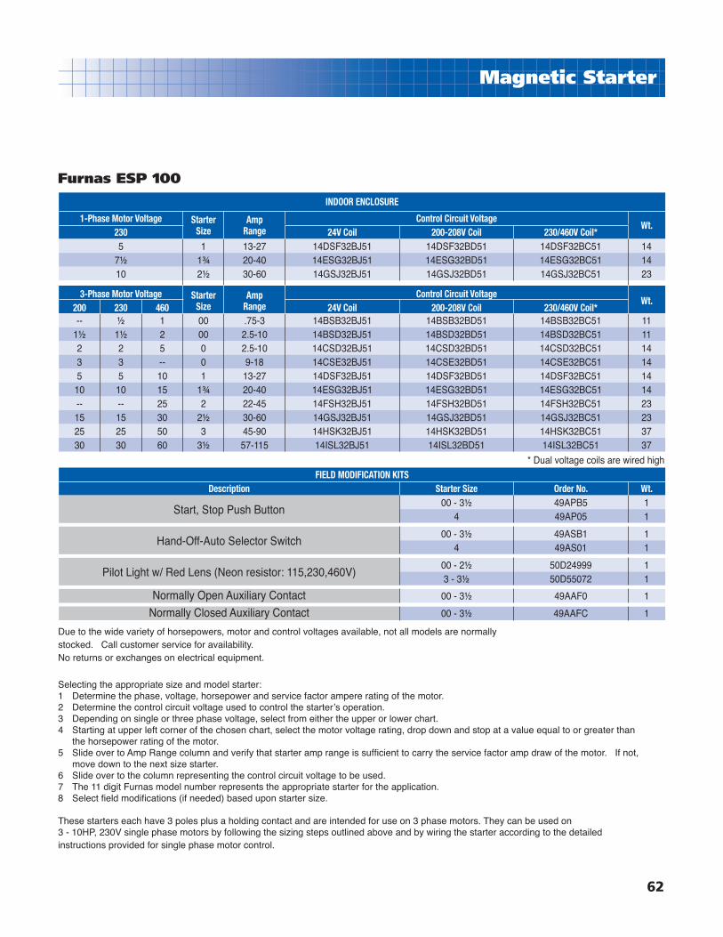
62
Magnetic Starter
INDOOR ENCLOSURE
1-Phase Motor Voltage StarterSize
AmpRange
Control Circuit VoltageWt.
230 24V Coil 200-208V Coil 230/460V Coil*5 1 13-27 14DSF32BJ51 14DSF32BD51 14DSF32BC51 14
7½ 1¾ 20-40 14ESG32BJ51 14ESG32BD51 14ESG32BC51 1410 2½ 30-60 14GSJ32BJ51 14GSJ32BD51 14GSJ32BC51 23
3-Phase Motor Voltage StarterSize
AmpRange
Control Circuit VoltageWt.
200 230 460 24V Coil 200-208V Coil 230/460V Coil*-- ½ 1 00 .75-3 14BSB32BJ51 14BSB32BD51 14BSB32BC51 11
1½ 1½ 2 00 2.5-10 14BSD32BJ51 14BSD32BD51 14BSD32BC51 112 2 5 0 2.5-10 14CSD32BJ51 14CSD32BD51 14CSD32BC51 143 3 -- 0 9-18 14CSE32BJ51 14CSE32BD51 14CSE32BC51 145 5 10 1 13-27 14DSF32BJ51 14DSF32BD51 14DSF32BC51 1410 10 15 1¾ 20-40 14ESG32BJ51 14ESG32BD51 14ESG32BC51 14-- -- 25 2 22-45 14FSH32BJ51 14FSH32BD51 14FSH32BC51 2315 15 30 2½ 30-60 14GSJ32BJ51 14GSJ32BD51 14GSJ32BC51 2325 25 50 3 45-90 14HSK32BJ51 14HSK32BD51 14HSK32BC51 3730 30 60 3½ 57-115 14ISL32BJ51 14ISL32BD51 14ISL32BC51 37
* Dual voltage coils are wired high
FIELD MODIFICATION KITSDescription Starter Size Order No. Wt.
Start, Stop Push Button00 - 3½ 49APB5 1
4 49AP05 1
Hand-Off-Auto Selector Switch00 - 3½ 49ASB1 1
4 49AS01 1
Pilot Light w/ Red Lens (Neon resistor: 115,230,460V)00 - 2½ 50D24999 13 - 3½ 50D55072 1
Normally Open Auxiliary Contact 00 - 3½ 49AAF0 1
Normally Closed Auxiliary Contact 00 - 3½ 49AAFC 1
Furnas ESP 100
Selecting the appropriate size and model starter: 1 Determine the phase, voltage, horsepower and service factor ampere rating of the motor.2 Determine the control circuit voltage used to control the starterʼs operation. 3 Depending on single or three phase voltage, select from either the upper or lower chart.4 Starting at upper left corner of the chosen chart, select the motor voltage rating, drop down and stop at a value equal to or greater than
the horsepower rating of the motor. 5 Slide over to Amp Range column and verify that starter amp range is suffi cient to carry the service factor amp draw of the motor. If not,
move down to the next size starter. 6 Slide over to the column representing the control circuit voltage to be used.7 The 11 digit Furnas model number represents the appropriate starter for the application. 8 Select fi eld modifi cations (if needed) based upon starter size.
These starters each have 3 poles plus a holding contact and are intended for use on 3 phase motors. They can be used on 3 - 10HP, 230V single phase motors by following the sizing steps outlined above and by wiring the starter according to the detailed instructions provided for single phase motor control.
Due to the wide variety of horsepowers, motor and control voltages available, not all models are normally stocked. Call customer service for availability. No returns or exchanges on electrical equipment.

8” Submersible Motors Leads
63
Convertible Jet Pumps
Features:■ Heavy-duty cast iron case and bronze impeller
ensure optimum durability.■ Thermoplastic diffuser is molded for effi ciency
and dependability.■ Screw-in injector for easy conversion from
shallow to deep well installation. ■ Shaft coupling designed for easy removal of
pump motor.■ Mechanical shaft seal ensures leakproof fi t
and continuous water lubrication.■ High service factor 56C-frame motor for
maximum performance.■ Hardware kit allows for versatility of installation
and includes pressure gauge, plugs, shallow well injector, and bypass plug.
■ Adjustable pressure switch is factory-installed at 30/50 PSI.
■ Connections 1-1/4” FNPT Suction 1” FNPT Discharge 1” FNPT Drive Line■ Maximum temperature of 140˚F.
Pro Series
NRTL/CCSA 108UL 778
Dimensions
Model No. HP A B5SFCWJPRO-S 1/2 18.65 10.44
7SFCWJPRO-S 3/4 19.15 11.19
1SFCWJPRO-S 1 19.65 11.44
Note: Dimensions will vary according to motor manufacturer.
3-7/86
4-1/4
5-1/4
8-13/16
7-31/32
6-15/32
A
B
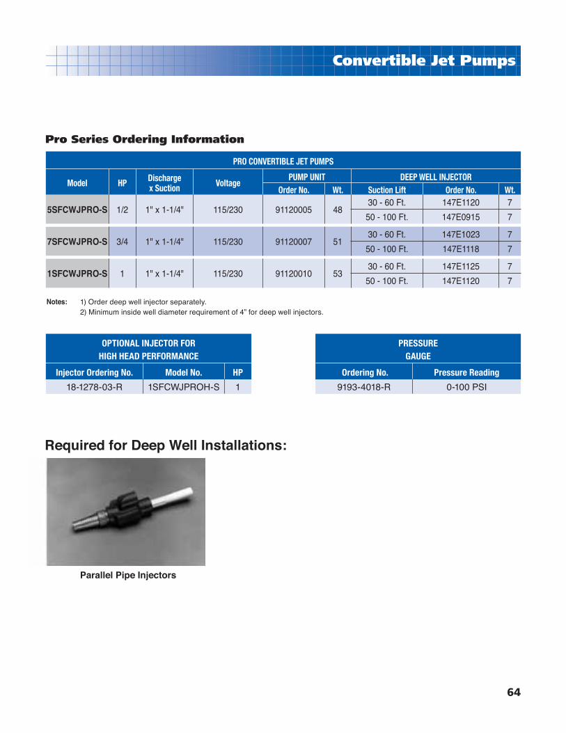
8” Submersible Motors Leads
64
Convertible Jet Pumps
Pro Series Ordering Information
PRO CONVERTIBLE JET PUMPS
Model HP Dischargex Suction Voltage
PUMP UNIT DEEP WELL INJECTOROrder No. Wt. Suction Lift Order No. Wt.
5SFCWJPRO-S 1/2 1" x 1-1/4" 115/230 91120005 4830 - 60 Ft. 147E1120 7
50 - 100 Ft. 147E0915 7
7SFCWJPRO-S 3/4 1" x 1-1/4" 115/230 91120007 5130 - 60 Ft. 147E1023 7
50 - 100 Ft. 147E1118 7
1SFCWJPRO-S 1 1" x 1-1/4" 115/230 91120010 5330 - 60 Ft. 147E1125 7
50 - 100 Ft. 147E1120 7
Notes:
OPTIONAL INJECTOR FOR HIGH HEAD PERFORMANCE
Injector Ordering No. Model No. HP
18-1278-03-R 1SFCWJPROH-S 1
PRESSUREGAUGE
Ordering No. Pressure Reading
9193-4018-R 0-100 PSI
Required for Deep Well Installations:
Parallel Pipe Injectors
1) Order deep well injector separately.2) Minimum inside well diameter requirement of 4” for deep well injectors.

8” Submersible Motors Leads
65
Convertible Jet Pumps
Pro Series Performance Charts
Shallow Well Performance
Pro 1” Discharge x 1-1/4” Suction Discharge Pressure - PSI Shut-offPressure
PSIHPInjector Order
No.Total Suction
Lift ft.
30 35 40 45 50 55 60 65 70
Gallons per Minute
1/2 HP 18-1278-03
5 15.5 13.5 11 8.5 6 4 2 65
10 13.5 12.5 10 7.5 5 3 1 63
15 11.5 10.5 8.5 6 4 2 60
20 9.5 9 7.5 5 3 1 58
25 7 7 6 4 2 55
3/4 HP 18-1279-02
5 19 18.5 18 16 12.5 9.5 6.5 3.5 70
10 16.5 16 15.5 14 10 8 4.5 1.5 68
15 14.5 14 13.5 12.5 9.5 6.5 3.5 66
20 11.5 11 10 8 5 2 63
25 8.5 8 6.5 3.5 1 61
1 HP 18-1280-09
5 23 22.5 22 21.5 20 17.5 14 10.5 7 81
10 19.5 19 18.5 17.5 15.5 12.5 9 5.5 78
15 16.5 16 15.5 15 13.5 11 7.5 4.5 76
20 13.5 13 12.5 11.5 9.5 6 2.5 74
25 10 10 9.5 7.5 4.5 1 71
Model No.
InjectorOrder No.
Total SuctionLift ft.
Discharge Pressure - PSI Shut-offPressure
PSI50 55 60 65 70 75 80 85 90
Gallons per Minute
High Head1 HP
18-1278-03
5 11 10 7.5 5.5 3.5 1.5 90
10 10 8.5 6.5 4.5 2.5 88
15 9 7.5 5.5 3.5 1.5 84
20 8 6 4 2 81
25 7 5 3 1 78
Notes: 1) Pressure Switch Pre-Set 30-50 PSI 2) The appropriate injector is included with the units. 3) Maximum pump working pressure is 150 PSI. 4) All the above discharge pressures were measured using 1-1/4” PVC suction pipe and 1-1/4” footvalve.

8” Submersible Motors Leads
66
Convertible Jet Pumps
Pro Series Performance Charts
Deep Well Performance
Pro 1” Discharge x 1-1/4” Suction1” Drive Pipe
Discharge Pressure - PSI Shut-offPressure
PSI
Inj. Min.OperatingPressureHP
InjectorOrder No.
Total SuctionLift ft.
30 35 40 45 50 55 60 65 70
Gallons per Minute
1/2 HPCast Iron147E-1120
30 9 7 5.5 4 2.5 1.5 65
1840 7.5 6 4 3 1.5 59
50 6 4.5 3 2 1 56
60 5 3.5 2 1 52
1/2 HPCast Iron
147E-0915
50 6 5 4 3 2.5 2 1 74
23
60 5 4 3.5 2.5 2 1 70
70 4 3.5 2.5 2 1.5 65
80 3.5 3 2 1.5 1 61
90 3 2 1.5 1 57
100 2.5 1.5 1 52
3/4 HPCast Iron
147E-1023
30 15.5 13.5 11 8.5 6.5 4 2 66
1840 13.5 11.5 9 7 4.5 2.4 61
50 11 9.5 7 5 3 57
60 9 7.5 5 3 1 53
3/4 HPCast Iron147E-1118
50 9 8 7 6 4.5 3.5 3 2 1 80
23
60 8 7 6 4.5 4 3 2 1.5 77
70 6.5 5.5 4.5 3.5 3 2 1 72
80 6 5 4 3 2 1.5 67
90 5 4 3 2 1.5 63
100 4 3 2.5 1.5 1 30
1 HPCast Iron147E-1125
30 19.5 17 14.5 12 9.5 7 5 72
3040 17.5 15 12.5 10 7.5 5 3 67
50 15.5 13 10.5 8 5.5 3.5 1 63
60 13 10.5 8.5 6 3.5 1.5 59
1 HPCast Iron147E-1120
50 11 9.5 8 6.5 5 4 3 2 82
36
60 10 8 7 5.5 4 3 2 1 78
70 8 7 6 4.5 3 2 1 73
80 7 6 4.5 3.5 2 1.5 70
90 6 5 3.5 2.5 1.5 65
100 5 4 3 1.5 61
Notes: 1) Pressure Switch Pre-Set 30-50 PSI 2) Maximum pump working pressure is 150 PSI. 3) All the above discharge pressures were measured using 1-1/4” PVC suction pipe and 1-1/4” foot valve and 1” drive pipe.

8” Submersible Motors Leads
67
Convertible Jet Pumps
CWJ Series
Dimensions
NRTL/CCSA 108UL 778
Features:■ Thermoplastic impeller assures increased
hydraulic effi ciency.
■ Thermoplastic diffuser is molded for effi ciency and dependability.
■ Cast-iron case for maximum durability.
■ Square fl ange motor with threaded shaft for direct mounting of impeller.
■ Mechanical shaft seal ensures leakproof fi t.
■ Pressure switch is factory installed at 20/40 PSI.
■ “Convertible” Hardware includes plugs, by-pass plug, and shallow well injector. (Screw-in injector allows for easy conversion from shallow to deep well installation).
■ Pressure gauge can be ordered separately.
■ Connections1-1/4” FNPT Suction1” FNPT Discharge1” FNPT Drive Line
■ Maximum temperature 140˚F.
Note: Dimensions will vary according to motor manufacturer.
1/2 HP - 15-13/16”3/4 HP - 16-5/16”1 HP - 16-13/16”
4-5/16”
6-3/8”2”
9-1/4”
6-1/2”
8-13
/16”
2-3/
8”

8” Submersible Motors Leads
68
Convertible Jet Pumps
SFCWJ-S SERIES CONVERTIBLE JET PUMPS
Model HPDischarge x
SuctionVoltage
PUMP UNIT DEEP WELL INJECTOR
Order No. Wt. Suction Lift Order No. Weight
5SFCWJ-S 1/2 1" x 1-1/4" 115/230 91030005 3630 - 60 Ft. 147E1118 7
60 - 90 Ft. 147E1115 7
7SFCWJ-S 3/4 1" x 1-1/4" 115/230 91030007 3830 - 60 Ft. 147E1123 7
60 - 90 Ft. 147E1118 7
1SFCWJ-S 1 1" x 1-1/4" 115/230 91030010 4130 - 60 Ft. 147E1123 7
60 - 90 Ft. 147E1118 7
5SFCWJH-S 1/2 1" x 1-1/4" 115/230 91030050 36High head confi guration SFCWJ-S pumps
are for shallow well application only.7SFCWJH-S 3/4 1" x 1-1/4" 115/230 91030075 38
1SFCWJH-S 1 1" x 1-1/4" 115/230 91030100 41
CWJ Series Ordering Information
OPTIONAL INJECTOR FOR HIGH HEAD PERFORMANCE
Injector Ordering No. Model No. HP
18-1200-12-R 5SFCWJ-S 1/2
18-1247-01-R 7SFCWJ-S 3/4
18-1247-01-R 1SFCWJ-S 1
PRESSURE GAUGE
Ordering No. Pressure Reading
9193-4018-R 0-100 PSI
Required for Deep Well Installations:
Parallel Pipe Injectors
Notes: 1) Order deep well injector separately.2) Minimum inside well diameter requirement of 4” for deep well injectors.
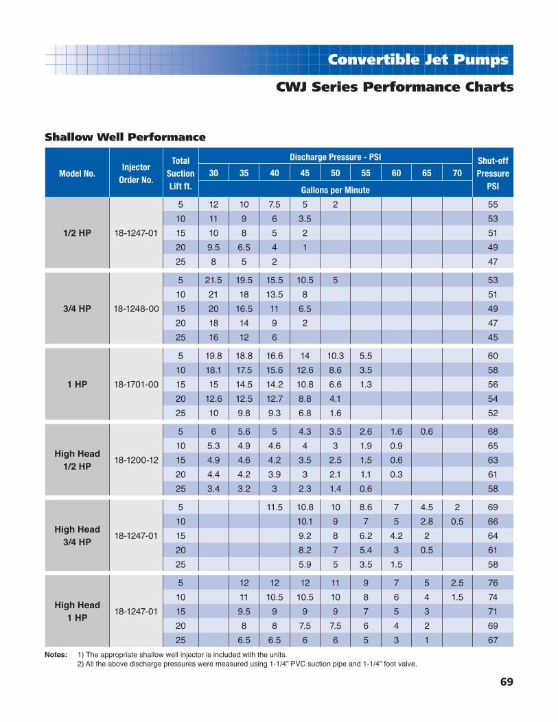
8” Submersible Motors Leads
69
Convertible Jet Pumps
CWJ Series Performance Charts
Shallow Well Performance
Model No.Injector
Order No.
TotalSuctionLift ft.
Discharge Pressure - PSI Shut-offPressure
PSI30 35 40 45 50 55 60 65 70
Gallons per Minute
1/2 HP 18-1247-01
5 12 10 7.5 5 2 55
10 11 9 6 3.5 53
15 10 8 5 2 51
20 9.5 6.5 4 1 49
25 8 5 2 47
3/4 HP 18-1248-00
5 21.5 19.5 15.5 10.5 5 53
10 21 18 13.5 8 51
15 20 16.5 11 6.5 49
20 18 14 9 2 47
25 16 12 6 45
1 HP 18-1701-00
5 19.8 18.8 16.6 14 10.3 5.5 60
10 18.1 17.5 15.6 12.6 8.6 3.5 58
15 15 14.5 14.2 10.8 6.6 1.3 56
20 12.6 12.5 12.7 8.8 4.1 54
25 10 9.8 9.3 6.8 1.6 52
High Head1/2 HP
18-1200-12
5 6 5.6 5 4.3 3.5 2.6 1.6 0.6 68
10 5.3 4.9 4.6 4 3 1.9 0.9 65
15 4.9 4.6 4.2 3.5 2.5 1.5 0.6 63
20 4.4 4.2 3.9 3 2.1 1.1 0.3 61
25 3.4 3.2 3 2.3 1.4 0.6 58
High Head3/4 HP
18-1247-01
5 11.5 10.8 10 8.6 7 4.5 2 69
10 10.1 9 7 5 2.8 0.5 66
15 9.2 8 6.2 4.2 2 64
20 8.2 7 5.4 3 0.5 61
25 5.9 5 3.5 1.5 58
High Head1 HP
18-1247-01
5 12 12 12 11 9 7 5 2.5 76
10 11 10.5 10.5 10 8 6 4 1.5 74
15 9.5 9 9 9 7 5 3 71
20 8 8 7.5 7.5 6 4 2 69
25 6.5 6.5 6 6 5 3 1 67
Notes: 1) The appropriate shallow well injector is included with the units. 2) All the above discharge pressures were measured using 1-1/4” PVC suction pipe and 1-1/4” foot valve.
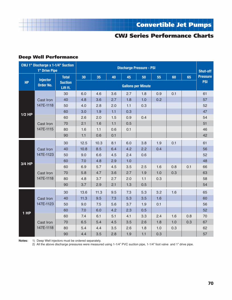
8” Submersible Motors Leads
70
Convertible Jet Pumps
CWJ Series Performance Charts
Deep Well Performance
CWJ 1” Discharge x 1-1/4” Suction 1” Drive Pipe
Discharge Pressure - PSIShut-offPressure
PSIHPInjector
Order No.
Total SuctionLift ft.
30 35 40 45 50 55 60 65
Gallons per Minute
1/2 HP
Cast Iron147E-1118
30 6.0 4.6 3.6 2.7 1.8 0.9 0.1 61
40 4.8 3.6 2.7 1.8 1.0 0.2 57
50 4.0 2.8 2.0 1.1 0.3 52
60 3.0 1.9 1.1 0.3 47
Cast Iron147E-1115
60 2.6 2.0 1.5 0.9 0.4 54
70 2.1 1.6 1.1 0.5 51
80 1.6 1.1 0.6 0.1 46
90 1.1 0.6 0.1 42
3/4 HP
Cast Iron147E-1123
30 12.5 10.3 8.1 6.0 3.8 1.9 0.1 61
40 10.8 8.5 6.4 4.2 2.2 0.4 56
50 9.0 6.6 4.5 2.4 0.6 52
60 7.0 4.8 2.9 1.0 48
Cast Iron147E-1118
60 6.9 5.7 4.5 3.5 2.5 1.6 0.8 0.1 66
70 5.8 4.7 3.6 2.7 1.9 1.0 0.3 63
80 4.8 3.7 2.7 2.0 1.1 0.3 58
90 3.7 2.9 2.1 1.3 0.5 54
1 HP
Cast Iron147E-1123
30 13.6 11.3 9.5 7.3 5.3 3.2 1.6 65
40 11.3 9.5 7.3 5.3 3.5 1.6 60
50 9.0 7.5 5.6 3.7 1.9 0.1 56
60 7.0 6.0 4.2 2.3 0.5 52
Cast Iron147E-1118
60 7.4 6.1 5.1 4.1 3.3 2.4 1.6 0.8 70
70 6.5 5.4 4.5 3.5 2.6 1.8 1.0 0.3 67
80 5.4 4.4 3.5 2.6 1.8 1.0 0.3 62
90 4.4 3.5 2.8 1.9 1.1 0.3 57
Notes: 1) Deep Well injectors must be ordered separately. 2) All the above discharge pressures were measured using 1-1/4” PVC suction pipe, 1-1/4” foot valve and 1” drive pipe.
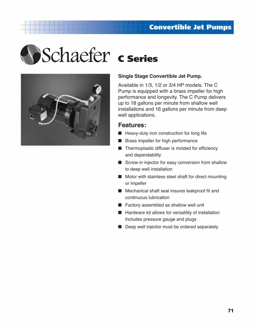
8” Submersible Motors Leads
71
Convertible Jet Pumps
Single Stage Convertible Jet Pump.
Available in 1/3, 1/2 or 3/4 HP models. The C Pump is equipped with a brass impeller for high performance and longevity. The C Pump delivers up to 18 gallons per minute from shallow well installations and 16 gallons per minute from deep well applications.
Features:■ Heavy-duty iron construction for long life
■ Brass impeller for high performance
■ Thermoplastic diffuser is molded for effi ciency
and dependability
■ Screw-in injector for easy conversion from shallow
to deep well installation
■ Motor with stainless steel shaft for direct mounting
or impeller
■ Mechanical shaft seal insures leakproof fi t and
continuous lubrication
■ Factory assembled as shallow well unit
■ Hardware kit allows for versatility of installation
Includes pressure gauge and plugs
■ Deep well injector must be ordered separately
C Series

8” Submersible Motors Leads
72
Convertible Jet Pumps
SERIES “C” CONVERTIBLE JET PUMPS
Model HP Discharge x Suction Voltage
PUMP UNIT DEEP WELL INJECTOROrder No. Wt. Suction Lift Order No. Weight
3SFC-S 1/3 1" x 1-1/4" 115/230 91100003 4520 - 60 Ft. 147E0916 7
60 - 90 Ft. 147E0914 7
5SFC-S 1/2 1" x 1-1/4" 115/230 91100005 45
20 - 60 Ft. 147E1018 7
60 - 90 Ft. 147E1117 7
60 - 90 Ft. 147E1115 7
7SFC-S 3/4 1" x 1-1/4" 115/230 91100007 50
20 - 60 Ft. 147E1124 7
50 - 90 Ft. 147E1019 7
80-120 Ft. 147E0914 7
C Series Ordering Information
PRESSURE GAUGE
Ordering No. Pressure Reading9193-4018-R 0-100 PSI
Required for Deep Well Installations:
Parallel Pipe Injectors
Notes: 1) Order deep well injector separately.2) Minimum inside well diameter requirement of 4” for deep well injectors.

8” Submersible Motors Leads
73
Convertible Jet Pumps
HPInjector
Order No.
TotalSuctionLift ft.
Discharge Pressure - PSI Shut-offPressure
PSI30 35 40 45 50
US Gallons per Hour/Minute
1/3 HP18-1200-12Code 1017
5 450/7.5 420/7 370/6 290/6 200/3.5 62
10 400/6.5 360/6 320/5.5 250/4 175/3 60
15 340/5.5 330/5.5 300/5 230/4 150/2.5 58
20 280/4.5 270/4.5 250/4 190/3 110/2 56
25 190/3 190/3 180/3 130/2 80/1.5 54
1/2 HP18-1293-04Code 0821
5 710/12 710/12 620/10.5 480/8 350/6 63
10 625/10.5 620/10.5 540/9 410/7 300/5 61
15 535/9 530/9 480/8 360/6 240/4 59
20 440/7.5 430/7 410/7 300/5 190/3 57
25 315/5.6 315/5.5 310/5 220/3.5 140/2.5 55
3/4 HP18-1248-18Code 1028
5 1100/18.5 1060/17.5 930/15.5 760/12.5 580/9.5 61
10 990/16.5 950/16 840/14 680/11.5 500/8.5 59
15 860/14.5 840/14 770/13 610/10 400/6.5 57
20 700/11.5 690/11.5 620/10.5 510/8.5 300/5 55
25 495/8.5 495/8.5 450/7.5 410/7 170/3 53
Notes: The appropriate shallow well injector is included with each model.
Pressure Switch Pre-Set 30-50 PSI
Pump Tappings:Suction Pipe - 1-1/4” NPTDischarge Pipe - 3/4” NPTPressure Pipe - 1” NPT (applies only to deep well installations)
Maximum pump working pressure is 150 PSI.
C Series Ordering Information-Shallow well-Self Priming

8” Submersible Motors Leads
74
Convertible Jet Pumps
C Series Performance Charts
Deep Well Performance-with Parallel Pipe Injector (4” min. i.d. well)
HPInjector
Order No.
Total SuctionLift ft.
Discharge Pressure - PSI Shut-offPressure
PSI
30 35 40 45 50
U.S. Gallons per Hour/Minute
1/3 HP
Cast Iron147E-0916
Bronze146E-0916
20 370/6 290/5 240/4 190/3 140/2 6230 310/5 240/4 190/3 150/2.5 110/2 6040 240/4 190/3 160/2.5 110/2 70/1 5850 200/3.5 150/2.5 110/2 70/1 - 5660 160/2.5 120/2 80/1.5 - - 54
Cast Iron147E-0914
Bronze147E-0914
60 190/3 160/2.5 130/2 100/1.5 90/1.5 6370 150/2.5 130/2 100/1.5 80/1 50/1 6180 130/2 110/2 80/1 60/1 - 59
90 100/1.5 80/1 60/1 - - 57
1/2HP
Cast Iron147E-1018
Bronze147E-1018
20 630/10.5 510/8.5 430/7 350/6 280/4.5 6130 510/8.5 410/7 330/5.5 260/4 210/3.5 5940 420/7 330/5.5 270/4.5 210/3.5 150/2.5 5750 340/5.5 280/4.5 230/4 170/3 110/2 5560 260/4.5 220/3.5 170/3 120/2 60/1 53
Cast Iron147E-1117
Bronze147E-1117
60 300/5 240/4 200/3.5 180/3 140/2.5 7070 240/4 200/3.5 180/3 150/2.5 120/2 6680 220/3.5 180/3 150/2.5 120/2 80/1.5 61
90 170/3 140/2.5 110/2 80/1.5 50/1 56
Cast Iron147E-1115
Bronze147E-1115
90 170/3 140/2.5 110/2 80/1.5 60/1 64100 140/2.5 110/2 90/1.5 60/1 40/0.5 60110 110/2 80/1.5 60/1 40/0.5 - 56
120 90/1.5 60/1 40/0.5 - - 52
3/4 HP
Cast Iron147E-1124
Bronze147E-1124
20 960/16 840/14 710/12 600/10 470/8 6930 830/14 720/12 600/10 470/8 350/6 6440 700/11.5 590/10 460/7.5 350/6 230/4 5950 600/10 480/8 360/6 240/4 120/2 5560 460/7.5 350/6 240/4 120/2 - 50
Cast Iron147E-1019
Bronze147E-1019
50 570/9.5 500/8.5 440/7.5 380/6.5 320/5.5 7460 480/8 420/7 360/6 300/5 240/4 7070 410/7 350/6 290/5 230/4 180/3 6680 350/6 290/5 230/4 180/3 120/2 6190 270/4.5 220/3.5 160/2.5 120/2 70/1 56
Cast Iron147E-0914
Bronze147E-0914
80 300/6 250/4 210/3.5 180/3 170/3 8790 240/4 210/3.5 200/3.5 180/3 160/2.5 83100 210/3.5 200/3.5 180/3 160/2.5 130/2 80110 200/3.5 180/3 160/2.5 130/2 110/2 76120 160/2.5 150/2.5 130/2 110/2 90/1.5 72

75
Shallow Well Jet Pumps
Features:■ Available in non-corrosive thermoplastic or cast
iron models.
■ Replaceable in-line nozzle/venturi design for
maximum hydraulic effi ciency and ease of
service.
■ Self cleaning, anti-clogging injector screen.
■ Thermoplastic impeller and diffuser ensure
increased hydraulic performance.
■ Floating stainless steel eye seal for maximum
performance and effi ciency.
■ Square-fl ange mounting provides easy
serviceability without disturbing the plumbing.
■ Built-in drain plug for easy winterizing and
servicing.
■ Mechanical shaft seal allows positive protection
against leaking.
■ Order pressure gauge separately.
■ Pressure switch is installed and set at 20/40 PSI.
■ Handles water temperatures up to 120˚F and
working pressure up to 75 PSI.
■ 1” FNPT discharge, 1-1/4” FNPT suction.
NRTL/CCSA 108UL 778
Dimensions
Note: Dimensions will vary according to motor manufacturer.
9-7/8”
4-1/8”
8-1/
4”
4-1/
8”
1/2 HP - 17-5/8”3/4 HP - 18-1/4”
6-1/4”
4-3/8”
SWJ Series
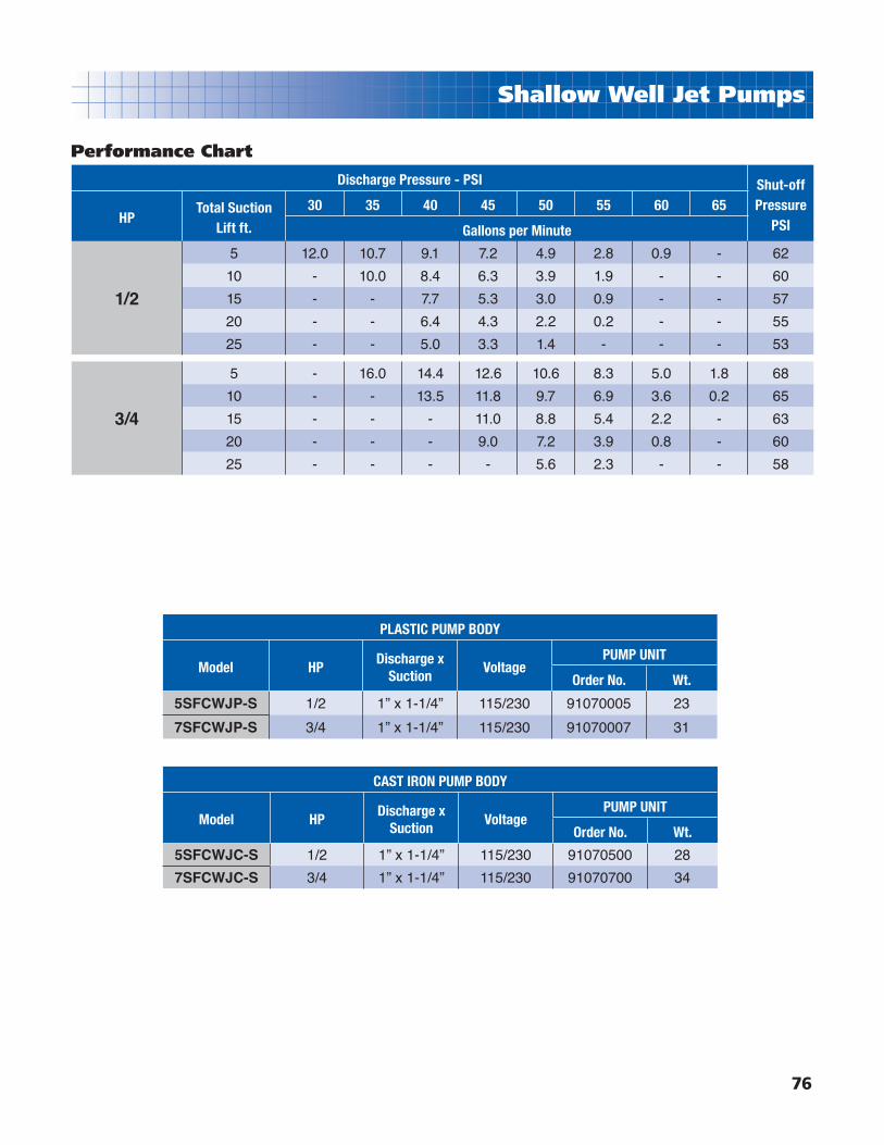
76
Shallow Well Jet Pumps
Performance Chart
Discharge Pressure - PSI Shut-offPressure
PSIHPTotal Suction
Lift ft.
30 35 40 45 50 55 60 65
Gallons per Minute
1/2
5 12.0 10.7 9.1 7.2 4.9 2.8 0.9 - 62
10 - 10.0 8.4 6.3 3.9 1.9 - - 60
15 - - 7.7 5.3 3.0 0.9 - - 57
20 - - 6.4 4.3 2.2 0.2 - - 55
25 - - 5.0 3.3 1.4 - - - 53
3/4
5 - 16.0 14.4 12.6 10.6 8.3 5.0 1.8 68
10 - - 13.5 11.8 9.7 6.9 3.6 0.2 65
15 - - - 11.0 8.8 5.4 2.2 - 63
20 - - - 9.0 7.2 3.9 0.8 - 60
25 - - - - 5.6 2.3 - - 58
PLASTIC PUMP BODY
Model HPDischarge x
SuctionVoltage
PUMP UNIT
Order No. Wt.
5SFCWJP-S 1/2 1” x 1-1/4” 115/230 91070005 23
7SFCWJP-S 3/4 1” x 1-1/4” 115/230 91070007 31
CAST IRON PUMP BODY
Model HPDischarge x
SuctionVoltage
PUMP UNIT
Order No. Wt.
5SFCWJC-S 1/2 1” x 1-1/4” 115/230 91070500 28
7SFCWJC-S 3/4 1” x 1-1/4” 115/230 91070700 34

8” Submersible Motors Leads
77
Convertible Jet Pumps
Jet Pump Accessories
Ordering Information
DEEP WELL 2-PIPE INJECTORS FOR 4" WELLS
Pump Model Suction Lift Order No. Wt.5SFCWJPRO-S 50 -100 Ft. 147E0915
7
7SFCWJPRO-S 30 - 60 Ft. 147E1023
5SFCWJ-S60 -90 Ft. 147E1115
30 - 60 Ft. 147E1118
7SFCWJPRO-S 50 - 100 Ft. 147E1118
7SFCWJ-S, 1SFCWJ-S 60 - 90 Ft. 147E1118
5SFCWJPRO-S 30 - 60 Ft. 147E1120
1SFCWJPRO-S 50 - 100 Ft. 147E1120
7SFCWJ-S, 1SFCWJ-S 30 - 60 Ft. 147E1123
1SFCWJPRO-S 30 - 60 Ft. 147E1125
Accessory Description Order No. Wt.
4-in-1 Footvalve, 3/4 - 1-1/2” 21339 1
Cast Iron Horizontal Check Valve, Poppet Type Bronze, 1-1/4”F x 1-1/4”M
91980680 4
SO125 Offset Suction/Intake Strainer, Thermoplastic, 1-1/4” x 1-1/4”
94070210 8
Note: For touch up paint see your local Sherwin Williams paint store for part #1415066.
Injector kit includes: Cast iron body, thermoplastic nozzle & venturi, bronze footvalve.
Parallel Pipe Injector
4 in 1 Footvalve
Horizontal Check Valve
Offset/Intake Strainer
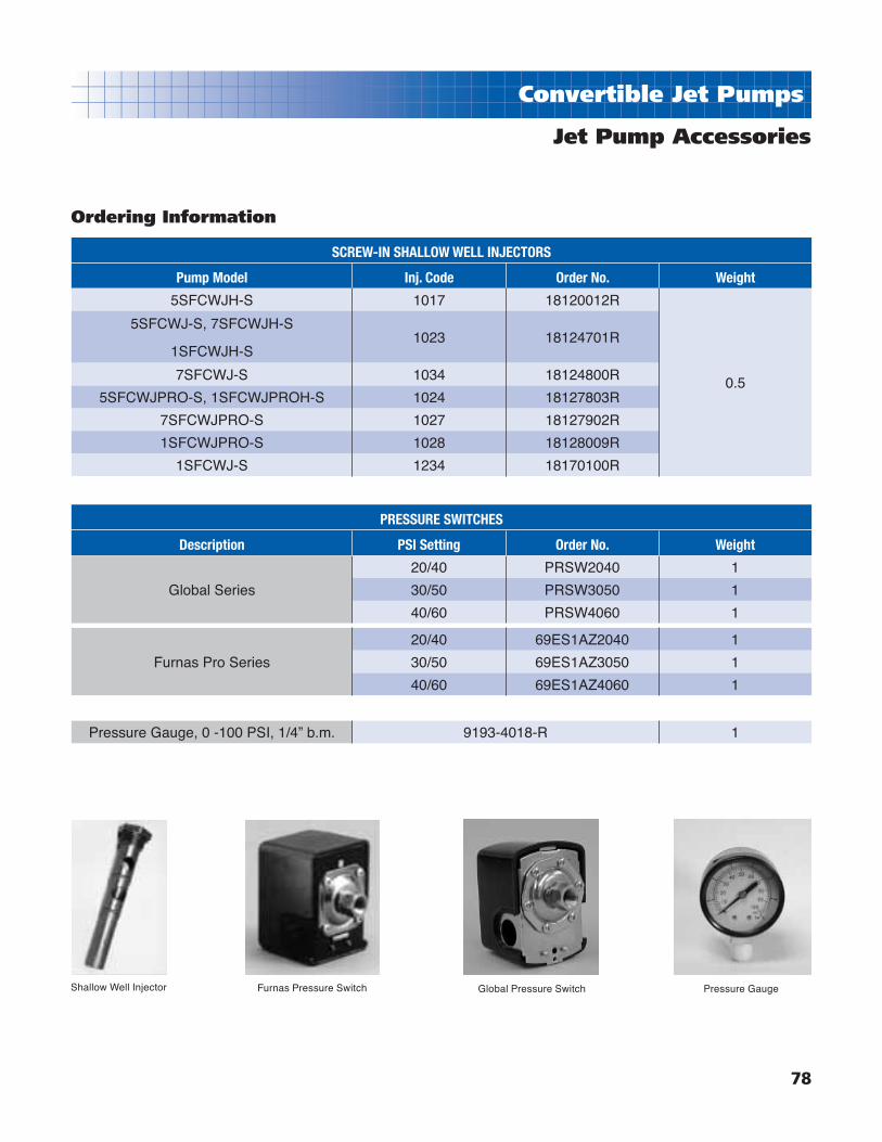
8” Submersible Motors Leads
78
Convertible Jet Pumps
Jet Pump Accessories
Ordering Information
SCREW-IN SHALLOW WELL INJECTORS
Pump Model Inj. Code Order No. Weight
5SFCWJH-S 1017 18120012R
0.5
5SFCWJ-S, 7SFCWJH-S
1SFCWJH-S1023 18124701R
7SFCWJ-S 1034 18124800R
5SFCWJPRO-S, 1SFCWJPROH-S 1024 18127803R
7SFCWJPRO-S 1027 18127902R
1SFCWJPRO-S 1028 18128009R
1SFCWJ-S 1234 18170100R
PRESSURE SWITCHES
Description PSI Setting Order No. Weight
Global Series
20/40 PRSW2040 1
30/50 PRSW3050 1
40/60 PRSW4060 1
Furnas Pro Series
20/40 69ES1AZ2040 1
30/50 69ES1AZ3050 1
40/60 69ES1AZ4060 1
Pressure Gauge, 0 -100 PSI, 1/4” b.m. 9193-4018-R 1
Shallow Well Injector Furnas Pressure Switch Global Pressure Switch Pressure Gauge

79
Jet Pump Accessories
AQ80Features:■ Constant pressure at fl ow rates of 1/2 GPM or higher,
eliminating the annoying pressure fl uctuations common with pump/tank systems.
■ Pump runs continuously while service is needed, eliminating short cycling, the major cause of motor wear and failure.
■ Handles fl ow rates up to 20 gpm. For fl ow rates above 20 gpm, AquaGenies may be connected in parallel to handle each 20 gpm increment.
■ Retrofi ttable to any existing pump & pressure tank system.
AQ80Works at any fl ow rate above 1/2 GPM. Provides constant pressure at each specifi c fl ow rate delivered by the pump. (Pressure will be slightly different for each fl ow rate.) A pressure tank is recommended for optimum performance. Maximum operating pressure: 80 PSI. (If installed with a submersible pump that develops more than 80 PSI at the inlet of the AQ80, use a pressure regulator to protect the AquaGenie from excessive pressure.)
Components of JetPump Installation
Above is an example of a shallow well application for your Jet Pump with the Constant Pressure Valve. Your installationmay be slightly different but the application is basically the same. Consult your dealer for assistance with your particular application.
ModelPreset Outlet
PressureInlet Outlet
Tank Connection
Max. InletPressure
Order No. Weight
AQ80 None 1” 1” 1” 80 PSI 91987321 2

80
Jet Pump Accessories
225A Jet ChargerFeatures:■ Specifi cally designed to prevent water-logging typically
associated with a conventional galvanized pressure tank.
■ Automatically maintains a proper balance of air and water
volume in the tank.
■ Eliminates frequent starts and stops, thus extending
motor life and reducing power consumption.
■ Eliminates tank draining normally required of
waterlogged tanks.
■ Eliminates need for other costly equipment.
■ Unit consists of 225A jet charger, reducer bushing,
adapter nut, 3/8" polyethylene tubing and
male connector.
ORDERING INFORMATION
Model No. Ordering No. Weight
225A 9190-8012 2

81
4” Sump Pump
Features:■ Ideal for effl uent pumping applications.
■ Thermoplastic discharge and motor bracket are
tough and non-corrosive. They cannot be harmed or
damaged by minerals, metals, and other substances
typically found in water.
■ Ceramic bearing sleeve has proven its durability with
years of fl awless performance.
■ Hex rubber bearing has an extra large surface to
assure shaft stability and multiple fl ow channels to
keep small particulates away from bearing surfaces.
■ Celcon® stage disk allows for close tolerances for
increased performance.
■ Stainless steel upthrust washer prevents excessive
wear in severe applications.
■ Built in check valve that can be easily removed if
needed.
■ Built in suction screen prevents debris from clogging
impellers and provides full fl ow performance.
■ Powered by Franklin corrosion-resistant motors with
10ʼ SJOW lead.
■ Available in 1/2HP, 115V and 230V single
phase models.
CAPACITY GPM
0 5 10 15 20 25 30
20
40
60
80
100
120
140
FE
ET
0
10
20
30
40
50
60
PS
I
TO
TAL
DY
NA
MIC
HE
AD
50
40
30 EF
FIC
IEN
CY
%
HIGH HEAD 4” SUBMERSIBLE EFFLUENT PUMPS with 1-1/4” DISCHARGE
Model HP Volts Cord Type Order No. Wt.
T5LY16EFF5-S1 1/2 115 10ʼ SJOW 93461605 28
T5LY16EFF5-S2 1/2 230 10ʼ SJOW 93462605 28

82
Self-Priming Sprinkler Pumps
TY Series-ThermoplasticThe self-priming sprinkler pump is ideal as a lawn sprinkler pump, for general recirculation.
Dimensions
SELF-PRIMING LAWN SPRINKLER PUMPS
Model HP VoltagePUMP UNIT
Order No. Wt.7SFTY 3/4 115/230 93352007 3710SFTY 1 115/230 93352010 3815SFTY 1-1/2 115/230 93352015 4020SFTY 2 115/230 93352020 43
Features:■ Self-priming with large 1” priming port.
■ Non-corrosive thermoplastic case with engineerd-fl ow,
high-effi ciency, low-noise design.
■ High performance, thermoplastic hydraulics, including
fl oating eye seal and stainless steel impeller wear ring.
■ 1-1/2” FNPT threaded suction and discharge.
■ Built in drain plug to facilitate servicing/winterizing.
■ Square-fl ange motor design.
■ Easy motor toggle switch changes from 230V to 115V
without rewiring. (Not available on 20HP)
■ Available in 3/4, 1, 1-1/2, and 2HP.
■ Handles water temperatures up to 120oF and working
pressure up to 75 PSI.
HP Frame A
3/4 48 18-1/4”
1 48 18-1/2”
1-1/2 48 18-3/8”
2 56 19-7/8”10.16
2.50
3.20
3.00
9.75 11
.83
8.874.37
2.70A

83
Self-Priming Sprinkler Pumps
TY Series-Thermoplastic Performance Curves & Charts
GPMCAPACITY
ME
TE
RS
PS
I
FE
ET
0
5
10
15
20
25
30
35
0
10
20
30
40
50
0
10
20
30
40
50
60
70
80
90
100
110
120
0 10 20 30 40 50 60 70 80 90
TO
TA
L D
YN
AM
IC H
EA
D
2HP
1½HP
1HP
¾HP
HPTotal
SuctionLift in feet
Discharge PSIShut off
Pressure (PSI)20 25 30 35 40
Capacity in GPM
3/4
5 43 39 35 28 16 42
10 41 37 32 23 - 40
15 39 35 29 18 - 38
20 38 33 25 - - 35
1
5 50 45 40 33 21 43
10 49 44 37 29 7 41
15 46 41 35 24 - 39
20 44 39 31 12 - 36
1-1/2
5 65 60 54 44 30 44
10 64 57 50 38 21 42
15 61 54 46 31 7 40
20 58 50 41 23 - 37
2
5 79 76 72 65 52 46
10 78 74 69 59 45 44
15 76 72 67 54 38 42
20 74 70 63 47 20 39

84
Self-Priming Sprinkler Pumps
TYCI Series-Cast IronFeatures:■ Heavy duty cast iron case with engineered high
effi ciency, quiet run design.
■ High performance, thermoplastic hydraulics, including
fl oating eye seal and stainless steel impeller wear
ring.
■ 1-1/2” FNPT threaded suction and discharge ports.
■ Self-priming with large 1” priming port.
■ Built in drain plug to facilitate servicing/winterizing.
■ Handles water temperatures up to 120oF and working
pressure up to 75 PSI.
■ All models have 2 compartment motors.
■ Easy motor toggle switch changes from 230V to
115V without rewiring. (Not available on 20HP)
Dimensions
SELF-PRIMING LAWN SPRINKLER PUMPS
Model HP VoltagePUMP UNIT
Order No. Wt.7SFTYCI 3/4 115/230 93353007 5110SFTYCI 1 115/230 93353010 6615SFTYCI 1-1/2 115/230 93353015 8220SFTYCI 2 115/230 93353020 99
HP Frame A
3/4 48 18-1/4”
1 48 18-1/2”
1-1/2 48 18-3/8”
2 56 19-7/8”
A2.70
8.87
10.742.50
3.20
3.00
9.75
11.8
3
Note: Motor dimensions will vary according to motor manufacturer.

85
Self-Priming Sprinkler Pumps
TY Series-Cast Iron Performance Curves & Charts
GPMCAPACITY
ME
TE
RS
PS
I
FE
ET
0
5
10
15
20
25
30
35
0
10
20
30
40
50
0
10
20
30
40
50
60
70
80
90
100
110
120
0 10 20 30 40 50 60 70 80 90
TO
TA
L D
YN
AM
IC H
EA
D
2HP
1½HP
1HP
¾HP
HPTotal
SuctionLift in feet
Discharge PSIShut off
Pressure (PSI)20 25 30 35 40
Capacity in GPM
3/4
5 43 39 35 28 16 42
10 41 37 32 23 - 40
15 39 35 29 18 - 38
20 38 33 25 - - 35
1
5 50 45 40 33 21 43
10 49 44 37 29 7 41
15 46 41 35 24 - 39
20 44 39 31 12 - 36
1-1/2
5 65 60 54 44 30 44
10 64 57 50 38 21 42
15 61 54 46 31 7 40
20 58 50 41 23 - 37
2
5 79 76 72 65 52 46
10 78 74 69 59 45 44
15 76 72 67 54 38 42
20 74 70 63 47 20 39

86
Lawn Sprinkler Pumps
HJ Series
Features:■ Stub shaft motor with bronze coupling and bronze
impeller offers easy serviceability and premium
construction features.
■ Cast iron pump case. Large capacity case
ensures excellent self-priming performance.
■ Thermoplastic diffuser for improved pressures.
■ Mechanical shaft seal ensures leakproof fi t and
continuous water lubrication.
■ Two-compartment motor for easy service. All
motors are single phase 115/230V.
11-1/2
7-7/8 A
8-3/8
The HJ Series Lawn Sprinkler Pumps are designed to handle a large capacity of water at high pressure. They are ideal for continuous use on lawn sprinkler systems, for garden irrigation, for boosting city main pressures and for recirculating water.
Dimensions
Note: Dimensions will vary according to motor manufacturer.
HJ SERIES LAWN SPRINKLER PUMPS
Model HPDischarge x
SuctionVoltage
Pump Unit
Order No. Wt.
1SFHJM1-S 1 1-1/2” x 1-1/2” 115/230 93351876 56
15SFHJM1-S 1-1/2 1-1/2” X 2” 115/230 93351884 61
2SFHJM1-S 2 1-1/2” X 2” 115/230 93351892 65
HP A
1 17-5/8”
1-1/2 18-5/8”
2 19-5/8”
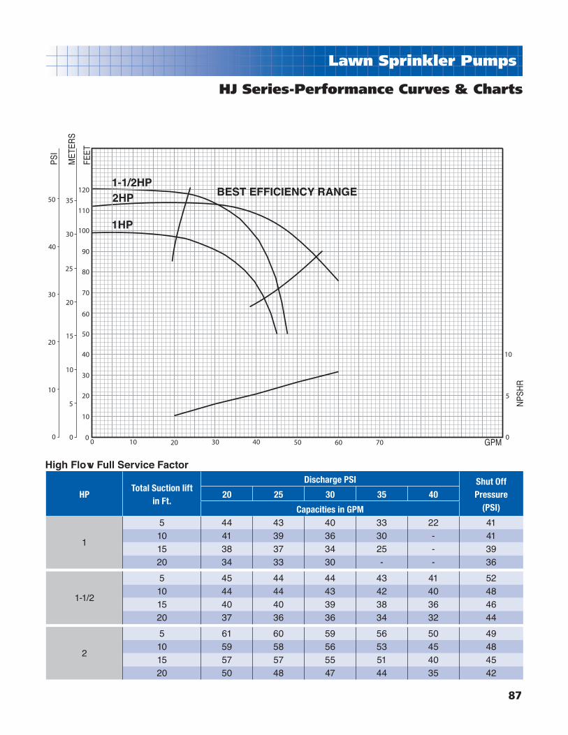
87
Lawn Sprinkler Pumps M
ETER
S
PSI
FEET
GPM
NPS
HR
0
5
10
15
20
25
30
35
0
10
20
30
40
50
0
10
20
30
40
50
60
70
80
90
100
110
120
100 20 30 40 50 60 700
5
10
1-1/2HP2HP
1HP
BEST EFFICIENCY RANGE
HJ Series-Performance Curves & Charts
HPTotal Suction lift
in Ft.
Discharge PSI Shut OffPressure
(PSI)20 25 30 35 40
Capacities in GPM
1
5 44 43 40 33 22 4110 41 39 36 30 - 4115 38 37 34 25 - 3920 34 33 30 - - 36
1-1/2
5 45 44 44 43 41 5210 44 44 43 42 40 4815 40 40 39 38 36 4620 37 36 36 34 32 44
2
5 61 60 59 56 50 4910 59 58 56 53 45 4815 57 57 55 51 40 4520 50 48 47 44 35 42
High Flow Full Service Factor

88
End Suction Centrifugal Pumps
DDD/DDS SeriesFeatures:■ Available in Cast Iron(DDD Series) or Stainless
Steel(DDS Series) models.
DDD Series Features:■ Cast iron seal plate for dependable high
temperature operation.
■ Dry run and loss-of-prime resistant
■ Glass-fi lled thermoplastic impeller for increased effi ciency and dependable high temperature operation.
■ Back pull-out design provides access to internal parts without disturbing the plumbing.
■ Mechanical shaft seal insures a leakproof fi t and continuous water lubrication.
■ Maximum temperature limit of 140oF and maximum working pressure of 150 PSI.
■ Square fl ange open drip-proof motor for easy service and reliability.
■ Available in single and three phase models.
■ Enclosed impeller design for increased effi ciencies.
■ Chemical resistant thermoplastic impeller.
DDS Series Features:
All of the DDD Series features above except:
■ Viton Mechanical shaft seal for added chemical resistance.
■ 304SS Case and seal plate.
NRTL/C CSA108UL778
2
1-5/16
13/32
9/16
15/32 4-7/16
6-1/2
1-13/16
1-7/8 2-3/4D
E
F
G
A
H
C
B
25-1/2
HPDisch.(NPT)
Suct.(NPT)
A B C D E F G H
1/2 1 1-1/4 14-11/16 2-3/8 5-5/16 4-7/16 3-1/2 4-5/8 8-3/4 5-1/23/4 1 1-1/4 14-11/16 2-3/8 5-5/16 4-7/16 3-1/2 4-5/8 8-3/4 5-1/21 1 1-1/4 14-11/16 2-3/8 5-5/16 4-7/16 3-1/2 4-5/8 8-3/4 5-1/2
1-1/2 1 1-1/4 15-3/16 2-3/8 5-5/16 4-7/16 3-1/2 4-5/8 8-3/4 5-1/22 1-1/4 1-1/2 16-11/16 2-13/16 6-1/8 5 3-9/16 5 9-1/8 6-5/16
2-1/2 1-1/2 2 16-11/16 2-13/16 6-1/8 5 3-9/16 5 9=1/8 6-5/16
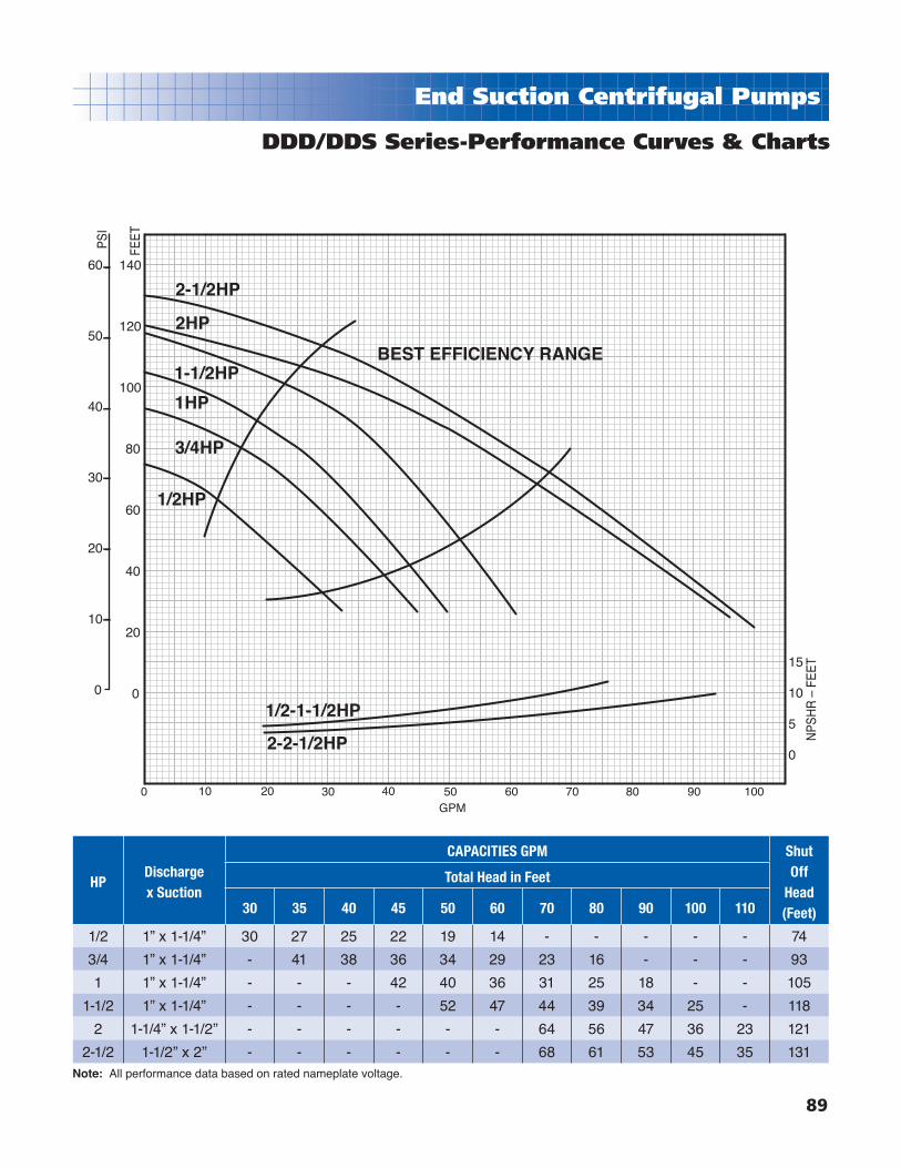
89
End Suction Centrifugal Pumps
GPM
60
50
40
30
20
10
0
140
120
100
80
60
40
20
0
PS
I
FEE
T
NP
SH
R –
FE
ET15
10
5
0
0 10 20 30 40 50 60 70 80 90 100
2-1/2HP
2HP
1-1/2HP
1HP
3/4HP
1/2HP
1/2-1-1/2HP
2-2-1/2HP
BEST EFFICIENCY RANGE
HPDischargex Suction
CAPACITIES GPM Shut Off
Head (Feet)
Total Head in Feet
30 35 40 45 50 60 70 80 90 100 110
1/2 1” x 1-1/4” 30 27 25 22 19 14 - - - - - 74
3/4 1” x 1-1/4” - 41 38 36 34 29 23 16 - - - 93
1 1” x 1-1/4” - - - 42 40 36 31 25 18 - - 105
1-1/2 1” x 1-1/4” - - - - 52 47 44 39 34 25 - 118
2 1-1/4” x 1-1/2” - - - - - - 64 56 47 36 23 121
2-1/2 1-1/2” x 2” - - - - - - 68 61 53 45 35 131
DDD/DDS Series-Performance Curves & Charts
Note: All performance data based on rated nameplate voltage.
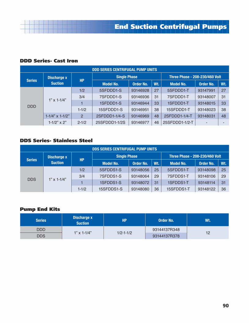
90
End Suction Centrifugal Pumps
DDD SERIES CENTRIFUGAL PUMP UNITS
SeriesDischarge x
SuctionHP
Single Phase Three Phase - 208-230/460 Volt
Model No. Order No. Wt. Model No. Order No. Wt.
DDD
1” x 1-1/4”
1/2 5SFDDD1-S 93146928 27 5SFDDD1-T 93147991 27
3/4 7SFDDD1-S 93146936 31 7SFDDD1-T 93148007 31
1 1SFDDD1-S 93146944 33 1SFDDD1-T 93148015 33
1-1/2 15SFDDD1-S 93146951 38 15SFDDD1-T 93148023 38
1-1/4” x 1-1/2” 2 2SFDDD1-1/4-S 93146969 48 2SFDDD1-1/4-T 93148031 48
1-1/2” x 2” 2-1/2 25SFDDD1-1/2S 93146977 46 25SFDDD1-1/2-T - -
DDD Series- Cast Iron
DDS SERIES CENTRIFUGAL PUMP UNITS
SeriesDischarge x
SuctionHP
Single Phase Three Phase - 208-230/460 Volt
Model No. Order No. Wt. Model No. Order No. Wt.
DDS 1” x 1-1/4”
1/2 5SFDDS1-S 93148056 25 5SFDDS1-T 93148098 25
3/4 7SFDDS1-S 93148064 29 7SFDDS1-T 93148106 29
1 1SFDDS1-S 93148072 31 1SFDDS1-T 93148114 31
1-1/2 15SFDDS1-S 93148080 36 15SFDDS1-T 93148122 36
DDS Series- Stainless Steel
SeriesDischarge x
SuctionHP Order No. Wt.
DDD1” x 1-1/4” 1/2-1-1/2
93144137R34812
DDS 93144137R378
Pump End Kits
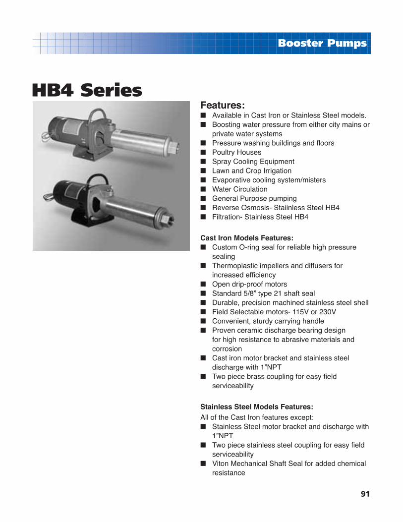
91
Booster Pumps
HB4 SeriesFeatures:■ Available in Cast Iron or Stainless Steel models.■ Boosting water pressure from either city mains or
private water systems■ Pressure washing buildings and fl oors■ Poultry Houses■ Spray Cooling Equipment■ Lawn and Crop Irrigation■ Evaporative cooling system/misters■ Water Circulation■ General Purpose pumping■ Reverse Osmosis- Staiinless Steel HB4■ Filtration- Stainless Steel HB4
Cast Iron Models Features:■ Custom O-ring seal for reliable high pressure
sealing■ Thermoplastic impellers and diffusers for
increased effi ciency■ Open drip-proof motors■ Standard 5/8” type 21 shaft seal■ Durable, precision machined stainless steel shell■ Field Selectable motors- 115V or 230V■ Convenient, sturdy carrying handle■ Proven ceramic discharge bearing design
for high resistance to abrasive materials and corrosion
■ Cast iron motor bracket and stainless steel discharge with 1”NPT
■ Two piece brass coupling for easy fi eld serviceability
Stainless Steel Models Features:All of the Cast Iron features except:■ Stainless Steel motor bracket and discharge with
1”NPT■ Two piece stainless steel coupling for easy fi eld
serviceability■ Viton Mechanical Shaft Seal for added chemical
resistance

92
Booster Pumps
HB4 Series-Performance Curves
CAST IRON MODELS
GPM HPSingle Phase
Model No. Order No. Wt.5 1 1SHB4F5C15-S 91250515 48
81/2 5SHB4F8C9-S 91250809 373/4 7SHB4F8C11-S 91250811 42
123/4 7SHB4F12C7-S 91251207 401 1SHB4F12C9-S 91251209 44
16 1 1SHB4F16C7-S 91251607 4322 1-1/2 15SHB4F22C7-S 91252207 50
STAINLESS STEEL MODELS
GPM HPSingle Phase
Model No. Order No. Wt.5 1 1SHB4F5S15-S 91254822 48
81/2 5SHB4F8S9-S 91254830 373/4 7SHB4F8S11-S 91254848 42
123/4 7SHB4F12S7-S 91254855 401 1SHB4F12S9-S 91254863 44
16 1 1SHB4F16S7-S 91254871 4322 1-1/2 15SHB4F22S7-S 91254889 50
Note: Single phase 1/2 - 2HP motors rated 115/230 volts.
HB4 Series Ordering Information

93
Booster Pumps
H4 SeriesThis multi-purpose pump is ideal for boosting water pressure around the home, industry or farm and is constructed with fi eld-proven hydraulics. Available in a variety of sizes for many applications 1/3 - 3HP and 5, 10, 18 and 25GPM performance ranges.
Features:■ Heavy-duty cast iron discharge housing and
suction bracket for long life
■ Thermoplastic impellers and diffusers are
molded for increased effi ciency and include
fl oating eye seal, ceramic shaft sleeve and
rubber discharge bearing
■ Stainless steel shell and shaft for increased
durability
■ Shaft coupling for easy serviceability
■ Tie rod construction for easy disassembly
■ Cast iron support foot for extra stability
■ Open drip-proof motors
■ 1/3 and 1/2HP models have 6-foot grounded
cord and carrying handle.
■ Maximum water temperature is 120oF
■ Maximum operating pressure is 400 PSI
■ Handles up to 150 PSI incoming pressure and
handles up to 10 ft. of suction lift
Model A B3SH4F5-7 14-3/16 10.195SH4F5-10 16-9/16 10.447SH4F5-14 19-3/4 11.191SH4F5-18 22-13/16 11.443SH4F10-4 12-1/4 10.195SH4F10-6 14-1/16 10.447SH4F10-9 16-11/16 11.191SH4F10-12 19-3/8 11.44
15SH4F10-16 22-13/16 11.945SH4F18-5 13-15/16 10.447SH4F18-7 16-1/6 11.191SH4F18-9 18-3/16 11.44
15SH4F18-12 21-5/6 11.942SH4F18-15 24-1/2 11.667SH4F25-F 14-13/16 11.191SH4F25-6 16-1/16 11.4415SH4F25-9 19-3/4 11.942SH4F25-11 22-3/16 11.663SH4F25-16 28-1/4 12.66
Dimensions- (in inches)
Note: Dimensions will vary according to motor manufacturer.
5-11/16
3-1/2
2-1/2
4-1/4
1 FNPTDISCHARGE
7/8
7/16 SLOTS (2)
1-1/4 FNPTSUCTION
A
3-3/16
7/16 HOLES (2)
1-1/4
B
7-1/2

94
Booster Pumps
H4 5 GPM Performance Curves & Chart
HPDischarge Pressure at Pump with no Lift (Capacities in GPM) Max Pres.
(PSI)40 50 60 70 80 90 100 110 120 130 140 150 160 170 180 190 200 210 220 230
1/3 8.1 7.3 6.5 5.6 4.5 3.1 98
1/2 7.9 7.3 6.8 6.2 5.6 4.8 4.0 2.9 140
3/4 7.8 7.4 7.0 6.6 6.1 5.7 5.2 4.6 4.1 3.4 2.5 192
1 7.8 7.5 7.2 6.8 6.5 6.2 5.8 5.4 5.1 4.7 4.2 3.7 3.1 2.3 244
GALLONS PER MINUTE

95
Booster Pumps
H4 10 GPM Performance Curves & Chart
HPDischarge Pressure at Pump with no Lift (Capacities in GPM) Max Pres.
(PSI)20 30 40 50 60 70 80 90 100 110 120 130 140 150 160 170 180 190 200 210
1/3 14.4 12.6 10.5 7.5 56
1/2 15.3 14.2 13.1 11.8 10.3 8.3 4.6 84
3/4 15.8 15.1 14.4 13.6 12.7 11.8 10.8 9.7 8.4 6.9 4.3 125
1 16.2 15.7 15.2 14.6 14.1 13.5 12.9 12.2 11.5 10.8 9.9 8.9 7.8 6.3 4.2 166
1-1/2 16.7 16.2 15.8 15.3 14.9 14.4 14.0 13.5 13.1 12.6 12.1 11.6 11.0 10.4 9.8 9.1 8.4 7.6 6.6 5.3 220
GALLONS PER MINUTE

96
Booster Pumps
H4 18 GPM Performance Curves & Chart
HPDischarge Pressure at Pump with no Lift (Capacities in GPM) Max Pres.
(PSI)20 30 40 50 60 70 80 90 100 110 120 130 140 150 160 170
1/2 24.3 21.7 18.1 13.7 60
3/4 25.2 24.0 22.4 20.3 17.6 14.4 10.0 88
1 25.7 24.7 23.8 22.2 20.5 18.4 16.2 13.8 10.2 4.0 111
1-1/2 26.0 25.4 24.8 24.0 23.3 22.3 21.1 19.8 18.2 16.4 14.4 12.0 8.2 148
2 26.5 26.0 25.4 24.7 24.0 23.4 22.5 21.6 20.5 19.4 18.1 16.7 15.3 13.6 11.6 8.4 179
GALLONS PER MINUTE

97
Booster Pumps
H4 25 GPM Performance Curves & Chart
HPDischarge Pressure at Pump with no Lift (Capacities in GPM) Max Pres.
(PSI)20 30 40 50 60 70 80 90 100 110 120 130 140 150 160 170 180 190
3/4 33.0 30.0 26.4 20.8 61
1 34.0 31.8 28.8 25.4 21.2 14.8 76
1-1/2 35.4 34.0 32.8 31.0 29.0 26.6 24.0 20.8 17.0 112
2 35.8 34.7 33.8 32.6 31.2 29.4 27.4 25.2 22.8 20.8 16.8 12.0 138
3 36.2 35.5 34.6 33.8 33.0 32.2 31.2 30.2 29.2 27.8 26.6 25.0 23.2 21.6 19.6 17.2 14.0 9.6 198
GALLONS PER MINUTE

98
Booster Pumps
H4 HORIZONTAL BOOSTER PUMPS with OPEN DRIP PROOF MOTORS
GPM HPSINGLE PHASE THREE PHASE - 208-230/460 VOLT
Model No. Order No. Wt. Model No. Order No. Wt.
51/3 3SH4F57-S 91221507 35 3SH4F57-T 91223507 351/2 5SH4F510-S 91221510 37 5SH4F510-T 91223510 373/4 7SH4F514-S 91321514 42 7SH4F514-T 91223514 411 1SH4F518-S 91221518 46 1SH4F518-T 91223518 44
10
1/3 3SH4F104-S 91222104 25 3SH4F104-T 91223104 311/2 5SH4F106-S 91222106 36 5SH4F106-T 91223106 363/4 7SH4F109-S 91222109 39 7SH4F109-T 91223109 381 1SH4F1012-S 91222112 45 1SH4F1012-T 91223112 43
1-1/2 15SH4F1016-S 91222116 51 15SH4F1016-T 91223116 51
18
1/2 5SH4F185-S 91222805 36 5SH4F185-T 91223805 363/4 7SH4F187-S 91222807 39 7SH4F187-T 91223807 381 1SH4F189-S 91222809 43 1SH4F189-T 91223809 42
1-1/2 15SH4F1812-S 91222812 51 15SH4F1812-T 91223812 492 2SH4F1815-S 91222815 55 2SH4F1815-T 91223815 55
25
3/4 7SH4F255-S 91223505 38 7SH4F255-T 91224505 371 1SH4F256-S 91223506 42 1SH4F256-T 91224506 40
1-1/2 15SH4F259-S 91223509 49 15SH4F259-T 91224509 472 2SH4F2511-S 91223511 54 2SH4F2511-T 91224511 543 3SH4F2516-S 91223516 65 3SH4F2516-T 91224516 64
HPH4 BOOSTER PUMP ENDSGPM H4 BOOSTER PUMPS - 575 VOLT
GPM HPPUMP ENDS THREE PHASE - 575VOLT
Model No. Order No. Wt. Model No. Order No. Wt.
5
1/3 3SH4F57 91220507 22 3SH4F57-T5 91224507 351/2 5SH4F510 91220510 23 5SH4F510-T5 91224510 373/4 7SH4F514 91220514 25 7SH4F514-T5 91224514 411 1SH4F518 91220518 26 1SH4F518-T5 91224518 44
10
1/3 3SH4F104 91221004 17 3SH4F104-T5 91224104 311/2 5SH4F106 91221006 22 5SH4F106-T5 91224106 363/4 7SH4F109 91221009 21 7SH4F109-T5 91224109 381 1SH4F1012 91221012 24 1SH4F1012-T5 91224112 43
1-1/2 15SH4F1016 91221016 26 15SH4F1016-T5 91224116 51
18
1/2 5SH4F185 91221805 22 5SH4F185-T5 91224805 363/4 7SH4F187 91221807 22 7SH4F187-T5 91224807 381 1SH4F189 91221809 23 1SH4F189-T5 91224809 42
1-1/2 15SH4F1812 91221812 25 15SH4F1812-T5 91224812 492 2SH4F1815 91221815 27 2SH4F1815-T5 91224815 55
25
3/4 7SH4F255 91222505 22 7SH4F255-T5 91225505 371 1SH4F256 91222506 22 1SH4F256-T5 91225507 40
1-1/2 15SH4F259 91222509 24 15SH4F259-T5 91225509 472 2SH4F2511 91222511 25 2SH4F2511-T5 91225511 543 3SH4F2516 91222516 28 3SH4F2516-T5 91225516 64
H4 Series Horizontal
Ordering Information
Note: Single Phase 1/3 - 2HP motors rated 115/230V. Single Phase 3HP motor rated 230V. Three Phase motors rated 208-230/460V.

99
Booster Pumps
The V6 Booster Pump is ideal for industrial/commercial applications where water pressure boosting is required. Designed with Premium hydraulics for reliability and excellent performance. The V650 is available in 1-1/2HP through 7-1/2 HP models. The V675 is available in 3 HP through 7-1/2 HP models.
2” TAPPINGSUCTION
B
C
A
2” TAPPINGDISCHARGE
9-3/167-11/16
19/32
V6 Series
Features:■ Heavy-duty cast iron discharge housing and motor bracket
for long life■ Stainless steel shell, shaft coupling and pump shaft for
increased durability■ Top access to mechanical seal for easy replacement of seal
without disturbing the plumbing or disassembling the pump■ Standard thrust motors which are available through normal
distribution channels■ High fl ow impellers and stages are glass-fi lled Noryl for
added durability and strength■ Unique design allowing rotation of either suction or
discharge in 90 degree increments for optimum installation fl exibility
■ Tie-rod construction for easy disassembly and service to impeller stack
■ Maximum water temperature is 120oF■ Maximum operating pressure is 150 PSI
■ 2” FNPT Suction x 2” FNPT Discharge
HIGH PRESSURE VERTICAL
HP AB C
1 Phase 3 Phase 1 Phase 3 Phase
1-1/2 16-1/2” 10-1/2” 9-15/16” 27” 26-7/16”
2 18-1/8” 10-1/2” 9-15/16” 28-11/16” 28-1/16”
3 19-3/4” 11-3/16” 10-5/8” 30-15/16” 30-3/16”
5 25-3/8” 15-9/16” 14-3/4” 41-1/16” 40-1/8”
7-1/2 30-3/8” 15-7/8” 15-7/8” 46-1/4” 46-1/4”
HP AB C
1 Phase 3 Phase 1 Phase 3 Phase
3 14-7/8” 12-7/8” 12-1/8” 27-3/4” 27”
5 20-1/2” 15-3/4” 14-1/2” 36-1/4” 35”
7-1/2 23-7/8” 15-7/8” 22-3/8” 39-3/4” 46-1/4”
50 GPM
75 GPM
Note: Shaft turns counter clockwise if viewed from above motor
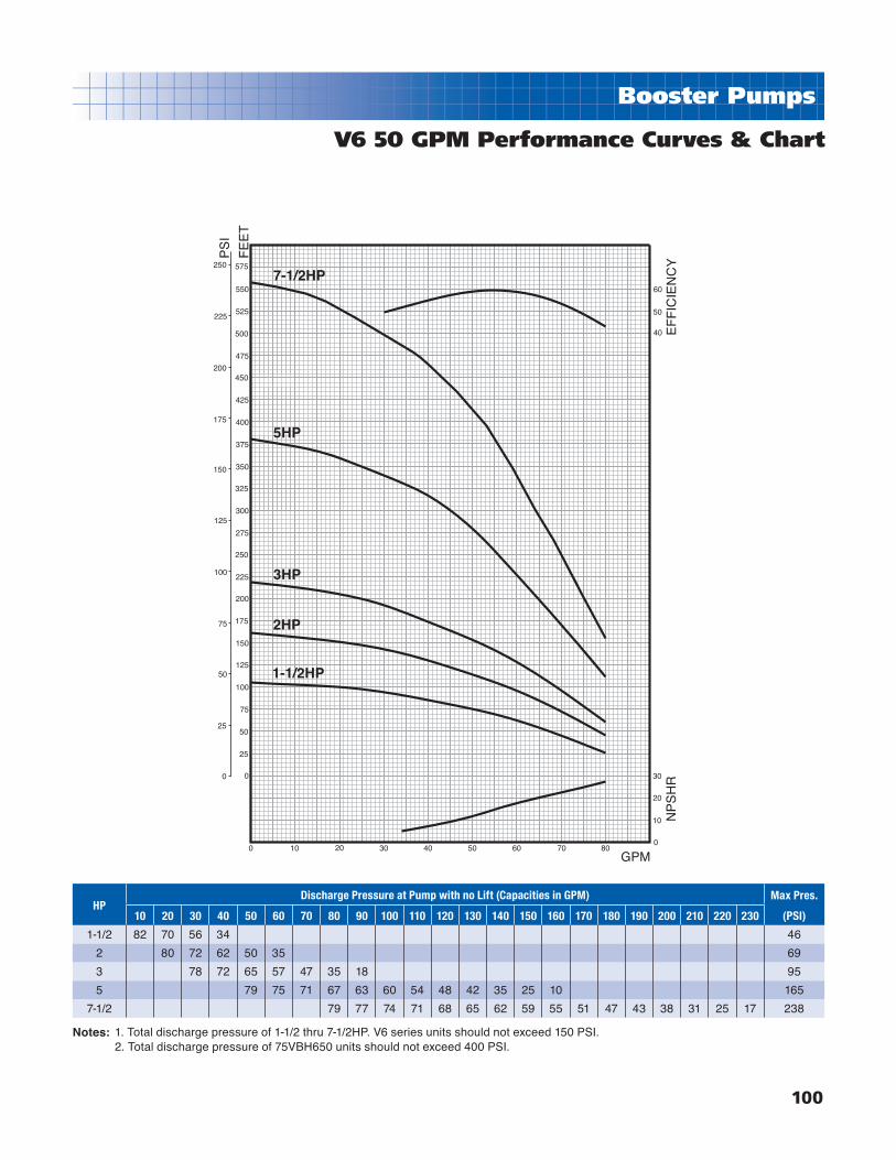
100
Booster Pumps
V6 50 GPM Performance Curves & Chart
PS
I
FE
ET
GPM
NP
SH
RE
FF
ICIE
NC
Y
0
25
50
75
100
125
150
175
200
225
250
0
25
50
75
100
125
150
175
200
225
250
275
300
325
350
375
400
425
450
475
500
525
550
575
0 10 20 30 40 50 60 70 800
10
20
30
40
50
60
7-1/2HP
5HP
3HP
2HP
1-1/2HP
HPDischarge Pressure at Pump with no Lift (Capacities in GPM) Max Pres.
(PSI)10 20 30 40 50 60 70 80 90 100 110 120 130 140 150 160 170 180 190 200 210 220 230
1-1/2 82 70 56 34 46
2 80 72 62 50 35 69
3 78 72 65 57 47 35 18 95
5 79 75 71 67 63 60 54 48 42 35 25 10 165
7-1/2 79 77 74 71 68 65 62 59 55 51 47 43 38 31 25 17 238
1. Total discharge pressure of 1-1/2 thru 7-1/2HP. V6 series units should not exceed 150 PSI. 2. Total discharge pressure of 75VBH650 units should not exceed 400 PSI.
Notes:

101
Booster Pumps
V6 75 GPM Performance Curves & Chart
PS
I
FE
ET
GPM
NP
SH
RE
FF
ICIE
NC
Y
60
50
40
0
10
20
0 10 20 30 40 50 60 70 80 90 100 110
0
25
50
75
100
125
150
0
25
50
75
100
125
150
175
200
225
250
275
300
325
350 7-1/2HP
5HP
3HP
HPDischarge Pressure at Pump with no Lift (Capacities in GPM) Max Pres.
(PSI)20 30 35 40 50 60 70 80 90 100 110 120 130 140
3 100 82 70 50 48
5 108 104 94 86 76 58 20 93
7-1/2 106 100 94 88 82 76 66 56 20 143
1. Total discharge pressure of V6 Series units should not exceed 150PSI.
Note:

102
Booster Pumps
V6 VERTICAL BOOSTER PUMPS with OPEN DRIP PROOF MOTORS
GPM HPSINGLE PHASE THREE PHASE - 208-230/460 VOLT
Model No. Order No. Wt. Model No. Order No. Wt.
50
1-1/2 15SVB6F50-2-S 91283915 100 15SVB6F50-2-T 91284913 103
2 2SVB6F50-3-S 91283923 105 2SVB6F50-3-T 91283964 108
3 3SVB6F50-4-S 91283931 109 3SVB6F50-4-T 91283972 112
5 5SVB6F50-7-S 91284301 208 5SVB6F50-7-T 91284327 188
7-1/2 Not Available in Single Phase 75SVB6F50-10-T 91284293 225
75
3 3SVB6F75-2-S 91284244 106 3SVB6F75-2-T 91284251 108
5 5SVB6F75-4-S 91284350 208 5SVB6F75-4-T 91284368 182
7-1/2 Not Available in Single Phase 75SVB6F75-6-T 91284269 222
1-1/2 - 7-1/2 HP V6 Series Booster Pump Ends V6 BOOSTER PUMPS - 575 VOLT
GPM HPPUMP ENDS ONLY THREE PHASE - 575 VOLT
Model No. Order No. Wt. Model No. Order No. Wt.
50
1-1/2 15SVB6F50-2 91284053 65 15SVB6F50-2-T5 91289019 103
2 2SVB6F50-3 91284061 72 2SVB6F50-3-T5 91289020 108
3 3SVB6F50-4 91284079 74 3SVB6F50-4-T5 91289021 112
5 5SVB6F50-7 91284335 89 5SVB6F50-7-T5 91289034 188
7-1/2 75SVB6F50-10 91284343 95 75SVB6F50-10-T5 91289035 225
75
3 3SVB6F75-2 91284277 70 3SVB6F75-2-T5 91329036 108
5 5SVB6F75-4 91284376 75 5SVB6F75-4-T5 91329037 182
7-1/2 75SVB6F75-6 91284285 84 75SVB6F75-6-T5 91329038 222
V6 Series Vertical
Ordering Information
Note: Single Phase 1/3 - 2HP motors rated 115/230V. Single Phase 3-5HP motor rated 230V. Three Phase motors rated 208-230/460V.

103
Replacement Motors
JM Frame CentrifugalREPLACEMENT MOTORS FOR JET & SMALL CENTRIFUGAL PUMPS
PumpSeries
Frame HPSingle Phase Three Phase
Voltage Order No. Wt. Voltage Order No. Wt.
CWJ ProHJH4D
56CKeyedShaft
1/2 115/230 90102294R 18 208-230/460 90102419R 19
3/4 115/230 90102302R 25 208-230/460 90102427R 27
1 115/230 90102310R 29 208-230/460 90102435R 29
1-1/2 115/230 90102328R 30 208-230/460 90102443R 30
2 115/230 90102336R 33 208-230/460 90102450R 33
3 230 90102897R 40 208-230/460 90110628R 68
H4D
56CKeyedShaft
1/2
Not Available in Single Phase
575 90109372R 19
3/4 575 90109380R 27
1 575 90109398R 29
1-1/2 575 90109406R 30
2 575 90109414R 33
3 575 90179961R 68
VB6
56CKeyedShaft
1-1/2 115/230 90118910R 31 208-230/460 90118977R 30
2 115/230 90118928R 34 208-230/460 90118985R 35
3 230 90119181R 41 208-230/460 90119207R 69
TC K. Shaft
5 230 90119199R 35 208-230/460 90119215R 58
7-1/2 230 Not Available 208-230/460 90119017R 74
CHJ
56JThreaded
Shaft
1/3 115/230 90177817R 17
Not Available in Three Phase
1/2 115/230 90100637R 18
3/4 115/230 90100561R 25
1 115/230 90100579R 29
1-1/2 115/230 90100587R 30
2 115/230 90119116R 34
SHJM56J
ThreadedShaft
1 115/230 90100629R 25
Not Available in Three Phase1-1/2 115/230 90100603R 30
2 115/230 90100611R 33
2-1/2 115/230 90100645R 34
DDD56Z
SquareFlange
1/2 115/230 90106246R 18 208-230/460 90106758R 9
3/4 115/230 90106253R 25 208-230/460 90106766R 10
1 115/230 90106261R 29 208-230/460 90106774R 12
1-1/2 115/230 90106279R 30 208-230/460 90106782R 14
2 115/230 90106287R 33 208-230/460 90106790R 17
2-1/2 115/230 90106295R 35 Not Available in Three Phase
CWJ56Z
SquareFlange
1/2 115/230 90101106R 18
Not Available in Three Phase3/4 115/230 90103227R 25
1 115/230 90103235R 29
SWJTY
TYCI
56ZSquareFlange
1/2 115/230 90101315R 18
Not Available in Three Phase
3/4 115/230 90101327R 25
1 115/230 90101331R 29
1-1/2 115/230 90101345R 30
2 115/230 90101352R 33
56C- Round fl ange motors have a 5/8” diameter shaft with 3/16” x 3/16” keyway.56J- Round fl ange motors have a 5/8” diameter shaft with 7/16-20 UNF-2A thread.56Z- Square fl ange motors have a 5/8” diameter shaft with 1/2-20 UNC-2A thread.
Notes:

104
Parts for Franklin Electric Control Boxes
FRANKLIN ELECTRIC Q.D. CONTROL BOX PARTSFOR SINGLE PHASE 1/3 - 1HP SUBMERSIBLE MOTORS
HP VoltageModel No.
Rating No. Req.Franklin
Component Part No.
Franklin KitOrder No.
Schaefer Order No.
1/3 HP - 115V 2801024915
Start Capacitor 159-191 MFD, 110V 1 275464125 305207925 99504516R
QD Relay 1 223415905 305101905 99490022R
1/3 HP - 230V 2801034915
Start Capacitor 43-53 MFD, 220V 1 275464126 305207926 99504813R
QD Relay 1 223415901 305101901 99490020R
1/2 HP - 115V 2801044915
Start Capacitor 250-300 MFD, 125V 1 275464201 305207951 99503013R
QD Relay 1 223415906 305101906 99490054R
1/2 HP - 230V 2801054915
Start Capacitor 59-71 MFD, 220V 1 275464105 305207905 99504219R
QD Relay 1 223415902 305101902 99490062R
3/4 HP - 230V 2801074915
Start Capacitor 86-103 MFD, 220V 1 275464118 305207918 99503617R
QD Relay 1 223415903 305101903 99490070R
1 HP - 230V 2801084915
Start Capacitor 105-126 MFD, 220V 1 275464113 305207913 99506982R
QD Relay 1 223415904 305101904 99490088R
1/2 HP - 230V CRC 2824055015
Start Capacitor 43-53 MFD, 220V 1 275464126 305207926 99504813R
Run Capacitor 15 MFD, 370V 1 156132101 305203907 99500022R
QD Relay 1 223415912 305105901 99490023R
3/4 HP - 230V CRC 2824075015
Start Capacitor 59-71 MFD, 220V 1 275464105 305207905 99504219R
Run Capacitor 23 MFD, 370V 1 156132102 305203908 99500023R
QD Relay 1 223415913 305105902 99490024R
1 HP - 230V CRC 2824085015
Start Capacitor 86-103 MFD, 220V 1 275464118 305207918 99503617R
Run Capacitor 23 MFD, 370V 1 156132102 305203908 99500023R
QD Relay 1 223415914 305105903 99490025R
REPLACEMENT PARTS FOR OLDER STYLE Q.D. CONTROL BOXES
Description Rating No. Req.Franklin
Component Part No.
Franklin KitOrder No.
Schaefer Order No.
Voltage ReplayKit*
115 Volt with bracket and screws 1 155031901 305102901 99497430R
230 Volt with bracket and screws 1 155031902 305102902 99497448R
208 Volt with bracket and screws 1 155031903 305102903 99490016R
CapacitorOverload
Assembly**
1/3 HP, 115 Volt 1 151033973 305218973 99491615R
1/3 HP, 230 Volt 1 151033974 305218974 99492217R
1/2 HP, 115 Volt 1 151033975 305218975 99493777R
1/2 HP, 230 Volt 1 151033976 305218976 99491912R
3/4 HP, 230 Volt 1 151033978 305218978 99492811R
1 HP, 230 Volt 1 151033979 305218979 99491011R
1.5 HP, 230 Volt 1 151033980 305218980 99493819R
Overload Kit***
1/3 HP, 115 Volt 1
N/A
305100901 N.A.
1/3 HP, 230 Volt 1 305100902 N.A.
1/2 HP, 115 Volt 1 305100903 99490013R
1/2 HP, 230 Volt 1 305100904 99490021R
3/4 HP, 230 Volt 1 305100905 99490039R
1 HP, 230 Volt 1 305100906 99490047R
Some Franklin motors, controls & parts are not stock items and may need to be special ordered.* Voltage realy kits will replace either current, voltage, or solid state switch relays.** O-D control boxes produced H85 or later do not contain an overload in the capacitor. On winding thermal overloads were added to three-wire motors rated 1/3-1HP in A85. If a control box dated H85 or later is applied with a motor dated M84 or earlier, overload protection can be provided by adding an overload kit to the control box.
Notes:
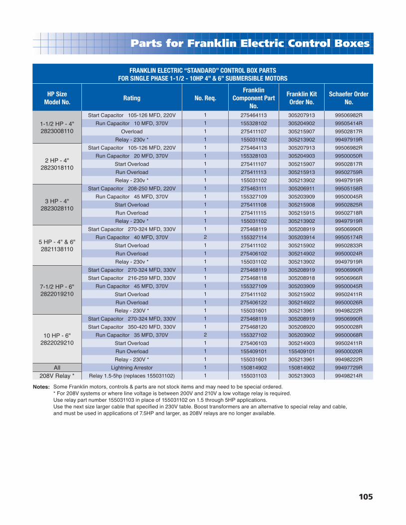
105
Parts for Franklin Electric Control Boxes
FRANKLIN ELECTRIC “STANDARD” CONTROL BOX PARTSFOR SINGLE PHASE 1-1/2 - 10HP 4” & 6” SUBMERSIBLE MOTORS
HP Size Model No.
Rating No. Req.Franklin
Component Part No.
Franklin KitOrder No.
Schaefer Order No.
1-1/2 HP - 4" 2823008110
Start Capacitor 105-126 MFD, 220V 1 275464113 305207913 99506982R
Run Capacitor 10 MFD, 370V 1 155328102 305204902 99505414R
Overload 1 275411107 305215907 99502817R
Relay - 230v * 1 155031102 305213902 99497919R
2 HP - 4" 2823018110
Start Capacitor 105-126 MFD, 220V 1 275464113 305207913 99506982R
Run Capacitor 20 MFD, 370V 1 155328103 305204903 99500050R
Start Overload 1 275411107 305215907 99502817R
Run Overload 1 275411113 305215913 99502759R
Relay - 230v * 1 155031102 305213902 99497919R
3 HP - 4" 2823028110
Start Capacitor 208-250 MFD, 220V 1 275463111 305206911 99505158R
Run Capacitor 45 MFD, 370V 1 155327109 305203909 99500045R
Start Overload 1 275411108 305215908 99502825R
Run Overload 1 275411115 305215915 99502718R
Relay - 230v * 1 155031102 305213902 99497919R
5 HP - 4" & 6" 2821138110
Start Capacitor 270-324 MFD, 330V 1 275468119 305208919 99506990R
Run Capacitor 40 MFD, 370V 2 155327114 305203914 99505174R
Start Overload 1 275411102 305215902 99502833R
Run Overload 1 275406102 305214902 99500024R
Relay - 230v * 1 155031102 305213902 99497919R
7-1/2 HP - 6" 2822019210
Start Capacitor 270-324 MFD, 330V 1 275468119 305208919 99506990R
Start Capacitor 216-259 MFD, 330V 1 275468118 305208918 99506966R
Run Capacitor 45 MFD, 370V 1 155327109 305203909 99500045R
Start Overload 1 275411102 305215902 99502411R
Run Overload 1 275406122 305214922 99500026R
Relay - 230V * 1 155031601 305213961 99498222R
10 HP - 6" 2822029210
Start Capacitor 270-324 MFD, 330V 1 275468119 305208919 99506990R
Start Capacitor 350-420 MFD, 330V 1 275468120 305208920 99500028R
Run Capacitor 35 MFD, 370V 2 155327102 305203902 99500068R
Start Overload 1 275406103 305214903 99502411R
Run Overload 1 155409101 155409101 99500020R
Relay - 230V * 1 155031601 305213961 99498222R
All Lightning Arrestor 1 150814902 150814902 99497729R
208V Relay * Relay 1.5-5hp (replaces 155031102) 1 155031103 305213903 99498214R
Some Franklin motors, controls & parts are not stock items and may need to be special ordered.* For 208V systems or where line voltage is between 200V and 210V a low voltage relay is required.Use relay part number 155031103 in place of 155031102 on 1.5 through 5HP applications.Use the next size larger cable that specifi ed in 230V table. Boost transformers are an alternative to special relay and cable,and must be used in applications of 7.5HP and larger, as 208V relays are no longer available.
Notes:

106
Parts for Franklin Electric Control Boxes
FRANKLIN ELECTRIC “DELUXE” CONTROL BOX PARTSFOR SINGLE PHASE 2- 15HP 4” & 6” SUBMERSIBLE MOTORS
HP Size Model No.
Rating No. Req.Franklin
Component Part No.
Franklin KitOrder No.
Schaefer Order No.
2 HP - 4" 2823018310
Start Capacitor 105-126 MFD, 220V 1 275464113 305207913 99506982RRun Capacitor 20 MFD, 370V 1 155328103 305204903 99500050R
Start Overload 1 275411107 305215907 99502817RRun Overload 1 275411113 305215913 99502759R
Contactor 1 155325102 305226901 99490017RRelay - 230V 1 155031102 305213902 99497919R
3 HP - 4" 2823028310
Start Capacitor 208-250 MFD, 220V 1 275463111 305206911 99505158RRun Capacitor 45 MFD, 370V 1 155327109 305203909 99500045R
Start Overload 1 275411108 305215908 99502825RRun Overload 1 275411115 305215915 99502718R
Contactor 1 155325102 305226901 99490017RRelay - 230V 1 155031102 305213902 99497919R
5 HP - 4" & 6" 2821138310
or 2821139310
Start Capacitor 270-324 MFD, 330V 1 275468119 305208919 99506990RRun Capacitor 40 MFD, 370V 2 155327114 305203914 99505174R
Start Overload 1 275411102 305215902 99502411RRun Overload 1 275406102 305214902 99500024R
Contactor 1 155326101 305347903 99490018RRelay - 230V 1 155031102 305213902 99497919R
7.5 HP - 6" 2822019310
Start Capacitor 270-324 MFD, 330V 1 275468119 305208919 99506990RStart Capacitor 216-259 MFD, 330V 1 275468118 305208918 99506966R
Run Capacitor 45 MFD, 370V 1 155327109 305203909 99500045RStart Overload 1 275411102 305215902 99502411RRun Overload 1 275406121 305214921 99500025R
Contactor 1 155326102 305347902 99490019RRelay - 230V 1 155031601 305213961 99498222R
10 HP - 6" 282202931
Start Capacitor 270-324 MFD, 330V 1 275468119 305208919 99506990RStart Capacitor 350-420 MFD, 330V 1 275468120 305208920 99500028R
Run Capacitor 35 MFD, 370V 2 155327102 305203902 99500068RStart Overload 1 275406103 305214903 99502411RRun Overload 1 155409101 155409101 99500020R
Contactor 1 155326102 305347902 99490019RRelay - 230V 1 155031601 305213961 99498222R
15 HP - 6" 2822039310 2822039330
Start Capacitor 350-420 MFD, 330V 2 275468119 305208919 99506990RStart Capacitor 161-193 MFD, 330V 1 275463122 305206912 99500030R
Run Capacitor 45 MFD, 370V 3 155327109 305203909 99500045RStart Overload 1 275406103 305214903 99502411RRun Overload 1 155409102 155409102 99500021R
Contactor 1 155429101 305347901 99490028RRelay - 230V 1 155031601 305213961 99498222R
15 HP - 6" 2822039621
X-Large Enclosure
Start Capacitor 350-420 MFD, 330V 2 275468119 305208919 99506990RStart Capacitor 161-193 MFD, 330V 1 275463122 305206912 99500030R
Run Capacitor 45 MFD, 370V 3 155327109 305203909 99500045RStart Overload 1 275406103 305214903 99502411RRun Overload 1 155409102 155409102 99500021R
Contactor 1 155429101 305347901 99490029RRelay - 230V 2 155031601 305213961 99498222R
All Lightning Arrestor 1 150814902 150814902 99497729R
208V Relay * Relay 1.5-5hp (replaces 155031102) 1 155031103 305213903 99498214R
Some Franklin motors, controls & parts are not stock items and may need to be special ordered.* For 208V systems or where line voltage is between 200V and 210V a low voltage relay is required.Use relay part number 155031103 in place of 155031102 on 1.5 through 5HP applications.Use the next size larger cable that specifi ed in 230V table. Boost transformers are an alternative to special relay and cable,and must be used in applications of 7.5HP and larger, as 208V relays are no longer available.
Notes:

107
Pump Accessories
DDD REPAIR KITS
Includes impeller, square ring, mechanical seal, wear-ring, and fasteners
DESCRIPTION PART NUMBER REPAIR MODELS
Impeller Kit
05388608K 5DD1
05388707K 7DD1
05388806K 1DD1
05388905K 15DD1
05389002K 2DD1
05389101K 25DD1
Fastener Kit 14443402K Repairs all DDD models
Seal, O-ring Kit 24017345 Includes Mechanical Seal & O-ring
DA1A & DAIB REPAIR KITSIncludes impeller, mechanical seal, & o-ring
DESCRIPTION PART NUMBER REPAIR MODELS
Impeller Kit
05394606K 3DA1A
05394705K 5DA1A
05394903K 7DA1A
05394804K DA1A
05394101K 7DA1B & 1DA1B
05394200K 15DA1B
05394309K 2DA1B
Fastener 14443303K DA1A, DA1B, RM2,RP2, RP3,HJM1, & HJM2
Seal, O-Ring Kit 24017352 Includes Mechanical Seal & O-Ring
DB1 & DB1-1/2 REPAIR KITSIncludes impeller, mechanical seal, impeller jam nut, and o-ring
DESCRIPTION PART NUMBER REPAIR MODELS
Impeller Kit
05371109K 7DB1
05163209K 1DB1
05163803K 15DB1
05164306K 2DB1
05165303K 3DB1
Fastener Kit 14443501K DB1-1/2, DB2, DC1-1/2
Seal Sleeve Kit 24017279 Includes all o-rings & imp.
Fasteners See Parts Page for details.
Seal, O-Ring Kit 24017352 Includes Mech. Seal & O-ring
Franklin Pump Systems Service Parts Kits
Ordering Information by Pump Model and Size
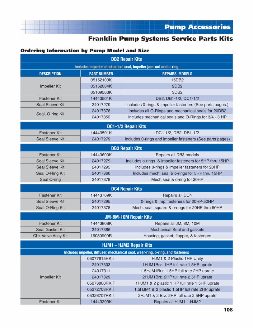
108
Pump Accessories
DB2 Repair Kits
Includes impeller, mechanical seal, impeller jam-nut and o-ring
DESCRIPTION PART NUMBER REPAIRS MODELS
Impeller Kit
05152103K 15DB2
05152004K 2DB2
05169503K 3DB2
Fastener Kit 14443501K DB2, DB1-1/2, DC1-1/2
Seal Sleeve Kit 24017279 Includes 0-rings & impeller fasteners (See parts pages.)
Seal, O-ring Kit24017378 Includes all O-Rings and mechanical seals for 20DB2
24017352 Includes mechanical seals and O-Rings for 3/4 - 3 HP
DC1-1/2 Repair KitsFastener Kit 14443501K DC1-1/2, DB2, DB1-1/2
Seal Sleeve Kit 24017279 Includes 0-rings and impeller fasteners (See parts pages)
DB3 Repair KitsFastener Kit 14443600K Repairs all DB3 models
Seal Sleeve Kit 24017279 Includes o-rings & impeller fasteners for 5HP thru 15HP
Seal Sleeve Kit 24017295 Includes 0-rings & impeller fasteners for 20HP
Seal O-Ring Kit 24017360 Includes mech. seal & o-rings for 5HP thru 15HP
Seal O-ring 24017378 Mech seal & o-ring for 20HP
DC4 Repair KitsFastener Kit 14443709K Repairs all DC4
Seal Sleeve Kit 24017295 0-rings & imp. fasteners for 20HP-50HP
Seal O-Ring Kit 24017378 Mech. seal, square & o-rings for 20HP thru 50HP
JM-8M-10M Repair KitsFastener Kit 14443808K Repairs all JM, 8M, 10M
Seal Gasket Kit 24017386 Mechanical Seal and gaskets
Chk Valve Assy Kit 16030900R Housing, gasket, fl apper, & fasteners
HJM1 – HJM2 Repair KitsIncludes impeller, diffuser, mechanical seal, wear-ring, o-ring, and fasteners
Impeller Kit
05077615RKIT HJM1 & 2 Plastic 1HP Unity
24017303 1HJM1Brz. 1HP full rate 1.5HP uprate
24017311 1.5HJM1Brz. 1.5HP full rate 2HP uprate
24017329 2HJM1Brz. 2HP full rate 2.5HP uprate
05273800RKIT 1HJM1 & 2 plastic 1 HP full rate 1.5HP uprate
05272703RKIT 1.5HJM1 & 2 plastic 1.5HP full rate 2HP uprate
05326707RKIT 2HJM1 & 2 Brz. 2HP full rate 2.5HP uprate
Fastener Kit 14443303K Repairs all HJM1 – HJM2
Franklin Pump Systems Service Parts Kits
Ordering Information by Pump Model and Size

109
Pump Accessories
CY-CCY & SWJ Repair KitsIncludes impeller, diffuser, wear ring, mechanical seal, o-ring & disc.
DESCRIPTION PART NUMBER REPAIRS MODELS
Impeller Kit
05380037RKIT S5CY – S5CCY
05392204RKIT 5CY – S7CY – 5CCY – S7CCY – 5SWJ
05392303RKIT 7CY – S1CY – 7CCY – S1CCY – 7SWJ
Fastener Kit 14443204K Cyclone, Deep, SRP3, CWJ, SWJ
SRP3, CWJ & DEEP Repair KitsIncludes impeller, diffuser, wear ring, mechanical seal, o-ring, and disc.
Impeller Kit
24013906 1/2HP DEEP, 5SRP3, 5CWJ
05392303RKIT 3/4HP DEEP, 7SRP3, 7CWJ
05385703RKIT 1HP DEEP, 1SRP3, 1CWJ
Fastener Kit 1443204K DEEP, SRP3, Cyclone, CWJ
Seal, O-ring Kit 24008500 Includes Mech. seal & all o-rings
RP2 Repair KitsIncludes impeller, diffuser, wear ring, mechanical seal, & square ring.
Impeller Kit24012106 5RP2
24012205 7RP2
Fastener 14443303K RP2, RM2, PRM3, DA1A, DA1B, HJM1, HJM2, CWJ Pro
Seal, Square Ring Kit 24012304 Includes mech. seal & all o-rings and square rings
Impeller Kit
24014508 5RM2, 5CWJ Pro
24014607 7RM2, 7CWJ Pro
24014904 1RM2, 1CWJ Pro
24017246 1PRM3
RM2, CWJ Pro & 7PRM3 Repair KitsImpeller Kit, The following kits are for units built prior to 7/96 and will include a 9/16” threaded motor coupling.
Impeller Kit
24012403 5RM2, 5CWJ Pro
24012502 7RM2, 7CWJ Pro
24012601 1RM2, 1CWJ Pro
Fastener Kit 14443303K RM2, PRM3, RP2, DA1A, DA1B, HJM1, HJM2, CWJ Pro
Seal, Square Ring Kit 24012700 Includes mech. seal & all o-ring and square rings
Franklin Pump Systems Service Parts Kits
Ordering Information by Pump Model and Size

110
Pump Accessories
Repair Kits
1918
1713
1211
16
14
164
310
98
5
V6 Booster Repair KitsDESCRIPTION PART NUMBER REPAIRS MODEL
Fastener Kit 14444004K Repairs all V6 Boosters
H4 Booster Repair KitsDESCRIPTION PART NUMBER REPAIRS MODEL
H4 Component Kit 24017519 Small Parts for all models
Fastener Kit 14443907K Repairs all H4 Boosters
Typhoon, TY, TYCI Hydraulic Repair KitsIncludes impeller, diffuser, wear ring, mechanical seal, square ring, and o-ring.
DESCRIPTION PART NUMBER REPAIRS MODEL
Impeller Kit
05034103RKIT 7TY, S10TY, 7TYCI
05034202RKIT 10TY, S15TY, 10TYCI
05034400RKIT 15TY, S20TY, 15TYCI
05034001RKIT 20TY, S25TY, 20TYCI
Rod Booster Repair Kits
Descr. Part # Desc. Part #H45-7 9132-2073 *H418-5 9132-2156
H45-10 9132-2081 *H418-7 9132-2164
H45-14 9132-2099 *H418-9 9132-2172
H4518 9132-2107 *H418-12 9132-2180
*H418-15 9132-2198
H410-4 9132-2859
H410-6 9132-2115 H425-5 9132-2206
H410-9 9132-2123 H425-6 9132-2214
H410-12 9132-2131 H425-9 9132-2222
H410-16 9132-2149 H425-11 9132-2230
H425-16 9132-2248
H425-27 9132-5001
Franklin Pump Systems Service Parts Kits
Ordering Information by Pump Model and Size
Note: For all 18GPM units built prior to 9/97, the shell, tie rods andshaft must also be replaced - they are longer. Please consult factory.

111
4” Submersible Parts
11
13
6A 6
1
2
3
8
13 9
7
4
12
5
S4PVS4XVHRModelsonly
HURS4PModelsonly
13
10
Parts for all Models (5-25 GPM)
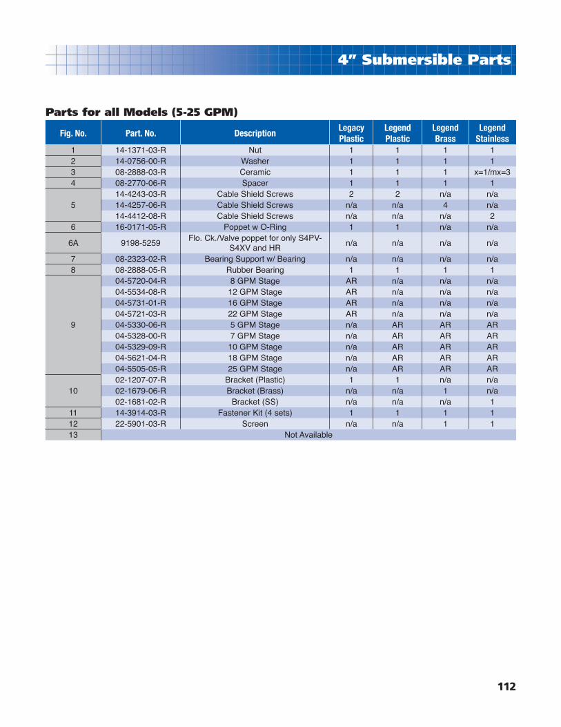
112
4” Submersible Parts
Fig. No. Part. No. DescriptionLegacyPlastic
LegendPlastic
LegendBrass
LegendStainless
1 14-1371-03-R Nut 1 1 1 12 14-0756-00-R Washer 1 1 1 13 08-2888-03-R Ceramic 1 1 1 x=1/mx=34 08-2770-06-R Spacer 1 1 1 1
514-4243-03-R Cable Shield Screws 2 2 n/a n/a14-4257-06-R Cable Shield Screws n/a n/a 4 n/a14-4412-08-R Cable Shield Screws n/a n/a n/a 2
6 16-0171-05-R Poppet w O-Ring 1 1 n/a n/a
6A 9198-5259Flo. Ck./Valve poppet for only S4PV-
S4XV and HRn/a n/a n/a n/a
7 08-2323-02-R Bearing Support w/ Bearing n/a n/a n/a n/a8 08-2888-05-R Rubber Bearing 1 1 1 1
9
04-5720-04-R 8 GPM Stage AR n/a n/a n/a04-5534-08-R 12 GPM Stage AR n/a n/a n/a04-5731-01-R 16 GPM Stage AR n/a n/a n/a04-5721-03-R 22 GPM Stage AR n/a n/a n/a04-5330-06-R 5 GPM Stage n/a AR AR AR04-5328-00-R 7 GPM Stage n/a AR AR AR04-5329-09-R 10 GPM Stage n/a AR AR AR04-5621-04-R 18 GPM Stage n/a AR AR AR04-5505-05-R 25 GPM Stage n/a AR AR AR
1002-1207-07-R Bracket (Plastic) 1 1 n/a n/a02-1679-06-R Bracket (Brass) n/a n/a 1 n/a02-1681-02-R Bracket (SS) n/a n/a n/a 1
11 14-3914-03-R Fastener Kit (4 sets) 1 1 1 112 22-5901-03-R Screen n/a n/a 1 113 Not Available
Parts for all Models (5-25 GPM)

113
4” Submersible Parts
1
2
3
4
5
7
12
8
9
14
15
13
12
6
10
11
16
Parts for all Models (35-90 GPM)
Figure No. Part No. Description
103-0905-03-R SS Discharge housing w/ rubber bearing
04-5340-04-R CI Discharge housing w/ rubber bearing (prior to 8/01)
2 08-2888-05-R Rubber Bearing
302-1707-02-R SS Motor Bracket
02-1134-05-R CI Motor Bracket
4 14-1371-03-R Hex Nut
5 14-0756-00-R Washer
6 14-1249-03-R Shim (5 each)
7 08-2903-06-R Hub Sleeve Ceramic (6 req'd)
8 14-4223-07-R Thrust washer (not required for 35)
9 08-2893-08-R Thrust Journal (not required for 35)
10
04-5783-08-R Stage Assy. for 35 (1 x no. of stages required)
04-5341-03-R Stage Assy. for 45 (1 x no. of stages required)
04-5343-01-R Stage Assy. for 60 (1 x no. of stages required)
04-5300-02-R Stage Assy. for 90 (1 x no. of stages required)
11 08-2506-23-R Hex Sleeve (1 x no. of stages required on 45, 60 only)
1208-2960-06-R Hex Sleeve (2 ea. req'd for 35, 1 ea. req'd for all others)
08-2506-23-R Hex Sleeve (2 req'd) prior to 8/01
1322-5925-05-R Submersible Screen
22-0579-05-R Submersible Screen (prior to 8/01)
14 14-3914-03-R Fastener Kit w/ motor lead protector 22-5694-04 (set of 4)
1514-4257-06-R Screw (4 or 5 req'd) all except 35 models
14-4258-20-R Hex wash Hd. 35 only (4 ea. req'd)
16 08-2961-05-R Bearing support stage w/ brg.

114
6” Submersible Parts
Parts for all Models (60-75 GPM)
7
6
5
4
3
2
1
8
9
Figure No. Part No. Description1 02-1708-01-R SS Bracket (All HP's)2 N/A Shell
3
04-5648-03 Stage Assy. for 50 1-1/2 and 2 HP04-5647-04 Stage Assy. for 50 3, 5, 7-1/2, and 10 HP04-5649-02 Stage Assy. for 75 3 & 5 HP04-5650-08 Stage Assy. for 75 7-1/2, 10, 15 and 20 HP
4 04-5820-03-R SS Discharge (3" NPT)5 22-5957-08-R SS Screen and Machine Screws (2)6 14-4421-07 4" and 6" Motor Fastener Kit7 N/A Cable Shield8 04-5848-01-R Bearing and Spacers Repair Kit9 NA Shaft

115
Jet Parts
Shallow Well Jet Pump
Models CY, CCY, & SWJ
19
14
8Base Kit
20
7
6
18
5
15Tube Kit 16
2
4
3
910
11
#1 Case Kit
#2 Impeller Kit
1217
Figure No. Old No. New No. Description
103-0873-00-R 03-0873-00-K Plastic Case Kit w/ fasteners & plugs
03-0892-08-R 03-0892-08-K Cast Iron Case Kit w/ fasteners & plugs
All Impeller Kits include: Impeller, diffuser, wear ring, mech. seal, O-ring, disk.-No. 2,3,4,5,6,18
2
05-3800-37-R 05-3800-37-RKIT Impeller Kit S5CY - S5CCY
05-3922-04-R 05-3922-04-RKIT Impeller Kit 5CY - S7CY - 5CCY - S7CCY - 5SWJ
05-3923-03-R 05-3923-03-RKIT Impeller Kit 7CY - S1CY - 7CCY - S1CCY - 7SWJ
3 06-0119-02-R See Item #2 Now included with impeller kits
4 08-0845-19-R See Item #2 Now included with impeller kits
5 10-0002-06 Mechanical Seal (also included w/ Impeller kits)
611-1502-08-R See Item #2 Disc f/5SCY, 5CY, S7CY, 5SWJ, (now included w/imp. kits)
11-1503-07-R See Item #2 Disc f/7CY, S1CY, 7SWJ, (now included w/imp. kits)
7 11-1521-05-R Seal Plate 6-1/2” dia.
8 12-1057-06-R Base assy. w/ rubber protector #14
9 14-0727-22-R 14443204K *Fastener Kit
10 14-0722-19-R 14443204K *Fastener Kit
1114-1302-23-R 14443204K *Fastener Kit
14-1296-13-R 14443204K *Fastener Kit
1218-0449-09-R Nozzle & venturi for 1/2HP
18-0450-05-R Nozzle & venturi for 3/4HP
14 22-5525-09-R 12-1057-06-R Now included with Base #8
15 31-1197-04-R014 31-1197-04-K Tube Kit 1/4 x 14-1/2” long w/barb
16 31-1198-03-R 31-1197-04-K Tube Kit w/barb see #15 included
17 31-0059-11-R 31-0059-11-06PK Plug 1/4” Galv. (Available in 6 pack only)
18 47-0361-48-R 47-0361-48-02PK O-ring Kit 6 x 6-3/8 x 3/16 (2 per kit)
19 9195-1061-R020 69ES1AZ20-40P Pressure Switch set 20-40
*Fastener Kit #14443204K includes the following:4 each 3/8 - 16 Hex Nuts4 each 3/8 reg. Lockwashers4 each 3/8 - 16 x 2-3/4 Hex capscrews f/ plastic pump body4 each 3/8 - 16 x 1-1/4 Hex capscrews f/ cast iron pump body

116
Jet Parts
Deep Well Jet Pump
Models S-DEEP
19
20
7
6
18
5
15Tube Kit
2
4
3
#2 Impeller Kit
1
11
Figure No. Old No. New No. Description1 03-0886-06-R New Descr. Case Assy. C.I. Kit w/ fasteners & plugs
All Impeller Kits include: Impeller, diffuser, wear ring, mech. seal, O-ring, disk.-No. 2,3,4,5,6,18
2
05-3857-03-R 05-3857-03-RKIT Impeller Kit f/ 1HP
05-3922-04-R 24-0139-06 Impeller Kit f/ 1/2HP
05-3923-03-R 05-3923-03-RKIT Impeller Kit f/ 3/4HP
306-0119-02-R See Item #2 Now included with impeller kits 3/4 & 1HP
06-0118-03-R See Item #2 Now included with impeller kit 1/2HP
4 08-0845-19-R See Item #2 Now included with impeller kits
5 10-0002-06 Mechanical Seal (also included with impeller kits)
611-1502-08-R See Item #2 Disc for 1/2HP (now included w/ impeller kits)
11-1503-07-R See Item #2 Disc for 3/4HP & 1HP (now included w/ impeller kits)
7 11-1521-05-R Seal Plate 6-1/2” dia.
11 14-1296-13-R 14443204K * Fastener Kit
15 31-1197-04-R014 31-1197-04-K Tube Kit 1/4 x 14-1/2 poly-black w/barb ftg.
18 47-0361-08-R 47-0361-48-02PK O-ring Kit 6x6-3/8x3/16 (2 per kit)
19 9195-1061-R020 69ES1AZ20-40 Pressure Switch set 20-40
20 Motor See Motor Selection page
*Fastener Kit #14443204K includes the following: 4 each 3/8 - 16 x 1-1/4 Hex capscrews Pl.

117
Jet Parts
Convertible Well Jet Pump
Models SRP3, CWJ
21
21
1
10
11
#2Impeller Kit
32A
5
4
17
16
15
16
#15 Tube Kit
20
6
#8Base Kit
12
19
14
18
9
Figure No. Old No. New No. Description1 03-0838-05-R New descr. Case Kit w/wear ring - plugs - capscrews #2A & 9
All Impeller Kits include: Impeller, diffuser, wear ring, mech. seal, O-ring, disk.-No. 2,3,4,5,7,2A
2
24-0139-06 24-0139-06 Impeller Kit 1/2HP
05-3857-03-R 05-3857-03-RKIT Impeller Kit 1HP
05-3923-03-R 05-3923-03-RKIT Impeller Kit 3/4HP
2A 08-0845-19-R See Item #2 Wear ring (now included w/impeller kits)
306-0118-03-R See Item #2 Diffuser f/ 1/2HP (now included w/impeller kits)
06-0119-02-R See Item #2 Diffuser f/ 3/4HP &1HP (now included w/impeller kits)
4 10-0002-06 Mechanical Seal (also included w/impeller kits)
5 47-0361-48-R 47-0361-48-02PK Case O-ring Kit 6 x 6-3/8 x 3/16 (2 per kit)
6 11-1521-05-R Seal Plate 6-1/2” dia.
711-1502-08-R See Item #2 Disc. for 1/2HP (now included w/impeller kits)
11-1503-07-R See Item #2 Disc. for 3/4HP & 1HP (now included w/impeller kits)
8 12-1057-06-R New descr. Base w/Protector #12
9 14-1296-13-R 14443204K *Fastener Kit
10 18-1290-07-R Deep Well Plug Assembly
1118-1248-00-R Shallow Well Injector for 3/4HP & 1HP
18-1247-01-R Shallow Well Injector for 1/2HP
12 22-5525-09-R 12-1057-06-K Now included with Base #8
14 23-2647-08-R Box Spacer
15 31-1197-04-R014 31-1197-04-K Tube Kit 1/4 x 14-1/2ʼ long w/barb
16 31-1198-03-R 31-1197-04-K Barb ftg. 90º elbow (now included w/#15 tube kit)
17 9193-4018-R 9193-4018 Pressure Gauge 0-100# 1/4M (see accessory pages)
18 9195-7027-R020 69ES1AZ20-40 Pressure Switch set 20
19 Motor See Motor Selection Page
Kit 24-0085-00 Convertible Jet “seal/o-ring Kit” incl mech seal, Injector O-rings, & case o-ring
*Fastener Kit #14443204K includes the following: 4 each 3/8 - 16 x 1-1/4 Hex capscrews

118
Jet Parts
Convertible Well Jet Pump
Models RP2
231514
13
1211
10
9
#21 Tube Kit
19
2017
7
1
6 5
4
2
3
8
9A
#9Impeller Kit
Figure No. Old No. New No. Description1 03-0636-09-R Case Kit w/wear ring #9A and plugs #7
218-1247-01-R Shallow well injector #1023 f/ 5RP2
18-1248-00-R Shallow well injector #1034 f/ 7RP2
3 18-1290-07-R Deep well plug assembly
4 47-0120-00-R 24-0123-04 Seal O-ring kit
5 47-0115-07-R 24-0123-04 Seal O-ring kit
6 47-0116-06-R 24-0123-04 Seal O-ring kit
7 31-0059-11-R 31-0059-11-06PK Plug 1/4” galv. (available in 6 pack only)
All Impeller Kits Include: Impeller, diffuser, mech. seal, sq.-ring- Fig. No. 8,9,9A,10,11
806-0118-03-R See Item #9 Diffuser for 5RP2 (now included w/impeller kits)
06-0119-02-R See Item #9 Diffuser for 7RP2 (now included w/impeller kits)
905-3074-00-R 24-0121-06 Impeller Kit f/ 5RP2
05-3075-09-R 24-0122-05 Impeller Kit f/ 7RP2
9A 08-0845-19-R See Item #9 Wear Ring (now included w/impeller kits)
10 10-1203-01 Mechanical Seal (also included w/impeller kits)
11 47-0258-53-R 47-0258-53-02PK Square ring kit 6 x 1/8 x 1/8 (2 per kit)
1202-1101-04-R New desc. 5RP2 Brkt 4-3/4 Imp fi t #4933 w/ capscrews #13
02-1102-03-R New desc. 7RP2 Brkt 5” Imp fi t #4933 w/ capscrews #13
13 14-1292-25-R 14443303K *Fastener Kit
14 07-21521-05-R001 Shaft Coupling w/set screws 7/16 thrd.
15 14-0002-02-R 14-0002-02-24PK Set Screw Kit (kit includes 24 per pack)
17 9195-7027-R020 69ES1AZ2040 Pressure Switch set 20-40
18 31-1198-03-R 31-1197-04-K Tube Kit 1/4 x 14-1/2” Long w/barb
19 23-2647-08-R Box Spacer
20 9193-4018-R 9193-4018 Pressure Gauge 0 - 100 lbs. “see accessory page”
21 31-1197-04-R014 31-1197-04-K Tube Kit 1/4 x 14-1/2” long w/barb #18
22 31-0063-07-R 1” Plug (also included with case item #1)
23 Motor See Motor Selection page
Kit 24-0123-04 RP2 Convertible jet “Seal/O-Ring Kit” Includes Noʼs 4,5,6,10,11
*Fastener Kit #14443203K includes the following: 8 each 3/8 - 16 x 3/4 Hex capscrews
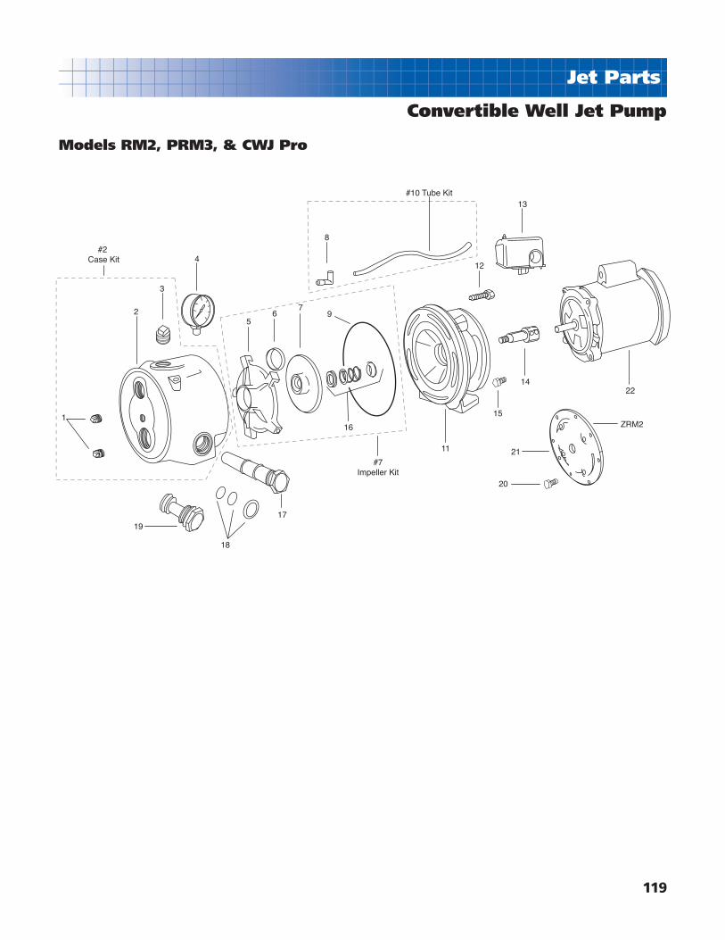
119
Jet Parts
Convertible Well Jet Pump
Models RM2, PRM3, & CWJ Pro
1
2
3
4
19
18
56
7
8
9
16
17
11
15
14
20
21
ZRM2
22
12
#10 Tube Kit
#2Case Kit
#7Impeller Kit
13

120
Jet Parts
Convertible Well Jet Pump
Models RM2, PRM3, & CWJ ProFigure No. Old No. New No. Description
1 31-0059-11-R 31-0059-11-06PK Plug 1/4” (available in 6 pack only)2 03-0642-01-R Pump Case with wear ring and plugs3 31-0063-07-R 1” Plug (also included with case assy. #2)4 9193-4018-R 9193-4018 Pressure Gauge 0-100lbs. “see accessory pg.”
All Impeller Kits include: Impeller, diffuser, mech. seal, sq. ring, wear ring. Fig. Nos- 6,7,8,16
506-0104-09-R See Item #7 Diffuser for 1/2HP (now included with impeller kits)06-0108-05-R See Item #7 Diffuser for 3/4HP (now included with impeller kits)06-0106-07-R See Item #7 Diffuser for 1HP (now included with impeller kits)
6 08-0845-19-R See Item #7 Wear Ring (now included with impeller kits)
7
05-3811-08-R 24-0145-08 Impeller Kit f/ 1/2HP05-3417-06-R 24-0146-07 Impeller Kit f/ 3/4HP05-3418-05-R 24-0149-04 Impeller Kit f/ 1HP05-2727-03-R 24-0172-46 Impeller Kit f/ 1PRM3
For units built prior to 7/96 use the following impeller kits, they include new shaft coupling, impeller, diffuser, mech. seal, sq. ring. Fig. Nos- 5,6,7,9,14,16
831-0093-01-R 31-0020-09-R016 Elbow Fitting (now available with #10 copper tube kit)31-1198-03-R 31-1197-04-K Elbow ftg. barb. for PRM3 (see tube kit #10)
9 47-0262-57-R 47-0262-57-02PK Square-Ring Kit (2 per kit)
1031-0020-09-R016 Copper tube kit 16-1/2” long with elbow #831-1197-04-R014 31-1197-04-K Tube Kit 1/4 x 14-1/2 long w/ barb #8
11
02-1255-05-R 02-1255-05-K Bracket Kit f/ 1/2HP w/fasteners02-1256-07-R 02-1256-07-K Bracket Kit f/ 3/4HP w/fasteners02-1272-07-R 02-1272-07-K Bracket Kit f/ 1Hp w/fasteners02-1363-07-R 02-1363-07-K Bracket Kit f/ 1HP PRM3 w/fasteners
12 14-4227-03-R 14443303K *Fastener Kit
139195-1269-R030 69ES1AZ3050 Pressure Switch set 30-50PSI F/other than PRM3
9195-0865-R 69ES1AZ2T3050 Pressure Switch set 30-50PSI F/PRM3
1407-3610-09-R001 Shaft Coupling 9/16 thrd. w/ set screws07-2152-05-R001 Shaft Coupling 7/16 thrd. w/ set screws
1514-1292-25-R 14443303K *Fastener Kit14-1294-23-R 14443303K *Fastener Kit
1610-1203-01 Mechanical Seal 3/4” all but PRM3 (also included w/imp. kits)10-1202-02 Mechanical Seal 5/8” f/PRM3 (also included w/imp. kits)
1718-1278-03-R Shallow Well Injector 1024 for 1/2HP (see accessory page)18-1279-02-R Shallow Well Injector 1027 for 3/4HP (see accessory page)18-1280-09-R Shallow Well Injector 1028 for 1HP (see accessory page)
1847-0123-48-R O-Ring Kit for Injectors (includes 3 o-rings)18-1291-06-R Deep Well Plug (see accessory page)
21 14-1289-12-R 14-1289-12-04PK Capscrews 5/16-24 x 3/4 for ZRM2 (4 pack kit only)22 11-0280-12-R Adaptor fl ange for Z1RM2Kit 24-0127-04 Seal O-ring kit; incl. mech. seal & o-rings #9,16,18
Motor See Motor Selection Page
*Fastener Kit #14443303K includes the following:5 each 3/8 - 16 x 1-3/4 SS Hex Capscrew4 each 3/8 - 16 x 3/4 PL Hex Capscrew4 each 3/8 - 16 x 7/8 PL Hex Capscrew

121
Jet Parts
Convertible Well Jet Pump
Models C- Single Stage Injector
14 15 22 1 19 23 2 26 6 24 4 16 17 3 5 25
2019
13127
8
91011
109
Impeller Kits
46
43
45
44
3941
40
4139
38
Fig. No. Part No. Description1 03-0055-01-K Case Kit w/plugs & fasteners
2
06-0110-01-K Diffuser Kit w/sq. ring #4 F/3C
06-0111-00-K Diffuser Kit w/sq. ring #4 F/5C
06-0112-09-K Diffuser Kit w/sq. ring #4 F/7C
3
02-1051-04-K Bracket Kit w/fasteners F/3C
02-1052-03-K Bracket Kit w/fasteners F/5C
02-1053-02-K Bracket Kit w/fasteners F/7C
4 13-1247-06-02PK Square-ring Kit (2 per kit)
5 22-3403-01-R Flinger 1-3/8 x37/64x1/8 NEO
Impeller Kit includes: Impeller, wear-ring, mech. seal, and sq. ring-fi g nos. 4,6,24,26
6
05-3073-19-K Impeller Kit for 3C
05-3074-18-K Impeller Kit for 5C
05-3075-17-K Impeller Kit for 7C
7
18-1200-12-R Injector for 3C w/ o-rings
18-1293-04-R Injector for 5C w/ o-rings
18-1248-18-R Injector for 7C w/ o-rings
8 18-1290-07-R Deep Well Plug w/o-ring
9 24-0174-44 O-ring Kit (incl. 1 ea. #9,10,11)
12 23-1284-08-R Locknut
13 23-2647-08-R Box Spacer
Fig. No. Part No. Description15 31-1198-04-K Tube Kit 1/4 x 14-1/2 w/barb #14
16-17 14-4433-03-K Fastener Kit (incl. 4ea. #16, #17)
18 31-0059-11-06PK Plug 1/4” (avail. in 6 pack only)
19 31-0062-08 3/4” plug (incl. w/case kit)
20 31-0063-08 1” plug (incl. w/case kit)
22 9195-9726-R030 Pressure Switch 30-50set
23 9193-4018-R Pressure Gauge
24 10-0002-06 Mech. Seal 5/8 (also w/imp. kits)
25
9017-7817-R Motor 1/3HP
9010-0637-R Motor 1/2HP
9010-0561-R Motor 3/4HP
26 08-0845-19-06PK Wear-ring Kit 2/92 (6ea. per kit)
40 31-3155-01-R Hose 1”x18” PVC #150
38 thru 45 14-4409-03-K Tank Mounting Kit
46 PJR-25S Pressure Tank
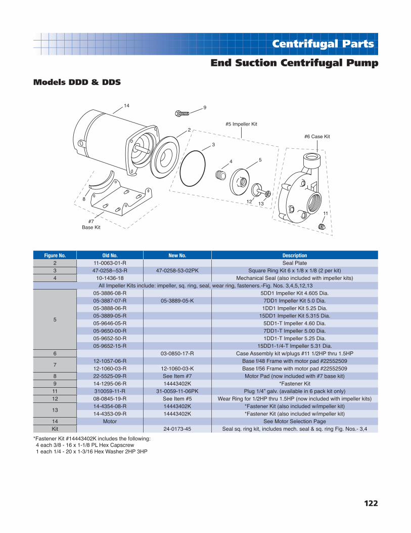
122
Centrifugal Parts
End Suction Centrifugal Pump
Models DDD & DDS
14
8
#7Base Kit
9
2#5 Impeller Kit
3
4 5
12 13
#6 Case Kit
11
Figure No. Old No. New No. Description2 11-0063-01-R Seal Plate3 47-0258--53-R 47-0258-53-02PK Square Ring Kit 6 x 1/8 x 1/8 (2 per kit)4 10-1436-18 Mechanical Seal (also included with impeller kits)
All Impeller Kits include: impeller, sq. ring, seal, wear ring, fasteners.-Fig. Nos. 3,4,5,12,13
5
05-3886-08-R 5DD1 Impeller Kit 4.605 Dia.05-3887-07-R 05-3889-05-K 7DD1 Impeller Kit 5.0 Dia.05-3888-06-R 1DD1 Impeller Kit 5.25 Dia.05-3889-05-R 15DD1 Impeller Kit 5.315 Dia.05-9646-05-R 5DD1-T Impeller 4.60 Dia.05-9650-00-R 7DD1-T Impeller 5.00 Dia.05-9652-50-R 1DD1-T Impeller 5.25 Dia.05-9652-15-R 15DD1-1/4-T Impeller 5.31 Dia.
6 03-0850-17-R Case Assembly kit w/plugs #11 1/2HP thru 1.5HP
712-1057-06-R Base f/48 Frame with motor pad #2255250912-1060-03-R 12-1060-03-K Base f/56 Frame with motor pad #22552509
8 22-5525-09-R See Item #7 Motor Pad (now included with #7 base kit)9 14-1295-06-R 14443402K *Fastener Kit11 310059-11-R 31-0059-11-06PK Plug 1/4” galv. (available in 6 pack kit only)12 08-0845-19-R See Item #5 Wear Ring for 1/2HP thru 1.5HP (now included with impeller kits)
1314-4354-08-R 14443402K *Fastener Kit (also included w/impeller kit)14-4353-09-R 14443402K *Fastener Kit (also included w/impeller kit)
14 Motor See Motor Selection PageKit 24-0173-45 Seal sq. ring kit, includes mech. seal & sq. ring Fig. Nos.- 3,4
*Fastener Kit #14443402K includes the following:4 each 3/8 - 16 x 1-1/8 PL Hex Capscrew1 each 1/4 - 20 x 1-3/16 Hex Washer 2HP 3HP
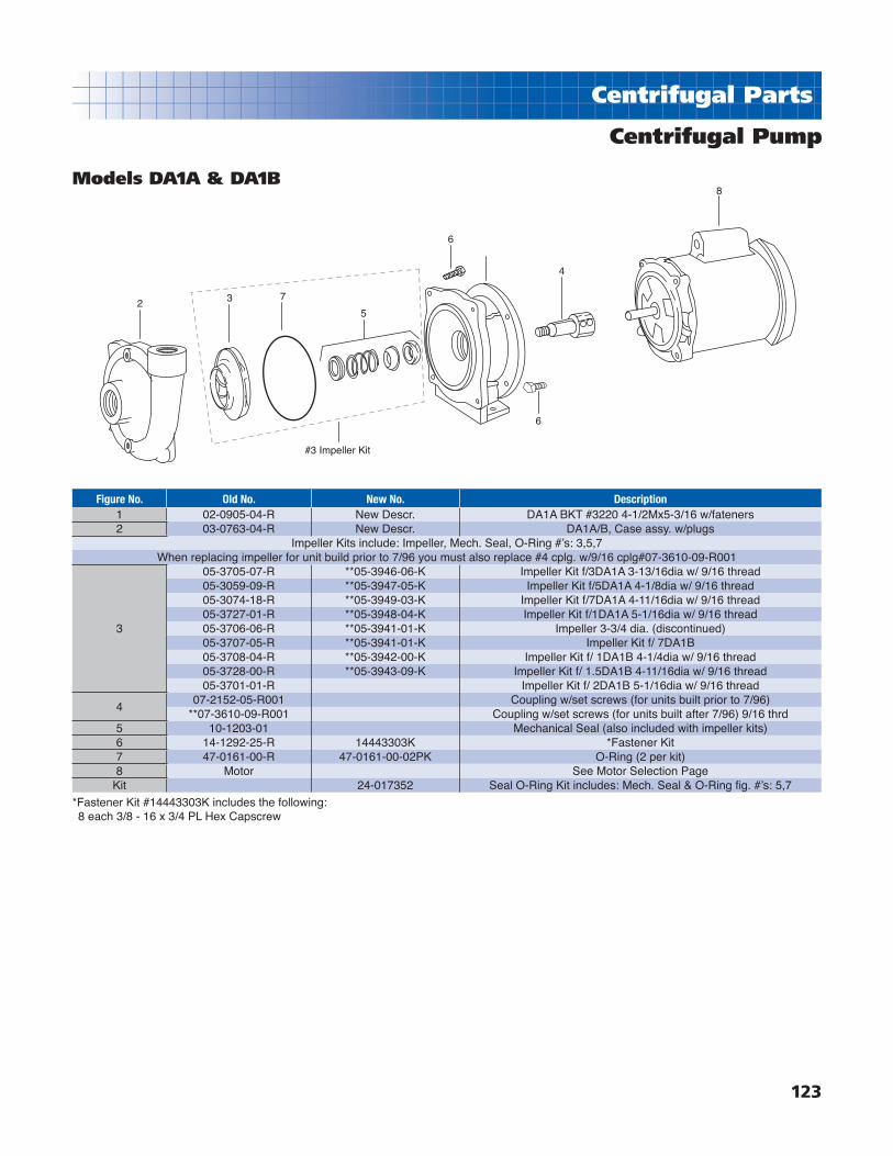
123
Centrifugal Parts
Centrifugal Pump
Models DA1A & DA1B
Figure No. Old No. New No. Description1 02-0905-04-R New Descr. DA1A BKT #3220 4-1/2Mx5-3/16 w/fateners2 03-0763-04-R New Descr. DA1A/B, Case assy. w/plugs
Impeller Kits include: Impeller, Mech. Seal, O-Ring #ʼs: 3,5,7When replacing impeller for unit build prior to 7/96 you must also replace #4 cplg. w/9/16 cplg#07-3610-09-R001
3
05-3705-07-R **05-3946-06-K Impeller Kit f/3DA1A 3-13/16dia w/ 9/16 thread05-3059-09-R **05-3947-05-K Impeller Kit f/5DA1A 4-1/8dia w/ 9/16 thread05-3074-18-R **05-3949-03-K Impeller Kit f/7DA1A 4-11/16dia w/ 9/16 thread05-3727-01-R **05-3948-04-K Impeller Kit f/1DA1A 5-1/16dia w/ 9/16 thread05-3706-06-R **05-3941-01-K Impeller 3-3/4 dia. (discontinued)05-3707-05-R **05-3941-01-K Impeller Kit f/ 7DA1B05-3708-04-R **05-3942-00-K Impeller Kit f/ 1DA1B 4-1/4dia w/ 9/16 thread05-3728-00-R **05-3943-09-K Impeller Kit f/ 1.5DA1B 4-11/16dia w/ 9/16 thread05-3701-01-R Impeller Kit f/ 2DA1B 5-1/16dia w/ 9/16 thread
407-2152-05-R001 Coupling w/set screws (for units built prior to 7/96)
**07-3610-09-R001 Coupling w/set screws (for units built after 7/96) 9/16 thrd5 10-1203-01 Mechanical Seal (also included with impeller kits)6 14-1292-25-R 14443303K *Fastener Kit7 47-0161-00-R 47-0161-00-02PK O-Ring (2 per kit)8 Motor See Motor Selection Page
Kit 24-017352 Seal O-Ring Kit includes: Mech. Seal & O-Ring fi g. #ʼs: 5,7
2 3 7
5
6
6
4
8
#3 Impeller Kit
*Fastener Kit #14443303K includes the following:8 each 3/8 - 16 x 3/4 PL Hex Capscrew

124
Centrifugal Parts
Centrifugal Pump
Models DB1 & DB1-1/2
Figure No. Old No. New No. Description
102-1264-07-R Bracket Assy. 4-1/2” x 6-1/2” 3/4HP thru 3HP w/base#1502-1590-02-R Bracket Assy. 4-1/2” x 6-1/2”, 5HP & 7.5HP
203-0764-02-R Case Assy. w/pugs f/DB103-0767-00-R Case Assy. w/plugs f/DB1-1/2
All Impeller Kits include: Impeller, Mech. Seal, Jam Nut, O-Ring
3
05-3711-09-R 05-3711-09-K Impeller Kit 4-1/2 dia. f/3/4HP DB105-1632-09-R 05-1632-09-K Impeller Kit 4-3/4 dia. f/1HP DB105-1638-03-R 05-1638-03-K Impeller Kit 5-3/16 dia. f/1.5HP DB105-1643-06-R 05-1643-06-K Impeller Kit 5-1/2 dia. f/2HP DB103-1653-03-R 03-1653-03-K Impeller Kit 6-1/2 dia. f/3HP DB105-1790-23-R Impeller 6-7/16” dia. 5HP, DB105-3709-03-R Impeller 3-15/16” dia. 1HP, DB1-1/205-3710-00-R Impeller 4-5/16” dia. 1.5HP, DB1-1/205-1665-09-R Impeller 4-5/8” dia. 2HP, DB1-1/205-1673-09-R Impeller 5-1/8” dia. 3HP, DB1-1/205-1816-23-R Impeller 5-3/4” dia. 5HP, DB1-1/205-1823-24-R Impeller 6-7/16” dia. 7.5HP, DB1-1/2
4 07-3610-09-R001 Shaft Coupling 9/16” thrd. w/setscrews 3/4HP thru 3HP
510-1203-01 3/4 Mechanical Seal f/3/4HP thru 3HP (also incl. in Impeller Kits)10-0369-03 1-1/4” Mechanical Seal f/5HP thru 7.5HP
6 14-1292-25-R 14443501K *Fastener Kit
714-1295-06-R 14443501K *Fastener Kit14-1330-29-R 14443501K *Fastener Kit
8 47-0165-06-R 47-0165-06-02PK O-Ring (2 per kit) (also incl. in Impeller Kits)9 47-0022-09-R 47-0022-09-02PK Sleeve O-Ring for 5 & 7HP (2 per kit)10 08-2872-03-R Seal Sleeve 1-1/4” x 1” SS f/5HP &7.5HP11 13-0384-01-R 13-0384-01-02PK O-Ring Kit 1” Sleeve f/ 5 & 7.5HP (2 per kit)12 14-4124-07-R 24-0172-79 Seal Sleeve Kit13 14-4226-04-R 24-0172-79 Seal Sleeve Kit14 14-1292-33 24-0172-79 Seal Sleeve Kit15 12-1036-02-R Base w/fasteners f/3/4HP thru 3HP16 Motor See Motor Selection Page17 New Eff. 1/30/02 14-4420-08-06PK Jam Nut Kit 9/16-18 NF SS eff. 1/30/02 (6 per kit)Kit New 24-0172-79 Seal Sleeve Kit f/5 & 7.5HP (includes #ʼs 8,9,11,12,13,14)Kit New 24-0173-52 Seal/O-Ring Kit 3/4 thru 3HP (includes #ʼs 5, 8)
*Fastener Kit #14443501K includes the following:8 each 3/8 - 16 x 3/4 PL Hex Capscrew, 1 each 3/8 x 3/4 Capscrew4 each 3/8 - 16 x 1-1/2 PL Hex Capscrew, 1 each 9/16 - 18 NF Impeller Jam Nut4 each 1/2 - 13 x 1-1/4 PL Hex Capscrew1 each 3/16 x 1-1/8 Square Key1 each 1-1/8 x 13/32 x 1/8 SS Impeller Washer
14 13 12 9 11
Seal Sleeve Kit
2
14 1312 38
5
17
6 1
4
16
7
15
109 11

125
Centrifugal Parts
Centrifugal Pump
Model DB2
14 13 12 9 11
Seal Sleeve Kit8
2
14 1312 38
5
17
6 1
4
16
7
15
109 11
Figure No. Old No. New No. Description
1
02-1264-07-R Bracket Assy. 4-1/2” x 6-1/2” 1.5HP thru 3Hp w/base #1502-1590-02-R Bracket Assy. 4-1/2” x 6-1/2” 5HP & 7.5HP02-1564-04-R Bracket Assy. 8-1/2” x 6-1/2” 10HPAdded - 2003 02-1263-08-R Bracket#9142 - 8-1/2” x 9” 15HP & 20HP
203-0766-01-R Case for 1.5HP thru 10HPAdded - 2003 03-0762-05-R Case for 15DB2-T and 20DB2-T
All Impeller Kits include: Impeller, Mech. Seal, Jam Nut, O-Ring
3
05-1521-03-R 05-1521-03-K Impeller Kit 3-13/16” dia. F/ 1.5HP05-1520-04-R 05-1520-04-K Impeller Kit 4” dia. F/ 2HP05-1695-03-R 05-1695-03-K Impeller Kit 4-1/2” dia. F/ 3HP05-1738-28-R Impeller 5-1/8” dia. 5HP05-1749-25-R Impeller 5-13/16” dia. 7.5HP05-1759-22-R Impeller 6-7/16” dia. 10HPAdded - 2003 05-3719-19-R Impeller for 15HPAdded - 2003 05-3703-17-R Impeller for 20HP
4 07-3610-09-R001 Shaft Coupling 9/16” thrd. w/setscrews 1.5HP thru 3HP
510-1203-01 34” Mechanical Seal for 1.5HP thru 3HP (also incl. w/Imp. kits)10-0369-03 1-1/4” Mechanical Seal for 5HP thru 15HP
Added - 2003 10-0370-00 Mech. Seal for 20HP6 14-1292-25-R 14443501K *Fastener Kit
714-1295-06-R 14443501K *Fastener Kit14-1330-29-R 14443501K *Fastener Kit
847-0165-06-R 47-0165-06-02PK O-ring Kit (2 per kit)Added - 2003 47-0175-04-02PK O-Ring kit f/ 15HP & 20HP (2 per kit)
947-0022-09-R 47-0022-09-02PK Sleeve O-Ring for 5 thru 10HP (2 per kit)Added - 2003 47-0126-04-02PK Sleeve O-Ring for 15 thru 20HP (2 per kit)
10 08-2872-03-R Seal Sleeve 1-1/4” x 1” for 5HP thru 10HP
1113-0384-01-R 13-0384-01-02PK O-Ring Kit 5 thru 10HP (2 per kit)Added - 2003 13-0385-00-02PK Spacer Sleeve sq. Ring f/DB2 20HP (2 per kit)
12 14-4124-07-R 24-0172-79 Seal Sleeve Kit13 14-4226-04-R 24-0172-79 Seal Sleeve Kit14 14-1292-33 24-0172-79 Seal Sleeve Kit15 12-1036-02-R Base w/fasteners for 3/4HP thru 3HP16 Motor See Motor Selection Page17 New Eff. 1/30/02 14-4420-08-06PK Jam Nut Kit 9/16-18 NF SS eff.1/30/02 (6 per kit)Kit New 24-0172-79 Seal Sleeve Kit f/5 thru 10HP- #ʼs: 8,9,11,12,13,14Kit New 24-0173-78 Seal/O-Ring Kit DB2 20HP incl. 5,8,9,11Kit New 24-0173-52 Seal/O-Ring Kit 3/4 thru 3HP incl. 5,8
*Fastener Kit #14443501K includes the following:8 each 3/8 - 16 x 3/4 PL Hex Capscrew, 1 each 1-1/8 x 13/32 x 1/8 SS Impeller washer4 each 3/8 - 16 x 1-1/2 PL Hex Capscrew, 1 each 3/8 - 16 x 3/4 Capscrew4 each 1/2 - 13 x 1-1/4 PL Hex Capscrew, 1 each 9/16 - 18 NF Impeller Jam Nut

126
Centrifugal Parts
Centrifugal Pump
Model DC1-1/2
213 11
34
13 12 11 8 7
6
9 1
14
785
9-10
Seal Sleeve Kit
12
4
Figure No. Old No. New No. Description
102-1593-09-R Bracket 4-1/2” x 9” for 3HP, 5HP, 7.5HP02-1565-03-R Bracket 8-1/2” x 9” for 10HP & 15HP
2 03-0765-02-R Case Assembly for DC1-1/2
3
05-3721-07-R Impeller 5-1/16” dia. 3HP DC1-1/205-3723-05-R Impeller 5-13/16” dia. 5HP DC1-1/205-3725-03-R Impeller 6-5/8” dia. 7.5HP DC1-1/205-3714-06-R Impeller 7-5/16” dia. 10HP DC1-1/205-3702-00-R Impeller 8-3/8” dia. 15HP DC1-1/2
**4 47-0175-04-R 47-0175-04-02PK Case O-RIng Kit 9 x 9-3/16 (2 per kit)5 08-2872-03-R Seal Sleeve 1-1/4” x 1” SS for 3HP thru 15HP6 10-0369-03 1-1/4” Mechanical Seal 3HP thru 15HP
**7 13-0384-01-R 13-0384-01-02PK O-Ring B-N 1” sleeve kit 3HP thru 15HP (2 per kit)**8 47-0022-09-R 47-0022-09-02PK Sleeve O-RIng Kit 3 thru 15HP (2 per kit)9 14-1292-25-R 14443501K *Fastener Kit10 14-1330-29-R 14443501K *Fastener Kit
**11 14-2124-07-R 24-0172-79 Seal Sleeve Kit (key also part of fastener kit)**12 14-4226-04-R 24-0172-79 Seal Sleeve Kit (washer also part of fastener kit)**13 14-1292-33 24-0172-79 Seal Sleeve Kit (screw also part of fastener kit)14 Motor See Motor Selection Page
**Kit New 24-0172-79 Seal Sleeve Kit 3HP thru 15HP includes #ʼs - 4,7,8,11,12,13
*Fastener Kit #14443501K includes the following:12 each 3/8 - 16 x 3/4 PL Hex Capscrew4 each 1/2 - 13 x 1-1/4 PL Hex Capscrew1 each 3/16 x 1-1/8 Square Key1 each 1-1/8 x 13/32 x 1/8 Impeller washer1 each 3/8 - 16 x 3/4 Capscrew

127
Centrifugal Parts
Centrifugal Pump
Models DB3
7 11 10 6 13
Seal Sleeve Kit
2
15 7 1110
314
5
81
16
94 6 13
12
Figure No. Old No. New No. Description
102-1590-02-R Mtr. Bracket 4-1/2”M x 6-1/2”C for 5HP & 7.5HP02-1564-04-R Mtr. Bracket 8-1/2”M x 6-1/2”C for 10HP & 15HP02-1390-04-R Mtr. Bracket 8-1/2”M x 6-1/2”C for 20HP
2 03-0840-01-R Case DB3
3
05-3837-08-R Impeller 4-1/2” dia. 5HP05-3838-07-R Impeller 4-15/16” dia. 7.5HP05-3839-06-R Impeller 5-5/16” dia. 10HP05-3840-03-R Impeller 5-3/4” dia. 15HP05-3841-02-R Impeller 6” dia. 20HP
408-2872-03-R Seal Sleeve 1-1/4” x 1” SS for 1.5HP thru 15HP08-2909-00-R Seal Sleeve 1-3/4” x 1-3/8” SS for 20HP
#510-0369-03 Mechanical Seal 1-1/4” for 5HP thru 15HP10-0370-00 Mechanical Seal 1-3/4” for 20HP
#6*13-0384-01-R 13-0384-01-02PK O-Ring 1” Sleeve Kit 5 thru 15HP (2 per kit)13-0385-00-R 13-0385-00-02PK O-Ring Sleeve Kit 20HP (2 per kit)
7*14-1292-33 14443600K *Fastener Kit
14-1330-11-R 14443600K *Fastener Kit8 14-1294-23-R 14443600K *Fastener Kit
914-1295-06-R 14443600K *Fastener Kit14-1787-01-R 14443600K *Fastener Kit14-0735-48-R 14443600K *Fastener Kit
10*14-4124-07-R 24-0172-79 Seal Sleeve Kit 5HP thru 15HP14-4125-06-R 24-0172-95 Seal Sleeve Kit 20HP
11*14-4226-04-R 24-0172-79 Seal Sleeve Kit 5HP thru 15HP14-4292-03-R 24-0172-95 Seal Sleeve Kit 20HP
1222-0204-08-R Defl ector 5HP thru 15HP22-0205-07-R Defl ector 20HP
#13*47-0022-09-R 47-0022-09-02PK Sleeve O-Ring Kit 5HP thru 15HP (2 per kit)47-0126-04-R 47-0126-04-02PK Sleeve O-Ring Kit 20 HP (2 per kit)
#14 47-0165-06-R 47-0165-06-02PK O-Ring Kit 6-1/2 x 6-11/16 (2 per kit)15 08-2908-01-R16 Motor See Motor Selection PageKit* New 24-0172-79 Seal Sleeve Kit 5HP thru 15HP incl. 6,7,10,11,13Kit* New 24-0172-95 Seal Sleeve Kit 20HP incl. 6,7,10,11,13Kit# New 24-0173-60 Mech. Seal & O-Ring Kit 5-15HP incl. 5,6,13,14Kit# New 24-0173-78 Mech. Seal & O-Ring Kit 20HP incl. 5,6,13,14
*Fastener Kit #14443600K includes the following:1 each 3/8 - 16 x 3/4 HT/TR 410SS Hex Capscrew, 1 each 1/2 - 13 x 1-1/4 HT/TR 410 SS Hex Capscrew, 4 each 3/8 - 16 x 1 PL Hex Capscrew4 each 3/8 - 16 x 1-1/8 PL Hex Capscrew, 4 each 1/2 - 13 x 1 PL Hex Capscrew, 4 each 1/2-13 x 2 PL Hex Capscrew1 each 3/16 x 1-1/8 303SS Square Key, 1 each 1/4 x 1-3/8 303SS Square Key, 1 each 1-1/8 x 13/32 x 1/8 Washer1 each Impeller Washer

128
Centrifugal Parts
Centrifugal Pump
Models DC4
16
#15 Tube Kit
15
16
5
54
214 1310
3
2
14 13 10 8 7
11
6 117
18
789
6
4
Seal Sleeve Kit
Figure No. Old No. New No. Description
102-0715-04-R Mtr. Bracket 20HP & 25HP 9-1/2”D
02-0716-03-R Mtr. Bracket 30HP, 40HP, 50HP. 13-1/2”D
203-0867-09-R Case 4” x 4” NPT (20,25,30HP) w/plugs
03-0868-08-R Case 4” x 5” Flange (40 & 50HP) w/plugs
3
05-3916-02-R Impeller 7-1/32” dia. 20HP
05-3917-01-R Impeller 7-15/32” dia. 25HP
05-3918-00-R Impeller 7-7/8” dia. 30HP
05-3919-09-R Impeller 8-7/16” dia. 40HP
05-3920-06-R Impeller 9-1/32” dia. 50HP
4 08-2940-01-R Wear ring
5 31-0059-11-R 31-0059-11-06PK Plug Kit 1/4” (6 per kit) incl. with case
614-1787-01-R 14443709K ** Fastener Kit
14-4293-02-R 14443709K **Fastener Kit
#7* 13-0385-00-R 13-0385-00-02PK Sq. Ring kit f/spacer sleeve 1-3/8 shaft (2 per kit)
#8* 47-0126-04-R 47-0126-04-02PK Sleeve O-Ring Kit (2 per kit)
9 08-2897-04-R Seal Sleeve
10* 14-4125-06-R 24-0172-95 Seal Sleeve Kit 20 thru 50HP
#11 10-0370-00 Mechanical Seal 1-3/4”
#12 47-0274-53-R 47-0274-53-02PK Case Sq.-Ring Kit (2 per kit)
13* 14-4292-03-R 24-0172-95 Seal Sleeve Kit 20 thru 50HP
14* 14-1330-11-R 24-0172-95 Seal Sleeve Kit 20 thru 50HP
15 31-1691-05-R020 31-1691-05-K Poly Tube Kit 3/8 x 20”L w/connector #17
16 31-1690-06-R 31-1691-05-K See #16 Poly Tube Kit
17 22-0205-07-R Defl ector 1-21/32” x 5-1/4” dia.
18 Motor See Motor Selection page
Kit* New 24-0172-95 Seal Sleeve Kit 20 thru 50HP Incl. #7,8,10,13,14
#Kit New 24-0173-78 Mech. Seal/Sq. & O-ring kit 20 thru 50HP Incl. #7,8,11,12
*Fastener Kit #14443709K includes the following:12 each 1/2 - 13 x 1 PL Hex Capscrew4 each 5/8 - 11 x 1-1/4 PL Hex Capscrew1 each 1/4 x 1-3/8 SS Square Key1 each Washer1 each 1/2 - 13 x 1-1/4 HT/TR 410SS Hex Capscrew
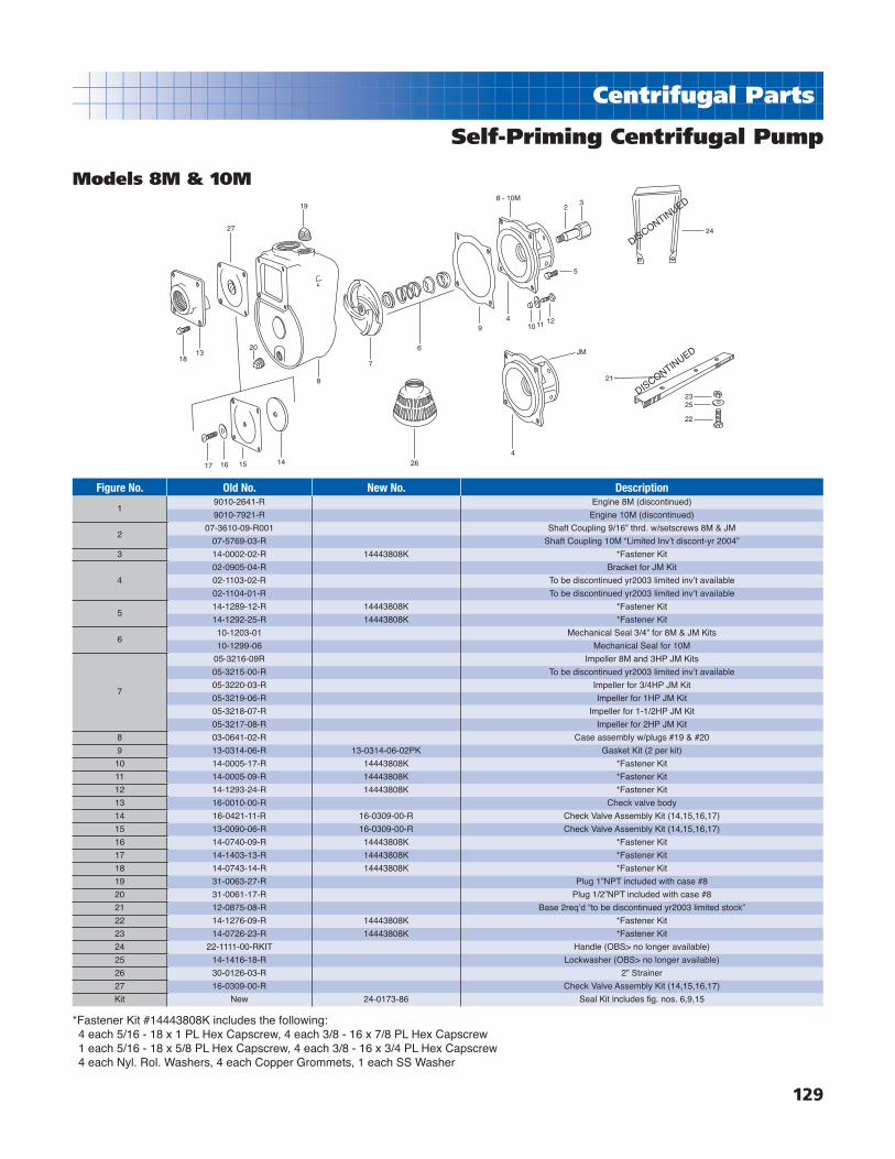
129
Centrifugal Parts
Self-Priming Centrifugal Pump
Models 8M & 10M
17 16 15 14
1813
20
8
27
19
24
JM
21
2325
22
DISCONTINUED
DISCONTINUED
8 - 10M2
3
1211104
9
6
7
5
264
Figure No. Old No. New No. Description
19010-2641-R Engine 8M (discontinued)
9010-7921-R Engine 10M (discontinued)
207-3610-09-R001 Shaft Coupling 9/16” thrd. w/setscrews 8M & JM
07-5769-03-R Shaft Coupling 10M “Limited Invʼt discont-yr 2004”
3 14-0002-02-R 14443808K *Fastener Kit
4
02-0905-04-R Bracket for JM Kit
02-1103-02-R To be discontinued yr2003 limited invʼt available
02-1104-01-R To be discontinued yr2003 limited invʼt available
514-1289-12-R 14443808K *Fastener Kit
14-1292-25-R 14443808K *Fastener Kit
610-1203-01 Mechanical Seal 3/4” for 8M & JM Kits
10-1299-06 Mechanical Seal for 10M
7
05-3216-09R Impeller 8M and 3HP JM Kits
05-3215-00-R To be discontinued yr2003 limited invʼt available
05-3220-03-R Impeller for 3/4HP JM Kit
05-3219-06-R Impeller for 1HP JM Kit
05-3218-07-R Impeller for 1-1/2HP JM Kit
05-3217-08-R Impeller for 2HP JM Kit
8 03-0641-02-R Case assembly w/plugs #19 & #20
9 13-0314-06-R 13-0314-06-02PK Gasket Kit (2 per kit)
10 14-0005-17-R 14443808K *Fastener Kit
11 14-0005-09-R 14443808K *Fastener Kit
12 14-1293-24-R 14443808K *Fastener Kit
13 16-0010-00-R Check valve body
14 16-0421-11-R 16-0309-00-R Check Valve Assembly Kit (14,15,16,17)
15 13-0090-06-R 16-0309-00-R Check Valve Assembly Kit (14,15,16,17)
16 14-0740-09-R 14443808K *Fastener Kit
17 14-1403-13-R 14443808K *Fastener Kit
18 14-0743-14-R 14443808K *Fastener Kit
19 31-0063-27-R Plug 1”NPT included with case #8
20 31-0061-17-R Plug 1/2”NPT included with case #8
21 12-0875-08-R Base 2reqʼd “to be discontinued yr2003 limited stock”
22 14-1276-09-R 14443808K *Fastener Kit
23 14-0726-23-R 14443808K *Fastener Kit
24 22-1111-00-RKIT Handle (OBS> no longer available)
25 14-1416-18-R Lockwasher (OBS> no longer available)
26 30-0126-03-R 2” Strainer
27 16-0309-00-R Check Valve Assembly Kit (14,15,16,17)
Kit New 24-0173-86 Seal Kit includes fi g. nos. 6,9,15
*Fastener Kit #14443808K includes the following:4 each 5/16 - 18 x 1 PL Hex Capscrew, 4 each 3/8 - 16 x 7/8 PL Hex Capscrew1 each 5/16 - 18 x 5/8 PL Hex Capscrew, 4 each 3/8 - 16 x 3/4 PL Hex Capscrew4 each Nyl. Rol. Washers, 4 each Copper Grommets, 1 each SS Washer

130
Centrifugal Parts
Self-Priming Centrifugal Pump
Models HJM1 & HJM2
12
8
9
10
4 5 6 7
4a
32
11
1
11
Figure No. Old No. New No. Description1 31-0061-17-R Plug 1/2” NPT included w/case see #2
2
03-0822-03-R 03-0387-00-K Case Kit 1-1/2”T f/1HP full rate - 1-1/2HP uprate w/w-ring
03-0823-02-R 03-0388-09-K Case Kit 2”T f/2HP full rate - 2-1/2HP uprate w/w-ring
03-0821-04-R 03-0386-01-K Case Kit 2”T f/1-1/2HP full rate - 2HP uprate w/w-ring
All Overhaul Kits include: Impeller, diffuser, mech. seal, wear-ring, O-ring, fasteners. Fig. Nos. 3,4,4A,5,6,8,9
3
06-0115-06-R 24-0173-03 HJM1 Overhaul Kit 1HP full rate 1-1/2HP unity
06-0116-05-R 24-0173-11 1.5HJM Overhaul Kit 1-1/2HP full rate & 2HP unity
06-0120-09 24-0173-29 2HJM1 Overhaul Kit 2HP full rate & 2.5HP unity
06-0141-04-R 05-0776-15-RKIT HJM1 & 2 plastic Overhaul Kit f/ 1HP unity
4
05-3417-06-R 24-0173-03 1HJM1 Overhaul Kit Brz. Imp. f/1HP full rate & 1.5HP unity
05-3418-05-R 24-0173-11 1.5HJM1 Overhaul Kit Brz. Imp. f/1.5HP full rate & 2HP unity
05-3419-04-R 24-0173-29 2HJM1 Overhaul Kit Brz. Imp. f/2HP & 2.5HP unity
05-3811-08-R Imp. Brz. for 1HP unity (Discontinued)
05-0776-15-R 05-0776-15-RKIT 1HJM1 & 2 Overhaul Kits Plastic Imp. f/ 1HP unity
05-2738-00-R 05-2738-00-RKIT 1HJM1 & 2 Overhaul Kits Plastic Imp. f/ 1HP fullrate 1.5 unity
05-2727-03-R 05-2727-03-RKIT 1.5HJM1 & 2 Overhaul Kits Plastic Imp. f/ 1.5HP fullrate 2 unity
05-3267-07-R 05-3267-07-RKIT 2HJM1 & 2 Overhaul Kits Brz. imp. f/2HP fullrate & 2.5HP unity
4A 08-0845-19-R Wear Ring (Now included with case and overhaul kits)
510-1203-01 Mechanical Seal 3/4” f/HJM1 (also included in OH kits)
10-1202-02 Mechanical Seal 5/8” f/HJM2 (also included in OH kits)
6 47-0262-57-R 47-0262-57-02PK Sq. Ring Kit (2 per kit)
7
02-1255-08-R Bracket for 1HP unity (with fasteners)
02-1256-07-R Bracket for 1HP fullrate & 1.5HP unity (with fasteners)
02-1272-07-R Bracket for 1.5HP fullrate & 2,2.5HP unity (with fasteners)
02-1364-06-R Bracket for 1HP unity HJM2
02-1362-08-R Bracket for 1HP full rate & 1-1/2HP unity HJM2
02-1363-07-R Bracket f/ 1.5 & 2HJM2 full rate & 2, 2.5HP unity ( with fasteners)
8 14-4227-03-R 14443303K *Fastener Kit
914-1292-25-R 14443303K *Fastener Kit
14-1294-23-R 14443303K *Fastener Kit
10 07-3610-09-R001 Coupling w/setscrews f/9/16 thrd. HJM1 mtr. shaft
11 31-0059-11-R 31-0059-11-06PK Plug Kit 1/4” (6 per kit) also included w/case
12 Motor See Motor Selection Page
*Fastener Kit #14443303K includes the following:5 each 3/8 - 16 x 1-3/4 PL Hex Capscrews 4 each 3/8 - 16 x 3/4 PL Hex Capscrews 4 each 3/8 - 16 x 1 PL Hex Capscrews

131
Centrifugal Parts
Self-Priming Centrifugal Pump
Models Typhoon, TY & TYCI
9
13 2 3
8
5
4 1
10
76
Figure No. Old No. New No. Description
103-0811-09-R Plastic Case w/drain and priming plug03-0045-06-R Cast Iron Case w/drain and priming plug
Hydraulic Repair Kits includes: Impellers, Diffuser, Seal Ring, Mech. Seal, Sq. Ring, O-Ring
2
05-0341-03-RKIT Hydraulic Repair Kit 3/4HP05-0342-02-RKIT Hydraulic Repair Kit 1HP05-0344-00-RKIT Hydraulic Repair Kit 1-1/2HP05-0340-01-RKIT Hydraulic Repair Kit 2HP
311-0060-04-R Plastic Seal Plate with fasteners- bolts, nuts, washers11-0012-03 Cast Iron Seal Plate with fasteners- studs, washers, nuts
4 14-4403-09-R Fastener Kit f/ cast iron unit 3/8-16x1-1/2
512-1144-01-R Base with fasteners and protector - 48 frame mtr.12-1145-00-R Base with fasteners and protector - 56 frame mtr.
6 47-0329-51-R 47-0329-51-02PK Square Ring Kit (2 per kit)7 42-3723-00-R Ring-Lok for Plastic Unit
831-1609-06-R 31-1609-06-02PK Plug Kit 1/4” f/plastic unit (2 per kit) also incl. w/case31-0059-11-R 31-0059-11-06PK Plug Kit 1/4” for cast iron unit (6 per kit) incl. w/case
931-1730-08-R Priming Plug f/plastic unit (also included with case)31-0063-07-R Priming Plug f/cast iron unit (also included with case)
10 Motor See Motor Selection page
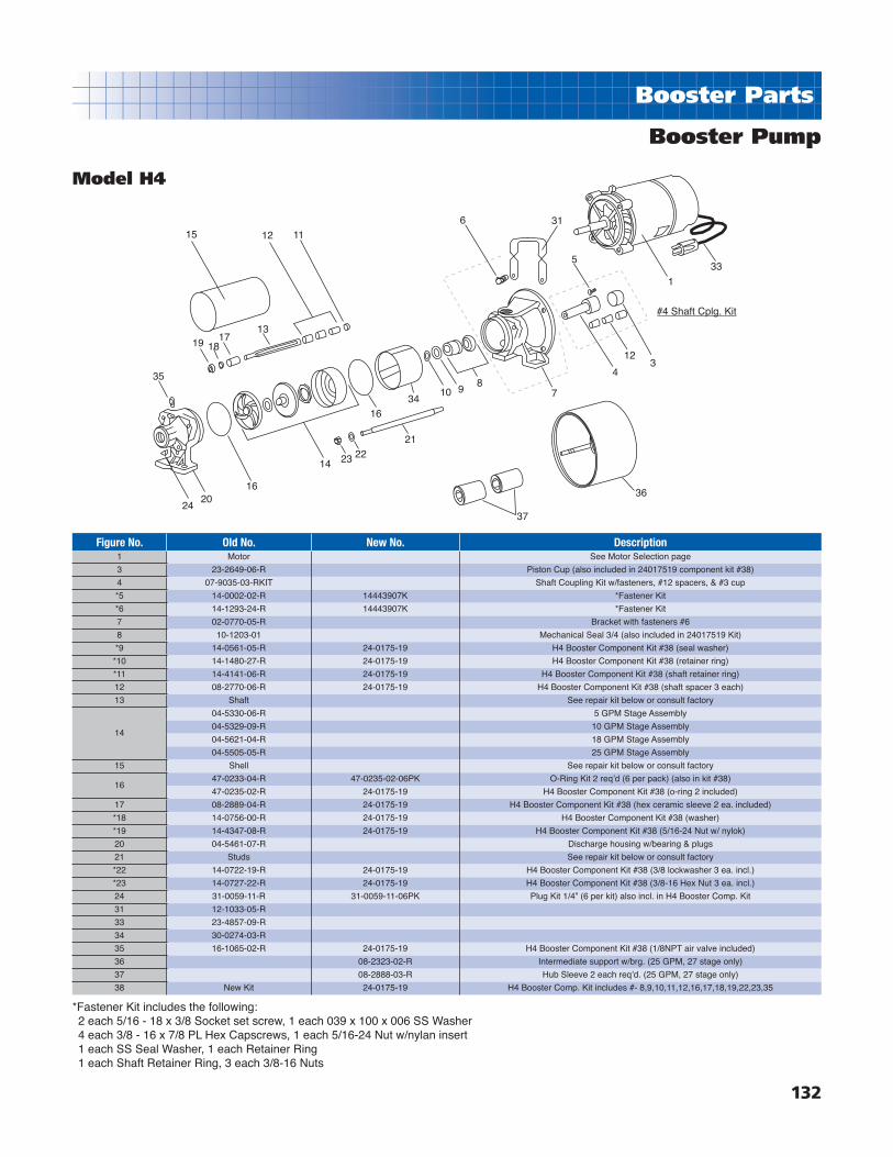
132
Booster Parts
Booster Pump
Model H4
15 12 11
1317
1819
35
2420
16
14 23 2221
1634
10 98
37
36
7
6 31
5
1
33
4
123
#4 Shaft Cplg. Kit
Figure No. Old No. New No. Description1 Motor See Motor Selection page
3 23-2649-06-R Piston Cup (also included in 24017519 component kit #38)
4 07-9035-03-RKIT Shaft Coupling Kit w/fasteners, #12 spacers, & #3 cup
*5 14-0002-02-R 14443907K *Fastener Kit
*6 14-1293-24-R 14443907K *Fastener Kit
7 02-0770-05-R Bracket with fasteners #6
8 10-1203-01 Mechanical Seal 3/4 (also included in 24017519 Kit)
*9 14-0561-05-R 24-0175-19 H4 Booster Component Kit #38 (seal washer)
*10 14-1480-27-R 24-0175-19 H4 Booster Component Kit #38 (retainer ring)
*11 14-4141-06-R 24-0175-19 H4 Booster Component Kit #38 (shaft retainer ring)
12 08-2770-06-R 24-0175-19 H4 Booster Component Kit #38 (shaft spacer 3 each)
13 Shaft See repair kit below or consult factory
14
04-5330-06-R 5 GPM Stage Assembly
04-5329-09-R 10 GPM Stage Assembly
04-5621-04-R 18 GPM Stage Assembly
04-5505-05-R 25 GPM Stage Assembly
15 Shell See repair kit below or consult factory
1647-0233-04-R 47-0235-02-06PK O-Ring Kit 2 reqʼd (6 per pack) (also in kit #38)
47-0235-02-R 24-0175-19 H4 Booster Component Kit #38 (o-ring 2 included)
17 08-2889-04-R 24-0175-19 H4 Booster Component Kit #38 (hex ceramic sleeve 2 ea. included)
*18 14-0756-00-R 24-0175-19 H4 Booster Component Kit #38 (washer)
*19 14-4347-08-R 24-0175-19 H4 Booster Component Kit #38 (5/16-24 Nut w/ nylok)
20 04-5461-07-R Discharge housing w/bearing & plugs
21 Studs See repair kit below or consult factory
*22 14-0722-19-R 24-0175-19 H4 Booster Component Kit #38 (3/8 lockwasher 3 ea. incl.)
*23 14-0727-22-R 24-0175-19 H4 Booster Component Kit #38 (3/8-16 Hex Nut 3 ea. incl.)
24 31-0059-11-R 31-0059-11-06PK Plug Kit 1/4” (6 per kit) also incl. in H4 Booster Comp. Kit
31 12-1033-05-R
33 23-4857-09-R
34 30-0274-03-R
35 16-1065-02-R 24-0175-19 H4 Booster Component Kit #38 (1/8NPT air valve included)
36 08-2323-02-R Intermediate support w/brg. (25 GPM, 27 stage only)
37 08-2888-03-R Hub Sleeve 2 each reqʼd. (25 GPM, 27 stage only)
38 New Kit 24-0175-19 H4 Booster Comp. Kit includes #- 8,9,10,11,12,16,17,18,19,22,23,35
*Fastener Kit includes the following:2 each 5/16 - 18 x 3/8 Socket set screw, 1 each 039 x 100 x 006 SS Washer 4 each 3/8 - 16 x 7/8 PL Hex Capscrews, 1 each 5/16-24 Nut w/nylan insert 1 each SS Seal Washer, 1 each Retainer Ring1 each Shaft Retainer Ring, 3 each 3/8-16 Nuts

133
Booster Parts
Model Vertical (50-75GPM)
17
31
15
11
24
25
22
34
33
7
15
31
17
18
13
35
20
11
24
25
5
8
32
16
9 & 102,3 &4
32
16
9 & 102,3 &4
22
1
26
20
19
35
13
14
17
21
12
19
36 (Module)

134
Booster Parts
Booster Pump
Model Vertical (50-75GPM)Figure No. Old No. New No. Description
1 Motor See Motor Selection page2 77-0759-01-R Motor Coupling 56C / 140TC w/ 5/16 setscrews3 77-0760-08-R Motor Coupling 180TC w/ 3/8 setscrews4 77-0761-07-R New description Motor Coupling 210TC w/3/8-16 x 1/2 setscrews5 04-5594-07-R Bracket6 14-1294-23-R 14444004K *Fastener Kit7 14-1264-11-R 14444004K *Fastener Kit8 08-2938-05-R Sleeve 5/8” x 7/8” x 1-3/4”9 14-4309-04-R 14444004K *Fastener Kit10 14-0004-00-R 14444004K *Fastener Kit11 14-4228-02-R 14444004K *Fastener Kit
#12 Tie Rod Consult Factory#13 Shaft Consult Factory#14 Shell Consult Factory15 08-2912-05-R Ceramic Sleeve (5 each required)16 14-4298-07-R 14444004K *Fastener Kit17 14-0727-22-R 14444004K *Fastener Kit18 08-2771-05-R Rubber Bearing19 47-0247-08-R 47-0247-08-02PK O-RIng Kit (2 per kit)20 08-2772-04-R Spacer21 14-0722-19-R 14444004K *Fastener Kit
2210-0369-03 Mechanical Seal 150PSI10-0470-01 Mechanical Seal 400PSI
23 04-5595-06-R Base24 14-4297-07-R 14444004K *Fastener Kit25 47-0113-09-R 47-0113-09-02PK O-Ring Kit (2 per kit)26 11-1514-04-R New description Motor adpt. Flg. 180TC thru 210TC frame w/ fasteners27 14-1787-01-R 14-1787-01-24PK Hex Cap. Kit 1/2-13x1 4 ea. reqʼd (24 per kit)28 31-0059-11-R 31-0059-11-06PK Plug Kit 1/4” (6 per kit)29 31-0061-17-R 31-0061-17 Plug 1/2”31 14-4277-02-R 14444004K *Fastener Kit32 14-4250-03-R 14444004K *Fastener Kit33 11-1515-03-R Seal Plate34 47-0138-59-R 47-0138-59-02PK Square-Ring Kit (2 per kit)
3504-5646-05-R04-5649-02-R
22-05764-09 V6 End-play Tool
#12-Tie Rod, #13-Shaft, #14-Shell---Consult factory for size and availability.
*Fastener Kit #14444004K includes the following:4 each 3/8 - 16 x 1 PL Hex Capscrews 4 each 1/4 - 20 x 1/2 SS Hex Capscrews 3 each 3/8 - 16 x 1/2 Set Screws3 each 5/16 - 18 x 1/2 Set Screws 1 each Washer1 each 5/8 Washer6 each 3/8 - 16 PL Hex Nut4 each 3/8 Lockwashers4 each 1/2 - 13 x 1 PL Hex Capscrews1 each 5/16 - 24 x 1 Capscrew
GPM HP StagesFig. 36
Module No.50 1.5 2 9132-451750 2 3 9132-452550 3 4 9132-453375 3 2 9132-458250 5 7 9132-454150 7.5 10 9132-456675 3 2 9132-458275 5 4 9132-459075 7.5 6 9132-4616
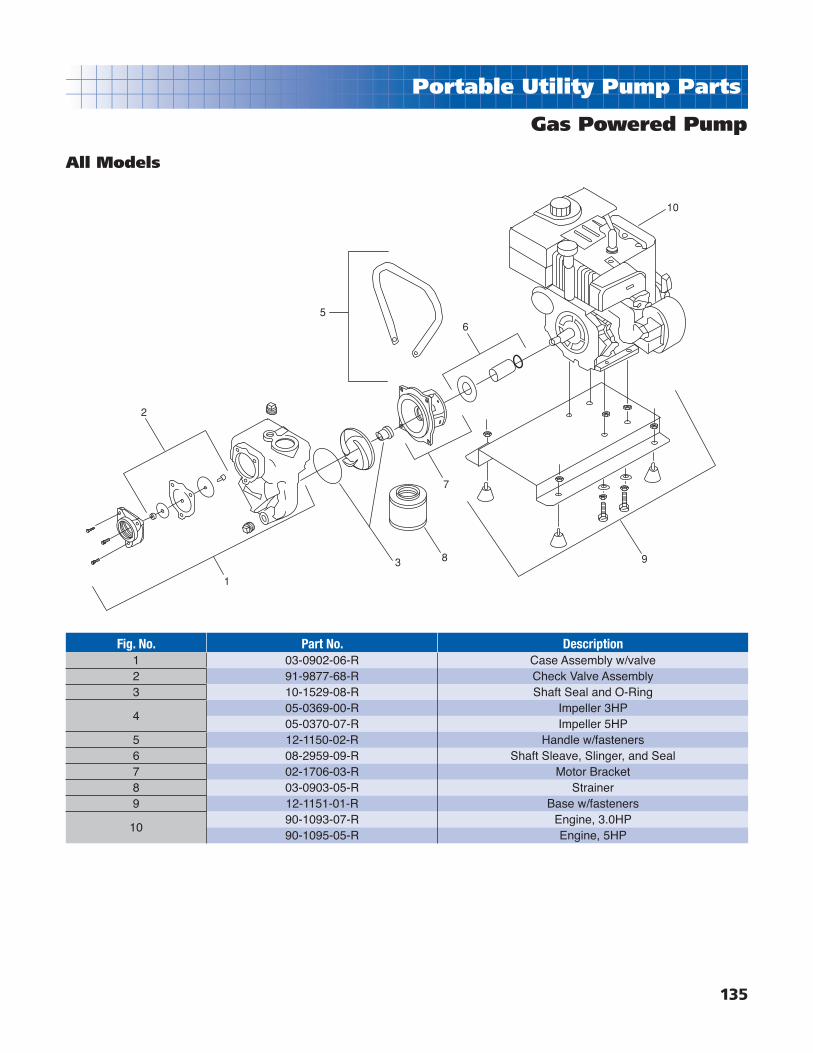
135
Portable Utility Pump Parts
Gas Powered Pump
All Models
Fig. No. Part No. Description1 03-0902-06-R Case Assembly w/valve2 91-9877-68-R Check Valve Assembly3 10-1529-08-R Shaft Seal and O-Ring
405-0369-00-R Impeller 3HP05-0370-07-R Impeller 5HP
5 12-1150-02-R Handle w/fasteners6 08-2959-09-R Shaft Sleave, Slinger, and Seal7 02-1706-03-R Motor Bracket8 03-0903-05-R Strainer9 12-1151-01-R Base w/fasteners
1090-1093-07-R Engine, 3.0HP90-1095-05-R Engine, 5HP
2
1
3
5
9
10
6
8
7

136
Portable Utility Pump Parts
Booster Pump
Models PHP, P & 5PUP
Figure No. Old No. New No. Description1 69231-R New description Body w/18951 pipe plug2 18951-R 69231-R body w/18951 pipe plug
Impeller Repair Kits include: Impeller, Sq. Ring, Seal, Slinger. #ʼs 3,4,5,73 69150-R 90183 Impeller repair kit incl. #ʼs 3,4,5,74 18192-R 90183 Impeller repair kit incl. #ʼs 3,4,5,75 18189-R 90183 Impeller repair kit incl. #ʼs 3,4,5,76 61058-R Seal Plate7 18190-R 90183 Impeller repair kit incl. #ʼs 3,4,5,78 39357-R Bearing9 74799-R Rotor
9A 74800-R Stator (not shown)9B 02618-R Lockwasher (not shown)9C 19125-R Capscrew (not shown)11 61055-R Motor Housing
13 18204-R 18204-KBrush-Cap Assy Kit (2 long & 2 short per kit) #ʼs 13,14,15,16,18206
long brush14 18205-R 18204-K See #13 above15 18438-R 18204-K See #13 above16 16660-R 18204-K See #13 above17 69211-R Cord Set18 18198-R Strain Relief19 19212-R Wire Connector20 02347-R Capscrew21 02577-R Flat Washer22 16684-R Hose Adapter
17
14 13
Brush Kit22
9
2021
18
19
15
11
87
#3
6
5 4
3
1
2
#3 Impeller Kit

137
Sump Pump Parts
Figure No. Old No. New No. Description1 79703-R Motor2 14-2256-01-R Screw (2 each)3 23469-R Screw (3 each)6 23-4902-04-R Shaft7 23-4907-09-R 23-4980-09 Float Assembly Kit includes: 7, 17,18,199 23-4901-05-R Column10 23-4904-02-R Body12 23-4905-01-R 23-4905-01-K Impeller- Bottom Plate Kit w/screws incl.#ʼs 12,15,1615 23-4903-03-R 23-4905-01-K Impeller- Bottom Plate Kit w/screws incl.#ʼs 12,15,1616 21502-R 23-4905-01-K Impeller- Bottom Plate Kit w/screws incl.#ʼs 12,15,1617 23-4906-00-R 23-4980-09 Float Assembly Kit includes: 7, 17,18,1918 90214-R 23-4980-09 Float Assembly Kit includes: 7, 17,18,1919 23-4908-08-R 23-4980-09 Float Assembly Kit includes: 7, 17,18,19
Pedestal Sump Pump
Model PED
#18Float Kit
#2 Impeller BottomPlate Kit
17
7
19
18 9
2
10
12
15
16
6
3
1

138
Sump Pump Parts
Sump Pump
Models SPP & SPC
Figure No. Old No. New No. Description1 90350B Cord Set
2 30786-R Handle
3 03200-R 31-0059-11-06PK Pipe Plug 1/4” galv. (6 each per kit pack)
429037-R 29037 Upper Motor Housing 3SPP, 3SPC
29035-R 29035 Upper Motor Housing 5SPP, 5SPC
5 23469-R to be discontinued Capscrew (discontinued)
6A 74610-R Switch
6B 68888-R Diaphragm Switch
7 38156-R to be discontinued Ground Screw (to be discontinued)
8 32141-R to be discontinued Insulation Shield (to be discontinued)
929722-R Motor 3SPP, 3SPC
90218-R 90218 Motor 5SPP, 5SPC
10 34157-R to be discontinued Washer (to be discontinued)
11 29723-R to be discontinued Bushing (to be discontinued)
12 32002-R to be discontinued Shim (to be discontinued)
SPP & SPC Service Parts Kits include: 13, 16,17,18,20,21,22,23,25
13 29926-R 24-0173-37 SPP, SPC Service Parts Kit
14 30198-R Square Ring
15 29038-R 29038 Motor Housing (lower)
16 2976A-R 24-0173-37 SPP, SPC Service Parts Kit
17 17837-R 24-0173-37 SPP, SPC Service Parts Kit
18 31504-R 24-0173-37 SPP, SPC Service Parts Kit
1951343-R Body with screws #39647
59734-R 59734H-R Body with screws #16660
20 21320-R 24-0173-37 SPP, SPC Service Parts Kit
21 19218-R 24-0173-37 SPP, SPC Service Parts Kit
22 37554-R 24-0173-37 SPP, SPC Service Parts Kit
23 21089-R 24-0173-37 SPP, SPC Service Parts Kit
2419211-R Bottom Plate SPP
19068-R Bottom Plate SPC
2539647-R 24-0173-37 SPP, SPC Service Parts Kit
16660-R 24-0173-37 SPP, SPC Service Parts Kit
26 90351-R Ground Wire
27 38542-R Gasket SPC
14
15
Service Kit
16
17
18
19
20
21
2223
24
27
1312
1110
9-SC27 Versions9A-SSC57 Versions
8
726
4
5
3
21
6A
6B
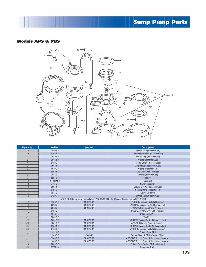
139
Sump Pump Parts
Models APS & PBS
Figure No. Old No. New No. Description1A 19595-R Handle Strip (discontinued)
1B 53967-R Diaphragm Handle (discontinued)
2 16898-R Handle Grip (discontinued)
3 35435-R Washer (discontinued)
4 21502-R Handle Screw (discontinued)
5 66651-R Motor Housing (discontinued)
6 19790-R Clamp (discontinued)
7 52681-R Capacitor (discontinued)
8 39858-R Bracket (discontinued)
9 68513-R Motor
10 34361M-R Cord Set
12 74610-R Switch Assembly
13 90351-R Ground GR Wire (discontinued)
14 21243-R Sealing Band (discontinued)
15 63143-R Lower End Bell
16 21502-R Serial Screw (discontinued)
APS & PBS Serive parts Kits include: 17,18,19,22,23,24,25,27, Also this is used on SPP & SPC
17 17837-R 24-0173-37 APS/PBS Service Parts Kit (washer)
18 29926-R 24-0173-37 APS/PBS Service Parts Kit (snap ring)
19 29726-R 24-0173-37 APS/PBS Service Parts Kit (seal)
2051343-R Pump Body APS w/9 ea 3947 screws
59735-R Pump Body PBS
21 33642-R Top Plate
22 39647-R 24-0173-37 APS/PBS Service Parts Kit (body screw)
23 19218-R 24-0173-37 APS/PBS Service Parts Kit (Impeller)
24 37554-R 24-0173-37 APS/PBS Service Parts Kit (lockwasher)
25 21089-R 24-0173-37 APS/PBS Service Parts Kit (set screw)
2619211-R Bottom Plate APS
19068-R 19068-K Bottom Plate Kit PBS w/gasket 38542
2739647-R 24-0173-37 APS/PBS Service Parts Kit (bottom plate screw)
16660-R 24-0173-37 APS/PBS Service Parts Kit (bottom plate screw)
28 28542-R Bottom Plate Gasket PBS (not shown)
29 68888-10 Diaphragm Switch
10
12
2913
11
7
8
9
4
3
5
16 1
2
14
15
19
17
18
2022
2425
23
27 27
22
21
20Service Kit
26

140
Sump Pump Parts
Sump Pump
Model ABS
Figure No. Old No. New No. Description1 34361M-R Cord Set Assembly
2 21502-R Screw (discontinued)
3 38338-R Handle Strap Assembly (discontinued)
4 16898-R Handle Grip (discontinued)
5 16660-R Screw
6 39228-R Housing Assembly
7 74610-R Switch Assembly
8 90351-R Ground Wire (discontinued)
10 34322-R Terminal Boot (discontinued)
11 70964-R Capacitor (discontinued)
12 39858-R Bracket (discontinued)
13 53859-R Motor
14 63693-R O-Ring
15 62075-R End Bell
16 17363-R End Bell Plug
Impeller Screen & Parts Kit includes: 17,18,19,20,21,22,23,24,25,26,27
17 29726A-R 39342-K Impeller Screen & Parts Kit (Seal)
18 17837-R 39342-K Impeller Screen & Parts Kit (Washer)
19 29926-R 39342-K Impeller Screen & Parts Kit (Snap Ring)
20 23501-R 39342-K Impeller Screen & Parts Kit (Spring)
21 38359-R 39342-K Impeller Screen & Parts Kit (Strainer)
22 35771-R Body
23 23469-R 39342-K Impeller Screen & Parts Kit (Screws)
24 02514-R 39342-K Impeller Screen & Parts Kit (Jam Nut)
25 39342-R 39342-K Impeller Screen & Parts Kit (Impeller)
26 37554-R 39342-K Impeller Screen & Parts Kit (Lockwasher)
27 21089-R 39342-K Impeller Screen & Parts Kit (Setscrew)
28 35873-R 16553-R Gasket (included w/bottom Plate #29)
29 16553-R 16553-R Bottom Plate Kit (includes #28 & #30)
30 16660-R 16553-R Screws (included with bottom plate #29)
31 68888-10 Switch Diaphragm
1
7
31
10
11
12
13
14
6
5
3
4
2 15
16
17
18
19
21
22
24
25
2627
28
29
30
23
#25 Impeller Kit

141
Non-Corrosive Parts
Non-Corrosive Pump
Models Magnum, Magnum Plus, Magnum Force, & Magnum Force 3
Magnum, Magnum Plus, Magnum Force Hydraulic/Motor Kits
Part No. Description9402-7471 UM750-H9402-7489 UM1000-H9402-7497 UM1500-H9402-7505 UM2000-H
5B
1
2
3
4
4A
5A 9A
9B
25A
5
4
3
2
1
4A11
1213
1415
17
16
2123
201918
9 10
24
26
27

142
Non-Corrosive Parts
Non-Corrosive Pump
Models Magnum, Magnum Plus, Magnum Force, & Magnum Force 3Fig. No. Part No. Description
1 42-2828-06-R Cover Ring-Lok2 39-2579-02-R Strainer Cover 7/88
347-0358-03-R O-Ring - Units after 7/8947-0434-01-R O-Ring 5-5/8 x 6-1/8 x 1/4 Units prior to 7/89
416-1097-04-R Strainer basket w/fl apper for Magnum Plus16-1086-06-R Strainer basket (9” tall) w/fl apper for Magnum Force (prior to 2/1/03)16-1134-09-R Strainer basket (12” tall) w/fl apper for Magnum Force (after 2/1/03)
4a 43-3036-01-R Flapper5 03-0856-02-R Magnum Plus Body - obsolete - refer to #25a below
5a03-2009-04-R Magnum Force body with plugs and basket (prior to 2/1/03)03-0906-02-R Magnum Force body with plugs and basket (after to 2/1/03)
5b03-2008-05-R Magnum Force 3 body with plugs and basket (prior to 2/1/03)03-0907-01-R Magnum Force 3 body with plugs and basket (after to 2/1/03)
6&731-1609-06-R2 1/4” Plugs w/o-rings (2 per bag)31-1609-06-R50 1/4” Plugs w/o-rings (50 per bag)
9 12-1069-02-R Base motor support assembly 2/889a 12-1124-05-R Motor Support9b 12-1126-03-R Motor Base10 14-4231-07-R Dowel pin 1/4 x 1-1/411 47-0232-54-R Square ring 2-3/4 x 1/8 x 1/812 14-4206-08-R5 Hex wash. hd. A8 - 16 X 1-1/4 SS (2,3 or 5 reqʼd.) (5 per bag)
13
06-0157-05-R Diffuser, 4-1/4” fi t. 1/2 HP full rate & 3/4 uprate06-0165-05-R Diffuser, 5-1/4” fi t, 1-1/2 - 3 HP full rate & uprate06-0167-03-R Diffuser, 4.875 fi t, 3/4 - 1 HP full rate 1-1/2 uprate06-0008-06-R Diffuser, 5-1/4” fi t, 4 & 5 HP uprate
1410-1462-07-R Eye Seal, 1/2 - 3 HP10-1463-14-R Eye Seal, 4 & 5 HP
15
05-3800-01-R Impeller, 1/2 HP full rate & 3/4 HP uprate 4-3/16” dia.05-3818-01-R Impeller, 2 HP full rate 5-3/16” dia.05-3819-00-R Impeller, 1-1/2 HP full rate & 2 HP uprate 5/8” dia.05-3820-07-R Impeller, 3 HP full rate & uprate 5/8” dia.05-3854-06-R Impeller, 1 HP full rate & 1-1/2 HP uprate 4-3/4” dia.05-3855-05-R Impeller, 3/4 HP full rate & 1 HP uprate 4-3/4” dia.05-0373-04-R Impeller, 4 HP uprate 4.80” dia.05-0371-06-R Impeller, 5 HP uprate 5.13” dia.
16 10-1502-09-R Shaft Seal (Replaces 10139004)17 47-0364-47-R O-Ring 6-3/4 x 7-1/8
1802-1392-02-R Seal Housing, 5-1/4” fi t, 1-1/2 - 3 HP full rate, 5 HP uprate02-1366-04-R Seal Housing, 4-9/16” fi t, 1/2 HP full rate, 3/4 HP uprate02-1393-01-R Seal Housing, 4-7/8” fi t, 3/4 - 1 HP full rate, 1-1/2 HP uprate
19 02-1368-02-R Motor Housing Bracket20 14-1293-24-R4 PL Hex Capscrews 3/8 - 16 x 7/8 (4 reqʼd.) (4 per bag)21 42-2886-05-R Pump mounting nut 2/88 w/ ratchet #2222 42-2867-08-R Mounting Nut Ratchet23 Motor (call your local pool dealer)24 42-3555-03-R Motor Support Kit25a 42-2345-06-R Case/Base Basket Assy. For Magnum Force - incl. #1,2,3,4,4a,5a,6,7,9a,9b,2826 31-1501-09-R2 2UN half kit (incl. 2 each), effective for units built after 10/9927 31-1003-05-R2 2UN half kit (incl. 2 each), effective for units built prior to 10/9928 31-1746-00-R Strainer Basket Air Bleed Tube
To order Magnum Repair Parts, contact: CCO Whirlpool and Spa Service 6075 East Henrietta Rd. Rush, NY 14543 p. 888-527-2787 Fax 585-533-1349
www.jbparts.com

143
Non-Corrosive Parts
End Suction “SPA” Pump
Model A
8
7
12
3
4
56
Figure No. Part No. Description1 02-1684-09-R Bracket SA Spa Pump2 10-0002-06 Mechanical Shaft Seal 5/8
3
05-1500-15-R S2A Impeller 3.875D #1143305-2000-20-R S35A Impeller 3.875D #1143405-2000-25-R S3A Impeller 3.75D #1143405-3000-30-R S4A Impeller 3.875D #1143505-0365-04-R S45A Impeller 4.20D
4 47-0258-53-R Sq. Ring 6-1/8 x 1/8 Ntrl
503-0872-03-R Case Assy. SA Spa Pump w/ plug03-0889-03-R Case Assy. S45A
6 31-1609-06-R 1/4 plug w/ O-ring (47-0112-00)7 14-4379-02-R Screws 10-12 x 1 Phil Pan HD SS8 Motor Motor Selection see index for page no.
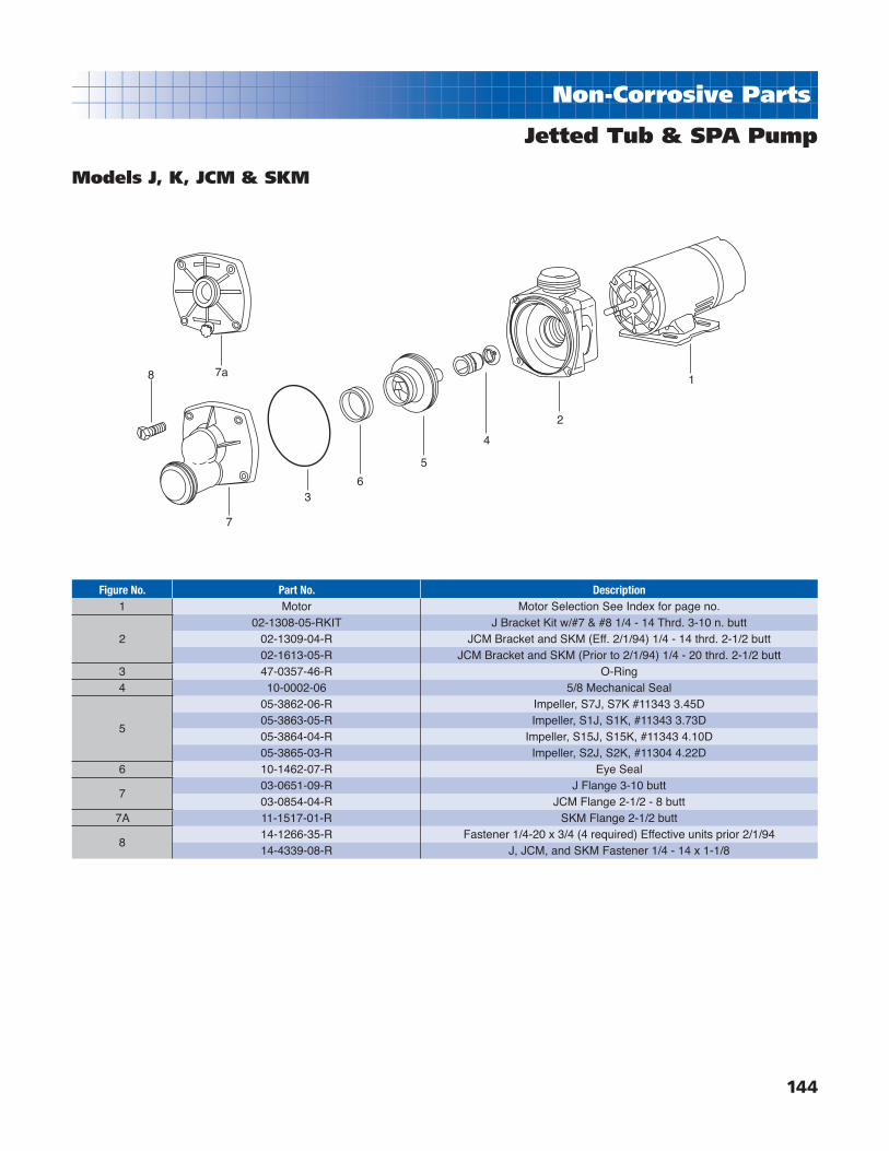
144
Non-Corrosive Parts
Jetted Tub & SPA Pump
Models J, K, JCM & SKM
8 7a
7
36
5
4
2
1
Figure No. Part No. Description1 Motor Motor Selection See Index for page no.
202-1308-05-RKIT J Bracket Kit w/#7 & #8 1/4 - 14 Thrd. 3-10 n. butt
02-1309-04-R JCM Bracket and SKM (Eff. 2/1/94) 1/4 - 14 thrd. 2-1/2 butt02-1613-05-R JCM Bracket and SKM (Prior to 2/1/94) 1/4 - 20 thrd. 2-1/2 butt
3 47-0357-46-R O-Ring4 10-0002-06 5/8 Mechanical Seal
5
05-3862-06-R Impeller, S7J, S7K #11343 3.45D05-3863-05-R Impeller, S1J, S1K, #11343 3.73D05-3864-04-R Impeller, S15J, S15K, #11343 4.10D05-3865-03-R Impeller, S2J, S2K, #11304 4.22D
6 10-1462-07-R Eye Seal
703-0651-09-R J Flange 3-10 butt03-0854-04-R JCM Flange 2-1/2 - 8 butt
7A 11-1517-01-R SKM Flange 2-1/2 butt
814-1266-35-R Fastener 1/4-20 x 3/4 (4 required) Effective units prior 2/1/9414-4339-08-R J, JCM, and SKM Fastener 1/4 - 14 x 1-1/8

145
Accessories
Injector Assembly-Series 146E Bronze & 147E Cast Iron
2
3
4
5
1 4
3
5
2
6
1
Figure No. Part No. Description
2 18-1191-07 Injector body cast iron 147E
3* 18-0913-xx Nozzle
4* 18-0914-xx Venturi
5 9198-7297 Foot valve 1-1/4 x 1 bronze*When ordering replace xx with proper code.
Check Valve (9198-0680)Figure No. Part No. Description
1 16-0110-00-R Body 1-1/4 F
2 16-0109-02-R Cap. Check Valve
3 13-0108-06-R Gasket
4 16-0414-10-R Poppet Assembly
S0125 StrainerFigure No. Part No. Description
1 16-0306-03 Strainer Body Assy.
2 16-0729-02 Basket
3 39-0753-04 Cover
4 42-1678-09 Nut
5 47--0352-09 O-ring 4-7/8x5-1/4x3/16
6 31-3285-40 Reducer
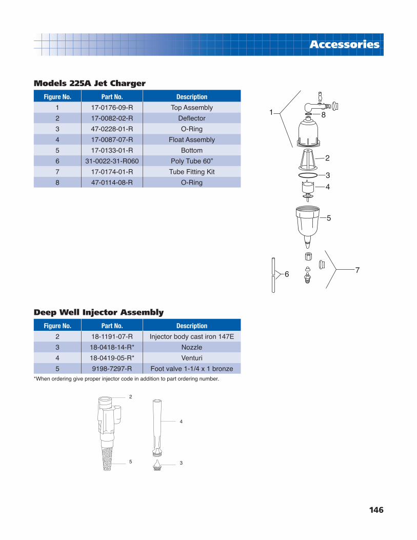
146
Accessories
1 8
2
3
4
5
76
Models 225A Jet Charger
Figure No. Part No. Description
1 17-0176-09-R Top Assembly
2 17-0082-02-R Defl ector
3 47-0228-01-R O-Ring
4 17-0087-07-R Float Assembly
5 17-0133-01-R Bottom
6 31-0022-31-R060 Poly Tube 60”
7 17-0174-01-R Tube Fitting Kit
8 47-0114-08-R O-Ring
Deep Well Injector Assembly
Figure No. Part No. Description
2 18-1191-07-R Injector body cast iron 147E
3 18-0418-14-R* Nozzle
4 18-0419-05-R* Venturi
5 9198-7297-R Foot valve 1-1/4 x 1 bronze*When ordering give proper injector code in addition to part ordering number.

147
Accessories
Plastic Bell
Friction Ring
Spring Disc
Spring
CartridgeAssembly
Body
1
2
3
Models AQ 80 Valve
Figure No. Part No. Description
1 14-3900-09-R Pan-Hd 10/16” x 1” (6 reqʼd)
2 16-0245-07-R Upper Valve Body
3 30-0128-01-R Upper Screen
4 16-0999-05-R Spring
5 16-0128-09-R Support Plate
6 13-0396-07-R Diaphragm
7 13-0407-04-R Gasket
8 30-0127-02-R Lower Screen
9 16-0244-08-R Lower Body
10 14-0153-09-R Seal Washer
11 16-1053-06-R Poppet
12 16-0079-08-R Poppet Sring
13 16-0126-19-R Lower Body Cap 13
1211
109
8
7
6
5
4
3
2
1
Figure No. Part No. Description
11611-2500 Bell Assy AQ400-1
1611-2807 Bell Assy AQ400-1-1/4
21611-2609 Cartridge Assy AQ400-1 w/ Spring
1611-2906 Cartridge Assy AQ400-1-1/4 w/Spring
31611-2708 Body Brass AQ400-1
1611-3003 Body Brass AQ400-1-1/4
Parts for AQ400 Valve

148
Application
Single Phase Motors
2 or 3 wire Cable, 60Hz (Service entrance to motor - max. length in feet)
Motor Rating 60ºC Insulation - AWG Copper Wire Size
Volts HP KW 14 12 10 8 6 4 3 2 1 0 00 000 0000
115 1/2 .37 100 160 250 390 620 960 1190 1460 1780 2160 2630 3140 3770
230
1/2 .37 400 650 1020 1610 2510 3880 4810 5880 7170 8720
3/4 .55 300 480 760 1200 1870 2890 3580 4370 5330 6470 7870
1 .75 250 400 630 990 1540 2380 2960 3610 4410 5360 6520
1-1/2 1.1 190 310 480 770 1200 1870 2320 2850 3500 4280 5240
2 1.5 150 250 390 620 970 1530 1910 2360 2930 3620 4480
3 2.2 120 190 300 470 750 1190 1490 1850 2320 2890 3610
5 3.7 0 0 180 280 450 710 890 1110 1390 1740 2170 2680
7-1/2 5.5 0 0 0 200 310 490 610 750 930 1140 1410 1720
10 7.5 0 0 0 0 250 390 490 600 750 930 1160 1430 1760
15 11 0 0 0 0 170 270 340 430 530 660 820 1020 1260
Motor Rating 75ºC Insulation - AWG Copper Wire Size
Volts HP KW 14 12 10 8 6 4 3 2 1 0 00 000 0000
115 1/2 .37 100 160 250 390 620 960 1190 1460 1780 2160 2630 3140 3770
230
1/2 .37 400 650 1020 1610 2510 3880 4810 5880 7170 8720
3/4 .55 300 480 760 1200 1870 2890 3580 4370 5330 6470 7870 9380
1 .75 250 400 630 990 1540 2380 2960 3610 4410 5360 6520 7780 9350
1-1/2 1.1 190 310 480 770 1200 1870 2320 2850 3500 4280 5240 6300 7620
2 1.5 150 250 390 620 970 1530 1910 2360 2930 3620 4480 5470 6700
3 2.2 120 190 300 470 750 1190 1490 1850 2320 2890 3610 4470 5550
5 3.7 0 110 180 280 450 710 890 1110 1390 1740 2170 2680 3330
7-1/2 5.5 0 0 120 200 310 490 610 750 930 1140 1410 1720 2100
10 7.5 0 0 0 160 250 390 490 600 750 930 1160 1430 1760
15 11 0 0 0 0 170 270 340 430 530 660 820 1020 1260
Lengths not in bold type meet the U.S. National Electrical Code ampacity for either individual conductors or jacketed 60ºC or 75ºC cable.
Lengths in bold type meet the National Electric Code ampacity only for individual conductor 60ºC or 75ºC cable, in free air or water, not in magnetic enclosure or conduit. If any other cable is used, the National Electric Code as well as the local codes should be observed. Flat molded and web cable is considered jacketed cable.
Cable lengths in tables allow for a 5% voltage drop running at maximum nameplate amperes. If 3% voltage drop is desired multiply table lengths by .6 to get maximum cable length.
Both tables are based on copper wire. If aluminum wire is used, it must be two sizes larger than copper wire and oxidation inhibitors must be used on connections.EXAMPLE: If tables call for #12 copper wire, #10 aluminum wire would be required.
The portion of the total cable length which is between the supply and single phase control bos with a line contactor, should not exceed 25% of total maximum allowable to ensure reliable contactor operation. Single phase control boxes without line contactors may be connected at any point in the total cable length.
Contact Franklin Electric for 90ºC cable length.
1 Foot = .3048 Meter

149
Application
Three Phase Motors
3-Phase 60ºC Cable, 60Hz(Service entrance to motor - max. length in feet)
Motor Rating 60ºC Insulation - AWG Copper Wire Size MCM Copper Wire SizeVolts HP KW 14 12 10 8 6 4 3 2 1 0 00 000 0000 250 300 350 400 500
200V60Hz
3Phase
3Lead
1/2 .37 710 1140 1800 2840 4420
3/4 .55 510 810 1280 2030 3160
1 .75 430 690 1080 1710 2670 4140 5140
1-1/2 1.1 310 500 790 1260 1960 3050 3780
2 1.5 240 390 610 970 1520 2360 2940 3610 4430 5420
3 2.2 180 290 470 740 1160 1810 2250 2760 3390 4130
5 3.7 110 170 280 440 690 1080 1350 1660 2040 2490 3050 3670 4440 5030
7-1/2 5.5 0 0 200 310 490 770 960 1180 1450 1770 2170 2600 3150 3560
10 7.5 0 0 0 230 370 570 720 880 1090 1330 1640 1970 2390 2720 3100 3480 3800 4420
15 11 0 0 0 160 250 390 490 600 740 910 1110 1340 1630 1850 2100 2350 2570 2980
20 15 0 0 0 0 190 300 380 460 570 700 860 1050 1270 1440 1650 1850 2020 2360
25 18.5 0 0 0 0 0 240 300 370 460 570 700 840 1030 1170 1330 1500 1640 1900
30 22 0 0 0 0 0 0 250 310 380 470 580 700 850 970 1110 1250 1360 1590
230V60Hz
3Phase
3Lead
1/2 .37 930 1490 2350 3700 5760 8910
3/4 .55 670 1080 1700 2580 4190 6490 8060 9860
1 .75 560 910 1430 2260 3520 5460 6780 8290
1-1/2 1.1 420 670 1060 1670 2610 4050 5030 6160 7530 9170
2 1.5 230 510 810 1280 2010 3130 3890 4770 5860 7170 8780
3 2.2 240 390 620 990 1540 2400 2980 3660 4480 5470 6690 8020 9680
5 3.7 140 230 370 590 920 1430 1790 2190 2690 3290 4030 4850 5870 6650 7560 8460 9220
7-1/2 5.5 0 160 260 420 650 1020 1270 1560 1920 2340 2870 3440 4160 4710 5340 5970 6500 7510
10 7.5 0 0 190 310 490 760 950 1170 1440 1760 2160 2610 3160 3590 4100 4600 5020 5840
15 11 0 0 0 210 330 520 650 800 980 1200 1470 1780 2150 2440 2780 3110 3400 3940
20 15 0 0 0 0 250 400 500 610 760 930 1140 1380 1680 1910 2180 2450 2680 3120
25 18.5 0 0 0 0 0 320 400 500 610 750 920 1120 1360 1540 1760 1980 2160 2520
30 22 0 0 0 0 0 260 330 410 510 620 760 930 1130 1280 1470 1650 1800 2110
380V60Hz
3Phase
3Lead
1/2 .37 2690 4290 6730
3/4 .55 2000 3190 5010 7860
1 .75 1620 2580 4060 6390 9980
1-1/2 1.1 1230 1970 3100 4890 7630
2 1.5 870 1390 2180 3450 5400 8380
3 2.2 680 1090 1710 2690 4200 6500 8020 9830
5 3.7 400 640 1010 1590 2490 3870 4780 5870 7230 8830
7-1/2 5.5 270 440 690 1090 1710 2640 3260 4000 4930 5010 7290 8780
10 7.5 200 320 510 800 1250 1930 2380 2910 3570 4330 5230 6260 7390 8280 9340
15 11 0 0 370 590 920 1430 1770 2170 2690 3290 4000 4840 5770 6520 7430 8250 8990
20 15 0 0 0 440 700 1090 1350 1670 2060 2530 3090 3760 4500 5110 5840 6510 7120 8190
25 18.5 0 0 0 360 570 880 1100 1350 1670 2050 2510 3040 3640 4130 4720 5250 5740 6590
30 22 0 0 0 0 470 730 910 1120 1380 1700 2080 2520 3020 3430 3920 4360 4770 5490
40 30 0 0 0 0 0 530 660 820 1010 1240 1520 1840 2200 2500 2850 3170 3470 3990
50 37 0 0 0 0 0 0 540 660 820 1000 1220 1480 1770 2010 2290 2550 2780 3190
60 45 0 0 0 0 0 0 0 560 690 850 1030 1250 1500 1700 1940 2150 2350 2700
75 55 0 0 0 0 0 0 0 0 570 700 860 1050 1270 1440 1660 1850 2030 2350
100 75 0 0 0 0 0 0 0 0 0 510 630 760 910 1030 1180 1310 1430 1650
125 90 0 0 0 0 0 0 0 0 0 0 0 620 740 840 950 1060 1160 1330
150 110 0 0 0 0 0 0 0 0 0 0 0 0 620 700 790 880 960 1090
175 130 0 0 0 0 0 0 0 0 0 0 0 0 0 650 750 840 920 1070
200 150 0 0 0 0 0 0 0 0 0 0 0 0 0 0 630 700 760 880
Continued on page 150

150
Application
Three Phase Motors
3-Phase 60ºC Cable, (Continued)Motor Rating 60ºC Insulation - AWG Copper Wire Size MCM Copper Wire Size
Volts HP KW 14 12 10 8 6 4 3 2 1 0 00 000 0000 250 300 350 400 500
460V60Hz
3Phase
3Lead
1/2 .37 3770 6020 9460
3/4 .55 2730 4350 6850
1 .75 2300 3670 5770 9070
1-1/2 1.1 1700 2710 4270 6730
2 1.5 1300 2070 3270 5150 8050
3 2.2 1000 1600 2520 3970 6200
5 3.7 590 950 1500 2360 3700 5750
7-1/2 5.5 420 680 1070 1690 2640 4100 5100 6260 7680
10 7.5 310 500 790 1250 1960 3050 3800 4680 5750 7050
15 11 0 340 540 850 1340 2090 2600 3200 3930 4810 5900 7110
20 15 0 0 410 650 1030 1610 2000 2470 3040 3730 4580 5530
25 18.5 0 0 0 530 830 1300 1620 1990 2450 3010 3700 4470 5430
30 22 0 0 0 430 680 1070 1330 1640 2030 2490 3060 3700 4500 5130 5860
40 30 0 0 0 0 500 790 980 1210 1490 1830 2250 2710 3290 3730 4250
50 37 0 0 0 0 0 640 800 980 1210 1480 1810 2190 2650 3010 3420 3830 4180 4850
60 45 0 0 0 0 0 540 670 830 1020 1250 1540 1850 2240 2540 2890 3240 3540 4100
75 55 0 0 0 0 0 0 0 680 840 1030 1260 1520 1850 2100 2400 2700 2950 3440
100 75 0 0 0 0 0 0 0 0 620 760 940 1130 1380 1560 1790 2010 2190 2550
125 90 0 0 0 0 0 0 0 0 0 0 740 890 1000 1220 1390 1560 1700 1960
150 110 0 0 0 0 0 0 0 0 0 0 0 760 920 1050 1190 1340 1460 1690
175 130 0 0 0 0 0 0 0 0 0 0 0 0 810 930 1060 1190 1300 1510
200 150 0 0 0 0 0 0 0 0 0 0 0 0 0 810 920 1030 1130 1310
575V60Hz
3Phase
3Lead
1/2 .37 5900 9410
3/4 .55 4270 6810
1 .75 3630 5800 9120
1-1/2 1.1 2620 4180 6580
2 1.5 2030 3250 5110 8060
3 2.2 1580 2530 3980 6270
5 3.7 920 1480 2330 3680 5750
7-1/2 5.5 660 1060 1680 2650 4150
10 7.5 490 780 1240 1950 3060 4770 5940
15 11 330 530 850 1340 2090 3260 4060
20 15 0 410 650 1030 1610 2520 3140 3860 4760 5830
25 18.5 0 0 520 830 1300 2030 2530 3110 3840 4710
30 22 0 0 430 680 1070 1670 2080 2560 3160 3880 4770 5780 7030 8000
40 30 0 0 0 500 790 1240 1540 1900 2330 2860 3510 4230 5140 5830
50 37 0 0 0 0 640 1000 1250 1540 1890 2310 2840 3420 4140 4700 5340 5990 6530 7580
60 45 0 0 0 0 0 850 1060 1300 1600 1960 2400 2890 3500 3970 4520 5070 5530 6410
75 55 0 0 0 0 0 690 860 1060 1310 1600 1970 2380 2890 3290 3750 5220 4610 5370
100 75 0 0 0 0 0 0 0 790 970 1190 1460 1770 2150 2440 2790 3140 3430 3990
125 90 0 0 0 0 0 0 0 0 770 950 1160 1400 1690 1920 2180 2440 2650 3070
150 110 0 0 0 0 0 0 0 0 0 800 990 1190 1440 1630 1860 2080 2270 2640
175 130 0 0 0 0 0 0 0 0 0 0 870 1050 1270 1450 1650 1860 2030 2360
200 150 0 0 0 0 0 0 0 0 0 0 0 920 1110 1260 1440 1620 1760 2050
See Footnotes on page 148 for information on fi gures in bold.

151
Pipe Friction
1”Schedule 40 pipe 1.049 in. i.d. / Type L Copper tube 1.025 in. i.d.
GPMVelocityFt./Sec.
Friction LossFt. Hd./100’ of pipe Velocity
Ft. /Sec.
Ft. Hd./100’ PipeFric. Loss
C=130Steel
C=100PVC
C=1402.0 0.74 0.60 0.32 .078 0.41
3.0 1.11 1.26 0.68 1.17 0.87
4.0 1.49 2.14 1.15 1.56 1.48
5.0 1.86 3.24 1.75 1.95 2.23
6.0 2.23 4.54 2.45 2.34 3.13
8.0 2.97 7.73 4.16 3.11 5.35
10 3.71 11.7 6.31 3.89 8.08
12 4.46 16.4 8.85 4.67 11.3
14 5.20 21.8 11.8 5.45 15.0
16 5.94 27.9 15.1 6.22 19.2
18 6.68 34.7 18.7 7.00 23.9
20 7.43 42.1 22.8 7.78 29.0
25 9.29 63.6 34.6 9.74 43.9
30 11.1 89.2 48.1 11.7 61.4
40 14.9 152 82.0 15.5 105
1½”Schedule 40 pipe 1.610 in. i.d. / Type L Copper tube 1.505 in. i.d.
GPMVelocityFt./Sec.
Friction LossFt. Hd./100’ of pipe Velocity
Ft. /Sec.
Ft. Hd./100’ PipeFric. Loss
C=130Steel
C=100PVC
C=1406.0 0.95 0.57 0.31 1.08 0.49
8.0 1.26 0.96 0.52 1.44 .082
10 1.58 1.45 0.79 1.80 1.24
12 1.89 2.04 1.10 2.16 1.73
15 2.36 2.95 1.59 2.70 2.62
20 3.15 5.24 2.83 3.60 4.46
25 3.94 7.90 4.26 4.51 6.74
30 4.73 11.1 6.00 5.41 9.44
40 6.30 18.9 10.2 7.21 16.1
50 7.88 28.5 15.4 9.01 24.3
60 9.46 40.0 21.6 10.8 34.1
70 11.0 53.2 28.7 12.6 45.5
80 12.6 68.1 36.8 14.4 58.1
90 14.2 84.7 45.7 16.2 72.1
100 15.8 103 56.6 18.0 87.7
2½”Schedule 40 pipe 2.469 in. i.d. / Type L Copper tube 2.465 in. i.d.
GPMVelocityFt./Sec.
Friction LossFt. Hd./100’ of pipe Velocity
Ft. /Sec.
Ft. Hd./100’ PipeFric. Loss
C=130Steel
C=100PVC
C=14020 1.21 0.66 0.35 1.34 0.40
30 2.01 1.39 0.75 2.02 0.85
40 2.68 2.36 1.27 2.69 1.46
50 3.35 3.56 1.92 3.36 2.20
60 4.02 4.99 2.69 4.03 3.08
70 4.69 6.64 3.58 4.70 4.11
80 5.36 8.50 4.59 5.37 5.25
90 6.03 10.6 5.72 6.04 6.52
100 6.70 12.8 6.90 6.71 7.94
110 7.37 15.3 8.22 7.38 9.44
130 8.71 20.9 11.3 8.73 12.9
150 10.0 27.3 14.7 10.1 16.8
200 13.4 46.3 25.0 13.4 28.6
250 16.8 81.7 44.1 16.8 43.4
300 20.1 98.1 52.9 20.1 61.1
1¼”Schedule 40 pipe 1.380 in. i.d. / Type L Copper tube 1.265 in. i.d.
GPMVelocityFt./Sec.
Friction LossFt. Hd./100’ of pipe Velocity
Ft. /Sec.
Ft. Hd./100’ PipeFric. Loss
C=130Steel
C=100PVC
C=1404.0 0.86 0.56 0.30 1.02 0.52
6.0 1.29 1.20 0.65 1.53 1.12
8.0 1.72 2.04 1.10 2.04 1.92
10 2.15 3.08 1.67 2.55 2.90
12 2.57 4.31 2.33 3.06 4.04
14 2.00 5.73 3.10 3.57 5.35
16 3.43 7.34 3.96 4.08 6.85
18 3.86 9.13 4.93 4.59 8.52
20 4.29 11.1 6.00 5.10 10.4
25 5.36 16.8 9.06 6.38 15.7
30 6.43 23.5 12.7 7.65 22.1
40 8.58 40.0 21.6 10.2 37.6
50 10.7 60.4 32.6 12.8 56.7
60 12.9 84.7 45.6 15.3 79.5
80 17.2 144 77.9 20.4 136
2”Schedule 40 pipe 2.067 in. i.d. / Type L Copper tube 1.985 in. i.d.
GPMVelocityFt./Sec.
Friction LossFt. Hd./100’ of pipe Velocity
Ft. /Sec.
Ft. Hd./100’ PipeFric. Loss
C=130Steel
C=100PVC
C=14010 0.96 0.43 0.23 1.07 0.35
15 1.44 0.92 0.50 1.60 .075
20 1.91 1.55 0.84 2.13 1.24
25 2.39 2.35 1.27 2.66 1.87
30 2.87 3.29 1.78 3.19 2.62
40 3.82 5.60 3.03 4.26 4.48
50 4.78 8.46 4.57 5.32 6.76
60 5.74 11.9 6.44 6.39 9.47
70 6.69 15.8 8.53 7.45 12.6
80 7.65 20.2 10.9 8.52 16.2
90 8.61 25.1 13.6 9.58 20.0
100 9.56 30.5 16.5 10.7 24.4
120 11.5 42.7 23.1 12.8 34.1
150 14.3 64.7 35.0 16.0 51.6
200 19.1 110 59.4 21.3 87.8
3”Schedule 40 pipe 3.000 in. i.d. / Type L Copper tube 2.945 in. i.d.
GPMVelocityFt./Sec.
Friction LossFt. Hd./100’ of pipe Velocity
Ft. /Sec.
Ft. Hd./100’ PipeFric. Loss
C=130Steel
C=100PVC
C=14040 1.82 0.91 0.49 1.88 0.62
60 2.72 1.94 1.04 2.82 1.31
80 3.63 3.30 1.77 3.76 2.22
100 4.54 4.98 2.67 4.70 3.35
120 5.45 6.98 3.75 5.64 4.70
140 6.35 9.28 4.98 6.58 6.25
160 7.26 11.9 6.38 7.52 8.00
180 8.16 14.8 7.93 8.46 9.94
200 9.08 17.9 9.64 9.40 12.1
250 11.3 27.1 14.6 11.8 18.3
300 13.6 38.0 20.4 14.1 25.6
350 15.9 50.6 27.1 16.5 34.0
400 18.2 64.7 34.7 18.8 43.6
450 20.5 80.5 43.2 21.2 54.2
500 22.7 97.8 52.5 23.5 65.8
Note: Chart shows friction loss per 100ʼ of pipe. To convert to friction loss per foot, move decimal point 2 places to the left.

152
Pipe Friction
4”Schedule 40 pipe 4.026 in. i.d. / Type L Copper tube 3.905 in. i.d.
GPMVelocityFt./Sec.
Friction LossFt. Hd./100’ of pipe Velocity
Ft. /Sec.
Ft. Hd./100’ PipeFric. Loss
C=130Steel
C=100PVC
C=14050 1.26 0.33 0.16 1.34 0.24
75 1.89 0.70 0.34 2.01 0.50
100 2.52 1.19 0.58 2.68 0.85
125 3.15 1.80 0.87 3.35 1.28
150 3.78 2.53 1.22 4.01 1.80
200 5.05 4.29 2.08 5.35 3.05
250 6.30 6.45 3.12 6.69 4.63
300 7.57 9.09 4.41 8.02 6.47
350 8.82 12.0 5.82 9.36 8.60
400 10.1 15.5 7.52 10.7 11.1
500 12.6 23.4 11.3 13.4 16.6
600 15.1 32.8 15.9 16.0 23.4
700 17.6 43.6 21.1 18.7 31.2
800 20.2 55.8 27.0 21.4 39.9
900 22.7 69.3 33.6 24.1 49.6
6”Schedule 40 pipe 6.065 in. i.d. / Type L Copper tube 5.845 in. i.d.
GPMVelocityFt./Sec.
Friction LossFt. Hd./100’ of pipe Velocity
Ft. /Sec.
Ft. Hd./100’ PipeFric. Loss
C=130Steel
C=100PVC
C=140100 1.111 0.16 0.07 1.19 0.12
150 1.67 0.34 0.16 1.79 0.25
200 2.22 0.58 0.28 2.39 0.43
250 2.77 0.89 0.42 2.98 0.65
300 3.33 1.24 0.58 3.58 0.91
400 4.44 2.11 0.99 4.79 1.55
500 5.55 3.19 1.50 5.98 2.34
600 6.66 4.46 2.10 7.17 3.28
700 7.78 5.93 2.79 8.36 4.36
800 8.90 7.60 3.60 9.56 5.58
900 10.0 9.44 4.46 10.8 6.95
1000 11.1 11.5 5.44 12.0 8.45
1200 13.3 16.1 7.62 14.3 11.8
1400 15.6 21.4 10.1 16.7 15.7
1600 17.8 27.4 13.0 19.1 20.2
5”Schedule 40 pipe 5.047 in. i.d. / Type L Copper tube 4.857 in. i.d.
GPMVelocityFt./Sec.
Friction LossFt. Hd./100’ of pipe Velocity
Ft. /Sec.
Ft. Hd./100’ PipeFric. Loss
C=130Steel
C=10075 1.20 0.24 1.29 0.17
100 1.60 0.40 1.72 0.30
125 2.00 0.67 2.15 0.45
150 2.40 0.94 2.58 0.63
175 2.80 1.25 3.01 0.83
200 3.20 1.43 3.44 1.07
250 4.01 2.15 4.30 1.62
300 4.81 3.03 5.15 2.27
400 6.41 5.15 6.87 3.87
500 8.02 7.79 8.59 5.84
600 9.62 10.9 10.3 8.20
700 11.2 14.5 12.0 10.9
800 12.8 18.6 13.7 13.9
1000 16.0 28.1 17.2 21.2
1200 19.2 39.3 20.6 29.5
Note: Chart shows friction loss per 100ʼ of pipe. To convert to friction loss per foot, move decimal point 2 places to the left.
Fittings - Friction losses expressed as equivalent lengths of pipe (feet).
Type of Fitting Material 1” 1-1/4” 1-1/2” 2” 2-1/2” 3” 3-1/2” 4” 5” 6” 8” 10” 12”
90º Std. Elbow/ run of Tee reduced to
half six
Steel 3 4 4 5 6 8 - 10 13 15 20 25 30
Plastic 6 7 8 9 10 14 - 17 - 25 - - -
Copper 3 4 4 5 6 8 9 10 13 15 20 - -
45º Elbow
Steel 1.3 1.7 2.1 2.6 3 3.6 - 4.7 5.9 7.1 9.4 12 14
Plastic 2.5 3 4 5 6 7 - 9 - 13 13 - -
Copper 1.3 1.7 2.1 2.6 3 3.6 4.1 4.7 5.9 7.1 9.4 - -

153
Information
Lost or Damaged Goods
IMPORTANTEvery carrier used by Franklin Pump Systems, Inc. is required to verify and sign for the condition of and the number of pieces that are released to them for delivery. Our control and responsibility for any shipment ceases when the carrier signs the Bill of Lading. When you sign the Bill of Lading, you legally assume responsibility of the shipment being delivered. Please, thoroughly inspect each shipment immediately upon arrival.
If cartons, packages, or crates are received in short or damaged condition, it is important that you notify the driver and insist on a notation of the loss or damage across the face of the freight bill. Failure to do this could negate any opportunity you have to fi le a claim. Claims for short or damaged material must be fi led in writing with the carrier immediately after delivery.
If concealed loss or damage is discovered, notify the carrier at once and request an inspection. It is also important that you do not discard the shipping carton or container. A concealed damage report should be made within ten (10) days of delivery of the shipment. The carrierʼs agent will make an inspection and usually will grant a concealed damage notation. If you give the carrier a clear receipt for the goods that have been damaged in transit, you do so at your own risk and expense.
We are willing to assist you to collect claims for loss or damage, but we are not responsible for collection of claims or replacement of material (shortage or damage) if not noted on the Bill of Lading at the time of delivery.
Due to frequent damage of heavy UPS shipments, Franklin Pump Systems, Inc. does not ship orders over75 lbs. by UPS unless customer agrees to take full responsibility.
For information or assistance contact:
Customer Service Departmentph: 501.455.1234 www.franklin-electric.com

154
Warranty
U.S. LIMITED WARRANTY*
Franklin Pump Systems, Inc.
Franklin Pump Systems, Inc. warrants its new products to be free of defects in material and workmanship for a period of 1 year from date of installation or 2 years from date of manufacture, whichever comes fi rst, WHEN installed in a domestic water systems application and pumping potable water only. Warranty does not cover applications pumping saltwater or other corrosive liquids. Consult and adhere to local codes for all applications.
Franklin Pump Systemʼs warranty obligation with regard to equipment not of its own manufacture is limited to the warranty actually extended to Franklin Pump System by its suppliers.
This warranty extends only to the original retail purchaser and only during the time in which the original retail purchaser occupies the site where the product was originally installed.
Requests for service under this warranty shall be made by contacting the installing Franklin Pump System dealer (point of purchase) as soon as possible after the discovery of any alleged defect. Franklin Pump System will subsequently take corrective action as promptly as reasonably possible.
Franklin Pump System at its discretion may replace or repair any product that fails under this warranty after inspection by an authorized company representative or after Franklin Pump System has received the product at our factory. Replacement or repair cannot be made until after the product is inspected. All charges or expenses for freight to and from the factory, removal and reinstallation of the product, or installation of a replacement product are the responsibility of the purchaser.
THIS WARRANTY SUPERSEDES ANY WARRANTY NOT DATED OR BEARING AN EARLIER DATE. ANY IMPLIED WARRANTIES WHICH THE PURCHASER MAY HAVE, INCLUDING MERCHANT ABILITY AND FITNESS FOR A PARTICULAR PURPOSE, SHALL NOT EXTEND BEYOND THE APPLICABLE WARRANTY PERIOD. Some states do not allow limitations on how long an implied warranty lasts, so the above limitation may not apply to you. IN NO EVENT SHALL FRANKLIN PUMP SYSTEM BE LIABLE FOR INCIDENTAL OR CONSEQUENTIAL DAMAGES. Some states do not allow the exclusion or limitation of incidental or consequential damages, so the above may not apply to you.
This warranty does not apply to any product which has been subjected to negligence, alteration, accident, abuse, misuse, improper installation, vandalism, civil disturbances, or acts of God. The only warranties authorized by Franklin Pump System are those set forth herein. Franklin Pump System does not authorize other persons to extend any warranties with respect to its products, nor will Franklin Pump System assume liability for any unauthorized warranties made in connection with the sale of its products.
THIS WARRANTY GIVES YOU SPECIFIC LEGAL RIGHTS, AND YOU MAY ALSO HAVE OTHER RIGHTS WHICH MAY VARY FROM STATE TO STATE.
* Contact Franklin Pump Systems, Inc. Export Division for International Warranty.
12401 Interstate 30 • P.O. Box 8903
Little Rock, AR 72219

Professional Water Systems Equipment
2005
12401 Interstate 30Little Rock, AR 72219-8903PH: 501.455.1234 FAX: 800.662.6044
www.franklinpumps.com
MS2009 9/05
Pro
fessio
nal W
ate
r Syste
ms E
quip
ment
2005