a totally awesome study of animated Disney films and the ...
Upload
khangminh22Category
view
35download
0
Siemens ST 70 · 2015
9
Brochures
For brochures serving as selection guides for SIMATIC products refer to:
www.siemens.com/simatic/printmaterial
9/4 Introduction
9/5 ET 200 systems for the control cabinet
9/5 ET 200SP9/5 Introduction9/8 Interface modules9/8 IM 155-69/12 SIPLUS interface modules9/13 I/O modules9/13 Digital input modules9/20 Digital output modules9/29 SIPLUS digital input modules9/31 SIPLUS digital output modules9/34 Analog input modules9/47 Analog output modules9/52 SIPLUS analog input modules9/54 SIPLUS analog output modules9/56 Technology modules9/56 • TM Count 1x24V counter module9/59 • TM PosInput 1 position recording
module9/63 • Time-based IO module
TM Timer DIDQ 10x24V9/66 • SIWAREX WP3219/68 Communication9/68 • CM PtP serial interface9/70 • CM IO-Link9/73 • CM AS-i Master ST
for SIMATIC ET 200SP9/75 • CM DP for ET 200SP CPU9/77 • SCALANCE W761 RJ45
for use in the control cabinet9/80 • SCALANCE W722 RJ45
for use in the control cabinet9/83 • SCALANCE W721 RJ45
for use in the control cabinet9/86 Fail-safe I/O modules9/86 Digital F input modules9/89 Digital F output modules9/92 Digital F output module relays9/94 Fail-safe special modules9/96 Communication9/96 • F-CM AS-i Safety ST for ET 200SP9/99 BaseUnits9/102 SIPLUS BaseUnits9/105 BusAdapters9/106 Accessories
9/107 ET 200S9/107 Introduction9/109 Interface modules9/109 IM 151-19/115 IM 151-3 PN9/118 SIPLUS IM 151-19/119 SIPLUS IM 151-3PN9/121 I/O modules9/121 Power modules
for PM-E electronic modules9/124 SIPLUS power modules
for PM-E electronic modules9/126 Spare modules9/127 Potential isolation module9/128 Digital electronic modules9/142 SIPLUS digital electronic modules9/146 Analog electronic modules9/164 SIPLUS analog electronic modules9/169 Technology modules9/169 SSI module9/171 2 PULSE pulse generator9/173 SIPLUS 2 PULSE pulse generator9/174 1STEP stepper module9/176 1 POS U positioning module9/178 1 COUNT 24 V/100 kHz counter module9/181 SIPLUS 1 COUNT 24V/100kHz
counter module9/182 1 COUNT 5 V/500 kHz counter module9/185 1SI interface module9/188 SIPLUS 1 SI interface module9/189 SIWAREX CS9/191 SIWAREX CF9/193 Terminal modules for power and
electronic modules9/196 SIPLUS terminal modules for power
and electronic modules9/199 Fail-safe I/O modules9/199 Introduction9/200 PM-E F PROFIsafe F power modules9/204 F electronic modules9/207 F electronic module relays9/209 F terminal modules9/211 SIPLUS F electronic modules9/213 IO-Link master modules9/213 4SI IO-Link electronic module9/214 4SI SIRIUS electronic module
I/O systems
ST70_2015_Kap09_EN.book Seite 1 Donnerstag, 21. Mai 2015 11:58 11
© Siemens AG 2015

Siemens ST 70 · 2015
9/107 ET 200S (continued)9/215 Motor starters and Safety motor starters9/215 General data9/221 Standard motor starters9/222 Standard terminal modules9/224 High Feature motor starters9/226 High Feature terminal modules9/227 Power modules9/228 Power module terminal modules9/229 ET 200S Failsafe motor starters9/231 Failsafe terminal modules9/232 Safety modules local and PROFIsafe9/241 Safety modules local and PROFIsafe
terminal modules9/243 Accessories9/248 Software9/248 Motor Starter ES9/252 Add-on products for the ET 200S9/252 EtherNet/IP interface module9/253 DeviceNet interface module9/254 Add-on products
from third-party manufacturers9/255 SIMATIC ET 200S
1-STEP-DRIVE-5A-48V9/257 SIMATIC ET 200S 1 SI CANopen
9/259 ET 200MP9/259 Introduction9/260 Interface modules9/260 IM 155-5 PN9/264 IM 155-5 DP9/266 SIPLUS IM 155-5 PN9/267 I/O modules
9/268 ET 200M9/268 Introduction9/269 Interface modules9/269 IM 153-1/153-29/273 IM 153-4 PN9/276 SIPLUS IM 153-1/153-29/279 SIPLUS IM 153-4 PN IO9/280 I/O modules9/280 Digital modules9/281 Analog input module with HART9/283 Analog output module with HART9/285 Ex-analog input module with HART9/289 Ex-analog output module with HART9/293 SIPLUS analog input module with HART9/294 SIPLUS analog output module with HART9/295 SIPLUS Ex analog input module
with HART9/296 Function modules9/298 Special modules, communication9/299 ASM 4759/301 Power supplies
9/302 ET 200iSP9/302 Introduction9/304 IM 152-1 interface modules9/307 Power supply units9/309 Digital electronic modules9/317 Analog electronic modules9/324 F digital input module9/327 F digital output module9/330 F analog input module9/333 ET 200iSP watchdog modules9/335 Reserve module9/338 Terminal modules9/339 RS 485-IS coupler9/341 Stainless steel wall enclosures
9/347 ET 200 systems without control cabinet
9/347 ET 200pro9/347 Introduction9/348 Interface modules9/348 IM 154-1 and IM 154-29/353 IM 154-4 PN9/357 IM 154-6 PN IWLAN9/360 I/O modules9/360 Digital expansion modules9/368 Analog expansion modules9/377 Fail-safe digital expansion modules9/379 PM-E power module9/381 PM-O power module output9/382 ET 200pro pneumatic interface9/384 SIMATIC RF170C9/386 Power supplies9/386 3-phase, 24 V DC (ET 200pro PS, IP67)9/388 ET 200pro motor starters9/388 General data9/391 Standard motor starters9/392 High Feature motor starters9/393 ET 200pro isolator module9/394 ET 200pro Safety motor starters
Solutions local/PROFIsafe9/394 Safety modules local9/397 Safety modules PROFIsafe9/398 Accessories for ET 200pro motor starters9/403 Software9/403 Motor Starter ES9/404 Add-on products for ET 200pro9/404 EtherNet/IP interface module
9/406 ET 200eco PN9/406 SIMATIC ET 200eco PN
9/422 IO-Link master ET 200eco PN
9/425 ET 200eco9/425 SIMATIC ET 200eco
I/O systems
ST70_2015_Kap09_EN.book Seite 2 Donnerstag, 21. Mai 2015 11:58 11
© Siemens AG 2015

Siemens ST 70 · 2015
99/434 SIMATIC ET 200AL9/434 Introduction9/435 Interface modules9/435 IM 157-1 DP9/437 IM 157-1 PN9/439 I/O modules9/439 Digital I/O modules9/443 Analog I/O modules9/446 Communication9/446 • CM IO-Link9/449 Accessories9/449 Cables and connectors9/459 Labels
9/460 Heating control systems
9/461 SIPLUS HCS3200 heating control system
9/463 SIPLUS HCS4200heating control system
9/463 Introduction9/464 Rack9/465 Central Interface Module (CIM)9/467 Power Output Module (POM)
9/469 SIPLUS HCS4300 heating control systems
9/469 Introduction9/470 Central Interface Module (CIM)9/472 Power Output Module (POM)
9/474 PROFIBUS components9/474 Power Rail Booster9/475 Diagnostics repeater for PROFIBUS DP9/477 PROFIBUS DP ASICs9/479 Connections/interfaces
9/480 SIPLUS PROFIBUS components for ET 200
9/480 SIPLUS diagnostics repeater for PROFIBUS
9/481 PROFINET components9/481 Enhanced Real-Time Ethernet Controllers
ERTEC9/483 Development kits9/484 PROFINET Driver
9/485 Network components for PROFIBUS9/485 Active RS 485 terminating element9/486 RS 485 repeater for PROFIBUS
9/487 SIPLUS network componentsfor PROFIBUS
9/487 SIPLUS DP active RS 485 terminating element
9/488 SIPLUS RS 485 repeater
9/489 Network transitions9/489 PN/PN coupler9/490 DP/DP coupler
I/O systems
ST70_2015_Kap09_EN.book Seite 3 Donnerstag, 21. Mai 2015 11:58 11
© Siemens AG 2015

9/4 Siemens ST 70 · 2015
9
I/O systemsIntroduction
I/O systems
■ Overview
SIMATIC ET 200 offers the right solution for every application
With SIMATIC ET 200 a wide range of distributed I/O systems is available - for solutions in the control cabinet or without a control cabinet directly at the machine, as well as for applications in hazardous areas. The modular design makes it possible to scale and expand the ET 200 systems simply and in small stages. Al-ready integrated add-on modules reduce costs, and at the same time offer a widely diverse range of possible applications. You can choose from many different combination options: Digital and analog inputs/outputs, intelligent modules with CPU functional-ity, safety systems, motor starters, pneumatic devices, fre-quency converters, as well as various different technology modules (e.g. for counting, positioning).
Communication over PROFINET and PROFIBUS, uniform engi-neering, transparent diagnostic possibilities as well as optimal interfacing to SIMATIC controllers and HMI units prove the unique integration of Totally Integrated Automation.
PROFINET
PROFINET is the open, cross-vendor Industrial Ethernet stan-dard (IEC 61158/61784) for automation.
Based on Industrial Ethernet, PROFINET enables direct commu-nication between field devices (IO Devices) and controllers (IO Controllers), up to and including the solution of isochronous drive controls for motion control applications.
As PROFINET is based on Standard Ethernet according to IEEE 802.3, any devices from the field level to the management level can be connected.
In this way, PROFINET enables system-wide communication, supports plant-wide engineering and applies IT standards, such as Web server or FTP, right down to field level. Tried and tested fieldbus systems, such as PROFIBUS or AS-Interface, can be easily integrated without any modification to the existing de-vices.
PROFIBUS
PROFIBUS is the international standard (IEC 61158/61784) for the field level. It is the only fieldbus to allow communication both in manufacturing applications and in process-oriented applica-tions.
PROFIBUS is used to connect field devices, e.g. distributed I/O devices or drives, to automation systems such as SIMATIC S7, SIMOTION, SINUMERIK, or PCs.
PROFIBUS is standardized in accordance with IEC 61158 and is a powerful, open and rugged fieldbus system with short re-sponse times. PROFIBUS is available in different forms for vari-ous applications.
PROFIBUS DP (distributed I/O)
PROFIBUS DP is used for connecting distributed field devices, e.g. SIMATIC ET 200, or drives with extremely fast response times. PROFIBUS DP is used when sensors/actuators are dis-tributed at the machine or in the plant (e.g. field level).
AS-Interface
AS-Interface, the international standard (IEC 62026/EN 50295) which, as an alternative to the cable harness, links especially cost-effective sensors and actuators by means of a two-wire line. This two-wire line is also used to supply the individual stations with power. Thus the AS-Interface is the ideal partner for the PROFIBUS DP fieldbus.
IO-Link
The communication standard IO-Link permits the intelligent con-nection of sensors and switching devices to the control level. IO-Link facilitates the integration of all components in the control cabinet and on the field level - for maximum integration and seamless communication on the final meters to the process.
IO-Link solutions from Siemens ensure maximum precision and cost-effectiveness in any production system. IO-Link is com-pletely integrated in Totally Integrated Automation (TIA) and offers many advantages.• The open standard permits the networking of devices from
different manufacturers• Simple wiring facilitates the installation process• Reduced wiring effort saves time and money during instal-
lation• Efficient engineering facilitates configuration and commis-
sioning• High-speed diagnostics ensures short plant standstill times
and high plant availability• High process transparency permits, for example, efficient
energy management
ST70_2015_Kap09_EN.book Seite 4 Donnerstag, 21. Mai 2015 11:58 11
© Siemens AG 2015

9/5Siemens ST 70 · 2015
9
I/O systemsET 200 systems for the control cabinet
ET 200SP
Introduction
■ Overview
SIMATIC ET 200SP
The scalable SIMATIC ET 200SP I/O system is a highly flexible, modular I/O system with IP20 degree of protection. Via interface modules with PROFINET or PROFIBUS interface it can ex-change IO data of the connected I/O modules with a higher-level control system. Alternatively, as further head-end stations, vari-ous PLC, F-PLC and open controllers are available as compact S7-1500 controllers (distributed controllers). ET 200SP compo-nents are available as SIPLUS version for extreme requirements and a high degree of robustness.
Compact design• Modular configuration with up to 64 modules• System-integrated self-assembling load group supply without
power module via light BaseUnits• Small size and highly flexible due to the modular design and
comprehensive product range• Up to 16 channels per module• Permanent wiring• Hot swapping: Module replacement without tools in RUN• Operation with gaps
Flexible connection system• Push-in terminals for cross-sections up to 2.5 mm2
• BaseUnits for 1-wire or direct multi-wire connection• Optimum accessibility for wiring due to spring release and
measuring tap next to the conductor opening• Flexible PROFINET-connection via BusAdapter (RJ45,
FastConnect, FiberOptic), also as integrated media converter
Safety Integrated• Easy integration of fail-safe modules• Easy F parameter assignment via software• Group-by-group disconnection of non-failsafe modules
High performance• Isochronous PROFINET• Internal data transfer with up to 100 Mbit/s• Record analog values and output as of 50 µs• Record digital values and output as of 1 µs
High-performance technology• Modules for the functions Counting, Positioning, Weighing
Energy efficiency• Energy meter for recording electrical variables• System-integrated PROFIenergy with interval substitute
values
Advanced functions• Configuration control:
Practical adaptation of the actual configuration via user software (option handling)
• Time-based IO: Time stamping of the signals to the µs
• MSI/MSO: Simultaneous access to I/O data from up to 4 PLCs
• Oversampling: N-fold acquisition or output of digital and analog signals within a PN cycle
Communication standards• PROFINET IO• PROFIBUS DP V0/V1• ET connection for connecting the ET 200AL (IP67)• IO-Link V1.1• AS-Interface• Point-to-point (RS 232, RS 485, RS 422)
CPU• PROFINET connection with 3 ports• IO Controller and PNIO Device• Optional expansion as DP master/slave• Also as failsafe version and open controller
Labeling of I/O modules• Meaningful labeling on the front of the I/O modules• Optionally expandable with
- Labeling strips- Reference identification label
ST70_2015_Kap09_EN.book Seite 5 Donnerstag, 21. Mai 2015 11:58 11
© Siemens AG 2015

9/6 Siemens ST 70 · 2015
9
■ Overview (continued)
I/O systemsET 200 systems for the control cabinetET 200SP
Introduction
Overview of ET 200SP components
Basic components Function
Mounting rail according to EN 60715
The mounting rail is the module sup-port of the ET 200SP. The ET 200SP is mounting on the mounting rail.
CPU The CPU:• executes the user program.• is used as IO Controller, I-Device on
PROFINET IO, or as standalone CPU
• connects the ET 200SP with the IO Devices or the IO Controller
• exchanges data with the I/O modules via the backplane bus
Further functions of the CPU:• Communication via PROFIBUS DP
(in combination with the CM DP communication module, the CPU can be used as DP master or slave)
• Integrated Web server• Integrated technology• Integrated trace functionality• Integrated system diagnostics• Integrated safety
Open controller As the first controller of this type, the SIMATIC ET 200SP Open Controller combines the functions of a PC-based software controller with visualization, PC applications and central I/Os (inputs/outputs) in a single, compact device.• All in one • High system availability• Compact and modular• Rugged• User-friendly design• Efficient engineering in the
TIA Portal
Interface modules for PROFINET IO (IM 155-6PN)
The interface module:• is used as IO Device on the
PROFINET IO• connects the ET 200SP with the
IO Controller• exchanges data with the
I/O modules via the backplane bus
Interface module for PROFIBUS DP (IM 155-6DP)
The interface module:• is used as DP slave on the
PROFIBUS DP• connects the ET 200SP with the
DP master• exchanges data with the
I/O modules via the backplane bus
BusAdapter (BA) BusAdapters permit the free selection of the connection method and con-nection technology for head-end sta-tions with PROFINET interface. The following versions are currently avail-able:• BA 2xRJ45 (copper)• BA 2xFC (FastConnect, direct con-
nection)• BA 2xSCRJ (FOC, POF or PCF)• BA SCRJ/RJ45 (media converter
FOC-copper RJ45)• BA SCRJ/FC (media converter
FOC-copper FC)
Cable length between 2 stations: max.. 100 m (copper), max. 50 m (POF), max. 100 m (PCF), max. 250 m (PCF-GI).
For expanding the station with the I/O systems ET 200AL via ET-connection, the BusAdapter BA-Send is available.
BaseUnit (BU) The BaseUnits provide the electrical and mechanical connection for the ET 200SP components.• Bright BaseUnits permit a new po-
tential group up to max. 10 A• Dark BaseUnits forward the self-as-
sembling voltage busbars P1, P2 and AUX from the left to the right BaseUnit.
• Suitable BaseUnits with 12 to 28 ter-minals are available for different connection systems and functions.
• The I/O module is plugged onto the desired BaseUnit and determines the potential assignment of the ter-minals on the BaseUnit.
• For expanding the station with the I/O systems ET 200AL via ET-con-nection, the BaseUnit BU-Send is available.
I/O modules and fail-safe I/O modules
The I/O module determines the func-tion at the terminals. The controller detects the current process state via the connected sensors and triggers corresponding responses via the connected actuators. Some I/O modules feature extended functions, in part they are also designed as individual operating mode. I/O module are divided into the following module types; the fail-safe versions are identified by a preceding “F-” and a yellow module enclosure.• DI (digital input)• DQ (digital output)• AI (analog input)• AQ (analog output)• TM (technology modules)• CM (communication modules)• SM (special modules)
Protective cover (BU cover) The ET 200SP system can be oper-ated with any number of slot gaps (BU slot without I/O module). Applica-tions for this include:• partial commissioning• prewired, and currently unequipped
options
To protect against damage, such slot gaps must be covered by a BU cover. Within des BU cover, an equipment labeling plate for the planned I/O module can be stored.
Versions:• for BaseUnits with a width of 15 mm• for BaseUnits with a width of 20 mm
Server module The server module concludes the setup of an ET 200SP station. On the server module there are holders for 3 spare fuses (5 × 20 mm). The server module is included in the scope of delivery of all head-end stations.
Basic components Function
ST70_2015_Kap09_EN.book Seite 6 Donnerstag, 21. Mai 2015 11:58 11
© Siemens AG 2015

9/7Siemens ST 70 · 2015
9
■ Overview (continued)
I/O systemsET 200 systems for the control cabinet
ET 200SP
Introduction
Coding element When plugging an I/O module onto a BaseUnit for the first time, the coding element moves from the I/O module to the BaseUnit. There it prevents the destruction of the ET 200SP compo-nents in the event of a subsequent module replacement with incorrectly selected I/O module.
The coding element is available in two versions:• Mechanical coding element • Electronic coding element:
Additionally features an electronic, re-writable memory for the redun-dant storage of module-specific configuration data (e.g. F target ad-dress for fail-safe modules, parame-ter data for IO-Link master). Thus these data are automatically backed up during a module replacement.
Shield connection The shield connection permits the connection of cable shields. Com-pared to external shield supports, the system offers the following advan-tages:• Quick installation without tools by
plugging the shield connection ele-ment onto the BaseUnit
• Automatic low-impedance connec-tion to the functional ground (mount-ing rail)
• Optimized EMC-properties by sepa-rating the supply voltage lines from the signal lines by means of the shield connection element and short, unshielded cable lengths
• Low space requirements
Labeling strips Optionally, for system-specific marking the head-end stations and I/O modules can be equipped with labeling strips (13 x 31 mm). The labeling strips can be inscribed mechanically. Labeling strips are available in two versions in the colors light gray and yellow:• 500 strips on the roll, for printing on
thermal-transfer printers. Core diameter 40 mm, external di-ameter 70 mm, width 62 mm.
• 10 DIN A4 sheets with 100 strips each, cardboard, preperforated, for printing using a laser printer direct from TIA-Portal or via print tem-plates.
Basic components Function
Reference identification label Optionally, one equipment labeling plate each can be plugged onto head-end stations, BusAdapters, BaseUnits, and I/O modules. Equip-ment labeling plates are supplied in packs of 10 sheets with 16 labels each. The labels can be printed with thermal-transfer card printers, inkjet printers or plotting units or stickers can be attached to them. Advantages compared to labels that are attached directly:• The inscription on the front is not
covered• Simple label replacement when re-
placing a module• No parallax errors when marking the
BaseUnits on the mounting plate
The size of the inscribable area of the labels is 14.8 x 10.5 mm (W x H)
Color-coded labels The I/O modules that are plugged onto the BaseUnits determine the potentials connected at the process terminals. These potentials can optionally be identified using module-specific color-coded labels. The potentials of the AUX and add-on ter-minals can also be marked using color-coded labels. Advantages of the color-coded labels:• Quick installation (one label for
marking 16 terminals)• Avoidance of wiring errors• Simple detection of potentials
during servicing
Basic components Function
ST70_2015_Kap09_EN.book Seite 7 Donnerstag, 21. Mai 2015 11:58 11
© Siemens AG 2015

9/8 Siemens ST 70 · 2015
9
I/O systemsET 200 systems for the control cabinetET 200SP - Interface modules
IM 155-6
■ Overview
• Interface module for connecting the I/O modules to a higher-level control with PROFINET or PROFIBUS
• Server module included in the scope of delivery• Station expansion with IP67 I/O system ET200AL via
ET-connection to BU-Send/BA-Send• PROFINET bus connection
- 2 ports for linear topology - Selectable PN connection via BusAdapter (ST, HF)- Two integrated RJ45 sockets (BA)
• PROFIBUS bus connection- 9-pole sub D socket function classes- PROFIBUS connector included in the scope of delivery- Hot swapping (module replacement during operation)- Startup and operation with gaps- Dynamic re-parameterization in RUN- Configuration control (option handling)- Plug-in 24 V DC power supply connector- Electronically readable rating plate (I&M data)
■ Technical specifications
Article number 6ES7155-6AA00-0BN0 6ES7155-6AU00-0BN0 6ES7155-6AU00-0CN0 6ES7155-6BA00-0CN0
IM155-6PN ST INCL. BA 2XRJ45
IM155-6PN ST ET 200SP IM155-6PN HF IM155-6DP HF INCL. DP-CONNECTOR
Product type designation
General information
Product function
• I&M data Yes Yes Yes; I&M0 to I&M4 Yes; I&M0 to I&M3
Engineering with
• STEP 7 TIA Portal can be configured/integrated as of version
V11 SP2 with HSP0024 / - V11 SP2 with HSP0024 / - V12 SP1 / V13 - / -
• STEP 7 can be configured/integrated as of version
V5.5 SP3 / - V5.5 SP3 / - V5.5 SP3 / - V5.5 SP3 / -
• PROFIBUS as of GSD version/GSD revision
GSD as of Revision 5
• PROFINET as of GSD version/GSD revision
V2.3 / - V2.3 / - V2.3 / -
Supply voltage
Type of supply voltage DC DC
Rated value (DC) 24 V 24 V 24 V 24 V
Reverse polarity protection Yes Yes Yes Yes
Mains buffering
• Mains/voltage failure stored energy time
5 ms 5 ms 5 ms 5 ms
Hardware configuration
Rack
• Modules per rack, max. 32 32 64
ST70_2015_Kap09_EN.book Seite 8 Donnerstag, 21. Mai 2015 11:58 11
© Siemens AG 2015

9/9Siemens ST 70 · 2015
9
■ Technical specifications (continued)
I/O systemsET 200 systems for the control cabinet
ET 200SP - Interface modules
IM 155-6
Interfaces
Number of PROFINET interfaces 1 1 1
Number of PROFIBUS interfaces 1
1st interface
Interface types
- Number of ports 2 2 2
- Integrated switch Yes Yes Yes
- RJ 45 (Ethernet) Yes; Pre-assembled BusAdapter BA 2x RJ45
- RS 485 Yes
- Bus adapter (PROFINET) Yes; Applicable BusAdapters: BA 2x RJ45, BA 2x FC
Yes; Applicable BusAdapters: BA 2x RJ45, BA 2x FC
Yes; Applicable bus adapters: BA 2xRJ45, BA 2xFC, BA 2xSCRJ (as from FS03)
- Output current of the interface, max.
90 mA
Protocols
- PROFINET IO Device Yes Yes Yes
- Open IE communication Yes Yes Yes
- PROFIBUS DP slave Yes
- Media redundancy Yes Yes Yes; As MRP or MRPD client; max. 50 or 30 devices in the ring
Interface types
RJ 45 (Ethernet)
• 10 Mbps Yes; for Ethernet services Yes; for Ethernet services Yes; for Ethernet services
• 100 Mbps Yes; PROFINET with 100 Mbit/s full duplex (100BASE-TX)
Yes; PROFINET with 100 Mbit/s full duplex (100BASE-TX)
Yes; PROFINET with 100 Mbit/s full duplex (100BASE-TX)
• Transmission procedure PROFINET with 100 Mbit/s full duplex (100BASE-TX)
PROFINET with 100 Mbit/s full duplex (100BASE-TX)
PROFINET with 100 Mbit/s full duplex (100BASE-TX)
• Autonegotiation Yes Yes Yes
• Autocrossing Yes Yes Yes
RS 485
• Transmission rate, max. 12 Mbit/s
Protocols
PROFINET IO
• PROFINET IO Yes Yes Yes
PROFINET IO Device
Services
- Isochronous mode No Yes; Bus cycle time: min. 250 µs
- Open IE communication Yes Yes Yes
- IRT Yes; with send cycles of between 250 µs and 4 ms in increments of 125 µs
Yes; with send cycles of between 250 µs and 4 ms in increments of 125 µs
Yes; 250 μs, 500 μs, 1 ms, 2 ms, 4 ms additionally with IRT with high performance: 250 µs to 4 ms in 125 µs frame
- MRP Yes
- MRPD Yes
- PROFIenergy Yes Yes Yes
- Prioritized startup Yes Yes Yes
- Shared device Yes Yes Yes
- Number of IO controllers with shared device, max.
2 2 4
Article number 6ES7155-6AA00-0BN0 6ES7155-6AU00-0BN0 6ES7155-6AU00-0CN0 6ES7155-6BA00-0CN0
IM155-6PN ST INCL. BA 2XRJ45
IM155-6PN ST ET 200SP IM155-6PN HF IM155-6DP HF INCL. DP-CONNECTOR
ST70_2015_Kap09_EN.book Seite 9 Donnerstag, 21. Mai 2015 11:58 11
© Siemens AG 2015

9/10 Siemens ST 70 · 2015
9
■ Technical specifications (continued)
I/O systemsET 200 systems for the control cabinetET 200SP - Interface modules
IM 155-6
Open IE communication
• TCP/IP Yes Yes Yes
• SNMP Yes Yes Yes; MIB2, LLDP-MIBm, MRP-MIB
• LLDP Yes Yes Yes
PROFIBUS
Services
- SYNC capability Yes
- FREEZE capability Yes
- DPV0 No
- DPV1 Yes
Isochronous mode
Isochronous operation (application synchronized up to terminal)
No Yes
equidistance Yes
shortest clock pulse 250 µs
max. cycle 4 ms
Interrupts/diagnostics/status information
Status indicator Yes Yes Yes Yes
Alarms
• Alarms Yes Yes Yes Yes
Diagnostic messages
• Diagnostic functions Yes Yes Yes Yes
Diagnostics indication LED
• RUN LED Yes; Green LED Yes; Green LED Yes; Green LED Yes; Green LED
• ERROR LED Yes; Red LED Yes; Red LED Yes; Red LED Yes; Red LED
• MAINT LED Yes; yellow LED Yes; yellow LED Yes; yellow LED Yes; yellow LED
• Monitoring of the supply voltage (PWR-LED)
Yes; Green LED Yes; Green LED Yes; Green LED Yes; green PWR LED
• Connection display LINK TX/RX Yes; 2x green LED Yes; 2x green LED Yes; 2x green LED
• Connection display DP Yes; Green DP LED
Isolation
Isolation checked with 707 V DC between supply voltage and electronics; 1500 V AC between Ethernet and electronics
707 V DC between supply voltage and electronics (type test); 1500 V AC between Ethernet and electronics (type test)
707 V DC between supply voltage and electronics (type test); 1500 V AC between Ethernet and electronics (type test)
707 V DC (type test)
Standards, approvals, certificates
Network loading class 3 3 3
Security level According to Security Level 1 Test Cases V1.1.1
According to Security Level 1 Test Cases V1.1.1
According to Security Level 1 Test Cases V1.1.1
Ambient conditions
Ambient temperature in operation
• horizontal installation, min. 0 °C
• horizontal installation, max. 60 °C
• vertical installation, min. 0 °C
• vertical installation, max. 50 °C
Dimensions
Width 50 mm 50 mm 50 mm 50 mm
Height 117 mm 117 mm 117 mm 117 mm
Depth 74 mm 74 mm 74 mm 74 mm
Weights
Weight, approx. 191 g; IM155PN ST with BA 2x RJ45 (mounted)
147 g; without bus adapter 147 g; without bus adapter 150 g
Article number 6ES7155-6AA00-0BN0 6ES7155-6AU00-0BN0 6ES7155-6AU00-0CN0 6ES7155-6BA00-0CN0
IM155-6PN ST INCL. BA 2XRJ45
IM155-6PN ST ET 200SP IM155-6PN HF IM155-6DP HF INCL. DP-CONNECTOR
ST70_2015_Kap09_EN.book Seite 10 Donnerstag, 21. Mai 2015 11:58 11
© Siemens AG 2015

9/11Siemens ST 70 · 2015
9
I/O systemsET 200 systems for the control cabinet
ET 200SP - Interface modules
IM 155-6
■ Ordering data Article No. Article No.
Interface module Basic• IM 155-6PN BA, with server
module6ES7155-6AR00-0AN0
Interface module Standard• IM 155-6PN ST, with server
module and installed BusAdapter BA 2xRJ45
6ES7155-6AA00-0BN0
• IM 155-6PN ST, with server module, without BusAdapter
6ES7155-6AU00-0BN0
Interface module High Feature• IM 155-6DP HF, with server
module, with multi-hot-swap, incl. PROFIBUS connector
6ES7155-6BA00-0CN0
• IM 155-6PN HF, incl. server module, without BusAdapter
6ES7155-6AU00-0CN0
Accessories
BusAdapter BA 2xRJ45 6ES7193-6AR00-0AA0
for IM 155-6PN ST, HF
BusAdapter BA 2xFC 6ES7193-6AF00-0AA0
for IM 155-6PN ST, HF; for increased vibration and EMC loads
BusAdapter BA 2xSCRJ 6ES7193-6AP00-0AA0
for IM 155-6PN HF, fiber-optic connection for POF or PCF cables up to 250 m, with monitoring of damping
BusAdapter BA SCRJ/RJ45 6ES7193-6AP20-0AA0
for IM 155-6PN HF; with media converter FOC-copper; 1 x SCRJ FO connection, 1 x RJ45 connection
BusAdapter BA SCRJ/FC 6ES7193-6AP40-0AA0
for IM 155-6PN HF; with media converter FOC-copper; 1 x SCRJ FO connection, 1 x FastConnect connection
Station expansion with IP67 I/O system ET 200AL
BusAdapter BA-Send 1 x FC 6ES7193-6AS00-0AA0
for station expansion with IP67 I/O system ET 200AL
BaseUnit BU-Send 6ES7193-6BN00-0NE0
for accommodating the BusAdapter BA-Send 1 x FC
Further accessories
Reference identification label 6ES7193-6LF30-0AW0
10 sheets of 16 labels; for printing with thermal-transfer card printer or plotting unit
Shield connection
5 shield connections and 5 shield terminals each for plugging onto BaseUnits with automatic low-impedance connection to functional ground
6ES7193-6SC00-1AM0
Labeling strips
500 labeling strips on roll, light gray, for inscription with thermal transfer roll printer
6ES7193-6LR10-0AA0
500 labeling strips on roll, yellow, for inscription with thermal transfer roll printer
6ES7193-6LR10-0AG0
1000 labeling strips DIN A4, light gray, cardboard, preperforated, for inscription with laser printer
6ES7193-6LA10-0AA0
1000 labeling strips DIN A4, yellow, cardboard, preperforated, for inscription with laser printer
6ES7193-6LA10-0AG0
DIN rail 35 mm
Length: 483 mm for 19" cabinets 6ES5710-8MA11
Length: 530 mm for 600 mm cabinets
6ES5710-8MA21
Length: 830 mm for 900 mm cabinets
6ES5710-8MA31
Length: 2 m 6ES5710-8MA41
Manuals for ET 200SP distributed I/O system
SIMATIC ET 200SP Manual Collection: PDF file with the following content:• Basic information
System manual, product information, overview tables, correction information or manual supplements
• Device-specific informationManuals for the interface modules, PLC, OC and I/O modules incl. failsafe
• General informationFunction manuals
The Manual Collection is available on the Internet as PDF file:
https://support.industry.sie-mens.com/cs/de/en/view/84133942
SIMATIC Manual Collection 6ES7998-8XC01-8YE0
Electronic manuals on DVD, multi-language: LOGO!, SIMADYN, SIMATIC bus components, SIMATIC C7, SIMATIC distributed I/O, SIMATIC HMI, SIMATIC Sensors, SIMATIC NET, SIMATIC PC Based Automation, SIMATIC PCS 7, SIMATIC PG/PC, SIMATIC S7, SIMATIC Software, SIMATIC TDC
SIMATIC Manual Collection update service for 1 year
6ES7998-8XC01-8YE2
Current "Manual Collection" DVD and the three subsequent updates
Spare parts
Server module 6ES7193-6PA00-0AA0
Terminates an ET 200SP station, included in the scope of delivery of the interface modules
Power supply connector for interface module
for connecting the 24 V DC supply voltage
with push-in terminals (10 units) 6ES7193-4JB00-0AA0
with screw-type terminals (10 units) 6ES7193-4JB50-0AA0
ST70_2015_Kap09_EN.book Seite 11 Donnerstag, 21. Mai 2015 11:58 11
© Siemens AG 2015

9/12 Siemens ST 70 · 2015
9
I/O systemsET 200 systems for the control cabinetET 200SP - Interface modules
SIPLUS interface modules
■ Overview
• Interface module for linking the ET 200SP to PROFINET • Handles all data exchange with the PROFINET IO Controller • Bus Adapter (BA) for individual PROFINET connection • Integrated 2-port switch for line configuration • Max. 32 I/O modules • Operation with gaps (non-equipped BaseUnits) possible • Replacement of an I/O module possible during operation
(single hot-swap) • Load group formation without power module
Note:
SIPLUS extreme products are based on SIMATIC standard products. The contents listed here were taken from the respec-tive standard products. SIPLUS extreme specific information was added.
■ Technical specifications
■ Ordering data Article No.
Article number 6AG1155-6AA00-7BN0
Based on 6ES7155-6AA00-0BN0
SIPLUS ET 200SP IM155-6PN ST
Ambient conditions
Ambient temperature in operation
• horizontal installation, min. -40 °C; = Tmin
• horizontal installation, max. 70 °C; = Tmax
• vertical installation, min. -40 °C; = Tmin
• vertical installation, max. 50 °C; = Tmax
Extended ambient conditions
• Relative to ambient temperature-atmospheric pressure-installation altitude
Tmin ... Tmax at 1080 hPa ... 795 hPa (-1000 m ... +2000 m) // Tmin ... (Tmax - 10K) at 795 hPa ... 658 hPa (+2000 m ... +3500 m) // Tmin ... (Tmax - 20K) at 658 hPa ... 540 hPa (+3500 m ... +5000 m)
Relative humidity
- With condensation, tested in accordance with IEC 60068-2-38, max.
100 %; RH incl. condensation/frost (no commissioning under conden-sation conditions)
Resistance
- against biologically active substances / conformity with EN 60721-3-3
Yes; Class 3B2 mold, fungus and dry rot spores (with the exception of fauna). The supplied connector covers must remain on the unused interfaces during operation!
- against chemically active substances / conformity with EN 60721-3-3
Yes; Class 3C4 (RH < 75%) incl. salt spray according to EN 60068-2-52 (degree of severity 3). The supplied connector covers must remain on the unused interfaces during operation!
- against mechanically active substances / conformity with EN 60721-3-3
Yes; Class 3S4 incl. sand, dust. The supplied connector covers must remain on the unused interfaces during operation!
SIPLUS IM 155-6PN Standard interface module
6AG1155-6AA00-7BN0
(Extended temperature range and medial exposure)
With server module and installed bus adapter BA 2xRJ45
Accessories See SIMATIC ET 200SP, IM 155-6 PN Standard interface module, page 9/11
ST70_2015_Kap09_EN.book Seite 12 Donnerstag, 21. Mai 2015 11:58 11
© Siemens AG 2015

9/13Siemens ST 70 · 2015
9
I/O systemsET 200 systems for the control cabinet
ET 200SP - I/O modules
Digital input modules
■ Overview
• 4, 8 and 16-channel DI modules• BaseUnits for single-wire or multi-wire connection• Function classes Basic, Standard, High-Feature, High-Speed
as well as fail-safe DI• Clear labeling on front of module• LEDs for diagnostics, status, and error• Individual system-integrated load group formation with self-
assembling voltage busbars (power module not required for ET 200SP)
• Electronically readable rating plate (I&M data)• Partially with additional operating modes• Optional accessories
- Labeling Strips- Equipment marking label- Color-coded label with module-specific CC code- Shield terminal
• Alternatively, partially also available as pack of 10(Ordering quantities: integer multiples of ten only)
Overview of digital input modules
Digital input Article number CC code BU type PU
DI 16 x DC 24 V ST 6ES7131-6BH00-0BA0 CC00 A0 1
DI 16 x DC 24 V ST 6ES7131-6BH00-2BA0 CC00 A0 10
DI 8 x 24 V DC BA 6ES7131-6BF00-0AA0 CC01 A0 1
DI 8 x 24 V DC BA 6ES7131-6BF00-2AA0 CC01 A0 10
DI 8 x 24 V DC SRC BA 6ES7131-6BF60-0AA0 CC02 A0 1
DI 8 x 24 V DC ST 6ES7131-6BF00-0BA0 CC01 A0 1
DI 8 x 24 V DC ST 6ES7131-6BF00-2BA0 CC01 A0 10
DI 8 x 24 V DC HF 6ES7131-6BF00-0CA0 CC01 A0 1
DI 8 x NAMUR HF 6ES7131-6TF00-0CA0 CC01 A0 1
DI 8 x 24 V DC HS
With three operating modes:• High-speed isochronous DI• 4 pulse counters 32-bit,
10 kHz• Oversampling
6ES7131-6BF00-0DA0 CC01 A0 1
DI 4 x 120...230 V AC ST 6ES7131-6FD00-0BB1 CC41 B1 1
ST70_2015_Kap09_EN.book Seite 13 Donnerstag, 21. Mai 2015 11:58 11
© Siemens AG 2015

9/14 Siemens ST 70 · 2015
9
■ Overview (continued)
I/O systemsET 200 systems for the control cabinetET 200SP - I/O modules
Digital input modules
Overview of BaseUnits
BaseUnit Article number CC codes for process terminals
CC codes for AUX terminals
PU
BU type A0• New load group (light)• 16 process terminals• With 10 AUX terminals
6ES7193-6BP20-0DA0 CC01 to CC05 CC71 to CC73 1
BU type A0• New load group (light)• 16 process terminals• With 10 AUX terminals
6ES7193-6BP20-2DA0 CC01 to CC05 CC71 to CC73 10
BU type A0• New load group (light)• 16 process terminals• Without AUX terminals
6ES7193-6BP00-0DA0 CC01 to CC05 -- 1
BU type A0• New load group (light)• 16 process terminals• Without AUX terminals
6ES7193-6BP00-2DA0 CC01 to CC05 -- 10
BU type A0• Forwarding of load group
(dark)• 16 process terminals• With 10 AUX terminals
6ES7193-6BP20-0BA0 CC01 to CC05 CC71 to CC73 1
BU type A0• Forwarding of load group
(dark)• 16 process terminals• With 10 AUX terminals
6ES7193-6BP20-2BA0 CC01 to CC05 CC71 to CC73 10
BU type A0• Forwarding of load group
(dark)• 16 process terminals• Without AUX terminals
6ES7193-6BP00-0BA0 CC01 to CC05 -- 1
BU type A0• Forwarding of load group
(dark)• 16 process terminals• Without AUX terminals
6ES7193-6BP00-2BA0 CC01 to CC05 -- 10
BU type B1• Forwarding of load group
(dark)• 12 process terminals• 2 x 2 (1L, 2L, 1N, 2N) direct
infeed module• Without AUX terminals
6ES7193-6BP20-0BB1 CC41 -- 1
ST70_2015_Kap09_EN.book Seite 14 Donnerstag, 21. Mai 2015 11:58 11
© Siemens AG 2015

9/15Siemens ST 70 · 2015
9
I/O systemsET 200 systems for the control cabinet
ET 200SP - I/O modules
Digital input modules
■ Technical specifications
Article number 6ES7131-6BF00-0BA0
6ES7131-6BF60-0AA0
6ES7131-6BH00-0BA0
6ES7131-6BF00-0CA0
6ES7131-6TF00-0CA0
6ES7131-6FD00-0BB1
DI 8X24VDC ST DI 8X24VDC SOURCE BA
DI 16X24VDC ST DI 8X24VDC HF DI 8XNAMUR HF DI 4X120..230VAC ST
Product type designation
General information
Product function
• I&M data Yes Yes Yes Yes Yes; I&M0 to I&M3 Yes; I&M0 to I&M3
Engineering with
• STEP 7 TIA Portal can be configured/integrated as of version
V11 SP2 / V13 V13 / V13 V11 SP2 / V13 V12 SP1 / V13 V13 / V13 V13 / V13
• STEP 7 can be configured/integrated as of version
V5.5 SP3 / - V5.5 SP3 / - V5.5 SP3 / - V5.5 SP3 / - V5.5 SP3 / - V5.5 SP3 / -
• PROFIBUS as of GSD version/GSD revision
GSD as of Revision 5
GSD Revision 5 GSD as of Revision 5
GSD Revision 5 GSD Revision 5 GSD as of Revision 5
• PROFINET as of GSD version/GSD revision
V2.3 V2.3 / -
Operating mode
• DI Yes Yes Yes Yes
• Counter No No No No
• Oversampling No No No No
• MSI No No No Yes
Supply voltage
Type of supply voltage DC 24 V DC DC DC 24 V DC 100 - 240 V AC
Rated value (DC) 24 V 24 V 24 V 24 V 24 V
Rated value (AC) 230 V
Reverse polarity protection Yes Yes Yes Yes Yes Yes
Encoder supply
Number of outputs 8 8 4
short-circuit protection Yes No; when using BU type B1, a fuse with 10 A tripping current must be provided
Output current
• up to 60 °C, max. 10 A
24 V encoder supply
• 24 V Yes Yes
• short-circuit protection Yes Yes
• Output current, max. 700 mA 700 mA
Digital inputs
Number of digital inputs 8 8 16 8 8 4
Digital inputs, configurable Yes
Type NAMUR
m/p-reading p-reading Yes; m-reading p-reading p-reading No
Input characteristic curve in accor-dance with IEC 61131, type 1
Yes Yes Yes Yes
Input characteristic curve in accor-dance with IEC 61131, type 2
No No No No
Input characteristic curve in accor-dance with IEC 61131, type 3
Yes Yes Yes Yes Yes
Pulse extension No No No Yes; Pulse duration from 4 µs
Yes; 0.5 s, 1 s, 2 s No
• Length 50 ms, 100 ms, 200 ms, 500 ms, 1 s, 2 s
Edge evaluation Yes; rising edge, falling edge, edge change
Signal change flutter Yes; 2 to 32 signal changes
Flutter observation window Yes; 0.5 s, 1 s to 100 s in 1-s steps
ST70_2015_Kap09_EN.book Seite 15 Donnerstag, 21. Mai 2015 11:58 11
© Siemens AG 2015

9/16 Siemens ST 70 · 2015
9
■ Technical specifications (continued)
I/O systemsET 200 systems for the control cabinetET 200SP - I/O modules
Digital input modules
Input voltage
• Type of input voltage DC DC DC DC DC 120/230V AC (47 Hz to 63 Hz)
• Rated value (AC) 230 V
• Rated value (DC) 24 V 24 V 24 V 24 V 8.2 V
• for signal "0" -30 to +5V 30 V to -5 V (reference potential is L+)
-30 to +5V -30 to +5V 0V AC to 40V AC
• for signal "1" +11 to +30V -11 V to -30 V (reference potential is L+)
+11 to +30V +11 to +30V 74 V AC to 264 V AC
Input current
• for signal "1", typ. 2.5 mA 6 mA 2.5 mA 2.5 mA 10.8 mA
for 10 k switched contact
- for signal "0" 0.35 to 1.2 mA
- for signal "1" 2.1 to 7 mA
for unswitched contact
- for signal "0", max. (permissible quiescent current)
0.5 mA
- for signal "1" typ. 8 mA
for NAMUR encoders
- for signal "0" 0.35 to 1.2 mA
- for signal "1" 2.1 to 7 mA
Input delay (for rated value of input voltage)
• Tolerated changeover time for changeover contacts
300 ms
for standard inputs
- Parameterizable Yes; 0.05 / 0.1 / 0.4 / 0.8 / 1.6 / 3.2 / 12.8 / 20 ms (in each case + delay of 30 to 500 µs, depending on line length)
Yes; 0.05 / 0.1 / 0.4 / 0.8 / 1.6 / 3.2 / 12.8 / 20 ms (in each case + delay of 30 to 500 µs, depending on line length)
Yes; 0.05 / 0.1 / 0.4 / 0.8 / 1.6 / 3.2 / 12.8 / 20 ms (in each case + delay of 30 to 500 µs, depending on line length)
Yes; 0.05 / 0.1 / 0.4 / 0.8 / 1.6 / 3.2 / 12.8 / 20 ms (in each case + delay of 30 to 500 µs, depending on line length)
No
for interrupt inputs
- Parameterizable No No No Yes
for counter/technological functions
- Parameterizable No No No No
for NAMUR inputs
- at "0" to "1", max. 12 ms
- at "1" to "0", max. 12 ms
Cable length
• shielded, max. 1 000 m 1 000 m 1 000 m 1 000 m 200 m 1 000 m
• Unshielded, max. 600 m 200 m 600 m 600 m 600 m
Encoder
Connectable encoders
• NAMUR encoder/changeover contact according to EN 60947
Yes
• Single contact / changeover contact unconnected
Yes
• Single contact / changeover contact connected with 10 kΩ
Yes
• 2-wire sensor Yes Yes Yes Yes Yes
- Permissible quiescent current (2-wire sensor), max.
1.5 mA 1.5 mA 1.5 mA 1.5 mA
Article number 6ES7131-6BF00-0BA0
6ES7131-6BF60-0AA0
6ES7131-6BH00-0BA0
6ES7131-6BF00-0CA0
6ES7131-6TF00-0CA0
6ES7131-6FD00-0BB1
DI 8X24VDC ST DI 8X24VDC SOURCE BA
DI 16X24VDC ST DI 8X24VDC HF DI 8XNAMUR HF DI 4X120..230VAC ST
ST70_2015_Kap09_EN.book Seite 16 Donnerstag, 21. Mai 2015 11:58 11
© Siemens AG 2015

9/17Siemens ST 70 · 2015
9
■ Technical specifications (continued)
I/O systemsET 200 systems for the control cabinet
ET 200SP - I/O modules
Digital input modules
Isochronous mode
Isochronous operation (application synchronized up to terminal)
No No No Yes No
Filtering and processing time (TCI), min.
420 µs
Bus cycle time (TDP), min. 500 µs
Interrupts/diagnostics/status information
Alarms
• Diagnostic alarm Yes Yes Yes Yes Yes; channel by channel
No
• Hardware interrupt No Yes Yes; Parameter-izable, channels 0 to 7
No
Diagnostic messages
• Diagnostic information readable Yes Yes Yes Yes Yes
• Diagnostics Yes Yes Yes Yes
• Monitoring the supply voltage Yes Yes Yes Yes Yes
• Wire break Yes Yes Yes Yes
• Short circuit Yes No No Yes Yes
• Group error Yes
Diagnostics indication LED
• Monitoring of the supply voltage (PWR-LED)
Yes; green PWR LED
Yes; green PWR LED
Yes; green PWR LED
Yes; green PWR LED
Yes; green PWR LED
Yes; green PWR LED
• Channel status display Yes; Green LED Yes; Green LED Yes; Green LED Yes; Green LED Yes; Green LED Yes; Green LED
• for channel diagnostics No No No Yes; Red LED Yes; Red LED No
• for module diagnostics Yes; green/red DIAG LED
Yes; green/red DIAG LED
Yes; green/red DIAG LED
Yes; green/red DIAG LED
Yes; green/red DIAG LED
Yes; green/red DIAG LED
Galvanic isolation
Electrical isolation channels
• between the channels and the backplane bus
Yes Yes Yes Yes Yes Yes
Isolation
Isolation checked with 707 V DC (type test)
707 V DC (type test)
707 V DC (type test)
707 V DC (type test)
707 V DC (type test)
2545V DC 2s (routine test)
Standards, approvals, certificates
Suitable for safety functions No No
Dimensions
Width 15 mm 15 mm 15 mm 15 mm 15 mm 20 mm
Weights
Weight, approx. 28 g 28 g 28 g 28 g 32 g 36 g
Article number 6ES7131-6BF00-0BA0
6ES7131-6BF60-0AA0
6ES7131-6BH00-0BA0
6ES7131-6BF00-0CA0
6ES7131-6TF00-0CA0
6ES7131-6FD00-0BB1
DI 8X24VDC ST DI 8X24VDC SOURCE BA
DI 16X24VDC ST DI 8X24VDC HF DI 8XNAMUR HF DI 4X120..230VAC ST
ST70_2015_Kap09_EN.book Seite 17 Donnerstag, 21. Mai 2015 11:58 11
© Siemens AG 2015

9/18 Siemens ST 70 · 2015
9
I/O systemsET 200 systems for the control cabinetET 200SP - I/O modules
Digital input modules
■ Ordering data Article No. Article No.
Digital input modules
Digital input module DI 8x24 V DC Basic, BU type A0, color code CC01• PU: 1 unit 6ES7131-6BF00-0AA0• PU: 10 units 6ES7131-6BF00-2AA0
Digital input module DI 8x24 V DC Source Input, Basic, BU type A0, color code CC02; PU: 1 unit
6ES7131-6BF60-0AA0
Digital input module DI 8x24 V DC Standard, BU type A0, color code CC01• PU: 1 unit 6ES7131-6BF00-0BA0• PU: 10 units 6ES7131-6BF00-2BA0
Digital input module DI 16x24 V DC Standard, BU type A0, color code CC00• PU: 1 unit 6ES7131-6BH00-0BA0• PU: 10 units 6ES7131-6BH00-2BA0
Digital input module DI 8x24 V DC High Feature, BU type A0, color code CC01, channel-specific diag-nostics, isochronous mode, shared input (MSI), PU: 1 unit
6ES7131-6BF00-0CA0
Digital input module DI 8x24VDC High Speed, BU type A0, color code CC01, 3 operating modes (high-speed isochronous DI, 4 pulse counters 32-bit 10 kHz, oversampling); PU: 1 unit
6ES7131-6BF00-0DA0
Digital input module DI 8xNAMUR High Feature, BU type A0, color code CC01; PU: 1 unit
6ES7131-6TF00-0CA0
Digital input module DI 4x120 V AC-230 V AC Standard, BU type B1, color code CC41; PU: 1 unit
6ES7131-6FD00-0BB1
Supported BaseUnits
BU15-P16+A10+2D
BU type A0; BaseUnit (light) with 16 process terminals (1...16) to the module and an additional 10 inter-nally jumpered AUX terminals (1 A to 10 A); for starting a new load group (max. 10 A)• PU: 1 unit 6ES7193-6BP20-0DA0• PU: 10 units 6ES7193-6BP20-2DA0
BU15-P16+A0+2D
BU type A0; BaseUnit (light) with 16 process terminals to the module; for starting a new load group (max. 10 A)• PU: 1 unit 6ES7193-6BP00-0DA0• PU: 10 units 6ES7193-6BP00-2DA0
BU15-P16+A10+2B
BU type A0; BaseUnit (dark) with 16 process terminals (1...16) to the module and an additional 10 inter-nally jumpered AUX terminals (1 A to 10 A); for continuing the load group• PU: 1 unit 6ES7193-6BP20-0BA0• PU: 10 units 6ES7193-6BP20-2BA0
BU15-P16+A0+2B
BU type A0; BaseUnit (dark) with 16 process terminals to the module; for continuing the load group• PU: 1 unit 6ES7193-6BP00-0BA0• PU: 10 units 6ES7193-6BP00-2BA0
BU20-P12+A0+4B 6ES7193-6BP20-0BB1
BU type B1; BaseUnit (dark) with 12 process terminals to the module; for continuing the load group; PU: 1 unit
ST70_2015_Kap09_EN.book Seite 18 Donnerstag, 21. Mai 2015 11:58 11
© Siemens AG 2015

9/19Siemens ST 70 · 2015
9
■ Ordering data Article No. Article No.
I/O systemsET 200 systems for the control cabinet
ET 200SP - I/O modules
Digital input modules
Accessories
Reference identification label 6ES7193-6LF30-0AW0
10 sheets of 16 labels; for printing with thermal-transfer card printer or plotting unit
Labeling strips
500 labeling strips on roll, light gray, for inscription with thermal transfer roll printer
6ES7193-6LR10-0AA0
500 labeling strips on roll, yellow, for inscription with thermal transfer roll printer
6ES7193-6LR10-0AG0
1000 labeling strips DIN A4, light gray, cardboard, preperforated, for inscription with laser printer
6ES7193-6LA10-0AA0
1000 labeling strips DIN A4, yellow, cardboard, preperforated, for inscription with laser printer
6ES7193-6LA10-0AG0
BU cover
for covering empty slots (gaps); 5 units• 15 mm wide 6ES7133-6CV15-1AM0
Shield connection 6ES7193-6SC00-1AM0
5 shield supports and 5 shield terminals
Color-coded labels for 15 mm wide BaseUnits
Color code CC00, for 16 process terminals, BU type A0, A1, gray (terminals 1 to 16), red (terminals 9 to 16), 10 units
6ES7193-6CP00-2MA0
Color code CC01, for 16 process terminals, BU type A0, A1, gray (terminals 1 to 16), red (terminals 9 to 16), 10 units
6ES7193-6CP01-2MA0
Color code CC02, for 16 process terminals, BU type A0, A1, gray (terminals 1 to 16), blue (terminals 9 to 16), 10 units
6ES7193-6CP02-2MA0
Color code CC71, for 10 AUX termi-nals, BU type A0, yellow-green (terminals 1 A to 10 A); 10 units
6ES7193-6CP71-2AA0
Color code CC72, for 10 AUX termi-nals, BU type A0, red (terminals 1 A to 10 A); 10 units
6ES7193-6CP72-2AA0
Color code CC73, for 10 AUX termi-nals, BU type A0, blue (terminals 1 A to 10 A); 10 units
6ES7193-6CP73-2AA0
Color-coded labels for 20 mm wide BaseUnits
Color code CC41, for 16 process terminals, BU type B1, gray (termi-nals 1 to 4), red (terminals 5 to 8), blue (terminals 9 to 12); 10 units
6ES7193-6CP41-2MB0
ST70_2015_Kap09_EN.book Seite 19 Donnerstag, 21. Mai 2015 11:58 11
© Siemens AG 2015

9/20 Siemens ST 70 · 2015
9
I/O systemsET 200 systems for the control cabinetET 200SP - I/O modules
Digital output modules
■ Overview
• 4, 8 and 16-channel DQ modules• 4-channel RQ modules• BaseUnits for single-wire or multi-wire connection• Function classes Basic, Standard, High-Feature, High-Speed
as well as fail-safe DQ and RQ• Clear labeling on front of module• LEDs for diagnostics, status, and error• Individual system-integrated load group formation with self-
assembling voltage busbars (power module not required for ET 200SP)
• Electronically readable rating plate (I&M data)• Partially with additional operating modes• Optional accessories
- Labeling strips- Equipment marking label- Color-coded label with module-specific CC code- Shield terminal
• Alternatively, partially also available as pack of 10(Ordering quantities: integer multiples of ten only)
Overview of digital output modules
Digital output Article number CC code BU type PU
DQ 16 x 24 V DC/0.5 A ST 6ES7132-6BH00-0BA0 CC00 A0 1
DQ 16 x 24 V DC/0.5 A ST 6ES7132-6BH00-2BA0 CC00 A0 10
DQ 8 x 24 V DC/0.5 A SNK BA 6ES7132-6BF60-0AA0 CC01 A0 1
DQ 8 x 24 V DC/0.5 A ST 6ES7132-6BF00-0BA0 CC02 A0 1
DQ 8 x 24 V DC/0.5 A ST 6ES7132-6BF00-2BA0 CC02 A0 10
DQ 8 x 24 V DC/0.5 A HF 6ES7132-6BF00-0CA0 CC02 A0 1
DQ 4 x 24 V DC/2 A ST 6ES7132-6BD20-0BA0 CC02 A0 1
DQ 4 x 24 V DC/2 A ST 6ES7132-6BD20-2BA0 CC02 A0 10
DQ 4 x 24 V DC/2 A HF 6ES7132-6BD20-0CA0 CC02 A0 1
DQ 4 x 24 V DC/2 A HF 6ES7132-6BD20-2CA0 CC02 A0 10
DQ 4 x 24 V DC/2 A HS
With three operating modes• High-speed isochronous DQ with valve
control• Pulse width modulation• Oversampling
6ES7132-6BD20-0DA0 CC02 A0 1
DQ 4 x 24...230 V AC/2 A ST 6ES7132-6FD00-0BB1 CC41 B0, B1 1
RQ 4 x 24 V UC/2 A CO ST 6ES7132-6GD50-0BA0 -- A0 1
RQ 4 x 120 V DC - 230 V AC/5 A NO ST 6ES7132-6HD00-0BB1 -- B0, B1 1
ST70_2015_Kap09_EN.book Seite 20 Donnerstag, 21. Mai 2015 11:58 11
© Siemens AG 2015

9/21Siemens ST 70 · 2015
9
■ Overview (continued)
I/O systemsET 200 systems for the control cabinet
ET 200SP - I/O modules
Digital output modules
Overview of BaseUnits
BaseUnit Article number CC codes for process terminals
CC codes for AUX terminals
PU
BU type A0 • New load group (light) • 16 process terminals • With 10 AUX terminals
6ES7193-6BP20-0DA0 CC01 to CC05 CC71 to CC73 1
BU type A0 • New load group (light) • 16 process terminals • With 10 AUX terminals
6ES7193-6BP20-2DA0 CC01 to CC05 CC71 to CC73 10
BU type A0 • New load group (light) • 16 process terminals • Without AUX terminals
6ES7193-6BP00-0DA0 CC01 to CC05 -- 1
BU type A0 • New load group (light) • 16 process terminals • Without AUX terminals
6ES7193-6BP00-2DA0 CC01 to CC05 -- 10
BU type A0 • Forwarding of load group
(dark) • 16 process terminals • With 10 AUX terminals
6ES7193-6BP20-0BA0 CC01 to CC05 CC71 to CC73 1
BU type A0 • Forwarding of load group
(dark) • 16 process terminals • With 10 AUX terminals
6ES7193-6BP20-2BA0 CC01 to CC05 CC71 to CC73 10
BU type A0 • Forwarding of load group
(dark) • 16 process terminals • Without AUX terminals
6ES7193-6BP00-0BA0 CC01 to CC05 -- 1
BU type A0 • Forwarding of load group
(dark) • 16 process terminals • Without AUX terminals
6ES7193-6BP00-2BA0 CC01 to CC05 -- 10
BU type B0• Forwarding of load group
(dark) • 12 process terminals• With 4 AUX terminals
6ES7193-6BP20-0BB0 CC41 CC81 to CC83 1
BU type B1 • Forwarding of load group
(dark) • 12 process terminals • 2 x 2 (1L, 2L, 1N, 2N) direct
infeed module • Without AUX terminals
6ES7193-6BP20-0BB1 CC41 -- 1
ST70_2015_Kap09_EN.book Seite 21 Donnerstag, 21. Mai 2015 11:58 11
© Siemens AG 2015

9/22 Siemens ST 70 · 2015
9
I/O systemsET 200 systems for the control cabinetET 200SP - I/O modules
Digital output modules
■ Technical specifications
Article number 6ES7132-6BD20-0BA0
6ES7132-6BD20-0CA0
6ES7132-6FD00-0BB1
6ES7132-6BF00-0BA0
6ES7132-6BF00-0CA0
DQ 4X24VDC/2A ST DQ 4X24VDC/2A HF DQ 4X24..230VAC/2A ST
DQ 8X24VDC/0,5A ST DQ 8X24VDC/0,5A HF
Product type designation
General information
Product function
• I&M data Yes; I&M0 to I&M3 Yes; I&M0 to I&M3 Yes; I&M0 to I&M3 Yes; I&M0 to I&M3 Yes; I&M0 to I&M3
Engineering with
• STEP 7 TIA Portal can be configured/integrated as of version
V11 SP2 / V13 V13 / V13 V13 / V13 V11 SP2 / V13 V13 / V13
• STEP 7 can be configured/integrated as of version
V5.5 SP3 / - V5.5 SP3 / - V5.5 SP3 / - V5.5 SP3 / - V5.5 SP3 / -
• PROFIBUS as of GSD version/GSD revision
GSD as of Revision 5 GSD Revision 5 GSD as of Revision 5 GSD Revision 5 GSD Revision 5
Operating mode
• DQ Yes Yes Yes Yes Yes
• DQ with energy-saving function No No No No No
• PWM No No No No No
• Oversampling No No No No No
• MSO No Yes No No Yes
Supply voltage
Type of supply voltage DC DC 24 V AC to 230 V AC DC DC
Rated value (DC) 24 V 24 V 24 V 24 V
Rated value (AC) 230 V
Reverse polarity protection Yes Yes Yes Yes
Digital outputs
Type of digital output Triac with zero point detection
Number of digital outputs 4 4 4 8 8
Current-sinking No No No No No
Current-sourcing Yes Yes Yes Yes Yes
Digital outputs, configurable Yes Yes No Yes Yes
short-circuit protection Yes Yes No; when using BU type B1, a fuse with 10 A tripping current must be provided
Limitation of inductive shutdown voltage to
Typ. L+ (-50 V) L+ -(37 to 41V) Typ. L+ (-50 V) Typ. L+ (-50 V)
Controlling a digital input Yes Yes; Minimum current consumption 7 mA
Yes Yes
Switching capacity of the outputs
• with resistive load, max. 2 A 2 A 2 A 0.5 A 0.5 A
• on lamp load, max. 10 W 10 W 100 W 5 W 5 W
Load resistance range
• lower limit 12 Ω 12 Ω 48 Ω 48 Ω• upper limit 3 400 Ω 3 400 Ω 12 kΩ 12 kΩOutput voltage
• Type of output voltage 24 V AC to 230 V AC
• for signal "1", min. 20.4 V
• Permissible voltage at output, min. 20.4 V
• Permissible voltage at output, max. 264 V
ST70_2015_Kap09_EN.book Seite 22 Donnerstag, 21. Mai 2015 11:58 11
© Siemens AG 2015

9/23Siemens ST 70 · 2015
9
■ Technical specifications (continued)
I/O systemsET 200 systems for the control cabinet
ET 200SP - I/O modules
Digital output modules
Output current
• for signal "1" rated value 2 A 2 A 2 A 0.5 A 0.5 A
• for signal "0" residual current, max. 0.1 mA 0.1 mA 460 µA 0.1 mA 0.1 mA
Output delay with resistive load
• "0" to "1", typ. 50 µs 50 µs 50 µs
• "0" to "1", max. 50 µs 10 ms 50 µs
• "1" to "0", typ. 100 µs 100 µs 100 µs
• "1" to "0", max. 100 µs 10 ms 100 µs
Parallel switching of 2 outputs
• for logic links No
• for increased power No No No No No
• for redundant control of a load Yes Yes Yes Yes
Switching frequency
• with resistive load, max. 100 Hz 100 Hz 10 Hz 100 Hz 100 Hz
• with inductive load, max. 2 Hz 2 Hz 0.5 Hz 2 Hz 2 Hz
• on lamp load, max. 10 Hz 10 Hz 1 Hz 10 Hz 10 Hz
Aggregate current of the outputs
• Current per channel, max. 2 A
• Current per module, max. 8 A 8 A 8 A 4 A 4 A
Total current of the outputs (per module)
horizontal installation
- up to 30 °C, max. 8 A 8 A
- up to 40 °C, max. 8 A 8 A 8 A
- up to 50 °C, max. 6 A 6 A 6 A
- up to 60 °C, max. 4 A 4 A 4 A 4 A 4 A
vertical installation
- up to 30 °C, max. 8 A 8 A 8 A
- up to 40 °C, max. 6 A 6 A 6 A
- up to 50 °C, max. 4 A 4 A 4 A 4 A 4 A
- up to 60 °C, max. 4 A
Output current per channel
horizontal installation
- up to 60 °C, max. 2 A
vertical installation
- up to 50 °C, max. 2 A
Triac outputs
• Size of motor starters according to NEMA, max.
5
Cable length
• shielded, max. 1 000 m 1 000 m 1 000 m 1 000 m 1 000 m
• Unshielded, max. 600 m 600 m 600 m 600 m 600 m
Isochronous mode
Isochronous operation (application synchronized up to terminal)
No Yes No No Yes
Execution and activation time (TCO), min.
48 µs
Bus cycle time (TDP), min. 500 µs 500 µs
Article number 6ES7132-6BD20-0BA0
6ES7132-6BD20-0CA0
6ES7132-6FD00-0BB1
6ES7132-6BF00-0BA0
6ES7132-6BF00-0CA0
DQ 4X24VDC/2A ST DQ 4X24VDC/2A HF DQ 4X24..230VAC/2A ST
DQ 8X24VDC/0,5A ST DQ 8X24VDC/0,5A HF
ST70_2015_Kap09_EN.book Seite 23 Donnerstag, 21. Mai 2015 11:58 11
© Siemens AG 2015

9/24 Siemens ST 70 · 2015
9
■ Technical specifications (continued)
I/O systemsET 200 systems for the control cabinetET 200SP - I/O modules
Digital output modules
Interrupts/diagnostics/status information
Substitute values connectable Yes Yes Yes Yes Yes
Alarms
• Diagnostic alarm Yes Yes No Yes Yes
Diagnostic messages
• Diagnostics Yes Yes No Yes Yes
• Monitoring the supply voltage Yes Yes No Yes Yes
• Wire break Yes Yes Yes Yes
• Short circuit Yes Yes Yes Yes
Diagnostics indication LED
• Monitoring of the supply voltage (PWR-LED)
Yes; green PWR LED Yes; green PWR LED Yes; green PWR LED Yes; green PWR LED Yes; green PWR LED
• Channel status display Yes; Green LED Yes; Green LED Yes; Green LED Yes; Green LED Yes; Green LED
• for channel diagnostics Yes; Red LED Yes; Red LED
• for module diagnostics Yes; green/red DIAG LED
Yes; green/red DIAG LED
Yes; green/red DIAG LED
Yes; green/red DIAG LED
Yes; green/red DIAG LED
Galvanic isolation
Electrical isolation channels
• between the channels and the backplane bus
Yes Yes Yes Yes Yes
Isolation
Isolation checked with 707 V DC (type test) 707 V DC (type test) 2545V DC 2s (routine test)
707 V DC (type test) 707 V DC (type test)
Dimensions
Width 15 mm 15 mm 20 mm 15 mm 15 mm
Weights
Weight, approx. 30 g 30 g 50 g 28 g 30 g
Article number 6ES7132-6BF60-0AA0 6ES7132-6BH00-0BA0 6ES7132-6HD00-0BB0 6ES7132-6GD50-0BA0
DQ 8X24VDC/0,5A SINK BASIC
DQ 16X24VDC/0,5A ST RQ NO 4X120VDC..230VAC/5A ST
RQ 4X24VDC/2A CO ST
Product type designation
General information
Product function
• I&M data Yes; I&M0 to I&M3 Yes; I&M0 to I&M3 Yes; I&M0 to I&M3 Yes; I&M0 to I&M3
Engineering with
• STEP 7 TIA Portal can be configured/integrated as of version
V13 / V13 V11 SP2 / V13 V12 SP1 / V13 V13 / V13
• STEP 7 can be configured/integrated as of version
V5.5 SP3 / - V5.5 SP3 / - V5.5 SP3 / - V5.5 SP3 / -
• PROFIBUS as of GSD version/GSD revision
GSD Revision 5 GSD Revision 5 GSD Revision 5 GSD Revision 5
Operating mode
• DQ Yes Yes Yes Yes
• DQ with energy-saving function No No No No
• PWM No No No No
• Oversampling No No No No
• MSO No No No No
Supply voltage
Type of supply voltage 24 V DC DC DC DC
Rated value (DC) 24 V 24 V 24 V 24 V
Reverse polarity protection Yes Yes
Article number 6ES7132-6BD20-0BA0
6ES7132-6BD20-0CA0
6ES7132-6FD00-0BB1
6ES7132-6BF00-0BA0
6ES7132-6BF00-0CA0
DQ 4X24VDC/2A ST DQ 4X24VDC/2A HF DQ 4X24..230VAC/2A ST
DQ 8X24VDC/0,5A ST DQ 8X24VDC/0,5A HF
ST70_2015_Kap09_EN.book Seite 24 Donnerstag, 21. Mai 2015 11:58 11
© Siemens AG 2015

9/25Siemens ST 70 · 2015
9
■ Technical specifications (continued)
I/O systemsET 200 systems for the control cabinet
ET 200SP - I/O modules
Digital output modules
Digital outputs
Type of digital output Relays Relays
Number of digital outputs 8 16 4 4
Current-sinking Yes No
Current-sourcing No Yes
Digital outputs, configurable Yes Yes
short-circuit protection Yes Yes No No
Open-circuit detection No
Limitation of inductive shutdown voltage to
Typ. 47 V Typ. L+ (-50 V)
Controlling a digital input Yes Yes
Switching capacity of the outputs
• with resistive load, max. 0.5 A 0.5 A
• on lamp load, max. 5 W 5 W
Load resistance range
• lower limit 48 Ω 48 Ω• upper limit 3 400 Ω 12 kΩOutput current
• for signal "1" rated value 0.5 A 0.5 A
• for signal "0" residual current, max. 5 µA 0.1 mA
Output delay with resistive load
• "0" to "1", typ. 50 µs
• "0" to "1", max. 300 µs
• "1" to "0", typ. 100 µs
• "1" to "0", max. 600 µs
Parallel switching of 2 outputs
• for increased power No No
• for redundant control of a load Yes Yes
Switching frequency
• with resistive load, max. 100 Hz 100 Hz 2 Hz 2 Hz
• with inductive load, max. 0.5 Hz 2 Hz 0.5 Hz
• on lamp load, max. 10 Hz 10 Hz 2 Hz
Aggregate current of the outputs
• Current per channel, max. 0.5 A
• Current per module, max. 4 A 8 A 20 A
Total current of the outputs (per module)
horizontal installation
- up to 30 °C, max. 8 A
- up to 40 °C, max. 8 A
- up to 50 °C, max. 6 A
- up to 60 °C, max. 4 A 4 A
vertical installation
- up to 30 °C, max. 8 A
- up to 40 °C, max. 6 A
- up to 50 °C, max. 4 A 4 A
Article number 6ES7132-6BF60-0AA0 6ES7132-6BH00-0BA0 6ES7132-6HD00-0BB0 6ES7132-6GD50-0BA0
DQ 8X24VDC/0,5A SINK BASIC
DQ 16X24VDC/0,5A ST RQ NO 4X120VDC..230VAC/5A ST
RQ 4X24VDC/2A CO ST
ST70_2015_Kap09_EN.book Seite 25 Donnerstag, 21. Mai 2015 11:58 11
© Siemens AG 2015

9/26 Siemens ST 70 · 2015
9
■ Technical specifications (continued)
I/O systemsET 200 systems for the control cabinetET 200SP - I/O modules
Digital output modules
Relay outputs
• Number of relay outputs 4 4
• Rated input voltage of relay coil L+ (DC)
24 V 24 V
• Current consumption of relays (coil current of all relays), max.
40 mA 40 mA
• external protection for relay outputs Yes, with 6A
Switching capacity of contacts
- with resistive load, max. 2 A
- Thermal continuous current, max. 5 A 2 A
- Switching current, min. 100 mA 1 mA; 5 V DC
- rated switching voltage (DC) 24 V
- rated switching voltage (AC) 24 V
Cable length
• shielded, max. 1 000 m 1 000 m 1 000 m 1 000 m
• Unshielded, max. 600 m 600 m 200 m 200 m
Isochronous mode
Isochronous operation (application synchronized up to terminal)
No No No No
Interrupts/diagnostics/status information
Substitute values connectable No Yes Yes Yes
Alarms
• Diagnostic alarm Yes Yes Yes Yes
Diagnostic messages
• Diagnostics Yes Yes Yes Yes
• Monitoring the supply voltage Yes Yes Yes Yes
• Wire break Yes
• Short circuit No Yes
Diagnostics indication LED
• Monitoring of the supply voltage (PWR-LED)
Yes; green PWR LED Yes; green PWR LED Yes; green PWR LED Yes; green PWR LED
• Channel status display Yes; Green LED Yes; Green LED Yes; Green LED Yes; Green LED
• for module diagnostics Yes; green/red DIAG LED Yes; green/red DIAG LED Yes; green/red DIAG LED Yes; green/red DIAG LED
Galvanic isolation
Electrical isolation channels
• between the channels and the backplane bus
Yes Yes Yes Yes
Isolation
Isolation checked with 707 V DC (type test) 707 V DC (type test) 707 V DC (type test)
tested with
• between channels and backplane bus/supply voltage
2500 V DC
• between backplane bus and supply voltage
500 V DC
Dimensions
Width 15 mm 15 mm 20 mm 15 mm
Weights
Weight, approx. 30 g 28 g 40 g 30 g
Article number 6ES7132-6BF60-0AA0 6ES7132-6BH00-0BA0 6ES7132-6HD00-0BB0 6ES7132-6GD50-0BA0
DQ 8X24VDC/0,5A SINK BASIC
DQ 16X24VDC/0,5A ST RQ NO 4X120VDC..230VAC/5A ST
RQ 4X24VDC/2A CO ST
ST70_2015_Kap09_EN.book Seite 26 Donnerstag, 21. Mai 2015 11:58 11
© Siemens AG 2015

9/27Siemens ST 70 · 2015
9
I/O systemsET 200 systems for the control cabinet
ET 200SP - I/O modules
Digital output modules
■ Ordering data Article No. Article No.
Digital output modules
Digital output module DQ 16x24 V DC/0.5 A Standard, BU type A0, color code CC00• PU: 1 unit 6ES7132-6BH00-0BA0• PU: 10 units 6ES7132-6BH00-2BA0
Digital output module DQ 8x24 V DC/0.5 A Sink Output, Basic, BU type A0, color code CC01; PU: 1 unit
6ES7132-6BF60-0AA0
Digital output module DQ 8x24 V DC/0.5 A Standard, BU type A0, color code CC02• PU: 1 unit 6ES7132-6BF00-0BA0• PU: 10 units 6ES7132-6BF00-2BA0
Digital output module DQ 8x24 V DC/0.5 A High Feature, BU type A0, color code CC02; PU: 1 unit
6ES7132-6BF00-0CA0
Digital output module DQ 4x24 V DC/2 A Standard, BU type A0, color code CC02• PU: 1 unit 6ES7132-6BD20-0BA0• PU: 10 units 6ES7132-6BD20-2BA0
Digital output module DQ 4x24 V DC/2 A High Feature, BU type A0, color code CC02, channel-precise diagnostics, isochronous mode, shared output (MSO); PU: 1 unit
• PU: 1 unit 6ES7132-6BD20-0CA0• PU: 10 units 6ES7132-6BD20-2CA0
Digital output module DQ 4x24VDC/2A High Feature, BU type A0, color code CC02, 3 operating modes (high-speed isochronous DQ with valve control, pulse width modulation, oversampling); PU: 1 unit
6ES7132-6BD20-0DA0
Digital output module DQ 4x24VAC...230VAC/2A Standard for BU type B1, color code CC41; 1 unit
6ES7132-6FD00-0BB1
Signal relay module RQ CO 4x24 V UC/2 A Standard, changeover contact, BU type A0, color code CC00; PU: 1 unit
6ES7132-6GD50-0BA0
Relay module RQ NO 4x120 V DC - 230 V AC/5 A Standard, normally-open contact, BU type B0, color code CC00; PU: 1 unit
6ES7132-6HD00-0BB0
Supported BaseUnits
BU15-P16+A10+2D
BU type A0; BaseUnit (light) with 16 process terminals (1...16) to the module and an additional 10 inter-nally jumpered AUX terminals (1 A to 10 A); for starting a new load group (max. 10 A)• PU: 1 unit 6ES7193-6BP20-0DA0• PU: 10 units 6ES7193-6BP20-2DA0
BU15-P16+A0+2D
BU type A0; BaseUnit (light) with 16 process terminals to the module; for starting a new load group (max. 10 A)• PU: 1 unit 6ES7193-6BP00-0DA0• PU: 10 units 6ES7193-6BP00-2DA0
BU15-P16+A10+2B
BU type A0; BaseUnit (dark) with 16 process terminals (1...16) to the module and an additional 10 inter-nally jumpered AUX terminals (1 A to 10 A); for continuing the load group• PU: 1 unit 6ES7193-6BP20-0BA0• PU: 10 units 6ES7193-6BP20-2BA0
BU15-P16+A0+2B
BU type A0; BaseUnit (dark) with 16 process terminals to the module; for continuing the load group• PU: 1 unit 6ES7193-6BP00-0BA0• PU: 10 units 6ES7193-6BP00-2BA0
BU20-P12+A4+0B 6ES7193-6BP20-0BB0
BU type B0; BaseUnit (dark) with 12 process terminals (1...12) to the module and an additional 4 inter-nally jumpered AUX terminals (1 A to 4 A); for continuing the load group; PU: 1 unit
BU20-P12+A0+4B 6ES7193-6BP20-0BB1
BU type B1; BaseUnit (dark) with 12 process terminals to the module; for continuing the load group; PU: 1 unit
ST70_2015_Kap09_EN.book Seite 27 Donnerstag, 21. Mai 2015 11:58 11
© Siemens AG 2015

9/28 Siemens ST 70 · 2015
9
■ Ordering data Article No. Article No.
I/O systemsET 200 systems for the control cabinetET 200SP - I/O modules
Digital output modules
Accessories
Reference identification label 6ES7193-6LF30-0AW0
10 sheets of 16 labels; for printing with thermal-transfer card printer or plotting unit
Labeling strips
500 labeling strips on roll, light gray, for inscription with thermal transfer roll printer
6ES7193-6LR10-0AA0
500 labeling strips on roll, yellow, for inscription with thermal transfer roll printer
6ES7193-6LR10-0AG0
1000 labeling strips DIN A4, light gray, cardboard, preperforated, for inscription with laser printer
6ES7193-6LA10-0AA0
1000 labeling strips DIN A4, yellow, cardboard, preperforated, for inscription with laser printer
6ES7193-6LA10-0AG0
BU cover
for covering empty slots (gaps); 5 units• 15 mm wide 6ES7133-6CV15-1AM0• 20 mm wide 6ES7133-6CV20-1AM0
Shield connection 6ES7193-6SC00-1AM0
5 shield supports and 5 shield terminals
Color-coded labels for 15 mm wide BaseUnits
Color code CC00, for 16 process terminals, BU type A0, A1, gray (terminals 1 to 16), red (terminals 9 to 16), 10 units
6ES7193-6CP00-2MA0
Color code CC01, for 16 process terminals, BU type A0, A1, gray (terminals 1 to 16), red (terminals 9 to 16), 10 units
6ES7193-6CP01-2MA0
Color code CC02, for 16 process terminals, BU type A0, A1, gray (terminals 1 to 16), blue (terminals 9 to 16), 10 units
6ES7193-6CP02-2MA0
Color code CC71, for 10 AUX termi-nals, BU type A0, yellow-green (terminals 1 A to 10 A); 10 units
6ES7193-6CP71-2AA0
Color code CC72, for 10 AUX termi-nals, BU type A0, red (terminals 1 A to 10 A); 10 units
6ES7193-6CP72-2AA0
Color code CC73, for 10 AUX termi-nals, BU type A0, blue (terminals 1 A to 10 A); 10 units
6ES7193-6CP73-2AA0
Color-coded labels for 20 mm wide BaseUnits
Color code CC41, for 16 process terminals, BU type B1, gray (termi-nals 1 to 4), red (terminals 5 to 8), blue (terminals 9 to 12); 10 units
6ES7193-6CP41-2MB0
Color code CC81, for 4 AUX termi-nals, BU type B0, yellow-green (terminals 1 A to 4 A); 10 units
6ES7193-6CP81-2AB0
Color code CC82, for 4 AUX termi-nals, BU type B0, red (terminals 1 A to 4 A); 10 units
6ES7193-6CP82-2AB0
Color code CC83, for 4 AUX termi-nals, BU type B0, blue (terminals 1 A to 4 A); 10 units
6ES7193-6CP83-2AB0
ST70_2015_Kap09_EN.book Seite 28 Donnerstag, 21. Mai 2015 11:58 11
© Siemens AG 2015

9/29Siemens ST 70 · 2015
9
I/O systemsET 200 systems for the control cabinet
ET 200SP - I/O modules
SIPLUS digital input modules
■ Overview
• 8 and 16-channel digital input modules for the ET 200SP• Can be plugged into type A0 BaseUnits (BU) with automatic
coding• LED display for error, operation, supply voltage and status• Clear labeling on front of module
- Plain text identification of the module type and function class- 2D matrix code (order and serial number)- Connection diagram- Color coding of the module type DI: white- Hardware and firmware version- Color code CC for module-specific color coding of the
potentials at the terminals of the BU- Complete article number
• Optional labeling accessories- Labeling strips- Reference identification label
• Optional module-specific color identification of the terminals according to the color code CC
• Optional system-integrated shield connection
Note:
SIPLUS extreme products are based on SIMATIC standard products. The contents listed here were taken from the respec-tive standard products. SIPLUS extreme specific information was added.
■ Technical specifications
Article number 6AG1131-6BF00-7BA0 6AG1131-6BH00-7BA0
Based on 6ES7131-6BF00-0BA0 6ES7131-6BH00-0BA0
SIPLUS ET 200SP DI 8X24VDC ST DI 16X24VDC ST
Ambient conditions
Ambient temperature in operation
• horizontal installation, min. -40 °C; = Tmin -40 °C; = Tmin
• horizontal installation, max. 70 °C; = Tmax; > +60 °C number of simultaneously controllable inputs max. 6
70 °C; = Tmax; > +60 °C number of simultaneously controllable inputs max. 4
• vertical installation, min. -40 °C; = Tmin -40 °C; = Tmin
• vertical installation, max. 50 °C; = Tmax 50 °C; = Tmax
Extended ambient conditions
• Relative to ambient temperature-atmospheric pressure-installation altitude
Tmin ... Tmax at 1080 hPa ... 795 hPa (-1000 m ... +2000 m) // Tmin ... (Tmax - 10K) at 795 hPa ... 658 hPa (+2000 m ... +3500 m) // Tmin ... (Tmax - 20K) at 658 hPa ... 540 hPa (+3500 m ... +5000 m)
Tmin ... Tmax at 1080 hPa ... 795 hPa (-1000 m ... +2000 m) // Tmin ... (Tmax - 10K) at 795 hPa ... 658 hPa (+2000 m ... +3500 m) // Tmin ... (Tmax - 20K) at 658 hPa ... 540 hPa (+3500 m ... +5000 m)
Relative humidity
- With condensation, tested in accordance with IEC 60068-2-38, max.
100 %; RH incl. condensation/frost (no commissioning under condensation conditions)
100 %; RH incl. condensation/frost (no commissioning under condensation conditions)
Resistance
- against biologically active substances / conformity with EN 60721-3-3
Yes; Class 3B2 mold, fungus and dry rot spores (with the exception of fauna). The supplied connector covers must remain on the unused interfaces during operation!
Yes; Class 3B2 mold, fungus and dry rot spores (with the exception of fauna). The supplied connector covers must remain on the unused interfaces during operation!
- against chemically active substances / conformity with EN 60721-3-3
Yes; Class 3C4 (RH < 75%) incl. salt spray according to EN 60068-2-52 (degree of severity 3). The supplied connector covers must remain on the unused interfaces during operation!
Yes; Class 3C4 (RH < 75%) incl. salt spray according to EN 60068-2-52 (degree of severity 3). The supplied connector covers must remain on the unused interfaces during operation!
- against mechanically active substances / conformity with EN 60721-3-3
Yes; Class 3S4 incl. sand, dust. The supplied connector covers must remain on the unused interfaces during operation!
Yes; Class 3S4 incl. sand, dust. The supplied connector covers must remain on the unused interfaces during operation!
ST70_2015_Kap09_EN.book Seite 29 Donnerstag, 21. Mai 2015 11:58 11
© Siemens AG 2015

9/30 Siemens ST 70 · 2015
9
I/O systemsET 200 systems for the control cabinetET 200SP - I/O modules
SIPLUS digital input modules
■ Ordering data Article No. Article No.
SIPLUS digital input modules
(Extended temperature range and medial exposure)
DI 8x24 V DC Standard, BU type A0, color code CC01
6AG1131-6BF00-7BA0
DI 16x24 V DC Standard, BU type A0, color code CC00
6AG1131-6BH00-7BA0
Supported SIPLUS BaseUnits
BU15-P16+A0+2D 6AG1193-6BP00-7DA0
(Extended temperature range and medial exposure)
BU type A0; BaseUnit (light) with 16 process terminals to the module, for starting a new load group (max. 10 A)
BU15-P16+A0+2B 6AG1193-6BP00-7BA0
(Extended temperature range and medial exposure)
BU type A0; BaseUnit (dark) with 16 process terminals to the module; for continuing the load group
BU15-P16+A10+2D 6AG1193-6BP20-7DA0
(Extended temperature range and medial exposure)
BU type A0; BaseUnit (light) with 16 process terminals (1...16) to the module and an additional 10 inter-nally jumpered AUX terminals (1 A to 10 A); for starting a new load group (max. 10 A)
BU15-P16+A10+2B 6AG1193-6BP20-7BA0
(Extended temperature range and medial exposure)
BU type A0; BaseUnit (dark) with 16 process terminals (1...16) to the module and an additional 10 inter-nally jumpered AUX terminals (1 A to 10 A); for continuing the load group
Accessories See SIMATIC ET 200SP, digital input modules, page 9/19
ST70_2015_Kap09_EN.book Seite 30 Donnerstag, 21. Mai 2015 11:58 11
© Siemens AG 2015

9/31Siemens ST 70 · 2015
9
I/O systemsET 200 systems for the control cabinet
ET 200SP - I/O modules
SIPLUS digital output modules
■ Overview
• 4, 8 and 16-channel digital output modules for the ET 200SP• Can be plugged into type A0 BaseUnits (BU) with automatic
coding• LED display for error, operation, supply voltage and status• Clear labeling on front of module
- Plain text identification of the module type and function class- 2D matrix code (order and serial number)- Connection diagram- Color coding of the module type DQ: black- Hardware and firmware version- Color code CC for module-specific color coding of the
potentials at the terminals of the BU- Complete article number
• Optional labeling accessories- Labeling strips- Reference identification label
• Optional module-specific color identification of the terminals according to the color code CC
Note:
SIPLUS extreme products are based on SIMATIC standard products. The contents listed here were taken from the respec-tive standard products. SIPLUS extreme specific information was added.
ST70_2015_Kap09_EN.book Seite 31 Donnerstag, 21. Mai 2015 11:58 11
© Siemens AG 2015

9/32 Siemens ST 70 · 2015
9
I/O systemsET 200 systems for the control cabinetET 200SP - I/O modules
SIPLUS digital output modules
■ Technical specifications
Article number 6AG1132-6BD20-7BA0 6AG1132-6BF00-7BA0 6AG1132-6BH00-7BA0
Based on 6ES7132-6BD20-0BA0 6ES7132-6BF00-0BA0 6ES7132-6BH00-0BA0
SIPLUS ET200SP DQ 4X24VDC/2A ST
SIPLUS ET200SP DQ 8X24VDC/0,5A ST
SIPLUS ET 200SP DQ 16X24VDC/0.5A ST
Ambient conditions
Ambient temperature in operation
• horizontal installation, min. -40 °C -40 °C; = Tmin -40 °C; = Tmin
• horizontal installation, max. 70 °C; = Tmax; > +60 °C number of simultaneously controllable outputs max. 2 x 0.25 A or max. 4 x 0.125 A, max. total current 0.5 A
70 °C; = Tmax; > +60 °C max. total current 1.0 A
70 °C; = Tmax; > +60 °C max. total current 1.0 A
• vertical installation, min. -40 °C -40 °C; = Tmin -40 °C; = Tmin
• vertical installation, max. 50 °C 50 °C; = Tmax 50 °C; = Tmax
Extended ambient conditions
• Relative to ambient temperature-atmospheric pressure-installation altitude
Tmin ... Tmax at 1080 hPa ... 795 hPa (-1000 m ... +2000 m) // Tmin ... (Tmax - 10K) at 795 hPa ... 658 hPa (+2000 m ... +3500 m) // Tmin ... (Tmax - 20K) at 658 hPa ... 540 hPa (+3500 m ... +5000 m)
Tmin ... Tmax at 1080 hPa ... 795 hPa (-1000 m ... +2000 m) // Tmin ... (Tmax - 10K) at 795 hPa ... 658 hPa (+2000 m ... +3500 m) // Tmin ... (Tmax - 20K) at 658 hPa ... 540 hPa (+3500 m ... +5000 m)
Tmin ... Tmax at 1080 hPa ... 795 hPa (-1000 m ... +2000 m) // Tmin ... (Tmax - 10K) at 795 hPa ... 658 hPa (+2000 m ... +3500 m) // Tmin ... (Tmax - 20K) at 658 hPa ... 540 hPa (+3500 m ... +5000 m)
Relative humidity
- With condensation, tested in accordance with IEC 60068-2-38, max.
100 %; RH incl. condensation/frost (no commissioning under conden-sation conditions)
100 %; RH incl. condensation/frost (no commissioning under conden-sation conditions)
100 %; RH incl. condensation/frost (no commissioning under conden-sation conditions)
Resistance
- against biologically active substances / conformity with EN 60721-3-3
Yes; Class 3B2 mold, fungus and dry rot spores (with the exception of fauna). The supplied connector covers must remain on the unused interfaces during operation!
Yes; Class 3B2 mold, fungus and dry rot spores (with the exception of fauna). The supplied connector covers must remain on the unused interfaces during operation!
Yes; Class 3B2 mold, fungus and dry rot spores (with the exception of fauna). The supplied connector covers must remain on the unused interfaces during operation!
- against chemically active substances / conformity with EN 60721-3-3
Yes; Class 3C4 (RH < 75%) incl. salt spray according to EN 60068-2-52 (degree of severity 3). The supplied connector covers must remain on the unused interfaces during operation!
Yes; Class 3C4 (RH < 75%) incl. salt spray according to EN 60068-2-52 (degree of severity 3). The supplied connector covers must remain on the unused interfaces during operation!
Yes; Class 3C4 (RH < 75%) incl. salt spray according to EN 60068-2-52 (degree of severity 3). The supplied connector covers must remain on the unused interfaces during operation!
- against mechanically active substances / conformity with EN 60721-3-3
Yes; Class 3S4 incl. sand, dust. The supplied connector covers must remain on the unused interfaces during operation!
Yes; Class 3S4 incl. sand, dust. The supplied connector covers must remain on the unused interfaces during operation!
Yes; Class 3S4 incl. sand, dust. The supplied connector covers must remain on the unused interfaces during operation!
ST70_2015_Kap09_EN.book Seite 32 Donnerstag, 21. Mai 2015 11:58 11
© Siemens AG 2015

9/33Siemens ST 70 · 2015
9
I/O systemsET 200 systems for the control cabinet
ET 200SP - I/O modules
SIPLUS digital output modules
■ Ordering data Article No. Article No.
SIPLUS digital output modules
(Extended temperature range and medial exposure)
DQ 4x24VDC/2A Standard, BU type A0, color code CC02
6AG1132-6BD20-7BA0
DQ 8x24VDC/0.5A Standard, BU type A0, color code CC02
6AG1132-6BF00-7BA0
DQ 16x24 V DC/0.5 A Standard, BU type A0, color code CC00
6AG1132-6BH00-7BA0
Supported SIPLUS BaseUnits
BU15-P16+A0+2D 6AG1193-6BP00-7DA0
(Extended temperature range and medial exposure)
BU type A0; BaseUnit (light) with 16 process terminals to the module, for starting a new load group (max. 10 A)
BU15-P16+A0+2B 6AG1193-6BP00-7BA0
(Extended temperature range and medial exposure)
BU type A0; BaseUnit (dark) with 16 process terminals to the module; for continuing the load group
BU15-P16+A10+2D 6AG1193-6BP20-7DA0
(Extended temperature range and medial exposure)
BU type A0; BaseUnit (light) with 16 process terminals (1...16) to the module and an additional 10 inter-nally jumpered AUX terminals (1 A to 10 A); for starting a new load group (max. 10 A)
BU15-P16+A10+2B 6AG1193-6BP20-7BA0
(Extended temperature range and medial exposure)
BU type A0; BaseUnit (dark) with 16 process terminals (1...16) to the module and an additional 10 inter-nally jumpered AUX terminals (1 A to 10 A); for continuing the load group
Accessories See SIMATIC ET 200SP, digital output modules, page 9/28
ST70_2015_Kap09_EN.book Seite 33 Donnerstag, 21. Mai 2015 11:58 11
© Siemens AG 2015

9/34 Siemens ST 70 · 2015
9
I/O systemsET 200 systems for the control cabinetET 200SP - I/O modules
Analog input modules
■ Overview
• 2, 4 and 8-channel AI modules• Measuring range for current, voltage, thermocouples,
resistance thermometers, resistors, and PTC• BaseUnits for 2, 3 and 4-wire connection• Function classes Basic, Standard, High-Feature and
High-Speed• Clear labeling on front of module• LEDs for diagnostics, status, and error• Individual system-integrated load group formation with self-
assembling voltage busbars (power module not required for ET 200SP), electronically readable rating plate (I&M data)
• Partially with additional operating modes• Optional accessories
- Labeling strips- Equipment marking label- Color-coded label with module-specific CC code- Shield terminal
Overview of analog input modules
Analog input Article number CC code BU type PU
AI 8 x I 2-/4-wire BA 6ES7134-6GF00-0AA1 CC01 A0, A1 1
AI 8 x U BA 6ES7134-6FF00-0AA1 CC02 A0, A1 1
AI 4 x U/I 2-wire ST 6ES7134-6HD00-0BA1 CC03 A0, A1 1
AI 4 x I 2-/4-wire ST 6ES7134-6GD00-0BA1 CC03 A0, A1 1
AI 4 x I 2-wire 4...20 mA HART 6ES7134-6TD00-0CA1 CC03 A0, A1 1
AI 2 x U/I 2-/4-wire HF 6ES7134-6HB00-0CA1 CC05 A0, A1 1
AI 2xU/I 2-/4-wire HS
With two operating modes• High-speed isochronous AI• Oversampling
6ES7134-6HB00-0DA1 CC00 A0, A1 1
AI 8 x RTD/TC 2-wire HF 6ES7134-6JF00-0CA1 CC00 A0, A1 1
AI 4 x RTD/TC 2-/3-/4-wire HF 6ES7134-6JD00-0CA1 CC00 A0, A1 1
AI Energy Meter AC 400 V ST 6ES7134-6PA00-0BD0 -- D0 1
ST70_2015_Kap09_EN.book Seite 34 Donnerstag, 21. Mai 2015 11:58 11
© Siemens AG 2015

9/35Siemens ST 70 · 2015
9
■ Overview (continued)
I/O systemsET 200 systems for the control cabinet
ET 200SP - I/O modules
Analog input modules
Overview of BaseUnits
BaseUnit Article number CC codes for process terminals
CC codes for AUX terminals
PU
BU type A0• New load group (light)• 16 process terminals • With 10 AUX terminals
6ES7193-6BP20-0DA0 CC01 to CC05 CC71 to CC73 1
BU type A0• New load group (light)• 16 process terminals • With 10 AUX terminals
6ES7193-6BP20-2DA0 CC01 to CC05 CC71 to CC73 10
BU type A0• New load group (light)• 16 process terminals • Without AUX terminals
6ES7193-6BP00-0DA0 CC01 to CC05 -- 1
BU type A0• New load group (light)• 16 process terminals • Without AUX terminals
6ES7193-6BP00-2DA0 CC01 to CC05 -- 10
BU type A0• Forwarding of load group
(dark)• 16 process terminals • With 10 AUX terminals
6ES7193-6BP20-0BA0 CC01 to CC05 CC71 to CC73 1
BU type A0• Forwarding of load group
(dark)• 16 process terminals • With 10 AUX terminals
6ES7193-6BP20-2BA0 CC01 to CC05 CC71 to CC73 10
BU type A0• Forwarding of load group
(dark)• 16 process terminals • Without AUX terminals
6ES7193-6BP00-0BA0 CC01 to CC05 -- 1
BU type A0• Forwarding of load group
(dark)• 16 process terminals • Without AUX terminals
6ES7193-6BP00-2BA0 CC01 to CC05 -- 10
BU type A1• New load group (light)• With temperature sensor• 16 process terminals• With 2x5 add-on terminals
6ES7193-6BP40-0DA1 CC01 to CC05 CC74 1
BU type A1• New load group (light)• With temperature sensor• 16 process terminals• Without 2x5 add-on terminals
6ES7193-6BP00-0DA1 CC01 to CC05 -- 1
BU type A1• Forwarding of load group
(dark)• With temperature sensor• 16 process terminals• With 2x5 add-on terminals
6ES7193-6BP40-0BA1 CC01 to CC05 CC74 1
BU type A1• Forwarding of load group
(dark)• With temperature sensor• 16 process terminals• Without 2x5 add-on terminals
6ES7193-6BP00-0BA1 CC01 to CC05 -- 1
BU type D0• Forwarding of load group
(dark)• 12 process terminals• Without AUX terminals
6ES7193-6BP00-0BD0 -- -- 1
ST70_2015_Kap09_EN.book Seite 35 Donnerstag, 21. Mai 2015 11:58 11
© Siemens AG 2015

9/36 Siemens ST 70 · 2015
9
I/O systemsET 200 systems for the control cabinetET 200SP - I/O modules
Analog input modules
■ Technical specifications
Article number 6ES7134-6HD00-0BA1 6ES7134-6GD00-0BA1 6ES7134-6JD00-0CA1 6ES7134-6TD00-0CA1
AI 4XU/I 2-WIRE ST AI 4XI 2-/4-WIRE ST AI 4XRTD/TC 2-/3-/4-WIRE HF
AI 4XI 2-WIRE 4...20MA HART
Product type designation
General information
Product function
• I&M data Yes Yes Yes; I&M0 to I&M3 Yes
• Scalable measuring range No No
Engineering with
• STEP 7 TIA Portal can be configured/integrated as of version
V11 SP2 / V13 V11 SP2 / V13 V12 SP1 / V13 V13 SP1
• STEP 7 can be configured/integrated as of version
V5.5 SP3 / - V5.5 SP3 / - V5.5 SP3 / V5.5 SP4 V5.5 SP4 and higher
• PROFIBUS as of GSD version/GSD revision
GSD Revision 5 GSD Revision 5 GSD Revision 5 GSD Revision 5
• PROFINET as of GSD version/GSD revision
V2.3 / - V2.3 / - GSDML V2.3 GSDML V2.31
Operating mode
• Oversampling No No
• MSI No No
CiR - Configuration in RUN
Reparameterization possible in RUN Yes Yes Yes
Calibration possible in RUN No Yes No
Supply voltage
Type of supply voltage DC DC
Rated value (DC) 24 V 24 V 24 V 24 V
Reverse polarity protection Yes Yes Yes Yes
Analog inputs
Number of analog inputs 4 4 4 4
permissible input voltage for voltage input (destruction limit), max.
30 V 30 V
Constant measurement current for resistance-type transmitter, typ.
2 mA
Cycle time (all channels), min. Sum of the basic conversion times and additional processing times (depending on the parame-terization of the active channels)
Sum of the basic conversion times and additional processing times (depending on the parame-terization of the active channels)
Sum of the basic conversion times and additional processing times (depending on the parame-terization of the active channels); for line compen-sation in case of a three-wire connection, an additional cycle is necessary
Technical unit for temperature measurement adjustable
Yes
Input ranges (rated values), voltages
• 0 to +10 V Yes; 15 bit
• 1 V to 5 V Yes; 15 bit
• -1 V to +1 V Yes; 16 bit incl. sign
• -10 V to +10 V Yes; 16 bit incl. sign
• -250 mV to +250 mV Yes; 16 bit incl. sign
• -5 V to +5 V Yes; 16 bit incl. sign
• -50 mV to +50 mV Yes; 16 bit incl. sign
• -80 mV to +80 mV Yes; 16 bit incl. sign
ST70_2015_Kap09_EN.book Seite 36 Donnerstag, 21. Mai 2015 11:58 11
© Siemens AG 2015

9/37Siemens ST 70 · 2015
9
■ Technical specifications (continued)
I/O systemsET 200 systems for the control cabinet
ET 200SP - I/O modules
Analog input modules
Input ranges (rated values), currents
• 0 to 20 mA Yes; 15 bit Yes; 15 bit No
• -20 mA to +20 mA Yes; 16 bit incl. sign No
• 4 mA to 20 mA Yes; 15 bit Yes; 15 bit Yes; 15 bits + sign
Input ranges (rated values), thermoelements
• Type B Yes; 16 bit incl. sign
• Type C Yes; 16 bit incl. sign
• Type E Yes; 16 bit incl. sign
• Type J Yes; 16 bit incl. sign
• Type K Yes; 16 bit incl. sign
• Type L Yes; 16 bit incl. sign
• Type N Yes; 16 bit incl. sign
• Type R Yes; 16 bit incl. sign
• Type S Yes; 16 bit incl. sign
• Type T Yes; 16 bit incl. sign
• Type U Yes; 16 bit incl. sign
• Type TXK/TXK(L) to GOST Yes; 16 bit incl. sign
Input ranges (rated values), resistance thermometer
• Cu 10 Yes; 16 bit incl. sign
• Ni 100 Yes; 16 bit incl. sign
• Ni 1000 Yes; 16 bit incl. sign
• LG-Ni 1000 Yes; 16 bit incl. sign
• Ni 120 Yes; 16 bit incl. sign
• Ni 200 Yes; 16 bit incl. sign
• Ni 500 Yes; 16 bit incl. sign
• Pt 100 Yes; 16 bit incl. sign
• Pt 1000 Yes; 16 bit incl. sign
• Pt 200 Yes; 16 bit incl. sign
• Pt 500 Yes; 16 bit incl. sign
Input ranges (rated values), resistors
• 0 to 150 ohms Yes; 15 bit
• 0 to 300 ohms Yes; 15 bit
• 0 to 600 ohms Yes; 15 bit
• 0 to 3000 ohms Yes; 15 bit
• 0 to 6000 ohms Yes; 15 bit
• PTC Yes; 15 bit
Thermocouple (TC)
• Technical unit for temperature measurement
°C/°F/K
Temperature compensation
- Parameterizable Yes
Resistance thermometer (RTD)
• permissible input voltage for voltage input (destruction limit), max.
30 V
• Technical unit for temperature measurement
°C/°F/K
Cable length
• shielded, max. 1 000 m; 200 m for voltage measurement
1 000 m 200 m; 50 m with thermo-couples
800 m
Article number 6ES7134-6HD00-0BA1 6ES7134-6GD00-0BA1 6ES7134-6JD00-0CA1 6ES7134-6TD00-0CA1
AI 4XU/I 2-WIRE ST AI 4XI 2-/4-WIRE ST AI 4XRTD/TC 2-/3-/4-WIRE HF
AI 4XI 2-WIRE 4...20MA HART
ST70_2015_Kap09_EN.book Seite 37 Donnerstag, 21. Mai 2015 11:58 11
© Siemens AG 2015

9/38 Siemens ST 70 · 2015
9
■ Technical specifications (continued)
I/O systemsET 200 systems for the control cabinetET 200SP - I/O modules
Analog input modules
Analog value generation for the inputs
Integration and conversion time/resolution per channel
• Resolution with overrange (bit including sign), max.
16 bit 16 bit 16 bit 16 bit
• Integration time, parameterizable Yes Yes Yes Yes; channel by channel
• Basic conversion time, including integration time (ms)
- additional processing time for wire-break check
2 ms; In the ranges resis-tance thermometers, resistors and thermocouples
- additional power line wire-break check
2 ms; for 3/4 wire transducer (resistance thermometer and resistor)
• Interference voltage suppression for interference frequency f1 in Hz
16.6 / 50 / 60 Hz 16.6 / 50 / 60 Hz 16.6 / 50 / 60 Hz 10 / 50 / 60 Hz
• Conversion time (per channel) 180 / 60 / 50 ms 180 / 60 / 50 ms 180 / 60 / 50 ms
Smoothing of measured values
• Number of levels 4 4
• Parameterizable Yes Yes Yes Yes
Encoder
Connection of signal encoders
• for voltage measurement Yes Yes No
• for current measurement as 2-wire transducer
Yes Yes Yes
- Burden of 2-wire transmitter, max. 650 Ω 650 Ω• for current measurement as 4-wire
transducerNo Yes
• for resistance measurement with two-wire connection
Yes
• for resistance measurement with three-wire connection
Yes
• for resistance measurement with four-wire connection
Yes
Errors/accuracies
Basic error limit (operational limit at 25 °C)
• Voltage, relative to input area, (+/-) 0.3 % 0.05 %
• Current, relative to input area, (+/-) 0.3 % 0.3 % 0.3 %
• Resistance, relative to input area, (+/-)
0.05 %
Interference voltage suppression for f = n x (f1 +/- 1 %), f1 = interference frequency
• Series mode interference (peak value of interference < rated value of input range), min.
70 dB 70 dB 70 dB 60 dB
• common mode voltage, max. 10 V 10 V 10 V
• Common mode interference, min. 90 dB 90 dB 90 dB
Article number 6ES7134-6HD00-0BA1 6ES7134-6GD00-0BA1 6ES7134-6JD00-0CA1 6ES7134-6TD00-0CA1
AI 4XU/I 2-WIRE ST AI 4XI 2-/4-WIRE ST AI 4XRTD/TC 2-/3-/4-WIRE HF
AI 4XI 2-WIRE 4...20MA HART
ST70_2015_Kap09_EN.book Seite 38 Donnerstag, 21. Mai 2015 11:58 11
© Siemens AG 2015

9/39Siemens ST 70 · 2015
9
■ Technical specifications (continued)
I/O systemsET 200 systems for the control cabinet
ET 200SP - I/O modules
Analog input modules
Isochronous mode
Isochronous operation (application synchronized up to terminal)
No No
Interrupts/diagnostics/status information
Alarms
• Diagnostic alarm Yes Yes Yes Yes
• Limit value alarm No Yes; two upper and two lower limit values in each case
Yes
Diagnostic messages
• Diagnostics Yes Yes Yes
• Monitoring the supply voltage Yes Yes Yes Yes
• Wire break Yes; at 4 to 20 mA Yes; at 4 to 20 mA Yes; channel by channel Yes; channel by channel
• Short circuit Yes; with 1 to 5 V or 2-wire mode: Short-circuit of the encoder supply to ground or of an input to the encoder supply
Yes; 2-wire mode: Short-circuit of the encoder supply to ground or of an input to the encoder supply
Yes; Channel-by-channel, short-circuit of the encoder supply to ground or of an input to the encoder supply
• Group error Yes
• Overflow/underflow Yes Yes Yes; channel by channel Yes; channel by channel
Diagnostics indication LED
• Monitoring of the supply voltage (PWR-LED)
Yes; Green LED Yes; Green LED Yes; green PWR LED Yes; green PWR LED
• Channel status display Yes; Green LED Yes; Green LED Yes; Green LED Yes; Green LED
• for channel diagnostics No Yes; Red LED Yes; Red LED
• for module diagnostics Yes; Green/red LED Yes; Green/red LED Yes; green/red DIAG LED Yes; green/red DIAG LED
Electrical isolation channels
• between the channels and the backplane bus
Yes Yes Yes Yes
Isolation
Isolation checked with 707 V DC (type test) 707 V DC (type test) 707 V DC (type test) 707 V DC (type test)
Ambient conditions
Ambient temperature in operation
• horizontal installation, min. 0 °C
• horizontal installation, max. 60 °C
• vertical installation, min. 0 °C
• vertical installation, max. 50 °C
Dimensions
Width 15 mm 15 mm 15 mm 15 mm
Weights
Weight, approx. 31 g 31 g 30 g 31 g
Article number 6ES7134-6HD00-0BA1 6ES7134-6GD00-0BA1 6ES7134-6JD00-0CA1 6ES7134-6TD00-0CA1
AI 4XU/I 2-WIRE ST AI 4XI 2-/4-WIRE ST AI 4XRTD/TC 2-/3-/4-WIRE HF
AI 4XI 2-WIRE 4...20MA HART
ST70_2015_Kap09_EN.book Seite 39 Donnerstag, 21. Mai 2015 11:58 11
© Siemens AG 2015

9/40 Siemens ST 70 · 2015
9
■ Technical specifications (continued)
I/O systemsET 200 systems for the control cabinetET 200SP - I/O modules
Analog input modules
Article number 6ES7134-6HB00-0DA1 6ES7134-6HB00-0CA1 6ES7134-6JF00-0CA1
ET 200SP AI 2 X U/I 2-, 4-WIRE HS ET 200SP AI 2 X U/I 2-, 4-WIRE HF AI 8XRTD/TC 2-WIRE HF
Product type designation
General information
Product function
• I&M data Yes; I&M0 to I&M3 Yes; I&M0 to I&M3 Yes; I&M0 to I&M3
• Scalable measuring range No No
Engineering with
• STEP 7 TIA Portal can be configured/integrated as of version
V13 SP1 V13 V13
• STEP 7 can be configured/integrated as of version
V5.5 SP3 / - V5.5 SP3 / - V5.5 / -
• PROFIBUS as of GSD version/GSD revision
GSD Revision 5 GSD Revision 5 GSD Revision 5
• PROFINET as of GSD version/GSD revision
GSDML V2.3 GSDML V2.3 GSDML V2.3
Operating mode
• Oversampling Yes No
• MSI No No
CiR - Configuration in RUN
Reparameterization possible in RUN Yes Yes Yes
Calibration possible in RUN No Yes Yes
Supply voltage
Type of supply voltage DC DC
Rated value (DC) 24 V 24 V 24 V
Reverse polarity protection Yes Yes Yes
Analog inputs
Number of analog inputs 2 2 8
permissible input voltage for voltage input (destruction limit), max.
30 V 30 V 30 V
Constant measurement current for resistance-type transmitter, typ.
2 mA
Cycle time (all channels), min. 125 µs Sum of the basic conversion times and additional processing times (depending on the parameterization of the active channels)
Technical unit for temperature measurement adjustable
Yes
Input ranges (rated values), voltages
• 0 to +10 V Yes; 15 bit Yes; 15 bit
• 1 V to 5 V Yes; 13 bit Yes; 15 bit
• -1 V to +1 V Yes; 16 bit incl. sign
• -10 V to +10 V Yes; 16 bit incl. sign Yes; 16 bit incl. sign
• -250 mV to +250 mV Yes; 16 bit incl. sign
• -5 V to +5 V Yes; 15 bit incl. sign Yes; 16 bit incl. sign
• -50 mV to +50 mV Yes; 16 bit incl. sign
• -80 mV to +80 mV Yes; 16 bit incl. sign
ST70_2015_Kap09_EN.book Seite 40 Donnerstag, 21. Mai 2015 11:58 11
© Siemens AG 2015

9/41Siemens ST 70 · 2015
9
■ Technical specifications (continued)
I/O systemsET 200 systems for the control cabinet
ET 200SP - I/O modules
Analog input modules
Input ranges (rated values), currents
• 0 to 20 mA Yes; 15 bit Yes; 15 bit
• -20 mA to +20 mA Yes; 16 bit incl. sign Yes; 16 bit incl. sign
• 4 mA to 20 mA Yes; 14 bit Yes; 15 bit
Input ranges (rated values), thermoelements
• Type B Yes; 16 bit incl. sign
• Type C Yes; 16 bit incl. sign
• Type E Yes; 16 bit incl. sign
• Type J Yes; 16 bit incl. sign
• Type K Yes; 16 bit incl. sign
• Type L Yes; 16 bit incl. sign
• Type N Yes; 16 bit incl. sign
• Type R Yes; 16 bit incl. sign
• Type S Yes; 16 bit incl. sign
• Type T Yes; 16 bit incl. sign
• Type U Yes; 16 bit incl. sign
• Type TXK/TXK(L) to GOST Yes; 16 bit incl. sign
Input ranges (rated values), resistance thermometer
• Ni 100 Yes; 16 bit incl. sign
• Ni 1000 Yes; 16 bit incl. sign
• LG-Ni 1000 Yes; 16 bit incl. sign
• Ni 120 Yes; 16 bit incl. sign
• Ni 200 Yes; 16 bit incl. sign
• Ni 500 Yes; 16 bit incl. sign
• Pt 100 Yes; 16 bit incl. sign
• Pt 1000 Yes; 16 bit incl. sign
• Pt 200 Yes; 16 bit incl. sign
• Pt 500 Yes; 16 bit incl. sign
Input ranges (rated values), resistors
• 0 to 150 ohms Yes; 15 bit
• 0 to 300 ohms Yes; 15 bit
• 0 to 600 ohms Yes; 15 bit
• 0 to 3000 ohms Yes; 15 bit
• 0 to 6000 ohms Yes; 15 bit
• PTC Yes; 15 bit
Thermocouple (TC)
• Technical unit for temperature measurement
°C/°F/K
Temperature compensation
- Parameterizable Yes
Resistance thermometer (RTD)
• permissible input voltage for voltage input (destruction limit), max.
30 V
• Technical unit for temperature measurement
°C/°F/K
Cable length
• shielded, max. 1 000 m; 200 m for voltage measurement
1 000 m; 200 m for voltage measurement
200 m; 50 m with thermocouples
Article number 6ES7134-6HB00-0DA1 6ES7134-6HB00-0CA1 6ES7134-6JF00-0CA1
ET 200SP AI 2 X U/I 2-, 4-WIRE HS ET 200SP AI 2 X U/I 2-, 4-WIRE HF AI 8XRTD/TC 2-WIRE HF
ST70_2015_Kap09_EN.book Seite 41 Donnerstag, 21. Mai 2015 11:58 11
© Siemens AG 2015

9/42 Siemens ST 70 · 2015
9
■ Technical specifications (continued)
I/O systemsET 200 systems for the control cabinetET 200SP - I/O modules
Analog input modules
Analog value generation for the inputs
Integration and conversion time/resolution per channel
• Resolution with overrange (bit including sign), max.
16 bit 16 bit 16 bit
• Integration time, parameterizable Yes Yes
• Basic conversion time, including integration time (ms)
- additional processing time for wire-break check
2 ms; In the ranges resistance thermometers, resistors and thermo-couples
• Interference voltage suppression for interference frequency f1 in Hz
No 16.6 / 50 / 60 Hz
• Conversion time (per channel) 10 µs 180 / 60 / 50 ms
• Basic execution time of the module (all channels released)
1 ms
Smoothing of measured values
• Number of levels 7; none; 2-/4-/8-/16-/32-/64-fold 6; none; 2-/4-/8-/16-/32-fold
• Parameterizable Yes Yes Yes
Encoder
Connection of signal encoders
• for voltage measurement Yes Yes Yes
• for current measurement as 2-wire transducer
Yes Yes
- Burden of 2-wire transmitter, max. 650 Ω 650 Ω• for current measurement as 4-wire
transducerYes Yes
• for resistance measurement with two-wire connection
Yes
• for resistance measurement with three-wire connection
No
• for resistance measurement with four-wire connection
No
Errors/accuracies
Basic error limit (operational limit at 25 °C)
• Voltage, relative to input area, (+/-) 0.2 % 0.05 %; 0.1 % at SFU 4.8 kHz 0.05 %
• Current, relative to input area, (+/-) 0.2 % 0.05 %; 0.1 % at SFU 4.8 kHz
• Resistance, relative to input area, (+/-)
0.05 %
Interference voltage suppression for f = n x (f1 +/- 1 %), f1 = interference frequency
• Series mode interference (peak value of interference < rated value of input range), min.
70 dB
• common mode voltage, max. 35 V 35 V 10 V
• Common mode interference, min. 90 dB 90 dB 90 dB
Isochronous mode
Isochronous operation (application synchronized up to terminal)
Yes Yes
Filtering and processing time (TCI), min.
80 µs 800 µs
Bus cycle time (TDP), min. 125 µs 1 ms
Article number 6ES7134-6HB00-0DA1 6ES7134-6HB00-0CA1 6ES7134-6JF00-0CA1
ET 200SP AI 2 X U/I 2-, 4-WIRE HS ET 200SP AI 2 X U/I 2-, 4-WIRE HF AI 8XRTD/TC 2-WIRE HF
ST70_2015_Kap09_EN.book Seite 42 Donnerstag, 21. Mai 2015 11:58 11
© Siemens AG 2015

9/43Siemens ST 70 · 2015
9
■ Technical specifications (continued)
I/O systemsET 200 systems for the control cabinet
ET 200SP - I/O modules
Analog input modules
Interrupts/diagnostics/status information
Alarms
• Diagnostic alarm Yes Yes Yes
• Limit value alarm Yes; two upper and two lower limit values in each case
Yes; two upper and two lower limit values in each case
Yes; two upper and two lower limit values in each case
Diagnostic messages
• Diagnostics Yes Yes Yes
• Monitoring the supply voltage Yes Yes Yes
• Wire break Yes; channel-by-channel, at 4 to 20 mA only
Yes; Measuring range 4 to 20 mA only Yes; channel by channel
• Short circuit Yes; channel-by-channel, at 1 to 5 V or for current measuring ranges short-circuit in encoder supply
Yes; For 1 to 5 V or for current measuring ranges short-circuit in encoder supply
• Overflow/underflow Yes Yes Yes; channel by channel
Diagnostics indication LED
• Monitoring of the supply voltage (PWR-LED)
Yes; green PWR LED Yes; green PWR LED Yes; green PWR LED
• Channel status display Yes; Green LED Yes; Green LED Yes; Green LED
• for channel diagnostics Yes; Red LED Yes; Red LED Yes; Red LED
• for module diagnostics Yes; green/red DIAG LED Yes; green/red DIAG LED Yes; green/red DIAG LED
Electrical isolation channels
• between the channels and the backplane bus
Yes Yes Yes
Isolation
Isolation checked with 707 V DC (type test) 707 V DC (type test) 707 V DC (type test)
Dimensions
Width 15 mm 15 mm 15 mm
Weights
Weight, approx. 32 g 32 g 32 g
Article number 6ES7134-6HB00-0DA1 6ES7134-6HB00-0CA1 6ES7134-6JF00-0CA1
ET 200SP AI 2 X U/I 2-, 4-WIRE HS ET 200SP AI 2 X U/I 2-, 4-WIRE HF AI 8XRTD/TC 2-WIRE HF
Article number 6ES7134-6PA00-0BD0
ET 200SP AI ENERGY METER ST
Product type designation
General information
Supported BaseUnits BU type D0, BU20-P12+A0+0B
Color code for module-specific color identification plate
CC00
Product function
• Voltage measurement Yes
• Current measurement Yes
• Energy measurement Yes
• Frequency measurement Yes
• Active power measurement Yes
• Reactive power measurement Yes
• I&M data Yes
• Isochronous mode No
Operating mode
• Cyclic measurement Yes
• Acyclic measurement Yes
Installation type/mounting
Mounting position Any
Supply voltage
Description Supply via voltage measurement channel L1
Type of supply voltage 100 - 240 V AC
Relative symmetrical tolerance of the supply voltage
10 %
permissible range, lower limit (AC) 90 V
permissible range, upper limit (AC) 264 V
Line frequency
• permissible frequency range, lower limit
47 Hz
• permissible frequency range, upper limit
63 Hz
Power
Power consumption without expansion module, typ.
0.6 V·A
Article number 6ES7134-6PA00-0BD0
ET 200SP AI ENERGY METER ST
ST70_2015_Kap09_EN.book Seite 43 Donnerstag, 21. Mai 2015 11:58 11
© Siemens AG 2015

9/44 Siemens ST 70 · 2015
9
■ Technical specifications (continued)
I/O systemsET 200 systems for the control cabinetET 200SP - I/O modules
Analog input modules
Address area
Address space per module
• Address space per module, max. 44 byte; 32 byte input / 12 byte output
Analog inputs
Cycle time (all channels), typ. 50 ms; Time for consistent update of all measured and calculated values (cyclic und acyclic data)
Analog value generation for the inputs
Integration and conversion time/resolution per channel
• Resolution with overrange (bit including sign), max.
24 bit; Sigma-delta converter, 1.024 MHz
Interrupts/diagnostics/status information
Alarms
• Diagnostic alarm Yes
• Limit value alarm No
Diagnostics indication LED
• Monitoring of the supply voltage (PWR-LED)
Yes
• Channel status display Yes
• for channel diagnostics Yes
• for module diagnostics Yes
Integrated Functions
Measuring functions
• Buffering of measured variables No
• Parameter length 44 byte
• Measuring procedure for voltage measurement
TRMS
• Measuring procedure for current measurement
TRMS
• Type of measured value acquisition seamless
• Curve shape of voltage Sinusoidal or distorted
Operating mode for measured value acquisition
- Automatic detection of line frequency
No; Parameterizable
- Fixation to 50 Hz No; Default setting
- Fixation to 60 Hz No
Measuring range
- Frequency measurement, min. 45 Hz
- Frequency measurement, max. 65 Hz
Measuring inputs for voltage
- Measurable line voltage between phase and neutral conductor
230 V
- Measurable line voltage between the line conductors
400 V
- Measurable line voltage between phase and neutral conductor, min.
90 V
- Measurable line voltage between phase and neutral conductor, max.
264 V
- Measurable line voltage between the line conductors, min.
155 V
- Measurable line voltage between the line conductors, max.
460 V
- Measurement category for voltage measurement
CAT III acc. to IEC 61010 Part 1
- Power consumption per phase 20 mW
Article number 6ES7134-6PA00-0BD0
ET 200SP AI ENERGY METER ST
Integrated Functions (continued)
Measuring inputs for current
- Measurable relative current (AC), min.
5 %; Relative to the secondary rated current; 1 A, 5 A
- Measurable relative current (AC), max.
100 %; Relative to the secondary rated current; 1 A, 5 A
- Continuous current (AC), maximum permissible
5 A
- Apparent power consumption per phase for measuring range 5 A
0.6 V·A
- Rated value short-time withstand current restricted to 1 s
100 A
- Zero point suppression Parameterizable: 20 - 250 mA, default 50 mA
- Surge strength for 1 s 10 A; for 1 minute
Meter uncertainties
- Reference condition for measurement accuracy
Symmetric load, rated current: 20-100%, 50 Hz; active power: LF = 1, reactive power: LF = 0
- for measured variable voltage ±0.5%
- for measured variable current ±0.5%
- for measured variable power ±0.5%
- for measured variable active power
±0.5%
- for measured variable reactive power
±0.5%
- for measured variable total active energy
Class 1 acc. to IEC 62053-21:2003
- for measured variable total reactive energy
Class 2 acc. to IEC 62053-23:2003
Dimensions
Width 20 mm
Weights
Weight (without packaging) 45 g
other
Data for selecting a current trans-former
• Burden power current transformer x/1A, min.
1.25 V·A
• Burden power current transformer x/5A, min.
1.5 V·A
• Cable length (terminal-transformer) dependent on Zn and Imax
200 m
Article number 6ES7134-6PA00-0BD0
ET 200SP AI ENERGY METER ST
ST70_2015_Kap09_EN.book Seite 44 Donnerstag, 21. Mai 2015 11:58 11
© Siemens AG 2015

9/45Siemens ST 70 · 2015
9
I/O systemsET 200 systems for the control cabinet
ET 200SP - I/O modules
Analog input modules
■ Ordering data Article No. Article No.
Analog input modules
Analog input module AI 8xI 2-/4-wire BA, BU type A0 or A1, color code CC01
6ES7134-6GF00-0AA1
Analog input module AI 8xU BA, BU type A0 or A1, color code CC02
6ES7134-6FF00-0AA1
Analog input module AI 4xU/I 2-wire Standard, BU type A0 or A1, color code CC03, 16 bit, ± 0.3%
6ES7134-6HD00-0BA1
Analog input module AI 4xI 2-/4-wire Standard, BU type A0 or A1, color code CC03, 16 bit, ± 0.3%
6ES7134-6GD00-0BA1
Analog input module AI 4xI 2-wire 4...20 mA HART, BU type A0 or A1, color code CC03
6ES7134-6TD00-0CA1
Analog input module AI 2xU/I 2-/4-wire High Feature, BU type A0 or A1, color code CC05, 16 bit, ± 0.1%, independent channel isolation, isochronous mode above 1 ms
6ES7134-6HB00-0CA1
Analog input module AI 2xU/I 2-/4-wire High Speed, BU type A0 or A1, color code CC00, 16 bit, ± 0.3%, isochronous mode above 250 µs, oversampling above 50 µs
6ES7134-6HB00-0DA1
Analog input module AI 8xRTD/TC 2-wire High Feature, BU type A0 or A1, color code CC00, 16 bit, ± 0.1%, scalable measuring range
6ES7134-6JF00-0CA1
Analog input module AI 4xRTD/TC 2-, 3-, 4-wire High Feature, BU type A0 or A1, color code CC00, 16 bit, ± 0.1%, scalable measuring range
6ES7134-6JD00-0CA1
Analog input module AI Energy Meter Standard, BU type D0
6ES7134-6PA00-0BD0
Supported type A0 BaseUnits
BU15-P16+A10+2D
BU type A0; BaseUnit (light) with 16 process terminals (1...16) to the module and an additional 10 inter-nally jumpered AUX terminals (1 A to 10 A); for starting a new load group (max. 10 A)• 1 unit 6ES7193-6BP20-0DA0• 10 units 6ES7193-6BP20-2DA0
BU15-P16+A0+2D
BU type A0; BaseUnit (light) with 16 process terminals to the module; for starting a new load group (max. 10 A)• 1 unit 6ES7193-6BP00-0DA0• 10 units 6ES7193-6BP00-2DA0
BU15-P16+A10+2B
BU type A0; BaseUnit (dark) with 16 process terminals (1...16) to the module and an additional 10 inter-nally jumpered AUX terminals (1 A to 10 A); for continuing the load group• 1 unit 6ES7193-6BP20-0BA0• 10 units 6ES7193-6BP20-2BA0
BU15-P16+A0+2B
BU type A0; BaseUnit (dark) with 16 process terminals to the module; for continuing the load group• 1 unit 6ES7193-6BP00-0BA0• 10 units 6ES7193-6BP00-2BA0
ST70_2015_Kap09_EN.book Seite 45 Donnerstag, 21. Mai 2015 11:58 11
© Siemens AG 2015

9/46 Siemens ST 70 · 2015
9
■ Ordering data Article No. Article No.
I/O systemsET 200 systems for the control cabinetET 200SP - I/O modules
Analog input modules
Supported type A1 BaseUnits (temperature detection)
BU15-P16+A0+12D/T 6ES7193-6BP40-0DA1
BU type A1; BaseUnit (light) with 16 process terminals (1...16) to the module and additionally 2x5 inter-nally jumpered add-on terminals (1 B to 5 B and 1 C to 5 C); for starting a new load group (max. 10 A)
BU15-P16+A0+2D/T 6ES7193-6BP00-0DA1
BU type A1; BaseUnit (light) with 16 process terminals to the module; for starting a new load group (max. 10 A)
BU15-P16+A0+12B/T 6ES7193-6BP40-0BA1
BU type A1; BaseUnit (dark) with 16 process terminals (1...16) to the module and an additional 2x5 inter-nally jumpered add-on terminals (1 B to 5 B and 1 C to 5 C); for continuing the load group
BU15-P16+A0+2B/T 6ES7193-6BP00-0BA1
BU type A1; BaseUnit (dark) with 16 process terminals to the module; for continuing the load group
Supported type D0 BaseUnits
BU20-P12+A0+0B 6ES7193-6BP00-0BD0
BU type D0; BaseUnit with 12 push-in terminals, without AUX terminals, bridged to the left
Accessories
Reference identification label 6ES7193-6LF30-0AW0
10 sheets of 16 labels; for printing with thermal-transfer card printer or plotting unit
Labeling strips
500 labeling strips on roll, light gray, for inscription with thermal transfer roll printer
6ES7193-6LR10-0AA0
500 labeling strips on roll, yellow, for inscription with thermal transfer roll printer
6ES7193-6LR10-0AG0
1000 labeling strips DIN A4, light gray, cardboard, preperforated, for inscription with laser printer
6ES7193-6LA10-0AA0
1000 labeling strips DIN A4, yellow, cardboard, preperforated, for inscription with laser printer
6ES7193-6LA10-0AG0
BU cover
for covering empty slots (gaps); 5 units• 15 mm wide 6ES7133-6CV15-1AM0• 20 mm wide 6ES7133-6CV20-1AM0
Shield connection 6ES7193-6SC00-1AM0
5 shield supports and 5 shield terminals
Color-coded labels
Color code CC00, for 16 process terminals, BU type A0, A1, gray (terminals 1 to 16), red (terminals 9 to 16), 10 units
6ES7193-6CP00-2MA0
Color code CC01, for 16 process terminals, BU type A0, A1, gray (terminals 1 to 16), red (terminals 9 to 16), 10 units
6ES7193-6CP01-2MA0
Color code CC02, for 16 process terminals, BU type A0, A1, gray (terminals 1 to 16), blue (terminals 9 to 16), 10 units
6ES7193-6CP02-2MA0
Color code CC03, for 16 process terminals, BU type A0, A1, gray (terminals 1 to 8), red (terminals 9 to 12), gray (terminals 13 to 16); 10 units
6ES7193-6CP03-2MA0
Color code CC05, for 16 process terminals, BU type A0, A1, gray (terminals 1 to 12), red (terminals 13 to 14), blue (terminals 15 to 16); 10 units
6ES7193-6CP05-2MA0
Color code CC71, for 10 AUX termi-nals, BU type A0, yellow-green (terminals 1 A to 10 A); 10 units
6ES7193-6CP71-2AA0
Color code CC72, for 10 AUX termi-nals, BU type A0, red (terminals 1 A to 10 A); 10 units
6ES7193-6CP72-2AA0
Color code CC73, for 10 AUX termi-nals, BU type A0, blue (terminals 1 A to 10 A); 10 units
6ES7193-6CP73-2AA0
Color code CC74, for 2x5 add-on terminals, BU type A1, red (termi-nals 1B to 5B), blue (terminals 1C to 5C); 10 units
6ES7193-6CP74-2AA0
ST70_2015_Kap09_EN.book Seite 46 Donnerstag, 21. Mai 2015 11:58 11
© Siemens AG 2015

9/47Siemens ST 70 · 2015
9
I/O systemsET 200 systems for the control cabinet
ET 200SP - I/O modules
Analog output modules
■ Overview
• 2 and 4-channel AQ modules• Output ranges for current, voltage• BaseUnits for 2, 3 and 4-wire connection• Function classes Standard, High-Feature and High-Speed• Clear labeling on front of module• LEDs for diagnostics, status, and error• Individual system-integrated load group formation with self-
assembling voltage busbars (power module not required for ET 200SP)
• Electronically readable rating plate (I&M data)• Partially with additional operating modes• Optional accessories
- Labeling strips- Equipment marking label- Color-coded label with module-specific CC code- Shield terminal
Overview of analog output modules
Analog input Article number CC code BU type PU
AQ 4 x U/I ST 6ES7135-6HD00-0BA1 CC00 A0, A1 1
AQ 2 x U/I HF 6ES7135-6HB00-0CA1 CC00 A0, A1 1
AQ 2xU/I HS
With two operating modes• High-speed isochronous AQ• Oversampling
6ES7135-6HB00-0DA1 CC00 A0, A1 1
ST70_2015_Kap09_EN.book Seite 47 Donnerstag, 21. Mai 2015 11:58 11
© Siemens AG 2015

9/48 Siemens ST 70 · 2015
9
■ Overview (continued)
I/O systemsET 200 systems for the control cabinetET 200SP - I/O modules
Analog output modules
Overview of BaseUnits
BaseUnit Article number CC codes for process terminals
CC codes for AUX terminals
PU
BU type A0• New load group (light)• 16 process terminals • With 10 AUX terminals
6ES7193-6BP20-0DA0 CC01 to CC05 CC71 to CC73 1
BU type A0• New load group (light)• 16 process terminals • With 10 AUX terminals
6ES7193-6BP20-2DA0 CC01 to CC05 CC71 to CC73 10
BU type A0• New load group (light)• 16 process terminals • Without AUX terminals
6ES7193-6BP00-0DA0 CC01 to CC05 -- 1
BU type A0• New load group (light)• 16 process terminals • Without AUX terminals
6ES7193-6BP00-2DA0 CC01 to CC05 -- 10
BU type A0• Forwarding of load group
(dark)• 16 process terminals • With 10 AUX terminals
6ES7193-6BP20-0BA0 CC01 to CC05 CC71 to CC73 1
BU type A0• Forwarding of load group
(dark)• 16 process terminals • With 10 AUX terminals
6ES7193-6BP20-2BA0 CC01 to CC05 CC71 to CC73 10
BU type A0• Forwarding of load group
(dark)• 16 process terminals • Without AUX terminals
6ES7193-6BP00-0BA0 CC01 to CC05 -- 1
BU type A0• Forwarding of load group
(dark)• 16 process terminals • Without AUX terminals
6ES7193-6BP00-2BA0 CC01 to CC05 -- 10
BU type A1• New load group (light)• With temperature sensor• 16 process terminals• With 2x5 add-on terminals
6ES7193-6BP40-0DA1 CC01 to CC05 CC74 1
BU type A1• New load group (light)• With temperature sensor• 16 process terminals• Without 2x5 add-on terminals
6ES7193-6BP00-0DA1 CC01 to CC05 -- 1
BU type A1• Forwarding of load group
(dark)• With temperature sensor• 16 process terminals• With 2x5 add-on terminals
6ES7193-6BP40-0BA1 CC01 to CC05 CC74 1
BU type A1• Forwarding of load group
(dark)• With temperature sensor• 16 process terminals• Without 2x5 add-on terminals
6ES7193-6BP00-0BA1 CC01 to CC05 -- 1
ST70_2015_Kap09_EN.book Seite 48 Donnerstag, 21. Mai 2015 11:58 11
© Siemens AG 2015

9/49Siemens ST 70 · 2015
9
I/O systemsET 200 systems for the control cabinet
ET 200SP - I/O modules
Analog output modules
■ Technical specifications
Article number 6ES7135-6HD00-0BA1 6ES7135-6HB00-0DA1 6ES7135-6HB00-0CA1
AQ 4XU/I ST ET 200SP AQ 2 X U/I HIGH SPEED ET 200SP AQ 2 X U/I HIGH FEATURE
Product type designation
General information
Product function
• I&M data Yes Yes; I&M0 to I&M3 Yes; I&M0 to I&M3
Engineering with
• STEP 7 TIA Portal can be configured/integrated as of version
V11 SP2 / V13 V12 SP1 / V13 V13 / V13
• STEP 7 can be configured/integrated as of version
V5.5 SP3 / - V5.5 SP3 / - V5.5 SP3 / -
• PROFIBUS as of GSD version/GSD revision
GSD Revision 5 GSD Revision 5 GSD Revision 5
• PROFINET as of GSD version/GSD revision
V2.3 / - GSDML V2.3 GSDML V2.3
Operating mode
• Oversampling Yes; 1 channel per module
CiR - Configuration in RUN
Reparameterization possible in RUN Yes Yes Yes
Calibration possible in RUN Yes Yes
Supply voltage
Type of supply voltage DC DC DC
Rated value (DC) 24 V 24 V 24 V
Reverse polarity protection Yes
Analog outputs
Number of analog outputs 4 2 2
Cycle time (all channels), min. 5 ms 125 µs 750 µs
Output ranges, voltage
• 0 to 10 V Yes; 15 bit Yes; 15 bit Yes; 15 bit
• 1 V to 5 V Yes; 13 bit Yes; 13 bit Yes; 13 bit
• -5 V to +5 V Yes; 15 bit incl. sign Yes; 15 bit incl. sign Yes; 15 bit incl. sign
• -10 V to +10 V Yes; 16 bit incl. sign Yes; 16 bit incl. sign Yes; 16 bit incl. sign
Output ranges, current
• 0 to 20 mA Yes; 15 bit Yes; 15 bit Yes; 15 bit
• -20 mA to +20 mA Yes; 16 bit incl. sign Yes; 16 bit incl. sign Yes; 16 bit incl. sign
• 4 mA to 20 mA Yes; 14 bit Yes; 14 bit Yes; 14 bit
Connection of actuators
• for voltage output two-wire connection
Yes Yes Yes
• for voltage output four-wire connection
Yes Yes Yes
• for current output two-wire connection
Yes Yes Yes
Load impedance (in rated range of output)
• with voltage outputs, min. 2 kΩ 2 kΩ 2 kΩ• with voltage outputs, capacitive
load, max.1 µF 1 µF 1 µF
• with current outputs, max. 500 Ω 500 Ω 500 Ω• with current outputs, inductive load,
max.1 mH 1 mH 1 mH
Cable length
• shielded, max. 1 000 m; 200 m for voltage output 200 m 1 000 m; 200 m for voltage output
ST70_2015_Kap09_EN.book Seite 49 Donnerstag, 21. Mai 2015 11:58 11
© Siemens AG 2015

9/50 Siemens ST 70 · 2015
9
■ Technical specifications (continued)
I/O systemsET 200 systems for the control cabinetET 200SP - I/O modules
Analog output modules
Analog value generation for the outputs
Integration and conversion time/resolution per channel
• Resolution with overrange (bit including sign), max.
16 bit 16 bit 16 bit
Settling time
• for resistive load 0.1 ms 0.05 ms 0.05 ms
• for capacitive load 1 ms 0.05 ms 0.05 ms
• for inductive load 0.5 ms 0.05 ms 0.05 ms
Errors/accuracies
Basic error limit (operational limit at 25 °C)
• Voltage, relative to output area, (+/-) 0.3 % 0.1 % 0.1 %
• Current, relative to output area, (+/-) 0.3 % 0.1 % 0.1 %
Isochronous mode
Isochronous operation (application synchronized up to terminal)
Yes Yes
Execution and activation time (TCO), min.
130 µs 500 µs
Bus cycle time (TDP), min. 250 µs 750 µs
Interrupts/diagnostics/status information
Substitute values connectable Yes Yes Yes
Alarms
• Diagnostic alarm Yes Yes Yes
Diagnostic messages
• Diagnostics Yes Yes Yes
• Monitoring the supply voltage Yes Yes Yes
• Wire break Yes Yes; channel-by-channel, only for output type "current"
Yes; channel-by-channel, only for output type "current"
• Short circuit Yes Yes; channel-by-channel, only for output type "voltage"
Yes; channel-by-channel, only for output type "voltage"
• Overflow/underflow Yes Yes Yes
Diagnostics indication LED
• Monitoring of the supply voltage (PWR-LED)
Yes; Green LED Yes; green PWR LED Yes; green PWR LED
• Channel status display Yes; Green LED Yes; Green LED Yes; Green LED
• for channel diagnostics Yes; Red LED Yes; Red LED
• for module diagnostics Yes; Green/red LED Yes; green/red DIAG LED Yes; green/red DIAG LED
Electrical isolation channels
• between the channels and the backplane bus
Yes Yes Yes
Isolation
Isolation checked with 707 V DC (type test) 707 V DC (type test) 707 V DC (type test)
Ambient conditions
Ambient temperature in operation
• horizontal installation, min. 0 °C 0 °C
• horizontal installation, max. 60 °C 60 °C
• vertical installation, min. 0 °C 0 °C
• vertical installation, max. 50 °C 50 °C
Dimensions
Width 15 mm 15 mm 15 mm
Weights
Weight, approx. 31 g 31 g 31 g
Article number 6ES7135-6HD00-0BA1 6ES7135-6HB00-0DA1 6ES7135-6HB00-0CA1
AQ 4XU/I ST ET 200SP AQ 2 X U/I HIGH SPEED ET 200SP AQ 2 X U/I HIGH FEATURE
ST70_2015_Kap09_EN.book Seite 50 Donnerstag, 21. Mai 2015 11:58 11
© Siemens AG 2015

9/51Siemens ST 70 · 2015
9
I/O systemsET 200 systems for the control cabinet
ET 200SP - I/O modules
Analog output modules
■ Ordering data Article No. Article No.
Analog output modules
Analog output module AQ 4xU/I Standard, BU type A0 or A1, color code CC00, 16 bit, ± 0.3%
6ES7135-6HD00-0BA1
Analog output module AQ 2xU/I High Feature, BU type A0 or A1, color code CC00, 16 bit, ± 0.1%
6ES7135-6HB00-0CA1
Analog output module AQ 2xU/I High Speed, BU type A0 or A1, color code CC00, 16 bit, ± 0.3%
6ES7135-6HB00-0DA1
Supported type A0 BaseUnits
BU15-P16+A10+2D
BU type A0; BaseUnit (light) with 16 process terminals (1...16) to the module and an additional 10 inter-nally jumpered AUX terminals (1 A to 10 A); for starting a new load group (max. 10 A)• 1 unit 6ES7193-6BP20-0DA0• 10 units 6ES7193-6BP20-2DA0
BU15-P16+A0+2D
BU type A0; BaseUnit (light) with 16 process terminals to the module; for starting a new load group (max. 10 A)• 1 unit 6ES7193-6BP00-0DA0• 10 units 6ES7193-6BP00-2DA0
BU15-P16+A10+2B
BU type A0; BaseUnit (dark) with 16 process terminals (1...16) to the module and an additional 10 inter-nally jumpered AUX terminals (1 A to 10 A); for continuing the load group• 1 unit 6ES7193-6BP20-0BA0• 10 units 6ES7193-6BP20-2BA0
BU15-P16+A0+2B
BU type A0; BaseUnit (dark) with 16 process terminals to the module; for continuing the load group• 1 unit 6ES7193-6BP00-0BA0• 10 units 6ES7193-6BP00-2BA0
Supported type A1 BaseUnits (temperature detection)
BU15-P16+A0+12D/T 6ES7193-6BP40-0DA1
BU type A1; BaseUnit (light) with 16 process terminals (1...16) to the module and additionally 2x5 inter-nally jumpered add-on terminals (1 B to 5 B and 1 C to 5 C); for starting a new load group (max. 10 A)
BU15-P16+A0+2D/T 6ES7193-6BP00-0DA1
BU type A1; BaseUnit (light) with 16 process terminals to the module; for starting a new load group (max. 10 A)
BU15-P16+A0+12B/T 6ES7193-6BP40-0BA1
BU type A1; BaseUnit (dark) with 16 process terminals (1...16) to the module and an additional 2x5 inter-nally jumpered add-on terminals (1 B to 5 B and 1 C to 5 C); for continuing the load group
BU15-P16+A0+2B/T 6ES7193-6BP00-0BA1
BU type A1; BaseUnit (dark) with 16 process terminals to the module; for continuing the load group
Accessories
Reference identification label 6ES7193-6LF30-0AW0
10 sheets of 16 labels; for printing with thermal-transfer card printer or plotting unit
Labeling strips
500 labeling strips on roll, light gray, for inscription with thermal transfer roll printer
6ES7193-6LR10-0AA0
500 labeling strips on roll, yellow, for inscription with thermal transfer roll printer
6ES7193-6LR10-0AG0
1000 labeling strips DIN A4, light gray, cardboard, preperforated, for inscription with laser printer
6ES7193-6LA10-0AA0
1000 labeling strips DIN A4, yellow, cardboard, preperforated, for inscription with laser printer
6ES7193-6LA10-0AG0
BU cover
for covering empty slots (gaps); 5 units• 15 mm 6ES7133-6CV15-1AM0• 20 mm 6ES7133-6CV20-1AM0
Shield connection 6ES7193-6SC00-1AM0
5 shield supports and 5 shield terminals
Color-coded labels
Color code CC00, for 16 process terminals, BU type A0, A1, gray (terminals 1 to 16), red (terminals 9 to 16), 10 units
6ES7193-6CP00-2MA0
Color code CC71, for 10 AUX termi-nals, BU type A0, yellow-green (terminals 1 A to 10 A); 10 units
6ES7193-6CP71-2AA0
Color code CC72, for 10 AUX termi-nals, BU type A0, red (terminals 1 A to 10 A); 10 units
6ES7193-6CP72-2AA0
Color code CC73, for 10 AUX termi-nals, BU type A0, blue (terminals 1 A to 10 A); 10 units
6ES7193-6CP73-2AA0
Color code CC74, for 2x5 add-on terminals, BU type A1, red (termi-nals 1B to 5B), blue (terminals 1C to 5C); 10 units
6ES7193-6CP74-2AA0
ST70_2015_Kap09_EN.book Seite 51 Donnerstag, 21. Mai 2015 11:58 11
© Siemens AG 2015

9/52 Siemens ST 70 · 2015
9
I/O systemsET 200 systems for the control cabinetET 200SP - I/O modules
SIPLUS analog input modules
■ Overview
• 4-channel analog input modules for the ET 200SP
Can be plugged into type A0 or A1 BaseUnits (BU) with automatic coding• LED display for error, operation, supply voltage and status• Clear labeling on front of module
- Plain text identification of the module type and function class- 2D matrix code (order and serial number)- Connection diagram- Color coding of the module type AI: light blue- Hardware and firmware version- Color code CC for module-specific color coding of the
potentials at the terminals of the BU- Complete article number
• Optional labeling accessories- Labeling strips- Reference identification label
• Optional module-specific color identification of the terminals according to the color code CC
• Optional system-integrated shield connection
Note:
SIPLUS extreme products are based on SIMATIC standard products. The contents listed here were taken from the respec-tive standard products. SIPLUS extreme specific information was added.
■ Technical specifications
Article number 6AG1134-6HD00-7BA1 6AG1134-6GD00-7BA1 6AG1134-6JD00-2CA1
Based on 6ES7134-6HD00-0BA1 6ES7134-6GD00-0BA1 6ES7134-6JD00-0CA1
SIPLUS ET 200SP AI 4XU/I 2-WIRE ST SIPLUS ET 200SP AI 4XI 2-/4-WIRE ST SIPLUS ET 200SP AI 4XRTD/TC HF
Ambient conditions
Ambient temperature in operation
• horizontal installation, min. -40 °C; = Tmin -40 °C; = Tmin -40 °C
• horizontal installation, max. 70 °C; = Tmax; > 60 °C max. 1x +/- 20 mA or 4x +/- 10 V permissible
70 °C; = Tmax; > 60 °C max. 1x +/- 20 mA permissible
60 °C
• vertical installation, min. -40 °C; = Tmin -40 °C; = Tmin -40 °C
• vertical installation, max. 50 °C; = Tmax 50 °C; = Tmax 50 °C
Extended ambient conditions
Relative humidity
- With condensation, tested in accordance with IEC 60068-2-38, max.
100 %; RH incl. condensation/frost (no commissioning under conden-sation conditions)
100 %; RH incl. condensation/frost (no commissioning under conden-sation conditions)
100 %; RH incl. condensation/frost (no commissioning under conden-sation conditions)
Resistance
- against biologically active substances / conformity with EN 60721-3-3
Yes; Class 3B2 mold, fungus and dry rot spores (with the exception of fauna). The supplied connector covers must remain on the unused interfaces during operation!
Yes; Class 3B2 mold, fungus and dry rot spores (with the exception of fauna). The supplied connector covers must remain on the unused interfaces during operation!
Yes; Class 3B2 mold, fungus and dry rot spores (with the exception of fauna). The supplied connector covers must remain on the unused interfaces during operation!
- against chemically active substances / conformity with EN 60721-3-3
Yes; Class 3C4 (RH < 75%) incl. salt spray according to EN 60068-2-52 (degree of severity 3). The supplied connector covers must remain on the unused interfaces during operation!
Yes; Class 3C4 (RH < 75%) incl. salt spray according to EN 60068-2-52 (degree of severity 3). The supplied connector covers must remain on the unused interfaces during operation!
Yes; Class 3C4 (RH < 75%) incl. salt spray according to EN 60068-2-52 (degree of severity 3). The supplied connector covers must remain on the unused interfaces during operation!
- against mechanically active substances / conformity with EN 60721-3-3
Yes; Class 3S4 incl. sand, dust. The supplied connector covers must remain on the unused interfaces during operation!
Yes; Class 3S4 incl. sand, dust. The supplied connector covers must remain on the unused interfaces during operation!
Yes; Class 3S4 incl. sand, dust. The supplied connector covers must remain on the unused interfaces during operation!
ST70_2015_Kap09_EN.book Seite 52 Donnerstag, 21. Mai 2015 11:58 11
© Siemens AG 2015

9/53Siemens ST 70 · 2015
9
I/O systemsET 200 systems for the control cabinet
ET 200SP - I/O modules
SIPLUS analog input modules
■ Ordering data Article No. Article No.
SIPLUS analog input modules
(Extended temperature range and medial exposure)
AI 4XU/I 2-wire Standard BU type A0 or A1, color code CC03
6AG1134-6HD00-7BA1
AI 4xI 2-, 4-wire Standard, BU type A0 or A1, color code CC03
6AG1134-6GD00-7BA1
AI 4xRTD/TC 2-, 3-, 4-wire High Feature BU type A0 or A1, color code CC00
6AG1134-6JD00-2CA1
Supported SIPLUS BaseUnits type A0
BU15-P16+A0+2D 6AG1193-6BP00-7DA0
(Extended temperature range and medial exposure)
BU type A0; BaseUnit (light) with 16 process terminals to the module, for starting a new load group (max. 10 A)
BU15-P16+A0+2B 6AG1193-6BP00-7BA0
(Extended temperature range and medial exposure)
BU type A0; BaseUnit (dark) with 16 process terminals to the module; for continuing the load group
BU15-P16+A10+2D 6AG1193-6BP20-7DA0
(Extended temperature range and medial exposure)
BU type A0; BaseUnit (light) with 16 process terminals (1...16) to the module and an additional 10 inter-nally jumpered AUX terminals (1 A to 10 A); for starting a new load group (max. 10 A)
BU15-P16+A10+2B 6AG1193-6BP20-7BA0
(Extended temperature range and medial exposure)
BU type A0; BaseUnit (dark) with 16 process terminals (1...16) to the module and an additional 10 inter-nally jumpered AUX terminals (1 A to 10 A); for continuing the load group
Supported SIPLUS BaseUnits type A1 (temperature detection)
BU15-P16+A0+2D/T 6AG1193-6BP00-7DA1
(Extended temperature range and medial exposure)
BU type A1; BaseUnit (light) with 16 process terminals to the module, for starting a new load group (max. 10 A)
BU15-P16+A0+2B/T 6AG1193-6BP00-7BA1
(Extended temperature range and medial exposure)
BU type A1; BaseUnit (dark) with 16 process terminals to the module; for continuing the load group
BU15-P16+A0+12D/T 6AG1193-6BP40-7DA1
(Extended temperature range and medial exposure)
BU type A1; BaseUnit (light) with 16 process terminals (1...16) to the module and an additional 2x5 inter-nally jumpered AUX terminals (1 B to 5 B and 1 C to 5 C); for starting a new load group (max. 10 A)
BU15-P16+A0+12B/T 6AG1193-6BP40-7BA1
(Extended temperature range and medial exposure)
BU type A1; BaseUnit (dark) with 16 process terminals (1...16) to the module and an additional 2x5 inter-nally jumpered AUX terminals (1 B to 5 B and 1 C to 5 C); for continuing the load group
Accessories See SIMATIC ET 200SP, analog input modules, page 9/46
ST70_2015_Kap09_EN.book Seite 53 Donnerstag, 21. Mai 2015 11:58 11
© Siemens AG 2015

9/54 Siemens ST 70 · 2015
9
I/O systemsET 200 systems for the control cabinetET 200SP - I/O modules
SIPLUS analog output modules
■ Overview
• 4-channel analog input modules for the ET 200SP• Can be plugged into type A0 or A1 BaseUnits (BU) with
automatic coding• LED display for error, operation, supply voltage and status• Clear labeling on front of module
- Plain text identification of the module type and function class- 2D matrix code (order and serial number)- Connection diagram- Color coding of the module type AQ: dark blue- Hardware and firmware version- Color code CC for module-specific color coding of the
potentials at the terminals of the BU- Complete article number
• Optional labeling accessories- Labeling strips- Reference identification label
• Optional module-specific color identification of the terminals according to the color code CC
• Optional system-integrated shield connection
Note:
SIPLUS extreme products are based on SIMATIC standard products. The contents listed here were taken from the respec-tive standard products. SIPLUS extreme specific information was added.
■ Technical specifications
Article number 6AG1135-6HD00-7BA1
Based on 6ES7135-6HD00-0BA1
SIPLUS ET 200SP AQ 4XU/I ST
Ambient conditions
Ambient temperature in operation
• horizontal installation, min. -40 °C; = Tmin
• horizontal installation, max. 70 °C; = Tmax; > +60 °C max. 2x +/- 10 V permissible
• vertical installation, min. -40 °C; = Tmin
• vertical installation, max. 50 °C; = Tmax
Extended ambient conditions
• Relative to ambient temperature-atmospheric pressure-installation altitude
Tmin ... Tmax at 1080 hPa ... 795 hPa (-1000 m ... +2000 m) // Tmin ... (Tmax - 10K) at 795 hPa ... 658 hPa (+2000 m ... +3500 m) // Tmin ... (Tmax - 20K) at 658 hPa ... 540 hPa (+3500 m ... +5000 m)
Relative humidity
- With condensation, tested in accordance with IEC 60068-2-38, max.
100 %; RH incl. condensation/frost (no commissioning under conden-sation conditions)
Resistance
- against biologically active substances / conformity with EN 60721-3-3
Yes; Class 3B2 mold, fungus and dry rot spores (with the exception of fauna). The supplied connector covers must remain on the unused interfaces during operation!
- against chemically active substances / conformity with EN 60721-3-3
Yes; Class 3C4 (RH < 75%) incl. salt spray according to EN 60068-2-52 (degree of severity 3). The supplied connector covers must remain on the unused interfaces during operation!
- against mechanically active substances / conformity with EN 60721-3-3
Yes; Class 3S4 incl. sand, dust. The supplied connector covers must remain on the unused interfaces during operation!
ST70_2015_Kap09_EN.book Seite 54 Donnerstag, 21. Mai 2015 11:58 11
© Siemens AG 2015

9/55Siemens ST 70 · 2015
9
I/O systemsET 200 systems for the control cabinet
ET 200SP - I/O modules
SIPLUS analog output modules
■ Ordering data Article No. Article No.
SIPLUS analog output modules
(Extended temperature range and medial exposure)
AQ 4XU/I Standard, BU type A0 or A1, color code CC03
6AG1135-6HD00-7BA1
Supported SIPLUS BaseUnits type A0
BU15-P16+A0+2D 6AG1193-6BP00-7DA0
(Extended temperature range and medial exposure)
BU type A0; BaseUnit (light) with 16 process terminals to the module, for starting a new load group (max. 10 A)
BU15-P16+A0+2B 6AG1193-6BP00-7BA0
(Extended temperature range and medial exposure)
BU type A0; BaseUnit (dark) with 16 process terminals to the module; for continuing the load group
BU15-P16+A10+2D 6AG1193-6BP20-7DA0
(Extended temperature range and medial exposure)
BU type A0; BaseUnit (light) with 16 process terminals (1...16) to the module and an additional 10 inter-nally jumpered AUX terminals (1 A to 10 A); for starting a new load group (max. 10 A)
BU15-P16+A10+2B 6AG1193-6BP20-7BA0
(Extended temperature range and medial exposure)
BU type A0; BaseUnit (dark) with 16 process terminals (1...16) to the module and an additional 10 inter-nally jumpered AUX terminals (1 A to 10 A); for continuing the load group
Supported SIPLUS BaseUnits type A1 (temperature detection)
BU15-P16+A0+2D/T 6AG1193-6BP00-7DA1
(Extended temperature range and medial exposure)
BU type A1; BaseUnit (light) with 16 process terminals to the module, for starting a new load group (max. 10 A)
BU15-P16+A0+2B/T 6AG1193-6BP00-7BA1
(Extended temperature range and medial exposure)
BU type A1; BaseUnit (dark) with 16 process terminals to the module; for continuing the load group
BU15-P16+A0+12D/T 6AG1193-6BP40-7DA1
(Extended temperature range and medial exposure)
BU type A1; BaseUnit (light) with 16 process terminals (1...16) to the module and an additional 2x5 inter-nally jumpered AUX terminals (1 B to 5 B and 1 C to 5 C); for starting a new load group (max. 10 A)
BU15-P16+A0+12B/T 6AG1193-6BP40-7BA1
(Extended temperature range and medial exposure)
BU type A1; BaseUnit (dark) with 16 process terminals (1...16) to the module and an additional 2x5 inter-nally jumpered AUX terminals (1 B to 5 B and 1 C to 5 C); for continuing the load group
Accessories See SIMATIC ET 200SP, analog output modules, page 9/51
ST70_2015_Kap09_EN.book Seite 55 Donnerstag, 21. Mai 2015 11:58 11
© Siemens AG 2015

9/56 Siemens ST 70 · 2015
9
I/O systemsET 200 systems for the control cabinetET 200SP - I/O modules - Technology modules
TM Count 1x24V counter module
■ Overview
Technical properties• ET 200SP counter module• Interfaces:
- 24 V encoder signals A, B and N from P, M or push-pull-switching encoders and sensors
- 24 V encoder supply output, short-circuit-proof - 3 digital inputs for controlling the count operation, for saving
or for setting the count value - 2 digital outputs for fast responses regardless of the counter
status or the measured value • Counting frequency 200 kHz (800 kHz with quadruple evalu-
ation) • Counting range +/- 31 bit • Measurement function • Process interrupts, parameterizable • Parameterizable input filter for suppressing faults at encoder
and digital inputs
Supported encoders/signal types• 24 V incremental encoder with and without signal N • 24 V pulse encoder with direction signal • 24 V pulse encoder without direction signal • 24 V pulse encoder for pulse up and down respectively
Supported system functions• Isochronous mode • Firmware update • Identification data I&M
■ Technical specifications
Article number 6ES7138-6AA00-0BA0
ET 200SP, TM COUNT 1X24V
Product type designation
General information
Product function
• I&M data Yes; I&M0 to I&M3
Engineering with
• STEP 7 TIA Portal can be configured/integrated as of version
V13 / V13
• STEP 7 can be configured/integrated as of version
V5.5 SP3 / V5.5 SP4
• PROFIBUS as of GSD version/GSD revision
GSD Revision 5
• PROFINET as of GSD version/GSD revision
GSDML V2.3
Installation type/mounting
Rack mounting possible Yes
Type of fitting, rail mounting Yes
Supply voltage
Load voltage L+
• Rated value (DC) 24 V
• permissible range, lower limit (DC) 19.2 V
• permissible range, upper limit (DC) 28.8 V
• Reverse polarity protection Yes
Input current
Current consumption, max. 60 mA; without load
Encoder supply
Number of outputs 1
24 V encoder supply
• 24 V Yes; L+ (-0.8 V)
• short-circuit protection Yes
• Output current, max. 300 mA
Power losses
Power loss, typ. 1 W
Digital inputs
Number of digital inputs 3
Digital inputs, configurable Yes
Input characteristic curve in accor-dance with IEC 61131, type 3
Yes
Digital input functions, parameterizable
• Gate start/stop Yes
• Capture Yes
• Synchronization Yes
• Freely usable digital input Yes
Input voltage
• Rated value (DC) 24 V
• for signal "0" -30 to +5V
• for signal "1" +11 to +30V
• permissible voltage at input, min. -30 V
• permissible voltage at input, max. 30 V
Input current
• for signal "1", typ. 2.5 mA
Input delay (for rated value of input voltage)
for standard inputs
- Parameterizable Yes; none / 0.05 / 0.1 / 0.4 / 0.8 / 1.6 / 3.2 / 12.8 / 20 ms
- at "0" to "1", min. 6 µs; for parameterization "none"
- at "1" to "0", min. 6 µs; for parameterization "none"
for counter/technological functions
- Parameterizable Yes
Cable length
• shielded, max. 1 000 m
• Unshielded, max. 600 m
Article number 6ES7138-6AA00-0BA0
ET 200SP, TM COUNT 1X24V
ST70_2015_Kap09_EN.book Seite 56 Donnerstag, 21. Mai 2015 11:58 11
© Siemens AG 2015

9/57Siemens ST 70 · 2015
9
■ Technical specifications (continued)
I/O systemsET 200 systems for the control cabinet
ET 200SP - I/O modules - Technology modules
TM Count 1x24V counter module
Digital outputs
Type of digital output Transistor
Number of digital outputs 2
Digital outputs, configurable Yes
short-circuit protection Yes; electronic/thermal
Limitation of inductive shutdown voltage to
L+ (-33 V)
Controlling a digital input Yes
Digital output functions, parameterizable
• Switching tripped by comparison values
Yes
• Freely usable digital output Yes
Switching capacity of the outputs
• with resistive load, max. 0.5 A; Per digital output
• on lamp load, max. 5 W
Load resistance range
• lower limit 48 Ω• upper limit 12 kΩOutput voltage
• for signal "1", min. 23.2 V; L+ (-0.8 V)
Output current
• for signal "1" rated value 0.5 A; Per digital output
• for signal "0" residual current, max. 0.5 mA
Output delay with resistive load
• "0" to "1", max. 50 µs
• "1" to "0", max. 50 µs
Switching frequency
• with resistive load, max. 10 kHz
• with inductive load, max. 0.5 Hz; Acc. to IEC 947-5-1, DC-13; observe derating curve
• on lamp load, max. 10 Hz
Aggregate current of the outputs
• Current per module, max. 1 A
Cable length
• shielded, max. 1 000 m
• Unshielded, max. 600 m
Encoder
Connectable encoders
• 2-wire sensor Yes
- Permissible quiescent current (2-wire sensor), max.
1.5 mA
Encoder signals, incremental encoder (asymmetrical)
• Input voltage 24 V
• Input frequency, max. 200 kHz
• Counting frequency, max. 800 kHz; with quadruple evaluation
• Signal filter, can be parameterized Yes
• Cable length, shielded, max. 600 m; depending on input frequency, encoder and cable quality; max. 50 m at 200 kHz
• Incremental encoder with A/B tracks, 90° out of phase
Yes
• Incremental encoder with A/B tracks, 90° out of phase and zero track
Yes
• Pulse encoder Yes
• Pulse encoder with direction Yes
• Pulse encoder with one impulse signal per count direction
Yes
Article number 6ES7138-6AA00-0BA0
ET 200SP, TM COUNT 1X24V
Encoder signal 24 V
- Permissible voltage at input, min. -30 V
- Permissible voltage at input, max. 30 V
Interface types
• Input characteristic curve in accor-dance with IEC 61131, type 3
Yes
• m/p-reading Yes
Isochronous mode
Isochronous operation (application synchronized up to terminal)
Yes
Interrupts/diagnostics/status information
Substitute values connectable Yes; Parameterizable
Alarms
• Diagnostic alarm Yes
• Hardware interrupt Yes
Diagnostic messages
• Monitoring the supply voltage Yes
• Wire break Yes
• Short circuit Yes
• A/B transition error at incremental encoder
Yes
• Group error Yes
Diagnostics indication LED
• Monitoring of the supply voltage (PWR-LED)
Yes; green PWR LED
• for module diagnostics Yes; green/red DIAG LED
• Status indicator backward counting (green)
Yes
• Status indicator forward counting (green)
Yes
Integrated Functions
Number of counters 1
Counter frequency (counter) max. 800 kHz; with quadruple evaluation
Counting functions
• Can be used with TO High_Speed_Counter
Yes
• Continuous counting Yes
• Counter response can be parameterized
Yes
• Hardware gate via digital input Yes
• Software gate Yes
• Event-controlled stop Yes
• Synchronization via digital input Yes
• Counting range, parameterizable Yes
Comparator
- Number of comparators 2
- Direction dependency Yes
- Can be changed from user program
Yes
Position detection
• Incremental acquisition Yes
• Suitable for S7-1500 Motion Control Yes
Article number 6ES7138-6AA00-0BA0
ET 200SP, TM COUNT 1X24V
ST70_2015_Kap09_EN.book Seite 57 Donnerstag, 21. Mai 2015 11:58 11
© Siemens AG 2015

9/58 Siemens ST 70 · 2015
9
■ Technical specifications (continued)
I/O systemsET 200 systems for the control cabinetET 200SP - I/O modules - Technology modules
TM Count 1x24V counter module
■ Ordering data Article No.
Measuring functions
• Measuring time, parameterizable Yes
• Dynamic measurement period adjustment
Yes
• Number of thresholds, parameter-izable
2
Measuring range
- Frequency measurement, min. 0.04 Hz
- Frequency measurement, max. 800 kHz
- Period measurement, min. 1.25 µs
- Period measurement, max. 25 s
Accuracy
- Frequency measurement 100 ppm; depending on measuring interval and signal evaluation
- Cycle duration measurement 100 ppm; depending on measuring interval and signal evaluation
- Speed measurement 100 ppm; depending on measuring interval and signal evaluation
Electrical isolation channels
• between the channels and the backplane bus
Yes
Permissible potential difference
between different circuits 75 V DC/60 V AC (base isolation)
Isolation
Isolation checked with 707 V DC (type test)
Dimensions
Width 15 mm
Weights
Weight, approx. 45 g
TM Count 1x24V counter module
With one channel, max. 200 kHz; for 24 V encoder
6ES7138-6AA00-0BA0
Supported BaseUnits
BU15-P16+A0+2D
BU type A0; BaseUnit (light) with 16 process terminals to the module; for starting a new load group (max. 10 A)• 1 unit 6ES7193-6BP00-0DA0• 10 units 6ES7193-6BP00-2DA0
BU15-P16+A0+2B
BU type A0; BaseUnit (dark) with 16 process terminals to the module; for continuing the load group• 1 unit 6ES7193-6BP00-0BA0• 10 units 6ES7193-6BP00-2BA0
Article number 6ES7138-6AA00-0BA0
ET 200SP, TM COUNT 1X24V
■ Ordering data Article No.
BU15-P16+A10+2D
BU type A0; BaseUnit (light) with 16 process terminals (1...16) to the module and an additional 10 inter-nally jumpered AUX terminals (1 A to 10 A); for starting a new load group (max. 10 A)• 1 unit 6ES7193-6BP20-0DA0• 10 units 6ES7193-6BP20-2DA0
BU15-P16+A10+2B
BU type A0; BaseUnit (dark) with 16 process terminals (1...16) to the module and an additional 10 inter-nally jumpered AUX terminals (1 A to 10 A); for continuing the load group• 1 unit 6ES7193-6BP20-0BA0• 10 units 6ES7193-6BP20-2BA0
Accessories
Reference identification label 6ES7193-6LF30-0AW0
10 sheets of 16 labels
Labeling strips
500 labeling strips on roll, light gray, for inscription with thermal transfer roll printer
6ES7193-6LR10-0AA0
500 labeling strips on roll, yellow, for inscription with thermal transfer roll printer
6ES7193-6LR10-0AG0
1000 labeling strips DIN A4, light gray, card, for inscription with laser printer
6ES7193-6LA10-0AA0
1000 labeling strips DIN A4, yellow, card, for inscription with laser printer
6ES7193-6LA10-0AG0
BU cover
for covering empty slots (gaps); 5 units• 15 mm wide 6ES7133-6CV15-1AM0• 20 mm wide 6ES7133-6CV20-1AM0
Shield connection 6ES7193-6SC00-1AM0
5 shield supports and 5 shield terminals
Color-coded labels• Color code CC71, for 10 AUX ter-
minals 1 A to 10 A, for BU type A0, yellow/green, with push-in termi-nals; 10 units
6ES7193-6CP71-2AA0
• Color code CC72, for 10 AUX ter-minals 1 A to 10 A, for BU type A0, red, with push-in terminals; 10 units
6ES7193-6CP72-2AA0
• Color code CC73, for 10 AUX ter-minals 1 A to 10 A, for BU type A0, blue, with push-in terminals; 10 units
6ES7193-6CP73-2AA0
ST70_2015_Kap09_EN.book Seite 58 Donnerstag, 21. Mai 2015 11:58 11
© Siemens AG 2015

9/59Siemens ST 70 · 2015
9
I/O systemsET 200 systems for the control cabinet
ET 200SP - I/O modules - Technology modules
TM PosInput 1 position recording module
■ Overview
Technical properties• Counter and position recording module for ET 200SP• Interfaces:
- Encoder signals A, B and N for 5 V TTL or RS 422 differential signals
- SSI interface with clock and data for RS 422 differential signals
- 24 V encoder supply output, short-circuit proof- 2 digital inputs for controlling the counting process, for
saving or setting the counter or position value- 2 digital outputs for fast reactions depending on the counter
reading, position value or measured value• Counter frequency 1 MHz (4 MHz with four-fold evaluation)• Count range: +/- 31 bits• Measurement function• Parameterizable hardware interrupts• Parameterizable input filters for suppressing interferences at
sensor and digital inputs
Supported types of encoders/signals• Incremental encoders with or without N signal• Pulse encoders with directional signal• Pulse encoders without directional signal• Pulse encoders for forward or reverse pulses• SSI encoders with a frame length of 10 to 40 bits, of which up
to 31 bits position value
Supported system functions• Isochronous mode• Firmware update• Identification data (I&M)
■ Technical specifications
Article number 6ES7138-6BA00-0BA0
ET 200SP, TM POSINPUT 1
Product type designation
General information
Product function
• I&M data Yes; I&M0 to I&M3
Engineering with
• STEP 7 TIA Portal can be configured/integrated as of version
V13 / V13
• STEP 7 can be configured/integrated as of version
V5.5 SP3 / V5.5 SP4
• PROFIBUS as of GSD version/GSD revision
GSD Revision 5
• PROFINET as of GSD version/GSD revision
GSDML V2.3
Installation type/mounting
Rack mounting possible Yes
Type of fitting, rail mounting Yes
Supply voltage
Load voltage L+
• Rated value (DC) 24 V
• permissible range, lower limit (DC) 19.2 V
• permissible range, upper limit (DC) 28.8 V
• Reverse polarity protection Yes
Input current
Current consumption, max. 75 mA; without load
Encoder supply
Number of outputs 1
24 V encoder supply
• 24 V Yes; L+ (-0.8 V)
• short-circuit protection Yes
• Output current, max. 300 mA
Power losses
Power loss, typ. 1.9 W
Digital inputs
Number of digital inputs 2
Digital inputs, configurable Yes
Input characteristic curve in accor-dance with IEC 61131, type 3
Yes
Digital input functions, parameterizable
• Gate start/stop Yes; only for pulse and incremental encoders
• Capture Yes
• Synchronization Yes; only for pulse and incremental encoders
• Freely usable digital input Yes
ST70_2015_Kap09_EN.book Seite 59 Donnerstag, 21. Mai 2015 11:58 11
© Siemens AG 2015

9/60 Siemens ST 70 · 2015
9
■ Technical specifications (continued)
I/O systemsET 200 systems for the control cabinetET 200SP - I/O modules - Technology modules
TM PosInput 1 position recording module
Input voltage
• Rated value (DC) 24 V
• for signal "0" -30 to +5V
• for signal "1" +11 to +30V
• permissible voltage at input, min. -30 V
• permissible voltage at input, max. 30 V
Input current
• for signal "1", typ. 2.5 mA
Input delay (for rated value of input voltage)
for standard inputs
- Parameterizable Yes; none / 0.05 / 0.1 / 0.4 / 0.8 / 1.6 / 3.2 / 12.8 / 20 ms
- at "0" to "1", min. 6 µs; for parameterization "none"
- at "1" to "0", min. 6 µs; for parameterization "none"
for counter/technological functions
- Parameterizable Yes
Cable length
• shielded, max. 1 000 m
• Unshielded, max. 600 m
Digital outputs
Type of digital output Transistor
Number of digital outputs 2
Digital outputs, configurable Yes
short-circuit protection Yes; electronic/thermal
Limitation of inductive shutdown voltage to
L+ (-33 V)
Controlling a digital input Yes
Digital output functions, parameterizable
• Switching tripped by comparison values
Yes
• Freely usable digital output Yes
Switching capacity of the outputs
• with resistive load, max. 0.5 A; Per digital output
• on lamp load, max. 5 W
Load resistance range
• lower limit 48 Ω• upper limit 12 kΩOutput voltage
• for signal "1", min. 23.2 V; L+ (-0.8 V)
Output current
• for signal "1" rated value 0.5 A; Per digital output
• for signal "0" residual current, max. 0.5 mA
Output delay with resistive load
• "0" to "1", max. 50 µs
• "1" to "0", max. 50 µs
Switching frequency
• with resistive load, max. 10 kHz
• with inductive load, max. 0.5 Hz; Acc. to IEC 947-5-1, DC-13; observe derating curve
• on lamp load, max. 10 Hz
Article number 6ES7138-6BA00-0BA0
ET 200SP, TM POSINPUT 1
Aggregate current of the outputs
• Current per module, max. 1 A
Cable length
• shielded, max. 1 000 m
• Unshielded, max. 600 m
Encoder signals, incremental encoder (symmetrical)
• Input voltage RS 422
• Input frequency, max. 1 MHz
• Counting frequency, max. 4 MHz; with quadruple evaluation
• Signal filter, can be parameterized Yes
• Cable length, shielded, max. 32 m; at 1 MHz
• Incremental encoder with A/B tracks, 90° out of phase
Yes
• Incremental encoder with A/B tracks, 90° out of phase and zero track
Yes
• Pulse encoder Yes
• Pulse encoder with direction Yes
• Pulse encoder with one impulse signal per count direction
Yes
Encoder signals, incremental encoder (asymmetrical)
• Input voltage 5 V TTL (push-pull encoders only)
• Input frequency, max. 1 MHz
• Counting frequency, max. 4 MHz; with quadruple evaluation
• Signal filter, can be parameterized Yes
• Incremental encoder with A/B tracks, 90° out of phase
Yes
• Incremental encoder with A/B tracks, 90° out of phase and zero track
Yes
• Pulse encoder Yes
• Pulse encoder with direction Yes
• Pulse encoder with one impulse signal per count direction
Yes
Encoder signals, absolute encoder (SSI)
• Input signal to RS-422
• Message frame length, parameterizable
10 ... 40 bit
• Clock frequency, max. 2 MHz; 125 kHz, 250 kHz, 500 kHz, 1 MHz, 1.5 MHz or 2 MHz
• Binary code Yes
• Gray code Yes
• Cable length, shielded, max. 320 m; Cable length, RS-422 SSI absolute encoders, Siemens type 6FX2001-5, 24 V supply: 125 kHz, 320 meters shielded, max.; 250 kHz, 160 meters shielded, max.; 500 kHz, 60 meters shielded, max.; 1 MHz, 20 meters shielded, max. 1.5 MHz, 10 meters shielded, max.; 2 MHz, 8 meters shielded, max.
• Parity bit, parameterizable Yes
• Monoflop time 16, 32, 48, 64 µs & automatic
• Multiturn Yes
• Singleturn Yes
Interface types
• RS422 Yes
• TTL 5 V Yes
Article number 6ES7138-6BA00-0BA0
ET 200SP, TM POSINPUT 1
ST70_2015_Kap09_EN.book Seite 60 Donnerstag, 21. Mai 2015 11:58 11
© Siemens AG 2015

9/61Siemens ST 70 · 2015
9
■ Technical specifications (continued)
I/O systemsET 200 systems for the control cabinet
ET 200SP - I/O modules - Technology modules
TM PosInput 1 position recording module
Isochronous mode
Isochronous operation (application synchronized up to terminal)
Yes
Interrupts/diagnostics/status information
Substitute values connectable Yes; Parameterizable
Alarms
• Diagnostic alarm Yes
• Hardware interrupt Yes
Diagnostic messages
• Monitoring the supply voltage Yes
• Wire break Yes
• Short circuit Yes
• A/B transition error at incremental encoder
Yes
• Frame error at SSI encoder Yes
• Group error Yes
Diagnostics indication LED
• Monitoring of the supply voltage (PWR-LED)
Yes; green PWR LED
• for module diagnostics Yes; green/red DIAG LED
• Status indicator backward counting (green)
Yes
• Status indicator forward counting (green)
Yes
Integrated Functions
Number of counters 1
Counter frequency (counter) max. 4 MHz; with quadruple evaluation
Counting functions
• Can be used with TO High_Speed_Counter
Yes; only for pulse and incremental encoders
• Continuous counting Yes
• Counter response can be parame-terized
Yes
• Hardware gate via digital input Yes
• Software gate Yes
• Event-controlled stop Yes
• Synchronization via digital input Yes
• Counting range, parameterizable Yes
Comparator
- Number of comparators 2
- Direction dependency Yes
- Can be changed from user program
Yes
Article number 6ES7138-6BA00-0BA0
ET 200SP, TM POSINPUT 1
Position detection
• Incremental acquisition Yes
• Absolute acquisition Yes
• Suitable for S7-1500 Motion Control Yes
Measuring functions
• Measuring time, parameterizable Yes
• Dynamic measurement period adjustment
Yes
• Number of thresholds, parameterizable
2
Measuring range
- Frequency measurement, min. 0.04 Hz
- Frequency measurement, max. 4 MHz
- Period measurement, min. 0.25 µs
- Period measurement, max. 25 s
Accuracy
- Frequency measurement 100 ppm; depending on measuring interval and signal evaluation
- Cycle duration measurement 100 ppm; depending on measuring interval and signal evaluation
- Speed measurement 100 ppm; depending on measuring interval and signal evaluation
Electrical isolation channels
• between the channels and the backplane bus
Yes
Permissible potential difference
between different circuits 75 V DC/60 V AC (base isolation)
Isolation
Isolation checked with 707 V DC (type test)
Ambient conditions
Ambient temperature in operation
• horizontal installation, min. 0 °C
• horizontal installation, max. 60 °C; Observe derating
• vertical installation, min. 0 °C
• vertical installation, max. 50 °C; Observe derating
Dimensions
Width 15 mm
Weights
Weight, approx. 45 g
Article number 6ES7138-6BA00-0BA0
ET 200SP, TM POSINPUT 1
ST70_2015_Kap09_EN.book Seite 61 Donnerstag, 21. Mai 2015 11:58 11
© Siemens AG 2015

9/62 Siemens ST 70 · 2015
9
I/O systemsET 200 systems for the control cabinetET 200SP - I/O modules - Technology modules
TM PosInput 1 position recording module
■ Ordering data Article No. Article No.
TM PosInput 1 counter and position recording module
With one channel, max. 1 MHz for 5 V TTL or RS 422 differential signalsor SSI absolute encoder
6ES7138-6BA00-0BA0
Supported BaseUnits
BU15-P16+A0+2D
BU type A0; BaseUnit (light) with 16 process terminals to the module; for starting a new load group (max. 10 A)• 1 unit 6ES7193-6BP00-0DA0• 10 units 6ES7193-6BP00-2DA0
BU15-P16+A0+2B
BU type A0; BaseUnit (dark) with 16 process terminals to the module; for continuing the load group• 1 unit 6ES7193-6BP00-0BA0• 10 units 6ES7193-6BP00-2BA0
BU15-P16+A10+2D
BU type A0; BaseUnit (light) with 16 process terminals (1...16) to the module and an additional 10 inter-nally jumpered AUX terminals (1 A to 10 A); for starting a new load group (max. 10 A)• 1 unit 6ES7193-6BP20-0DA0• 10 units 6ES7193-6BP20-2DA0
BU15-P16+A10+2B
BU type A0; BaseUnit (dark) with 16 process terminals (1...16) to the module and an additional 10 inter-nally jumpered AUX terminals (1 A to 10 A); for continuing the load group• 1 unit 6ES7193-6BP20-0BA0• 10 units 6ES7193-6BP20-2BA0
Accessories
Reference identification label 6ES7193-6LF30-0AW0
10 sheets of 16 labels
Labeling strips
500 labeling strips on roll, light gray, for inscription with thermal transfer roll printer
6ES7193-6LR10-0AA0
500 labeling strips on roll, yellow, for inscription with thermal transfer roll printer
6ES7193-6LR10-0AG0
1000 labeling strips DIN A4, light gray, card, for inscription with laser printer
6ES7193-6LA10-0AA0
1000 labeling strips DIN A4, yellow, card, for inscription with laser printer
6ES7193-6LA10-0AG0
BU cover
For covering empty slots (gaps); 5 units• 15 mm wide 6ES7133-6CV15-1AM0• 20 mm wide 6ES7133-6CV20-1AM0
Shield connection 6ES7193-6SC00-1AM0
5 shield supports and 5 shield terminals
Color-coded labels• Color code CC71, for 10 AUX ter-
minals 1 A to 10 A, for BU type A0, yellow/green, with push-in termi-nals; 10 units
6ES7193-6CP71-2AA0
• Color code CC72, for 10 AUX ter-minals 1 A to 10 A, for BU type A0, red, with push-in terminals; 10 units
6ES7193-6CP72-2AA0
• Color code CC73, for 10 AUX ter-minals 1 A to 10 A, for BU type A0, blue, with push-in terminals; 10 units
6ES7193-6CP73-2AA0
ST70_2015_Kap09_EN.book Seite 62 Donnerstag, 21. Mai 2015 11:58 11
© Siemens AG 2015

9/63Siemens ST 70 · 2015
9
I/O systemsET 200 systems for the control cabinet
ET 200SP - I/O modules - Technology modules
Time-based IO module TM Timer DIDQ 10x24V
■ Overview
• 4 digital inputs, 6 digital outputs • Inputs for detecting the input edges with µs accuracy• Outputs for outputting the switching signals with µs accuracy• 32x oversampling• PWM output• Counter function• Outputs can be switched between 0.5 A standard and
especially fast 0.1 A high-speed mode
■ Technical specifications
Article number 6ES7138-6CG00-0BA0
ET 200SP, TM TIMER DIDQ 10X24V
Product type designation
General information
Product function
• I&M data Yes; I&M 0
Engineering with
• STEP 7 TIA Portal can be configured/integrated as of version
V13 Update 3
• STEP 7 can be configured/integrated as of version
V5.5 SP3 / -
Supply voltage
Load voltage L+
• Rated value (DC) 24 V
• permissible range, lower limit (DC) 19.2 V
• permissible range, upper limit (DC) 28.8 V
• Reverse polarity protection Yes; against destruction
Input current
Current consumption, max. 50 mA; without load
Encoder supply
Number of outputs 1
24 V encoder supply
• 24 V Yes; L+ (-0.8 V)
• short-circuit protection Yes
• Output current, max. 500 mA; Observe derating
Power losses
Power loss, typ. 1.5 W
Digital inputs
Number of digital inputs 4
Digital inputs, configurable Yes
Input characteristic curve in accor-dance with IEC 61131, type 3
Yes
Digital input functions, parameterizable
• Digital input with time stamp Yes
- Number, max. 4
• Counter Yes
- Number, max. 3
• Counter for incremental encoder Yes
- Number, max. 1
• Digital input with oversampling Yes
- Number, max. 4
• HW enable for digital input Yes
- Number, max. 1
• HW enable for digital output Yes
- Number, max. 3
Input voltage
• Type of input voltage DC
• Rated value (DC) 24 V
• for signal "0" -30 to +5V
• for signal "1" +11 to +30V
• permissible voltage at input, min. -30 V
• permissible voltage at input, max. 30 V
Input current
• for signal "1", typ. 2.5 mA
Input delay (for rated value of input voltage)
• Minimum pulse width for program reactions
3 µs for parameterization "none"
for standard inputs
- Parameterizable Yes; none / 0.05 / 0.1 / 0.4 / 0.8 ms
- at "0" to "1", min. 4 µs
- at "1" to "0", min. 4 µs
Cable length
• shielded, max. 1 000 m; Depending on sensor, cable quality and rate of change
• Unshielded, max. 600 m; Depending on sensor, cable quality and rate of change
Article number 6ES7138-6CG00-0BA0
ET 200SP, TM TIMER DIDQ 10X24V
ST70_2015_Kap09_EN.book Seite 63 Donnerstag, 21. Mai 2015 11:58 11
© Siemens AG 2015

9/64 Siemens ST 70 · 2015
9
■ Technical specifications (continued)
I/O systemsET 200 systems for the control cabinetET 200SP - I/O modules - Technology modules
Time-based IO module TM Timer DIDQ 10x24V
Digital outputs
Type of digital output Transistor
Number of digital outputs 6
Current-sinking Yes; With High Speed output
Current-sourcing Yes
Digital outputs, configurable Yes
short-circuit protection Yes; electronic/thermal
Limitation of inductive shutdown voltage to
-0.8 V
Digital output functions, parameterizable
• Digital output with time stamp Yes
- Number, max. 6
• PWM output Yes
- Number, max. 6
• Digital output with oversampling Yes
- Number, max. 6
Switching capacity of the outputs
• with resistive load, max. 0.5 A; 0.1 A with High Speed output
• on lamp load, max. 5 W; 1 W with High Speed output
Load resistance range
• lower limit 48 ?; 240 ohm with High Speed output
• upper limit 12 k?
Output voltage
• Type of output voltage DC
• for signal "0", max. 1 V; With High Speed output
• for signal "1", min. 23.2 V; L+ (-0.8 V)
Output current
• for signal "1" rated value 0.5 A; 0.1 A with High Speed output, observe derating
• for signal "0" residual current, max. 0.5 mA
Output delay with resistive load
• "0" to "1", max. 1 µs; With High Speed output, 5 µs with Standard output
• "1" to "0", max. 1 µs; With High Speed output, 6 µs with Standard output
Switching frequency
• with resistive load, max. 10 kHz
• on lamp load, max. 10 Hz
Aggregate current of the outputs
• Current per module, max. 3.5 A; Observe derating
Cable length
• shielded, max. 1 000 m; Depending on load and cable quality
• Unshielded, max. 600 m; Depending on load and cable quality
Encoder
Connectable encoders
• Incremental encoder (asymmetrical) Yes
• 24 V initiator Yes
• 2-wire sensor Yes
- Permissible quiescent current (2-wire sensor), max.
1.5 mA
Article number 6ES7138-6CG00-0BA0
ET 200SP, TM TIMER DIDQ 10X24V
Encoder signals, incremental encoder (asymmetrical)
• Input voltage 24 V
• Input frequency, max. 50 kHz
• Counting frequency, max. 200 kHz; with quadruple evaluation
• Cable length, shielded, max. 600 m; Depending on input frequency, encoder and cable quality; max. 200 m at 50 kHz
• Incremental encoder with A/B tracks, 90° out of phase
Yes
• Pulse encoder Yes
Encoder signal 24 V
- Permissible voltage at input, min. -30 V
- Permissible voltage at input, max. 30 V
Interface types
• Input characteristic curve in accor-dance with IEC 61131, type 3
Yes
Isochronous mode
Isochronous operation (application synchronized up to terminal)
Yes
Bus cycle time (TDP), min. 375 µs
Interrupts/diagnostics/status information
Substitute values connectable Yes
Alarms
• Diagnostic alarm Yes
Diagnostic messages
• Diagnostics Yes
• Monitoring the supply voltage Yes
• Short circuit Yes
Diagnostics indication LED
• Monitoring of the supply voltage (PWR-LED)
Yes; green PWR LED
• Channel status display Yes
• for module diagnostics Yes; green/red DIAG LED
Integrated Functions
Number of counters 3
Counter frequency (counter) max. 200 kHz; with quadruple evaluation
Counting functions
• Continuous counting Yes
Electrical isolation channels
• between the channels and the backplane bus
Yes
Permissible potential difference
between different circuits 75 V DC/60 V AC (base isolation)
Isolation
Isolation checked with 707 V DC (type test)
Ambient conditions
Ambient temperature in operation
• horizontal installation, min. 0 °C
• horizontal installation, max. 60 °C; Observe derating
• vertical installation, min. 0 °C
• vertical installation, max. 50 °C; Observe derating
Decentralized operation
To SIMATIC S7-1500 Yes
Dimensions
Width 15 mm
Weights
Weight, approx. 45 g
Article number 6ES7138-6CG00-0BA0
ET 200SP, TM TIMER DIDQ 10X24V
ST70_2015_Kap09_EN.book Seite 64 Donnerstag, 21. Mai 2015 11:58 11
© Siemens AG 2015

9/65Siemens ST 70 · 2015
9
I/O systemsET 200 systems for the control cabinet
ET 200SP - I/O modules - Technology modules
Time-based IO module TM Timer DIDQ 10x24V
■ Ordering data Article No. Article No.
TM Timer DIDQ 10x24V time-based IO module
4 time-controlled inputs, 6 time-controlled outputs
6ES7138-6CG00-0BA0
Supported BaseUnits
BU15-P16+A0+2D
BU type A0; BaseUnit (light) with 16 process terminals to the module; for starting a new load group (max. 10 A)• 1 unit 6ES7193-6BP00-0DA0• 10 units 6ES7193-6BP00-2DA0
BU15-P16+A0+2B
BU type A0; BaseUnit (dark) with 16 process terminals to the module; for continuing the load group• 1 unit 6ES7193-6BP00-0BA0• 10 units 6ES7193-6BP00-2BA0
BU15-P16+A10+2D
BU type A0; BaseUnit (light) with 16 process terminals (1...16) to the module and an additional 10 inter-nally jumpered AUX terminals (1 A to 10 A); for starting a new load group (max. 10 A)• 1 unit 6ES7193-6BP20-0DA0• 10 units 6ES7193-6BP20-2DA0
BU15-P16+A10+2B
BU type A0; BaseUnit (dark) with 16 process terminals (1...16) to the module and an additional 10 inter-nally jumpered AUX terminals (1 A to 10 A); for continuing the load group• 1 unit 6ES7193-6BP20-0BA0• 10 units 6ES7193-6BP20-2BA0
Accessories
Reference identification label 6ES7193-6LF30-0AW0
10 sheets of 16 labels
Labeling strips
500 labeling strips on roll, light gray, for inscription with thermal transfer roll printer
6ES7193-6LR10-0AA0
500 labeling strips on roll, yellow, for inscription with thermal transfer roll printer
6ES7193-6LR10-0AG0
1000 labeling strips DIN A4, light gray, card, for inscription with laser printer
6ES7193-6LA10-0AA0
1000 labeling strips DIN A4, yellow, card, for inscription with laser printer
6ES7193-6LA10-0AG0
BU cover
For covering empty slots (gaps); 5 units• 15 mm wide 6ES7133-6CV15-1AM0• 20 mm wide 6ES7133-6CV20-1AM0
Shield connection 6ES7193-6SC00-1AM0
5 shield supports and 5 shield terminals
Color-coded labels• Color code CC71, for 10 AUX
terminals 1 A to 10 A, for BU type A0, yellow/green, with push-in terminals; 10 units
6ES7193-6CP71-2AA0
• Color code CC72, for 10 AUX terminals 1 A to 10 A, for BU type A0, red, with push-in terminals; 10 units
6ES7193-6CP72-2AA0
• Color code CC73, for 10 AUX terminals 1 A to 10 A, for BU type A0, blue, with push-in terminals; 10 units
6ES7193-6CP73-2AA0
ST70_2015_Kap09_EN.book Seite 65 Donnerstag, 21. Mai 2015 11:58 11
© Siemens AG 2015

9/66 Siemens ST 70 · 2015
9
I/O systemsET 200 systems for the control cabinetET 200SP - I/O modules - Technology modules
SIWAREX WP321
■ Overview
SIWAREX WP321 is a versatile and flexible weighing module for the seamless integration of a static scale into the SIMATIC auto-mation environment.
The electronic weighing system is integrated in the SIMATIC ET 200SP series and uses all the features of a modern automation system, such as integrated communication, operator control and monitoring, the diagnostic system and configuration tools in the TIA Portal, SIMATIC Step 7 and WinCC flexible.
■ Technical specifications
1) The S7 standard modules may not be operated at temperatures below 0 °C. For operating conditions below 0°C, SIMATIC modules from the SIPLUS series must be used.
SIWAREX WP321
Integration in automation systems
SIMATIC S7-300, S7-400, S7-1200 and S7-1500
Via SIMATIC ET 200SP interface module (PROFIBUS or PROFINET)
Other manufacturers (with restrictions) Via SIMATIC ET 200SP interface module (PROFIBUS or PROFINET)
Communication interfaces • SIMATIC ET 200SP backplane bus• RS485 (SIWATOOL, Siebert remote
indicator)
Optional remote weight indicator (via RS 485)
Siebert S102
Commissioning options for the scale
• using SIWATOOL (PC software)• using CPU / Touch Panel
Measuring accuracy
according to DIN 1319-1 of full-scale value at 20 °C ± 10 K
0,05 %
Internal resolution ± 2 million parts
Number of measurements/second (internal)
100 / 120 Hz
Digital filter Variable adjustable low-pass and average filter
Typical applications • Non-automatic scales• Force measurements• Fill-level monitoring• Belt tension monitors
Weighing functions
Weight values • Gross• Net• Tare
Limits • Min/max• Empty
Zeroing function Via command by controller or HMI
Tare function Via command by controller or HMI
External tare specification Via command by controller or HMI
Calibration commands Via command by controller or HMI
Load cells Strain gauges in 4-wire or 6-wire system
Load cell excitation
Supply voltage (value applies at sensor, cable-related voltage drops of up to 5 V are controlled)
4.85 V DC ±2 %
Permissible load resistance• RLmin > 40 Ω• RLmax < 4100 Ω
With SIWAREX IS Ex interface• RLmin > 50 Ω• RLmax < 4100 Ω
Load cell characteristic 1 … 4 mV/V
Permissible range of measuring signal (at greatest set characteristic value)
-21.3 ... +21.3 mV
Max. distance of load cells 1000 m (459.32 ft)
Connection to load cells in Ex zone 1
Optionally via SIWAREX IS Ex interface (compatibility of the load cells must be checked)
Approvals • ATEX Zone 2 (manufacturer declaration)
• UL available soon• FM available soon
Max. cable length 1000 m
Transmission rate 9 600 … 115 000 bit/s
Auxiliary power supply
Rated voltage 24 V DC
Max. power consumption typ. 0.1 A @ 24 V DC (0.2 A max.)
Max. power consumption SIMATIC Bus
30 mA
IP degree of protection to DIN EN 60529; IEC 60529
IP20
Climatic requirements Tmin (IND) ... Tmax (IND) (operating temperature)
Vertical installation in SIMATIC S7 1) -25 ... +60 °C (-13 ... 140 °F)
Horizontal installation in SIMATIC S7 1) -25 ... +60 °C (-13 ... 140 °F)
EMC requirements according to IEC 61000-6-2, IEC 61000-6-4, OIML-R76-1
Dimensions (width) 15 mm (0.6 in.)
SIWAREX WP321
ST70_2015_Kap09_EN.book Seite 66 Donnerstag, 21. Mai 2015 11:58 11
© Siemens AG 2015

9/67Siemens ST 70 · 2015
9
I/O systemsET 200 systems for the control cabinet
ET 200SP - I/O modules - Technology modules
SIWAREX WP321
■ Ordering data Article No. Article No.
SIWAREX WP321Single-channel weighing electronics for scales in SIMATIC ET200SP
7MH4138-6AA00-0BA0
SIWAREX WP321 manual
Available in a range of languages
Free download from the Internet at: http://www.siemens.com/weighing
SIWAREX WP321 "Ready for Use"
TIA Portal and SIMATIC Manager sample configuration
Free download from the Internet at:http://www.siemens.com/weighing
SIWAREX WP321 configuration package on CD-ROM
7MH4138-1AK01
• "Ready for use" software for operating a scale with SIWAREX WP321 and a touch panel (in many different languages)
• SIWATOOL V7.0 calibration tool
• Device manuals (PDF files in a variety of languages)
Accessories (mandatory)
BaseUnit (Type A0 – one BaseUnit required for each WP321)• For opening a new potential group
- BU15P-16+A0+2D or 6ES7193-6BP00-0DA0- BU15P-16+A10+2D 6ES7193-6BP20-0DA0
• For continuing the potential group
- BU15P-16+A0+2B 6ES7193-6BP00-0BA0- BU15P-16+A10+2B 6ES7193-6BP20-0BA0
Shielded connection for BaseUnit (5 units / for 5 scales)
For laying the load cell cable
6ES7193-6SC00-1AM0
Accessories (optional)
SIWAREX JB junction box, aluminum housing
7MH4710-1BA
For connecting up to 4 load cells in parallel, and for connecting several junction boxes
SIWAREX JB junction box, stainless steel housing
7MH4710-1EA
For connecting up to 4 load cells in parallel
SIWAREX JB junction box, stainless steel housing (ATEX)
7MH4710-1EA01
For parallel connection of up to 4 load cells(for zone allocation, see manual or type-examination certificate)
Ex interface, type SIWAREX IS
With ATEX approval, but without UL and FM approvals, for intrinsi-cally-safe connection of load cells, including device manual
Suitable for the SIWAREX U, CS, MS, FTA, FTC, M, CF, WP231 and WP321 weighing modules
Approved for use in the EU• Short-circuit current < 199 mA DC 7MH4710-5BA• Short-circuit current < 137 mA DC 7MH4710-5CA
Cable (optional)
Cables Li2Y 1 x 2 x 0.75 ST + 2 x (2 x 0.34 ST) – CY,orange sheath
7MH4702-8AG
To connect SIWAREX U, CS, MS, FTA, FTC, M, CF, WP231, WP241 and WP321 to the junction box (JB), extension box (EB) and Ex interface (Ex I) or between two JBs, for fixed laying, occasional bending permit-ted, approx. 10.8 mm (0.43") outer diameter, for ambient temperature -40 to +80 °C (-104 to +176 °F)
Cable Li2Y 1 x 2 x 0.75 ST + 2 x (2 x 0.34 ST) – CY,blue sheath
7MH4702-8AF
To connect SIWAREX U, CS, MS, FTA, FTC, M, CF, WP231, WP241 and WP321 to the junction box (JB), extension box (EB) and Ex interface (Ex I) or between two JBs, for fixed laying, occasional bending permit-ted, approx. 10.8 mm (0.43") outer diameter, for ambient temperature -40 to +80 °C (-104 to +176 °F)
RS 485/USB interface converter
Commercially available interface converter with FTDI chip, e.g. USB-Nano from CTI
http://www.cti-shop.com/RS485-Konverter/USB-Nano-485
Remote display
The Siebert S102 and S302 remote digital displays can be directly con-nected to the SIWAREX FTA via an RS 485 interface.
Siebert Industrieelektronik GmbHP.O. Box 118065565 Eppelborn GermanyTel.: +49 6806/980-9Fax: +49 6806/980-999Internet: http://www.siebert-group.com/en
Detailed information is available from the manufacturer.
ST70_2015_Kap09_EN.book Seite 67 Donnerstag, 21. Mai 2015 11:58 11
© Siemens AG 2015

9/68 Siemens ST 70 · 2015
9
I/O systemsET 200 systems for the control cabinetET 200SP - I/O modules - Communication
CM PtP serial interface
■ Overview
• CM PtP communication module;module for serial communication connections with RS 232 and RS 422 interfaces. RS 485 for the Freeport, 3964(R), Modbus RTU, and USS protocols, max. 115.2 kbit/s, 2 KB frame length, 4 KB receive buffer.
• Protocols supported- Freeport: User-parameterizable frame format for universal
communication- 3964(R) for improved transmission reliability- Modbus RTU master (requires instructions in SIMATIC S7)- Modbus RTU slave (requires instructions in SIMATIC S7)- USS, implemented through instructions
• Interface properties - RS 232 with auxiliary signals- RS 422 for full-duplex connections- RS 485 for half-duplex and multi-point connections- Transmission rates from 300 to 115200 bit/s
• Can be plugged into type A0 BaseUnits (BU) with automatic coding
• LED display for errors, operation, and supply voltage• Communication display for sending and receiving• Clear labeling on front of module
- Plain text identification of the module type and function class - 2D matrix code (order and serial number) - Connection diagram - Color coding of the CM module type: silver- Hardware and firmware version - Complete article number
• Optional labeling accessories - Labeling strips - Reference identification label
• Optional system-integrated shield connection
■ Technical specifications
Article number 6ES7137-6AA00-0BA0
ET 200SP, CM PTP
Product type designation
General information
Product function
• I&M data Yes
Engineering with
• STEP 7 TIA Portal can be configured/integrated as of version
V12 / V12
• STEP 7 can be configured/integrated as of version
V5.5 SP2 with GSD file
Installation type/mounting
Rack mounting possible Yes
Type of fitting, rail mounting Yes
Supply voltage
Type of supply voltage 24 V DC
Rated value (DC) 24 V
permissible range, lower limit (DC) 19.2 V
permissible range, upper limit (DC) 28.8 V
Reverse polarity protection Yes
Input current
Current consumption (rated value) 29 mA
Power losses
Power loss, typ. 0.7 W
Interfaces
1st interface
Interface types
- RS 232 Yes
- RS 422 Yes
- RS 485 Yes
RS 232
• Transmission rate, max. 115.2 kbit/s
• Cable length, max. 15 m
• RS-232 accompanying signals RTS, CTS, DTR, DSR, RI, DCD
RS 485
• Transmission rate, max. 115.2 kbit/s
• Cable length, max. 1 200 m
RS 422
• Transmission rate, max. 115.2 kbit/s
• Cable length, max. 1 200 m
• 4-wire full duplex connection Yes
• 4-wire multipoint connection Yes
Article number 6ES7137-6AA00-0BA0
ET 200SP, CM PTP
ST70_2015_Kap09_EN.book Seite 68 Donnerstag, 21. Mai 2015 11:58 11
© Siemens AG 2015

9/69Siemens ST 70 · 2015
9
■ Technical specifications (continued)
I/O systemsET 200 systems for the control cabinet
ET 200SP - I/O modules - Communication
CM PtP serial interface
Integrated protocols
Freeport
- Telegram length, max. 2 kbyte
- Bits per character 7 or 8
- Number of stop bits 1 or 2 bit
- Parity None, even, odd, always 1, always 0, any
3964 (R)
- Telegram length, max. 2 kbyte
- Bits per character 7 or 8
- Number of stop bits 1 or 2 bit
- Parity None, even, odd, always 1, always 0, any
Modbus RTU master
- Address area 1 to 247, extended 1 to 65535
- Number of slaves, max. 32
MODBUS RTU slave
- Address area 1 to 247, extended 1 to 65535
Frame buffer
• Buffer memory for message frames 4 kbyte
• Number of message frames which can be buffered
255
Interrupts/diagnostics/status information
Alarms
• Diagnostic alarm Yes
• Hardware interrupt No
Diagnostic messages
• Diagnostics Yes
• Wire break Yes
Diagnostics indication LED
• Monitoring of the supply voltage (PWR-LED)
Yes; green PWR LED
• for module diagnostics Yes; green/red DIAG LED
• Receive RxD Yes; Green LED
• Send TxD Yes; Green LED
Galvanic isolation
between the backplane bus and interface
Yes
Permissible potential difference
between different circuits 75 V DC/60 V AC (base isolation)
Isolation
Isolation checked with 707 V DC (type test)
Decentralized operation
To SIMATIC S7-300 Yes
To SIMATIC S7-400 Yes
To SIMATIC S7-1200 No
To SIMATIC S7-1500 Yes
To standard PROFINET controller Yes
Dimensions
Width 15 mm
Weights
Weight, approx. 30 g
Article number 6ES7137-6AA00-0BA0
ET 200SP, CM PTP
■ Ordering data Article No.
CM PtP communication module 6ES7137-6AA00-0BA0
for serial communication connec-tions with RS 232, RS 422, RS 485 interfaces, BU type A0, color code CC00
Accessories
BU15-P16+A0+2D 6ES7193-6BP00-0DA0
BU type A0; BaseUnit (light) with 16 process terminals to the module; for starting a new load group (max. 10 A)
BU15-P16+A0+2B 6ES7193-6BP00-0BA0
BU type A0; BaseUnit (dark) with 16 process terminals to the module; for continuing the load group
BU15-P16+A10+2D 6ES7193-6BP20-0DA0
BU type A0; BaseUnit (light) with 16 process terminals (1...16) to the module and an additional 10 inter-nally jumpered AUX terminals (1 A to 10 A); for starting a new load group (max. 10 A)
BU15-P16+A10+2B 6ES7193-6BP20-0BA0
BU type A0; BaseUnit (dark) with 16 process terminals (1...16) to the module and an additional 10 inter-nally jumpered AUX terminals (1 A to 10 A); for continuing the load group
Reference identification label 6ES7193-6LF30-0AW0
10 sheets of 16 labels
Labeling strips 6ES7193-6LR10-0AA0
500 labeling strips on roll, light gray, for inscription with thermal transfer roll printer
Shield connection 6ES7193-6SC00-1AM0
5 shield supports and 5 shield terminals, for direct connection
ST70_2015_Kap09_EN.book Seite 69 Donnerstag, 21. Mai 2015 11:58 11
© Siemens AG 2015

9/70 Siemens ST 70 · 2015
9
I/O systemsET 200 systems for the control cabinetET 200SP - I/O modules - Communication
CM IO-Link
■ Overview
• CM IO-Link communication moduleSerial communication module for connecting up to 4 IO-Link devices in accordance with IO-Link specification V1.0 and V1.1. The IO-Link parameters are configured using the Port Configuration Tool (PCT), version V3.0 and higher.
• Supported data transfer rates- COM1 (4.8 kbit/s)- COM2 (38.4 kbit/s)- COM3 (230.4 kbit/s)
• Expansion limits- Length of cable: Max. 20 m- Max. 32 bytes of input and output data per port- Max. 32 bytes of input and output data per module
• Supported ET 200SP system functions - Replacement without PG with automatic backup without the
engineering tool of the IO-Link device parameters (V1.1 devices only) and the IO-Link master parameters by means of redundant saving of parameters to e-coding element
- Reparameterization during operation- Identification data I&M- Firmware update- PROFIenergy
• Can be plugged into type A0 BaseUnits (BU) with automatic e-coding
• LED indicators- DIAG: Operating state indicator (green/red) of the module- C1..C4: Port status indicator (green) for Port 1, 2, 3 and 4- Q1..Q4: Channel status indicator (green) for Port 1, 2, 3
and 4- F1..F4: Port fault indicator (red) for Port 1, 2, 3 and 4- PWR: Supply voltage indicator (green)
• Clear labeling on front of module - Plain text identification of the module type and function class - 2D matrix code (order and serial number) - Connection diagram - Color-coding of the module class CM: silver- Hardware and firmware version - Complete article number
• Optional accessories - Labeling strips - Reference identification label- Color-coding plate with color code CC04
• Optional system-integrated shield connection
Overview of CM 4xIO-Link
Analog output Article number CC code BU type PU
CM 4xIO-Link 6ES7137-6BD00-0BA0 CC04 A0 1
ST70_2015_Kap09_EN.book Seite 70 Donnerstag, 21. Mai 2015 11:58 11
© Siemens AG 2015

9/71Siemens ST 70 · 2015
9
■ Overview (continued)
I/O systemsET 200 systems for the control cabinet
ET 200SP - I/O modules - Communication
CM IO-Link
Overview of BaseUnits
■ Technical specifications
BaseUnit Article number CC codes for process terminals
CC codes for AUX terminals
PU
BU type A0• New load group (light)• 16 process terminals • With 10 AUX terminals
6ES7193-6BP20-0DA0 CC01 to CC05 CC71 to CC73 1
BU type A0• New load group (light)• 16 process terminals • With 10 AUX terminals
6ES7193-6BP20-2DA0 CC01 to CC05 CC71 to CC73 10
BU type A0• New load group (light)• 16 process terminals • Without AUX terminals
6ES7193-6BP00-0DA0 CC01 to CC05 -- 1
BU type A0• New load group (light)• 16 process terminals • Without AUX terminals
6ES7193-6BP00-2DA0 CC01 to CC05 -- 10
BU type A0• Forwarding of load group
(dark)• 16 process terminals • With 10 AUX terminals
6ES7193-6BP20-0BA0 CC01 to CC05 CC71 to CC73 1
BU type A0• Forwarding of load group
(dark)• 16 process terminals • With 10 AUX terminals
6ES7193-6BP20-2BA0 CC01 to CC05 CC71 to CC73 10
BU type A0• Forwarding of load group
(dark)• 16 process terminals • Without AUX terminals
6ES7193-6BP00-0BA0 CC01 to CC05 -- 1
BU type A0• Forwarding of load group
(dark)• 16 process terminals • Without AUX terminals
6ES7193-6BP00-2BA0 CC01 to CC05 -- 10
Article number 6ES7137-6BD00-0BA0
ET 200SP, CM 4 X IO-LINK ST
Supply voltage
Type of supply voltage 24 V DC
Rated value (DC) 24 V
Reverse polarity protection Yes
Power losses
Power loss, typ. 1 W
Isochronous mode
equidistance Yes
Interrupts/diagnostics/status information
Alarms
• Diagnostic alarm Yes; The port diagnosis is available in the IO-Link mode only.
Diagnostic messages
• Diagnostics Yes
• Monitoring the supply voltage Yes
Diagnostics indication LED
• Monitoring of the supply voltage (PWR-LED)
Yes; green PWR LED
• Channel status display Yes; one green LED for channel status Qn (SIO mode) and port status Cn (IO-Link mode) per channel
• for channel diagnostics Yes; red Fn LED
• for module diagnostics Yes; green/red DIAG LED
Galvanic isolation
Electrical isolation channels
• between the channels No
• between the channels and the backplane bus
Yes
Permissible potential difference
between different circuits 75 V DC/60 V AC (base isolation)
Isolation
Isolation checked with 707 V DC (type test)
Dimensions
Width 15 mm
Weights
Weight, approx. 30 g
Article number 6ES7137-6BD00-0BA0
ET 200SP, CM 4 X IO-LINK ST
ST70_2015_Kap09_EN.book Seite 71 Donnerstag, 21. Mai 2015 11:58 11
© Siemens AG 2015

9/72 Siemens ST 70 · 2015
9
I/O systemsET 200 systems for the control cabinetET 200SP - I/O modules - Communication
CM IO-Link
■ Ordering data Article No. Article No.
CM IO-Link Master V1.1 Standard communication module
6ES7137-6BD00-0BA0
Serial communication module for connecting up to 4 IO-Link devices, time-based IO, BU type A0, color code CC04
Accessories
Supported type A0 BaseUnits
BU15-P16+A10+2D
BU type A0; BaseUnit (light) with 16 process terminals (1...16) to the module and an additional 10 inter-nally jumpered AUX terminals (1 A to 10 A); for starting a new load group (max. 10 A)• 1 unit 6ES7193-6BP20-0DA0• 10 units 6ES7193-6BP20-2DA0
BU15-P16+A0+2D
BU type A0; BaseUnit (light) with 16 process terminals to the module; for starting a new load group (max. 10 A)• 1 unit 6ES7193-6BP00-0DA0• 10 units 6ES7193-6BP00-2DA0
BU15-P16+A10+2B
BU type A0; BaseUnit (dark) with 16 process terminals (1...16) to the module and an additional 10 inter-nally jumpered AUX terminals (1 A to 10 A); for continuing the load group• 1 unit 6ES7193-6BP20-0BA0• 10 units 6ES7193-6BP20-2BA0
BU15-P16+A0+2B
BU type A0; BaseUnit (dark) with 16 process terminals to the module; for continuing the load group• 1 unit 6ES7193-6BP00-0BA0• 10 units 6ES7193-6BP00-2BA0
Reference identification label 6ES7193-6LF30-0AW0
10 sheets of 16 labels; for printing with thermal-transfer card printer or plotting unit
Labeling strips
500 labeling strips on roll, light gray, for inscription with thermal transfer roll printer
6ES7193-6LR10-0AA0
500 labeling strips on roll, yellow, for inscription with thermal transfer roll printer
6ES7193-6LR10-0AG0
1000 labeling strips DIN A4, light gray, cardboard, preperforated, for inscription with laser printer
6ES7193-6LA10-0AA0
1000 labeling strips DIN A4, yellow, cardboard, preperforated, for inscription with laser printer
6ES7193-6LA10-0AG0
Color-coding plates
Color code CC04, for 16 process terminals, BU type A0, A1, gray (terminals 1 to 8), red (terminals 9 to 12), blue (terminals 13 to 16); 10 units
6ES7193-6CP04-2MA0
Color code CC71, for 10 AUX termi-nals, BU type A0, yellow-green (terminals 1 A to 10 A); 10 units
6ES7193-6CP71-2AA0
Color code CC72, for 10 AUX termi-nals, BU type A0, red (terminals 1 A to 10 A); 10 units
6ES7193-6CP72-2AA0
Color code CC73, for 10 AUX termi-nals, BU type A0, blue (terminals 1 A to 10 A); 10 units
6ES7193-6CP73-2AA0
ST70_2015_Kap09_EN.book Seite 72 Donnerstag, 21. Mai 2015 11:58 11
© Siemens AG 2015

9/73Siemens ST 70 · 2015
9
I/O systemsET 200 systems for the control cabinet
ET 200SP - I/O modules - Communication
CM AS-i Master ST for SIMATIC ET 200SP
■ Overview
CM AS-i Master ST for SIMATIC ET 200SP
The CM AS-i Master ST communication module is designed for use in the SIMATIC ET 200SP distributed I/O system and has the following features:• As many as 62 AS-Interface slaves can be connected• Supports all AS-Interface master functions according to the
AS-Interface Specification V3.0• User-friendly configuration with graphic display of the AS-i line
in TIA Portal V12.0 or in other systems by using GSD• Supply via AS-Interface cable• Suitable for AS-i Power24V and for AS-Interface with 30 V
voltage• Integrated ground-fault monitoring for the AS-Interface cable• Through connection to AS-Interface and in combination with
ET 200SP, the number of digital inputs and outputs available for the control system is greatly increased (max. 496 DI/496 DO on the AS-Interface per CM AS-i Master ST).
• Integrated analog value processing
Basic unit: ET 200SP Distributed I/O System
SIMATIC ET 200SP is a scalable and highly flexible distributed I/O system for connecting the process signals to a central control system via PROFIBUS or PROFINET.
Up to eight CM AS-i Master STs can be plugged into a SIMATIC ET 200SP with the IM 155-6 PN standard interface module.
For more information, see "SIMATIC ET 200SP Distributed I/O system" System Manual http://support.automation.siemens.com/WW/view/en/58649293
Design
The CM AS-i Master ST module has an ET 200SP module enclo-sure with a width of 20 mm. A C0 type BaseUnit (BU) is required for use in the ET 200SP.
The module has LED indicators for diagnostics, operation, AS-i voltage and AS-i slave status and offers informative front-side module inscription for• Plain-text marking of the module type and function class• 2D matrix code (article number and serial number)• Connection diagram• Color coding of the CM module type: light gray• Hardware and firmware version• Complete article number
Function
The CM AS-i Master ST supports all specified functions of the AS-Interface Specification V3.0.
The input/output values of the digital AS-i slaves can be acti-vated via the cyclic process image. The values of the analog AS-i slaves can be attained via the cyclic process image (firm-ware V1.1 or higher) or via data record transfer.
If required, master calls can be performed with the command interface, e.g. read/write parameters, read/write configuration.
Changeover of the operating mode, automatic application of the slave configuration and the re-addressing of a connected AS-i slave can be implemented via the control panel of the CM AS-i Master ST in STEP 7.
Expansions from firmware version V1.1
In order to implement modular machine concepts, the AS-i Slaves can be activated or deactivated via the PLC program (option handling). The configuration of AS-i slaves can be mod-ified while being executed, thus enabling variable machine set-ups.
An existing AS-i installation can be read into the STEP 7 hard-ware configuration and then adapted and documented in the project. Analog values are transmitted via the cyclic process image, the length of which is adjustable and extendable up to 288 Bytes (depending on the interface module (IM) used).
Diagnostic information is accessed in the program by means of data record reading, process image, alarm messages or in STEP 7 in a graphical overview matrix. The new functions are available with the TIA Portal STEP 7 V13 SP1 or with STEP 7 V5.5 with HSP 2092 V3.01). Configuration is possible with SIMATIC CPUs S7-300 up to S7-1500 and with a SINU-MERIK or other controller.
Safety note
The use of this product requires suitable protective measures (including network segmentation for IT security) in order to en-sure safe plant operation; seehttp://www.siemens.com/industrialsecurity.
1) HSP 2092 seehttps://support.industry.siemens.com/cs/ww/en/view/23183356.
ST70_2015_Kap09_EN.book Seite 73 Donnerstag, 21. Mai 2015 11:58 11
© Siemens AG 2015

9/74 Siemens ST 70 · 2015
9
■ Overview (continued)
I/O systemsET 200 systems for the control cabinetET 200SP - I/O modules - Communication
CM AS-i Master ST for SIMATIC ET 200SP
Configuration
The following software is required for configuration of the CM AS-i Master ST module: • STEP 7 (classic) V5.5 SP3 HF4 or higher with HSP 2092 or
HSP 2092 V3.0 (for firmware V1.1) or • STEP 7 (TIA Portal) V12 or higher or V13 SP1 or higher
(for firmware V1.1) or• the GSD file of the ET 200SP with STEP 7 or another
engineering tool
STEP 7 enables user-friendly configuration and diagnostics of the AS-i master and any connected slaves.
Alternatively, you can also apply the AS-Interface ACTUAL con-figuration as the DESIRED configuration at the "touch of a button" via the control panel integrated in the TIA Portal or an optional expansion button. Configuration with the GSD file is possible only with the button.
Configuration of an AS-Interface network with CM AS-i Master ST via TIA Portal
The CM AS-i Master ST module occupies up to 288 input bytes and up to 288 output bytes in the I/O data of the ET 200SP sta-tion. The I/O assignment depends on the configuration in STEP 7.
■ Ordering data Article No.
CM AS-i Master ST communication module
3RK7137-6SA00-0BC1
• AS-Interface master forSIMATIC ET 200SP, can be plugged onto BaseUnit type C0
• Corresponds to AS-Interface Specification V3.0
• Dimensions (W × H × D / mm):20 x 73 x 58
Accessories
BaseUnit BU20-P6+A2+4D 6ES7193-6BP20-0DC0• BaseUnit (light), BU type C0
• Suitable for theCM AS-i Master ST module
• For connection of AS-Interface cable to the CM AS-i Master ST
• Beginning of an AS-i network, disconnection of AS-i voltage to the left-hand module
PROFINET interface modules IM 155-6 PN Standard
Max. 32 I/O modules, Max. 256 bytes I/O data per station• Including server module and bus
adapter 2 x RJ45 (delivered without RJ45 plug)
6ES7155-6AA00-0BN0
• Including server module (bus adapter must be orderedseparately, see below)
6ES7155-6AU00-0BN0
PROFINET interface moduleIM 155-6 PN High Feature
Max. 64 I/O modules, Max. 1440 bytes I/O data per station• Including server module
(bus adapter must be orderedseparately, see below)
6ES7155-6AU00-0CN0
PROFIBUS interface module IM 155-6 DP High Feature
Max. 32 I/O modules, Max. 244 bytes I/O data per station• Including server module
and PROFIBUS connector6ES7155-6BA00-0CN0
Bus adapters for PROFINET
For connection of the Ethernet cable to the PROFINET IM 155-6 PNinterface module• Connection 2 x RJ45
(supplied without RJ45 connector)6ES7193-6AR00-0AA0
• Connection 2 x FC (FastConnect) 6ES7193-6AF00-0AA0
ST70_2015_Kap09_EN.book Seite 74 Donnerstag, 21. Mai 2015 11:58 11
© Siemens AG 2015

9/75Siemens ST 70 · 2015
9
I/O systemsET 200 systems for the control cabinet
ET 200SP - I/O modules - Communication
CM DP for ET 200SP CPU
■ Overview
• PROFIBUS DP master/slave with electrical interface for connecting the ET 200SP CPUs to PROFIBUS at up to 12 Mbit/s
• Expands the ET 200SP CPUs 1510SP-1 PN / 1512SP-1 PN by one PROFIBUS connection
• For communication with lower-level PROFIBUS devices at bandwidths of 9.6 kbit/s to 12 Mbit/s
• Communication services: - PROFIBUS DP - PG/OP communication - S7 communication:
This makes it possible to establish communication between the ET 200SP CPU and other devices, for example those from the SIMATIC S7-300/400/1500 range.
• Time synchronization • Simple programming and configuration over PROFIBUS • Cross-network PG communication using S7 routing • Data set routing
■ Technical specifications
Article number 6ES7545-5DA00-0AB0
ET 200SP, CM DP FOR ET 200SP CPU
Product type designation
Engineering with
• STEP 7 TIA Portal can be configured/integrated as of version
V13 Update 3
Installation type/mounting
Rack mounting possible No
Type of fitting, rail mounting Yes; Standard - DIN rail
Supply voltage
Type of supply voltage 24 V DC
Rated value (DC) 24 V
permissible range, lower limit (DC) 19.2 V
permissible range, upper limit (DC) 28.8 V
Reverse polarity protection Yes
Interfaces
1st interface
Interface types
- RS 485 Yes
Protocols
- SIMATIC communication Yes
- PROFIBUS DP master Yes
- PROFIBUS DP slave Yes
RS 485
• Transmission rate, max. 12 Mbit/s
• Cable length, max. 100 m
Protocols
PROFIBUS DP master
Services
- PG/OP communication Yes
- S7 routing Yes
- Data record routing Yes
- Isochronous mode No
- equidistance No
- Number of DP slaves 125
- Activation/deactivation of DP slaves
Yes
PROFIBUS DP slave
• Transmission rate, max. 12 Mbit/s
• Automatic baud rate search Yes
• Address area, max. 120
• User data per address area, max. 128 byte
Services
- PG/OP communication Yes; Only with active interface
- Routing Yes; Only with active interface
- S7 communication Yes; Only with active interface
- Direct data exchange (slave-to-slave communication)
Yes; No subscriber possible - only passive publisher
- DPV1 Yes
Transfer memory
- Inputs 244 byte
- Outputs 244 byte
Diagnostic messages
• Diagnostics Yes
Diagnostics indication LED
• for module diagnostics Yes; green/red DIAG LED
Galvanic isolation
between the backplane bus and interface
Yes
Ambient conditions
Ambient temperature in operation
• horizontal installation, min. 0 °C
• horizontal installation, max. 60 °C
• vertical installation, min. 0 °C
• vertical installation, max. 50 °C
Dimensions
Width 35 mm
Height 117 mm
Depth 75 mm
Weights
Weight, approx. 80 g
Article number 6ES7545-5DA00-0AB0
ET 200SP, CM DP FOR ET 200SP CPU
ST70_2015_Kap09_EN.book Seite 75 Donnerstag, 21. Mai 2015 11:58 11
© Siemens AG 2015

9/76 Siemens ST 70 · 2015
9
I/O systemsET 200 systems for the control cabinetET 200SP - I/O modules - Communication
CM DP for ET 200SP CPU
■ Ordering data Article No. Article No.
CM DP for ET 200SP CPU 6ES7545-5DA00-0AB0
PROFIBUS DP master/slave with electrical interface for connecting the ET 200SP CPUs to PROFIBUS at up to 12 Mbit/s
Accessories
Reference identification label 6ES7193-6LF30-0AW0
10 sheets of 16 labels
Labeling strips
500 labeling strips on roll, light gray, for inscription with thermal transfer roll printer
6ES7193-6LR10-0AA0
500 labeling strips on roll, yellow, for inscription with thermal transfer roll printer
6ES7193-6LR10-0AG0
1000 labeling strips DIN A4, light gray, card, for inscription with laser printer
6ES7193-6LA10-0AA0
1000 labeling strips DIN A4, yellow, card, for inscription with laser printer
6ES7193-6LA10-0AG0
PROFIBUS DP bus connector RS 485
With 90° cable outlet, max. transfer rate 12 Mbit/s• without PG interface 6ES7972-0BA12-0XA0• with PG interface 6ES7972-0BB12-0XA0
With 90° cable outlet for FastConnect connection system, max. transfer rate 12 Mbit/s• without PG interface, 1 unit 6ES7972-0BA52-0XA0• without PG interface, 100 units 6ES7972-0BA52-0XB0• with PG interface, 1 unit 6ES7972-0BB52-0XA0• with PG interface, 100 units 6ES7972-0BB52-0XB0
FastConnect bus cable 6XV1830-0EH10
Standard type with special design for quick mounting, 2-core, shielded, sold by the meter; max. delivery unit 1000 m, minimum ordering quantity 20 m
ST70_2015_Kap09_EN.book Seite 76 Donnerstag, 21. Mai 2015 11:58 11
© Siemens AG 2015

9/77Siemens ST 70 · 2015
9
I/O systemsET 200 systems for the control cabinet
ET 200SP - I/O modules - Communication
SCALANCE W761 RJ45 for use in the control cabinet
■ Overview
• Low-cost Access Point, suitable for applications where the device is to be mounted in the control cabinet
Product versions
SCALANCE W761-1 RJ45• A wireless card permanently installed in the device
■ Technical specifications
Article number 6GK5761-1FC00-0AA0
6GK5761-1FC00-0AB0 1)
Product type designation SCALANCE W761-1 RJ45
Transmission rate
Transfer rate
• with WLAN maximum 150 Mbit/s
• 1 for Industrial Ethernet 10 Mbit/s
• 2 for Industrial Ethernet 100 Mbit/s
• for Industrial Ethernet 10 Mbit/s, 100 Mbit/s
Interfaces
Number of electrical connections
• for network components or terminal equipment
1
• for power supply 1
• for redundant voltage supply 0
Type of electrical connection
• for network components or terminal equipment
RJ45 socket
• for power supply 3-pole screw terminal
design of the removable storage
• C-PLUG No
• KEY-PLUG No
Interfaces wireless
Number of radio cards permanently installed
1
Number of electrical connections for external antenna(s)
1
Type of electrical connection for external antenna(s)
R-SMA (socket)
Product property external antenna can be mounted directly on device
Yes
Supply voltage, current consumption, power loss
Type of voltage of the supply voltage DC
Supply voltage 1
• from terminal block 19.2 V
Supply voltage 2
• from terminal block 28.8 V
Consumed current
• for DC at 24 V typical 0.15 A
Active power loss
• for DC at 24 V typical 3.6 W
Permitted ambient conditions
Ambient temperature
• during operation 0 ... 55 °C
• during storage -40 ... +85 °C
• during transport -40 ... +85 °C
Relative humidity at 25 °C without condensation during operation maximum
95 %
Ambient condition for operation When used under hazardous condi-tions (Zone 2), the SCALANCE W761-1 RJ45 or W72x-1 RJ45 product must be installed in an enclosure. To comply with EN 50021, this enclosure must meet the require-ments of at least IP 54 in compliance with EN 60529.
Protection class IP IP20
Article number 6GK5761-1FC00-0AA0
6GK5761-1FC00-0AB0 1)
Product type designation SCALANCE W761-1 RJ45
ST70_2015_Kap09_EN.book Seite 77 Donnerstag, 21. Mai 2015 11:58 11
© Siemens AG 2015

9/78 Siemens ST 70 · 2015
9
■ Technical specifications (continued)
I/O systemsET 200 systems for the control cabinetET 200SP - I/O modules - Communication
SCALANCE W761 RJ45 for use in the control cabinet
Design, dimensions and weight
Width 50 mm
Height 114 mm
Depth 74 mm
Width of the enclosure without antenna
50 mm
Height of the enclosure without antenna
114 mm
Depth of the enclosure without antenna
74 mm
Net weight 0.13 kg
Mounting type
• S7-300 rail mounting No
• S7-1500 rail mounting No
• wall mounting No
Wireless frequencies
Operating frequency
• for WLAN in 2.4 GHz frequency band
2.41 ... 2.48 GHz
• for WLAN in 5 GHz frequency band 4.9 ... 5.8 GHz
Product properties, functions, components general
Product function Access Point Mode Yes
Product function Client Mode Yes
Number of SSIDs 1
Product function
• Dual Client No
• iPCF Access Point No
• iPCF client No
• iPCF-MC Access Point No
• iPCF-MC client No
Product functions management, configuration
Number of manageable IP addresses in client
4
Product function
• CLI Yes
• web-based management Yes
• MIB support Yes
• TRAPs via e-mail Yes
• Configuration with STEP 7 Yes
• configuration with STEP 7 in the TIA Portal
Yes
• forced roaming with IWLAN No
• WDS Yes
Protocol is supported
• Address Resolution Protocol (ARP) Yes
• ICMP Yes
• Telnet Yes
• HTTP Yes
• HTTPS Yes
• TFTP Yes
• DCP Yes
• LLDP Yes
Identification & maintenance function
• I&M0 - device-specific information Yes
• I&M1 – higher-level designation/location designation
Yes
Article number 6GK5761-1FC00-0AA0
6GK5761-1FC00-0AB0 1)
Product type designation SCALANCE W761-1 RJ45
Product functions Diagnosis
Product function
• PROFINET IO diagnosis Yes
• Link Check No
• connection monitoring IP-Alive No
• localization via Aeroscout No
• SysLog Yes
Protocol is supported
• SNMP v1 Yes
• SNMP v2 Yes
• SNMP v3 Yes
Product functions VLAN
Product function
• function VLAN with IWLAN Yes
Product functions DHCP
Product function
• DHCP client Yes
• in Client Mode DHCP server via LAN No
Product functions Redundancy
Protocol is supported
• STP/RSTP Yes
Product functions Security
Product function
• ACL - MAC-based No
• Management security, ACL-IP based
Yes
• IEEE 802.1x (radius) Yes
• NAT/NAPT No
• access protection according to IEEE802.11i
Yes
• WPA/WPA2 Yes
• TKIP/AES Yes
Protocol is supported
• SSH Yes
Product functions Time
Protocol is supported
• SNTP Yes
• SIMATIC Time Yes
Article number 6GK5761-1FC00-0AA0
6GK5761-1FC00-0AB0 1)
Product type designation SCALANCE W761-1 RJ45
ST70_2015_Kap09_EN.book Seite 78 Donnerstag, 21. Mai 2015 11:58 11
© Siemens AG 2015

9/79Siemens ST 70 · 2015
9
■ Technical specifications (continued)
I/O systemsET 200 systems for the control cabinet
ET 200SP - I/O modules - Communication
SCALANCE W761 RJ45 for use in the control cabinet
1) Wireless approval in the USA
Standards, specifications, approvals
Standard
• for FM FM 3611: Class I, Division 2, Groups A,B,C,D, T4 / Class 1, Zone 2, Group IIC, T4
• for hazardous zone EN 60079-15:2005, EN 60079-0:2006, II 3 G Ex nA II T4 KEMA 07 ATEX 0145X
• for safety from CSA and UL UL 60950-1 CSA C22.2 No. 60950-1
• for hazardous zone from CSA and UL
ANSI/ISA 12.12.01-2013, CAN/CSA C22.2 No.213-M1987, CL. 1, Div. 2, GP. A,B,C,D, T4 / CL. 1, Zone 2, GP IIC
Certificate of suitability
• EC declaration of conformity Yes
• CE marking Yes
• C-Tick Yes
• CCC No
• E1 approval No
• Railway application in accordance with EN 50155
No
• Fire protection in accordance with EN 45545-2
No
• NEMA TS2 No
• IEC 61375 No
• IEC 61850-3 No
• NEMA4X No
• Power-over-Ethernet according IEEE802.3at for type 1 and IEEE802.3af
No
• Power-over-Ethernet according to IEEE802.3at for type 2
No
Standard for wireless communication
• IEEE 802.11a Yes
• IEEE 802.11b Yes
• IEEE 802.11e Yes
• IEEE 802.11g Yes
• IEEE 802.11h Yes
• IEEE 802.11i Yes
• IEEE 802.11n Yes
Wireless approval You will find the current list of countries at: www.siemens.com/wireless-approvals
Marine classification association
• American Bureau of Shipping Europe Ltd. (ABS)
No
• Bureau Veritas (BV) No
• Det Norske Veritas (DNV) No
• Germanische Lloyd (GL) No
• Lloyds Register of Shipping (LRS) No
• Nippon Kaiji Kyokai (NK) No
• Polski Rejestr Statkow (PRS) No
Accessories
accessories 24 V DC screw terminal included in scope of delivery
Article number 6GK5761-1FC00-0AA0
6GK5761-1FC00-0AB0 1)
Product type designation SCALANCE W761-1 RJ45
■ Ordering data Article No.
1) Please note national approvals under http://www.siemens.com/wireless-approvals
SCALANCE W761 Access Points
IWLAN Access Point with built-in wireless interface; wireless networks IEEE 802.11a/b/g/h/n at 2.4/5 GHz up to 150 Mbit/s; WPA2/AES; IP20 degree of protection (0 °C to +55 °C); scope of delivery: mounting hardware, 3-pin screw terminal for 24V DC; manual on CD-ROM; German/English
SCALANCE W761-1 RJ45
IWLAN Access Point with one built-in wireless interface• National approvals for operation
outside the USA6GK5761-1FC00-0AA0
• National approvals for operation within the USA1)
6GK5761-1FC00-0AB0
Accessories
IE FC RJ45 Plug 180 2 x 2
RJ45 plug connector for Industrial Ethernet with a rugged metal enclo-sure and integrated insulation-dis-placement contacts for connecting Industrial Ethernet FC installation cables; with a 180° cable outlet; for network components and CPs/CPUs with Industrial Ethernet interface• 1 pack = 1 unit 6GK1901-1BB10-2AA0• 1 pack = 10 units 6GK1901-1BB10-2AB0• 1 pack = 50 units 6GK1901-1BB10-2AE0
IE FC Standard Cable GP 2 x 2 6XV1840-2AH10
4-core, shielded TP installation cable for connection to IE FC outlet RJ45 plug / IE FC RJ45 plug; PROFINET-compliant; with UL approval; sold by the meter; max. quantity 1000 m, minimum order 20 m
IE FC stripping tool 6GK1901-1GA00
Preadjusted stripping tool for fast stripping of the Industrial Ethernet FC cables
Antennas and miscellaneous IWLAN accessories
See Industrial Wireless LAN/accessories, Catalog IK PI
ST70_2015_Kap09_EN.book Seite 79 Donnerstag, 21. Mai 2015 11:58 11
© Siemens AG 2015

9/80 Siemens ST 70 · 2015
9
I/O systemsET 200 systems for the control cabinetET 200SP - I/O modules - Communication
SCALANCE W722 RJ45 for use in the control cabinet
■ Overview
• Low-cost Client Module, suitable for applications where the device is to be mounted in the control cabinet
• Equipped with iFeatures
ET 200SP station with SCALANCE W722 RJ45
Product versions
SCALANCE W722-1 RJ45• A wireless card permanently installed in the device; suitable
for establishing wireless connections with iFeatures
■ Technical specifications
Article number 6GK5722-1FC00-0AA0
6GK5722-1FC00-0AB0 1)
Product type designation SCALANCE W722-1 RJ45
Transmission rate
Transfer rate
• with WLAN maximum 150 Mbit/s
• 1 for Industrial Ethernet 10 Mbit/s
• 2 for Industrial Ethernet 100 Mbit/s
• for Industrial Ethernet 10 Mbit/s, 100 Mbit/s
Interfaces
Number of electrical connections
• for network components or terminal equipment
1
• for power supply 1
• for redundant voltage supply 0
Type of electrical connection
• for network components or terminal equipment
RJ45 socket
• for power supply 3-pole screw terminal
design of the removable storage
• C-PLUG No
• KEY-PLUG No
Interfaces wireless
Number of radio cards permanently installed
1
Number of electrical connections for external antenna(s)
1
Type of electrical connection for external antenna(s)
R-SMA (socket)
Product property external antenna can be mounted directly on device
Yes
Supply voltage, current consumption, power loss
Type of voltage of the supply voltage DC
Supply voltage 1
• from terminal block 19.2 V
Supply voltage 2
• from terminal block 28.8 V
Consumed current
• for DC at 24 V typical 0.15 A
Active power loss
• for DC at 24 V typical 3.6 W
Permitted ambient conditions
Ambient temperature
• during operation 0 ... 55 °C
• during storage -40 ... +85 °C
• during transport -40 ... +85 °C
Relative humidity at 25 °C without condensation during operation maximum
95 %
Ambient condition for operation When used under hazardous condi-tions (Zone 2), the SCALANCE W761-1 RJ45 or W72x-1 RJ45 product must be installed in an enclosure. To comply with EN 50021, this enclosure must meet the require-ments of at least IP 54 in compliance with EN 60529.
Protection class IP IP20
Article number 6GK5722-1FC00-0AA0
6GK5722-1FC00-0AB0 1)
Product type designation SCALANCE W722-1 RJ45
ST70_2015_Kap09_EN.book Seite 80 Donnerstag, 21. Mai 2015 11:58 11
© Siemens AG 2015

9/81Siemens ST 70 · 2015
9
■ Technical specifications (continued)
I/O systemsET 200 systems for the control cabinet
ET 200SP - I/O modules - Communication
SCALANCE W722 RJ45 for use in the control cabinet
Design, dimensions and weight
Width 50 mm
Height 114 mm
Depth 74 mm
Width of the enclosure without antenna
50 mm
Height of the enclosure without antenna
114 mm
Depth of the enclosure without antenna
74 mm
Net weight 0.13 kg
Mounting type
• S7-300 rail mounting No
• S7-1500 rail mounting No
• wall mounting No
Wireless frequencies
Operating frequency
• for WLAN in 2.4 GHz frequency band
2.41 ... 2.48 GHz
• for WLAN in 5 GHz frequency band 4.9 ... 5.8 GHz
Product properties, functions, components general
Product function Access Point Mode No
Product function Client Mode Yes
Product function
• Dual Client No
• iPCF client Yes
• iPCF-MC Access Point No
• iPCF-MC client Yes
Number of iPCF-capable radio modules
1
Product functions management, configuration
Number of manageable IP addresses in client
4
Product function
• CLI Yes
• web-based management Yes
• MIB support Yes
• TRAPs via e-mail Yes
• Configuration with STEP 7 Yes
• configuration with STEP 7 in the TIA Portal
Yes
• forced roaming with IWLAN No
• WDS No
Protocol is supported
• Address Resolution Protocol (ARP) Yes
• ICMP Yes
• Telnet Yes
• HTTP Yes
• HTTPS Yes
• TFTP Yes
• DCP Yes
• LLDP No
Identification & maintenance function
• I&M0 - device-specific information Yes
• I&M1 – higher-level designation/location designation
Yes
Article number 6GK5722-1FC00-0AA0
6GK5722-1FC00-0AB0 1)
Product type designation SCALANCE W722-1 RJ45
Product functions Diagnosis
Product function
• PROFINET IO diagnosis Yes
• Link Check No
• connection monitoring IP-Alive No
• localization via Aeroscout No
• SysLog Yes
Protocol is supported
• SNMP v1 Yes
• SNMP v2 Yes
• SNMP v3 Yes
Product functions VLAN
Product function
• function VLAN with IWLAN No
Product functions DHCP
Product function
• DHCP client Yes
• in Client Mode DHCP server via LAN No
Product functions Security
Product function
• ACL - MAC-based No
• Management security, ACL-IP based
Yes
• IEEE 802.1x (radius) Yes
• NAT/NAPT No
• access protection according to IEEE802.11i
Yes
• WPA/WPA2 Yes
• TKIP/AES Yes
Protocol is supported
• SSH Yes
Product functions Time
Protocol is supported
• SNTP Yes
• SIMATIC Time Yes
Article number 6GK5722-1FC00-0AA0
6GK5722-1FC00-0AB0 1)
Product type designation SCALANCE W722-1 RJ45
ST70_2015_Kap09_EN.book Seite 81 Donnerstag, 21. Mai 2015 11:58 11
© Siemens AG 2015

9/82 Siemens ST 70 · 2015
9
■ Technical specifications (continued)
I/O systemsET 200 systems for the control cabinetET 200SP - I/O modules - Communication
SCALANCE W722 RJ45 for use in the control cabinet
1) Wireless approval in the USA
Standards, specifications, approvals
Standard
• for FM FM 3611: Class I, Division 2, Groups A,B,C,D, T4 / Class 1, Zone 2, Group IIC, T4
• for hazardous zone EN 60079-15:2005, EN 60079-0:2006, II 3 G Ex nA II T4 KEMA 07 ATEX 0145X
• for safety from CSA and UL UL 60950-1 CSA C22.2 No. 60950-1
• for hazardous zone from CSA and UL
ANSI/ISA 12.12.01-2013, CAN/CSA C22.2 No.213-M1987, CL. 1, Div. 2, GP. A,B,C,D, T4 / CL. 1, Zone 2, GP IIC
Certificate of suitability
• EC declaration of conformity Yes
• CE marking Yes
• C-Tick Yes
• CCC No
• E1 approval No
• Railway application in accordance with EN 50155
No
• Fire protection in accordance with EN 45545-2
No
• NEMA TS2 No
• IEC 61375 No
• IEC 61850-3 No
• NEMA4X No
• Power-over-Ethernet according IEEE802.3at for type 1 and IEEE802.3af
No
• Power-over-Ethernet according to IEEE802.3at for type 2
No
Standard for wireless communication
• IEEE 802.11a Yes
• IEEE 802.11b Yes
• IEEE 802.11e Yes
• IEEE 802.11g Yes
• IEEE 802.11h Yes
• IEEE 802.11i Yes
• IEEE 802.11n Yes
Wireless approval You will find the current list of countries at: www.siemens.com/wireless-approvals
Marine classification association
• American Bureau of Shipping Europe Ltd. (ABS)
No
• Bureau Veritas (BV) No
• Det Norske Veritas (DNV) No
• Germanische Lloyd (GL) No
• Lloyds Register of Shipping (LRS) No
• Nippon Kaiji Kyokai (NK) No
• Polski Rejestr Statkow (PRS) No
Accessories
accessories 24 V DC screw terminal included in scope of delivery
Article number 6GK5722-1FC00-0AA0
6GK5722-1FC00-0AB0 1)
Product type designation SCALANCE W722-1 RJ45
■ Ordering data Article No.
1) Please note national approvals under http://www.siemens.com/wireless-approvals
SCALANCE W722 Client Modules
IWLAN Ethernet Client Modules with iFeatures support and built-in wireless interface; wireless networks IEEE 802.11a/b/g/h/n at 2.4/5 GHz up to 150 Mbit/s; WPA2/AES; IP20 degree of protection (0 °C to +55 °C); scope of delivery: mounting hardware, 3-pin screw terminal for 24V DC; manual on CD-ROM; German/English
SCALANCE W722-1 RJ45
For administration of the wireless connection with iFeatures from a connected device with Industrial Ethernet connection• National approvals for operation
outside the USA6GK5722-1FC00-0AA0
• National approvals for operation within the USA1)
6GK5722-1FC00-0AB0
Accessories
IE FC RJ45 Plug 180 2 x 2
RJ45 plug connector for Industrial Ethernet with a rugged metal enclo-sure and integrated insulation-dis-placement contacts for connecting Industrial Ethernet FC installation cables; with a 180° cable outlet; for network components and CPs/CPUs with Industrial Ethernet interface• 1 pack = 1 unit 6GK1901-1BB10-2AA0• 1 pack = 10 units 6GK1901-1BB10-2AB0• 1 pack = 50 units 6GK1901-1BB10-2AE0
IE FC Standard Cable GP 2 x 2 6XV1840-2AH10
4-core, shielded TP installation cable for connection to IE FC outlet RJ45 plug / IE FC RJ45 plug; PROFINET-compliant; with UL approvalSold by the metermax. quantity 1000 m minimum order 20 m
IE FC Stripping Tool 6GK1901-1GA00
Preadjusted stripping tool for fast stripping of the Industrial Ethernet FC cables
Antennas and miscellaneous IWLAN accessories
See Industrial Wireless LAN/accessories
ST70_2015_Kap09_EN.book Seite 82 Donnerstag, 21. Mai 2015 11:58 11
© Siemens AG 2015

9/83Siemens ST 70 · 2015
9
I/O systemsET 200 systems for the control cabinet
ET 200SP - I/O modules - Communication
SCALANCE W721 RJ45 for use in the control cabinet
■ Overview
• Low-cost Client Module, suitable for applications where the device is to be mounted in the control cabinet
SCALANCE W721-1 RJ45• A wireless card permanently installed in the device
■ Technical specifications
Article number 6GK5721-1FC00-0AA0
6GK5721-1FC00-0AB0 1)
Product type designation SCALANCE W721-1 RJ45
Transmission rate
Transfer rate
• with WLAN maximum 150 Mbit/s
• 1 for Industrial Ethernet 10 Mbit/s
• 2 for Industrial Ethernet 100 Mbit/s
• for Industrial Ethernet 10 Mbit/s, 100 Mbit/s
Interfaces
Number of electrical connections
• for network components or terminal equipment
1
• for power supply 1
• for redundant voltage supply 0
Type of electrical connection
• for network components or terminal equipment
RJ45 socket
• for power supply 3-pole screw terminal
design of the removable storage
• C-PLUG No
• KEY-PLUG No
Interfaces wireless
Number of radio cards permanently installed
1
Number of electrical connections for external antenna(s)
1
Type of electrical connection for external antenna(s)
R-SMA (socket)
Product property external antenna can be mounted directly on device
Yes
Supply voltage, current consumption, power loss
Type of voltage of the supply voltage DC
Supply voltage 1
• from terminal block 19.2 V
Supply voltage 2
• from terminal block 28.8 V
Consumed current
• for DC at 24 V typical 0.15 A
Active power loss
• for DC at 24 V typical 3.6 W
Permitted ambient conditions
Ambient temperature
• during operation 0 ... 55 °C
• during storage -40 ... +85 °C
• during transport -40 ... +85 °C
Relative humidity at 25 °C without condensation during operation maximum
95 %
Ambient condition for operation When used under hazardous condi-tions (Zone 2), the SCALANCE W761-1 RJ45 or W72x-1 RJ45 product must be installed in an enclosure. To comply with EN 50021, this enclosure must meet the require-ments of at least IP 54 in compliance with EN 60529.
Protection class IP IP20
Design, dimensions and weight
Width 50 mm
Height 114 mm
Depth 74 mm
Width of the enclosure without antenna
50 mm
Height of the enclosure without antenna
114 mm
Depth of the enclosure without antenna
74 mm
Net weight 0.13 kg
Mounting type
• S7-300 rail mounting No
• S7-1500 rail mounting No
• wall mounting No
Wireless frequencies
Operating frequency
• for WLAN in 2.4 GHz frequency band 2.41 ... 2.48 GHz
• for WLAN in 5 GHz frequency band 4.9 ... 5.8 GHz
Product properties, functions, components general
Product function Access Point Mode No
Product function Client Mode Yes
Product function
• Dual Client No
• iPCF client No
• iPCF-MC client No
Article number 6GK5721-1FC00-0AA0
6GK5721-1FC00-0AB0 1)
Product type designation SCALANCE W721-1 RJ45
ST70_2015_Kap09_EN.book Seite 83 Donnerstag, 21. Mai 2015 11:58 11
© Siemens AG 2015

9/84 Siemens ST 70 · 2015
9
■ Technical specifications (continued)
I/O systemsET 200 systems for the control cabinetET 200SP - I/O modules - Communication
SCALANCE W721 RJ45 for use in the control cabinet
1) Wireless approval in the USA
Product functions management, configuration
Number of manageable IP addresses in client
4
Product function
• CLI Yes
• web-based management Yes
• MIB support Yes
• TRAPs via e-mail Yes
• Configuration with STEP 7 Yes
• configuration with STEP 7 in the TIA Portal
Yes
• forced roaming with IWLAN No
• WDS No
Protocol is supported
• Address Resolution Protocol (ARP) Yes
• ICMP Yes
• Telnet Yes
• HTTP Yes
• HTTPS Yes
• TFTP Yes
• DCP Yes
• LLDP No
Identification & maintenance function
• I&M0 - device-specific information Yes
• I&M1 – higher-level designation/location designation
Yes
Product functions Diagnosis
Product function
• PROFINET IO diagnosis Yes
• Link Check No
• connection monitoring IP-Alive No
• localization via Aeroscout No
• SysLog Yes
Protocol is supported
• SNMP v1 Yes
• SNMP v2 Yes
• SNMP v3 Yes
Product functions VLAN
Product function
• function VLAN with IWLAN No
Product functions DHCP
Product function
• DHCP client Yes
• in Client Mode DHCP server via LAN No
Product functions Security
Product function
• ACL - MAC-based No
• Management security, ACL-IP based
Yes
• IEEE 802.1x (radius) Yes
• NAT/NAPT No
• access protection according to IEEE802.11i
Yes
• WPA/WPA2 Yes
• TKIP/AES Yes
Protocol is supported
• SSH Yes
Article number 6GK5721-1FC00-0AA0
6GK5721-1FC00-0AB0 1)
Product type designation SCALANCE W721-1 RJ45
Product functions Time
Protocol is supported
• SNTP Yes
• SIMATIC Time Yes
Standards, specifications, approvals
Standard
• for FM FM 3611: Class I, Division 2, Groups A,B,C,D, T4 / Class 1, Zone 2, Group IIC, T4
• for hazardous zone EN 60079-15:2005, EN 60079-0:2006, II 3 G Ex nA II T4 KEMA 07 ATEX 0145X
• for safety from CSA and UL UL 60950-1 CSA C22.2 No. 60950-1
• for hazardous zone from CSA and UL
ANSI/ISA 12.12.01-2013, CAN/CSA C22.2 No.213-M1987, CL. 1, Div. 2, GP. A,B,C,D, T4 / CL. 1, Zone 2, GP IIC
Certificate of suitability
• EC declaration of conformity Yes
• CE marking Yes
• C-Tick Yes
• CCC No
• E1 approval No
• Railway application in accordance with EN 50155
No
• Fire protection in accordance with EN 45545-2
No
• NEMA TS2 No
• IEC 61375 No
• IEC 61850-3 No
• NEMA4X No
• Power-over-Ethernet according IEEE802.3at for type 1 and IEEE802.3af
No
• Power-over-Ethernet according to IEEE802.3at for type 2
No
Standard for wireless communication
• IEEE 802.11a Yes
• IEEE 802.11b Yes
• IEEE 802.11e Yes
• IEEE 802.11g Yes
• IEEE 802.11h Yes
• IEEE 802.11i Yes
• IEEE 802.11n Yes
Wireless approval You will find the current list of countries at: www.siemens.com/wireless-approvals
Marine classification association
• American Bureau of Shipping Europe Ltd. (ABS)
No
• Bureau Veritas (BV) No
• Det Norske Veritas (DNV) No
• Germanische Lloyd (GL) No
• Lloyds Register of Shipping (LRS) No
• Nippon Kaiji Kyokai (NK) No
• Polski Rejestr Statkow (PRS) No
Accessories
accessories 24 V DC screw terminal included in scope of delivery
Article number 6GK5721-1FC00-0AA0
6GK5721-1FC00-0AB0 1)
Product type designation SCALANCE W721-1 RJ45
ST70_2015_Kap09_EN.book Seite 84 Donnerstag, 21. Mai 2015 11:58 11
© Siemens AG 2015

9/85Siemens ST 70 · 2015
9
I/O systemsET 200 systems for the control cabinet
ET 200SP - I/O modules - Communication
SCALANCE W721 RJ45 for use in the control cabinet
■ Ordering data Article No. Article No.
1) Please note national approvals under http://www.siemens.com/wireless-approvals
SCALANCE W721 Client Modules
IWLAN Ethernet Client Modules with built-in wireless interface; wireless networks IEEE 802.11a/b/g/h/n at 2.4/5 GHz up to 150 Mbit/s; WPA2/AES; IP20 degree of protection (0 °C to +55 °C); scope of delivery: mounting hardware, 3-pin screw terminal for 24V DC; manual on CD-ROM; German/English
SCALANCE W721-1 RJ45
For administration of the wireless connection from a connected device with Industrial Ethernet connection• National approvals for operation
outside the USA6GK5721-1FC00-0AA0
• National approvals for operation within the USA1)
6GK5721-1FC00-0AB0
Accessories
IE FC RJ45 Plug 180 2 x 2
RJ45 plug connector for Industrial Ethernet with a rugged metal enclo-sure and integrated insulation-dis-placement contacts for connecting Industrial Ethernet FC installation cables; with a 180° cable outlet; for network components and CPs/CPUs with Industrial Ethernet interface• 1 pack = 1 unit 6GK1901-1BB10-2AA0• 1 pack = 10 units 6GK1901-1BB10-2AB0• 1 pack = 50 units 6GK1901-1BB10-2AE0
IE FC Standard Cable GP 2 x 2 6XV1840-2AH10
4-core, shielded TP installation cable for connection to IE FC outlet RJ45 plug / IE FC RJ45 plug; PROFINET-compliant; with UL approval; sold by the meter; max. quantity 1000 m, minimum order 20 m
IE FC Stripping Tool 6GK1901-1GA00
Preadjusted stripping tool for fast stripping of the Industrial Ethernet FC cables
Antennas and miscellaneous IWLAN accessories
See Industrial Wireless LAN/accessories
ST70_2015_Kap09_EN.book Seite 85 Donnerstag, 21. Mai 2015 11:58 11
© Siemens AG 2015

9/86 Siemens ST 70 · 2015
9
I/O systemsET 200 systems for the control cabinetET 200SP - Fail-safe I/O modules
Digital F input modules
■ Overview
Digital fail-safe input module: F-DI 8x24 V DC High Feature for BU type A0, color code CC01
Important features:• 8-channel digital fail-safe input module for the ET 200SP• For fail-safe reading of sensor information (1 or 2 channels) • Provides integral discrepancy evaluation for 2-out-of-2 signals • 8 internal sensor supplies (incl. test function) onboard • Certified up to SIL 3 (IEC 61508), PL e (ISO 13849) • Can be plugged into type A0 BaseUnits (BU) with automatic
coding• LED display for error, operation, supply voltage and status
• Clear labeling on front of module- Plain text identification of the module type and function class - 2D matrix code (order and serial number) - Connection diagram - Color coding of the module type DI: white - Hardware and firmware version - Color code CC for module-specific color coding of the
potentials at the terminals of the BU - Complete article number
• Optional labeling accessories- Labeling strips - Reference identification label
• Optional module-specific color identification of the terminals according to the color code CC
• Optional system-integrated shield connection• The modules support PROFIsafe, both in PROFIBUS, and in
PROFINET configurations. They can be used with all fail-safe SIMATIC S7 CPUs.
■ Technical specifications
Article number 6ES7136-6BA00-0CA0
ET 200SP, EL-MOD., F-DI 8X24VDC HF
Product type designation
General information
Product function
• I&M data Yes; I&M0 to I&M3
Engineering with
• STEP 7 TIA Portal can be configured/integrated as of version
V12
• STEP 7 can be configured/integrated as of version
V5.5 SP3 / -
• PROFINET as of GSD version/GSD revision
V2.31
Supply voltage
Type of supply voltage 24 V DC
Rated value (DC) 24 V
Reverse polarity protection Yes
Encoder supply
Number of outputs 8
short-circuit protection Yes; Electronic (response threshold 0.7 A to 1.8 A)
Output current
• up to 60 °C, max. 0.3 A
24 V encoder supply
• 24 V Yes; min. L+ (-1.5 V)
• short-circuit protection Yes
• Output current, max. 800 mA
Digital inputs
Number of digital inputs 8
m/p-reading Yes; p-reading
Input characteristic curve in accor-dance with IEC 61131, type 1
Yes
Input voltage
• Type of input voltage DC
• Rated value (DC) 24 V
• for signal "0" -30 to +5V
• for signal "1" +15 to +30V
Input current
• for signal "1", typ. 3.7 mA
Input delay (for rated value of input voltage)
for standard inputs
- Parameterizable Yes
for counter/technological functions
- Parameterizable No
Cable length
• shielded, max. 1 000 m
• Unshielded, max. 500 m
Interrupts/diagnostics/status information
Alarms
• Diagnostic alarm Yes
• Hardware interrupt No
Diagnostics indication LED
• RUN LED Yes; Green LED
• ERROR LED Yes; Red LED
• Monitoring of the supply voltage (PWR-LED)
Yes; green PWR LED
• Channel status display Yes; Green LED
• for channel diagnostics Yes; Red LED
• for module diagnostics Yes; green/red DIAG LED
Article number 6ES7136-6BA00-0CA0
ET 200SP, EL-MOD., F-DI 8X24VDC HF
ST70_2015_Kap09_EN.book Seite 86 Donnerstag, 21. Mai 2015 11:58 11
© Siemens AG 2015

9/87Siemens ST 70 · 2015
9
■ Technical specifications (continued)
I/O systemsET 200 systems for the control cabinet
ET 200SP - Fail-safe I/O modules
Digital F input modules
Galvanic isolation
Electrical isolation channels
• between the channels and the backplane bus
Yes
Isolation
Isolation checked with 707 V DC (type test)
Standards, approvals, certificates
Suitable for safety functions Yes
Highest safety class achievable in safety mode
• Performance level according to EN ISO 13849-1:2008
PLe
• SIL according to IEC 61508 SIL 3
• Low demand mode: PFDavg < 2.00E-05 1/h
• High demand/continuous mode: PFH
< 1.00E-09 1/h
Ambient conditions
Ambient temperature in operation
• horizontal installation, min. 0 °C
• horizontal installation, max. 60 °C
• vertical installation, min. 0 °C
• vertical installation, max. 50 °C
Dimensions
Width 15 mm
Weights
Weight, approx. 49 g
Article number 6ES7136-6BA00-0CA0
ET 200SP, EL-MOD., F-DI 8X24VDC HF
■ Ordering data Article No.
Digital F input modules
F-DI 8x24 V DC High Feature, BU type A0, color code CC01
6ES7136-6BA00-0CA0
Supported BaseUnits
BU15-P16+A0+2D
BU type A0; BaseUnit (light) with 16 process terminals to the module; for starting a new load group (max. 10 A)• 1 unit 6ES7193-6BP00-0DA0• 10 units 6ES7193-6BP00-2DA0
BU15-P16+A0+2B
BU type A0; BaseUnit (dark) with 16 process terminals to the module; for continuing the load group• 1 unit 6ES7193-6BP00-0BA0• 10 units 6ES7193-6BP00-2BA0
BU15-P16+A10+2D
BU type A0; BaseUnit (light) with 16 process terminals (1...16) to the module and an additional 10 inter-nally jumpered AUX terminals (1 A to 10 A); for starting a new load group (max. 10 A)• 1 unit 6ES7193-6BP20-0DA0• 10 units 6ES7193-6BP20-2DA0
BU15-P16+A10+2B
BU type A0; BaseUnit (dark) with 16 process terminals (1...16) to the module and an additional 10 inter-nally jumpered AUX terminals (1 A to 10 A); for continuing the load group• 1 unit 6ES7193-6BP20-0BA0• 10 units 6ES7193-6BP20-2BA0
ST70_2015_Kap09_EN.book Seite 87 Donnerstag, 21. Mai 2015 11:58 11
© Siemens AG 2015

9/88 Siemens ST 70 · 2015
9
■ Ordering data Article No. Article No.
I/O systemsET 200 systems for the control cabinetET 200SP - Fail-safe I/O modules
Digital F input modules
1) For up-to-date information and download availability, see:http://www.siemens.com/tia-online-software-delivery
Accessories
S7 Distributed Safety programming tool V5.4
Task: Engineering tool for configuring fail-safe user programs for SIMATIC S7-300F, S7-400F, WinAC RTX F, ET 200S, ET 200M, ET 200iSP, ET 200pro, ET 200eco Requirement: STEP 7 V5.3 SP3 and higher
Floating license for 1 user 6ES7833-1FC02-0YA5
Floating license for 1 user, license key download without software or documentation1); e-mail address required for delivery
6ES7833-1FC02-0YH5
STEP 7 Safety Advanced V13 SP1
Task:Engineering tool for configuring fail-safe user programs for SIMATIC S7-1200 FC, S7-1500F, S7-300F, S7-400F, WinAC RTX F, ET 200SP F Controller, ET 200SP, ET 200S, ET 200M, ET 200iSP, ET 200pro, ET 200eco Requirement:STEP 7 Professional V13 SP1
Floating license for 1 user 6ES7833-1FA13-0YA5
Floating license for 1 user, license key download without software or documentation1); e-mail address required for delivery
6ES7833-1FA13-0YH5
Reference identification label 6ES7193-6LF30-0AW0
10 sheets of 16 labels
Labeling strips
500 labeling strips on roll, light gray, for inscription with thermal transfer roll printer
6ES7193-6LR10-0AA0
500 labeling strips on roll, yellow, for inscription with thermal transfer roll printer
6ES7193-6LR10-0AG0
1000 labeling strips DIN A4, light gray, card, for inscription with laser printer
6ES7193-6LA10-0AA0
1000 labeling strips DIN A4, yellow, card, for inscription with laser printer
6ES7193-6LA10-0AG0
BU cover
For covering empty slots (gaps); 5 units• 15 mm wide 6ES7133-6CV15-1AM0• 20 mm wide 6ES7133-6CV20-1AM0
Shield connection 6ES7193-6SC00-1AM0
5 shield supports and 5 shield terminals
Color-coding plates• Color code CC01, module-specif-
ic, for 16 push-in terminals; for BaseUnit type A0, A1; 10 units
6ES7193-6CP01-2MA0
• Color code CC71, for 10 AUX ter-minals 1 A to 10 A, for BU type A0, yellow/green, with push-in termi-nals; 10 units
6ES7193-6CP71-2AA0
• Color code CC72, for 10 AUX ter-minals 1 A to 10 A, for BU type A0, red, with push-in terminals; 10 units
6ES7193-6CP72-2AA0
• Color code CC73, for 10 AUX ter-minals 1 A to 10 A, for BU type A0, blue, with push-in terminals; 10 units
6ES7193-6CP73-2AA0
E-coding element type F 6ES7193-6EF00-1AA0
5 units, spare part
ST70_2015_Kap09_EN.book Seite 88 Donnerstag, 21. Mai 2015 11:58 11
© Siemens AG 2015

9/89Siemens ST 70 · 2015
9
I/O systemsET 200 systems for the control cabinet
ET 200SP - Fail-safe I/O modules
Digital F output modules
■ Overview
Digital fail-safe output module: F-DQ 4x24 V DC High Feature, BU type A0, color code CC01
Important features:• 4-channel digital fail-safe output module for the ET 200SP• Fail-safe 2-channel activation (sink/source output) by
actuators• Actuators can be controlled up to 2 A • Certified up to SIL 3 (IEC 61508), PL e (ISO 13849) • Can be plugged into type A0 BaseUnits (BU) with automatic
coding• LED display for error, operation, supply voltage and status
• Clear labeling on front of module - Plain text identification of the module type and function class - 2D matrix code (order and serial number) - Connection diagram - Color coding of the module type DI: white - Hardware and firmware version - Color code CC for module-specific color coding of the
potentials at the terminals of the BU - Complete article number
• Optional labeling accessories- Labeling strips - Reference identification label
• Optional module-specific color identification of the terminals according to the color code CC
• Optional system-integrated shield connection • The modules support PROFIsafe, both in PROFIBUS, and in
PROFINET configurations. • They can be used with all fail-safe SIMATIC S7 CPUs.
■ Technical specifications
Article number 6ES7136-6DB00-0CA0
ET 200SP, EL-MOD., F-DQ 4XDC 24V/2A
Product type designation
General information
Product function
• I&M data Yes; I&M0 to I&M3
Engineering with
• STEP 7 TIA Portal can be configured/integrated as of version
V12
• STEP 7 can be configured/integrated as of version
V5.5 SP3 / -
• PROFINET as of GSD version/GSD revision
V2.31
Supply voltage
Type of supply voltage 24 V DC
Rated value (DC) 24 V
Reverse polarity protection Yes
Digital outputs
Number of digital outputs 4
Digital outputs, configurable Yes
short-circuit protection Yes
Open-circuit detection Yes
Overload protection Yes
Limitation of inductive shutdown voltage to
typ. 2*47V
Switching capacity of the outputs
• with resistive load, max. 2 A
• on lamp load, max. 10 W
Load resistance range
• lower limit 12 Ω• upper limit 2 000 ΩOutput voltage
• Type of output voltage DC
• for signal "1", min. 24 V; L+ (-0.5 V)
Output current
• for signal "1" rated value 2 A
• for signal "0" residual current, max. 0.5 mA
Switching frequency
• with resistive load, max. 30 Hz; Symmetrical
• with inductive load, max. 0.1 Hz; according to IEC 947-5-1, DC-13, symmetrical
• on lamp load, max. 10 Hz; Symmetrical
Aggregate current of the outputs
• Current per channel, max. 2 A; Note derating data in the manual
• Current per module, max. 6 A; Note derating data in the manual
Cable length
• shielded, max. 1 000 m
• Unshielded, max. 500 m
Interrupts/diagnostics/status information
Substitute values connectable No
Alarms
• Diagnostic alarm Yes
Diagnostics indication LED
• RUN LED Yes; Green LED
• ERROR LED Yes; Red LED
• Monitoring of the supply voltage (PWR-LED)
Yes; green PWR LED
• Channel status display Yes; Green LED
• for channel diagnostics Yes; Red LED
• for module diagnostics Yes; green/red DIAG LED
Article number 6ES7136-6DB00-0CA0
ET 200SP, EL-MOD., F-DQ 4XDC 24V/2A
ST70_2015_Kap09_EN.book Seite 89 Donnerstag, 21. Mai 2015 11:58 11
© Siemens AG 2015

9/90 Siemens ST 70 · 2015
9
■ Technical specifications (continued)
I/O systemsET 200 systems for the control cabinetET 200SP - Fail-safe I/O modules
Digital F output modules
Galvanic isolation
Electrical isolation channels
• between the channels and the backplane bus
Yes
Isolation
Isolation checked with 707 V DC (type test)
Standards, approvals, certificates
Suitable for safety functions Yes
Highest safety class achievable in safety mode
• Performance level according to EN ISO 13849-1:2008
PLe
• SIL according to IEC 61508 SIL 3
• Low demand mode: PFDavg < 2.00E-05 1/h
• High demand/continuous mode: PFH
< 1.00E-09 1/h
Ambient conditions
Ambient temperature in operation
• horizontal installation, min. 0 °C
• horizontal installation, max. 60 °C
• vertical installation, min. 0 °C
• vertical installation, max. 50 °C
Dimensions
Width 15 mm
Weights
Weight, approx. 57 g
Article number 6ES7136-6DB00-0CA0
ET 200SP, EL-MOD., F-DQ 4XDC 24V/2A
■ Ordering data Article No.
Digital F output modules
F-DQ 4x24 V DC High Feature, BU type A0, color code CC01
6ES7136-6DB00-0CA0
Supported BaseUnits
BU15-P16+A0+2D
BU type A0; BaseUnit (light) with 16 process terminals to the module; for starting a new load group (max. 10 A)• 1 unit 6ES7193-6BP00-0DA0• 10 units 6ES7193-6BP00-2DA0
BU15-P16+A0+2B
BU type A0; BaseUnit (dark) with 16 process terminals to the module; for continuing the load group• 1 unit 6ES7193-6BP00-0BA0• 10 units 6ES7193-6BP00-2BA0
BU15-P16+A10+2D
BU type A0; BaseUnit (light) with 16 process terminals (1...16) to the module and an additional 10 inter-nally jumpered AUX terminals (1 A to 10 A); for starting a new load group (max. 10 A)• 1 unit 6ES7193-6BP20-0DA0• 10 units 6ES7193-6BP20-2DA0
BU15-P16+A10+2B
BU type A0; BaseUnit (dark) with 16 process terminals (1...16) to the module and an additional 10 inter-nally jumpered AUX terminals (1 A to 10 A); for continuing the load group• 1 unit 6ES7193-6BP20-0BA0• 10 units 6ES7193-6BP20-2BA0
BU20-P12+A4+0B 6ES7193-6BP20-0BB0
BU type B0; BaseUnit (dark) with 12 process terminals (1...12) to the module and an additional 4 inter-nally jumpered AUX terminals (1 A to 4 A); for continuing the load group
ST70_2015_Kap09_EN.book Seite 90 Donnerstag, 21. Mai 2015 11:58 11
© Siemens AG 2015

9/91Siemens ST 70 · 2015
9
■ Ordering data Article No. Article No.
I/O systemsET 200 systems for the control cabinet
ET 200SP - Fail-safe I/O modules
Digital F output modules
1) For up-to-date information and download availability, see:http://www.siemens.com/tia-online-software-delivery
Accessories
S7 Distributed Safety programming tool V5.4
Task: Engineering tool for configuring fail-safe user programs for SIMATIC S7-300F, S7-400F, WinAC RTX F, ET 200S, ET 200M, ET 200iSP, ET 200pro, ET 200eco Requirement: STEP 7 V5.3 SP3 and higher
Floating license for 1 user 6ES7833-1FC02-0YA5
Floating license for 1 user, license key download without software or documentation1); e-mail address required for delivery
6ES7833-1FC02-0YH5
STEP 7 Safety Advanced V13 SP1
Task:Engineering tool for configuring fail-safe user programs for SIMATIC S7-1200 FC, S7-1500F, S7-300F, S7-400F, WinAC RTX F, ET 200SP F Controller, ET 200SP, ET 200S, ET 200M, ET 200iSP, ET 200pro, ET 200ecoRequirement:STEP 7 Professional V13 SP1
Floating license for 1 user 6ES7833-1FA13-0YA5
Floating license for 1 user, license key download without software or documentation1); e-mail address required for delivery
6ES7833-1FA13-0YH5
Reference identification label 6ES7193-6LF30-0AW0
10 sheets of 16 labels
Labeling strips
500 labeling strips on roll, light gray, for inscription with thermal transfer roll printer
6ES7193-6LR10-0AA0
500 labeling strips on roll, yellow, for inscription with thermal transfer roll printer
6ES7193-6LR10-0AG0
1000 labeling strips DIN A4, light gray, card, for inscription with laser printer
6ES7193-6LA10-0AA0
1000 labeling strips DIN A4, yellow, card, for inscription with laser printer
6ES7193-6LA10-0AG0
BU cover
For covering empty slots (gaps); 5 units• 15 mm wide 6ES7133-6CV15-1AM0• 20 mm wide 6ES7133-6CV20-1AM0
Shield connection 6ES7193-6SC00-1AM0
5 shield supports and 5 shield terminals
Color-coding plates• Color code CC02, module-
specific, for 16 push-in terminals; for BaseUnit type A0, A1; 10 units
6ES7193-6CP02-2MA0
• Color code CC71, for 10 AUX terminals 1 A to 10 A, for BU type A0, yellow/green, with push-in terminals; 10 units
6ES7193-6CP71-2AA0
• Color code CC72, for 10 AUX terminals 1 A to 10 A, for BU type A0, red, with push-in terminals; 10 units
6ES7193-6CP72-2AA0
• Color code CC73, for 10 AUX terminals 1 A to 10 A, for BU type A0, blue, with push-in terminals; 10 units
6ES7193-6CP73-2AA0
E-coding element type F 6ES7193-6EF00-1AA0
5 units, spare part
ST70_2015_Kap09_EN.book Seite 91 Donnerstag, 21. Mai 2015 11:58 11
© Siemens AG 2015

9/92 Siemens ST 70 · 2015
9
I/O systemsET 200 systems for the control cabinetET 200SP - Fail-safe I/O modules
Digital F output module relay
■ Overview
The digital F electronic module relay 1 F-RQ 24 V DC/24...230 V AC/5 A has the following characteristics:• 1 relay output (2 NO contacts) • Total output current 5 A • Rated load voltage 24 V DC and 24...230 V AC • The control circuit of the two safety relays must be routed from
the outside to the respective terminals.
The attainable safety integrity level is SIL3 (IEC 61508) when the control of the F-RQ module is implemented via a fail-safe output (e.g. ET 200SP 4F-DQ 24 V DC/2 A PROFIsafe).
■ Technical specifications
Article number 6ES7136-6RA00-0BF0
ET 200SP, F-RQ 1X24VDC/24..230VAC/5A ST
Product type designation
General information
Product function
• I&M data Yes; I&M0 to I&M3
Engineering with
• STEP 7 TIA Portal can be configured/integrated as of version
V13
• STEP 7 can be configured/integrated as of version
V5.5 SP4 and higher
Supply voltage
Type of supply voltage 24 V DC
Rated value (DC) 24 V; Coil voltage
Digital outputs
Number of digital outputs 1
Limitation of inductive shutdown voltage to
No
Controlling a digital input Yes
Switching capacity of the outputs
• with resistive load, max. 5 A
• on lamp load, max. 25 W
Switching frequency
• with resistive load, max. 2 Hz
• with inductive load, max. 0.1 Hz; See data in manual
• with inductive load (to IEC 60947-5-1, DC13), max.
0.1 Hz
• with inductive load (to IEC 60947-5-1, AC15), max.
2 Hz
Total current of the outputs (per module)
horizontal installation
- up to 40 °C, max. 5 A; Note derating data in the manual
- up to 50 °C, max. 4 A; Note derating data in the manual
- up to 60 °C, max. 3 A; Note derating data in the manual
vertical installation
- up to 50 °C, max. 3 A; Note derating data in the manual
Relay outputs
• Number of relay outputs 1; 2 NO contacts
• Rated input voltage of relay coil L+ (DC)
24 V
• Current consumption of relays (coil current of all relays), max.
70 mA
• external protection for relay outputs yes; 6 A, see data in manual
• Relay approved acc. to UL 508 Yes; Pilot Duty B300, R300
Switching capacity of contacts
- with inductive load, max. see additional description in the manual
- with resistive load, max. see additional description in the manual
- Thermal continuous current, max. 5 A
- Switching current, min. 1 mA
- Switching current after exceeding 300 mA, min.
10 mA
- Switching current after exceeding 300 mA, max.
5 A
- rated switching voltage (DC) 24 V
- rated switching voltage (AC) 230 V
Cable length
• shielded, max. 500 m; for load contacts
• Unshielded, max. 300 m; for load contacts
• Control cable (input), max. 10 m
Diagnostic messages
• Diagnostics yes, firmware update
Diagnostics indication LED
• RUN LED Yes; green/red DIAG LED
• Channel status display Yes; Green LED
Galvanic isolation
Electrical isolation channels
• between the channels and the backplane bus
Yes
Isolation
Isolation checked with 2545V DC 2s (routine test)
Overvoltage category III
tested with
• between channels and backplane bus/supply voltage
DC 2545 V 2 s (routine test), impulse voltage test DC 7200 V / 5 positive and 5 negative pulses (type test)
• between backplane bus and supply voltage
707 V DC (type test)
Article number 6ES7136-6RA00-0BF0
ET 200SP, F-RQ 1X24VDC/24..230VAC/5A ST
ST70_2015_Kap09_EN.book Seite 92 Donnerstag, 21. Mai 2015 11:58 11
© Siemens AG 2015

9/93Siemens ST 70 · 2015
9
I/O systemsET 200 systems for the control cabinet
ET 200SP - Fail-safe I/O modules
Digital F output module relay
■ Ordering data Article No. Article No.
1) For up-to-date information and download availability, see:http://www.siemens.com/tia-online-software-delivery
Standards, approvals, certificates
Suitable for safety functions Yes
Highest safety class achievable in safety mode
• Performance level according to EN ISO 13849-1:2008
PLe
• Category acc. to ISO 13849-1:2008 4
• SIL according to IEC 61508 SIL 3
• Low demand (PFD) acc. to SIL2 < 1.00E-04, function test 1x per year
• Low demand mode: PFDavg < 1.00E-05, function test 1x per month
• High demand (PFH) acc. to SIL2 < 1.00E-08 1/h, function test 1x per year
• High demand/continuous mode: PFH
< 6.00E-09 1/h, function test 1x per month
Article number 6ES7136-6RA00-0BF0
ET 200SP, F-RQ 1X24VDC/24..230VAC/5A ST
Dimensions
Width 20 mm
Weights
Weight, approx. 56 g
Article number 6ES7136-6RA00-0BF0
ET 200SP, F-RQ 1X24VDC/24..230VAC/5A ST
Digital F output module relay 1 F-RQ
BU type F0, relay output (2 NO contacts), total output current 5 A, load voltages 24 V DC and 24...230 V AC; can be used up to SIL 3 / Category 4/ PL e if controlled via F-DQ
6ES7136-6RA00-0BF0
Supported BaseUnits
BU20-P8+A4+0B 6ES7193-6BP20-0BF0
BU type F0; BaseUnit (dark) with 8 process terminals to the module and an additional 4 internally jump-ered AUX terminals (1 A to 4 A); for continuing the load group
Accessories
S7 Distributed Safety programming tool V5.4
Task: Engineering tool for configuring fail-safe user programs for SIMATIC S7-300F, S7-400F, WinAC RTX F, ET 200S, ET 200M, ET 200iSP, ET 200pro, ET 200eco Requirement: STEP 7 V5.3 SP3 and higher
Floating license for 1 user 6ES7833-1FC02-0YA5
Floating license for 1 user, license key download without software or documentation1); e-mail address required for delivery
6ES7833-1FC02-0YH5
STEP 7 Safety Advanced V13 SP1
Task:Engineering tool for configuring fail-safe user programs for SIMATIC S7-1200 FC, S7-1500F, S7-300F, S7-400F, WinAC RTX F, ET 200SP F Controller, ET 200SP, ET 200S, ET 200M, ET 200iSP, ET 200pro, ET 200ecoRequirement:STEP 7 Professional V13 SP1
Floating license for 1 user 6ES7833-1FA13-0YA5
Floating license for 1 user, license key download without software or documentation1); e-mail address required for delivery
6ES7833-1FA13-0YH5
Reference identification label 6ES7193-6LF30-0AW0
10 sheets of 16 labels
Labeling strips
500 labeling strips on roll, light gray 6ES7193-6LR10-0AA0
500 labeling strips on roll, yellow 6ES7193-6LR10-0AG0
1000 labeling strips DIN A4, light gray
6ES7193-6LA10-0AA0
1000 labeling strips DIN A4, yellow 6ES7193-6LA10-0AG0
BU cover 6ES7133-6CV15-1AM0
For covering empty slots (gaps); 5 units• 20 mm wide
Shield connection 6ES7193-6SC00-1AM0
5 shield supports and 5 shield terminals
Color-coded labels• Color code CC42, module-
specific; for BaseUnit type F0; 10 units
6ES7193-6CP42-2MB0
ST70_2015_Kap09_EN.book Seite 93 Donnerstag, 21. Mai 2015 11:58 11
© Siemens AG 2015

9/94 Siemens ST 70 · 2015
9
I/O systemsET 200 systems for the control cabinetET 200SP - Fail-safe I/O modules
Fail-safe special modules
■ Overview
Digital fail-safe power module:·F-PM-E PPM 24 V DC/8 A for BU type C0, color code CC52
Important features:• Certified up to SIL 3 (IEC 61508), PL e (ISO 13849) • Safety-related shutdown of output modules within the potential
group of the F-PM-E• Two fail-safe digital inputs, for reading of sensor information
(1 or 2 channels)• One fail-safe digital output onboard (ppm switching, up to 2 A,
up to SIL 3/PL e)• Fail-safe digital output and potential supply pp or pm
switching can be parameterized• Parameterizable onboard evaluation of the fail-safe inputs for
control of the fail-safe digital outputs and of the potential group• Digital standard output modules can be shut down up to PL d
(ISO 13849) and SIL 2 (IEC 61508) (up to 8 A).• Can be plugged into type C0 BaseUnits (BU) with automatic
coding• LED display for error, operation, supply voltage and status• Clear labeling on front of module
- Plain text identification of the module type and function class- 2D matrix code (order and serial number) - Connection diagram - Color coding of the module type DI: white - Hardware and firmware version - Color code CC for module-specific color coding of the
potentials at the terminals of the BU - Complete article number
• Optional labeling accessories- Labeling strips - Reference identification label
• Optional module-specific color identification of the terminals according to the color code CC
• Optional system-integrated shield connection• The modules support PROFIsafe in both PROFIBUS and
PROFINET configurations. They can be used with all fail-safe SIMATIC S7 CPUs.
■ Technical specifications
Article number 6ES7136-6PA00-0BC0
ET 200SP, POWERMOD. F-PM-E PPM, DC24V
Product type designation
General information
Product function
• I&M data Yes; I&M0 to I&M3
Engineering with
• STEP 7 TIA Portal can be configured/integrated as of version
V12
• STEP 7 can be configured/integrated as of version
V5.5 SP3 / -
• PROFIBUS as of GSD version/GSD revision
V2.3
• PROFINET as of GSD version/GSD revision
V2.31
Supply voltage
Type of supply voltage 24 V DC
Rated value (DC) 24 V
Reverse polarity protection Yes
Input voltage
• Type of input voltage DC
Output voltage
Type of output voltage DC
Encoder supply
Number of outputs 2
short-circuit protection Yes; Electronic (response threshold 0.7 A to 2.1 A)
Output current
• up to 60 °C, max. 0.3 A
24 V encoder supply
• 24 V Yes; min. L+ (-1.5 V)
• short-circuit protection Yes
• Output current, max. 600 mA
Digital inputs
Number of digital inputs 2
m/p-reading Yes; p-reading
Input characteristic curve in accor-dance with IEC 61131, type 1
Yes
Input voltage
• Type of input voltage DC
• Rated value (DC) 24 V
• for signal "0" -30 to +5V
• for signal "1" +15 to +30V
Input current
• for signal "1", typ. 3.7 mA
Input delay (for rated value of input voltage)
for standard inputs
- Parameterizable Yes
for counter/technological functions
- Parameterizable No
Cable length
• shielded, max. 1 000 m
• Unshielded, max. 500 m
ST70_2015_Kap09_EN.book Seite 94 Donnerstag, 21. Mai 2015 11:58 11
© Siemens AG 2015

9/95Siemens ST 70 · 2015
9
■ Technical specifications (continued)
I/O systemsET 200 systems for the control cabinet
ET 200SP - Fail-safe I/O modules
Fail-safe special modules
■ Ordering data Article No. Article No.
Digital outputs
Number of digital outputs 1
Digital outputs, configurable Yes
short-circuit protection Yes
Open-circuit detection Yes
Overload protection Yes
Limitation of inductive shutdown voltage to
max. 1.5 V
Switching capacity of the outputs
• with resistive load, max. 8 A
• on lamp load, max. 100 W
Load resistance range
• lower limit 3 Ω• upper limit 2 000 ΩOutput voltage
• for signal "1", min. 24 V; L+ (-0.5 V)
Output current
• for signal "1" rated value 8 A
• for signal "0" residual current, max. 1.5 mA; PP-switching: max. 1.5 mA; PM-switching: max. 1 mA
Switching frequency
• with resistive load, max. 10 Hz; Symmetrical
• with inductive load, max. 0.1 Hz; according to IEC 947-5-1, DC-13, symmetrical
• on lamp load, max. 4 Hz; Symmetrical
Aggregate current of the outputs
• Current per channel, max. 8 A; Note derating data in the manual
• Current per module, max. 8 A; Note derating data in the manual
Cable length
• shielded, max. 1 000 m
• Unshielded, max. 500 m
Article number 6ES7136-6PA00-0BC0
ET 200SP, POWERMOD. F-PM-E PPM, DC24V
Interrupts/diagnostics/status information
Substitute values connectable No
Alarms
• Diagnostic alarm Yes
• Hardware interrupt No
Diagnostics indication LED
• RUN LED Yes; Green LED
• ERROR LED Yes; Red LED
• Monitoring of the supply voltage (PWR-LED)
Yes; green PWR LED
• Channel status display Yes; Green LED
• for channel diagnostics Yes; Red LED
• for module diagnostics Yes; green/red DIAG LED
Galvanic isolation
Electrical isolation channels
• between the channels and the backplane bus
Yes
Isolation
Isolation checked with 707 V DC (type test)
Standards, approvals, certificates
Suitable for safety functions Yes
Highest safety class achievable in safety mode
• Performance level according to EN ISO 13849-1:2008
PLe
• SIL according to IEC 61508 SIL 3
• Low demand mode: PFDavg < 2.00E-05 1/h
• High demand/continuous mode: PFH
< 1.00E-09 1/h
Dimensions
Width 20 mm
Height 72 mm
Depth 55 mm
Weights
Weight, approx. 70 g
Article number 6ES7136-6PA00-0BC0
ET 200SP, POWERMOD. F-PM-E PPM, DC24V
F-PM-E 24 V DC/8 A PPM Standard digital F power module
6ES7136-6PA00-0BC0
BU type C0, color code CC52. 2 inputs, 1 output, SIL 3/Cat. 4/PL e
Type C0 BaseUnits
BU20-P6+A2+4D 6ES7193-6BP20-0DC0
BU type C0; BaseUnit (light) with 6 push-in terminals (1...6) to the module and an additional 2 AUX terminals; new load group
Accessories
Reference identification label 6ES7193-6LF30-0AW0
10 sheets of 16 labels
Labeling strips
1000 labeling strips DIN A4, yellow, card, for inscription with laser printer
6ES7193-6LA10-0AG0
BU cover
For covering empty slots (gaps); 5 units• 20 mm wide 6ES7133-6CV20-1AM0
Shield connection 6ES7193-6SC00-1AM0
5 shield supports and 5 shield terminals
Color-coding plates• Color code CC52, module-
specific, for 8 push-in terminals; 10 units
6ES7193-6CP52-2MC0
E-coding element type F 6ES7193-6EF00-1AA0
5 units, spare part
ST70_2015_Kap09_EN.book Seite 95 Donnerstag, 21. Mai 2015 11:58 11
© Siemens AG 2015

9/96 Siemens ST 70 · 2015
9
I/O systemsET 200 systems for the control cabinetET 200SP - Fail-safe I/O modules - Communication
F-CM AS-i Safety ST for ET 200SP
■ Overview
F-CM AS-i Safety ST for SIMATIC ET 200SP
The FCM AS-i Safety ST fail-safe communication module supplements an AS-Interface network without additional wiring to produce a safety-related AS-i network.
Important features: • Fail-safe communication module for the ET 200SP
- 31 fail-safe input channels in the process image- 16 fail-safe output channels in the process image- Certified up to SIL 3 (IEC 62061/IEC 61508), PL e
(EN ISO 13849-1)- Parameterization conforms with other fail-safe I/O modules
of the ET 200SP• The communication module supports PROFIsafe in
PROFINET and PROFIBUS configurations. Can be used with fail-safe SIMATIC S7-300F/S7-416F CPUs and S7-1500F CPUs (TIA Portal V13 SP1 and higher with HSP 0070 V2.0).
• For reading up to 31 fail-safe AS-i input slaves- 2 sensor inputs/signals for each fail-safe AS-i input slave - Adjustable evaluation of sensor signals: 2-channel or
2 x 1-channel- Integrated discrepancy evaluation in the case of 2-channel
signals- Integrated AND operation in the case of 2 x 1-channel
signals- Input delay can be parameterized- Start-up test can be set- Sequence monitoring can be activated
• For control of up to 16 fail-safe AS-i output circuit groups- The output circuit groups are controlled independently of
one another. - One output circuit group can act on one or more actuators
(e.g. to switch drives simultaneously).- An actuator (e.g. a contactor) is interfaced via a fail-safe
AS-i output module (e.g. safe SlimLine module S45F, Article No. 3RK1405-1SE15-0AA2; see Catalog IC 10, Chapter 2 "Industrial communication" → "ASIsafe" → "Fail-safe AS-Interface modules").
- Simple fault acknowledgment via the process image• Simple module replacement thanks to automatic importing of
the safety parameters from the coding element
• Comprehensive diagnostic options• Can be plugged onto type C1 or type C0 BaseUnits (BU)• Supply via AS-Interface voltage• 8 LED indicators for diagnostics, operating state, fault
indication and supply voltage• Informative front-side module inscription
- Plain-text marking of the module type and function class- 2D matrix code (article number and serial number)- Connection diagram- Color coding of the CM module type: light gray- Hardware and firmware version- Complete article number
• Optional labeling accessories- Labeling strips- Reference identification label
Design
The fail-safe F-CM AS-i Safety ST master has an ET 200SP module enclosure with a width of 20 mm.
One AS-i master according to the AS-i Specification V3.0 and fail-safe AS-i input slaves and/or fail-safe AS-i output modules are needed for operation. The CM AS-i Master ST communica-tion module (Article No. 3RK7137-6SA00-0BC1; see page 9/73) is recommended as the AS-i master for the ET 200SP.
SIMATIC AS-i F-Link
The simple combination of the CM AS-i Master ST and F-CM AS-i Safety ST modules in one ET 200SP station results in a powerful PROFIBUS or PROFINET/AS-i F-Link that can be expanded further on a modular basis.
SIMATIC AS-i F-Link: combination of an ET 200SP interface module, CM AS-i Master ST and F-CM AS-i Safety ST
With the digital and analog I/O modules of the ET 200SP, local in-puts and outputs can be realized in the SIMATIC ASi F-Link so as to ensure that the F-Link complies precisely with customer re-quirements. Expansion variants for almost every application are possible thanks to the selection of standard and fail-safe I/O modules.
Besides the single AS-i master, double, triple or generally multi-ple masters can be realized with or without fail-safe functionality.
ST70_2015_Kap09_EN.book Seite 96 Donnerstag, 21. Mai 2015 11:58 11
© Siemens AG 2015

9/97Siemens ST 70 · 2015
9
■ Overview (continued)
I/O systemsET 200 systems for the control cabinet
ET 200SP - Fail-safe I/O modules - Communication
F-CM AS-i Safety ST for ET 200SP
Supported BaseUnits
With the recommended combination of the CM AS-i Master ST and F-CM AS-i Safety ST modules, the CM module is plugged onto a light type C0 BaseUnit and, directly on the right of it, the F-CM module is plugged onto a dark type C1 BaseUnit. The AS-i cable is connected only on the light BaseUnit of the CM module.
If the F-CM AS-i Safety ST module is not combined with the CM AS-i Master ST module, but another AS-i master is used in-stead, then the F-CM module is plugged onto a light type C0 BaseUnit. In this case, the AS-i cable is connected on the light BaseUnit of the F-CM module.
Safety note
The use of this product requires suitable protective measures (including network segmentation for IT security) in order to ensure safe plant operation; see http://www.siemens.com/industrialsecurity.
Configuration
The following software is required for configuration of the F-CM AS-i Safety ST module: • STEP 7 (classic), V5.5 SP3 HF4 or higher with HSP 20931) and
Distributed Safety V5.4 SP5 or F-Configuration Pack SP11
or• STEP 7 (TIA Portal) V13 or higher with HSP 00702) and Safety
Advanced V13. For connection to S7-1500F you require STEP 7 V13 SP1. When configuring with STEP 7 V13 SP1, the new version of the HSP 0070 V2.0 (or higher) is required.
Configuration and programming are done entirely in the STEP 7 user interface. No additional configuration software is needed for commissioning.
Data management – together with all other configuration data of the SIMATIC – is realized completely in the S7 project.
The input and output channels are assigned to the process im-age automatically and manual linking via configuration function blocks is not necessary.
If the F-CM AS-i Safety ST module is replaced, all necessary settings are automatically imported into the new module.
The F-CM AS-i Safety ST module occupies 16 input bytes and 8 output bytes in the I/O data of the ET 200SP station.
1) HSP 2093 seehttps://support.industry.siemens.com/cs/ww/en/view/23183356.
2) HSP 0070 seehttps://support.industry.siemens.com/cs/ww/en/view/72341852.
AS-Interface configuration with SIMATIC AS-i F-Link, consisting of an ET 200SP station with CM AS-i Master ST and F-CM AS-i Safety ST modules
Safety-orientedprocessing
Operationalcontrol
Safety switch with tumbler
Field module
Load feeder with safe AS-i outputs
Digital K45 field module
3RA2 load feeder
Safe EMERGENCY-STOP
AS-Interfacepower supply
AS-Interfacepower supply
AS-Interfacepower supply
Safe controle. g. SIMATIC S7-1500For SIMATIC S7-300F
IC01
_002
88b
AS-Interface / ASIsafe
PROFINET / PROFIsafe
SIMATIC AS-i F-Link
SIMATIC AS-i F-Link
3
4
5
6
1
2
3 4 5 61 2 3 4 5 61 2 3 4 5 61 2
AS-Interface / ASIsafe
AS-Interface / ASIsafe
ST70_2015_Kap09_EN.book Seite 97 Donnerstag, 21. Mai 2015 11:58 11
© Siemens AG 2015

9/98 Siemens ST 70 · 2015
9
I/O systemsET 200 systems for the control cabinetET 200SP - Fail-safe I/O modules - Communication
F-CM AS-i Safety ST for ET 200SP
■ Ordering data Article No. Article No.
F-CM AS-i Safety ST communication modules
3RK7136-6SC00-0BC1
• Fail-safe module forSIMATIC ET 200SP, can be plugged onto BaseUnit type C1 (alternatively type C0)
• Operation requires an AS-i master, e.g. CM AS-i Master ST(see page 9/74).
• Can be used up to SIL 3 (IEC 62061/IEC 61508), PL e (EN ISO 13849-1)
• Coding element type F(included in scope of supply)
• Dimensions (W × H × D / mm):20 x 73 x 58
Accessories
BaseUnit BU20-P6+A2+4B 6ES7193-6BP20-0BC1
• BaseUnit (dark), BU type C1• Suitable for the
F-CM AS-i Safety STfail-safe module
• Continuation of an AS-i network, connection with the AS-i voltage of the left-hand module
Coding element type F(spare part)
6ES7193-6EF00-1AA0
• For ET 200SP modules F-CM AS-i Safety ST, F-DI,F-DQ, F-PM-E
• Packing unit 5 items
More accessories See page 9/74
ST70_2015_Kap09_EN.book Seite 98 Donnerstag, 21. Mai 2015 11:58 11
© Siemens AG 2015

9/99Siemens ST 70 · 2015
9
I/O systemsET 200 systems for the control cabinet
ET 200SP
BaseUnits
■ Overview
With the BaseUnits, the ET 200SP offers a rugged and service-friendly design with permanent wiring:• No tools needed for one-handed wiring using push-in
terminals• Outstanding access due to arrangement of measuring tap,
spring NC contacts and cable entry in columns, while at the same time reducing the space required by 64%
• Fault-proof color coding of the spring NC contacts for better orientation in the terminal panel
• Replacement of I/O modules during operation without affecting the wiring
• Operation with module gaps (missing I/O module)• Automatic coding of the I/O modules prevents destruction of
the electronics if a module is accidentally inserted in the wrong slot during replacement
• High immunity to electromagnetic interference due to- self-assembling shielded backplane bus,- multi-layer conductor plate with shield levels for inter-
ference-free signal transmission from the terminal to the I/O module,
- system-integrated, space-saving shield connection for quick installation.
• Self-assembling potential groups without external wiring or jumpers
• Replaceable terminal box• Side-by-side latching of the BUs for high mechanical load
capacity• Optional module-specific color identification of the terminals
according to the color code CC• Actuation of the spring NC contacts with a standard screw-
driver, with a blade width up to 3.5 mm
■ Technical specifications
Article number 6ES7193-6BP00-0BA0
6ES7193-6BP00-0BA1
6ES7193-6BP00-0BD0
6ES7193-6BP00-0DA0
6ES7193-6BP00-0DA1
BASEUNIT TYPE A0, BU15-P16+A0+2B
BASEUNIT TYPE A1, BU15-P16+A0+2B/T
BASEUNIT TYPE D0, BU20-P12+A0+0B
BASEUNIT TYPE A0, BU15-P16+A0+2D
BASEUNIT TYPE A1, BU15-P16+A0+2D/T
Product type designation
Dimensions
Width 15 mm 15 mm 20 mm 15 mm 15 mm
Height 117 mm 117 mm 117 mm 117 mm 117 mm
Weights
Weight, approx. 40 g 40 g 47 g 40 g 40 g
Article number 6ES7193-6BP40-0BA1 6ES7193-6BP40-0DA1
BASEUNIT TYPE A1, BU15-P16+A0+12B/T BASEUNIT TYPE A1, BU15-P16+A0+12D/T
Product type designation
Dimensions
Width 15 mm 15 mm
Height 141 mm 141 mm
Weights
Weight, approx. 50 g 50 g
Article number 6ES7193-6BP20-0BA0 6ES7193-6BP20-0BB0 6ES7193-6BP20-0DA0 6ES7193-6BP20-0DC0
BASEUNIT TYPE A0, BU15-P16+A10+2B
BASEUNIT TYP B0, BU20-P12+A4+0B
BASEUNIT TYPE A0, BU15-P16+A10+2D
BASEUNIT TYP C0, BU20-P6+A2+4D
Product type designation
Dimensions
Width 15 mm 20 mm 15 mm 20 mm
Height 141 mm 117 mm 141 mm 117 mm
Weights
Weight, approx. 50 g 48 g 50 g 47 g
ST70_2015_Kap09_EN.book Seite 99 Donnerstag, 21. Mai 2015 11:58 11
© Siemens AG 2015

9/100 Siemens ST 70 · 2015
9
I/O systemsET 200 systems for the control cabinetET 200SP
BaseUnits
■ Ordering data Article No. Article No.
Type A0 BaseUnits
BU15-P16+A10+2D
BU type A0; BaseUnit (light) with 16 process terminals (1...16) to the module and an additional 10 inter-nally jumpered AUX terminals (1 A to 10 A); for starting a new load group (max. 10 A)• 1 unit 6ES7193-6BP20-0DA0• 10 units 6ES7193-6BP20-2DA0
BU15-P16+A0+2D
BU type A0; BaseUnit (light) with 16 process terminals to the module; for starting a new load group (max. 10 A)• 1 unit 6ES7193-6BP00-0DA0• 10 units 6ES7193-6BP00-2DA0
BU15-P16+A10+2B
BU type A0; BaseUnit (dark) with 16 process terminals (1...16) to the module and an additional 10 inter-nally jumpered AUX terminals (1 A to 10 A); for continuing the load group• 1 unit 6ES7193-6BP20-0BA0• 10 units 6ES7193-6BP20-2BA0
BU15-P16+A0+2B
BU type A0; BaseUnit (dark) with 16 process terminals to the module; for continuing the load group• 1 unit 6ES7193-6BP00-0BA0• 10 units 6ES7193-6BP00-2BA0
Type B0 BaseUnits
BU20-P12+A4+0B 6ES7193-6BP20-0BB0
BU type B0; BaseUnit (dark) with 12 process terminals (1...12) to the module and an additional 4 inter-nally jumpered AUX terminals (1 A to 4 A); for continuing the load group
Type B1 BaseUnits
BU20-P12+A0+4B 6ES7193-6BP20-0BB1
BU type B1; BaseUnit (dark) with 12 process terminals to the module; for continuing the load group; 1 unit
Type C0 BaseUnits
BU20-P6+A2+4D 6ES7193-6BP20-0DC0
BU type C0; BaseUnit (light) with 6 push-in terminals (1...6) to the module and an additional 2 AUX terminals; new load group
Type D0 BaseUnits
BU20-P12+A0+0B 6ES7193-6BP00-0BD0
BU type D0; BaseUnit (dark) with 12 push-in terminals, without AUX terminals, bridged to the left
Type A1 BaseUnits (with temperature detection)
BU15-P16+A0+12D/T 6ES7193-6BP40-0DA1
BU type A1; BaseUnit (light) with 16 process terminals (1...16) to the module and additionally 2x5 inter-nally jumpered add-on terminals (1 B to 5 B and 1 C to 5 C); for starting a new load group (max. 10 A)
BU15-P16+A0+2D/T 6ES7193-6BP00-0DA1
BU type A1; BaseUnit (light) with 16 process terminals to the module; for starting a new load group (max. 10 A)
BU15-P16+A0+12B/T 6ES7193-6BP40-0BA1
BU type A1; BaseUnit (dark) with 16 process terminals (1...16) to the module and an additional 2x5 inter-nally jumpered add-on terminals (1 B to 5 B and 1 C to 5 C); for continuing the load group
BU15-P16+A0+2B/T 6ES7193-6BP00-0BA1
BU type A1; BaseUnit (dark) with 16 process terminals to the module; for continuing the load group
Type F0 BaseUnits
BU20-P8+A4+0B 6ES7193-6BP20-0BF0
BU type F0; BaseUnit (dark) with 8 process terminals to the module and an additional 4 internally jump-ered AUX terminals (1 A to 4 A); for continuing the load group
ST70_2015_Kap09_EN.book Seite 100 Donnerstag, 21. Mai 2015 11:58 11
© Siemens AG 2015

9/101Siemens ST 70 · 2015
9
■ Ordering data Article No. Article No.
I/O systemsET 200 systems for the control cabinet
ET 200SP
BaseUnits
Accessories
Reference identification label 6ES7193-6LF30-0AW0
10 sheets of 16 labels
BU cover
for covering empty slots (gaps); 5 units• 15 mm wide 6ES7133-6CV15-1AM0• 20 mm wide 6ES7133-6CV20-1AM0
Shield connection 6ES7193-6SC00-1AM0
5 shield supports and 5 shield terminals
Color-coded labels• Color code CC01, module-
specific, for 16 push-in terminals; for BaseUnit type A0, A1; 10 units
6ES7193-6CP01-2MA0
• Color code CC02, module-specific, for 16 push-in terminals; for BaseUnit type A0, A1; 10 units
6ES7193-6CP02-2MA0
• Color code CC03, module-specific, for 16 push-in terminals; for BaseUnit type A0, A1; 10 units
6ES7193-6CP03-2MA0
• Color code CC04, module-specific, for 16 push-in terminals; for BaseUnit type A0, A1; 10 units
6ES7193-6CP04-2MA0
• Color code CC71, for 10 AUX terminals 1 A to 10 A, for BU type A0, yellow/green, with push-in terminals; 10 units
6ES7193-6CP71-2AA0
• Color code CC72, for 10 AUX terminals 1 A to 10 A, for BU type A0, red, with push-in terminals; 10 units
6ES7193-6CP72-2AA0
• Color code CC73, for 10 AUX terminals 1 A to 10 A, for BU type A0, blue, with push-in terminals; 10 units
6ES7193-6CP73-2AA0
• Color code CC74, for 2x5 addi-tional terminals, 5 x red, 5 x blue, for BU type A1, with push-in terminals; 10 units
6ES7193-6CP74-2AA0
• Color code CC81, for 4 AUX terminals 1 A to 4 A, yellow/green, for BaseUnit type B0; 10 units
6ES7193-6CP81-2AB0
• Color code CC82, for 4 AUX terminals 1 A to 4 A, red, for BaseUnit type B0; 10 units
6ES7193-6CP82-2AB0
• Color code CC83, for 4 AUX terminals 1 A to 4 A, blue, for BaseUnit type B0; 10 units
6ES7193-6CP83-2AB0
• Color code CC41, module-specific, for 12 push-in terminals; for BaseUnit type B1; 10 units
6ES7193-6CP41-2MB0
• Color code CC84, for 2 AUX terminals 1 A to 2 A, yellow/green, for BaseUnit type C0; 10 units
6ES7193-6CP84-2AC0
• Color code CC85, for 2 AUX terminals 1 A to 2 A, red, for BaseUnit type C0; 10 units
6ES7193-6CP85-2AC0
• Color code CC86, for 2 AUX terminals 1 A to 2 A, blue, for BaseUnit type C0; 10 units
6ES7193-6CP86-2AC0
ST70_2015_Kap09_EN.book Seite 101 Donnerstag, 21. Mai 2015 11:58 11
© Siemens AG 2015

9/102 Siemens ST 70 · 2015
9
I/O systemsET 200 systems for the control cabinetET 200SP
SIPLUS BaseUnits
■ Overview
With the BaseUnits, the ET 200SP offers a rugged and service-friendly design with permanent wiring:• No tools needed for one-handed wiring using push-in
terminals• Outstanding access due to arrangement of measuring tap,
spring NC contacts and cable entry in columns, while at the same time reducing the space required by 64%
• Fault-proof color coding of the spring NC contacts for better orientation in the terminal panel
• Replacement of I/O modules during operation without affecting the wiring
• Operation with module gaps (missing I/O module)• Automatic coding of the I/O modules prevents destruction of
the electronics if a module is accidentally inserted in the wrong slot during replacement
• High immunity to electromagnetic interference due to - self-assembling shielded backplane bus,- multi-layer conductor plate with shield levels for inter-
ference-free signal transmission from the terminal to the I/O module,
- system-integrated, space-saving shield connection for quick installation.
• Self-assembling potential groups without external wiring or jumpers
• Replaceable terminal box• Side-by-side latching of the BUs for high mechanical load
capacity• Optional module-specific color identification of the terminals
according to the color code CC• Actuation of the spring NC contacts with a standard screw-
driver, with a blade width up to 3.5 mm
Note:
SIPLUS extreme products are based on SIMATIC standard products. The contents listed here were taken from the respec-tive standard products. SIPLUS extreme specific information was added.
■ Technical specifications
Article number 6AG1193-6BP00-7BA0 6AG1193-6BP00-7DA0 6AG1193-6BP20-7BA0 6AG1193-6BP20-7DA0
Based on 6ES7193-6BP00-0BA0 6ES7193-6BP00-70A0 6ES7193-6BP20-0BA0 6ES7193-6BP20-0DA0
SIPLUS ET200SP BU15-P16+A0+2B
SIPLUS ET200SP BU15-P16+A0+2D
SIPLUS ET200SP BU15-P16+A10+2B
SIPLUS ET200SP BU15-P16+A10+2D
Extended ambient conditions
• Relative to ambient temperature-atmospheric pressure-installation altitude
Tmin ... Tmax at 1080 hPa ... 795 hPa (-1000 m ... +2000 m) //Tmin ... (Tmax - 10K) at 795 hPa ... 658 hPa (+2000 m ... +3500 m) // Tmin ... (Tmax - 20K) at 658 hPa ... 540 hPa (+3500 m ... +5000 m)
Tmin ... Tmax at 1080 hPa ... 795 hPa (-1000 m ... +2000 m) // Tmin ... (Tmax - 10K) at 795 hPa ... 658 hPa (+2000 m ... +3500 m) // Tmin ... (Tmax - 20K) at 658 hPa ... 540 hPa (+3500 m ... +5000 m)
Tmin ... Tmax at 1080 hPa ... 795 hPa (-1000 m ... +2000 m) // Tmin ... (Tmax - 10K) at 795 hPa ... 658 hPa (+2000 m ... +3500 m) // Tmin ... (Tmax - 20K) at 658 hPa ... 540 hPa (+3500 m ... +5000 m)
Tmin ... Tmax at 1080 hPa ... 795 hPa (-1000 m ... +2000 m) // Tmin ... (Tmax - 10K) at 795 hPa ... 658 hPa (+2000 m ... +3500 m) // Tmin ... (Tmax - 20K) at 658 hPa ... 540 hPa (+3500 m ... +5000 m)
Relative humidity
- With condensation, tested in accordance with IEC 60068-2-38, max.
100 %; RH incl. conden-sation/frost (no commis-sioning under condensation conditions)
100 %; RH incl. conden-sation/frost (no commis-sioning under condensation conditions)
100 %; RH incl. conden-sation/frost (no commis-sioning under condensation conditions)
100 %; RH incl. conden-sation/frost (no commis-sioning under condensation conditions)
ST70_2015_Kap09_EN.book Seite 102 Donnerstag, 21. Mai 2015 11:58 11
© Siemens AG 2015
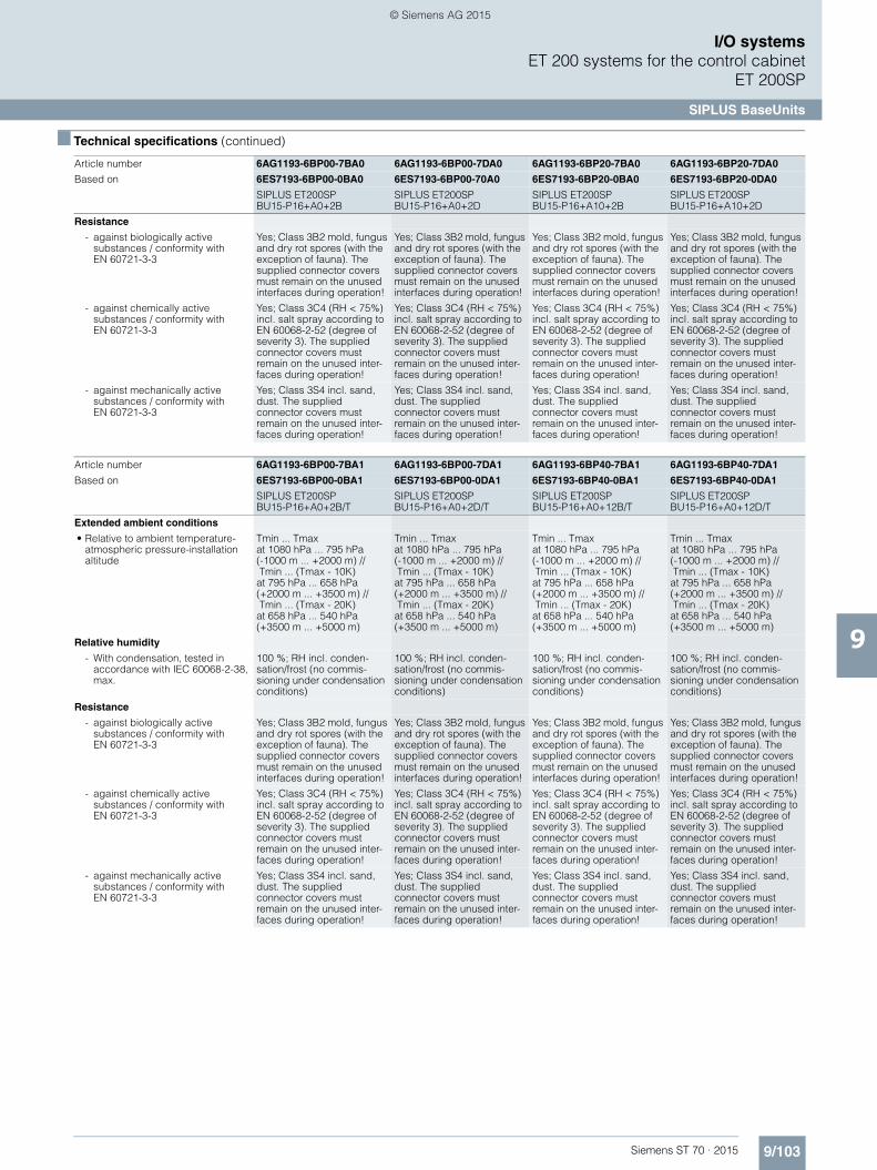
9/103Siemens ST 70 · 2015
9
■ Technical specifications (continued)
I/O systemsET 200 systems for the control cabinet
ET 200SP
SIPLUS BaseUnits
Resistance
- against biologically active substances / conformity with EN 60721-3-3
Yes; Class 3B2 mold, fungus and dry rot spores (with the exception of fauna). The supplied connector covers must remain on the unused interfaces during operation!
Yes; Class 3B2 mold, fungus and dry rot spores (with the exception of fauna). The supplied connector covers must remain on the unused interfaces during operation!
Yes; Class 3B2 mold, fungus and dry rot spores (with the exception of fauna). The supplied connector covers must remain on the unused interfaces during operation!
Yes; Class 3B2 mold, fungus and dry rot spores (with the exception of fauna). The supplied connector covers must remain on the unused interfaces during operation!
- against chemically active substances / conformity with EN 60721-3-3
Yes; Class 3C4 (RH < 75%) incl. salt spray according to EN 60068-2-52 (degree of severity 3). The supplied connector covers must remain on the unused inter-faces during operation!
Yes; Class 3C4 (RH < 75%) incl. salt spray according to EN 60068-2-52 (degree of severity 3). The supplied connector covers must remain on the unused inter-faces during operation!
Yes; Class 3C4 (RH < 75%) incl. salt spray according to EN 60068-2-52 (degree of severity 3). The supplied connector covers must remain on the unused inter-faces during operation!
Yes; Class 3C4 (RH < 75%) incl. salt spray according to EN 60068-2-52 (degree of severity 3). The supplied connector covers must remain on the unused inter-faces during operation!
- against mechanically active substances / conformity with EN 60721-3-3
Yes; Class 3S4 incl. sand, dust. The supplied connector covers must remain on the unused inter-faces during operation!
Yes; Class 3S4 incl. sand, dust. The supplied connector covers must remain on the unused inter-faces during operation!
Yes; Class 3S4 incl. sand, dust. The supplied connector covers must remain on the unused inter-faces during operation!
Yes; Class 3S4 incl. sand, dust. The supplied connector covers must remain on the unused inter-faces during operation!
Article number 6AG1193-6BP00-7BA1 6AG1193-6BP00-7DA1 6AG1193-6BP40-7BA1 6AG1193-6BP40-7DA1
Based on 6ES7193-6BP00-0BA1 6ES7193-6BP00-0DA1 6ES7193-6BP40-0BA1 6ES7193-6BP40-0DA1
SIPLUS ET200SP BU15-P16+A0+2B/T
SIPLUS ET200SP BU15-P16+A0+2D/T
SIPLUS ET200SP BU15-P16+A0+12B/T
SIPLUS ET200SP BU15-P16+A0+12D/T
Extended ambient conditions
• Relative to ambient temperature-atmospheric pressure-installation altitude
Tmin ... Tmax at 1080 hPa ... 795 hPa (-1000 m ... +2000 m) // Tmin ... (Tmax - 10K) at 795 hPa ... 658 hPa (+2000 m ... +3500 m) // Tmin ... (Tmax - 20K) at 658 hPa ... 540 hPa (+3500 m ... +5000 m)
Tmin ... Tmax at 1080 hPa ... 795 hPa (-1000 m ... +2000 m) // Tmin ... (Tmax - 10K) at 795 hPa ... 658 hPa (+2000 m ... +3500 m) // Tmin ... (Tmax - 20K) at 658 hPa ... 540 hPa (+3500 m ... +5000 m)
Tmin ... Tmax at 1080 hPa ... 795 hPa (-1000 m ... +2000 m) // Tmin ... (Tmax - 10K) at 795 hPa ... 658 hPa (+2000 m ... +3500 m) // Tmin ... (Tmax - 20K) at 658 hPa ... 540 hPa (+3500 m ... +5000 m)
Tmin ... Tmax at 1080 hPa ... 795 hPa (-1000 m ... +2000 m) // Tmin ... (Tmax - 10K) at 795 hPa ... 658 hPa (+2000 m ... +3500 m) // Tmin ... (Tmax - 20K) at 658 hPa ... 540 hPa (+3500 m ... +5000 m)
Relative humidity
- With condensation, tested in accordance with IEC 60068-2-38, max.
100 %; RH incl. conden-sation/frost (no commis-sioning under condensation conditions)
100 %; RH incl. conden-sation/frost (no commis-sioning under condensation conditions)
100 %; RH incl. conden-sation/frost (no commis-sioning under condensation conditions)
100 %; RH incl. conden-sation/frost (no commis-sioning under condensation conditions)
Resistance
- against biologically active substances / conformity with EN 60721-3-3
Yes; Class 3B2 mold, fungus and dry rot spores (with the exception of fauna). The supplied connector covers must remain on the unused interfaces during operation!
Yes; Class 3B2 mold, fungus and dry rot spores (with the exception of fauna). The supplied connector covers must remain on the unused interfaces during operation!
Yes; Class 3B2 mold, fungus and dry rot spores (with the exception of fauna). The supplied connector covers must remain on the unused interfaces during operation!
Yes; Class 3B2 mold, fungus and dry rot spores (with the exception of fauna). The supplied connector covers must remain on the unused interfaces during operation!
- against chemically active substances / conformity with EN 60721-3-3
Yes; Class 3C4 (RH < 75%) incl. salt spray according to EN 60068-2-52 (degree of severity 3). The supplied connector covers must remain on the unused inter-faces during operation!
Yes; Class 3C4 (RH < 75%) incl. salt spray according to EN 60068-2-52 (degree of severity 3). The supplied connector covers must remain on the unused inter-faces during operation!
Yes; Class 3C4 (RH < 75%) incl. salt spray according to EN 60068-2-52 (degree of severity 3). The supplied connector covers must remain on the unused inter-faces during operation!
Yes; Class 3C4 (RH < 75%) incl. salt spray according to EN 60068-2-52 (degree of severity 3). The supplied connector covers must remain on the unused inter-faces during operation!
- against mechanically active substances / conformity with EN 60721-3-3
Yes; Class 3S4 incl. sand, dust. The supplied connector covers must remain on the unused inter-faces during operation!
Yes; Class 3S4 incl. sand, dust. The supplied connector covers must remain on the unused inter-faces during operation!
Yes; Class 3S4 incl. sand, dust. The supplied connector covers must remain on the unused inter-faces during operation!
Yes; Class 3S4 incl. sand, dust. The supplied connector covers must remain on the unused inter-faces during operation!
Article number 6AG1193-6BP00-7BA0 6AG1193-6BP00-7DA0 6AG1193-6BP20-7BA0 6AG1193-6BP20-7DA0
Based on 6ES7193-6BP00-0BA0 6ES7193-6BP00-70A0 6ES7193-6BP20-0BA0 6ES7193-6BP20-0DA0
SIPLUS ET200SP BU15-P16+A0+2B
SIPLUS ET200SP BU15-P16+A0+2D
SIPLUS ET200SP BU15-P16+A10+2B
SIPLUS ET200SP BU15-P16+A10+2D
ST70_2015_Kap09_EN.book Seite 103 Donnerstag, 21. Mai 2015 11:58 11
© Siemens AG 2015

9/104 Siemens ST 70 · 2015
9
I/O systemsET 200 systems for the control cabinetET 200SP
SIPLUS BaseUnits
■ Ordering data Article No. Article No.
SIPLUS BaseUnits type A0
BU15-P16+A0+2D 6AG1193-6BP00-7DA0
(Extended temperature range and medial exposure)
BU type A0; BaseUnit (light) with 16 process terminals to the module, for starting a new load group (max. 10 A)
BU15-P16+A0+2B 6AG1193-6BP00-7BA0
(Extended temperature range and medial exposure)
BU type A0; BaseUnit (dark) with 16 process terminals to the module; for continuing the load group
BU15-P16+A10+2D 6AG1193-6BP20-7DA0
(Extended temperature range and medial exposure)
BU type A0; BaseUnit (light) with 16 process terminals (1...16) to the module and an additional 10 inter-nally jumpered AUX terminals (1A to 10A); for starting a new load group (max. 10 A)
BU15-P16+A10+2B 6AG1193-6BP20-7BA0
(Extended temperature range and medial exposure)
BU type A0; BaseUnit (dark) with 16 process terminals (1...16) to the module and an additional 10 inter-nally jumpered AUX terminals (1A to 10A); for continuing the load group
SIPLUS BaseUnits type A1 (with temperature detection)
BU15-P16+A0+2D/T 6AG1193-6BP00-7DA1
(Extended temperature range and medial exposure)
BU type A1; BaseUnit (light) with 16 process terminals to the module, for starting a new load group (max. 10 A)
BU15-P16+A0+2B/T 6AG1193-6BP00-7BA1
(Extended temperature range and medial exposure)
BU type A1; BaseUnit (dark) with 16 process terminals to the module; for continuing the load group
BU15-P16+A0+12D/T 6AG1193-6BP40-7DA1
(Extended temperature range and medial exposure)
BU type A1; BaseUnit (light) with 16 process terminals (1...16) to the module and an additional 2x5 inter-nally jumpered AUX terminals (1 B to 5 B and 1 C to 5 C); for starting a new load group (max. 10 A)
BU15-P16+A0+12B/T 6AG1193-6BP40-7BA1
(Extended temperature range and medial exposure)
BU type A1; BaseUnit (dark) with 16 process terminals (1...16) to the module and an additional 2x5 inter-nally jumpered AUX terminals (1 B to 5 B and 1 C to 5 C); for continuing the load group
Accessories See SIMATIC ET 200SP BaseUnits, page 9/101
ST70_2015_Kap09_EN.book Seite 104 Donnerstag, 21. Mai 2015 11:58 11
© Siemens AG 2015

9/105Siemens ST 70 · 2015
9
I/O systemsET 200 systems for the control cabinet
ET 200SP
BusAdapters
■ Overview
BusAdapter BA 2xRJ45
BusAdapter BA 2xFC
Some interface modules of the SIMATIC ET 200SP have a univer-sal PROFINET interface for BusAdapters. With the appropriate bus adapter, the type of connection can be adapted to the re-quirements of the respective application:• For standard applications with a moderate mechanical and
EMC load, the BusAdapter BA 2xRJ45 is used. It offers two sockets for standard RJ45 plugs.
• For machines and systems in which higher mechanical and/or EMC loads act on the devices, the BusAdapter BA 2xFC is recommended. In this case, the bus cables are connected directly by means of FastConnect terminals – similar to the PROFIBUS connector, proven in millions of applications. The technology is extremely quick to assemble and achieves 5 times better vibration resistance and also 5 times greater resistance to electromagnetic interference, when compared to RJ45 plug-in connectors.
• BusAdapters with connections for fiber-optic cables can be used to cover high potential differences between two stations and/or high EMC loads.
Another advantage of the BusAdapters: In order to repair defec-tive RJ45 sockets or for subsequent conversion to the rugged FastConnect technology or a fiber-optic connection, only the adapter needs to be replaced.
The following interface modules offer a PROFINET connection via BusAdapter:• IM 155-6PN Standard• IM 155-6PN High Feature
■ Ordering data Article No. Article No.
BusAdapter BA 2xRJ45 6ES7193-6AR00-0AA0
For IM 155-6PN ST, HF
BusAdapter BA 2xFC 6ES7193-6AF00-0AA0
For IM 155-6PN ST, HF; for increased vibration and EMC loads
BusAdapter BA 2xSCRJ 6ES7193-6AP00-0AA0
For IM 155-6PN HF, fiber-optic connection for POF or PCF cables up to 250 m, with monitoring of damping
BusAdapter BA SCRJ/RJ45 6ES7193-6AP20-0AA0
For IM 155-6PN HF; with media converter FOC-copper; 1 x SCRJ FO connection, 1 x RJ45 connection
BusAdapter BA SCRJ/FC 6ES7193-6AP40-0AA0
For IM 155-6PN HF; with media converter FOC-copper; 1 x SCRJ FO connection, 1 x FastConnect connection
Reference identification label 6ES7193-6LF30-0AW0
10 sheets of 16 labels; for printing with thermal-transfer card printer or plotting unit
ST70_2015_Kap09_EN.book Seite 105 Donnerstag, 21. Mai 2015 11:58 11
© Siemens AG 2015

9/106 Siemens ST 70 · 2015
9
I/O systemsET 200 systems for the control cabinetET 200SP
Accessories
■ Overview
Labeling strips• Labeling strips for ET 200SP• Can be used for the interface module, bus adapter,
I/O module and BU cover
Reference identification labels
• For the labeling of ET 200SP components with a reference code (equipment identifier)
• Can be used for the interface module, I/O module, bus adapter and BU cover
BU covers• Protective cover for empty slots of an ET 200SP• For protecting the plug-in connectors of a BaseUnit without
I/O module
Color-coded labels• For module-specific identification of the potentials at the
terminals of the BaseUnit• For the prevention of wiring faults
Shield connection• Simple, quick-mounting shield connection• For space-saving and optimized connection of cable shields
from EMC viewpoint
■ Ordering data Article No.
■ Ordering data Article No.
Labeling strips
500 labeling strips on roll, light gray, for inscription with thermal transfer roll printer
6ES7193-6LR10-0AA0
500 labeling strips on roll, yellow, for inscription with thermal transfer roll printer
6ES7193-6LR10-0AG0
1000 labeling strips DIN A4, light gray, card, for inscription with laser printer
6ES7193-6LA10-0AA0
1000 labeling strips DIN A4, yellow, card, for inscription with laser printer
6ES7193-6LA10-0AG0
Reference identification label 6ES7193-6LF30-0AW0
10 sheets of 16 labels
BU cover
For covering empty slots (gaps); 5 units• 15 mm wide 6ES7133-6CV15-1AM0• 20 mm wide 6ES7133-6CV20-1AM0
Color-coded labels• Color code CC01, module-
specific, for 16 push-in terminals; for BaseUnit type A0, A1; 10 units
6ES7193-6CP01-2MA0
• Color code CC02, module-specific, for 16 push-in terminals; for BaseUnit type A0, A1; 10 units
6ES7193-6CP02-2MA0
• Color code CC03, module-specific, for 16 push-in terminals; for BaseUnit type A0, A1; 10 units
6ES7193-6CP03-2MA0
• Color code CC04, module-specific, for 16 push-in terminals; for BaseUnit type A0, A1; 10 units
6ES7193-6CP04-2MA0
• Color code CC05, module-specific, for 16 push-in terminals; for BaseUnit type A0, A1; 10 units
6ES7193-6CP05-2MA0
• Color code CC71, for 10 AUX terminals 1 A to 10 A, for BU type A0, yellow/green, with push-in terminals; 10 units
6ES7193-6CP71-2AA0
• Color code CC72, for 10 AUX terminals 1 A to 10 A, for BU type A0, red, with push-in terminals; 10 units
6ES7193-6CP72-2AA0
• Color code CC73, for 10 AUX terminals 1 A to 10 A, for BU type A0, blue, with push-in terminals; 10 units
6ES7193-6CP73-2AA0
• Color code CC74, for 2x5 addi-tional terminals, 5 x red, 5 x blue, for BU type A1, with push-in terminals; 10 units
6ES7193-6CP74-2AA0
• Color code CC81, for 4 AUX terminals 1 A to 4 A, yellow/green, for BaseUnit type B0; 10 units
6ES7193-6CP81-2AB0
• Color code CC82, for 4 AUX terminals 1 A to 4 A, red, for BaseUnit type B0; 10 units
6ES7193-6CP82-2AB0
• Color code CC83, for 4 AUX terminals 1 A to 4 A, blue, for BaseUnit type B0; 10 units
6ES7193-6CP83-2AB0
• Color code CC41, module-specific, for 12 push-in terminals; for BaseUnit type B1; 10 units
6ES7193-6CP41-2MB0
• Color code CC84, for 2 AUX terminals 1 A to 2 A, yellow/green, for BaseUnit type C0; 10 units
6ES7193-6CP84-2AC0
• Color code CC85, for 2 AUX terminals 1 A to 2 A, red, for BaseUnit type C0; 10 units
6ES7193-6CP85-2AC0
• Color code CC86, for 2 AUX terminals 1 A to 2 A, blue, for BaseUnit type C0; 10 units
6ES7193-6CP86-2AC0
• Color code CC42, module-specific; for BaseUnit type F0; 10 units
6ES7193-6CP42-2MB0
Shield connection 6ES7193-6SC00-1AM0
5 shield connections and 5 shield terminals each for plugging onto BaseUnits with automatic low-impedance connection to functional ground
ST70_2015_Kap09_EN.book Seite 106 Donnerstag, 21. Mai 2015 11:58 11
© Siemens AG 2015

9/107Siemens ST 70 · 2015
9
I/O systemsET 200 systems for the control cabinet
ET 200S
Introduction
■ Overview
SIMATIC ET 200S• Distributed I/O system to degree of protection IP20 with
minimal wiring outlay, also for extremely time-critical tasks such as high-speed closed-loop controls
• Can be used with integrated S7-CPU as mini PLC:- also available as fail-safe PROFIsafe version- with optional lower-level PROFIBUS DP
• Bit-modular design for exact adaptation to the automation task in hand.
• Interface modules available with PROFIBUS DP or PROFINET interfaces
• Can be combined from digital and analog in/output modules, technology modules, motor starters and frequency converters for the control of drives up to 7.5 or 4 kW.
• Exchange of modules during operation (hot swapping), permanent wiring with multi-conductor connection
• Channel-specific diagnostics for high availability• Can be supplied with integrated fiber optic interface if
required• Transmission rates up to 12 Mbit/s• FastConnect using unstripped quick connection technology,
screw or spring-loaded terminals• Ex approval to Cat. 3 for Zone 2 acc. to ATEX 100 a• Slot reservation with spare modules• Fail-safe DI modules with safety-related signal processing
according to PROFIsafe• Option handling – for simplest management of machine
options
SIMATIC ET 200S COMPACT• Block I/O to degree of protection IP20 with 32 channels,
comprising terminal block and electronic block • Discretely modular expansion to maximum of 128 channels or
12 modules• The complete ET 200S module spectrum can be used
(with the exception of PROFIsafe modules)• Separation of terminal connections and electronics with
permanent wiring • Screw-type and spring-loaded terminal connections• Standard terminal block with 2-wire connection system;
3-wire and 4-wire systems available using additional terminals• Mounting on standard rail• Hot swapping of expansion modules• Communication via PROFIBUS• Up to 100 byte inputs and outputs (address space)
ST70_2015_Kap09_EN.book Seite 107 Donnerstag, 21. Mai 2015 11:58 11
© Siemens AG 2015

9/108 Siemens ST 70 · 2015
9
I/O systemsET 200 systems for the control cabinetET 200S
Introduction
■ Technical specifications
Within the context of converting SIMATIC from UL / CSA to cULus, the ET 200S modules will also be converted
General technical specifications
Degree of protection IP20
Ambient temperature 0 … 60 °C
Vibration resistance 2 g continuously, 5 g temporarily (motor starter max. 2 g)
Maximum configuration (none of the limits listed below must be exceeded)• Number of modules per IM 151,
max.IM 151-1 BASIC: Up to 12 modules
IM 151-1 COMPACT: Up to 12 modules
IM 151-1 STANDARD: Up to 63 modules
IM 151-1 HIGH-FEATURE: Up to 63 modules
IM 151-7 CPU: Up to 63 modules
IM 151-3 PN: Up to 63 modules• Line width, max. IM 151-1 BASIC: Up to 2 m
IM 151-1 COMPACT: Up to 2 m
IM 151-1 STANDARD: Up to 2 m
IM 151-1 HIGH-FEATURE: Up to 2 m
IM 151-7 CPU: Up to 1 m
IM 151-3 PN: Up to 2 m• User data length Depending on the number and type
of connected modules
IM 151-1 BASIC: Up to 88 byte for inputs and outputs
IM 151-1 COMPACT: Up to 100 byte for inputs and outputs
IM 151-1 STANDARD: Up to 244 byte for inputs and outputs
IM 151-1 HIGH-FEATURE: Up to 244 byte for inputs and outputs
IM 151-7 CPU: Not relevant
IM 151-3 PN: 256 byte• Parameter length Depending on the number and type
of connected modules
IM 151-1 BASIC: 198 byte
IM 151-1 COMPACT: 218 byte
IM 151-1 STANDARD: Up to 244 byte
IM 151-1 HIGH-FEATURE: Up to 244 byte
IM 151-7 CPU: Not relevant
IM 151-3 PN: Not relevant
Requirements of the DP master system• PROFIBUS DP master In accordance with EN 50170• Parameter length >32 byte, depending on the number
and type of connected modules• User data length Depending on the number and type
of connected modules• Diagnostics length 17 … 64 byte (adjustable)
Standards and approvals• PROFIBUS EN 50170, Volume 2• IEC 1131 IEC 1131, Part 2• UL acc. to UL508 standard, File No.
E 116536/E 75310 (AC modules)• C-Tick AS/NZS 2064 (Class A)• CSA acc. to standard C22.2 No. 142,
File No. LR 48323/LR 44226 (AC modules)
• cULus for hazardous locations acc. to UL 508 standard, File No. E 116536acc. to hazardous locations UL 1604, File no. E 222109acc. to CSA C22.2 standard, No. 142
• FM Standard Class No. 3611, Class I, Division 2, Group A, B, C, D, Class I, Zone 2, Group IIC (without motor starter and frequency converter)
• Shipbuilding American Bureau of Shipping
Bureau Veritas
Det Norske Veritas
Germanischer Lloyd
Lloyds Register of Shipping
Nippon Kaiji Kyokai
(without motor starters and frequency converters)
• Ex approval Cat. 3 (for Zone 2 acc. to ATEX–100a)
EN 50021(without frequency converters)
General technical specifications
ST70_2015_Kap09_EN.book Seite 108 Donnerstag, 21. Mai 2015 11:58 11
© Siemens AG 2015

9/109Siemens ST 70 · 2015
9
I/O systemsET 200 systems for the control cabinet
ET 200S - Interface modules
IM 151-1
■ Overview
• Interface module for linking the ET 200S to PROFIBUS DP• Handles all data exchange with the PROFIBUS DP master• 6 variants:
- IM151-1 BASIC (RS 485)- IM151-1 COMPACT 32DI 24VDC (RS 485)- IM151-1 COMPACT 16DI 24VDC /
16DO 24VDC/0.5A (RS 485)- IM151-1 STANDARD (RS 485)- IM151-1 STANDARD (FO)- IM151-1 HIGH FEATURE (RS 485)
• Delivery including connection module
The main differences between the IM151-1 variants:
IM151-1BASIC
IM151-1 COMPACT
IM151-1 STANDARD
IM151-1 FO STANDARD
IM151-1HIGH FEATURE
Article number 6ES7151- 1CA00-0AB0 1CA00-1BL001CA00-3BL00
1AA05-0AB0 1AB05-0AB0 1BA02-0AB0
Integral I/O - 32 DI16DI / 16 DO
- - -
Maximum number of I/O modules
12 12 63 63 63
Maximum station width 2 m 2 m 2 m 1 m 2 m
Maximum number of parameters
198 bytes 218 bytes 244 bytes 244 bytes 244 bytes
Maximum address space for inputs and outputs
88 bytes each 100 bytes each 244 bytes 128 bytes Depending on the DP master: 244 bytes or not relevant
Maximum diagnostics length
6 to 43 bytes 6 to 44 bytes 6 to 122 bytes 6 to 64 bytes 6 to 128 bytes
Protocol DP V0 DP V0 DP V0 and DP V1 DP V0 DP V0 and DP V1
DP connection type RS 485 RS 485 RS 485 Fiber-optic cable RS 485
Firmware update No No Yes No Yes
Option handling No No Yes Yes Yes
Isochronous mode No No No No Yes
Maximum address vol-ume per module
8 bytes 8 bytes 32 bytes 8 bytes 32 bytes
Identification data No No Yes No Yes
Use of fail-safe modules (PROFIsafe)
No No No No Yes
I-slave-to-slave communication
No No No No Yes
ST70_2015_Kap09_EN.book Seite 109 Donnerstag, 21. Mai 2015 11:58 11
© Siemens AG 2015

9/110 Siemens ST 70 · 2015
9
I/O systemsET 200 systems for the control cabinetET 200S - Interface modules
IM 151-1
■ Technical specifications
Article number 6ES7151-1CA00-1BL0 6ES7151-1CA00-3BL0
ET 200S COMPACT, 32DI STD, DC24V, 3MS ET 200S COMPACT, 16DI/16DO STD, DC24V
Product type designation
General information
Vendor identification (VendorID) 8200H
Supply voltage
Load voltage 1L+
• Rated value (DC) 24 V 24 V
• Reverse polarity protection Yes Yes
Input current
from supply voltage 1L+, max. 100 mA; 100 100 mA
Address area
Addressing volume
• Inputs 100 byte 100 byte
• Outputs 100 byte 100 byte
Digital inputs
Number of digital inputs 32 16
Input voltage
• Type of input voltage DC DC
• Rated value (DC) 24 V 24 V
• for signal "0" -30 to +5V -30 to +5V
• for signal "1" 13 to 30V 13 to 30V
Input current
• for signal "1", typ. 4 mA; At 24 V min. 2 mA 3 mA
Input delay (for rated value of input voltage)
for standard inputs
- at "0" to "1", min. 3 ms 3 ms
- at "0" to "1", max. 3 ms 3 ms
Cable length
• Unshielded, max. 1 000 m 1 000 m
Digital outputs
Number of digital outputs 0 16
short-circuit protection Yes
Limitation of inductive shutdown voltage to
L+ (-55 to -60 V)
Controlling a digital input Yes
Switching capacity of the outputs
• on lamp load, max. 5 W
Output current
• for signal "1" permissible range for 0 to 60 °C, min.
7 mA
• for signal "0" residual current, max. 0.5 mA
Output delay with resistive load
• "0" to "1", max. 0.5 ms
• "1" to "0", max. 1.3 ms
Switching frequency
• with resistive load, max. 100 Hz
• with inductive load, max. 2 Hz
• on lamp load, max. 10 Hz
Aggregate current of outputs (per group)
all mounting positions
- up to 60 °C, max. 2 A
Cable length
• Unshielded, max. 1 000 m
ST70_2015_Kap09_EN.book Seite 110 Donnerstag, 21. Mai 2015 11:58 11
© Siemens AG 2015

9/111Siemens ST 70 · 2015
9
■ Technical specifications (continued)
I/O systemsET 200 systems for the control cabinet
ET 200S - Interface modules
IM 151-1
Encoder
Connectable encoders
• 2-wire sensor Yes
- Permissible quiescent current (2-wire sensor), max.
1.5 mA
Interfaces
Interface physics, RS 485 Yes Yes
Interface physics, FOC No No
PROFINET IO
• Transmission rate, max. 12 Mbit/s
PROFIBUS DP
• Output current, max. 80 mA
• Transmission procedure RS 485 RS 485
• Direct data exchange (slave-to-slave communication)
Yes Yes
Cable length
- Cable length, max. 1 200 m 1 200 m
Protocols
PROFINET IO No No
PROFIBUS DP Yes Yes
Protocols (Ethernet)
• TCP/IP No No
Isochronous mode
Isochronous operation (application synchronized up to terminal)
No No
Interrupts/diagnostics/status information
Alarms
• Alarms No No
Diagnostic messages
• Diagnostic functions Yes Yes
Diagnostics indication LED
• Run mode RUN (green) Yes
• Group error SF (red) Yes Yes
• Status indicator digital output (green)
Yes
• Status indicator digital input (green) Yes
• Monitoring 24 V voltage supply ON (green)
Yes Yes
• Connection to network LINK (green) No
• Transmit/receive RX/TX (yellow) No
Galvanic isolation
between backplane bus and electronics
No
between supply voltage and electronics
No
Galvanic isolation digital inputs
• Galvanic isolation digital inputs No
Galvanic isolation digital outputs
• Galvanic isolation digital outputs Yes
Isolation
Isolation checked with 500 V DC 500 V DC
Degree and class of protection
Degree of protection to EN 60529
• IP20 Yes Yes
Connection method
Inputs/outputs Screw-type and spring-loaded terminals, permanent wiring; 3 and 4-wire connection
Article number 6ES7151-1CA00-1BL0 6ES7151-1CA00-3BL0
ET 200S COMPACT, 32DI STD, DC24V, 3MS ET 200S COMPACT, 16DI/16DO STD, DC24V
ST70_2015_Kap09_EN.book Seite 111 Donnerstag, 21. Mai 2015 11:58 11
© Siemens AG 2015

9/112 Siemens ST 70 · 2015
9
■ Technical specifications (continued)
I/O systemsET 200 systems for the control cabinetET 200S - Interface modules
IM 151-1
Dimensions
Width 120 mm 120 mm
Height 81 mm 81 mm
Depth 758 mm; 58 58 mm
Weights
Weight, approx. 230 g; EB only
Article number 6ES7151-1AA05-0AB0 6ES7151-1AB05-0AB0 6ES7151-1BA02-0AB0 6ES7151-1CA00-0AB0
ET200S, IM151-1 STD, 12MBIT/S
ET200S, INTERFACE MODULE IM151-1 FO
ET200S, INTERF.MOD. IM151-1 HF, 12MBIT/S
ET200S, IM151-1 BASIC, 12MBIT/S
Product type designation
General information
Vendor identification (VendorID) 806Ah 806Bh 80F3h
Supply voltage
Mains buffering
• Mains/voltage failure stored energy time
20 ms 20 ms 20 ms No
Input current
from supply voltage 1L+, max. 200 mA 200 mA 200 mA 70 mA
Output current
Current output to backplane bus (DC 5 V), max.
700 mA
Power losses
Power loss, typ. 3.3 W 3.3 W 3.3 W 1.5 W
Address area
Addressing volume
• Inputs 244 byte 244 byte 244 byte 88 byte
• Outputs 244 byte 244 byte 244 byte 88 byte
Interfaces
Interface physics, RS 485 Yes; 9-pin sub D socket Yes Yes; 9-pin sub D socket
Interface physics, FOC Yes; 4 x Simplex socket
PROFIBUS DP
• Output current, max. 80 mA 80 mA
• Transmission rate, max. 12 Mbit/s; 9,6 / 19,2 / 45,45 / 93,75 / 187,5 / 500 kbit/s; 1,5 / 3 / 6 / 12 Mbit/s
12 Mbit/s; 9,6 / 19,2 / 45,45 / 93,75 / 187,5 / 500 kbit/s; 1,5 / 12 Mbit/s
12 Mbit/s 12 Mbit/s; 9,6 / 19,2 / 45,45 / 93,75 / 187,5 / 500 kbit/s; 1,5 / 3 / 6 / 12 Mbit/s
• Transmission procedure RS 485
• SYNC capability Yes Yes Yes Yes
• FREEZE capability Yes Yes Yes Yes
• Direct data exchange (slave-to-slave communication)
Yes Yes Yes Yes
Cable length
- Cable length, max. 1 200 m 2 m
Protocols
PROFIBUS DP Yes Yes Yes Yes
Isochronous mode
Isochronous operation (application synchronized up to terminal)
No No Yes No
Interrupts/diagnostics/status information
Alarms
• Alarms Yes Yes Yes No
Diagnostic messages
• Diagnostic functions Yes Yes Yes Yes
Diagnostics indication LED
• Bus fault BF (red) Yes Yes Yes Yes
• Group error SF (red) Yes Yes Yes Yes
• Monitoring 24 V voltage supply ON (green)
Yes Yes Yes Yes
Article number 6ES7151-1CA00-1BL0 6ES7151-1CA00-3BL0
ET 200S COMPACT, 32DI STD, DC24V, 3MS ET 200S COMPACT, 16DI/16DO STD, DC24V
ST70_2015_Kap09_EN.book Seite 112 Donnerstag, 21. Mai 2015 11:58 11
© Siemens AG 2015

9/113Siemens ST 70 · 2015
9
■ Technical specifications (continued)
I/O systemsET 200 systems for the control cabinet
ET 200S - Interface modules
IM 151-1
■ Ordering data Article No. Article No.
Galvanic isolation
between backplane bus and electronics
No No No No
between electronic block and PROFIBUS DP
Yes Yes Yes
between supply voltage and electronics
No No No No
Permissible potential difference
between different circuits 75V DC/60V AC 500 V DC 75V DC/60V AC 75V DC/60V AC
Isolation
Isolation checked with 500 V DC 57V DC/60V AC 500 V DC 500 V DC
Standards, approvals, certificates
CE mark Yes Yes
UL approval Yes Yes
Ambient conditions
Ambient temperature in operation
• Min. 0 °C 0 °C
• max. 60 °C 60 °C
Dimensions
Width 45 mm 45 mm 45 mm 45 mm
Height 119.5 mm 119.5 mm 119.5 mm 119.5 mm
Depth 75 mm 75 mm 75 mm 75 mm
Weights
Weight, approx. 150 g 150 g 150 g 150 g
Article number 6ES7151-1AA05-0AB0 6ES7151-1AB05-0AB0 6ES7151-1BA02-0AB0 6ES7151-1CA00-0AB0
ET200S, IM151-1 STD, 12MBIT/S
ET200S, INTERFACE MODULE IM151-1 FO
ET200S, INTERF.MOD. IM151-1 HF, 12MBIT/S
ET200S, IM151-1 BASIC, 12MBIT/S
IM 151-1 BASIC interface module 6ES7151-1CA00-0AB0
for ET 200S; transfer rates up to 12 Mbit/s; max. 12 power, electronic and motor start modules can be connected; bus connection via 9-pin sub D incl. termination module
IM 151-1 COMPACT 32 DI 24 V DC interface module
6ES7151-1CA00-1BL0
for ET 200S; transfer rates up to 12 Mbit/s; max. 32 digital inputs, can be expanded by max. 12 power, electronic and motor start modules; bus connection via 9-pin sub D incl. termination module
IM 151-1 COMPACT 16 DI 24 V DC / 16 DO 24 V/0.5 A interface module
6ES7151-1CA00-3BL0
for ET 200S; transfer rates up to 12 Mbit/s; max. 16 digital inputs and 16 digital outputs, can be expanded by max. 12 power, electronic and motor start modules; bus connection via 9-pin sub D incl. termination module
IM 151-1 STANDARD interface module
6ES7151-1AA05-0AB0
for ET 200S; transfer rates up to 12 Mbit/s; data volumes 244 bytes each for inputs and outputs, max. 63 power, electronic and motor start modules can be connected; bus connection via 9-pin sub D incl. termination module
IM 151-1 FO STANDARD interface module
6ES7151-1AB05-0AB0
for ET 200S, transfer rates up to 12 Mbit/s; data volumes 244 bytes each for inputs and outputs; max. 63 power, electronic and starter modules can be connected; bus connection via integrated fiber-optic cable incl. termination module
IM 151-1 HIGH FEATURE interface module
6ES7151-1BA02-0AB0
for ET 200S; transfer rate up to 12 Mbit/s; data volumes 244 bytes each for I/O, up to 63 modules can be connected; connection of PROFIsafe modules, isochronous mode; bus connection via 9-pin sub D incl. termination module
ST70_2015_Kap09_EN.book Seite 113 Donnerstag, 21. Mai 2015 11:58 11
© Siemens AG 2015

9/114 Siemens ST 70 · 2015
9
■ Ordering data Article No. Article No.
I/O systemsET 200 systems for the control cabinetET 200S - Interface modules
IM 151-1
Accessories
TM-C120S terminal module 6ES7193-4DL10-0AA0
Terminal module for ET 200S COMPACT, screw-type terminals
TM-C120C terminal module 6ES7193-4DL00-0AA0
Terminal module for ET 200S COMPACT, spring-loaded terminals
TE-U120S4x10 add-on terminal 6ES7193-4FL10-0AA0
Add-on terminal for TM-C120x terminal modules of ET 200S COMPACT; screw-type terminals for 3-wire connection; please order two for 4-wire connection
Can also be attached to TM-E/TM-P, provided at least 120 mm of the construction width attains the same overall height as the terminal module
TE-U120C4x10 add-on terminal 6ES7193-4FL00-0AA0
Add-on terminal for TM-C120x terminal modules of ET 200S COM-PACT; spring-loaded terminals for 3-wire connection; please order two for 4-wire connection
Can also be attached to TM-E/TM-P, provided at least 120 mm of the construction width attains the same overall height as the terminal module
ET 200S distributed I/O system manuals
are available on the Internet as PDF files:
http://www.siemens.com/simatic-docu
SIMATIC Manual Collection 6ES7998-8XC01-8YE0
Electronic manuals on DVD, multi-language: S7-200, TD 200, S7-300, M7-300, C7, S7-400, M7-400, STEP 7, Engineering Tools, Runtime Software, SIMATIC DP (Distributed I/O), SIMATIC HMI (Human Machine Interface), SIMATIC NET (Industrial Communication)
SIMATIC Manual Collection – Update service for 1 year
6ES7998-8XC01-8YE2
Scope of delivery: Current DVD "S7 Manual Collection" and the three subsequent updates
PROFIBUS DP bus connector RS 485
With 90° cable outlet for FastConnect connection system, max. transfer rate 12 Mbit/s
Without PG interface• 1 unit 6ES7972-0BA52-0XA0• 100 units 6ES7972-0BA52-0XB0
With PG interface• 1 unit 6ES7972-0BB52-0XA0• 100 units 6ES7972-0BB52-0XB0
100 Simplex connectors 6GK1901-0FB00-0AA0
For plastic fiber-optic cable incl. 5 polishing sets
50 plug adapters 6ES7195-1BE00-0XA0
For 2 Simplex connectors each
Label sheets DIN A4 (10 pieces)
Each sheet contains 60 labeling strips for I/O modules and 20 labeling strips for interface modules• petrol 6ES7193-4BH00-0AA0• red 6ES7193-4BD00-0AA0• yellow 6ES7193-4BB00-0AA0• light beige 6ES7193-4BA00-0AA0
Label sheets DIN A4 (10 pieces)
Can be used for ET 200S COMPACT.Each sheet has 10 labeling strips• beige 6ES7193-4BA10-0AA0• yellow 6ES7193-4BB10-0AA0• red 6ES7193-4BD10-0AA0• petrol 6ES7193-4BH10-0AA0
Termination module 6ES7193-4JA00-0AA0
as spare part for ET 200S
Power supply connector
Spare part;for connecting the 24 V DC supply voltage• with push-in terminals 6ES7193-4JB00-0AA0• with screw-type terminals 6ES7193-4JB50-0AA0
SIMATIC S5, 35 mm DIN rail • Length: 483 mm for 19" cabinets 6ES5710-8MA11• Length: 530 mm for 600 mm
cabinets6ES5710-8MA21
• Length: 830 mm for 900 mm cabinets
6ES5710-8MA31
• Length: 2 m 6ES5710-8MA41
ST70_2015_Kap09_EN.book Seite 114 Donnerstag, 21. Mai 2015 11:58 11
© Siemens AG 2015

9/115Siemens ST 70 · 2015
9
I/O systemsET 200 systems for the control cabinet
ET 200S - Interface modules
IM 151-3 PN
■ Overview
• Interface module for linking the ET 200S to PROFINET• Handles all data exchange with the PROFINET IO Controller• 3 versions:
- IM151-3 PN STANDARD- IM151-3 PN HIGH FEATURE and IM 151-3 PN FO:
supports, in contrast to the STANDARD version, the operation of PROFIsafe F modules
• With integrated 2-port switch for line topology• Delivery including connecting module
Note:
Micro Memory Card required for operation depending on the configuration.
■ Technical specifications
Article number 6ES7151-3AA23-0AB0 6ES7151-3BA23-0AB0
ET200S, IM151-3 PN ST INTERFACEMODULE ET200S, IM151-3 PN HF INTERFACEMODULE
Product type designation
Supply voltage
Mains buffering
• Mains/voltage failure stored energy time
20 ms
Input current
from supply voltage 1L+, max. 200 mA
Power losses
Power loss, typ. 3.3 W
Address area
Addressing volume
• Inputs 256 byte
• Outputs 256 byte
Interfaces
PROFINET IO
• Number of PROFINET interfaces 1
• Autocrossing Yes
• Automatic detection of transmission speed
Yes
• Transmission rate, max. 100 Mbit/s
• Services Ping; arp; LLDP; network diagnostics (SNMP) / MIB-2, reset SNMP parameters to factory settings; prioritized startup; media redundancy MRP; shared device
• RJ 45 Yes
1st interface
Functionality
• PROFINET IO Device Yes
PROFINET IO Device
Services
- Isochronous mode Yes
- IRT Yes
- PROFIenergy Yes
- Prioritized startup Yes
- Shared device Yes
- Number of IO controllers with shared device, max.
2
ST70_2015_Kap09_EN.book Seite 115 Donnerstag, 21. Mai 2015 11:58 11
© Siemens AG 2015

9/116 Siemens ST 70 · 2015
9
■ Technical specifications (continued)
I/O systemsET 200 systems for the control cabinetET 200S - Interface modules
IM 151-3 PN
■ Ordering data Article No. Article No.
Protocols
PROFINET IO Yes Yes
IRT Yes
MRP Yes
Protocols (Ethernet)
• SNMP Yes
• LLDP Yes
• ping Yes
• ARP Yes
Interrupts/diagnostics/status information
Alarms
• Alarms Yes
Diagnostic messages
• Diagnostic functions Yes
Diagnostics indication LED
• Bus fault BF (red) Yes
• Group error SF (red) Yes
• Monitoring 24 V voltage supply ON (green)
Yes
• Connection to network LINK (green) Yes
Galvanic isolation
between backplane bus and electronics
No
between supply voltage and electronics
No
between Ethernet and electronics Yes
Permissible potential difference
between different circuits 75V DC/60V AC
Isolation
Isolation checked with 500 V
Standards, approvals, certificates
CE mark Yes
UL approval Yes
Ambient conditions
Ambient temperature in operation
• Min. 0 °C
• max. 60 °C
Dimensions
Width 60 mm 60 mm
Height 119.5 mm 119.5 mm
Depth 75 mm 75 mm; with mounting rail
Weights
Weight, approx. 150 g
Article number 6ES7151-3AA23-0AB0 6ES7151-3BA23-0AB0
ET200S, IM151-3 PN ST INTERFACEMODULE ET200S, IM151-3 PN HF INTERFACEMODULE
IM 151-3 PN interface module
for ET 200S; transfer rates up to 100 Mbit/s; data volume depends on the number of modules inserted, up to 63 modules can be con-nected, bus connection through RJ45
6ES7151-3AA23-0AB0
IM 151-3 PN PROFINET High Feature interface module
for ET 200S; transfer rate up to 100 Mbit/s; max. 63 modules up to 2 m wide can be connected; bus connection via RJ45, incl. termination module
6ES7151-3BA23-0AB0
IM 151-3 FO interface module 6ES7151-3BB23-0AB0
for ET 200S; with 2 PROFINET FO-interfaces and integrated 2-port switch, max. 63 modules up to 2 m wide can be connected, incl. termination module
ST70_2015_Kap09_EN.book Seite 116 Donnerstag, 21. Mai 2015 11:58 11
© Siemens AG 2015

9/117Siemens ST 70 · 2015
9
■ Ordering data Article No. Article No.
I/O systemsET 200 systems for the control cabinet
ET 200S - Interface modules
IM 151-3 PN
1) For operating the IM 151-3, an MMC is essential
Accessories
Industrial Ethernet FC RJ45 Plug 90
RJ45 plug connector for Industrial Ethernet with a rugged metal enclo-sure and integrated insulation dis-placement contacts for connecting Industrial Ethernet FC installation cables; with 90° cable outlet
1 unit 6GK1901-1BB20-2AA0
10 units 6GK1901-1BB20-2AB0
50 units 6GK1901-1BB20-2AE0
Industrial Ethernet FastConnect installation cables
FastConnect standard cable 6XV1840-2AH10
FastConnect trailing cable 6XV1840-3AH10
FastConnect marine cable 6XV1840-4AH10
Termination Kits
SC RJ POF PlugAssembly case for on-site assembly of SC RJ plugs consisting of strip-ping tool, kevlar cutter, microscope, abrasive paper, grinding support
6GK1900-0ML00-0AA0
IE SC RJ POF PlugScrew-in plug for on-site assembly to POF fiber optic cable (1 pack = 20 units)
6GK1900-0MB00-0AC0
IE SC RJ Refill Set POFRefill set for Termination Kit SC RJ POF Plug, consisting of abrasive paper and grinding plate (set of 5)
6GK1900-0MN00-0AA0
SC RJ PCF PlugAssembly case for on-site assembly of SC RJ plugs consisting of strip-ping tool, buffer stripping tool, kevlar cutter, fiber breaking tool, microscope
6GK1900-0NL00-0AA0
Industrial Ethernet SC RJ PCF PlugScrew-in plug for on-site assembly to PCF fiber optic cable (1 pack = 10 units)
6GK1900-0NB00-0AC0
Industrial Ethernet FastConnect stripping tool
6GK1901-1GA00
MMC 64 KB 1) 6ES7953-8LF30-0AA0
For storing the device name
MMC 128 KB 1) 6ES7953-8LG30-0AA0
For storing the device name
MMC 512 KB 1) 6ES7953-8LJ30-0AA0
For storing the device name
MMC 2 MB 1) 6ES7953-8LL31-0AA0
For storing the device name and/or firmware update
MMC 4 MB 1) 6ES7953-8LM31-0AA0
For storing the device name and/or firmware update
MMC 8 MB 1) 6ES7953-8LP31-0AA0
For storing the device name and/or firmware update
ET 200S distributed I/O system manuals
are available on the Internet as PDF files:
http://www.siemens.com/simatic-docu
SIMATIC Manual Collection 6ES7998-8XC01-8YE0
Electronic manuals on DVD, multi-language: S7-200, TD 200, S7-300, M7-300, C7, S7-400, M7-400, STEP 7, Engineering Tools, Runtime Software, SIMATIC DP (Distributed I/O), SIMATIC HMI (Human Machine Interface), SIMATIC NET (Industrial Communication)
SIMATIC Manual Collection – Update service for 1 year
6ES7998-8XC01-8YE2
Scope of delivery: Current DVD "S7 Manual Collection" and the three subsequent updates
Label sheets DIN A4 (10 pieces)
Each sheet contains 60 labeling strips for I/O modules and 20 labeling strips for interface modules• petrol 6ES7193-4BH00-0AA0• red 6ES7193-4BD00-0AA0• yellow 6ES7193-4BB00-0AA0• light beige 6ES7193-4BA00-0AA0
Termination module 6ES7193-4JA00-0AA0
as spare part for ET 200S
Power supply connector
Spare part;for connecting the 24 V DC supply voltage• with push-in terminals 6ES7193-4JB00-0AA0• with screw-type terminals 6ES7193-4JB50-0AA0
DIN rail 35 mm • Length: 483 mm for 19" cabinets 6ES5710-8MA11• Length: 530 mm for 600 mm
cabinets6ES5710-8MA21
• Length: 830 mm for 900 mm cabinets
6ES5710-8MA31
• Length: 2 m 6ES5710-8MA41
Industrial Ethernet Switches
Managed Industrial Ethernet Switches; Isochronous real time, LED diagnostics, fault signaling contact with SET button, redundant power supply• SCALANCE X202-2P IRT;
2 x 10/100 Mbit/s RJ45 ports, 2 x 100 Mbit/s POF/PCF SC RJ
6GK5202-2BH00-2BA3
• SCALANCE X201-3P IRT;1 x 10/100 Mbit/s RJ45 ports, 3 x 100 Mbit/s POF/PCF SC RJ
6GK5201-3BH00-2BA3
• SCALANCE X200-4P IRT;4 x 100 Mbit/s POF/PCF SC RJ
6GK5200-4AH00-2BA3
ST70_2015_Kap09_EN.book Seite 117 Donnerstag, 21. Mai 2015 11:58 11
© Siemens AG 2015

9/118 Siemens ST 70 · 2015
9
I/O systemsET 200 systems for the control cabinetET 200S - Interface modules
SIPLUS IM 151-1
■ Overview
• Interface module for linking the ET 200S to PROFIBUS DP • Handles all data exchange with the PROFIBUS DP master
Note:
SIPLUS extreme products are based on SIMATIC standard products. The contents listed here were taken from the respec-tive standard products. SIPLUS extreme specific information was added.
For technical documentation on SIPLUS, see:
http://www.siemens.com/siplus-extreme
■ Technical specifications
■ Ordering data Article No. Article No.
Article number 6AG1151-1AA05-7AB0 6AG1151-1BA02-2AB0
Based on 6ES7151-1AA05-0AB0 6ES7151-1BA02-0AB0
SIPLUS ET200S IM 151-1 STANDARD SIPLUS ET200S IM151 HF
Ambient conditions
Ambient temperature in operation
• Min. -25 °C; = Tmin
• max. 60 °C; = Tmax
Extended ambient conditions
• Relative to ambient temperature-atmospheric pressure-installation altitude
Tmin ... Tmax at 1080 hPa ... 795 hPa (-1000 m ... +2000 m) // Tmin ... (Tmax - 10K) at 795 hPa ... 658 hPa (+2000 m ... +3500 m) // Tmin ... (Tmax - 20K) at 658 hPa ... 540 hPa (+3500 m ... +5000 m)
Tmin ... Tmax at 1080 hPa ... 795 hPa (-1000 m ... +2000 m) // Tmin ... (Tmax - 10K) at 795 hPa ... 658 hPa (+2000 m ... +3500 m) // Tmin ... (Tmax - 20K) at 658 hPa ... 540 hPa (+3500 m ... +5000 m)
Relative humidity
- With condensation, max. 100 %; incl. condensation / frost permitted (no commissioning under condensation conditions)
100 %; Relative humidity, incl. condensation / frost permitted (no commissioning under condensation conditions)
Resistance
- against biologically active substances / conformity with EN 60721-3-3
Yes; Class 3B2 mold, fungus and dry rot spores (with the exception of fauna). The supplied connector covers must remain on the unused interfaces during operation in corrosive atmospheres!
Yes; Class 3B2 mold, fungus and dry rot spores (with the exception of fauna). The supplied connector covers must remain on the unused interfaces during operation!
- against chemically active substances / conformity with EN 60721-3-3
Yes; Class 3C4 incl. salt spray according to EN 60068-2-52 (degree of severity 3). The supplied connector covers must remain on the unused interfaces during operation!
Yes; Class 3C4 incl. salt spray according to EN 60068-2-52 (degree of severity 3). The supplied connector covers must remain on the unused interfaces during operation!
- against mechanically active substances / conformity with EN 60721-3-3
Yes; Class 3S4 incl. sand, dust. The supplied connector covers must remain on the unused interfaces during operation!
Yes; Class 3S4 incl. sand, dust. The supplied connector covers must remain on the unused interfaces during operation!
SIPLUS IM 151-1 STANDARD interface module
6AG1151-1AA05-7AB0
(extended temperature range and medial exposure)
for ET 200S; transfer rates up to 12 Mbit/s; data volumes 244 bytes each for inputs and outputs, max. 63 power, electronic and motor start modules can be connected; bus connection via 9-pin D-sub incl. termination module
SIPLUS IM 151-1 HIGH FEATURE interface module
6AG1151-1BA02-2AB0
(extended temperature range and medial exposure)
for ET 200S; transfer rate up to 12 Mbit/s; data volumes 244 bytes each for inputs and outputs, up to 63 modules can be connected; connection of PROFIsafe modules, isochronous mode (clock synchro-nization); bus connection via 9-pin Sub-D incl. terminating module
Accessories See SIMATIC IM 151-1, page 9/114
ST70_2015_Kap09_EN.book Seite 118 Donnerstag, 21. Mai 2015 11:58 11
© Siemens AG 2015

9/119Siemens ST 70 · 2015
9
I/O systemsET 200 systems for the control cabinet
ET 200S - Interface modules
SIPLUS IM 151-3PN
■ Overview
• Interface module for linking the ET 200S PROFINET• Handles all data exchange with the PROFINET IO controller• IM 151-3 PN STANDARD• With integrated 2-port switch for line topology
Micro Memory Card required for operation of CPU.
Note:
SIPLUS extreme products are based on SIMATIC standard products. The contents listed here were taken from the respec-tive standard products. SIPLUS extreme specific information was added.
For technical documentation on SIPLUS, see:
http://www.siemens.com/siplus-extreme
■ Technical specifications
Article number 6AG1151-3AA23-2AB0 6AG1151-3AA23-7AB0
Based on 6ES7151-3AA23-0AB0 6ES7151-3AA23-0AB0
SIPLUS ET200S IM151-3 ST SIPLUS ET200S IM151-3 ST
Product type designation
Standards, approvals, certificates
CE mark Yes Yes
Ambient conditions
Ambient temperature in operation
• Min. -25 °C; = Tmin -25 °C; = Tmin
• max. 60 °C; = Tmax 70 °C; = Tmax
Extended ambient conditions
• Relative to ambient temperature-atmospheric pressure-installation altitude
Tmin ... Tmax at 1080 hPa ... 795 hPa (-1000 m ... +2000 m) // Tmin ... (Tmax - 10K) at 795 hPa ... 658 hPa (+2000 m ... +3500 m) // Tmin ... (Tmax - 20K) at 658 hPa ... 540 hPa (+3500 m ... +5000 m)
Tmin ... Tmax at 1080 hPa ... 795 hPa (-1000 m ... +2000 m) // Tmin ... (Tmax - 10K) at 795 hPa ... 658 hPa (+2000 m ... +3500 m) // Tmin ... (Tmax - 20K) at 658 hPa ... 540 hPa (+3500 m ... +5000 m)
Relative humidity
- With condensation, tested in accordance with IEC 60068-2-38, max.
100 %; RH incl. condensation/frost (no commissioning under condensation conditions)
100 %; RH incl. condensation/frost (no commissioning under condensation conditions)
Resistance
- against biologically active substances / conformity with EN 60721-3-3
Yes; Class 3B2 mold, fungus and dry rot spores (with the exception of fauna). The supplied connector covers must remain on the unused interfaces during operation!
Yes; Class 3B2 mold, fungus and dry rot spores (with the exception of fauna). The supplied connector covers must remain on the unused interfaces during operation!
- against chemically active substances / conformity with EN 60721-3-3
Yes; Class 3C4 (RH < 75%) incl. salt spray according to EN 60068-2-52 (degree of severity 3). The supplied connector covers must remain on the unused interfaces during operation!
Yes; Class 3C4 (RH < 75%) incl. salt spray according to EN 60068-2-52 (degree of severity 3). The supplied connector covers must remain on the unused interfaces during operation!
- against mechanically active substances / conformity with EN 60721-3-3
Yes; Class 3S4 incl. sand, dust. The supplied connector covers must remain on the unused interfaces during operation!
Yes; Class 3S4 incl. sand, dust. The supplied connector covers must remain on the unused interfaces during operation!
ST70_2015_Kap09_EN.book Seite 119 Donnerstag, 21. Mai 2015 11:58 11
© Siemens AG 2015

9/120 Siemens ST 70 · 2015
9
I/O systemsET 200 systems for the control cabinetET 200S - Interface modules
SIPLUS IM 151-3PN
■ Ordering data Article No. Article No.
SIPLUS IM 151-3 PN interface module
(extended temperature range and medial exposure)
for ET 200S; transfer rates up to 100 Mbit/s; data volume depends on the number of modules inserted, up to 63 modules can be con-nected, bus connection through RJ45
6AG1151-3AA23-2AB0
SIPLUS IM 151-3 PN PROFINET High Feature interface module
(extended temperature range and medial exposure)
for ET 200S; transfer rate up to 100 Mbit/s; max. 63 modules up to 2 m wide can be connected; bus connection via RJ45, incl. termination module
6AG1151-3BA23-7AB0
Accessories See SIMATIC IM 151-3 PN interface module, page 9/117
ST70_2015_Kap09_EN.book Seite 120 Donnerstag, 21. Mai 2015 11:58 11
© Siemens AG 2015

9/121Siemens ST 70 · 2015
9
I/O systemsET 200 systems for the control cabinet
ET 200S - I/O modules
Power modules for PM-E electronic modules
■ Overview
• For monitoring and, depending on the version, fusing the load and sensor supply voltage
• Can be plugged onto TM-P terminal modules with automatic coding.
• Diagnostics message for voltage and blown fuse (can be switched off via configuration)
• PM-E 24 V DC Standard- load voltage diagnostics
• PM-E 24 V DC High Feature- load voltage and reverse voltage diagnostics- with status information - option handling (only in combination with the IM 151-1
Standard, IM 151-1 FO Standard and IM 151-1 High Feature)• PM-E 24 to 48 V DC
- load voltage diagnostics- with status information- option handling (only in combination with the IM 151-1
Standard, IM 151-1 FO Standard and IM 151-1 High Feature)• PM-E 24 V DC to 230 V AC
- power module for universal use- with integral replaceable fuse- with status information- option handling (only in combination with the IM 151-1
Standard, IM 151-1 FO Standard and IM151-1 High Feature)
■ Technical specifications
Article number 6ES7138-4CA01-0AA0 6ES7138-4CB11-0AB0
ET200S, POWER MODULE PM-E, 24V DC ET200S, POWERMOD.PM-E;DC24-48V/AC24-230V
Product type designation
Supply voltage
Load voltage L+
• Rated value (DC) 24 V
• short-circuit protection No; external (e.g. automatic circuit breaker), tripping characteristic C
• Reverse polarity protection Yes
Input current
from load voltage 1L+ (without load), max.
4 mA
Current carrying capacity
up to 60 °C, max. 10 A
Power losses
Power loss, typ. 0.1 W
Interrupts/diagnostics/status information
Diagnostic messages
• Diagnostics Yes
• Missing load voltage Yes
Diagnostics indication LED
• Rated load voltage PWR (green) Yes
• Group error SF (red) Yes
Parameter
Remark 3 byte
Missing load voltage Disable / enable
Galvanic isolation
primary/secondary Yes; between rated load voltage and backplane bus, between power modules
Isolation
Isolation checked with 500 V DC
Dimensions
Width 15 mm 15 mm
Height 81 mm 81 mm
Depth 52 mm 52 mm
Weights
Weight, approx. 35 g
ST70_2015_Kap09_EN.book Seite 121 Donnerstag, 21. Mai 2015 11:58 11
© Siemens AG 2015

9/122 Siemens ST 70 · 2015
9
■ Technical specifications (continued)
I/O systemsET 200 systems for the control cabinetET 200S - I/O modules
Power modules for PM-E electronic modules
Article number 6ES7138-4CA50-0AB0 6ES7138-4CA60-0AB0
ET200S, POWERMOD. PM-E, DC 24-48V ET200S, POWERMOD. PM-E HF, DC24V
Product type designation
Supply voltage
Load voltage L+
• Rated values 24 to 48 V DC
• short-circuit protection No; external (e.g. automatic circuit breaker), tripping characteristic B, C
• Reverse polarity protection Yes
Input current
from load voltage 1L+ (without load), max.
12 mA
Current carrying capacity
up to 60 °C, max. 10 A
Power losses
Power loss, typ. 500 mW
Interrupts/diagnostics/status information
Diagnostic messages
• Diagnostics Yes
• Missing load voltage Yes
Diagnostics indication LED
• Rated load voltage PWR (green) Yes
• Group error SF (red) Yes
Parameter
Remark 3 byte
Missing load voltage Disable / enable
Galvanic isolation
primary/secondary Yes; between rated load voltage and backplane bus, between power modules
Isolation
Isolation checked with 500 V DC
Dimensions
Width 15 mm 15 mm
Height 81 mm 81 mm
Depth 52 mm 52 mm
Weights
Weight, approx. 35 g
ST70_2015_Kap09_EN.book Seite 122 Donnerstag, 21. Mai 2015 11:58 11
© Siemens AG 2015

9/123Siemens ST 70 · 2015
9
I/O systemsET 200 systems for the control cabinet
ET 200S - I/O modules
Power modules for PM-E electronic modules
■ Ordering data Article No. Article No.
1) Can be used for all electronic and technology modules except 2 DI 120 V AC / 2 DI 230 V AC / 2 DO 120/230 V AC
Selection tool for terminal modules
PM-E 24 V DC Standard power module 1)
For electronic modules; with diagnostics
1 unit 6ES7138-4CA01-0AA0
5 units 6ES7138-4CA01-1AA0
PM-E 24 V DC High Feature power module 1)
6ES7138-4CA60-0AB0
For electronic modules; with diagnostics
PM-E 24 to 48 V DC power module
For electronic modules; with diagnostics, with status bit "load voltage" present
1 unit 6ES7138-4CA50-0AB0
5 units 6ES7138-4CA50-1AB0
PM-E 24 to 48 V DC, 42 to 230 V AC power module
6ES7138-4CB11-0AB0
For electronic modules; with diagnostics and fuse
Accessories
Label sheets DIN A4 (10 pieces)
Each sheet contains 60 labeling strips for I/O modules and 20 labeling strips for interface modules• petrol 6ES7193-4BH00-0AA0• red 6ES7193-4BD00-0AA0• yellow 6ES7193-4BB00-0AA0• light beige 6ES7193-4BA00-0AA0
Power modules TM-P terminal modules for power modules
Screw-type terminal type designation TM-P15S23-A1 TM-P15S23-A0 TM-P15S22-01 TM-P30S44-A0
Article number 6ES7193... 4CC20-0AA0 4CD20-0AA0 4CE00-0AA0 4CK20-0AA0
Spring-loaded terminal type designation TM-P15C23-A1 TM-P15C23-A0 TM-P15C22-01 TM-P30C44-A0
Article number 6ES7193... 4CC30-0AA0 4CD30-0AA0 4CE10-0AA0 4CK30-0AA0
FastConnect type designation TM-P15N23-A1 TM-P15N23-A0 TM-P15N22-01 Soon to come
Article number 6ES7193... 4CC70-0AA0 4CD70-0AA0 4CE60-0AA0
PM-E 24 V DC • • •
PM-E 24 to 48 V DC • • •
PM-E 24 V DC/120/230 V AC • • •
PM-E F 24 V DC PROFIsafe •
ST70_2015_Kap09_EN.book Seite 123 Donnerstag, 21. Mai 2015 11:58 11
© Siemens AG 2015

9/124 Siemens ST 70 · 2015
9
I/O systemsET 200 systems for the control cabinetET 200S - I/O modules
SIPLUS power modules for PM-E electronic modules
■ Overview
• For monitoring and, depending on the version, fusing the load and sensor supply voltage
• Can be plugged onto TM-P terminal modules with automatic coding
• Diagnostics message for voltage and blown fuse (can be switched off via configuration)
• Fail-safe PM-E F PROFIsafe power module for safely switching off sequentially plugged-in 24 V DC to 10 A digital output modules or external loads; 3 additional integrated fail-safe 24 V DC/2 A outputs
• PM-E 24 to 48 V DC- with status information and diagnostics "Load voltage
present" - for option handling
• PM-E 24 V DC to 230 V AC - power module for universal use - for option handling
Note:
SIPLUS extreme products are based on SIMATIC standard products. The contents listed here were taken from the respec-tive standard products. SIPLUS extreme specific information was added.
For technical documentation on SIPLUS, see: http://www.siemens.com/siplus-extreme
■ Technical specifications
Article number 6AG1138-4CA01-2AA0 6AG1138-4CB11-2AB0 6AG1138-4CA50-2AB0
Based on 6ES7138-4CA01-0AA0 6ES7138-4CA50-0AB0 6ES7138-4CB11-0AB0
SIPLUS DP PM-E ET200S SIPLUS ET200S PM-E DC/AC SIPLUS ET200S PM 24V-48V
Ambient conditions
Ambient temperature in operation
• Min. -40 °C; = Tmin -25 °C; = Tmin -25 °C; = Tmin
• max. 70 °C; = Tmax 60 °C; = Tmax 60 °C; = Tmax
Extended ambient conditions
• Relative to ambient temperature-atmospheric pressure-installation altitude
Tmin ... Tmax at 1080 hPa ... 795 hPa (-1000 m ... +2000 m) // Tmin ... (Tmax - 10K) at 795 hPa ... 658 hPa (+2000 m ... +3500 m) // Tmin ... (Tmax - 20K) at 658 hPa ... 540 hPa (+3500 m ... +5000 m)
Tmin ... Tmax at 1080 hPa ... 795 hPa (-1000 m ... +2000 m) // Tmin ... (Tmax - 10K) at 795 hPa ... 658 hPa (+2000 m ... +3500 m) // Tmin ... (Tmax - 20K) at 658 hPa ... 540 hPa (+3500 m ... +5000 m)
Tmin ... Tmax at 1080 hPa ... 795 hPa (-1000 m ... +2000 m) // Tmin ... (Tmax - 10K) at 795 hPa ... 658 hPa (+2000 m ... +3500 m) // Tmin ... (Tmax - 20K) at 658 hPa ... 540 hPa (+3500 m ... +5000 m)
Relative humidity
- With condensation, max. 100 %; Relative humidity, incl. condensation / frost permitted (no commissioning under condensation conditions)
100 %; Relative humidity, incl. condensation / frost permitted (no commissioning under condensation conditions)
100 %; Relative humidity, incl. condensation / frost permitted (no commissioning under condensation conditions)
Resistance
- against biologically active substances / conformity with EN 60721-3-3
Yes; Class 3B2 mold, fungus and dry rot spores (with the exception of fauna). The supplied connector covers must remain on the unused interfaces during operation!
Yes; Class 3B2 mold, fungus and dry rot spores (with the exception of fauna). The supplied connector covers must remain on the unused interfaces during operation!
Yes; Class 3B2 mold, fungus and dry rot spores (with the exception of fauna). The supplied connector covers must remain on the unused interfaces during operation!
- against chemically active substances / conformity with EN 60721-3-3
Yes; Class 3C4 incl. salt spray. The supplied connector covers must remain on the unused interfaces during operation!
Yes; Class 3C4 incl. salt spray according to EN 60068-2-52 (degree of severity 3). The supplied connector covers must remain on the unused interfaces during operation!
Yes; Class 3C4 incl. salt spray according to EN 60068-2-52 (degree of severity 3). The supplied connector covers must remain on the unused interfaces during operation!
- against mechanically active substances / conformity with EN 60721-3-3
Yes; Class 3S4 incl. sand, dust. The supplied connector covers must remain on the unused interfaces during operation!
Yes; Class 3S4 incl. sand, dust. The supplied connector covers must remain on the unused interfaces during operation!
Yes; Class 3S4 incl. sand, dust. The supplied connector covers must remain on the unused interfaces during operation!
ST70_2015_Kap09_EN.book Seite 124 Donnerstag, 21. Mai 2015 11:58 11
© Siemens AG 2015

9/125Siemens ST 70 · 2015
9
I/O systemsET 200 systems for the control cabinet
ET 200S - I/O modules
SIPLUS power modules for PM-E electronic modules
■ Ordering data Article No. Article No.
1) Can be used for all electronic and technology modules except 2 DI 120 V AC / 2 DI 230 V AC / 2 DO 120/230 V AC
Selection tool for terminal modules
SIPLUS PM-E power modules
(extended temperature range and medial exposure)
PM-E 24 V DC power module 1) 6AG1138-4CA01-2AA0
For electronic modules; with diagnostics
PM-E 24 to 48 V DC power module
6AG1138-4CA50-2AB0
For electronic modules; with diagnostics; with status bit "load voltage" present
PM-E 24 to 48 V DC, 24 to 230 V AC power module
6AG1138-4CB11-2AB0
For electronic modules; with diagnostics and fuse
Accessories See SIMATIC PM-E power modules, page 9/123
Power modules Terminal modules TM-P for power modules
Screw-type terminal type designation TM-P15S23-A1 TM-P15S23-A0 TM-P15S22-01 TM-P30S44-A0
Article number 6ES7193... 4CC20-0AA0 4CD20-0AA0 4CE00-0AA0 4CK20-0AA0
Spring-loaded terminal type designation TM-P15C23-A1 TM-P15C23-A0 TM-P15C22-01 TM-P30C44-A0
Article number 6ES7193... 4CC30-0AA0 4CD30-0AA0 4CE10-0AA0 4CK30-0AA0
FastConnect type designation TM-P15N23-A1 TM-P15N23-A0 TM-P15N22-01 Soon to come
Article number 6ES7193... 4CC70-0AA0 4CD70-0AA0 4CE60-0AA0
PM-E 24 V DC • • •
PM-E 24 to 48 V DC • • •
PM-E 24 V DC/120/230 V AC • • •
PM-E F 24 V DC PROFIsafe •
ST70_2015_Kap09_EN.book Seite 125 Donnerstag, 21. Mai 2015 11:58 11
© Siemens AG 2015

9/126 Siemens ST 70 · 2015
9
I/O systemsET 200 systems for the control cabinetET 200S - I/O modules
Spare modules
■ Overview
• Applicable only on IM 151-1 Standard interface modules as of 6ES7151-1AA04-0AB0 and IM 151-1 High Feature as of 6ES7151-1BA02-0AB0
• Suitable for all TM-E terminal modules (15 mm and 30 mm construction width)
• Reserves one slot for any electronic module. The reserve module is inserted into the reserved slot of the ET 200S config-uration.
• Terminal module can be wired up for the function to be used later
• The reserve module has no connection to the terminals of the TM-E terminal module. The TM-E terminal module can therefore be completely wired up and prepared for its future purpose.
• Parameterizable diagnostic response with IM 151-1 STANDARD and IM 151-1 HIGH FEATURE
• Facilitates retroffiting of I/O modules during operation• Options can be released via the PLC program without the
need for re-engineering
■ Technical specifications
■ Ordering data Article No.
Article number 6ES7138-4AA01-0AA0 6ES7138-4AA11-0AA0
ET200S, RESERVE MODULE , 15MM, 5PCS ET200S, RESERVE MODULE, 30MM, 1PC
Product type designation
Installation type/mounting
Wall mounting/direct mounting possible
Yes Yes
Power losses
Power loss, typ. 0.025 W 0.025 W
Address area
Occupied address area
• Inputs according to configured module according to configured module
Digital inputs
Number of digital inputs 0 0
Interrupts/diagnostics/status information
Diagnostic messages
• Diagnostic functions No No
Diagnostics indication LED
• Status indicator digital input (green) No No
Parameter
Remark according to configured module according to configured module
Dimensions
Width 15 mm 30 mm
Height 81 mm 81 mm
Depth 52 mm 52 mm
Weights
Weight, approx. 33 g 55 g
Reserve modules for ET 200S
for reserving unused slots• 15 mm overall width (5 units) 6ES7138-4AA01-0AA0• 30 mm overall width (1 unit) 6ES7138-4AA11-0AA0
ST70_2015_Kap09_EN.book Seite 126 Donnerstag, 21. Mai 2015 11:58 11
© Siemens AG 2015

9/127Siemens ST 70 · 2015
9
I/O systemsET 200 systems for the control cabinet
ET 200S - I/O modules
Potential isolation module
■ Overview
• Potential isolation module with 4 outputs• Output current 5 A per output / 10 A per module• Nominal load voltage: According to the load voltage on the
power module of this load voltage group• Is suitable for all terminal modules TM-E
(construction width 15 mm)
■ Technical specifications
■ Ordering data Article No.
Potential isolation module 6ES7138-4FD00-0AA0
Module-specific specifications
Supported synchronous operation no
Number of outputs 4
Cable length • Unshielded max. 600 m • Shielded max. 1000 m
Parameter length 1 byte
Voltages, Currents, Potentials
Nominal load voltage L+ (from power module)
24 … 48 V DC; 24 AC … 230 V
• Polarity reversal protection no
Total current of the outputs (per module)
max. 10 A
Potential isolation • Between the channels no• Between the channels and
backplane bus Yes
Permissible potential difference • Between the supply voltage and the
backplane bus 75 V DC, 240 V AC
Isolation tested • Between the supply voltage and the
backplane bus 500 V DC, 1500 V AC
Diagnostic alarm no
Data for selecting an actuator
Short-circuit protection for the output No, possible via PM-E or external
Dimensions and weight
Dimensions W × H × D (mm, the total dimensions depend on the selected terminal module)
15 x 81 x 52
Weight Approx. 33 g
Potential isolation module for ET 200S
6ES7138-4FD00-0AA0
for preparing the load voltage on additional terminals, 15 mm con-struction width, 1 piece
Accessories for labeling
Label sheets DIN A4 (10 pieces)
Each sheet contains 60 labeling strips for I/O modules and 20 labeling strips for interface modules• petrol 6ES7193-4BH00-0AA0• red 6ES7193-4BD00-0AA0• yellow 6ES7193-4BB00-0AA0• light beige 6ES7193-4BA00-0AA0
ST70_2015_Kap09_EN.book Seite 127 Donnerstag, 21. Mai 2015 11:58 11
© Siemens AG 2015

9/128 Siemens ST 70 · 2015
9
I/O systemsET 200 systems for the control cabinetET 200S - I/O modules
Digital electronic modules
■ Overview
• 2, 4 and 8-channel digital inputs and outputs for the ET 200S• Can be plugged onto TM-E terminal modules with automatic
coding.• High-feature versions for enhanced plant availability,
additional functions and comprehensive diagnostics• Hot swapping of modules possible
■ Technical specifications
Article number 6ES7131-4BB01-0AA0
6ES7131-4BB01-0AB0
6ES7131-4BD01-0AA0
6ES7131-4BD01-0AB0
6ES7131-4BD51-0AA0
6ES7131-4BF00-0AA0
ET200S, EL-MOD., 2DI ST, DC 24V, 5PCS.
ET200S, EL-MOD., 2DI HF, DC 24V, 5PCS.
ET200S, EL-MOD., 4DI ST., DC 24V, 5PCS.
ET200S, EL-MOD., 4DI HF, DC 24V, 5PC.
ET200S, EL-MOD., 4DI HF, DC 24V, 5PCS.
ET200S, ELEKTRONIC MODULE, 8DI DC 24V
Product type designation
Supply voltage
Rated value (DC)
• 24 V DC Yes; From power module
Yes; From power module
Yes; From power module
Yes; From power module
Yes; From power module
Yes
permissible range, lower limit (DC) 20.4 V 20.4 V 20.4 V 20.4 V 20.4 V 20.4 V
permissible range, upper limit (DC) 28.8 V 28.8 V 28.8 V 28.8 V 28.8 V 28.8 V
Reverse polarity protection Yes Yes Yes Yes Yes Yes
Input current
from backplane bus 3.3 V DC, max. 10 mA 10 mA 10 mA 10 mA 10 mA
from supply voltage L+, max. Dependent on encoder
Dependent on encoder
Dependent on encoder
Dependent on encoder
Dependent on encoder
Dependent on encoder
Encoder supply
Number of outputs 0; no encoder supply
Type of output voltage min. L+ (-0.5 V), under load
min. L+ (-0.5 V), under load
min. L+ (-0.5 V), under load
min. L+ (-0.5 V), under load
max. M +0.5 V, under load
short-circuit protection Yes; Electronic Yes; Electronic
Output current
• nominal 500 mA 500 mA 500 mA 500 mA 500 mA
Power losses
Power loss, typ. 0.4 W 0.4 W 0.7 W 0.7 W 0.7 W 1.2 W
Address space per module
• with packing 2 bit 2 bit 4 bit 4 bit 4 bit
• without packing 1 byte 1 byte 1 byte 1 byte 1 byte 1 byte
ST70_2015_Kap09_EN.book Seite 128 Donnerstag, 21. Mai 2015 11:58 11
© Siemens AG 2015

9/129Siemens ST 70 · 2015
9
■ Technical specifications (continued)
I/O systemsET 200 systems for the control cabinet
ET 200S - I/O modules
Digital electronic modules
Digital inputs
Number of digital inputs 2 2 4 4 4 8
Input characteristic curve in accor-dance with IEC 61131, type 1
Yes Yes Yes Yes Yes Yes; 2-wire sensors connectable
Number of simultaneously controllable inputs
• Number of simultaneously control-lable inputs
8
Input voltage
• Type of input voltage DC DC DC DC DC DC
• Rated value (DC) 24 V 24 V 24 V 24 V 24 V 24 V
• for signal "0" -30 to +5V -30 to +5V -30 to +5V -30 to +5V -5 to +30V -30 to +5V
• for signal "1" +11 to +30V +11 to +30V -15 to -30 V
Input current
• for signal "1", typ. 7 mA; at 24 V 8 mA 7 mA; at 24 V 8 mA 7 mA; at 24 V 5 mA
Input delay (for rated value of input voltage)
for standard inputs
- Parameterizable No Yes; 0.1 / 0.5 / 3 / 15 ms
No Yes; 0.1 / 0.5 / 3 / 15 ms
No No
- at "0" to "1", min. 2 ms; typically 3 ms
0.05 / 0.4 / 2.7 / 14.85
2 ms; typically 3 ms
0.05 / 0.4 / 2.7 / 14.85
2 ms; typically 3 ms
2 ms
- at "0" to "1", max. 4.5 ms 0,15 / 0,6 / 3,3 / 15,15
4.5 ms 0,15 / 0,6 / 3,3 / 15,15
4.5 ms 4.5 ms
- at "1" to "0", min. 2 ms; typically 3 ms
0.05 / 0.4 / 2.7 / 14.85
2 ms; typically 3 ms
0.05 / 0.4 / 2.7 / 14.85
2 ms; typically 3 ms
2 ms
- at "1" to "0", max. 4.5 ms 0,15 / 0,6 / 3,3 / 15,15
4.5 ms 0,15 / 0,6 / 3,3 / 15,15
4.5 ms 4.5 ms
Cable length
• shielded, max. 1 000 m 1 000 m 1 000 m 1 000 m 1 000 m 1 000 m
• Unshielded, max. 600 m 600 m 600 m 600 m 600 m 600 m
Encoder
Connectable encoders
• 2-wire sensor Yes Yes Yes Yes Yes Yes
- Permissible quiescent current (2-wire sensor), max.
1.5 mA 1.5 mA 1.5 mA 1.5 mA 1.5 mA 1.5 mA
Isochronous mode
Isochronous operation (application synchronized up to terminal)
Yes; TWE = 3000 us
Diagnostic messages
• Diagnostic functions No Yes No Yes No No
• Short circuit Yes; Short-circuit of outputs to ground; module by module
Yes; Short-circuit of outputs to ground; module by module
Diagnostics indication LED
• Group error SF (red) No Yes No Yes No
• Status indicator digital input (green) Yes; per channel Yes; per channel Yes; per channel Yes; per channel Yes; per channel Yes
Parameter
Remark 1 byte 3 byte 1 byte 3 byte 1 byte 3-byte parameter (not accessible for the user)
Diagnosis: short circuit Disable / enable Disable / enable
Article number 6ES7131-4BB01-0AA0
6ES7131-4BB01-0AB0
6ES7131-4BD01-0AA0
6ES7131-4BD01-0AB0
6ES7131-4BD51-0AA0
6ES7131-4BF00-0AA0
ET200S, EL-MOD., 2DI ST, DC 24V, 5PCS.
ET200S, EL-MOD., 2DI HF, DC 24V, 5PCS.
ET200S, EL-MOD., 4DI ST., DC 24V, 5PCS.
ET200S, EL-MOD., 4DI HF, DC 24V, 5PC.
ET200S, EL-MOD., 4DI HF, DC 24V, 5PCS.
ET200S, ELEKTRONIC MODULE, 8DI DC 24V
ST70_2015_Kap09_EN.book Seite 129 Donnerstag, 21. Mai 2015 11:58 11
© Siemens AG 2015

9/130 Siemens ST 70 · 2015
9
■ Technical specifications (continued)
I/O systemsET 200 systems for the control cabinetET 200S - I/O modules
Digital electronic modules
Galvanic isolation
Galvanic isolation digital inputs
• between the channels No No No No No No
• between the channels and the backplane bus
Yes Yes Yes Yes Yes Yes
Permissible potential difference
between different circuits 75V DC/60V AC 75V DC/60V AC 75V DC/60V AC 75V DC/60V AC 75V DC/60V AC 75V DC/60V AC
Isolation
Isolation checked with 500 V DC 500 V DC 500 V DC 500 V DC 500 V DC 500 V DC
Dimensions
Width 15 mm 15 mm 15 mm 15 mm 15 mm 15 mm
Height 81 mm 81 mm 81 mm 81 mm 81 mm 81 mm
Depth 52 mm 52 mm 52 mm 52 mm 52 mm 52 mm
Weights
Weight, approx. 35 g 35 g 35 g 35 g 35 g 35 g
Article number 6ES7131-4CD02-0AB0
6ES7131-4EB00-0AB0
6ES7131-4FB00-0AB0
6ES7131-4RD02-0AB0
6ES7131-4BF50-0AA0
ET200S, EL-MOD., 4DI, UC 24-48V, 5 PCS
ET200S, EL-MOD., 2DI, AC 120V, 5PCS.
ET200S, EL-MOD., 2DI, AC 230V, 5PCS.
ET200S, EL-MOD., 4DI DC 24V NAMUR
ET200S, 8DI SOURCE OUTPUT DC24V
Product type designation
Supply voltage
Rated value (DC)
• 24 V DC Yes Yes; From power module
permissible range, lower limit (DC) 20.4 V 20.4 V
permissible range, upper limit (DC) 28.8 V 28.8 V
Rated value (AC)
• 120 V AC Yes; From power module
• 230 V AC Yes
Reverse polarity protection Yes
Input current
from backplane bus 3.3 V DC, max. 6 mA 6 mA
from supply voltage L+, max. Dependent on encoder
from supply voltage L1, max. Dependent on encoder
Dependent on encoder
Encoder supply
Number of outputs 1
Type of output voltage min. 8.2 V, loaded
short-circuit protection Yes; Electronic
Output current
• nominal 45 mA
Power losses
Power loss, typ. 0.5 W 0.7 W 1.6 W 1.2 W
Address space per module
• with packing 2 bit 2 bit 4 bit
• without packing 1 byte 1 byte 1 byte
Article number 6ES7131-4BB01-0AA0
6ES7131-4BB01-0AB0
6ES7131-4BD01-0AA0
6ES7131-4BD01-0AB0
6ES7131-4BD51-0AA0
6ES7131-4BF00-0AA0
ET200S, EL-MOD., 2DI ST, DC 24V, 5PCS.
ET200S, EL-MOD., 2DI HF, DC 24V, 5PCS.
ET200S, EL-MOD., 4DI ST., DC 24V, 5PCS.
ET200S, EL-MOD., 4DI HF, DC 24V, 5PC.
ET200S, EL-MOD., 4DI HF, DC 24V, 5PCS.
ET200S, ELEKTRONIC MODULE, 8DI DC 24V
ST70_2015_Kap09_EN.book Seite 130 Donnerstag, 21. Mai 2015 11:58 11
© Siemens AG 2015

9/131Siemens ST 70 · 2015
9
■ Technical specifications (continued)
I/O systemsET 200 systems for the control cabinet
ET 200S - I/O modules
Digital electronic modules
Digital inputs
Number of digital inputs 2 2 4 8
Number of NAMUR inputs 4
Parallel switching of inputs No
Input characteristic curve in accor-dance with IEC 61131, type 1
Yes Yes Yes
Number of simultaneously controllable inputs
• Number of simultaneously control-lable inputs
4
Input voltage
• Type of input voltage AC AC DC DC
• Rated value (AC) 120 V 230 V
• Rated value (DC) 24 V
• for signal "0" 0V AC to 20V AC 0V AC to 40V AC -5 to +30V
• for signal "1" 79 to 132 V AC 164V AC to 264V AC -15 to -30 V
• Frequency range 47 ... 63 Hz 47 ... 63 Hz
Input current
• for signal "1", typ. 3 mA; 3 to 9 mA 5 mA; 5 to 15mA 6 mA; at 24 V
for 10 k switched contact
- for signal "0" 0.35 to 1.2 mA
- for signal "1" 2.1 to 7 mA
for unswitched contact
- for signal "0", max. (permissible quiescent current)
0.5 mA
- for signal "1" typ. 8 mA
for NAMUR encoders
- for signal "0" 0.35 to 1.2 mA
- for signal "1" 2.1 to 7 mA
Input delay (for rated value of input voltage)
for standard inputs
- Parameterizable No
- at "0" to "1", min. 15 ms 15 ms 2 ms
- at "0" to "1", max. 4.6 µs 4.5 ms
- at "1" to "0", min. 25 ms 45 ms 2 ms
- at "1" to "0", max. 4.6 µs 4.5 ms
Cable length
• shielded, max. 1 000 m 1 000 m 200 m 1 000 m
• Unshielded, max. 600 m 600 m 600 m
Encoder
Connectable encoders
• 2-wire sensor No No Yes
- Permissible quiescent current (2-wire sensor), max.
1 mA 2 mA 1.5 mA
Isochronous mode
Isochronous operation (application synchronized up to terminal)
No No Yes
Interrupts/diagnostics/status information
Alarms
• Diagnostic alarm Yes; can be set
• Hardware interrupt No
Diagnostic messages
• Diagnostic functions No No Yes; Diagnostic alarm No
• Diagnostic information readable Yes
• Short circuit No No
Diagnostics indication LED
• Group error SF (red) Yes No
• Status indicator digital input (green) Yes; per channel Yes; per channel Yes; per channel Yes; per channel
Article number 6ES7131-4CD02-0AB0
6ES7131-4EB00-0AB0
6ES7131-4FB00-0AB0
6ES7131-4RD02-0AB0
6ES7131-4BF50-0AA0
ET200S, EL-MOD., 4DI, UC 24-48V, 5 PCS
ET200S, EL-MOD., 2DI, AC 120V, 5PCS.
ET200S, EL-MOD., 2DI, AC 230V, 5PCS.
ET200S, EL-MOD., 4DI DC 24V NAMUR
ET200S, 8DI SOURCE OUTPUT DC24V
ST70_2015_Kap09_EN.book Seite 131 Donnerstag, 21. Mai 2015 11:58 11
© Siemens AG 2015

9/132 Siemens ST 70 · 2015
9
■ Technical specifications (continued)
I/O systemsET 200 systems for the control cabinetET 200S - I/O modules
Digital electronic modules
Parameter
Remark 3 byte 3 byte 12 byte 3 byte
Galvanic isolation
Galvanic isolation digital inputs
• between the channels No No No No
• between the channels and the backplane bus
Yes Yes Yes Yes
• between the channels and the load voltage L+
Yes
Permissible potential difference
between different circuits 75V DC/60V AC 75V DC/60V AC
between M internally and the inputs 1500 V AC 1500 V AC
Isolation
Isolation checked with 2500 V DC 4000 VDC 500 V DC 500 V DC
Dimensions
Width 15 mm 15 mm 15 mm 15 mm
Height 81 mm 81 mm 81 mm 81 mm
Depth 52 mm 52 mm 52 mm 52 mm
Weights
Weight, approx. 31 g 31 g 35 g 35 g
Article number 6ES7132-4BB01-0AB0
6ES7132-4BB01-0AA0
6ES7132-4BB31-0AB0
6ES7132-4BB31-0AA0
6ES7132-4BD00-0AB0
6ES7132-4BD02-0AA0
ET200S, EL-MOD., 2DO HF,DC24V, 0.5A, 5PC
ET200S, EL-MOD., 2DO ST,DC24V, 0.5A, 5PC
ET200S, EL-MOD., 2DO HF, DC 24V, 2A, 5PC
ET200S, EL-MOD., 2DO ST, DC 24V, 2A, 5PC
ET200S, EL-MOD., 4DO HF,DC24V, 0.5A,5PCS
ET200S, EL-MOD., 4DO ST,DC24V, 0.5A,5PCS
Product type designation
Supply voltage
Reverse voltage protection Yes; when using the same load voltage as on the power module
Yes; when using the same load voltage as on the power module
Yes; when using the same load voltage as on the power module
Yes; when using the same load voltage as on the power module
Yes; when using the same load voltage as on the power module
Yes; when using the same load voltage as on the power module
Load voltage L+
• Rated value (DC) 24 V; From power module
24 V; From power module
24 V; From power module
24 V; From power module
24 V; From power module
24 V; From power module
• Reverse polarity protection Yes; polarity reversal can lead to the digital outputs being connected through
Yes; polarity reversal can lead to the digital outputs being connected through
Yes; polarity reversal can lead to the digital outputs being connected through
Yes; polarity reversal can lead to the digital outputs being connected through
Yes; polarity reversal can lead to the digital outputs being connected through
Yes; polarity reversal can lead to the digital outputs being connected through
Input current
from load voltage L+ (without load), max.
5 mA; Per channel 5 mA; per module 5 mA; Per channel 5 mA; Per channel 5 mA; Per channel 10 mA; Per channel
from backplane bus 3.3 V DC, max. 10 mA 10 mA 10 mA 10 mA 10 mA 10 mA
Power losses
Power loss, typ. 0.4 W 0.4 W 1.4 W 1.4 W 0.8 W
Address area
Address space per module
• with packing 2 bit 2 bit 2 bit 2 bit 4 bit 4 bit
• without packing 1 byte 1 byte 1 byte 1 byte 1 byte 1 byte
Article number 6ES7131-4CD02-0AB0
6ES7131-4EB00-0AB0
6ES7131-4FB00-0AB0
6ES7131-4RD02-0AB0
6ES7131-4BF50-0AA0
ET200S, EL-MOD., 4DI, UC 24-48V, 5 PCS
ET200S, EL-MOD., 2DI, AC 120V, 5PCS.
ET200S, EL-MOD., 2DI, AC 230V, 5PCS.
ET200S, EL-MOD., 4DI DC 24V NAMUR
ET200S, 8DI SOURCE OUTPUT DC24V
ST70_2015_Kap09_EN.book Seite 132 Donnerstag, 21. Mai 2015 11:58 11
© Siemens AG 2015

9/133Siemens ST 70 · 2015
9
■ Technical specifications (continued)
I/O systemsET 200 systems for the control cabinet
ET 200S - I/O modules
Digital electronic modules
Digital outputs
Number of digital outputs 2 2 2 2 4 4
short-circuit protection Yes Yes Yes Yes Yes Yes
• Response threshold, typ. 1,5 A 0.7 to 1.8 A 4 A 2.8 to 7.2 A 0.7 to 1.5 A 1 to 1.5 A
Limitation of inductive shutdown voltage to
-55 to -60 V, typ. L+( )
-55 to -60 V, typ. L+( )
-55 to -60 V, typ. L+( )
-55 to -60 V, typ. L+( )
-55 to -60 V, L+( ) (L+) -55 to -60 V
Controlling a digital input Yes Yes Yes Yes Yes Yes
Switching capacity of the outputs
• on lamp load, max. 2.5 W 5 W 5 W 10 W 5 W 5 W
Load resistance range
• lower limit 48 Ω 48 Ω 12 Ω 12 Ω 48 Ω 48 Ω• upper limit 3 400 Ω 3 400 Ω 3 400 Ω 3 400 Ω 3 400 Ω 3 400 ΩOutput voltage
• for signal "1", min. L+ (-1 V) L+ (-1 V) L+ (-1 V) L+ (-1 V) L+ (-1 V) L+ (-1 V)
Output current
• for signal "1" rated value 0.5 A 0.5 A 2 A 2 A 0.5 A 0.5 A
• for signal "1" permissible range for 0 to 60 °C, min.
7 mA 7 mA 7 mA 7 mA 7 mA 7 mA
• for signal "1" permissible range for 0 to 60 °C, max.
600 mA 600 mA 2.4 A 2.4 A 600 mA 600 mA
• for signal "0" residual current, max. 0.3 mA 0.3 mA 0.5 mA 0.5 mA 0.3 mA 0.3 mA
Output delay with resistive load
• "0" to "1", max. 100 µs 200 µs 100 µs 200 µs 100 µs 45 µs; Typical value
• "1" to "0", max. 400 µs 1.3 ms 400 µs 1.3 ms 300 µs 90 µs; Typical value
Parallel switching of 2 outputs
• for increased power No No No No No No
• for redundant control of a load Yes; per module Yes; per module Yes; per module Yes; per module Yes; per module Yes; per module
Switching frequency
• with resistive load, max. 100 Hz 100 Hz 100 Hz 100 Hz 100 Hz 800 Hz
• with inductive load, max. 2 Hz 2 Hz 2 Hz; 0,5 H 2 Hz; 0,5 H 2 Hz 2 Hz
• on lamp load, max. 10 Hz 10 Hz 10 Hz 10 Hz 10 Hz 10 Hz
Aggregate current of outputs (per group)
all mounting positions
- up to 60 °C, max. 1 A 1 A 4 A 4 A 2 A 2 A
Cable length
• shielded, max. 1 000 m 1 000 m 1 000 m 1 000 m 1 000 m 1 000 m
• Unshielded, max. 600 m 600 m 600 m 600 m 600 m 600 m
Isochronous mode
Isochronous operation (application synchronized up to terminal)
Yes No Yes No Yes Yes
Interrupts/diagnostics/status information
Substitute values connectable Yes; 0/1 Yes; 0/1
Diagnostic messages
• Diagnostic functions Yes; Can be read out
No Yes; Can be read out
No Yes No
• Wire break Yes; channel by channel
Yes; channel by channel
• Short circuit Yes; channel by channel
Yes; channel by channel
Yes; Module-wise
Diagnostics indication LED
• Group error SF (red) Yes Yes Yes; SF-LED (red)
• Status indicator digital output (green)
Yes Yes Yes Yes Yes; Per channel Yes
Article number 6ES7132-4BB01-0AB0
6ES7132-4BB01-0AA0
6ES7132-4BB31-0AB0
6ES7132-4BB31-0AA0
6ES7132-4BD00-0AB0
6ES7132-4BD02-0AA0
ET200S, EL-MOD., 2DO HF,DC24V, 0.5A, 5PC
ET200S, EL-MOD., 2DO ST,DC24V, 0.5A, 5PC
ET200S, EL-MOD., 2DO HF, DC 24V, 2A, 5PC
ET200S, EL-MOD., 2DO ST, DC 24V, 2A, 5PC
ET200S, EL-MOD., 4DO HF,DC24V, 0.5A,5PCS
ET200S, EL-MOD., 4DO ST,DC24V, 0.5A,5PCS
ST70_2015_Kap09_EN.book Seite 133 Donnerstag, 21. Mai 2015 11:58 11
© Siemens AG 2015

9/134 Siemens ST 70 · 2015
9
■ Technical specifications (continued)
I/O systemsET 200 systems for the control cabinetET 200S - I/O modules
Digital electronic modules
Parameter
Remark 3 byte 1 byte 3 byte 1 byte 1 byte
Diagnosis: wire break Disable / enable Disable / enable
Diagnosis: short circuit Disable / enable Disable / enable
Behavior on CPU/Master STOP, channel-wise
Substitute a value/keep last value
Substitute a value/keep last value
Galvanic isolation
Galvanic isolation digital outputs
• between the channels No No No No No No
• between the channels and the backplane bus
Yes Yes Yes Yes Yes Yes
Isolation
Isolation checked with 500 V DC 500 V DC 500 V DC 500 V DC 500 V DC 500 V DC
Dimensions
Width 15 mm 15 mm 15 mm 15 mm 15 mm 15 mm
Height 81 mm 81 mm 81 mm 81 mm 81 mm 81 mm
Depth 52 mm 52 mm 52 mm 52 mm 52 mm 52 mm
Weights
Weight, approx. 40 g 40 g 40 g 40 g 40 g 40 g
Article number 6ES7132-4BF00-0AB0 6ES7132-4BF00-0AA0
ET200S, ELECTR.MODULE 8DO HF DC24V/0,5A ET200S, ELEKTRONIC MODULE 8DO DC24V/0,5A
Product type designation
Supply voltage
Reverse voltage protection Yes; when using the same load voltage as on the power module
Yes
Load voltage L+
• Rated value (DC) 24 V; From power module 24 V
• Reverse polarity protection Yes; polarity reversal can lead to the digital outputs being connected through
Yes
Input current
from load voltage L+ (without load), max.
5 mA; Per channel 5 mA; Per channel
from backplane bus 3.3 V DC, max. 10 mA 10 mA
Power losses
Power loss, typ. 1.5 W
Address area
Address space per module
• with packing Not relevant
• without packing 1 byte 1 byte
Article number 6ES7132-4BB01-0AB0
6ES7132-4BB01-0AA0
6ES7132-4BB31-0AB0
6ES7132-4BB31-0AA0
6ES7132-4BD00-0AB0
6ES7132-4BD02-0AA0
ET200S, EL-MOD., 2DO HF,DC24V, 0.5A, 5PC
ET200S, EL-MOD., 2DO ST,DC24V, 0.5A, 5PC
ET200S, EL-MOD., 2DO HF, DC 24V, 2A, 5PC
ET200S, EL-MOD., 2DO ST, DC 24V, 2A, 5PC
ET200S, EL-MOD., 4DO HF,DC24V, 0.5A,5PCS
ET200S, EL-MOD., 4DO ST,DC24V, 0.5A,5PCS
ST70_2015_Kap09_EN.book Seite 134 Donnerstag, 21. Mai 2015 11:58 11
© Siemens AG 2015

9/135Siemens ST 70 · 2015
9
■ Technical specifications (continued)
I/O systemsET 200 systems for the control cabinet
ET 200S - I/O modules
Digital electronic modules
Digital outputs
Number of digital outputs 8 8
short-circuit protection Yes Yes
• Response threshold, typ. 0.7 to 1.9 A o.k.
Limitation of inductive shutdown voltage to
L+ -(47 to 60 V) o.k.
Controlling a digital input Yes Yes
Switching capacity of the outputs
• on lamp load, max. 5 W 5 W
Load resistance range
• lower limit 48 Ω 48 Ω• upper limit 3 400 Ω 3 400 ΩOutput voltage
• for signal "1", min. L+ (-1.0 V) o.k.
Output current
• for signal "1" rated value 0.5 A 0.5 A
• for signal "1" permissible range for 0 to 60 °C, min.
7 mA 7 mA
• for signal "1" permissible range for 0 to 60 °C, max.
600 mA 600 mA
• for signal "0" residual current, max. 0.3 mA 0.3 mA
Output delay with resistive load
• "0" to "1", max. 300 µs 300 µs
• "1" to "0", max. 600 µs 600 µs
Parallel switching of 2 outputs
• for increased power No No
• for redundant control of a load Yes; per module Yes
Switching frequency
• with resistive load, max. 100 Hz 100 Hz
• with inductive load, max. 2 Hz 2 Hz
• on lamp load, max. 10 Hz 10 Hz
Aggregate current of outputs (per group)
all mounting positions
- up to 60 °C, max. 4 A
horizontal installation
- up to 60 °C, max. 4 A
vertical installation
- up to 40 °C, max. 4 A; At 55 °C and 24 V DC
Cable length
• shielded, max. 1 000 m 1 000 m
• Unshielded, max. 600 m 600 m
Isochronous mode
Isochronous operation (application synchronized up to terminal)
Yes Yes; jitter incumbered < 100us
Interrupts/diagnostics/status information
Diagnostic messages
• Diagnostic functions Yes No
• Short circuit Yes; Module-wise
Diagnostics indication LED
• Group error SF (red) Yes; SF-LED (red)
• Status indicator digital output (green)
Yes; Per channel Yes
Article number 6ES7132-4BF00-0AB0 6ES7132-4BF00-0AA0
ET200S, ELECTR.MODULE 8DO HF DC24V/0,5A ET200S, ELEKTRONIC MODULE 8DO DC24V/0,5A
ST70_2015_Kap09_EN.book Seite 135 Donnerstag, 21. Mai 2015 11:58 11
© Siemens AG 2015

9/136 Siemens ST 70 · 2015
9
■ Technical specifications (continued)
I/O systemsET 200 systems for the control cabinetET 200S - I/O modules
Digital electronic modules
Parameter
Remark 1 byte 3-byte parameter (not accessible for the user)
Galvanic isolation
Galvanic isolation digital outputs
• between the channels No No
• between the channels and the backplane bus
Yes Yes
Isolation
Isolation checked with 500 V DC 500 V DC
Dimensions
Width 15 mm 15 mm
Height 81 mm 81 mm
Depth 52 mm 52 mm
Weights
Weight, approx. 40 g 40 g
Article number 6ES7132-4BD30-0AB0
6ES7132-4BD32-0AA0
6ES7132-4FB01-0AB0
6ES7132-4HB01-0AB0
6ES7132-4HB12-0AB0
ET200S, EL-MOD., 4DO HF, DC24V, 2A, 5PCS
ET200S, EL-MOD., 4DO ST, DC24V, 2A, 5PCS
ET200S, ELECT. MOD., 2DO, AC 230V, 5PCS
ET200S, EL-MOD., 2RO. DC24VAC230V,5A,5PCS
ET200S, EL-MOD., 2RO,DC48V/AC230V,5A,5PCS
Product type designation
Supply voltage
Reverse voltage protection Yes; when using the same load voltage as on the power module
Yes; when using the same load voltage as on the power module
Yes; when using the same load voltage as on the power module
Load voltage L+
• Rated value (DC) 24 V; From power module
24 V; From power module
24 V; From power module
24 V; From power module
• Reverse polarity protection Yes; polarity reversal can lead to the digital outputs being connected through
Yes Yes Yes
Load voltage L1
• permissible range, lower limit (AC) 24 V; From power module
• permissible range, upper limit (AC) 230 V
Input current
from load voltage L+ (without load), max.
5 mA; Per channel 10 mA; Per channel 30 mA 30 mA 30 mA
from backplane bus 3.3 V DC, max. 10 mA 10 mA 18 mA 10 mA 10 mA
Power losses
Power loss, typ. 1.6 W 1.6 W 4 W 0.6 W 0.6 W
Address area
Address space per module
• with packing 4 bit 4 bit 2 bit 2 bit 2 bit
• without packing 1 byte 1 byte 1 byte 1 byte 1 byte
Article number 6ES7132-4BF00-0AB0 6ES7132-4BF00-0AA0
ET200S, ELECTR.MODULE 8DO HF DC24V/0,5A ET200S, ELEKTRONIC MODULE 8DO DC24V/0,5A
ST70_2015_Kap09_EN.book Seite 136 Donnerstag, 21. Mai 2015 11:58 11
© Siemens AG 2015

9/137Siemens ST 70 · 2015
9
■ Technical specifications (continued)
I/O systemsET 200 systems for the control cabinet
ET 200S - I/O modules
Digital electronic modules
Digital outputs
Number of digital outputs 4 4 2 2 2
short-circuit protection Yes Yes Yes No No
• Response threshold, typ. 5 to 10 A 2.8 to 7.2 A
Limitation of inductive shutdown voltage to
L+ -(37 to 41V) Typ. L+ (-55 to -60 V) -55 to -60 V No No
Controlling a digital input Yes Yes Yes; possible Yes Yes
Switching capacity of the outputs
• on lamp load, max. 10 W 100 W
Load resistance range
• lower limit 12 Ω 12 Ω• upper limit 3 400 Ω 3 400 ΩOutput voltage
• for signal "1", min. L+ (-1.0 V) L+ (-1.0 V) L+ (-1.5 V)
Output current
• for signal "1" rated value 2 A 2 A 2 A 5 A 5 A
• for signal "1" permissible range for 0 to 60 °C, min.
7 mA 7 mA 0.1 mA
• for signal "1" permissible range for 0 to 60 °C, max.
2.4 A 2.4 A 2.2 A
• for signal "1" minimum load current 8 mA 8 mA
• for signal "0" residual current, max. 0.5 mA 0.5 mA 3 mA
Output delay with resistive load
• "0" to "1", max. 250 µs 50 µs; Typ. 45 µs 15 ms
• "1" to "0", max. 400 µs 120 µs; Typ. 90 µs 15 ms
Parallel switching of 2 outputs
• for increased power No No No
• for redundant control of a load Yes; per module Yes; per module Yes; per module
Switching frequency
• with resistive load, max. 100 Hz 1 000 Hz 10 Hz 2 Hz 2 Hz
• with inductive load, max. 2 Hz 2 Hz; At 0.5 H 0.5 Hz 0.5 Hz 0.5 Hz
• on lamp load, max. 10 Hz 10 Hz 1 Hz 2 Hz 2 Hz
Aggregate current of outputs (per group)
all mounting positions
- up to 40 °C, max. 2 A
- up to 50 °C, max. 1.5 A
- up to 60 °C, max. 4 A 1 A
horizontal installation
- up to 60 °C, max. 4 A
vertical installation
- up to 40 °C, max. 4 A; At 55 °C and 24 V DC
4 A; At 55 °C and 24 V DC
Relay outputs
Switching capacity of contacts
- Thermal continuous current, max. 5 A 5 A
Cable length
• shielded, max. 1 000 m 1 000 m 1 000 m 1 000 m 1 000 m
• Unshielded, max. 600 m 600 m 600 m 600 m 600 m
Isochronous mode
Isochronous operation (application synchronized up to terminal)
Yes Yes No No
Article number 6ES7132-4BD30-0AB0
6ES7132-4BD32-0AA0
6ES7132-4FB01-0AB0
6ES7132-4HB01-0AB0
6ES7132-4HB12-0AB0
ET200S, EL-MOD., 4DO HF, DC24V, 2A, 5PCS
ET200S, EL-MOD., 4DO ST, DC24V, 2A, 5PCS
ET200S, ELECT. MOD., 2DO, AC 230V, 5PCS
ET200S, EL-MOD., 2RO. DC24VAC230V,5A,5PCS
ET200S, EL-MOD., 2RO,DC48V/AC230V,5A,5PCS
ST70_2015_Kap09_EN.book Seite 137 Donnerstag, 21. Mai 2015 11:58 11
© Siemens AG 2015

9/138 Siemens ST 70 · 2015
9
■ Technical specifications (continued)
I/O systemsET 200 systems for the control cabinetET 200S - I/O modules
Digital electronic modules
Interrupts/diagnostics/status information
Substitute values connectable Yes; 0/1 Yes; 0/1
Diagnostic messages
• Diagnostic functions Yes No No No No
• Short circuit Yes; Module-wise
Diagnostics indication LED
• Group error SF (red) Yes; SF-LED (red)
• Status indicator digital output (green)
Yes; Per channel Yes Yes Yes Yes
Parameter
Remark 1 byte 3 byte
Behavior on CPU/Master STOP, channel-wise
Substitute a value/keep last value, 0/1
Substitute a value/keep last value
Substitute a value/keep last value
Galvanic isolation
Galvanic isolation digital outputs
• between the channels No No No Yes Yes
• between the channels and the backplane bus
Yes Yes Yes Yes Yes
• between the channels and the load voltage L+
Yes Yes
Isolation
Isolation checked with 500 V DC 500 V DC 2500 V DC
tested with
• Channels against backplane bus and load voltage L+
1500 V AC 1500 V AC
• Load voltage L+ against backplane bus
500 V DC 500 V DC
Extended ambient conditions
• Relative to ambient temperature-atmospheric pressure-installation altitude
Tmin ... Tmax at 1080 hPa ... 795 hPa (-1000 m ... +2000 m) // Tmin ... (Tmax - 10K) at 795 hPa ... 658 hPa (+2000 m ... +3500 m) // Tmin ... (Tmax - 20K) at 658 hPa ... 540 hPa (+3500 m ... +5000 m)
Tmin ... Tmax at 1080 hPa ... 795 hPa (-1000 m ... +2000 m) // Tmin ... (Tmax - 10K) at 795 hPa ... 658 hPa (+2000 m ... +3500 m) // Tmin ... (Tmax - 20K) at 658 hPa ... 540 hPa (+3500 m ... +5000 m)
Dimensions
Width 15 mm 15 mm 15 mm 15 mm 15 mm
Height 81 mm 81 mm 81 mm 81 mm 81 mm
Depth 52 mm 52 mm 52 mm 52 mm 52 mm
Weights
Weight, approx. 40 g 40 g 37 g 50 g 50 g
Article number 6ES7132-4BD30-0AB0
6ES7132-4BD32-0AA0
6ES7132-4FB01-0AB0
6ES7132-4HB01-0AB0
6ES7132-4HB12-0AB0
ET200S, EL-MOD., 4DO HF, DC24V, 2A, 5PCS
ET200S, EL-MOD., 4DO ST, DC24V, 2A, 5PCS
ET200S, ELECT. MOD., 2DO, AC 230V, 5PCS
ET200S, EL-MOD., 2RO. DC24VAC230V,5A,5PCS
ET200S, EL-MOD., 2RO,DC48V/AC230V,5A,5PCS
ST70_2015_Kap09_EN.book Seite 138 Donnerstag, 21. Mai 2015 11:58 11
© Siemens AG 2015

9/139Siemens ST 70 · 2015
9
■ Technical specifications (continued)
I/O systemsET 200 systems for the control cabinet
ET 200S - I/O modules
Digital electronic modules
Article number 6ES7132-4BF50-0AA0 6ES7132-4BD50-0AA0 6ES7132-4HB50-0AB0
ET200S, 8DO SINK OUTPUT DC24V/0,5A
ET200S,4DO SINK OUTPUT DC24V/0,5A , 5PCS
ET200S,2RO,DC48V/AC230V, MANUAL ACTUATION
Product type designation
Supply voltage
Reverse voltage protection Yes; when using the same correctly polarized load voltage as on the power module
Yes; when using the same load voltage as on the power module
Load voltage L+
• Rated value (DC) 24 V; From power module 24 V; From power module 24 V; From power module
• Reverse polarity protection Yes Yes Yes
Input current
from load voltage L+ (without load), max.
5 mA 5 mA; Per channel 30 mA
from backplane bus 3.3 V DC, max. 10 mA 10 mA 10 mA
Power losses
Power loss, typ. 1.5 W 0.8 W 0.6 W
Address area
Address space per module
• with packing 4 bit 2 bit
• without packing 1 byte 1 byte 1 byte
Digital outputs
Number of digital outputs 8 4 2
short-circuit protection Yes Yes No
• Response threshold, typ. 1,5 A
Limitation of inductive shutdown voltage to
Typ. 47 V No
Controlling a digital input Yes Yes Yes
Switching capacity of the outputs
• on lamp load, max. 5 W 5 W
Load resistance range
• lower limit 48 Ω 48 Ω• upper limit 3 400 Ω 3 400 ΩOutput voltage
• for signal "1", min. Max. 1 V 1 V
Output current
• for signal "1" rated value 0.5 A 0.5 A 5 A
• for signal "1" permissible range for 0 to 60 °C, min.
5 mA 5 mA
• for signal "1" permissible range for 0 to 60 °C, max.
700 mA 700 mA
• for signal "1" minimum load current 8 mA
• for signal "0" residual current, max. 5 µA 5 µA
Output delay with resistive load
• "0" to "1", max. 300 µs 300 µs
• "1" to "0", max. 600 µs 600 µs
Parallel switching of 2 outputs
• for increased power No No
• for redundant control of a load Yes; per module Yes; per module
Switching frequency
• with resistive load, max. 100 Hz 100 Hz 2 Hz
• with inductive load, max. 0.5 Hz 0.5 Hz 0.5 Hz
• on lamp load, max. 10 Hz 10 Hz 2 Hz
Aggregate current of outputs (per group)
all mounting positions
- up to 60 °C, max. 4 A 2 A
Relay outputs
Switching capacity of contacts
- Thermal continuous current, max. 5 A
Cable length
• shielded, max. 1 000 m 1 000 m 1 000 m
• Unshielded, max. 600 m 600 m 600 m
ST70_2015_Kap09_EN.book Seite 139 Donnerstag, 21. Mai 2015 11:58 11
© Siemens AG 2015

9/140 Siemens ST 70 · 2015
9
■ Technical specifications (continued)
I/O systemsET 200 systems for the control cabinetET 200S - I/O modules
Digital electronic modules
Isochronous mode
Isochronous operation (application synchronized up to terminal)
Yes Yes No
Interrupts/diagnostics/status information
Substitute values connectable Yes; 0/1
Diagnostic messages
• Diagnostic functions No No No
Diagnostics indication LED
• Status indicator digital output (green)
Yes Yes Yes
Parameter
Remark 3 byte 1 byte
Behavior on CPU/Master STOP, channel-wise
Substitute a value/keep last value
Galvanic isolation
Galvanic isolation digital outputs
• between the channels No No Yes
• between the channels and the backplane bus
Yes Yes Yes
• between the channels and the load voltage L+
Yes
Isolation
Isolation checked with 500 V DC 500 V DC
tested with
• Channels against backplane bus and load voltage L+
1500 V AC
• Load voltage L+ against backplane bus
500 V DC
Extended ambient conditions
• Relative to ambient temperature-atmospheric pressure-installation altitude
Tmin ... Tmax at 1080 hPa ... 795 hPa (-1000 m ... +2000 m) // Tmin ... (Tmax - 10K) at 795 hPa ... 658 hPa (+2000 m ... +3500 m) // Tmin ... (Tmax - 20K) at 658 hPa ... 540 hPa (+3500 m ... +5000 m)
Dimensions
Width 15 mm 15 mm 15 mm
Height 81 mm 81 mm 81 mm
Depth 52 mm 52 mm 52 mm
Weights
Weight, approx. 40 g 40 g 50 g
Article number 6ES7132-4BF50-0AA0 6ES7132-4BD50-0AA0 6ES7132-4HB50-0AB0
ET200S, 8DO SINK OUTPUT DC24V/0,5A
ET200S,4DO SINK OUTPUT DC24V/0,5A , 5PCS
ET200S,2RO,DC48V/AC230V, MANUAL ACTUATION
ST70_2015_Kap09_EN.book Seite 140 Donnerstag, 21. Mai 2015 11:58 11
© Siemens AG 2015

9/141Siemens ST 70 · 2015
9
I/O systemsET 200 systems for the control cabinet
ET 200S - I/O modules
Digital electronic modules
■ Ordering data Article No. Article No.
Digital input modules
Ordering unit 5 items• 2 DI 24 V DC Standard 6ES7131-4BB01-0AA0• 2 DI 24 V DC High Feature 6ES7131-4BB01-0AB0• 4 DI 24 V DC Standard 6ES7131-4BD01-0AA0• 4 DI 24 V DC High Feature 6ES7131-4BD01-0AB0• 2 DI 120 V AC 6ES7131-4EB00-0AB0• 2 DI 230 V AC 6ES7131-4FB00-0AB0• 4 DI 24 to 48 V UC 6ES7131-4CD02-0AB0• 4 DI 24 V DC SOURCE INPUT 6ES7131-4BD51-0AA0
Ordering unit 1 item• 4 DI 24 V DC NAMUR 6ES7131-4RD02-0AB0• 8 DI 24 V DC Standard 6ES7131-4BF00-0AA0• 8 DI, 24 V DC, Standard SOURCE
INPUT6ES7131-4BF50-0AA0
Ordering unit 100 items• 8 DI 24 V DC Standard 6ES7131-4BF00-4AA0
Digital output modules
Ordering unit 5 items• 2 DO 24 V DC/0.5 A Standard 6ES7132-4BB01-0AA0• 2 DO 24 V DC/0.5 A High Feature 6ES7132-4BB01-0AB0• 2 DO 24 V DC/2 A Standard 6ES7132-4BB31-0AA0• 2 DO 24 V DC/2 A High Feature 6ES7132-4BB31-0AB0• 4 DO 24 V DC/0.5 A Standard 6ES7132-4BD02-0AA0• 4 DO, 24 V DC/0.5 A, Standard
SOURCE OUTPUT6ES7132-4BD50-0AA0
• 4 DO 24 V DC/0.5 A High Feature 6ES7132-4BD00-0AB0• 8 DO 24 V DC/0.5 A High Feature 6ES7132-4BF00-0AB0• 4 DO 24 V DC/2 A Standard 6ES7132-4BD32-0AA0• 4 DO 24 V DC/2 A High Feature 6ES7132-4BD30-0AB0• 2 DO 24 to 230 V AC/2 A 6ES7132-4FB01-0AB0• 2 DO 24 V DC to 230 V AC/5 A
relay, NO contact6ES7132-4HB01-0AB0
• 2 DO 24...48 V DC/5 A, 24...230 V AC/5 A relay, changeover contact
6ES7132-4HB12-0AB0
Ordering unit 1 item• 2 DO 24...48 V DC/5 A, 24...230 V
AC/5 A relay, changeover contact, with manual operation
6ES7132-4HB50-0AB0
• 8 DO 24 V DC/0.5 A Standard 6ES7132-4BF00-0AA0• 8 DO, 24 V DC/0.5 A, Standard
SINK OUTPUT6ES7132-4BF50-0AA0
Ordering unit 100 items• 8 DO 24 V DC/0.5 A Standard 6ES7132-4BF00-4AA0
Accessories
Label sheets DIN A4 (10 pieces)
Each sheet contains 60 labeling strips for I/O modules and 20 labeling strips for interface modules• petrol 6ES7193-4BH00-0AA0• red 6ES7193-4BD00-0AA0• yellow 6ES7193-4BB00-0AA0• light beige 6ES7193-4BA00-0AA0
ST70_2015_Kap09_EN.book Seite 141 Donnerstag, 21. Mai 2015 11:58 11
© Siemens AG 2015

9/142 Siemens ST 70 · 2015
9
I/O systemsET 200 systems for the control cabinetET 200S - I/O modules
SIPLUS digital electronic modules
■ Overview
• 2, 4 and 8-channel digital inputs and outputs for the ET 200S • Can be plugged onto TM-E terminal modules with automatic
coding • High-feature versions for enhanced plant availability,
additional functions and comprehensive diagnostics • Hot swapping of modules possible
Note:
SIPLUS extreme products are based on SIMATIC standard products. The contents listed here were taken from the respec-tive standard products. SIPLUS extreme-specific information was added.
For further technical documentation on SIPLUS, see:
http://www.siemens.com/siplus-extreme
■ Technical specifications
Article number 6AG1131-4BD01-2AA0 6AG1131-4BD01-7AB0 6AG1131-4BF00-7AA0 6AG1131-4BF50-7AA0
Based on 6ES7131-4BD01-0AA0 6ES7131-4BD01-0AB0 6ES7131-4BF00-0AA0 6ES7131-4BF50-0AA0
SIPLUS DP 4DI ET200S SIPLUS ET200S EM 4 DI HIGH FEATURES
SIPLUS ET200S EM 8 DI SIPLUS ET200S EM 8 DI DC24V
Ambient conditions
Ambient temperature in operation
• Min. -25 °C; = Tmin -25 °C; = Tmin -25 °C; = Tmin -40 °C; = Tmin
• max. 60 °C; = Tmax 70 °C; = Tmax 70 °C; = Tmax 70 °C; = Tmax
Extended ambient conditions
• Relative to ambient temperature-atmospheric pressure-installation altitude
Tmin ... Tmax at 1080 hPa ... 795 hPa (-1000 m ... +2000 m) // Tmin ... (Tmax - 10K) at 795 hPa ... 658 hPa (+2000 m ... +3500 m) // Tmin ... (Tmax - 20K) at 658 hPa ... 540 hPa (+3500 m ... +5000 m)
Tmin ... Tmax at 1080 hPa ... 795 hPa (-1000 m ... +2000 m) // Tmin ... (Tmax - 10K) at 795 hPa ... 658 hPa (+2000 m ... +3500 m) // Tmin ... (Tmax - 20K) at 658 hPa ... 540 hPa (+3500 m ... +5000 m)
Tmin ... Tmax at 1080 hPa ... 795 hPa (-1000 m ... +2000 m) // Tmin ... (Tmax - 10K) at 795 hPa ... 658 hPa (+2000 m ... +3500 m) // Tmin ... (Tmax - 20K) at 658 hPa ... 540 hPa (+3500 m ... +5000 m)
Relative humidity
- With condensation, max. 100 %; Relative humidity, incl. condensation / frost permitted (no commis-sioning under condensation conditions)
100 %; Relative humidity, incl. condensation / frost permitted (no commis-sioning under condensation conditions)
100 %; incl. condensation / frost permitted (no commis-sioning under condensation conditions)
100 %; Relative humidity, incl. condensation / frost permitted (no commis-sioning under condensation conditions)
Resistance
- against biologically active substances / conformity with EN 60721-3-3
Yes; Class 3B2 mold, fungus and dry rot spores (with the exception of fauna). The supplied connector covers must remain on the unused interfaces during operation!
Yes; Class 3B2 mold, fungus and dry rot spores (with the exception of fauna). The supplied connector covers must remain on the unused interfaces during operation!
Yes; Class 3B2 mold, fungus and dry rot spores (with the exception of fauna). The supplied connector covers must remain on the unused interfaces during operation in corrosive atmospheres!
Yes; Class 3B2 mold, fungus and dry rot spores (with the exception of fauna). The supplied connector covers must remain on the unused interfaces during operation!
- against chemically active substances / conformity with EN 60721-3-3
Yes; Class 3C4 incl. salt spray. The supplied connector covers must remain on the unused inter-faces during operation!
Yes; Class 3C4 incl. salt spray according to EN 60068-2-52 (degree of severity 3). The supplied connector covers must remain on the unused inter-faces during operation!
Yes; Class 3C4 incl. salt spray according to EN 60068-2-52 (degree of severity 3). The supplied connector covers must remain on the unused inter-faces during operation!
Yes; Class 3C4 incl. salt spray according to EN 60068-2-52 (degree of severity 3). The supplied connector covers must remain on the unused inter-faces during operation!
- against mechanically active substances / conformity with EN 60721-3-3
Yes; Class 3S4 incl. sand, dust. The supplied connector covers must remain on the unused inter-faces during operation!
Yes; Class 3S4 incl. sand, dust. The supplied connector covers must remain on the unused inter-faces during operation!
Yes; Class 3S4 incl. sand, dust. The supplied connector covers must remain on the unused inter-faces during operation!
Yes; Class 3S4 incl. sand, dust. The supplied connector covers must remain on the unused inter-faces during operation!
ST70_2015_Kap09_EN.book Seite 142 Donnerstag, 21. Mai 2015 11:58 11
© Siemens AG 2015

9/143Siemens ST 70 · 2015
9
■ Technical specifications (continued)
I/O systemsET 200 systems for the control cabinet
ET 200S - I/O modules
SIPLUS digital electronic modules
Article number 6AG1132-4BB01-2AB0 6AG1132-4BB31-7AB0 6AG1132-4BD02-7AA0 6AG1132-4BD32-2AA0
Based on 6ES7132-4BB01-0AB0 6ES7132-4BB31-0AB0 6ES7132-4BD02-0AA0 6ES7132-4BD32-0AA0
SIPLUS DP 2DO HF ET200S SIPLUS ET200S 2DO HIGH FEATURE
SIPLUS ET200S 4DO (1VE = 5 STUECK)
SIPLUS_ET200S_4DO DC24V/2A
Ambient conditions
Ambient temperature in operation
• Min. -25 °C; = Tmin -25 °C; = Tmin -25 °C; = Tmin -25 °C; = Tmin
• max. 60 °C; = Tmax 70 °C; = Tmax 70 °C; = Tmax 60 °C; = Tmax
Extended ambient conditions
• Relative to ambient temperature-atmospheric pressure-installation altitude
Tmin ... Tmax at 1080 hPa ... 795 hPa (-1000 m ... +2000 m) // Tmin ... (Tmax - 10K) at 795 hPa ... 658 hPa (+2000 m ... +3500 m) // Tmin ... (Tmax - 20K) at 658 hPa ... 540 hPa (+3500 m ... +5000 m)
Tmin ... Tmax at 1080 hPa ... 795 hPa (-1000 m ... +2000 m) // Tmin ... (Tmax - 10K) at 795 hPa ... 658 hPa (+2000 m ... +3500 m) // Tmin ... (Tmax - 20K) at 658 hPa ... 540 hPa (+3500 m ... +5000 m)
Tmin ... Tmax at 1080 hPa ... 795 hPa (-1000 m ... +2000 m) // Tmin ... (Tmax - 10K) at 795 hPa ... 658 hPa (+2000 m ... +3500 m) // Tmin ... (Tmax - 20K) at 658 hPa ... 540 hPa (+3500 m ... +5000 m)
Tmin ... Tmax at 1080 hPa ... 795 hPa (-1000 m ... +2000 m) // Tmin ... (Tmax - 10K) at 795 hPa ... 658 hPa (+2000 m ... +3500 m) // Tmin ... (Tmax - 20K) at 658 hPa ... 540 hPa (+3500 m ... +5000 m)
Relative humidity
- With condensation, tested in accordance with IEC 60068-2-38, max.
100 %; RH incl. conden-sation/frost (no commis-sioning under condensation conditions)
100 %; RH incl. conden-sation/frost (no commis-sioning under condensation conditions)
100 %; RH incl. conden-sation/frost (no commis-sioning under condensation conditions)
100 %; RH incl. conden-sation/frost (no commis-sioning under condensation conditions)
Resistance
- against biologically active substances / conformity with EN 60721-3-3
Yes; Class 3B2 mold, fungus and dry rot spores (with the exception of fauna). The supplied connector covers must remain on the unused interfaces during operation!
Yes; Class 3B2 mold, fungus and dry rot spores (with the exception of fauna). The supplied connector covers must remain on the unused interfaces during operation!
Yes; Class 3B2 mold, fungus and dry rot spores (with the exception of fauna). The supplied connector covers must remain on the unused interfaces during operation!
Yes; Class 3B2 mold, fungus and dry rot spores (with the exception of fauna). The supplied connector covers must remain on the unused interfaces during operation!
- against chemically active substances / conformity with EN 60721-3-3
Yes; Class 3C4 (RH < 75%) incl. salt spray according to EN 60068-2-52 (degree of severity 3). The supplied connector covers must remain on the unused inter-faces during operation!
Yes; Class 3C4 (RH < 75%) incl. salt spray according to EN 60068-2-52 (degree of severity 3). The supplied connector covers must remain on the unused inter-faces during operation!
Yes; Class 3C4 (RH < 75%) incl. salt spray according to EN 60068-2-52 (degree of severity 3). The supplied connector covers must remain on the unused inter-faces during operation!
Yes; Class 3C4 (RH < 75%) incl. salt spray according to EN 60068-2-52 (degree of severity 3). The supplied connector covers must remain on the unused inter-faces during operation!
- against mechanically active substances / conformity with EN 60721-3-3
Yes; Class 3S4 incl. sand, dust. The supplied connector covers must remain on the unused inter-faces during operation!
Yes; Class 3S4 incl. sand, dust. The supplied connector covers must remain on the unused inter-faces during operation!
Yes; Class 3S4 incl. sand, dust. The supplied connector covers must remain on the unused inter-faces during operation!
Yes; Class 3S4 incl. sand, dust. The supplied connector covers must remain on the unused inter-faces during operation!
ST70_2015_Kap09_EN.book Seite 143 Donnerstag, 21. Mai 2015 11:58 11
© Siemens AG 2015

9/144 Siemens ST 70 · 2015
9
■ Technical specifications (continued)
I/O systemsET 200 systems for the control cabinetET 200S - I/O modules
SIPLUS digital electronic modules
Article number 6AG1132-4BF00-7AA0 6AG1132-4BF50-7AA0 6AG1132-4HB01-2AB0 6AG1132-4HB12-2AB0
Based on 6ES7132-4BF00-0AA0 6ES7132-4BF50-0AA0 6ES7132-4HB01-0AB0 6ES7132-4HB12-0AB0
SIPLUS ET200S EM 8 DO SIPLUS ET200S EM 8 DO DC24V/0.5A
SIPLUS ET200S 2DORLY 24-48VDC 230VAC/5A
SIPLUS ET200S 2DORLY 24-48VDC 230VAC/5A
Ambient conditions
Ambient temperature in operation
• Min. -40 °C; = Tmin -25 °C; = Tmin -25 °C; = Tmin -25 °C; = Tmin
• max. 70 °C; = Tmax 70 °C; = Tmax 70 °C; = Tmax 60 °C; = Tmax
Extended ambient conditions
• Relative to ambient temperature-atmospheric pressure-installation altitude
Tmin ... Tmax at 1080 hPa ... 795 hPa (-1000 m ... +2000 m) // Tmin ... (Tmax - 10K) at 795 hPa ... 658 hPa (+2000 m ... +3500 m) // Tmin ... (Tmax - 20K) at 658 hPa ... 540 hPa (+3500 m ... +5000 m)
Tmin ... Tmax at 1080 hPa ... 795 hPa (-1000 m ... +2000 m) // Tmin ... (Tmax - 10K) at 795 hPa ... 658 hPa (+2000 m ... +3500 m) // Tmin ... (Tmax - 20K) at 658 hPa ... 540 hPa (+3500 m ... +5000 m)
Tmin ... Tmax at 1080 hPa ... 795 hPa (-1000 m ... +2000 m)
Tmin ... Tmax at 1080 hPa ... 795 hPa (-1000 m ... +2000 m)
Relative humidity
- With condensation, tested in accordance with IEC 60068-2-38, max.
100 %; RH incl. conden-sation/frost (no commis-sioning under condensation conditions)
100 %; RH incl. conden-sation/frost (no commis-sioning under condensation conditions)
100 %; RH incl. conden-sation/frost (no commis-sioning under condensation conditions)
100 %; RH incl. conden-sation/frost (no commis-sioning under condensation conditions)
Resistance
- against biologically active substances / conformity with EN 60721-3-3
Yes; Class 3B2 mold, fungus and dry rot spores (with the exception of fauna). The supplied connector covers must remain on the unused interfaces during operation!
Yes; Class 3B2 mold, fungus and dry rot spores (with the exception of fauna). The supplied connector covers must remain on the unused interfaces during operation!
Yes; Class 3B2 mold, fungus and dry rot spores (with the exception of fauna). The supplied connector covers must remain on the unused interfaces during operation!
Yes; Class 3B2 mold, fungus and dry rot spores (with the exception of fauna). The supplied connector covers must remain on the unused interfaces during operation!
- against chemically active substances / conformity with EN 60721-3-3
Yes; Class 3C4 (RH < 75%) incl. salt spray according to EN 60068-2-52 (degree of severity 3). The supplied connector covers must remain on the unused inter-faces during operation!
Yes; Class 3C4 (RH < 75%) incl. salt spray according to EN 60068-2-52 (degree of severity 3). The supplied connector covers must remain on the unused inter-faces during operation!
Yes; Class 3C4 (RH < 75%) incl. salt spray according to EN 60068-2-52 (degree of severity 3). The supplied connector covers must remain on the unused inter-faces during operation!
Yes; Class 3C4 (RH < 75%) incl. salt spray according to EN 60068-2-52 (degree of severity 3). The supplied connector covers must remain on the unused inter-faces during operation!
- against mechanically active substances / conformity with EN 60721-3-3
Yes; Class 3S4 incl. sand, dust. The supplied connector covers must remain on the unused inter-faces during operation!
Yes; Class 3S4 incl. sand, dust. The supplied connector covers must remain on the unused inter-faces during operation!
Yes; Class 3S4 incl. sand, dust. The supplied connector covers must remain on the unused inter-faces during operation!
Yes; Class 3S4 incl. sand, dust. The supplied connector covers must remain on the unused inter-faces during operation!
ST70_2015_Kap09_EN.book Seite 144 Donnerstag, 21. Mai 2015 11:58 11
© Siemens AG 2015

9/145Siemens ST 70 · 2015
9
I/O systemsET 200 systems for the control cabinet
ET 200S - I/O modules
SIPLUS digital electronic modules
■ Ordering data Article No. Article No.
SIPLUS digital input modules
(extended temperature range and medial exposure)
Ordering unit 5 units• 4 DI 24 V DC Standard 6AG1131-4BD01-2AA0• 4 DI 24 V DC High Feature 6AG1131-4BD01-7AB0• 8 DI 24 V DC Standard 6AG1131-4BF00-7AA0
Ordering unit 1 unit• 8 DI 24 V DC Source Input 6AG1131-4BF50-7AA0
SIPLUS digital output modules
(extended temperature range and medial exposure)
Ordering unit 5 units• 2 DO 24 V DC/0.5 A High Feature 6AG1132-4BB01-2AB0• 2 DO 24 V DC/2 A High Feature 6AG1132-4BB31-7AB0• 4 DO 24 V DC/0.5 A Standard 6AG1132-4BD02-7AA0• 4 DO 24 V DC/2 A Standard 6AG1132-4BD32-2AA0• 2 DO 24 V DC to 230 V AC/5 A
relay, NO contact6AG1132-4HB01-2AB0
• 2 DO 24...48 V DC/5 A, 24...230 V AC/5 A relay, changeover contact
6AG1132-4HB12-2AB0
Ordering unit 1 unit• 8 DO 24 V DC/0.5 A Standard 6AG1132-4BF00-7AA0• 8 DO, 24 V DC/0.5 A, Standard
SOURCE OUTPUT6AG1132-4BF50-7AA0
Accessories See SIMATIC ET 200S digital electronic module, page 9/141
ST70_2015_Kap09_EN.book Seite 145 Donnerstag, 21. Mai 2015 11:58 11
© Siemens AG 2015

9/146 Siemens ST 70 · 2015
9
I/O systemsET 200 systems for the control cabinetET 200S - I/O modules
Analog electronic modules
■ Overview
• Analog inputs and outputs for the ET 200S• Can be plugged onto TM-E terminal modules with automatic
coding• High-feature variants with enhanced performance, precision
and resolution• High-speed variants with extremely fast, isochronous cycle
times.• Hot swapping of modules possible
Note:
Consult the configuring guide for selection of the appropriate TM-E terminal modules.
■ Technical specifications
Article number 6ES7134-4FB01-0AB0 6ES7134-4LB02-0AB0 6ES7134-4GB01-0AB0 6ES7134-4GB52-0AB0
ET200S, EL-MOD., 2AI STD U, +/-10V,1-5V
ET200S, EL-MOD., 2AI U HF, +/-10V, 1..5V
ET200S, EL-MOD., 2AI STD I-2DMU, 0-20MA,
ET200S, EL-MOD., 2AI HS I-2DMU, 0-20MA,
Product type designation
Supply voltage
Load voltage L+
• Rated value (DC) 24 V; From power module 24 V 24 V; From power module 24 V
• short-circuit protection Yes
• Reverse polarity protection Yes Yes Yes; Destruction limit 35 mA per channel
Yes
Input current
from load voltage L+ (without load), max.
30 mA 55 mA 80 mA 225 mA
from backplane bus 3.3 V DC, max. 10 mA 10 mA 10 mA 10 mA
Output voltage
Power supply to the transmitters
• present No Yes
• short-circuit proof Yes
Power losses
Power loss, typ. 0.6 W 0.85 W 0.6 W 2.5 W
Address area
Address space per module
• Address space per module, max. 4 byte 4 byte 4 byte 4 byte
Analog inputs
Number of analog inputs 2 2 2 2
permissible input voltage for voltage input (destruction limit), max.
35 V; 35 V continuous; 75 V for max. 1 ms (mark to space ratio 1:20)
35 V; 35 V continuous; 75 V for max. 1 ms
permissible input current for current input (destruction limit), max.
40 mA
Cycle time (all channels) max. Number of active channels per module x basic conversion time
0.5 ms; 0.5 ms for 2 channels without noise suppression, 18 / 21 ms per channel with noise suppression
Number of active channels per module x basic conversion time
0.25 ms
Input ranges
• Voltage Yes Yes No No
• Current No No Yes Yes
• Thermocouple No No No No
• Resistance thermometer No No No No
• Resistance No No No No
ST70_2015_Kap09_EN.book Seite 146 Donnerstag, 21. Mai 2015 11:58 11
© Siemens AG 2015

9/147Siemens ST 70 · 2015
9
■ Technical specifications (continued)
I/O systemsET 200 systems for the control cabinet
ET 200S - I/O modules
Analog electronic modules
Input ranges (rated values), voltages
• 1 V to 5 V Yes Yes
• Input resistance (1 V to 5 V) 800 kΩ• -10 V to +10 V Yes Yes
• Input resistance (-10 V to +10 V) 800 kΩ• -5 V to +5 V Yes Yes
• Input resistance (-5 V to +5 V) 800 kΩInput ranges (rated values), currents
• 0 to 20 mA Yes
• Input resistance (0 to 20 mA) 106 Ω• 4 mA to 20 mA Yes; on 50 ohms Yes
Cable length
• shielded, max. 200 m 200 m 200 m 200 m
Analog value creation
Measurement principle integrating integrating
Integration and conversion time/resolution per channel
• Resolution with overrange (bit including sign), max.
14 bit; +/-10 V: 13 bits + sign, +/-5 V: 13 bits + sign; 1 to 5 V: 13 bits
16 bit; 0 to 5 V: 15 bits, +/-10 V: 16 bits, +/-5 V: 16 bits
13 bit; 4 to 20 mA: 13 bits 16 bit
• Integration time, parameterizable Yes
• Integration time (ms) 16,7 / 20 ms 16,7 / 20 ms
• Interference voltage suppression for interference frequency f1 in Hz
60 / 50 Hz / no
• Conversion time (per channel) 65 ms; 55 / 65 ms 0.04 ms; Without noise suppression 17/20 ms per channel with error
65 ms; 55 / 65 ms
Smoothing of measured values
• Parameterizable Yes; In four stages by means of digital filtering
Yes; In 4 stages: 1 x, 4 x, 16 x, 32 x cycle time
Yes; In four stages by means of digital filtering
Yes
• Step: None Yes; 1 x cycle time Yes; 1 x Yes; 1 x cycle time Yes; 1
• Step: low Yes; 4 x cycle time Yes; 4 x Yes; 4 x cycle time Yes; 4
• Step: Medium Yes; 32 x cycle time Yes; 16 x Yes; 32 x cycle time Yes; 16
• Step: High Yes; 64 x cycle time Yes; 32 x Yes; 64 x cycle time Yes; 32
Encoder
Connection of signal encoders
• for voltage measurement Yes
• for current measurement as 2-wire transducer
Yes
- Burden of 2-wire transmitter, max. 750 ΩErrors/accuracies
Linearity error (relative to input range), (+/-)
0.01 % 0.01 % 0.01 % 0.03 %
Temperature error (relative to input range), (+/-)
0.01 %/K 0.003 %/K 0.005 %/K 0.01 %/K
Crosstalk between the inputs, min. -50 dB -100 dB -50 dB 50 dB
Repeat accuracy in steady state at 25 °C (relative to input area), (+/-)
0.05 % 0.01 % 0.05 % 0.1 %
Operational limit in overall temperature range
• Voltage, relative to input area, (+/-) 0.6 % 0.1 %; 0.2% without inter-ference frequency suppression
• Current, relative to input area, (+/-) 0.6 % 0.3 %
Article number 6ES7134-4FB01-0AB0 6ES7134-4LB02-0AB0 6ES7134-4GB01-0AB0 6ES7134-4GB52-0AB0
ET200S, EL-MOD., 2AI STD U, +/-10V,1-5V
ET200S, EL-MOD., 2AI U HF, +/-10V, 1..5V
ET200S, EL-MOD., 2AI STD I-2DMU, 0-20MA,
ET200S, EL-MOD., 2AI HS I-2DMU, 0-20MA,
ST70_2015_Kap09_EN.book Seite 147 Donnerstag, 21. Mai 2015 11:58 11
© Siemens AG 2015

9/148 Siemens ST 70 · 2015
9
■ Technical specifications (continued)
I/O systemsET 200 systems for the control cabinetET 200S - I/O modules
Analog electronic modules
Basic error limit (operational limit at 25 °C)
• Voltage, relative to input area, (+/-) 0.4 % 0.05 %; 0.1% without inter-ference frequency suppression
• Current, relative to input area, (+/-) 0.4 % 0.2 %
Interference voltage suppression for f = n x (f1 +/- 1 %), f1 = interference frequency
• Series mode interference (peak value of interference < rated value of input range), min.
70 dB 90 dB 70 dB
• common mode voltage (USS < 2.5 V) , min.
90 dB 100 dB
Isochronous mode
Isochronous operation (application synchronized up to terminal)
No Yes No Yes
Interrupts/diagnostics/status information
Alarms
• Hardware interrupt Yes Yes
Diagnostic messages
• Diagnostic functions Yes Yes
• Wire break Yes; Measuring range 1 to 5 V only
Yes; Measuring range 1 to 5 V only
Yes Yes; at 4 to 20 mA
• Group error Yes Yes Yes Yes
• Overflow/underflow Yes Yes Yes Yes
Diagnostics indication LED
• Group error SF (red) Yes Yes Yes Yes
Parameter
Remark 4 byte 12 bytes, 4 bytes in compatibility mode
4 byte
Diagnosis: wire break Disable / enable (only in measuring range 1 to 5 V)
At 4 to 20 mA
Measurement type/range deactivated / +/-5 V / 1 to 5 V / +/-10 V
deactivated / +/-5 V / 1 to 5 V / +/-10 V
deactivated / 4 to 20 mA 4 to 20 mA, 0 to 20 mA
Interference frequency suppression No
Group diagnostics Disable / enable Disable / enable Disable / enable 1
Overflow/underflow Disable / enable Disable / enable Disable / enable 1
Galvanic isolation
Galvanic isolation analog inputs
• between the channels No No; however, increased permissible potential difference between the inputs.
No No
• between the channels and the backplane bus
Yes Yes Yes Yes
• between the channels and the load voltage L+
Yes Yes No Yes
Permissible potential difference
between the inputs (UCM) 140V DC/100V AC
between inputs and MANA (UCM) 2 V AC PP
between MANA and M internally (UISO)
75V DC/60V AC 75V DC/60V AC
Isolation
Isolation checked with 500 V DC 500 V DC 500 V DC
Dimensions
Width 15 mm 15 mm 15 mm 15 mm
Height 81 mm 81 mm 81 mm 81 mm
Depth 52 mm 52 mm 52 mm 52 mm
Weights
Weight, approx. 40 g 45 g 40 g
Article number 6ES7134-4FB01-0AB0 6ES7134-4LB02-0AB0 6ES7134-4GB01-0AB0 6ES7134-4GB52-0AB0
ET200S, EL-MOD., 2AI STD U, +/-10V,1-5V
ET200S, EL-MOD., 2AI U HF, +/-10V, 1..5V
ET200S, EL-MOD., 2AI STD I-2DMU, 0-20MA,
ET200S, EL-MOD., 2AI HS I-2DMU, 0-20MA,
ST70_2015_Kap09_EN.book Seite 148 Donnerstag, 21. Mai 2015 11:58 11
© Siemens AG 2015

9/149Siemens ST 70 · 2015
9
■ Technical specifications (continued)
I/O systemsET 200 systems for the control cabinet
ET 200S - I/O modules
Analog electronic modules
Article number 6ES7134-4GB11-0AB0
6ES7134-4MB02-0AB0
6ES7134-4GD00-0AB0
6ES7134-4FB52-0AB0
6ES7134-4GB62-0AB0
ET200S, EL-MOD., 2AI STD I-4DMU, 0-20MA,
ET200S, EL-MOD., 2AI HF I, +/-20MA
ET200S, EL-MOD., 4AI STANDARD I 2-WIRE
ET200S, EL-MOD., 2AI HS U, +/-10V, 15BIT
ET200S, EL-MOD., 2AI HS I-4WIRE, 0-20MA
Product type designation
Supply voltage
Load voltage L+
• Rated value (DC) 24 V; From power module
24 V 24 V; From power module
24 V 24 V
• short-circuit protection Yes
• Reverse polarity protection Yes Yes Yes Yes
Input current
from load voltage L+ (without load), max.
30 mA 48 mA 125 mA 80 mA 80 mA; without load
from backplane bus 3.3 V DC, max. 10 mA 10 mA 10 mA 10 mA 10 mA
Output voltage
Power supply to the transmitters
• present Yes Yes Yes
• short-circuit proof Yes Yes; approx. 200 mA for module
Yes
Encoder supply
Number of outputs 2
Type of output voltage 24 V
short-circuit protection Yes
Output current
• nominal 80 mA; Per channel
• permissible range 0 to 90 mA
Power losses
Power loss, typ. 0.6 W 1.2 W 0.6 W 1.9 W 1.9 W
Address area
Address space per module
• Address space per module, max. 4 byte 4 byte 8 byte 4 byte 4 byte
Analog inputs
Number of analog inputs 2 2 4 2 2
permissible input voltage for voltage input (destruction limit), max.
35 V; Permanent
permissible input current for current input (destruction limit), max.
40 mA 50 mA 30 mA; limited electronically
30 mA
Cycle time (all channels) max. Number of active channels per module x basic conversion time
0.5 ms; 0.5 ms for 2 channels without noise suppression, 18 / 21 ms per channel with noise suppression
40 ms; 33 to 40 ms 250 µs 250 µs
Input ranges
• Voltage No No No Yes No
• Current Yes Yes Yes No Yes
• Thermocouple No No No No No
• Resistance thermometer No No No No No
• Resistance No No No No No
ST70_2015_Kap09_EN.book Seite 149 Donnerstag, 21. Mai 2015 11:58 11
© Siemens AG 2015

9/150 Siemens ST 70 · 2015
9
■ Technical specifications (continued)
I/O systemsET 200 systems for the control cabinetET 200S - I/O modules
Analog electronic modules
Input ranges (rated values), voltages
• 1 V to 5 V Yes
• Input resistance (1 V to 5 V) 120 kΩ• -10 V to +10 V Yes
• Input resistance (-10 V to +10 V) 120 kΩ• -2.5 V to +2.5 V Yes
• Input resistance (-2.5 V to +2.5 V) 120 kΩ• -5 V to +5 V Yes
• Input resistance (-5 V to +5 V) 120 kΩInput ranges (rated values), currents
• 0 to 20 mA Yes
• Input resistance (0 to 20 mA) 106 Ω• -20 mA to +20 mA Yes; 50 Ohm Yes Yes
• 4 mA to 20 mA Yes; 50 Ohm Yes Yes; Into 25 Ohm Yes
Cable length
• shielded, max. 200 m 200 m 200 m 200 m 200 m
Analog value creation
Measurement principle integrating Sigma Delta integrating
Integration and conversion time/resolution per channel
• Resolution with overrange (bit including sign), max.
14 bit; +/-20 mA: 14 bits, 4 to 20 mA: 13 bits
16 bit; as required 13 bit; 4 to 20 mA: 13 bits
16 bit; 15 bits: 1 to 5 V; +/-2.5 V; 16 bits: +/-10 V; +/-5 V
16 bit
• Integration time, parameterizable Yes Yes
• Integration time (ms) 16,7 / 20 ms 16,67 / 20 ms
• Interference voltage suppression for interference frequency f1 in Hz
60 / 50 Hz / no
• Conversion time (per channel) 65 ms; 55 / 65 ms 0.04 ms; Without noise suppression 17/20 ms per channel with error
Smoothing of measured values
• Parameterizable Yes; In four stages by means of digital filtering
Yes; In 4 stages: 1 x, 4 x, 16 x, 32 x cycle time
Yes; in 4 stages Yes Yes
• Step: None Yes; 1 x cycle time Yes; 1 x Yes; 1 x cycle time Yes; 1 x cycle time Yes; 1 x cycle time
• Step: low Yes; 4 x cycle time Yes; 4 x Yes; 4 x cycle time Yes; 4 x cycle time Yes; 4 x cycle time
• Step: Medium Yes; 32 x cycle time Yes; 16 x Yes; 16 x cycle time Yes; 16 x cycle time Yes; 16 x cycle time
• Step: High Yes; 64 x cycle time Yes; 32 x Yes; 32 x cycle time Yes; 32 x cycle time Yes; 32 x cycle time
Encoder
Connection of signal encoders
• for voltage measurement Yes
• for current measurement as 2-wire transducer
No
- Burden of 2-wire transmitter, max. 750 Ω 750 Ω 750 Ω
Article number 6ES7134-4GB11-0AB0
6ES7134-4MB02-0AB0
6ES7134-4GD00-0AB0
6ES7134-4FB52-0AB0
6ES7134-4GB62-0AB0
ET200S, EL-MOD., 2AI STD I-4DMU, 0-20MA,
ET200S, EL-MOD., 2AI HF I, +/-20MA
ET200S, EL-MOD., 4AI STANDARD I 2-WIRE
ET200S, EL-MOD., 2AI HS U, +/-10V, 15BIT
ET200S, EL-MOD., 2AI HS I-4WIRE, 0-20MA
ST70_2015_Kap09_EN.book Seite 150 Donnerstag, 21. Mai 2015 11:58 11
© Siemens AG 2015

9/151Siemens ST 70 · 2015
9
■ Technical specifications (continued)
I/O systemsET 200 systems for the control cabinet
ET 200S - I/O modules
Analog electronic modules
Errors/accuracies
Linearity error (relative to input range), (+/-)
0.01 % 0.03 % 0.01 % 0.03 % 0.03 %
Temperature error (relative to input range), (+/-)
0.005 %/K 0.003 %/K 0.003 %/K 0.01 %/K 0.01 %/K
Crosstalk between the inputs, min. -50 dB -100 dB -50 dB -50 dB -50 dB
Repeat accuracy in steady state at 25 °C (relative to input area), (+/-)
0.05 % 0.01 % 0.05 % 0.1 % 0.1 %
Operational limit in overall temperature range
• Voltage, relative to input area, (+/-) 0.3 %
• Current, relative to input area, (+/-) 0.6 % 0.1 %; 0.2% without interference frequency suppression
0.4 % 0.3 %
Basic error limit (operational limit at 25 °C)
• Voltage, relative to input area, (+/-) 0.2 %
• Current, relative to input area, (+/-) 0.4 % 0.05 %; 0.1% without interference frequency suppression
0.3 % 0.2 %
Interference voltage suppression for f = n x (f1 +/- 1 %), f1 = interference frequency
• Series mode interference (peak value of interference < rated value of input range), min.
70 dB 90 dB 70 dB
• common mode voltage (USS < 2.5 V) , min.
100 dB
Isochronous mode
Isochronous operation (application synchronized up to terminal)
No Yes No Yes Yes
Interrupts/diagnostics/status information
Alarms
• Hardware interrupt Yes Yes Yes
Diagnostic messages
• Diagnostic functions Yes Yes; Can be read out Yes Yes
• Diagnostic information readable Yes Yes
• Wire break Yes; Measuring range 4 to 20 mA only
Yes; Measuring range 4 to 20 mA only
Yes; Measuring range 1 to 5 V only
Yes; at 1 to 5 V Yes; Measuring range 4 to 20 mA only
• Group error Yes Yes Yes Yes Yes
• Overflow/underflow Yes Yes Yes Yes Yes
Diagnostics indication LED
• Group error SF (red) Yes Yes Yes Yes Yes
Parameter
Remark 4 byte 12 bytes, 4 bytes in compatibility mode
7 byte 12 bytes, 4 bytes in compatibility mode
Diagnosis: wire break Disable / enable (only in measuring range 4 to 20 mA)
Disable / enable 1 At 4 to 20 mA
Measurement type/range deactivated / +/-20 mA / 4 to 20 mA
deactivated / +/-20 mA / 4 to 20 mA
1 Deactivated / +/-5 V / 1 to 5 V / +/-10 V / +/-2.5 V
4 to 20 mA, 0 to 20 mA, +/-20 mA
Group diagnostics Disable / enable Disable / enable 1 Disable / enable Yes
Overflow/underflow Disable / enable Disable / enable 1 Disable / enable Yes
Article number 6ES7134-4GB11-0AB0
6ES7134-4MB02-0AB0
6ES7134-4GD00-0AB0
6ES7134-4FB52-0AB0
6ES7134-4GB62-0AB0
ET200S, EL-MOD., 2AI STD I-4DMU, 0-20MA,
ET200S, EL-MOD., 2AI HF I, +/-20MA
ET200S, EL-MOD., 4AI STANDARD I 2-WIRE
ET200S, EL-MOD., 2AI HS U, +/-10V, 15BIT
ET200S, EL-MOD., 2AI HS I-4WIRE, 0-20MA
ST70_2015_Kap09_EN.book Seite 151 Donnerstag, 21. Mai 2015 11:58 11
© Siemens AG 2015

9/152 Siemens ST 70 · 2015
9
■ Technical specifications (continued)
I/O systemsET 200 systems for the control cabinetET 200S - I/O modules
Analog electronic modules
Galvanic isolation
Galvanic isolation analog inputs
• between the channels No No; however, increased permissible potential difference between the inputs.
No No No
• between the channels and the backplane bus
Yes Yes Yes Yes Yes
• between the channels and the load voltage L+
No Yes No Yes Yes
Permissible potential difference
between MANA and M internally (UISO)
75V DC/60V AC
Isolation
Isolation checked with 500 V DC 500 V DC 500 V DC
Dimensions
Width 15 mm 15 mm 15 mm 15 mm 15 mm
Height 81 mm 81 mm 81 mm 81 mm 81 mm
Depth 52 mm 52 mm 52 mm 52 mm 52 mm
Weights
Weight, approx. 40 g 45 g 40 g 45 g 45 g
Article number 6ES7134-4JB01-0AB0
6ES7134-4JB51-0AB0
6ES7134-4JD00-0AB0
6ES7134-4NB01-0AB0
6ES7134-4NB51-0AB0
ET200S, EL-MOD., 2AI TC, +/-80MV, 15BIT
ET200S, EL-MOD., 2/4 AI RTD STANDARD
ET200S, EL-MOD., 4AI TC, +/-80MV, 15BIT
ET200S, EL-MOD., 2AI TC HF, 15BIT
ET200S, EL-MOD., 2AI RTD HF, 15BIT
Product type designation
Supply voltage
Load voltage L+
• Rated value (DC) 24 V; From power module
24 V; From power module
24 V; From power module
24 V; From power module
24 V; From power module
• Reverse polarity protection Yes Yes Yes Yes Yes
Input current
from load voltage L+ (without load), max.
30 mA 30 mA 30 mA 30 mA 30 mA
from backplane bus 3.3 V DC, max. 10 mA 10 mA 10 mA 10 mA 10 mA
Output voltage
Power supply to the transmitters
• present Yes
• short-circuit proof Yes
Power losses
Power loss, typ. 0.6 W 0.6 W 0.6 W 0.6 W 0.6 W
Address area
Address space per module
• Address space per module, max. 4 byte 8 byte 8 byte 4 byte 4 byte
Article number 6ES7134-4GB11-0AB0
6ES7134-4MB02-0AB0
6ES7134-4GD00-0AB0
6ES7134-4FB52-0AB0
6ES7134-4GB62-0AB0
ET200S, EL-MOD., 2AI STD I-4DMU, 0-20MA,
ET200S, EL-MOD., 2AI HF I, +/-20MA
ET200S, EL-MOD., 4AI STANDARD I 2-WIRE
ET200S, EL-MOD., 2AI HS U, +/-10V, 15BIT
ET200S, EL-MOD., 2AI HS I-4WIRE, 0-20MA
ST70_2015_Kap09_EN.book Seite 152 Donnerstag, 21. Mai 2015 11:58 11
© Siemens AG 2015

9/153Siemens ST 70 · 2015
9
■ Technical specifications (continued)
I/O systemsET 200 systems for the control cabinet
ET 200S - I/O modules
Analog electronic modules
Analog inputs
Number of analog inputs 2 4; 2 for 3 or 4-wire connection
4 2 2
permissible input voltage for voltage input (destruction limit), max.
10 V; Permanent 9 V 10 V; Permanent 20 V; +/-20 V, continuous
9 V
Constant measurement current for resistance-type transmitter, typ.
1.67 mA 1.25 mA
Cycle time (all channels) max. Number of active channels per module x basic conversion time
Number of active channels per module x basic conversion time
Number of active channels per module x basic conversion time
Number of active channels per module x basic conversion time
Number of active channels per module x basic conversion time
Technical unit for temperature measurement adjustable
No No No Yes Yes
Input ranges
• Voltage Yes No Yes Yes No
• Current No No No No No
• Thermocouple Yes No Yes Yes No
• Resistance thermometer No Yes No No Yes
• Resistance No Yes No No Yes
Input ranges (rated values), voltages
• -80 mV to +80 mV Yes Yes Yes
• Input resistance (-80 mV to +80 mV) 1 MΩ 1 MΩ 1 MΩInput ranges (rated values), thermoelements
• Type B Yes Yes Yes
• Input resistance (Type B) 1 MΩ 1 MΩ 1 MΩ• Type C Yes
• Input resistance (Type C) 1 MΩ• Type E Yes Yes Yes
• Input resistance (Type E) 1 MΩ 1 MΩ 1 MΩ• Type J Yes Yes Yes
• Input resistance (type J) 1 MΩ 1 MΩ 1 MΩ• Type K Yes Yes Yes
• Input resistance (Type K) 1 MΩ 1 MΩ 1 MΩ• Type L Yes Yes Yes
• Input resistance (Type L) 1 MΩ 1 MΩ 1 MΩ• Type N Yes Yes Yes
• Input resistance (Type N) 1 MΩ 1 MΩ 1 MΩ• Type R Yes Yes Yes
• Input resistance (Type R) 1 MΩ 1 MΩ 1 MΩ• Type S Yes Yes Yes
• Input resistance (Type S) 1 MΩ 1 MΩ 1 MΩ• Type T Yes Yes Yes
• Input resistance (Type T) 1 MΩ 1 MΩ 1 MΩ
Article number 6ES7134-4JB01-0AB0
6ES7134-4JB51-0AB0
6ES7134-4JD00-0AB0
6ES7134-4NB01-0AB0
6ES7134-4NB51-0AB0
ET200S, EL-MOD., 2AI TC, +/-80MV, 15BIT
ET200S, EL-MOD., 2/4 AI RTD STANDARD
ET200S, EL-MOD., 4AI TC, +/-80MV, 15BIT
ET200S, EL-MOD., 2AI TC HF, 15BIT
ET200S, EL-MOD., 2AI RTD HF, 15BIT
ST70_2015_Kap09_EN.book Seite 153 Donnerstag, 21. Mai 2015 11:58 11
© Siemens AG 2015

9/154 Siemens ST 70 · 2015
9
■ Technical specifications (continued)
I/O systemsET 200 systems for the control cabinetET 200S - I/O modules
Analog electronic modules
Input ranges (rated values), resistance thermometer
• Cu 10 Yes
• Input resistance (Cu 10) 10 MΩ• Ni 100 Yes; Standard/climate Yes
• Input resistance (Ni 100) 2 000 kΩ 10 MΩ• Ni 1000 Yes
• Input resistance (Ni 1000) 10 MΩ• Ni 120 Yes
• Input resistance (Ni 120) 10 MΩ• Ni 200 Yes
• Input resistance (Ni 200) 10 MΩ• Ni 500 Yes
• Input resistance (Ni 500) 10 MΩ• Pt 100 Yes; Standard/climate Yes
• Input resistance (Pt 100) 2 000 kΩ 10 MΩ• Pt 1000 Yes
• Input resistance (Pt 1000) 10 MΩ• Pt 200 Yes
• Input resistance (Pt 200) 10 MΩ• Pt 500 Yes
• Input resistance (Pt 500) 10 MΩInput ranges (rated values), resistors
• 0 to 150 ohms Yes Yes
• Input resistance (0 to 150 ohms) 2 000 kΩ 10 MΩ• 0 to 300 ohms Yes Yes
• Input resistance (0 to 300 ohms) 2 000 kΩ 10 MΩ• 0 to 600 ohms Yes Yes
• Input resistance (0 to 600 ohms) 2 000 kΩ 10 MΩ• 0 to 3000 ohms Yes
• Input resistance (0 to 3000 ohms) 10 MΩThermocouple (TC)
Temperature compensation
- internal temperature compensation
Not possible Not possible Yes; possible with TM-E15S24-AT, TM-E15C24-AT
Yes
- external temperature compensation with compensations socket
Yes; possible, one external compen-sating box per channel
Yes; possible, one external compen-sating box per channel
Yes; one external compensating box per channel
Characteristic linearization
• Parameterizable Yes; Type B, E, J, K, L, N, R, S, T to IEC 584
Yes; for Pt100, Ni100 Yes; Type B, E, J, K, L, N, R, S, T to IEC 584
Yes Yes; for Ptxxx, Nixxx
- for thermocouples Type B, C, E, J, K, L, N, R, S, T to IEC 584
- for resistance thermometer Pt100 (standard, climatic range), Ni100 (standard, climatic range)
Ptxxx, Nixxx
Cable length
• shielded, max. 50 m 200 m 50 m 50 m 200 m
Article number 6ES7134-4JB01-0AB0
6ES7134-4JB51-0AB0
6ES7134-4JD00-0AB0
6ES7134-4NB01-0AB0
6ES7134-4NB51-0AB0
ET200S, EL-MOD., 2AI TC, +/-80MV, 15BIT
ET200S, EL-MOD., 2/4 AI RTD STANDARD
ET200S, EL-MOD., 4AI TC, +/-80MV, 15BIT
ET200S, EL-MOD., 2AI TC HF, 15BIT
ET200S, EL-MOD., 2AI RTD HF, 15BIT
ST70_2015_Kap09_EN.book Seite 154 Donnerstag, 21. Mai 2015 11:58 11
© Siemens AG 2015

9/155Siemens ST 70 · 2015
9
■ Technical specifications (continued)
I/O systemsET 200 systems for the control cabinet
ET 200S - I/O modules
Analog electronic modules
Analog value creation
Measurement principle integrating integrating integrating integrating integrating (Sigma-Delta)
Integration and conversion time/resolution per channel
• Resolution with overrange (bit including sign), max.
16 bit; 15 bits + sign 16 bit; 150 ohms: 14 bits; 300, 600 ohms: 15 bits, Pt100, Ni100: 16 bits
16 bit; 15 bits + sign 16 bit 16 bit; for Pt100, Ni100, Ni120, Pt200, Ni200, Pt 500, Ni 500, Pt1000, Ni1000, Cu10: 15 bits + sign; for 150, 300, 600, 3000 ohms: 15 bits; for PTC: 1 bits
• Integration time, parameterizable Yes Yes Yes
• Integration time (ms) 16,7 / 20 ms 16,7 / 20 ms 16,7 / 20 ms 16,7 / 20 ms 16,7 / 20 ms
• Conversion time (per channel) 65 s; 55 / 65 ms (additional 20 ms on activated wire-break test)
66 / 80 ms; additional conversion time for diagnostic wire break test
65 ms; 55 / 65 ms (additional 20 ms on activated wire-break test)
66 ms; 66 / 80 ms; additional conversion time for diagnostic wire break test
Basic conversion time incl. integration time: 50 / 60 ms; additional conversion time for diagnostics of wire break test: 5 / 5 ms; additional conversion time for line compen-sation with 3-wire connection: 50 / 60 ms
Smoothing of measured values
• Parameterizable Yes; In four stages by means of digital filtering
Yes; In four stages by means of digital filtering
Yes; In four stages by means of digital filtering
Yes; In four stages by means of digital filtering
Yes; In four stages by means of digital filtering
• Step: None Yes; 1 x cycle time Yes; 1 x cycle time Yes; 1 x cycle time Yes; 1 x cycle time Yes; 1 x cycle time
• Step: low Yes; 4 x cycle time Yes; 4 x cycle time Yes; 4 x cycle time Yes; 4 x cycle time Yes; 4 x cycle time
• Step: Medium Yes; 32 x cycle time Yes; 32 x cycle time Yes; 32 x cycle time Yes; 32 x cycle time Yes; 32 x cycle time
• Step: High Yes; 64 x cycle time Yes; 64 x cycle time Yes; 64 x cycle time Yes; 64 x cycle time Yes; 64 x cycle time
Encoder
Connection of signal encoders
• for voltage measurement Yes Yes
• for resistance measurement with two-wire connection
Yes Yes
• for resistance measurement with three-wire connection
Yes Yes; internal compen-sation of the line resis-tances
• for resistance measurement with four-wire connection
Yes Yes
Article number 6ES7134-4JB01-0AB0
6ES7134-4JB51-0AB0
6ES7134-4JD00-0AB0
6ES7134-4NB01-0AB0
6ES7134-4NB51-0AB0
ET200S, EL-MOD., 2AI TC, +/-80MV, 15BIT
ET200S, EL-MOD., 2/4 AI RTD STANDARD
ET200S, EL-MOD., 4AI TC, +/-80MV, 15BIT
ET200S, EL-MOD., 2AI TC HF, 15BIT
ET200S, EL-MOD., 2AI RTD HF, 15BIT
ST70_2015_Kap09_EN.book Seite 155 Donnerstag, 21. Mai 2015 11:58 11
© Siemens AG 2015

9/156 Siemens ST 70 · 2015
9
■ Technical specifications (continued)
I/O systemsET 200 systems for the control cabinetET 200S - I/O modules
Analog electronic modules
Errors/accuracies
Linearity error (relative to input range), (+/-)
0.01 % 0.01 % 0.01 % 0.01 % 0.01 %
Temperature error (relative to input range), (+/-)
0.005 %/K 0.005 %/K 0.005 %/K 0.005 %/K 0.0009 %/K
Crosstalk between the inputs, min. -50 dB -50 dB -50 dB -50 dB -50 dB
Repeat accuracy in steady state at 25 °C (relative to input area), (+/-)
0.05 % 0.05 % 0.05 % 0.05 % 0.05 %
Operational limit in overall temperature range
• Voltage, relative to input area, (+/-) 0.6 % 0.6 % 0.1 %; +/-1.5 K for thermocouples, +/-7 K for thermocouples type C,+/-2.5 K with static thermal state (ambient temperature change < 0.3 K/min)
• Resistance thermometer, relative to input area, (+/-)
0.6 % Resistance-type transmitter: +/-0.1%; Pt100, Pt200, Pt500, Pt1000 standard: +/-1.0 K; Pt100, Pt200, Pt500, Pt1000 climate: +/-0.25 K; Ni100, Ni120, Ni200, Ni500, Ni1000 standard and climate: +/-0.4 K; Cu10 +/-1.5 K
Basic error limit (operational limit at 25 °C)
• Voltage, relative to input area, (+/-) 0.4 % 0.4 % 0.05 %; +/-1 K with thermocouples, +/-5 K with thermocouples type C, +/-1.5 K with static thermal state (ambient temperature change < 0.3 K/min)
• Resistance thermometer, relative to input area, (+/-)
0.4 % Resistance-type transmitter: +/-0.05%; Pt100, Pt200, Pt500, Pt1000 standard: +/-0.6 K; Pt100, Pt200, Pt500, Pt1000 climate: +/-0.13 K; Ni100, Ni120, Ni200, Ni500, Ni1000 standard and climate: +/-0.2 K; Cu10 +/-1 K
Interference voltage suppression for f = n x (f1 +/- 1 %), f1 = interference frequency
• Series mode interference (peak value of interference < rated value of input range), min.
70 dB 70 dB 70 dB 70 dB 70 dB
• common mode voltage (USS < 2.5 V) , min.
90 dB 90 dB 90 dB 90 dB 90 dB
Article number 6ES7134-4JB01-0AB0
6ES7134-4JB51-0AB0
6ES7134-4JD00-0AB0
6ES7134-4NB01-0AB0
6ES7134-4NB51-0AB0
ET200S, EL-MOD., 2AI TC, +/-80MV, 15BIT
ET200S, EL-MOD., 2/4 AI RTD STANDARD
ET200S, EL-MOD., 4AI TC, +/-80MV, 15BIT
ET200S, EL-MOD., 2AI TC HF, 15BIT
ET200S, EL-MOD., 2AI RTD HF, 15BIT
ST70_2015_Kap09_EN.book Seite 156 Donnerstag, 21. Mai 2015 11:58 11
© Siemens AG 2015

9/157Siemens ST 70 · 2015
9
■ Technical specifications (continued)
I/O systemsET 200 systems for the control cabinet
ET 200S - I/O modules
Analog electronic modules
Isochronous mode
Isochronous operation (application synchronized up to terminal)
No No No No
Diagnostic messages
• Diagnostic functions Yes; Can be read out Yes; Can be read out Yes; Can be read out
• Diagnostic information readable Yes Yes
• Wire break Yes; A break in the wire is only detected for thermocouples
Yes Yes; A break in the wire is only detected for thermocouples
Yes; only thermo-couples
Yes
• Group error Yes Yes Yes Yes Yes
• Overflow/underflow Yes Yes Yes Yes Yes
Diagnostics indication LED
• Group error SF (red) Yes Yes Yes Yes Yes
Parameter
Remark 4 byte 4 byte 4 byte 7 byte
Diagnosis: wire break Disable / enable (wire break is detected only in thermocouples)
Disable / enable Disable / enable (wire break is detected only in thermocouples)
Disable / enable (wire break is detected only in thermocouples)
Disable / enable
Measurement type/range Deactivated/ +/- 80 mV/ TC-EL Type T (Cu-CuNi)/ TC-EL Type K (NiCr-Ni)/ TC-EL Type B (PtRh-PtRh)/ TC-EL Type c (Wer-Wer) TC-EL Type N (NiCrSi-NiSi)/ TC-EL Type E (NiCr-CuNi)/ TC-EL Type R (PtRh-Pt)/ TC-EL Type S (PtRh-Pt)/ TC-EL Type J (Fe-Cu-Ni)/ TC
deactivated/150 ohms/; 300 ohms/600 ohms/ Pt100 climatic/ Pt100 standard; Ni100 standard / Ni100 climatic, 2, 3 or 4-wire
Deactivated/ +/- 80 mV/ TC-EL Type T (Cu-CuNi)/ TC-EL Type K (NiCr-Ni)/ TC-EL Type B (PtRh-PtRh)/ TC-EL Type c (Wer-Wer) TC-EL Type N (NiCrSi-NiSi)/ TC-EL Type E (NiCr-CuNi)/ TC-EL Type R (PtRh-Pt)/ TC-EL Type S (PtRh-Pt)/ TC-EL Type J (Fe-Cu-Ni)/ TC
Deactivated/ +/- 80 mV/ TC-EL Type T (Cu-CuNi)/ TC-EL Type K (NiCr-Ni)/ TC-EL Type B (PtRh-PtRh)/ TC-EL Type c (Wer-Wer) TC-EL Type N (NiCrSi-NiSi)/ TC-EL Type E (NiCr-CuNi)/ TC-EL Type R (PtRh-Pt)/ TC-EL Type S (PtRh-Pt)/ TC-EL Type J (Fe-Cu-Ni)/ TC
Deactivated/ 150 Ohm / 300 Ohm / 600 Ohm /Pt100/Pt200/Pt500/Pt1000 each standard or climate range / Ni100/Ni120/Ni200/Ni500/Ni1000 each standard or climate range / Cu10 each standard or climate range / PTC
Group diagnostics Disable / enable Disable / enable Disable / enable Disable / enable Disable / enable
Overflow/underflow Disable / enable Disable / enable Disable / enable Disable / enable Disable / enable
Comparison point none / RTD none / RTD none / yes, internal
Comparison point number None / 1 / 2 / 3 / 4 / 5 / 6 / 7 / 8
None / 1 / 2 / 3 / 4 / 5 / 6 / 7 / 8
Unit Celsius Celsius Celsius / Fahrenheit
Galvanic isolation
Galvanic isolation analog inputs
• between the channels No No No No No
• between the channels and the backplane bus
Yes Yes Yes Yes Yes
• between the channels and the load voltage L+
Yes Yes Yes Yes Yes
Permissible potential difference
between inputs and MANA (UCM) 2 V AC PP 2 V AC PP 140V DC/100V AC
between MANA and M internally (UISO)
75V DC/60V AC 75V DC/60V AC 75V DC/60V AC 75V DC/60V AC 75V DC/60V AC
Isolation
Isolation checked with 500 V DC 500 V DC 500 V DC 500 V DC 500 V DC
Dimensions
Width 15 mm 15 mm 15 mm 15 mm 15 mm
Height 81 mm 81 mm 81 mm 81 mm 81 mm
Depth 52 mm 52 mm 52 mm 52 mm 52 mm
Weights
Weight, approx. 40 g 40 g 40 g 40 g 40 g
Article number 6ES7134-4JB01-0AB0
6ES7134-4JB51-0AB0
6ES7134-4JD00-0AB0
6ES7134-4NB01-0AB0
6ES7134-4NB51-0AB0
ET200S, EL-MOD., 2AI TC, +/-80MV, 15BIT
ET200S, EL-MOD., 2/4 AI RTD STANDARD
ET200S, EL-MOD., 4AI TC, +/-80MV, 15BIT
ET200S, EL-MOD., 2AI TC HF, 15BIT
ET200S, EL-MOD., 2AI RTD HF, 15BIT
ST70_2015_Kap09_EN.book Seite 157 Donnerstag, 21. Mai 2015 11:58 11
© Siemens AG 2015

9/158 Siemens ST 70 · 2015
9
■ Technical specifications (continued)
I/O systemsET 200 systems for the control cabinetET 200S - I/O modules
Analog electronic modules
Article number 6ES7135-4FB01-0AB0 6ES7135-4FB52-0AB0 6ES7135-4LB02-0AB0
ET200S, EL-MOD., 2AO U, +/-10V, 1-5V
ET200S, EL-MOD., 2AO U, +/-10V, 1-5V
ET200S, EL-MOD., 2AO HF U, +/-10V, 1-5V
Product type designation
Supply voltage
Load voltage L+
• Rated value (DC) 24 V; From power module 24 V; From power module 24 V
• Reverse polarity protection Yes Yes Yes
Input current
from load voltage L+ (without load), max.
130 mA 100 mA 80 mA
from backplane bus 3.3 V DC, max. 10 mA 10 mA 10 mA
Power losses
Power loss, max. 2 W 2 W 1.2 W
Address area
Address space per module
• Address space per module, max. 4 byte 4 byte 4 byte
Analog outputs
Number of analog outputs 2 2 2
Voltage output, short-circuit protection Yes Yes Yes
Voltage output, short-circuit current, max.
25 mA 25 mA 25 mA
Cycle time (all channels) max. 1.5 ms 0.25 ms 0.5 ms; At max. 0.5 µF
Output ranges, voltage
• 1 V to 5 V Yes Yes Yes; -5 to +5 V also implemented
• -10 V to +10 V Yes Yes; +/-5V as well Yes
Connection of actuators
• for voltage output two-wire connection
Yes; Without compensation of the line resistances
Yes; Without compensation of the line resistances
Yes
• for voltage output four-wire connection
Yes Yes Yes
Load impedance (in rated range of output)
• with voltage outputs, min. 1 kΩ 1 kΩ 1 kΩ• with voltage outputs, capacitive
load, max.1 µF 1 µF; 0.1 µF for Twa=0.1 ms 0.5 µF
Destruction limits against externally applied voltages and currents
• Voltages at the outputs towards MANA
15 V; max. 15 V continuous; 75 V for max. 1 s (mark to space ratio 1:20)
15 V; Max. 15 V for max. 5 hours, 75 V for max. 1 s
15 V; as required
• Current, max. 50 mA; DC 30 mA; DC
Cable length
• shielded, max. 200 m 200 m; Max. 20 m for TWA 100 µs 200 m; 100m if Twa < 2ms
ST70_2015_Kap09_EN.book Seite 158 Donnerstag, 21. Mai 2015 11:58 11
© Siemens AG 2015

9/159Siemens ST 70 · 2015
9
■ Technical specifications (continued)
I/O systemsET 200 systems for the control cabinet
ET 200S - I/O modules
Analog electronic modules
Analog value creation
Integration and conversion time/resolution per channel
• Resolution with overrange (bit including sign), max.
14 bit; 1 to 5 V: 12 bits, +/-10 V: 13 bits + sign
16 bit; 1 to 5 V: 14 bits, +/-10 V: 15 bit + sign, +/-5 V: 14 bits + sign
16 bit; 15 bits + sign
Settling time
• for resistive load 0.1 ms 0.05 ms 0.2 ms
• for capacitive load 0.5 ms 0.05 ms 0.5 ms; At max. 0.5 µF
• for inductive load 0.5 ms 0.05 ms 0.5 ms
Errors/accuracies
Output ripple (based on output area, bandwidth 0 to 50 kHz), (+/-)
0.02 % 0.02 % 0.02 %
Linearity error (relative to output range), (+/-)
0.02 % 0.03 % 0.01 %
Temperature error (relative to output range), (+/-)
0.01 %/K 0.01 %/K
Crosstalk between the outputs, min. 60 dB 60 dB
Repeat accuracy in steady state at 25 °C (relative to output area), (+/-)
0.05 % 0.03 % 0.01 %
Operational limit in overall temperature range
• Voltage, relative to output area, (+/-) 0.4 % 0.2 % 0.1 %
Basic error limit (operational limit at 25 °C)
• Voltage, relative to output area, (+/-) 0.2 % 0.01 % 0.05 %
Isochronous mode
Isochronous operation (application synchronized up to terminal)
Yes Yes
Interrupts/diagnostics/status information
Substitute values connectable Yes; 0 to 65535 (range of values must be within the rated range)
Yes; 0 to 65535 (range of values must be within the rated range)
Yes
Diagnostic messages
• Diagnostic functions Yes
• Diagnostic information readable Yes Yes
• Wire break No
• Short circuit Yes Yes Yes
• Group error Yes Yes Yes
Diagnostics indication LED
• Group error SF (red) Yes Yes Yes
Parameter
Remark 7 byte 7 7 byte
Output type/range deactivated / 1 to 5 V / +/ -10 V deactivated / 1 to 5 V / +/ -10 V / +/- 5 V deactivated / 1 to 5 V / +/ -10 V / +/- 5 V
Diagnosis: short circuit Disable / enable Disable / enable Disable / enable
Interference frequency suppression No
Group diagnostics Disable / enable Disable / enable Disable / enable
Behavior on CPU/Master STOP Output current and de-energized/substitute a value/keep last value
Output current and de-energized/substitute a value/keep last value
Output current and de-energized/substitute a value/keep last value
Article number 6ES7135-4FB01-0AB0 6ES7135-4FB52-0AB0 6ES7135-4LB02-0AB0
ET200S, EL-MOD., 2AO U, +/-10V, 1-5V
ET200S, EL-MOD., 2AO U, +/-10V, 1-5V
ET200S, EL-MOD., 2AO HF U, +/-10V, 1-5V
ST70_2015_Kap09_EN.book Seite 159 Donnerstag, 21. Mai 2015 11:58 11
© Siemens AG 2015

9/160 Siemens ST 70 · 2015
9
■ Technical specifications (continued)
I/O systemsET 200 systems for the control cabinetET 200S - I/O modules
Analog electronic modules
Galvanic isolation
Galvanic isolation analog outputs
• between the channels No No No
• between the channels and the backplane bus
Yes Yes Yes
• between the channels and the load voltage L+
Yes Yes Yes
Permissible potential difference
between MANA and M internally (UISO)
75V DC/60V AC 75V DC/60V AC 75V DC/60V AC
Isolation
Isolation checked with 500 V DC
Dimensions
Width 15 mm 15 mm 15 mm
Height 81 mm 81 mm 81 mm
Depth 52 mm 52 mm 52 mm
Weights
Weight, approx. 40 g 40 g 40 g
Article number 6ES7135-4GB01-0AB0 6ES7135-4MB02-0AB0 6ES7135-4GB52-0AB0
ET200S, EL-MOD., 2AO I, +/-20MA, 4-20MA
ET200S, EL-MOD., 2AO I HF,+/-20MA,4-20MA
ET200S, EL-MOD., 2AO I, +/-20MA, 4-20MA
Product type designation
Supply voltage
Load voltage L+
• Rated value (DC) 24 V; From power module 24 V 24 V
• Reverse polarity protection Yes Yes Yes
Input current
from load voltage L+ (without load), max.
150 mA 80 mA 150 mA; With load
from backplane bus 3.3 V DC, max. 10 mA 10 mA 10 mA
Power losses
Power loss, max. 2 W 1.2 W 2.4 W; Typical
Address area
Address space per module
• Address space per module, max. 4 byte 4 byte 4 byte
Analog outputs
Number of analog outputs 2 2 2
Current output, no-load voltage, max. 18 V 18 V 18 V
Cycle time (all channels) max. 1.5 ms 0.5 ms 250 µs
Output ranges, current
• -20 mA to +20 mA Yes Yes Yes
• 4 mA to 20 mA Yes Yes Yes
Connection of actuators
• for current output two-wire connection
Yes Yes Yes
• for current output four-wire connection
No No
Load impedance (in rated range of output)
• with current outputs, max. 500 Ω 500 Ω 500 Ω• with current outputs, inductive load,
max.1 mH 1 mH 1 mH; for TWA 100µs
Destruction limits against externally applied voltages and currents
• Voltages at the outputs towards MANA
15 V; max. 15 V continuous; 75 V for max. 1 s (mark to space ratio 1:20)
• Current, max. 50 mA; DC 50 mA 15 mA; Max. 15 V / 5 hours (higher voltages not permissible even briefly)
Cable length
• shielded, max. 200 m 200 m; 100m if Twa < 2ms 200 m; Max. 20 m for TWA 100 µs
Article number 6ES7135-4FB01-0AB0 6ES7135-4FB52-0AB0 6ES7135-4LB02-0AB0
ET200S, EL-MOD., 2AO U, +/-10V, 1-5V
ET200S, EL-MOD., 2AO U, +/-10V, 1-5V
ET200S, EL-MOD., 2AO HF U, +/-10V, 1-5V
ST70_2015_Kap09_EN.book Seite 160 Donnerstag, 21. Mai 2015 11:58 11
© Siemens AG 2015

9/161Siemens ST 70 · 2015
9
■ Technical specifications (continued)
I/O systemsET 200 systems for the control cabinet
ET 200S - I/O modules
Analog electronic modules
Analog value creation
Integration and conversion time/resolution per channel
• Resolution with overrange (bit including sign), max.
14 bit; 4 to 20 mA: 13 bits, +/-20 mA: 14 bits
16 bit 16 bit
Settling time
• for resistive load 0.1 ms 0.3 ms 0.05 ms
• for capacitive load 0.5 ms 1 ms 0.05 ms; at a load of up to 500 ohms/100 nF and a max. cable length of 20 m
• for inductive load 0.5 ms 0.5 ms 0.05 ms
Errors/accuracies
Output ripple (based on output area, bandwidth 0 to 50 kHz), (+/-)
0.02 % 0.02 % 0.02 %
Linearity error (relative to output range), (+/-)
0.02 % 0.01 % 0.03 %; with resistive load
Temperature error (relative to output range), (+/-)
0.01 %/K 0.003 %/K 0.01 %/K
Crosstalk between the outputs, min. 60 dB -60 dB
Repeat accuracy in steady state at 25 °C (relative to output area), (+/-)
0.05 % 0.01 % 0.03 %
Operational limit in overall temperature range
• Current, relative to output area, (+/-) 0.5 % 0.1 % 0.2 %; Specified value applies to loads from 200 to 350 Ohm, deviating opera-tional limits for loads up to 200 Ohm and from 350 to 500 Ohm with up to 0.4%
Basic error limit (operational limit at 25 °C)
• Current, relative to output area, (+/-) 0.3 % 0.05 % 0.1 %; Specified value applies for loads from 200 to 350 ohms, deviating basic error limits for loads up to 200 ohms and from 350 to 500 ohms with up to 0.3%
Isochronous mode
Isochronous operation (application synchronized up to terminal)
Yes Yes
Interrupts/diagnostics/status information
Substitute values connectable Yes; 0 to 65535 (range of values must be within the rated range)
Yes Yes
Diagnostic messages
• Diagnostic functions Yes
• Diagnostic information readable Yes Yes
• Wire break Yes Yes Yes
• Group error Yes Yes Yes
Diagnostics indication LED
• Group error SF (red) Yes Yes Yes
Article number 6ES7135-4GB01-0AB0 6ES7135-4MB02-0AB0 6ES7135-4GB52-0AB0
ET200S, EL-MOD., 2AO I, +/-20MA, 4-20MA
ET200S, EL-MOD., 2AO I HF,+/-20MA,4-20MA
ET200S, EL-MOD., 2AO I, +/-20MA, 4-20MA
ST70_2015_Kap09_EN.book Seite 161 Donnerstag, 21. Mai 2015 11:58 11
© Siemens AG 2015

9/162 Siemens ST 70 · 2015
9
■ Technical specifications (continued)
I/O systemsET 200 systems for the control cabinetET 200S - I/O modules
Analog electronic modules
Parameter
Remark 7 byte 7 byte 7 byte
Output type/range deactivated / +/-20 mA / 4 to 20 mA deactivated / +/-20 mA / 4 to 20 mA deactivated / +/-20 mA / 4 to 20 mA
Diagnosis: wire break Disable / enable Disable / enable Disable / enable
Interference frequency suppression Disable / enable
Group diagnostics Disable / enable Disable / enable Disable / enable
Behavior on CPU/Master STOP Output current and de-energized/substitute a value/keep last value
Output current and de-energized/substitute a value/keep last value
Output current and de-energized/substitute a value/keep last value
Ex(i) characteristics
Max. values of output circuits (per channel)
• Uo (output no-load voltage), max. 18 V
Galvanic isolation
Galvanic isolation analog outputs
• Galvanic isolation analog outputs Yes Yes
• between the channels No No No
• between the channels and the backplane bus
Yes Yes Yes
• between the channels and the load voltage L+
Yes Yes Yes
Permissible potential difference
between MANA and M internally (UISO)
75V DC/60V AC 75V DC/60V AC 75V DC/60V AC
Isolation
Isolation checked with 500 V DC 500 V DC
Dimensions
Width 15 mm 15 mm 15 mm
Height 81 mm 81 mm 81 mm
Depth 52 mm 52 mm 52 mm
Weights
Weight, approx. 40 g 40 g 45 g
Article number 6ES7135-4GB01-0AB0 6ES7135-4MB02-0AB0 6ES7135-4GB52-0AB0
ET200S, EL-MOD., 2AO I, +/-20MA, 4-20MA
ET200S, EL-MOD., 2AO I HF,+/-20MA,4-20MA
ET200S, EL-MOD., 2AO I, +/-20MA, 4-20MA
ST70_2015_Kap09_EN.book Seite 162 Donnerstag, 21. Mai 2015 11:58 11
© Siemens AG 2015

9/163Siemens ST 70 · 2015
9
I/O systemsET 200 systems for the control cabinet
ET 200S - I/O modules
Analog electronic modules
■ Ordering data Article No. Article No.
Analog input modules
Ordering unit 1 item• 2 AI U High Speed 6ES7134-4FB52-0AB0• 2 AI U Standard 6ES7134-4FB01-0AB0• 2 AI U High Feature 6ES7134-4LB02-0AB0• 2 AI I Standard 2-wire 6ES7134-4GB01-0AB0• 2 AI I High Speed 2-wire 6ES7134-4GB52-0AB0• 2 AI High Speed 4-wire 6ES7134-4GB62-0AB0• 2 AI I Standard 4-wire 6ES7134-4GB11-0AB0• 2 AI I High Feature 2-wire/4-wire
(15 bits + sign)6ES7134-4MB02-0AB0
• 2 AI RTD standard 6ES7134-4JB51-0AB0• 2 AI TC Standard 6ES7134-4JB01-0AB0• 2 AI RTD High Feature 6ES7134-4NB51-0AB0• 2 AI TC High Feature 6ES7134-4NB01-0AB0• 4 AI Standard 2-wire 6ES7134-4GD00-0AB0• 4 AI TC Standard 6ES7134-4JD00-0AB0
Analog output modules
Ordering unit 1 item• 2 AO U Standard 6ES7135-4FB01-0AB0• 2 AO U High Speed 6ES7135-4FB52-0AB0• 2 AO U High Feature 6ES7135-4LB02-0AB0• 2 AO I Standard 6ES7135-4GB01-0AB0• 2 AO I High Speed 6ES7135-4GB52-0AB0• 2 AO I High Feature 6ES7135-4MB02-0AB0
Accessories for labeling
Label sheets DIN A4 (10 pieces)
Each sheet contains 60 labeling strips for I/O modules and 20 labeling strips for interface modules• petrol 6ES7193-4BH00-0AA0• red 6ES7193-4BD00-0AA0• yellow 6ES7193-4BB00-0AA0• light beige 6ES7193-4BA00-0AA0
Accessories for system-integrated shield connection
Shield connection element 6ES7193-4GA00-0AA0
Ordering unit 5 items
For plugging into TM-E and TM-P
Shield clamps 6ES7193-4GB00-0AA0
Ordering unit 5 items
For 3 × 10 mm busbars
Grounding terminal 8WA2868
Ordering unit 1 item
For cable cross-sections up to 25 mm2
3 × 10 mm busbars 8WA2842
Ordering unit 1 item
ST70_2015_Kap09_EN.book Seite 163 Donnerstag, 21. Mai 2015 11:58 11
© Siemens AG 2015

9/164 Siemens ST 70 · 2015
9
I/O systemsET 200 systems for the control cabinetET 200S - I/O modules
SIPLUS analog electronic modules
■ Overview
• Analog inputs and outputs for the ET 200S• Can be plugged onto TM-E terminal modules with automatic
coding• High-speed variants with extremely short isochronous cycle
times• Hot swapping of modules possible
Notes:
Consult the configuring guide for selection of the appropriate TM-E terminal modules.
SIPLUS extreme products are based on SIMATIC standard products. The contents listed here were taken from the respec-tive standard products. SIPLUS extreme-specific information was added.
SIPLUS analog electronic module 2 AI U Standard
Article number 6AG1134-4FB01-2AB0
BasedOn Article No. 6ES7134-4FB01-0AB0
Ambient temperature range -25 ... +60 °C
Ambient conditions Suitable for exceptional exposure to media (e.g. in sulfur chloride atmo-sphere).
Technical data The technical data are identical with those of the BasedOn modules.
SIPLUS analog electronic module 2 AI I Standard 2-wire
Article No. 6AG1134-4GB01-2AB0
BasedOn Article No. 6ES7134-4GB01-0AB0
Ambient temperature range -25 ... +60 °C
Ambient conditions Suitable for exceptional exposure to media (e.g. in sulfur chloride atmo-sphere).
Technical data The technical data are identical with those of the BasedOn modules.
SIPLUS analog electronic module 2 AI I Standard 4-wire
Article No. 6AG1134-4GB11-2AB0
BasedOn Article No. 6ES7134-4GB11-0AB0
Ambient temperature range -25 ... +60 °C
Ambient conditions Suitable for exceptional exposure to media (e.g. in sulfur chloride atmo-sphere).
Technical data The technical data are identical with those of the BasedOn modules.
SIPLUS analog electronic module 2 AI I High Feature
Article No. 6AG1134-4MB02-2AB0
BasedOn Article No. 6ES7134-4MB02-0AB0
Ambient temperature range -25 ... +70 °C
Ambient conditions Suitable for exceptional exposure to media (e.g. in sulfur chloride atmo-sphere).
Technical data The technical data are identical with those of the BasedOn modules.
SIPLUS analog electronic module 2 AI High Speed
Article No. 6AG1134-4GB52-2AB0
BasedOn Article No. 6ES7134-4GB52-0AB0
Ambient temperature range -25 ... +60 °C
Ambient conditions Suitable for exceptional exposure to media (e.g. in sulfur chloride atmo-sphere).
Technical data The technical data are identical with those of the BasedOn modules.
SIPLUS analog electronic module 4 AI I Standard 2-wire
Article No. 6AG1134-4GD00-2AB0
BasedOn Article No. 6ES7134-4GD00-0AB0
Ambient temperature range -25 ... +70 °C
Ambient conditions Suitable for exceptional exposure to media (e.g. in sulfur chloride atmo-sphere).
Technical data The technical data are identical with those of the BasedOn modules.
SIPLUS analog electronic module 2 AI RTD
Article No. 6AG1134-4JB51-7AB0
BasedOn Article No. 6ES7134-4JB51-0AB0
Ambient temperature range -25 ... +60 °C
Ambient conditions Suitable for exceptional exposure to media (e.g. in sulfur chloride atmo-sphere).
Technical data The technical data are identical with those of the BasedOn modules.
SIPLUS analog electronic module 2 AI RTD High Feature
Article No. 6AG1134-4NB51-2AB0
BasedOn Article No. 6ES7134-4NB51-0AB0
Ambient temperature range -25 ... +60 °C
Ambient conditions Suitable for exceptional exposure to media (e.g. in sulfur chloride atmo-sphere).
Technical data The technical data are identical with those of the BasedOn modules.
ST70_2015_Kap09_EN.book Seite 164 Donnerstag, 21. Mai 2015 11:58 11
© Siemens AG 2015

9/165Siemens ST 70 · 2015
9
■ Overview (continued)
I/O systemsET 200 systems for the control cabinet
ET 200S - I/O modules
SIPLUS analog electronic modules
For further technical documentation on SIPLUS, see:
http://www.siemens.com/siplus-extreme
SIPLUS analog electronic module 2 AI TC High Feature
Article No. 6AG1134-4NB01-7AB0
BasedOn Article No. 6ES7134-4NB01-0AB0
Ambient temperature range 0 ... +70 °C
Ambient conditions Suitable for exceptional exposure to media (e.g. in sulfur chloride atmo-sphere).
Technical data The technical data are identical with those of the BasedOn modules.
SIPLUS analog electronic module 2 AO U Standard
Article No. 6AG1135-4FB01-2AB0
BasedOn Article No. 6ES7135-4FB01-0AB0
Ambient temperature range -25 ... +60 °C
Ambient conditions Suitable for exceptional exposure to media (e.g. in sulfur chloride atmo-sphere).
Technical data The technical data are identical with those of the BasedOn modules.
SIPLUS analog electronic module 2 AO U High Feature
Article No. 6AG1135-4LB02-7AB0
BasedOn Article No. 6ES7135-4LB02-0AB0
Ambient temperature range -25 ... +60 °C
Ambient conditions Suitable for exceptional exposure to media (e.g. in sulfur chloride atmo-sphere).
Technical data The technical data are identical with those of the BasedOn modules.
SIPLUS analog electronic module 2 AO I Standard
Article No. 6AG1135-4GB01-2AB0
BasedOn Article No. 6ES7135-4GB01-0AB0
Ambient temperature range -25 ... +70 °C
Ambient conditions Suitable for exceptional exposure to media (e.g. in sulfur chloride atmo-sphere).
Technical data The technical data are identical with those of the BasedOn modules.
Ambient conditions
Relative humidity 100%, condensation/frost permissi-ble. No commissioning if condensa-tion present.
Biologically active substances, compliance with EN 60721-3-3
Class 3B2 mold and fungal spores (excluding fauna). The supplied plug covers must remain in place over the unused interfaces during operation!
Chemically active substances, compliance with EN 60721-3-3
Class 3C4 incl. salt spray in accor-dance with EN60068-2-52 (degree of severity 3). The supplied plug covers must remain in place over the unused interfaces during operation!
Mechanically active substances, compliance with EN 60721-3-3
Class 3S4 incl. sand, dust. The sup-plied plug covers must remain in place over the unused interfaces dur-ing operation!
Air pressure (depending on the highest positive temperature range specified)
1 080 ... 795 hPa (-1 000 ... +2 000 m) see ambient temperature range
795 ... 658 hPa (+2 000 ... +3 500 m) derating 10 K
658 ... 540 hPa (+3 500 ... +5 000 m) derating 20 K
ST70_2015_Kap09_EN.book Seite 165 Donnerstag, 21. Mai 2015 11:58 11
© Siemens AG 2015

9/166 Siemens ST 70 · 2015
9
I/O systemsET 200 systems for the control cabinetET 200S - I/O modules
SIPLUS analog electronic modules
■ Technical specifications
Article number 6AG1134-4FB01-2AB0 6AG1134-4GB01-2AB0 6AG1134-4GB11-2AB0 6AG1134-4GB52-2AB0
SIPLUS ET200S 2AI STANDARD U
SIPLUS_ET200S 2AI I/2 WIRE STANDARD
SIPLUS_ET200S_2AI SIPLUS ET200S 2AI HIGH SPEED
Ambient conditions
Ambient temperature in operation
• Min. -25 °C; = Tmin -25 °C; = Tmin -25 °C; = Tmin -25 °C; = Tmin
• max. 70 °C; = Tmax 60 °C; = Tmax 60 °C; = Tmax 60 °C; = Tmax
Extended ambient conditions
• Relative to ambient temperature-atmospheric pressure-installation altitude
Tmin ... Tmax at 1080 hPa ... 795 hPa (-1000 m ... +2000 m) // Tmin ... (Tmax - 10K) at 795 hPa ... 658 hPa (+2000 m ... +3500 m) // Tmin ... (Tmax - 20K) at 658 hPa ... 540 hPa (+3500 m ... +5000 m)
Tmin ... Tmax at 1080 hPa ... 795 hPa (-1000 m ... +2000 m) // Tmin ... (Tmax - 10K) at 795 hPa ... 658 hPa (+2000 m ... +3500 m) // Tmin ... (Tmax - 20K) at 658 hPa ... 540 hPa (+3500 m ... +5000 m)
Tmin ... Tmax at 1080 hPa ... 795 hPa (-1000 m ... +2000 m) // Tmin ... (Tmax - 10K) at 795 hPa ... 658 hPa (+2000 m ... +3500 m) // Tmin ... (Tmax - 20K) at 658 hPa ... 540 hPa (+3500 m ... +5000 m)
Tmin ... Tmax at 1080 hPa ... 795 hPa (-1000 m ... +2000 m) // Tmin ... (Tmax - 10K) at 795 hPa ... 658 hPa (+2000 m ... +3500 m) // Tmin ... (Tmax - 20K) at 658 hPa ... 540 hPa (+3500 m ... +5000 m)
Relative humidity
- With condensation, max. 100 %; incl. condensation / frost permitted (no commis-sioning under condensation conditions)
100 %; Relative humidity, incl. condensation / frost permitted (no commis-sioning under condensation conditions)
100 %; Relative humidity, incl. condensation / frost permitted (no commis-sioning under condensation conditions)
100 %; Relative humidity, incl. condensation / frost permitted (no commis-sioning under condensation conditions)
Resistance
- against biologically active substances / conformity with EN 60721-3-3
Yes; Class 3B2 mold, fungus and dry rot spores (with the exception of fauna). The supplied connector covers must remain on the unused interfaces during operation in corrosive atmospheres!
Yes; Class 3B2 mold, fungus and dry rot spores (with the exception of fauna). The supplied connector covers must remain on the unused interfaces during operation!
Yes; Class 3B2 mold, fungus and dry rot spores (with the exception of fauna). The supplied connector covers must remain on the unused interfaces during operation!
Yes; Class 3B2 mold, fungus and dry rot spores (with the exception of fauna). The supplied connector covers must remain on the unused interfaces during operation!
- against chemically active substances / conformity with EN 60721-3-3
Yes; Class 3C4 incl. salt spray according to EN 60068-2-52 (degree of severity 3). The supplied connector covers must remain on the unused inter-faces during operation!
Yes; Class 3C4 incl. salt spray according to EN 60068-2-52 (degree of severity 3). The supplied connector covers must remain on the unused inter-faces during operation!
Yes; Class 3C4 incl. salt spray according to EN 60068-2-52 (degree of severity 3). The supplied connector covers must remain on the unused inter-faces during operation!
Yes; Class 3C4 incl. salt spray according to EN 60068-2-52 (degree of severity 3). The supplied connector covers must remain on the unused inter-faces during operation!
- against mechanically active substances / conformity with EN 60721-3-3
Yes; Class 3S4 incl. sand, dust. The supplied connector covers must remain on the unused inter-faces during operation!
Yes; Class 3S4 incl. sand, dust. The supplied connector covers must remain on the unused inter-faces during operation!
Yes; Class 3S4 incl. sand, dust. The supplied connector covers must remain on the unused inter-faces during operation!
Yes; Class 3S4 incl. sand, dust. The supplied connector covers must remain on the unused inter-faces during operation!
ST70_2015_Kap09_EN.book Seite 166 Donnerstag, 21. Mai 2015 11:58 11
© Siemens AG 2015

9/167Siemens ST 70 · 2015
9
■ Technical specifications (continued)
I/O systemsET 200 systems for the control cabinet
ET 200S - I/O modules
SIPLUS analog electronic modules
Article number 6AG1134-4GD00-2AB0
6AG1134-4JB51-7AB0
6AG1134-4MB02-2AB0
6AG1134-4NB01-7AB0
6AG1134-4NB51-2AB0
SIPLUS_ET200S 4 AI I 2WIRE
SIPLUS ET200S 2AI RTD
SIPLUS_ET200S EM 2 AE I HF
SIPLUS_ET200S 2 AI TC HF
SIPLUS_ET200S 2 AI RTD HF
Ambient conditions
Ambient temperature in operation
• Min. -25 °C; = Tmin -25 °C; = Tmin -25 °C; = Tmin 0 °C; = Tmin -25 °C; = Tmin
• max. 70 °C; = Tmax 70 °C; = Tmax 70 °C; = Tmax 70 °C; = Tmax 60 °C; = Tmax
Extended ambient conditions
• Relative to ambient temperature-atmospheric pressure-installation altitude
Tmin ... Tmax at 1080 hPa ... 795 hPa (-1000 m ... +2000 m) // Tmin ... (Tmax - 10K) at 795 hPa ... 658 hPa (+2000 m ... +3500 m) // Tmin ... (Tmax - 20K) at 658 hPa ... 540 hPa (+3500 m ... +5000 m)
Tmin ... Tmax at 1080 hPa ... 795 hPa (-1000 m ... +2000 m) // Tmin ... (Tmax - 10K) at 795 hPa ... 658 hPa (+2000 m ... +3500 m) // Tmin ... (Tmax - 20K) at 658 hPa ... 540 hPa (+3500 m ... +5000 m)
Tmin ... Tmax at 1080 hPa ... 795 hPa (-1000 m ... +2000 m) // Tmin ... (Tmax - 10K) at 795 hPa ... 658 hPa (+2000 m ... +3500 m) // Tmin ... (Tmax - 20K) at 658 hPa ... 540 hPa (+3500 m ... +5000 m)
Tmin ... Tmax at 1080 hPa ... 795 hPa (-1000 m ... +2000 m) // Tmin ... (Tmax - 10K) at 795 hPa ... 658 hPa (+2000 m ... +3500 m) // Tmin ... (Tmax - 20K) at 658 hPa ... 540 hPa (+3500 m ... +5000 m)
Tmin ... Tmax at 1080 hPa ... 795 hPa (-1000 m ... +2000 m) // Tmin ... (Tmax - 10K) at 795 hPa ... 658 hPa (+2000 m ... +3500 m) // Tmin ... (Tmax - 20K) at 658 hPa ... 540 hPa (+3500 m ... +5000 m)
Relative humidity
- With condensation, max. 100 %; RH incl. condensation/frost (no commissioning under condensation conditions)
100 %; Relative humidity, incl. conden-sation / frost permitted (no commissioning under condensation conditions)
100 %; Relative humidity, incl. conden-sation / frost permitted (no commissioning under condensation conditions)
100 %; Relative humidity, incl. conden-sation / frost permitted (no commissioning under condensation conditions)
100 %; Relative humidity, incl. conden-sation / frost permitted (no commissioning under condensation conditions)
Resistance
- against biologically active substances / conformity with EN 60721-3-3
Yes; Class 3B2 mold, fungus and dry rot spores (with the exception of fauna). The supplied connector covers must remain on the unused interfaces during operation in corrosive atmospheres!
Yes; Class 3B2 mold, fungus and dry rot spores (with the exception of fauna). The supplied connector covers must remain on the unused interfaces during operation!
Yes; Class 3B2 mold, fungus and dry rot spores (with the exception of fauna). The supplied connector covers must remain on the unused interfaces during operation!
Yes; Class 3B2 mold, fungus and dry rot spores (with the exception of fauna). The supplied connector covers must remain on the unused interfaces during operation!
Yes; Class 3B2 mold, fungus and dry rot spores (with the exception of fauna). The supplied connector covers must remain on the unused interfaces during operation!
- against chemically active substances / conformity with EN 60721-3-3
Yes; Class 3C4 (RH < 75%) incl. salt spray according to EN 60068-2-52 (degree of severity 3). The supplied connector covers must remain on the unused interfaces during operation!
Yes; Class 3C4 incl. salt spray according to EN 60068-2-52 (degree of severity 3). The supplied connector covers must remain on the unused interfaces during operation!
Yes; Class 3C4 incl. salt spray according to EN 60068-2-52 (degree of severity 3). The supplied connector covers must remain on the unused interfaces during operation!
Yes; Class 3C4 incl. salt spray according to EN 60068-2-52 (degree of severity 3). The supplied connector covers must remain on the unused interfaces during operation!
Yes; Class 3C4 incl. salt spray according to EN 60068-2-52 (degree of severity 3). The supplied connector covers must remain on the unused interfaces during operation!
- against mechanically active substances / conformity with EN 60721-3-3
Yes; Class 3S4 incl. sand, dust. The supplied connector covers must remain on the unused interfaces during operation!
Yes; Class 3S4 incl. sand, dust. The supplied connector covers must remain on the unused interfaces during operation!
Yes; Class 3S4 incl. sand, dust. The supplied connector covers must remain on the unused interfaces during operation!
Yes; Class 3S4 incl. sand, dust. The supplied connector covers must remain on the unused interfaces during operation!
Yes; Class 3S4 incl. sand, dust. The supplied connector covers must remain on the unused interfaces during operation!
ST70_2015_Kap09_EN.book Seite 167 Donnerstag, 21. Mai 2015 11:58 11
© Siemens AG 2015

9/168 Siemens ST 70 · 2015
9
■ Technical specifications (continued)
I/O systemsET 200 systems for the control cabinetET 200S - I/O modules
SIPLUS analog electronic modules
■ Ordering data Article No. Article No.
Article number 6AG1135-4FB01-2AB0 6AG1135-4GB01-2AB0 6AG1135-4LB02-7AB0
SIPLUS ET200S EM 2AO U SIPLUS_ET200S 2AO I STANDARD SIPLUS ET200S 2AO U HIGH FEATURE
Ambient conditions
Ambient temperature in operation
• Min. -25 °C; = Tmin -25 °C; = Tmin -25 °C; = Tmin
• max. 60 °C; = Tmax 70 °C; = Tmax 60 °C; = Tmax
Extended ambient conditions
• Relative to ambient temperature-atmospheric pressure-installation altitude
Tmin ... Tmax at 1080 hPa ... 795 hPa (-1000 m ... +2000 m) // Tmin ... (Tmax - 10K) at 795 hPa ... 658 hPa (+2000 m ... +3500 m) // Tmin ... (Tmax - 20K) at 658 hPa ... 540 hPa (+3500 m ... +5000 m)
Tmin ... Tmax at 1080 hPa ... 795 hPa (-1000 m ... +2000 m) // Tmin ... (Tmax - 10K) at 795 hPa ... 658 hPa (+2000 m ... +3500 m) // Tmin ... (Tmax - 20K) at 658 hPa ... 540 hPa (+3500 m ... +5000 m)
Tmin ... Tmax at 1080 hPa ... 795 hPa (-1000 m ... +2000 m) // Tmin ... (Tmax - 10K) at 795 hPa ... 658 hPa (+2000 m ... +3500 m) // Tmin ... (Tmax - 20K) at 658 hPa ... 540 hPa (+3500 m ... +5000 m)
Relative humidity
- With condensation, max. 100 %; RH incl. condensation/frost (no commissioning under condensation conditions)
100 %; RH incl. condensation/frost (no commissioning under condensation conditions)
100 %; RH incl. condensation/frost (no commissioning under condensation conditions)
Resistance
- against biologically active substances / conformity with EN 60721-3-3
Yes; Class 3B2 mold, fungus and dry rot spores (with the exception of fauna). The supplied connector covers must remain on the unused interfaces during operation!
Yes; Class 3B2 mold, fungus and dry rot spores (with the exception of fauna). The supplied connector covers must remain on the unused interfaces during operation in corrosive atmospheres!
Yes; Class 3B2 mold, fungus and dry rot spores (with the exception of fauna). The supplied connector covers must remain on the unused interfaces during operation!
- against chemically active substances / conformity with EN 60721-3-3
Yes; Class 3C4 (RH < 75%) incl. salt spray according to EN 60068-2-52 (degree of severity 3). The supplied connector covers must remain on the unused interfaces during operation!
Yes; Class 3C4 (RH < 75%) incl. salt spray according to EN 60068-2-52 (degree of severity 3). The supplied connector covers must remain on the unused interfaces during operation!
Yes; Class 3C4 (RH < 75%) incl. salt spray according to EN 60068-2-52 (degree of severity 3). The supplied connector covers must remain on the unused interfaces during operation!
- against mechanically active substances / conformity with EN 60721-3-3
Yes; Class 3S4 incl. sand, dust. The supplied connector covers must remain on the unused interfaces during operation!
Yes; Class 3S4 incl. sand, dust. The supplied connector covers must remain on the unused interfaces during operation!
Yes; Class 3S4 incl. sand, dust. The supplied connector covers must remain on the unused interfaces during operation!
SIPLUS analog input modules
(extended temperature range and medial exposure)• 2 AI U Standard 6AG1134-4FB01-2AB0• 2 AI I Standard 2-wire 6AG1134-4GB01-2AB0• 2 AI I Standard 4-wire 6AG1134-4GB11-2AB0• 2 AI I High Feature 2-wire/4-wire
(15 bits + sign)6AG1134-4MB02-2AB0
• 2 AI High Speed 2-wire 6AG1134-4GB52-2AB0• 4 AI Standard 2-wire 6AG1134-4GD00-2AB0• 2 AI RTD Standard 6AG1134-4JB51-7AB0• 2 AI RTD High Feature 6AG1134-4NB51-2AB0• 2 AI TC High Feature 6AG1134-4NB01-7AB0
SIPLUS analog output modules• 2 AO U Standard 6AG1135-4FB01-2AB0• 2 AO U High Feature 6AG1135-4LB02-7AB0• 2 AO I Standard 6AG1135-4GB01-2AB0
Accessories See SIMATIC ET 200S analog electronics modules, page 9/163
ST70_2015_Kap09_EN.book Seite 168 Donnerstag, 21. Mai 2015 11:58 11
© Siemens AG 2015

9/169Siemens ST 70 · 2015
9
I/O systemsET 200 systems for the control cabinet
ET 200S - I/O modules - Technology modules
SSI module
■ Overview
• 1-channel module for connecting SSI sensors to the ET 200S• For position detection and simple positioning tasks• With two comparison operations with specifiable comparison
values (standard mode)• With a digital input for latching actual values (standard mode)• Can be plugged into TM-E terminal module with automatic
coding• Fast mode for high-speed acquisition of encoder values
(e.g. for drive controls)• Module replacement possible during operation and when live
(hot swapping)• Simple parameterization without additional software
Note:
We supply positioning systems and prepared connection cables for counting and positioning functions as SIMODRIVE Sensors or Motion Connect 500 (also visit http://www.siemens.com/simatic-technology)
■ Technical specifications
Article number 6ES7138-4DB03-0AB0
ET200S, EL-MOD., 1SSI 25BIT/1MHZ
Product type designation
Supply voltage
Load voltage L+
• Rated value (DC) 24 V
• permissible range, lower limit (DC) 20.4 V
• permissible range, upper limit (DC) 28.8 V
• Reverse polarity protection Yes
Input current
from load voltage L+ (without load), max.
40 mA
Encoder supply
24 V encoder supply
• 24 V Yes
• short-circuit protection Yes
• Output current, max. 500 mA
Absolute encoder (SSI) encoder supply
• Absolute encoder (SSI) Yes
• Type of output voltage L+ (-0.8 V)
• Output current, max. 500 mA
• short-circuit protection Yes
Power losses
Power loss, typ. 1 W
Hardware configuration
Module exchange
• Hot swapping the IM-DP Yes
• Module exchange under process voltage
Yes
Digital inputs
Number of digital inputs 1
Input voltage
• for signal "0" -30 to +5V
• for signal "1" +11 to +30V
Input current
• for signal "0", max. (permissible quiescent current)
2 mA
• for signal "1", typ. 9 mA
Cable length
• shielded, max. 50 m
Encoder
Number of connectable encoders, max.
1
Connectable encoders
• Absolute encoder (SSI) Yes
Encoder signals, absolute encoder (SSI)
• Message frame length, parameterizable
13, 14, 16, 21, 24 & 25 bit
• Binary code Yes
• Gray code Yes
• Cable length, shielded, max. 320 m; At 125 kHz
• Monoflop time 16/32/48/64 µs
Diagnostics indication LED
• Group error SF (red) Yes
• Status indicator digital input (green) Yes
• Status indicator backward counting (green)
Yes
• Status indicator forward counting (green)
Yes
Galvanic isolation
Galvanic isolation digital inputs
• Galvanic isolation digital inputs No; same potential with L+ and SSI
Galvanic isolation counter
• between the channels and the backplane bus
Yes
• between the channels and the load voltage L+
No
Dimensions
Width 15 mm
Height 81 mm
Depth 52 mm
Weights
Weight, approx. 40 g
Article number 6ES7138-4DB03-0AB0
ET200S, EL-MOD., 1SSI 25BIT/1MHZ
ST70_2015_Kap09_EN.book Seite 169 Donnerstag, 21. Mai 2015 11:58 11
© Siemens AG 2015

9/170 Siemens ST 70 · 2015
9
I/O systemsET 200 systems for the control cabinetET 200S - I/O modules - Technology modules
SSI module
■ Ordering data Article No. Article No.
SSI module 6ES7138-4DB03-0AB0
For connecting absolute encoders with an SSI interface
Accessories
Label sheets DIN A4 (10 pieces)
Each sheet contains 60 labeling strips for I/O modules and 20 labeling strips for interface modules• petrol 6ES7193-4BH00-0AA0• red 6ES7193-4BD00-0AA0• yellow 6ES7193-4BB00-0AA0• light beige 6ES7193-4BA00-0AA0
Signal cable
Preassembled for SSI absolute encoder 6FX2001-5, without D-Sub connector, UL/DESINA.For length code, see page 5/142.
6FX5002-2CC12-....
ST70_2015_Kap09_EN.book Seite 170 Donnerstag, 21. Mai 2015 11:58 11
© Siemens AG 2015

9/171Siemens ST 70 · 2015
9
I/O systemsET 200 systems for the control cabinet
ET 200S - I/O modules - Technology modules
2 PULSE pulse generator
■ Overview
• 2-channel pulse generator and timer module for ET 200S• For controlling final control elements, valves, heating
elements, etc. • Pulse-width modulation (PWM)• Pulse trains• Pulse chains• Frequency output• Time-precise switching signals to 24 V DC output• Measurement of output current• Isochronous mode
■ Technical specifications
Article number 6ES7138-4DD01-0AB0
ET200S, EL-MOD., 2 PULSE
Product type designation
Supply voltage
Load voltage L+
• Rated value (DC) 24 V; From power module
• Reverse polarity protection Yes
Input current
from load voltage L+ (without load), max.
40 mA
from backplane bus 3.3 V DC, max. 10 mA
Encoder supply
Type of output voltage L+ (-0.8 V)
short-circuit protection Yes
Output current
• nominal 500 mA
Power losses
Power loss, typ. 1.8 W
Digital inputs
Number of digital inputs 2
Input characteristic curve in accordance with IEC 61131, type 2
Yes
Input voltage
• Rated value (DC) 24 V
• for signal "0" -30 to +5V
• for signal "1" +11 to +30V
Input current
• for signal "1", typ. 9 mA
Input delay (for rated value of input voltage)
• Input frequency (with a time delay of 0.1 ms), max.
20 kHz
• Minimum pulse width for program reactions
100 µs
Cable length
• shielded, max. 100 m
Digital outputs
Number of digital outputs 2
short-circuit protection Yes
• Response threshold, typ. 10 A
Limitation of inductive shutdown voltage to
L+ (-50 to -65 V)
Accuracy of pulse duration +/- (time period x 100 ppm), +/-100 µs with a load <= 50 ohms
minimum pulse duration 100 µs
Controlling a digital input Yes
Switching capacity of the outputs
• on lamp load, max. 10 W
Output voltage
• for signal "1", min. L+ (-1 V)
Output current
• for signal "1" rated value 2 A
• for signal "1" permissible range for 0 to 60 °C, min.
7 mA
• for signal "1" permissible range for 0 to 60 °C, max.
2 A
• for signal "0" residual current, max. 0.5 mA
Output delay with resistive load
• "0" to "1", max. 100 µs
• "1" to "0", max. 200 µs
Switching frequency
• with resistive load, max. 5 kHz
• with inductive load, max. 2 Hz
• on lamp load, max. 10 Hz
Cable length
• shielded, max. 1 000 m
• Unshielded, max. 600 m
Encoder
Connectable encoders
• 2-wire sensor Yes
- Permissible quiescent current (2-wire sensor), max.
2 mA
Article number 6ES7138-4DD01-0AB0
ET200S, EL-MOD., 2 PULSE
ST70_2015_Kap09_EN.book Seite 171 Donnerstag, 21. Mai 2015 11:58 11
© Siemens AG 2015

9/172 Siemens ST 70 · 2015
9
■ Technical specifications (continued)
I/O systemsET 200 systems for the control cabinetET 200S - I/O modules - Technology modules
2 PULSE pulse generator
■ Ordering data Article No. Article No.
Interrupts/diagnostics/status information
Diagnostics indication LED
• Group error SF (red) Yes
• Status indicator digital output (green)
Yes
• Status indicator digital input (green) Yes
Pulse generator
Number of channels 2; 1 digital input and 1 digital output per channel
Galvanic isolation
Galvanic isolation digital inputs
• between the channels No
• between the channels and the backplane bus
Yes
Galvanic isolation digital outputs
• between the channels No
• between the channels and the backplane bus
Yes
Article number 6ES7138-4DD01-0AB0
ET200S, EL-MOD., 2 PULSE
Permissible potential difference
between different circuits 75V DC/60V AC
Isolation
Isolation checked with 500 V DC
Dimensions
Width 15 mm
Height 81 mm
Depth 52 mm
Weights
Weight, approx. 40 g
Article number 6ES7138-4DD01-0AB0
ET200S, EL-MOD., 2 PULSE
2 PULSE pulse generator and timer module
6ES7138-4DD01-0AB0
For ET 200S
Accessories
Label sheets DIN A4 (10 pieces)
Each sheet contains 60 labeling strips for I/O modules and 20 labeling strips for interface modules• petrol 6ES7193-4BH00-0AA0• red 6ES7193-4BD00-0AA0• yellow 6ES7193-4BB00-0AA0• light beige 6ES7193-4BA00-0AA0
ST70_2015_Kap09_EN.book Seite 172 Donnerstag, 21. Mai 2015 11:58 11
© Siemens AG 2015

9/173Siemens ST 70 · 2015
9
I/O systemsET 200 systems for the control cabinet
ET 200S - I/O modules - Technology modules
SIPLUS 2 PULSE pulse generator
■ Overview
• 2-channel pulse generator and timer module for ET 200S• For controlling final control elements, valves, heating
elements, etc. • Pulse-width modulation (PWM)• Pulse trains• Pulse chains• Frequency output• Precision-timed switching signals to 24 V DC output• Measurement of output current• Isochronous mode
Note:
SIPLUS extreme products are based on SIMATIC standard products. The contents listed here were taken from the respec-tive standard products. SIPLUS extreme-specific information was added.
For technical documentation on SIPLUS, see:
http://www.siemens.com/siplus-extreme
■ Ordering data Article No.
SIPLUS pulse generator and timer module 2PULSE
Article No. 6AG1138-4DD01-7AB0
Article No. based on 6ES7138-4DD01-0AB0
Ambient temperature range -25 ... +70 °C
Conformal coating Coating of the printed circuit boards and the electronic components
Technical specifications The technical specifications of the standard product apply except for the ambient conditions.
Ambient conditions
Relative humidity 100%, condensation/frost permissi-ble. No commissioning if condensa-tion present.
Biologically active substances, compliance with EN 60721-3-3
Class 3B2 mold and fungal spores (excluding fauna). The supplied plug covers must remain in place over the unused interfaces during operation!
Chemically active substances, compliance with EN 60721-3-3
Class 3C4 incl. salt spray in accor-dance with EN60068-2-52 (degree of severity 3). The supplied plug covers must remain in place over the unused interfaces during operation!
Mechanically active substances, compliance with EN 60721-3-3
Class 3S4 incl. sand, dust. The sup-plied plug covers must remain in place over the unused interfaces dur-ing operation!
Air pressure (depending on the highest positive temperature range specified)
1080 ... 795 hPa (-1000 ... +2000 m) see ambient temperature range
795 ... 658 hPa (+2000 ... +3500 m) derating 10 K
658 ... 540 hPa (+3500 ... +5000 m) derating 20 K
SIPLUS 2 PULSE pulse generator and timer module
6AG1138-4DD01-7AB0
for ET 200S
Accessories
Label sheets DIN A4 (10 units)
Each sheet contains 60 label strips for I/O modules and 20 label strips for interface modules• petrol 6ES7193-4BH00-0AA0• red 6ES7193-4BD00-0AA0• yellow 6ES7193-4BB00-0AA0• light beige 6ES7193-4BA00-0AA0
ST70_2015_Kap09_EN.book Seite 173 Donnerstag, 21. Mai 2015 11:58 11
© Siemens AG 2015

9/174 Siemens ST 70 · 2015
9
I/O systemsET 200 systems for the control cabinetET 200S - I/O modules - Technology modules
1STEP stepper module
■ Overview
• 1-channel module for ET 200S for controlled positioning of a stepper motor
• Operating modes: absolute and relative positioning, reference point approach, set reference point and speed mode
• Connection of power units with pulse/direction interface by means of 5 V differential signals up to 510 kHz
• External stop with/without ramp via digital input• Status display and error indication via LEDs:
Errors during positioning and statuses of the digital inputs are indicated by means of LEDs and displayed at the interface to the master
• Isochronous mode
■ Technical specifications
Article number 6ES7138-4DC01-0AB0
ET200S, EL-MOD., 1 STEP 5V/204KHZ
Product type designation
Supply voltage
Load voltage L+
• Rated value (DC) 24 V
Power losses
Power loss, typ. 1.5 W
Digital inputs
Number of digital inputs 2
Functions Reference cams, pulse suppression, external stop, limit switch
Repeat frequency, max. 100 Hz
Input characteristic curve in accordance with IEC 61131, type 2
Yes
Input voltage
• Rated value (DC) 24 V
• for signal "0" -30 to +5 V (-15% / +20%)
• for signal "1" +11 to +30V
Input current
• for signal "0", max. (permissible quiescent current)
2 mA
• for signal "1", typ. 9 mA
Input delay (for rated value of input voltage)
for standard inputs
- at "0" to "1", max. 4 ms
- at "1" to "0", max. 4 ms
Cable length
• shielded, max. 1 000 m
• Unshielded, max. 600 m
Encoder
Connectable encoders
• 2-wire sensor Yes
Interrupts/diagnostics/status information
Diagnostics indication LED
• Description 1 green LED for status indication "Ready for positioning jobs"
• Positioning mode POS (green) Yes
• Group error SF (red) Yes
• Status indicator digital input (green) Yes
Drive technology
Cable length, max. 100 m; twisted and shielded in pairs
Step-by-step controllers
Connection for stepper motors Differential signals for pulses (PULSE, notPULSE) and direction (DIR, notDIR) to RS422
Number of stepper motor channels 1
Dimensions
Width 15 mm
Height 81 mm
Depth 52 mm
Weights
Weight, approx. 40 g
Article number 6ES7138-4DC01-0AB0
ET200S, EL-MOD., 1 STEP 5V/204KHZ
ST70_2015_Kap09_EN.book Seite 174 Donnerstag, 21. Mai 2015 11:58 11
© Siemens AG 2015

9/175Siemens ST 70 · 2015
9
I/O systemsET 200 systems for the control cabinet
ET 200S - I/O modules - Technology modules
1STEP stepper module
■ Ordering data Article No. Article No.
1STEP stepper module 6ES7138-4DC01-0AB0
for simple positioning tasks with stepper motor axes
Accessories
Label sheets DIN A4 (10 pieces)
Each sheet contains 60 labeling strips for I/O modules and 20 labeling strips for interface modules• petrol 6ES7193-4BH00-0AA0• red 6ES7193-4BD00-0AA0• yellow 6ES7193-4BB00-0AA0• light beige 6ES7193-4BA00-0AA0
ST70_2015_Kap09_EN.book Seite 175 Donnerstag, 21. Mai 2015 11:58 11
© Siemens AG 2015

9/176 Siemens ST 70 · 2015
9
I/O systemsET 200 systems for the control cabinetET 200S - I/O modules - Technology modules
1 POS U positioning module
■ Overview
• The positioning module 1 POS U is a single-channel positioning module for ET 200S for positioning of adjusting and operating axes
• For controlled positioning by means of digital outputs according to the rapid traverse/creep speed principle
• With position value recording for - Incremental encoders with 5 V differential signals or 24 V
signals or for SSI encoders- Dosing operation (single evaluation of encoder signal A only)
• Reference point approach, set actual value • Parameter change during operation
- Switchover difference - Switch-off difference
• Functions - Jog:
Direct specification of control signals by the master - Travel:
Absolute or relative - Axes:
For linear and rotary axes - Latch function:
Saving the current actual value by setting a digital input
Note
We offer position measuring systems and preassembled con-necting cables for counting and positioning functions under the names SIMODRIVE Sensor or Motion Connect 500.
■ Technical specifications
Article number 6ES7138-4DL00-0AB0
ET200S, EL-MOD., 1 POS U, INC./SSI-ENC.
Product type designation
Supply voltage
Load voltage L+
• Rated value (DC) 24 V
• permissible range, lower limit (DC) 20.4 V
• permissible range, upper limit (DC) 28.8 V
• Reverse polarity protection Yes
Input current
from load voltage L+ (without load), max.
55 mA
from backplane bus 3.3 V DC, max. 10 mA
Encoder supply
5 V encoder supply
• 5 V No
24 V encoder supply
• 24 V Yes
• short-circuit protection Yes
• Output current, max. 500 mA
Absolute encoder (SSI) encoder supply
• Absolute encoder (SSI) Yes
• Type of output voltage L+ (-0.8 V)
• Output current, max. 500 mA
• short-circuit protection Yes
Power losses
Power loss, typ. 2 W
Digital inputs
Input characteristic curve in accordance with IEC 61131, type 2
Yes
Input voltage
• Rated value (DC) 24 V
• for signal "0" -30 to +5V
• for signal "1" +11 to +30V
Input current
• for signal "0", max. (permissible quiescent current)
2 mA
• for signal "1", typ. 9 mA
Cable length
• Unshielded, max. 50 m
Digital outputs
short-circuit protection Yes
• Response threshold, typ. 0.7 to 1.8 A
Limitation of inductive shutdown voltage to
Yes; L+ -(55 to 60 V)
Controlling a digital input Yes
Switching capacity of the outputs
• on lamp load, max. 5 W
Output voltage
• Rated value (DC) 24 V
• for signal "0", max. 3 V
• for signal "1", min. L+ (-1 V)
Output current
• for signal "1" permissible range for 0 to 60 °C, min.
7 mA
• for signal "1" permissible range for 0 to 60 °C, max.
600 mA
• for signal "0" residual current, max. 0.3 mA
Article number 6ES7138-4DL00-0AB0
ET200S, EL-MOD., 1 POS U, INC./SSI-ENC.
ST70_2015_Kap09_EN.book Seite 176 Donnerstag, 21. Mai 2015 11:58 11
© Siemens AG 2015

9/177Siemens ST 70 · 2015
9
■ Technical specifications (continued)
I/O systemsET 200 systems for the control cabinet
ET 200S - I/O modules - Technology modules
1 POS U positioning module
■ Ordering data Article No.
Output delay with resistive load
• "0" to "1", max. typically 150 µs
• "1" to "0", max. typically 150 µs
Switching frequency
• with resistive load, max. 100 Hz
• with inductive load, max. 2 Hz
• on lamp load, max. 10 Hz
Cable length
• shielded, max. 1 000 m
• Unshielded, max. 600 m
Encoder
Number of connectable encoders, max.
1
Connectable encoders
• Incremental encoder (symmetrical) Yes
• Incremental encoder (asymmetrical) Yes
• Absolute encoder (SSI) Yes
• 2-wire sensor Yes; Type 2
Encoder signals, incremental encoder (symmetrical)
Encoder signal 5 V
- Signal level to RS-422
- Terminating resistor 330 ?
- Differential input voltage, min. 1 V
- Input frequency, max. 500 kHz
- Cable length, shielded, max. 50 m
Encoder signal 24 V
- Rated value 24 V DC Yes
- Input voltage for signal "0" 5 V
- Input voltage for signal "1" 30 V
- Input current for signal "0", max. (permissible quiescent current)
2 mA
- Input current for signal "1", typ. 9 mA
- Input frequency, max. 100 kHz
- Cable length, shielded, max. 50 m
Article number 6ES7138-4DL00-0AB0
ET200S, EL-MOD., 1 POS U, INC./SSI-ENC.
Encoder signals, absolute encoder (SSI)
• Cable length, shielded, max. 320 m at 125 kHz, 160 m at 250 kHz, 60 m at 500 kHz, 20 m at 1 MHz, 8 m at 2 MHz, twisted in pairs and shielded
• Monoflop time 64 µs
Updating the encoder value
- Telegram runtime at 13 bit, min. 7 µs
- Telegram runtime at 25 bit, min. 13 µs
Response times
Update time of the feedback messages
1 ms
Latch In the case of incremental encoders: typ. 400 ms; in the case of SSI encoders: typ. 400 ms + age of the encoder value:
Response time at switchover/switchoff time
In the case of incremental encoders: output delay + 30 µs; in the case of SSI encoders: output delay + message frame runtime + 30 ms
Interrupts/diagnostics/status information
Diagnostics indication LED
• Actual value falling DN (green) Yes
• Actual value rising UP (green) Yes
• Positioning mode POS (green) Yes
• Group error SF (red) Yes
• Status indicator digital input (green) Yes
Galvanic isolation
between backplane bus and all other circuit components
Yes
between the channels and backplane bus
Yes
Dimensions
Width 30 mm
Height 81 mm
Depth 52 mm
Weights
Weight, approx. 65 g
Article number 6ES7138-4DL00-0AB0
ET200S, EL-MOD., 1 POS U, INC./SSI-ENC.
1 POS U positioning module 6ES7138-4DL00-0AB0
Single-channel positioning module for ET 200S for positioning of operating and positioning axes
ST70_2015_Kap09_EN.book Seite 177 Donnerstag, 21. Mai 2015 11:58 11
© Siemens AG 2015

9/178 Siemens ST 70 · 2015
9
I/O systemsET 200 systems for the control cabinetET 200S - I/O modules - Technology modules
1 COUNT 24 V/100 kHz counter module
■ Overview
• 1-channel 32-bit intelligent counter module for universal count tasks and time-based measuring tasks
• For the direct connection of 24 V incremental sensors or initi-ators
• Comparison function with predefinable comparison values• Integrated digital output to output the reaction when the
comparison value is attained• Can be plugged into TM-E terminal module with automatic
coding• Module replacement possible during operation and under
power (hot swapping)• Simple parameterization without additional software
Note:
Siemens is now able to offer distance measuring systems and pre-assembled connecting cables for counting and positioning functions in the product ranges SIMODRIVE Sensor and Motion Connect 500.
■ Technical specifications
Article number 6ES7138-4DA04-0AB0
ET200S, EL-MOD., COUNTER 100KHZ, 24V DC
Product type designation
Supply voltage
Load voltage L+
• Rated value (DC) 24 V
• permissible range, lower limit (DC) 20.4 V
• permissible range, upper limit (DC) 28.8 V
• Reverse polarity protection Yes
Input current
from load voltage L+ (without load), max.
42 mA
from backplane bus 3.3 V DC, max. 10 mA
Encoder supply
24 V encoder supply
• 24 V Yes; L+ (-0.8 V)
• short-circuit protection Yes
• Output current, max. 500 mA
Power losses
Power loss, typ. 1 W
Hardware configuration
Module exchange
• Hot swapping the IM-DP Yes
• Module exchange under process voltage
Yes
Digital inputs
Number of digital inputs 1
Functions Gate control, synchronization, latch function
Input characteristic curve in accor-dance with IEC 61131, type 2
Yes
Input voltage
• Rated value (DC) 24 V
• for signal "0" -30 to +5V
• for signal "1" +11 to +30V
Input current
• for signal "0", max. (permissible quiescent current)
2 mA
• for signal "1", typ. 9 mA
Input delay (for rated value of input voltage)
for standard inputs
- at "0" to "1", max. 2.5 µs; Filter off: 2.5 µs (200 kHz), filter on: 25 µs (20 kHz)
Cable length
• shielded, max. 100 m; Filter 20 kHz: 100 m, filter 200 kHz: 50 m
Article number 6ES7138-4DA04-0AB0
ET200S, EL-MOD., COUNTER 100KHZ, 24V DC
ST70_2015_Kap09_EN.book Seite 178 Donnerstag, 21. Mai 2015 11:58 11
© Siemens AG 2015

9/179Siemens ST 70 · 2015
9
■ Technical specifications (continued)
I/O systemsET 200 systems for the control cabinet
ET 200S - I/O modules - Technology modules
1 COUNT 24 V/100 kHz counter module
Digital outputs
Number of digital outputs 1
short-circuit protection Yes
• Response threshold, typ. 2.6 A to 4 A
Limitation of inductive shutdown voltage to
L+ (-50 to -60 V)
Controlling a digital input Yes
Switching capacity of the outputs
• on lamp load, max. 5 W
Output voltage
• Rated value (DC) 24 V
• for signal "0", max. 3 V
• for signal "1", min. L+ (-1 V)
Output current
• for signal "1" permissible range for 0 to 40 °C, min.
5 mA
• for signal "1" permissible range for 0 to 40 °C, max.
2 000 mA
• for signal "1" permissible range for 0 to 60 °C, min.
5 mA
• for signal "1" permissible range for 0 to 60 °C, max.
500 mA; 1000 mA at 50 °C
• for signal "0" residual current, max. 0.5 mA
Output delay with resistive load
• "0" to "1", max. 100 µs
Switching frequency
• with resistive load, max. 100 Hz
• with inductive load, max. 2 Hz
• on lamp load, max. 10 Hz
Cable length
• shielded, max. 1 000 m
• Unshielded, max. 600 m
Encoder
Number of connectable encoders, max.
1
Connectable encoders
• Incremental encoder (asymmetrical) Yes
• 24 V initiator Yes
• 2-wire sensor Yes
Article number 6ES7138-4DA04-0AB0
ET200S, EL-MOD., COUNTER 100KHZ, 24V DC
Interrupts/diagnostics/status information
Diagnostic messages
• Diagnostic functions Yes
Diagnostics indication LED
• Group error SF (red) Yes
• Status indicator digital output (green)
Yes
• Status indicator digital input (green) Yes
• Status indicator backward counting (green)
Yes
• Status indicator forward counting (green)
Yes
Integrated Functions
Measuring functions
Measuring range
- Frequency measurement, min. 0.1 Hz
- Frequency measurement, max. 100 kHz
- Period measurement, min. 10 µs
- Period measurement, max. 120 s
- Velocity measurement, min. 1 1/min
- Velocity measurement, max. 25 000 1/min
Counter
Number of counter inputs 1; 32 Bit
Minimum pulse width 2.5 µs; Filter off: 2.5 µs (200 kHz), filter on: 25 µs (20 kHz)
Parameter
Remark 16 byte
Galvanic isolation
Galvanic isolation digital inputs
• Galvanic isolation digital inputs No; only opposite shielding
Galvanic isolation counter
• between the channels and the backplane bus
Yes
• between the channels and the load voltage L+
No
Dimensions
Width 15 mm
Height 81 mm
Depth 52 mm
Weights
Weight, approx. 40 g
Article number 6ES7138-4DA04-0AB0
ET200S, EL-MOD., COUNTER 100KHZ, 24V DC
ST70_2015_Kap09_EN.book Seite 179 Donnerstag, 21. Mai 2015 11:58 11
© Siemens AG 2015

9/180 Siemens ST 70 · 2015
9
I/O systemsET 200 systems for the control cabinetET 200S - I/O modules - Technology modules
1 COUNT 24 V/100 kHz counter module
■ Ordering data Article No. Article No.
1 COUNT 24 V/100 kHz counter module
6ES7138-4DA04-0AB0
For universal counting and measuring tasks with ET 200S
Accessories
Label sheets DIN A4 (10 pieces)
Each sheet contains 60 labeling strips for I/O modules and 20 labeling strips for interface modules• petrol 6ES7193-4BH00-0AA0• red 6ES7193-4BD00-0AA0• yellow 6ES7193-4BB00-0AA0• light beige 6ES7193-4BA00-0AA0
Shield connection element 6ES7193-4GA00-0AA0
For TM-P and TM-E terminal modules, as fixing for busbars 3 x 10 mm, 5 items
Shield clamps 6ES7193-4GB00-0AA0
For connecting braided cable shields to the busbar, 5 items
SIMODRIVE sensor incremental encoder
Externally mounted encoder, optical, incremental with HTL level, operating voltage 10 to 30 V• With synchronous flange,
universal axial/radial cable outlet with connector- 100 pulses/revolution 6FX2001-4DA10- 500 pulses/revolution 6FX2001-4DA50- 1000 pulses/revolution 6FX2001-4DB00- 2500 pulses/revolution 6FX2001-4DC50
• With synchronous flange, radial flange outlet- 100 pulses/revolution 6FX2001-4FA10- 500 pulses/revolution 6FX2001-4FA50- 1000 pulses/revolution 6FX2001-4FB00- 2500 pulses/revolution 6FX2001-4FC50
• With synchronous flange, axial flange outlet- 100 pulses/revolution 6FX2001-4HA10- 500 pulses/revolution 6FX2001-4HA50- 1000 pulses/revolution 6FX2001-4HB00- 2500 pulses/revolution 6FX2001-4HC50
• With clamping flange, universal axial/radial cable outlet with connector- 100 pulses/revolution 6FX2001-4NA10- 500 pulses/revolution 6FX2001-4NA50- 1000 pulses/revolution 6FX2001-4NB00- 2500 pulses/revolution 6FX2001-4NC50
• With clamping flange, radial flange outlet- 100 pulses/revolution 6FX2001-4QA10- 500 pulses/revolution 6FX2001-4QA50- 1000 pulses/revolution 6FX2001-4QB00- 2500 pulses/revolution 6FX2001-4QC50
• With clamping flange, axial flange outlet- 100 pulses/revolution 6FX2001-4SA10- 500 pulses/revolution 6FX2001-4SA50- 1000 pulses/revolution 6FX2001-4SB00- 2500 pulses/revolution 6FX2001-4SC50
Signal cable
Preassembled for HTL and TTL encoder, without Sub-D connector, UL/DESINA.For length code, see page 5/142.
6FX5002-2CA12-....
ST70_2015_Kap09_EN.book Seite 180 Donnerstag, 21. Mai 2015 11:58 11
© Siemens AG 2015

9/181Siemens ST 70 · 2015
9
I/O systemsET 200 systems for the control cabinet
ET 200S - I/O modules - Technology modules
SIPLUS 1 COUNT 24V/100kHz counter module
■ Overview
• Single-channel, intelligent 32-bit counter module for universal counting and measuring tasks
• For direct connection of 24 V incremental encoders or initi-ators
• Comparison functions with definable comparison values• Integrated digital output for output of the response on
reaching the comparison value• Can be plugged onto TM-E terminal modules with automatic
coding• Hot swapping of modules possible• Simple parameterization without additional software
Notes:
We offer position measuring systems and pre-assembled con-necting cables for counting and positioning functions under the names SIMODRIVE Sensor or Motion Connect 500.
SIPLUS extreme products are based on SIMATIC standard products. The contents listed here were taken from the respec-tive standard products. SIPLUS extreme specific information was added.
For further technical documentation on SIPLUS, see: http://www.siemens.com/siplus-extreme
■ Technical specifications
■ Ordering data Article No.
Article number 6AG1138-4DA04-2AB0
Based on 6ES7138-4DA04-0AB0
SIPLUS_ET200S 1COUNT 24V
Ambient conditions
Extended ambient conditions
• Relative to ambient temperature-atmospheric pressure-installation altitude
Tmin ... Tmax at 1080 hPa ... 795 hPa (-1000 m ... +2000 m) // Tmin ... (Tmax - 10K) at 795 hPa ... 658 hPa (+2000 m ... +3500 m) // Tmin ... (Tmax - 20K) at 658 hPa ... 540 hPa (+3500 m ... +5000 m)
Relative humidity
- With condensation 100%, condensation/frost permis-sible. No commissioning if conden-sation present.
Resistance
- against biologically active substances / conformity with EN 60721-3-3
Yes; Class 3B2 mold, fungus and dry rot spores (with the exception of fauna). The supplied connector covers must remain on the unused interfaces during operation!
- against chemically active substances / conformity with EN 60721-3-3
Yes; Class 3C4 (RH < 75%) incl. salt spray according to EN 60068-2-52 (degree of severity 3). The supplied connector covers must remain on the unused interfaces during operation!
- against mechanically active substances / conformity with EN 60721-3-3
Yes; Class 3S4 incl. sand, dust. The supplied connector covers must remain on the unused interfaces during operation!
SIPLUS 1 COUNT 24 V/100 kHzcounter module
6AG1138-4DA04-2AB0
(extended temperature range and medial exposure)
For universal counting and measur-ing tasks with ET 200S
Accessories See SIMATIC 1 COUNT 24 V/100 kHz counter module, page 9/180
ST70_2015_Kap09_EN.book Seite 181 Donnerstag, 21. Mai 2015 11:58 11
© Siemens AG 2015

9/182 Siemens ST 70 · 2015
9
I/O systemsET 200 systems for the control cabinetET 200S - I/O modules - Technology modules
1 COUNT 5 V/500 kHz counter module
■ Overview
• 1-channel 32-bit intelligent counter module for universal count tasks and time-based measuring tasks
• For direct connection of 5 V incremental encoders (RS 422)• Comparison function with predefinable comparison values• 2 integrated digital outputs to output the response upon
reaching the comparison value• Can be plugged into TM-E terminal module with automatic
coding• Module replacement possible during operation and under
power (hot swapping)• Simple parameterization without additional software
Note:
Siemens is now able to offer distance measuring systems and pre-assembled connecting cables for counting and positioning functions in the product ranges SIMODRIVE Sensor and Motion Connect 500.
■ Technical specifications
Article number 6ES7138-4DE02-0AB0
ET200S, EL-MOD., 1 COUNT 5V/500KHZ
Product type designation
Supply voltage
Load voltage L+
• Rated value (DC) 24 V
• permissible range, lower limit (DC) 20.4 V
• permissible range, upper limit (DC) 28.8 V
• Reverse polarity protection Yes
Input current
from load voltage L+ (without load), max.
45 mA
from backplane bus 3.3 V DC, max. 10 mA
Encoder supply
24 V encoder supply
• 24 V Yes; L+ (-0.8 V)
• short-circuit protection Yes
• Output current, max. 500 mA
Power losses
Power loss, typ. 2 W
Hardware configuration
Module exchange
• Hot swapping the IM-DP Yes
• Module exchange under process voltage
Yes
Digital inputs
Number of digital inputs 1
Functions Gate control, synchronization, latch function
Input characteristic curve in accor-dance with IEC 61131, type 2
Yes
Input voltage
• Rated value (DC) 24 V
• for signal "0" -30 to +5V
• for signal "1" +11 to +30V
Input current
• for signal "0", max. (permissible quiescent current)
2 mA
• for signal "1", typ. 9 mA
Input delay (for rated value of input voltage)
for standard inputs
- at "0" to "1", max. 2.5 µs
Cable length
• shielded, max. 50 m
Article number 6ES7138-4DE02-0AB0
ET200S, EL-MOD., 1 COUNT 5V/500KHZ
ST70_2015_Kap09_EN.book Seite 182 Donnerstag, 21. Mai 2015 11:58 11
© Siemens AG 2015

9/183Siemens ST 70 · 2015
9
■ Technical specifications (continued)
I/O systemsET 200 systems for the control cabinet
ET 200S - I/O modules - Technology modules
1 COUNT 5 V/500 kHz counter module
Digital outputs
Number of digital outputs 2
short-circuit protection Yes
• Response threshold, typ. 2.6 A to 4 A
Limitation of inductive shutdown voltage to
L+ (-50 to -60 V)
Controlling a digital input Yes
Switching capacity of the outputs
• on lamp load, max. 10 W
Output voltage
• Rated value (DC) 24 V
• for signal "0", max. 3 V
• for signal "1", min. L+ (-1 V)
Output current
• for signal "1" rated value 2 A
• for signal "1" permissible range for 0 to 60 °C, min.
5 mA
• for signal "1" permissible range for 0 to 60 °C, max.
2.4 A
• for signal "0" residual current, max. 0.5 mA
Output delay with resistive load
• "0" to "1", max. 100 µs
Switching frequency
• with resistive load, max. 100 Hz
• with inductive load, max. 2 Hz
• on lamp load, max. 10 Hz
Cable length
• shielded, max. 1 000 m
• Unshielded, max. 600 m
Encoder
Number of connectable encoders, max.
1
Connectable encoders
• Incremental encoder (symmetrical) Yes
Encoder signals, incremental encoder (symmetrical)
• Trace mark signals A, notA, B, notB, A and B offset by 90°
• Zero mark signal N, notN
• Input signal 5 V difference signal (phys. RS 422)
• Input frequency, max. 650 kHz
• Cable length, shielded, max. 50 m; > 500 kHz: 30 m
Article number 6ES7138-4DE02-0AB0
ET200S, EL-MOD., 1 COUNT 5V/500KHZ
Interrupts/diagnostics/status information
Diagnostic messages
• Diagnostic functions Yes
Diagnostics indication LED
• Group error SF (red) Yes
• Status indicator digital output (green)
Yes
• Status indicator digital input (green) Yes
• Status indicator backward counting (green)
Yes
• Status indicator forward counting (green)
Yes
• Synchronization SYN (green) Yes
Integrated Functions
Measuring functions
Measuring range
- Frequency measurement, min. 0.1 Hz
- Frequency measurement, max. 100 kHz
- Period measurement, min. 10 µs
- Period measurement, max. 120 s
- Velocity measurement, min. 1 1/min
- Velocity measurement, max. 25 000 1/min
Counter
Number of counter inputs 1; 32 Bit
Parameter
Remark 16 byte
Galvanic isolation
Galvanic isolation digital inputs
• Galvanic isolation digital inputs No; only opposite shielding
Galvanic isolation counter
• between the channels and the backplane bus
Yes
• between the channels and the load voltage L+
No
Dimensions
Width 30 mm
Height 81 mm
Depth 52 mm
Weights
Weight, approx. 65 g
Article number 6ES7138-4DE02-0AB0
ET200S, EL-MOD., 1 COUNT 5V/500KHZ
ST70_2015_Kap09_EN.book Seite 183 Donnerstag, 21. Mai 2015 11:58 11
© Siemens AG 2015

9/184 Siemens ST 70 · 2015
9
I/O systemsET 200 systems for the control cabinetET 200S - I/O modules - Technology modules
1 COUNT 5 V/500 kHz counter module
■ Ordering data Article No. Article No.
1 COUNT 5 V/500 kHz counter module
6ES7138-4DE02-0AB0
For universal counting and measuring tasks with ET 200S
Accessories
Label sheets DIN A4 (10 pieces)
Each sheet contains 60 labeling strips for I/O modules and 20 labeling strips for interface modules• petrol 6ES7193-4BH00-0AA0• red 6ES7193-4BD00-0AA0• yellow 6ES7193-4BB00-0AA0• light beige 6ES7193-4BA00-0AA0
Shield connection element 6ES7193-4GA00-0AA0
For TM-P and TM-E terminal modules, as fixing for busbars 3 x 10 mm, 5 items
Shield clamps 6ES7193-4GB00-0AA0
For connecting braided cable shields to the busbar, 5 items
SIMODRIVE Incremental shaft encoder
With RS 422 (TTL), operating voltage 10 to 30 V• With synchronous flange,
universal axial/radial cable outlet with connector- 500 pulses/revolution 6FX2001-2DA50- 1000 pulses/revolution 6FX2001-2DB00- 1024 pulses/revolution 6FX2001-2DB02- 1250 pulses/revolution 6FX2001-2DB25- 1500 pulses/revolution 6FX2001-2DB50- 2000 pulses/revolution 6FX2001-2DC00- 2048 pulses/revolution 6FX2001-2DC04- 2500 pulses/revolution 6FX2001-2DC50- 3600 pulses/revolution 6FX2001-2DD60- 5000 pulses/revolution 6FX2001-2DF00
• With synchronous flange, radial flange outlet- 500 pulses/revolution 6FX2001-2FA50- 1000 pulses/revolution 6FX2001-2FB00- 1024 pulses/revolution 6FX2001-2FB02- 1250 pulses/revolution 6FX2001-2FB25- 1500 pulses/revolution 6FX2001-2FB50- 2000 pulses/revolution 6FX2001-2FC00- 2048 pulses/revolution 6FX2001-2FC04- 2500 pulses/revolution 6FX2001-2FC50- 3600 pulses/revolution 6FX2001-2FD60- 5000 pulses/revolution 6FX2001-2FF00
• With synchronous flange, axial flange outlet- 500 pulses/revolution 6FX2001-2HA50- 1000 pulses/revolution 6FX2001-2HB00- 1024 pulses/revolution 6FX2001-2HB02- 1250 pulses/revolution 6FX2001-2HB25- 1500 pulses/revolution 6FX2001-2HB50- 2000 pulses/revolution 6FX2001-2HC00- 2048 pulses/revolution 6FX2001-2HC04- 2500 pulses/revolution 6FX2001-2HC50- 3600 pulses/revolution 6FX2001-2HD60- 5000 pulses/revolution 6FX2001-2HF00
• With clamping flange, universal axial/radial cable outlet with connector- 500 pulses/revolution 6FX2001-2NA50- 1000 pulses/revolution 6FX2001-2NB00- 1024 pulses/revolution 6FX2001-2NB02- 1250 pulses/revolution 6FX2001-2NB25- 1500 pulses/revolution 6FX2001-2NB50- 2000 pulses/revolution 6FX2001-2NC00- 2048 pulses/revolution 6FX2001-2NC04- 2500 pulses/revolution 6FX2001-2NC50- 3600 pulses/revolution 6FX2001-2ND60- 5000 pulses/revolution 6FX2001-2NF00
• With clamping flange, radial flange outlet- 500 pulses/revolution 6FX2001-2QA50- 1000 pulses/revolution 6FX2001-2QB00- 1024 pulses/revolution 6FX2001-2QB02- 1250 pulses/revolution 6FX2001-2QB25- 1500 pulses/revolution 6FX2001-2QB50- 2000 pulses/revolution 6FX2001-2QC00- 2048 pulses/revolution 6FX2001-2QC04- 2500 pulses/revolution 6FX2001-2QC50- 3600 pulses/revolution 6FX2001-2QD60- 5000 pulses/revolution 6FX2001-2QF00
• With clamping flange, axial flange outlet- 500 pulses/revolution 6FX2001-2SA50- 1000 pulses/revolution 6FX2001-2SB00- 1024 pulses/revolution 6FX2001-2SB02- 1250 pulses/revolution 6FX2001-2SB25- 1500 pulses/revolution 6FX2001-2SB50- 2000 pulses/revolution 6FX2001-2SC00- 2048 pulses/revolution 6FX2001-2SC04- 2500 pulses/revolution 6FX2001-2SC50- 3600 pulses/revolution 6FX2001-2SD60- 5000 pulses/revolution 6FX2001-2SF00
Signal cable
Preassembled for HTL and TTL encoder, without Sub-D connector, UL/DESINA.For length code, see page 5/142.
6FX5002-2CA12-....
ST70_2015_Kap09_EN.book Seite 184 Donnerstag, 21. Mai 2015 11:58 11
© Siemens AG 2015

9/185Siemens ST 70 · 2015
9
I/O systemsET 200 systems for the control cabinet
ET 200S - I/O modules - Technology modules
1SI interface module
■ Overview
• 1-channel module for serial data communication via point-to-point link
• For message frames max. 224 bytes long• RS 232C, RS 422, RS 485• 2 versions
- ASCII and 3964(R) protocols- Modbus and USS protocols
• Configuration via GSD file or STEP 7 (from V5.1)
■ Technical specifications
Article number 6ES7138-4DF01-0AB0 6ES7138-4DF11-0AB0
ET 200S, EL-MOD., 1SI,RS 232/422/485,3964R ET 200S, EL-MOD.,1SI,RS 232/422/485 MODBUS
Product type designation
Supply voltage
Load voltage L+
• Rated value (DC) 24 V 24 V
Input current
from backplane bus 3.3 V DC, max. 10 mA 10 mA
from backplane bus 24 V DC, max. 80 mA; Typ. 20 mA 80 mA
Power losses
Power loss, typ. 1.2 W 1.2 W
Memory
Standard blocks 5 100 byte; S_SEND 2700, S_RCV 2400, S_XON 2600, S_RTS 2600, S_V24 2700, S_VSTAT 1800, S_VSET 1800
11 100 byte; Modbus: S_SEND 2700, S_RCV 2400, S_MODB 6000; USI: S_SEND 2700, S_RCV 2400, S_USST 1900, S_USSR 2600, S_USSI 1500
Interfaces
Number of interfaces 1 1
RS 422/RS485 Yes; RS-422 signals: 5 (TxD(A), RxD(A), TxD(B), RxD(B), PE); RS-485 signals: 3 (R/T(A), R/T(B), PE)
Yes; RS-422 signals: 5 (TxD(A), RxD(A), TxD(B), RxD(B), PE); RS-485 signals: 3 (R/T(A), R/T(B), PE)
RS 232, cable length, shielded, max. 15 m 15 m
RS 422/485, cable length, shielded, max.
1 200 m 1 200 m
Point-to-point
• RS 232C Yes; RS 232C signals: 8 (TxD, RxD, RTS, CTS, DTR, DSR, DCD, PE)
Yes; RS 232C signals: 8 (TxD, RxD, RTS, CTS, DTR, DSR, DCD, PE)
ST70_2015_Kap09_EN.book Seite 185 Donnerstag, 21. Mai 2015 11:58 11
© Siemens AG 2015

9/186 Siemens ST 70 · 2015
9
■ Technical specifications (continued)
I/O systemsET 200 systems for the control cabinetET 200S - I/O modules - Technology modules
1SI interface module
Integrated protocol driver
- 3964 (R) Yes
- ASCII Yes
- MODBUS Yes
- Transmission speed, Modbus protocol, max.
115.2 kbit/s; half duplex: 110, 300, 600, 1200, 2400, 4800, 9600, 19,200, 38,400, 57,600, 76,800, 115,200 bit/s
- USS Yes
- Transmission speed, USS protocol, max.
115.2 kbit/s; half duplex: 110, 300, 600, 1200, 2400, 4800, 9600, 19,200, 38,400, 57,600, 76,800, 115,200 bit/s
Telegram length, max.
- 3964 (R) 224 byte
- ASCII 224 byte
Transmission speed, RS 422/485
- with 3964 (R) protocol, max. 115.2 kbit/s; half duplex: 110, 300, 600, 1200, 2400, 4800, 9600, 19,200, 38,400, 57,600, 76,800, 115,200 bit/s
- with ASCII protocol, max. 115.2 kbit/s; Full duplex: 110, 300, 600, 1200, 2400, 4800, 9600, 19,200, 38,400, 57,600, 76,800, 115,200 bit/s
Transmission speed, RS232
- with 3964 (R) protocol, max. 115.2 kbit/s; half duplex: 110, 300, 600, 1200, 2400, 4800, 9600, 19,200, 38,400, 57,600, 76,800, 115,200 bit/s
- with ASCII protocol, max. 115.2 kbit/s; Full duplex: 110, 300, 600, 1200, 2400, 4800, 9600, 19,200, 38,400, 57,600, 76,800, 115,200 bit/s
Character frame (adjustable)
- Bits per character 7 or 8 8
- Number of start/stop bits 1 or 2 1 or 2 (USS only 1)
- Bits per character frame 10 10 or 11 (USS only 11 bits)
- Parity none, odd, even, any none, odd, even (USI even only)
Number of bytes per PLC sampling cycle
- Data quantity per PLC sampling cycle, receiving
32 byte; with IM151-1 Standard as of 6ES7151-1AA04-0AB0; with IM151-1 High Feature as of 6ES7151-1BA01-0AB0; otherwise 8 bytes
32 byte; with IM151-1 Standard as of 6ES7151-1AA04-0AB0; with IM151-1 High Feature as of 6ES7151-1BA01-0AB0; otherwise 8 bytes
- Data quantity per PLC sampling cycle, transmitting
32 byte; with IM151-1 Standard as of 6ES7151-1AA04-0AB0; with IM151-1 High Feature as of 6ES7151-1BA01-0AB0; otherwise 8 bytes
32 byte; with IM151-1 Standard as of 6ES7151-1AA04-0AB0; with IM151-1 High Feature as of 6ES7151-1BA01-0AB0; otherwise 8 bytes
Interrupts/diagnostics/status information
Diagnostics indication LED
• Receive RxD (green) Yes Yes
• Transmit TxD (green) Yes Yes
• Group error SF (red) Yes Yes
Article number 6ES7138-4DF01-0AB0 6ES7138-4DF11-0AB0
ET 200S, EL-MOD., 1SI,RS 232/422/485,3964R ET 200S, EL-MOD.,1SI,RS 232/422/485 MODBUS
ST70_2015_Kap09_EN.book Seite 186 Donnerstag, 21. Mai 2015 11:58 11
© Siemens AG 2015

9/187Siemens ST 70 · 2015
9
■ Technical specifications (continued)
I/O systemsET 200 systems for the control cabinet
ET 200S - I/O modules - Technology modules
1SI interface module
■ Ordering data Article No. Article No.
Galvanic isolation
Electrical isolation interface
• between 422/485 and internal power supply
Yes Yes
• between RS 232 and internal power supply
Yes Yes
Ambient conditions
Ambient temperature in operation
• Min. 0 °C 0 °C
• max. 60 °C 60 °C
Storage/transport temperature
• Min. -40 °C -40 °C
• max. 70 °C 70 °C
Dimensions
Width 15 mm 15 mm
Height 81 mm 81 mm
Depth 52 mm 52 mm
Weights
Weight, approx. 50 g 50 g
Article number 6ES7138-4DF01-0AB0 6ES7138-4DF11-0AB0
ET 200S, EL-MOD., 1SI,RS 232/422/485,3964R ET 200S, EL-MOD.,1SI,RS 232/422/485 MODBUS
1 SI interface module• ASCII and 3964(R) protocols 6ES7138-4DF01-0AB0• Modbus and USS protocols 6ES7138-4DF11-0AB0
Accessories
TM-E15S26-A1 terminal module 6ES7193-4CA40-0AA0
Ordering unit 5 items
TM-E15C26-A1 terminal module 6ES7193-4CA50-0AA0
Ordering unit 5 items
TM-E15N24-A1 terminal module 6ES7193-4CA80-0AA0
Ordering unit 5 items
TM-E15S24-01 terminal module 6ES7193-4CB20-0AA0
Ordering unit 5 items
TM-E15C24-01 terminal module 6ES7193-4CB30-0AA0
Ordering unit 5 items
TM-E15N24-01 terminal module 6ES7193-4CB70-0AA0
Ordering unit 5 items
ST70_2015_Kap09_EN.book Seite 187 Donnerstag, 21. Mai 2015 11:58 11
© Siemens AG 2015

9/188 Siemens ST 70 · 2015
9
I/O systemsET 200 systems for the control cabinetET 200S - I/O modules - Technology modules
SIPLUS 1 SI interface module
■ Overview
• 1-channel module for serial data communication via point-to-point link
• For message frames max. 200 bytes long• RS 232C, RS 422, RS 485• 2 versions
- ASCII and 3964 (R) protocols- Modbus and USS protocols
• Configuration via GSD file or STEP 7 (from V5.1)
Note:
SIPLUS extreme products are based on SIMATIC standard products. The contents listed here were taken from the respec-tive standard products. SIPLUS extreme specific information was added.
For technical documentation on SIPLUS, see: http://www.siemens.com/siplus-extreme
■ Technical specifications
■ Ordering data Article No.
Article number 6AG1138-4DF01-7AB0 6AG1138-4DF11-7AB0
Based on 6ES7138-4DF01-0AB0 6ES7138-4DF11-0AB0
SIPLUS ET 200S EM ET 1SI SIPLUS ET 200S EM 1SI RS 232/422
Ambient conditions
Ambient temperature in operation
• Min. -25 °C; = Tmin -25 °C; = Tmin
• max. 70 °C; = Tmax 70 °C; = Tmax
Storage/transport temperature
• Min. -40 °C -40 °C
• max. 70 °C 70 °C
Extended ambient conditions
• Relative to ambient temperature-atmospheric pressure-installation altitude
Tmin ... Tmax at 1080 hPa ... 795 hPa (-1000 m ... +2000 m) // Tmin ... (Tmax - 10K) at 795 hPa ... 658 hPa (+2000 m ... +3500 m) // Tmin ... (Tmax - 20K) at 658 hPa ... 540 hPa (+3500 m ... +5000 m)
Tmin ... Tmax at 1080 hPa ... 795 hPa (-1000 m ... +2000 m) // Tmin ... (Tmax - 10K) at 795 hPa ... 658 hPa (+2000 m ... +3500 m) // Tmin ... (Tmax - 20K) at 658 hPa ... 540 hPa (+3500 m ... +5000 m)
Relative humidity
- With condensation, max. 100 %; Relative humidity, incl. condensation / frost permitted (no commissioning under condensation condi-tions)
100 %; Relative humidity, incl. condensation / frost permitted (no commissioning under condensation condi-tions)
Resistance
- against biologically active substances / conformity with EN 60721-3-3
Yes; Class 3B2 mold, fungus and dry rot spores (with the exception of fauna). The supplied connector covers must remain on the unused interfaces during operation!
Yes; Class 3B2 mold, fungus and dry rot spores (with the exception of fauna). The supplied connector covers must remain on the unused interfaces during operation!
- against chemically active substances / conformity with EN 60721-3-3
Yes; Class 3C4 incl. salt spray according to EN 60068-2-52 (degree of severity 3). The supplied connector covers must remain on the unused interfaces during operation!
Yes; Class 3C4 incl. salt spray according to EN 60068-2-52 (degree of severity 3). The supplied connector covers must remain on the unused interfaces during operation!
- against mechanically active substances / conformity with EN 60721-3-3
Yes; Class 3S4 incl. sand, dust. The supplied connector covers must remain on the unused interfaces during operation!
Yes; Class 3S4 incl. sand, dust. The supplied connector covers must remain on the unused interfaces during operation!
1 SI interface module
(extended temperature range and medial exposure)• ASCII and 3964(R) protocols 6AG1138-4DF11-7AB0• Modbus and USS protocols 6AG1138-4DF01-7AB0
Accessories See SIMATIC 1 SI interface module, page 9/187
ST70_2015_Kap09_EN.book Seite 188 Donnerstag, 21. Mai 2015 11:58 11
© Siemens AG 2015

9/189Siemens ST 70 · 2015
9
I/O systemsET 200 systems for the control cabinet
ET 200S - I/O modules - Technology modules
SIWAREX CS
■ Overview
SIWAREX CS is a versatile weighing module for all simple weigh-ing and force measuring tasks. The compact module is easy to install in all SIMATIC automation systems. Data can be accessed directly in the SIMATIC.
■ Technical specifications
SIWAREX CS
Integration in automation systems• S7-400, S7-300, C7 Through ET 200S• IM151-7 CPU Through backplane bus• Automation systems from other
manufacturers (possible with limitations)
Through ET 200S
Communication interfaces SIMATIC S7 (ET 200S backplane bus), RS 232, TTY
Connection of remote display(via serial TTY interface)
Display for weight value
Adjustment of scales settings Using SIMATIC S7/C7 IM151-7 CPU or SIWATOOL CS PC parameter assignment software (RS 232)
Measuring accuracy
Error limit to DIN 1319-1 of full-scale value at 20 °C ± 10 K
0.05 %
Internal resolutionData format of weight values
65 535 2 byte (fixed-point)
Number of measurements/second 50
Digital filter 0.05 ... 5 Hz (in 7 steps), mean value filter
Weighing functions
Weight values Gross, net
Limit values 2 (min./max.)
Zero setting function Per command
Tare function Per command
Tare specification Per command
Load cells Strain gages in 4-wire or 6-wire system
Load cell powering
Supply voltage Us (rated value) 6 V DC typ.
Max. supply current ≤ 68 mA
Permissible load impedance• RLmin > 87 Ω• RLmax < 4 010 Ω
With SIWAREX IS Ex interface:• RLmin > 87 Ω• RLmax < 4010 Ω
Load cell characteristic 1 mV/V to 4 mV/V
Permissible range of measuring signal (at greatest set characteristic value)
-2.4 ... +26.4 mV
Max. distance of load cells 1 000 m
Intrinsically-safe load cell powering Optional (SIWAREX IS Ex interface)
External load cell powering Possible up to 24 V
Connection to load cells in Ex zone 1
Optionally via SIWAREX IS Ex interface
Ex approvals zone 2 and safety ATEX 95, FM, cULUS Haz. Loc.
Auxiliary power supply
Rated voltage 24 V DC
Max. current consumption 150 mA
IP degree of protection to EN 60529; IEC 60529
IP20
Climatic requirements
Tmin (IND) to Tmax (IND)) (operating temperature)• Vertical installation -10 ... +60 °C (14 … 140 °F)• Horizontal installation -10 ... +40 °C (14 … 104 °F)
EMC requirements according to EN 61326, EN 45501
NAMUR NE21, Part 1
Dimensions 80 x 125 x 130 mm (3.15 x 4.92 x 5.12 inch)
ST70_2015_Kap09_EN.book Seite 189 Donnerstag, 21. Mai 2015 11:58 11
© Siemens AG 2015

9/190 Siemens ST 70 · 2015
9
I/O systemsET 200 systems for the control cabinetET 200S - I/O modules - Technology modules
SIWAREX CS
■ Ordering data Article No. Article No.
SIWAREX CS
Weighing electronics for scales in SIMATIC ET 200S
7MH4910-0AA01
SIWAREX CS Manual
Available in a range of languages
Free download on the Internet at: http://www.siemens.com/weighing-technology
SIWAREX CS "Getting started"
Sample software shows beginners how to program the scales in STEP 7.
Free download on the Internet at: http://www.siemens.com/weighing-technology
Configuration package SIWAREX CS on CD-ROM for SIMATIC S7, version V5.4 or higher
7MH4910-0AK01
• Software for SIWATOOL CS scale adjustment (in a range of languages)
• Manuals available on CD (in a range of languages)
• SIWAREX CS "Getting started"
SIWATOOL cable From SIWAREX U/CS with serial PC interface, for 9-pin PC interfaces (RS 232), length 3 m (9.84 ft)
7MH4607-8CA
Installation material (mandatory)
Terminal module 6ES7193-4CG20-0AA0
TM-E 30 mm (1.18 inch) wide (required for each SIWAREX module)
or compatible
Shield contact element 6ES7193-4GA00-0AA0
Contents 5 items, sufficient for 5 cables
Shield connection terminal 6ES7193-4GB00-0AA0
Contents: 5 items, sufficient for 5 cables
Note: one shield connection terminal is required each for the• scales connection and
• TTY interface or
• RS 232 interface
N busbar, galvanized 8WA2842
3 x 10 mm (0.12 x 0.39 inch), 1.0 m (3.28 ft) long
Feeder terminal for N busbar 8WA2868
Remote displays (option)
The digital remote displays can be connected directly to the SIWAREX CS through the TTY interface.
The following remote display can be used:
S102
Siebert Industrieelektronik GmbHP.O. Box 118066565 EppelbornGermanyTel.: +49 6806/980-0Fax: +49 6806/980-999Internet: http://www.siebertgroup.com/en
Detailed information available from manufacturer.
Accessories
SIWAREX JB junction box, aluminium housing
For connecting up to 4 load cells in parallel, and for connecting several junction boxes
7MH4710-1BA
SIWAREX JB junction box, stainless steel housing
For connecting up to 4 load cells in parallel
7MH4710-1EA
Ex interface, type SIWAREX IS
With ATEX approval, but without UL or FM approvalfor intrinsically-safe connection of load cells,including manual, suitable for the SIWAREX U, CS, MS, FTA, FTC and CF weighing modules,Approved for use in the EU.• With short-circuit current
< 199 mA DC7MH4710-5BA
• With short-circuit current < 137 mA DC
7MH4710-5CA
Cable (optional)
Cable Li2Y 1 x 2 x 0.75 ST + 2 x (2 x 0.34 ST) - CY, orange sheath
7MH4702-8AG
To connect SIWAREX U, CS, MS, FTA, FTC and CF to the junction box (JB), extension box (EB) or Ex inter-face (Ex-I) or between two JBs, for fixed laying, occasional bending permitted, 10.8 mm (0.43 inch) outer diameter, for ambient temper-ature -40 ... +80 °C (-40 ... +176 °F)
Cable Li2Y 1 x 2 x 0.75 ST + 2 x (2 x 0.34 ST) - CY, blue sheath
7MH4702-8AF
To connect the junction box (JB) or extension box (EB) in a potentially explosive atmosphere to the Ex interface (Ex I), for fixed laying, occasional bending permitted, blue PVC insulating sheath, approx. 10.8 mm (0.43 inch) outer diameter, for ambient temperature -40 ... +80 °C (-40 ... +176 °F)
Cable LiYCY 4 x 2 x 0.25 mm² 7MH4407-8BD0
For TTY (connect 2 pairs of conduc-tors in parallel), for connection of a remote display
ST70_2015_Kap09_EN.book Seite 190 Donnerstag, 21. Mai 2015 11:58 11
© Siemens AG 2015

9/191Siemens ST 70 · 2015
9
I/O systemsET 200 systems for the control cabinet
ET 200S - I/O modules - Technology modules
SIWAREX CF
■ Overview
SIWAREX CF is a transmitter for connecting strain-gauge sen-sors for tasks such as measuring force and torque. The compact module is easy to install in all SIMATIC automation systems. Complete data access to the current measured values is then possible via the SIMATIC.
■ Technical specifications
SIWAREX CF
Integration in automation systems
S7-400, S7-300, C7 Through ET 200S
Automation systems from other vendors
Possible through ET 200S with IM 151-1
Communication interfaces SIMATIC S7 (ET 200S backplane bus), 8 bytes, I/O area
Module parameterization Not required (module is pre-parameterized)
Measuring properties
Error limit to DIN 1319-1 of full-scale value at 20 °C ± 10 K
≤0.15 %
Signal resolution 14 bitsplus 1 bit sign
Number of measurements/second 50
Low-pass filter Without or 2 Hz
Sensors In accordance with the principle of expansion measurement (full bridge)4-wire connection
Sensor feed
Supply voltage, short-circuit-proof 6 V DC ± 5 %
Permissible sensor resistance• RLmin > 250 Ω• RLmax < 4010 Ω
Permissible sensor cell coefficient Up to 4 mV/V
Permissible range of the measuring signal
-25.2 ... +25.2 mV
Auxiliary power supply
Rated voltage 24 V DC
Max. current consumption 150 mA
Current consumption on backplane bus
Typ. 10 mA
Connection to sensors in Ex zone 1 Optionally via SIWAREX IS Ex interface
Ex approval zone 2 and safety ATEX 95, cULus Haz. Loc.
IP degree of protection to EN 60529; IEC 60529
IP20
Climatic requirementsTmin (IND) to Tmax (IND) (operating temperature)• Vertical installation 0 ... +60 °C • Horizontal installation 0 ... +40 °C
EMC requirements according to NAMUR NE21, Part 189/386/EEC
Dimensions 30 x 80 x 50 mm (1.18 x 3.15 x 1.97 inch)
ST70_2015_Kap09_EN.book Seite 191 Donnerstag, 21. Mai 2015 11:58 11
© Siemens AG 2015

9/192 Siemens ST 70 · 2015
9
I/O systemsET 200 systems for the control cabinetET 200S - I/O modules - Technology modules
SIWAREX CF
■ Ordering data Article No. Article No.
SIWAREX CF 7MH4920-0AA01
Weighing module for strain-gauge sensors in SIMATIC ET 200S
(SIWAREX CF configuring package not required)
SIWAREX CF manual• German• English
Free download on the Internet at: http://www.siemens.com/weighing
SIWAREX CF "Getting started"
Sample software for easy acquain-tance with programming in STEP 7.
Free download on the Internet at: http://www.siemens.com/weighing-technology
Installation material (mandatory)
Terminal module 6ES7193-4CG20-0AA0
TM-E 30 mm (1.18 inch) wide (required for each SIWAREX module)
or compatible
Shield contact element 6ES7193-4GA00-0AA0
Contents 5 items, sufficient for 5 cables
Shield connection terminal 6ES7193-4GB00-0AA0
Contents: 5 items, sufficient for 5 cables
One shield terminal element is required per sensor cable
N busbar, galvanized 8WA2842
3 mm x 10 mm (0.12 in. x 0.39 in.), 1.5 m (4.92 ft.) long
Feeder terminal for N busbar 8WA2868
Accessories
SIWAREX EB extension box
for extending sensor cables
7MH4710-2AA
Ex interface, type SIWAREX ISWith ATEX approval, but without UL or FM approvals, for intrinsi-cally-safe connection of load cells,including manual,suitable for the SIWAREX U, CS, MS, FTA, FTC and CF weighing modules.Approved for use in the EU.• With short-circuit current
< 199 mA DC7MH4710-5BA
• With short-circuit current < 137 mA DC
7MH4710-5CA
Cable (optional)
Cable Li2Y 1 x 2 x 0.75 ST + 2 x (2 x 0.34 ST) - CY, orange sheath
7MH4702-8AG
for connecting SIWAREX U, CS, MS, FTA, FTC and CF to the junction box (JB), extension box (EB) or Ex interface (Ex-I) or between two JBs, for fixed laying, occasional bending permitted, 10.8 mm (0.43 in.) outer diameter, for ambient temperature -40 to +80 °C (-40 ... +176 °F)
ST70_2015_Kap09_EN.book Seite 192 Donnerstag, 21. Mai 2015 11:58 11
© Siemens AG 2015

9/193Siemens ST 70 · 2015
9
I/O systemsET 200 systems for the control cabinet
ET 200S - I/O modules
Terminal modules for power and electronic modules
■ Overview
• Mechanical modules as receptacles for the electronic modules
• For setting up permanent wiring via build-as-you-go voltage buses
• Keyed connection technology to ensure an enhanced vibration resistance of up to 5 g
• Different variants for accepting power modules and electronic modules
• Replaceable terminal box (even within the station network)• Automatic coding of the electronics modules• Build-as-you-go shielding of the backplane bus for high data
security• Color coding facility for the terminals and for identifying the
slot numbers• Alternatively available with screw-type or spring-loaded
terminals as well as with no-strip fast connection system "FastConnect" for up to 60 % quicker process wiring
■ Ordering data Article No. Article No.
TM-P terminal modules for PM-E power modules
TM-P15S23-A1
2 × 3 terminals, terminal access to AUX1 bus, AUX1 interconnected to the left, screw-type terminals
Ordering unit 1 item 6ES7193-4CC20-0AA0
Ordering unit 5 items 6ES7193-4CC20-1AA0
TM-P15C23-A1
2 × 3 terminals, terminal access to AUX1 bus, AUX1 interconnected to the left, spring-loaded terminals
Ordering unit 1 item 6ES7193-4CC30-0AA0
Ordering unit 5 items 6ES7193-4CC30-1AA0
TM-P15N23-A1 6ES7193-4CC70-0AA0
Ordering unit 1 item 2 x 3 terminals, terminal access to AUX1 bus, AUX1 interconnected to the left, FastConnect
TM-P15S23-A0
2 × 3 terminals, terminal access to AUX1 bus, AUX1 interrupted to the left, screw-type terminals
Ordering unit 1 item 6ES7193-4CD20-0AA0
Ordering unit 5 items 6ES7193-4CD20-1AA0
TM-P15C23-A0
2 × 3 terminals, terminal access to AUX1 bus, AUX1 interrupted to the left, spring-loaded terminals
Ordering unit 1 item 6ES7193-4CD30-0AA0
Ordering unit 5 items 6ES7193-4CD30-1AA0
TM-P15N23-A0 6ES7193-4CD70-0AA0
Ordering unit 1 item 2 x 3 terminals, terminal access to AUX1 bus, AUX1 interrupted to the left, FastConnect
TM-P15S22-01
2 x 2 terminals, no terminal access to AUX1 bus, AUX1 interconnected to the left, screw-type terminals
Ordering unit 1 item 6ES7193-4CE00-0AA0
Ordering unit 5 items 6ES7193-4CE00-1AA0
TM-P15C22-01
2 × 2 terminals, no terminal access to AUX1 bus, AUX1 interconnected to the left, spring-loaded terminals
Ordering unit 1 item 6ES7193-4CE10-0AA0
Ordering unit 5 items 6ES7193-4CE10-1AA0
TM-P15N22-01 6ES7193-4CE60-0AA0
Ordering unit 1 item 2 x 2 terminals, no terminal access to AUX1 bus, AUX1 interconnected to the left, FastConnect
TM-P30S44-A0 6ES7193-4CK20-0AA0
Ordering unit 1 item 7 x 2 terminals, terminal access to AUX1 bus, AUX1 interrupted to the left, screw-type terminals for PM-E F PROFIsafe
TM-P30C44-A0 6ES7193-4CK30-0AA0
Ordering unit 1 item 7 x 2 terminals, terminal access to AUX1 bus, AUX1 interrupted to the left, spring-loaded terminals for PM-E F PROFIsafe
ST70_2015_Kap09_EN.book Seite 193 Donnerstag, 21. Mai 2015 11:58 11
© Siemens AG 2015

9/194 Siemens ST 70 · 2015
9
■ Ordering data Article No. Article No.
I/O systemsET 200 systems for the control cabinetET 200S - I/O modules
Terminal modules for power and electronic modules
TM-E terminal modules for electronic modules1)
TM-E15S24-A1 6ES7193-4CA20-0AA0
Ordering unit 5 items 2 x 4 terminals, terminal access to AUX1 bus, AUX1 interconnected to the left, screw-type terminals
TM-E15C24-A1 6ES7193-4CA30-0AA0
Ordering unit 5 items 2 x 4 terminals, terminal access to AUX1 bus, AUX1 interconnected to the left, spring-loaded terminals
TM-E15S24-01 6ES7193-4CB20-0AA0
Ordering unit 5 items 2 x 4 terminals, no terminal access to AUX1 bus, AUX1 interconnected to the left, screw-type terminals
TM-E15C24-01 6ES7193-4CB30-0AA0
Ordering unit 5 items 2 x 4 terminals, no terminal access to AUX1 bus, AUX1 interconnected to the left, spring-loaded terminals
TM-E15S23-01 6ES7193-4CB00-0AA0
Ordering unit 5 items 2 x 3 terminals, no terminal access to AUX1 bus, AUX1 interconnected to the left, screw-type terminals
TM-E15C23-01 6ES7193-4CB10-0AA0
Ordering unit 5 items 2 x 3 terminals, no terminal access to AUX1 bus, AUX1 interconnected to the left, spring-loaded terminals
TM-E15N23-01 6ES7193-4CB60-0AA0
Ordering unit 5 items 2 x 3 terminals, no terminal access to AUX1 bus, AUX1 interconnected to the left, FastConnect
TM-E15N24-01 6ES7193-4CB70-0AA0
Ordering unit 5 items 2 x 4 terminals, no terminal access to AUX1 bus, AUX1 interconnected to the left, FastConnect
TM-E15S26-A1 6ES7193-4CA40-0AA0
Ordering unit 5 items 2 x 6 terminals, terminal access to AUX1 bus, AUX1 interconnected to the left, screw-type terminals
TM-E15C26-A1 6ES7193-4CA50-0AA0
Ordering unit 5 items 2 x 6 terminals, terminal access to AUX1 bus, AUX1 interconnected to the left, spring-loaded terminals
TM-E15N24-A1 6ES7193-4CA70-0AA0
Ordering unit 5 items 2 x 4 terminals, terminal access to AUX1 bus, AUX1 interconnected to the left, FastConnect
TM-E15N26-A1 6ES7193-4CA80-0AA0
Ordering unit 5 items 2 x 6 terminals, terminal access to AUX1 bus, AUX1 interconnected to the left, FastConnect
TM-E30S44-01 6ES7193-4CG20-0AA0
Ordering unit 1 item 4 x 4 terminals, no terminal access to AUX1 bus, AUX1 interconnected to the left, screw-type terminals
TM-E30C44-01 6ES7193-4CG30-0AA0
Ordering unit 1 item 4 x 4 terminals, no terminal access to AUX1 bus, AUX1 interconnected to the left, spring-loaded terminals
TM-E30S46-A1 6ES7193-4CF40-0AA0
Ordering unit 1 item 4 x 6 terminals, terminal access to AUX1 bus, AUX1 interconnected to the left, screw-type terminals
TM-E30C46-A1 6ES7193-4CF50-0AA0
Ordering unit 1 item 4 x 6 terminals, terminal access to AUX1 bus, AUX1 interconnected to the left, spring-loaded terminals
TM-E15S24-AT 6ES7193-4CL20-0AA0
Ordering unit 1 itemfor internal temperature compensa-tion with 2 AI TC High Feature, screw-type terminal
TM-E15C24-AT 6ES7193-4CL30-0AA0
Ordering unit 1 itemfor internal temperature compensa-tion with 2 AI TC High Feature, spring-loaded terminals
1) Observe project planning help for selecting the suitable TM-E and TM-P
ST70_2015_Kap09_EN.book Seite 194 Donnerstag, 21. Mai 2015 11:58 11
© Siemens AG 2015

9/195Siemens ST 70 · 2015
9
■ Ordering data Article No. Article No.
I/O systemsET 200 systems for the control cabinet
ET 200S - I/O modules
Terminal modules for power and electronic modules
Accessories for shield connection
Shield connection element 6ES7193-4GA00-0AA0
Ordering unit 5 pieces for plugging into TM-E and TM-P
Shield clamps 6ES7193-4GB00-0AA0
Ordering unit 5 pieces for busbar 3 × 10 mm
Grounding terminal 8WA2868
Ordering unit 1 item for cable cross-sections up to 25 mm2
3 × 10 mm busbars 8WA2842
Ordering unit 1 item
Accessories for coding
Color coding plates
Ordering unit 200 pieces for TM-P, TM-E• white 6ES7193-4LA20-0AA0• yellow 6ES7193-4LB20-0AA0• yellow/green 6ES7193-4LC20-0AA0• red 6ES7193-4LD20-0AA0• blue 6ES7193-4LF20-0AA0• brown 6ES7193-4LG20-0AA0• turquoise 6ES7193-4LH20-0AA0
Labels, inscribed
Ordering unit 1 set
200 items for slot numbering (1 to 20) 10 ×
8WA8861-0AB
200 items for slot numbering (1 to 40) 5 ×
8WA8861-0AC
100 items for slot numbering, inscription in plain text
8WA8848-0XA
Labels, blank
200 items for slot numbering 8WA8848-2AY
ST70_2015_Kap09_EN.book Seite 195 Donnerstag, 21. Mai 2015 11:58 11
© Siemens AG 2015

9/196 Siemens ST 70 · 2015
9
I/O systemsET 200 systems for the control cabinetET 200S - I/O modules
SIPLUS terminal modules for power and electronic modules
■ Overview
• Mechanical modules as receptacles for the electronics modules
• For setting up permanent wiring via build-as-you-go voltage buses
• Positive-fit connection technology to ensure enhanced vibration resistance of up to 5 g
• Different versions as receptacles for power modules and electronics modules
• Replaceable terminal box (even within the station network) • Automatic coding of the electronics modules • Build-as-you-go shielding of the backplane bus for high data
security • Color coding facility for the terminals and for identifying the
slot numbers • Alternatively available with screw-type or spring-loaded
terminals as well as with no-strip fast connection system "FastConnect" for up to 60% quicker process wiring
Note:
SIPLUS extreme products are based on SIMATIC standard products. The contents listed here were taken from the respec-tive standard products. SIPLUS extreme-specific information was added.
SIPLUS DP TM-P12S23-A0
Article number 6AG1193-4CD20-2AA0
BasedOn Article No. 6ES7193-4CD20-0AA0
Ambient temperature range -25 ... +60 °C
Ambient conditions Suitable for exceptional exposure to media (e.g. in sulfur chloride atmo-sphere).
Technical data The technical data are identical with those of the BasedOn modules.
SIPLUS DP TM-P15C23-A1
Article No. 6AG1193-4CD30-2AA0
BasedOn Article No. 6ES7193-4CD30-0AA0
Ambient temperature range -25 … +60 °C
Ambient conditions Suitable for exceptional exposure to media (e.g. in sulfur chloride atmo-sphere).
Technical data The technical data are identical with those of the BasedOn modules.
SIPLUS DP TM-P15C22-01
Article No. 6AG1193-4CE10-2AA0
BasedOn Article No. 6ES7193-4CE10-0AA0
Ambient temperature range -40 ... +70 °C
Ambient conditions Suitable for exceptional exposure to media (e.g. in sulfur chloride atmo-sphere).
Technical data The technical data are identical with those of the BasedOn modules.
SIPLUS DP TM-E15C23-01
Article No. 6AG1193-4CB10-7AA0
BasedOn Article No. 6ES7193-4CB10-0AA0
Ambient temperature range 0 ... +70 °C
Ambient conditions Suitable for exceptional exposure to media (e.g. in sulfur chloride atmo-sphere).
Technical data The technical data are identical with those of the BasedOn modules.
SIPLUS DP TM-E15N24-01
Article No. 6AG1193-4CB70-7AA0
BasedOn Article No. 6ES7193-4CB70-0AA0
Ambient temperature range -40 … +70 °C
Ambient conditions Suitable for exceptional exposure to media (e.g. in sulfur chloride atmo-sphere).
Technical data The technical data are identical with those of the BasedOn modules.
ST70_2015_Kap09_EN.book Seite 196 Donnerstag, 21. Mai 2015 11:58 11
© Siemens AG 2015

9/197Siemens ST 70 · 2015
9
■ Overview (continued)
I/O systemsET 200 systems for the control cabinet
ET 200S - I/O modules
SIPLUS terminal modules for power and electronic modules
1) ISA-S71.04 severity level GX: Long-term load: SO2 < 4.8 ppm; H2S < 9.9 ppm; Cl < 0.2 ppm; HCl < 0.66 ppm; HF < 0.12 ppm; NH < 49 ppm; O3 < 0.1 ppm; NOX < 5.2 ppm limit value (max. 30 min/d): SO2 < 17.8 ppm; H2S < 49.7 ppm; Cl < 1.0 ppm; HCl < 3.3 ppm; HF < 2.4 ppm; NH < 247 ppm; O3 < 1.0 ppm; NOX < 10.4 ppm
2) The supplied plug covers must remain in place over the unused interface when operated in atmospheres containing corrosive gases!
For further technical documentation on SIPLUS, see: http://www.siemens.com/siplus-extreme
SIPLUS DP TM-E15C24-A1
Article No. 6AG1193-4CA30-2AA0
BasedOn Article No. 6ES7193-4CA30-0AA0
Ambient temperature range -25 … +60 °C
Ambient conditions Suitable for exceptional exposure to media (e.g. in sulfur chloride atmo-sphere).
Technical data The technical data are identical with those of the BasedOn modules.
SIPLUS DP TM-E15C24-A1
Article No. 6AG1193-4CB30-2AA0
BasedOn Article No. 6ES7193-4CB30-0AA0
Ambient temperature range -25 … +60 °C
Ambient conditions Suitable for exceptional exposure to media (e.g. in sulfur chloride atmo-sphere).
Technical data The technical data are identical with those of the BasedOn modules.
SIPLUS DP TM-E15S26-A1
Article No. 6AG1193-4CA40-2AA0
BasedOn Article No. 6ES7193-4CA40-0AA0
Ambient temperature range -25 … +60 °C
Ambient conditions Suitable for exceptional exposure to media (e.g. in sulfur chloride atmo-sphere).
Technical data The technical data are identical with those of the BasedOn modules.
SIPLUS DP TM-E15C26-A1
Article No. 6AG1193-4CA50-2AA0
BasedOn Article No. 6ES7193-4CA50-0AA0
Ambient temperature range -25 ... +60 °C
Ambient conditions Suitable for exceptional exposure to media (e.g. in sulfur chloride atmo-sphere).
Technical data The technical data are identical with those of the BasedOn modules.
SIPLUS DP TM-E30C44-01
Article No. 6AG1193-4CG30-2AA0
BasedOn Article No. 6ES7193-4CG30-0AA0
Ambient temperature range -25 … +60 °C
Ambient conditions Suitable for exceptional exposure to media (e.g. in sulfur chloride atmo-sphere).
Technical data The technical data are identical with those of the BasedOn modules.
SIPLUS DP TM-E30C46-A1
Article No. 6AG1193-4CF50-7AA0
BasedOn Article No. 6ES7193-4CF50-0AA0
Ambient temperature range -40 ... +70 °C
Ambient conditions Suitable for exceptional exposure to media (e.g. in sulfur chloride atmo-sphere).
Technical data The technical data are identical with those of the BasedOn modules.
SIPLUS DP TM-E15C24-AT
Article No. 6AG1193-4CL30-7AA0
BasedOn Article No. 6ES7193-4CL30-0AA0
Ambient temperature range 0 … +70 °C
Ambient conditions Suitable for exceptional exposure to media (e.g. in sulfur chloride atmo-sphere).
Technical data The technical data are identical with those of the BasedOn modules.
Ambient conditions
Relative humidity 5 ... 100 %Condensation permissible
Biologically active substances Conformity with EN 60721-3-3, Class 3B2 mold and fungal spores (except fauna)
Chemically active substances Conformity with EN 60721-3-3, Class 3C4 incl. salt mist and ISA–S71.04 severity level G1; G2; G3; GX 1)2)
Mechanically active substances Conformity with EN 60721-3-3, Class 3S4 including conductive sand, dust 2)
Air pressure (depending on the highest positive temperature range specified)
1080 ... 795 hPa (-1000 ... +2000 m) see ambient temperature range
795 ... 658 hPa (+2000 ... +3500 m) derating 10 K
658 ... 540 hPa (+3500 ... +5000 m) derating 20 K
ST70_2015_Kap09_EN.book Seite 197 Donnerstag, 21. Mai 2015 11:58 11
© Siemens AG 2015
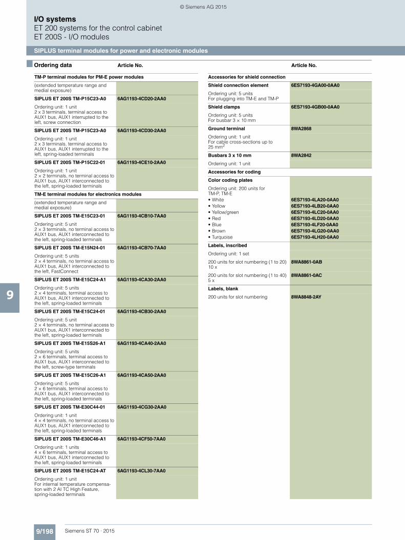
9/198 Siemens ST 70 · 2015
9
I/O systemsET 200 systems for the control cabinetET 200S - I/O modules
SIPLUS terminal modules for power and electronic modules
■ Ordering data Article No. Article No.
TM-P terminal modules for PM-E power modules
(extended temperature range and medial exposure)
SIPLUS ET 200S TM-P15C23-A0 6AG1193-4CD20-2AA0
Ordering unit: 1 unit2 x 3 terminals, terminal access to AUX1 bus, AUX1 interrupted to the left, screw connection
SIPLUS ET 200S TM-P15C23-A0 6AG1193-4CD30-2AA0
Ordering unit: 1 unit2 x 3 terminals, terminal access to AUX1 bus, AUX1 interrupted to the left, spring-loaded terminals
SIPLUS ET 200S TM-P15C22-01 6AG1193-4CE10-2AA0
Ordering unit: 1 unit2 × 2 terminals, no terminal access to AUX1 bus, AUX1 interconnected to the left, spring-loaded terminals
TM-E terminal modules for electronics modules
(extended temperature range and medial exposure)
SIPLUS ET 200S TM-E15C23-01 6AG1193-4CB10-7AA0
Ordering unit: 5 unit2 × 3 terminals, no terminal access to AUX1 bus, AUX1 interconnected to the left, spring-loaded terminals
SIPLUS ET 200S TM-E15N24-01 6AG1193-4CB70-7AA0
Ordering unit: 5 units2 × 4 terminals, no terminal access to AUX1 bus, AUX1 interconnected to the left, FastConnect
SIPLUS ET 200S TM-E15C24-A1 6AG1193-4CA30-2AA0
Ordering unit: 5 units2 × 4 terminals, terminal access to AUX1 bus, AUX1 interconnected to the left, spring-loaded terminals
SIPLUS ET 200S TM-E15C24-01 6AG1193-4CB30-2AA0
Ordering unit: 5 unit2 × 4 terminals, no terminal access to AUX1 bus, AUX1 interconnected to the left, spring-loaded terminals
SIPLUS ET 200S TM-E15S26-A1 6AG1193-4CA40-2AA0
Ordering unit: 5 units2 × 6 terminals, terminal access to AUX1 bus, AUX1 interconnected to the left, screw-type terminals
SIPLUS ET 200S TM-E15C26-A1 6AG1193-4CA50-2AA0
Ordering unit: 5 units2 × 6 terminals, terminal access to AUX1 bus, AUX1 interconnected to the left, spring-loaded terminals
SIPLUS ET 200S TM-E30C44-01 6AG1193-4CG30-2AA0
Ordering unit: 1 unit4 × 4 terminals, no terminal access to AUX1 bus, AUX1 interconnected to the left, spring-loaded terminals
SIPLUS ET 200S TM-E30C46-A1 6AG1193-4CF50-7AA0
Ordering unit: 1 units4 × 6 terminals, terminal access to AUX1 bus, AUX1 interconnected to the left, spring-loaded terminals
SIPLUS ET 200S TM-E15C24-AT 6AG1193-4CL30-7AA0
Ordering unit: 1 unitFor internal temperature compensa-tion with 2 AI TC High Feature, spring-loaded terminals
Accessories for shield connection
Shield connection element 6ES7193-4GA00-0AA0
Ordering unit: 5 unitsFor plugging into TM-E and TM-P
Shield clamps 6ES7193-4GB00-0AA0
Ordering unit: 5 unitsFor busbar 3 × 10 mm
Ground terminal 8WA2868
Ordering unit: 1 unitFor cable cross-sections up to 25 mm2
Busbars 3 x 10 mm 8WA2842
Ordering unit: 1 unit
Accessories for coding
Color coding plates
Ordering unit: 200 units for TM-P, TM-E• White 6ES7193-4LA20-0AA0• Yellow 6ES7193-4LB20-0AA0• Yellow/green 6ES7193-4LC20-0AA0• Red 6ES7193-4LD20-0AA0• Blue 6ES7193-4LF20-0AA0• Brown 6ES7193-4LG20-0AA0• Turquoise 6ES7193-4LH20-0AA0
Labels, inscribed
Ordering unit: 1 set
200 units for slot numbering (1 to 20) 10 x
8WA8861-0AB
200 units for slot numbering (1 to 40) 5 x
8WA8861-0AC
Labels, blank
200 units for slot numbering 8WA8848-2AY
ST70_2015_Kap09_EN.book Seite 198 Donnerstag, 21. Mai 2015 11:58 11
© Siemens AG 2015

9/199Siemens ST 70 · 2015
9
I/O systemsET 200 systems for the control cabinet
ET 200S - Fail-safe I/O modules
Introduction
■ Overview
The fail-safe SIMATIC S7 CPUs, plus the fail-safe signal modules of SIMATIC ET 200S / ET200 / 200pro / ET200eco and ET200M have been specially developed for distributed applications in manufacturing systems. Thanks to the discrete structure of the F I/Os, safety technology is only applied where actually required. The new system replaces conventional electromechanical components, such as:• Freely programmable safe linking of sensors to actuators;• Selective safe shutdown of actuators;• Hybrid configurations of F modules (F stands for fail-safe) and
standard modules in a station;• Single-bus concept, F signals and standard signals are trans-
ferred over one bus medium (PROFIBUS DP, PROFINET).
Totally Integrated Automation (TIA)
Safety technology (Safety Integrated) is a component of Totally Integrated Automation resulting in the total integration of safety and standard automation (SIMATIC S7).
Whereas today, standard automation (conventional PLCs) and safety automation (electromechanics) are still separate, these two worlds are growing closer together to form one uniform, in-tegrated overall system.
Siemens can therefore present itself as a complete supplier for automation engineering for which safety technology is part of the standard automation and uniformity exists throughout the com-plete system.
ST70_2015_Kap09_EN.book Seite 199 Donnerstag, 21. Mai 2015 11:58 11
© Siemens AG 2015

9/200 Siemens ST 70 · 2015
9
I/O systemsET 200 systems for the control cabinetET 200S - Fail-safe I/O modules
PM-E F PROFIsafe F power modules
■ Overview
Fail-safe PM-E F PROFIsafe power modules for safety shutdown of standard digital output modules.• Up to 2 fail-safe digital outputs onboard (source/sink outputs,
up to 2A, up to SIL3/Cat. 4)• The standard digital output modules can be shut down up to
PL e according to ISO 13849.1 and SIL 2 (IEC 61508) (up to 10 A). The following modules can be used down-circuit of the power modules.- 2DO / 0.5 A ST, 6ES7132-4BB01-0AA0- 2 DO / 2 A ST, 6ES7132-4BB31-0AA0- 2 DO / 0.5 A HF, 6ES7132-4BB01-0AB0- 2 DO / 2 A HF, 6ES7132-4BB31-0AB0- 4 DO / 0.5 A ST, 6ES7132-4BD01-0AA0- 4 DO / 2 A ST, 6ES7132-4BD31-0AA0
The modules support PROFIsafe, both in PROFIBUS, and in PROFINET configurations. They can be used with all fail-safe SIMATIC S7-CPUs.
■ Technical specifications
Article number 6ES7138-4CF03-0AB0 6ES7138-4CF42-0AB0
ET200S, POWERMOD. PM-E F PM, DC24V ET200S, POWERMOD. PM-E F PP, DC24V
Product type designation
Supply voltage
Load voltage L+
• Rated value (DC) 24 V 24 V
• Reverse polarity protection No No
Input current
from load voltage L+ (without load), max.
typ. 100 mA typ. 100 mA
from backplane bus 24 V DC, max. 28 mA 28 mA
Current carrying capacity
up to 30 °C, max. 10 A
up to 40 °C, max. 10 A 8 A
up to 60 °C, max. 6 A 7 A
Power losses
Power loss, typ. 4 W 4 W
Address area
Address space per module
• without packing 5 byte; Input and output in each case 5 byte; Input and output in each case
Digital inputs
Cable length
• shielded, max. 200 m 200 m
• Unshielded, max. 200 m 200 m
Digital outputs
Number of digital outputs 2 1; Relays
short-circuit protection Yes; Electronic No
• Response threshold, typ. Response threshold (short-circuit): 5 to 12 A; response threshold (external short-circuit to ground): 5 to 12 A; response threshold (external short-circuit to P potential): 25 to 45 A
Limitation of inductive shutdown voltage to
L+ (-2x 47 V)
Controlling a digital input No Yes
ST70_2015_Kap09_EN.book Seite 200 Donnerstag, 21. Mai 2015 11:58 11
© Siemens AG 2015

9/201Siemens ST 70 · 2015
9
■ Technical specifications (continued)
I/O systemsET 200 systems for the control cabinet
ET 200S - Fail-safe I/O modules
PM-E F PROFIsafe F power modules
Switching capacity of the outputs
• on lamp load, max. 10 W 100 W
Load resistance range
• lower limit 12 Ω• upper limit 1 kΩOutput voltage
• for signal "1", min. L+ (-2,0 V), current sourcing switch: L+ (-1,5 V), voltage drop on current sinking switch: max. 0.5 V
Output current
• for signal "1" rated value 2 A
• for signal "1" permissible range for 0 to 60 °C, min.
20 mA
• for signal "1" permissible range for 0 to 60 °C, max.
2.4 A
• for signal "0" residual current, max. 0.5 mA
Parallel switching of 2 outputs
• for increased power No
• for redundant control of a load No
Switching frequency
• with resistive load, max. 30 Hz 2 Hz
• with inductive load, max. 0.1 Hz 0.1 Hz; with inductive load to IEC 947-5-1, DC-13 / AC-15
• on lamp load, max. 10 Hz 2 Hz
Aggregate current of outputs (per group)
horizontal installation
- up to 40 °C, max. 10 A 10 A
- up to 55 °C, max. 7 A 8 A
- up to 60 °C, max. 6 A 7 A
vertical installation
- up to 40 °C, max. 6 A 8 A
Relay outputs
Switching capacity of contacts
- at ohmic load, up to 50 °C, max. 10 A 10 A
Cable length
• shielded, max. 200 m
• Unshielded, max. 200 m
Article number 6ES7138-4CF03-0AB0 6ES7138-4CF42-0AB0
ET200S, POWERMOD. PM-E F PM, DC24V ET200S, POWERMOD. PM-E F PP, DC24V
ST70_2015_Kap09_EN.book Seite 201 Donnerstag, 21. Mai 2015 11:58 11
© Siemens AG 2015

9/202 Siemens ST 70 · 2015
9
■ Technical specifications (continued)
I/O systemsET 200 systems for the control cabinetET 200S - Fail-safe I/O modules
PM-E F PROFIsafe F power modules
Interrupts/diagnostics/status information
Diagnostic messages
• Diagnostic functions Yes Yes
• Diagnostic information readable Yes Yes
• Diagnostics Yes
• Wire break Yes No
• Short circuit Yes Yes
• Missing load voltage Yes Yes
Diagnostics indication LED
• Rated load voltage PWR (green) Yes Yes
• Group error SF (red) Yes Yes
• Status indicator digital output (green)
Yes Yes
Galvanic isolation
Galvanic isolation digital outputs
• between the channels No No
• between the channels and the backplane bus
Yes Yes
• between the channels and the load voltage L+
No No
Isolation
Isolation checked with 500 V DC 500 V DC
tested with
• Channels against backplane bus and load voltage L+
500 V DC 500 V DC
Standards, approvals, certificates
Highest safety class achievable in safety mode
• acc. to EN 954 4 4
• SIL according to IEC 61508 Up to SIL 3 With Std-DO: Max. SIL 2, without Std-DO max. SIL 3 depending on configuration
Dimensions
Width 30 mm 30 mm
Height 81 mm 81 mm
Depth 52 mm 52 mm
Weights
Weight, approx. 88 g 80 g
Article number 6ES7138-4CF03-0AB0 6ES7138-4CF42-0AB0
ET200S, POWERMOD. PM-E F PM, DC24V ET200S, POWERMOD. PM-E F PP, DC24V
ST70_2015_Kap09_EN.book Seite 202 Donnerstag, 21. Mai 2015 11:58 11
© Siemens AG 2015

9/203Siemens ST 70 · 2015
9
I/O systemsET 200 systems for the control cabinet
ET 200S - Fail-safe I/O modules
PM-E F PROFIsafe F power modules
■ Ordering data Article No. Article No.
1) For up-to-date information and download availability, see:http://www.siemens.com/tia-online-software-delivery
PM-E F pm PROFIsafe power module, 24 V DC
6ES7138-4CF03-0AB0
For safe shutdown of digital output modules
PM-E F pp PROFIsafe power module, 24 V DC
6ES7138-4CF42-0AB0
For safe shutdown of digital output modules
Accessories
IM 151-1 HIGH FEATURE interface module
6ES7151-1BA02-0AB0
For ET 200S; transfer rate up to 12 Mbit/s; data volumes 244 bytes each for I/O, up to 63 modules can be connected; connection of PROFIsafe modules, isochronous mode; bus connection via 9-pin Sub-D incl. terminating module
IM 151-3 PN HF interface module 6ES7151-3BA23-0AB0
For ET 200S; transfer rate up to 100 Mbit/s; max. 63 I/O modules up to 2 m wide can be connected; 2 x bus connection via RJ45 con-nector, incl. terminating module
IM 151-3 PN FO interface module 6ES7151-3BB23-0AB0
For ET 200S; 2 PROFINET FO interfaces, integrated 2-port switch, max. 63 I/O modules up to 2 m wide can be connected, incl. terminating module
Terminal modules for power modules
TM-P30S44-A0 6ES7193-4CK20-0AA0
Ordering unit 1 item 7 x 2 terminals, terminal access to AUX1 bus, AUX1 interrupted to the left, screw-type terminals for PM-E F PROFIsafe
TM-P30C44-A0 6ES7193-4CK30-0AA0
Ordering unit 1 item 7 x 2 terminals, terminal access to AUX1 bus, AUX1 interrupted to the left, spring-loaded terminals for PM-E F PROFIsafe
S7 Distributed Safety programming tool V5.4
Task: Engineering tool for configuring fail-safe user programs for SIMATIC S7-300F, S7-400F, WinAC RTX F, ET 200S, ET 200M, ET 200iSP, ET 200pro, ET 200eco Requirement: STEP 7 V5.3 SP3 and higher
Floating license 6ES7833-1FC02-0YA5
Floating license for 1 user, license key download without software or documentation1); e-mail address required for delivery
6ES7833-1FC02-0YH5
S7 Distributed Safety Upgrade
From V5.x to V5.4; floating license for 1 user
6ES7833-1FC02-0YE5
STEP 7 Safety Advanced V13 SP1
Task:Engineering tool for configuring fail-safe user programs for SIMATIC S7-1200 FC, S7-1500F, S7-300F, S7-400F, WinAC RTX F, ET 200SP F Controller, ET 200SP, ET 200S, ET 200M, ET 200iSP, ET 200pro, ET 200eco Requirement:STEP 7 Professional V13 SP1
Floating license for 1 user 6ES7833-1FA13-0YA5
Floating license for 1 user, license key download without software or documentation1); e-mail address required for delivery
6ES7833-1FA13-0YH5
SIMATIC Manual Collection 6ES7998-8XC01-8YE0
Electronic manuals on DVD, five languages: S7-200/300/400, C7, LOGO!, SIMATIC DP, PC, PG, STEP 7, engineering software, runtime software, PCS 7, SIMATIC HMI, SIMATIC NET
SIMATIC Manual Collection update service for 1 year
6ES7998-8XC01-8YE2
ST70_2015_Kap09_EN.book Seite 203 Donnerstag, 21. Mai 2015 11:58 11
© Siemens AG 2015

9/204 Siemens ST 70 · 2015
9
I/O systemsET 200 systems for the control cabinetET 200S - Fail-safe I/O modules
F electronic modules
■ Overview
F electronic modules are digital inputs/outputs for the fail-safe SIMATIC S7 systems.
Fail-safe digital input module• For fail-safe reading of sensor information (1 or 2 channels) • Provides integral discrepancy evaluation for 2-out-of-2 signals • 2 internal sensor supplies (incl. test function) onboard • Certified up to SIL 3 (IEC 61508) and PL e (ISO 13849)
Fail-safe digital output module• Fail-safe 2-channel activation (sink/source output) by
actuators • Actuators can be driven by up to 2 A • Certified up to SIL 3 (IEC 61508), PL e (ISO 13849)
Fail-safe digital hybrid module• 4 fail-safe inputs/3 fail-safe outputs• Certified up to SIL 2 (IEC 61508) and PL d (ISO 13849)
The modules support PROFIsafe, both in PROFIBUS, and in PROFINET configurations. They can be used with all fail-safe SIMATIC S7 CPUs.
■ Technical specifications
Article number 6ES7138-4FA05-0AB0
ET200S, EL-MOD., 4/8 F-DI, DC 24V
Product type designation
Supply voltage
Rated value (DC)
• 24 V DC Yes
permissible range, lower limit (DC) 20.4 V
permissible range, upper limit (DC) 28.8 V
Encoder supply
Number of outputs 2
Type of output voltage min. L+ (-1.5 V)
short-circuit protection Yes; Electronic (response threshold 0.7 A to 1.8 A)
Output current
• nominal 300 mA
• permissible range 0 to 300 mA
Address area
Occupied address area
• Inputs 6 byte
• Outputs 4 byte
Digital inputs
Number of digital inputs 8; 8 (one-channel); 4 (two-channel)
Input characteristic curve in accor-dance with IEC 61131, type 1
Yes
Number of simultaneously controllable inputs
• Number of simultaneously controllable inputs
8
Input voltage
• Type of input voltage DC
• Rated value (DC) 24 V
Input current
• for signal "1", typ. 3.7 mA
Input delay (for rated value of input voltage)
for standard inputs
- Parameterizable Yes
- at "0" to "1", min. 0.3 ms
- at "0" to "1", max. 17 ms
- at "1" to "0", min. 0.3 ms
- at "1" to "0", max. 17 ms
Cable length
• shielded, max. 500 m
• Unshielded, max. 500 m
Encoder
Connectable encoders
• 2-wire sensor No
- Permissible quiescent current (2-wire sensor), max.
0.6 mA; max.
Interrupts/diagnostics/status information
Alarms
• Diagnostic alarm Yes
Diagnostic messages
• Diagnostic functions Yes
• Diagnostic information readable Yes
• Short circuit Yes
Diagnostics indication LED
• Group error SF (red) Yes
• Status indicator digital input (green) Yes
Galvanic isolation
Galvanic isolation digital inputs
• between the channels No
• between the channels and the backplane bus
Yes
• between the channels and the load voltage L+
No
Article number 6ES7138-4FA05-0AB0
ET200S, EL-MOD., 4/8 F-DI, DC 24V
ST70_2015_Kap09_EN.book Seite 204 Donnerstag, 21. Mai 2015 11:58 11
© Siemens AG 2015

9/205Siemens ST 70 · 2015
9
■ Technical specifications (continued)
I/O systemsET 200 systems for the control cabinet
ET 200S - Fail-safe I/O modules
F electronic modules
Standards, approvals, certificates
Highest safety class achievable in safety mode
• SIL according to IEC 61508 SIL 2 (single-channel), SIL 3 (two-channel)
Dimensions
Width 30 mm
Height 81 mm
Depth 52 mm
Weights
Weight, approx. 78 g
Article number 6ES7138-4FB04-0AB0
ET200S, EL-MOD., 4 F-DO, DC 24V/2A
Product type designation
Supply voltage
Load voltage L+
• Rated value (DC) 24 V
• Reverse polarity protection No
Input current
from load voltage L+ (without load), max.
typ. 100 mA
from backplane bus 3.3 V DC, max. 28 mA
Digital outputs
Number of digital outputs 4
short-circuit protection Yes
Limitation of inductive shutdown voltage to
Typ. (2L+) -47 V
Controlling a digital input No
Switching capacity of the outputs
• on lamp load, max. 10 W
Load resistance range
• lower limit 12 Ω• upper limit 1 k?
Output voltage
• for signal "1", min. L+ (-2,0 V), current sourcing switch: L+ (-1,5 V), voltage drop on current sinking switch: max. 0.5 V
Output current
• for signal "1" rated value 2 A
• for signal "1" permissible range for 0 to 60 °C, min.
20 mA
• for signal "1" permissible range for 0 to 60 °C, max.
2.4 A
• for signal "0" residual current, max. 0.5 mA; P- and M-switching
Parallel switching of 2 outputs
• for increased power No
• for redundant control of a load No
Switching frequency
• with resistive load, max. 30 Hz; Symmetrical
• with inductive load, max. 0.1 Hz; Symmetrical
• on lamp load, max. 10 Hz; Symmetrical
horizontal installation
- up to 40 °C, max. 6 A
- up to 55 °C, max. 5 A
- up to 60 °C, max. 4 A
vertical installation
- up to 40 °C, max. 4 A
Cable length
• shielded, max. 500 m
• Unshielded, max. 500 m
Article number 6ES7138-4FA05-0AB0
ET200S, EL-MOD., 4/8 F-DI, DC 24V
Interrupts/diagnostics/status information
Diagnostic messages
• Diagnostic functions Yes
• Wire break Yes
• Short circuit Yes
Diagnostics indication LED
• Group error SF (red) Yes
• Status indicator digital output (green)
Yes
Galvanic isolation
Galvanic isolation digital outputs
• between the channels No
• between the channels and the backplane bus
Yes
• between the channels and the load voltage L+
No
Isolation
tested with
• Load voltage L+ against backplane bus
2545 V DC
Standards, approvals, certificates
Highest safety class achievable in safety mode
• SIL according to IEC 61508 SIL 3
Dimensions
Width 30 mm
Height 81 mm
Depth 52 mm
Weights
Weight, approx. 85 g
Article number 6ES7138-4FC01-0AB0
ET200S, EL-MOD.,4 F-DI/3 F-DO, DC 24V/2A
Product type designation
Supply voltage
permissible range, lower limit (DC) 20.4 V
permissible range, upper limit (DC) 28.8 V
Digital inputs
Number of digital inputs 4
Input voltage
• Type of input voltage DC
Standards, approvals, certificates
Highest safety class achievable in safety mode
• SIL according to IEC 61508 2
Dimensions
Width 30 mm
Height 81 mm
Depth 52 mm
Article number 6ES7138-4FB04-0AB0
ET200S, EL-MOD., 4 F-DO, DC 24V/2A
ST70_2015_Kap09_EN.book Seite 205 Donnerstag, 21. Mai 2015 11:58 11
© Siemens AG 2015

9/206 Siemens ST 70 · 2015
9
I/O systemsET 200 systems for the control cabinetET 200S - Fail-safe I/O modules
F electronic modules
■ Ordering data Article No. Article No.
1) For up-to-date information and download availability, see:http://www.siemens.com/tia-online-software-delivery
4/8 F-DI PROFIsafe 24 V DC electronic module
6ES7138-4FA05-0AB0
30 mm wide, up to PL e according to ISO 13849.1
4 F-DO PROFIsafe 24 V DC/2A electronic module
6ES7138-4FB04-0AB0
30 mm wide, up to PL e according to ISO 13849.1
4 F-DI / 3 F-DO PROFIsafe 24 V DC/2A electronic module
6ES7138-4FC01-0AB0
30 mm wide, up to PL e according to ISO 13849.1 / SIL 2 (IEC 62061)
Accessories
Terminal modules for electronic modules
See F terminal modules
IM 151-1 High Feature interface module
6ES7151-1BA02-0AB0
For ET 200S; transmission rate up to 12 Mbit/s; max. 63 modules can be connected, with isochronous mode, bus connection via 9-pin Sub-D connector incl. terminating module
IM 151-3 PN HF interface module 6ES7151-3BA23-0AB0
For ET 200S; transfer rate up to 100 Mbit/s; max. 63 I/O modules up to 2 m wide can be connected; 2 x bus connection via RJ45 con-nector, incl. terminating module
IM 151-3 PN FO interface module 6ES7151-3BB23-0AB0
For ET 200S; 2 PROFINET FO interfaces, integrated 2-port switch, max. 63 I/O modules up to 2 m wide can be connected, incl. terminating module
S7 Distributed Safety programming tool V5.4
Task: Engineering tool for configuring fail-safe user programs for SIMATIC S7-300F, S7-400F, WinAC RTX F, ET 200S, ET 200M, ET 200iSP, ET 200pro, ET 200eco Requirement: STEP 7 V5.3 SP3 and higher
Floating license 6ES7833-1FC02-0YA5
Floating license for 1 user, license key download without software or documentation1); e-mail address required for delivery
6ES7833-1FC02-0YH5
S7 Distributed Safety Upgrade
From V5.x to V5.4; floating license for 1 user
6ES7833-1FC02-0YE5
STEP 7 Safety Advanced V13 SP1
Task:Engineering tool for configuring fail-safe user programs for SIMATIC S7-1200 FC, S7-1500F, S7-300F, S7-400F, WinAC RTX F, ET 200SP F Controller, ET 200SP, ET 200S, ET 200M, ET 200iSP, ET 200pro, ET 200eco Requirement:STEP 7 Professional V13 SP1
Floating license for 1 user 6ES7833-1FA13-0YA5
Floating license for 1 user, license key download without software or documentation1); e-mail address required for delivery
6ES7833-1FA13-0YH5
SIMATIC Manual Collection 6ES7998-8XC01-8YE0
Electronic manuals on DVD, multi-language: S7-200, TD 200, S7-300, M7-300, C7, S7-400, M7-400, STEP 7, Engineering Tools, Runtime Software, SIMATIC DP (Distributed I/O), SIMATIC HMI (Human Machine Interface), SIMATIC NET (Industrial Communication)
SIMATIC Manual Collection – Update service for 1 year
6ES7998-8XC01-8YE2
Scope of delivery: Current DVD "S7 Manual Collection" and the three subsequent updates
ST70_2015_Kap09_EN.book Seite 206 Donnerstag, 21. Mai 2015 11:58 11
© Siemens AG 2015

9/207Siemens ST 70 · 2015
9
I/O systemsET 200 systems for the control cabinet
ET 200S - Fail-safe I/O modules
F electronic module relays
■ Overview
The digital F electronic module relay 1 F-RO 24 V DC / 5 A 24 to 230 V AC / 5A has the following characteristics:• 1 relay output (2 NO contacts) • Output current 5 A • Rated load voltage 24 V DC and 24 to 230 V AC • The control circuit of the two safety relays must be routed from
the outside to the respective terminals.
The attainable safety integrity level is SIL 3 (IEC 61508), when the control of the F-RO module is implemented via a fail-safe output (e.g. EM 4F-DO 24 V DC/2A PROFIsafe).
■ Technical specifications
Article number 6ES7138-4FR00-0AA0
ET200S, 1 F-RO DC24V/5A AC24..230V/5A
Product type designation
Supply voltage
Load voltage L+
• Rated value (DC) 24 V; Supply via fail-safe output, e.g. of an F-DO
Input current
from load voltage L+ (without load), max.
100 mA; from control voltage
from backplane bus 3.3 V DC, max. 10 mA
Power losses
Power loss, typ. 2.1 W
Address area
Address space per module
• with packing 2 bit
• without packing 1 byte
Digital outputs
Number of digital outputs 1
short-circuit protection No
Controlling a digital input Yes
Output current
• for signal "1" rated value 5 A
• for signal "1" minimum load current 5 mA
Switching frequency
• with resistive load, max. 2 Hz
• with inductive load, max. 0.1 Hz
horizontal installation
- up to 40 °C, max. 8 A
- up to 55 °C, max. 6 A; At 50 °C
- up to 60 °C, max. 5 A; up to max. 24.8 V
vertical installation
- up to 40 °C, max. 6 A
Relay outputs
Switching capacity of contacts
- Thermal continuous current, max. 5 A
Cable length
• shielded, max. 200 m
• Unshielded, max. 200 m
Diagnostics indication LED
• Status indicator digital output (green)
Yes
Galvanic isolation
Galvanic isolation digital outputs
• between the channels Yes
• between the channels and the backplane bus
Yes
• between the channels and the load voltage L+
Yes; between channels and control voltage
Standards, approvals, certificates
Highest safety class achievable in safety mode
• acc. to EN 954 4
• SIL according to IEC 61508 Up to SIL 3
Dimensions
Width 30 mm
Height 81 mm
Depth 52 mm
Weights
Weight, approx. 90 g
Article number 6ES7138-4FR00-0AA0
ET200S, 1 F-RO DC24V/5A AC24..230V/5A
ST70_2015_Kap09_EN.book Seite 207 Donnerstag, 21. Mai 2015 11:58 11
© Siemens AG 2015

9/208 Siemens ST 70 · 2015
9
I/O systemsET 200 systems for the control cabinetET 200S - Fail-safe I/O modules
F electronic module relays
■ Ordering data Article No. Article No.
1) For up-to-date information and download availability, see:http://www.siemens.com/tia-online-software-delivery
1 F-RO F electronic module relay 6ES7138-4FR00-0AA0
Relay output (2 NO contacts), output current 5 A, load voltages DC 24 V and AC 24 ... 230 V, can be used at up to Category 4/SIL3, if controlled via F-DO
Accessories
Terminal modules for electronic modules
See F terminal modules
IM 151-1 High Feature interface module
6ES7151-1BA02-0AB0
For ET 200S; transmission rate up to 12 Mbit/s; max. 63 modules can be connected, with isochronous mode, bus connection via 9-pin Sub-D connector incl. terminating module
IM 151-3 PN HF interface module 6ES7151-3BA23-0AB0
For ET 200S; transfer rate up to 100 Mbit/s; max. 63 I/O modules up to 2 m wide can be connected; 2 x bus connection via RJ45 connector, incl. terminating module
IM 151-3 PN FO interface module 6ES7151-3BB23-0AB0
For ET 200S; 2 PROFINET FO interfaces, integrated 2-port switch, max. 63 I/O modules up to 2 m wide can be connected, incl. terminating module
S7 Distributed Safety programming tool V5.4
Task: Engineering tool for configuring fail-safe user programs for SIMATIC S7-300F, S7-400F, WinAC RTX F, ET 200S, ET 200M, ET 200iSP, ET 200pro, ET 200eco Requirement: STEP 7 V5.3 SP3 and higher
Floating license 6ES7833-1FC02-0YA5
Floating license for 1 user, license key download without software or documentation1); e-mail address required for delivery
6ES7833-1FC02-0YH5
S7 Distributed Safety Upgrade
From V5.x to V5.4; floating license for 1 user
6ES7833-1FC02-0YE5
STEP 7 Safety Advanced V13 SP1
Task:Engineering tool for configuring fail-safe user programs for SIMATIC S7-1200 FC, S7-1500F, S7-300F, S7-400F, WinAC RTX F, ET 200SP F Controller, ET 200SP, ET 200S, ET 200M, ET 200iSP, ET 200pro, ET 200ecoRequirement:STEP 7 Professional V13 SP1
Floating license for 1 user 6ES7833-1FA13-0YA5
Floating license for 1 user, license key download without software or documentation1); e-mail address required for delivery
6ES7833-1FA13-0YH5
SIMATIC Manual Collection 6ES7998-8XC01-8YE0
Electronic manuals on DVD, multi-language: S7-200, TD 200, S7-300, M7-300, C7, S7-400, M7-400, STEP 7, Engineering Tools, Runtime Soft-ware, SIMATIC DP (Distributed I/O), SIMATIC HMI (Human Machine Interface), SIMATIC NET (Industrial Communication)
SIMATIC Manual Collection – Update service for 1 year
6ES7998-8XC01-8YE2
Scope of delivery: Current DVD "S7 Manual Collection" and the three subsequent updates
ST70_2015_Kap09_EN.book Seite 208 Donnerstag, 21. Mai 2015 11:58 11
© Siemens AG 2015

9/209Siemens ST 70 · 2015
9
I/O systemsET 200 systems for the control cabinet
ET 200S - Fail-safe I/O modules
F terminal modules
■ Overview
• Mechanical modules as receptacles for the electronic modules
• For setting up permanent wiring through self-configuring voltage buses
• Keyed connection technology to ensure an enhanced vibration resistance of up to 5 g
• Different versions to accommodate power modules and electronic modules
• Replaceable terminal box (even within the station network)• Automatic coding of the electronic modules• Self-shielding of the backplane bus for high data security• Color coding facility for the terminals and for identifying the
slot numbers• Alternatively available with screw-type or spring-loaded
terminals• For up to 60 % faster process wiring also with FastConnect
connection method (av. soon)
■ Ordering data Article No. Article No.
F-terminal modules for power modules
TM-P15S23-A1
2 × 3 terminals, terminal access to AUX1 bus, AUX1 interconnected to the left, screw-type terminals
Ordering unit 1 item 6ES7193-4CC20-0AA0
Ordering unit 5 items 6ES7193-4CC20-1AA0
TM-P15C23-A1
2 × 3 terminals, terminal access to AUX1 bus, AUX1 interconnected to the left, spring-loaded terminals
Ordering unit 1 item 6ES7193-4CC30-0AA0
Ordering unit 5 items 6ES7193-4CC30-1AA0
TM-P15S23-A0
2 × 3 terminals, terminal access to AUX1 bus, AUX1 interrupted to the left, screw-type terminals
Ordering unit 1 item 6ES7193-4CD20-0AA0
Ordering unit 5 items 6ES7193-4CD20-1AA0
TM-P15C23-A0
2 × 3 terminals, terminal access to AUX1 bus, AUX1 interrupted to the left, spring-loaded terminals
Ordering unit 1 item 6ES7193-4CD30-0AA0
Ordering unit 5 items 6ES7193-4CD30-1AA0
TM-P15S22-01
2 x 2 terminals, no terminal access to AUX1 bus, AUX1 interconnected to the left, screw-type terminals
Ordering unit 1 item 6ES7193-4CE00-0AA0
Ordering unit 5 items 6ES7193-4CE00-1AA0
TM-P15C22-01
2 × 2 terminals, no terminal access to AUX1 bus, AUX1 interconnected to the left, spring-loaded terminals
Ordering unit 1 item 6ES7193-4CE10-0AA0
Ordering unit 5 items 6ES7193-4CE10-1AA0
TM-P30S44-A0 6ES7193-4CK20-0AA0
Ordering unit 1 item 7 x 2 terminals, terminal access to AUX1 bus, AUX1 interrupted to the left, screw-type terminals for PM-E F PROFIsafe
TM-P30C44-A0 6ES7193-4CK30-0AA0
Ordering unit 1 item 7 x 2 terminals, terminal access to AUX1 bus, AUX1 interrupted to the left, spring-loaded terminals for PM-E F PROFIsafe
ST70_2015_Kap09_EN.book Seite 209 Donnerstag, 21. Mai 2015 11:58 11
© Siemens AG 2015

9/210 Siemens ST 70 · 2015
9
■ Ordering data Article No. Article No.
I/O systemsET 200 systems for the control cabinetET 200S - Fail-safe I/O modules
F terminal modules
F-terminal modules for electronic modules
TM-E30S44-01 6ES7193-4CG20-0AA0
Ordering unit 1 item 4 x 4 terminals, no terminal access to AUX1 bus, AUX1 interconnected to the left, screw-type terminals
TM-E30C44-01 6ES7193-4CG30-0AA0
Ordering unit 1 item 4 x 4 terminals, no terminal access to AUX1 bus, AUX1 interconnected to the left, spring-loaded terminals
TM-E30S46-A1 6ES7193-4CF40-0AA0
Ordering unit 1 item 4 x 6 terminals, terminal access to AUX1 bus, AUX1 interconnected to the left, screw-type terminals
TM-E30C46-A1 6ES7193-4CF50-0AA0
Ordering unit 1 item 4 x 6 terminals, terminal access to AUX1 bus, AUX1 interconnected to the left, spring-loaded terminals
Accessories
Color coding plates
Ordering unit 200 pieces for TM-P, TM-E• white 6ES7193-4LA20-0AA0• yellow 6ES7193-4LB20-0AA0• yellow/green 6ES7193-4LC20-0AA0• red 6ES7193-4LD20-0AA0• blue 6ES7193-4LF20-0AA0• brown 6ES7193-4LG20-0AA0• turquoise 6ES7193-4LH20-0AA0
Grounding terminal 8WA2868
Ordering unit 1 item
For cable cross-sections up to 25 mm2
3 × 10 mm busbars 8WA2842
Ordering unit 1 item
Labels, inscribed
Ordering unit 1 set• 200 items for slot numbering
(1 to 20) 10 ×8WA8861-0AB
• 200 items for slot numbering (1 to 40) 5 ×
8WA8861-0AC
• 100 items for slot numbering, inscription in plain text
8WA8848-0XA
Labels, blank
200 items for slot numbering 8WA8848-2AY
ST70_2015_Kap09_EN.book Seite 210 Donnerstag, 21. Mai 2015 11:58 11
© Siemens AG 2015

9/211Siemens ST 70 · 2015
9
I/O systemsET 200 systems for the control cabinet
ET 200S - Fail-safe I/O modules
SIPLUS F electronic modules
■ Overview
Digital inputs/outputs for the fail-safe SIMATIC S7 systems
Fail-safe digital input module• For fail-safe reading of sensor information (1 or 2 channels) • Provides integral discrepancy evaluation for 2-out-of-2 signals • 2 internal sensor supplies (incl. test function) onboard
Fail-safe digital output module• Fail-safe 2-channel activation (sink/source output) by
actuators • Actuators can be controlled up to 2 A
All modules are certified up to Cat. 4 (EN 954-1) and up to SIL 3 (IEC 61508).
The modules support PROFIsafe, in both PROFIBUS and PROFINET configurations.
They can be used with all fail-safe SIMATIC S7-CPUs.
Note:
SIPLUS extreme products are based on SIMATIC standard products. The contents listed here were taken from the respec-tive standard products. SIPLUS extreme specific information was added.
For technical documentation on SIPLUS, see:
http://www.siemens.com/siplus-extreme
■ Technical specifications
Article number 6AG1138-4FA05-2AB0
Based on 6ES7138-4FA05-0AB0
SIPLUS ET200S EM F-DI 24V PROFISAFE
Ambient conditions
Ambient temperature in operation
• Min. -25 °C
• max. 60 °C
Extended ambient conditions
• Relative to ambient temperature-atmospheric pressure-installation altitude
Tmin ... Tmax at 1080 hPa ... 795 hPa (-1000 m ... +2000 m)
• At cold restart, min. -25 °C
Relative humidity
- With condensation, tested in accordance with IEC 60068-2-38, max.
100 %; RH incl. condensation/frost (no commissioning under conden-sation conditions)
Resistance
- against biologically active substances / conformity with EN 60721-3-3
Yes; Class 3B2 mold, fungus and dry rot spores (with the exception of fauna). The supplied connector covers must remain on the unused interfaces during operation!
- against chemically active substances / conformity with EN 60721-3-3
Yes; Class 3C4 incl. salt spray according to EN 60068-2-52 (degree of severity 3). The supplied connector covers must remain on the unused interfaces during operation!
- against mechanically active substances / conformity with EN 60721-3-3
Yes; Class 3S4 incl. sand, dust. The supplied connector covers must remain on the unused interfaces during operation!
Article number 6AG1138-4FB04-2AB0
Based on 6ES7138-4FB04-0AB0
SIPLUS ET200S EM F-DO 24V PROFISAFE
Ambient conditions
Ambient temperature in operation
• Min. -25 °C
• max. 60 °C
Extended ambient conditions
• Relative to ambient temperature-atmospheric pressure-installation altitude
Tmin ... Tmax at 1080 hPa ... 795 hPa (-1000 m ... +2000 m)
• At cold restart, min. -25 °C
Relative humidity
- With condensation, tested in accordance with IEC 60068-2-38, max.
100 %; RH incl. condensation/frost (no commissioning under conden-sation conditions)
Resistance
- against biologically active substances / conformity with EN 60721-3-3
Yes; Class 3B2 mold, fungus and dry rot spores (with the exception of fauna). The supplied connector covers must remain on the unused interfaces during operation!
- against chemically active substances / conformity with EN 60721-3-3
Yes; Class 3C4 incl. salt spray according to EN 60068-2-52 (degree of severity 3). The supplied connector covers must remain on the unused interfaces during operation!
- against mechanically active substances / conformity with EN 60721-3-3
Yes; Class 3S4 incl. sand, dust. The supplied connector covers must remain on the unused interfaces during operation!
ST70_2015_Kap09_EN.book Seite 211 Donnerstag, 21. Mai 2015 11:58 11
© Siemens AG 2015

9/212 Siemens ST 70 · 2015
9
I/O systemsET 200 systems for the control cabinetET 200S - Fail-safe I/O modules
SIPLUS F electronic modules
■ Ordering data Article No. Article No.
SIPLUS F electronic modules
(extended temperature range and medial exposure)
4/8 F DI PROFIsafe 24 V DC electronic module
6AG1138-4FA05-2AB0
30 mm construction width, up to Category 4 (EN 954-1)
4 F-DO PROFIsafe 24 V DC/2 A electronic module
6AG1138-4FB04-2AB0
30 mm construction width, up to Category 4 (EN 954-1)
Accessories See SIMATIC F electronic modules, page 9/210
ST70_2015_Kap09_EN.book Seite 212 Donnerstag, 21. Mai 2015 11:58 11
© Siemens AG 2015

9/213Siemens ST 70 · 2015
9
I/O systemsET 200 systems for the control cabinet
ET 200S - IO-Link master modules
4SI IO-Link electronic module
■ Overview
The electronic module 4SI IO-Link is an IO-Link master and supports the easy integration of sensors and actuators from different manufacturers in the multifunctional, distributed I/O system SIMATIC ET 200S on a total of four ports.
Features• Up to four IO-Link devices can be connected to each IO-Link
master module (three-wire connection). 3RA6 compact starters or load feeders with 3RA27 function modules can even be bundled in groups of four devices each at an IO-Link port. This means that up to 16 load feeders can be connected to the controller at an IO-Link master module.
• Up to 4 standard sensors (2-wire/3-wire connection) can be connected.
• The electronic module 4SI IO-Link is 15 mm in width and can be used with the following universal terminal modules: - TM-E15S26-A1 (screw terminal)- TM-E15C26-A1 (spring-loaded terminal)- TM-E15N26-A1 (FastConnect)
• Supports firmware update (STEP 7 V5.4 SP4 and higher)• Corresponds to IO-Link specification V1.0
■ Ordering data Article No. Article No.
4SI IO-Link electronic module 6ES7138-4GA50-0AB0
IO-Link master, screw terminal, spring-loaded terminal or FastConnect connection method
Accessories
Universal terminal module for ET 200S• TM-E15S26-A1
with screw terminal6ES7193-4CA40-0AA0
• TM-E15C26-A1 with spring-loaded terminal
6ES7193-4CA50-0AA0
• TM-E15N26-A1 with FastConnect
6ES7193-4CA80-0AA0
ST70_2015_Kap09_EN.book Seite 213 Donnerstag, 21. Mai 2015 11:58 11
© Siemens AG 2015

9/214 Siemens ST 70 · 2015
9
I/O systemsET 200 systems for the control cabinetET 200S - IO-Link master modules
4SI SIRIUS electronic module
■ Overview
The electronic module 4SI SIRIUS supports easy, cost-effective connection of SIRIUS switching devices with IO-Link to the mul-tifunctional, distributed I/O system SIMATIC ET 200S on a total of four ports.
Features• Up to 4 SIRIUS devices can be connected to the 4 ports of
each 4SI SIRIUS electronic module.3RA6 compact starters or load feeders with 3RA27 function modules can even be bundled in groups of 4 devices each at an IO-Link port. This means that up to 16 load feeders can be connected to the controller at an IO-Link master module.
• The electronic module 4SI SIRIUS is 15 mm in width and can be used with the following universal terminal modules:- TM-E15S26-A1 (screw terminal)- TM-E15C26-A1 (spring-loaded terminal)- TM-E15N26-A1 (FastConnect)
• Supports firmware updates (STEP 7 V5.4 SP5 and higher)• Corresponds to IO-Link specification V1.0
■ Ordering data Article No. Article No.
4SI SIRIUS electronic module 3RK1005-0LB00-0AA0
For the connection of SIRIUS switching devices to ET 200S; 4 ports. Screw terminal, spring-loaded terminal, or FastConnect connection method
Accessories
Universal terminal module for ET 200S• TM-E15S26-A1 with
screw terminal6ES7193-4CA40-0AA0
• TM-E15C26-A1 with spring-loaded terminal
6ES7193-4CA50-0AA0
• TM-E15N26-A1 with FastConnect 6ES7193-4CA80-0AA0
ET 200S manual for 4SI SIRIUS electronic module
Note:http://support.automation.siemens.com/WW/view/en/37856470
ST70_2015_Kap09_EN.book Seite 214 Donnerstag, 21. Mai 2015 11:58 11
© Siemens AG 2015

9/215Siemens ST 70 · 2015
I/O systemsET 200 systems for the control cabinet
ET 200S - Motor starters and Safety motor starters
General data
9
■ Overview
ET 200S motor starters in the ET 200S I/O system
The SIMATIC ET 200S is the multifunctional and bit-modularI/O system in degree of protection IP20 for exact adaptation to the automation task.
Interface modules (IM) are used for connecting the ET 200S to PROFIBUS DP or PROFINET. If interface modules with inte-grated S7-CPU are used, the ET 200S can act as a miniature controller.
The ET 200S is designed for combining with a large range of dig-ital and analog input or output modules, technology modules, IO-Link master modules, pneumatic connections, or motor start-ers and frequency converters for the control of drives.
In addition to the standard versions, SIPLUS versions are avail-able both for interface modules and I/O modules. They can be
used for an extended temperature range and increased medial loads.
Device replacement is easy and quick thanks to permanent wiring and automatic re-parameterization.
Hot swapping, i.e. the disconnection and connection of modules without prior isolation, ensures high availability of the automation system along with extensive diagnostics information.
The ET 200S motor starters are connected to the control system and parameterized through the fieldbus using either PROFIBUS or PROFINET via IM modules – available in both standard and safety-related versions.
With the ET 200S motor starters, any AC loads can be protected and switched. The communication interface makes them ideal for operation in distributed control cabinets or control enclo-sures.
Interaction of ET 200S motor starter components in the ET 200S I/O system
Interface moduleIM 151
Power modulePM-E
TM-P15 Terminal module for PM-D
Solid-state modules
Power modulePM-D
Standard direct-on-line starterDS1-x
High Feature direct-on-line starterDS1e-x HF
High Feature direct-on-line starter DS1e-x HF
Brake control module xB4
High Feature soft starter DSS1e-x HF
Terminal module for standard direct-on-line starter with infeed
TM-DS45-S32
Terminal module for High-Feature direct-on-line starter/soft starter with infeedTM-DS65-S32
Terminal module for High-Feature direct-on-line starter/soft starter without infeedTM-DS65-S31
Terminal module for standard direct-on-line starter
without infeed TM-DS45-S31
Terminal module for brake control moduleTM-xB215-S24-01
PE/N terminal blockM45-PEN-F
PE/N terminal blockM45-PEN-S
Infeed moduleM65-PEN-F
Connection moduleM65-PEN-S
NS
A0_
0045
9
ST70_2015_Kap09_EN.book Seite 215 Donnerstag, 21. Mai 2015 11:58 11
© Siemens AG 2015

9/216 Siemens ST 70 · 2015
I/O systemsET 200 systems for the control cabinetET 200S - Motor starters and Safety motor starters
General data
9
Motor starter versions
The ET 200S motor starters are available as direct-on-line, reversing or soft starter versions:• Standard motor starters up to 5.5 kW
(direct-on-line and reversing starters)• High Feature motor starters up to 7.5 kW
(direct-on-line, reversing and direct-on-line soft starters)• Failsafe motor starters up to 7.5 kW
(direct-on-line and reversing starters)- Properties of the High Feature motor starter- Failsafe functionality
Innovation of the ET 200S High Feature motor starters
The ET 200S High Feature motor starters have undergone radical innovation and now support the acyclic services on PROFIBUS and PROFINET as well as PROFIenergy on PROFINET. They are now:• Even more flexible – flexible assignment of parameters• Even better integrated in TIA (Totally Integrated Automation)• Even more transparent – through comprehensive diagnostic
data records• Even more anticipatory – through maintenance functions• Energy-efficient – through PROFIenergy
Basic functionality of the ET 200S motor starters
All versions of the ET 200S motor starters have the following functionality. Any additional specific functionality is described for the respective versions. • Fully pre-wired motor starters for switching and protecting any
AC loads up to 7.5 kW at 400 V AC and 500 V AC• With self-assembling 40/50 A power bus, i.e. the load voltage
is only fed in once for a group of motor starters• All control supply voltages connected only once, i.e. when
modules are added they are automatically connected to the next module
• Hot swapping is permissible• Inputs and outputs for activating and signaling the states are
already integrated• Control of the motor starter from the control system and of the
diagnostics status via the cyclic process image• Diagnostics capability for active monitoring of the switching
and protection functions• The signal states in the process image of the motor starter
provide information about protective devices (short circuit or overload), the switching states of contactor(s) or soft starters, and system faults.
• Interface for controlling an expansion module, e.g. brake con-trol module xB1 ... xB4 for controlling mechanical brakes in three-phase motors for 24 V DC and 500 V DC.
• Brake Control Module xB5 and xB6 for 400 V AC• Can be combined with safety technology for use in safety-
related system components (IEC 62061 and ISO 13849-1).
Mounting
As the motor starters are fully pre-wired, up to 80 % of the wiring outlay can be saved. The control cabinets can be assembled far more quickly and compactly.
Expansions are easily possible through the subsequent adding of terminal modules. With their terminal block design (10 mm²), the latter also do away with the distribution wiring otherwise re-quired. Through the permanent wiring and the "hot swapping" function (disconnection and connection during operation) a mo-tor starter can be replaced within seconds if necessary. The mo-tor starters are therefore recommendable in particular for appli-cations with special demands on availability.
Parameterization and configuration
Configuration is made easier by the bit-modular structure.
When using the ET 200S motor starters, the list of parts per load feeder is reduced to two main items: The passive terminal mod-ule and the motor starter. This makes the ET 200S ideal for mod-ular machine concepts as well.
All ET 200S motor starters are set up without fuses. Contactors and soft starters are activated through the integrated outputs. The inputs of the motor starters evaluate the signal states of the protective devices (short circuit or overload), the switching states of contactor(s) or soft starters, and system faults.
The motor starter protector signaling is freely programmable with regard to group fault signals (group fault at motor starter protector "Off"/group fault signal at motor starter protector "Off" only in case of "On" command from the motor starter).
Brake control modules and optional digital inputs and outputs
With one of the optional brake control modules (xB1-xB6), which is butt-mounted to the right of a motor starter, it is possible to control a mechanical holding brake on a three-phase motor from the process image of the motor starter.
Motors with 24 V DC brakes (xB1, xB3) as well as motors with 500 V DC brakes (xB2, xB4) can be controlled using the brake control modules xB1-xB4.
The modules xB5 (without digital input) and xB6 (with two digital inputs) have been added to the range in order to control a mechanical holding brake with a rated operational voltage of 400 V AC. A further motor brake voltage commonly found on the market is thus supported.
The 24 V DC brakes have an external supply and can be re-leased independently of the switching state of the motor starter. By contrast the 500 V DC brakes and the 400 V AC brakes usu-ally have a direct supply from the terminal board of the motor through a rectifier module and therefore cannot be released when the motor starter is switched off. These brakes cannot be used in combination with the DSS1e-x motor starter (soft starter).
The outputs of the Brake Control Modules can also be used for other purposes, e.g. for controlling DC valves.
With two digital inputs available on the brake control modules (xB3, xB4, xB6) and another two digital inputs available on the optional control module it is possible to realize autonomous spe-cial functions which work independently of the bus and the higher-level control system, e.g. as a quick stop on gate valve controls. The signals of these digital inputs are in the process image and are reported to the control system.
Power supply through terminal modules
Power is supplied through the terminal modules for motor starters:• The auxiliary voltages are fed in only once via the PM-D or
PM-DFx power module which must be connected to the left of the first motor starter.
• The load voltage is fed in at the first (left) TM-xxxxS32 terminal module of a motor starter. The other TM-xxxxS31 terminal modules are automatically supplied with power through the in-tegrated power bus when they are mounted side by side. If the power bus is utilized to its full capacity of 40 A for Standard motor starters or 50 A for High Feature motor starters, a new supply must be fed in through an additional TM-xxxxS32 ter-minal module.
ST70_2015_Kap09_EN.book Seite 216 Donnerstag, 21. Mai 2015 11:58 11
© Siemens AG 2015

9/217Siemens ST 70 · 2015
I/O systemsET 200 systems for the control cabinet
ET 200S - Motor starters and Safety motor starters
General data
9
TM-DS and TM-RS terminal modules for motor starters• Mechanical modules in which the motor starter and expansion
modules are inserted• For constructing the permanent wiring and self-assembling
voltage bus• For connecting the motor connection cables• Positive-locking connection to ensure enhanced vibration re-
sistance
Terminal modules are purely mechanical components for ac-commodating the ET 200S I/O modules. The self-assembling voltage buses integrated into the terminal modules reduce the wiring outlay to the single infeed (both of auxiliary and load volt-age). All modules following on the right are automatically sup-plied upon plugging the terminal modules together. The rugged design and keyed connection technology enables use in harsh industrial conditions.
The TM-DS and TM-RS terminal modules are available in various versions for the Standard motor starters and the High Feature motor starters.
Terminal modules with the suffix "-S32" • The terminal modules with the suffix "-S32" have connection
terminals for feeding into the integrated 40A/50A power bus and connection terminals for the motor connection cable. They are mounted at the beginning (left) of a power bus seg-ment.
• To configure a new load group, another "-S32" terminal module is plugged in.
• The "-S32" terminal modules are supplied with three caps for closing the power bus contacts on the final terminal module of a segment.
• Optionally expandable with PE/N modules
Terminal modules with the suffix "-S31"• The terminal modules with the suffix "-S31" only have connec-
tion terminals for the motor connection cable. These terminal modules follow on the right after a "-S32" terminal module.
• Optionally expandable with PE/N modules
All connection terminals of the terminal modules for motor starters are equipped with powerful 10 mm² screw terminals.
Power modules (page 9/227)
PM-D power modules are used for monitoring the two 24 V DC auxiliary voltages for the group of motor starters following on the right or for supplying power to the group of frequency converters following on the right.
TM-P terminal modules for PM-D power modules (page 9/228)• Connection using screw terminals• Light colored enclosure for visual distinction• Always before the first TM-DS/TM-RS
ET 200S Safety motor starters with integrated safety technology
The safety-related, communication-capable ET 200S motor starters offer the right solution for every safety application. The range extends from the simple local safety solution through to the user-friendly version with PROFIsafe, which can be used in conjunction with a safe control system (see "Safety Modules local and PROFIsafe", page 9/232).
The safety technology is an integral part and is therefore pre-wired at the factory.
The ET 200S Safety Motor Starter Solutions comprise:• Safety modules (page 9/233)• Standard motor starters (page 9/221) • High Feature motor starters (page 9/224) • Failsafe motor starters (page 9/229)
System configuration with ET 200S motor starters
When constructing an ET 200S station with motor starters a distinction can be made between the following configurations:• Conventional ET 200S motor starter solution consisting of:
- PM-D module- Standard motor starter or High Feature motor starter
• ET 200S Safety Motor Starter Solution local (page 9/232) • ET 200S Safety Motor Starter Solutions PROFIsafe
(page 9/236)
SIRIUS motor starter block library for SIMATIC PCS 7
With the SIRIUS motor starter PCS 7 block library, SIRIUS ET 200S motor starters (direct and reversing starters, direct-on-line soft starters) can be easily and simply integrated into the SIMATIC PCS 7 process control system. The SIRIUS mo-tor starter PCS 7 function block library contains the diagnostics and driver blocks corresponding with the diagnostics and driver concept of SIMATIC PCS 7 as well as the elements required for operation and monitoring (symbols and faceplates), see Catalog IC 10, Chapter 14 "Parameterizing, Configuration and Visualization with SIRIUS".
Configuration tool for ET 200S station
The "TIA Selection Tool" enables the fast and accurate selection of SIMATIC hardware. It is available as a configurator in the Siemens Industry Mall free of charge. Combine your stations (e.g. S7-1200, S7-300, S7-400, S7-400H) and select the desired distributed I/O (e.g. ET 200S, ET 200pro). You can transfer the parts list you receive to the Industry Mall shopping cart and place your order quickly, conveniently and with no problems.
You can find detailed information about the ET 200S system at:
www.siemens.com/ET200S
Here you will find a link to the TIA Selection Tool.
ST70_2015_Kap09_EN.book Seite 217 Donnerstag, 21. Mai 2015 11:58 11
© Siemens AG 2015

9/218 Siemens ST 70 · 2015
I/O systemsET 200 systems for the control cabinetET 200S - Motor starters and Safety motor starters
General data
9
✓ Function available
-- Function not available
1) The specified device functions apply in full only to the new .-.AB4 starters.2) http://support.automation.siemens.com/WW/view/en/6008567
SIMATIC ET 200S SIMATIC ET 200S
Standard motor starters High Feature motor starters1) Device functions (firmware features) Slave on the bus
Fieldbus ✓ Dependent on interface module
Parameterization
PROFIBUS/PROFINET data records -- ✓
Parameterization using data record start up -- ✓
Diagnosis
Acyclic through data records -- ✓
Diagnostic interrupt support ✓
Diagnostics using PROFIBUS/PROFINET -- ✓ See manual2)
Process image
Process image ✓ 3I/3O ✓ 16I/7O
Address area required per module ✓ 4 bits ✓ 2 bytes
Data channels
Manual mode local interface -- ✓ Through module
Motor Starter ES via local interface -- ✓ Starting end of 2011
Motor Starter ES via bus -- ✓ Starting end of 2011
Data records (acyclic)
Parameterization -- ✓
Support for PROFIenergy profile -- ✓ Measurement of motor current and disconnection in idle times
Diagnostics -- ✓
Measured values -- ✓
Statistics -- ✓
Commands -- ✓
Min/max pointer -- ✓
Logbook -- ✓
Device identification -- ✓
I&M data -- ✓
Inputs
Number ✓ Maximum 2, via xB3, xB4, xB6 ✓ Maximum 4, 2 via xB3, xB4, xB6 and 2 via module 2DI 24 V DC COM
• Of which in the process image -- ✓ 4
Input action ✓ End position on left, right ✓ Parameterizable: Flexible
Quick Stop -- ✓ Parameterizable
Outputs
Number ✓ Internal, for controlling the brake module
Output action ✓ Brake
Brake output with additional module
Motor brake voltage: brake module ✓ 24 V DC: xB1/xB3, 500 V DC: xB2/xB4, 400 V AC: xB5/xB6
Motor protection
Overload protection ✓ Thermal, range 1:1.3 ✓ Solid-state, wide range 1:10
Overload warning -- Tripping only ✓
Short-circuit protection ✓ Motor starter protector ✓
Full motor protection --
Motor protection response in case of overloadThermal motor model response
-- ✓ Parameterizable: disconnection without restart, disconnection with restart, warning
Automatic reset --
Temperature sensor --
Emergency start function -- (✓ with Control Unit 3RK1903-0CG00) ✓
ST70_2015_Kap09_EN.book Seite 218 Donnerstag, 21. Mai 2015 11:58 11
© Siemens AG 2015

9/219Siemens ST 70 · 2015
I/O systemsET 200 systems for the control cabinet
ET 200S - Motor starters and Safety motor starters
General data
9✓ Function available
-- Function not available
✓ Function available
-- Function not available
■ Technical specifications
SIMATIC ET 200S SIMATIC ET 200S
Standard motor starters High Feature motor startersDevice functions (firmware features) Device functions
Repair switch ✓ Rocker switch ✓ Motor starter protector
Motor starter protector signaling ✓ ✓ Parameterizable
Lower current limit monitoring -- ✓ Parameterizable, increment 3.125 %, 18.75 ... 100 %
Upper current limit monitoring -- ✓ Parameterizable, increment 3.125 %, 50 ... 400 %
Zero current detection -- ✓ Parameterizable: warning, disconnection
Stall protection/disconnecting the blocking current -- ✓ Parameterizable
Asymmetry ✓ ✓ Parameterizable: warning, disconnection
Load type -- ✓ Parameterizable: 1 and 3-phase
Tripping class ✓ CLASS 10 ✓ Parameterizablefor DS1e-x, RS1e-x: CLASS 5 (10a), 10, 15, 20 for DSS1e-x: CLASS 5 (10a), 10 (only at 0.3 ... 3 A)
Protection against voltage failure ✓ ✓ Parameterizable: activated/deactivated
Local diagnostics functions using LEDs
"C-STAT" switching status ✓ Red/green/yellow LEDs
"SF" group fault ✓ Red LEDs
"DEVICE" device status -- ✓ Red/green/yellow LEDs
Auxiliary switches for enabling circuit of the ET 200S – safety technology already integrated (For use up to SIL 3 (IEC 61508) or PL e (EN ISO 13849-1) in combin. with infeed contactor)
-- Failsafe kit needed ✓ Except DSS1e-x (max. SIL 1 or PL b can be achieved)
ET 200S Standardmotor starters
ET 200S High Feature motor starters
DS1-x, RS1-x DS1e-x, RS1e-x DSS1e-xDevice functions (firmware features)Control function soft starter
Soft start function -- ✓
Bypass function --
Starting time -- ✓ Locally adjustable, not through bus0 ... 20 s
Ramp-down time -- ✓ Locally adjustable, not through bus0 ... 20 s
Ramp-down mode -- ✓ Locally adjustable, not through bus
Starting voltage -- ✓ Locally adjustable, not through bus30 ... 100 % of Ue
Stopping voltage -- ✓ Locally adjustable, not through bus
Trace --
ET 200S Standard motor starters ET 200S High Feature motor starters
DS1-x, RS1-x DS1e-x, RS1e-x DSS1e-x
Mechanics and environmentMotor starters for connection to ET 200S, max.1) 42 17
Mounting dimensions (W x H x D)
• Direct-on-line starters mm 45 x (265 + 45) x (120 + 27); (45: PE/N block; 27: auxiliary switch contactor from F-Kit)
65 x (290 + 45) x (150 + 23); (45: PE/N block; 23: control module)
ST70_2015_Kap09_EN.book Seite 219 Donnerstag, 21. Mai 2015 11:58 11
© Siemens AG 2015

9/220 Siemens ST 70 · 2015
I/O systemsET 200 systems for the control cabinetET 200S - Motor starters and Safety motor starters
General data
9
1) Additional limits: process image, max. design width 2 m.2) If two different conductor cross-sections are connected to one clamping
point, both cross-sections must be in the range specified. If identical cross-sections are used, this restriction does not apply.
3) http://support.automation.siemens.com/WW/view/en/6008567
■ More information
Notes on safety
System networking requires suitable protective measures (including network segmentation for IT security) in order toensure safe plant operation.
More information on the subject of Industrial Security, see www.siemens.com/industrialsecurity.
• Reversing starters mm 90 x (265 + 45) x (120 + 27); (45: PE/N block; 27: auxiliary switch contactor from F-Kit)
130 x (290 + 45) x (150 + 23); (45: PE/N block; 23: control module)
Permissible ambient temperature
• During operation °C 0 ... +60, from +40 with derating 0 ... +60 for horizontal mounting up to +40
• During storage °C -40 ... +70 -40 ... +70
• Permissible mounting position °C Vertical, horizontal with derating Vertical, horizontal
Weight• Direct-on-line/reversing starters incl. terminal module kg 1.0/1.6 1.6/2.2 1• Direct-on-line/revers. starters incl. terminal block PE/N 1.1/1.8 1.7/2.3 1.1
Vibration resistance acc. to IEC 60068, parts 2-6 g 2
Shock resistance acc. to IEC 60068, parts 2-27 g/ms Square 5/11
Conductor cross-section• Solid mm2 2 x (1 ... 2.5)2); 2 x (2.5 ... 6)2), according to IEC 60947: max. 1 x 10• Finely stranded with end sleeve mm2 2 x (1 ... 2.5)2); 2 x (2.5 ... 6)2)
• AWG cables, solid or stranded AWG 2 x (14 ... 10)
Degree of protection IP20, finger-safe (also applies to terminal modules on a dismounted motor starter)
Mechanical endurance• Motor starter protector Oper-
ating cycles
100 000• Contactors 30 million 10 million --• Contactors with safety function (F-Kit) 10 million -- --
Electrical specificationsCurrent consumption• From auxiliary circuit L+/M (U1) mA Approx. 20 Approx. 40• From auxiliary circuit A1/A2 (U2) mA Approx. 100 Approx. 1 700
(80 ms long),approx. 350 (after 80 ms)
Approx. 30
Rat. operat. current for terminal modules TM-D Ie A 40 50
Rated operational voltage Ue V 400
Approval DIN VDE 0106, part 101 V Yes, up to 500 Yes, up to 480
CSA and UL approval V Yes, up to 600 Yes, up to 480
Rated operational current Ie for motor starters
• AC-1/2/3 at 60 °C- At 400 V A 12 16 3 / 8 / 16- At 500 V A 9 11 --
• AC-4 at 60 °C- At 400 V A 4.1 9 --
Rated short-circuit breaking capacity kA 50 at 400 V
Power of three-phase motors at 500 V kW 5.5 7.5
Utilization categories AC-1, AC-2, AC-3, AC-4
Protective separation between main and auxiliary circuits
V 400, according to DIN VDE 0106, part 101
Positively-driven operation of contactor relay (NC)
Yes --
Trip class CLASS 10 ParameterizableCLASS 5 (10 A), 10, 15, 20
0.3 ... 3 A: CLASS 10/10A, parameterizable; 2.4 ... 8 A: CLASS 10A 2.4 ... 16 A: CLASS 10A
Type of coordination Up to 1.6 A: 2Up to 12 A: 1
Up to 16 A: 2 Up to 16 A: 1
Electrical endurance• Motor starter protector h 100 000• Contactors See manual3) --
Permissible switching frequencywith starting time tA = 0.1 s and relative ON period tED = 50 %
1/h < 80 See manual3)
Induction protection Already installed
ET 200S Standard motor starters ET 200S High Feature motor starters
DS1-x, RS1-x DS1e-x, RS1e-x DSS1e-x
ST70_2015_Kap09_EN.book Seite 220 Donnerstag, 21. Mai 2015 11:58 11
© Siemens AG 2015

9/221Siemens ST 70 · 2015
I/O systemsET 200 systems for the control cabinet
ET 200S - Motor starters and Safety motor starters
Standard motor starters
9
■ Overview
Functionality of the Standard motor starters• For basic functionality see "General data" ➞ "Overview",
page 9/216• Direct-on-line and reversing starters up to 5.5 kW• Power bus up to 40 A• With motor starter protector and contactor assembly• Integrated isolating function via motor starter protector• Can be combined with local safety technology for use in
safety-related system components with F-Kit and PM-D F modules (see "Accessories" ➞ "Overview", page 9/243)
Device functions (firmware features)
See "General data" ➞ "Overview", page 9/218
■ Technical specifications
See "General data" ➞ "Technical specifications", page 9/219
■ Selection and ordering data
Motor rating three-phase motor 4-pin at 400 V AC, standard output P
Setting range of the overcurrent release
Article No.
kW A
Standard motor starters, with diagnostics, electromechanical, fuseless, expandable with brake control module
DS1-x
Direct starter DS1-x< 0.06 0.14 ... 0.20 3RK1301-0BB00-0AA20.06 0.18 ... 0.25 3RK1301-0CB00-0AA20.09 0.22 ... 0.32 3RK1301-0DB00-0AA2
0.10 0.28 ... 0.40 3RK1301-0EB00-0AA20.12 0.35 ... 0.50 3RK1301-0FB00-0AA20.18 0.45 ... 0.63 3RK1301-0GB00-0AA2
0.21 0.55 ... 0.80 3RK1301-0HB00-0AA20.25 0.70 ... 1.00 3RK1301-0JB00-0AA20.37 0.90 ... 1.25 3RK1301-0KB00-0AA2
0.55 1.1 ... 1.6 3RK1301-1AB00-0AA20.75 1.4 ... 2.0 3RK1301-1BB00-0AA20.90 1.8 ... 2.5 3RK1301-1CB00-0AA2
1.1 2.2 ... 3.2 3RK1301-1DB00-0AA21.5 2.8 ... 4.0 3RK1301-1EB00-0AA21.9 3.5 ... 5.0 3RK1301-1FB00-0AA2
2.2 4.5 ... 6.3 3RK1301-1GB00-0AA23.0 5.5 ... 8.0 3RK1301-1HB00-0AA24.0 7 ... 10 3RK1301-1JB00-0AA25.5 9 ... 12 3RK1301-1KB00-0AA2
RS1-x
Reversing starter RS1-x< 0.06 0.14 ... 0.20 3RK1301-0BB00-1AA20.06 0.18 ... 0.25 3RK1301-0CB00-1AA20.09 0.22 ... 0.32 3RK1301-0DB00-1AA2
0.10 0.28 ... 0.40 3RK1301-0EB00-1AA20.12 0.35 ... 0.50 3RK1301-0FB00-1AA20.18 0.45 ... 0.63 3RK1301-0GB00-1AA2
0.21 0.55 ... 0.80 3RK1301-0HB00-1AA20.25 0.70 ... 1.00 3RK1301-0JB00-1AA20.37 0.90 ... 1.25 3RK1301-0KB00-1AA2
0.55 1.1 ... 1.6 3RK1301-1AB00-1AA20.75 1.4 ... 2.0 3RK1301-1BB00-1AA20.90 1.8 ... 2.5 3RK1301-1CB00-1AA2
1.1 2.2 ... 3.2 3RK1301-1DB00-1AA21.5 2.8 ... 4.0 3RK1301-1EB00-1AA21.9 3.5 ... 5.0 3RK1301-1FB00-1AA2
2.2 4.5 ... 6.3 3RK1301-1GB00-1AA23.0 5.5 ... 8.0 3RK1301-1HB00-1AA24.0 7 ... 10 3RK1301-1JB00-1AA25.5 9 ... 12 3RK1301-1KB00-1AA2
ST70_2015_Kap09_EN.book Seite 221 Donnerstag, 21. Mai 2015 11:58 11
© Siemens AG 2015

9/222 Siemens ST 70 · 2015
I/O systemsET 200 systems for the control cabinetET 200S - Motor starters and Safety motor starters
Standard terminal modules
9
■ Overview
Terminal modules TM-DS, TM-RS
More information see also "General data" ➞ "Overview" ➞from the section "Power supply through terminal modules", page 9/216.
• "-S32" version with supply terminals: 2 x 3 x 10 mm² screw terminals for power bus and motor feeder
• "-S31" version without supply terminals: 1 x 3 x 10 mm² screw terminals for motor feeder
• Optionally expandable with PE/N modules(see "Accessories", page 9/246)
• Applies only to Standard motor starters: For applications with high motor currents (> 6.3 A) or high ambient tempera-tures (> 40 °C), it is recommended to use the DM-V15 dis-tance module between two DS1-x motor starters(see "Accessories", page 9/244).
■ Technical specifications
TM-DS45 and TM-DS65/TM-FDS65 terminal modules
1) If two different conductor cross-sections are connected to one clamping point, both cross-sections must be in the range specified. If identical cross-sections are used, this restriction does not apply.
TM-RS90 and TM-RS130/TM-FRS130 terminal modules
TM-DS45 TM-DS65/TM-FDS65
Dimensions
• Mounting dimensions (W x H x D) mm 45 x 264 x 100 65 x 290 x 100
• Height with PE/N terminal block mm 306 332
• Depth with motor starter mm 127 150
• Depth with motor starter and F-Kit (safety technology) mm 152 --
• Depth with motor starter and 2DI control module mm -- 173
Rated voltages, currents and frequencies for the power bus
• Rated insulation voltage Ui V 690
• Rated operational voltage Ue V AC 500
• Rated impulse withstand voltage Uimp kV 6
• Rated operational current Ie A 40 50
• Rated frequency Hz 50/60
Conductor cross-sections
• Solid mm2 2 x (1 ... 2.5)1) or 2 x (2.5 ... 6)1)
• Finely stranded with end sleeve mm2 1 x 10 or2 x (1 ... 2.5 )1) or2 x (2.5 ... 6)1) according to IEC 60947
• AWG cables, solid or stranded AWG 2 x (14 ... 10)
• With additional three-phase infeed terminal if required- Solid or stranded mm2 1 x 2.5 ... 25- Finely stranded with end sleeve mm2 1 x 2.5 ... 25- AWG cables, solid or stranded AWG 1 x 12 ... 4
Wiring
• Required tool Standard screwdriver size 2 and Pozidriv 2
• Tightening torque Nm 2.0 ... 2.5
TM-RS90 TM-RS130/TM-FRS130
Dimensions
• Mounting dimensions (W x H x D) mm 90 x 264 x 100 130 x 290 x 100
• Height with PE/N mm 306 332
• Depth with motor starter mm 127 150
• Depth with motor starter and F-Kit (safety technology) mm 152 --
• Depth with motor starter and 2DI control module mm -- 173
Rated voltages, currents and frequencies for the power bus
• Rated insulation voltage Ui V 690
• Rated operational voltage Ue V AC 500
• Rated impulse withstand voltage Uimp kV 6
• Rated operational current Ie A 40 50
• Rated frequency Hz 50/60
ST70_2015_Kap09_EN.book Seite 222 Donnerstag, 21. Mai 2015 11:58 11
© Siemens AG 2015

9/223Siemens ST 70 · 2015
I/O systemsET 200 systems for the control cabinet
ET 200S - Motor starters and Safety motor starters
Standard terminal modules
9
1) If two different conductor cross-sections are connected to one clamping point, both cross-sections must be in the range specified. If identical cross-sections are used, this restriction does not apply.
■ Selection and ordering data
Conductor cross-sections
• Solid mm2 2 x (1 ... 2.5)1) or 2 x (2.5 ... 6)1)
• Finely stranded with end sleeve mm2 1 x 10 or2 x (1 ... 2.5 )1) or 2 x (2.5 ... 6)1) according to IEC 60947
• AWG cables, solid or stranded AWG 2 x (14 ... 10)
• With additional three-phase infeed terminal if required- Solid or stranded mm2 1 x 2.5 ... 25- Finely stranded with end sleeve mm2 1 x 2.5 ... 25- AWG cables, solid or stranded AWG 1 x 12 ... 4
Wiring
• Required tool Standard screwdriver size 2 and Pozidriv 2
• Tightening torque Nm 2.0 ... 2.5
TM-RS90 TM-RS130/TM-FRS130
Version Article No.
Terminal modules for Standard motor starters
3RK1903-0AB00
TM-DS45-S32 for DS1-x direct-on-line starters with incoming power bus connectionincluding three caps for terminating the power bus
3RK1903-0AB00
3RK1903-0AB10
TM-DS45-S31 for DS1-x direct-on-line starterswithout incoming power bus connection
3RK1903-0AB10
3RK1903-0AC00
TM-RS90-S32 for RS1-x reversing starters with incoming power bus connectionincluding three caps for terminating the power bus
3RK1903-0AC00
TM-RS90-S31 for RS1-x reversing starters without incoming power bus connection
3RK1903-0AC10
ST70_2015_Kap09_EN.book Seite 223 Donnerstag, 21. Mai 2015 11:58 11
© Siemens AG 2015

9/224 Siemens ST 70 · 2015
I/O systemsET 200 systems for the control cabinetET 200S - Motor starters and Safety motor starters
High Feature motor starters
9
■ Overview
Functionality of the High Feature motor starters• For basic functionality see "General data" ➞ "Overview",
page 9/216.• Direct-on-line, reversing or soft starters up to 7.5 kW• With wide range in 3 setting ranges, with 0.3 to 3 A,
2.4 up to 8 A, 2.4 to 16 A available• With combination of starter circuit breaker, electronic overload
protection (parameterizable), and contactor or soft starter• Power bus up to 50 A• Upper and lower current limits for plant and process
monitoring• Motor stall protection, zero current detection and asymmetry
detection integrated• The actual motor current is measured and transmitted for
diagnostics in the cycle process image• Control of the motor starter from the control system and
extensive diagnostics status via the cyclic process image• Optional digital inputs available in the cyclic process image
and flexibly assignable with functions for adaptation to all applications
• Integrated isolating function using starter circuit breakers• Detection of the switching state of the starter circuit breaker
via auxiliary switches and of the contactor via current evalua-tion
• Local safety engineering possible (without F-kit in the case of the HF starter, because the function of the failsafe kit is already integrated)
• Front-mounting 2DI LC COM control module for another 2 parameterizable digital inputs
• Optional "Motor Starter ES" software for easy commissioning and diagnostics (see Chapter 14 "Parameterization, Configu-ration and Visualization with SIRIUS" in Catalog IC 10)
• PROFIenergy capable• Supplying the motor current in PROFIenergy format and
shutting down in dead times• Support of all DPV1 acyclic services on PROFIBUS and
PROFINET- Changing of parameters during operation, e.g. the rated
operational current- Reading and writing acyclic data for exact diagnostics of the
unit or process and for analysis of the plant status
Selective protection concept for ET 200S High Feature motor starters
As the result of the selective protection concept (separate tripping of short circuit and overload) with electronic overload evaluation, additional advantages are realized on the High Feature motor starters – advantages which soon make them-selves positively felt particularly in manufacturing processes with high plant stoppage costs:• Only two versions up to 7.5 kW – hence little order variance
and stock keeping• All settings can be parameterized by bus – hence full
TIA capability• Separate signaling of overload and short circuit –
enables selective diagnostics• Overload can be acknowledged by remote reset – ideal for
highly automated plants• Current asymmetry monitoring – complete monitoring of the
motor• Stall protection – complete monitoring of the motor• Emergency start function in case of overload – operation is
possible in an emergency
• Current value transmission via bus – monitoring of the applica-tion
• Current limit monitoring• Trip class can be parameterized – overload tripping can be
adapted to the application• Type of coordination "2" – still functional after short circuit with
magnitude of 50 kA• Very high contact endurance
ET 200S High Feature motor starters: DS1e-x direct-on-line starter
ET 200S High Feature motor starters: DSS1e-x direct-on-line soft starter
ET 200S High Feature motor starters: RS1e-x reversing starters
ST70_2015_Kap09_EN.book Seite 224 Donnerstag, 21. Mai 2015 11:58 11
© Siemens AG 2015

9/225Siemens ST 70 · 2015
I/O systemsET 200 systems for the control cabinet
ET 200S - Motor starters and Safety motor starters
High Feature motor starters
9
PROFIenergy for ET 200S High Feature motor starters1)
Increasing energy prices, far-reaching ecological problems worldwide and the threat of climate change make it necessary for you to be more conscious about your use of energy.
Active and effective energy management is possible with PROFIenergy.
PROFIenergy is a manufacturer-independent profile on PROFINET, which can be used by all manufacturers, has been standardized by PNO1) and supports shutting down electrical devices during dead times and reading out measured values.
The ET 200S HF motor starter supplies the motor current in PROFIenergy format and switches off during dead times.
Support of all acyclic services on PROFIBUS and PROFINET
Thanks to the acyclic services, the ET 200S HF motor starters now offer plenty of diagnostics data via data records. There are new extensive options for reading out data from the motor starter for monitoring devices, systems or processes. The motor starter is equipped internally with three logbooks for device faults, motor starter trips and events, which are issued with a time stamp. These logbooks can be read out of the motor starter on demand at any time and provide the plant operator with plenty of information about the state of his plant and process which he can use to carry out improvements.
With the min/max pointer and statistical data functions it is possible to read out, for example, the maximum internal current values or the number of motor starter connection operations. This allows deviations in the process to be monitored, but also optimum initial commissioning to take place.
Statistical data or measured values make plant monitoring easy for the user.
The device diagnostics data record contains details of all the states of the motor starter, the device configuration and the com-munication status as a basis for central device and plant moni-toring.
The Installation and Maintenance functions (I&M) store, firstly, in-formation (I&M) about the modules used in the motor starter and, secondly, data (I&M) that can be defined during configuration, e.g. location designations. I&M functions are used for for trou-bleshooting faults and localizing changes in hardware at a plant or checking the system configuration.
Supported data records:• DS 0 S7-V1 system diagnostics (S7 diagnostics alarm)• DS 72, 73, 75 logbooks, device faults, trips, events• DS 92 device diagnostics • DS 93 command• DS 94 measured values• DS 95 statistics • DS 96 min/max pointer• DS 100 device identification • DS 131 device parameters• DS 134 maintenance• DS 165 comment• DS 226 PROFIenergy technology function • DS 231 I&M 0 (= device identification) • DS 232 I&M 1 (= equipment identifier) • DS 233 I&M 2 (= installation) • DS 234 I&M 3 (= description)
Device functions (firmware features)
See "General data" ➞ "Overview", page 9/218
1) In the PNO (PROFIBUS Nutzerorganisation e. V. – PROFIBUS User Organi-zation), manufacturers and users have come together to agree on the stan-dardized PROFIBUS and PROFINET communication technologies.
■ Technical specifications
See "General data" ➞ "Technical specifications", page 9/219
■ Selection and ordering data
High Feature motor starters in fully innovated design (".-.AB4 starters") 1)
1) When a device is replaced, the innovated motor starter will behave like a not yet innovated motor starter (".-.AA4 starter"), i.e. it will run in DPV0 mode.
Setting range of the overcurrent release
Article No.
A
High Feature motor starters, with diagnostics, electronic overload protection, fuseless, expandable with brake control module
DS1e-x
DS1e-x direct-on-line starter 0.3 ... 3 3RK1301-0AB10-0AB42.4 ... 8 3RK1301-0BB10-0AB42.4 ... 16 3RK1301-0CB10-0AB4
RS1e-x reversing starters 0.3 ... 3 3RK1301-0AB10-1AB42.4 ... 8 3RK1301-0BB10-1AB42.4 ... 16 3RK1301-0CB10-1AB4
DSS1e-x direct-on-line soft starter 0.3 ... 3 3RK1301-0AB20-0AB42.4 ... 8 3RK1301-0BB20-0AB42.4 ... 16 3RK1301-0CB20-0AB4
ST70_2015_Kap09_EN.book Seite 225 Donnerstag, 21. Mai 2015 11:58 11
© Siemens AG 2015

9/226 Siemens ST 70 · 2015
I/O systemsET 200 systems for the control cabinetET 200S - Motor starters and Safety motor starters
High Feature terminal modules
9
■ Overview
Terminal modules TM-DS, TM-RS
More information see also "General data" ➞ "Overview" ➞ from the section "Power supply through terminal modules", page 9/216.
• "-S32" version with incoming connection: 2 x 3 x 10 mm² screw terminals for power bus and motor feeder
• "-S31" version without incoming connection: 1 x 3 x 10 mm² screw terminals for motor feeder
• Optionally expandable with PE/N modules(see "Accessories", page 9/246)
■ Technical specifications
See "Standard terminal modules" ➞ "Technical specifications", page 9/222.
■ Selection and ordering data
Version Article No.
Terminal modules for High Feature motor starters
3RK1903-0AK00
TM-DS65-S32 for DS1e-x and DSS1e-x direct-on-line starters with incoming power bus connection including three caps for terminating the power bus
3RK1903-0AK00
TM-DS65-S31 for DS1e-x and DSS1e-x direct-on-line starters without incoming power bus connection
3RK1903-0AK10
TM-RS130-S32 for RS1e-x reversing starters with incoming power bus connection including three caps for terminating the power bus
3RK1903-0AL00
TM-RS130-S31 for RS1e-x reversing starters without incoming power bus connection
3RK1903-0AL10
ST70_2015_Kap09_EN.book Seite 226 Donnerstag, 21. Mai 2015 11:58 11
© Siemens AG 2015

9/227Siemens ST 70 · 2015
I/O systemsET 200 systems for the control cabinet
ET 200S - Motor starters and Safety motor starters
Power modules
9
■ Overview
• Disconnection of a complete group of motor starters ispossible without any additional outlay (PL b according toISO 13849-1 or SIL 1 according to IEC 62061)
• PM-D power modules are plugged onto the TM-P15 terminal modules. (A PM-D power module must be followed by at least one motor starter or one frequency converter.)
PM-D power modules are used for monitoring the two 24 V DC auxiliary voltages for the group of motor starters following on the right or for supplying power to the group of frequency converters following on the right. The voltage is fed in through TM-D termi-nal modules to the self-assembling potential bars.
A voltage failure is signaled through PROFIBUS diagnostics to the higher-level master. Additional LEDs inform locally about the status of the auxiliary voltages.
The separation of auxiliary voltages for signal checkback and power unit actuation enables the entire group to be shut down while maintaining the diagnostics capability.
■ Technical specifications
■ Selection and ordering data
PM-D power module3RK1903-0BA00
Rated control supply voltage Us up to 60 °C
V 20.4 ... 28
Rated operational current Ie• Recommended short-circuit protec-
tionA 10
• Melting fuse A 10
• Miniature circuit breaker A 10, tripping characteristic B
Power consumptionfrom backplane bus
mA ≤ 10
Supply of
• Motor starters Yes
• Frequency converters Yes
• Motor starters for safety technology No
• Electronic modules No
• Ex(i) modules No
Alarms None
Diagnostic functions Yes
• System fault/device fault Red "SF" LED
• Monitoring of the electronics power supply U1
Green "PWR" LED
• Monitoring of the supply voltagefor contactors U2
Green "CON" LED
• Diagnostics information can be read out
Yes
Conductor cross-sections
• Flexible with end sleeve mm2 1.5
• Rigid mm2 2.5
Mounting dimensions (W x H x D) mm 15 x 195.5 x 117.5
Version Article No.
Power module
3RK1903-0BA00
PM-D power module for 24 V DC with diagnostics
3RK1903-0BA00
ST70_2015_Kap09_EN.book Seite 227 Donnerstag, 21. Mai 2015 11:58 11
© Siemens AG 2015

9/228 Siemens ST 70 · 2015
I/O systemsET 200 systems for the control cabinetET 200S - Motor starters and Safety motor starters
Power module terminal modules
9
■ Overview
Terminal module for power module
For supplying load and sensor voltage to the self-assembling potential bars of the Standard motor starters, High Feature motor starters and frequency converters. Power modules for voltage monitoring are plugged onto TM-P modules.
TM-P modules can be used any number of times within the ET 200S. A power module must always be plugged upstream from the first motor starter/frequency converter.
■ Selection and ordering data
Version Article No.
Terminal module for power module
3RK1903-0AA00
TM-P15 S27-01 terminal modulefor PM-D power module
3RK1903-0AA00 1
ST70_2015_Kap09_EN.book Seite 228 Donnerstag, 21. Mai 2015 11:58 11
© Siemens AG 2015

9/229Siemens ST 70 · 2015
I/O systemsET 200 systems for the control cabinet
ET 200S - Motor starters and Safety motor starters
ET 200S Failsafe motor starters
9
■ Overview
ET 200S Failsafe motor starters: F-DS1e-x direct-on-line starter
The Failsafe motor starter has been developed on the basis of the High Feature motor starter (.-.AA4 starter). It differs in that in addition to a motor starter protector and contactor assembly, a safe electronic evaluation circuit is installed for fault detection purposes which makes the motor starter failsafe.
If the contactor to be switched fails in an EMERGENCY STOP case, the evaluation electronics detects a fault and opens the motor starter protector in the motor starter through a shunt re-lease in a safety-related manner. The second redundant shut-down component is therefore no longer a main contactor, as is generally the case, but the motor starter protector installed in the motor.
All functions of the High Feature starter are already integrated
The new Failsafe motor starters are characterized by easy, space-saving assembly as well as minimal wiring outlay. Like the High Feature starters, the Failsafe motor starters have a switch-ing capacity of up to 7.5 kW (16 A) which is achieved with just two motor starter versions. Another important feature is the high availability due to the high short-circuit strength (type of coordi-nation "2").
Use
The Failsafe motor starter is predestined for use in combination with PROFIsafe (see connection diagram "ET 200S Safety Motor Starter Solution PROFIsafe with Failsafe motor starters", page 9/237). Another field of application is in combination with ASIsafe or safety relays (see Example 2, page 9/235).
High degree of flexibility with safety technology
Solution PROFIsafe with PM-D F PROFIsafe
In EMERGENCY STOP applications, the fail-safe motor starters are selectively switched off through the upstream PM-D F PROFIsafe safety module. For each safety module, six switch-off groups can be formed. In the first delivery stage, the fail-safe freely-programmable logic of the SIMATIC controller is used to interface with the relevant fail-safe sensor technology. The inter-face between PROFIsafe and installations that use conventional safety technologies is implemented through the F-CM Failsafe contact multiplier with four floating contacts.
Solution local with PM-D FX1
Failsafe motor starters with safety relay (version 1) or ASIsafe (version 2, see example 2, page 9/235): Signals with relevance for safety can be input to ET 200S through a PM-D F X1 infeed terminal module through the enabling cir-cuits of the AS-i safety monitor or the safety relay to control the Failsafe motor starters which then selectively switch off the downstream motors.
■ Benefits
Advantages over conventional safety technology• Significant savings in components (less hardware)• Less mounting and installation work • Motor starters are fail-safe and offer high availability
■ Technical specifications
F-DS1e-x direct-on-line starters/F-RS1e-x reversing starters
F-DS1e-x direct-on-line starters F-RS1e-x reversing starters
Dimensions Dimensions (W x H x D) mm 65 x 290 x 150
(incl. terminal module)130 x 290 x 150 (incl. terminal module)
Height with PE/N module mm 332
Depth with 2DI control module (not safe) mm 173
Module-specific specifications Type of coordination Type 2 up to Ie ≤ 16 A at 400 V
Internal power supply U1 (from PM-D F / PM-D X1)
Maximum achievable safety class
• According to IEC 62061 SIL 3
• According to DIN VDE 0801 Tripping class 6 (AK6)
• According to ISO 13849-1 PL e
Safety characteristics
Low demand PFDAVG (10a)
• Test interval 3 months 3.5 x 10⁻⁵
• Test interval 6 months 8.0 x 10⁻⁵
High demand/continuous mode PFH
• Test interval 3 months 1/h 8.1 x 10⁻¹⁰
• Test interval 6 months 1/h 1.8 x 10⁻⁹
Proof-test interval Years 10
ST70_2015_Kap09_EN.book Seite 229 Donnerstag, 21. Mai 2015 11:58 11
© Siemens AG 2015

9/230 Siemens ST 70 · 2015
I/O systemsET 200 systems for the control cabinetET 200S - Motor starters and Safety motor starters
ET 200S Failsafe motor starters
9
■ Selection and ordering data
Voltages, currents, potentials Switching capacity
AAA
Up to 7.5 kW at 400 V AC in three setting ranges• 0.3 ... 3• 2.4 ... 8• 2.4 ... 16
Status, alarms, diagnostics Status display SF, DEVICE and C-STAT, SG1 ... SG6
Diagnostic functions
• Group fault display Red LED (SF)
• Diagnostics information can be read out Possible
Control circuit Rated operational voltage for electronics U1 V DC 24 (20.4 ... 28.8) 24 (21.6 ... 26.4)
Reverse polarity protection for electronics U1 Yes
Rated operational voltage for contactor U2 V DC 24 (20.4 ... 28.8)
Reverse polarity protection for contactor U2 Yes
Current consumption
• From electronics supply U1 mA Approx. 40 Approx. 100
• From contactor supply U2- Pickup A 1.7 (for 80 ms) --- Hold mA Max. 350 --
• From SG1 to 6- Pickup mA 250 (for 200 ms)- Hold mA Max. 55
• Test function of the shunt release/starter circuit breaker (50 ms) from U1
A Approx. 1.5
• From the backplane bus mA Approx. 20
Main circuit Rated operational voltage Ue
• Acc. to DIN VDE 0106, part 1014, IEC 60947-1, EN 60947-1 V AC 500
• Protective separation between main and auxiliary circuits V 400
• UL, CSA V AC 600
Rated insulation voltage Ui V AC 500
Rated impulse withstand voltage Uimp kV 6
Rated frequency Hz 50/60
F-DS1e-x direct-on-line starters F-RS1e-x reversing starters
Setting range of the overcurrent release
Article No.
A
ET 200S Failsafe motor starters
F-DS1e-x direct-on-line starters
F-DS1e-x direct-on-line startersFailsafe direct-on-line starters up to 7.5 kW at 400 V ACMechanically switchingElectronic overload protection
• 0.3 ... 3 3RK1301-0AB13-0AA4
• 2.4 ... 8 3RK1301-0BB13-0AA4
• 2.4 ... 16 3RK1301-0CB13-0AA4
F-RS1e-x reversing startersFailsafe reversing starters up to 7.5 kW at 400 V ACMechanically switchingElectronic overload protection, fuseless
• 0.3 ... 3 3RK1301-0AB13-1AA4
• 2.4 ... 8 3RK1301-0BB13-1AA4
• 2.4 ... 16 3RK1301-0CB13-1AA4
ST70_2015_Kap09_EN.book Seite 230 Donnerstag, 21. Mai 2015 11:58 11
© Siemens AG 2015

9/231Siemens ST 70 · 2015
I/O systemsET 200 systems for the control cabinet
ET 200S - Motor starters and Safety motor starters
Failsafe terminal modules
9
■ Selection and ordering data
Version Article No.
Terminal modules for Failsafe motor starters
3RK1903-3AC00
TM-FDS65-S32-01/S31-01 terminal modules for F-DS1e-x direct-on-line starters with coding
• With incoming power bus connection (TM-FDS65-S32-01)
3RK1903-3AC00
• Without incoming power bus connection (TM-FDS65-S31-01)
3RK1903-3AC10
TM-FRS130-S32-01/S31-01 terminal modules for F-RS1e-x reversing starter with coding
• With incoming power bus connection (TM-FRS130-S32-01)
3RK1903-3AD00
• Without incoming power bus connection(TM-FRS130-S31-01)
3RK1903-3AD10
ST70_2015_Kap09_EN.book Seite 231 Donnerstag, 21. Mai 2015 11:58 11
© Siemens AG 2015

9/232 Siemens ST 70 · 2015
I/O systemsET 200 systems for the control cabinetET 200S - Motor starters and Safety motor starters
Safety modules local and PROFIsafe
9
■ Overview
ET 200S Safety Motor Starter Solutions local/PROFIsafe
The ET 200S Safety Motor Starter Solutions are preferred in all production and process automation fields in which the enhance-ment of plant availability and flexibility play a key role.• ET 200S Safety Motor Starters Solutions local are preferred
from the safety technology point of view for locally restricted safety applications. These motor starters are not dependent on a safe control system.
• ET 200S Safety Motor Starters Solutions PROFIsafe, on the other hand, are often found in safety applications of the more complex type that are interlinked. In this case a safe control system is used with the PROFINET or PROFIBUS bus systems with the PROFIsafe profile.
The ET 200S Safety Motor Starter Solutions comprise:• Safety modules (page 9/233) • Standard motor starters (page 9/221) • High Feature motor starters (page 9/224) • Failsafe motor starters (page 9/229)
With the ET 200S Safety Motor Starter Solution local there is no complicated and hence cost-intensive configuring and wiring
compared to conventional safety systems. The ET 200S Safety Motor Starter Solutions local are designed for Pl e according to ISO 13849-1 or SIL 3 IEC 62061.
They enable the use of safety-related direct-on-line starters or reversing starters in the SIMATIC ET 200S distributed peripher-als system on PROFINET or PROFIBUS. The bit-modular archi-tecture of the system permits optimum imaging of machine or plant applications.
Within an ET 200S station, the Safety Motor Starter Solutions lo-cal can also be combined with Standard motor starters or High Feature motor starters without safety functions up to max. 4 kW up to PL d according to ISO 13849-1 or SIL 2 according toIEC 62061.
ET 200S Safety Motor Starter Solution local
Interaction of ET 200S Safety Motor Starter Solutions local components
Terminal modulefor safety module PM-X
Terminal modulefor direct-on-line starterwith TM-DS65-S32supply connection
Terminal modulefor safety modulePM-D F1/2
Terminal module for safety module PM-X
Terminal modulefor direct-on-line starterwithout supply connectionTM-DS45-S31
Terminal module for direct-on-line starter with supply connection
TM-DS45-S32
Auxiliary switch ofthe failsafe equipment for
direct-on-line starter F-Kit 1
Terminal modulefor safety module
PM-D F1/2
Safety modulePM-D F1
Standard direct-on-line starter DS1-x
Safety modulePM-X
Safety modulePM-D F2
High-Feature direct-on-line starter DS1e-x Safety module
PM-X
Terminal modulefor direct-on-line starterwithout supply connectionTM-DS65-S31
Interface moduleIM 151
PE/N terminal blockwithout supply connectionM65-PEN-S
PE/N terminal blockwith supply connection
M65-PEN-F
NS
A0_
0043
4a
ST70_2015_Kap09_EN.book Seite 232 Donnerstag, 21. Mai 2015 11:58 11
© Siemens AG 2015

9/233Siemens ST 70 · 2015
I/O systemsET 200 systems for the control cabinet
ET 200S - Motor starters and Safety motor starters
Safety modules local and PROFIsafe
9
Components for ET 200S Safety Motor Starter Solution local
The ET 200S Safety Motor Starter Solutions local comprise:
Version 1 (see example 1, page 9/235): • Safety modules PMD F1 ... 5 • PM-X module• Standard motor starter or High Feature motor starter
Version 2 (see example 2, page 9/235): • PM-D FX1 safety module• Failsafe motor starters
Functionality of the ET 200S Safety Motor Starter Solution local• For using Standard, High Feature or Failsafe motor starters in
systems with safety category SIL 1 (according to IEC 62061) or PL c to PL e (according to ISO 13849-1)
• Can also be used in combination with external safety relays• Can also be used to activate external safety systems• No complex wiring for conventional safety technology• Safety module available for function-monitored and automatic
starting• Safety module available for Stop category 0 and 1• Safety module for monitoring the auxiliary voltages for motor
starters• Safety modules can be plugged onto the TM-PF30 terminal
modules
With Safety Motor Starter Solutions local the highest safety cate-gory can be achieved according to ISO 13849-1 and IEC 62061. They can thus be used for evaluation of EMERGENCY STOP cir-cuits or for monitoring protective doors and also for time-delayed disconnections. With the contact multiplier the safety-relevant signals can also be made available to external systems.
All standard safety applications can be covered by combining of different TM-PF30 terminal modules. Needless to say, ET 200S motor starters can also be used in conjunction with external safety relays or with ASIsafe.
With the Safety Motor Starter Solutions local, up to 80 % of wiring is saved compared to conventional safety systems with local safety applications.
With the Safety Motor Starter Solutions local it is easy to config-ure several safety circuits. The safety sensors are connected di-rectly and locally to the safety modules. These safety modules perform the work of the otherwise obligatory safety relays and safely shut down the downstream motor starters in accordance with the function selected. The crosslinks required for this are al-ready integrated in the system and need no additional wiring. All signals from the safety modules are automatically relayed as diagnostic signals, e.g. in the event of cross-circuit in the EMERGENCY STOP circuit.
The safety module evaluates the signal state of the connected safety sensors and, using the integrated safety relays, shuts down the group(s) of downstream motor starters. The shutdown function is monitored by the module, as are the auxiliary voltages.
Safety-relevant system signals, e.g. due to an actuated EMERGENCY STOP switch or a missing auxiliary voltage, are automatically generated and notified to the interface module. The latter assigns an unambiguous ID to the fault. Using the PROFIBUS DP diagnostics block, faults of this type can be iden-tified and localized without a great deal of programming work.
PM-D F1/F2/F3/F4/F5 safety modules• PM-D F1/F2/F3/F4/F5 safety modules monitor auxiliary volt-
ages and contain the complete functionality of a safety relay:- PM-D F1: For evaluation of EMERGENCY STOP circuits with
the function "Monitored start"- PM-D F2: For monitoring of protective doors with the function
"Automatic start"- PM-D F3: Expansion to PM-D F1/F2 for time-delayed discon-
nection- PM-D F4: For expanding safety circuits with other ET 200S
motor starters, e.g. in a different tier- PM-D F5: Transmits the status from PM-D F1 ... 4 via four
floating enabling circuits to external safety devices (contact multipliers)
• The PM-D F1 and PM-D F2 modules can be combined with the PM-D F3 or PM-D F4 modules.
• A PM-D F5 can be positioned at any point between a PM-D F1 ... 4 and a PM-X1).
• Safety modules monitor the U1 and U2 auxiliary voltages. A voltage failure is relayed as a diagnostic signal over the bus.- No additional PM-D safety module is required when the
safety modules are used.- Each safety circuit, beginning with a PM-D F1 ... 4, must be
terminated with one PM-X each1).1) See "Accessories for Safety modules local", page 9/247.
PM-D F1 safety module
PM-D FX1 safety module
The PM-D FX1 safety module is used for feeding in 1 to 6 switch-off groups. The infeed voltage can be switched using 1 to 6 ex-ternal safety shutdown devices (either ASIsafe monitors or 3TK28 safety relays). This safety module is used in applications with external safety shutdown devices where there is a need for the fully selective safety shutdown of Failsafe motor starters/fre-quency converters (see example 2, page 9/235).
Terminal modules for (TM-PF30) safety module
For feeding load and sensor voltage to the potential bars of the motor starters, and for connection of the 2-channel sensor circuit (e.g. EMERGENCY STOP pushbutton) and a RESET button. Different terminal modules are available for the configuring of separate safety circuits or for the cascading of safety circuits, and for applications with time-delayed disconnection (see page 9/241).
ST70_2015_Kap09_EN.book Seite 233 Donnerstag, 21. Mai 2015 11:58 11
© Siemens AG 2015

9/234 Siemens ST 70 · 2015
I/O systemsET 200 systems for the control cabinetET 200S - Motor starters and Safety motor starters
Safety modules local and PROFIsafe
9
Terminal module (TM-X)
For connection of an external infeed contactor (2nd shutdown possibility), with terminals for the contactor coil and feedback contact, this module is always required to terminate a group of safety-related motor starters.
Failsafe Kit
The Failsafe Kit (F-Kit) must be added to each Standard motor starter in a safety segment in order to monitor the switching func-tion.
F-Kit 1 supplements the DS1-x direct-on-line starter,and F-Kit 2 supplements the RS1-x reversing starter.
The F-Kits are comprised of: • Contact supports for the terminal modules • One or two auxiliary switch blocks for the contactor/contactors
of the motor starter• Connecting cables
High Feature motor starters and their terminal modules come as standard with the functionality of the F-Kits integrated.
Components needed for applications with safety requirement
✓ Required
-- Not required1) An external infeed contactor is required in the main circuit
(2-channel capability).2) F-Kit is only required for the Standard motor starter; it is already integrated
in the High Feature motor starter.
Possible combinations of safety and terminal modules
✓ Possible
-- Not possible
Components needed Maximum achievable safety integrity according to ISO 13849-1 or IEC 62061
ISO 13849-1 PL b/c PL c PL d1) PL d / PL e1)
IEC 62061 SIL 1 SIL 1 SIL 2 SIL 3
PM-D ✓ -- -- --
PM-D F1/-F2/-F4 -- ✓ ✓ ✓
PM-D F3 -- ✓ ✓ --
Failsafe kit 1/failsafe kit 2 -- ✓2) ✓2) ✓2)
PM-X -- ✓ ✓ ✓
PM-D FX1 -- ✓ ✓ ✓
Terminal modules PM-D F1 PM-D F2 PM-D F3 PM-D F4 PM-D F5 PM-X PM-DFX1 FCM
TM-PF30 S47-B0 ✓ ✓ -- -- -- -- -- --
TM-PF30 S47-B1 ✓ ✓ -- -- -- -- -- --
TM-PF30 S47-C0 -- -- ✓ ✓ -- -- -- --
TM-PF30 S47-C1 -- -- ✓ ✓ -- -- -- --
TM-PF30 S47-D0 -- -- -- -- ✓ -- -- --
TM-X15 S27-01 -- -- -- -- -- ✓ -- --
TM-PFX30 S47-G0 -- -- -- -- -- -- ✓ --
TM-PFX30 S47-G1 -- -- -- -- -- -- ✓ --
TM-FCM30 S47 -- -- -- -- -- -- -- ✓
ST70_2015_Kap09_EN.book Seite 234 Donnerstag, 21. Mai 2015 11:58 11
© Siemens AG 2015

9/235Siemens ST 70 · 2015
I/O systemsET 200 systems for the control cabinet
ET 200S - Motor starters and Safety motor starters
Safety modules local and PROFIsafe
9
Examples
The diverse possible uses of the Safety Motor Starter Solutions local are presented in the manual SIMATIC ET 200S Motor Starters in the context of typical sample applications.
Safety functional examples for easy, quick and low-cost imple-mentations of applications with Safety Motor Starter Solutions local are available on the Internet:
More information can be found on the Internet at:www.siemens.com/ET200S-motorstarter
Example 1:
ET 200S Safety Motor Starter Solutions local with 2 safety circuits (= switch-off groups), Standard motor starters and High Feature motor starters.
Example 2:
ET 200S Safety Motor Starter Solutions local with 2 external safety combinations (= safety relays or ASIsafe monitors) and with Failsafe motor starters (PM-DFX1 application). 2 of the 6 available safe switch-off groups are used.
Signals with relevance for safety can be input to ET 200S through a PM-DFX1 infeed terminal module through the enabling circuits of theASIsafe monitor or the safety relay to control the Failsafe motor starters which then selectively switch off the downstream motors.
NS
A0_
0043
3a
PROFIBUS
PROFINET
PLC
EMERGENCY-STOP Position switchwith sep. actuator
Motor 4 Motor 5Motor 1 Motor 2 Motor 3
ET 200S
PM-D F1 PM-D F2PM-XPM-X
ET 200S
PROFIBUS
PROFINET
PM-D FX1
ASIsafe
AS-i
AS-i
NS
A0_
0043
1b
Safety relay,e. g. 3SK
Standard PLC
Motor 1 Motor 2
ST70_2015_Kap09_EN.book Seite 235 Donnerstag, 21. Mai 2015 11:58 11
© Siemens AG 2015

9/236 Siemens ST 70 · 2015
I/O systemsET 200 systems for the control cabinetET 200S - Motor starters and Safety motor starters
Safety modules local and PROFIsafe
9
ET 200S Safety Motor Starter Solution PROFIsafe
Interaction of ET 200S Safety Motor Starter Solution PROFIsafe components
Components for Safety Motor Starter ET 200S Solution PROFIsafe
The ET 200S Safety Motor Starter Solutions PROFIsafe consist of (see example, page 9/237):• PMD F PROFIsafe safety modules• Failsafe motor starters• Safe control system with the PROFINET or PROFIBUS bus sys-
tems and the PROFIsafe profile
Functionality of the ET 200S Safety Motor Starter Solution PROFIsafe• For the use of Failsafe motor starters in plants with PL c to
PL e according to ISO 13849-1 and SIL 2 and 3 according to IEC 62061. The use of Standard or High Feature motor starters is also possible with certain assemblies.
• High flexibility (any assignment of sensors to motor starters using the PLC)
• Full selectivity of disconnection of the Failsafe motor starters• No complex wiring for conventional safety systems, e.g. no
infeed contactors even in the highest safety category• Can also be used to activate external safety systems through
F-CM contact multiplier• Safety module available for any safety function• Safety module available for Stop category 0 and 1• Safety module for monitoring the auxiliary voltages for motor
starters
• Safety modules can be plugged into the TM-PF30 terminal modules
Sensor and actuator assignment are freely configurable within the framework of the distributed safety concept:
The logic of the safety functions is implemented by software. Safety-related PROFIsafe communication and the use of a safety-related control system are required. Integration of the safety technology in the standard automation is realized through a single bus system (see Advantages of PROFIsafe), using PROFIBUS as well as PROFINET.
High degree of flexibility with safety technology Failsafe motor starters for PROFIsafe
In EMERGENCY STOP applications, the Failsafe motor starters are selectively switched off through the upstream PM-D F PROFIsafe safety module. For each safety module, six switch-off groups can be formed. In the first delivery stage, the Failsafe freely-programmable logic of the SIMATIC controller is used to interface with the relevant Failsafe sensor technology.
F-CM contact multipliers
The interface between PROFIsafe and installations that useconventional safety technology is implemented through theF-CM Failsafe contact multiplier with four floating contacts.
Terminal modulefor F-DS1e-x
with supply connection TM-FDS65-S32
Failsafe direct-on-line starter F-DS1e-x
Terminal modulefor PM-D F PROFIsafe
TM-PF30 S47-F0
Safety modulePM-D F PROFIsafe
PE/N terminal blockwith supply connection
M65-PEN-F
Interface moduleIM 151
Terminal modulefor F-DS1e-xwithout supply connectionTM-FDS65-S31
PE/N terminal blockwithout supply connectionM65-PEN-S
Terminal modulefor F-RS1e-xwithout supply connectionTM-FRS130-S31-01
Failsafe reversing starterF-RS1e-x
NS
A0_
0043
5
ST70_2015_Kap09_EN.book Seite 236 Donnerstag, 21. Mai 2015 11:58 11
© Siemens AG 2015

9/237Siemens ST 70 · 2015
I/O systemsET 200 systems for the control cabinet
ET 200S - Motor starters and Safety motor starters
Safety modules local and PROFIsafe
9
PM-D F PROFIsafe safety module
The PM-D F PROFIsafe safety module receives the shutdown signal from the interface module of the ET 200S and safely switches off 1 to 6 switch-off groups. This safety module is used in PROFIsafe applications where there is a need for the selective safety shutdown of Failsafe motor starters/frequency converters.
PM-D F PROFIsafe with TM-PF30 S47-F0 terminal module
Terminal modules
The terminal assignment of the terminal modules for safe motor starters corresponds to the terminal assignment of the 45 mm and 65 mm terminal modules. The terminal modules for safe mo-tor starters have a coding module in addition. This enables the safe motor starter to be assigned to one of the six switch-off groups.
The terminal module contains three coding elements which fully cover the three coding openings in the terminal module. The la-beled coding element contains (in the chamber marked with the dash) the busbar tap; the non-labeled coding elements are used only to cover the coding openings. Switch-off group 1 (AG1 or SG1) is coded in the as-delivered state. The coding can be changed to switch-off group 2 by releasing the coding element and turning it through 180°. Changing the coding to switch-off group 3 is possible by exchanging the labeled and blank coding elements. In this case, the dash on the labeled coding element must correlate with the dash of the required switch-off group (symbolized busbar).
The Failsafe motor starters are assigned to one of the six possible switch-off groups.
Example:
The diverse possible uses of the Safety Motor Starter Solutions PROFIsafe are presented in the SIMATIC ET 200S Motor Starters manual in the context of typical sample applications.
Safety functional examples for easy, quick and low-cost imple-mentations of applications with Safety Motor Starter Solution PROFIsafe are available on the Internet:
More information can be found on the Internet at:www.siemens.com/ET200S
ET 200S Safety Motor Starter Solution PROFIsafe with Failsafe motor starters and fully selective disconnection (PM-DF PROFIsafe application)
Within an ET 200S station the Failsafe motor starters are as-signed to one of 6 safety segments. For plants with distributed configuration the shutdown signals of these safety segments are preferably issued by a higher-level, safety-related control sys-tem through PROFIsafe. This permits the greatest flexibility for assigning the motor starters to different safety circuits.
Alternatively, an ET 200S F-CPU can also be used for control purposes.
If a safety-related SIMATIC CPU is used, the ET 200S is available as a safety-related I/O. Nevertheless, in such a station it is pos-sible to configure conventional motor starters and input/output modules mixed with modules with safety functions.
Thanks to the PROFIsafe profile, the safety functions are avail-able in the complete network, which means that the Safety Motor Starter Solutions PROFIsafe enable the selective disconnection of Failsafe motor starters or the disconnection of a group of Standard and High Feature motor starters, regardless of where and on which peripheral station the safe control devices were connected. As such, this solution provides an unprecedented level of flexibility and reduction of wiring for applications in wide-spread plants or with sporadic demand for changes in the as-signment of safety segments.
The Safety Motor Starter Solutions PROFIsafe are ideally suited for safety concepts with Cat. 2 to 4 according to ISO 13849-1 and up to SIL 3 according to IEC 62061.
Each safety module switches up to 6 switch-off groups for Failsafe motor starters/frequency converters.
E 0
1
SG1SG2
SG3SG4
SG5SG6
NS
A0_
0033
465
4321
8 765
4321
8 7
65
4321
8 765
4321
8 7
SIEMENS
Codification
NSA
0_00
432a
ET 200S
PM-D FPROFIsafe
PROFIBUS
PROFINET
F-PLC
EMERGENCY-STOP
Positionswitch
Cable-operatedswitch
Motor 1 Motor 2
EMERGENCY-STOP
ST70_2015_Kap09_EN.book Seite 237 Donnerstag, 21. Mai 2015 11:58 11
© Siemens AG 2015

9/238 Siemens ST 70 · 2015
I/O systemsET 200 systems for the control cabinetET 200S - Motor starters and Safety motor starters
Safety modules local and PROFIsafe
9
■ Technical specifications
Safety modules PM-D F1, F2, F3, F4 and F5 Mechanical endurance Operat-
ing cycles
10 x 106
Electrical endurance Operat-ing cycles
200 000 at Ie
Utilization category DC-13
Control times • Minimum command duration ms 200• Recovery time s < 1• OFF-delay ms 30
Control circuit U1• Rated control supply voltage US V DC 24• Operating range DC up to 60 °C 0.85 ... 1.2 x Us• Power consumption W 2.4• Recommended short-circuit protection gG 2 A• Output OUT+/OUT- for control of expansion modules 24 V DC/< 50 mA (PTC fuse)
Switched auxiliary circuit U2• Rated control supply voltage US V DC 24• Operating range DC up to 60 °C 0.85 ... 1.2 x Us• Rated operational current Ie (13 ... 24 V DC) A 4• Uninterrupted thermal current Ith A 5
Recommended short-circuit protection for enabling and signaling circuits Fuse links: LV HRC type 3NA, DIAZED type 5SB, NEOZED type 5SE Operating class gG 6 A
Supply of • Motor starters Yes • Electronic modules No• Ex(i) modules No• BG certification Yes• UL, CSA certification Yes
Cable length for EMERGENCY STOP and ON buttons m max. 1 000
Mounting dimensions (W x H x D) mm 30 x 196.5 x 117.5 (incl. terminal module)
Enabling circuits with PM-D F5 4 (floating)
PM-D FX1 safety module (infeed terminal module)Dimensions
Mounting dimensions (W x H x D) mm 30 x 196.5 x 117.5 (incl. terminal module)
Module-specific specifications
Ambient temperature °C 0 ... +60
Degree of protection IP20
Maximum achievable safety classes• IEC 62061 SIL 3• DIN V 19250 Tripping class 5 and 6• ISO 13849-1 PL e
Safety characteristics
Proof-test interval 10 years
Voltages, currents, potentials
Rated control supply voltage Us V DC 21.6 ... 26.4 to 60 °C
Rated operational current Ie A 6 Internal fuse protection 7 A (quick-response)
Recommended upstream short-circuit protection A Melting fuse gG 6.3
Supply of• Failsafe motor starters Yes• Failsafe frequency converters Yes• Electronic modules No• Ex[i] modules No
Current consumption• From the backplane bus mA ≤ 10 • From U1 mA ≤ 35 • From SGx mA ≤ 15
Status, alarms, diagnostics
Alarms None
Diagnostic functions• Group fault/device fault Red "SF" LED• Monitoring of the electronics power supply U 1 (PWR) Green LED PWR• Monitoring of six switch-off groups Green LED SG1 ... SG6• Diagnostics information can be read out Yes
Standards, approvals • TÜV Yes• UL, CSA certification Yes
ST70_2015_Kap09_EN.book Seite 238 Donnerstag, 21. Mai 2015 11:58 11
© Siemens AG 2015

9/239Siemens ST 70 · 2015
I/O systemsET 200 systems for the control cabinet
ET 200S - Motor starters and Safety motor starters
Safety modules local and PROFIsafe
9
F-CM contact multipliersDimensions
Dimensions (W x H x D) mm 30 x 196.5 x 117.5 (incl. terminal module)
Module-specific specifications
Number of relay outputs 4 (4 x 1-channel or 2 x 2-channel safe coupling / contact multiplication)
Internal power supply for busbar U1 (from PM-D F / PM-D FX1)
Maximum achievable safety class• According to IEC 62061 SIL 3• According to DIN VDE 0801 AK 6• According to ISO 13849-1 Cat. 4
Voltages, currents, potentials Switching capacity of relay outputs Utilization category DC-13 (Ie/Ue): 1.5 A/24 V
Electrical separation• Between outputs and backplane bus Yes• Between outputs and power supply Yes• Between outputs Yes• Between outputs/power supply and shield Yes
Status, alarms, diagnostics
Status display PWR and STAT
Alarms: Diagnostic interrupt None
Diagnostic functions Yes• Group fault display Red LED (SF)• Diagnostics information can be read out Possible• Monitoring of the electronics power supply U1 (PWR) Green LED PWR• Monitoring of the switching status of the enabling circuit Red/green LED STAT
PM-D F PROFIsafe safety modulesDimensions
Dimensions (W x H x D) mm 30 x 196.5 x 117.5 (incl. terminal module)
Module-specific specifications
Number of outputs, switching to P potential 6 switch-off groups (safety group 1 ... 6)
Internal power supply for busbar U1
Assigned address range
• in the PII Byte 5 • in the PIQ Byte 5
Maximum achievable safety class• According to IEC 62061 SIL 3• According to DIN VDE 0801 AK 6• According to ISO 13849-1 Cat. 4
Voltages, currents, potentials
Supply voltage V 24 DC
Electrical separation
• Between outputs and backplane bus Yes• Between outputs and power supply No• Between outputs No• Between outputs/power supply and shield Yes
Status, alarms, diagnostics
Status display Green LED per SGGreen LED for electronics supplyGreen LED for load voltage
Alarms: Diagnostic interrupt "ON"
Diagnostic functions
• Group fault display Red LED (SF)• Diagnostics information can be read out Possible
Settings
Module address Diverse:
1. Using a safety-related parameter in the parameterization message frame via the backplane bus
2. Using the 10-pole DIL switch (binary-coded) on theleft side of the module
The received address is then compared with the DIL switch setting.
ST70_2015_Kap09_EN.book Seite 239 Donnerstag, 21. Mai 2015 11:58 11
© Siemens AG 2015

9/240 Siemens ST 70 · 2015
I/O systemsET 200 systems for the control cabinetET 200S - Motor starters and Safety motor starters
Safety modules local and PROFIsafe
9
■ Selection and ordering data
Version Article No.
Safety modules local
3RK1903-3DA00
PM-D F1 With diagnostics Safety module for EMERGENCY STOP application Monitored start
3RK1903-1BA00
PM-D F2 With diagnostics Safety module for protective door monitoring Automatic start
3RK1903-1BB00
PM-D F3 With diagnostics Safety module for expanding PM-D F1/2 for another voltage groupTime-delayed 0 to 15 s
3RK1903-1BD00
PM-D F4 With diagnostics Safety module for expanding PM-D F1/2 for another voltage group
3RK1903-1BC00
PM-D F5 With diagnostics Safety module for expanding PM-D F1...4 with four floating enabling circuitsContact multipliers
3RK1903-1BE00
PM-D FX1 With diagnostics Infeed terminal module for supply of 1 to 6 switch-off groups
3RK1903-3DA00
FC-M contact multipliers With 4 safe floating contacts
3RK1903-3CA00
Safety modules PROFIsafePM-D F PROFIsafe safety modulesFor PROFIBUS and PROFINETFor Failsafe motor starters For Failsafe contact multipliers With six switch-off groups (SG1 to SG6)
3RK1903-3BA02
F-CM contact multipliersWith 4 safe floating contacts
3RK1903-3CA00
ST70_2015_Kap09_EN.book Seite 240 Donnerstag, 21. Mai 2015 11:58 11
© Siemens AG 2015

9/241Siemens ST 70 · 2015
I/O systemsET 200 systems for the control cabinet
ET 200S - Motor starters and Safety motor starters
Safety modules local and PROFIsafe terminal modules
9
■ Overview
Terminal modules for PM-D F1/F2/F3/F4/F5 safety modules
For supplying load and sensor voltage to the self-assembling potential bars of the Standard motor starters, High Feature motor starters and frequency converters. Safety modules for voltage monitoring are plugged onto TM-P modules. TM-P modules can be used any number of times within the ET 200S. A safety module must always be plugged upstream from the first motor starter.
Different safety circuits can be functionally separated or else cascaded using different terminal modules. Each group in such a case must be terminated with a PM-X safety module (connec-tion module).
TM-PF30 S47-B1
This terminal module is always positioned at the beginning of a safety segment and accommodates the PM-DF1 safety module for EMERGENCY STOP applications or the PM-DF2 safety mod-ule for protective door monitoring. The 24 V control supply volt-ages for the electronics (U1) and those for supplying the contac-tors (U2) of the motor starters must be connected along with the 2-channel connection of the safety sensors (e.g. EMERGENCY STOP pushbuttons) to this terminal module. Connections for the ON button (enabling) and safe output of the safety module are available in addition.
TM-PF30 S47-B0
This terminal module is used to cascade lower level safety segments and accommodates the PM-DF1 safety module for EMERGENCY STOP applications or the PM-DF2 safety module for protective door monitoring. No other auxiliary voltage has to be connected to this terminal module. The supply comes from the preceding PM-DF1 or PM-DF2 module over the potential bars of the terminal modules. Once the potential of the preced-ing safety module is disconnected, this sub-potential also has no voltage.
TM-PF30 S47-C1
This terminal module is always positioned at the beginning of a safety segment expansion in a new station, e.g. at an interlace point. It accommodates the PM-D F3 safety module for time-de-layed shutdown or the PM-D F4 safety module for direct shut-down in separately located ET 200S stations. The 24 V control supply voltages for the electronics (U1) and those for supplying the contactors (U2) are fed in anew. The shutdown command from an upstream ET 200S station is re-ceived through a safe input. Separate terminals are available for connecting the feedback circuit to the upstream ET 200S station. It is not possible to connect safety sensors to this terminal module.
TM-PF30 S47-C0
This terminal module is used to cascade lower-level safety seg-ments and accommodates the PM-D F3 safety module for time-delayed shutdown, or the PM-D F4 safety module. Only the U2 control supply voltage for the contactors must be connected to this terminal module. The U1 supply comes from the preceding safety module (sub-potential group) over the potential bars of the terminal modules. It is not possible to connect safety sensors to this terminal module.
TM-PF30 S47-D0
This terminal module is used to accommodate the PM-D F5 safety module. On this terminal module, safe signals can be re-layed to external systems through four groups, each with two safety relay contacts configured with redundancy. The terminal module must always be positioned between one of the above mentioned terminal modules and a terminal module for theTM-X connection module. It is not possible to connect safety sensors to this terminal module.
Terminal module for PM-X safety module (TM-X)
TM-X15 S27-01
For connection of an external infeed contactor (second shut-down option) for SIL 2 and SIL 3 or PL d and PL e. The PM-X safety module (connection module) is plugged on the right next to the last motor starter of a safety segment. On the TM-X termi-nal module there are the terminals for connecting the positively driven NC contact of the contactors as well as the terminals for connecting the contactor coil. If no contactor with redundant switching is required, e.g. for PL c (ISO 13849-1), the feedback circuit has to be closed at these terminals with a jumper.In applications with external safety relays it is also used instead of the safety module as interface to the external safety relay.
ST70_2015_Kap09_EN.book Seite 241 Donnerstag, 21. Mai 2015 11:58 11
© Siemens AG 2015

9/242 Siemens ST 70 · 2015
I/O systemsET 200 systems for the control cabinetET 200S - Motor starters and Safety motor starters
Safety modules local and PROFIsafe terminal modules
9
■ Technical specifications
■ Selection and ordering data
TM-PFX30 S47/TM-PF30 S47 terminal modulesDimensions
• Mounting dimensions (W x H x D) mm 30 x 196.5 x 102
• Depth with power module mm 117.5
Insulation voltages and rated currents
• Insulation voltage V 500
• Rated operational voltage V DC 24
• Rated operational current A 10
Conductor cross-sections
• Solid mm2 1 x (0.14 ... 2.5), according to IEC 609471 x 2.5
• Finely stranded with end sleeve mm2 1 x (0.14 ... 1.5), according to IEC 60947
• AWG cables, solid or stranded AWG 1 x (18 ... 22)
Wiring
• Required tool Standard screwdriver size 1
• Tightening torque Nm 0.4 ... 0.7
Version Article No.
Terminal modules for Safety modules local
3RK1903-1AA00
TM-PF30 S47-B1 terminal module For PM-D F1/2 safety modules With infeed U1/U2 and sensor connection
3RK1903-1AA00
TM-PF30 S47-B0 terminal module For PM-D F1/2 safety modules With sensor connection
3RK1903-1AA10
TM-PF30 S47-C1 terminal module For PM-D F3/4 safety modules With infeed U1/U2 and control input IN+/IN-
3RK1903-1AC00
TM-PF30 S47-C0 terminal moduleFor PM-D F3/4 safety modules With infeed U2
3RK1903-1AC10
TM-PF30 S47-D0 terminal module For PM-D F5 safety modules
3RK1903-1AD10
TM-X15 S27-01 terminal module For PM-X safety module
3RK1903-1AB00
TM-P15-S27-01 terminal module For PM-D power module
3RK1903-0AA00
TM-PFX30 S47-G0/G1 terminal moduleFor PM-D FX1 safety modules (infeed terminal modules)
• Infeed left (TM-PFX30 S47-G0) 3RK1903-3AE10
• Infeed center (TM-PFX30 S47-G1) 3RK1903-3AE00
TM-FCM30 S47-F01 terminal moduleFor F-CM contact multipliers
3RK1903-3AB10
Terminal modules for Safety modules PROFIsafeTM-PF30 S47-F0 terminal moduleFor PM-D F PROFIsafe safety modules
3RK1903-3AA00
TM-FCM30 S47-F01 terminal moduleFor F-CM contact multipliers
3RK1903-3AB10
ST70_2015_Kap09_EN.book Seite 242 Donnerstag, 21. Mai 2015 11:58 11
© Siemens AG 2015

9/243Siemens ST 70 · 2015
I/O systemsET 200 systems for the control cabinet
ET 200S - Motor starters and Safety motor starters
Accessories
9
■ Overview
Accessories for Standard motor starters
Control kit
The control kit for the Standard motor starter makes it possible to test the motor during start up or service by actuating the motor starter protector. Using the control kit with the motor starter pro-tector tripped, the contactor is mechanically locked in ON posi-tion.
Control unit
With the control unit the contactor coils of the Standard motor starter can be directly controlled using 24 V DC. The motor starter can thus be started as normal using a local control station without a PLC or bus.
Note:
The control unit cannot be used in combination with the safety system or a brake control module.
DM-V15 distance module• Passive module without bus connection and terminals• Does not need a separate terminal module • Follows a TM-DS45 or TM-RS90 or TM-xB if required• Does not need to be taken into account when configuring
the GSD file
The distance module is available for applications with high motor currents or high ambient temperatures involving Standard motor starters. It can be used to the right and left of a DS1-x direct-on-line starter or to the right of an xB1...4 brake module in order to improve heat dissipation to the side. The distance module is a completely passive module and does not need to be taken into account with regard to the control system during configuration. Details of the distance module can be found in the "SIMATIC ET 200S" manual. If you have any queries concerning the use of the distance module, contact Technical Support for Siemens Industrial Controls (Fax: +49(0)911/895-5907).
Accessories for High Feature motor starters
2DI LC COM control module
The 2DI LC COM control module is plugged onto the interface on the front of the motor starter. The module provides two inputs which can receive signals from the process and be assigned directly to the starter.
The functionality can be selected from a list of various control functions as part of the PROFIBUS parameterization. Local con-trol point, emergency start and quick stop, for example, are available as functions. The signal levels can also be parameter-ized (NO/NC). For more extensive control functions the two in-puts of an xB3 or xB4 brake control module plugged in to the right, can also be integrated. The signal states of all inputs are transmitted parallel to internal use to the higher-level control sys-tem.
When a motor starter is replaced, the parameterization is auto-matically transmitted by download to the new starter. The inputs on the motor starter ensure autonomous operation, e.g. in the event of PLC failure, on the one hand and short response times through direct processing in the starter on the other hand. An-other advantage results from the direct assignment of functions to modular machine concepts.
The 2DI LC COM control module has in addition a PC interface for connecting the Switch ES Motor Starter parameterization and diagnostics software (Version 2.0 and higher). The module works solely on High Feature motor starters with Motor Starter ES interfaces. The Logo! PC cable is used as the connecting cable between the 2DI LC COM control module and the High Feature motor starter.
Accessories for Standard and High Feature motor starters
PE/N bridge modules
PE/N bridge modules are used to bridge gaps of the PE/N bus which are caused, for example, by using brake control modules, PM-D(F) power modules or PM-X connection modules. If a bridge module is used, the supply does not have to be fed in anew. They are available in 15 mm and in 30 mm widths.
L123 bridge modules
The L123 bridge modules are used to bridge gaps of the power bus (see above). They are available in 15 mm and in 30 mm widths.
Brake control modules
For motors with mechanical brakes (see "General Data" ➞ "Overview", page 9/216)
Terminal modules for brake control modules
The TM-xB terminal modules are used to accommodate the xB1, xB2, xB3 and xB4 brake control modules. The TM-xB terminal module must always follow directly after a terminal module for Standard motor starters, High Feature motor starters or fre-quency converters as control of the solid-state braking switch is provided through an output of the motor starter/frequency con-verter. The xB215 terminal modules for the brake control modules not only have terminals for connecting the motor brake cable, but also the terminals of the two local acting inputs. These local inputs are not evaluated by a frequency converter, which is why the xB215 terminal module can only be switched down-stream of a motor starter.
Accessories for Standard, High Feature and Failsafe motor starters
PE/N terminal blocks
The PE/N terminal block is required for direct connection of the protective conductor in the motor cable without intermediate ter-minals. It is plugged together with the terminal module for motor starters or frequency converters before the latter is mounted on the standard mounting rail. With two PE terminals and one N ter-minal the "-F" version is connected to the "-S32" terminal modules for motor starters or frequency converters. The "-S" version is combined with the "-S31" terminal module. The "F" terminal bocks are delivered with two caps for closing the PE/N bus con-tacts on the final terminal block of a segment. The modules for the Standard motor starters have a width of 45 mm and the mod-ules for the High Feature motor starters and frequency convert-ers have a width of 65 mm.
There is no electrical connection between the terminals of the PE/N terminal block and the integrated shielding of the fre-quency converter. The PE/N terminal block must therefore not be used for the shielding of the motor cable.
Accessories for Safety modules local
The Failsafe Kit (F-Kit) is required for Standard motor starters in a safety segment (see page 9/234).
ST70_2015_Kap09_EN.book Seite 243 Donnerstag, 21. Mai 2015 11:58 11
© Siemens AG 2015

9/244 Siemens ST 70 · 2015
I/O systemsET 200 systems for the control cabinetET 200S - Motor starters and Safety motor starters
Accessories
9
■ Technical specifications
Brake control modules xB1, xB2, xB3, xB4, xB5, xB6
■ Selection and ordering data
xB1 xB3 xB2 xB4 xB5 xB6
Dimensions (W x H x D) mm 15 x 196.5 x 125.5 including terminal module on 7.5 mm standard mounting rail
Rated operational voltage V 24 DC 500 DC (at least 100) 400 AC
Power supply Externally through terminal module From brake rectifier throughterminal module
Externally through terminal module
Rated operational current A 4 0.7 0.5
Reverse polarity protection No, in the event of polarity reversal the brake is released and theoverload/short-circuit protection is ineffective
Not applicable
Overload/short-circuit protection Electronic 1 A melting fuse
Conductor cross-section of terminal module for brake control module
mm2 1 x 2.5 without end sleeve 1 x 1.5 with end sleeve
Number of outputs 0 1 (used inter-nally)
0 1 (used inter-nally)
0 1 (used inter-nally)
Number of inputs 0 2 0 2 0 2
Address area required per module
• With summary 0 2 bits 0 2 bits 0 2 bits
• Without summary 0 1 byte 0 1 byte 0 1 byte
Diagnostic functions
• Group fault "SF" Red LED
• Switching status for brake "STAT" Yellow LED
• Inputs 1 and 5 -- Green LED -- Green LED -- Green LED
Parameters (default value underlined)
• Brake overload diagnostics -- Disable/Enable
-- Disable/Enable
--
• Input delay ms -- 0 / 0.1 / 0.5 / 3 / 15
-- 0 / 0.1 / 0.5 / 3 / 15
-- 0 / 0.1 / 0.5 / 3 / 15
Version Article No.
Accessories for Standard motor starters
3RK1903-0CA00
Control kits for manually operating the contactor contacts during start up and servicing (one set contains five control kits)
3RK1903-0CA00
3RK1903-0CG00
Control units for direct contactor control(manual control)24 V DC
3RK1903-0CG00
3RK1903-0CD00
DM-V15 distance modules for DS1-x direct-on-line starters with high temperatures or high current loading 15 mm wide
3RK1903-0CD00
ST70_2015_Kap09_EN.book Seite 244 Donnerstag, 21. Mai 2015 11:58 11
© Siemens AG 2015

9/245Siemens ST 70 · 2015
I/O systemsET 200 systems for the control cabinet
ET 200S - Motor starters and Safety motor starters
Accessories
9
Accessories for Standard motor starters(continued)
3RK1903-2AA00
PE/N M45-PEN-F terminal blocks 45 mm wideincluding two capsin combination with TM-DS45-S32/TM-RS90-S32
3RK1903-2AA00
3RK1903-2AA10
PE/N M45-PEN-S terminal blocks 45 mm widein combination with TM-DS45-S31/TM-RS90-S31
3RK1903-2AA10
Accessories for High Feature motor starters
3RK1903-0CH20
2DI LC COM control module Digital input module with 2 inputs (cable length up to100 m) for local motor starter functions for mounting onto the front of motor starters, operational voltage 24 V DC (supplied from U1), short-circuit proof, floating contact with serial interface for connecting Motor Starter ES, connected using LOGO! PC cable
3RK1903-0CH20
3RK1922-3BA00
Hand-held deviceFor ET 200S High Feature motor starters (or for ET 200pro and M200D motor starters) for local operation. The motor starter-specific serial interface cables must be ordered separately.The LOGO! PC cable is used for the MS ET 200S HF.
3RK1922-3BA00
6ED1057-1AA01-0BA0
LOGO! USB PC cable For connecting the ET 200S High Feature motor starters to the RS232 interface of a PG/PC/laptop (with the Motor Starter ES software) or the hand-held device 3RK1922-3BA00.
6ED1057-1AA01-0BA0
3RK1903-2AC10
M65-PEN-F terminal block 65 mm wide, including two caps, in combinationwith TM-DS65-S32/TM-RS130-S32
3RK1903-2AC00
M65-PEN-S terminal block 65 mm wide, in combination with TM-DS65-S31/TM-RS130-S31
3RK1903-2AC10
Version Article No.
ST70_2015_Kap09_EN.book Seite 245 Donnerstag, 21. Mai 2015 11:58 11
© Siemens AG 2015

9/246 Siemens ST 70 · 2015
I/O systemsET 200 systems for the control cabinetET 200S - Motor starters and Safety motor starters
Accessories
9
Accessories for Standard/High Feature motor starters
3RK1903-0AH00
M15-PE/N bridge module 15 mm widefor bridging a 15 mm module
3RK1903-0AH00
3RK1903-0AJ00
M30-PE/N bridge module 30 mm widefor bridging a 30 mm module
3RK1903-0AJ00
3RK1903-0AE00
M15-L123 bridge module 15 mm widefor bridging a 15 mm module
3RK1903-0AE00
3RK1903-0AF00
M30-L123 bridge module 30 mm widefor bridging a 30 mm module
3RK1903-0AF00
3RK1903-0AF20
Sealing capsfor L123 and PE/N bridge modules(bag containing 20 units)
3RK1903-0AF20
3RK1903-0CB00
Brake control modules for motors with mechanical brakes
• xB1 for motor starters24 V DC/4 A
3RK1903-0CB00
• xB2 for motor starters500 V DC/0.7 A
3RK1903-0CC00
• xB3 for motor starters 24 V DC/4 A/2 DI 24 V DC local controlwith diagnostics, with two inputs
3RK1903-0CE00
• xB4 for motor starters 500 V DC/0.7 A/2 DI 24 V DC local controlwith diagnostics, with two inputs
3RK1903-0CF00
• xB5 for motor starters400 V ACwithout digital input
3RK1903-0CJ00
• xB6 for motor starters400 V ACwith two digital inputs
3RK1903-0CK00
Terminal modules for brake control modules
• TM-xB15 S24-01 for xB1, xB2 or xB5
3RK1903-0AG00
• TM-xB215 S24-01 for xB3, xB4 or xB6
3RK1903-0AG01
Version Article No.
ST70_2015_Kap09_EN.book Seite 246 Donnerstag, 21. Mai 2015 11:58 11
© Siemens AG 2015

9/247Siemens ST 70 · 2015
I/O systemsET 200 systems for the control cabinet
ET 200S - Motor starters and Safety motor starters
Accessories
9
1) The function of the Failsafe Kit is already integrated into High Feature motor starters.
Accessories for Failsafe motor startersM65-PEN-F terminal blockwith incoming connection, with caps
3RK1903-2AC00
M65-PEN-S terminal blockwithout incoming connection
3RK1903-2AC10
Accessories for Safety modules local
3RK1903-1CA00
3RK1903-1CA01
PM-X safety module (connection module)with diagnostics, for plugging onto TM-X15 S27-01Module for connecting a safety group and for connecting an external infeed contactor or for connecting to an exter-nal safety circuit
3RK1903-1CB00
F-Kit 1 Failsafe equipment for DS1-x Standard motor starters1)
3RK1903-1CA00
F-Kit 2 Failsafe equipment for RS1-x Standard motor starters1)
3RK1903-1CA01
Manual "SIMATIC ET 200S Motor Starters, Fail-Safe Motor Starters, Safety-Integrated Systems"
The manual can be downloaded free of charge in PDF format from the Internet, seehttp://support.automation.siemens.com/WW/view/en/6008567
Version Article No.
ST70_2015_Kap09_EN.book Seite 247 Donnerstag, 21. Mai 2015 11:58 11
© Siemens AG 2015

9/248 Siemens ST 70 · 2015
I/O systemsET 200 systems for the control cabinetET 200S - Software
Motor Starter ES
9
■ Overview
Motor Starter ES for parameterization, monitoring, diagnostics and testing of motor starters
Motor Starter ES is used for start up, parameterization, diagnostics, documentation and the preventative maintenance of the motor starters in the SIMATIC ET 200S, ET 200pro, ECOFAST and M200D product families.
Interfacing is performed• Through the local interface on the device• With PROFIBUS DP V1-capable motor starters
from any point in PROFIBUS or in PROFINET (applies to ET 200S DP V1/ET 200pro/ECOFAST/M200D)
• With PROFINET capable motor starters from any point in PROFINET or in PROFIBUS(applies to ET 200S DP V1/ ET 200pro/M200D)
Using Motor Starter ES, the communication-capable motor start-ers are easily parameterized during start up, monitored during normal operation and successfully diagnosed for service pur-poses. Preventative maintenance is supported by a function for reading out diverse statistical data (e.g. operating hours, oper-ating cycles, cut-off currents, etc.). The user is supported during these procedures with comprehensive Help functions and plain text displays.
Motor Starter ES can either be used as a stand-alone program or it can be integrated into STEP 7 via an object manager.
Efficient engineering with three program versions
The Motor Starter ES software program is available in three ver-sions which differ in their user-friendliness, scope of functions and price.
✓ Function available, (✓) Available with restricted functionality
-- Function not available
✓ Function available
-- Function not available
Additional functions• Standard-compatible printouts
The software tool greatly simplifies machine documentation. It enables parameterization printouts according to EN ISO 7200. The elements to be printed are easy to select and group as re-quired.
• Easy creation of typicalsTypicals can be created for devices and applications with only minimum differences in their parameters. These typicals con-tain all the parameters which are needed for the parameteriza-tion. In addition it is possible to specify which of these param-eters are fixed and which can be adapted, e.g. by the startup engineer.
• Teleservice via MPIThe Motor Starter ES Premium version supports the use of MPI Teleservice (comprising the Teleservice software and various Teleservice adapters) for remote diagnostics of the devices. This facilitates diagnostics and maintenance, and it shortens response times for service purposes.
Types of delivery and licenseMotor Starter ES is available with the following licenses: • Floating license – the license for any one user at any one time
- Authorizes any one user- Independent of the number of installations (unlike the single
license which may only be installed once)- Only the actual use of the program has to be licensed- Trial license (free use of all program functions for 14 days for
test and evaluation purposes, included on every product CD, available in the download file of the SIRIUS ES program in the Service&Support portal)
Motor Starter ES Basic Standard PremiumET 200S High Feature PROFIBUS IM
✓ ✓ ✓
ET 200S High Feature PROFINET IM
✓ ✓ ✓
ECOFAST AS-Interface High Feature
✓ ✓ --
ECOFAST PROFIBUS ✓ ✓ ✓
ET 200pro PROFIBUS IM ✓ ✓ ✓
ET 200pro PROFINET IM ✓ ✓ ✓
M200D AS-Interface Standard ✓ ✓ (✓)M200D PROFIBUS ✓ ✓ ✓
M200D PROFINET ✓ ✓ ✓
Motor Starter ES Basic Standard PremiumAccess through the local interface on the device
✓ ✓ ✓
Parameter assignment ✓ ✓ ✓
Operating ✓ ✓ ✓
Diagnostics -- ✓ ✓
Creation of typicals -- ✓ ✓
Comparison functions -- ✓ ✓
Standard-compliant printout according to EN ISO 7200
-- ✓ ✓
Service data (min/max pointer, statistics data)
-- ✓ ✓
Access through PROFIBUS -- -- ✓
Access through PROFINET -- -- ✓
S7 routing -- -- ✓
Teleservice through MPI -- -- ✓
STEP 7 Object Manager -- -- ✓
Trace function -- ✓ ✓
ST70_2015_Kap09_EN.book Seite 248 Donnerstag, 21. Mai 2015 11:58 11
© Siemens AG 2015

9/249Siemens ST 70 · 2015
I/O systemsET 200 systems for the control cabinet
ET 200S - Software
Motor Starter ES
9
The following delivery versions are also available for Motor Starter ES 2007:• Upgrade
Switching from an old to a new version with expanded func-tions, e.g. upgrade from Motor Starter ES 2006 to Mo-tor Starter ES 2007.
• PowerpackSpecial pack for switching within the same software version to a more powerful version with more functionality, e.g. Power-pack for Motor Starter ES 2007 for switching from Standard to Premium.
• Software Update ServiceTo keep you up to date at all times we offer a special service which supplies you automatically with all service packs and upgrades.
• License downloadUser-friendly license key download from our Mall (for selected countries) as an easy and quick way for you to receive addi-tional licenses for your software.For more information seewww.siemens.com/tia-online-software-delivery.
System requirements
1) Additional free space recommended, e.g. for swap-out file.
■ Benefits
• Fast, error-free configuration and startup of motor starters even without extensive previous knowledge
• Transparent setting of the device functions and their parame-ters – online and offline
• Effective diagnostics functions on the soft starter and display of the most important measured values
• Trace function (oscilloscope function) for recording measured values and events (included in the Motor Starter ES Standard and Premium software version for M200D PROFIBUS and PROFINET).
Parameterization, start up and diagnostics software Motor Starter ES 2007For ECOFAST motor starters, SIMATIC ET 200S High Feature starters, SIMATIC ET 200pro starters, and M200D (AS-I standard, PROFIBUS, PROFINET)
Operating system Windows XP Professional (Service Pack 2 or 3)Windows 7 32/64-bit Professional/Ultimate/Enterprise (Service Pack 1)
Processor ≥ Pentium 800 MHz/≥ 1 GHz (Windows 7)
RAM ≥ 512 MB (Windows XP Professional)/≥ 1 GB (Windows 7 32-bit)/≥ 2 GB (Windows 7 64-bit)
Monitor resolution ≥ 1024 x 768
Free space on hard disk1) ≥ 400 Mbyte
CD-ROM/DVD drive Yes (only when installing from CD)
Interface Depends on PC cable: serial (COM) or USB
PC cable/parameterization cable/connection cable Yes
PROFIBUS card/PROFIBUS processor Optional, for parameterization and diagnostics through PROFIBUS
Ethernet interface/PROFINET card Optional, for parameterization and diagnostics through PROFINET
ST70_2015_Kap09_EN.book Seite 249 Donnerstag, 21. Mai 2015 11:58 11
© Siemens AG 2015

9/250 Siemens ST 70 · 2015
I/O systemsET 200 systems for the control cabinetET 200S - Software
Motor Starter ES
9
■ Selection and ordering data
Parameterization, start up and diagnostics software Motor Starter ES 2007
For ECOFAST motor starters, SIMATIC ET 200S High Feature starters, SIMATIC ET 200pro starters, and M200D (AS-I standard, PROFIBUS, PROFINET)• Delivered without PC cable
Notes:
Please order PC cable separately, see page 9/251.
For description of the software versions, see page 9/248.
Version Article No.
Motor Starter ES 2007 Basic
3ZS1310-4CC10-0YA5
Floating license for one user
Engineering software in limited-function version for diagnostics purposes Software and documentation on CD, 3 languages (German/English/French), communication through system interface
• License key on USB stick, Class A, including CD 3ZS1310-4CC10-0YA5
• License key download, Class A, without CD 3ZS1310-4CE10-0YB5
Motor Starter ES 2007 Standard
3ZS1310-5CC10-0YA5
Floating license for one user
Engineering software, software and documentation on CD, 3 languages (German/English/French), communication through system interface
• License key on USB stick, Class A, including CD 3ZS1310-5CC10-0YA5
• License key download, Class A, without CD 3ZS1310-5CE10-0YB5
Upgrade for Motor Starter ES 2006
Floating license for one user,engineering software, software and documentation on CD, license key on USB stick, Class A, 3 languages (German/English/French), communication through the system interface
3ZS1310-5CC10-0YE5
Powerpack for Motor Starter ES 2007 Basic
Floating license for one user, engineering software, license key on USB stick, Class A, 3 languages (German/English/French), communication through the system interface
3ZS1310-5CC10-0YD5
Software Update Service
For 1 year with automatic extension, assuming the current software version is in use, engineering software, software and documentation on CD, communication through the system interface
3ZS1310-5CC10-0YL5
ST70_2015_Kap09_EN.book Seite 250 Donnerstag, 21. Mai 2015 11:58 11
© Siemens AG 2015

9/251Siemens ST 70 · 2015
I/O systemsET 200 systems for the control cabinet
ET 200S - Software
Motor Starter ES
9
Notes:
Please order PC cable separately, see Accessories.
For description of the software versions, see page 9/248.
■ Accessories
Version Article No.
Motor Starter ES 2007 Premium
3ZS1310-6CC10-0YA5
Floating license for one user
Engineering software, software and documentation on CD, 3 languages (German/English/French), communication through system interface orPROFIBUS/PROFINET, STEP7 Object Manager
• License key on USB stick, Class A, including CD 3ZS1310-6CC10-0YA5
• License key download, Class A, without CD 3ZS1310-6CE10-0YB5
Upgrade for Motor Starter ES 2006
Floating license for one user,engineering software, software and documentation on CD, license key on USB stick, Class A, 3 languages (German/English/French), communication through the system interface orPROFIBUS/PROFINET, STEP7 Object Manager
3ZS1310-6CC10-0YE5
Powerpack for Motor Starter ES 2007 Standard
Floating license for one user, engineering software, license key on USB stick, Class A, 3 languages (German/English/French), communication through system interface or PROFIBUS/PROFINET, STEP7 Object Manager
3ZS1310-6CC10-0YD5
Software Update Service
For 1 year with automatic extension, assuming the current software version is in use, engineering software, software and documentation on CD, communication through the system interface or PROFIBUS/PROFINET, STEP7 Object Manager
3ZS1310-6CC10-0YL5
Version Article No.
Optional accessories
3RK1903-0CH20
2DI LC COM control module
For ET 200S High Feature starter, Failsafe starter A
3RK1903-0CH20
LOGO! USB PC cable
For ET 200S High Feature starter
6ED1057-1AA01-0BA0
RS 232 interface cable
Serial data connection between ET 200pro MS/FC, M200D and laptop/PC/PG or MS
3RK1922-2BP00
USB interface cable
Serial data connection between ET 200pro MS/FC, M200D and laptop/PC/PG or MS
6SL3555-0PA00-2AA0
USB/serial adapter
For connecting an RS 232 PC cable to the USB interface of a PC, recommended for use in conjunction with ET 200S/ECOFAST/ET 200pro motor starters
3UF7946-0AA00-0
ST70_2015_Kap09_EN.book Seite 251 Donnerstag, 21. Mai 2015 11:58 11
© Siemens AG 2015

9/252 Siemens ST 70 · 2015
9
I/O systemsET 200 systems for the control cabinetET 200S - Add-on products for the ET 200S
EtherNet/IP interface module
■ Overview
An interface module (EtherNet/IP adapter) is provided for operating the ET 200S on EtherNet/IP. It can be used together with system and IO components of the ET 200S distributed I/O system.
■ Technical specifications
■ Ordering data Article No.
Article number ZNX:EIP--200S
ETHERNET/IP HEAD ASSEMBLY FOR ET200S
Product type designation
General information
Vendor identification (VendorID) 0008h
Device identifier (DeviceID) 0239h
Supply voltage
Mains buffering
• Mains/voltage failure stored energy time
20 ms
Input current
from supply voltage 1L+, max. 250 mA
Power losses
Power loss, typ. 2.5 W; Typical
Address area
Addressing volume
• Inputs 256 byte
• Outputs 256 byte
Interfaces
PROFINET IO
• Automatic detection of transmission speed
Yes
• Transmission rate, max. 100 Mbit/s
• Services See manual
• RJ 45 Yes
Diagnostics indication LED
• Monitoring 24 V voltage supply ON (green)
Yes
• Connection to network LINK (green) Yes
Galvanic isolation
between backplane bus and electronics
No
between supply voltage and electronics
No
between Ethernet and electronics Yes
Permissible potential difference
between different circuits 75V DC/60V AC
Isolation
Isolation checked with 500 V
Standards, approvals, certificates
CE mark Yes
UL approval Yes
Dimensions
Width 60 mm
Height 119.5 mm
Depth 75 mm
Weights
Weight, approx. 120 g
Article number ZNX:EIP--200S
ETHERNET/IP HEAD ASSEMBLY FOR ET200S
SIMATIC ET 200S interface module for EtherNet/IP
Including:
• SD card 2 MB (6ES7954-8LB01-0AA0)
• Bus termination module for ET 200S(6ES7193-4JA00-0AA0)
• Connector for 24 V DC supply voltage
• Companion disk with the manuals and the configuration tool
ZNX:EIP-200S
ST70_2015_Kap09_EN.book Seite 252 Donnerstag, 21. Mai 2015 11:58 11
© Siemens AG 2015

9/253Siemens ST 70 · 2015
9
I/O systemsET 200 systems for the control cabinet
ET 200S - Add-on products for the ET 200S
DeviceNet interface modul
■ Overview
An interface module (DeviceNet adapter) is provided for operat-ing the ET 200S on DeviceNet. It can be used together with sys-tem and IO components of the ET 200S distributed I/O system.
■ Application
Nearly the entire range of ET 200S modules can be used, which makes it is possible to use them across all industrial sectors, for example, the automotive industry, bottling plants, or conveyor systems. They can also be used in hybrid industries such as the cement, pharmaceutical or food and beverages industry.
The interface module enables connection of the ET 200S to DeviceNet and handles the communication between the modules and the higher-level control system (scanner) autonomously.
■ Technical specifications
■ Ordering data Article No.
Article number ZNX:100000005188 (Basic Version)
Product type designation DeviceNet Interface Module for ET 200S
Power dissipation, typ. 3.8 W
Address space• Outputs 128 bytes• Inputs 128 bytes
RS 485 interfaces Yes
Reports• PROFINET IO No• PROFIBUS DP protocol No• Ethernet TCP/IP No
Isochronous mode (application syn-chronized up to terminal)
No
Alarms No
Diagnostics functions Yes
Connection to the network LINK (green)
Yes
Electrical isolation• Between the rear panel bus and
electronic componentsYes
• Between electronics block and PROFIBUS DP
Yes
• Between the supply voltage and electronic components
No
Isolation test voltage 500 V
Emission of radio interference acc. to EN 55 011• Limit class A, for use in industrial
areasYes
• Limit class B, for use in residential areas
No
Dimensions• Width 45 mm• Height 109.5 mm• Depth 75 mm
Weight 300 g
SIMATIC ET 200S interface module for DeviceNet
Including:
• Bus termination module for ET 200S (6ES7193-4JA00-0AA0)
• Power module PM-E 24 ... 4 V DC/24 ... 230 V AC(6ES7138-4CB11-0AB0)
• Terminal module TM-P (6ES7193-4CD30-0AA0)
• Connector for the connection to DeviceNet.
ZNX:100000005188
ST70_2015_Kap09_EN.book Seite 253 Donnerstag, 21. Mai 2015 11:58 11
© Siemens AG 2015

9/254 Siemens ST 70 · 2015
9
I/O systemsET 200 systems for the control cabinetET 200S - Add-on products from third-party manufacturers
Add-on products from third-party manufacturers
■ Overview
The following catalog pages contain non-binding information on supplementary products that are manufactured and marketed, not by Siemens, but by third-parties outside the Siemens group ("external companies"). These external companies organize the manufacture, sale and delivery of their products independently. Their own terms and conditions of business and delivery apply.
Responsibility for these supplementary products and for the re-lated information presented here therefore rests exclusively with the respective external company. Unless compulsory by law, Siemens assumes no liability and makes no guarantee for the supplementary products of external companies. Please refer also to the note on "Exemption from liability/Use of hyperlinks" included with each product.
ST70_2015_Kap09_EN.book Seite 254 Donnerstag, 21. Mai 2015 11:58 11
© Siemens AG 2015

9/255Siemens ST 70 · 2015
9
I/O systemsET 200 systems for the control cabinet
ET 200S - Add-on products from third-party manufacturers
SIMATIC ET 200S 1-STEP-DRIVE-5A-48V
■ Overview
The 1-STEP-DRIVE-5A-48V module from Phytron GmbH is a high-precision stepper motor control with integrated power output stage for use in the SIMATIC ET 200S distributed I/O system.
The module can be used together with system and I/O compo-nents of the ET 200S distributed I/O system. Operation is possi-ble with the following head assemblies:• IM PROFIBUS• IM PROFINET• ET 200S CPU
Corresponding GSD files and an HSP are available for this.
Note:
The 1-STEP-DRIVE-5A-48V module is a Phytron GmbH product and can only be obtained from them.
■ Application
High-precision control of stepper motors:
The technology of the 1-STEP-DRIVE-5A-48V enables highly precise current settings which facilitate fine positioning up to 1/512 step with an absolute error of only ~0.0015°. This corresponds to approx. 102,400 positions per revolution or 0.0035°/step with a 200-step motor.
The module permits connection of a 2-phase stepping motor in the 200 W power range up to 5 A peak with a power supply of 24 to 48 V DC.
Sample function blocks are available for operation with SIMATIC and can be downloaded by the user from the Internet site specified below and then modified.
The 1-STEP-DRIVE-5A-48V provides the following positioning functions:• Absolute positioning • Relative positioning • Reference point approach • Endless axes: Speed mode/frequency output • Selection of feedback value
In the manufacturer's manual, you can find a list of possible terminal modules with which the 1-STEP-DRIVE-5A-48V can be operated.
■ Technical specifications
• Suitable for bipolar control of 2-phase stepping motors of 4-, (6-) or 8-wire design (in 4-wire system)
• 5 A peak phase current with adjustable current steps • Power supply 24 V to 48 V DC• Up to 1/512 microstep (physical resolution: approx.
102,400 positions per revolution (0.0035° / step)). A counter module with encoder should be evaluated for microstep positioning
• Maximum step frequency: 510,000 steps/s • 2 digital inputs for limit and reference switches • Diagnostics LEDs (overcurrent, overtemperature, traversing
task or motor running, ...) • Short-circuit-proof, overload-proof • Online power output stage parameterization and diagnostics• Boost: boosted torque during acceleration or braking • Selectable current controller frequency: 18, 20, 22 or 25 kHz
ST70_2015_Kap09_EN.book Seite 255 Donnerstag, 21. Mai 2015 11:58 11
© Siemens AG 2015

9/256 Siemens ST 70 · 2015
9
I/O systemsET 200 systems for the control cabinetET 200S - Add-on products from third-party manufacturers
SIMATIC ET 200S 1-STEP-DRIVE-5A-48V
■ More information
You can find further information on the module and associated contact information on the Internet at:http://www.phytron.de/1-step-drive
There you will also find the manual, the data sheet, the HSP, a link to the GSD files as well as sample function blocks for SIMATIC.
You can find Service and Support at: http://www.phytron.de/support
Exemption from liability/Use of hyperlinks
Siemens has prepared this description with great care. It is not possible, however, for Siemens to verify that the data supplied by external companies is complete, correct or up to date. The possibility that individual items of information might be incorrect, incomplete, or not up-to-date cannot therefore be ruled out. Un-less compulsory by law, Siemens accepts no liability for the us-ability of the data or of the product for the user per se.
This contribution includes addresses of third-party Web sites. Siemens is not responsible for the contents of these Web sites, nor does Siemens adopt these Web sites and their contents, as Siemens does not control the information presented therein and cannot be held responsible for the content and information they contain. You therefore use these links at your own risk.
ST70_2015_Kap09_EN.book Seite 256 Donnerstag, 21. Mai 2015 11:58 11
© Siemens AG 2015

9/257Siemens ST 70 · 2015
9
I/O systemsET 200 systems for the control cabinet
ET 200S - Add-on products from third-party manufacturers
SIMATIC ET 200S 1 SI CANopen
■ Overview
A CANopen module (1 SI CANopen) from HMS is available for use in ET 200S. It can be used together with system and I/O components of the ET 200S distributed I/O system. Operation is possible with the following head assemblies:• IM PROFIBUS• IM PROFINET• ET 200S CPU
Corresponding GSD files and an HSP are available for this.
In the manual, you can find a list of possible terminal modules with which the 1 SI CANopen module can be operated.
Please note that the module cannot be operated together with the ET 200S COMPACT or the BASIC header of the ET 200S. Please refer to the manual for the currently approved Article No.'s. of the ET 200S head assemblies.
Note:
The 1 SI CANopen module is an HMS product and can only be obtained from them.
■ Application
CANopen is a widely used industrial bus system suitable for a variety of different applications. The module allows simple and cost-effective connection of CANopen applications to SIMATIC.• Control of hydraulic valves/axes in vehicles• Control of motors in packaging machines or conveyors• Capturing of angular encoder positions in wind turbines• Capturing of control devices on machines, e.g. joysticks• Capturing the measured data of path encoders, inclinometers
or angular encoders, e.g. for tower cranes or gantry cranes
The 1 SI CANopen module has the following properties:• Operation either as CAN master or CAN slave • The module complies with the CiA301rev CANopen specifi-
cation. 4.2 or CiA302 (master). • It supports the transparent CAN 2.0A standard (11-bit
identifier). In this mode, CAN message frames can be sent and received by the CPU program, thus enabling implemen-tation of customized CAN protocols.
• When used as master, up to 126 slaves, e.g. valves or actuators, can be operated on the module.
■ More information
The CANopen bus can be configured via any commercially available CANopen configuration tool. The HMS company pro-vides corresponding "Anybus Configuration Manager CANopen" software together with the product. The configuration is saved directly in the module by means of a point-to-point connection via a USB to CAN adapter. Routing via PROFIBUS/PROFINET is not possible.
Function blocks are available for operation with SIMATIC and can be downloaded by the user from the Internet site specified below.
The module is also available in a SIPLUS version for use in ex-treme conditions as encountered e.g. on vehicles used out-doors. This version is also only available from HMS.
For further information, please contact HMS directly:
http://www.hms-networks.com/can-for-et200s
There you will also find the manual, the HSP, a link to the GSD files as well as the function blocks for SIMATIC.
CiA and CANopen are Community Trademarks of CAN in Automation e.V.
ST70_2015_Kap09_EN.book Seite 257 Donnerstag, 21. Mai 2015 11:58 11
© Siemens AG 2015

9/258 Siemens ST 70 · 2015
9
■ More information (continued)
I/O systemsET 200 systems for the control cabinetET 200S - Add-on products from third-party manufacturers
SIMATIC ET 200S 1 SI CANopen
Ordering and Support
Please note that ordering and support for the module are exclu-sively carried out via HMS. Please contact HMS directly should you have any questions concerning this module. The relevant contact details can be found on the Internet at:
http://www.hms-networks.com/can-for-et200s
Exemption from liability/Use of hyperlinks
Siemens has prepared this description with great care. It is not possible, however, for Siemens to verify that the data supplied by external companies is complete, correct or up to date. The possibility that individual items of information might be incorrect, incomplete, or not up-to-date cannot therefore be ruled out. Un-less compulsory by law, Siemens accepts no liability for the us-ability of the data or of the product for the user per se.
This contribution includes addresses of third-party Web sites. Siemens is not responsible for the contents of these Web sites, nor does Siemens adopt these Web sites and their contents, as Siemens does not control the information presented therein and cannot be held responsible for the content and information they contain. You therefore use these links at your own risk.
ST70_2015_Kap09_EN.book Seite 258 Donnerstag, 21. Mai 2015 11:58 11
© Siemens AG 2015

9/259Siemens ST 70 · 2015
9
I/O systemsET 200 systems for the control cabinet
ET 200MP
Introduction
■ Overview
The SIMATIC ET 200MP is a modular and scalable I/O system with IP20 degree of protection for universal use, and offersthe same system advantages as the S7-1500. The SIMATIC ET 200MP permits extremely short bus cycles and very fast response times, even with large quantity structures.
SIMATIC ET 200MP consists of the following components:• Interface module for connecting S7-1500 I/O modules to
PROFINET; up to 30 modules can be connected to one interface module.
• Interface module for connecting S7-1500 I/O modules to PROFIBUS; up to 12 modules can be connected to one interface module.
The SIMATIC ET 200MP distributed I/O system is particularly easy to install, wire, and commission.
Highlights:• Modular I/O system with IP20 protection for PROFINET or
alternatively for PROFIBUS• Compact dimensions • High degree of user-friendliness due to the following design
features:- Uniform 40-pin front connector simplifies ordering, logistics,
and warehousing - Uniform pin assignment per module type simplifies wiring
and helps avoid errors- Integrated potential bridges simplify wiring and allow flexible
subsequent modification - The cable storage space grows along with the requirements
and allows a uniform appearance even with insulated conductors with a large cross-section and/or thick insulation
- The prewiring position for the front connector allows conve-nient wiring both when commissioning and making changes during operation
- The DIN rail integrated in the S7-1500 mounting rail allows snapping-on of many standard components such as additional terminals, miniature circuit breakers or small relays
- The 1:1 allocation of channel status and diagnostics LED, terminal and inscription allows fast location and elimination of errors. Assistance is provided by the wiring diagram printed on the inside of the front panels.
- The integrated shielding concept for analog and technology modules allows reliable and rugged operation, in particular with high-speed applications. Installation does not require any tools.
- Particularly space-saving and simple design with slim 25 mm modules; the maximum possible station configuration with power supply (PS), interface module (IM) and 30 I/O modules can be accommodated on an 830-mm wide S7-1500 mounting rail.
• Comprehensive product portfolio comprising digital and analog input or output modules, technology modules, and communication modules for point-to-point communication; further modules, e.g. F modules, will be available soon
• Extensive system functions - Integrated system diagnostics when operated with an
S7-1500 and the TIA portal- Increased communication availability by using Media
Redundancy Protocol (MRP) on the PROFINET; in addition, the IM 155-5 PN HF High Feature interface module can be operated on an S7-400H. Configuration is carried out with STEP 7 V5.5 SP3 and a GSDML file. The IM 155-5 PN HF also supports the functions MRPD (Media Redundancy with Planned Duplication) and operation on an S7-400H CPU (system redundancy).
- Consistent use of identification and maintenance data IM0 to IM3 for fast electronic and unambiguous identification of individual modules (Article No., serial number, etc.).
- Uniform firmware update for the interface module and all I/O modules for subsequent expansion of functions (investment security)
- Bus cycle time ≥ 250 µs and coupling to the isochronous task permit implementation of applications with high perfor-mance requirements with PROFINET
- Up to 30 I/O modules (PROFINET) or 12 I/O modules (PROFIBUS) within a station save on interface modules and installation time
- CompactFlash card not required with PROFINET; automatic address assignment via LLDP or manually via TIA portal or PST tool
- Shared Device on up to two (IM 155-5 PN ST) orfour (IM 155-5 PN HF) IO Controllers
- Modular Shared Input / Modular Shared Output as system function for all S7-1500 I/O modules
ST70_2015_Kap09_EN.book Seite 259 Donnerstag, 21. Mai 2015 11:58 11
© Siemens AG 2015

9/260 Siemens ST 70 · 2015
9
I/O systemsET 200 systems for the control cabinetET 200MP – Interface modules
IM 155-5 PN
■ Overview
• Interface modules for linking the ET 200MP to PROFINET • These handle data exchange with the PROFINET IO controller
in the PLC• Integrated 2-port switch for line topology• Max. 30 I/O modules • Shortest bus cycle 250 µs• Linking to the isochronous task of the CPU• Prioritized fast startup (FSU) with 500 ms
(max. 12 I/O modules)• Media Redundancy Protocol (MRP)• Shared device on up to two I/O controllers (when configuring
using GSD file; depends on the respective configuration tool)• Omission of SIMATIC memory card (SMC); IM replacement
without PG using LLDP
Starting from FW version V2.0.0, the IM155-5 PN ST interface module supports the following new functions:• Submodule-granular shared device with up to two I/O
controllers• Configuration control (option handling)• Module-internal shared input and output (MSI/MSO), i.e. the
inputs or outputs of a module can be made available simulta-neously to up to two I/O controllers
The IM155-5 PN HF interface module has the following additional functions:• Shared device on up to 4 IO controllers• Module-internal shared input and output (MSI/MSO) on up to
four IO controllers• Operation on a highly available SIMATIC S7-400H• Support for the MRPD function (media redundancy with
planned duplication)
ST70_2015_Kap09_EN.book Seite 260 Donnerstag, 21. Mai 2015 11:58 11
© Siemens AG 2015

9/261Siemens ST 70 · 2015
9
I/O systemsET 200 systems for the control cabinet
ET 200MP – Interface modules
IM 155-5 PN
■ Technical specifications
Article number 6ES7155-5AA00-0AB0 6ES7155-5AA00-0AC0
IM 155-5 PN ST IM 155-5 PN HF
Product type designation
General information
Product function
• I&M data Yes; I&M0 to I&M3 Yes; I&M0 to I&M3
Engineering with
• STEP 7 TIA Portal can be configured/integrated as of version
V13 / V13 V13 / V13
• STEP 7 can be configured/integrated as of version
V5.5 SP3 / - V5.5 SP3 / -
• PROFINET as of GSD version/GSD revision
V2.3 / - V2.3 / -
Supply voltage
Type of supply voltage DC DC
Rated value (DC) 24 V 24 V
Reverse polarity protection Yes Yes
short-circuit protection Yes Yes
Mains buffering
• Mains/voltage failure stored energy time
5 ms 5 ms
Hardware configuration
Integrated power supply Yes
Rack
• Modules per rack, max. 30; I/O modules 30; I/O modules
Interfaces
Number of PROFINET interfaces 1 1
1st interface
Interface types
- Number of ports 2 2
- Integrated switch Yes Yes
- RJ 45 (Ethernet) Yes Yes
Protocols
- PROFINET IO Device Yes Yes
- Media redundancy Yes Yes
Interface types
RJ 45 (Ethernet)
• 10 Mbps No
• 100 Mbps Yes Yes
• Transmission procedure PROFINET with 100 Mbit/s full duplex (100BASE-TX) PROFINET with 100 Mbit/s full duplex (100BASE-TX)
• Autonegotiation Yes Yes
• Autocrossing Yes Yes
Protocols
PROFINET IO
• PROFINET IO Yes Yes
PROFINET IO Device
Services
- Isochronous mode Yes Yes
- IRT Yes Yes
- MRP Yes Yes
- MRPD Yes
- PROFINET system redundancy Yes
- Prioritized startup Yes Yes
- Shared device Yes Yes
- Number of IO controllers with shared device, max.
2 4
Open IE communication
• TCP/IP Yes Yes
• SNMP Yes Yes
• LLDP Yes Yes
ST70_2015_Kap09_EN.book Seite 261 Donnerstag, 21. Mai 2015 11:58 11
© Siemens AG 2015

9/262 Siemens ST 70 · 2015
9
■ Technical specifications (continued)
I/O systemsET 200 systems for the control cabinetET 200MP – Interface modules
IM 155-5 PN
■ Ordering data Article No. Article No.
Isochronous mode
Isochronous operation (application synchronized up to terminal)
Yes Yes
equidistance Yes Yes
shortest clock pulse 250 µs 250 µs
max. cycle 4 ms 4 ms
Interrupts/diagnostics/status information
Status indicator Yes Yes
Alarms
• Alarms Yes Yes
Diagnostic messages
• Diagnostic functions Yes Yes
Diagnostics indication LED
• RUN LED Yes; Green LED Yes; Green LED
• ERROR LED Yes; Red LED Yes; Red LED
• MAINT LED Yes; yellow LED Yes; yellow LED
• Connection display LINK TX/RX Yes; yellow LED Yes; yellow LED
Isolation
Isolation checked with 707 V DC (type test) 707 V DC (type test)
Dimensions
Width 35 mm 35 mm
Height 147 mm 147 mm
Depth 129 mm 129 mm
Weights
Weight, approx. 310 g 350 g
Article number 6ES7155-5AA00-0AB0 6ES7155-5AA00-0AC0
IM 155-5 PN ST IM 155-5 PN HF
IM 155-5 PN interface module
IP 20 degree of protection, module width 35 mm, installation on S7-1500 mounting rail
IM 155-5 PN ST, standard version 6ES7155-5AA00-0AB0
IM 155-5 PN HF, High Feature version with additional functions
6ES7155-5AA00-0AC0
Accessories
Front flap for IM 155-5 PN (spare part), 5 units
6ES7528-0AA70-7AA0
SIMATIC S7-1500 mounting rail
Fixed lengths, with grounding elements• 160 mm 6ES7590-1AB60-0AA0• 245 mm 6ES7590-1AC40-0AA0• 482 mm 6ES7590-1AE80-0AA0• 530 mm 6ES7590-1AF30-0AA0• 830 mm 6ES7590-1AJ30-0AA0
For cutting to length by customer, without drill holes; grounding ele-ments must be ordered separately• 2000 mm 6ES7590-1BC00-0AA0
PE connection element for mounting rail 2000 mm
6ES7590-5AA00-0AA0
20 units
Power supply
For supplying the backplane bus of the S7-1500
24 V DC input voltage, power 25 W 6ES7505-0KA00-0AB0
24/48/60 V DC input voltage, power 60 W
6ES7505-0RA00-0AB0
120/230 V AC input voltage, power 60 W
6ES7507-0RA00-0AB0
Power connector 6ES7590-8AA00-0AA0
With coding element for power supply module; spare part, 10 units
Load power supply
24 V DC/3 A 6EP1332-4BA00
24 V DC/8 A 6EP1333-4BA00
Power supply connector
Spare part; for connecting the 24 V DC supply voltage• with push-in terminals 6ES7193-4JB00-0AA0
ST70_2015_Kap09_EN.book Seite 262 Donnerstag, 21. Mai 2015 11:58 11
© Siemens AG 2015

9/263Siemens ST 70 · 2015
9
■ Ordering data Article No. Article No.
I/O systemsET 200 systems for the control cabinet
ET 200MP – Interface modules
IM 155-5 PN
IE FC RJ45 plugs
RJ45 plug connector for Industrial Ethernet with a rugged metal enclo-sure and integrated insulation dis-placement contacts for connecting Industrial Ethernet FC installation cables
IE FC RJ45 plug 180
180° cable outlet
1 unit 6GK1901-1BB10-2AA0
10 units 6GK1901-1BB10-2AB0
50 units 6GK1901-1BB10-2AE0
IE FC TP Standard Cable GP 2x2 6XV1840-2AH10
4-core, shielded TP installation cable for connection to IE FC Outlet RJ45/ IE FC RJ45 Plug; PROFINET-compatible; with UL approval;
Sold by the meter, max. length 1000 m; minimum order 20 m
IE FC TP Trailing Cable 2 x 2 (Type C)
6XV1840-3AH10
4-core, shielded TP installation cable for connection toIE FC Outlet RJ45/ IE FC RJ45 Plug 180/90 for trailing cable use; PROFINET-compatible; with UL approval;
Sold by the meter, max. length 1000 m; minimum order 20 m
IE FC TP Marine Cable 2 x 2 (Type B)
6XV1840-4AH10
4-core, shielded TP installation cable for connection to IE FC Outlet RJ45/ IE FC RJ45 Plug 180/90 marine certified;
Sold by the meter, max. length 1000 m; minimum order 20 m
IE FC Stripping Tool 6GK1901-1GA00
Preadjusted stripping tool for fast stripping of Industrial Ethernet FC cables
ST70_2015_Kap09_EN.book Seite 263 Donnerstag, 21. Mai 2015 11:58 11
© Siemens AG 2015

9/264 Siemens ST 70 · 2015
9
I/O systemsET 200 systems for the control cabinetET 200MP – Interface modules
IM 155-5 DP
■ Overview
• Interface module for linking the ET 200MP to PROFIBUS• Handles data exchange with the PROFIBUS master in the PLC• Max. 12 I/O modules • Automatic detection of baud rate 9.6 kBd ... 12 MBd• PROFIBUS addresses 1 ... 125; adjustable using DIP switches• Identification and maintenance data IM0 ... IM3
■ Technical specifications
Article number 6ES7155-5BA00-0AB0
IM155-5 DP ST
Product type designation
General information
Product function
• I&M data Yes; I&M0 to I&M3
Engineering with
• STEP 7 TIA Portal can be configured/integrated as of version
V13 / V13
• STEP 7 can be configured/integrated as of version
V5.5 SP3 / -
• PROFIBUS as of GSD version/GSD revision
V1.0 / V5.1
Supply voltage
Type of supply voltage DC
Rated value (DC) 24 V
Reverse polarity protection Yes
Mains buffering
• Mains/voltage failure stored energy time
5 ms
Hardware configuration
Rack
• Modules per rack, max. 12; I/O modules
Interfaces
Number of PROFIBUS interfaces 1
Protocols
- PROFIBUS DP slave Yes
RS 485
• Transmission rate, max. 12 Mbit/s
PROFIBUS
Services
- SYNC capability Yes
- FREEZE capability Yes
- DPV1 Yes
Interrupts/diagnostics/status information
Status indicator Yes
Alarms
• Alarms Yes
Diagnostic messages
• Diagnostic functions Yes
Diagnostics indication LED
• RUN LED Yes; Green LED
• ERROR LED Yes; Red LED
• MAINT LED Yes; yellow LED
Isolation
Isolation checked with 707 V DC (type test)
Dimensions
Width 35 mm
Height 147 mm
Depth 129 mm
Weights
Weight, approx. 360 g
Article number 6ES7155-5BA00-0AB0
IM155-5 DP ST
ST70_2015_Kap09_EN.book Seite 264 Donnerstag, 21. Mai 2015 11:58 11
© Siemens AG 2015

9/265Siemens ST 70 · 2015
9
I/O systemsET 200 systems for the control cabinet
ET 200MP – Interface modules
IM 155-5 DP
■ Ordering data Article No. Article No.
IM 155-5 DP ST interface module 6ES7155-5BA00-0AB0
IP 20 degree of protection, module width 35 mm, installation on S7-1500 mounting rail
Accessories
Front flap for IM 155-5 PN (spare part), 5 units
6ES7528-0AA70-7AA0
SIMATIC S7-1500 mounting rail
Fixed lengths, with grounding elements• 160 mm 6ES7590-1AB60-0AA0• 245 mm 6ES7590-1AC40-0AA0• 482 mm 6ES7590-1AE80-0AA0• 530 mm 6ES7590-1AF30-0AA0• 830 mm 6ES7590-1AJ30-0AA0
For cutting to length by customer, without drill holes; grounding ele-ments must be ordered separately• 2000 mm 6ES7590-1BC00-0AA0
PE connection element for mounting rail 2000 mm
6ES7590-5AA00-0AA0
20 units
Load power supply
24 V DC/3 A 6EP1332-4BA00
24 V DC/8 A 6EP1333-4BA00
Power supply connector
Spare part; for connectingthe 24 V DC supply voltage• with push-in terminals 6ES7193-4JB00-0AA0
PROFIBUS connector• Connector for PROFIBUS,
up to 12 Mbit/s, 90° cable outlet, insulation displacement system, without PG socket
6ES7972-0BA70-0XA0
• Connector for PROFIBUS, up to 12 Mbit/s, 90° cable outlet, insulation displacement system, with PG socket
6ES7972-0BB70-0XA0
PROFIBUS Stripping Tool 6GK1905-6AA00
Stripping tool for fast strippingof the PROFIBUS
PROFIBUS FastConnect bus cable• Standard type with special design
for quick mounting, 2-core, shielded, sold by the meter, max. delivery unit 1000 m, minimum ordering quantity 20 m
6XV1830-0EH10
• 20 m 6XV1830-0EN20• 50 m 6XV1830-0EN50• 100 m 6XV1830-0ET10• 200 m 6XV1830-0ET20• 500 m 6XV1830-0ET50• 1000 m 6XV1830-0EU10
FC robust cable 6XV1830-0JH10
Bus cable with PUR sheathfor use under conditions of extreme mechanical stress or aggressive chemicals, 2-core, shielded, sold by the meter, maximum delivery unit 1000 m, minimum order quantity 20 m
FC flexible cable 6XV1831-2K
PROFIBUS bus cable, flexible, with special design for quick mounting, 2-core, shielded, sold by the meter, max. delivery unit 1000 m, minimum ordering quantity 20 m
FC trailing cable 6XV1830-3EH10
PROFIBUS trailing cable,at least 3 million bending cycles, min. bending radius approx. 120 mm, 2-core, shielded, sold by the meter, max. delivery unit 1000 m, minimum ordering quantity 20 m
FC bus cable 6XV1830-0GH10
PROFIBUS Food bus cable with PE sheath for use in the foodand beverages industry, 2-core, shielded, sold by the meter, maximum delivery unit 1000 m, minimum order quantity 20 m
FC underground cable 6XV1830-3FH10
PROFIBUS underground cable, 2-core, shielded, sold by the meter, maximum delivery unit 1000 m, minimum order quantity 20 m
FC FRNC cable 6XV1830-0LH10
PROFIBUS bus cable,flame-retardant and halogen-free, with copolymer sheath FRNC, sold by the meter, max. delivery unit 1000 m, minimum order quantity 20 m
FC trailing cable 6XV1831-2L
PROFIBUS trailing cable, at least 3 million bending cycles, min. bending radius approx. 120 mm, 2-core, shielded, sold by the meter,max. delivery unit 1000 m,minimum ordering quantity 20 m
IE FC Stripping Tool 6GK1901-1GA00
Preadjusted stripping tool for fast stripping of Industrial Ethernet FC cables
ST70_2015_Kap09_EN.book Seite 265 Donnerstag, 21. Mai 2015 11:58 11
© Siemens AG 2015

9/266 Siemens ST 70 · 2015
9
I/O systemsET 200 systems for the control cabinetET 200MP – Interface modules
SIPLUS IM 155-5 PN
■ Overview
• Interface module for linking the ET 200MP to PROFINET • Handles data exchange with the PROFINET IO controller in
the PLC• Integrated 2-port switch for line topology• Max. 30 I/O modules • Shortest bus cycle 250 µs• Linking to the isochronous task of the CPU• Prioritized fast startup (FSU) with 500 ms
(max. 12 I/O modules)• Media Redundancy Protocol (MRP)• Shared device on up to two I/O controllers (when configuring
using GSD file; depends on the respective configuration tool)• Omission of SIMATIC memory card (SMC); IM replacement
without PG using LLDP
Note:
SIPLUS extreme products are based on SIMATIC standard products. The contents listed here were taken from the respec-tive standard products. SIPLUS extreme-specific information was added.
■ Technical specifications
■ Ordering data Article No.
Article number 6AG1155-5AA00-7AB0
Based on 6ES7155-5AA00-0AB0
SIPLUS ET 200MP IM 155-5 PN ST
Ambient conditions
Ambient temperature in operation
• horizontal installation, min. -40 °C; = Tmin
• horizontal installation, max. 70 °C; = Tmax
• vertical installation, min. -40 °C; = Tmin
• vertical installation, max. 40 °C; = Tmax
Extended ambient conditions
• Relative to ambient temperature-atmospheric pressure-installation altitude
Tmin ... Tmax at 1080 hPa ... 795 hPa(-1000 m ... +2000 m) // Tmin ... (Tmax - 10K) at 795 hPa ... 658 hPa (+2000 m ... +3500 m) //Tmin ... (Tmax - 20K) at 658 hPa ... 540 hPa (+3500 m ... +5000 m)
Relative humidity
- With condensation, tested in accordance with IEC 60068-2-38, max.
100 %; RH incl. condensation/frost (no commissioning under conden-sation conditions)
Resistance
- against biologically active substances / conformity with EN 60721-3-3
Yes; Class 3B2 mold, fungus and dry rot spores (with the exception of fauna). The supplied connector covers must remain on the unused interfaces during operation!
- against chemically active substances / conformity with EN 60721-3-3
Yes; Class 3C4 (RH < 75%) incl. salt spray according to EN 60068-2-52 (degree of severity 3). The supplied connector covers must remain on the unused interfaces during operation!
- against mechanically active substances / conformity with EN 60721-3-3
Yes; Class 3S4 incl. sand, dust.The supplied connector covers must remain on the unused interfaces during operation!
SIPLUS IM 155-5 PNinterface module
6AG1155-5AA00-7AB0
(extended temperature range and medial exposure)
IP 20 degree of protection, module width 35 mm,installation on S7-1500 rail
Accessories See SIMATIC ET 200MP, interface module IM 155-5 PN, page 9/262
ST70_2015_Kap09_EN.book Seite 266 Donnerstag, 21. Mai 2015 11:58 11
© Siemens AG 2015

9/267Siemens ST 70 · 2015
9
I/O systemsET 200 systems for the control cabinet
ET 200MP – I/O modules
I/O modules
■ Overview
I/O modules constitute the interface of the SIMATIC ET 200MPto the process:• Digital and analog modules provide exactly the inputs/outputs
required for each task. • Technology modules for SIMATIC S7-1500 and ET 200MP
- With integrated functions for high-speed counting and position detection
- With integrated inputs and outputs for tasks at the process level and short response times
• Communication modules for SIMATIC S7-1500 and ET 200MP - For data exchange using point-to-point coupling - For connecting to PROFIBUS - For connecting to Industrial Ethernet
• Connection system for user-friendly, low-overhead wiring of the S7-1500 and ET 200MP modules
For more information see SIMATIC S7-1500 Catalog, chapter 4.
ST70_2015_Kap09_EN.book Seite 267 Donnerstag, 21. Mai 2015 11:58 11
© Siemens AG 2015

9/268 Siemens ST 70 · 2015
9
I/O systemsET 200 systems for the control cabinetET 200M
Introduction
■ Overview
• Modular I/O system with IP20 degree of protection, particu-larly suitable for user-specific and complex automation tasks
• Consists of a PROFIBUS DP or PROFINET interface moduleIM 153, up to 8 or 12 I/O modules of the S7-300 automation system (structure with bus connection or with active bus modules), and a power supply if applicable
• Can be expanded with S7-300 automation system signal, communication and function modules
• Applicable Ex analog input or output modules with HART optimize the ET 200M for use in process engineering
• Can be used in redundant systems (S7-400H, S7-400F/FH)• Modules can be replaced during operation (hot swapping)
with the bus modules active• Transmission rates up to 12 Mbit/s• Ex approval to Cat. 3 for Zone 2 acc. to ATEX 100 a• Failsafe digital inputs/outputs as well as analog inputs for
safety-oriented signal processing in accordance with PROFIsafe
• Support of modules with expanded user data, e.g. HART modules with HART minor variables
■ Technical specifications
General technical data ET 200M
Cables and connections Screw and spring-loaded connections in permanent wiring
Degree of protection IP20
Ambient temperature on vertical wall (preferred mounting position) • with horizontal assembly 0 to +60 °C• with other assembly 0 to +40 °C
Relative humidity 5 to 95% (RH stress level 2 according to IEC 1131-2)
Atmospheric pressure 795 to 1080 hPa
Mechanical stress• Vibrations IEC 68, parts 2 – 6:
10 - 57 Hz (const.amplitude 0.075 mm) 57 - 150 Hz (constant acceleration 1 g)
• Shock IEC 68, parts 2 – 27half-sine, 15 g, 11 ms
ST70_2015_Kap09_EN.book Seite 268 Donnerstag, 21. Mai 2015 11:58 11
© Siemens AG 2015

9/269Siemens ST 70 · 2015
9
I/O systemsET 200 systems for the control cabinet
ET 200M – Interface modules
IM 153-1/153-2
■ Overview
The ET 200M system with various interface modules is available for the distributed use of S7-300 I/O modules. Depending on the application purpose, the best suited IM in terms of costs and functions can be selected:
IM 153-1 Standard
The IM 153-1 is a reasonably priced variant that is excellently suited for most applications in the manufacturing environment.It permits the use of up to 8 S7-300 I/O modules.
IM 153-2 High Feature
For higher requirements in manufacturing technology, such as the use of F-technology or the highest performance in conjunc-tion with clock synchronization, the IM 153-2 High Feature is available. This IM is also designed for use with the PCS 7 in the field of manufacturing applications. This IM can be redundantly used and supports typical functions as they are required in the control field. These include, for example, clock synchronization or time stamping with an accuracy of up to 1ms.
■ Technical specifications
Article number 6ES7153-1AA03-0XB0 6ES7153-2BA02-0XB0 6ES7153-2BA82-0XB0
ET200M, INTERFACE MODULE IM153-1
ET200M, INTERFACE IM153-2 HF
ET200M, INTERFACE IM153-2 HF OUTDOOR
Product type designation
General information
Vendor identification (VendorID) 801Dh 801Eh 801Eh
Supply voltage
Rated value (DC)
• 24 V DC Yes Yes Yes
permissible range, lower limit (DC) 20.4 V 20.4 V 20.4 V
permissible range, upper limit (DC) 28.8 V 28.8 V 28.8 V
permissible range (ripple included), lower limit (DC)
20.4 V 20.4 V 20.4 V
permissible range (ripple included), upper limit (DC)
28.8 V 28.8 V 28.8 V
External protection for supply cables (recommendation)
not necessary 2,5 A 2,5 A
Mains buffering
• Mains/voltage failure stored energy time
5 ms 5 ms 5 ms
Input current
Current consumption, max. 350 mA; at 24 V DC 600 mA 650 mA
Inrush current, typ. 2.5 A 3 A 3 A
I²t 0.1 A²·s 0.1 A²·s 0.1 A²·s
Output voltage
Rated value (DC) 5 V 5 V 5 V
Output current
for backplane bus (5 V DC), max. 1 A 1.5 A 1.5 A
Power losses
Power loss, typ. 3 W 5.5 W 5.5 W
ST70_2015_Kap09_EN.book Seite 269 Donnerstag, 21. Mai 2015 11:58 11
© Siemens AG 2015

9/270 Siemens ST 70 · 2015
9
■ Technical specifications (continued)
I/O systemsET 200 systems for the control cabinetET 200M – Interface modules
IM 153-1/153-2
Address area
Addressing volume
• Inputs 128 byte 244 byte 244 byte
• Outputs 128 byte 244 byte 244 byte
Hardware configuration
Number of modules per DP slave interface, max.
8 12 12
Time stamping
Accuracy 1 ms; 1ms at up to 8 modules; 10ms at up to 12 modules
1 ms; 1ms at up to 8 modules;10ms at up to 12 modules
Number of message buffers 15 15
Messages per message buffer 20 20
Number of stampable digital inputs, max.
128; Max. 128 signals/station; max. 32 signals/slot
128; Max. 128 signals/station;max. 32 signals/slot
Time format RFC 1119 RFC 1119
Time resolution 0.466 ns 0.466 ns
Time interval for transmitting the message buffer if a message is present
1 000 ms 1 000 ms
Time stamp on signal change rising / falling edge as signal entering or exiting
rising / falling edge as signal entering or exiting
Interfaces
Interface physics, RS 485 Yes Yes Yes
Interface physics, FOC No No No
PROFIBUS DP
• Node addresses 1 to 125 permitted 1 to 125 permitted 1 to 125 permitted
• Automatic detection of transmission speed
Yes Yes Yes
• Output current, max. 90 mA 70 mA 70 mA
• Transmission rate, max. 12 Mbit/s 12 Mbit/s 12 Mbit/s
• Transmission procedure RS 485 RS 485 RS 485
• SYNC capability Yes Yes Yes
• FREEZE capability Yes Yes Yes
• Direct data exchange (slave-to-slave communication)
Yes; Sender Yes; Sender Yes; Sender
• Connector type 9-pin sub D socket 9-pin sub D 9-pin sub D
1st interface
DP slave
• GSD file (for DPV1) SIEM801D.GSD; SI01801D.GSG
SI04801.GSG SI0480E.GSG
• Automatic baud rate search Yes Yes Yes
Article number 6ES7153-1AA03-0XB0 6ES7153-2BA02-0XB0 6ES7153-2BA82-0XB0
ET200M, INTERFACE MODULE IM153-1
ET200M, INTERFACE IM153-2 HF
ET200M, INTERFACE IM153-2 HF OUTDOOR
ST70_2015_Kap09_EN.book Seite 270 Donnerstag, 21. Mai 2015 11:58 11
© Siemens AG 2015

9/271Siemens ST 70 · 2015
9
■ Technical specifications (continued)
I/O systemsET 200 systems for the control cabinet
ET 200M – Interface modules
IM 153-1/153-2
Protocols
Bus protocol/transmission protocol PROFIBUS DP to EN 50170 PROFIBUS DP to EN 50170 PROFIBUS DP to EN 50170
Isolation
Isolation checked with Isolation voltage 500 V Isolation voltage 500 V Isolation voltage 500 V
Degree and class of protection
Degree of protection to EN 60529
• IP20 Yes Yes Yes
Ambient conditions
Ambient temperature in operation
• Min. 0 °C 0 °C -25 °C
• max. 60 °C 60 °C 60 °C
Air pressure acc. to IEC 60068-2-13
• Operating altitude above sea level, max.
3 000 m 3 000 m 3 000 m
Configuration
Configuration software
• STEP 7 STEP 7 / COM PROFIBUS / non-Siemens tools via GSD file
Yes; STEP 7 / COM PROFIBUS / non-Siemens tools via GSD file
Yes; STEP 7 / COM PROFIBUS / non-Siemens tools via GSD file
Dimensions
Width 40 mm 40 mm 40 mm
Height 125 mm 125 mm 125 mm
Depth 117 mm 117 mm 117 mm
Weights
Weight, approx. 360 g 360 g 360 g
Article number 6ES7195-7HD10-0XA0
ET200M, BUS UNIT F. 2 IM 153-2 RED.
Product type designation
Accessories
belongs to product ET 200M
Dimensions
Width 97 mm
Height 92 mm
Depth 30 mm
Weights
Weight, approx. 133 g
Article number 6ES7195-7HA00-0XA0 6ES7195-7HB00-0XA0 6ES7195-7HC00-0XA0
ET200M, BUS UNIT F. PS AND IM 153 ET200M, BUS UNIT F. 2 40MMI/O MODULES
ET200M, BUS UNIT F. 1 80MMI/O MODULE
Product type designation
Accessories
belongs to product ET 200M ET 200M ET 200M
Dimensions
Width 97 mm 97 mm 97 mm
Height 92 mm 92 mm 92 mm
Depth 30 mm 30 mm 30 mm
Weights
Weight, approx. 111 g 140 g 127 g
Article number 6ES7153-1AA03-0XB0 6ES7153-2BA02-0XB0 6ES7153-2BA82-0XB0
ET200M, INTERFACE MODULE IM153-1
ET200M, INTERFACE IM153-2 HF
ET200M, INTERFACE IM153-2 HF OUTDOOR
ST70_2015_Kap09_EN.book Seite 271 Donnerstag, 21. Mai 2015 11:58 11
© Siemens AG 2015

9/272 Siemens ST 70 · 2015
9
I/O systemsET 200 systems for the control cabinetET 200M – Interface modules
IM 153-1/153-2
■ Ordering data Article No. Article No.
IM 153-1 interface module
Slave interface for connecting an ET 200M to PROFIBUS DP• Standard temperature range 6ES7153-1AA03-0XB0
IM 153-2 interface module
Slave interface for connectingan ET 200M to PROFIBUS DP; also for use in redundant systems• High Feature 6ES7153-2BA02-0XB0• High Feature with extended
temperature range6ES7153-2BA82-0XB0
Active IM 153 /IM 153 bus module 6ES7195-7HD10-0XA0
For two IM 153-2 High Feature modules for designing redundant systems
Bus module for ET 200M• For accommodating a power
supply and an IM 153 module for the hot-swapping function during RUN, incl. bus module cover
6ES7195-7HA00-0XA0
• For accommodating two 40-mm wide I/O modules for the hot-swapping function
6ES7195-7HB00-0XA0
• For accommodating one 80-mm wide I/O module for the hot-swapping function
6ES7195-7HC00-0XA0
ET 200M redundancy bundle 6ES7153-2AR03-0XA0
Comprising twoIM 153-2 High Feature modules and one IM 153/IM 153 bus module
Accessories
PROFIBUS bus connector
90° outgoing cable, terminating resistor with disconnecting function, up to 12 Mbit/s, FastConnect
Without PG interface• 1 unit 6ES7972-0BA52-0XA0• 100 units 6ES7972-0BA52-0XB0
With PG interface• 1 unit 6ES7972-0BB52-0XA0• 100 units 6ES7972-0BB52-0XB0
SIMATIC DP DIN rail for ET 200M
Accommodatesup to 5 bus modules;for hot-swapping function • Length: 483 mm (19“) 6ES7195-1GA00-0XA0• Length: 530 mm 6ES7195-1GF30-0XA0• Length: 620 mm 6ES7195-1GG30-0XA0• Length: 2000 mm 6ES7195-1GC00-0XA0
SIMATIC S7-300 DIN rail• Length: 160 mm 6ES7390-1AB60-0AA0• Length: 480 mm (19“) 6ES7390-1AE80-0AA0• Length: 530 mm 6ES7390-1AF30-0AA0• Length: 830 mm 6ES7390-1AJ30-0AA0• Length: 2000 mm 6ES7390-1BC00-0AA0
S7 Manual Collection 6ES7998-8XC01-8YE0
Electronic manuals on DVD,multi-language: S7-200, TD 200, S7-300, M7-300, C7, S7-400, M7-400, STEP 7, Engineering Tools,Runtime Software, SIMATIC DP (Distributed I/O), SIMATIC HMI (Human Machine Interface), SIMATIC NET(Industrial Communication)
S7 Manual Collection, update service for 1 year
6ES7998-8XC01-8YE2
Scope of delivery: Current DVD "S7 Manual Collection" and the three subsequent updates
ST70_2015_Kap09_EN.book Seite 272 Donnerstag, 21. Mai 2015 11:58 11
© Siemens AG 2015

9/273Siemens ST 70 · 2015
9
I/O systemsET 200 systems for the control cabinet
ET 200M – Interface modules
IM 153-4 PN
■ Overview
• For connecting ET 200M to PROFINET IO(via copper line, RJ45) as an IO device
• 2 versions:- IM 153-4 PN STANDARD- IM 153-4 PN HIGH FEATURE:
supports, in contrast to the STANDARD version, the operation of PROFIsafe F and HART modules. The operation of an S7-400H (system redundancy) is likewise possible.
• Integrated 2-port switch• 12 modules per station• Usable I/O capacity: 192 bytes each• Active bus backplane to hot-swap modules available as an
option• Baud rate 10 Mbit/s / 100 Mbit/s (autonegotiation / full duplex)• I&M functions according to PNO Guideline Order No. 3.502,
Version V1.1
Note:
Micro Memory Card with at least 64 KB required if not all the stations in the network support LLDP (Link Layer Discovery Protocol; proximity detection).
■ Technical specifications
Article number 6ES7153-4AA01-0XB0 6ES7153-4BA00-0XB0
IM153-4 PN IO FOR 12 MODULES S7-300 IM153-4 PN IO HF FOR 12 MODULES S7-300
Product type designation
General information
Vendor identification (VendorID) 002AH 002AH
Device identifier (DeviceID) 0302H 0302H
Supply voltage
Rated value (DC)
• 24 V DC Yes Yes
permissible range, lower limit (DC) 20.4 V 20.4 V
permissible range, upper limit (DC) 28.8 V 28.8 V
permissible range (ripple included), lower limit (DC)
20.4 V 18.5 V
permissible range (ripple included), upper limit (DC)
28.8 V 30.2 V
External protection for supply cables (recommendation)
In a construction with grounded reference potential, a fuse is necessary for redundant interface modules (Recommendation: 2.5 A)
In a construction with grounded reference potential, a fuse is necessary for redundant interface modules (Recommendation: 2.5 A)
ST70_2015_Kap09_EN.book Seite 273 Donnerstag, 21. Mai 2015 11:58 11
© Siemens AG 2015

9/274 Siemens ST 70 · 2015
9
■ Technical specifications (continued)
I/O systemsET 200 systems for the control cabinetET 200M – Interface modules
IM 153-4 PN
Mains buffering
• Mains/voltage failure stored energy time
5 ms 5 ms
Input current
Current consumption, max. 600 mA 600 mA
Inrush current, typ. 4 A 4 A
I²t 0.09 A²·s 0.09 A²·s
Output voltage
Rated value (DC) 5 V 5 V
Output current
for backplane bus (5 V DC), max. 1.5 A 1.5 A
Power losses
Power loss, typ. 6 W; Typical 6 W; Typical
Address area
Addressing volume
• Inputs 192 byte 672 byte; Extended HART user data
• Outputs 192 byte 192 byte
Hardware configuration
Number of modules per DP slave interface, max.
12 12
PROFINET IO Controller
Services
- PROFINET system redundancy Yes
Protocols
Bus protocol/transmission protocol PROFINET IO PROFINET IO
Interrupts/diagnostics/status information
Diagnostics indication LED
• Connection to network LINK (green) Yes Yes
• Transmit/receive RX/TX (yellow) Yes Yes
Isolation
Isolation checked with 500 V DC Between PROFINET and 24V supply: 1500V AC, between functional grounding and 24V supply: 500V DC
Degree and class of protection
Degree of protection to EN 60529
• IP20 Yes Yes
Ambient conditions
Ambient temperature in operation
• Min. 0 °C 0 °C
• max. 60 °C 60 °C
Air pressure acc. to IEC 60068-2-13
• Operating altitude above sea level, max.
2 000 m 2 000 m
Dimensions
Width 40 mm 40 mm
Height 125 mm 125 mm
Depth 118 mm 118 mm
Weights
Weight, approx. 215 g 215 g
Article number 6ES7153-4AA01-0XB0 6ES7153-4BA00-0XB0
IM153-4 PN IO FOR 12 MODULES S7-300 IM153-4 PN IO HF FOR 12 MODULES S7-300
ST70_2015_Kap09_EN.book Seite 274 Donnerstag, 21. Mai 2015 11:58 11
© Siemens AG 2015

9/275Siemens ST 70 · 2015
9
I/O systemsET 200 systems for the control cabinet
ET 200M – Interface modules
IM 153-4 PN
■ Ordering data Article No. Article No.
1) To operate the IM153-4, an MMC is required with at least 64 KB memory. Cards with higher memory capacity may also be used.
IM 153-4 PN interface module
I/O device for connectingan ET 200M to PROFINET
Standard 6ES7153-4AA01-0XB0
High Feature 6ES7153-4BA00-0XB0
Accessories
Bus modules for ET 200M• For accommodating a power
supply and an IM 153 module for the hot-swapping function during RUN, incl. bus module cover
6ES7195-7HA00-0XA0
• For accommodating two 40-mm wide I/O modules for the hot-swapping function
6ES7195-7HB00-0XA0
• For accommodating one 80-mm wide I/O module for the hot-swapping function
6ES7195-7HC00-0XA0
SIMATIC Micro Memory Card
64 KB1) 6ES7953-8LF30-0AA0
SIMATIC DP DIN rail for ET 200M
Accommodates bus modules;for hot-swapping function • Length: 483 mm (19“) 6ES7195-1GA00-0XA0• Length: 530 mm 6ES7195-1GF30-0XA0• Length: 620 mm 6ES7195-1GG30-0XA0• Length: 2 000 mm 6ES7195-1GC00-0XA0
SIMATIC S7-300 DIN rail
Length: 160 mm 6ES7390-1AB60-0AA0
Length: 480 mm (19“) 6ES7390-1AE80-0AA0
Length: 530 mm 6ES7390-1AF30-0AA0
Length: 830 mm 6ES7390-1AJ30-0AA0
Length: 2000 mm 6ES7390-1BC00-0AA0
Power supply connector
For connection of the 24 V DC power supply; spare part,1 pack containing 10 units
Spring-loaded connection 6ES7193-4JB00-0AA0
Screw terminal connection 6ES7193-4JB50-0AA0
S7 Manual Collection 6ES7998-8XC01-8YE0
Electronic manuals on DVD,multi-language: S7-200, TD 200, S7-300, M7-300, C7, S7-400, M7-400, STEP 7, Engineering Tools, Runtime Software, SIMATIC DP (distributed I/O), SIMATIC HMI (Human Machine Interface), SIMATIC NET(Industrial Communication)
S7 Manual Collection update service for 1 year
6ES7998-8XC01-8YE2
Scope of delivery: Current DVD "S7 Manual Collection" and the three subsequent updates
Industrial Ethernet FC RJ45 Plug 180
RJ45 plug connector for Industrial Ethernet with a rugged metal housing and integrated insulation displacement contacts for connect-ing Industrial Ethernet FC installa-tion cables; with 180° cable outlet
1 unit 6GK1901-1BB10-2AA0
10 units 6GK1901-1BB10-2AB0
50 units 6GK1901-1BB10-2AE0
Industrial Ethernet FastConnect installation cables• FastConnect standard cable 6XV1840-2AH10• FastConnect trailing cable 6XV1840-3AH10• FastConnect marine cable 6XV1840-4AH10
Industrial Ethernet FastConnect
Stripping Tool 6GK1901-1GA00
ST70_2015_Kap09_EN.book Seite 275 Donnerstag, 21. Mai 2015 11:58 11
© Siemens AG 2015

9/276 Siemens ST 70 · 2015
9
I/O systemsET 200 systems for the control cabinetET 200M – Interface modules
SIPLUS IM 153-1/153-2
■ Overview
Note:
SIPLUS extreme products are based on SIMATIC standard products. The contents listed here were taken from the respec-tive standard products. SIPLUS extreme specific information was added.
For technical documentation on SIPLUS, see:
http://www.siemens.com/siplus-extreme
■ Technical specifications
Article number 6AG1153-1AA03-2XB0 6AG1153-2BA02-2XY0 6AG1153-2BA02-7XB0
Based on 6ES7153-1AA03-0XB0 6ES7153-2BA02-0XY0 6ES7153-2BA02-0XB0
SIPLUS IM153-1 SIPLUS ET200M IM153-2 EN50155 SIPLUS_IM153-2
Ambient conditions
Ambient temperature in operation
• Min. -40 °C; = Tmin -25 °C; = Tmin -40 °C; = Tmin
• max. 70 °C; = Tmax; 60 °C @ UL/cUL, ATEX and FM use
60 °C; = Tmax; the rated temperature range of -25 ... +55 °C (T1) applies for the use on railway vehicles according to EN50155
70 °C; = Tmax; 60 °C @ UL/cUL use
Extended ambient conditions
• Relative to ambient temperature-atmospheric pressure-installation altitude
Tmin ... Tmax at 1080 hPa ... 795 hPa(-1000 m ... +2000 m) //Tmin ... (Tmax - 10K) at 795 hPa ... 658 hPa(+2000 m ... +3500 m) //Tmin ... (Tmax - 20K) at 658 hPa ... 540 hPa(+3500 m ... +5000 m)
Tmin ... Tmax at 1080 hPa ... 795 hPa(-1000 m ... +2000 m) //Tmin ... (Tmax - 10K)at 795 hPa ... 658 hPa(+2000 m ... +3500 m) //Tmin ... (Tmax - 20K) at 658 hPa ... 540 hPa(+3500 m ... +5000 m)
Tmin ... Tmaxat 1080 hPa ... 795 hPa (-1000 m ... +2000 m) //Tmin ... (Tmax - 10K) at 795 hPa ... 658 hPa (+2000 m ... +3500 m) // Tmin ... (Tmax - 20K) at 658 hPa ... 540 hPa(+3500 m ... +5000 m)
• At cold restart, min. -25 °C -25 °C
Relative humidity
- With condensation, tested in accordance with IEC 60068-2-38, max.
100 %; RH incl. condensation/frost(no commissioning under conden-sation conditions)
100 %; RH incl. condensation/frost(no commissioning under conden-sation conditions)
100 %; RH incl. condensation/frost (no commissioning under conden-sation conditions)
Resistance
- against biologically active substances / conformity with EN 60721-3-3
Yes; Class 3B2 mold, fungus and dry rot spores (with the exception of fauna). The supplied connector covers must remain on the unused interfaces during operation!
Yes; Class 3B2 mold, fungus and dry rot spores (with the exception of fauna). The supplied connector covers must remain on the unused interfaces during operation!
Yes; Class 3B2 mold, fungus and dry rot spores (with the exception of fauna). The supplied connector covers must remain on the unused interfaces during operation!
- against chemically active substances / conformity with EN 60721-3-3
Yes; Class 3C4 incl. salt spray according to EN 60068-2-52 (degree of severity 3). The supplied connector covers must remain on the unused interfaces during operation!
Yes; Class 3C4 (RH < 75%) incl. salt spray according to EN 60068-2-52 (degree of severity 3). The supplied connector covers must remain on the unused interfaces during operation!
Yes; Class 3C4 (RH < 75%) incl. salt spray according to EN 60068-2-52 (degree of severity 3). The supplied connector covers must remain on the unused interfaces during operation!
- against mechanically active substances / conformitywith EN 60721-3-3
Yes; Class 3S4 incl. sand, dust.The supplied connector covers must remain on the unused interfaces during operation!
Yes; Class 3S4 incl. sand, dust. The supplied connector covers must remain on the unused interfaces during operation!
Yes; Class 3S4 incl. sand, dust.The supplied connector covers must remain on the unused interfaces during operation!
ST70_2015_Kap09_EN.book Seite 276 Donnerstag, 21. Mai 2015 11:58 11
© Siemens AG 2015

9/277Siemens ST 70 · 2015
9
■ Technical specifications (continued)
I/O systemsET 200 systems for the control cabinet
ET 200M – Interface modules
SIPLUS IM 153-1/153-2
Article number 6AG1195-7HA00-2XA0 6AG1195-7HB00-7XA0 6AG1195-7HC00-2XA0 6AG1195-7HD10-2XA0
Based on 6ES7195-7HA00-0XA0 6ES7195-7HB00-0XA0 6ES7195-7HC00-0XA0 6ES7195-7HD10-0XA0
SIPLUS_ET200M_DP_BUSMODUL
SIPLUS DP BUSMODUL ET200M 2X40
SIPLUS_ET200M_BUSMODUL
SIPLUS_ET200M_DP_BUSMODUL
Ambient conditions
Ambient temperature in operation
• Min. -25 °C; = Tmin
• max. 70 °C; = Tmax; 60 °C @ UL/cUL, ATEX and FM use
Extended ambient conditions
• Relative to ambient temperature-atmospheric pressure-installation altitude
Tmin ... Tmax at 1080 hPa ... 795 hPa(-1000 m ... +2000 m) // Tmin ... (Tmax - 10K) at 795 hPa ... 658 hPa (+2000 m ... +3500 m) // Tmin ... (Tmax - 20K) at 658 hPa ... 540 hPa (+3500 m ... +5000 m)
Relative humidity
- With condensation, tested in accordance with IEC 60068-2-38, max.
100 %; RH incl. conden-sation/frost (no commis-sioning under condensation conditions)
Resistance
- against biologically active substances / conformitywith EN 60721-3-3
Yes; Class 3B2 mold, fungus and dry rot spores (with the exception of fauna). The supplied connector covers must remain on the unused interfaces during operation!
- against chemically active substances / conformity with EN 60721-3-3
Yes; Class 3C4 (RH < 75%) incl. salt spray according to EN 60068-2-52 (degree of severity 3). The supplied connector covers must remain on the unused inter-faces during operation!
- against mechanically active substances / conformity with EN 60721-3-3
Yes; Class 3S4 incl. sand, dust. The supplied connector covers must remain on the unused inter-faces during operation!
ST70_2015_Kap09_EN.book Seite 277 Donnerstag, 21. Mai 2015 11:58 11
© Siemens AG 2015

9/278 Siemens ST 70 · 2015
9
I/O systemsET 200 systems for the control cabinetET 200M – Interface modules
SIPLUS IM 153-1/153-2
■ Ordering data Article No. Article No.
SIPLUS ET 200M IM 153-1
Slave interface for connecting an ET 200M to PROFIBUS DP for a maximum of 8 S7-300 modules• Extended temperature range
and exposure to media6AG1153-1AA03-2XB0
• Conforms to EN 50155 6AG1153-1AA03-2XB0
SIPLUS ET 200M IM 153-2 High Feature
Slave interface for connecting an ET 200M to PROFIBUS DP for a maximum of 12 S7-300 modules; also for use in redundant systems• Extended temperature range
and exposure to media6AG1153-2BA02-7XB0
• Conforms to EN 50155 6AG1153-2BA02-2XY0
Bus module for SIPLUS ET 200M
Bus module for accommodating a power supply and an IM 153 module for the hot-swappingfunction during RUN, incl. bus module cover• Extended temperature range
and exposure to media6AG1195-7HA00-2XA0
Bus module for accommodating two 40-mm wide I/O modules for the hot-swapping function• Extended temperature range
and exposure to media6AG1195-7HB00-7XA0
Bus module for accommodating one 80 mm wide I/O module for the hot swapping function• Extended temperature range
and exposure to media6AG1195-7HC00-2XA0
Bus module for accommodating two IM-153 modules for the hot-swapping function; for setting up redundant systems• Extended temperature range
and exposure to media6AG1195-7HD10-2XA0
RS 485 bus connectorwith 90° cable outlet
Max. transfer rate 12 Mbit/s
Extended temperature rangeand exposure to media• without PG interface 6AG1972-0BA12-2XA0• with PG interface 6AG1972-0BB12-2XA0
Further accessories See SIMATIC ET 200M IM 153-1/153-2, page 9/272
ST70_2015_Kap09_EN.book Seite 278 Donnerstag, 21. Mai 2015 11:58 11
© Siemens AG 2015

9/279Siemens ST 70 · 2015
9
I/O systemsET 200 systems for the control cabinet
ET 200M – Interface modules
SIPLUS IM 153-4 PN IO
■ Overview
• For connection of ET 200M as IO Device to PROFINET IO (copper, RJ-45)
• 2 versions:- IM 153-4 PN STANDARD- IM 153-4 PN HIGH FEATURE:
Compared to the STANDARD version, also allows operation of PROFIsafe F and HART modules
• Integrated 2-port switch• 12 modules per station• Usable I/O quantity structure: 192 bytes each• Active backplane bus for hot swapping of modules optionally
available• Baud rate 10 Mbit/s / 100 Mbit/s (Autonegotiation/Full Duplex)• I&M functions according to PNO Guideline Order No. 3.502,
Version V1.1
Notes:
Micro Memory Card with min. 64 KB required if not all participants in the network support LLDP (Link Layer Discovery Protocol; proximity detection).
SIPLUS extreme products are based on SIMATIC standard products. The contents listed here were taken from the respec-tive standard products. SIPLUS extreme-specific information was added.
For technical documentation on SIPLUS, see: http://www.siemens.com/siplus-extreme
■ Technical specifications ■ Ordering data Article No.
Article number 6AG1153-4AA01-7XB0
Based on 6ES7153-4AA01-0XB0
SIPLUS ET200M IM 153-4 PN IO
Ambient conditions
Ambient temperature in operation
• Min. -25 °C; = Tmin
• max. 70 °C; = Tmax; 60 °C @ UL/cUL, ATEX and FM use
Extended ambient conditions
• Relative to ambient temperature-atmospheric pressure-installation altitude
Tmin ... Tmax at 1080 hPa ... 795 hPa (-1000 m ... +2000 m) // Tmin ... (Tmax - 10K) at 795 hPa ... 658 hPa (+2000 m ... +3500 m) //Tmin ... (Tmax - 20K) at 658 hPa ... 540 hPa(+3500 m ... +5000 m)
Relative humidity
- With condensation, tested in accordance with IEC 60068-2-38, max.
100 %; RH incl. condensation/frost (no commissioning under conden-sation conditions)
Resistance
- against biologically active substances / conformity with EN 60721-3-3
Yes; Class 3B2 mold, fungus and dry rot spores (with the exception of fauna). The supplied connector covers must remain on the unused interfaces during operation!
- against chemically active substances / conformity with EN 60721-3-3
Yes; Class 3C4 (RH < 75%) incl. salt spray according to EN 60068-2-52 (degree of severity 3). The supplied connector covers must remain on the unused interfaces during operation!
- against mechanically active substances / conformity with EN 60721-3-3
Yes; Class 3S4 incl. sand, dust.The supplied connector covers must remain on the unused interfaces during operation!
SIPLUS ET 200M IM 153-4 PN
Slave interface for connectingan ET 200M to PROFINET for a maximum of 12 S7-300 modules• Extended temperature range
and exposure to media6AG1153-4AA01-7XB0
Accessories
IE FC RJ45 Plug 180 6AG1901-1BB10-7AA0
180° cable outlet; 1 unit
Additional accessories See SIMATIC ET 200M interface module IM 153-4 PN, page 9/275
ST70_2015_Kap09_EN.book Seite 279 Donnerstag, 21. Mai 2015 11:58 11
© Siemens AG 2015

9/280 Siemens ST 70 · 2015
9
I/O systemsET 200 systems for the control cabinetET 200M – I/O modules
Digital modules, analog modules
■ Overview Digital modules
• Digital inputs/outputs• For flexible adaptation of the controller to the respective task• For connecting digital sensors and actuators
For further information, see SIMATIC S7-300, chapter 5.
■ Overview Analog modules
• Analog inputs and outputs • For solving more complex tasks with analog process signals• For connecting analog actuators and sensors without
additional measuring amplifiers
For further information, see SIMATIC S7-300, chapter 5.
ST70_2015_Kap09_EN.book Seite 280 Donnerstag, 21. Mai 2015 11:58 11
© Siemens AG 2015

9/281Siemens ST 70 · 2015
9
I/O systemsET 200 systems for the control cabinet
ET 200M – I/O modules
Analog input module with HART
■ Overview
• Can only be plugged into ET 200M with IM 153-2 andIM 153-2 FO
• 8 AI HART• Redundancy switching • Firmware update• HART minor variables
■ Technical specifications
Article number 6ES7331-7TF01-0AB0
SM331, 8AI, 0/4-20MA HART
Product type designation
Supply voltage
Load voltage L+
• Rated value (DC) 24 V
• Reverse polarity protection Yes
Input current
from load voltage L+ (without load), max.
20 mA
from backplane bus 5 V DC, max. 120 mA
Output voltage
Power supply to the transmitters
• present Yes
• Rated value (DC) 24 V
• short-circuit proof Yes
Power losses
Power loss, typ. 1.5 W
Analog inputs
Number of analog inputs 8
permissible input current for current input (destruction limit), max.
40 mA
Input ranges
• Current Yes
Input ranges (rated values), currents
• 0 to 20 mA Yes
• Input resistance (0 to 20 mA) 240 Ω• Input resistance (-20 mA to +20 mA) 240 Ω• Input resistance (4 mA to 20 mA) 240 ΩCable length
• shielded, max. 800 m
Analog value generation for the inputs
Measurement principle Sigma Delta
Integration and conversion time/resolution per channel
• Resolution with overrange(bit including sign), max.
16 bit
• Integration time, parameterizable Yes
• Integration time (ms) 20 ms@50 Hz/16.6 ms@60 Hz/100 ms@100 Hz
• Basic conversion time, including integration time (ms)
65ms@50Hz / 55ms@60Hz / 305ms@100Hz
• Interference voltage suppressionfor interference frequency f1 in Hz
60 / 50 / 10 Hz
Encoder
Connection of signal encoders
• for current measurementas 2-wire transducer
Yes
• for current measurementas 4-wire transducer
Yes
Errors/accuracies
Linearity error (relative to input range), (+/-)
0.01 %
Temperature error(relative to input range), (+/-)
0.001 %/K
Crosstalk between the inputs, min. 70 dB
Repeat accuracy in steady state at 25 °C (relative to input area), (+/-)
0.1 %
Operational limitin overall temperature range
• Current, relative to input area, (+/-) 0.15 %
Basic error limit (operational limit at 25 °C)
• Current, relative to input area, (+/-) 0.1 %
Interference voltage suppressionfor f = n x (f1 +/- 1 %),f1 = interference frequency
• Series mode interference(peak value of interference < rated value of input range), min.
40 dB
• Common mode interference, min. 100 dB
Article number 6ES7331-7TF01-0AB0
SM331, 8AI, 0/4-20MA HART
ST70_2015_Kap09_EN.book Seite 281 Donnerstag, 21. Mai 2015 11:58 11
© Siemens AG 2015

9/282 Siemens ST 70 · 2015
9
■ Technical specifications (continued)
I/O systemsET 200 systems for the control cabinetET 200M – I/O modules
Analog input module with HART
Isochronous mode
Isochronous operation (application synchronized up to terminal)
No
Interrupts/diagnostics/status information
Alarms
• Diagnostic alarm Yes
• Limit value alarm Yes
Diagnostic messages
• Diagnostic functions Yes
• Diagnostic information readable Yes
Diagnostics indication LED
• Group error SF (red) Yes
Galvanic isolation
Galvanic isolation analog inputs
• between the channels No
• between the channels, in groups of 8
• between the channels and the backplane bus
Yes
Isolation
Isolation checked with 500
Connection method
required front connector 20-pin
Dimensions
Width 40 mm
Height 125 mm
Depth 117 mm
Weights
Weight, approx. 205 g
Article number 6ES7331-7TF01-0AB0
SM331, 8AI, 0/4-20MA HART
■ Ordering data Article No.
SM 331 HART analog input module
6ES7331-7TF01-0AB0
8 inputs, 0/4 – 20 mA, HART for ET 200M with IM 153-2 interface module
Accessories
Front connectors• 20-pin, with screw contacts
- 1 unit 6ES7392-1AJ00-0AA0- 100 units 6ES7392-1AJ00-1AB0
• 20-pin, with spring contacts
- 1 unit 6ES7392-1BJ00-0AA0- 100 units 6ES7392-1BJ00-1AB0
LK 393 cable guide 6ES7393-4AA00-0AA0
Mandatory for operation in hazardous areas
SIMATIC DP DIN rail for ET 200M
For mounting of up to 5 bus modules for hot-swapping function • Length: 483 mm (19") 6ES7195-1GA00-0XA0• Length: 530 mm 6ES7195-1GF30-0XA0
SIMATIC S7-300 DIN rail• Length: 160 mm 6ES7390-1AB60-0AA0• Length: 480 mm (19") 6ES7390-1AE80-0AA0• Length: 530 mm 6ES7390-1AF30-0AA0• Length: 830 mm 6ES7390-1AJ30-0AA0• Length: 2000 mm 6ES7390-1BC00-0AA0
Label cover 6ES7392-2XY00-0AA0
(10 units, spare part) for signal modules (not 32-channel modules), function modules and CPU 312 IFM
Labeling strips 6ES7392-2XX00-0AA0
(10 units, spare part) for signal modules (not 32-channel modules), function modules and CPU 312 IFM
Labeling sheetsfor machine printing
For modules with 20-pin frontconnector, DIN A4, for printingwith laser printer; 10 units
petrol 6ES7392-2AX00-0AA0
light beige 6ES7392-2BX00-0AA0
yellow 6ES7392-2CX00-0AA0
red 6ES7392-2DX00-0AA0
ST70_2015_Kap09_EN.book Seite 282 Donnerstag, 21. Mai 2015 11:58 11
© Siemens AG 2015

9/283Siemens ST 70 · 2015
9
I/O systemsET 200 systems for the control cabinet
ET 200M – I/O modules
Analog output module with HART
■ Overview
• For plugging into ET 200M exclusively with IM 153-2 and IM 153-2 FO
• 8 AO HART• Redundancy switching• Firmware update• HART minor variables
■ Technical specifications
Article number 6ES7332-8TF01-0AB0
SM332, 8AO, 0/4 - 20MA HART
Product type designation
Supply voltage
Load voltage L+
• Rated value (DC) 24 V
• Reverse polarity protection Yes
Input current
from load voltage L+ (without load), max.
350 mA
from backplane bus 5 V DC, max. 110 mA
Power losses
Power loss, typ. 6 W
Analog outputs
Number of analog outputs 8
Current output, no-load voltage, max. 24 V
Output ranges, current
• 0 to 20 mA Yes
• -20 mA to +20 mA No
• 4 mA to 20 mA Yes
Connection of actuators
• for current output two-wire connection
Yes
Load impedance(in rated range of output)
• with current outputs, max. 750 Ω• with current outputs,
inductive load, max.10 mH
Destruction limits against exter-nally applied voltages and currents
• Voltages at the outputstowards MANA
+60/-0.5 V
Cable length
• shielded, max. 800 m
Analog value generationfor the outputs
Integration and conversion time/resolution per channel
• Resolution with overrange (bit including sign), max.
16 bit
Settling time
• for resistive load 0.1 ms
• for inductive load 0.5 ms
Errors/accuracies
Output ripple (based on output area, bandwidth 0 to 50 kHz), (+/-)
0.02 %
Linearity error(relative to output range), (+/-)
0.01 %
Temperature error (relative to output range), (+/-)
0.002 %/K
Crosstalk between the outputs, min. 70 dB
Repeat accuracy in steady state at 25 °C (relative to output area), (+/-)
0.05 %
Operational limit in overall temperature range
• Current, relative to output area, (+/-) 0.2 %
Basic error limit(operational limit at 25 °C)
• Current, relative to output area, (+/-) 0.1 %
Interrupts/diagnostics/status information
Substitute values connectable Yes
Alarms
• Diagnostic alarm Yes
Diagnostic messages
• Diagnostic functions Yes
• Diagnostic information readable Yes
• Diagnostics Yes
Diagnostics indication LED
• Group error SF (red) Yes
Galvanic isolation
Galvanic isolation analog outputs
• between the channels No
• between the channels and the backplane bus
Yes
• between the channels and the load voltage L+
Yes
Article number 6ES7332-8TF01-0AB0
SM332, 8AO, 0/4 - 20MA HART
ST70_2015_Kap09_EN.book Seite 283 Donnerstag, 21. Mai 2015 11:58 11
© Siemens AG 2015

9/284 Siemens ST 70 · 2015
9
■ Technical specifications (continued)
I/O systemsET 200 systems for the control cabinetET 200M – I/O modules
Analog output module with HART
Isolation
Isolation checked with 500 V DC
Connection method
required front connector 20-pin
Dimensions
Width 40 mm
Height 125 mm
Depth 117 mm
Weights
Weight, approx. 220 g
Article number 6ES7332-8TF01-0AB0
SM332, 8AO, 0/4 - 20MA HART
■ Ordering data Article No.
SM 332 HART analog output module
6ES7332-8TF01-0AB0
HART analog output, 8 outputs, 0/4 – 20 mA, HART for ET 200M with IM 153-2
Accessories
Front connector (1 unit) 6ES7392-1AJ00-0AA0
20-pin, with screw contacts
LK 393 cable guide 6ES7393-4AA00-0AA0
Mandatory for operationin hazardous areas
SIMATIC DP DIN railfor ET 200M
For mounting of up to 5 bus modules for hot-swapping function • Length: 483 mm 6ES7195-1GA00-0XA0• Length: 530 mm 6ES7195-1GF30-0XA0
SIMATIC S7-300 DIN rail• Length: 160 mm 6ES7390-1AB60-0AA0• Length: 480 mm 6ES7390-1AE80-0AA0• Length: 530 mm 6ES7390-1AF30-0AA0• Length: 830 mm 6ES7390-1AJ30-0AA0• Length: 2000 mm 6ES7390-1BC00-0AA0
Label cover 6ES7392-2XY00-0AA0
(10 units, spare part) for signal modules (not 32-channel modules), function modules and CPU 312 IFM
Labeling strips 6ES7392-2XX00-0AA0
(10 units, spare part) for signal modules (not 32-channel modules), function modules and CPU 312 IFM
S7 Manual Collection 6ES7998-8XC01-8YE0
Electronic manuals on DVD, multi-language: S7-200, TD 200, S7-300, M7-300, C7, S7-400, M7-400, STEP 7, Engineering Tools, Runtime Software, SIMATIC DP (distributed I/O), SIMATIC HMI (Human Machine Interface), SIMATIC NET (Industrial Communication)
S7 Manual Collection update service for 1 year
6ES7998-8XC01-8YE2
Scope of delivery: Current DVD "S7 Manual Collection" and the three subsequent updates
Labeling sheetsfor machine printing
For modules with 20-pin front connector, DIN A4, for printing with laser printer; 10 units
petrol 6ES7392-2AX00-0AA0
light beige 6ES7392-2BX00-0AA0
yellow 6ES7392-2CX00-0AA0
red 6ES7392-2DX00-0AA0
ST70_2015_Kap09_EN.book Seite 284 Donnerstag, 21. Mai 2015 11:58 11
© Siemens AG 2015

9/285Siemens ST 70 · 2015
9
I/O systemsET 200 systems for the control cabinet
ET 200M – I/O modules
Ex-analog input module with HART
■ Overview
• For connecting HART devices in hazardous areas• Can only be plugged into ET 200M• 2 AI HART, Ex• 2 inputs in 2 channel groups (single-channel isolation)• Measurement type/range can be selected for each channel• Diagnostics and diagnostic alarm parameterizable
■ Technical specifications
Article number 6ES7331-7TB00-0AB0 6ES7331-7TB10-0AB0
SIMATIC DP, HART ANALOG INPUT M SIMATIC DP, HART ANALOG INPUT M
Product type designation
Supply voltage
Load voltage L+
• Rated value (DC) 24 V 24 V
• Reverse polarity protection Yes Yes
Input current
from backplane bus 5 V DC, max. 100 mA 100 mA
from supply voltage L+, max. 180 mA 180 mA
Output voltage
Power supply to the transmitters
• present Yes Yes
• Rated value (DC) 15 V; at 22 mA 15 V; at 22 mA
• short-circuit proof Yes; approx. 30 mA Yes; approx. 30 mA
• No-load voltage (DC) 29.6 V 29.6 V
Power losses
Power loss, typ. 4.5 W 4.5 W
Analog inputs
Number of analog inputs 2 2
permissible input current for current input (destruction limit), max.
40 mA 40 mA
Input ranges
• Current Yes Yes
Input ranges (rated values), currents
• 0 to 20 mA Yes Yes
• Input resistance (0 to 20 mA) 50 Ω 50 Ω• 4 mA to 20 mA Yes Yes
• Input resistance (4 mA to 20 mA) 50 Ω 50 ΩCable length
• shielded, max. 400 m 400 m
ST70_2015_Kap09_EN.book Seite 285 Donnerstag, 21. Mai 2015 11:58 11
© Siemens AG 2015

9/286 Siemens ST 70 · 2015
9
■ Technical specifications (continued)
I/O systemsET 200 systems for the control cabinetET 200M – I/O modules
Ex-analog input module with HART
Analog value generationfor the inputs
Measurement principle Sigma Delta Sigma Delta
Integration and conversion time/resolution per channel
• Resolution with overrange(bit including sign), max.
16 bit; 10 to 15 bits + sign 16 bit; 10 to 15 bits + sign
• Integration time, parameterizable Yes Yes
• Integration time (ms) 2,5 / 16,67 / 20 / 100 ms 2,5 / 16,67 / 20 / 100 ms
• Basic conversion time,including integration time (ms)
2.5 / 16.67 / 20 / 100 (1 channel enabled); 7.5 / 50 / 60 / 300 (2 channels enabled)
2.5 / 16.67 / 20 / 100 (1 channel enabled);7.5 / 50 / 60 / 300 (2 channels enabled)
• Interference voltage suppressionfor interference frequency f1 in Hz
10 / 50 / 60 / 400 Hz 10 / 50 / 60 / 400 Hz
Encoder
Connection of signal encoders
• for current measurement as 2-wire transducer
Yes Yes
• for current measurementas 4-wire transducer
Yes Yes
Errors/accuracies
Linearity error (relative to input range), (+/-)
0.01 % 0.01 %
Temperature error (relative to input range), (+/-)
0.01 %/K 0.01 %/K
Crosstalk between the inputs, min. 130 dB 130 dB
Repeat accuracy in steady state at 25 °C (relative to input area), (+/-)
0.05 % 0.05 %
Operational limitin overall temperature range
• Current, relative to input area, (+/-) 0.45 %; From 0/4 to 20 mA 0.45 %; From 0/4 to 20 mA
Basic error limit(operational limit at 25 °C)
• Current, relative to input area, (+/-) 0.1 %; From 0/4 to 20 mA 0.1 %; From 0/4 to 20 mA
Interference voltage suppression for f = n x (f1 +/- 1 %), f1 = interference frequency
• Series mode interference (peak value of interference < rated value of input range), min.
60 dB 60 dB
• Common mode interference, min. 130 dB 130 dB
Interrupts/diagnostics/status information
Alarms
• Diagnostic alarm Yes; Parameterizable Yes; Parameterizable
• Limit value alarm Yes; Parameterizable, channels 0 and 1 Yes; Parameterizable, channels 0 and 1
Diagnostic messages
• Diagnostic functions Yes; can be set in parameters, red LED, alarm message Yes; Parameterizable
• Diagnostic information readable Yes Yes; possible
• Overrange Yes; Red LED, signal Yes; Red LED, signal
• Wire break in signal transmitter cable
Yes; Red LED, signal Yes; Red LED, signal
• Short circuit of the signal encoder cable
Yes; Red LED, signal Yes; Red LED, signal
• HART communication active Yes; green LED (H) Yes; green LED (H)
Diagnostics indication LED
• Group error SF (red) Yes Yes
• Channel error indicator F (red) Yes Yes
Article number 6ES7331-7TB00-0AB0 6ES7331-7TB10-0AB0
SIMATIC DP, HART ANALOG INPUT M SIMATIC DP, HART ANALOG INPUT M
ST70_2015_Kap09_EN.book Seite 286 Donnerstag, 21. Mai 2015 11:58 11
© Siemens AG 2015

9/287Siemens ST 70 · 2015
9
■ Technical specifications (continued)
I/O systemsET 200 systems for the control cabinet
ET 200M – I/O modules
Ex-analog input module with HART
Ex(i) characteristics
Module for Ex(i) protection Yes Yes
Max. values of input circuits (per channel)
• Co (permissible external capacity), max.
62 nF 62 nF
• Io (short-circuit current), max. 96.1 mA 96.1 mA
• Lo (permissible external inductivity), max.
3 mH 3 mH
• Po (power of load), max. 511 mW 511 mW
• Uo (output no-load voltage), max. 26 V 26 V
• Um (fault voltage), max. 250 V; DC 250 V; DC
• Ta (permissible ambient temperature), max.
0.6 °C 60 °C
Galvanic isolation
between the channels and backplane bus
Yes
Galvanic isolation analog inputs
• Galvanic isolation analog inputs Yes
• between the channels Yes
• between the channels and the backplane bus
Yes
Galvanic isolation analog outputs
• between the channels Yes
• between the channels and the load voltage L+
Yes
Permissible potential difference
between the inputs (UCM) 60V DC/30V AC 60 V DC/30 V AC permitted potential difference (Viso) of signals from hazardous areas
Isolation
tested with
• Channels against backplane bus and load voltage L+
1500 V AC 2500 V DC
• Channels among one another 1500 V AC 2500 V DC
• Load voltage L+ against backplane bus
500 V DC 500 V DC
Standards, approvals, certificates
CE mark Yes
UL approval Yes
FM approval Available soon Yes
RCM (formerly C-TICK) Yes
KC approval Yes
EAC (formerly Gost-R) Yes
Use in hazardous areas
• Type of protection acc. to EN 50020 (CENELEC)
[EEx ib] IIC
• Type of protection acc. to FM Class I, Division 2, Group A, B, C, D T4; Class I, Zone 2, Group IIC T4
Class I, Division 2, Group A, B, C, D T4; Class I, Zone 2, Group IIC T4
• Test number KEMA KEMA 97 ATEX 3039X DEKRA 14 ATEX 0052X
• Type of protection acc. to KEMA II3 (2) G Eex nA [ib] IIC T4 II 3 G (2) GD Ex nA [ib Gb] [ib IIIC Db] IIC T4 Gc
Ambient conditions
Ambient temperature in operation
• Min. 0 °C
• max. 60 °C 60 °C
Connection method
required front connector 1x 20-pin
Dimensions
Width 40 mm 40 mm
Height 125 mm 125 mm
Depth 120 mm 120 mm
Weights
Weight, approx. 260 g 260 g
Article number 6ES7331-7TB00-0AB0 6ES7331-7TB10-0AB0
SIMATIC DP, HART ANALOG INPUT M SIMATIC DP, HART ANALOG INPUT M
ST70_2015_Kap09_EN.book Seite 287 Donnerstag, 21. Mai 2015 11:58 11
© Siemens AG 2015

9/288 Siemens ST 70 · 2015
9
I/O systemsET 200 systems for the control cabinetET 200M – I/O modules
Ex-analog input module with HART
■ Ordering data Article No. Article No.
1) A connector with spring-loaded terminals cannot be used if the cable guide is used.
SM 331 HARTanalog input module
2 inputs, 0/4 – 20 mA, HART for ET 200M with IM 153-2 interface module
For HART protocol up to V5.0 6ES7331-7TB00-0AB0
For HART protocol V5.0 and higher 6ES7331-7TB10-0AB0
Accessories
Front connector1)
20-pin, with screw contacts• 1 unit 6ES7392-1AJ00-0AA0• 100 units 6ES7392-1AJ00-1AB0
LK 393 cable guide 6ES7393-4AA00-0AA0
Mandatory for operation in hazardous areas
SIMATIC DP DIN railfor ET 200M
For mounting ofup to 5 bus modules for • Length: 483 mm 6ES7195-1GA00-0XA0• Length: 530 mm 6ES7195-1GF30-0XA0
SIMATIC S7-300 DIN rail• Length: 160 mm 6ES7390-1AB60-0AA0• Length: 480 mm (19") 6ES7390-1AE80-0AA0• Length: 530 mm 6ES7390-1AF30-0AA0• Length: 830 mm 6ES7390-1AJ30-0AA0• Length: 2000 mm 6ES7390-1BC00-0AA0
Label cover 6ES7392-2XY00-0AA0
(10 units, spare part) for signal modules (not 32-channel modules), function modules and CPU 312 IFM
Labeling strips 6ES7392-2XX00-0AA0
(10 units, spare part) for signal modules (not 32-channel modules), function modules and CPU 312 IFM
Labeling sheetsfor machine printing
For modules with 20-pin front connector, DIN A4, for printing with laser printer; 10 units
petrol 6ES7392-2AX00-0AA0
light beige 6ES7392-2BX00-0AA0
yellow 6ES7392-2CX00-0AA0
red 6ES7392-2DX00-0AA0
ST70_2015_Kap09_EN.book Seite 288 Donnerstag, 21. Mai 2015 11:58 11
© Siemens AG 2015

9/289Siemens ST 70 · 2015
9
I/O systemsET 200 systems for the control cabinet
ET 200M – I/O modules
Ex-analog output module with HART
■ Overview
• For using HART devices in hazardous areas• Can only be plugged into ET 200M• 2 AO HART, Ex• 2 current outputs in 2 channel groups
(single-channel isolation)• Output type and range can be selected for each channel• Diagnostics and diagnostic alarm parameterizable• Read-back capability of the analog outputs
■ Technical specifications
Article number 6ES7332-5TB00-0AB0 6ES7332-5TB10-0AB0
SM332, 2AA, 0/4 - 20MA HART SM332, 2AA, 0/4 - 20MA HART
Product type designation
Supply voltage
Load voltage L+
• Rated value (DC) 24 V 24 V
• Reverse polarity protection Yes Yes
Input current
from load voltage L+ (without load), max.
150 mA
from backplane bus 5 V DC, max. 100 mA 100 mA
from supply voltage L+, max. 150 mA
Power losses
Power loss, typ. 3.5 W 3.5 W
Analog outputs
Number of analog outputs 2 2
Voltage output, short-circuit protection Yes
Current output, no-load voltage, max. 19 V 19 V
Cycle time (all channels) max. 5 ms 5 ms
Output ranges, current
• 0 to 20 mA Yes Yes
• -20 mA to +20 mA No
• 4 mA to 20 mA Yes Yes
Connection of actuators
• for current output two-wire connection
Yes Yes
Load impedance (in rated range of output)
• with current outputs, max. 650 Ω 650 Ω• with current outputs,
inductive load, max.7.5 mH 7.5 mH
Destruction limits against exter-nally applied voltages and currents
• Voltages at the outputs towards MANA
max. 17 V / -0.5 V max. 17 V / -0.5 V
• Current, max. 60 mA / -1 A 60 mA / -1 A
Cable length
• shielded, max. 400 m 400 m
ST70_2015_Kap09_EN.book Seite 289 Donnerstag, 21. Mai 2015 11:58 11
© Siemens AG 2015

9/290 Siemens ST 70 · 2015
9
■ Technical specifications (continued)
I/O systemsET 200 systems for the control cabinetET 200M – I/O modules
Ex-analog output module with HART
Analog value generationfor the outputs
Integration and conversion time/resolution per channel
• Resolution with overrange (bit including sign), max.
12 bit; Output value; 8 bit (+ sign) read back value 12 bit; + sign
• Conversion time (per channel) 40 ms 40 ms
Settling time
• for resistive load 2.5 ms 2.5 ms
• for capacitive load 4 ms 4 ms
• for inductive load 2.5 ms 2.5 ms
Errors/accuracies
Output ripple (based on output area, bandwidth 0 to 50 kHz), (+/-)
0.02 % 0.02 %
Linearity error (relative to output range), (+/-)
0.03 % 0.03 %
Temperature error (relative to output range), (+/-)
0.01 %/K 0.01 %/K
Crosstalk between the outputs, min. 130 dB 130 dB
Repeat accuracy in steady state at 25 °C (relative to output area), (+/-)
0.005 % 0.005 %
Operational limitin overall temperature range
• Current, relative to output area, (+/-) 0.55 % 0.55 %
Basic error limit (operational limit at 25 °C)
• Current, relative to output area, (+/-) 0.15 % 0.15 %
Interrupts/diagnostics/status information
Substitute values connectable Yes; Parameterizable Yes; Parameterizable
Alarms
• Diagnostic alarm Yes; Parameterizable Yes; Parameterizable
Diagnostic messages
• Diagnostic functions Yes; Parameterizable Yes; Parameterizable
• Diagnostic information readable Yes Yes; possible
• Diagnostics Yes Yes
• Overrange Yes Yes
• Wire break Yes; as of output value > 0.5 mA Yes; as of output value > 0.5 mA
• Wire break in actuator cable Yes
• HART communication active Yes; green LED (H) Yes; green LED (H)
Diagnostics indication LED
• Group error SF (red) Yes; Additional group message per channel Yes; Red LED
• Channel error indicator F (red) Yes; per channel Yes; per channel
Article number 6ES7332-5TB00-0AB0 6ES7332-5TB10-0AB0
SM332, 2AA, 0/4 - 20MA HART SM332, 2AA, 0/4 - 20MA HART
ST70_2015_Kap09_EN.book Seite 290 Donnerstag, 21. Mai 2015 11:58 11
© Siemens AG 2015

9/291Siemens ST 70 · 2015
9
■ Technical specifications (continued)
I/O systemsET 200 systems for the control cabinet
ET 200M – I/O modules
Ex-analog output module with HART
Ex(i) characteristics
Module for Ex(i) protection Yes Yes
Max. values of output circuits(per channel)
• Co (permissible external capacity), max.
230 nF 230 nF
• Io (short-circuit current), max. 66 mA 66 mA
• Lo (permissible external inductivity), max.
7.5 mH 7.5 mH
• Po (power of load), max. 506 mW 506 mW
• Uo (output no-load voltage), max. 19 V 19 V
• Um (fault voltage), max. 60 V; DC 60 V; DC
• Ta (permissible ambient temperature), max.
60 °C 60 °C
Galvanic isolation
between the channels and backplane bus
Yes
Galvanic isolation analog outputs
• Galvanic isolation analog outputs Yes
• between the channels Yes Yes
• between the channels and the backplane bus
Yes
• between the channels and the load voltage L+
Yes Yes
Permissible potential difference
between the outputs (UCM) 60V DC/30V AC 60 V DC/30 V AC permitted potential difference (Viso)of signals from hazardous areas
between M internally and the outputs 60V DC/30V AC
Isolation
tested with
• Channels against backplane bus and load voltage L+
1500 V AC 2500 V DC
• Channels among one another 1500 V AC 2500 V DC
• Load voltage L+ against backplane bus
500 V DC 500 V DC
Standards, approvals, certificates
FM approval Available soon Yes
Use in hazardous areas
• Type of protection acc. to EN 50020 (CENELEC)
[EEx ib] IIC
• Type of protection acc. to FM Class I, Division 2, Group A, B, C, D T4; Class I, Zone 2, Group IIC T4
Class I, Division 2, Group A, B, C, D T4; Class I, Zone 2, Group IIC T4
• Test number KEMA 97 ATEX 2359 X DEKRA 14 ATEX 0053X
• Type of protection acc. to KEMA II3 (2) G Eex nA [ib] IIC T4 II 3 G (2) GD Ex nA [ib Gb] [ib IIIC Db] IIC T4 Gc
Connection method
required front connector 20-pin
Dimensions
Width 40 mm 40 mm
Height 125 mm 125 mm
Depth 120 mm 120 mm
Weights
Weight, approx. 280 g 290 g
Article number 6ES7332-5TB00-0AB0 6ES7332-5TB10-0AB0
SM332, 2AA, 0/4 - 20MA HART SM332, 2AA, 0/4 - 20MA HART
ST70_2015_Kap09_EN.book Seite 291 Donnerstag, 21. Mai 2015 11:58 11
© Siemens AG 2015

9/292 Siemens ST 70 · 2015
9
I/O systemsET 200 systems for the control cabinetET 200M – I/O modules
Ex-analog output module with HART
■ Ordering data Article No. Article No.
SM 332 HART analog output module
HART analog output, 8 outputs, 0/4 – 20 mA, HART for ET 200M with IM 153-2
For HART protocol up to V5.0 6ES7332-5TB00-0AB0
For HART protocol V5.0 and higher 6ES7332-5TB10-0AB0
Accessories
Front connectors
20-pin, with screw contacts• 1 unit 6ES7392-1AJ00-0AA0• 100 units 6ES7392-1AJ00-1AB0
LK 393 cable guide 6ES7393-4AA00-0AA0
Mandatory for operationin hazardous areas
SIMATIC DP DIN rail for ET 200M
For mounting of up to 5 bus modules for hot-swapping function • Length: 483 mm (19") 6ES7195-1GA00-0XA0• Length: 530 mm 6ES7195-1GF30-0XA0
SIMATIC S7-300 DIN rail• Length: 160 mm 6ES7390-1AB60-0AA0• Length: 480 mm (19") 6ES7390-1AE80-0AA0• Length: 530 mm 6ES7390-1AF30-0AA0• Length: 830 mm 6ES7390-1AJ30-0AA0• Length: 2000 mm 6ES7390-1BC00-0AA0
Label cover 6ES7392-2XY00-0AA0
(10 units, spare part) for signal modules (not 32-channel modules), function modules and CPU 312 IFM
Labeling strips 6ES7392-2XX00-0AA0
(10 units, spare part) for signal modules (not 32-channel modules), function modules and CPU 312 IFM
Software for machine labeling of modules directly from the STEP 7 project
Labeling sheetsfor machine printing
For modules with 20-pin front connector, DIN A4, for printingwith laser printer; 10 units
petrol 6ES7392-2AX00-0AA0
light beige 6ES7392-2BX00-0AA0
yellow 6ES7392-2CX00-0AA0
red 6ES7392-2DX00-0AA0
S7 Manual Collection 6ES7998-8XC01-8YE0
Electronic manuals on DVD, multi-language: S7-200, TD 200, S7-300, M7-300, C7, S7-400, M7-400, STEP 7, Engineering Tools, Runtime Software, SIMATIC DP (distributed I/O), SIMATIC HMI (Human Machine Interface), SIMATIC NET (Industrial Communication)
S7 Manual Collection update service for 1 year
6ES7998-8XC01-8YE2
Scope of delivery: Current DVD "S7 Manual Collection" and the three subsequent updates
ST70_2015_Kap09_EN.book Seite 292 Donnerstag, 21. Mai 2015 11:58 11
© Siemens AG 2015

9/293Siemens ST 70 · 2015
9
I/O systemsET 200 systems for the control cabinet
ET 200M – I/O modules
SIPLUS analog input module with HART
■ Overview
• Can only be plugged into ET 200M with IM 153-2 andIM 153-2 FO
• 8 AI HART• Redundant connection • Firmware update• HART secondary variables
Note:
SIPLUS extreme products are based on SIMATIC standard products. The contents listed here were taken from the respec-tive standard products. SIPLUS extreme specific information was added.
For technical documentation on SIPLUS, see:
http://www.siemens.com/siplus-extreme
■ Technical specifications ■ Ordering data Article No.
Article number 6AG1331-7TF01-7AB0
Based on 6ES7331-7TF01-0AB0
SIPLUS SM331 AI 8 X 0/4...20MA HART
Ambient conditions
Ambient temperature in operation
• Min. -25 °C; = Tmin
• max. 70 °C; = Tmax; 60 °C @ UL/cUL use
Extended ambient conditions
• Relative to ambient temperature-atmospheric pressure-installation altitude
Tmin ... Tmaxat 1080 hPa ... 795 hPa (-1000 m ... +2000 m) // Tmin ... (Tmax - 10K) at 795 hPa ... 658 hPa (+2000 m ... +3500 m) // Tmin ... (Tmax - 20K) at 658 hPa ... 540 hPa(+3500 m ... +5000 m)
Relative humidity
- With condensation, tested in accordance with IEC 60068-2-38, max.
100 %; RH incl. condensation/frost (no commissioning under conden-sation conditions)
Resistance
- against biologically active substances / conformitywith EN 60721-3-3
Yes; Class 3B2 mold, fungus and dry rot spores (with the exception of fauna). The supplied connector covers must remain on the unused interfaces during operation!
- against chemically active substances / conformity with EN 60721-3-3
Yes; Class 3C4 (RH < 75%) incl. salt spray according to EN 60068-2-52 (degree of severity 3). The supplied connector covers must remain on the unused interfaces during operation!
- against mechanically active substances / conformitywith EN 60721-3-3
Yes; Class 3S4 incl. sand, dust.The supplied connector covers must remain on the unused interfaces during operation!
SIPLUS SM 331 analog input module with HART
6AG1331-7TF01-7AB0
8 inputs, 0/4 – 20 mA, HART for ET 200M with IM 153-2 interface module
Extended temperature rangeand exposure to media
Accessories See SIMATIC ET 200M analog module with HART, page 9/282
ST70_2015_Kap09_EN.book Seite 293 Donnerstag, 21. Mai 2015 11:58 11
© Siemens AG 2015

9/294 Siemens ST 70 · 2015
9
I/O systemsET 200 systems for the control cabinetET 200M – I/O modules
SIPLUS analog output module with HART
■ Overview
• Pluggable exclusively in ET 200M with IM 153-2 and IM 153-2 FO
• 8 AO HART• Redundant connection• Firmware update• HART secondary variables
Note:
SIPLUS extreme products are based on SIMATIC standard products. The contents listed here were taken from the respec-tive standard products. SIPLUS extreme specific information was added.
For technical documentation on SIPLUS, see:
http://www.siemens.com/siplus-extreme
■ Technical specifications ■ Ordering data Article No.
Article number 6AG1332-8TF01-2AB0
Based on 6ES7332-8TF01-0AB0
SIPLUS SM332 8AO HART
Ambient conditions
Ambient temperature in operation
• Min. -25 °C; = Tmin
• max. 60 °C; = Tmax
Extended ambient conditions
• Relative to ambient temperature-atmospheric pressure-installation altitude
Tmin ... Tmaxat 1080 hPa ... 795 hPa(-1000 m ... +2000 m) //Tmin ... (Tmax - 10K) at 795 hPa ... 658 hPa(+2000 m ... +3500 m) //Tmin ... (Tmax - 20K) at 658 hPa ... 540 hPa (+3500 m ... +5000 m)
Relative humidity
- With condensation, tested in accordance with IEC 60068-2-38, max.
100 %; RH incl. condensation/frost (no commissioning under conden-sation conditions)
Resistance
- against biologically active substances / conformity with EN 60721-3-3
Yes; Class 3B2 mold, fungus and dry rot spores (with the exception of fauna). The supplied connector covers must remain on the unused interfaces during operation!
- against chemically active substances / conformity with EN 60721-3-3
Yes; Class 3C4 (RH < 75%) incl. salt spray according to EN 60068-2-52 (degree of severity 3). The supplied connector covers must remain on the unused interfaces during operation!
- against mechanically active substances / conformity with EN 60721-3-3
Yes; Class 3S4 incl. sand, dust.The supplied connector covers must remain on the unused interfaces during operation!
SIPLUS SM 332 analog output module with HART
6AG1332-8TF01-2AB0
8 outputs, 0/4...20 mA HART, for ET 200M with IM 153-2 interface module
Extended temperature range and exposure to media
Accessories See SIMATIC SM 332 analog output modulewith HART, page 9/284
ST70_2015_Kap09_EN.book Seite 294 Donnerstag, 21. Mai 2015 11:58 11
© Siemens AG 2015

9/295Siemens ST 70 · 2015
9
I/O systemsET 200 systems for the control cabinet
ET 200M – I/O modules
SIPLUS Ex analog input module with HART
■ Overview
• For connecting HART devices in hazardous areas• Can only be plugged into ET 200M• 2 AI HART, Ex• 2 inputs in 2 channel groups (single-channel isolation)• Measurement type/range can be selected for each channel• Programmable diagnostics and diagnostic interrupt
Note:
SIPLUS extreme products are based on SIMATIC standard products. The contents listed here were taken from the respec-tive standard products. SIPLUS extreme specific information was added.
For technical documentation on SIPLUS, see:
http://www.siemens.com/siplus-extreme
■ Technical specifications ■ Ordering data Article No.
Article number 6AG1331-7TB00-7AB0
Based on 6ES7331-7TB00-0AB0
SIPLUS S7-300 SM331 2AE HART
Ambient conditions
Ambient temperature in operation
• Min. -25 °C; = Tmin
• max. 70 °C; = Tmax; 60 °C @ UL/cUL, ATEX and FM use
Extended ambient conditions
• Relative to ambient temperature-atmospheric pressure-installation altitude
Tmin ... Tmaxat 1080 hPa ... 795 hPa(-1000 m ... +2000 m) //Tmin ... (Tmax - 10K) at 795 hPa ... 658 hPa (+2000 m ... +3500 m) //Tmin ... (Tmax - 20K) at 658 hPa ... 540 hPa(+3500 m ... +5000 m)
Relative humidity
- With condensation, tested in accordance with IEC 60068-2-38, max.
100 %; RH incl. condensation/frost (no commissioning under conden-sation conditions)
Resistance
- against biologically active substances / conformity with EN 60721-3-3
Yes; Class 3B2 mold, fungus and dry rot spores (with the exception of fauna). The supplied connector covers must remain on the unused interfaces during operation!
- against chemically active substances / conformity with EN 60721-3-3
Yes; Class 3C4 (RH < 75%) incl. salt spray according to EN 60068-2-52 (degree of severity 3). The supplied connector covers must remain on the unused interfaces during operation!
- against mechanically active substances / conformity with EN 60721-3-3
Yes; Class 3S4 incl. sand, dust.The supplied connector covers must remain on the unused interfaces during operation!
SIPLUS SM 331 Ex analog input module with HART
2 inputs, 0/4 ... 20 mA, HART for ET 200M with IM 153-2 interface module
Extended temperature range and exposure to media
6AG1331-7TB00-7AB0
Accessories See SIMATIC ET 200M Ex analog input module with HART, page 9/288
ST70_2015_Kap09_EN.book Seite 295 Donnerstag, 21. Mai 2015 11:58 11
© Siemens AG 2015

9/296 Siemens ST 70 · 2015
9
I/O systemsET 200 systems for the control cabinetET 200M – I/O modules
Function modules
■ Overview
Function modules relieve the CPU of work-intensive tasks such as counting, positioning and controlling
Module spectrum• Counter modules• Positioning modules for rapid traverse and creep speed
drives• Positioning modules for stepper motors• Positioning modules for servo motors• Positioning and continuous path modules• SSI position detection modules• Electronic cam controllers• High-speed Boolean processor• Control modules
1) Not for ET 200M
Function modules
Counting FM 350-1 counter module
FM 350-2 counter module
Positioning• of rapid traverse and creep speed
drivesFM 351 positioning module
• of stepper motors FM 353 positioning module• of servo motors FM 354 positioning module
Position and path control FM 357-2 path and position control module1)
SSI position detection SM 338 POS input modules
Electronic cam control FM 352 electronic cam controller
High speed logic operation FM 352-5 high speed Booleanprocessor
Controlling FM 355 controller module
FM 355-2 temperature controller module
Weighing and proportioning elec-tronics
SIWAREX
ST70_2015_Kap09_EN.book Seite 296 Donnerstag, 21. Mai 2015 11:58 11
© Siemens AG 2015

9/297Siemens ST 70 · 2015
9
■ Overview (continued)
I/O systemsET 200 systems for the control cabinet
ET 200M – I/O modules
Function modules
Applicability with ET 200M distributed I/O device
Almost all function modules can be used in the ET 200M distrib-uted I/O device. In doing so, the following details must be ob-served:
: configurable--: not configurable1) Configuration using the meta-knowledge integrated into STEP 7 (in hardware catalog under PROFIBUS DP > ET200M > IM 153-1 / IM 153-2 or
PROFINET IO > I/O > ET 200M > IM153-4 PN).2) Configuration using GSD file
(after installation of the GSD file configurable from the Hardware Catalog under PROFIBUS DP > Additional field devices > I/O > ET200M).During configuration on the CP 342-5 as DP master, S5 (IM 308C) as DP master or external masters, the GSD file must be configured.
3) Visible and configurable only with the corresponding configuration package in STEP 7.
Note:
Position measurement systems and prefabricated connecting cables for counter and positioning function are offered under SIMODRIVE Sensor and Motion Connect 500.
http://www.siemens.com/simatic-technology
For further information, see SIMATIC S7-300, chapter 5.
For plugging in behindIM 153-1 (6ES7153-1AA03-0XB0)
For plugging in behindIM 153-2(6ES7153-2BA02-0XB0)
For plugging in behind IM 153-2 FO(6ES7153-2BB00-0XB0)
For plugging in behindIM 153-4 PN (6ES7153-4AA00-0XB0)
configurable with
Module Article No. STEP 71) GSD2) STEP 71) GSD2) STEP 71) GSD2) STEP 71)
FM 350-1 counter module
6ES7350-1AH03-0AE0 -- -- --
FM 350-2 counter module
6ES7350-2AH01-0AE0 -- -- --
FM 351 positioning module
6ES7351-1AH01-0AE0 -- -- --
FM 352 cam controller 6ES7352-1AH02-0AE0 -- -- --
FM 352-5 high speed Boolean processor
6ES7352-5AH00-0AE0 3) 3) 3)
FM 352-5 high speed Boolean processor
6ES7352-5AH10-0AE0 3) 3) 3)
FM 353positioning module
6ES7353-1AH01-0AE0 -- -- -- -- --
FM 354 positioning module
6ES7354-1AH01-0AE0 -- -- -- -- --
FM 355 C controller module
6ES7355-0VH10-0AE0 -- -- -- --
FM 355 S controller module
6ES7355-1VH10-0AE0 -- -- -- --
FM 355-2 C tempera-ture controller module
6ES7355-2CH00-0AE0 -- -- --
FM 355-2 S tempera-ture controller module
6ES7355-2SH00-0AE0 -- -- --
SM 338 POSinput module
6ES7338-4BC01-0AB0
ST70_2015_Kap09_EN.book Seite 297 Donnerstag, 21. Mai 2015 11:58 11
© Siemens AG 2015

9/298 Siemens ST 70 · 2015
9
I/O systemsET 200 systems for the control cabinetET 200M – I/O modules
Special modules, Communication
■ Overview Special modules
The special modules provide the user with functions for diagnostics, as well as commissioning.
For further information, see SIMATIC S7-300, chapter 5.
■ Overview Communication
• Communication boards for data exchange using point-to-point coupling
• Communication board for the connection of identification systems
For further information, see SIMATIC S7-300, chapter 5.
ST70_2015_Kap09_EN.book Seite 298 Donnerstag, 21. Mai 2015 11:58 11
© Siemens AG 2015

9/299Siemens ST 70 · 2015
9
I/O systemsET 200 systems for the control cabinet
ET 200M – I/O modules – Communication
ASM 475
■ Overview
The ASM 475 is a powerful module for connecting the MOBY D, U, SIMATIC RF200, RF300, RF600 and SIMATIC MV400 identifi-cation systems to the S7-300 and ET 200M.
■ Technical specifications
Article No. 6GT2002-0GA10
Product-type designation ASM 475 communication module
Suitability for installation SIMATIC S7-300, ET200Min conjunction with RF200/300/600, MOBY D/E/I/U, MV
Transmission rate at point-to-point connection serial maximum
115.2 kbit/s
Interfaces
Design of interface for point-to-point connection
RS422
Number of readers connectable 2
Design of electrical connection• of the backplane bus S7-300 backplane bus• of the PROFIBUS interface (according to the head module)• the Industrial Ethernet Interface (according to the head module)• for supply voltage Screw-type or spring-loaded
terminals
Version of the interface to the reader for communication
Screw-type or spring-loadedterminals
Mechanical data
Material Noryl
Color Anthracite
Supply voltage, current consumption, power loss
Supply voltage for DC• rated value 24 V• minimum 20 V• maximum 30 V
Current consumed at 24 V DC• without connected devices typical 0.1 A• including connected devices
maximum1 A
Permitted ambient conditions
Ambient temperature• during operating 0 … 60 °C• during storage -40 … +70 °C• during transport -40 … +70 °C
Protection class IP IP 20
Resistance against shock According to IEC 61131-2
Resistance against shock 150 m/s²
Resistance against vibration 10 m/s²
Design, dimensions and weight
Width 40 mm
Height 125 mm
Depth 120 mm
Net weight 0.2 kg
Mounting type S7-300 rack
Cable length for RS 422 interface maximum
1000 m
Product properties, functions, components general
Type of display 4 LEDs per reader connection, 2 LEDs for device status
Product function transponderfile handler can be addressed
Yes
Protocol is supportedS7 communication
Yes
Product functions management, configuration
Type of parameterization Object manager, GSD
Type of programming FB 45, FB 55, FC 56 (FC 45/55 with limited functionality)
Type of computer-mediated communication
acyclic communication
Standards, specifications, approvals
Verification of suitability CE, FCC, UL/CSA
Accessories
Accessories Front connector with screw-type or spring-loaded terminals
Article No. 6GT2002-0GA10
Product-type designation ASM 475 communication module
ST70_2015_Kap09_EN.book Seite 299 Donnerstag, 21. Mai 2015 11:58 11
© Siemens AG 2015

9/300 Siemens ST 70 · 2015
9
I/O systemsET 200 systems for the control cabinetET 200M – I/O modules – Communication
ASM 475
■ Ordering data Article No. Article No.
1) The connecting cables can be extended using RF300 connecting cables of type 6GT2891-4Fxxx. These connecting cables are available in the lengths 2 m, 5 m, 10 m, 20 m and 50 m.
ASM 475 communication module 6GT2002-0GA10
For SIMATIC S7-300 and ET 200M, parameterizable
Accessories
Front connector (1 x per ASM 475)• with screw terminals 6ES7392-1AJ00-0AA0• with spring-loaded terminals 6ES7392-1BJ00-0AA0
MOBY U connecting cablePre-assembled,between the ASM 475 and reader, angled connector, PUR material,in the following lengths:
2 m 6GT2091-4EH20
5 m 6GT2091-4EH50
10 m 6GT2091-4EN10
20 m 6GT2091-4EN20
50 m 6GT2091-4EN50
MOBY D connecting cablePre-assembled, between ASM 475 and reader D1xS, 9-pin sub D plug, PUR material, CMG approval, suitable for cable carriers, in the following lengths:
5 m 6GT2491-4EH50
20 m 6GT2491-4EN20
50 m 6GT2491-4EN50
SIMATIC RF200 / RF300 / RF600 / MV400 connecting cablePre-assembled, between the ASM 475 and RF200 / RF300 / RF600 / MV400, IP65, straight connector, PUR material, suitable for cable carriers, CMG approval, in the following lengths1):
2 m 6GT2891-4EH20
5 m 6GT2891-4EH50
Extension cable SIMATIC RF200 / RF300 / RF600 / MV400, PUR material, CMG approval, suitable for cable carriers, straight connector
2 m 6GT2891-4FH20
5 m 6GT2891-4FH50
10 m 6GT2891-4FN10
20 m 6GT2891-4FN20
50 m 6GT2891-4FN50
DVD "RFID Systems Software & Documentation"
6GT2080-2AA20
ST70_2015_Kap09_EN.book Seite 300 Donnerstag, 21. Mai 2015 11:58 11
© Siemens AG 2015

9/301Siemens ST 70 · 2015
9
I/O systemsET 200 systems for the control cabinet
ET 200M – Power supplies
Power supplies
■ Overview
• Load current supplies for S7-300/ET 200M• For converting the line voltage to the required operating
voltage (24V DC)• Output current 2 A, 5 A or 10 A
For further information, see SIMATIC S7-300, chapter 5.
ST70_2015_Kap09_EN.book Seite 301 Donnerstag, 21. Mai 2015 11:58 11
© Siemens AG 2015

9/302 Siemens ST 70 · 2015
9
I/O systemsET 200 systems for the control cabinetET 200iSP
Introduction
■ Overview
• Failsafe distributed I/O system to IP30 degree of protection for use in hazardous gaseous and dusty areas, i.e. in Zones 1 and 2 as well as 21 and 22
• Sensors and actuators can also be situated directly in Zone 0 or 20
• Individual configuration and flexible expansion with the modular design for optimization to the respective automation task
• Independent wiring enables prewiring without the electronics connected
• Optimized for integration into process control systems(e.g. SIMATIC PCS 7)
• Parameters can be assigned using SIMATIC PDM• Optimal integration of HART field devices (HART trans-
parency) • Failsafe digital inputs and outputs as well as analog inputs for
the safety-related signal processing according to PROFIsafe• Connection to PROFIBUS DP via isolating transformers• Module replacement (hot swapping) and configuration
expansion (Configuration in Run) possible during operation• Extensive diagnostics possibilities • Condensation-proof modules in temperature range -20 °C to
+70 °C• EMC in accordance with NE 21 (on NAMUR recommendation)• Full redundancy of PROFIBUS and power supply
ST70_2015_Kap09_EN.book Seite 302 Donnerstag, 21. Mai 2015 11:58 11
© Siemens AG 2015

9/303Siemens ST 70 · 2015
9
I/O systemsET 200 systems for the control cabinet
ET 200iSP
Introduction
■ Technical specifications
General
Degree of protection IP30
Ambient temperature -20°C … +70°C
Medial load In accordance with ISA-S71.04 severity level G1 ;G2 ;G3 (with the exception of NH3 here only Level G2)
EMC Electromagnetic compatibility in accordance with NE21
Vibration-proof 0.5 g continuously, 1 g periodically
Approvals, standards• ATEX II 2 G (1) GD
I M2
Ex de [ia/ib] IIC T4
Ex de [ia/ib] I• IECEx Zone 1 Ex de [ia/ib] IIC
T4• INMETRO Zone 1 BR-Ex de [ia/ib]
IIC T4• cFMus Class I,II,II NI Division 2,
Groups A, B, C, D, E, F, G T4
AIS Division 1, Groups A, B, C, D, E, F, G
Class I Zone 1, AEx de [ia/ib] IIC T4
• cULus Class I,II,II Division 2, Groups A, B, C, D, E, F, G T4
providing int. safe circuits for Divi-sion
1, Groups A, B, C, D, E, F, G
Class I Zone 1, AEx de [ia/ib] IIC T4
• PROFIBUS EN 50170, Volume 2• IEC IEC 61131, Part 2• CE In accordance with 94/9/EG (ATEX
100a), 89/336/EEC and 73/23/EEC• Shipbuilding approval Classification companies
• ABS (American Bureau of Shipping)• BV (Bureau Veritas)• DNV (Det Norske Veritas)• GL (Germanischer Lloyd)• LRS (Lloyds Register of Shipping)• Class NK (Nippon Kaiji Kyokai)
General
ST70_2015_Kap09_EN.book Seite 303 Donnerstag, 21. Mai 2015 11:58 11
© Siemens AG 2015

9/304 Siemens ST 70 · 2015
9
I/O systemsET 200 systems for the control cabinetET 200iSP
IM 152-1 interface module
■ Overview
• The IM 152 interface module is plugged onto the corre-sponding terminal module TM-IM/EM (to be ordered separately). For redundant operation, two IM 152s are used. They are plugged onto the TM-IM/IM.
• The interface module IM 152 has the following properties:- Connects the ET 200iSP to PROFIBUS DP- Prepares data for the fitted electronic modules- The PROFIBUS address of ET 200iSP can be adjusted using
a switch- Slot for MMC- Firmware updating over PROFIBUS DP or MMC
• Shutting down the 24 V DC supply voltage at the terminal module TM-PS also shuts down the interface module IM 152
• The maximum address size is 244 byte inputs and 244 byte outputs.
■ Technical specifications
Article number 6ES7152-1AA00-0AB0
ET200ISP, IM152-1 INTERFACE MODULE
Product type designation
General information
Vendor identification (VendorID) 8110H
Input current
from supply voltage 1L+, max. 30 mA
Power losses
Power loss, typ. 0.5 W
Time stamping
Description for each digital input, digital input module, total ET 200iS
Accuracy 20 ms
Number of stampable digital inputs, max.
64; for accuracy class 20 ms
Time format RFC 1119 Internet (ISP)
Time resolution 1 ms
Time interval for transmitting the message buffer if a message is present
1 000 ms
Time stamp on signal change rising / falling edge as signal entering or exiting
Interfaces
Interface physics, RS 485 Yes; intrinsically safe
PROFIBUS DP
• Transmission rate, max. 1.5 Mbit/s; 9,6 / 19,2 / 45,45 / 93,75 / 187,5 / 500 kbit/s
• SYNC capability Yes
• FREEZE capability Yes
• Direct data exchange(slave-to-slave communication)
Yes; Slave to slave as publisher
Protocols
PROFIBUS DP Yes
Protocols (Ethernet)
• TCP/IP No
Isochronous mode
Isochronous operation (application synchronized up to terminal)
No
Interrupts/diagnostics/status information
Alarms
• Alarms Yes
• Acyclic function, interrupts Yes
• Acyclic function, parameters Yes
Diagnostic messages
• Diagnostic functions Yes
Diagnostics indication LED
• Bus fault BF (red) Yes
• Group error SF (red) Yes
• Monitoring 24 V voltage supply ON (green)
Yes
Galvanic isolation
between supply voltage and electronics
Yes
Standards, approvals, certificates
CE mark Yes
Use in hazardous areas
• Type of protection acc. to EN 50020 (CENELEC)
II2 G Ex ib IIC T4 and I M2 Ex ib I
• Type of protection acc. to KEMA 04 ATEX 1243
Dimensions
Width 30 mm
Height 129 mm
Depth 136.5 mm
Weights
Weight, approx. 245 g
Article number 6ES7152-1AA00-0AB0
ET200ISP, IM152-1 INTERFACE MODULE
ST70_2015_Kap09_EN.book Seite 304 Donnerstag, 21. Mai 2015 11:58 11
© Siemens AG 2015

9/305Siemens ST 70 · 2015
9
■ Technical specifications (continued)
I/O systemsET 200 systems for the control cabinet
ET 200iSP
IM 152-1 interface module
■ Ordering data Article No. Article No.
Article number 6ES7193-7AA00-0AA0 6ES7193-7AA10-0AA0 6ES7193-7AB00-0AA0
ET200ISP, TERM.-MOD. TM-IM/EM60S, SCREW
ET200ISP, TERM.-MOD. TM-IM/EM60C, SPRING
ET200ISP, TERM.-MOD. TM-IM/IM F. TWO IM
Product type designation
Standards, approvals, certificates
CE mark Yes Yes Yes
Use in hazardous areas
• Type of protection acc. to EN 50020 (CENELEC)
see ET200iSP system see ET200iSP system see ET200iSP system
• Test number KEMA 04 ATEX 2242 04 ATEX 2242 04 ATEX 2242
Dimensions
Width 60 mm 60 mm 60 mm
Height 190 mm 190 mm 190 mm
Depth 52 mm 52 mm 52 mm
Weights
Weight, approx. 235 g 235 g 195 g
IM152• ET 200iSP-IM152-1 6ES7152-1AA00-0AB0
Terminal module for IM152 incl. termination module• TM-IM/EM60S 6ES7193-7AA00-0AA0• TM-IM/EM60C 6ES7193-7AA10-0AA0• TM-IM/IM 6ES7193-7AB00-0AA0
Accessories
Connectors 6ES7972-0DA60-0XA0
PROFIBUS connector with active terminating resistor
For RS 485-IS circuit; 1.5 Mbit/s
RS 485-IS coupler 6ES7972-0AC80-0XA0
Isolating transformer for coupling of PROFIBUS DP and PROFIBUS RS 485-IS
Labeling sheets
DIN A4, perforated, each consisting of 10 sheets of 30 strips each for electronic modules, and 20 strips each for IM 152• petrol 6ES7193-7BH00-0AA0• yellow 6ES7193-7BB00-0AA0
Labels, inscribed
Ordering unit 1 set with 200 pieces each for slot numbering• 200 items, 10 x slots 1 to 2 8WA8861-0AB• 200 items, 5 x slots 1 to 40 8WA8861-0AC• 100 items for slot numbering,
inscription in plain text 8WA8848-0XA
Labels, blank 8WA8848-2AY
Ordering unit 1 set with 200 pieces each for slot numbering
S7-300 DIN rails
Standard rail 585 mm 6ES7390-1AF85-0AA0
Standard rail 885 mm 6ES7390-1AJ85-0AA0
Stainless steel enclosure IP66 for hazardous zone 1 in protection class EEx e
Empty enclosure without installation of modules, for use in gaseous area, IP65 (IP54 when using a breather gland) • Wall enclosure 650 x 450 x 230, for
installation of max. 15 ET 200iSP modules, for use in gaseous area, with 3 rows of M16 cable glands (41 units) and 2 rows of blanking plugs
6DL2804-0AD30
• Wall enclosure 650 x 450 x 230, for installation of max. 15 ET 200iSP modules, for use in gaseous area, with 5 rows of M16 cable entries (66 units)
6DL2804-0AD50
• Wall enclosure 950 x 450 x 230, for installation of max. 25 ET 200iSP modules, for use in gaseous area, with 3 rows of M16 cable entries (68 units) and 2 rows of blanking plugs
6DL2804-0AE30
• Wall enclosure 950 x 450 x 230, for installation of max. 25 ET 200iSP modules, for use in gaseous area, with 5 rows of M16 cable entries (111 units)
6DL2804-0AE50
Empty enclosure without installation of modules, for use in dust area, IP65 • Wall enclosure 650 x 450 x 230, for
installation of max. 15 ET 200iSP modules, for use in dust area, with 3 rows of M16 cable entries (41 units) and 2 rows of blanking plugs
6DL2804-0DD30
• Wall enclosure 650 x 450 x 230, for installation of max. 15 ET 200iSP modules, for use in dust area, with 5 rows of M16 cable entries (66 units)
6DL2804-0DD50
• Wall enclosure 950 x 450 x 230, for installation of max. 25 ET 200iSP modules, for use in dust area, with 3 rows of M16 cable entries (68 units) and 2 rows of blanking plugs
6DL2804-0DE30
• Wall enclosure 950 x 450 x 230, for installation of max. 25 ET 200iSP modules, for use in dust area, with 5 rows of M16 cable entries (111 units)
6DL2804-0DE50
ST70_2015_Kap09_EN.book Seite 305 Donnerstag, 21. Mai 2015 11:58 11
© Siemens AG 2015

9/306 Siemens ST 70 · 2015
9
■ Ordering data Article No. Article No.
I/O systemsET 200 systems for the control cabinetET 200iSP
IM 152-1 interface module
Enclosure with installation of ET 200iSP modules for use in gaseous area, IP65 (IP54 when using a breather gland); ET 200iSP components must be ordered sepa-rately• Wall enclosure 650 x 450 x 230, for
installation of max. 15 ET 200iSP modules, for use in gaseous area, with 3 rows of M16 cable glands (41 units) and 2 rows of blanking plugs
6DL2804-1AD30
• Wall enclosure 650 x 450 x 230, for installation of max. 15 ET 200iSP modules, for use in gaseous area, with 5 rows of M16 cable entries (66 units)
6DL2804-1AD50
• Wall enclosure 950 x 450 x 230, for installation of max. 25 ET 200iSP modules, for use in gaseous area, with 3 rows of M16 cable entries (68 units) and 2 rows of blanking plugs
6DL2804-1AE30
• Wall enclosure 950 x 450 x 230, for installation of max. 25 ET 200iSP modules, for use in gaseous area, with 5 rows of M16 cable entries (111 units)
6DL2804-1AE50
Enclosure with installation of modules, for use in dust area, IP65; the ET 200iSP components must be ordered separately• Wall enclosure 650 x 450 x 230, for
installation of max. 15 ET 200iSP modules, for use in dust area, with 3 rows of M16 cable entries (41 units) and 2 rows of blanking plugs
6DL2804-1DD30
• Wall enclosure 650 x 450 x 230, for installation of max. 15 ET 200iSP modules, for use in dust area, with 5 rows of M16 cable entries (66 units)
6DL2804-1DD50
• Wall enclosure 950 x 450 x 230, for installation of max. 25 ET 200iSP modules, for use in dust area, with 3 rows of M16 cable entries (68 units) and 2 rows of blanking plugs
6DL2804-1DE30
• Wall enclosure 950 x 450 x 230, for installation of max. 25 ET 200iSP modules, for use in dust area, with 5 rows of M16 cable entries (111 units)
6DL2804-1DE50
ST70_2015_Kap09_EN.book Seite 306 Donnerstag, 21. Mai 2015 11:58 11
© Siemens AG 2015

9/307Siemens ST 70 · 2015
9
I/O systemsET 200 systems for the control cabinet
ET 200iSP
Power supply units
■ Overview
The power supply (PS) is plugged into the associated terminal module TM-PS-A or TM-PS-B (with redundancy; to be ordered separately).
The power supply unit fulfills the following functions:• It provides a reliable isolated power supply for the ET 200iSP
with the necessary operating voltages for- logic (through the backplane bus)- PROFIBUS DP interface of IM 152-1- powerbus (for supplying the electronic modules)
• Takes over the safety limit of the output voltage• Has an explosion-proof metal enclosure
(explosion protection EEx d)• Can be redundantly configured
■ Technical specifications
Article number 6ES7138-7EA01-0AA0 6ES7138-7EC00-0AA0
ET200ISP, POWER SUPPLY MODULE ET200ISP, POWER SUPPLY MOD. AC120/230V
Product type designation
Supply voltage
Load voltage L+
• Rated value (DC) 24 V
• Reverse polarity protection Yes
Load voltage L1
• Rated value (AC) 230 V; 120/230V AC
• permissible range, lower limit (AC) 85 V
• permissible range, upper limit (AC) 264 V
• permissible frequency range, lower limit
47 Hz
• permissible frequency range,upper limit
63 Hz
Input current
from supply voltage L+, max. 4 A
from supply voltage L1, max. 1.04 A; at rated voltage 230 VAC:0.45A at rated voltage 120 VAC:0.75A
Power losses
Power loss, typ. 20 W 5 W; 5 W + 1.2 x total power loss of the electronics modules
Power loss, max. 20 W 21.3 W
Interrupts/diagnostics/status information
Status indicator Yes Yes
Alarms
• Alarms No No
Diagnostic messages
• Diagnostic information readable Yes; via IM 152 Yes; via IM 152
Diagnostics indication LED
• Group error SF (red) No No
Ex(i) characteristics
Max. values of input circuits(per channel)
• Um (fault voltage), max. 250 V; DC 264 V; AC/DC
Galvanic isolation
primary/secondary Yes Yes
between supply voltage and electronics
Yes No
ST70_2015_Kap09_EN.book Seite 307 Donnerstag, 21. Mai 2015 11:58 11
© Siemens AG 2015

9/308 Siemens ST 70 · 2015
9
■ Technical specifications (continued)
I/O systemsET 200 systems for the control cabinetET 200iSP
Power supply units
■ Ordering data Article No.
Standards, approvals, certificates
CE mark Yes Yes
Use in hazardous areas
• Type of protection acc. to EN 50020 (CENELEC)
Ex de [ib]IIC T4 Ex de [ib]IIC T4
• Type of protection acc. to KEMA 04 ATEX 2263 09 ATEX 0156
Dimensions
Width 60 mm 60 mm
Height 190 mm 190 mm
Depth 136.5 mm 136.5 mm
Weights
Weight, approx. 2 700 g 2 700 g
Article number 6ES7193-7DA10-0AA0 6ES7193-7DB10-0AA0 6ES7193-7DA20-0AA0 6ES7193-7DB20-0AA0
ET200ISP, TERMINAL-MOD. TM-PS-A F. PS
ET200ISP, TERMINAL-MOD. TM-PS-A F. PS
ET200ISP, TERM.-MOD. TM-PS-A UC
ET200ISP, TERM.-MOD. TM-PS-B UC
Product type designation
Standards, approvals, certificates
CE mark Yes Yes
Use in hazardous areas
• Type of protection acc. to EN 50020 (CENELEC)
see ET200iSP system see ET200iSP system see ET200iSP system see ET200iSP system
• Test number KEMA 04 ATEX 2242 04 ATEX 2242 04 ATEX 2242 04 ATEX 2242
Dimensions
Width 60 mm 60 mm 60 mm 60 mm
Height 190 mm 190 mm 190 mm 190 mm
Depth 52 mm 52 mm 52 mm 52 mm
Weights
Weight, approx. 230 g 230 g
Article number 6ES7138-7EA01-0AA0 6ES7138-7EC00-0AA0
ET200ISP, POWER SUPPLY MODULE ET200ISP, POWER SUPPLY MOD. AC120/230V
Power supply module PS 24 V DC 6ES7138-7EA01-0AA0
Terminal module TM-PS-A Standard
6ES7193-7DA10-0AA0
Terminal module TM-PS-B for redundant operation
6ES7193-7DB10-0AA0
Power supply modulePS 120/230 V AC
6ES7138-7EC00-0AA0
Terminal module TM-PS-A UC Standard
6ES7193-7DA20-0AA0
Terminal module TM-PS-B UCfor redundant operation
6ES7193-7DB20-0AA0
ST70_2015_Kap09_EN.book Seite 308 Donnerstag, 21. Mai 2015 11:58 11
© Siemens AG 2015

9/309Siemens ST 70 · 2015
9
I/O systemsET 200 systems for the control cabinet
ET 200iSP
Digital electronic modules
■ Overview
• The electronic modules are plugged into the associated terminal modules that must be ordered separately (with screw-type or spring-loaded terminals).
• When plugged in, the modules are automatically and uniquely mechanically coded
• Modules can be replaced under potentially explosive conditions during runtime.
■ Technical specifications
Article number 6ES7131-7RF00-0AB0
ET200ISP, EL-MOD., 8DI, NAMUR
Product type designation
Supply voltage
permissible range, lower limit (DC) 20.4 V
permissible range, upper limit (DC) 28.8 V
Digital inputs
Number of digital inputs 8
Number of NAMUR inputs 8
Input voltage
• Type of input voltage DC
Input delay (for rated value of input voltage)
for standard inputs
- at "0" to "1", min. 2.8 ms
- at "0" to "1", max. 3.5 ms
- at "1" to "0", min. 2.8 ms
- at "1" to "0", max. 3.5 ms
Cable length
• shielded, max. 500 m
Encoder
Number of connectable encoders, max.
8
Connectable encoders
• NAMUR encoder Yes
NAMUR encoder
• Input current for signal "0", max. 1.2 mA
• Input current for signal "1", min. 2.1 mA
Interrupts/diagnostics/status information
Alarms
• Diagnostic alarm Yes; Parameterizable
• Hardware interrupt No
Diagnostic messages
• Diagnostic functions Yes
• Diagnostic information readable Yes
• Short circuit Yes; R load < 150 ohms withNAMUR sensor/sensor and NAMUR changeover contact/sensor to DIN 19234
Diagnostics indication LED
• Group error SF (red) Yes
Integrated Functions
Frequency meter Yes
Frequency measurement Yes; (Gate time) 50 ms; 200 ms; 1 s
Number of frequency meters 2
Counter
Number of counter inputs 2; normal and periodic count function
Input frequency, max. 5 kHz; with a cable length of 20 m: 5 kHz; with a cable length of 100 m: 1 kHz; with a cable length of 200 m: 500 Hz
Galvanic isolation
Galvanic isolation digital inputs
• between the channels No
• between the channels and the backplane bus
Yes
Permissible potential difference
between different circuits 60V DC/30V AC
Standards, approvals, certificates
CE mark Yes
Use in hazardous areas
• Type of protection acc. to EN 50020 (CENELEC)
II2 G (1) GD Ex ib[ia] IIC T4 and I M2 Ex ib[ia] I
• Type of protection acc. to KEMA 04 ATEX 1248
Dimensions
Width 30 mm
Height 129 mm
Depth 136.5 mm
Weights
Weight, approx. 255 g
Article number 6ES7131-7RF00-0AB0
ET200ISP, EL-MOD., 8DI, NAMUR
ST70_2015_Kap09_EN.book Seite 309 Donnerstag, 21. Mai 2015 11:58 11
© Siemens AG 2015

9/310 Siemens ST 70 · 2015
9
■ Technical specifications (continued)
I/O systemsET 200 systems for the control cabinetET 200iSP
Digital electronic modules
Article number 6ES7132-7RD01-0AB0 6ES7132-7RD11-0AB0 6ES7132-7RD22-0AB0
ET200ISP, EL-MOD., 4DO, DC 23,1V, 20MA
ET200ISP, EL-MOD., 4DO, DC 17,4V, 27MA
ET200ISP, EL-MOD., 4DO, DC 17.4V, 40MA
Product type designation
Input current
from load voltage L+ (without load), max.
340 mA; with actuator supply 300 mA 400 mA
from backplane bus 3.3 V DC, max. 10 mA 10 mA
Power losses
Power loss, typ. 2.5 W 2.1 W 2.8 W
Address area
Address space per module
• without packing 2 byte 2 byte 2 byte
Digital inputs
Cable length
• shielded, max. 20 m
• Unshielded, max. 20 m
Digital outputs
Number of digital outputs 4; additionally 1 intrinsically-safe input for H shutdown
4; additionally 1 intrinsically-safe input for H shutdown
4; additionally 1 intrinsically-safe input for H shutdown
short-circuit protection Yes Yes Yes
No-load voltage Uao (DC) 23.1 V 17.4 V 17.4 V
Internal resistor Ri 275 Ω 150 Ω 167 ΩTrend key points E
• Voltage Ue (DC) 17.1 V 13.2 V 10.7 V
• Current Ie 20 mA 27 mA 40 mA; 80 mA when outputs connected in parallel
Output current
• for signal "1" rated value 0.02 A 0.027 A 0.04 A
Output delay with resistive load
• "0" to "1", max. 2 ms 2 ms 2 ms
• "1" to "0", max. 1.5 ms 1.5 ms 1.5 ms
Parallel switching of 2 outputs
• for increased power No; for Ex reasons not possible; nor for predecessor
Yes Yes
Switching frequency
• with resistive load, max. 100 Hz 100 Hz 100 Hz
• with inductive load, max. 2 Hz 2 Hz 2 Hz
Cable length
• shielded, max. 500 m 500 m 500 m
• Unshielded, max. 500 m 500 m 500 m
Interrupts/diagnostics/status information
Status indicator Yes Yes Yes
Alarms
• Alarms No
• Diagnostic alarm Yes; Parameterizable Yes; Parameterizable Yes; Parameterizable
Diagnostic messages
• Diagnostic functions Yes Yes
• Diagnostic information readable Yes Yes Yes
• Wire break Yes; R > 10 kohms, I < 100 µA Yes Yes; R > 10 kohms, I < 100 µA
• Short circuit Yes; R< 800 ohms (one output), R< 40 ohms (outputs connected in parallel)
Yes Yes; R< 80 Ohm (one output), R< 40 Ohm (outputs connected in parallel)
Diagnostics indication LED
• Group error SF (red) Yes Yes Yes
• Status indicator digital output (green)
Yes Yes Yes; Per channel
ST70_2015_Kap09_EN.book Seite 310 Donnerstag, 21. Mai 2015 11:58 11
© Siemens AG 2015

9/311Siemens ST 70 · 2015
9
■ Technical specifications (continued)
I/O systemsET 200 systems for the control cabinet
ET 200iSP
Digital electronic modules
Parameter
Remark 14 byte
Diagnosis: wire break Yes Yes Yes
Diagnosis: short circuit Yes Yes Yes
Behavior on CPU/Master STOP, channel-wise
Substitute a value/keep last value Substitute a value/keep last value Substitute a value/keep last value
Ex(i) characteristics
Max. values of output circuits (per channel)
• Co (permissible external capacity), max.
241 nF; For IIC, 1507 nF for IIB
• Io (short-circuit current), max. 118 mA
• Lo (permissible external inductivity), max.
1.7 mH; For IIC, 10.4 mH for IIB
• Po (power of load), max. 572 mW
• Uo (output no-load voltage), max. 19.4 V
• Ta (permissible ambient temperature), max.
70 °C 70 °C
Galvanic isolation
Galvanic isolation digital outputs
• between the channels No No No
• between the channels and the backplane bus
Yes Yes Yes
• between the channels and the load voltage L+
Yes Yes Yes
Permissible potential difference
between different circuits 60V DC/30V AC
Standards, approvals, certificates
CE mark Yes
Highest safety class achievable in safety mode
• SIL according to IEC 61508 No No
Use in hazardous areas
• Type of protection acc. to EN 50020 (CENELEC)
II2 G (1) GD Ex ib[ia] IIC T4 and I M2 Ex ib[ia] I
II2 G (1) GD Ex ib[ia] IIC T4 and I M2 Ex ib[ia] I
II2 G (1) GD Ex ib[ia] IIC T4 and I M2 Ex ib[ia] I
• Type of protection acc. to KEMA 04 ATEX 1249 04 ATEX 1249 04 ATEX 1249
Dimensions
Width 30 mm 30 mm 30 mm
Height 129 mm 129 mm 129 mm
Depth 136.5 mm 136.5 mm 136.5 mm
Weights
Weight, approx. 255 g 255 g 255 g
Article number 6ES7132-7RD01-0AB0 6ES7132-7RD11-0AB0 6ES7132-7RD22-0AB0
ET200ISP, EL-MOD., 4DO, DC 23,1V, 20MA
ET200ISP, EL-MOD., 4DO, DC 17,4V, 27MA
ET200ISP, EL-MOD., 4DO, DC 17.4V, 40MA
ST70_2015_Kap09_EN.book Seite 311 Donnerstag, 21. Mai 2015 11:58 11
© Siemens AG 2015

9/312 Siemens ST 70 · 2015
9
■ Technical specifications (continued)
I/O systemsET 200 systems for the control cabinetET 200iSP
Digital electronic modules
Article number 6ES7132-7GD00-0AB0 6ES7132-7GD10-0AB0 6ES7132-7GD21-0AB0 6ES7132-7GD30-0AB0
ET200ISP, EL-MOD., 4DO, DC 23,1V, 20MA
ET200ISP, EL-MOD., 4DO, DC 17,4V, 27MA
ET200ISP, EL-MOD., 4DO, DC 17,4V, 40MA
ET200ISP, EL-MOD., 4DO, DC 25.5V, 22MA
Product type designation
Input current
from load voltage L+ (without load), max.
340 mA; with actuator supply 300 mA; with actuator supply 400 mA 400 mA
from backplane bus 3.3 V DC, max. 10 mA 10 mA
Power losses
Power loss, typ. 2.5 W 2.1 W 2.8 W 2.8 W
Address area
Address space per module
• without packing 2 byte 2 byte 2 byte 2 byte
Digital inputs
Cable length
• shielded, max. 20 m 20 m
• Unshielded, max. 20 m 20 m
Digital outputs
Number of digital outputs 4; additionally 1 intrinsically-safe input for L shutdown
4; additionally 1 intrinsically-safe input for L shutdown
4; additionally 1 intrinsically-safe input for L shutdown
4; additionally 1 intrinsically-safe input for L shutdown
short-circuit protection Yes Yes Yes Yes
No-load voltage Uao (DC) 23.1 V 17.4 V 17.4 V 25.5 V
Internal resistor Ri 150 Ω 167 Ω 260 ΩTrend key points E
• Voltage Ue (DC) 17.1 V 13.2 V 10.7 V 19.8 V
• Current Ie 20 mA 27 mA; 54 mA when outputs connected in parallel
40 mA 22 mA
Output current
• for signal "1" rated value 0.02 A 0.027 A 0.04 A 0.022 A
Output delay with resistive load
• "0" to "1", max. 2 ms 2 ms 2 ms 2 ms
• "1" to "0", max. 1.5 ms 1.5 ms 1.5 ms 1.5 ms
Parallel switching of 2 outputs
• for increased power No; for Ex reasons not possible; nor for prede-cessor
Yes Yes No
Switching frequency
• with resistive load, max. 100 Hz 100 Hz 100 Hz 100 Hz
• with inductive load, max. 2 Hz 2 Hz 2 Hz 2 Hz
Cable length
• shielded, max. 500 m 500 m 500 m 500 m
• Unshielded, max. 500 m 500 m 500 m 500 m
Interrupts/diagnostics/status information
Status indicator Yes Yes Yes Yes
Alarms
• Diagnostic alarm Yes; Parameterizable Yes; Parameterizable Yes; Parameterizable Yes; Parameterizable
Diagnostic messages
• Diagnostic functions Yes Yes Yes Yes
• Diagnostic information readable Yes Yes Yes Yes
• Wire break Yes; R > 10 kohms,I < 100 µA
Yes; R > 10 kohms,I < 100 µA
Yes; R > 10 kohms,I < 100 µA
Yes; R > 10 kohms,I < 100 µA
• Short circuit Yes; R< 80 Ohm (one output), R< 40 Ohm (outputs connected in parallel)
Yes; R< 800 ohms (one output), R< 40 ohms (outputs connected in parallel)
Yes; R< 80 Ohm (one output), R< 40 Ohm (outputs connected in parallel)
Yes; R < 80 ohms
Diagnostics indication LED
• Group error SF (red) Yes Yes Yes Yes
• Status indicator digital output (green)
Yes Yes Yes; Per channel Yes; Per channel
ST70_2015_Kap09_EN.book Seite 312 Donnerstag, 21. Mai 2015 11:58 11
© Siemens AG 2015

9/313Siemens ST 70 · 2015
9
■ Technical specifications (continued)
I/O systemsET 200 systems for the control cabinet
ET 200iSP
Digital electronic modules
Parameter
Remark 14 byte 14 byte
Diagnosis: wire break Yes Yes Yes Yes
Diagnosis: short circuit Yes Yes Yes Yes
Behavior on CPU/Master STOP, channel-wise
Substitute a value/keep last value
Substitute a value/keep last value
Substitute a value/keep last value
Substitute a value/keep last value
Ex(i) characteristics
Max. values of output circuits (per channel)
• Co (permissible external capacity), max.
241 nF; For IIC, 1507 nF for IIB
81 nF; For IIC, 651 nF for IIB
• Io (short-circuit current), max. 118 mA 110 mA
• Lo (permissible external inductivity), max.
1.7 mH; For IIC, 10.4 mH for IIB
1.7 mH; For IIC, 11.5 mH for IIB
• Po (power of load), max. 572 mW 764 mW
• Uo (output no-load voltage), max. 19.4 V 27.9 V
• Ta (permissible ambient temperature), max.
70 °C 70 °C
Galvanic isolation
Galvanic isolation digital outputs
• between the channels No No No No
• between the channels and the backplane bus
Yes Yes Yes Yes
• between the channels and the load voltage L+
Yes Yes Yes Yes
Permissible potential difference
between different circuits 60V DC/30V AC 60V DC/30V AC
Standards, approvals, certificates
CE mark Yes Yes Yes Yes
Highest safety class achievable in safety mode
• SIL according to IEC 61508 No No No No
Use in hazardous areas
• Type of protection acc. to EN 50020 (CENELEC)
II2 G (1) GD Ex ib[ia] IIC T4 and I M2 Ex ib[ia] I
II2 G (1) GD Ex ib[ia] IIC T4 and I M2 Ex ib[ia] I
II 2 G (1) GD and I M2 Ex ib[ia][iaD] IIC T4; Ex ib [ia] I
II 2 G (1) GD and I M2 Ex ib[ia][iaD] IIC T4; Ex ib [ia] I
• Type of protection acc. to KEMA 04 ATEX 1249 04 ATEX 1249 04 ATEX 1249 04 ATEX 1249
Dimensions
Width 30 mm 30 mm 30 mm 30 mm
Height 129 mm 129 mm 129 mm 129 mm
Depth 136.5 mm 136.5 mm 136.5 mm 136.5 mm
Weights
Weight, approx. 255 g 255 g 255 g 255 g
Article number 6ES7132-7GD00-0AB0 6ES7132-7GD10-0AB0 6ES7132-7GD21-0AB0 6ES7132-7GD30-0AB0
ET200ISP, EL-MOD., 4DO, DC 23,1V, 20MA
ET200ISP, EL-MOD., 4DO, DC 17,4V, 27MA
ET200ISP, EL-MOD., 4DO, DC 17,4V, 40MA
ET200ISP, EL-MOD., 4DO, DC 25.5V, 22MA
ST70_2015_Kap09_EN.book Seite 313 Donnerstag, 21. Mai 2015 11:58 11
© Siemens AG 2015

9/314 Siemens ST 70 · 2015
9
■ Technical specifications (continued)
I/O systemsET 200 systems for the control cabinetET 200iSP
Digital electronic modules
Article number 6ES7132-7HB00-0AB0
ET200ISP, RELAY-MOD., 2DO, UC60V, 2A
Product type designation
Input current
from load voltage L+ (without load), max.
120 mA
Power losses
Power loss, typ. 1 W
Digital outputs
Number of digital outputs 2
short-circuit protection Yes
Output current
• for signal "1" rated value 2 A
Output delay with resistive load
• "0" to "1", max. 8 ms
• "1" to "0", max. 3 ms
Parallel switching of 2 outputs
• for increased power No
• for redundant control of a load No
Switching frequency
• with resistive load, max. 0.5 Hz; See data in manual
• with inductive load, max. 0.2 Hz; See data in manual
Relay outputs
Switching capacity of contacts
- at ohmic load, up to 60 °C, max. 2 A; See data in manual
- Thermal continuous current, max. 2 A; See data in manual
Cable length
• shielded, max. 500 m
• Unshielded, max. 500 m
Interrupts/diagnostics/status information
Status indicator Yes
Substitute values connectable Yes
Alarms
• Alarms No
• Diagnostic alarm Yes
• Hardware interrupt No
Diagnostic messages
• Diagnostic information readable Yes
• Wire break No; Cannot be determined in contact power circuit
• Short circuit No; Cannot be determined in contact power circuit
Diagnostics indication LED
• Group error SF (red) Yes
• Status indicator digital output (green)
Yes; Per channel
Ex(i) characteristics
Max. values of output circuits(per channel)
• Uo (output no-load voltage), max. 60 V
• Um (fault voltage), max. 250 V
• Ta (permissible ambienttemperature), max.
70 °C
Galvanic isolation
Galvanic isolation digital outputs
• between the channels Yes
• between the channels and the backplane bus
Yes
• between the channels and the load voltage L+
Yes; Channels and power bus
Standards, approvals, certificates
CE mark Yes
Highest safety class achievable in safety mode
• SIL according to IEC 61508 No
Use in hazardous areas
• Type of protection acc. to EN 50020 (CENELEC)
II 2 G and I M2 Ex eibmb IIC T4; Ex eibmb I
• Type of protection acc. to KEMA 07 ATEX 0180
Dimensions
Width 30 mm
Height 129 mm
Depth 136.5 mm
Weights
Weight, approx. 280 g
Article number 6ES7132-7HB00-0AB0
ET200ISP, RELAY-MOD., 2DO, UC60V, 2A
ST70_2015_Kap09_EN.book Seite 314 Donnerstag, 21. Mai 2015 11:58 11
© Siemens AG 2015

9/315Siemens ST 70 · 2015
9
■ Technical specifications (continued)
I/O systemsET 200 systems for the control cabinet
ET 200iSP
Digital electronic modules
■ Ordering data Article No. Article No.
Article number 6ES7193-7CA00-0AA0 6ES7193-7CA10-0AA0 6ES7193-7CB00-0AA0
ET200ISP, TERM.-MOD. TM-EM/EM60S F. EM
ET200ISP, TERM.-MOD. TM-EM/EM60C F. EM
ET200ISP, TERM.-MOD. TM-RM/RM
Product type designation
Standards, approvals, certificates
CE mark Yes Yes Yes
Use in hazardous areas
• Type of protection acc. to EN 50020 (CENELEC)
see ET200iSP system see ET200iSP system see ET200iSP system
• Test number KEMA 04 ATEX 2242 04 ATEX 2242 07 ATEX 0205
Dimensions
Width 60 mm 60 mm 60 mm
Height 190 mm 190 mm 190 mm
Depth 52 mm 52 mm 52 mm
Weights
Weight, approx. 275 g 275 g 340 g
Digital input modules
8 x DI NAMUR
Digital input module 8 DI NAMUR 6ES7131-7RF00-0AB0
Digital output modules for EEX i
4 x DO; 1 additional intrinsically safe input for "H" shut-off
Digital output module 4 DO 23.1 V DC/20 mA
6ES7132-7RD01-0AB0
Digital output module 4 DO 17.4 V DC/27 mA
6ES7132-7RD11-0AB0
Digital output module 4 DO17.4 V DC/40 mA
6ES7132-7RD22-0AB0
4 x DO; 1 additional intrinsically safe input for "L" shut-off
Digital output module 4 DO23.1 V DC/20 mA
6ES7132-7GD00-0AB0
Digital output module 4 DO 17.4 V DC/27 mA
6ES7132-7GD10-0AB0
Digital output module 4 DO 17.4 V DC/40 mA
6ES7132-7GD21-0AB0
Digital output module 4 DO25.4 V DC/22 mA
6ES7132-7GD30-0AB0
Digital output modules for EEX e
Digital output module 2 DO relay, 60 V UC, 2 A
6ES7132-7HB00-0AB0
Terminal modules
TM-EM/EM60S 6ES7193-7CA00-0AA0
For accommodating all electronic modules except 2 DO relay; screw-type terminals
TM-EM/EM60C 6ES7193-7CA10-0AA0
For accommodating all electronic modules except 2 DO relay; spring-loaded terminals
TM-RM/RM 60S 6ES7193-7CB00-0AA0
For accommodating digital output module 2 DO relay and reserve modules; screw-type terminal
Accessories
Connector
PROFIBUS connector with active terminating resistor
6ES7972-0DA60-0XA0
For RS 485-IS circuit; 1.5 Mbit/s
RS 485-IS coupler 6ES7972-0AC80-0XA0
Isolating transformer for couplingof PROFIBUS DP and PROFIBUS RS 485-IS
Labeling sheets
DIN A4, perforated, each consisting of 10 sheets of 30 strips each,used for electronic modules and 20 strips, used for IM 151• petrol 6ES7193-7BH00-0AA0• yellow 6ES7193-7BB00-0AA0
Labels, inscribed
Ordering unit 1 set with 200 pieces each for slot numbering• 10 x slots 1 to 2 8WA8861-0AB• 5 x slots 1 to 40 8WA8861-0AC
Labels, blank 8WA8848-2AY
Ordering unit 1 set with 200 pieces each for slot numbering
S7-300 DIN rails
Standard rail 585 mm 6ES7390-1AF85-0AA0
Standard rail 885 mm 6ES7390-1AJ85-0AA0
ST70_2015_Kap09_EN.book Seite 315 Donnerstag, 21. Mai 2015 11:58 11
© Siemens AG 2015

9/316 Siemens ST 70 · 2015
9
■ Ordering data Article No. Article No.
I/O systemsET 200 systems for the control cabinetET 200iSP
Digital electronic modules
Stainless steel enclosure IP66 for hazardous zone 1 in protection class EEx e
Empty enclosure without installation of modules, for use in gaseous area, IP65 (IP54 when using a breather gland) • Wall enclosure 650 x 450 x 230, for
installation of max. 15 ET 200iSP modules, for use in gaseous area, with 3 rows of M16 cable entries (41 units) and 2 rows of blanking plugs
6DL2804-0AD30
• Wall enclosure 650 x 450 x 230, for installation of max. 15 ET 200iSP modules, for use in gaseous area, with 5 rows of M16 cable entries (66 units)
6DL2804-0AD50
• Wall enclosure 950 x 450 x 230, for installation of max. 25 ET 200iSP modules, for use in gaseous area, with 3 rows of M16 cable entries (68 units) and 2 rows of blanking plugs
6DL2804-0AE30
• Wall enclosure 950 x 450 x 230, for installation of max. 25 ET 200iSP modules, for use in gaseous area, with 5 rows of M16 cable entries (111 units)
6DL2804-0AE50
Empty enclosure without installation of modules, for use in dust area, IP65 • Wall enclosure 650 x 450 x 230, for
installation of max. 15 ET 200iSP modules, for use in dust area, with 3 rows of M16 cable entries (41 units) and 2 rows of blanking plugs
6DL2804-0DD30
• Wall enclosure 650 x 450 x 230, for installation of max. 15 ET 200iSP modules, for use in dust area, with 5 rows of M16 cable entries (66 units)
6DL2804-0DD50
• Wall enclosure 950 x 450 x 230, for installation of max. 25 ET 200iSP modules, for use in dust area, with 3 rows of M16 cable entries (68 units) and 2 rows of blanking plugs
6DL2804-0DE30
• Wall enclosure 950 x 450 x 230, for installation of max. 25 ET 200iSP modules, for use in dust area, with 5 rows of M16 cable entries (111 units)
6DL2804-0DE50
Enclosure with installation of ET 200iSP modules for use in gas-eous area, IP65 (IP54 when using a breather gland); ET 200iSP compo-nents must be ordered separately• Wall enclosure 650 x 450 x 230, for
installation of max. 15 ET 200iSP modules, for use in gaseous area, with 3 rows of M16 cable entries (41 units) and 2 rows of blanking plugs
6DL2804-1AD30
• Wall enclosure 650 x 450 x 230, for installation of max. 15 ET 200iSP modules, for use in gaseous area, with 5 rows of M16 cable entries (66 units)
6DL2804-1AD50
• Wall enclosure 950 x 450 x 230, for installation of max. 25 ET 200iSP modules, for use in gaseous area, with 3 rows of M16 cable entries (68 units) and 2 rows of blanking plugs
6DL2804-1AE30
• Wall enclosure 950 x 450 x 230, for installation of max. 25 ET 200iSP modules, for use in gaseous area, with 5 rows of M16 cable entries (111 units)
6DL2804-1AE50
Enclosure with installation of mod-ules, for use in dust area, IP65;the ET 200iSP components must be ordered separately• Wall enclosure 650 x 450 x 230, for
installation of max. 15 ET 200iSP modules, for use in dust area, with 3 rows of M16 cable entries (41 units) and 2 rows of blanking plugs
6DL2804-1DD30
• Wall enclosure 650 x 450 x 230, for installation of max. 15 ET 200iSP modules, for use in dust area, with 5 rows of M16 cable entries (66 units)
6DL2804-1DD50
• Wall enclosure 950 x 450 x 230, for installation of max. 25 ET 200iSP modules, for use in dust area, with 3 rows of M16 cable entries (68 units) and 2 rows of blanking plugs
6DL2804-1DE30
• Wall enclosure 950 x 450 x 230, for installation of max. 25 ET 200iSP modules, for use in dust area, with 5 rows of M16 cable entries (111 units)
6DL2804-1DE50
ST70_2015_Kap09_EN.book Seite 316 Donnerstag, 21. Mai 2015 11:58 11
© Siemens AG 2015

9/317Siemens ST 70 · 2015
9
I/O systemsET 200 systems for the control cabinet
ET 200iSP
Analog electronic modules
■ Overview
• The electronic modules are plugged into the associated terminal modules that must be ordered separately (with screw-type or spring-loaded terminals)
• When plugged in, the modules are automatically and uniquely mechanically coded
• Modules can be replaced under potentially explosive condi-tions during runtime
■ Technical specifications
Article number 6ES7134-7SD00-0AB0 6ES7134-7SD51-0AB0 6ES7134-7TD00-0AB0 6ES7134-7TD50-0AB0
ET200ISP, EL-MOD., 4 AI TC ET200ISP, EL-MOD., 4 AI RTD, PT100/NI100
ET200ISP, EL-MOD.,4 AI, HART, 2-WIRE
ET200ISP, EL-MOD.,4 AI, HART, 4-WIRE
Product type designation
Input current
from supply voltage L+, max. 30 mA 22 mA 320 mA 30 mA
Output voltage
Power supply to the transmitters
• short-circuit proof Yes
• Supply current, max. 23 mA; per channel
Power losses
Power loss, typ. 0.4 W 0.4 W 2.7 W 0.4 W
Analog inputs
Number of analog inputs 4 4 4 4
permissible input current for current input (destruction limit), max.
90 mA 50 mA
Cycle time (all channels) max. 320 ms 320 ms 120 ms; 30 ms basic conversion time x 4 channels with 60 Hz, 50 Hz inter-ference frequency suppression
120 ms; 30 ms basic conversion time x 4 channels with 60 Hz, 50 Hz inter-ference frequency suppression
Technical unit for temperature measurement adjustable
Yes Yes Yes Yes
Input ranges
• Voltage Yes No No No
• Current No No Yes Yes
• Thermocouple Yes No No No
• Resistance thermometer No Yes No No
• Resistance No Yes No No
Input ranges (rated values), voltages
• -80 mV to +80 mV Yes
• Input resistance (-80 mV to +80 mV) 1 000 kΩInput ranges (rated values), currents
• 4 mA to 20 mA Yes Yes; Min. 295 Ohm
Input ranges (rated values), thermoelements
• Type B Yes
• Input resistance (Type B) 1 000 kΩ• Type C Yes
• Input resistance (Type C) 1 000 kΩ• Type E Yes
• Input resistance (Type E) 1 000 kΩ
ST70_2015_Kap09_EN.book Seite 317 Donnerstag, 21. Mai 2015 11:58 11
© Siemens AG 2015

9/318 Siemens ST 70 · 2015
9
■ Technical specifications (continued)
I/O systemsET 200 systems for the control cabinetET 200iSP
Analog electronic modules
• Type J Yes
• Input resistance (type J) 1 000 kΩ• Type K Yes
• Input resistance (Type K) 1 000 kΩ• Type L Yes
• Input resistance (Type L) 1 000 kΩ• Type N Yes
• Input resistance (Type N) 1 000 kΩ• Type R Yes
• Input resistance (Type R) 1 000 kΩ• Type S Yes
• Input resistance (Type S) 1 000 kΩ• Type T Yes
• Input resistance (Type T) 1 000 kΩ• Type U Yes
• Input resistance (Type U) 1 000 kΩInput ranges (rated values),resistance thermometer
• Ni 100 Yes
• Input resistance (Ni 100) 2 000 kΩ• Pt 100 Yes
• Input resistance (Pt 100) 2 000 kΩInput ranges (rated values), resistors
• 0 to 600 ohms Yes; Also 1000 ohms
• Input resistance (0 to 600 ohms) 1 000 kΩThermocouple (TC)
Temperature compensation
- internal temperature compensation
Yes; via supplied TC sensor module
- external temperature compensation with compensations socket
Yes; via temperature value, acquired by an analog module of the same ET 200iSP station
Characteristic linearization
• Parameterizable Yes Yes
- for thermocouples 1
- for resistance thermometer Yes
Cable length
• shielded, max. 50 m 500 m 500 m 500 m
Analog value generationfor the inputs
Measurement principle integrating (Sigma-Delta) integrating (Sigma-Delta) integrating (Sigma-Delta) integrating (Sigma-Delta)
Integration and conversion time/resolution per channel
• Resolution with overrange(bit including sign), max.
16 bit 16 bit 13 bit 12 bit; + sign
• Integration time, parameterizable Yes Yes No Yes
• Basic conversion time, including integration time (ms)
80 ms at 50 Hz; 66 ms at 60 Hz
80 ms at 50 Hz; 66 ms at 60 Hz
30 ms
- additional conversion timefor wire break monitoring
5 ms 5 ms
• Interference voltage suppression for interference frequency f1 in Hz
50 / 60 Hz 50 / 60 Hz 50 / 60 Hz 50 / 60 Hz
Smoothing of measured values
• Parameterizable Yes; in 4 stages Yes; in 4 stages Yes; in 4 stages Yes; in 4 stages
• Step: None Yes; 1 x cycle time Yes; 1 x cycle time Yes; 1 x cycle time Yes; 1 x cycle time
• Step: low Yes; 4 x cycle time Yes; 4 x cycle time Yes; 4 x cycle time Yes; 4 x cycle time
• Step: Medium Yes; 32 x cycle time Yes; 32 x cycle time Yes; 32 x cycle time Yes; 32 x cycle time
• Step: High Yes; 64 x cycle time Yes; 64 x cycle time Yes; 64 x cycle time Yes; 64 x cycle time
Article number 6ES7134-7SD00-0AB0 6ES7134-7SD51-0AB0 6ES7134-7TD00-0AB0 6ES7134-7TD50-0AB0
ET200ISP, EL-MOD., 4 AI TC ET200ISP, EL-MOD., 4 AI RTD, PT100/NI100
ET200ISP, EL-MOD.,4 AI, HART, 2-WIRE
ET200ISP, EL-MOD.,4 AI, HART, 4-WIRE
ST70_2015_Kap09_EN.book Seite 318 Donnerstag, 21. Mai 2015 11:58 11
© Siemens AG 2015

9/319Siemens ST 70 · 2015
9
■ Technical specifications (continued)
I/O systemsET 200 systems for the control cabinet
ET 200iSP
Analog electronic modules
Encoder
Connection of signal encoders
• for current measurement as 2-wire transducer
Yes
- Burden of 2-wire transmitter, max. 750 ?
• for current measurement as 4-wire transducer
Yes
• for resistance measurement with two-wire connection
Yes
• for resistance measurement with three-wire connection
Yes
• for resistance measurement with four-wire connection
Yes
Errors/accuracies
Linearity error (relative to input range), (+/-)
0.015 % 0.015 % 0.015 % 0.015 %
Temperature error (relative to input range), (+/-)
0.02 %/K 0.02 %/K 0.005 %/K 0.005 %/K
Crosstalk between the inputs, min. -50 dB -50 dB -50 dB -50 dB
Repeat accuracy in steady state at 25 °C (relative to input area), (+/-)
0.01 % 0.01 % 0.01 % 0.01 %
Operational limit in overall temperature range
• Voltage, relative to input area, (+/-) 0.15 %
• Current, relative to input area, (+/-) 0.15 % 0.15 %
• Resistance thermometer, relative to input area, (+/-)
0.15 %; Applies to resis-tances standard ±0.8 K, climatic ±0.3 K
Basic error limit (operational limit at 25 °C)
• Voltage, relative to input area, (+/-) 0.1 %
• Current, relative to input area, (+/-) 0.1 % 0.1 %
• Resistance thermometer, relative to input area, (+/-)
0.1 %; Applies to resistances standard ±0.5 K, climatic ±0.2 K
Interference voltage suppression for f = n x (f1 +/- 1 %), f1 = interference frequency
• Series mode interference(peak value of interference < rated value of input range), min.
70 dB 70 dB 70 dB 70 dB
• Common mode interference, min. 90 dB 90 dB
Interrupts/diagnostics/status information
Alarms
• Diagnostic alarm Yes; Parameterizable Yes Yes; Parameterizable Yes; Parameterizable
• Limit value alarm Yes; Parameterizable Yes Yes; Parameterizable Yes; Parameterizable
Diagnostic messages
• Diagnostic information readable Yes Yes Yes Yes
• Wire break Yes Yes Yes
• Short circuit Yes Yes
• Group error Yes
Diagnostics indication LED
• Group error SF (red) Yes Yes Yes Yes
Article number 6ES7134-7SD00-0AB0 6ES7134-7SD51-0AB0 6ES7134-7TD00-0AB0 6ES7134-7TD50-0AB0
ET200ISP, EL-MOD., 4 AI TC ET200ISP, EL-MOD., 4 AI RTD, PT100/NI100
ET200ISP, EL-MOD.,4 AI, HART, 2-WIRE
ET200ISP, EL-MOD.,4 AI, HART, 4-WIRE
ST70_2015_Kap09_EN.book Seite 319 Donnerstag, 21. Mai 2015 11:58 11
© Siemens AG 2015

9/320 Siemens ST 70 · 2015
9
■ Technical specifications (continued)
I/O systemsET 200 systems for the control cabinetET 200iSP
Analog electronic modules
Galvanic isolation
Galvanic isolation analog inputs
• between the channels Yes; Functional, yes No No No
• between the channels and the backplane bus
Yes Yes Yes Yes
• between the channels and the load voltage L+
Yes; Channels and power bus
Standards, approvals, certificates
CE mark Yes Yes Yes Yes
Highest safety class achievable in safety mode
• Performance level according toEN ISO 13849-1:2008
none none none none
• SIL according to IEC 61508 No No No No
Use in hazardous areas
• Type of protection acc. to EN 50020 (CENELEC)
II2 G (1) GD Ex ib[ia] IIC T4 and I M2 Ex ib[ia] I
II2 G (1) GD Ex ib[ia] IIC T4 and I M2 Ex ib[ia] I
II2 G (1) GD Ex ib[ia] IIC T4 and I M2 Ex ib[ia] I
II2 G (1) GD Ex ib[ia] IIC T4 and I M2 Ex ib[ia] I
• Type of protection acc. to KEMA 04 ATEX 1246 04 ATEX 1247 04 ATEX 1244 04 ATEX 1245
Dimensions
Width 30 mm 30 mm 30 mm 30 mm
Height 129 mm 129 mm 129 mm 129 mm
Depth 136.5 mm 136.5 mm 136.5 mm 136.5 mm
Weights
Weight, approx. 230 g 230 g 230 g 230 g
Article number 6ES7134-7SD00-0AB0 6ES7134-7SD51-0AB0 6ES7134-7TD00-0AB0 6ES7134-7TD50-0AB0
ET200ISP, EL-MOD., 4 AI TC ET200ISP, EL-MOD., 4 AI RTD, PT100/NI100
ET200ISP, EL-MOD.,4 AI, HART, 2-WIRE
ET200ISP, EL-MOD.,4 AI, HART, 4-WIRE
ST70_2015_Kap09_EN.book Seite 320 Donnerstag, 21. Mai 2015 11:58 11
© Siemens AG 2015

9/321Siemens ST 70 · 2015
9
■ Technical specifications (continued)
I/O systemsET 200 systems for the control cabinet
ET 200iSP
Analog electronic modules
Article number 6ES7135-7TD00-0AB0
ET200ISP, EL-MOD., 4 AO, 4-20MA, HART
Product type designation
Input current
from load voltage1L+, max. 330 mA
Power losses
Power loss, max. 2.7 W
Analog outputs
Number of analog outputs 4
Cycle time (all channels) max. 3.6 ms
Output ranges, current
• 0 to 20 mA Yes
• 4 mA to 20 mA Yes
Connection of actuators
• for current output two-wire connection
Yes
Load impedance(in rated range of output)
• with current outputs, max. 750 ?
Cable length
• shielded, max. 500 m
Analog value generationfor the outputs
Integration and conversion time/resolution per channel
• Resolution with overrange(bit including sign), max.
14 bit
Settling time
• for resistive load 4 ms
• for capacitive load 40 ms
• for inductive load 40 ms
Errors/accuracies
Linearity error(relative to output range), (+/-)
0.015 %
Temperature error(relative to output range), (+/-)
0.005 %/K
Crosstalk between the outputs, min. -50 dB
Repeat accuracy in steady state at 25 °C (relative to output area), (+/-)
0.01 %
Operational limitin overall temperature range
• Current, relative to output area, (+/-) 0.15 %
Basic error limit(operational limit at 25 °C)
• Current, relative to output area, (+/-) 0.1 %
Interrupts/diagnostics/status information
Substitute values connectable Yes
Alarms
• Diagnostic alarm Yes
Diagnostic messages
• Diagnostic information readable Yes
• Wire break Yes
• Short circuit Yes
Diagnostics indication LED
• Group error SF (red) Yes
Galvanic isolation
Galvanic isolation analog outputs
• between the channels No
• between the channels and the backplane bus
Yes
Standards, approvals, certificates
Use in hazardous areas
• Type of protection acc. to EN 50020 (CENELEC)
II2 G (1) GD Ex ib[ia] IIC T4 and I M2 Ex ib[ia] I
• Type of protection acc. to KEMA 04 ATEX 1250
Dimensions
Width 30 mm
Height 129 mm
Depth 136.5 mm
Weights
Weight, approx. 265 g
Article number 6ES7135-7TD00-0AB0
ET200ISP, EL-MOD., 4 AO, 4-20MA, HART
ST70_2015_Kap09_EN.book Seite 321 Donnerstag, 21. Mai 2015 11:58 11
© Siemens AG 2015

9/322 Siemens ST 70 · 2015
9
■ Technical specifications (continued)
I/O systemsET 200 systems for the control cabinetET 200iSP
Analog electronic modules
■ Ordering data Article No. Article No.
Article number 6ES7193-7CA00-0AA0 6ES7193-7CA10-0AA0 6ES7193-7CB00-0AA0
ET200ISP, TERM.-MOD. TM-EM/EM60S F. EM
ET200ISP, TERM.-MOD. TM-EM/EM60C F. EM
ET200ISP, TERM.-MOD. TM-RM/RM
Product type designation
Standards, approvals, certificates
CE mark Yes Yes Yes
Use in hazardous areas
• Type of protection acc. to EN 50020 (CENELEC)
see ET200iSP system see ET200iSP system see ET200iSP system
• Test number KEMA 04 ATEX 2242 04 ATEX 2242 07 ATEX 0205
Dimensions
Width 60 mm 60 mm 60 mm
Height 190 mm 190 mm 190 mm
Depth 52 mm 52 mm 52 mm
Weights
Weight, approx. 275 g 275 g 340 g
Analog input modules
4 AI I 2WIRE HART 6ES7134-7TD00-0AB0
4 AI I 4WIRE HART 6ES7134-7TD50-0AB0
4 AI RTD 6ES7134-7SD51-0AB0
4 AI TC 6ES7134-7SD00-0AB0
Analog output modules
4 AO I HART 6ES7135-7TD00-0AB0
Terminal modules
TM-EM/EM60S 6ES7193-7CA00-0AA0
Terminal module E60S(screw-type terminal)
TM-EM/EM60C 6ES7193-7CA10-0AA0
Terminal module E60C (spring-loaded terminal)
Accessories
Connector
PROFIBUS connector with active terminating resistor
6ES7972-0DA60-0XA0
For RS 485-IS circuit; 1.5 Mbit/s
RS 485-IS coupler 6ES7972-0AC80-0XA0
Isolating transformer for coupling of PROFIBUS DP and PROFIBUS RS 485-IS
Labeling sheets
DIN A4, perforated, each consisting of 10 sheets of 30 strips each, used for electronic modules and 20 strips, used for IM 151• petrol 6ES7193-7BH00-0AA0• yellow 6ES7193-7BB00-0AA0
Labels, inscribed
Ordering unit 1 set with 200 pieces each for slot numbering• 10 x slots 1 to 2 8WA8861-0AB• 5 x slots 1 to 40 8WA8861-0AC
Labels, blank 8WA8848-2AY
Ordering unit 1 set with 200 pieces each for slot numbering
S7-300 DIN rails
Standard rail 585 mm 6ES7390-1AF85-0AA0
Standard rail 885 mm 6ES7390-1AJ85-0AA0
ST70_2015_Kap09_EN.book Seite 322 Donnerstag, 21. Mai 2015 11:58 11
© Siemens AG 2015

9/323Siemens ST 70 · 2015
9
■ Ordering data Article No. Article No.
I/O systemsET 200 systems for the control cabinet
ET 200iSP
Analog electronic modules
Stainless steel enclosure IP66 for hazardous zone 1 in protection class EEx e
Empty enclosure without installation of modules, for use in gaseous area, IP65 (IP54 when using a breather gland) • Wall enclosure 650 x 450 x 230, for
installation of max. 15 ET 200iSP modules, for use in gaseous area, with 3 rows of M16 cable entries (41 units) and 2 rows of blanking plugs
6DL2804-0AD30
• Wall enclosure 650 x 450 x 230, for installation of max. 15 ET 200iSP modules, for use in gaseous area, with 5 rows of M16 cable entries (66 units)
6DL2804-0AD50
• Wall enclosure 950 x 450 x 230, for installation of max. 25 ET 200iSP modules, for use in gaseous area, with 3 rows of M16 cable entries (68 units) and 2 rows of blanking plugs
6DL2804-0AE30
• Wall enclosure 950 x 450 x 230, for installation of max. 25 ET 200iSP modules, for use in gaseous area, with 5 rows of M16 cable entries (111 units)
6DL2804-0AE50
Empty enclosure without installation of modules, for use in dust area, IP65 • Wall enclosure 650 x 450 x 230, for
installation of max. 15 ET 200iSP modules, for use in dust area, with 3 rows of M16 cable entries (41 units) and 2 rows of blanking plugs
6DL2804-0DD30
• Wall enclosure 650 x 450 x 230, for installation of max. 15 ET 200iSP modules, for use in dust area, with 5 rows of M16 cable entries (66 units)
6DL2804-0DD50
• Wall enclosure 950 x 450 x 230, for installation of max. 25 ET 200iSP modules, for use in dust area, with 3 rows of M16 cable entries (68 units) and 2 rows of blanking plugs
6DL2804-0DE30
• Wall enclosure 950 x 450 x 230, for installation of max. 25 ET 200iSP modules, for use in dust area, with 5 rows of M16 cable entries (111 units)
6DL2804-0DE50
Enclosure with installation of ET 200iSP modules for use in gas-eous area, IP65 (IP54 when using a breather gland); ET 200iSP compo-nents must be ordered separately• Wall enclosure 650 x 450 x 230, for
installation of max. 15 ET 200iSP modules, for use in gaseous area, with 3 rows of M16 cable entries (41 units) and 2 rows of blanking plugs
6DL2804-1AD30
• Wall enclosure 650 x 450 x 230, for installation of max. 15 ET 200iSP modules, for use in gaseous area, with 5 rows of M16 cable entries (66 units)
6DL2804-1AD50
• Wall enclosure 950 x 450 x 230, for installation of max. 25 ET 200iSP modules, for use in gaseous area, with 3 rows of M16 cable entries (68 units) and 2 rows of blanking plugs
6DL2804-1AE30
• Wall enclosure 950 x 450 x 230, for installation of max. 25 ET 200iSP modules, for use in gaseous area, with 5 rows of M16 cable entries (111 units)
6DL2804-1AE50
Enclosure with installation of modules, for use in dust area, IP65; the ET 200iSP components must be ordered separately• Wall enclosure 650 x 450 x 230, for
installation of max. 15 ET 200iSP modules, for use in dust area, with 3 rows of M16 cable entries (41 units) and 2 rows of blanking plugs
6DL2804-1DD30
• Wall enclosure 650 x 450 x 230, for installation of max. 15 ET 200iSP modules, for use in dust area, with 5 rows of M16 cable entries (66 units)
6DL2804-1DD50
• Wall enclosure 950 x 450 x 230, for installation of max. 25 ET 200iSP modules, for use in dust area, with 3 rows of M16 cable entries (68 units) and 2 rows of blanking plugs
6DL2804-1DE30
• Wall enclosure 950 x 450 x 230, for installation of max. 25 ET 200iSP modules, for use in dust area, with 5 rows of M16 cable entries (111 units)
6DL2804-1DE50
ST70_2015_Kap09_EN.book Seite 323 Donnerstag, 21. Mai 2015 11:58 11
© Siemens AG 2015

9/324 Siemens ST 70 · 2015
9
I/O systemsET 200 systems for the control cabinetET 200iSP – Fail-safe electronic modules
F digital input module
■ Overview
• Digital inputs for fail-safe SIMATIC S7 systems• Can be used in the distributed ET 200iSP I/O device
with IM 152-1
The digital electronic module 8 F-DI Ex NAMUR has the following features:• Suitable for the connection of encoders from the hazardous
area• 8 inputs 1-channel (SIL3/Category 3/PLe) or
4 inputs 2-channel (SIL3/Category 4/PLe)• Isolated from the power bus/backplane bus• Suitable for the following sensors:
- According to IEC 60947-5-6 or NAMUR (with diagnostic evaluation)
- Wired mechanical contacts (with diagnostic evaluation)- Unwired mechanical contacts (with deactivated diagnostics)
• Programmable diagnostic interrupt• Diagnostic buffer integrated in module• Firmware update• Identification data I&M• Channel-selective passivation• Supports time stamping• Can only be used in safety mode
■ Technical specifications
Article number 6ES7138-7FN00-0AB0
ET200ISP, 8F-DI NAMUR EX, FAILSAFE
Product type designation
FH technology
Module for failsafe applications Yes
Input current
from supply voltage L+, max. 150 mA; int. Powerbus
Encoder supply
Number of outputs 8
Type of output voltage 8 V DC
Power losses
Power loss, typ. 1.4 W
Address area
Occupied address area
• Inputs 6 byte
• Outputs 4 byte
Digital inputs
Number of digital inputs 8
Number of NAMUR inputs 8
Input voltage
• Type of input voltage DC
Input current
• for signal "1", typ. 9.5 mA
Input delay(for rated value of input voltage)
for standard inputs
- at "0" to "1", min. 0.7 ms
- at "0" to "1", max. 16 ms; Parameterizable
- at "1" to "0", min. 0.7 ms
- at "1" to "0", max. 16 ms; Parameterizable
Cable length
• shielded, max. 500 m
• Unshielded, max. 200 m
Encoder
Number of connectable encoders, max.
8
Connectable encoders
• NAMUR encoder Yes
NAMUR encoder
• Input current for signal "0", max. 1.2 mA
• Input current for signal "1", min. 2.1 mA
Interrupts/diagnostics/status information
Status indicator Yes
Alarms
• Diagnostic alarm Yes; Parameterizable
• Hardware interrupt No
Diagnostic messages
• Diagnostic functions Yes
• Diagnostic information readable Yes
• Wire break Yes; NAMUR encoders or single contact with 10 kOhm parallel resistor
• Short circuit Yes; R load < 150 ohms with NAMUR sensor/sensor and NAMUR changeover contact/sensor to DIN 19234
Diagnostics indication LED
• Group error SF (red) Yes
Article number 6ES7138-7FN00-0AB0
ET200ISP, 8F-DI NAMUR EX, FAILSAFE
ST70_2015_Kap09_EN.book Seite 324 Donnerstag, 21. Mai 2015 11:58 11
© Siemens AG 2015

9/325Siemens ST 70 · 2015
9
■ Technical specifications (continued)
I/O systemsET 200 systems for the control cabinet
ET 200iSP – Fail-safe electronic modules
F digital input module
■ Ordering data Article No. Article No.
Parameter
Diagnosis: wire break channel by channel
Diagnosis: short circuit channel by channel
Galvanic isolation
between the channels and backplane bus
Yes
Galvanic isolation digital inputs
• between the channels No
• between the channels and the backplane bus
Yes
Permissible potential difference
between different circuits 60V DC/30V AC
Isolation
Isolation checked with 350 V AC/1 min between the shield and backplane bus connection 350 V AC/1 min between the shield and I/O 2830 V AC/1 min between backplane bus connection and I/O
Article number 6ES7138-7FN00-0AB0
ET200ISP, 8F-DI NAMUR EX, FAILSAFE
Standards, approvals, certificates
CE mark Yes
Highest safety class achievable in safety mode
• Performance level according toEN ISO 13849-1:2008
PLe
• SIL according to IEC 61508 SIL 3
Use in hazardous areas
• Type of protection acc. to EN 50020 (CENELEC)
II 2 G (1) GD Ex ib[ia Ga][ia IIIC Da] IIC T4 GB and I M2 Ex ib[ia Ma] I Mb
• Type of protection acc. to KEMA 10 ATEX 0056
Dimensions
Width 30 mm
Height 129 mm
Depth 136.5 mm
Weights
Weight, approx. 288 g
Article number 6ES7138-7FN00-0AB0
ET200ISP, 8F-DI NAMUR EX, FAILSAFE
F digital input modules
8 F-DI Ex NAMUR 6ES7138-7FN00-0AB0
Terminal modules
TM-EM/EM60S 6ES7193-7CA00-0AA0
Terminal module E60S(screw-type terminal)
TM-EM/EM60C 6ES7193-7CA10-0AA0
Terminal module E60C(spring-loaded terminal)
Accessories
Cable connector
PROFIBUS cable connector with active terminating resistor
6ES7972-0DA60-0XA0
For RS 485-IS electric circuit; 1.5 Mbit/s
RS 485-IS coupler 6ES7972-0AC80-0XA0
Isolating transformer forconnection of PROFIBUS DPand PROFIBUS RS 485-IS
Labeling sheets
DIN A4, perforated, each consisting of 10 sheets of 30 strips each, can be used for electronic modules, and 20 strips each, can be used for IM 151• petrol 6ES7193-7BH00-0AA0• yellow 6ES7193-7BB00-0AA0
Labels, inscribed
Ordering unit: 1 set with 200 items each for slot numbering• 10 x slots 1 to 2 8WA8861-0AB• 5 x slots 1 to 40 8WA8861-0AC
Labels, not inscribed 8WA8848-2AY
Ordering unit: 1 set with 200 items each for slot numbering
Distributed Safety V5.4 programming tool
Task: Software for configuring fail-safe user programs for SIMATIC S7-300F, S7-400F, ET 200S Requirement: STEP 7 V5.3 SP3and higher
Floating License 6ES7833-1FC02-0YA5
S7 F Systems RT License 6ES7833-1CC00-6YX0
For processing safety-related user programs, for one AS 412F/FH, AS 414F/FH or AS 417F/FH
S7 F Systems V6.1 6ES7833-1CC02-0YA5
Programming and configuring envi-ronment for creating and operating safety-related STEP 7 programs for an S7 400H-based target system, Floating License for 1 user, execut-able under Windows XP Prof SP2/SP3, Windows Server 2003 SP2
2 languages (German, English)
Delivery form:Certificate of License as well as software and electronic documenta-tion on CD
ST70_2015_Kap09_EN.book Seite 325 Donnerstag, 21. Mai 2015 11:58 11
© Siemens AG 2015

9/326 Siemens ST 70 · 2015
9
■ Ordering data Article No. Article No.
I/O systemsET 200 systems for the control cabinetET 200iSP – Fail-safe electronic modules
F digital input module
SIMATIC Safety Matrix Tool V6.2Creation, configuration,compilation, loading and online monitoring of the Safety Matrix ina SIMATIC PCS 7 environment
Including SIMATIC Safety Matrix Viewer for SIMATIC PCS 7, for oper-ation and monitoring of the Safety Matrix in a SIMATIC PCS 7 environ-ment with several operator control levels
1 language (English), executes with Windows XP Professional
Type of delivery: Certificate of License and authorization diskette for Safety Matrix Tool and Safety Matrix Viewer; software and elec-tronic documentation on CD
Floating License for 1 installation 6ES7833-1SM02-0YA5
Floating License upgrade from V5.x/V6.x to V6.2
6ES7833-1SM02-0YE5
SIMATIC Safety Matrix Editor V6.2 6ES7833-1SM42-0YA5Creation and checking of the Safety Matrix logic on an external com-puter without a SIMATIC PCS 7 or STEP 7 environment1 language (English), executes with Windows 2000 Professional or Win-dows XP Professional, single license for 1 installationType of delivery: Certificate of License and authorization diskette; software and electronic documenta-tion on CD
SIMATIC Safety Matrix Viewer V6.2 for SIMATIC PCS 7Operation and monitoring of the Safety Matrix in the SIMATIC PCS 7 environment with several operator control levels2 languages (English/German), runs under Windows 2000 Profes-sional, Windows XP Professional, Windows 2003 ServerType of delivery: Certificate of License and authorization diskette; software and electronic documenta-tion on CDFloating License for 1 installation 6ES7833-1SM62-0YA5Floating License upgrade from V6.x to V6.2
6ES7833-1SM62-0YE5
ST70_2015_Kap09_EN.book Seite 326 Donnerstag, 21. Mai 2015 11:58 11
© Siemens AG 2015

9/327Siemens ST 70 · 2015
9
I/O systemsET 200 systems for the control cabinet
ET 200iSP – Fail-safe electronic modules
F digital output module
■ Overview
• Digital outputs for fail-safe SIMATIC S7 systems • Can be used in the distributed ET 200iSP I/O device
with IM 152-1
The digital electronic module 4 F-DO Ex 17.4 V/40 mA has the following properties: • Suitable for the connection of actuators from the hazardous
area • 4 outputs, PP-switching (SIL3/Category 4/PLe) • Isolated from the power bus/backplane bus • Max. output current 40 mA • Rated load voltage 17.4 V DC • Short-circuit, overload and wire-break monitoring • Suitable for Ex i solenoid valves, DC current relays and
actuators • To increase the power rating, two digital outputs can be
connected in parallel for one actuator • Programmable diagnostics • Programmable diagnostic interrupt • Diagnostic buffer integrated in module • Firmware update • Identification data I&M • Channel-selective passivation • Can only be used in safety mode
■ Technical specifications
Article number 6ES7138-7FD00-0AB0
ET200ISP, 4F-DO 40MA EX, FAILSAFE
Product type designation
Input current
from load voltage L+ (without load), max.
510 mA; int. Powerbus
Power losses
Power loss, typ. 5.3 W; max.
Digital outputs
Number of digital outputs 4
short-circuit protection Yes
• Response threshold, typ. Depending on the "short-circuit level" parameter
Controlling a digital input No
No-load voltage Uao (DC) 17.4 V
Internal resistor Ri 167 ΩLoad resistance range
• lower limit 270 Ω• upper limit 18 kΩTrend key points E
• Voltage Ue (DC) 10 V
• Current Ie 40 mA
Output voltage
• for signal "1", min. max. 17.4 V
Output current
• for signal "0" residual current, max. 10 µA
Parallel switching of 2 outputs
• for increased power Yes
• for redundant control of a load No
Switching frequency
• with resistive load, max. 30 Hz
• with inductive load, max. 2 Hz
Cable length
• shielded, max. 500 m
• Unshielded, max. 500 m
Interrupts/diagnostics/status information
Status indicator Yes
Substitute values connectable Yes
Alarms
• Diagnostic alarm Yes; Parameterizable
Diagnostic messages
• Diagnostic information readable Yes
• Wire break Yes
• Short circuit Yes
Diagnostics indication LED
• Group error SF (red) Yes
• Status indicator digital output (green)
Yes
Article number 6ES7138-7FD00-0AB0
ET200ISP, 4F-DO 40MA EX, FAILSAFE
ST70_2015_Kap09_EN.book Seite 327 Donnerstag, 21. Mai 2015 11:58 11
© Siemens AG 2015

9/328 Siemens ST 70 · 2015
9
■ Technical specifications (continued)
I/O systemsET 200 systems for the control cabinetET 200iSP – Fail-safe electronic modules
F digital output module
■ Ordering data Article No. Article No.
Parameter
Diagnosis: wire break Yes
Diagnosis: short circuit Yes
Galvanic isolation
Galvanic isolation digital outputs
• between the channels No
• between the channels and the backplane bus
Yes
• between the channels and the load voltage L+
Yes
Permissible potential difference
between different circuits 60V DC/30V AC
Isolation
Isolation checked with 370V for 1 min
Article number 6ES7138-7FD00-0AB0
ET200ISP, 4F-DO 40MA EX, FAILSAFE
Standards, approvals, certificates
CE mark Yes
Highest safety class achievable in safety mode
• Performance level according to EN ISO 13849-1:2008
PLe
• SIL according to IEC 61508 SIL 3
Use in hazardous areas
• Type of protection acc. to EN 50020 (CENELEC)
II 2 G (1) GD Ex ib[ia Ga][ia IIIC Da] IIC T4 GB and I M2 Ex ib[ia Ma] I Mb
• Type of protection acc. to KEMA 10 ATEX 0057
Dimensions
Width 30 mm
Height 129 mm
Depth 136.5 mm
Weights
Weight, approx. 285 g
Article number 6ES7138-7FD00-0AB0
ET200ISP, 4F-DO 40MA EX, FAILSAFE
Digital output module
4 F-DO Ex 17.4 V/40 mA 6ES7138-7FD00-0AB0
Terminal modules
TM-EM/EM60S 6ES7193-7CA00-0AA0
Terminal module E60S(screw-type terminal)
TM-EM/EM60C 6ES7193-7CA10-0AA0
Terminal module E60C(spring-loaded terminal)
Accessories
Cable connector
PROFIBUS cable connector with active terminating resistor
6ES7972-0DA60-0XA0
For RS 485-IS electric circuit;1.5 Mbit/s
RS 485-IS coupler 6ES7972-0AC80-0XA0
Isolating transformer forconnection of PROFIBUS DP and PROFIBUS RS 485-IS
Labeling sheets
DIN A4, perforated, each consisting of 10 sheets of 30 strips each, can be used for electronic modules, and 20 strips each, can be used for IM 151• petrol 6ES7193-7BH00-0AA0• yellow 6ES7193-7BB00-0AA0
Labels, inscribed
Ordering unit: 1 set with 200 items each for slot numbering• 10 x slots 1 to 2 8WA8861-0AB• 5 x slots 1 to 40 8WA8861-0AC
Labels, not inscribed 8WA8848-2AY
Ordering unit: 1 set with 200 items each for slot numbering
Distributed Safety V5.4 programming tool
Task: Software for configuringfail-safe user programs for SIMATIC S7-300F, S7-400F, ET 200S Requirement: STEP 7 V5.3 SP3 and higher
Floating License 6ES7833-1FC02-0YA5
S7 F Systems RT License 6ES7833-1CC00-6YX0
For processing safety-related user programs, for one AS 412F/FH, AS 414F/FH or AS 417F/FH
S7 F Systems V6.1 6ES7833-1CC02-0YA5
Programming and configuring envi-ronment for creating and operating safety-related STEP 7 programs for an S7 400H-based target system, Floating License for 1 user, execut-able under Windows XP Prof SP2/SP3, Windows Server 2003 SP2
2 languages (German, English)
Delivery form:Certificate of License as well as software and electronic documenta-tion on CD
ST70_2015_Kap09_EN.book Seite 328 Donnerstag, 21. Mai 2015 11:58 11
© Siemens AG 2015

9/329Siemens ST 70 · 2015
9
■ Ordering data Article No. Article No.
I/O systemsET 200 systems for the control cabinet
ET 200iSP – Fail-safe electronic modules
F digital output module
SIMATIC Safety Matrix Tool V6.2Creation, configuration,compilation, loading and online monitoring of the Safety Matrix ina SIMATIC PCS 7 environment
Including SIMATIC Safety Matrix Viewer for SIMATIC PCS 7, for oper-ation and monitoring of the Safety Matrix in a SIMATIC PCS 7 environ-ment with several operator control levels
1 language (English), executes with Windows XP Professional
Delivery form: Certificate of License and authorization diskette for Safety Matrix Tool and Safety Matrix Viewer; software and electronic documentation on CD
Floating License for 1 installation 6ES7833-1SM02-0YA5
Floating License upgrade from V5.x/V6.x to V6.2
6ES7833-1SM02-0YE5
SIMATIC Safety Matrix Editor V6.2 6ES7833-1SM42-0YA5Creation and checking of the Safety Matrix logic on an external com-puter without a SIMATIC PCS 7 or STEP 7 environment1 language (English), executes with Windows 2000 Professional or Windows XP Professional, single license for 1 installationDelivery form: Certificate of License and authorization diskette; software and electronic documentation on CD
SIMATIC Safety Matrix Viewer V6.2 for SIMATIC PCS 7Operation and monitoring of the Safety Matrix in the SIMATIC PCS 7 environment with several operator control levels2 languages (English/German), runs under Windows 2000 Profes-sional, Windows XP Professional, Windows 2003 ServerDelivery form: Certificate of License and authorization diskette; software and electronic documentation on CDFloating License for 1 installation 6ES7833-1SM62-0YA5Floating License upgrade from V6.x to V6.2
6ES7833-1SM62-0YE5
ST70_2015_Kap09_EN.book Seite 329 Donnerstag, 21. Mai 2015 11:58 11
© Siemens AG 2015

9/330 Siemens ST 70 · 2015
9
I/O systemsET 200 systems for the control cabinetET 200iSP – Fail-safe electronic modules
F analog input module
■ Overview
• Analog inputs for fail-safe SIMATIC S7 systems • Can be used in the distributed ET 200iSP I/O device
with IM 152-1
The analog electronic module 4 F-AI Ex HART has the following properties: • Suitable for the connection of encoders from the hazardous
area • 4 analog inputs 1-channel (SIL3/Cat.3/PLe) or 4 inputs
2-channel (SIL3/Cat.4/PLe, with two 4 F-AI Ex HART modules) • Electrical isolation between channels and the backplane bus • Input ranges:
- 0 to 20 mA - 4 to 20 mA
• Suitable for the following sensors:- 2-wire transducers - HART field devices
• Programmable diagnostics • Programmable diagnostic interrupt • Diagnostic buffer integrated in module • HART communication (HART protocol versions 5, 6, 7) • Firmware update • Identification data I&M • Can only be used in safety mode
■ Technical specifications
Article number 6ES7138-7FA00-0AB0
ET200ISP, 4F-AI HART EX, FAILSAFE
Product type designation
Input current
from supply voltage L+, max. 490 mA; int. Powerbus
Output voltage
Power supply to the transmitters
• short-circuit proof Yes
• Supply current, max. 25 mA; Plus 4 mA per channel
Power losses
Power loss, typ. 5.4 W; max.
Address area
Address space per module
• Address space per module, max. 16 byte; 12 bytes in the I area / 4 bytes in the O area
Analog inputs
Number of analog inputs 4
Cycle time (all channels) max. See data in manual
Input ranges
• Voltage No
• Current Yes
• Thermocouple No
• Resistance thermometer No
• Resistance No
Input ranges (rated values), currents
• 4 mA to 20 mA Yes; and 0 to 20 mA
Cable length
• shielded, max. 500 m
Analog value generation for the inputs
Measurement principle integrating (Sigma-Delta)
Integration and conversion time/resolution per channel
• Resolution with overrange(bit including sign), max.
16 bit
• Integration time, parameterizable Yes
• Interference voltage suppression for interference frequency f1 in Hz
50 / 60 Hz
Smoothing of measured values
• Parameterizable Yes; in 4 stages
• Step: None Yes; 1 x cycle time
• Step: low Yes; 4 x cycle time
• Step: Medium Yes; 32 x cycle time
• Step: High Yes; 64 x cycle time
Encoder
Connection of signal encoders
• for current measurement as 2-wire transducer
Yes
- Burden of 2-wire transmitter, max. 750 Ω
Article number 6ES7138-7FA00-0AB0
ET200ISP, 4F-AI HART EX, FAILSAFE
ST70_2015_Kap09_EN.book Seite 330 Donnerstag, 21. Mai 2015 11:58 11
© Siemens AG 2015

9/331Siemens ST 70 · 2015
9
■ Technical specifications (continued)
I/O systemsET 200 systems for the control cabinet
ET 200iSP – Fail-safe electronic modules
F analog input module
Errors/accuracies
Linearity error (relative to input range), (+/-)
0.015 %
Temperature error (relative to input range), (+/-)
0.005 %/K
Crosstalk between the inputs, min. -50 dB
Repeat accuracy in steady state at25 °C (relative to input area), (+/-)
0.015 %
Operational limit in overall temperature range
• Current, relative to input area, (+/-) 0.35 %
Basic error limit(operational limit at 25 °C)
• Current, relative to input area, (+/-) 0.1 %
Interference voltage suppression for f = n x (f1 +/- 1 %), f1 = interference frequency
• Series mode interference (peak value of interference < rated value of input range), min.
40 dB
• Common mode interference, min. 50 dB
Interrupts/diagnostics/status information
Alarms
• Diagnostic alarm Yes; Parameterizable
Diagnostic messages
• Diagnostic information readable Yes
• Wire break Yes
• Short circuit Yes
Diagnostics indication LED
• Group error SF (red) Yes
Article number 6ES7138-7FA00-0AB0
ET200ISP, 4F-AI HART EX, FAILSAFE
Galvanic isolation
Galvanic isolation analog inputs
• between the channels No
• between the channels and the backplane bus
Yes
• between the channels and the load voltage L+
Yes; Power bus
Permissible potential difference
between the inputs (UCM) 60V DC/30V AC
Standards, approvals, certificates
CE mark Yes
Highest safety class achievable in safety mode
• Performance level according toEN ISO 13849-1:2008
PLe
• SIL according to IEC 61508 SIL 3
Use in hazardous areas
• Type of protection acc. to EN 50020 (CENELEC)
II 2 G (1) GD Ex ib[ia Ga][ia IIIC Da] IIC T4 GB and I M2 Ex ib[ia Ma] I Mb
• Type of protection acc. to KEMA 10 ATEX 0058
Dimensions
Width 30 mm
Height 129 mm
Depth 136.5 mm
Weights
Weight, approx. 299 g
Article number 6ES7138-7FA00-0AB0
ET200ISP, 4F-AI HART EX, FAILSAFE
ST70_2015_Kap09_EN.book Seite 331 Donnerstag, 21. Mai 2015 11:58 11
© Siemens AG 2015

9/332 Siemens ST 70 · 2015
9
I/O systemsET 200 systems for the control cabinetET 200iSP – Fail-safe electronic modules
F analog input module
■ Ordering data Article No. Article No.
F analog input module
4 F-AI Ex HART 6ES7138-7FA00-0AB0
Terminal modules
TM-EM/EM60S 6ES7193-7CA00-0AA0
Terminal module E60S(screw-type terminal)
TM-EM/EM60C 6ES7193-7CA10-0AA0
Terminal module E60C(spring-loaded terminal)
Accessories
Cable connector
PROFIBUS cable connector with active terminating resistor
6ES7972-0DA60-0XA0
For RS 485-IS electric circuit; 1.5 Mbit/s
RS 485-IS coupler 6ES7972-0AC80-0XA0
Isolating transformer for connection of PROFIBUS DP and PROFIBUS RS 485-IS
Labeling sheets
DIN A4, perforated, each consisting of 10 sheets of 30 strips each, can be used for electronic modules, and 20 strips each, can be used for IM 151• petrol 6ES7193-7BH00-0AA0• yellow 6ES7193-7BB00-0AA0
Labels, inscribed
Ordering unit: 1 set with 200 items each for slot numbering• 10 x slots 1 to 2 8WA8861-0AB• 5 x slots 1 to 40 8WA8861-0AC
Labels, not inscribed 8WA8848-2AY
Ordering unit: 1 set with 200 items each for slot numbering
Distributed Safety V5.4 programming tool
Task: Software for configuring of fail-safe user programs for SIMATIC S7-300F, S7-400F, ET 200S Requirement: STEP 7 V5.3 SP3 and higher
Floating License 6ES7833-1FC02-0YA5
S7 F Systems RT License 6ES7833-1CC00-6YX0
For processing safety-related user programs, for one AS 412F/FH, AS 414F/FH or AS 417F/FH
S7 F Systems V6.1 6ES7833-1CC02-0YA5
Programming and configuring envi-ronment for creating and operating safety-related STEP 7 programs for an S7 400H-based target system, Floating License for 1 user, execut-able under Windows XP Prof SP2/SP3, Windows Server 2003 SP2
2 languages (German, English)
Delivery form:Certificate of License as well as software and electronic documenta-tion on CD
SIMATIC Safety Matrix Tool V6.2Creation, configuration, compila-tion, loading and online monitoring of the Safety Matrix in a SIMATIC PCS 7 environment
Including SIMATIC Safety Matrix Viewer for SIMATIC PCS 7, for oper-ation and monitoring of the Safety Matrix in a SIMATIC PCS 7 environ-ment with several operator control levels
1 language (English), executes with Windows XP Professional
Delivery form: Certificate of License and authorization diskette for Safety Matrix Tool and Safety Matrix Viewer; software and electronic documentation on CD
Floating License for 1 installation 6ES7833-1SM02-0YA5
Floating License upgrade from V5.x/V6.x to V6.2
6ES7833-1SM02-0YE5
SIMATIC Safety Matrix Editor V6.2 6ES7833-1SM42-0YA5Creation and checking of the Safety Matrix logic on an external com-puter without a SIMATIC PCS 7 or STEP 7 environment1 language (English), executes with Windows 2000 Professional or Windows XP Professional, single license for 1 installationDelivery form: Certificate of License and authorization diskette; software and electronic documentation on CD
SIMATIC Safety Matrix Viewer V6.2 for SIMATIC PCS 7Operation and monitoring of the Safety Matrix in the SIMATIC PCS 7 environment with several operator control levels2 languages (English/German), runs under Windows 2000 Profes-sional, Windows XP Professional, Windows 2003 ServerDelivery form: Certificate of License and authorization diskette; software and electronic documentation on CDFloating License for 1 installation 6ES7833-1SM62-0YA5Floating License upgrade from V6.x to V6.2
6ES7833-1SM62-0YE5
ST70_2015_Kap09_EN.book Seite 332 Donnerstag, 21. Mai 2015 11:58 11
© Siemens AG 2015

9/333Siemens ST 70 · 2015
9
I/O systemsET 200 systems for the control cabinet
ET 200iSP
ET 200iSP watchdog module
■ Overview
• The watchdog module is plugged onto the associated terminal module with screw or spring-loaded connection (to be ordered separately).
• Modules can be replaced under potentially explosive condi-tions during runtime.
■ Technical specifications
■ Ordering data Article No. Article No.
Article number 6ES7138-7BB00-0AB0
ET 200ISP, WATCHDOG MOD.
Product type designation
Supply voltage
permissible range, lower limit (DC) 20.4 V
permissible range, upper limit (DC) 28.8 V
Digital inputs
Number of digital inputs 0
Dimensions
Width 30 mm
Height 129 mm
Depth 136.5 mm
Watchdog module 6ES7138-7BB00-0AB0
Terminal modules
TM-EM/EM60S 6ES7193-7CA00-0AA0
Terminal module E60S (screw-type terminal)
TM-EM/EM60C 6ES7193-7CA10-0AA0
Terminal module E60C (spring-loaded terminal)
Accessories
Connectors
PROFIBUS connector with active terminating resistor
6ES7972-0DA60-0XA0
For RS485-IS circuit; 1.5 Mbit/s
RS 485-IS coupler 6ES7972-0AC80-0XA0
Isolating transformer for coupling of PROFIBUS DP and PROFIBUS RS 485-IS
Labeling sheets
DIN A4, perforated, each consisting of 10 sheets of 30 strips each, used for electronic modules and 20 strips, used for IM 151• petrol 6ES7193-7BH00-0AA0• yellow 6ES7193-7BB00-0AA0
ST70_2015_Kap09_EN.book Seite 333 Donnerstag, 21. Mai 2015 11:58 11
© Siemens AG 2015

9/334 Siemens ST 70 · 2015
9
■ Ordering data Article No. Article No.
I/O systemsET 200 systems for the control cabinetET 200iSP
ET 200iSP watchdog module
Labels, inscribed
Ordering unit 1 set with 200 pieces each for slot numbering• 10 x slots 1 to 2 8WA8861-0AB• 5 x slots 1 to 40 8WA8861-0AC
Labels, blank 8WA8848-2AY
Ordering unit 1 set with 200 pieces each for slot numbering
S7-300 DIN rails
Standard Rail 585 mm 6ES7390-1AF85-0AA0
Standard Rail 885 mm 6ES7390-1AJ85-0AA0
Stainless steel enclosure IP66 for hazardous zone 1 in protection class EEx e
Empty enclosure without installation of modules, for use in gaseous area, IP65 (IP54 when using a breather gland) • Wall enclosure 650 x 450 x 230, for
installation of max. 15 ET 200iSP modules, for use in gaseous area, with 3 rows of M16 cable entries (41 units) and 2 rows of blanking plugs
6DL2804-0AD30
• Wall enclosure 650 x 450 x 230, for installation of max. 15 ET 200iSP modules, for use in gaseous area, with 5 rows of M16 cable entries (66 units)
6DL2804-0AD50
• Wall enclosure 950 x 450 x 230, for installation of max. 25 ET 200iSP modules, for use in gaseous area, with 3 rows of M16 cable entries (68 units) and 2 rows of blanking plugs
6DL2804-0AE30
• Wall enclosure 950 x 450 x 230, for installation of max. 25 ET 200iSP modules, for use in gaseous area, with 5 rows of M16 cable entries (111 units)
6DL2804-0AE50
Empty enclosure without installation of modules, for use in dust area, IP65 • Wall enclosure 650 x 450 x 230, for
installation of max. 15 ET 200iSP modules, for use in dust area, with 3 rows of M16 cable entries (41 units) and 2 rows of blanking plugs
6DL2804-0DD30
• Wall enclosure 650 x 450 x 230, for installation of max. 15 ET 200iSP modules, for use in dust area, with 5 rows of M16 cable entries (66 units)
6DL2804-0DD50
• Wall enclosure 950 x 450 x 230, for installation of max. 25 ET 200iSP modules, for use in dust area, with 3 rows of M16 cable entries (68 units) and 2 rows of blanking plugs
6DL2804-0DE30
• Wall enclosure 950 x 450 x 230, for installation of max. 25 ET 200iSP modules, for use in dust area, with 5 rows of M16 cable entries (111 units)
6DL2804-0DE50
Enclosure with installation of ET 200iSP modules for use in gaseous area, IP65 (IP54 when using a breather gland); ET 200iSP components must be ordered separately• Wall enclosure 650 x 450 x 230, for
installation of max. 15 ET 200iSP modules, for use in gaseous area, with 3 rows of M16 cable entries (41 units) and 2 rows of blanking plugs
6DL2804-1AD30
• Wall enclosure 650 x 450 x 230, for installation of max. 15 ET 200iSP modules, for use in gaseous area, with 5 rows of M16 cable entries (66 units)
6DL2804-1AD50
• Wall enclosure 950 x 450 x 230, for installation of max. 25 ET 200iSP modules, for use in gaseous area, with 3 rows of M16 cable entries (68 units) and 2 rows of blanking plugs
6DL2804-1AE30
• Wall enclosure 950 x 450 x 230, for installation of max. 25 ET 200iSP modules, for use in gaseous area, with 5 rows of M16 cable entries (111 units)
6DL2804-1AE50
Enclosure with installation of modules, for use in dust area, IP65; the ET 200iSP components must be ordered separately• Wall enclosure 650 x 450 x 230, for
installation of max. 15 ET 200iSP modules, for use in dust area, with 3 rows of M16 cable entries (41 units) and 2 rows of blanking plugs
6DL2804-1DD30
• Wall enclosure 650 x 450 x 230, for installation of max. 15 ET 200iSP modules, for use in dust area, with 5 rows of M16 cable entries (66 units)
6DL2804-1DD50
• Wall enclosure 950 x 450 x 230, for installation of max. 25 ET 200iSP modules, for use in dust area, with 3 rows of M16 cable entries (68 units) and 2 rows of blanking plugs
6DL2804-1DE30
• Wall enclosure 950 x 450 x 230, for installation of max. 25 ET 200iSP modules, for use in dust area, with 5 rows of M16 cable entries (111 units)
6DL2804-1DE50
ST70_2015_Kap09_EN.book Seite 334 Donnerstag, 21. Mai 2015 11:58 11
© Siemens AG 2015

9/335Siemens ST 70 · 2015
9
I/O systemsET 200 systems for the control cabinet
ET 200iSP
Reserve module
■ Overview
• The reserve module is plugged onto the relevant terminal module (to be ordered separately; screw-type or spring-loaded connection).
• Modules can be replaced under potentially explosive condi-tions during runtime.
■ Technical specifications
Article number 6ES7138-7AA00-0AA0
ET200ISP, RESERVE MODULE
Product type designation
Installation type/mounting
Wall mounting/direct mounting possible
Yes
Digital inputs
Number of digital inputs 0
Standards, approvals, certificates
CE mark Yes
Use in hazardous areas
• Type of protection acc. to EN 50020 (CENELEC)
II2 G EEx ib IIC T4
• Test number KEMA 04 ATEX 1251
Dimensions
Width 30 mm
Height 129 mm
Depth 136.5 mm
Weights
Weight, approx. 180 g
Article number 6ES7193-7CA00-0AA0 6ES7193-7CA10-0AA0 6ES7193-7CB00-0AA0
ET200ISP, TERM.-MOD. TM-EM/EM60S F. EM
ET200ISP, TERM.-MOD.TM-EM/EM60C F. EM
ET200ISP, TERM.-MOD. TM-RM/RM
Product type designation
Standards, approvals, certificates
CE mark Yes Yes Yes
Use in hazardous areas
• Type of protection acc. to EN 50020 (CENELEC)
see ET200iSP system see ET200iSP system see ET200iSP system
• Test number KEMA 04 ATEX 2242 04 ATEX 2242 07 ATEX 0205
Dimensions
Width 60 mm 60 mm 60 mm
Height 190 mm 190 mm 190 mm
Depth 52 mm 52 mm 52 mm
Weights
Weight, approx. 275 g 275 g 340 g
ST70_2015_Kap09_EN.book Seite 335 Donnerstag, 21. Mai 2015 11:58 11
© Siemens AG 2015

9/336 Siemens ST 70 · 2015
9
I/O systemsET 200 systems for the control cabinetET 200iSP
Reserve module
■ Ordering data Article No. Article No.
Reserve module 6ES7138-7AA00-0AA0
Terminal modules
TM-EM/EM 60S 6ES7193-7CA00-0AA0
Terminal module E60S(screw-type terminal)
TM-EM/EM 60C 6ES7193-7CA10-0AA0
Terminal module E60C (spring-loaded terminal)
TM-RM/RM 60S 6ES7193-7CB00-0AA0
For accommodating digital output module 2 DO relay and reserve modules; screw-type terminal
Accessories
Connectors
PROFIBUS connector with active terminating resistor
6ES7972-0DA60-0XA0
For RS 485-IS circuit; 1.5 Mbit/s
RS 485-IS coupler 6ES7972-0AC80-0XA0
Isolating transformer for coupling of PROFIBUS DP and PROFIBUS RS 485-IS
Labeling sheets
DIN A4, perforated, each consisting of 10 sheets of 30 strips each, used for electronic modules and20 strips, used for IM 151• petrol 6ES7193-7BH00-0AA0• yellow 6ES7193-7BB00-0AA0
Labels, inscribed
Ordering unit 1 set with 200 pieces each for slot numbering• 10 x slots 1 to 2 8WA8861-0AB• 5 x slots 1 to 40 8WA8861-0AC
Labels, blank 8WA8848-2AY
Ordering unit 1 set with 200 pieces each for slot numbering
S7-300 DIN rails
Standard rail 585 mm 6ES7390-1AF85-0AA0
Standard rail 885 mm 6ES7390-1AJ85-0AA0
Stainless steel enclosure IP66 for hazardous zone 1 in protection class EEx e
Empty enclosure without installation of modules, for use in gaseous area, IP65 (IP54 when using a breather gland) • Wall enclosure 650 x 450 x 230, for
installation of max. 15 ET 200iSP modules, for use in gaseous area, with 3 rows of M16 cable entries (41 units) and 2 rows of blanking plugs
6DL2804-0AD30
• Wall enclosure 650 x 450 x 230, for installation of max. 15 ET 200iSP modules, for use in gaseous area, with 5 rows of M16 cable entries (66 units)
6DL2804-0AD50
• Wall enclosure 950 x 450 x 230, for installation of max. 25 ET 200iSP modules, for use in gaseous area, with 3 rows of M16 cable entries (68 units) and 2 rows of blanking plugs
6DL2804-0AE30
• Wall enclosure 950 x 450 x 230, for installation of max. 25 ET 200iSP modules, for use in gaseous area, with 5 rows of M16 cable entries (111 units)
6DL2804-0AE50
Empty enclosure without installation of modules, for use in dust area, IP65 • Wall enclosure 650 x 450 x 230, for
installation of max. 15 ET 200iSP modules, for use in dust area, with 3 rows of M16 cable entries (41 units) and 2 rows of blanking plugs
6DL2804-0DD30
• Wall enclosure 650 x 450 x 230, for installation of max. 15 ET 200iSP modules, for use in dust area, with 5 rows of M16 cable entries (66 units)
6DL2804-0DD50
• Wall enclosure 950 x 450 x 230, for installation of max. 25 ET 200iSP modules, for use in dust area, with 3 rows of M16 cable entries (68 units) and 2 rows of blanking plugs
6DL2804-0DE30
• Wall enclosure 950 x 450 x 230, for installation of max. 25 ET 200iSP modules, for use in dust area, with 5 rows of M16 cable entries (111 units)
6DL2804-0DE50
ST70_2015_Kap09_EN.book Seite 336 Donnerstag, 21. Mai 2015 11:58 11
© Siemens AG 2015

9/337Siemens ST 70 · 2015
9
■ Ordering data Article No. Article No.
I/O systemsET 200 systems for the control cabinet
ET 200iSP
Reserve module
Enclosure with installation ofET 200iSP modules for use in gaseous area, IP65 (IP54 when using a breather gland); ET 200iSP components must be ordered separately• Wall enclosure 650 x 450 x 230, for
installation of max. 15 ET 200iSP modules, for use in gaseous area, with 3 rows of M16 cable entries (41 units) and 2 rows of blanking plugs
6DL2804-1AD30
• Wall enclosure 650 x 450 x 230, for installation of max. 15 ET 200iSP modules, for use in gaseous area, with 5 rows of M16 cable entries (66 units)
6DL2804-1AD50
• Wall enclosure 950 x 450 x 230, for installation of max. 25 ET 200iSP modules, for use in gaseous area, with 3 rows of M16 cable entries (68 units) and 2 rows of blanking plugs
6DL2804-1AE30
• Wall enclosure 950 x 450 x 230, for installation of max. 25 ET 200iSP modules, for use in gaseous area, with 5 rows of M16 cable entries (111 units)
6DL2804-1AE50
Enclosure with installation of modules, for use in dust area, IP65; the ET 200iSP components must be ordered separately• Wall enclosure 650 x 450 x 230, for
installation of max. 15 ET 200iSP modules, for use in dust area, with 3 rows of M16 cable entries (41 units) and 2 rows of blanking plugs
6DL2804-1DD30
• Wall enclosure 650 x 450 x 230, for installation of max. 15 ET 200iSP modules, for use in dust area, with 5 rows of M16 cable entries (66 units)
6DL2804-1DD50
• Wall enclosure 950 x 450 x 230, for installation of max. 25 ET 200iSP modules, for use in dust area, with 3 rows of M16 cable entries (68 units) and 2 rows of blanking plugs
6DL2804-1DE30
• Wall enclosure 950 x 450 x 230, for installation of max. 25 ET 200iSP modules, for use in dust area, with 5 rows of M16 cable entries (111 units)
6DL2804-1DE50
ST70_2015_Kap09_EN.book Seite 337 Donnerstag, 21. Mai 2015 11:58 11
© Siemens AG 2015

9/338 Siemens ST 70 · 2015
9
I/O systemsET 200 systems for the control cabinetET 200iSP
Terminal modules
■ Overview
• Mechanical modules for accommodating the power supply unit, interface and electronic modules
• For setting up the fixed wiring via self-assembling voltage buses
• Different versions for accommodating electronic modules • Automatic encoding of the electronic modules • Self-assembling shielding of the backplane bus for high data
security • Alternatively with screw or spring-loaded terminals
■ Ordering data Article No. Article No.
TM-PS terminal modules
TM-PS A for accommodating a 24 V DC power supply
6ES7193-7DA10-0AA0
TM-PS A UC for accommodating a 110/230 V AC power supply
6ES7193-7DA20-0AA0
TM-PS B for accommodating an additional, redundant 24 V DC power supply
6ES7193-7DB10-0AA0
TM-PS B UC for accommodating an additional, redundant 110/230 V AC power supply
6ES7193-7DB20-0AA0
TM-IM/xx terminal modules
TM-IM/EM60S for accommodating the IM152-1 and an electronic module, including power terminationmodule; screw terminals
6ES7193-7AA00-0AA0
TM-IM/EM60S for accommodating the IM152-1 and an electronic module, including power termination module; screw terminals, black
6ES7193-7AA20-0AA0
TM-IM/EM60C for accommodating the IM152-1 and an electronic module, including power termination module; spring-loaded terminals
6ES7193-7AA10-0AA0
TM-IM/IM for accommodating two IM152-1 modules in redundant mode, including power termination module
6ES7193-7AB00-0AA0
TM-EM/EM terminal modules
TM-EM/EM60S for accommodating two electronic modules, screw terminals
6ES7193-7CA00-0AA0
TM-EM/EM60S for accommodating two electronic modules, screw terminals, black
6ES7193-7CA20-0AA0
TM-EM/EM60C for accommodating two electronic modules, spring-loaded terminals
6ES7193-7CA10-0AA0
TM-RM/RM terminal module
TM-RM/RM for accommodating two relay modules, screw terminals
6ES7193-7CB00-0AA0
ST70_2015_Kap09_EN.book Seite 338 Donnerstag, 21. Mai 2015 11:58 11
© Siemens AG 2015

9/339Siemens ST 70 · 2015
9
I/O systemsET 200 systems for the control cabinet
ET 200iSP
RS 485-IS coupler
■ Overview
• Coupler for converting PROFIBUS DP into PROFIBUS RS485-IS intrinsically safe(protection type intrinsically safe i)
• Required for connecting intrinsically safe PROFIBUS DP stations (e.g. ET 200iS, ET 200iSP) and on all third-party devices that have an Ex i DP connection
• Additional use as a repeater in the hazardous area• Acts as a safety barrier • Passive bus node, configuration not required• Certified according to ATEX 100a
■ Technical specifications
Technical specifications RS 485-IS Coupler
Dimensions and weight
Dimensions W x H x D (mm) 80 x 125 x 130
Weight Approx. 500 g
Technical specifications – General
Degree of protection IP20
Ambient temperature - 20 °C … + 60 °C
Standards and approvals• PROFIBUS IEC 61784-1: 2002 Ed1 CP 3/1• EU directive 94/9/EG (ATEX 100a)• CENELEC II 3 (2) G EEx nA[ib] IIC T4• UL and CSA Class I, Division2, Group A, B, C, D
T4Class I Zone 2, Group IIC T4AIS Class I, Divison 1, Group A, B, C, D[Aexib] IIC, Class I, Zone1, 2, Group IIC
• FM Class I, Division2, Group A, B, C, D T4Class I Zone 2, Group IIC T4AIS Class I, Divison 1, Group A, B, C, D[Aexib] IIC, Class I, Zone1, 2, Group IIC
• IEC IEC61131-2, Part 2• CE Conforming with 89/336/EWG
Conforming with 73/23/EWG• Ship-building certification Classification companies
• ABS (American Bureau of Shipping)
• BV (Bureau Veritas)
• DNV (Det Norske Veritas)
• GL (Germanischer Lloyd)
• LRD (Lloyds Register of Shipping)
• Class NK (Nippon Kaiji Kyokai)
Module-specific specifications
Data transmission rate on PROFIBUS DP, PROFIBUS RS 485-IS
9.6; 19.2; 45.45; 93.75; 187.5; 500 kbit/s1.5 Mbit/s
Bus protocol PROFIBUS DP
Voltages, currents, potentials
Nominal supply voltage for RS 485-IS coupler
24 V DC (20.4 … 28.8 V)
• Polarity reversal protection Yes• Voltage drop bypass Min. 5 ms
Potential isolation for 24 V power supply• to PROFIBUS DP Yes
- tested with 500 V DC• to PROFIBUS RS 485-IS Yes
- tested with 500 V AC
Current consumption RS 485-IScoupler (24 V DC), max.
150 mA
Power loss of the module, typically 3 Watts
Status, alarms, diagnostics
Status display No
Alarms None
Diagnostic functions Yes• Bus monitoring PROFIBUS DP
(primary)Yellow LED "DP1"
• Bus monitoring PROFIBUSRS 485-IS (secondary)
Yellow LED "DP2"
• Monitoring 24 V power supply Green LED "ON"
Technical safety notice
VDC ±4.2 V
ISC ±93 mA
P0 0.1 Watts
Vmax ±4.2 V
LI 0
Ci 0
Um 250 V AC
Ta –25 ... +60 °C
RS 485-IS segment
Permitted cable length on a single line RS 485-IS DP Ex i• 9,6 ... 187.5 kbit/s 1,000 m 200 m• 500 kbit/s 400 m 200 m• 1.5 Mbit/s 200 m 200 m
Number of PROFIBUS DP nodes that can be connected, max.
31 16
PROFIBUS RS 485-IS bus termination switch
integrated, can be added
Technical specifications RS 485-IS Coupler
ST70_2015_Kap09_EN.book Seite 339 Donnerstag, 21. Mai 2015 11:58 11
© Siemens AG 2015

9/340 Siemens ST 70 · 2015
9
I/O systemsET 200 systems for the control cabinetET 200iSP
RS 485-IS coupler
■ Ordering data Article No. Article No.
RS 485-IS coupler 6ES7972-0AC80-0XA0
Isolating transformer for coupling of PROFIBUS DP and PROFIBUS RS 485-IS
Accessories
PROFIBUS connector with active terminating resistor
6ES7972-0DA60-0XA0
For RS 485-IS circuit; 1.5 Mbit/s
PROFIBUS cable connector 6ES7972-0BA30-0XA0
For the intrinsically safe PROFIBUS, 1.5 Mbit/s
DIN rail
160 mm 6ES7390-1AB60-0AA0
482 mm 6ES7390-1AE80-0AA0
530 mm 6ES7390-1AF30-0AA0
830 mm 6ES7390-1AJ30-0AA0
2000 mm 6ES7390-1BC00-0AA0
PROFIBUS FastConnect bus cable
6XV1830-0EH10
Standard type with special design for quick assembly, 2-core, shielded, sold by the meter, max. delivery unit 1000 m, minimum ordering quantity 20 m
ST70_2015_Kap09_EN.book Seite 340 Donnerstag, 21. Mai 2015 11:58 11
© Siemens AG 2015

9/341Siemens ST 70 · 2015
9
I/O systemsET 200 systems for the control cabinet
ET 200iSP
Stainless steel wall enclosures
■ Design
ET 200iSP modules can also be installed in stainless steel wall enclosures designed to meet more exacting protection require-ments. The enclosures are available in various sizes. They com-ply with degree of protection IP65 and can be used in Ex zones 1 and 21.
Delivery is possible as an empty enclosure (6DL2804-0….) or in-cluding components (6DL2804-1…. or 6DL2804-2….), depend-ing on the order. The ET 200iSP components and AirLINE Ex components (see Catalog "Add-ons for SIMATIC PCS 7") envis-aged for installation must be ordered separately and delivered to the following address with reference to the enclosure order:
Siemens AGI IA CE SE MF_PLAN _CENMs. Vala(please enter a project name at this position)Siemensallee 84D-76187 Karlsruhe, Germany
■ Ordering data Article No. Article No.
Stainless steel enclosure IP65, protection class Ex e, suitable for Ex zones 1 and 21
Empty enclosure without installa-tion of modules, for use in gas area (zones 1 and 2), IP65
Enclosure with hinged cover 650 × 450 × 230For the installation of max. 15 ET 200iSP modules, for use in gas area, for temperature range -20 … +70 °C, with equipotential bonding rail and cable inlets:• 2 × M32 for infeed, 4 × M20 for
bus cables, 39 × M16 (3 rows) for signal lines and 2 rows of blanking plugs, all cable inlets of black plastic
6DL2804-0AD30
• 2 × M32 for infeed, 4 × M20 for bus cables, 39 × M16 (3 rows) for signal lines, and 2 rows of blank-ing plugs, all cable inlets of metal, for extended temperature range -40 … +70 °C
6DL2804-0AD31
• 2 × M32 for infeed, 4 × M20 for bus cables, 39 × M16 (3 rows) for signal lines and 2 rows of blanking plugs, cable inlets M20 and M16 of blue plastic, M32 of black plastic
6DL2804-0AD32
• 2 × M32 for infeed, 4 × M20 for bus cables, 36 × M20 (3 rows) for signal lines and 2 rows of blanking plugs, cable inlets M20 of blue plastic, M32 of black plastic
6DL2804-0AD42
• 2 × M32 for infeed, 4 × M20 for bus cables, 65 × M16 (5 rows) for signal lines, all cable inlets of black plastic
6DL2804-0AD50
• 2 × M32 for infeed, 4 × M20 for bus cables, 65 × M16 (5 rows) for signal lines, all cable inlets of met-al, for extended temperature range -40 … +70 °C
6DL2804-0AD51
• 2 × M32 for infeed, 4 × M20 for bus cables, 65 × M16 (5 rows) for signal lines, cable inlets M20 and M16 of blue plastic, M32 of black plastic
6DL2804-0AD52
• 2 × M32 for infeed, 4 × M20 for bus cables, 60 × M20 (5 rows) for signal lines, cable inlets M20 of blue plastic, M32 of black plastic
6DL2804-0AD62
ST70_2015_Kap09_EN.book Seite 341 Donnerstag, 21. Mai 2015 11:58 11
© Siemens AG 2015

9/342 Siemens ST 70 · 2015
9
■ Ordering data Article No. Article No.
I/O systemsET 200 systems for the control cabinetET 200iSP
Stainless steel wall enclosures
Enclosure with hinged cover 950 × 450 × 230For the installation of max. 25 ET 200iSP modules, for use in gas area, for temperature range -20 … +70 °C, with equipotential bonding rail and cable inlets:• 2 × M32 for infeed, 4 × M20 for
bus cables, 66 × M16 (3 rows) for signal lines and 2 rows of blanking plugs, all cable inlets of black plastic
6DL2804-0AE30
• 2 × M32 for infeed, 4 × M20 for bus cables, 66 × M16 (3 rows) for signal lines, and 2 rows of blank-ing plugs, all cable inlets of metal, for extended temperature range -40 … +70 °C
6DL2804-0AE31
• 2 × M32 for infeed, 4 × M20 for bus cables, 66 × M16 (3 rows) for signal lines and 2 rows of blanking plugs, cable inlets M20 and M16 of blue plastic, M32 of black plas-tic
6DL2804-0AE32
• 2 × M32 for infeed, 4 × M20 for bus cables, 57 × M20 (3 rows) for signal lines and 2 rows of blanking plugs, cable inlets M20 of blue plastic, M32 of black plastic
6DL2804-0AE42
• 2 × M32 for infeed, 4 × M20 for bus cables, 110 × M16 (5 rows) for signal lines, all cable inlets of black plastic
6DL2804-0AE50
• 2 × M32 for infeed, 4 × M20 for bus cables, 110 × M16 (5 rows) for signal lines, all cable inlets of metal, for extended temperature range -40 … +70 °C
6DL2804-0AE51
• 2 × M32 for infeed, 4 × M20 for bus cables, 110 × M16 (5 rows) for signal lines, cable inlets M20 and M16 of blue plastic, M32 of black plastic
6DL2804-0AE52
• 2 × M32 for infeed, 4 × M20 for bus cables, 90 × M20 (5 rows) for signal lines, cable inlets M20 of blue plastic, M32 of black plastic
6DL2804-0AE62
Empty enclosure without installa-tion of modules, for use in dust area (zones 21 and 22), IP65
Enclosure with hinged cover 650 × 450 × 230For the installation of max. 15 ET 200iSP modules, for use in dust area, for temperature range -20 … +70 °C, with equipotential bonding rail and cable inlets:• 2 × M32 for infeed, 4 × M20 for
bus cables, 39 × M16 (3 rows) for signal lines and 2 rows of blanking plugs, all cable inlets of black plastic
6DL2804-0DD30
• 2 × M32 for infeed, 4 × M20 for bus cables, 39 × M16 (3 rows) for signal lines and 2 rows of blanking plugs, cable inlets M20 and M16 of blue plastic, M32 of black plastic
6DL2804-0DD32
• 2 × M32 for infeed, 4 × M20 for bus cables, 36 × M20 (3 rows) for signal lines and 2 rows of blanking plugs, cable inlets M20 of blue plastic, M32 of black plastic
6DL2804-0DD42
• 2 × M32 for infeed, 4 × M20 for bus cables, 65 × M16 (5 rows) for signal lines, all cable inlets of black plastic
6DL2804-0DD50
• 2 × M32 for infeed, 4 × M20 for bus cables, 65 × M16 (5 rows) for signal lines, cable inlets M20 and M16 of blue plastic, M32 of black plastic
6DL2804-0DD52
• 2 × M32 for infeed, 4 × M20 for bus cables, 60 × M20 (5 rows) for signal lines, cable inlets M20 of blue plastic, M32 of black plastic
6DL2804-0DD62
ST70_2015_Kap09_EN.book Seite 342 Donnerstag, 21. Mai 2015 11:58 11
© Siemens AG 2015

9/343Siemens ST 70 · 2015
9
■ Ordering data Article No. Article No.
I/O systemsET 200 systems for the control cabinet
ET 200iSP
Stainless steel wall enclosures
Enclosure with hinged cover 950 × 450 × 230For the installation of max. 25 ET 200iSP modules, for use in dust area, for temperature range -20 … +70 °C, with equipotential bonding rail and cable inlets: • 2 × M32 for infeed, 4 × M20 for
bus cables, 66 × M16 (3 rows) for signal lines and 2 rows of blanking plugs, all cable inlets of black plastic
6DL2804-0DE30
• 2 × M32 for infeed, 4 × M20 for bus cables, 66 × M16 (3 rows) for signal lines and 2 rows of blanking plugs, cable inlets M20 and M16 of blue plastic, M32 of black plastic
6DL2804-0DE32
• 2 × M32 for infeed, 4 × M20 for bus cables, 57 × M20 (3 rows) for signal lines and 2 rows of blanking plugs, cable inlets M20 of blue plastic, M32 of black plastic
6DL2804-0DE42
• 2 × M32 for infeed, 4 × M20 for bus cables, 110 × M16 (5 rows) for signal lines, all cable inlets of black plastic
6DL2804-0DE50
• 2 × M32 for infeed, 4 × M20 for bus cables, 110 × M16 (5 rows) for signal lines, cable inlets M20 and M16 of blue plastic, M32 of black plastic
6DL2804-0DE52
• 2 × M32 for infeed, 4 × M20 for bus cables, 95 × M20 (5 rows) for signal lines, cable inlets M20 of blue plastic, M32 of black plastic
6DL2804-0DE62
Empty enclosure without installation of modules,for use in mining (Cat. M2), IP65
Enclosure with hinged cover 650 × 450 × 230For the installation of max. 15 ET 200iSP modules, for use in mining (Cat. M2), for temperature range -20 … +70 °C, with equi-potential bonding rail and cable inlets:• 6 × M25 for infeed, 6 × M32
(1 row) for signal lines, all cable inlets of metal
6DL2804-0MD16
• 6 × M25 for infeed, 12 × M32 (2 rows) for signal lines, all cable inlets of metal
6DL2804-0MD26
Enclosure with hinged cover 950 × 450 × 230For the installation of max. 25 ET 200iSP modules, for use in mining (Cat. M2), for temperature range -20 … +70 °C, with equi-potential bonding rail and cable inlets:• 6 × M25 for infeed, 9 × M32
(1 row) for signal lines, all cable inlets of metal
6DL2804-0ME16
• 6 × M25 for infeed, 18 × M32 (2 rows) for signal lines, all cable inlets of metal
6DL2804-0ME26
Enclosure with installation of ET 200iSP modules, for use in gas area (zones 1 and 2), IP651)
Enclosure with hinged cover 650 × 450 × 230For installation of max. 15 ET 200iSP modules, for use in gas area, for temperature range -20 … +70 °C, with equipotential bonding rail and cable inlets:• 2 × M32 for infeed, 4 × M20 for
bus cables, 39 × M16 (3 rows) for signal lines and 2 rows of blanking plugs, all cable inlets of black plastic
6DL2804-1AD30
• 2 × M32 for infeed, 4 × M20 for bus cables, 39 × M16 (3 rows) for signal lines, and 2 rows of blank-ing plugs, all cable inlets of metal, minimum ambient operating tem-perature -30 °C (heater must be ordered separately)
6DL2804-1AD31
• 2 × M32 for infeed, 4 × M20 for bus cables, 39 × M16 (3 rows) for signal lines and 2 rows of blanking plugs, cable inlets M20 and M16 of blue plastic, M32 of black plastic
6DL2804-1AD32
• 2 × M32 for infeed, 4 × M20 for bus cables, 36 × M20 (3 rows) for signal lines and 2 rows of blanking plugs, cable inlets M20 of blue plastic, M32 of black plastic
6DL2804-1AD42
• 2 × M32 for infeed, 4 × M20 for bus cables, 65 × M16 (5 rows) for signal lines, all cable inlets of black plastic
6DL2804-1AD50
• 2 × M32 for infeed, 4 × M20 for bus cables, 65 × M16 (5 rows) for signal lines, all cable inlets of metal, minimum ambient operat-ing temperature -30 °C (heater must be ordered separately)
6DL2804-1AD51
• 2 × M32 for infeed, 4 × M20 for bus cables, 65 × M16 (5 rows) for signal lines, cable inlets M20 and M16 of blue plastic, M32 of black plastic
6DL2804-1AD52
• 2 × M32 for infeed, 4 × M20 for bus cables, 60 × M20 (5 rows) for signal lines, cable inlets M20 of blue plastic, M32 of black plastic
6DL2804-1AD62
1) The ET 200iSP components must be ordered separately.
ST70_2015_Kap09_EN.book Seite 343 Donnerstag, 21. Mai 2015 11:58 11
© Siemens AG 2015

9/344 Siemens ST 70 · 2015
9
■ Ordering data Article No. Article No.
I/O systemsET 200 systems for the control cabinetET 200iSP
Stainless steel wall enclosures
Enclosure with hinged cover 950 × 450 × 230For the installation of max. 25 ET 200iSP modules, for use in gas area, for temperature range -20 … +70 °C, with equipotential bonding rail and cable inlets:• 2 × M32 for infeed, 4 × M20 for
bus cables, 66 × M16 (3 rows) for signal lines and 2 rows of blanking plugs, all cable inlets of black plastic
6DL2804-1AE30
• 2 × M32 for infeed, 4 × M20 for bus cables, 66 × M16 (3 rows) for signal lines, and 2 rows of blank-ing plugs, all cable inlets of metal, minimum ambient operating tem-perature -30 °C (heater must be ordered separately)
6DL2804-1AE31
• 2 × M32 for infeed, 4 × M20 for bus cables, 66 × M16 (3 rows) for signal lines and 2 rows of blanking plugs, cable inlets M20 and M16 of blue plastic, M32 of black plastic
6DL2804-1AE32
• 2 × M32 for infeed, 4 × M20 for bus cables, 57 × M20 (3 rows) for signal lines, and 2 rows of blank-ing plugs, all cable inlets of metal, minimum ambient operating tem-perature -30 °C (heater must be ordered separately)
6DL2804-1AE41
• 2 × M32 for infeed, 4 × M20 for bus cables, 57 × M20 (3 rows) for signal lines and 2 rows of blanking plugs, cable inlets M20 of blue plastic, M32 of black plastic
6DL2804-1AE42
• 2 × M32 for infeed, 4 × M20 for bus cables, 110 × M16 (5 rows) for signal lines, all cable inlets of black plastic
6DL2804-1AE50
• 2 × M32 for infeed, 4 × M20 for bus cables, 110 × M16 (5 rows) for signal lines, all cable inlets of metal, minimum ambient operat-ing temperature -30 °C (heater must be ordered separately)
6DL2804-1AE51
• 2 × M32 for infeed, 4 × M20 for bus cables, 110 × M16 (5 rows) for signal lines, cable inlets M20 and M16 of blue plastic, M32 of black plastic
6DL2804-1AE52
• 2 × M32 for infeed, 4 × M20 for bus cables, 95 × M20 (5 rows) for signal lines, all cable inlets of met-al, minimum ambient operating temperature -30 °C (heater must be ordered separately)
6DL2804-1AE61
• 2 × M32 for infeed, 4 × M20 for bus cables, 90 × M20 (5 rows) for signal lines, cable inlets M20 of blue plastic, M32 of black plastic
6DL2804-1AE62
Enclosure with installation of ET 200iSP modules, for use in dust area (zones 21 and 22), IP651)
Enclosure with hinged cover 650 × 450 × 230For the installation of max. 15 ET 200iSP modules, for use in dust area, for temperature range -20 … +70 °C, with equipotential bonding rail and cable inlets: • 2 × M32 for infeed, 4 × M20 for
bus cables, 39 × M16 (3 rows) for signal lines and 2 rows of blanking plugs, all cable inlets of black plastic
6DL2804-1DD30
• 2 × M32 for infeed, 4 × M20 for bus cables, 39 × M16 (3 rows) for signal lines and 2 rows of blanking plugs, cable inlets M20 and M16 of blue plastic, M32 of black plastic
6DL2804-1DD32
• 2 × M32 for infeed, 4 × M20 for bus cables, 36 × M20 (3 rows) for signal lines and 2 rows of blanking plugs, cable inlets M20 of blue plastic, M32 of black plastic
6DL2804-1DD42
• 2 × M32 for infeed, 4 × M20 for bus cables, 65 × M16 (5 rows) for signal lines, all cable inlets of black plastic
6DL2804-1DD50
• 2 × M32 for infeed, 4 × M20 for bus cables, 65 × M16 (5 rows) for signal lines, all cable inlets of met-al, minimum ambient operating temperature -30 °C (heater must be ordered separately)
6DL2804-1DD51
• 2 × M32 for infeed, 4 × M20 for bus cables, 65 × M16 (5 rows) for signal lines, cable inlets M20 and M16 of blue plastic, M32 of black plastic
6DL2804-1DD52
• 2 × M32 for infeed, 4 × M20 for bus cables, 60 × M20 (5 rows) for signal lines, cable inlets M20 of blue plastic, M32 of black plastic
6DL2804-1DD62
1) The ET 200iSP components must be ordered separately.
ST70_2015_Kap09_EN.book Seite 344 Donnerstag, 21. Mai 2015 11:58 11
© Siemens AG 2015

9/345Siemens ST 70 · 2015
9
■ Ordering data Article No. Article No.
I/O systemsET 200 systems for the control cabinet
ET 200iSP
Stainless steel wall enclosures
Enclosure with hinged cover 950 × 450 × 230For the installation of max. 25 ET 200iSP modules, for use in dust area, for temperature range -20 … +70 °C, with equipotential bonding rail and cable inlets: • 2 × M32 for infeed, 4 × M20 for
bus cables, 66 × M16 (3 rows) for signal lines and 2 rows of blanking plugs, all cable inlets of black plastic
6DL2804-1DE30
• 2 × M32 for infeed, 4 × M20 for bus cables, 66 × M16 (3 rows) for signal lines and 2 rows of blanking plugs, cable inlets M20 and M16 of blue plastic, M32 of black plas-tic
6DL2804-1DE32
• 2 × M32 for infeed, 4 × M20 for bus cables, 57 × M20 (3 rows) for signal lines and 2 rows of blanking plugs, cable inlets M20 of blue plastic, M32 of black plastic
6DL2804-1DE42
• 2 × M32 for infeed, 4 × M20 for bus cables, 110 × M16 (5 rows) for signal lines, all cable inlets of black plastic
6DL2804-1DE50
• 2 × M32 for infeed, 4 × M20 for bus cables, 110 × M16 (5 rows) for signal lines, cable inlets M20 and M16 of blue plastic, M32 of black plastic
6DL2804-1DE52
• 2 × M32 for infeed, 4 × M20 for bus cables, 95 × M20 (5 rows) for signal lines, cable inlets M20 of blue plastic, M32 of black plastic
6DL2804-1DE62
Enclosure with installation of ET 200iSP modules, for use in mining (Cat. M2), IP65
Enclosure with hinged cover 650 × 450 × 230For the installation of max. 15 ET 200iSP modules, for use in mining (Cat. M2), for temperature range -20 … +70 °C, with equi-potential bonding rail and cable inlets:• 6 × M25 for infeed, 6 × M32
(1 row) for signal lines, all cable inlets of metal
6DL2804-1MD16
• 6 × M25 for infeed, 12 × M32 (2 rows) for signal lines, all cable inlets of metal
6DL2804-1MD26
Enclosure with hinged cover 950 × 450 × 230For the installation of max. 25 ET 200iSP modules, for use in mining (Cat. M2), for temperature range -20 … +70 °C, with equi-potential bonding rail and cable inlets:• 6 × M25 for infeed, 9 × M32
(1 row) for signal lines, all cable inlets of metal
6DL2804-1ME16
• 6 × M25 for infeed, 18 × M32 (2 rows) for signal lines, all cable inlets of metal
6DL2804-1ME26
ST70_2015_Kap09_EN.book Seite 345 Donnerstag, 21. Mai 2015 11:58 11
© Siemens AG 2015

9/346 Siemens ST 70 · 2015
9
■ Ordering data Article No. Article No.
I/O systemsET 200 systems for the control cabinetET 200iSP
Stainless steel wall enclosures
1) The AirLINE Ex components (see catalog "Add-ons for SIMATIC PCS 7") and the ET 200iSP components must be ordered separately.
■ Options
Special configurations
For all configurations which deviate from the described standard configurations the Article no. 6DL5711-8AB must be listed as an additional order number alongside one of the specified basic article numbers.
The following additional information must be appended to the article number:• Specification/description of the supplementary service
and/or • Reference to an offer
Enclosure with installation of ET 200iSP and AirLINE Ex mod-ules, for use in gaseous area (zones 1 and 2), IP651)
Enclosure with hinged cover 650 × 450 × 230For the installation of max. 15 ET 200iSP modules, for use in gas area, for temperature range -20 … +70 °C, with equipotential bonding rail and cable inlets: • 2 × M32 for infeed, 4 × M20 for
bus cables, 39 × M16 (3 rows) for signal lines and 2 rows of blanking plugs, all cable inlets of black plastic
6DL2804-2AD30
• 2 × M32 for infeed, 4 × M20 for bus cables, 65 × M16 (5 rows) for signal lines, all cable inlets of black plastic
6DL2804-2AD50
• 2 × M32 for infeed, 4 × M20 for bus cables, 60 × M20 (5 rows) for signal lines, cable inlets M20 of blue plastic, M32 of black plastic
6DL2804-2AD62
Enclosure with hinged cover 950 × 450 × 230For the installation of max. 25 ET 200iSP modules, for use in gas area, for temperature range -20 … +70 °C, with equipotential bonding rail and cable inlets:• 2 × M32 for infeed, 4 × M20 for
bus cables, 66 × M16 (3 rows) for signal lines and 2 rows of blanking plugs, all cable inlets of black plastic
6DL2804-2AE30
• 2 × M32 for infeed, 4 × M20 for bus cables, 110 × M16 (5 rows) for signal lines, all cable inlets of black plastic
6DL2804-2AE50
• 2 × M32 for infeed, 4 × M20 for bus cables, 95 × M20 (5 rows) for signal lines, cable inlets M20 of blue plastic, M32 of black plastic
6DL2804-2AE62
Enclosure with installation of ET 200iSP and AirLINE Ex modules, for use in dusty area (zones 21 and 22), IP651)
Enclosure with hinged cover 650 × 450 × 230For the installation of max. 15 ET 200iSP modules, for use in dust area, for temperature range -20 19,679 mm +70 °C, with equipotential bonding rail and cable inlets:• 2 × M32 for infeed, 4 × M20 for
bus cables, 36 × M20 (3 rows) for signal lines and 2 rows of blanking plugs, all cable inlets of black plastic
6DL2804-2DD40
Enclosure with hinged cover 950 × 450 × 230For installation of max. 25 ET 200iSP modules, for use in dust area, for temperature range -20 … +70 °C, with equipotential bonding rail and cable inlets:• 2 × M32 for infeed, 4 × M20 for
bus cables, 57 × M20 (3 rows) for signal lines and 2 rows of blanking plugs, all cable inlets of black plastic
6DL2804-2DE40
• 2 × M32 for infeed, 4 × M20 for bus cables, 110 × M16 (5 rows) for signal lines, all cable inlets of black plastic
6DL2804-2DE50
Special configurations
See the section "Options".
ST70_2015_Kap09_EN.book Seite 346 Donnerstag, 21. Mai 2015 11:58 11
© Siemens AG 2015

9/347Siemens ST 70 · 2015
9
I/O systemsET 200 systems without control cabinet
ET 200pro
SIMATIC ET 200pro
■ Overview
• SIMATIC ET 200pro distributed I/O system with IP65/67 degree of protection for cabinet-free use at the machine.
• Small, multifunctional complete solution: Digital inputs/outputs, fail-safe modules, motor starters up to 5.5 kW, etc.
• Communication over PROFIBUS or PROFINET• Mixed arrangement of fail-safe and standard modules in the
same station• Freely selectable connection technique: Direct, ECOFAST or
M12 7/8"• Power module for easy implementation of load groups• Module replacement during operation (hot swapping)• Easy installation as well as permanent wiring• Transmission rate for PROFIBUS DP up to 12 Mbit/s• Extensive diagnostics: Module-specific or channel-specific• Intelligent motor starters for starting and protection of motors
and loads up to 5.5 kW - Versions: Direct and reversing starters -
Standard and High Feature• Fail-safe motor starters• Fail-safe modules with safety-related signal processing
according to PROFIsafe• Frequency converters• RFID communication modules• Pneumatic interface modules
■ Technical specifications
General technical specifications
Electronic modules • Digital inputs/outputs
• Analog inputs
• Analog outputs
Connections M12 and M8 round connector with standard assignment for actuator/sensor
Transmission rate, max. 12 Mbit/s (PROFIBUS DP), 100 Mbit/s (PROFINET IO)
Supply voltage 24 V DC
Current consumption of one ET 200pro (internal and encoder supply, non-switched voltage), up to 55 °C, max.
≤ 5 A
Load current for ET 200pro per incoming supply (IM, PM, switched voltage), up to 55 °C, max.
10 A
For overall configuration with looping through (multiple ET 200pros), up to 55 °C, max.
16 A (with connecting module, directly)
Degree of protection IP65/66/IP67 for interface, digital and analog modules
Material Thermoplastic (reinforced with glass fiber)
Environmental conditions
Temperature From -25 °C/0 °C to +55 °C
Relative humidity From 5 to 100%
Air pressure From 795 to 1080 hPa
Mechanical stress• Vibration Vibration test according to IEC 60068,
Part 2-6 (sinusoidal)
• Constant acceleration 5 g, occasion-ally 10 g for interface, digital and an-alog modules
• 2 g motor starters• Shock • Shock test according to IEC 680068
Part 2-27, half-sine, 30 g, 18 ms dura-tion for interface, digital and analog modules
• 15 g, 11 ms duration for motor starters
Approvals UL, CSA or cULus
ST70_2015_Kap09_EN.book Seite 347 Donnerstag, 21. Mai 2015 11:58 11
© Siemens AG 2015

9/348 Siemens ST 70 · 2015
9
I/O systemsET 200 systems without control cabinetET 200pro – Interface modules
IM 154-1 and IM 154-2
■ Overview
Interface modules for handling communication between the ET 200pro and the higher-level master over PROFIBUS DP.
■ Technical specifications
Article number 6ES7154-1AA01-0AB0 6ES7154-2AA01-0AB0
ET200PRO, IM 154-1 DP ET200PRO, IM154-2 DP HF
Product type designation
General information
Vendor identification (VendorID) 8118H 8119H
Supply voltage
Rated value (DC)
• 24 V DC Yes Yes
permissible range, lower limit (DC) 20.4 V 20.4 V
permissible range, upper limit (DC) 28.8 V 28.8 V
Load voltage 1L+
• Rated value (DC) 24 V 24 V
• short-circuit protection Yes; over exchangeable fuses Yes; over exchangeable fuses
• Reverse polarity protection Yes; against destruction Yes; against destruction
Input current
from supply voltage 1L+, max. 200 mA 200 mA
Power losses
Power loss, typ. 5 W 5 W
Address area
Addressing volume
• Inputs 244 byte 244 byte
• Outputs 244 byte 244 byte
PROFIBUS DP
• Automatic detection of transmission speed
Yes Yes
ST70_2015_Kap09_EN.book Seite 348 Donnerstag, 21. Mai 2015 11:58 11
© Siemens AG 2015

9/349Siemens ST 70 · 2015
9
■ Technical specifications (continued)
I/O systemsET 200 systems without control cabinet
ET 200pro – Interface modules
IM 154-1 and IM 154-2
1st interface
Interface type PROFIBUS DP PROFIBUS DP
Physics RS 485 RS 485
Functionality
• DP slave Yes Yes
DP slave
• Transmission rate, min. 9.6 kbit/s 9.6 kbit/s
• Transmission rate, max. 12 Mbit/s 12 Mbit/s
Services
- SYNC/FREEZE Yes Yes
- Direct data exchange(slave-to-slave communication)
Yes Yes
Interrupts/diagnostics/status information
Diagnostics indication LED
• Bus fault BF (red) Yes Yes
• Group error SF (red) Yes Yes
• Monitoring 24 V voltage supply ON (green)
Yes Yes
• Load voltage monitoring DC 24 V (green)
Yes Yes
Parameter
DPV1 operation possible possible
Hardware interrupt Parameterizable Parameterizable
Swapping interrupt Parameterizable Parameterizable
Startup if setpoint not equal to actual configuration
Parameterizable Parameterizable
Galvanic isolation
between supply voltage and electronics
Yes Yes
Isolation
Isolation checked with 500 V DC 500 V DC
Degree and class of protection
Degree of protection to EN 60529
• IP67 Yes Yes
Ambient conditions
Ambient temperature in operation
• Min. -25 °C -25 °C
• max. 55 °C 55 °C
Storage/transport temperature
• Min. -40 °C -40 °C
• max. 70 °C 70 °C
Dimensions
Width 90 mm 90 mm
Height 130 mm 130 mm
Depth 59.3 mm 59.3 mm
Weights
Weight, approx. 375 g 375 g
Article number 6ES7154-1AA01-0AB0 6ES7154-2AA01-0AB0
ET200PRO, IM 154-1 DP ET200PRO, IM154-2 DP HF
ST70_2015_Kap09_EN.book Seite 349 Donnerstag, 21. Mai 2015 11:58 11
© Siemens AG 2015

9/350 Siemens ST 70 · 2015
9
I/O systemsET 200 systems without control cabinetET 200pro – Interface modules
IM 154-1 and IM 154-2
■ Ordering data Article No. Article No.
IM154-1 interface module 6ES7154-1AA01-0AB0
For ET 200pro; for communication between ET 200pro and higher-level masters over PROFIBUS DP.
IM154-2 DP High Featureinterface module
6ES7154-2AA01-0AB0
For ET 200pro; for communication between ET 200pro and higher-level masters over PROFIBUS DP; supports PROFIsafe.
Accessories
CM IM DP ECOFAST connection module
6ES7194-4AA00-0AA0
For connecting PROFIBUS DP and the 24 V power supply to PROFIBUS interface modules,2 ECOFAST Cu connections.
CM IM DP direct connection module
6ES7194-4AC00-0AA0
For connecting PROFIBUS DP and the 24 V power supply directly to PROFIBUS interface modules, up to six M20 cable glands.
CM IM DP M12, 7/8" connection module
6ES7194-4AD00-0AA0
For connecting PROFIBUS DP and the 24 V power supply toPROFIBUS interface modules,2 x M12 and 2 x 7/8".
Accessories for CM IM DP ECOFAST
PROFIBUS ECOFAST hybrid cable, preassembled
With 2 ECOFAST connectors, trailing-type cable with 2 x CU 0.64 mm2 and 4 x Cu 1.5 mm2, in various lengths:
1.5 m 6XV1830-7BH15
3.0 m 6XV1830-7BH30
5.0 m 6XV1830-7BH50
10 m 6XV1830-7BN10
15 m 6XV1830-7BN15
20 m 6XV1830-7BN20
25 m 6XV1830-7BN25
30 m 6XV1830-7BN30
35 m 6XV1830-7BN35
40 m 6XV1830-7BN40
45 m 6XV1830-7BN45
50 m 6XV1830-7BN50
PROFIBUS ECOFAST hybrid cable GP, preassembled
With 2 ECOFAST connectors, trailing-type cablewith 2 x CU 0.64 mm2 and 4 x Cu 1.5 mm2, in various lengths:
1.5 m 6XV1860-3PH15
3.0 m 6XV1860-3PH30
5.0 m 6XV1860-3PH50
10 m 6XV1860-3PN10
15 m 6XV1860-3PN15
20 m 6XV1860-3PN20
25 m 6XV1860-3PN25
30 m 6XV1860-3PN30
35 m 6XV1860-3PN35
40 m 6XV1860-3PN40
45 m 6XV1860-3PN45
50 m 6XV1860-3PN50
PROFIBUS ECOFAST hybrid cable, non-assembled
Trailing-type cable with 2 x CU 0.64 mm2 and 4 x Cu 1.5 mm2, in various lengths:
50 m 6XV1830-7AN50
100 m 6XV1830-7AT10
PROFIBUS ECOFAST hybrid cable GP, non-assembled
Trailing-type cablewith 2 x CU 0.64 mm2 and 4 x Cu 1.5 mm2, in various lengths:
50 m 6XV1860-4PN50
100 m 6XV1860-4PT10
PROFIBUS ECOFASThybrid connector 180
ECOFAST Cu, 2 x Cu, 4 x 1.5 mm2,, HANBRID connector• With male insert, 5-pack 6GK1905-0CA00• With female insert, 5-pack 6GK1905-0CB00
ST70_2015_Kap09_EN.book Seite 350 Donnerstag, 21. Mai 2015 11:58 11
© Siemens AG 2015

9/351Siemens ST 70 · 2015
9
■ Ordering data Article No. Article No.
I/O systemsET 200 systems without control cabinet
ET 200pro – Interface modules
IM 154-1 and IM 154-2
PROFIBUS ECOFASThybrid connector angular
ECOFAST Cu, 2 x Cu, 4 x 1.5 mm2,, HANBRID connector• With male insert, 5-pack 6GK1905-0CC00• With female insert, 5-pack 6GK1905-0CD00
Accessories for CM IM DP direct
PROFIBUS trailing cable 6XV1830-3EH10
Max. acceleration 4 m/s2, at least 3 000 000 bending cycles, bending radius at least 60 mm,2-core shielded, sold by the meter, minimum order quantity 20 m, maximum order quantity 1 000 m.
PROFIBUS FC Food bus cable 6XV1830-0GH10
With PE sheath for use in the food and beverages industry, 2-core, shielded, sold by the meter, minimum order quantity 20 m,maximum order quantity 1 000 m.
PROFIBUS FC Robust bus cable 6XV1830-0JH10
With PUR sheath for use in environ-ments subject to harsh chemicals and extreme mechanical stress,2-core, shielded, sold by the meter, minimum order quantity 20 m, maximum order quantity 1 000 m.
Power line 6XV1830-8AH10
5-core, 5 x 1.5 mm2, trailing type, sold by the meter, minimum order quantity 20 m, maximum order quantity 1 000 m.
Accessories for CM IM DP M12, 7/8"
PROFIBUS M12 connecting cable
Preassembled with two M12 con-nectors, 5-pin, in various lengths:
1.5 m 6XV1830-3DH15
2.0 m 6XV1830-3DH20
3.0 m 6XV1830-3DH30
5.0 m 6XV1830-3DH50
10 m 6XV1830-3DN10
15 m 6XV1830-3DN15
7/8" connecting cableto power supply
5-core, 5 x 1.5 mm2, trailing type, preassembled with two 7/8" con-nectors, 5-pin, in various lengths:
1.5 m 6XV1822-5BH15
2.0 m 6XV1822-5BH20
3.0 m 6XV1822-5BH30
5.0 m 6XV1822-5BH50
10 m 6XV1822-5BN10
15 m 6XV1822-5BN15
M12 cable connector
For ET 200eco,with axial cable outlet.• With male insert, 5-pack 6GK1905-0EA00• With female insert, 5-pack 6GK1905-0EB00
PROFIBUS M12 bus termination connector
6GK1905-0EC00
With male insert.
7/8" cable connector
For ET 200eco, with axial cable outlet.• With male insert, 5-pack 6GK1905-0FA00• With female insert, 5-pack 6GK1905-0FB00
M12 sealing cap 3RX9802-0AA00
For protection of unused M12 con-nections with ET 200pro.
Sealing cap 7/8" 6ES7194-3JA00-0AA0
For protection of unused 7/8" con-nections with ET 200pro; 10 units per pack.
ST70_2015_Kap09_EN.book Seite 351 Donnerstag, 21. Mai 2015 11:58 11
© Siemens AG 2015

9/352 Siemens ST 70 · 2015
9
■ Ordering data Article No. Article No.
I/O systemsET 200 systems without control cabinetET 200pro – Interface modules
IM 154-1 and IM 154-2
General accessories
ET 200pro rack• Narrow, for interface,
electronics and power modules- 500 mm 6ES7194-4GA00-0AA0- 1000 mm 6ES7194-4GA60-0AA0- 2000 mm, can be cut to length 6ES7194-4GA20-0AA0
• Compact, for interface,electronics and power modules- 500 mm 6ES7194-4GC70-0AA0- 1000 mm 6ES7194-4GC60-0AA0- 2000 mm, can be cut to length 6ES7194-4GC20-0AA0
• Wide, for interface, electronics, power modules and motor starters- 500 mm 6ES7194-4GB00-0AA0- 1000 mm 6ES7194-4GB60-0AA0- 2000 mm, can be cut to length 6ES7194-4GB20-0AA0
• Wide, for I/O modules and motor starters- 500 mm 6ES7194-4GD00-0AA0- 1000 mm 6ES7194-4GD10-0AA0- 2000 mm 6ES7194-4GD20-0AA0
Spare fuse 6ES7194-4HB00-0AA0
12.5 A fast-blow, for interface and power modules, 10 units per pack.
PROFIBUS FastConnectbus cable
6XV1830-0EH10
Standard type with special design for quick mounting, 2-core, shielded, sold by the meter, max. delivery unit 1 000 m, minimum order quantity 20 m.
PROFIBUS Hybrid Standard Cable GP
6XV1860-2R
Standard PROFIBUS hybrid cable with 2 energy cables (1.5 mm2) for supplying data and energy for ET 200pro.
SIMATIC Manual Collection 6ES7998-8XC01-8YE0
Electronic manuals on DVD, multi-language: S7-200, TD 200, S7-300, M7-300, C7, S7-400, M7-400, STEP 7, Engineering Tools, Runtime Software, SIMATIC DP (distributed I/O), SIMATIC HMI (Human Machine Interface), SIMATIC NET(Industrial Communication).
SIMATIC Manual Collection – Update service for 1 year
6ES7998-8XC01-8YE2
Scope of delivery: Current DVD "S7 Manual Collection" and the three subsequent updates.
ST70_2015_Kap09_EN.book Seite 352 Donnerstag, 21. Mai 2015 11:58 11
© Siemens AG 2015

9/353Siemens ST 70 · 2015
9
I/O systemsET 200 systems without control cabinet
ET 200pro – Interface modules
IM 154-4 PN
■ Overview
Interface module for processing the communication between ET 200pro and a higher-level controller over PROFINET IO.
■ Technical specifications
Article number 6ES7154-4AB10-0AB0
ET200PRO, IM 154-4 PN HF
Product type designation
General information
Vendor identification (VendorID) 0x002A
Device identifier (DeviceID) 0x0305
Supply voltage
Rated value (DC)
• 24 V DC Yes
permissible range, lower limit (DC) 20.4 V; Unit [V]
permissible range, upper limit (DC) 28.8 V; Unit [V]
Load voltage 1L+
• Rated value (DC) 24 V
• short-circuit protection Yes; Fuse in lower part is exchangeable, the fuse on the IM-LP is not
• Reverse polarity protection Yes; against destruction
Input current
from supply voltage 1L+, max. 400 mA; Dependent on terminal module, typ. maximum value for FO connection method, full load on RWB and 20.4 V input voltage
Power losses
Power loss, typ. 6 W; Dependent on terminal module, typ. maximum value for CU connection method, full load on RWB, for FO the value is approx. 0.7 W higher
Memory
Micro Memory Card No; Internal memory medium
Address area
Addressing volume
• Inputs 256 byte
• Outputs 256 byte
Interfaces
PROFINET IO
• Automatic detection of transmission speed
Yes
• Transmission rate, max. 100 Mbit/s
• Services ARP, PING, SNMP
Protocols
PROFINET IO Yes
Interrupts/diagnostics/status infor-mation
Diagnostics indication LED
• Bus fault BF (red) Yes; Additional LEDs (MAINT, P1/2 LINK, P1/2 RX/TX) available
• Group error SF (red) Yes
• Monitoring 24 V voltage supply ON (green)
Yes
• Load voltage monitoring DC 24 V (green)
Yes
Article number 6ES7154-4AB10-0AB0
ET200PRO, IM 154-4 PN HF
ST70_2015_Kap09_EN.book Seite 353 Donnerstag, 21. Mai 2015 11:58 11
© Siemens AG 2015

9/354 Siemens ST 70 · 2015
9
■ Technical specifications (continued)
I/O systemsET 200 systems without control cabinetET 200pro – Interface modules
IM 154-4 PN
■ Ordering data Article No. Article No.
Parameter
Diagnostic alarm 1
Hardware interrupt 1
Swapping interrupt 1
identifier-related diagnostic data 1
Module status 1
Channel-related diagnostics 1
Startup if setpoint not equal to actual configuration
1
Hot swapping of modules 1
Galvanic isolation
between backplane bus and electronics
No
between supply voltage and electronics
Yes
Isolation
Isolation checked with 500 V DC
Article number 6ES7154-4AB10-0AB0
ET200PRO, IM 154-4 PN HF
Degree and class of protection
Degree of protection to EN 60529
• IP65 Yes
• IP66 Yes
• IP67 Yes
Ambient conditions
Ambient temperature in operation
• Min. -25 °C
• max. 55 °C
Storage/transport temperature
• Min. -40 °C
• max. 70 °C
Dimensions
Width 135 mm
Height 130 mm
Depth 59.3 mm
Weights
Weight, approx. 490 g
Article number 6ES7154-4AB10-0AB0
ET200PRO, IM 154-4 PN HF
IM 154-4 PN High Feature interface module
6ES7154-4AB10-0AB0
For communication between ET 200pro and higher-level control-lers over PROFINET IO; support of PROFIsafe.
Accessories
CM IM PN connection module M12, 7/8"
6ES7194-4AJ00-0AA0
For connecting PROFINET PN and 24 V power supply to PROFINET interface modules, 2 x M12 and2 x 7/8".
CM IM PN connection module 2xRJ45
6ES7194-4AF00-0AA0
For connecting PROFINET PN and 24 V power supply to PROFINET interface modules, 2 x RJ45 and 2 x push-pull power connector.
CM IM PN 2xSCRJ FO connection module
6ES7194-4AG00-0AA0
For connecting PROFINET PN and 24 V power supply to PROFINET interface modules, 2 x SCRJ FO and 2 x push-pull power connector.
M12 sealing cap 3RX9 802-0AA00
For protection of unused M12 con-nections with ET 200pro.
IE M12 connecting cables
Preassembled with two M12 con-nectors, up to 85 m, in various lengths:
0.3 m 6XV1 870-8AE30
0.5 m 6XV1 870-8AE50
1.0 m 6XV1 870-8AH10
1.5 m 6XV1 870-8AH15
2.0 m 6XV1 870-8AH20
3.0 m 6XV1 870-8AH30
5.0 m 6XV1 870-8AH50
10 m 6XV1 870-8AN10
15 m 6XV1 870-8AN15
Other special lengths with 90° or 180° cable outlet.
Seehttp://support.automation.sie-mens.com/WW/view/en/26999294
7/8" sealing caps 6ES7194-3JA00-0AA0
1 pack = 10 units
ST70_2015_Kap09_EN.book Seite 354 Donnerstag, 21. Mai 2015 11:58 11
© Siemens AG 2015

9/355Siemens ST 70 · 2015
9
■ Ordering data Article No. Article No.
I/O systemsET 200 systems without control cabinet
ET 200pro – Interface modules
IM 154-4 PN
7/8" connecting cable to power supply
5-core, 5 x 1.5 mm2, trailing type, preassembled with two 7/8" con-nectors, 5-pin, up to 50 m,in various lengths:
1.5 m 6XV1 822-5BH15
2.0 m 6XV1 822-5BH20
3.0 m 6XV1 822-5BH30
5.0 m 6XV1 822-5BH50
10 m 6XV1 822-5BN10
15 m 6XV1 822-5BN15
Other special lengthswith 90° or 180° cable outlet.
Seehttp://support.automation.sie-mens.com/WW/view/en/26999294
Power line 6XV1 830-8AH10
5-core, 5 x 1.5 mm2, trailing type, sold by the meter, minimum order quantity 20 m, maximum order quantity 1 000 m.
7/8" cable connector
For ET 200eco, with axial cable outlet.• With male insert, 5-pack 6GK1 905-0FA00• With female insert, 5-pack 6GK1 905-0FB00
Industrial Ethernet FastConnect installation cables• IE FC TP Standard Cable GP
2 x 2; Sold by the meter, max. delivery unit 1 000 m; minimum order quantity 20 m.
6XV1 840-2AH10
• IE FC TP Trailing Cable 2 x 2; Sold by the meter, max. order quantity 1000 m; Minimum order quantity 20 m.
6XV1 840-3AH10
• IE FC TP Trailing Cable GP 2 x 2; Sold by the meter, max. delivery unit 1000 m; minimum order quantity 20 m.
6XV1 870-2D
• IE TP Torsion Cable GP 2 x 2; Sold by the meter, max. delivery unit 1000 m; minimum order quantity 20 m.
6XV1 870-2F
• IE FC TP Marine Cable 2 x 2; Sold by the meter, max. order quantity 1000 m; Minimum order quantity 20 m.
6XV1 840-4AH10
IE RJ45 Plug PRO
RJ45 plug in IP65/67-rated design for on-site assembly, plastic housing, insulation/displacement connection system, for SCALANCE X-200IRT PRO and ET200pro: 1 pack = 1 unit.
6GK1901-1BB10-6AA0
IE SC RJ POF Plug PRO
SC RJ plug for POF fibers in IP65/67-rated design for on-siteassembly, plastic housing, for SCALANCE X-200IRT PRO and ET200pro; 1 pack = 1 unit
6GK1900-0MB00-6AA0
IE SC RJ PCF Plug PRO
SC RJ plug connector for PCF fibers in IP65/67-rated design for on-site assembly, plastic housing, for SCALANCE X-200IRT PRO 1 pack = 1 unit.
6GK1900-0NB00-6AA0
Power Plug PRO
5-pin power plug for 2 x 24 V power supply in IP65/67-rated design, for on-site assembly, plastic housing, for SCALANCE X-200IRT and ET200 pro 1 pack = 1 unit.
6GK1907-0AB10-6AA0
IE panel feedthrough
Control cabinet feedthrough for converting M12 D-coded connec-tion system (IP65) to RJ45 connec-tion system (IP20).• 1 pack = 5 units 6GK1 901-0DM20-2AA5
Push-pull cable connector 6GK1 907-0AB10-6AA0
For 1L+/ 2L+, unassembled
Cover caps for Push-pull RJ45 female connectors
6ES7194-4JD50-0AA0
5 items per pack
ST70_2015_Kap09_EN.book Seite 355 Donnerstag, 21. Mai 2015 11:58 11
© Siemens AG 2015

9/356 Siemens ST 70 · 2015
9
■ Ordering data Article No. Article No.
I/O systemsET 200 systems without control cabinetET 200pro – Interface modules
IM 154-4 PN
General accessories
ET 200pro rack• Narrow, for interface,
electronics and power modules- 500 mm 6ES7194-4GA00-0AA0- 1000 mm 6ES7194-4GA60-0AA0- 2000 mm, can be cut to length 6ES7194-4GA20-0AA0
• Compact, for interface,electronics and power modules- 500 mm 6ES7194-4GC70-0AA0- 1000 mm 6ES7194-4GC60-0AA0- 2000 mm, can be cut to length 6ES7194-4GC20-0AA0
• Wide, for interface, electronics, power modules and motor starters- 500 mm 6ES7194-4GB00-0AA0- 1000 mm 6ES7194-4GB60-0AA0- 2000 mm, can be cut to length 6ES7194-4GB20-0AA0
• Wide, for I/O modules and motor starters- 500 mm 6ES7194-4GD00-0AA0- 1000 mm 6ES7194-4GD10-0AA0- 2000 mm 6ES7194-4GD20-0AA0
Spare fuse 6ES7194-4HB00-0AA0
12.5 A fast-blow, for interface and power modules, 10 units per pack.
SIMATIC Manual Collection 6ES7998-8XC01-8YE0
Electronic manuals on DVD, multi-language: S7-200, TD 200, S7-300, M7-300, C7, S7-400, M7-400, STEP 7, Engineering Tools, Runtime Software, SIMATIC DP (distributed I/O), SIMATIC HMI (Human Machine Interface), SIMATIC NET (Industrial Communication).
SIMATIC Manual Collection – Update service for 1 year
6ES7998-8XC01-8YE2
Scope of delivery: Current DVD "S7 Manual Collection" and the three subsequent updates.
ST70_2015_Kap09_EN.book Seite 356 Donnerstag, 21. Mai 2015 11:58 11
© Siemens AG 2015

9/357Siemens ST 70 · 2015
9
I/O systemsET 200 systems without control cabinet
ET 200pro – Interface modules
IM 154-6 PN IWLAN
■ Overview
Interface module IM 154-6 PN IWLAN for handling communica-tion between ET 200pro and host PROFINET IO controller over Industrial Wireless LAN (IWLAN) wireless networks for 2.4 GHz or 5 GHz with data transfer rates up to 54 Mbit/s. • Protection against illegal access, espionage, tapping and
falsification through use of effective encryption mechanisms • Fast replacement of devices through use of the SIMATIC Micro
Memory Card swap medium• With country permit for USA only
■ Technical specifications
IM 154-6 PN IWLANinterface module
6ES7154-6AB50-0AB0
Supply voltage for electronic compo-nents 1L+• Rated value 24 V DC• Valid range, lower limit 20.4 V DC• Valid range, upper limit 28.8 V DC• Short-circuit protection Yes; replaceable fuse• Reverse polarity protection Yes; against destruction• Max. infeed current 5 A
Load voltage 2L+• Rated value (DC) 24 V DC• Lower limit of permissible range
(DC)20.4 V DC
• Upper limit of permissible range (DC)
28.8 V DC
• Short-circuit protection Yes, for potential group• Reverse polarity protection Yes; against destruction• Max. infeed current 8 A
Current consumption from supply voltage 1L+, typ.
335 mA
Power loss, typ. 8.5 W
Memory type Micro Memory Card, is required
Address range/address volume• Outputs 256 byte• Inputs 256 byte
Reports• PROFINET IO Yes• Industrial Wireless LAN Yes
PROFINET IO services ARP, PING, SNMP
Industrial Wireless LAN• Transmission rate, max. 54 Mbit/s• Standards
for wireless communicationIEEE 802.11a
IEEE 802.11b
IEEE 802.11g
IEEE 802.11e
IEEE 802.11i• Radio frequency for WLAN
in 2.4 GHz frequency band2,4 ... 2.4835 GHz
• Radio frequency for WLAN in 5 GHz frequency band
5,15 ... 5.825 GHz
• Transmission method Direct Sequence Spread Spectrum (DSSS)
Complementary Code Keying (CCK)
Orthogonal Frequency Division Multiplexing (OFDM)
• Supported IWLAN services Current approvals can be foundin the Internet at
http://support.automation.siemens. com/WW/view/en/19812553
• Connection for external antenna
IM 154-6 PN IWLANinterface module
6ES7154-6AB50-0AB0
ST70_2015_Kap09_EN.book Seite 357 Donnerstag, 21. Mai 2015 11:58 11
© Siemens AG 2015

9/358 Siemens ST 70 · 2015
9
■ Technical specifications (continued)
I/O systemsET 200 systems without control cabinetET 200pro – Interface modules
IM 154-6 PN IWLAN
■ Ordering data Article No. Article No.
Parameters• Diagnostic interrupt Yes• Maintenance alarm Yes• Hardware interrupt Yes• Swapping interrupt Yes• Identifier-related diagnostic data Yes• Module status Yes• Channel-specific diagnostics Yes• Start-up if preset configuration is
not equal to actual configurationYes
• Module replacement during operation
Yes
Diagnostics indication (LED) Yes• Group fault (red) Yes• Bus fault (red) Yes• Maintenance information (yellow) Yes• Monitoring 24 V power supply ON
(green)Yes
• Load voltage monitoring 24 V DC (green)
Yes
• Connection to an Access Point R1 LINK (green)
Yes
• Data exchange R1 RX/TX (yellow) Yes• Connection to a PG/PC (green) Yes• Data exchange with a PG/PC
(yellow)Yes
Insulation tested at 500 V DC
IM 154-6 PN IWLANinterface module
6ES7154-6AB50-0AB0
Isolation• Between the backplane bus and
supply voltage 1L+ and 2L+Yes
• Between Ethernet and supply volt-age 1L+ and 2L+
Yes
• Between the supply voltage and electronic components
Yes
Operating temperature• Minimum -25 °C• Maximum 55 °C
Storage/transport temperature• Minimum -40 °C• Maximum 70 °C
Degree of protection IP65, IP66, IP67
General information• Manufacturer's code (VendorID) 0x002A• Device ID 0x0305
Dimensions• Width 135 mm• Height 130 mm• Depth 60 mm
Weight, approx. 1085 g
IM 154-6 PN IWLANinterface module
6ES7154-6AB50-0AB0
IM 154-6 PN HF IWLAN interface module
For communication between ET 200pro and higher-level control-lers over Industrial Wireless LAN (IWLAN) radio networks; support of PROFIsafe.
With country permit for USA 6ES7154-6AB50-0AB0
Antennas with omnidirectional characteristic
Mounting directly onIM154-6 PN HF IWLAN• ANT IM 154-6 IWLAN; 2 units 6ES7194-4MA00-0AA0
For wall or mast mounting• ANT 792-6MN; rod antenna
N-Connect female 2.4 GHz; 1 unit6GK5792-6MN00-0AA6
• ANT793-6MN; rod antenna N-Connect female 5 GHz; 1 unit
6GK5793-6MN00-0AA6
For use with the RCoax antenna system• ANT 792-4DN; RCoax N-Connect
female 2.4 GHz; 1 unit6GK5792-4DN00-0AA6
• ANT793-4MN; RCoax N-Connect female 5 GHz; 1 unit
6GK5793-4MN00-0AA6
Antenna cables IWLAN RCoax; N-Connect / R-SMA
1 m 6XV1875-5CH10
2 m 6XV1875-5CH20
5 m 6XV1875-5CH50
10 m 6XV1875-5CN10
IWLAN terminating resistor 50 ohms for second R-SMA antenna socket, 3 units.
6GK5795-1TR10-0AA6
Accessories
7/8" connecting cable to power supply
5-core, 5 x 1.5 mm2, trailing type, preassembled with two 7/8" con-nectors, in various lengths:
1.5 m 6XV1822-5BH15
2.0 m 6XV1822-5BH20
3.0 m 6XV1822-5BH30
5.0 m 6XV1822-5BH50
10 m 6XV1822-5BN10
15 m 6XV1822-5BN15
Other special lengths with 90° or 180° cable outlet.
see http://support.automation.siemens. com/WW/view/en/26999294
Power line 6XV1830-8AH10
5-core, 5 x 1.5 mm2, trailing type, sold by the meter, minimum order quantity 20 m, maximum order quantity 1 000 m.
7/8" cable connector 6GK1905-0FB00
For ET 200eco, with axial cable out-let; with female contact insert, pack of 5.
Twisted Pair cables 4x2 with RJ45 connectors
0.5 m 6XV1870-3QE50
1 m 6XV1870-3QH10
2 m 6XV1870-3QH20
6 m 6XV1870-3QH60
10 m 6XV1870-3QN10
ST70_2015_Kap09_EN.book Seite 358 Donnerstag, 21. Mai 2015 11:58 11
© Siemens AG 2015

9/359Siemens ST 70 · 2015
9
■ Ordering data Article No. Article No.
I/O systemsET 200 systems without control cabinet
ET 200pro – Interface modules
IM 154-6 PN IWLAN
Crossed Twisted Pair cables 4x2 with RJ45 connectors
0.5 m 6XV1870-3RE50
1 m 6XV1870-3RH10
2 m 6XV1870-3RH20
6 m 6XV1870-3RH60
10 m 6XV1870-3RN10
IE FC RJ45 Plug 180
180° cable outlet; for line compo-nents and CPs/CPUs with Industrial Ethernet interface.• 1 pack = 1 unit 6GK1901-1BB10-2AA0• 1 pack = 10 units 6GK1901-1BB10-2AB0
IE FC RJ45 Plug 90
90° cable outlet; e.g. for ET 200S.• 1 pack = 1 unit 6GK1901-1BB20-2AA0• 1 pack = 10 units 6GK1901-1BB20-2AB0
General accessories
ET 200pro module rack• Narrow, for interface, electronics
and power modules- 500 mm 6ES7194-4GA00-0AA0- 1000 mm 6ES7194-4GA60-0AA0- 2000 mm, can be cut to length 6ES7194-4GA20-0AA0
• Compact, for interface, electron-ics and power modules- 500 mm 6ES7194-4GC70-0AA0- 1000 mm 6ES7194-4GC60-0AA0- 2000 mm, can be cut to length 6ES7194-4GC20-0AA0
• Wide, for interface, electronics, power modules and motor starters- 500 mm 6ES7194-4GB00-0AA0- 1000 mm 6ES7194-4GB60-0AA0- 2000 mm, can be cut to length 6ES7194-4GB20-0AA0
• Wide, for I/O modules and motor starters- 500 mm 6ES7194-4GD00-0AA0- 1000 mm 6ES7194-4GD10-0AA0- 2000 mm 6ES7194-4GD20-0AA0
Spare fuse 6ES7194-4HB00-0AA0
12.5 A quick-response, for interface and power modules, 10 units per pack.
Labels 3RT1900-1SB20
20 x 7 mm, pale turquoise, 340 units per pack.
SIMATIC Micro Memory Card• 64 KB 6ES7953-8LF30-0AA0• 128 KB 6ES7953-8LG30-0AA0• 512 KB 6ES7953-8LJ30-0AA0
SIMATIC Manual Collection 6ES7998-8XC01-8YE0
Electronic manuals on DVD, multi-language: S7-200, TD 200, S7-300, M7-300, C7, S7-400, M7-400, STEP 7, Engineering Tools, Runtime Software, SIMATIC DP (distributed I/O), SIMATIC HMI (Human Machine Interface), SIMATIC NET(Industrial Communication).
SIMATIC Manual Collection – Update service for 1 year
6ES7998-8XC01-8YE2
Product package: Current DVD "S7 Manual Collection" and the three subsequent updates.
ST70_2015_Kap09_EN.book Seite 359 Donnerstag, 21. Mai 2015 11:58 11
© Siemens AG 2015

9/360 Siemens ST 70 · 2015
9
I/O systemsET 200 systems without control cabinetET 200pro – I/O modules
Digital expansion modules
■ Overview
• Expansion modules with digital inputs/outputs for connection of actuators/sensors
• With scalable diagnostics- Standard modules with module-specific diagnostics- High-feature module with channel-specific diagnostics and
parameterizable input delay or hardware interrupts• Double or single assignment can be implemented for each
M12 in the case of the 8DI and 8DO module by selecting CM IO 4 x M12 or CM IO 8 x M12
• IO connection modules are available in metal and plastic versions
■ Technical specifications
Article number 6ES7141-4BF00-0AA0 6ES7141-4BF00-0AB0 6ES7141-4BH00-0AA0
ET200PRO, EM 8DI 24V DC ET200PRO, EM 8DI 24V DC HF ET200PRO, EM 16DI DC 24V
Product type designation
FH technology
Module for failsafe applications No No No
Supply voltage
Rated value (DC)
• 24 V DC Yes Yes Yes
permissible range, lower limit (DC) 20.4 V 20.4 V 20.4 V
permissible range, upper limit (DC) 28.8 V 28.8 V 28.8 V
Reverse polarity protection Yes; Against destruction; encoder power supply outputs applied with reversed polarity
Yes; against destruction; load increasing
Yes; Against destruction; encoder power supply outputs applied with reversed polarity
Input current
from backplane bus 3.3 V DC, max. 20 mA 40 mA 20 mA
from supply voltage 1L+, max. 20 mA 20 mA 30 mA
Encoder supply
Number of outputs 8 8 8
Output current
• up to 55 °C, max. 1 A 1 A 1 A
Power losses
Power loss, typ. 2.5 W 2.5 W 3 W
Address area
Occupied address area
• Inputs 1 byte 1 byte 2 byte
ST70_2015_Kap09_EN.book Seite 360 Donnerstag, 21. Mai 2015 11:58 11
© Siemens AG 2015

9/361Siemens ST 70 · 2015
9
■ Technical specifications (continued)
I/O systemsET 200 systems without control cabinet
ET 200pro – I/O modules
Digital expansion modules
Digital inputs
Number of digital inputs 8 8 16
Input characteristic curve in accordance with IEC 61131, type 1
Yes No Yes
Input characteristic curve in accordance with IEC 61131, type 2
No Yes
Number of simultaneously controllable inputs
all mounting positions
- up to 55 °C, max. 8 8 16
Input voltage
• Type of input voltage DC DC DC
• Rated value (DC) 24 V 24 V 24 V
• for signal "0" -3 to +5V -3 to +5V -3 to +5V
• for signal "1" 13 to 30V +11 to +30V +11 to +30V
Input current
• for signal "1", typ. 7 mA 7 mA 4 mA
Input delay (for rated value of input voltage)
for standard inputs
- Parameterizable No Yes No
- at "0" to "1", min. 1.2 ms 0.5 ms; 0.5 ms/ 3ms/ 15 ms/ 20 ms 1.2 ms
- at "0" to "1", max. 4.8 ms 20 ms 4.8 ms
- at "1" to "0", min. 1.2 ms 0.5 ms; 0.5 ms/ 3ms/ 15 ms/ 20 ms 0.7 ms
- at "1" to "0", max. 4.8 ms 20 ms 3 ms
Cable length
• shielded, max. 30 m 30 m 30 m
• Unshielded, max. 30 m 30 m 30 m
Encoder
Connectable encoders
• 2-wire sensor Yes Yes Yes
- Permissible quiescent current(2-wire sensor), max.
1.5 mA 1.5 mA 1.5 mA
Isochronous mode
Isochronous operation (application synchronized up to terminal)
No No No
Interrupts/diagnostics/status information
Diagnostic messages
• Diagnostic functions Yes Yes; channel by channel, parameter-izable
Yes
• Diagnostic information readable Yes Yes Yes
• Wire break Yes; Monitoring, I < 0.3 mA
• Short circuit Yes; Sensor supply to M; module by module
Yes Yes; Sensor supply to M; module by module
• Group error Yes
Diagnostics indication LED
• Group error SF (red) Yes Yes Yes
• Status indicator digital input (green) Yes; Per channel Yes; Per channel Yes; Per channel
Article number 6ES7141-4BF00-0AA0 6ES7141-4BF00-0AB0 6ES7141-4BH00-0AA0
ET200PRO, EM 8DI 24V DC ET200PRO, EM 8DI 24V DC HF ET200PRO, EM 16DI DC 24V
ST70_2015_Kap09_EN.book Seite 361 Donnerstag, 21. Mai 2015 11:58 11
© Siemens AG 2015

9/362 Siemens ST 70 · 2015
9
■ Technical specifications (continued)
I/O systemsET 200 systems without control cabinetET 200pro – I/O modules
Digital expansion modules
Parameter
Diagnostic alarm Yes
Hardware interrupt for 6 channels
Diagnosis: wire break channel by channel
Diagnosis: short circuit Sensor supply to M; module by module channel by channel
Galvanic isolation
Galvanic isolation digital inputs
• between the channels No No No
• between the channels and the backplane bus
Yes Yes Yes
Permissible potential difference
between different circuits 75V DC/60V AC 75V DC/60V AC 75V DC/60V AC
Isolation
Isolation checked with 500 V DC 500 V DC 500 V DC
Degree and class of protection
Degree of protection to EN 60529
• IP65 Yes Yes Yes
• IP66 Yes Yes Yes
• IP67 Yes Yes Yes
Dimensions
Width 45 mm 45 mm 45 mm
Height 130 mm 130 mm 130 mm
Depth 35 mm 35 mm; without terminal module 35 mm
Weights
Weight, approx. 140 g 140 g 140 g
Article number 6ES7142-4BD00-0AA0 6ES7142-4BD00-0AB0 6ES7142-4BF00-0AA0
ET200PRO, EM 4DO 24V DC/2.0A ET200PRO, EM 4DO 24VDC/2.0A HF ET200PRO, EM 8DO DC24V/0.5A
Product type designation
FH technology
Module for failsafe applications No No No
Supply voltage
Load voltage 2L+
• Rated value (DC) 24 V 24 V 24 V
• short-circuit protection Yes; per channel, electronic Yes; per channel, electronic Yes; per channel, electronic
• Reverse polarity protection Yes; against destruction; load increasing
Yes; against destruction;load increasing
Yes; against destruction;load increasing
Input current
from load voltage 2L+ (without load), max.
20 mA 40 mA 30 mA
from backplane bus 3.3 V DC, max. 20 mA 40 mA 30 mA
Power losses
Power loss, typ. 2 W 2.5 W 2 W
Address area
Address space per module
• with packing 4 bit 4 bit 8 bit
• without packing 1 byte 1 byte 1 byte
Article number 6ES7141-4BF00-0AA0 6ES7141-4BF00-0AB0 6ES7141-4BH00-0AA0
ET200PRO, EM 8DI 24V DC ET200PRO, EM 8DI 24V DC HF ET200PRO, EM 16DI DC 24V
ST70_2015_Kap09_EN.book Seite 362 Donnerstag, 21. Mai 2015 11:58 11
© Siemens AG 2015

9/363Siemens ST 70 · 2015
9
■ Technical specifications (continued)
I/O systemsET 200 systems without control cabinet
ET 200pro – I/O modules
Digital expansion modules
Digital outputs
Number of digital outputs 4 4 8
short-circuit protection Yes Yes Yes
• Response threshold, typ. 3 3 0,7
Limitation of inductive shutdown voltage to
2L+ (-47 V) 2L+ (-47 V) 2L+ (-47 V)
Controlling a digital input Yes Yes Yes; Isolation between 1L+ and 2L+ is no longer provided, as 1M and 2M are jumpered
Switching capacity of the outputs
• on lamp load, max. 10 W 10 W 5 W
Load resistance range
• lower limit 12 Ω 12 Ω 48 Ω• upper limit 4 kΩ 4 kΩ 4 kΩOutput voltage
• for signal "1", min. 2L+ (-0,8 V) 2L+ (-0,8 V) 2L+ (-0,8 V)
Output current
• for signal "1" rated value 2 A 2 A 0.5 A
• for signal "0" residual current, max. 0.5 mA 0.5 mA 0.5 mA
Parallel switching of 2 outputs
• for increased power No No No
• for redundant control of a load Yes Yes Yes
Switching frequency
• with resistive load, max. 100 Hz 100 Hz 100 Hz
• with inductive load, max. 0.5 Hz 0.5 Hz 0.5 Hz
• on lamp load, max. 1 Hz 1 Hz 1 Hz
Aggregate current of outputs(per group)
all mounting positions
- up to 55 °C, max. 4 A 4 A 4 A
Cable length
• shielded, max. 30 m 30 m 30 m
• Unshielded, max. 30 m 30 m 30 m
Interrupts/diagnostics/status information
Substitute values connectable Yes
Alarms
• Diagnostic alarm Yes
Diagnostic messages
• Diagnostic functions Yes Yes Yes
• Diagnostic information readable Yes Yes Yes
• Wire break Yes
• Short circuit Yes; Short-circuit of outputs to ground; module by module
Yes Yes; Short-circuit of outputs to ground; module by module
Diagnostics indication LED
• Group error SF (red) Yes Yes Yes
• Status indicator digital output (green)
Yes Yes Yes
• Channel error indicator F (red) Yes
Article number 6ES7142-4BD00-0AA0 6ES7142-4BD00-0AB0 6ES7142-4BF00-0AA0
ET200PRO, EM 4DO 24V DC/2.0A ET200PRO, EM 4DO 24VDC/2.0A HF ET200PRO, EM 8DO DC24V/0.5A
ST70_2015_Kap09_EN.book Seite 363 Donnerstag, 21. Mai 2015 11:58 11
© Siemens AG 2015

9/364 Siemens ST 70 · 2015
9
■ Technical specifications (continued)
I/O systemsET 200 systems without control cabinetET 200pro – I/O modules
Digital expansion modules
Parameter
Diagnosis: wire break channel by channel
Diagnosis: short circuit channel by channel
Behavior on CPU/Master STOP channel by channel
Galvanic isolation
between backplane bus andall other circuit components
Yes
between the channels and backplane bus
Yes
Galvanic isolation digital outputs
• between the channels No No No
• between the channels and the backplane bus
Yes Yes Yes
Permissible potential difference
between different circuits 75V DC/60V AC
Isolation
Isolation checked with 500 V DC 500 V DC 500 V DC
Dimensions
Width 45 mm 45 mm 45 mm
Height 130 mm 130 mm 130 mm
Depth 35 mm 35 mm; without terminal module 35 mm
Weights
Weight, approx. 140 g 140 g 140 g
Article number 6ES7143-4BF50-0AA0 6ES7143-4BF00-0AA0
ET200PRO, EM 4DI / 4DO DC 24V, 0.5A ET200PRO, EM 4 DIO / 4 DO DC 24V, 0.5A
Product type designation
Supply voltage
Rated value (DC)
• 24 V DC Yes Yes
permissible range, lower limit (DC) 20.4 V 20.4 V
permissible range, upper limit (DC) 28.8 V 28.8 V
Reverse polarity protection Yes Yes; Against destruction; encoder power supply outputs applied with reversed polarity
Load voltage 2L+
• Rated value (DC) 24 V 24 V
• permissible range, lower limit (DC) 20.4 V 20.4 V
• permissible range, upper limit (DC) 28.8 V 28.8 V
• Reverse polarity protection Yes Yes; against destruction; load increasing
Input current
from load voltage 1L+(unswitched voltage)
20 mA
from load voltage 2L+, max. 20 mA 20 mA
Article number 6ES7142-4BD00-0AA0 6ES7142-4BD00-0AB0 6ES7142-4BF00-0AA0
ET200PRO, EM 4DO 24V DC/2.0A ET200PRO, EM 4DO 24VDC/2.0A HF ET200PRO, EM 8DO DC24V/0.5A
ST70_2015_Kap09_EN.book Seite 364 Donnerstag, 21. Mai 2015 11:58 11
© Siemens AG 2015

9/365Siemens ST 70 · 2015
9
■ Technical specifications (continued)
I/O systemsET 200 systems without control cabinet
ET 200pro – I/O modules
Digital expansion modules
Encoder supply
Number of outputs 4 4
Output current
• nominal 1 A; per module, electronic 1 A; per module, electronic
24 V encoder supply
• short-circuit protection Yes; per module, electronic Yes; per module, electronic
Power losses
Power loss, typ. 2 W 3 W
Digital inputs
Number of digital inputs 4 4; 4 DIOs can be parameterized
Input characteristic curve in accordance with IEC 61131, type 3
Yes Yes
Number of simultaneously controllable inputs
all mounting positions
- up to 60 °C, max. 4; Up to 55 °C
Input voltage
• Type of input voltage DC DC
• Rated value (DC) 24 V 24 V
• for signal "0" -3 to +5V -3 to +5V
• for signal "1" +11 to +30V +11 to +30V
Input current
• for signal "0", max.(permissible quiescent current)
1.5 mA 1.5 mA
• for signal "1", typ. 7 mA 7 mA
Input delay(for rated value of input voltage)
for standard inputs
- at "0" to "1", max. 3 ms 4.8 ms
- at "1" to "0", max. 3 ms 4.8 ms
Cable length
• Unshielded, max. 30 m 30 m
Digital outputs
Number of digital outputs 4 8; 4 DO fixed, 4 DIO parameterizable
• In groups of 4; 2 load groups for 4 outputs each
short-circuit protection Yes; per channel, electronic Yes; per channel, electronic
• Response threshold, typ. 0,7 A 0,7 A
Limitation of inductive shutdown voltage to
Typ. (2L+) -47 V Typ. (L1+, L2+) -47 V
Controlling a digital input Yes Yes
Switching capacity of the outputs
• on lamp load, max. 5 W 5 W
Output current
• for signal "1" rated value 0.5 A 0.5 A
• for signal "0" residual current, max. 0.5 mA 0.5 mA
Parallel switching of 2 outputs
• for increased power No No
• for redundant control of a load Yes Yes
Switching frequency
• with resistive load, max. 100 Hz 100 Hz
• with inductive load, max. 0.5 Hz 0.5 Hz
• on lamp load, max. 1 Hz 1 Hz
Aggregate current of outputs(per group)
all mounting positions
- up to 55 °C, max. 2 A 2 A
Cable length
• Unshielded, max. 30 m 30 m
Article number 6ES7143-4BF50-0AA0 6ES7143-4BF00-0AA0
ET200PRO, EM 4DI / 4DO DC 24V, 0.5A ET200PRO, EM 4 DIO / 4 DO DC 24V, 0.5A
ST70_2015_Kap09_EN.book Seite 365 Donnerstag, 21. Mai 2015 11:58 11
© Siemens AG 2015

9/366 Siemens ST 70 · 2015
9
■ Technical specifications (continued)
I/O systemsET 200 systems without control cabinetET 200pro – I/O modules
Digital expansion modules
Interrupts/diagnostics/status information
Status indicator Yes; Green LED Yes; Green LED
Alarms
• Diagnostic alarm Yes Yes
Diagnostic messages
• Diagnostic functions Yes Yes
• Diagnostic information readable Yes Yes
• Short circuit Yes; Short-circuit of outputs to ground; module by module Yes; Short-circuit of outputs to ground; module by module
• Short circuit encoder supply Yes; per module Yes; per module
• Group error Yes Yes
Galvanic isolation
between the load voltages Yes Yes
between load voltage and all other switching components
Yes Yes
Galvanic isolation digital inputs
• between the channels No No
Permissible potential difference
between different circuits 75V DC/60V AC 75V DC/60V AC
Isolation
tested with
• 24 V DC circuits 500 V 500 V
Dimensions
Width 45 mm 45 mm
Height 130 mm 130 mm
Depth 35 mm 35 mm
Weights
Weight (without packaging) 140 g 140 g
Article number 6ES7143-4BF50-0AA0 6ES7143-4BF00-0AA0
ET200PRO, EM 4DI / 4DO DC 24V, 0.5A ET200PRO, EM 4 DIO / 4 DO DC 24V, 0.5A
ST70_2015_Kap09_EN.book Seite 366 Donnerstag, 21. Mai 2015 11:58 11
© Siemens AG 2015

9/367Siemens ST 70 · 2015
9
I/O systemsET 200 systems without control cabinet
ET 200pro – I/O modules
Digital expansion modules
■ Ordering data Article No. Article No.
8 DI digital input module 6ES7141-4BF00-0AA0
24 V DC, with module-specific diagnostics, including bus module. Connection module must be ordered separately
8 DI High Feature digital input module
6ES7141-4BF00-0AB0
24 V DC, with channel-specific diagnostics, including bus module Connection module must be ordered separately
16 DI digital input module 6ES7141-4BH00-0AA0
24 V DC, with module-specific diagnostics, including bus module. Connection module6ES7194-4CB50-0AA0 must be ordered separately
4 DO digital output module 6ES7142-4BD00-0AA0
24 V DC, 2 A, with module-specific diagnostics, including bus module. Connection module must be ordered separately
4 DO High Feature digital output module
24 V DC, 2 A, with channel-specific diagnostics, including bus module. Connection module must be ordered separately
6ES7142-4BD00-0AB0
8 DO digital output module 6ES7142-4BF00-0AA0
24 V DC, 0.5 A, with module-specific diagnostics, including bus module. Connection module must be ordered separately
4 DI/4 DO digital input and output module
6ES7143-4BF50-0AA0
24 V DC, 0.5 A, with module-specific diagnostics, including bus module. Connection module must be ordered separately
Digital input and output module 4 DIO / 4 DO
6ES7143-4BF00-0AA0
24 V DC, 0.5 A, with module-specific diagnostics, including bus module. Connection module must be ordered separately
Accessories
CM IO 4 x M12 connection module
6ES7194-4CA00-0AA0
4 M12 sockets for connecting digital or analog sensors or actuators to ET 200pro
CM IO 4 x M12 inverse connection module
6ES7194-4CA50-0AA0
4 sockets M12 for connection of digital actuators to ET 200pro (4 DO and 4 DO HF); 2 x M12 single assignment, 2 x M12 double assignment
CM IO 4 x M12 Pconnection module
6ES7194-4CA10-0AA0
4 M12 sockets for connecting digi-tal sensors/actuators to ET 200pro; plastic version
CM IO 8 x M12connection module
6ES7194-4CB00-0AA0
8 M12 sockets for connecting digital sensors or actuators toET 200pro
CM IO 8 x M12 P connection module
6ES7194-4CB10-0AA0
8 M12 sockets for connecting digi-tal sensors/actuators to ET 200pro; plastic version
CM IO 8 x M12Dconnection module
6ES7194-4CB50-0AA0
8 M12 sockets for connectingdigital sensors or actuators toET 200pro
CM IO 8 x M8 connection module 6ES7194-4EB00-0AA0
8 sockets M8 for connection of digital sensors or actuators to ET 200pro
CM IO 2 x M12 connection module
6ES7194-4FB00-0AA0
2 M12 8-pin sockets; for use with: EM 8 DI, 24 V DC and 8 DO,24 V DC/0.5 A
CM IO 1 x M23connection module
6ES7194-4FA00-0AA0
1 socket M23; for use with: EM 8 DI, 24 V DC and 8 DO, 24 V DC/0.5 A
Module identification labels 6ES7194-4HA00-0AA0
For color coding of the CM IOs in the colors of white, red, blue and green; pack with 100 units each
M12 sealing cap 3RX9802-0AA00
For protection of unused M12 connections with ET 200pro
Labels 3RT1900-1SB20
20 x 7, pale turquoise, 340 items per pack
Y circular connector M12 6ES7194-1KA01-0XA0
For double connection of sensors via a single cable, 5-pin; cannot be used for F DI 4/8
Y cable M12
For double connection of I/O by means of a single-cable on ET200, 5-pin
6ES7194-6KA00-0XA0
M8 sealing cap 3RK1901-1PN00
For IP 67 modules
ST70_2015_Kap09_EN.book Seite 367 Donnerstag, 21. Mai 2015 11:58 11
© Siemens AG 2015

9/368 Siemens ST 70 · 2015
9
I/O systemsET 200 systems without control cabinetET 200pro – I/O modules
Analog expansion modules
■ Overview
• Expansion modules with analog inputs and outputs for connecting sensors/actuators
• With diagnostics functionality, limit values and substitute values
■ Technical specifications
Article number 6ES7144-4FF01-0AB0 6ES7144-4GF01-0AB0 6ES7144-4JF00-0AB0 6ES7144-4PF00-0AB0
ET200PRO, EM 4AI-U HF ET200PRO, EM 4AI-I HF ET200PRO, EM 4 AI-RTD HF ET200PRO, EM 4 AI-TC HF
Product type designation
Supply voltage
Load voltage L+
• Rated value (DC) 24 V 24 V 24 V 24 V
• Reverse polarity protection Yes; against destruction Yes; against destruction Yes; against destruction Yes; against destruction
Input current
from load voltage L+ (without load), max.
34 mA; Typical
from backplane bus 3.3 V DC, max. 12 mA; Typical 12 mA; Typical 10 mA; Typical 20 mA; Typical
Encoder supply
short-circuit protection Yes; per module, electronic to frame
Yes; per module, electronic to frame
Power losses
Power loss, typ. 1.1 W 1.1 W 0.7 W 0.7 W
Address area
Address space per module
• Address space per module, max. 8 byte 8 byte 8 byte 8 byte
Analog inputs
Number of analog inputs 4 4 4 4
permissible input voltage for voltage input (destruction limit), max.
35 V 20 V
permissible input current for current input (destruction limit), max.
40 mA
Constant measurement current for resistance-type transmitter, typ.
1.25 mA; 1.25 / 0.5 mA depending on measuring range
Cycle time (all channels) max. 5 ms 10 ms 83 ms; 83 ms at 50 Hz; 69 ms at 60 Hz
Number of active channels per module x basic conversion time
Technical unit for temperature measurement adjustable
Yes
ST70_2015_Kap09_EN.book Seite 368 Donnerstag, 21. Mai 2015 11:58 11
© Siemens AG 2015

9/369Siemens ST 70 · 2015
9
■ Technical specifications (continued)
I/O systemsET 200 systems without control cabinet
ET 200pro – I/O modules
Analog expansion modules
Input ranges
• Voltage Yes No No Yes
• Current No Yes No No
• Thermocouple No No No Yes
• Resistance thermometer No No Yes No
• Resistance No No Yes No
Input ranges (rated values), voltages
• 0 to +10 V Yes
• 1 V to 5 V Yes
• -10 V to +10 V Yes
• -5 V to +5 V Yes
• -80 mV to +80 mV Yes
• Input resistance (-80 mV to +80 mV) 10 MΩInput ranges (rated values), currents
• 0 to 20 mA Yes
• Input resistance (0 to 20 mA) 50 Ω• -20 mA to +20 mA Yes
• Input resistance (-20 mA to +20 mA) 50 Ω• 4 mA to 20 mA Yes
• Input resistance (4 mA to 20 mA) 50 ΩInput ranges (rated values), thermoelements
• Type B Yes
• Input resistance (Type B) 10 MΩ• Type E Yes
• Input resistance (Type E) 10 MΩ• Type J Yes
• Input resistance (type J) 10 MΩ• Type K Yes
• Input resistance (Type K) 10 MΩ• Type L Yes
• Input resistance (Type L) 10 MΩ• Type N Yes
• Input resistance (Type N) 10 MΩ• Type R Yes
• Input resistance (Type R) 10 MΩ• Type S Yes
• Input resistance (Type S) 10 MΩ• Type T Yes
• Input resistance (Type T) 10 MΩ
Article number 6ES7144-4FF01-0AB0 6ES7144-4GF01-0AB0 6ES7144-4JF00-0AB0 6ES7144-4PF00-0AB0
ET200PRO, EM 4AI-U HF ET200PRO, EM 4AI-I HF ET200PRO, EM 4 AI-RTD HF ET200PRO, EM 4 AI-TC HF
ST70_2015_Kap09_EN.book Seite 369 Donnerstag, 21. Mai 2015 11:58 11
© Siemens AG 2015

9/370 Siemens ST 70 · 2015
9
■ Technical specifications (continued)
I/O systemsET 200 systems without control cabinetET 200pro – I/O modules
Analog expansion modules
Input ranges (rated values),resistance thermometer
• Cu 10 No
• Ni 100 Yes
• Input resistance (Ni 100) 10 000 kΩ• Ni 1000 Yes
• Input resistance (Ni 1000) 10 000 kΩ• Ni 120 Yes
• Input resistance (Ni 120) 10 000 kΩ• Ni 200 Yes
• Input resistance (Ni 200) 10 000 kΩ• Ni 500 Yes
• Input resistance (Ni 500) 10 000 kΩ• Pt 100 Yes
• Input resistance (Pt 100) 10 000 kΩ• Pt 1000 Yes
• Input resistance (Pt 1000) 10 000 kΩ• Pt 200 Yes
• Input resistance (Pt 200) 10 000 kΩ• Pt 500 Yes
• Input resistance (Pt 500) 10 000 kΩInput ranges (rated values), resistors
• 0 to 150 ohms Yes
• Input resistance (0 to 150 ohms) 10 000 kΩ• 0 to 300 ohms Yes
• Input resistance (0 to 300 ohms) 10 000 kΩ• 0 to 600 ohms Yes
• Input resistance (0 to 600 ohms) 10 000 kΩ• 0 to 3000 ohms Yes
• Input resistance (0 to 3000 ohms) 10 000 kΩThermocouple (TC)
Temperature compensation
- internal temperature compen-sation
Yes
- external temperature compen-sation with compensations socket
Yes
Characteristic linearization
• Parameterizable Yes
- for resistance thermometer Ptxxx, Nixxx
Cable length
• shielded, max. 30 m 30 m 30 m 30 m
Article number 6ES7144-4FF01-0AB0 6ES7144-4GF01-0AB0 6ES7144-4JF00-0AB0 6ES7144-4PF00-0AB0
ET200PRO, EM 4AI-U HF ET200PRO, EM 4AI-I HF ET200PRO, EM 4 AI-RTD HF ET200PRO, EM 4 AI-TC HF
ST70_2015_Kap09_EN.book Seite 370 Donnerstag, 21. Mai 2015 11:58 11
© Siemens AG 2015

9/371Siemens ST 70 · 2015
9
■ Technical specifications (continued)
I/O systemsET 200 systems without control cabinet
ET 200pro – I/O modules
Analog expansion modules
Analog value generation for the inputs
Measurement principle integrating integrating integrating integrating
Integration and conversion time/resolution per channel
• Resolution with overrange (bit including sign), max.
15 bit; 15 bits + sign at ±10 V, at ±5 V; 15 bits at 0 V to 10 V, at 1 V to 5 V
15 bit; 15 bits + sign at ±10 V, at ±5 V; 15 bits at 0 V to 10 V, at 1 V to 5 V
15 bit; at 150, 300, 600 and 3000 ohms; otherwise 15 bits + sign
15 bit; + sign
• Integration time (ms) 0.3 / 16.7 / 20 / 60 0.3 / 16.7 / 20 / 60 20 / 16.667 2.5 / 16.67 / 20 / 100 ms
• Interference voltage suppression for interference frequency f1 in Hz
16.67 / 50 / 60 / 3 600 16.67 / 50 / 60 / 3 600 50 / 60 Hz 10 / 50 / 60 / 400 Hz
• Conversion time (per channel) 1.1 ms 1.1 ms 20.625 ms; 20.625 msat 50 Hz; 17.25 ms at 60 Hz
4.7/19/22/102 ms
Smoothing of measured values
• Parameterizable Yes Yes Yes Yes
• Step: None Yes; 1 x cycle time Yes; 1 x cycle time Yes; 1 x cycle time Yes; 1 x cycle time
• Step: low Yes; 4 x cycle time Yes; 4 x cycle time Yes; 4 x cycle time Yes; 4 x cycle time
• Step: Medium Yes; 16 x cycle time Yes; 16 x cycle time Yes; 16 x cycle time Yes; 16 x cycle time
• Step: High Yes; 64 x cycle time Yes; 64 x cycle time Yes; 64 x cycle time Yes; 64 x cycle time
Encoder
Connection of signal encoders
• for current measurement as 2-wire transducer
Yes
• for current measurement as 4-wire transducer
Yes
• for resistance measurement with two-wire connection
Yes; Line resistances are also measured
• for resistance measurement with three-wire connection
Yes
• for resistance measurement with four-wire connection
Yes
Errors/accuracies
Linearity error (relative to input range), (+/-)
0.0075 % 0.0075 % 0.05 % 0.01 %
Temperature error (relative to input range), (+/-)
0.00075 %/K 0.00075 %/K 0.002 %/K 0.0004 %/K;Positive temperature
Crosstalk between the inputs, min. -70 dB -70 dB -50 dB -90 dB; max.
Repeat accuracy in steady state at 25 °C (relative to input area), (+/-)
0.004 % 0.004 % 0.015 % 0.01 %
Operational limit in overall temperature range
• Voltage, relative to input area, (+/-) 0.1 % 0.12 %; Positive temperature
• Current, relative to input area, (+/-) 0.1 %
• Resistance thermometer, relative to input area, (+/-)
0.175 %
Basic error limit (operational limit at 25 °C)
• Voltage, relative to input area, (+/-) 0.075 % 0.1 %
• Current, relative to input area, (+/-) 0.075 %
• Resistance thermometer, relative to input area, (+/-)
0.125 %
Article number 6ES7144-4FF01-0AB0 6ES7144-4GF01-0AB0 6ES7144-4JF00-0AB0 6ES7144-4PF00-0AB0
ET200PRO, EM 4AI-U HF ET200PRO, EM 4AI-I HF ET200PRO, EM 4 AI-RTD HF ET200PRO, EM 4 AI-TC HF
ST70_2015_Kap09_EN.book Seite 371 Donnerstag, 21. Mai 2015 11:58 11
© Siemens AG 2015

9/372 Siemens ST 70 · 2015
9
■ Technical specifications (continued)
I/O systemsET 200 systems without control cabinetET 200pro – I/O modules
Analog expansion modules
Interference voltage suppression for f = n x (f1 +/- 1 %), f1 = interference frequency
• Series mode interference(peak value of interference < rated value of input range), min.
50 dB 42 dB
• common mode voltage(USS < 2.5 V) , min.
70 dB; Interference voltage < 5 V
85 dB; Interference voltage < 10 V
Interference voltage suppression for f = n x (f1 +/- 0.5 %), f1 = interference frequency
• Series mode interference (peak value of interference < rated value of input range), min.
60 dB 60 dB
• common mode voltage(USS < 2.5 V) , min.
80 dB; Interference voltage < 10 V
80 dB; Interference voltage < 5 V
Interrupts/diagnostics/status information
Alarms
• Diagnostic alarm Yes; Parameterizable Yes; Parameterizable Yes; Parameterizable Yes; Parameterizable
• Limit value alarm Yes Yes
• Hardware interrupt Yes; (limit value alarm), can be parameterized for channel 0
Yes; (limit value alarm),can be parameterized for channel 0
No No
Diagnostic messages
• Diagnostics Yes Yes
• Wire break Yes; at 1 to 5 V Yes; at 4 to 20 mA Yes Yes
• Short circuit Yes; at 1 to 5 V Yes; at 4 to 20 mA
• Group error Yes Yes Yes Yes
• Overflow/underflow Yes Yes
Diagnostics indication LED
• Group error SF (red) Yes Yes Yes Yes
Parameter
Diagnosis: wire break Yes Yes
Load voltage No
Measurement type/range R4L / R3L / R2L/ TR4L / TR3L / TR2L
Deactivated/ +/- 80 mV/ TC-EL Type T (Cu-CuNi)/ TC-EL Type K (NiCr-Ni)/ TC-EL Type B (PtRh-PtRh)/ TC-EL Type N (NiCrSi-NiSi)/ TC-EL Typ E (NiCr-CuNi)/ TC-EL Type R (PtRh-Pt)/ TC-EL Type S (PtRh-Pt)/ TC-ELType J (Fe-Cu-Ni)/ TC-EL Type L (Fe-CuNi)
Interference frequency suppression 50 / 60 Hz 10 / 50 / 60 / 400 Hz
Group diagnostics Yes Yes
Overflow/underflow Yes Yes
Comparison point None/internal/RTD(0)/dyn. ref. temp./fix. ref. temp.
Unit Degrees C / Degrees F °C/°F/K
Galvanic isolation
Galvanic isolation analog inputs
• between the channels No No No No
• between the channels and the backplane bus
Yes Yes Yes Yes
• between the channels and the load voltage L+
Yes
Article number 6ES7144-4FF01-0AB0 6ES7144-4GF01-0AB0 6ES7144-4JF00-0AB0 6ES7144-4PF00-0AB0
ET200PRO, EM 4AI-U HF ET200PRO, EM 4AI-I HF ET200PRO, EM 4 AI-RTD HF ET200PRO, EM 4 AI-TC HF
ST70_2015_Kap09_EN.book Seite 372 Donnerstag, 21. Mai 2015 11:58 11
© Siemens AG 2015

9/373Siemens ST 70 · 2015
9
■ Technical specifications (continued)
I/O systemsET 200 systems without control cabinet
ET 200pro – I/O modules
Analog expansion modules
Permissible potential difference
between the inputs (UCM) 5 Vpp AC 20 Vpp AC
between inputs and MANA (UCM) 10 Vpp AC 5 Vpp AC
between MANA and M internally (UISO)
500 V DC
Isolation
Isolation checked with 500 V DC 500 V DC 500 V DC 500 V DC
Dimensions
Width 45 mm 45 mm 45 mm 45 mm
Height 130 mm 130 mm 130 mm 130 mm
Depth 35 mm 35 mm 35 mm 35 mm
Weights
Weight, approx. 150 g 150 g 150 g 150 g
Article number 6ES7145-4FF00-0AB0 6ES7145-4GF00-0AB0
ET200PRO, EM 4AO-U HF ET200PRO, EM 4 AO-I HF
Product type designation
Supply voltage
Load voltage L+
• Rated value (DC) 24 V 24 V
• Reverse polarity protection Yes; against destruction Yes; against destruction
Input current
from backplane bus 3.3 V DC, max. 10 mA 10 mA
Address area
Address space per module
• Address space per module, max. 8 byte 8 byte
Analog outputs
Number of analog outputs 4 4
Voltage output, short-circuit protection Yes; per channel, electronic to chassis Yes; per module, electronic to frame
Voltage output, short-circuit current, max.
50 mA
Current output, no-load voltage, max. 16 V
Cycle time (all channels) max. 3 ms 3 ms
Output ranges, voltage
• 0 to 10 V Yes
• 1 V to 5 V Yes
• -10 V to +10 V Yes
Output ranges, current
• 0 to 20 mA Yes
• -20 mA to +20 mA Yes
• 4 mA to 20 mA Yes
Article number 6ES7144-4FF01-0AB0 6ES7144-4GF01-0AB0 6ES7144-4JF00-0AB0 6ES7144-4PF00-0AB0
ET200PRO, EM 4AI-U HF ET200PRO, EM 4AI-I HF ET200PRO, EM 4 AI-RTD HF ET200PRO, EM 4 AI-TC HF
ST70_2015_Kap09_EN.book Seite 373 Donnerstag, 21. Mai 2015 11:58 11
© Siemens AG 2015

9/374 Siemens ST 70 · 2015
9
■ Technical specifications (continued)
I/O systemsET 200 systems without control cabinetET 200pro – I/O modules
Analog expansion modules
Connection of actuators
• for voltage output two-wire connection
Yes
• for voltage output four-wire connection
Yes
• for current output two-wire connection
Yes
• for current output four-wire connection
Yes
Load impedance(in rated range of output)
• with voltage outputs, min. 1 000 ?
• with voltage outputs, capacitive load, max.
1 µF
• with current outputs, max. 600 ?
• with current outputs, inductive load, max.
1 mH
Destruction limits against exter-nally applied voltages and currents
• Voltages at the outputstowards MANA
16 V; Permanent
• Current, max. 100 mA
Cable length
• shielded, max. 30 m 30 m
Analog value generation for the outputs
Integration and conversion time/resolution per channel
• Resolution with overrange(bit including sign), max.
15 bit; at -10 to +10 V; 14 bits at 1 to 5 V; 15 bits at 0 to 10 V
15 bit; at +/- 20 mA; 14 bits at 0 to 20 mA; 15 bits at 4 to 20 mA
• Conversion time (per channel) 0.7 ms 0.7 ms
Settling time
• for resistive load 0.1 ms 0.1 ms
• for capacitive load 6 ms
• for inductive load 1 ms
Errors/accuracies
Output ripple (based on output area, bandwidth 0 to 50 kHz), (+/-)
0.02 % 0.02 %
Linearity error(relative to output range), (+/-)
0.1 % 0.1 %
Temperature error(relative to output range), (+/-)
0.01 %/K 0.01 %/K
Repeat accuracy in steady state at25 °C (relative to output area), (+/-)
0.05 % 0.05 %
Operational limitin overall temperature range
• Voltage, relative to output area, (+/-) 0.2 %
• Current, relative to output area, (+/-) 0.2 %
Basic error limit (operational limit at 25 °C)
• Voltage, relative to output area, (+/-) 0.15 %
• Current, relative to output area, (+/-) 0.15 %
Article number 6ES7145-4FF00-0AB0 6ES7145-4GF00-0AB0
ET200PRO, EM 4AO-U HF ET200PRO, EM 4 AO-I HF
ST70_2015_Kap09_EN.book Seite 374 Donnerstag, 21. Mai 2015 11:58 11
© Siemens AG 2015

9/375Siemens ST 70 · 2015
9
■ Technical specifications (continued)
I/O systemsET 200 systems without control cabinet
ET 200pro – I/O modules
Analog expansion modules
Interrupts/diagnostics/status information
Substitute values connectable Yes Yes
Alarms
• Diagnostic alarm Yes; Parameterizable Yes; Parameterizable
• Hardware interrupt No No
Diagnostic messages
• Diagnostic functions Yes
• Diagnostic information readable Yes
• Wire break No Yes; per channel, not in zero range
• Short circuit Yes; per channel, not in zero range
• Short circuit encoder supply Yes; per module Yes; per module
Diagnostics indication LED
• Group error SF (red) Yes Yes
Parameter
Output type/range 1 1
Diagnosis: wire break 1
Diagnosis: short circuit Outputs; sensor supply to M Encoder supply to M
Group diagnostics 1 1
Behavior on CPU/Master STOP 1 1
Galvanic isolation
Galvanic isolation analog outputs
• between the channels No No
• between the channels and the backplane bus
Yes Yes
Dimensions
Width 45 mm 45 mm
Height 130 mm 130 mm
Depth 35 mm 35 mm
Weights
Weight, approx. 150 g 150 g
Article number 6ES7145-4FF00-0AB0 6ES7145-4GF00-0AB0
ET200PRO, EM 4AO-U HF ET200PRO, EM 4 AO-I HF
ST70_2015_Kap09_EN.book Seite 375 Donnerstag, 21. Mai 2015 11:58 11
© Siemens AG 2015

9/376 Siemens ST 70 · 2015
9
I/O systemsET 200 systems without control cabinetET 200pro – I/O modules
Analog expansion modules
■ Ordering data Article No. Article No.
4AI U analog input module 6ES7144-4FF01-0AB0
High Feature, ±10 V; ±5 V; 0 to 10 V; 1 to 5 V, channel-specific diagnostics, including bus module. Connection module must be ordered separately
4AI I analog input module 6ES7144-4GF01-0AB0
High Feature, ±20 mA; 0 to 20 mA; 4 to 20 mA, channel-specific diagnostics, including bus module. Connection module must be ordered separately
4AI RTD analog input module 6ES7144-4JF00-0AB0
High Feature; resistances: 150, 300, 600 and 3000 Ohm; resistance thermometer: Pt100, 200, 500, 1000, Ni100, 120, 200, 500 and 1000; channel-discrete diagnostics, incl. bus module. Connection mod-ule must be ordered separately
Analog input module 4AI TC 6ES7144-4PF00-0AB0
High Feature; thermocouples:Type B, E, J, K, L, N, R, S, T; voltage measurement: ±80 mV; channel diagnostics, including bus module. Connection module must be ordered separately
4AO U analog output module 6ES7145-4FF00-0AB0
High Feature, ±10 V; 0 to 10 V; 1 to 5 V, channel-specific diagnos-tics, including bus module. Con-nection module must be ordered separately
4AO I analog output module 6ES7145-4GF00-0AB0
High Feature, ±20 mA; 0 to 20 mA; 4 to 20 mA, channel-specific diagnostics, including bus module. Connection module must be ordered separately
Accessories
CM IO 4 x M12 connection module
6ES7194-4CA00-0AA0
4 M12 sockets for connecting digital or analog sensors oractuators to ET 200pro
M12 compensation connectors 6ES7194-4AB00-0AA0
with integral PT100 for reference point compensation when connecting thermocouples
Module identification labels 6ES7194-4HA00-0AA0
for color coding of the CM IOs in the colors of white, red, blue and green; pack with 100 units each
M12 sealing cap 3RX9802-0AA00
for protection of unused M12 connections with ET 200pro
ST70_2015_Kap09_EN.book Seite 376 Donnerstag, 21. Mai 2015 11:58 11
© Siemens AG 2015

9/377Siemens ST 70 · 2015
9
I/O systemsET 200 systems without control cabinet
ET 200pro – I/O modules
Fail-safe digital expansion modules
■ Overview
Fail-safe digital inputs/outputs with IP65/66/67 degree of protec-tion for application on the machine level without control cabinet.
Fail-safe digital inputs• For fail-safe reading of sensor information (1 or 2 channels)• Provide integral discrepancy evaluation for 2-out-of-2 signals• Internal sensor supplies (incl. test function) available
Fail-safe digital outputs• Fail-safe 2-channel activation (sink/source output) by
actuators• Actuators can be driven by up to 2 A
All modules are certified up to SIL 3 (IEC 61508) and feature detailed diagnostics.
The modules support PROFIsafe, both in PROFIBUS, and in PROFINET configurations. They can be used with IM151-7 F-CPU, CPU31xF-2 DP, CPU31xF-2 PN/DP and CPU416F-2.
■ Technical specifications
Article number 6ES7148-4FA00-0AB0
ET200PRO, EL-MOD., 8/16 F-DI 24V DC
Product type designation
Supply voltage
permissible range, lower limit (DC) 20.4 V
permissible range, upper limit (DC) 28.8 V
Digital inputs
Number of digital inputs 16
Input voltage
• Type of input voltage DC
Input current
• for signal "1", typ. 3.7 mA
Dimensions
Width 90 mm
Height 130 mm
Depth 65 mm
Article number 6ES7148-4FC00-0AB0 6ES7148-4FS00-0AB0
ET200PRO,EL-MOD,4/8 F-DI/4 F-DO 24VDC/2A ET200PRO,EL-MOD, F-SWITCH PROFISAFE
Product type designation
Supply voltage
permissible range, lower limit (DC) 20.4 V 20.4 V
permissible range, upper limit (DC) 28.8 V 28.8 V
Digital inputs
Number of digital inputs 8 2
Digital outputs
Number of digital outputs 4 3
short-circuit protection Yes Yes
Output current
• for signal "1" rated value 2 A
Dimensions
Width 90 mm 45 mm
Height 130 mm 130 mm
Depth 65 mm 65 mm
ST70_2015_Kap09_EN.book Seite 377 Donnerstag, 21. Mai 2015 11:58 11
© Siemens AG 2015

9/378 Siemens ST 70 · 2015
9
I/O systemsET 200 systems without control cabinetET 200pro – I/O modules
Fail-safe digital expansion modules
■ Ordering data Article No. Article No.
Fail-safe digital input module8/16 F-DI PROFIsafe
6ES7148-4FA00-0AB0
24 V DC, including bus module Connection module must be ordered separately
Fail-safe digital input/output module 4/8 F-DI, 4 F-DO 2 A
6ES7148-4FC00-0AB0
24 V DC, including bus module Connection module must be ordered separately
Fail-safe electronic moduleF-Switch PROFIsafe
6ES7148-4FS00-0AB0
Three fail-safe PP-switching outputs for safe switching of the rear panel busbar (2L+, F0, F1); two fail-safe digital inputs, 45 mm; usable up to SIL3 (IEC 61508)
Accessories
Connection module 6ES7194-4DA00-0AA0
For the fail-safe electronic module F-switch PROFIsafe
Connection module 6ES7194-4DC00-0AA0
For the fail-safe electronic module 4/8 F-DI/4 F DO, 24 V DC/2 A
Connection module 6ES7194-4DD00-0AA0
For the fail-safe electronic module 8/16 F-DI, 24 V DC
PROFIBUS DP interface module IM154-2
6ES7154-2AA01-0AB0
Including termination module
PROFINET interface module IM154-4 PN
6ES7154-4AB10-0AB0
Including termination module
M12 sealing cap 3RX9802-0AA00
For protection of unused M12 connections with ET 200pro
ST70_2015_Kap09_EN.book Seite 378 Donnerstag, 21. Mai 2015 11:58 11
© Siemens AG 2015

9/379Siemens ST 70 · 2015
9
I/O systemsET 200 systems without control cabinet
ET 200pro – I/O modules
PM-E power module
■ Overview
• PM-E 24 V DC power module
■ Technical specifications
Article number 6ES7148-4CA00-0AA0
ET200PRO, PM-E 24V DC
Product type designation
Supply voltage
Rated value (DC) 24 V
Load voltage 2L+
• short-circuit protection Yes; via an exchangeable fuse in the power module
• Reverse polarity protection Yes; against destruction
Current carrying capacity
max. 10 A; up to 55 °C (on the internal busbars of the ET 200pro)
Interrupts/diagnostics/status infor-mation
Diagnostic messages
• Diagnostic functions Yes
• Diagnostic information readable Yes
• Missing load voltage Yes
Diagnostics indication LED
• Group error SF (red) Yes
• Load voltage monitoring DC 24 V (green)
Yes
Parameter
Missing load voltage Potential group of the power module
Isolation
Isolation checked with 500 V DC
Degree and class of protection
Degree of protection to EN 60529
• IP65 Yes
• IP66 Yes
• IP67 Yes
Dimensions
Width 15 mm
Height 81 mm
Depth 52 mm
Weights
Weight, approx. 35 g
Article number 6ES7148-4CA00-0AA0
ET200PRO, PM-E 24V DC
ST70_2015_Kap09_EN.book Seite 379 Donnerstag, 21. Mai 2015 11:58 11
© Siemens AG 2015

9/380 Siemens ST 70 · 2015
9
I/O systemsET 200 systems without control cabinetET 200pro – I/O modules
PM-E power module
■ Ordering data Article No. Article No.
PM-E 24 V DC power module 6ES7148-4CA00-0AA0
For backfeed and group formation of the 24 V DC load supply for elec-tronic modules within an ET 200pro station.
Accessories
CM PM-E ECOFAST connecting module
6ES7194-4BA00-0AA0
For supplying 24 V load voltage, 1 ECOFAST Cu connection
CM PM-E direct connecting module
6ES7194-4BC00-0AA0
For supplying 24 V load voltage, up to 2 M20 screwed cable glands
CM PM-E 7/8" connecting module 6ES7194-4BD00-0AA0
For supplying 24 V load voltage, 1 x 7/8"
CM PM-E PP connection module 6ES7194-4BE00-0AA0
For supplying 24-V load voltage, 2 x push-pull, with spare fuse
Spare fuse 6ES7194-4HB00-0AA0
12.5 A quick-response, for interface and power modules, 10 items per package unit
PROFIBUS ECOFAST hybrid cable, copper
Trailing-type cable (PUR casing) with two shielded copper cables for PROFIBUS DP and four copper cores of 1.5 mm2 in cross-section
Unassembled• 50 m 6XV1830-7AN50• 100 m 6XV1830-7AT10
Preassembled with ECOFAST male and female connector, fixed length• 1.5 m 6XV1830-7BH15• 3 m 6XV1830-7BH30• 5 m 6XV1830-7BH50• 10 m 6XV1830-7BN10• 15 m 6XV1830-7BN15• 20 m 6XV1830-7BN20• 25 m 6XV1830-7BN25• 30 m 6XV1830-7BN30• 35 m 6XV1830-7BN35• 40 m 6XV1830-7BN40• 45 m 6XV1830-7BN45• 50 m 6XV1830-7BN50
PROFIBUS ECOFAST hybrid cable, GP
Trailing-type cable with 4 x copper cores and 2 x copper cores, shielded, with UL approval
Unassembled• 50 m 6XV1860-4PN50• 100 m 6XV1860-4PT10
Preassembled with ECOFAST male and female connector• 1.5 m 6XV1860-3PH15• 3 m 6XV1860-3PH30• 5 m 6XV1860-3PH50• 10 m 6XV1860-3PN10• 15 m 6XV1860-3PN15• 20 m 6XV1860-3PN20• 25 m 6XV1860-3PN25• 30 m 6XV1860-3PN30• 35 m 6XV1860-3PN35• 40 m 6XV1860-3PN40• 45 m 6XV1860-3PN45• 50 m 6XV1860-3PN50
ECOFAST cable connector, for user assembly
6GK1905-0CB00
Female connector; ordering unit 5 items
PROFIBUS ECOFAST hybrid plug, angled
6GK1905-0CD00
With 2 x shielded copper cores and 4 x 1.5 mm2 copper cores; 5 items; with assembly instructions; female insert
Push-pull cable connector 6GK1907-0AB10-6AA0
For 1L+/ 2L+, unassembled
Cover caps for push-pull female connectors
6ES7194-4JA50-0AA0
5 units
Accessories for CM PM-E direct
Power line 6XV1830-8AH10
5-core, 5 x 1.5 mm2, trailing type, sold by the meter, minimum order quantity 20 m, maximum order quantity 1,000 m
Accessories for CM PM-E 7/8"
7/8" connecting cable to power supply
5-core, 5 x 1.5 mm2, trailing type, preassembled with two 7/8" con-nectors, 5-pin• 1.5 m long 6XV1822-5BH15• 2.0 m long 6XV1822-5BH20• 3.0 m long 6XV1822-5BH30• 5.0 m long 6XV1822-5BH50• 10 m long 6XV1822-5BN10• 15 m long 6XV1822-5BN15
7/8" cable connector
With axial cable outlet• with female insert, 5 per pack 6GK1905-0FB00
ST70_2015_Kap09_EN.book Seite 380 Donnerstag, 21. Mai 2015 11:58 11
© Siemens AG 2015

9/381Siemens ST 70 · 2015
9
I/O systemsET 200 systems without control cabinet
ET 200pro – I/O modules
PM-O power module output
■ Overview
PM-O 2 x 24 V DC power module with CM PM-O PP• PM-O 2x 24 V DC power module
■ Technical specifications
■ Ordering data Article No. Article No.
Article number 6ES7148-4CA60-0AA0
ET200PRO, PM-O DC 2X24V
Product type designation
Supply voltage
Rated value (DC) 24 V
Load voltage 2L+
• short-circuit protection Yes
• Reverse polarity protection Yes; against destruction
Current carrying capacity
max. Output current 2 A for 1L+ and 6 A for 2L+
Interrupts/diagnostics/status information
Diagnostic messages
• Diagnostic functions Yes
• Diagnostic information readable Yes
• Fuse blown No; Indirect diagnostics (short-circuit to M for 1L+), since electronic fuse
• Missing load voltage No
Diagnostics indication LED
• Rated load voltage PWR (green) No
• Group error SF (red) Yes
• Load voltage monitoring DC 24 V (green)
No; Signalled in IM or in PM
Parameter
Remark Diagnosis short circuit implemented after M for 1L+
Galvanic isolation
primary/secondary No
Isolation
Isolation checked with 500 V DC
Degree and class of protection
Degree of protection to EN 60529
• IP65 Yes
• IP66 Yes
• IP67 Yes
Dimensions
Width 45 mm
Height 130 mm
Depth 35 mm
Weights
Weight, approx. 150 g
Article number 6ES7148-4CA60-0AA0
ET200PRO, PM-O DC 2X24V
PM-O 2 x 24 VDC power module 6ES7148-4CA60-0AA0
For drawing the 24 V load voltage 2L+ and electronic/encoder supply voltage 1L+ within an ET 200pro station.
Accessories
CM PM-O PP connection module 6ES7194-4BH00-0AA0
For drawing the 24 V load voltage and electronic/encoder supply voltage, 2 x push-pull connector
Push-pull cable connector 6GK1907-0AB10-6AA0
For 1L+/ 2L+, unassembled
Cover caps for push-pull female connectors
6ES7194-4JA50-0AA0
5 units
ST70_2015_Kap09_EN.book Seite 381 Donnerstag, 21. Mai 2015 11:58 11
© Siemens AG 2015

9/382 Siemens ST 70 · 2015
9
I/O systemsET 200 systems without control cabinetET 200pro – I/O modules
ET 200pro pneumatic interface
■ Overview
• Interface for holding an original FESTO CPV 10 or CPV 14 compact performance valve terminal
• For using the ET 200pro in applications with flexible pneumatics
• Highly flexible pneumatics due to a variety of valve functions and choice of flow rates
■ Technical specifications
Article number 6ES7148-4EA00-0AA0 6ES7148-4EB00-0AA0
ET200PRO, 16DO, PNEUMATIC INTERFACE CPV10 ET200PRO, 16DO, PNEUMATIC INTERFACE CPV14
Product type designation
Supply voltage
Load voltage 2L+
• Rated value (DC) 24 V 24 V
• short-circuit protection Yes Yes
• Reverse polarity protection Yes Yes
Input current
from load voltage 2L+ (without load), max.
20 mA 20 mA
from backplane bus 3.3 V DC, max. 25 mA 25 mA
Power losses
Power loss, typ. 2.6 W 3.7 W
Address area
Address space per module
• without packing 2 byte 2 byte
Digital outputs
Number of digital outputs 16 16
Load resistance range
• lower limit 500 Ω 500 Ω• upper limit 2 500 Ω 2 500 ΩOutput current
• for signal "1" rated value 12 mA 16 mA
Switching frequency
• with inductive load, max. 25 Hz 20 Hz
Aggregate current of outputs (per group)
all mounting positions
- up to 55 °C, max. 250 mA; only up to 50 °C, limited by valves 330 mA; only up to 50 °C, limited by valves
ST70_2015_Kap09_EN.book Seite 382 Donnerstag, 21. Mai 2015 11:58 11
© Siemens AG 2015

9/383Siemens ST 70 · 2015
9
■ Technical specifications (continued)
I/O systemsET 200 systems without control cabinet
ET 200pro – I/O modules
ET 200pro pneumatic interface
■ Ordering data Article No. Article No.
Interrupts/diagnostics/status information
Alarms
• Diagnostic alarm Yes Yes
Diagnostic messages
• Diagnostic functions Yes Yes
• Diagnostic information readable Yes Yes
Diagnostics indication LED
• Group error SF (red) Yes Yes
• Status indicator digital output (green)
Yes Yes
Pneumatics
permissible working pressure, min. 3 bar 3 bar
permissible working pressure, max. 8 bar 8 bar
Rated flow rate 400 l/min 800 l/min
Number of connectable valves, max. 16 16
Parameter
Remark Diagnosis load voltage 2L+ Diagnosis load voltage 2L+
Behavior on CPU/Master STOP No
Galvanic isolation
between backplane busand all other circuit components
Yes Yes
between the channels and backplane bus
Yes Yes
Galvanic isolation digital outputs
• between the channels and the backplane bus
Yes Yes
Permissible potential difference
between different circuits 75V DC/60V AC 75V DC/60V AC
Isolation
Isolation checked with 500 V DC 500 V DC
tested with
• Load voltage L+ against backplane bus
500 V DC 500 V DC
Dimensions
Width 90 mm 120 mm
Height 130 mm 152 mm
Depth 47 mm 47 mm
Article number 6ES7148-4EA00-0AA0 6ES7148-4EB00-0AA0
ET200PRO, 16DO, PNEUMATIC INTERFACE CPV10 ET200PRO, 16DO, PNEUMATIC INTERFACE CPV14
EM 148-P pneumatic interface
DO 16 x P/CPV 10 for direct acco-modation of FESTO valve terminal CPV 10 16 DO x P
6ES7148-4EA00-0AA0
DO 16 x P/CPV 14 for direct acco-modation of FESTO valve terminal CPV 14 16 DO x P
6ES7148-4EB00-0AA0
FESTO CPV10 valve terminal available from FESTO
FESTO CPV 14 valve terminal available from FESTO
FESTO AG & CoRuiterstr. 82D-73732 Esslingen
More addresseson Internet at:http://www.festo.de
ST70_2015_Kap09_EN.book Seite 383 Donnerstag, 21. Mai 2015 11:58 11
© Siemens AG 2015

9/384 Siemens ST 70 · 2015
9
I/O systemsET 200 systems without control cabinetET 200pro – I/O modules
SIMATIC RF170C
■ Overview
The SIMATIC RF170C is a communication module for connect-ing the SIMATIC identification systems to the ET 200pro distrib-uted I/O system. The readers (SLGs) of all RFID systems as well as the MV400 code-reading systems can be operated on the SIMATIC RF170C.
Thanks to its high degree of protection and ruggedness, ET 200pro is particularly suitable for machine-level use. The modular structure with PROFIBUS and PROFINET connection systems allows them to be used in all applications. The uniform plug-in connection system ensures rapid commissioning.
■ Technical specifications
Article No. 6GT2002-0HD00
Product-type designation RF170C communication module
Suitability for installation Distributed IO ET 200pro, in conjunction with RF200/300/600, MOBY D/E/I/U, MV
Transmission rate at point-to-point connection serial maximum
115.2 kbit/s
Interfaces
Design of interface for point-to-point connection
RS422 via connection block
Number of readers connectable 2
Design of electrical connection• of the backplane bus ET 200pro backplane bus• of the PROFIBUS interface (according to the head module)• the Industrial Ethernet Interface (according to the head module)• for supply voltage ET 200pro backplane bus
Version of the interface to the reader for communication
Internal plug to the connection block
Mechanical data
Material Thermoplastic(Valox 467, fiberglass reinforced)
Color IP Basic 714
Tightening torque of screw for mounting the equipment maximum
1.5 N·m
Supply voltage, current consumption, power loss
Supply voltage for DC• rated value 24 V• minimum 20 V• maximum 30 V
Current consumed at 24 V DC• without connected devices typical 0.13 A• including connected devices
maximum1 A
Permitted ambient conditions
Ambient temperature• during operating -25 … +55 °C• during storage -40 … +70 °C• during transport -40 … +70 °C
Protection class IP IP 67
Resistance against shock According to IEC 61131-2
Resistance against shock 300 m/s²
Resistance against vibration 100 m/s²
Design, dimensions and weight
Width 90 mm
Height 130 mm
Depth 35 mm
Net weight 0.27 kg
Mounting type ET 200pro rack
Cable length for RS 422 interface maximum
1000 m
Product properties, functions,components general
Type of display (see connection block)
Product function transponder file handler can be addressed
No
Protocol is supported S7 communication
Yes
Product functions management, configuration
Type of parameterization HSP
Type of programming FB 45, FB 55(FC 45/55 with limited functionality)
Type of computer-mediated communication
acyclic communication
Standards, specifications, approvals
Verification of suitability CE, FCC, cULus
Accessories
Accessories Connection block for RF170C
Article No. 6GT2002-0HD00
Product-type designation RF170C communication module
ST70_2015_Kap09_EN.book Seite 384 Donnerstag, 21. Mai 2015 11:58 11
© Siemens AG 2015

9/385Siemens ST 70 · 2015
9
■ Technical specifications (continued)
I/O systemsET 200 systems without control cabinet
ET 200pro – I/O modules
SIMATIC RF170C
Article No. 6GT2002-1HD00
Product-type designation Connection block for RF170C
Suitability for installation Connection block for RF170C
Interfaces
Design of interface for point-to-point connection
RS422
Number of readers connectable 2
Mechanical data
Material Die-cast zinc
Color Silver
Tightening torque of screw for mount-ing the equipment maximum
1.5 N·m
Supply voltage, current consumption, power loss
Supply voltage for DC rated value 24 V
Supply voltage• for DC 20 … 30 V
Permitted ambient conditions
Ambient temperature• during operating -25 … +55 °C• during storage -40 … +70 °C• during transport -40 … +70 °C
Protection class IP IP 67
Resistance against shock According to IEC 61131-2
Resistance against shock 300 m/s²
Resistance against vibration 100 m/s²
Design, dimensions and weight
Width 90 mm
Height 130 mm
Depth 25 mm
Net weight 0.5 kg
Mounting type 4 screws included
Product properties, functions, components general
Type of display 4 LEDs per reader connection, 1 LEDs for device status
■ Ordering data Article No.
SIMATIC RF170C communication module
6GT2002-0HD00
For connecting to the distributed I/O system ET 200pro
Accessories
Connection block for SIMATIC RF170C
6GT2002-1HD00
For connecting 2 readers via an M12 connector
Reader cables for SIMATIC RF200 / RF300 / RF600 / MV400 Or extension cable MOBY D and SIMATIC RF200 / RF300 / RF600 / MV400, PUR material, CMG approved, suitable for cable carriers, straight connector
2 m 6GT2891-4FH20
5 m 6GT2891-4FH50
10 m 6GT2891-4FN10
20 m 6GT2891-4FN20
50 m 6GT2891-4FN50
2 m, plug angled at reader 6GT2891-4JH20
5 m, plug angled at reader 6GT2891-4JH50
10 m, plug angled at reader 6GT2891-4JN10
Reader cable for MOBY DPUR material, CMG approved,suitable for cable carriers, 2 m
6GT2691-4FH20
M12 sealing caps for unused reader connections10 units minimum order quantity, price per 100 units
3RX9802-0AA00
DVD "RFID Systems Software & Documentation"
6GT2080-2AA20
ST70_2015_Kap09_EN.book Seite 385 Donnerstag, 21. Mai 2015 11:58 11
© Siemens AG 2015

9/386 Siemens ST 70 · 2015
9
I/O systemsET 200 systems without control cabinetET 200pro – Power supplies
3-phase, 24 V DC (ET 200pro PS, IP67)
■ Overview
Power supply for ET200pro:• 3-phase, 24 V DC/8 A
The SIMATIC ET 200pro PS power supply unit with degree of protection IP67 is used as the electronics/encoder supply and load voltage supply of the new SIMATIC ET 200pro distributed I/O system for use close to the machine without a cabinet. With a signaling contact for "24 V OK" and "Overtemperature", as well as a second plug-in connector for input voltage loop-through.
■ Technical specifications
Article number 6ES7148-4PC00-0HA0
Product SIMATIC ET 200pro PS
Power supply, type 24 V/8 A
Input
Input 3-phase AC
Rated voltage value Vin rated 400 ... 480 V
Voltage range AC 340 ... 550 V
• Note 320 ... 340 V for max. 1 min
Wide-range input Yes
Overvoltage resistance Implemented internally with varistors
Mains buffering at Iout rated, min. 15 ms; at Vin = 400 V
Rated line frequency 50 ... 60 Hz
Rated line range 45 ... 66 Hz
Input current
• at rated input voltage 400 V 0.5 A
Switch-on current limiting (+25 °C), max.
40 A
I²t, max. 3.5 A²·s
Built-in incoming fuse T 4 A
Protection in the mains power input (IEC 898)
Required: Circuit breaker 3RV2011-1DA10 or3RV2711-1DD10 (UL 489)
Output
Output Controlled, isolated DC voltage
Rated voltage Vout DC 24 V
Total tolerance, static ± 3 %
Static mains compensation, approx. 0.5 %
Static load balancing, approx. 0.5 %
Residual ripple peak-peak, max. 200 mV
Spikes peak-peak, max.(bandwidth: 20 MHz)
250 mV
Product function Output voltage adjustable
No
Output voltage setting -
Status display Green LED for 24 V OK
Signaling max. 30 V, 10 mA; Power-Good (High-Pegel 1L+ for Vout in range 21.3 ... 29 V); Overtemperature warning at least 30 s before switch-off (high level 1L+ when the max. internal temperature is exceeded)
On/off behavior Overshoot of Vout < 2 %
Startup delay, max. 1.5 s
Voltage rise, typ. 40 ms
Rated current value Iout rated 8 A
Current range 0 ... 8 A
Active power supplied typical 192 W
Short-term overload current
• on short-circuiting during the start-up typical
50 A
• at short-circuit during operation typical
50 A
Duration of overloading capability for excess current
• on short-circuitingduring the start-up
100 ms
• at short-circuit during operation 100 ms
Parallel switching for enhanced performance
No
Article number 6ES7148-4PC00-0HA0
Product SIMATIC ET 200pro PS
Power supply, type 24 V/8 A
ST70_2015_Kap09_EN.book Seite 386 Donnerstag, 21. Mai 2015 11:58 11
© Siemens AG 2015

9/387Siemens ST 70 · 2015
9
■ Technical specifications (continued)
I/O systemsET 200 systems without control cabinet
ET 200pro – Power supplies
3-phase, 24 V DC (ET 200pro PS, IP67)
■ Ordering data Article No. Article No.
Efficiency
Efficiency at Vout rated, Iout rated, approx.
88 %
Power loss at Vout rated, Iout rated, approx.
25 W
Closed-loop control
Dynamic mains compensation(Vin rated ±15 %), max.
0.5 %
Dynamic load smoothing(Iout: 50/100/50 %), Uout ± typ.
1 %
Setting time maximum 2 ms
Protection and monitoring
Output overvoltage protection < 33 V
Current limitation, typ. 9.4 A
Property of the output Short-circuit proof
Yes
Short-circuit protection Electronic shutdown, automatic restart
Enduring short circuit current RMS value
• maximum 10 A
Overload/short-circuit indicator -
Safety
Primary/secondary isolation Yes
Galvanic isolation Protective extra low output voltage Vout according to EN 60950-1 and EN 50178
Protection class Class I
Leakage current
• maximum 3.5 mA
• typical 0.4 mA
CE mark Yes
UL/CSA approval Yes
UL/cUL (CSA) approval UL-Listed (UL 508) according to NFPA compatibility (National Fire Protection Association), see operating instructions
Explosion protection No
Certificate of suitability IECEx No
Certificate of suitability NEC Class 2 No
FM approval -
CB approval Yes
Marine approval No
Degree of protection (EN 60529) IP67, enclosure type 4 indoor
Article number 6ES7148-4PC00-0HA0
Product SIMATIC ET 200pro PS
Power supply, type 24 V/8 A
EMC
Emitted interference EN 55022 Class A
Supply harmonics limitation -
Noise immunity EN 61000-6-2
Operating data
Ambient temperature
• during operation -25 ... +55 °C
- Note with natural convection
• during transport -40 ... +70 °C
• during storage -40 ... +70 °C
Humidity class according to EN 60721
Climate class 3K3, no condensation
Mechanics
Connection technology screw-type terminals
Connections
• Supply input L1, L2, L3, PE: Plug connector HAN Q4/2 (counterpart see "Electrical accessories")
• Output L+, M: 2 x 1.5 mm² each (4-pole cable for +/- with open, labeled ends, 4 x 1.5 mm²)
• Auxiliary Alarm signals: M12 plug-in connector 5-pin
Width of the enclosure 310 mm
Height of the enclosure 135 mm
Depth of the enclosure 90 mm
Weight, approx. 2.8 kg
Product property of the enclosure housing for side-by-side mounting
No
Installation Can be mounted onto ET200pro mounting rail
Electrical accessories Power connector(Input: 3RK1911-2BE30 (6 mm²)) (Output: 3RK1911-2BF10 (4 mm²))
Other information Specifications at rated input voltage and ambient temperature +25 °C (unless otherwise specified)
Article number 6ES7148-4PC00-0HA0
Product SIMATIC ET 200pro PS
Power supply, type 24 V/8 A
SIMATIC ET 200pro PS 6ES7148-4PC00-0HA0
Stabilized power supply in distrib-uted I/O system design, permitting the loop-through of energy to fur-ther modules; with degree of pro-tection IP67; Input: 400-480 V 3 ACOutput: 24 V DC/8 A
Accessories
Power connector
For connecting to thedistributed I/O system• For X1 (6 mm2) 3RK1911-2BE30• For X2 (6 mm2) 3RK1911-2BF10
Sealing cap
For 9-pin power sockets• X2 (1 unit) 3RK1902-0CJ0• X2 (10 units) 3RK1902-0CK00
ST70_2015_Kap09_EN.book Seite 387 Donnerstag, 21. Mai 2015 11:58 11
© Siemens AG 2015

9/388 Siemens ST 70 · 2015
I/O systemsET 200 systems without control cabinetET 200 pro - ET 200pro motor starters
General data
9
■ Overview
ET 200pro motor starters in the ET 200pro I/O system
SIMATIC ET 200pro is a modular I/O system in the degree of protection IP65/66/67 for machine-level, cabinet-free use. ET 200pro motor starters in the high degree of protection IP65 are an integral part of ET 200pro.
ET 200pro motor starter: Isolator module, Standard starter and High Feature starter mounted on a wide module rack
ET 200pro motor starters• Only two versions up to 5.5 kW• All settings can be parameterized by bus• Comprehensive diagnostics signals• PROFIenergy support• Overload can be acknowledged by remote reset• Current unbalance monitoring• Stall protection• Emergency start function in the event of overload• Current value transmission by bus• Current limit monitoring• Full support of acyclic services• Direct-on-line or reversing starters• Power bus connection can be plugged in using Han Q4/2
plug-in connectors• Motor feeder with Han Q8/0 connector• Conductor cross-sections up to 6 x 4 mm²• 25 A per segment (power looped through using jumper plug)• In the Standard and High Feature versions (with 4 DI on board)• Electromechanical switching and electronic switching• Electronic starter for direct activation or with integrated soft
starter function• Supplied with 400 V AC brake contact as an option• Provision of the motor current in PROFIenergy format to
higher-level systems, motor current shutdown in dead times using PROFIenergy
ET 200pro isolator modules (see page 9/393)
The isolator module with switch disconnector function is used for safe disconnection of the 400 V operational voltage during re-pair work in the plant and provides an integrated group fusing function (i.e. additional group short-circuit protection for all downstream supplied motor starters).
Depending on the power distribution concept, all stations can be equipped with an isolator module as an option.
Safety applications
Safety Solution local (see page 9/394)
With the Safety local modules• Safety local isolator module and
• 400 V disconnecting module it is possible to achieve safety level SIL 3 (according to IEC 62061) and PL e (according to ISO 13849-1) with an appropriate connection.
Safety Solution PROFIsafe (see page 9/397)
With the Safety PROFIsafe modules • F-Switch and • 400 V disconnecting module it is likewise possible to achieve safety level SIL 3 (according to IEC 62061) and PL e (according to ISO 13849-1).
Functionality
With the ET 200pro motor starters, any AC loads can be protected and switched.
The ET 200pro motor starters are available with both mechanical and electronic contacts.
The ET 200pro electromechanical starters are offered as direct-on-line (DSe) and reversing starters (RSe) in the versions Stan-dard and High Feature. There are device versions with or without control for externally fed brakes with 400 V AC.
Compared to the Standard motor starter, the High Feature mechanical motor starter also has:• 4 digital inputs• Advanced parameterization options
The ET 200pro electronic starters are offered as direct-on-line starters (sDSSte/sDSte) and reversing starters (sRSSte/sRSte) in the High Feature version.
Compared to the High Feature mechanical motor starter, the High Feature electronic motor starter also has:• Soft starting and smooth ramp-down function• Deactivated soft start function as an electronic starter for
applications with a high switching frequency• Advanced parameterization options
As a result of the protection concept with electronic overload evaluation and the use of SIRIUS controls, size S00, additional advantages are realized on the Standard and High Feature mo-tor starters – advantages which soon make themselves posi-tively felt particularly in manufacturing processes with high plant downtime costs: • Configuration is made easier and flexibility enhanced by the
fine modular structure with ET 200pro. When using the ET 200pro motor starters, the parts list per load feeder is reduced to 2 main items: the bus module and the motor starter. This makes the ET 200pro ideal for modular machine concepts or solutions for conveyor systems and in machine-tool construction.
• Expansions are easily possible through the subsequent add-ing of modules. The innovative plug-in technology also does away with the wiring needed up to now. Through the hot swap-ping function (disconnection and connection during opera-tion) a motor starter can be replaced within seconds if neces-sary, without having to shut down the ET 200pro station and with it the process in the plant. The motor starters are therefore recommendable in particular for applications with special de-mands on availability. Storage costs are optimized in addition by the low level of variance (2 units up to 5.5 kW).
The ordering option for motor starters with a 400 V AC brake out-put provides the possibility of controlling motors with 400 V AC brakes. With four locally acting inputs available on the High Feature motor starter it is possible to realize autonomous special functions which work independently of the bus and the higher-level control system, e.g. as a quick stop on gate valve controls or limit position disconnectors. In parallel with this, the states of these inputs are signaled to the control system.
ST70_2015_Kap09_EN.book Seite 388 Donnerstag, 21. Mai 2015 11:58 11
© Siemens AG 2015

9/389Siemens ST 70 · 2015
I/O systemsET 200 systems without control cabinet
ET 200 pro - ET 200pro motor starters
General data
9
✓ Function available
-- Function not available1) DS .... direct-on-line starter
RS .... reversing starterDSS .. direct soft starterRSS .. reversing soft startere ....... electronic motor protectionte ...... full motor protection (thermal + electronic)s ....... electronic switching with semiconductor.
Type Standard motorstarters
High Feature motor starters
Technology designation1) DSe, RSe DSe, RSe sDSSte, sDSte, sRSSte, sRSte
Device functions (firmware features) Parameterizable rated operational current ✓
Integrated short-circuit protection ✓
Parameterizable current limit values -- ✓ 2 limit values
Parameterizable response in case of current limit violation -- ✓
Zero current monitoring ✓
Parameterizable response in case of zero current violation ✓
Parameterizable current unbalance limit % -- fixed limit value(30 x Ie)
✓ 30 ... 60 x Ie
Parameterizable response in case of unbalance limit violation ✓
Motor blocking monitoring -- ✓
Parameterizable blocking current limit % -- ✓ 150 ... 1 000 x IeParameterizable blocking time limit s -- ✓ 1 ... 5
Current value transmission ✓
Group warning diagnostics -- ✓ parameterizable
Group diagnostics ✓ parameterizable
Emergency start ✓
Digital inputs -- ✓ 4 inputs• Parameterizable input signal -- ✓ latching/non-latching• Parameterizable input level -- ✓ NC/NO• Parameterizable input signal delay ms -- ✓ 10 ... 80• Parameterizable input signal extension ms -- ✓ 0 ... 200• Parameterizable input control actions -- ✓ 12 different actions
Brake output (400 V AC) ✓ order option
Parameterizable brake enabling delay s ✓ -2.5 ... 2.5
Parameterizable holding time of the brake during stopping s ✓ 0 ... 25
Parameterizable start up type -- ✓
Parameterizable ramp-down time -- ✓
Parameterizable starting voltage -- ✓
Parameterizable stopping voltage -- ✓
Local device interface ✓
Firmware update ✓ by specialists
Thermal motor model ✓
Parameterizable trip class -- CLASS 10 fixed ✓ CLASS 5, 10, 15, 20
Parameterizable response in case of overload of thermal motor model
-- ✓ 3 possible states
Advance warning limit for motor heating % -- ✓ parameterizable 0 ... 95
Advance warning limit time-related trip reserve s -- ✓ parameterizable 0 ... 500
Parameterizable recovery time min -- ✓ 1 ... 30
Parameterizable protection against voltage failure -- permanently inte-grated
✓
Reversing start function ✓ order option
Parameterizable interlock time for reversing starters -- 150 ms fixed ✓ 0 ... 60 s
Integrated logbook functions ✓ 3 device logbooks
Integrated statistics data memory ✓
Parameterizable response in case of CPU/master stop ✓
PROFIenergy profile support• Disconnection of the motor current during idle times ✓• Measured motor current values ✓
Device indications• Group fault SF LED (red)• Switching state STATE LED (red, yellow, green)• Device status DEVICE LED (red, yellow, green)• Digital inputs -- IN 1 ... IN 4, LED
ST70_2015_Kap09_EN.book Seite 389 Donnerstag, 21. Mai 2015 11:58 11
© Siemens AG 2015

9/390 Siemens ST 70 · 2015
I/O systemsET 200 systems without control cabinetET 200 pro - ET 200pro motor starters
General data
9
■ Technical specifications
1) DS .... direct-on-line starterRS .... reversing starterDSS .. direct soft starterRSS .. reversing soft startere ....... electronic motor protectionte ...... full motor protection (thermal + electronic)s ....... electronic switching with semiconductor.
2) Note:If the soft starter control function is deactivated, the permissible rated operational current is reduced to 9 A up to CLASS 10.
3) With parameterization as electronic starter max. 4 kW.4) 8-hour operation.
5) http://support.automation.siemens.com/WW/view/en/22332388
■ More information
Notes on safety
System networking requires suitable protective measures (in-cluding network segmentation for IT security) in order to ensure safe plant operation.
More information on the subject of Industrial Security, see www.siemens.com/industrialsecurity.
Type Standard motor starters High Feature motor starters
Mechanically switching without inputs
Mechanically switching with inputs
Mechanically switching with inputs and soft starter function
Technology designation1) DSe, RSe DSe, RSe sDSSte, sDSte, sRSSte, sRSte
Mechanics and environmentMotor starters or modules that can be connected to ET 200pro With width of 110 mm
max. 8
Mounting dimensions (W x H x D)• Direct-on-line starters and reversing starters mm 110 x 230 x 150 110 x 230 x 160
Permissible ambient temperature• During operation °C -25 ... +55
from +40 with derating• During storage °C -40 ... +70
Permissible mounting position Vertical, horizontal
Vibration resistance acc. to IEC 60068, parts 2-6 g 2
Shock resistance acc. to IEC 60068, parts 2-27 g/ms Half-sine 15/11
Degree of protection IP65
Pollution degree 3, IEC 60664 (IEC 61131)
Electrical specificationsPower consumption at 24 V DC• From auxiliary circuit L+/M (U1) mA Approx. 40• From auxiliary circuit A1/A2 (U2) mA Approx. 200
Rated operational current Ie for power bus A 25
Rated operational voltage Ue V AC 400 (50/60 Hz)• Approval according to EN 60947-1, Appendix N V AC Up to 400 (50/60 Hz) Up to 400 (50/60 Hz)• Approval according to CSA and UL V AC Up to 600 (50/60 Hz) Up to 480 (50/60 Hz)
Approval • DIN VDE 0106, Part 101 V Up to 400 Up to 480• CSA and UL approval V Up to 600 Up to 480
Conductor cross-sections• Incoming energy supply mm2 max. 6 x 4
Touch protection Finger-safe
Rated impulse withstand voltage Uimp kV 6
Rated insulation voltage Ui V 400
Rated operational current Ie for starters
• AC-1/2/3 at 40 °C- At 400 V A 0.15 ... 2.0/1.5 ... 12.0 0.15 ... 2.0/1.5 ... 12.02)
- At 500 V A 0.15 ... 2.0/1.5 ... 9.0
• AC-4 at 40 °C- At 400 V A 0.15 ... 2.0/1.5 ... 4.0
Rated short-circuit breaking capacity kA 100 at 400 V
Type of coordination acc. to IEC 60947-4-1 1
Power of three-phase motors at 400 V kW max. 5.5 Max. 5.5/43)
Utilization categories AC-1, AC-2, AC-3, AC-4 AC-53a4) (max. 9 A with deacti-vated soft start function up to CLASS 10)
Protective separation between main and auxiliary circuits V 400, acc. to EN 60947-1, Appendix N
Endurance of contactor• Mechanical Operating
cycles30 million --
• Electrical Operating cycles
Up to 10 million; depending on the current loading (see manual5))
--
Permissible switching frequency Depending on the current load, motor starting time, and relative ON period (see manual5))
Operating times for 0.85 ... 1.1 x Ue• Closing delay ms 11 ... 50 --• Opening delay ms 5 ... 45 --
ST70_2015_Kap09_EN.book Seite 390 Donnerstag, 21. Mai 2015 11:58 11
© Siemens AG 2015

9/391Siemens ST 70 · 2015
I/O systemsET 200 systems without control cabinet
ET 200 pro - ET 200pro motor starters
Standard motor starters
9
■ Overview
The functionality, device functions, and technical specifications of the Standard motor starter are described in "ET 200pro Motor Starters, General Data" (see from page 9/388).
■ Selection and ordering data
1) Only functions when used together with the backplane bus module and the wide module rack. The backplane bus module and the wide module rack must be ordered separately (see "Accessories for ET 200pro motor starters" on page 9/398).
Version Article No.
Standard motor starters, mechanicalMotor protection: thermal model
DSe Standard
DSe direct-on-line starters1)
• Without brake output 3RK1304-5@S40-4AA0• With brake output 400 V AC 3RK1304-5@S40-4AA3
RSe reversing starters1)
• Without brake output 3RK1304-5@S40-5AA0• With brake output 400 V AC 3RK1304-5@S40-5AA3
Setting range Rated operational current
• 0.15 ... 2.0 A K• 1.5 ... 12.0 A L
ST70_2015_Kap09_EN.book Seite 391 Donnerstag, 21. Mai 2015 11:58 11
© Siemens AG 2015

9/392 Siemens ST 70 · 2015
I/O systemsET 200 systems without control cabinetET 200 pro - ET 200pro motor starters
High Feature motor starters
9
■ Overview
The functionality, device functions, and technical specifications of the High Feature motor starter are described in "ET 200pro Motor Starters, General Data" (see from page 9/388).
The High Feature motor starter differs from the Standard motor starter in having more parameters and four integrated, freely-parameterizable digital inputs.
■ Selection and ordering data
1) Only functions when used together with the backplane bus module and the wide module rack. The backplane bus module and the wide module rack must be ordered separately (see "Accessories for ET 200pro Motor Starters" on page 9/398).
2) The solid-state motor starters can be used not only as solid-state motors starters with a high level of switching frequency but also as fully fledged soft starters for soft starting and stopping. The changeover from motor starter to soft starter takes place through reparameterization in HW Config. Depending on the setting, this results in the following current ranges: - Parameterization as solid-state motor starter: 0.15 to 2 A and 1.5 to 9 A (4 kW) - Parameterization as soft starter: 0.15 to 2 A and 1.5 to 12 A (5.5 kW).
Version Article No.
High Feature motor starters, mechanical Motor protection: thermal model
RSe High Feature
DSe direct-on-line starters1)
• Without brake output and with 4 inputs 3RK1304-5@S40-2AA0• With brake output 400 V AC and 4 inputs 3RK1304-5@S40-2AA3
RSe reversing starters1)
• Without brake output and with 4 inputs 3RK1304-5@S40-3AA0• With brake output 400 V AC and 4 inputs 3RK1304-5@S40-3AA3
Setting range Rated operational current
• 0.15 ... 2.0 A K• 1.5 ... 12.0 A L
High Feature motor starters2), electronicFull motor protection, comprising thermal motor protection and thermistor motor protection
sRSSte High Feature
sDSSte/sDSte direct-on-line starters1)2)
• Without brake output and with 4 inputs 3RK1304-5@S70-2AA0• With brake output 400 V AC and 4 inputs 3RK1304-5@S70-2AA3
sRSSte/sRSte reversing starters1)2)
• Without brake output and with 4 inputs 3RK1304-5@S70-3AA0• With brake output 400 V AC and 4 inputs 3RK1304-5@S70-3AA3
Setting range Rated operational current
• 0.15 ... 2.0 A K• 1.5 ... 12.0 A L
ST70_2015_Kap09_EN.book Seite 392 Donnerstag, 21. Mai 2015 11:58 11
© Siemens AG 2015

9/393Siemens ST 70 · 2015
I/O systemsET 200 systems without control cabinet
ET 200 pro - ET 200pro motor starters
ET 200pro isolator module
9
■ Overview
The isolator module with integrated group fusing function (i.e. additional group short-circuit protection for all subsequently supplied motor starters) and switch disconnector function is used for safe disconnection of the 400 V operational voltage in the plant.
Depending on the power distribution concept, all stations can be equipped with an isolator module as an option.
The following properties apply to the isolator module:• Increase of plant availability through fast replacement of units
(easy mounting and plug-in technology) • Cabinet-free design thanks to high degree of protection IP65
The isolator module is also available in a safety version (see page 9/394 "Safety local Isolator Modules").
■ Technical specifications
■ Selection and ordering data
1) Only functions when used together with the corresponding 110 mm back-plane bus module and the wide module rack. The backplane bus module and the wide module rack must be ordered separately (see page 9/398, "Accessories for ET 200pro Motor Starters").
Type Isolator modules
General dataMounting dimensions (W x H x D)• Direct-on-line starters and reversing
startersmm 110 x 230 x 170
Permissible ambient temperature• During operation °C -25 ... +55• During storage °C -40 ... +70
Permissible mounting position any
Vibration resistance acc. to IEC 60068 Part 2-6
g 2
Shock resistance acc. to IEC 60068, parts 2-27
g/ms Half-sine 15/11
Current consumption• From auxiliary circuit L+/M (U1) mA Approx. 20• From auxiliary circuit A1/A2 (U2) --
Rated operational current Ie for power bus
A 25
Rated operational voltage Ue V 400
Approvals according to • DIN VDE 0106, Part 101 V Up to 500• CSA and UL V Up to 600
Conductor cross-sections• Incoming energy supply mm2 max. 6 x 4
Degree of protection IP65
Touch protection Finger-safe
Pollution degree 3, IEC 60664 (IEC 61131)
Rated impulse withstand voltage Uimp
kV 6
Rated insulation voltage Ui V 400
Rated operational current Ie for starters
• AC-1/2/3 at 40 °C- At 400 V A 25- At 500 V A 25
Rated short-circuit breaking capacity
kA 50 at 400 V
Type of coordination acc. to IEC 60947-4-1
2
Protective separation between main and auxiliary circuits
V 400, acc. to DIN VDE 0106 Part 101
Device functions• Group diagnostics Yes, parameterizable
Device indications• Group fault SF LED (red)
Type Isolator modules
Version Article No.
ET 200pro isolator module, mechanical
3RK1304-0HS00-6AA0
Isolator module1)
Rated operational current 25 A 3RK1304-0HS00-6AA0
ST70_2015_Kap09_EN.book Seite 393 Donnerstag, 21. Mai 2015 11:58 11
© Siemens AG 2015
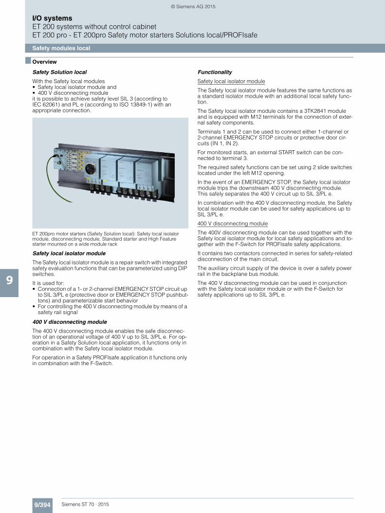
9/394 Siemens ST 70 · 2015
I/O systemsET 200 systems without control cabinetET 200 pro - ET 200pro Safety motor starters Solutions local/PROFIsafe
Safety modules local
9
■ Overview
Safety Solution local
With the Safety local modules • Safety local isolator module and • 400 V disconnecting module it is possible to achieve safety level SIL 3 (according to IEC 62061) and PL e (according to ISO 13849-1) with an appropriate connection.
ET 200pro motor starters (Safety Solution local): Safety local isolator module, disconnecting module, Standard starter and High Feature starter mounted on a wide module rack
Safety local isolator module
The Safety local isolator module is a repair switch with integrated safety evaluation functions that can be parameterized using DIP switches.
It is used for: • Connection of a 1- or 2-channel EMERGENCY STOP circuit up
to SIL 3/PL e (protective door or EMERGENCY STOP pushbut-tons) and parameterizable start behavior
• For controlling the 400 V disconnecting module by means of a safety rail signal
400 V disconnecting module
The 400 V disconnecting module enables the safe disconnec-tion of an operational voltage of 400 V up to SIL 3/PL e. For op-eration in a Safety Solution local application, it functions only in combination with the Safety local isolator module.
For operation in a Safety PROFIsafe application it functions only in combination with the F-Switch.
Functionality
Safety local isolator module
The Safety local isolator module features the same functions as a standard isolator module with an additional local safety func-tion.
The Safety local isolator module contains a 3TK2841 module and is equipped with M12 terminals for the connection of exter-nal safety components.
Terminals 1 and 2 can be used to connect either 1-channel or 2-channel EMERGENCY STOP circuits or protective door cir-cuits (IN 1, IN 2).
For monitored starts, an external START switch can be con-nected to terminal 3.
The required safety functions can be set using 2 slide switches located under the left M12 opening.
In the event of an EMERGENCY STOP, the Safety local isolator module trips the downstream 400 V disconnecting module. This safely separates the 400 V circuit up to SIL 3/PL e.
In combination with the 400 V disconnecting module, the Safety local isolator module can be used for safety applications up to SIL 3/PL e.
400 V disconnecting module
The 400V disconnecting module can be used together with the Safety local isolator module for local safety applications and to-gether with the F-Switch for PROFIsafe safety applications.
It contains two contactors connected in series for safety-related disconnection of the main circuit.
The auxiliary circuit supply of the device is over a safety power rail in the backplane bus module.
The 400 V disconnecting module can be used in conjunction with the Safety local isolator module or with the F-Switch for safety applications up to SIL 3/PL e.
ST70_2015_Kap09_EN.book Seite 394 Donnerstag, 21. Mai 2015 11:58 11
© Siemens AG 2015

9/395Siemens ST 70 · 2015
I/O systemsET 200 systems without control cabinet
ET 200 pro - ET 200pro Safety motor starters Solutions local/PROFIsafe
Safety modules local
9
■ Technical specifications
Type Safety local isolator module 400 V disconnecting module
General dataMounting dimensions (W x H x D) in mm• Direct-on-line starters and reversing starters mm 110 x 230 x 170 110 x 230 x 150
Permissible ambient temperature• During operation °C -25 ... +55• During storage °C -40 ... +70
Permissible mounting position any
Vibration resistance acc. to IEC 60068, parts 2-6 2 g
Shock resistance acc. to IEC 60068, parts 2-27 Half-wave 15 g/11 ms
Current consumption• From auxiliary circuit L+/M (U1) mA Approx. 20• From auxiliary circuit A1/A2 (U2) --
Rated operational current Ie for power bus A 25
Rated operational voltage Ue V 400 (50/60 Hz)
Approval DIN VDE 0106, part 101 V Up to 500
CSA and UL approval V Up to 600
Conductor cross-sectionsIncoming energy supply mm2 max. 6 x 4
Degree of protection IP65
Touch protection Finger-safe
Pollution degree 3, IEC 60664 (IEC 61131)
Rated impulse withstand voltage Uimp kV 6
Rated insulation voltage Ui V 400
Rated operational current Ie for starters
• AC-1/2/3 at 40 °C- At 400 V A 16 25- At 500 V A 16 25
Rated short-circuit breaking capacity kA 50 at 400 V
Type of coordination acc. to IEC 60947-4-1 2
Protective separation between main and auxiliary circuits V 400, acc. to DIN VDE 0106 Part 101
Operating times for 0.85 ... 1.1 x Ue• Closing delay ms -- 25 ... 100• Opening delay ms -- 7 ... 10
Device functions• Group diagnostics Yes, parameterizable
Device indications• Group fault SF LED (red)
ST70_2015_Kap09_EN.book Seite 395 Donnerstag, 21. Mai 2015 11:58 11
© Siemens AG 2015

9/396 Siemens ST 70 · 2015
I/O systemsET 200 systems without control cabinetET 200 pro - ET 200pro Safety motor starters Solutions local/PROFIsafe
Safety modules local
9
■ Selection and ordering data
1) The Safety local isolator module only functions when used together with the 400 V disconnecting module.
2) Only in combination with the special backplane bus module for the Safety local isolator module (see page 9/402, "Accessories for ET 200pro Motor Starters").
3) The 400 V disconnecting module functions only when used together with the Safety local isolator module or with the F-Switch.
4) The 400 V disconnecting module functions only when used together with the backplane bus module and the wide module rack. The backplane bus module and the wide module rack must be ordered separately (see page 9/402, "Accessories for ET 200pro Motor Starters").
Version Article No.
Safety modules local
3RK1304-0HS00-7AA0
Safety local isolator modules1)2)
Rated operational current 16 A 3RK1304-0HS00-7AA0
3RK1304-0HS00-8AA0
400 V disconnecting modules3)4)
Rated operational current 25 A 3RK1304-0HS00-8AA0
ST70_2015_Kap09_EN.book Seite 396 Donnerstag, 21. Mai 2015 11:58 11
© Siemens AG 2015

9/397Siemens ST 70 · 2015
I/O systemsET 200 systems without control cabinet
ET 200 pro - ET 200pro Safety motor starters Solutions local/PROFIsafe
Safety modules PROFIsafe
9
■ Overview
Safety Solution PROFIsafe
With the Safety PROFIsafe modules • F-Switch and • 400 V disconnecting module it is possible to achieve safety level SIL 3 (according to IEC 62061) and PL e (according to ISO 13849-1) with an appropriate connection.
F-Switch PROFIsafe
Fail-safe digital inputs/outputs in degrees of protection IP65 to IP67 for machine-level, cabinet-free use.
Failsafe digital inputs• For the fail-safe reading in of sensor information
(1-/2-channel)• Including integrated discrepancy evaluation for
2v2 signals• Internal sensor supplies (incl. testing) available
Failsafe digital outputs • 3 fail-safe PP-switching outputs for safe switching of the
backplane busbars
The F-Switch is certified up to SIL 3/PL e and has detailed diagnostics.
It supports PROFIsafe in PROFIBUS configurations as well as in PROFINET configurations.
Note:
Safety characteristics see Catalog IC 10 ·2015, Chapter 16 "Appendix" ➞ "Standards and Approvals" ➞ "Overview".
400 V disconnecting module
See "Safety modules local", Overview page 9/394 and Technical specifications page 9/395.
Functionality
The PROFIsafe F-Switch is a fail-safe electronic module for PROFIsafe safety applications. It has two fail-safe inputs and outputs for safe switching of the 24 V supply over backplane busbars. In combination with the 400 V disconnecting module, the fail-safe disconnection of ET 200pro motor starters is possi-ble in PROFIsafe applications up to SIL 3/PL e.
■ Selection and ordering data
1) The 400 V disconnecting module functions only when used together with the Safety local isolator module or with the F-Switch.
2) The 400 V disconnecting module functions only when used together with the backplane bus module and the wide module rack. The backplane bus module and the wide module rack must be ordered separately (see page 9/402, "Accessories for ET 200pro Motor Starters").
Version Article No.
ET 200pro safety modules
3RK1304-0HS00-8AA0
400 V disconnecting modules1)2)
Rated operational current 25 A 3RK1304-0HS00-8AA0
6ES7148-4FS00-0AB0
F-Switch PROFIsafe
24 V DC, including bus module
Connection module must be ordered separately
6ES7148-4FS00-0AB0
Connection modules for F-Switch
24 V DC 6ES7194-4DA00-0AA0
ST70_2015_Kap09_EN.book Seite 397 Donnerstag, 21. Mai 2015 11:58 11
© Siemens AG 2015

9/398 Siemens ST 70 · 2015
I/O systemsET 200 systems without control cabinetET 200 pro - ET 200pro Safety motor starters Solutions local/PROFIsafe
Accessories for ET 200pro motor starters
9
■ Overview
Basic design of an ET 200pro version with (from the left) connection mod-ule for IM, interface module for communication (IM), RSM isolator mod-ule, two ET 200pro motor starters (MS), and connections for power
Infeed on the ET 200pro motor starter
Infeed on the RSM isolator module
Legend: $ Power feeder plug (see page 9/400) % Power connection plug (see page 9/400) & Power jumper plug (see page 9/400) ( Motor connection plug (see page 9/400) ) Motor plug (see page 9/400) * Motor plug with EMC suppressor circuit (see page 9/400) + Power loop-through plug (see page 9/400) , Power connection cable (see page 9/400) - Power connection cable for isolator modules (see page 9/400) . Motor cable (see page 9/401)
MSMS
M M
NS
A0_
0046
5a
RSM
6
2
1
5 /
743
1234567
Power feeder plugPower connection plugPower jumper plugMotor connection plugMotor plugMotor plug with EMC suppressor circuitPower loop-through plug
MS MS
NS
A0_
0046
6a
108
108
Infeed onET 200pro motor starter
Power connection cableMotor cable
NS
A0_
0046
7a
MSMS
RSM
9
Infeed onisolator module
9 Power connection cable for isolator module
ST70_2015_Kap09_EN.book Seite 398 Donnerstag, 21. Mai 2015 11:58 11
© Siemens AG 2015

9/399Siemens ST 70 · 2015
I/O systemsET 200 systems without control cabinet
ET 200 pro - ET 200pro Safety motor starters Solutions local/PROFIsafe
Accessories for ET 200pro motor starters
9
Power bus
The power supply to the field devices (ET 200pro motor starters, M200D motor starters) is provided via the power bus, in which the power T terminal connectors or power double-T terminal connectors are connected by power bus cables.
Feeders
From the terminal connectors, spur lines with Han Q4/2 plugs lead to the field devices, from which the motors are supplied with power via motor connection cables.
Interruption-free thanks to power terminal connectors
In finger-safe connection technology the power T terminal con-nectors and power double-T terminal connectors connect the components of a feeder to the power bus. They ensure interrup-tion-free operation, i.e. when the components are plugged in, the power bus is not interrupted.
Power supply to the motors via the power bus with power T and double-T terminal connectors linked by power bus cables, spur lines to the field devices (motor starters), and power loop-through connections to the motors via motor connection cables
Motor control via PROFIBUS
The interface modules (IM) for PROFIBUS can be combined with three different connection modules for connecting PROFIBUS DP and the power supply:• Direct connection with cable glands• ECOFAST connection with hybrid fieldbus cables (with two
copper cores for data transmission with PROFIBUS DP, and four copper cores for the power supply), and ECOFAST connectors (HanBrid)1)
• M12, 7/8" connection - with M12 connecting cable and M12 plugs for data
transmission with PROFIBUS DP- with 7/8" connecting cable and 7/8" plugs for the power
supply2)
The connection modules with the relevant accessories can be found among the accessories for the ET 200pro interface mod-ules IM 154-1 and IM 154-2 (see page 9/350).1) Hybrid fieldbus connections with HanBrid sockets designed as cabinet
bushings transmit data and energy from the control cabinet (IP20) to the field (IP65). They are the interface for jointly routing PROFIBUS DP and the auxiliary voltages into the hybrid fieldbus cable.
2) On the control cabinet bushings with two M12 sockets for the PROFIBUS M12 connecting cables, the 24 V supply of the motor startersis implemented via separate 7/8" connecting cables.
Motor control via PROFINET
The connection modules with the relevant accessories can be found among the accessories for the ET 200pro interface mod-ule IM 154-4 PN (see page 9/354).
Motor control via Industrial Wireless LAN
As well as wired solutions, communication can also be made via Industrial Wireless LAN (see interface moduleIM 154-6 PN IWLAN, page 9/357).
1211 14
13 13
Power bus line (sold by the meter)Power T terminal connectorPower double-T terminal connectorPrefabricated power cable
11121314
Motors
IC01
_002
30
ET 200pro
M200DM200D
ST70_2015_Kap09_EN.book Seite 399 Donnerstag, 21. Mai 2015 11:58 11
© Siemens AG 2015

9/400 Siemens ST 70 · 2015
I/O systemsET 200 systems without control cabinetET 200 pro - ET 200pro Safety motor starters Solutions local/PROFIsafe
Accessories for ET 200pro motor starters
9
■ Selection and ordering data
Version Article No.
Incoming energy supply$ Power feeder plugsConnector set for energy supply, e.g. for connecting toT terminal connectors, comprising a coupling enclosure, straight outgoing feeder (with bracket), pin insert forHAN Q4/2, incl. gland
• 5 male contacts 2.5 mm2 3RK1911-2BS60• 5 male contacts 4 mm2 3RK1911-2BS20• 5 male contacts 6 mm2 3RK1911-2BS40
% Power connection plugsConnector set for energy supply for connection to ET 200pro motor starters/ET 200pro isolator modules, comprising a cable-end connector hood, angular outgoing feeder, female insert for HAN Q4/2, incl. gland
• 5 female contacts 2.5 mm2 3RK1911-2BE50• 5 female contacts 4 mm2 3RK1911-2BE10• 5 female contacts 6 mm2 3RK1911-2BE30
, Power connection cables, assembled at one end Power connection cable for ET 200pro motor starters, open at one end, for HAN Q4/2, angular, insert turned at isolator module end, 4 x 4 mm2
• Length 1.5 m 3RK1911-0DB13• Length 5.0 m 3RK1911-0DB33
- Power connection cables for isolator module, assembled at one end Power connection cable for ET 200pro isolator modules, open at one end, for HAN Q4/2, angular, insert turned at isolator module end, 4 x 4 mm2
• Length 1.5 m 3RK1911-0DF13• Length 5.0 m 3RK1911-0DF33
Power loop-through on the field device& Power jumper plug 3RK1922-2BQ00
+ Power loop-through plugs Connector set for power loop-through for connection to ET 200pro motor starters/ET 200pro isolator modules, comprising a cable-end connector hood, angular outgoing feeder, pin insert for HAN Q4/2, incl. gland
• 4 male contacts 2.5 mm2 3RK1911-2BF50• 4 male contacts 4 mm2 3RK1911-2BF10
Motor cable ( Motor connection plugsConnector set for motor cable for connection to ET 200pro motor starters, comprising a cable-end connector hood, angular outgoing feeder, pin insert for HAN Q8/0, incl. gland
• 8 male contacts 1.5 mm2 3RK1902-0CE00• 6 male contacts 2.5 mm2 3RK1902-0CC00
) Motor plugs Connector set for motor cable for connection to motors, comprising a cable-end connector hood, straight outgoing feeder, female insert for HAN 10e, incl. star jumper, incl. gland
• 7 female contacts 1.5 mm2 3RK1911-2BM21• 7 female contacts 2.5 mm2 3RK1911-2BM22
* Motor plugs with EMC suppressor circuit Connector set for motor cable for connection to motors, comprising a cable-end connector hood, straight outgoing feeder, female insert for HAN 10e withEMC suppressor circuit, incl. star jumper, incl. gland
• 7 female contacts 1.5 mm2 3RK1911-2BL21• 7 female contacts 2.5 mm2 3RK1911-2BL22
ST70_2015_Kap09_EN.book Seite 400 Donnerstag, 21. Mai 2015 11:58 11
© Siemens AG 2015

9/401Siemens ST 70 · 2015
I/O systemsET 200 systems without control cabinet
ET 200 pro - ET 200pro Safety motor starters Solutions local/PROFIsafe
Accessories for ET 200pro motor starters
9
More connection technology products can be found at our "Siemens Solution Partners Automation" websiteunder "Distributed Field Installation System" technology:www.siemens.com/automation/partnerfinder
Motor cables (continued). Motor cables, assembled at one end Open at one end, HAN Q8, angular, length 5 m
• Motor cable for motor without brake, for ET 200pro,4 x 1.5 mm2
3RK1911-0EB31
• Motor cable for motor with brake for ET 200pro, 6 x 1.5 mm2
3RK1911-0ED31
Power bus0 Power T terminal connectors For 400 V AC, for connection of feeders (e.g. motor start-ers) by means of standard round cables at any point of the power bus, by insulation displacement connection,used with preassembled bus segments
• 2.5 mm² / 4 mm² 3RK1911-2BF01• 4 mm² / 6 mm² 3RK1911-2BF02
1 Power double-T terminal connectors For 400 V AC, for connection of feeders (e.g. motor start-ers) by means of standard round cable at any point of the power bus, by insulation displacement connection,used with preassembled bus segments,connection of two motor starters possible
• 4 mm² / 6 mm² 3RK1911-2BG02
Sealing set (comprising 2 seals) For power T/power double-T terminal connectors
• For power cables with Ø 10 ... 13 mm 3RK1911-5BA00• For power cables with Ø 13 ... 16 mm 3RK1911-5BA10• For power cables with Ø 16 ... 19 mm 3RK1911-5BA20• For power cables with Ø 19 ... 22 mm 3RK1911-5BA30• Blanking plugs 3RK1911-5BA50
Further accessories for energy connections
3RK1902-0CW00
Crimping tools for pins/sockets 4 mm2 and 6 mm2 3RK1902-0CW00
Dismantling tools• For male and female contacts
for 9-pin HAN Q4/2 inserts3RK1902-0AB00
• For male and female contacts for 9-pin HAN Q8 inserts 3RK1902-0AJ00
3RK1902-0CK00
Sealing capsFor 9-pin power socket connectors
• 1 unit per pack 3RK1902-0CK00• 10 units per pack 3RK1902-0CJ00
Version Article No.
ST70_2015_Kap09_EN.book Seite 401 Donnerstag, 21. Mai 2015 11:58 11
© Siemens AG 2015

9/402 Siemens ST 70 · 2015
I/O systemsET 200 systems without control cabinetET 200 pro - ET 200pro Safety motor starters Solutions local/PROFIsafe
Accessories for ET 200pro motor starters
9 1) The wide module rack can accommodate all ET 200pro motor starters and any optional modules (isolator module, Safety local isolator module and 400 V disconnecting module).
2) The backplane bus module is a prerequisite for operation of theET 200pro motor starters and the optional modules.
Version Article No.
Further accessories Module racks, wide1)
• Length 500 mm 6ES7194-4GB00-0AA0• Length 1 000 mm 6ES7194-4GB60-0AA0• Length 2 000 mm 6ES7194-4GB20-0AA0
Module racks, wide, compact1)
• Length 500 mm 6ES7194-4GD00-0AA0• Length 1 000 mm 6ES7194-4GD10-0AA0• Length 2 000 mm 6ES7194-4GD20-0AA0
Backplane bus modules 110 mm2) 3RK1922-2BA00
Backplane bus modules for Safety local isolator modules
3RK1922-2BA01
3RK1922-3BA00
Handheld devicesFor ET 200pro motor starters(or for ET 200S High Feature and M200D motor starters) for local operation. The motor starter-specific serialinterface cables must be ordered separately.The RS 232 interface cable 3RK1922-2BP00 is used for the MS ET 200pro.
3RK1922-3BA00
RS 232 interface cableSerial data connection between ET 200pro (or M200D) motor starters and the RS 232 interface of a PC/PG/laptop (with the Motor Starter ES software) or the hand-held device 3RK1922-3BA00.
3RK1922-2BP00
USB interface cable, 2.5 mSerial data connection between ET 200pro (or M200D) motor starters and the USB interface of a PC/PG/laptop (with the Motor Starter ES software).
6SL3555-0PA00-2AA0
3RK1901-1KA00
M12 sealing capFor sealing unused M12 input or output sockets (one set contains ten sealing caps)
3RK1901-1KA00
Manual SIMATIC ET 200pro Motor Starters The manual can be downloaded free of charge in PDF format from the Internet, seehttp://support.automation.siemens.com/WW/view/en/22332388
ST70_2015_Kap09_EN.book Seite 402 Donnerstag, 21. Mai 2015 11:58 11
© Siemens AG 2015

9/403Siemens ST 70 · 2015
I/O systemsET 200 systems without control cabinet
ET 200pro - Software
Motor Starter ES
9
■ Overview
Motor Starter ES for parameterization, monitoring, diagnostics and testing of motor starters
Motor Starter ES is used for start up, parameterization, diagnostics, documentation and the preventative maintenance of the motor starters in the SIMATIC ET 200S, ET 200pro, ECOFAST and M200D product families.
Note:
For more information, see pages 9/248 to 9/251.
ST70_2015_Kap09_EN.book Seite 403 Donnerstag, 21. Mai 2015 11:58 11
© Siemens AG 2015

9/404 Siemens ST 70 · 2015
9
I/O systemsET 200 systems without control cabinetET 200pro – Add-on products for ET 200pro
EtherNet/IP interface module
■ Overview
An interface module (EtherNet/IP adapter) is provided for oper-ating the ET 200pro on EtherNet/IP. It can be used together with system and IO components of the ET 200pro distributed I/O sys-tem.
■ Technical specifications
Article number ZNX:EIP-200PRO
ETHERNET/IP HEAD ASSEMBLY FOR ET 200PRO
Product type designation
General information
Vendor identification (VendorID) 0008h
Device identifier (DeviceID) 0240h
Supply voltage
permissible range, lower limit (DC) 20.4 V
permissible range, upper limit (DC) 28.8 V
Input current
from supply voltage 1L+, max. 250 mA
Power losses
Power loss, typ. 6 W
Address area
Addressing volume
• Inputs 255 byte
• Outputs 255 byte
Interfaces
PROFINET IO
• Automatic detection of transmission speed
Yes
• Transmission rate, max. 100 Mbit/s
• Services See manual
Interrupts/diagnostics/status information
Diagnostics indication LED
• Bus fault BF (red) Yes
• Group error SF (red) Yes
• Monitoring 24 V voltage supply ON (green)
Yes
• Load voltage monitoring DC 24 V (green)
Yes
Galvanic isolation
between backplane bus and electronics
Yes
between supply voltage and electronics
Yes
Isolation
Isolation checked with 707 V DC (type test)
Degree and class of protection
Degree of protection to EN 60529
• IP65 Yes
• IP66 Yes
• IP67 Yes
Ambient conditions
Ambient temperature in operation
• Min. -25 °C
• max. 55 °C
Storage/transport temperature
• Min. -40 °C
• max. 70 °C
Dimensions
Width 135 mm
Height 130 mm
Depth 76 mm
Weights
Weight, approx. 490 g
Article number ZNX:EIP-200PRO
ETHERNET/IP HEAD ASSEMBLY FOR ET 200PRO
ST70_2015_Kap09_EN.book Seite 404 Donnerstag, 21. Mai 2015 11:58 11
© Siemens AG 2015

9/405Siemens ST 70 · 2015
9
■ Technical specifications (continued)
I/O systemsET 200 systems without control cabinet
ET 200pro – Add-on products for ET 200pro
EtherNet/IP interface module
Article number ZNX:EIP-200PR-OCM1
ET200PRO, CM IM DP M12 / 7/8"
Product type designation
Input current
from load voltage 2L+ (without load), max.
No current input, only infeed current, max. 8 A
from supply voltage 1L+, max. No current input, only infeed current, max. 8 A
Interfaces
PROFIBUS DP
• Transmission rate, max. 100 Mbit/s; full-duplex, PROFINET
Accessories
Function description IM PN; 2xM12 2x7/8" interface module, power supply from 1L+ and 2L+ max. per 8 A, internal transfer 2L+ max. 8 A, 1L+ max. 5 A
belongs to product M154-4PN High Feature
Weights
Weight, approx. 540 g
■ Ordering data Article No.
SIMATIC ET 200pro interface module for EtherNet/IP
ZNX:EIP200PRO
Including:• Bus termination module
for ET 200pro• Companion disk with the manuals
and the Configuration Tool
Connecting modulefor EtherNet/IP
ZNX:EIP200PROCM1
For connecting the interface module to EtherNet/IP
ST70_2015_Kap09_EN.book Seite 405 Donnerstag, 21. Mai 2015 11:58 11
© Siemens AG 2015

9/406 Siemens ST 70 · 2015
9
I/O systemsET 200 systems without control cabinetET 200eco PN
SIMATIC ET 200eco PN
■ Overview
• Compact block I/O for processing digital, analog and IO-Link signals for connecting to the PROFINET bus system
• Cabinet-free design with degree of protection IP65/66/67 with M12 connections
• Extremely rugged and resistant metal housing and casting • Compact module in two types of enclosures:
- 30 mm x 200 mm x 37 mm (W x H x D, long and narrow enclosure), with 4 x M12 for digital signals
- 60 mm x 175 mm x 37 mm (W x H x D, short and wide enclosure), with 8 x M12 for digital signals and IO-Link
- 60 mm x 175 mm x 37 mm (W x H x D, short and wide enclosure) with 4 x M12 or 8 x M12 for analog signals
• PROFINET connection: 2 x M12 and automatic PROFINET address assignment
• Data transmission rate 100 Mbit/s • LLDP proximity detection without PG and Fast Startup
(boot up within approx 0.5 seconds) • Supply and load voltage connection: 2 x M12 • Module variance:
- 8 DI - 16 DI - 8 DO (2 A) - 8 DO (1.3 A) - 8 DO (0.5 A) - 16 DO (1.3 A) - 8 DI/DO (1.3 A) - 8 AI (U, I, TC, RTD) - 8 AI (TC, RTD)- 4 AO (U, I) - 4 IO-Link + 8 DI + 4 DO (1.3 A)
• Channel-specific diagnostics• Ambient temperature range -40 °C to 60 °C
■ Technical specifications
Article number 6ES7141-6BF00-0AB0 6ES7141-6BG00-0AB0 6ES7141-6BH00-0AB0
ET200ECO PN, 8DI, DC24V, 4XM12 ET200ECO PN, 8DI, DC24V, 8XM12 ET200ECO PN, 16DI, DC24V, 8XM12
Product type designation
General information
Vendor identification (VendorID) 002AH 002AH 002AH
Device identifier (DeviceID) 0306H 0306H 0306H
Supply voltage
Rated value (DC)
• 24 V DC Yes Yes Yes
permissible range, lower limit (DC) 20.4 V 20.4 V 20.4 V
permissible range, upper limit (DC) 28.8 V 28.8 V 28.8 V
Reverse polarity protection Yes Yes Yes
Input current
Current consumption, typ. 100 mA 100 mA 100 mA
Encoder supply
Number of outputs 4 8 8
Output current
• nominal 100 mA; per output 100 mA; per output 100 mA; per output
24 V encoder supply
• short-circuit protection Yes Yes Yes
ST70_2015_Kap09_EN.book Seite 406 Donnerstag, 21. Mai 2015 11:58 11
© Siemens AG 2015

9/407Siemens ST 70 · 2015
9
■ Technical specifications (continued)
I/O systemsET 200 systems without control cabinet
ET 200eco PN
SIMATIC ET 200eco PN
Power losses
Power loss, typ. 5.5 W 4.5 W 6.5 W
Digital inputs
Number of digital inputs 8 8 16
• In groups of 2 1 2
Input characteristic curve in accordance with IEC 61131, type 3
Yes Yes Yes
Number of simultaneously controllable inputs
all mounting positions
- up to 60 °C, max. 8 8 16
Input voltage
• Type of input voltage DC DC DC
• Rated value (DC) 24 V 24 V 24 V
• for signal "0" -3 to +5V -3 to +5V -3 to +5V
• for signal "1" +11 to +30V +11 to +30V +11 to +30V
Input current
• for signal "0", max. (permissible quiescent current)
1.5 mA 1.5 mA 1.5 mA
• for signal "1", typ. 7 mA 7 mA 7 mA
Input delay(for rated value of input voltage)
for standard inputs
- at "0" to "1", max. typically 3 ms typically 3 ms typically 3 ms
- at "1" to "0", max. typically 3 ms typically 3 ms typically 3 ms
Cable length
• Unshielded, max. 30 m 30 m 30 m
Interfaces
Transmission procedure 100BASE-TX 100BASE-TX 100BASE-TX
Transmission rate, max. 100 Mbit/s 100 Mbit/s 100 Mbit/s
PROFINET IO
• Number of PROFINET interfaces 1 1 1
• Autocrossing Yes Yes Yes
• Automatic detection of transmission speed
Yes Yes Yes
• Integrated switch Yes Yes Yes
PROFINET IO Device
- IRT with the option "high flexibility" supported
Yes Yes Yes
- Prioritized startup Yes Yes Yes
Protocols
PROFINET IO Yes Yes Yes
PROFINET CBA No No No
Supports protocol for PROFIsafe No No No
Protocols (Ethernet)
• SNMP Yes Yes Yes
• DCP Yes Yes Yes
• LLDP Yes Yes Yes
• ping Yes Yes Yes
• ARP Yes Yes Yes
Article number 6ES7141-6BF00-0AB0 6ES7141-6BG00-0AB0 6ES7141-6BH00-0AB0
ET200ECO PN, 8DI, DC24V, 4XM12 ET200ECO PN, 8DI, DC24V, 8XM12 ET200ECO PN, 16DI, DC24V, 8XM12
ST70_2015_Kap09_EN.book Seite 407 Donnerstag, 21. Mai 2015 11:58 11
© Siemens AG 2015

9/408 Siemens ST 70 · 2015
9
■ Technical specifications (continued)
I/O systemsET 200 systems without control cabinetET 200eco PN
SIMATIC ET 200eco PN
Interrupts/diagnostics/status information
Status indicator Yes; Green LED Yes; Green LED Yes; Green LED
Alarms
• Diagnostic alarm Yes Yes Yes
Diagnostic messages
• Diagnostic functions Yes Yes Yes
• Diagnostic information readable Yes Yes Yes
• Monitoring the supply voltage Yes; Green "ON" LED Yes; Green "ON" LED Yes; Green "ON" LED
• Wire break in signal transmitter cable
Yes Yes Yes
• Short circuit encoder supply Yes; Per channel group Yes; Per channel group Yes; Per channel group
• Group error Yes; Red/yellow "SF/MT" LED Yes; Red/yellow "SF/MT" LED Yes; Red/yellow "SF/MT" LED
Galvanic isolation
between the load voltages Yes Yes Yes
between load voltage and all other switching components
No No No
between Ethernet and electronics Yes Yes Yes
Galvanic isolation digital inputs
• between the channels No No No
Permissible potential difference
between different circuits 75V DC/60V AC 75V DC/60V AC 75V DC/60V AC
Isolation
tested with
• 24 V DC circuits 500 V 500 V 500 V
• Interface 1 500 V; According to IEEE 802.3 1 500 V; According to IEEE 802.3 1 500 V; According to IEEE 802.3
Degree and class of protection
Degree of protection to EN 60529
• IP65 Yes Yes Yes
• IP66 Yes Yes Yes
• IP67 Yes Yes Yes
Connection method
M12 Yes Yes Yes
Dimensions
Width 30 mm 60 mm 60 mm
Height 200 mm 175 mm 175 mm
Depth 49 mm 49 mm 49 mm
Weights
Weight (without packaging) 550 g 910 g 910 g
Article number 6ES7141-6BF00-0AB0 6ES7141-6BG00-0AB0 6ES7141-6BH00-0AB0
ET200ECO PN, 8DI, DC24V, 4XM12 ET200ECO PN, 8DI, DC24V, 8XM12 ET200ECO PN, 16DI, DC24V, 8XM12
ST70_2015_Kap09_EN.book Seite 408 Donnerstag, 21. Mai 2015 11:58 11
© Siemens AG 2015

9/409Siemens ST 70 · 2015
9
■ Technical specifications (continued)
I/O systemsET 200 systems without control cabinet
ET 200eco PN
SIMATIC ET 200eco PN
Article number 6ES7142-6BF50-0AB0
6ES7142-6BF00-0AB0
6ES7142-6BG00-0AB0
6ES7142-6BR00-0AB0
6ES7142-6BH00-0AB0
ET200ECO PN, 8DO, DC24V/0.5A, 4XM12
ET200ECO PN, 8DO, DC24V/1.3A, 4XM12
ET200ECO PN, 8DO, DC24V/1.3A, 8XM12
ET200ECO PN, 8 DO, DC24V/2A, 8XM12
ET200ECO PN, 16DO DC24V/1.3A, 8XM12
Product type designation
General information
Vendor identification (VendorID) 002AH 002AH 002AH 002AH 002AH
Device identifier (DeviceID) 0306H 0306H 0306H 0306H 0306H
Supply voltage
Load voltage 1L+
• Rated value (DC) 24 V 24 V 24 V 24 V 24 V
• permissible range, lower limit (DC) 20.4 V 20.4 V 20.4 V 20.4 V 20.4 V
• permissible range, upper limit (DC) 28.8 V 28.8 V 28.8 V 28.8 V 28.8 V
• Reverse polarity protection Yes Yes Yes Yes Yes
Load voltage 2L+
• Rated value (DC) 24 V 24 V 24 V 24 V 24 V
• permissible range, lower limit (DC) 20.4 V 20.4 V 20.4 V 20.4 V 20.4 V
• permissible range, upper limit (DC) 28.8 V 28.8 V 28.8 V 28.8 V 28.8 V
• Reverse polarity protection Yes Yes Yes Yes Yes
Input current
from load voltage 1L+(unswitched voltage)
100 mA 4 A 4 A 4 A 4 A
from load voltage 2L+, max. 4 A 4 A 4 A 4 A 4 A
Power losses
Power loss, typ. 3 W 5.5 W 5.5 W 5 W 5.5 W
Digital outputs
Number of digital outputs 8 8 8 8 16
• In groups of 8 4 4 4 8
short-circuit protection Yes Yes Yes Yes Yes
• Response threshold, typ. 0.7 A 1.8 A 1.8 A 2.8 A 1.8 A
Limitation of inductive shutdown voltage to
Typ. (L1+, L2+) -47 V Typ. (L1+, L2+) -47 V Typ. (L1+, L2+) -47 V Typ. (L1+, L2+) -47 V Typ. (L1+, L2+) -47 V
Controlling a digital input Yes Yes Yes Yes Yes
Switching capacity of the outputs
• on lamp load, max. 5 W 5 W 5 W 10 W 5 W
Output current
• for signal "1" rated value 0.5 A 1.3 A; Maximum 1.3 A; Maximum 2 A 1.3 A; Maximum
• for signal "0" residual current, max. 1.5 mA 1.5 mA 1.5 mA 1.5 mA 1.5 mA
Parallel switching of 2 outputs
• for increased power No No No No No
• for redundant control of a load Yes Yes Yes Yes Yes
Switching frequency
• with resistive load, max. 100 Hz 100 Hz 100 Hz 100 Hz 100 Hz
• with inductive load, max. 0.5 Hz 0.5 Hz 0.5 Hz 0.5 Hz 0.5 Hz
• on lamp load, max. 1 Hz 1 Hz 1 Hz 1 Hz 1 Hz
Aggregate current of outputs (per group)
all mounting positions
- up to 55 °C, max. 3.9 A
- up to 60 °C, max. 4 A 2.6 A 3.9 A 3.9 A 3.9 A
Cable length
• Unshielded, max. 30 m 30 m 30 m 30 m 30 m
ST70_2015_Kap09_EN.book Seite 409 Donnerstag, 21. Mai 2015 11:58 11
© Siemens AG 2015

9/410 Siemens ST 70 · 2015
9
■ Technical specifications (continued)
I/O systemsET 200 systems without control cabinetET 200eco PN
SIMATIC ET 200eco PN
Interfaces
Transmission procedure 100BASE-TX 100BASE-TX 100BASE-TX 100BASE-TX 100BASE-TX
Transmission rate, max. 100 Mbit/s 100 Mbit/s 100 Mbit/s 100 Mbit/s 100 Mbit/s
PROFINET IO
• Number of PROFINET interfaces 1 1 1 1 1
• Autocrossing Yes Yes Yes Yes Yes
• Automatic detection of transmission speed
Yes Yes Yes Yes Yes
• Integrated switch Yes Yes Yes Yes Yes
PROFINET IO Device
- IRT with the option "high flexibility" supported
Yes Yes Yes Yes Yes
- Prioritized startup Yes Yes Yes Yes Yes
Protocols
PROFINET IO Yes Yes Yes Yes Yes
PROFINET CBA No No No No No
Supports protocol for PROFIsafe No No No No No
Protocols (Ethernet)
• SNMP Yes Yes Yes Yes Yes
• DCP Yes Yes Yes Yes Yes
• LLDP Yes Yes Yes Yes Yes
• ping Yes Yes Yes Yes Yes
• ARP Yes Yes Yes Yes Yes
Interrupts/diagnostics/status information
Status indicator Yes; Green LED Yes; Green LED Yes; Green LED Yes; Green LED Yes; Green LED
Alarms
• Diagnostic alarm Yes Yes Yes Yes Yes
Diagnostic messages
• Diagnostic functions Yes Yes Yes Yes Yes
• Diagnostic information readable Yes Yes Yes Yes Yes
• Monitoring the supply voltage Yes; Green "ON" LED Yes; Green "ON" LED Yes; Green "ON" LED Yes; Green "ON" LED Yes; Green "ON" LED
• Wire break in actuator cable Yes Yes Yes Yes Yes
• Short circuit Yes Yes Yes Yes Yes
• Group error Yes; Red/yellow "SF/MT" LED
Yes; Red/yellow"SF/MT" LED
Yes; Red/yellow"SF/MT" LED
Yes; Red/yellow"SF/MT" LED
Yes; Red/yellow "SF/MT" LED
Article number 6ES7142-6BF50-0AB0
6ES7142-6BF00-0AB0
6ES7142-6BG00-0AB0
6ES7142-6BR00-0AB0
6ES7142-6BH00-0AB0
ET200ECO PN, 8DO, DC24V/0.5A, 4XM12
ET200ECO PN, 8DO, DC24V/1.3A, 4XM12
ET200ECO PN, 8DO, DC24V/1.3A, 8XM12
ET200ECO PN, 8 DO, DC24V/2A, 8XM12
ET200ECO PN, 16DO DC24V/1.3A, 8XM12
ST70_2015_Kap09_EN.book Seite 410 Donnerstag, 21. Mai 2015 11:58 11
© Siemens AG 2015

9/411Siemens ST 70 · 2015
9
■ Technical specifications (continued)
I/O systemsET 200 systems without control cabinet
ET 200eco PN
SIMATIC ET 200eco PN
Galvanic isolation
between the load voltages Yes Yes Yes Yes Yes
between load voltage and all other switching components
No No No No No
between Ethernet and electronics Yes Yes Yes Yes Yes
Galvanic isolation digital outputs
• between the channels No No No No No
Permissible potential difference
between different circuits 75V DC/60V AC 75V DC/60V AC 75V DC/60V AC 75V DC/60V AC 75V DC/60V AC
Isolation
tested with
• 24 V DC circuits 500 V 500 V 500 V 500 V 500 V
• Interface 1 500 V; According to IEEE 802.3
1 500 V; According to IEEE 802.3
1 500 V; According to IEEE 802.3
1 500 V; According to IEEE 802.3
1 500 V; According to IEEE 802.3
Degree and class of protection
Degree of protection to EN 60529
• IP65 Yes Yes Yes Yes Yes
• IP66 Yes Yes Yes Yes Yes
• IP67 Yes Yes Yes Yes Yes
Connection method
M12 Yes Yes Yes Yes Yes
Dimensions
Width 30 mm 30 mm 60 mm 60 mm 60 mm
Height 200 mm 200 mm 175 mm 175 mm 175 mm
Depth 49 mm 49 mm 49 mm 49 mm 49 mm
Weights
Weight (without packaging) 550 g 550 g 910 g 910 g 910 g
Article number 6ES7142-6BF50-0AB0
6ES7142-6BF00-0AB0
6ES7142-6BG00-0AB0
6ES7142-6BR00-0AB0
6ES7142-6BH00-0AB0
ET200ECO PN, 8DO, DC24V/0.5A, 4XM12
ET200ECO PN, 8DO, DC24V/1.3A, 4XM12
ET200ECO PN, 8DO, DC24V/1.3A, 8XM12
ET200ECO PN, 8 DO, DC24V/2A, 8XM12
ET200ECO PN, 16DO DC24V/1.3A, 8XM12
ST70_2015_Kap09_EN.book Seite 411 Donnerstag, 21. Mai 2015 11:58 11
© Siemens AG 2015

9/412 Siemens ST 70 · 2015
9
■ Technical specifications (continued)
I/O systemsET 200 systems without control cabinetET 200eco PN
SIMATIC ET 200eco PN
Article number 6ES7147-6BG00-0AB0
ET200ECO PN, 8 DIO, DC24V/1.3A, 8XM12
Product type designation
General information
Vendor identification (VendorID) 002AH
Device identifier (DeviceID) 0306H
Supply voltage
Rated value (DC)
• 24 V DC Yes
permissible range, lower limit (DC) 20.4 V
permissible range, upper limit (DC) 28.8 V
Reverse polarity protection Yes
Load voltage 2L+
• Rated value (DC) 24 V
• permissible range, lower limit (DC) 20.4 V
• permissible range, upper limit (DC) 28.8 V
• Reverse polarity protection Yes
Input current
from load voltage 1L+ (unswitched voltage)
4 A
from load voltage 2L+, max. 4 A
Encoder supply
Number of outputs 8
Output current
• nominal 100 mA; per output
24 V encoder supply
• short-circuit protection Yes
Power losses
Power loss, typ. 6.5 W
Digital inputs
Number of digital inputs 8
• In groups of 4
Input characteristic curve in accordance with IEC 61131, type 3
Yes
Number of simultaneously controllable inputs
all mounting positions
- up to 60 °C, max. 8
Input voltage
• Type of input voltage DC
• Rated value (DC) 24 V
• for signal "0" -3 to +5V
• for signal "1" +11 to +30V
Input current
• for signal "0", max.(permissible quiescent current)
1.5 mA
• for signal "1", typ. 7 mA
Input delay(for rated value of input voltage)
for standard inputs
- at "0" to "1", max. typically 3 ms
- at "1" to "0", max. typically 3 ms
Cable length
• Unshielded, max. 30 m
Digital outputs
Number of digital outputs 8
• In groups of 4
short-circuit protection Yes; Electronic
• Response threshold, typ. 1.8 A
Limitation of inductive shutdown voltage to
Typ. (L1+, L2+) -47 V
Controlling a digital input Yes
Switching capacity of the outputs
• on lamp load, max. 5 W
Output current
• for signal "1" rated value 1.3 A; Maximum
• for signal "0" residual current, max. 1.5 mA
Parallel switching of 2 outputs
• for increased power No
• for redundant control of a load Yes
Switching frequency
• with resistive load, max. 100 Hz
• with inductive load, max. 0.5 Hz
• on lamp load, max. 1 Hz
Aggregate current of outputs (per group)
all mounting positions
- up to 60 °C, max. 3.9 A
Cable length
• Unshielded, max. 30 m
Interfaces
Transmission procedure 100BASE-TX
Transmission rate, max. 100 Mbit/s
PROFINET IO
• Number of PROFINET interfaces 1
• Autocrossing Yes
• Automatic detection of transmission speed
Yes
• Integrated switch Yes
PROFINET IO Device
- IRT with the option "high flexibility" supported
Yes
- Prioritized startup Yes
Article number 6ES7147-6BG00-0AB0
ET200ECO PN, 8 DIO, DC24V/1.3A, 8XM12
ST70_2015_Kap09_EN.book Seite 412 Donnerstag, 21. Mai 2015 11:58 11
© Siemens AG 2015

9/413Siemens ST 70 · 2015
9
■ Technical specifications (continued)
I/O systemsET 200 systems without control cabinet
ET 200eco PN
SIMATIC ET 200eco PN
Protocols
PROFINET IO Yes
PROFINET CBA No
Supports protocol for PROFIsafe No
PROFIBUS No
Protocols (Ethernet)
• TCP/IP No
• SNMP Yes
• DCP Yes
• LLDP Yes
• ping Yes
• ARP Yes
Interrupts/diagnostics/status information
Status indicator Yes; Green LED
Alarms
• Diagnostic alarm Yes
Diagnostic messages
• Diagnostic functions Yes
• Diagnostic information readable Yes
• Monitoring the supply voltage Yes; Green "ON" LED
• Wire break in actuator cable Yes
• Wire break in signal transmitter cable
Yes
• Short circuit Yes
• Short circuit encoder supply Yes
• Group error Yes; Red/yellow "SF/MT" LED
Article number 6ES7147-6BG00-0AB0
ET200ECO PN, 8 DIO, DC24V/1.3A, 8XM12
Galvanic isolation
between the load voltages Yes
between load voltage and all other switching components
No
between Ethernet and electronics Yes
Galvanic isolation digital inputs
• between the channels No
Galvanic isolation digital outputs
• between the channels No
Permissible potential difference
between different circuits 75V DC/60V AC
Isolation
tested with
• 24 V DC circuits 500 V
• Interface 1 500 V; According to IEEE 802.3
Degree and class of protection
Degree of protection to EN 60529
• IP65 Yes
• IP66 Yes
• IP67 Yes
Connection method
M12 Yes
Dimensions
Width 60 mm
Height 175 mm
Depth 49 mm
Weights
Weight (without packaging) 910 g
Article number 6ES7147-6BG00-0AB0
ET200ECO PN, 8 DIO, DC24V/1.3A, 8XM12
Article number 6ES7144-6KD00-0AB0 6ES7144-6KD50-0AB0
ET200ECO PN, 8AI; 4 U/I; 4 RTD/TC 8XM12 ET200ECO PN, 8AI RTD/TC 8XM12
Product type designation
General information
Vendor identification (VendorID) 002AH 002AH
Device identifier (DeviceID) 0306H 0306H
Supply voltage
Rated value (DC)
• 24 V DC Yes Yes
permissible range, lower limit (DC) 20.4 V 20.4 V
permissible range, upper limit (DC) 28.8 V 28.8 V
Reverse polarity protection Yes Yes; against destruction
Input current
Current consumption, typ. 110 mA 110 mA
Encoder supply
Number of outputs 4
24 V encoder supply
• short-circuit protection Yes; Electronic at 1.4 A
• Output current, max. 1 A
ST70_2015_Kap09_EN.book Seite 413 Donnerstag, 21. Mai 2015 11:58 11
© Siemens AG 2015

9/414 Siemens ST 70 · 2015
9
■ Technical specifications (continued)
I/O systemsET 200 systems without control cabinetET 200eco PN
SIMATIC ET 200eco PN
Power losses
Power loss, typ. 2.8 W 2.8 W
Analog inputs
Number of analog inputs 8 8
• For voltage/current measurement 4
• For resistance/resistance thermometer measurement
4 8
permissible input voltage for voltage input (destruction limit), max.
28.8 V permanent, 35 V for max. 500 ms
Input ranges (rated values), voltages
• 0 to +10 V Yes
• 1 V to 5 V Yes
• -10 V to +10 V Yes
• -80 mV to +80 mV Yes Yes
Input ranges (rated values), currents
• 0 to 20 mA Yes
• -20 mA to +20 mA Yes
• 4 mA to 20 mA Yes
Input ranges (rated values),thermoelements
• Type E Yes Yes
• Type J Yes Yes
• Type K Yes Yes
• Type N Yes Yes
Input ranges (rated values), resistance thermometer
• Ni 100 Yes Yes
• Ni 1000 Yes Yes
• Ni 120 Yes Yes
• Ni 200 Yes Yes
• Ni 500 Yes Yes
• Pt 100 Yes Yes
• Pt 1000 Yes Yes
• Pt 200 Yes Yes
• Pt 500 Yes Yes
Input ranges (rated values), resistors
• 0 to 150 ohms Yes Yes
• 0 to 300 ohms Yes Yes
• 0 to 600 ohms Yes Yes
• 0 to 3000 ohms Yes Yes
Thermocouple (TC)
Temperature compensation
- Parameterizable Yes Yes
- internal temperature compensation
Yes Yes
- external temperature compensation with compensations socket
Yes Yes
- external temperaturecompensation with Pt100
Yes
- dynamic reference temperature value
Yes
- for definable comparison point temperature
Yes
Cable length
• shielded, max. 30 m 30 m
Article number 6ES7144-6KD00-0AB0 6ES7144-6KD50-0AB0
ET200ECO PN, 8AI; 4 U/I; 4 RTD/TC 8XM12 ET200ECO PN, 8AI RTD/TC 8XM12
ST70_2015_Kap09_EN.book Seite 414 Donnerstag, 21. Mai 2015 11:58 11
© Siemens AG 2015

9/415Siemens ST 70 · 2015
9
■ Technical specifications (continued)
I/O systemsET 200 systems without control cabinet
ET 200eco PN
SIMATIC ET 200eco PN
Analog value creation
Analog value display SIMATIC S7 format SIMATIC S7 format
Measurement principle integrating integrating
Integration and conversion time/resolution per channel
• Resolution (incl. overrange) 15 bits + sign 15 bits + sign
• Integration time, parameterizable Yes Yes
• Integration time (ms) 2/16.67/20/100 ms 2/16.67/20/100 ms
• Interference voltage suppressionfor interference frequency f1 in Hz
500 / 60 / 50 / 10 Hz 500 / 60 / 50 / 10 Hz
• Conversion time (per channel) 4 / 19 / 22 / 102 ms 4 / 19 / 22 / 102 ms
Smoothing of measured values
• Parameterizable Yes Yes
• Step: None Yes; 1 x cycle time Yes; 1 x cycle time
• Step: low Yes; 4 x cycle time Yes; 4 x cycle time
• Step: Medium Yes; 16 x cycle time Yes; 16 x cycle time
• Step: High Yes; 64 x cycle time Yes; 64 x cycle time
Encoder
Number of connectable encoders, max.
8 8
Connection of signal encoders
• for voltage measurement Yes
• for current measurement as 2-wire transducer
Yes
• for current measurementas 4-wire transducer
Yes
• for resistance measurementwith two-wire connection
Yes Yes
• for resistance measurement with three-wire connection
Yes Yes
• for resistance measurement with four-wire connection
Yes Yes
Errors/accuracies
Linearity error (relative to input range), (+/-)
0.01 % 0.01 %
Temperature error(relative to input range), (+/-)
U: 0.0035%/°C; I:0.006%/°C;RTD: 0.0005%/°C; TC: 0.0035%/°C
RTD: 0.0005%/°C; TC: 0.0035%/°C
Crosstalk between the inputs, min. 85 dB -85 dB
Repeat accuracy in steady stateat 25 °C (relative to input area), (+/-)
0.008 % 0.008 %
Interference voltage suppression for f = n x (f1 +/- 1 %), f1 = interference frequency
• Series mode interference(peak value of interference < rated value of input range), min.
46 dB 46 dB
• Common mode interference, min. 70 dB 70 dB
Article number 6ES7144-6KD00-0AB0 6ES7144-6KD50-0AB0
ET200ECO PN, 8AI; 4 U/I; 4 RTD/TC 8XM12 ET200ECO PN, 8AI RTD/TC 8XM12
ST70_2015_Kap09_EN.book Seite 415 Donnerstag, 21. Mai 2015 11:58 11
© Siemens AG 2015

9/416 Siemens ST 70 · 2015
9
■ Technical specifications (continued)
I/O systemsET 200 systems without control cabinetET 200eco PN
SIMATIC ET 200eco PN
Interfaces
Transmission procedure 100BASE-TX 100BASE-TX
Transmission rate, max. 100 Mbit/s 100 Mbit/s
PROFINET IO
• Number of PROFINET interfaces 1 1
• Autocrossing Yes Yes
• Automatic detectionof transmission speed
Yes Yes
• Integrated switch Yes Yes
PROFINET IO Device
- IRT with the option "high flexibility" supported
Yes
- Prioritized startup Yes Yes
Protocols
PROFINET IO Yes Yes
PROFINET CBA No No
Supports protocol for PROFIsafe No No
Protocols (Ethernet)
• SNMP Yes Yes
• DCP Yes Yes
• LLDP Yes Yes
• ping Yes Yes
• ARP Yes Yes
Interrupts/diagnostics/status information
Status indicator Yes
Alarms
• Diagnostic alarm Yes Yes
Diagnostic messages
• Diagnostic functions Yes Yes
• Diagnostic information readable Yes Yes
• Monitoring the supply voltage Yes; Green "ON" LED Yes; Green "ON" LED
• Short circuit encoder supply Yes; per module
• Group error Yes; Red/yellow "SF/MT" LED Yes; Red/yellow "SF/MT" LED
• Overflow/underflow Yes Yes
Galvanic isolation
between the load voltages Yes Yes
between load voltage and all other switching components
No No
between Ethernet and electronics Yes Yes
Galvanic isolation analog inputs
• between the channels No No
Article number 6ES7144-6KD00-0AB0 6ES7144-6KD50-0AB0
ET200ECO PN, 8AI; 4 U/I; 4 RTD/TC 8XM12 ET200ECO PN, 8AI RTD/TC 8XM12
ST70_2015_Kap09_EN.book Seite 416 Donnerstag, 21. Mai 2015 11:58 11
© Siemens AG 2015

9/417Siemens ST 70 · 2015
9
■ Technical specifications (continued)
I/O systemsET 200 systems without control cabinet
ET 200eco PN
SIMATIC ET 200eco PN
Permissible potential difference
between inputs and MANA (UCM) 10 Vpp AC 10 Vpp AC
Isolation
tested with
• 24 V DC circuits 500 V 500 V
• Interface 1 500 V; According to IEEE 802.3 1 500 V; According to IEEE 802.3
Degree and class of protection
Degree of protection to EN 60529
• IP65 Yes Yes
• IP66 Yes Yes
• IP67 Yes Yes
Connection method
M12 Yes Yes
Dimensions
Width 60 mm 60 mm
Height 175 mm 175 mm
Depth 49 mm 49 mm
Weights
Weight (without packaging) 930 g 930 g
Article number 6ES7144-6KD00-0AB0 6ES7144-6KD50-0AB0
ET200ECO PN, 8AI; 4 U/I; 4 RTD/TC 8XM12 ET200ECO PN, 8AI RTD/TC 8XM12
Article number 6ES7145-6HD00-0AB0
ET200ECO PN, 4AO U/I 4XM12
Product type designation
General information
Vendor identification (VendorID) 002AH
Device identifier (DeviceID) 0306H
Supply voltage
Rated value (DC)
• 24 V DC Yes
permissible range, lower limit (DC) 20.4 V
permissible range, upper limit (DC) 28.8 V
Reverse polarity protection Yes
Input current
Current consumption, typ. 280 mA
Encoder supply
Number of outputs 4
24 V encoder supply
• short-circuit protection Yes; Electronic at 1.4 A
• Output current, max. 1 A
Power losses
Power loss, typ. 5.5 W
Analog outputs
Number of analog outputs 4
Voltage output, short-circuit protection Yes
Voltage output, short-circuit current, max.
30 mA
Current output, no-load voltage, max. 20 V
Output ranges, voltage
• 0 to 10 V Yes
• 1 V to 5 V Yes
• -10 V to +10 V Yes
Output ranges, current
• 0 to 20 mA Yes
• -20 mA to +20 mA Yes
• 4 mA to 20 mA Yes
Connection of actuators
• for voltage output two-wire connection
Yes
• for current output two-wire connection
Yes
Article number 6ES7145-6HD00-0AB0
ET200ECO PN, 4AO U/I 4XM12
ST70_2015_Kap09_EN.book Seite 417 Donnerstag, 21. Mai 2015 11:58 11
© Siemens AG 2015

9/418 Siemens ST 70 · 2015
9
■ Technical specifications (continued)
I/O systemsET 200 systems without control cabinetET 200eco PN
SIMATIC ET 200eco PN
Load impedance(in rated range of output)
• with voltage outputs, min. 1 kΩ• with voltage outputs, capacitive
load, max.1 µF
• with current outputs, max. 600 Ω• with current outputs, inductive load,
max.1 mH
Destruction limits against exter-nally applied voltages and currents
• Voltages at the outputs towards MANA
28.8 V permanent, 35 V for max. 500 ms
Cable length
• shielded, max. 30 m
Analog value creation
Analog value display SIMATIC S7 format
Measurement principle Resistor network
Integration and conversion time/resolution per channel
• Resolution (incl. overrange) 15 bits + sign
• Conversion time (per channel) 1 ms
Settling time
• for resistive load 2 ms
• for capacitive load 1.8 ms
• for inductive load 2 ms
Errors/accuracies
Output ripple (based on output area, bandwidth 0 to 50 kHz), (+/-)
U: ±0.6 mVrms; I: ±0.4 nArms
Linearity error(relative to output range), (+/-)
0.02 %
Temperature error (relative to output range), (+/-)
U: 0.001%/°C; I: 0.0025%/°C
Crosstalk between the outputs, min. 70 dB
Repeat accuracy in steady state at25 °C (relative to output area), (+/-)
0.008 %
Interfaces
Transmission procedure 100BASE-TX
Transmission rate, max. 100 Mbit/s
PROFINET IO
• Number of PROFINET interfaces 1
• Autocrossing Yes
• Automatic detection of transmission speed
Yes
• Integrated switch Yes
PROFINET IO Device
- IRT with the option "high flexibility" supported
Yes
- Prioritized startup Yes
Article number 6ES7145-6HD00-0AB0
ET200ECO PN, 4AO U/I 4XM12
Protocols
PROFINET IO Yes
PROFINET CBA No
Supports protocol for PROFIsafe No
Protocols (Ethernet)
• SNMP Yes
• DCP Yes
• LLDP Yes
• ping Yes
• ARP Yes
Interrupts/diagnostics/status information
Status indicator Yes
Substitute values connectable Yes
Alarms
• Diagnostic alarm Yes
Diagnostic messages
• Diagnostic functions Yes
• Diagnostic information readable Yes
• Monitoring the supply voltage Yes; Green "ON" LED
• Wire break Yes; Channel-by-channel with current output
• Short circuit Yes; Channel-by-channel with voltage output
• Group error Yes; Red/yellow "SF/MT" LED
Galvanic isolation
between the load voltages Yes
between load voltage and all other switching components
No
between Ethernet and electronics Yes
Galvanic isolation analog outputs
• between the channels No
Permissible potential difference
between M internally and the outputs 10 Vpp AC
Degree and class of protection
Degree of protection to EN 60529
• IP65 Yes
• IP66 Yes
• IP67 Yes
Connection method
M12 Yes
Dimensions
Width 60 mm
Height 175 mm
Depth 49 mm
Weights
Weight (without packaging) 930 g
Article number 6ES7145-6HD00-0AB0
ET200ECO PN, 4AO U/I 4XM12
ST70_2015_Kap09_EN.book Seite 418 Donnerstag, 21. Mai 2015 11:58 11
© Siemens AG 2015

9/419Siemens ST 70 · 2015
9
■ Technical specifications (continued)
I/O systemsET 200 systems without control cabinet
ET 200eco PN
SIMATIC ET 200eco PN
Article number 6ES7148-6JA00-0AB0
ET 200ECO PN: IO-LINK MASTER
Product type designation
General information
Vendor identification (VendorID) 002AH
Device identifier (DeviceID) 0306H
Supply voltage
Rated value (DC)
• 24 V DC Yes
permissible range, lower limit (DC) 20.4 V
permissible range, upper limit (DC) 28.8 V
Reverse polarity protection Yes
Load voltage 2L+
• Rated value (DC) 24 V
• permissible range, lower limit (DC) 20.4 V
• permissible range, upper limit (DC) 28.8 V
• Reverse polarity protection Yes
Input current
from load voltage 1L+ (unswitched voltage)
4 A
from load voltage 2L+, max. 4 A
Encoder supply
Number of outputs 6
Output current
• nominal 200 mA; 100 mA per output to X5-X6
24 V encoder supply
• short-circuit protection Yes
Power losses
Power loss, typ. 8 W
Digital inputs
Number of digital inputs 8
Input characteristic curve inaccordance with IEC 61131, type 3
Yes
Number of simultaneously controllable inputs
all mounting positions
- up to 60 °C, max. 8
Input voltage
• Rated value (DC) 24 V
• for signal "0" -3 to +5V
• for signal "1" +11 to +30V
Input current
• for signal "0", max. (permissible quiescent current)
1.5 mA
• for signal "1", typ. 7 mA
Input delay(for rated value of input voltage)
for standard inputs
- at "0" to "1", max. typically 3 ms
- at "1" to "0", max. typically 3 ms
Cable length
• Unshielded, max. 30 m
Digital outputs
Number of digital outputs 4
short-circuit protection Yes; Electronic
• Response threshold, typ. 1.8 A
Limitation of inductive shutdown voltage to
Typ. (L1+, L2+) -47 V
Controlling a digital input Yes
Switching capacity of the outputs
• on lamp load, max. 5 W
Output current
• for signal "1" rated value 1.3 A; Maximum
• for signal "0" residual current, max. 1.5 mA
Parallel switching of 2 outputs
• for increased power No
• for redundant control of a load Yes
Switching frequency
• with resistive load, max. 100 Hz
• with inductive load, max. 0.5 Hz
• on lamp load, max. 1 Hz
Aggregate current of outputs (per group)
all mounting positions
- up to 60 °C, max. 3.9 A
Cable length
• Unshielded, max. 30 m
Interfaces
Transmission procedure 100BASE-TX
Transmission rate, max. 100 Mbit/s
PROFINET IO
• Number of PROFINET interfaces 1
• Autocrossing Yes
• Automatic detection of transmission speed
Yes
• Integrated switch Yes
PROFINET IO Device
- IRT with the option "high flexibility" supported
Yes
- Prioritized startup Yes
Protocols
PROFINET IO Yes
PROFINET CBA No
Supports protocol for PROFIsafe No
Protocols (Ethernet)
• SNMP Yes
• DCP Yes
• LLDP Yes
• ping Yes
• ARP Yes
Article number 6ES7148-6JA00-0AB0
ET 200ECO PN: IO-LINK MASTER
ST70_2015_Kap09_EN.book Seite 419 Donnerstag, 21. Mai 2015 11:58 11
© Siemens AG 2015

9/420 Siemens ST 70 · 2015
9
■ Technical specifications (continued)
I/O systemsET 200 systems without control cabinetET 200eco PN
SIMATIC ET 200eco PN
IO-Link
Number of ports 4
• of which simultaneously controllable 4
Transmission rate 4.8 kBd (COM1); 38.4 kBd (COM2)
Cable length unshielded, max. 20 m
Operating modes
• IO-Link Yes
• DI Yes
• DQ Yes
Connection of IO-Link devices
• via three-wire connection Yes
Interrupts/diagnostics/status information
Status indicator Yes; Green LED
Alarms
• Diagnostic alarm Yes
Diagnostic messages
• Diagnostic functions Yes
• Diagnostic information readable Yes
• Monitoring the supply voltage Yes; Green "ON" LED
• Wire break in actuator cable Yes
• Wire break in signal transmitter cable
Yes
• Short circuit Yes
• Short circuit encoder supply Yes
• Group error Yes; Red/yellow "SF/MT" LED
Article number 6ES7148-6JA00-0AB0
ET 200ECO PN: IO-LINK MASTER
Galvanic isolation
between the load voltages Yes
between load voltage and all other switching components
No
between Ethernet and electronics Yes
Galvanic isolation digital inputs
• between the channels No
Galvanic isolation digital outputs
• between the channels No
Permissible potential difference
between different circuits 75V DC/60V AC
Isolation
tested with
• 24 V DC circuits 500 V
• Interface 1 500 V; According to IEEE 802.3
Degree and class of protection
Degree of protection to EN 60529
• IP65 Yes
• IP66 Yes
• IP67 Yes
Connection method
M12 Yes
Dimensions
Width 60 mm
Height 175 mm
Depth 49 mm
Weights
Weight (without packaging) 910 g
Article number 6ES7148-6JA00-0AB0
ET 200ECO PN: IO-LINK MASTER
ST70_2015_Kap09_EN.book Seite 420 Donnerstag, 21. Mai 2015 11:58 11
© Siemens AG 2015

9/421Siemens ST 70 · 2015
9
I/O systemsET 200 systems without control cabinet
ET 200eco PN
SIMATIC ET 200eco PN
■ Ordering data Article No. Article No.
ET 200eco PN digital input module• 8 DI 24 V DC;
4 x M12, dual assignment, degree of protection IP67
6ES7141-6BF00-0AB0
• 8 DI 24 V DC; 8 x M12, degree of protection IP67
6ES7141-6BG00-0AB0
• 16 DI 24 V DC; 8 x M12, dual assignment, degree of protection IP67
6ES7141-6BH00-0AB0
ET 200eco PNdigital output module• 8 DO 24 V DC/0.5 A;
4 x M12, dual assignment, 1 load voltage supply DO; degree of protection IP67
6ES7142-6BF50-0AB0
• 8 DO 24 V DC/1.3 A; 4 x M12, dual assignment,degree of protection IP67
6ES7142-6BF00-0AB0
• 8 DO 24 V DC/1.3 A; 8 x M12, degree of protection IP67
6ES7142-6BG00-0AB0
• 8 DO 24 V DC/2 A; 8 x M12, degree of protection IP67
6ES7142-6BR00-0AB0
• 16 DO 24 V DC/1.3 A; 8 x M12, dual assignment, degree of protection IP67
6ES7142-6BH00-0AB0
ET 200eco PN digital input/output modules• 8 DI/DO 24 V DC/1.3 A;
8 x M12, degree of protection IP676ES7147-6BG00-0AB0
ET 200eco PN analog input modules• 8 AI 4 U/I + 4 RTD/TC; 8 x M12,
degree of protection IP676ES7144-6KD00-0AB0
• 8 AI RTD/TC; 8 x M12, degree of protection IP67
6ES7144-6KD50-0AB0
ET 200eco PN analog output modules• 4 AO U/I; 4 x M12,
degree of protection IP676ES7145-6HD00-0AB0
ET 200eco PN IO-Link master module• 4 IO-L + 8 DI + 4 DO 24 V DC/1.3 A;
8 x M12, degree of protection IP676ES7148-6JA00-0AB0
Accessories• PD voltage distributor, 24 V DC;
1 X 7/8", 4 X M126ES7148-6CB00-0AA0
• Terminal block for ET 200eco PN, 10 A insulation displacement terminals
6ES7194-6CA00-0AA0
• Spare fuses for terminal block, 10 units
6ES7194-6HB00-0AA0
• Mounting rail 0.5 m 6ES7194-6GA00-0AA0• Profile screw for mounting rail,
50 units6ES7194-6MA00-0AA0
• Sealing cap M12 for IP67 modules, 10 units
3RX9802-0AA00
• Labels 10 × 7 mm,pastel turquoise, 816 units
3RT1900-1SB10
PROFINET M12 connector,for user assembly
IE FC M12 connector PRO,for user assembly• 1 unit 6GK1901-0DB20-6AA0• 8 units 6GK1901-0DB20-6AA8
PROFINET M12 connecting cables
Preassembled connecting cables with 2 M12 connectors (D-coded) in various lengths:
0.3 m 6XV1870-8AE30
0.5 m 6XV1870-8AE50
1.0 m 6XV1870-8AH10
1.5 m 6XV1870-8AH15
2.0 m 6XV1870-8AH20
3.0 m 6XV1870-8AH30
5.0 m 6XV1870-8AH50
10.0 m 6XV1870-8AN10
15.0 m 6XV1870-8AN15
M12 connector for24 V DC load power supply
Connection socket for 24 V DC incoming supply; 4-pin, A-coded, 3 units
6GK1907-0DC10-6AA3
Connector for loop-through of 24 V DC; 4-pin, A-coded, 3 units
6GK1907-0DB10-6AA3
M12 plug-in power cables
Preassembled plug-in power cables, fitted at each end with M12 socket and plug 4 x 0.75 mm2,in various lengths:
0.3 m 6XV1801-5DE30
0.5 m 6XV1801-5DE50
1.0 m 6XV1801-5DH10
1.5 m 6XV1801-5DH15
2.0 m 6XV1801-5DH20
3.0 m 6XV1801-5DH30
5.0 m 6XV1801-5DH50
10.0 m 6XV1801-5DN10
15.0 m 6XV1801-5DN15
M12 coupler plug
Can be assembled, for connecting actuators or sensors, 5-pin
3RK1902-4BA00-5AA0
Y cable M12
For double connection of I/O by means of single cable to ET 200,5-pin
6ES7194-6KA00-0XA0
ST70_2015_Kap09_EN.book Seite 421 Donnerstag, 21. Mai 2015 11:58 11
© Siemens AG 2015

9/422 Siemens ST 70 · 2015
9
I/O systemsET 200 systems without control cabinetIO-Link master ET 200eco PN
IO-Link master ET 200eco PN
■ Overview
The IO-Link master module ET200eco PN is part of the compact block I/O range ET 200eco PN. It is characterized by:• Compact block I/O for processing digital and IO-Link signals
for connection to the PROFINET bus system • Cabinet-free installation in the IP67 degree of protection with
M12 connection system • Extremely rugged and resistant metal enclosure and casting • Compact module in enclosure size 60 mm x 175 mm x 37 mm
(W x H x D, short and wide ) with 8 x M12 for digital signals and IO-Link
• PROFINET connection: 2 x M12 and automatic PROFINET address assignment
• 100 Mbit/s data transmission rate • LLDP proximity detection without the need for a programming
device• Supply and load voltage connection: 2 x M12 • Channel-specific diagnostics
■ Technical specifications
Article number 6ES7148-6JA00-0AB0
ET 200ECO PN: IO-LINK MASTER
Product type designation
General information
Vendor identification (VendorID) 002AH
Device identifier (DeviceID) 0306H
Supply voltage
Rated value (DC)
• 24 V DC Yes
permissible range, lower limit (DC) 20.4 V
permissible range, upper limit (DC) 28.8 V
Reverse polarity protection Yes
Load voltage 2L+
• Rated value (DC) 24 V
• permissible range, lower limit (DC) 20.4 V
• permissible range, upper limit (DC) 28.8 V
• Reverse polarity protection Yes
Input current
from load voltage 1L+(unswitched voltage)
4 A
from load voltage 2L+, max. 4 A
Encoder supply
Number of outputs 6
Output current
• nominal 200 mA; 100 mA per output to X5-X6
24 V encoder supply
• short-circuit protection Yes
Power losses
Power loss, typ. 8 W
Digital inputs
Number of digital inputs 8
Input characteristic curve in accordance with IEC 61131, type 3
Yes
Number of simultaneously controllable inputs
all mounting positions
- up to 60 °C, max. 8
Input voltage
• Rated value (DC) 24 V
• for signal "0" -3 to +5V
• for signal "1" +11 to +30V
Input current
• for signal "0", max.(permissible quiescent current)
1.5 mA
• for signal "1", typ. 7 mA
Input delay(for rated value of input voltage)
for standard inputs
- at "0" to "1", max. typically 3 ms
- at "1" to "0", max. typically 3 ms
Cable length
• Unshielded, max. 30 m
Article number 6ES7148-6JA00-0AB0
ET 200ECO PN: IO-LINK MASTER
ST70_2015_Kap09_EN.book Seite 422 Donnerstag, 21. Mai 2015 11:58 11
© Siemens AG 2015

9/423Siemens ST 70 · 2015
9
■ Technical specifications (continued)
I/O systemsET 200 systems without control cabinet
IO-Link master ET 200eco PN
IO-Link master ET 200eco PN
Digital outputs
Number of digital outputs 4
short-circuit protection Yes; Electronic
• Response threshold, typ. 1,8 A
Limitation of inductive shutdown voltage to
Typ. (L1+, L2+) -47 V
Controlling a digital input Yes
Switching capacity of the outputs
• on lamp load, max. 5 W
Output current
• for signal "1" rated value 1.3 A; Maximum
• for signal "0" residual current, max. 1.5 mA
Parallel switching of 2 outputs
• for increased power No
• for redundant control of a load Yes
Switching frequency
• with resistive load, max. 100 Hz
• with inductive load, max. 0.5 Hz
• on lamp load, max. 1 Hz
Aggregate current of outputs(per group)
all mounting positions
- up to 60 °C, max. 3.9 A
Cable length
• Unshielded, max. 30 m
Interfaces
Transmission procedure 100BASE-TX
Transmission rate, max. 100 Mbit/s
PROFINET IO
• Number of PROFINET interfaces 1
• Autocrossing Yes
• Automatic detectionof transmission speed
Yes
• Integrated switch Yes
PROFINET IO Device
- IRT with the option "high flexibility" supported
Yes
- Prioritized startup Yes
Protocols
PROFINET IO Yes
PROFINET CBA No
Supports protocol for PROFIsafe No
Protocols (Ethernet)
• SNMP Yes
• DCP Yes
• LLDP Yes
• ping Yes
• ARP Yes
Article number 6ES7148-6JA00-0AB0
ET 200ECO PN: IO-LINK MASTER
IO-Link
Number of ports 4
• of which simultaneously controllable 4
Transmission rate 4.8 kBd (COM1); 38.4 kBd (COM2)
Cable length unshielded, max. 20 m
Operating modes
• IO-Link Yes
• DI Yes
• DQ Yes
Connection of IO-Link devices
• via three-wire connection Yes
Interrupts/diagnostics/status information
Status indicator Yes; Green LED
Alarms
• Diagnostic alarm Yes
Diagnostic messages
• Diagnostic functions Yes
• Diagnostic information readable Yes
• Monitoring the supply voltage Yes; Green "ON" LED
• Wire break in actuator cable Yes
• Wire break in signal transmitter cable
Yes
• Short circuit Yes
• Short circuit encoder supply Yes
• Group error Yes; Red/yellow "SF/MT" LED
Galvanic isolation
between the load voltages Yes
between load voltage and all other switching components
No
between Ethernet and electronics Yes
Galvanic isolation digital inputs
• between the channels No
Galvanic isolation digital outputs
• between the channels No
Permissible potential difference
between different circuits 75V DC/60V AC
Isolation
tested with
• 24 V DC circuits 500 V
• Interface 1 500 V; According to IEEE 802.3
Degree and class of protection
Degree of protection to EN 60529
• IP65 Yes
• IP66 Yes
• IP67 Yes
Connection method
M12 Yes
Dimensions
Width 60 mm
Height 175 mm
Depth 49 mm
Weights
Weight (without packaging) 910 g
Article number 6ES7148-6JA00-0AB0
ET 200ECO PN: IO-LINK MASTER
ST70_2015_Kap09_EN.book Seite 423 Donnerstag, 21. Mai 2015 11:58 11
© Siemens AG 2015

9/424 Siemens ST 70 · 2015
9
I/O systemsET 200 systems without control cabinetIO-Link master ET 200eco PN
IO-Link master ET 200eco PN
■ Ordering data Article No. Article No.
IO-Link Master ET 200eco PN • 4 IO-L + 8 DI + 4 DO 24 V DC/
1.3 A; 8 x M12,degree of protection IP67
6ES7148-6JA00-0AB0
Accessories• PD voltage distributor, 24 V DC;
1 X 7/8", 4 X M126ES7148-6CB00-0AA0
• Terminal block for ET 200eco PN, 10 A insulation displacement terminals
6ES7194-6CA00-0AA0
• Spare fuses for terminal block,10 units
6ES7194-6HB00-0AA0
• Mounting rail 0.5 m 6ES7194-6GA00-0AA0• Profile screw for mounting rail,
50 units6ES7194-6MA00-0AA0
• Sealing cap M12for IP67 modules, 10 units
3RK1901-1KA00
• Labels 10 × 7 mm, pastel turquoise, 816 units
3RT1900-1SB10
PROFINET M12 connector, for user assembly
IE FC M12 connector PRO, for user assembly• 1 unit 6GK1901-0DB20-6AA0• 8 units 6GK1901-0DB20-6AA8
PROFINET M12 connecting cables
Preassembled connecting cables with 2 M12 connectors (D-coded), in various lengths:
0.3 m 6XV1870-8AE30
0.5 m 6XV1870-8AE50
1.0 m 6XV1870-8AH10
1.5 m 6XV1870-8AH15
2.0 m 6XV1870-8AH20
3.0 m 6XV1870-8AH30
5.0 m 6XV1870-8AH50
10.0 m 6XV1870-8AN10
15.0 m 6XV1870-8AN15
M12 connector for24 V DC load power supply
Connection socket for 24 V DC incoming supply; 4-pin, A-coded, 3 units
6GK1907-0DC10-6AA3
Connector for loop-throughof 24 V DC; 4-pin, A-coded, 3 units
6GK1907-0DB10-6AA3
M12 plug-in power cables
Preassembled plug-in power cables, fitted at each end with M12 socket and plug 4 x 0.75 mm2, in various lengths:
0.3 m 6XV1801-5DE30
0.5 m 6XV1801-5DE50
1.0 m 6XV1801-5DH10
1.5 m 6XV1801-5DH15
2.0 m 6XV1801-5DH20
3.0 m 6XV1801-5DH30
5.0 m 6XV1801-5DH50
10.0 m 6XV1801-5DN10
15.0 m 6XV1801-5DN15
Y cable M12
For double connection of I/O by means of a single-cable on ET200, 5-pin
6ES7194-6KA00-0XA0
ST70_2015_Kap09_EN.book Seite 424 Donnerstag, 21. Mai 2015 11:58 11
© Siemens AG 2015

9/425Siemens ST 70 · 2015
9
I/O systemsET 200 systems without control cabinet
ET 200eco
SIMATIC ET 200eco
■ Overview
• Compact, cost-effective I/O devices for processing digital signals
• Design without control cabinet with degree of protectionIP65/67 with flexible and fast connections
• Comprises a basic module and various connection blocks for application-specific implementation options:- ECOFAST: 2 x RS 485 hybrid fieldbus connection with identi-
fication plug for setting the PROFIBUS address- M12: 2 x M12 and 2 x 7/8" with 2 rotary coding switches for
assigning the PROFIBUS address• Connection block contains T-functionality for bus and power
supply so that during commissioning and service, the modules can be disconnected from and reconnected to the PROFIBUS without interruption
• Module variance: 8DI, 16DI, 8DI/8DO (1.3 A), 8DI/8DO (2.0 A), 8DO (2.0 A), 16DO (0.5 A)
• Transmission rates up to 12 Mbit/s• Failsafe DI modules 4/8 F-DI with safety-related signal
processing according to PROFIsafe
■ Technical specifications
Article number 6ES7141-3BF00-0XA0 6ES7141-3BH00-0XA0 6ES7148-3FA00-0XB0
ET200ECO, BM141, 8DI, 24V DC ET200ECO, BM141, 16DI, 24V DC ET200ECO, EL-MOD., 4/8 F-DI, 24V DC
Product type designation
General information
Vendor identification (VendorID) 80DBh 80DAh
FH technology
Module for failsafe applications Yes
Supply voltage
Load voltage 1L+
• Rated value (DC) 24 V 24 V 24 V
• Reverse polarity protection Yes Yes No
Input current
from supply voltage 1L+, max. 70 mA; Typical 70 mA; Typical 100 mA
Encoder supply
Number of outputs 8 8 2
Type of output voltage 24 V DC 24 V DC min. L+ (-1.5 V)
short-circuit protection Yes; Electronic Yes; Electronic Yes
Output current
• nominal 1 A; Aggregate current up to 55 °C 1 A; Aggregate current up to 55 °C 300 mA
Power losses
Power loss, typ. 2.4 W 3.6 W 3 W
ST70_2015_Kap09_EN.book Seite 425 Donnerstag, 21. Mai 2015 11:58 11
© Siemens AG 2015

9/426 Siemens ST 70 · 2015
9
■ Technical specifications (continued)
I/O systemsET 200 systems without control cabinetET 200eco
SIMATIC ET 200eco
Digital inputs
Number of digital inputs 8 16 8; 8 single channel, 4 two-channel
Input characteristic curve in accordance with IEC 61131, type 1
Yes Yes Yes
Number of simultaneously controllable inputs
• Number of simultaneously controllable inputs
8; All mounting positions up to 55 °C 16; All mounting positions up to 55 °C 8; 8 single channel, 4 two-channel
Input voltage
• Type of input voltage DC DC DC
• Rated value (DC) 24 V 24 V 24 V
• for signal "0" -3 to +5V -3 to +5V -30 to +5V
• for signal "1" 13 to 30V 13 to 30V
Input current
• for signal "1", typ. 7 mA 7 mA 3.7 mA
Input delay(for rated value of input voltage)
for standard inputs
- at "0" to "1", max. 3 ms; Typical 3 ms; Typical
- at "1" to "0", max. 3 ms; Typical 3 ms; Typical
Cable length
• Unshielded, max. 30 m 30 m 30 m
Encoder
Connectable encoders
• 2-wire sensor Yes Yes No
- Permissible quiescent current(2-wire sensor), max.
1.5 mA 1.5 mA
Interfaces
PROFIBUS DP
• Transmission rate, max. 12 Mbit/s; 9.6 / 19.2 / 45.45 / 93.75 / 187.5 / 500 kbit/s; 1.5 / 3 / 6 / 12 Mbit/s
12 Mbit/s; 9.6 / 19.2 / 45.45 / 93.75 / 187.5 / 500 kbit/s; 1.5 / 3 / 6 / 12 Mbit/s
12 Mbit/s
Protocols
PROFIBUS DP Yes Yes Yes
Interrupts/diagnostics/status information
Status indicator Yes Yes
Alarms
• Alarms No No
Diagnostic messages
• Diagnostics Yes; Diagnostic information readable Yes; Diagnostic information readable
Diagnostics indication LED
• Group error SF (red) Yes Yes Yes
• Status indicator digital input (green) Yes Yes Yes
• Channel error indicator F (red) No No No
Article number 6ES7141-3BF00-0XA0 6ES7141-3BH00-0XA0 6ES7148-3FA00-0XB0
ET200ECO, BM141, 8DI, 24V DC ET200ECO, BM141, 16DI, 24V DC ET200ECO, EL-MOD., 4/8 F-DI, 24V DC
ST70_2015_Kap09_EN.book Seite 426 Donnerstag, 21. Mai 2015 11:58 11
© Siemens AG 2015

9/427Siemens ST 70 · 2015
9
■ Technical specifications (continued)
I/O systemsET 200 systems without control cabinet
ET 200eco
SIMATIC ET 200eco
Galvanic isolation
between PROFIBUS DP and all other circuit components
Yes Yes Yes
Galvanic isolation digital inputs
• between the channels No No No
Permissible potential difference
between different circuits 75V DC/60V AC 75V DC/60V AC 75V DC/60V AC
Isolation
Isolation checked with 500 V DC 500 V DC 500V AC for 1 minute
Standards, approvals, certificates
Highest safety class achievable in safety mode
• SIL according to IEC 61508 No No SIL 2 (single-channel), SIL 3 (two-channel)
Dimensions
Width 60 mm 60 mm 60 mm
Height 210 mm 210 mm 210 mm
Depth 28 mm 28 mm 28 mm
Weights
Weight, approx. 210 g 210 g 220 g
Article number 6ES7142-3BF00-0XA0 6ES7142-3BH00-0XA0
ET200ECO, BM142, 8DO, DC 24V/2A ET200ECO, BM142, 16DO 24V DC/0.5A
Product type designation
General information
Vendor identification (VendorID) 80DDh 80FBh
Supply voltage
Load voltage 1L+
• Rated value (DC) 24 V 24 V
• Reverse polarity protection Yes Yes
Load voltage 2L+
• Rated value (DC) 24 V 24 V
• Reverse polarity protection Yes Yes
Input current
from load voltage 2L+ (without load), max.
60 mA; Typical 80 mA; Typical
from supply voltage 1L+, max. 70 mA; Typical 70 mA; Typical
Power losses
Power loss, typ. 4 W 4 W
Digital outputs
Number of digital outputs 8 16
short-circuit protection Yes Yes
• Response threshold, typ. 4 A per channel 1.4 A (per channel)
Limitation of inductive shutdown voltage to
2L+ (-44 V) 2L+ (-47 V)
Controlling a digital input Yes Yes
Switching capacity of the outputs
• on lamp load, max. 10 W 5 W
Article number 6ES7141-3BF00-0XA0 6ES7141-3BH00-0XA0 6ES7148-3FA00-0XB0
ET200ECO, BM141, 8DI, 24V DC ET200ECO, BM141, 16DI, 24V DC ET200ECO, EL-MOD., 4/8 F-DI, 24V DC
ST70_2015_Kap09_EN.book Seite 427 Donnerstag, 21. Mai 2015 11:58 11
© Siemens AG 2015

9/428 Siemens ST 70 · 2015
9
■ Technical specifications (continued)
I/O systemsET 200 systems without control cabinetET 200eco
SIMATIC ET 200eco
Load resistance range
• lower limit 12 Ω 12 Ω• upper limit 4 kΩ 4 kΩOutput voltage
• for signal "1", min. 2L+ (-0.8 V) 2L+ (-0.8 V)
Output current
• for signal "1" rated value 2 A 0.5 A
• for signal "1" permissible rangefor 0 to 55 °C, min.
5 mA 5 mA
• for signal "1" permissible rangefor 0 to 55 °C, max.
2.4 A 1 A
• for signal "0" residual current, max. 0.5 mA 0.1 mA
Parallel switching of 2 outputs
• for increased power No No
• for redundant control of a load Yes Yes
Switching frequency
• with resistive load, max. 100 Hz 100 Hz
• with inductive load, max. 0.5 Hz; to IEC 947-5-1, DC-13 0.5 Hz; to IEC 947-5-1, DC-13
• on lamp load, max. 1 Hz 1 Hz
Aggregate current of outputs (per group)
all mounting positions
- up to 55 °C, max. 4 A; 4 A each for sockets X1, X3, X5, X7 and 4 A each for sockets X2, X4, X6, X8; note the current carrying capacity of the cable
4 A; Please note the current carrying capacity of the cable!
Cable length
• Unshielded, max. 30 m 30 m
Interfaces
PROFIBUS DP
• Transmission rate, max. 12 Mbit/s; 9.6 / 19.2 / 45.45 / 93.75 / 187.5 / 500 kbit/s; 1.5 / 3 / 6 / 12 Mbit/s
12 Mbit/s; 9.6 / 19.2 / 45.45 / 93.75 / 187.5 / 500 kbit/s;1.5 / 3 / 6 / 12 Mbit/s
Protocols
PROFIBUS DP Yes Yes
Interrupts/diagnostics/status information
Status indicator Yes Yes
Alarms
• Alarms No No
Diagnostic messages
• Diagnostics Yes; Diagnostic information readable Yes; Diagnostic information readable
Diagnostics indication LED
• Group error SF (red) Yes Yes
• Status indicator digital output (green)
Yes Yes
• Channel error indicator F (red) No No
Article number 6ES7142-3BF00-0XA0 6ES7142-3BH00-0XA0
ET200ECO, BM142, 8DO, DC 24V/2A ET200ECO, BM142, 16DO 24V DC/0.5A
ST70_2015_Kap09_EN.book Seite 428 Donnerstag, 21. Mai 2015 11:58 11
© Siemens AG 2015

9/429Siemens ST 70 · 2015
9
■ Technical specifications (continued)
I/O systemsET 200 systems without control cabinet
ET 200eco
SIMATIC ET 200eco
Galvanic isolation
between PROFIBUS DP and all other circuit components
Yes Yes
Galvanic isolation digital outputs
• between the channels No No
Permissible potential difference
between different circuits 75V DC/60V AC 75V DC/60V AC
Isolation
Isolation checked with 500 V DC 500 V DC
Dimensions
Width 60 mm 60 mm
Height 210 mm 210 mm
Depth 28 mm 28 mm
Weights
Weight, approx. 210 g 210 g
Article number 6ES7143-3BH00-0XA0 6ES7143-3BH10-0XA0
ET200ECO, BM143, 8DI/DO, 2A ET200ECO, BM143, 8DI/8DO, 1.3A
Product type designation
General information
Vendor identification (VendorID) 80DCh 80FCh
Supply voltage
Load voltage 1L+
• Rated value (DC) 24 V 24 V
• Reverse polarity protection No Yes
Load voltage 2L+
• Rated value (DC) 24 V 24 V
• Reverse polarity protection No Yes
Input current
from load voltage 2L+ (without load), max.
60 mA; Typical 60 mA; Typical
from supply voltage 1L+, max. 70 mA; Typical 70 mA; Typical
Encoder supply
Number of outputs 8 8
Type of output voltage 24 V DC
short-circuit protection Yes; Electronic Yes; Electronic
Output current
• nominal 0.75 A; up to 55°C max. 0.75 A (summation current) 1 A; Up to 55°C max. 1 A (summation current)
Power losses
Power loss, typ. 5 W 5 W
Article number 6ES7142-3BF00-0XA0 6ES7142-3BH00-0XA0
ET200ECO, BM142, 8DO, DC 24V/2A ET200ECO, BM142, 16DO 24V DC/0.5A
ST70_2015_Kap09_EN.book Seite 429 Donnerstag, 21. Mai 2015 11:58 11
© Siemens AG 2015

9/430 Siemens ST 70 · 2015
9
■ Technical specifications (continued)
I/O systemsET 200 systems without control cabinetET 200eco
SIMATIC ET 200eco
Digital inputs
Number of digital inputs 8 8
Input characteristic curve in accordance with IEC 61131, type 1
Yes Yes
Number of simultaneously controllable inputs
• Number of simultaneously controllable inputs
8; All mounting positions up to 55 °C 8; All mounting positions up to 55 °C
Input voltage
• Type of input voltage DC DC
• Rated value (DC) 24 V 24 V
• for signal "0" -3 to +5V -3 to +5V
• for signal "1" 13 to 30V 13 to 30V
Input current
• for signal "1", typ. 7 mA 7 mA
Input delay(for rated value of input voltage)
for standard inputs
- at "0" to "1", max. 3 ms; Typical 3 ms; Typical
- at "1" to "0", max. 3 ms; Typical 3 ms; Typical
Digital outputs
Number of digital outputs 8 8
short-circuit protection Yes Yes
• Response threshold, typ. 4 A per channel 4 A per channel
Limitation of inductive shutdown voltage to
2L+ (-44 V) 2L+ (-44 V)
Controlling a digital input Yes Yes
Switching capacity of the outputs
• on lamp load, max. 10 W 10 W
Load resistance range
• lower limit 12 Ω 12 Ω• upper limit 4 kΩ 4 kΩOutput voltage
• for signal "1", min. 2L+ (-0,8 V) 2L+ (-1,2 V)
Output current
• for signal "1" rated value 2 A 1.3 A
• for signal "1" permissible rangefor 0 to 55 °C, min.
5 mA 5 mA
• for signal "1" permissible rangefor 0 to 55 °C, max.
2.4 A 1.8 A
• for signal "0" residual current, max. 0.5 mA 0.5 mA
Parallel switching of 2 outputs
• for increased power No No
• for redundant control of a load Yes Yes
Switching frequency
• with resistive load, max. 100 Hz 100 Hz
• with inductive load, max. 0.5 Hz; to IEC 947-5-1, DC-13 0.5 Hz; to IEC 947-5-1, DC-13
• on lamp load, max. 1 Hz 1 Hz
Aggregate current of outputs(per group)
all mounting positions
- up to 55 °C, max. 4 A; 4 A each for sockets X1, X3, X5, X7 and 4 A each for sockets X2, X4, X6, X8; note the current carrying capacity of the cable
5.2 A; Please note the current carrying capacity of the cable!
Cable length
• Unshielded, max. 30 m 30 m
Article number 6ES7143-3BH00-0XA0 6ES7143-3BH10-0XA0
ET200ECO, BM143, 8DI/DO, 2A ET200ECO, BM143, 8DI/8DO, 1.3A
ST70_2015_Kap09_EN.book Seite 430 Donnerstag, 21. Mai 2015 11:58 11
© Siemens AG 2015

9/431Siemens ST 70 · 2015
9
■ Technical specifications (continued)
I/O systemsET 200 systems without control cabinet
ET 200eco
SIMATIC ET 200eco
Encoder
Connectable encoders
• 2-wire sensor Yes Yes
- Permissible quiescent current(2-wire sensor), max.
1.5 mA 1.5 mA
Interfaces
PROFIBUS DP
• Transmission rate, max. 12 Mbit/s; 9.6 / 19.2 / 45.45 / 93.75 / 187.5 / 500 kbit/s; 1.5 / 3 / 6 / 12 Mbit/s
12 Mbit/s; 9.6 / 19.2 / 45.45 / 93.75 / 187.5 / 500 kbit/s; 1.5 / 3 / 6 / 12 Mbit/s
Protocols
PROFIBUS DP Yes Yes
Interrupts/diagnostics/status information
Status indicator Yes Yes
Alarms
• Alarms No No
Diagnostic messages
• Diagnostics Yes; Diagnostic information readable Yes; Diagnostic information readable
Diagnostics indication LED
• Group error SF (red) Yes Yes
• Status indicator digital output (green)
Yes Yes
• Status indicator digital input (green) Yes Yes
• Channel error indicator F (red) No No
Galvanic isolation
between PROFIBUS DP and all other circuit components
Yes Yes
Galvanic isolation digital inputs
• between the channels No No
Galvanic isolation digital outputs
• between the channels No No
Permissible potential difference
between different circuits 75V DC/60V AC 75V DC/60V AC
Isolation
Isolation checked with 500 V DC 500 V DC
Dimensions
Width 60 mm 60 mm
Height 210 mm 210 mm
Depth 28 mm 28 mm
Weights
Weight, approx. 210 g 210 g
Article number 6ES7194-3AA00-0AA0 6ES7194-3AA00-0BA0
ET200ECO, CONNECTING BLOCK ECOFAST ET200ECO, CONNECTING BLOCK, M12, 7/8"
Product type designation
Power losses
Power loss, typ. 2 W; The power loss depends on the current that you loop through via the connection block.
2 W; The power loss depends on the current that you loop through via the connection block.
Dimensions
Width 79 mm 79 mm
Height 60 mm 60 mm
Depth 30 mm 29 mm
Weights
Weight, approx. 313 g 392 g
Article number 6ES7143-3BH00-0XA0 6ES7143-3BH10-0XA0
ET200ECO, BM143, 8DI/DO, 2A ET200ECO, BM143, 8DI/8DO, 1.3A
ST70_2015_Kap09_EN.book Seite 431 Donnerstag, 21. Mai 2015 11:58 11
© Siemens AG 2015

9/432 Siemens ST 70 · 2015
9
I/O systemsET 200 systems without control cabinetET 200eco
SIMATIC ET 200eco
■ Ordering data Article No. Article No.
ET 200eco basic modules BM 141• 8 DI DC 24 V 8 x M12, individual
assignment, IP65/67 connection block 6ES7194-3AA00-0.A0to be ordered separately
6ES7141-3BF00-0XA0
• 16 DI DC 24 V 8 x M12, doubleassignment, IP65/67 connection block 6ES7194-3AA00-0.A0 to be ordered separately
6ES7141-3BH00-0XA0
ET 200eco basic module BM 142• 8 DO DC 24 V/1.2 A 8 x M12,
individual assignment, IP65/67 connection block 6ES7194-3AA00-0.A0 to be ordered separately
6ES7142-3BF00-0XA0
• 16 DO DC 24 V/0.5 A 8 x M12, double assignment,IP65/67; connection block 6ES7194-3AA00-0.A0 to be ordered separately
6ES7142-3BH00-0XA0
ET 200eco basic modules BM 143• 8 DI/8 DO, 2 A 8 x M12,
IP65/67 connection block 6ES7194-3AA00-0.A0 to be ordered separately
6ES7143-3BH00-0XA0
• 8 DI/8 DO, 1.3 A 8 x M12, double assignment, IP65/67 connection block 6ES7194-3AA00-0.A0to be ordered separately
6ES7143-3BH10-0XA0
ET 200eco basic modules BM 148• 4/8 F-DI, 8 x M12, connection
block 6ES7194-3AA00-0.A0to be ordered separately
6ES7148-3FA00-0XB0
ECOFAST connection block 6ES7194-3AA00-0AA0
For ET 200eco, 2 x ECOFAST con-nection RS 485 identification con-nector for PROFIBUS DP, address setting
M12 connection block, 7/8" 6ES7194-3AA00-0BA0
For ET 200eco, 2 x M12 and 2 x 7/8" 2 rotary coding switch for PROFIBUS DP, address setting
Accessories for ECOFAST connection block
PROFIBUS ECOFAST hybrid plug• Female contact insert, straight 6GK1905-0CB00• Female contact insert, angled 6GK1905-0CD00• Male contact insert, straight 6GK1905-0CA00• Male contact insert, angled 6GK1905-0CC00
PROFIBUS ECOFAST terminating plugECOFAST terminating resistor for PROFIBUS DP• 1 pack = 1 unit 6GK1905-0DA10• 1 pack = 5 units 6GK1905-0DA00
PROFIBUS ECOFAST
Hybrid cable – Cu
See ECOFAST bus cables
M12 connection block,7/8" accessories
PROFIBUS M12 connection plug
1 pack = 5 units• Male contact insert 6GK1905-0EA00• Female contact insert 6GK1905-0EB00
PROFIBUS M12 connecting cable
For PROFIBUS DP, 1 pack = 5 units• Male contact insert 6GK1905-0EC00
PROFIBUS M12 bus termination connector
Preassembled 2-wire(inverse coded) with M12 connec-tors (straight) in various lengths:• 0.3 m 6XV1830-3DE30• 0.5 m 6XV1830-3DE50• 1.0 m 6XV1830-3DH10• 1.5 m 6XV1830-3DH15• 2.0 m 6XV1830-3DH20• 3.0 m 6XV1830-3DH30• 5.0 m 6XV1830-3DH50• 10.0 m 6XV1830-3DN10• 15.0 m 6XV1830-3DN15• Other special lengths with 90°
or 180° cable outletSeehttp://support.automation.siemens. com/WW/view/en/26999294
ST70_2015_Kap09_EN.book Seite 432 Donnerstag, 21. Mai 2015 11:58 11
© Siemens AG 2015

9/433Siemens ST 70 · 2015
9
■ Ordering data Article No. Article No.
I/O systemsET 200 systems without control cabinet
ET 200eco
SIMATIC ET 200eco
7/8" connector
1 pack = 5 units• Male contact insert, straight 6GK1905-0FA00• Male contact insert, angled 3RK1902-3BA00• Female contact insert, straight 6GK1905-0FB00• Female contact insert, angled 3RK1902-3DA00
7/8" sealing caps
1 pack = 10 units
6ES7194-3JA00-0AA0
SIMATIC NET energy cable
5-wire energy cable, stranded 5 x 1.5 mm2, trailing-type• Sold by the meter,
minimum order quantity = 20 m6XV1830-8AH10
7/8" connecting cable to power supply
Preassembled 5-wire cable with 7/8" connectors (straight) in various lengths:• 0.3 m 6XV1822-5BE30• 0.5 m 6XV1822-5BE50• 1.0 m 6XV1822-5BH10• 1.5 m 6XV1822-5BH15• 2.0 m 6XV1822-5BH20• 3.0 m 6XV1822-5BH30• 5.0 m 6XV1822-5BH50• 10.0 m 6XV1822-5BN10• 15.0 m 6XV1822-5BN15
Preassembled 5-wire cablewith 7/8" connectors (straight)in various lengths:• 3.0 m 3RK1902-3NB30• 5.0 m 3RK1902-3NB50• 10.0 m 3RK1902-3NC10• Other special lengths with 90°
or 180° cable outletseehttp://support.automation.siemens. com/WW/view/en/26999294
Other accessories
Identification connector 6ES7194-1KB00-0XA0
For setting the PROFIBUS station address
Y circular connector M12 6ES7194-1KA01-0XA0
For double connection of sensors via a single cable, 5-pin; cannot be used for F DI 4/8
Y cable M12 6ES7194-6KA00-0XA0
For double connection of sensors via a single cable, 5-pin; cannot be used for F DI 4/8
M12 coupler plug 3RK1902-4BA00-5AA0
For connecting actuators or sen-sors, 5-pin
M12 covering caps 3RX9802-0AA00
For sealing unused I/O sockets
Labels 3RT1900-1SB20
"Distributed Safety" V5.4 F programming tool
6ES7833-1FC02-0YA5
Floating License for 1 user, with documentation, 3 languages (German, English, French), on CD, runs on STEP 7 V5.3 SP3 or higher
"Distributed Safety" F programming tool
6ES7833-1FC02-0YE5
Upgrade from V5.x to V5.4
S7 Manual Collection 6ES7998-8XC01-8YE0
Electronic manuals on DVD, multi-language: S7-200, TD 200, S7-300, M7-300, C7, S7-400, M7-400, STEP 7, Engineering Tools, Runtime Software, SIMATIC DP (distributed I/O), SIMATIC HMI (Human Machine Interface), SIMATIC NET(Industrial Communication)
S7 Manual Collectionupdate service for 1 year
6ES7998-8XC01-8YE2
Scope of delivery: Current DVD "S7 Manual Collection" and the three subsequent updates
ST70_2015_Kap09_EN.book Seite 433 Donnerstag, 21. Mai 2015 11:58 11
© Siemens AG 2015

9/434 Siemens ST 70 · 2015
9
I/O systemsET 200 systems without control cabinetSIMATIC ET 200AL
Introduction
■ Overview
• Modular, distributed I/O system with compact I/O modulesin IP65/67
• Especially easy and flexible installation, even in extremely confined spaces.
• Easy wiring• Easy commissioning• SIMATIC ET 200AL consists of the following components:
- Interface module for communication with IO controllers on PROFINET.
- Interface module for communication with all masters on the PROFIBUS.
- Bus adapters for connection to the ET 200SP I/O system.- Different I/O modules, 300 mm wide.
• Maximum configuration of an ET 200AL station: - Up to 32 I/O modules with PROFINET or PROFIBUS in any
combination - Up to 16 I/O modules at the ET 200SP I/O system in any
combination • Connection of the modules via an internal backplane bus
established using bus cables (ET connection).
Highlights• Compact dimensions• Low weight• Safety-oriented collective shutdown of the outputs
(available soon)• High degree of user-friendliness due to the following design
features:- Flexible mounting in all positions possible due to screw
fastening through the front or side- Direct installation on even surfaces or aluminum mounting
rails- Labels for the identification of channels, modules and slots- Integrated cable tie opening- Clear and CAx-compliant interface designations- Uniform coloring of the system interfaces and system cables- 1:1 assignment of channel status LED, I/O socket and label- Pin assignment on the side
• I/O module portfolio comprising digital and analog modules as well as IO-Link communication module
• Ambient temperature range from -25 °C to +55 °C• Extensive system functions
- All interface and I/O modules support firmware update- Configuration control (option handling) via user software- System support of PROFIenergy for energy saving purposes- Consistent use of identification and maintenance data IM0 to
IM3/4 (electronic rating plate) for fast electronic and unambiguous identification of individual modules(Article No., serial number, etc.).
ST70_2015_Kap09_EN.book Seite 434 Donnerstag, 21. Mai 2015 11:58 11
© Siemens AG 2015

9/435Siemens ST 70 · 2015
9
I/O systemsET 200 systems without control cabinetSIMATIC ET 200AL– Interface modules
IM 157-1 DP
■ Overview
• Interface module for linking the ET 200AL to PROFIBUS• As DPV1 slave it handles the data exchange with the
PROFIBUS master in the PLC• Max. 32 I/O modules can be connected• Max. data volume of 244 bytes, for input and output data
respectively• Automatic detection of baud rate 9.6 kBd ... 12 MBd • PROFIBUS addresses 1 ... 99, can be set by means of rotary
switch • Identification and maintenance data IM0 ... IM3• Firmware update• Configuration management (option handling)
■ Technical specifications
Article number 6ES7157-1AA00-0AB0
ET 200AL, IM 157-1 DP
Product type designation
General information
HW functional status E01
Firmware version V1.0.0
Vendor identification (VendorID) 81A9H
Product function
• I&M data Yes; I&M0 to I&M3
Engineering with
• STEP 7 TIA Portal can be configured/integrated as of version
STEP 7 V13 SP1 or higher
• PROFIBUS as of GSD version/GSD revision
GSD as of Revision 5
Configuration control
for dataset Yes
Supply voltage
Load voltage 1L+
• Rated value (DC) 24 V
• permissible range, lower limit (DC) 20.4 V
• permissible range, upper limit (DC) 28.8 V
• Reverse polarity protection Yes; against destruction
Load voltage 2L+
• Rated value (DC) 24 V
Input current
Current consumption (rated value) 50 mA
from load voltage 1L+(unswitched voltage)
4 A; Maximum value
from load voltage 2L+, max. 4 A; Maximum value
Power losses
Power loss, typ. 1.7 W
Address area
Address space per station
• Address space per station, max. 244 byte
Interfaces
Number of PROFIBUS interfaces 1
1st interface
• Interface type PROFIBUS DP
Interface types
- RS 485 Yes
- M12 port Yes; 2x M12 b-coded
Protocols
- PROFIBUS DP slave Yes
Interface types
RS 485
• Transmission rate, max. 12 Mbit/s
PROFIBUS
Services
- SYNC capability Yes
- FREEZE capability Yes
- Direct data exchange(slave-to-slave communication)
Yes
- DPV0 Yes
- DPV1 Yes
Interrupts/diagnostics/status information
Alarms
• Alarms Yes
Diagnostic messages
• Diagnostic functions Yes
Diagnostics indication LED
• RUN LED Yes; Green LED
• ERROR LED Yes; Red LED
• MAINT LED Yes; yellow LED
• Connection display DP Yes; Green LED
Galvanic isolation
between the load voltages Yes
between PROFIBUS DP and all other circuit components
Yes
Permissible potential difference
between different circuits 60 V DC/50 V AC (basic insulation)
Article number 6ES7157-1AA00-0AB0
ET 200AL, IM 157-1 DP
ST70_2015_Kap09_EN.book Seite 435 Donnerstag, 21. Mai 2015 11:58 11
© Siemens AG 2015

9/436 Siemens ST 70 · 2015
9
■ Technical specifications (continued)
I/O systemsET 200 systems without control cabinetSIMATIC ET 200AL– Interface modules
IM 157-1 DP
■ Ordering data Article No.
Isolation
Isolation checked with 707 V DC (type test)
Degree and class of protection
Degree of protection to EN 60529
• IP65 Yes
• IP67 Yes
Ambient conditions
Ambient temperature in operation
• Min. -25 °C
• max. 55 °C
Connection method
Power supply M8, 4-pole
ET-Connection
• ET-Connection M8, 4-pin, shielded
Dimensions
Width 45 mm
Height 159 mm
Depth 34 mm; Without connector
Weights
Weight, approx. 211 g
IM 157-1 DP interface module 6ES7157-1AA00-0AB0
For connecting ET 200ALto PROFIBUS
Accessories
Bus cable for backplane bus (ET connection)
4-pole, shielded
Pre-assembled at both ends,2 M8 connectors, angled
0.3 m 6ES7194-2LH03-0AA0
1 m 6ES7194-2LH10-0AA0
2 m 6ES7194-2LH20-0AA0
5 m 6ES7194-2LH50-0AA0
10 m 6ES7194-2LN10-0AA0
Pre-assembled at both ends,2 M8 connectors, angled
0.3 m 6ES7194-2LH03-0AB0
1 m 6ES7194-2LH10-0AB0
2 m 6ES7194-2LH20-0AB0
5 m 6ES7194-2LH50-0AB0
10 m 6ES7194-2LN10-0AB0
Pre-assembled at one end, 1 M8 connector
2 m 6ES7194-2LH20-0AC0
5 m 6ES7194-2LH50-0AC0
10 m 6ES7194-2LN10-0AC0
Article number 6ES7157-1AA00-0AB0
ET 200AL, IM 157-1 DP
■ Ordering data Article No.
Power cable M8
4-pin
Pre-assembled at both ends, M8 connector and M8 socket
0.3 m 6ES7194-2LH03-1AA0
1 m 6ES7194-2LH10-1AA0
2 m 6ES7194-2LH20-1AA0
5 m 6ES7194-2LH50-1AA0
10 m 6ES7194-2LN10-1AA0
Pre-assembled at both ends, angled M8 connector and angled M8 socket
0.3 m 6ES7194-2LH03-1AB0
1 m 6ES7194-2LH10-1AB0
2 m 6ES7194-2LH20-1AB0
5 m 6ES7194-2LH50-1AB0
10 m 6ES7194-2LN10-1AB0
Pre-assembled at one end, M8 socket
2 m 6ES7194-2LH20-1AC0
5 m 6ES7194-2LH50-1AC0
10 m 6ES7194-2LN10-1AC0
M8 connector for ET connection 6ES7194-2AB00-0AA0
4-pin, shielded
M8 power connector 6ES7194-2AA00-0AA0
Male insert, 4-pin
ET connection FastConnect stripping tool
6ES7194-2KA00-0AA0
Stripping tool for stripping the ET connection bus cable
Labels 6ES7194-2BA00-0AA0
10 x 5 mm, RAL 9016;5 frames with 40 labels each
ST70_2015_Kap09_EN.book Seite 436 Donnerstag, 21. Mai 2015 11:58 11
© Siemens AG 2015

9/437Siemens ST 70 · 2015
9
I/O systemsET 200 systems without control cabinetSIMATIC ET 200AL – Interface modules
IM 157-1 PN
■ Overview
• Interface module for linking the ET 200AL to PROFINET• Handles data exchange with the PROFINET IO controller in
the PLC• Max. 32 I/O modules can be connected• Max. data volume of 1430 bytes, for input and output data
respectively • Shortest bus cycle 250 µs• Automatic power-up by means of topology recognition• Autocrossover• Shared device on up to 4 IO controllers • Support for the MRP (media redundancy protocol) and MRPD
(media redundancy with planned duplication) functions • Identification and maintenance data IM0 ... IM4• Firmware update• Configuration management (option handling)• PROFIenergy
■ Technical specifications
Article number 6ES7157-1AB00-0AB0
ET 200AL, IM 157-1 PN
Product type designation
General information
HW functional status E01
Firmware version V1.0.0
Vendor identification (VendorID) 002AH
Product function
• I&M data Yes; I&M0 to I&M4
Engineering with
• STEP 7 TIA Portal can be configured/integrated as of version
STEP 7 V13 SP1 or higher
• PROFINET as of GSD version/GSD revision
GSDML V2.3.1
Configuration control
for dataset Yes
Supply voltage
Load voltage 1L+
• Rated value (DC) 24 V
• permissible range, lower limit (DC) 20.4 V
• permissible range, upper limit (DC) 28.8 V
• Reverse polarity protection Yes; against destruction
Load voltage 2L+
• Rated value (DC) 24 V
Input current
Current consumption (rated value) 100 mA
from load voltage 1L+ (unswitched voltage)
4 A; Maximum value
from load voltage 2L+, max. 4 A; Maximum value
Power losses
Power loss, typ. 2.9 W
Address area
Address space per station
• Address space per station, max. 1 430 byte
Interfaces
Number of PROFINET interfaces 1
1st interface
• Interface type PROFINET
Interface types
- Integrated switch Yes
- M12 port Yes; 2x M12 d-coded
Protocols
- PROFINET IO Device Yes
M12 port
• 10 Mbps Yes; for Ethernet services
• 100 Mbps Yes; PROFINET with 100 Mbit/s full duplex (100BASE-TX)
• Transmission procedure PROFINET with 100 Mbit/s full duplex (100BASE-TX)
• Autonegotiation Yes
• Autocrossing Yes
PROFINET IO Device
Services
- Open IE communication Yes
- IRT Yes; 250 µs, 500 µs, 1 ms, 2 ms, 4 ms, 8 ms, 16 ms, 32 ms, 64 ms, 128 ms
- MRP Yes
- MRPD Yes
- PROFIenergy Yes
- Shared device Yes
- Number of IO controllers with shared device, max.
4
Open IE communication
• TCP/IP Yes
• SNMP Yes
• LLDP Yes
Article number 6ES7157-1AB00-0AB0
ET 200AL, IM 157-1 PN
ST70_2015_Kap09_EN.book Seite 437 Donnerstag, 21. Mai 2015 11:58 11
© Siemens AG 2015

9/438 Siemens ST 70 · 2015
9
■ Technical specifications (continued)
I/O systemsET 200 systems without control cabinetSIMATIC ET 200AL – Interface modules
IM 157-1 PN
■ Ordering data Article No. Article No.
Interrupts/diagnostics/status information
Alarms
• Alarms Yes
Diagnostic messages
• Diagnostic functions Yes
Diagnostics indication LED
• RUN LED Yes; Green LED
• ERROR LED Yes; Red LED
• MAINT LED Yes; yellow LED
• Connection display LINK TX/RX Yes; 2x green LED
Galvanic isolation
between the load voltages Yes
between PROFINET and all other circuits
Yes
Permissible potential difference
between different circuits 60 V DC/50 V AC (basic insulation)
Isolation
Isolation checked with 707 V DC (type test)
Article number 6ES7157-1AB00-0AB0
ET 200AL, IM 157-1 PN
Degree and class of protection
Degree of protection to EN 60529
• IP65 Yes
• IP67 Yes
Ambient conditions
Ambient temperature in operation
• Min. -25 °C
• max. 55 °C
Connection method
Power supply M8, 4-pole
ET-Connection
• ET-Connection M8, 4-pin, shielded
Dimensions
Width 45 mm
Height 159 mm
Depth 34 mm; Without connector
Weights
Weight, approx. 263 g
Article number 6ES7157-1AB00-0AB0
ET 200AL, IM 157-1 PN
IM 157-1 PN interface module 6ES7157-1AB00-0AB0
For connecting ET 200AL to PROFINET
Accessories
Bus cable for backplane bus(ET connection)
4-pin, shielded
Pre-assembled at both ends,2 M8 connectors, angled
0.3 m 6ES7194-2LH03-0AA0
1 m 6ES7194-2LH10-0AA0
2 m 6ES7194-2LH20-0AA0
5 m 6ES7194-2LH50-0AA0
10 m 6ES7194-2LN10-0AA0
Pre-assembled at both ends, 2 M8 connectors, angled
0.3 m 6ES7194-2LH03-0AB0
1 m 6ES7194-2LH10-0AB0
2 m 6ES7194-2LH20-0AB0
5 m 6ES7194-2LH50-0AB0
10 m 6ES7194-2LN10-0AB0
Pre-assembled at one end, 1 M8 connector
2 m 6ES7194-2LH20-0AC0
5 m 6ES7194-2LH50-0AC0
10 m 6ES7194-2LN10-0AC0
Power cable M8
4-pin
Pre-assembled at both ends,M8 connector and M8 socket
0.3 m 6ES7194-2LH03-1AA0
1 m 6ES7194-2LH10-1AA0
2 m 6ES7194-2LH20-1AA0
5 m 6ES7194-2LH50-1AA0
10 m 6ES7194-2LN10-1AA0
Pre-assembled at both ends, angled M8 connector and angled M8 socket
0.3 m 6ES7194-2LH03-1AB0
1 m 6ES7194-2LH10-1AB0
2 m 6ES7194-2LH20-1AB0
5 m 6ES7194-2LH50-1AB0
10 m 6ES7194-2LN10-1AB0
Pre-assembled at one end, M8 socket
2 m 6ES7194-2LH20-1AC0
5 m 6ES7194-2LH50-1AC0
10 m 6ES7194-2LN10-1AC0
M8 connector for ET connection 6ES7194-2AB00-0AA0
4-pin, shielded
M8 power connector 6ES7194-2AA00-0AA0
Male insert, 4-pin
ET connection FastConnect stripping tool
6ES7194-2KA00-0AA0
Stripping tool for stripping theET connection bus cable
Labels 6ES7194-2BA00-0AA0
10 x 5 mm, RAL 9016; 5 frames with 40 labels each
ST70_2015_Kap09_EN.book Seite 438 Donnerstag, 21. Mai 2015 11:58 11
© Siemens AG 2015

9/439Siemens ST 70 · 2015
9
I/O systemsET 200 systems without control cabinet
SIMATIC ET 200AL – I/O modules
Digital I/O modules
■ Overview
• 30 mm wide modules with parameters and diagnostic functions
• 8-channel digital input module with M8 connection• 8-channel digital input/output module with M8 connection
■ Technical specifications
Article number 6ES7141-5BF00-0BA0
ET 200AL, DI 8X24VDC, 8XM8
Product type designation
General information
HW functional status E01
Firmware version V1.0.0
Product function
• I&M data Yes; I&M0 to I&M3
Engineering with
• STEP 7 TIA Portal can be configured/integrated as of version
STEP 7 V13 SP1 or higher
• PROFIBUS as of GSD version/GSD revision
GSD as of Revision 5
• PROFINET as of GSD version/GSD revision
GSDML V2.3.1
Supply voltage
Load voltage 1L+
• Rated value (DC) 24 V
• permissible range, lower limit (DC) 20.4 V
• permissible range, upper limit (DC) 28.8 V
• Reverse polarity protection Yes; Against destruction; encoder power supply outputs applied with reversed polarity
Load voltage 2L+
• Rated value (DC) 24 V
Input current
Current consumption (rated value) 25 mA; without load
from load voltage 1L+ (unswitched voltage)
4 A; Maximum value
from load voltage 2L+, max. 4 A; Maximum value
Encoder supply
Number of outputs 8
24 V encoder supply
• short-circuit protection Yes; per module, electronic
• Output current, max. 0.7 A
Power losses
Power loss, typ. 2.1 W
Digital inputs
Number of digital inputs 8
Input characteristic curve in accor-dance with IEC 61131, type 3
Yes
Number of simultaneously control-lable inputs
all mounting positions
- up to 55 °C, max. 8
Input voltage
• Rated value (DC) 24 V
• for signal "0" -30 to +5V
• for signal "1" +11 to +30V
Input current
• for signal "1", typ. 3.2 mA
Input delay(for rated value of input voltage)
for standard inputs
- at "0" to "1", min. 1.2 ms
- at "0" to "1", max. 4.8 ms
- at "1" to "0", min. 1.2 ms
- at "1" to "0", max. 4.8 ms
Cable length
• Unshielded, max. 30 m
Article number 6ES7141-5BF00-0BA0
ET 200AL, DI 8X24VDC, 8XM8
ST70_2015_Kap09_EN.book Seite 439 Donnerstag, 21. Mai 2015 11:58 11
© Siemens AG 2015

9/440 Siemens ST 70 · 2015
9
■ Technical specifications (continued)
I/O systemsET 200 systems without control cabinetSIMATIC ET 200AL – I/O modules
Digital I/O modules
Encoder
Connectable encoders
• 2-wire sensor Yes
- Permissible quiescent current(2-wire sensor), max.
1.5 mA
Interrupts/diagnostics/status information
Alarms
• Diagnostic alarm Yes; Parameterizable
Diagnostic messages
• Short circuit Yes; Sensor supply to M;module by module
Diagnostics indication LED
• Channel status display Yes; Green LED
• for module diagnostics Yes; Green/red LED
Galvanic isolation
between the load voltages Yes
Electrical isolation channels
• between the channels No
• between the channels and the backplane bus
Yes
• between the channels and the supply voltage of the electronics
No
Article number 6ES7141-5BF00-0BA0
ET 200AL, DI 8X24VDC, 8XM8
Permissible potential difference
between different circuits 60 V DC/50 V AC (basic insulation)
Isolation
Isolation checked with 707 V DC (type test)
Degree and class of protection
Degree of protection to EN 60529
• IP65 Yes
• IP67 Yes
Ambient conditions
Ambient temperature in operation
• Min. -25 °C
• max. 55 °C
Connection method
Inputs/outputs M8, 3-pole
Power supply M8, 4-pole
ET-Connection
• ET-Connection M8, 4-pin, shielded
Dimensions
Width 30 mm
Height 159 mm
Depth 34 mm; Without connector
Weights
Weight, approx. 145 g
Article number 6ES7141-5BF00-0BA0
ET 200AL, DI 8X24VDC, 8XM8
Article number 6ES7143-5BF00-0BA0
ET 200AL, DIQ 4+DQ 4X24VDC/0.5A, 8XM8
Product type designation
General information
HW functional status E01
Firmware version V1.0.0
Product function
• I&M data Yes; I&M0 to I&M3
Engineering with
• STEP 7 TIA Portal can be configured/integrated as of version
STEP 7 V13 SP1 or higher
• PROFIBUS as of GSD version/GSD revision
GSD as of Revision 5
• PROFINET as of GSD version/GSD revision
GSDML V2.3.1
Supply voltage
Load voltage 1L+
• Rated value (DC) 24 V
• permissible range, lower limit (DC) 20.4 V
• permissible range, upper limit (DC) 28.8 V
• Reverse polarity protection Yes; Against destruction; encoder power supply outputs applied with reversed polarity
Load voltage 2L+
• Rated value (DC) 24 V
• permissible range, lower limit (DC) 20.4 V
• permissible range, upper limit (DC) 28.8 V
• Reverse polarity protection Yes; against destruction; load increasing
Input current
Current consumption (rated value) 30 mA; without load
from load voltage 1L+ (unswitched voltage)
4 A; Maximum value
from load voltage 2L+, max. 4 A; Maximum value
Encoder supply
Number of outputs 4
24 V encoder supply
• short-circuit protection Yes; per module, electronic
• Output current, max. 0.7 A
Power losses
Power loss, typ. 2.6 W
Digital inputs
Number of digital inputs 4; Parameterizable as DIQ
Input characteristic curve in accordance with IEC 61131, type 3
Yes
Number of simultaneously controllable inputs
all mounting positions
- up to 55 °C, max. 4
Input voltage
• Rated value (DC) 24 V
• for signal "0" -3 to +5V
• for signal "1" +11 to +30V
Input current
• for signal "1", typ. 3.2 mA
Article number 6ES7143-5BF00-0BA0
ET 200AL, DIQ 4+DQ 4X24VDC/0.5A, 8XM8
ST70_2015_Kap09_EN.book Seite 440 Donnerstag, 21. Mai 2015 11:58 11
© Siemens AG 2015

9/441Siemens ST 70 · 2015
9
■ Technical specifications (continued)
I/O systemsET 200 systems without control cabinet
SIMATIC ET 200AL – I/O modules
Digital I/O modules
Input delay (for rated value of input voltage)
for standard inputs
- at "0" to "1", min. 1.2 ms
- at "0" to "1", max. 4.8 ms
- at "1" to "0", min. 1.2 ms
- at "1" to "0", max. 4.8 ms
Cable length
• Unshielded, max. 30 m
Digital outputs
Number of digital outputs 8; 4 DQ fixed, 4 DIQ parameterizable
• In groups of 4; 2 load groups for 4 outputs each
short-circuit protection Yes; per channel, electronic
• Response threshold, typ. 0.7 A
Limitation of inductive shutdown voltage to
2L+ (-47 V)
Switching capacity of the outputs
• on lamp load, max. 5 W
Load resistance range
• lower limit 48 Ω• upper limit 4 kΩOutput voltage
• for signal "1", min. 24 V; L+ (-0.8 V)
Output current
• for signal "1" rated value 0.5 A
• for signal "0" residual current, max. 0.5 mA
Switching frequency
• with resistive load, max. 100 Hz
• with inductive load, max. 0.5 Hz
• on lamp load, max. 1 Hz
Aggregate current of the outputs
• Current per group, max. 2 A
Cable length
• Unshielded, max. 30 m
Encoder
Connectable encoders
• 2-wire sensor Yes
- Permissible quiescent current (2-wire sensor), max.
1.5 mA
Article number 6ES7143-5BF00-0BA0
ET 200AL, DIQ 4+DQ 4X24VDC/0.5A, 8XM8
Interrupts/diagnostics/status information
Substitute values connectable Yes; channel by channel, parameterizable
Alarms
• Diagnostic alarm Yes; Parameterizable
Diagnostic messages
• Short circuit Yes; Outputs to M; encoder supply to M; module by module
Diagnostics indication LED
• Channel status display Yes; Green LED
• for module diagnostics Yes; Green/red LED
Galvanic isolation
between the load voltages Yes
Electrical isolation channels
• between the channels, in groups of 4; DIQ channels are isolatedfrom DQ channels
• between the channels and the backplane bus
Yes
• between the channels and the supply voltage of the electronics
No; DIQ channels are non-isolated and DQ channels are isolated from supply voltage 1L+
Permissible potential difference
between different circuits 60 V DC/50 V AC (basic insulation)
Isolation
Isolation checked with 707 V DC (type test)
Degree and class of protection
Degree of protection to EN 60529
• IP65 Yes
• IP67 Yes
Ambient conditions
Ambient temperature in operation
• Min. -25 °C
• max. 55 °C
Connection method
Inputs/outputs M8, 3-pole
Power supply M8, 4-pole
ET-Connection
• ET-Connection M8, 4-pin, shielded
Dimensions
Width 30 mm
Height 159 mm
Depth 34 mm; Without connector
Weights
Weight, approx. 145 g
Article number 6ES7143-5BF00-0BA0
ET 200AL, DIQ 4+DQ 4X24VDC/0.5A, 8XM8
ST70_2015_Kap09_EN.book Seite 441 Donnerstag, 21. Mai 2015 11:58 11
© Siemens AG 2015

9/442 Siemens ST 70 · 2015
9
I/O systemsET 200 systems without control cabinetSIMATIC ET 200AL – I/O modules
Digital I/O modules
■ Ordering data Article No. Article No.
Digital input module
8 DI 24 V DC 6ES7141-5BF00-0BA0
Digital input/output modules
4 DIO / 4 DO, 24 V DC, 0.5 A 6ES7143-5BF00-0BA0
Accessories
Bus cable for backplane bus(ET connection)
Shielded, 4-pin
Pre-assembled at both ends,two M8 connectors, angled
0.3 m 6ES7194-2LH03-0AA0
1 m 6ES7194-2LH10-0AA0
2 m 6ES7194-2LH20-0AA0
5 m 6ES7194-2LH50-0AA0
10 m 6ES7194-2LN10-0AA0
Pre-assembled at both ends,two M8 connectors, angled
0.3 m 6ES7194-2LH03-0AB0
1 m 6ES7194-2LH10-0AB0
2 m 6ES7194-2LH20-0AB0
5 m 6ES7194-2LH50-0AB0
10 m 6ES7194-2LN10-0AB0
Pre-assembled at one end, one M8 connector
2 m 6ES7194-2LH20-0AC0
5 m 6ES7194-2LH50-0AC0
10 m 6ES7194-2LN10-0AC0
Power cable M8
4-pin
Pre-assembled at both ends,M8 connector and M8 socket
0.3 m 6ES7194-2LH03-1AA0
1 m 6ES7194-2LH10-1AA0
2 m 6ES7194-2LH20-1AA0
5 m 6ES7194-2LH50-1AA0
10 m 6ES7194-2LN10-1AA0
Pre-assembled at both ends, angled M8 connector and angled M8 socket
0.3 m 6ES7194-2LH03-1AB0
1 m 6ES7194-2LH10-1AB0
2 m 6ES7194-2LH20-1AB0
5 m 6ES7194-2LH50-1AB0
10 m 6ES7194-2LN10-1AB0
Pre-assembled at one end, M8 socket
2 m 6ES7194-2LH20-1AC0
5 m 6ES7194-2LH50-1AC0
10 m 6ES7194-2LN10-1AC0
M8 connector for ET connection 6ES7194-2AB00-0AA0
Shielded, 4-pin
M8 power connector 6ES7194-2AA00-0AA0
Male insert, 4-pin
ET connection FastConnect stripping tool
6ES7194-2KA00-0AA0
Stripping tool for strippingthe ET connection bus cable
Labels 6ES7194-2BA00-0AA0
10 x 5 mm, RAL 9016; 5 frames with 40 labels each
ST70_2015_Kap09_EN.book Seite 442 Donnerstag, 21. Mai 2015 11:58 11
© Siemens AG 2015

9/443Siemens ST 70 · 2015
9
I/O systemsET 200 systems without control cabinet
SIMATIC ET 200AL – I/O modules
Analog I/O modules
■ Overview
• 30-mm wide module with parameters and diagnostic functions
• For the connection of analog sensors without additional ampli-fiers
• 4-channel analog input module with M12 connection
■ Technical specifications
Article number 6ES7144-5KD00-0BA0
ET 200AL, AI 4XU/I/RTD, 4XM12
Product type designation
General information
HW functional status E01
Firmware version V1.0.0
Product function
• I&M data Yes; I&M0 to I&M3
Engineering with
• STEP 7 TIA Portal can be configured/integrated as of version
STEP 7 V13 SP1 or higher
• PROFIBUS as of GSD version/GSD revision
GSD as of Revision 5
• PROFINET as of GSD version/GSD revision
GSDML V2.3.1
Supply voltage
Load voltage 1L+
• Rated value (DC) 24 V
• permissible range, lower limit (DC) 20.4 V
• permissible range, upper limit (DC) 28.8 V
• Reverse polarity protection Yes; against destruction
Input current
Current consumption (rated value) 50 mA; without load
from load voltage 1L+(unswitched voltage)
4 A; Maximum value
from load voltage 2L+, max. 4 A; Maximum value
Encoder supply
Number of outputs 4
24 V encoder supply
• short-circuit protection Yes; per channel, electronic
• Output current, max. 0.5 A; per channel, total current of all channels max. 1 A
Power losses
Power loss, typ. 2.5 W
Analog inputs
Number of analog inputs 4
• For current measurement 4
• For voltage measurement 4
• For resistance/resistance thermometer measurement
4
permissible input voltage for voltage input (destruction limit), max.
30 V
permissible input current for current input (destruction limit), max.
50 mA
Cycle time (all channels), min. 8 ms
Technical unit for temperature measurement adjustable
Yes; Degrees Celsius /degrees Fahrenheit / Kelvin
Input ranges (rated values), voltages
• 0 to +10 V Yes
• Input resistance (0 to 10 V) 10 MΩ• 1 V to 5 V Yes
• Input resistance (1 V to 5 V) 10 MΩInput ranges (rated values), currents
• 0 to 20 mA Yes
• Input resistance (0 to 20 mA) 50 Ω• 4 mA to 20 mA Yes
• Input resistance (4 mA to 20 mA) 50 ΩInput ranges (rated values),resistance thermometer
• Ni 100 Yes; Standard/climate
• Input resistance (Ni 100) 10 MΩ• Pt 100 Yes; Standard/climate
• Input resistance (Pt 100) 10 MΩ
Article number 6ES7144-5KD00-0BA0
ET 200AL, AI 4XU/I/RTD, 4XM12
ST70_2015_Kap09_EN.book Seite 443 Donnerstag, 21. Mai 2015 11:58 11
© Siemens AG 2015

9/444 Siemens ST 70 · 2015
9
■ Technical specifications (continued)
I/O systemsET 200 systems without control cabinetSIMATIC ET 200AL – I/O modules
Analog I/O modules
Input ranges (rated values), resistors
• 0 to 150 ohms Yes
• Input resistance (0 to 150 ohms) 10 MΩ• 0 to 300 ohms Yes
• Input resistance (0 to 300 ohms) 10 MΩResistance thermometer (RTD)
• Technical unit for temperature measurement
°C/°F/K
Cable length
• shielded, max. 30 m
Analog value generationfor the inputs
Measurement principle integrating
Integration and conversion time/resolution per channel
• Resolution with overrange(bit including sign), max.
16 bit
• Integration time, parameterizable Yes; channel by channel
• Integration time (ms) 0.3 / 16.7 / 20 / 60
• Conversion time (per channel) 2 / 18 / 21 / 61 ms
Smoothing of measured values
• Parameterizable Yes
• Step: None Yes; 1 x cycle time
• Step: low Yes; 4 x cycle time
• Step: Medium Yes; 16 x cycle time
• Step: High Yes; 32 x cycle time
Encoder
Connection of signal encoders
• for voltage measurement Yes
• for current measurement as 2-wire transducer
Yes
• for current measurement as 4-wire transducer
Yes
• for resistance measurement with two-wire connection
Yes
• for resistance measurement with three-wire connection
Yes
Article number 6ES7144-5KD00-0BA0
ET 200AL, AI 4XU/I/RTD, 4XM12
Errors/accuracies
Linearity error (relative to input range), (+/-)
0.025 %
Temperature error(relative to input range), (+/-)
0.01 %/K
Crosstalk between the inputs, max. -70 dB
Repeat accuracy in steady state at 25 °C (relative to input area), (+/-)
0.01 %
Operational limitin overall temperature range
• Voltage, relative to input area, (+/-) 0.35 %
• Current, relative to input area, (+/-) 0.45 %
• Resistance, relative to input area,(+/-)
0.25 %
• Resistance thermometer, relative to input area, (+/-)
0.25 %
Basic error limit(operational limit at 25 °C)
• Voltage, relative to input area, (+/-) 0.25 %
• Current, relative to input area, (+/-) 0.25 %
• Resistance, relative to input area,(+/-)
0.15 %
• Resistance thermometer,relative to input area, (+/-)
0.15 %
Interference voltage suppression for f = n x (f1 +/- 0.5 %), f1 = interference frequency
• Series mode interference(peak value of interference < rated value of input range), min.
40 dB
Interrupts/diagnostics/status information
Alarms
• Diagnostic alarm Yes; Parameterizable
• Limit value alarm Yes; Parameterizable
Diagnostic messages
• Wire break Yes; at 4 mA to 20 mA and 1 V to 5 V
• Short circuit Yes; Encoder supply to M, channel by channel
• Overflow/underflow Yes
Diagnostics indication LED
• Channel status display Yes; Green LED
• for module diagnostics Yes; Green/red LED
Article number 6ES7144-5KD00-0BA0
ET 200AL, AI 4XU/I/RTD, 4XM12
ST70_2015_Kap09_EN.book Seite 444 Donnerstag, 21. Mai 2015 11:58 11
© Siemens AG 2015

9/445Siemens ST 70 · 2015
9
■ Technical specifications (continued)
I/O systemsET 200 systems without control cabinet
SIMATIC ET 200AL – I/O modules
Analog I/O modules
■ Ordering data Article No. Article No.
Galvanic isolation
between the load voltages Yes
Electrical isolation channels
• between the channels No
• between the channels and the backplane bus
Yes
• between the channels and the supply voltage of the electronics
No
Permissible potential difference
between different circuits 60 V DC/50 V AC (basic insulation)
Isolation
Isolation checked with 707 V DC (type test)
Degree and class of protection
Degree of protection to EN 60529
• IP65 Yes
• IP67 Yes
Article number 6ES7144-5KD00-0BA0
ET 200AL, AI 4XU/I/RTD, 4XM12
Ambient conditions
Ambient temperature in operation
• Min. -25 °C
• max. 55 °C
Connection method
Inputs/outputs M12, 5-pole
Power supply M8, 4-pole
ET-Connection
• ET-Connection M8, 4-pin, shielded
Dimensions
Width 30 mm
Height 159 mm
Depth 34 mm; Without connector
Weights
Weight, approx. 168 g
Article number 6ES7144-5KD00-0BA0
ET 200AL, AI 4XU/I/RTD, 4XM12
Analog input modules
4 AI U/I/RTD 6ES7144-5KD00-0BA0
Accessories
Bus cable for backplane bus (ET connection)
4-pin, shielded
Pre-assembled at both ends, 2 M8 connectors, angled
0.3 m 6ES7194-2LH03-0AA0
1 m 6ES7194-2LH10-0AA0
2 m 6ES7194-2LH20-0AA0
5 m 6ES7194-2LH50-0AA0
10 m 6ES7194-2LN10-0AA0
Pre-assembled at both ends, 2 M8 connectors, angled
0.3 m 6ES7194-2LH03-0AB0
1 m 6ES7194-2LH10-0AB0
2 m 6ES7194-2LH20-0AB0
5 m 6ES7194-2LH50-0AB0
10 m 6ES7194-2LN10-0AB0
Pre-assembled at one end, 1 M8 connector
2 m 6ES7194-2LH20-0AC0
5 m 6ES7194-2LH50-0AC0
10 m 6ES7194-2LN10-0AC0
Power cable M8
4-pin
Pre-assembled at both ends, M8 connector and M8 socket
0.3 m 6ES7194-2LH03-1AA0
1 m 6ES7194-2LH10-1AA0
2 m 6ES7194-2LH20-1AA0
5 m 6ES7194-2LH50-1AA0
10 m 6ES7194-2LN10-1AA0
Pre-assembled at both ends, angled M8 connector and angled M8 socket
0.3 m 6ES7194-2LH03-1AB0
1 m 6ES7194-2LH10-1AB0
2 m 6ES7194-2LH20-1AB0
5 m 6ES7194-2LH50-1AB0
10 m 6ES7194-2LN10-1AB0
Pre-assembled at one end, M8 socket
2 m 6ES7194-2LH20-1AC0
5 m 6ES7194-2LH50-1AC0
10 m 6ES7194-2LN10-1AC0
M8 connector for ET connection 6ES7194-2AB00-0AA0
4-pin, shielded
M8 power connector 6ES7194-2AA00-0AA0
Male insert, 4-pin
ET connection FastConnect stripping tool
6ES7194-2KA00-0AA0
Stripping tool for stripping theET connection bus cable
Labels 6ES7194-2BA00-0AA0
10 x 5 mm, RAL 9016; 5 frames with 40 labels each
ST70_2015_Kap09_EN.book Seite 445 Donnerstag, 21. Mai 2015 11:58 11
© Siemens AG 2015

9/446 Siemens ST 70 · 2015
9
I/O systemsET 200 systems without control cabinetSIMATIC ET 200AL – I/O modules – Communication
CM IO-Link
■ Overview
• 30-mm wide CM IO-Link communication module• For the connection of up to 4 IO-Link devices according
to IO-Link Specification V1.0 and V1.1 and port Class B• The IO-Link parameters are configured using the
Port Configuration Tool (PCT), version V3.2 and higher.
■ Technical specifications
Article number 6ES7147-5JD00-0BA0
ET 200AL, CM 4X IO-LINK, 4XM12
Product type designation
General information
HW functional status E01
Firmware version V1.0.0
Product function
• I&M data Yes; I&M0 to I&M3
Engineering with
• STEP 7 TIA Portal can be configured/integrated as of version
STEP 7 V13 SP1 or higher
• PROFIBUS as of GSD version/GSD revision
GSD as of Revision 5
• PROFINET as of GSD version/GSD revision
GSDML V2.3.1
Supply voltage
Load voltage 1L+
• Rated value (DC) 24 V
• permissible range, lower limit (DC) 20.4 V
• permissible range, upper limit (DC) 28.8 V
• Reverse polarity protection Yes; Against destruction; encoder power supply outputs applied with reversed polarity
Load voltage 2L+
• Rated value (DC) 24 V
• permissible range, lower limit (DC) 20.4 V
• permissible range, upper limit (DC) 28.8 V
• Reverse polarity protection Yes; against destruction;load increasing
Input current
Current consumption (rated value) 40 mA; without load
from load voltage 1L+(unswitched voltage)
4 A; Maximum value
from load voltage 2L+, max. 4 A; Maximum value
Encoder supply
Number of outputs 4
24 V encoder supply
• short-circuit protection Yes; per module, electronic
• Output current, max. 0.8 A; Total current of all ports
Power losses
Power loss, typ. 2.6 W
IO-Link
Number of ports 4
• of which simultaneously controllable 4
IO-Link protocol 1.0 Yes
IO-Link protocol 1.1 Yes
Transmission rate 4.8 kBaud (COM1); 38.4 kBaud (COM2), 230 kBaud (COM3)
Cycle time, min. 2 ms
Size of process data, input per port 32 byte
Size of process data,input per module
32 byte
Size of process data, output per port 32 byte
Size of process data,output per module
32 byte
Memory size for device parameter 2 kbyte; for each port
Cable length unshielded, max. 20 m
Operating modes
• IO-Link Yes
• DI Yes
• DQ Yes; max. 100 mA
Connection of IO-Link devices
• Port type A Yes; via 3-core cable
• Port type B Yes; Additional device supply: 1.6 A total current of all ports
Article number 6ES7147-5JD00-0BA0
ET 200AL, CM 4X IO-LINK, 4XM12
ST70_2015_Kap09_EN.book Seite 446 Donnerstag, 21. Mai 2015 11:58 11
© Siemens AG 2015

9/447Siemens ST 70 · 2015
9
■ Technical specifications (continued)
I/O systemsET 200 systems without control cabinet
SIMATIC ET 200AL – I/O modules – Communication
CM IO-Link
Interrupts/diagnostics/status information
Alarms
• Diagnostic alarm Yes; Parameterizable
Diagnostic messages
• Diagnostic functions Yes
• Diagnostic information readable Yes
• Monitoring the supply voltage Yes
• Short circuit Yes
Diagnostics indication LED
• Channel status display Yes; Green LED
• for module diagnostics Yes; Green/red LED
Galvanic isolation
between the load voltages Yes
Electrical isolation channels
• between the channels No
• between the channels and the backplane bus
Yes
• between the channels and the supply voltage of the electronics
No
Article number 6ES7147-5JD00-0BA0
ET 200AL, CM 4X IO-LINK, 4XM12
Permissible potential difference
between different circuits 60 V DC/50 V AC (basic insulation)
Isolation
Isolation checked with 707 V DC (type test)
Degree and class of protection
Degree of protection to EN 60529
• IP65 Yes
• IP67 Yes
Ambient conditions
Ambient temperature in operation
• Min. -25 °C
• max. 55 °C
Connection method
Inputs/outputs M12, 5-pole
Power supply M8, 4-pole
ET-Connection
• ET-Connection M8, 4-pin, shielded
Dimensions
Width 30 mm
Height 159 mm
Depth 34 mm; Without connector
Weights
Weight, approx. 168 g
Article number 6ES7147-5JD00-0BA0
ET 200AL, CM 4X IO-LINK, 4XM12
ST70_2015_Kap09_EN.book Seite 447 Donnerstag, 21. Mai 2015 11:58 11
© Siemens AG 2015

9/448 Siemens ST 70 · 2015
9
I/O systemsET 200 systems without control cabinetSIMATIC ET 200AL – I/O modules – Communication
CM IO-Link
■ Ordering data Article No. Article No.
CM IO-Link
For the connection of up to4 IO-Link devices according toIO-Link Specification V1.0 and V1.1 and port Class B
6ES7147-5JD00-0BA0
Accessories
Bus cable for backplane bus (ET connection)
4-pin, shielded
Pre-assembled at both ends, 2 M8 connectors
0.3 m 6ES7194-2LH03-0AA0
1 m 6ES7194-2LH10-0AA0
2 m 6ES7194-2LH20-0AA0
5 m 6ES7194-2LH50-0AA0
10 m 6ES7194-2LN10-0AA0
Pre-assembled at both ends, 2 M8 connectors, angled
0.3 m 6ES7194-2LH03-0AB0
1 m 6ES7194-2LH10-0AB0
2 m 6ES7194-2LH20-0AB0
5 m 6ES7194-2LH50-0AB0
10 m 6ES7194-2LN10-0AB0
Pre-assembled at one end, 1 M8 connector
2 m 6ES7194-2LH20-0AC0
5 m 6ES7194-2LH50-0AC0
10 m 6ES7194-2LN10-0AC0
Power cable M8
4-pin
Pre-assembled at both ends,M8 connector and M8 socket
0.3 m 6ES7194-2LH03-1AA0
1 m 6ES7194-2LH10-1AA0
2 m 6ES7194-2LH20-1AA0
5 m 6ES7194-2LH50-1AA0
10 m 6ES7194-2LN10-1AA0
Pre-assembled at both ends, angled M8 connector and angled M8 socket
0.3 m 6ES7194-2LH03-1AB0
1 m 6ES7194-2LH10-1AB0
2 m 6ES7194-2LH20-1AB0
5 m 6ES7194-2LH50-1AB0
10 m 6ES7194-2LN10-1AB0
Pre-assembled at one end, M8 socket
2 m 6ES7194-2LH20-1AC0
5 m 6ES7194-2LH50-1AC0
10 m 6ES7194-2LN10-1AC0
M8 connector for ET connection 6ES7194-2AB00-0AA0
4-pin, shielded
M8 power connector 6ES7194-2AA00-0AA0
Male insert, 4-pin
ET connection FastConnect stripping tool
6ES7194-2KA00-0AA0
Stripping tool for stripping the ET connection bus cable
Labels 6ES7194-2BA00-0AA0
10 x 5 mm, RAL 9016; 5 frames with 40 labels each
ST70_2015_Kap09_EN.book Seite 448 Donnerstag, 21. Mai 2015 11:58 11
© Siemens AG 2015

9/449Siemens ST 70 · 2015
9
I/O systemsET 200 systems without control cabinet
SIMATIC ET 200AL – Accessories
Cables and connectors
■ Overview
• Pre-assembled cables in various designs and lengths:- For connecting the interface modules and I/O modules via
the internal backplane bus (ET connection).- For power supply.
■ Technical specifications
Article number 6ES7194-2LH03-0AA0
6ES7194-2LH10-0AA0
6ES7194-2LH20-0AA0
6ES7194-2LH50-0AA0
6ES7194-2LN10-0AA0
CONNECTING CABLE ET-CONNECTION, 0.3M
CONNECTING CABLE ET-CONNECTION, 1.0M
CONNECTING CABLE ET-CONNECTION, 2.0M
CONNECTING CABLE ET-CONNECTION, 5.0M
BUS CABLE ET-CONNECTION, 10M
Product type designation
General information
Product description Flexible cable (4-core), preassembled at both ends with 2x M8 plugs, 4-pin, shielded
Flexible cable (4-core), preassembled at both ends with 2x M8 plugs, 4-pin, shielded
Flexible cable (4-core), preassembled at both ends with 2x M8 plugs, 4-pin, shielded
Flexible cable (4-core), preassembled at both ends with 2x M8 plugs, 4-pin, shielded
Flexible cable (4-core), preassembled at both ends with 2x M8 plugs, 4-pin, shielded
Application/function for connecting ET-CONNECTION nodes (e.g. SIMATIC ET 200AL) in degree of protection IP65 / 67
for connecting ET-CONNECTION nodes (e.g. SIMATIC ET 200AL) in degree of protection IP65 / 67
for connectingET-CONNECTION nodes (e.g. SIMATIC ET 200AL) in degree of protection IP65 / 67
for connectingET-CONNECTION nodes (e.g. SIMATIC ET 200AL) in degree of protection IP65 / 67
for connecting ET-CONNECTION nodes (e.g. SIMATIC ET 200AL) in degree of protection IP65 / 67
Degree and class of protection
Degree of protection to EN 60529
• IP65 Yes Yes Yes Yes Yes
• IP67 Yes Yes Yes Yes Yes
Ambient conditions
Ambient temperature during assemgly, min.
-30 °C -30 °C -30 °C -30 °C -30 °C
Ambient temperature during assemgly, max.
80 °C 80 °C 80 °C 80 °C 80 °C
Storage/transport temperature
• Ambient temperature during storage, min.
-40 °C -40 °C -40 °C -40 °C -40 °C
• Ambient temperature during storage, max.
80 °C 80 °C 80 °C 80 °C 80 °C
• Ambient temperature during transport, min.
-40 °C -40 °C -40 °C -40 °C -40 °C
• Ambient temperature during transport, max.
80 °C 80 °C 80 °C 80 °C 80 °C
ST70_2015_Kap09_EN.book Seite 449 Donnerstag, 21. Mai 2015 11:58 11
© Siemens AG 2015

9/450 Siemens ST 70 · 2015
9
■ Technical specifications (continued)
I/O systemsET 200 systems without control cabinetSIMATIC ET 200AL – Accessories
Cables and connectors
Cables
Cable designation 2Y(ST)CY 1x4x0.5/1.0-100-GN
2Y(ST)CY 1x4x0.5/1.0-100-GN
2Y(ST)CY 1x4x0.5/1.0-100-GN
2Y(ST)CY 1x4x0.5/1.0-100-GN
2Y(ST)CY 1x4x0.5/1.0-100-GN
Cable length 0.3 m 1 m 2 m 5 m 10 m
Number of electrical cores 4 4 4 4 4
Design of shield Overlapped aluminum-clad foil, sheathed in a braid of tin-plated copper wires
Overlapped aluminum-clad foil, sheathed in a braid of tin-plated copper wires
Overlapped aluminum-clad foil, sheathed in a braid of tin-plated copper wires
Overlapped aluminum-clad foil, sheathed in a braid of tin-plated copper wires
Overlapped aluminum-clad foil, sheathed in a braid of tin-plated copper wires
Outer diameter of inner conductor 0.5 mm 0.5 mm 0.5 mm 0.5 mm 0.5 mm
Outer diameter of core insulation 1 mm 1 mm 1 mm 1 mm 1 mm
Outer diameter of cable sheath 5 mm 5 mm 5 mm 5 mm 5 mm
Number of bending cycles 1 000 000; Cable carrier compliant for1 million bending cycles with a bending radius of 100 mm, a speed of 4 m/s and an acceleration of 4 m/s²
1 000 000; Cable carrier compliant for1 million bending cycles with a bending radius of 100 mm, a speed of 4 m/s and an acceleration of 4 m/s²
1 000 000; Cable carrier compliant for 1 million bending cycles with a bending radius of 100 mm, a speed of 4 m/s and an acceler-ation of 4 m/s²
1 000 000; Cable carrier compliant for1 million bending cycles with a bending radius of 100 mm, a speed of 4 m/s and an acceleration of 4 m/s²
1 000 000; Cable carrier compliant for 1 million bending cycles with a bending radius of 100 mm, a speed of 4 m/s and an acceleration of 4 m/s²
Permissible bending radius, single bend, min.
20 mm 20 mm 20 mm 20 mm 20 mm
Permissible bending radius, multiple bends, min.
40 mm 40 mm 40 mm 40 mm 40 mm
Bending radius for continuous bending
100 mm 100 mm 100 mm 100 mm 100 mm
Color of cable sheath green green green green green
Color of core insulation of data cores white / yellow / blue / orange
white / yellow / blue / orange
white / yellow / blue / orange
white / yellow / blue / orange
white / yellow / blue / orange
Weight per length 34 kg/km 34 kg/km 34 kg/km 34 kg/km 34 kg/km
Mechanics/material
Type of cable outlet 180 degree cable outlet
180 degree cable outlet
180 degree cable outlet
180 degree cable outlet
180 degree cable outlet
Material of housing metal metal metal metal metal
Material of core insulation PE PE PE PE PE
Material of cable sheath PVC PVC PVC PVC PVC
Material property halogen-free No No No No No
Material property silicone-free Yes Yes Yes Yes Yes
Article number 6ES7194-2LH03-0AA0
6ES7194-2LH10-0AA0
6ES7194-2LH20-0AA0
6ES7194-2LH50-0AA0
6ES7194-2LN10-0AA0
CONNECTING CABLE ET-CONNECTION, 0.3M
CONNECTING CABLE ET-CONNECTION, 1.0M
CONNECTING CABLE ET-CONNECTION, 2.0M
CONNECTING CABLE ET-CONNECTION, 5.0M
BUS CABLE ET-CONNECTION, 10M
ST70_2015_Kap09_EN.book Seite 450 Donnerstag, 21. Mai 2015 11:58 11
© Siemens AG 2015

9/451Siemens ST 70 · 2015
9
■ Technical specifications (continued)
I/O systemsET 200 systems without control cabinet
SIMATIC ET 200AL – Accessories
Cables and connectors
Article number 6ES7194-2LH03-0AB0
6ES7194-2LH10-0AB0
6ES7194-2LH20-0AB0
6ES7194-2LH50-0AB0
6ES7194-2LN10-0AB0
CONNECTING CABLE ET-CON., ANGLED, 0.3M
CONNECTING CABLE ET-CON., ANGLED, 1.0M
CONNECTING CABLE ET-CON., ANGLED, 2.0M
CONNECTING CABLE ET-CON., ANGLED, 5.0M
BUS CABLE ET-CONNECTION, ANGLED, 10M
Product type designation
General information
Product description Flexible cable (4-core), preassembled at both ends with 2x M8 plugs, angled, 4-pin, shielded
Flexible cable (4-core), preassembled at both ends with 2x M8 plugs, angled, 4-pin, shielded
Flexible cable (4-core), preassembled at both ends with 2x M8 plugs, angled, 4-pin, shielded
Flexible cable (4-core), preassembled at both ends with 2x M8 plugs, angled, 4-pin, shielded
Flexible cable (4-core), preassembled at both ends with 2x M8 plugs, angled, 4-pin, shielded
Application/function for connecting ET-CONNECTION nodes (e.g. SIMATIC ET 200AL) in degree of protection IP65 / 67
for connecting ET-CONNECTION nodes (e.g. SIMATIC ET 200AL) in degree of protection IP65 / 67
for connecting ET-CONNECTION nodes (e.g. SIMATIC ET 200AL) in degree of protection IP65 / 67
for connecting ET-CONNECTION nodes (e.g. SIMATIC ET 200AL) in degree of protection IP65 / 67
for connecting ET-CONNECTION nodes (e.g. SIMATIC ET 200AL) in degree of protection IP65 / 67
Degree and class of protection
Degree of protection to EN 60529
• IP65 Yes Yes Yes Yes Yes
• IP67 Yes Yes Yes Yes Yes
Ambient conditions
Ambient temperature during assemgly, min.
-30 °C -30 °C -30 °C -30 °C -30 °C
Ambient temperature during assemgly, max.
80 °C 80 °C 80 °C 80 °C 80 °C
Storage/transport temperature
• Ambient temperature during storage, min.
-40 °C -40 °C -40 °C -40 °C -40 °C
• Ambient temperature during storage, max.
80 °C 80 °C 80 °C 80 °C 80 °C
• Ambient temperature during transport, min.
-40 °C -40 °C -40 °C -40 °C -40 °C
• Ambient temperature during transport, max.
80 °C 80 °C 80 °C 80 °C 80 °C
Cables
Cable designation 2Y(ST)CY 1x4x0.5/1.0-100-GN
2Y(ST)CY 1x4x0.5/1.0-100-GN
2Y(ST)CY 1x4x0.5/1.0-100-GN
2Y(ST)CY 1x4x0.5/1.0-100-GN
2Y(ST)CY 1x4x0.5/1.0-100-GN
Cable length 0.3 m 1 m 2 m 5 m 10 m
Number of electrical cores 4 4 4 4 4
Design of shield Overlapped aluminum-clad foil, sheathed in a braid of tin-plated copper wires
Overlapped aluminum-clad foil, sheathed in a braid of tin-plated copper wires
Overlapped aluminum-clad foil, sheathed in a braid of tin-plated copper wires
Overlapped aluminum-clad foil, sheathed in a braid of tin-plated copper wires
Overlapped aluminum-clad foil, sheathed in a braid of tin-plated copper wires
Outer diameter of inner conductor 0.5 mm 0.5 mm 0.5 mm 0.5 mm 0.5 mm
Outer diameter of core insulation 1 mm 1 mm 1 mm 1 mm 1 mm
Outer diameter of cable sheath 5 mm 5 mm 5 mm 5 mm 5 mm
Number of bending cycles 1 000 000; Cable carrier compliant for 1 million bending cycles with a bending radius of 100 mm, a speed of 4 m/s and an acceleration of 4 m/s²
1 000 000; Cable carrier compliant for1 million bending cycles with a bending radius of 100 mm, a speed of 4 m/s and an acceleration of 4 m/s²
1 000 000; Cable carrier compliant for 1 million bending cycles with a bending radius of 100 mm, a speed of 4 m/s and an acceleration of 4 m/s²
1 000 000; Cable carrier compliant for1 million bending cycles with a bending radius of 100 mm, a speed of 4 m/s and an acceleration of 4 m/s²
1 000 000; Cable carrier compliant for 1 million bending cycles with a bending radius of 100 mm, a speed of 4 m/s and an acceleration of 4 m/s²
Permissible bending radius, single bend, min.
20 mm 20 mm 20 mm 20 mm 20 mm
Permissible bending radius, multiple bends, min.
40 mm 40 mm 40 mm 40 mm 40 mm
Bending radius for continuous bending
100 mm 100 mm 100 mm 100 mm 100 mm
Color of cable sheath green green green green green
Color of core insulation of data cores white / yellow / blue / orange
white / yellow / blue / orange
white / yellow / blue / orange
white / yellow / blue / orange
white / yellow / blue / orange
Weight per length 34 kg/km 34 kg/km 34 kg/km 34 kg/km 34 kg/km
ST70_2015_Kap09_EN.book Seite 451 Donnerstag, 21. Mai 2015 11:58 11
© Siemens AG 2015

9/452 Siemens ST 70 · 2015
9
■ Technical specifications (continued)
I/O systemsET 200 systems without control cabinetSIMATIC ET 200AL – Accessories
Cables and connectors
Mechanics/material
Type of cable outlet 90 degree cable outlet 90 degree cable outlet 90 degree cable outlet 90 degree cable outlet 90 degree cable outlet
Material of housing metal metal metal metal metal
Material of core insulation PE PE PE PE PE
Material of cable sheath PVC PVC PVC PVC PVC
Material property halogen-free No No No No No
Material property silicone-free Yes Yes Yes Yes Yes
Article number 6ES7194-2LH20-0AC0 6ES7194-2LH50-0AC0 6ES7194-2LN10-0AC0
CONNECTING CABLE ET-CONNECTION, 2.0M
CONNECTING CABLE ET-CONNECTION, 5.0M
BUS CABLE ET-CONNECTION, 10M
Product type designation
General information
Product description Flexible cable (4-core), preassembled at one end with 1x M8 plug, 4-pin, shielded
Flexible cable (4-core), preassembled at one end with 1x M8 plug, 4-pin, shielded
Flexible cable (4-core), preassembled at one end with 1x M8 plug, 4-pin, shielded
Application/function for connecting ET-CONNECTION nodes (e.g. SIMATIC ET 200AL) in degree of protection IP65 / 67
for connecting ET-CONNECTION nodes (e.g. SIMATIC ET 200AL) in degree of protection IP65 / 67
for connecting ET-CONNECTION nodes (e.g. SIMATIC ET 200AL) in degree of protection IP65 / 67
Degree and class of protection
Degree of protection to EN 60529
• IP65 Yes Yes Yes
• IP67 Yes Yes Yes
Ambient conditions
Ambient temperature during assemgly, min.
-30 °C -30 °C -30 °C
Ambient temperature during assemgly, max.
80 °C 80 °C 80 °C
Storage/transport temperature
• Ambient temperature during storage, min.
-40 °C -40 °C -40 °C
• Ambient temperature during storage, max.
80 °C 80 °C 80 °C
• Ambient temperature during transport, min.
-40 °C -40 °C -40 °C
• Ambient temperature during transport, max.
80 °C 80 °C 80 °C
Article number 6ES7194-2LH03-0AB0
6ES7194-2LH10-0AB0
6ES7194-2LH20-0AB0
6ES7194-2LH50-0AB0
6ES7194-2LN10-0AB0
CONNECTING CABLE ET-CON., ANGLED, 0.3M
CONNECTING CABLE ET-CON., ANGLED, 1.0M
CONNECTING CABLE ET-CON., ANGLED, 2.0M
CONNECTING CABLE ET-CON., ANGLED, 5.0M
BUS CABLE ET-CONNECTION, ANGLED, 10M
ST70_2015_Kap09_EN.book Seite 452 Donnerstag, 21. Mai 2015 11:58 11
© Siemens AG 2015

9/453Siemens ST 70 · 2015
9
■ Technical specifications (continued)
I/O systemsET 200 systems without control cabinet
SIMATIC ET 200AL – Accessories
Cables and connectors
Cables
Cable designation 2Y(ST)CY 1x4x0.5/1.0-100-GN 2Y(ST)CY 1x4x0.5/1.0-100-GN 2Y(ST)CY 1x4x0.5/1.0-100-GN
Cable length 2 m 5 m 10 m
Number of electrical cores 4 4 4
Design of shield Overlapped aluminum-clad foil, sheathed in a braid of tin-plated copper wires
Overlapped aluminum-clad foil, sheathed in a braid of tin-plated copper wires
Overlapped aluminum-clad foil, sheathed in a braid of tin-plated copper wires
Outer diameter of inner conductor 0.5 mm 0.5 mm 0.5 mm
Outer diameter of core insulation 1 mm 1 mm 1 mm
Outer diameter of cable sheath 5 mm 5 mm 5 mm
Number of bending cycles 1 000 000; Cable carrier compliantfor 1 million bending cycles with a bending radius of 100 mm, a speed of 4 m/s and an acceleration of 4 m/s²
1 000 000; Cable carrier compliant for 1 million bending cycles with a bending radius of 100 mm, a speed of 4 m/s and an acceleration of 4 m/s²
1 000 000; Cable carrier compliant for 1 million bending cycles with a bending radius of 100 mm, a speed of 4 m/s and an acceleration of 4 m/s²
Permissible bending radius,single bend, min.
20 mm 20 mm 20 mm
Permissible bending radius, multiple bends, min.
40 mm 40 mm 40 mm
Bending radius for continuous bending
100 mm 100 mm 100 mm
Color of cable sheath green green green
Color of core insulation of data cores white / yellow / blue / orange white / yellow / blue / orange white / yellow / blue / orange
Weight per length 34 kg/km 34 kg/km 34 kg/km
Mechanics/material
Type of cable outlet 180 degree cable outlet 180 degree cable outlet 180 degree cable outlet
Material of housing metal metal metal
Material of core insulation PE PE PE
Material of cable sheath PVC PVC PVC
Material property halogen-free No No No
Material property silicone-free Yes Yes Yes
Article number 6ES7194-2LH03-1AA0
6ES7194-2LH10-1AA0
6ES7194-2LH20-1AA0
6ES7194-2LH50-1AA0
6ES7194-2LN10-1AA0
POWER CABLE M8, 0.3M
POWER CABLE M8, 1.0M
POWER CABLE M8, 2.0M
POWER CABLE M8, 5.0M
POWER CABLE M8, 10M
Product type designation
General information
Product description Flexible cable (4-core), preassembled at each end with a 4-pin M8 male / female connector
Flexible cable (4-core), preassembled at each end with a 4-pin M8 male / female connector
Flexible cable (4-core), preassembled at each end with a 4-pin M8 male / female connector
Flexible cable (4-core), preassembled at each end with a 4-pin M8 male / female connector
Flexible cable (4-core), preassembled at each end with a 4-pin M8 male / female connector
Application/function For connection to ET 200AL for 24 V DC power supply
For connection to ET 200AL for 24 V DC power supply
For connection toET 200AL for 24 V DC power supply
For connection to ET 200AL for 24 V DC power supply
For connection to ET 200AL for 24 V DC power supply
Degree and class of protection
Degree of protection to EN 60529
• IP65 Yes Yes Yes Yes Yes
• IP67 Yes Yes Yes Yes Yes
Ambient conditions
Ambient temperature during assemgly, min.
-30 °C -30 °C -30 °C -30 °C -30 °C
Ambient temperature during assemgly, max.
80 °C 80 °C 80 °C 80 °C 80 °C
Storage/transport temperature
• Ambient temperature during storage, min.
-40 °C -40 °C -40 °C -40 °C -40 °C
• Ambient temperature during storage, max.
80 °C 80 °C 80 °C 80 °C 80 °C
• Ambient temperature during transport, min.
-40 °C -40 °C -40 °C -40 °C -40 °C
• Ambient temperature during transport, max.
80 °C 80 °C 80 °C 80 °C 80 °C
Article number 6ES7194-2LH20-0AC0 6ES7194-2LH50-0AC0 6ES7194-2LN10-0AC0
CONNECTING CABLE ET-CONNECTION, 2.0M
CONNECTING CABLE ET-CONNECTION, 5.0M
BUS CABLE ET-CONNECTION, 10M
ST70_2015_Kap09_EN.book Seite 453 Donnerstag, 21. Mai 2015 11:58 11
© Siemens AG 2015

9/454 Siemens ST 70 · 2015
9
■ Technical specifications (continued)
I/O systemsET 200 systems without control cabinetSIMATIC ET 200AL – Accessories
Cables and connectors
Cables
Cable designation 4 Li9Y 0.50 4 Li9Y 0.50 4 Li9Y 0.50 4 Li9Y 0.50 4 Li9Y 0.50
Cable length 0.3 m 1 m 2 m 5 m 10 m
Number of electrical cores 4 4 4 4 4
Outer diameter of inner conductor 0.8 mm 0.8 mm 0.8 mm 0.8 mm 0.8 mm
Outer diameter of core insulation 1.46 mm 1.46 mm 1.46 mm 1.46 mm 1.46 mm
Outer diameter of cable sheath 5.2 mm 5.2 mm 5.2 mm 5.2 mm 5.2 mm
Number of bending cycles 2 500 000; Cable carrier compliant for 2.5 million bending cycles with a bending radius of 52 mm, a speed of 3 m/s and an acceleration of 10 m/s²
2 500 000; Cable carrier compliant for 2.5 million bending cycles with a bending radius of 52 mm, a speed of 3 m/s and an acceleration of 10 m/s²
2 500 000; Cable carrier compliant for 2.5 million bending cycles with a bending radius of 52 mm, a speed of 3 m/s and an acceleration of 10 m/s²
2 500 000; Cable carrier compliant for 2.5 million bending cycles with a bending radius of 52 mm, a speed of 3 m/s and an acceleration of 10 m/s²
2 500 000; Cable carrier compliant for 2.5 million bending cycles with a bending radius of 52 mm, a speed of 3 m/s and an acceleration of 10 m/s²
Permissible bending radius, single bend, min.
26 mm 26 mm 26 mm 26 mm 26 mm
Permissible bending radius, multiple bends, min.
52 mm 52 mm 52 mm 52 mm 52 mm
Bending radius for continuous bending
52 mm 52 mm 52 mm 52 mm 52 mm
Color of cable sheath gray gray gray gray gray
Color of core insulation of energy core white / brown / blue / black
white / brown / blue / black
white / brown / blue / black
white / brown / blue / black
white / brown / blue / black
Weight per length 44 kg/km 44 kg/km 44 kg/km 44 kg/km 44 kg/km
Mechanics/material
Type of cable outlet 180 degree cable outlet
180 degree cable outlet
180 degree cable outlet
180 degree cable outlet
180 degree cable outlet
Material of housing plastic plastic plastic plastic plastic
Material of core insulation PP PP PP PP PP
Material of cable sheath PVC PVC PVC PVC PVC
Material property silicone-free Yes Yes Yes Yes Yes
Article number 6ES7194-2LH03-1AB0
6ES7194-2LH10-1AB0
6ES7194-2LH20-1AB0
6ES7194-2LH50-1AB0
6ES7194-2LN10-1AB0
POWER CABLE M8, ANGLED, 0.3M
POWER CABLE M8, ANGLED, 1.0M
POWER CABLE M8, ANGLED, 2.0M
POWER CABLE M8, ANGLED, 5.0M
POWER CABLE M8, ANGLED, 10M
Product type designation
General information
Product description Flexible cable (4-core), preassembled at each end with a 4-pin M8 male / female connector, angled
Flexible cable (4-core), preassembled at each end with a 4-pin M8 male / female connector, angled
Flexible cable (4-core), preassembled at each end with a 4-pin M8 male / female connector, angled
Flexible cable (4-core), preassembled at each end with a 4-pin M8 male / female connector, angled
Flexible cable (4-core), preassembled at each end with a 4-pin M8 male / female connector, angled
Application/function For connection to ET 200AL for 24 V DC power supply
For connection to ET 200AL for 24 V DC power supply
For connection toET 200AL for 24 V DC power supply
For connection to ET 200AL for 24 V DC power supply
For connection to ET 200AL for 24 V DC power supply
Degree and class of protection
Degree of protection to EN 60529
• IP65 Yes Yes Yes Yes Yes
• IP67 Yes Yes Yes Yes Yes
Article number 6ES7194-2LH03-1AA0
6ES7194-2LH10-1AA0
6ES7194-2LH20-1AA0
6ES7194-2LH50-1AA0
6ES7194-2LN10-1AA0
POWER CABLE M8, 0.3M
POWER CABLE M8, 1.0M
POWER CABLE M8, 2.0M
POWER CABLE M8, 5.0M
POWER CABLE M8, 10M
ST70_2015_Kap09_EN.book Seite 454 Donnerstag, 21. Mai 2015 11:58 11
© Siemens AG 2015

9/455Siemens ST 70 · 2015
9
■ Technical specifications (continued)
I/O systemsET 200 systems without control cabinet
SIMATIC ET 200AL – Accessories
Cables and connectors
Ambient conditions
Ambient temperature during assemgly, min.
-30 °C -30 °C -30 °C -30 °C -30 °C
Ambient temperature during assemgly, max.
80 °C 80 °C 80 °C 80 °C 80 °C
Storage/transport temperature
• Ambient temperature during storage, min.
-40 °C -40 °C -40 °C -40 °C -40 °C
• Ambient temperature during storage, max.
80 °C 80 °C 80 °C 80 °C 80 °C
• Ambient temperature during transport, min.
-40 °C -40 °C -40 °C -40 °C -40 °C
• Ambient temperature during transport, max.
80 °C 80 °C 80 °C 80 °C 80 °C
Cables
Cable designation 4 Li9Y 0.50 4 Li9Y 0.50 4 Li9Y 0.50 4 Li9Y 0.50 4 Li9Y 0.50
Cable length 0.3 m 1 m 2 m 5 m 10 m
Number of electrical cores 4 4 4 4 4
Outer diameter of inner conductor 0.8 mm 0.8 mm 0.8 mm 0.8 mm 0.8 mm
Outer diameter of core insulation 1.46 mm 1.46 mm 1.46 mm 1.46 mm 1.46 mm
Outer diameter of cable sheath 5.2 mm 5.2 mm 5.2 mm 5.2 mm 5.2 mm
Number of bending cycles 2 500 000; Cable carrier compliant for 2.5 million bending cycles with a bending radius of 52 mm, a speed of 3 m/s and an acceleration of 10 m/s²
2 500 000; Cable carrier compliant for 2.5 million bending cycles with a bending radius of 52 mm, a speed of 3 m/s and an acceleration of 10 m/s²
2 500 000; Cable carrier compliant for 2.5 million bending cycles with a bending radius of 52 mm, a speed of 3 m/s and an acceleration of 10 m/s²
2 500 000; Cable carrier compliant for 2.5 million bending cycles with a bending radius of 52 mm, a speed of 3 m/s and an acceleration of 10 m/s²
2 500 000; Cable carrier compliant for 2.5 million bending cycles with a bending radius of 52 mm, a speed of 3 m/s and an acceleration of 10 m/s²
Permissible bending radius,single bend, min.
26 mm 26 mm 26 mm 26 mm 26 mm
Permissible bending radius, multiple bends, min.
52 mm 52 mm 52 mm 52 mm 52 mm
Bending radius for continuous bending
52 mm 52 mm 52 mm 52 mm 52 mm
Color of cable sheath gray gray gray gray gray
Color of core insulation of energy core white / brown / blue / black
white / brown / blue / black
white / brown / blue / black
white / brown / blue / black
white / brown / blue / black
Weight per length 44 kg/km 44 kg/km 44 kg/km 44 kg/km 44 kg/km
Mechanics/material
Type of cable outlet 90 degree cable outlet 90 degree cable outlet 90 degree cable outlet 90 degree cable outlet 90 degree cable outlet
Material of housing plastic plastic plastic plastic plastic
Material of core insulation PP PP PP PP PP
Material of cable sheath PVC PVC PVC PVC PVC
Material property silicone-free Yes Yes Yes Yes Yes
Article number 6ES7194-2LH03-1AB0
6ES7194-2LH10-1AB0
6ES7194-2LH20-1AB0
6ES7194-2LH50-1AB0
6ES7194-2LN10-1AB0
POWER CABLE M8, ANGLED, 0.3M
POWER CABLE M8, ANGLED, 1.0M
POWER CABLE M8, ANGLED, 2.0M
POWER CABLE M8, ANGLED, 5.0M
POWER CABLE M8, ANGLED, 10M
ST70_2015_Kap09_EN.book Seite 455 Donnerstag, 21. Mai 2015 11:58 11
© Siemens AG 2015

9/456 Siemens ST 70 · 2015
9
■ Technical specifications (continued)
I/O systemsET 200 systems without control cabinetSIMATIC ET 200AL – Accessories
Cables and connectors
Article number 6ES7194-2LH20-1AC0 6ES7194-2LH50-1AC0 6ES7194-2LN10-1AC0
POWER CABLE M8, 2.0M POWER CABLE M8, 5.0M POWER CABLE M8, 10M
Product type designation
General information
Product description Flexible cable (4-core), preassembled at one end with 1x M8 female connector
Flexible cable (4-core), preassembled at one end with 1x M8 female connector
Flexible cable (4-core), preassembled at one end with 1x M8 plug, 4-pin, shielded
Application/function For connection to ET 200AL for 24 V DC power supply
For connection to ET 200ALfor 24 V DC power supply
For connection to ET 200ALfor 24 V DC power supply
Degree and class of protection
Degree of protection to EN 60529
• IP65 Yes Yes Yes
• IP67 Yes Yes Yes
Ambient conditions
Ambient temperature during assemgly, min.
-30 °C -30 °C -30 °C
Ambient temperature during assemgly, max.
80 °C 80 °C 80 °C
Storage/transport temperature
• Ambient temperature during storage, min.
-40 °C -40 °C -40 °C
• Ambient temperature during storage, max.
80 °C 80 °C 80 °C
• Ambient temperature during transport, min.
-40 °C -40 °C -40 °C
• Ambient temperature during transport, max.
80 °C 80 °C 80 °C
Cables
Cable designation 4 Li9Y 0.50 4 Li9Y 0.50 4 Li9Y 0.50
Cable length 2 m 5 m 10 m
Number of electrical cores 4 4 4
Outer diameter of inner conductor 0.8 mm 0.8 mm 0.8 mm
Outer diameter of core insulation 1.46 mm 1.46 mm 1.46 mm
Outer diameter of cable sheath 5.2 mm 5.2 mm 5.2 mm
Number of bending cycles 2 500 000; Cable carrier compliantfor 2.5 million bending cycles with a bending radius of 52 mm, a speed of 3 m/s and an acceleration of 10 m/s²
2 500 000; Cable carrier compliantfor 2.5 million bending cycles with a bending radius of 52 mm, a speed of 3 m/s and an acceleration of 10 m/s²
2 500 000; Cable carrier compliantfor 2.5 million bending cycles with a bending radius of 52 mm, a speed of3 m/s and an acceleration of 10 m/s²
Permissible bending radius, single bend, min.
26 mm 26 mm 26 mm
Permissible bending radius, multiple bends, min.
52 mm 52 mm 52 mm
Bending radius for continuous bending
52 mm 52 mm 52 mm
Color of cable sheath gray gray gray
Color of core insulation of energy core white / brown / blue / black white / brown / blue / black white / brown / blue / black
Weight per length 44 kg/km 44 kg/km 44 kg/km
Mechanics/material
Type of cable outlet 180 degree cable outlet 180 degree cable outlet 180 degree cable outlet
Material of housing plastic plastic plastic
Material of core insulation PP PP PP
Material of cable sheath PVC PVC PVC
Material property silicone-free Yes Yes Yes
ST70_2015_Kap09_EN.book Seite 456 Donnerstag, 21. Mai 2015 11:58 11
© Siemens AG 2015

9/457Siemens ST 70 · 2015
9
■ Technical specifications (continued)
I/O systemsET 200 systems without control cabinet
SIMATIC ET 200AL – Accessories
Cables and connectors
Article number 6ES7194-2AA00-0AA0
M8 POWER CONNECTOR
Product type designation
General information
Product description M8 plug connector with high degree of protection, 4-pin, plastic version
Application/function For connection to ET 200AL for 24 V DC power supply
Degree and class of protection
Degree of protection to EN 60529
• IP65 Yes
• IP67 Yes
Ambient conditions
Ambient temperature during assemgly, min.
-30 °C
Ambient temperature during assemgly, max.
85 °C
Storage/transport temperature
• Ambient temperature during storage, min.
-40 °C
• Ambient temperature during storage, max.
85 °C
• Ambient temperature during transport, min.
-40 °C
• Ambient temperature during transport, max.
85 °C
Mechanics/material
Type of cable outlet 180 degree cable outlet
Material of housing plastic
Dimensions
Width 14 mm
Depth 47 mm
Article number 6ES7194-2AB00-0AA0
M8 CONNECTOR ET-CONNECTION
Product type designation
General information
Product description M8 plug connector with high degree of protection, 4-pin, metal version
Application/function for connecting ET-CONNECTION nodes (e.g. SIMATIC ET 200AL) in degree of protection IP65 / 67
Degree and class of protection
Degree of protection to EN 60529
• IP65 Yes
• IP67 Yes
Ambient conditions
Ambient temperature during assemgly, min.
-30 °C
Ambient temperature during assemgly, max.
80 °C
Storage/transport temperature
• Ambient temperature during storage, min.
-40 °C
• Ambient temperature during storage, max.
80 °C
• Ambient temperature during transport, min.
-40 °C
• Ambient temperature during transport, max.
80 °C
Mechanics/material
Type of cable outlet 180 degree cable outlet
Material of housing metal
Dimensions
Width 14 mm
Depth 47 mm
ST70_2015_Kap09_EN.book Seite 457 Donnerstag, 21. Mai 2015 11:58 11
© Siemens AG 2015

9/458 Siemens ST 70 · 2015
9
I/O systemsET 200 systems without control cabinetSIMATIC ET 200AL – Accessories
Cables and connectors
■ Ordering data Article No. Article No.
Bus cable for backplane bus(ET connection)
4-pin, shielded
Pre-assembled at both ends, 2 M8 connectors, angled
0.3 m 6ES7194-2LH03-0AA0
1 m 6ES7194-2LH10-0AA0
2 m 6ES7194-2LH20-0AA0
5 m 6ES7194-2LH50-0AA0
10 m 6ES7194-2LN10-0AA0
Pre-assembled at both ends, 2 M8 connectors, angled
0.3 m 6ES7194-2LH03-0AB0
1 m 6ES7194-2LH10-0AB0
2 m 6ES7194-2LH20-0AB0
5 m 6ES7194-2LH50-0AB0
10 m 6ES7194-2LN10-0AB0
Pre-assembled at one end, 1 M8 connector
2 m 6ES7194-2LH20-0AC0
5 m 6ES7194-2LH50-0AC0
10 m 6ES7194-2LN10-0AC0
Power cable M8
4-pin
Pre-assembled at both ends, M8 connector and M8 socket
0.3 m 6ES7194-2LH03-1AA0
1 m 6ES7194-2LH10-1AA0
2 m 6ES7194-2LH20-1AA0
5 m 6ES7194-2LH50-1AA0
10 m 6ES7194-2LN10-1AA0
Pre-assembled at both ends, angled M8 connector and angled M8 socket
0.3 m 6ES7194-2LH03-1AB0
1 m 6ES7194-2LH10-1AB0
2 m 6ES7194-2LH20-1AB0
5 m 6ES7194-2LH50-1AB0
10 m 6ES7194-2LN10-1AB0
Pre-assembled at one end, M8 socket
2 m 6ES7194-2LH20-1AC0
5 m 6ES7194-2LH50-1AC0
10 m 6ES7194-2LN10-1AC0
M8 connector for ET connection 6ES7194-2AB00-0AA0
4-pin, shielded
M8 power connector 6ES7194-2AA00-0AA0
Male insert, 4-pin
ET connection FastConnect stripping tool
6ES7194-2KA00-0AA0
Stripping tool for strippingthe ET connection bus cable
ST70_2015_Kap09_EN.book Seite 458 Donnerstag, 21. Mai 2015 11:58 11
© Siemens AG 2015

9/459Siemens ST 70 · 2015
9
I/O systemsET 200 systems without control cabinet
SIMATIC ET 200AL – Accessories
Labels
■ Overview
• Labels for the identification of channels, modules and slots of ET 200AL components
• Can be used for interface modules and I/O modules
■ Ordering data Article No.
Labels 6ES7194-2BA00-0AA0
10 x 5 mm, RAL 9016; 5 frames with 40 labels each
ST70_2015_Kap09_EN.book Seite 459 Donnerstag, 21. Mai 2015 11:58 11
© Siemens AG 2015

9/460 Siemens ST 70 · 2015
9
I/O systemsHeating control systems
Introduction
■ Overview
Heating control systems
SIPLUS HCS heating control systems: Industrial heating processes – maximum precision and efficiency
In manufacturing processes where temperature plays a crucial role, deviations of just a few degrees can cause enormous qual-ity problems. To avoid this and to minimize rejection rates, high-precision and reliable, individual control of the electrical heating elements is essential.
Nearly all industrially manufactured products undergo heat treatment. Even small deviations in the heating process can result in enormous negative effects on product quality.
To increase the quality and quantity of a heat-treated product,it is important to be able to focus the energy required with the highest level of spatial and temporal precision. The SIPLUS HCS ensures utmost precision in the control of electric heating units such as infrared heaters.
Three heating control systems are available:• With integrated power outputs – compact design• With integrated power outputs - modular design• Without integrated power outputs
The SIPLUS HCS family of heating control systems saves time, costs and resources when it comes to configuring, commission-ing, operation and maintenance.
This is achieved by:• Simple integration into existing automation systems such as
SIMATIC and SIMOTION• Lower wiring costs and user-friendly engineering• Intelligent diagnostics options for swift fault detection• Service-friendly design thanks to ready-to-use function and
data blocks• Reduced volume in the control cabinet with space savings of
up to 50 %
For more information, visit http://www.siemens.com/siplus-hcs.
ST70_2015_Kap09_EN.book Seite 460 Donnerstag, 21. Mai 2015 11:58 11
© Siemens AG 2015

9/461Siemens ST 70 · 2015
9
I/O systemsHeating control systems
SIPLUS HCS3200 heating control system
SIPLUS HCS3200 heating control system
■ Overview
SIPLUS HCS3200 heating control system with fixing brackets
The SIPLUS HCS3200 heating control system was developed as a compact solution for controlling linear heat emitter arrays.
Thanks to the high IP65 degree of protection, it can be used independently of a control cabinet at a distributed location near the emitters.
■ Technical specifications
Article number 6BK1932-0BA00-0AA0
Product description HCS3200 fan
General data
Version of the control of the heat emitter
Half-wave control
Type of load Resistive load
Reference code in accor-dance with DIN EN 81346-2
Q
Degree of pollution 2
Approvals/certificates
Certificate of suitability CE
Supply voltage
Type of voltage of supply voltage
AC
Supply voltage with AC Rated value
V 400
• Relative negative tolerance % 10• Relative positive tolerance % 10
Supply voltage frequency• 1 Hz 50• 2 Hz 60• Relative symmetrical
tolerance% 5
Switching capacity current per phase Maximum
A 63
Breaking capacity, short-circuit current limit (Icu) at 400 V Rated value
kA 25
Electrical isolation version Optocoupler between main circuit and PELV
Power carrying capacity maximum permissible
W 25 200
Electrical connection version for supply voltage
Connector, 4-pole + PE
Type of conductor cross-sections that can be connected• for supply voltage,
finely stranded with prepared core ends
3x (6 ... 25 mm²) and 1x PE (6 ... 16 mm²)
• for AWG cables, for supply voltage
AWG 3x (8 ... 4)
Power electronics
Number of outputs• for fans 1• for heating power 9
Number of heat emitters per output Maximum
1
Output voltageat the output• for heating power V 400• for fans V 230
Power carrying capacity• per output W 200 … 4 000• for fans, per output W 60 … 500
Output current at the output for heating power Rated value
A 10
Electrical isolation between outputs
No
Design of the short-circuit protection• on output for fan Safety fuse 4 A• for heating power, per output Safety fuse 16 A
Electrical connection version at the output for heater and fan
Connector, 20-pole + PE
Type of conductorcross-sections that can be connected• For heater and fan, finely
stranded with end sleeve20x (1.5 ... 4 mm²), 1x PE (1.5 ... 16 mm²)
• For AWG cables, stranded AWG 20x (18 ... 12)
Measuring inputs for voltage
Product functionVoltage measurement
yes
Article number 6BK1932-0BA00-0AA0
ST70_2015_Kap09_EN.book Seite 461 Donnerstag, 21. Mai 2015 11:58 11
© Siemens AG 2015

9/462 Siemens ST 70 · 2015
9
■ Technical specifications (continued)
I/O systemsHeating control systemsSIPLUS HCS3200 heating control system
SIPLUS HCS3200 heating control system
■ Ordering data Article No.
Communications
Protocol supported PROFIBUS DP protocol
yes
Interface design PROFIBUS DP
Transmission rate With PROFIBUS DP Maximum
Mbps 12
Electrical connection version of the PROFIBUS interface
ECOFAST
Display
Number of status indicators 2
Display versionas LED status indication
LED green = status indicator,LED red = fault indicator
Auxiliary circuit
Type of power supply External
Type of voltage DC
Supply voltagefor the electronics
V 24
• Relative symmetrical toler-ance of input voltage
% 20
Current consumptionFor the electronicsMaximum
A 0.25
Monitoring functions
Product functionTemperature monitoring
yes
Temperature monitoring version
NTC thermistor
Diagnostics function Voltage diagnostics• Fuse blown yes• Wire break yes• Heat emitter defect yes
Mechanical features
Installation position Vertical
Type of mounting Screw mounting
Type of ventilation Self-ventilation
Shock resistance• according to IEC 60068-2-27 15 g / 11 ms / 3 shocks / axis• according to IEC 60068-2-29 25 g / 6 ms / 1 000 shocks / axis
Vibration resistance• during operation according to
IEC 60068-2-610 ... 58 Hz / 0.15 mm, 58 ... 150 Hz / 1 g
• during storage according to IEC 60068-2-6
5 ... 9 Hz / 3.5 mm, 9 ... 500 Hz / 1 g
IP degree of protection IP65
Dimensions• Width mm 300• Height mm 380• Depth mm 200
Article number 6BK1932-0BA00-0AA0
Electromagnetic compatibility
Conducted interference BURST according toIEC 61000-4-4
2 kV power supply lines / 1 kV signal cables
Conducted interference SURGE according toIEC 61000-4-5
On supply lines: 1 kV symmetrical, 2 kV asymmetrical, (24 V DC supply only with external protective measure) for PROFIBUS DP cable: asymmetrical 1 kV
Conducted interference as high frequency radiation according to IEC 61000-4-6
10 V (0.15 ... 80 MHz)
Electrostatic discharging according to IEC 61000-4-2
4 kV contact discharging / 8 kV air discharging
Field-based interference according to IEC 61000-4-3
10 V/m (80 ... 1 000 MHz), 3 V/m (1.4 ... 2.0 GHz), 1 V/m (2.0 ... 2.7 GHz)
EMC interference emission in accordance withIEC 61000-6-4:2007 + A1:2011
Overvoltage category III
Climatic environmental conditions
Ambient temperature• During operation °C 0 … 50• During storage °C -40 … +70• During transport °C -40 … +70
Atmospheric pressure• During operation hPa 860 … 1 080• During storage hPa 660 … 1 080
Relative humidity• at 25 °C during operation,
maximum% 95
• at 50 °C during operation, maximum
% 50
Installation altitude at height above sea level Maximum
m 2 000
SIPLUS HCS3200heating control systemHCS3200 fan 6BK1932-0BA00-0AA0
Article number 6BK1932-0BA00-0AA0
ST70_2015_Kap09_EN.book Seite 462 Donnerstag, 21. Mai 2015 11:58 11
© Siemens AG 2015

9/463Siemens ST 70 · 2015
9
I/O systemsHeating control systems
SIPLUS HCS4200 heating control system
Introduction
■ Overview
SIPLUS HCS4200 heating control system
The SIPLUS HCS4200 heating control system controls and switches heat emitter arrays and other resistive loads in 230 V AC voltage supply systems in industrial environments.
Communication takes place via PROFINET, and together with the SIMATIC S7, SIMOTION or industrial PC, forms a modern and powerful automation system. The modular, compact and space-saving distributed I/O system can be adapted individu-ally to suit the application.
ST70_2015_Kap09_EN.book Seite 463 Donnerstag, 21. Mai 2015 11:58 11
© Siemens AG 2015

9/464 Siemens ST 70 · 2015
9
I/O systemsHeating control systemsSIPLUS HCS4200 heating control system
Rack
■ Overview
SIPLUS HCS4200 heating control system
The rack constitutes the basic mechanical structure of SIPLUS HCS4200.
■ Technical specifications
■ Ordering data Article No. Article No.
Article number 6BK1942-0AA00-0AA0
Product brand name SIPLUS
Product designation Rack4200 for 12 POM
General technical data:
Equipment marking /acc. to DIN EN 81346-2
K
Number of slots 12
Type of power output / connectable
POM4220
Supply voltage:
Power capacity
• without fan / per rack / maximum
kW 88
• with fan / per rack / maximum kW 193
Communication:
Design of the interface system interface
Mechanical data:
mounting position horizontal
Mounting type Control cabinet backplane
Type of ventilation Self ventilation or forced ventilation
Vibration resistance
• during operation / acc. to IEC 60068-2-6
10 ... 58 Hz / 0.15 mm, 58 ... 150 Hz / 1g
• during storage / acc. to IEC 60068-2-6
5 ... 9 Hz / 3.5 mm, 9 ... 500 Hz / 1g
Shock resistance
• acc. to IEC 60068-2-29 25 g / 6 ms / 1000 shocks / axis
• acc. to IEC 60068-2-27 15g / 11 ms / 3 shocks / axis
Protection class IP IP20
Depth mm 293
Height mm 285
Width mm 488
Electromagnetic compatibility:
EMC emitted interference Limit value in accordance with IEC 61000-6-4:2007 + A1:2011
Field-bound parasitic coupling / acc. toIEC 61000-4-3
10 V/m (80 ... 1000 MHz), 3 V/m (1.4 ... 2.0 GHz), 1 V/m (2.0 ... 2.7 GHz)
Electrostatic discharge / acc. to IEC 61000-4-2
4 kV contact discharge / 8 kV air discharge
Ambient conditions:
Ambient temperature
• during operation 0 ... 55
• during storage -25 ... +70
• during transport -25 ... +70
Air pressure
• during operation 860 ... 1 080
• during storage 660 ... 1 080
Degree of pollution 2
Installation altitude / at height above sea level / maximum
m 2 000
Relative humidity
• at 25 °C / during operation / maximum
% 95
• at 50 °C / during operation / maximum
% 50
• at 50 °C / during operation / maximum / Note
95% at 25 °C, decreasing linearly to 50% at 50 °C
Article number 6BK1942-0AA00-0AA0
SIPLUS HCS4200 Rack 6BK1942-0AA00-0AA0
Rack for accommodating up to 12 POM4320 power output modules
Accessories
SIPLUS HCS4200 Fan Module 6BK1942-4AA00-0AA0
Attached to the top of the rack for accommodating up to 4 power output modules
Blanking cover (10 items) 6BK1942-6DA00-0AA0
For covering unoccupied slots in the rack
ST70_2015_Kap09_EN.book Seite 464 Donnerstag, 21. Mai 2015 11:58 11
© Siemens AG 2015

9/465Siemens ST 70 · 2015
9
I/O systemsHeating control systems
SIPLUS HCS4200 heating control system
Central Interface Module (CIM)
■ Overview
The Central Interface Module (CIM) is the intelligent processor module of the SIPLUS HCS4200 heating control system.
■ Technical specifications
Article number 6BK1942-1AA00-0AA0
Product brand name SIPLUS
Product designation CIM4210 PROFINET
General technical data:
Equipment marking /acc. to DIN EN 81346-2
K
Number of slots 1
Supply voltage:
Type of voltage / of the supply voltage
DC
Supply voltage / 1 / for DC / Rated value
V 24
Relative negative tolerance / of the supply voltage
% 20
Relative positive tolerance / of the supply voltage
% 20
Active power consumption W 3
Type of electrical connection /for supply voltage
Connector, 2 x 2-pole
Type of connectable conductor cross-section
• for supply voltage / solid 1x (0.2 ... 2.5 mm²)
• for supply voltage /finely stranded /with core end processing
1x (0.2 ... 2.5 mm²)
• for AWG conductors / for supply voltage
26 ... 12
Communication:
Design of the interface PROFINET IO
Protocol / is supported
• PROFIBUS DP protocol -
• PROFINET IO protocol Yes
Transfer rate
• with PROFIBUS DP / maximum
-
• with PROFINET IO / maximum Mbit/s 100
Type of electrical connection
• of the PROFIBUS interface -
• of the PROFINET interface 2 x RJ45
Display:
Number of status displays 3
Display version / as status display by LED
LED green = ready, LED yellow = heating on/off, LED red = error display
Mechanical data:
Mounting position vertical
Mounting type Screw mounting to rack
Type of ventilation Forced ventilation
Vibration resistance
• during operation / acc. to IEC 60068-2-6
10 ... 58 Hz / 0.075 mm,58 ... 150 Hz / 1g
• during storage /acc. to IEC 60068-2-6
5 ... 8.5 Hz / 3.5 mm, 8.5 ... 500 Hz / 1g
Shock resistance
• acc. to IEC 60068-2-29 25 g / 6 ms / 1000 shocks / axis
• acc. to IEC 60068-2-27 15g / 11 ms / 3 shocks / axis
Protection class IP IP20
Depth mm 136
Height mm 285
Width mm 43
Article number 6BK1942-1AA00-0AA0
ST70_2015_Kap09_EN.book Seite 465 Donnerstag, 21. Mai 2015 11:58 11
© Siemens AG 2015

9/466 Siemens ST 70 · 2015
9
■ Technical specifications (continued)
I/O systemsHeating control systemsSIPLUS HCS4200 heating control system
Central Interface Module (CIM)
Electromagnetic compatibility:
EMC emitted interference Limit value in accordance with IEC 61000-6-4:2007 + A1:2011
Conducted interference / due to burst / acc. toIEC 61000-4-4
2 kV power supply lines, 2 kV PROFINET cables
Conducted interference / due to surge / acc. to IEC 61000-4-5
DC supply lines: 0.5 kV symmetric and unsymmetric PROFINET cables: 1 kV unsymmetric
Conducted interference / due to high-frequency radiation / acc. to IEC 61000-4-6
10 V (0.15 ... 80 MHz)
Field-bound parasitic coupling / acc. toIEC 61000-4-3
10 V/m (80 ... 1000 MHz), 3 V/m (1.4 ... 2.0 GHz), 1 V/m (2.0 ... 2.7 GHz)
Electrostatic discharge / acc. to IEC 61000-4-2
4 kV contact discharging, 8 kV air discharging
Overvoltage category III
Ambient conditions:
Ambient temperature
• during operation 0 ... 55
• during storage -25 ... +70
• during transport -25 ... +70
Air pressure
• during operation 860 ... 1 080
• during storage 660 ... 1 080
Degree of pollution 2
Installation altitude / at height above sea level / maximum
m 2 000
Relative humidity
• at 25 °C / during operation / maximum
% 95
• at 50 °C / during operation / maximum
% 50
• at 50 °C / during operation / maximum / Note
95% at 25 °C, decreasing linearly to 50% at 50 °C
Article number 6BK1942-1AA00-0AA0
■ Ordering data Article No.
SIPLUS HCS4200 CIM4210 PROFINET
6BK1942-1AA00-0AA0
Central interface module with PROFINET communication
ST70_2015_Kap09_EN.book Seite 466 Donnerstag, 21. Mai 2015 11:58 11
© Siemens AG 2015

9/467Siemens ST 70 · 2015
9
I/O systemsHeating control systems
SIPLUS HCS4200 heating control system
Power Output Module (POM)
■ Overview
The power output modules (POMs) are an essential component of the SIPLUS HCS4200 heating control system. Up to 12 power output modules can be operated on one CIM.
POM4220 low-end power output module:• 16 outputs for switching ohmic loads.• A current of up to 6.3 A can be used per output channel.• Connection of both phases and neutral conductor via a 3-pin
connector (mating connector incl. in scope of delivery!).• Connection of the heat emitters via two 8-pin connectors
(mating connector incl. in scope of delivery!).• One fuse per output for outgoing lines.• Heat dissipation via an optional fan module on the upper side
of the rack (for 4 POM4220).• Module simply slides into the rack. • And is secured by one screw at the bottom and another screw
at the top.• Three diagnostic LEDs for displaying the rack errors.• Sixteen diagnostic LEDs for displaying the channel errors.
■ Technical specifications
Article number 6BK1942-2AA00-0AA0
Product brand name SIPLUS
Product designation HCS POM4220 Lowend
General technical data:
Type of load Ohmic load
Equipment marking / acc. to DIN EN 81346-2
Q
Supply voltage:
Type of voltage / of the supply voltage
AC
Supply voltage / with AC / Rated value
V 230
Relative negative tolerance / of the supply voltage
% 10
Relative positive tolerance / of the supply voltage
% 10
Supply voltage frequency / 1 / Rated value
Hz 50
Supply voltage frequency / 2 / Rated value
Hz 60
Relative symmetrical tolerance / of the supply voltage frequency
% 5
Power capacity
• of the module / with star connection / at 40 °C / with fan / maximum
kW 16.1
• of the module / with star connection / at 40 °C / without fan / maximum
kW 7.3
• maximum permissible kW 16.1
Switching capacity current / per phase / maximum
A 35
Short-time withstand current (SCCR) / acc. to UL 508A
-
Design of the electrical isolation
Optocoupler and/or protective impedance between main circuit and PELV
Recovery time / after power failure / typical
s 1
Type of electrical connection / for supply voltage
Connector, 3-pin
Type of connectable conductor cross-section
• for supply voltage / finely stranded / with core end processing
1x (0.25 ... 6 mm²)
• for AWG conductors /for supply voltage
24 ... 8
Power Electronics:
Control version / of heat emitters
Half-wave control
Number of outputs / for heating power
16
Number of heat emitters / per output / maximum
1
Output voltage / at output / for heating power
V 230
Power capacity
• per output 100 ... 1 449
Output current / at output / for heating power / Rated value
A 6.3
Peak current
Design of short-circuit protection / for heating power / per output
Safety fuse 6.3 A
Melting I2t value A²·s 57
Design of the overvoltage protection
Transil Diode
Galvanic isolation / between the outputs
No
Type of electrical connection / at output / for heating and fan
Connector, 8-pole
Type of connectable conductor cross-section
• for heating and fan / solid 1x (0.2 ... 10 mm²)
• for heating and fan / finely stranded / with core end processing
1x (0.25 ... 6 mm²)
• for AWG conductors / stranded
24 ... 8
Article number 6BK1942-2AA00-0AA0
ST70_2015_Kap09_EN.book Seite 467 Donnerstag, 21. Mai 2015 11:58 11
© Siemens AG 2015

9/468 Siemens ST 70 · 2015
9
■ Technical specifications (continued)
I/O systemsHeating control systemsSIPLUS HCS4200 heating control system
Power Output Module (POM)
■ Ordering data Article No.
Communication:
Design of the interface system interface
Display:
Number of status displays 19
Display version / as status display by LED
LED green = ready, LED yellow = heating on/off, LED red = error display, LED red = error for each channel
Auxiliary circuit:
Design of the power supply Power supply via rack
Active power consumption / maximum
W 1
Protective and monitoring functions:
Product function / Temperature monitoring
Yes
Type of the temperature monitoring
NTC thermistor
Diagnostics function Voltage diagnostics
• Tripped fuse Yes
• Cable break Yes
• Heat emitter failure Yes
Mechanical data:
mounting position vertical
Mounting type Screw mounting to rack
Type of ventilation Self ventilation or forced ventilation
Vibration resistance
• during operation / acc. to IEC 60068-2-6
10 ... 58 Hz / 0.075 mm,58 ... 150 Hz / 1g
• during storage / acc. to IEC 60068-2-6
5 ... 8.5 Hz / 3.5 mm, 8.5 ... 500 Hz / 1g
Shock resistance
• acc. to IEC 60068-2-29 25 g / 6 ms / 1000 shocks / axis
• acc. to IEC 60068-2-27 15g / 11 ms / 3 shocks / axis
Protection class IP IP20
Depth mm 281
Height mm 285
Width mm 36
Article number 6BK1942-2AA00-0AA0
Electromagnetic compati-bility:
EMC emitted interference Limit value in accordance with IEC 61000-6-4:2007 + A1:2011
Conducted interference /due to burst / acc. toIEC 61000-4-4
2 kV power supply lines,2 kV load lines
Conducted interference / due to surge / acc. to IEC 61000-4-5
Supply and load lines: 1 kV symmetric, 2 kV unsymmetric PROFINET cables: 1 kV unsymmetric
Conducted interference / due to high-frequency radiation / acc. to IEC 61000-4-6
10 V (0.15 ... 80 MHz)
Field-bound parasitic coupling / acc. toIEC 61000-4-3
10 V/m (80 ... 1000 MHz),3 V/m (1.4 ... 2.0 GHz), 1 V/m (2.0 ... 2.7 GHz)
Electrostatic discharge / acc. to IEC 61000-4-2
4 kV contact discharging,8 kV air discharging
Overvoltage category III
Ambient conditions:
Ambient temperature
• during operation 0 ... 55
• during storage -25 ... +70
• during transport -25 ... +70
Air pressure
• during operation 860 ... 1 080
• during storage 660 ... 1 080
Degree of pollution 2
Installation altitude / at height above sea level / maximum
m 2 000
Relative humidity
• at 25 °C / during operation / maximum
% 95
• at 50 °C / during operation / maximum
% 50
• at 50 °C / during operation / maximum / Note
95% at 25 °C, decreasing linearly to 50% at 50 °C
SIPLUS HCS4200 POM4220Low-End
6BK1942-2AA00-0AA0
Power output module with 16 out-puts for connecting resistive loads
Article number 6BK1942-2AA00-0AA0
ST70_2015_Kap09_EN.book Seite 468 Donnerstag, 21. Mai 2015 11:58 11
© Siemens AG 2015

9/469Siemens ST 70 · 2015
9
I/O systemsHeating control systems
SIPLUS HCS4300 heating control system
Introduction
■ Overview
SIPLUS HCS4300 heating control systems
The SIPLUS HCS4300 heating control system controls and switches heat emitter arrays and other resistive loads in 400 V/480 V voltage supply systems in industrial environments.
Communication takes place via PROFINET and provides, together with the SIMATIC S7, for example, a highly modern and powerful automation system.
ST70_2015_Kap09_EN.book Seite 469 Donnerstag, 21. Mai 2015 11:58 11
© Siemens AG 2015

9/470 Siemens ST 70 · 2015
9
I/O systemsHeating control systemSIPLUS HCS4300 heating control system
Central Interface Module (CIM)
■ Overview
The Central Interface Module (CIM) is the intelligent processor module of the SIPLUS HCS4300 heating control system.
■ Technical specifications
Article number 6BK1943-1AA00-0AA0
Product brand name SIPLUS
Product designation CIM4310 PROFINET
General technical data:
Equipment marking / acc. to DIN EN 81346-2
K
Number of slots 1
Type of power output / connectable
POM4320
Power supply:
Type of voltage / of the supply voltage
DC
Supply voltage / 1 / for DC / Rated value
V 24
Relative negative tolerance / of the supply voltage
% 20
Relative positive tolerance / of the supply voltage
% 20
Active power consumption W 3
Type of electrical connection / for supply voltage
Connector, 2 x 2-pole
Type of connectable conductor cross-section
• for supply voltage
- solid 1x (0.2 ... 2.5 mm²)
- finely stranded / with core end processing
1x (0.2 ... 2.5 mm²)
• for AWG conductors /for supply voltage
26 ... 12
Communication:
Design of the interface PROFINET IO
Protocol
• is supported
- PROFIBUS DP protocol -
- PROFINET IO protocol Yes
Transfer rate
• with PROFIBUS DP / maximum
-
• with PROFINET IO / maximum Mbit/s 100
Type of electrical connection
• of the PROFIBUS interface -
• of the PROFINET interface 2 x RJ45
Number of status displays 3
Display version / as status display by LED
LED green = ready, LED yellow = heating on/off, LED red = error display
Mechanical data:
Mounting position vertical
Mounting type Screw mounting to POM
Type of ventilation Forced ventilation
Shock resistance
• acc. to IEC 60068-2-27 15g / 11 ms / 3 shocks / axis
• acc. to IEC 60068-2-29 25 g / 6 ms / 1000 shocks / axis
Vibration resistance
• during operation / acc. to IEC 60068-2-6
10 ... 58 Hz / 0.075 mm, 58 ... 150 Hz / 1g
• during storage / acc. to IEC 60068-2-6
5 ... 8.5 Hz / 3.5 mm, 8.5 ... 500 Hz / 1g
Protection class IP IP20
Width mm 56
Height mm 285
Depth mm 136
Article number 6BK1943-1AA00-0AA0
ST70_2015_Kap09_EN.book Seite 470 Donnerstag, 21. Mai 2015 11:58 11
© Siemens AG 2015

9/471Siemens ST 70 · 2015
9
■ Technical specifications (continued)
I/O systemsHeating control system
SIPLUS HCS4300 heating control system
Central Interface Module (CIM)
Electical data:
Conducted interference / due to burst / acc. toIEC 61000-4-4
2 kV power supply lines,2 kV PROFINET cables
Conducted interference / due to surge / acc. toIEC 61000-4-5
DC supply lines: 0.5 kV symmetric and unsymmetric PROFINET cables: 1 kV unsymmetric
Conducted interference / due to high-frequency radiation / acc. to IEC 61000-4-6
10 V (0.15 ... 80 MHz)
Electrostatic discharge / acc. to IEC 61000-4-2
4 kV contact discharge / 8 kV air discharge
Field-bound parasitic coupling / acc. toIEC 61000-4-3
10 V/m (80 ... 1000 MHz), 3 V/m (1.4 ... 2.0 GHz), 1 V/m (2.0 ... 2.7 GHz)
EMC emitted interference Limit value in accordance with IEC 61000-6-4:2007 + A1:2011
Overvoltage category III
Ambient conditions:
Ambient temperature
• during operation °C 0 ... 55
• during storage °C -25 ... +70
• during transport °C -25 ... +70
Air pressure
• during operation hPa 860 ... 1 080
• during storage hPa 660 ... 1 080
Relative humidity
• at 25 °C / during operation / maximum
% 95
• at 50 °C / during operation
- maximum % 50
Note 95% at 25 °C, decreasing linearly to 50% at 50 °C
Degree of pollution 2
Installation altitude / at height above sea level / maximum
m 2 000
Article number 6BK1943-1AA00-0AA0
■ Ordering data Article No.
HCS4300 CIM heating controllerCIM4310 PROFINETCentral Interface Module
6BK1 943-1AA00-0AA0
ST70_2015_Kap09_EN.book Seite 471 Donnerstag, 21. Mai 2015 11:58 11
© Siemens AG 2015

9/472 Siemens ST 70 · 2015
9
I/O systemsHeating control systemsSIPLUS HCS4300 heating control system
Power Output Module (POM)
■ Overview
• Module (encapsulated) in metal enclosure• 9 outputs for connecting resistive loads• A current of up to 16 A per output can be used• Connection of the phases via rear busbar adapter or
connecting terminals• 2-pin connection of heat emitter via mating connectors
(mating connectors are included in scope of supply!)• 2 fuses per output for supply and return circuit in a plug and
pull fuse module• Heat dissipation by fan mounted on top • Internal serial interface• Three diagnostics LEDs for indicating module faults• Nine diagnostics LEDs for indicating channel faults
■ Technical specifications
Article number 6BK1943-2AA00-0AA0
product brand name SIPLUS
Product designation POM4320_IEC_ STROMSCHIENEN-MONTAGE
General technical data:
Type of load Ohmic load
Equipment marking /acc. to DIN EN 81346-2
Q
Supply voltage:
Supply voltage / with AC / Rated value
V 400
Relative negative tolerance / of the supply voltage
% 10
Relative positive tolerance / of the supply voltage
% 30
Supply voltage frequency / 1 / Rated value
Hz 50
Supply voltage frequency / 2 / Rated value
Hz 60
Relative symmetrical tolerance / of the supply voltage frequency
% 5
Power capacity
• of the module / with delta connection / at 40 °C / with fan / maximum
kW 69.1
• maximum permissible kW 69.1
Switching capacity current / per phase / maximum
A 83
Short-time withstand current (SCCR) / acc. to UL 508A
-
Design of the electrical isolation
Optocoupler and/or protective impedance between main circuitand PELV
Recovery time / after power failure / typical
s 1
Type of electrical connection / for supply voltage
Busbar adapter, 3-pole + PEfor 60 mm busbar system
Type of connectable conductor cross-section
• for supply voltage / solid -
• for supply voltage / finely stranded / with core end processing
-
• for AWG conductors / for supply voltage
-
Power Electronics:
Control version / of heat emitters
Half-wave control
Number of outputs / for heating power
9
Number of heat emitters / per output / maximum
1
Output voltage / at output / for heating power
V 400
Power capacity
• per output 200 ... 7 680
Output current / at output / for heating power / Rated value
A 16
Peak current A 150
Design of short-circuit protection / for heating power / per output
Fuse 16 A
Melting I2t value A²·s 250
Design of the overvoltage protection
Transil Diode
Galvanic isolation / between the outputs
No
Type of electrical connection / at output /for heating and fan
Connector, 3-pole
Type of connectable conductor cross-section
• for heating and fan / solid 1x (0.2 ... 10 mm²)
• for heating and fan / finely stranded / with core end processing
1x (0.25 ... 6 mm²)
• for AWG conductors / stranded
24 ... 8
Article number 6BK1943-2AA00-0AA0
ST70_2015_Kap09_EN.book Seite 472 Donnerstag, 21. Mai 2015 11:58 11
© Siemens AG 2015

9/473Siemens ST 70 · 2015
9
■ Technical specifications (continued)
I/O systemsHeating control systems
SIPLUS HCS4300 heating control system
Power Output Module (POM)
■ Ordering data Article No.
Measuring inputs
Product function / voltage detection
Yes
Communication:
Design of the interface system interface
Display:
Number of status displays 12
Display version / as status display by LED
LED green = ready,LED yellow = heating on/off, LED red = error display, LED red = error for each channel
Auxiliary circuit:
Design of the power supply Power supply via CIM
Active power consumption / maximum
W 8
Protective and monitoring functions:
Product function / Temper-ature monitoring
Yes
Type of the temperature monitoring
NTC thermistor
Diagnostics function Voltage diagnostics
• Tripped fuse Yes
• Cable break Yes
• Heat emitter failure Yes
Mechanical data:
mounting position vertical
Mounting type Busbar mounting
Type of ventilation Self-ventilation
Vibration resistance
• during operation / acc. to IEC 60068-2-6
10 ... 58 Hz / 0.075 mm, 58 ... 150 Hz / 1g
• during storage / acc. to IEC 60068-2-6
5 ... 8.5 Hz / 3.5 mm, 8.5 ... 500 Hz / 1g
Shock resistance
• acc. to IEC 60068-2-29 25 g / 6 ms / 1000 shocks / axis
• acc. to IEC 60068-2-27 15g / 11 ms / 3 shocks / axis
Protection class IP IP20
Depth mm 250
Height mm 340
Width mm 104
Article number 6BK1943-2AA00-0AA0
Electromagnetic compati-bility:
Conducted interference / due to burst / acc. toIEC 61000-4-4
2 kV power supply lines, 2 kV load lines
Conducted interference /due to surge / acc. toIEC 61000-4-5
on supply and load lines: 1 kV symmetric, 2 kV unsymmetric
Conducted interference / due to high-frequency radiation / acc. to IEC 61000-4-6
10 V (0.15 ... 80 MHz)
Field-bound parasitic coupling /acc. to IEC 61000-4-3
10 V/m (80 ... 1000 MHz), 3 V/m (1.4 ... 2.0 GHz), 1 V/m (2.0 ... 2.7 GHz)
Electrostatic discharge / acc. to IEC 61000-4-2
4 kV contact discharge / 8 kV air discharge
Overvoltage category III
Ambient conditions:
Ambient temperature
• during operation 0 ... 55
• during storage -25 ... +70
• during transport -25 ... +70
Air pressure
• during operation 860 ... 1 080
• during storage 660 ... 1 080
Degree of pollution 2
Installation altitude / at height above sea level / maximum
m 2 000
Relative humidity
• at 25 °C / during operation / maximum
% 95
• at 50 °C / during operation / maximum
% 50
• at 50 °C / during operation / maximum / Note
95% at 25 °C, decreasing linearly to 50% at 50 °C
SIPLUS HCS4300 heating controller POMPOM4320 IECfor busbar mounting
6BK1 943-2AA00-0AA0
Article number 6BK1943-2AA00-0AA0
ST70_2015_Kap09_EN.book Seite 473 Donnerstag, 21. Mai 2015 11:58 11
© Siemens AG 2015

9/474 Siemens ST 70 · 2015
9
I/O systemsPROFIBUS components
Power Rail Booster
■ Overview
• Device for low-cost PROFIBUS DP transfer over contact conductors and slip rings to degree of protection IP20
• Permissible baud rates from 9600 bit/s to 500 kbit/s, self-optimizing
• Permissible busbar length: From 25 m at 500 kbit/s to 1200 m at 9600 bit/s
• Configuring with PRB Checker software• Up to 125 nodes per segment• Transparent for data communication:
The power rail booster does not reserve DP addresses• Easy to install due to connection without terminating resistor
and filter element• Diagnostics LED for power supply, bus activity and group
errors• Isolated electronic changeover contact for external group
error display or diagnostic alarm• Uninterruptible communication beyond segment limits using
the "PRB segment controller"
■ Technical specifications
■ Ordering data Article No.
Degree of protection IP20
Dimensions(W x H x D, with connector) in mm
90 x 132 x 75
Supply voltage 24 V DC
Power consumption max. 20 W
Data transmission rate, max. 500 kbit/s, self-adjusting
Cable length (depends on baud rate), max.
1200 m
Shock-hazard protected voltage Yes, to EN 61131-2
Stations per PRB segment, max. 125
Operation without terminatingresistance
Yes
Operation without filter Yes
Wiring options: Line / star Yes / Yes
Power Rail Booster 6ES7972-4AA02-0XA0
Signal amplifier for PROFIBUS DP transmission over contact cables, max. 500 kbit/s
PRB segment controller 6ES7972-4AA50-0XA0
Automatic change-over switch between PRB segments
ST70_2015_Kap09_EN.book Seite 474 Donnerstag, 21. Mai 2015 11:58 11
© Siemens AG 2015

9/475Siemens ST 70 · 2015
9
I/O systemsPROFIBUS components
Diagnostics repeater for PROFIBUS DP
■ Overview
• RS 485 repeater with online line diagnostics for PROFIBUS DP• DP standard PROFIBUS slave (DP-V1)• Automatic determination of fault types and locations • Data transmission rate 9.6 kbit/s to 12 Mbit/s• Connection through FastConnect using the insulation
displacement method
■ Technical specifications
Article number 6ES7972-0AB01-0XA0
SIMATIC S7, DIAGNOSIS-REPEATER
Product type designation
Supply voltage
Rated value (DC)
• 24 V DC Yes
permissible range, lower limit (DC) 20.4 V
permissible range, upper limit (DC) 28.8 V
Interfaces
Bus cables FastConnect insulation displacement, 10 clamping cycles possible
PROFIBUS DP
• Transmission rate, max. 12 Mbit/s; 9.6 kbit/s to 12 Mbit/s
Degree and class of protection
Degree of protection to EN 60529
• IP20 Yes
Ambient conditions
Ambient temperature in operation
• Min. 0 °C
• max. 60 °C
Storage/transport temperature
• Min. -40 °C
• max. 70 °C
Relative humidity
• Operation, max. 95 %; at 25 °C
Connection method
Power supply Terminal block
Dimensions
Width 80 mm
Height 125 mm
Depth 67.5 mm
Weights
Weight, approx. 300 g
Article number 6ES7972-0AB01-0XA0
SIMATIC S7, DIAGNOSIS-REPEATER
ST70_2015_Kap09_EN.book Seite 475 Donnerstag, 21. Mai 2015 11:58 11
© Siemens AG 2015

9/476 Siemens ST 70 · 2015
9
I/O systemsPROFIBUS components
Diagnostics repeater for PROFIBUS DP
■ Ordering data Article No. Article No.
RS 485 Diagnostics Repeater 6ES7972-0AB01-0XA0
For connection of 1 or 2 segments to PROFIBUS DP; with online diagnostics functions for monitoring the bus cables
Accessories
RS 485 bus connector with 90° cable outlet
With screw terminals Max. transfer rate 12 Mbit/s • Without PG interface 6ES7972-0BA12-0XA0• With PG interface 6ES7972-0BB12-0XA0
PROFIBUS FastConnect bus connector RS 485 with 90° cable outlet
With insulation displacement terminals Max. data transfer rate 12 Mbit/s
Without PG interface• 1 unit 6ES7972-0BA52-0XA0• 100 units 6ES7972-0BA52-0XB0
With PG interface• 1 unit 6ES7972-0BB52-0XA0• 100 units 6ES7972-0BB52-0XB0
Without PG interface, grounding via control cabinet cover• 1 unit 6ES7972-0BA70-0XA0
With PG interface, groundingvia control cabinet cover• 1 unit 6ES7972-0BB70-0XA0
RS 485 bus connector with angled cable outlet (35°)
With screw terminals, max. transfer rate 12 Mbit/s• Without PG interface 6ES7972-0BA42-0XA0• With PG interface 6ES7972-0BB42-0XA0
PROFIBUS FastConnect RS 485 bus connector with angular cable outlet (35°)
With insulation displacement termi-nals, max. transfer rate 12 Mbit/s• Without PG interface 6ES7972-0BA60-0XA0• With PG interface 6ES7972-0BB60-0XA0
PROFIBUS FastConnect Stripping Tool
6GK1 905-6AA00
Preadjusted stripping tool forfast stripping of PROFIBUSFastConnect bus cables
PROFIBUS FC Standard Cable 6XV1 830-0EH10
Standard type with special design for quick mounting, 2-core, shielded, sold by the meter, max. delivery unit 1000 m,minimum order quantity 20 m
S7 Manual Collection 6ES7998-8XC01-8YE0
Electronic manuals on DVD, multilingual: S7-200, TD 200, S7-300, M7-300, C7, S7-400, M7-400, STEP 7,Engineering Tools, Runtime Software, SIMATIC DP (distributed I/O), SIMATIC HMI (Human Machine Interface), SIMATIC NET(Industrial Communication)
S7 Manual Collectionupdate service for 1 year
6ES7998-8XC01-8YE2
Scope of delivery: Current DVD "S7 Manual Collection" and the three subsequent updates
Connecting cable for PROFIBUS 6ES7901-4BD00-0XA0
12 Mbit/s, for PG connection to PROFIBUS DP, preassembled with 2 x 9-pin sub D connector, 3.0 m
ST70_2015_Kap09_EN.book Seite 476 Donnerstag, 21. Mai 2015 11:58 11
© Siemens AG 2015

9/477Siemens ST 70 · 2015
9
I/O systemsPROFIBUS components
PROFIBUS DP ASICs
■ Overview
• Easy connection of field devices to PROFIBUS• Integrated low power management• Different ASICs for the different functional requirements and
application areas
■ Technical specifications
LSPM 2 SPC 3 SPC 3LV DPC 31
Protocol PROFIBUS DP PROFIBUS DP PROFIBUS DP PROFIBUS DP, PROFIBUS PA
Application range simple slave application intelligent slave application intelligent slave application intelligent slave application
Transmission rate, max. 12 Mbit/s 12 Mbit/s 12 Mbit/s 12 Mbit/s
Bus access in ASIC in ASIC in ASIC in ASIC
Automatic determination of transmis-sion rate
yes yes yes yes
Microprocessor required no yes yes integrated
Scope of firmware not required 6 to 24 KB 6 to 24 KB approx. 38 KB
Message buffer - 1.5 KB 1.5 KB 6 KB
Power supply 5 V DC 5 V DC 3.3 V DC 3.3 V DC
Power loss, max. 0.35 W 0.5 W <0.5 W 0.2 W
Permissible ambient temperature -40 °C … +75 °C -40 °C … +85 °C -40 °C … +85 °C -40 °C … +85 °C
Housing MQFP, 80-pin PQFP, 44-pin PQFP, 44-pin PQFP, 100-pin
Frame size 4 cm2 2 cm2 2 cm2 4 cm2
Delivery quantities (pcs.) 6/66/330/4950 6/96/750/960/4800 5/160/800/1000/4800 STEP B: 6/60/300/5100
STEP C1: 6/66/660/4620
SPC 4-2 ASPC 2 SIM 1-2 FOCSI
Protocol PROFIBUS DP PROFIBUS FMS PROFIBUS PA
PROFIBUS DP PROFIBUS FMS PROFIBUS PA
PROFIBUS PA -
Application range Intelligent slave application Master application Medium Attachment Medium Management Unit
Transmission rate, max. 12 Mbit/s 12 Mbit/s 31.25 kbit/s 12 Mbit/s
Bus access in ASIC in ASIC - -
Automatic determination of transmission rate
yes yes - -
Microprocessor required yes yes - -
Scope of firmware 3 … 30 KB 80 KB not required not required
Message buffer 3 KB 1 MB (external) - -
Voltage supply 5 V DC, 3.3 V 5 V DC via bus 3.3 V DC
Power loss, max. 0.6 W at 5V 0.01 W at 3.3 V
0.9 W 0.05 W 0.75 W
Permissible ambient temperature -40 °C … +85 °C -40 °C … +85 °C -40 °C … +85 °C -40 °C … +85 °C
Housing TQFP, 44-pin P-MQFP, 100-pin MLPQ, 40-pin TQFP, 44-pin
Frame size 2 cm2 4 cm2 36 mm2 2 cm2
Delivery quantities (pcs.) 5/160 6/66/660/4620 30/60/1000 40
ST70_2015_Kap09_EN.book Seite 477 Donnerstag, 21. Mai 2015 11:58 11
© Siemens AG 2015

9/478 Siemens ST 70 · 2015
9
I/O systemsPROFIBUS components
PROFIBUS DP ASICs
■ Ordering data Article No. Article No.
ASIC ASPC 2
For constructing master interfaces (quantity discount)• 6 units (lead-free) 6ES7195-0AA05-0XA0• 66 units (lead-free) 6ES7195-0AA15-0XA0• 660 units (lead-free) 6ES7195-0AA25-0XA0• 4620 units (lead-free) 6ES7195-0AA35-0XA0
ASIC LSPM 2
For constructing simple slave inter-faces (quantity discount)• 6 units (lead-free) 6ES7195-0BA02-0XA0• 66 units (lead-free) 6ES7195-0BA12-0XA0• 330 units (lead-free) 6ES7195-0BA22-0XA0• 4950 units (lead-free) 6ES7195-0BA32-0XA0
ASIC SPC 3
For constructing intelligent DP slave interfaces (quantity discount)• 6 units (lead-free) 6ES7195-0BD04-0XA0• 96 units (lead-free) 6ES7195-0BD14-0XA0• 960 units (lead-free) 6ES7195-0BD24-0XA0• 4800 units (lead-free) 6ES7195-0BD34-0XA0• 750 units (lead-free) T&R 6ES7195-0BD44-0XA0
ASIC SPC 3LV
For constructing intelligent DP slave interfaces (quantity discount)• 5 units (lead-free) 6ES7195-0BG00-0XA0• 160 units (lead-free) 6ES7195-0BG10-0XA0• 800 units (lead-free) 6ES7195-0BG20-0XA0• 4800 units (lead-free) 6ES7195-0BG30-0XA0• 1000 units (lead-free) T&R 6ES7195-0BG40-0XA0
ASIC DPC 31 STEP B
For constructing intelligent DP slave interfaces (quantity discount)• 6 units (lead-free) 6ES7195-0BE02-0XA0• 60 units (lead-free) 6ES7195-0BE12-0XA0• 300 units (lead-free) 6ES7195-0BE22-0XA0• 5100 units (lead-free) 6ES7195-0BE32-0XA0
ASIC DPC 31 STEP C1
For constructing intelligent DP slave interfaces (quantity discount)• 6 units (lead-free) 6ES7195-0BF02-0XA0• 66 units (lead-free) 6ES7195-0BF12-0XA0• 660 units (lead-free) 6ES7195-0BF22-0XA0• 4620 units (lead-free) 6ES7195-0BF32-0XA0
ASIC SPC 4-2
For constructing intelligent DP slave interfaces (quantity discount)• 5 units for laboratory development
(lead-free)6GK1588-3AA00
• 160 units (lead-free, 1 tray) 6GK1588-3AA15
ASIC SIM 1-2
For connection according to IEC H1 for PROFIBUS PA with a transmis-sion rate of 31.25 kbit/s• 60 units (in tube) 6GK1588-3BB02• 1000 units (tape & reel) 6GK1588-3BB21
Accessories
Firmwarefor Siemens ASIC SPC 3• DP firmware 6ES7195-2BA00-0XA0• DPV1 firmware 6ES7195-2BA01-0XA0• DPV1 firmware upgrade 6ES7195-2BA02-0XA0
Firmwarefor Siemens ASIC DPC 31• DPV1 firmware 6ES7195-2BB00-0XA0
ST70_2015_Kap09_EN.book Seite 478 Donnerstag, 21. Mai 2015 11:58 11
© Siemens AG 2015

9/479Siemens ST 70 · 2015
9
I/O systemsPROFIBUS components
Connections/interfaces
■ Overview
• PC slave board IM 182-1 for the connection of AT-compatible PCs as DP slaves
■ Technical specifications
■ Ordering data Article No. Article No.
Article number 6ES7182-0AA01-0XA0
IM 182-1 PC SLAVE BOARD F. PROFIBUS DP
Product type designation
General information
Application/function Slave applications
ASIC SPC 3
• Scope of firmware 4 to 24 KB (incl. test program)
Supply voltage
Rated value (DC)
• 5 V DC Yes
Input current
Current consumption, typ. 250 mA
Processor
Microprocessor type Processor of the PG/PC
Interfaces
PROFIBUS DP
• Transmission rate, max. 12 Mbit/s
Protocols
PROFIBUS DP Yes
Ambient conditions
Ambient temperature in operation
• Min. 0 °C
• max. 60 °C
Dimensions
Width 168 mm
Height 105 mm
Article number 6ES7182-0AA01-0XA0
IM 182-1 PC SLAVE BOARD F. PROFIBUS DP
SIMATIC S5/S7 IM 182-1 PC slave board
6ES7182-0AA01-0XA0
For PROFIBUS DP, max. 12 Mbit/s
Accessories
Firmware for SiemensASIC SPC 3 and IM 182-1• DP firmware 6ES7195-2BA00-0XA0• DPV1 firmware 6ES7195-2BA01-0XA0• DPV1 firmware upgrade 6ES7195-2BA02-0XA0
ST70_2015_Kap09_EN.book Seite 479 Donnerstag, 21. Mai 2015 11:58 11
© Siemens AG 2015

9/480 Siemens ST 70 · 2015
9
I/O systemsSIPLUS PROFIBUS components for ET 200
SIPLUS diagnostics repeater for PROFIBUS
■ Overview
• RS 485 repeater with online line diagnostics for PROFIBUS DP• PROFIBUS DP standard slave (DP-V1)• Automatic determination of fault type and location • Transmission rate from 9.6 kbit/s to 12 Mbit/s• Connection via FastConnect IDC
Note:
SIPLUS extreme products are based on SIMATIC standard products. The contents listed here were taken from the respec-tive standard products. SIPLUS extreme specific information was added.
For technical documentation on SIPLUS, see:
http://www.siemens.com/siplus-extreme
■ Ordering data
SIPLUS diagnostics repeater for PROFIBUS DP
Article No. 6AG1972-0AB01-4XA0
BasedOn Article No. 6ES7972-0AB01-0AA0
Ambient temperature range 0 °C … +60 °C
Conformal coating Coating of the printed circuit boards and the electronic components.
Technical data The technical data of the standard product applies except for the ambient conditions.
Ambient conditions
Relative humidity 100%, condensation/frost permissi-ble. No commissioning if condensa-tion present.
Biologically active substances, compliance with EN 60721-3-3
Class 3B2 mold and fungal spores (excluding fauna). The supplied plug covers must remain in place over the unused interfaces during operation!
Chemically active substances, compliance with EN 60721-3-3
Class 3C4 incl. salt spray in accor-dance with EN60068-2-52 (degree of severity 3). The supplied plug covers must remain in place over the unused interfaces during operation!
Mechanically active substances, compliance with EN 60721-3-3
Class 3S4 incl. sand, dust. The supplied plug covers must remain in place over the unusedinterfaces during operation!
Air pressure (depending on thehighest positive temperature range specified)
1 080 ... 795 hPa(-1 000 ... +2 000m) see ambient temperature range
795 … 658 hPa(+2 000 … +3 500m)derating 10 K
658 ... 540 hPa(+3 500 ... +5 000 m)derating 20 K
SIPLUS RS 485 diagnostics repeater
For connecting up to 2 segmentsto PROFIBUS DP, with on-linediagnostics functions for monitoring the bus lines
Exposure to media 6AG1972-0AB01-4XA0
Accessories
RS 485 bus connectorwith 90° cable outlet
Max. transfer rate 12 Mbit/s
Extended temperature range and exposure to media• without PG interface 6AG1972-0BA12-2XA0• with PG interface 6AG1972-0BB12-2XA0
RS 485 bus connector with angled cable outlet
(Extended temperature range-40°C ... +70°C and medial exposure)
Max. transfer rate 12 Mbit/s• without PG interface 6AG1972-0BA42-7XA0• with PG interface 6AG1972-0BB42-7XA0
Additional accessories SeeSIMATIC RS 485 diagnostics repeater, page 9/476
ST70_2015_Kap09_EN.book Seite 480 Donnerstag, 21. Mai 2015 11:58 11
© Siemens AG 2015

9/481Siemens ST 70 · 2015
9
I/O systemsPROFINET components
Enhanced Real-Time Ethernet Controllers ERTEC
■ Overview
With the Industrial Ethernet ASICs of the ERTEC family (Enhanced Real-Time Ethernet Controller), devices and systems can be connected to PROFINET without great effort. The high-performance Ethernet controllers with 32-bit microprocessor as well as integral real-time switch for Real Time Ethernet have been specially developed for industrial use.
These Ethernet controllers handle all the data transmission for PROFINET with Real-Time (RT) and Isochronous Real-Time (IRT) and thus offload the application processor. Thanks to the integral 2-port switch (ERTEC 200 and ERTEC 200P) or 4-port switch (ERTEC 400), there are no costs for external switches. Flexible topologies such as star, tree and linear topologies can be imple-mented without any other external network components.• ERTEC 200P
with an integral 2-port switch and maximum performance for compact and modular PROFINET field devices. The ERTEC 200P is designed for cycle times up to 31.25 µs. In conjunction with a high-speed ARM 926 CPU, it meets all the requirements for powerful PROFINET implementation.
• ERTEC 200with an integral 2-port switch for developing compact or modular PROFINET field devices.
• ERTEC 400with 4 integral ports and one integral PCI interface for devel-oping network components and field devices with specific requirements regarding communication capabilities.
The EK-ERTEC 200P PN IO, DK-ERTEC 200 PN IO andDK-ERTEC 400 PN IO development kits enable the uncompli-cated development of PROFINET field devices thanks to fast and simple integration of the PROFINET IO functionalities based on the ERTEC.
■ Technical specifications
ERTEC 400 ERTEC 200 ERTEC 200P
Transmission rate 10/100 Mbit/s 10/100 Mbit/s 100 Mbit/s
Interfaces
• Ethernet / PHY interface 4 x PHY interface 2 x Ethernet interface (PHY integrated) or alternatively2 x PHY interface (for connection of optical PHYs)
2 x Ethernet interface (PHY integrated) or alternatively 2 x PHY interface (for connection of optical PHYs)
• Half/full duplex • Half/full duplex Half/full duplex - In connection with the
corresponding PHY types:Support for copper and fiber-optic cables; autosensing; autocrossover
Support for copper and fiber-optic cables (PHY for copper integrated); autosensing; autocrossover
Support for copper and fiber-optic cables (PHY for copper integrated); autosensing; autocrossover
• Local Bus Unit (LBU) Local bus master interface for con-necting an external host with access to internal areas of the ERTEC; 16 bit data bit width
Local bus master interface for con-necting an external host with access to internal areas of the ERTEC; 16 bit data bit width
XHIG (external host interface);16/32 bit data bit width
• External memory interface (EMIF)
- SDRAM controller 128 MB/16 bit or 256 MB/32 bit 64 MB/16 bit or 128 MB/32 bit 128 MB/16 bit or 256 MB/32 bit- SRAM controller 4 x 16 MB for asynchronous blocks
(SRAM, flash, I/O 8/16/32 bit)4 x 16 MB for asynchronous blocks (SRAM, flash, I/O 8/16/32 bit)
4 x 16 MB for asynchronous blocks (SRAM, flash, I/O 8/16/32 bit)
- Chip-select support yes yes yes• IO interfaces 32 parameterizable I/O (GPIO);
multifunctional outputs45 parameterizable I/O (GPIO); multifunctional outputs
up to 96 parameterizable I/O (GPIO); multifunctional outputs
• Intelligent switching and PROFINET IRT prioritization/timing
yes yes yes
ARM processor
• Integral ARM946 processor 32-bit ARM system 32-bit ARM system 32-bit ARM system- Adjustable operating frequency 50/100/150 MHz 50/100/150 MHz 125/250 MHz
ST70_2015_Kap09_EN.book Seite 481 Donnerstag, 21. Mai 2015 11:58 11
© Siemens AG 2015

9/482 Siemens ST 70 · 2015
9
■ Technical specifications (continued)
I/O systemsPROFINET components
Enhanced Real-Time Ethernet Controllers ERTEC
■ Ordering data Article No. Article No.
Supply voltage
• Core (VDD Core) 1.5 V +/- 10 % 1.5 V +/- 10 % 1.2 V +5%/-0.1 V• I/Os (VDD IO) 3.3 V +/- 10 % 3.3 V +/- 10 % 3.3 V +5%/-10%• External host interface (XHIF) - - 1.8 V +5%/-10%• PHY - - 1.5 V +5%/-10%• External host interface (XHIF) - - 1.8 V/3.3 V +5%/-10%
Perm. ambient conditions
• Operating temperature -40 °C to +85 °C -40 °C to +85 °C -40 °C to +85 °C• Transport/storage temperature -40 °C to +85 °C -40 °C to +85 °C -40 °C to +85 °C• Relative humidity Max. 95 % at +25 °C Max. 95 % at +25 °C Max. 95 % at +25 °C
Constructional design• Housing Plastic FBGA 304 Pin Plastic FBGA 304 Pin Plastic FBGA 400 Pin• Pinning Ball Pitch 0.8 mm 0.8 mm 0.8 mm
Dimensions (W x H x D) in mm 19 x 1 x 19 19 x 1 x 19 17 x 1 x 17- ERTEC
Supported communications protocols
• General Ethernet protocols In accordance with the respective software implementation that uses the ERTEC as Ethernet controller
In accordance with the respectivesoftware implementation that uses the ERTEC as Ethernet controller
In accordance with the respective software implementation that uses the ERTEC as Ethernet controller
• PROFINET in combination witha PROFINET Software Stack
Real-Time communication (RT); Isochronous Real-Time communication (IRT)
Real-Time communication (RT); Isochronous Real-Time communication (IRT)
Real-Time communication (RT); Isochronous Real-Time communication (IRT)
ERTEC 400 ERTEC 200 ERTEC 200P
ERTEC 200P
ASIC for connection to Switched Ethernet 100 Mbit/s, Ethernet con-troller with integral 2-port switch, ARM 926 processor and integral PHYs• 10 units (Evaluation Pack) 6ES7195-0BH00-0XA0• 90 units (single tray) 6ES7195-0BH10-0XA0• 450 units (drypack, 5 trays) 6ES7195-0BH20-0XA0
Evaluation Kit EK-ERTEC 200P PN IO
6ES7195-3BE00-0YA0
ERTEC 200
ASIC ERTEC 200 for connection to Switched Ethernet 10/100 Mbit/s, Ethernet controller with integral 2-port switch, ARM 946 processor and integral PHYs• 70 units (single tray), 6GK1182-0BB01-0AA1• 350 units (drypack, 5 trays), 6GK1182-0BB01-0AA2• 3500 units
(package, 10 drypacks)6GK1182-0BB01-0AA3
Evaluation Kit EK-ERTEC 200 PN IO
6ES7195-3BG00-0YA0
ERTEC 400
ASIC ERTEC 400 for connection to switched Ethernet 10/100 Mbit/s, Ethernet controller with integrated 4-port switch, ARM 946 processor and PCI interface (V2.2), data preparation for real-time and isochronous real-time for PROFINET IO• 70 units (single tray), 6GK1184-0BB01-0AA1• 350 units (drypack, 5 trays) 6GK1184-0BB01-0AA2
Evaluation Kit DK-ERTEC 400 PN IO
6ES7195-3BH00-0YA0
ST70_2015_Kap09_EN.book Seite 482 Donnerstag, 21. Mai 2015 11:58 11
© Siemens AG 2015

9/483Siemens ST 70 · 2015
9
I/O systemsPROFINET components
Development kits
■ Overview
With the development packages for PROFINET, compact or modular PROFINET field devices can be developed quickly and with little effort. Depending on the application, different devel-opment packages are available.
The development packages for the ASICs of the ERTEC family (Enhanced Real-Time Ethernet Controller) are suitable for the development of field devices with an integrated IRT switch (Iso-chronous Real-Time). The demand for real-time capability, linear topology capability, and for IT integration is therefore met per-fectly.
With the help of the development package for standard Ethernet controllers, PROFINET devices can be developed on the basis of a standard Ethernet controller. Devices with RT (Real-Time) can be implemented in the field device without special hard-ware.
The PROFIsafe StarterKit permits the implementation of fail-safe devices. In so doing, the PROFIsafe Stack applicatively builds on the PROFINET stack.
■ Ordering data Article No. Article No.
ERTEC development kits / evaluation kits
Evaluation Kit EK-ERTEC 200P PN IO
6ES7195-3BE00-0YA0
Evaluation kit EK-ERTEC 200 PN IO 6ES7195-3BG00-0YA0
Evaluation kit DK-ERTEC 400 PN IO 6ES7195-3BH00-0YA0
Development kit for standard Ethernet controller
6ES7195-3BC00-0YA0
PROFIsafe starter kit V3.4 6ES7195-3BF02-0YA0
ERTEC ASICs
ERTEC 200P
ASIC for connection to Switched Ethernet 100 Mbit/s, Ethernet con-troller with integral 2-port switch, ARM 926 processor and integral PHYs• 10 units (Evaluation Pack) 6ES7195-0BH00-0XA0• 90 units (single tray) 6ES7195-0BH10-0XA0• 450 units (drypack, 5 trays) 6ES7195-0BH20-0XA0
ERTEC 200
ASIC ERTEC 200 for connection to Switched Ethernet 10/100 Mbit/s, Ethernet controller with integral 2-port switch, ARM 946 processor and integral PHYs• 70 units (single trays) 6GK1182-0BB01-0AA1• 350 units (drypack, 5 trays) 6GK1182-0BB01-0AA2• 3500 units
(package, 10 drypacks)6GK1182-0BB01-0AA3
ERTEC 400
ASIC ERTEC 400 for connectionto Switched Ethernet 10/100 Mbit/s, Ethernet controller with integral 4-port switch, ARM 946 processor and PCI interface (V2.2)• 70 units (single trays) 6GK1184-0BB01-0AA1• 350 units (drypack, 5 trays) 6GK1184-0BB01-0AA2
Accessories
PROFINET IO product line license for one product line
6ES7195-3BC10-0YA0
ST70_2015_Kap09_EN.book Seite 483 Donnerstag, 21. Mai 2015 11:58 11
© Siemens AG 2015

9/484 Siemens ST 70 · 2015
9
I/O systemsPROFINET components
PROFINET Driver
■ Overview
• For connecting distributed I/O and drives to user-specific control applications via PROFINET
• Operation of the control software on a standard PC using the standard Ethernet interface of the PC
• Supplied as portable source code and can therefore be used with any operating system
• Sample application for Windows included in the scope of delivery; uses SIMATIC IPCs as example hardware
■ Ordering data Article No.
PROFINET Driver
For connecting distributed I/O and drives to user-specific control appli-cations via PROFINET
Development license 6ES7195-3AA00-0YA0
Runtime licenses• 10 units 6ES7195-3AA10-0XA0• 50 units 6ES7195-3AA20-0XA0• 200 units 6ES7195-3AA30-0XA0• 500 units 6ES7195-3AA40-0XA0
ST70_2015_Kap09_EN.book Seite 484 Donnerstag, 21. Mai 2015 11:58 11
© Siemens AG 2015

9/485Siemens ST 70 · 2015
9
I/O systemsNetwork components for PROFIBUS
Active RS 485 terminating element
■ Overview
• Terminates bus segments at data transmission ratesof 9.6 kbit/s to 12 Mbit/s
• Power supply independent of bus station
Designed for Industry• Terminal-independent bus termination through onboard
power supply
■ Technical specifications
■ Ordering data Article No.
Article number 6ES7972-0DA00-0AA0
RS485 TERM. RESISTOR F. PROFIBUS/MPI
Product type designation
Supply voltage
Rated value (DC)
• 24 V DC Yes
permissible range, lower limit (DC) 20.4 V
permissible range, upper limit (DC) 28.8 V
Input current
Current consumption, typ. 30 mA
Power losses
Power loss, max. 0.72 W
Interfaces
Bus cables Screw terminal block
PROFIBUS DP
• Transmission rate, max. 12 Mbit/s; 9.6 kbit/s to 12 Mbit/s
Degree and class of protection
Degree of protection to EN 60529
• IP20 Yes
Ambient conditions
Ambient temperature in operation
• Min. 0 °C
• max. 60 °C
Storage/transport temperature
• Min. -40 °C
• max. 70 °C
Relative humidity
• Operation, max. 95 %; at +25 °C
Connection method
Power supply Screw terminal block
Dimensions
Width 60 mm
Height 70 mm
Depth 43 mm
Weights
Weight, approx. 95 g
Article number 6ES7972-0DA00-0AA0
RS485 TERM. RESISTOR F. PROFIBUS/MPI
Active RS 485 terminatingelement for PROFIBUS
6ES7972-0DA00-0AA0
For terminating bus segments for transmission rates of 9.6 kbit/sto 12 Mbit/s
ST70_2015_Kap09_EN.book Seite 485 Donnerstag, 21. Mai 2015 11:58 11
© Siemens AG 2015

9/486 Siemens ST 70 · 2015
9
I/O systemsNetwork components for PROFIBUS
Repeater RS 485 for PROFIBUS
■ Overview
• Automatic detection of transmission rates• Transmission rates from 9.6 kbit/s to 12 Mbit/s are possible,
incl. 45.45 kbit/s• 24 V DC voltage display• Indication of bus activity segment 1 and 2 • The separation of segment 1 and segment 2 by means of
switches is possible • Separation of the right segment with an inserted terminating
resistor• Decoupling of segment 1 and segment 2 in the case of static
interference
Designed for Industry• For increasing the expansion• Electrical isolation of segments• Commissioning support
- Switches for separation of segments- Bus activity display- Segment separation in the case of an incorrectly inserted
terminating resistor
In this context, please also note the diagnostics repeater that provides extensive diagnostics functions for physical line diag-nostics in addition to the normal repeater functionality. This is described on page 9/475.
■ Technical specifications
■ Ordering data Article No.
Article number 6ES7972-0AA02-0XA0
REPEATER RS485 F. PROFIBUS/MPI
Product type designation
Supply voltage
Rated value (DC)
• 24 V DC Yes
permissible range, lower limit (DC) 20.4 V
permissible range, upper limit (DC) 28.8 V
Input current
Current consumption, max. 100 mA; 100 mA without loads at PG/OP socket; 130 mA load atPG/OP socket (5 V/90 mA); 200 mA load at PG/OP socket (24 V/100 mA)
Interfaces
Bus cables 2 terminal blocks
PROFIBUS DP
• Transmission rate, max. 12 Mbit/s; 9.6 kbit/s to 12 Mbit/s
Degree and class of protection
Degree of protection to EN 60529
• IP20 Yes
Ambient conditions
Ambient temperature in operation
• Min. 0 °C
• max. 60 °C
Storage/transport temperature
• Min. -40 °C
• max. 70 °C
Relative humidity
• Operation, max. 95 %; at 25 °C
Connection method
Power supply Terminal block
Dimensions
Width 45 mm
Height 128 mm
Depth 67 mm
Weights
Weight, approx. 350 g
RS 485 repeater for PROFIBUS 6ES7972-0AA02-0XA0
Transfer rate up to max. 12 Mbit/s, 24 V DC, enclosure IP20
ST70_2015_Kap09_EN.book Seite 486 Donnerstag, 21. Mai 2015 11:58 11
© Siemens AG 2015

9/487Siemens ST 70 · 2015
9
I/O systemsSIPLUS network components for PROFIBUS
SIPLUS DP active RS485 terminating element
■ Overview
• Used to complete bus segments at rates of 9.6 kbit/sto 12 Mbit/s
• Power supply independent of the bus participants.
Designed for Industry• End-device independent bus termination due to own power
supply
Note:
SIPLUS extreme products are based on SIMATIC standard products. The contents listed here were taken from the respec-tive standard products. SIPLUS extreme specific information was added. For technical documentation on SIPLUS, see:
http://www.siemens.com/siplus-extreme
■ Ordering data Article No.
SIPLUS active RS 485 terminating element
Article No. 6AG1972-0DA00-2AA0
Based on Article No. 6ES7972-0DA00-0AA0
Ambient temperature range -25 °C … +60 °C
Conformal coating Coating of the printed circuit boards and the electronic components
Technical data The technical data of the standard product applies except for the ambient conditions.
Ambient conditions
Relative humidity 100%, condensation/frost permissi-ble. No commissioning if condensa-tion present.
Biologically active substances, com-pliance with EN 60721-3-3
Class 3B2 mold and fungal spores (excluding fauna). The supplied plug covers must remain in place over the unused interfaces during operation!
Chemically active substances, com-pliance with EN 60721-3-3
Class 3C4 incl. salt spray in accor-dance with EN60068-2-52 (degree of severity 3). The supplied plug covers must remain in place over the unused interfaces during operation!
Mechanically active substances, compliance with EN 60721-3-3
Class 3S4 incl. sand, dust.The supplied plug covers must remain in place over the unusedinterfaces during operation!
Air pressure (depending on thehighest positive temperature range specified)
1 080...795 hPa (-1 000 ... +2 000 m)
See ambient temperature range
795...658 hPa (+2,000 ... +3,500 m)
Derating 10 K
658...540 hPa (+3 500 ... +5 000m)
Derating 20K
SIPLUS active RS 485 terminating element for PROFIBUS
To complete bus segments for transmission rates of 9.6 kbit/sto 12 Mbit/s
Extended temperature range and exposure to media
6AG1972-0DA00-2AA0
Accessories See SIMATIC active RS 485 terminating element for PROFIBUS, page 9/485
ST70_2015_Kap09_EN.book Seite 487 Donnerstag, 21. Mai 2015 11:58 11
© Siemens AG 2015

9/488 Siemens ST 70 · 2015
9
I/O systemsSIPLUS network components for PROFIBUS
SIPLUS RS 485 repeater
■ Overview
• Automatically detects transmission rate• 45.45 kbit/s transmission rate is possible• 24 V DC voltage display• Bus activity segment 1 and 2 display • The separation of segment 1 and segment 2 on switch is
possible • Separation of the right segment with an inserted terminator• Decoupling of segment 1 and segment 2 with static inter-
ference
Designed for Industry• To increase the number of participants and the extension• Electrical isolation of segments• Commissioning support
- Segment separation switch- Bus activity display- Segment separation with an incorrectly inserted terminator
Please also note in this context the diagnostics repeater that pro-vides extensive diagnostics functions for physical line diagnos-tics in addition to the normal repeater functionality. This is de-scribed on page 9/480.
Note:
SIPLUS extreme products are based on SIMATIC standard products. The contents listed here were taken from the respec-tive standard products. SIPLUS extreme-specific information was added.
For further technical documentation on SIPLUS, see:
http://www.siemens.com/siplus-extreme
■ Technical specifications
■ Ordering data Article No.
Article number 6AG1972-0AA02-7XA0
Based on 6ES7972-0AA02-0XA0
SIPLUS DP RS485-REPEATER
Ambient conditions
Ambient temperature in operation
• Min. -25 °C
• max. 70 °C
Storage/transport temperature
• Min. -40 °C
• max. 70 °C
Extended ambient conditions
• Relative to ambient temperature-atmospheric pressure-installation altitude
Tmin ... Tmax at 1080 hPa ... 795 hPa (-1000 m ... +2000 m) // Tmin ... (Tmax - 10K)at 795 hPa ... 658 hPa(+2000 m ... +3500 m) // Tmin ... (Tmax - 20K)at 658 hPa ... 540 hPa (+3500 m ... +5000 m)
Relative humidity
- With condensation, tested in accordance with IEC 60068-2-38, max.
100 %
Resistance
- against biologically active substances / conformity with EN 60721-3-3
Yes; Class 3B2 mold, fungus and dry rot spores (with the exception of fauna). The supplied connector covers must remain on the unused interfaces during operation!
- against chemically active substances / conformity with EN 60721-3-3
Yes; Class 3C4 incl. salt spray. The supplied connector covers must remain on the unused interfaces during operation!
- against mechanically active substances / conformity with EN 60721-3-3
Yes; Class 3S4 incl. sand, dust.The supplied connector covers must remain on the unused interfaces during operation!
SIPLUS RS 485 repeaterfor PROFIBUS
Transfer rate up to max. 12 Mbit/s, 24 V DC, enclosure IP20
Extended temperature range and exposure to media
6AG1972-0AA02-7XA0
Accessories See SIMATIC RS 485 repeater for PROFIBUS, page 9/486
ST70_2015_Kap09_EN.book Seite 488 Donnerstag, 21. Mai 2015 11:58 11
© Siemens AG 2015

9/489Siemens ST 70 · 2015
9
I/O systemsNetwork transitions
PN/PN coupler
■ Overview
• Maximum data exchange of 256-byte input data and 256-byte output data between two PROFINET networks
• Maximum of 16 input/output ranges for the exchange of data• Electrical isolation between the two PROFINET IO subnets• Redundant power supply• Supported Ethernet services
- ping- arp- network diagnostics (SNMP/MIB-2)
• Diagnostic interrupts• ReturnOfSubmodule interrupts
■ Ordering data Article No.
PN/PN coupler 6ES7158-3AD01-0XA0
For connecting two PROFINET networks
Power supply connector
Spare part;for connectingthe 24 V DC supply voltage• with push-in terminals 6ES7193-4JB00-0AA0• with screw-type terminals 6ES7193-4JB50-0AA0
ST70_2015_Kap09_EN.book Seite 489 Donnerstag, 21. Mai 2015 11:58 11
© Siemens AG 2015

9/490 Siemens ST 70 · 2015
9
I/O systemsNetwork transitions
DP/DP coupler
■ Overview
• For interconnecting two PROFIBUS DP networks• The interchange of data between both DP networks takes
place by internal copying in the coupler.
■ Technical specifications
■ Ordering data Article No.
Note:
The manual is available free on the Internet.
DP/DP coupler
PROFIBUS transmission rate max. 12 Mbit/s
Interfaces• PROFIBUS DP 9-pin Sub-D connector
Supply voltage 24 V DC
Current consumption typ. 150 mA
Mounting Upright (DIP switches above)
Perm. environmental conditions• Operating temperature
- horizontal mounting 0°C … +60°C- all other mounting positions 0°C … +40°C
• Transport/storage temperature -40 °C … +70 °C • Relative humidity 10-95 % at +25 °C
Design• Dimensions (W x H x D) in mm 40 x 127 x 117• Weight approx. 250 g
Degree of protection IP20
DP/DP coupler 6ES7158-0AD01-0XA0
ST70_2015_Kap09_EN.book Seite 490 Donnerstag, 21. Mai 2015 11:58 11
© Siemens AG 2015
Copyright © 2022 FDOKUMEN