
product-guide-o-e-w31.pdf - Wärtsilä
166
-
Upload
khangminh22 -
Category
Documents
-
view
5 -
download
0
Transcript of product-guide-o-e-w31.pdf - Wärtsilä

© Copyright by WÄRTSILÄ FINLAND Oy
COPYRIGHT © 2021 by WÄRTSILÄ FINLAND Oy
All rights reserved. No part of this booklet may be reproduced or copied in any form or by any means (electronic,mechanical, graphic, photocopying, recording, taping or other information retrieval systems) without the prior writtenpermission of the copyright owner.
THIS PUBLICATION IS DESIGNED TO PROVIDE AN ACCURATE AND AUTHORITATIVE INFORMATION WITHREGARD TO THE SUBJECT-MATTER COVERED AS WAS AVAILABLE AT THE TIME OF PRINTING. HOWEVER,THE PUBLICATION DEALS WITH COMPLICATED TECHNICAL MATTERS SUITED ONLY FOR SPECIALISTS IN THEAREA, AND THE DESIGN OF THE SUBJECT-PRODUCTS IS SUBJECT TO REGULAR IMPROVEMENTS,MODIFICATIONS AND CHANGES. CONSEQUENTLY, THE PUBLISHER AND COPYRIGHT OWNER OF THISPUBLICATION CAN NOT ACCEPT ANY RESPONSIBILITY OR LIABILITY FOR ANY EVENTUAL ERRORS OROMISSIONS IN THIS BOOKLET OR FOR DISCREPANCIES ARISING FROM THE FEATURES OF ANY ACTUAL ITEMIN THE RESPECTIVE PRODUCT BEING DIFFERENT FROM THOSE SHOWN IN THIS PUBLICATION. THE PUBLISHERAND COPYRIGHT OWNER SHALL UNDER NO CIRCUMSTANCES BE HELD LIABLE FOR ANY FINANCIALCONSEQUENTIAL DAMAGES OR OTHER LOSS, OR ANY OTHER DAMAGE OR INJURY, SUFFERED BY ANYPARTY MAKING USE OF THIS PUBLICATION OR THE INFORMATION CONTAINED HEREIN.
Introduction
This Product Guide provides data and system proposals for the early designphase of marine engine installations. For contracted projects specificinstructions for planning the installation are always delivered. Any data andinformation herein is subject to revision without notice.
UpdatesPublishedIssue
Updates throughout the guide20.5.20211/2021
Updates throughout the guide14.4.20201/2020
Updates throughout the guide14.3.20191/2019
9.2.4 Temperature control valve for central cooler (4V08) updated7.06.20182/2018
SCR ready data added in Chapter Technical Data. Other updates throughoutthe Product Guide.
25.05.20181/2018
see CN-A07617528.09.20172/2017
Drawing section updated (Infoboard only). Other updates throughout theProduct Guide.
10.03.20171/2017
First version of Product Guide W3118.10.20161/2016
Wärtsilä Marine Business
Vaasa, May 2021
DBAE248994 iii
IntroductionWärtsilä 31 Product Guide

This page intentionally left blank
Table of contents
1-11. Main Data and Outputs ............................................................................................................................1-11.1 Maximum continuous output ...............................................................................................................1-21.2 Engine optimization ..............................................................................................................................1-21.3 Reference conditions ...........................................................................................................................1-21.4 Operation in inclined position ...............................................................................................................1-31.5 Principle dimensions and weights .......................................................................................................
2-12. Operating Ranges ....................................................................................................................................2-12.1 Engine operating range ........................................................................................................................2-22.2 Loading capacity ..................................................................................................................................2-52.3 Low load operation ...............................................................................................................................2-62.4 SCR Operation .....................................................................................................................................2-62.5 Low air temperature ............................................................................................................................
3-13. Technical Data ..........................................................................................................................................3-13.1 Introduction ..........................................................................................................................................
4-14. Description of the Engine ........................................................................................................................4-14.1 Definitions .............................................................................................................................................4-14.2 Main components and systems ...........................................................................................................4-54.3 Time between inspection or Overhaul & Expected Life Time ..............................................................4-64.4 Engine storage .....................................................................................................................................
5-15. Piping Design, Treatment and Installation .............................................................................................5-15.1 Pipe dimensions ...................................................................................................................................5-25.2 Pressure class ......................................................................................................................................5-35.3 Pipe class .............................................................................................................................................5-35.4 Insulation ..............................................................................................................................................5-45.5 Local gauges ........................................................................................................................................5-45.6 Cleaning procedures ............................................................................................................................5-55.7 Flexible pipe connections .....................................................................................................................5-75.8 Clamping of pipes ................................................................................................................................
6-16. Fuel System ..............................................................................................................................................6-16.1 Acceptable fuel characteristics ............................................................................................................6-86.2 External fuel oil system ........................................................................................................................
7-17. Lubricating Oil System ............................................................................................................................7-17.1 Lubricating oil requirements .................................................................................................................7-37.2 External lubricating oil system .............................................................................................................
7-117.3 Crankcase ventilation system .............................................................................................................7-137.4 Flushing instructions ............................................................................................................................
8-18. Compressed Air System ..........................................................................................................................8-18.1 Instrument air quality ............................................................................................................................8-18.2 External compressed air system ..........................................................................................................
9-19. Cooling Water System .............................................................................................................................9-19.1 Water quality ........................................................................................................................................9-29.2 External cooling water system .............................................................................................................
10-110. Combustion Air System .........................................................................................................................10-110.1 Engine room ventilation ......................................................................................................................
DBAE248994 v
Table of contentsWärtsilä 31 Product Guide
10-310.2 Combustion air system design ...........................................................................................................
11-111. Exhaust Gas System ..............................................................................................................................11-111.1 Exhaust gas outlet ..............................................................................................................................11-311.2 External exhaust gas system .............................................................................................................
12-112. Turbocharger Cleaning ..........................................................................................................................12-112.1 Turbine cleaning system .....................................................................................................................12-212.2 Compressor cleaning system .............................................................................................................12-212.3 Purge air for turbine cleaning nozzles ................................................................................................
13-113. Exhaust Emissions .................................................................................................................................13-113.1 Diesel engine exhaust components ...................................................................................................13-213.2 Marine exhaust emissions legislation .................................................................................................13-213.3 Methods to reduce exhaust emissions ..............................................................................................
14-114. Automation System ................................................................................................................................14-114.1 Technical data and system overview .................................................................................................14-614.2 Functions ...........................................................................................................................................14-814.3 Alarm and monitoring signals .............................................................................................................14-814.4 Electrical consumers ..........................................................................................................................
14-1014.5 System requirements and guidelines for diesel-electric propulsion ..................................................
15-115. Foundation ..............................................................................................................................................15-115.1 Steel structure design ........................................................................................................................15-115.2 Mounting of main engines ..................................................................................................................
15-1115.3 Mounting of generating sets ..............................................................................................................15-1315.4 Flexible pipe connections ...................................................................................................................
16-116. Vibration and Noise ................................................................................................................................16-116.1 External forces & couples ...................................................................................................................16-416.2 Mass moments of inertia ....................................................................................................................16-416.3 Air borne noise ...................................................................................................................................16-416.4 Exhaust noise .....................................................................................................................................16-416.5 Air Inlet Noise .....................................................................................................................................
17-117. Power Transmission ...............................................................................................................................17-117.1 Flexible coupling ................................................................................................................................17-117.2 Clutch .................................................................................................................................................17-117.3 Shaft locking device ...........................................................................................................................17-217.4 Input data for torsional vibration calculations ....................................................................................17-317.5 Turning gear ........................................................................................................................................
18-118. Engine Room Layout ..............................................................................................................................18-118.1 Crankshaft distances ..........................................................................................................................18-518.2 Space requirements for maintenance ................................................................................................18-518.3 Transportation and storage of spare parts and tools .........................................................................18-518.4 Required deck area for service work ..................................................................................................
19-119. Transport Dimensions and Weights .....................................................................................................19-119.1 Lifting of main engines .......................................................................................................................19-319.2 Lifting of generating sets ....................................................................................................................19-419.3 Engine components ...........................................................................................................................
20-120. Product Guide Attachments ..................................................................................................................
21-121. ANNEX .....................................................................................................................................................21-121.1 Unit conversion tables ........................................................................................................................
vi DBAE248994
Wärtsilä 31 Product GuideTable of contents

21-221.2 Collection of drawing symbols used in drawings ...............................................................................
DBAE248994 vii
Table of contentsWärtsilä 31 Product Guide

This page intentionally left blank

1. Main Data and Outputs
The Wärtsilä 31 is a 4-stroke, non-reversible, turbocharged and intercooled diesel engine withdirect fuel injection.
310 mmCylinder bore ........................
430 mmStroke ...................................
2 inlet valves, 2 exhaust valvesNumber of valves .................
8, 10, 12, 14 and 16Cylinder configuration .........
50°V-angle .................................
Clockwise, counterclockwiseDirection of rotation .............
720, 750 rpmSpeed ...................................
10.32 - 10.75 m/sMean piston speed ...............
1.1 Maximum continuous output
Table 1-1 Rating table for Wärtsilä 31
Generating setsMain enginesCylinderconfiguration
750 rpm720 rpm750 rpm
Generator [kVA]Engine [kW]Generator [kVA]Engine [kW][kW]
58564880566447204880W 8V31
73206100708059006100W 10V31
87847320849670807320W 12V31
102488540991282608540W 14V31
1171297601132894409760W 16V31
The mean effective pressure Pe can be calculated as follows:
where:
mean effective pressure [bar]Pe =
output per cylinder [kW]P =
engine speed [r/min]n =
cylinder diameter [mm]D =
length of piston stroke [mm]L =
operating cycle (4)c =
DBAE248994 1-1
1. Main Data and OutputsWärtsilä 31 Product Guide

1.2 Engine optimization
1.2.1 Diesel operationThe engine is optimized according to IMO Tier II NOx – emission limits.
1.3 Reference conditionsThe output is available up to an air temperature of max. 45°C. For higher temperatures, theoutput has to be reduced according to the formula stated in ISO 3046-1:2002 (E).
The specific fuel oil consumption is available through Wärtsilä website (an online tool calledEngine Online Configurator). The stated specific fuel oil consumption applies to engines withengine driven pumps, operating in ambient conditions according to ISO 15550:2002 (E). TheISO standard reference conditions are:
100 kPatotal barometric pressure
25 °Cair temperature
30 %relative humidity
25 °Ccharge air coolant temperature
Correction factors for the fuel oil consumption in other ambient conditions are given in standardISO 15550:2002 (E).
1.4 Operation in inclined positionThe engine is designed to ensure proper engine operation at inclination positions. Inclinationangle according to IACS requirement M46.2 (1982) (Rev.1 June 2002) - Main and auxiliarymachinery.
Max. inclination angles at which the engine will operate satisfactorily:
Table 1-2 Inclination with Normal Oil Sump
15°● Permanent athwart ship inclinations (list)
22.5°● Temporary athwart ship inclinations (roll)
10°● Permanent fore and aft inclinations (trim)
10°● Temporary fore and aft inclinations (pitch)
1-2 DBAE248994
Wärtsilä 31 Product Guide1. Main Data and Outputs
1.5 Principle dimensions and weights
1.5.1 Main engines
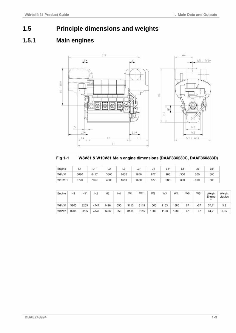
Fig 1-1 W8V31 & W10V31 Main engine dimensions (DAAF336230C, DAAF360383D)
L6*L6L5L4*L4L3*L3L2L1*L1Engine
50050030098687716501650356064176080W8V31
50050030098687716501650420070576720W10V31
WeightLiquids
WeightEngine
**
W5*W5W4W3W2W1*W1H4H3H2H1*H1Engine
3.357,1*-6767158511531600311531156501496474732053205W8V31
3.9564,7*-6767158511531600311531156501496474732053205W10V31
DBAE248994 1-3
1. Main Data and OutputsWärtsilä 31 Product Guide
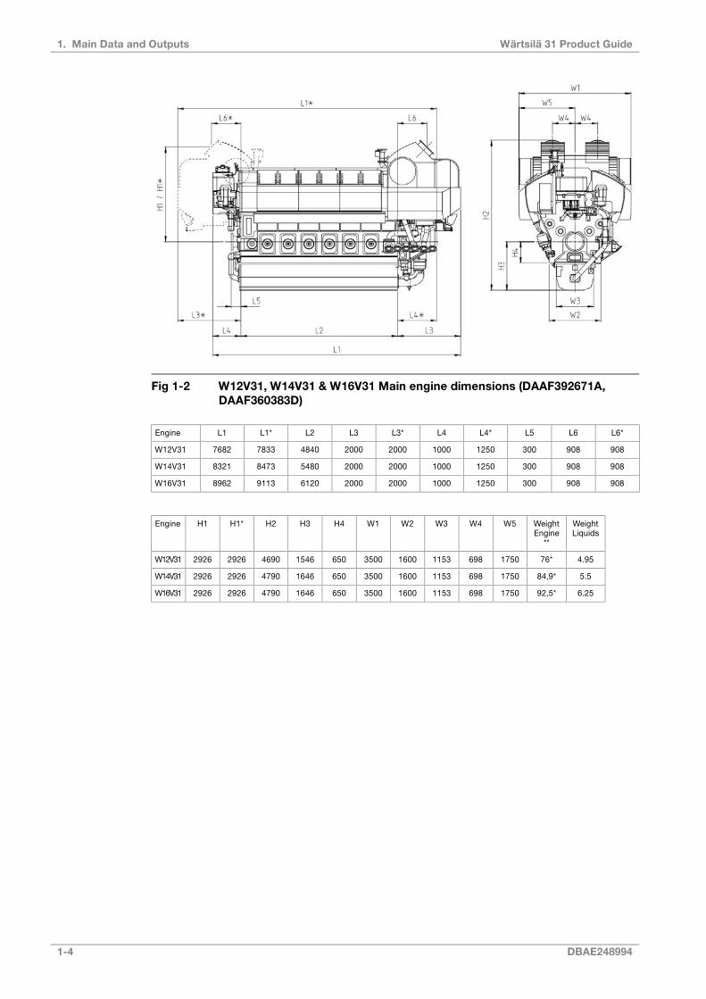
Fig 1-2 W12V31, W14V31 & W16V31 Main engine dimensions (DAAF392671A,DAAF360383D)
L6*L6L5L4*L4L3*L3L2L1*L1Engine
9089083001250100020002000484078337682W12V31
9089083001250100020002000548084738321W14V31
9089083001250100020002000612091138962W16V31
WeightLiquids
WeightEngine
**
W5W4W3W2W1H4H3H2H1*H1Engine
4.9576*17506981153160035006501546469029262926W12V31
5.584,9*17506981153160035006501646479029262926W14V31
6.2592,5*17506981153160035006501646479029262926W16V31
1-4 DBAE248994
Wärtsilä 31 Product Guide1. Main Data and Outputs
Total length of engineL1
Length of the engine blockL2
Length from the engine block to the outer most point in turbocharger endL3
Length from the engine block to the outer most point in non-turbocharger endL4
Length from engine block to crankshaft flangeL5
Length from engine block to center of exhaust gas outletL6
Height from the crankshaft centerline to center of exhaust gas outletH1
Total height of engine (normal wet sump)H2
Height from crankshaft centerline to bottom of the oil sump (normal wet sump)H3
Height from the crankshaft centerline to engine feet (fixed mounted)H4
Total width of engineW1
Width of engine block at the engine feetW2
Width of oil sumpW3
Width from crankshaft centerline to center of exhaust gas outletW4
Width from crankshaft centerline to the outer most point of the engineW5
* Turbocharger at flywheel end;
** Weight without liquids, damper and flywheel;
All dimensions in mm, weights in tonne.
NOTE
For reference only, project specific engine measurements please contact Wärtsilä.
DBAE248994 1-5
1. Main Data and OutputsWärtsilä 31 Product Guide

This page intentionally left blank

2. Operating Ranges
2.1 Engine operating rangeRunning below nominal speed the load must be limited according to the diagrams in thischapter in order to maintain engine operating parameters within acceptable limits. Minimumspeed is indicated in the diagram, but project specific limitations may apply.
2.1.1 Controllable pitch propellersThe engine load must be limited according to the diagram below when operating below nominalspeed, in order to maintain engine operating parameters within acceptable limits. Operationin the shaded area is permitted only temporarily during transients to permit smooth overloadcontrol.
Note that project specific vibration calculations may result in higher minimum speed than inthe diagram below.
The propeller efficiency is highest at design pitch. It is common practice to dimension thepropeller so that the specified ship speed is attained with design pitch, nominal engine speedand 85% output in the specified loading condition. The power demand from a possible shaftgenerator or PTO must be taken into account. The 15% margin is a provision for weatherconditions and fouling of hull and propeller. An additional engine margin can be applied formost economical operation of the engine, or to have reserve power.
Fig 2-1 Operating field for Controllable Pitch Propeller (DAAF292639D)
DBAE248994 2-1
2. Operating RangesWärtsilä 31 Product Guide
NOTE
1) Minimum engine speed 472 rpm with oil pump intended for CPP operation.Project specific limitations for minimum speed may apply
2) Additional restrictions may apply to low load operation
3) 720 rpm operating line could be used for example for operation with 60 Hz PTOor shaft generator. Maximum load 586 kW/cyl at 720 rpm.
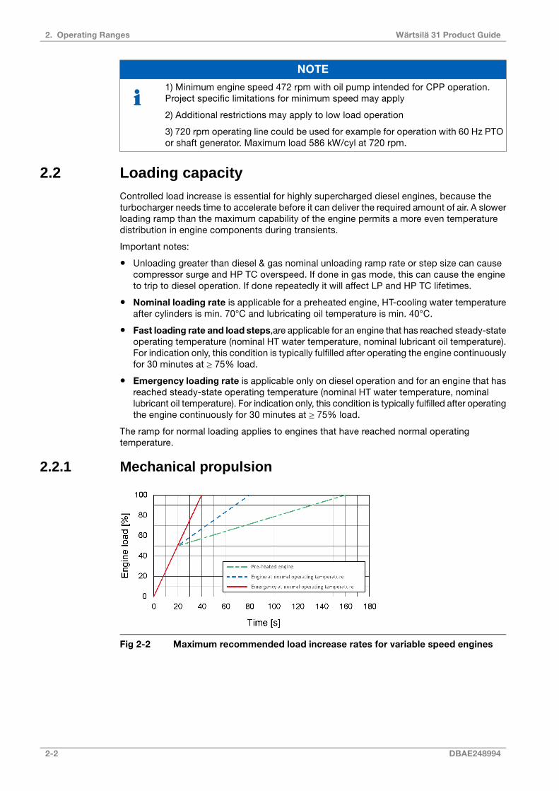
2.2 Loading capacityControlled load increase is essential for highly supercharged diesel engines, because theturbocharger needs time to accelerate before it can deliver the required amount of air. A slowerloading ramp than the maximum capability of the engine permits a more even temperaturedistribution in engine components during transients.
Important notes:
● Unloading greater than diesel & gas nominal unloading ramp rate or step size can causecompressor surge and HP TC overspeed. If done in gas mode, this can cause the engineto trip to diesel operation. If done repeatedly it will affect LP and HP TC lifetimes.
● Nominal loading rate is applicable for a preheated engine, HT-cooling water temperatureafter cylinders is min. 70°C and lubricating oil temperature is min. 40°C.
● Fast loading rate and load steps,are applicable for an engine that has reached steady-stateoperating temperature (nominal HT water temperature, nominal lubricant oil temperature).For indication only, this condition is typically fulfilled after operating the engine continuouslyfor 30 minutes at ≥ 75% load.
● Emergency loading rate is applicable only on diesel operation and for an engine that hasreached steady-state operating temperature (nominal HT water temperature, nominallubricant oil temperature). For indication only, this condition is typically fulfilled after operatingthe engine continuously for 30 minutes at ≥ 75% load.
The ramp for normal loading applies to engines that have reached normal operatingtemperature.
2.2.1 Mechanical propulsion
Fig 2-2 Maximum recommended load increase rates for variable speed engines
2-2 DBAE248994
Wärtsilä 31 Product Guide2. Operating Ranges

Fig 2-3 Maximum rate of load decrease at constant and variable speed
The propulsion control must include automatic limitation of the load increase rate. If the controlsystem has only one load increase ramp, then the ramp for a preheated engine should beused. In tug applications the engines have usually reached normal operating temperaturebefore the tug starts assisting. The “emergency” curve is close to the maximum capability ofthe engine.
Large load reductions from high load should also be performed gradually. In normal operationthe load should not be reduced from 100% to 0% in less than 45 seconds. When absolutelynecessary, the load can be reduced as fast as the pitch setting system can react (overspeeddue to windmilling must be considered for high speed ships).
DBAE248994 2-3
2. Operating RangesWärtsilä 31 Product Guide
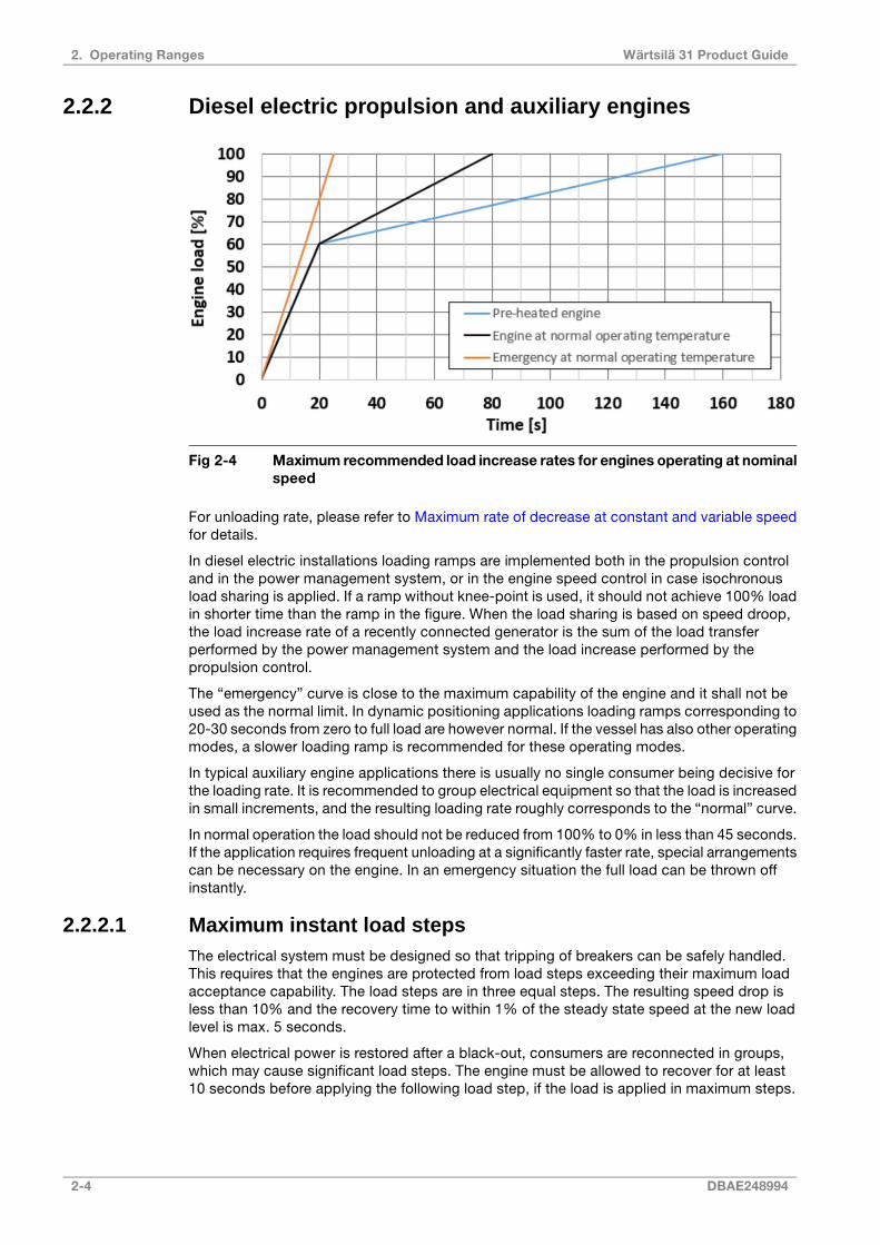
2.2.2 Diesel electric propulsion and auxiliary engines
Fig 2-4 Maximum recommended load increase rates for engines operating at nominalspeed
For unloading rate, please refer to Maximum rate of decrease at constant and variable speedfor details.
In diesel electric installations loading ramps are implemented both in the propulsion controland in the power management system, or in the engine speed control in case isochronousload sharing is applied. If a ramp without knee-point is used, it should not achieve 100% loadin shorter time than the ramp in the figure. When the load sharing is based on speed droop,the load increase rate of a recently connected generator is the sum of the load transferperformed by the power management system and the load increase performed by thepropulsion control.
The “emergency” curve is close to the maximum capability of the engine and it shall not beused as the normal limit. In dynamic positioning applications loading ramps corresponding to20-30 seconds from zero to full load are however normal. If the vessel has also other operatingmodes, a slower loading ramp is recommended for these operating modes.
In typical auxiliary engine applications there is usually no single consumer being decisive forthe loading rate. It is recommended to group electrical equipment so that the load is increasedin small increments, and the resulting loading rate roughly corresponds to the “normal” curve.
In normal operation the load should not be reduced from 100% to 0% in less than 45 seconds.If the application requires frequent unloading at a significantly faster rate, special arrangementscan be necessary on the engine. In an emergency situation the full load can be thrown offinstantly.
2.2.2.1 Maximum instant load stepsThe electrical system must be designed so that tripping of breakers can be safely handled.This requires that the engines are protected from load steps exceeding their maximum loadacceptance capability. The load steps are in three equal steps. The resulting speed drop isless than 10% and the recovery time to within 1% of the steady state speed at the new loadlevel is max. 5 seconds.
When electrical power is restored after a black-out, consumers are reconnected in groups,which may cause significant load steps. The engine must be allowed to recover for at least10 seconds before applying the following load step, if the load is applied in maximum steps.
2-4 DBAE248994
Wärtsilä 31 Product Guide2. Operating Ranges

2.2.2.2 Start-upA diesel generator typically reaches nominal speed in about 15 or 30 seconds (depending onstart mode) after the start signal. The acceleration is limited by the speed control to minimizesmoke during start-up. If requested faster starting times can be arranged.
2.3 Low load operationEngine idling and low load operating restrictions :
17.520%Load
3005015hLFO, max continous time
2001010hHFO, max continous time
Fig 2-5 Low load operating restrictions
NOTE
1) Above 17.5% load there is no additional restriction from low load operation.
2) Duration at low load only applies if charge air temperature in receiver is at :
- LFO: 35°C or above
- HFO: 45°C or above
3) High load running (minimum 70%) is to be followed for a minimum of 60 minutesto clean up the engine after maximum allowed low load running time has beenreached.
NOTE
Operating restrictions on SCR applications in low load operation to be observed.
DBAE248994 2-5
2. Operating RangesWärtsilä 31 Product Guide
2.4 SCR OperationSCR operations on sustained low load or idling might need special attention from the operator.For further details please contact Wärtsilä.
2.5 Low air temperatureIn standard conditions the following minimum inlet air temperatures apply:
● -10 ºC
NOTE
For starting with suction air temperature below -10 °C, arctic cooling system isneeded (All CACs in LT). LT-water or suction air heating is typically not needed.
For lower suction air temperatures engines shall be configured for arctic operation.
For further guidelines, see chapter Combustion air system design.
2-6 DBAE248994
Wärtsilä 31 Product Guide2. Operating Ranges

3. Technical Data
3.1 IntroductionReal-time product information including all technical data can be found by using Engine OnlineConfigurator available through Wärtsilä's website. Please check online for the most up to datetechnical data.
NOTE
Fuel consumptions in SCR operation guaranteed only when using Wärtsilä SCRunit.
NOTE
For proper operation of the Wärtsilä Nitrogen Oxide Reducer (NOR) systems, theexhaust temperature after the engine needs to be kept within a certain temperaturewindow. Please consult your sales contact at Wärtsilä for more information aboutSCR Operation.
DBAE248994 3-1
3. Technical DataWärtsilä 31 Product Guide

This page intentionally left blank
4. Description of the Engine
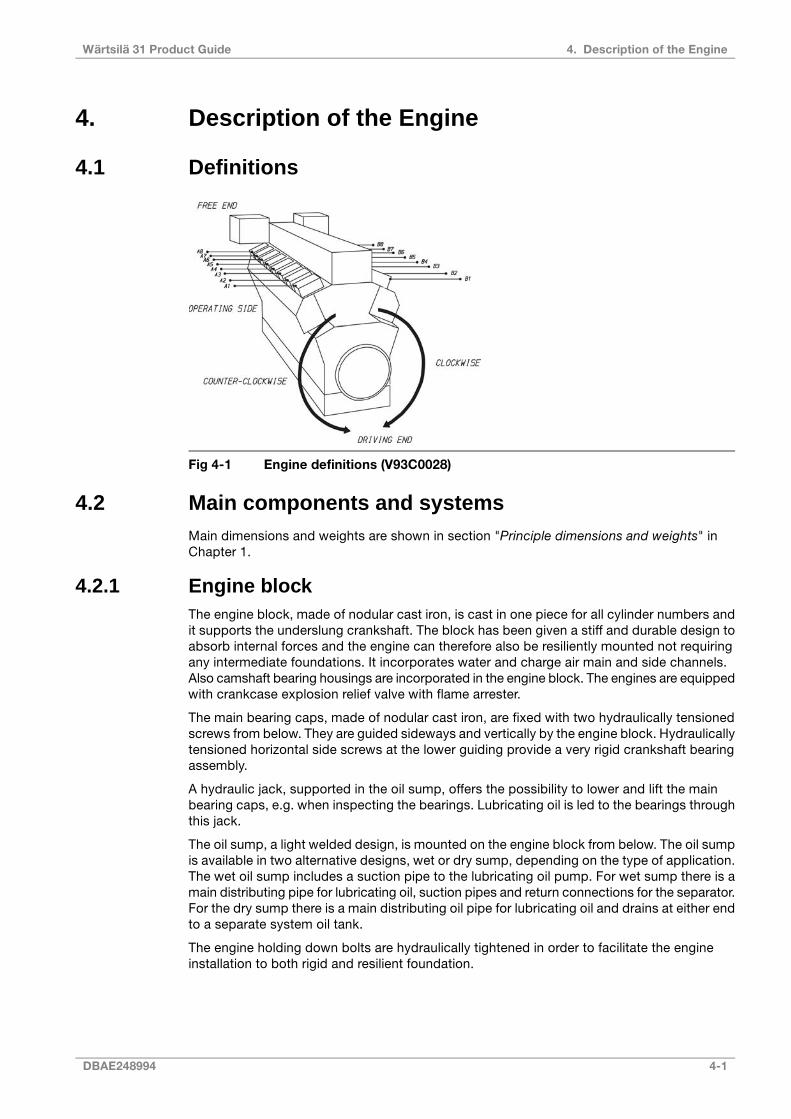
4.1 Definitions
Fig 4-1 Engine definitions (V93C0028)
4.2 Main components and systemsMain dimensions and weights are shown in section "Principle dimensions and weights" inChapter 1.
4.2.1 Engine blockThe engine block, made of nodular cast iron, is cast in one piece for all cylinder numbers andit supports the underslung crankshaft. The block has been given a stiff and durable design toabsorb internal forces and the engine can therefore also be resiliently mounted not requiringany intermediate foundations. It incorporates water and charge air main and side channels.Also camshaft bearing housings are incorporated in the engine block. The engines are equippedwith crankcase explosion relief valve with flame arrester.
The main bearing caps, made of nodular cast iron, are fixed with two hydraulically tensionedscrews from below. They are guided sideways and vertically by the engine block. Hydraulicallytensioned horizontal side screws at the lower guiding provide a very rigid crankshaft bearingassembly.
A hydraulic jack, supported in the oil sump, offers the possibility to lower and lift the mainbearing caps, e.g. when inspecting the bearings. Lubricating oil is led to the bearings throughthis jack.
The oil sump, a light welded design, is mounted on the engine block from below. The oil sumpis available in two alternative designs, wet or dry sump, depending on the type of application.The wet oil sump includes a suction pipe to the lubricating oil pump. For wet sump there is amain distributing pipe for lubricating oil, suction pipes and return connections for the separator.For the dry sump there is a main distributing oil pipe for lubricating oil and drains at either endto a separate system oil tank.
The engine holding down bolts are hydraulically tightened in order to facilitate the engineinstallation to both rigid and resilient foundation.
DBAE248994 4-1
4. Description of the EngineWärtsilä 31 Product Guide

4.2.2 CrankshaftCrankshaft line is built up from several pieces: crankshaft, counter weights, split camshaftgear wheel and pumpdrive arrangement.
Crankshaft itself is forged in one piece. Both main bearings and big end bearings temperaturesare continuously monitored.
Counterweights are fitted on every web. High degree of balancing results in an even and thickoil film for all bearings.
The connecting rods are arranged side-by-side and the diameters of the crank pins and journalsare equal irrespective of the cylinder number.
All crankshafts can be provided with torsional vibration dampers or tuning masses at the freeend of the engine, if necessary. Main features of crankshaft design: clean steel technologyminimizes the amount of slag forming elements and guarantees superior material durability.
The crankshaft alignment is always done on a thoroughly warm engine after the engine isstopped.
4.2.3 Connecting rodThe connecting rod is of forged alloy steel. All connecting rod studs are hydraulically tightened.
The connecting rod is of a three-piece design, which gives a minimum dismantling height andenables the piston to be dismounted without opening the big end bearing.
4.2.4 Main bearings and big end bearingsThe main bearings and the big end bearings are of tri-metal design with steel back, bronzelining and a soft running layer. The bearings are covered with a Sn-flash for corrosion protection.Even minor form deviations can become visible on the bearing surface in the running in phase.This has no negative influence on the bearing function. A wireless system for real-timetemperature monitoring of connecting rod big end bearings, "BEB monitoring system", is asstandard.
4.2.5 Cylinder linerThe cylinder liners are centrifugally cast of a special alloyed cast iron. The top collar of thecylinder liner is provided with a water jacket for distributing cooling water through the cylinderliner cooling bores. This will give an efficient control of the liner temperature. An oil lubricationsystem inside the cylinder liner lubricates the gudgeon pin bearing and also cools piston crownthrough the oil channels underside of the piston.
4.2.6 PistonThe piston is of composite type with steel crown and nodular cast iron skirt. A piston skirtlubricating system, featuring oil bores in a groove on the piston skirt, lubricates the pistonskirt/cylinder liner. The piston top is oil cooled by the same system mentioned above. Thepiston ring grooves are hardened for extended lifetime.
4.2.7 Piston ringsThe piston ring set are located in the piston crown and consists of two directional compressionrings and one spring-loaded conformable oil scraper ring. Running face of compression ringsare chromium-ceramic-plated.
4.2.8 Cylinder headThe cross flow cylinder head is made of cast iron. The mechanical load is absorbed by a flameplate, which together with the upper deck and the side walls form a rigid box section. There
4-2 DBAE248994
Wärtsilä 31 Product Guide4. Description of the Engine

are four hydraulically tightened cylinder head bolts. The exhaust valve seats and the flamedeck are efficiently and direct water-cooled. The valve seat rings are made of alloyed steel,for wear resistance. All valves are hydraulic controlled with valve guides and equipped withvalve springs and rotators.
A small side air receiver is located in the hot box, including charge air bends with integratedhydraulics and charge air riser pipes.
Following components are connected to the cylinder head:
● Charge air components for side receiver
● Exhaust gas pipe to exhaust system
● Cooling water collar
● Quill pipe with High Pressure (HP) fuel pipe connections
4.2.9 Camshaft and valve mechanismThe cams are integrated in the drop forged shaft material. The bearing journals are made inseparate pieces, which are fitted, to the camshaft pieces by flange connections. The camshaftbearing housings are integrated in the engine block casting and are thus completely closed.The bearings are installed and removed by means of a hydraulic tool. The camshaft covers,one for each cylinder, seal against the engine block with a closed O-ring profile. The valvetappets are of piston type with self-adjustment of roller against cam to give an even distributionof the contact pressure. Inlet and exhaust valves have a special steam coating and hard facingon the seat surface, for long lifetime. The valve springs make the valve mechanism dynamicallystable.
The step-less valve mechanism makes it possible to control the timing of both inlet & exhaustvalves. It allows to always use a proper scavenging period. This is needed to optimize andbalance emissions, fuel consumption, operational flexibility & load taking, whilst maintainingthermal and mechanical reliability. The design enables clearly longer maintenance interval,due to the reduced thermal and mechanical stress on most of the components in the valvemechanism.
4.2.10 Camshaft driveThe camshafts are driven by the crankshaft through a gear train. The gear wheel on thecrankshaft is clamped between the crankshaft and the end piece with expansion bolts.
4.2.11 Turbocharging and charge air coolingThe selected 2-stage turbocharging offers ideal combination of high-pressure ratios and goodefficiency both at full and part load. The turbochargers can be placed at the free end or flywheel end of the engine. For cleaning of the turbochargers during operation there is, asstandard, a water washing device for the air (compressor) and exhaust gas (turbine) side ofthe LP stage and for the exhaust gas (turbine) side of the HP stage. The water washing deviceis to be connected to an external unit. The turbochargers are lubricated by engine lubricatingoil with integrated connections.
An Exhaust gas Waste Gate (EWG) system controls the exhaust gas flow by-passing for bothhigh pressure (HP) and low pressure (LP) turbine stages. EWG is needed in case of enginesequipped with exhaust gas after treatment based on Selective Catalytic Reaction (SCR).
By using Air Waste Gate (AWG) the charge air pressure and the margin from LP compressoris controlled.
A step-less Air By-pass valve (ABP) system is used in all engine applications for preventingsurging of turbocharger compressors in case of rapid engine load reduction.
The Charge Air Coolers (CAC) consist of a 2-stage type cooler (LP CAC) between the LP andHP compressor stages and a 1-stage cooler (HP CAC) between the HP compressor stageand the charge air receiver. The LP CAC is cooled with LT-water or in some cases by both
DBAE248994 4-3
4. Description of the EngineWärtsilä 31 Product Guide

HT- and LT-water. The HP CAC is always cooled by LT-water and fresh water is used for bothcircuits. When there is a risk for over-speeding of the engine due to presence of combustiblegas or vapour in the inlet air, a UNIC automation controlled Charge Air Blocking device, canbe installed.
See chapter Exhaust gas & charge air systems for more information.
4.2.12 Fuel injection equipmentThe fuel injection equipment and system piping are located in a hotbox, providing maximumreliability and safety when using preheated heavy fuels. In the Wärtsilä electronic fuel injectionsystem, the fuel is pressurized in the high pressure HP-pumps from where the fuel is fed tothe injection valves which are rate optimized. The fuel system consists of different numbersof fuel oil HP pumps, depending of the cylinder configuration. HP pumps are located at theengine pump cover and from there high pressure pipes are connected to the system piping.A valve block is mounted at the fuel outlet pipe, including Pressure Drop and Safety Valve(PDSV), Circulation Valve (CV) and a fuel pressure discharge volume. The PDSV acts asmechanical safety valve and the fuel volume lowers the system pressure. The injection valvesare electronic controlled and the injection timing is pre-set in the control system software.
4.2.13 Lubricating oil systemThe engine internal lubricating oil system include the engine driven lubricating oil pump, theelectrically driven prelubricating oil pump, thermostatic valve, filters and lubricating oil cooler.The lubricating oil pumps are located in the free end of the engine, while the automatic filter,cooler and thermostatic valve are integrated into one module.
4.2.14 Cooling water systemThe fresh water cooling system is divided into a high temperature (HT) and a low temperature(LT) circuit.
For engines operating in normal conditions the HT-water is cooling the cylinders (jacket) andthe first stage of the low pressure 2-stage charge air cooler. The LT-water is cooling thelubricating oil cooler, the second stage of the low pressure 2-stage charge air cooler and thehigh pressure 1-stage charge air cooler.
For engines operating in cold conditions the HT-water is cooling the cylinders (Jacket). AHT-water pump is circulating the cooling water in the circuit and a thermostatic valve mountedin the internal cooling water system, controls the outlet temperature of the circuit. The LT-circuitis cooling the Lubricating Oil Cooler (LOC), the second stage of the Low Pressure 2-stagecharge air cooler, the High Pressure 1-stage charge air cooler and the first stage of the lowpressure 2-stage charge air cooler. An LT-thermostatic valve mounted in the external coolingwater system, controls the inlet temperature to the engine for achieving correct receivertemperature.
4.2.15 Exhaust pipesThe exhaust manifold pipes are made of special heat resistant nodular cast iron alloy.
The complete exhaust gas system is enclosed in an insulating box consisting of easilyremovable panels. Mineral wool is used as insulating material.
4.2.16 Automation systemThe Wärtsilä 31 engine is equipped with an UNIC electronic control system. UNIC havehardwired interface for control functions and a bus communication interface for alarm andmonitoring. Additionally UNIC includes fuel injection control for engines with electronic fuelinjection rate optimized nozzles.
For more information, see chapter Automation system.
4-4 DBAE248994
Wärtsilä 31 Product Guide4. Description of the Engine
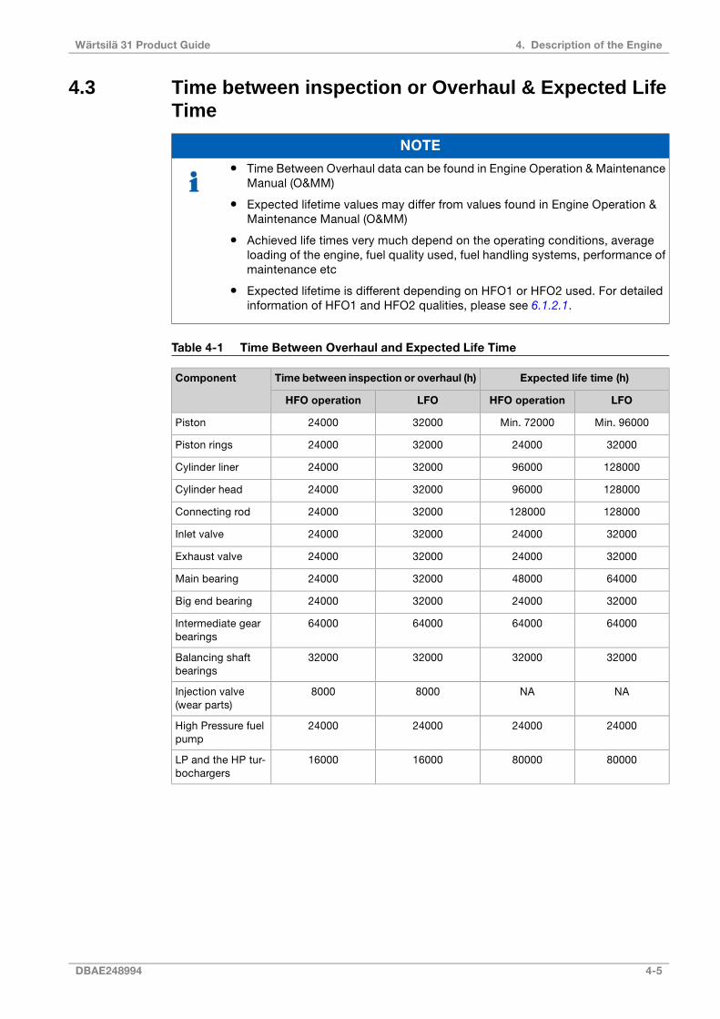
4.3 Time between inspection or Overhaul & Expected LifeTime
NOTE
● Time Between Overhaul data can be found in Engine Operation & MaintenanceManual (O&MM)
● Expected lifetime values may differ from values found in Engine Operation &Maintenance Manual (O&MM)
● Achieved life times very much depend on the operating conditions, averageloading of the engine, fuel quality used, fuel handling systems, performance ofmaintenance etc
● Expected lifetime is different depending on HFO1 or HFO2 used. For detailedinformation of HFO1 and HFO2 qualities, please see 6.1.2.1.
Table 4-1 Time Between Overhaul and Expected Life Time
Expected life time (h)Time between inspection or overhaul (h)Component
LFOHFO operationLFOHFO operation
Min. 96000Min. 720003200024000Piston
32000240003200024000Piston rings
128000960003200024000Cylinder liner
128000960003200024000Cylinder head
1280001280003200024000Connecting rod
32000240003200024000Inlet valve
32000240003200024000Exhaust valve
64000480003200024000Main bearing
32000240003200024000Big end bearing
64000640006400064000Intermediate gearbearings
32000320003200032000Balancing shaftbearings
NANA80008000Injection valve(wear parts)
24000240002400024000High Pressure fuelpump
80000800001600016000LP and the HP tur-bochargers
DBAE248994 4-5
4. Description of the EngineWärtsilä 31 Product Guide
NOTE
Even if residual fuels (HFO) do fulfil Wärtsilä fuel specification for HFO2 those theycan contain elevated amounts of sulphur and various ash constituents. This canincrease the risks of exhaust valve burning, hot corrosion of piston tops, increasedwear rate of cylinder liners and piston rings as well as deposit formation on enginecomponent surfaces. As a result of this the expected service intervals andcomponent lifetime might be shorter than compared to operation on average ortypical world-wide residual fuel quality.
4.4 Engine storageAt delivery the engine is provided with VCI coating and a tarpaulin. For storage longer than 3months please contact Wärtsilä Finland Oy.
4-6 DBAE248994
Wärtsilä 31 Product Guide4. Description of the Engine

5. Piping Design, Treatment and Installation
This chapter provides general guidelines for the design, construction and planning of pipingsystems, however, not excluding other solutions of at least equal standard. Installation relatedinstructions are included in the project specific instructions delivered for each installation.
Fuel, lubricating oil, fresh water and compressed air piping is usually made in seamless carbonsteel (DIN 2448) and seamless precision tubes in carbon or stainless steel (DIN 2391), exhaustgas piping in welded pipes of corten or carbon steel (DIN 2458). Sea-water piping should bein Cunifer or hot dip galvanized steel.
NOTE
The pipes in the freshwater side of the cooling water system must not be galvanized!
Attention must be paid to fire risk aspects. Fuel supply and return lines shall be designed sothat they can be fitted without tension. Flexible hoses must have an approval from theclassification society. If flexible hoses are used in the compressed air system, a purge valveshall be fitted in front of the hose(s).
It is recommended to make a fitting order plan prior to construction.
The following aspects shall be taken into consideration:
● Pockets shall be avoided. When not possible, drain plugs and air vents shall be installed
● Leak fuel drain pipes shall have continuous slope
● Vent pipes shall be continuously rising
● Flanged connections shall be used, cutting ring joints for precision tubes
Maintenance access and dismounting space of valves, coolers and other devices shall betaken into consideration. Flange connections and other joints shall be located so thatdismounting of the equipment can be made with reasonable effort.
5.1 Pipe dimensionsWhen selecting the pipe dimensions, take into account:
● The pipe material and its resistance to corrosion/erosion.
● Allowed pressure loss in the circuit vs delivery head of the pump.
● Required net positive suction head (NPSH) for pumps (suction lines).
● In small pipe sizes the max acceptable velocity is usually somewhat lower than in largepipes of equal length.
● The flow velocity should not be below 1 m/s in sea water piping due to increased risk offouling and pitting.
● In open circuits the velocity in the suction pipe is typically about 2/3 of the velocity in thedelivery pipe.
DBAE248994 5-1
5. Piping Design, Treatment and InstallationWärtsilä 31 Product Guide

Table 5-1 Recommended maximum velocities on pump delivery side for guidance
Max velocity [m/s]Pipe materialPiping
1.0Black steelFuel oil piping (MDF and HFO)
1.5Black steelLubricating oil piping
2.5Black steelFresh water piping
2.5Galvanized steelSea water piping
2.5Aluminum brass
3.010/90 copper-nickel-iron
4.570/30 copper-nickel
4.5Rubber lined pipes
NOTE
The diameter of gas fuel piping depends only on the allowed pressure loss in thepiping, which has to be calculated project specifically.
Compressed air pipe sizing has to be calculated project specifically. The pipe sizes may bechosen on the basis of air velocity or pressure drop. In each pipeline case it is advised tocheck the pipe sizes using both methods, this to ensure that the alternative limits are not beingexceeded.
Pipeline sizing on air velocity: For dry air, practical experience shows that reasonablevelocities are 25...30 m/s, but these should be regarded as the maximum above which noiseand erosion will take place, particularly if air is not dry. Even these velocities can be high interms of their effect on pressure drop. In longer supply lines, it is often necessary to restrictvelocities to 15 m/s to limit the pressure drop.
Pipeline sizing on pressure drop: As a rule of thumb the pressure drop from the starting airvessel to the inlet of the engine should be max. 0.1 MPa (1 bar) when the bottle pressure is 3MPa (30 bar).
It is essential that the instrument air pressure, feeding to some critical control instrumentation,is not allowed to fall below the nominal pressure stated in chapter "Compressed air system"due to pressure drop in the pipeline.
5.2 Pressure classThe pressure class of the piping should be higher than or equal to the design pressure, whichshould be higher than or equal to the highest operating (working) pressure. The highestoperating (working) pressure is equal to the setting of the safety valve in a system.
The pressure in the system can:
● Originate from a positive displacement pump
● Be a combination of the static pressure and the pressure on the highest point of the pumpcurve for a centrifugal pump
● Rise in an isolated system if the liquid is heated
Within this publication there are tables attached to drawings, which specify pressure classesof connections. The pressure class of a connection can be higher than the pressure classrequired for the pipe.
Example 1:
5-2 DBAE248994
Wärtsilä 31 Product Guide5. Piping Design, Treatment and Installation
The fuel pressure before the engine should be 0.7 MPa (7 bar). The safety filter in dirty conditionmay cause a pressure loss of 0.1 MPa (1.0 bar). The viscosimeter, automatic filter, preheaterand piping may cause a pressure loss of 0.25 MPa (2.5 bar). Consequently the dischargepressure of the circulating pumps may rise to 1.05 MPa (10.5 bar), and the safety valve of thepump shall thus be adjusted e.g. to 1.2 MPa (12 bar).
● A design pressure of not less than 1.2 MPa (12 bar) has to be selected.
● The nearest pipe class to be selected is PN16.
● Piping test pressure is normally 1.5 x the design pressure = 1.8 MPa (18 bar).
Example 2:
The pressure on the suction side of the cooling water pump is 0.1 MPa (1 bar). The deliveryhead of the pump is 0.3 MPa (3 bar), leading to a discharge pressure of 0.4 MPa (4 bar). Thehighest point of the pump curve (at or near zero flow) is 0.1 MPa (1 bar) higher than the nominalpoint, and consequently the discharge pressure may rise to 0.5 MPa (5 bar) (with closed orthrottled valves).
● Consequently a design pressure of not less than 0.5 MPa (5 bar) shall be selected.
● The nearest pipe class to be selected is PN6.
● Piping test pressure is normally 1.5 x the design pressure = 0.75 MPa (7.5 bar).
Standard pressure classes are PN4, PN6, PN10, PN16, PN25, PN40, etc.
5.3 Pipe classClassification societies categorize piping systems in different classes (DNV) or groups (ABS)depending on pressure, temperature and media. The pipe class can determine:
● Type of connections to be used
● Heat treatment
● Welding procedure
● Test method
Systems with high design pressures and temperatures and hazardous media belong to classI (or group I), others to II or III as applicable. Quality requirements are highest on class I.
Examples of classes of piping systems as per DNV rules are presented in the table below.
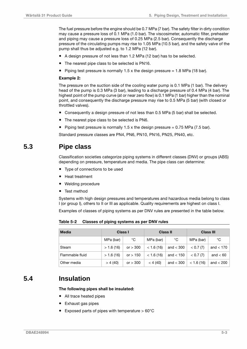
Table 5-2 Classes of piping systems as per DNV rules
Class IIIClass IIClass IMedia
°CMPa (bar)°CMPa (bar)°CMPa (bar)
and < 170< 0.7 (7)and < 300< 1.6 (16)or > 300> 1.6 (16)Steam
and < 60< 0.7 (7)and < 150< 1.6 (16)or > 150> 1.6 (16)Flammable fluid
and < 200< 1.6 (16)and < 300< 4 (40)or > 300> 4 (40)Other media
5.4 InsulationThe following pipes shall be insulated:
● All trace heated pipes
● Exhaust gas pipes
● Exposed parts of pipes with temperature > 60°C
DBAE248994 5-3
5. Piping Design, Treatment and InstallationWärtsilä 31 Product Guide
Insulation is also recommended for:
● Pipes between engine or system oil tank and lubricating oil separator
● Pipes between engine and jacket water preheater
5.5 Local gaugesLocal thermometers should be installed wherever a new temperature occurs, i.e. before andafter heat exchangers, etc.
Pressure gauges should be installed on the suction and discharge side of each pump.
5.6 Cleaning proceduresInstructions shall be given at an early stage to manufacturers and fitters how different pipingsystems shall be treated, cleaned and protected.
5.6.1 Cleanliness during pipe installationAll piping must be verified to be clean before lifting it onboard for installation. During theconstruction time uncompleted piping systems shall be maintained clean. Open pipe endsshould be temporarily closed. Possible debris shall be removed with a suitable method. Alltanks must be inspected and found clean before filling up with fuel, oil or water.
Piping cleaning methods are summarised in table below:
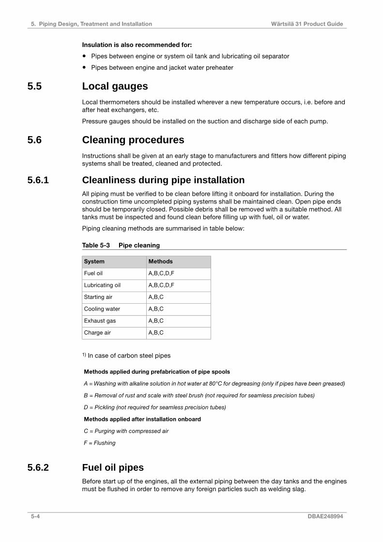
Table 5-3 Pipe cleaning
MethodsSystem
A,B,C,D,FFuel oil
A,B,C,D,FLubricating oil
A,B,CStarting air
A,B,CCooling water
A,B,CExhaust gas
A,B,CCharge air
1) In case of carbon steel pipes
Methods applied during prefabrication of pipe spools
A = Washing with alkaline solution in hot water at 80°C for degreasing (only if pipes have been greased)
B = Removal of rust and scale with steel brush (not required for seamless precision tubes)
D = Pickling (not required for seamless precision tubes)
Methods applied after installation onboard
C = Purging with compressed air
F = Flushing
5.6.2 Fuel oil pipesBefore start up of the engines, all the external piping between the day tanks and the enginesmust be flushed in order to remove any foreign particles such as welding slag.
5-4 DBAE248994
Wärtsilä 31 Product Guide5. Piping Design, Treatment and Installation

Disconnect all the fuel pipes at the engine inlet and outlet . Install a temporary pipe or hoseto connect the supply line to the return line, bypassing the engine. The pump used for flushingshould have high enough capacity to ensure highly turbulent flow, minimum same as the maxnominal flow. Heaters, automatic filters and the viscosimeter should be bypassed to preventdamage caused by debris in the piping. The automatic fuel filter must not be used as flushingfilter.
The pump used should be protected by a suction strainer. During this time the welds in thefuel piping should be gently knocked at with a hammer to release slag and the filter inspectedand carefully cleaned at regular intervals.
The cleanliness should be minimum ISO 4406 © 20/18/15, or NAS 1638 code 9. A measurementcertificate shows required cleanliness has been reached there is still risk that impurities mayoccur after a time of operation.
Note! The engine must not be connected during flushing.
5.6.3 Lubricating oil pipesFlushing of the piping and equipment built on the engine is not required and flushing oil shallnot be pumped through the engine oil system (which is flushed and clean from the factory).
It is however acceptable to circulate the flushing oil via the engine sump if this is advantageous.Cleanliness of the oil sump shall be verified after completed flushing and is acceptable whenthe cleanliness has reached a level in accordance with ISO 4406 © 21/19/15, or NAS 1638code 10. All pipes connected to the engine, the engine wet sump or to the external enginewise oil tank shall be flushed. Oil used for filling shall have a cleanliness of ISO 4406 © 21/19/15,or NAS 1638 code 10.
Note! The engine must not be connected during flushing
5.6.4 PicklingPrefabricated pipe spools are pickled before installation onboard.
Pipes are pickled in an acid solution of 10% hydrochloric acid and 10% formaline inhibitor for4-5 hours, rinsed with hot water and blown dry with compressed air.
After acid treatment the pipes are treated with a neutralizing solution of 10% caustic sodaand 50 grams of trisodiumphosphate per litre of water for 20 minutes at 40...50°C, rinsed withhot water and blown dry with compressed air.
Great cleanliness shall be validated in all work phases after completed pickling.
5.7 Flexible pipe connectionsAll external pipes must be precisely aligned to the fitting or the flange of the engine to minimizecausing external forces to the engine connection.
Adding adapter pieces to the connection between the flexible pipe and engine, which are notvalidated by Wärtsilä are forbidden. Observe that the pipe clamp for the pipe outside theflexible connection must be very rigid and welded to the steel structure of the foundation toprevent vibrations and external forces to the connection, which could damage the flexibleconnections and transmit noise. The support must be close to the flexible connection. Mostproblems with bursting of the flexible connection originate from poor clamping.
Proper installation of pipe connections between engines and ship’s piping to be ensured.
● Flexible pipe connections must not be twisted
● Installation length of flexible pipe connections must be correct
● Minimum bending radius must be respected
DBAE248994 5-5
5. Piping Design, Treatment and InstallationWärtsilä 31 Product Guide

● Piping must be concentrically aligned
● When specified, the flow direction must be observed
● Mating flanges shall be clean from rust, burrs and anticorrosion coatings
● If not otherwise instructed, bolts are to be tightened crosswise in several stages
● Painting of flexible elements is not allowed
● Rubber bellows must be kept clean from oil and fuel
● The piping must be rigidly supported close to the flexible piping connections.
Fig 5-1 Flexible hoses
NOTE
Pressurized flexible connections carrying flammable fluids or compressed air haveto be type approved.
5-6 DBAE248994
Wärtsilä 31 Product Guide5. Piping Design, Treatment and Installation
5.8 Clamping of pipesIt is very important to fix the pipes to rigid structures next to flexible pipe connections in orderto prevent damage caused by vibration. The following guidelines should be applied:
● Pipe clamps and supports next to the engine must be very rigid and welded to the steelstructure of the foundation.
● The first support should be located as close as possible to the flexible connection. Nextsupport should be 0.3-0.5 m from the first support.
● First three supports closest to the engine or generating set should be fixed supports. Wherenecessary, sliding supports can be used after these three fixed supports to allow thermalexpansion of the pipe.
● Supports should never be welded directly to the pipe. Either pipe clamps or flange supportsshould be used for flexible connection.
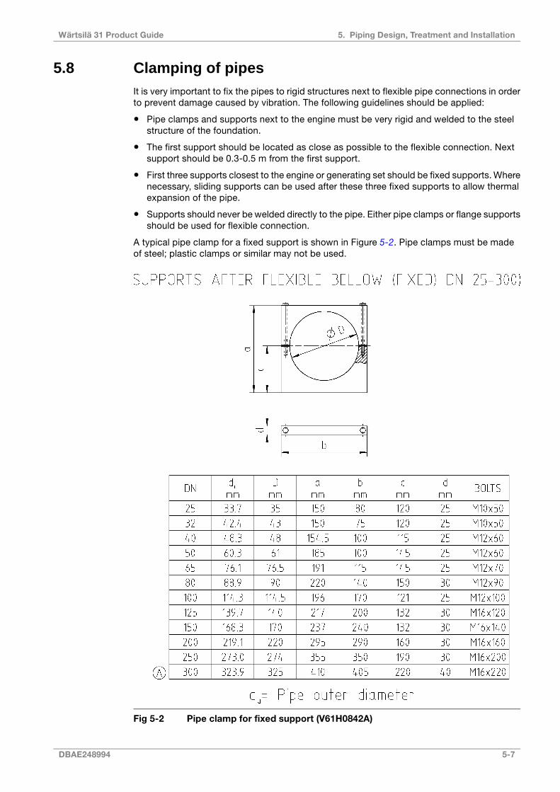
A typical pipe clamp for a fixed support is shown in Figure 5-2. Pipe clamps must be madeof steel; plastic clamps or similar may not be used.
Fig 5-2 Pipe clamp for fixed support (V61H0842A)
DBAE248994 5-7
5. Piping Design, Treatment and InstallationWärtsilä 31 Product Guide

This page intentionally left blank
6. Fuel System
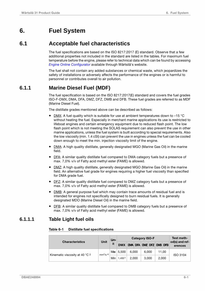
6.1 Acceptable fuel characteristicsThe fuel specifications are based on the ISO 8217:2017 (E) standard. Observe that a fewadditional properties not included in the standard are listed in the tables. For maximum fueltemperature before the engine, please refer to technical data which can be found by accessingEngine Online Configurator available through Wärtsilä's website.
The fuel shall not contain any added substances or chemical waste, which jeopardizes thesafety of installations or adversely affects the performance of the engines or is harmful topersonnel or contributes overall to air pollution.
6.1.1 Marine Diesel Fuel (MDF)The fuel specification is based on the ISO 8217:2017(E) standard and covers the fuel gradesISO-F-DMX, DMA, DFA, DMZ, DFZ, DMB and DFB. These fuel grades are referred to as MDF(Marine Diesel Fuel).
The distillate grades mentioned above can be described as follows:
● DMX: A fuel quality which is suitable for use at ambient temperatures down to –15 °Cwithout heating the fuel. Especially in merchant marine applications its use is restricted tolifeboat engines and certain emergency equipment due to reduced flash point. The lowflash point which is not meeting the SOLAS requirement can also prevent the use in othermarine applications, unless the fuel system is built according to special requirements. Alsothe low viscosity (min. 1.4 cSt) can prevent the use in engines unless the fuel can be cooleddown enough to meet the min. injection viscosity limit of the engine.
● DMA: A high quality distillate, generally designated MGO (Marine Gas Oil) in the marinefield.
● DFA: A similar quality distillate fuel compared to DMA category fuels but a presence ofmax. 7,0% v/v of Fatty acid methyl ester (FAME) is allowed.
● DMZ: A high quality distillate, generally designated MGO (Marine Gas Oil) in the marinefield. An alternative fuel grade for engines requiring a higher fuel viscosity than specifiedfor DMA grade fuel.
● DFZ: A similar quality distillate fuel compared to DMZ category fuels but a presence ofmax. 7,0% v/v of Fatty acid methyl ester (FAME) is allowed.
● DMB: A general purpose fuel which may contain trace amounts of residual fuel and isintended for engines not specifically designed to burn residual fuels. It is generallydesignated MDO (Marine Diesel Oil) in the marine field.
● DFB: A similar quality distillate fuel compared to DMB category fuels but a presence ofmax. 7,0% v/v of Fatty acid methyl ester (FAME) is allowed.
6.1.1.1 Table Light fuel oils
Table 6-1 Distillate fuel specifications
Test meth-od(s) and ref-erences
Category ISO-FLim-it
UnitCharacteristicsDFBDMBDFZDMZDFADMADMX
ISO 310411,006,0006,0005,500Max
mm2/s a)Kinematic viscosity at 40 °C j)
2,0003,0002,0001,400 i)Min
DBAE248994 6-1
6. Fuel SystemWärtsilä 31 Product Guide

Test meth-od(s) and ref-erences
Category ISO-FLim-it
UnitCharacteristicsDFBDMBDFZDMZDFADMADMX
ISO 3675 orISO 12185
900,0890,0890,0-Maxkg/m³Density at 15 °C
ISO 426435404045MinCetane index
ISO 8754 orISO 14596,
ASTM D42941,501,001,001,00Max
% m/
mSulphur b, k)
ISO 271960,060,060,043,0 l)Min°CFlash point
IP 5702,002,002,002,00Maxmg/kgHydrogen sulfide
ASTM D6640,50,50,50,5Maxmg
KOH/gAcid number
ISO 10307-10,10 c)---Max% m/
mTotal sediment by hot filtration
ISO 1220525 d)252525Maxg/m³Oxidation stability
ASTM D7963or IP 579
7,0-7,0-7,0--Max% v/vFatty acid methyl ester (FAME) e)
ISO 10370-0,300,300,30Max% m/
mCarbon residue – Micro methodon 10% distillation residue
ISO 103700,30---Max% m/
mCarbon residue – Micro method
ISO 3015-ReportReport-16
Max°Cwinter
Cloud point f)
----16summer
IP 309 or IP612
-ReportReport-Max°C
winterCold filter plugging pointf)
----summer
ISO 30160-6-6-
Max°Cwinter
Pour point f)
600-summer
-c)Clear and bright g)-Appearance
ISO 3733 orASTM D6304-
C m)0,30 c)---Max% v/vWater
ISO 62450,0100,0100,0100,010Max% m/
mAsh
ISO 12156-1520 d)520520520MaxµmLubricity, corr. wear scar diam. h)
6-2 DBAE248994
Wärtsilä 31 Product Guide6. Fuel System
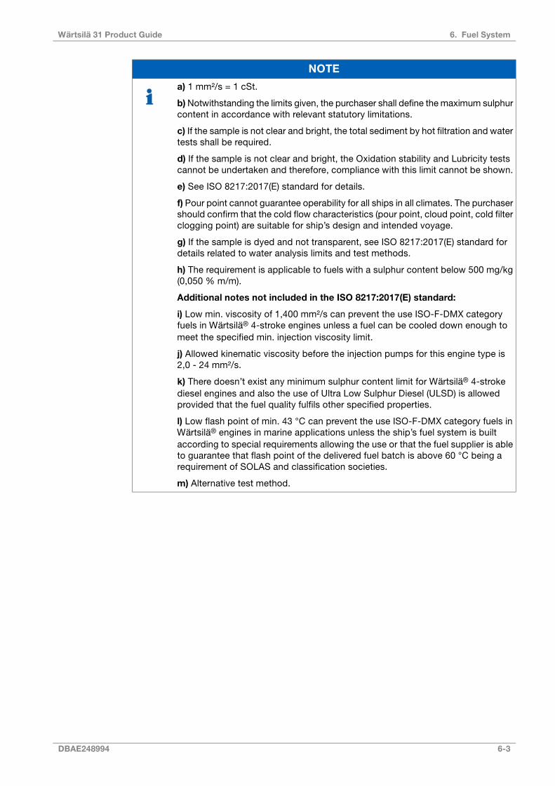
NOTE
a) 1 mm²/s = 1 cSt.
b)Notwithstanding the limits given, the purchaser shall define the maximum sulphurcontent in accordance with relevant statutory limitations.
c) If the sample is not clear and bright, the total sediment by hot filtration and watertests shall be required.
d) If the sample is not clear and bright, the Oxidation stability and Lubricity testscannot be undertaken and therefore, compliance with this limit cannot be shown.
e) See ISO 8217:2017(E) standard for details.
f) Pour point cannot guarantee operability for all ships in all climates. The purchasershould confirm that the cold flow characteristics (pour point, cloud point, cold filterclogging point) are suitable for ship’s design and intended voyage.
g) If the sample is dyed and not transparent, see ISO 8217:2017(E) standard fordetails related to water analysis limits and test methods.
h) The requirement is applicable to fuels with a sulphur content below 500 mg/kg(0,050 % m/m).
Additional notes not included in the ISO 8217:2017(E) standard:
i) Low min. viscosity of 1,400 mm²/s can prevent the use ISO-F-DMX categoryfuels in Wärtsilä® 4-stroke engines unless a fuel can be cooled down enough tomeet the specified min. injection viscosity limit.
j) Allowed kinematic viscosity before the injection pumps for this engine type is2,0 - 24 mm²/s.
k) There doesn’t exist any minimum sulphur content limit for Wärtsilä® 4-strokediesel engines and also the use of Ultra Low Sulphur Diesel (ULSD) is allowedprovided that the fuel quality fulfils other specified properties.
l) Low flash point of min. 43 °C can prevent the use ISO-F-DMX category fuels inWärtsilä® engines in marine applications unless the ship’s fuel system is builtaccording to special requirements allowing the use or that the fuel supplier is ableto guarantee that flash point of the delivered fuel batch is above 60 °C being arequirement of SOLAS and classification societies.
m) Alternative test method.
DBAE248994 6-3
6. Fuel SystemWärtsilä 31 Product Guide
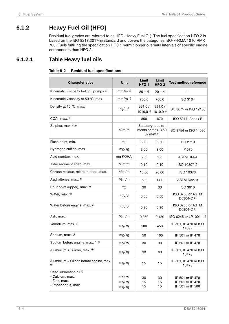
6.1.2 Heavy Fuel Oil (HFO)Residual fuel grades are referred to as HFO (Heavy Fuel Oil). The fuel specification HFO 2 isbased on the ISO 8217:2017(E) standard and covers the categories ISO-F-RMA 10 to RMK700. Fuels fulfilling the specification HFO 1 permit longer overhaul intervals of specific enginecomponents than HFO 2.
6.1.2.1 Table Heavy fuel oils
Table 6-2 Residual fuel specifications
Test method referenceLimitHFO 2
LimitHFO 1
UnitCharacteristics
-20 ± 420 ± 4mm2/s b)Kinematic viscosity bef. inj. pumps d)
ISO 3104700,0700,0mm2/s b)Kinematic viscosity at 50 °C, max.
ISO 3675 or ISO 12185991,0 /
1010,0 a)
991,0 /
1010,0 a)kg/m3Density at 15 °C, max.
ISO 8217, Annex F870850-CCAI, max. f)
ISO 8754 or ISO 14596Statutory require-
ments or max. 3,50% m/m c)
%m/mSulphur, max. c, g)
ISO 271960,060,0°CFlash point, min.
IP 5702,002,00mg/kgHydrogen sulfide, max.
ASTM D6642,52,5mg KOH/gAcid number, max.
ISO 10307-20,100,10%m/mTotal sediment aged, max.
ISO 1037020,0015,00%m/mCarbon residue, micro method, max.
ASTM D327914,08,0%m/mAsphaltenes, max. d)
ISO 30163030°CPour point (upper), max. e)
ISO 3733 or ASTMD6304-C d)0,500,50%V/VWater, max. d)
ISO 3733 or ASTMD6304-C d)0,300,30%V/VWater before engine, max. d)
ISO 6245 or LP1001 d, i)0,1500,050%m/mAsh, max.
IP 501, IP 470 or ISO14597
450100mg/kgVanadium, max. g)
IP 501 or IP 47010050mg/kgSodium, max. g)
IP 501 or IP 4703030mg/kgSodium before engine, max. d, g)
IP 501, IP 470 or ISO10478
6030mg/kgAluminium + Silicon, max. d)
IP 501, IP 470 or ISO10478
1515mg/kgAluminium + Silicon before engine, max.d)
IP 501 or IP 470IP 501 or IP 470IP 501 or IP 500
301515
301515
mg/kg
mg/kg
mg/kg
Used lubricating oil h)
- Calcium, max.- Zinc, max.- Phosphorus, max.
6-4 DBAE248994
Wärtsilä 31 Product Guide6. Fuel System

NOTE
a) Max. 1010 kg/m³ at 15 °C, provided the fuel treatment system can reduce waterand solids (sediment, sodium, aluminium, silicon) before engine to the specifiedlevels.
b) 1 mm²/s = 1 cSt.
c) The purchaser shall define the maximum sulphur content in accordance withrelevant statutory limitations. However, the use of fuels with sulphur content higherthan 3,50 % m/m is also possible. Please contact Wärtsilä for further evaluation.
d) Additional properties specified by the engine manufacturer, which are notincluded in the ISO 8217:2017(E) standard.
e) Purchasers shall ensure that this pour point is suitable for the equipment onboard / at the plant, especially if the ship operates / plant is located in cold climates.
f) Straight run residues show CCAI values in the 770 to 840 range and are verygood ignitors. Cracked residues delivered as bunkers may range from 840 to – inexceptional cases – above 900. Most bunkers remain in the max. 850 to 870 rangeat the moment. CCAI value cannot always be considered as an accurate tool todetermine fuels’ ignition properties, especially concerning fuels originating frommodern and more complex refinery processes.
g) Sodium contributes to hot corrosion on exhaust valves when combined withhigh sulphur and vanadium contents. Sodium also strongly contributes to foulingof the exhaust gas turbine blading at high loads. The aggressiveness of the fueldepends on its proportions of sodium and vanadium, but also on the total amountof ash. Hot corrosion and deposit formation are, however, also influenced by otherash constituents. It is therefore difficult to set strict limits based only on the sodiumand vanadium content of the fuel. Also a fuel with lower sodium and vanadiumcontents than specified above, can cause hot corrosion on engine components.
h) The fuel shall be free from used lubricating oil (ULO). A fuel shall be consideredto contain ULO when either one of the following conditions is met:
● Calcium > 30 mg/kg and zinc > 15 mg/kg OR
● Calcium > 30 mg/kg and phosphorus > 15 mg/kg
i) The ashing temperatures can vary when different test methods are used havingan influence on the test result.
6.1.3 Biofuel oilsLiquid biofuel characteristics and specifications
Wärtsilä engine is designed and developed for continuous operation on below specified liquidbiofuel (LBF) qualities with the properties included in the tables below. The engine is notdesigned nor developed for properties not included in these tables.
NOTE
Liquid biofuels included in the Table have typically lower heating value than fossilfuels, while the capacity of fuel injection system influencing on guaranteed engineoutput must be checked case by case.
DBAE248994 6-5
6. Fuel SystemWärtsilä 31 Product Guide

NOTE
Liquid biofuels included in the Table have a low density, while the capacity of fuelinjection system influencing on guaranteed engine output must be checked caseby case. Their flash point can based on specifications be also lower than 60 °Crequired for marine applications by SOLAS and Classification societies, which mayprevent the use.
NOTE
The use of liquid biofuels qualities always require a NSR to be made.
Blending of different fuel qualities:
Liquid biofuel qualities presented in the Table 1 and 2 can be mixed with fossil distillate fuelwith various ratios. Fossil fuel being used as a blending component must fulfil Wärtsilä’ sdistillate fuel specification based on the ISO 8217:2017(E) standard. Depending on the biocomponent type its quality must meet either the EN 14214:2012 standard included in the Table1 or the EN 15940:2016 standard included in the Table 2.
6.1.3.1 Fatty acid methyl ester (FAME) / BiodieselRenewable refined liquid biofuels which are manufactured by using transesterificationprocesses, can contain both vegetable and / or animal based feedstock and do normally showout very good physical and chemical properties. These fuels can be used provided that thespecification included in the table below is fulfilled. International standards ASTM D 6751-19or EN 14214:2012 (E) are typically used for specifying biodiesel quality.
Table 6-3 Fatty acid methyl ester (FAME) / Biodiesel specification based on the EN14214:2012 standard
Test method referenceLimitUnitProperty
EN ISO 31043.5 - 5.0mm2/s @ 40
°CViscosity, min. - max.
EN ISO 31041.8 - 2.0 1)mm2/sInjection viscosity, min.
EN ISO 3675 / 12185860 - 900kg/m3 @ 15
°CDensity, min. - max.
EN ISO 516551.0-Cetane number, min.
EN ISO 20846 / 20884 / 1303210.0mg/kgSulphur content, max.
ISO 39870.02% m/mSulphated ash content, max.
EN 1266224mg/kgTotal contamination, max.
EN ISO 12937500mg/kgWater content, max.
EN 141074.0mg/kgPhosphorus content, max.
EN 14108 / EN 14109 / 145385.0mg/kgGroup I metals (Na + K) content, max.
EN 145385.0mg/kgGroup II metals (Ca + Mg) content, max.
EN ISO 2719A / 3679101°CFlash point, min.
EN 116-20 → +5 2)°CCold filter plugging point, max. (climatedependent requirement)
6-6 DBAE248994
Wärtsilä 31 Product Guide6. Fuel System

Test method referenceLimitUnitProperty
EN 141128.0hOxidation stability @ 110 °C, min.
EN ISO 2160Class 1RatingCopper strip corrosion (3 hrs @ 50 °C),max.
EN 141040.50mg KOH/gAcid value, max.
EN 14111 / 16300120g iodine/100 gIodine value, max.
EN 1410396.5% m/mFAME content, min.
EN 1410312.0% m/mLinolenic acid methyl ester, max.
EN 157791.00% m/mPolyunsaturated ( ≥ 4 double bonds)methyl esters, max.
EN 141100.20% m/mMethanol content, max.
EN 141050.70% m/mMonoglyceride content, max.
EN 141050.20% m/mDiglyceride content, max.
EN 141050.20% m/mTriglyceride content, max.
EN 14105 / EN 141060.02% m/mFree glycerol, max.
EN 141050.25% m/mTotal glycerol, max.
NOTE
1) Min. viscosity limit at engine inlet in running conditions; 2,0 cSt.
2) Cold flow properties of renewable biodiesel can vary based on the geographicallocation and also based on the feedstock properties, which issues must be takeninto account when designing the fuel system. For arctic climates even lower CFPPvalues down to -44 °C are specified.
6.1.3.2 Paraffinic diesel fuels from synthesis and hydrotreatmentParaffinic renewable distillate fuels originating from synthesis or hydrotreatment representclearly a better quality than transesterfied biodiesel and the comparison to biodiesel qualityrequirements is thus so relevant. The quality of the fuel qualities shall meet the EN 15940:2016Class A requirements included in the table below. For arctic or severe winter climates additionalor more stringent requirements are set concerning cold filter plugging point, cloud point,viscosity and distillation properties.
Table 6-4 Requirements for paraffinic diesel from synthesis or hydrotreatment basedon the EN 15940:2016 standard
Test method referenceLimitUnitProperty
EN ISO 31042.0 - 4.5mm2/s @ 40
°CViscosity, min. - max.
EN ISO 31041.8 - 2.0 1)mm2/sInjection viscosity, min.
EN ISO 3675 / 12185765 - 800 2)kg/m3 @ 15
°CDensity, min. - max.
EN 15195 / EN ISO 516570.0-Cetane number, min.
DBAE248994 6-7
6. Fuel SystemWärtsilä 31 Product Guide

Test method referenceLimitUnitProperty
EN ISO 20846 / 208845.0mg/kgSulphur content, max.
EN ISO 62450.010% m/mAsh content, max.
EN 1266224mg/kgTotal contamination, max.
EN ISO 12937200mg/kgWater content, max.
EN 129161.1% m/mTotal aromatics, max.
EN ISO 103700.30% m/mCarbon residue on 10% distillationresidue, max.
EN ISO 12156-1460µmLubricity, max.
EN ISO 271955 3)°CFlash point, min.
EN 116 / 16329-20 → +5 4)°CCold filter plugging point, max. (climatedependent requirement)
EN ISO 12205EN 15751
2520 5)
g/m3
hOxidation stability, max.Oxidation stability, min.
EN ISO 2160Class 1RatingCopper strip corrosion (3 hrs @ 50 °C),max.
EN ISO 3405 / 3924Distillation
65% v/v% v/v recovered @ 250 °C, max.
85% v/v% v/v recovered @ 350 °C, min.
360°C95 % v/v recovered at, max.
EN ISO 3405 / 3924
6585
360
% v/v
% v/v
°C
Distillation% v/v recovered @ 250 °C, max.
% v/v recovered @ 350 °C, min.
95 % v/v recovered at, max.
EN 140787.0% v/vFAME content, max.
NOTE
1) Min. viscosity limit at engine inlet in running conditions; 2,0 cSt.
2) Due to low density the guaranteed engine output of pure hydrotreated fuel /GTL has to be confirmed case by case.
3) The use in marine applications is allowed provided that a fuel supplier canguarantee min. flash point of 60 °C.
4) Cold flow properties of renewable biodiesel can vary based on the geographicallocation and also based on the feedstock properties, which issues must be takeninto account when designing the fuel system. For arctic or severe winter climateseven lower CFPP values down to -44 °C are specified.
5) Additional requirement if the fuel contains > 2.0 % v/v of FAME.
6.2 External fuel oil systemThe design of the external fuel system may vary from installation to installation but everysystem shall be designed to provide the engine with fuel oil of correct flow, pressure, viscosityand degree of purity. Temperature control is required to maintain stable and correct viscosityof the fuel before the high pressure pumps (please refer to technical data, which could be
6-8 DBAE248994
Wärtsilä 31 Product Guide6. Fuel System

found by accessing Engine Online Configurator available through Wärtsilä's website). Sufficientcirculation through every engine connected to the same circuit must be ensured in all operatingconditions.
The fuel treatment system should comprise at least one settling tank and two separators.Correct dimensioning of HFO separators is of greatest importance, and therefore therecommendations of the separator manufacturer must be closely followed. Poorly centrifugedfuel is harmful to the engine and a high content of water may also damage the fuel feed system.
The fuel pipes between the feed unit and the engine must be properly clamped to rigidstructures. The distance between the fixing points should be at close distance next to theengine. See chapter Piping design, treatment and installation.
A connection for compressed air should be provided before the engine, together with a drainfrom the fuel return line to the clean leakage fuel or overflow tank. With this arrangement it ispossible to blow out fuel from the engine prior to maintenance work, to avoid spilling.
NOTE
In multiple engine installations, where several engines are connected to the samefuel feed circuit, it must be possible to close the fuel supply and return linesconnected to the engine individually. This is a SOLAS requirement. It is furtherstipulated that the means of isolation shall not affect the operation of the otherengines, and it shall be possible to close the fuel lines from a position that is notrendered inaccessible due to fire on any of the engines.
6.2.1 Definitions Filtration term used● mesh size: opening of the mesh (surface filtration), and often used as commercial name
at purchase. Only approximately related to Efficiency and Beta-value. Insufficient to comparetwo filters from two suppliers. Good to compare two meshes of same filter model fromsame supplier. Totally different than micron absolute, that is always much bigger size inmicron.
- e.g. a real example: 30 micron mesh size = approx. 50 micron ß50 = 75
● XX micron, nominal: commercial name of that mesh, at purchase. Not really related tofiltration capability, especially when comparing different suppliers. Typically, a totallydifferent value than XX micron, absolute.
- e.g. a real example: 10 micron nominal (ε10 = 60%) = approx. 60 micron absolute.
● XX micron, absolute: intended here as ßxx = 75 ISO 16889 (similar to old εxx = 98,7% )
- Beta value ßxx = YY : ISO name with ISO 16889 standardised test method. Weakrepeteability for dust bigger than 25..45 microns.
- Example: ß20 = 75 means “every 75 particles 20 micron ISO dust sent, one passes”.
- Efficiency εxx = YY % : same meaning as Beta-value, but not any ISO standardised testmethod, hence sometimes used for particles larger than 25..45 micron.
- Example: ε20 = 98,7% means “every 75 particles 20 micron non-ISO dust sent, one passes,which is 98,7% stopped.”
6.2.2 Fuel heating requirements HFOHeating is required for:
● Bunker tanks, settling tanks, day tanks
● Pipes (trace heating)
● Separators
● Fuel feeder/booster units
DBAE248994 6-9
6. Fuel SystemWärtsilä 31 Product Guide
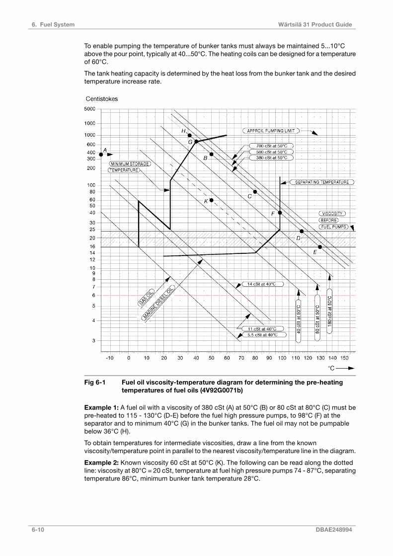
To enable pumping the temperature of bunker tanks must always be maintained 5...10°Cabove the pour point, typically at 40...50°C. The heating coils can be designed for a temperatureof 60°C.
The tank heating capacity is determined by the heat loss from the bunker tank and the desiredtemperature increase rate.
Fig 6-1 Fuel oil viscosity-temperature diagram for determining the pre-heatingtemperatures of fuel oils (4V92G0071b)
Example 1: A fuel oil with a viscosity of 380 cSt (A) at 50°C (B) or 80 cSt at 80°C (C) must bepre-heated to 115 - 130°C (D-E) before the fuel high pressure pumps, to 98°C (F) at theseparator and to minimum 40°C (G) in the bunker tanks. The fuel oil may not be pumpablebelow 36°C (H).
To obtain temperatures for intermediate viscosities, draw a line from the knownviscosity/temperature point in parallel to the nearest viscosity/temperature line in the diagram.
Example 2: Known viscosity 60 cSt at 50°C (K). The following can be read along the dottedline: viscosity at 80°C = 20 cSt, temperature at fuel high pressure pumps 74 - 87°C, separatingtemperature 86°C, minimum bunker tank temperature 28°C.
6-10 DBAE248994
Wärtsilä 31 Product Guide6. Fuel System
6.2.3 Fuel tanksThe fuel oil is first transferred from the bunker tanks to settling tanks for initial separation ofsludge and water. After centrifuging the fuel oil is transferred to day tanks, from which fuel issupplied to the engines.
6.2.3.1 Settling tank, HFO (1T02) and MDF (1T10)Separate settling tanks for HFO and MDF are recommended.
To ensure sufficient time for settling (water and sediment separation), the capacity of eachtank should be sufficient for min. 24 hours operation at maximum fuel consumption. The tanksshould be provided with internal baffles to achieve efficient settling and have a sloped bottomfor proper draining. The temperature in HFO settling tanks should be maintained between50°C and 70°C, which requires heating coils and insulation of the tank. Usually MDF settlingtanks do not need heating or insulation, but the tank temperature should be in the range20...40°C.
6.2.3.2 Day tank, HFO (1T03) and MDF (1T06)Two day tanks for HFO are to be provided, each with a capacity sufficient for at least 8 hoursoperation at maximum fuel consumption. A separate tank is to be provided for MDF. Thecapacity of the MDF tank should ensure fuel supply for 8 hours. Settling tanks may not beused instead of day tanks.
The day tank must be designed so that accumulation of sludge near the suction pipe isprevented and the bottom of the tank should be sloped to ensure efficient draining. HFO daytanks shall be provided with heating coils and insulation. It is recommended that the viscosityis kept below 140 cSt in the day tanks. Due to risk of wax formation, fuels with a viscositylower than 50 cSt at 50°C must be kept at a temperature higher than the viscosity wouldrequire. Continuous separation is nowadays common practice, which means that the HFOday tank temperature normally remains above 90°C. The temperature in the MDF day tankshould be in the range 20...40°C. The level of the tank must ensure a positive static pressureon the suction side of the fuel feed pumps.
6.2.3.3 Leak fuel tank, clean fuel (1T04)Clean leak fuel is drained by gravity from the engine. The fuel should be collected in a separateclean leak fuel tank, from where it can be pumped to the day tank and reused withoutseparation. The pipes from the engine to the clean leak fuel tank should be arranged continuoslysloping. The tank and the pipes must be heated and insulated, unless the installation is designedfor operation on MDF only.
The leak fuel piping should be fully closed to prevent dirt from entering the system.
6.2.3.4 Leak fuel tank, dirty fuel (1T07)In normal operation no fuel should leak out from the components of the fuel system. Inconnection with maintenance, or due to unforeseen leaks, fuel or water may spill in the hotbox of the engine. The spilled liquids are collected and drained by gravity from the enginethrough the dirty fuel connection.
Dirty leak fuel shall be led to a sludge tank. The tank and the pipes must be heated andinsulated, unless the installation is designed for operation exclusively on MDF.
6.2.4 Fuel treatment
6.2.4.1 SeparationHeavy fuel (residual, and mixtures of residuals and distillates) must be cleaned in an efficientcentrifugal separator before it is transferred to the day tank.
DBAE248994 6-11
6. Fuel SystemWärtsilä 31 Product Guide

Classification rules require the separator arrangement to be redundant so that required capacityis maintained with any one unit out of operation.
All recommendations from the separator manufacturer must be closely followed.
Centrifugal disc stack separators are recommended also for installations operating on MDFonly, to remove water and possible contaminants. The capacity of MDF separators should besufficient to ensure the fuel supply at maximum fuel consumption. Would a centrifugal separatorbe considered too expensive for a MDF installation, then it can be accepted to use coalescingtype filters instead. A coalescing filter is usually installed on the suction side of the circulationpump in the fuel feed system. The filter must have a low pressure drop to avoid pump cavitation.
Separator mode of operation
The best separation efficiency is achieved when also the stand-by separator is in operationall the time, and the throughput is reduced according to actual consumption.
Separators with monitoring of cleaned fuel (without gravity disc) operating on a continuousbasis can handle fuels with densities exceeding 991 kg/m3 at 15°C. In this case the main andstand-by separators should be run in parallel.
When separators with gravity disc are used, then each stand-by separator should be operatedin series with another separator, so that the first separator acts as a purifier and the secondas clarifier. This arrangement can be used for fuels with a density of max. 991 kg/m3 at 15°C.The separators must be of the same size.
Separation efficiency
The term Certified Flow Rate (CFR) has been introduced to express the performance ofseparators according to a common standard. CFR is defined as the flow rate in l/h, 30 minutesafter sludge discharge, at which the separation efficiency of the separator is 85%, when usingdefined test oils and test particles. CFR is defined for equivalent fuel oil viscosities of 380 cStand 700 cSt at 50°C. More information can be found in the CEN (European Committee forStandardisation) document CWA 15375:2005 (E).
The separation efficiency is measure of the separator's capability to remove specified testparticles. The separation efficiency is defined as follows:
where:
separation efficiency [%]n =
number of test particles in cleaned test oilCout =
number of test particles in test oil before separatorCin =
6.2.4.2 Separator unit (1N02/1N05)Separators are usually supplied as pre-assembled units designed by the separatormanufacturer.
Typically separator modules are equipped with:
● Suction strainer (1F02)
● Feed pump (1P02)
● Pre-heater (1E01)
● Sludge tank (1T05)
● Separator (1S01/1S02)
6-12 DBAE248994
Wärtsilä 31 Product Guide6. Fuel System

● Sludge pump
● Control cabinets including motor starters and monitoring
Fig 6-2 Fuel transfer and separating system (V76F6626G)
6.2.4.3 Separator feed pumps (1P02)Feed pumps should be dimensioned for the actual fuel quality and recommended throughputof the separator. The pump should be protected by a suction strainer (mesh size about 0.5mm)
An approved system for control of the fuel feed rate to the separator is required.
MDFHFODesign data:
0.5 MPa (5 bar)0.5 MPa (5 bar)Design pressure
50°C100°CDesign temperature
100 cSt1000 cStViscosity for dimensioning electric motor
DBAE248994 6-13
6. Fuel SystemWärtsilä 31 Product Guide
6.2.4.4 Separator pre-heater (1E01)The pre-heater is dimensioned according to the feed pump capacity and a given settling tanktemperature.
The surface temperature in the heater must not be too high in order to avoid cracking of thefuel. The temperature control must be able to maintain the fuel temperature within ± 2°C.
Recommended fuel temperature after the heater depends on the viscosity, but it is typically98°C for HFO and 20...40°C for MDF. The optimum operating temperature is defined by thesperarator manufacturer.
The required minimum capacity of the heater is:
where:
heater capacity [kW]P =
capacity of the separator feed pump [l/h]Q =
temperature rise in heater [°C]ΔT =
For heavy fuels ΔT = 48°C can be used, i.e. a settling tank temperature of 50°C. Fuels havinga viscosity higher than 5 cSt at 50°C require pre-heating before the separator.
The heaters to be provided with safety valves and drain pipes to a leakage tank (so that thepossible leakage can be detected).
6.2.4.5 Separator (1S01/1S02)Based on a separation time of 23 or 23.5 h/day, the service throughput Q [l/h] of the separatorcan be estimated with the formula:
where:
max. continuous rating of the diesel engine(s) [kW]P =
specific fuel consumption + 15% safety margin [g/kWh]b =
density of the fuel [kg/m3]ρ =
daily separating time for self cleaning separator [h] (usually = 23 h or 23.5 h)t =
The flow rates recommended for the separator and the grade of fuel must not be exceeded.The lower the flow rate the better the separation efficiency.
Sample valves must be placed before and after the separator.
6.2.4.6 MDF separator in HFO installations (1S02)A separator for MDF is recommended also for installations operating primarily on HFO. TheMDF separator can be a smaller size dedicated MDF separator, or a stand-by HFO separatorused for MDF.
6-14 DBAE248994
Wärtsilä 31 Product Guide6. Fuel System

6.2.4.7 Sludge tank (1T05)The sludge tank should be located directly beneath the separators, or as close as possiblebelow the separators, unless it is integrated in the separator unit. The sludge pipe must becontinuously falling.
DBAE248994 6-15
6. Fuel SystemWärtsilä 31 Product Guide

6.2.5 Fuel feed system - MDF installations
Fig 6-3 MDF fuel oil system with electric fuel circulation pump, single main engine(DAAF314554D)
6-16 DBAE248994
Wärtsilä 31 Product Guide6. Fuel System
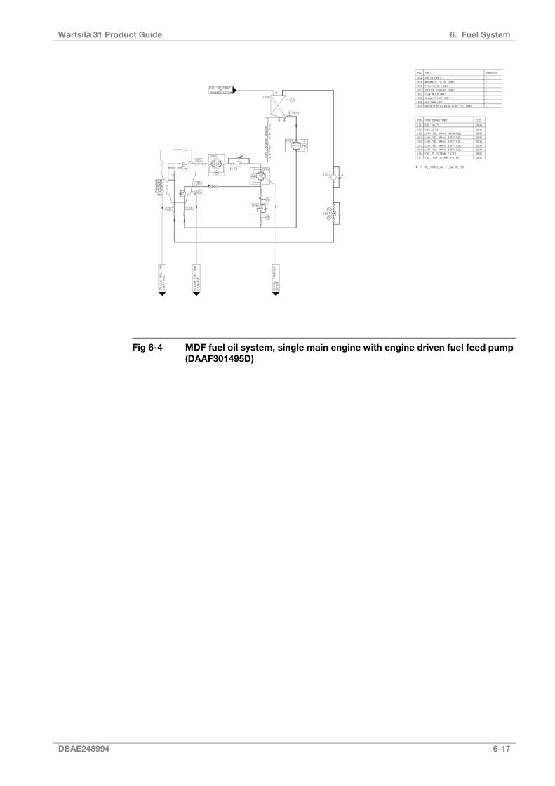
Fig 6-4 MDF fuel oil system, single main engine with engine driven fuel feed pump(DAAF301495D)
DBAE248994 6-17
6. Fuel SystemWärtsilä 31 Product Guide
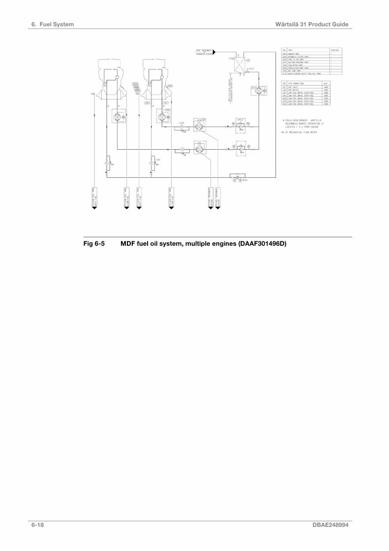
Fig 6-5 MDF fuel oil system, multiple engines (DAAF301496D)
6-18 DBAE248994
Wärtsilä 31 Product Guide6. Fuel System
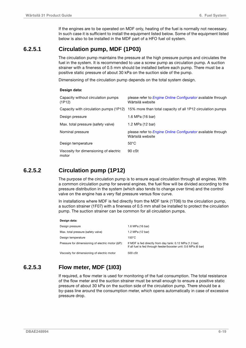
If the engines are to be operated on MDF only, heating of the fuel is normally not necessary.In such case it is sufficient to install the equipment listed below. Some of the equipment listedbelow is also to be installed in the MDF part of a HFO fuel oil system.
6.2.5.1 Circulation pump, MDF (1P03)The circulation pump maintains the pressure at the high pressure pumps and circulates thefuel in the system. It is recommended to use a screw pump as circulation pump. A suctionstrainer with a fineness of 0.5 mm should be installed before each pump. There must be apositive static pressure of about 30 kPa on the suction side of the pump.
Dimensioning of the circulation pump depends on the total system design.
Design data:
please refer to Engine Online Configurator available throughWärtsilä website
Capacity without circulation pumps(1P12)
15% more than total capacity of all 1P12 circulation pumpsCapacity with circulation pumps (1P12)
1.6 MPa (16 bar)Design pressure
1.2 MPa (12 bar)Max. total pressure (safety valve)
please refer to Engine Online Configurator available throughWärtsilä website
Nominal pressure
50°CDesign temperature
90 cStViscosity for dimensioning of electricmotor
6.2.5.2 Circulation pump (1P12)The purpose of the circulation pump is to ensure equal circulation through all engines. Witha common circulation pump for several engines, the fuel flow will be divided according to thepressure distribution in the system (which also tends to change over time) and the controlvalve on the engine has a very flat pressure versus flow curve.
In installations where MDF is fed directly from the MDF tank (1T06) to the circulation pump,a suction strainer (1F07) with a fineness of 0.5 mm shall be installed to protect the circulationpump. The suction strainer can be common for all circulation pumps.
Design data:
1.6 MPa (16 bar)Design pressure
1.2 MPa (12 bar)Max. total pressure (safety valve)
150°CDesign temperature
If MDF is fed directly from day tank: 0.12 MPa (1.2 bar)If all fuel is fed through feeder/booster unit: 0.6 MPa (6 bar)
Pressure for dimensioning of electric motor (ΔP):
500 cStViscosity for dimensioning of electric motor
6.2.5.3 Flow meter, MDF (1I03)If required, a flow meter is used for monitoring of the fuel consumption. The total resistanceof the flow meter and the suction strainer must be small enough to ensure a positive staticpressure of about 30 kPa on the suction side of the circulation pump. There should be aby-pass line around the consumption meter, which opens automatically in case of excessivepressure drop.
DBAE248994 6-19
6. Fuel SystemWärtsilä 31 Product Guide
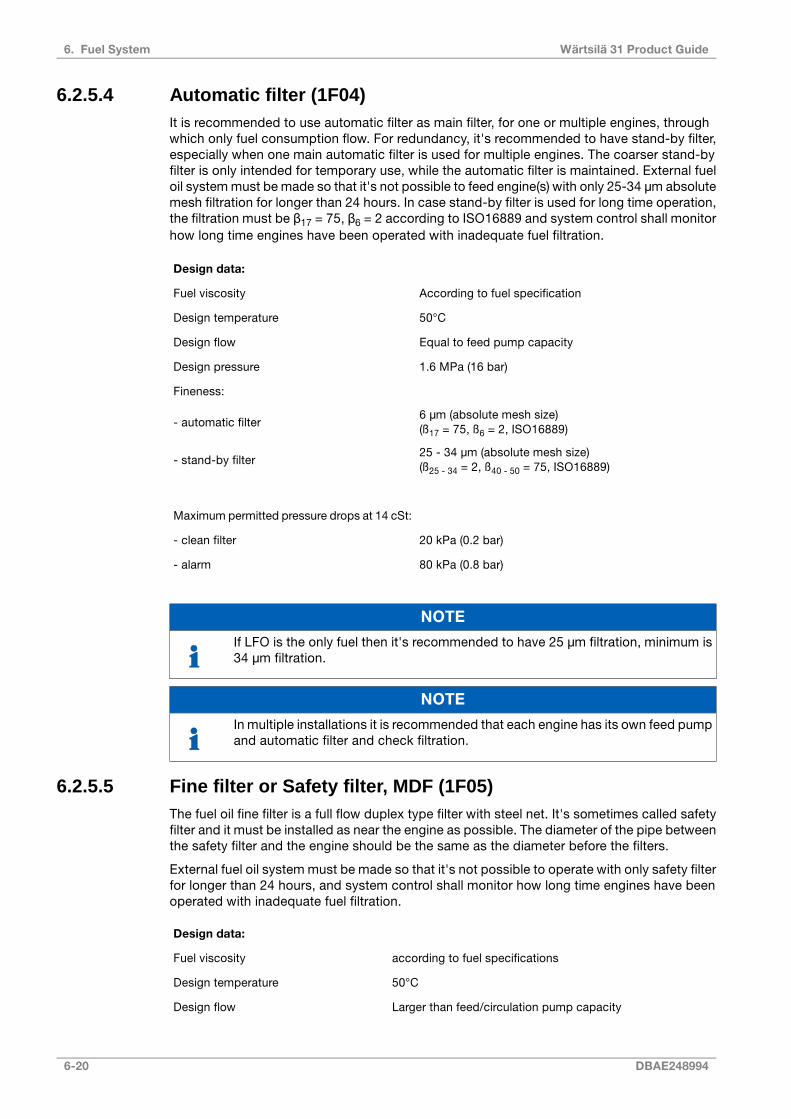
6.2.5.4 Automatic filter (1F04)It is recommended to use automatic filter as main filter, for one or multiple engines, throughwhich only fuel consumption flow. For redundancy, it's recommended to have stand-by filter,especially when one main automatic filter is used for multiple engines. The coarser stand-byfilter is only intended for temporary use, while the automatic filter is maintained. External fueloil system must be made so that it's not possible to feed engine(s) with only 25-34 μm absolutemesh filtration for longer than 24 hours. In case stand-by filter is used for long time operation,the filtration must be β17 = 75, β6 = 2 according to ISO16889 and system control shall monitorhow long time engines have been operated with inadequate fuel filtration.
Design data:
According to fuel specificationFuel viscosity
50°CDesign temperature
Equal to feed pump capacityDesign flow
1.6 MPa (16 bar)Design pressure
Fineness:
6 μm (absolute mesh size)(ß17 = 75, ß6 = 2, ISO16889)- automatic filter
25 - 34 μm (absolute mesh size)(ß25 - 34 = 2, ß40 - 50 = 75, ISO16889)- stand-by filter
Maximum permitted pressure drops at 14 cSt:
20 kPa (0.2 bar)- clean filter
80 kPa (0.8 bar)- alarm
NOTE
If LFO is the only fuel then it's recommended to have 25 μm filtration, minimum is34 μm filtration.
NOTE
In multiple installations it is recommended that each engine has its own feed pumpand automatic filter and check filtration.
6.2.5.5 Fine filter or Safety filter, MDF (1F05)The fuel oil fine filter is a full flow duplex type filter with steel net. It's sometimes called safetyfilter and it must be installed as near the engine as possible. The diameter of the pipe betweenthe safety filter and the engine should be the same as the diameter before the filters.
External fuel oil system must be made so that it's not possible to operate with only safety filterfor longer than 24 hours, and system control shall monitor how long time engines have beenoperated with inadequate fuel filtration.
Design data:
according to fuel specificationsFuel viscosity
50°CDesign temperature
Larger than feed/circulation pump capacityDesign flow
6-20 DBAE248994
Wärtsilä 31 Product Guide6. Fuel System

1.6 MPa (16 bar)Design pressure
25 - 34 μm (absolute mesh size)(ß25 - 34 = 2, ß40 - 50 = 75, ISO16889)
Fineness
Maximum permitted pressure drops at 14 cSt:
20 kPa (0.2 bar)- clean filter
80 kPa (0.8 bar)- alarm
NOTE
If LFO is the only fuel then it's recommended to have 25 μm filtration, minimum is34 μm filtration.
6.2.5.6 MDF cooler (1E04)The fuel viscosity may not drop below the minimum value stated in Engine Online Configuratoravailable through Wärtsilä website. When operating on MDF, the practical consequence isthat the fuel oil inlet temperature must be kept below 45°C. Very light fuel grades may requireeven lower temperature.
Sustained operation on MDF usually requires a fuel oil cooler. The cooler is to be installed inthe return line after the engine(s). LT-water is normally used as cooling medium.
If MDF viscosity in day tank drops below stated minimum viscosity limit then it is recommendedto install an MDF cooler into the engine fuel supply line in order to have reliable viscositycontrol.
Design data:
30 kW per engineHeat to be dissipated
80 kPa (0.8 bar)Max. pressure drop, fuel oil
60 kPa (0.6 bar)Max. pressure drop, water
min. 15%Margin (heat rate, fouling)
50/150°CDesign temperature MDF/HFO installa-
tion
6.2.5.7 Black out startDiesel generators serving as the main source of electrical power must be able to resume theiroperation in a black out situation by means of stored energy. Depending on system designand classification regulations, it may in some cases be permissible to use the emergencygenerator. HFO engines without engine driven fuel feed pump can reach sufficient fuel pressureto enable black out start by means of:
● A pneumatically driven fuel feed pump (1P11)
● An electrically driven fuel feed pump (1P11) powered by an emergency power source
DBAE248994 6-21
6. Fuel SystemWärtsilä 31 Product Guide

6.2.6 Fuel feed system - HFO installations
Fig 6-6 HFO fuel oil system, single main engine installation (DAAF301497D)
6-22 DBAE248994
Wärtsilä 31 Product Guide6. Fuel System
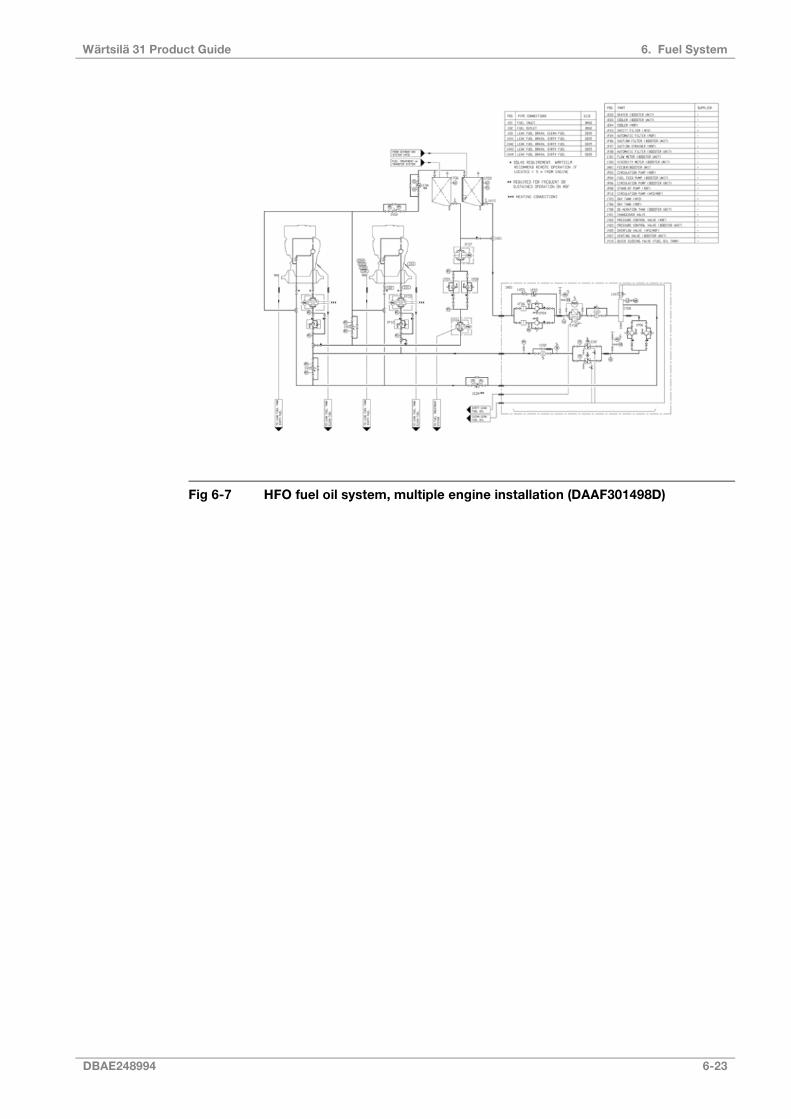
Fig 6-7 HFO fuel oil system, multiple engine installation (DAAF301498D)
DBAE248994 6-23
6. Fuel SystemWärtsilä 31 Product Guide
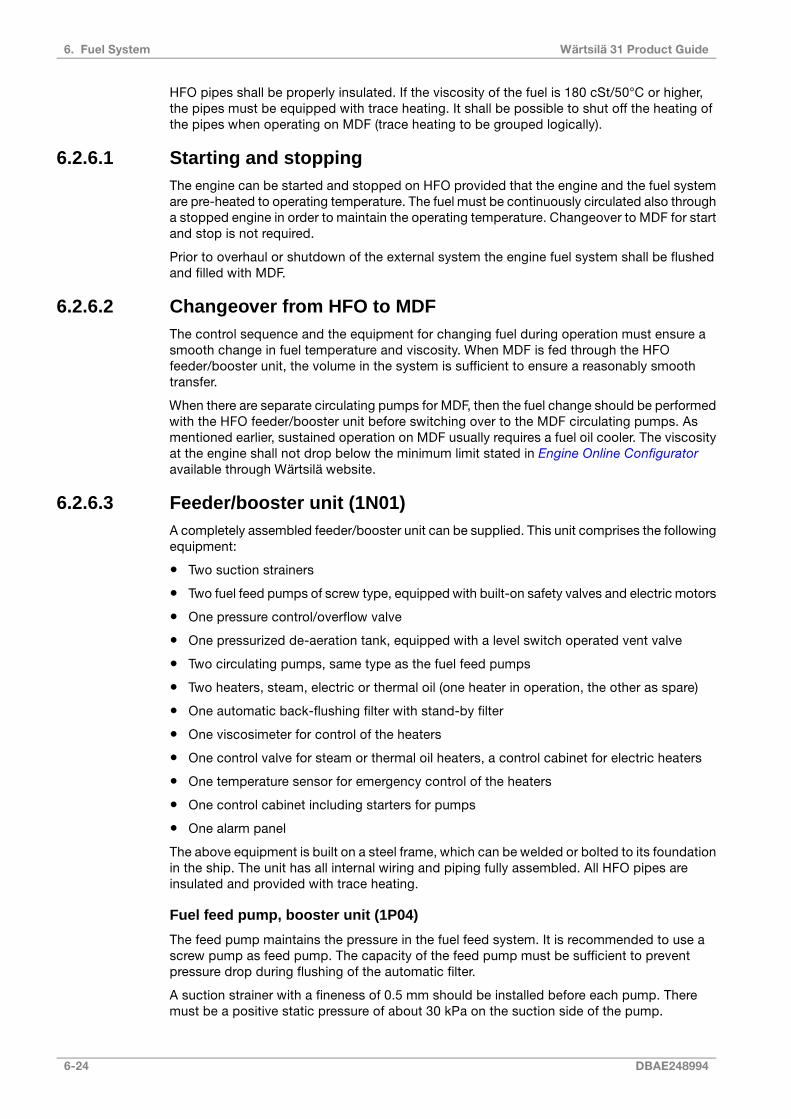
HFO pipes shall be properly insulated. If the viscosity of the fuel is 180 cSt/50°C or higher,the pipes must be equipped with trace heating. It shall be possible to shut off the heating ofthe pipes when operating on MDF (trace heating to be grouped logically).
6.2.6.1 Starting and stoppingThe engine can be started and stopped on HFO provided that the engine and the fuel systemare pre-heated to operating temperature. The fuel must be continuously circulated also througha stopped engine in order to maintain the operating temperature. Changeover to MDF for startand stop is not required.
Prior to overhaul or shutdown of the external system the engine fuel system shall be flushedand filled with MDF.
6.2.6.2 Changeover from HFO to MDFThe control sequence and the equipment for changing fuel during operation must ensure asmooth change in fuel temperature and viscosity. When MDF is fed through the HFOfeeder/booster unit, the volume in the system is sufficient to ensure a reasonably smoothtransfer.
When there are separate circulating pumps for MDF, then the fuel change should be performedwith the HFO feeder/booster unit before switching over to the MDF circulating pumps. Asmentioned earlier, sustained operation on MDF usually requires a fuel oil cooler. The viscosityat the engine shall not drop below the minimum limit stated in Engine Online Configuratoravailable through Wärtsilä website.
6.2.6.3 Feeder/booster unit (1N01)A completely assembled feeder/booster unit can be supplied. This unit comprises the followingequipment:
● Two suction strainers
● Two fuel feed pumps of screw type, equipped with built-on safety valves and electric motors
● One pressure control/overflow valve
● One pressurized de-aeration tank, equipped with a level switch operated vent valve
● Two circulating pumps, same type as the fuel feed pumps
● Two heaters, steam, electric or thermal oil (one heater in operation, the other as spare)
● One automatic back-flushing filter with stand-by filter
● One viscosimeter for control of the heaters
● One control valve for steam or thermal oil heaters, a control cabinet for electric heaters
● One temperature sensor for emergency control of the heaters
● One control cabinet including starters for pumps
● One alarm panel
The above equipment is built on a steel frame, which can be welded or bolted to its foundationin the ship. The unit has all internal wiring and piping fully assembled. All HFO pipes areinsulated and provided with trace heating.
Fuel feed pump, booster unit (1P04)
The feed pump maintains the pressure in the fuel feed system. It is recommended to use ascrew pump as feed pump. The capacity of the feed pump must be sufficient to preventpressure drop during flushing of the automatic filter.
A suction strainer with a fineness of 0.5 mm should be installed before each pump. Theremust be a positive static pressure of about 30 kPa on the suction side of the pump.
6-24 DBAE248994
Wärtsilä 31 Product Guide6. Fuel System

Design data:
Total consumption of the connected engines added withthe flush quantity of the automatic filter (1F08) and 15%margin.
Capacity
1.6 MPa (16 bar)Design pressure
0.7 MPa (7 bar)Max. total pressure (safety valve)
100°CDesign temperature
1000 cStViscosity for dimensioning of electric motor
Pressure control valve, booster unit (1V03)
The pressure control valve in the feeder/booster unit maintains the pressure in the de-aerationtank by directing the surplus flow to the suction side of the feed pump.
Design data:
Equal to feed pumpCapacity
1.6 MPa (16 bar)Design pressure
100°CDesign temperature
0.3...0.5 MPa (3...5 bar)Set-point
Automatic filter, booster unit (1F08)
It is recommended to use automatic filter as main filter, for one or multiple engines, throughwhich only fuel consumption flow. The automatic filter must be installed before the heater,between feed pump and the de-aeration tank and, it should be equipped with a heating jacket.Overheating (temperature exceeding 100°C), however, is to be prevented, and it must bepossible to switch off heating for MDF operation. For redundancy, it's recommended to havestand-by filter, especially when one main automatic filter is used for multiple engines. Thecoarser stand-by filter is only intended for temporary use, while the automatic filter ismaintained. External fuel oil system must be made so that it's not possible to feed engine(s)with only 25-34 µm absolute mesh filtration for longer than 24 hours. In case stand-by filter isused for long time operation, the filtration must be β17 = 75, β6 = 2 according to ISO16889and system control shall monitor how long time engines have been operated with inadequatefuel filtration.
Design data:
According to fuel specificationFuel viscosity
100°CDesign temperature
If fuel viscosity is higher than 25 cSt/100°CPreheating
Equal to feed pump capacityDesign flow
1.6 MPa (16 bar)Design pressure
Fineness:
ß17 = 75, ß6 = 2, ISO16889 (typically reached with 6 µmabsolute mesh size, β value is to be used for filter selec-tion)
- automatic filter
25 - 34 μm (absolute mesh size)(ß25 - 34 = 2, ß40 - 50 = 75, ISO16889)- stand-by filter
DBAE248994 6-25
6. Fuel SystemWärtsilä 31 Product Guide

Maximum permitted pressure drops at 14 cSt:
20 kPa (0.2 bar)- clean filter
80 kPa (0.8 bar)- alarm
NOTE
If LFO is the only fuel then it's recommended to have 25 μm filtration, minimum is34 μm filtration.
NOTE
In multiple engine installations it is recommended to have each engine has its ownfeed pump and automatic filter.
Flow meter, booster unit (1I01)
If a fuel consumption meter is required, it should be fitted between the feed pumps and thede-aeration tank. When it is desired to monitor the fuel consumption of individual engines ina multiple engine installation, two flow meters per engine are to be installed: one in the feedline and one in the return line of each engine.
There should be a by-pass line around the consumption meter, which opens automatically incase of excessive pressure drop.
If the consumption meter is provided with a prefilter, an alarm for high pressure differenceacross the filter is recommended.
De-aeration tank, booster unit (1T08)
It shall be equipped with a low level alarm switch and a vent valve. The vent pipe should, ifpossible, be led downwards, e.g. to the overflow tank. The tank must be insulated and equippedwith a heating coil. The volume of the tank should be at least 100 l.
Circulation pump, booster unit (1P06)
The purpose of this pump is to circulate the fuel in the system and to maintain the requiredpressure at the high pressure pumps (please refer to technical data, which could be found byaccessing Engine Online Configurator available through Wärtsilä's website). By circulating thefuel in the system it also maintains correct viscosity, and keeps the piping and the high pressurepumps at operating temperature.
Dimensioning of the circulation pump depends on the total system design. In the multi engineinstallation circulation pump of 1P12 is used, the circulation pump 1P06 capacity needs to beapprox. 10% higher than the other circulation pumps in the system. The nominal capacity forthe specific engine is available in the technical data, which could be found by accessing EngineOnline Configurator available through Wärtsilä's website
Heater, booster unit (1E02)
The heater must be able to maintain a fuel viscosity of 14 cSt at maximum fuel consumption,with fuel of the specified grade and a given day tank temperature (required viscosity at highpressure pumps stated in Technical data, which could be found by accessing Engine OnlineConfigurator available through Wärtsilä's website). When operating on high viscosity fuels,the fuel temperature at the engine inlet may not exceed 135°C however.
The power of the heater is to be controlled by a viscosimeter. The set-point of the viscosimetershall be somewhat lower than the required viscosity at the high pressure pumps to compensatefor heat losses in the pipes. A thermostat should be fitted as a backup to the viscosity control.
6-26 DBAE248994
Wärtsilä 31 Product Guide6. Fuel System
To avoid cracking of the fuel the surface temperature in the heater must not be too high. Theheat transfer rate in relation to the surface area must not exceed 1.5 W/cm2.
The required heater capacity can be estimated with the following formula:
where:
heater capacity (kW)P =
total fuel consumption at full output + 15% margin [l/h]Q =
temperature rise in heater [°C]ΔT =
Viscosimeter, booster unit (1I02)
The heater is to be controlled by a viscosimeter. The viscosimeter should be of a design thatcan withstand the pressure peaks caused by the high pressure pumps of the diesel engine.
Design data:
0...50 cStOperating range
180°CDesign temperature
4 MPa (40 bar)Design pressure
6.2.6.4 Safety filter, HFO (1F03)The safety filter is a full flow duplex type filter with steel net. The filter should be equipped witha heating jacket. The safety filter or a pump and filter unit shall be installed as near the engineas possible.
External fuel oil system must be made so that it's not possible to operate with only safety filterfor longer than 24 hours, and system control shall monitor how long time engines have beenoperated with inadequate fuel filtration.
Consider to have a filter with 25 - 34 μm absolute mesh size (approx. β25 - 34 = 2, β40 - 50 = 75according to ISO16889) for pre-filtration before main filter β17 = 75, β6 = 2 according toISO16889.
Design data:
According to fuel specificationFuel viscosity
150°CDesign temperature
Equal to circulation pump capacityDesign flow
1.6 MPa (16 bar)Design pressure
25 - 34 μm (absolute mesh size)(ß25 - 34 = 2, ß40 - 50 = 75, ISO16889)Filter fineness
Clean filter: 20 kPa (0.2 bar)Alarm: 80 kPa (0.8 bar)
Maximum permitted pressure drops at 14 cSt:
DBAE248994 6-27
6. Fuel SystemWärtsilä 31 Product Guide

NOTE
If LFO is the only fuel then it's recommended to have 25 μm filtration, minimum is34 μm filtration.
6.2.6.5 Overflow valve, HFO (1V05)When several engines are connected to the same feeder/booster unit an overflow valve isneeded between the feed line and the return line. The overflow valve limits the maximumpressure in the feed line, when the fuel lines to a parallel engine are closed for maintenancepurposes.
The overflow valve should be dimensioned to secure a stable pressure over the whole operatingrange.
Design data:
Equal to circulation pump (1P06)Capacity
1.6 MPa (16 bar)Design pressure
150°CDesign temperature
6-28 DBAE248994
Wärtsilä 31 Product Guide6. Fuel System

6.2.7 FlushingThe external piping system must be thoroughly flushed before the engines are connected andfuel is circulated through the engines. The piping system must have provisions for installationof a temporary flushing filter.
The fuel pipes at the engine (connections 101 and 102) are disconnected and the supply andreturn lines are connected with a temporary pipe or hose on the installation side. All filterinserts are removed, except in the flushing filter of course. The automatic filter and theviscosimeter should be bypassed to prevent damage.
The fineness of the flushing filter should be 6 μm or finer.
DBAE248994 6-29
6. Fuel SystemWärtsilä 31 Product Guide

This page intentionally left blank
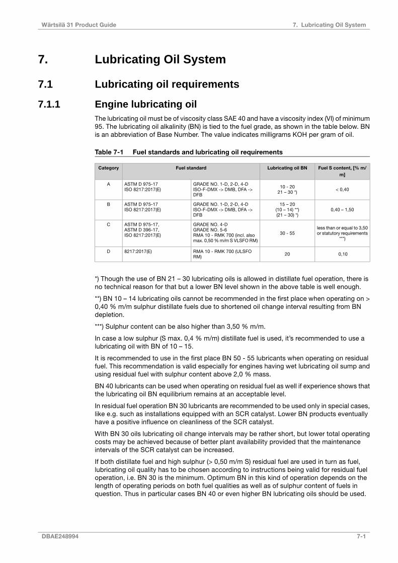
7. Lubricating Oil System
7.1 Lubricating oil requirements
7.1.1 Engine lubricating oilThe lubricating oil must be of viscosity class SAE 40 and have a viscosity index (VI) of minimum95. The lubricating oil alkalinity (BN) is tied to the fuel grade, as shown in the table below. BNis an abbreviation of Base Number. The value indicates milligrams KOH per gram of oil.
Table 7-1 Fuel standards and lubricating oil requirements
Fuel S content, [% m/m]
Lubricating oil BNFuel standardCategory
< 0,4010 - 2021 – 30 *)
GRADE NO. 1-D, 2-D, 4-DISO-F-DMX -> DMB, DFA ->DFB
ASTM D 975-17ISO 8217:2017(E)
A
0,40 – 1,5015 – 20
(10 – 14) **)(21 – 30) *)
GRADE NO. 1-D, 2-D, 4-DISO-F-DMX -> DMB, DFA ->DFB
ASTM D 975-17ISO 8217:2017(E)
B
less than or equal to 3,50or statutory requirements
***)30 - 55
GRADE NO. 4-DGRADE NO. 5-6RMA 10 - RMK 700 (incl. alsomax. 0,50 % m/m S VLSFO RM)
ASTM D 975-17,ASTM D 396-17,ISO 8217:2017(E)
C
0,1020RMA 10 - RMK 700 (ULSFORM)
8217:2017(E)D
*) Though the use of BN 21 – 30 lubricating oils is allowed in distillate fuel operation, there isno technical reason for that but a lower BN level shown in the above table is well enough.
**) BN 10 – 14 lubricating oils cannot be recommended in the first place when operating on >0,40 % m/m sulphur distillate fuels due to shortened oil change interval resulting from BNdepletion.
***) Sulphur content can be also higher than 3,50 % m/m.
In case a low sulphur (S max. 0,4 % m/m) distillate fuel is used, it’s recommended to use alubricating oil with BN of 10 – 15.
It is recommended to use in the first place BN 50 - 55 lubricants when operating on residualfuel. This recommendation is valid especially for engines having wet lubricating oil sump andusing residual fuel with sulphur content above 2,0 % mass.
BN 40 lubricants can be used when operating on residual fuel as well if experience shows thatthe lubricating oil BN equilibrium remains at an acceptable level.
In residual fuel operation BN 30 lubricants are recommended to be used only in special cases,like e.g. such as installations equipped with an SCR catalyst. Lower BN products eventuallyhave a positive influence on cleanliness of the SCR catalyst.
With BN 30 oils lubricating oil change intervals may be rather short, but lower total operatingcosts may be achieved because of better plant availability provided that the maintenanceintervals of the SCR catalyst can be increased.
If both distillate fuel and high sulphur (> 0,50 m/m S) residual fuel are used in turn as fuel,lubricating oil quality has to be chosen according to instructions being valid for residual fueloperation, i.e. BN 30 is the minimum. Optimum BN in this kind of operation depends on thelength of operating periods on both fuel qualities as well as of sulphur content of fuels inquestion. Thus in particular cases BN 40 or even higher BN lubricating oils should be used.
DBAE248994 7-1
7. Lubricating Oil SystemWärtsilä 31 Product Guide
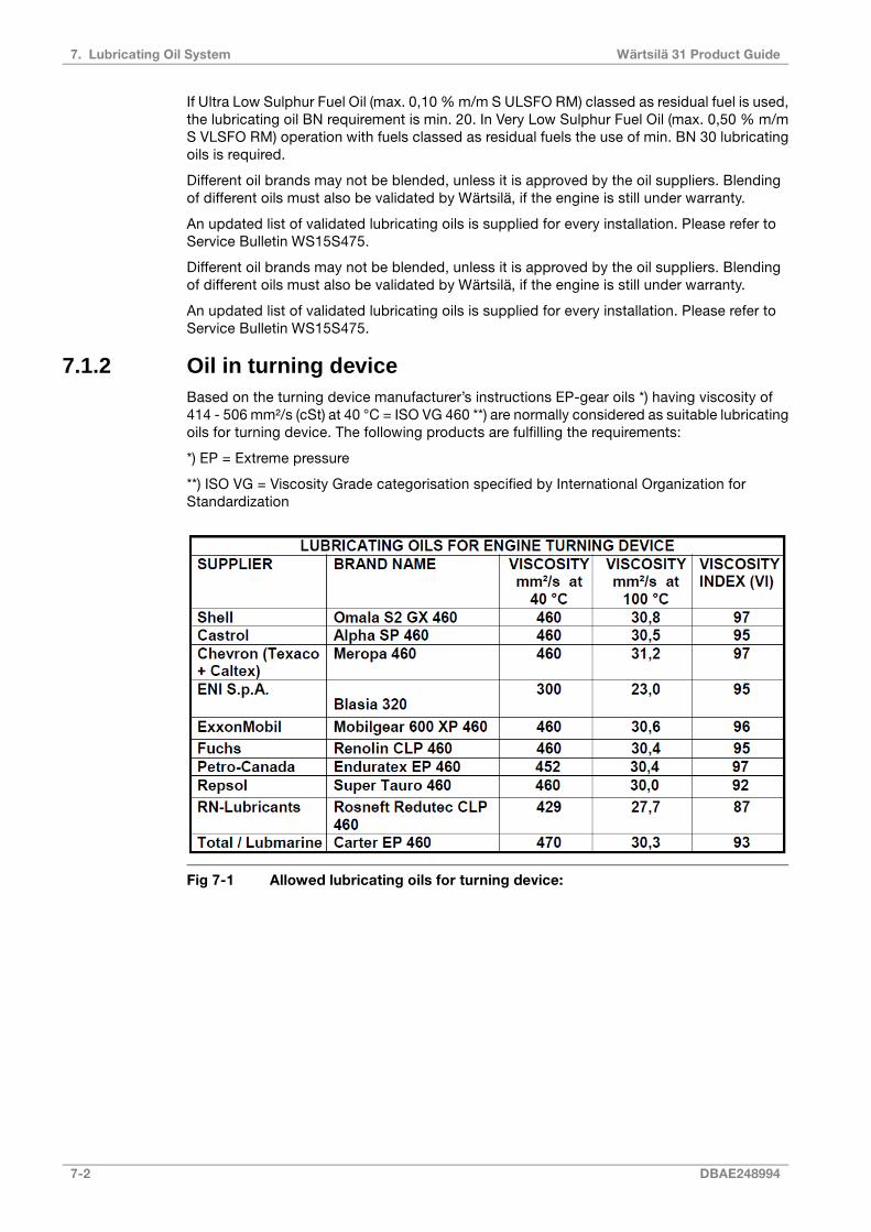
If Ultra Low Sulphur Fuel Oil (max. 0,10 % m/m S ULSFO RM) classed as residual fuel is used,the lubricating oil BN requirement is min. 20. In Very Low Sulphur Fuel Oil (max. 0,50 % m/mS VLSFO RM) operation with fuels classed as residual fuels the use of min. BN 30 lubricatingoils is required.
Different oil brands may not be blended, unless it is approved by the oil suppliers. Blendingof different oils must also be validated by Wärtsilä, if the engine is still under warranty.
An updated list of validated lubricating oils is supplied for every installation. Please refer toService Bulletin WS15S475.
7.1.2 Oil in turning deviceBased on the turning device manufacturer’s instructions EP-gear oils *) having viscosity of414 - 506 mm²/s (cSt) at 40 °C = ISO VG 460 **) are normally considered as suitable lubricatingoils for turning device. The following products are fulfilling the requirements:
*) EP = Extreme pressure
**) ISO VG = Viscosity Grade categorisation specified by International Organization forStandardization
Fig 7-1 Allowed lubricating oils for turning device:
7-2 DBAE248994
Wärtsilä 31 Product Guide7. Lubricating Oil System

7.2 External lubricating oil system
Fig 7-2 Lubricating oil system, single main engine HFO/MDF (DAAF301499B)
System components:
Separator pump (separator unit)2P03Heater (separator unit)2E02
Stand-by pump2P04Suction strainer (main lubricating oil pump)2F01
Separator2S01Suction filter (separator unit)2F03
Condensate trap2S02Suction strainer (Prelubricating oil pump)2F04
System oil tank2T01Suction strainer (stand-by pump)2F06
Sludge tank2T06Separator unit2N01
Pressure control valve2V03Pre lube oil pump2P02
12V - 16V8V - 10VPipe connections:
DN250DN200Lubricating oil outlet*202
DN250DN200Lubricating oil to engine driven pump*203
DBAE248994 7-3
7. Lubricating Oil SystemWärtsilä 31 Product Guide

12V - 16V8V - 10VPipe connections:
DN80DN80Lubricating oil from priming pump206
DN125DN125Lubricating oil from electric driven pump208
DN150DN125Crankcase air vent701
DN50DN50Inert gas inlet**723
7-4 DBAE248994
Wärtsilä 31 Product Guide7. Lubricating Oil System

Fig 7-3 Lubricating oil system, single main engine MDF (DAAF301501C)
System components:
Condensate trap2S02Heater (separator unit)2E02
New oil tank2T03Suction filter (separator unit)2F03
Renovating oil tank2T04Separator unit2N01
Renovated oil tank2T05Separator pump (separator unit)2P03
Sludge tank2T06Stand-by pump2P04
Pressure control valve2V03Separator2S01
12V - 16V8V - 10VPipe connections:
DN200 / DN250Lube oil to el. driven pump**207
DN125DN125Lube oil from el. driven pump208
DN40DN40Lubricating oil from separator and filling213
DN40DN40Lubricating oil to separator and drain214
DN40DN40Lube oil to generator bearing217
DN40DN40Lube oil from generator bearing218
DN150DN125Crankcase air vent701
DN50DN50Inert gas inlet***723
DBAE248994 7-5
7. Lubricating Oil SystemWärtsilä 31 Product Guide

Fig 7-4 Lubricating oil system (MDF), multiple engine (DAAF301500B)
System components:
Condensate trap2S02Heater (separator unit)2E02
New oil tank2T03Suction filter (separator unit)2F03
Renovating oil tank2T04Separator unit2N01
Renovated oil tank2T05Separator pump (separator unit)2P03
Sludge tank2T06Separator2S01
12V - 16V8V - 10VPipe connections:
DN40DN40Lubricating oil from separator and filling213
DN40DN40Lubricating oil to separator and drain214
DN40DN40Lube oil to generator bearing217
DN40DN40Lube oil from generator bearing218
DN150DN125Crankcase air vent701
DN50DN50Inert gas inlet**723
7-6 DBAE248994
Wärtsilä 31 Product Guide7. Lubricating Oil System

7.2.1 Separation system
7.2.1.1 Separator unit (2N01)Lube oil by-pass treatment is recommended for marine engines.
A lube oil separator is required, as an oil by-pass treatment device, for engines running onfuels classified as lower grade than ISO-F-DMB. For ISO-F-DMB fuels or higher grade, otheralternative as oil by-pass treatment is allowed as long as the oil quality and cleanliness canbe maintained. Specific conditions for oil temperature during starting to be considered if lubeoil by-pass treatment is used in case it is not including heater.
General Separator requirements:
● The separator should be dimensioned for continuous centrifuging
● Each lubricating oil system should have its own individual separator
● Rate of circulation of the entire volume per 24h: approx. 5 times
● Centrifuging temperature: 95 °C
Separators are usually supplied as pre-assembled units.
Typically lubricating oil separator units are equipped with:
● Feed pump with suction strainer and safety valve
● Preheater
● Separator
● Control cabinet
The lubricating oil separator unit may also be equipped with an intermediate sludge tank anda sludge pump, which offers flexibility in placement of the separator since it is not necessaryto have a sludge tank directly beneath the separator.
Separator feed pump (2P03)
The feed pump must be selected to match the recommended throughput of the separator.Normally the pump is supplied and matched to the separator by the separator manufacturer.
The lowest foreseen temperature in the system oil tank (after a long stop) must be taken intoaccount when dimensioning the electric motor.
Separator preheater (2E02)
The preheater is to be dimensioned according to the feed pump capacity and the temperaturein the system oil tank. When the engine is running, the temperature in the system oil tanklocated in the ship's bottom is normally 65...75°C. To enable separation with a stopped enginethe heater capacity must be sufficient to maintain the required temperature without heat supplyfrom the engine.
Recommended oil temperature after the heater is 95°C.
It shall be considered that, while the engine is stopped in stand-by mode without LT watercirculation, the separator unit may be heating up the total amount of lubricating oil in the oiltank to a value higher than the nominal one required at engine inlet, after lube oil cooler (pleaserefer to Engine Online Configurator available through Wärtsilä website). Higher oil temperaturesat engine inlet than the nominal, may be creating higher component wear and in worstconditions damages to the equipment and generate alarm signal at engine start, or even aload reduction request to PMS.
The surface temperature of the heater must not exceed 150°C in order to avoid cooking ofthe oil.
DBAE248994 7-7
7. Lubricating Oil SystemWärtsilä 31 Product Guide

The heaters should be provided with safety valves and drain pipes to a leakage tank (so thatpossible leakage can be detected).
Separator (2S01)
The separators should preferably be of a type with controlled discharge of the bowl to minimizethe lubricating oil losses.
The service throughput Q [l/h] of the separator can be estimated with the formula:
where:
volume flow [l/h]Q =
engine output [kW]P =
5 for HFO, 4 for MDFn =
operating time [h/day]: 24 for continuous separator operation, 23 for normal dimensioningt =
Sludge tank (2T06)
The sludge tank should be located directly beneath the separators, or as close as possiblebelow the separators, unless it is integrated in the separator unit. The sludge pipe must becontinuously falling.
7.2.2 System oil tank (2T01)Recommended oil tank volume is stated in Engine Online Configurator available throughWärtsilä website.
The system oil tank is usually located beneath the engine foundation. The tank may not protrudeunder the reduction gear or generator, and it must also be symmetrical in transverse directionunder the engine. The location must further be such that the lubricating oil is not cooled downbelow normal operating temperature. Suction height is especially important with engine drivenlubricating oil pump. Losses in strainers etc. add to the geometric suction height. Maximumsuction ability of the pump is stated in Engine Online Configurator available through Wärtsiläwebsite.
The pipe connection between the engine oil sump and the system oil tank must be flexible toprevent damages due to thermal expansion. The return pipes from the engine oil sump mustend beneath the minimum oil level in the tank. Further on the return pipes must not be locatedin the same corner of the tank as the suction pipe of the pump.
The suction pipe of the pump should have a trumpet shaped or conical inlet to minimise thepressure loss. For the same reason the suction pipe shall be as short and straight as possibleand have a sufficient diameter. A pressure gauge shall be installed close to the inlet of thelubricating oil pump. The suction pipe shall further be equipped with a non-return valve of flaptype without spring. The non-return valve is particularly important with engine driven pumpand it must be installed in such a position that self-closing is ensured.
Suction and return pipes of the separator must not be located close to each other in the tank.
The ventilation pipe from the system oil tank may not be combined with crankcase ventilationpipes.
It must be possible to raise the oil temperature in the tank after a long stop. In cold conditionsit can be necessary to have heating coils in the oil tank in order to ensure pumpability. Theseparator heater can normally be used to raise the oil temperature once the oil is pumpable.Further heat can be transferred to the oil from the preheated engine, provided that the oil
7-8 DBAE248994
Wärtsilä 31 Product Guide7. Lubricating Oil System

viscosity and thus the power consumption of the pre-lubricating oil pump does not exceedthe capacity of the electric motor.
Fig 7-5 Example of system oil tank arrangement (DAAE007020F)
Design data:
1.2...1.5 l/kW, please refer to Engine Online Configurator
available through Wärtsilä website
Oil tank volume
DBAE248994 7-9
7. Lubricating Oil SystemWärtsilä 31 Product Guide
75...80% of tank volumeOil level at service
60% of tank volumeOil level alarm
7.2.3 Suction strainers (2F01, 2F04, 2F06)It is recommended to install a suction strainer before each pump to protect the pump fromdamage. The suction strainer and the suction pipe must be amply dimensioned to minimizepressure losses. The suction strainer should always be provided with alarm for high differentialpressure.
Design data:
0.5...1.0 mmFineness
7.2.4 Pre-lubricating oil pump (2P02)The pre-lubricating oil pump is a scew or gear pump, which is to be equipped with a safetyvalve.
The installation of a pre-lubricating pump is mandatory. An electrically driven main pump orstandby pump (with full pressure) may not be used instead of a dedicated pre-lubricatingpump, as the maximum permitted pressure is 200 kPa (2 bar) to avoid leakage through thelabyrinth seal in the turbocharger (not a problem when the engine is running). A two speedelectric motor for a main or standby pump is not accepted.
The piping shall be arranged so that the pre-lubricating oil pump fills the main oil pump, whenthe main pump is engine driven.
The pre-lubricating pump should always be running, when the engine is stopped.
Depending on the foreseen oil temperature after a long stop, the suction ability of the pumpand the geometric suction height must be specially considered with regards to high viscosity.
The pump is to be equipped with a pressure regulating valve or then an external valve outsidepump bypassing oil back to pump suction. If pressure regulating valve is integrated into pumpit is to be confirmed with supplier that pump can manage about 50% recirculation.
Design data:
please refer to technical data, which could be found by ac-cessing Engine Online Configurator available through Wärt-silä's website
Capacity
350 kPa (3.5 bar)Max. pressure (safety valve)
100°CDesign temperature
500 cStViscosity for dimensioning of the electricmotor
7.2.5 Pressure control valve (2V03)
Design data:
1.0 MPa (10 bar)Design pressure
Difference between pump capacity and oil flow through engineCapacity
100 °CDesign temperature
7-10 DBAE248994
Wärtsilä 31 Product Guide7. Lubricating Oil System

7.2.6 Lubricating oil pump, stand-by (2P04)The stand-by lubricating oil pump is normally of screw type and should be provided with ansafety valve.
Design data:
please refer to Engine Online Configurat-or available through Wärtsilä website
Capacity
0.8 MPa (8 bar)Design pressure, max
100°CDesign temperature, max.
SAE 40Lubricating oil viscosity
500 mm2/s (cSt)Viscosity for dimensioning the electricmotor
7.3 Crankcase ventilation systemThe purpose of the crankcase ventilation is to evacuate gases from the crankcase in order tokeep the pressure in the crankcase within acceptable limits.
Each engine must have its own vent pipe into open air. The crankcase ventilation pipes maynot be combined with other ventilation pipes, e.g. vent pipes from the system oil tank.
The diameter of the pipe shall be large enough to avoid excessive back pressure. Other possibleequipment in the piping must also be designed and dimensioned to avoid excessive flowresistance.
A condensate trap and a drain must be provided for the vent pipe near the engine.
The connection between engine and pipe is to be flexible. It is very important that the crankcaseventilation pipe is properly fixed to a support rigid in all directions directly after the flexiblehose from crankcase ventilation outlet, extra mass on the oil mist detector must be avoided.There should be a fixing point on both sides of the pipe at the support. Absolutely rigid mountingbetween the pipe and the support is recommended. The supporting must allow thermalexpansion and ship’s structural deflections.
Design data:
please refer to Engine Online Configurator available throughWärtsilä website
Flow
please refer to Engine Online Configurator available throughWärtsilä website
Crankcase pressure, max.
80°CTemperature
DBAE248994 7-11
7. Lubricating Oil SystemWärtsilä 31 Product Guide

Fig 7-6 Condensate trap(DAAE032780B)
The size of the ventilation pipe (D2) outfrom the condensate trap should bebigger than the ventilation pipe (D) com-ing from the engine.For more information about ventilationpipe (D) size, see the external lubricatingoil system drawing.
The max. back-pressure must also beconsidered when selecting the ventilationpipe size.
7-12 DBAE248994
Wärtsilä 31 Product Guide7. Lubricating Oil System

7.4 Flushing instructionsFlushing instructions in this Product Guide are for guidance only. For contracted projects,read the specific instructions included in the installation planning instructions (IPI). The finenessof the flushing filter and further instructions are found from installation planning instructions(IPI).
7.4.1 Piping and equipment built on the engineFlushing of the piping and equipment built on the engine is not required and flushing oil shallnot be pumped through the engine oil system (which is flushed and clean from the factory).It is however acceptable to circulate the flushing oil via the engine sump if this is advantageous.Cleanliness of the oil sump shall be verified after completed flushing.
7.4.2 External oil systemRefer to the system diagram(s) in section External lubricating oil system for location/descriptionof the components mentioned below.
If the engine is equipped with a wet oil sump the external oil tanks, new oil tank (2T03),renovating oil tank (2T04) and renovated oil tank (2T05) shall be verified to be clean beforebunkering oil. Especially pipes leading from the separator unit (2N01) directly to the engineshall be ensured to be clean for instance by disconnecting from engine and blowing withcompressed air.
If the engine is equipped with a dry oil sump the external oil tanks, new oil tank and the systemoil tank (2T01) shall be verified to be clean before bunkering oil.
Operate the separator unit continuously during the flushing (not less than 24 hours). Leavethe separator running also after the flushing procedure, this to ensure that any remainingcontaminants are removed.
If an electric motor driven stand-by pump (2P04) is installed then piping shall be flushed runningthe pump circulating engine oil through a temporary external oil filter (recommended mesh 34microns) into the engine oil sump through a hose and a crankcase door. The pump shall beprotected by a suction strainer (2F06).
Whenever possible the separator unit shall be in operation during the flushing to remove dirt.The separator unit is to be left running also after the flushing procedure, this to ensure thatany remaining contaminants are removed.
7.4.3 Type of flushing oil
7.4.3.1 ViscosityIn order for the flushing oil to be able to remove dirt and transport it with the flow, ideal viscosityis 10...50 cSt. The correct viscosity can be achieved by heating engine oil to about 65°C orby using a separate flushing oil which has an ideal viscosity in ambient temperature.
7.4.3.2 Flushing with engine oilThe ideal is to use engine oil for flushing. This requires however that the separator unit is inoperation to heat the oil. Engine oil used for flushing can be reused as engine oil provided thatno debris or other contamination is present in the oil at the end of flushing.
7.4.3.3 Flushing with low viscosity flushing oilIf no separator heating is available during the flushing procedure it is possible to use a lowviscosity flushing oil instead of engine oil. In such a case the low viscosity flushing oil mustbe disposed of after completed flushing. Great care must be taken to drain all flushing oil from
DBAE248994 7-13
7. Lubricating Oil SystemWärtsilä 31 Product Guide

pockets and bottom of tanks so that flushing oil remaining in the system will not compromisethe viscosity of the actual engine oil.
7.4.3.4 Lubricating oil sampleTo verify the cleanliness a LO sample shall be taken by the shipyard after the flushing iscompleted. The properties to be analyzed are Viscosity, BN, AN, Insolubles, Fe and ParticleCount.
Commissioning procedures shall in the meantime be continued without interruption unlessthe commissioning engineer believes the oil is contaminated.
7-14 DBAE248994
Wärtsilä 31 Product Guide7. Lubricating Oil System

8. Compressed Air System
Compressed air is used to start engines and to provide actuating energy for safety and controldevices. The use of starting air for other purposes is limited by the classification regulations.
To ensure the functionality of the components in the compressed air system, the compressedair has to be free from solid particles and oil.
8.1 Instrument air qualityThe quality of instrument air, from the ships instrument air system, for safety and controldevices must fulfill the following requirements.
Instrument air specification:
1 MPa (10 bar)Design pressure
0.7 MPa (7 bar)Nominal pressure
+3°CDew point temperature
1 mg/m3Max. oil content
3 µmMax. particle size
8.2 External compressed air systemThe design of the starting air system is partly determined by classification regulations. Mostclassification societies require that the total capacity is divided into two equally sized startingair receivers and starting air compressors. The requirements concerning multiple engineinstallations can be subject to special consideration by the classification society.
The starting air pipes should always be slightly inclined and equipped with manual or automaticdraining at the lowest points.
Instrument air to safety and control devices must be treated in an air dryer.
DBAE248994 8-1
8. Compressed Air SystemWärtsilä 31 Product Guide

Fig 8-1 External starting air system (DAAF301502A)
8.2.1 Starting air compressor unit (3N02)At least two starting air compressors must be installed. It is recommended that the compressorsare capable of filling the starting air vessel from minimum (1.8 MPa) to maximum pressure in15...30 minutes. For exact determination of the minimum capacity, the rules of the classificationsocieties must be followed.
8.2.2 Oil and water separator (3S01)An oil and water separator should always be installed in the pipe between the compressorand the air vessel. Depending on the operation conditions of the installation, an oil and waterseparator may be needed in the pipe between the air vessel and the engine.
8.2.3 Starting air vessel (3T01)The starting air vessels should be dimensioned for a nominal pressure of 3 MPa.
The number and the capacity of the air vessels for propulsion engines depend on therequirements of the classification societies and the type of installation.
It is recommended to use a minimum air pressure of 1.8 MPa, when calculating the requiredvolume of the vessels.
The starting air vessels are to be equipped with at least a manual valve for condensate drain.If the air vessels are mounted horizontally, there must be an inclination of 3...5° towards thedrain valve to ensure efficient draining.
8-2 DBAE248994
Wärtsilä 31 Product Guide8. Compressed Air System

Fig 8-2 Starting air vessel
Weight[kg]
Dimensions [mm]Size[Litres]
DL3 1)L2 1)L1
2744801102431767250
4504801332433204500
6256501332552740710
81065013325535601000
98080013325529301250
1) Dimensions are approximate.
The starting air consumption stated in Engine Online Configurator (available through Wärtsiläwebsite) is for a successful start. During start the main starting valve is kept open until theengine starts, or until the max. time for the starting attempt has elapsed. A failed start cantake twice the air consumption of a successful start. If the ship has a class notation forunattended machinery spaces, then the starts are to be demonstrated.
The required total starting air vessel volume can be calculated using the formula:
where:
total starting air vessel volume [m3]VR =
normal barometric pressure (NTP condition) = 0.1 MPapE =
air consumption per start [Nm3] please refer to Engine Online Configurator available throughWärtsilä website
VE =
required number of starts according to the classification societyn =
maximum starting air pressure = 3 MPapRmax =
minimum starting air pressure = please refer to Engine Online Configurator available throughWärtsilä website
pRmin =
NOTE
The total vessel volume shall be divided into at least two equally sized starting airvessels.
DBAE248994 8-3
8. Compressed Air SystemWärtsilä 31 Product Guide
8.2.4 Air filter, starting air inlet (3F02)Condense formation after the water separator (between starting air compressor and startingair vessels) create and loosen abrasive rust from the piping, fittings and receivers. Thereforeit is recommended to install a filter before the starting air inlet on the engine to prevent particlesto enter the starting air equipment.
8-4 DBAE248994
Wärtsilä 31 Product Guide8. Compressed Air System
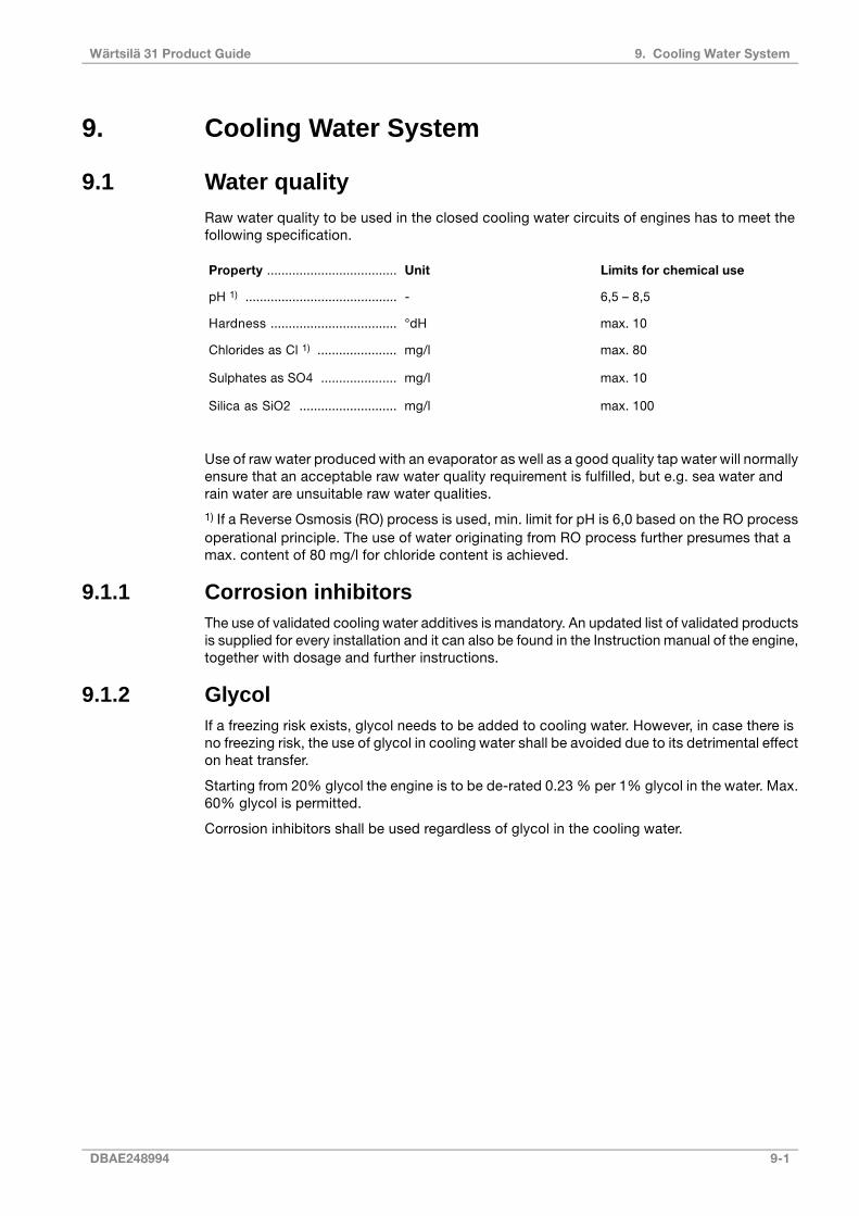
9. Cooling Water System
9.1 Water qualityRaw water quality to be used in the closed cooling water circuits of engines has to meet thefollowing specification.
Limits for chemical useUnitProperty ....................................
6,5 – 8,5-pH 1) ..........................................
max. 10°dHHardness ...................................
max. 80mg/lChlorides as Cl 1) ......................
max. 10mg/lSulphates as SO4 .....................
max. 100mg/lSilica as SiO2 ...........................
Use of raw water produced with an evaporator as well as a good quality tap water will normallyensure that an acceptable raw water quality requirement is fulfilled, but e.g. sea water andrain water are unsuitable raw water qualities.
1) If a Reverse Osmosis (RO) process is used, min. limit for pH is 6,0 based on the RO processoperational principle. The use of water originating from RO process further presumes that amax. content of 80 mg/l for chloride content is achieved.
9.1.1 Corrosion inhibitorsThe use of validated cooling water additives is mandatory. An updated list of validated productsis supplied for every installation and it can also be found in the Instruction manual of the engine,together with dosage and further instructions.
9.1.2 GlycolIf a freezing risk exists, glycol needs to be added to cooling water. However, in case there isno freezing risk, the use of glycol in cooling water shall be avoided due to its detrimental effecton heat transfer.
Starting from 20% glycol the engine is to be de-rated 0.23 % per 1% glycol in the water. Max.60% glycol is permitted.
Corrosion inhibitors shall be used regardless of glycol in the cooling water.
DBAE248994 9-1
9. Cooling Water SystemWärtsilä 31 Product Guide
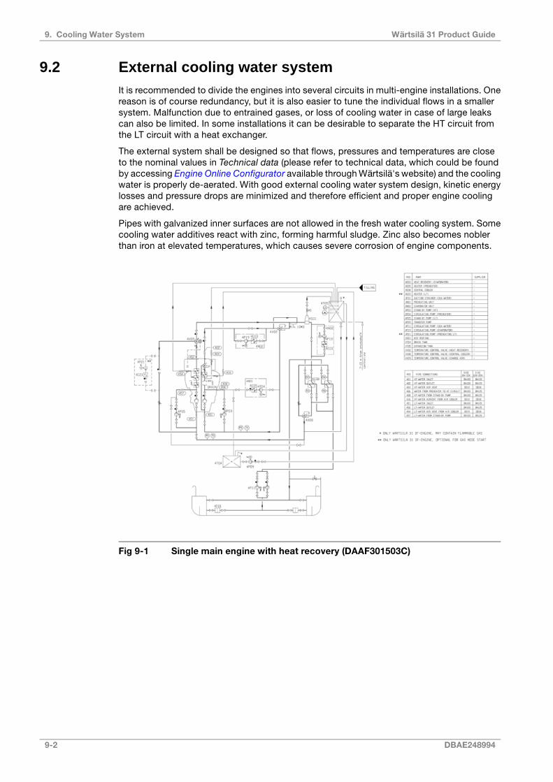
9.2 External cooling water systemIt is recommended to divide the engines into several circuits in multi-engine installations. Onereason is of course redundancy, but it is also easier to tune the individual flows in a smallersystem. Malfunction due to entrained gases, or loss of cooling water in case of large leakscan also be limited. In some installations it can be desirable to separate the HT circuit fromthe LT circuit with a heat exchanger.
The external system shall be designed so that flows, pressures and temperatures are closeto the nominal values in Technical data (please refer to technical data, which could be foundby accessing Engine Online Configurator available through Wärtsilä's website) and the coolingwater is properly de-aerated. With good external cooling water system design, kinetic energylosses and pressure drops are minimized and therefore efficient and proper engine coolingare achieved.
Pipes with galvanized inner surfaces are not allowed in the fresh water cooling system. Somecooling water additives react with zinc, forming harmful sludge. Zinc also becomes noblerthan iron at elevated temperatures, which causes severe corrosion of engine components.
Fig 9-1 Single main engine with heat recovery (DAAF301503C)
9-2 DBAE248994
Wärtsilä 31 Product Guide9. Cooling Water System
Fig 9-2 Multiple main engines with heat recovery (DAAF301505C)
DBAE248994 9-3
9. Cooling Water SystemWärtsilä 31 Product Guide

Fig 9-3 Cooling water system, single main engine arctic solution without heatrecovery (DAAF320499C)
9-4 DBAE248994
Wärtsilä 31 Product Guide9. Cooling Water System
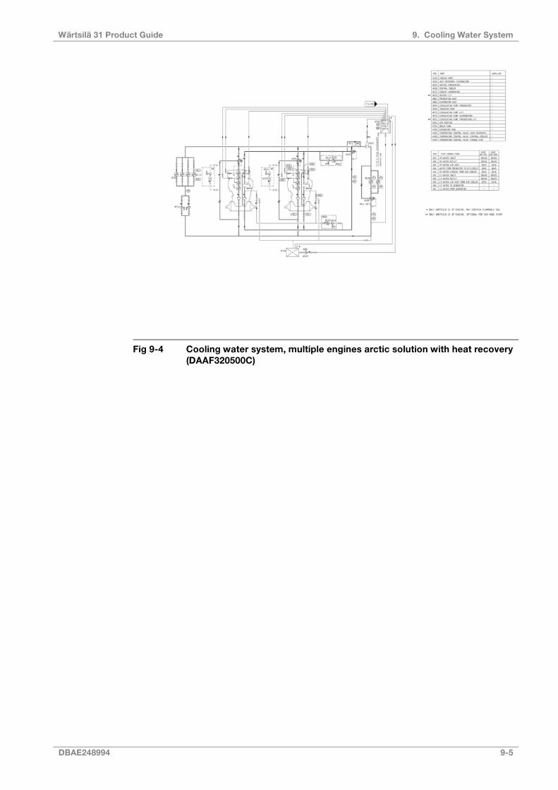
Fig 9-4 Cooling water system, multiple engines arctic solution with heat recovery(DAAF320500C)
DBAE248994 9-5
9. Cooling Water SystemWärtsilä 31 Product Guide
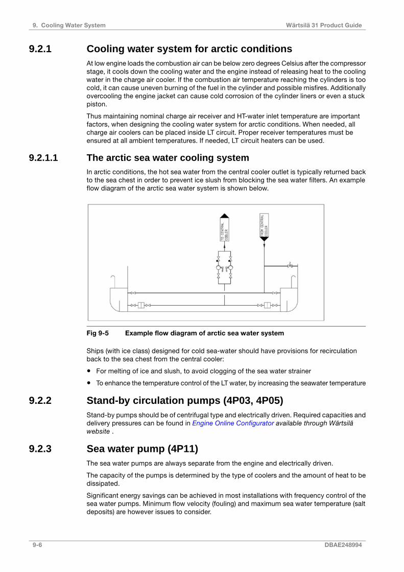
9.2.1 Cooling water system for arctic conditionsAt low engine loads the combustion air can be below zero degrees Celsius after the compressorstage, it cools down the cooling water and the engine instead of releasing heat to the coolingwater in the charge air cooler. If the combustion air temperature reaching the cylinders is toocold, it can cause uneven burning of the fuel in the cylinder and possible misfires. Additionallyovercooling the engine jacket can cause cold corrosion of the cylinder liners or even a stuckpiston.
Thus maintaining nominal charge air receiver and HT-water inlet temperature are importantfactors, when designing the cooling water system for arctic conditions. When needed, allcharge air coolers can be placed inside LT circuit. Proper receiver temperatures must beensured at all ambient temperatures. If needed, LT circuit heaters can be used.
9.2.1.1 The arctic sea water cooling systemIn arctic conditions, the hot sea water from the central cooler outlet is typically returned backto the sea chest in order to prevent ice slush from blocking the sea water filters. An exampleflow diagram of the arctic sea water system is shown below.
Fig 9-5 Example flow diagram of arctic sea water system
Ships (with ice class) designed for cold sea-water should have provisions for recirculationback to the sea chest from the central cooler:
● For melting of ice and slush, to avoid clogging of the sea water strainer
● To enhance the temperature control of the LT water, by increasing the seawater temperature
9.2.2 Stand-by circulation pumps (4P03, 4P05)Stand-by pumps should be of centrifugal type and electrically driven. Required capacities anddelivery pressures can be found in Engine Online Configurator available through Wärtsiläwebsite .
9.2.3 Sea water pump (4P11)The sea water pumps are always separate from the engine and electrically driven.
The capacity of the pumps is determined by the type of coolers and the amount of heat to bedissipated.
Significant energy savings can be achieved in most installations with frequency control of thesea water pumps. Minimum flow velocity (fouling) and maximum sea water temperature (saltdeposits) are however issues to consider.
9-6 DBAE248994
Wärtsilä 31 Product Guide9. Cooling Water System
9.2.4 Temperature control valve for central cooler (4V08)When external equipment (e.g. a reduction gear, generator or MDO cooler) are installed in thesame cooling water circuit, there must be a common LT temperature control valve and separatepump 4P15 in the external system. The common LT temperature control valve is installed afterthe central cooler and controls the temperature of the water before the engine and the externalequipment, by partly bypassing the central cooler. The valve can be either direct acting orelectrically actuated. The maximum inlet water temperature for those equipment is generally38 ºC. The set-point of the temperature control valve 4V08 can be up to 45 ºC for the engine.
9.2.5 Charge air temperature control valve (4V09)The temperature of the charge air is maintained on desired level with an electrically actuatedtemperature control valve in the external LT circuit. The control valve regulates the water flowthrough the LT-stage of the charge air cooler according to the measured temperature in thecharge air receiver.
9.2.6 Temperature control valve for heat recovery (4V02)The temperature control valve after the heat recovery controls the maximum temperature ofthe water that is mixed with HT water from the engine outlet before the HT pump. The controlvalve can be either self-actuated or electrically actuated.
Especially in installations with dynamic positioning (DP) feature, installation of valve 4V02 isstrongly recommended in order to avoid HT temperature fluctuations during low load operation.
The set-point is usually up to 75 ºC.
9.2.7 Coolers for other equipment and MDF coolersThe engine driven LT circulating pump can supply cooling water to one or two small coolersinstalled in parallel to the engine, for example a MDF cooler or a reduction gear cooler. Thisis only possible for engines operating on MDF, because the LT temperature control valvecannot be built on the engine to control the temperature after the engine. Separate circulatingpumps are required for larger flows.
Design guidelines for the MDF cooler are given in chapter Fuel system.
9.2.8 Fresh water central cooler (4E08)The flow to the fresh water cooler must be calculated case by case based on how the circuitis designed.
In case the fresh water central cooler is used for combined LT and HT water flows in a parallelsystem the total flow can be calculated with the following formula:
where:
total fresh water flow [m³/h]q =
nominal LT pump capacity[m³/h]qLT =
heat dissipated to HT water [kW]Φ =
HT water temperature after engine ( 96°C)Tout =
HT water temperature after cooler (38°C)Tin =
DBAE248994 9-7
9. Cooling Water SystemWärtsilä 31 Product Guide

Design data:
please refer to Engine Online Configurator available throughWärtsilä website
Fresh water flow
please refer to Engine Online Configurator available throughWärtsilä website
Heat to be dissipated
max. 60 kPa (0.6 bar)Pressure drop on fresh water side
acc. to cooler manufacturer, normally 1.2 - 1.5 x the freshwater flow
Sea-water flow
acc. to pump head, normally 80 - 140 kPa (0.8 - 1.4 bar)Pressure drop on sea-water side, norm.
max. 38 °CFresh water temperature after LT cooler
max. 83 °CFresh water temperature after HT cooler
15%Margin (heat rate, fouling)
As an alternative to central coolers of plate or tube type, a box cooler can be installed. Theprinciple of box cooling is very simple. Cooling water is forced through a U-tube-bundle, whichis placed in a sea-chest having inlet- and outlet-grids. Cooling effect is reached by naturalcirculation of the surrounding water. The outboard water is warmed up and rises by its lowerdensity, thus causing a natural upward circulation flow which removes the heat.
Box cooling has the advantage that no raw water system is needed, and box coolers are lesssensitive for fouling and therefor well suited for shallow or muddy waters.
9.2.9 Waste heat recoveryThe waste heat in the HT cooling water can be used for fresh water production, central heating,tank heating etc. The system should in such case be provided with a temperature controlvalve to avoid unnecessary cooling, as shown in the example diagrams. With this arrangementthe HT water flow through the heat recovery can be increased.
The heat available from HT cooling water is affected by ambient conditions. It should also betaken into account that the recoverable heat is reduced by circulation to the expansion tank,radiation from piping and leakages in temperature control valves.
9.2.10 Air ventingAir may be entrained in the system after an overhaul, or a leak may continuously add air orgas into the system. The engine is equipped with vent pipes to evacuate air from the coolingwater circuits. The vent pipes should be drawn separately to the expansion tank from eachconnection on the engine, except for the vent pipes from the charge air cooler on V-engines,which may be connected to the corresponding line on the opposite cylinder bank.
Venting pipes to the expansion tank are to be installed at all high points in the piping system,where air or gas can accumulate.
The vent pipes must be continuously rising.
9.2.11 Expansion tank (4T05)The expansion tank compensates for thermal expansion of the coolant, serves for venting ofthe circuits and provides a sufficient static pressure for the circulating pumps.
Design data:
min. 10% of the total system volumeVolume
9-8 DBAE248994
Wärtsilä 31 Product Guide9. Cooling Water System
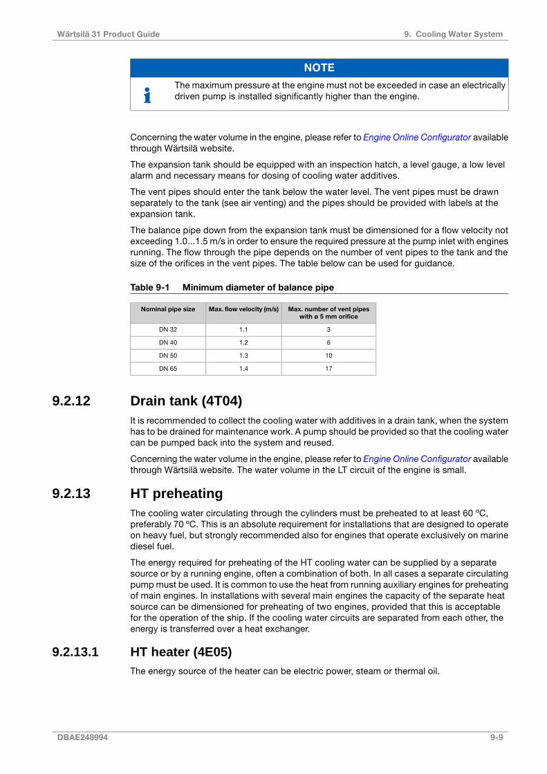
NOTE
The maximum pressure at the engine must not be exceeded in case an electricallydriven pump is installed significantly higher than the engine.
Concerning the water volume in the engine, please refer to Engine Online Configurator availablethrough Wärtsilä website.
The expansion tank should be equipped with an inspection hatch, a level gauge, a low levelalarm and necessary means for dosing of cooling water additives.
The vent pipes should enter the tank below the water level. The vent pipes must be drawnseparately to the tank (see air venting) and the pipes should be provided with labels at theexpansion tank.
The balance pipe down from the expansion tank must be dimensioned for a flow velocity notexceeding 1.0...1.5 m/s in order to ensure the required pressure at the pump inlet with enginesrunning. The flow through the pipe depends on the number of vent pipes to the tank and thesize of the orifices in the vent pipes. The table below can be used for guidance.
Table 9-1 Minimum diameter of balance pipe
Max. number of vent pipeswith ø 5 mm orifice
Max. flow velocity (m/s)Nominal pipe size
31.1DN 32
61.2DN 40
101.3DN 50
171.4DN 65
9.2.12 Drain tank (4T04)It is recommended to collect the cooling water with additives in a drain tank, when the systemhas to be drained for maintenance work. A pump should be provided so that the cooling watercan be pumped back into the system and reused.
Concerning the water volume in the engine, please refer to Engine Online Configurator availablethrough Wärtsilä website. The water volume in the LT circuit of the engine is small.
9.2.13 HT preheatingThe cooling water circulating through the cylinders must be preheated to at least 60 ºC,preferably 70 ºC. This is an absolute requirement for installations that are designed to operateon heavy fuel, but strongly recommended also for engines that operate exclusively on marinediesel fuel.
The energy required for preheating of the HT cooling water can be supplied by a separatesource or by a running engine, often a combination of both. In all cases a separate circulatingpump must be used. It is common to use the heat from running auxiliary engines for preheatingof main engines. In installations with several main engines the capacity of the separate heatsource can be dimensioned for preheating of two engines, provided that this is acceptablefor the operation of the ship. If the cooling water circuits are separated from each other, theenergy is transferred over a heat exchanger.
9.2.13.1 HT heater (4E05)The energy source of the heater can be electric power, steam or thermal oil.
DBAE248994 9-9
9. Cooling Water SystemWärtsilä 31 Product Guide
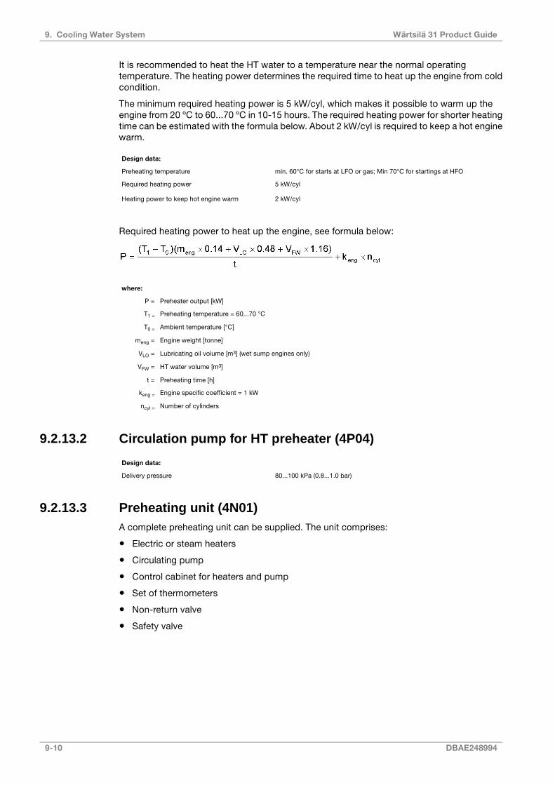
It is recommended to heat the HT water to a temperature near the normal operatingtemperature. The heating power determines the required time to heat up the engine from coldcondition.
The minimum required heating power is 5 kW/cyl, which makes it possible to warm up theengine from 20 ºC to 60...70 ºC in 10-15 hours. The required heating power for shorter heatingtime can be estimated with the formula below. About 2 kW/cyl is required to keep a hot enginewarm.
Design data:
min. 60°C for starts at LFO or gas; Min 70°C for startings at HFOPreheating temperature
5 kW/cylRequired heating power
2 kW/cylHeating power to keep hot engine warm
Required heating power to heat up the engine, see formula below:
where:
Preheater output [kW]P =
Preheating temperature = 60...70 °CT1 =
Ambient temperature [°C]T0 =
Engine weight [tonne]meng =
Lubricating oil volume [m3] (wet sump engines only)VLO =
HT water volume [m3]VFW =
Preheating time [h]t =
Engine specific coefficient = 1 kWkeng =
Number of cylindersncyl =
9.2.13.2 Circulation pump for HT preheater (4P04)
Design data:
80...100 kPa (0.8...1.0 bar)Delivery pressure
9.2.13.3 Preheating unit (4N01)A complete preheating unit can be supplied. The unit comprises:
● Electric or steam heaters
● Circulating pump
● Control cabinet for heaters and pump
● Set of thermometers
● Non-return valve
● Safety valve
9-10 DBAE248994
Wärtsilä 31 Product Guide9. Cooling Water System

Fig 9-6 Preheating unit, electric (V60L0562C)
Dimensions [mm]Pipe conn.Weight[kg]
Pump capacity[m³/h]
Heater capacity[kW]
EDCBAIn/outlet60 HZ50 Hz
4602406609001250DN4095131118
4802907007201050DN40100131122.5
4802907009001250DN40103131227
4802907007201050DN40105131230
4802907009001250DN40125131236
5103507557201250DN40145131245
5103507559001250DN40150131254
5504008059001260DN40187131272
5504008059001260DN40190131281
5754508559001260DN402151312108
9.2.14 ThrottlesThrottles (orifices) are to be installed in all by-pass lines to ensure balanced operating conditionsfor temperature control valves. Throttles must also be installed wherever it is necessary tobalance the waterflow between alternate flow paths.
9.2.15 Thermometers and pressure gaugesLocal thermometers should be installed wherever there is a temperature change, i.e. beforeand after heat exchangers etc. in external system.
Local pressure gauges should be installed on the suction and discharge side of each pump.
DBAE248994 9-11
9. Cooling Water SystemWärtsilä 31 Product Guide

This page intentionally left blank

10. Combustion Air System
The engine draws the combustion air either from the engine room through the inlet filter fittedon the turbocharger or from outside of the engine room. In case air is taken from inside of theengine room, the combustion air should be delivered through a dedicated duct close to theturbochargers, directed towards the air intakes. For the required amount of combustion airand the heat emitted by the engine is listed in chapter 3. Technical Data.
10.1 Engine room ventilationTo maintain acceptable operating conditions for the engines and to ensure trouble free operationof all equipment, attention shall be paid to the engine room ventilation and the supply ofcombustion air.
The air intakes to the engine room must be located and designed so that water spray, rainwater, dust and exhaust gases cannot enter the ventilation ducts and the engine room.
The dimensioning of blowers and extractors should ensure that an overpressure of about 50Pa is maintained in the engine room in all running conditions.
During normal operating conditions the air temperature at the turbocharger inlet should bekept between 15ºC and 35ºC. Max. 45ºC is allowed.
For the minimum requirements concerning the engine room ventilation and more details, seeapplicable standards, such as ISO 8861.
The amount of air required for ventilation is calculated from the total heat emission Φ toevacuate. To determine Φ, all heat sources shall be considered, e.g.:
● Main and auxiliary diesel engines
● Exhaust gas piping
● Generators
● Electric appliances and lighting
● Boilers
● Steam and condensate piping
● Tanks
● Other auxiliary equipment
It is recommended to consider an outside air temperature of no less than 35°C and atemperature rise of 11°C for the ventilation air.
The amount of air required for ventilation is then calculated using the formula:
where:
qv = air flow [m³/s]
Φ = total heat emission to be evacuated [kW]
ρ = air density 1.13 kg/m³
c = specific heat capacity of the ventilation air 1.01 kJ/kgK
ΔT = temperature rise in the engine room [°C]
DBAE248994 10-1
10. Combustion Air SystemWärtsilä 31 Product Guide

The heat emitted by the engine is listed in Engine Online Configurator available through Wärtsiläwebsite.
The engine room ventilation air has to be provided by separate ventilation fans. These fansshould preferably have two-speed electric motors (or variable speed). The ventilation can thenbe reduced according to outside air temperature and heat generation in the engine room, forexample during overhaul of the main engine when it is not preheated (and therefore not heatingthe room).
The ventilation air is to be equally distributed in the engine room considering air flows frompoints of delivery towards the exits. This is usually done so that the funnel serves as exit formost of the air. To avoid stagnant air, extractors can be used.
It is good practice to provide areas with significant heat sources, such as separator roomswith their own air supply and extractors.
Under-cooling of the engine room should be avoided during all conditions (service conditions,slow steaming and in port). Cold draft in the engine room should also be avoided, especiallyin areas of frequent maintenance activities. For very cold conditions a pre-heater in the systemshould be considered. Suitable media could be thermal oil or water/glycol to avoid the riskfor freezing. If steam is specified as heating medium for the ship, the pre-heater should be ina secondary circuit.
Fig 10-1 Engine room ventilation, turbocharger with air filter (DAAF391752)
10-2 DBAE248994
Wärtsilä 31 Product Guide10. Combustion Air System

Fig 10-2 Engine room ventilation, air duct connected to the turbocharger(DAAF391711)
10.2 Combustion air system designUsually, the combustion air is taken from the engine room through a filter on the turbocharger.This reduces the risk for too low temperatures and contamination of the combustion air. It isimportant that the combustion air is free from sea water, dust, fumes, etc.
For the required amount of combustion air, please refer to Engine Online Configurator availablethrough Wärtsilä website.
The combustion air shall be supplied by separate combustion air fans, with a capacity slightlyhigher than the maximum air consumption. The combustion air mass flow stated in EngineOnline Configurator available through Wärtsilä website is defined for an ambient air temperatureof 25°C. Calculate with an air density corresponding to 30°C or more when translating themass flow into volume flow. The expression below can be used to calculate the volume flow.
where:
combustion air volume flow [m³/s]qc =
combustion air mass flow [kg/s]m' =
air density 1.15 kg/m³ρ =
The fans should preferably have two-speed electric motors (or variable speed) for enhancedflexibility. In addition to manual control, the fan speed can be controlled by engine load.
In multi-engine installations each main engine should preferably have its own combustion airfan. Thus the air flow can be adapted to the number of engines in operation.
The combustion air should be delivered through a dedicated duct close to the turbocharger,directed towards the turbocharger air intake. The outlet of the duct should be equipped witha flap for controlling the direction and amount of air. Also other combustion air consumers,for example other engines, gas turbines and boilers shall be served by dedicated combustionair ducts.
If necessary, the combustion air duct can be connected directly to the turbocharger with aflexible connection piece. With this arrangement an external filter must be installed in the duct
DBAE248994 10-3
10. Combustion Air SystemWärtsilä 31 Product Guide

to protect the turbocharger and prevent fouling of the charge air cooler. The permissible totalpressure drop in the duct is max. 1.5 kPa. The duct should be provided with a step-lesschange-over flap to take the air from the engine room or from outside depending on engineload and air temperature.
For very cold conditions arctic setup is to be used. The combustion air fan is stopped duringstart of the engine and the necessary combustion air is drawn from the engine room. Afterstart either the ventilation air supply, or the combustion air supply, or both in combinationmust be able to maintain the minimum required combustion air temperature. The air supplyfrom the combustion air fan is to be directed away from the engine, when the intake air is cold,so that the air is allowed to heat up in the engine room.
10.2.1 Charge air shut-off valve (optional)In installations where it is possible that the combustion air includes combustible gas or vapourthe engines can be equipped with charge air shut-off valve. This is regulated mandatory whereingestion of flammable gas or fume is possible.
10.2.2 Condensation in charge air coolersAir humidity may condense in the charge air cooler, especially in tropical conditions. Theengine is equipped with an active dewpoint control to minimize condensation in the chargeair coolers and the charge air receiver by raising the LT-cooling water temperature based onambient humidity and charge air pressure. The engine is also equipped with a small drain pipefrom the charge air cooler and receiver for possible condensed water. Humidity sensor ismounted in external system.
10-4 DBAE248994
Wärtsilä 31 Product Guide10. Combustion Air System
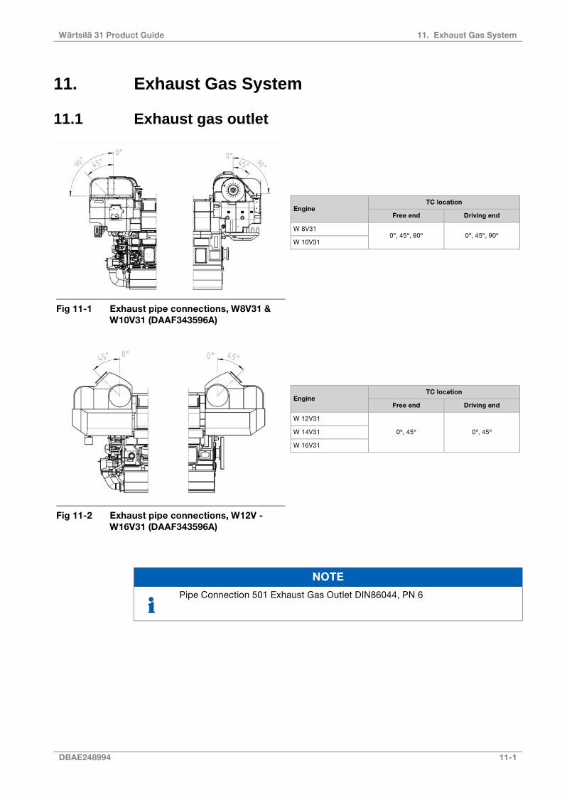
11. Exhaust Gas System
11.1 Exhaust gas outlet
Fig 11-1 Exhaust pipe connections, W8V31 &W10V31 (DAAF343596A)
TC locationEngine
Driving endFree end
0º, 45º, 90º0º, 45º, 90ºW 8V31
W 10V31
TC locationEngine
Driving endFree end
0º, 45º0º, 45º
W 12V31
W 14V31
W 16V31
Fig 11-2 Exhaust pipe connections, W12V -W16V31 (DAAF343596A)
NOTE
Pipe Connection 501 Exhaust Gas Outlet DIN86044, PN 6
DBAE248994 11-1
11. Exhaust Gas SystemWärtsilä 31 Product Guide

Fig 11-3 Exhaust pipe, diameters and support(DAAF351047)
ØB [mm]A [mm]Engine
700DN550W 8V31
800DN550W 10V31
ØB [mm]A [mm]Engine
800DN450W 12V31
900DN450W 14V31
900DN450W 16V31
Fig 11-4 Exhaust pipe, diameters and support(DAAF351275A, DAAF351507A)
11-2 DBAE248994
Wärtsilä 31 Product Guide11. Exhaust Gas System

11.2 External exhaust gas systemEach engine should have its own exhaust pipe into open air. Backpressure, thermal expansionand supporting are some of the decisive design factors.
Flexible bellows must be installed directly on the turbocharger outlet, to compensate forthermal expansion and prevent damages to the turbocharger due to vibrations.
Engine1
Exhaust gas bellows2
Transitions piece3
Not applicable for Wärtsilä 31 Diesel Engines4
Connection for measurement of back pressure5
Drain with water trap, continuosuly open6
Bilge7
Not applicable for Wärtsilä 31 Diesel Engines8
Selective Catalytic Reactor (SCR)9
Urea injection unit (SCR)10
Silencer with spark arrestor11a
CSS silencer element11b
Fig 11-5 External exhaust gas sys-tem (DAAF391527)
11.2.1 PipingThe piping should be as short and straight as possible. Pipe bends and expansions shouldbe smooth to minimise the backpressure. The diameter of the exhaust pipe should be increaseddirectly after the bellows on the turbocharger. Pipe bends should be made with the largestpossible bending radius; the bending radius should not be smaller than 1.5 x D.
The recommended flow velocity in the pipe is maximum 35…40 m/s at full output. If there aremany resistance factors in the piping, or the pipe is very long, then the flow velocity needs tobe lower. The exhaust gas mass flow given in Engine Online Configurator available throughWärtsilä website can be translated to velocity using the formula:
where:
gas velocity [m/s]v =
exhaust gas mass flow [kg/s]m' =
exhaust gas temperature [°C]T =
exhaust gas pipe diameter [m]D =
The exhaust pipe must be insulated with insulation material approved for concerned operationconditions, minimum thickness 30 mm considering the shape of engine mounted insulation.
DBAE248994 11-3
11. Exhaust Gas SystemWärtsilä 31 Product Guide

Insulation has to be continuous and protected by a covering plate or similar to keep theinsulation intact.
Closest to the turbocharger the insulation should consist of a hook on padding to facilitatemaintenance. It is especially important to prevent the airstream to the turbocharger fromdetaching insulation, which will clog the filters.
After the insulation work has been finished, it has to be verified that it fulfils SOLAS-regulations.Surface temperatures must be below 220°C on whole engine operating range.
11.2.2 SupportingIt is very important that the exhaust pipe is properly fixed to a support that is rigid in alldirections directly after the bellows on the turbocharger. There should be a fixing point onboth sides of the pipe at the support. The bellows on the turbocharger may not be used toabsorb thermal expansion from the exhaust pipe. The first fixing point must direct the thermalexpansion away from the engine. The following support must prevent the pipe from pivotingaround the first fixing point.
Absolutely rigid mounting between the pipe and the support is recommended at the first fixingpoint after the turbocharger. Resilient mounts can be accepted for resiliently mounted engineswith “double” variant bellows (bellow capable of handling the additional movement), providedthat the mounts are self-captive; maximum deflection at total failure being less than 2 mmradial and 4 mm axial with regards to the bellows. The natural frequencies of the mountingshould be on a safe distance from the running speed, the firing frequency of the engine andthe blade passing frequency of the propeller. The resilient mounts can be rubber mounts ofconical type, or high damping stainless steel wire pads. Adequate thermal insulation must beprovided to protect rubber mounts from high temperatures. When using resilient mounting,the alignment of the exhaust bellows must be checked on a regular basis and corrected whennecessary.
After the first fixing point resilient mounts are recommended. The mounting supports shouldbe positioned at stiffened locations within the ship’s structure, e.g. deck levels, frame websor specially constructed supports.
The supporting must allow thermal expansion and ship’s structural deflections.
11.2.3 Back pressureThe maximum permissible exhaust gas back pressure is stated in Engine Online Configuratoravailable through Wärtsilä website. The back pressure in the system must be calculated bythe shipyard based on the actual piping design and the resistance of the components in theexhaust system. The exhaust gas mass flow and temperature given in Engine OnlineConfigurator available through Wärtsilä website may be used for the calculation.
Each exhaust pipe should be provided with a connection for measurement of the back pressure.The back pressure must be measured by the shipyard during the sea trial.
11.2.4 Exhaust gas bellows (5H01, 5H03)Bellows must be used in the exhaust gas piping where thermal expansion or ship’s structuraldeflections have to be segregated. The flexible bellows mounted directly on the turbochargeroutlet serves to minimise the external forces on the turbocharger and thus prevent excessivevibrations and possible damage. All exhaust gas bellows must be of an approved type.
11.2.5 SCR-unit (11N14)The SCR-unit requires special arrangement on the engine in order to keep the exhaust gastemperature and backpressure into SCR-unit working range. The exhaust gas piping must bestraight at least 3...5 meters in front of the SCR unit. If both an exhaust gas boiler and a SCRunit will be installed, then the exhaust gas boiler shall be installed after the SCR. Arrangements
11-4 DBAE248994
Wärtsilä 31 Product Guide11. Exhaust Gas System
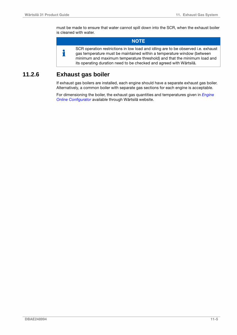
must be made to ensure that water cannot spill down into the SCR, when the exhaust boileris cleaned with water.
NOTE
SCR operation restrictions in low load and idling are to be observed i.e. exhaustgas temperature must be maintained within a temperature window (betweenminimum and maximum temperature threshold) and that the minimum load andits operating duration need to be checked and agreed with Wärtsilä.
11.2.6 Exhaust gas boilerIf exhaust gas boilers are installed, each engine should have a separate exhaust gas boiler.Alternatively, a common boiler with separate gas sections for each engine is acceptable.
For dimensioning the boiler, the exhaust gas quantities and temperatures given in EngineOnline Configurator available through Wärtsilä website.
DBAE248994 11-5
11. Exhaust Gas SystemWärtsilä 31 Product Guide

11.2.7 Exhaust gas silencersThe exhaust gas silencing can be accomplished either by the patented Compact SilencerSystem (CSS) technology or by the conventional exhaust gas silencer.
11.2.7.1 Exhaust noiseThe unattenuated exhaust noise is typically measured in the exhaust duct. The in-ductmeasurement is transformed into free field sound power through a number of correctionfactors.
The spectrum of the required attenuation in the exhaust system is achieved when the freefield sound power (A) is transferred into sound pressure (B) at a certain point and comparedwith the allowable sound pressure level (C).
Fig 11-6 Exhaust noise, source power corrections
The conventional silencer is able to reduce the sound level in a certain area of the frequencyspectrum. CSS is designed to cover the whole frequency spectrum.
11-6 DBAE248994
Wärtsilä 31 Product Guide11. Exhaust Gas System
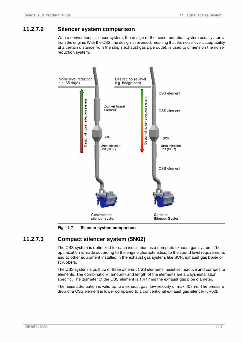
11.2.7.2 Silencer system comparisonWith a conventional silencer system, the design of the noise reduction system usually startsfrom the engine. With the CSS, the design is reversed, meaning that the noise level acceptabilityat a certain distance from the ship's exhaust gas pipe outlet, is used to dimension the noisereduction system.
Fig 11-7 Silencer system comparison
11.2.7.3 Compact silencer system (5N02)The CSS system is optimized for each installation as a complete exhaust gas system. Theoptimization is made according to the engine characteristics, to the sound level requirementsand to other equipment installed in the exhaust gas system, like SCR, exhaust gas boiler orscrubbers.
The CSS system is built up of three different CSS elements; resistive, reactive and compositeelements. The combination-, amount- and length of the elements are always installationspecific. The diameter of the CSS element is 1.4 times the exhaust gas pipe diameter.
The noise attenuation is valid up to a exhaust gas flow velocity of max 40 m/s. The pressuredrop of a CSS element is lower compared to a conventional exhaust gas silencer (5R02).
DBAE248994 11-7
11. Exhaust Gas SystemWärtsilä 31 Product Guide
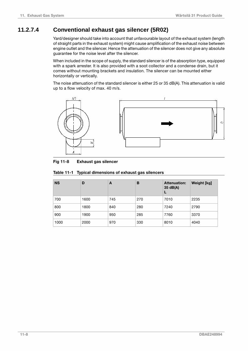
11.2.7.4 Conventional exhaust gas silencer (5R02)Yard/designer should take into account that unfavourable layout of the exhaust system (lengthof straight parts in the exhaust system) might cause amplification of the exhaust noise betweenengine outlet and the silencer. Hence the attenuation of the silencer does not give any absoluteguarantee for the noise level after the silencer.
When included in the scope of supply, the standard silencer is of the absorption type, equippedwith a spark arrester. It is also provided with a soot collector and a condense drain, but itcomes without mounting brackets and insulation. The silencer can be mounted eitherhorizontally or vertically.
The noise attenuation of the standard silencer is either 25 or 35 dB(A). This attenuation is validup to a flow velocity of max. 40 m/s.
Fig 11-8 Exhaust gas silencer
Table 11-1 Typical dimensions of exhaust gas silencers
Weight [kg]Attenuation:35 dB(A)L
BADNS
223570102707451600700
279072402808401800800
337077602859501900900
4040801033097020001000
11-8 DBAE248994
Wärtsilä 31 Product Guide11. Exhaust Gas System

12. Turbocharger Cleaning
Regular water cleaning of the turbine and the compressor reduces the formation of depositsand extends the time between overhauls. Fresh water is injected into the turbocharger duringoperation. Additives, solvents or salt water must not be used and the cleaning instructions,as outlined in the Engine Operation & Maintenance Manual, must be carefully followed.
12.1 Turbine cleaning systemA dosing unit consisting of a flow meter and an adjustable throttle valve is delivered for eachinstallation. The dosing unit is installed in the engine room and connected to the engine witha detachable rubber hose. The rubber hose is connected with quick couplings and the lengthof the hose is normally 10 m. One dosing unit can be used for several engines.
Water supply:
Fresh water
0.6 MPa (6 bar)Min. pressure
0.8 MPa (8 bar)Max. pressure
80 °CMax. temperature
15-30 l/min (depending on cylinder configuration)Flow
Fig 12-1 Turbocharger cleaning system (DAAF347567E)
Pipe connectionsSystem components
Cleaning water to turbine502##TC cleaning device5Z03
Cleaning water to compressor509##Wärtsilä control unit02
Scavenging air outlet to TC cleaning valve unit614##Flow meter/control (10 - 85 l/min)03
Flow adjustment valve, built in04
Air filter05
DBAE248994 12-1
12. Turbocharger CleaningWärtsilä 31 Product Guide

WaterEngine (8V - 10V)
Water consumption/wash (l)Water inlet flow rate (l/min)Turbine / compressor
18LP-compressor
20020LP-turbine
18HP-compressor
20020HP-turbine
WaterEngine (12V - 16V)
Water consumption/wash (l)Water inlet flow rate (l/min)Turbine / compressor
0.56LP-compressor
15015LP-turbine
0.56HP-compressor
15015HP-turbine
12.2 Compressor cleaning systemThe compressor side of the turbocharger is cleaned with the same equipment as the turbine.
NOTE
If the turbocharger suction air is below +5 ºC, washing is not possible.
NOTE
The engine has automatic cleaning unit. One cleaning device per engine and onecontrol unit can control up to 3 cleaning devices.
12.3 Purge air for turbine cleaning nozzlesThe nozzles of the turbine cleaning module have to be connected permanently to purge air inbetween the cleaning cycles. Purge air will be taken from the air receiver at higher engineloads, a purge air flow of 0,1-0,2% of compressor air flow is used. On low load below 35%instrumentation air is used. This is to prevent exhaust gas flow into the cleaning system
Instrument air consumption is 120 l/min per engine wash unit for purging below 35% load.
NOTE
For cleaning interval, washing instruction of turbocharger, please refer to EngineOperation & Maintenance Manual.
12-2 DBAE248994
Wärtsilä 31 Product Guide12. Turbocharger Cleaning

13. Exhaust Emissions
Exhaust emissions from the diesel engine mainly consist of nitrogen, oxygen and combustionproducts like carbon dioxide (CO2), water vapour and minor quantities of carbon monoxide(CO), sulphur oxides (SOx), nitrogen oxides (NOx), partially reacted and non-combustedhydrocarbons (HC) and particulate matter (PM).
There are different emission control methods depending on the aimed pollutant. These aremainly divided in two categories; primary methods that are applied on the engine itself andsecondary methods that are applied on the exhaust gas stream.
13.1 Diesel engine exhaust componentsThe nitrogen and oxygen in the exhaust gas are the main components of the intake air whichdon't take part in the combustion process.
CO2 and water are the main combustion products. Secondary combustion products are carbonmonoxide, hydrocarbons, nitrogen oxides, sulphur oxides, soot and particulate matters.
In a diesel engine the emission of carbon monoxide and hydrocarbons are low compared toother internal combustion engines, thanks to the high air/fuel ratio in the combustion process.The air excess allows an almost complete combustion of the HC and oxidation of the CO toCO2, hence their quantity in the exhaust gas stream are very low.
13.1.1 Nitrogen oxides (NOx)The combustion process gives secondary products as Nitrogen oxides. At high temperaturethe nitrogen, usually inert, react with oxygen to form Nitric oxide (NO) and Nitrogen dioxide(NO2), which are usually grouped together as NOx emissions. Their amount is strictly relatedto the combustion temperature.
NO can also be formed through oxidation of the nitrogen in fuel and through chemical reactionswith fuel radicals. NO in the exhaust gas flow is in a high temperature and high oxygenconcentration environment, hence oxidizes rapidly to NO2. The amount of NO2 emissions isapproximately 5 % of total NOx emissions.
13.1.2 Sulphur Oxides (SOx)Sulphur oxides (SOx) are direct result of the sulphur content of the fuel oil. During thecombustion process the fuel bound sulphur is rapidly oxidized to sulphur dioxide (SO2). Asmall fraction of SO2 may be further oxidized to sulphur trioxide (SO3).
13.1.3 Particulate Matter (PM)The particulate fraction of the exhaust emissions represents a complex mixture of inorganicand organic substances mainly comprising soot (elemental carbon), fuel oil ash (together withsulphates and associated water), nitrates, carbonates and a variety of non or partiallycombusted hydrocarbon components of the fuel and lubricating oil.
13.1.4 SmokeAlthough smoke is usually the visible indication of particulates in the exhaust, the correlationsbetween particulate emissions and smoke is not fixed. The lighter and more volatilehydrocarbons will not be visible nor will the particulates emitted from a well maintained andoperated diesel engine.
Smoke can be black, blue, white, yellow or brown in appearance. Black smoke is mainlycomprised of carbon particulates (soot). Blue smoke indicates the presence of the products
DBAE248994 13-1
13. Exhaust EmissionsWärtsilä 31 Product Guide

of the incomplete combustion of the fuel or lubricating oil. White smoke is usually condensedwater vapour. Yellow smoke is caused by NOx emissions. When the exhaust gas is cooledsignificantly prior to discharge to the atmosphere, the condensed NO2 component can havea brown appearance.
13.2 Marine exhaust emissions legislation
13.2.1 International Maritime Organization (IMO)The increasing concern over the air pollution has resulted in the introduction of exhaustemission controls to the marine industry. To avoid the growth of uncoordinated regulations,the IMO (International Maritime Organization) has developed the Annex VI of MARPOL 73/78,which represents the first set of regulations on the marine exhaust emissions.
The IMO Tier 3 NOx emission standard has entered into force from year 2016. It applies fornew marine diesel engines that:
● Are > 130 kW
● Installed in ships which keel laying date is 1.1.2016 or later
● Operating inside the North American ECA and the US Caribbean Sea ECA
From 1.1.2021 onwards Baltic sea and North sea will be included in to IMO Tier 3 NOxrequirements.
13.2.2 Other LegislationsThere are also other local legislations in force in particular regions.
13.3 Methods to reduce exhaust emissionsAll standard Wärtsilä engines meet the NOx emission level set by the IMO (International MaritimeOrganisation) and most of the local emission levels without any modifications. Wärtsilä hasalso developed solutions to significantly reduce NOx emissions when this is required.
Diesel engine exhaust emissions can be reduced either with primary or secondary methods.The primary methods limit the formation of specific emissions during the combustion process.The secondary methods reduce emission components after formation as they pass throughthe exhaust gas system.
Refer to the "Wärtsilä Environmental Product Guide" for information about exhaust gas emissioncontrol systems.
13-2 DBAE248994
Wärtsilä 31 Product Guide13. Exhaust Emissions
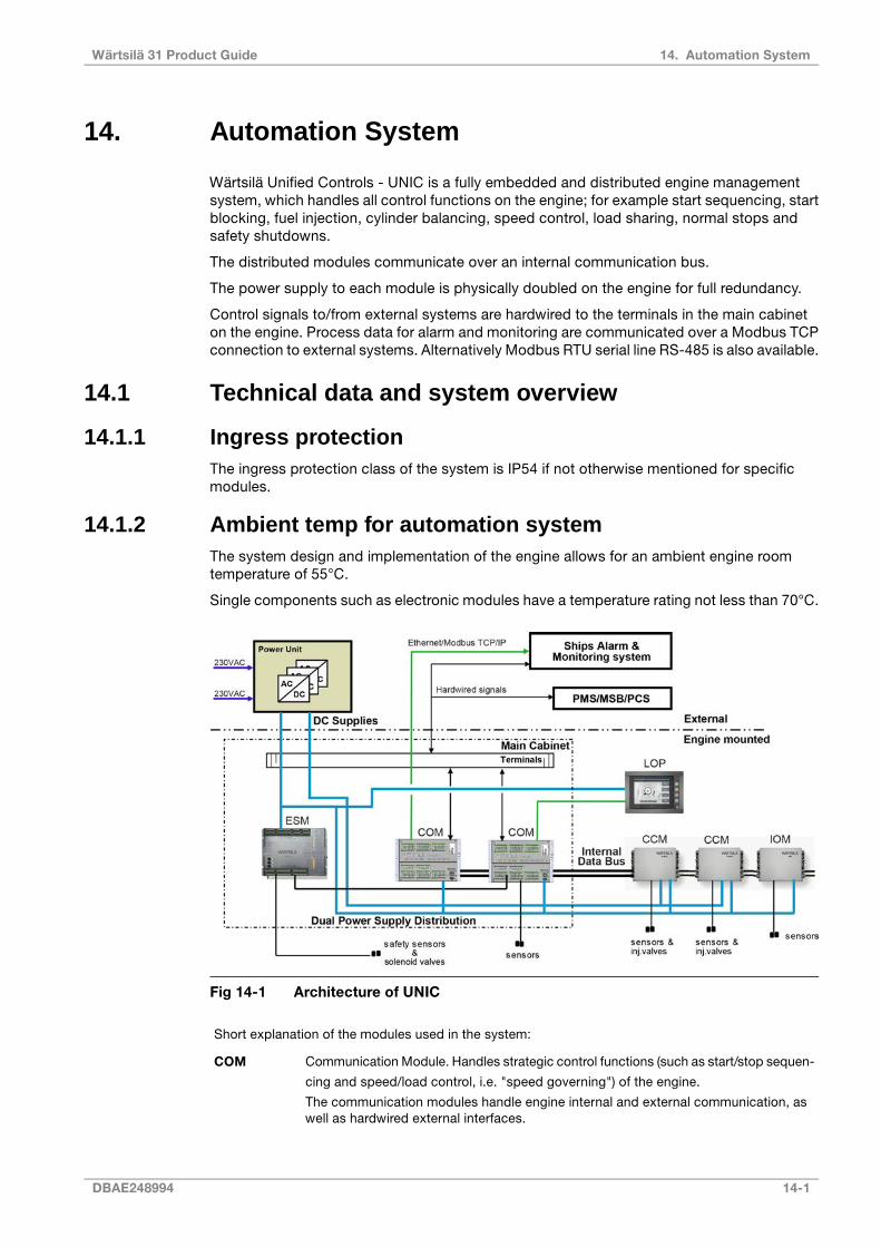
14. Automation System
Wärtsilä Unified Controls - UNIC is a fully embedded and distributed engine managementsystem, which handles all control functions on the engine; for example start sequencing, startblocking, fuel injection, cylinder balancing, speed control, load sharing, normal stops andsafety shutdowns.
The distributed modules communicate over an internal communication bus.
The power supply to each module is physically doubled on the engine for full redundancy.
Control signals to/from external systems are hardwired to the terminals in the main cabineton the engine. Process data for alarm and monitoring are communicated over a Modbus TCPconnection to external systems. Alternatively Modbus RTU serial line RS-485 is also available.
14.1 Technical data and system overview
14.1.1 Ingress protectionThe ingress protection class of the system is IP54 if not otherwise mentioned for specificmodules.
14.1.2 Ambient temp for automation systemThe system design and implementation of the engine allows for an ambient engine roomtemperature of 55°C.
Single components such as electronic modules have a temperature rating not less than 70°C.
Fig 14-1 Architecture of UNIC
Short explanation of the modules used in the system:
Communication Module. Handles strategic control functions (such as start/stop sequen-
cing and speed/load control, i.e. "speed governing") of the engine.
The communication modules handle engine internal and external communication, aswell as hardwired external interfaces.
COM
DBAE248994 14-1
14. Automation SystemWärtsilä 31 Product Guide
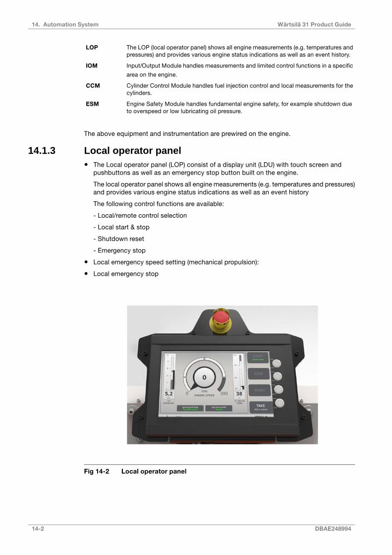
The LOP (local operator panel) shows all engine measurements (e.g. temperatures andpressures) and provides various engine status indications as well as an event history.
LOP
Input/Output Module handles measurements and limited control functions in a specific
area on the engine.
IOM
Cylinder Control Module handles fuel injection control and local measurements for thecylinders.
CCM
Engine Safety Module handles fundamental engine safety, for example shutdown dueto overspeed or low lubricating oil pressure.
ESM
The above equipment and instrumentation are prewired on the engine.
14.1.3 Local operator panel● The Local operator panel (LOP) consist of a display unit (LDU) with touch screen and
pushbuttons as well as an emergency stop button built on the engine.
The local operator panel shows all engine measurements (e.g. temperatures and pressures)and provides various engine status indications as well as an event history
The following control functions are available:
- Local/remote control selection
- Local start & stop
- Shutdown reset
- Emergency stop
● Local emergency speed setting (mechanical propulsion):
● Local emergency stop
Fig 14-2 Local operator panel
14-2 DBAE248994
Wärtsilä 31 Product Guide14. Automation System

14.1.4 Engine safety systemThe engine safety module handles fundamental safety functions, for example overspeedprotection.
Main features:
● Redundant design for power supply, speed inputs and stop solenoid control
● Fault detection on sensors, solenoids and wires
● Led indication of status and detected faults
● Digital status outputs
● Shutdown latching and reset
● Shutdown pre-warning
● Shutdown override (configuration depending on application)
14.1.5 Power unitA power unit is delivered with each engine. The power unit supplies DC power to the automationsystem on the engine and provides isolation from other power supply systems onboard. Thecabinet is designed for bulkhead mounting, protection degree IP44, max. ambient temperature50°C.
The power unit contains redundant power converters, each converter dimensioned for 100%load. At least one of the two incoming supplies must be connected to a UPS. The power unitsupplies the automation system on the engine with 24 VDC and 110 VDC.
Power supply from ship's system:
● Supply 1: 230 VAC / abt. 750 W
● Supply 2: 230 VAC / abt. 750 W
14.1.6 Ethernet communication unitEthernet switch and firewall/router are installed in a steel sheet cabinet for bulkhead mounting,protection class IP44.
DBAE248994 14-3
14. Automation SystemWärtsilä 31 Product Guide

14.1.7 Cabling and system overview
Fig 14-3 UNIC overview
Table 14-1 Typical amount of cables
Cable types (typical)From <=> ToCable
2 x 4 mm2 (power supply) *2 x 4 mm2 (power supply) *2 x 4 mm2 (power supply) *2 x 4 mm2 (power supply) *2 x 4 mm2 (power supply) *2 x 4 mm2 (power supply) *2 x 4 mm2 (power supply) *2 x 4 mm2 (power supply) *
Engine <=> Power UnitA
2 x 2.5 mm2 (power supply) *Power unit => Communication interface unitB
1 x 2 x 0.75 mm2
1 x 2 x 0.75 mm2
1 x 2 x 0.75 mm2
24 x 0.75 mm2
24 x 0.75 mm2
Engine <=> Propulsion Control SystemEngine <=> Power Management System / Main Switch-
board
C
2 x 0.75 mm2Power unit <=> Integrated Automation SystemD
3 x 2 x 0.75 mm2Engine <=> Integrated Automation SystemE
1 x Ethernet CAT 5Engine => Communication interface unitF
1 x Ethernet CAT 5Communication interface unit => Integrated automationsystem
G
2 x 0.75 mm2Engine => Pre-lubrication pump starterH
1 x CAN bus (120 ohm)Engine => Turning gear starterI
14-4 DBAE248994
Wärtsilä 31 Product Guide14. Automation System
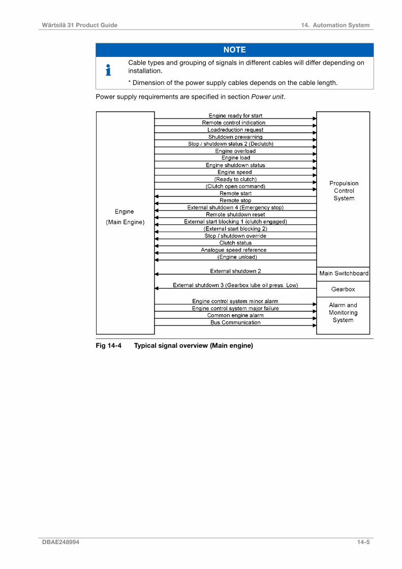
NOTE
Cable types and grouping of signals in different cables will differ depending oninstallation.
* Dimension of the power supply cables depends on the cable length.
Power supply requirements are specified in section Power unit.
Fig 14-4 Typical signal overview (Main engine)
DBAE248994 14-5
14. Automation SystemWärtsilä 31 Product Guide

Fig 14-5 Typical signal overview (Generating set)
14.2 Functions
14.2.1 StartThe engine is started by injecting compressed air directly into the cylinders.
The engine can be started locally, or remotely if applicable for the installation e.g. from thepower management system or control room. In an emergency situation it is also possible tooperate the starting air valve manually.
Starting is blocked both pneumatically and electrically when the turning gear is engaged.
The engine is equipped with a slow turning system, which rotates the engine without fuelinjection for a few turns before start. Slow turning is performed automatically at predefinedintervals, if the engine has been selected as stand-by.
14.2.1.1 StartblockingsStarting is inhibited by the following functions:
● Turning gear engaged
● Pre-lubricating pressure low
● Blocked by operator from the local operator panel
● Stop or shutdown active
● External start blockings active
● Engine running
14-6 DBAE248994
Wärtsilä 31 Product Guide14. Automation System

14.2.2 Stop and shutdownA normal stop can be initiated locally, or remotely if applicable for the installation. At normalstop the stop sequence is active until the engine has come to standstill. Thereafter the systemautomatically returns to “ready for start" mode in case no start block functions are active, i.e.there is no need for manually resetting a normal stop.
Emergency stop can be activated with the local emergency stop button, or from a remotelocation as applicable.
The engine safety module handles safety shutdowns. Safety shutdowns can be initiated eitherindependently by the safety module, or executed by the safety module upon a shutdownrequest from some other part of the automation system.
Typical shutdown functions are:
● Lubricating oil pressure low
● Overspeed
● Oil mist in crankcase
● Lubricating oil pressure low in reduction gear
At a stop or shutdown the fuel injection is disabled and the pressure in the high pressure fuelline is instantly released.
Depending on the application it is possible to override a shutdown via a separate input. It isnot possible to override a shutdown due to overspeed or emergency stop.
Before restart the reason for the shutdown must be thoroughly investigated and rectified.
14.2.3 Speed control
14.2.3.1 Main engines (mechanical propulsion)The electronic speed control is integrated in the engine automation system.
The remote speed setting from the propulsion control is an analogue 4-20 mA signal. It is alsopossible to select an operating mode in which the speed reference can be adjusted withincrease/decrease signals.
The electronic speed control handles load sharing between parallel engines, fuel limiters, andvarious other control functions (e.g. ready to open/close clutch, speed filtering). Overloadprotection and control of the load increase rate must however be included in the propulsioncontrol as described in the chapter Operating Ranges.
14.2.3.2 Generating setsThe electronic speed control is integrated in the engine automation system.
The load sharing can be based on traditional speed droop, or handled independently by thespeed control units without speed droop. The later load sharing principle is commonly referredto as isochronous load sharing. With isochronous load sharing there is no need for loadbalancing, frequency adjustment, or generator loading/unloading control in the external controlsystem.
In a speed droop system each individual speed control unit decreases its internal speedreference when it senses increased load on the generator. Decreased network frequency withhigher system load causes all generators to take on a proportional share of the increased totalload. Engines with the same speed droop and speed reference will share load equally. Loadingand unloading of a generator is accomplished by adjusting the speed reference of the individualspeed control unit. The speed droop is typically 4%, which means that the difference infrequency between zero load and maximum load is 4%.
DBAE248994 14-7
14. Automation SystemWärtsilä 31 Product Guide

In isochronous mode the speed reference remains constant regardless of load level. Bothisochronous load sharing and traditional speed droop are standard features in the speedcontrol and either mode can be easily selected. If the ship has several switchboard sectionswith tie breakers between the different sections, then the status of each tie breaker is requiredfor control of the load sharing in isochronous mode.
14.3 Alarm and monitoring signalsRegarding sensors on the engine, the actual configuration of signals and the alarm levels arefound in the project specific documentation supplied for all contracted projects.
14.4 Electrical consumers
14.4.1 Motor starters and operation of electrically driven pumpsMotor starters are not part of the control system supplied with the engine, but available asloose supplied items.
14.4.1.1 Engine turning device (9N15)The crankshaft can be slowly rotated with the turning device for maintenance purposes andfor engine slowturning. The engine turning device is controlled with an electric motor via afrequency converter. The frequency converter is to be mounted on the external system. Theelectric motor ratings are listed in the table below.
Table 14-2 Electric motor ratings for engine turning device (DAAF026149AV,DAAF026159S)
Current [A]Power [kW]Frequency [Hz]Voltage [V]Engine type
5.1 - 15.34 - 7.5503 x 380 - 690Wärtsilä 31
14.4.1.2 Pre-lubricating oil pumpThe pre-lubricating oil pump must always be running when the engine is stopped. The enginecontrol system handles start/stop of the pump automatically via a motor starter.
It is recommended to arrange a back-up power supply from an emergency power source.Diesel generators serving as the main source of electrical power must be able to resume theiroperation in a black out situation by means of stored energy. Depending on system designand classification regulations, it may be permissible to use the emergency generator.
Electric motor ratings are listed in the table below.
Table 14-3 Electric motor ratings for pre-lubricating pump (DAAF026149AV,DAAF026159S)
Current [A]Power [kW]Frequency [Hz]Voltage [V]Engine type
16.1 - 2915.050 / 603 x 380 - 690Wärtsilä 31
14.4.1.3 Stand-by pump, lubricating oil (if applicable) (2P04)The engine control system starts the pump automatically via a motor starter, if the lubricatingoil pressure drops below a preset level when the engine is running.
14-8 DBAE248994
Wärtsilä 31 Product Guide14. Automation System

The pump must not be running when the engine is stopped, nor may it be used forpre-lubricating purposes. Neither should it be operated in parallel with the main pump, whenthe main pump is in order.
14.4.1.4 Stand-by pump, HT cooling water (if applicable) (4P03)The engine control system starts the pump automatically via a motor starter, if the coolingwater pressure drops below a preset level when the engine is running.
14.4.1.5 Stand-by pump, LT cooling water (if applicable) (4P05)The engine control system starts the pump automatically via a motor starter, if the coolingwater pressure drops below a preset level when the engine is running.
14.4.1.6 Circulating pump for preheater (4P04)The preheater pump shall start when the engine stops (to ensure water circulation throughthe hot engine) and stop when the engine starts. The engine control system handles start/stopof the pump automatically.
DBAE248994 14-9
14. Automation SystemWärtsilä 31 Product Guide

14.5 System requirements and guidelines for diesel-electricpropulsionTypical features to be incorporated in the propulsion control and power management systemsin a diesel-electric ship:
1. The load increase program must limit the load increase rate during ship acceleration andload transfer between generators according to the curves in chapter 2.2 Loading Capacity.
● Continuously active limit: “normal max. loading in operating condition"
● During the first 6 minutes after starting an engine: “preheated engine"
If the control system has only one load increase ramp, then the ramp for a preheated engineis to be used.
The load increase rate of a recently connected generator is the sum of the load transferperformed by the power management system and the load increase performed by thepropulsion control, if the load sharing is based on speed droop. In a system with isochronousload sharing the loading rate of a recently connected generator is not affected by changes inthe total system load (as long as the generators already sharing load equally are not loadedover 100%).
2. Rapid loading according to the “emergency" curve in chapter 2.2 Loading Capacity mayonly be possible by activating an emergency function, which generates visual and audiblealarms in the control room and on the bridge.
3. The propulsion control should be able to control the propulsion power according to theload increase rate at the diesel generators. Controlled load increase with different number ofgenerators connected and in different operating conditions is difficult to achieve with onlytime ramps for the propeller speed.
4. The load reduction rate should also be limited in normal operation. Crash stop can berecognised by for example a large lever movement from ahead to astern.
5. Some propulsion systems can generate power back into the network. The diesel generatorcan absorb max. 5% reverse power.
6. The power management system performs loading and unloading of generators in a speeddroop system, and it usually also corrects the system frequency to compensate for the droopoffset, by adjusting the speed setting of the individual speed control units. The speed referenceis adjusted by sending an increase/decrease pulse of a certain length to the speed controlunit. The power management should determine the length of the increase/decrease pulsebased on the size of the desired correction and then wait for 30 seconds or more beforeperforming a new correction, in particular when performing small corrections.
The relation between duration of increase/decrease signal and change in speed reference isusually 0.1 Hz per second. The actual speed and/or load will change at a slower rate.
7. The full output of the generator is in principle available as soon as the generator is connectedto the network, but only if there is no power limitation controlling the power demand. In practicethe control system should monitor the generator load and reduce the system load, if thegenerator load exceeds 100%.
In speed droop mode all generators take an equal share of increased system load, regardlessof any difference in initial load. If the generators already sharing load equally are loaded beyondtheir max. capacity, the recently connected generator will continue to pick up load accordingto the speed droop curve. Also in isochronous load sharing mode a generator still on theloading ramp will start to pick up load, if the generators in even load sharing have reachedtheir max. capacity.
8. The system should monitor the network frequency and reduce the load, if the networkfrequency tends to drop excessively. To safely handle tripping of a breaker more direct actioncan be required, depending on the operating condition and the load step on the engine(s).
14-10 DBAE248994
Wärtsilä 31 Product Guide14. Automation System

15. Foundation
Engines can be either rigidly mounted on chocks, or resiliently mounted on rubber elements.If resilient mounting is considered, Wärtsilä must be informed about existing excitations suchas propeller blade passing frequency. Dynamic forces caused by the engine are listed in thechapter Vibration and noise.
15.1 Steel structure designThe system oil tank may not extend under the reduction gear, if the engine is of dry sump typeand the oil tank is located beneath the engine foundation. Neither should the tank extendunder the support bearing, in case there is a PTO arrangement in the free end. The oil tankmust also be symmetrically located in transverse direction under the engine.
The foundation and the double bottom should be as stiff as possible in all directions to absorbthe dynamic forces caused by the engine, reduction gear and thrust bearing. The foundationshould be dimensioned and designed so that harmful deformations are avoided.
The foundation of the driven equipment must be integrated with the engine foundation.
15.2 Mounting of main engines
15.2.1 Rigid mountingMain engines can be rigidly mounted to the foundation either on steel chocks or resin chocks.
The holding down bolts are through-bolts with a lock nut at the lower end and a hydraulicallytightened nut at the upper end. The tool included in the standard set of engine tools is usedfor hydraulic tightening of the holding down bolts. Two of the holding down bolts are fittedbolts and the rest are clearance bolts. The two Ø43H7/n6 fitted bolts are located closest tothe flywheel, one on each side of the engine.
A distance sleeve should be used together with the fitted bolts. The distance sleeve must bemounted between the seating top plate and the lower nut in order to provide a sufficientguiding length for the fitted bolt in the seating top plate. The guiding length in the seating topplate should be at least equal to the bolt diameter.
The design of the holding down bolts is shown in the foundation drawings. It is recommendedthat the bolts are made from a high-strength steel, e.g. 42CrMo4 or similar. A high strengthmaterial makes it possible to use a higher bolt tension, which results in a larger bolt elongation(strain). A large bolt elongation improves the safety against loosening of the nuts.
To avoid sticking during installation and gradual reduction of tightening tension due tounevenness in threads, the threads should be machined to a finer tolerance than normalthreads. The bolt thread must fulfil tolerance 6g and the nut thread must fulfil tolerance 6H.In order to avoid bending stress in the bolts and to ensure proper fastening, the contact faceof the nut underneath the seating top plate should be counterbored.
Lateral supports must be installed for all engines. One pair of supports should be located atflywheel end and one pair (at least) near the middle of the engine. The lateral supports are tobe welded to the seating top plate before fitting the chocks. The wedges in the supports areto be installed without clearance, when the engine has reached normal operating temperature.The wedges are then to be secured in position with welds. An acceptable contact surfacemust be obtained on the wedges of the supports.
15.2.1.1 Resin chocksThe recommended dimensions of resin chocks are 150 x 400 mm. The total surface pressureon the resin must not exceed the maximum permissible value, which is determined by the
DBAE248994 15-1
15. FoundationWärtsilä 31 Product Guide

type of resin and the requirements of the classification society. It is recommended to selecta resin type that is approved by the relevant classification society for a total surface pressureof 5 N/mm2. (A typical conservative value is Ptot 3.5 N/mm2).
During normal conditions, the support face of the engine feet has a maximum temperature ofabout 75°C, which should be considered when selecting the type of resin.
The bolts must be made as tensile bolts with a reduced shank diameter to ensure a sufficientelongation since the bolt force is limited by the permissible surface pressure on the resin. Fora given bolt diameter the permissible bolt tension is limited either by the strength of the boltmaterial (max. stress 80% of the yield strength), or by the maximum permissible surfacepressure on the resin.
15-2 DBAE248994
Wärtsilä 31 Product Guide15. Foundation
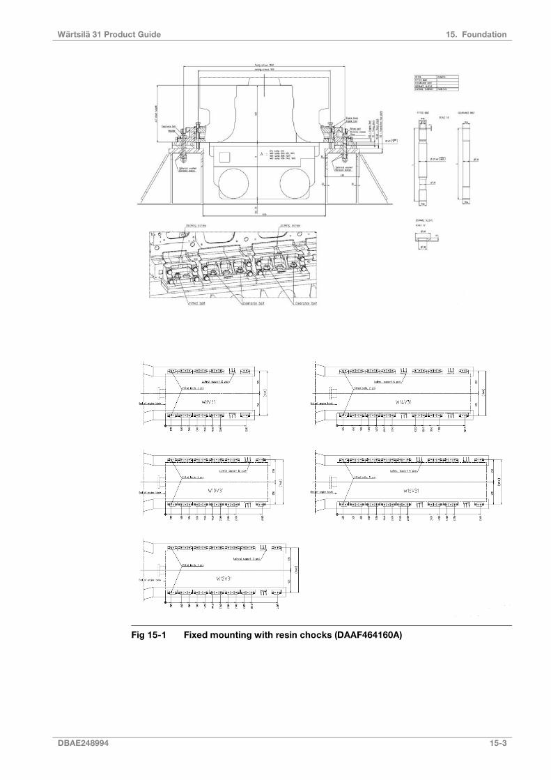
Fig 15-1 Fixed mounting with resin chocks (DAAF464160A)
DBAE248994 15-3
15. FoundationWärtsilä 31 Product Guide
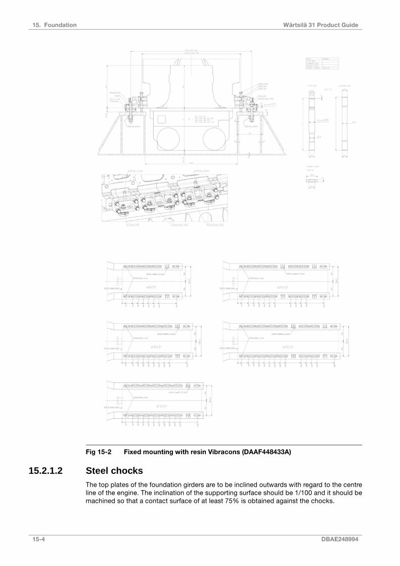
Fig 15-2 Fixed mounting with resin Vibracons (DAAF448433A)
15.2.1.2 Steel chocksThe top plates of the foundation girders are to be inclined outwards with regard to the centreline of the engine. The inclination of the supporting surface should be 1/100 and it should bemachined so that a contact surface of at least 75% is obtained against the chocks.
15-4 DBAE248994
Wärtsilä 31 Product Guide15. Foundation
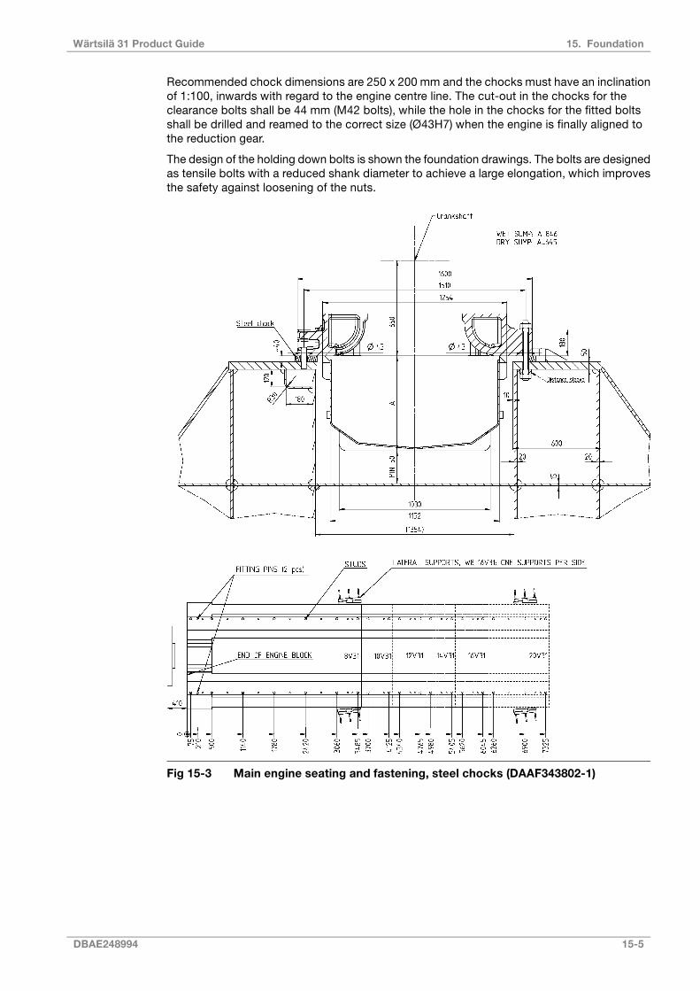
Recommended chock dimensions are 250 x 200 mm and the chocks must have an inclinationof 1:100, inwards with regard to the engine centre line. The cut-out in the chocks for theclearance bolts shall be 44 mm (M42 bolts), while the hole in the chocks for the fitted boltsshall be drilled and reamed to the correct size (Ø43H7) when the engine is finally aligned tothe reduction gear.
The design of the holding down bolts is shown the foundation drawings. The bolts are designedas tensile bolts with a reduced shank diameter to achieve a large elongation, which improvesthe safety against loosening of the nuts.
Fig 15-3 Main engine seating and fastening, steel chocks (DAAF343802-1)
DBAE248994 15-5
15. FoundationWärtsilä 31 Product Guide

Fig 15-4 Main engine seating and fastening, steel chocks (DAAF343802-2)
15-6 DBAE248994
Wärtsilä 31 Product Guide15. Foundation

15.2.1.3 Steel chocks with adjustable heightAs an alternative to resin chocks or conventional steel chocks it is also permitted to install theengine on adjustable steel chocks. The chock height is adjustable between 45 mm and 65mm for the approved type of chock. There must be a chock of adequate size at the positionof each holding down bolt.
DBAE248994 15-7
15. FoundationWärtsilä 31 Product Guide
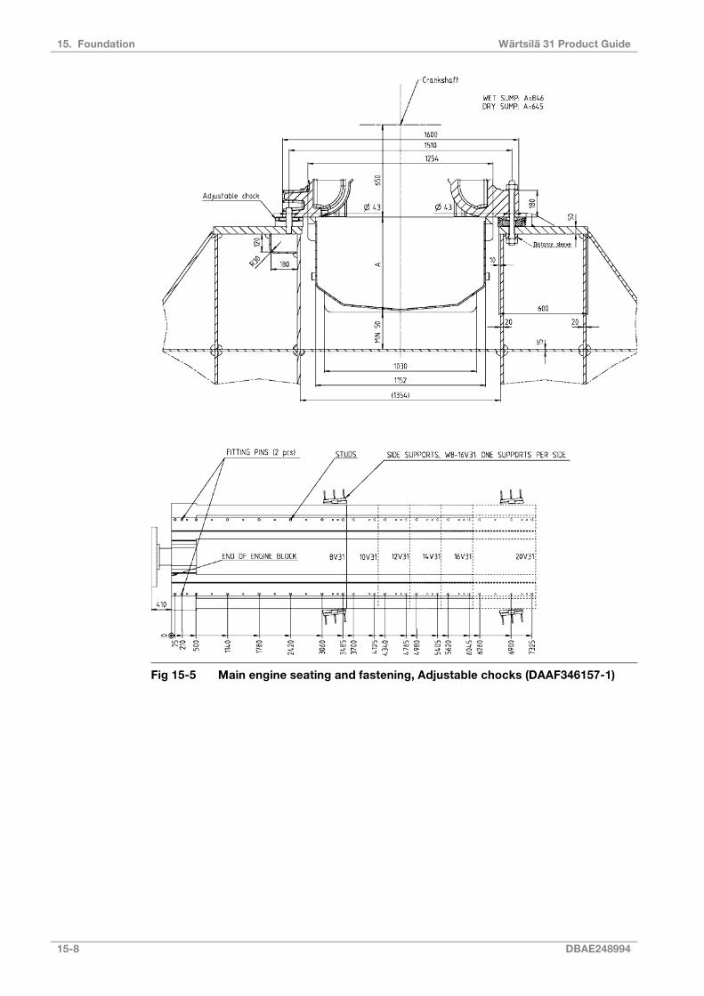
Fig 15-5 Main engine seating and fastening, Adjustable chocks (DAAF346157-1)
15-8 DBAE248994
Wärtsilä 31 Product Guide15. Foundation
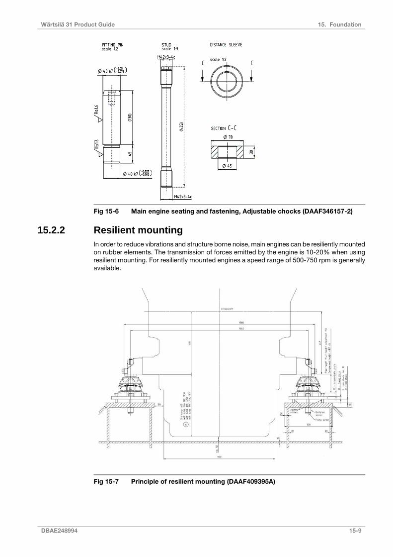
Fig 15-6 Main engine seating and fastening, Adjustable chocks (DAAF346157-2)
15.2.2 Resilient mountingIn order to reduce vibrations and structure borne noise, main engines can be resiliently mountedon rubber elements. The transmission of forces emitted by the engine is 10-20% when usingresilient mounting. For resiliently mounted engines a speed range of 500-750 rpm is generallyavailable.
Fig 15-7 Principle of resilient mounting (DAAF409395A)
DBAE248994 15-9
15. FoundationWärtsilä 31 Product Guide

Fig 15-8 Flexible mounting with fixing rails (DAAF356004D)
15-10 DBAE248994
Wärtsilä 31 Product Guide15. Foundation

15.3 Mounting of generating sets
15.3.1 Resilient mountingGenerating sets, comprising engine and generator mounted on a common base frame, areusually installed on resilient mounts on the foundation in the ship.
The resilient mounts reduce the structure borne noise transmitted to the ship and also serveto protect the generating set bearings from possible fretting caused by hull vibration.
The number of mounts and their location is calculated to avoid resonance with excitationsfrom the generating set engine, the main engine and the propeller.
NOTE
To avoid induced oscillation of the generating set, the following data must be sentby the shipyard to Wärtsilä at the design stage:
● main engine speed [RPM] and number of cylinders
● propeller shaft speed [RPM] and number of propeller blades
The selected number of mounts and their final position is shown in the generating set drawing.
Fig 15-9 Recommended design of the generating set seating, Inline engines(V46L0295E)
DBAE248994 15-11
15. FoundationWärtsilä 31 Product Guide

Fig 15-10 Recommended design of the generating set seating, V engines(DAAE020067B)
15.3.1.1 Rubber mountsThe generating set is mounted on conical resilient mounts, which are designed to withstandboth compression and shear loads. In addition the mounts are equipped with an internal bufferto limit the movements of the generating set due to ship motions. Hence, no additional sideor end buffers are required.
The rubber in the mounts is natural rubber and it must therefore be protected from oil, oilywater and fuel.
The mounts should be evenly loaded, when the generating set is resting on the mounts. Themaximum permissible variation in compression between mounts is 2.0 mm. If necessary,chocks or shims should be used to compensate for local tolerances. Only one shim is permittedunder each mount.
The transmission of forces emitted by the engine is 10 -20% when using conical mounts. Forthe foundation design, see drawing 3V46L0294.
15-12 DBAE248994
Wärtsilä 31 Product Guide15. Foundation

Fig 15-11 Rubber mount, (DAAE018766C)
15.4 Flexible pipe connectionsWhen the engine or generating set is resiliently installed, all connections must be flexible andno grating nor ladders may be fixed to the engine or generating set. When installing the flexiblepipe connections, unnecessary bending or stretching should be avoided. The external pipemust be precisely aligned to the fitting or flange on the engine. It is very important that thepipe clamps for the pipe outside the flexible connection must be very rigid and welded to thesteel structure of the foundation to prevent vibrations, which could damage the flexibleconnection.
DBAE248994 15-13
15. FoundationWärtsilä 31 Product Guide

This page intentionally left blank
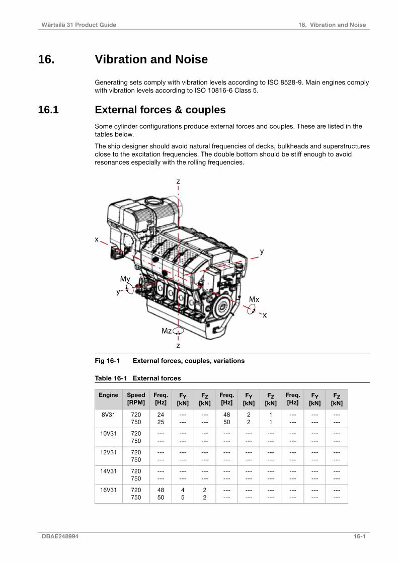
16. Vibration and Noise
Generating sets comply with vibration levels according to ISO 8528-9. Main engines complywith vibration levels according to ISO 10816-6 Class 5.
16.1 External forces & couplesSome cylinder configurations produce external forces and couples. These are listed in thetables below.
The ship designer should avoid natural frequencies of decks, bulkheads and superstructuresclose to the excitation frequencies. The double bottom should be stiff enough to avoidresonances especially with the rolling frequencies.
Fig 16-1 External forces, couples, variations
Table 16-1 External forces
FZ[kN]
FY[kN]
Freq.[Hz]
FZ[kN]
FY[kN]
Freq.[Hz]
FZ[kN]
FY[kN]
Freq.[Hz]
Speed[RPM]
Engine
------
------
------
11
22
4850
------
------
2425
720750
8V31
------
------
------
------
------
------
------
------
------
720750
10V31
------
------
------
------
------
------
------
------
------
720750
12V31
------
------
------
------
------
------
------
------
------
720750
14V31
------
------
------
------
------
------
22
45
4850
720750
16V31
DBAE248994 16-1
16. Vibration and NoiseWärtsilä 31 Product Guide

--- couples and forces = zero or insignificant.
16-2 DBAE248994
Wärtsilä 31 Product Guide16. Vibration and Noise
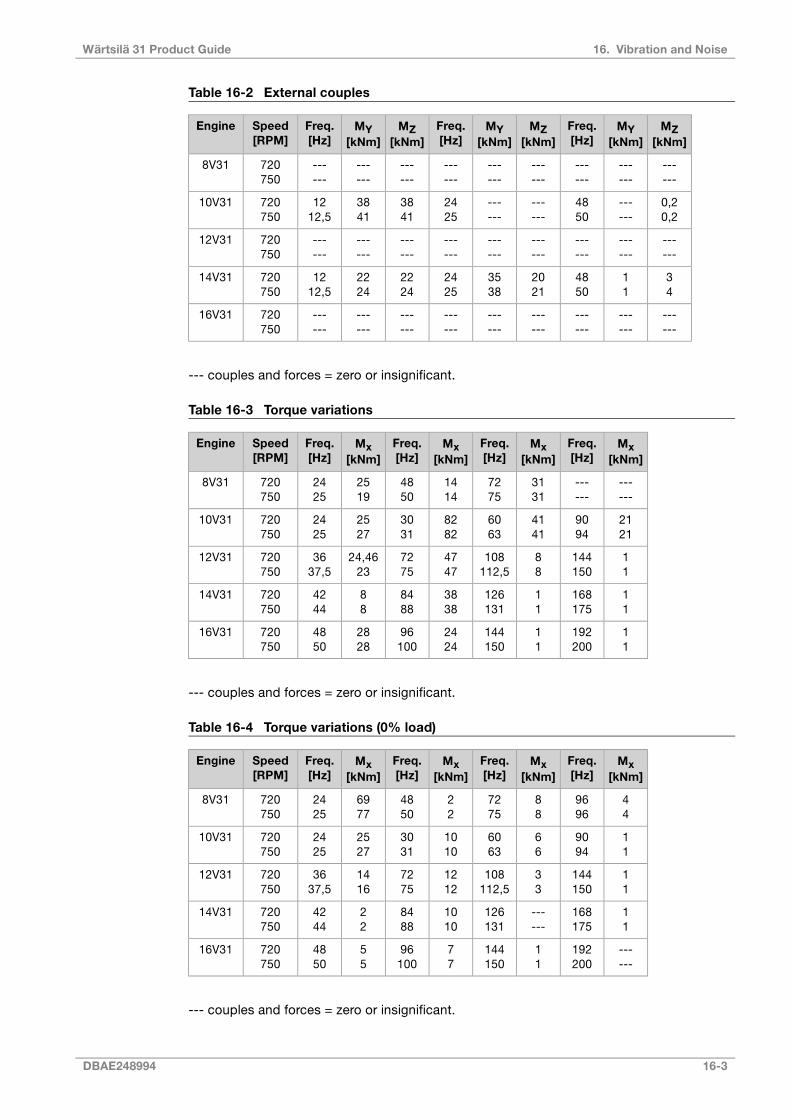
Table 16-2 External couples
MZ[kNm]
MY[kNm]
Freq.[Hz]
MZ[kNm]
MY[kNm]
Freq.[Hz]
MZ[kNm]
MY[kNm]
Freq.[Hz]
Speed[RPM]
Engine
------
------
------
------
------
------
------
------
------
720750
8V31
0,20,2
------
4850
------
------
2425
3841
3841
1212,5
720750
10V31
------
------
------
------
------
------
------
------
------
720750
12V31
34
11
4850
2021
3538
2425
2224
2224
1212,5
720750
14V31
------
------
------
------
------
------
------
------
------
720750
16V31
--- couples and forces = zero or insignificant.
Table 16-3 Torque variations
Mx[kNm]
Freq.[Hz]
Mx[kNm]
Freq.[Hz]
Mx[kNm]
Freq.[Hz]
Mx[kNm]
Freq.[Hz]
Speed[RPM]
Engine
------
------
3131
7275
1414
4850
2519
2425
720750
8V31
2121
9094
4141
6063
8282
3031
2527
2425
720750
10V31
11
144150
88
108112,5
4747
7275
24,4623
3637,5
720750
12V31
11
168175
11
126131
3838
8488
88
4244
720750
14V31
11
192200
11
144150
2424
96100
2828
4850
720750
16V31
--- couples and forces = zero or insignificant.
Table 16-4 Torque variations (0% load)
Mx[kNm]
Freq.[Hz]
Mx[kNm]
Freq.[Hz]
Mx[kNm]
Freq.[Hz]
Mx[kNm]
Freq.[Hz]
Speed[RPM]
Engine
44
9696
88
7275
22
4850
6977
2425
720750
8V31
11
9094
66
6063
1010
3031
2527
2425
720750
10V31
11
144150
33
108112,5
1212
7275
1416
3637,5
720750
12V31
11
168175
------
126131
1010
8488
22
4244
720750
14V31
------
192200
11
144150
77
96100
55
4850
720750
16V31
--- couples and forces = zero or insignificant.
DBAE248994 16-3
16. Vibration and NoiseWärtsilä 31 Product Guide
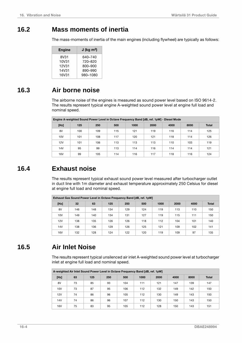
16.2 Mass moments of inertiaThe mass-moments of inertia of the main engines (including flywheel) are typically as follows:
J (kg m2)Engine
640–740720–820800–900890–990
980–1080
8V3110V3112V3114V3116V31
16.3 Air borne noiseThe airborne noise of the engines is measured as sound power level based on ISO 9614-2.The results represent typical engine A-weighted sound power level at engine full load andnominal speed.
Engine A-weighted Sound Power Level in Octave Frequency Band [dB, ref. 1pW] - Diesel Mode
Total8000400020001000500250125[Hz]
1251141161191211151091008V
12611411812112011710810110V
11910311011311311310610112V
121114114116114113999514V
1241161181171161141059916V
16.4 Exhaust noiseThe results represent typical exhaust sound power level measured after turbocharger outletin duct line with 1m diameter and exhaust temperature approximately 250 Celsius for dieselat engine full load and nominal speed.
Exhaust Gas Sound Power Level in Octave Frequency Band [dB, ref. 1pW]
Total4000200010005002501256332[Hz]
1501101131191241291341481468V
15011111511912713113414014910V
14010110411211812612613513812V
14110210912112512612913613814V
1359710911912012212412813216V
16.5 Air Inlet NoiseThe results represent typical unsilenced air inlet A-weighted sound power level at turbochargerinlet at engine full load and nominal speed.
A-weighted Air Inlet Sound Power Level in Octave Frequency Band [dB, ref. 1pW]
Total800040002000100050025012563[Hz]
1471391471211111049385738V
15014214913211210695877310V
15014314913011210596867412V
15014315013011210796867414V
15114315012811210595837516V
16-4 DBAE248994
Wärtsilä 31 Product Guide16. Vibration and Noise
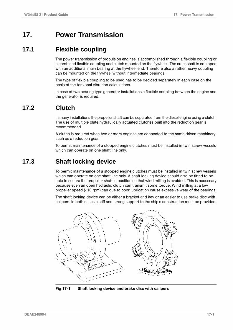
17. Power Transmission
17.1 Flexible couplingThe power transmission of propulsion engines is accomplished through a flexible coupling ora combined flexible coupling and clutch mounted on the flywheel. The crankshaft is equippedwith an additional main bearing at the flywheel end. Therefore also a rather heavy couplingcan be mounted on the flywheel without intermediate bearings.
The type of flexible coupling to be used has to be decided separately in each case on thebasis of the torsional vibration calculations.
In case of two bearing type generator installations a flexible coupling between the engine andthe generator is required.
17.2 ClutchIn many installations the propeller shaft can be separated from the diesel engine using a clutch.The use of multiple plate hydraulically actuated clutches built into the reduction gear isrecommended.
A clutch is required when two or more engines are connected to the same driven machinerysuch as a reduction gear.
To permit maintenance of a stopped engine clutches must be installed in twin screw vesselswhich can operate on one shaft line only.
17.3 Shaft locking deviceTo permit maintenance of a stopped engine clutches must be installed in twin screw vesselswhich can operate on one shaft line only. A shaft locking device should also be fitted to beable to secure the propeller shaft in position so that wind milling is avoided. This is necessarybecause even an open hydraulic clutch can transmit some torque. Wind milling at a lowpropeller speed (<10 rpm) can due to poor lubrication cause excessive wear of the bearings.
The shaft locking device can be either a bracket and key or an easier to use brake disc withcalipers. In both cases a stiff and strong support to the ship’s construction must be provided.
Fig 17-1 Shaft locking device and brake disc with calipers
DBAE248994 17-1
17. Power TransmissionWärtsilä 31 Product Guide

17.4 Input data for torsional vibration calculationsA torsional vibration calculation is made for each installation. For this purpose exact data ofall components included in the shaft system are required. See list below.
Installation
● Classification
● Ice class
● Operating modes
Reduction gear
A mass elastic diagram showing:
● All clutching possibilities
● Sense of rotation of all shafts
● Dimensions of all shafts
● Mass moment of inertia of all rotating parts including shafts and flanges
● Torsional stiffness of shafts between rotating masses
● Material of shafts including tensile strength and modulus of rigidity
● Gear ratios
● Drawing number of the diagram
Propeller and shafting
A mass-elastic diagram or propeller shaft drawing showing:
● Mass moment of inertia of all rotating parts including the rotating part of the OD-box, SKFcouplings and rotating parts of the bearings
● Mass moment of inertia of the propeller at full/zero pitch in water
● Torsional stiffness or dimensions of the shaft
● Material of the shaft including tensile strength and modulus of rigidity
● Drawing number of the diagram or drawing
Main generator or shaft generator
A mass-elastic diagram or an generator shaft drawing showing:
● Generator output, speed and sense of rotation
● Mass moment of inertia of all rotating parts or a total inertia value of the rotor, includingthe shaft
● Torsional stiffness or dimensions of the shaft
● Material of the shaft including tensile strength and modulus of rigidity
● Drawing number of the diagram or drawing
Flexible coupling/clutch
If a certain make of flexible coupling has to be used, the following data of it must be informed:
● Mass moment of inertia of all parts of the coupling
● Number of flexible elements
● Linear, progressive or degressive torsional stiffness per element
● Dynamic magnification or relative damping
● Nominal torque, permissible vibratory torque and permissible power loss
17-2 DBAE248994
Wärtsilä 31 Product Guide17. Power Transmission
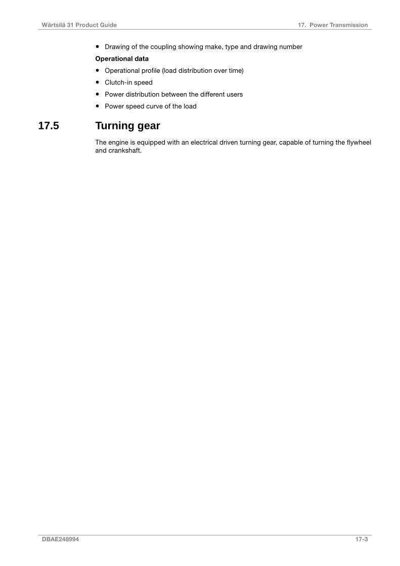
● Drawing of the coupling showing make, type and drawing number
Operational data
● Operational profile (load distribution over time)
● Clutch-in speed
● Power distribution between the different users
● Power speed curve of the load
17.5 Turning gearThe engine is equipped with an electrical driven turning gear, capable of turning the flywheeland crankshaft.
DBAE248994 17-3
17. Power TransmissionWärtsilä 31 Product Guide

This page intentionally left blank
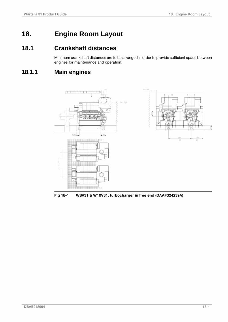
18. Engine Room Layout
18.1 Crankshaft distancesMinimum crankshaft distances are to be arranged in order to provide sufficient space betweenengines for maintenance and operation.
18.1.1 Main engines
Fig 18-1 W8V31 & W10V31, turbocharger in free end (DAAF324239A)
DBAE248994 18-1
18. Engine Room LayoutWärtsilä 31 Product Guide
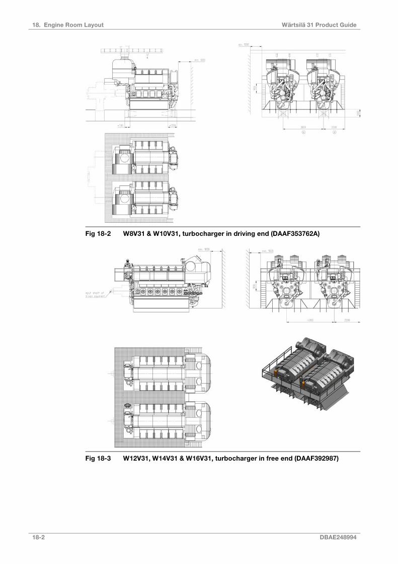
Fig 18-2 W8V31 & W10V31, turbocharger in driving end (DAAF353762A)
Fig 18-3 W12V31, W14V31 & W16V31, turbocharger in free end (DAAF392987)
18-2 DBAE248994
Wärtsilä 31 Product Guide18. Engine Room Layout

Fig 18-4 W12V31, W14V31 & W16V31, turbocharger in driving end (DAAF393139)
All dimensions in mm.
DBAE248994 18-3
18. Engine Room LayoutWärtsilä 31 Product Guide

18.1.2 Generating sets
Fig 18-5 W8V31, W10V31 Engine Room Arrangement (DAAF363645B-1)
Fig 18-6 W12V31, W14V31 & W16V31 Engine Room Arrangement (DAAF363645B-2)
All dimensions in mm.
18-4 DBAE248994
Wärtsilä 31 Product Guide18. Engine Room Layout
18.2 Space requirements for maintenance
18.2.1 Working space around the engineThe required working space around the engine is mainly determined by the dismountingdimensions of engine components, and space requirement of some special tools. It is especiallyimportant that no obstructive structures are built next to engine driven pumps, as well ascamshaft and crankcase doors.
However, also at locations where no space is required for dismounting of engine parts, aminimum of 1000 mm free space is recommended for maintenance operations everywherearound the engine.
18.2.2 Engine room height and lifting equipmentThe required engine room height is determined by the transportation routes for engine parts.If there is sufficient space in transverse and longitudinal direction, there is no need to transportengine parts over the engine and in such case the necessary height is minimized. Separatelifting arrangements are usually required for overhaul of the turbocharger since the crane travelis limited by the exhaust pipe. A chain block on a rail located over the turbocharger axis isrecommended.
18.2.3 Maintenance platformsIn order to enable efficient maintenance work on the engine, it is advised to build themaintenance platforms on recommended elevations. The width of the platforms should be atminimum 800 mm to allow adequate working space. The surface of maintenance platformsshould be of non-slippery material (grating or chequer plate).
NOTE
Working Platforms should be designed and positioned to prevent personnel slipping,tripping or falling on or between the walkways and the engine
18.3 Transportation and storage of spare parts and toolsTransportation arrangement from engine room to storage and workshop has to be preparedfor heavy engine components. This can be done with several chain blocks on rails oralternatively utilising pallet truck or trolley. If transportation must be carried out using severallifting equipment, coverage areas of adjacent cranes should be as close as possible to eachother.
Engine room maintenance hatch has to be large enough to allow transportation of maincomponents to/from engine room.
It is recommended to store heavy engine components on slightly elevated adaptable surfacee.g. wooden pallets. All engine spare parts should be protected from corrosion and excessivevibration.
On single main engine installations it is important to store heavy engine parts close to theengine to make overhaul as quick as possible in an emergency situation.
18.4 Required deck area for service workDuring engine overhaul some deck area is required for cleaning and storing dismantledcomponents. Size of the service area is dependent of the overhauling strategy chosen, e.g.one cylinder at time, one bank at time or the whole engine at time. Service area should beplain steel deck dimensioned to carry the weight of engine parts.
DBAE248994 18-5
18. Engine Room LayoutWärtsilä 31 Product Guide
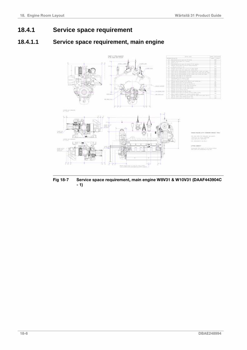
18.4.1 Service space requirement
18.4.1.1 Service space requirement, main engine
Fig 18-7 Service space requirement, main engine W8V31 & W10V31 (DAAF443904C- 1)
18-6 DBAE248994
Wärtsilä 31 Product Guide18. Engine Room Layout
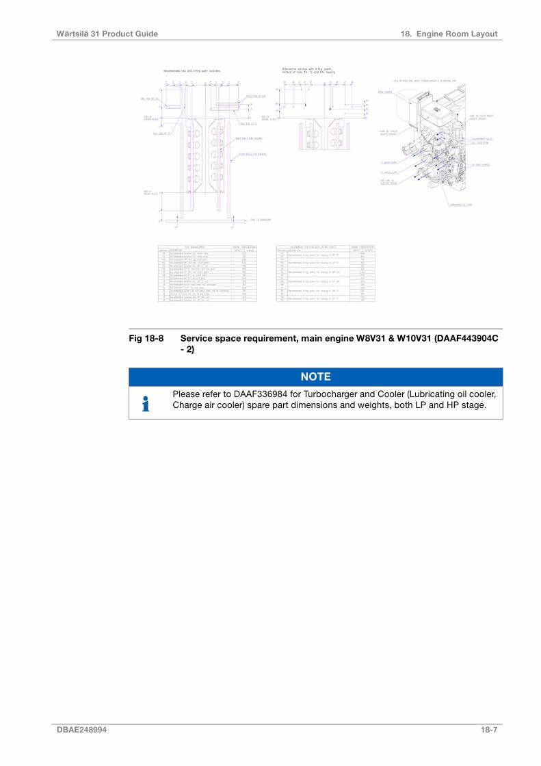
Fig 18-8 Service space requirement, main engine W8V31 & W10V31 (DAAF443904C- 2)
NOTE
Please refer to DAAF336984 for Turbocharger and Cooler (Lubricating oil cooler,Charge air cooler) spare part dimensions and weights, both LP and HP stage.
DBAE248994 18-7
18. Engine Room LayoutWärtsilä 31 Product Guide

Fig 18-9 Service space requirement, main engine W12V31, W14V31 & W16V31(DAAF438352B)
NOTE
Please refer to DAAF410568 for Turbocharger and Cooler (Lubricating oil cooler,Charge air cooler) spare part dimensions and weights, both LP and HP stage.
18-8 DBAE248994
Wärtsilä 31 Product Guide18. Engine Room Layout
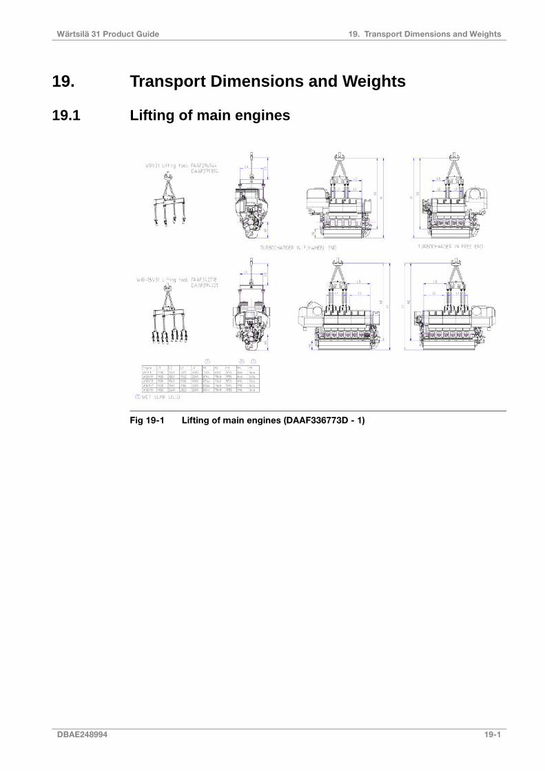
19. Transport Dimensions and Weights
19.1 Lifting of main engines
Fig 19-1 Lifting of main engines (DAAF336773D - 1)
DBAE248994 19-1
19. Transport Dimensions and WeightsWärtsilä 31 Product Guide
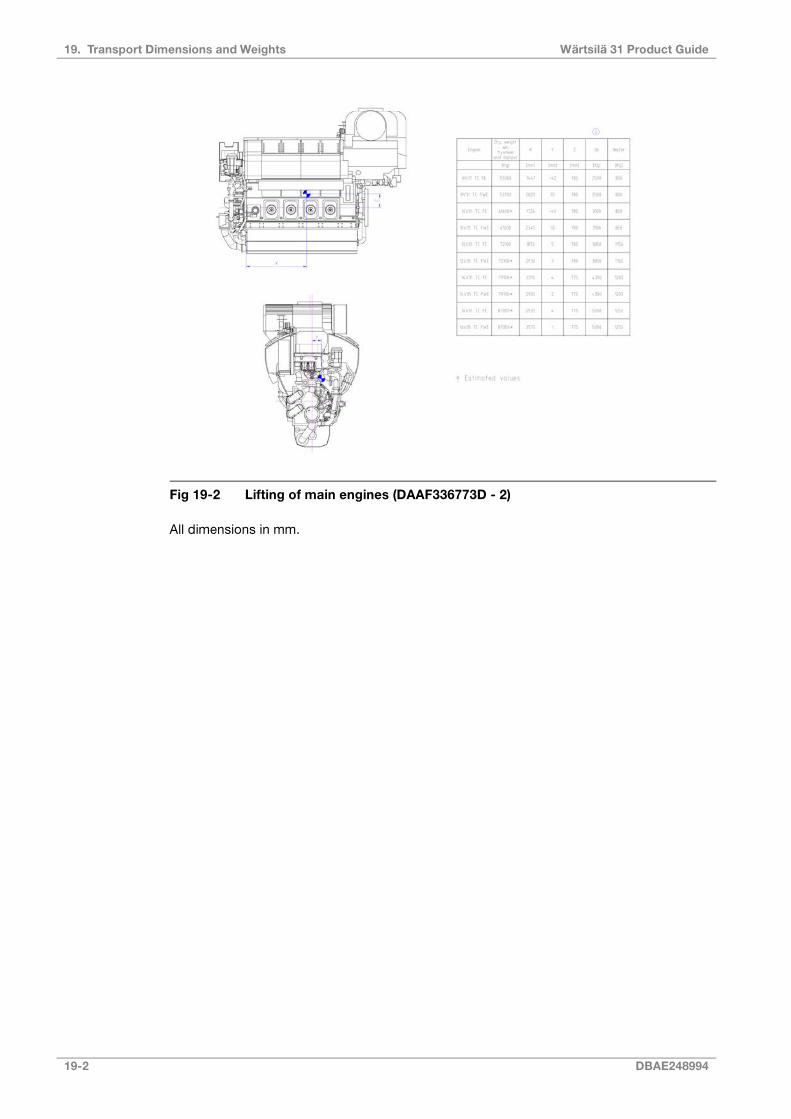
Fig 19-2 Lifting of main engines (DAAF336773D - 2)
All dimensions in mm.
19-2 DBAE248994
Wärtsilä 31 Product Guide19. Transport Dimensions and Weights

19.2 Lifting of generating sets
Fig 19-3 Lifting of generating sets (DAAF341224)
DBAE248994 19-3
19. Transport Dimensions and WeightsWärtsilä 31 Product Guide

19.3 Engine components
Table 19-1 Turbocharger and cooler inserts (DAAF336984 for 8V, 10V & DAAF410568 for 12,14,16V)
Dimensions [mm]Weight[kg]Engine
CBA
314537830232W 8V31
314537830232W 10V31
419537830282W 12V31
419537830282W 14V31
463537830307W 16V31
Fig 19-4 Lube oil cooler
Dimensions [mm]Weight[kg]Engine
FED
6259151165790W 8V31
6259151165790W 10V31
6259121135730W 12V31
6259121135730W 14V31
6259121135730W 16V31
Fig 19-5 Charge air cooler (HP)
Dimensions [mm]Weight[kg]Engine
IHG
6258501155830W 8V31
6258501155830W 10V31
5586681075650W 12V31
5586681075650W 14V31
5586681075650W 16V31
Fig 19-6 Charge air cooler (LP)
Dimensions[mm]Weight
[kg]Engine
KJ
7171612680W 8V31
7171612680W 10V31
6101421443W 12V31
6101421443W 14V31
6101421443W 16V31Fig 19-7 Turbocharger (HP)
19-4 DBAE248994
Wärtsilä 31 Product Guide19. Transport Dimensions and Weights

Dimensions [mm]Weight[kg]Engine
K2J2
10301633 (with filter) or2160 (with suction
branch)1568W 8V31
10301633 (with filter) or2160 (with suction
branch)1568W 10V31
8761411 (with filter) or1861 (with suction
branch)1020W 12V31
8761411 (with filter) or1861 (with suction
branch)1020W 14V31
8761411 (with filter) or1861 (with suction
branch)1020W 16V31
Fig 19-8 Turbocharger (LP)
DBAE248994 19-5
19. Transport Dimensions and WeightsWärtsilä 31 Product Guide

Fig 19-9 Major spare parts (DAAF337022)
Table 19-2 Weights
Weight [kg]DescriptionItemNo
Weight [kg]DescriptionItemno
7.6Starting valve9192Connecting rod1
4.7Main bearing shell1072.4Piston2
94.7Split gear wheel11307Cylinder liner3
21.6Small intermediate gear12400Cylinder head4
60.6Large intermediate gear135.2Inlet valve5
61.8Camshaft drive gear143.3Exhaust valve6
1.5Piston ring set15
134HP fuel pump7
0.5Piston ring27Injection valve8
19-6 DBAE248994
Wärtsilä 31 Product Guide19. Transport Dimensions and Weights

20. Product Guide Attachments
This and all other product guides can be accessed on the internet, at www.wartsila.com.Product guides are available both in web and PDF format. Engine outline drawings are availablenot only in 2D drawings (in PDF, DXF format), but also in 3D models in near future. Pleaseconsult your sales contact at Wärtsilä for more information.
Engine outline drawings are not available in the printed version of this product guide.
DBAE248994 20-1
20. Product Guide AttachmentsWärtsilä 31 Product Guide

This page intentionally left blank

21. ANNEX
21.1 Unit conversion tablesThe tables below will help you to convert units used in this product guide to other units. Wherethe conversion factor is not accurate a suitable number of decimals have been used.
Mass conversion factorsLength conversion factors
Multiply byToConvert fromMultiply byToConvert from
2.205lbkg0.0394inmm
35.274ozkg0.00328ftmm
Volume conversion factorsPressure conversion factors
Multiply byToConvert fromMultiply byToConvert from
61023.744in3m30.145psi (lbf/in2)kPa
35.315ft3m320.885lbf/ft2kPa
219.969Imperial gallonm34.015inch H2OkPa
264.172US gallonm30.335foot H2OkPa
1000l (litre)m3101.972mm H2OkPa
0.01barkPa
Moment of inertia and torque conversion factorsPower conversion
Multiply byToConvert fromMultiply byToConvert from
23.730lbft2kgm21.360hp (metric)kW
737.562lbf ftkNm1.341US hpkW
Flow conversion factorsFuel consumption conversion factors
Multiply byToConvert fromMultiply byToConvert from
4.403US gallon/minm3/h (liquid)0.736g/hphg/kWh
0.586ft3/minm3/h (gas)0.00162lb/hphg/kWh
Density conversion factorsTemperature conversion factors
Multiply byToConvert fromMultiply byToConvert from
0.00834lb/US gallonkg/m3F = 9/5 *C + 32F°C
0.01002lb/Imperial gallonkg/m3K = C + 273.15K°C
0.0624lb/ft3kg/m3
21.1.1 Prefix
Table 21-1 The most common prefix multipliers
FactorSymbolNameFactorSymbolNameFactorSymbolName
10-9nnano103kkilo1012Ttera
10-3mmilli109Ggiga
10-6μmicro106Mmega
DBAE248994 21-1
21. ANNEXWärtsilä 31 Product Guide
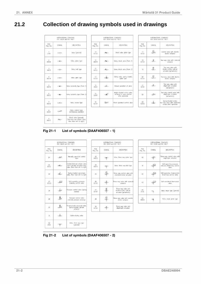
21.2 Collection of drawing symbols used in drawings
Fig 21-1 List of symbols (DAAF406507 - 1)
Fig 21-2 List of symbols (DAAF406507 - 2)
21-2 DBAE248994
Wärtsilä 31 Product Guide21. ANNEX

Fig 21-3 List of symbols (DAAF406507 - 3)
Fig 21-4 List of symbols (DAAF406507 - 4)
DBAE248994 21-3
21. ANNEXWärtsilä 31 Product Guide
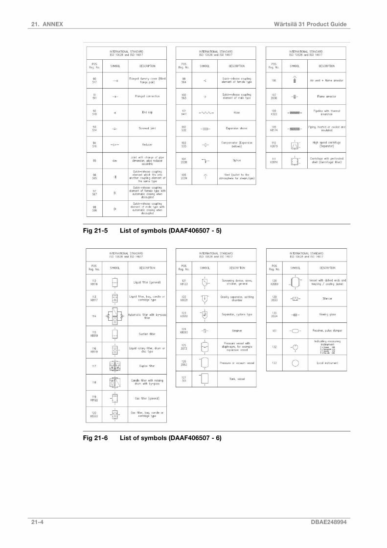
Fig 21-5 List of symbols (DAAF406507 - 5)
Fig 21-6 List of symbols (DAAF406507 - 6)
21-4 DBAE248994
Wärtsilä 31 Product Guide21. ANNEX

Fig 21-7 List of symbols (DAAF406507 - 7)
DBAE248994 21-5
21. ANNEXWärtsilä 31 Product Guide