
Product Catalogue ETL Systems
114
Product Catalogue ETL Systems ROUTE AMPLIFY SWITCH SPLIT Excelling in RF Engineering
-
Upload
khangminh22 -
Category
Documents
-
view
0 -
download
0
Transcript of Product Catalogue ETL Systems

Product CatalogueETL Systems
ROUTE AMPLIFY SWITCH SPLIT
Excelling in RF Engineering

Page 2
www.etlsystems.com
Our CompanyETL designs and manufactures professional RF distribution equipment for Satellite Ground Stations, Teleports and other Microwave users around the world. Many of our products are custom built and all benefit from in-house assembly and testing.
Our ProductsThe product range covers DC-40GHz and includes Matrix Routers, Switches, Splitters, Combiners, Amplifiers, as well as RF over Fibre. These are used for RF routing, RF distribution, satellite signal handling and redundancy switching, as well as more esoteric applications.
Our FocusReliability, Resilience, and RF performance are at the heart of all ETL designs and these drive our product innovation and development. Adaptability and scale-ability allows future expansion for growing Satcom users.
Our CustomersETL’s RF equipment is used by customers in a wide range of sectors.
Broadcasters and Telecom Operators use our products for IPTV, TVRO, news gathering and sports events, where rapid changes are needed for occasional use services.
Government and Military customers rely on ETL’s high performance monitoring switch matrices and custom build products.
Satellite Operators depend on our range of satellite signal handling equipment, in TT & C, monitoring and traffic management applications for new fleets of HTS and Ka Band satellites.
Oil & Gas and Marine sectors use our compact splitters and combiners, as well as LNB service shelves to deliver dependable RF VSAT signals.
ETL SystemsExcelling in RF Engineering
Page 3
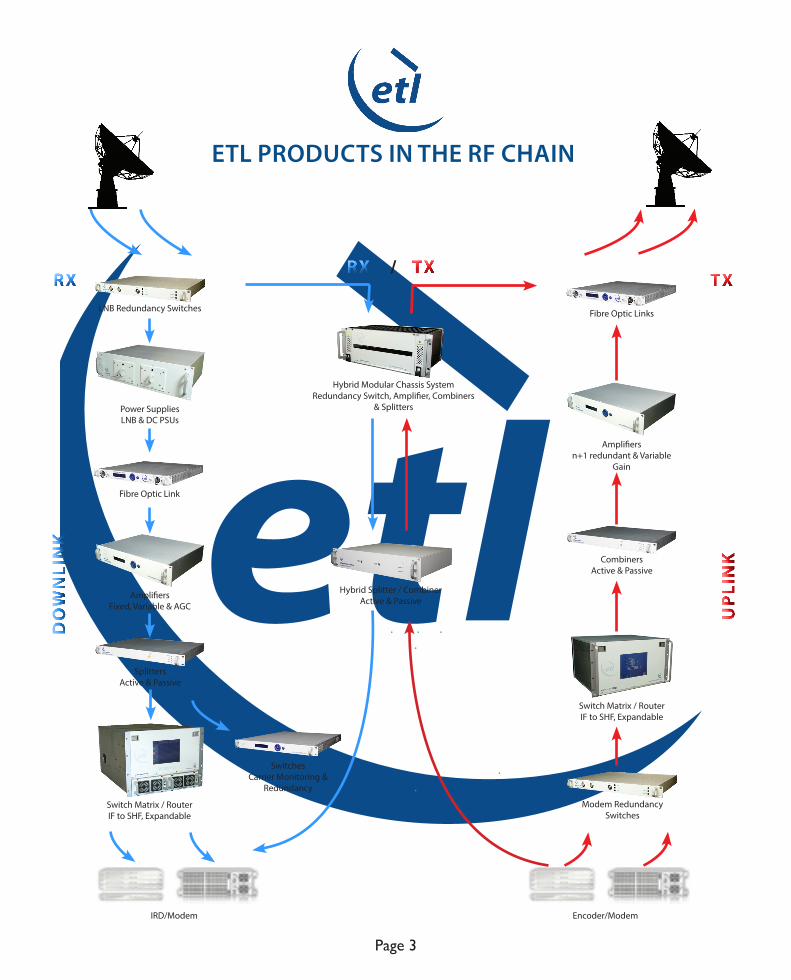
ETL PRODUCTS IN THE RF CHAIN
DO
WN
LIN
K
UP
LIN
K
TXTXRX
RX/
Power Supplies LNB & DC PSUs
Fibre Optic Link
Fibre Optic Links
Amplifiersn+1 redundant & Variable
Gain
Amplifiers Fixed, Variable & AGC
SwitchesCarrier Monitoring &
Redundancy
Hybrid Splitter / CombinerActive & Passive
CombinersActive & Passive
Splitters Active & Passive
Hybrid Modular Chassis SystemRedundancy Switch, Amplifier, Combiners
& Splitters
Switch Matrix / RouterIF to SHF, Expandable
IRD/Modem Encoder/Modem
Switch Matrix / RouterIF to SHF, Expandable
LNB Redundancy Switches
Modem Redundancy Switches

Page 21
Remote Controller
Remote NGM and VCN XY Controller
Matrix / Routers
Page 6 - 7
Contents
128 x 128 Vulcan Matrix / Router
64 x 64 Vortex Matrix / Router Page 8 - 9
32 x 32 Enigma Matrix / Router Page 10 - 12
32 x 32 Ensign Matrix / Router Page 13 - 14
16 x 32 Valiant Matrix / Router Page 15 - 16
16 x 16 Victor Matrix / Router Page 17 - 18
4 x 16 / 4 x 32 / 4 x 64 Optimus Matrix / Router Page 19 -20
RF over Fibre
Page 22 - 27
Page 30
Page 28 - 29
Indoor Chassis Options
Flyaway Unit
Outdoor Chassis Options
Splitters & Combiners
Page 31 - 36Dextra Splitter & Combiner Range
LD Series Splitter & Combiner Range Page 37 - 38
Hybrid Splitter/Combiner Range Page 39 - 42
Passive Splitter & Combiner Range Page 43 - 44
IF to C-band Splitter & Combiner Range Page 45 - 48
RF Matrix System Active Splitter & Combiner Range Page 49 - 50
Page 51 - 52LS series Monitoring Switch Range
SHF Switch Range
Redundancy Switch Range
Page 53 -54
Page 55 -56
Switches

AmplifiersPage 57 - 73Alto Amplifier Range
RF Power Amplifier Range Page 74 - 75
Power Supplies / Inserters
Modular System
Page 76 - 77
Page 79 - 80
Page 78
Page 81
Page 83
Page 84
Page 82
LNB PSU Range
Chassis
Piranha Power Inserter Range
Splitter Modules
Switch Modules
Amplifier Modules
Combiner Modules
RF ComponentsPage 85 - 86Active Splitters & Terminations
Active Combiners & Terminations Page 87 - 88
Passive Splitters & Combiners Page 89 - 91
Scorpion Component Mounting System Page 92
Impedance Transformers, DC Blocks, Attenuators & Power supplies Page 93 - 94
Fixed & Variable Gain Amplifiers Page 95 - 96
Multiplexers, Couplers & Bias TEE’s Page 97 - 98
Page 99 - 100
Page 101
Page 102
Page 103
Page 104
Oscillators
Equalisers
Frequency Convertors
Outdoor IP Rated ModulesRF over Fibre Modules
Fact Racks
Page 105 - 106Useful Facts and Figures
Contents

Telephone: +44(0)1981 259020 Email: [email protected]
UK Office:Telephone: +1 703 657 0411 Email: [email protected]
US Office:
www.etlsystems.com
ETL SystemsExcelling in RF Engineering
Page 6
Telephone: +971 4 428 0918 Email: [email protected]
UAE Office:
MAT
RIX
128 x128 Vulcan Matrix / Router
ETL’s ground breaking Vulcan high density RF matrices offer a full fan-out / fully distributive system.
Designed for use in modern multiple antenna sites, particularly for Government and large commercial teleports.
Offering up to 128 x 128 routing in an extremely compact 16U high chassis, this resilient matrix offer a high performance solution to frequent signal routing changes and handling a high volume of downlink feeds.
Benefits 128 x 128 routing in a compact 16U high chassis. Simple ‘plug & go’ installation. Further expansion of RF Matrix in steps up to 1024 x 1024. Continuous monitoring and reporting of all active components (e.g amplifiers). Reliability in service with hot-swappable active components. All settings are retained after a communications / power failure.
FEATURES Model VCN-11 VCN-12
Frequency 850-2150 MHz (L-band) 40-200 MHz (IF)
Matrix Type Distributive (fan-out)
Capacity 128 inputs x 128 outputs
Hot-swap Active Components RF Matrix Cards, CPUs, PSUs & Fans
Remote Control & Monitoring RS232/RS485 Serial port, RJ45 Ethernet port, SNMP, Web Browser Interface & PC software (optional)
Local Control XGA touchscreen
Dual Redundant CPUs & PSUs P
Redundant Mid Matrix Paths P
www.etlsystems.com
ETL SystemsExcelling in RF Engineering
Page 7
Telephone: +971 4 428 0918 Email: [email protected]
UAE Office: Telephone: +44(0)1981 259020 Email: [email protected]
UK Office:Telephone: +1 703 657 0411 Email: [email protected]
US Office:
MAT
RIX
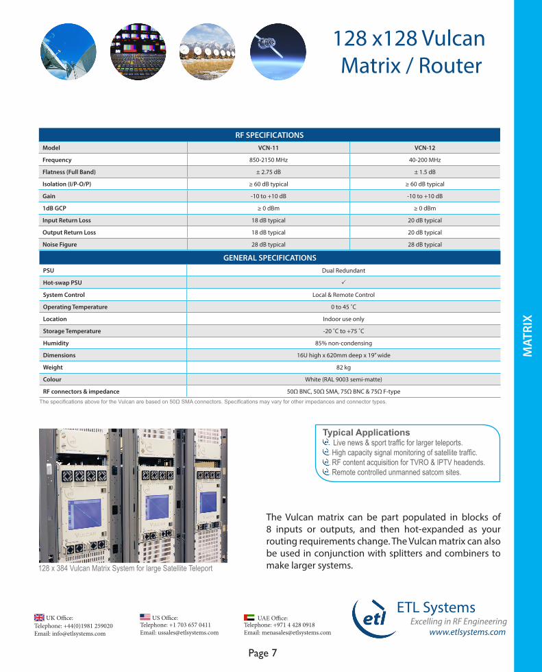
128 x128 Vulcan Matrix / Router
Typical Applications Live news & sport traffic for larger teleports. High capacity signal monitoring of satellite traffic. RF content acquisition for TVRO & IPTV headends. Remote controlled unmanned satcom sites.
128 x 384 Vulcan Matrix System for large Satellite Teleport
The specifications above for the Vulcan are based on 50Ω SMA connectors. Specifications may vary for other impedances and connector types.
RF SPECIFICATIONSModel VCN-11 VCN-12
Frequency 850-2150 MHz 40-200 MHz
Flatness (Full Band) ± 2.75 dB ± 1.5 dB
Isolation (I/P-O/P) ≥ 60 dB typical ≥ 60 dB typical
Gain -10 to +10 dB -10 to +10 dB
1dB GCP ≥ 0 dBm ≥ 0 dBm
Input Return Loss 18 dB typical 20 dB typical
Output Return Loss 18 dB typical 20 dB typical
Noise Figure 28 dB typical 28 dB typical
GENERAL SPECIFICATIONSPSU Dual Redundant
Hot-swap PSU P
System Control Local & Remote Control
Operating Temperature 0 to 45 ˚C
Location Indoor use only
Storage Temperature -20 ˚C to +75 ˚C
Humidity 85% non-condensing
Dimensions 16U high x 620mm deep x 19” wide
Weight 82 kg
Colour White (RAL 9003 semi-matte)
RF connectors & impedance 50Ω BNC, 50Ω SMA, 75Ω BNC & 75Ω F-type
The Vulcan matrix can be part populated in blocks of 8 inputs or outputs, and then hot-expanded as your routing requirements change. The Vulcan matrix can also be used in conjunction with splitters and combiners to make larger systems.
Telephone: +44(0)1981 259020 Email: [email protected]
UK Office:Telephone: +1 703 657 0411 Email: [email protected]
US Office:
www.etlsystems.com
ETL SystemsExcelling in RF Engineering
Page 8
Telephone: +971 4 428 0918 Email: [email protected]
UAE Office:
MAT
RIX
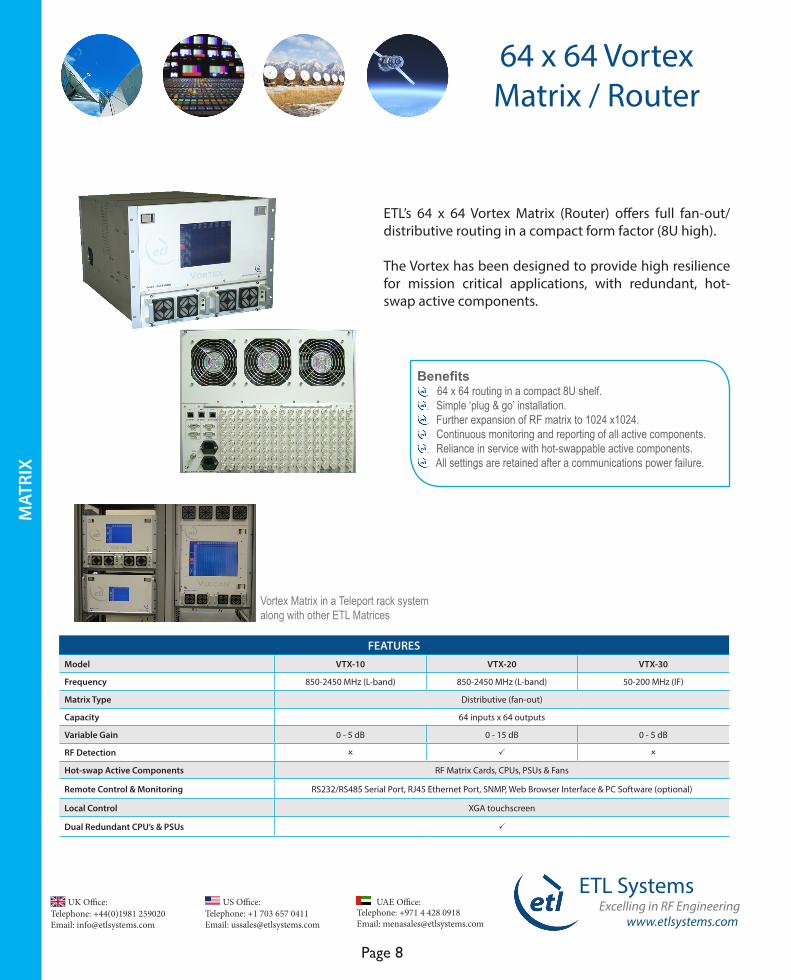
64 x 64 Vortex Matrix / Router
ETL’s 64 x 64 Vortex Matrix (Router) offers full fan-out/distributive routing in a compact form factor (8U high).
The Vortex has been designed to provide high resilience for mission critical applications, with redundant, hot-swap active components.
FEATURES Model VTX-10 VTX-20 VTX-30
Frequency 850-2450 MHz (L-band) 850-2450 MHz (L-band) 50-200 MHz (IF)
Matrix Type Distributive (fan-out)
Capacity 64 inputs x 64 outputs
Variable Gain 0 - 5 dB 0 - 15 dB 0 - 5 dB
RF Detection O P O
Hot-swap Active Components RF Matrix Cards, CPUs, PSUs & Fans
Remote Control & Monitoring RS232/RS485 Serial Port, RJ45 Ethernet Port, SNMP, Web Browser Interface & PC Software (optional)
Local Control XGA touchscreen
Dual Redundant CPU’s & PSUs P
Benefits 64 x 64 routing in a compact 8U shelf. Simple ‘plug & go’ installation. Further expansion of RF matrix to 1024 x1024. Continuous monitoring and reporting of all active components. Reliance in service with hot-swappable active components. All settings are retained after a communications power failure.
Vortex Matrix in a Teleport rack system along with other ETL Matrices
www.etlsystems.com
ETL SystemsExcelling in RF Engineering
Page 9
Telephone: +971 4 428 0918 Email: [email protected]
UAE Office: Telephone: +44(0)1981 259020 Email: [email protected]
UK Office:Telephone: +1 703 657 0411 Email: [email protected]
US Office:
MAT
RIX
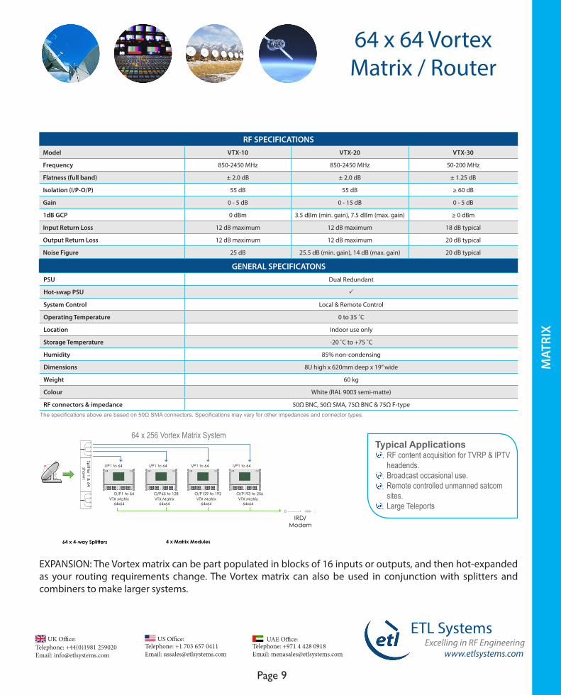
64 x 64 Vortex Matrix / Router
Typical Applications RF content acquisition for TVRP & IPTV headends. Broadcast occasional use. Remote controlled unmanned satcom sites. Large Teleports
RF SPECIFICATIONS Model VTX-10 VTX-20 VTX-30
Frequency 850-2450 MHz 850-2450 MHz 50-200 MHz
Flatness (full band) ± 2.0 dB ± 2.0 dB ± 1.25 dB
Isolation (I/P-O/P) 55 dB 55 dB ≥ 60 dB
Gain 0 - 5 dB 0 - 15 dB 0 - 5 dB
1dB GCP 0 dBm 3.5 dBm (min. gain), 7.5 dBm (max. gain) ≥ 0 dBm
Input Return Loss 12 dB maximum 12 dB maximum 18 dB typical
Output Return Loss 12 dB maximum 12 dB maximum 20 dB typical
Noise Figure 25 dB 25.5 dB (min. gain), 14 dB (max. gain) 20 dB typical
GENERAL SPECIFICATONS PSU Dual Redundant
Hot-swap PSU P
System Control Local & Remote Control
Operating Temperature 0 to 35 ˚C
Location Indoor use only
Storage Temperature -20 ˚C to +75 ˚C
Humidity 85% non-condensing
Dimensions 8U high x 620mm deep x 19” wide
Weight 60 kg
Colour White (RAL 9003 semi-matte)
RF connectors & impedance 50Ω BNC, 50Ω SMA, 75Ω BNC & 75Ω F-type
IRD/Modem
64 x 4-way Splitters
Splitter 1 &
64show
n
4 x Matrix Modules
VTX Matrix64x64
I/P1 to 64
O/P1 to 64VTX Matrix
64x64
I/P1 to 64
O/P65 to 128VTX Matrix
64x64
I/P1 to 64
O/P129 to 192VTX Matrix
64x64
I/P1 to 64
O/P193 to 256
The specifications above are based on 50Ω SMA connectors. Specifications may vary for other impedances and connector types.
EXPANSION: The Vortex matrix can be part populated in blocks of 16 inputs or outputs, and then hot-expanded as your routing requirements change. The Vortex matrix can also be used in conjunction with splitters and combiners to make larger systems.
64 x 256 Vortex Matrix System
Telephone: +44(0)1981 259020 Email: [email protected]
UK Office:Telephone: +1 703 657 0411 Email: [email protected]
US Office:
www.etlsystems.com
ETL SystemsExcelling in RF Engineering
Page 10
Telephone: +971 4 428 0918 Email: [email protected]
UAE Office:
MAT
RIX
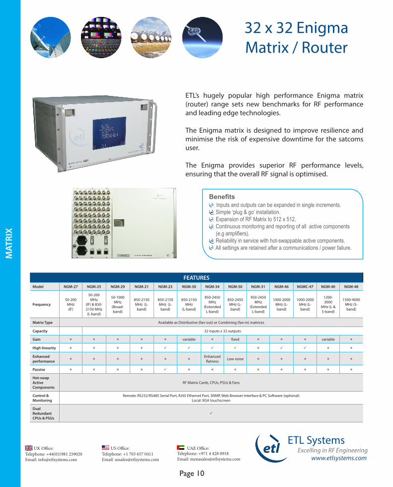
ETL’s hugely popular high performance Enigma matrix (router) range sets new benchmarks for RF performance and leading edge technologies. The Enigma matrix is designed to improve resilience and minimise the risk of expensive downtime for the satcoms user.
The Enigma provides superior RF performance levels, ensuring that the overall RF signal is optimised.
Benefits Inputs and outputs can be expanded in single increments. Simple ‘plug & go’ installation. Expansion of RF Matrix to 512 x 512. Continuous monitoring and reporting of all active components (e.g amplifiers). Reliability in service with hot-swappable active components. All settings are retained after a communications / power failure.
FEATURES Model NGM-27 NGM-25 NGM-29 NGM-21 NGM-23 NGM-30 NGM-34 NGM-50 NGM-31 NGM-46 NGMC-47 NGM-40 NGM-48
Frequency50-200
MHz (IF)
50-200 MHz
(IF) & 850-2150 MHz (L-band)
50-1000 MHz
(Broad-band)
850-2150 MHz (L-
band)
850-2150 MHz (L-
band)
850-2150 MHz
(L-band)
850-2450 MHz
(Extended L-band)
850-2450 MHz (L-band)
950-2450 MHz
(Extended L-band)
1000-2000 MHz (L-band)
1000-2000 MHz (L-band)
1200-3000
MHz (L & S-band)
1500-4000 MHz (S-band)
Matrix Type Available as Distributive (fan-out) or Combining (fan-in) matrices
Capacity 32 inputs x 32 outputs
Gain O O O O O variable O fixed O O O variable O
High linearity O O O O P P P P O P P O O
Enhanced performance O O O O O O
Enhanced flatness Low noise O O O O O
Passive O O O O P O O O O O O O O
Hot-swap ActiveComponents
RF Matrix Cards, CPUs, PSUs & Fans
Control & Monitoring
Remote: RS232/RS485 Serial Port, RJ45 Ethernet Port, SNMP, Web Browser Interface & PC Software (optional) Local: XGA touchscreen
Dual Redundant CPUs & PSUs
P
32 x 32 Enigma Matrix / Router
www.etlsystems.com
ETL SystemsExcelling in RF Engineering
Page 11
Telephone: +971 4 428 0918 Email: [email protected]
UAE Office: Telephone: +44(0)1981 259020 Email: [email protected]
UK Office:Telephone: +1 703 657 0411 Email: [email protected]
US Office:
MAT
RIX
32 x 32 Enigma Matrix / Router
RF SPECIFICATIONSModel NGM-27 NGM-25 NGM-29 NGM-21 NGM-23 NGM-30 NGM-34 NGM-50 NGM-31 NGM-46 NGMC-47 NGM-40 NGM-48
Frequency 50-200 MHz
50-2150 MHz
50-1000 MHz
850-2150 MHz
850-2150 MHz
850-2150 MHz
850-2450 MHz
850-2450 MHz
950-2450 MHz
1000-2000 MHz
1000-2000 MHz
1200-3000 MHz
1500-4000 MHz
Flatness (full band) ± 1.0 dB ± 1.0
dB* ± 1.0 dB ± 1.0 dB ± 1.0 dB ± 1.25 dB ± 1.0 dB ± 1.5 dB ± 1.0 dB ± 1.0 dB ± 1.0 dB ± 1.80 dB ± 2.25 dB
Isolation (I/P-O/P) 80 dB 65 dB
typical*65 dB min.
65 dB typical
65 dB min.
60 dB min.
55 dB min.
55 dB min.
55 dB min.
50 dB min.
50 dB min.
50 dB min. 50 dB min.
Gain 0 dB ± 1 dB 0 ± 1 dB 0 dB ±
1 dB 0 ± 1 dB 34 ± 2 dB (Loss)
-5 ± 1 dB (min.)
5 ± 1 dB (max.)
0 dB ± 1.5 dB
0 ± 1 dB (min.)
10 ± 1 dB (max.)
0 ± 1 dB +8 ± 2 dB -20 ± 1 dB 0-10 dB ± 2 dB +8 ± 2 dB
1 dB GCP 5 dBm 3.5 dBm 5 dBm 5 dBm +40 dBm12 dBm
(max. gain)
12.5 dBm +10 dBm
(max. gain)
5 dBm ≥10 dBm 10 dBm0 dBm (3000 MHz)
+ 3dBm
Input Return Loss
20 dB typical
22 dB typical*
20 dB typical
20 dB typical
18 dB typical
15 dB typical
18 dB typical
20 dB typical ≥ 15 dB 18 dB
typical18 dB
typical13 dB
minimum 14 dB
typical
Output Return Loss
20 dB typical
22 dB typical *
20 dB typical
20 dB typical
18 dB typical
15 dB typical
18 dB typical
20 dB typical ≥ 15 dB 18 dB
typical18 dB
typical12 dB
minimum 14 dB
typical
Noise Figure
20 dB typical
23 dB typical
20 dB typical
20 dB typical
34 dB typical
24 dB typical (max. gain)
25.5 dB max. 14 dB 20 dB
typical ≤ 21 dB 40 dB typical
20 dB max.
18.5 dB max.
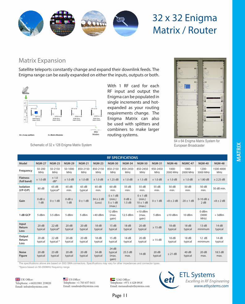
Satellite teleports constantly change and expand their downlink feeds. The Enigma range can be easily expanded on either the inputs, outputs or both.
With 1 RF card for each RF input and output the Enigma can be populated in single increments and hot-expanded as your routing requirements change. The Enigma Matrix can also be used with splitters and combiners to make larger routing systems.
64 x 64 Enigma Matrix System for European Broadcaster
The specifications above are based on 50Ω SMA connectors. Specifications may vary for other impedances and connector types.*Specs based on 50-200MHz frequency range
Matrix Expansion
IRD/Modem32 x 4-way splitters 4 x Matrix Modules
Splitter 1 and 32
shown
NGM MasterMatrix 32x32
I/P1 to 32
O/P1 to 32NGM Slave
Matrix 32x32
I/P1 to 32
O/P33 to 64NGM Slave
Matrix 32x32
I/P1 to 32
O/P65 to 96NGM Slave
Matrix 32x32
I/P1 to 32
O/P97 to 128
Schematic of 32 x 128 Enigma Matrix System
Telephone: +44(0)1981 259020 Email: [email protected]
UK Office:Telephone: +1 703 657 0411 Email: [email protected]
US Office:
www.etlsystems.com
ETL SystemsExcelling in RF Engineering
Page 12
Telephone: +971 4 428 0918 Email: [email protected]
UAE Office:
MAT
RIX
GENERAL SPECIFICATIONSModel NGM-27 NGM-25 NGM-29 NGM-21 NGM-23 NGM-30 NGM-34 NGM-50 NGM-31 NGM-46 NGMC-47 NGM-40 NGM-48
PSU Dual Redundant
Hot-swap PSU P
System Control Local & Remote Control
Operating Temperature 0 to 45 ˚C
Location Indoor use only
Storage Temperature -20 ˚C to +75 ˚C
Humidity 20-90% non-condensing
Dimensions 6U high x 450mm deep x 19” wide
Weight 29 kg
Colour White (RAL 9003 semi-matte)
RF connectors & impedance 50Ω BNC, 50Ω SMA, 75Ω BNC & 75Ω F-type
32 x 32 Enigma Matrix / Router
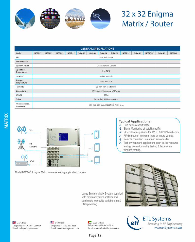
Typical Applications Live news & sport traffic. Signal Monitoring of satellite traffic. RF content acquisition for TVRO & IPTV head ends. RF distribution in cruise liners or luxury yachts. Remote controlled unmanned satcom sites. Test environment applications such as lab resource testing, network mobility testing & large scale wireless testing.
Large Enigma Matrix System supplied with modular system splitters and combiners to provide variable gain & LNB powering
Model NGM-23 Enigma Matrix wireless testing application diagram

www.etlsystems.com
ETL SystemsExcelling in RF Engineering
Page 13
Telephone: +971 4 428 0918 Email: [email protected]
UAE Office: Telephone: +44(0)1981 259020 Email: [email protected]
UK Office:Telephone: +1 703 657 0411 Email: [email protected]
US Office:
MAT
RIX
ETL’s Ensign Fan-In and Fan-Out (FIFO) Matrix (Router) is a resilient solution which allows multiple inputs to be combined and the combined signal can then be routed (distributed) to multiple outputs.
This design provides modems access to multiple uplink and downlink chains. The Ensign can also be used as a Transmit and Receive matrix for smaller teleports or ground stations.
Benefits Fan in & Fan out capability in one 6U chassis. Input and output cards can be expanded 1 by 1. Further expansion of RF Matrix to 512 x 512. Continuous monitoring and reporting of all active components (e.g amplifiers). Reliance in service with hot-swappable active components. All settings are retained after a communications/power failure.
FEATURESModel NSN- 10
Frequency 850-2450 MHz (Extended L-band)
Matrix type Distributive & Combining / Fan-in Fan-out (FIFO)
Capacity 32 inputs x 32 outputs
Fixed Gain P
Hot-swap Active Components RF Matrix Cards, CPUs & PSUs
Remote Control & Monitoring RS232/RS485 Serial Port, RJ45 Ethernet Port, SNMP, Web Browser Interface & PC Software (optional)
Local Control VGA Touchscreen
Dual Redundant CPUs & PSUs P
32 x 32 Ensign Matrix / Router
Telephone: +44(0)1981 259020 Email: [email protected]
UK Office:Telephone: +1 703 657 0411 Email: [email protected]
US Office:
www.etlsystems.com
ETL SystemsExcelling in RF Engineering
Page 14
Telephone: +971 4 428 0918 Email: [email protected]
UAE Office:
Typical Applications Downlink and uplink of Live news & sport traffic. VSAT traffic distribution. RF content acquisition for remote TVRO & IPTV headends. RF distribution in cruise liners or luxury yachts. Remote controlled unmanned satcom sites.
RF SPECIFICATIONSModel NSN-10
Frequency 850-2450 MHz
Flatness (full band) ± 1.5 dB
Isolation (I/P-O/P) ≥ 55 dB
Gain 5 ± 1 dB
1 dB GCP ≥ + 5 dBm
Input Return Loss 17 dB typical
Output Return Loss 18 dB typical
Noise Figure 20 dB maximum (at 5 dB gain setting)
GENERAL SPECIFICATIONS PSU Dual Redundant
Hot-swap PSU P
System Control Local & Remote Control
Operating Temperature 0 to 45 ˚ C
Location Indoor use only
Storage Temperature -20 to +75 ˚ C
Humidity 20-90% non-condensing
Dimensions 6U high x 450mm deep x 19” wide
Weight 29 kg
Colour White (RAL 9003 semi-matte)
RF connectors & impedance 50Ω BNC, 50Ω SMA, 75Ω BNC & 75Ω F-type
The specifications above are based on 50Ω SMA connectors. Specifications may vary for other impedances and connector types.
MAT
RIX
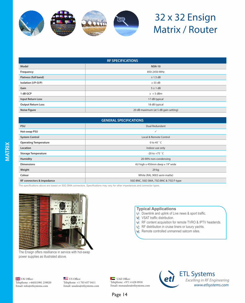
The Ensign offers resilliance in service with hot-swap power supplies as illustrated above.
32 x 32 Ensign Matrix / Router
www.etlsystems.com
ETL SystemsExcelling in RF Engineering
Page 15
Telephone: +971 4 428 0918 Email: [email protected]
UAE Office: Telephone: +44(0)1981 259020 Email: [email protected]
UK Office:Telephone: +1 703 657 0411 Email: [email protected]
US Office:
MAT
RIX
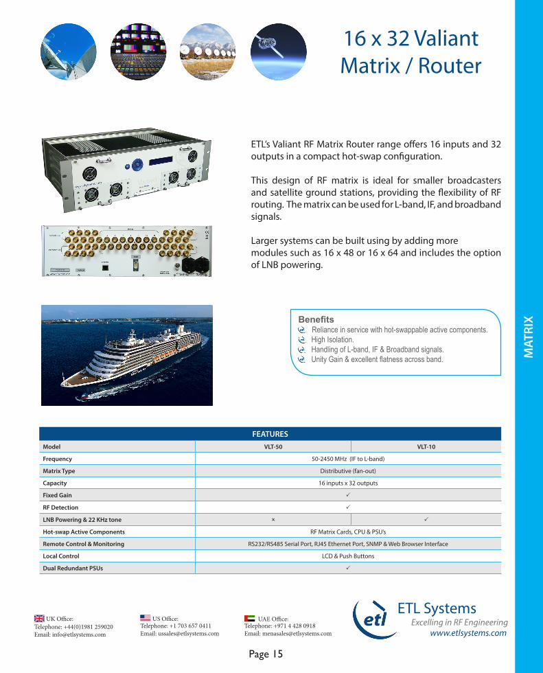
ETL’s Valiant RF Matrix Router range offers 16 inputs and 32 outputs in a compact hot-swap configuration.
This design of RF matrix is ideal for smaller broadcasters and satellite ground stations, providing the flexibility of RF routing. The matrix can be used for L-band, IF, and broadband signals.
Larger systems can be built using by adding more modules such as 16 x 48 or 16 x 64 and includes the option of LNB powering.
Benefits Reliance in service with hot-swappable active components. High Isolation. Handling of L-band, IF & Broadband signals. Unity Gain & excellent flatness across band.
FEATURESModel VLT-50 VLT-10
Frequency 50-2450 MHz (IF to L-band)
Matrix Type Distributive (fan-out)
Capacity 16 inputs x 32 outputs
Fixed Gain P
RF Detection P
LNB Powering & 22 KHz tone O P
Hot-swap Active Components RF Matrix Cards, CPU & PSU’s
Remote Control & Monitoring RS232/RS485 Serial Port, RJ45 Ethernet Port, SNMP & Web Browser Interface
Local Control LCD & Push Buttons
Dual Redundant PSUs P
16 x 32 Valiant Matrix / Router
Telephone: +44(0)1981 259020 Email: [email protected]
UK Office:Telephone: +1 703 657 0411 Email: [email protected]
US Office:
www.etlsystems.com
ETL SystemsExcelling in RF Engineering
Page 16
Telephone: +971 4 428 0918 Email: [email protected]
UAE Office:
GENERAL SPECIFICATIONS PSU Dual Redundant
Hot-swap PSU P
System Control Local & Remote Control
Operating Temperature 0 to 55 ˚C
Location Indoor use only
Storage Temperature -20 to +75 ˚C
Humidity 20 to 90% non-condensing
Dimensions 3U high x 300mm deep x 19” wide
Weight 12 kg
Colour White (RAL 9003 semi-matte)
RF connectors & impedance 50Ω BNC, 50Ω SMA, 75Ω BNC & 75Ω F-type
RF SPECIFICATIONS Model VLT-50 VLT-10
Frequency 50-2450 MHz
Flatness (full band) ± 2.0 dB
Isolation (I/P-O/P) ≥ 60 dB typical
Gain 0 ± 2.5 dB
1dB GCP 0 dBm at unity gain
Input Return Loss 15 dB typical
Outout Return Loss 15 dB typical
Noise Figure 22 dB typical at unity gain 25 dB at unity gain
LNB Power & 22KHz tone O 0/13/18V @ 500mA, 22Khz tone
16 x 32 Valiant Matrix / Router
The specifications above are based on 50Ω SMA connectors. Specifications may vary for other impedances and connector types.
Typical Applications Live news & sport traffic for smaller applications. SNG or outside broadcast trucks. RF content acquisition for smaller TVRO & IPTV headends. RF distribution in larger cruise liners or luxury yachts. Remote controlled unmanned satcom sites.
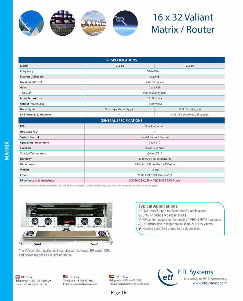
The Valiant offers resilliance in service with hot-swap RF cards, CPU and power supplies as illustrated above.
MAT
RIX
www.etlsystems.com
ETL SystemsExcelling in RF Engineering
Page 17
Telephone: +971 4 428 0918 Email: [email protected]
UAE Office: Telephone: +44(0)1981 259020 Email: [email protected]
UK Office:Telephone: +1 703 657 0411 Email: [email protected]
US Office:
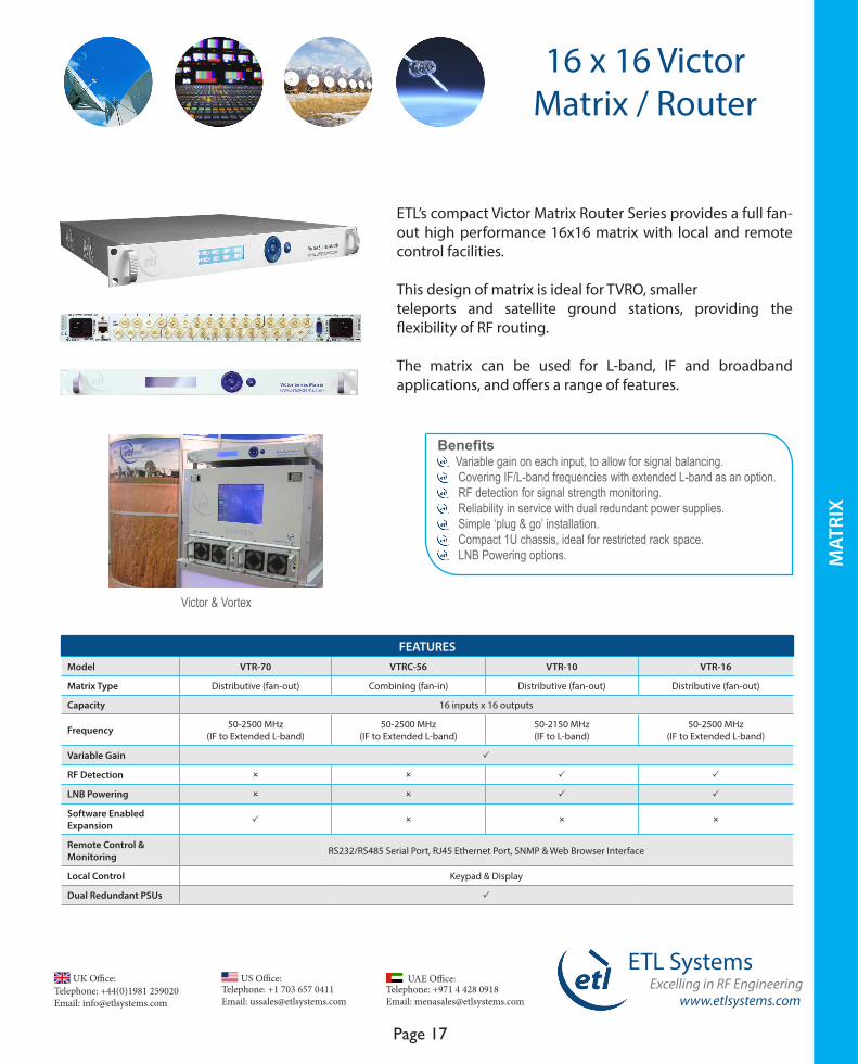
ETL’s compact Victor Matrix Router Series provides a full fan-out high performance 16x16 matrix with local and remote control facilities.
This design of matrix is ideal for TVRO, smaller teleports and satellite ground stations, providing the flexibility of RF routing.
The matrix can be used for L-band, IF and broadband applications, and offers a range of features.
FEATURESModel VTR-70 VTRC-56 VTR-10 VTR-16
Matrix Type Distributive (fan-out) Combining (fan-in) Distributive (fan-out) Distributive (fan-out)
Capacity 16 inputs x 16 outputs
Frequency 50-2500 MHz (IF to Extended L-band)
50-2500 MHz (IF to Extended L-band)
50-2150 MHz (IF to L-band)
50-2500 MHz (IF to Extended L-band)
Variable Gain P
RF Detection O O P P
LNB Powering O O P P
Software Enabled Expansion P O O O
Remote Control & Monitoring RS232/RS485 Serial Port, RJ45 Ethernet Port, SNMP & Web Browser Interface
Local Control Keypad & Display
Dual Redundant PSUs P
16 x 16 Victor Matrix / Router
MAT
RIX
Benefits Variable gain on each input, to allow for signal balancing. Covering IF/L-band frequencies with extended L-band as an option. RF detection for signal strength monitoring. Reliability in service with dual redundant power supplies. Simple ‘plug & go’ installation. Compact 1U chassis, ideal for restricted rack space. LNB Powering options.
Victor & Vortex
Telephone: +44(0)1981 259020 Email: [email protected]
UK Office:Telephone: +1 703 657 0411 Email: [email protected]
US Office:
www.etlsystems.com
ETL SystemsExcelling in RF Engineering
Page 18
Telephone: +971 4 428 0918 Email: [email protected]
UAE Office:
RF SPECIFICATIONSModel VTR-70 VTRC-56 VTR-10 VTR-16
Frequency 50-2500 MHz 50-2500 MHz 50-2150 MHz 50-2500 MHz
Flatness ± 1.75 dB
Isolation (I/P-O/P) 70 dB typical
Gain -3 dB to +3 dB
1dB GCP 2 dBm typical 1 dBm ± 2 (50-2150 MHz)-3 dBm ±2 (2150-2500 MHz) 3 dBm typical 3 dBm typical
Input Return Loss 18 dB typical 18 dB typical 15 dB typical 15 dB typical
Output Return Loss 18 dB typical 18 dB typical 16 dB typical 16 dB typical
Noise Figure 20 dB at maximum gain setting 23 dB at maximum gain setting 17 dB at maximum gain setting 19 dB at maximum gain setting
LNB Power O O0/13/18V selectable, 22 kHz
on/off0/13/18V selectable, 22 kHz
on/off
GENERAL SPECIFICATIONS PSU Dual Redundant
Hot-swap PSU O
System Control Local & Remote Control
Operating Temperature 0 to 45 ˚C
Location Indoor use only
Storage Temperature -20 ˚C to +75 ˚C
Humidity 20-90% non-condensing
Dimensions 1U high x 500mm deep x 19” wide
Weight 6 kg
Colour White (RAL 9003 semi-matte)
RF connectors & impedance 50Ω BNC, 50Ω SMA, 75Ω BNC & 75Ω F-type
Typical Applications Live news & sport traffic especially in SNG or OB trucks. Oil & Gas applications. RF content acquisition for TVRO & IPTV headends. RF distribution in cruise liners or luxury yachts. Remote controlled unmanned satcom sites.
The specifications above are based on 50Ω SMA connectors. Specifications may vary for other impedances and connector types.
16 x 16 Victor Matrix / Router
MAT
RIX
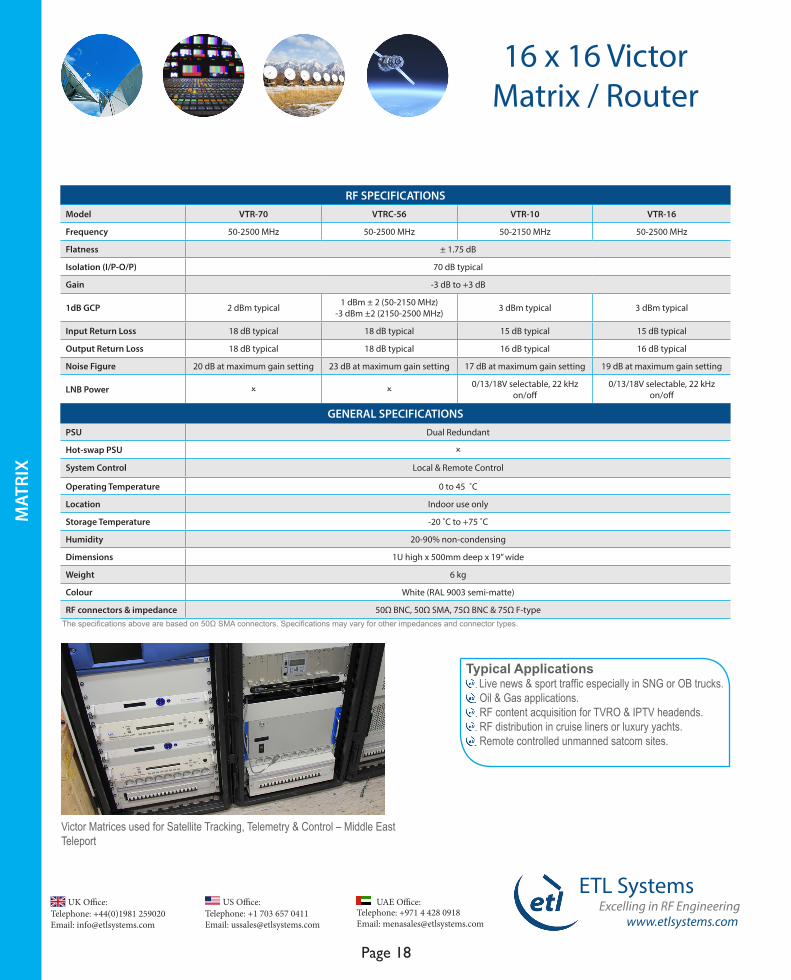
Victor Matrices used for Satellite Tracking, Telemetry & Control – Middle East Teleport
www.etlsystems.com
ETL SystemsExcelling in RF Engineering
Page 19
Telephone: +971 4 428 0918 Email: [email protected]
UAE Office: Telephone: +44(0)1981 259020 Email: [email protected]
UK Office:Telephone: +1 703 657 0411 Email: [email protected]
US Office:
4 x 16 /4 x 32 / 4 x 64Optimus
Matrix / Router
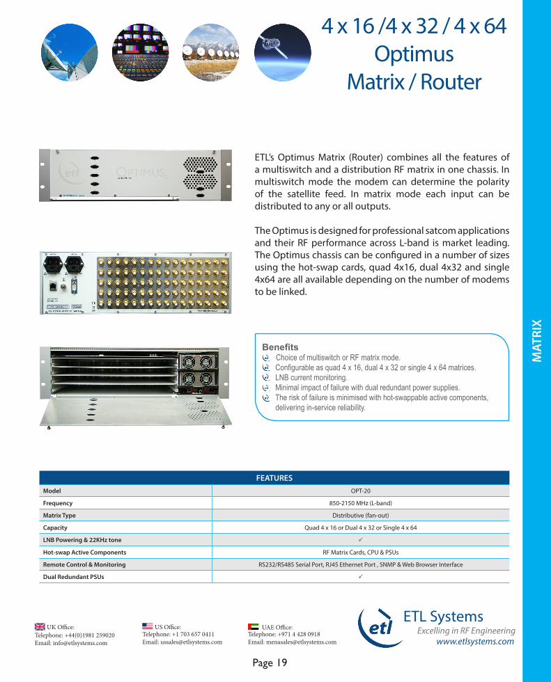
ETL’s Optimus Matrix (Router) combines all the features of a multiswitch and a distribution RF matrix in one chassis. In multiswitch mode the modem can determine the polarity of the satellite feed. In matrix mode each input can be distributed to any or all outputs.
The Optimus is designed for professional satcom applications and their RF performance across L-band is market leading. The Optimus chassis can be configured in a number of sizes using the hot-swap cards, quad 4x16, dual 4x32 and single 4x64 are all available depending on the number of modems to be linked.
Benefits Choice of multiswitch or RF matrix mode. Configurable as quad 4 x 16, dual 4 x 32 or single 4 x 64 matrices. LNB current monitoring. Minimal impact of failure with dual redundant power supplies. The risk of failure is minimised with hot-swappable active components, delivering in-service reliability.
FEATURESModel OPT-20
Frequency 850-2150 MHz (L-band)
Matrix Type Distributive (fan-out)
Capacity Quad 4 x 16 or Dual 4 x 32 or Single 4 x 64
LNB Powering & 22KHz tone P
Hot-swap Active Components RF Matrix Cards, CPU & PSUs
Remote Control & Monitoring RS232/RS485 Serial Port, RJ45 Ethernet Port , SNMP & Web Browser Interface
Dual Redundant PSUs P
MAT
RIX
Telephone: +44(0)1981 259020 Email: [email protected]
UK Office:Telephone: +1 703 657 0411 Email: [email protected]
US Office:
www.etlsystems.com
ETL SystemsExcelling in RF Engineering
Page 20
Telephone: +971 4 428 0918 Email: [email protected]
UAE Office:
MAT
RIX
Typical Applications Live news & sport traffic. Bulk distribution of satellite transponders. RF content acquisition for TVRO & IPTV headends. RF distribution in cruise liners or luxury yachts. Remote controlled unmanned satcom sites.
RF SPECIFICATIONSModel OPT-20
Frequency 850-2150 MHz
Flatness ± 2.5 dB
Gain 0 ± 2.0 dB
1 dB GCP +3 dBm
Input Return Loss 10 dB minimum
Output Return Loss 10 dB minimum
Noise Figure 25 dB
LNB Power 13V/18V/22 kHz
GENERAL SPECIFICATIONSPSU Dual Redundant
Hot-swap PSU P
System Control Remote Control
Operating Temperature 0 to 45 ˚ C
Location Indoor use only
Storage Temperature -20 ˚ C to +75 ˚ C
Humidity 20-90% non-condensing
Dimensions 3U high x 500mm deep x 19” wide
Weight 6 kg
Colour White (RAL 9003 semi-matte)
RF connectors & impedance 50Ω BNC, 50Ω SMA, 75Ω BNC & 75Ω F-typeThe specifications above are based on 50Ω SMA connectors. Specifications may vary for other impedances and connector types.
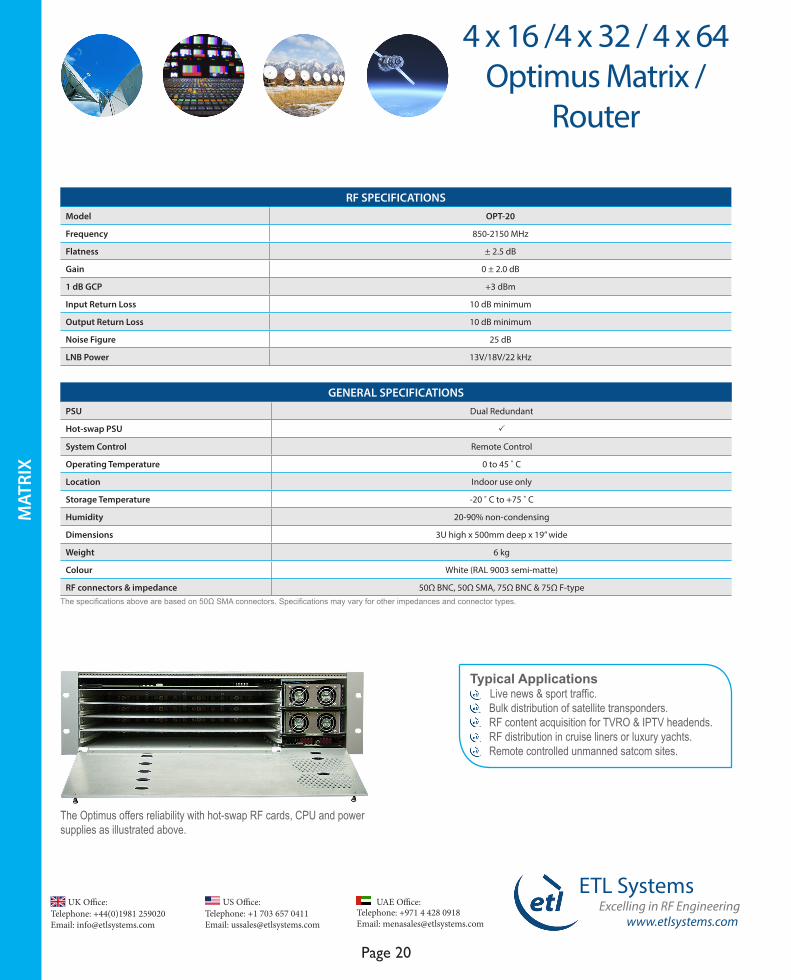
The Optimus offers reliability with hot-swap RF cards, CPU and power supplies as illustrated above.
4 x 16 /4 x 32 / 4 x 64Optimus Matrix /
Router

www.etlsystems.com
ETL SystemsExcelling in RF Engineering
Page 21
Telephone: +971 4 428 0918 Email: [email protected]
UAE Office: Telephone: +44(0)1981 259020 Email: [email protected]
UK Office:Telephone: +1 703 657 0411 Email: [email protected]
US Office:
ETL’s range of XY Controllers are designed to control the routing of either a Vulcan or Enigma matrix, where PC control is not preferred. They allow simple and configurable control from a remote location and are designed to make controlling the RF matrix as simple as possible.
FEATURES Model VCNXY-11 NGMXY-01
Compatible with Vulcan Matrix, Model VCN-11 All Enigma Matrix Models
Local Control Rotary controls, Keypad & Display
Remote Control RJ45 Ethernet Port & Web Browser Interface
Dual Redundant PSUs P
GENERAL SPECIFICATIONS PSU Dual Redundant
Hot-swap PSU O
System Control Local & Remote Control
Operating Temperature 0 to 40˚C
Location Indoor use only
Storage Temperature -20˚C to +75˚C
Humidity 85% non-condensing
Dimensions 2U high x 120mm deep x 19” wide
Weight 3 kg
Colour White (RAL 9003 semi-matte)
Typical Applications Remote control from an MCR. Multiple simultaneous users if several XY controllers used. Bulk update of satellite signal routing changes.
Benefits Pre-set programmable routings can be set in salvo mode. Ideal if a set of routings is required at certain times of the day. Allows user selectable groups of inputs or outputs to provide faster cross point changes. Extra resilience with dual redundant power supplies. All settings are retained after a communications / power failure.
XY Matrix / Router Remote Controller
REM
OTE
CO
NTR
OLL
ER
www.etlsystems.com
ETL SystemsExcelling in RF Engineering
Page 22
Telephone: +971 4 428 0918 Email: [email protected]
UAE Office: Telephone: +44(0)1981 259020 Email: [email protected]
UK Office:Telephone: +1 703 657 0411 Email: [email protected]
US Office:
StingRay RF over Fibre
RF O
VER
FIB
RE
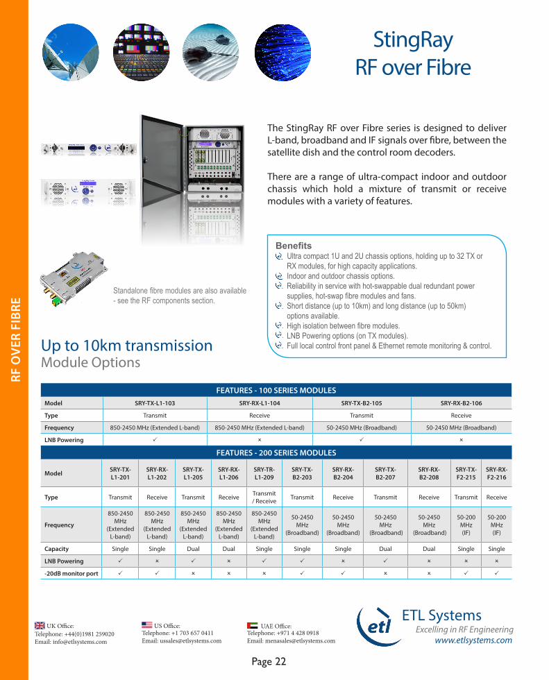
The StingRay RF over Fibre series is designed to deliver L-band, broadband and IF signals over fibre, between the satellite dish and the control room decoders.
There are a range of ultra-compact indoor and outdoor chassis which hold a mixture of transmit or receive modules with a variety of features.
Standalone fibre modules are also available - see the RF components section.
Benefits Ultra compact 1U and 2U chassis options, holding up to 32 TX or RX modules, for high capacity applications. Indoor and outdoor chassis options. Reliability in service with hot-swappable dual redundant power supplies, hot-swap fibre modules and fans. Short distance (up to 10km) and long distance (up to 50km) options available. High isolation between fibre modules. LNB Powering options (on TX modules). Full local control front panel & Ethernet remote monitoring & control. Up to 10km transmission
Module Options
FEATURES - 100 SERIES MODULESModel SRY-TX-L1-103 SRY-RX-L1-104 SRY-TX-B2-105 SRY-RX-B2-106
Type Transmit Receive Transmit Receive
Frequency 850-2450 MHz (Extended L-band) 850-2450 MHz (Extended L-band) 50-2450 MHz (Broadband) 50-2450 MHz (Broadband)
LNB Powering P O P O
FEATURES - 200 SERIES MODULES
Model SRY-TX-L1-201
SRY-RX-L1-202
SRY-TX-L1-205
SRY-RX-L1-206
SRY-TR-L1-209
SRY-TX-B2-203
SRY-RX-B2-204
SRY-TX-B2-207
SRY-RX-B2-208
SRY-TX-F2-215
SRY-RX-F2-216
Type Transmit Receive Transmit Receive Transmit/ Receive Transmit Receive Transmit Receive Transmit Receive
Frequency
850-2450 MHz
(Extended L-band)
850-2450 MHz
(Extended L-band)
850-2450 MHz
(Extended L-band)
850-2450 MHz
(Extended L-band)
850-2450 MHz
(Extended L-band)
50-2450 MHz
(Broadband)
50-2450 MHz
(Broadband)
50-2450 MHz
(Broadband)
50-2450 MHz
(Broadband)
50-200 MHz (IF)
50-200 MHz (IF)
Capacity Single Single Dual Dual Single Single Single Dual Dual Single Single
LNB Powering P O P O P P O P O O O
-20dB monitor port P P O O O P P O O P P

www.etlsystems.com
ETL SystemsExcelling in RF Engineering
Page 23
Telephone: +971 4 428 0918 Email: [email protected]
UAE Office: Telephone: +44(0)1981 259020 Email: [email protected]
UK Office:Telephone: +1 703 657 0411 Email: [email protected]
US Office:
RF O
VER
FIB
RE
StingRay RF over Fibre
Chassis Options
FEATURES - 100 SERIES CHASSIS (for 100 series modules only)
Model - Chassis SRY-C100-1U SRY-C101-1U SRY-C102-2U SRY-C103-1U
Capacity Up to 16 modules Up to 12 modules Up to 32 modules Up to 12 modules
Single/Dual IECs Single Dual Dual Dual
Remote control & monitoring
RJ45 Ethernet Port, SNMP, Web Browser Interface & PC Software
(optional)
RJ45 Ethernet Port, SNMP, Web Browser Interface & PC Software (optional). Summary alarm port
RJ45 Ethernet Port, SNMP, Web Browser Interface & PC Software
(optional)
RJ45 Ethernet Port, SNMP, Web Browser Interface & PC Software (optional). Summary alarm port
Local control & monitoring Front panel keypad & display
Dual Redundant PSUs P
Hot-swap Power supplies, fibre modules & fan modules
FEATURES - 200 SERIES CHASSIS (for 200 series modules only)
Model SRY-C200-1U SRY-C201-2U SRY-C204-2U SRY-C205-2U SRY-C206-2U SRY-C207-1U
Capacity Up to 4 modules Up to 16 modules Up to 10 modules Up to 16 modules Up to 16 modules Up to 4 modules
Single/Dual IECs Dual Dual Dual Dual Dual Dual
Remote Control & monitoring RS232/RS485 Serial Port, RJ45 Ethernet Port, SNMP, Web Browser Interface & PC Software (optional). Summary alarm port.
Local Control & monitoring Front panel keypad & display
Dual Redundant PSUs P
Hot-swap Power supplies, fibre modules & fan modules
Typical Applications Distribution of comms traffic across site with minimal loss. General satcoms - teleports, video headends, TVRO. Compact solution for small quantity links such as tactical HQ.
Typical fibre link application
www.etlsystems.com
ETL SystemsExcelling in RF Engineering
Page 24
Telephone: +971 4 428 0918 Email: [email protected]
UAE Office: Telephone: +44(0)1981 259020 Email: [email protected]
UK Office:Telephone: +1 703 657 0411 Email: [email protected]
US Office:
RF SPECIFICATIONS - 200 SERIES MODULES
Model SRY-TX-L1-201
SRY-RX-L1-202
SRY-TX-L1-205
SRY-RX-L1-206
SRY-TR-L1-209
SRY-TX-B2-203
SRY-RX-B2-204
SRY-TX-B2-207
SRY-RX-B2-208
SRY-TX-F2-215
SRY-RX-F2-216
Frequency 850-2450 MHz
850-2450 MHz
850-2450 MHz
850-2450 MHz
850-2450 MHz
50-2450 MHz
50-2450 MHz
50-2450 MHz
50-2450 MHz
50-200 MHz
50-200 MHz
Flatness (full band) ±1.7 dB ± 1.7 dB ± 2.4 dB ± 2.4 dB ± 2.4 dB ± 2.0 dB ± 2.0 dB ± 2.9 dB ± 2.9 dB ± 1.0 dB ± 1.0 dB
Return Loss 18 dB typ 18 dB typ 18 dB typ 18 dB typ 16 dB typ 18 dB typ 18 dB typ 18 dB typ 18 dB typ 18 dB typ 18 dB typ
Noise Figure 12 dB typ 12 dB typ 10 dB typ 10 dB typ 11 dB typ 12 dB typ 12 dB typ 10 dB typ 10 dB typ 12 dB typ 12 dB typ
CNR (any 36MHz) -48 dB typ -48 dB typ -50 dB typ -50 dB typ -50 dB typ -48 dB typ -48 dB typ -50 dB typ -50 dB typ -48 dB typ -48 dB typ
SFDR 105 dB/Hz2/3 typical
Link Budget 4 dB (compact fibre links of up to 10km)
Optical Wavelength
1310 ± 10 nm
1100 to 1650 nm
1310 ± 10 nm
1100 to 1650 nm
1310 ± 10 nm
1310 ± 10 nm
1100 to 1650 nm
1310 ± 10 nm
1100 to 1650 nm
1310 ± 10 nm
1100 to 1650 nm
Optical Power Out: 3.8 dBm typ
In: 0 - 4.5 dBm
Out: 3.8 dBm typ
In: 0 - 4.5 dBm
Out: 3.8 dBm typ
Out: 3.8 dBm typ
In: 0 - 4.5 dBm
Out: 3.8 dBm typ
In: 0 - 4.5 dBm
Out: 3.8 dBm typ
In: 0 - 4.5 dBm
LNB Powering13/18V
& 22 kHz tone
O13/18V
& 22 kHz tone
O13/18V
& 22 kHz tone
13/18V & 22 kHz
toneO
13/18V & 22 kHz
toneO O O
The specifications above are based on 50Ω SMA connectors. Other impedances and connector types are available - specifications may vary.* Preliminary specifications** With chassis SRY-C103-1U only
RF SPECIFICATIONS - 100 SERIES MODULES Model SRY-TX-L1-103 SRY-RX-L1-104 SRY-TX-B2-105 SRY-RX-B2-106
Frequency 850-2450 MHz 850-2450 MHz 50-2450 MHz 50-2450 MHz
Flatness (full band) ± 1.5 dB ± 1.5 dB ± 2.0 dB ± 2.0 dB
Return Loss 18 dB typical 18 dB typical 18 dB typical 18 dB typical
Noise Figure 10 dB typical 10 dB typical 10 dB typical 10 dB typical
CNR (any 36MHz) -50 dB typical
SFDR 105 dB/Hz2/3 typical
Link Budget 4 dB (compact fibre links of up to 10km)
Optical Wavelength 1310 ± 10 nm 1100 to 1650 nm 1310 ± 10 nm 1100 to 1650 nm
Optical Power Out: 3.8 dBm typical In: 0-4.5 dBm Out: 3.8 dBm typical In: 0-4.5 dBm
LNB Powering 18V** O 18V** O
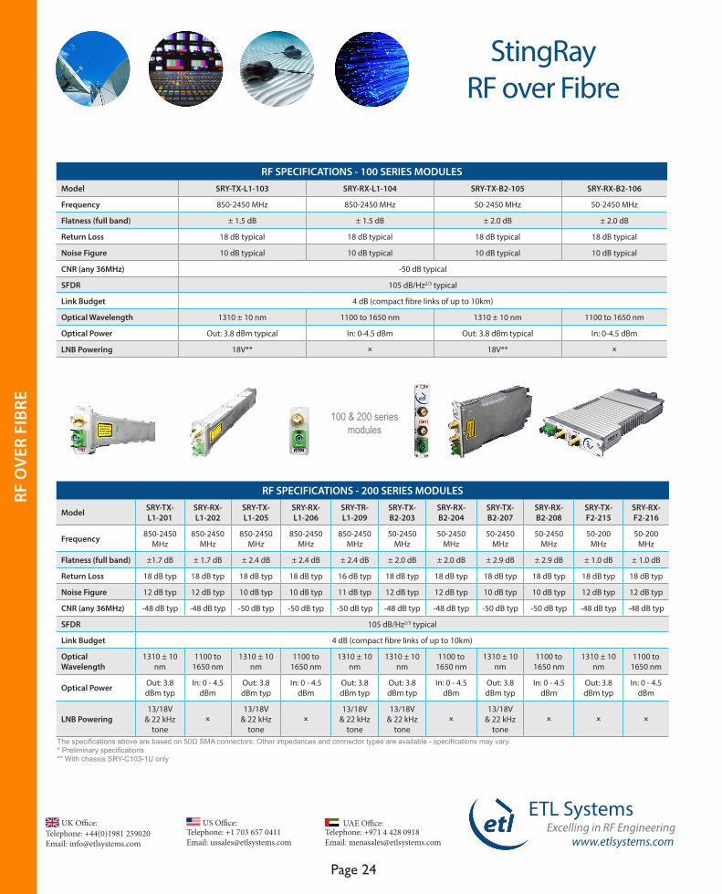
100 & 200 series modules
StingRay RF over Fibre
RF O
VER
FIB
RE
www.etlsystems.com
ETL SystemsExcelling in RF Engineering
Page 25
Telephone: +971 4 428 0918 Email: [email protected]
UAE Office: Telephone: +44(0)1981 259020 Email: [email protected]
UK Office:Telephone: +1 703 657 0411 Email: [email protected]
US Office:
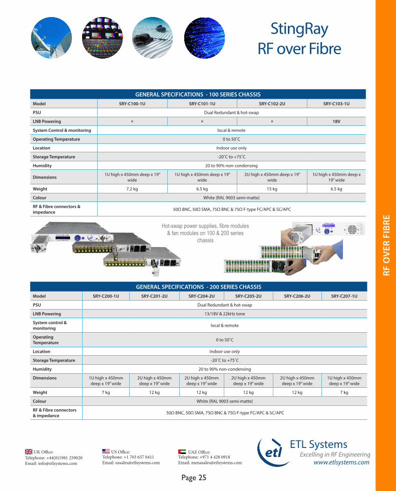
GENERAL SPECIFICATIONS - 200 SERIES CHASSIS Model SRY-C200-1U SRY-C201-2U SRY-C204-2U SRY-C205-2U SRY-C206-2U SRY-C207-1U
PSU Dual Redundant & hot-swap
LNB Powering 13/18V & 22kHz tone
System control & monitoring local & remote
Operating Temperature 0 to 50˚C
Location Indoor use only
Storage Temperature -20˚C to +75˚C
Humidity 20 to 90% non-condensing
Dimensions 1U high x 450mm deep x 19” wide
2U high x 450mm deep x 19” wide
2U high x 450mm deep x 19” wide
2U high x 450mm deep x 19” wide
2U high x 450mm deep x 19” wide
1U high x 450mm deep x 19” wide
Weight 7 kg 12 kg 12 kg 12 kg 12 kg 7 kg
Colour White (RAL 9003 semi-matte)
RF & Fibre connectors & impedance 50Ω BNC, 50Ω SMA, 75Ω BNC & 75Ω F-type FC/APC & SC/APC
GENERAL SPECIFICATIONS - 100 SERIES CHASSISModel SRY-C100-1U SRY-C101-1U SRY-C102-2U SRY-C103-1U
PSU Dual Redundant & hot-swap
LNB Powering O O O 18V
System Control & monitoring local & remote
Operating Temperature 0 to 50˚C
Location Indoor use only
Storage Temperature -20˚C to +75˚C
Humidity 20 to 90% non-condensing
Dimensions 1U high x 450mm deep x 19” wide
1U high x 450mm deep x 19” wide
2U high x 450mm deep x 19” wide
1U high x 450mm deep x 19” wide
Weight 7.2 kg 6.5 kg 15 kg 6.5 kg
Colour White (RAL 9003 semi-matte)
RF & Fibre connectors & impedance 50Ω BNC, 50Ω SMA, 75Ω BNC & 75Ω F-type FC/APC & SC/APC
Hot-swap power supplies, fibre modules & fan modules on 100 & 200 series
chassis
StingRay RF over Fibre
RF O
VER
FIB
RE

www.etlsystems.com
ETL SystemsExcelling in RF Engineering
Page 26
Telephone: +971 4 428 0918 Email: [email protected]
UAE Office: Telephone: +44(0)1981 259020 Email: [email protected]
UK Office:Telephone: +1 703 657 0411 Email: [email protected]
US Office:
StingRay RF over Fibre
Redundancy SystemModule Options
To be housed in 100 series chassis only
The StingRay series of redundancy RF over fibre modules can be configured to provide 1+1 and 4+1 redundancy solutions. Redundancy provides additional resilience for uplink and downlink transmissions over fibre. If one fibre link fails, the signal is automatically switched to the redundant path.
The StingRay CWDM system transmits RF signals up to 50km in distance. It comprises transmit modules and a multiplexer module to combine up to 8 wavelengths on to a single fibre cable at the transmit end. A demultiplexer module and receive modules are then used at the receive end to split the separate wavelengths.
4+1 redundancy schematic
RF SPECIFICATIONS - CWDM FIBRE MODULESModel SRY-TxxL1-141 SRY-RX-L1-142 SRY-Txx-B2-143 SRY-RX-B2-144
Type Transmit Receive Transmit Receive
Frequency 850-2450 MHz 850-2450 MHz 50-2450 MHz 50-2450 MHz
Flatness (full band) ± 1.5 dB ± 1.5 dB ± 2.0 dB ± 2.0 dB
Return Loss 18 dB typical 18 dB typical 18 dB typical 18 dB typical
Noise Figure 10 dB typical 10 dB typical 10 dB typical 10 dB typical
CNR (any 36MHz) -38 dB typical -38 dB typical -38 dB typical -38 dB typical
SFDR 105 dB/Hz2/3 typical
Optical Wavelength ±2 nm 1100 to 1650 nm ±2 nm 1100 to 1650 nm
Optical Power Out: 4.5 ±2.5 dBm In: -9.5 to 3.5 dBm Out: 4.5 ±2.5 dBm In: -10 to -5.5 dBm
LNB Powering 18V* O 18V* O
RF SPECIFICATIONS - MUX/DEMUX MODULE
Model SRY-OCM-08-545-47
Type 8 channel optical mux/demux
Operating wavelength
1471 / 1491 / 1511 / 1531 / 1551 / 1571 1591 / 1611 nm
Insertion Loss 2.5 dB
Isolation > 30 dB
Return Loss > 45 dB
Up to 50km transmissionCWDM System Module Options
* With chassis SRY-C103-1U only
RF O
VER
FIB
RE

www.etlsystems.com
ETL SystemsExcelling in RF Engineering
Page 27
Telephone: +971 4 428 0918 Email: [email protected]
UAE Office: Telephone: +44(0)1981 259020 Email: [email protected]
UK Office:Telephone: +1 703 657 0411 Email: [email protected]
US Office:
RF SPECIFICATIONS - 100 & 200 SERIES MODULESModel SRY-OSP-02-501 SRY-OSP-04-503 SRY-OSP-08-504 SRY-OSP-02-601 SRY-OSP-04-603 SRY-OSP-08-604
Capacity 2-way (100 series) 4-way (100 series) 8-way (100 series) 2-way (200 series) 4-way (200 series) 8-way (200 series)
Insertion Loss 4 dB 8 dB 12 dB 4 dB 8 dB 12 dB
Loss Uniformity 0.4 dB 0.6 dB 0.9 dB 0.4 dB 0.6 dB 0.9 dB
Optical Wavelength 1260 to 1650 nm 1260 to 1650 nm 1260 to 1650 nm 1260 to 1650 nm 1260 to 1650 nm 1260 to 1650 nm
StingRay RF over Fibre
RF SPECIFICATIONS - 100 & 200 SERIES MODULES Model SRY-TX-Y-107 SRY-RX-Y-108 SRY-TX-Y-211 SRY-RX-Y-212
Type Transmit (100 series) Receive (100 series) Transmit (200 series) Receive (200 series)
Frequency 10 MHz 10 MHz 10 MHz 10 MHz
Return Loss 18 dB typical 18 dB typical 18 dB typical 18 dB typical
Optical Wavelength 1310 ± 10 nm 1100 to 1650 nm 1310 ± 10 nm 1100 to 1650 nm
Optical Power Out: 5.5 ± 2 dBm In: 0 - 7 dBm Out: 5.5 ± 2 dBm In: 0 - 7 dBm
RF SPECIFICATIONS - 200 SERIES MODULESModel SRY-DIV-L1-213 SRY-SW-L1-214
Module Type RF Splitter RF Switch
Frequency 850-2450 MHz 850-2450 MHz
Flatness (full band) ±1.5 dB ±1.5 dB
1dB GCP +5 dBm minimum +7 dBm
Noise Figure 12 dB maximum 12 dB maximum
Return Loss 18 dB typical 18 dB typical
10 MHz Reference
Optical SplittersModule Options
Module Options
To be housed in 200 series & ODU-201 chassis only
To be housed in 100 series, 200 series & ODU-201 chassis
To be housed in 100 series, 200 series & ODU-201 chassis
The StingRay series of 10 MHz Reference RF over fibre modules can be used to provide a timing reference signal to lock oscillators in both up and down converters (LNB and BUC).
The StingRay series of passive optical splitter modules allow distribution of signal to multiple control rooms. They are designed to work with StingRay high gain receivers for a 14 dB link budget allowing high split ratios and long distance operation up to 35km.
1+1 redundancy schematic
RF O
VER
FIB
RE
www.etlsystems.com
ETL SystemsExcelling in RF Engineering
Page 28
Telephone: +971 4 428 0918 Email: [email protected]
UAE Office: Telephone: +44(0)1981 259020 Email: [email protected]
UK Office:Telephone: +1 703 657 0411 Email: [email protected]
US Office:
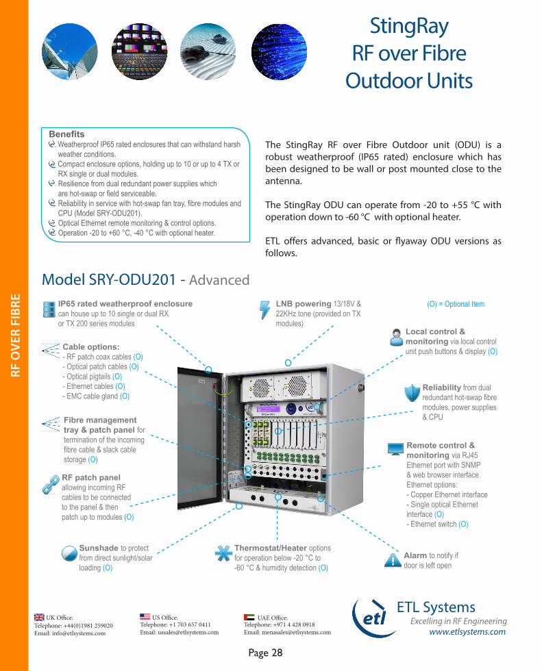
The StingRay RF over Fibre Outdoor unit (ODU) is a robust weatherproof (IP65 rated) enclosure which has been designed to be wall or post mounted close to the antenna.
The StingRay ODU can operate from -20 to +55 °C with operation down to -60 °C with optional heater.
ETL offers advanced, basic or flyaway ODU versions as follows.
Benefits Weatherproof IP65 rated enclosures that can withstand harsh weather conditions. Compact enclosure options, holding up to 10 or up to 4 TX or RX single or dual modules. Resilience from dual redundant power supplies which are hot-swap or field serviceable. Reliability in service with hot-swap fan tray, fibre modules and CPU (Model SRY-ODU201). Optical Ethernet remote monitoring & control options. Operation -20 to +60 °C, -40 °C with optional heater.
StingRay RF over Fibre
Outdoor Units
IP65 rated weatherproof enclosure can house up to 10 single or dual RX or TX 200 series modules
RF patch panel allowing incoming RF cables to be connected to the panel & then patch up to modules (O)
Sunshade to protect from direct sunlight/solar loading (O)
Thermostat/Heater options for operation below -20 °C to-60 °C & humidity detection (O)
Alarm to notify if door is left open
Remote control & monitoring via RJ45 Ethernet port with SNMP & web browser interface. Ethernet options: - Copper Ethernet interface- Single optical Ethernet interface (O)- Ethernet switch (O)
Reliability from dual redundant hot-swap fibre modules, power supplies & CPU
Local control & monitoring via local control unit push buttons & display (O)
LNB powering 13/18V & 22KHz tone (provided on TX modules)
(O) = Optional Item
Cable options:- RF patch coax cables (O)- Optical patch cables (O)- Optical pigtails (O)- Ethernet cables (O)- EMC cable gland (O)
Fibre management tray & patch panel for termination of the incoming fibre cable & slack cable storage (O)
Model SRY-ODU201 - Advanced
RF O
VER
FIB
RE

www.etlsystems.com
ETL SystemsExcelling in RF Engineering
Page 29
Telephone: +971 4 428 0918 Email: [email protected]
UAE Office: Telephone: +44(0)1981 259020 Email: [email protected]
UK Office:Telephone: +1 703 657 0411 Email: [email protected]
US Office:
IP65 rated weatherproof enclosure can house up to 4 single RX or TX 400 series modules
Sunshade to protect from direct sunlight/solar loading (O)
Remote control & monitoring via RJ45 Ethernet port with SNMP & web browser interface. Ethernet options: - Copper Ethernet interface (O)- Single optical Ethernet interface (O)
Reliability from dual redundant field serviceable power supplies
Local control & monitoring via dip switches located under access panel
StingRay RF over Fibre
Outdoor Units
FEATURES - CHASSISModel ODU-201 ODU-203
Capacity Up to 10 modules (200 series only) Up to 4 modules (400 series only)
Remote Control RS232/RS485 Serial Port, RJ45 Ethernet Port, SNMP, Web Browser Interface & PC Software (optional)
Local Control Optional Keypad & Display Module DIP Switches
Dual Redundant PSUs P
Hot-swap PSU’s P Field serviceable
GENERAL SPECIFICATIONS - CHASSISPSU Dual Redundant
System Control Remote Control
Operating Temperature (with LNB)8 feeds: -20 to +55 °C
12 feeds: -20 to +45 °C20 feeds: -20 to +40 °C
8 feeds: -20 to +50 °C
Operating Temperature (without LNB) 10 feeds: -20 to +55 °C 4 feeds: -20 to +55 °C
Location Outdoor or Indoor use
Storage Temperature -40˚C to +80˚C
Humidity 20 to 90% non-condensing
Dimensions 407 x 356 x 254 mm 407 x 154 x 254 mm
Weight 21 kg TBD
Colour RAL9003 White semi-matte
RF & Fibre connectors & impedance 50Ω BNC, 50Ω SMA, 75Ω BNC & 75Ω F-type FC/APC & SC/APC
Model SRY-ODU203 - Basic
LNB powering 13/18V & 22KHz tone (provided on TX modules)
RF O
VER
FIB
RE
www.etlsystems.com
ETL SystemsExcelling in RF Engineering
Page 30
Telephone: +971 4 428 0918 Email: [email protected]
UAE Office: Telephone: +44(0)1981 259020 Email: [email protected]
UK Office:Telephone: +1 703 657 0411 Email: [email protected]
US Office:
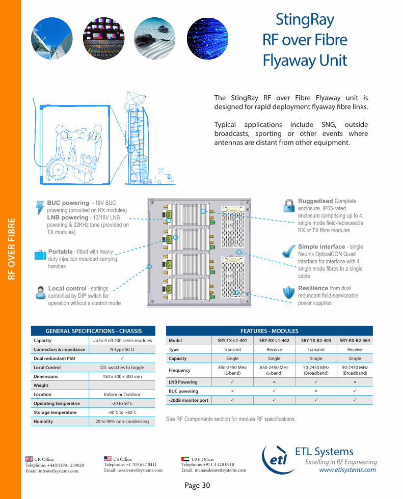
StingRay RF over Fibre Flyaway Unit
The StingRay RF over Fibre Flyaway unit is designed for rapid deployment flyaway fibre links.
Typical applications include SNG, outside broadcasts, sporting or other events where antennas are distant from other equipment.
GENERAL SPECIFICATIONS - CHASSISCapacity Up to 4 off 400 series modules
Connectors & impedance N-type 50 Ω
Dual redundant PSU P
Local Control DIL switches to toggle
Dimensions 450 x 300 x 300 mm
Weight
Location Indoor or Outdoor
Operating temperatire -20 to 50˚C
Storage temperature -40˚C to +80˚C
Humidity 20 to 90% non-condensing
FEATURES - MODULESModel SRY-TX-L1-401 SRY-RX-L1-462 SRY-TX-B2-403 SRY-RX-B2-464
Type Transmit Receive Transmit Receive
Capacity Single Single Single Single
Frequency 850-2450 MHz (L-band)
850-2450 MHz (L-band)
50-2450 MHz (Broadband)
50-2450 MHz (Broadband)
LNB Powering P O P O
BUC powering O P O P
-20dB monitor port P P P P
BUC powering - 18V BUC powering (provided on RX modules) LNB powering - 13/18V LNB powering & 22KHz tone (provided on TX modules)
Portable - fitted with heavy duty injection moulded carrying handles
Local control - settings controlled by DIP switch for operation without a control mode
Resilience from dual redundant field-serviceable power supplies
Simple interface - single Neutrik OpticalCON Quad interface for interface with 4 single mode fibres in a single cable
Ruggedised Complete enclosure, IP65-rated enclosure comprising up to 4, single mode field-replaceable RX or TX fibre modules
See RF Components section for module RF specifications.
RF O
VER
FIB
RE
www.etlsystems.com
ETL SystemsExcelling in RF Engineering
Page 31
Telephone: +971 4 428 0918 Email: [email protected]
UAE Office: Telephone: +44(0)1981 259020 Email: [email protected]
UK Office:Telephone: +1 703 657 0411 Email: [email protected]
US Office:
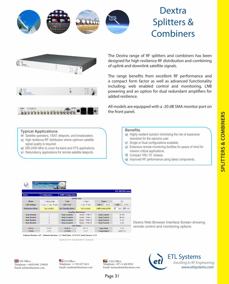
The Dextra range of RF splitters and combiners has been designed for high resilience RF distribution and combining of uplink and downlink satellite signals.
The range benefits from excellent RF performance and a compact form factor as well as advanced functionality including; web enabled control and monitoring, LNB powering and an option for dual redundant amplifiers for added resilience.
All models are equipped with a -20 dB SMA monitor port on the front panel.
Benefits Highly resilient solution minimising the risk of expensive downtime for the satcoms user. Single or Dual configurations available. Extensive remote monitoring facilities for peace of mind for mission critical applications. Compact 1RU 19” chassis. Improved RF performance using latest components.
DextraSplitters & Combiners
SPLI
TTER
S &
CO
MBI
NER
S
Typical Applications Satellite operators, VSAT, teleports, and broadcasters. High resilience RF distribution where optimum satellite signal quality is required. 850-2450 MHz to cover Ka-band and HTS applications. Redundancy applications for remote satellite teleports.
Dextra Web Browser Interface Screen showing remote control and monitoring options

Telephone: +44(0)1981 259020 Email: [email protected]
UK Office:Telephone: +1 703 657 0411 Email: [email protected]
US Office:
www.etlsystems.com
ETL SystemsExcelling in RF Engineering
Page 32
Telephone: +971 4 428 0918 Email: [email protected]
UAE Office:
DextraSplitters & Combiners
SPLI
TTER
S &
CO
MBI
NER
S
* Preliminary specificationsThe specifications above are based on 50Ω SMA connectors. Other impedances and connector types are available - specifications may vary.
RF SPECIFICATIONS
Model D0104S1ULA -22410
D0108S1ULA -22412
D0116S1ULA -22414
D0104S1ULA-22450
D0108S1ULA-22452
D0116S1ULA-22454
D0104S1UIA-22470
D0108S1UIA-22472
D0116S1UIA-22474
Frequency 850 - 2450 MHz (Extended L-band) 5 - 1000 MHz (IF)
Flatness (Full Band) ± 0.8 dB ± 0.8 dB ± 0.8 dB ± 0.8 dB ± 0.8 dB ± 0.8 dB ± 0.8 dB ± 0.8 dB ± 0.8 dB
Isolation (O/P-O/P)
24 dB minimum
24 dB minimum
24 dB minimum
24 dB minimum
24 dB minimum
24 dB minimum
20 dB minimum(@70MHz)
20 dB minimum(@70MHz)
20 dB minimum(@70MHz)
Gain 0 ± 1.0 dB 0 ± 1.0 dB 0 ± 1.0 dB 0 ± 1.0 dB 0 ± 1.0 dB 0 ± 1.0 dB 0 ± 1.0 dB 0 ± 1.0 dB 0 ± 1.0 dB
1 dB Gain Compression Point
+5 dBm 0 dBm 0 dBm 0 dBm 0 dBm 0 dBm 0 dBm 0 dBm 0 dBm
Noise Figure 10 dB 10 dB 10 dB 10 dB 10 dB 10 dB 10 dB 10 dB 10 dB
Input Return Loss 20 dB typical 20 dB typical 20 dB typical 20 dB typical 20 dB typical 20 dB typical 20 dB typical 20 dB typical 20 dB typical
Output Return Loss 21 dB typical 21 dB typical 21 dB typical 21 dB typical 21 dB typical 21 dB typical 21 dB typical 21 dB typical 21 dB typical
FEATURES
Model D0104S1ULA -22410
D0108S1ULA -22412
D0116S1ULA -22414
D0104S1ULA-22450
D0108S1ULA-22452
D0116S1ULA-22454
D0104S1UIA-22470
D0108S1UIA-22472
D0116S1UIA-22474
Frequency 850 - 2450 MHz (Extended L-band) 5 - 1000 MHz (IF)
Size Single 4-way Single 8-way Single 16-way Single 4-way Single 8-way Single 16-way Single 4-way Single 8-way Single 16-way
Single Amplifier P
Dual Redundant Amps*
Optional
10MHz Pass O O O P P P O O O
Dual Redundant PSUs
P
LNB Powering P
Remote Control & Monitoring
-20 dB monitor port, RS232/RS485 Serial port, RJ45 Ethernet port, SNMP & Web Browser Interface
Single Splitters
* Please use suffix OPT-R on the model number to specify the option of dual redundant amplifiers

www.etlsystems.com
ETL SystemsExcelling in RF Engineering
Page 33
Telephone: +971 4 428 0918 Email: [email protected]
UAE Office: Telephone: +44(0)1981 259020 Email: [email protected]
UK Office:Telephone: +1 703 657 0411 Email: [email protected]
US Office:
GENERAL SPECIFICATONS PSU Dual Redundant
System Control Remote Control
Operating Temperature 0 to 50 ˚C
Location Indoor use only
Storage Temperature -20 ˚C to +75 ˚C
Humidity 85% non-condensing
Dimensions 1U high x 350mm deep x 19” wide
Weight 3 kg
Colour White (00-E-55 semi-gloss)
RF connectors & impedance 50Ω BNC, 50Ω SMA, 75Ω BNC & 75Ω F-type ( 50Ω N-Type available for some models )
The specifications above are based on 50Ω SMA connectors. Other impedances and connector types are available - specifications may vary.
DextraSplitters & Combiners
SPLI
TTER
S &
CO
MBI
NER
S
Dual SplittersFEATURES
Model D0104D1ULA -22411 D0108D1ULA -22413 D0104D1ULA-22451 D0108D1ULA-22453 D0104D1UIA-22471 D0108D1UIA-22473
Frequency 850 - 2450 MHz (Extended L-band)
850 - 2450 MHz (Extended L-band)
850 - 2450 MHz (Extended L-band)
850 - 2450 MHz (Extended L-band) 5 - 1000 MHz (IF) 5 - 1000 MHz (IF)
Size Dual 4-way Dual 8-way Dual 4-way Dual 8-way Dual 4-way Dual 8-way
Single Amplifier P
Dual Redundant Amps* Optional
10MHz Pass O O P P O O
Dual Redundant PSUs P
LNB Powering P P P P P P
Remote Control & Monitoring -20 dB monitor port, RS232/RS485 Serial port, RJ45 Ethernet port, SNMP & Web Browser Interface
RF SPECIFICATIONSModel D0104D1ULA -22411 D0108D1ULA -22413 D0104D1ULA-22451 D0108D1ULA-22453 D0104D1UIA-22471 D0108D1UIA-22473
Flatness (Full Band) ± 0.8 dB ± 0.8 dB ± 0.8 dB ± 0.8 dB ± 0.8 dB ± 0.8 dB
Isolation (O/P-O/P) 24 dB minimum 24 dB minimum 24 dB minimum 24 dB minimum 20 dB minimum(@70MHz)
20 dB minimum(@70MHz)
Gain 0 ± 1.0 dB
1 dB Gain Compression Point +5 dBm 0 dBm +5 dBm +5 dBm 0 dBm 0 dBm
Noise Figure 10 dB 10 dB 10 dB 10 dB 10 dB 10 dB
Input Return Loss 20 dB typical
Output Return Loss 21 dB typical
Telephone: +44(0)1981 259020 Email: [email protected]
UK Office:Telephone: +1 703 657 0411 Email: [email protected]
US Office:
www.etlsystems.com
ETL SystemsExcelling in RF Engineering
Page 34
Telephone: +971 4 428 0918 Email: [email protected]
UAE Office:
DextraSplitters & Combiners
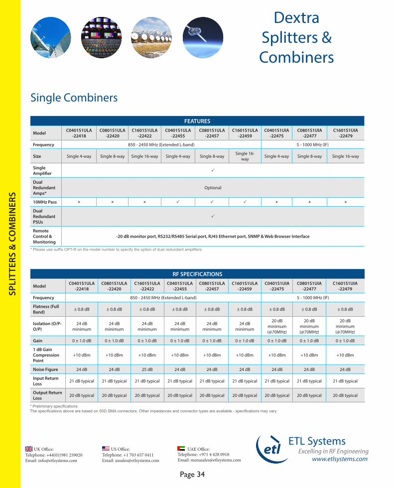
Single Combiners
SPLI
TTER
S &
CO
MBI
NER
S
FEATURES
Model C0401S1ULA -22418
C0801S1ULA -22420
C1601S1ULA -22422
C0401S1ULA-22455
C0801S1ULA-22457
C1601S1ULA-22459
C0401S1UIA-22475
C0801S1UIA-22477
C1601S1UIA-22479
Frequency 850 - 2450 MHz (Extended L-band) 5 - 1000 MHz (IF)
Size Single 4-way Single 8-way Single 16-way Single 4-way Single 8-way Single 16-way Single 4-way Single 8-way Single 16-way
Single Amplifier P
Dual Redundant Amps*
Optional
10MHz Pass O O O P P P O O O
Dual Redundant PSUs
P
Remote Control & Monitoring
-20 dB monitor port, RS232/RS485 Serial port, RJ45 Ethernet port, SNMP & Web Browser Interface
* Please use suffix OPT-R on the model number to specify the option of dual redundant amplifiers
* Preliminary specificationsThe specifications above are based on 50Ω SMA connectors. Other impedances and connector types are available - specifications may vary.
RF SPECIFICATIONS
Model C0401S1ULA -22418
C0801S1ULA -22420
C1601S1ULA -22422
C0401S1ULA-22455
C0801S1ULA-22457
C1601S1ULA-22459
C0401S1UIA-22475
C0801S1UIA-22477
C1601S1UIA-22479
Frequency 850 - 2450 MHz (Extended L-band) 5 - 1000 MHz (IF)
Flatness (Full Band) ± 0.8 dB ± 0.8 dB ± 0.8 dB ± 0.8 dB ± 0.8 dB ± 0.8 dB ± 0.8 dB ± 0.8 dB ± 0.8 dB
Isolation (O/P-O/P)
24 dB minimum
24 dB minimum
24 dB minimum
24 dB minimum
24 dB minimum
24 dB minimum
20 dB minimum(@70MHz)
20 dB minimum(@70MHz)
20 dB minimum(@70MHz)
Gain 0 ± 1.0 dB 0 ± 1.0 dB 0 ± 1.0 dB 0 ± 1.0 dB 0 ± 1.0 dB 0 ± 1.0 dB 0 ± 1.0 dB 0 ± 1.0 dB 0 ± 1.0 dB
1 dB Gain Compression Point
+10 dBm +10 dBm +10 dBm +10 dBm +10 dBm +10 dBm +10 dBm +10 dBm +10 dBm
Noise Figure 24 dB 24 dB 25 dB 24 dB 24 dB 24 dB 24 dB 24 dB 24 dB
Input Return Loss 21 dB typical 21 dB typical 21 dB typical 21 dB typical 21 dB typical 21 dB typical 21 dB typical 21 dB typical 21 dB typical
Output Return Loss 20 dB typical 20 dB typical 20 dB typical 20 dB typical 20 dB typical 20 dB typical 20 dB typical 20 dB typical 20 dB typical
www.etlsystems.com
ETL SystemsExcelling in RF Engineering
Page 35
Telephone: +971 4 428 0918 Email: [email protected]
UAE Office: Telephone: +44(0)1981 259020 Email: [email protected]
UK Office:Telephone: +1 703 657 0411 Email: [email protected]
US Office:
DextraSplitters & Combiners
SPLI
TTER
S &
CO
MBI
NER
S
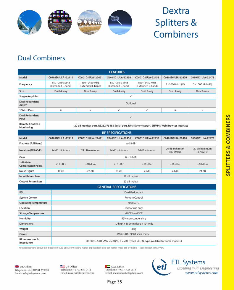
Dual Combiners
FEATURES Model C0401D1ULA -22419 C0801D1ULA -22421 C0401D1ULA-22456 C0801D1ULA-22458 C0401D1UIA-22476 C0801D1UIA-22478
Frequency 850 - 2450 MHz (Extended L-band)
850 - 2450 MHz (Extended L-band)
850 - 2450 MHz (Extended L-band)
850 - 2450 MHz (Extended L-band) 5 - 1000 MHz (IF) 5 - 1000 MHz (IF)
Size Dual 4-way Dual 8-way Dual 4-way Dual 8-way Dual 4-way Dual 8-way
Single Amplifier P
Dual Redundant Amps* Optional
10MHz Pass O O P P O O
Dual Redundant PSUs P
Remote Control & Monitoring -20 dB monitor port, RS232/RS485 Serial port, RJ45 Ethernet port, SNMP & Web Browser Interface
RF SPECIFICATIONSModel C0401D1ULA -22419 C0801D1ULA -22421 C0401D1ULA-22456 C0801D1ULA-22458 C0401D1UIA-22476 C0801D1UIA-22478
Flatness (Full Band) ± 0.8 dB
Isolation (O/P-O/P) 24 dB minimum 24 dB minimum 24 dB minimum 24 dB minimum 20 dB minimum(@70MHz)
20 dB minimum(@70MHz)
Gain 0 ± 1.0 dB
1 dB Gain Compression Point +12 dBm +10 dBm +10 dBm +10 dBm +10 dBm +10 dBm
Noise Figure 18 dB 22 dB 24 dB 24 dB 24 dB 24 dB
Input Return Loss 21 dB typical
Output Return Loss 20 dB typical
GENERAL SPECIFICATONS PSU Dual Redundant
System Control Remote Control
Operating Temperature 0 to 50 ˚C
Location Indoor use only
Storage Temperature -20 ˚C to +75 ˚C
Humidity 85% non-condensing
Dimensions 1U high x 350mm deep x 19” wide
Weight 3 kg
Colour White (RAL 9003 semi-matte)
RF connectors & impedance 50Ω BNC, 50Ω SMA, 75Ω BNC & 75Ω F-type ( 50Ω N-Type available for some models )
The specifications above are based on 50Ω SMA connectors. Other impedances and connector types are available - specifications may vary.
Telephone: +44(0)1981 259020 Email: [email protected]
UK Office:Telephone: +1 703 657 0411 Email: [email protected]
US Office:
www.etlsystems.com
ETL SystemsExcelling in RF Engineering
Page 36
Telephone: +971 4 428 0918 Email: [email protected]
UAE Office:
DextraSplitters & Combiners
SPLI
TTER
S &
CO
MBI
NER
S
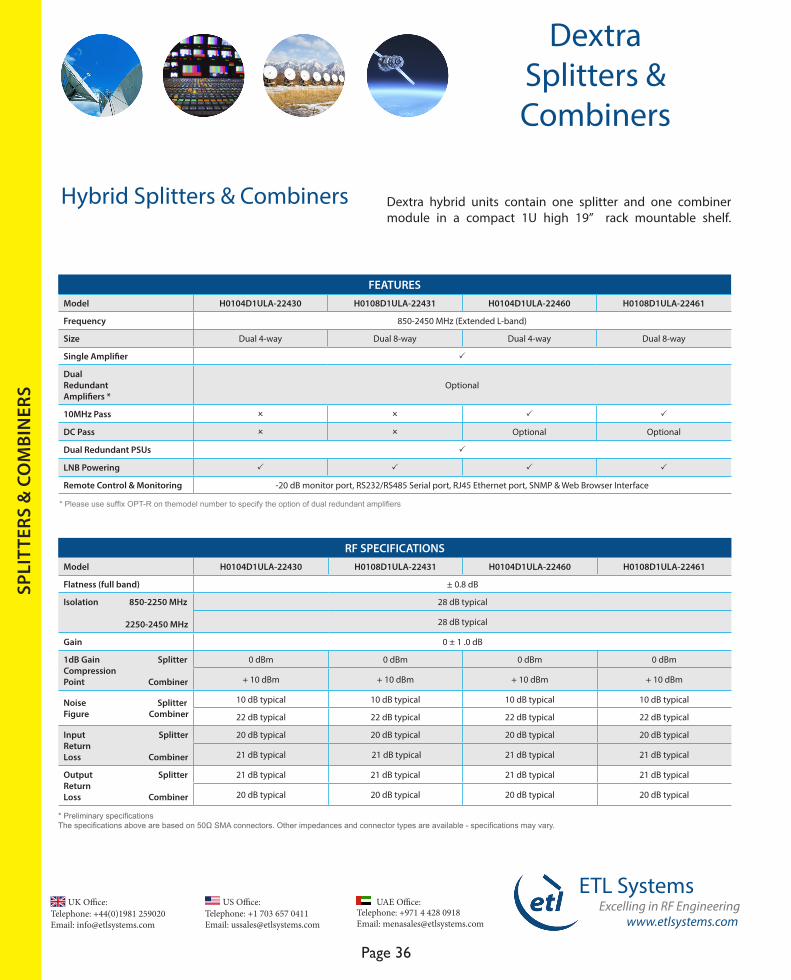
FEATURESModel H0104D1ULA-22430 H0108D1ULA-22431 H0104D1ULA-22460 H0108D1ULA-22461
Frequency 850-2450 MHz (Extended L-band)
Size Dual 4-way Dual 8-way Dual 4-way Dual 8-way
Single Amplifier P
Dual Redundant Amplifiers *
Optional
10MHz Pass O O P P
DC Pass O O Optional Optional
Dual Redundant PSUs P
LNB Powering P P P P
Remote Control & Monitoring -20 dB monitor port, RS232/RS485 Serial port, RJ45 Ethernet port, SNMP & Web Browser Interface
RF SPECIFICATIONSModel H0104D1ULA-22430 H0108D1ULA-22431 H0104D1ULA-22460 H0108D1ULA-22461
Flatness (full band) ± 0.8 dB
Isolation 850-2250 MHz 2250-2450 MHz
28 dB typical
28 dB typical
Gain 0 ± 1 .0 dB
1dB Gain SplitterCompression Point Combiner
0 dBm 0 dBm 0 dBm 0 dBm
+ 10 dBm + 10 dBm + 10 dBm + 10 dBm
Noise Splitter Figure Combiner
10 dB typical 10 dB typical 10 dB typical 10 dB typical
22 dB typical 22 dB typical 22 dB typical 22 dB typical
Input SplitterReturnLoss Combiner
20 dB typical 20 dB typical 20 dB typical 20 dB typical
21 dB typical 21 dB typical 21 dB typical 21 dB typical
Output SplitterReturn Loss Combiner
21 dB typical 21 dB typical 21 dB typical 21 dB typical
20 dB typical 20 dB typical 20 dB typical 20 dB typical
Hybrid Splitters & Combiners Dextra hybrid units contain one splitter and one combiner module in a compact 1U high 19” rack mountable shelf.
* Please use suffix OPT-R on themodel number to specify the option of dual redundant amplifiers
* Preliminary specificationsThe specifications above are based on 50Ω SMA connectors. Other impedances and connector types are available - specifications may vary.
www.etlsystems.com
ETL SystemsExcelling in RF Engineering
Page 37
Telephone: +971 4 428 0918 Email: [email protected]
UAE Office: Telephone: +44(0)1981 259020 Email: [email protected]
UK Office:Telephone: +1 703 657 0411 Email: [email protected]
US Office:
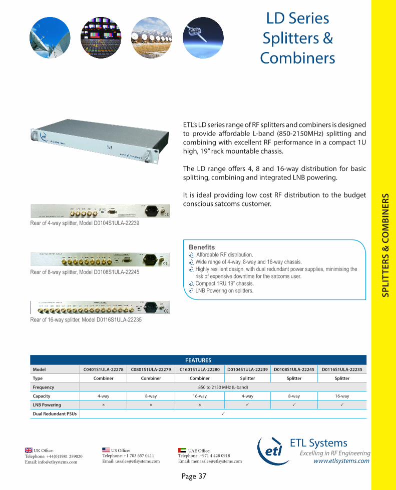
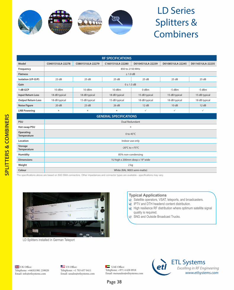
LD Series Splitters & Combiners
ETL’s LD series range of RF splitters and combiners is designed to provide affordable L-band (850-2150MHz) splitting and combining with excellent RF performance in a compact 1U high, 19” rack mountable chassis.
The LD range offers 4, 8 and 16-way distribution for basic splitting, combining and integrated LNB powering.
It is ideal providing low cost RF distribution to the budget conscious satcoms customer.
FEATURESModel C0401S1ULA-22278 C0801S1ULA-22279 C1601S1ULA-22280 D0104S1ULA-22239 D0108S1ULA-22245 D0116S1ULA-22235
Type Combiner Combiner Combiner Splitter Splitter Splitter
Frequency 850 to 2150 MHz (L-band)
Capacity 4-way 8-way 16-way 4-way 8-way 16-way
LNB Powering O O O P P P
Dual Redundant PSUs P
Rear of 4-way splitter, Model D0104S1ULA-22239
Benefits Affordable RF distribution. Wide range of 4-way, 8-way and 16-way chassis. Highly resilient design, with dual redundant power supplies, minimising the risk of expensive downtime for the satcoms user. Compact 1RU 19” chassis. LNB Powering on splitters.
Rear of 8-way splitter, Model D0108S1ULA-22245
Rear of 16-way splitter, Model D0116S1ULA-22235
SPLI
TTER
S &
CO
MBI
NER
S
Telephone: +44(0)1981 259020 Email: [email protected]
UK Office:Telephone: +1 703 657 0411 Email: [email protected]
US Office:
www.etlsystems.com
ETL SystemsExcelling in RF Engineering
Page 38
Telephone: +971 4 428 0918 Email: [email protected]
UAE Office:
LD Series Splitters & Combiners
SPLI
TTER
S &
CO
MBI
NER
S
Typical Applications Satellite operators, VSAT, teleports, and broadcasters. IPTV and DTH headend content distribution. High resilience RF distribution where optimum satellite signal quality is required. SNG and Outside Broadcast Trucks.
RF SPECIFICATIONSModel C0401S1ULA-22278 C0801S1ULA-22279 C1601S1ULA-22280 D0104S1ULA-22239 D0108S1ULA-22245 D0116S1ULA-22235
Frequency 850 to 2150 MHz
Flatness ± 1.0 dB
Isolation (I/P-O/P) 23 dB 25 dB 25 dB 25 dB 25 dB 25 dB
Gain 0 ± 1.5 dB
1 dB GCP 10 dBm 10 dBm 10 dBm 0 dBm -5 dBm -5 dBm
Input Return Loss 18 dB typical 18 dB typical 18 dB typical 15 dB typical 15 dB typical 15 dB typical
Output Return Loss 18 dB typical 15 dB typical 15 dB typical 18 dB typical 18 dB typical 18 dB typical
Noise Figure 20 dB 23 dB 26 dB 12 dB 10 dB 12 dB
LNB Powering O O O P P P
GENERAL SPECIFICATIONSPSU Dual Redundant
Hot-swap PSU O
Operating Temperature 0 to 45°C
Location Indoor use only
Storage Temperature -20°C to +75°C
Humidity 85% non-condensing
Dimensions 1U high x 200mm deep x 19” wide
Weight 2 kg
Colour White (RAL 9003 semi-matte)
LD Splitters installed in German Teleport
The specifications above are based on 50Ω SMA connectors. Other impedances and connector types are available - specifications may vary.

www.etlsystems.com
ETL SystemsExcelling in RF Engineering
Page 39
Telephone: +971 4 428 0918 Email: [email protected]
UAE Office: Telephone: +44(0)1981 259020 Email: [email protected]
UK Office:Telephone: +1 703 657 0411 Email: [email protected]
US Office:
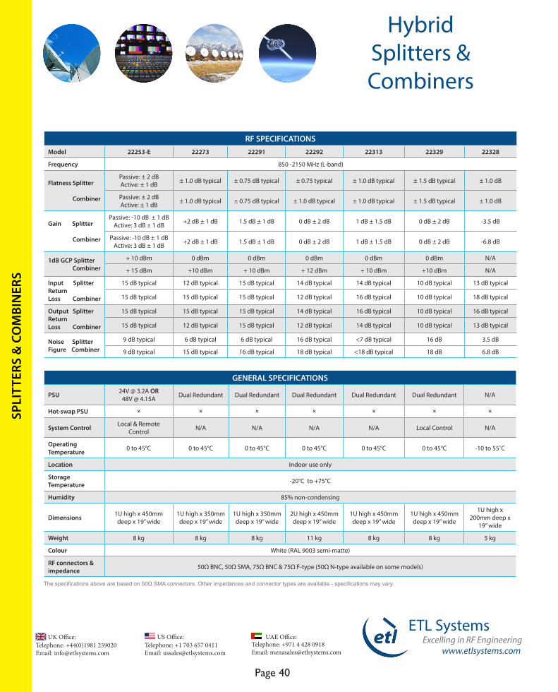
FEATURES Model 22253-E 22273 22291 22292 22313 22329 22328
Frequency 850-2150 MHz (L-band)
Capacity 4-way 4-way 4-way 4-way 4-way 4-way 4-way (splitter)2-way (combiner)
Remote Monitoring
RS232/485 Serial port, RJ45 Ethernet port, SNMP & Web Browser Interface
PSU Dry contactalarm port
PSU Dry contactalarm port
RS232/485 Serial port & RJ45 Ethernet port
RJ45 Ethernet port RJ45 Ethernet port O
LNB / BUC Powering P O
LNB Powering on splitter P O
LNB Powering on splitter O
10 MHz Reference Source Internal O O Internal O External O
DC & 10 MHz Pass O P O O O O P
Dual Redundant Amplifiers
O O O P O PN/A
(passive)
-20 dB Port for Carrier Monitoring O P O O O O O
Dual Redundant PSUs
24V @ 3.2 A OR48V @ 4.15 A P P P
-48V DC supply required P O
HybridSplitters & Combiners
The ETL Hybrid design includes an RF splitter and combiner in a single chassis and is designed primarily for VSAT or telecoms applications. The range uses 4-way, 8-way and 16-way RF modules handling IF, L-band or C-band frequencies.
The compact design maximises rack space where transmit and receive satellite signals are distributed. With a large number of options available this can be a professional solution for many satcoms applications.
Benefits Compact form factor provides a space saving solution. Resilience in service with dual redundant power supplies. Can be easily customised for different applications.
Hybrid example - Dual 4 - way with SMA connectors
Hybrid example - Dual 4 - way with 10 MHz source patch
SPLI
TTER
S &
CO
MBI
NER
S
4-way
Telephone: +44(0)1981 259020 Email: [email protected]
UK Office:Telephone: +1 703 657 0411 Email: [email protected]
US Office:
www.etlsystems.com
ETL SystemsExcelling in RF Engineering
Page 40
Telephone: +971 4 428 0918 Email: [email protected]
UAE Office:
RF SPECIFICATIONSModel 22253-E 22273 22291 22292 22313 22329 22328
Frequency 850 -2150 MHz (L-band)
Flatness Splitter Combiner
Passive: ± 2 dB Active: ± 1 dB ± 1.0 dB typical ± 0.75 dB typical ± 0.75 typical ± 1.0 dB typical ± 1.5 dB typical ± 1.0 dB
Passive: ± 2 dB Active: ± 1 dB ± 1.0 dB typical ± 0.75 dB typical ± 1.0 dB typical ± 1.0 dB typical ± 1.5 dB typical ± 1.0 dB
Gain Splitter Combiner
Passive: -10 dB ± 1 dBActive: 3 dB ± 1 dB +2 dB ± 1 dB 1.5 dB ± 1 dB 0 dB ± 2 dB 1 dB ± 1.5 dB 0 dB ± 2 dB -3.5 dB
Passive: -10 dB ± 1 dB Active: 3 dB ± 1 dB +2 dB ± 1 dB 1.5 dB ± 1 dB 0 dB ± 2 dB 1 dB ± 1.5 dB 0 dB ± 2 dB -6.8 dB
1dB GCP Splitter Combiner
+ 10 dBm 0 dBm 0 dBm 0 dBm 0 dBm 0 dBm N/A
+ 15 dBm +10 dBm + 10 dBm + 12 dBm + 10 dBm +10 dBm N/A
Input SplitterReturnLoss Combiner
15 dB typical 12 dB typical 15 dB typical 14 dB typical 14 dB typical 10 dB typical 13 dB typical
15 dB typical 15 dB typical 15 dB typical 12 dB typical 16 dB typical 10 dB typical 18 dB typical
Output SplitterReturn Loss Combiner
15 dB typical 15 dB typical 15 dB typical 14 dB typical 16 dB typical 10 dB typical 16 dB typical
15 dB typical 12 dB typical 15 dB typical 12 dB typical 14 dB typical 10 dB typical 13 dB typical
Noise SplitterFigure Combiner
9 dB typical 6 dB typical 6 dB typical 16 dB typical <7 dB typical 16 dB 3.5 dB
9 dB typical 15 dB typical 16 dB typical 18 dB typical <18 dB typical 18 dB 6.8 dB
GENERAL SPECIFICATIONS
PSU 24V @ 3.2A OR 48V @ 4.15A Dual Redundant Dual Redundant Dual Redundant Dual Redundant Dual Redundant N/A
Hot-swap PSU O O O O O O O
System Control Local & Remote Control N/A N/A N/A N/A Local Control N/A
Operating Temperature 0 to 45°C 0 to 45°C 0 to 45°C 0 to 45°C 0 to 45°C 0 to 45°C -10 to 55˚C
Location Indoor use only
Storage Temperature -20°C to +75°C
Humidity 85% non-condensing
Dimensions 1U high x 450mm deep x 19” wide
1U high x 350mm deep x 19” wide
1U high x 350mm deep x 19” wide
2U high x 450mm deep x 19” wide
1U high x 450mm deep x 19” wide
1U high x 450mm deep x 19” wide
1U high x 200mm deep x
19” wide
Weight 8 kg 8 kg 8 kg 11 kg 8 kg 8 kg 5 kg
Colour White (RAL 9003 semi-matte)
RF connectors & impedance 50Ω BNC, 50Ω SMA, 75Ω BNC & 75Ω F-type (50Ω N-type available on some models)
HybridSplitters & Combiners
The specifications above are based on 50Ω SMA connectors. Other impedances and connector types are available - specifications may vary.
SPLI
TTER
S &
CO
MBI
NER
S

www.etlsystems.com
ETL SystemsExcelling in RF Engineering
Page 41
Telephone: +971 4 428 0918 Email: [email protected]
UAE Office: Telephone: +44(0)1981 259020 Email: [email protected]
UK Office:Telephone: +1 703 657 0411 Email: [email protected]
US Office:
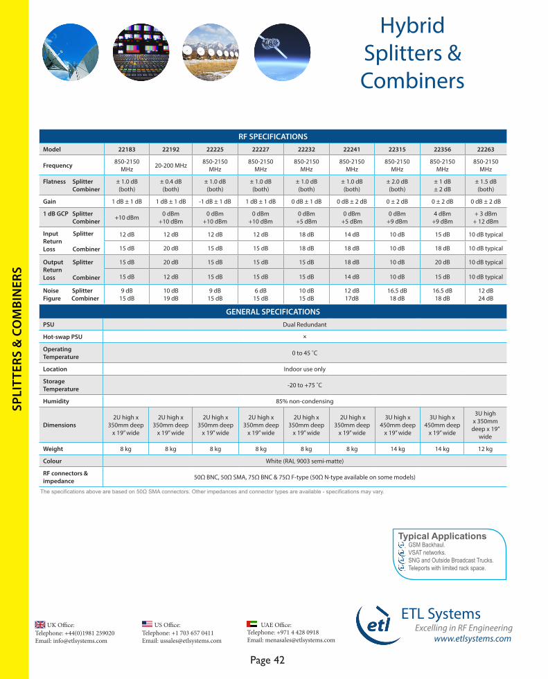
HybridSplitters & Combiners
FEATURESModel 22183 22192 22225 22227 22232 22241 22315 22356 22263
Frequency 850-2150 MHz (L-band)
20-200 MHz (IF)
850-2150 MHz (L-band)
850-2150 MHz (L-band)
850-2150 MHz (L-band)
850-2150 MHz (L-band)
850-2150 MHz (L-band)
850-2150 MHz (L-band)
850-2150 MHz (L-band)
Capacity 8-way 8-way 8-way 8-way 8-way 8-way 8-way 8-way 16-way
Remote Monitoring
PSU Alarms
PSU Alarms
PSU Alarms
PSU Alarms
PSU Alarms
PSU Alarms
RS232/485 serial port &
RJ45 Ethernet port
RS232/485 serial port &
RJ45 Ethernet port
RJ45 Ethernet port
LNB / BUC Powering O O O
LNB Powering on splitter
LNB Powering on splitter
LNB Powering on splitter
LNB Powering on splitter P
LNB Powering on splitter
10 MHz Reference Source
O O O O Internal O Internal Internal Internal
DC & 10 MHz Pass O O P O O O O O O
Dual Redundant Amplifiers
O O O O P P P P P
-20 dB Port for Carrier Monitoring
O O O O O O O O O
Dual Redundant PSUs
P
8-way L-band hybrid splitter and combiner with switchable LNB Powering, dual redundant amplifiers & 10MHz Source
4-way L-band hybrid splitter and combiner with -20dB monitor ports & PSU status LED monitoring
16-way L-band hybrid splitter and combiner with switchable LNB Powering, dual redundant amplifiers & 10MHz Source
SPLI
TTER
S &
CO
MBI
NER
S
8-way & 16-way
Telephone: +44(0)1981 259020 Email: [email protected]
UK Office:Telephone: +1 703 657 0411 Email: [email protected]
US Office:
www.etlsystems.com
ETL SystemsExcelling in RF Engineering
Page 42
Telephone: +971 4 428 0918 Email: [email protected]
UAE Office:
HybridSplitters & Combiners
GENERAL SPECIFICATIONSPSU Dual Redundant
Hot-swap PSU O
Operating Temperature 0 to 45 ˚C
Location Indoor use only
StorageTemperature -20 to +75 ˚C
Humidity 85% non-condensing
Dimensions 2U high x
350mm deep x 19” wide
2U high x 350mm deep
x 19” wide
2U high x 350mm deep
x 19” wide
2U high x 350mm deep
x 19” wide
2U high x 350mm deep
x 19” wide
2U high x 350mm deep
x 19” wide
3U high x 450mm deep
x 19” wide
3U high x 450mm deep
x 19” wide
3U high x 350mm
deep x 19” wide
Weight 8 kg 8 kg 8 kg 8 kg 8 kg 8 kg 14 kg 14 kg 12 kg
Colour White (RAL 9003 semi-matte)
RF connectors & impedance 50Ω BNC, 50Ω SMA, 75Ω BNC & 75Ω F-type (50Ω N-type available on some models)
RF SPECIFICATIONSModel 22183 22192 22225 22227 22232 22241 22315 22356 22263
Frequency 850-2150 MHz 20-200 MHz 850-2150
MHz850-2150
MHz850-2150
MHz850-2150
MHz850-2150
MHz850-2150
MHz850-2150
MHz
Flatness Splitter Combiner
± 1.0 dB (both)
± 0.4 dB (both)
± 1.0 dB (both)
± 1.0 dB (both)
± 1.0 dB (both)
± 1.0 dB (both)
± 2.0 dB (both)
± 1 dB± 2 dB
± 1.5 dB (both)
Gain 1 dB ± 1 dB 1 dB ± 1 dB -1 dB ± 1 dB 1 dB ± 1 dB 0 dB ± 1 dB 0 dB ± 2 dB 0 ± 2 dB 0 ± 2 dB 0 dB ± 2 dB
1 dB GCP Splitter Combiner +10 dBm 0 dBm
+10 dBm0 dBm
+10 dBm0 dBm
+10 dBm0 dBm
+5 dBm0 dBm
+5 dBm0 dBm
+9 dBm4 dBm
+9 dBm+ 3 dBm
+ 12 dBm
Input SplitterReturn Loss Combiner
12 dB 12 dB 12 dB 12 dB 18 dB 14 dB 10 dB 15 dB 10 dB typical
15 dB 20 dB 15 dB 15 dB 18 dB 18 dB 10 dB 18 dB 10 dB typical
Output SplitterReturn Loss Combiner
15 dB 20 dB 15 dB 15 dB 15 dB 18 dB 10 dB 20 dB 10 dB typical
15 dB 12 dB 15 dB 15 dB 15 dB 14 dB 10 dB 15 dB 10 dB typical
Noise SplitterFigure Combiner
9 dB 15 dB
10 dB19 dB
9 dB 15 dB
6 dB 15 dB
10 dB15 dB
12 dB17dB
16.5 dB 18 dB
16.5 dB 18 dB
12 dB 24 dB
Typical Applications GSM Backhaul. VSAT networks. SNG and Outside Broadcast Trucks. Teleports with limited rack space.
The specifications above are based on 50Ω SMA connectors. Other impedances and connector types are available - specifications may vary.
SPLI
TTER
S &
CO
MBI
NER
S
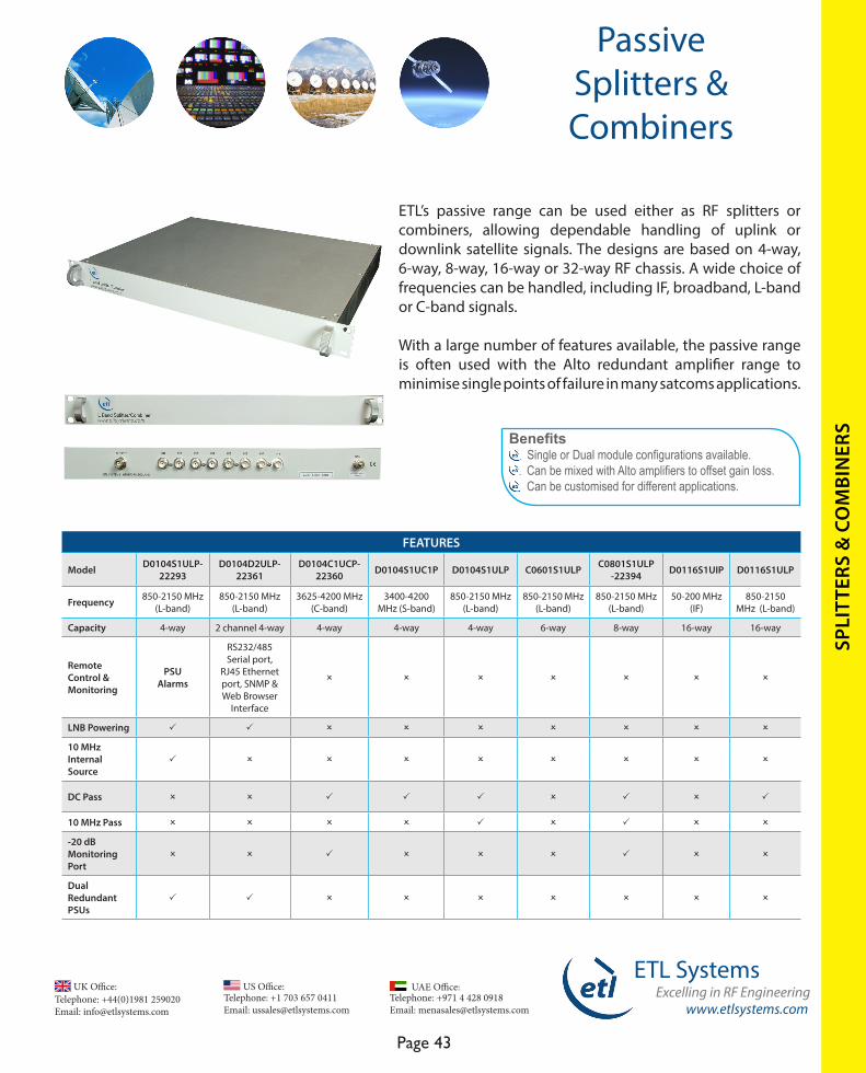
www.etlsystems.com
ETL SystemsExcelling in RF Engineering
Page 43
Telephone: +971 4 428 0918 Email: [email protected]
UAE Office: Telephone: +44(0)1981 259020 Email: [email protected]
UK Office:Telephone: +1 703 657 0411 Email: [email protected]
US Office:
SPLI
TTER
S &
CO
MBI
NER
S
ETL’s passive range can be used either as RF splitters or combiners, allowing dependable handling of uplink or downlink satellite signals. The designs are based on 4-way, 6-way, 8-way, 16-way or 32-way RF chassis. A wide choice of frequencies can be handled, including IF, broadband, L-band or C-band signals.
With a large number of features available, the passive range is often used with the Alto redundant amplifier range to minimise single points of failure in many satcoms applications.
Benefits Single or Dual module configurations available. Can be mixed with Alto amplifiers to offset gain loss. Can be customised for different applications.
FEATURES
Model D0104S1ULP-22293
D0104D2ULP-22361
D0104C1UCP-22360 D0104S1UC1P D0104S1ULP C0601S1ULP C0801S1ULP
-22394 D0116S1UIP D0116S1ULP
Frequency 850-2150 MHz (L-band)
850-2150 MHz (L-band)
3625-4200 MHz (C-band)
3400-4200 MHz (S-band)
850-2150 MHz (L-band)
850-2150 MHz (L-band)
850-2150 MHz (L-band)
50-200 MHz (IF)
850-2150 MHz (L-band)
Capacity 4-way 2 channel 4-way 4-way 4-way 4-way 6-way 8-way 16-way 16-way
Remote Control & Monitoring
PSUAlarms
RS232/485 Serial port,
RJ45 Ethernet port, SNMP & Web Browser
Interface
O O O O O O O
LNB Powering P P O O O O O O O
10 MHz Internal Source
P O O O O O O O O
DC Pass O O P P P O P O P
10 MHz Pass O O O O P O P O O
-20 dB Monitoring Port
O O P O O O P O O
Dual RedundantPSUs
P P O O O O O O O
PassiveSplitters & Combiners
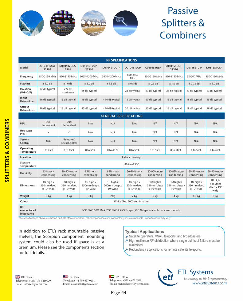
Telephone: +44(0)1981 259020 Email: [email protected]
UK Office:Telephone: +1 703 657 0411 Email: [email protected]
US Office:
www.etlsystems.com
ETL SystemsExcelling in RF Engineering
Page 44
Telephone: +971 4 428 0918 Email: [email protected]
UAE Office:
Typical Applications Satellite operators, VSAT, teleports, and broadcasters. High resilience RF distribution where single points of failure must be minimised. Redundancy applications for remote satellite teleports.
RF SPECIFICATIONS
Model D0104S1ULA-22293
D010402ULA-2361
D0104C1UCP-22360 D0104S1UC1P D0104S1ULP C0601S1ULP C0801S1ULP-
22394 D0116S1UIP D0116S1ULP
Frequency 850-2150 MHz 850-2150 MHz 3625-4200 MHz 3400-4200 MHz 850-2150 MHz 850-2150 MHz 850-2150 MHz 50-200 MHz 850-2150 MHz
Flatness ± 1.0 dB ±1.0 dB ± 1.0 dB ± 1.5 dB ± 0.5 dB ± 0.5 dB ± 1.0 dB ± 0.75 dB ± 1.0 dB
Isolation (O/P-O/P)
22 dB typical >22 dB maximum 25 dB typical - 23 dB typical 23 dB typical 26 dB typical 23 dB typical 23 dB typical
Input Return Loss 16 dB typical 15 dB typical 16 dB typical > 10 dB typical 15 dB typical 20 dB typical 18 dB typical 18 dB typical 15 dB typical
Output Return Loss 18 dB typical 18 dB typical 25 dB typical > 10 dB typical 20 dB typical 15 dB typical 18 dB typical 18 dB typical 18 dB typical
GENERAL SPECIFICATIONS
PSU Dual Redundant
Dual Redundant N/A N/A N/A N/A N/A N/A N/A
Hot-swap PSU O P N/A N/A N/A N/A N/A N/A N/A
System Control N/A Remote &
Local Control N/A N/A N/A N/A N/A N/A N/A
Operating Temperature 0 to 45 °C 0 to 45 °C 0 to 55˚C 0 to 45 °C 0 to 55˚C 0 to 55˚C 0 to 50 °C 0 to 55˚C 0 to 45˚C
Location Indoor use only
Storage Temperature -20 to +75 °C
Humidity 85% non-condensing
20-90% non-condensing
85% non-condensing
85% non-condensing
20-90% non-condensing
20-90% non-condensing
20-85% non-condensing
20-90% non-condensing
20-90% non-condensing
Dimensions 1U high x
350mm deep x 19” wide
2U high x 350mm deep
x 19” wide
1U high x 250mm deep x
19” wide
1U high x 200mm deep x
19” wide
1U high x 200mm deep
x 19” wide
1U high x 350mm deep
x 19” wide
1U high x 350mm deep x
19” wide
1U high x 350mm deep
x 19” wide
1U high x 350mm
deep x 19” wide
Weight 8 kg 4 kg 3 kg 2 kg 2 kg 2 kg 4 kg 1.5 kg 5 kg
Colour White (RAL 9003 semi-matte)
RF connectors & impedance
50Ω BNC, 50Ω SMA, 75Ω BNC & 75Ω F-type (50Ω N-type available on some models)
In addition to ETL’s rack mountable passive shelves, the Scorpion component mounting system could also be used if space is at a premium. Please see the components section for full details.
PassiveSplitters & Combiners
The specifications above are based on 50Ω SMA connectors. Other impedances and connector types are available - specifications may vary.
SPLI
TTER
S &
CO
MBI
NER
S
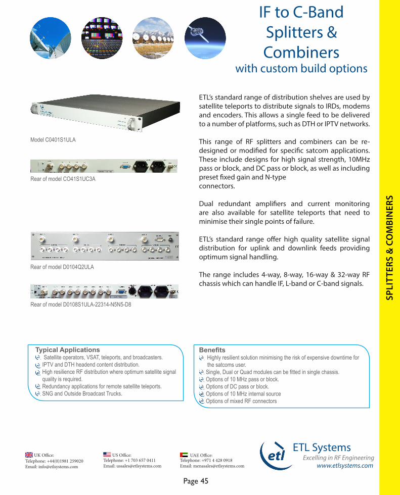
www.etlsystems.com
ETL SystemsExcelling in RF Engineering
Page 45
Telephone: +971 4 428 0918 Email: [email protected]
UAE Office: Telephone: +44(0)1981 259020 Email: [email protected]
UK Office:Telephone: +1 703 657 0411 Email: [email protected]
US Office:
SPLI
TTER
S &
CO
MBI
NER
S
IF to C-BandSplitters & Combiners
with custom build options
ETL’s standard range of distribution shelves are used by satellite teleports to distribute signals to IRDs, modems and encoders. This allows a single feed to be delivered to a number of platforms, such as DTH or IPTV networks.
This range of RF splitters and combiners can be re-designed or modified for specific satcom applications. These include designs for high signal strength, 10MHz pass or block, and DC pass or block, as well as including preset fixed gain and N-type connectors.
Dual redundant amplifiers and current monitoring are also available for satellite teleports that need to minimise their single points of failure.
ETL’s standard range offer high quality satellite signal distribution for uplink and downlink feeds providing optimum signal handling.
The range includes 4-way, 8-way, 16-way & 32-way RF chassis which can handle IF, L-band or C-band signals.
Benefits Highly resilient solution minimising the risk of expensive downtime for the satcoms user. Single, Dual or Quad modules can be fitted in single chassis. Options of 10 MHz pass or block. Options of DC pass or block. Options of 10 MHz internal source Options of mixed RF connectors
Rear of model CO41S1UC3A
Rear of model D0104Q2ULA
Rear of model D0108S1ULA-22314-N5N5-D8
Model C0401S1ULA
Typical Applications Satellite operators, VSAT, teleports, and broadcasters. IPTV and DTH headend content distribution. High resilience RF distribution where optimum satellite signal quality is required. Redundancy applications for remote satellite teleports. SNG and Outside Broadcast Trucks.

Telephone: +44(0)1981 259020 Email: [email protected]
UK Office:Telephone: +1 703 657 0411 Email: [email protected]
US Office:
www.etlsystems.com
ETL SystemsExcelling in RF Engineering
Page 46
Telephone: +971 4 428 0918 Email: [email protected]
UAE Office:
IF to C-BandSplitters & Combiners
with custom build options
FEATURES
Model C0401S1ULA C0401S1UC3A C0801S1ULA-22242
C0801S1ULA-22251 C0801S1UIA
Frequency 850-2150 MHz (L-band) 5.85-6.725 GHz (C-band) 850-2150 MHz (L-band) 850-2150 MHz (L-band) 20-200 MHz (IF)
Capacity 4-way 4-way 8-way 8-way 8-way
N-types Connectors Available P P P P P
Dual Redundant Amplifiers O O P O O
10 MHz Pass O O O P O
10 MHz Source O O P O O
DC Pass O O O P O
LNB Powering O O O O O
RF SPECIFICATIONS
Model C0401S1ULA C0401S1UC3A C0801S1ULA-22242
C0801S1ULA-22251 C0801S1UIA
Frequency 850 -2150 MHz 5.8- 6.5 GHz 850 -2150 MHz 850 -2150 MHz 20- 200 MHz
Flatness ± 0.5 dB ± 1.5 dB typical ± 1.0 dB typical ± 0.7 dB typical ± 0.5 dB
Gain 0 dB ± 1 dB 0 dB ± 1 dB 0 dB ± 2 dB 0 ± 1 dB 1 dB ± 1 dB
1 dB GCP 15 dBm typical +5 dBm +12 dBm +10 dBm +10 dBm
Input Return Loss 18 dB typical 10 dB typical 18 dB typical 18 dB typical 24 dB typical
Output Return Loss 18 dB typical 15 dB typical 14 dB typical 18 dB typical 24 dB typical
Noise Figure 15 dB typical 14 dB typical 10 dB typical 19 dB typical 16 dB typical
Custom designs to your specifications always available to order
Our Engineers at work on a new custom design
4-way & 8-way Combiners
SPLI
TTER
S &
CO
MBI
NER
S
The specifications above are based on 50Ω N-type connectors. Other impedances and connector types are available - specifications may vary.
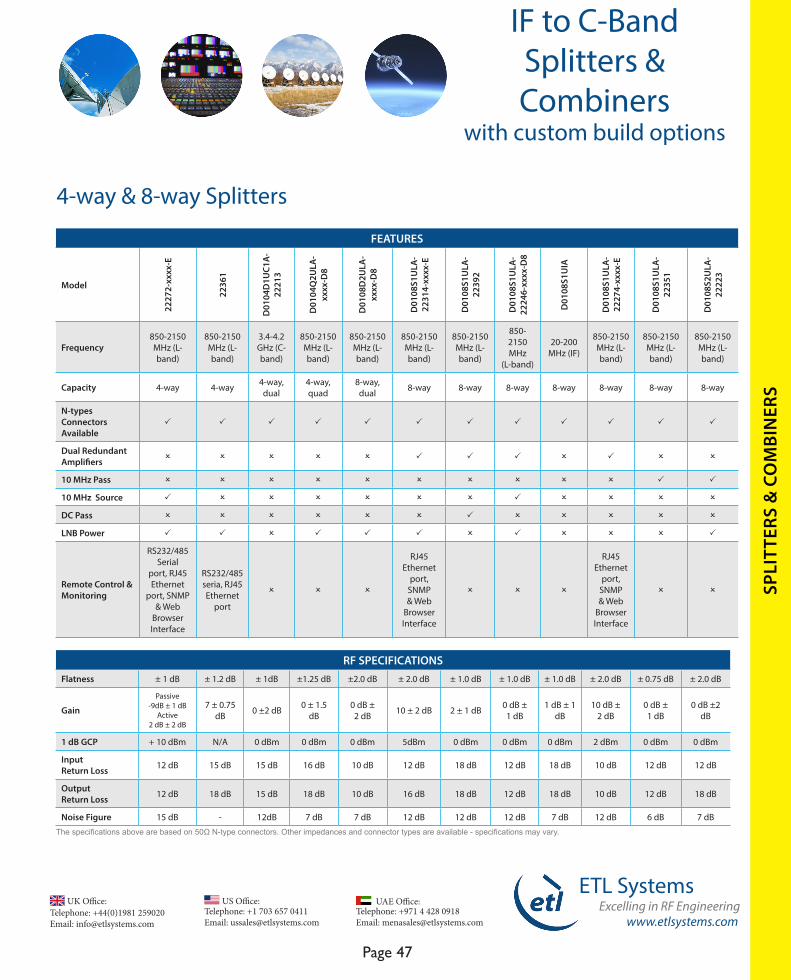
www.etlsystems.com
ETL SystemsExcelling in RF Engineering
Page 47
Telephone: +971 4 428 0918 Email: [email protected]
UAE Office: Telephone: +44(0)1981 259020 Email: [email protected]
UK Office:Telephone: +1 703 657 0411 Email: [email protected]
US Office:
RF SPECIFICATIONSFlatness ± 1 dB ± 1.2 dB ± 1dB ±1.25 dB ±2.0 dB ± 2.0 dB ± 1.0 dB ± 1.0 dB ± 1.0 dB ± 2.0 dB ± 0.75 dB ± 2.0 dB
Gain
Passive-9dB ± 1 dB
Active2 dB ± 2 dB
7 ± 0.75 dB 0 ±2 dB 0 ± 1.5
dB0 dB ± 2 dB 10 ± 2 dB 2 ± 1 dB 0 dB ±
1 dB1 dB ± 1
dB10 dB ±
2 dB0 dB ± 1 dB
0 dB ±2 dB
1 dB GCP + 10 dBm N/A 0 dBm 0 dBm 0 dBm 5dBm 0 dBm 0 dBm 0 dBm 2 dBm 0 dBm 0 dBm
Input Return Loss 12 dB 15 dB 15 dB 16 dB 10 dB 12 dB 18 dB 12 dB 18 dB 10 dB 12 dB 12 dB
Output Return Loss 12 dB 18 dB 15 dB 18 dB 10 dB 16 dB 18 dB 12 dB 18 dB 10 dB 12 dB 18 dB
Noise Figure 15 dB - 12dB 7 dB 7 dB 12 dB 12 dB 12 dB 7 dB 12 dB 6 dB 7 dB
IF to C-BandSplitters & Combiners
with custom build options
FEATURES
Model
2227
2-xx
xx-E
2236
1
D01
04D
1UC1
A-
2221
3
D01
04Q
2ULA
-xx
xx-D
8
D01
08D
2ULA
-xx
xx-D
8
D01
08S1
ULA
-22
314-
xxxx
-E
D01
08S1
ULA
-22
392
D01
08S1
ULA
-22
246-
xxxx
-D8
D01
08S1
UIA
D01
08S1
ULA
-22
274-
xxxx
-E
D01
08S1
ULA
-22
351
D01
08S2
ULA
-22
223
Frequency850-2150 MHz (L-band)
850-2150 MHz (L-band)
3.4-4.2 GHz (C-band)
850-2150 MHz (L-band)
850-2150 MHz (L-band)
850-2150 MHz (L-band)
850-2150 MHz (L-band)
850-2150 MHz
(L-band)
20-200 MHz (IF)
850-2150 MHz (L-band)
850-2150 MHz (L-band)
850-2150 MHz (L-band)
Capacity 4-way 4-way 4-way, dual
4-way, quad
8-way, dual 8-way 8-way 8-way 8-way 8-way 8-way 8-way
N-types Connectors Available
P P P P P P P P P P P P
Dual Redundant Amplifiers O O O O O P P P O P O O
10 MHz Pass O O O O O O O O O O P P
10 MHz Source P O O O O O O P O O O O
DC Pass O O O O O O P O O O O O
LNB Power P P O P P P O P O O O P
Remote Control & Monitoring
RS232/485 Serial
port, RJ45 Ethernet
port, SNMP & Web
Browser Interface
RS232/485 seria, RJ45 Ethernet
port
O O O
RJ45 Ethernet
port, SNMP & Web
Browser Interface
O O O
RJ45 Ethernet
port, SNMP & Web
Browser Interface
O O
4-way & 8-way Splitters
SPLI
TTER
S &
CO
MBI
NER
S
The specifications above are based on 50Ω N-type connectors. Other impedances and connector types are available - specifications may vary.

Telephone: +44(0)1981 259020 Email: [email protected]
UK Office:Telephone: +1 703 657 0411 Email: [email protected]
US Office:
www.etlsystems.com
ETL SystemsExcelling in RF Engineering
Page 48
Telephone: +971 4 428 0918 Email: [email protected]
UAE Office:
FEATURES
Model
D01
16S2
ULA
-xx
xx-D
8
D01
16S2
ULA
-22
200
(-E
avai
labl
e)
D01
16S2
ULA
-22
250
D01
16S2
UIA
D01
16S1
ULA
-22
289
D01
16S2
ULA
-22
345
D01
16S1
UIA
-22
248
D01
32S3
ULA
-xx
xx-D
8
D01
32S3
ULA
-22
203
Frequency 850-2150 MHz (L-band)
850-2150 MHz (L-band)
850-2150 MHz (L-band) IF 850-2150
MHz (L-band)850-2150
MHz (L-band)20-200 MHz
(IF) 850-2150
MHz (L-band)
850-2150 MHz (L-band)
Capacity 16-way 16-way 16-way 16-way 16-way 16-way 16-way 32-way 32-way
N-types Connectors Available P P P P O P P P P
Dual Redundant Amplifiers O P O O P P P O O
10 MHz Pass O O P O O O O O P
10 MHz Source O O O O O O O O O
DC Pass O O P O O O O O O
LNB Power P O O O O O O P P
Remote Monitoring ORJ45
Ethernet Port (Optional)
O ORJ45 Ethernet Port & SNMP P O O O
Other O O O OExternal 24V
DC power required
External 24V DC power required
O O O
IF to C-BandSplitters & Combiners
with custom build options
RF SPECIFICATIONS
Frequency 850-2150 MHz 850-2150 MHz
850-2150 MHz 20-200 MHz 850-2150 MHz 850-2150
MHz 20-200 MHz 850-2150 MHz
850-2150 MHz
Flatness ± 1.25 dB ± 0.75 dB ± 1.25 dB ± 0.25 dB ± 1.5 dB ±1.5 dB ± 1.5 dB ± 1.25 dB ± 1.5 dB
Gain 0 dB ±1 dB 0 dB ±2 dB 1 dB ±1 dB 0 dB ±1 dB 0 ± 2 dB 0 dB ±2 dB 0 dB ± 2 dB 0 dB ± 2 dB 0 dB ± 2 dB
1 dB GCP 0 dBm 5 dBm typical 0 dBm 5 dBm 0 dBm 0 dBm +3 dBm 0 dBm 0 dBm
Input Return Loss >12 dB typical 15 dB 12 dB 18 dB 10 dB 10 dB 15 dB 15 dB 12 dB
Output Return Loss >8 dB typical 18 dB 12 dB 18 dB 10 dB 10 dB 15 dB 15 dB 15 dB
Noise Figure 14 dB 17 dB (max) 13 dB 12 dB 10 dB 10 dB 12dB 9 dB 9 dB
16-way & 32-way Splitters
SPLI
TTER
S &
CO
MBI
NER
S
The specifications above are based on 50Ω N-type connectors. Specifications may vary for other impedances and connector types.
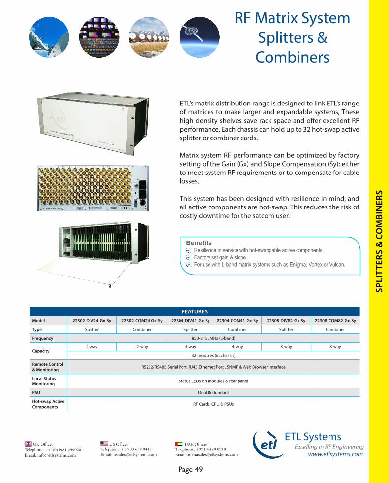
www.etlsystems.com
ETL SystemsExcelling in RF Engineering
Page 49
Telephone: +971 4 428 0918 Email: [email protected]
UAE Office: Telephone: +44(0)1981 259020 Email: [email protected]
UK Office:Telephone: +1 703 657 0411 Email: [email protected]
US Office:
SPLI
TTER
S &
CO
MBI
NER
S
ETL’s matrix distribution range is designed to link ETL’s range of matrices to make larger and expandable systems, These high density shelves save rack space and offer excellent RF performance. Each chassis can hold up to 32 hot-swap active splitter or combiner cards.
Matrix system RF performance can be optimized by factory setting of the Gain (Gx) and Slope Compensation (Sy); either to meet system RF requirements or to compensate for cable losses.
This system has been designed with resilience in mind, and all active components are hot-swap. This reduces the risk of costly downtime for the satcom user.
Benefits Resilience in service with hot-swappable active components. Factory set gain & slope. For use with L-band matrix systems such as Enigma, Vortex or Vulcan.
FEATURESModel 22302-DIV24-Gx-Sy 22302-COM24-Gx-Sy 22304-DIV41-Gx-Sy 22304-COM41-Gx-Sy 22308-DIV82-Gx-Sy 22308-COM82-Gx-Sy
Type Splitter Combiner Splitter Combiner Splitter Combiner
Frequency 850-2150MHz (L-band)
Capacity2-way 2-way 4-way 4-way 8-way 8-way
32 modules (in chassis)
Remote Control & Monitoring RS232/RS485 Serial Port, RJ45 Ethernet Port , SNMP & Web Browser Interface
Local Status Monitoring Status LEDs on modules & rear panel
PSU Dual Redundant
Hot-swap Active Components RF Cards, CPU & PSUs
RF Matrix SystemSplitters & Combiners
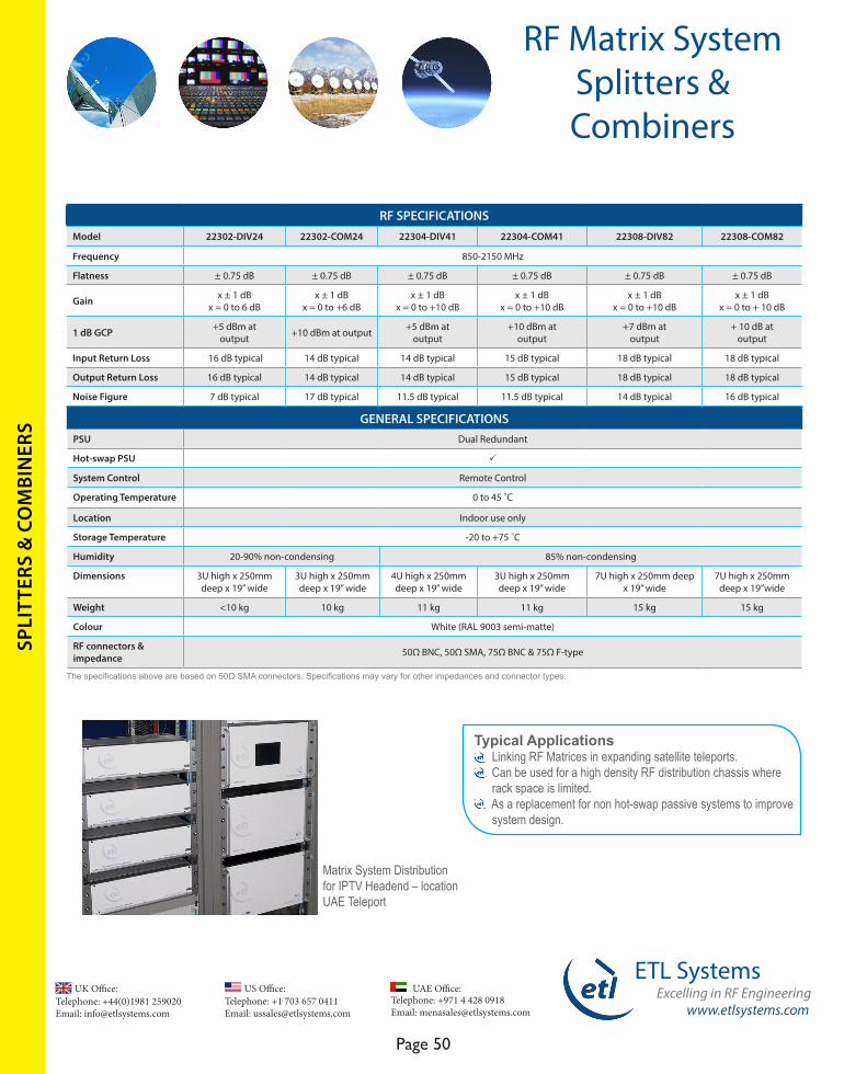
Telephone: +44(0)1981 259020 Email: [email protected]
UK Office:Telephone: +1 703 657 0411 Email: [email protected]
US Office:
www.etlsystems.com
ETL SystemsExcelling in RF Engineering
Page 50
Telephone: +971 4 428 0918 Email: [email protected]
UAE Office:
SPLI
TTER
S &
CO
MBI
NER
S
Typical Applications Linking RF Matrices in expanding satellite teleports. Can be used for a high density RF distribution chassis where rack space is limited. As a replacement for non hot-swap passive systems to improve system design.
The specifications above are based on 50Ω SMA connectors. Specifications may vary for other impedances and connector types.
RF SPECIFICATIONSModel 22302-DIV24 22302-COM24 22304-DIV41 22304-COM41 22308-DIV82 22308-COM82
Frequency 850-2150 MHz
Flatness ± 0.75 dB ± 0.75 dB ± 0.75 dB ± 0.75 dB ± 0.75 dB ± 0.75 dB
Gain x ± 1 dB x = 0 to 6 dB
x ± 1 dB x = 0 to +6 dB
x ± 1 dBx = 0 to +10 dB
x ± 1 dBx = 0 to +10 dB
x ± 1 dB x = 0 to +10 dB
x ± 1 dBx = 0 to + 10 dB
1 dB GCP +5 dBm at output +10 dBm at output +5 dBm at
output+10 dBm at
output +7 dBm at
output+ 10 dB at
output
Input Return Loss 16 dB typical 14 dB typical 14 dB typical 15 dB typical 18 dB typical 18 dB typical
Output Return Loss 16 dB typical 14 dB typical 14 dB typical 15 dB typical 18 dB typical 18 dB typical
Noise Figure 7 dB typical 17 dB typical 11.5 dB typical 11.5 dB typical 14 dB typical 16 dB typical
GENERAL SPECIFICATIONSPSU Dual Redundant
Hot-swap PSU P
System Control Remote Control
Operating Temperature 0 to 45 ˚C
Location Indoor use only
Storage Temperature -20 to +75 ˚C
Humidity 20-90% non-condensing 85% non-condensing
Dimensions 3U high x 250mm deep x 19” wide
3U high x 250mm deep x 19” wide
4U high x 250mm deep x 19” wide
3U high x 250mm deep x 19” wide
7U high x 250mm deep x 19” wide
7U high x 250mm deep x 19”wide
Weight <10 kg 10 kg 11 kg 11 kg 15 kg 15 kg
Colour White (RAL 9003 semi-matte)
RF connectors & impedance 50Ω BNC, 50Ω SMA, 75Ω BNC & 75Ω F-type
RF Matrix SystemSplitters & Combiners
Matrix System Distribution for IPTV Headend – location UAE Teleport

www.etlsystems.com
ETL SystemsExcelling in RF Engineering
Page 51
Telephone: +971 4 428 0918 Email: [email protected]
UAE Office: Telephone: +44(0)1981 259020 Email: [email protected]
UK Office:Telephone: +1 703 657 0411 Email: [email protected]
US Office:
SWIT
CH
Benefits Cost effective solution for carrier monitoring applications. Fast switching using solid state switch design. Resilience in service with dual redundant power supplies. Compact 1U chassis. Can be linked together to create larger switch systems.
FEATURESModel 23225 23226 23227 23228 23229 23230
Frequency 50-2450 MHz (IF - Extended L-band)
Switch Type Solid state
Capacity 8 x 1 16 x 1 32 x 1 1 x 8 1 x 16 1 x 32
Remote Control & Monitoring RS232 or RS422/485 Serial port, Ethernet (RJ45-100BASE-TX) on rear panel
Local Control LCD & push buttons
Dual Redundant PSUs P
LS Series Monitoring Switch
8 x 1 Model 23225
16 x 1 Model 23226
32 x 1 Model 23227
ETL’s LS series range of RF monitoring Switches are designed principally for satellite signal carrier monitoring applications.
They are available in capacities of 8x1, 16x1 and 32x1 and can be linked together if the number of feeds is larger. Each LS switch is designed to deliver a high quality signal to a test and measurement system.
The LS Switch design can also be used as a single input to multiple outputs allowing a signal to be switched to different IRD / modems.
The range uses solid state switches and so benefits from long life and excellent RF performance. Resilience is designed in with dual redundant power supplies.
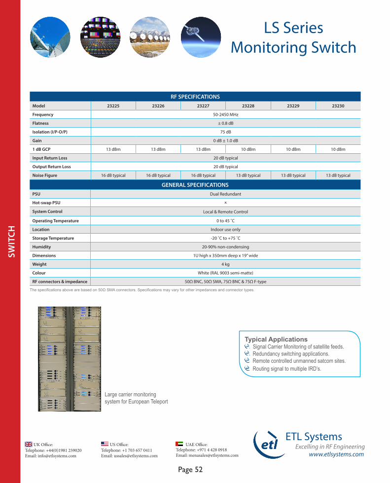
Telephone: +44(0)1981 259020 Email: [email protected]
UK Office:Telephone: +1 703 657 0411 Email: [email protected]
US Office:
www.etlsystems.com
ETL SystemsExcelling in RF Engineering
Page 52
Telephone: +971 4 428 0918 Email: [email protected]
UAE Office:
RF SPECIFICATIONSModel 23225 23226 23227 23228 23229 23230
Frequency 50-2450 MHz
Flatness ± 0.8 dB
Isolation (I/P-O/P) 75 dB
Gain 0 dB ± 1.0 dB
1 dB GCP 13 dBm 13 dBm 13 dBm 10 dBm 10 dBm 10 dBm
Input Return Loss 20 dB typical
Output Return Loss 20 dB typical
Noise Figure 16 dB typical 16 dB typical 16 dB typical 13 dB typical 13 dB typical 13 dB typical
GENERAL SPECIFICATIONSPSU Dual Redundant
Hot-swap PSU O
System Control Local & Remote Control
Operating Temperature 0 to 45 ˚C
Location Indoor use only
Storage Temperature -20 ˚C to +75 ˚C
Humidity 20-90% non-condensing
Dimensions 1U high x 350mm deep x 19” wide
Weight 4 kg
Colour White (RAL 9003 semi-matte)
RF connectors & impedance 50Ω BNC, 50Ω SMA, 75Ω BNC & 75Ω F-type
The specifications above are based on 50Ω SMA connectors. Specifications may vary for other impedances and connector types.
SWIT
CH
LS Series Monitoring Switch
Large carrier monitoringsystem for European Teleport
Typical Applications Signal Carrier Monitoring of satellite feeds. Redundancy switching applications. Remote controlled unmanned satcom sites. Routing signal to multiple IRD’s.
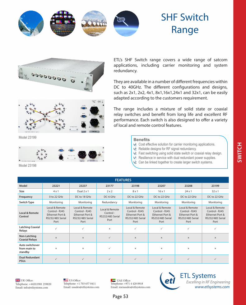
www.etlsystems.com
ETL SystemsExcelling in RF Engineering
Page 53
Telephone: +971 4 428 0918 Email: [email protected]
UAE Office: Telephone: +44(0)1981 259020 Email: [email protected]
UK Office:Telephone: +1 703 657 0411 Email: [email protected]
US Office:
SWIT
CH
ETL’s SHF Switch range covers a wide range of satcom applications, including carrier monitoring and system redundancy.
They are available in a number of different frequencies within DC to 40GHz. The different configurations and designs, such as 2x1, 2x2, 4x1, 8x1,16x1,24x1 and 32x1, can be easily adapted according to the customers requirement.
The range includes a mixture of solid state or coaxial relay switches and benefit from long life and excellent RF performance. Each switch is also designed to offer a variety of local and remote control features.
Benefits Cost effective solution for carrier monitoring applications. Reliable designs for RF signal redundancy. Fast switching using solid state switch or coaxial relay design. Resilience in service with dual redundant power supplies. Can be linked together to create larger switch systems.
FEATURESModel 23221 23237 23177 23198 23207 23208 23199
Size 4 x 1 Dual 2 x 1 2 x 2 8 x 1 16 x 1 24 x 1 32 x 1
Frequency 0 to 22 GHz DC to 18 GHz DC-6 GHz DC to 22 GHz DC to 22 GHz DC to 22 GHz DC to 22 GHz
Switch Type Monitoring Monitoring Redundancy Monitoring Monitoring Monitoring Monitoring
Local & Remote Control
Local & Remote Control - RJ45
Ethernet Port & RS232/485 Serial
Port
Local & Remote Control - RJ45
Ethernet Port & RS232/485 Serial
Port
Local & Remote Control -
RS232/485 Serial Port
Local & Remote Control - RJ45
Ethernet Port & RS232/485 Serial
Port
Local & Remote Control - RJ45
Ethernet Port & RS232/485 Serial
Port
Local & Remote Control - RJ45
Ethernet Port & RS232/485 Serial
Port
Local & Remote Control - RJ45
Ethernet Port & RS232/485 Serial
Port
Latching Coaxial Relays P P O P P P P
Non-Latching Coaxial Relays O O P O O O O
Auto switchover from main to standby
O O P O O O O
Dual Redundant PSUs P P P P P P P
Model 23198
Model 23199
SHF SwitchRange
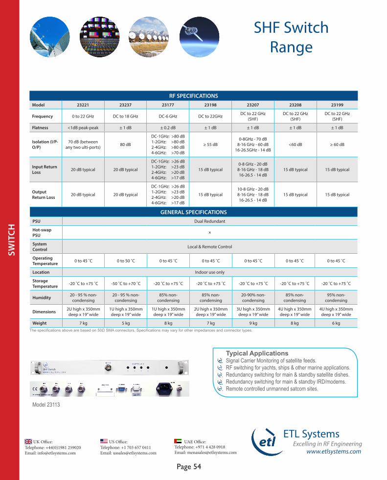
Telephone: +44(0)1981 259020 Email: [email protected]
UK Office:Telephone: +1 703 657 0411 Email: [email protected]
US Office:
www.etlsystems.com
ETL SystemsExcelling in RF Engineering
Page 54
Telephone: +971 4 428 0918 Email: [email protected]
UAE Office:
SHF SwitchRange
RF SPECIFICATIONSModel 23221 23237 23177 23198 23207 23208 23199
Frequency 0 to 22 GHz DC to 18 GHz DC-6 GHz DC to 22GHz DC to 22 GHz (SHF)
DC to 22 GHz (SHF)
DC to 22 GHz (SHF)
Flatness <1dB peak-peak ± 1 dB ± 0.2 dB ± 1 dB ± 1 dB ± 1 dB ± 1 dB
Isolation (I/P-O/P)
70 dB (between any two ulti-ports) 80 dB
DC-1GHz: >80 dB1-2GHz: >80 dB2-4GHz: >80 dB4-6GHz: >70 dB
≥ 55 dB0-8GHz - 70 dB
8-16 GHz - 60 dB16-26.5GHz - 14 dB
<60 dB ≥ 60 dB
Input Return Loss 20 dB typical 20 dB typical
DC-1GHz: >26 dB1-2GHz: >23 dB2-4GHz: >20 dB4-6GHz: >17 dB
15 dB typical 0-8 GHz - 20 dB
8-16 GHz - 18 dB16-26.5 - 14 dB
15 dB typical 15 dB typical
Output Return Loss 20 dB typical 20 dB typical
DC-1GHz: >26 dB1-2GHz: >23 dB2-4GHz: >20 dB4-6GHz: >17 dB
15 dB typical 10-8 GHz - 20 dB8-16 GHz - 18 dB16-26.5 - 14 dB
15 dB typical 15 dB typical
Typical ApplicationsSignal Carrier Monitoring of satellite feeds. RF switching for yachts, ships & other marine applications. Redundancy switching for main & standby satellite dishes. Redundancy switching for main & standby IRD/modems. Remote controlled unmanned satcom sites.
GENERAL SPECIFICATIONSPSU Dual Redundant
Hot-swap PSU O
System Control Local & Remote Control
Operating Temperature 0 to 45 ˚C 0 to 50 ˚C 0 to 45 ˚C 0 to 45 ˚C 0 to 45 ˚C 0 to 45 ˚C 0 to 45 ˚C
Location Indoor use only
Storage Temperature -20 ˚C to +75 ˚C -50 ˚C to +70 ˚C -20 ˚C to +75 ˚C -20 ˚C to +75 ˚C -20 ˚C to +75 ˚C -20 ˚C to +75 ˚C -20 ˚C to +75 ˚C
Humidity 20 - 95 % non-condensing
20 - 95 % non-condensing
85% non-condensing
85% non-condensing
20-90% non-condensing
85% non-condensing
95% non-condensing
Dimensions 2U high x 350mm deep x 19” wide
1U high x 350mm deep x 19” wide
1U high x 350mm deep x 19” wide
2U high x 350mm deep x 19” wide
3U high x 350mm deep x 19” wide
4U high x 350mm deep x 19” wide
4U high x 350mm deep x 19” wide
Weight 7 kg 5 kg 8 kg 7 kg 9 kg 8 kg 6 kg
SWIT
CH
Model 23113
The specifications above are based on 50Ω SMA connectors. Specifications may vary for other impedances and connector types.

www.etlsystems.com
ETL SystemsExcelling in RF Engineering
Page 55
Telephone: +971 4 428 0918 Email: [email protected]
UAE Office: Telephone: +44(0)1981 259020 Email: [email protected]
UK Office:Telephone: +1 703 657 0411 Email: [email protected]
US Office:
SWIT
CH
Redundancy Switches
FEATURESModel 23116 23235 23192 23177
Frequency 850-2150 MHz (L-band) 50-2150 MHz (IF-L-band) 850-2150 MHz (L-band) DC-6 GHz (SHF)
Capacity 2 x 1 2 x 1 2 x 1 2 x 2
RF detection P O
Auto switchover from main to standby P O
Remote Control & MonitoringRS232/RS485 Serial port, RJ45
Ethernet port, SNMP & Web Browser Interface
RS232/RS422/485 Serial port, RJ45 Ethernet port
Dry contact alarm ports for each antenna External alarm contacts
Local Control Front panel push buttons
Dual Redundant PSUs P
Redundancy switching is a critical feature for many satellite ground stations, and ETL have developed a number of redundancy switch products to meet specific customer requirements.
The redundancy switch includes RF detection to monitor the main and standby signals and auto switch-over to the standby feed in the event of signal failure.
BenefitsAuto switching from main to standby feed with RF monitoring in the event of a signal failure.Automatic and manual switching modes.Dual redundant power supplies for reliability in service.Simple protocol for M & C integration.
Redundancy switches are also available in a modular system chassis which can hold up to 16 switch modules - see page 84.
Front & rear view of Model 23116
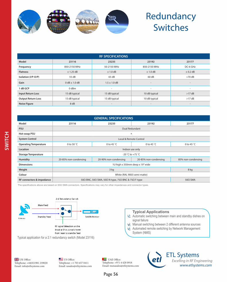
Telephone: +44(0)1981 259020 Email: [email protected]
UK Office:Telephone: +1 703 657 0411 Email: [email protected]
US Office:
www.etlsystems.com
ETL SystemsExcelling in RF Engineering
Page 56
Telephone: +971 4 428 0918 Email: [email protected]
UAE Office:
Redundancy Switches
SWIT
CH
GENERAL SPECIFICATIONSModel 23116 23235 23192 23177
PSU Dual Redundant
Hot-swap PSU O
System Control Local & Remote Control
Operating Temperature 0 to 50 ˚C 0 to 45 ˚C 0 to 45 ˚C 0 to 45 ˚C
Location Indoor use only
Storage Temperature -20 ˚C to +75 ˚C
Humidity 20-85% non-condensing 20-90% non-condensing 20-85% non-condensing 85% non-condensing
Dimensions 1U high x 350mm deep x 19” wide
Weight 3 kg 8 kg
Colour White (RAL 9003 semi-matte)
RF connectors & impedance 50Ω BNC, 50Ω SMA, 50Ω N-type, 75Ω BNC & 75Ω F-type 50Ω SMA
RF SPECIFICATIONSModel 23116 23235 23192 23177
Frequency 850-2150 MHz 50-2150 MHz 850-2150 MHz DC-6 GHz
Flatness ± 1.25 dB ± 1.0 dB ± 1.0 dB ± 0.2 dB
Isolation (I/P-O/P) 55 dB 65 dB 60 dB >70 dB
Gain 0 dB ± 1.0 dB 1.5 ± 1.0 dB - -
1 dB GCP 0 dBm - - -
Input Return Loss 15 dB typical 15 dB typical 10 dB typical >17 dB
Output Return Loss 15 dB typical 15 dB typical 10 dB typical >17 dB
Noise Figure 8 dB - - -
Typical ApplicationsAutomatic switching between main and standby dishes on signal failureManual switching between 2 different antenna sourcesAutomated remote switching by Network Management System (NMS)
Typical application for a 2:1 redundancy switch (Model 23116)
The specifications above are based on 50Ω SMA connectors. Specifications may vary for other impedances and connector types.
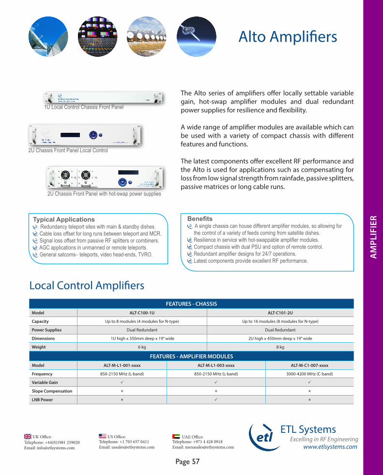
www.etlsystems.com
ETL SystemsExcelling in RF Engineering
Page 57
Telephone: +971 4 428 0918 Email: [email protected]
UAE Office: Telephone: +44(0)1981 259020 Email: [email protected]
UK Office:Telephone: +1 703 657 0411 Email: [email protected]
US Office:
Alto Amplifiers
AM
PLIF
IER
The Alto series of amplifiers offer locally settable variable gain, hot-swap amplifier modules and dual redundant power supplies for resilience and flexibility.
A wide range of amplifier modules are available which can be used with a variety of compact chassis with different features and functions. The latest components offer excellent RF performance and the Alto is used for applications such as compensating for loss from low signal strength from rainfade, passive splitters, passive matrices or long cable runs.
Benefits A single chassis can house different amplifier modules, so allowing for the control of a variety of feeds coming from satellite dishes. Resilience in service with hot-swappable amplifier modules. Compact chassis with dual PSU and option of remote control. Redundant amplifier designs for 24/7 operations. Latest components provide excellent RF performance.
FEATURES - CHASSISModel ALT-C100-1U ALT-C101-2U
Capacity Up to 8 modules (4 modules for N-type) Up to 16 modules (8 modules for N-type)
Power Supplies Dual Redundant Dual Redundant
Dimensions 1U high x 350mm deep x 19” wide 2U high x 450mm deep x 19” wide
Weight 6 kg 8 kg
FEATURES - AMPLIFIER MODULESModel ALT-M-L1-001-xxxx ALT-M-L1-003-xxxx ALT-M-C1-007-xxxx
Frequency 850-2150 MHz (L-band) 850-2150 MHz (L-band) 3000-4200 MHz (C-band)
Variable Gain P P P
Slope Compensation O O O
LNB Power O P O
Local Control Amplifiers
1U Local Control Chassis Front Panel
2U Chassis Front Panel Local Control
2U Chassis Front Panel with hot-swap power supplies
Typical Applications Redundancy teleport sites with main & standby dishes. Cable loss offset for long runs between teleport and MCR. Signal loss offset from passive RF splitters or combiners. AGC applications in unmanned or remote teleports. General satcoms– teleports, video head-ends, TVRO.
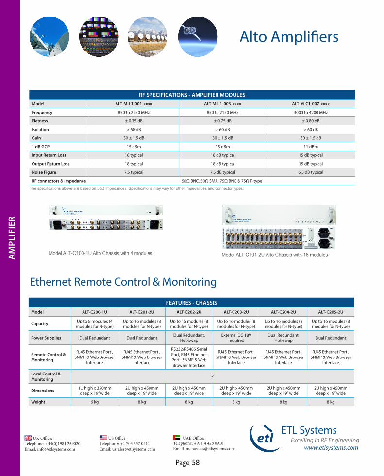
Telephone: +44(0)1981 259020 Email: [email protected]
UK Office:Telephone: +1 703 657 0411 Email: [email protected]
US Office:
www.etlsystems.com
ETL SystemsExcelling in RF Engineering
Page 58
Telephone: +971 4 428 0918 Email: [email protected]
UAE Office:
Alto Amplifiers
AM
PLIF
IER
RF SPECIFICATIONS - AMPLIFIER MODULESModel ALT-M-L1-001-xxxx ALT-M-L1-003-xxxx ALT-M-C1-007-xxxx
Frequency 850 to 2150 MHz 850 to 2150 MHz 3000 to 4200 MHz
Flatness ± 0.75 dB ± 0.75 dB ± 0.80 dB
Isolation > 60 dB > 60 dB > 60 dB
Gain 30 ± 1.5 dB 30 ± 1.5 dB 30 ± 1.5 dB
1 dB GCP 15 dBm 15 dBm 11 dBm
Input Return Loss 18 typical 18 dB typical 15 dB typical
Output Return Loss 18 typical 18 dB typical 15 dB typical
Noise Figure 7.5 typical 7.5 dB typical 6.5 dB typical
RF connectors & impedance 50Ω BNC, 50Ω SMA, 75Ω BNC & 75Ω F-type
Ethernet Remote Control & Monitoring
The specifications above are based on 50Ω impedances. Specifications may vary for other impedances and connector types.
Model ALT-C100-1U Alto Chassis with 4 modules Model ALT-C101-2U Alto Chassis with 16 modules
FEATURES - CHASSIS
Model ALT-C200-1U ALT-C201-2U ALT-C202-2U ALT-C203-2U ALT-C204-2U ALT-C205-2U
Capacity Up to 8 modules (4 modules for N-type)
Up to 16 modules (8 modules for N-type)
Up to 16 modules (8 modules for N-type)
Up to 16 modules (8 modules for N-type)
Up to 16 modules (8 modules for N-type)
Up to 16 modules (8 modules for N-type)
Power Supplies Dual Redundant Dual Redundant Dual Redundant, Hot-swap
External DC 18V required
Dual Redundant, Hot-swap Dual Redundant
Remote Control & Monitoring
RJ45 Ethernet Port , SNMP & Web Browser
Interface
RJ45 Ethernet Port , SNMP & Web Browser
Interface
RS232/RS485 Serial Port, RJ45 Ethernet Port , SNMP & Web Browser Interface
RJ45 Ethernet Port , SNMP & Web Browser
Interface
RJ45 Ethernet Port , SNMP & Web Browser
Interface
RJ45 Ethernet Port , SNMP & Web Browser
Interface
Local Control &Monitoring P
Dimensions 1U high x 350mm deep x 19” wide
2U high x 450mm deep x 19” wide
2U high x 450mm deep x 19” wide
2U high x 450mm deep x 19” wide
2U high x 450mm deep x 19” wide
2U high x 450mm deep x 19” wide
Weight 6 kg 8 kg 8 kg 8 kg 8 kg 8 kg
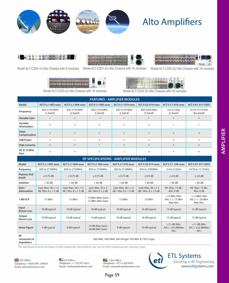
www.etlsystems.com
ETL SystemsExcelling in RF Engineering
Page 59
Telephone: +971 4 428 0918 Email: [email protected]
UAE Office: Telephone: +44(0)1981 259020 Email: [email protected]
UK Office:Telephone: +1 703 657 0411 Email: [email protected]
US Office:
The specifications above are based on 50Ω impedances. Specifications may vary for other impedances and connector types.
Alto Amplifiers
AM
PLIF
IER
Model ALT-C201-2U Alto Chassis with 16 modulesModel ALT-C200-1U Alto Chassis with 8 modules Model ALT-C202-2U Alto Chassis with 16 modules
Model ALT-C203-2U Alto Chassis with 16 modules Model ALT-C204-2U Alto Chassis with 16 modules
FEATURES - AMPLIFIER MODULESModel ALT-S-L1-002-xxxx ALT-S-L1-004-xxxx ALT-S-L1-005-xxxx ALT-S-L1-010-xxxx ALT-S-S2-014-xxxx ALT-S-C1-016-xxxx ALT-S-K1-017-S5S5
Frequency 850-2150 MHz (L-band)
850-2150 MHz (L-band)
850-2150 MHz (L-band)
850-2150 MHz (L-band)
850-2500 MHz (S-band)
3.4-4.2 GHz (C-band)
10.70-12.75 GHz (Ku-band)
Variable Gain P P P P P O O
Variable Attenuation O O O O O P P
SlopeCompensation P P P P P O O
LNB Power O P O O O O O
High Linearity O O P O O O O
DC & 10 MHz Pass O O O P O O O
RF SPECIFICATIONS - AMPLIFIER MODULESModel ALT-S-L1-002-xxxx ALT-S-L1-004-xxxx ALT-S-L1-005-xxxx ALT-S-L1-010-xxxx ALT-S-S2-014-xxxx ALT-S-C1-106-xxxx ALT-S-K1-017-S5S5
Frequency 850 to 2150MHz 850 to 2150MHz 850 to 2150MHz 850 to 2150MHz 850 to 2500MHz 3.4 to 4.2GHz 10.70 to 12.75GHz
Flatness (full band) ± 0.75 dB ± 0.75 dB ± 0.75 dB ± 0.75 dB ± 0.9 dB ± 2.0 dB ± 2.0 dB
Isolation > 60 dB > 60 dB > 60 dB > 60 dB > 60 dB > 60 dB > 60 dB
Gain /Attenuation
Gain Max: 38 ± 1.5 dB /Min: 8 ± 1.5 dB
Gain Max: 38 ± 1.5 dB / Min: 8 ± 1.5 dB
Gain Max: 20 ± 2 dB / Min: 0 ± 2 dB
Gain Max: 38 ± 1.5 dB / Min: 8 ± 1.5 dB
Gain Max: 38 ± 1.5 dB / Min: 8 ± 1.5 dB
Att. Max: 15 dB / Min: 0 dB
Att. Max: 15 dB / Min: 0 dB
1 dB GCP 15 dBm 15 dBm 19 dBm (Max Gain)17 dBm (Min Gain) 15 dBm 15 dBm
≥ 0 dBm (Min Att.) / ≥ -15 dBm
Max Att.)
≥ -5 dBm (Min Att.) / ≥ -20 dBm
Max Att.)
Input Return Loss 18 dB typical 18 dB typical 18 dB typical 18 dB typical 18 dB typical 15 dB typical 15 dB typical
Output Return Loss 18 dB typical 18 dB typical 14 dB typical 18 dB typical 18 dB typical 15 dB typical 15 dB typical
Noise Figure 9 dB typical 9 dB typical 10 dB (Max Gain)28 dB (Min Gain) 9 dB typical 10 dB typical
≤11 dB (Min Att.) / ≤22 dB(Max
Att.)
≤11 dB (Min Att.) / ≤22 dB(Max
Att.)
RF connectors & impedance
50Ω BNC, 50Ω SMA, 50Ω N-type 75Ω BNC & 75Ω F-type

Telephone: +44(0)1981 259020 Email: [email protected]
UK Office:Telephone: +1 703 657 0411 Email: [email protected]
US Office:
www.etlsystems.com
ETL SystemsExcelling in RF Engineering
Page 60
Telephone: +971 4 428 0918 Email: [email protected]
UAE Office:
Alto Amplifiers
WA
MPL
IFIE
R
The specifications above are based on 50Ω impedances. Specifications may vary for other impedances and connector types.
AM
PLIF
IER
Automatic Gain Control (AGC) Amplifiers
FEATURES - CHASSISModel ALT-C202-2U ALT-C203-2U ALT-C206-2U ALT-C207-1U
Capacity Up to 16 modules (8 modules for N-type)
Up to 16 modules (8 modules for N-type)
Up to 16 modules (8 modules for N-type)
Up to 8 modules (4 modules for N-type)
Power Supplies Dual Redundant, Hot-swap External DC 18V required Dual Redundant, Hot-swap Dual Redundant
Remote Control & MonitoringRS232/RS485 Serial Port, RJ45 Ethernet Port , SNMP & Web
Browser Interface
RJ45 Ethernet Port , SNMP & Web Browser Interface
RJ45 Ethernet Port , SNMP & Web Browser Interface
RJ45 Ethernet Port , SNMP & Web Browser Interface
Local Control & Monitoring P
Dimensions 2U high x 450mm deep x 19” wide
2U high x 450mm deep x 19” wide
2U high x 450mm deep x 19” wide
1U high x 450mm deep x 19” wide
Weight 8 kg 8 kg 8 kg 6 kg
RF SPECIFICATIONS - MODULESFlatness (full band) ± 1.5 dB ± 1.5 dB ± 1.5 dB
Isolation > 60 dB > 60 dB > 60 dB
Gain Max: 55 ± 1.5 dB / Min: 0 ± 1.5 dB Max: 55 ± 1.5 dB / Min: 0 ± 1.5 dB Max: 55 ± 1.5 dB / Min: 0 ± 1.5 dB
1 dB GCP 17.5 dBm typical 17.5 dBm typical 17.5 dBm typical
Input Return Loss 18 dB typical 18 dB typical 18 dB typical
Output Return Loss 18 dB typical 18 dB typical 18 dB typical
Noise Figure 9 dB (Max Gain) / 28 dB (Min Gain) 9 dB (Max Gain) / 35 dB (Min Gain) 9 dB (Max Gain) / 35 dB (Min Gain)
RF connectors & impedance 50Ω BNC, 50Ω SMA, 50Ω N-type 75Ω BNC & 75Ω F-type
FEATURES - MODULESModel ALT-A-B2-009-xxxx ALT-A-L1-011-xxxx ALT-A-L1-031-xxxx
Frequency Broadband (50-2150 MHz) L-band (850-2150 MHz) L-band (850-2150 MHz)
Variable Gain P P P
Slope Compensation O P O
LNB Power O O O
High Linearity O O P
DC & 10 MHz Pass O O O
AGC amplifiers are used where an output level is required at a constant. The AGC amplifier circuit will adjust the gain to ensure the output signal level remains at a set constant.
The AGC amplifier chassis range provides hot-swap amplifier modules as standard, so that in the unlikely event of a failure it can be hot swapped. There are also options available which offer dual redundant and hot-swap power supply modules.
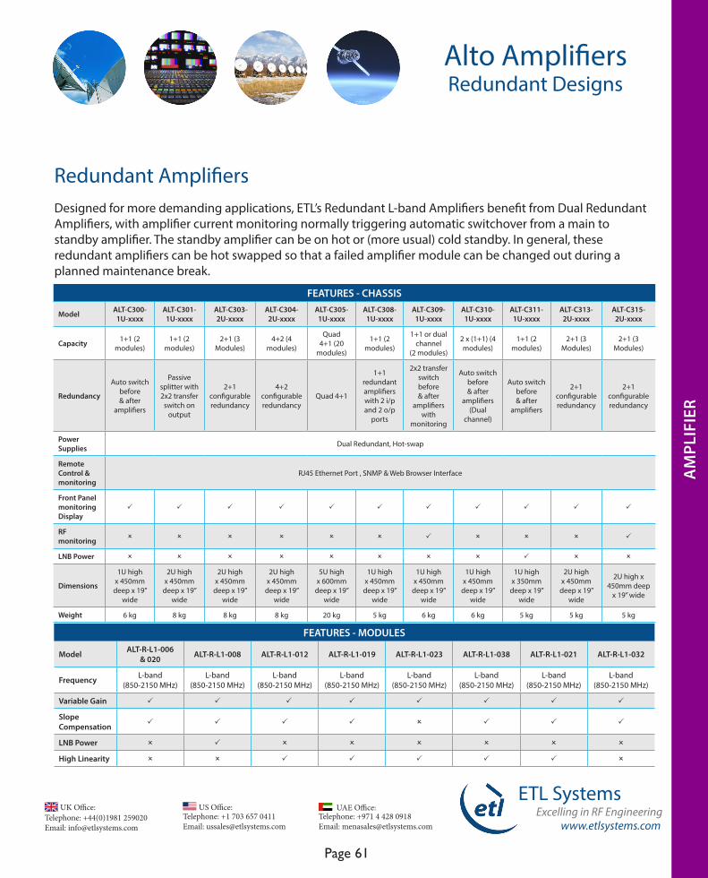
www.etlsystems.com
ETL SystemsExcelling in RF Engineering
Page 61
Telephone: +971 4 428 0918 Email: [email protected]
UAE Office: Telephone: +44(0)1981 259020 Email: [email protected]
UK Office:Telephone: +1 703 657 0411 Email: [email protected]
US Office:
Redundant Amplifiers
FEATURES - MODULES
Model ALT-R-L1-006 & 020 ALT-R-L1-008 ALT-R-L1-012 ALT-R-L1-019 ALT-R-L1-023 ALT-R-L1-038 ALT-R-L1-021 ALT-R-L1-032
Frequency L-band (850-2150 MHz)
L-band (850-2150 MHz)
L-band (850-2150 MHz)
L-band (850-2150 MHz)
L-band(850-2150 MHz)
L-band(850-2150 MHz)
L-band(850-2150 MHz)
L-band(850-2150 MHz)
Variable Gain P P P P P P P P
SlopeCompensation P P P P O P P P
LNB Power O P O O O O O O
High Linearity O O P P P P P O
Designed for more demanding applications, ETL’s Redundant L-band Amplifiers benefit from Dual Redundant Amplifiers, with amplifier current monitoring normally triggering automatic switchover from a main to standby amplifier. The standby amplifier can be on hot or (more usual) cold standby. In general, these redundant amplifiers can be hot swapped so that a failed amplifier module can be changed out during a planned maintenance break.
Alto AmplifiersRedundant Designs
AM
PLIF
IER
FEATURES - CHASSIS
Model ALT-C300-1U-xxxx
ALT-C301-1U-xxxx
ALT-C303-2U-xxxx
ALT-C304-2U-xxxx
ALT-C305-1U-xxxx
ALT-C308-1U-xxxx
ALT-C309-1U-xxxx
ALT-C310-1U-xxxx
ALT-C311-1U-xxxx
ALT-C313-2U-xxxx
ALT-C315-2U-xxxx
Capacity 1+1 (2 modules)
1+1 (2 modules)
2+1 (3 Modules)
4+2 (4 modules)
Quad 4+1 (20
modules)
1+1 (2 modules)
1+1 or dual channel
(2 modules)
2 x (1+1) (4 modules)
1+1 (2 modules)
2+1 (3 Modules)
2+1 (3 Modules)
Redundancy
Auto switch before & after
amplifiers
Passive splitter with 2x2 transfer
switch on output
2+1 configurable redundancy
4+2 configurable redundancy
Quad 4+1
1+1 redundant amplifiers with 2 i/p and 2 o/p
ports
2x2 transfer switch before & after
amplifiers with
monitoring
Auto switch before & after
amplifiers (Dual
channel)
Auto switch before & after
amplifiers
2+1 configurable redundancy
2+1 configurable redundancy
Power Supplies Dual Redundant, Hot-swap
Remote Control & monitoring
RJ45 Ethernet Port , SNMP & Web Browser Interface
Front Panel monitoring Display
P P P P P P P P P P P
RF monitoring O O O O O O P O O O P
LNB Power O O O O O O O O P O O
Dimensions
1U high x 450mm
deep x 19” wide
2U high x 450mm
deep x 19” wide
2U high x 450mm
deep x 19” wide
2U high x 450mm
deep x 19” wide
5U high x 600mm
deep x 19” wide
1U high x 450mm
deep x 19” wide
1U high x 450mm
deep x 19” wide
1U high x 450mm
deep x 19” wide
1U high x 350mm
deep x 19” wide
2U high x 450mm
deep x 19” wide
2U high x 450mm deep
x 19” wide
Weight 6 kg 8 kg 8 kg 8 kg 20 kg 5 kg 6 kg 6 kg 5 kg 5 kg 5 kg
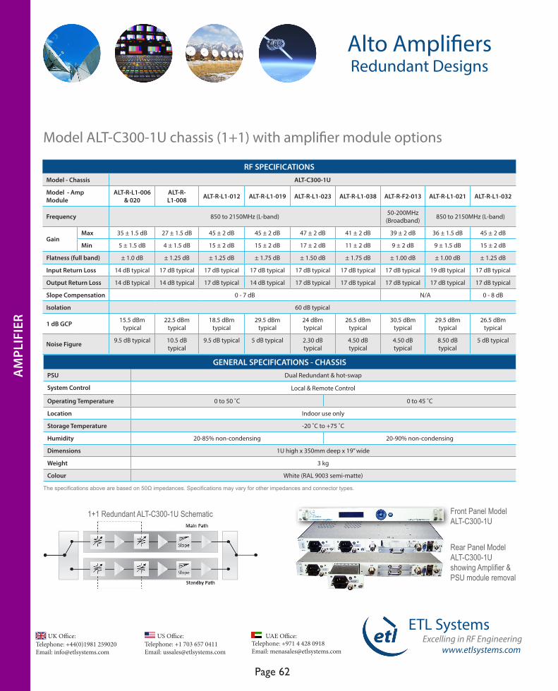
Telephone: +44(0)1981 259020 Email: [email protected]
UK Office:Telephone: +1 703 657 0411 Email: [email protected]
US Office:
www.etlsystems.com
ETL SystemsExcelling in RF Engineering
Page 62
Telephone: +971 4 428 0918 Email: [email protected]
UAE Office:
The specifications above are based on 50Ω impedances. Specifications may vary for other impedances and connector types.
RF SPECIFICATIONSModel - Chassis ALT-C300-1U
Model - Amp Module
ALT-R-L1-006 & 020
ALT-R-L1-008 ALT-R-L1-012 ALT-R-L1-019 ALT-R-L1-023 ALT-R-L1-038 ALT-R-F2-013 ALT-R-L1-021 ALT-R-L1-032
Frequency 850 to 2150MHz (L-band) 50-200MHz (Broadband) 850 to 2150MHz (L-band)
GainMax 35 ± 1.5 dB 27 ± 1.5 dB 45 ± 2 dB 45 ± 2 dB 47 ± 2 dB 41 ± 2 dB 39 ± 2 dB 36 ± 1.5 dB 45 ± 2 dB
Min 5 ± 1.5 dB 4 ± 1.5 dB 15 ± 2 dB 15 ± 2 dB 17 ± 2 dB 11 ± 2 dB 9 ± 2 dB 9 ± 1.5 dB 15 ± 2 dB
Flatness (full band) ± 1.0 dB ± 1.25 dB ± 1.25 dB ± 1.75 dB ± 1.50 dB ± 1.75 dB ± 1.00 dB ± 1.00 dB ± 1.25 dB
Input Return Loss 14 dB typical 17 dB typical 17 dB typical 17 dB typical 17 dB typical 17 dB typical 17 dB typical 19 dB typical 17 dB typical
Output Return Loss 14 dB typical 14 dB typical 17 dB typical 14 dB typical 17 dB typical 17 dB typical 17 dB typical 17 dB typical 17 dB typical
Slope Compensation 0 - 7 dB N/A 0 - 8 dB
Isolation 60 dB typical
1 dB GCP 15.5 dBm typical
22.5 dBm typical
18.5 dBm typical
29.5 dBm typical
24 dBm typical
26.5 dBm typical
30.5 dBm typical
29.5 dBm typical
26.5 dBm typical
Noise Figure 9.5 dB typical 10.5 dB typical
9.5 dB typical 5 dB typical 2.30 dB typical
4.50 dB typical
4.50 dB typical
8.50 dB typical
5 dB typical
Alto AmplifiersRedundant Designs
1+1 Redundant ALT-C300-1U Schematic Front Panel Model ALT-C300-1U
Rear Panel Model ALT-C300-1U showing Amplifier & PSU module removal
Model ALT-C300-1U chassis (1+1) with amplifier module options
GENERAL SPECIFICATIONS - CHASSISPSU Dual Redundant & hot-swap
System Control Local & Remote Control
Operating Temperature 0 to 50 ˚C 0 to 45 ˚C
Location Indoor use only
Storage Temperature -20 ˚C to +75 ˚C
Humidity 20-85% non-condensing 20-90% non-condensing
Dimensions 1U high x 350mm deep x 19” wide
Weight 3 kg
Colour White (RAL 9003 semi-matte)
AM
PLIF
IER
AM
PLIF
IER
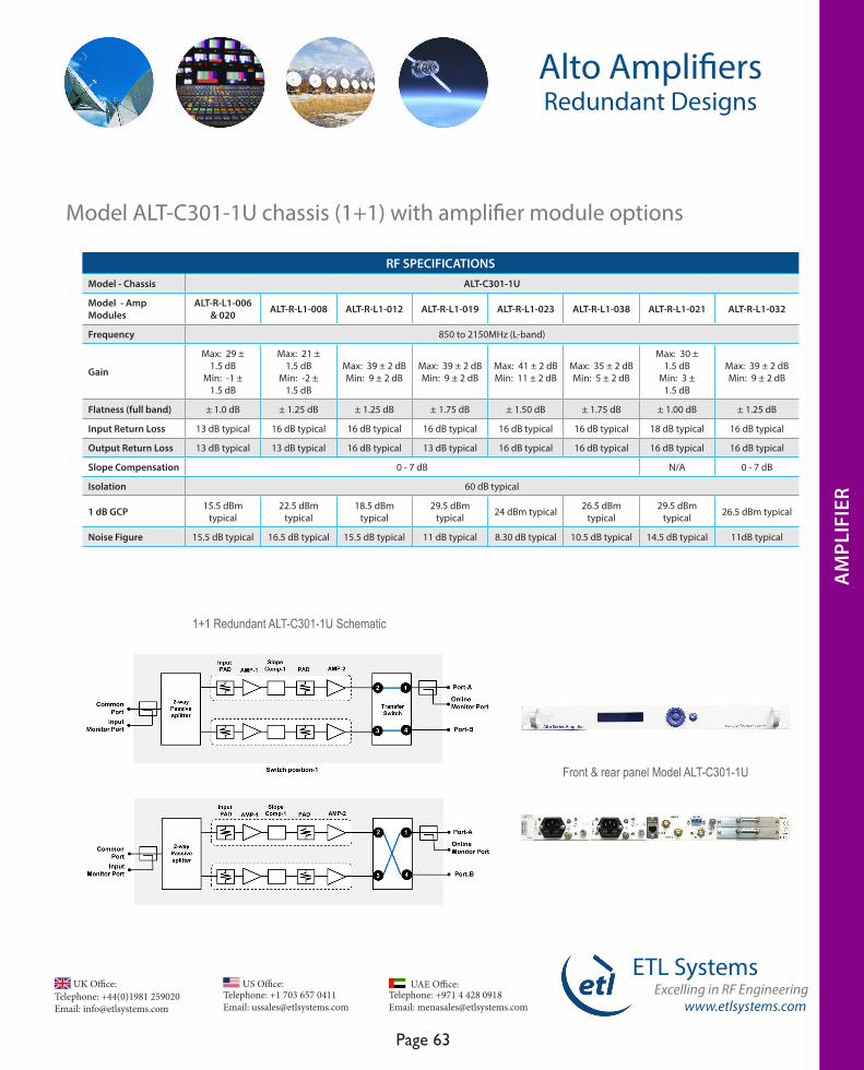
www.etlsystems.com
ETL SystemsExcelling in RF Engineering
Page 63
Telephone: +971 4 428 0918 Email: [email protected]
UAE Office: Telephone: +44(0)1981 259020 Email: [email protected]
UK Office:Telephone: +1 703 657 0411 Email: [email protected]
US Office:
Alto AmplifiersRedundant Designs
Model ALT-C301-1U chassis (1+1) with amplifier module options
RF SPECIFICATIONSModel - Chassis ALT-C301-1U
Model - Amp Modules
ALT-R-L1-006 & 020 ALT-R-L1-008 ALT-R-L1-012 ALT-R-L1-019 ALT-R-L1-023 ALT-R-L1-038 ALT-R-L1-021 ALT-R-L1-032
Frequency 850 to 2150MHz (L-band)
Gain
Max: 29 ± 1.5 dB
Min: -1 ±1.5 dB
Max: 21 ± 1.5 dB
Min: -2 ±1.5 dB
Max: 39 ± 2 dB Min: 9 ± 2 dB
Max: 39 ± 2 dB Min: 9 ± 2 dB
Max: 41 ± 2 dB Min: 11 ± 2 dB
Max: 35 ± 2 dB Min: 5 ± 2 dB
Max: 30 ± 1.5 dB
Min: 3 ±1.5 dB
Max: 39 ± 2 dB Min: 9 ± 2 dB
Flatness (full band) ± 1.0 dB ± 1.25 dB ± 1.25 dB ± 1.75 dB ± 1.50 dB ± 1.75 dB ± 1.00 dB ± 1.25 dB
Input Return Loss 13 dB typical 16 dB typical 16 dB typical 16 dB typical 16 dB typical 16 dB typical 18 dB typical 16 dB typical
Output Return Loss 13 dB typical 13 dB typical 16 dB typical 13 dB typical 16 dB typical 16 dB typical 16 dB typical 16 dB typical
Slope Compensation 0 - 7 dB N/A 0 - 7 dB
Isolation 60 dB typical
1 dB GCP 15.5 dBm typical
22.5 dBm typical
18.5 dBm typical
29.5 dBm typical 24 dBm typical 26.5 dBm
typical29.5 dBm
typical 26.5 dBm typical
Noise Figure 15.5 dB typical 16.5 dB typical 15.5 dB typical 11 dB typical 8.30 dB typical 10.5 dB typical 14.5 dB typical 11dB typical
AM
PLIF
IER
1+1 Redundant ALT-C301-1U Schematic
Front & rear panel Model ALT-C301-1U
AM
PLIF
IER

Telephone: +44(0)1981 259020 Email: [email protected]
UK Office:Telephone: +1 703 657 0411 Email: [email protected]
US Office:
www.etlsystems.com
ETL SystemsExcelling in RF Engineering
Page 64
Telephone: +971 4 428 0918 Email: [email protected]
UAE Office:
The specifications above are based on 50Ω impedances. Specifications may vary for other impedances and connector types.
2+1 Redundant ALT-C303-2U Schematic ALT-C303-2U Redundancy Options
Front Panel Model ALT-C303-2U Rear Panel Model ALT-C303-2U
Alto AmplifiersRedundant Designs
Model ALT-C303-2U chassis (2+1) with amplifier module options
RF SPECIFICATIONSModel - Chassis ALT-C303-2U
Model - Amp Modules
ALT-R-L1-006 & 020 ALT-R-L1-008 ALT-R-L1-012 ALT-R-L1-019 ALT-R-L1-023 ALT-R-L1-038 ALT-R-L1-021 ALT-R-L1-032
Frequency 850 to 2150MHz (L-band)
GainMax: 30 ± 1.5 dB
Min: 0.0 ±1.5 dB
Max: 22 ± 1.5 dB Min: -1 ±
1.5 dB
Max: 40 ± 2 dB Min: 10 ± 2 dB
Max: 40 ± 2 dB Min: 10 ± 2 dB
Max: 42 ± 2 dB
Min: 12 ± 2 dB
Max: 36 ± 2 dB
Min: 6 ± 2 dB
Max: 31 ± 1.5 dB
Min: 4 ±1.5 dB
Max: 40 ± 2 dB
Min: 10 ± 2 dB
Flatness (full band) ± 1.0 dB ± 1.25 dB ± 1.25 dB ± 1.75 dB ± 1.50 dB ± 1.75 dB ± 1.00 dB ± 1.25 dB
Input Return Loss 13 dB typical 16 dB typical 16 dB typical 16 dB typical 16 dB typical 16 dB typical 18 dB typical 16 dB typical
Output Return Loss 13 dB typical 13 dB typical 16 dB typical 13 dB typical 16 dB typical 16 dB typical 16 dB typical 16 dB typical
Slope Compensation 0 - 5 dB N/A 0 - 5 dB
Isolation 60 dB typical
1 dB GCP 12.5 dBm typical 19.5 dBm typical 15.5 dBm typical 23 dBm typical 23 dBm typical
23 dBm typical 23 dBm typical 23 dBm
typical
Noise Figure 12.5 dB typical 13.5 dB typical 12.5 dB typical 8 dB typical 5.30 dB typical 7.5 dB typical 11.5 dB typical 8dB typical
AM
PLIF
IER
AM
PLIW
FIER
AM
PLIF
IER
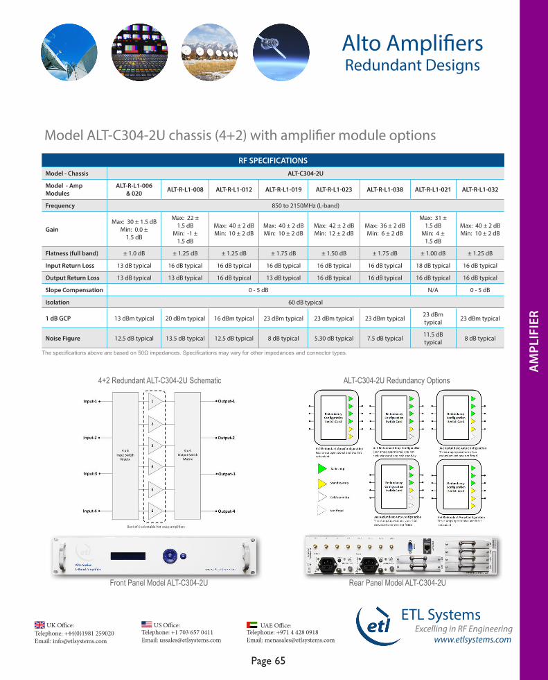
www.etlsystems.com
ETL SystemsExcelling in RF Engineering
Page 65
Telephone: +971 4 428 0918 Email: [email protected]
UAE Office: Telephone: +44(0)1981 259020 Email: [email protected]
UK Office:Telephone: +1 703 657 0411 Email: [email protected]
US Office:
AM
PLIF
IER
Alto AmplifiersRedundant Designs
The specifications above are based on 50Ω impedances. Specifications may vary for other impedances and connector types.
4+2 Redundant ALT-C304-2U Schematic ALT-C304-2U Redundancy Options
Front Panel Model ALT-C304-2U Rear Panel Model ALT-C304-2U
Model ALT-C304-2U chassis (4+2) with amplifier module options
RF SPECIFICATIONSModel - Chassis ALT-C304-2U
Model - Amp Modules
ALT-R-L1-006 & 020 ALT-R-L1-008 ALT-R-L1-012 ALT-R-L1-019 ALT-R-L1-023 ALT-R-L1-038 ALT-R-L1-021 ALT-R-L1-032
Frequency 850 to 2150MHz (L-band)
GainMax: 30 ± 1.5 dB
Min: 0.0 ±1.5 dB
Max: 22 ± 1.5 dB
Min: -1 ±1.5 dB
Max: 40 ± 2 dB Min: 10 ± 2 dB
Max: 40 ± 2 dB Min: 10 ± 2 dB
Max: 42 ± 2 dB Min: 12 ± 2 dB
Max: 36 ± 2 dB Min: 6 ± 2 dB
Max: 31 ± 1.5 dB
Min: 4 ±1.5 dB
Max: 40 ± 2 dB Min: 10 ± 2 dB
Flatness (full band) ± 1.0 dB ± 1.25 dB ± 1.25 dB ± 1.75 dB ± 1.50 dB ± 1.75 dB ± 1.00 dB ± 1.25 dB
Input Return Loss 13 dB typical 16 dB typical 16 dB typical 16 dB typical 16 dB typical 16 dB typical 18 dB typical 16 dB typical
Output Return Loss 13 dB typical 13 dB typical 16 dB typical 13 dB typical 16 dB typical 16 dB typical 16 dB typical 16 dB typical
Slope Compensation 0 - 5 dB N/A 0 - 5 dB
Isolation 60 dB typical
1 dB GCP 13 dBm typical 20 dBm typical 16 dBm typical 23 dBm typical 23 dBm typical 23 dBm typical 23 dBm typical 23 dBm typical
Noise Figure 12.5 dB typical 13.5 dB typical 12.5 dB typical 8 dB typical 5.30 dB typical 7.5 dB typical 11.5 dB typical 8 dB typical
AM
PLIF
IER
AM
PLIF
IER
AM
PLIF
IER

Telephone: +44(0)1981 259020 Email: [email protected]
UK Office:Telephone: +1 703 657 0411 Email: [email protected]
US Office:
www.etlsystems.com
ETL SystemsExcelling in RF Engineering
Page 66
Telephone: +971 4 428 0918 Email: [email protected]
UAE Office:
The specifications above are based on 50Ω impedances. Specifications may vary for other impedances and connector types.
ALT-C305-5U Redundancy OptionsFront Panel Model ALT-C305-5U - showing dual redundant hot-swap
CPU & power supply modules
Rear Panel Model ALT-C305-5U
Alto AmplifiersRedundant Designs
Model ALT-C305-5U chassis (Quad 4+1) with amplifier module options
RF SPECIFICATIONSModel - Chassis ALT-C305-1U
Model - Amp Modules
ALT-R-L1-006 & 020 ALT-R-L1-008 ALT-R-L1-012 ALT-R-L1-019 ALT-R-L1-023 ALT-R-L1-038 ALT-R-L1-021 ALT-R-L1-032
Frequency 850 to 2150MHz (L-band)
GainMax: 30 ± 1.5 dB
Min: 0.0 ±1.5 dB
Max: 22 ± 1.5 dB
Min: -1 ±1.5 dB
Max: 40 ± 2 dB Min: 10 ± 2 dB
Max: 40 ± 2 dB Min: 10 ± 2 dB
Max: 42 ± 2 dB Min: 12 ± 2 dB
Max: 36 ± 2 dB
Min: 6 ± 2 dB
Max: 31 ± 1.5 dB
Min: 4 ±1.5 dB
Max: 40 ± 2 dB
Min: 10 ± 2 dB
Flatness (full band) ± 1.0 dB ± 1.25 dB ± 1.25 dB ± 1.75 dB ± 1.50 dB ± 1.75 dB ± 1.00 dB ± 1.25 dB
Input Return Loss 13 dB typical 16 dB typical 16 dB typical 16 dB typical 16 dB typical 16 dB typical 18 dB typical 16 dB typical
Output Return Loss 13 dB typical 13 dB typical 16 dB typical 13 dB typical 16 dB typical 16 dB typical 16 dB typical 16 dB typical
Slope Compensation 0 - 5 dB N/A 0 - 5 dB
Isolation 60 dB typical
1 dB GCP 13 dBm typical 20 dBm typical 16 dBm typical 23 dBm typical 23 dBm typical 23 dBm typical 23 dBm typical 23 dBm typical
Noise Figure 12.5 dB typical 13.5 dB typical 12.5 dB typical 8 dB typical 5.30 dB typical 7.5 dB typical 11.5 dB typical 8 dB typical
AM
PLIF
IER
AM
PLIF
IER
AM
PLIF
IER
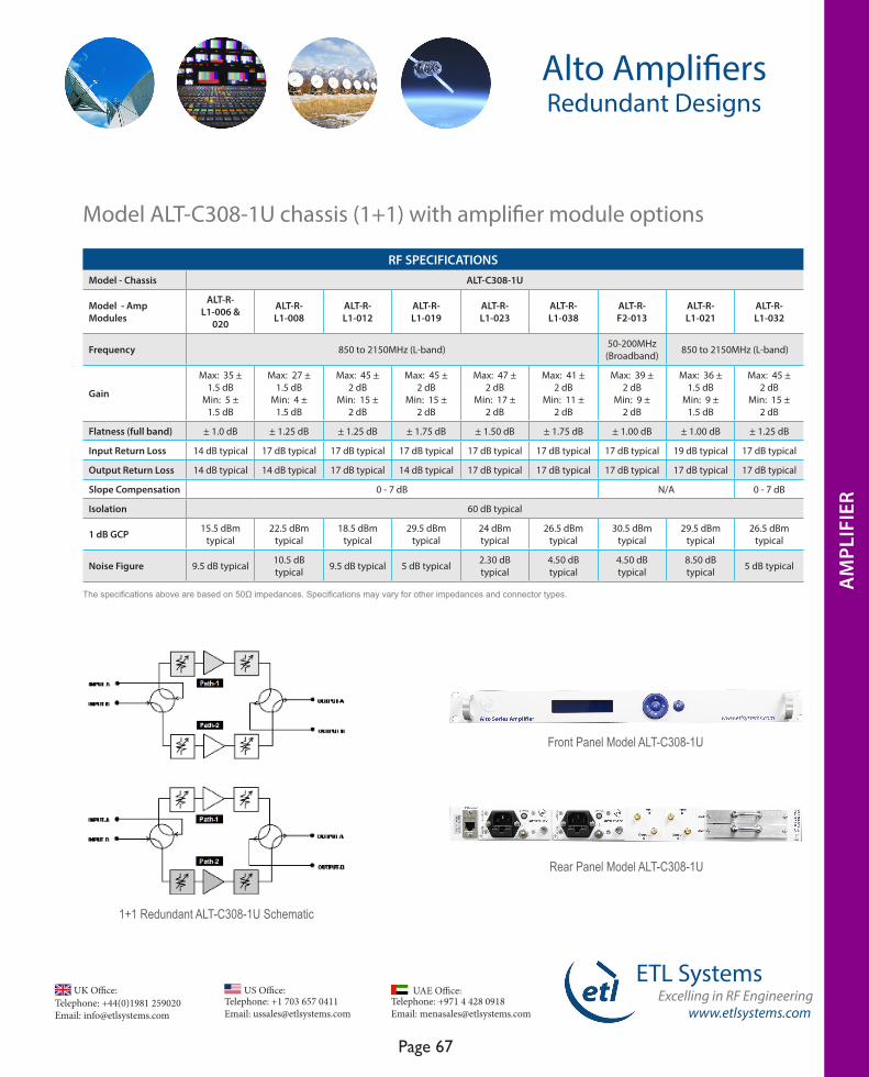
www.etlsystems.com
ETL SystemsExcelling in RF Engineering
Page 67
Telephone: +971 4 428 0918 Email: [email protected]
UAE Office: Telephone: +44(0)1981 259020 Email: [email protected]
UK Office:Telephone: +1 703 657 0411 Email: [email protected]
US Office:
AM
PLIF
IER
Alto AmplifiersRedundant Designs
Model ALT-C308-1U chassis (1+1) with amplifier module options
RF SPECIFICATIONSModel - Chassis ALT-C308-1U
Model - Amp Modules
ALT-R-L1-006 &
020
ALT-R-L1-008
ALT-R-L1-012
ALT-R-L1-019
ALT-R-L1-023
ALT-R-L1-038
ALT-R-F2-013
ALT-R-L1-021
ALT-R-L1-032
Frequency 850 to 2150MHz (L-band) 50-200MHz (Broadband) 850 to 2150MHz (L-band)
Gain
Max: 35 ± 1.5 dB
Min: 5 ± 1.5 dB
Max: 27 ± 1.5 dB
Min: 4 ± 1.5 dB
Max: 45 ± 2 dB
Min: 15 ± 2 dB
Max: 45 ± 2 dB
Min: 15 ± 2 dB
Max: 47 ± 2 dB
Min: 17 ± 2 dB
Max: 41 ± 2 dB
Min: 11 ± 2 dB
Max: 39 ± 2 dB
Min: 9 ± 2 dB
Max: 36 ± 1.5 dB
Min: 9 ± 1.5 dB
Max: 45 ± 2 dB
Min: 15 ± 2 dB
Flatness (full band) ± 1.0 dB ± 1.25 dB ± 1.25 dB ± 1.75 dB ± 1.50 dB ± 1.75 dB ± 1.00 dB ± 1.00 dB ± 1.25 dB
Input Return Loss 14 dB typical 17 dB typical 17 dB typical 17 dB typical 17 dB typical 17 dB typical 17 dB typical 19 dB typical 17 dB typical
Output Return Loss 14 dB typical 14 dB typical 17 dB typical 14 dB typical 17 dB typical 17 dB typical 17 dB typical 17 dB typical 17 dB typical
Slope Compensation 0 - 7 dB N/A 0 - 7 dB
Isolation 60 dB typical
1 dB GCP 15.5 dBm typical
22.5 dBm typical
18.5 dBm typical
29.5 dBm typical
24 dBm typical
26.5 dBm typical
30.5 dBm typical
29.5 dBm typical
26.5 dBm typical
Noise Figure 9.5 dB typical 10.5 dB typical 9.5 dB typical 5 dB typical 2.30 dB
typical4.50 dB typical
4.50 dB typical
8.50 dB typical 5 dB typical
AM
PLIF
IER
Front Panel Model ALT-C308-1U
Rear Panel Model ALT-C308-1U
1+1 Redundant ALT-C308-1U Schematic
The specifications above are based on 50Ω impedances. Specifications may vary for other impedances and connector types.
AM
PLIF
IER
AM
PLIF
IER
AM
PLIF
IER
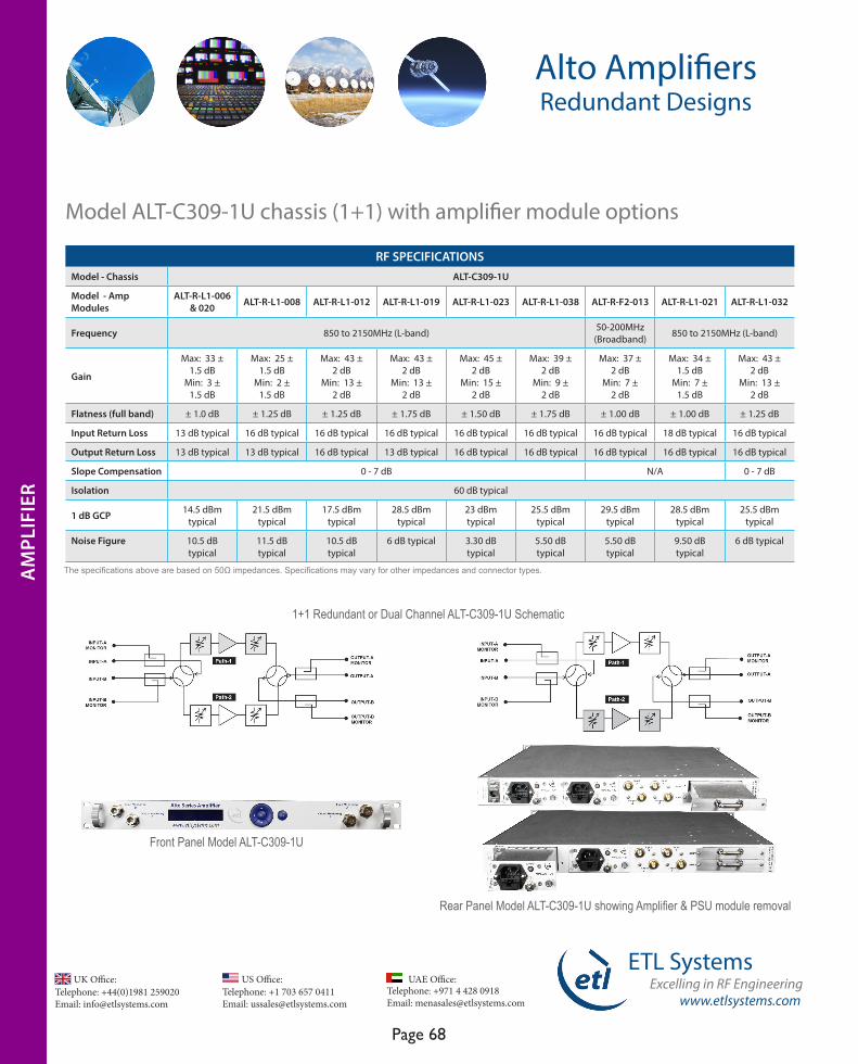
Telephone: +44(0)1981 259020 Email: [email protected]
UK Office:Telephone: +1 703 657 0411 Email: [email protected]
US Office:
www.etlsystems.com
ETL SystemsExcelling in RF Engineering
Page 68
Telephone: +971 4 428 0918 Email: [email protected]
UAE Office:
Alto AmplifiersRedundant Designs
1+1 Redundant or Dual Channel ALT-C309-1U Schematic
Front Panel Model ALT-C309-1U
Rear Panel Model ALT-C309-1U showing Amplifier & PSU module removal
Model ALT-C309-1U chassis (1+1) with amplifier module options
RF SPECIFICATIONSModel - Chassis ALT-C309-1U
Model - Amp Modules
ALT-R-L1-006 & 020 ALT-R-L1-008 ALT-R-L1-012 ALT-R-L1-019 ALT-R-L1-023 ALT-R-L1-038 ALT-R-F2-013 ALT-R-L1-021 ALT-R-L1-032
Frequency 850 to 2150MHz (L-band) 50-200MHz (Broadband) 850 to 2150MHz (L-band)
Gain
Max: 33 ± 1.5 dB
Min: 3 ± 1.5 dB
Max: 25 ± 1.5 dB
Min: 2 ± 1.5 dB
Max: 43 ± 2 dB
Min: 13 ± 2 dB
Max: 43 ± 2 dB
Min: 13 ± 2 dB
Max: 45 ± 2 dB
Min: 15 ± 2 dB
Max: 39 ± 2 dB
Min: 9 ± 2 dB
Max: 37 ± 2 dB
Min: 7 ± 2 dB
Max: 34 ± 1.5 dB
Min: 7 ± 1.5 dB
Max: 43 ± 2 dB
Min: 13 ± 2 dB
Flatness (full band) ± 1.0 dB ± 1.25 dB ± 1.25 dB ± 1.75 dB ± 1.50 dB ± 1.75 dB ± 1.00 dB ± 1.00 dB ± 1.25 dB
Input Return Loss 13 dB typical 16 dB typical 16 dB typical 16 dB typical 16 dB typical 16 dB typical 16 dB typical 18 dB typical 16 dB typical
Output Return Loss 13 dB typical 13 dB typical 16 dB typical 13 dB typical 16 dB typical 16 dB typical 16 dB typical 16 dB typical 16 dB typical
Slope Compensation 0 - 7 dB N/A 0 - 7 dB
Isolation 60 dB typical
1 dB GCP 14.5 dBm typical
21.5 dBm typical
17.5 dBm typical
28.5 dBm typical
23 dBm typical
25.5 dBm typical
29.5 dBm typical
28.5 dBm typical
25.5 dBm typical
Noise Figure 10.5 dB typical
11.5 dB typical
10.5 dB typical
6 dB typical 3.30 dB typical
5.50 dB typical
5.50 dB typical
9.50 dB typical
6 dB typical
AM
PLIF
IER
AM
PLIF
IER
The specifications above are based on 50Ω impedances. Specifications may vary for other impedances and connector types.AM
PLIF
IER
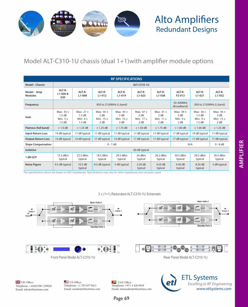
www.etlsystems.com
ETL SystemsExcelling in RF Engineering
Page 69
Telephone: +971 4 428 0918 Email: [email protected]
UAE Office: Telephone: +44(0)1981 259020 Email: [email protected]
UK Office:Telephone: +1 703 657 0411 Email: [email protected]
US Office:
AM
PLIF
IER
Alto AmplifiersRedundant Designs
2 x (1+1) Redundant ALT-C310-1U Schematic
Front Panel Model ALT-C310-1U Rear Panel Model ALT-C310-1U
Model ALT-C310-1U chassis (dual 1+1)with amplifier module options
RF SPECIFICATIONSModel - Chassis ALT-C310-1U
Model - Amp Modules
ALT-R-L1-006 &
020
ALT-R-L1-008
ALT-R-L1-012
ALT-R-L1-019
ALT-R-L1-023
ALT-R-L1-038
ALT-R-F2-013
ALT-R-L1-021
ALT-R-L1-032
Frequency 850 to 2150MHz (L-band) 50-200MHz (Broadband) 850 to 2150MHz (L-band)
Gain
Max: 35 ± 1.5 dB
Min: 5 ± 1.5 dB
Max: 27 ± 1.5 dB
Min: 4 ± 1.5 dB
Max: 45 ± 2 dB
Min: 15 ± 2 dB
Max: 45 ± 2 dB
Min: 15 ± 2 dB
Max: 47 ± 2 dB
Min: 17 ± 2 dB
Max: 41 ± 2 dB
Min: 11 ± 2 dB
Max: 39 ± 2 dB
Min: 9 ± 2 dB
Max: 36 ± 1.5 dB
Min: 9 ± 1.5 dB
Max: 45 ± 2 dB
Min: 15 ± 2 dB
Flatness (full band) ± 1.0 dB ± 1.25 dB ± 1.25 dB ± 1.75 dB ± 1.50 dB ± 1.75 dB ± 1.00 dB ± 1.00 dB ± 1.25 dB
Input Return Loss 14 dB typical 17 dB typical 17 dB typical 17 dB typical 17 dB typical 17 dB typical 17 dB typical 19 dB typical 17 dB typical
Output Return Loss 14 dB typical 14 dB typical 17 dB typical 14 dB typical 17 dB typical 17 dB typical 17 dB typical 17 dB typical 17 dB typical
Slope Compensation 0 - 7 dB N/A 0 - 8 dB
Isolation 60 dB typical
1 dB GCP 15.5 dBm typical
22.5 dBm typical
18.5 dBm typical
29.5 dBm typical
24 dBm typical
26.5 dBm typical
30.5 dBm typical
29.5 dBm typical
26.5 dBm typical
Noise Figure 9.5 dB typical 10.5 dB typical
9.5 dB typical 5 dB typical 2.30 dB typical
4.50 dB typical
4.50 dB typical
8.50 dB typical
5 dB typical AM
PLIF
IER
The specifications above are based on 50Ω impedances. Specifications may vary for other impedances and connector types.
AM
PLIF
IER
AM
PLIF
IER
AM
PLIF
IER
AM
PLIF
IER
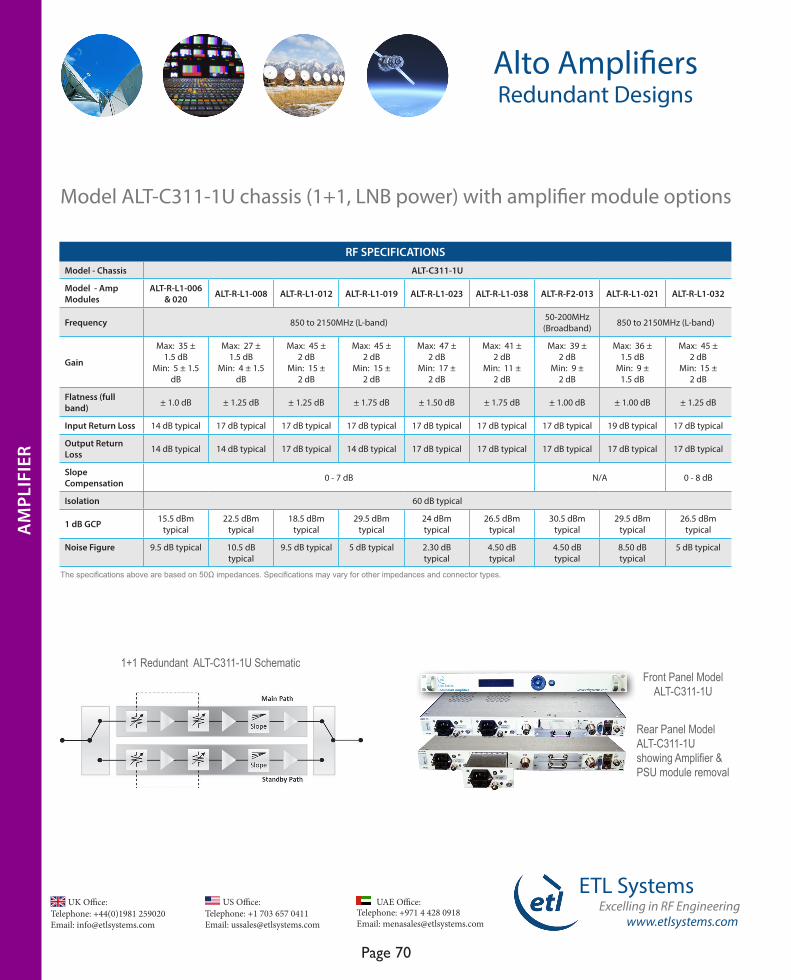
Telephone: +44(0)1981 259020 Email: [email protected]
UK Office:Telephone: +1 703 657 0411 Email: [email protected]
US Office:
www.etlsystems.com
ETL SystemsExcelling in RF Engineering
Page 70
Telephone: +971 4 428 0918 Email: [email protected]
UAE Office:
Front Panel Model ALT-C311-1U
Alto AmplifiersRedundant Designs
Model ALT-C311-1U chassis (1+1, LNB power) with amplifier module options
RF SPECIFICATIONSModel - Chassis ALT-C311-1U
Model - Amp Modules
ALT-R-L1-006 & 020 ALT-R-L1-008 ALT-R-L1-012 ALT-R-L1-019 ALT-R-L1-023 ALT-R-L1-038 ALT-R-F2-013 ALT-R-L1-021 ALT-R-L1-032
Frequency 850 to 2150MHz (L-band) 50-200MHz (Broadband) 850 to 2150MHz (L-band)
Gain
Max: 35 ± 1.5 dB
Min: 5 ± 1.5 dB
Max: 27 ± 1.5 dB
Min: 4 ± 1.5 dB
Max: 45 ± 2 dB
Min: 15 ± 2 dB
Max: 45 ± 2 dB
Min: 15 ± 2 dB
Max: 47 ± 2 dB
Min: 17 ± 2 dB
Max: 41 ± 2 dB
Min: 11 ± 2 dB
Max: 39 ± 2 dB
Min: 9 ± 2 dB
Max: 36 ± 1.5 dB
Min: 9 ± 1.5 dB
Max: 45 ± 2 dB
Min: 15 ± 2 dB
Flatness (full band) ± 1.0 dB ± 1.25 dB ± 1.25 dB ± 1.75 dB ± 1.50 dB ± 1.75 dB ± 1.00 dB ± 1.00 dB ± 1.25 dB
Input Return Loss 14 dB typical 17 dB typical 17 dB typical 17 dB typical 17 dB typical 17 dB typical 17 dB typical 19 dB typical 17 dB typical
Output Return Loss 14 dB typical 14 dB typical 17 dB typical 14 dB typical 17 dB typical 17 dB typical 17 dB typical 17 dB typical 17 dB typical
Slope Compensation 0 - 7 dB N/A 0 - 8 dB
Isolation 60 dB typical
1 dB GCP 15.5 dBm typical
22.5 dBm typical
18.5 dBm typical
29.5 dBm typical
24 dBm typical
26.5 dBm typical
30.5 dBm typical
29.5 dBm typical
26.5 dBm typical
Noise Figure 9.5 dB typical 10.5 dB typical
9.5 dB typical 5 dB typical 2.30 dB typical
4.50 dB typical
4.50 dB typical
8.50 dB typical
5 dB typical
AM
PLIF
IER
The specifications above are based on 50Ω impedances. Specifications may vary for other impedances and connector types.
1+1 Redundant ALT-C311-1U Schematic
Rear Panel Model ALT-C311-1U showing Amplifier & PSU module removal
AM
PLIF
IER
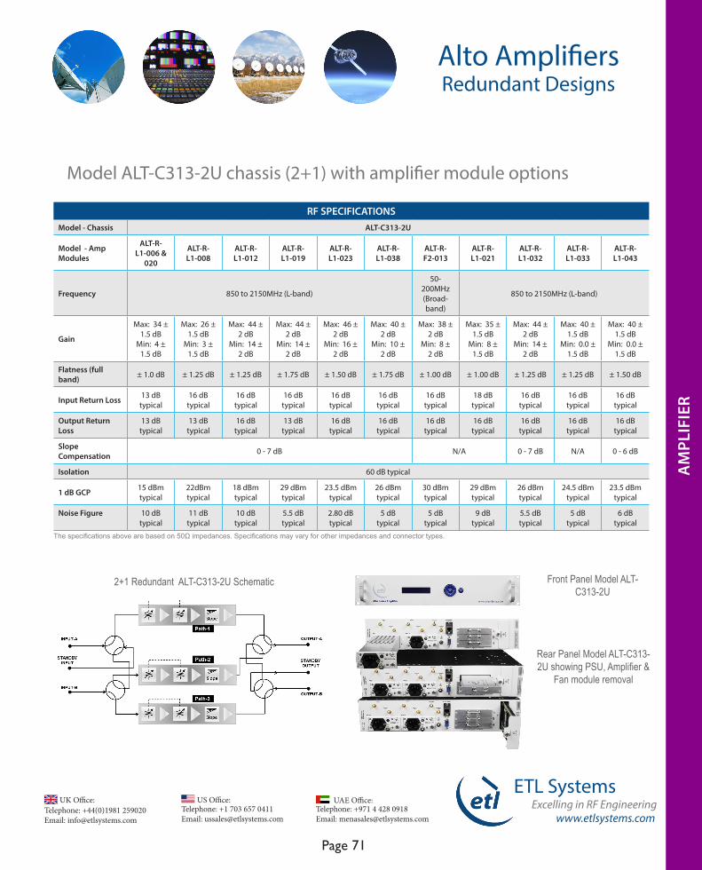
www.etlsystems.com
ETL SystemsExcelling in RF Engineering
Page 71
Telephone: +971 4 428 0918 Email: [email protected]
UAE Office: Telephone: +44(0)1981 259020 Email: [email protected]
UK Office:Telephone: +1 703 657 0411 Email: [email protected]
US Office:
Model ALT-C313-2U chassis (2+1) with amplifier module options
RF SPECIFICATIONSModel - Chassis ALT-C313-2U
Model - Amp Modules
ALT-R-L1-006 &
020
ALT-R-L1-008
ALT-R-L1-012
ALT-R-L1-019
ALT-R-L1-023
ALT-R-L1-038
ALT-R-F2-013
ALT-R-L1-021
ALT-R-L1-032
ALT-R-L1-033
ALT-R-L1-043
Frequency 850 to 2150MHz (L-band)
50-200MHz (Broad-band)
850 to 2150MHz (L-band)
Gain
Max: 34 ± 1.5 dB
Min: 4 ± 1.5 dB
Max: 26 ± 1.5 dB
Min: 3 ± 1.5 dB
Max: 44 ± 2 dB
Min: 14 ± 2 dB
Max: 44 ± 2 dB
Min: 14 ± 2 dB
Max: 46 ± 2 dB
Min: 16 ± 2 dB
Max: 40 ± 2 dB
Min: 10 ± 2 dB
Max: 38 ± 2 dB
Min: 8 ± 2 dB
Max: 35 ± 1.5 dB
Min: 8 ± 1.5 dB
Max: 44 ± 2 dB
Min: 14 ± 2 dB
Max: 40 ± 1.5 dB
Min: 0.0 ± 1.5 dB
Max: 40 ± 1.5 dB
Min: 0.0 ± 1.5 dB
Flatness (full band) ± 1.0 dB ± 1.25 dB ± 1.25 dB ± 1.75 dB ± 1.50 dB ± 1.75 dB ± 1.00 dB ± 1.00 dB ± 1.25 dB ± 1.25 dB ± 1.50 dB
Input Return Loss 13 dB typical
16 dB typical
16 dB typical
16 dB typical
16 dB typical
16 dB typical
16 dB typical
18 dB typical
16 dB typical
16 dB typical
16 dB typical
Output Return Loss
13 dB typical
13 dB typical
16 dB typical
13 dB typical
16 dB typical
16 dB typical
16 dB typical
16 dB typical
16 dB typical
16 dB typical
16 dB typical
Slope Compensation 0 - 7 dB N/A 0 - 7 dB N/A 0 - 6 dB
Isolation 60 dB typical
1 dB GCP 15 dBm typical
22dBm typical
18 dBm typical
29 dBm typical
23.5 dBm typical
26 dBm typical
30 dBm typical
29 dBm typical
26 dBm typical
24.5 dBm typical
23.5 dBm typical
Noise Figure 10 dB typical
11 dB typical
10 dB typical
5.5 dB typical
2.80 dB typical
5 dB typical
5 dB typical
9 dB typical
5.5 dB typical
5 dB typical
6 dB typical
Alto AmplifiersRedundant Designs
Front Panel Model ALT-C313-2U
Rear Panel Model ALT-C313-2U showing PSU, Amplifier &
Fan module removal
2+1 Redundant ALT-C313-2U Schematic
The specifications above are based on 50Ω impedances. Specifications may vary for other impedances and connector types.
AM
PLIF
IER
AM
PLIF
IER
AM
PLIF
IER
AM
PLIF
IER
AM
PLIF
IER
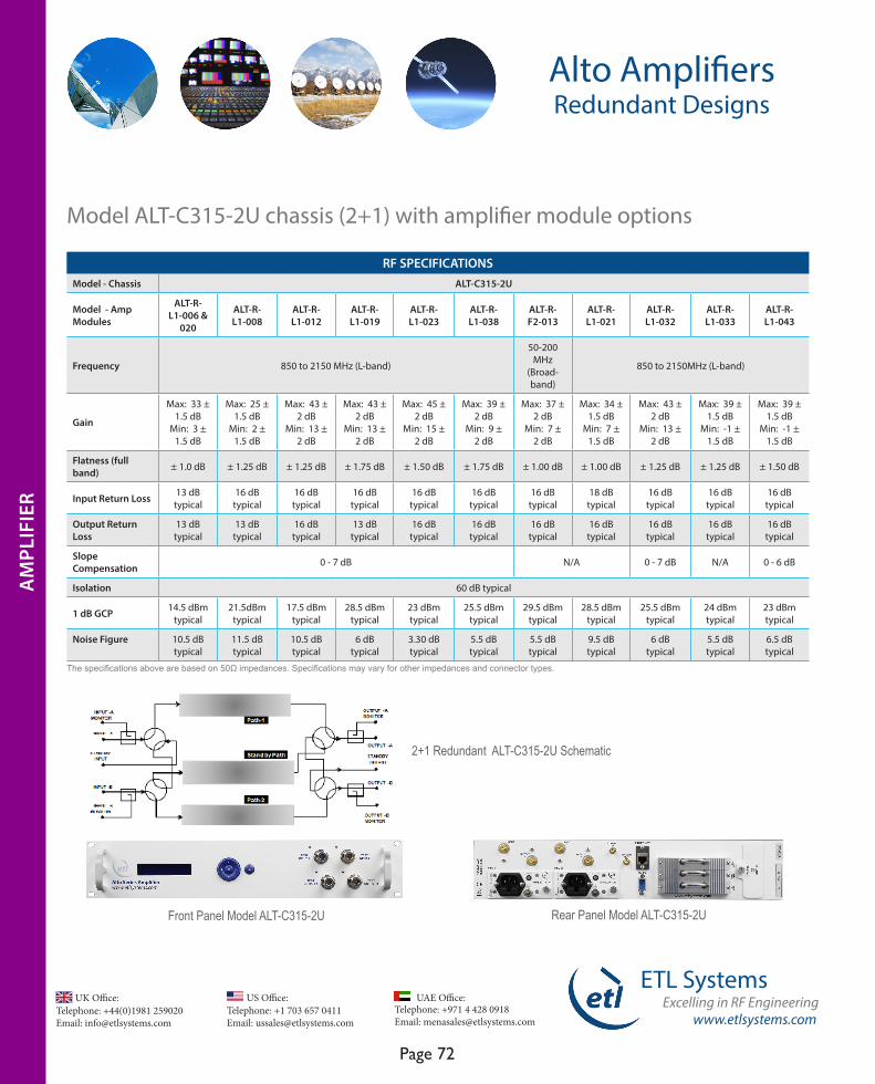
Telephone: +44(0)1981 259020 Email: [email protected]
UK Office:Telephone: +1 703 657 0411 Email: [email protected]
US Office:
www.etlsystems.com
ETL SystemsExcelling in RF Engineering
Page 72
Telephone: +971 4 428 0918 Email: [email protected]
UAE Office:
Model ALT-C315-2U chassis (2+1) with amplifier module options
RF SPECIFICATIONSModel - Chassis ALT-C315-2U
Model - Amp Modules
ALT-R-L1-006 &
020
ALT-R-L1-008
ALT-R-L1-012
ALT-R-L1-019
ALT-R-L1-023
ALT-R-L1-038
ALT-R-F2-013
ALT-R-L1-021
ALT-R-L1-032
ALT-R-L1-033
ALT-R-L1-043
Frequency 850 to 2150 MHz (L-band)
50-200 MHz
(Broad-band)
850 to 2150MHz (L-band)
Gain
Max: 33 ± 1.5 dB
Min: 3 ± 1.5 dB
Max: 25 ± 1.5 dB
Min: 2 ± 1.5 dB
Max: 43 ± 2 dB
Min: 13 ± 2 dB
Max: 43 ± 2 dB
Min: 13 ± 2 dB
Max: 45 ± 2 dB
Min: 15 ± 2 dB
Max: 39 ± 2 dB
Min: 9 ± 2 dB
Max: 37 ± 2 dB
Min: 7 ± 2 dB
Max: 34 ± 1.5 dB
Min: 7 ± 1.5 dB
Max: 43 ± 2 dB
Min: 13 ± 2 dB
Max: 39 ± 1.5 dB
Min: -1 ± 1.5 dB
Max: 39 ± 1.5 dB
Min: -1 ± 1.5 dB
Flatness (full band) ± 1.0 dB ± 1.25 dB ± 1.25 dB ± 1.75 dB ± 1.50 dB ± 1.75 dB ± 1.00 dB ± 1.00 dB ± 1.25 dB ± 1.25 dB ± 1.50 dB
Input Return Loss 13 dB typical
16 dB typical
16 dB typical
16 dB typical
16 dB typical
16 dB typical
16 dB typical
18 dB typical
16 dB typical
16 dB typical
16 dB typical
Output Return Loss
13 dB typical
13 dB typical
16 dB typical
13 dB typical
16 dB typical
16 dB typical
16 dB typical
16 dB typical
16 dB typical
16 dB typical
16 dB typical
Slope Compensation 0 - 7 dB N/A 0 - 7 dB N/A 0 - 6 dB
Isolation 60 dB typical
1 dB GCP 14.5 dBm typical
21.5dBm typical
17.5 dBm typical
28.5 dBm typical
23 dBm typical
25.5 dBm typical
29.5 dBm typical
28.5 dBm typical
25.5 dBm typical
24 dBm typical
23 dBm typical
Noise Figure 10.5 dB typical
11.5 dB typical
10.5 dB typical
6 dB typical
3.30 dB typical
5.5 dB typical
5.5 dB typical
9.5 dB typical
6 dB typical
5.5 dB typical
6.5 dB typical
Alto AmplifiersRedundant Designs
AM
PLIF
IER
Front Panel Model ALT-C315-2U Rear Panel Model ALT-C315-2U
2+1 Redundant ALT-C315-2U Schematic
The specifications above are based on 50Ω impedances. Specifications may vary for other impedances and connector types.
AM
PLIF
IER
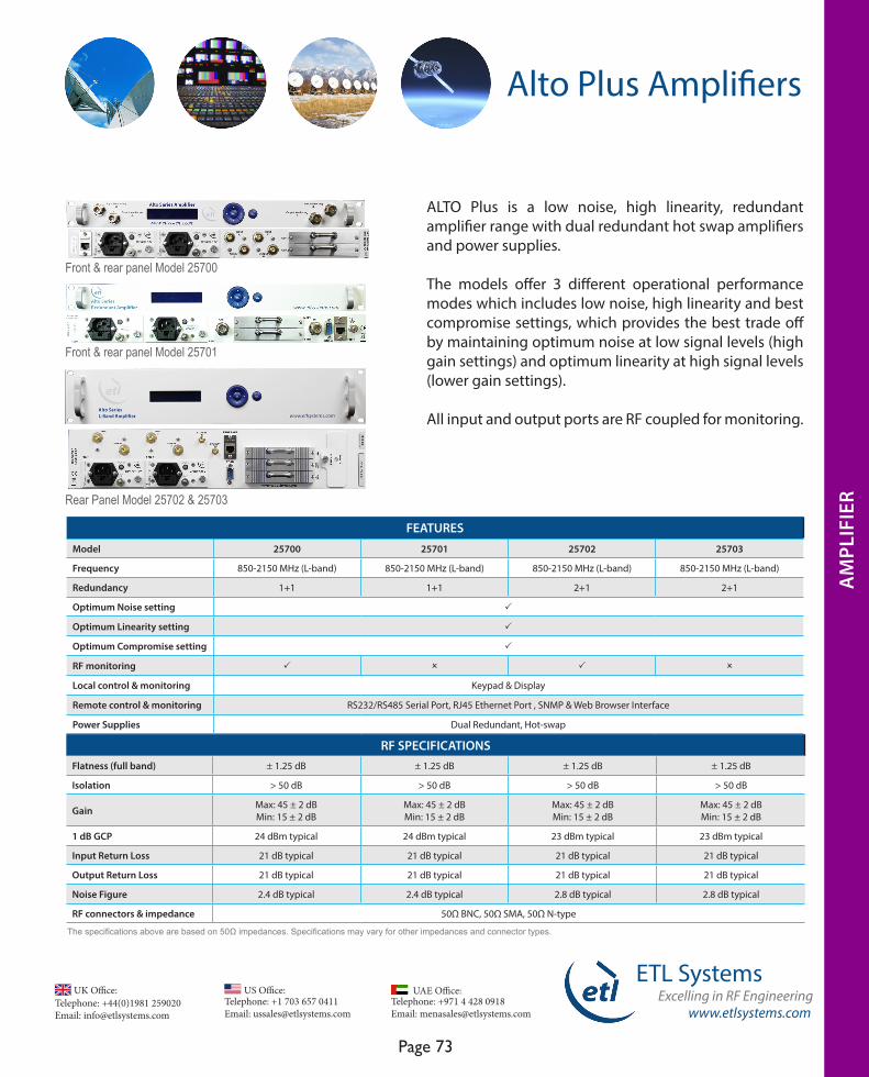
www.etlsystems.com
ETL SystemsExcelling in RF Engineering
Page 73
Telephone: +971 4 428 0918 Email: [email protected]
UAE Office: Telephone: +44(0)1981 259020 Email: [email protected]
UK Office:Telephone: +1 703 657 0411 Email: [email protected]
US Office:
Rear Panel Model 25702 & 25703
Front & rear panel Model 25700
Front & rear panel Model 25701
Alto Plus Amplifiers
ALTO Plus is a low noise, high linearity, redundant amplifier range with dual redundant hot swap amplifiers and power supplies.
The models offer 3 different operational performance modes which includes low noise, high linearity and best compromise settings, which provides the best trade off by maintaining optimum noise at low signal levels (high gain settings) and optimum linearity at high signal levels (lower gain settings).
All input and output ports are RF coupled for monitoring.
The specifications above are based on 50Ω impedances. Specifications may vary for other impedances and connector types.
RF SPECIFICATIONSFlatness (full band) ± 1.25 dB ± 1.25 dB ± 1.25 dB ± 1.25 dB
Isolation > 50 dB > 50 dB > 50 dB > 50 dB
Gain Max: 45 ± 2 dBMin: 15 ± 2 dB
Max: 45 ± 2 dBMin: 15 ± 2 dB
Max: 45 ± 2 dBMin: 15 ± 2 dB
Max: 45 ± 2 dBMin: 15 ± 2 dB
1 dB GCP 24 dBm typical 24 dBm typical 23 dBm typical 23 dBm typical
Input Return Loss 21 dB typical 21 dB typical 21 dB typical 21 dB typical
Output Return Loss 21 dB typical 21 dB typical 21 dB typical 21 dB typical
Noise Figure 2.4 dB typical 2.4 dB typical 2.8 dB typical 2.8 dB typical
RF connectors & impedance 50Ω BNC, 50Ω SMA, 50Ω N-type
FEATURES Model 25700 25701 25702 25703
Frequency 850-2150 MHz (L-band) 850-2150 MHz (L-band) 850-2150 MHz (L-band) 850-2150 MHz (L-band)
Redundancy 1+1 1+1 2+1 2+1
Optimum Noise setting P
Optimum Linearity setting P
Optimum Compromise setting P
RF monitoring P O P O
Local control & monitoring Keypad & Display
Remote control & monitoring RS232/RS485 Serial Port, RJ45 Ethernet Port , SNMP & Web Browser Interface
Power Supplies Dual Redundant, Hot-swap
AM
PLIF
IER
AM
PLIF
IER
AM
PLIF
IER
AM
PLIF
IER
AM
PLIF
IER
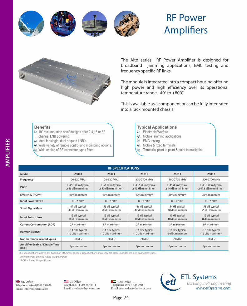
www.etlsystems.com
ETL SystemsExcelling in RF Engineering
Page 74
Telephone: +971 4 428 0918 Email: [email protected]
UAE Office: Telephone: +44(0)1981 259020 Email: [email protected]
UK Office:Telephone: +1 703 657 0411 Email: [email protected]
US Office:
RF Power Amplifiers
The Alto series RF Power Amplifier is designed for broadband jamming applications, EMC testing and frequency specific RF links.
The module is integrated into a compact housing offering high power and high efficiency over its operational temperature range, -40° to +80°C.
This is available as a component or can be fully integrated into a rack mounted chassis.
AM
PLIF
IER
Typical Applications Electronic Warfare Mobile jamming applications EMC testing Mobile & fixed terminals Terrestrial point to point & point to multipoint
Benefits 19” rack mounted shelf designs offer 2,4,16 or 32 channel LNB powering. Ideal for single, dual or quad LNB’s. Wide variety of remote control and monitoring options. Wide choice of RF connector types fitted.
RF SPECIFICATIONSModel 25800 25801 25810 25811 25812
Frequency 20-520 MHz 20-520 MHz 500-2700 MHz 500-2700 MHz 500-2700 MHz
Psat* ≥ 46.3 dBm typical≥ 46 dBm minimum
≥ 51 dBm typical≥ 50 dBm minimum
≥ 43.5 dBm typical≥ 43 dBm minimum
≥ 45 dBm typical≥ 44 dBm minimum
≥ 48.8 dBm typical≥ 47.8 dBm minimum
Efficiency (ROP**) 45% minimum 45% minimum 40% minimum 25% minimum 35% minimum
Input Power (ROP) 0 ± 2 dBm 0 ± 2 dBm 0 ± 2 dBm 0 ± 2 dBm 0 ± 2 dBm
Small Signal Gain 47 dB typical44 dB minimum
55 dB typical50 dB minimum
46 dB typical42 dB minimum
54 dB typical48 dB minimum
58 dB typical55 dB minimum
Input Return Loss 15 dB typical10 dB minimum
15 dB typical10 dB minimum
15 dB typical10 dB minimum
15 dB typical10 dB minimum
15 dB typical8 dB minimum
Current Consumption (ROP) 2A maximum 8A maximum 2A maximum 3A maximum 9A maximum
Harmonics (ROP) -14 dBc typical-10 dBc maximum
-14 dBc typical-10 dBc maximum
-14 dBc typical-10 dBc maximum
-14 dBc typical-9 dBc maximum
-18 dBc typical-12 dBc maximum
Non-harmonic related Spurii -60 dBc -60 dBc -60 dBc -60 dBc -60 dBc
Amplifier Enable / Disable Time (ROP) 5µs maximum 5µs maximum 5µs maximum 5µs maximum 5µs maximum
AM
PLIF
IER
The specifications above are based on 50Ω impedances. Specifications may vary for other impedances and connector types.*Minimum Psat defines Rated Output Power**ROP = Rated Output Power
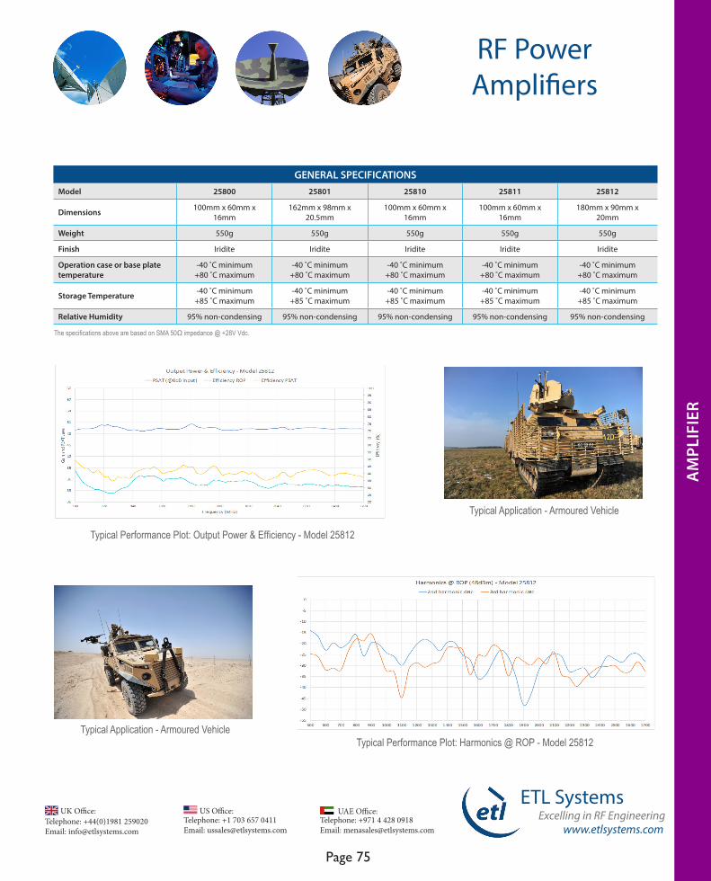
www.etlsystems.com
ETL SystemsExcelling in RF Engineering
Page 75
Telephone: +971 4 428 0918 Email: [email protected]
UAE Office: Telephone: +44(0)1981 259020 Email: [email protected]
UK Office:Telephone: +1 703 657 0411 Email: [email protected]
US Office:
GENERAL SPECIFICATIONSModel 25800 25801 25810 25811 25812
Dimensions 100mm x 60mm x 16mm
162mm x 98mm x 20.5mm
100mm x 60mm x 16mm
100mm x 60mm x 16mm
180mm x 90mm x 20mm
Weight 550g 550g 550g 550g 550g
Finish Iridite Iridite Iridite Iridite Iridite
Operation case or base plate temperature
-40 ˚C minimum+80 ˚C maximum
-40 ˚C minimum+80 ˚C maximum
-40 ˚C minimum+80 ˚C maximum
-40 ˚C minimum+80 ˚C maximum
-40 ˚C minimum+80 ˚C maximum
Storage Temperature -40 ˚C minimum+85 ˚C maximum
-40 ˚C minimum+85 ˚C maximum
-40 ˚C minimum+85 ˚C maximum
-40 ˚C minimum+85 ˚C maximum
-40 ˚C minimum+85 ˚C maximum
Relative Humidity 95% non-condensing 95% non-condensing 95% non-condensing 95% non-condensing 95% non-condensing
The specifications above are based on SMA 50Ω impedance @ +28V Vdc.
RF Power Amplifiers
Typical Performance Plot: Output Power & Efficiency - Model 25812
Typical Application - Armoured Vehicle
Typical Application - Armoured Vehicle
Typical Performance Plot: Harmonics @ ROP - Model 25812
AM
PLIF
IER
AM
PLIF
IER
AM
PLIF
IER
AM
PLIF
IER
AM
PLIF
IER
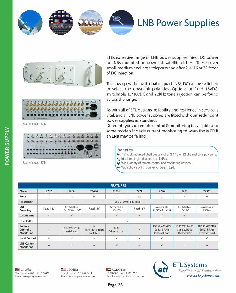
Telephone: +44(0)1981 259020 Email: [email protected]
UK Office:Telephone: +1 703 657 0411 Email: [email protected]
US Office:
www.etlsystems.com
ETL SystemsExcelling in RF Engineering
Page 76
Telephone: +971 4 428 0918 Email: [email protected]
UAE Office:
LNB Power Supplies
ETL’s extensive range of LNB power supplies inject DC power to LNBs mounted on downlink satellite dishes. These cover small, medium and large teleports and offer 2, 4, 16 or 32 feeds of DC injection.
To allow operation with dual or quad LNBs, DC can be switched to select the downlink polarities. Options of fixed 18vDC, switchable 13/18vDC and 22KHz tone injection can be found across the range.
As with all of ETL designs, reliability and resilience in service is vital, and all LNB power supplies are fitted with dual redundant power supplies as standard. Different types of remote control & monitoring is available and some models include current monitoring to warn the MCR if an LNB may be failing.
Benefits 19” rack mounted shelf designs offer 2,4,16 or 32 channel LNB powering. Ideal for single, dual or quad LNB’s. Wide variety of remote control and monitoring options. Wide choice of RF connector types fitted.
FEATURESModel 2732 2764 2745A 2772-E 2774 2776 2778 22361
Ports 16 16 16 16 32 2 4 4
Frequency 850-2150MHz (L-band)
LNB Powering Fixed 18V Switchable
13/18V & on/off Fixed 18V Switchable 13/18V Fixed 18V Switchable
13/18V & on/offSwitchable
13/18VSwitchable
13/18V
22 KHz tone O P O P O P P P
Dual PSU’s P
Remote Control & Monitoring
ORS232/422/485
serial port
O(Ethernet option
available)
RJ45 Ethernet port O
RS232/422/485 Serial & RJ45 Ethernet port
RS232/422/485 Serial & RJ45 Ethernet port
RS232/422/485 Serial & RJ45 Ethernet port
Local Control O P O P O P P P
LNB Current Monitoring O P O P O P P O
POW
ER S
UPP
LY
Rear of model 2732
Rear of model 2764
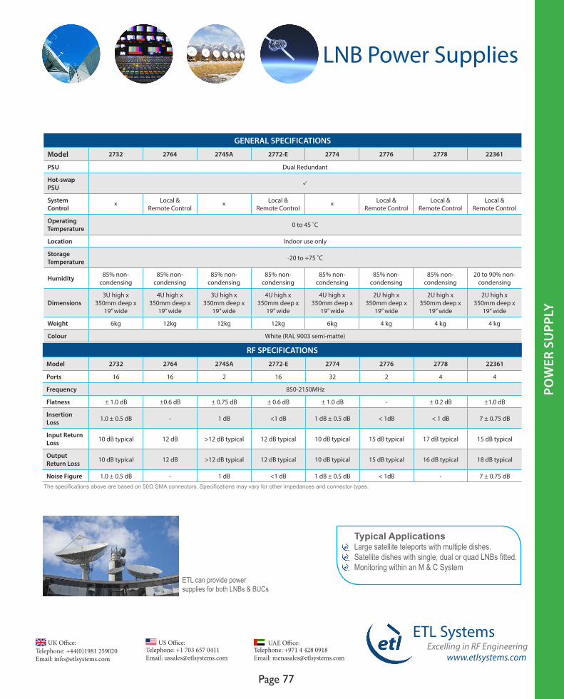
www.etlsystems.com
ETL SystemsExcelling in RF Engineering
Page 77
Telephone: +971 4 428 0918 Email: [email protected]
UAE Office: Telephone: +44(0)1981 259020 Email: [email protected]
UK Office:Telephone: +1 703 657 0411 Email: [email protected]
US Office:
POW
ER S
UPP
LYPO
WER
SU
PPLY
RF SPECIFICATIONSModel 2732 2764 2745A 2772-E 2774 2776 2778 22361
Ports 16 16 2 16 32 2 4 4
Frequency 850-2150MHz
Flatness ± 1.0 dB ±0.6 dB ± 0.75 dB ± 0.6 dB ± 1.0 dB - ± 0.2 dB ±1.0 dB
Insertion Loss 1.0 ± 0.5 dB - 1 dB <1 dB 1 dB ± 0.5 dB < 1dB < 1 dB 7 ± 0.75 dB
Input Return Loss 10 dB typical 12 dB >12 dB typical 12 dB typical 10 dB typical 15 dB typical 17 dB typical 15 dB typical
Output Return Loss 10 dB typical 12 dB >12 dB typical 12 dB typical 10 dB typical 15 dB typical 16 dB typical 18 dB typical
Noise Figure 1.0 ± 0.5 dB - 1 dB <1 dB 1 dB ± 0.5 dB < 1dB - 7 ± 0.75 dB
GENERAL SPECIFICATIONS
Model 2732 2764 2745A 2772-E 2774 2776 2778 22361
PSU Dual Redundant
Hot-swapPSU P
System Control O
Local & Remote Control O
Local & Remote Control O
Local & Remote Control
Local & Remote Control
Local & Remote Control
Operating Temperature 0 to 45 ˚C
Location Indoor use only
Storage Temperature -20 to +75 ˚C
Humidity 85% non-condensing
85% non-condensing
85% non-condensing
85% non-condensing
85% non-condensing
85% non-condensing
85% non-condensing
20 to 90% non-condensing
Dimensions3U high x
350mm deep x 19” wide
4U high x 350mm deep x
19” wide
3U high x 350mm deep x
19” wide
4U high x 350mm deep x
19” wide
4U high x 350mm deep x
19” wide
2U high x 350mm deep x
19” wide
2U high x 350mm deep x
19” wide
2U high x 350mm deep x
19” wide
Weight 6kg 12kg 12kg 12kg 6kg 4 kg 4 kg 4 kg
Colour White (RAL 9003 semi-matte)
The specifications above are based on 50Ω SMA connectors. Specifications may vary for other impedances and connector types.
LNB Power Supplies
Typical ApplicationsLarge satellite teleports with multiple dishes.Satellite dishes with single, dual or quad LNBs fitted.Monitoring within an M & C System ETL can provide power
supplies for both LNBs & BUCs
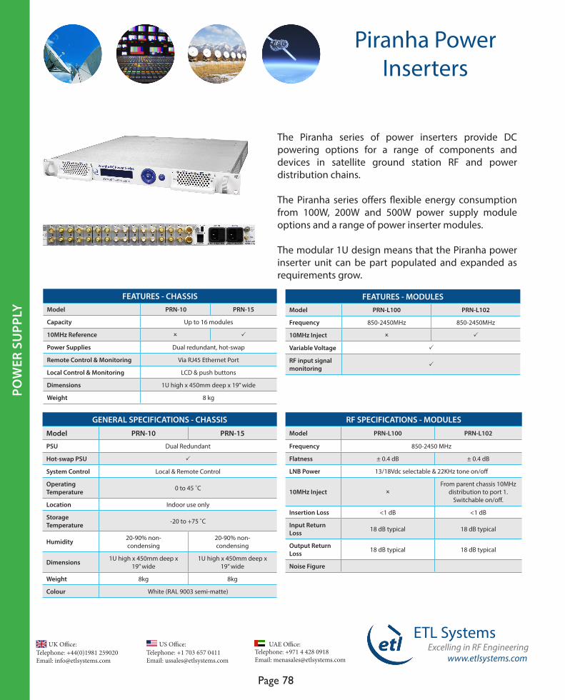
Telephone: +44(0)1981 259020 Email: [email protected]
UK Office:Telephone: +1 703 657 0411 Email: [email protected]
US Office:
www.etlsystems.com
ETL SystemsExcelling in RF Engineering
Page 78
Telephone: +971 4 428 0918 Email: [email protected]
UAE Office:
POW
ER IN
SERT
ER
Piranha Power Inserters
FEATURES - CHASSIS Model PRN-10 PRN-15
Capacity Up to 16 modules
10MHz Reference O P
Power Supplies Dual redundant, hot-swap
Remote Control & Monitoring Via RJ45 Ethernet Port
Local Control & Monitoring LCD & push buttons
Dimensions 1U high x 450mm deep x 19” wide
Weight 8 kg
FEATURES - MODULESModel PRN-L100 PRN-L102
Frequency 850-2450MHz 850-2450MHz
10MHz Inject O P
Variable Voltage P
RF input signal monitoring P
RF SPECIFICATIONS - MODULESModel PRN-L100 PRN-L102
Frequency 850-2450 MHz
Flatness ± 0.4 dB ± 0.4 dB
LNB Power 13/18Vdc selectable & 22KHz tone on/off
10MHz Inject OFrom parent chassis 10MHz
distribution to port 1. Switchable on/off.
Insertion Loss <1 dB <1 dB
Input Return Loss 18 dB typical 18 dB typical
Output Return Loss 18 dB typical 18 dB typical
Noise Figure
GENERAL SPECIFICATIONS - CHASSIS
Model PRN-10 PRN-15
PSU Dual Redundant
Hot-swap PSU P
System Control Local & Remote Control
Operating Temperature 0 to 45 ˚C
Location Indoor use only
Storage Temperature -20 to +75 ˚C
Humidity 20-90% non-condensing
20-90% non-condensing
Dimensions 1U high x 450mm deep x 19” wide
1U high x 450mm deep x 19” wide
Weight 8kg 8kg
Colour White (RAL 9003 semi-matte)
The Piranha series of power inserters provide DC powering options for a range of components and devices in satellite ground station RF and power distribution chains.
The Piranha series offers flexible energy consumption from 100W, 200W and 500W power supply module options and a range of power inserter modules.
The modular 1U design means that the Piranha power inserter unit can be part populated and expanded as requirements grow.
POW
ER S
UPP
LY

www.etlsystems.com
ETL SystemsExcelling in RF Engineering
Page 79
Telephone: +971 4 428 0918 Email: [email protected]
UAE Office: Telephone: +44(0)1981 259020 Email: [email protected]
UK Office:Telephone: +1 703 657 0411 Email: [email protected]
US Office:
MO
DU
LAR
SYST
EM
Modular System
The modular system comprises a chassis which accommodates up to 16 hot-swap RF modules (8 modules for 8-way versions), dual redundant hot-swap PSUs and a hot-swap CPU.
The modules are constructed from ETL’s high performance technology building blocks and can be inserted while the shelf is in service giving excellent levels of flexibility and resilience.
Benefits Handles satellite signals over IF & L-band. 4 and 8-way splitter or combiner cards available. Different card types can be mixed within the same chassis. Resilience in service with hot-swappable active components (chassis).
FEATURES - CHASSIS
Capacity Up to 16 4-way modules & 8 8-way modules
Remote Control & Monitoring RS232/RS485 Serial Port, RJ45 Ethernet Port, SNMP, Web Browser Interface & PC Software (optional)
Hot-swap Active Components RF Splitter/Combiner Cards, CPU & PSU’s
Dual Redundant PSUs P
RF MODULE OPTIONSModulFunctionalityOptions
Operating FrequencyActive Passive
Gain Slope Compensation LNB Powering
Dual Redundant Amplifiers
RF Level DetectionL-band IF Fixed Variable Fixed Variable
4-way splitter modules P P P P P P O P P P P
8-way splitter modules P P P O P P O P P P P
4-way combiner modules P O P O P P P P O P O
8-way combiner modules P O P O O P O P O O O
Amplifier modules P P O O P P P P O P P
Redundancy switch modules P O O O O O O O P O P

Telephone: +44(0)1981 259020 Email: [email protected]
UK Office:Telephone: +1 703 657 0411 Email: [email protected]
US Office:
www.etlsystems.com
ETL SystemsExcelling in RF Engineering
Page 80
Telephone: +971 4 428 0918 Email: [email protected]
UAE Office:
MO
DU
LAR
SYST
EM
Modular System
Typical Applications Expansion of ETL’s RF matrix range. Compensating for cable and other system losses between satellite dishes and the teleport. Distribution of multiple polarities into a teleport. Signal distribution into standby IRD’s. Combining signals in Tx chains to the BUC.
Modular system chassis showing hot-swap RF module, power supply and CPU module
RF splitter and combiner modules showing gain & slope settings
GENERAL SPECIFICATIONS - 26128 CHASSISPSU Dual Redundant
Hot-swap PSU P
System Control Local & Remote Control
Operating Temperature 0 to 45˚C
Location Indoor use only
Storage Temperature -20˚C to +75˚C
Humidity 85% non-condensing
Dimensions 4U high x 450mm deep x 19” wide
Weight 20 kg
Colour White ( RAL 9003 semi-matte)
MO
DU
LAR
SYST
EM

www.etlsystems.com
ETL SystemsExcelling in RF Engineering
Page 81
Telephone: +971 4 428 0918 Email: [email protected]
UAE Office: Telephone: +44(0)1981 259020 Email: [email protected]
UK Office:Telephone: +1 703 657 0411 Email: [email protected]
US Office:
Rear view of Modular System chassis fitted with 8 x 8-way splitter modules (each module takes up 2 slots)
Modular System
FEATURESModel 26128-
DIV40426128-DIV407
26128-DIV409
26128-DIV411
26128-DIV415
26128-DIV804
26128-DIV807
26128-DIV811
Frequency 850-2150 MHz (L-band)
850-2150 MHz (L-band)
950 -2150 MHz (L-band)
850-2150 MHz (L-band)
850-2150 MHz (L-band)
850-2150 MHz (L-band)
850-2150 MHz (L-band)
1000-1400 MHz (L-band)
Capacity 4-way 4-way 4-way 4-way 4-way 8-way 8-way 8-way
Variable SlopeCompensation O P O O O O P O
Fixed Gain P O P P P P O O
Variable Gain O P O O O O P P
Switchable LNB Power & 22KHz tone P P O O O P P P
RF SPECIFICATIONS
Model 26128-DIV404
26128-DIV407
26128-DIV409
26128-DIV411
26128-DIV415
26128-DIV804
26128-DIV807
26128-DIV811
Frequency 850-2150 MHz 850-2150 MHz 950-2150 MHz 850-2150 MHz 850-2150 MHz 850-2150 MHz 850-2150 MHz 1000-1400 MHz
Flatness ± 1.5 dB ± 2.0 dB ± 1.5 dB ± 1.5 dB ± 1.0 typical ± 1.5 dB ± 2.0 dB ± 0.5dB
Gain 0 dB ± 2.0 dB Max: 28 ± 2 dBMin: 0 ± 2 dB
Max: +3 dBMin: -3 dB 8 ± 2 dB 8 ± 2 dB 0 ± 2 dB Max: 24 ± 2 dB
Min: 0 ± 2 dBMax: ≥10 dBMin: ≤ 0 dB
1 dB GCP +5 dBm
Minimum: 0 dBm
Maximum:10 dBm
Minimum: > -5 dBm
Maximum: > +10 dBm
+8 dBm 10 dBm +3 dBm
Minimum:0 dBm
Maximum:5 dBm
10 dBm
Input Return Loss 14 dB typical 14 dB typical 12 dB typical 14 dB typical 15 dB typical 12 dB typical 14 dB typical ≥ 15 dB typical
Output Return Loss 14 dB typical 14 dB typical 12 dB typical 14 dB typical 15 dB typical 12 dB typical 14 dB typical ≥ 15 dB typical
Noise Figure 16 dB
Maximum:30 dB
Minimum:12 dB
Maximum:18 dB
Minnimum: 15 dB
15 dB 10 dB 14 dB
Maximum:30 dB
Minimum:12 dB
25 dB
Splitter Modules ETL’s Modular System Splitter and Combiner cards offer flexibility in managing IF & L-band signals. With a large number of options available this solution is suitable for a wide number of applications.
MO
DU
LAR
SYST
EM

Telephone: +44(0)1981 259020 Email: [email protected]
UK Office:Telephone: +1 703 657 0411 Email: [email protected]
US Office:
www.etlsystems.com
ETL SystemsExcelling in RF Engineering
Page 82
Telephone: +971 4 428 0918 Email: [email protected]
UAE Office:
MO
DU
LAR
SYST
EM
Modular system being used to distribute live signals in European Teleport. Note the monitoring shelf above which allows hand held carrier monitoring of signal condition.
RF SPECIFICATIONS Model 26128-COM402 26128-COM403 26128-COM407 26128-COM409 26128-COM807
Frequency 850-2150 MHz 850-2150 MHz 850-2150 MHz 950 to 2150 MHz 850-2150 MHz
Flatness ± 1.5 dB ± 1.5 dB ± 1.5 dB ± 1.5 dB ± 2.0 dB
Gain 0-28 dB 0 ± 2 dB 0-28 dB Minimum: -3 dB Maximum: +3 dB
Minimum: 0 ± 2 dBMaximum: 24 ± 2 dB
1 dB GCP
+10 dBm + 5 dBm0 dB gain setting: -5dBm
14 dB gain setting:+10dBm28 dB gain setting:+15dBm
Minimum gain setting:> -5 dBm
Maximum gain setting: > +10 dBm
0 dB gain: 0 dBm 14 dB gain: 14 dBm24 dB gain: 16 dBm
Input Return Loss 12 dB typical 12 dB typical 12 dB typical 12 dB typical 14 dB typical
Output Return Loss 12 dB typical 12 dB typical 12 dB typical 12 dB typical 14 dB typical
Noise Figure
10 dB 15 dB 0 dB gain setting: 25 dB
14 dB gain setting: 18 dB 28 dB gain setting: 17 dB
Minimum gain setting:20 dB
Maximum gain setting:18 dB
0 dB gain: 24 dB14 dB gain: 21 dB24 dB gain: 20 dB
The specifications above are based on 50Ω SMA connectors. Other impedances and connector types are available - specifications may vary.
Modular System
FEATURES
Model 26128-COM402 26128-COM403 26128-COM407 26128-COM409 26128-COM807
Frequency 850-2150 MHz (L-band) 850-2150 MHz (L-band) 850-2150 MHz (L-band) 950 to 2150 MHz (L-band) 850-2150 MHz (L-band)
Capacity 4-way 4-way 4-way 4-way 8-way
Variable Slope Compensation O O P O P
Fixed Gain O P O P O
Variable Gain P O P O P
Combiner Modules
MO
DU
LAR
SYST
EM
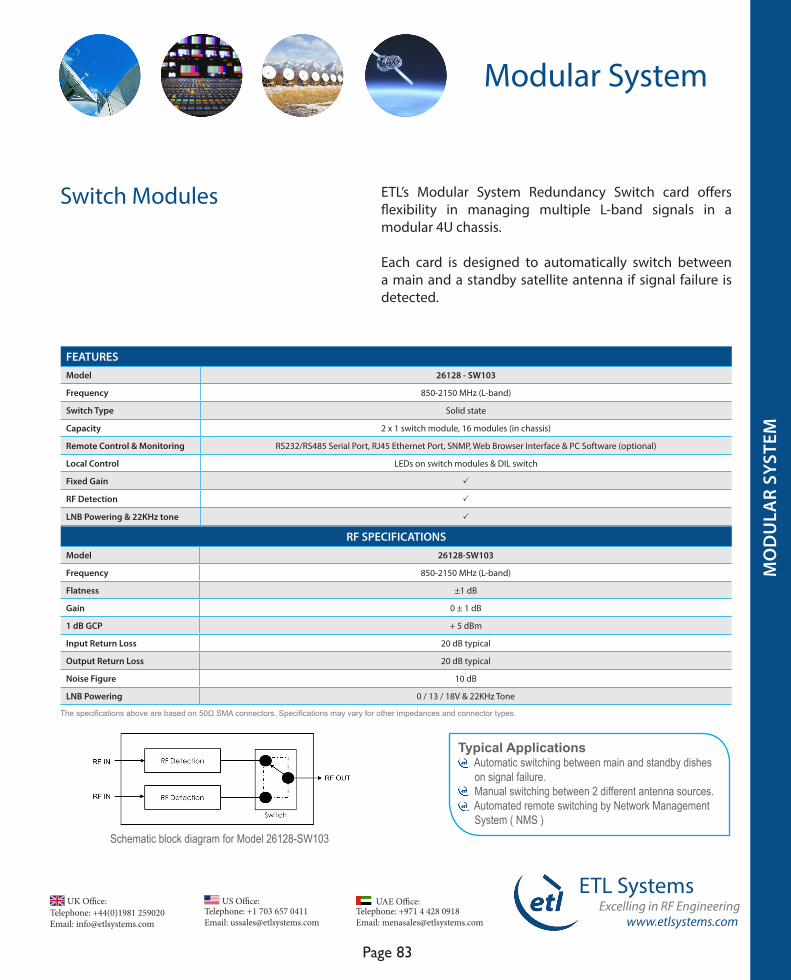
www.etlsystems.com
ETL SystemsExcelling in RF Engineering
Page 83
Telephone: +971 4 428 0918 Email: [email protected]
UAE Office: Telephone: +44(0)1981 259020 Email: [email protected]
UK Office:Telephone: +1 703 657 0411 Email: [email protected]
US Office:
Modular System
RF SPECIFICATIONSModel 26128-SW103
Frequency 850-2150 MHz (L-band)
Flatness ±1 dB
Gain 0 ± 1 dB
1 dB GCP + 5 dBm
Input Return Loss 20 dB typical
Output Return Loss 20 dB typical
Noise Figure 10 dB
LNB Powering 0 / 13 / 18V & 22KHz Tone
The specifications above are based on 50Ω SMA connectors. Specifications may vary for other impedances and connector types.
Schematic block diagram for Model 26128-SW103
Typical Applications Automatic switching between main and standby dishes on signal failure. Manual switching between 2 different antenna sources. Automated remote switching by Network Management System ( NMS )
Switch Modules
FEATURESModel 26128 - SW103
Frequency 850-2150 MHz (L-band)
Switch Type Solid state
Capacity 2 x 1 switch module, 16 modules (in chassis)
Remote Control & Monitoring RS232/RS485 Serial Port, RJ45 Ethernet Port, SNMP, Web Browser Interface & PC Software (optional)
Local Control LEDs on switch modules & DIL switch
Fixed Gain P
RF Detection P
LNB Powering & 22KHz tone P
ETL’s Modular System Redundancy Switch card offers flexibility in managing multiple L-band signals in a modular 4U chassis.
Each card is designed to automatically switch between a main and a standby satellite antenna if signal failure is detected.
MO
DU
LAR
SYST
EM
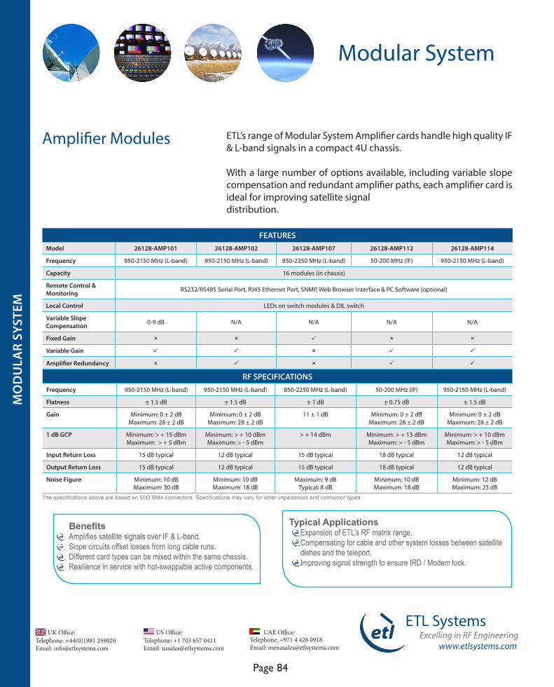
Telephone: +44(0)1981 259020 Email: [email protected]
UK Office:Telephone: +1 703 657 0411 Email: [email protected]
US Office:
www.etlsystems.com
ETL SystemsExcelling in RF Engineering
Page 84
Telephone: +971 4 428 0918 Email: [email protected]
UAE Office:
Modular System
RF SPECIFICATIONSFrequency 950-2150 MHz (L-band) 950-2150 MHz (L-band) 850-2250 MHz (L-band) 50-200 MHz (IF) 950-2150 MHz (L-band)
Flatness ± 1.5 dB ± 1.5 dB ± 1 dB ± 0.75 dB ± 1.5 dB
Gain Minimum: 0 ± 2 dB Maximum: 28 ± 2 dB
Minimum: 0 ± 2 dB Maximum: 28 ± 2 dB
11 ± 1 dB Minimum: 0 ± 2 dB Maximum: 28 ± 2 dB
Minimum: 0 ± 2 dB Maximum: 28 ± 2 dB
1 dB GCP Minimum: > + 15 dBmMaximum: > + 5 dBm
Minimum: > + 10 dBm Maximum: > - 5 dBm
> + 14 dBm Minimum: > + 13 dBm Maximum: > - 5 dBm
Minimum: > + 10 dBm Maximum: > - 5 dBm
Input Return Loss 15 dB typical 12 dB typical 15 dB typical 18 dB typical 12 dB typical
Output Return Loss 15 dB typical 12 dB typical 15 dB typical 18 dB typical 12 dB typical
Noise Figure Minimum: 10 dB Maximum: 30 dB
Minimum: 10 dB Maximum: 18 dB
Maximum: 9 dBTypical: 8 dB
Minimum: 10 dB Maximum: 18 dB
Minimum: 12 dB Maximum: 23 dB
The specifications above are based on 50Ω SMA connectors. Specifications may vary for other impedances and connector types.
Typical Applications Expansion of ETL’s RF matrix range. Compensating for cable and other system losses between satellite dishes and the teleport. Improving signal strength to ensure IRD / Modem lock.
ETL’s range of Modular System Amplifier cards handle high quality IF & L-band signals in a compact 4U chassis.
With a large number of options available, including variable slope compensation and redundant amplifier paths, each amplifier card is ideal for improving satellite signaldistribution.
BenefitsAmplifies satellite signals over IF & L-band.Slope circuits offset losses from long cable runs. Different card types can be mixed within the same chassis.Resilience in service with hot-swappable active components.
FEATURESModel 26128-AMP101 26128-AMP102 26128-AMP107 26128-AMP112 26128-AMP114
Frequency 950-2150 MHz (L-band) 950-2150 MHz (L-band) 850-2250 MHz (L-band) 50-200 MHz (IF) 950-2150 MHz (L-band)
Capacity 16 modules (in chassis)
Remote Control & Monitoring RS232/RS485 Serial Port, RJ45 Ethernet Port, SNMP, Web Browser Interface & PC Software (optional)
Local Control LEDs on switch modules & DIL switch
Variable Slope Compensation 0-9 dB N/A N/A N/A N/A
Fixed Gain O O P O O
Variable Gain P P O P P
Amplifier Redundancy O P O P P
Amplifier Modules
MO
DU
LAR
SYST
EM
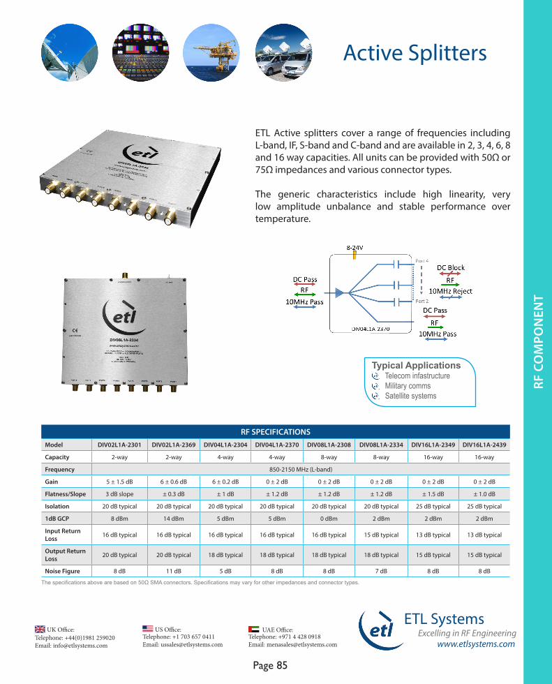
www.etlsystems.com
ETL SystemsExcelling in RF Engineering
Page 85
Telephone: +971 4 428 0918 Email: [email protected]
UAE Office: Telephone: +44(0)1981 259020 Email: [email protected]
UK Office:Telephone: +1 703 657 0411 Email: [email protected]
US Office:
Active Splitters
RF C
OM
PO
NEN
T
ETL Active splitters cover a range of frequencies including L-band, IF, S-band and C-band and are available in 2, 3, 4, 6, 8 and 16 way capacities. All units can be provided with 50Ω or 75Ω impedances and various connector types.
The generic characteristics include high linearity, very low amplitude unbalance and stable performance over temperature.
Typical Applications Telecom infastructure Military comms Satellite systems
RF SPECIFICATIONS Model DIV02L1A-2301 DIV02L1A-2369 DIV04L1A-2304 DIV04L1A-2370 DIV08L1A-2308 DIV08L1A-2334 DIV16L1A-2349 DIV16L1A-2439
Capacity 2-way 2-way 4-way 4-way 8-way 8-way 16-way 16-way
Frequency 850-2150 MHz (L-band)
Gain 5 ± 1.5 dB 6 ± 0.6 dB 6 ± 0.2 dB 0 ± 2 dB 0 ± 2 dB 0 ± 2 dB 0 ± 2 dB 0 ± 2 dB
Flatness/Slope 3 dB slope ± 0.3 dB ± 1 dB ± 1.2 dB ± 1.2 dB ± 1.2 dB ± 1.5 dB ± 1.0 dB
Isolation 20 dB typical 20 dB typical 20 dB typical 20 dB typical 20 dB typical 20 dB typical 25 dB typical 25 dB typical
1dB GCP 8 dBm 14 dBm 5 dBm 5 dBm 0 dBm 2 dBm 2 dBm 2 dBm
Input Return Loss 16 dB typical 16 dB typical 16 dB typical 16 dB typical 16 dB typical 15 dB typical 13 dB typical 13 dB typical
Output Return Loss 20 dB typical 20 dB typical 18 dB typical 18 dB typical 18 dB typical 18 dB typical 15 dB typical 15 dB typical
Noise Figure 8 dB 11 dB 5 dB 8 dB 8 dB 7 dB 8 dB 8 dB
The specifications above are based on 50Ω SMA connectors. Specifications may vary for other impedances and connector types.
RF C
OM
PON
ENT
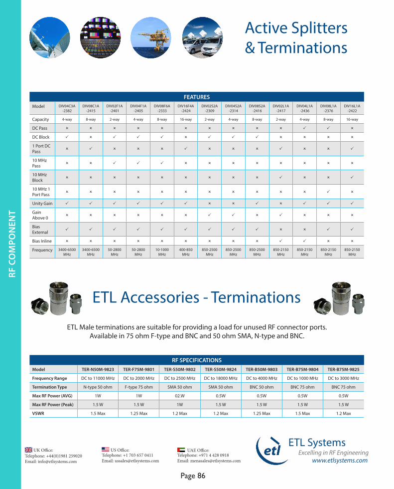
www.etlsystems.com
ETL SystemsExcelling in RF Engineering
Page 86
Telephone: +971 4 428 0918 Email: [email protected]
UAE Office: Telephone: +44(0)1981 259020 Email: [email protected]
UK Office:Telephone: +1 703 657 0411 Email: [email protected]
US Office:
Active Splitters & Terminations
FEATURESModel DIV04C3A
-2382DIV08C1A
-2415DIV02F1A
-2401 DIV04F1A
-2405DIV08F6A
-2333DIV16F4A
-2424DIV02S2A
-2309DIV04S2A
-2314DIV08S2A
-2416DIV02L1A
-2417DIV04L1A
-2436DIV08L1A
-2376DIV16L1A
-2422
Capacity 4-way 8-way 2-way 4-way 8-way 16-way 2-way 4-way 8-way 2-way 4-way 8-way 16-way
DC Pass O O O O O O O O O O P P O
DC Block P O P P P O P P P O O O O
1 Port DC Pass O P O O O P O O O P O O P
10 MHz Pass O O P P P O O O O O O O O
10 MHz Block O O O O O O O O O P O O P
10 MHz 1 Port Pass O O O O O O O O O O O P O
Unity Gain P P P P P P O O P O P P P
Gain Above 0 O O O O O O P P O P O O O
Bias External P P P P P P P P P O O P P
Bias Inline O O O O O O O O O P P O O
Frequency 3400-6500 MHz
3400-6500 MHz
50-2800 MHz
50-2800 MHz
10-1000 MHz
400-850 MHz
850-2500 MHz
850-2500 MHz
850-2500 MHz
850-2150 MHz
850-2150 MHz
850-2150 MHz
850-2150 MHz
ETL Male terminations are suitable for providing a load for unused RF connector ports. Available in 75 ohm F-type and BNC and 50 ohm SMA, N-type and BNC.
RF SPECIFICATIONSModel TER-N50M-9823 TER-F75M-9801 TER-S50M-9802 TER-S50M-9824 TER-B50M-9803 TER-B75M-9804 TER-B75M-9825
Frequency Range DC to 11000 MHz DC to 2000 MHz DC to 2500 MHz DC to 18000 MHz DC to 4000 MHz DC to 1000 MHz DC to 3000 MHz
Termination Type N-type 50 ohm F-type 75 ohm SMA 50 ohm SMA 50 ohm BNC 50 ohm BNC 75 ohm BNC 75 ohm
Max RF Power (AVG) 1W 1W 02.W 0.5W 0.5W 0.5W 0.5W
Max RF Power (Peak) 1.5 W 1.5 W 1W 1.5 W 1.5 W 1.5 W 1.5 W
VSWR 1.5 Max 1.25 Max 1.2 Max 1.2 Max 1.25 Max 1.5 Max 1.2 Max
ETL Accessories - Terminations
RF C
OM
PON
ENT

www.etlsystems.com
ETL SystemsExcelling in RF Engineering
Page 87
Telephone: +971 4 428 0918 Email: [email protected]
UAE Office: Telephone: +44(0)1981 259020 Email: [email protected]
UK Office:Telephone: +1 703 657 0411 Email: [email protected]
US Office:
Active Combiners
ETL Active combiners cover a range of frequencies including L-band, IF, S-band and C-band and are available in 2, 3, 4, 6, 8, 12 and 16 way capacities. All units can be provided with 50Ω or 75Ω impedances and various connector types.
The generic characteristics include high linearity, very low amplitude unbalance and stable performance over temperature.
Typical Applications Telecom infrastructures Satellite systems Microwave links Test and instrumentation Military communications Radar networks
RF SPECIFICATIONS Model COM02L1A-2201 COM02L1A-2254 COM04L1A-2204 COM04L1A-2252 COM08L1A-2208 COM08L1A-2247 COM16L1A-2223 COM16L1A-2273
Capacity 2-way 2-way 4-way 4-way 8-way 8-way 16-way 16-way
Frequency 850-2150 MHz (L-band)
Gain 10 ± 1.0 dB 0 ± 2 0±1.5 dB 0 ± 1.0 dB 0±1.5 dB 0±1.5 dB 0 ± 0.50 dB 0 ±2 dB
Flatness/Slope ± 0.5 dB ± 0.4 dB ± 0.6 dB ± 0.8 dB ± 0.8 dB ±0.8 dB ± 0.6 dB ± 1 dB
Isolation 16 dB typical 20 dB typical 16 dB typical 16 dB typical 16 dB typical 16 dB typical 20 dB typical 20 dB typical
1dB GCP 9 dBm typical 12 dBm typical 15 dB typical 15 dBm typical 14 dBm typ 15 dBm typical 16 dB typical 10 dBm typical
Input Return Loss 18 typical 16 dB typical 18 dB typical 18 dB typical 14 dB typical 14 dB typical 22 dB typical 20 dB typical
Output Return Loss 15 dB typical 16 dB typical 16 dB typical 16 dB typical 12 dB typical 12 dB typical 20 dB typical 14 dB typical
Noise Figure 9 dB 10 dB typical 16 dB 14 dB 20 dB 20 dB 15 dB 15 dB
The specifications above are based on 50Ω SMA connectors. Specifications may vary for other impedances and connector types.
RF C
OM
PO
NEN
TRF
CO
MPO
NEN
T

www.etlsystems.com
ETL SystemsExcelling in RF Engineering
Page 88
Telephone: +971 4 428 0918 Email: [email protected]
UAE Office: Telephone: +44(0)1981 259020 Email: [email protected]
UK Office:Telephone: +1 703 657 0411 Email: [email protected]
US Office:
Active Combiners & Terminations
FEATURES
Model
COM
04C3
A-
2259
COM
02F1
A-
2101
COM
04F1
A-
2105
COM
08F1
A-
2109
COM
16F6
A-
2272
COM
02S2
A-
2256
COM
04S2
A-
2264
COM
08S2
A-
2218
COM
02L1
A-
2267
COM
04L1
A-
2275
COM
08L1
A-
2235
COM
16L1
A-
2273
Capacity 4-way 2-way 4-way 8-way 16-way 2-way 4-way 8-way 2-way 4-way 8-way 16-way
DC Pass O O O O O O O O O O P O
DC Block P P P P P O P P O O O O
1 Port DC Pass O O O O O P O O P P O P
10MHz Pass O P P P O O O O O O P O
10MHz Block O O O O O O O O P O O O
10MHz 1 Port pass O O O O O P O O O P O P
Unity Gain P P P P P P P P P P P
Gain Above 0 O O O O P O O O O O O O
Bias External P P P P P P P P P P P
Bias Inline O O O O O O O O O P O O
Frequency 3400-6500MHz
50-2800MHz
50-2800MHz
50-2800MHz
10-1000MHz
850-2500MHz
850-2500MHz
850-2500MHz
850-2150MHz
850-2150MHz
850-2150MHz
850-2150MHz
RF SPECIFICATIONSModel TER-N50M-9823 TER-F75M-9801 TER-S50M-9802 TER-S50M-9824 TER-B50M-9803 TER-B75M-9804 TER-B75M-9825
Frequency Range DC to 11000 MHz DC to 2000 MHz DC to 2500 MHz DC to 18000 MHz DC to 4000 MHz DC to 1000 MHz DC to 3000 MHz
Termination Type N-type 50 ohm F-type 75 ohm SMA 50 ohm SMA 50 ohm BNC 50 ohm BNC 75 ohm BNC 75 ohm
Max RF Power (AVG) 1W 1W 02.W 0.5W 0.5W 0.5W 0.5W
Max RF Power (Peak) 1.5 W 1.5 W 1W 1.5 W 1.5 W 1.5 W 1.5 W
VSWR 1.5 Max 1.25 Max 1.2 Max 1.2 Max 1.25 Max 1.5 Max 1.2 Max
ETL 9800 series of Male terminations are suitable for providing a load for unused RF connector ports. Available in 75 ohm F-type and BNC and 50 ohm SMA, N-type and BNC.
ETL Accessories - Terminations
RF C
OM
PON
ENT
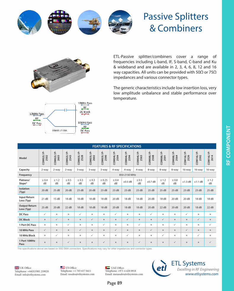
www.etlsystems.com
ETL SystemsExcelling in RF Engineering
Page 89
Telephone: +971 4 428 0918 Email: [email protected]
UAE Office: Telephone: +44(0)1981 259020 Email: [email protected]
UK Office:Telephone: +1 703 657 0411 Email: [email protected]
US Office:
Passive Splitters & Combiners
ETL-Passive splitter/combiners cover a range of frequencies including L-band, IF, S-band, C-band and Ku & wideband and are available in 2, 3, 4, 6, 8, 12 and 16 way capacities. All units can be provided with 50Ω or 75Ω impedances and various connector types.
The generic characteristics include low insertion loss, very low amplitude unbalance and stable performance over temperature.
FEATURES & RF SPECIFICATIONS
Model
COM
02L1
P-25
02
COM
02L1
P-26
03
COM
02L1
P-25
43
COM
03L1
P-25
28
COM
03L1
P-26
02
COM
03L1
P-25
90
COM
04L1
P-25
04
COM
04L1
P-25
94
COM
04L1
P-25
63
COM
08L1
P-25
08
COM
08L1
P-25
91
COM
08L1
P-25
64
COM
16L1
P-25
26
COM
16L1
P-25
92
COM
16L1
P-26
14
Capacity 2-way 2-way 2-way 3-way 3-way 3-way 4-way 4-way 4-way 8-way 8-way 8-way 16-way 16-way 16-way
Frequency 850-2150 MHz
Flatness/Slope*
± 0.4 dB
± 1.2 dB
± 0.5 dB
± 0.3 dB
± 0.3 dB
± 0.25 dB
± 0.4 dB ±0.5 dB ± 0.5
dB ±0.7 dB ± 1.2 dB
± 0.8 dB ±1.3 dB ±1.1 dB ± 1.2
dB
Isolation (Typ) 20 dB 25 dB 20 dB 23 dB 20 dB 23 dB 23 dB 23 dB 23 dB 25 dB 25 dB 25 dB 23 dB 23 dB 25 dB
Input ReturnLoss (Typ) 21 dB 15 dB 18 dB 18 dB 18 dB 18 dB 20 dB 18 dB 18 dB 20 dB 18 dB 20 dB 20 dB 18 dB 18 dB
Output ReturnLoss (Typ) 25 dB 20 dB 22 dB 18 dB 18 dB 18 dB 20 dB 18 dB 18 dB 20 dB 22 dB 20 dB 20 dB 18 dB 22 dB
DC Pass P O O P O O P O O P O O P O O
DC Block O P O O P O O P O O P O O P O
1 Port DC Pass O O P O O P O O P O O P O O P
10 MHz Pass P O O P O O P O O P O O P O O
10 MHz Block O P O O P O O P O O P O O P O
1 Port 10MHz Pass O O P O O P O O P O O P O O P
The specifications above are based on 50Ω SMA connectors. Specifications may vary for other impedances and connector types.
RF C
OM
PO
NEN
TRF
CO
MPO
NEN
T
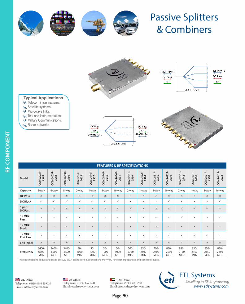
www.etlsystems.com
ETL SystemsExcelling in RF Engineering
Page 90
Telephone: +971 4 428 0918 Email: [email protected]
UAE Office: Telephone: +44(0)1981 259020 Email: [email protected]
UK Office:Telephone: +1 703 657 0411 Email: [email protected]
US Office:
Passive Splitters & Combiners
FEATURES & RF SPECIFICATIONS
Model
COM
02C3
P-25
49
COM
04C3
P-25
88
COM
16C3
P-25
60
COM
02F4
P-26
25
COM
04F4
P-25
37
COM
08F4
P-25
36
COM
16F4
P-26
31
COM
02S1
P-25
99
COM
04S2
P-25
84
COM
08S1
P-26
05
COM
16S2
P-26
39
COM
02L1
P-25
42
COM
04L1
P-26
20
COM
08L1
P-25
68
COM
16L1
P-26
23
Capacity 2-way 4-way 8-way 2-way 4-way 8-way 16-way 2-way 4-way 8-way 16-way 2-way 4-way 8-way 16-way
DC Pass O O O O O O O O P P O O O O O
DC Block P P P P P P P O O O P O O O P
1 port DC Pass O O O O O O O P O O O P P P O
10 MHz Pass O O O O O O O O O P O P O O P
10 MHz Block O O O O O O O O O O O O O O O
10 MHz 1 Port Pass O O O O O O O O O O O O P P O
LNB Inject O O O O O O O O O O O P P O O
Frequency 3400-6500 MHz
3400-6500 MHz
3400-6500 MHz
50-1000 MHz
50-1000 MHz
50-1000 MHz
50-1000 MHz
500-2750 MHz
850-2500 MHz
700-2700 MHz
850-2500 MHz
850-2150 MHz
850-2150 MHz
850-2150 MHz
850-2150 MHz
Typical Applications Telecom infrastructures. Satellite systems. Microwave links. Test and instrumentation. Military Communications. Radar networks.
The specifications above are based on 50Ω SMA connectors. Specifications may vary for other impedances and connector types.
RF C
OM
PON
ENT
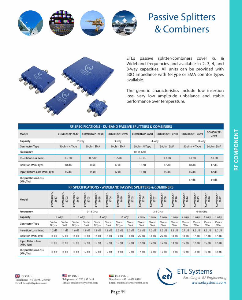
www.etlsystems.com
ETL SystemsExcelling in RF Engineering
Page 91
Telephone: +971 4 428 0918 Email: [email protected]
UAE Office: Telephone: +44(0)1981 259020 Email: [email protected]
UK Office:Telephone: +1 703 657 0411 Email: [email protected]
US Office:
Passive Splitters & Combiners
RF SPECIFICATIONS - KU-BAND PASSIVE SPLITTERS & COMBINERS
Model COM02K2P-2647 COM02K2P- 2698 COM03K2P-2699 COM04K2P-2648 COM04K2P- 2700 COM08K2P- 2649 COM08K2P- 2701
Capacity 2-way 3-way 4-way 8-way
Connector Type 50ohm N-Type 50ohm SMA 50ohm SMA 50ohm N-Type 50ohm SMA 50ohm N-Type 50ohm SMA
Frequency 10-15 GHz
Insertion Loss (Max) 0.5 dB 0.7 dB 1.2 dB 0.8 dB 1.2 dB 1.3 dB 2.0 dB
Isolation (Min, Typ) 18 dB 18 dB 17 dB 16 dB 17 dB 18 dB 17 dB
Input Return Loss (Min, Typ) 15 dB 15 dB 12 dB 12 dB 15 dB 15 dB 12 dB
Output Return Loss (Min,Typ) 17 dB 14 dB
RF SPECIFICATIONS - WIDEBAND PASSIVE SPLITTERS & COMBINERS
Model
COM
02KX
P-26
67
COM
02KX
P-
2702
COM
03KX
P-26
53
COM
03KX
P-
2703
COM
04KX
P-26
68
COM
04KX
P-
2704
COM
08KX
P-26
69
COM
08KX
P-
2705
COM
02CX
P-
2706
COM
03CX
P-
2707
COM
04CX
P-
2708
COM
08CX
P-
2710
COM
02KX
P-26
94
COM
03KX
P-26
95
COM
04KX
P-26
96
COM
08KX
P-26
97
Frequency 2-18 GHz 2-8 GHz 6-18 GHz
Capacity 2-way 3-way 4-way 8-way 2-way 3-way 4-way 8-way 2-way 3-way 4-way 8-way
Connector Type 50ohm N-Type
50ohm SMA
50ohm N-Type
50ohm SMA
50ohm N-Type
50ohm SMA
50ohm N-Type
50ohm SMA
50ohm SMA
50ohm SMA
50ohm SMA
50ohm SMA
50ohm SMA
50ohm SMA
50ohm SMA
50ohm SMA
Insertion Loss (Max) 1.2 dB 1.1 dB 1.6 dB 1.8 dB 1.8 dB 1.8 dB 3.5 dB 3.0 dB 0.6 dB 1.0 dB 1.2 dB 1.8 dB 0.7 dB 1.2 dB 1.2 dB 3.0 dB
Isolation (Min, Typ) 16 dB 19 dB 16 dB 18 dB 16 dB 17 dB 15 dB 16 dB 20 dB 18 dB 20 dB 18 dB 18 dB 17 dB 17 dB 17 dB
Input Return Loss (Min, Typ) 13 dB 15 dB 10 dB 12 dB 12 dB 12 dB 10 dB 10 dB 17 dB 15 dB 15 dB 14 dB 15 dB 12 dB 15 dB 12 dB
Output Return Loss (Min,Typ) 13 dB 15 dB 13 dB 12 dB 12 dB 12 dB 13 dB 10 dB 17 dB 15 dB 15 dB 14 dB 15 dB 12 dB 15 dB 12 dB
ETL’s passive splitter/combiners cover Ku & Wideband frequencies and available in 2, 3, 4, and 8-way capacities. All units can be provided with 50Ω impedance with N-Type or SMA conntor types available.
The generic characteristics include low insertion loss, very low amplitude unbalance and stable performance over temperature.
RF C
OM
PO
NEN
TRF
CO
MPO
NEN
T
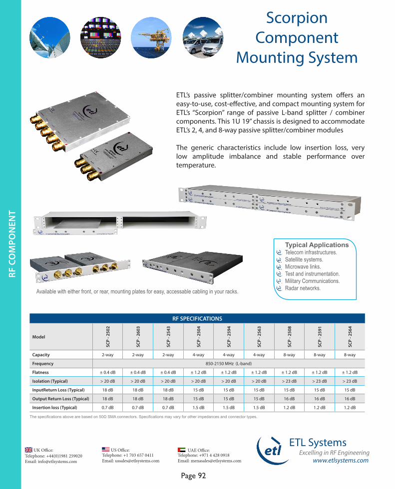
www.etlsystems.com
ETL SystemsExcelling in RF Engineering
Page 92
Telephone: +971 4 428 0918 Email: [email protected]
UAE Office: Telephone: +44(0)1981 259020 Email: [email protected]
UK Office:Telephone: +1 703 657 0411 Email: [email protected]
US Office:
Scorpion Component
Mounting System
ETL’s passive splitter/combiner mounting system offers an easy-to-use, cost-effective, and compact mounting system for ETL’s “Scorpion” range of passive L-band splitter / combiner components. This 1U 19” chassis is designed to accommodate ETL’s 2, 4, and 8-way passive splitter/combiner modules
The generic characteristics include low insertion loss, very low amplitude imbalance and stable performance over temperature.
Typical ApplicationsTelecom infrastructures. Satellite systems.Microwave links.Test and instrumentation. Military Communications. Radar networks.
RF SPECIFICATIONS
Model
SCP
- 250
2
SCP
- 260
3
SCP
- 254
3
SCP
- 250
4
SCP
- 259
4
SCP
- 256
3
SCP
- 250
8
SCP
- 259
1
SCP
- 256
4Capacity 2-way 2-way 2-way 4-way 4-way 4-way 8-way 8-way 8-way
Frequency 850-2150 MHz (L-band)
Flatness ± 0.4 dB ± 0.4 dB ± 0.4 dB ± 1.2 dB ± 1.2 dB ± 1.2 dB ± 1.2 dB ± 1.2 dB ± 1.2 dB
Isolation (Typical) > 20 dB > 20 dB > 20 dB > 20 dB > 20 dB > 20 dB > 23 dB > 23 dB > 23 dB
InputReturn Loss (Typical) 18 dB 18 dB 18 dB 15 dB 15 dB 15 dB 15 dB 15 dB 15 dB
Output Return Loss (Typical) 18 dB 18 dB 18 dB 15 dB 15 dB 15 dB 16 dB 16 dB 16 dB
Insertion loss (Typical) 0.7 dB 0.7 dB 0.7 dB 1.5 dB 1.5 dB 1.5 dB 1.2 dB 1.2 dB 1.2 dB
The specifications above are based on 50Ω SMA connectors. Specifications may vary for other impedances and connector types.
Available with either front, or rear, mounting plates for easy, accessable cabling in your racks.
RF C
OM
PON
ENT

www.etlsystems.com
ETL SystemsExcelling in RF Engineering
Page 93
Telephone: +971 4 428 0918 Email: [email protected]
UAE Office: Telephone: +44(0)1981 259020 Email: [email protected]
UK Office:Telephone: +1 703 657 0411 Email: [email protected]
US Office:
Impedance Transformers, DC
Blocks, Attenuators & Power Supplies
ETL DC block units provides reliable DC block which can be used in conjunction with any of ETL’s other products.
ETL Passive impedance transformers cover either an L-band frequency range of 850MHz to 2150MHz or an S-band frequency range of 500MHz to 2500MHz.
ETL Attenuators covering IF and L-band frequencies. The attenuators are available as DC pass or DC block.
ETL’s range of power supplies available for powering ETL components, including amplifiers and active splitters/combiners and anything requiring an LNB bias.
FEATURES - IMPEDANCE TRANSFORMERS Model TRFL1-4600 TRFL1-4601 TRFL1-4602 TRFB4-4603 TRFB4-4604 TRFB4-4605 TRFL1-4606 TRFL1-4607 TRFL1-4608
DC Pass P O O P O O O O P
DC Block O P P O P P O O O
1 Port DC Pass O O O O O O P P O
10 MHz Pass P P P P P P P
10 MHz Block O P O O P O O O O
DC Inject O O O O O O P P O
Frequency 850-2150 MHz 850-2150 MHz 850-2150 MHz 500-2500 MHz 500-2500 MHz 500-2500 MHz 850-2150 MHz 850-2150 MHz 850-2150 MHz
Typical ApplicationsTelecom infrastructures. Satellite systems.Microwave links. Test and instrumentation. Military comms.Radar networks. R
F C
OM
PO
NEN
TRF
CO
MPO
NEN
T
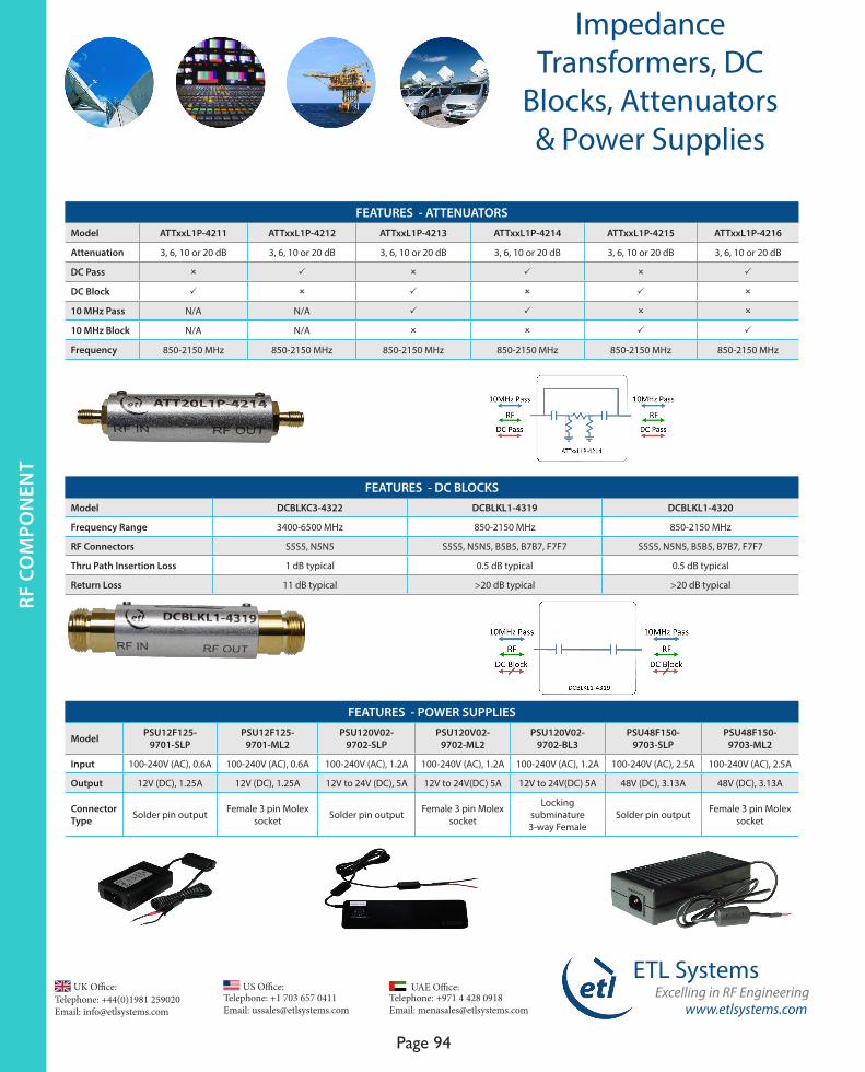
www.etlsystems.com
ETL SystemsExcelling in RF Engineering
Page 94
Telephone: +971 4 428 0918 Email: [email protected]
UAE Office: Telephone: +44(0)1981 259020 Email: [email protected]
UK Office:Telephone: +1 703 657 0411 Email: [email protected]
US Office:
Impedance Transformers, DC
Blocks, Attenuators & Power Supplies
FEATURES - ATTENUATORSModel ATTxxL1P-4211 ATTxxL1P-4212 ATTxxL1P-4213 ATTxxL1P-4214 ATTxxL1P-4215 ATTxxL1P-4216
Attenuation 3, 6, 10 or 20 dB 3, 6, 10 or 20 dB 3, 6, 10 or 20 dB 3, 6, 10 or 20 dB 3, 6, 10 or 20 dB 3, 6, 10 or 20 dB
DC Pass O P O P O P
DC Block P O P O P O
10 MHz Pass N/A N/A P P O O
10 MHz Block N/A N/A O O P P
Frequency 850-2150 MHz 850-2150 MHz 850-2150 MHz 850-2150 MHz 850-2150 MHz 850-2150 MHz
FEATURES - DC BLOCKS Model DCBLKC3-4322 DCBLKL1-4319 DCBLKL1-4320
Frequency Range 3400-6500 MHz 850-2150 MHz 850-2150 MHz
RF Connectors S5S5, N5N5 S5S5, N5N5, B5B5, B7B7, F7F7 S5S5, N5N5, B5B5, B7B7, F7F7
Thru Path Insertion Loss 1 dB typical 0.5 dB typical 0.5 dB typical
Return Loss 11 dB typical >20 dB typical >20 dB typical
FEATURES - POWER SUPPLIES
Model PSU12F125-9701-SLP
PSU12F125-9701-ML2
PSU120V02-9702-SLP
PSU120V02-9702-ML2
PSU120V02-9702-BL3
PSU48F150-9703-SLP
PSU48F150-9703-ML2
Input 100-240V (AC), 0.6A 100-240V (AC), 0.6A 100-240V (AC), 1.2A 100-240V (AC), 1.2A 100-240V (AC), 1.2A 100-240V (AC), 2.5A 100-240V (AC), 2.5A
Output 12V (DC), 1.25A 12V (DC), 1.25A 12V to 24V (DC), 5A 12V to 24V(DC) 5A 12V to 24V(DC) 5A 48V (DC), 3.13A 48V (DC), 3.13A
Connector Type Solder pin output Female 3 pin Molex
socket Solder pin output Female 3 pin Molex socket
Locking subminature 3-way Female
Solder pin output Female 3 pin Molex socket
RF C
OM
PON
ENT
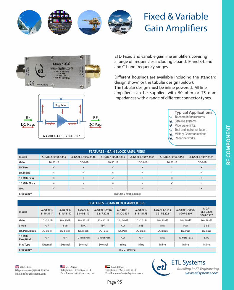
www.etlsystems.com
ETL SystemsExcelling in RF Engineering
Page 95
Telephone: +971 4 428 0918 Email: [email protected]
UAE Office: Telephone: +44(0)1981 259020 Email: [email protected]
UK Office:Telephone: +1 703 657 0411 Email: [email protected]
US Office:
Fixed & VariableGain Amplifiers
ETL- Fixed and variable gain line amplifiers coveringa range of frequencies including L-band, IF and S-bandand C-band frequency ranges.
Different housings are available including the standard design shown or the tubular design (below). The tubular design must be inline powered. All line amplifiers can be supplied with 50 ohm or 75 ohm impedances with a range of different connector types.
FEATURES - GAIN BLOCK AMPLIFIERS Model A-GABL1-3331-3335 A-GABL1-3336-3340 A-GABL1-3341-3345 A-GABL1-3347-3351 A-GABL1-3352-3356 A-GABL1-3357-3361
Gain 10-30 dB 10-30 dB 10-30 dB 10-30 dB 10-30 dB 10-30 dB
DC Pass P O P O O O
DC Block O P O P P P
10 MHz Pass O O P O O O
10 MHz Block O O O O P P
N/A P P O P O O
Frequency 850-2150 MHz (L-band)
FEATURES - GAIN BLOCK AMPLIFIERS
Model A-GABL1-3110-3114
A-GABL1-3145-3147
A-GABL1-3140-3143
A-GABL1-3210, 3217,3218
A-GABL1-3130-3134
A-GABL1-3151-3153
A-GABL1-3135, 3219-3222
A-GABL1- 3139-3207-3209
A-GA-BL1-3330, 3364-3367
Gain 10 - 30 dB 10 - 20dB 10 - 25 dB 20 - 30 dB 10 - 30 dB 10 - 20 dB 10 - 25 dB 10 - 28 dB 10 - 28 dB
Slope N/A 3 dB N/A N/A N/A 3 dB N/A N/A 3 dB
DC Pass/Block DC Block DC Block DC Block DC Pass DC Pass DC Block DC Block DC Pass DC Pass
10 MHz Pass/Block N/A N/A 10 MHz Pass 10 MHz Pass N/A N/A N/A 10 MHz Pass N/A
Bias Type External External External External Inline Inline Inline Inline Inline
Frequency 850-2150 MHz
Typical ApplicationsTelecom infrastructures. Satellite systems.Micorwave links.Test and instrumentation. Military Communications. Radar networks.
RF C
OM
PO
NEN
TRF
CO
MPO
NEN
T
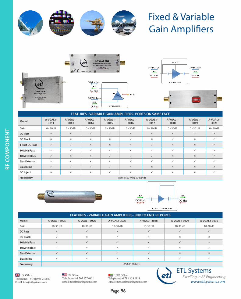
www.etlsystems.com
ETL SystemsExcelling in RF Engineering
Page 96
Telephone: +971 4 428 0918 Email: [email protected]
UAE Office: Telephone: +44(0)1981 259020 Email: [email protected]
UK Office:Telephone: +1 703 657 0411 Email: [email protected]
US Office:
Fixed & VariableGain Amplifiers
FEATURES - VARIABLE GAIN AMPLIFIERS- PORTS ON SAME FACE
Model A-VGAL1-3011
A-VGAL1-3013
A-VGAL1-3014
A-VGAL1-3015
A-VGAL1-3016
A-VGAL1-3017
A-VGAL1-3018
A-VGAL1-3019
A-VGAL1-3020
Gain 0 - 30dB 0 - 30dB 0 - 30dB 0 - 30dB 0 - 30dB 0 - 30dB 0 - 30dB 0 - 30 dB 0 - 30 dB
DC Pass O O P P O O O P O
DC Block O O O O P O P O P
1 Port DC Pass P P O O O P O O P
10 MHz Pass O P P O O O P P O
10 MHz Block P O O P P P O O P
Bias External O O O O P P P P P
Bias Inline P P P P O O O O O
DC Inject O O O P O P O O P
Frequency 850-2150 MHz (L-band)
FEATURES - VARIABLE GAIN AMPLIFIERS- END TO END RF PORTS Model A-VGAL1-3025 A-VGAL1-3026 A-VGAL1-3027 A-VGAL1-3028 A-VGAL1-3029 A-VGAL1-3030
Gain 10-30 dB 10-30 dB 10-30 dB 10-30 dB 10-30 dB 10-30 dB
DC Pass O P O P P P
DC Block P O P O O O
10 MHz Pass O P P O P O
10 MHz Block P O O P O P
Bias External P P P P O O
Bias Inline O O O O P P
Frequency 850-2150 MHz
RF C
OM
PON
ENT
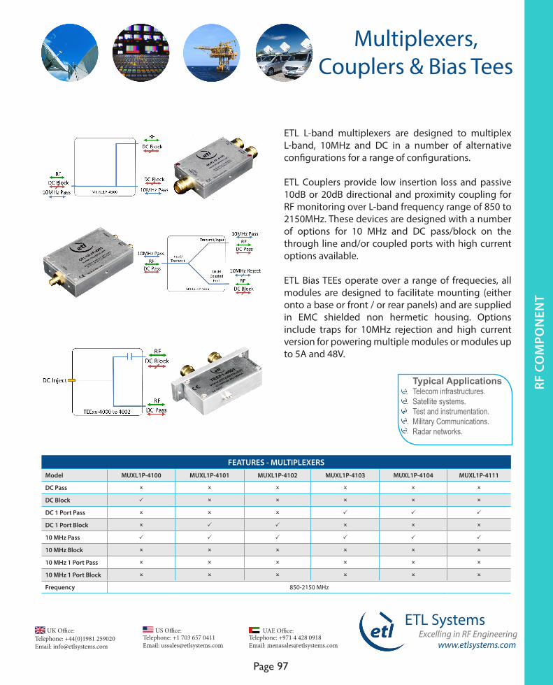
www.etlsystems.com
ETL SystemsExcelling in RF Engineering
Page 97
Telephone: +971 4 428 0918 Email: [email protected]
UAE Office: Telephone: +44(0)1981 259020 Email: [email protected]
UK Office:Telephone: +1 703 657 0411 Email: [email protected]
US Office:
Multiplexers, Couplers & Bias Tees
ETL L-band multiplexers are designed to multiplex L-band, 10MHz and DC in a number of alternative configurations for a range of configurations.
ETL Couplers provide low insertion loss and passive 10dB or 20dB directional and proximity coupling for RF monitoring over L-band frequency range of 850 to 2150MHz. These devices are designed with a number of options for 10 MHz and DC pass/block on the through line and/or coupled ports with high current options available.
ETL Bias TEEs operate over a range of frequecies, all modules are designed to facilitate mounting (either onto a base or front / or rear panels) and are supplied in EMC shielded non hermetic housing. Options include traps for 10MHz rejection and high current version for powering multiple modules or modules up to 5A and 48V.
FEATURES - MULTIPLEXERS Model MUXL1P-4100 MUXL1P-4101 MUXL1P-4102 MUXL1P-4103 MUXL1P-4104 MUXL1P-4111
DC Pass O O O O O O
DC Block P O O O O O
DC 1 Port Pass O O O P P P
DC 1 Port Block O P P O O O
10 MHz Pass P P P P P P
10 MHz Block O O O O O O
10 MHz 1 Port Pass O O O O O O
10 MHz 1 Port Block O O O O O O
Frequency 850-2150 MHz
Typical ApplicationsTelecom infrastructures. Satellite systems.Test and instrumentation. Military Communications. Radar networks.
RF C
OM
PO
NEN
TRF
CO
MPO
NEN
T

www.etlsystems.com
ETL SystemsExcelling in RF Engineering
Page 98
Telephone: +971 4 428 0918 Email: [email protected]
UAE Office: Telephone: +44(0)1981 259020 Email: [email protected]
UK Office:Telephone: +1 703 657 0411 Email: [email protected]
US Office:
Multiplexers, Couplers & Bias Tees
FEATURES - BIAS TEES
Model
TEEL
1-40
00
TEEF
1-40
01
TEEL
1-40
02
TEEB
4-40
03
TEEL
1-40
04
TEEL
1-40
05
TEEL
1-40
06
TEEL
1-40
07
TEEB
X-
4010
TEEB
X-
4013
DC Pass O O O O O O O O O O
DC Block O O O O O O O O O O
DC 1 Port Pass O O O O O O O O O O
DC 1 Port Block P P P P P P P P P O
10 MHz Pass O O O P O O P O P O
10 MHz Block O O O O P P O O O O
10 MHz 1 Port Pass O O O O O O O O O O
10 MHz 1 Port Block O O O O O O O O O O
N/A P P P O O O O P O P
DC Inject 5A 48V via Filter-Con O O O O O O O O O P
Frequency 850-2150 MHz
50-2800 MHz
850-2150 MHz
500-2500 MHz
850-2150 MHz
850-2150 MHz
850-2150 MHz
850-2150 MHz
1-4200 MHz
1-5450 MHz
FEATURES - COUPLERS Model CPL20-L1P-4301 CPL10-L1P-4303 CPL20-L1P-4304 CPL10-L1P-4305 CPL20-L1P-4306 CPL10-L1P-4307
DC Pass O O O O O O
DC Block P P O O O O
DC 1 Port Pass O O O O O O
DC 1 Port Block O O P P P P
10 MHz Pass O O O O O O
10 MHz Block O O O O O O
10 MHz 1 Port Pass O O O O O O
10 MHz 1 Port Block O O P P P P
N/A P P O O O O
Frequency 850-2150 MHz (L-band)
RF C
OM
PON
ENT

www.etlsystems.com
ETL SystemsExcelling in RF Engineering
Page 99
Telephone: +971 4 428 0918 Email: [email protected]
UAE Office: Telephone: +44(0)1981 259020 Email: [email protected]
UK Office:Telephone: +1 703 657 0411 Email: [email protected]
US Office:
10MHz Oscillators
ETL Oscillators cover the L-band (850-2150MHz) frequency range. ETL’s 10 MHz Oscillators offer high stability, 10 MHz source with built in harmonic rejection filters.
Options include units with single output port and preset 10 MHz output power levels as well as units that offer L-band multiplexing with options that include settable10 MHz output levels, switchable DC and 10 MHz injection (on/off), externally powered or inline powered.
FEATURESModel OSC-10-8106 OSC-10-8108 OSC-10-8109 OSC-10-8101 OSC-10-8104 OSC-10-8107
RF Through P
Selectable DC P P O O O O
Selectable 10 MHz P P P O O O
Selectable 10 MHz output level O P O O O O
Inline Bias P P O O O O
External Bias O O P O O O
Voltage rating 8 - 24 V 8 - 48 V 15 - 30 V O O O
RF C
OM
PO
NEN
TRF
CO
MPO
NEN
T
Typical ApplicationsVSAT.TVRO - Marine applications.SNG Broadcast.

www.etlsystems.com
ETL SystemsExcelling in RF Engineering
Page 100
Telephone: +971 4 428 0918 Email: [email protected]
UAE Office: Telephone: +44(0)1981 259020 Email: [email protected]
UK Office:Telephone: +1 703 657 0411 Email: [email protected]
US Office:
RF SPECIFICATIONSModel OSC-10-8106 OSC-10-8108 OSC-10-8109 OSC-10-8101 OSC-10-8104 OSC-10- 8107
Frequency 850 - 2150 MHz (L-band)
Output level 5±2.5 dBm 0, 5, 10 or 15 dBm 5±2.5 dBm 5±2.5 dBm 5±2.5 dBm 5±2.5 dBm
Insertion Loss 0.4 dB typical 0.5 dB typical 0.5 dB typical N/A
input return loss 18 dB typical 16 dB typical 16 dB typical 5±2.5 dBm 10±2.5 dBm 0±2.5 dBm
Output return loss 18 dB typical 15 dB typical 15 dB typical 5±2.5 dBm 10±2.5 dBm 0±2.5 dB
10MHz Oscillators
OSCILLATOR CHARACTERISTICS
Frequency stability
Over temperature(within 0 to 55oC) <±3x10⁻⁸
Over time <±5x10⁻⁸
Short term stability(per second) <±1x10-11
PHASE NOISE CHARACTERISTICS ( dBc / Hz )
1 Hz <-85
10Hz <-115
100Hz <-140
1000Hz <-150
10000 Hz <155
10 MHzCHARACTERISTICS
Frequency Setting 10±0.000001MHz
Output Type Sinewave
Harmonic rejection
2nd >65 dB
3rd >50 dB
4th >60 dB
5th >60 dB
RF C
OM
PON
ENT
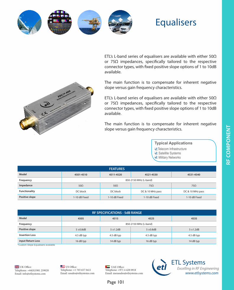
www.etlsystems.com
ETL SystemsExcelling in RF Engineering
Page 101
Telephone: +971 4 428 0918 Email: [email protected]
UAE Office: Telephone: +44(0)1981 259020 Email: [email protected]
UK Office:Telephone: +1 703 657 0411 Email: [email protected]
US Office:
Equalisers
ETL’s L-band series of equalisers are available with either 50Ω or 75Ω impedances, specifically tailored to the respective connector types, with fixed positive slope options of 1 to 10dB available.
The main function is to compensate for inherent negative slope versus gain frequency characteristics.
ETL’s L-band series of equalisers are available with either 50Ω or 75Ω impedances, specifically tailored to the respective connector types, with fixed positive slope options of 1 to 10dB available.
The main function is to compensate for inherent negative slope versus gain frequency characteristics.
Typical Applications Telecom Infrastructure Satellite Systems Military Networks
RF SPECIFICATIONS - 5dB RANGEModel 4505 4515 4525 4535
Frequency 850-2150 MHz (L-band)
Positive slope 5 ±0.8dB 5 ±1.2dB 5 ±0.8dB 5 ±1.2dB
Insertion Loss 4.5 dB typ 4.5 dB typ 4.5 dB typ 4.5 dB typ
input Return Loss 16 dB typ 14 dB typ 16 dB typ 14 dB typ
FEATURES Model 4501-4510 4511-4520 4521-4530 4531-4540
Frequency 850-2150 MHz (L-band)
Impedance 50Ω 50Ω 75Ω 75Ω
Functionality DC block DC block DC & 10 MHz pass DC & 10 MHz pass
Positive slope 1-10 dB Fixed 1-10 dB Fixed 1-10 dB Fixed 1-10 dB Fixed
*Custom Slope Equalisers available
RF C
OM
PO
NEN
TRF
CO
MPO
NEN
T
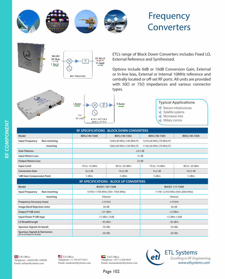
www.etlsystems.com
ETL SystemsExcelling in RF Engineering
Page 102
Telephone: +971 4 428 0918 Email: [email protected]
UAE Office: Telephone: +44(0)1981 259020 Email: [email protected]
UK Office:Telephone: +1 703 657 0411 Email: [email protected]
US Office:
FrequencyConverters
ETL’s range of Block Down Converters includes Fixed LO, External Reference and Synthesised.
Options include 0dB or 10dB Conversion Gain, External or In-line bias, External or Internal 10MHz reference and centrally located or off-set RF ports. All units are provided with 50Ω or 75Ω impedances and various connector types.
Typical Applications Telecom infrastructures Satellite systems Microwave links Military comms
RF SPECIFICATIONS - BLOCK DOWN CONVERTERS Model BDCL140-7200 BDCL140-7202 BDCL140-7203 BDCL140-7204
Input Frequency Non-inverting 1340±40 MHz (140 MHz IF) 1270±40 MHz (70 MHz IF)
Inverting 1060±40 MHz (140 MHz IF) 1130±40 MHz (70 MHz IF)
Gain Flatness ±0.5 dB
Input Return Loss 15 dB
Output Return Loss 23 dB
Input Level -70 to -10 dBm -80 to -20 dBm -70 to -10 dBm -80 to -20 dBm
Conversion Gain 0±2 dB 10±2 dB 0±2 dB 10±2 dB
1dB Gain Compression Point 5 dBm -5 dBm 5 dBm -5 dBm
RF SPECIFICATIONS - BLOCK UP CONVERTERS Model BUCK1-107-7208 BUCK1-117-7209
Input Frequency Non-inverting 10700-11700 MHz (950 -1950 MHz) 11700-12750 MHz (950-2000 MHz)
Inverting Filtered Filtered
Frequency Accuracy (max) ±10 kHz ±10 kHz
Image Band Rejection (min) 60 dB 60 dB
Output P1dB (min) +27 dBm +27dBm
Input Power P1dB (typ) -12 dBm ±3dB -12 dBm ±3dB
LO Breakthrough -40 dBm -40 dBm
Spurious Signals (In-band) -50 dBc -50 dBc
Spurious Signals & Harmonics (DC to LO freq & 14-20 GHz) -60 dBc -60 dBc
RF C
OM
PON
ENT
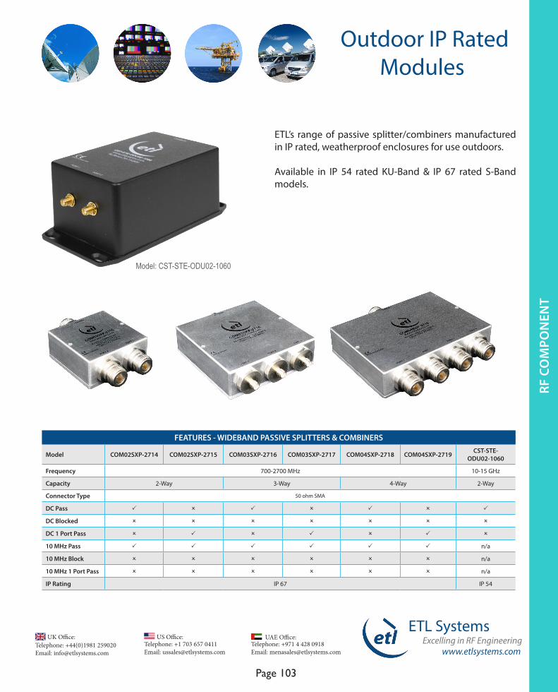
www.etlsystems.com
ETL SystemsExcelling in RF Engineering
Page 103
Telephone: +971 4 428 0918 Email: [email protected]
UAE Office: Telephone: +44(0)1981 259020 Email: [email protected]
UK Office:Telephone: +1 703 657 0411 Email: [email protected]
US Office:
Outdoor IP Rated Modules
ETL’s range of passive splitter/combiners manufactured in IP rated, weatherproof enclosures for use outdoors.
Available in IP 54 rated KU-Band & IP 67 rated S-Band models.
FEATURES - WIDEBAND PASSIVE SPLITTERS & COMBINERS
Model COM02SXP-2714 COM02SXP-2715 COM03SXP-2716 COM03SXP-2717 COM04SXP-2718 COM04SXP-2719 CST-STE-ODU02-1060
Frequency 700-2700 MHz 10-15 GHz
Capacity 2-Way 3-Way 4-Way 2-Way
Connector Type 50 ohm SMA
DC Pass P O P O P O P
DC Blocked O O O O O O O
DC 1 Port Pass O P O P O P O
10 MHz Pass P P P P P P n/a
10 MHz Block O O O O O O n/a
10 MHz 1 Port Pass O O O O O O n/a
IP Rating IP 67 IP 54
Model: CST-STE-ODU02-1060
RF C
OM
PO
NEN
TRF
CO
MPO
NEN
T

www.etlsystems.com
ETL SystemsExcelling in RF Engineering
Page 104
Telephone: +971 4 428 0918 Email: [email protected]
UAE Office: Telephone: +44(0)1981 259020 Email: [email protected]
UK Office:Telephone: +1 703 657 0411 Email: [email protected]
US Office:
StingRayRF Over Fibre
Stand Alone Modules
The StingRay RF over Fibre series is designed to deliver short distance L-Band & Broadband over fibre between the satellite dish and the control room decoders.
There are a range of ultra compact, stand alone, transmit or receive modules which hold a mixture of features.
RF SPECIFICATIONSModel SRY-TX-L1-401 SRY-RX-L1-402 SRY-TX-B2-403 SRY-RX-B2-404 SRY-RX-L1-462 SRY-RX-B2-462
Frequency L-Band to Optical Fibre 850-2450 MHz
Optical Fibre to L-Band 850-2450 MHz
Broadband to Optical Fibre 50 to 2450 MHz
Optical Fibre to Broad-band 50 to 2450 MHz
Optical Fibre to L-Band 850-2450 MHz
Optical Fibre to Broad-band 50 to 2450 MHz
Transmit Receive Transmit Receive Receive Receive
Flatness
±1.2dB850-2150 MHz
±1.2dB850-2150 MHz
±2.0 dB 50 to 200 MHz
±2.0 dB 50 to 200 MHz
±1.2dB 850 to 2150 MHz
±2.0 dB 50 to 200 MHz
±1.7dB850-2450 MHz
±1.7dB850-2450 MHz
±2.0 dB 850 to 2450 MHz
±2.0 dB 850 to 2450 MHz
±1.2dB 850 to 2150 MHz
±2.0 dB 850 to 2450 MHz
Return Loss* (Typical) 18 dB 18 dB 18 dB 18 dB 18 dB 18 dB
Noise Figure (Typical) 12 dB 12 dB 10 dB 12dB 12dB 12dB
CNR (Typical) -50 dB -50 dB -50 dB -50 dB -50 dB -50 dB
SFDR (Typical) 105 dB/Hz 2/3 105 dB/Hz 2/3 105 dB/Hz2/3 105 dB/Hz2/3 105 dB/Hz2/3 105 dB/Hz2/3
Optical Wavelength 1310 ± 10 nm 1100 to 1650 nm 1310 ± 10 nm 1100 to 1650 nm 1100 to 1650 nm 1100 to 1650 nm
Optical Power Output 4.5 ±2.5 dBm 0 to 4.5 dBm 4.5 ±2.5 dBm 0 to 4.5 dBm 0 to 4.5 dBm 0 to 4.5 dBm
LNB Power (Max) 18/13V ±5 %, 500 mA - 18/13V ±5 %, 500 mA - -
Additional Features
BUC powering for VSAT applications
BUC powering for VSAT applications
Benefits Optimised Transmission distances up to 10km. Interoperable with all Stingray series modules. Ideal for single or small number of links.
The specifications above are based on 50Ω SMA connectors. Specifications may vary for other impedances and connector types.
RF C
OM
PON
ENT

Page 105
Power ConversiondBm
A measurement of ‘ x dBm’ indicates that a particular signal is x dB greater than (‘above’) 1 milliwatt. A negative dBm value indicates that the signal
is x dB less than (‘below’) 1 milliwatt.To convert x milliwatts to dBm:
dBm = 10 log ( x milliwatts )
dBmV A power measurement of ‘x dBmV’ indicates
that a particular signal is x dB greater than (‘above’) 1 millivolt in 75 ohms. A negative dBm value indicates that the signal is
x dB less than (‘below’) 1 millivolt in 75 ohms. To convert x millivolts to dBmV :
dBmV = 20 log ( x millivolts )
dBµV Similarly, a measurement of ‘ x dBµV ‘ indicates that the signal is x dB above one microvolt in 75 ohms.
To convert x microvolts to dBµV:dBµV = 20 log ( x microvolts )
To convert dBmV to dBµV, add 60 to the dBmV reading:
x dBµV = dBmV + 60
Cable Theory - The Decibel
The original unit is called the Bel, after Alexander Graham Bell.
A Decibel is one tenth of a Bel. The Decibel (dB) provides a means of representing
large power ratios as more managable, smaller numbers, allowing the gains and losses
in a network or module to be calculated by addition and subtraction, rather than
by multiplication and division.The power ratio of two power measurements
is calculated as follows :
Ratio of power P1 to power P2, in dB.
The power ratio of two voltage measurements is calculated as follows ;
Ratio of voltage V1 to voltage V2, in dB.
When all the power scales (dBm, dBmV and dBµV ) are laid next to each other,
it is easy to see each track on a dB for dB basis.
Cable Loss Ratiothe ratio of cable attenuation at two frequencies is
approximately equal to the square root of the ratio of the 2 frequencies:
Tilt to cable loss
“Tilt” is used to define the differential in signal level between end frequencies of the cable band pass.
To convert tilt to cable loss at the highest frequency
Ohm’s Law Joule’s LawV = IR P = IV
V = Voltage in volts P = power in watts I = current in amperes I = current in amperes
R = resistance in ohms V = Voltage in volts
Page 105
Power ConversiondBm
A measurement of ‘ x dBm’ indicates that a particular signal is x dB greater than (‘above’) 1 milliwatt. A negative dBm value indicates that the signal
is x dB less than (‘below’) 1 milliwatt.To convert x milliwatts to dBm:
dBm = 10 log ( x milliwatts )
dBmV A power measurement of ‘x dBmV’ indicates
that a particular signal is x dB greater than (‘above’) 1 millivolt in 75 ohms. A negative dBm value indicates that the signal is
x dB less than (‘below’) 1 millivolt in 75 ohms. To convert x millivolts to
dBmV :dBmV = 20 log ( x millivolts )
dBµV Similarly, a measurement of ‘ x dBµV ‘ indicates that the signal is x dB above one microvolt in 75 ohms.
To convert x microvolts to dBµV:dBµV = 20 log ( x microvolts )
To convert dBmV to dBµV, add 60 to the dBmV reading:
x dBµV = dBmV + 60
Cable Theory - The Decibel
The original unit is called the Bel, after Alexander Graham Bell.
A Decibel is one tenth of a Bel. The Decibel (dB) provides a means of representing
large power ratios as more managable, smaller numbers, allowing the gains and losses
in a network or module to be calculated by addition and subtraction, rather than
by multiplication and division.The power ratio of two power measurements
is calculated as follows :
Ratio of power P1 to power P2, in dB.
The power ratio of two voltage measurements is calculated as follows ;
Ratio of voltage V1 to voltage V2, in dB.
When all the power scales (dBm, dBmV and dBµV ) are laid next to each other,
it is easy to see each track on a dB for dB basis.
Cable Loss Ratiothe ratio of cable attenuation at two frequencies is
approximately equal to the square root of the ratio of the 2 frequencies:
Tilt to cable loss
“Tilt” is used to define the differential in signal level between end frequencies of the cable band pass.
To convert tilt to cable loss at the highest frequency
Ohm’s Law Joule’s LawV = IR P = IV
V = Voltage in volts P = power in watts I = current in amperes I = current in amperes
R = resistance in ohms V = Voltage in volts
dB = 10*log
P2
P1
dB = 20*log
V2
V1
dB of Cable =
Tilt (dB)
f1
f2
Cable Loss Ratio =
f1
f2

Page 106
EIRP down
C/N up
G/Tup
EIRP G/T up down
C/N up
L down
I down
I up
L up
SATELLITE SIGNAL LINK BUDGET
Return loss versus Reflected Power loss Calculator versus VSWR
EIRP = Pt+GtC/N = EIRP - Lp - La - Lm + G/T - 10log(B) + 228.6
Power to V- Peak ETL Systems Excelling in RF Engineering www.etlsystems.com
UK Office Telephone; +44 (0) 1981 259020
Email; [email protected]
US OfficeTelephone; 703 657 0411
Email; [email protected]
UAE OfficeTelephone; +971 (50) 656 9978
Email; [email protected]
Page 106
ETL Systems Excelling in RF Engineering www.etlsystems.com
UK Office Telephone: +44 (0) 1981 259020
Email: [email protected]
US OfficeTelephone: +1 703 657 0411
Email: [email protected]
UAE OfficeTelephone: +971 (50) 656 9978
Email: [email protected]
Power In 50 ohms 75 ohms
dBm W Vrms Vpeak Vrms Vpeak
0 0.001 0.224 0.316 0.274 0.387
1 0.001 0.251 0.355 0.307 0.435
2 0.002 0.082 0.398 0.345 0.488
3 0.002 0.316 0.447 0.387 0.547
4 0.003 0.354 0.501 0.434 0.614
5 0.003 0.398 0.562 0.487 0.689
6 0.004 0.446 0.631 0.546 0.773
7 0.005 0.501 0.708 0.613 0.867
8 0.006 0.562 0.794 0.688 0.973
9 0.008 0.630 0.891 0.772 1.092
10 0.010 0.707 1.000 0.866 1.225
11 0.013 0.793 1.122 0.972 1.374
12 0.016 0.890 1.259 1.090 1.542
13 0.020 0.999 1.413 1.223 1.730
14 0.025 1.121 1.585 1.373 1.941
15 0.032 1.257 1.778 1.540 2.178
16 0.040 1.411 1.995 1.728 2.444
17 0.050 1.583 2.239 1.939 2.742
18 0.063 1.776 2.512 2.175 3.076
19 0.079 1.993 2.818 2.441 3.452
20 0.100 2.236 3.162 2.739 3.873
21 0.126 2.509 3.548 3.073 4.346
22 0.158 2.815 3.981 3.448 4.876
23 0.200 3.159 4.467 3.868 5.471
24 0.251 3.544 5.012 4.340 6.138
25 0.316 3.976 5.623 4.870 6.887
26 0.398 4.462 6.310 5.464 7.728
27 0.501 5.006 7.079 6.131 8.671
28 0.631 5.617 7.943 6.879 9.728
29 0.794 6.302 8.913 7.718 10.916
30 1.000 7.071 10.000 8.660 12.247

www.etlsystems.com
ETL SystemsExcelling in RF Engineering
Page 107
Telephone: +971 4 428 0918 Email: [email protected]
UAE Office: Telephone: +44(0)1981 259020 Email: [email protected]
UK Office:Telephone: +1 703 657 0411 Email: [email protected]
US Office:
Notes

Telephone: +44(0)1981 259020 Email: [email protected]
UK Office:Telephone: +1 703 657 0411 Email: [email protected]
US Office:
www.etlsystems.com
ETL SystemsExcelling in RF Engineering
Page 108
Telephone: +971 4 428 0918 Email: [email protected]
UAE Office:
Notes

www.etlsystems.com
ETL SystemsExcelling in RF Engineering
Page 109
Telephone: +971 4 428 0918 Email: [email protected]
UAE Office: Telephone: +44(0)1981 259020 Email: [email protected]
UK Office:Telephone: +1 703 657 0411 Email: [email protected]
US Office:
Notes

Telephone: +44(0)1981 259020 Email: [email protected]
UK Office:Telephone: +1 703 657 0411 Email: [email protected]
US Office:
www.etlsystems.com
ETL SystemsExcelling in RF Engineering
Page 110
Telephone: +971 4 428 0918 Email: [email protected]
UAE Office:
Notes

www.etlsystems.com
ETL SystemsExcelling in RF Engineering
Page 111
Telephone: +971 4 428 0918 Email: [email protected]
UAE Office: Telephone: +44(0)1981 259020 Email: [email protected]
UK Office:Telephone: +1 703 657 0411 Email: [email protected]
US Office:
Notes

Telephone: +44(0)1981 259020 Email: [email protected]
UK Office:Telephone: +1 703 657 0411 Email: [email protected]
US Office:
www.etlsystems.com
ETL SystemsExcelling in RF Engineering
Page 112
Telephone: +971 4 428 0918 Email: [email protected]
UAE Office:
Notes

Come and see us at the following international exhibitions each year:
Cabsat, DubaiSatellite, Washington DC, USA
NAB, Las Vegas, USAIMS, USA
CommunicAsia, Singapore IBC, Amsterdam
ETL Systems International Tradeshow Stand
www.etlsystems.com