
product catalogue 2020 Engineering Excellence in Education
328
TECQUIPMENT.COM product catalogue 2020 Engineering Excellence in Education
-
Upload
khangminh22 -
Category
Documents
-
view
1 -
download
0
Transcript of product catalogue 2020 Engineering Excellence in Education

TecQuipment Ltd, Bonsall Street, Long Eaton, Nottingham NG10 2AN, UK
Product Catalogue 2020
T E C Q U I P M E N T . C O M
p r o d u c t c a t a l o g u e 2 0 2 0E n g i n e e r i n g E x c e l l e n c e i n E d u c a t i o n

+ 4 4 1 1 5 9 7 2 2 6 1 1 I N F O @ T E C Q U I P M E N T . C O M
T e c Q u i p m e n tE x p a n d sC a p a b i l i t y w i t hA c q u i s i t i o n o fA s s e t s f r o mC u s s o n sT e c h n o l o g y
This year TecQuipment will be expanding the range ofteaching products it offers as a result of the 2019acquisition of certain assets of Cussons Technology Ltd. Cussons Technology was founded in 1876, and has a long-standing reputation for providing educational teachingproducts for thermodynamics, automotive technology,fluid mechanics, process control, theory of machines andapplied mechanics. The acquisition of this technology alsoencompasses teaching products for understandingalternative energy technology including wind, tidal andsolar energy. The intellectual property for all of theseproducts is now owned by TecQuipment and will beincrementally incorporated into the company’s productportfolio during a phase of product enhancement.Visit t e c q u i p m e n t . c o m / c u s s o n s for all the latest updates onCussons Technology Engineering Educational Divisionproducts by TecQuipment.
A g e n t s a r o u n d t h e w o r l dMilton talked highly of the local TecQuipment agent in Canada,AYVA Educational Solutions:“The AVYA experience is great! Their post-sale technical supportis unparalleled.” TecQuipment works with 60 plus agents around the world,supported by a strong team of export personnel based in the UKheadquarters.Modular products make incremental investment easy anddecrease laboratory set-up time Many products within the Fluid Mechanics range fromTecQuipment are modular. Not only does this mean thatinvestments can be done incrementally, but it also makeslaboratory set-up time quicker and easier. Milton commented:
The University of Regina recently purchased eight of the newestdigital hydraulic benches from TecQuipment. While many of theirolder benches were still in good functioning order, the decisionwas made to update to the latest model, with digital flow andcapacity measurement capabilities, which ultimately means thatexperiments can be performed much more quickly. The olderunits have been donated to a local college. With the hydraulicbenches, the University uses the following experiments:
• Impact of a Jet• Friction Loss in a Pipe• Discharge Over a Notch• Flow Measurement Methods and the Bernoulli’s Theorem.
U p g r a d e s t o i n c r e a s e t h e p r o d u c t ’ s l i f e t i m e As new product upgrades have been made available, theUniversity of Regina has been quick to seize these opportunitiesto extend the life of their products. Their Losses in PipingExperiment purchased in the 1990s was recently upgraded withan electronic pressure measurement system. This has improvedthe accuracy of the experiment results and eliminated the use ofmercury in the apparatus.
E n g i n e e r i n g u n d e r s t a n d i n g f o r l o c a l e n v i r o n m e n t a lc h a l l e n g e sMilton was explaining how in Canada the region experiencesmany challenges with infiltration of water into the basements ofbuildings. In response to this, the University purchased theHydrology and Rainfall apparatus that simulates rain andmoving storms over a permeable medium. It also demonstrateshydrology phenomenon, such as erosion caused by water flowand watersheds for simulated islands with rainfall and well flows.
F a c t o r y v i s i tTecQuipment encourages people from around the world to visittheir factory in Nottingham, UK where the equipment is designedand manufactured all under one roof.Milton noted that:
“I’m often running two laboratory sessions at one time in twodifferent rooms. Being able to use the base module like thehydraulic bench and quickly be able to switch out theexperimental modules makes running a tight schedule oflaboratory sessions possible. With a few of my ownmodifications, like adding quick connects and valves, I canmake this changeover even slicker.”
“After visiting the factory and having a meet and greet withthe key players, I was left with a great confidence in dealingwith the people of TecQuipment. I know I can call and speakto people about any problems I might have with theequipment.”
3 2 5

P o ly t e c h n i c M a n u fa c t u r i n g B a n g d u n g 208C a s e s t u d y
U n i v e r s i t y o f L i n c o l n v i d e o c a s e s t u d Y 250
E a s t T e n n e s s e e u n i v e r s i t y c a s e s t u d y 260
B i r m i n g h a m C i t y U n i v e r s i t y v i d e o c a s e s t u d y 278
G e n e r a l- P u r p o s e A n c i l l a r i e s a n d E q u i p m e n t 313
C o n ta c t i n g T e c Q u i p m e n t 316
K e y w o r d I n d e x 317
P r o d u c t L i s t 321
U n i v e r s i t y o f R e g i n a c a s e s t u d y 324
+ 4 4 1 1 5 9 7 2 2 6 1 1 I N F O @ T E C Q U I P M E N T. C O M 1
C O N T E N T S E N G I N E E R I N G S C I E N C E 5
A E R O D Y N A M I C S 29
C O N T R O L E N G I N E E R I N G 65
P R O C E S S C O N T R O L E N G I N E E R I N G 79
F L U I D M E C H A N I C S 91
M A T E R I A L S T E S T I N G A N D P R O P E R T I E S 157
S T A T I C S F U N D A M E N T A L S 189
S T R U C T U R E S 195
T H E O R Y O F M A C H I N E S 223
T H E R M O D Y N A M I C S 251
E N G I N E S 277
e n v i r o n m e n t a l c o n t r o l 295
s o l a r e n e r g y 303
V e r s a t i l e D a t a A c q u i s i t i o n S y s t e m ( V D A S ® ) 309
V i s i t o u r w e b s i t e at i n d u s t r i a l .t e c q u i p m e n t. c o m f o r E l e c t r i c a l p o w e r S y s t e m S 314
N e w p r o d u c t s 2
M a d e i n t h e U K 3
P r o d u c t s a n d I n d u s t r y 4
T e x a s A & M U n i v e r s i t y c a s e s t u d y 56
S t u d e n t C o m p e t i t i o n s 64
N at i o n a l C o l l e g e o f N u c l e a r 74N o r t h h u b c a s e s t u d y
E q u i p m e n t u p g r a d e c a s e s t u d y 94
T e c q u i p m e n t u s e r g u i d e s 96
N o t t i n g h a m T r e n t U n i v e r s i t y 175v i d e o c a s e s t u d y

T E C Q U I P M E N T. C O M2
n E W P R O D U C T S i n t h i s e d i t i o nFor 2020, TecQuipment has focused on developing new products across the ranges to offer morecomprehensive and flexible teaching.
N e w t o E n v i r o n m e n ta lC o n t r o lThe A d va n c e d H VA C a n d R T r a i n e r(EC1550V) is the most advancedEnvironmental Control teachingproduct available from TecQuipment. Itoffers comprehensive, practicalteaching of a vast range of topicsrelating to heating, ventilation, airconditioning and refrigeration systems.In addition to the breath ofexperimentation options, the depth anddetail of study is huge thanks to theextensive network of sensors integratedthroughout, with VDAS® Onboard dataacquisition (see page 298).
N e w t o M at e r i a l s T e s t i n g
With the rise in use of compositematerials across industries such asaerospace, automotive, marine and civilengineering, TecQuipment hasintroduced the new C o m p o s i t e B e a mPa c k s for testing different types ofcomposites to explore the bendingbehaviour and strength of differentformulations with varying inner andouter materials and weave (seepage 185).
N e w t o F l u i d M e c h a n i c sThe Fluid Mechanics range features two new products for more advanced teaching.The FC600 F l u m e features a 600 mm wide, 8 to 20 metres long open flow channel forstudent study and for advanced research into a wide range of flow topics. This hugeflume can be used for clear demonstration of flow characteristics. In addition to theflume, a large number of purpose-built ancillaries and instruments are available for thedemonstration of fluid mechanics; these can be used in combination for advancedresearch projects (see page 122) The Va r i a b l e s p e e d S e r i e s a n d Pa r a l l e l P u m p s (H53V) benchtop test set allows studentsto investigate the operation and performance of two centrifugal pumps arranged inseries or parallel. In comparison to the similar Series and Parallel Pumps benchtop testset launched in 2019, theadvanced version has VDAS®
Onboard data acquisition andboth fixed and variable-speed pumps. It allows thedemonstration of cavitation,the performance ofsuction tests on a singlepump, along withfundamental teachingcovering pumps inseries and parallel(see page 139).

+ 4 4 1 1 5 9 7 2 2 6 1 1 I N F O @ T E C Q U I P M E N T. C O M 3
TecQuipment takes great pride in designing andmanufacturing its products in the United Kingdom.
M o d e r n m a n u fa c t u r i n g p r o c e s s e sTecQuipment’s manufacturing facilities are at the company’sglobal headquarters, where they embrace the heritage of thelocal area based within an old lace making factory. Behind thebuilding’s exterior resides a highly specialised team thatdesigns and manufactures the 450+ engineering educationalteaching products. This team utilises modern productionfacilities, including advanced CNC machines and high-throughput paint booths. High quality is ensured by combiningin-house fabrication and machining of components with the
buying in of specialist components, such as engines. Thesebought-in components are then customised in-house withextra functionality, such as instrumentation, data acquisitionand software integration capabilities.Watch the Made Under One Roof series ont e c q u i p m e n t. c o m / v i d e o s , or the TecQuipment YouTubechannel, to see how the design and manufacturingprocess works.
M a d e i n t h e U K

T E C Q U I P M E N T. C O M4
p r o d u c t s a n d i n d u s t r y
I N D U S T R Y
Util
itie
s
ü
üü
üüüüüü
üü
ü
üü
üü
Rene
wab
les
ü
ü
ü
ü
ü
üüü
üüüüüü
ü
Rail
üüü
ü
üüüüü
üü
ü
üüüüüü
üü
üü
Pow
er
ü
üü
ü
üü
ü
ü
üüüüüüü
üü
üüüü
Oil
and
Gas
üüüüü
ü
üü
üüüü
üüüüüüüüü
Min
ing
üüüüüü
üüüüüüüü
ü
ü
Met
als
üüü
ü
üüüüüü
Mar
ine
ü
üü
ü
üüüüü
ü
üü
üü
üüüü
Food
and
Dri
nk
üüü
üü
ü
üü
üü
üüü
ü
Defe
nce
üüüü
ü
ü
ü
ü
ü
ü
ü
ü
üüü
Cons
truc
tion
ü
ü
üü
üüüü
üü
üüüüüüüü
üü
ü
üü
Civi
l En
gine
erin
g
ü
ü
üüü
ü
üüüüüüüüüüüüüüüüüüüü
üü
Chem
ical
/Pha
rma
üüüü
üü
ü
ü
ü
üüü
üü
ü
üü
Auto
mot
ive
üüüü
üüüüüü
üüüü
üü
üüü
ü
ü
ü
Agri
cult
ure
üüüüü
üüüü
ü
aero
spac
eüüüü
üü
üüüü
üüüüüü
üüüüüüüü
üüüü
S U B J E C T A R E ASubsonic Wind Tunnels
Supersonic Wind Tunnels
Special Purpose Wind Tunnels
Forces and Moments
Materials Testing
Vibration, Friction, Energy
Simple Machines
Mechanisms
Flow and Pressure
Friction
Open Channel
Hydrostatics
Hydrology
Fluid Power
Basic Properties
Strain Gauging
Destructive Testing
Beams
Failure
Arches, Bridges, Trusses
Friction
Motion
Vibration
Fundamentals
Heat Transfer/Exchange
Steam
Compressors
Internal Combustion Engines
Gas Turbines
t e c q u i p m e n t R A N G EA e r o d y n a m i c s
C o n t r o l E n g i n e e r i n gP r o c e s s C o n t r o le l e c t r i c a l p o w e rE n g i n e e r i n g S c i e n c e
F l u i d M e c h a n i c s
M at e r i a l s T e s t i n g a n dP r o p e r t i e s
S tat i c s F u n d a m e n ta l sS t r u c t u r e s
T h e o r y o f M a c h i n e s
T h e r m o d y n a m i c s
E n g i n e s
e n v i r o n m e n ta l c o n t r o lS o l a r E n e r g y

+ 4 4 1 1 5 9 7 2 2 6 1 1 I N F O @ T E C Q U I P M E N T. C O M 5
Engineering Science
E n g i n e e r i n g S c i e n c e
“I am very pleased to find the highly innovative and professional approach of TecQuipment Ltdin designing and manufacturing a variety of equipment for engineering and technicaleducation at all levels. Such equipment is very useful to develop conceptual skills in students.
D r I n g V P S i n g hS h r i Va i s h a n v I n s t i t u t e o f T e c h n o l o g y a n d S c i e n c e , I n d o r e , I n d i a
Pa c k a g e s 7
W o r k Pa n e l 8
f o r c e s a n d m o m e n t s 9
m at e r i a l s t e s t i n g 1 1
v i b r at i o n , f r i c t i o n a n d e n e r g y 1 5
s i m p l e m a c h i n e s 1 9
m e c h a n i s m s 2 3
S t o r a g e E q u i p m e n t a n d A n c i l l a r i e s 2 7
T E C Q U I P M E N T. C O M6
Engi
neer
ing
Scie
nce
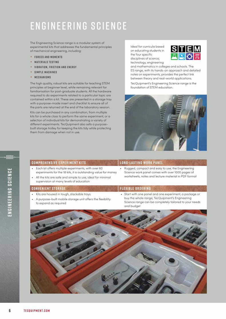
The Engineering Science range is a modular system ofexperimental kits that addresses the fundamental principlesof mechanical engineering, including:
• F o r c e s a n d m o m e n t s
• M at e r i a l s t e s t i n g
• V i b r at i o n , f r i c t i o n a n d e n e r g y
• S i m p l e m a c h i n e s
• M e c h a n i s m s
The high quality, robust kits are suitable for teaching STEMprinciples at beginner level, while remaining relevant forfamiliarisation for post-graduate students. All the hardwarerequired to do experiments related to a particular topic arecontained within a kit. These are presented in a storage traywith a purpose-made insert and checklist to ensure all ofthe parts are returned at the end of the laboratory session. Kits can be purchased in any combination, from multiplekits for a whole class to perform the same experiment, or aselection of individual kits for demonstrating a variety ofdifferent experiments. TecQuipment also sells a purpose-built storage trolley for keeping the kits tidy while protectingthem from damage when not in use.
Ideal for curricula basedon educating students inthe four specificdisciplines of science,technology, engineeringand mathematics in colleges and schools. TheES range, with its hands-on approach and detailednotes on experiments, provides the perfect linkbetween theory and real-world applications. TecQuipment’s Engineering Science range is thefoundation of STEM education.
C o m p r e h e n s i v e e x p e r i m e n t k i t s L o n g - l a s t i n g w o r k pa n e l• Each kit offers multiple experiments, with over 60
experiments for the 18 kits, it is outstanding value for money• All the kits are safe and simple to use, ideal for minimal
supervision at many levels of education
• Rugged, compact and easy to use, the EngineeringScience work panel comes with over 1000 pages ofworksheets, notes and lecture material in PDF format
C o n v e n i e n t s t o r a g e F l e x i b l e o r d e r i n g• Kits are housed in tough, stackable trays• A purpose-built mobile storage unit offers the flexibility
to expand as required
• Start with one panel and one experiment, a package orbuy the whole range, TecQuipment’s EngineeringScience range can be completely tailored to your needsand budget
E n g i n e e r i n g S c i e n c e
+ 4 4 1 1 5 9 7 2 2 6 1 1 I N F O @ T E C Q U I P M E N T. C O M 7
Engineering SciencePackages
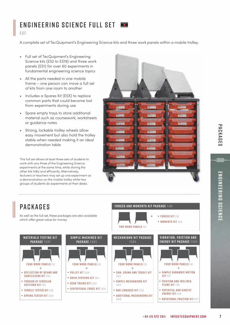
This full set allows at least three sets of students towork with any three of the Engineering Scienceexperiments at the same time, while storing theother kits tidily and efficiently. Alternatively,lecturers or teachers may set up one experiment asa demonstration on the mobile trolley while twogroups of students do experiments at their desks.
E n g i n e e r i n g S c i e n c e F u l l S e tE S F
A complete set of TecQuipment’s Engineering Science kits and three work panels within a mobile trolley.
• Full set of TecQuipment’s EngineeringScience kits (ES2 to ES19) and three workpanels (ES1) for over 60 experiments infundamental engineering science topics
• All the parts needed in one mobileframe – one person can move a full setof kits from one room to another
• Includes a Spares Kit (ESX) to replacecommon parts that could become lostfrom experiments during use
• Spare empty trays to store additionalmaterial such as coursework, worksheetsor guidance notes
• Strong, lockable trolley wheels alloweasy movement but also hold the trolleystable when needed making it an idealdemonstration table
Pa c k a g e sAs well as the full set, these packages are also availablewhich offer great value for money.
+
t w o W o r k Pan e l s E S 1
F o r c e s an d m o m e n t s k i t pac kag e
• F o r c e s K i t E S 2
• M o m e n t s K i t E S 3
S i m p l e Mac h i n e s k i t pac kag e e sb3
• P u l l e y K i t E S 1 0
• D r i v e S y s t e m s K i t E S 1 1
• G ear T ra i n s K i t E S 1 3
• C e n t r i f u gal F o r c e K i t E S 1 6
+f o u r W o r k Pan e l s E S 1
Mat e r ial s T e s t i n g k i t pac kag e e sb2
• D e f l e c t i o n o f B eam s an d Can t i l e v e r s K i t E S 4
• T o r s i o n o f C i r c u lar S e c t i o n s K i t E S 5
• T e n s i l e T e s t e r K i t E S 6
• S p r i n g T e s t e r K i t E S 1 9
+f o u r W o r k Pan e l s E S 1
M e c han i s m s k i t pac kag ee sb4
• Cam , C ran k an d T o g g l e K i tE S 1 2
• S i m p l e M e c han i s m s K i tE S 1 4
• Bar L i n kag e s K i t E S 1 5
• Ad d i t i o nal M e c han i s m s K i t E S 1 8
+f o u r W o r k Pan e l s E S 1
+f o u r W o r k Pan e l s E S 1
V ibrat i o n , F r i c t i o n an d e n e r g y k i t pac kag e e sb5
• S i m p l e har m o n i c m o t i o n K i t E S 7
• F r i c t i o n an d I n c l i n e d P lan e K i t E S 8
• P o t e n t ial an d K i n e t i c e n e r g y K i t E S 9
• R o tat i o nal F r i c t i o n K i t E S 1 7

T E C Q U I P M E N T. C O M8
Engi
neer
ing
Scie
nce
Wor
k Pa
nel
W O R K PA N E LE S 1
Multi-position work panel for use with TecQuipment’s Engineering Science kits.
• Forces Kit (ES2) 9• Moments Kit (ES3) 10• Deflection of Beams and Cantilevers Kit (ES4) 11• Torsion of Circular Sections Kit (ES5) 12• Tensile Tester Kit (ES6) 13• Simple Harmonic Motion Kit (ES7) 15• Friction and Inclined Plane Kit (ES8) 16• Potential and Kinetic Energy Kit (ES9) 17• Pulley Kit (ES10) 19• Drive Systems Kit (ES11) 20• Cam, Crank and Toggle Kit (ES12) 23• Gear Trains Kit (ES13) 21• Simple Mechanisms Kit (ES14) 24• Bar Linkages Kit (ES15) 25• Centrifugal Force Kit (ES16) 22• Rotational Friction Kit (ES17) 18• Additional Mechanisms Kit (ES18) 26• Spring Tester Kit (ES19) 14
ava i labl e e x p e r i m e n t k i t s :
Experiment Kits(ES2–ES19)
Essential Base Unit (ES1)
M O D U LAR S Y S T E M
For use with TecQuipment’s Engineering Science kits, thework panel fits on any standard desk or bench top. Students,teachers or lecturers fit the parts of the kit to the Work Panel(ES1) to study or demonstrate an engineering science topic.
• Perfect size for both experiments andsimple classroom demonstrations
• Supplied with digital copy of all teachingmaterial needed for the full EngineeringScience range
• Stable and multi-positional, can be used inmany different ways to suit the experimentsor demonstrations
• Solid, thick perforated metal plate for longlife and choice of fixing positions for theexperiments
• Simple thumbscrews for safe, quick andeasy assembly
o v e r 1 0 0 0 pa g e s o f T e a c h i n g m at e r i a l f o r a l l t h ee x p e r i m e n t s i n t h e r a n g e
+ 4 4 1 1 5 9 7 2 2 6 1 1 I N F O @ T E C Q U I P M E N T. C O M 9
Engineering ScienceForces and M
oments
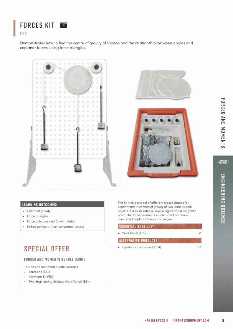
F O R C E S K I TE S 2
Demonstrates how to find the centre of gravity of shapes and the relationship between angles andcoplanar forces, using force triangles.
L E A R N I N G O U T C O M E S :• Centre of gravity• Force triangles• Force polygons and Bow’s notation• Linked polygons (non-concurrent forces)
s p e c ial o f f e rF o r c e s an d M o m e n t s B u n d l e ( E S B 1 )
This basic experiment bundle includes: • Forces Kit (ES2)• Moments Kit (ES3) • Two Engineering Science Work Panels (ES1)
This kit includes a set of different plastic shapes forexperiments in centres of gravity of two-dimensionalobjects. It also includes pulleys, weights and a magneticprotractor for experiments in concurrent and non-concurrent coplanar forces and angles.
• Work Panel (ES1) 8
• Equilibrium of Forces (STF4) 193
e s s e n t ial bas e u n i t:
alt e r nat i v e p r o d u c t s :
T E C Q U I P M E N T. C O M1 0
Engi
neer
ing
Scie
nce
Forc
es a
nd M
omen
ts
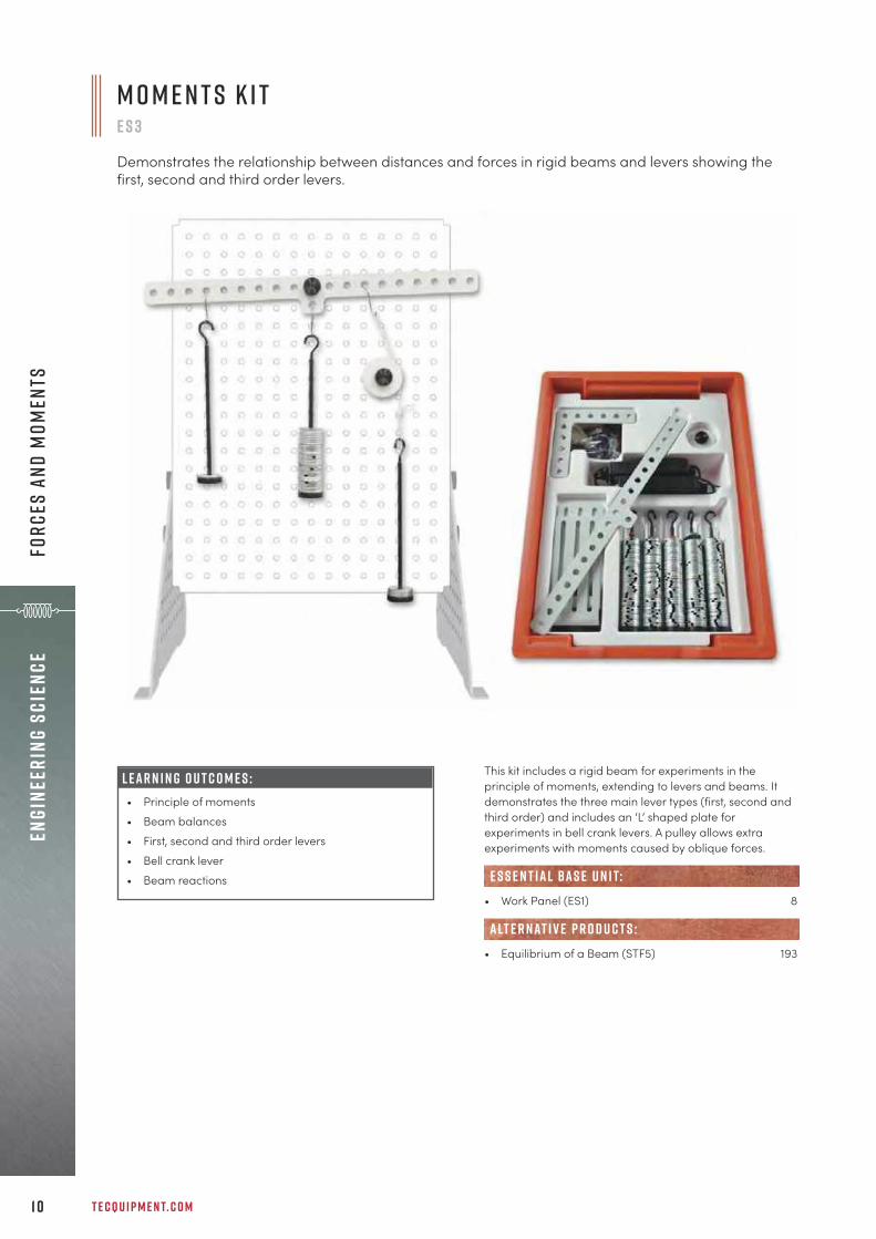
M o m e n t s K i te s 3
Demonstrates the relationship between distances and forces in rigid beams and levers showing thefirst, second and third order levers.
L E A R N I N G O U T C O M E S :• Principle of moments• Beam balances• First, second and third order levers• Bell crank lever• Beam reactions
This kit includes a rigid beam for experiments in theprinciple of moments, extending to levers and beams. Itdemonstrates the three main lever types (first, second andthird order) and includes an ‘L’ shaped plate forexperiments in bell crank levers. A pulley allows extraexperiments with moments caused by oblique forces.
• Work Panel (ES1) 8
• Equilibrium of a Beam (STF5) 193
e s s e n t ial bas e u n i t:
alt e r nat i v e p r o d u c t s :

+ 4 4 1 1 5 9 7 2 2 6 1 1 I N F O @ T E C Q U I P M E N T. C O M 1 1
Engineering ScienceM
aterials Testing
D e f l e c t i o n o f B e a m s a n d C a n t i l e v e r s K i te s 4
Demonstrates the deflection of beams of different materials and dimensions, held on different supports,both clamps and knife edges.
This kit includes different beams and fixing blocks. The fixingblocks work as clamps or knife-edge supports. They holdthe beams in different ways, such as a cantilever, simplysupported, fixed (encastre) and a propped cantilever.
• Work Panel (ES1) 8
• Stiffness, Bending and Torsion (TE16) 160• Beam and Leaf Spring (SM1000g) 173• Beam Apparatus (SM1004) 184• Deflection of Beams and Cantilevers (STR4) 212• Continuous and Indeterminate Beams (STR13) 214
e s s e n t ial bas e u n i t:
alt e r nat i v e p r o d u c t s :
L E A R N I N G O U T C O M E S :• Beam length and deflection• Beam material and deflection (Young’s modulus)• Beam ‘I’ value and deflection• Beam supports (cantilever, propped cantilever, fixed
beam and simply supported) and deflection

T E C Q U I P M E N T. C O M1 2
Engi
neer
ing
Scie
nce
Mat
eria
ls T
esti
ng
This kit includes different circular section specimens andadjustable chucks for experiments in torsion. Students fixthe specimens in the chucks and apply weights to a leverarm. The arm applies a moment (torque) to one end of thespecimen. A scale on the arm shows the angle of twist.
• Work Panel (ES1) 8
• Torsion Testing Machine, 30 Nm (SM1001) 166• Torsion of Circular Sections (STR6) 221• Torsion Testing Components (TE16b) 160
e s s e n t ial bas e u n i t:
alt e r nat i v e p r o d u c t s :
T o r s i o n o f C i r c u l a r S e c t i o n s K i t e s 5
Demonstrates the torsion in circular section specimens of different materials and lengths.
L E A R N I N G O U T C O M E S :• Specimen length and angle of twist• Specimen material and angle of twist (modulus of
rigidity)• Specimen ‘J’ value and angle of twist
h e r e t o h e l p y o uA team of specialist customer care personnel are available to answer a range of questions relating to technical details, spare parts and maintenance.
c u s t o m e r . car e@t e cqu i p m e n t. c o m
Question
Question
Question
Questionq u e s t i o n
questionQuestion
Question
Que
on
t
on
u
QQQQu
on
Q
i
Answer

+ 4 4 1 1 5 9 7 2 2 6 1 1 I N F O @ T E C Q U I P M E N T. C O M 1 3
Engineering ScienceM
aterials Testing
This kit includes a cased tensile tester with specimens ofdifferent materials for students to stretch specimens todestruction, while measuring the extension and force.
• Work Panel (ES1) 8
• Tensile Test Specimens (MTT) 28
• Universal Testing Machine (SM1000) 171• Bench-top Tensile Testing Machine (SM1002) 169• Materials Laboratory with Data Capture 176
(MF40 MkII)
R E C O M M E N D E D AN C I L LAR I E S :
e s s e n t ial bas e u n i t:
alt e r nat i v e p r o d u c t s :
L E A R N I N G O U T C O M E S :• Tensile tests (to destruction) of different materials• Finding the tensile strength of a material• Material behaviour in the elastic and plastic region• Creating a force and extension chart
T e n s i l e T e s t e r K i te s 6
Demonstrates the principles of tensile tests on specimens of different materials, showing materialbehaviour in the elastic and plastic region (Young’s modulus).
s p e c ial o f f e rMat e r ial s T e s t i n g B u n d l e ( E S B 2 )
This experiment bundle includes:• Deflection of Beams Kit (ES4)• Torsion of Circular Sections Kit (ES5) • Tensile Tester Kit (ES6)• Spring Tester Kit (ES19)• Four Engineering Science Work Panels (ES1)
T E C Q U I P M E N T. C O M1 4
Engi
neer
ing
Scie
nce
Mat
eria
ls T
esti
ng
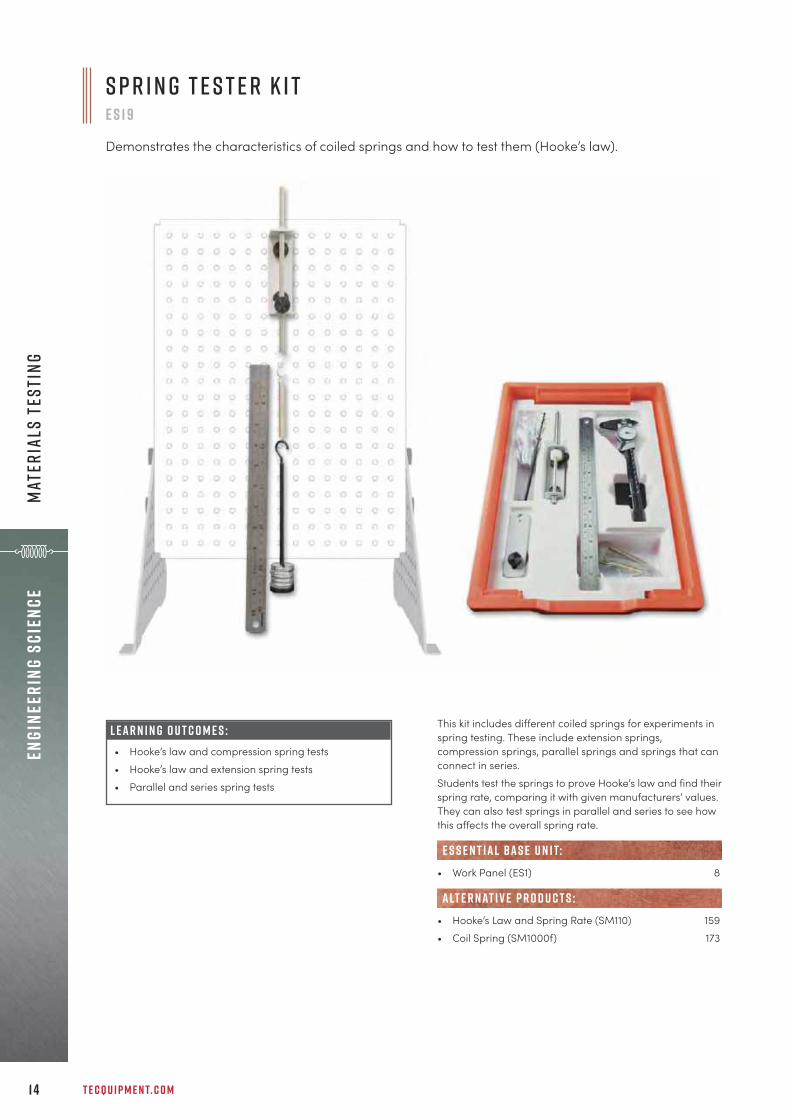
L E A R N I N G O U T C O M E S :• Hooke’s law and compression spring tests• Hooke’s law and extension spring tests• Parallel and series spring tests
This kit includes different coiled springs for experiments inspring testing. These include extension springs,compression springs, parallel springs and springs that canconnect in series.Students test the springs to prove Hooke’s law and find theirspring rate, comparing it with given manufacturers’ values.They can also test springs in parallel and series to see howthis affects the overall spring rate.
• Work Panel (ES1) 8
• Hooke’s Law and Spring Rate (SM110) 159• Coil Spring (SM1000f) 173
e s s e n t ial bas e u n i t:
alt e r nat i v e p r o d u c t s :
S p r i n g T e s t e r K i te s 1 9
Demonstrates the characteristics of coiled springs and how to test them (Hooke’s law).

+ 4 4 1 1 5 9 7 2 2 6 1 1 I N F O @ T E C Q U I P M E N T. C O M 1 5
Engineering ScienceVibration, Friction and Energy
S i m p l e H a r m o n i c M o t i o n K i te s 7
Demonstrates simple harmonic motion (oscillation) in springs and pendulums, and its usefulness.
This kit includes different pendulums and a spring to showstudents the principles and uses of simple harmonic motion.Students test different pendulums and a spring to see howdifferent factors, such as mass or pendulum length, affectsimple harmonic motion and the period of oscillation.
• Work Panel (ES1) 8
• Simple and Compound Pendulums (TM161) 241• Filar Pendulums (TM162) 242
e s s e n t ial bas e u n i t:
alt e r nat i v e p r o d u c t s :
L E A R N I N G O U T C O M E S :• Simple harmonic motion of simple, bifilar and trifilar
pendulums of different lengths and masses• Simple harmonic motion of a spring with different
masses, and a simple spring rate test• Simple harmonic motion of a compound pendulum• Simple harmonic motion and gravity using a Kater’s
pendulum

T E C Q U I P M E N T. C O M1 6
Engi
neer
ing
Scie
nce
Vibr
atio
n, F
rict
ion
and
Ener
gy
L E A R N I N G O U T C O M E S :• Forces on an inclined plane• Rolling and sliding friction on different surfaces• Kinetic and static sliding friction between different
surfaces• Surface angle and friction between different
surfaces
F r i c t i o n a n d I n c l i n e d P l a n e K i te s 8
Demonstrates kinetic and static sliding friction and rolling friction on bodies and between differentsurfaces on a flat or inclined plane.
This kit includes parts for experiments in friction and forceson a flat or inclined plane. The plane has an inclinometerand adjustment to allow the student to set the plane to anyangle between zero and 90 degrees. The parts includedifferent friction surfaces, a roller set, a rolling car or sledwith adjustable mass, and a simple roller.
• Work Panel (ES1) 8
e s s e n t ial bas e u n i t:
p r o d u c t d e v e l o p m e n tProducts are continually being improved. For the latest up-to-date specifications refer to the digital datasheets ont e cqu i p m e n t. c o m

+ 4 4 1 1 5 9 7 2 2 6 1 1 I N F O @ T E C Q U I P M E N T. C O M 1 7
Engineering ScienceVibration, Friction and Energy
L E A R N I N G O U T C O M E S :• Kinetic and potential energy in a pendulum• Elastic potential energy in a spring • Kinetic energy in a flywheel
P o t e n t i a l a n d K i n e t i c E n e r g y K i t e s 9
Demonstrates the difference between potential and kinetic energy and how it can change from one tothe other using a pendulum or flywheel. Also demonstrates elastic potential energy in a spring.
This kit includes a pendulum, a spring and a flywheel forexperiments in potential and kinetic energy. Students testeach part to discover the difference between potential andkinetic energy and the transfer of energy from one form toanother.
• Work Panel (ES1) 8
• Geared Systems Test Stand (TM1018a) 233
e s s e n t ial bas e u n i t:
alt e r nat i v e p r o d u c t s :

T E C Q U I P M E N T. C O M1 8
Engi
neer
ing
Scie
nce
Vibr
atio
n, F
rict
ion
and
Ener
gy
L E A R N I N G O U T C O M E S :• Efficiency of a screw jack• Efficiency of a wedge • Efficiency of different bearings
This kit includes a screw jack (or ‘jackscrew’), a wedge anddifferent bearings. It helps students understand howrotational friction affects the efficiency of popular machineelements and bearing materials. It shows why engineerschoose some materials and devices above others for anygiven application.
• Work Panel (ES1) 8
e s s e n t ial bas e u n i t:
R o tat i o n a l F r i c t i o n K i te s 1 7
Demonstrates how rotational friction affects the efficiency of popular machine elements, including ascrew jack, wedge and different bearings.
s p e c ial o f f e rV ibrat i o n , F r i c t i o n an d E n e r g y K i t B u n d l e( E S B5 )
This experiment bundle includes:• Simple Harmonic Motion Kit (ES7)• Friction and Inclined Plane Kit (ES8) • Potential and Kinetic Energy Kit (ES9)• Rotational Friction Kit (ES17)• Four Engineering Science Work Panels (ES1)
+ 4 4 1 1 5 9 7 2 2 6 1 1 I N F O @ T E C Q U I P M E N T. C O M 1 9
Engineering ScienceSim
ple Machines
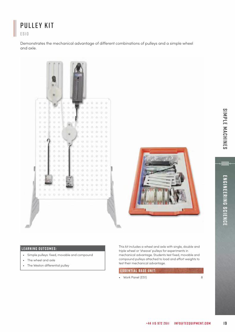
This kit includes a wheel and axle with single, double andtriple wheel or ‘sheave’ pulleys for experiments inmechanical advantage. Students test fixed, movable andcompound pulleys attached to load and effort weights totest their mechanical advantage.
• Work Panel (ES1) 8
e s s e n t ial bas e u n i t:
P u l l e y K i te s 1 0
Demonstrates the mechanical advantage of different combinations of pulleys and a simple wheeland axle.
L E A R N I N G O U T C O M E S :• Simple pulleys: fixed, movable and compound• The wheel and axle• The Weston differential pulley

T E C Q U I P M E N T. C O M2 0
Engi
neer
ing
Scie
nce
Sim
ple
Mac
hine
s
This kit includes three different drive systems to show theirrelative advantages and disadvantages. Students test a universal coupling, a belt drive and a chaindrive to see how they work and how they differ in the waythey transfer motion (power).
• Work Panel (ES1) 8
• Geared Systems (TM1018) 232
e s s e n t ial bas e u n i t:
alt e r nat i v e p r o d u c t s :
D r i v e S y s t e m s K i te s 1 1
Demonstrates the advantages and disadvantages of three popular drive systems (belt, chain and auniversal coupling) using a manually rotated frame with a low-friction cantilever linkage, adjustablemasses and a spring to apply force.
L E A R N I N G O U T C O M E S :• Power transfer, efficiency and direction in a belt
drive• Power transfer and efficiency in a chain drive• Input and output relationships of a universal
coupling• Friction and angle of lap on a pulley
s p e c ial o f f e rs i m p l e mac h i n e s k i t bu n d l e ( E S B3 )
This experiment bundle includes:• Pulley Kit (ES10)• Drive Systems Kit (ES11) • Gear Trains Kit (ES13)• Centrifugal Force Kit (ES16)• Four Engineering Science Work Panels (ES1)

+ 4 4 1 1 5 9 7 2 2 6 1 1 I N F O @ T E C Q U I P M E N T. C O M 2 1
Engineering ScienceSim
ple Machines
L E A R N I N G O U T C O M E S :• Characteristics of spur gears, including single and
compound gear trains and the ‘idler’ gear• Characteristics of a bevel gear• Characteristics of a worm drive
This kit includes a selection of different gears forexperiments to find their unique characteristics.The gears include spur gears, a bevel gear and a wormdrive. The spur gears have two sets of teeth on the sameshaft, allowing extra experiments in compound gear trains.Students test each set of gears to see how it works and notethe differences in characteristics (such as efficiency, gearratio and mechanical advantage) of each set.
• Work Panel (ES1) 8
• Geared Systems (TM1018) 232
e s s e n t ial bas e u n i t:
alt e r nat i v e p r o d u c t s :
G e a r T r a i n s K i t e s 1 3
Demonstrates the characteristics of a spur gear, bevel gear and a worm drive.
F u l l s p e c i f i cat i o n datas h e e t sDatasheets contain full specifications such as size, weight, noise output, fluid capacity, voltage requirements etc. Download from each individual product webpage.
t e cqu i p m e n t. c o m (search product)

T E C Q U I P M E N T. C O M2 2
Engi
neer
ing
Scie
nce
Sim
ple
Mac
hine
s
L E A R N I N G O U T C O M E S :• Relationship between centrifugal force, radius and
velocity of different rotating masses.
This kit includes a manually rotated frame with a low-friction cantilever linkage. The frame has mountingpositions for adjustable masses and a spring that applies afixed frictional force value to a rotating drum. The range ofmounting positions and masses allows many variations ofthe experiment to help students understand therelationships between the variables of speed, mass andradial position.
• Work Panel (ES1) 8
• Centrifugal Force (TM1005) 237
e s s e n t ial bas e u n i t:
alt e r nat i v e p r o d u c t s :
C e n t r i f u g a l F o r c e K i te s 1 6
Demonstrates the relationship between centrifugal force, radius and velocity of rotating masses.
Q ual i t y C o n t r o l w i t h I n - H o u s e P r o d u c t i o nTo maintain high quality and keep lead times to a minimum, products are designed and manufactured all under one roof at the TecQuipment headquarters based in the UK.
+ 4 4 1 1 5 9 7 2 2 6 1 1 I N F O @ T E C Q U I P M E N T. C O M 2 3
Engineering ScienceM
echanisms
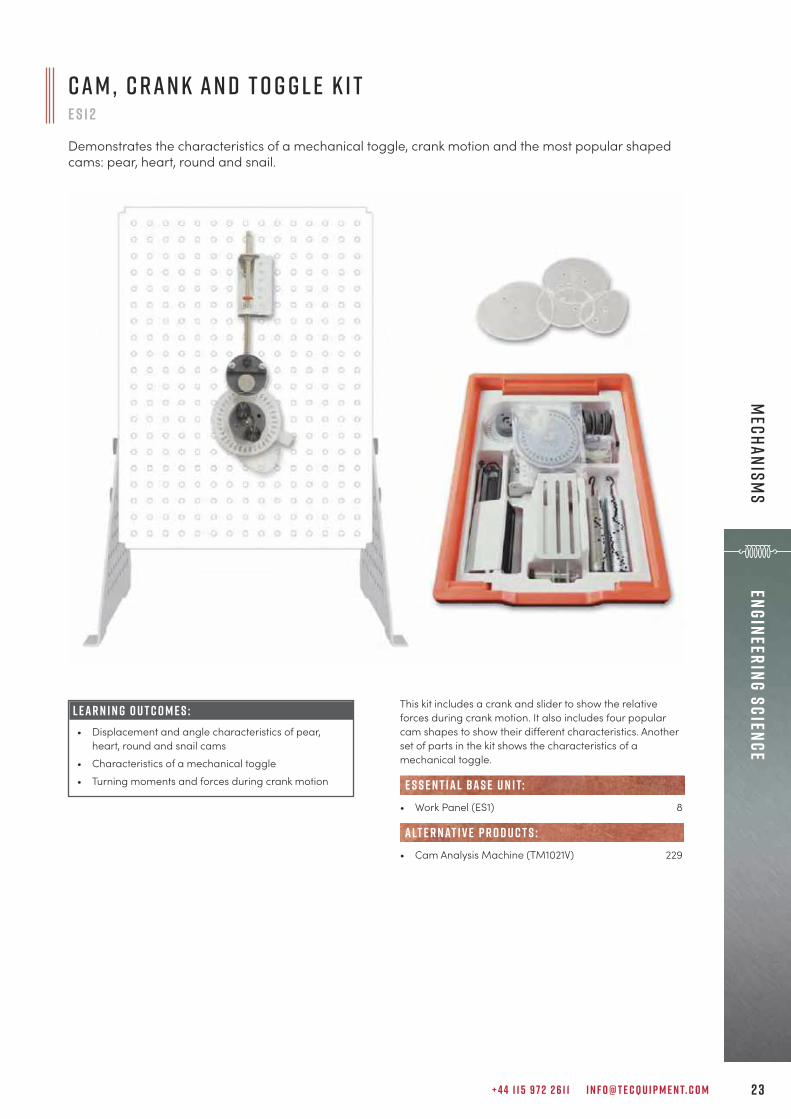
L E A R N I N G O U T C O M E S :• Displacement and angle characteristics of pear,
heart, round and snail cams• Characteristics of a mechanical toggle• Turning moments and forces during crank motion
This kit includes a crank and slider to show the relativeforces during crank motion. It also includes four popularcam shapes to show their different characteristics. Anotherset of parts in the kit shows the characteristics of amechanical toggle.
• Work Panel (ES1) 8
• Cam Analysis Machine (TM1021V) 229
e s s e n t ial bas e u n i t:
alt e r nat i v e p r o d u c t s :
C a m , C r a n k a n d T o g g l e K i tE S 1 2
Demonstrates the characteristics of a mechanical toggle, crank motion and the most popular shapedcams: pear, heart, round and snail.
T E C Q U I P M E N T. C O M2 4
Engi
neer
ing
Scie
nce
Mec
hani
sms
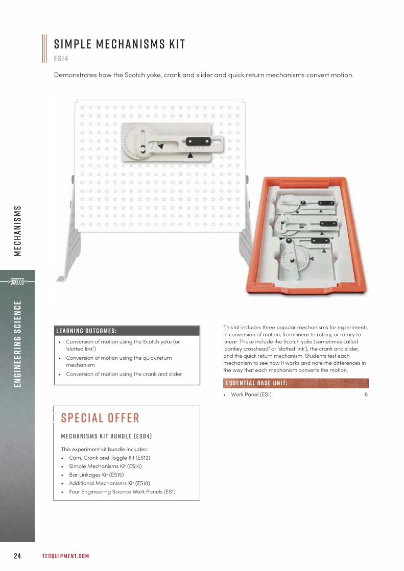
This kit includes three popular mechanisms for experimentsin conversion of motion, from linear to rotary, or rotary tolinear. These include the Scotch yoke (sometimes called‘donkey crosshead’ or ‘slotted link’), the crank and slider,and the quick return mechanism. Students test eachmechanism to see how it works and note the differences inthe way that each mechanism converts the motion.
• Work Panel (ES1) 8
e s s e n t ial bas e u n i t:
S i m p l e M e c h a n i s m s K i t e s 1 4
Demonstrates how the Scotch yoke, crank and slider and quick return mechanisms convert motion.
L E A R N I N G O U T C O M E S :• Conversion of motion using the Scotch yoke (or
‘slotted link’)• Conversion of motion using the quick return
mechanism• Conversion of motion using the crank and slider
s p e c ial o f f e rm e c han i s m s k i t B u n d l e ( E S B4)
This experiment kit bundle includes:• Cam, Crank and Toggle Kit (ES12)• Simple Mechanisms Kit (ES14) • Bar Linkages Kit (ES15)• Additional Mechanisms Kit (ES18)• Four Engineering Science Work Panels (ES1)
+ 4 4 1 1 5 9 7 2 2 6 1 1 I N F O @ T E C Q U I P M E N T. C O M 2 5
Engineering ScienceM
echanisms
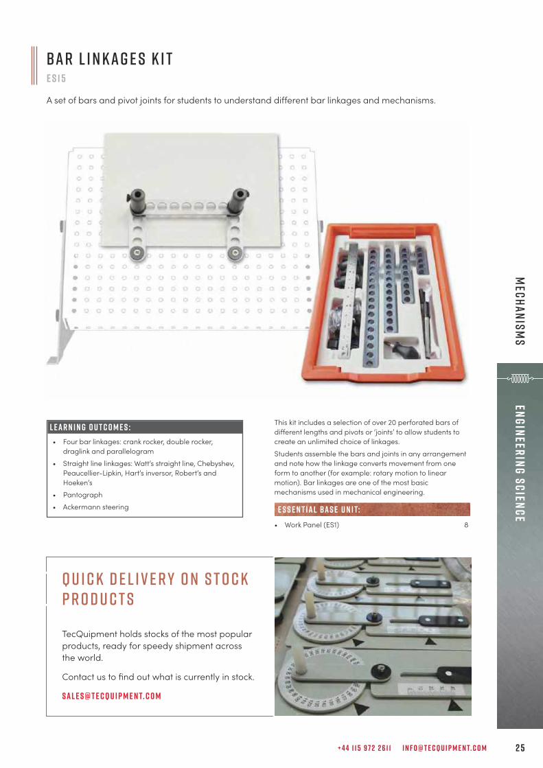
L E A R N I N G O U T C O M E S :• Four bar linkages: crank rocker, double rocker,
draglink and parallelogram• Straight line linkages: Watt’s straight line, Chebyshev,
Peaucellier-Lipkin, Hart’s inversor, Robert’s andHoeken’s
• Pantograph• Ackermann steering
This kit includes a selection of over 20 perforated bars ofdifferent lengths and pivots or ‘joints’ to allow students tocreate an unlimited choice of linkages.Students assemble the bars and joints in any arrangementand note how the linkage converts movement from oneform to another (for example: rotary motion to linearmotion). Bar linkages are one of the most basicmechanisms used in mechanical engineering.
• Work Panel (ES1) 8
e s s e n t ial bas e u n i t:
B a r L i n k a g e s K i t e s 1 5
A set of bars and pivot joints for students to understand different bar linkages and mechanisms.
Q u i c k d e l i v e r y o n S t o c k P r o d u c t s
TecQuipment holds stocks of the most popular products, ready for speedy shipment across the world.
Contact us to find out what is currently in stock.
Sal e s@t e cqu i p m e n t. c o m

T E C Q U I P M E N T. C O M2 6
Engi
neer
ing
Scie
nce
Mec
hani
sms
This kit includes two popular mechanisms for experiments inconversion of motion from one form to another. Theseinclude the Geneva mechanism (sometimes called theMaltese cross mechanism or crank and star), and a ratchetmechanism. Students test each mechanism to see how itworks and note the differences in the way that eachmechanism converts the motion.
• Work Panel (ES1) 8
e s s e n t ial bas e u n i t:
L E A R N I N G O U T C O M E S :• Conversion of motion using the Geneva mechanism• Conversion of motion using a ratchet
A d d i t i o n a l M e c h a n i s m s K i t e s 1 8
Demonstrates how the Geneva mechanism and a ratchet mechanism convert motion.
S o c ial M e d ia Find out all the latest up-to-the-minute news, promotions, stories from users, videos etc. Plus, embrace the opportunity to interact with other academics, students and get fresh ideas.
s har essssss hssssssss
c o m m e n t
L i k e

+ 4 4 1 1 5 9 7 2 2 6 1 1 I N F O @ T E C Q U I P M E N T. C O M 2 7
Engineering ScienceStorage Equipm
ent and Ancillaries
S t o r a g e Equ i p m e n tE S T / E T L
Storage equipment for use with TecQuipment’s Engineering Science range.
• A set of five spare trays and lids (ETL),useful for safely storing ancillaries orprinted material such as lecturerguides or worksheets
• A compact mobile frame (EST) thatstores up to 24 trays safely and tidily,while allowing one person to move all24 trays from one room to another
For use with the Engineering Science kits, TecQuipmentoffers these supporting products as a useful resource forlecturers or teachers:
S t o r a g e U n i t E S TA mobile trolley for use with the EngineeringScience kits. This trolley allows lecturers orteachers to safely and tidily store up to 24 trays inone mobile unit.
T r ay s a n d L i d s E T LA set of five trays and lids. Identical to those usedfor the kits, so they fit and stack in the same way.
D o c u m e n t s I n c l u d e d – E v e r y t h i n g Y o u N e e dA comprehensive pack of documents is supplied with all experiments, including:
U s e r Man ual : How to use the product, along with instructions on experiment set-up and supporting enginering principles for guided learning. Pac k i n g c o n t e n t s l i s t: All the parts that make up the complete product. T e s t c e r t i f i cat e : Your peace of mind that the product has been thoroughly tested before dispatch.

T E C Q U I P M E N T. C O M2 8
Engi
neer
ing
Scie
nce
Stor
age
Equi
pmen
t an
d An
cill
arie
s
S pa r e s a n d C o n s u m a b l e sE S X / S W 1 / W T / W T L / M T T
Spares and consumables for use with TecQuipment’s Engineering Science range.
• Useful to replace any parts that become lostfrom the experiment kits during use, or toincrease the variation of experiments
• Additional tensile test specimens (MTT) forthe Tensile Tester Kit (ES6)
TecQuipment offers these spares and consumables mainlyfor the Engineering Science range. However, the stopwatchand weight sets also work as spares for other TecQuipmentproduct ranges.
S pa r e Pa r t s K i t E S XThis kit includes spares of the most common parts used inthe other Engineering Science kits, including fixings, weights,hooks and cord.
S t o p wat c h S W 1An easy-to-use, accurate, hand-held digital stopwatch. Replacesany lost from the kits or allowsmore students to shareexperiments.
W e i g h t S e t s W T a n d W T LSlotted masses that fit onto TecQuipment’s weight hangers.They will work as general-purpose weights and spares forthose in several otherTecQuipment products, suchas the Structures range. W T: A set of 10 g masses andweight hangersW T L : A set of 1 g masses
T e n s i l e T e s t S p e c i m e n s M T TSpecimens made from a choice of four different materialsfor use with the Engineering Science Tensile Tester (ES6).M T TA : AluminiumM T T D : Aluminium HE30M T T P : PVCM T T S : Mild steelN o t e : TecQuipment suppliesall specimens individually,but a minimum ordercharge applies.
S pa r e Pa r t s K i t ( E S X )
• Additional weight sets (WT and WTL) andstopwatch (SW1) are useful spares for boththe Engineering Science range and otherTecQuipment products
• A tray of spares (ESX) containing themost common parts of the EngineeringScience kits

+ 4 4 1 1 5 9 7 2 2 6 1 1 I N F O @ T E C Q U I P M E N T. C O M 2 9
aERODYNAMICS
A E R O D Y N A M I C S
“We recently purchased a wind tunnel for the training of our aeronautical engineering studentsfrom TecQuipment. The product was easy to set up, straight forward to operate and I amconfident will continue to be used for many years to come. The service and training thatTecQuipment provides makes them a pleasure to work with.
S e a n H a i n s w o r t hA e r o n a u t i c a l E n g i n e e r i n g L e c t u r e r , M i lt o n K e y n e s C o l l e g e
S u b s o n i c W i n d T u n n e l s 3 1
S p e c i a l P u r p o s e W i n d T u n n e l s 5 4
S u p e r s o n i c N o z z l e 5 9
S u p e r s o n i c W i n d T u n n e l s 6 0
T E C Q U I P M E N T. C O M3 0
aERO
DYNA
MICS
a e r o d y n a m i c sThe aerodynamics range is used for teaching a vast rangeof aerodynamic principles – from fundamentals through toadvanced theories – with products to suit every space,budget and complexity requirement. The wind tunnels spana variety of sizes and experimentation capabilities, frombenchtop models for learning the basics, to versionsrequiring large laboratories for a more detailedunderstanding of aerodynamics.
P r i n c i p l e s o f A e r o d y n a m i c sTecQuipment’s subsonic wind tunnels teach students thebasics of lift, drag and pitching moments, plus high-leveltopics such as boundary layer and pressure distributionaround models. Students can also perform wakeinvestigations.
A d va n c e d T h e o r y o f A e r o d y n a m i c sTecQuipment’s supersonic wind tunnels are for the moreadvanced teaching of aerodynamics engineering, withexperiments that start with nozzle pressure distribution, onto analysis of Mach numbers, and the measurement andvisualisation of pressure and shock waves using Schlierenapparatus.
A u t o m at i c d ata a c q u i s i t i o n A variety of the products in this range work withTecQuipment’s unique Versatile Data Acquisition System(VDAS®), page 310.
M a d e f o r t e a c h i n g : Realistic results yet small enoughfor laboratories.
F l e x i b i l i t y: Packages of equipment can be chosen tosuit budgets and needs.
E a s y s e t- u p : It takes only minutes to change and set upan experiment.
H a n d s o n : Laboratory-scale parts allow easy fitting andadjustments, for a more practical understanding.
k e y f eat u r e s an d b e n e f i t s :
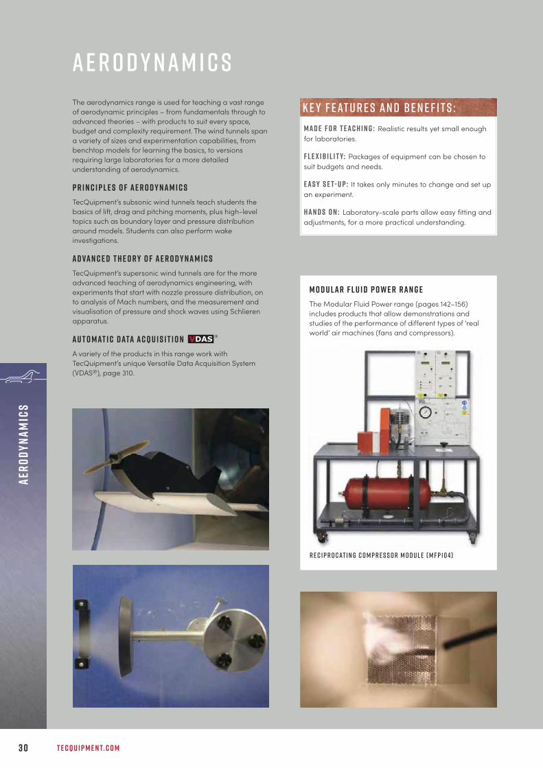
M o d u l a r F l u i d P o w e r r a n g eThe Modular Fluid Power range (pages 142–156)includes products that allow demonstrations andstudies of the performance of different types of ‘realworld’ air machines (fans and compressors).
R e c i p r o c at i n g C o m p r e s s o r M o d u l e ( M F P 1 0 4)

+ 4 4 1 1 5 9 7 2 2 6 1 1 I N F O @ T E C Q U I P M E N T. C O M 3 1
aERODYNAMICSsUBSONIC W
IND tUNNELS
M o d u l a r A i r F l o w B e n c ha f 1 0
This is a small-scale wind tunnel with an electricfan and adjustable air flow control, with eightdifferent experiment modules that demonstratekey principles and phenomena of air flow.
S h o w n f i t t e d w i t h o n e o f t h e ava i l abl e e x p e r i m e n tm o d u l e s ( A F 1 2 ) a n d M u lt i -T ube M a n o m e t e r ( A F 1 0 a )
recommendedancillary (af10a)
Experiment modules(af11–af18)
Essential Base Unit (af10)
M O D U LAR S Y S T E M
• Bernoulli’s Equation (AF11) 32• Drag Force (AF12) 33• Round Turbulent Jet (AF13) 34• Boundary Layer (AF14) 35• Flow Around a Bend (AF15) 36 • Coandă Effect and Jet Flow (AF16) 37• Flow Visualisation (AF17) 37• Tapped Aerofoil (AF18) 38
• Multi-Tube Manometer (AF10a) 38
• Benchtop Subsonic Wind Tunnel (AF1125) 39• Subsonic Wind Tunnels 40 / 46 / 48
(AF1300, AF1450S, AF1600S) 40• Flight Demonstration Wind Tunnel (AF41) 54• Flow Visualisation Wind Tunnel (AF80) 58
ava i labl e e x p e r i m e n t m o d u l e s :
R E C O M M E N D E D AN C I L LAR I E S :
alt e r nat i v e p r o d u c t s :
Supports and supplies a controllable air flow toits optional experiment modulesModular design saves space and reduces costs
Eight different optional experiment modulesCovers all aspects of a basic aerodynamicscurriculum
Compact, mobile and easy to installSimplifies laboratory layout
Easy set-up, just minutes to remove and fitexperiment modulesMaximises experiment time and requires minimalsupervision
F eat u r e s an d be n e f i t s :

T E C Q U I P M E N T. C O M3 2
aERO
DYNA
MICS
sUBS
ONIC
WIN
D tU
NNEL
S
This experiment module illustrates Bernoulli’s equation asapplied to a convergent-divergent duct. A Pitot static tubemeasures both the total pressure and the static pressureindependently. The tube traverses along the axis of the ductand connects to the AF10a Multi-Tube Manometer(available separately) via flexible tubes fitted with quick-release couplings.
B e r n o u l l i ’ s E q u at i o n a f 1 1
Allows students to measure the pressuredistribution in a convergent-divergent duct toconfirm Bernouli’s equation.
• Quickly and simply illustrates Bernoulli’sequation for air, and its limitations due toboundary layer effects
• Quick-release couplings for rapid and reliablepressure connection to the AF10a Manometer
• Transparent front to the duct so that theprofile of the test nozzle and the position ofthe Pitot static tube can be seen clearly
• One of a series of eight experiment modulesthat fit to the Modular Air Flow Bench (AF10)
L E A R N I N G O U T C O M E S :• Confirmation of Bernoulli’s equation• The use of a Pitot static tube and water manometer
• Modular Air Flow Bench (AF10) 31
• Multi-Tube Manometer (AF10a) 38
• Bernoulli’s Theorem (H5) 98
e s s e n t ial bas e u n i t:
E S S E N T IAL AN C I L LAR I E S :
alt e r nat i v e p r o d u c t s :
T e cqu i p m e n t ’ s b l o gRead the TecQuipment blog for informative posts, from topics focused on engineering education through to guest posts from academics sharing viewpoints, relevant teaching projects and perspectives.
T e cqu i p m e n t. c o m / k n o w l e d g e

+ 4 4 1 1 5 9 7 2 2 6 1 1 I N F O @ T E C Q U I P M E N T. C O M 3 3
aERODYNAMICSsUBSONIC W
IND tUNNELS
This simple yet comprehensive experiment module consistsof a duct with transparent front and rear. The front hasscales printed on it to position the various parts during theexperiments. A Pitot tube and simple mass balance areattached to the outside of the duct for wake traverse anddirect drag measurements respectively.
• Modular Air Flow Bench (AF10) 31
• Multi-Tube Manometer (AF10a) 38
• Cylinder Model (AF1300a) 41• NACA 0012 Aerofoil with Tappings (AF1300b) 42• Flat Plate Drag Model (AF1300e) 42• Three-Dimensional Drag Models (AF1300j) 42• S1210 Aerofoil (AF1300l) 42
e s s e n t ial bas e u n i t:
E S S E N T IAL AN C I L LAR I E S :
alt e r nat i v e p r o d u c t s :
L E A R N I N G O U T C O M E S :• Determination of the drag coefficient by
measurement of the pressure distribution around thecylinder
• Determination of the drag coefficient by waketraverse
• Determination of the drag coefficient around thecylinder by direct measurement and comparison toresults obtained by pressure distribution and waketraverse
• Direct measurement and comparison of dragcoefficient between a cylinder, flat plate and aerofoil
D r a g F o r c e a f 1 2
Allows students to investigate the direct and indirect measurement of drag on various shapes and tocalculate and analyse the drag coefficient by different methods.
• Compares drag for a cylinder calculatedfrom a measured pressure distribution, anda wake traverse against that measureddirectly for a cylinder
• Allows comparisons of drag force betweena cylinder, flat plate and aerofoil
• The test duct has transparent sides withclearly printed scales, allowing students tosee the experiment and accurately positionthe models and the Pitot tube
• One of a series of eight experiment modulesthat fit to the Modular Air Flow Bench (AF10)
T E C Q U I P M E N T. C O M3 4
aERO
DYNA
MICS
sUBS
ONIC
WIN
D tU
NNEL
S
R o u n d T u rbu l e n t J e t a f 1 3
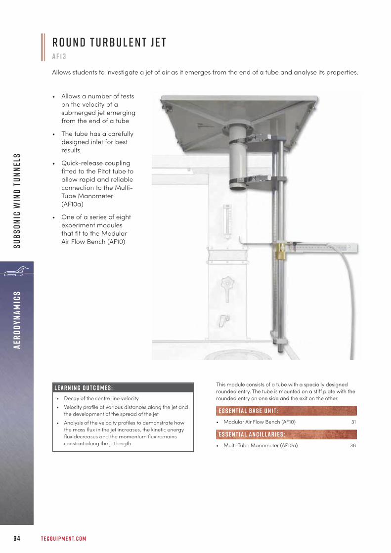
Allows students to investigate a jet of air as it emerges from the end of a tube and analyse its properties.
• Allows a number of testson the velocity of asubmerged jet emergingfrom the end of a tube
• The tube has a carefullydesigned inlet for bestresults
• Quick-release couplingfitted to the Pitot tube toallow rapid and reliableconnection to the Multi-Tube Manometer(AF10a)
• One of a series of eightexperiment modulesthat fit to the ModularAir Flow Bench (AF10)
This module consists of a tube with a specially designedrounded entry. The tube is mounted on a stiff plate with therounded entry on one side and the exit on the other.
• Modular Air Flow Bench (AF10) 31
• Multi-Tube Manometer (AF10a) 38
e s s e n t ial bas e u n i t:
E S S E N T IAL AN C I L LAR I E S :
L E A R N I N G O U T C O M E S :• Decay of the centre line velocity• Velocity profile at various distances along the jet and
the development of the spread of the jet• Analysis of the velocity profiles to demonstrate how
the mass flux in the jet increases, the kinetic energyflux decreases and the momentum flux remainsconstant along the jet length

+ 4 4 1 1 5 9 7 2 2 6 1 1 I N F O @ T E C Q U I P M E N T. C O M 3 5
aERODYNAMICSsUBSONIC W
IND tUNNELS
B o u n d a r y L ay e ra f 1 4
Allows students to investigate both the laminar and turbulent boundary layers on flat plates with roughand smooth surfaces.
• Allows a number of tests onlaminar and turbulentboundary layers, with roughand smooth surfaces withdifferent pressure gradients
• Boundary layer velocity profileis measured with a Pitot tubewith a fine micrometeradjustment for best results
• Test section has a transparentfront so students can see theexperiment and the position ofthe Pitot tube clearly
• One of a series of eightexperiment modules that fit tothe Modular Air Flow Bench(AF10)
This module consists of a duct in which there is situated aflat plate. The flat plate is rough on one side and smooth onthe other, providing different surface conditions for theformation of a boundary layer.
• Modular Air Flow Bench (AF10) 31
• Multi-Tube Manometer (AF10a) 38
• Flat Plate Drag Model (AF1300e) 42
e s s e n t ial bas e u n i t:
E S S E N T IAL AN C I L LAR I E S :
alt e r nat i v e p r o d u c t s :
L E A R N I N G O U T C O M E S :• Measurement of the velocity profile in laminar and
turbulent boundary layers• Measurement of the velocity profile in the boundary
layer formed over both rough and smooth plates• Measurement of the velocity profile in the boundary
layer at various distances from the leading edge ofthe plate
• Effect of the pressure gradient on the boundary layervelocity profile

T E C Q U I P M E N T. C O M3 6
aERO
DYNA
MICS
sUBS
ONIC
WIN
D tU
NNEL
S
F l o w A r o u n d a B e n d a f 1 5
Allows students to measure the pressure distribution in a smooth rectangular bend via tapping pointson the curved walls and radius.
• Shows the pressure distribution in asmooth rectangular bend as anexample of internal flow problems
• Quick-release couplings for rapidand reliable pressure measurementconnection to the Multi-TubeManometer (AF10a)
• Highly visual plot of the pressureprofile on the manometer
• One of a series of eight experimentmodules that fit to the Modular AirFlow Bench (AF10)
This module consists of a smooth rectangular bend with tenstatic tapping points on both the inner and outer curvedwalls, plus a further nine along the radius.
• Modular Air Flow Bench (AF10) 31
• Multi-Tube Manometer (AF10a) 38
e s s e n t ial bas e u n i t:
E S S E N T IAL AN C I L LAR I E S :
L E A R N I N G O U T C O M E S :• Pressure distribution along the curved inner and
outer walls• Radial pressure distribution and comparison with
that predicted assuming free vortex velocitydistribution
• Calculation of loss coefficient (K)
T o p 5 r eas o n s t o v i s i t t e cqu i p m e n t
1. Personal development
2. See real products in production
3. Get hands-on with equipment
4. Meet the teams
5. Combine with university visits

+ 4 4 1 1 5 9 7 2 2 6 1 1 I N F O @ T E C Q U I P M E N T. C O M 3 7
aERODYNAMICSsUBSONIC W
IND tUNNELS
C o a n d ă E f f e c t a n d J e t F l o w a f 1 6
Allows students to investigatethe Coandă effect and a fluidicflip flop.
• Shows an example of how thephenomena of fluid mechanicscan be exploited to perform auseful task, a fluidic flip flop
• Transparent fronted test ductwith clearly printed scalesallows the experiment to beclearly seen and componentsaccurately positioned
• Effectively demonstrates theCoandă effect
• One of a series of eight experiment modulesthat fit to the Modular Air Flow Bench (AF10)
This module consists of an aerodynamically shaped nozzlefrom which a jet of air emerges. This flows against a wall towhich it attaches.
• Modular Air Flow Bench (AF10) 31
e s s e n t ial bas e u n i t:
F l o w V i s u a l i s at i o na f 1 7
Allows students to see the air flow aroundvarious shapes by using smoke filaments. Theshapes are viewed through a transparentwindow.
• Includes a set of differently shaped two-dimensional models
• Transparent fronted test duct, with clearlyprinted angular scale, allows the models tobe clearly seen and accurately positioned
• Comes complete with ducting to allow thesmoke to be easily and safely drawn awayby the Modular Air Flow Bench
• One of a series of eight experiment modulesthat fit to the Modular Air Flow Bench (AF10)
This module consists of a specially shaped duct which has alarge working section with transparent window. The inlet ofthe duct is attached to the Air Flow Bench plenum chamberusing quick-release clamps; the outlet is located into thebench exhaust.
• Modular Air Flow Bench (AF10) 31
• Flow Visualisation Wind Tunnel (AF80) 58
e s s e n t ial bas e u n i t:
alt e r nat i v e p r o d u c t s :
L E A R N I N G O U T C O M E S :• Demonstration of the Coandă effect• Demonstration of the fluidic flip flop
L E A R N I N G O U T C O M E S :• Demonstration of the flow patterns round a cylinder,
flat plate, aerofoil and a sharp-edged orifice/slit
T E C Q U I P M E N T. C O M3 8
aERO
DYNA
MICS
sUBS
ONIC
WIN
D tU
NNEL
S
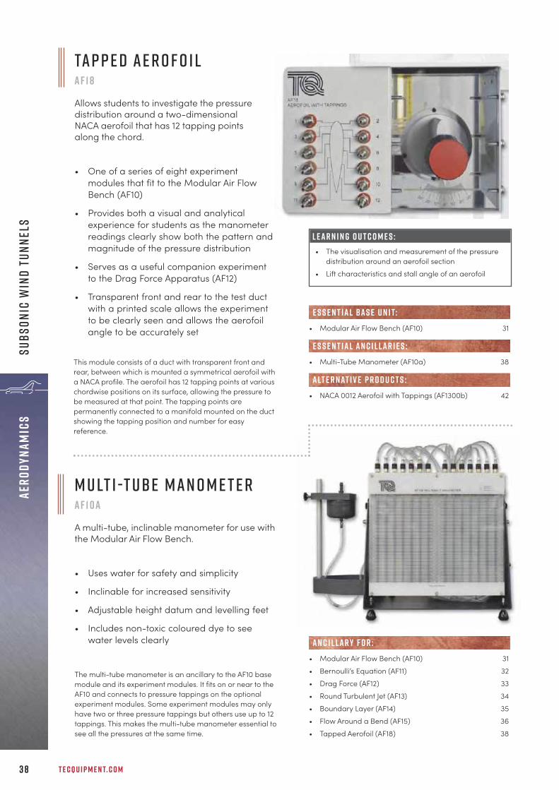
Ta p p e d A e r o f o i la f 1 8
Allows students to investigate the pressuredistribution around a two-dimensionalNACA aerofoil that has 12 tapping pointsalong the chord.
• One of a series of eight experimentmodules that fit to the Modular Air FlowBench (AF10)
• Provides both a visual and analyticalexperience for students as the manometerreadings clearly show both the pattern andmagnitude of the pressure distribution
• Serves as a useful companion experimentto the Drag Force Apparatus (AF12)
• Transparent front and rear to the test ductwith a printed scale allows the experimentto be clearly seen and allows the aerofoilangle to be accurately set
m u lt i -t ube m a n o m e t e ra f 1 0 a
A multi-tube, inclinable manometer for use withthe Modular Air Flow Bench.
• Uses water for safety and simplicity
• Inclinable for increased sensitivity
• Adjustable height datum and levelling feet
• Includes non-toxic coloured dye to seewater levels clearly
This module consists of a duct with transparent front andrear, between which is mounted a symmetrical aerofoil witha NACA profile. The aerofoil has 12 tapping points at variouschordwise positions on its surface, allowing the pressure tobe measured at that point. The tapping points arepermanently connected to a manifold mounted on the ductshowing the tapping position and number for easyreference.
L E A R N I N G O U T C O M E S :• The visualisation and measurement of the pressure
distribution around an aerofoil section• Lift characteristics and stall angle of an aerofoil
The multi-tube manometer is an ancillary to the AF10 basemodule and its experiment modules. It fits on or near to theAF10 and connects to pressure tappings on the optionalexperiment modules. Some experiment modules may onlyhave two or three pressure tappings but others use up to 12tappings. This makes the multi-tube manometer essential tosee all the pressures at the same time.
• Modular Air Flow Bench (AF10) 31• Bernoulli’s Equation (AF11) 32• Drag Force (AF12) 33• Round Turbulent Jet (AF13) 34• Boundary Layer (AF14) 35• Flow Around a Bend (AF15) 36• Tapped Aerofoil (AF18) 38
AN C I L LAR Y F O R :
• Modular Air Flow Bench (AF10) 31
• Multi-Tube Manometer (AF10a) 38
• NACA 0012 Aerofoil with Tappings (AF1300b) 42
e s s e n t ial bas e u n i t:
E S S E N T IAL AN C I L LAR I E S :
alt e r nat i v e p r o d u c t s :

+ 4 4 1 1 5 9 7 2 2 6 1 1 I N F O @ T E C Q U I P M E N T. C O M 3 9
aERODYNAMICSsUBSONIC W
IND tUNNELS
• Selection of models included for studies ofdrag and pressure profiles
• Efficient and compact where laboratoryspace is at a premium
• Two-component balance with digitaldisplay for lift and drag measurement
• Compact, open circuit suction design
• Transparent working section for a full viewof the test area
• Electronic controller for variable air velocity
be n c h t o p S ubs o n i c W i n d T u n n e la f 1 1 2 5
An ultra-compact, open circuit, benchtop subsonic wind tunnel that offers a complete system ready foraerodynamic experimentation, suitable for college use, undergraduate study and research projects.
Air enters the tunnel through an aerodynamically designedeffuser (inlet cone) and honeycomb flow straightener thataccelerate the air linearly. It then enters the workingsection and passes through a grille before moving througha diffuser and then to a variable speed fan. The grilleprotects the fan from damage by loose objects. The airleaves the fan, passes up through a silencer unit and thenback out to atmosphere.
E X P E R I M E N T M O D E L S I N C L U D E D :• Flat plate• Cylinder with pressure tapping• NACA0020 aerofoil
• Smoke Generator (AFA11) 52
R E C O M M E N D E D AN C I L LAR I E S :
L E A R N I N G O U T C O M E S :A wide variety of subsonic aerodynamics experiments,including:• Flow past bluff and streamlined bodies• Pressure distribution around a cylinder• Lift and drag forces
• Modular Air Flow Bench (AF10) 31• Subsonic Wind Tunnel (AF1300) 40• Subsonic Wind Tunnel (AF1450S) 46• Subsonic Wind Tunnel (AF1600S) 48• Flight Demonstration Wind Tunnel (AF41) 54• Flow Visualisation Wind Tunnel (AF80) 58• Supersonic Wind Tunnel (Intermittent) (AF300) 60• Supersonic Wind Tunnel (Continuous) (AF302) 62
alt e r nat i v e p r o d u c t s :
L i f t a n d D r a g B a l a n c e ( i n c l u d e d )
s ta r t e r s e t A F 1 3 0 0 SIncluded with the wind tunnel in this starter set are:• Basic Lift and Drag Balance (AF1300z)• Set of Three-Dimensional Drag Models (AF1300j)
T E C Q U I P M E N T. C O M4 0
S ubs o n i c W i n d T u n n e l 3 05 m ma f 1 3 0 0
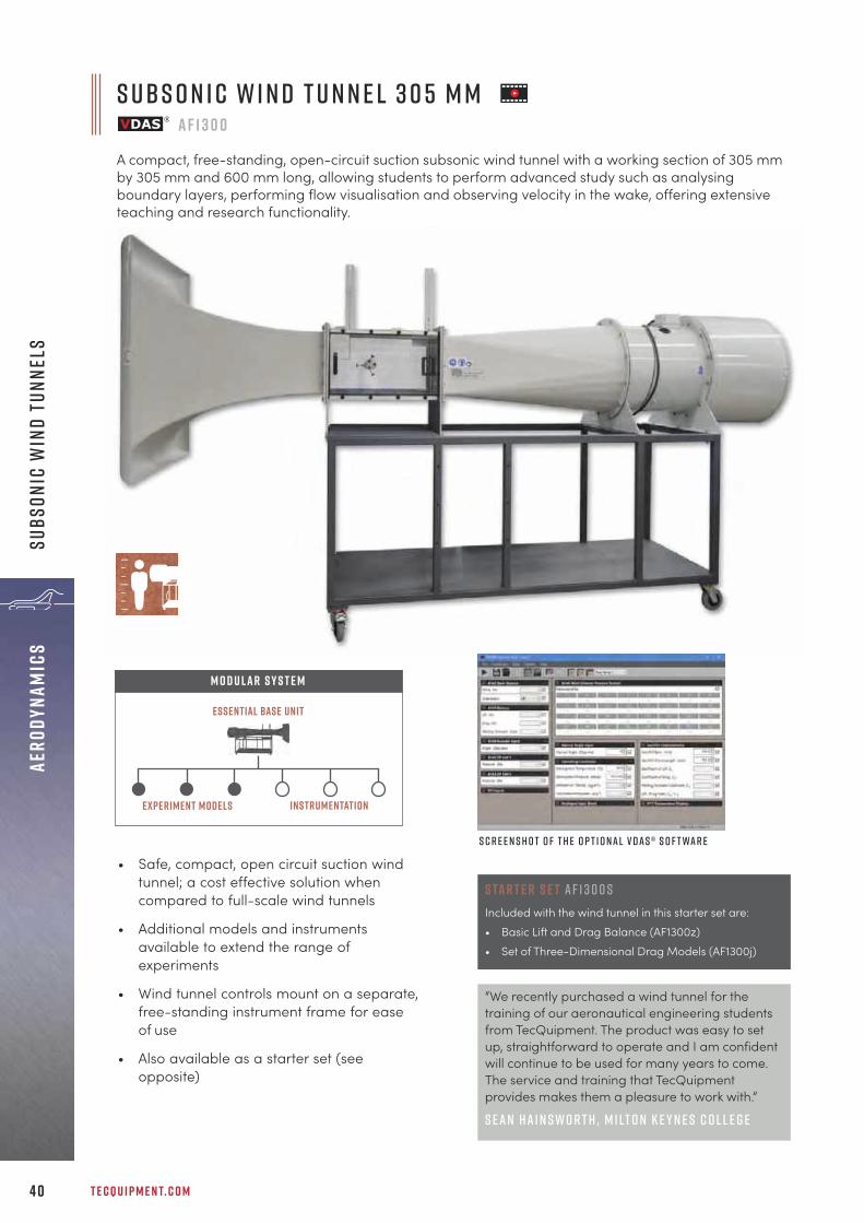
A compact, free-standing, open-circuit suction subsonic wind tunnel with a working section of 305 mmby 305 mm and 600 mm long, allowing students to perform advanced study such as analysingboundary layers, performing flow visualisation and observing velocity in the wake, offering extensiveteaching and research functionality.
S c r e e n s h o t o f t h e o p t i o n a l V D A S ® s o f t wa r e
Essential Base Unit
M O D U LAR S Y S T E M
instrumentationExperiment models
• Safe, compact, open circuit suction windtunnel; a cost effective solution whencompared to full-scale wind tunnels
• Additional models and instrumentsavailable to extend the range ofexperiments
• Wind tunnel controls mount on a separate,free-standing instrument frame for easeof use
• Also available as a starter set (seeopposite)
“We recently purchased a wind tunnel for thetraining of our aeronautical engineering studentsfrom TecQuipment. The product was easy to setup, straightforward to operate and I am confidentwill continue to be used for many years to come.The service and training that TecQuipmentprovides makes them a pleasure to work with.”
S e a n H a i n s w o r t h , M i lt o n K e y n e s C o l l e g e
aERO
DYNA
MICS
sUBS
ONIC
WIN
D tU
NNEL
S
C y l i n d e r M o d e l w i t h p r e s s u r e ta p p i n g A F 1 3 0 0 aA cylinder model with a singlepressure tapping point. Themodel spans the full widthof the working section ofthe wind tunnel.
+ 4 4 1 1 5 9 7 2 2 6 1 1 I N F O @ T E C Q U I P M E N T. C O M 4 1
aERODYNAMICSsUBSONIC W
IND tUNNELS
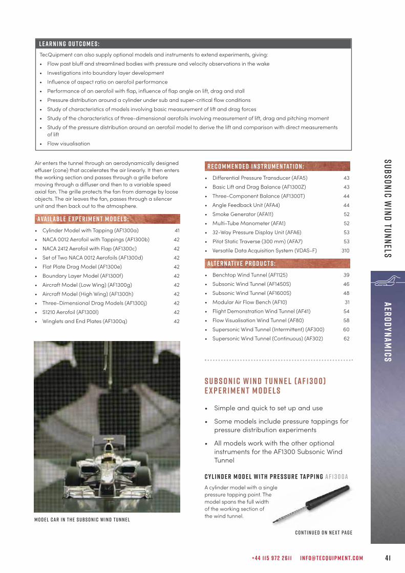
M o d e l c a r i n t h e s ubs o n i c w i n d t u n n e l
Air enters the tunnel through an aerodynamically designedeffuser (cone) that accelerates the air linearly. It then entersthe working section and passes through a grille beforemoving through a diffuser and then to a variable speedaxial fan. The grille protects the fan from damage by looseobjects. The air leaves the fan, passes through a silencerunit and then back out to the atmosphere.
• Cylinder Model with Tapping (AF1300a) 41• NACA 0012 Aerofoil with Tappings (AF1300b) 42• NACA 2412 Aerofoil with Flap (AF1300c) 42• Set of Two NACA 0012 Aerofoils (AF1300d) 42• Flat Plate Drag Model (AF1300e) 42• Boundary Layer Model (AF1300f) 42• Aircraft Model (Low Wing) (AF1300g) 42• Aircraft Model (High Wing) (AF1300h) 42• Three-Dimensional Drag Models (AF1300j) 42• S1210 Aerofoil (AF1300l) 42• Winglets and End Plates (AF1300q) 42
ava i labl e e x p e r i m e n t m o d e l s :
• Differential Pressure Transducer (AFA5) 43• Basic Lift and Drag Balance (AF1300Z) 43• Three-Component Balance (AF1300T) 44• Angle Feedback Unit (AFA4) 44• Smoke Generator (AFA11) 52• Multi-Tube Manometer (AFA1) 52• 32-Way Pressure Display Unit (AFA6) 53• Pitot Static Traverse (300 mm) (AFA7) 53• Versatile Data Acquisition System (VDAS-F) 310
• Benchtop Wind Tunnel (AF1125) 39• Subsonic Wind Tunnel (AF1450S) 46• Subsonic Wind Tunnel (AF1600S) 48• Modular Air Flow Bench (AF10) 31• Flight Demonstration Wind Tunnel (AF41) 54• Flow Visualisation Wind Tunnel (AF80) 58• Supersonic Wind Tunnel (Intermittent) (AF300) 60• Supersonic Wind Tunnel (Continuous) (AF302) 62
alt e r nat i v e p r o d u c t s :
r e c o m m e n d e d i n s t r u m e n tat i o n :
L E A R N I N G O U T C O M E S :TecQuipment can also supply optional models and instruments to extend experiments, giving:• Flow past bluff and streamlined bodies with pressure and velocity observations in the wake• Investigations into boundary layer development• Influence of aspect ratio on aerofoil performance• Performance of an aerofoil with flap, influence of flap angle on lift, drag and stall• Pressure distribution around a cylinder under sub and super-critical flow conditions• Study of characteristics of models involving basic measurement of lift and drag forces• Study of the characteristics of three-dimensional aerofoils involving measurement of lift, drag and pitching moment• Study of the pressure distribution around an aerofoil model to derive the lift and comparison with direct measurements
of lift• Flow visualisation
S u b s o n i c W i n d T u n n e l ( A F 1 3 0 0 )E x p e r i m e n t m o d e l s
• Simple and quick to set up and use
• Some models include pressure tappings forpressure distribution experiments
• All models work with the other optionalinstruments for the AF1300 Subsonic WindTunnel
c o n t i n u e d o n n e x t pa g e

A i r c r a f t M o d e l( L o w W i n g ) A F 1 3 0 0 gA i r c r a f t M o d e l( H i g h W i n g ) A F 1 3 0 0 hModel aircraft withNACA profile wings. Onehas a low wing position(bottom of the fuselage),the other has a highwing position (above the fuselage).
T H R E E - D I M E N S I O N A L D R A G M O D E L S A F 1 3 0 0 JA set of five differently shaped models with identical frontalarea to allow students to compare the different coefficientof drag for each shape. Includes a dummy stem for tests tocancel out the drag due to each model’s support arm.
S 1 2 1 0 A e r o f o i l A F 1 3 0 0 LAn unsymmetrical aerofoil thatspans the full width of theworking section of the windtunnel, for two-dimensionalexperiments.
W i n g l e t s a n d E n d P l at e s A F 1 3 0 0 QTwo aerofoils, one raked and a plain version, that can befitted with a range of winglets and end plates, forunderstanding how they can reduce turbulence in bothaerospace and automotive applications.
T E C Q U I P M E N T. C O M4 2
aERO
DYNA
MICS
sUBS
ONIC
WIN
D tU
NNEL
S
s ubs o n i c w i n d t u n n e l ( A F 1 3 0 0 ) C o n t i n u e d f r o m p r e v i o u s pa g e
N A C A 0 0 1 2 A E R O F O I L M O D E L W I T H TA P P I N G SA F 1 3 0 0BThe aerofoilhas 20staticpressuretappingsalong itschord onthe upperand lower surfaces.They each connect to tubes that pass through the aerofoiland then out to clear, numbered, flexible tubes.
1 5 0 m m c h o r d N A C A 2 4 1 2 a e r o f o i l w i t hVa r i a b l e F l a p A F 1 3 0 0 CAn unsymmetrical section(cambered) aerofoil withadjustable flap. Theadjustable flap allowsstudents to study theeffects of controlsurfaces such as flaps,ailerons, elevator orrudder.
1 5 0 m m C h o r d N A C A 0 0 1 2 A e r o f o i l s A F 1 3 0 0 DA set of two aerofoils. Oneaerofoil has a spanthat extends thefull width ofthe workingsection of thewind tunnel. This modelhas the characteristics of atwo-dimensional aerofoil. The other aerofoil has a spanthat extends for half of the working section of the windtunnel. This model has the characteristics of a three-dimensional aerofoil.
1 0 0 m m D i a m e t e r F l at P l at e A F 1 3 0 0 EThis model showsthe flow around abluff body mountednormal to the airflow direction, andthe drag force exerted on it.
F l at P l at e Bo u n d a r y L ay e r M o d e l A F 1 3 0 0 f
Demonstrates boundary layer development andseparation. The model is a flat plate that spans the fullwidth of the wind tunnel working section. It hasaerodynamically shaped blocks mounted across the plateat different distances from the leading edge.

+ 4 4 1 1 5 9 7 2 2 6 1 1 I N F O @ T E C Q U I P M E N T. C O M 4 3
aERODYNAMICSsUBSONIC W
IND tUNNELS
c o n t i n u e d o n n e x t pa g e
The balance mechanism enables test models with a rigidsupport arm to be mounted and held securely in position inthe working section of the wind tunnel. The arm transmitsthe force on the test model directly to a strain gauged loadcell. The load cell is connected to a readout unit with adigital display, which is powered by a desktop power supply(included).
Ba s i c L i f t a n d D r a g Ba l a n c e A F 1 3 0 0 zA two-component balance that measures lift and drag forceson models mounted in the AF1300 Subsonic Wind Tunnel.
• Transmits the force on the modeldirectly to a strain gauged loadcell with digital display
• Includes power supply
S u b s o n i c w i n d t u n n e l ( A F 1 3 0 0 )i n s t r u m e n tat i o n :
D i f f e r e n t i a l P r e s s u r e T r a n s d u c e r A FA 5Digital differential pressure measurement anddisplay unit for use with the AF1300 SubsonicWind Tunnel.
• Measures and displays differential pressuresfrom models, Pitot static tubes and otherdevices
• Quicker, easier and more versatile thanusing liquid manometers
• Measures differential pressures or pressurewith respect to atmosphere
The Differential Pressure Transducer and read outmeasures and displays pressures in Pitot static tubes andother pressure-sensing devices fitted to the AF1300Subsonic Wind Tunnel, with respect to the atmosphere ordifferential pressures.
• Subsonic Wind Tunnel (AF1300) 40• Cylinder Model (AF1300a) 41• NACA 0012 Aerofoil Model with Tappings (AF1300b) 42• 150 mm Chord NACA2412 Aerofoil with 42
Variable Flap (AF1300c)• Set of 2 NACA 0012 Aerofoils (AF1300d) 42• Flat Plate Drag Model (AF1300e) 42• Boundary Layer Model (AF1300f) 42• Aircraft Model (Low Wing) (AF1300g) 42• Aircraft Model (High Wing) (AF1300h) 42• Three-Dimensional Drag Models (AF1300j) 42• S1210 Aerofoil (AF1300l) 42• Winglets and End Plates (AF1300q) 42
• Multi-Tube Manometer (AFA1) 52• 32-Way Pressure Display Unit (AFA6) 53
alt e r nat i v e p r o d u c t s :
AN C I L LAR Y F O R :
• Subsonic Wind Tunnel (AF1300) 40• Cylinder Model with Pressure tapping (AF1300a) 41• 150 mm Chord NACA0012 Aerofoils (AF1300d) 42• 100 mm Diameter Flat Plate (AF1300e) 42• Three-Dimensional Drag Models (AF1300j) 42• S1210 Aerofoil (AF1300l) 42
• Three-Component Balance (AF1300t) 44
alt e r nat i v e p r o d u c t s :
AN C I L LAR Y F O R :
N o t e : Two AFA5 units are required when using VDAS®.

T E C Q U I P M E N T. C O M4 4
aERO
DYNA
MICS
sUBS
ONIC
WIN
D tU
NNEL
S
s ubs o n i c w i n d t u n n e l ( A F 1 3 0 0 ) C o n t i n u e d f r o m p r e v i o u s pa g e
T h r e e - C o m p o n e n t Ba l a n c e A F 1 3 0 0 tSupports wind tunnel models in the AF1300 Subsonic Tunnel and measures their lift, drag andpitching moment.
• Provides a convenient support system formodels to measure the lift, drag andpitching moment
• Digital display shows lift, drag andpitching moment directly
• Fully adjustable for varying the angle ofincidence to the direction of air flow
The Three-Component Balance provides an easy-to-usesupport system for wind tunnel models. It measures lift,drag and pitching moment exerted on the model.
• Balance Angle Feedback Unit (AFA4) 44
• Subsonic Wind Tunnel (AF1300) 40• Cylinder Model with Pressure Tapping (AF1300a) 41• 150 mm Chord NACA0012 Aerofoils (AF1300b) 42• 150 mm Chord NACA2412 Aerofoil with Variable 42
Flap (AF1300c)• 100 mm Diameter Flat Plate (AF1300e) 42• Aircraft Model - Low Wing (AF1300g) 42• Aircraft Model - High Wing (AF1300h) 42• Three-Dimensional Drag Models (AF1300j) 42• S1210 Aerofoil Model (AF1300l) 42• Winglets and End Plates (AF1300q) 42
R E C O M M E N D E D AN C I L LAR I E S :
AN C I L LAR Y F O R :
b a l a n c e a n g l e f e e d b a c k u n i t A FA 4Compact instrument that fixes to the Three-Component Balance (AF1300T). It measures the anglepositions of models mounted in the balance and feeds the information directly to the Versatile DataAcquisition System (VDAS®).
The Balance Angle Feedback Unit is an ancillary for usewith TecQuipment’s Three-Component Balance and VDAS®
together to measure and record the angular position ofmodels mounted on the balance in TecQuipment’s subsonicwind tunnel.
• Three-Component Balance (AF1300t) 44
AN C I L LAR Y F O R :
• Basic Lift and Drag Balance (AF1300z) 43
alt e r nat i v e p r o d u c t s :
+ 4 4 1 1 5 9 7 2 2 6 1 1 I N F O @ T E C Q U I P M E N T. C O M 4 5
aERODYNAMICSsUBSONIC W
IND tUNNELS
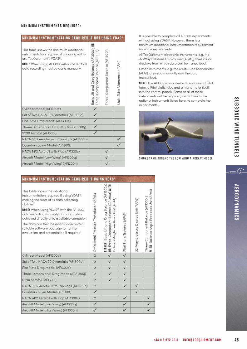
It is possible to complete all AF1300 experimentswithout using VDAS®. However, there is aminimum additional instrumentation requirementfor some experiments.All TecQuipment electronic instruments, e.g. the32-Way Pressure Display Unit (AFA6), have visualdisplays from which data can be transcribed. Other instruments, e.g. the Multi-Tube Manometer(AFA1), are read manually and the datatranscribed.N o t e : The AF1300 is supplied with a standard Pitottube, a Pitot static tube and a manometer (builtinto the control panel). Some or all of theseinstruments will be required, in addition to theoptional instruments listed here, to complete theexperiments.
M i n i m u m i n s t r u m e n tat i o n r e q u i r e d i f n o t u s i n g v d a s ®
This table shows the minimum additionalinstrumentation required if choosing not touse TecQuipment’s VDAS®.N o t e : When using AF1300 without VDAS® alldata recording must be done manually.
Basic
Lift
and
Dra
g Ba
lanc
e (A
F130
0z)
ORTh
ree-
Com
pone
nt B
alan
ce (A
F130
0t)
Thre
e-C
ompo
nent
Bal
ance
(AF1
300t
)
Mul
ti-Tu
beM
anom
eter
(AFA
1)
Cylinder Model (AF1300a) üSet of Two NACA 0012 Aerofoils (AF1300d) üFlat Plate Drag Model (AF1300e) üThree-Dimensional Drag Models (AF1300j) üS1210 Aerofoil (AF1300l) üNACA 0012 Aerofoil with Tappings (AF1300b) üBoundary Layer Model (AF1300f) üNACA 2412 Aerofoil with Flap (AF1300c) üAircraft Model (Low Wing) (AF1300g) üAircraft Model (High Wing) (AF1300h) ü
M i n i m u m i n s t r u m e n tat i o n r e q u i r e d i f u s i n g v d a s ®
This table shows the additionalinstrumentation required if using VDAS®,making the most of its data collectingabilities.N o t e : When using VDAS® with the AF1300,data recording is quickly and accuratelyachieved directly onto a suitable computer. The data can then be downloaded into asuitable software package for furtherevaluation and presentation if required.
Diff
eren
tial P
ress
ure
Tran
sduc
er (
AFA5
)
EITH
ERBa
sic L
ift a
nd D
rag
Bala
nce
(AF1
300z
)OR
Thre
e-C
ompo
nent
Bal
ance
(AF1
300t
) WIT
HBa
lanc
e An
gle
Feed
back
Uni
t (AF
A4)
Pito
t Sta
tic T
rave
rse
(AFA
7)
32-W
ay p
ress
ure
Disp
lay
Uni
t (AF
A6)
Thre
e-C
ompo
nent
Bal
ance
(AF1
300t
)W
ITH
Bala
nce
Angl
e Fe
edba
ck U
nit (
AFA4
)
Cylinder Model (AF1300a) 2 ü üSet of Two NACA 0012 Aerofoils (AF1300d) 2 ü üFlat Plate Drag Model (AF1300e) 2 ü üThree-Dimensional Drag Models (AF1300j) 2 ü üS1210 Aerofoil (AF1300l) 2 ü üNACA 0012 Aerofoil with Tappings (AF1300b) 2 ü üBoundary Layer Model (AF1300f) ü üNACA 2412 Aerofoil with Flap (AF1300c) 2 ü üAircraft Model (Low Wing) (AF1300g) ü ü üAircraft Model (High Wing) (AF1300h) ü ü ü
S m o k e t r a i l a r o u n d t h e L o w W i n g A i r c r a f t M o d e l
M i n i m u m i n s t r u m e n t s r e q u i r e d :

T E C Q U I P M E N T. C O M4 6
aERO
DYNA
MICS
sUBS
ONIC
WIN
D tU
NNEL
s
L E A R N I N G O U T C O M E S :A wide variety of subsonic aerodynamics experiments (some need ancillaries), including:• Flow past bluff and streamlined bodies with pressure and velocity observations in the wake• Investigations into boundary layer development• Influence of aspect ratio on aerofoil performance• Performance of an aerofoil with flap, influence of flap angle on lift, drag and stall• Pressure distribution around a cylinder under sub and super critical flow conditions• Study of characteristics of models involving basic measurement of lift and drag forces• Study of the characteristics of three-dimensional aerofoils involving measurements of lift, drag and pitching moment• Study of the pressure distribution around an aerofoil model to derive the lift, and comparison with direct measurements
of lift• Drag force on a bluff body normal to air flow• Flow visualisation
S ubs o n i c W i n d T u n n e l 450 m m a f 1 4 5 0 S
A sizable open circuit, suction subsonic wind tunnel with a working section of 450 mm by 450 mm and1000 mm length. It provides a cost-effective balance between being able to carry out advancedaerodynamics study, while having a smaller footprint than the largest of TecQuipment’s wind tunnels.
• Cost-effective solution when compared tofull-scale wind tunnels or airbornelaboratories
• Operates at meaningful Reynolds numbers
• Safe, open circuit suction design
• Package includes an aerofoil with tappings,a three-component balance, anglefeedback, dual differential pressure display,a 32-way pressure display unit, 2 x Pitotstatic traverse, protractor, model holder anddata acquisition (VDAS-F)
• Controls and instrumentation convenientlymount on a separate, free-standing frame
Air passes into the wind tunnel through a honeycomb flowstraightener and a grille. It then passes into anaerodynamically designed effuser (cone) that acceleratesthe air in a linear manner before it moves through theworking section. Finally, it passes through a diffuser, theninto the variable speed axial fan. The grille protects the fanfrom damage by loose objects. The air leaves the fan,passes through a silencer unit and then back out to theatmosphere.

I n c l u d e d w i t h t h e w i n d t u n n e l :
T h r e e - C o m p o n e n t Ba l a n c e A F 1 4 5 0 TThe Three-Component Balance measures lift, drag andpitching moment exerted on the model. Includes a balanceangle feedback unit which measures the angular position ofmodels mounted on the balance in the wind tunnel andfeeds the information directly to VDAS®.
N A C A 0 0 1 2 A e r o f o i l w i t h Ta p p i n g s A F 1 4 5 0BA 150 mm chord 450 mm span NACA0012 aerofoil withpressure tappings.
D u a l d i f f e r e n t i a l P r e s s u r eD i s p l ay d p 6Measures and displays pressures in Pitotstatic tubes and other pressure-sensingdevices fitted to the wind tunnel, withrespect to the atmosphere or differentialpressures.
+ 4 4 1 1 5 9 7 2 2 6 1 1 I N F O @ T E C Q U I P M E N T. C O M 47
aERODYNAMICSsUBSONIC W
IND tUNNELs
3 2 -Way P r e s s u r e D i s p l ay U n i t A FA 6Measures and displays up to 32different pressures frommodels, Pitot static tubes andother measuring instrumentsfitted to the wind tunnel (page 53).
P i t o t S tat i c T r av e r s e x 2A FA7Two traversing Pitot static tubes with electronic positionmeasurement for use with TecQuipment’s Subsonic WindTunnels (page 53).
P r o t r a c t o rFor assisting with setting up modelsand rotating them during experiments.
M o d e l h o l d e rTo hold models when the three-component balance is not used. Alsofor use with the user’s own models.
V e r s at i l e D ata A c q u i s i t i o n S y s t e m V D A S - FA frame-mounting versatile data acquisition system(VDAS®) to allow computer-based data capture (page 310).
s h o w n f i t t e d w i t ht h e ba l a n c e a n g l ef e e dba c k u n i t( i n c l u d e d )
• Multi-Tube manometer (AFA1) 52• Smoke Generator (AFA11) 52
• Cylinder Model with Tapping (AF1450a)• NACA 2412 Aerofoil with Flap (AF1450c)• Set of 2 NACA 0012 Aerofoils (AF1450d)• Flat Plate Drag Model (AF1450e)• Boundary Layer (AF1450f)• Aircraft Model (Low Wing) (AF1450g)• Aircraft Model (High Wing) (AF1450h)• Three-Dimensional Drag Models (AF1450j)• Two Vehicle Drag Models (AF1450k)• S1210 Aerofoil Model (AF1450l)
ava i labl e e x p e r i m e n t m o d e l s :
R E C O M M E N D E D AN C I L LAR I E S :
• Benchtop Wind Tunnel (AF1125) 39• Subsonic Wind Tunnel (AF1300) 40• Subsonic Wind Tunnel (AF1600S) 48• Modular Air Flow Bench (AF10) 31• Flight Demonstration Wind Tunnel (AF41) 54• Flow Visualisation Wind Tunnel (AF80) 58• Supersonic Wind Tunnel (Intermittent) (AF300) 60• Supersonic Wind Tunnel (Continuous) (AF302) 62
alt e r nat i v e p r o d u c t s :

T E C Q U I P M E N T. C O M4 8
aERO
DYNA
MICS
sUBS
ONIC
WIN
D tU
NNEL
S
• A cost-effective solution when compared tofull-scale wind tunnels or airbornelaboratories
• Operates at meaningful Reynolds numbers
• Safe, open circuit suction design
• Package includes three-componentbalance, angle feedback unit, dualdifferential pressure display, 32-waypressure display unit, Pitot static traverse,X/Y Pitot static traverse, protractor, modelholder and data acquisition (VDAS-F)
• High levels of safety
Air passes into the AF1600S through a honeycomb flowstraightener and a grille. It then passes into anaerodynamically designed effuser (cone) that acceleratesthe air in a linear manner, before it moves through theworking section. Finally, it passes through a diffuser, theninto the variable speed axial fan. The grille protects the fanfrom damage by loose objects. The air leaves the fan,passes through a silencer unit and then back out to theatmosphere.
S c r e e n s h o t o f t h e V D A S ® s o f t wa r e
S ubs o n i c W i n d T u n n e l 6 0 0 m m a f 1 6 0 0 S
TecQuipment’s largest open circuit subsonic wind tunnel, with a working section of 600 mm by 600 mmand 1250 mm long, is for the study of advanced aerodynamics theory and research. With the larger sizecomes greater visualisation and more accurate results, operating at meaningful Reynolds numbers.

+ 4 4 1 1 5 9 7 2 2 6 1 1 I N F O @ T E C Q U I P M E N T. C O M 4 9
aERODYNAMICSsUBSONIC W
IND tUNNELS
L E A R N I N G O U T C O M E S :AF1600S is designed to be flexible and utilised for a variety of possible experiments designed by our customers. Typical examples include:• Flow past bluff and streamlined bodies with pressure and velocity observations in the wake• Investigations into boundary layer development• Influence of aspect ratio on aerofoil performance• Pressure distribution around a cylinder under sub and super critical flow conditions• Study of characteristics of models involving basic measurement of lift and drag forces• Study of the characteristics of three-dimensional aerofoils involving measurements of lift, drag and pitching moment• Study of the pressure distribution around an aerofoil model to derive the lift, and comparison with direct measurements
of lift• Drag force on a bluff body normal to an air flow• Flow visualisation
C o n t i n u e d o n n e x t pa g e
s i z e c o m pa r i s o n o f t h e w i n d t u n n e l s r a n g e
A F 1 1 25
A F 1 6 0 0 s
A F 1 450 s A F 1 3 0 0

T E C Q U I P M E N T. C O M5 0
aERO
DYNA
MICS
sUBS
ONIC
WIN
D tU
NNEL
S
C y l i n d e r M o d e l w i t h p r e s s u r e ta p p i n gA F 1 6 0 0 aA cylinder model with asingle pressure tappingpoint. The model spansthe full width of theworking section of thewind tunnel.
P i t o t S tat i c T r av e r s e A FA7A traversing Pitot static tube with electronic positionmeasurement (page 53).
P i t o t s tat i c x / y t r av e r s e A F 1 6 0 0 x yA traversing Pitot static tube with electronic position measurements for both the x and y planes.
P r o t r a c t o rFor assisting with setting up models and rotating them duringexperiments.
M o d e l h o l d e rTo hold models when the three-component balance is not used. Alsofor use with the user’s own models.
V e r s at i l e D ata A c q u i s i t i o n S y s t e m V D A S - FA frame mounting versatile data acquisition system (VDAS®)to allow computer-based data capture (page 310).
• Benchtop Wind Tunnel (AF1125) 39• Subsonic Wind Tunnel (AF1300) 40• Subsonic Wind Tunnel (AF1450S) 46• Modular Air Flow Bench (AF10) 31• Flight Demonstration Wind Tunnel (AF41) 54• Flow Visualisation Wind Tunnel (AF80) 58• Supersonic Wind Tunnel (Intermittent) (AF300) 60• Supersonic Wind Tunnel (Continuous) (AF302) 62
alt e r nat i v e p r o d u c t s :
I n c l u d e d w i t h t h e w i n d t u n n e l :
T h r e e - C o m p o n e n t Ba l a n c e A F 1 6 0 0 TThe Three-Component Balance measures lift, drag andpitching moment exerted on the model. It includes abalance angle feedback unitwhich measures the angularposition of modelsmountedon thebalance inthe windtunnel andfeeds theinformationdirectly toVDAS®.
D u a l d i f f e r e n t i a l P r e s s u r eD i s p l ay D P 6Measures and displays pressureswith respect to the atmosphere ordifferential pressures.
3 2 -Way P r e s s u r e D i s p l ayU n i t A FA 6Measures and displays up to32 different pressures frommodels, Pitot static tubes andother measuring instrumentsfitted to the wind tunnel (page 53).
s h o w n f i t t e d w i t h t h eba l a n c e a n g l e f e e dba c ku n i t ( i n c l u d e d )
• Multi-Tube Manometer (AFA1) 52• Smoke Generator (AFA11) 52
• NACA 0012 Aerofoil with Tappings (AF1600b) 51• NACA 2412 Aerofoil with Flap (AF1600c) 51• Set of two NACA 0012 Aerofoils (AF1600d) 51• Flat Plate Boundary Layer Model, Roughened 51
and Smooth (AF1600f)• Aircraft Model (Low Wing) (AF1600g) 51• Aircraft Model (High Wing) (AF1600h) 51• Three-Dimensional Drag Models (AF1600j) 51
R E C O M M E N D E D AN C I L LAR I E S :
ava i labl e e x p e r i m e n t m o d e l s :
S ubs o n i c w i n d t u n n e l 6 0 0 m m ( A F 1 6 0 0 S ) C o n t i n u e d o n n e x t pa g e

+ 4 4 1 1 5 9 7 2 2 6 1 1 I N F O @ T E C Q U I P M E N T. C O M 5 1
aERODYNAMICSsUBSONIC W
IND tUNNELS
F l at P l at e Bo u n d a r y L ay e r M o d e l , R o u g h e n e da n d S m o o t h A F 1 6 0 0 FA pair of boundary layer models with a mounting plate,also a Pitot and a static probe for investigating boundarylayer. One plate is roughened, the other smooth to allowcomparisons on boundary layer growth.
A i r c r a f t M o d e l ( L o w W i n g ) A F 1 6 0 0 gA i r c r a f t M o d e l ( H i g h W i n g ) A F 1 6 0 0 hModel aircraft withNACA profile wings.One has a low wingposition (bottom ofthe fuselage), theother has a highwing position (abovethe fuselage).
T H R E E - D I M E N S I O N A L D R A G M O D E L S A F 1 6 0 0 J
A set of five different shaped models with identical frontalarea to allow students to compare the different coefficientof drag for each shape. Includes a dummy stem for tests tocancel out the drag due to each model’s support arm.
N A C A 0 0 1 2 A E R O F O I L M O D E L W I T H TA P P I N G SA F 1 6 0 0BThe aerofoil has 20 static pressure tappings along its chordon the upper and lower surfaces. They each connect totubes that pass through the aerofoil and then out to clear,numbered, flexible tubes.
1 5 0 m m c h o r d N A C A 2 4 1 2 a e r o f o i l w i t hVa r i a b l e F l a p A F 1 6 0 0 CAn unsymmetrical section(cambered) aerofoil withadjustable flap. Theadjustable flap allowsstudents to study theeffects of controlsurfaces such as flaps,ailerons, elevator orrudder.
1 5 0 m m C h o r d N A C A 0 0 1 2 A e r o f o i l s A F 1 3 0 0 DA set of two aerofoils. Oneaerofoil has a spanthat extends thefull width ofthe workingsection of thewind tunnel. This modelhas the characteristics of atwo-dimensional aerofoil. The other aerofoil has a spanthat extends for half of the working section of the windtunnel. This model has the characteristics of a three-dimensional aerofoil.
S u b s o n i c W i n d T u n n e l ( A F 1 6 0 0 S ) E x p e r i m e n t m o d e l s :
M e t i c u l o u s ly pac k e dTecQuipment’s dedicated packing department uses specialist equipment, custom-made transit crates and the most reliable global carriers to ensure products are delivered in perfect condition.

T E C Q U I P M E N T. C O M5 2
aERO
DYNA
MICS
sUBS
ONIC
WIN
D tU
NNEL
s
S m o k e G e n e r at o rA FA 1 1
A smoke generator and probe which allows the observation of air flow in subsonic wind tunnels andother air flow situations.
A control unit that pumps oil to the tip of a probe. A low-voltage electrical coil at the probe tip heats the oil toproduce a fine smoke trail. The smoke moves into the airstream smoothly and steadily. Students can adjust thecontrols of the control unit to change the smoke strength tosuit the air flow conditions.
• Subsonic Wind Tunnel (AF1125) 39• Subsonic Wind Tunnel (AF1300) 40• Subsonic Wind Tunnel (AF1450S) 46• Subsonic Wind Tunnel (AF1600S) 48
AN C I L LAR Y F O R :
For safety and convenience, the manometer uses water asthe manometer fluid. This is via an adjustable reservoir withfine-adjust hand-wheel held at the side of the equipment.Water colouring is included to aid visibility.
• Subsonic Wind Tunnel (AF1300) 40• Subsonic Wind Tunnel (AF1450S) 46• Subsonic Wind Tunnel (AF1600S) 48• NACA 0012 Aerofoil Model with Tappings (AF1300b) 42• NACA 0012 Aerofoil Model with Tappings (AF1450b) 47• Flat Plate Boundary Layer Model (AF1300f) 42• Flat Plate Boundary Layer Model (AF1450f)
AN C I L LAR Y F O R :
S u b s o n i c W i n d T u n n e l ( A F 1 3 0 0 / A F 1 4 5 0 S / A F 1 6 0 0 s ) I n s t r u m e n tat i o n a n da c c e s s o r i e s :
M u lt i -T ube M a n o m e t e rA FA 1
A tilting 36-tube manometer for use with the AF1300, and AF1600S Subsonic Wind Tunnels, otherTecQuipment products, or as a general purpose instrument.
• Uses water as manometer fluid withcolouring for ease of visibility
• Easy-to-read scale common to eachmanometer tube
• Preset incline levels for consistency andaccuracy, up to five times magnification
• Pressure reading level preset by adjustablefluid reservoir, includes fine-adjustmenthand-wheel
• Different Pressure Transducer (AFA5) 43• Dual Differential Pressure Display (DP6) 47/50• 32-Way Pressure Display Unit (AFA6) 53
alt e r nat i v e p r o d u c t s :

+ 4 4 1 1 5 9 7 2 2 6 1 1 I N F O @ T E C Q U I P M E N T. C O M 5 3
aERODYNAMICSsUBSONIC W
IND tUNNELs
3 2 -Way P r e s s u r e D i s p l ay U n i t A FA 6
A 32-way pressure measurement and display unit for use withTecQuipment’s Subsonic Wind Tunnels (AF1300, AF1450S, AF1600S).
• Measures and displays up to 32 differentialpressures from models, Pitot static tubesand other devices
• Quicker, easier and more versatile thanusing liquid manometers
• Measures pressures with respect toatmosphere
• Fully compatible with TecQuipment’sVersatile Data Acquisition System (VDAS®) toenable accurate real-time data capture,monitoring and display on a computer
The unit mounts onto the control and instrumentation frameof the wind tunnel. Connection to each of the 32 calibratedpressure transducers is via quick-release pressure inputsmounted on the front panel of the unit. This allows easy andquick connection between the unit and an experimentmounted in the wind tunnel. All pressures are measuredwith respect to atmosphere.
A Pitot static tube, its vertical position within the workingsection is displayed on a digital indicator that can be set tozero in any position. The signals from the indicator can beread directly or output to VDAS® for accurate, reliable datacapture.
P i t o t S tat i c T r av e r s e ( d i g i ta l )A FA7
A traversing Pitot static tubewith electronic positionmeasurement for use withTecQuipment’s Subsonic WindTunnels (AF1300, AF1450S,AF1600S).
• Mounts either upstream or downstream ofa test model to measure pressures acrossthe wake of a model
• Accurate digital display of position
• Zero facility allows the starting point of anexperiment to be set in any position
• Subsonic Wind Tunnel 40/46/48(AF1300, AF1450S, AF1600S)
• NACA 0012 Aerofoil Model with Tappings 42/47/51(AF1300b, AF1450b, AF1600b)
• Flat Plate Boundary Layer Model 42/47/51(AF1300f, AF1450f, AF1600f)
• Multi-Tube Manometer (AFA1) 52• Dual Differential Pressure Transducer (DP6) 47/50• Differential Pressure Transducer (AFA5) 43
AN C I L LAR Y F O R :
alt e r nat i v e p r o d u c t s :
• Subsonic Wind Tunnels 40/46/48(AF1300, AF1450S, AF1600S)
• Cylinder Model with Tappings 41/47/51(AF1300a, AF1450a, AF1600a)
• NACA 0012 Aerofoil With Tappings 42/47/51(AF1300b, AF1450b, AF1600b)
• NACA 2412 Aerofoil With Variable Flap 42/51(AF1300c, AF1450c, AF1600c)
• NACA 0012 Aerofoils (AF1300d, AF1450d, AF1600d) 42/51
• Flat Plate Drag Model (AF1300e, AF1450e) 42/51• Aircraft Model (Low Wing)
(AF1300g, AF1450g, AF1600g) 42/51• Aircraft Model (High Wing)
(AF1300h, AF1450h, AF1600h) 42/51• Three-Dimensional Drag Models 42/51
(AF1300j, AF1450j, AF1600j)• S1210 Aerofoil Model (AF1300l, AF1450l) 42/51
AN C I L LAR Y F O R :

T E C Q U I P M E N T. C O M5 4
aERO
DYNA
MICS
sPEC
IAL
PURP
OSE
WIN
D tU
NNEL
S
F l i g h t D e m o n s t r at i o n W i n d T u n n e l a f 4 1
A hands-on simulator that consists of a model aircraft suspended in an open circuit wind tunnel.Includes realistic flight controls to simulate a variety of states of flight, including take off, level flight,cruise and landing, along with stall.
• Simulates take off, level flight, cruise andlanding
• Demonstrations include aerofoil lift, stall,longitudinal stability and transient motion
• Includes electronic display of air speed,attitude, altitude, pressure and lift
• Tufts on the wing clearly demonstrate thephenomenon of separation and stall
• Adjustable centre of gravity of the model

+ 4 4 1 1 5 9 7 2 2 6 1 1 I N F O @ T E C Q U I P M E N T. C O M 5 5
aERODYNAMICSsPECIAL PURPOSE W
IND tUNNELS
For classroom demonstrations and student investigationsinto the behaviour of fixed-wing aircraft and wingperformance during take off, flight and landing. The apparatus is an open circuit wind tunnel with a modelaircraft suspended in the working section. The model issupported by linkages that allow it to move vertically and topitch about the quarter chord point independently.
• Two-Pen Chart Recorder (AF41a) 55• Smoke Generator (AFA11) 52
• Modular Air Flow Bench (AF10) 31• Benchtop Subsonic Wind Tunnel (AF1125) 39• Subsonic Wind Tunnel (AF1300) 40• Subsonic Wind Tunnel (AF1450S) 46• Subsonic Wind Tunnel (AF1600S) 48• Flow Visualisation Wind Tunnel (AF80) 58
R E C O M M E N D E D AN C I L LAR I E S :
alt e r nat i v e p r o d u c t s :
L E A R N I N G O U T C O M E S :A variety of practical demonstrations, ‘hands-on’ flightsimulations, and student investigations into thebehaviour of fixed-wing aircraft and wing performance,including:• Practical investigation of longitudinal stability and
control of the aircraft to demonstrate behaviourduring take-off, level flight and landing
• Determination of the effect of speed on attitude forlevel flight and stall
• Measurement of the lift curve for the wing up to andbeyond stall
• Students can adjust the centre of gravity of themodel to alter its trim. They can then plot trim curvesand determine the neutral point
W i t h T w o - P e n C h a r t R e c o r d e r ( A F 4 1 a , ava i l abl es e pa r at e ly ) : • Demonstration of phugoid motion in terms of
altitude• Short period oscillation due to sudden disturbance
can be shown by the change of incidenceW i t h S m o k e G e n e r at o r ( A FA1 1 , ava i l abl e s e pa r at e ly ) : • Visualisation of flow patterns past the aircraft’s
aerofoil and tail plane
P lay N ow – T e c Q u i p m e n t Y o u T u b e C han n e lVisit and subscribe to the TecQuipment YouTube channel for all the latest products showcases, installation and user videos: y o u t ube . c o m / c / t e cqu i p m e n t
YouTube videos available for all products with this icon
T u r b o j e t T ra i n e r w i t h R e h eat ( G T 1 0 0 R S ) H y d r o s tat i c s an d P r o p e r t i e s o f F l u i d s ( H 3 14)
U n i v e r sal T e s t i n g Mac h i n e ( S M 1 0 0 0 ) C e n t r i f u gal P u m p M o d u l e ( M F P 1 0 1 )

T E C Q U I P M E N T. C O M5 6
T e x a s A & M U n i v e r s i t y Z a c h r yE n g i n e e r i n g E d u c at i o n C o m p l e xRecently one of the USA’s largestengineering schools, Texas A&MUniversity, invested in a newengineering education complex thatwould revolutionise the way they teachtheir 20,000 engineering students. Oneelement of this new complex was a newmodel for laboratories that would allowthem to fully utilise equipment andspace by creating “commonlaboratories” – shared facilities withinZachry Engineering EducationComplex, completed in 2018. The newbuilding was only part of the story; theyinvested heavily in new teachingequipment to be housed in this facility,including a vast range of practicalengineering teaching products fromTecQuipment. Before the new facility, the engineeringschool’s utilisation of laboratory spaceand equipment was not as efficientlydesigned. Different departments wouldhave their own laboratory space, that for some courses wasunderutilised, while in contrast other departments wereoperating at maximum capacity with no flexibility. Thesolution was a shared laboratory facility with standardisedmodular equipment that could be utilised by the Mechanical,Civil, Chemical and Petroleum Engineering departments.
Once the State of Texas had approved the new building in 2016, thenext step was to establish what equipment would be required for eachdepartment, and the laboratory arrangement that would work to bemost effective. Equipment committees that included technicians andfaculty members were established. Lists of teaching objectives and awish list of equipment compiled. During this period, the team pulled inquotes from across the engineering education industry and, despiteonly having had a few years of experience using TecQuipmentproducts, made the shift to standardise across the board withTecQuipment’s teaching equipment.
T r u s t a n d L o c a l S u p p o r t
T h e L a b o r at o r y E q u i p m e n t S e t- U pTexas A&M’s engineering graduates are among the most highlyrecruited in the USA, typically receiving two or more job offers withhigher-than-average salaries at graduation. This is testament to theirteaching and ability to prepare students for the world of work: one keyelement of this is incorporating practical teaching in the laboratories.The Zachry Engineering Education Complex has a series of commonlaboratories that house TecQuipment’s teaching equipment, plus adesign center.
“One of the reasons we chose TecQuipment as our equipmentprovider was that we had trust in what they delivered. Colleagueswho had used TecQuipment products vouched for the quality andsuitability of the products, and the support and conduct of bothTecQuipment and their local representative in the region, TechLabs,” explained Director of Undergraduate Laboratory InstructionDr David Staack from the J Mike Walker ’66 Department ofMechanical Engineering at Texas A&M University.
c a s e s t u d y

+ 4 4 1 1 5 9 7 2 2 6 1 1 I N F O @ T E C Q U I P M E N T. C O M 5 7
• P h i l l i p s 6 6 F l u i d s L a b o r at o r y:5m Flow and Sediment Transport Channel (FC80) withcylindrical gate, radial sector gate, crump weir, dam spillway,streamlined hump, parshall flume, bridge piers, roughenedbed, siphon spillway, culvert model, flow splitter, plus wavegenerator and beach.
• S h e l l T r a n s p o r t P h e n o m e n a L a b o r at o r yThree Heat Exchangers Service Modules (TD360) withVDAS®, along with three experiments (concentric tube heatexchanger, shell and tube heat exchanger, plate heatexchanger) and the Filmwise and dropwise Condensationand Boiling experiment (TE78).
• Va l e r a H i g h Bay L a b o r at o r ySubsonic Wind Tunnel (AF1300) with three-componentbalance, balance angle feedback unit, Pitot static traverse,32-way pressure display, differential pressure unit, NACA 0012aerofoil with tappings, NACA 2412 aerofoil with flap andcylinder model.
V i d e o M a n u a l sOne important delivery element for placing the order withTecQuipment was the ability to deliver instructional videos onhow to use the equipment, as well as the written manuals. Theteam at TecQuipment provided these bespoke, filmed on siteusing Texas A&M’s very own pieces of equipment.
A c c o m m o d at i n g M o d i f i c at i o n sAs everything is designed and manufactured all under one roof,TecQuipment is, in some cases, able to make modifications toequipment to suit specific requirements from the customer. Inthe case of Texas A&M, TecQuipment was able to modify aproduct to feature a closed water supply so that it would not bedependent on building services.
I n s ta l l at i o n a n d O n g o i n g T e c h n i c a l S u p p o r tA specialist installation engineer from TecQuipment joined thelocal TecQuipment partner, Tech Labs, to assist with theinstallation, set-up and training for all the equipment.Shei Sia Su, Technical Lab Coordinator at the Zachry Building,commented on their technical support experience:
In reference to the manuals, Shei Sia Su explained further:
M o r e A b o u t T e x a s A & M U n i v e r s i t yTexas A&M in the United Sates is home to more than 69,000students and has a heritage that dates back to 1876. The Collegeof Engineering itself is one of the largest engineering schools inthe USA, ranking first in undergraduate enrolment in the 2019survey by the American Society of Engineering Education. Whenit comes to mechanical engineering, they boast the biggestprogramme on the continent.
“Warner Brown and the Tech Labs team delivered excellentservice. They made sure installation went smoothly and allequipment was ready for students to start experimentingwithin a timely manner. Our academics and support staffwere well trained by Dave Giddings from TecQuipment.”
“The examples of experiments are particularly useful forinstructors to design new experiments.“With multiple courses using the shared facilities, we have notsuffered any major equipment downtime and this isimpossible without the excellent technical support from TechLabs team.”
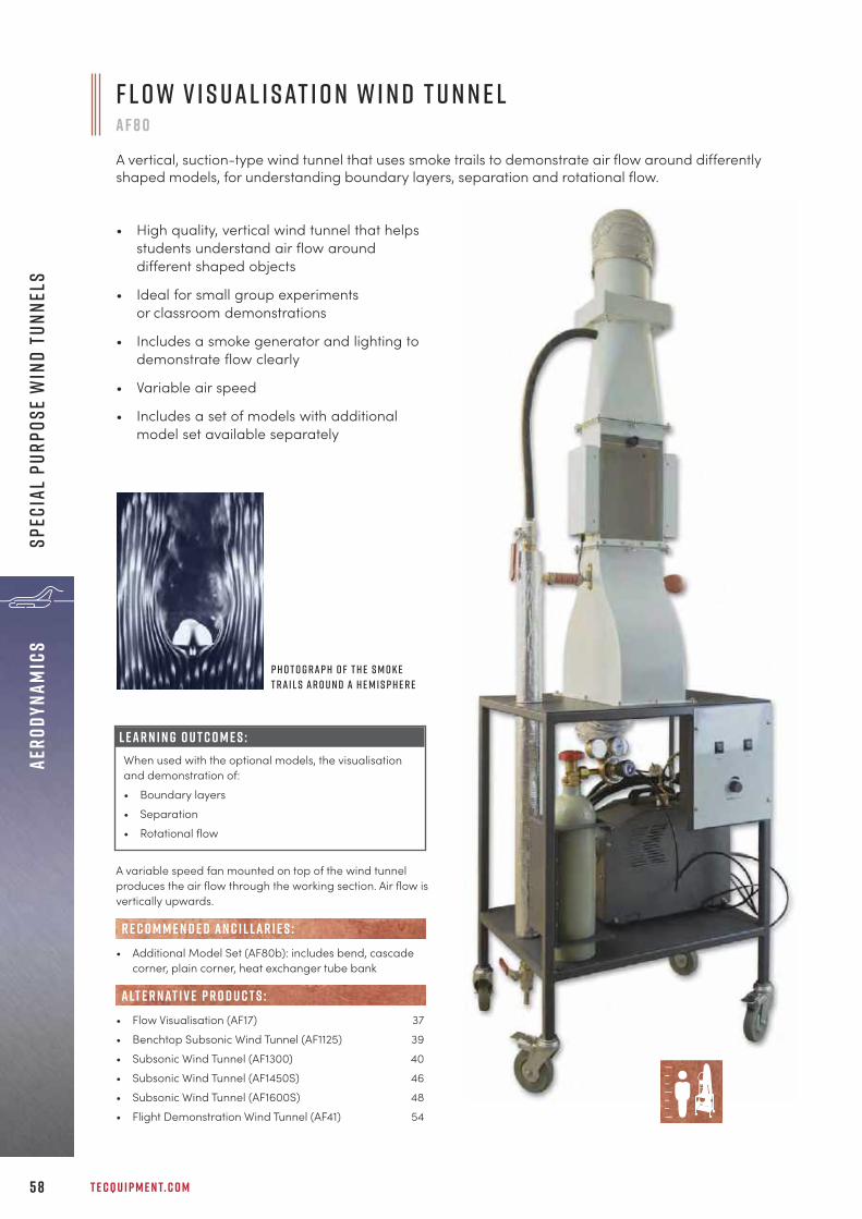
T E C Q U I P M E N T. C O M5 8
aERO
DYNA
MICS
sPEC
IAL
PURP
OSE
WIN
D tU
NNEL
S
A variable speed fan mounted on top of the wind tunnelproduces the air flow through the working section. Air flow isvertically upwards.
• Additional Model Set (AF80b): includes bend, cascadecorner, plain corner, heat exchanger tube bank
• Flow Visualisation (AF17) 37• Benchtop Subsonic Wind Tunnel (AF1125) 39• Subsonic Wind Tunnel (AF1300) 40• Subsonic Wind Tunnel (AF1450S) 46• Subsonic Wind Tunnel (AF1600S) 48• Flight Demonstration Wind Tunnel (AF41) 54
R E C O M M E N D E D AN C I L LAR I E S :
alt e r nat i v e p r o d u c t s :
P h o t o g r a p h o f t h e s m o k et r a i l s a r o u n d a h e m i s p h e r e
F l o w V i s u a l i s at i o n W i n d T u n n e la f 8 0
A vertical, suction-type wind tunnel that uses smoke trails to demonstrate air flow around differentlyshaped models, for understanding boundary layers, separation and rotational flow.
• High quality, vertical wind tunnel that helpsstudents understand air flow arounddifferent shaped objects
• Ideal for small group experimentsor classroom demonstrations
• Includes a smoke generator and lighting todemonstrate flow clearly
• Variable air speed
• Includes a set of models with additionalmodel set available separately
L e a r n i n g o u t c o m e s :When used with the optional models, the visualisationand demonstration of:• Boundary layers• Separation• Rotational flow
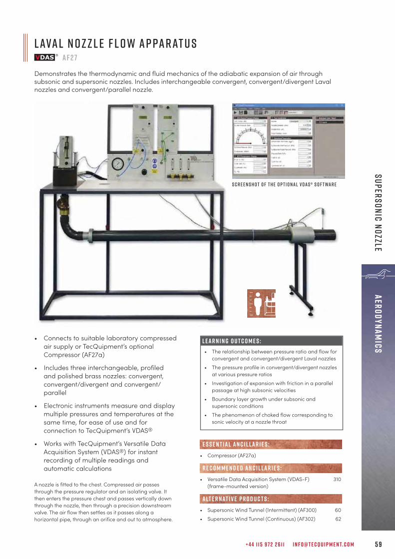
+ 4 4 1 1 5 9 7 2 2 6 1 1 I N F O @ T E C Q U I P M E N T. C O M 5 9
aERODYNAMICSSupersonic Nozzle
L ava l N o z z l e F l o w A p pa r at u s a f 2 7
Demonstrates the thermodynamic and fluid mechanics of the adiabatic expansion of air throughsubsonic and supersonic nozzles. Includes interchangeable convergent, convergent/divergent Lavalnozzles and convergent/parallel nozzle.
• Connects to suitable laboratory compressedair supply or TecQuipment’s optionalCompressor (AF27a)
• Includes three interchangeable, profiledand polished brass nozzles: convergent,convergent/divergent and convergent/parallel
• Electronic instruments measure and displaymultiple pressures and temperatures at thesame time, for ease of use and forconnection to TecQuipment’s VDAS®
• Works with TecQuipment’s Versatile DataAcquisition System (VDAS®) for instantrecording of multiple readings andautomatic calculations
L E A R N I N G O U T C O M E S :• The relationship between pressure ratio and flow for
convergent and convergent/divergent Laval nozzles• The pressure profile in convergent/divergent nozzles
at various pressure ratios• Investigation of expansion with friction in a parallel
passage at high subsonic velocities• Boundary layer growth under subsonic and
supersonic conditions • The phenomenon of choked flow corresponding to
sonic velocity at a nozzle throat
S c r e e n s h o t o f t h e o p t i o n a l V D A S ® s o f t wa r e
A nozzle is fitted to the chest. Compressed air passesthrough the pressure regulator and an isolating valve. Itthen enters the pressure chest and passes vertically downthrough the nozzle, then through a precision downstreamvalve. The air flow then settles as it passes along ahorizontal pipe, through an orifice and out to atmosphere.
• Compressor (AF27a)
• Versatile Data Acquisition System (VDAS-F) 310(frame-mounted version)
• Supersonic Wind Tunnel (Intermittent) (AF300) 60• Supersonic Wind Tunnel (Continuous) (AF302) 62
alt e r nat i v e p r o d u c t s :
R E C O M M E N D E D AN C I L LAR I E S :
E S S E N T IAL AN C I L LAR I E S :

T E C Q U I P M E N T. C O M6 0
aERO
DYNA
MICS
sUPE
RSON
IC W
IND
tUNN
ELS
L E A R N I N G O U T C O M E S :• Pressure distribution along a convergent-divergent
(Laval) nozzle with subsonic and supersonic air flow• Comparison of theoretical and actual pressure
distributions• Comparison of actual and theoretical area ratios of
a nozzle at supersonic air velocities (Mach numbers)• Pressures around a two-dimensional model in
subsonic and supersonic flow conditions, at differentangles of incidence
• Lift coefficients for aerodynamic models insupersonic flow
• Shock waves and expansion patterns around a two-dimensional model in supersonic flow conditions(when used with the optional Schlieren apparatus)
I n t e r m i t t e n t S u p e r s o n i c W i n d T u n n e l a f 3 0 0
An intermittent supersonic (up to Mach 1.8) wind tunnel for investigations into subsonic and supersonicair flow around two-dimensional models. Also for analysis of the profile of the tunnel working section.
• Laboratory scale wind tunnel for subsonicand supersonic tests, nominally up toMach 1.8
• Supplied with aerodynamic models forsupersonic tests; includes model angle-feedback encoder
• Supplied with a set of different liners forcontrolled subsonic and supersonic air flow
• Induction flow for better air flow andaccurate results
S c r e e n s h o to f t h e V D A S ®s o f t wa r e
S h o w n w i t h t h eo p t i o n a l S c h l i e r e nA p pa r at u s ( A F 3 0 0 a )

+ 4 4 1 1 5 9 7 2 2 6 1 1 I N F O @ T E C Q U I P M E N T. C O M 6 1
aERODYNAMICSsUperSONIC W
IND tUNNELS
• Schlieren Apparatus (AF300a) 61
• Benchtop Subsonic Wind Tunnel (AF1125) 39• Subsonic Wind Tunnel (AF1300) 40• Subsonic Wind Tunnel (AF1450S) 46• Subsonic Wind Tunnel (AF1600S) 48• Laval Nozzle Flow Apparatus (AF27) 59• Continuous Supersonic Wind Tunnel (AF302) 62
R E C O M M E N D E D AN C I L LAR I E S :
alt e r nat i v e p r o d u c t s :
s c h l i e r e n a p pa r at u s a f 3 0 0 a
The Schlieren apparatus enables students to see air flow (including supersonic shock waves) aroundtwo-dimensional models as variations in the intensity of illumination. For use with the AF300 IntermittentSupersonic Wind Tunnel.
• High quality, laboratory standardmirrors and lenses for clear imageswithout distortion
• Shows supersonic air flow patternsaround models
• Shows shockwaves and expansions
• Includes digital imaging equipmentand TV monitor
A compressed air supply (AF300b, available separately)induces a flow in the working section of the wind tunnel.This gives a less turbulent and more stable flow foraccurate results and comparison with theory. The essentialcompressed air supply includes filters and air dryers to givethe dust-free and dry air source needed for good results.
• Air Compressor Receiver and Dryer (AF300b)• Versatile Data Acquisition System (VDAS-F) 310
(frame-mounted version)
E S S E N T IAL AN C I L LAR I E S :
The focused light from the light source (and condenser lens)passes through the optical slit and is reflected at90 degrees to the first achromatic lens. The light passesthrough the working section of the wind tunnel, thenthrough the second achromatic lens. A second mirrorreflects the light at 90 degrees towards the Schlieren edge.The Schlieren edge enhances the light refracted image. Thesmall lens focuses this image onto the imaging screen.
Achromatic lenses are chosen because of their ability topass light without colour distortion, that would normally ruinthe Schlieren image.
• Intermittent Supersonic Wind Tunnel (AF300) 60
AN C I L LAR Y F O R :
I m a g e o f a i r f l o w pat t e r nr o u n d a 5 ° S i n g l e W e d g e m o d e l
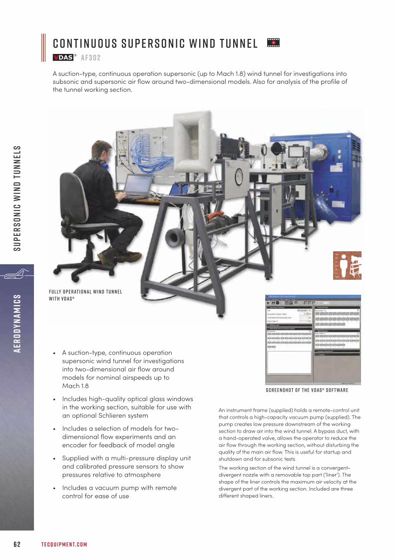
T E C Q U I P M E N T. C O M6 2
aERO
DYNA
MICS
Supe
rSON
IC W
IND
tUNN
ELS
C o n t i n u o u s S u p e r s o n i c W i n d T u n n e la f 3 0 2
A suction-type, continuous operation supersonic (up to Mach 1.8) wind tunnel for investigations intosubsonic and supersonic air flow around two-dimensional models. Also for analysis of the profile ofthe tunnel working section.
• A suction-type, continuous operationsupersonic wind tunnel for investigationsinto two-dimensional air flow aroundmodels for nominal airspeeds up toMach 1.8
• Includes high-quality optical glass windowsin the working section, suitable for use withan optional Schlieren system
• Includes a selection of models for two-dimensional flow experiments and anencoder for feedback of model angle
• Supplied with a multi-pressure display unitand calibrated pressure sensors to showpressures relative to atmosphere
• Includes a vacuum pump with remotecontrol for ease of use
F u l ly o p e r at i o n a l w i n d t u n n e lw i t h V D A S ®
S c r e e n s h o t o f t h e V D A S ® s o f t wa r e
An instrument frame (supplied) holds a remote-control unitthat controls a high-capacity vacuum pump (supplied). Thepump creates low pressure downstream of the workingsection to draw air into the wind tunnel. A bypass duct, witha hand-operated valve, allows the operator to reduce theair flow through the working section, without disturbing thequality of the main air flow. This is useful for startup andshutdown and for subsonic tests. The working section of the wind tunnel is a convergent-divergent nozzle with a removable top part (‘liner’). Theshape of the liner controls the maximum air velocity at thedivergent part of the working section. Included are threedifferent shaped liners.

+ 4 4 1 1 5 9 7 2 2 6 1 1 I N F O @ T E C Q U I P M E N T. C O M 6 3
aERODYNAMICSsUperSONIC W
IND tUNNELS
• High quality, laboratory standard mirrorsand lenses for clear images withoutdistortion
• Shows supersonic air flow patterns aroundmodels
• Shows shockwaves and expansions
• Includes digital imaging equipment and TVmonitor
The focused light from the light source (and condenser lens)passes through the optical slit and is reflected at 90 degreesto the first achromatic lens. The light passes through theworking section of the wind tunnel, then through the secondachromatic lens. A second mirror reflects the light at 90degrees towards the Schlieren edge. The Schlieren edgeenhances the light refracted image. The small lens focusesthis image onto the imaging screen. Achromatic lenses arechosen because of their ability to pass light without colourdistortion, that would normally ruin the Schlieren image.
• Continuous Supersonic Wind Tunnel (AF302) 62
AN C I L LAR Y F O R :
s c h l i e r e n a p pa r at u s a f 3 0 2 a
The Schlieren apparatus enables students to see air flow(including supersonic shock waves) around two-dimensionalmodels as variations in the intensity of illumination. For use withthe AF302 Continuous Supersonic Wind Tunnel.
L e a r n i n g o u t c o m e s :• Pressure distribution along a convergent-divergent
(Laval) nozzle with subsonic and supersonic air flow• Comparison of theoretical and actual pressure
distributions• Comparison of actual and theoretical area ratios of
a nozzle at supersonic air velocities (Mach numbers)• Pressures around a two-dimensional model in
subsonic and supersonic flow conditions, at differentangles of incidence
• Lift coefficients for aerodynamic models insupersonic flow
• Shock waves and expansion patterns around a two-dimensional model in supersonic flow conditions(when used with the optional Schlieren apparatus)
5 d e g r e e s m a c h 1 - 8 a n d 5 d e g r e e w e d g e
• Versatile Data Acquisition System (VDAS-F) 310(frame-mounted version)
• Schlieren Apparatus AF302a 63
• Benchtop Subsonic Wind Tunnel (AF1125) 39• Subsonic Wind Tunnel (AF1300) 40• Subsonic Wind Tunnel (AF1450S) 46• Subsonic Wind Tunnel (AF1600S) 48• Laval Nozzle Flow Apparatus (AF27) 59• Intermittent Supersonic Wind Tunnel (AF300) 60
alt e r nat i v e p r o d u c t s :
E S S E N T IAL AN C I L LAR I E S :
R E C O M M E N D E D AN C I L LAR I E S :
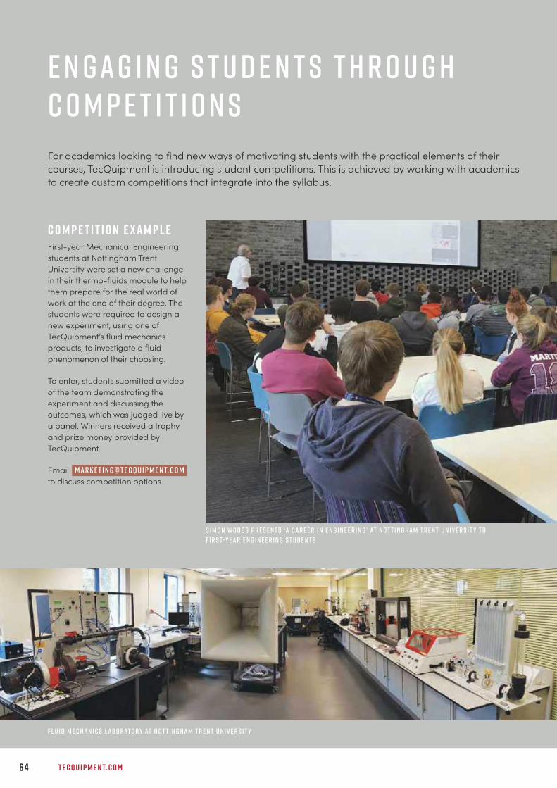
T E C Q U I P M E N T. C O M6 4
E n g a g i n g S t u d e n t s t h r o u g hC o m p e t i t i o n sFor academics looking to find new ways of motivating students with the practical elements of theircourses, TecQuipment is introducing student competitions. This is achieved by working with academicsto create custom competitions that integrate into the syllabus.
C o m p e t i t i o n E x a m p l eFirst-year Mechanical Engineeringstudents at Nottingham TrentUniversity were set a new challengein their thermo-fluids module to helpthem prepare for the real world ofwork at the end of their degree. Thestudents were required to design anew experiment, using one ofTecQuipment’s fluid mechanicsproducts, to investigate a fluidphenomenon of their choosing.
To enter, students submitted a videoof the team demonstrating theexperiment and discussing theoutcomes, which was judged live bya panel. Winners received a trophyand prize money provided byTecQuipment.
Email to discuss competition options.
S i m o n W o o d s P r e s e n t s ‘a C a r e e r i n E n g i n e e r i n g ’ at N o t t i n g h a m T r e n t U n i v e r s i t y t of i r s t-y e a r E n g i n e e r i n g S t u d e n t s
F l u i d M e c h a n i c s L abo r at o r y at N o t t i n g h a m T r e n t U n i v e r s i t y
m a r k e t i n g @ t e c q u i p m e n t. c o m

+ 4 4 1 1 5 9 7 2 2 6 1 1 I N F O @ T E C Q U I P M E N T. C O M 6 5
Control Engineering
c o n t r o l e n g i n e e r i n gC o n t r o l E n g i n e e r i n g P r i n c i p l e s 6 7
“Our students are comfortable while using products from TecQuipment in labs. Highlyinnovative products by TecQuipment Ltd for engineering education are ideal for engineeringand technical education at all levels. Our students are regularly using this equipment formasters and doctoral research. The products are user-friendly and need minimum after-salesservice.
P r o f e s s o r R D M i s a lD e f e n c e I n s t i t u t e o f A d va n c e d T e c h n o l o g y, G i r i n a g a r , P u n e , I n d i a
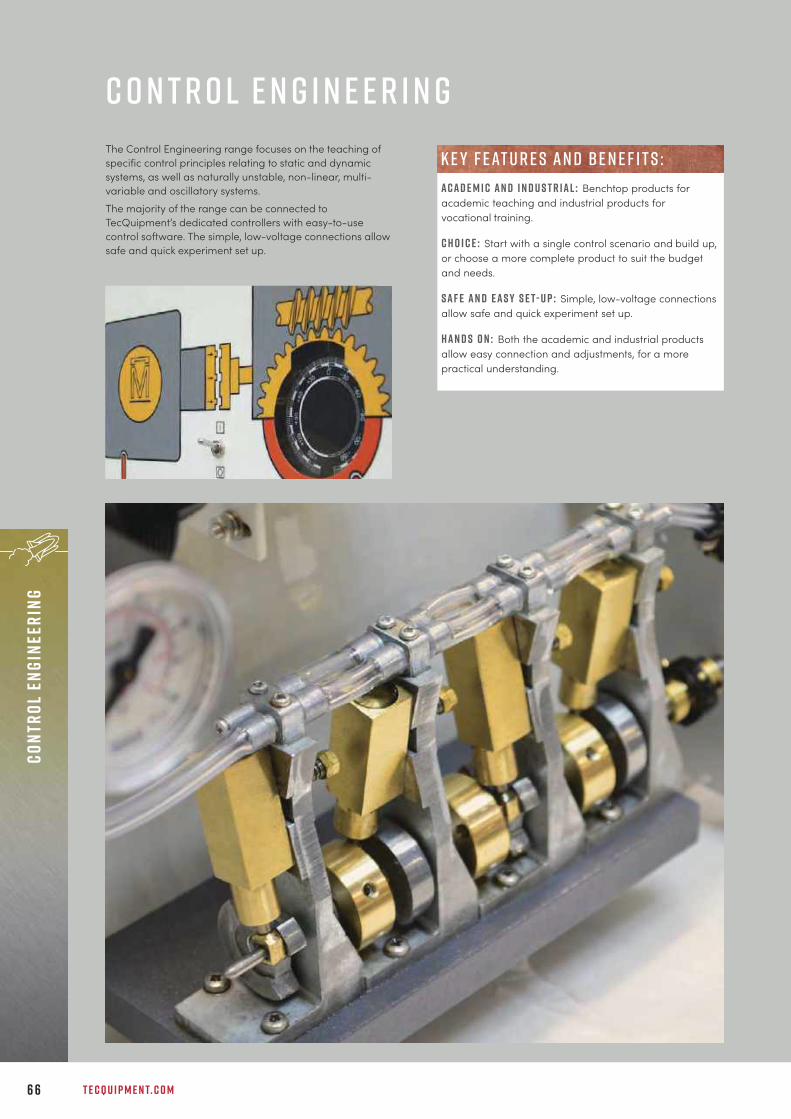
T E C Q U I P M E N T. C O M6 6
Cont
rol
Engi
neer
ing
c o n t r o l e n g i n e e r i n gThe Control Engineering range focuses on the teaching ofspecific control principles relating to static and dynamicsystems, as well as naturally unstable, non-linear, multi-variable and oscillatory systems. The majority of the range can be connected toTecQuipment’s dedicated controllers with easy-to-usecontrol software. The simple, low-voltage connections allowsafe and quick experiment set up.
A c a d e m i c a n d i n d u s t r i a l : Benchtop products foracademic teaching and industrial products forvocational training.
c h o i c e : Start with a single control scenario and build up,or choose a more complete product to suit the budgetand needs.
s a f e a n d e a s y s e t- u p : Simple, low-voltage connectionsallow safe and quick experiment set up.
H a n d s o n : Both the academic and industrial productsallow easy connection and adjustments, for a morepractical understanding.
k e y f eat u r e s an d b e n e f i t s :

+ 4 4 1 1 5 9 7 2 2 6 1 1 I N F O @ T E C Q U I P M E N T. C O M 6 7
Control EngineeringControl Engineering Principles
C o n t r o l S o f t wa r ec e 2 0 0 0
Software that simulates control systems and works with TecQuipment’s controller (CE120) or digitalinterface (CE122) to control and acquire data from TecQuipment’s Control Engineering range.
• Easy-to-create control circuits made bylinking together drag-and-drop icons
• Includes a range of ready-made fuzzy logicand control blocks, such as proportional,integral and derivative blocks
• Real-time display of variables by virtualmeters, virtual chart recorders or virtualoscilloscopes
• Collected data can be shown and printedas charts or exported for use in otherprograms
• Users can create their own circuits and savethem, or use the ready-made circuitssupplied
L E A R N I N G O U T C O M E S :S o f t wa r e o n ly:The user guide shows students how to use the softwareand how to build and test common control systems,such as:• Design and implementation of three-term controllers• Design of controllers and filtersS o f t wa r e a n d h a r d wa r e ( w h e n u s e d w i t h o t h e rp r o d u c t s f r o m t h e C E r a n g e ) :• Thermal control (CE103)• Level control (CE105/CE105MV)• Ball and beam control (CE106)• Engine speed control (CE107)• Coupled drives control (CE108)• Ball and hoop control (CE109)• Servo control (CE110)• Flow, level, pressure and temperature control (CE117)
The CE2000 is a powerful control software package withmany features. It is supplied as standard withTecQuipment’s Controller (CE120), Digital Interface (CE122)and Process Trainer (CE117). The software allows studentsand experienced control engineers to develop and test awide selection of controllers and filters.
U p -t o -t h e - m i n u t e s t o r i e s o n s o c ial m e d ia f r o m T e c Q u i p m e n t

T E C Q U I P M E N T. C O M6 8
Cont
rol
Engi
neer
ing
Cont
rol
Engi
neer
ing
Prin
cipl
es
This compact unit has analogue electronic circuitsconnected in blocks. These blocks mimic the importantparts of industrial controllers. Clear diagrams on the frontpanel of the controller show the blocks, each of which hasits own set of connection sockets. The user connects theblocks in any way that they need and then connects them totheir chosen experiment module.
• Thermal Control Process Apparatus (CE103) 70• Coupled Tanks Apparatus (CE105/CE105MV) 71• Ball and Beam Apparatus (CE106) 72• Engine Speed Control Apparatus (CE107) 73• Coupled Drives Apparatus (CE108) 76• Ball and Hoop Apparatus (CE109) 77• Servo Trainer (CE110) 78
ava i lab l e e x p e r i m e n t m o d u l e s :
C o n t r o l l e rc e 1 2 0
A self-contained analogue and computer-based controller designed to support practical investigationsinto the basic and advanced principles of control engineering at all academic levels.
Experiment modules(ce103, ce105–ce110)
Essential Base Unit (ce120)
M O D U LAR S Y S T E M
L E A R N I N G O U T C O M E S :When used with the experiment modules:• Temperature (thermal) control• Level control• Engine speed control• Servo control• Coupled drive control• Ball and beam control• Ball and hoop control
Controls and monitors signals to and fromselected Control Range experiment modules Modular design saves space and reduces costs
Manual controls plus additional interface withanalogue-to-digital and digital-to-analogueconversionAllows ‘hands on’ control arrangements, pluscomputer control and data acquisition, with noneed to fit interface cards in the computer
Buffered, low-voltage connectionsSafe, even for inexperienced students, withminimal supervision
Multiple summing junctions, proportional,integral and PID blocks Allows many different control arrangements
Includes TecQuipment’s CE2000 ControlSoftwareReal-time control and data acquisition with morechoice of control arrangements
Standard 10 VDC signalsMay be used to control other suitable systems
F eat u r e s an d b e n e f i t s :

+ 4 4 1 1 5 9 7 2 2 6 1 1 I N F O @ T E C Q U I P M E N T. C O M 6 9
Control EngineeringControl Engineering Principles
D i g i ta l I n t e r fa c ec e 1 2 2
A self-contained, computer-based controller designed to support practical investigations, covering thebasic and advanced principles of control engineering at all academic levels.
The Digital Interface is an alternative to the CE120Controller, when the user only needs the interface part ofthe CE120. It converts analogue inputs from otherequipment into digital signals for a computer. It alsoconverts the digital signals from a computer into analoguesignals to control other equipment.
• Thermal Control Process Apparatus (CE103) 70• Coupled Tanks Apparatus (CE105/CE105MV) 71• Ball and Beam Apparatus (CE106) 72• Engine Speed Control Apparatus (CE107) 73• Coupled Drives Apparatus (CE108) 76• Ball and Hoop Apparatus (CE109) 77• Servo Trainer (CE110) 78
Ancillaries
ava i lab l e e x p e r i m e n t m o d u l e s :
Experiment modules(ce103, ce105–ce110)
Essential Base Unit (ce122)
M O D U LAR S Y S T E M
Connects between a computer and selectedControl Engineering range experiment modulesfor control and monitoring of signals No need to fit interface cards in your computer
Buffered, low-voltage connectionsSafe, even for inexperienced students, withminimal supervision
Fully digital with simple set upNeeds no adjustments and saves time
Includes TecQuipment’s CE2000 ControlSoftwareReal-time control and data acquisition withhundreds of different control arrangements
Standard 10 VDC signalsMay be used to control other suitable systems
F eat u r e s an d b e n e f i t s :
e x p e r t s o n t h e e n d o f t h e p h o n e
The dedicated, multi-lingual Sales team is available to discuss equipment specifications, teaching objectives and constraints, to offer the best products to suit requirements.
Cal l +44 ( 0 ) 1 15 97 2 2 6 1 1

T E C Q U I P M E N T. C O M7 0
Cont
rol
Engi
neer
ing
Cont
rol
Engi
neer
ing
Prin
cipl
es
The apparatus has a variable speed fan that forces airthrough a duct. In the duct is an electrically-heated processblock. A balance of the heat gained from electrical heatingand heat lost by convection and conduction gives a steadytemperature at the block.Two temperature sensors measure the temperature of theblock. One sensor is in direct thermal contact with the block.The other sensor mounts on an insulating spacer tointroduce thermal inertia and variable time constants intothe control loop. A servo-driven vane, mounted after the fanand the process block, creates a variable restrictiondownstream for more advanced experiments.
L E A R N I N G O U T C O M E S :• Heat transfer• On/off control: experiment includes investigation of
overshoot and undershoot, on and off time ratio,rates of heating and cooling, offset and hysteresis
• Proportional, proportional + integral, or proportional+ integral + differential control
• Frequency response of model process• Thermal inertia and variable time constants• Multi-variable control so up to three variables can
be monitored and individually controlled
T h e r m a l C o n t r o l P r o c e s s A p pa r at u sc e 1 0 3
A self-contained, benchtop temperature control apparatus that mimics common industrialprocesses, designed to allow students at all academic levels to investigate the basic and advancedprinciples of control.
• Electrically heated, air-cooled modelprocess that mimics areal industrial process
• Includes variablehysteresis for advancedprocess controlexperiments
• Temperature sensorswith different thermalcontact to the processgive variations inthermal inertia andtime constant
• All inputs and outputsbuffered for connectionto TecQuipment’soptional controllers orother suitablecontrollers
• Controller (CE120): a controller with analogue 68and digital controls and instruments o r
• Digital Interface (CE122): an interface which 69connects between most products in the ControlEngineering range and a suitable computer (not included)
Both the CE120 and the CE122 include TecQuipment’sCE2000 Control Software (see page 67) with editable, pre-made control experiments for use with the CE103.
• Process Trainer (CE117) 83• Temperature Process Training System (TE3300/05) 89• Control and Instrumentation Study Station (TE37) 84
e s s e n t ial bas e u n i t:
alt e r nat i v e p r o d u c t s :
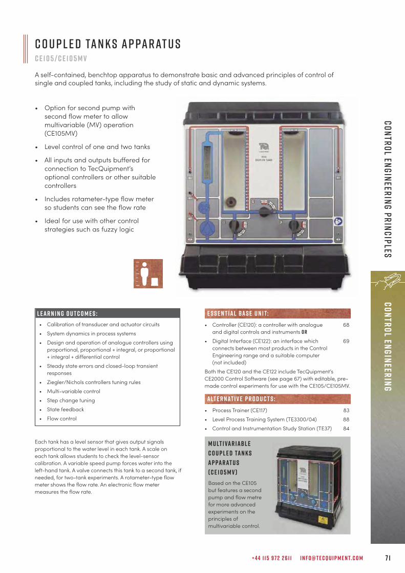
+ 4 4 1 1 5 9 7 2 2 6 1 1 I N F O @ T E C Q U I P M E N T. C O M 7 1
Control EngineeringControl Engineering Principles
C o u p l e d Ta n k s A p pa r at u sC E 1 0 5 / C E 1 0 5 M V
A self-contained, benchtop apparatus to demonstrate basic and advanced principles of control ofsingle and coupled tanks, including the study of static and dynamic systems.
• Option for second pump withsecond flow meter to allowmultivariable (MV) operation(CE105MV)
• Level control of one and two tanks
• All inputs and outputs buffered forconnection to TecQuipment’soptional controllers or other suitablecontrollers
• Includes rotameter-type flow meterso students can see the flow rate
• Ideal for use with other controlstrategies such as fuzzy logic
M u lt i va r i abl eC o u p l e d Ta n k sA p pa r at u s( C E 1 0 5 M V )Based on the CE105but features a secondpump and flow metrefor more advancedexperiments on theprinciples ofmultivariable control.
Each tank has a level sensor that gives output signalsproportional to the water level in each tank. A scale oneach tank allows students to check the level-sensorcalibration. A variable speed pump forces water into theleft-hand tank. A valve connects this tank to a second tank, ifneeded, for two-tank experiments. A rotameter-type flowmeter shows the flow rate. An electronic flow metermeasures the flow rate.
L E A R N I N G O U T C O M E S :• Calibration of transducer and actuator circuits • System dynamics in process systems• Design and operation of analogue controllers using
proportional, proportional + integral, or proportional+ integral + differential control
• Steady state errors and closed-loop transientresponses
• Ziegler/Nichols controllers tuning rules• Multi-variable control• Step change tuning • State feedback• Flow control
• Controller (CE120): a controller with analogue 68and digital controls and instruments o r
• Digital Interface (CE122): an interface which 69connects between most products in the ControlEngineering range and a suitable computer (not included)
Both the CE120 and the CE122 include TecQuipment’sCE2000 Control Software (see page 67) with editable, pre-made control experiments for use with the CE105/CE105MV.
• Process Trainer (CE117) 83• Level Process Training System (TE3300/04) 88• Control and Instrumentation Study Station (TE37) 84
alt e r nat i v e p r o d u c t s :
e s s e n t ial bas e u n i t:
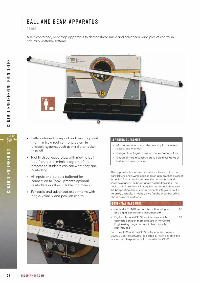
T E C Q U I P M E N T. C O M7 2
Cont
rol
Engi
neer
ing
Cont
rol
Engi
neer
ing
Prin
cipl
es
B a l l a n d B e a m A p pa r at u sc e 1 0 6
A self-contained, benchtop apparatus to demonstrate basic and advanced principles of control innaturally unstable systems.
The apparatus has a steel ball which is free to roll on twoparallel tensioned wires positioned on a beam that pivots atits centre. A servo motor controls the beam angle andsensors measure the beam angle and ball position. Thebasic control problem is to vary the beam angle to controlthe ball position. The system is a double integrator, so it isnaturally unstable. It needs active feedback control usingphase advance methods.
• Controller (CE120): a controller with analogue 68and digital controls and instruments o r
• Digital Interface (CE122): an interface which 69connects between most products in the ControlEngineering range and a suitable computer (not included)
Both the CE120 and the CE122 include TecQuipment’sCE2000 Control Software (see page 67) with editable, pre-made control experiments for use with the CE106.
e s s e n t ial bas e u n i t:
L E A R N I N G O U T C O M E S :• Measurement of system dynamics by transient and
closed loop methods• Design of analogue phase advance compensators• Design of state reconstructors to obtain estimates of
ball velocity and position
• Self-contained, compact and benchtop unitthat mimics a real control problem inunstable systems, such as missile or rockettake off
• Highly visual apparatus, with moving balland front panel mimic diagram of theprocess so students can see what they arecontrolling
• All inputs and outputs buffered forconnection to TecQuipment’s optionalcontrollers or other suitable controllers
• For basic and advanced experiments withangle, velocity and position control

+ 4 4 1 1 5 9 7 2 2 6 1 1 I N F O @ T E C Q U I P M E N T. C O M 7 3
Control EngineeringControl Engineering Principles
A scale model engine, driven by compressed air (notsupplied) for safety. The basic purpose is to adjust amotorised valve to regulate the engine speed under load.A DC generator connects to the engine output and loads it.The engine dynamics are similar to those of a typicalignition compression engine coupled to a dynamometer-controlled test bed. It is an ideal physical model to helpengineering students at all academic levels to gaininvaluable practical experience.
L E A R N I N G O U T C O M E S :• The use of dither signals in the compensation of
system non-linearities• The measurement of system dynamics from step
response information• Inner loop feedback compensation• P+I controller design
E n g i n e S p e e d C o n t r o l A p pa r at u sc e 1 0 7
A self-contained, benchtop apparatus to demonstrate basic and advanced principles of enginespeed control, including non-linear systems and inner loop feedback techniques.
• Small-scale, compressed air-powered piston engine tomimic a full size engine withrealistic results
• Demonstrates problems ofspeed control in non-linearsystems
• Front panel includes mimicdiagram of the process sostudents can clearly see whatthey are controlling
• For basic and advancedexperiments with speed controland non-linearity compensation
• All inputs and outputs bufferedfor connection to TecQuipment’soptional controllers or othersuitable controller
• Controller (CE120): a controller with analogue 68and digital controls and instruments o r
• Digital Interface (CE122): an interface which 69connects between most products in the ControlEngineering range and a suitable computer (not included)
Both the CE120 and the CE122 include TecQuipment’sCE2000 Control Software (see page 67) with editable, pre-made control experiments for use with the CE107.
• Compressor (CE1B) 313
• Optical Tachometer (OT1) 313• Stroboscope (ST1) 313
e s s e n t ial bas e u n i t:
E S S E N T IAL AN C I L LAR I E S :
R E C O M M E N D E D AN C I L LAR I E S :
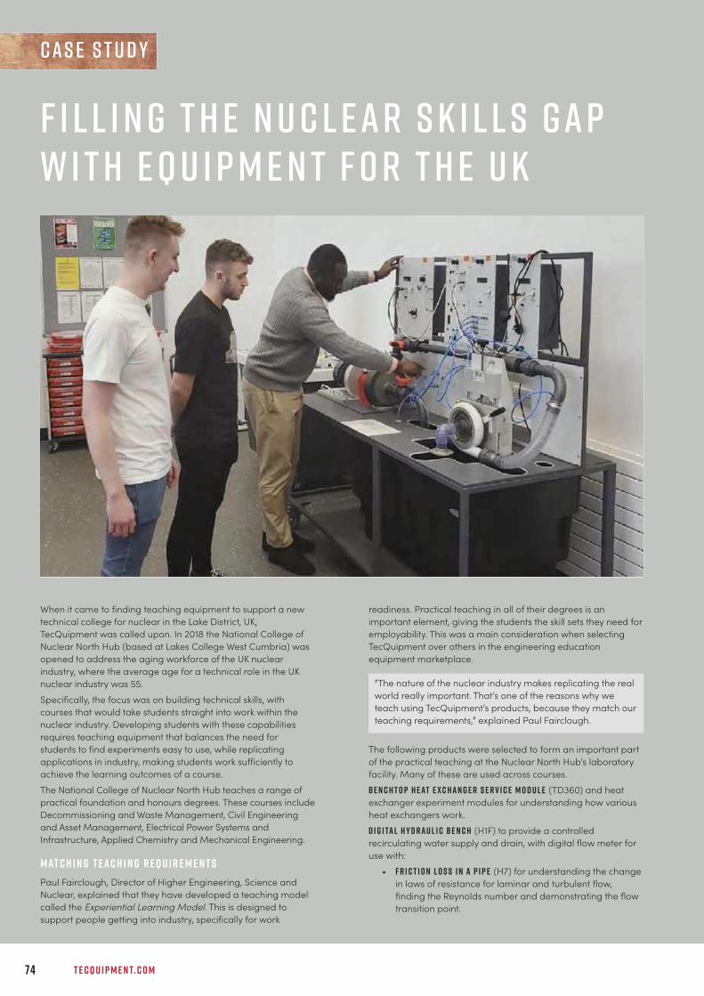
T E C Q U I P M E N T. C O M74
Cont
rol
Engi
neer
ing
sUBS
ONIC
WIN
D tU
NNEL
S
F i l l i n g t h e N u c l e a r S k i l l s G a pw i t h E q u i p m e n t f o r t h e U K
When it came to finding teaching equipment to support a newtechnical college for nuclear in the Lake District, UK,TecQuipment was called upon. In 2018 the National College ofNuclear North Hub (based at Lakes College West Cumbria) wasopened to address the aging workforce of the UK nuclearindustry, where the average age for a technical role in the UKnuclear industry was 55. Specifically, the focus was on building technical skills, withcourses that would take students straight into work within thenuclear industry. Developing students with these capabilitiesrequires teaching equipment that balances the need forstudents to find experiments easy to use, while replicatingapplications in industry, making students work sufficiently toachieve the learning outcomes of a course. The National College of Nuclear North Hub teaches a range ofpractical foundation and honours degrees. These courses includeDecommissioning and Waste Management, Civil Engineeringand Asset Management, Electrical Power Systems andInfrastructure, Applied Chemistry and Mechanical Engineering.
M at c h i n g T e a c h i n g R e q u i r e m e n t sPaul Fairclough, Director of Higher Engineering, Science andNuclear, explained that they have developed a teaching modelcalled the Experiential Learning Model. This is designed tosupport people getting into industry, specifically for work
readiness. Practical teaching in all of their degrees is animportant element, giving the students the skill sets they need foremployability. This was a main consideration when selectingTecQuipment over others in the engineering educationequipment marketplace.
The following products were selected to form an important partof the practical teaching at the Nuclear North Hub’s laboratoryfacility. Many of these are used across courses.Be n c h t o p H e at E x c h a n g e r S e r v i c e M o d u l e (TD360) and heatexchanger experiment modules for understanding how variousheat exchangers work.D i g i ta l H y d r a u l i c Be n c h (H1F) to provide a controlledrecirculating water supply and drain, with digital flow meter foruse with:
• F r i c t i o n L o s s i n a P i p e (H7) for understanding the changein laws of resistance for laminar and turbulent flow,finding the Reynolds number and demonstrating the flowtransition point.
“The nature of the nuclear industry makes replicating the realworld really important. That’s one of the reasons why weteach using TecQuipment’s products, because they match ourteaching requirements,” explained Paul Fairclough.
c a s e s t u d y

+ 4 4 1 1 5 9 7 2 2 6 1 1 I N F O @ T E C Q U I P M E N T. C O M 7 5
• P i p e w o r k E n e r g y L o s s (H34) to demonstrate energy lossesaround typical bends and fittings.
• F r i c t i o n L o s s i n a P i p e E x p e r i m e n t (H7) that allowsstudents to investigate losses in a small-bore horizontalpipe under laminar and turbulent flow conditions.
• Be r n o u l l i ’ s T h e o r e m (H5) experiment, which is aneducational Venturi for studying Venturi meters andBernoulli’s theorem.
C e n t r i f u g a l P u m p M o d u l e (MFP101), with the pelton wheel,propeller and Francis turbine experiment modules, to study andcompare the different turbines on a centrifugal pump.E n g i n e e r i n g S c i e n c e K i t (ESF), consisting of all 18 experiment kitswithin the Engineering Science range from TecQuipment, forunderstanding basic mechanical principles.F r e e V ibr at i o n s T e s t F r a m e (TM160) and both the S i m p l e a n dC o m p o u n d P e n d u l u m s (TM161) and F i l a r P e n d u l u m s (TM162), forlearning about harmonic motion and factors that affect theperiod of oscillation of these different types of pendulums.T h i n C y l i n d e r (SM1007) apparatus for learning about thestresses and strains of a pressurised thin-walled cylinder.M u lt i va r i abl e C o u p l e d Ta n k s (CE105MV) experiment andC o n t r o l l e r (CE120) for learning about the principles of openand closed-loop control of flow rate and liquid level in a singleand dual-tank systems.For comprehensive teaching of structures they use the A r c h e s ,Br i d g e s a n d T r u s s e s Pa c k a g e (STRA), D e f l e c t i o n a n d S t r e s s e sPa c k a g e (STRB) plus Fa i l u r e Pa c k a g e (STRC), plus individualexperiments:
• Be n d i n g M o m e n t s i n a Be a m (STR2)• S h e a r F o r c e i n a Be a m (STR3)• U n s y m m e t r i c a l Be n d i n g a n d S h e a r C e n t r e (STR7)
As well as TecQuipment’s teaching products, the purpose-builtfacility also features simulated radioactive fields and virtual-reality systems that mean they can simulate the internalelements of a nuclear facility.
Q u a l i t yPaul Fairclough has used TecQuipment teaching equipmentsince 1989. In this period he has worked for a range ofuniversities and colleges, choosing TecQuipment repeatedly. Thenumber one reason for this is quality.TecQuipment designs and manufactures products in thecompany’s headquarters based in the Midlands region of theUK. The ability to control the whole process means that highquality standards can be maintained.
M o r e t h a n J u s t t h e P r o d u c tThe benefit of using TecQuipment teaching products goes farbeyond the apparatus itself. The lifelong customer care andsupporting documentation makes a big difference.
Fairclough added: “The key thing is the learning materials thatcome with the products, including the exercises.” Each product comes with a manual, that includes set upinstructions, maintenance guidelines, step-by-step guides onhow to carry out experiments and, in many cases, supportingtheory. The purpose is to make practical teaching asstraightforward as possible.
R e s u lt s S p e a k L o u d e r t h a n W o r d sReporting in October 2019, Paul Fairclough talks about theirresults: “We’re coming towards the end of our first round ofdegrees, which have resulted in high pass rates and goodretention. In January 2020 we are due to have 430 students onthe various courses.” Aside from the statistics, their model of practical teaching hasbeen recognised by other national colleges as good practiceand is being used as an example of excellence to replicate.
“TecQuipment delivers consistently good quality. That’s agood manufacturing build and reliability, plus the equipmentlooks good and is easy for students to use,” explainedFairclough.

7 6
Cont
rol
Engi
neer
ing
Cont
rol
Engi
neer
ing
Prin
cipl
es
The apparatus has two electric motors, coupled by acontinuous flexible belt. The belt also passes over aswinging arm with a ‘jockey wheel’ that measures the beltspeed and tension. A manual control allows the user toadjust the spring tension at the swinging arm.
L E A R N I N G O U T C O M E S :• Independent control of speed and tension• Simultaneous control of speed and tension• Practical methods of controlling multi-variable
electro-mechanical systems
• Controller (CE120): a controller with analogue 68and digital controls and instruments o r
• Digital Interface (CE122): an interface which 69connects between most products in the ControlEngineering range and a suitable computer (not included)
Both the CE120 and the CE122 include TecQuipment’sCE2000 Control Software (see page 67) with editable, pre-made control experiments for use with the CE108.
• Optical Tachometer (OT1) 313
e s s e n t ial bas e u n i t:
R E C O M M E N D E D AN C I L LAR I E S :
C o u p l e d D r i v e s A p pa r at u sc e 1 0 8
Compact, benchtop apparatus designed to allow students at all academic levels to investigate basicand advanced principles of control, including control of multi-variable systems.
• Coupled drives demonstrate theproblems of speed and tensioncontrol
• Mimics many industrial andhousehold applications withrealistic results
• All inputs and outputs buffered forconnection to TecQuipment’soptional controllers or othersuitable controllers
• Front panel includes a mimicdiagram of the process so thatstudents can see what they arecontrolling
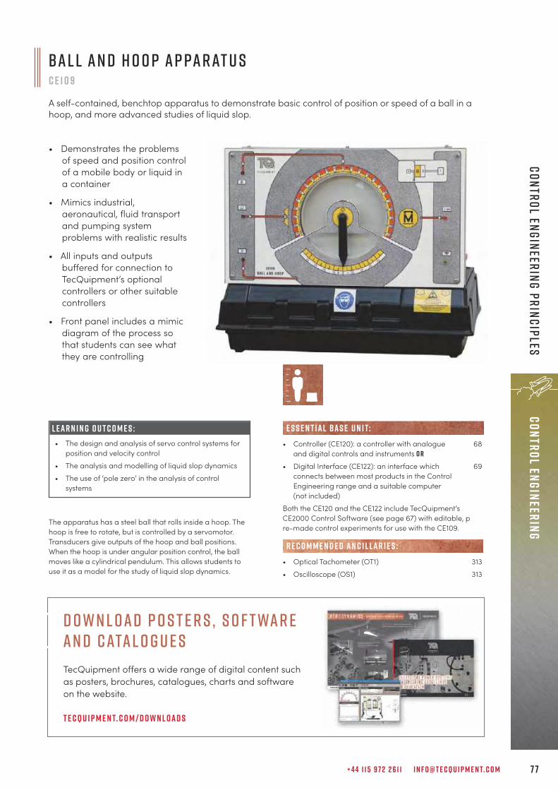
+ 4 4 1 1 5 9 7 2 2 6 1 1 I N F O @ T E C Q U I P M E N T. C O M 7 7
Control EngineeringControl Engineering Principles
B a l l a n d H o o p A p pa r at u s c e 1 0 9
A self-contained, benchtop apparatus to demonstrate basic control of position or speed of a ball in ahoop, and more advanced studies of liquid slop.
• Demonstrates the problemsof speed and position controlof a mobile body or liquid ina container
• Mimics industrial,aeronautical, fluid transportand pumping systemproblems with realistic results
• All inputs and outputsbuffered for connection toTecQuipment’s optionalcontrollers or other suitablecontrollers
• Front panel includes a mimicdiagram of the process sothat students can see whatthey are controlling
The apparatus has a steel ball that rolls inside a hoop. Thehoop is free to rotate, but is controlled by a servomotor.Transducers give outputs of the hoop and ball positions.When the hoop is under angular position control, the ballmoves like a cylindrical pendulum. This allows students touse it as a model for the study of liquid slop dynamics.
L E A R N I N G O U T C O M E S :• The design and analysis of servo control systems for
position and velocity control• The analysis and modelling of liquid slop dynamics• The use of ‘pole zero’ in the analysis of control
systems
• Controller (CE120): a controller with analogue 68and digital controls and instruments o r
• Digital Interface (CE122): an interface which 69connects between most products in the ControlEngineering range and a suitable computer (not included)
Both the CE120 and the CE122 include TecQuipment’sCE2000 Control Software (see page 67) with editable, pre-made control experiments for use with the CE109.
• Optical Tachometer (OT1) 313• Oscilloscope (OS1) 313
e s s e n t ial bas e u n i t:
R E C O M M E N D E D AN C I L LAR I E S :
D own l oad P o s t e r s , S o f twar e an d Catal o g u e sTecQuipment offers a wide range of digital content such as posters, brochures, catalogues, charts and software on the website.
T e cqu i p m e n t. c o m / d o w n l oad s

T E C Q U I P M E N T. C O M7 8
The CE110 has a DC servomotor, a DC generator and aflywheel mounted on a common shaft. Analogue 0 to ±10 Vcontrol signals vary the servomotor shaft speed in eitherdirection. An optical sensor measures the speed and showsit on a panel-mounted digital meter. The DC generatorstatically or dynamically loads the servomotor. An electricclutch connects or disconnects the shaft to a 30:1 reductiongearbox for position control studies. A manual controlallows the user to set a position control setpoint.
• Controller (CE120): a controller with analogue 68and digital controls and instruments o r
• Digital Interface (CE122): an interface which 69connects between most products in the ControlEngineering range and a suitable computer (not included)
Both the CE120 and the CE122 include TecQuipment’sCE2000 Control Software (see page 67) with editable, pre-made control experiments for use with the CE110.
e s s e n t ial bas e u n i t:
L E A R N I N G O U T C O M E S :• Basic tests and transducer calibration • Response calculation and measurement • Proportional and proportional plus integral control of
servo system speed • Disturbance cancelling and feedforward control • Angular position control: proportional control and
velocity feedback• Angular position control and the influence of non-
linearities • Non-linear system characteristics
S e r v o T r a i n e r c e 1 1 0
A self-contained, benchtop DC servo apparatus to study basic control of speed of a servomotor,through to more advanced studies of non-linear effects of hysteresis, deadzone and saturation.
• Demonstrates the problemsof speed and positioncontrol of a servomotorunder different loads
• Mimics industrial, transportand aeronautical problemswith realistic results
• All inputs and outputsbuffered for connection toTecQuipment’s optionalcontrollers or other suitablecontrollers
• Front panel includes amimic diagram of theprocess so that studentscan see what they arecontrolling
Cont
rol
Engi
neer
ing
Cont
rol
Engi
neer
ing
Prin
cipl
es
p r o d u c t d e v e l o p m e n tProducts are continually being improved. For the latest up-to-date specifications refer to the digital datasheets ont e cqu i p m e n t. c o m

+ 4 4 1 1 5 9 7 2 2 6 1 1 I N F O @ T E C Q U I P M E N T. C O M 7 9
Process Control Engineering
p r o c e s s c o n t r o l e n g i n e e r i n g
“Just wanted to say what a great guy Dave Giddings (TecQuipment’s ICT Manager) is. Thankyou for sending him. I was very impressed with his work ethic and expertise. Also, he is verygood interacting with the customer. You probably know all this already but I just wanted tosay it!
C a r y S t o v e rb u c k e y e e d u c at i o n a l s y s t e m s
e n g i n e e r i n gD i g i ta l C o n t r o l 8 1
P r o c e s s C o n t r o l 8 3
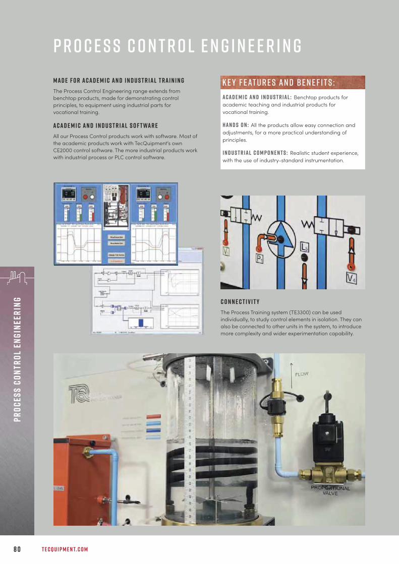
T E C Q U I P M E N T. C O M8 0
Proc
ess
Cont
rol
Engi
neer
ing
p r o c e s s c o n t r o l e n g i n e e r i n gM a d e f o r a c a d e m i c a n d i n d u s t r i a l t r a i n i n gThe Process Control Engineering range extends frombenchtop products, made for demonstrating controlprinciples, to equipment using industrial parts forvocational training.
A c a d e m i c a n d i n d u s t r i a l s o f t wa r eAll our Process Control products work with software. Most ofthe academic products work with TecQuipment’s ownCE2000 control software. The more industrial products workwith industrial process or PLC control software.
C o n n e c t i v i t yThe Process Training system (TE3300) can be usedindividually, to study control elements in isolation. They canalso be connected to other units in the system, to introducemore complexity and wider experimentation capability.
A c a d e m i c a n d i n d u s t r i a l : Benchtop products foracademic teaching and industrial products forvocational training.
h a n d s o n : All the products allow easy connection andadjustments, for a more practical understanding ofprinciples.
i n d u s t r i a l c o m p o n e n t s : Realistic student experience,with the use of industry-standard instrumentation.
k e y f eat u r e s an d be n e f i t s :
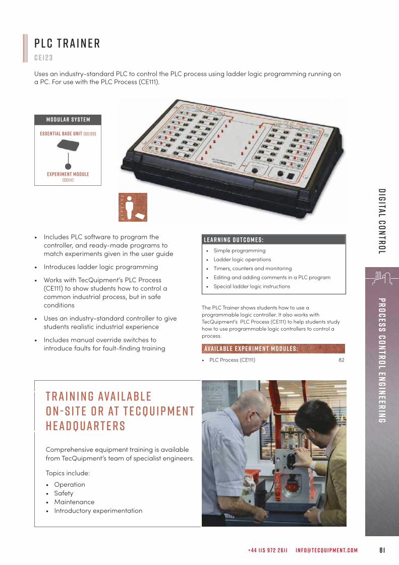
+ 4 4 1 1 5 9 7 2 2 6 1 1 I N F O @ T E C Q U I P M E N T. C O M 8 1
Process Control EngineeringDigital Control
P L C T r a i n e rc e 1 2 3
Uses an industry-standard PLC to control the PLC process using ladder logic programming running ona PC. For use with the PLC Process (CE111).
• Includes PLC software to program thecontroller, and ready-made programs tomatch experiments given in the user guide
• Introduces ladder logic programming
• Works with TecQuipment’s PLC Process(CE111) to show students how to control acommon industrial process, but in safeconditions
• Uses an industry-standard controller to givestudents realistic industrial experience
• Includes manual override switches tointroduce faults for fault-finding training
L E A R N I N G O U T C O M E S :• Simple programming• Ladder logic operations• Timers, counters and monitoring• Editing and adding comments in a PLC program• Special ladder logic instructions
The PLC Trainer shows students how to use aprogrammable logic controller. It also works withTecQuipment’s PLC Process (CE111) to help students studyhow to use programmable logic controllers to control aprocess.
• PLC Process (CE111) 82
ava i lab l e e x p e r i m e n t m o d u l e s :
Experiment module(ce111)
Essential Base Unit (ce123)
M O D U LAR S Y S T E M
T ra i n i n g Ava i labl e O n - S i t e o r at T e c Q u i p m e n t H ead q uar t e r sComprehensive equipment training is available from TecQuipment’s team of specialist engineers.
Topics include:
• Operation• Safety • Maintenance• Introductory experimentation
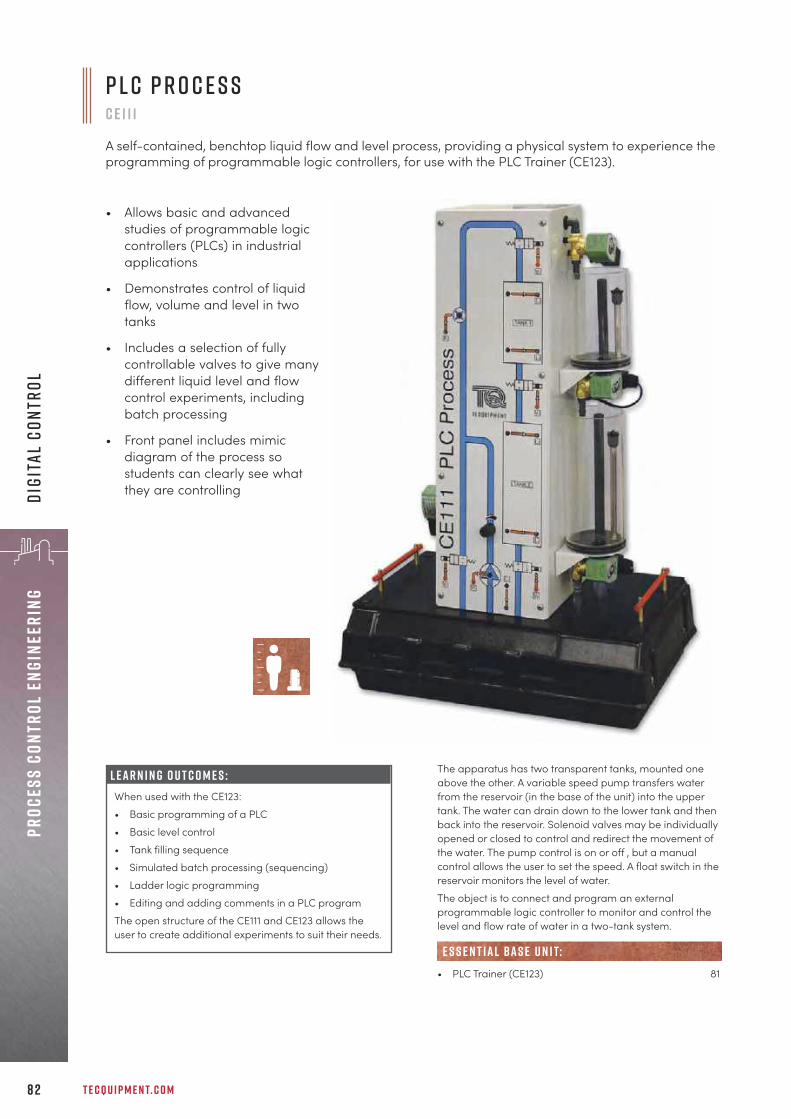
T E C Q U I P M E N T. C O M8 2
Proc
ess
Cont
rol
Engi
neer
ing
Digi
tal
Cont
rol
The apparatus has two transparent tanks, mounted oneabove the other. A variable speed pump transfers waterfrom the reservoir (in the base of the unit) into the uppertank. The water can drain down to the lower tank and thenback into the reservoir. Solenoid valves may be individuallyopened or closed to control and redirect the movement ofthe water. The pump control is on or off , but a manualcontrol allows the user to set the speed. A float switch in thereservoir monitors the level of water.The object is to connect and program an externalprogrammable logic controller to monitor and control thelevel and flow rate of water in a two-tank system.
• PLC Trainer (CE123) 81
e s s e n t ial bas e u n i t:
L E A R N I N G O U T C O M E S :When used with the CE123:• Basic programming of a PLC• Basic level control• Tank filling sequence• Simulated batch processing (sequencing)• Ladder logic programming• Editing and adding comments in a PLC programThe open structure of the CE111 and CE123 allows theuser to create additional experiments to suit their needs.
P L C P r o c e s s c e 1 1 1
A self-contained, benchtop liquid flow and level process, providing a physical system to experience theprogramming of programmable logic controllers, for use with the PLC Trainer (CE123).
• Allows basic and advancedstudies of programmable logiccontrollers (PLCs) in industrialapplications
• Demonstrates control of liquidflow, volume and level in twotanks
• Includes a selection of fullycontrollable valves to give manydifferent liquid level and flowcontrol experiments, includingbatch processing
• Front panel includes mimicdiagram of the process sostudents can clearly see whatthey are controlling

P r o c e s s T r a i n e rc e 1 1 7
A self-contained, benchtop, fully integrated teaching apparatus that mimics industrial processengineering, including a comprehensive range of experiments in flow, level, pressure and temperature,ranging from basic theories through to more advanced principles.
+ 4 4 1 1 5 9 7 2 2 6 1 1 I N F O @ T E C Q U I P M E N T. C O M 8 3
Process Control EngineeringProcess Control
• Includes four basic process control methodsin one compact unit
• Supplied with TecQuipment’s CE2000software for supervisory control of theprocess with data acquisition
• Mimics common industrial parts andprocesses with realistic results
• Ideal for classroom demonstrations andstudent experiments
• Includes experiments from basic control toadvanced control methods, including ratiocontrol, cascade control, interactive controland feedforward control
Using water as the working fluid, the equipment allows safe,practical experiments on control of flow, liquid level,temperature and pressure. Students can study each ofthese separately or in combinations.
• Thermal Control Process Apparatus (CE103) 70• Coupled Tanks Apparatus (CE105/CE105MV) 71• Pressure Process Training System (TE3300/02) 86• Flow Process Training System (TE3300/03) 87• Level Process Training System (TE3300/04) 88• Temperature Process Training System (TE3300/05) 89• Control and Instrumentation Study Station (TE37) 84
alt e r nat i v e p r o d u c t s :
L E A R N I N G O U T C O M E S :• Proportional, integral and derivative (PID) control• Control of flow• Control of level• Control of pressure• Control of temperature• Ratio control• Cascade control• Multi-loop control• Interacting control loops
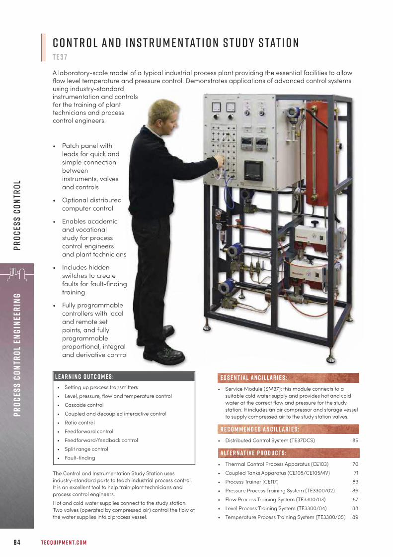
T E C Q U I P M E N T. C O M8 4
Proc
ess
Cont
rol
Engi
neer
ing
Proc
ess
Cont
rol
The Control and Instrumentation Study Station usesindustry-standard parts to teach industrial process control.It is an excellent tool to help train plant technicians andprocess control engineers.
Hot and cold water supplies connect to the study station.Two valves (operated by compressed air) control the flow ofthe water supplies into a process vessel.
C o n t r o l a n d I n s t r u m e n tat i o n S t u d y S tat i o n T E 3 7
A laboratory-scale model of a typical industrial process plant providing the essential facilities to allowflow level temperature and pressure control. Demonstrates applications of advanced control systemsusing industry-standardinstrumentation and controlsfor the training of planttechnicians and processcontrol engineers.
• Patch panel withleads for quick andsimple connectionbetweeninstruments, valvesand controls
• Optional distributedcomputer control
• Enables academicand vocationalstudy for processcontrol engineersand plant technicians
• Includes hiddenswitches to createfaults for fault-findingtraining
• Fully programmablecontrollers with localand remote setpoints, and fullyprogrammableproportional, integraland derivative control
• Service Module (SM37): this module connects to asuitable cold water supply and provides hot and coldwater at the correct flow and pressure for the studystation. It includes an air compressor and storage vesselto supply compressed air to the study station valves.
• Distributed Control System (TE37DCS) 85
• Thermal Control Process Apparatus (CE103) 70
• Coupled Tanks Apparatus (CE105/CE105MV) 71
• Process Trainer (CE117) 83
• Pressure Process Training System (TE3300/02) 86
• Flow Process Training System (TE3300/03) 87
• Level Process Training System (TE3300/04) 88
• Temperature Process Training System (TE3300/05) 89
E S S E N T IAL AN C I L LAR I E S :
R E C O M M E N D E D AN C I L LAR I E S :
alt e r nat i v e p r o d u c t s :
L E A R N I N G O U T C O M E S :• Setting up process transmitters
• Level, pressure, flow and temperature control
• Cascade control
• Coupled and decoupled interactive control
• Ratio control
• Feedforward control
• Feedforward/feedback control
• Split range control
• Fault-finding

+ 4 4 1 1 5 9 7 2 2 6 1 1 I N F O @ T E C Q U I P M E N T. C O M 8 5
Process Control EngineeringProcess Control
D i s t r i b u t e d C o n t r o l S y s t e mT E 3 7 D C S
Easy-to-use software that connects to the Control and Instrumentation Study Station (TE37) for remotecontrol and monitoring of processes (distributed control).
• Industry-standard supervisorycontrol and data acquisition(SCADA) software, with colourful,easy-to-use on-screen mimics ofthe processes
• Improves students’ understandingof industrial process control
• Includes high specificationcomputer, large monitor, keyboardand mouse
• Real-time displays of variables
• Mimics and controls both controllersof the TE37
The Distributed Control System (TE37DCS) is a computer-control package for use with TecQuipment’s Control andInstrumentation Study Station (TE37). It allows remotecontrol and data acquisition when set in a multitude ofdifferent configurations.
• Control and Instrumentation Study Station (TE37) 84
AN C I L LAR Y F O R :
L E A R N I N G O U T C O M E S :When used with the Control and Instrumentation StudyStation (TE37), the remote control and monitoring ofcontrol processes including:• Level• Pressure• Temperature• Cascade control• Coupled interactive control• Decoupled interactive control• Ratio control• Feedforward control• Feedforward/feedback control• Split range control
T e c Q u i p m e n t n E W S L E T T E R S I G N - U PDon’t miss out on the latest new products, case studies, demonstration videos and blog posts. Sign up to the TecQuipment newsletter today.
T e c q u i p m e n t. c o m / s u b s c r i b e
NEWS

T E C Q U I P M E N T. C O M8 6
Proc
ess
Cont
rol
Engi
neer
ing
Proc
ess
Cont
rol
P r e s s u r e P r o c e s s T r a i n i n g S y s t e mT E 3 3 0 0 / 0 2
A self-contained, mobile module using pressure as the control variable to illustrate the principles ofsingle-loop control and the calibration and tuning of controllers, transmitters, converters and valves.
• Demonstrates automatic control of pressurein an accumulator using proportional,proportional plus integral, and proportional,integral plus derivative (PID) control
• Uses industry-standard parts making itideal for industrial, vocational andacademic training
• Demonstrates operation, calibration andtuning of controllers, transmitters, convertersand valves
• Connects to the Flow Process TrainingSystem (TE3300/03) for cascade control
• Connects to the Computer Control System(TE3300/06) for distributed control
• Service Module (SM3300)
• Flow Process Training System (TE3300/03) 87• Computer Control System (TE3300/06) 90
• Flow Process Training System (TE3300/03) 87
• Process Trainer (CE117) 83• Control and Instrumentation Study Station (TE37) 84
E S S E N T IAL AN C I L LAR I E S :
R E C O M M E N D E D AN C I L LAR I E S :
AN C I L LAR Y F O R :
alt e r nat i v e p r o d u c t s :
L E A R N I N G O U T C O M E S :• Proportional, integral and derivative control• Setting up and demonstrating automatic control• The principles of loop control and the calibration and
tuning of controllers, transmitters, converters andvalves
• Cascade control of flow and pressure (when usedwith the TE3300/03 Flow Process Training System)
• Distributed control (when used with the TE3300/06Computer Control System)
To carry out experiments, students fill the reservoir withclean water and prime the system. They then set thecontroller to regulate the flow of water using a pneumaticvalve. This alters the pressure in the accumulator. A pressuretransmitter measures the accumulator pressure and givesfeedback to the controller. For a realistic experience, theequipment has industry-standard instrumentationand parts.The apparatus includes two gate valves. One valve controlsthe flow at the output (drain) and the other acts as a flow-bypass valve. A chart recorder shows and logs the changesof the process variable (level) and the controller output.The self-contained unit can perform many experiments. Byconnecting this to other products in the TE3300 rangefurther experiments are possible.

+ 4 4 1 1 5 9 7 2 2 6 1 1 I N F O @ T E C Q U I P M E N T. C O M 8 7
Process Control EngineeringProcess Control
To carry out experiments, students fill the reservoir withclean water and prime the system. They then set thecontroller to regulate the flow of the water using apneumatic valve. The gap-type flow meter gives a visualindication of flow. The fixed orifice and pressure transmittergive feedback to the controller. For a realistic experience,the equipment has industry-standard instrumentationand parts.The apparatus includes two gate valves. One valve controlsthe flow at the output (drain) and the other acts as a flow-bypass valve. A chart recorder shows and logs the changesof the process variable (level) and the controller output.The self-contained unit can perform many experiments. Byconnecting this to other products in the TE3300 rangefurther experiments are possible.
• Service Module (SM3300)
• Pressure Process Training System (TE3300/02) 86• Level Process Training System (TE3300/04) 88• Computer Control System (TE3300/06) 90
• Pressure Process Training System (TE3300/02) 86• Level Process Training System (TE3300/04) 88
• Process Trainer (CE117) 83• Control and Instrumentation Study Station (TE37) 84
E S S E N T IAL AN C I L LAR I E S :
R E C O M M E N D E D AN C I L LAR I E S :
alt e r nat i v e p r o d u c t s :
AN C I L LAR Y F O R :
F l o w P r o c e s s T r a i n i n g S y s t e mT E 3 3 0 0 / 0 3
A self-contained, mobile module for flow process control experiments to illustrate the principles ofsingle-loop control and the calibration and tuning of controllers, transmitters, converters and valves.
• Demonstrates automatic control of flowusing proportional, proportional plusintegral, and proportional plus integral plusderivative (PID) control
• Uses industry-standard parts making itideal for industrial, vocational andacademic training
• Demonstrates operation, calibration andtuning of controllers, transmitters, convertersand valves
• Connects to the Pressure Process(TE3300/02) and Level Process (TE3300/04)Training Systems for cascade control
• Connects to the Computer Control System(TE3300/06) for distributed control
L E A R N I N G O U T C O M E S :• Proportional, integral and derivative control• Setting up and demonstrating automatic control• The principles of loop control and the calibration and
tuning of controllers, transmitters, converters andvalves
• Calibration of an orifice flow meter with a differentialpressure transmitter
• Quadratic flow laws and square root extraction• Cascade control of pressure and flow, and level and
flow (when used with the TE3300/02 andTE3300/04)
• Distributed control (when used with the TE3300/06Computer Control System)
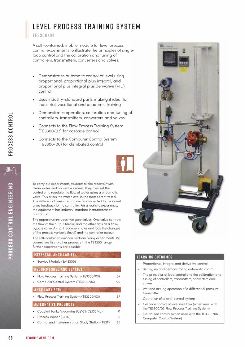
T E C Q U I P M E N T. C O M8 8
Proc
ess
Cont
rol
Engi
neer
ing
Proc
ess
Cont
rol
To carry out experiments, students fill the reservoir withclean water and prime the system. They then set thecontroller to regulate the flow of water using a pneumaticvalve. This alters the water level in the transparent vessel.The differential pressure transmitter connected to the vesselgives feedback to the controller. For a realistic experience,the equipment has industry-standard instrumentationand parts.The apparatus includes two gate valves. One valve controlsthe flow at the output (drain) and the other acts as a flow-bypass valve. A chart recorder shows and logs the changesof the process variable (level) and the controller output.The self-contained unit can perform many experiments. Byconnecting this to other products in the TE3300 rangefurther experiments are possible.
• Service Module (SM3300)
• Flow Process Training System (TE3300/03) 87• Computer Control System (TE3300/06) 90
• Flow Process Training System (TE3300/03) 87
• Coupled Tanks Apparatus (CE105/CE105MV) 71• Process Trainer (CE117) 83• Control and Instrumentation Study Station (TE37) 84
E S S E N T IAL AN C I L LAR I E S :
R E C O M M E N D E D AN C I L LAR I E S :
AN C I L LAR Y F O R :
alt e r nat i v e p r o d u c t s :
L E A R N I N G O U T C O M E S :• Proportional, integral and derivative control• Setting up and demonstrating automatic control• The principles of loop control and the calibration and
tuning of controllers, transmitters, converters andvalves
• Wet and dry leg operation of a differential pressuretransmitter
• Operation of a level-control system• Cascade control of level and flow (when used with
the TE3300/03 Flow Process Training System)• Distributed control (when used with the TE3300/06
Computer Control System)
L e v e l P r o c e s s T r a i n i n g S y s t e m T E 3 3 0 0 / 0 4
A self-contained, mobile module for level processcontrol experiments to illustrate the principles of single-loop control and the calibration and tuning ofcontrollers, transmitters, converters and valves.
• Demonstrates automatic control of level usingproportional, proportional plus integral, andproportional plus integral plus derivative (PID)control
• Uses industry-standard parts making it ideal forindustrial, vocational and academic training
• Demonstrates operation, calibration and tuning ofcontrollers, transmitters, converters and valves
• Connects to the Flow Process Training System(TE3300/03) for cascade control
• Connects to the Computer Control System(TE3300/06) for distributed control

+ 4 4 1 1 5 9 7 2 2 6 1 1 I N F O @ T E C Q U I P M E N T. C O M 8 9
Process Control EngineeringProcess Control
To carry out experiments, students fill the reservoir withclean water and prime the system. They then set thecontroller to regulate the power to the in-line heater andcontrol the temperature of the water at any of three places.The heat-exchanger removes the heat from the water, togive quicker experiments. The thermocouples (selected by athree-way switch) give feedback to the controller. For arealistic experience, the equipment has industry-standardinstrumentation and parts.The apparatus includes one gate valve that works as a flowbypass. A chart recorder shows and logs the changes of theprocess variable (temperature) and the controller output.
• Computer Control System (TE3300/06) 90
• Thermal Control Process Apparatus (CE103) 70• Process Trainer (CE117) 83• Control and Instrumentation Study Station (TE37) 84
R E C O M M E N D E D AN C I L LAR I E S :
alt e r nat i v e p r o d u c t s :
T e m p e r at u r e P r o c e s s T r a i n i n g S y s t e mT E 3 3 0 0 / 0 5
A self-contained, mobile module for temperature process control experiments to illustrate the principlesof single-loop control and the calibration and tuning of controllers, transmitters, converters and valves.
• Demonstrates automatic control oftemperature using proportional,proportional plus integral, and proportionalplus integral plus derivative (PID) control
• Uses industry-standard parts making itideal for industrial, vocational andacademic training
• Demonstrates operation, calibration andtuning of temperature transmitters andthermocouples
• Includes delay coil to mimic realistic timelag due to a process
• Connects to the Computer Control System(TE3300/06) for distributed control
L E A R N I N G O U T C O M E S :• Proportional, integral and derivative control• Setting up and demonstrating automatic control• The principles of loop control and the calibration and
tuning of temperature transmitters andthermocouples
• Operation of a temperature control system • Distributed control (when used with the TE3300/06
Computer Control System)

T E C Q U I P M E N T. C O M9 0
Proc
ess
Cont
rol
Engi
neer
ing
Proc
ess
Cont
rol
C o m p u t e r C o n t r o l S y s t e mT E 3 3 0 0 / 0 6
Easy-to-use software that connects to the TE3300 Process Control modules for remote control andmonitoring of processes (distributed control).
• Industry-standard supervisorycontrol and data acquisition(SCADA) software, withcolourful, easy-to-use on-screen mimics of the processes
• Improves students’understanding of industrialprocess control
• Includes high specificationcomputer, large monitor,keyboard and mouse
• Real-time displays of variables
The Computer Control System (TE3300/06) is a computercontrol package for use with modules from TecQuipment’sTE3300 process control range. It allows remote control anddata acquisition from the controller of each process. Thissystem will also control and collect data from the controllersof TE3300 modules when connected in cascade.
One or more modules from the TE3300 process control range:• Pressure Process Training System (TE3300/02) 86• Flow Process Training System (TE3300/03) 87• Level Process Training System (TE3300/04) 88• Temperature Process Training System (TE3300/05) 89
AN C I L LAR Y F O R :
L E A R N I N G O U T C O M E S :When used with the TE3300 process control modules,computer control and monitoring of:• Pressure process (TE3300/02)• Flow process (TE3300/03)• Level control process (TE3300/04)• Temperature process (TE3300/05)• Cascaded flow and pressure (TE3300/02 and
TE3300/03)• Cascaded flow and level (TE3300/03 and
TE3300/04)
e x p e r t s o n t h e e n d o f t h e p h o n e
The dedicated, multi-lingual Sales team is available to discuss equipment specifications, teaching objectives and constraints, to offer the best products to suit requirements.
Cal l +44 ( 0 ) 1 15 97 2 2 6 1 1
+ 4 4 1 1 5 9 7 2 2 6 1 1 I N F O @ T E C Q U I P M E N T. C O M 9 1
Fluid Mechanics
“Repeatability when it comes to running experiments to prove theory, is the number one reasonwe stick with these products. I know that my students are going to get good, consistent,reliable results. I also know they are going to last. The fact that equipment which the Universitybought over half a century ago is still working says it all. This isn’t just because they aredesigned and built really well, it’s also down to these products being really good to maintain.
D e a n M i lt o nL a b o r at o r y i n s t r u c t o r , U n i v e r s i t y o f R e g i n a , C a n a d a
f l u i d m e c h a n i c sd i g i ta l H y d r a u l i c B e n c h 9 3
F l o w a n d P r e s s u r e M e a s u r e m e n t 9 5
P i p e F r i c t i o n a n d E n e r g y L o s s 1 0 3
L a m i n a r a n d T u r b u l e n t F l o w 1 0 7
N o z z l e s a n d J e t s 1 0 8
V o r t i c e s a n d C av i tat i o n 1 1 1
F l o w V i s u a l i s at i o n 1 1 3
P i p e S u r g e a n d Wat e r H a m m e r 1 1 4
O p e n C h a n n e l F l o w 1 1 6
H y d r o s tat i c s a n d P r o p e r t i e s o f F l u i d s 1 2 5
H y d r o l o g y 1 2 9
P u m p s a n d T u r b i n e s 1 3 2
M o d u l a r F l u i d P o w e r ( P u m p s , T u r b i n e s 1 4 2a n d C o m p r e s s o r s )

T E C Q U I P M E N T. C O M9 2
Flui
d Me
chan
ics
f l u i d m e c h a n i c sThe Fluid Mechanics range offers a wide scope of teachingequipment for the delivery of complete courses in fluiddynamics.
B a s e U n i t a n d M o d u l e s f o r F l e x i b i l i t yIn many settings, the modular Digital Hydraulic Bench (H1F)acts as a base unit, allowing tutors to swap out individuallymounted experiment modules on these self-containedbenches, reducing laboratory set-up time, spacerequirements, the need to be near a water source and cost.Modules include experiments for exploring Bernoulli’stheorem, the function and dynamics of weirs, pressure andflow measurement, pipe friction and energy loss, andmuch more.
U n d e r s ta n d i n g F l o wThe impressive flow and sediment channels, fordemonstrating the mechanics of flow, also enable thepractical teaching and demonstration of phenomena such
as critical and subcritical flow,hydraulic jump, anddune formation.There are manyancillaries availablefor use with the flowchannels, enablingthem to be used asboth teaching andresearch aids.
M o d u l a r F l u i d P o w e r r a n g e The Fluid Mechanics range includes a sub-section ofModular Fluid Power products (pages 134–148) todemonstrate real-world applications of fluidmechanics. They include pumps and turbines, whichalso provide a link to renewable energy.
A u t o m at i c D ata A c q u i s i t i o n Each product in this range works with TecQuipment’sunique Versatile Data Acquisition System (VDAS®),page 310.
l o n g e v i t y: Long-lasting equipment to teach principlesthat do not go out of date.
wat e r a n d s pa c e s av i n g : Many experiments work withthe self-contained, mobile hydraulic bench to save waterand laboratory space.
l a r g e c h o i c e o f e x p e r i m e n t s : A huge range ofexperiments for a complete course in fluid mechanics,from simple flow and pressure measurements toadvanced studies of vortices and open channel flow.
k e y f eat u r e s an d be n e f i t s :
P i t o t t u b e f o rt h e F C 8 0 f l u m e
s p i l lway f o r t h e F C 3 0 0 f l u m e

+ 4 4 1 1 5 9 7 2 2 6 1 1 I N F O @ T E C Q U I P M E N T. C O M 9 3
Fluid MechanicsDigital Hydraulic Bench
This product supplies a controlled flow of water to a widevariety of laboratory experiment modules (availableseparately). The body of the bench forms a reservoir or‘sump tank’ with a submersible pump. Once filled, thebench needs no external water supply.
B e n c h - m o u n t e d :• Flow Visualisation (FC15) 95• Flow Through an Orifice (H4) 108• Bernoulli’s Theorem (H5) 98• Discharge Over a Notch (H6) 97
ava i labl e e x p e r i m e n t m o d u l e s :
• Friction Loss in a Pipe (H7) 103• Impact of a Jet (H8) 109• Flow Measurement Methods (H10) 99• Vortex Apparatus (H13) 111• Francis Turbine (H18) 132• Pelton Turbine (H19) 133• Hydraulic Ram Pump (H31) 135• Jet Trajectory and Orifice Flow (H33) 110• Pipework Energy Losses (H34) 105• Flow Meter Calibration (H40) 101F r e e s ta n d i n g :• Losses in Piping Systems (H16) 104• 2.5 Metre Flow Channel (FC50–2.5) 116• Pipe Surge And Water Hammer (H405) 114• Fluid Friction Apparatus (H408) 106
Experiment modules
Essential Base Unit (h1f)
M O D U LAR S Y S T E M
T h e D i g i ta l H y d r a u l i c B e n c h s h o w n w i t h t h e J e t T r a j e c t o r ya n d O r i f i c e F l o w ( H 3 3 ) e x p e r i m e n t m o d u l e
D i g i ta l f l o w d i s p l ay
D i g i ta l H y d r a u l i c B e n c h h 1 f
A mobile, self-contained bench with recirculating water supply. It provideswater at variable flow rates direct to experiments and includes digitalflow display for hydraulic and fluid mechanics experiments.
U p g r a d e y o u r o l d e r g e n e r at i o ng r av i m e t r i c o r V o l u m e t r i c
h y d r a u l i c b e n c h w i t h a :d i g i ta l e l e c t r o n i cm e a s u r i n g k i t H 1 x
S e e pa g e 1 1 5
Supplies and measures water flow to over 15different experiment modulesSaves space and reduces costs
Electronic flowmeter and digital displayAccurate measurements and reducedexperiment time
Self-contained with recirculating water circuitNeeds no external water supply, saves mainswater
Fully mobile unit with a flat top to hold severalexperiment modulesMakes best use of laboratory space
Fibreglass constructionStrength, easier transport and long life
F eat u r e s an d be n e f i t s :

T E C Q U I P M E N T. C O M9 4
O l d E q u i p m e n t G e t s a n U p g r a d eat N o t t i n g h a m T r e n t U n i v e r s i t y
A Hydraulic Bench Upgrade Kit (H1X) that electronically measuresflow rates was recently purchased by Nottingham TrentUniversity. It delivered a 15–30 per cent time saving whencarrying out experiments. The separate electronic flow measurement instrument can beretrofitted by a laboratory technician onto older models ofTecQuipment’s Hydraulic Bench that use manual measurementmethods; this reduces experiment time while retaining thelearning experience. James Cooper, a technical specialist working for the School ofArchitecture, Design and the Built Environment at NottinghamTrent University, explains: “Students have commented on howmuch time is spent calculating flow rates on the gravimetricbenches using the original method of volume/time. To helpimprove this, I recently fitted an H1X conversion kit to one of thebenches.”Each kit is supplied with the core electronic measurement device,all the parts necessary to carry out the upgrade and acomprehensive installation guide.
When running the loss in pipe and impact of a jet experiments,the students save around 10–20 minutes in a one-hour laboratorysession (depending on the flow rate and the volume of water thatwas previously measured). Cooper went on to explain the benefits: “This allowed for moretime being spent working towards the desired learningoutcomes. The student feedback about the conversion was verypositive. The students previously felt that their time doing manualcalculations of flow rates was a waste of the practical timeavailable to them.”
“The fitting was simple, with clear, concise instructions. It includedeverything needed for the conversion. The fitting time was aroundfour hours including the checking and testing of the accuracy of theflow meter read-out,” explained Cooper.
c a s e s t u d y
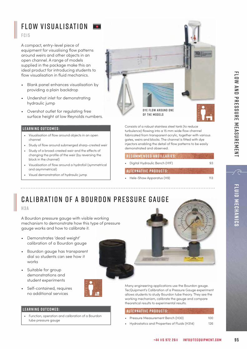
+ 4 4 1 1 5 9 7 2 2 6 1 1 I N F O @ T E C Q U I P M E N T. C O M 9 5
Fluid MechanicsFlow
and Pressure Measurem
ent
C a l i b r at i o n o f a B o u r d o n P r e s s u r e G a u g eH 3 a
A Bourdon pressure gauge with visible workingmechanism to demonstrate how this type of pressuregauge works and how to calibrate it.
• Demonstrates ‘dead weight’calibration of a Bourdon gauge
• Bourdon gauge has transparentdial so students can see how itworks
• Suitable for groupdemonstrations andstudent experiments
• Self-contained, requiresno additional services
L E A R N I N G O U T C O M E S :• Function, operation and calibration of a Bourdon
tube pressure gauge
Many engineering applications use the Bourdon gauge.TecQuipment’s Calibration of a Pressure Gauge experimentallows students to study Bourdon tube theory. They see theworking mechanism, calibrate the gauge and comparetheoretical results to experimental results.
• Pressure Measurement Bench (H30) 100
• Hydrostatics and Properties of Fluids (H314) 126
alt e r nat i v e p r o d u c t s :
L E A R N I N G O U T C O M E S :• Visualisation of flow around objects in an open
channel
• Study of flow around submerged sharp-crested weir
• Study of a broad-crested weir and the effects ofchanging the profile of the weir (by reversing theblock in the channel)
• Visualisation of flow around a hydrofoil (symmetricaland asymmetrical)
• Visual demonstration of hydraulic jump
Consists of a robust stainless steel tank (to reduceturbulence) flowing into a 15 mm wide flow channelfabricated from transparent acrylic, together with variousgates, weirs and blocks. The channel is fitted with dyeinjectors enabling the detail of flow patterns to be easilydemonstrated and observed.
• Digital Hydraulic Bench (H1F) 93
• Hele-Shaw Apparatus (H9) 113
R E C O M M E N D E D AN C I L LAR I E S :
alt e r nat i v e p r o d u c t s :
• Blank panel enhances visualisation byproviding a plain backdrop
• Undershot inlet for demonstratinghydraulic jump
• Overshot outlet for regulating freesurface height at low Reynolds numbers.
F l o w v i s u a l i s at i o nF c 1 5
A compact, entry-level piece ofequipment for visualising flow patternsaround weirs and other objects in anopen channel. A range of modelssupplied in the package make this anideal product for introducing students toflow visualisation in fluid mechanics.
D y e f l o w a r o u n d o n eo f t h e m o d e l s

T E C Q U I P M E N T. C O M9 6
T e c Q u i p m e n t U s e r G u i d e sEach piece of apparatus is accompanied by acomprehensive user guide which includes:
• Assembly instructions• Use and maintenance instructions• Associated theory
T h e o r y I n c l u d e dSupporting theory is included in the user guide, accompanied by suggested experiments along with sample results. In aselection of guides, suggested text books that the students and teachers may find useful are also included. MostTecQuipment products are suitable for further experiments to those included in the guide; for this reason, furtherinvestigations using the equipment or results are frequently suggested.
W o r k b o o k s I n c l u d e dFor some of the ranges, for example the Engineering Science range (page 5), both teacherand student guides are included, along with workbooks for the students to follow. The fullEngineering Science set (ESF, page 7) covers a complete basic engineeringsyllabus. These guides are supplied electronically for ease of distribution tostudents.
D i a g r a m s a n d P h o t o sWhere necessary, the guides are illustrated with step-by-step photographs or diagrams to assist withassembling and maintaining the equipment,and performing experiments. Suggestedtable layouts for results are alsoincluded, easing the workloadon tutors as results shouldbe presented in thesame formatfrom eachstudent.
“Every time we look at the quality of the materialsyou have used to build these apparatuses, and theuser-friendliness of your software, we thank you andwished other companies would learn from you.”
P r o f e s s o r K h o s r o wj e r d iW e s t e r n N e w E n g l a n d U n i v e r s i t y

+ 4 4 1 1 5 9 7 2 2 6 1 1 I N F O @ T E C Q U I P M E N T. C O M 9 7
Fluid MechanicsFlow
and Pressure Measurem
ent
The Discharge Over a Notch apparatus demonstratesclearly the use of weirs as simple flow regulators. It allowsstudents to do tests on relationships between upstreamwater level and weir discharge for different shapednotches. They can then compare their results with theory.
• Digital Hydraulic Bench (H1F) 93
• Flumes 116–124
e s s e n t ial bas e u n i t:
alt e r nat i v e p r o d u c t s :
D i s c h a r g e o v e r a N o t c hh 6
A tank and set of notch weirs for the study of flow regulation and measurement devices.
• Portable, corrosion-resistant glass fibrechannel for ease of use and long life
• Includes one rectangular and two V-shapednotches for basic experiments
• Two additional weirs (Cipolletti and Sutro)are included for more advanced experiments
• Adjustable depth gauge for precisemeasurement of water level
• Works with TecQuipment’s Digital HydraulicBench for easy installation
L E A R N I N G O U T C O M E S :Comprehensive study of flow over weirs, including:• Investigation of head against discharge• Coefficient of discharge for notches• Rectangular and different angled V-notches
S h o w n w i t h t h e D i g i ta l H y d r a u l i cB e n c h ( H 1 F ) , ava i l a b l e s e pa r at e ly

T E C Q U I P M E N T. C O M9 8
Flui
d Me
chan
ics
Flow
and
Pre
ssur
e M
easu
rem
ent
The Venturi tube in TecQuipment’s Bernoulli’s Theorem istypical of meters used throughout industry. However, it hasmany more pressure tappings, connecting to watermanometers, which allow full study of the pressuredistribution along the convergent-divergent passage.
• Digital Hydraulic Bench (H1F) 93
• Bernoulli’s Equation (AF11) 32• Flow Measurement Methods (H10) 99• Flow Meter Calibration (H40) 101• Fluid Friction Apparatus (H408) 106
alt e r nat i v e p r o d u c t s :
e s s e n t ial bas e u n i t:
B e r n o u l l i ’ s T h e o r e m h 5
A benchtop Venturi tube that allows students to study Bernoulli’s thorem by measuring the completestatic head distribution along the horizontal tube.
• Eleven pressure tappingsalong the tube
• Direct measurement ofstatic heads
• Complete pressuredistribution clearly visible
• Compact and simple tooperate
• Works with TecQuipment’sDigital Hydraulic Bench foreasy installation
L E A R N I N G O U T C O M E S :Comprehensive study of a Venturi meter and Bernoulli’stheorem, including:• Direct measurement of the static head distribution
along a Venturi tube• Comparison of experimental results with theoretical
predictions• Measurement of the meter coefficient of discharge
at various flow rates

+ 4 4 1 1 5 9 7 2 2 6 1 1 I N F O @ T E C Q U I P M E N T. C O M 9 9
Fluid MechanicsFlow
and Pressure Measurem
ent
Students measure flow using a Venturi meter, an orificeplate meter and a rotameter. Students find and comparethe head losses associated with each meter, as well asthose arising in a rapid enlargement and a 90-degreeelbow.
F l o w M e a s u r e m e n t M e t h o d sH 1 0
A Venturi meter, an orifice plate meter and a rotameter that demonstrate typical methods ofmeasuring the flow of an incompressible fluid and show applications of Bernoulli’s equation.
L E A R N I N G O U T C O M E S :Study of Bernoulli’s equation, flow measurement andlosses, including:• Application of the Bernoulli equation for
incompressible fluids• Direct comparison of flow measurement using a
Venturi meter, orifice plate and rotameter• Comparison of pressure drops across each flow-
measurement device• Comparison of pressure drops across a sudden
enlargement and a 90-degree elbow
• Includes Venturi meter, orifice plate androtameter
• Works with TecQuipment’s Digital HydraulicBench for easy installation
• Direct measurement of head loss
• Three different flow meters which work withBernoulli’s equation
• Multi-tube manometer demonstratespressure at various points
• Digital Hydraulic Bench (H1F) 93
• Bernoulli’s Theorem (H5) 98• Flow Meter Calibration (H40) 101• Fluid Friction Apparatus (H408) 106
e s s e n t ial bas e u n i t:
alt e r nat i v e p r o d u c t s :

T E C Q U I P M E N T. C O M1 0 0
Flui
d Me
chan
ics
Flow
and
Pre
ssur
e M
easu
rem
ent
The apparatus consists of two units: a manometers andgauges unit, and a Bourdon pressure gauge calibration unit.
• Calibration of a Bourdon Pressure Gauge (H3a) 95• Hydrostatics and Properties of Fluids (H314) 126
alt e r nat i v e p r o d u c t s :
P r e s s u r e M e a s u r e m e n t B e n c hH 3 0
A self-contained, benchtop apparatus that enables a range of practical investigations into manometerand Bourdon gauge pressure measurement techniques, including inclined and U-tube manometers,and Bourdon-type vacuum and pressure gauges.
• Provides practical investigations forpressure measurement using inclined andU-tube manometers, and Bourdon-typevacuum and pressure gauges
• Enables instant comparison ofmeasurement methods
• Includes separate Bourdon gauge withdeadweight calibration apparatus, andBourdon tube mechanism clearly visible
• Fully self-contained, benchtop apparatus
• Suitable for group demonstrations andindividual student experiments
L E A R N I N G O U T C O M E S :A range of investigations into common pressure/measurement techniques, including:• Comparison of pressure measurement by
manometer and Bourdon gauge• Calibration of a pressure gauge• Determination of gauge errors as a function of true
pressure

Supports and measures pressures in its optionalexperiment modulesSaves space and reduces costs
Nozzle flow meter included as standardAllows tests ‘out of the box’
Optional Pitot, Venturi and orifice flow metersFor comparisons of accuracy, losses, and tests ofvelocity profile and boundary layer effect
Unique quick-change adaptors and self-sealingpressure connectionsMaximises experiment time and reduces waterspills
Works with TecQuipment’s Digital HydraulicBench (H1F)Easy installation and accurate external flowmeasurement
F eat u r e s an d be n e f i t s :
+ 4 4 1 1 5 9 7 2 2 6 1 1 I N F O @ T E C Q U I P M E N T. C O M 1 0 1
Fluid MechanicsFlow
and Pressure Measurem
ent
The Flow Meter Calibration works with TecQuipment’sDigital Hydraulic Bench (H1F, available separately) andstands on the hydraulic bench worktop. Four water-filledmanometers show the pressure differences at the flowmeter and across the overall flow meter assembly.
• Digital Hydraulic Bench (H1F) 93
• Pitot Tube (H40a) 102• Venturi Flow Meter (H40b) 102• Orifice Flow Meter (H40c) 102
• Bernoulli’s Theorem (H5) 98• Flow Measurement Methods (H10) 99• Fluid Friction Apparatus (H408) 106
e s s e n t ial bas e u n i t:
ava i labl e e x p e r i m e n t m o d u l e s :
alt e r nat i v e p r o d u c t s :
F l o w M e t e r C a l i b r at i o nH 4 0
A compact manometer and nozzleflow meter that compares anddemonstrates the accuracy, lossesand use of fundamental flow meters.
L E A R N I N G O U T C O M E S :• Accuracy of nozzle flow meters• Losses and k value• Calculation of the coefficient of discharge
S h o w n f i t t e d w i t h t h e o p t i o n a l P i t o t T u b e ( H 4 0 a ) e x p e r i m e n t m o d u l e
Experiment modules(H40a–h40c)
Essential Base Units
M O D U LAR S Y S T E M
H40
H1F

V e n t u r i F l o w M e t e rH 4 0 b
Venturi flow meter for use with the Flow MeterCalibration unit (H40).
• Demonstrates the accuracy and use of aVenturi flow meter
• Demonstrates how a flow constrictionaffects pressure
• ISO standard dimensions for morepredictable results
T E C Q U I P M E N T. C O M1 0 2
Flui
d Me
chan
ics
Flow
and
Pre
ssur
e M
easu
rem
ent
• Flow Meter Calibration (H40) with H1F 101
e s s e n t ial bas e u n i t:
P i t o t T u b eH 4 0 a
Pitot tube flow meter for use with the FlowMeter Calibration unit (H40).
• Demonstrates the accuracy and use of aPitot tube flow meter
• Demonstrates the boundary layer effectand the fluid velocity profile
• Micrometer head for precise adjustment
L E A R N I N G O U T C O M E S :• Accuracy of Pitot tube flow meters• Losses and k value• Calculation of the coefficient of discharge• Velocity profile
• Flow Meter Calibration (H40) with H1F 101
e s s e n t ial bas e u n i t:
• Flow Meter Calibration (H40) with H1F 101
e s s e n t ial bas e u n i t:
L E A R N I N G O U T C O M E S :• Accuracy of Venturi flow meters• Losses and k value• Calculation of the coefficient of discharge
O r i f i c e F l o w M e t e r H 4 0 c
Sharp-edged orifice flow meter for use with theFlow Meter Calibration unit (H40).
• Demonstrates the accuracy and use of asharp-edged orifice flow meter
• Demonstrates how an orifice affectspressure
• ISO standard dimensions for morepredictable results
L E A R N I N G O U T C O M E S :• Accuracy of orifice flow meters• Losses and k value• Calculation of the coefficient of discharge
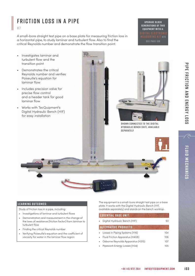
The equipment is a small-bore straight test pipe on a baseplate. It works with the Digital Hydraulic Bench (H1F,available separately) and stands on the bench worktop.
• Digital Hydraulic Bench (H1F) 93
• Losses in Piping Systems (H16) 104• Fluid Friction Apparatus (H408) 106• Osborne Reynolds Apparatus (H215) 107• Pipework Energy Losses (H34) 105
e s s e n t ial bas e u n i t:
alt e r nat i v e p r o d u c t s :
+ 4 4 1 1 5 9 7 2 2 6 1 1 I N F O @ T E C Q U I P M E N T. C O M 1 0 3
Fluid MechanicsPipe friction and energy loss
L E A R N I N G O U T C O M E S :Study of friction loss in a pipe, including: • Investigations of laminar and turbulent flows• Demonstration and measurement in the change of
the laws of resistance (friction factor) from laminar toturbulent flow
• Finding the critical Reynolds number• Verifying Poiseuille’s equation and the coefficient of
viscosity for water in the laminar flow region
S h o w n c o n n e c t e d t o t h e D i g i ta lH y d r a u l i c B e n c h ( H 1 F ) , ava i l a b l es e pa r at e ly
F r i c t i o n L o s s i n a P i p eH 7
A small-bore straight test pipe on a base plate for measuring friction loss ina horizontal pipe, to study laminar and turbulent flow. Also to find thecritical Reynolds number and demonstrate the flow transition point.
• Investigates laminar andturbulent flow and thetransition point
• Demonstrates the criticalReynolds number and verifiesPoiseuille’s equation forlaminar flow
• Includes precision valve forprecise flow control and a header tank for goodlaminar flow
• Works with TecQuipment’sDigital Hydraulic Bench (H1F) for easy installation
U p g r a d e o l d e rg e n e r at i o n s o f t h i s
e q u i p m e n t w i t h a :d i g i ta l e l e c t r o n i cm e a s u r i n g k i t H 7 x
s e e pa g e 1 0 9

T E C Q U I P M E N T. C O M1 0 4
Flui
d Me
chan
ics
Pipe
fri
ctio
n an
d en
ergy
los
s
L o s s e s i n P i p i n g S y s t e m sH 1 6
Free-standing, mobile apparatus demonstrates pressure losses in several small-bore pipe circuit components, typical of those found in central heating systems.
• Includes two colour-coded water circuits
• Works with TecQuipment’s Digital HydraulicBench for easy installation
• Includes different pipe bends and valves forstudents to compare losses
• Fitted with a range of piezometers and apressure gauge to give accurate pressuremeasurement
• Optional roughened pipe ancillary toinvestigate flow characteristics in aroughened pipe
The Losses in Piping Systems apparatus comprises avertical panel with two separate hydraulic circuits, colour-coded for clarity. Each circuit includes various pipe systemcomponents. The unit has wheels for mobility.
L E A R N I N G O U T C O M E S :A comprehensive range of investigations into losses in avariety of pipes and pipe system components, including:• Straight pipe loss• Sudden expansion• Sudden contraction• Bends with different radii• Valves• Elbows• Flow in a roughened pipe (needs the optional H16p
Roughened Pipe)
• Digital Hydraulic Bench (H1F) 93
• Roughened Pipe (H16p)
• Friction Loss in a Pipe (H7) 103• Pipework Energy Losses (H34) 105• Fluid Friction Apparatus (H408) 106
e s s e n t ial bas e u n i t:
alt e r nat i v e p r o d u c t s :
R E C O M M E N D E D AN C I L LAR I E S :
U p g r a d e o l d e rg e n e r at i o n s o f t h i s
e q u i p m e n t w i t h a :d i g i ta l e l e c t r o n i cm e a s u r i n g k i t H 1 6 x
s e e pa g e 1 0 9
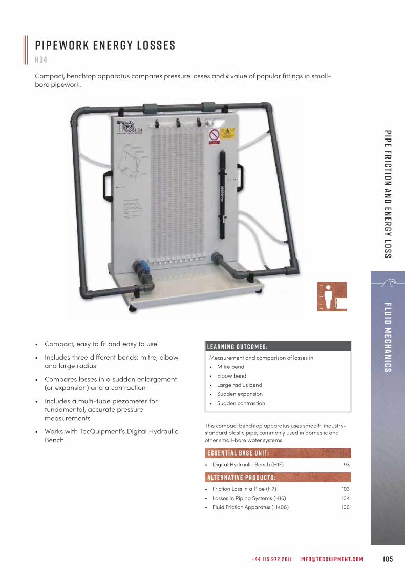
+ 4 4 1 1 5 9 7 2 2 6 1 1 I N F O @ T E C Q U I P M E N T. C O M 1 0 5
Fluid MechanicsPipe friction and energy loss
This compact benchtop apparatus uses smooth, industry-standard plastic pipe, commonly used in domestic andother small-bore water systems.
• Digital Hydraulic Bench (H1F) 93
• Friction Loss in a Pipe (H7) 103• Losses in Piping Systems (H16) 104• Fluid Friction Apparatus (H408) 106
e s s e n t ial bas e u n i t:
alt e r nat i v e p r o d u c t s :
P i p e w o r k E n e r g y L o s s e sH 3 4
Compact, benchtop apparatus compares pressure losses and k value of popular fittings in small-bore pipework.
• Compact, easy to fit and easy to use
• Includes three different bends: mitre, elbowand large radius
• Compares losses in a sudden enlargement(or expansion) and a contraction
• Includes a multi-tube piezometer forfundamental, accurate pressuremeasurements
• Works with TecQuipment’s Digital HydraulicBench
L E A R N I N G O U T C O M E S :Measurement and comparison of losses in: • Mitre bend • Elbow bend • Large radius bend • Sudden expansion • Sudden contraction

T E C Q U I P M E N T. C O M1 0 6
Flui
d Me
chan
ics
Pipe
fri
ctio
n an
d en
ergy
los
s
F l u i d F r i c t i o n A p pa r at u s H 4 0 8
A mobile vertical panel featuring various pipe configurations to demonstrate flow and losses in differentpipes, fittings and valves. Includes Pitot tube, Venturi and orifice meters for flow measurement.
• A space-saving vertical panel that workswith TecQuipment’s Digital Hydraulic Benchfor easy installation
• Includes experiments on roughened pipes
• Uses Bernoulli’s equation
• Demonstrates how to use Venturi and orificemeters to measure flow
• Includes a traversing Pitot tube to measurethe velocity profile
L E A R N I N G O U T C O M E S :• Use of the Pitot static tube• Flow measurement using a Venturi meter and an
orifice meter• Smooth pipes• Artificially roughened pipe• Straight pipe loss• Sudden expansion and contraction• Bends and elbows• Valves• In-line strainer
TecQuipment’s Fluid Friction Apparatus allows students tostudy flow, flow measurement techniques and losses in awide variety of pipes and fittings. The equipment has threewater circuits with instruments, pipes and pipe systemcomponents.
• Digital Hydraulic Bench (H1F) 93
e s s e n t ial bas e u n i t:
• Losses in Piping System (H16) 104• Pipework Energy Losses (H34) 105• Flow Meter Calibration (H40) 101• Flow Measurement Methods (H10) 99• Bernoulli’s Theorem (H5) 98• Friction Loss in a Pipe (H7) 103
alt e r nat i v e p r o d u c t s :

+ 4 4 1 1 5 9 7 2 2 6 1 1 I N F O @ T E C Q U I P M E N T. C O M 1 0 7
Fluid MechanicsLam
inar and Turbulent Flow
The apparatus consists of a precision-bore glass pipe (testtube) held vertically in a large shroud. The shroud is open atthe front and the inside surface is light coloured. This allowsthe students to see the flow clearly.
• Stopwatch (SW1): to measure flow rates 28
E S S E N T IAL AN C I L LAR I E S :
• Heater Module (H215a): free-standing unit to vary andcontrol the water temperature and hence its viscosity
• Friction Loss in a Pipe (H7) 103• Viscosity and Particle Drag (H410) 127
R E C O M M E N D E D AN C I L LAR I E S :
alt e r nat i v e p r o d u c t s :
L E A R N I N G O U T C O M E S :• Demonstration of transition between laminar and
turbulent flow• Determination of transition Reynolds numbers and
comparison with accepted values• Investigation of the effect of varying viscosity, and
demonstration that the Reynolds number attransition is independent of viscosity
O s b o r n e R e y n o l d s A p pa r at u sH 2 1 5
Free-standing apparatus that gives a visual demonstration of laminar and turbulent flow. It also allowsstudents to investigate the effect of varying viscosity and investigate Reynolds numbers.
• Constant head reservoir and diffuser for asmooth flow
• Uses dye injector system to demonstrateflow patterns
• Investigates Reynolds number at transition
• Optional heater module available for testsat different viscosities
O p t i o n a l H e at e r M o d u l e ( H 2 1 5 a )
D y e S t r e a m S h o w i n g L a m i n a r F l o w

T E C Q U I P M E N T. C O M1 0 8
Flui
d Me
chan
ics
Nozz
les
and
Jets
Water flows from the hydraulic bench and into thecylindrical tank through an adjustable diffuser. The flow rateand an overflow pipe set the water level. To change thelevel in the tank (and so the head on the orifice), studentsadjust the flow to the diffuser. Water leaves the tank throughthe orifice. The jet that leaves the orifice discharges backinto the hydraulic bench. The equipment is supplied with aset of interchangeable orifices (nozzles).
• Digital Hydraulic Bench (H1F) 93
• Jet Trajectory and Orifice Flow (H33) 110
e s s e n t ial bas e u n i t:
alt e r nat i v e p r o d u c t s :
S h o w n f i t t e d t o t h e D i g i ta l H y d r a u l i cB e n c h ( H 1 F ) , ava i l a b l e s e pa r at e ly
L E A R N I N G O U T C O M E S :Investigations into a variety of orifices over a range offlow rates, including:• Determination of contraction and velocity
coefficients• Calculation of discharge coefficient• Determination of actual discharge coefficient, and
comparison with calculated values• Determination of the various coefficients over a
range of flow rates to demonstrate the influence ofReynolds number
• Study of the characteristics of different orifices, usinga set of four circular orifices (nozzles). Each has thesame minimum throat diameter but a differentlength. Each has a different approach and dischargesection. Also included are additional square andtriangular orifices.
I n c l u d e s s e to f o r i f i c e s
F l o w T h r o u g h a n O r i f i c eh 4
A cylindrical tank with an adjustable diffuser that demonstrates flowthrough different orifices for different flow rates.
• Direct measurement of total head, head lossand diameter of jet
• Vertical water jet
• Integral Pitot traverse tube
• Sharp-edged orifice included
• Works with TecQuipment’s Digital HydraulicBench for easy installation

+ 4 4 1 1 5 9 7 2 2 6 1 1 I N F O @ T E C Q U I P M E N T. C O M 1 0 9
Fluid MechanicsNozzles and Jets
The Impact of a Jet apparatus demonstrates the forceproduced by a jet of water as it strikes a flat plate orhemispherical cup, which can be compared to themomentum flow rate in the jet. To extend the range ofinvestigations, the 120° conical plate and 30° angled plateare included.
• Digital Hydraulic Bench (H1F) 93
• Pelton Turbine (H19) 133• Pelton Wheel (Turbine) (MFP101b) 145
e s s e n t ial bas e u n i t:
alt e r nat i v e p r o d u c t s :
I m pa c t o f a J e tH 8
A cylindrical tank for investigating the forcegenerated by a jet striking plates (representingturbine vanes) to aid in the understanding of howturbines work.
• Includes flat and hemispherical plates
• Extra angled and conical plates
• Ideal for demonstrations as well as in-depthexperiments
• Works with TecQuipment’s Digital HydraulicBench for easy installation
L E A R N I N G O U T C O M E S :Measurement of the impact force and comparison withmomentum change of four different plates:• Flat plate• Hemispherical plate• Inclined flat plate• 120° conical plate• 30° angled plate
1 2 0 ° C o n i c a l P l at e a n d 3 0 ° A n g l e d P l at e
F eat u r e s : Easy to use with quick-connect couplings Electronic pressure measuring instrument
specification: • Range 0-2 bar • Accuracy 0.15% rdg + 0.1 fs + digit
Be n e f i t s : Health and safety: eliminates the use of mercury, which is widely prohibited from use in the teaching laboratory
Improved accuracy Purchase from maintenance budget
U p g rad e y o u r k i tUpgrade mercury-filled older generation TecQuipment L o s s e s i n P i p i n g S y s t e m s (H16) and F r i c t i o n L o s s i n a P i p e (H7) with upgrade kits (H16x and H7x) and eliminate the use of mercury.

T E C Q U I P M E N T. C O M1 1 0
Flui
d Me
chan
ics
Nozz
les
and
Jets
J e t T r a j e c t o r y a n d O r i f i c e F l o wH 3 3
A constant head device, backboard, set of nozzles and Pitot tube. This apparatus demonstrates verticalflow and horizontal jet trajectories through different orifices (nozzles) and allows students to study thetrajectory profiles of water jets from the nozzles when mounted horizontally.
• Supplied with fourinterchangeable nozzles withdifferent throat (or orifice) designs
• Simple and clear plotting ofhorizontal jet trajectory
• Direct measurement of totalhead, head loss and diameter ofa vertical water jet
• Integral Pitot traverse with bladeto measure head in the verticaljet and diameter of jet
• Works with TecQuipment’s DigitalHydraulic Bench (H1F) for easyinstallation
S h o w n w i t h t h e D i g i ta l H y d r a u l i c B e n c h ( H 1 F ) ,ava i l a b l e s e pa r at e ly
With this apparatus students can measure the decrease inflow, contraction of the stream and energy loss as waterdischarges from four vertically mounted, interchangeablenozzles with different orifice designs.It works with the Digital Hydraulic Bench (H1F, availableseparately) and stands on the bench worktop.
L E A R N I N G O U T C O M E S :• Determination of the contraction and velocity
coefficients• Calculation of the discharge coefficient• Determination of the actual discharge coefficient by
measurement of flow rate• Demonstrates the influence of Reynolds number• Determination of discharge characteristics (jet
trajectory) for an orifice mounted in the side of avertical tank
• Digital Hydraulic Bench (H1F) 93
• Flow Through an Orifice (H4) 108
alt e r nat i v e p r o d u c t s :
e s s e n t ial bas e u n i t:

+ 4 4 1 1 5 9 7 2 2 6 1 1 I N F O @ T E C Q U I P M E N T. C O M 1 1 1
Fluid MechanicsVortices and Cavitation
A transparent vessel on a support frame mounts on aTecQuipment Digital Hydraulic Bench (H1F, availableseparately). A low-voltage, variable speed motor rotatesthe vessel about its vertical axis and a speed-control unitcontrols the speed of rotation.To produce a forced vortex, students add water to therotating vessel until it is about half full. A forced vortexforms. After a few minutes the vortex becomes constant,and students can measure the surface profile using thetraverse probe.
• Digital Hydraulic Bench (H1F) 93
e s s e n t ial bas e u n i t:
• Transparent vessel so users can see thevortices from all angles
• Includes a traverse probe to measure watersurface profile
• Low-voltage, variable speed motor forsafety
• Ideal for classroom demonstrations as wellas laboratory experiments
• Works with TecQuipment’s Digital HydraulicBench (H1F)
L E A R N I N G O U T C O M E S :• Determination of the surface profile of a forced
vortex• Determination of the surface profile of a free vortex• Determination of the total head variation in a forced
vortex• Comparison of results with theoretical predictions
S h o w n w i t h t h e D i g i ta l H y d r a u l i c B e n c h ( H 1 F ) ,ava i l a b l e s e pa r at e ly
V o r t e x A p pa r at u sH 1 3
A transparent, double-walled vessel that demonstrates the phenomena of free and forced vortices withmeasuring devices for calculating the water surface profile.

T E C Q U I P M E N T. C O M1 1 2
Flui
d Me
chan
ics
Vort
ices
and
Cav
itat
ion
C av i tat i o n i n a V e n t u r iH 4 0 0
A floor-standing, self-contained apparatus to demonstrate and observe the basic principles of cavitationand its implications on the performance of hydraulic machines and systems.
• Allows practical and effectivestudy of flow and pressure in aVenturi meter
• Ideal for classroomdemonstrations and studentexperiments
• Fully self-contained recirculatingapparatus, no additional watersupply needed
• Includes full instrumentation, forpressure, flow and temperaturemeasurement
C av i tat i o n i n t h e V e n t u r i
The apparatus is a self-contained, mobile unit. It consists ofa robust frame which holds a water tank (or reservoir), anelectric pump, a flow-control valve, a flow meter and aVenturi.
• Stroboscope (ST1) 313
R E C O M M E N D E D AN C I L LAR I E S :
L E A R N I N G O U T C O M E S :Investigations into cavitation and the Venturi, including: • Flow and pressure in the Venturi• Demonstrations of cavitation • How to predict the onset of cavitation• Study of upstream and throat pressures

L E A R N I N G O U T C O M E S :Various flow visualisation experiments in twodimensions, including sink and source points and flowaround models, for example: • Sources and sinks in a uniform stream• Doublet in a uniform stream• Flow around a cylinder (disc) and an aerofoil• Flow through an orifice and a diffuser• Flow through a heat exchanger• The momentum equation• Laminar flow relationship for flow between two
parallel plates• Mean velocity equations (including seepage in soils) • Potential flow relationships• Allows lecturers to represent flow in other branches
of engineering, such as aerodynamics or electricityand heat flow
+ 4 4 1 1 5 9 7 2 2 6 1 1 I N F O @ T E C Q U I P M E N T. C O M 1 1 3
Fluid MechanicsFlow
Visualisation
The apparatus works with a steady, air-free water supplyand suitable drain. It consists of a channel, formed betweentwo plates, where water flows at a low Reynolds number. Adye flowing through several small holes at the upstreamend produces streamlines. To perform experiments,students start the water flow and open a dye valve justenough to produce easily visible streamlines. They thenuse valves to allow water to flow from a source point ordrain into a sink point, or to set various combinations of flowor sink points.
H e l e - S h aw A p pa r at u sH 9
A benchtop apparatus to demonstrate two-dimensional laminar flow around differently shapedmodels, allowing the study of various source and sink arrangements.
• Visually effective demonstration of a widevariety of flow patterns around differentshapes
• Models easily cut from sheet (included) soalmost any shape possible
• Ideal introduction to incompressiblepotential flow (aerodynamics)
• Source and sink points provided
• Can demonstrate soil seepage problems
• Header Tank (H9a): wall-mounted tank with a floatvalve, overflow and a flow-control valve and pipework
• Flow Visualisation (FC15) 95• Flow Through an Orifice (H4) 108
R E C O M M E N D E D AN C I L LAR I E S :
alt e r nat i v e p r o d u c t s :
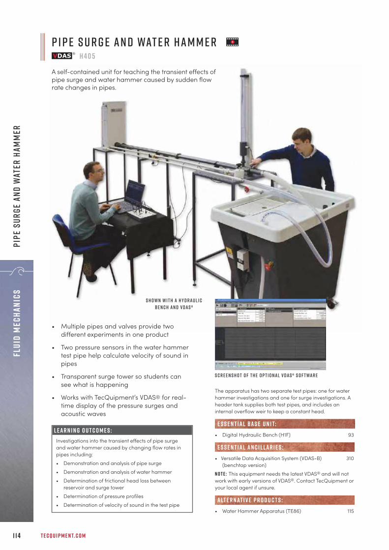
T E C Q U I P M E N T. C O M1 1 4
Flui
d Me
chan
ics
Pipe
Sur
ge a
nd W
ater
Ham
mer
The apparatus has two separate test pipes: one for waterhammer investigations and one for surge investigations. Aheader tank supplies both test pipes, and includes aninternal overflow weir to keep a constant head.
• Digital Hydraulic Bench (H1F) 93
• Versatile Data Acquisition System (VDAS-B) 310(benchtop version)
N o t e : This equipment needs the latest VDAS® and will notwork with early versions of VDAS®. Contact TecQuipment oryour local agent if unsure.
• Water Hammer Apparatus (TE86) 115
alt e r nat i v e p r o d u c t s :
E S S E N T IAL AN C I L LAR I E S :
e s s e n t ial bas e u n i t:
P i p e S u r g e a n d Wat e r H a m m e rh 4 0 5
A self-contained unit for teaching the transient effects ofpipe surge and water hammer caused by sudden flowrate changes in pipes.
L E A R N I N G O U T C O M E S :Investigations into the transient effects of pipe surgeand water hammer caused by changing flow rates inpipes including:• Demonstration and analysis of pipe surge• Demonstration and analysis of water hammer• Determination of frictional head loss between
reservoir and surge tower• Determination of pressure profiles• Determination of velocity of sound in the test pipe
S h o w n w i t h a H y d r a u l i cB e n c h a n d V D A S ®
S c r e e n s h o t o f t h e o p t i o n a l v d A S ® s o f t wa r e
• Multiple pipes and valves provide twodifferent experiments in one product
• Two pressure sensors in the water hammertest pipe help calculate velocity of sound inpipes
• Transparent surge tower so students cansee what is happening
• Works with TecQuipment’s VDAS® for real-time display of the pressure surges andacoustic waves

+ 4 4 1 1 5 9 7 2 2 6 1 1 I N F O @ T E C Q U I P M E N T. C O M 1 1 5
Fluid MechanicsPipe Surge and W
ater Hamm
er
The apparatus is made up of a coil of copper pipe 60 mlong. The inlet connects to a water supply and thedischarge end has a solenoid valve.
• Dual Beam Storage Oscilloscope (H405a) 313
• Pipe Surge and Water Hammer (H405) 114
E S S E N T IAL AN C I L LAR I E S :
alt e r nat i v e p r o d u c t s :
• Illustrates the propagation ofshock waves at sonic velocity inwater
• Demonstrates how to calibratean electronic pressuretransducer
• Includes an electric valve to stopflow instantly
• Contains over 60 m of pipe inone compact unit to save space
• Includes mechanical andelectronic pressuremeasurement
• Includes connectors for extra(optional) equipment fortransient measurements
L E A R N I N G O U T C O M E S :• Water hammer• Propagation of shock waves in water• Velocity of sound in a water filled pipe• Transducer calibration
Wat e r H a m m e r A p pa r at u sT E 8 6
A 60 metre copper coil that demonstrates waterhammer and cavitation and the propagation ofshock waves at sonic velocity in water.
F eat u r e s : Instant display of flow rate in l.min-1 and l.s-1
Comprehensive assembly instructions and drilling templates supplied
Be n e f i t s : Significant time savings for experiments:
for example, save 25 minutes for Bernoulli’s theorem (H5) experiment
Purchase from maintenance budget
U p g rad e y o u r H y d rau l i c be n c hUsing a TecQuipment Gravimetric or Volumetric Hydraulic Bench? It can now be upgraded to include an electronic flow measurement instrument, offering the convenience of the electronic flowmeter display currently found on the D i g i tal H y d rau l i c Be n c h (H1F).

T E C Q U I P M E N T. C O M1 1 6
Flui
d Me
chan
ics
Open
Cha
nnel
Flo
w
2 . 5 M e t r e F l u m eF C 5 0 – 2 . 5
A 53 mm wide, 2.5 metre long flume complete with models and instruments for demonstrating flowaround weirs and other objects in an open channel.
The apparatus consists of a floor-standing 2.5 metre,53 mm wide flume, together with various gates, weirs andblocks, enabling the phenomena of flumes to be easilydemonstrated and studied. The FC50 is TecQuipment’smost compact flume, providing simple installation andflexible storage in the laboratory.
• Digital Hydraulic Bench (H1F) 93
• Sediment Transport Channels (FC80) 118• Flumes (FC300) 120
e s s e n t ial bas e u n i t:
alt e r nat i v e p r o d u c t s :
• Inclinable acrylic channel providingmaximum flow visualisation
• Inlet includes diffuser section to providesteady flow conditions
• Works with TecQuipment’s DigitalHydraulic Bench (H1F) for easy installation
• Includes:
• Depth gauge • Pitot tube • Sharp-crested weir • Sluice gate • Drum gate • Venturi • Broad-crested weir • Sharp broad-crested weir• Crump weir • Calliper gauge
L E A R N I N G O U T C O M E S :• Study of sluice and drum gates including
investigation into hydraulic jump, specific energy andthe determination of discharge coefficient
• Study of sharp-crested and crump weirs revealingthe relationship between head over a weir anddischarge
• Study of a broad-crested weir (by combining thesquare and radius jump blocks) and the effects ofchanging the profile of the weir
• Study of uniform flow in an inclined channel withinvestigations into the Chézy factor and coefficient
• Study of a Venturi flume to indicate the dischargeand surface profile, thus the derivation of thedischarge coefficient
s H O W N W I T H T H E D I G I TA L H Y D R A U L I CB E N C H ( h 1 f ) , AVA I L A B L E S E PA R AT E LY

+ 4 4 1 1 5 9 7 2 2 6 1 1 I N F O @ T E C Q U I P M E N T. C O M 1 1 7
Fluid MechanicsOpen channel flow
F l o w o v e r S h a r p B r o a d - C r e s t e d W e i r
D e p t h G a u g e P i t o t T u b e S h a r p - c r e s t e d W e i r S l u i c e G at e
D r u m G at e V e n t u r i b r o a d - c r e s t e d w e i r S h a r p b r o a d - c r e s t e d w e i r
C r u m p W e i r C a l l i p e r G a u g e
I n c l u d e d w i t h t h e f l u m e :
• Flow Visualisation (FC80di)• Roughened Beds: 2 grades (FC50k)
R E C O M M E N D E D AN C I L LAR I E S :
F l o w V i s u a l i s at i o nF C 5 0 d i
R o u g h e n e d B e d s : t w o g r a d e s F C 5 0 k

The FC80 Flow and Sediment Transport Channel workingsections are 80 mm in width and 250 mm deep. They areavailable in lengths of 2.5 metres and 5 metres. Each flumehas a built-in recirculating water supply connected to adigital flowmeter for accurate measurements duringexperimentation.The models included with each flume are: • Broad-crested weir• Sharp-crested weir• Venturi flume• Two sluice gates
T E C Q U I P M E N T. C O M1 1 8
Flui
d Me
chan
ics
open
Cha
nnel
Flo
w
2 . 5 - m e t r e S e d i m e n t T r a n s p o r t C h a n n e l
F l o w a n d S e d i m e n t T r a n s p o r t C h a n n e l sF C 8 0 ( 2 . 5 a n d 5 )
An 80 mm wide, 2.5 or 5-metre long flow and sediment transport channel with a starter kit of modelsand instruments. It provides students with the ability to study the varying effects of sediment transport,bedform dynamics and fluid flow around weirs and other objects in an open channel.
L E A R N I N G O U T C O M E S :• Investigations in fixed and smooth bedform• Mechanics of sediment transport• Local (bridge) scour experiments, to understand
scour holes and effects on the integrity of a structure• Sluice gates for investigations into hydraulic jump,
specific energy and the determination of dischargecoefficient
• Submerged sharp-crested weir reveals therelationship between head over a weir anddischarge
• A broad-crested weir and the effects of changingthe profile of the weir
• Uniform flow in an inclined channel withinvestigations into the Chezy factor and coefficient
• A Venturi flume to indicate the discharge and surfaceprofile, thus the derivation of the dischargecoefficient
• Includes four models with the flow channelfor experimentation options
• Digital flowmeter for quick and accuratemeasurements
• Transparent sides for clear visibility, ideal forgroup demonstrations
• Stainless steel bed and toughened glasschannel walls, provides long-lasting usewith sedimentation
• Built-in recirculating water supply forconvenient laboratory use
• Includes two bags of graded sand forsediment experiments, e.g. bed formdevelopment or scour
• 2.5 Metre Flume (FC50-2.5) 114• Flumes (FC300) 117
alt e r nat i v e p r o d u c t s :
S u b c r i t i c a l a n d c r i t i c a l f l o w pa s t a P i e r

+ 4 4 1 1 5 9 7 2 2 6 1 1 I N F O @ T E C Q U I P M E N T. C O M
1 1 9
Fluid MechanicsOpen Channel Flow
D r u m G at eF C 8 0 a
R a d i a l S e c t o r G at e F C 8 0 b
S l u i c e G at e a n d D y e K i t F C 8 0 c
C r u m p W e i r F C 8 0 d
D a m S p i l lway F C 8 0 e
S t r e a m l i n e d H u m p F C 8 0 g
pa r s h a l l f l u m e ( r e q u i r e sV e n t u r i s i d e s , i n c l u d e d ) f c 8 0 h
B r i d g e P i e r s ( C y l i n d e r , R o u n d ,S q u a r e , S h a r p N o s e ) F C 8 0 j
R o u g h e n e d B e d s F C 8 0 k
Wav e G e n e r at o r a n d B e a c hF C 8 0 n
s I P H O N s P I L LWAY f c 8 0 L
c U LV E R T M O D E Lf c 8 0 P
F l o w S p l i t t e r F C 8 0 U
F l o w V i s u a l i s at i o nF C 8 0 d i
S e d i m e n t f e e d e rF C 8 0 s f
5 - m e t r eS e d i m e n tT r a n s p o r tC h a n n e l
O p t i o n a l m o d e l s :
R E C O M M E N D E D AN C I L LAR I E S :S h a r p - c r e s t e d w e i r V e n t u r i F l u m e
S l u i c e g at e s B r o a d - c r e s t e d w e i r
F l o w U n d e r a S l u i c e G at e
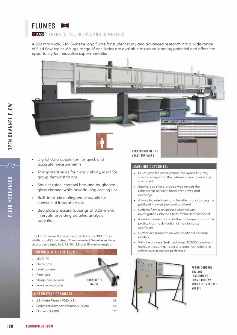
T E C Q U I P M E N T. C O M1 2 0
Flui
d Me
chan
ics
Open
Cha
nnel
Flo
w
The FC300 series flume working sections are 300 mm inwidth and 450 mm deep. They come in 2.5-metre sectionsand are available in 5, 7.5, 10, 12.5 and 15-metre lengths.
• VDAS-FC• Sluice gate• Level gauges• Pitot tube• Sharp-crested weir• Powered end gate
I n c l u d e d w i t h t h e f l u m e :
f l U m e s F C 3 0 0 ( 5 , 7. 5 , 1 0 , 1 2 . 5 a n d 1 5 m e t r e s )
A 300 mm wide, 5 to 15-metre long flume for student study and advanced research into a wide rangeof fluid flow topics. A huge range of ancillaries are available to extend learning potential and offers theopportunity for innovative experimentation.
• 2.5 Metre Flume (FC50-2.5) 116• Sediment Transport Channels (FC80) 118• Flumes (FC600) 122
alt e r nat i v e p r o d u c t s :
• Digital data acquisition for quick andaccurate measurements
• Transparent sides for clear visibility, ideal forgroup demonstrations
• Stainless steel channel bed and toughenedglass channel walls provide long-lasting use
• Built-in re-circulating water supply forconvenient laboratory use
• Bed plate pressure tappings at 0.25-metreintervals, providing detailed analysispotential
F C 3 0 0 C o n t r o lB o x a n dI n s t r u m e n tF r a m e ( s h o w nw i t h t h e i n c l u d e dV D A S ® )
L E A R N I N G O U T C O M E S :• Sluice gate for investigations into hydraulic jump,
specific energy and the determination of dischargecoefficient
• Submerged sharp-crested weir reveals therelationship between head over a weir anddischarge
• A broad-crested weir and the effects of changing theprofile of the weir (optional ancillary)
• Uniform flow in an inclined channel withinvestigations into the Chezy factor and coefficient
• A Venturi flume to indicate the discharge and surfaceprofile, thus the derivation of the dischargecoefficient
• Further experimentation with additional optionalmodels
• With the optional Sediment Loop (FC300sl) sedimenttransport, scouring, ripple and dune formation andsimilar studies can be performed
S c r e e n s h o t o f t h eV D A S ® s o f t wa r e
H o o k d e p t hg a u g e

+ 4 4 1 1 5 9 7 2 2 6 1 1 I N F O @ T E C Q U I P M E N T. C O M 1 2 1
Fluid MechanicsOpen Channel Flow
R a d i a l G at e F C 3 0 0 b
S l u i c e G at e w i t h ta p p i n g sF C 3 0 0 c
C r u m p W e i r F C 3 0 0 d
D a m S p i l lway F C 3 0 0 e
O g e e W e i r w i t h Ta p p i n g sF C 3 0 0 e 2
E n e r g y D i s s i pat i o n F C 3 0 0 e 3
V e n t u r i F l u m e F C 3 0 0 f
Pa r s h a l l F l u m e F C 3 0 0 h
B r i d g e P i e r s : C y l i n d e r , R o u n dA N D S H A R P N o s e , S q u a r e F C 3 0 0 j
Roughened Beds: 2x gravel FC300kSand FC300k2 , Turf FC300k3
S i p h o n S p i l lway F C 3 0 0 l
S e l f - R e g u l at i n g S i p h o n F C 3 0 0 l 2
L i f t a n d D r a g F C 3 0 0 l d
V o r t e x- i n d u c e d v i b r at i o n s F C 3 0 0 m
Wav e G e n e r at o r a n d B e a c hF C 3 0 0 n
C u lv e r t M o d e l F C 3 0 0 p
Rectangular, V-Notch, Cipollettiand Sutro Weirs FC300q
B r o a d C r e s t e d W e i r S : S H A R P A N D S T R E A M L I N E D F C 3 0 0 r
T r a p e z o i d a l F l u m e F C 3 0 0 z
S e d i m e n t L o o p F C 3 0 0 s l
I n s t r u m e n t C a r r i e r F C 3 0 0 i c
Wat e r V e l o c i t y M e t e r F C 3 0 0 x
3 2 -Way P r e s s u r e D i s p l ay F C A1
D i g i ta l I n s t r u m e n t C a r r i e rF C 3 0 0 i c 2
M u lt i -T u b e M a n o m e t e r F C 3 0 0 w
I n s t r u m e n tat i o n :
R E C O M M E N D E D AN C I L LAR I E S :
m o d e l s :

T E C Q U I P M E N T. C O M1 2 2
Flui
d Me
chan
ics
Open
Cha
nnel
Flo
w
F l u m e sF C 6 0 0 ( 8 , 1 0 , 1 2 , 1 4 , 1 6 , 1 8 a n d 2 0 m e t r e s )
A 600 mm wide, 8 to 20-metre long open flow channel for student study and advanced research into awide range of fluid flow topics. A huge range of ancillaries are available to extend learning potentialand offer the opportunity for innovative experimentation.
TecQuipment’s FC600 is a large flume with a workingsection 600 mm wide and 820 mm deep. The channel isavailable in 2 metre lengths between 8 and 20 metres. Forease of operation it is supplied with a touchscreen humanmachine interface (HMI).
I n s t r u m e n tat i o n :• Digital Data Acquisition (VDAS®) for quick and accurate
measurements (requires a PC, not supplied)• Magnetic inductive flow meter, with no internal moving
parts• Instrument frame, supplied to hold electronic boxes• Handheld electronic chlorine meterA c c e s s o r i e s :• Level switch• Log weir• Level gauges• Pitot tube• Sharp-crested weir• Powered end gate
I n c l u d e d w i t h t h e f l u m e :
S h a r p - c r e s t e d w e i r
L o g w e i r
L e v e l G a u g e s
P i t o t T u b e

+ 4 4 1 1 5 9 7 2 2 6 1 1 I N F O @ T E C Q U I P M E N T. C O M 1 2 3
Fluid MechanicsOpen Channel Flow
C o n t i n u e d o n n e x t pa g e
• Sediment Loop (FC600sl)• Sediment Removal System (FC600srs)• Weighing System (FC600ws)I n s t r u m e n tat i o n :• Additional touchscreen human machine interface
(FC600hmi)• Instrument Carrier (FC300ic)• 32-Way Pressure Display (FCA2)• Multi-Tube Manometer (FC600w)• Water Velocity Meter (FC600x)
• 2.5 Metre Flume (FC50-2.5) 116• Sediment Transport Channels (FC80) 118• Flumes (FC300) 120
alt e r nat i v e p r o d u c t s :
R E C O M M E N D E D AN C I L LAR I E S :
3 2 -Way p r e s s u r ed i s p l ay ( F C A 2 )
I n s t r u m e n t C a r r i e r( F C 3 0 0 i c )
M u lt i -T u b eM a n o m e t e r ( F C 6 0 0 w )
Wat e r V e l o c i t y m e t e r( F C 6 0 0 x )
s i z e c o m pa r i s o n o f t h e F l u m e s r a n g e
F C 8 0
F C 3 0 0
F C 6 0 0

T E C Q U I P M E N T. C O M1 2 4
Flui
d Me
chan
ics
Open
Cha
nnel
Flo
w
R a d i a l G at e F C 6 0 0 b S l u i c e G at e ( U n d e r s h o t W e i r ) F C 6 0 0 c C r u m p W e i r F C 6 0 0 d
D a m S p i l lway ( O g e e W e i r ) w i t h ta p p i n g sF C 6 0 0 e
E n e r g y D i s s i pat i o n F C 6 0 0 e 3 V e n t u r i F l u m e F C 6 0 0 f
Pa r s h a l l F l u m e F C 6 0 0 h B r i d g e P i e r s : C y l i n d e r , R o u n d A N D S H A R PN o s e , S q u a r e F C 6 0 0 j
R o u g h e n e d B e d s : 2 x G r av e l F C 6 0 0 kS a n d F C 6 0 0 k 2 , T u r f F C 6 0 0 k 3
S i p h o n S p i l lway F C 6 0 0 l S e l f - R e g u l at i n g S i p h o n F C 6 0 0 l 2 L i f t a n d D r a g F C 6 0 0 l d
V o r t e x- i n d u c e d v i b r at i o n s F C 6 0 0 m Wav e G e n e r at o r a n d B e a c h F C 6 0 0 n C u lv e r t M o d e l F C 6 0 0 p
R e c ta n g u l a r , V- N o t c h , C i p o L l e t t i a n dS u t r o W e i r s F C 6 0 0 q
B r o a d - C r e s t e d W e i r s : S h a r p a n dS t r e a m l i n e d F C 6 0 0 r
T r a p e z o i d a l F l u m e F C 6 0 0 z
S e d i m e n t L o o p F C 6 0 0 s l
O p t i o n a l m o d e l s :
F C 6 0 0 F l u m e s C o n t i n u e d f r o m P r e v i o u s pa g e
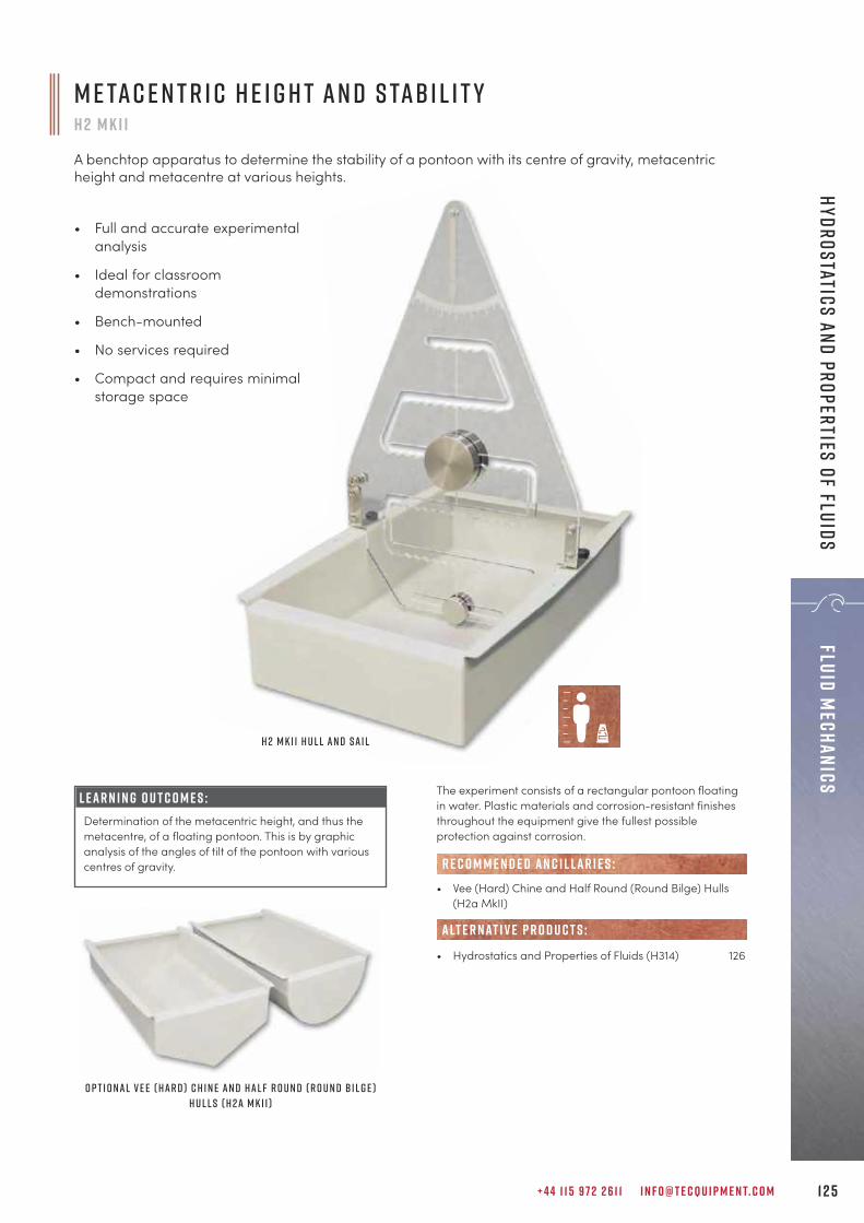
M e ta c e n t r i c H e i g h t a n d S ta b i l i t yh 2 M K I I
A benchtop apparatus to determine the stability of a pontoon with its centre of gravity, metacentricheight and metacentre at various heights.
• Full and accurate experimentalanalysis
• Ideal for classroomdemonstrations
• Bench-mounted
• No services required
• Compact and requires minimalstorage space
+ 4 4 1 1 5 9 7 2 2 6 1 1 I N F O @ T E C Q U I P M E N T. C O M 1 2 5
Fluid MechanicsHydrostatics and properties of fluids
L E A R N I N G O U T C O M E S :Determination of the metacentric height, and thus themetacentre, of a floating pontoon. This is by graphicanalysis of the angles of tilt of the pontoon with variouscentres of gravity.
The experiment consists of a rectangular pontoon floatingin water. Plastic materials and corrosion-resistant finishesthroughout the equipment give the fullest possibleprotection against corrosion.
• Vee (Hard) Chine and Half Round (Round Bilge) Hulls(H2a MkII)
• Hydrostatics and Properties of Fluids (H314) 126
alt e r nat i v e p r o d u c t s :
R E C O M M E N D E D AN C I L LAR I E S :
O p t i o n a l V e e ( H a r d ) C h i n e a n d H a l f R o u n d ( R o u n d B i l g e )H u l l s ( H 2 a M k I I )
H 2 M k I I H u l l a n d S a i l

T E C Q U I P M E N T. C O M1 2 6
Flui
d Me
chan
ics
Hydr
osta
tics
and
pro
pert
ies
of f
luid
s
L E A R N I N G O U T C O M E S :• Determination of fluid density and specific gravity• Principles and use of a hydrometer• Capillarity in tubes and between plates• Measurement of viscosity by falling sphere method• Demonstration of Pascal’s law• Measurement of fluid levels by Vernier hook gauge• Fluid flow head relationship• Verification of Archimedes’ principle and
demonstration of principles of flotation • Stability of a floating body and determination of
metacentric height• Measurement of force and centre of pressure on a
plane surface• Operation and calibration of a Bourdon pressure
gauge• U-tube manometers with fluids of different density
H y d r o s tat i c s a n d P r o p e r t i e s o f F l u i d sh 3 1 4
Self-contained mobile unit for many experiments in fluid mechanics. Among other experiments itcovers: properties of fluids, hydrostatic principles and buoyancy/floatation and Archimedes principle.
• Wide range of experiments
• Determination of fluid propertiesincluding density, specific gravity,surface tension and viscosity
• Demonstration of hydrostatic principles,including Pascal’s law, Archimedes’ principleand determination of pressure at a point ina fluid
• Experiments cover study of buoyancy,flotation and stability of floating bodies,forces on a plane surface, centre ofpressure, operation and calibration of aBourdon pressure gauge and liquid columnmanometers
• Includes integrated Centre of Pressure (H11)and Metacentric Height and Stability (H2 MkII) experiments

+ 4 4 1 1 5 9 7 2 2 6 1 1 I N F O @ T E C Q U I P M E N T. C O M 1 2 7
Fluid MechanicsHydrostatics and properties of fluids
The apparatus consists of a self-contained bench, completewith all necessary equipment for a wide range ofdemonstrations and experiments in hydrostatics andproperties of fluids. Much of the equipment is rigidlymounted on the bench, the remainder being free-standingitems suitable for use on the benchtop.
• Surface Tension Balance (H314a)• Hares Tube (H314b)
• Metacentric Height and Stability (H2 MkII) 125• Calibration of a Bourdon Pressure Gauge (H3a) 95• Centre of Pressure (H11) 128• Pressure Measurement Bench (H30) 100
R E C O M M E N D E D AN C I L LAR I E S :
alt e r nat i v e p r o d u c t s :
S u r fa c e T e n s i o n B a l a n c e ( H 3 1 4 a )
H a r e s t u b e ( H 3 1 4 b )
The self-standing Viscosity and Particle Drag apparatus is asimple falling-sphere viscometer. A back plate holds a glasstube filled with the test fluid.
• Osborne Reynolds Apparatus (H215) 107
alt e r nat i v e p r o d u c t s :
V i s c o s i t y a n d Pa r t i c l e D r a gh 4 1 0
Floor-standing, simple falling sphere viscometer that demonstrates the dragcoefficient of different sized particles (spheres) and the viscosity of liquids.
• Chemically inert, high-quality clearglass tube for use with water andother suitable fluids
• Safe, low-voltage backlighting sostudents can see the falling testspheres through dark fluids (lowtranslucence)
• Includes test spheres of differentsizes and densities to help match arange of test fluids
• Includes stopwatch and timingmarks for accurate results
L E A R N I N G O U T C O M E S :• Determination of the viscosity of different fluids• Determination of the drag coefficient of various
spheres

T E C Q U I P M E N T. C O M1 2 8
Flui
d Me
chan
ics
Hydr
osta
tics
and
pro
pert
ies
of f
luid
s
The equipment consists of a vertical panel that holds a clearplastic quadrant, to which students add water. The planeworks in either a vertical or inclined (angled) position.Students then compare their measurements withtheoretical analysis.
• Hydrostatics and Properties of Fluids (H314) 126
alt e r nat i v e p r o d u c t s :
C e n t r e o f P r e s s u r eh 1 1
A pivoted, clear plastic assembly which students use to find the centre of pressure of a totally or partiallysubmerged plane surface. Compact, self-contained and excellent for classroom demonstrations.
• Compact and self-contained, just needsclean water
• Determines theoreticalcentre of pressure andcompares actual andtheoretical hydrostaticthrust
• Simple but accuratebalance to measuremoment due tohydrostatic thrust
• Tests a vertical andinclined plane surface
L E A R N I N G O U T C O M E S :• Studying the relationship between hydrostatic force
and head of water for a fully and partiallysubmerged vertical and inclined plane
• Comparison of actual and theoretical hydrostaticforce on a fully or partially submerged plane for anygiven head of water
• Theoretical calculation of the position of centre ofpressure on a fully or partially submerged plane
Question
Question
Question
Questionqu e s t i o n
questionQuestion
Question
Que
on
t
on
u
QQQQu
on
Q
i
Answerh e r e t o h e l p y o uA team of specialist customer care personnel are available to answer a range of questions relating to technical details, spare parts and maintenance.
c u s t o m e r . car e@t e cqu i p m e n t. c o m

+ 4 4 1 1 5 9 7 2 2 6 1 1 I N F O @ T E C Q U I P M E N T. C O M 1 2 9
Fluid MechanicsHydrology
L i q u i d S e d i m e n tat i o n A p pa r at u sh 3 1 1
A self-contained, benchtop apparatus of transparent sediment columns for studies into the settlingcharacteristics of suspended solids and the display of particle wall effects.
• Finds settling characteristics andparticle sizes of suspended solids
• Five identical sedimentation columnsfor comparison of different sediments
• Translucent rear panel with backlighting for better visibility
• Includes stopwatch, measuringbeakers and specific gravity bottle
The benchtop apparatus consists of five long, transparentsedimentation columns mounted on a rigid frame.
• Sediment Transport Channel (FC80) 118
alt e r nat i v e p r o d u c t s :
L E A R N I N G O U T C O M E S :• Comparison of settling characteristics of different
sediments• Determination of the effect of concentration on
settling characteristics (hindered settlement)• Determination of velocity distribution curves• Comparison of flocculent and particle
suspensions• Determination of particle size distribution
(grading curve) by liquid sedimentation
Qu i c k d e l i v e r y o n S t o c k P r o d u c t s
TecQuipment holds stocks of the most popular products, ready for speedy shipment across the world.
Contact us to find out what is currently in stock.
Sal e s@t e cqu i p m e n t. c o m
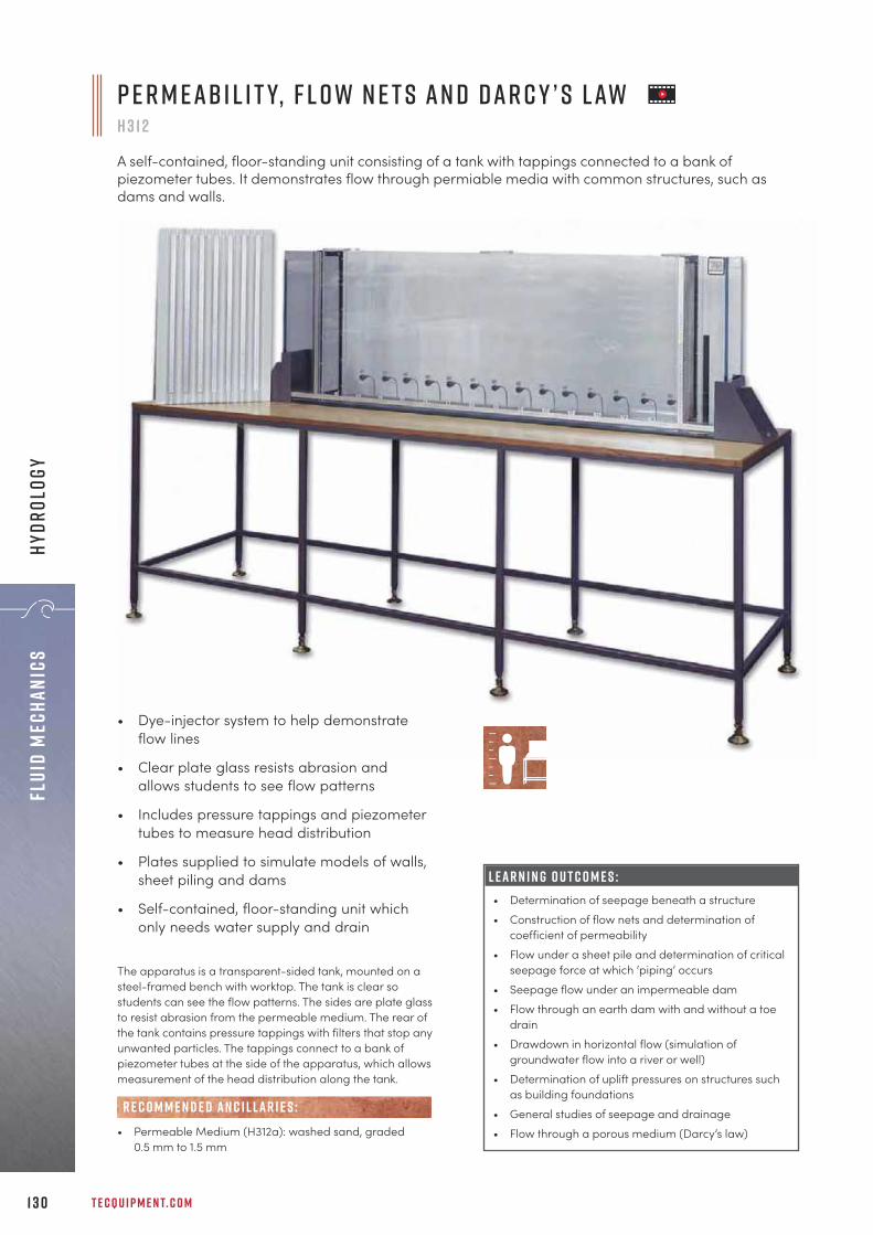
The apparatus is a transparent-sided tank, mounted on asteel-framed bench with worktop. The tank is clear sostudents can see the flow patterns. The sides are plate glassto resist abrasion from the permeable medium. The rear ofthe tank contains pressure tappings with filters that stop anyunwanted particles. The tappings connect to a bank ofpiezometer tubes at the side of the apparatus, which allowsmeasurement of the head distribution along the tank.
• Permeable Medium (H312a): washed sand, graded0.5 mm to 1.5 mm
R E C O M M E N D E D AN C I L LAR I E S :
P e r m e a b i l i t y, F l o w N e t s a n d D a r c y ’ s L awh 3 1 2
A self-contained, floor-standing unit consisting of a tank with tappings connected to a bank ofpiezometer tubes. It demonstrates flow through permiable media with common structures, such asdams and walls.
L E A R N I N G O U T C O M E S :• Determination of seepage beneath a structure • Construction of flow nets and determination of
coefficient of permeability • Flow under a sheet pile and determination of critical
seepage force at which ‘piping’ occurs • Seepage flow under an impermeable dam • Flow through an earth dam with and without a toe
drain • Drawdown in horizontal flow (simulation of
groundwater flow into a river or well) • Determination of uplift pressures on structures such
as building foundations • General studies of seepage and drainage• Flow through a porous medium (Darcy’s law)
• Dye-injector system to help demonstrateflow lines
• Clear plate glass resists abrasion andallows students to see flow patterns
• Includes pressure tappings and piezometertubes to measure head distribution
• Plates supplied to simulate models of walls,sheet piling and dams
• Self-contained, floor-standing unit whichonly needs water supply and drain
T E C Q U I P M E N T. C O M1 3 0
Flui
d Me
chan
ics
Hydr
olog
y
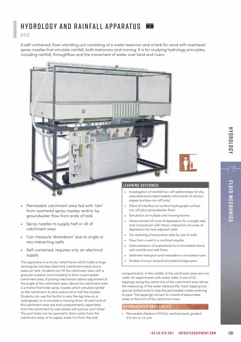
+ 4 4 1 1 5 9 7 2 2 6 1 1 I N F O @ T E C Q U I P M E N T. C O M 1 3 1
Fluid MechanicsHydrology
The apparatus is a sturdy metal frame which holds a largerectangular stainless steel tank (catchment area) and areservoir tank. Students can fill the catchment area with agranular medium (not included) to form a permeablecatchment area. A jacking mechanism allows adjustment ofthe angle of the catchment area. Above the catchment areais a frame that holds spray nozzles which simulate rainfallon the catchment. A valve selects all or half the nozzles.Students can use this facility to vary the lag time on ahydrograph, or to simulate a moving storm. At each end ofthe catchment area are end compartments, separatedfrom the catchment by weir plates with porous ‘port holes’.The port holes can be opened to drain water from thecatchment area, or to supply water to it from the end
H y d r o l o g y a n d R a i n fa l l A p pa r at u s H 3 1 3
A self-contained, floor-standing unit consisting of a water reservoir and a tank for sand with overheadspray nozzles that simulate rainfall, both stationary and moving. It is for studying hydrology principles,including rainfall, throughflow and the movement of water over land and rivers.
• Permeable catchment area fed with ‘rain’from overhead spray nozzles and/or bygroundwater flow from ends of tank
• Spray nozzles to supply half or all ofcatchment area
• Can measure ‘drawdown’ due to single ortwo interacting wells
• Self-contained, requires only an electricalsupply
L E A R N I N G O U T C O M E S :• Investigation of rainfall/run-off relationships for dry,
saturated and impermeable catchments of variousslopes (surface run-off only)
• Effect of interflow on outflow hydrograph surfacerun-off (plus groundwater flow)
• Simulation of multiple and moving storms• Measurement of cone of depression for a single well,
and comparison with theory interaction of cones ofdepression for two adjacent wells
• De-watering of excavation sites by use of wells• Flow from a well in a confined aquifer• Demonstration of watersheds for a simulated island
with rainfall and well flows• Sediment transport and meanders in simulated rivers• Studies of scour around simulated bridge piers
compartments. In the middle of the catchment area are two‘wells’ for experiments with water wells. A row of 20tappings along the centre line of the catchment area allowsthe measuring of the water table profile. Each tapping hasspecial slotted ends to stop the permeable media enteringits pipe. The tappings connect to a bank of piezometertubes at the front of the catchment area.
• Permeable Medium (H313a): washed sand, graded0.5 mm to 1.5 mm
R E C O M M E N D E D AN C I L LAR I E S :
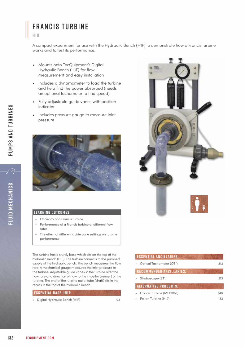
T E C Q U I P M E N T. C O M1 3 2
Flui
d Me
chan
ics
Pum
ps a
nd t
urbi
nes
The turbine has a sturdy base which sits on the top of thehydraulic bench (H1F). The turbine connects to the pumpedsupply of the hydraulic bench. The bench measures the flowrate. A mechanical gauge measures the inlet pressure tothe turbine. Adjustable guide vanes in the turbine alter theflow rate and direction of flow to the impeller (runner) of theturbine. The end of the turbine outlet tube (draft) sits in therecess in the top of the hydraulic bench.
• Digital Hydraulic Bench (H1F) 93
e s s e n t ial bas e u n i t:
F r a n c i s T u r b i n eH 1 8
A compact experiment for use with the Hydraulic Bench (H1F) to demonstrate how a Francis turbineworks and to test its performance.
• Mounts onto TecQuipment’s DigitalHydraulic Bench (H1F) for flowmeasurement and easy installation
• Includes a dynamometer to load the turbineand help find the power absorbed (needsan optional tachometer to find speed)
• Fully adjustable guide vanes with positionindicator
• Includes pressure gauge to measure inletpressure
• Optical Tachometer (OT1) 313
• Stroboscope (ST1) 313
• Francis Turbine (MFP101d) 146• Pelton Turbine (H19) 133
R E C O M M E N D E D AN C I L LAR I E S :
alt e r nat i v e p r o d u c t s :
E S S E N T IAL AN C I L LAR I E S :
L E A R N I N G O U T C O M E S :• Efficiency of a Francis turbine• Performance of a Francis turbine at different flow
rates• The effect of different guide vane settings on turbine
performance

+ 4 4 1 1 5 9 7 2 2 6 1 1 I N F O @ T E C Q U I P M E N T. C O M 1 3 3
Fluid MechanicsPum
ps and turbines
P e lt o n T u r b i n eH 1 9
A compact experiment for use with the Hydraulic Bench (H1F) to demonstrate how a Pelton turbineworks and to test its performance.
• Works with TecQuipment’s Digital HydraulicBench for easy installation
• Includes dynamometer to load the turbineand help find the power absorbed (needsan optional tachometer to find speed)
• Includes pressure gauge to measure inletpressure
• Screw-controlled spear valve for preciseinlet flow control
L E A R N I N G O U T C O M E S :• Performance charts of power, speed, torque and
efficiency• The effect of spear valve position
The product consists of a Pelton wheel mounted in acorrosion-resistant enclosure. A transparent front panelallows students to see the turbine working. An optionalstroboscope (ST1, available separately) can ‘freeze’ theimage of the turbine to help students better understandhow it works. An adjustable spear valve directs a jet ofwater through a nozzle to the buckets of the Pelton wheel tomake it turn. Manual adjustment of the spear valve controlsthe water jet from the nozzle.
• Digital Hydraulic Bench (H1F) 93
• Optical Tachometer (OT1) 313
• Stroboscope (ST1) 313
• Impact of a Jet (H8) 109• Francis Turbine (H18) 132• Pelton Wheel (Turbine) (MFP101b) 145
e s s e n t ial bas e u n i t:
E S S E N T IAL AN C I L LAR I E S :
R E C O M M E N D E D AN C I L LAR I E S :
alt e r nat i v e p r o d u c t s :

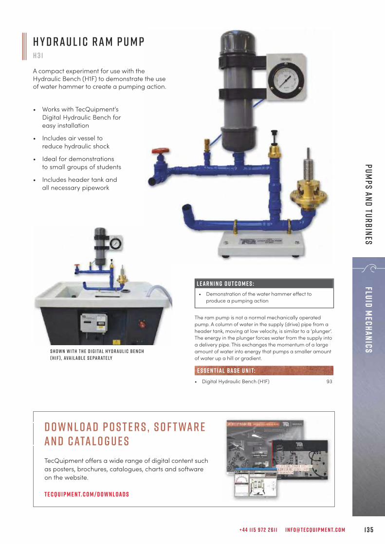
+ 4 4 1 1 5 9 7 2 2 6 1 1 I N F O @ T E C Q U I P M E N T. C O M 1 3 5
Fluid MechanicsPum
ps and Turbines
S h o w n w i t h t h e D i g i ta l H y d r a u l i c B e n c h( H 1 F ) , ava i l a b l e s e pa r at e ly
The ram pump is not a normal mechanically operatedpump. A column of water in the supply (drive) pipe from aheader tank, moving at low velocity, is similar to a ‘plunger’.The energy in the plunger forces water from the supply intoa delivery pipe. This exchanges the momentum of a largeamount of water into energy that pumps a smaller amountof water up a hill or gradient.
• Digital Hydraulic Bench (H1F) 93
e s s e n t ial bas e u n i t:
H y d r a u l i c R a m P u m pH 3 1
A compact experiment for use with theHydraulic Bench (H1F) to demonstrate the useof water hammer to create a pumping action.
• Works with TecQuipment’sDigital Hydraulic Bench foreasy installation
• Includes air vessel toreduce hydraulic shock
• Ideal for demonstrationsto small groups of students
• Includes header tank andall necessary pipework
L E A R N I N G O U T C O M E S :• Demonstration of the water hammer effect to
produce a pumping action
D own l oad P o s t e r s , S o f twar e an d Catal o g u e sTecQuipment offers a wide range of digital content such as posters, brochures, catalogues, charts and software on the website.
T e cqu i p m e n t. c o m / d o w n l oad s

T E C Q U I P M E N T. C O M1 3 6
Flui
d Me
chan
ics
Pum
ps a
nd t
urbi
nes
C e n t r i f u g a l P u m p T e s t S e tH 47
A self-contained, floor-standing, mobile unit consisting of a water reservoir, pump, motor andVenturi meter for a comprehensive range of investigations into the performance andcharacteristics of a centrifugal pump. Demonstrates cavitation and the use of a Venturi tube.
• Pump has a transparent ‘window’ to allowstudents to see clearly its impeller, the waterflow and cavitation
• Demonstrates how to use a Venturi meterand differential pressure measurement tofind flow rate
• Optional stroboscope allows students to seeclearly the effects of cavitation around thepump impeller
• Optional easy-to-read analogueinstrumentation
L E A R N I N G O U T C O M E S :Comprehensive demonstrations and investigations intoa centrifugal pump including:• Centrifugal pump performance and characteristics,
typically head versus flow and efficiency versus flow• Non-dimensional performance characteristics• Flow measurement using a Venturi tube• Demonstration of cavitation
S c r e e n s h o t o f t h e o p t i o n a lV D A S ® s o f t wa r e
T e s t S e t s h o w n w i t h o p t i o n a l V e r s at i l e D ataA c q u i s i t i o n U n i t ( V D A S - F )
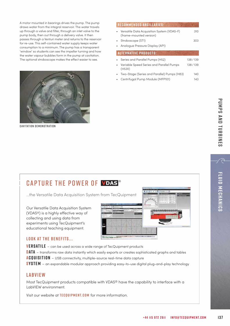
+ 4 4 1 1 5 9 7 2 2 6 1 1 I N F O @ T E C Q U I P M E N T. C O M
• Versatile Data Acquisition System (VDAS-F) 310(frame-mounted version)
• Stroboscope (ST1) 303• Analogue Pressure Display (AP1)
• Series and Parallel Pumps (H52) 138 / 139• Variable Speed Series and Parallel Pumps 138 / 139
(H53V) • Two-Stage (Series and Parallel) Pumps (H83) 140• Centrifugal Pump Module (MFP101) 143
R E C O M M E N D E D AN C I L LAR I E S :
alt e r nat i v e p r o d u c t s :
A motor mounted in bearings drives the pump. The pumpdraws water from the integral reservoir. The water travelsup through a valve and filter, through an inlet valve to thepump body, then out through a delivery valve. It thenpasses through a Venturi meter and returns to the reservoirfor re-use. This self-contained water supply keeps waterconsumption to a minimum. The pump has a transparent‘window’ so students can see the impeller turning and howthe water vapour bubbles form in the pump at cavitation.The optional stroboscope makes the effect easier to see.
C av i tat i o n d e m o n s t r at i o n
1 3 7
Fluid MechanicsPum
ps and turbines
cap t u r e t h e p owe r o f...the Versatile Data Acquisition System from TecQuipment
Our Versatile Data Acquisition System (VDAS®) is a highly effective way of collecting and using data from experiments using TecQuipment’s educational teaching equipment.
L O O K AT T H E BE N E F I T S . . .v e r sat i l e – can be used across a wide range of TecQuipment productsdata – transforms raw data instantly which easily exports or creates sophisticated graphs and tablesacqu i s i t i o n – USB connectivity, multiple-source real-time data captures y s t e m – an expandable modular approach providing easy-to-use digital plug-and-play technology
labv i e wMost TecQuipment products compatible with VDAS® have the capability to interface with a LabVIEW environment.
Visit our website at t e cqu i p m e n t. c o m for more information.

T E C Q U I P M E N T. C O M1 3 8
Flui
d Me
chan
ics
Pum
ps a
nd t
urbi
nes
H 5 2 / H 5 3 V :• Self-contained, compact, benchtop and
easy-to-use test set for a range of experimentsand demonstrations
• Includes two centrifugal pumps
• Easily configurable system to enable pumps to betested individually, in series and in parallel, with amanually adjustable water flow rate
• Long-life, robust valves with large handles allowstudents to change the water circuit in seconds,ready for the next experiment
• Measures intake and delivery pressures
• Discharge flow measurement
H 5 3 V o n ly:• Includes TecQuipment’s Versatile Data Acquisition
System VDAS® Onboard, featuring data acquisitionvia USB
• One of the centrifugal pumps is variable speed andfeatures torque, speed and power measurement
• Additional pressure sensor on variable speedpump inlet
These products both feature two centrifugal pumps.The pumps draw water from the clear acrylicreservoir, where it then travels through a series ofvalves to be delivered to a flow measurementdevice. The water then returns to the reservoir for re-use, keeping water use to a minimum.Both products share a common fundamental design,being self-contained and easily configurable,allowing tests on individual pumps or two pumpsconfigured in series or parallel.The higher specification product (H53V) includesenhanced features such as a variable speed pump,electronic instrumentation and VDAS® Onboard.Speed of the variable pump is measured and theinverter drive calculates torque, allowing a greatervariety of experimentation to be performed.
n e w
Va r i a b l e s p e e d S e r i e s a n d Pa r a l l e l P u m p s ( H 5 3 v )
S e r i e s a n d Pa r a l l e l P u m p sH 5 2 / H 5 3 V
Two benchtop test sets that allow students to investigate the operation and performance of asingle centrifugal pump and two centrifugal pumps configured in series or parallel. The H53Vfeatures a variable speed pump, speed, torque, power measurement and has VDAS® Onboard forautomatic data acquisition.
H 5 3 V C o n t r o l u n i t

+ 4 4 1 1 5 9 7 2 2 6 1 1 I N F O @ T E C Q U I P M E N T. C O M 1 3 9
Fluid MechanicsPum
ps and turbines
L E A R N I N G O U T C O M E S :H 5 2 / H 5 3 V : Comprehensive demonstrations and investigations intoa centrifugal pump including:• Centrifugal pump performance and characteristics,
typically: head versus flow rate and efficiency versusflow rate
• Operation of centrifugal pumps in series• Operation of centrifugal pumps in parallel• Suction tests of a single pump• Demonstration of cavitation• Dertermination of water horsepower (WHP)H 5 3 V o n ly:• Determination of pump shaft power from measured
parameters• Development of pump characteristic curves such as
efficiency, shaft and hydralic power over the rangeof pump speeds
• Understanding energy balance in centrifugal pumps
C o n t r o l u n i t
• Stroboscope (ST1) 313
• Centrifugal Pump Test Set (H47) 136• Two-Stage (Series and Parallel) Pumps (H83) 140• Centrifugal Pump Module (MFP101) 143
alt e r nat i v e p r o d u c t s :
R E C O M M E N D E D AN C I L LAR I E S :
S e r i e s a n d Pa r a l l e l P u m p s ( H 5 2 )
F e at u r e s : H 5 2 H 5 3 V
Two centrifugal pumps Identical fixed speed pumps One variable speed, one fixed speed
Configurable in series and parallel ü üDemonstrates cavitation ü üPressure measurement Three analogue pressure gauges Four electronic pressure sensors
Discharge flow measurement Rotameter Electronic flow sensor
Speed, torque and power measurement û üVariable speed pump features electronic speed
pickup, torque calculated by motor drive
Water temperature measurement û üElectronic display of all parameters û üData acquisition û ü
Includes TecQuipment's Versatile DataAcquisition System, VDAS® Onboard
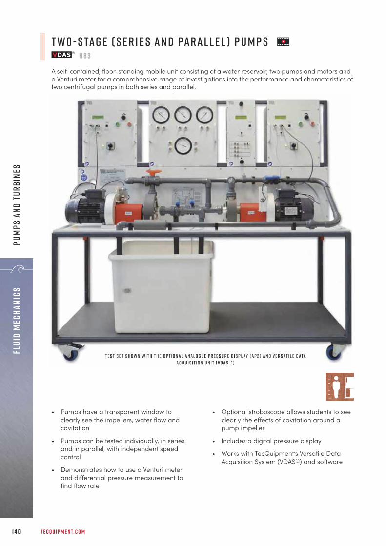
T E C Q U I P M E N T. C O M1 4 0
Flui
d Me
chan
ics
Pum
ps a
nd t
urbi
nes
T w o - S ta g e ( S e r i e s a n d Pa r a l l e l ) P u m p sH 8 3
A self-contained, floor-standing mobile unit consisting of a water reservoir, two pumps and motors anda Venturi meter for a comprehensive range of investigations into the performance and characteristics oftwo centrifugal pumps in both series and parallel.
T e s t s e t s h o w n w i t h t h e O p t i o n a l A n a l o g u e P r e s s u r e D i s p l ay ( A P 2 ) a n d V e r s at i l e D ataA c q u i s i t i o n U n i t ( V D A S - F )
• Pumps have a transparent window toclearly see the impellers, water flow andcavitation
• Pumps can be tested individually, in seriesand in parallel, with independent speedcontrol
• Demonstrates how to use a Venturi meterand differential pressure measurement tofind flow rate
• Optional stroboscope allows students to seeclearly the effects of cavitation around apump impeller
• Includes a digital pressure display
• Works with TecQuipment’s Versatile DataAcquisition System (VDAS®) and software

+ 4 4 1 1 5 9 7 2 2 6 1 1 I N F O @ T E C Q U I P M E N T. C O M 1 4 1
Fluid MechanicsPum
ps and turbines
L E A R N I N G O U T C O M E S :Comprehensive demonstrations and investigations intoa centrifugal pump including:• Centrifugal pump performance and characteristics,
typically head versus flow and efficiency versus flow• Non-dimensional performance characteristics• Flow measurement using a Venturi tube• Demonstration of cavitation• Operation of centrifugal pumps in series• Operation of centrifugal pumps in parallel
S c r e e n s h o t o f t h e o p t i o n a l V D A S ® s o f t wa r e
Two bearing-mounted motors drive each pumpindependently. The pumps draw water from the integralreservoir. The water travels through strainers and a series ofvalves to be delivered to a Venturi meter. The water thenreturns to the reservoir for re-use, keeping water use to aminimum. The pumps each have a transparent ‘window’ sostudents can see the impeller turning and how the watervapour bubbles form in the pump at cavitation. Theoptional stroboscope makes the effect easier to see.
• Versatile Data Acquisition System (VDAS-F) 310(frame-mounted version)
• Stroboscope (ST1) 313• Analogue Pressure Display (AP2)
• Centrifugal Pump Test Set (H47) 136• Series and Parallel Pumps (H52) 138• Centrifugal Pump Module (MFP101) 143
R E C O M M E N D E D AN C I L LAR I E S :
alt e r nat i v e p r o d u c t s :
M o r e i n f o r mat i o nDatasheets contain full specifications such as size, weight, noise output, fluid capacity, voltage requirements etc. Download from each individual product webpage:
t e cqu i p m e n t. c o m (search product)
DAtas h e e t s
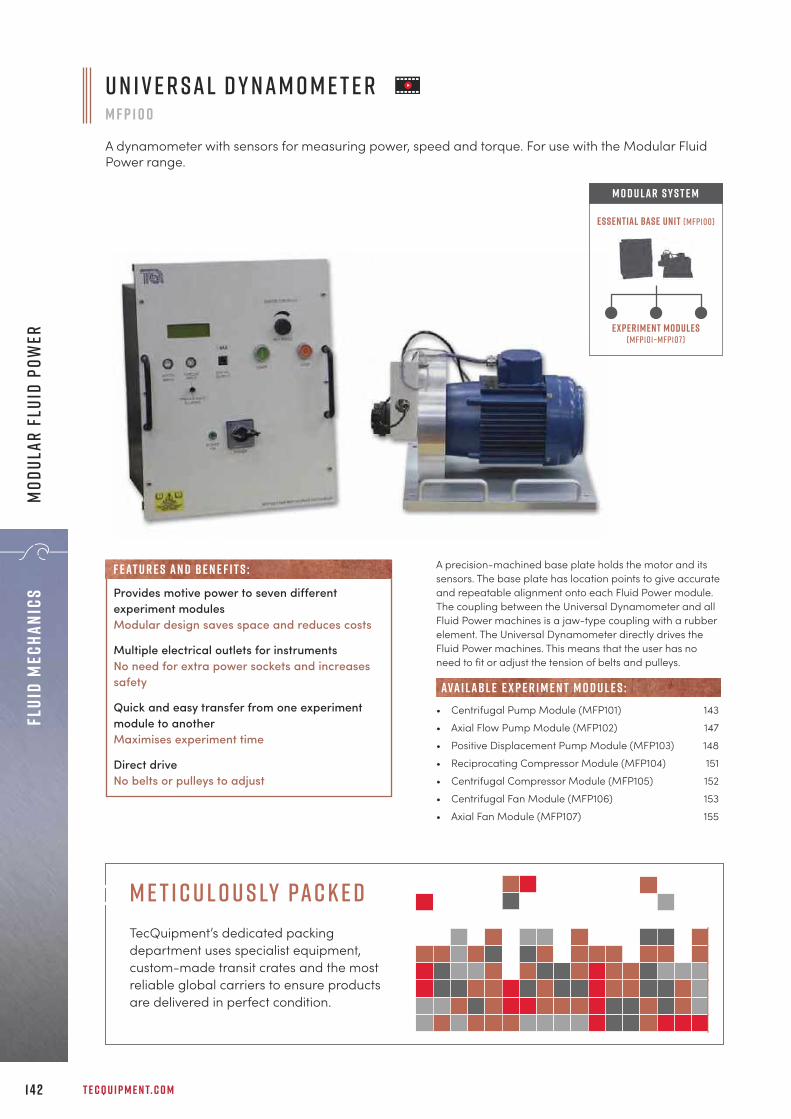
T E C Q U I P M E N T. C O M1 4 2
Flui
d Me
chan
ics
Mod
ular
Flu
id P
ower
A precision-machined base plate holds the motor and itssensors. The base plate has location points to give accurateand repeatable alignment onto each Fluid Power module.The coupling between the Universal Dynamometer and allFluid Power machines is a jaw-type coupling with a rubberelement. The Universal Dynamometer directly drives theFluid Power machines. This means that the user has noneed to fit or adjust the tension of belts and pulleys.
• Centrifugal Pump Module (MFP101) 143• Axial Flow Pump Module (MFP102) 147• Positive Displacement Pump Module (MFP103) 148• Reciprocating Compressor Module (MFP104) 151• Centrifugal Compressor Module (MFP105) 152• Centrifugal Fan Module (MFP106) 153• Axial Fan Module (MFP107) 155
ava i labl e e x p e r i m e n t m o d u l e s :
U n i v e r s a l D y n a m o m e t e rM F P 1 0 0
A dynamometer with sensors for measuring power, speed and torque. For use with the Modular FluidPower range.
Experiment modules(mfp101–mfp107)
Essential Base Unit (mfp100)
M O D U LAR S Y S T E M
Provides motive power to seven differentexperiment modulesModular design saves space and reduces costs
Multiple electrical outlets for instrumentsNo need for extra power sockets and increasessafety
Quick and easy transfer from one experimentmodule to another Maximises experiment time
Direct driveNo belts or pulleys to adjust
F eat u r e s an d be n e f i t s :
M e t i c u l o u s ly pac k e dTecQuipment’s dedicated packing department uses specialist equipment, custom-made transit crates and the most reliable global carriers to ensure products are delivered in perfect condition.

• Centrifugal pump mounted in mobile framewith full instrumentation
• Part of TecQuipment’s Modular Fluid Powerrange which connects with the UniversalDynamometer (MFP100) as a commonmotive power source, for a cost-effectivesolution
• Inlet and delivery valves for wide range ofoperating conditions
• Turbine dynamometer and turbines(available separately): propeller, Francisand Pelton
+ 4 4 1 1 5 9 7 2 2 6 1 1 I N F O @ T E C Q U I P M E N T. C O M 1 4 3
Fluid MechanicsM
odular Fluid Power
L E A R N I N G O U T C O M E S :• Centrifugal pump performance and characteristics,
typically head against flow and efficiency againstflow
• Variation of pump performance with inlet pressure• Variation of pump performance with speed• Non-dimensional performance characteristics• Flow measurement using a Venturi tube
C e n t r i f u g a l P u m p M o d u l eM F P 1 0 1
A self-contained, floor-standing mobile unit with full instrumentation for studying and performing testson a centrifugal pump and optional turbines, to understand how they work and calculate performance.
S h o w n f i t t e d w i t h t h e U n i v e r s a l D y n a m o m e t e r ( M F P 1 0 0 ) , T u r b i n e D y n a m o m e t e r ( M F P 1 0 1 a ) a n da n d P e lt o n W h e e l T u r b i n e ( M F P 1 0 1 b )
C o n t i n u e d o n n e x t pa g e

T E C Q U I P M E N T. C O M1 4 4
Flui
d Me
chan
ics
Mod
ular
Flu
id P
ower
S c r e e n s h o t o f t h e o p t i o n a l V D A S ® s o f t wa r e
The module includes a centrifugal pump, a Venturiflowmeter, valves, a reservoir and instrumentation, allmounted on a robust, mobile trolley for ease of use. Theseparate Universal Dynamometer (MFP100) measures anddisplays the speed and torque of the pump to calculate anddisplay mechanical (shaft) power. Electronic pressuretransducers measure the pump inlet and delivery pressuresand the Venturi differential pressure (flow rate). Speed isfully variable up to the maximum allowable for the pump.
• Universal Dynamometer (MFP100) 142
• Pelton Wheel (Turbine) (MFP101b) 145• Propeller Turbine (MFP101c) 145• Francis Turbine (MFP101d) 146n o t e : The above turbines require a Turbine Dynamometer (MFP101a)
• Versatile Data Acquisition System (VDAS-F) 310(frame-mounted version)
• Stroboscope (ST1) 313
• Centrifugal Pump Test Set (H47) 136• Series and Parallel Pumps (H52) 138 / 139• Variable Speed Series and Parallel Pumps 138 / 139
(H53V) • Two-Stage (Series and Parallel) Pumps (H83) 140
ava i labl e e x p e r i m e n t m o d u l e s :
R E C O M M E N D E D AN C I L LAR I E S :
alt e r nat i v e p r o d u c t s :
e s s e n t ial bas e u n i t:
T u r b i n e D y n a m o m e t e rM F P 1 0 1 a
Dynamometer for the turbines of the Centrifugal Pump Module (MFP101).
• Dynamometer that fits on the CentrifugalPump Module to test the optional turbines
• Electrically powered from outlets on theUniversal Dynamometer motor drive
• Measures and displays torque, speed andshaft power
• Can connect to TecQuipment’s VersatileData Acquisition System (VDAS®)
The Turbine Dynamometer is required for tests on theoptional turbines. It fits on the Centrifugal Pump Module(MFP101), near the outlet end of the centrifugal pump. Fitany of the three optional turbines to the TurbineDynamometer. Each turbine has a brake drum that fitsinside the dynamometer.
• Pelton Wheel (MFP101b) 145• Propeller Turbine (MFP101c) 145• Francis Turbine (MFP101d) 146N o t e : Only one Turbine Dynamometer is needed to test all three turbines.
AN C I L LAR Y F O R :
c e n t r i f u g a l p u m p m o d u l e ( M F P 1 0 1 ) c o n t i n u e d f r o m p r e v i o u s pa g e

+ 4 4 1 1 5 9 7 2 2 6 1 1 I N F O @ T E C Q U I P M E N T. C O M 1 4 5
Fluid MechanicsM
odular Fluid Power
P e lt o n W h e e l ( T u r b i n e )M F P 1 0 1 b
Impulse turbine for use with the Centrifugal Pump Module (MFP101).
• Optional turbine that fits on the TurbineDynamometer (MFP101a) of theCentrifugal Pump Module (MFP101)
• Impulse turbine
• Variable spear jet
L E A R N I N G O U T C O M E S :• Variation of turbine performance with inlet
pressure and flow rate• Variation of turbine performance with speed• Non-dimensional performance
characteristics
The Pelton wheel has a large wheel or ‘runner’ that has‘buckets’ (turbine blades) that absorb the energy in thewater. The buckets are in pairs to correctly balance thewheel and to work efficiently. The Pelton wheel has avariable spear jet at its inlet. This allows students tounderstand the effect of changing the velocity of the waterthat hits the buckets. A clear viewing window on the side ofthe turbine allows students to see how the turbine works.
• Centrifugal Pump Module (MFP101) 143(with Universal Dynamometer MFP100) 142
• Turbine Dynamometer (MFP101a) 144
• Impact of a Jet (H8) 109• Pelton Turbine (H19) 133
e s s e n t ial bas e u n i t:
E S S E N T IAL AN C I L LAR I E S :
alt e r nat i v e p r o d u c t s :
P r o p e l l e r T u r b i n eM F P 1 0 1 c
Propeller turbine for use with theCentrifugal Pump Module (MFP101).
• Optional turbine that fits on theTurbine Dynamometer (MFP101a)of the Centrifugal Pump Module(MFP101)
• Inward flow reaction turbine
• Four-blade propeller
• Fully adjustable guide vanes
The turbine has adjustable guide vanes that control thewater flow in the turbine. They also direct the water at anangle to the back of the propeller. Students learn how theguide vane setting affects how the turbine works. Theturbine has a clear viewing window around the guidevanes and a clear draft tube so that students can see theturbine working.
• Centrifugal Pump Module (MFP101) 143(with Universal Dynamometer MFP100) 142
• Turbine Dynamometer (MFP101a) 144
e s s e n t ial bas e u n i t:
E S S E N T IAL AN C I L LAR I E S :
L E A R N I N G O U T C O M E S :• Variation of turbine performance with inlet pressure
and flow rate• Variation of turbine performance with speed• Non-dimensional performance characteristics
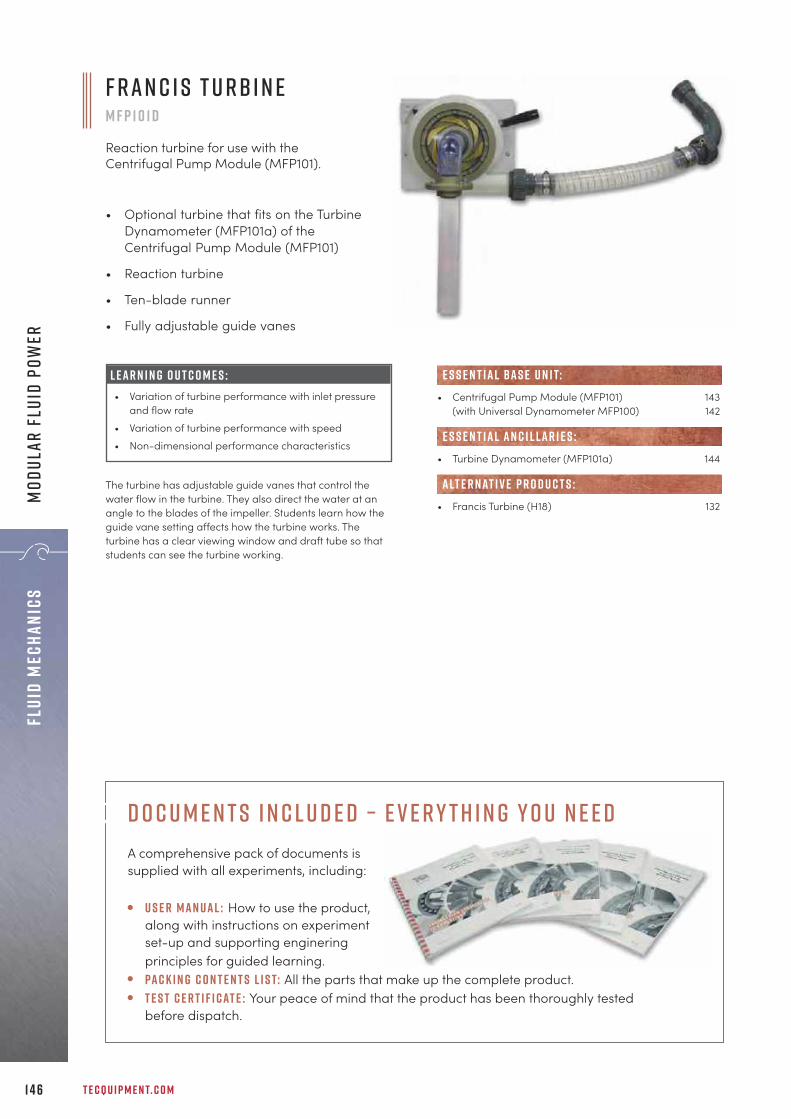
T E C Q U I P M E N T. C O M
F r a n c i s T u r b i n e M F P 1 0 1 d
Reaction turbine for use with theCentrifugal Pump Module (MFP101).
• Optional turbine that fits on the TurbineDynamometer (MFP101a) of theCentrifugal Pump Module (MFP101)
• Reaction turbine
• Ten-blade runner
• Fully adjustable guide vanes
The turbine has adjustable guide vanes that control thewater flow in the turbine. They also direct the water at anangle to the blades of the impeller. Students learn how theguide vane setting affects how the turbine works. Theturbine has a clear viewing window and draft tube so thatstudents can see the turbine working.
• Centrifugal Pump Module (MFP101) 143(with Universal Dynamometer MFP100) 142
• Turbine Dynamometer (MFP101a) 144
• Francis Turbine (H18) 132
e s s e n t ial bas e u n i t:
E S S E N T IAL AN C I L LAR I E S :
alt e r nat i v e p r o d u c t s :
L E A R N I N G O U T C O M E S :• Variation of turbine performance with inlet pressure
and flow rate• Variation of turbine performance with speed• Non-dimensional performance characteristics
1 4 6
Flui
d Me
chan
ics
Mod
ular
Flu
id P
ower
D o c u m e n t s I n c l u d e d – E v e r y t h i n g Y o u N e e dA comprehensive pack of documents is supplied with all experiments, including:
U s e r Man ual : How to use the product, along with instructions on experiment set-up and supporting enginering principles for guided learning. Pac k i n g c o n t e n t s l i s t: All the parts that make up the complete product. T e s t c e r t i f i cat e : Your peace of mind that the product has been thoroughly tested before dispatch.

+ 4 4 1 1 5 9 7 2 2 6 1 1 I N F O @ T E C Q U I P M E N T. C O M 1 47
Fluid MechanicsM
odular Fluid Power
The pump fitted to this module has two sections: one fixedand one moving, each with a set of blades. Water movesfrom a water tank through a calibrated nozzle. It thenpasses through the pump and down to a fully adjustabledelivery valve. It then returns to the water tank. The deliveryvalve allows the user to gradually shut the downstreamwater flow for a range of pump performance tests.
• Universal Dynamometer (MFP100) 142
• Versatile Data Acquisition System (VDAS-F) 310(frame-mounted version)
e s s e n t ial bas e u n i t:
R E C O M M E N D E D AN C I L LAR I E S :
• Axial flow pump, mounted in amobile frame with full instrumentation,including a digital pressure display
• Self-contained, has its own water reservoirand needs no external water supply
• Part of TecQuipment’s Modular Fluid Powerrange which connects with the UniversalDynamometer (MFP100) as a commonmotive power source for a cost-effectivesolution
• Connection plate with schematic diagramshows the water flow circuit and how partsof the module connect to each other
A x i a l F l o w P u m p M o d u l eM F P 1 0 2
A self-contained, floor-standing, mobile unitconsisting of a water reservoir,pump, calibrated nozzle andvalves. It allows students tostudy and perform tests on anaxial flow pump, tounderstand how it works andcalculate its performance.
S c r e e n s h o t o ft h e o p t i o n a lV D A S ®s o f t wa r e
S h o w n f i t t e d w i t ht h e U n i v e r s a lD y n a m o m e t e r( M F P 1 0 0 )
L E A R N I N G O U T C O M E S :• Variation of pump performance with speed • Variation of pump performance with different outlet
pressures and flow rate• Non-dimensional performance curves• Determination of the specific speed of the pump
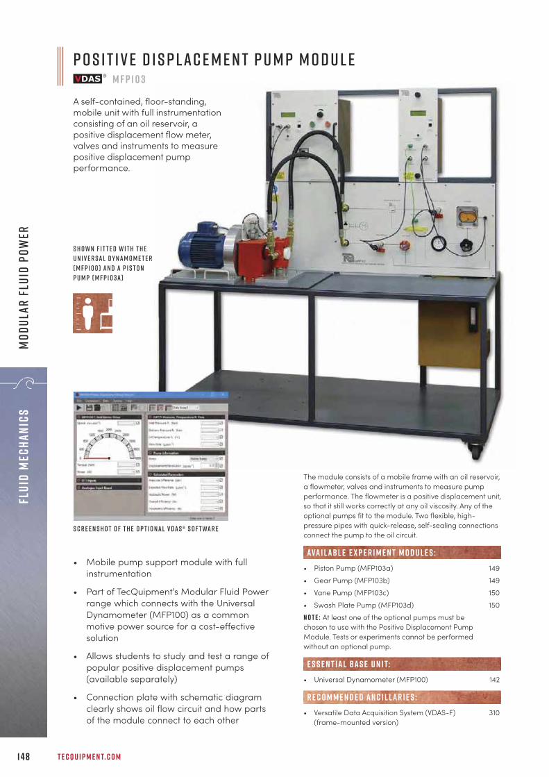
T E C Q U I P M E N T. C O M1 4 8
Flui
d Me
chan
ics
Mod
ular
Flu
id P
ower
• Mobile pump support module with fullinstrumentation
• Part of TecQuipment’s Modular Fluid Powerrange which connects with the UniversalDynamometer (MFP100) as a commonmotive power source for a cost-effectivesolution
• Allows students to study and test a range ofpopular positive displacement pumps(available separately)
• Connection plate with schematic diagramclearly shows oil flow circuit and how partsof the module connect to each other
The module consists of a mobile frame with an oil reservoir,a flowmeter, valves and instruments to measure pumpperformance. The flowmeter is a positive displacement unit,so that it still works correctly at any oil viscosity. Any of theoptional pumps fit to the module. Two flexible, high-pressure pipes with quick-release, self-sealing connectionsconnect the pump to the oil circuit.
• Piston Pump (MFP103a) 149• Gear Pump (MFP103b) 149• Vane Pump (MFP103c) 150• Swash Plate Pump (MFP103d) 150N o t e : At least one of the optional pumps must be chosen to use with the Positive Displacement PumpModule. Tests or experiments cannot be performed without an optional pump.
• Universal Dynamometer (MFP100) 142
• Versatile Data Acquisition System (VDAS-F) 310(frame-mounted version)
e s s e n t ial bas e u n i t:
R E C O M M E N D E D AN C I L LAR I E S :
ava i labl e e x p e r i m e n t m o d u l e s :
P o s i t i v e D i s p l a c e m e n t P u m p M o d u l eM F P 1 0 3
A self-contained, floor-standing,mobile unit with full instrumentationconsisting of an oil reservoir, apositive displacement flow meter,valves and instruments to measurepositive displacement pumpperformance.
S c r e e n s h o t o f t h e o p t i o n a l V D A S ® s o f t wa r e
S h o w n f i t t e d w i t h t h eU n i v e r s a l D y n a m o m e t e r( M F P 1 0 0 ) a n d a P i s t o nP u m p ( M F P 1 0 3 A )
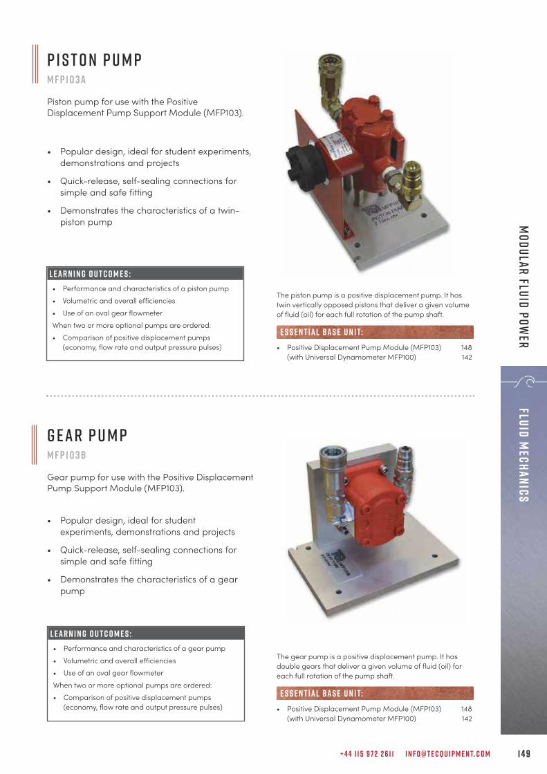
+ 4 4 1 1 5 9 7 2 2 6 1 1 I N F O @ T E C Q U I P M E N T. C O M 1 4 9
Fluid MechanicsM
odular Fluid Power
P i s t o n P u m pM F P 1 0 3 a
Piston pump for use with the PositiveDisplacement Pump Support Module (MFP103).
• Popular design, ideal for student experiments,demonstrations and projects
• Quick-release, self-sealing connections forsimple and safe fitting
• Demonstrates the characteristics of a twin-piston pump
L E A R N I N G O U T C O M E S :• Performance and characteristics of a piston pump• Volumetric and overall efficiencies• Use of an oval gear flowmeterWhen two or more optional pumps are ordered:• Comparison of positive displacement pumps
(economy, flow rate and output pressure pulses)
The piston pump is a positive displacement pump. It hastwin vertically opposed pistons that deliver a given volumeof fluid (oil) for each full rotation of the pump shaft.
• Positive Displacement Pump Module (MFP103) 148(with Universal Dynamometer MFP100) 142
e s s e n t ial bas e u n i t:
G e a r P u m pM F P 1 0 3 b
Gear pump for use with the Positive DisplacementPump Support Module (MFP103).
• Popular design, ideal for studentexperiments, demonstrations and projects
• Quick-release, self-sealing connections forsimple and safe fitting
• Demonstrates the characteristics of a gearpump
L E A R N I N G O U T C O M E S :• Performance and characteristics of a gear pump• Volumetric and overall efficiencies• Use of an oval gear flowmeterWhen two or more optional pumps are ordered:• Comparison of positive displacement pumps
(economy, flow rate and output pressure pulses)
The gear pump is a positive displacement pump. It hasdouble gears that deliver a given volume of fluid (oil) foreach full rotation of the pump shaft.
• Positive Displacement Pump Module (MFP103) 148(with Universal Dynamometer MFP100) 142
e s s e n t ial bas e u n i t:

Va n e P u m pM F P 1 0 3 c
Vane pump for use with the Positive DisplacementPump Support Module (MFP103).
• Popular design, ideal for studentexperiments, demonstrations and projects
• Quick-release, self-sealing connections forsimple and safe fitting
• Demonstrates the characteristics of a vanepump
L E A R N I N G O U T C O M E S :• Performance and characteristics of a vane pump• Volumetric and overall efficiencies• Use of an oval gear flowmeterWhen two or more optional pumps are ordered:• Comparison of positive displacement pumps
(economy, flow rate and output pressure pulses)
The vane pump is a positive displacement pump. It has afixed displacement balanced vane that delivers a givenvolume of fluid (oil) for each full rotation of the pump shaft.
• Positive Displacement Pump Module (MFP103) 148(with Universal Dynamometer MFP100) 142
e s s e n t ial bas e u n i t:
• Popular design, ideal for studentexperiments, demonstrations and projects
• Quick-release, self-sealing connections forsimple and safe fitting
• Demonstrates the characteristics of a swashplate pump
L E A R N I N G O U T C O M E S :• Performance and characteristics of a swash plate
pump• Volumetric and overall efficiencies• Use of an oval gear flowmeterWhen two or more optional pumps are ordered:• Comparison of positive displacement pumps
(economy, flow rate and output pressure pulses)
The Swash Plate Pump is a positive displacement pump. Ithas a fixed displacement axial piston assembly that deliversa given volume of fluid (oil) for each full rotation of thepump shaft.
• Positive Displacement Pump Module (MFP103) 148(with Universal Dynamometer MFP100) 142
e s s e n t ial bas e u n i t:
T E C Q U I P M E N T. C O M1 5 0
Flui
d Me
chan
ics
Mod
ular
Flu
id P
ower
s wa s h p l at e P u m pM F P 1 0 3 d
Swash plate pump for use with the PositiveDisplacement Pump Support Module (MFP103).

+ 4 4 1 1 5 9 7 2 2 6 1 1 I N F O @ T E C Q U I P M E N T. C O M 1 5 1
Fluid MechanicsM
odular Fluid Power
• Reciprocating compressor and air receivermounted in a mobile frame with fullinstrumentation
• Allows students to study and test a popularfluid power machine
• Temperature and pressure measurementsat key points in the system
• Connection plate with schematic diagramclearly shows how parts of the moduleconnect together
L E A R N I N G O U T C O M E S :• Energy balance for a compressor• Variation of compressor performance with pressure• Variation of compressor performance with speed• Mechanical, volumetric and isothermal efficiencies• Thermodynamics of a compressor
R e c i p r o c at i n g C o m p r e s s o r M o d u l eM F P 1 0 4
A self-contained, floor-standing, mobileunit that includes a small compressor withan air receiver and instrumentation. Itallows students to study and perform testson a reciprocating compressor, tounderstand how it works and calculate itsperformance.
S c r e e n s h o t o f t h eo p t i o n a l V D A S ®s o f t wa r e
The module includes a small compressor with an airreceiver and instrumentation, all mounted on a robust,mobile trolley for ease of use. Speed is fully variable up tothe maximum allowable for the compressor. Air enters thecompressor, which then delivers it under pressure to thereceiver. A valve releases pressure from the receiver toatmosphere through an orifice. The valve sets the pressurein the receiver and hence the flow rate; the orifice allows anaccurate measurement of the mass flow rate of the outletair. These values help students to discover how thecompressor flow rate relates to the pressure delivered bythe compressor.
• Universal Dynamometer (MFP100) 142
• Versatile Data Acquisition System (VDAS-F) 310(frame-mounted version)
• Two-Stage Compressor Test Set (GT103) 276
e s s e n t ial bas e u n i t:
R E C O M M E N D E D AN C I L LAR I E S :
alt e r nat i v e p r o d u c t s :
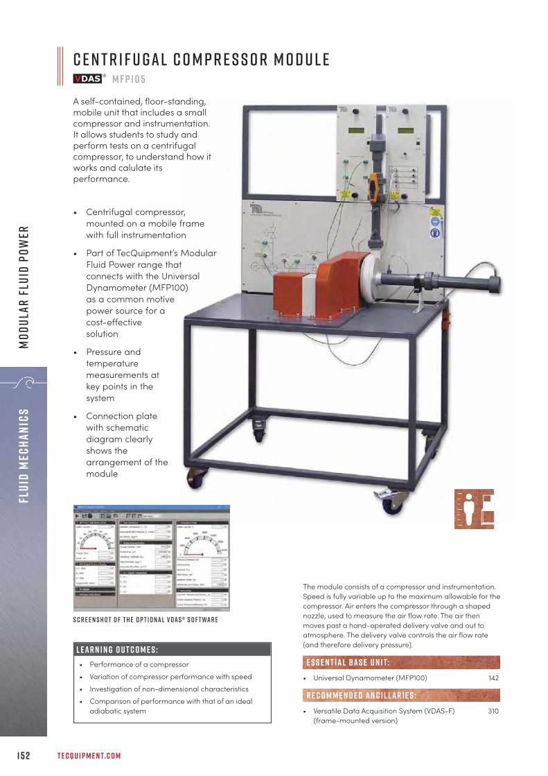
T E C Q U I P M E N T. C O M1 5 2
Flui
d Me
chan
ics
Mod
ular
Flu
id P
ower
• Centrifugal compressor,mounted on a mobile framewith full instrumentation
• Part of TecQuipment’s ModularFluid Power range thatconnects with the UniversalDynamometer (MFP100)as a common motivepower source for acost-effectivesolution
• Pressure andtemperaturemeasurements atkey points in thesystem
• Connection platewith schematicdiagram clearlyshows thearrangement of themodule
C e n t r i f u g a l C o m p r e s s o r M o d u l eM F P 1 0 5
A self-contained, floor-standing,mobile unit that includes a smallcompressor and instrumentation.It allows students to study andperform tests on a centrifugalcompressor, to understand how itworks and calulate itsperformance.
S c r e e n s h o t o f t h e o p t i o n a l V D A S ® s o f t wa r e
The module consists of a compressor and instrumentation.Speed is fully variable up to the maximum allowable for thecompressor. Air enters the compressor through a shapednozzle, used to measure the air flow rate. The air thenmoves past a hand-operated delivery valve and out toatmosphere. The delivery valve controls the air flow rate(and therefore delivery pressure).
• Universal Dynamometer (MFP100) 142
• Versatile Data Acquisition System (VDAS-F) 310(frame-mounted version)
R E C O M M E N D E D AN C I L LAR I E S :
e s s e n t ial bas e u n i t:L E A R N I N G O U T C O M E S :• Performance of a compressor• Variation of compressor performance with speed • Investigation of non-dimensional characteristics• Comparison of performance with that of an ideal
adiabatic system

+ 4 4 1 1 5 9 7 2 2 6 1 1 I N F O @ T E C Q U I P M E N T. C O M 1 5 3
Fluid MechanicsM
odular Fluid Power
L E A R N I N G O U T C O M E S :• Performance of a centrifugal fan• Variation of fan performance with speed • Variation of fan performance with type of impeller• Non-dimensional performance curves• Determination of the specific speed of the fan
C e n t r i f u g a l Fa n M o d u l eM F P 1 0 6
A self-contained, floor-standing,mobile unit that includes a fan andinstrumentation to allow students tostudy and perform tests on acentrifugal fan, to understand how itworks and calculate its performance.
The module consists of a fan and instrumentation. Speed isfully variable up to the maximum allowable for the fan. Airenters the fan through a shaped nozzle, used to measurethe air flow rate. The air then moves past a slide valve andout to atmosphere. The slide valve controls the air flow rate(and therefore delivery pressure). The fan impeller (movingpart) is interchangeable. Supplied with the fan are threedifferent impellers for more tests on fan performance.
• Universal Dynamometer (MFP100) 142
• Versatile Data Acquisition System (VDAS-F) 310(frame-mounted version)
• Pipe Flow and Nozzle Kit (MFP106a) 154
R E C O M M E N D E D AN C I L LAR I E S :
e s s e n t ial bas e u n i t:
• Centrifugal fan, mounted on a mobile frame with fullinstrumentation
• Part of TecQuipment’sModular Fluid Powerrange that connectswith the UniversalDynamometer(MFP100) as acommon motive powersource for a cost-effectivesolution
• Three interchangeableimpellers provided asstandard
• Optional Pipe Flow andNozzle Kit for moreexperiments
S h o w n f i t t e d w i t h t h e U n i v e r s a l D y n a m o m e t e r( M F P 1 0 0 )
S c r e e n s h o t o f t h e o p t i o n a l V D A S ® s o f t wa r e
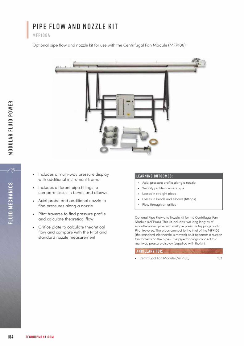
T E C Q U I P M E N T. C O M1 5 4
Flui
d Me
chan
ics
Mod
ular
Flu
id P
ower
• Includes a multi-way pressure displaywith additional instrument frame
• Includes different pipe fittings tocompare losses in bends and elbows
• Axial probe and additional nozzle tofind pressures along a nozzle
• Pitot traverse to find pressure profileand calculate theoretical flow
• Orifice plate to calculate theoreticalflow and compare with the Pitot andstandard nozzle measurement
L E A R N I N G O U T C O M E S :• Axial pressure profile along a nozzle• Velocity profile across a pipe• Losses in straight pipes• Losses in bends and elbows (fittings)• Flow through an orifice
Optional Pipe Flow and Nozzle Kit for the Centrifugal FanModule (MFP106). This kit includes two long lengths ofsmooth-walled pipe with multiple pressure tappings and aPitot traverse. The pipes connect to the inlet of the MFP106(the standard inlet nozzle is moved), so it becomes a suctionfan for tests on the pipes. The pipe tappings connect to amultiway pressure display (supplied with the kit).
• Centrifugal Fan Module (MFP106) 153
AN C I L LAR Y F O R :
P i p e F l o w a n d N o z z l e K i tM F P 1 0 6 a
Optional pipe flow and nozzle kit for use with the Centrifugal Fan Module (MFP106).

+ 4 4 1 1 5 9 7 2 2 6 1 1 I N F O @ T E C Q U I P M E N T. C O M 1 5 5
Fluid MechanicsM
odular Fluid Power
L E A R N I N G O U T C O M E S :• Characteristics of an axial fan, including head
against flow efficiency• Relationship between power and speed (power law)• Velocity distribution in a round duct• Calibration of an inlet nozzle• Duct resistance and matching to fan to find
operating point
A x i a l Fa n M o d u l eM F P 1 0 7
A self-contained, floor-standing, mobile unit that includes an axial fan, duct and instrumentation. Itallows students to study and perform tests on an axial fan, to understand how it works and calculateits performance.
S c r e e n s h o t o f t h e o p t i o n a l V D A S ® s o f t wa r e
The module has an axial fan mounted in a cylindrical steelduct. Air enters the duct through an inlet nozzle. Thepressure at a set of tappings just downstream of the nozzleallows calculation of the inlet air flow rate. A slide valve(downstream of the fan) controls flow rate and deliverypressure. Air exits the duct through a silencer to reducenoise in the laboratory.
• Universal Dynamometer (MFP100) 142
• Pitot Static Traverse, 450 mm (MFP107a) 156• Versatile Data Acquisition System (VDAS-F) 310
(frame-mounted version)
e s s e n t ial bas e u n i t:
R E C O M M E N D E D AN C I L LAR I E S :
S h o w n f i t t e d w i t h t h e U n i v e r s a lD y n a m o m e t e r ( M F P 1 0 0 )
• Part of TecQuipment’s Modular Fluid Powerrange which connects with the UniversalDynamometer (MFP100) as a commonmotive power source for a cost-effectivesolution
• Multiple pressure measurement points alongthe fan duct allow students to examine a fullrange of performance characteristics
• Connection plate with schematic diagramclearly shows air flow circuit and how partsof the module connect to each other
• Traversing, calibrated Pitot tube allowsinvestigations of velocity distribution

T E C Q U I P M E N T. C O M1 5 6
Flui
d Me
chan
ics
Mod
ular
Flu
id P
ower
The Pitot Static Traverse allows students to find the velocitydistribution across the duct of the Axial Fan Module(MFP107). This optional ancillary comprises a Pitot-statictube which fits on the duct of the Axial Fan Module and hasa digital indicator to show the tube position across the duct.
• Axial Fan Module (MFP107) 155
AN C I L LAR Y F O R :
P i t o t S tat i c T r av e r s e , 4 5 0 m m M F P 1 0 7a
A traversing Pitot static tube with electronic positionmeasurement for use with TecQuipment’s Axial FanModule (MFP107)
P lay N ow – T e cQu i p m e n t Y o u T ube C han n e lVisit and subscribe to the TecQuipment YouTube channel for all the latest products showcases, installation and user videos: y o u t ube . c o m / c / t e cqu i p m e n t
YouTube videos available for all products with this icon
T u rbo j e t T ra i n e r w i t h R e h eat ( G T 1 0 0 R S ) H y d r o s tat i c s an d P r o p e r t i e s o f F l u i d s ( H 3 14)
U n i v e r sal T e s t i n g Mac h i n e ( S M 1 0 0 0 ) C e n t r i f u gal P u m p M o d u l e ( M F P 1 0 1 )

+ 4 4 1 1 5 9 7 2 2 6 1 1 I N F O @ T E C Q U I P M E N T. C O M 1 5 7
Materials Testing and properties“For a number of years I have been using TecQuipment equipment at the Institute ofTechnology in Bandung. Now at the Polytechnic Manufacturing Bandung it was a logicalchoice to once again purchase TecQuipment products given our previous positive experienceof working with the company and their local agent in Indonesia, ‘Jitrasindo’. Plus I know fromyears of use that TecQuipment manufactures good quality products.
A s e p I n d r a K o m a r aP o ly t e c h n i c M a n u fa c t u r i n g B a n d u n g , E a s t J ava , I n d o n e s i a
m a t e r i a l s t e s t i n ga n d p r o p e r t i e sb a s i c e l a s t i c p r o p e r t i e s 1 5 9
s t r e s s a n d s t r a i n a n a ly s i s 1 6 1
t o r s i o n t e s t i n g 1 6 6
fat i g u e t e s t i n g 1 6 7
c r e e p t e s t i n g 1 6 8
t e n s i l e a n d u n i v e r s a l t e s t i n g m a c h i n e s 1 6 9
i m pa c t t e s t i n g 1 7 7
i n d u s t r i a l h a r d n e s s t e s t e r s 1 7 9
t e s t s p e c i m e n s 1 8 2
f r e e - s ta n d i n g s t r u c t u r e s e x p e r i m e n t s 1 8 4

T E C Q U I P M E N T. C O M1 5 8
Mate
rial
s Te
stin
g an
d pr
oper
ties
m at e r i a l s t e s t i n g a n d p r o p e r t i e sThe Materials Testing and Properties products offer a widerange of teaching equipment to demonstrate key materials’properties; they cover Hooke’s law and Young’s modulusassociated with elastic properties, and stress/strainanalysis. For more advanced learning, experimentsavailable progress to hardness testing, complex analysis ofstress and strain, testing specimens to destruction andvarious apparatus for learning about material fatigue.The range also extends into the area of structures andstructural elements, providing supplementary products tothe complete modular Structures range (page 185).
L o o k at t h e o t h e r r a n g e s The S t r u c t u r e s (page 195) and E n g i n e e r i n g S c i e n c e(page 5) ranges also include products thatdemonstratehow thechoice ofmaterialsaffects theperformanceof structuralelements.
V D A S ® e n a b l e d P r o d u c t s Pa g e
Thin Cylinder (SM1007) 161
Diaphragm (SM1008) 162
Thick Cylinder (SM1011) 163
Strain Gauge Trainer (SM1009) 164
Digital Strain Display (SM1010) 165
Torsion Testing Machine, 30 Nm (SM1001) 166
Rotating Fatigue Machine (SM1090V) 167
Creep Machine (SM1006) 168
Benchtop Tensile Testing Machine (SM1002) 169
Universal Testing Machine (SM1000) 171
Unsymmetrical Cantilever Apparatus (SM1003) 188
Beam Apparatus (SM1004) 184
Euler Buckling Apparatus (SM1005) 186
A u t o m at i c d ata a c q u i s i t i o nMany of the products in this range work with TecQuipment’s unique Versatile Data Acquisition System (VDAS®), page 310.
r e f i n e d p r o d u c t s : Meets the needs of a modernmaterials course.
b r o a d a n d p r o g r e s s i v e r a n g e o f e x p e r i m e n t s :Teaches the fundamental principles, progressing tocomplex stress and strain analysis.
a u t o m at i c d ata a c q u i s i t i o n : Multiple and fast-changing measurements make data acquisition avaluable tool.
k e y f eat u r e s an d b e n e f i t s :
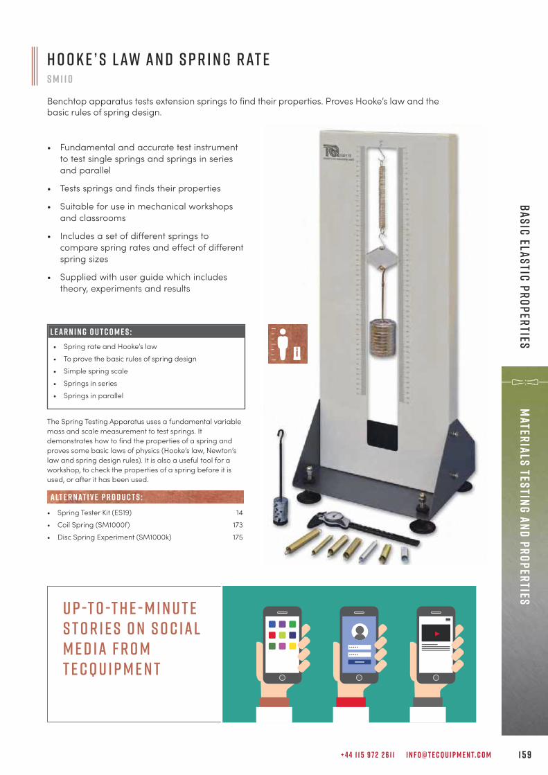
+ 4 4 1 1 5 9 7 2 2 6 1 1 I N F O @ T E C Q U I P M E N T. C O M 1 5 9
Materials Testing and propertiesBasic elastic properties
H o o k e ’ s L aw a n d S p r i n g R at eS M 1 1 0
Benchtop apparatus tests extension springs to find their properties. Proves Hooke’s law and thebasic rules of spring design.
• Fundamental and accurate test instrumentto test single springs and springs in seriesand parallel
• Tests springs and finds their properties
• Suitable for use in mechanical workshopsand classrooms
• Includes a set of different springs tocompare spring rates and effect of differentspring sizes
• Supplied with user guide which includestheory, experiments and results
L E A R N I N G O U T C O M E S :• Spring rate and Hooke’s law• To prove the basic rules of spring design• Simple spring scale• Springs in series• Springs in parallel
The Spring Testing Apparatus uses a fundamental variablemass and scale measurement to test springs. Itdemonstrates how to find the properties of a spring andproves some basic laws of physics (Hooke’s law, Newton’slaw and spring design rules). It is also a useful tool for aworkshop, to check the properties of a spring before it isused, or after it has been used.
• Spring Tester Kit (ES19) 14• Coil Spring (SM1000f) 173• Disc Spring Experiment (SM1000k) 175
alt e r nat i v e p r o d u c t s :
U p -t o -t h e - m i n u t e s t o r i e s o n s o c ial m e d ia f r o m T e c Q u i p m e n t

L E A R N I N G O U T C O M E S :S ta n d a r d T E 1 6 k i t:• Investigation of the stiffness in bending of different
materials of the same cross-section (Young’smodulus/stiffness)
• Investigation of the stiffness of a single material withdifferent cross-section geometries (second momentof area, or I value)
W h e n u s e d w i t h t h e o p t i o n a l T E 1 6 a :• Experiments to find the deflected shape of a beam
and bending of a beam clamped at one end (acantilever)
• Comparison of a simply supported beam, acantilever and an encastré beam
W h e n u s e d w i t h t h e o p t i o n a l T E 1 6b :• Experiments to find the relationship between angular
deflection and the dimensional and materialproperties of rods and tubes (torsional stiffness)
T E C Q U I P M E N T. C O M1 6 0
Mate
rial
s Te
stin
g an
d pr
oper
ties
Basi
c el
asti
c pr
oper
ties
S t i f f n e s s , B e n d i n g a n d T o r s i o nT E 1 6
Compact, benchtop apparatus enabling a variety of investigations into material stiffness includingYoung’s modulus.
A rigid metal frame supplied with two adjustable knifeedges that work as simple supports for test beams. A linearscale allows accurate positioning of the knife edges. Alsoincluded are weights, a magnetic dial gauge, a set ofdifferent beams and a Vernier gauge.
• Additional Experimentation Kit (TE16a)• Additional Torsion Testing Kit (TE16b)
• Beam and Leaf Spring (SM1000g) 173• Beam Apparatus (SM1004) 184• Deflection of Beams and Cantilevers (STR4) 212• Continuous and Indeterminate Beams (STR13) 214• Deflection of Beams and Cantilevers Kit (ES4) 11W h e n u s e d w i t h t h e A d d i t i o n a l T o r s i o n T e s t i n g K i t ( T E 1 6b ) :• Torsion of Circular Sections Kit (ES5) 12• Torsion Testing Machine, 30 Nm (SM1001) 166• Torsion of Circular Sections (STR6) 221
R E C O M M E N D E D AN C I L LAR I E S :
alt e r nat i v e p r o d u c t s :
• Allows investigations into stiffness inbending of beams of different materialsand cross-section
• Easy-to-use precision parts and instrumentsfor accurate, repeatable and reliable results
• The standard TE16 kit includes test beams ofdifferent materials and cross-section
• Optional additional kits (TE16a and TE16b)available for experiments with differentbeam fixings (cantilever and encastré) andtorsional stiffness experiments
A d d i t i o n a l E x p e r i m e n tat i o nK i t ( T E 1 6 a )
A d d i t i o n a l T o r s i o nT e s t i n g K i t ( T E 1 6b )

+ 4 4 1 1 5 9 7 2 2 6 1 1 I N F O @ T E C Q U I P M E N T. C O M 1 6 1
Materials Testing and propertiesStress and strain analysis
• Includes experiments to find Young’smodulus and Poisson’s ratio
• Closed-end and open-end conditions toallow circumferential or biaxial stress tests
• Includes built-in microprocessor-controlleddisplay of strain measurements
• Self-contained, hand-operated hydraulicpressurising system for accurate pressurecontrol
L E A R N I N G O U T C O M E S :Investigations into stresses and strains in a thin cylinder,to give students an understanding of: • Longitudinal stress, hoop (or circumferential) stress,
radial stress and biaxial stress• The behaviour of the cylinder under both open and
closed-end conditions• The use of strain gauges• The stress/strain relationship and value of Young’s
modulus for the cylinder material• Indirect strain and stress• The value of Poisson’s ratio for the cylinder material• The use of Mohr’s circle to calculate the shear strain
at any position in the cylinder• The use of the ‘superposition method’ to find the
principal strains• The effect of the biaxial stress system• Sources of errors in experiments
T h i n C y l i n d e rS M 1 0 0 7
Benchtop machine to allow students to perform stress and strain tests on a thin-walled cylinder. IntroducingMohr’s circle and Poisson’s ratio.
S c r e e n s h o t o f t h e o p t i o n a l V D A S ® s o f t wa r e
A thin-walled, oil-filled aluminium cylinder held in a robustframe so that the cylinder is free to move along its axis. Thecylinder is stressed using a hydraulic handpump topressurise the oil. Strain gauges on the cylinder surfacemeasure strain, and a gauge and electronic sensormeasure hydraulic pressure.
• Versatile Data Acquisition System (VDAS-B) 310(benchtop version)
• Thick Cylinder (SM1011) 163
alt e r nat i v e p r o d u c t s :
R E C O M M E N D E D AN C I L LAR I E S :
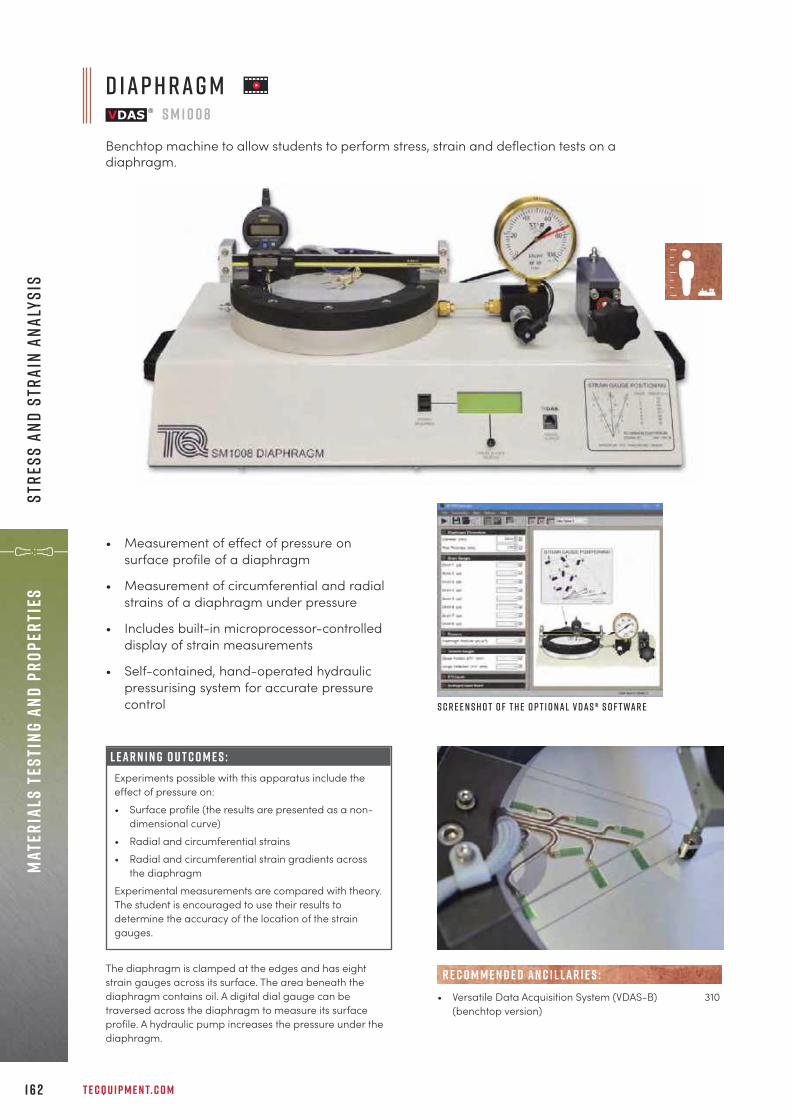
T E C Q U I P M E N T. C O M1 6 2
Mate
rial
s Te
stin
g an
d pr
oper
ties
Stre
ss a
nd s
trai
n an
alys
is
L E A R N I N G O U T C O M E S :Experiments possible with this apparatus include theeffect of pressure on:• Surface profile (the results are presented as a non-
dimensional curve)• Radial and circumferential strains • Radial and circumferential strain gradients across
the diaphragm Experimental measurements are compared with theory.The student is encouraged to use their results todetermine the accuracy of the location of the straingauges.
• Measurement of effect of pressure onsurface profile of a diaphragm
• Measurement of circumferential and radialstrains of a diaphragm under pressure
• Includes built-in microprocessor-controlleddisplay of strain measurements
• Self-contained, hand-operated hydraulicpressurising system for accurate pressurecontrol
The diaphragm is clamped at the edges and has eightstrain gauges across its surface. The area beneath thediaphragm contains oil. A digital dial gauge can betraversed across the diaphragm to measure its surfaceprofile. A hydraulic pump increases the pressure under thediaphragm.
• Versatile Data Acquisition System (VDAS-B) 310(benchtop version)
R E C O M M E N D E D AN C I L LAR I E S :
D i a p h r a g mS M 1 0 0 8
Benchtop machine to allow students to perform stress, strain and deflection tests on adiaphragm.
S c r e e n s h o t o f t h e o p t i o n a l V D A S ® s o f t wa r e

+ 4 4 1 1 5 9 7 2 2 6 1 1 I N F O @ T E C Q U I P M E N T. C O M 1 6 3
Materials Testing and propertiesStress and strain analysis
• For comprehensive analysis of the stressesand strains in a thick-walled cylinder, underinternal pressure
• Experiment results compared with Lamépredictions
• Includes built-in microprocessor-controlleddisplay of strain measurements
• Self-contained, hand-operated hydraulicpressurising system for accurate pressurecontrol
L E A R N I N G O U T C O M E S :• Radial and hoop strains throughout the cylinder wall• Radial and hoop stress distribution in the wall• Longitudinal stress and strain at the outer surface• Circumferential stress and strains at the inner and
outer surfaces• Comparison with Lamé predictions • Principal stresses and maximum shear stress• Appraisal of accuracy of location of strain gauges
T h i c k C y l i n d e rS M 1 0 1 1
Benchtop machine to allow students to perform stress and strain tests on a thick-walled cylinder.
The apparatus consists of a thick-walled aluminium cylinderheld in a frame. The cylinder is in two halves cementedtogether. One face of the joint has an eccentric shallowgroove that contains ten strain gauges at precise radii andorientation. These gauges measure the radial and hoopstrains. Jointing cement fills the groove. Strain gauges onthe inner and outer walls of the cylinder measurelongitudinal and circumferential strains. The cylinder isstressed using a hydraulic hand-pump.
• Versatile Data Acquisition System (VDAS-B) 310(benchtop version)
• Thin Cylinder (SM1007) 161
R E C O M M E N D E D AN C I L LAR I E S :
alt e r nat i v e p r o d u c t s :
S c r e e n s h o t o f t h e o p t i o n a l V D A S ® s o f t wa r e

T E C Q U I P M E N T. C O M1 6 4
Mate
rial
s Te
stin
g an
d pr
oper
ties
Stre
ss a
nd s
trai
n an
alys
is
• Clear layoutwith printedgraphics to helpstudents understandhow strain gauges work
• Includes electronic strain display to show allreadings, and automatically calculates strain
• Fully open bridge connection, with dummyresistors to allow quarter, half and full-bridge connection, to demonstrate howstrain bridge connections work
• Uses strain gauges on three different,popular structures for realistic experiments
L E A R N I N G O U T C O M E S :• Introduction to the equipment and the different
bridge connections (quarter, half and full bridge)• Strains and stresses in a bending system• Strains and stresses in a torsion system• Strains and stresses in a tension system, Poisson’s
ratio and Young’s modulus• Tensile strains and stresses in different materials
(needs optional tensile specimens) and comparisonof Poisson’s ratio and Young’s modulus
• Comparison of different strain measurement systemsand how they could measure force
S t r a i n G a u g e T r a i n e rS M 1 0 0 9
Benchtop bending system to test tension, torsion and bending to illustrate how resistance strain gaugeswork and methods of measuring strains in different structures. Can be used to demonstrate Young’smodulus and Poisson’s ratio.
The bending system uses gauges to measure direct tensileand compression strain. The torsion system shows the use ofshear/torque strain gauges. The tension system shows theuse of two gauges at right angles in a ‘Tee’ rosette.
• Versatile Data Acquisition System (VDAS-B) 310(benchtop version)
• Optional Tension Specimens (SM1009a):aluminium, brass and copper
R E C O M M E N D E D AN C I L LAR I E S :
S c r e e n s h o t o f t h e o p t i o n a lV D A S ® s o f t wa r e

+ 4 4 1 1 5 9 7 2 2 6 1 1 I N F O @ T E C Q U I P M E N T. C O M 1 6 5
Materials Testing and propertiesStress and strain analysis
• All expendable items required forcementing gauges included
• Reduced risk of spillage of chemicals
• Refills available (E19a)
• Step-by-step instructions supplied
• Supplied in a PVC carrying case
S t r a i n G a u g e I n s t r u m e n tat i o nTecQuipment offers the following instrumentation formonitoring and display of strain:• Digital Strain Display (SM1010), see above
S t r a i n G a u g e K i tE 1 9
Selection of resistance strain gauges and necessaryaccessories and consumable materials, for use withTecQuipment’s SM1010 Digital Strain Display.
• Direct connections for half and full strainbridge connections, with internal ‘make-up’resistors
• Supplied with cable, self-locking connectorsand a crimp tool to reduce connectionproblems
• Fully programmable to match most types ofstrain gauges and connections
• Ideal for use with TecQuipment’s StrainGauge Kit (E19)
D i g i ta l S t r a i n D i s p l ayS M 1 0 1 0
A 16-channel instrument that connects to industry-standard strain gauges to give direct readings of strain.
S c r e e n s h o t o f t h e o p t i o n a l V D A S ®s o f t wa r e The Digital Strain Display accepts up to 16 channels from
strain gauges connected in quarter, half or full bridge. Thedisplay is fully programmable to match the strain gaugesand their bridge connections. The display includes precisioninternal ‘make-up’ resistors to work with half-bridgeconnections, if needed. Two channels include additionalindividually adjusted dynamic outputs. They can connect tosuitable instruments, e.g. oscilloscope (not supplied).
• Versatile Data Acquisition System (VDAS-B) 310(benchtop version)
• Strain Gauge Kit (E19) 165
R E C O M M E N D E D AN C I L LAR I E S :
AN C I L LAR Y F O R :
• Digital Strain Display (SM1010) 165• Refill Kit for E19 (E19a)
R E C O M M E N D E D AN C I L LAR I E S :
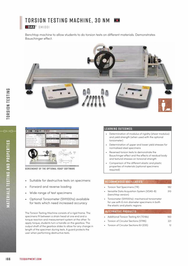
T E C Q U I P M E N T. C O M1 6 6
Mate
rial
s Te
stin
g an
d pr
oper
ties
Tors
ion
Test
ing
T o r s i o n T e s t i n g M a c h i n e , 3 0 N mS M 1 0 0 1
Benchtop machine to allow students to do torsion tests on different materials. DemonstratesBauschinger effect.
L E A R N I N G O U T C O M E S :• Determination of modulus of rigidity (shear modulus)
and yield strength (when used with the optionaltorsiometer)
• Determination of upper and lower yield stresses fornormalised steel specimens
• Reversed torsion tests to demonstrate theBauschinger effect and the effects of residual bodyand textural stresses on torsional strength
• Comparison of the different elastic and plasticproperties of materials (optional specimensrequired)
• Suitable for destructive tests on specimens
• Forward and reverse loading
• Wide range of test specimens
• Optional Torsiometer (SM1001a) availablefor tests which need increased accuracy
The Torsion Testing Machine consists of a rigid frame. Thespecimens fit between a strain head at one end and atorque reaction and measurement system at the other. Toapply torque, students turn a handle on the gearbox. Theoutput shaft of the gearbox slides to allow for any change inlength of the specimen during tests. A guard protects theuser when performing destructive tests.
• Torsion Test Specimens (TR) 182• Versatile Data Acquisition System (VDAS-B) 310
(benchtop version)• Torsiometer (SM1001a): mechanical torsiometer
for use with 6 mm diameter specimens in both the elastic and plastic regions
• Additional Torsion Testing Kit (TE16b) 160• Torsion of Circular Sections (STR6) 221• Torsion of Circular Sections Kit (ES5) 12
R E C O M M E N D E D AN C I L LAR I E S :
alt e r nat i v e p r o d u c t s :
S c r e e n s h o t o f t h e o p t i o n a l V D A S ® s o f t wa r e
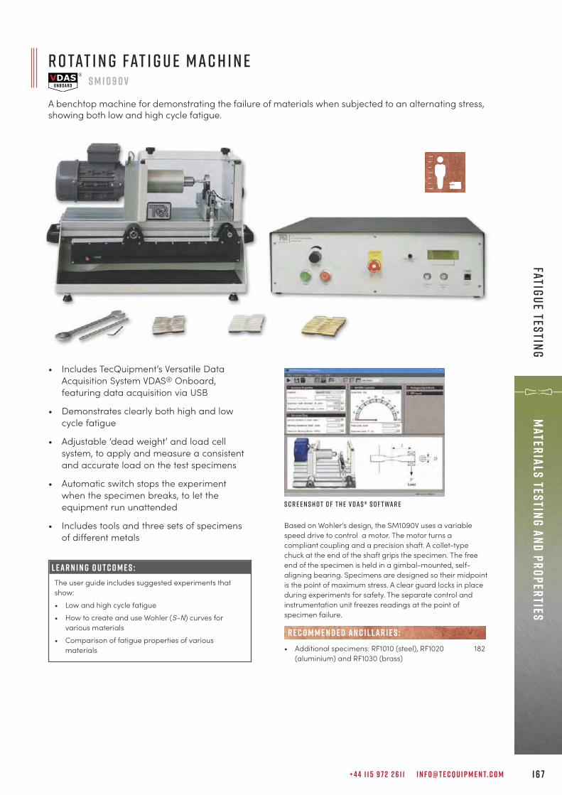
+ 4 4 1 1 5 9 7 2 2 6 1 1 I N F O @ T E C Q U I P M E N T. C O M 1 6 7
Materials Testing and propertiesFatigue testing
R o tat i n g Fat i g u e M a c h i n eS M 1 0 9 0 V
A benchtop machine for demonstrating the failure of materials when subjected to an alternating stress,showing both low and high cycle fatigue.
S c r e e n s h o t o f t h e V D A S ® s o f t wa r e
• Includes TecQuipment’s Versatile DataAcquisition System VDAS® Onboard,featuring data acquisition via USB
• Demonstrates clearly both high and lowcycle fatigue
• Adjustable ‘dead weight’ and load cellsystem, to apply and measure a consistentand accurate load on the test specimens
• Automatic switch stops the experimentwhen the specimen breaks, to let theequipment run unattended
• Includes tools and three sets of specimensof different metals
L E A R N I N G O U T C O M E S :The user guide includes suggested experiments thatshow:• Low and high cycle fatigue• How to create and use Wohler (S-N) curves for
various materials• Comparison of fatigue properties of various
materials
Based on Wohler’s design, the SM1090V uses a variablespeed drive to control a motor. The motor turns acompliant coupling and a precision shaft. A collet-typechuck at the end of the shaft grips the specimen. The freeend of the specimen is held in a gimbal-mounted, self-aligning bearing. Specimens are designed so their midpointis the point of maximum stress. A clear guard locks in placeduring experiments for safety. The separate control andinstrumentation unit freezes readings at the point ofspecimen failure.
• Additional specimens: RF1010 (steel), RF1020 182(aluminium) and RF1030 (brass)
R E C O M M E N D E D AN C I L LAR I E S :
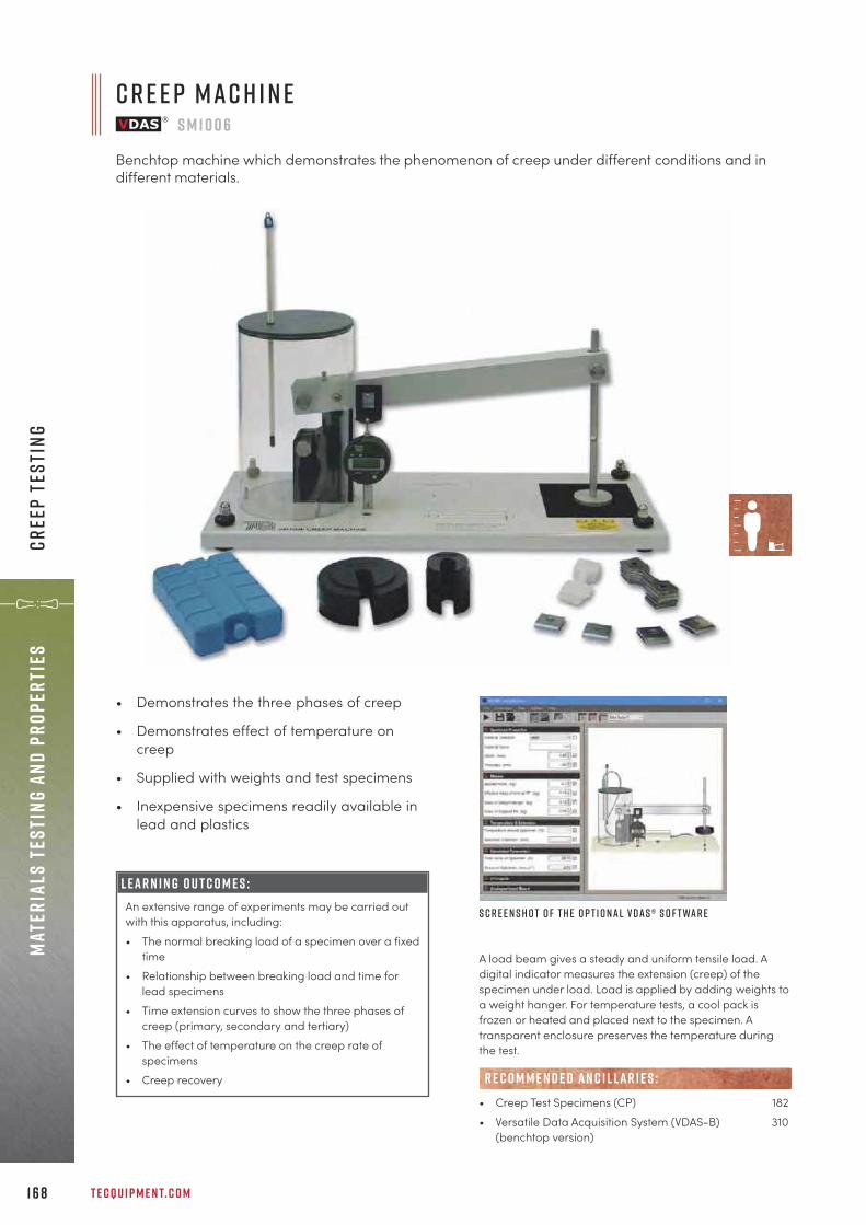
T E C Q U I P M E N T. C O M
• Demonstrates the three phases of creep
• Demonstrates effect of temperature oncreep
• Supplied with weights and test specimens
• Inexpensive specimens readily available inlead and plastics
L E A R N I N G O U T C O M E S :An extensive range of experiments may be carried outwith this apparatus, including:• The normal breaking load of a specimen over a fixed
time• Relationship between breaking load and time for
lead specimens• Time extension curves to show the three phases of
creep (primary, secondary and tertiary)• The effect of temperature on the creep rate of
specimens• Creep recovery
A load beam gives a steady and uniform tensile load. Adigital indicator measures the extension (creep) of thespecimen under load. Load is applied by adding weights toa weight hanger. For temperature tests, a cool pack isfrozen or heated and placed next to the specimen. Atransparent enclosure preserves the temperature duringthe test.
• Creep Test Specimens (CP) 182• Versatile Data Acquisition System (VDAS-B) 310
(benchtop version)
R E C O M M E N D E D AN C I L LAR I E S :
S c r e e n s h o t o f t h e o p t i o n a l V D A S ® s o f t wa r e
C r e e p M a c h i n eS M 1 0 0 6
Benchtop machine which demonstrates the phenomenon of creep under different conditions and indifferent materials.
1 6 8
Mate
rial
s Te
stin
g an
d pr
oper
ties
Cree
p Te
stin
g

+ 4 4 1 1 5 9 7 2 2 6 1 1 I N F O @ T E C Q U I P M E N T. C O M 1 6 9
Materials Testing and propertiesTensile and Universal Testing M
achines
B e n c h T o p T e n s i l e T e s t i n g M a c h i n eS M 1 0 0 2
A laboratory-scale, hand-driven benchtop tensile testing machine, 20 kN capacity.
S c r e e n s h o t o f t h e o p t i o n a l V D A S ® s o f t wa r e O p t i o n a l E x t e n s o m e t e r ( S M 1 0 0 2 a ) f i t t e dt o T L s p e c i m e n
C o n t i n u e d o n n e x t pa g e
Simple hand-operated load application For safe and easy operation that minimises risksto students
Supplied with chucks for standard 20 mm2
specimensCompatible with older Hounsfield specimens andchucks for cost saving
Optional Extensometer (SM1002a)For tests of Young’s modulus
Optional Compression Cage and Brinell Test Set(SM1002b and SM1002c) Combines hardness testing with tensile testingfor flexibility and cost saving
F eat u r e s an d be n e f i t s : A sturdy base holds a hand-driven worm and wheelgearbox, driving a lead screw with approximately 400 mmof travel. The mechanism uses ball races and self-aligningball thrust races in the direction of loading. These low-friction bearings with the large handwheel allow the user toapply maximum load with minimum effort. The load-measuring mechanism is a strain-gauged loadcell that connects to a microprocessor-controlled digitaldisplay. The load display unit has a ‘peak hold’ function toregister the maximum load before the specimen breaks. Asliding digital display measures the tensile displacement(extension) over the entire movement. The tensile specimensmount between the load application mechanism and loadcell, in collet chucks via ball-jointed spigots. This ensurespurely axial loading.
L E A R N I N G O U T C O M E S :• Tensile tests up to 20 kN on specimens made of
different metals, to find material characteristics suchas upper and lower yield strengths, tensile strengthand overall extension.
• Tests of Young’s modulus (E) for the specimenmaterial (needs SM1002a and TL specimens)
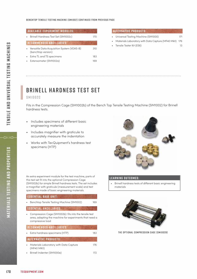
T E C Q U I P M E N T. C O M1 7 0
Mate
rial
s Te
stin
g an
d pr
oper
ties
Tens
ile
and
Univ
ersa
l Te
stin
g M
achi
nes
• Brinell Hardness Test Set (SM1002c) 170
• Versatile Data Acquisition System (VDAS-B) 310(benchtop version)
• Extra TL and TS specimens 183• Extensometer (SM1002a) 169
R E C O M M E N D E D AN C I L LAR I E S :
ava i labl e e x p e r i m e n t m o d u l e s :• Universal Testing Machine (SM1000) 171• Materials Laboratory with Data Capture (MF40 MkII) 176• Tensile Tester Kit (ES6) 13
alt e r nat i v e p r o d u c t s :
B r i n e l l H a r d n e s s T e s t S e tS M 1 0 0 2 c
Fits in the Compression Cage (SM1002b) of the Bench Top Tensile Testing Machine (SM1002) for Brinellhardness tests.
• Includes specimens of different basicengineering materials
• Includes magnifier with graticule toaccurately measure the indentation
• Works with TecQuipment’s hardness testspecimens (HTP)
An extra experiment module for the test machine, parts ofthis test set fit into the optional Compression Cage(SM1002b) for simple Brinell hardness tests. The set includesa magnifier with graticule (measurement scale) and testspecimens made of basic engineering materials.
• Benchtop Tensile Testing Machine (SM1002) 169
• Compression Cage (SM1002b): fits into the tensile testarea, adapting the machine for experiments that need acompressive load
• Extra hardness specimens (HTP) 183
• Materials Laboratory with Data Capture 176(MF40 MKII)
• Brinell Indenter (SM1000e) 172
e s s e n t ial bas e u n i t:
E S S E N T IAL AN C I L LAR I E S :
R E C O M M E N D E D AN C I L LAR I E S :
alt e r nat i v e p r o d u c t s :
T h e o p t i o n a l C o m p r e s s i o n C a g e ( S M 1 0 0 2b )
L E A R N I N G O U T C O M E S :• Brinell hardness tests of different basic engineering
materials
B e n c h t o p t e n s i l e t e s t i n g m a c h i n e ( S M 1 0 0 2 ) C o n t i n u e d f r o m p r e v i o u s pa g e
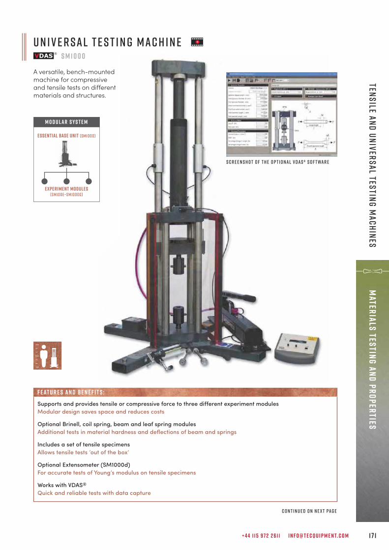
U n i v e r s a l T e s t i n g M a c h i n eS M 1 0 0 0
A versatile, bench-mountedmachine for compressiveand tensile tests on differentmaterials and structures.
+ 4 4 1 1 5 9 7 2 2 6 1 1 I N F O @ T E C Q U I P M E N T. C O M 1 7 1
Materials Testing and propertiesTensile and Universal Testing M
achines
Experiment modules(sm100e–sm1000g)
Essential Base Unit (sm1000)
M O D U LAR S Y S T E M
S c r e e n s h o t o f t h e o p t i o n a l V D A S ® s o f t wa r e
C o n t i n u e d o n n e x t pa g e
Supports and provides tensile or compressive force to three different experiment modulesModular design saves space and reduces costs
Optional Brinell, coil spring, beam and leaf spring modulesAdditional tests in material hardness and deflections of beam and springs
Includes a set of tensile specimensAllows tensile tests ‘out of the box’
Optional Extensometer (SM1000d)For accurate tests of Young’s modulus on tensile specimens
Works with VDAS®
Quick and reliable tests with data capture
F eat u r e s an d be n e f i t s :

T E C Q U I P M E N T. C O M1 7 2
Mate
rial
s Te
stin
g an
d pr
oper
ties
Tens
ile
and
Univ
ersa
l Te
stin
g M
achi
nes
A steel frame with four columns supports a hydraulic ram.The ram pushes up a loading platform. The area above theloading platform is for compression tests on a wide rangeof materials, such as wood, brick and mortar. The spacebelow the platform is for tensile tests.
• Brinell Indenter (SM1000e) 172• Coil Spring (SM1000f) 173• Beam and Leaf Spring (SM1000g) 173• Cupping Experiment (SM1000h) 174• Double Shear Experiment (SM1000j) 174• Disc Spring Experiment (SM1000k) 175
ava i labl e e x p e r i m e n t m o d u l e s :
L E A R N I N G O U T C O M E S :• Tensile tests on different materials• Compression tests on different materials
B r i n e l l I n d e n t e rS M 1 0 0 0 e
Fits in the Universal Testing Machine (SM1000) for Brinell hardness tests.
• Includes magnifier with graticule toaccurately measure the indentation
• Includes specimens of different basicengineering materials
• Works with TecQuipment’s hardness testspecimens (HTP)
L E A R N I N G O U T C O M E S :• Brinell hardness tests of different basic engineering
materials
The Brinell Indenter (SM1000e) fits in the area above theloading platform of TecQuipment’s Universal TestingMachine (SM1000).
• Versatile Data Acquisition System (VDAS-B) 310(benchtop version)
• Support Table and Cupboard (SM1000a): steel-framed table with a pre-drilled worktop to accept the Universal Testing Machine. Includes a cupboard underneath.
• Extensometer (SM1000d): precision sliding gauge with a digital indicator
• Tensile test (TH) specimens 182
• Materials Laboratory with Data Capture (MF40 MkII) 176• Benchtop Tensile Testing Machine (SM1002) 169• Tensile Tester Kit (ES6) 13
alt e r nat i v e p r o d u c t s :
R E C O M M E N D E D AN C I L LAR I E S :
• Universal Testing Machine (SM1000) 171
• Extra hardness specimens (HTP) 183
• Materials Laboratory with Data Capture 176(MF40 MkII)
• Brinell Hardness Test Set (SM1002c) 170
R E C O M M E N D E D AN C I L LAR I E S :
alt e r nat i v e p r o d u c t s :
e s s e n t ial bas e u n i t:
U n i v e r s a l t e s t i n g m a c h i n e ( S M 1 0 0 0 ) C o n t i n u e d f r o m p r e v i o u s pa g e
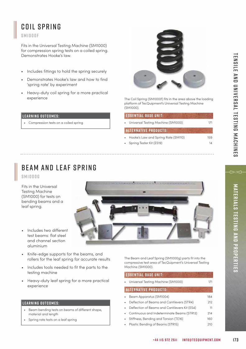
+ 4 4 1 1 5 9 7 2 2 6 1 1 I N F O @ T E C Q U I P M E N T. C O M 1 7 3
Materials Testing and propertiesTensile and Universal Testing M
achines
C o i l S p r i n gS M 1 0 0 0 f
Fits in the Universal Testing Machine (SM1000)for compression spring tests on a coiled spring.Demonstrates Hooke’s law.
• Includes fittings to hold the spring securely
• Demonstrates Hooke’s law and how to find‘spring rate’ by experiment
• Heavy-duty coil spring for a more practicalexperience The Coil Spring (SM1000f) fits in the area above the loading
platform of TecQuipment’s Universal Testing Machine(SM1000).
• Universal Testing Machine (SM1000) 171
• Hooke’s Law and Spring Rate (SM110) 159• Spring Tester Kit (ES19) 14
e s s e n t ial bas e u n i t:
alt e r nat i v e p r o d u c t s :
L E A R N I N G O U T C O M E S :• Compression tests on a coiled spring
• Includes two differenttest beams: flat steeland channel sectionaluminium
• Knife-edge supports for the beams, androllers for the leaf spring for accurate results
• Includes tools needed to fit the parts to thetesting machine
• Heavy-duty leaf spring for a more practicalexperience
B e a m a n d L e a f S p r i n gS M 1 0 0 0 g
Fits in the UniversalTesting Machine(SM1000) for tests onbending beams and aleaf spring.
L E A R N I N G O U T C O M E S :• Beam bending tests on beams of different shape,
material and length• Spring rate tests on a leaf spring
The Beam and Leaf Spring (SM1000g) parts fit into thecompressive test area of TecQuipment’s Universal TestingMachine (SM1000).
• Universal Testing Machine (SM1000) 171
• Beam Apparatus (SM1004) 184• Deflection of Beams and Cantilevers (STR4) 212• Deflection of Beams and Cantilevers Kit (ES4) 11• Continuous and Indeterminate Beams (STR13) 214• Stiffness, Bending and Torsion (TE16) 160• Plastic Bending of Beams (STR15) 210
e s s e n t ial bas e u n i t:
alt e r nat i v e p r o d u c t s :

T E C Q U I P M E N T. C O M1 74
Mate
rial
s Te
stin
g an
d pr
oper
ties
Tens
ile
and
Univ
ersa
l Te
stin
g M
achi
nes
D o ubl e S h e a r E x p e r i m e n tS M 1 0 0 0 j
An experiment for determining the shear strength of specimens using a double shear test. It fits in theUniversal Testing Machine (SM1000) and consists of a specimen holder and shear strap.
• Includes copper specimens
L E A R N I N G O U T C O M E S :• Determining the shear stress of the specimen
materials
The Double Shear Experiment (SM1000j) fits in the areabelow the loading platform of TecQuipment’s UniversalTesting Machine (SM1000).
• Universal Testing Machine (SM1000) 171
• Extra hardness specimens (DS1010) 182
• Materials Laboratory with Data Capture 176(MF40 MkII)
• Shear Force in a Beam (STR3) 219
• Unsymmetrical Bending and Shear Centre (STR7) 222
• Torsion Testing Machine, 30 Nm (SM1001) 166
• Unsymmetrical Cantilever Apparatus (SM1003) 188
e s s e n t ial bas e u n i t:
R E C O M M E N D E D AN C I L LAR I E S :
alt e r nat i v e p r o d u c t s :
C u p p i n g E x p e r i m e n tS M 1 0 0 0 h
An experiment for testing cold formed sheet metals by cupping, for understanding properties inmoulding manufacturing processes. It fits in the Universal Testing Machine (SM1000) and consists of asphere that is pressed into the specimen held between two plates until the specimen ruptures.
• Includes a mirror for easy viewing of thematerial rupturing
• Includes specimens of different basicengineering materials
The penetrator is made of hardened steel, the cuppingspecimen is clamped between the clamping plate and thedie plate. An angled mirror is placed below the die plate toenable easy viewing of the specimen rupturing.
L E A R N I N G O U T C O M E S :• An understanding of the limits of various sheet
materials• An understanding of the Erichsen number, i.e. the
depth of penetration achieved when a specimen firstruptures
• An understanding of the difference betweenisotropic and anisotropic ruptures
• Universal Testing Machine (SM1000) 171
• Extra specimens (ER1010, ER1020, ER1030, ER1040)
e s s e n t ial bas e u n i t:
R E C O M M E N D E D AN C I L LAR I E S :
n e w
n e w
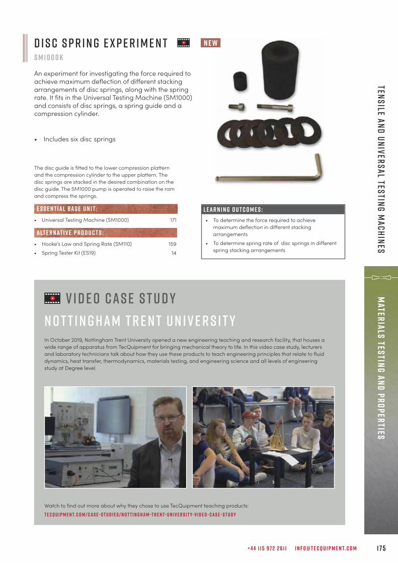
+ 4 4 1 1 5 9 7 2 2 6 1 1 I N F O @ T E C Q U I P M E N T. C O M 1 7 5
Materials Testing and propertiesTensile and Universal Testing M
achines
D i s c S p r i n g E x p e r i m e n tS M 1 0 0 0 K
An experiment for investigating the force required toachieve maximum deflection of different stackingarrangements of disc springs, along with the springrate. It fits in the Universal Testing Machine (SM1000)and consists of disc springs, a spring guide and acompression cylinder.
• Includes six disc springs
The disc guide is fitted to the lower compression platternand the compression cylinder to the upper plattern. Thedisc springs are stacked in the desired combination on thedisc guide. The SM1000 pump is operated to raise the ramand compress the springs.
• Universal Testing Machine (SM1000) 171
• Hooke’s Law and Spring Rate (SM110) 159• Spring Tester Kit (ES19) 14
e s s e n t ial bas e u n i t:
alt e r nat i v e p r o d u c t s :
L E A R N I N G O U T C O M E S :• To determine the force required to achieve
maximum deflection in different stackingarrangements
• To determine spring rate of disc springs in differentspring stacking arrangements
V i d e o C a s e S t u d yN o t t i n g h a m T r e n t U n i v e r s i t yIn October 2019, Nottingham Trent University opened a new engineering teaching and research facility, that houses awide range of apparatus from TecQuipment for bringing mechanical theory to life. In this video case study, lecturersand laboratory technicians talk about how they use these products to teach engineering principles that relate to fluiddynamics, heat transfer, thermodynamics, materials testing, and engineering science and all levels of engineeringstudy at Degree level.
Watch to find out more about why they chose to use TecQuipment teaching products:t e c q u i p m e n t. c o m / c a s e - s t u d i e s / n o t t i n g h a m -t r e n t- u n i v e r s i t y-v i d e o - c a s e - s t u d y
n e w

T E C Q U I P M E N T. C O M1 7 6
Mate
rial
s Te
stin
g an
d pr
oper
ties
Tens
ile
and
Univ
ersa
l Te
stin
g M
achi
nes
The MF40 MkII consists of a load frame, a digital display offorce (load), a ball indenter for Brinell hardness testing, andan extensometer with a digital display for tensile testing. Toapply loads, students pump a handle connected to ahydraulic pump.
• Additional tensile test specimens of different 183materials:Mild steel (ML1MS) Aluminium (ML4AL) Carbon steel (ML2CS) Brass (ML5BR)Stainless steel (ML3SS)
• Hardness test specimens of different materials: 183Aluminium (HTPAL) Carbon steel (HTPMS)Brass (HTPBR) Nylon (HTPNY)
• Tensile Tester Kit (ES6) 13• Benchtop Tensile Testing Machine (SM1002) 169• Universal Testing Machine (SM1000) 171
alt e r nat i v e p r o d u c t s :
R E C O M M E N D E D AN C I L LAR I E S :
M at e r i a l s L abo r at o r y w i t h D ata C a p t u r eM F 4 0 M K I I
A versatile, benchtop machine for compressiveand tensile tests on different materials andstructures.
• For Brinell hardness tests andtensile tests of materials
• Includes an extensometer foraccurate tensile test results
• Supplied with a set of testspecimens (additional testspecimens available separately)
• Includes software to automaticallyrecord results and produce charts(a suitable computer is required)
L E A R N I N G O U T C O M E S :• Tensile testing to destruction and Brinell hardness
testing of various specimens• Modulus of elasticity• Yield stress• Ultimate tensile stress• Percentage elongation• Brinell hardness test and hardness number
derivation

T e c Q u i p m e n t n EWS L E T T E R S I G N - U PDon’t miss out on the latest new products, case studies, demonstration videos and blog posts. Sign up to the TecQuipment newsletter today.
T e cqu i p m e n t. c o m / s ubs c r ibe
NEWS
+ 4 4 1 1 5 9 7 2 2 6 1 1 I N F O @ T E C Q U I P M E N T. C O M 1 7 7
Materials Testing and propertiesIm
pact testing
• Many safety features, including enclosure ofall moving parts and mechanicallyinterlocked guard
• Allows investigations into the resistance ofmaterials to crack propagation
• Includes digital display of energy absorbedat impact, and angular position before andafter impact
• Visually-effective, interesting and motivatingexperiments
L E A R N I N G O U T C O M E S :• Introduction to the principles of common impact
testing methods, such as Izod and Charpy tests• Investigations into the resistance of materials to
crack propagation
The apparatus consists of a main unit, an instrumentationunit and a power supply. The main unit consists of apendulum supported in a rigid frame by low-frictionbearings. The pivot arrangement includes an angularencoder to measure the angular position of the pendulumover its range of movement. The apparatus is fully enclosedwith an interlocking guard covering all moving parts.Adjustable feet on the base of the unit enable accuratelevelling of the equipment.
E n e r g y Abs o rbe d at F r a c t u r eT E 1 5
Compact, benchtop apparatus for testing notched specimens. Forms an introduction to impacttesting such as Izod and Charpy.
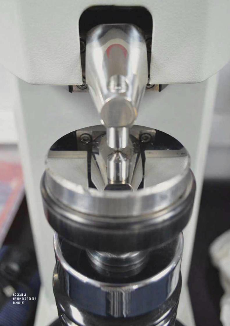
R o c k w e l lh a r d n e s s t e s t e r( S M 1 0 1 5 )

+ 4 4 1 1 5 9 7 2 2 6 1 1 I N F O @ T E C Q U I P M E N T. C O M 1 7 9
Materials Testing and propertiesIndustrial hardness testers
R o c k w e l l H a r d n e s s T e s t e rS M 1 0 1 5
A benchtop, industrial-standard tester for accurate measurements of Rockwell hardness.
• Nose-mounted indenter allows 360-degreeaccess
• Fully automatic testing cycle and automaticconversion to alternative scales eliminatesoperator influence on the test results
• High level of test result repeatability
• Robust construction with a play-free screwspindle running on ball bearings
• Visual and audible signals when specifiedtolerance exceeded and during preloadsetting
L E A R N I N G O U T C O M E S :Hardness testing of classical Rockwell methodsaccording to ISO 6508 and ASTM E18
The machine performs Rockwell hardness tests inaccordance with established specifications, including BS ENISO 6508:1999 and ASTM E18. The machine is supplied witha diamond cone indenter and a 1/16” diameter ballindenter, as standard.
• Hardness Reference Blocks (HTB-R) 183
R E C O M M E N D E D AN C I L LAR I E S :
S o c ial M e d ia Find out all the latest up-to-the-minute news, promotions, stories from users, videos etc. Plus, embrace the opportunity to interact with other academics, students and get fresh ideas.
s har essssss hssssssss
c o m m e n t
L i k e

• Capable of performing tests using forces: 0.2, 0.5, 1, 3, 5, 10, 30 kgm
• Dead weight load application provides longterm test force stability
• Unique nose-mounted indenter, allowsaccess to awkward-to-reach test points
• Fully automatic testing cycle, eliminatesoperator influence on the test results
• Calculation of average (x) and range (R)
T E C Q U I P M E N T. C O M1 8 0
Mate
rial
s Te
stin
g an
d pr
oper
ties
Indu
stri
al h
ardn
ess
test
ers
V i c k e r s H a r d n e s s T e s t e rS M 1 0 1 6
A benchtop industrial-standard tester for accurate measurements of Vickers hardness.
L E A R N I N G O U T C O M E S :Vickers testing to ISO 6507, ASTM E384 and ASTM E92,UKAS accredited Key Specifications
The machine performs the Vickers hardness test, inaccordance with established specifications including BS ENISO 6507 and ASTM E92.
• Hardness Reference Blocks (HTB-V) 183
R E C O M M E N D E D AN C I L LAR I E S :
h e r e t o h e l p y o uA team of specialist customer care personnel is available to answer a range of questions relating to technical details, spare parts and maintenance.
c u s t o m e r . car e@t e cqu i p m e n t. c o m

+ 4 4 1 1 5 9 7 2 2 6 1 1 I N F O @ T E C Q U I P M E N T. C O M 1 8 1
Materials Testing and propertiesIndustrial hardness testers
L E A R N I N G O U T C O M E S :Hardness testing of a range of different materials, usingthree different methods:• Vickers (HV) DIN EN ISO 6507, ASTM E92• Brinell (HB) DIN EN ISO 6506, ASTM E10• Rockwell (HR) DIN EN ISO 6508, ASTM E18
• Dead weight load combinations up to187.5 kg
• Setting of hardness tolerance and statistics(x and R), for a range of experiments
• Integral microscope with measuringshutters and push button for transfer ofdimensional data
• Simple operation
U n i v e r s a l H a r d n e s s T e s t e rS M 1 0 1 7
A benchtop industrial-standard tester for accurate measurements of Vickers, Brinell andRockwell hardness.
The machine performs Brinell, Vickers and Rockwell tests inaccordance with established specifications:• Brinell: ISO 6506, ASTM E10• Vickers: ISO 6507, ASTM E92• Rockwell: ISO 6508, ASTM E18
• Hardness Reference Blocks (HTB-B): Brinell 183• Hardness Reference Blocks (HTB-R): Rockwell 183• Hardness Reference Blocks (HTB-V): Vickers 183
R E C O M M E N D E D AN C I L LAR I E S :
h a r d n e s s t e s t e r d i s p l ay

C u p p i n g t e s t S p e c i m e n sE S
For use with TecQuipment’s Universal TestingMachine (SM1000).
E R 1 0 1 0 : HE30 aluminium E R 1 0 3 0 : CZ108 HH brass
E R 1 0 2 0 : C101 HH copper E R 1 0 4 0 : CR4 mild steel
T E C Q U I P M E N T. C O M1 8 2
Mate
rial
s Te
stin
g an
d pr
oper
ties
Test
spe
cim
ens
T e n s i l e T e s t S p e c i m e n s t h
For use with TecQuipment’s Universal TestingMachine (SM100 or SM1000).
T H 4 0 1 0 : 0.1% Carbon Steel. As drawn. To British StandardSpecification 230M07. Has no identity rings.
T H 4 0 1 5 : 0.1% Carbon Steel. Normalised at 900°C. To BritishStandard Specification 230M07. Has one identity ring.
T H 4 0 3 5 : 0.4% Carbon Steel. Normalised at 860°C. ToBritish Standard Specification 212A42. Has two identityrings.
T o r s i o n T e s t S p e c i m e n sT R
For use with TecQuipment’s Torsion TestingMachine (SM1 or SM1001).
T R 1 0 1 0 : 0.1% Carbon Steel. As drawn. To British StandardSpecification 230M07. No grooves.
T R 1 0 1 1 : 0.1% Carbon Steel. Normalised at 900°C. To BritishStandard Specification 230M07. 1 groove.
T R 1 0 2 0 : 0.4% Carbon Steel. As drawn. To British StandardSpecification 212A42. 2 grooves.
T R 1 0 2 1 : 0.4% Carbon Steel. Normalised at 860°C. To BritishStandard Specification 212A42. 3 grooves.
T R 1 0 4 0 : Half-hard Brass. 60% Copper, 40% Zinc. To BritishStandard Specification CZ121. No grooves.
T R 1 0 5 0 : Castiron. Grade 260.To BritishStandardBS1452. 4 grooves.
C r e e p T e s t S p e c i m e n sC P
For use with TecQuipment’s Creep Machine(SM106 or SM1006).
C P 1 0 1 0 : Lead
C P 1 0 2 0 : Polypropylene
C P 1 0 2 5 : Nylon 66 (unfilled)
C P 1 0 3 0 : Unplasticised PVC
R o tat i n g Fat i g u eS p e c i m e n sR F
For use with TecQuipment’s Rotating FatigueMachine (SM1090/SM1090V).
R F 1 0 1 0 : Mild Steel
R F 1 0 2 0 : Aluminium
R F 1 0 3 0 : Brass
s p e c i m e n s ava i l abl e e x- s t o c k :
D o ubl e s h e a r t e s tS p e c i m e n sD S
For use with TecQuipment’sUniversal Testing Machine(SM1000).
D S 1 0 1 0 : C101 Copper
ava i l abl e i n pa c k s o f 1 0

+ 4 4 1 1 5 9 7 2 2 6 1 1 I N F O @ T E C Q U I P M E N T. C O M 1 8 3
Materials Testing and propertiesTest specim
ens
H a r d n e s s T e s tS p e c i m e n s H T P
For use with the Materials Laboratory withData Capture (MF40 series), Benchtop TensileTesting Machine (SM1002) and BrinellIndenter (SM1000e).
H T PA L : Aluminium (6026-T9)
H T PBR : Brass (CZ121/CW614N)
H T P M S : 0.1% Carbon steel (230M07)
H T P N Y: Nylon 6
H a r d n e s s r e f e r e n c e bl o c k s H TB
For use with the Rockwell Hardness Tester(SM1015), Vickers Hardness Tester (SM1016) andUniversal Hardness Tester (SM1017).
H TB - R : Rockwell block for use on the SM1015 or SM1017
H TB - V : Vickers block for use on the SM1016 or SM1017
H TB -B : Brunel block for use on the SM1017 only
T e n s i l e T e s t S p e c i m e n sM L
For use with the Materials Laboratory with Data Capture (MF40 series).
M L1 M S : Mild steel – specification EN1A or 230M07
M L 2 C S : Carbon steel – specification EN8 or 080M40
M L 3 S S : Stainless steel – specification SAE303
M L4 A L : Aluminium – specification 2011-T3
M L 5BR : Brass – specification CZ121
T e n s i l e T e s t S p e c i m e n s T L a n d T S
For use with TecQuipment’s Tensile Testing Machine (SM1002). Willalso fit Hounsfield or Monsanto tensometer.
T L1 0 1 0 a n d T S 1 0 1 0 : 0.1% Carbon Steel. As drawn. To British Standard Specification220M07 or 230M07.
T L1 0 1 1 a n d T S 1 0 1 1 : 0.1% Carbon Steel. Normalised at 900°C. To British StandardSpecification 220M07 or 230M07.
T L1 0 2 0 a n d T S 1 0 2 0 : 0.4% Carbon Steel. As drawn. To British Standard Specification080M040.
T L1 0 2 1 a n d T S 1 0 2 1 : 0.4% Carbon Steel. Normalised at 860°C. To British StandardSpecification 080M040.
T L1 0 3 0 a n d T S 1 0 3 0 : Aluminium 2011 – T3.
T L1 0 4 0 a n d T S 1 0 4 0 : Half hard Brass. To British Standard Specification CZ121.
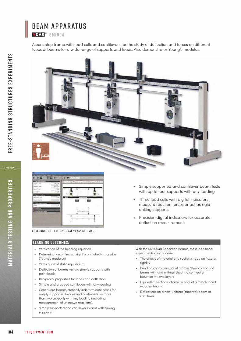
L E A R N I N G O U T C O M E S :• Verification of the bending equation • Determination of flexural rigidity and elastic modulus
(Young’s modulus)• Verification of static equilibrium• Deflection of beams on two simple supports with
point loads• Reciprocal properties for loads and deflection• Simple and propped cantilevers with any loading• Continuous beams, statically indeterminate cases for
simply supported beams and cantilevers on morethan two supports with any loading (includingmeasurement of unknown reactions)
• Simply supported and cantilever beams with sinkingsupports
T E C Q U I P M E N T. C O M1 8 4
Mate
rial
s Te
stin
g an
d pr
oper
ties
Free
-sta
ndin
g st
ruct
ures
exp
erim
ents
• Simply supported and cantilever beam testswith up to four supports with any loading
• Three load cells with digital indicatorsmeasure reaction forces or act as rigidsinking supports
• Precision digital indicators for accuratedeflection measurements
S c r e e n s h o t o f t h e o p t i o n a l V D A S ® s o f t wa r e
B e a m A p pa r at u sS M 1 0 0 4
A benchtop frame with load cells and cantilevers for the study of deflection and forces on differenttypes of beams for a wide range of supports and loads. Also demonstrates Young’s modulus.
With the SM1004a Specimen Beams, these additionalexperiments can be done:• The effects of material and section shape on flexural
rigidity• Bending characteristics of a brass/steel compound
beam, with and without shearing connectionbetween the two layers
• Equivalent sections, characteristics of a metal-facedwooden beam
• Deflections on a non-uniform (tapered) beam orcantilever
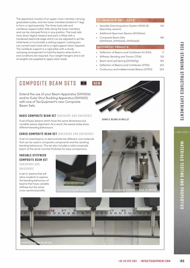
+ 4 4 1 1 5 9 7 2 2 6 1 1 I N F O @ T E C Q U I P M E N T. C O M 1 8 5
Materials Testing and propertiesFree-standing structures experim
ents
The apparatus consists of an upper cross-member carryinggraduated scales, and two lower members bolted to T-legsto form a rigid assembly. The three load cells andcantilever-support pillar slide along the lower membersand can be clamped firmly in any position. The load cellshave direct digital readout and each is fitted with ahardened steel knife edge which can be adjusted to set theinitial level, or to simulate a sinking support. Locking pinscan convert each load cell to a rigid support when required.The cantilever support is a rigid pillar with a sturdyclamping arrangement to hold the beams when built-inend conditions are required. Four weight hangers and a setof weights are supplied to apply static loads.
• Versatile Data Acquisition System (VDAS-B) 310(benchtop version)
• Additional Specimen Beams (SM1004a)• Composite Beam Sets 185
(SM1004d1, SM1004d2, SM1004d3)
• Deflection of Beams and Cantilevers Kit (ES4) 11• Stiffness, Bending and Torsion (TE16) 152• Beam and Leaf Spring (SM1000g) 165• Deflection of Beams and Cantilevers (STR4) 202• Continuous and Indeterminate Beams (STR13) 204
alt e r nat i v e p r o d u c t s :
R E C O M M E N D E D AN C I L LAR I E S :
C o m p o s i t e B e a m S e t sExtend the use of your Beam Apparatus (SM1004)and/or Euler Strut Buckling Apparatus (SM1005)with one of TecQuipment’s new CompositeBeam Sets:
Ba s i c C o m p o s i t e Be a m S e t ( S M 1 0 0 4 d 1 a n d S M 1 0 0 5 b 1 )A set of basic beams which have the same dimensions butvariable weave alignment. As a result, the weave styles showdifferent bending behaviours.
C o r e d C o m p o s i t e Be a m S e t ( S M 1 0 0 4 d 2 a n d S M 1 0 0 5 b 2 )A set of cored beams, to demonstrate the different core materialsthat can be used in composite components and the resultingbending behaviours. This set also includes a solid compositebeam of the same nominal thickness for easy comparisons.
Va r i a b l e S t i f f n e s sC o m p o s i t e Be a m S e t( S M 1 0 0 4 d 3 a n dS M 1 0 0 5 b 3 )A set of beams that willallow students to explorethe bending behaviour ofbeams that have variablestiffness but the samecross-sectional profile.
n e w
S e l e c t i o n o f be a m s ava i l abl e H i g h D e f l e c t i o n o f C o m p o s i t e B e a m o n S M 1 0 0 5
S a m p l e B e a m s i n Wa l l e t
C o m p o s i t e B e a m o n S M 1 0 0 4
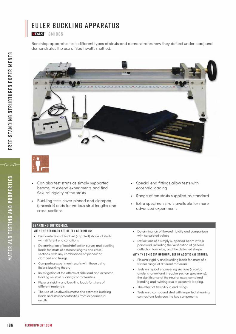
T E C Q U I P M E N T. C O M1 8 6
Mate
rial
s Te
stin
g an
d pr
oper
ties
Free
-sta
ndin
g st
ruct
ures
exp
erim
ents
E u l e r B u c k l i n g A p pa r at u sS M 1 0 0 5
Benchtop apparatus tests different types of struts and demonstrates how they deflect under load, anddemonstrates the use of Southwell's method.
LEARNING OUTCOMES:W i t h t h e s ta n d a r d s e t o f t e n s p e c i m e n s : • Demonstration of buckled (crippled) shape of struts
with different end conditions• Determination of load/deflection curves and buckling
loads for struts of different lengths and cross-sections, with any combination of ‘pinned’ orclamped end fixings
• Comparing experiment results with those usingEuler’s buckling theory
• Investigation of the effects of side load and eccentricloading on strut buckling characteristics
• Flexural rigidity and buckling loads for struts ofdifferent materials
• The use of Southwell’s method to estimate bucklingloads and strut eccentricities from experimentalresults
• Can also test struts as simply supportedbeams, to extend experiments and findflexural rigidity of the struts
• Buckling tests cover pinned and clamped(encastré) ends for various strut lengths andcross-sections
• Special end fittings allow tests witheccentric loading
• Range of ten struts supplied as standard
• Extra specimen struts available for moreadvanced experiments
• Determination of flexural rigidity and comparisonwith calculated values
• Deflections of a simply supported beam with apoint load, including the verification of generaldeflection formulae, and the deflected shape
W i t h t h e S M 1 0 0 5 a o p t i o n a l s e t o f a d d i t i o n a l s t r u t s : • Flexural rigidity and buckling loads for struts of a
further range of different materials• Tests on typical engineering sections (circular,
angle, channel and irregular section specimens);the significance of the neutral axes; combinedbending and twisting due to eccentric loading.
• The effect of flexibility in end fixings• Tests on a compound strut with imperfect shearing
connections between the two components
L E A R N I N G O U T C O M E S :

+ 4 4 1 1 5 9 7 2 2 6 1 1 I N F O @ T E C Q U I P M E N T. C O M 1 8 7
Materials Testing and propertiesFree-standing structures experim
ents
S c r e e n s h o t o f t h e o p t i o n a l V D A S ® s o f t wa r e
A sturdy base that at one end has a loading device whichuses a screw to apply loads to the struts. The screw is infixing blocks with bearings to give precise and easy loadapplication. At the opposite end is the load measuringdevice. This is a precision mechanism that resists thebending moments produced by the struts as they deflect,and transmits the pure axial force to an electronic load cell.This gives an accurate measurement of buckling load. Adigital load meter (DL1, included) shows the load.
• Versatile Data Acquisition System (VDAS-B) 310(benchtop version)
• Set of Additional Struts (SM1005a)• Composite Beam Sets 185
(SM1005b1, SM1005b2, SM1005b3)
• Euler Buckling of a Column (STR12) 207
R E C O M M E N D E D AN C I L LAR I E S :
alt e r nat i v e p r o d u c t s :
cap t u r e t h e p owe r o f...the Versatile Data Acquisition System from TecQuipment
Our Versatile Data Acquisition System (VDAS®) is a highly effective way of collecting and using data from experiments using TecQuipment’s educational teaching equipment.
L O O K AT T H E B E N E F I T S . . .v e r sat i l e – can be used across a wide range of TecQuipment productsdata – transforms raw data instantly which easily exports or creates sophisticated graphs and tablesacqu i s i t i o n – USB connectivity, multiple-source real-time data captures y s t e m – an expandable modular approach providing easy-to-use digital plug-and-play technology
labv i e wMost TecQuipment products compatible with VDAS® have the capability to interface with a LabVIEW environment.
Visit our website at t e cqu i p m e n t. c o m for more information.

T E C Q U I P M E N T. C O M1 8 8
Mate
rial
s Te
stin
g an
d pr
oper
ties
Free
-sta
ndin
g st
ruct
ures
exp
erim
ents
L E A R N I N G O U T C O M E S :Investigations into bending of unsymmetricalcantilevers, including:• Vertical and horizontal displacement
measurement for varying angles of appliedload
• Demonstration that maximum and minimumvertical deflection occurs when horizontaldeflection is zero
• Use of Mohr’s circle• Experimental and theoretical determination of
the principal moments of area of test sections• Location of shear centre of each section
A beam is mounted vertically in the test frame and the topfixes to a ring that can rotate through 360 degrees. Anincremental load is added to the free end of the test beam.Beam deflections are measured in two directions at rightangles to each other. To find shear stress, a cross piece isused to allow loads to be applied across and outside thesection of the cantilever.
S c r e e n s h o t o f t h e o p t i o n a l V D A S ® s o f t wa r e
U n s y m m e t r i c a l C a n t i l e v e r A p pa r at u sS M 1 0 0 3
A benchtop test frame for examining and displaying bending of an unsymmetrical cantilever. Demonstratesthe use of Mohr’s circle.
• Self-contained, needs no other parts
• Explains ‘shear centre’ and the use andconstruction of Mohr’s circle
• Supplied with set of different specimens
• Versatile Data Acquisition System (VDAS-B) 310(benchtop version)
• Unsymmetrical Bending and Shear Centre (STR7) 222
R E C O M M E N D E D AN C I L LAR I E S :
alt e r nat i v e p r o d u c t s :

+ 4 4 1 1 5 9 7 2 2 6 1 1 I N F O @ T E C Q U I P M E N T. C O M 1 8 9
Statics Fundamentals
s t a t i c s f u n d a m e n t a l sw o r k pa n e l 1 9 1
e x p e r i m e n t s 1 9 2
“After inviting companies to bid for the new equipment, we selected TecQuipment based on thepremium specifications, competitive price, and reputation for quality of service supported bythe excellent pre-sales experience.
Pa u l M at t h e w sS e n i o r L e c t u r e r a n d C o o r d i n at o r at S o l i h u l l C o l l e g e

E a c h k i t i s s u p p l i e d w i t h a f u l ly i l l u s t r at e d u s e r g u i d ec o n ta i n i n g t h e o r y, e x p e r i m e n t s a n d t y p i c a l r e s u lt s .
T E C Q U I P M E N T. C O M1 9 0
Stat
ics
Fund
amen
tals
s tat i c s f u n d a m e n ta l s
a S tat i c s F u n d a m e n ta l s e x p e r i m e n t k i t f i t t e dt o t h e w o r k pa n e l
The Statics Fundamentals range offersteaching equipment for understandingthe core principles required for civil andmechanical engineering disciplines. Therange brings theories, such as concurrentand non-concurrent coplanar forces,Bow’s notation, equilibrium theory,parabola theory, and many more, to life. The range consists of a series of modularexperiment kits that fit to the essentialbase unit (Statics Work Panel), these canbe mixed and matched to suit teachingrequirements.
f l e x i b i l i t y: Share one work panel between experimentkits, or one work panel for each kit.
h a n d s o n : Large tactile parts for students to fit andadjust.
h i g h ly v i s u a l : Ideal for classroom demonstrations orgroups of students.
k e y f eat u r e s an d b e n e f i t s :
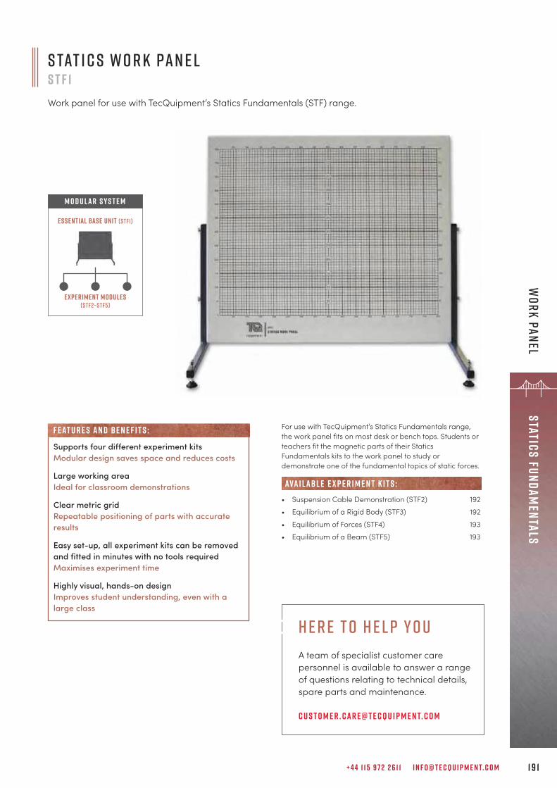
+ 4 4 1 1 5 9 7 2 2 6 1 1 I N F O @ T E C Q U I P M E N T. C O M 1 9 1
Statics FundamentalsW
ork Panel
For use with TecQuipment’s Statics Fundamentals range,the work panel fits on most desk or bench tops. Students orteachers fit the magnetic parts of their StaticsFundamentals kits to the work panel to study ordemonstrate one of the fundamental topics of static forces.
• Suspension Cable Demonstration (STF2) 192• Equilibrium of a Rigid Body (STF3) 192• Equilibrium of Forces (STF4) 193• Equilibrium of a Beam (STF5) 193
ava i labl e e x p e r i m e n t k i t s :
Experiment modules(stf2–stf5)
Essential Base Unit (STF1)
M O D U L A R S Y S T E M
s tat i c s w o r k pa n e ls t F 1Work panel for use with TecQuipment’s Statics Fundamentals (STF) range.
Supports four different experiment kitsModular design saves space and reduces costs
Large working areaIdeal for classroom demonstrations
Clear metric gridRepeatable positioning of parts with accurateresults
Easy set-up, all experiment kits can be removedand fitted in minutes with no tools requiredMaximises experiment time
Highly visual, hands-on designImproves student understanding, even with alarge class
F eat u r e s an d be n e f i t s :
h e r e t o h e l p y o uA team of specialist customer care personnel is available to answer a range of questions relating to technical details, spare parts and maintenance.
c u s t o m e r . car e@t e c q u i p m e n t. c o m

T E C Q U I P M E N T. C O M1 9 2
Stat
ics
Fund
amen
tals
Expe
rim
ents
S u s p e n s i o n C abl e D e m o n s t r at i o nS T F 2
A kit for use with the work panel thatdemonstrates the tensions and shapes in asuspension cable, comparing them withtheory.
L e a r n i n g o u t c o m e s :• Analysis using catenary and parabola
theory• Cable weight and tension• Comparison of a symmetrical suspension
cable and catenary• Unsymmetrical suspension cable• A point load on a suspension cable
For use with the Work Panel (STF1), the kit allows severalexperiments with a suspension cable. Students or teachersfit the magnetic parts of the kit to the work panel to study ordemonstrate the shapes and tensions in a suspensioncable.
E q u i l ibr i u m o f a R i g i d B o d yS T F 3
A kit for use with the work panel that demonstratesthe forces around a ladder-type structure.
For use with the Work Panel (STF1), the kit allows severalexperiments with a rigid body, i.e. a ladder structure.Students or teachers fit the magnetic parts of the kit to theWork Panel (STF1) to study or demonstrate the forcesaround an inclined ladder-type structure. • Work Panel (STF1) 191
e s s e n t ial bas e u n i t:
• Work Panel (STF1) 191
• Simple Suspension Bridge (STR19) 206
e s s e n t ial bas e u n i t:
alt e r nat i v e p r o d u c t s :
L e a r n i n g o u t c o m e s :• Horizontal and vertical reaction forces on a ladder• Safe angles for a ladder• A climbing mass on a ladder• A ladder at different angles
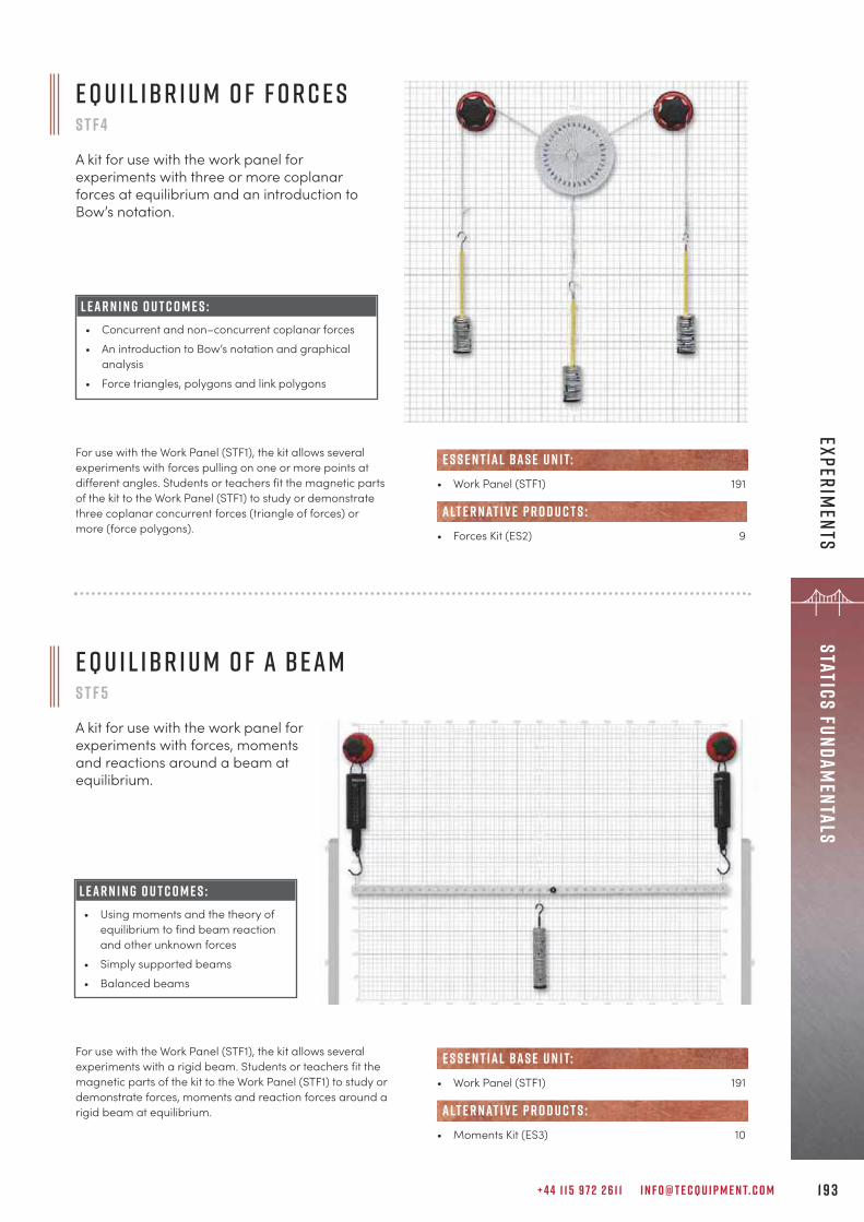
+ 4 4 1 1 5 9 7 2 2 6 1 1 I N F O @ T E C Q U I P M E N T. C O M 1 9 3
Statics FundamentalsExperim
ents
E q u i l ibr i u m o f F o r c e sS T F 4
A kit for use with the work panel forexperiments with three or more coplanarforces at equilibrium and an introduction toBow’s notation.
For use with the Work Panel (STF1), the kit allows severalexperiments with forces pulling on one or more points atdifferent angles. Students or teachers fit the magnetic partsof the kit to the Work Panel (STF1) to study or demonstratethree coplanar concurrent forces (triangle of forces) ormore (force polygons).
• Work Panel (STF1) 191
• Forces Kit (ES2) 9
e s s e n t ial bas e u n i t:
alt e r nat i v e p r o d u c t s :
E q u i l ibr i u m o f a B e a mS T F 5
A kit for use with the work panel forexperiments with forces, momentsand reactions around a beam atequilibrium.
For use with the Work Panel (STF1), the kit allows severalexperiments with a rigid beam. Students or teachers fit themagnetic parts of the kit to the Work Panel (STF1) to study ordemonstrate forces, moments and reaction forces around arigid beam at equilibrium.
• Work Panel (STF1) 191
• Moments Kit (ES3) 10
e s s e n t ial bas e u n i t:
alt e r nat i v e p r o d u c t s :
L e a r n i n g o u t c o m e s :• Concurrent and non–concurrent coplanar forces• An introduction to Bow’s notation and graphical
analysis• Force triangles, polygons and link polygons
L e a r n i n g o u t c o m e s :• Using moments and the theory of
equilibrium to find beam reactionand other unknown forces
• Simply supported beams• Balanced beams
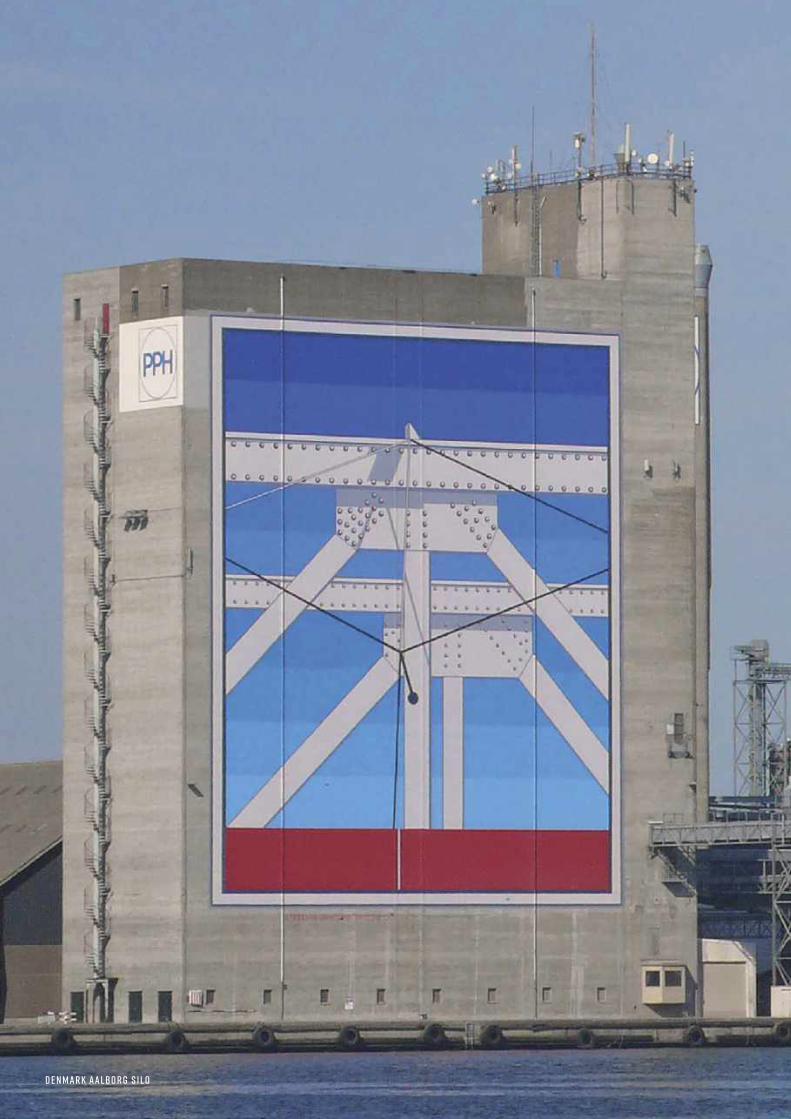
D e n m a r k A a lbo r g S i l o

+ 4 4 1 1 5 9 7 2 2 6 1 1 I N F O @ T E C Q U I P M E N T. C O M 1 9 5
Structures
s t r u c t u r e ss u p p o r t e q u i p m e n t a n d a n c i l l a r i e s 1 9 8
s o f t wa r e 2 0 0
A r c h e s , B r i d g e s a n d T r u s s e s 2 0 1
Fa i l u r e 2 0 7
d e f l e c t i o n s a n d s t r e s s 2 1 2
m o m e n t s 2 1 8
T o r s i o n 2 2 1
“TecQuipment’s Structures line was chosen to enhance the learning experience of ourengineering students. The products were delivered in a timely manner and were easy to set up.After-sales support has been very accommodating, allowing us to modify the experimentmanuals as we saw fit, giving us flexibility in learning objectives. Students have shown greatinterest and have found operating the units to be easy and simple.
R i a d R a j a by o r k u n i v e r s i t y, o n ta r i o , c a n a d a
Ö r e s u n d B r i d g e b e t w e e n S w e d e n a n d D e n m a r k

T E C Q U I P M E N T. C O M1 9 6
Stru
ctur
es
The Structures range consists of teaching equipment forunderstanding basic structural principles, focusing onbeams, bridges and cantilevers for students ofmechanical, civil and structural engineering. The 19 desk-mounted experiment modules can be usedstand alone or with TecQuipment’s powerful Structuressoftware which provides automatic data acquisition(ADA). To complement laboratory learning, experimentscan also be performed virtually, using only the software.
T h e S t r u c t u r e sT e s t F r a m e S T R 1This strong, sturdybenchtop test frameholds theinterchangeableexperiment modulesand instruments ofTecQuipment’sStructures range.
A u t o m at i c D ataA c q u i s i t i o n U n i tS T R 2 0 0 0Links to load cells and otherinstruments in the Structuresrange to send data to asuitable computer (notsupplied).
S t r u c t u r e sS o f t wa r e S T R SThe software accuratelysimulates all 19experiment modules ona suitable computer (notsupplied) without theneed of the Structureshardware.
T h e E x p e r i m e n t M o d u l e s S T R 2 – S T R 2 0
Interchangeable experiment modules give realistic andverifiable experiment results.
I n c l u d e s S t r u c t u r e sS o f t wa r e S T R S I n c l u d e s e x t e n s i v e u s e r g u i d e s
a n d e x a m p l e e x p e r i m e n t s
s t r u c t u r e s
F l e x i b l e a n d m o d u l a r A u t h e n t i c s o f t wa r e s i m u l at i o n• Experiment modules and instrumentation fix easily to the
test frame• Easily removeable and changeable experiments, making
good use of laboratory space• The modularity of the range allows for expansion as
required
• The Structures software offers an affordable and effectivemethod for students to quickly learn structures principles byperforming virtual experiments on a computer
• Allows students the flexibility of working away from thelaboratory
• Expands experiments beyond the limits of the hardware
A u t o m at i c d ata a c q u i s i t i o n H i g h f u n c t i o n a l i t y, a f f o r d a b ly p r i c e d• The use of automatic data acquisition and digital
instrumentation means students can get quick andaccurate results, optimising laboratory time
• There are no difficult-to-read instruments or abstractexperiment set-ups to distract students
• One experiment can demonstrate several principles, forexcellent value
• Extensive experiment capabilities and choice of hardwareand software, mean our Structures range provides anunsurpassed teaching solution at an unbeatable price

+ 4 4 1 1 5 9 7 2 2 6 1 1 I N F O @ T E C Q U I P M E N T. C O M 1 9 7
Structures
HAR D WAR E E X P E R I M E N T S V I R T UAL E X P E R I M E N T S e x t e n d e d e x p e r i m e n t s AU T O MAT I C DATA ACQU I S I T I O N
= V I R T UAL E X P E R I M E N T S e x t e n d e d e x p e r i m e n t s
S o f twar e( S T R S )
= HAR D WAR E E X P E R I M E N T S
E x p e r i m e n t M o d u l e s( S T R 2 – S T R 2 0 )
T e s t F ram e( S T R 1 )
+ =A D A U n i t
( S T R 2 0 0 0 , i n c l u d e s S T R S S o f twar e )E x p e r i m e n t M o d u l e s
( S T R 2 – S T R 2 0 )T e s t F ram e
( S T R 1 )
O r d e r i n gThe modular nature of our Structures range means items can be chosen to create the right combination of products that bestsuits teaching needs.
A R C H E S , B R I D G E S A N D T R U S S E S pa c k a g e S T R A
• Pin Jointed Frameworks (STR8) 201• Three-Pinned Arch (STR9) 202• Two-Pinned Arch (STR10) 203• Fixed Arch (STR11) 204• Redundant Truss (STR17) 205• Simple Suspension Bridge (STR19) 206
FA I L U R E pa c k a g e S T R C
• Euler Buckling of a Column (STR12) 207• Plastic Bending of Beams (STR15) 210• Plastic Bending of Portals (STR16) 211
D E F L E C T I O N S A N D S T R E S S pa c k a g e S T R B
• Deflection of Beams and Cantilevers (STR4) 212• Bending Stress in a Beam (STR5) 213• Continuous and Indeterminate Beams (STR13) 214• Curved Bars and Davits (STR14) 216• Frame Deflections and Reactions (STR18) 217
M O M E N T S Pa c k a g e S T R D
• Bending Moments in a Beam (STR2) 218• Shear Force in a Beam (STR3) 219• Bending Moments in a Portal Frame (STR20) 220
T O R S I O N Pa c k a g e S T R E
• Torsion of Circular Sections (STR6) 221• Unsymmetrical Bending and Shear Centre (STR7) 222
Pa c k a g e sThe following packages are available which offer greatvalue for money. Each hardware package is supplied with a25-seat software licence.
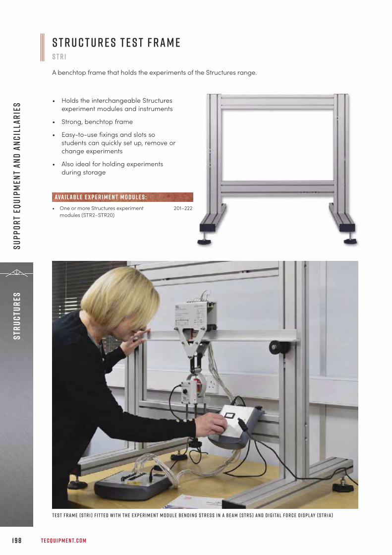
T E C Q U I P M E N T. C O M1 9 8
Stru
ctur
esSu
ppor
t Eq
uipm
ent
and An
cill
arie
s
• One or more Structures experiment 201–222modules (STR2–STR20)
ava i labl e e x p e r i m e n t m o d u l e s :
• Holds the interchangeable Structuresexperiment modules and instruments
• Strong, benchtop frame
• Easy-to-use fixings and slots sostudents can quickly set up, remove orchange experiments
• Also ideal for holding experimentsduring storage
S t r u c t u r e s T e s t F r a m eS T R 1
A benchtop frame that holds the experiments of the Structures range.
T e s t F r a m e ( S T R 1 ) f i t t e d w i t h t h e e x p e r i m e n t m o d u l e B e n d i n g S t r e s s i n a B e a m ( S T R 5 ) a n d D i g i ta l F o r c e D i s p l ay ( S T R 1 a )
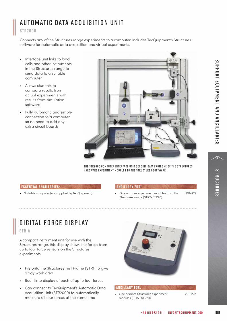
+ 4 4 1 1 5 9 7 2 2 6 1 1 I N F O @ T E C Q U I P M E N T. C O M 1 9 9
StructuresSupport Equipm
ent and Ancillaries
Au t o m at i c D ata Ac q u i s i t i o n U n i tS T R 2 0 0 0
Connects any of the Structures range experiments to a computer. Includes TecQuipment’s Structuressoftware for automatic data acquisition and virtual experiments.
• Interface unit links to loadcells and other instrumentsin the Structures range tosend data to a suitablecomputer
• Allows students tocompare results fromactual experiments withresults from simulationsoftware
• Fully automatic and simpleconnection to a computerso no need to add anyextra circuit boards
• Suitable computer (not supplied by TecQuipment)
E S S E N T IAL AN C I L LAR I E S :
T h e S T R 2 0 0 0 c o m p u t e r i n t e r fa c e u n i t s e n d i n g d ata f r o m o n e o f t h e S t r u c t u r e sh a r d wa r e e x p e r i m e n t m o d u l e s t o t h e S t r u c t u r e s S o f t wa r e
D i g i ta l F o r c e D i s p l ayS T R 1 a
A compact instrument unit for use with theStructures range, this display shows the forces fromup to four force sensors on the Structuresexperiments.
• Fits onto the Structures Test Frame (STR1) to givea tidy work area
• Real-time display of each of up to four forces
• Can connect to TecQuipment’s Automatic DataAcquisition Unit (STR2000) to automaticallymeasure all four forces at the same time
• One or more Structures experiment 201–222modules (STR2–STR20)
AN C I L LAR Y F O R :
• One or more experiment modules from the 201–222Structures range (STR2–STR20)
AN C I L LAR Y F O R :
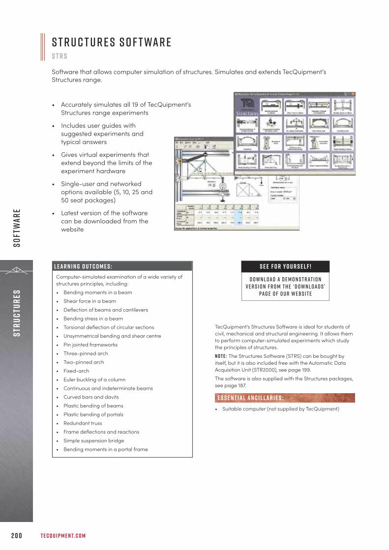
S t r u c t u r e s S o f t wa r eS T R S
Software that allows computer simulation of structures. Simulates and extends TecQuipment’sStructures range.
• Accurately simulates all 19 of TecQuipment’sStructures range experiments
• Includes user guides withsuggested experiments andtypical answers
• Gives virtual experiments thatextend beyond the limits of theexperiment hardware
• Single-user and networkedoptions available (5, 10, 25 and50 seat packages)
• Latest version of the softwarecan be downloaded from thewebsite
T E C Q U I P M E N T. C O M2 0 0
Stru
ctur
esSo
ftw
are
TecQuipment’s Structures Software is ideal for students ofcivil, mechanical and structural engineering. It allows themto perform computer-simulated experiments which studythe principles of structures. N o t e : The Structures Software (STRS) can be bought byitself, but it is also included free with the Automatic DataAcquisition Unit (STR2000), see page 199.The software is also supplied with the Structures packages,see page 187.
• Suitable computer (not supplied by TecQuipment)
E S S E N T IAL AN C I L LAR I E S :
L e a r n i n g o u t c o m e s :Computer-simulated examination of a wide variety ofstructures principles, including:• Bending moments in a beam• Shear force in a beam• Deflection of beams and cantilevers• Bending stress in a beam• Torsional deflection of circular sections• Unsymmetrical bending and shear centre• Pin jointed frameworks• Three-pinned arch• Two-pinned arch• Fixed-arch• Euler buckling of a column• Continuous and indeterminate beams• Curved bars and davits• Plastic bending of beams• Plastic bending of portals• Redundant truss • Frame deflections and reactions• Simple suspension bridge• Bending moments in a portal frame
S E E F O R Y O U R S E L F !
D O W N L OAD A D E M O N S T RAT I O NV E R S I O N F R O M T H E ‘ d o w n l o a d s ’
PAG E O F O U R W E B S I T E

+ 4 4 1 1 5 9 7 2 2 6 1 1 I N F O @ T E C Q U I P M E N T. C O M 2 0 1
StructuresArches, Bridges and Trusses
Students use stainless steel members to build different pinjointed frameworks. The equipment includes twoframework supports: a pivoting support, and a pivoting androlling support. Each member has a strain gauge attachedthat connects to a digital strain bridge. Load cells measurethe load applied at various angles. A second load cell canbe fitted to simulate lateral forces on the truss (STR8a).
P i n J o i n t e d F r a m e w o r k sS T R 8
Experiment for the study of strains, stresses,forces and deflections in various pin jointedframeworks, and the study of Bow’s notation.Mounts on the Structures test frame andconnects to Structures automatic dataacquisition unit and software.
S c r e e n s h o t o f t h e o p t i o n a lT e c Q u i p m e n t S t r u c t u r e s S o f t wa r e
L E A R N I N G O U T C O M E S :• Study of Bow’s notation, strains, stresses, forces and
deflections in various frameworks, including aWarren girder and roof truss
• Comparison of different frameworks
• Structures Test Frame (STR1) 198
• Digital Force Display (STR1a) 199
• Structures Software (STRS) for virtual experiments 200o r
• Automatic Data Acquisition Unit (STR2000) for 199automatic data acquisition and virtual experiments
• Additional Load Cell (STR8a)
• Redundant Truss (STR17) 205
alt e r nat i v e p r o d u c t s :
e s s e n t ial bas e u n i t:
E S S E N T IAL AN C I L LAR I E S :
R E C O M M E N D E D AN C I L LAR I E S :
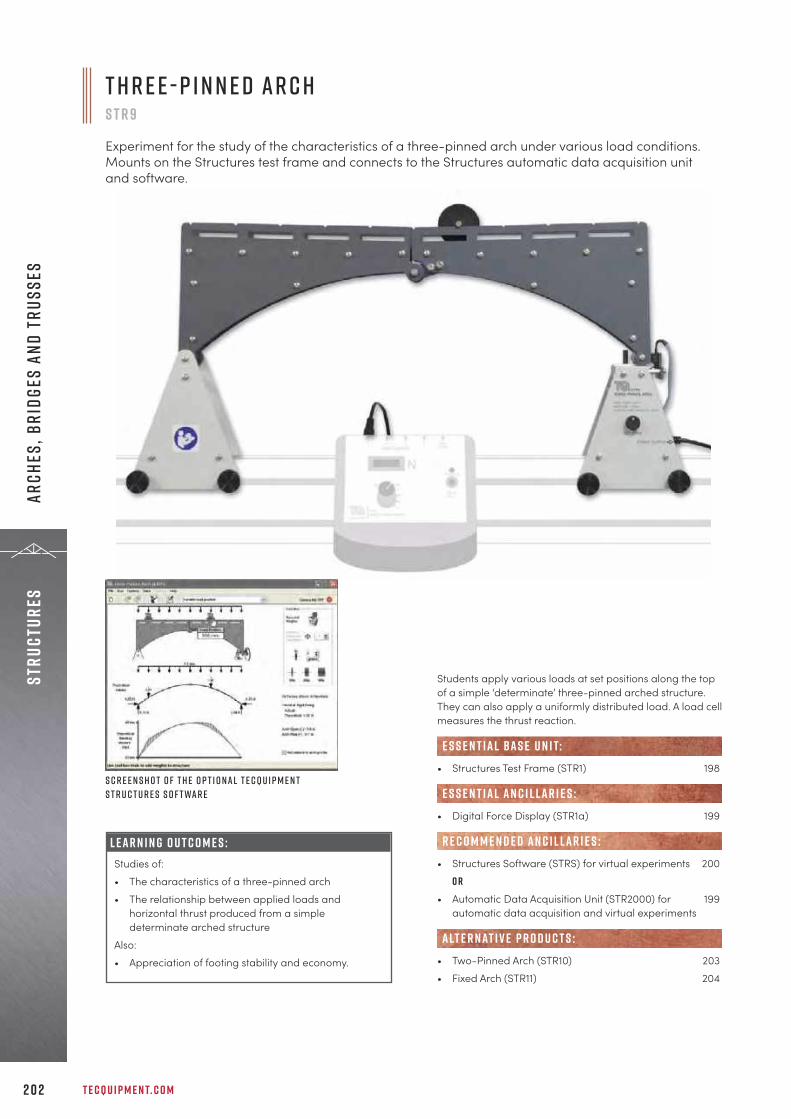
T E C Q U I P M E N T. C O M2 0 2
Stru
ctur
esAr
ches
, Bri
dges
and
Tru
sses
Students apply various loads at set positions along the topof a simple ‘determinate’ three-pinned arched structure.They can also apply a uniformly distributed load. A load cellmeasures the thrust reaction.
• Structures Test Frame (STR1) 198
• Digital Force Display (STR1a) 199
• Structures Software (STRS) for virtual experiments 200o r
• Automatic Data Acquisition Unit (STR2000) for 199automatic data acquisition and virtual experiments
• Two-Pinned Arch (STR10) 203• Fixed Arch (STR11) 204
alt e r nat i v e p r o d u c t s :
e s s e n t ial bas e u n i t:
E S S E N T IAL AN C I L LAR I E S :
R E C O M M E N D E D AN C I L LAR I E S :
S c r e e n s h o t o f t h e o p t i o n a l T e c Q u i p m e n tS t r u c t u r e s S o f t wa r e
L E A R N I N G O U T C O M E S :Studies of:• The characteristics of a three-pinned arch• The relationship between applied loads and
horizontal thrust produced from a simpledeterminate arched structure
Also:• Appreciation of footing stability and economy.
T h r e e - P i n n e d Ar c hS T R 9
Experiment for the study of the characteristics of a three-pinned arch under various load conditions.Mounts on the Structures test frame and connects to the Structures automatic data acquisition unitand software.
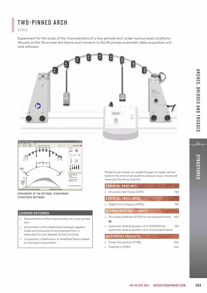
+ 4 4 1 1 5 9 7 2 2 6 1 1 I N F O @ T E C Q U I P M E N T. C O M 2 0 3
StructuresArches, Bridges and Trusses
Students use masses on weight hangers to apply variousloads to the arch at set positions along its span. A load cellmeasures the thrust reaction.
• Structures Test Frame (STR1) 198
• Digital Force Display (STR1a) 199
• Structures Software (STRS) for virtual experiments 200o r
• Automatic Data Acquisition Unit (STR2000) for 199automatic data acquisition and virtual experiments
• Three-Pinned Arch (STR9) 202• Fixed Arch (STR11) 204
alt e r nat i v e p r o d u c t s :
e s s e n t ial bas e u n i t:
E S S E N T IAL AN C I L LAR I E S :
R E C O M M E N D E D AN C I L LAR I E S :L E A R N I N G O U T C O M E S :• Demonstration of the characteristics of a two-pinned
arch• Examination of the relationship between applied
loads and horizontal thrust produced from aredundant (in one degree) arched structure
• Comparison of behaviour to simplified theory basedon the Secant assumption
S c r e e n s h o t o f t h e o p t i o n a l T e c Q u i p m e n tS t r u c t u r e s S o f t wa r e
T w o - P i n n e d Ar c hS T R 1 0
Experiment for the study of the characteristics of a two-pinned arch under various load conditions.Mounts on the Structures test frame and connects to the Structures automatic data acquisition unitand software.

T E C Q U I P M E N T. C O M2 0 4
Stru
ctur
esAr
ches
, Bri
dges
and
Tru
sses
L E A R N I N G O U T C O M E S :• Demonstration of the characteristics of a fixed arch• Examination of the relationship between applied
loads, horizontal thrust and fixing moment producedfrom a fixed (thus redundant in three degrees)arched structure.
• Comparison of behaviour to simplified theory basedon the Secant assumption.
To load the arch, students fit masses on weight hangers toset positions along the arch span. Load cells measure thefixed moment reaction and horizontal thrust.
• Structures Test Frame (STR1) 198
• Digital Force Display (STR1a) 199
• Structures Software (STRS) for virtual experiments 200o r
• Automatic Data Acquisition Unit (STR2000) for 199automatic data acquisition and virtual experiments
• Three-Pinned Arch (STR9) 202• Two-Pinned Arch (STR10) 203
alt e r nat i v e p r o d u c t s :
e s s e n t ial bas e u n i t:
E S S E N T IAL AN C I L LAR I E S :
R E C O M M E N D E D AN C I L LAR I E S :
S c r e e n s h o t o f t h e o p t i o n a l T e c Q u i p m e n tS t r u c t u r e s S o f t wa r e
F i x e d Ar c hS T R 1 1
Experiment for the study of the characteristics of a fixed arch under various load conditions. Mounts onthe Structures test frame and connects to the Structures automatic data acquisition unit and software.
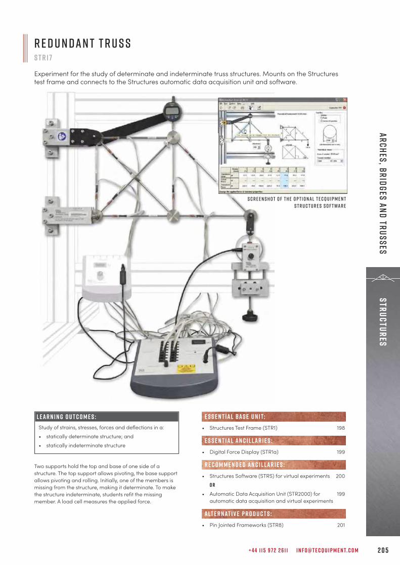
+ 4 4 1 1 5 9 7 2 2 6 1 1 I N F O @ T E C Q U I P M E N T. C O M 2 0 5
StructuresArches, Bridges and Trusses
L E A R N I N G O U T C O M E S :Study of strains, stresses, forces and deflections in a:• statically determinate structure; and• statically indeterminate structure
R e d u n d a n t T r u s sS T R 1 7
Experiment for the study of determinate and indeterminate truss structures. Mounts on the Structurestest frame and connects to the Structures automatic data acquisition unit and software.
Two supports hold the top and base of one side of astructure. The top support allows pivoting, the base supportallows pivoting and rolling. Initially, one of the members ismissing from the structure, making it determinate. To makethe structure indeterminate, students refit the missingmember. A load cell measures the applied force.
• Structures Test Frame (STR1) 198
• Digital Force Display (STR1a) 199
• Structures Software (STRS) for virtual experiments 200o r
• Automatic Data Acquisition Unit (STR2000) for 199automatic data acquisition and virtual experiments
• Pin Jointed Frameworks (STR8) 201
alt e r nat i v e p r o d u c t s :
e s s e n t ial bas e u n i t:
E S S E N T IAL AN C I L LAR I E S :
R E C O M M E N D E D AN C I L LAR I E S :
S c r e e n s h o t o f t h e o p t i o n a l T e c Q u i p m e n tS t r u c t u r e s S o f t wa r e

L E A R N I N G O U T C O M E S :• Demonstration of the characteristics of a simple
suspension bridge• Examination of the relationship between applied
loads and the suspension cable tension• Observation of the stability of the structure• Comparison of behaviour to simplified cable theory
S c r e e n s h o t o f t h e o p t i o n a lT e c Q u i p m e n t S t r u c t u r e s S o f t wa r e
S i m p l e S u s p e n s i o n B r i d g es t r 1 9
Experiment for the study of the characteristics of a simple suspension bridge. Mounts on the Structurestest frame and connects to the Structures automatic data acquisition unit and software.
Students use masses on weight hangers to apply variousloads to a rigid deck, joined to a parabolic cable viahangers. A load cell measures the cable tension.
• Structures Test Frame (STR1) 198
• Digital Force Display (STR1a) 199
• Structures Software (STRS) for virtual experiments 200o r
• Automatic Data Acquisition Unit (STR2000) for 199automatic data acquisition and virtual experiments
• Suspension Cable Demonstration (STF2) 192
alt e r nat i v e p r o d u c t s :
e s s e n t ial bas e u n i t:
E S S E N T IAL AN C I L LAR I E S :
R E C O M M E N D E D AN C I L LAR I E S :
T E C Q U I P M E N T. C O M2 0 6
Stru
ctur
esAr
ches
, Bri
dges
and
Tru
sses
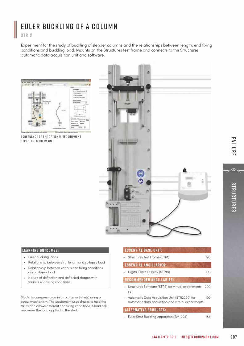
+ 4 4 1 1 5 9 7 2 2 6 1 1 I N F O @ T E C Q U I P M E N T. C O M 2 0 7
StructuresFailure
Students compress aluminium columns (struts) using ascrew mechanism. The equipment uses chucks to hold thestruts and allows different end fixing conditions. A load cellmeasures the load applied to the strut.
S c r e e n s h o t o f t h e o p t i o n a l T e c Q u i p m e n tS t r u c t u r e s S o f t wa r e
E u l e r B u c k l i n g o f a C o l u m nS T R 1 2
Experiment for the study of buckling of slender columns and the relationships between length, end fixingconditions and buckling load. Mounts on the Structures test frame and connects to the Structuresautomatic data acquisition unit and software.
• Structures Test Frame (STR1) 198
• Digital Force Display (STR1a) 199
• Structures Software (STRS) for virtual experiments 200o r
• Automatic Data Acquisition Unit (STR2000) for 199automatic data acquisition and virtual experiments
• Euler Strut Buckling Apparatus (SM1005) 186
alt e r nat i v e p r o d u c t s :
e s s e n t ial bas e u n i t:
E S S E N T IAL AN C I L LAR I E S :
R E C O M M E N D E D AN C I L LAR I E S :
L E A R N I N G O U T C O M E S :• Euler buckling loads• Relationship between strut length and collapse load• Relationship between various end fixing conditions
and collapse load• Nature of deflection and deflected shapes with
various end fixing conditions

T E C Q U I P M E N T. C O M2 0 8
The Design Engineering Department at PolytechnicManufacturing Bandung on the island of East Java in Indonesiaapproached TecQuipment for engineering teaching equipmentwhen they wanted apparatus for their laboratory expansion.The institution, which has a long history of providing engineeringeducation in the region, recently expanded into offering courseson Design Engineering. They needed civil engineering teachingequipment for teaching students about structures and thebehaviour of materials.Mr Asep Indra Komara, SST, MT, commented on their decision tochoose TecQuipment products:
T h e L a b o r at o r y S e t- U pPolytechnic Manufacturing Bandung upgraded their laboratoryequipment with structures and materials-based apparatus intwo phases, adopting them as students progressed through theacademic year.
P h a s e 1For teaching the theory around torsion they chose a series ofuniversal test frames that provide a rigid support for the 19interchangeable experiment modules in TecQuipment’sStructures range. They purchased two different experiments tomount on the test frames: the Bending Stress in a Beamexperiment, for investigating stresses and strains within astructure relative to loads; and the Torsion of Circular Sectionsexperiment, for investigating the relationship between torqueand deflection in the elastic region of solid and tubular sectionsof various material specimens.
P o ly t e c h n i c M a n u fa c t u r i n gB a n d u n g E x pa n d D e s i g nE n g i n e e r i n g L a b o r at o r y
c a s e s t u d y
“For a number of years I have been using TecQuipmentequipment at the Institute of Technology in Bandung. Now atthe Polytechnic Manufacturing Bandung it was a logicalchoice to once again purchase TecQuipment products, givenour previous positive experience of working with the companyand their local agent in Indonesia, Jitrasindo. Plus, I know fromyears of use that TecQuipment manufactures good qualityproducts.”

+ 4 4 1 1 5 9 7 2 2 6 1 1 I N F O @ T E C Q U I P M E N T. C O M 2 0 9
StructuresFailure
To complement the above, they added an UnsymmetricalCantilever Apparatus that allows students to investigate thedeflections of unsymmetrical cantilevers, and a BeamApparatus for investigating deflections and reactions in simplysupported and cantilevered beams.
P h a s e 2For this next phase they purchased a Euler Buckling Apparatusfor showing the load and deflection, plus buckling loads forvarious strut lengths, cross sections and end conditions.Additionally, a Pin Jointed Frameworks experiment to fit on atest frame was selected to investigate different pin joinedframeworks and the impact of applying forces on them. Finally, to familiarise their students with strain gaugetechniques, a Strain Gauge Kit was included, which features aselection of resistance strain gauges.
T r a i n i n g b y L o c a l A g e n t s J i t r a s i n d oTecQuipment works with an expansive network of trustedagents across the world, including Jitrasindo in Indonesia, whosupported the installation process and provided training on theequipment at Polytechnic Manufacturing Bandung.
“The training was thorough and efficiently delivered. Theyeven recorded videos for our future reference.”
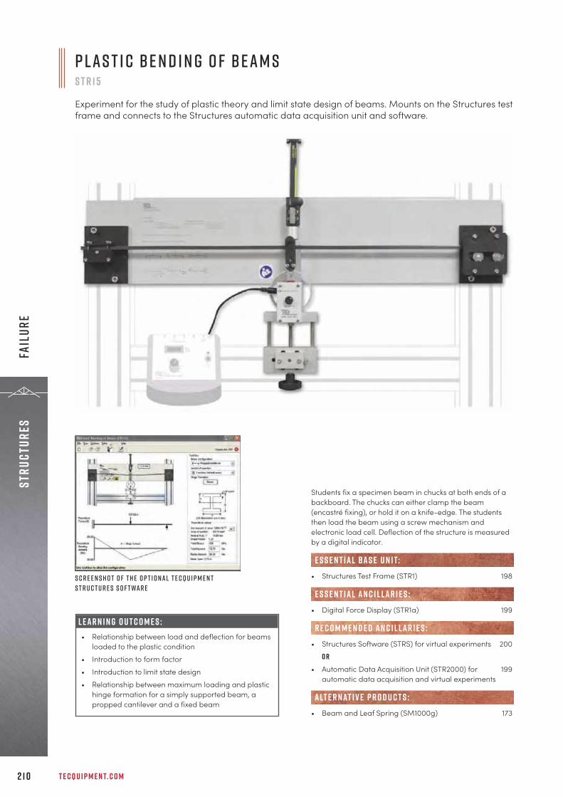
T E C Q U I P M E N T. C O M2 1 0
Stru
ctur
esFa
ilur
e
Students fix a specimen beam in chucks at both ends of abackboard. The chucks can either clamp the beam(encastré fixing), or hold it on a knife-edge. The studentsthen load the beam using a screw mechanism andelectronic load cell. Deflection of the structure is measuredby a digital indicator.
• Structures Test Frame (STR1) 198
• Digital Force Display (STR1a) 199
• Structures Software (STRS) for virtual experiments 200o r
• Automatic Data Acquisition Unit (STR2000) for 199automatic data acquisition and virtual experiments
• Beam and Leaf Spring (SM1000g) 173
alt e r nat i v e p r o d u c t s :
e s s e n t ial bas e u n i t:
E S S E N T IAL AN C I L LAR I E S :
R E C O M M E N D E D AN C I L LAR I E S :
S c r e e n s h o t o f t h e o p t i o n a l T e c Q u i p m e n tS t r u c t u r e s S o f t wa r e
P l a s t i c B e n d i n g o f B e a m sS T R 1 5
Experiment for the study of plastic theory and limit state design of beams. Mounts on the Structures testframe and connects to the Structures automatic data acquisition unit and software.
L E A R N I N G O U T C O M E S :• Relationship between load and deflection for beams
loaded to the plastic condition• Introduction to form factor• Introduction to limit state design• Relationship between maximum loading and plastic
hinge formation for a simply supported beam, apropped cantilever and a fixed beam
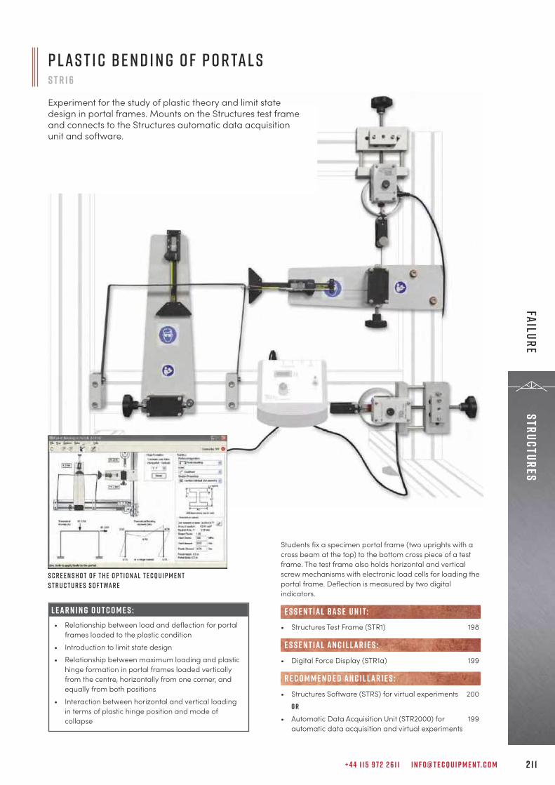
+ 4 4 1 1 5 9 7 2 2 6 1 1 I N F O @ T E C Q U I P M E N T. C O M 2 1 1
StructuresFailure
S c r e e n s h o t o f t h e o p t i o n a l T e c Q u i p m e n tS t r u c t u r e s S o f t wa r e
P l a s t i c B e n d i n g o f P o r ta l sS T R 1 6
Experiment for the study of plastic theory and limit statedesign in portal frames. Mounts on the Structures test frameand connects to the Structures automatic data acquisitionunit and software.
L E A R N I N G O U T C O M E S :• Relationship between load and deflection for portal
frames loaded to the plastic condition• Introduction to limit state design• Relationship between maximum loading and plastic
hinge formation in portal frames loaded verticallyfrom the centre, horizontally from one corner, andequally from both positions
• Interaction between horizontal and vertical loadingin terms of plastic hinge position and mode ofcollapse
Students fix a specimen portal frame (two uprights with across beam at the top) to the bottom cross piece of a testframe. The test frame also holds horizontal and verticalscrew mechanisms with electronic load cells for loading theportal frame. Deflection is measured by two digitalindicators.
• Structures Test Frame (STR1) 198
• Digital Force Display (STR1a) 199
• Structures Software (STRS) for virtual experiments 200o r
• Automatic Data Acquisition Unit (STR2000) for 199automatic data acquisition and virtual experiments
e s s e n t ial bas e u n i t:
E S S E N T IAL AN C I L LAR I E S :
R E C O M M E N D E D AN C I L LAR I E S :

T E C Q U I P M E N T. C O M2 1 2
Stru
ctur
esDe
flec
tion
s an
d St
ress
D e f l e c t i o n o f B e a m s a n d C a n t i l e v e r sS T R 4
Experiment for the study of beam deflection under different loads and fixing conditions, and thedemonstration of Young’s modulus. Mounts on the Structures test frame and connects to the Structuresautomatic data acquisition unit and software.
L E A R N I N G O U T C O M E S :E x a m i n at i o n o f :• Beam deflections• General bending formulae• Beam end rotations • Elastic modulus (Young’s modulus) for various
materials T y p i c a l c o n d i t i o n s a r e :• Cantilever• Propped cantilever• Encastré beam• Simply supported beam
The experiment hardware consists of a backboard that fixesto the Structures Test Frame (STR1, available separately).Test beams fit onto the backboard using a rigid clamp andknife-edge supports. Students apply loads at any positionusing hangers holding various masses. Mounted on atrammel, a digital deflection indicator traverses the beamto measure beam deflection.
• Structures Test Frame (STR1) 198
• Structures Software (STRS) for virtual experiments 200o r
• Automatic Data Acquisition Unit (STR2000) for 199automatic data acquisition and virtual experiments
• Deflection of Beams and Cantilevers Kit (ES4) 11• Stiffness, Bending and Torsion (TE16) 160• Beam and Leaf Spring (SM1000g) 173• Beam Apparatus (SM1004) 184• Continuous and Indeterminate Beams (STR13) 214
e s s e n t ial bas e u n i t:
R E C O M M E N D E D AN C I L LAR I E S :
alt e r nat i v e p r o d u c t s :
S c r e e n s h o t o f t h e o p t i o n a l T e c Q u i p m e n tS t r u c t u r e s S o f t wa r e
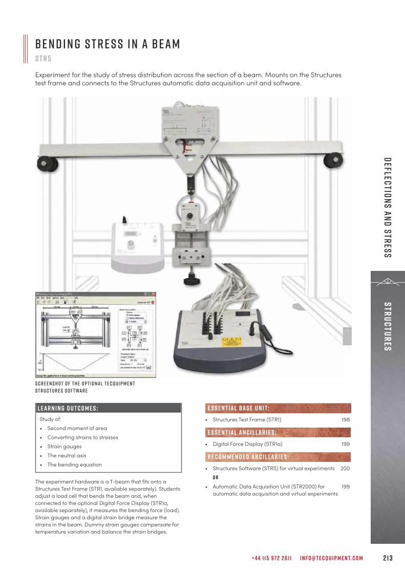
+ 4 4 1 1 5 9 7 2 2 6 1 1 I N F O @ T E C Q U I P M E N T. C O M 2 1 3
StructuresDeflections and Stress
L E A R N I N G O U T C O M E S :Study of:• Second moment of area• Converting strains to stresses• Strain gauges• The neutral axis• The bending equation
The experiment hardware is a T-beam that fits onto aStructures Test Frame (STR1, available separately). Studentsadjust a load cell that bends the beam and, whenconnected to the optional Digital Force Display (STR1a,available separately), it measures the bending force (load).Strain gauges and a digital strain bridge measure thestrains in the beam. Dummy strain gauges compensate fortemperature variation and balance the strain bridges.
S c r e e n s h o t o f t h e o p t i o n a l T e c Q u i p m e n tS t r u c t u r e s S o f t wa r e
B e n d i n g S t r e s s i n a B e a mS T R 5
Experiment for the study of stress distribution across the section of a beam. Mounts on the Structurestest frame and connects to the Structures automatic data acquisition unit and software.
• Structures Test Frame (STR1) 198
• Digital Force Display (STR1a) 199
• Structures Software (STRS) for virtual experiments 200o r
• Automatic Data Acquisition Unit (STR2000) for 199automatic data acquisition and virtual experiments
e s s e n t ial bas e u n i t:
E S S E N T IAL AN C I L LAR I E S :
R E C O M M E N D E D AN C I L LAR I E S :
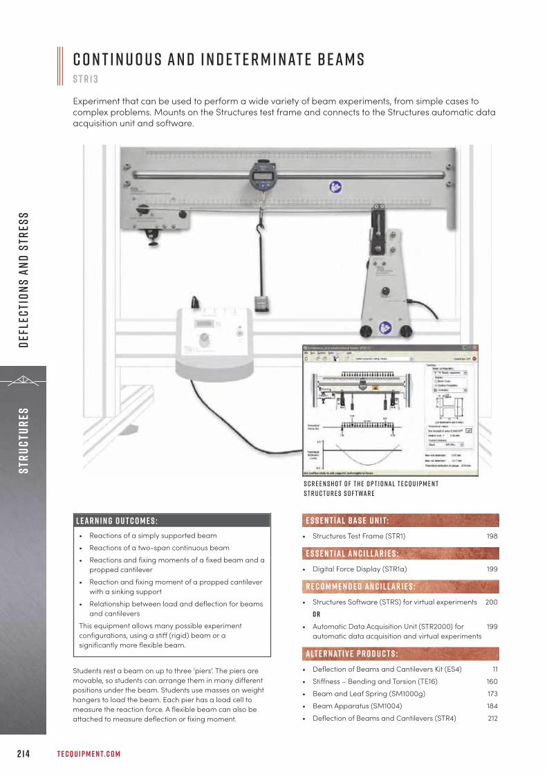
T E C Q U I P M E N T. C O M2 1 4
Stru
ctur
esDe
flec
tion
s an
d St
ress
• Structures Test Frame (STR1) 198
• Digital Force Display (STR1a) 199
• Structures Software (STRS) for virtual experiments 200o r
• Automatic Data Acquisition Unit (STR2000) for 199automatic data acquisition and virtual experiments
• Deflection of Beams and Cantilevers Kit (ES4) 11• Stiffness – Bending and Torsion (TE16) 160• Beam and Leaf Spring (SM1000g) 173• Beam Apparatus (SM1004) 184• Deflection of Beams and Cantilevers (STR4) 212
alt e r nat i v e p r o d u c t s :
e s s e n t ial bas e u n i t:
E S S E N T IAL AN C I L LAR I E S :
R E C O M M E N D E D AN C I L LAR I E S :
S c r e e n s h o t o f t h e o p t i o n a l T e c Q u i p m e n tS t r u c t u r e s S o f t wa r e
C o n t i n u o u s a n d I n d e t e r m i n at e B e a m sS T R 1 3
Experiment that can be used to perform a wide variety of beam experiments, from simple cases tocomplex problems. Mounts on the Structures test frame and connects to the Structures automatic dataacquisition unit and software.
Students rest a beam on up to three ‘piers’. The piers aremovable, so students can arrange them in many differentpositions under the beam. Students use masses on weighthangers to load the beam. Each pier has a load cell tomeasure the reaction force. A flexible beam can also beattached to measure deflection or fixing moment.
L E A R N I N G O U T C O M E S :• Reactions of a simply supported beam• Reactions of a two-span continuous beam• Reactions and fixing moments of a fixed beam and a
propped cantilever• Reaction and fixing moment of a propped cantilever
with a sinking support• Relationship between load and deflection for beams
and cantileversThis equipment allows many possible experimentconfigurations, using a stiff (rigid) beam or asignificantly more flexible beam.
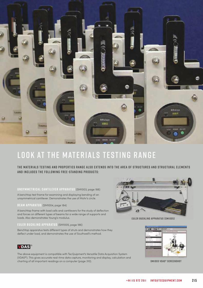
+ 4 4 1 1 5 9 7 2 2 6 1 1 I N F O @ T E C Q U I P M E N T. C O M 2 1 5
t h e M at e r i a l s T e s t i n g a n d P r o p e r t i e s r a n g e a l s o e x t e n d s i n t o t h e a r e a o f s t r u c t u r e s a n d s t r u c t u r a l e l e m e n t sa n d i n c l u d e s t h e f o l l o w i n g f r e e - s ta n d i n g p r o d u c t s :
U n s y m m e t r i c a l C a n t i l e v e r A p pa r at u s (SM1003, page 188)
A benchtop test frame for examining and displaying bending of anunsymmetrical cantilever. Demonstrates the use of Mohr’s circle.
B e a m A p pa r at u s (SM1004, page 184)
A benchtop frame with load cells and cantilevers for the study of deflectionand forces on different types of beams for a wide range of supports andloads. Also demonstrates Young’s modulus.
e u l e r b u c k l i n g a p pa r at u s (SM1005, page 186)
Benchtop apparatus tests different types of struts and demonstrates how they deflect under load, and demonstrates the use of Southwell’s method.
L o o k at t h e M at e r i a l s T e s t i n g r a n g e
The above equipment is compatible with TecQuipment’s Versatile Data Acquisition System(VDAS®). This gives accurate real-time data capture, monitoring and display, calculation andcharting of all important readings on a computer (page 310). S M 1 0 0 3 V DAS ® S c r e e n s h o t
E u l e r b u c k l i n g a p pa r at u s ( S M 1 0 0 5 )
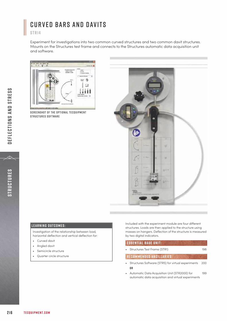
T E C Q U I P M E N T. C O M2 1 6
Stru
ctur
esDe
flec
tion
s an
d St
ress
L E A R N I N G O U T C O M E S :Investigation of the relationship between load,horizontal deflection and vertical deflection for:• Curved davit• Angled davit• Semicircle structure• Quarter circle structure
Included with the experiment module are four differentstructures. Loads are then applied to the structure usingmasses on hangers. Deflection of the structure is measuredby two digital indicators.
• Structures Test Frame (STR1) 198
• Structures Software (STRS) for virtual experiments 200o r
• Automatic Data Acquisition Unit (STR2000) for 199automatic data acquisition and virtual experiments
e s s e n t ial bas e u n i t:
R E C O M M E N D E D AN C I L LAR I E S :
S c r e e n s h o t o f t h e o p t i o n a l T e c Q u i p m e n tS t r u c t u r e s S o f t wa r e
C u r v e d B a r s a n d D av i t sS T R 1 4
Experiment for investigations into two common curved structures and two common davit structures.Mounts on the Structures test frame and connects to the Structures automatic data acquisition unitand software.

+ 4 4 1 1 5 9 7 2 2 6 1 1 I N F O @ T E C Q U I P M E N T. C O M 2 1 7
StructuresDeflections and Stress
L E A R N I N G O U T C O M E S :Study and comparison of load, horizontal reactions,fixing moments, sway and shear forces in a:• rectangular portal with a uniform section; and• rectangular portal with a non-uniform section
The hardware includes two rectangular portal frames withthe same dimensions. However, one of the frames has aconstant second moment of area, while the other has oneleg with a smaller second moment of area. Load is appliedusing variable masses whilst deflection is measured by adigital indicator.
F r a m e D e f l e c t i o n s a n d R e a c t i o n sS T R 1 8
Experiment for the study of rectangular portals subjected to vertical loads. Mounts on the Structurestest frame and connects to the Structures automatic data acquisition unit and software.
S c r e e n s h o t o f t h e o p t i o n a l T e c Q u i p m e n tS t r u c t u r e s S o f t wa r e
• Structures Test Frame (STR1) 198
• Digital Force Display (STR1a) 199
• Structures Software (STRS) for virtual experiments 200o r
• Automatic Data Acquisition Unit (STR2000) for 199automatic data acquisition and virtual experiments
• Bending Moments in a Portal Frame (STR20) 220
alt e r nat i v e p r o d u c t s :
e s s e n t ial bas e u n i t:
E S S E N T IAL AN C I L LAR I E S :
R E C O M M E N D E D AN C I L LAR I E S :
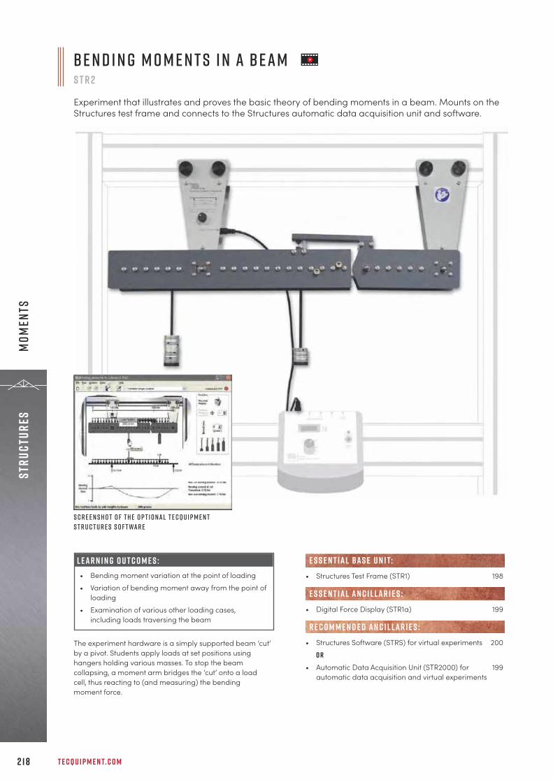
T E C Q U I P M E N T. C O M2 1 8
Stru
ctur
esM
omen
ts
B e n d i n g M o m e n t s i n a B e a mS T R 2
Experiment that illustrates and proves the basic theory of bending moments in a beam. Mounts on theStructures test frame and connects to the Structures automatic data acquisition unit and software.
The experiment hardware is a simply supported beam ‘cut’by a pivot. Students apply loads at set positions usinghangers holding various masses. To stop the beamcollapsing, a moment arm bridges the ‘cut’ onto a loadcell, thus reacting to (and measuring) the bendingmoment force.
• Structures Test Frame (STR1) 198
• Digital Force Display (STR1a) 199
• Structures Software (STRS) for virtual experiments 200o r
• Automatic Data Acquisition Unit (STR2000) for 199automatic data acquisition and virtual experiments
R E C O M M E N D E D AN C I L LAR I E S :
E S S E N T IAL AN C I L LAR I E S :
e s s e n t ial bas e u n i t:
S c r e e n s h o t o f t h e o p t i o n a l T e c Q u i p m e n tS t r u c t u r e s S o f t wa r e
L E A R N I N G O U T C O M E S :• Bending moment variation at the point of loading• Variation of bending moment away from the point of
loading• Examination of various other loading cases,
including loads traversing the beam
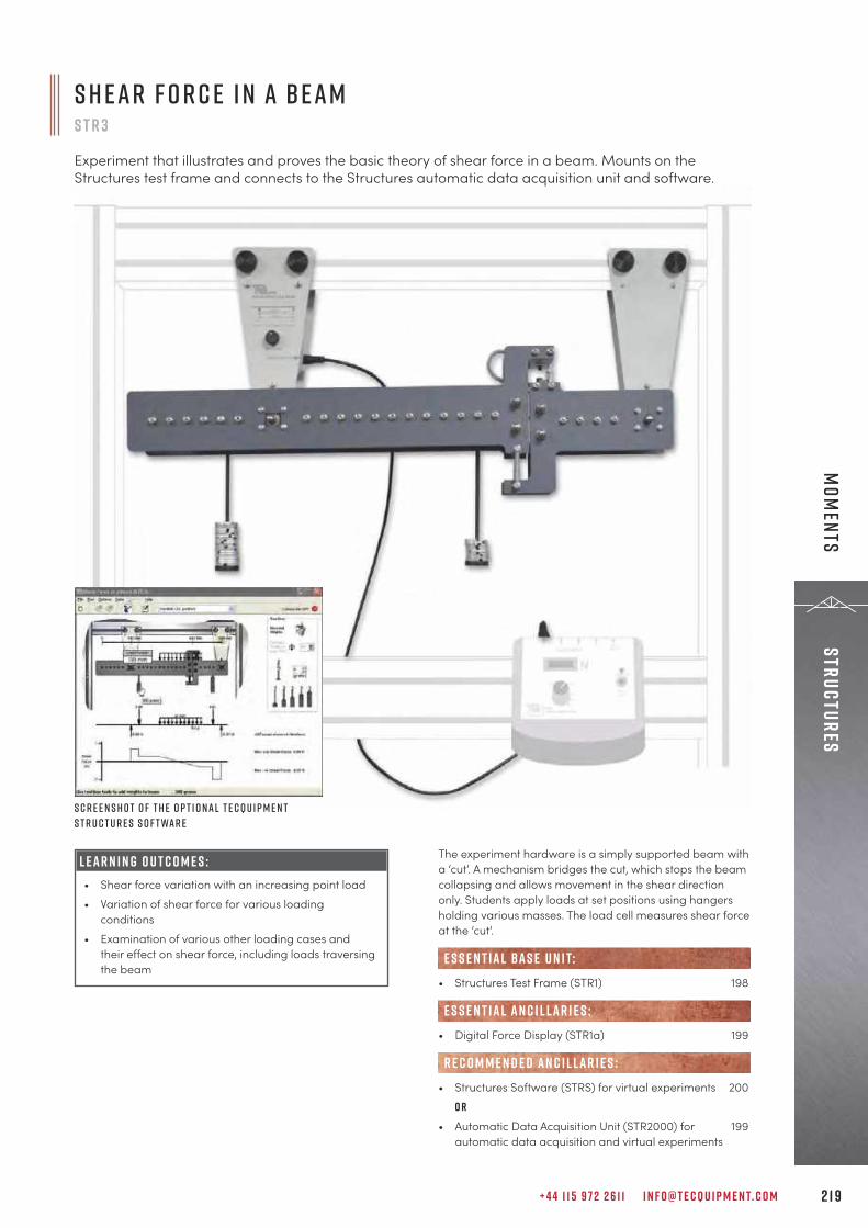
+ 4 4 1 1 5 9 7 2 2 6 1 1 I N F O @ T E C Q U I P M E N T. C O M 2 1 9
StructuresM
oments
S h e a r F o r c e i n a B e a mS T R 3
Experiment that illustrates and proves the basic theory of shear force in a beam. Mounts on theStructures test frame and connects to the Structures automatic data acquisition unit and software.
The experiment hardware is a simply supported beam witha ‘cut’. A mechanism bridges the cut, which stops the beamcollapsing and allows movement in the shear directiononly. Students apply loads at set positions using hangersholding various masses. The load cell measures shear forceat the ‘cut’.
• Structures Test Frame (STR1) 198
• Digital Force Display (STR1a) 199
• Structures Software (STRS) for virtual experiments 200o r
• Automatic Data Acquisition Unit (STR2000) for 199automatic data acquisition and virtual experiments
e s s e n t ial bas e u n i t:
E S S E N T IAL AN C I L LAR I E S :
R E C O M M E N D E D AN C I L LAR I E S :
S c r e e n s h o t o f t h e o p t i o n a l T e c Q u i p m e n tS t r u c t u r e s S o f t wa r e
L E A R N I N G O U T C O M E S :• Shear force variation with an increasing point load• Variation of shear force for various loading
conditions• Examination of various other loading cases and
their effect on shear force, including loads traversingthe beam

T E C Q U I P M E N T. C O M2 2 0
Stru
ctur
esM
omen
ts
B e n d i n g M o m e n t s i n a P o r ta l F r a m eS T R 2 0
Experiment for the study of bending moments and sway in portal frames. Mounts on the Structures testframe and connects to the Structures automatic data acquisition unit and software.
S c r e e n s h o t o f t h e o p t i o n a l T e c Q u i p m e n tS t r u c t u r e s S o f t wa r e
Students use masses on weight hangers to apply variousloads to a portal frame. The portal has three members: ahorizontal beam and two vertical members or ‘legs’ joinedat two upper corners. All members are of the same materialand have the same flexural rigidity, i.e. value. Deflection ismeasured by a digital indicator.
• Structures Test Frame (STR1) 198
• Structures Software (STRS) for virtual experiments 200o r
• Automatic Data Acquisition Unit (STR2000) for 199automatic data acquisition and virtual experiments
• Frame Deflections and Reactions (STR18) 217
e s s e n t ial bas e u n i t:
R E C O M M E N D E D AN C I L LAR I E S :
alt e r nat i v e p r o d u c t s :
L E A R N I N G O U T C O M E S :• Strain gauge linearity• Using strain measurement to find the bending
moment• Bending moments and sway for vertical and
horizontal loads• Bending moments for internal and external moments
on vertical members• Comparison of ideal and non-ideal structures

+ 4 4 1 1 5 9 7 2 2 6 1 1 I N F O @ T E C Q U I P M E N T. C O M 2 2 1
StructuresTorsion
The experiment module examines the behaviour in theelastic region of solid and tubular section specimens. Twochucks on a backboard hold a test specimen. A mechanismon one chuck applies torque manually to the specimen. Aprotractor scale on this chuck measures angular movement.A load cell on the other chuck measures torque.
• Structures Test Frame (STR1) 198
• Digital Force Display (STR1a) 199
• Structures Software (STRS) for virtual experiments 200o r
• Automatic Data Acquisition Unit (STR2000) for 199automatic data acquisition and virtual experiments
• Torsion of Circular Sections Kit (ES5) 12• Additional Torsion Testing Kit (TE16b) 160• Torsion Testing Machine, 30 Nm (SM1001) 166
e s s e n t ial bas e u n i t:
E S S E N T IAL AN C I L LAR I E S :
R E C O M M E N D E D AN C I L LAR I E S :
alt e r nat i v e p r o d u c t s :
S c r e e n s h o t o f t h e o p t i o n a l T e c Q u i p m e n tS t r u c t u r e s S o f t wa r e
T o r s i o n o f C i r c u l a r S e c t i o n sS T R 6
Experiment for the study of torque and deflection in different materials with circular section.Mounts on the Structures test frame and connects to the Structures automatic data acquisition unitand software.
L E A R N I N G O U T C O M E S :Study of:• The relationship between specimen length, torque
and angular deflection• The behaviour of specimens of different materials
and sections• General torsion theory• Shear modulus• Polar moment of inertia

T E C Q U I P M E N T. C O M2 2 2
Stru
ctur
esTo
rsio
n
U n s y m m e t r i c a l B e n d i n g a n d S h e a r C e n t r eS T R 7
Experiment for the study of the vertical and horizontal deflection of different unsymmetricalsections. Mounts on the Structures test frame and connects to the Structures automatic dataacquisition unit and software.
The experiment module examines the vertical andhorizontal deflection of different unsymmetrical sections atvarious angles and loads. Two multi-way chucks hold a testspecimen vertically. One chuck has an indexing system forrotating the beam in set increments. This changes the angleof loading. The other chuck and a weight hanger applies avariable load. Two digital deflection indicators measuredeflection in the x and y directions. An interchangeableplate allows students to find the shear centre of thespecimen.
• Structures Test Frame (STR1) 198
• Structures Software (STRS) for virtual experiments 200o r
• Automatic Data Acquisition Unit (STR2000) for 199automatic data acquisition and virtual experiments
• Unsymmetrical Cantilever Apparatus (SM1003) 188
e s s e n t ial bas e u n i t:
R E C O M M E N D E D AN C I L LAR I E S :
alt e r nat i v e p r o d u c t s :
S c r e e n s h o t o f t h e o p t i o n a l T e c Q u i p m e n tS t r u c t u r e s S o f t wa r e
L E A R N I N G O U T C O M E S :Study of:• Horizontal and vertical deflection of different
unsymmetrical sections under various loads and atvarious angles
• Relationship between the vertical and horizontaldeflections and the principal moments of area ofeach section
• Shear centre of various unsymmetrical sections
+ 4 4 1 1 5 9 7 2 2 6 1 1 I N F O @ T E C Q U I P M E N T. C O M 2 2 3
Theory of machines
“One of the reasons we chose TecQuipment as our equipment provider was that we had trust inwhat they delivered. Colleagues who had used TecQuipment products vouched for the qualityand suitability of the products, and the support and conduct of both TecQuipment and theirlocal representative in the region, Tech Labs.
D r D av i d S ta a c k D i r e c t o r o f U n d e r g r a d u at e L a b o r at o r y I n s t r u c t i o n , T e x a s A & M U n i v e r s i t y, U S A
T H E O R Y O F M A C H I N E SF R I C T I O N 2 2 5
M O T I O N 2 2 9
V I B R AT I O N 2 4 0
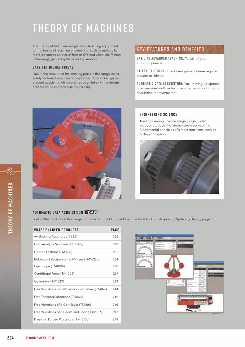
T E C Q U I P M E N T. C O M2 2 4
Theo
ry o
f ma
chin
es
The Theory of Machines range offers teaching equipmentfor the basics of machine engineering, such as motion, tomore advanced studies of free and forced vibration, frictionin bearings, geared systems and governors.
S a f e Y e t H i g h ly V i s u a lDue to the amount of fast moving parts in this range, extrasafety features have been incorporated. Interlocked guardsprevent accidents, while care has been taken in the designprocess not to compromise the visibility.
T H E O R Y O F M A C H I N E S
E n g i n e e r i n g S c i e n c eThe Engineering Science range (page 5) alsoincludes products that demonstrate some of thefundamental principles of simple machines, such aspulleys and gears.
V D A S ® e n a b l e d P r o d u c t s Pa g eAir Bearing Apparatus (TE96) 225
Cam Analysis Machine (TM1021V) 229
Geared Systems (TM1018) 232
Balance of Reciprocating Masses (TM1022V) 234
Gyroscope (TM1004) 236
Centrifugal Force (TM1005) 237
Governors (TM1027) 239
Free Vibrations of a Mass-Spring System (TM164) 244
Free Torsional Vibrations (TM165) 245
Free Vibrations of a Cantilever (TM166) 246
Free Vibrations of a Beam and Spring (TM167) 247
Free and Forced Vibrations (TM1016V) 249
A u t o m at i c d ata a c q u i s i t i o n Look at the products in this range that work with TecQuipment’s unique Versatile Data Acquisition System (VDAS®), page 310.
B A S I C T O A D VA N C E D T E A C H I N G : To suit all yourlaboratory needs.
s a f e t y b y d e s i g n : Interlocked guards where requiredprevent accidents.
a u t o m at i c d ata a c q u i s i t i o n : Fast moving equipmentoften requires multiple fast measurements, making dataacquisition a powerful tool.
k e y f eat u r e s an d be n e f i t s :

+ 4 4 1 1 5 9 7 2 2 6 1 1 I N F O @ T E C Q U I P M E N T. C O M 2 2 5
Theory of machinesFriction
A i r B e a r i n g A p pa r at u sT E 9 6
Benchtop, self-contained air bearing apparatus to demonstrate the performance of self-acting, gas-lubricated journal bearings, including the phenomenon of half-speed whirl.
• Demonstrates the performance of a self-acting, gas (air)-lubricated journal bearing
• Self-contained benchtop apparatus,includes all instrumentation needed for tests
• Variable bearing load and speed, for arange of tests
• Includes a multi-channel digital pressuredisplay
• Demonstrates the onset of bearing ‘whirl’
L E A R N I N G O U T C O M E S :• Demonstrate how a vertical load affects the pressure
distribution around an air-lubricated journal bearing• Demonstrate how bearing speed, and therefore
compressibility number, affects the pressuredistribution in the bearing, and how this compareswith theory
• Demonstrate the onset of ‘whirl’
s c r e e n s h o t o f t h e o p t i o n a l V D A S ® s o f t wa r e
The main part has a variable speed motor that turns a beltdrive. The belt drive turns a precision bearing shaft. Theshaft has a high-quality surface finish and spins inside avertically loaded bush. A hand-operated load control andload cell allow the user to apply and measure the load onthe bearing bush. The bush has pressure tappings equallyspaced around its circumference. The tappings connect to amultichannel digital pressure display unit.
• Versatile Data Acquisition System (VDAS-F) 310(frame-mounted version)
• Michell Pad Apparatus (TE99) 227• Journal Bearing Demonstration (TM25) 228
R E C O M M E N D E D AN C I L LAR I E S :
alt e r nat i v e p r o d u c t s :

T E C Q U I P M E N T. C O M2 2 6
Theo
ry o
f ma
chin
esFr
icti
on
H e r t z i a n C o n ta c t A p pa r at u sT E 9 8
Benchtop, self-contained unit that allows a practical examination of Hertz’s theories of contact betweenmaterials.
L E A R N I N G O U T C O M E S :• The effect of varied pressure with constant angle• The effect of varied angle (different relative
curvature) with constant pressure
• Compact, self-contained unit that needs noelectricity or external services
• Uses flexible material to produce magnifiedand easily viewed results
• Controllable hydraulic pressure system withgauge for repeatable results
• Variable relative contact angles andpressures for a range of experiments
The apparatus has two pads with curved contact surfaces.The upper pad (made of a transparent plastic material) hasa compound radius. The lower pad (made of an opaqueflexible material) has a simple radius. A hand-operatedhydraulic pump and cylinder force the two pads together.Students may rotate the lower pad, a pointer shows theangle of rotation. This allows a study of the effect ofdifferent relative curvatures.
Q ual i t y C o n t r o l w i t h I n - H o u s e P r o d u c t i o nTo maintain high quality and keep lead times to a minimum, products are designed and manufactured all under one roof at the TecQuipment headquarters based in the UK.

+ 4 4 1 1 5 9 7 2 2 6 1 1 I N F O @ T E C Q U I P M E N T. C O M 2 2 7
Theory of machinesFriction
L E A R N I N G O U T C O M E S :Study of:• Pressure distributions in a tilting pad bearing• Influence of sliding speed and viscosity on the
pressure distribution in the bearing, and comparisonwith calculations based on Reynold’s equation
• Relationship between pressure and the film thicknessat the trailing edge of the pad
M i c h e l l Pa d A p pa r at u sT E 9 9
A benchtop, self-contained apparatus to demonstrate the pressure distribution across the film of oil in aMichell tilting pad slider bearing. Helps to prove Reynold’s equation for pressure gradient in fluid film.
The benchtop unit has an aluminium plate (pad) mountedabove a continuous loop flat belt. The belt runs in an oilreservoir to provide a continuous supply of oil under thepad. This creates a pressurised film of oil between the padand the belt. A set of 13 graduated tubes show the oilpressure across and along the film under the pad.
• Air Bearing Apparatus (TE96) 225• Journal Bearing Demonstration (TM25) 228
alt e r nat i v e p r o d u c t s :
• Proven design, based on a machinecreated by Imperial College London
• Accurately mimics a Michell tilting pad,fluid-lubricated slider bearing
• Fully adjustable pad (tilt) angle
• Includes oil and a viscometer
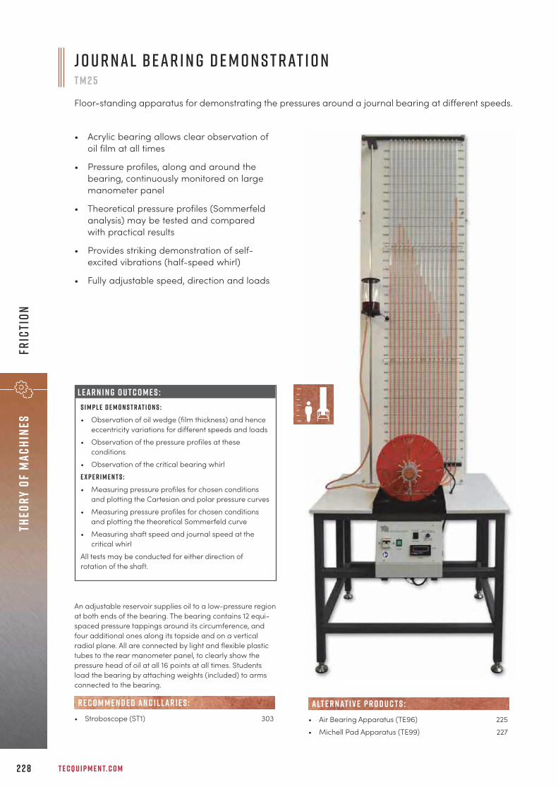
T E C Q U I P M E N T. C O M2 2 8
Theo
ry o
f ma
chin
esFr
icti
on
J o u r n a l B e a r i n g D e m o n s t r at i o nT M 2 5
Floor-standing apparatus for demonstrating the pressures around a journal bearing at different speeds.
L E A R N I N G O U T C O M E S :S i m p l e d e m o n s t r at i o n s :• Observation of oil wedge (film thickness) and hence
eccentricity variations for different speeds and loads • Observation of the pressure profiles at these
conditions • Observation of the critical bearing whirl E x p e r i m e n t s :• Measuring pressure profiles for chosen conditions
and plotting the Cartesian and polar pressure curves • Measuring pressure profiles for chosen conditions
and plotting the theoretical Sommerfeld curve• Measuring shaft speed and journal speed at the
critical whirl All tests may be conducted for either direction ofrotation of the shaft.
• Acrylic bearing allows clear observation ofoil film at all times
• Pressure profiles, along and around thebearing, continuously monitored on largemanometer panel
• Theoretical pressure profiles (Sommerfeldanalysis) may be tested and comparedwith practical results
• Provides striking demonstration of self-excited vibrations (half-speed whirl)
• Fully adjustable speed, direction and loads
An adjustable reservoir supplies oil to a low-pressure regionat both ends of the bearing. The bearing contains 12 equi-spaced pressure tappings around its circumference, andfour additional ones along its topside and on a verticalradial plane. All are connected by light and flexible plastictubes to the rear manometer panel, to clearly show thepressure head of oil at all 16 points at all times. Studentsload the bearing by attaching weights (included) to armsconnected to the bearing.
• Stroboscope (ST1) 303
R E C O M M E N D E D AN C I L LAR I E S :• Air Bearing Apparatus (TE96) 225• Michell Pad Apparatus (TE99) 227
alt e r nat i v e p r o d u c t s :

+ 4 4 1 1 5 9 7 2 2 6 1 1 I N F O @ T E C Q U I P M E N T. C O M 2 2 9
Theory of machinesm
otion
• Includes TecQuipment’s Versatile DataAcquisition System VDAS® Onboard,featuring data acquisition via USB
• Illustrates cam and follower separation or‘cam bounce’ under safe and controlledconditions
• Fully interlocked for safety
• Highly visual and audible, perfect fordemonstrations
C a m A n a ly s i s M a c h i n eT M 1 0 2 1 V
Benchtop apparatus and control and instrumentation unit,for studying the dynamic behaviour of different cams andfollowers and their ‘bounce’ speed.
S c r e e n s h o t o f t h e V D A S ® s o f t wa r e
The main part of the product has a precision-machinedheavy steel base which holds a high-torque, direct-drivevariable speed motor. The motor shaft connects through acoupling to the main shaft which then passes into the camtest area. Self-aligning heavy-duty bearings support theshaft which has a substantial flywheel. The flywheel reducesspeed variations as the torque demand changes during thecam rotation cycle. The cam under test fits to the end of themain shaft, accurately mounted both axially and radially toensure repeatability. The follower fits to the bottom of avertical shaft running in low-friction linear bearings.
• Cam and Crank and Toggle Kit (ES12) 23
alt e r nat i v e p r o d u c t s :
L E A R N I N G O U T C O M E S :• Comparing actual results with theory for profiles of
follower displacement, acceleration and velocity• Cam bounce speeds for different cam and follower
combinations, and comparison of speeds to thosepredicted by simplified theory
• How spring rate, preload and follower mass affectcam bounce speed

T E C Q U I P M E N T. C O M2 3 0
P lay N ow – T e c Q u i p m e n t Y o u T ube C han n e lVisit and subscribe to the TecQuipment YouTube channel for all the latest products showcases, installation and user videos: y o u t ube . c o m / c / t e cqu i p m e n t
YouTube videos available for all products with this icon
H e l e - s haw Ap parat u s ( H 9 ) T h e r mal P owe r P lan t w i t h S t eam E n g i n e T ra i n e r ( T D 1 0 5 0 )
R e f r i g e rat i o n C y c l e ( E C 1 5 0 0 ) P i n -J o i n t e d F ram ewo r k s ( S T R 8 )
P r o c e s s T ra i n e r ( C E 1 1 7 ) I m pac t o f a J e t ( H 8 )
S c h l i e r e n Ap parat u s (AF 3 0 2a ) T e n s i l e T e s t e r ( E S 6 )

+ 4 4 1 1 5 9 7 2 2 6 1 1 I N F O @ T E C Q U I P M E N T. C O M 2 3 1
Theory of machinesM
otion
• Demonstrates first and second mode whirlspeeds and how to predict them
• Extra bearings and weights (included) givea choice of free/free, fixed/free andfixed/fixed end conditions and experimentswith loaded shafts and eccentric loading
• Supplied with different shafts to study howlength and diameter affects whirling
• Optional stroboscope to ‘freeze’ the imageof the shaft to see its shape clearly
L E A R N I N G O U T C O M E S :• Basic whirling demonstration• The effect of shaft length and diameter• The effect of end conditions (fixings)• Loaded shaft (one and two masses)• Eccentric loading
W h i r l i n g o f S h a f t s a n d C r i t i c a l S p e e dT M 1 0 0 1
Benchtop apparatus that demonstrates ‘whirling’ in different horizontal shafts with a varietyof fixings (end conditions), loaded and unloaded.
A variable speed motor turns the horizontal test shaft. Twobearings hold the shaft: one bearing at the ‘driven end’ andthe other bearing at the ‘tail end’ of the shaft. The tail endbearing slides in its housing to allow the shaft length tochange as it ‘whirls’. Similar to a beam on two simple knife-edge supports, both bearings allow free angular shaftmovement (free ends condition). Also supplied with theequipment are extra bearings that restrict angularmovement when fitted, to give ‘fixed ends’.
• Stroboscope (ST1) 313
R E C O M M E N D E D AN C I L LAR I E S :

T E C Q U I P M E N T. C O M2 3 2
Theo
ry o
f ma
chin
esM
otio
n
G e a r e d S y s t e m sT M 1 0 1 8
Benchtop apparatus for dynamic and static experiments on geared and other drive systems. This baseunit requires at least one of the optional drive units: toothed belt drive, round belt drive, chain drive andhelical gear drive.
Fully equipped benchtop base unit for tests onseveral different drive unitsSaves space and reduces costs
Includes gear drive unit, with optional belt, chainand helical gear drive systemsOffers comparative tests of different designs
Optional test stand (TM1018a)For additional tests in static efficiency and inertia
Easy set-up, all drive units can be removed andfitted in minutesMaximises experiment time
Works with VDAS®
Quick and reliable tests with data capture
F eat u r e s an d be n e f i t s : L E A R N I N G O U T C O M E S :D y n a m i c :• Simple and compound gear trains• Mechanical advantage, velocity ratio and dynamic
efficiencies of gear trains• Mechanical advantage, velocity ratio and dynamic
efficiencies of optional drive systems (chain, belt andhelical gears)
• Appreciation of the different characteristics of drivesystems
• Chain and belt drive tension, including differentmethods of application
A c c e l e r at i o n a n d s tat i c :• Mechanical advantage, velocity ratio and static
efficiencies of gear drives• Mass moment of inertia of a flywheel by experiment
and calculation• Mass moment of inertia of geared drive systems by
experiment and calculation
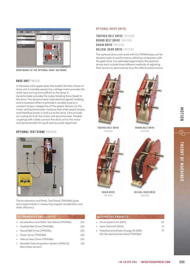
+ 4 4 1 1 5 9 7 2 2 6 1 1 I N F O @ T E C Q U I P M E N T. C O M 2 3 3
Theory of machinesM
otion
O p t i o n a l D r i v e U n i t s :
T o o t h e d B e lt D r i v e T M 1 0 1 8 bR o u n d B e lt D r i v e T M 1 0 1 8 cC h a i n D r i v e T M 1 0 1 8 dh e l i c a l g e a r d r i v e t m 1 0 1 8 eThe optional drive units work with the TM1018 base unit fordynamic tests on performance, allowing comparison withthe gear drive. For extended experiments, the optionaldrives each include three different methods of adjustingtheir tension to demonstrate how this affects performance.
O p t i o n a l T e s t S ta n d T M 1 0 1 8 a
The Acceleration and Static Test Stand (TM1018a) givesextra experiments in measuring angular acceleration andstatic efficiency.
S c r e e n s h o t o f t h e o p t i o n a l V D A S ® s o f t wa r e
• Acceleration and Static Test Stand (TM1018a) 233• Toothed Belt Drive (TM1018b) 233• Round Belt Drive (TM1018c) 233• Chain Drive (TM1018d) 233• Helical Gear Drive (TM1018e) 233• Versatile Data Acquisition System (VDAS-B) 310
(benchtop version)
R E C O M M E N D E D AN C I L LAR I E S :
B a s e u n i t T M 1 0 1 8In the base unit’s upper level, the student fits their choice ofdrive unit. A variable speed, low-voltage motor provides theshaft input turning force (effort) to the drive. Adynamometer provides the output braking force (load) tothe drive. The dynamometer uses electromagnetic brakingand a hysteresis effect to provide a variable load at aconstant torque, irrespective of the speed. Sensors on themotor and dynamometer measure their shaft speed, torqueand therefore power in and out at the drive. Fans provideair cooling for both the motor and dynamometer. Flexiblecouplings with collets connect the drive unit to the motorand dynamometer for quick and accurate alignment.
• Drive Systems Kit (ES11) 20• Gear Trains Kit (ES13) 21• Potential and Kinetic Energy Kit (ES9) 17
(for the optional test stand TM1018a)
alt e r nat i v e p r o d u c t s :
T o o t h e d B e lt D r i v eT M 1 0 1 8 b
R o u n d B e lt D r i v eT M 1 0 1 8 c
C h a i n D r i v eT M 1 0 1 8 d
h e l i c a l g e a r d r i v et m 1 0 1 8 e
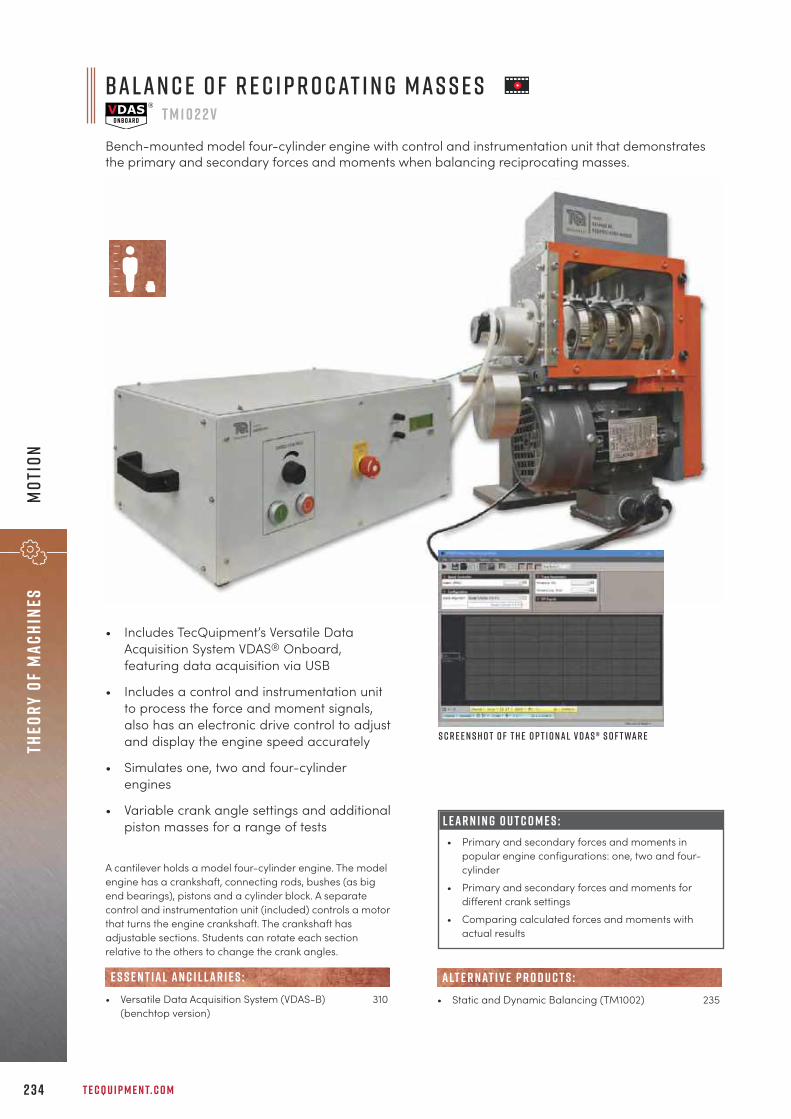
B a l a n c e o f R e c i p r o c at i n g M a s s e sT M 1 0 2 2 V
Bench-mounted model four-cylinder engine with control and instrumentation unit that demonstratesthe primary and secondary forces and moments when balancing reciprocating masses.
T E C Q U I P M E N T. C O M2 3 4
Theo
ry o
f ma
chin
esM
otio
n
L E A R N I N G O U T C O M E S :• Primary and secondary forces and moments in
popular engine configurations: one, two and four-cylinder
• Primary and secondary forces and moments fordifferent crank settings
• Comparing calculated forces and moments withactual results
• Includes TecQuipment’s Versatile DataAcquisition System VDAS® Onboard,featuring data acquisition via USB
• Includes a control and instrumentation unitto process the force and moment signals,also has an electronic drive control to adjustand display the engine speed accurately
• Simulates one, two and four-cylinderengines
• Variable crank angle settings and additionalpiston masses for a range of tests
A cantilever holds a model four-cylinder engine. The modelengine has a crankshaft, connecting rods, bushes (as bigend bearings), pistons and a cylinder block. A separatecontrol and instrumentation unit (included) controls a motorthat turns the engine crankshaft. The crankshaft hasadjustable sections. Students can rotate each sectionrelative to the others to change the crank angles.
• Versatile Data Acquisition System (VDAS-B) 310(benchtop version)
E S S E N T IAL AN C I L LAR I E S :• Static and Dynamic Balancing (TM1002) 235
alt e r nat i v e p r o d u c t s :
S c r e e n s h o t o f t h e o p t i o n a l V D A S ® s o f t wa r e

+ 4 4 1 1 5 9 7 2 2 6 1 1 I N F O @ T E C Q U I P M E N T. C O M 2 3 5
Theory of machinesM
otion
• Interlocked transparent dome allowsstudents to observe the masses rotating
• Demonstrates balancing a horizontal shaftwith two, three or four rotating masses
• Independent analysis of static and dynamicbalancing
• Includes four removeable rotating masses(balance blocks) with different inserts for arange of moments
• Protractor, horizontal scale and slidingindicator to help accurately position therotating masses
L E A R N I N G O U T C O M E S :• Demonstration of simple static and dynamic
balancing of two, three and four rotating masses • Dynamic balancing of rotating mass systems by
calculation and vector diagrams (triangle andpolygon)
S tat i c a n d D y n a m i c B a l a n c i n gT M 1 0 0 2
Benchtop apparatus for experiments in balancing a rotating mass system, statically and dynamically.
The test assembly includes a balanced steel shaft mountedhorizontally on low-friction bearings. The equipmentincludes a set of four rotating masses (balance blocks). Thebalance blocks fix in any horizontal position and relativeangle on the shaft. Each block contains a different (andremovable) circular insert, allowing students to create fourblocks of different mass and moment. Without the inserts,the blocks become four identical masses for simplebalancing tests.
• Balance of Reciprocating Masses (TM1022V) 234
alt e r nat i v e p r o d u c t s :

T E C Q U I P M E N T. C O M2 3 6
Theo
ry o
f ma
chin
esM
otio
n
• Directmeasurementof gyroscopictilting force,couple andvelocities(speeds)shown ondigital displays
• Interlocked,transparentdome allowsstudents toobserve the gyroscope spinning in safety
• Works in both clockwise and anticlockwisedirections for a full range of tests
• Unique multifunction controls for coarseand fine adjustment of velocity anddirection
L E A R N I N G O U T C O M E S :• Direction of gyroscopic couple (in relation to
precession and rotor spin directions).• Magnitude of gyroscopic couple (in relation to
precession and rotor spin velocities).
The rotor of an electric motor shares a horizontallysupported shaft with a flywheel, forming the gyroscope. Asecond electric motor turns a belt that turns a turntableunder the gyroscope, causing precession about a verticalaxis. Both motors work in clockwise and anticlockwiserotation and with variable velocity.
• Versatile Data Acquisition System (VDAS-B) 310(benchtop version)
R E C O M M E N D E D AN C I L LAR I E S :
S c r e e n s h o t o f t h e o p t i o n a l V D A S ® s o f t wa r e
G y r o s c o p eT M 1 0 0 4
Benchtop apparatus for experiments in gyroscopic couple and velocities of rotor and precision.

+ 4 4 1 1 5 9 7 2 2 6 1 1 I N F O @ T E C Q U I P M E N T. C O M 2 3 7
Theory of machinesM
otion
• Demonstrates the relationship betweencentrifugal force, mass of a rotating body,its distance from the axis, and its angularvelocity
• Balanced arm mechanism for accuratereadings
• Interlocked, transparent dome allowsstudents to see the mechanism rotating insafety
• Includes a set of weights for differentexperiments
L E A R N I N G O U T C O M E S :Finding the relationship between centrifugal force, themass of a rotating body, its distance from the axis ofrotation (radial position) and the speed of rotation.
S c r e e n s h o t o f t h e o p t i o n a l V D A S ® s o f t wa r e
C e n t r i f u g a l F o r c eT M 1 0 0 5
Benchtop apparatus for experiments in centrifugal force and angular velocity.
A base unit supports a mechanism that rotates under aclear dome. An electric motor turns a belt that turns aturntable under the mechanism. The motor works inclockwise and anticlockwise direction and with variablevelocity. A sensor measures the rotational velocity of themechanism.
• Versatile Data Acquisition System (VDAS-B) 310(benchtop version)
• Centrifugal Force Kit (ES16) 22
R E C O M M E N D E D AN C I L LAR I E S :
alt e r nat i v e p r o d u c t s :
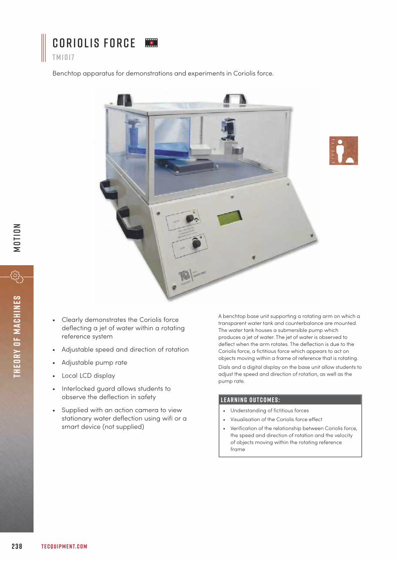
T E C Q U I P M E N T. C O M2 3 8
Theo
ry o
f ma
chin
esM
otio
n
C o r i o l i s F o r c eT M 1 0 1 7
Benchtop apparatus for demonstrations and experiments in Coriolis force.
A benchtop base unit supporting a rotating arm on which atransparent water tank and counterbalance are mounted.The water tank houses a submersible pump whichproduces a jet of water. The jet of water is observed todeflect when the arm rotates. The deflection is due to theCoriolis force, a fictitious force which appears to act onobjects moving within a frame of reference that is rotating.Dials and a digital display on the base unit allow students toadjust the speed and direction of rotation, as well as thepump rate.
• Clearly demonstrates the Coriolis forcedeflecting a jet of water within a rotatingreference system
• Adjustable speed and direction of rotation
• Adjustable pump rate
• Local LCD display
• Interlocked guard allows students toobserve the deflection in safety
• Supplied with an action camera to viewstationary water deflection using wifi or asmart device (not supplied)
L E A R N I N G O U T C O M E S :• Understanding of fictitious forces• Visualisation of the Coriolis force effect • Verification of the relationship between Coriolis force,
the speed and direction of rotation and the velocityof objects moving within the rotating referenceframe

2 3 9
Theory of machinesM
otion
L E A R N I N G O U T C O M E S :• Finding characteristic curves of governor speed
against sleeve lift• Comparison of governor types in terms of sensitivity,
stability and effort• On the Porter and Proell governors, the effects of
varying centre sleeve mass• On the Hartnell governor, the effects of varying:
– arm length – spring rate – spring compression– rotating mass
• Demonstration of the isochronous condition (Hartnellgovernor)
A base unit contains a variable speed motor. The motorturns each of three different governors: Proell, Porter andHartnell. N o t e : Only one governor can be tested at a time.
• Versatile Data Acquisition System (VDAS-B) 310(benchtop version)
R E C O M M E N D E D AN C I L LAR I E S :
• Includes three easy-to-fit governors:Hartnell, Porter and Proell
• Interlocked, transparent dome allowsstudents to observe the governors rotatingin safety
• Includes additional weights to change themass of the Porter and Proell governorsleeves
• Supplied with different springs and rotatingmasses for the Hartnell governor
H a r t n e l l g o v e r n o rs h o w n f i t t e d
S c r e e n s h o t o f t h e o p t i o n a l V D A S ® s o f t wa r e
G o v e r n o r sT M 1 0 2 7
Benchtop apparatus for demonstrating how different governors work, including Hartnell, Porter andProell governors.
p o r t e r g o v e r n o r P r o e l l g o v e r n o r

T E C Q U I P M E N T. C O M2 4 0
Theo
ry o
f ma
chin
esVi
brat
ion
For use with TecQuipment’s Free Vibrations experiments, thetest frame fits on any standard desk or benchtop. Students,teachers or lecturers fit the parts of their free vibrationsexperiments to the test frame to study or demonstrate afree vibrations topic.
F r e e V i b r at i o n s T e s t F r a m eT M 1 6 0
A sturdy benchtop frame for use with the Free Vibrations experiment modules.
Experiment modules(tm161–tm167)
Essential Base Unit (tm160)
M O D U LAR S Y S T E M
S h o w n w i t h o n e o f t h e ava i l a b l e e x p e r i m e n t m o d u l e s
Rigid and lightweight constructionEnsures repeatability of results and long servicelife, yet light enough to move around thelaboratory
Supplied with all the tools needed for assemblyQuick and easy set-up time, optimisesexperiment time during laboratory sessions
Includes a storage tray for safe storage of anytools and smaller parts of the optionalexperimentsReduces risk of losing components giving greaterlongevity
F eat u r e s an d be n e f i t s :• Simple and Compound Pendulums (TM161) 241• Filar Pendulums (TM162) 242• Centre of Percussion (TM163) 243• Free Vibrations of a Mass-Spring System (TM164) 244• Free Torsional Vibrations (TM165) 245• Free Vibrations of a Cantilever (TM166) 236• Free Vibrations of a Beam and Spring (TM167) 247
ava i labl e e x p e r i m e n t m o d u l e s :
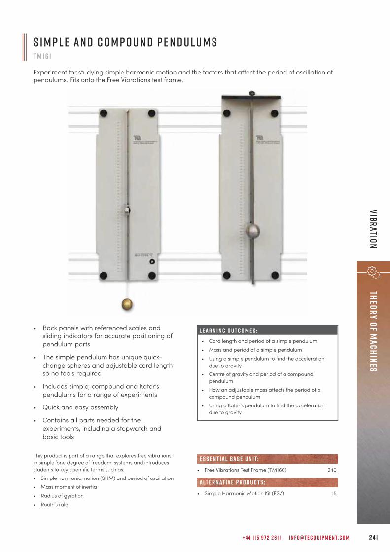
+ 4 4 1 1 5 9 7 2 2 6 1 1 I N F O @ T E C Q U I P M E N T. C O M 2 4 1
Theory of machinesVibration
This product is part of a range that explores free vibrationsin simple ‘one degree of freedom’ systems and introducesstudents to key scientific terms such as:• Simple harmonic motion (SHM) and period of oscillation• Mass moment of inertia• Radius of gyration• Routh’s rule
S i m p l e a n d C o m p o u n d P e n d u l u m sT M 1 6 1
Experiment for studying simple harmonic motion and the factors that affect the period of oscillation ofpendulums. Fits onto the Free Vibrations test frame.
• Back panels with referenced scales andsliding indicators for accurate positioning ofpendulum parts
• The simple pendulum has unique quick-change spheres and adjustable cord lengthso no tools required
• Includes simple, compound and Kater’spendulums for a range of experiments
• Quick and easy assembly
• Contains all parts needed for theexperiments, including a stopwatch andbasic tools
L E A R N I N G O U T C O M E S :• Cord length and period of a simple pendulum• Mass and period of a simple pendulum• Using a simple pendulum to find the acceleration
due to gravity• Centre of gravity and period of a compound
pendulum• How an adjustable mass affects the period of a
compound pendulum• Using a Kater’s pendulum to find the acceleration
due to gravity
• Free Vibrations Test Frame (TM160) 240
• Simple Harmonic Motion Kit (ES7) 15
alt e r nat i v e p r o d u c t s :
e s s e n t ial bas e u n i t:

T E C Q U I P M E N T. C O M2 4 2
Theo
ry o
f ma
chin
esVi
brat
ion
This product is part of a range that explores free vibrationsin simple ‘one degree of freedom’ systems and introducesstudents to key scientific terms such as:• Simple harmonic motion (SHM) and period of oscillation• Mass moment of inertia• Radius of gyration• Axis of rotation• Parallel axis theorem
• Free Vibrations Test Frame (TM160) 240
• Simple Harmonic Motion Kit (ES7) 15
alt e r nat i v e p r o d u c t s :
e s s e n t ial bas e u n i t:
• Flexible and modular, fits onto the testframe (TM160) for experiments andlaboratory demonstrations
• Different pendulum designs, lengths, massand inertia, for a range of experiments
• Quick and easy assembly
• Contains all parts needed for theexperiments, including an ‘examplemachine element’, stopwatch, steel rule andbasic tools
L E A R N I N G O U T C O M E S :• Cord length and period of bifilar and trifilar
pendulums• Cord (support) positions and period of bifilar and
trifilar pendulums• Mass and period of bifilar and trifilar pendulums• Position of mass on bifilar and trifilar pendulums• Finding moment of inertia of an ‘example machine
part’ in two different axes
F i l a r P e n d u l u m sT M 1 6 2
Experiment for studying simple harmonic motion and the factors that affect the period of oscillationof bifilar and trifilar pendulums. Fits onto the Free Vibrations test frame.
S h o w n w i t h t h e T e s t F r a m e ( T M 160 )

+ 4 4 1 1 5 9 7 2 2 6 1 1 I N F O @ T E C Q U I P M E N T. C O M 2 4 3
Theory of machinesVibration
This product is part of a range that explores free vibrationsin simple ‘one degree of freedom’ systems and introducesstudents to key scientific terms such as:• Simple harmonic motion (SHM) and period of oscillation• Radius of gyration• Centre of gravity• Centre of percussion (CoP) and the ‘sweet spot’• Impact reactions
• Free Vibrations Test Frame (TM160) 240
e s s e n t ial bas e u n i t:
• Flexible and modular, fits onto the testframe (TM160) for experiments andlaboratory demonstrations
• Realistic scale for highly visual and accurateexperiments in complete safety
• Quick and easy assembly
• Contains all parts needed for theexperiments, including a stopwatch andbasic tools
L E A R N I N G O U T C O M E S :• Centre of gravity, period of oscillation and radius of
gyration of a compound pendulum• Centre of percussion of a compound pendulum
C e n t r e o f P e r c u s s i o nT M 1 6 3
Experiment that illustrates how to calculate and find a compound centre of percussion pendulums. Fitsonto the Free Vibrations test frame.
S h o w n w i t h t h e T e s t F r a m e ( T M 160 )

T E C Q U I P M E N T. C O M2 4 4
Theo
ry o
f ma
chin
esVi
brat
ion
• Flexible and modular, fits onto the testframe (TM160) for experiments andlaboratory demonstrations
• Optional dashpot for extra experiments inoscillation damping
• Non-contacting measurement sensors fornegligible damping
• Additional acceleration sensor forcomparison with software-derivedwaveform
• Works with TecQuipment’s Versatile DataAcquisition System (VDAS®) for real-timedisplay of the mass-spring oscillations
L E A R N I N G O U T C O M E S :• Spring extension and force (spring constant) and
Hooke’s law• Frequency of oscillation, spring constant and varying
mass• Phase difference between displacement and its
derivatives• Comparison of measured and derived acceleration• Oscillation damping and coefficient – needs optional
Damper Kit (TM164a)
F r e e V i b r at i o n s o f a M a s s - S p r i n g S y s t e mT M 1 6 4
Experiment that uses simple harmonic motiontheory to demonstrate how to calculate thefrequency of oscillation in simple mass-springsystems; demonstrates Hooke’s law.
S c r e e n s h o t o f t h e V D A S ® s o f t wa r e
S h o w n f i t t e d w i t ht h e o p t i o n a lD a m p e r K i t ( T M 164 a )
This product is part of a range that explores free vibrationsin simple ‘one degree of freedom’ systems and introducesstudents to key scientific terms such as:• Simple harmonic motion (SHM) and frequency of
oscillation• Spring constant and Hooke’s law• Oscillation damping• Phase difference between displacement and its
derivatives
• Free Vibrations Test Frame (TM160) 240
• 2 x Damper Kit (TM164a)
• Versatile Data Acquisition System (VDAS-B) 310(benchtop version)
N o t e : This equipment needs the latest VDAS® and will notwork with early versions of VDAS®. Contact TecQuipment or the local agent if unsure.
• Free and Forced Vibrations (TM1016V) 249
R E C O M M E N D E D AN C I L LAR I E S :
alt e r nat i v e p r o d u c t s :
e s s e n t ial bas e u n i t:
E S S E N T IAL AN C I L LAR I E S :
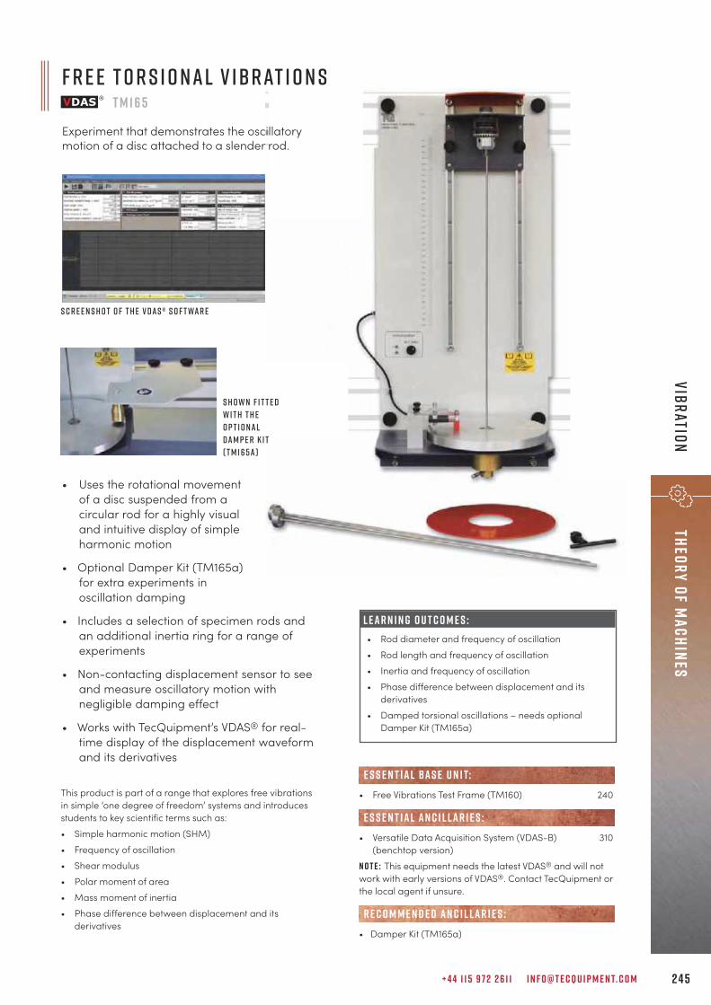
• Uses the rotational movementof a disc suspended from acircular rod for a highly visualand intuitive display of simpleharmonic motion
• Optional Damper Kit (TM165a)for extra experiments inoscillation damping
• Includes a selection of specimen rods andan additional inertia ring for a range ofexperiments
• Non-contacting displacement sensor to seeand measure oscillatory motion withnegligible damping effect
• Works with TecQuipment’s VDAS® for real-time display of the displacement waveformand its derivatives
+ 4 4 1 1 5 9 7 2 2 6 1 1 I N F O @ T E C Q U I P M E N T. C O M 2 4 5
Theory of machinesVibration
• Free Vibrations Test Frame (TM160) 240
• Versatile Data Acquisition System (VDAS-B) 310(benchtop version)
N o t e : This equipment needs the latest VDAS® and will notwork with early versions of VDAS®. Contact TecQuipment orthe local agent if unsure.
• Damper Kit (TM165a)
R E C O M M E N D E D AN C I L LAR I E S :
e s s e n t ial bas e u n i t:
E S S E N T IAL AN C I L LAR I E S :
S h o w n f i t t e dw i t h t h eo p t i o n a lD a m p e r K i t( T M 165a )
S c r e e n s h o t o f t h e V D A S ® s o f t wa r e
This product is part of a range that explores free vibrationsin simple ‘one degree of freedom’ systems and introducesstudents to key scientific terms such as:• Simple harmonic motion (SHM)• Frequency of oscillation• Shear modulus• Polar moment of area• Mass moment of inertia• Phase difference between displacement and its
derivatives
L E A R N I N G O U T C O M E S :• Rod diameter and frequency of oscillation• Rod length and frequency of oscillation• Inertia and frequency of oscillation• Phase difference between displacement and its
derivatives• Damped torsional oscillations – needs optional
Damper Kit (TM165a)
F r e e T o r s i o n a l V i b r at i o n sT M 1 6 5
Experiment that demonstrates the oscillatorymotion of a disc attached to a slender rod.
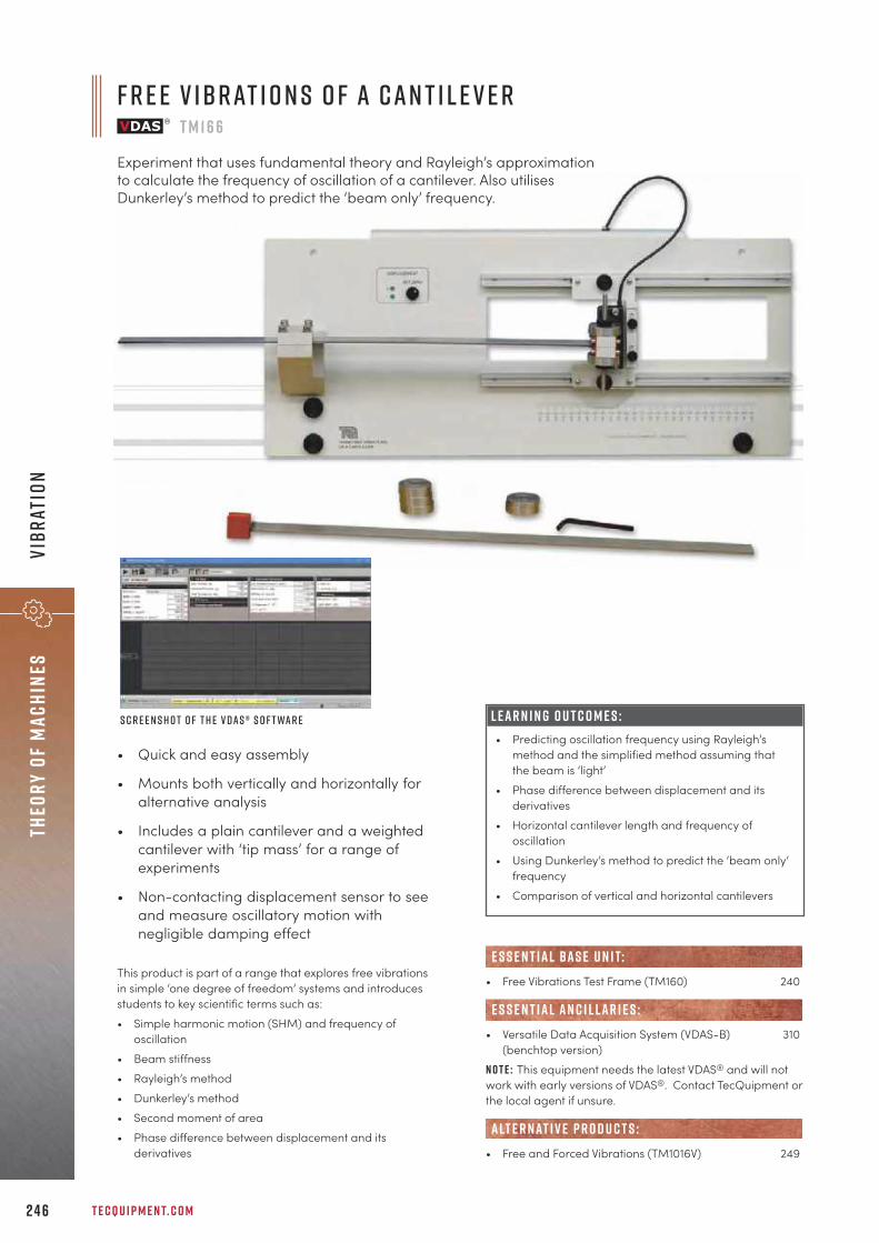
T E C Q U I P M E N T. C O M2 4 6
Theo
ry o
f ma
chin
esVi
brat
ion
This product is part of a range that explores free vibrationsin simple ‘one degree of freedom’ systems and introducesstudents to key scientific terms such as:• Simple harmonic motion (SHM) and frequency of
oscillation• Beam stiffness• Rayleigh’s method• Dunkerley’s method• Second moment of area• Phase difference between displacement and its
derivatives
L E A R N I N G O U T C O M E S :• Predicting oscillation frequency using Rayleigh’s
method and the simplified method assuming thatthe beam is ‘light’
• Phase difference between displacement and itsderivatives
• Horizontal cantilever length and frequency ofoscillation
• Using Dunkerley’s method to predict the ‘beam only’frequency
• Comparison of vertical and horizontal cantilevers
F r e e V i b r at i o n s o f a C a n t i l e v e rT M 1 6 6
Experiment that uses fundamental theory and Rayleigh’s approximationto calculate the frequency of oscillation of a cantilever. Also utilisesDunkerley’s method to predict the ‘beam only’ frequency.
S c r e e n s h o t o f t h e V D A S ® s o f t wa r e
• Quick and easy assembly
• Mounts both vertically and horizontally foralternative analysis
• Includes a plain cantilever and a weightedcantilever with ‘tip mass’ for a range ofexperiments
• Non-contacting displacement sensor to seeand measure oscillatory motion withnegligible damping effect
• Free Vibrations Test Frame (TM160) 240
• Versatile Data Acquisition System (VDAS-B) 310(benchtop version)
N o t e : This equipment needs the latest VDAS® and will notwork with early versions of VDAS®. Contact TecQuipment orthe local agent if unsure.
• Free and Forced Vibrations (TM1016V) 249
alt e r nat i v e p r o d u c t s :
E S S E N T IAL AN C I L LAR I E S :
e s s e n t ial bas e u n i t:
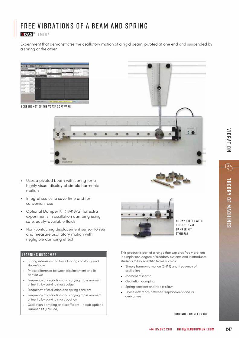
+ 4 4 1 1 5 9 7 2 2 6 1 1 I N F O @ T E C Q U I P M E N T. C O M 2 47
Theory of machinesVibration
This product is part of a range that explores free vibrationsin simple ‘one degree of freedom’ systems and It introducesstudents to key scientific terms such as:• Simple harmonic motion (SHM) and frequency of
oscillation• Moment of inertia• Oscillation damping• Spring constant and Hooke’s law• Phase difference between displacement and its
derivatives
S c r e e n s h o t o f t h e V D A S ® s o f t wa r e
S h o w n f i t t e d w i t ht h e o p t i o n a lD a m p e r K i t( T M 167a )
L E A R N I N G O U T C O M E S :• Spring extension and force (spring constant), and
Hooke’s law• Phase difference between displacement and its
derivatives• Frequency of oscillation and varying mass moment
of inertia by varying mass value• Frequency of oscillation and spring constant• Frequency of oscillation and varying mass moment
of inertia by varying mass position• Oscillation damping and coefficient – needs optional
Damper Kit (TM167a)
• Uses a pivoted beam with spring for ahighly visual display of simple harmonicmotion
• Integral scales to save time and forconvenient use
• Optional Damper Kit (TM167a) for extraexperiments in oscillation damping usingsafe, easily-available fluids
• Non-contacting displacement sensor to seeand measure oscillatory motion withnegligible damping effect
C o n t i n u e d o n n e x t pa g e
F r e e V i b r at i o n s o f a B e a m a n d S p r i n gT M 1 6 7
Experiment that demonstrates the oscillatory motion of a rigid beam, pivoted at one end and suspended bya spring at the other.

T E C Q U I P M E N T. C O M2 4 8
Theo
ry o
f ma
chin
esVi
brat
ion
• Versatile Data Acquisition System (VDAS-B) 310(benchtop version)
N o t e : This equipment needs the latest VDAS® and will notwork with early versions of VDAS®. Contact TecQuipment or the agent if unsure.
• Free and Forced Vibrations (TM1016V) 249
alt e r nat i v e p r o d u c t s :
E S S E N T IAL AN C I L LAR I E S :
S h o w n f i t t e d t o t h e T e s t F r a m e ( T M 160 ) a n d c o n n e c t e d t o V D A S ®
• Free Vibrations Test Frame (TM160) 240
• Damper Kit (TM167a) 247
R E C O M M E N D E D AN C I L LAR I E S :
e s s e n t ial bas e u n i t:
F r e e V i b r at i o n s o f a B e a m a n d S p r i n g ( T M 167 ) C o n t i n u e d f r o m p r e v i o u s pa g e
u n i v e r s a l v i b r at i o n s a p pa r at u sT M 1 6 s
This package includes all products from the Vibration section of TecQuipment’s Theory ofMachines range (TM160–TM167 and TM1016V). It offers multiple experiments in both free andforced vibrations, and includes our Versatile Data Acquisition System (VDAS®).
Products included in the package:
• Free and Forced Vibrations (TM1016V)• Free Vibrations Test Frame (TM160)• Simple and Compound Pendulums (TM161)• Filar Pendulums (TM162)• Centre of Percussion (TM163)• Free Vibrations of a Mass-Spring System
(TM164)
• 2 x Damper Kit (TM164a)• Free Torsional Vibrations (TM165)• 1 x Damper Kit (TM165a)• Free Vibrations of a Cantilever (TM166)• Free Vibrations of a Beam and Spring (TM167)• 2 x Damper Kit (TM167a)• 1 x Versatile Data Acquisition System (VDAS-B)

+ 4 4 1 1 5 9 7 2 2 6 1 1 I N F O @ T E C Q U I P M E N T. C O M 2 4 9
Theory of machinesVibration
F r e e a n d F o r c e d V i b r at i o n sT M 1 0 1 6 V
Investigates the free and forced vibrations of a rigid beam with a spring, and a simply supported beam.Demonstrates Rayleigh’s approximation and Dunkerley’s method.
S c r e e n s h o t o f t h eV D A S ® s o f t wa r e
C o n t i n u e d o n n e x t pa g e
Two different vibration systems in one self-contained unit: a ‘rigid’ beam with a spring and a pinned/pinned(simply supported) ‘flexible’ beamIncreased experimental scope with minimal set up time
Non-contacting displacement sensorFrictionless measurement of displacement that minimises influence on experiment results
High-quality servomotor ‘exciter’, for forced vibrations at a constant speedMinimises cyclical variations and enhances accuracy and repeatability
Offset mass position sensorDemonstrates the phase relationship between applied force and displacement
Built-in accelerometer for comparison of derived and measured acceleration waveformsHigh level functions deepen students’ understanding
Includes TecQuipment’s Versatile Data Acquisition System (VDAS® Onboard), featuring data acquisition via USBAdvanced software eliminates need for additional expensive oscilloscope
F eat u r e s an d be n e f i t s :
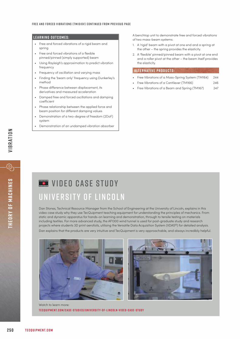
T E C Q U I P M E N T. C O M2 5 0
Theo
ry o
f ma
chin
esVi
brat
ion
F r e e a n d F o r c e d V i b r at i o n s ( T M 1 0 16V ) C o n t i n u e d f r o m p r e v i o u s pa g e
L E A R N I N G O U T C O M E S :• Free and forced vibrations of a rigid beam and
spring• Free and forced vibrations of a flexible
pinned/pinned (simply supported) beam• Using Rayleigh’s approximation to predict vibration
frequency • Frequency of oscillation and varying mass• Finding the ‘beam only’ frequency using Dunkerley’s
method• Phase difference between displacement, its
derivatives and measured acceleration• Damped free and forced oscillations and damping
coefficient• Phase relationship between the applied force and
beam position for different damping values• Demonstration of a two-degree of freedom (2DoF)
system• Demonstration of an undamped vibration absorber
A benchtop unit to demonstrate free and forced vibrationsof two mass-beam systems:1. A ‘rigid’ beam with a pivot at one end and a spring at
the other – the spring provides the elasticity.2. A ‘flexible’ pinned/pinned beam with a pivot at one end
and a roller pivot at the other – the beam itself providesthe elasticity.
• Free Vibrations of a Mass-Spring System (TM164) 244• Free Vibrations of a Cantilever (TM166) 246• Free Vibrations of a Beam and Spring (TM167) 247
alt e r nat i v e p r o d u c t s :
V i d e o C a s e S t u d yU n i v e r s i t y o f L i n c o l nDan Stones, Technical Resource Manager from the School of Engineering at the University of Lincoln, explains in thisvideo case study why they use TecQuipment teaching equipment for understanding the principles of mechanics. Fromstatic and dynamic apparatus for hands-on learning and demonstration, through to tensile testing on materialsincluding textiles. For more advanced study, the AF1300 wind tunnel is used for post-graduate study and researchprojects where students 3D print aerofoils, utilising the Versatile Data Acquisition System (VDAS®) for detailed analysis.Dan explains that the products are very intuitive and TecQuipment is very approachable, and always incredibly helpful.
Watch to learn more: t e c q u i p m e n t. c o m / c a s e - s t u d i e s / u n i v e r s i t y- o f - l i n c o l n -v i d e o - c a s e - s t u d y

+ 4 4 1 1 5 9 7 2 2 6 1 1 I N F O @ T E C Q U I P M E N T. C O M 2 5 1
Thermodynamics
“The nature of the nuclear industry makes replicating the real world really important. That’s oneof the reasons why we teach using TecQuipment’s products, because they match our teachingrequirements.
Pa u l Fa i r c l o u g hD i r e c t o r o f H i g h e r E n g i n e e r i n g , S c i e n c e a n d N u c l e a rt h e N at i o n a l C o l l e g e o f N u c l e a r , U K
t h e r m o d y n a m i c sT H E R M O D Y N A M I C P R I N C I P L E S 2 5 3
H E AT T R A N S F E R 2 5 6
T E M P E R AT U R E 2 74
S T E A M 2 7 5
C O M P R E S S O R S 2 7 6

T E C Q U I P M E N T. C O M2 5 2
Ther
mody
nami
cs
The Thermodynamics range offers teaching equipment forthe illustration of the basic principles of thermodynamicsthrough to complex theories. Students can learn usingpractical experiments about the behaviour of gases, heattransfer and thermal conductivity, conduction, convectionand heat exchange. They can get hands-on to provetheories such as the Antoine equation, Seebeck effect, Lenzand Thomson effects, Carnot cycle and reversible Carnotcycle, Stefan Boltzmann law, Kirchhoff’s law and Lambert’sdirection law.
S a f e , p r a c t i c a l a n d r e a l i s t i cAs thermodynamics experiments can often take manyhours, the range has been designed to reduce theexperiment time to a practical and realistic level, with safetyas the key aspect.
T H E R M O D Y N A M I C S
A u t o m at i c d ata a c q u i s i t i o n Look at the products in this range that work withTecQuipment’s unique Versatile Data AcquisitionSystem (VDAS®), page 310.
M o d u l a r f l u i d p o w e rThe Modular Fluid Power range includes products thatcan be analysed in terms of thermodynamicperformance, such as compressors (pages 142–156).
s a f e a n d p r a c t i c a l d e s i g n : Reduced experiment times.
b r o a d r a n g e o f p r o d u c t s : From basic principles togas turbines.
a u t o m at i c d ata a c q u i s i t i o n : Thermodynamicsexperiments require setting time and constant monitoringto achieve thermal equilibrium, making automatic dataacquisition a useful tool.
k e y f eat u r e s an d b e n e f i t s :
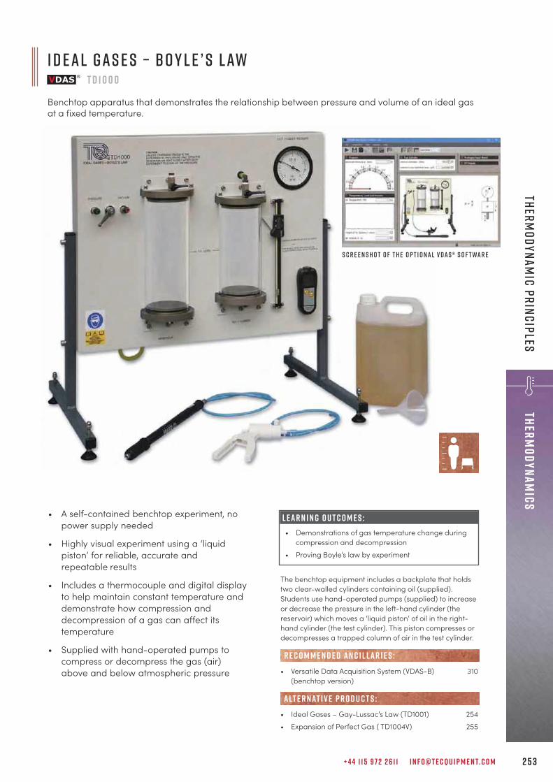
+ 4 4 1 1 5 9 7 2 2 6 1 1 I N F O @ T E C Q U I P M E N T. C O M 2 5 3
ThermodynamicsTherm
odynamic principles
• A self-contained benchtop experiment, nopower supply needed
• Highly visual experiment using a ‘liquidpiston’ for reliable, accurate andrepeatable results
• Includes a thermocouple and digital displayto help maintain constant temperature anddemonstrate how compression anddecompression of a gas can affect itstemperature
• Supplied with hand-operated pumps tocompress or decompress the gas (air)above and below atmospheric pressure
L E A R N I N G O U T C O M E S :• Demonstrations of gas temperature change during
compression and decompression• Proving Boyle’s law by experiment
I d e a l G a s e s – B o y l e ’ s L awT D 1 0 0 0
Benchtop apparatus that demonstrates the relationship between pressure and volume of an ideal gasat a fixed temperature.
S c r e e n s h o t o f t h e o p t i o n a l V D A S ® s o f t wa r e
The benchtop equipment includes a backplate that holdstwo clear-walled cylinders containing oil (supplied).Students use hand-operated pumps (supplied) to increaseor decrease the pressure in the left-hand cylinder (thereservoir) which moves a ‘liquid piston’ of oil in the right-hand cylinder (the test cylinder). This piston compresses ordecompresses a trapped column of air in the test cylinder.
• Versatile Data Acquisition System (VDAS-B) 310(benchtop version)
• Ideal Gases – Gay-Lussac’s Law (TD1001) 254• Expansion of Perfect Gas ( TD1004V) 255
R E C O M M E N D E D AN C I L LAR I E S :
alt e r nat i v e p r o d u c t s :
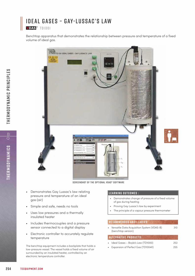
T E C Q U I P M E N T. C O M2 5 4
Ther
mody
nami
csTh
erm
odyn
amic
pri
ncip
les
• Demonstrates Gay Lussac’s law relatingpressure and temperature of an idealgas (air)
• Simple and safe, needs no tools
• Uses low pressures and a thermallyinsulated heater
• Includes thermocouples and a pressuresensor connected to a digital display
• Electronic controller to accurately regulatetemperature
L E A R N I N G O U T C O M E S :• Demonstrates change of pressure of a fixed volume
of gas during heating• Proving Gay Lussac’s law by experiment• The principle of a vapour pressure thermometer
I d e a l G a s e s – G ay- L u s s a c ’ s L awT D 1 0 0 1
Benchtop apparatus that demonstrates the relationship between pressure and temperature of a fixedvolume of ideal gas.
S c r e e n s h o t o f t h e o p t i o n a l V D A S ® s o f t wa r e
The benchtop equipment includes a backplate that holds alow-pressure vessel. The vessel holds a fixed volume of airsurrounded by an insulated heater, controlled by anelectronic temperature controller.
• Versatile Data Acquisition System (VDAS-B) 310(benchtop version)
• Ideal Gases – Boyle’s Law (TD1000) 253• Expansion of Perfect Gas (TD1004V) 255
R E C O M M E N D E D AN C I L LAR I E S :
alt e r nat i v e p r o d u c t s :
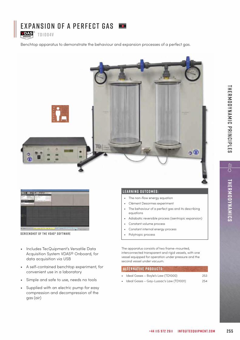
+ 4 4 1 1 5 9 7 2 2 6 1 1 I N F O @ T E C Q U I P M E N T. C O M 2 5 5
ThermodynamicsTherm
odynamic principles
e x pa n s i o n o f a p e r f e c t g a sT D 1 0 0 4 V
Benchtop apparatus to demonstrate the behaviour and expansion processes of a perfect gas.
• Includes TecQuipment’s Versatile DataAcquisition System VDAS® Onboard, fordata acquisition via USB
• A self-contained benchtop experiment, forconvenient use in a laboratory
• Simple and safe to use, needs no tools
• Supplied with an electric pump for easycompression and decompression of thegas (air)
The apparatus consists of two frame-mounted,interconnected transparent and rigid vessels, with onevessel equipped for operation under pressure and thesecond vessel under vacuum.
• Ideal Gases – Boyle’s Law (TD1000) 253• Ideal Gases – Gay-Lussac’s Law (TD1001) 254
alt e r nat i v e p r o d u c t s :
L E A R N I N G O U T C O M E S :• The non-flow energy equation• Clément Desormes experiment• The behaviour of a perfect gas and its describing
equations• Adiabatic reversible process (isentropic expansion)• Constant volume process• Constant internal energy process• Polytropic processS c r e e n s h o t o f t h e V D A S ® s o f t wa r e

T E C Q U I P M E N T. C O M2 5 6
Ther
mody
nami
csHe
at T
rans
fer
• Has a glass vessel so students can see whatis happening
• Demonstrates nucleate, film and sub-cooled boiling
• Demonstrates condensation on differentsurface finishes
• Demonstrates filmwise and dropwisecondensation
L E A R N I N G O U T C O M E S :• Boiling heat transfer• Condensing heat transfer
S c r e e n s h o t o f t h e o p t i o n a l V D A S ® s o f t wa r e
Heating and condensing takes place inside a partially filledglass vessel. A heater coil heats the water. For boiling heattransfer experiments, students adjust the current in aresistant wire heater element in the water. The temperatureof the wire reaches significantly higher than 100°C.
• Versatile Data Acquisition System (VDAS-B) 310(benchtop version)
R E C O M M E N D E D AN C I L LAR I E S :
F i l m w i s e a n d D r o p w i s e C o n d e n s at i o n a n d B o i l i n gT E 7 8
Benchtop apparatus with control and instrumentation unit that demonstrates heat transfer duringdifferent boiling and condensing processes.
T e c q u i p m e n t ’ s b l o gRead the TecQuipment blog for informative posts, from topics focused on engineering education through to guest posts from academics sharing viewpoints, relevant teaching projects and perspectives.
T e cqu i p m e n t. c o m / k n o w l e d g e

E m i s s i v i t y – N at u r a l C o n v e c t i o n a n d R a d i at i o nT D 1 0 1 1 V
Trolley-mounted, mobile apparatus that demonstrates how different types of heat can transfer over a rangeof pressures; helps the understanding of the Stefan Boltzman constant.
+ 4 4 1 1 5 9 7 2 2 6 1 1 I N F O @ T E C Q U I P M E N T. C O M 2 5 7
ThermodynamicsHeat Transfer • Includes TecQuipment’s
Versatile Data AcquisitionSystem VDAS® Onboard,for data acquisition viaUSB
• Helps students tounderstand natural ‘free’convection, radiation,emissivity and the StefanBoltzman equation
• Includes a pressure vesselto allow tests above andbelow atmospheric pressure
• All instruments and vacuum pumpincluded
S c r e e n s h o t o f t h e V D A S ® s o f t wa r e
A small heated element hangs in the centre of a pressurevessel. The heater has a matt black surface. Attached to itssurface is a thermocouple to measure the temperature. Thevessel’s inside is also black, and it has a thermocouple fittedto its wall to measure the temperature in the vessel. Thevessel may be charged with compressed air up to 1 bar(gauge) or evacuated down to approximately 5 Pa(absolute). Students can extrapolate the results down to atotal vacuum (no convection). This allows them to isolate theheat transfer by radiation.
• Free and Forced Convection (TD1005) 265• Radiant Transfer Experiments (TD1003) 170
alt e r nat i v e p r o d u c t s :
L E A R N I N G O U T C O M E S :• Determination of emissivity of the heater element• Verification of the Stefan Boltzmann constant

T E C Q U I P M E N T. C O M2 5 8
Ther
mody
nami
csHe
at T
rans
fer
L E A R N I N G O U T C O M E S :• Transient temperature changes with sudden
immersion (unsteady state)• How shape and surface area affect heat transfer• How materials of different thermal conductivity
affect heat transfer
• Includes TecQuipment’s Versatile DataAcquisition System VDAS® Onboard, fordata acquisition via USB
• Includes a set of different solid shapes ofdifferent materials, for multiple experiments
• Simple to use, needs no tools
• Water temperature controller for consistentresults
• Clear digital displays of all readings
U n s t e a d y S tat e H e at T r a n s f e rT D 1 0 0 9 v
Benchtop apparatus that measures unsteady state heat transfer to bodies of different shape andthermal conductivity.
H e i s l e r c h a r t c r e at e d by t h eV D A S ® s o f t wa r e
S c r e e n s h o t o f t h e V D A S ® s o f t wa r e
T e s t s h a p e s
A sturdy benchtop frame contains a hot water vessel andinstrumentation. The test shapes are of different dimensionsand material to give different heat transfer areas andthermal conductivities. This gives multiple experiments inheat transfer.

+ 4 4 1 1 5 9 7 2 2 6 1 1 I N F O @ T E C Q U I P M E N T. C O M 2 5 9
ThermodynamicsHeat Transfer
F o r c e d C o n v e c t i o n H e at T r a n s f e rT D 1
Trolley-mounted, mobile apparatus that demonstrates forced convection in pipes and heat transfertheory. Illustrates the derivation of the value of Nusselt number, determination of the Stanton numberand determination of the validity of the Reynolds analogy for air.
L E A R N I N G O U T C O M E S :• Derivation of the value of Nusselt number (Nu) and
comparison with empirical formula• Calculation of the local heat transfer coefficient (h)• Determination of the Stanton number (St)• Calculation of the friction factor (f) and comparison
with experimental value• Investigate the validity of the Reynolds analogy
for air
• Heater interlock for safety
• Includes Pitot tube traverse for velocityprofile measurements, and traversingthermocouple to measure temperaturedistribution across the test pipe
• Includes thermocouples along the test pipeto measure heat transfer
The fan runs at a constant speed and draws air through acontrol valve. The air then moves into a u-shaped pipe. Anorifice plate in the pipe connects to a manometer on theinstrumentation panel to measure the air flow rate. A largermanometer on the instrument panel measures the fanpressure drop. The u-shaped pipe connects to a smallerdiameter insulated and electrically heated copper ‘testpipe’. Students control the power input to the test pipeheater using a variable transformer, while noting the powerusing instrumentation on the panel. The test pipedischarges to atmosphere.
• Cross-Flow Heat Exchanger (TE93) 269• Free and Forced Convection (TD1005) 265• Water-to-Air Heat Exchanger (TD1007) 271
alt e r nat i v e p r o d u c t s :
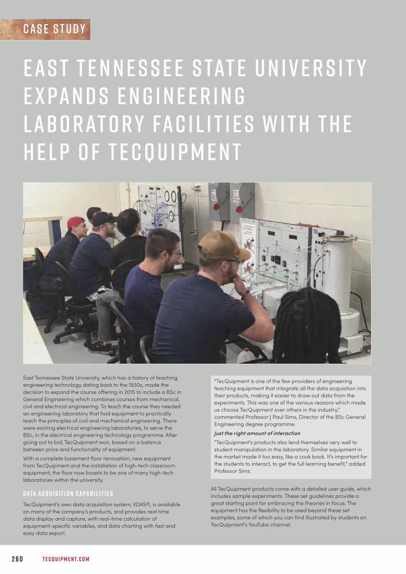
T E C Q U I P M E N T. C O M2 6 0
E a s t T e n n e s s e e S tat e U n i v e r s i t yE x pa n d s E n g i n e e r i n gL abo r at o r y Fa c i l i t i e s w i t h t h eH e l p o f T e c Q u i p m e n t
c a s e s t u d y
East Tennessee State University, which has a history of teachingengineering technology dating back to the 1930s, made thedecision to expand the course offering in 2015 to include a BSc inGeneral Engineering which combines courses from mechanical,civil and electrical engineering. To teach the course they neededan engineering laboratory that had equipment to practicallyteach the principles of civil and mechanical engineering. Therewere existing electrical engineering laboratories, to serve theBSc, in the electrical engineering technology programme. Aftergoing out to bid, TecQuipment won, based on a balancebetween price and functionality of equipment.With a complete basement floor renovation, new equipmentfrom TecQuipment and the installation of high-tech classroomequipment, the floor now boasts to be one of many high-techlaboratories within the university.
D ata A c q u i s i t i o n C a pa b i l i t i e sTecQuipment’s own data acquisition system, VDAS®, is availableon many of the company’s products, and provides real timedata display and capture, with real-time calculation ofequipment-specific variables, and data charting with fast andeasy data export.
All TecQuipment products come with a detailed user guide, whichincludes sample experiments. These set guidelines provide agreat starting point for embracing the theories in focus. Theequipment has the flexibility to be used beyond these setexamples, some of which you can find illustrated by students onTecQuipment’s YouTube channel.
“TecQuipment is one of the few providers of engineeringteaching equipment that integrate all the data acquisition intotheir products, making it easier to draw out data from theexperiments. This was one of the various reasons which madeus choose TecQuipment over others in the industry,”commented Professor J Paul Sims, Director of the BSc GeneralEngineering degree programme.
Just the right amount of interaction“TecQuipment’s products also lend themselves very well tostudent manipulation in the laboratory. Similar equipment inthe market made it too easy, like a cook book. It’s important forthe students to interact, to get the full learning benefit,” addedProfessor Sims.

+ 4 4 1 1 5 9 7 2 2 6 1 1 I N F O @ T E C Q U I P M E N T. C O M 2 6 1
T h e L a b o r at o r y S e t- u pFor the practicals required for the General Engineering degree,the team selected a range of Thermodynamics, Fluid Mechanicsand Engineering Science range equipment from TecQuipment.Thermodynamics included:• A S m a l l E n g i n e T e s t S e t (TD200) that acts as a base unit for
attaching a modified four-stroke petrol engine and modifiedfour-stroke diesel engine, plus a frame-mounted VDAS® unit(Versatile Data Acquisition System). Used with a ManualVolumetric Fuel Gauge (AVF1), Crank Angle Shaft Encoder(ECA102) and Engine Cycle Analyser (ECA100), students caninvestigate the thermodynamic cycle of each of the engines,and explore variables, including mean effective pressure andindicated power, the mechanical efficiency, and carry outcombustion analysis, plus much more.
A video of a student using this test set illustrates Professor Sims’spoints: y o u t u b e . c o m / wat c h ? v = Y K i G 8 N t 7 p E E• A Wat e r -t o -A i r H e at E x c h a n g e r s (TD1007) experimental unit
for learning how cross-flow water-to-air heat exchangerswork, plus frame-mounted VDAS® that allows them tocomplete tests quicker and make the recording of resultseasier. For comprehensive teaching on the topic, they alsopurchased the 16-tube heat exchanger and 16-finned heatexchanger ancillaries.
• The H e at T r a n s f e r E x p e r i m e n t B a s e U n i t (TD1002), LinearHeat Conduction Experiment (TD1002a) and versatile dataacquisition was selected together for teaching thefundamentals of heat transfer.
Fluid Mechanics included:• A D i g i ta l H y d r a u l i c B e n c h (H1F) which is the base unit that
supplies, recirculates and measures water for flow pressureand measurement experiments including:
• D i s c h a r g e O v e r a N o t c h (H6) for studying weirs for flowregulation and measurement, and the Flow MeasurementMethods (H10) apparatus for measuring the effectiveness andcomparisons on and between the Venturi meter, orifice plateand rotameter of an incompressible fluid. Plus a couple ofdifferent turbines: the Pelton (H19) and Francis (H18) turbine.
• A L o s s e s i n P i p i n g S y s t e m s (H16) apparatus for investigatingthe friction losses in different types of piping systems (straight,bends, valves, elbows, sudden contraction and suddenexpansion).
• A C e n t r i f u g a l P u m p T e s t S e t (H47) apparatus for teachingstudents about centrifugal pump performance. For clearpressure display, the team opted for an Analogue PressureDisplay (AP1) ancillary and frame-mounted VDAS® to fit onthe instrumentation frame of the test set.
Engineering Science included:• Two E n g i n e e r i n g S c i e n c e W o r k Pa n e l s (ES1), along with two
experiments: a P u l l e y K i t (ES10) and a G e a r T r a i n s K i t (ES13).Another key point for the BSc programme was the ability tointegrate VDAS® with LabVIEW. Both the Engineering Technologyand Engineering programmes use LabVIEW in most laboratoriesto support student development and provide students with aworking knowledge of LabVIEW, which is a standard industrialplatform for control and monitoring of processes.
I n s ta l l at i o n a n d T r a i n i n gIn major installation cases, TecQuipment personnel will often besent out to site to help with the commissioning and training ofproducts.
L o c a l S a l e s a n d S u p p o r tTecQuipment works with partner companies across the worldthat specialise in understanding the local engineering educationinstitutions and delivering products that best match theirteaching requirements. In this case, local partner for Tennessee,RELETECH, had proven themselves before the bid even came in.“We trust the team from RELETECH, and TecQuipment too. Thisestablished relationship gave us extra conviction in knowing thatthe bid process had selected the rightful vendor to work with,”added Professor Sims.
“After the customer service installation I feel very confident. Theproducts are straight forward and the user manuals aregreat!” explained Assistant Professor Samia Afran. “I cameprepared with a whole blank notebook to document all thatTecQuipment’s applications engineer was going to train meon. But I didn’t need to write anything, it was all in theprovided documentation.”
“This product is a great example of how TecQuipmentbalances the right level of student interaction with theequipment to improve the learning experience. From puttingthe fuel in, and physically pulling the manual starter on themotor, to making adjustments to the needle valve and throttleto take readings and carry out performance comparisonswithin VDAS®,” added Professor Sims.

T E C Q U I P M E N T. C O M2 6 2
Ther
mody
nami
csHe
at T
rans
fer
H e at T r a n s f e r E x p e r i m e n t s B a s e U n i tT D 1 0 0 2
A benchtop base unit fordemonstrating different methods ofheat transfer. Requires at least one ofthe four optional experiments.
S c r e e n s h o t o f t h e o p t i o n a l V D A S ® s o f t wa r e
The Heat Transfer Experiments Base Unit (TD1002) is thecore of the TD1002 range. It provides cold water and heaterpower to the optional experiments and all the instrumentsneeded to measure their performance.
• Linear Heat Conduction Experiment (TD1002a MkII) 263• Radial Heat Conduction Experiment (TD1002b) 263• Extended Surface Heat Transfer Experiment 264
(TD1002c)• Conductivity of Liquids and Gases Experiment 264
(TD1002d)
• Versatile Data Acquisition System (VDAS-F) 310(frame-mounted version)
• Free and Forced Convection (TD1005) 265• Radiant Transfer Experiments (TD1003) 270
R E C O M M E N D E D AN C I L LAR I E S :
ava i labl e e x p e r i m e n t m o d u l e s :
alt e r nat i v e p r o d u c t s :
Experiment modules(td1002a–td1002d)
recommenedancillary (vdas-f)
Essential Base Unit (TD1002)
M O D U LAR S Y S T E M
Self-contained benchtop base unit with fouroptional experimentsModular approach reduces total laboratory costs
Easy-to-use fittings with self-sealing connectorsAllows students to change and connect theoptional experiments quickly and easily withouttools and water spillage
Clear digital displays of all readings No computer needed to operate it or takereadings, simplified approach enhances studentlearning
Experiments each have a bedplate with a clearschematic diagram to show students how theyconnect, and the measuring point positionsMaximises teaching effectiveness, simple to setup and students can easily understand theexperiment
F eat u r e s an d be n e f i t s :
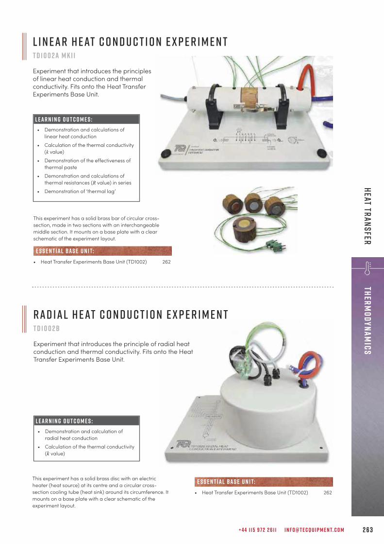
+ 4 4 1 1 5 9 7 2 2 6 1 1 I N F O @ T E C Q U I P M E N T. C O M 2 6 3
ThermodynamicsHeat Transfer
L E A R N I N G O U T C O M E S :• Demonstration and calculations of
linear heat conduction• Calculation of the thermal conductivity
(k value)• Demonstration of the effectiveness of
thermal paste• Demonstration and calculations of
thermal resistances (R value) in series • Demonstration of ‘thermal lag’
This experiment has a solid brass bar of circular cross-section, made in two sections with an interchangeablemiddle section. It mounts on a base plate with a clearschematic of the experiment layout.
• Heat Transfer Experiments Base Unit (TD1002) 262
e s s e n t ial bas e u n i t:
L i n e a r H e at C o n d u c t i o n E x p e r i m e n tT D 1 0 0 2 a M K I I
Experiment that introduces the principlesof linear heat conduction and thermalconductivity. Fits onto the Heat TransferExperiments Base Unit.
This experiment has a solid brass disc with an electricheater (heat source) at its centre and a circular cross-section cooling tube (heat sink) around its circumference. Itmounts on a base plate with a clear schematic of theexperiment layout.
• Heat Transfer Experiments Base Unit (TD1002) 262
e s s e n t ial bas e u n i t:
L E A R N I N G O U T C O M E S :• Demonstration and calculation of
radial heat conduction• Calculation of the thermal conductivity
(k value)
R a d i a l H e at C o n d u c t i o n E x p e r i m e n tT D 1 0 0 2 b
Experiment that introduces the principle of radial heat conduction and thermal conductivity. Fits onto the Heat Transfer Experiments Base Unit.
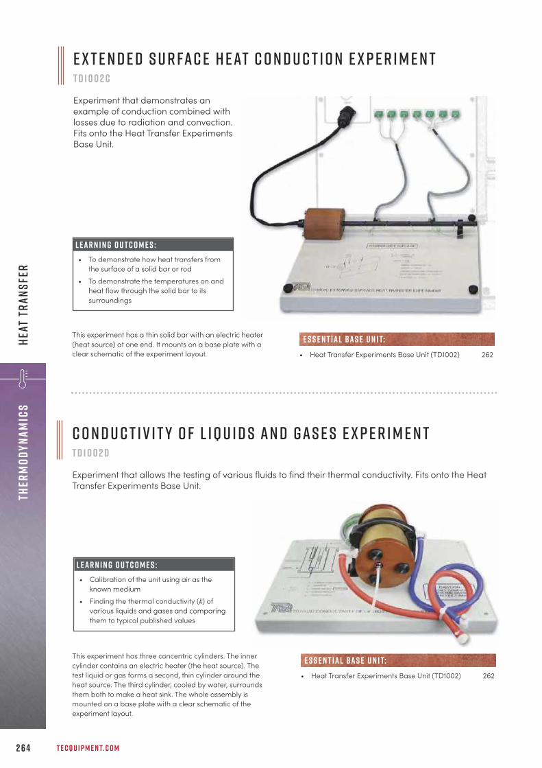
T E C Q U I P M E N T. C O M2 6 4
Ther
mody
nami
csHe
at T
rans
fer
E x t e n d e d S u r fa c e H e at C o n d u c t i o n E x p e r i m e n tT D 1 0 0 2 c
Experiment that demonstrates anexample of conduction combined withlosses due to radiation and convection.Fits onto the Heat Transfer ExperimentsBase Unit.
This experiment has a thin solid bar with an electric heater(heat source) at one end. It mounts on a base plate with aclear schematic of the experiment layout. • Heat Transfer Experiments Base Unit (TD1002) 262
e s s e n t ial bas e u n i t:
C o n d u c t i v i t y o f L iqu i d s a n d G a s e s E x p e r i m e n tT D 1 0 0 2 d
Experiment that allows the testing of various fluids to find their thermal conductivity. Fits onto the HeatTransfer Experiments Base Unit.
L E A R N I N G O U T C O M E S :• Calibration of the unit using air as the
known medium• Finding the thermal conductivity (k) of
various liquids and gases and comparingthem to typical published values
This experiment has three concentric cylinders. The innercylinder contains an electric heater (the heat source). Thetest liquid or gas forms a second, thin cylinder around theheat source. The third cylinder, cooled by water, surroundsthem both to make a heat sink. The whole assembly ismounted on a base plate with a clear schematic of theexperiment layout.
• Heat Transfer Experiments Base Unit (TD1002) 262
e s s e n t ial bas e u n i t:
L E A R N I N G O U T C O M E S :• To demonstrate how heat transfers from
the surface of a solid bar or rod• To demonstrate the temperatures on and
heat flow through the solid bar to itssurroundings
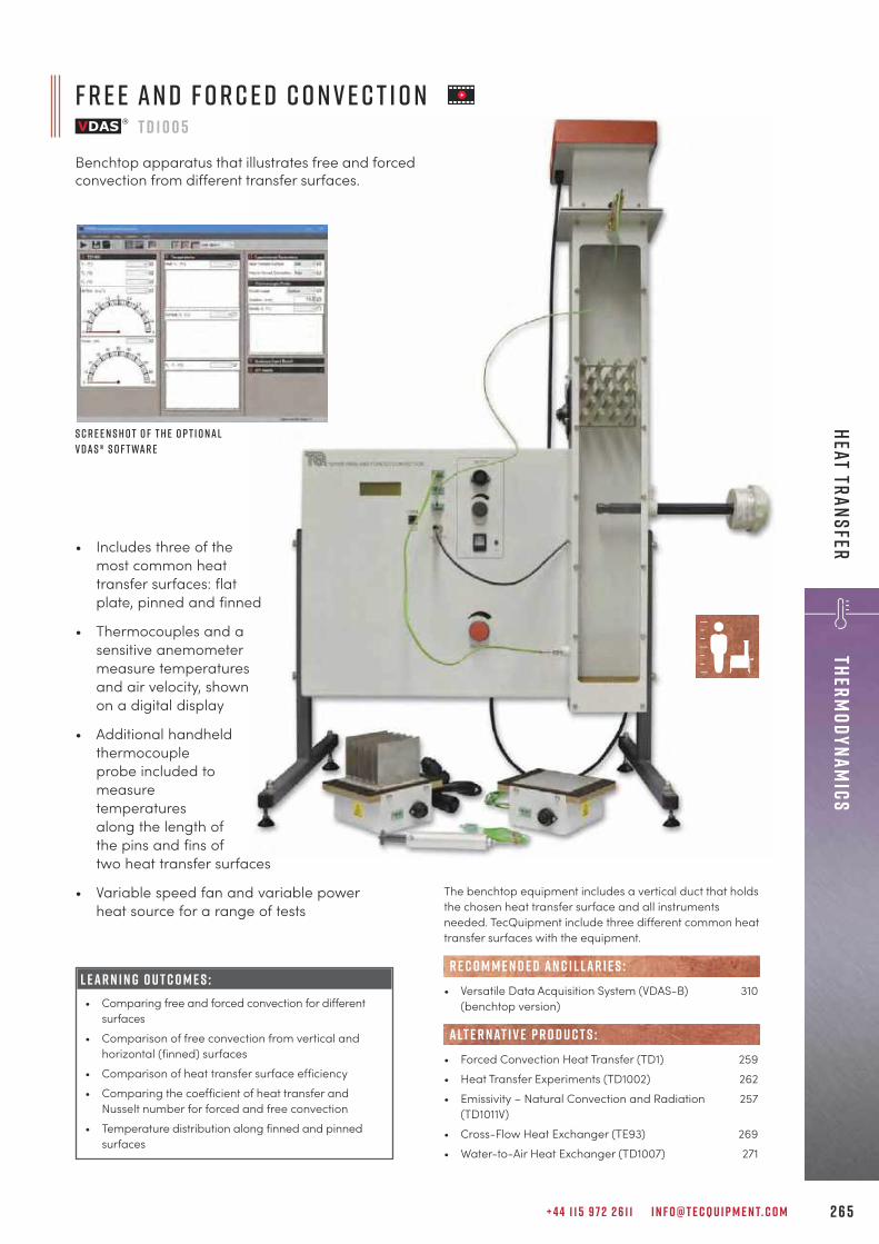
+ 4 4 1 1 5 9 7 2 2 6 1 1 I N F O @ T E C Q U I P M E N T. C O M 2 6 5
ThermodynamicsHeat Transfer • Includes three of the
most common heattransfer surfaces: flatplate, pinned and finned
• Thermocouples and asensitive anemometermeasure temperaturesand air velocity, shownon a digital display
• Additional handheldthermocoupleprobe included tomeasuretemperaturesalong the length ofthe pins and fins oftwo heat transfer surfaces
• Variable speed fan and variable powerheat source for a range of tests
F r e e a n d F o r c e d C o n v e c t i o nT D 1 0 0 5
Benchtop apparatus that illustrates free and forcedconvection from different transfer surfaces.
S c r e e n s h o t o f t h e o p t i o n a lV D A S ® s o f t wa r e
L E A R N I N G O U T C O M E S :• Comparing free and forced convection for different
surfaces• Comparison of free convection from vertical and
horizontal (finned) surfaces• Comparison of heat transfer surface efficiency • Comparing the coefficient of heat transfer and
Nusselt number for forced and free convection• Temperature distribution along finned and pinned
surfaces
The benchtop equipment includes a vertical duct that holdsthe chosen heat transfer surface and all instrumentsneeded. TecQuipment include three different common heattransfer surfaces with the equipment.
• Versatile Data Acquisition System (VDAS-B) 310(benchtop version)
• Forced Convection Heat Transfer (TD1) 259• Heat Transfer Experiments (TD1002) 262• Emissivity – Natural Convection and Radiation 257
(TD1011V) • Cross-Flow Heat Exchanger (TE93) 269• Water-to-Air Heat Exchanger (TD1007) 271
R E C O M M E N D E D AN C I L LAR I E S :
alt e r nat i v e p r o d u c t s :
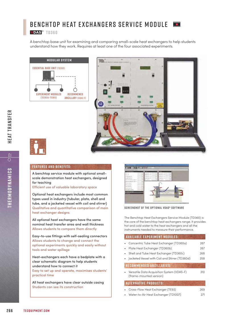
T E C Q U I P M E N T. C O M2 6 6
Ther
mody
nami
csHe
at T
rans
fer
The Benchtop Heat Exchangers Service Module (TD360) isthe core of the benchtop heat exchangers range. It provideshot and cold water to the heat exchangers and all theinstruments needed to measure their performance.
• Concentric Tube Heat Exchanger (TD360a) 267• Plate Heat Exchanger (TD360b) 267• Shell and Tube Heat Exchanger (TD360c) 268• Jacketed Vessel with Coil and Stirrer (TD360d) 258
• Versatile Data Acquisition System (VDAS-F) 310(frame-mounted version)
• Cross-Flow Heat Exchanger (TE93) 269• Water-to-Air Heat Exchanger (TD1007) 271
R E C O M M E N D E D AN C I L LAR I E S :
ava i labl e e x p e r i m e n t m o d u l e s :
alt e r nat i v e p r o d u c t s :
S c r e e n s h o t o f t h e o p t i o n a l V D A S ® s o f t wa r e
B e n c h t o p H e at E x c h a n g e r s S e r v i c e M o d u l eT D 3 6 0
A benchtop base unit for examining and comparing small-scale heat exchangers to help studentsunderstand how they work. Requires at least one of the four associated experiments.
A benchtop service module with optional small-scale demonstration heat exchangers, designedfor teachingEfficient use of valuable laboratory space
Optional heat exchangers include most commontypes used in industry (tubular, plate, shell andtube, and a jacketed vessel with coil and stirrer)Qualitative and quantitative comparison of mainheat exchanger designs
All optional heat exchangers have the samenominal heat transfer area and wall thicknessAllows students to compare them directly
Easy-to-use fittings with self-sealing connectorsAllows students to change and connect theoptional experiments quickly and easily withouttools and water spillage
Heat-exchangers each have a bedplate with aclear schematic diagram to help studentsunderstand how to connect itEasy to set up and operate, maximises students’practical time
All heat exchangers have clear outside casingStudents can see its construction
F eat u r e s an d be n e f i t s :
Experiment modules(td360a–td30d)
recommenedancillary (vdas-f)
Essential Base Unit (TD360)
M O D U LAR S Y S T E M

+ 4 4 1 1 5 9 7 2 2 6 1 1 I N F O @ T E C Q U I P M E N T. C O M 2 6 7
ThermodynamicsHeat Transfer
L E A R N I N G O U T C O M E S :• Demonstration of heat transfer from
one fluid to another through a solidwall
• Energy balance and efficiencycalculations
• Demonstration of parallel flow andcounter flow operation of heatexchangers
• Measurement of the heat transfercoefficient, and the effect of fluid flowrates and the driving force(temperature differential) upon it
• Introduction to the logarithmic meantemperature difference in heatexchangers
• Comparison of different types of heatexchanger in terms of performance,size and relative cost (only if two ormore optional heat exchangers havebeen bought)
C o n c e n t r i c T ube H e at E x c h a n g e rT D 3 6 0 a
Experiment that illustrates how a simple concentric shell and tube heat exchanger works. Fits onto theBenchtop Heat Exchanger Service Module.
L E A R N I N G O U T C O M E S :• Demonstration of heat transfer from
one fluid to another through a solidwall
• Energy balance and efficiencycalculations
• Demonstration of parallel flow andcounter flow operation of heatexchangers
• Measurement of the heat transfercoefficient, and the effect of fluid flowrates and the driving force(temperature differential) upon it
• Introduction to the logarithmic meantemperature difference in heatexchangers
• Comparison of different types of heatexchanger in terms of performance,size and relative cost (only if two ormore optional heat exchangers havebeen bought)
This heat exchanger is a set of metal plates separated byspacers (gaskets). The plates and gaskets have holes thatmake the hot and cold flow run on alternate sides of theplates, thereby transferring heat.
• Service Module (TD360) 266
e s s e n t ial bas e u n i t:
P l at e H e at E x c h a n g e rT D 3 6 0 b
Experiment that illustrates how a compact plate heat exchanger works. Fits onto the Benchtop HeatExchanger Service Module.
This is the simplest of the optional heat exchangers. It hastwo tubes, one inside the other. One tube carries hot fluid,the other carries cold fluid.
• Service Module (TD360) 266
e s s e n t ial bas e u n i t:
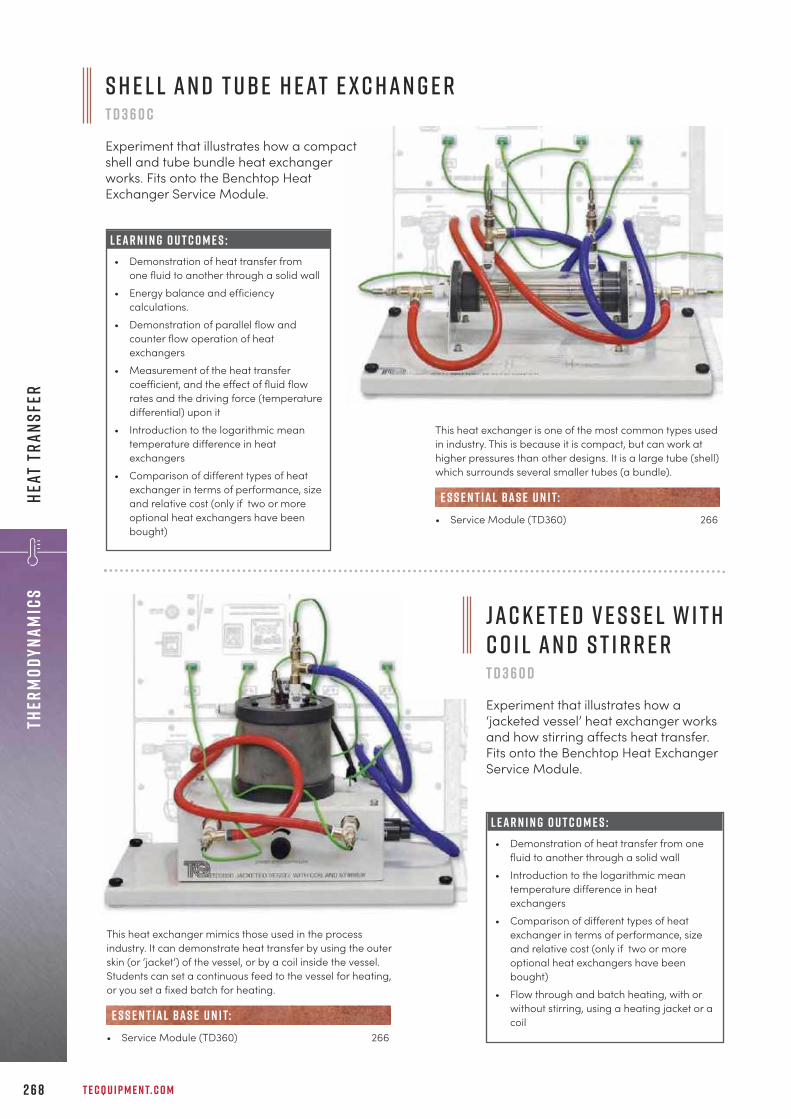
T E C Q U I P M E N T. C O M2 6 8
Ther
mody
nami
csHe
at T
rans
fer
L E A R N I N G O U T C O M E S :• Demonstration of heat transfer from
one fluid to another through a solid wall• Energy balance and efficiency
calculations.• Demonstration of parallel flow and
counter flow operation of heatexchangers
• Measurement of the heat transfercoefficient, and the effect of fluid flowrates and the driving force (temperaturedifferential) upon it
• Introduction to the logarithmic meantemperature difference in heatexchangers
• Comparison of different types of heatexchanger in terms of performance, sizeand relative cost (only if two or moreoptional heat exchangers have beenbought)
This heat exchanger is one of the most common types usedin industry. This is because it is compact, but can work athigher pressures than other designs. It is a large tube (shell)which surrounds several smaller tubes (a bundle).
• Service Module (TD360) 266
e s s e n t ial bas e u n i t:
L E A R N I N G O U T C O M E S :• Demonstration of heat transfer from one
fluid to another through a solid wall• Introduction to the logarithmic mean
temperature difference in heatexchangers
• Comparison of different types of heatexchanger in terms of performance, sizeand relative cost (only if two or moreoptional heat exchangers have beenbought)
• Flow through and batch heating, with orwithout stirring, using a heating jacket or acoil
This heat exchanger mimics those used in the processindustry. It can demonstrate heat transfer by using the outerskin (or ‘jacket’) of the vessel, or by a coil inside the vessel.Students can set a continuous feed to the vessel for heating,or you set a fixed batch for heating.
• Service Module (TD360) 266
e s s e n t ial bas e u n i t:
J a c k e t e d V e s s e l w i t hC o i l a n d S t i r r e r T D 3 6 0 d
Experiment that illustrates how a‘jacketed vessel’ heat exchanger worksand how stirring affects heat transfer.Fits onto the Benchtop Heat ExchangerService Module.
S h e l l a n d T ube H e at E x c h a n g e r T D 3 6 0 c
Experiment that illustrates how a compactshell and tube bundle heat exchangerworks. Fits onto the Benchtop HeatExchanger Service Module.

L E A R N I N G O U T C O M E S :Typical experiments include:• Determining the pressure losses created by the heat
exchange rods and creating a chart of pressure dropagainst upstream pressure
• Calculating the inlet velocity and the mean velocitythrough the rods
• Determining the rate at which the heated rod coolsdown, within a bank of rods and by itself
• Plotting ‘cooling curves’ and using them to find thecoefficient of heat transfer (h) for the heated rod atvarious positions in the heat exchanger
• Determining the velocity distribution (profile)downstream of the rods
• Converting results into dimensionless values(typically using Nusselt, Prandtl and Reynoldsequations)
• Comparing results and producing heat transfercoefficient curves
+ 4 4 1 1 5 9 7 2 2 6 1 1 I N F O @ T E C Q U I P M E N T. C O M 2 6 9
ThermodynamicsHeat Transfer
The TE93 is a horizontal wind tunnel with a contractioncone, a working section, a diffuser, a constant-speed fan,and an exhaust with silencer. A variable slide valve controlsthe air flow. The working section includes a series of rodsarranged in a matrix and at right-angles to the direction ofair flow. To do experiments, students can remove any one ofthese rods and replace it with a cylindrical copper element.The copper element is of known thermal capacity andincludes a built-in thermocouple. Students insert theelement, which has been pre-heated to a specifictemperature, into the working section at a known airvelocity. They measure the time taken for the temperatureto drop and determine the heat transfer rate.
• Versatile Data Acquisition System (VDAS-B) 310(benchtop version)
• Forced Convection Heat Transfer (TD1) 259• Benchtop Heat Exchangers (TD360) 266• Free and Forced Convection (TD1005) 265• Water-to-Air Heat Exchanger (TD1007) 271
R E C O M M E N D E D AN C I L LAR I E S :
alt e r nat i v e p r o d u c t s :
C r o s s - F l o w H e at E x c h a n g e rT E 9 3
Benchtop apparatus with a control and instrument unit for studies into the principles and performanceof heat exchangers.
• For full understanding of heat exchange by forcedconvection and measurement of heat transfer
• Consists of a wind tunnelwith fully controllable airflow and heat exchangerrod matrix
• Separate pre-heatedelement with built-inthermocouple can take theplace of any heatexchanger rod
• Instrumentation unit alsoincludes controlled heatsource to pre-heatelement
S c r e e n s h o t o f t h e o p t i o n a l V D A S ® s o f t wa r e

T E C Q U I P M E N T. C O M2 7 0
Ther
mody
nami
csHe
at T
rans
fer • Uses a safe, low-voltage heat source and
thermopile (heat flux sensor) for radiantheat transfer experiments
• Includes plates with different heatabsorption properties and apertures forextra experiments in heat transfer
• Uses a safe, low-voltage ‘integrating sphere’light source and lux meter for light transferexperiments
• Includes different optical filters for extraexperiments in light transfer
L E A R N I N G O U T C O M E S :H e at:• Inverse square law (or Lambert’s distance law/area
law), demonstrating that radiation is inverselyproportional to distance squared
• Stefan Boltzmann’s law, demonstrating therelationship between radiation and sourcetemperature
• Kirchhoff's law, demonstrating that a body with goodemissivity also has good absorptivity
• Area factor, demonstrating that radiation transferdepends on the exposed area of the radiant source
L i g h t:• Inverse square law (or Lambert’s distance law/area
law), demonstrating radiation is inverselyproportional to distance squared
• Lambert’s direction law (or cosine law),demonstrating that radiation is proportional to thecosine of the angle between the emitter and thereceiver
• Transmittance and absorbance, demonstrating thatoptical filters can reduce light intensity
R a d i a n t T r a n s f e r E x p e r i m e n t sT D 1 0 0 3
Benchtop apparatus with a control box that demonstrates the laws of radiant transfer from heat andlight sources.
S c r e e n s h o t o f t h e o p t i o n a l V D A S ®s o f t wa r e
The equipment has two parts: an aluminium experimentframe and a control box. The frame holds all theexperiment parts and allows the user to slide the partsalong easily for experiments of transfer over distances. Thecontrol box contains the electrical controls and displays themeasured readings.
• Versatile Data Acquisition System (VDAS-B) 310(benchtop version)
• Heat Transfer Experiments (TD1002) 262• Emissivity – Natural Convection and Radiation 257
(TD1011V)
R E C O M M E N D E D AN C I L LAR I E S :
alt e r nat i v e p r o d u c t s :

L E A R N I N G O U T C O M E S :• Heat transfer between fluids through a solid wall• Energy balance and efficiency• Finding the heat transfer coefficient and log mean
temperature difference (LMTD)• Effect of water temperature (the ‘driving force’)• Comparison of heat exchangers of different
construction and heat transfer area (needs optionalheat exchangers, TD1007a and TD1007b)
Includes a 32-tube heat exchanger as standardComplete experiment ‘out of the box’
Two additional heat exchangers available forextended experimentsAllows quantitative comparison of differentdesigns of heat exchanger
Heat exchangers have schematic diagramsEnhanced learning capabilities help studentsunderstand how they work and how to connectthem
Easy-to-use fittings with self-sealing connectorsAllows students to change and connect theoptional experiments quickly and easily withouttools and water spillage
F eat u r e s an d be n e f i t s :
+ 4 4 1 1 5 9 7 2 2 6 1 1 I N F O @ T E C Q U I P M E N T. C O M 2 7 1
ThermodynamicsHeat Transfer
Wat e r -t o -A i r H e at E x c h a n g e rT D 1 0 0 7
Benchtop apparatus that illustrates how cross-flow water-to-air heat exchangers work. Includes a 32-tube heat exchanger. Also available separately are 16-tube and finned heat exchangers.
S c r e e n s h o t o f t h e o p t i o n a l V D A S ® s o f t wa r e
16 -T ube H e at E x c h a n g e r( T D 1 0 0 7a )
F i n n e d H e at E x c h a n g e r( T D 1 0 0 7b )
c o n t i n u e d o n n e x t pa g e
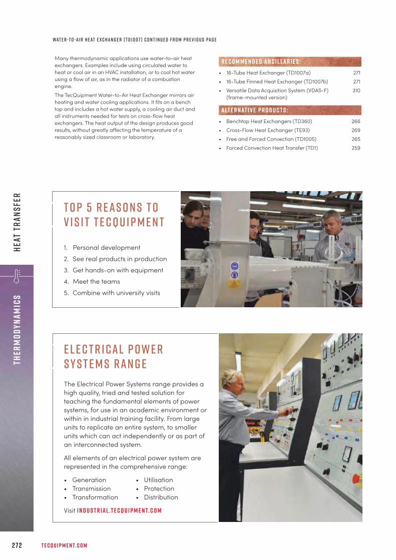
T E C Q U I P M E N T. C O M2 7 2
Ther
mody
nami
csHe
at T
rans
fer
Many thermodynamic applications use water-to-air heatexchangers. Examples include using circulated water toheat or cool air in an HVAC installation, or to cool hot waterusing a flow of air, as in the radiator of a combustionengine.The TecQuipment Water-to-Air Heat Exchanger mirrors airheating and water cooling applications. It fits on a benchtop and includes a hot water supply, a cooling air duct andall instruments needed for tests on cross-flow heatexchangers. The heat output of the design produces goodresults, without greatly affecting the temperature of areasonably sized classroom or laboratory.
• 16-Tube Heat Exchanger (TD1007a) 271• 16-Tube Finned Heat Exchanger (TD1007b) 271• Versatile Data Acquisition System (VDAS-F) 310
(frame-mounted version)
• Benchtop Heat Exchangers (TD360) 266• Cross-Flow Heat Exchanger (TE93) 269• Free and Forced Convection (TD1005) 265• Forced Convection Heat Transfer (TD1) 259
R E C O M M E N D E D AN C I L LAR I E S :
alt e r nat i v e p r o d u c t s :
wat e r -t o -a i r h e at e x c h a n g e r ( t d 1 0 0 7 ) c o n t i n u e d f r o m p r e v i o u s pa g e
e l e c t r i cal p owe r s y s t e m s ran g eThe Electrical Power Systems range provides a high quality, tried and tested solution for teaching the fundamental elements of power systems, for use in an academic environment or within in industrial training facility. From large units to replicate an entire system, to smaller units which can act independently or as part of an interconnected system.
All elements of an electrical power system are represented in the comprehensive range:
• Generation • Utilisation• Transmission • Protection• Transformation • Distribution
Visit i n d u s t r ial .t e cqu i p m e n t. c o m
T o p 5 r eas o n s t o v i s i t t e c q u i p m e n t
1. Personal development
2. See real products in production
3. Get hands-on with equipment
4. Meet the teams
5. Combine with university visits

+ 4 4 1 1 5 9 7 2 2 6 1 1 I N F O @ T E C Q U I P M E N T. C O M 2 7 3
ThermodynamicsHeat Transfer
• Connects for both Peltier or Seebeck tests,giving a full set of experiments
• Schematic diagram and transparent guardto help students understand the deviceconstruction and allow simpledemonstrations
• A switchable load, variable heat source anddevice power supply for multiple testconditions
• Clear, multi-line digital displays of allreadings (a computer is not required tooperate it or collect data)
L E A R N I N G O U T C O M E S :• Seebeck coefficient and the performance of a
thermoelectric generator (TEG)• Peltier heat pump tests and the performance of a
thermoelectric cooler (TEC)• Coefficient of performance (CoP) and energy
balance• Comparisons of manufacturers’ data, theoretical
performance and results from experiments• Observation of the Lenz and Thomson effects• Simple cooling demonstrations (determined by local
conditions)
P e lt i e r a n d S e ebe c k E f f e c tT D 1 0 0 8
Benchtop apparatus that examines the performance of a thermoelectric device when connected forPeltier heat pump or Seebeck exchanger.
S c r e e n s h o t o f t h e o p t i o n a l V D A S ® s o f t wa r e
The TD1008 can be connected in a choice of two modes: • Heat to electricity for power generation when used in
Seebeck mode; often used for thermoelectric generationand given the acronym ‘TEG’.
• As an electrically powered heat pump when used inPeltier mode; often used in thermoelectric cooling andgiven the acronym ‘TEC’.
• Versatile Data Acquisition System (VDAS-B) 310(benchtop version)
R E C O M M E N D E D AN C I L LAR I E S :

• Uses a platinum resistance thermometer asa reference to accurately calibrate the otherdevices
• Demonstrates how electrical resistancedevices and thermocouples work, theircharacteristics and how to connect themcorrectly to reduce measurement errors
• Handheld digital thermometer for thermalinfrared measurements
• Built-in water heater tank with protectiveguard and drain tap for safe experiments
• Built-in pressure sensor (barometer) withdisplay of local water boiling temperature
T E C Q U I P M E N T. C O M2 74
Ther
mody
nami
csTe
mpe
ratu
re
L E A R N I N G O U T C O M E S :• Simulation of two, three and four-wire connection of
a platinum resistance thermometer (PRT)• Constant current and voltage sources• Calibration and linearity of temperature
measurement devices and temperature lag• Thermal infrared temperature measurement on
surfaces of different emissivity• Thermocouples in series, parallel and the Seebeck
effect• Resistance in thermocouple circuits
T e m p e r at u r e M e a s u r e m e n t a n d C a l ibr at i o n T D 4 0 0
Benchtop apparatus that studies the accuracy, linearity and important characteristics of populartemperature measuring devices.
S c r e e n s h o t o f t h e o p t i o n a l V D A S ® s o f t wa r e
The Temperature Measurement and Calibration apparatusfits on a desk or bench top. It includes eight differenttemperature measurement devices and demonstrates theircharacteristics and how to calibrate them against a standard.
• Versatile Data Acquisition System (VDAS-B) 310(benchtop version)
R E C O M M E N D E D AN C I L LAR I E S :

+ 4 4 1 1 5 9 7 2 2 6 1 1 I N F O @ T E C Q U I P M E N T. C O M
L E A R N I N G O U T C O M E S :• Variation of saturated steam pressure with
temperature• Confirmation of the Antoine equation
• Proves the Antoine equation for saturatedsteam
• Vessel (boiler) has viewing window to seethe boiling process and the water level
• Simple and safe to use, includestemperature cut-out switches and apressure-relief valve
• Electronic sensors measure boilertemperature and pressure, shown on adigital display in both SI and non SI units(including absolute values) The Marcet boiler is a simple experiment to demonstrate
the relationship between pressure and temperature forsaturated (wet) steam for comparison with publishedresults.The apparatus consists of a rigid frame containing aninsulated pressure vessel (boiler) and an instrumentationand control unit. The frame also has extra space for theoptional VDAS® interface.
• Versatile Data Acquisition System (VDAS-F) 310(frame-mounted version)
• Thermal Power Plant with Steam Engine Trainer 291(TD1050)
R E C O M M E N D E D AN C I L LAR I E S :
alt e r nat i v e p r o d u c t s :
S at u r at e d S t e a m – T h e M a r c e t B o i l e rT D 1 0 0 6
Benchtop apparatus that illustrates the pressure and temperature relationship for saturated steam.
S c r e e n s h o t o f t h e o p t i o n a l V D A S ® s o f t wa r e
2 7 5
ThermodynamicsSteam

T w o - S ta g e C o m p r e s s o r T e s t S e tG T 1 0 3
Trolley-mounted, mobile apparatus that illustrates how single and two-stage compressors work, andtheir thermodynamic properties.
T E C Q U I P M E N T. C O M2 7 6
Ther
mody
nami
csCo
mpr
esso
rs
L E A R N I N G O U T C O M E S :A range of experiments and tests based on:• Volumetric, mechanical and isothermal efficiency• Indicated work done• Motor output power (compressor shaft power)• Pressure ratio• Temperature ratio• Inlet dryness calculations• P-V indicator diagram (needs optional pressure
indicator)• Effect of inter-stage cooling on compressor total
power requirements and effect on cycletemperatures
• Effect of two-stage compression and inter-stagepressure on power requirements
This test set has two independently controlled, motor-drivencompressors, intercooler and air receiver. It works as asingle-stage, two-stage or two-stage compressor withintercooler. All controls and instrumentation are on an easy-to-operate mimic panel.
• Pressure Indicator (GT103a)N o t e : A computer with a spare USB socket is required tosetup and analyse the pressure indicator results.
• Reciprocating Compressor Module (MFP104) 151
R E C O M M E N D E D AN C I L LAR I E S :
alt e r nat i v e p r o d u c t s :
• Works assingle-stage,two-stage ortwo-stageintercooledcompressor
• Independentlycontrolledcompressorunits, both withvariable speeddynamometer drives
• Clear, fully instrumented control panel withmimic diagram
• Completely fail-safe operation, interlocksand pressure-relief valves prevent misuse

+ 4 4 1 1 5 9 7 2 2 6 1 1 I N F O @ T E C Q U I P M E N T. C O M 2 7 7
eNGINES
e n g i n e si n t e r n a l c o m b u s t i o n e n g i n e t e s t s e t s 2 7 9
s t e a m 2 9 1
g a s t u r b i n e s 2 9 2
“For a number of years we have procured laboratory-based teaching resources fromTecQuipment. Operation of this equipment, coupled with the robust build quality, provides ourstudents with a clear understanding of the intrinsic features behind thermo-fluids andmechanical principles. This instils confidence for a safe, hands-on experience demonstratingthese principles in practice. Furthermore, the build quality of TecQuipment products also givesassurance that the investment made satisfies our ongoing teaching needs well into the future.
g r a h a m p r e e c efa c u lt y o f c o m p u t i n g , e n g i n e e r i n g a n d s c i e n c e s , s ta f f o r d s h i r e u n i v e r s i t y
R o l l s - R o y c e B R 7 1 0 E n g i n e

T E C Q U I P M E N T. C O M2 7 8
eNGI
NES
The Engines range offers teaching equipment for a widevariety of engine-specific theory. It covers internalcombustion engines, starting with simple four-strokeengines, through to gas turbines/turbojets, along with asteam engine trainer. The range meets entry level requirements for the generalteaching of mechanical engineering. It also addresses themore advanced theories required for final-year students,enabling them to meet the learning objectives required forspecific industries, such as aerospace, automotive andpower.
e n g i n e s
P r o d u c t Pa g eSmall Engine Test Set (TD200) 279
Regenerative Engine Test Set (TD300) 284
Exhaust Gas Calorimeter (TDX00a) 288
Automatic Volumetric Fuel Gauge (DVF1) 289
Thermal Power Plant with Steam Engine Trainer 291(TD1050)
Turbojet Trainer (GT100) 292
Turbojet Trainer with Reheat (GT100RS) 293
Two-Shaft Gas Turbine (GT185) 294
ADA
üüü
VDAS
®üüüü
ü
A u t o m at i c D ata A c q u i s i t i o nLook at the products in this range thatwork with TecQuipment’s unique
Versatile Data Acquisition System (VDAS®), page 310.
TecQuipment’s gas turbine products workwith our unique Gas Turbine software.
m o d u l a r : Entry-level packages with further optionsavailable.
d e s i g n e d f o r s a f e t y: Suitable for all university studentlevels.
k e y f eat u r e s an d b e n e f i t s :
V i d e o C a s e S t u d yB i r m i n g h a m c i t y U n i v e r s i t yIn the various mechanics laboratories at Birmingham City University, an extensive amount of TecQuipment teachingproducts are used for teaching first and foundation years. For some students they are also central to research in thirdand final-year projects.Watch this video to learn what Laboratory Technician Karl Snape likes about TecQuipment products and his favouritepiece of equipment, the Small Engine Test Bed (TD200).“I summarise my experience of working with TecQuipment to be easy and fluid,” explained Karl.
Watch for the full story:t e c q u i p m e n t. c o m / c a s e - s t u d i e s / b i r m i n g h a m - c i t y- u n i v e r s i t y-v i d e o - c a s e - s t u d y

+ 4 4 1 1 5 9 7 2 2 6 1 1 I N F O @ T E C Q U I P M E N T. C O M 2 7 9
eNGINES Internal Com
bustion Engine Test Sets
S c r e e n s h o t o f t h e o p t i o n a l V D A S ®s o f t wa r e
C o n t i n u e d o n n e x t pa g e
Experiment modules(TD201 or TD211,TD202 or td212)
essentialancillary
(avf1 or dvf1)
recommendedancillaries
(TDX00a and vdas-f)
Essential Base Unit (TD200)
M O D U LAR S Y S T E M
S h o w n f i t t e d w i t h o n e o f t h e o p t i o n a l e n g i n e s
S m a l l E n g i n e T e s t S e tT D 2 0 0
Trolley-mounted, mobile engine test bed with benchtop instrumentation for investigations into thefundamental features of internal combustion engines. Requires at least one of the eight available engines,available in pull or electric start (ES).
Fully equipped test set that supports a choice ofinternal combustion enginesSaves space and reduces costs
Optional petrol and diesel enginesAllows comparative tests of different engines
Several engine and instrument optionsExpands the range of studies
Separate instruments and test bedAvoids transmission of vibration to give accurate,repeatable results
Robust, simple hydraulic dynamometerReliability and long life
Easy set-up, it takes minutes to remove and fit anengineMaximises experiment time
Works with VDAS®
Quick and reliable tests with data capture
F eat u r e s an d be n e f i t s :
H av e y o u c o n s i d e r e d t h eg e a r e d s y s t e m s ( T M 1 0 1 8 ) e x p e r i m e n ta l u n i t f o r
f i n d i n g t h e d y n a m i c e f f i c i e n c y o f va r i o u s d r i v e t y p e s .S e e pa g e 2 3 2

T E C Q U I P M E N T. C O M2 8 0
eNGI
NES
Inte
rnal
Com
bust
ion
Engi
ne T
est
Sets
L e a r n i n g o u t c o m e s :A comprehensive range of investigations into thefeatures of single-cylinder, four-stroke petrol and dieselengines including:• Torque, speed and power relationship• Brake mean effective pressure• Engine performance curves• Air and fuel consumption• Volumetric and thermal efficiencies• Willans line for a diesel engineBy using the recommended ancillaries and enginechoices, students can investigate more featuresincluding:• Plotting p-q and p-V diagrams• Engine cycle analysis• Indicated mean effective pressure• Indicated power• Comparison of brake and indicated mean effective
pressures• Mechanical efficiency of the engine
The test bed sits on a trolley for portability. It includes arobust, precision-machined, trunnion-mounted hydraulicdynamometer. The dynamometer applies load according tothe flow rate and level of water in the casing. An accurateneedle valve controls the flow rate and level. An electronicload cell measures torque. The engines (availableseparately) are supplied pre-mounted on a sturdy precisionbase plate. When the engine is initially mounted onto the testbed or exchanged with an alternative engine, dowels andslots locate the engine quickly, accurately and reliably. Toenable students to measure air flow, an airbox and orificeplate are located underneath the engine bed on the trolley.
• Four-Stroke Petrol Engine 280 / 282(TD201 or TD211, TD201ES or TD211ES)
• Four-Stroke Diesel Engine 280 / 282(TD202 or TD212, TD202ES or TD212ES)
• Manual Volumetric Fuel Gauge (AVF1) or 289• Automatic Volumetric Fuel Gauge with Digital 289
Display (DVF1)
• Versatile Data Acquisition System (VDAS-F) 310(frame-mounted version)
• Gas Calorimeter (TDX00a)
• Regenerative Engine Test Set (TD300) 284
R E C O M M E N D E D AN C I L LAR I E S :
alt e r nat i v e p r o d u c t s :
ava i labl e e x p e r i m e n t m o d u l e s :
E S S E N T IAL AN C I L LAR I E S :
S m a l l E n g i n e T e s t S e t ( T D 2 0 0 ) C o n t i n u e d f r o m p r e v i o u s pa g e
F o u r - S t r o k e P e t r o l E n g i n eT D 2 0 1 / T D 2 0 1 E S
Four-stroke, single-cylinder petrol engine for use with the Small Engine Test Set, available in pull andelectric start (ES).
• High-quality yet cost-effective enginespecially modified for educational use
• Wide range ofinvestigations possible
• Quickly and accuratelymounts on the test bed
• Includes colour-codedfuel tank with quick-release couplings

+ 4 4 1 1 5 9 7 2 2 6 1 1 I N F O @ T E C Q U I P M E N T. C O M 2 8 1
eNGINES Internal Com
bustion Engine Test Sets
L e a r n i n g o u t c o m e s :When used with TecQuipment’s Small EngineTest Set (TD200), investigations into theperformance and characteristics of a four-stroke petrol engine, including:• Torque, speed and power relationship• Brake mean effective pressure• Engine performance curves• Air and fuel consumption• Volumetric and thermal efficiencies
Adapted specially for education, the engine includes anexhaust thermocouple, a half-coupling to link to the test setdynamometer and all essential fittings. The engine ismounted on a sturdy precision bedplate and includes anexhaust thermocouple, a half-coupling to link to the test setdynamometer and all essential hoses and fittings. Inaddition, each engine includes a colour-coded fuel tank withself-sealing couplings. The couplings ensure the engine canbe connected and disconnected quickly and efficiently, withminimum loss or spillage of fuel. This engine starts using asimple pull cord, however, TecQuipment can supply anelectric start version (TD201ES).
L e a r n i n g o u t c o m e s :When used with TecQuipment’s Small Engine Test Set(TD200), investigations into the performance andcharacteristics of a four-stroke diesel engine, including:• Torque, speed and power relationship• Brake mean effective pressure• Engine performance curves• Air and fuel consumption• Volumetric and thermal efficiencies• Willans line
Adapted specially for education, the engine is mounted ona sturdy precision bedplate. The bedplate has dowels andslots which align and locate it accurately with thedynamometer test set. This minimises the time spentreplacing one engine with another. In addition, each engineincludes a colour-coded fuel tank with self-sealingcouplings. The couplings ensure the engine can beconnected and disconnected quickly and efficiently, withminimum loss or spillage of fuel. This engine starts using asimple pull cord, however, TecQuipment can supply anelectric start version (TD202ES).
• Small Engine Test Set (TD200) 279
• Four-Stroke Petrol Engine (TD201) 280• Modified Four-Stroke Petrol Engine (TD211) 282• Modified Four-Stroke Diesel Engine (TD212) 283
alt e r nat i v e p r o d u c t s :
e s s e n t ial bas e u n i t:
F o u r - S t r o k e D i e s e l E n g i n eT D 2 0 2 / T D 2 0 2 E S
Four-stroke, single-cylinder diesel engine for use with theSmall Engine Test Set, available in pull and electric start (ES).
• High-quality yet cost-effectiveengine specially modified foreducational use
• Wide range of investigationspossible
• Quickly and accurately mountson the test bed
• Includes colour-coded fuel tankwith quick-release couplings
• Small Engine Test Set (TD200) 279
• Four-Stroke Diesel Engine (TD202) 281• Modified Four-Stroke Petrol Engine (TD211) 282• Modified Four-Stroke Diesel Engine (TD212) 283
alt e r nat i v e p r o d u c t s :
e s s e n t ial bas e u n i t:

T E C Q U I P M E N T. C O M
L e a r n i n g o u t c o m e s :When used with TecQuipment’s Small Engine Test Set(TD200), investigations into the performance andcharacteristics of a four-stroke petrol engine, including:• Torque, speed and power relationship• Brake mean effective pressure• Engine performance curves• Air and fuel consumption• Volumetric and thermal efficienciesWhen used with TecQuipment’s Small Engine Test Set(TD200), Cylinder Head Pressure Transducer (ECA101),Crank Angle Encoder (ECA102) and Engine CycleAnalyser (ECA100), students can investigate furtherfeatures including:• Plotting p-q and p-V diagrams• Engine cycle analysis• Indicated mean effective pressure• Indicated power• Comparison of brake and indicated mean effective
pressures• Mechanical efficiency of the engine
Adapted specially for education, the engine includes anexhaust thermocouple, a half-coupling to link to the test setdynamometer and all essential hoses and fittings. Inaddition, each engine includes a colour-coded fuel tankwith self-sealing couplings. The engine has a modifiedcylinder head and crank. These allow use with the CylinderHead Pressure Transducer (ECA101, available separately)and the Crank Angle Encoder (EA102, available separately).These can then connect to the Engine Cycle Analyser(ECA100, available separately) to extend the range ofexperiments possible. The engine is mounted on a sturdyprecision bedplate. The bedplate has dowels and slotswhich align and locate it accurately with the dynamometertest set. This engine starts using a simple pull cord, however,TecQuipment can supply an electric start version (TD211ES).
• Small Engine Test Set (TD200) 279
• Engine Cycle Analyser (ECA100) 290• Cylinder Head Pressure Transducer (ECA101) 290• Crank Angle Encoder (ECA102) 290
• Four-Stroke Petrol Engine (TD201) 280• Four-Stroke Diesel Engine (TD202) 281• Modified Four-Stroke Diesel Engine (TD212) 283
R E C O M M E N D E D AN C I L LAR I E S :
alt e r nat i v e p r o d u c t s :
e s s e n t ial bas e u n i t:
M o d i f i e d F o u r - S t r o k e P e t r o l E n g i n eT D 2 1 1 / T D 2 1 1 E S
Four-stroke, single-cylinder petrol engine, with modified cylinder head and crank, for use with SmallEngine Test Set, available in pull and electric start (ES).
• Modified for use with optionalPressure (ECA101), Crank Angle(ECA102) Transducers and EngineCycle Analyser (ECA100)
• Wide range ofinvestigations possible
• Quickly and accuratelymounts on the test bed
• Includes colour-codedfuel tank with quick-release couplings
2 8 2
eNGI
NES
Inte
rnal
Com
bust
ion
Engi
ne T
est
Sets
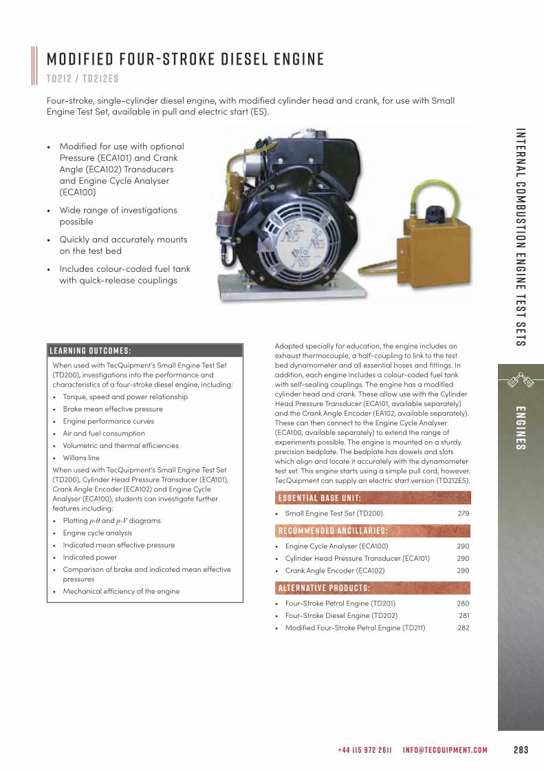
+ 4 4 1 1 5 9 7 2 2 6 1 1 I N F O @ T E C Q U I P M E N T. C O M
M o d i f i e d F o u r - S t r o k e D i e s e l E n g i n eT D 2 1 2 / T D 2 1 2 E S
Four-stroke, single-cylinder diesel engine, with modified cylinder head and crank, for use with SmallEngine Test Set, available in pull and electric start (ES).
• Modified for use with optionalPressure (ECA101) and CrankAngle (ECA102) Transducersand Engine Cycle Analyser(ECA100)
• Wide range of investigationspossible
• Quickly and accurately mountson the test bed
• Includes colour-coded fuel tankwith quick-release couplings
L e a r n i n g o u t c o m e s :When used with TecQuipment’s Small Engine Test Set(TD200), investigations into the performance andcharacteristics of a four-stroke diesel engine, including:• Torque, speed and power relationship• Brake mean effective pressure• Engine performance curves• Air and fuel consumption• Volumetric and thermal efficiencies• Willans lineWhen used with TecQuipment’s Small Engine Test Set(TD200), Cylinder Head Pressure Transducer (ECA101),Crank Angle Encoder (ECA102) and Engine CycleAnalyser (ECA100), students can investigate furtherfeatures including:• Plotting p-q and p-V diagrams• Engine cycle analysis• Indicated mean effective pressure• Indicated power• Comparison of brake and indicated mean effective
pressures• Mechanical efficiency of the engine
Adapted specially for education, the engine includes anexhaust thermocouple, a half-coupling to link to the testbed dynamometer and all essential hoses and fittings. Inaddition, each engine includes a colour-coded fuel tankwith self-sealing couplings. The engine has a modifiedcylinder head and crank. These allow use with the CylinderHead Pressure Transducer (ECA101, available separately)and the Crank Angle Encoder (EA102, available separately).These can then connect to the Engine Cycle Analyser(ECA100, available separately) to extend the range ofexperiments possible. The engine is mounted on a sturdyprecision bedplate. The bedplate has dowels and slotswhich align and locate it accurately with the dynamometertest set. This engine starts using a simple pull cord, however,TecQuipment can supply an electric start version (TD212ES).
• Small Engine Test Set (TD200) 279
• Engine Cycle Analyser (ECA100) 290• Cylinder Head Pressure Transducer (ECA101) 290• Crank Angle Encoder (ECA102) 290
• Four-Stroke Petrol Engine (TD201) 280• Four-Stroke Diesel Engine (TD202) 281• Modified Four-Stroke Petrol Engine (TD211) 282
R E C O M M E N D E D AN C I L LAR I E S :
alt e r nat i v e p r o d u c t s :
e s s e n t ial bas e u n i t:
2 8 3
eNGINES Internal Com
bustion Engine Test Sets
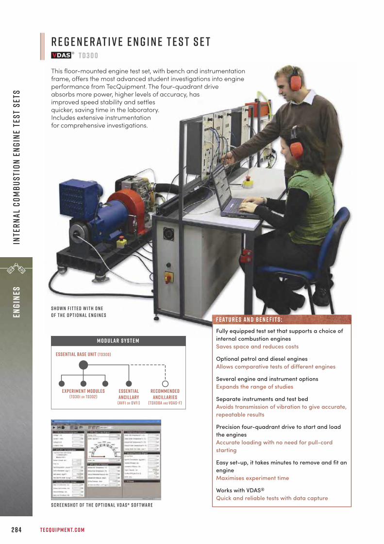
T E C Q U I P M E N T. C O M2 8 4
eNGI
NES
Inte
rnal
Com
bust
ion
Engi
ne T
est
Sets
Experiment modules(TD301 or TD302)
essentialancillary
(avf1 or dvf1)
recommendedancillaries
(TDX00a and vdas-f)
Essential Base Unit (TD300)
M O D U LAR S Y S T E M
R e g e n e r at i v e E n g i n e T e s t S e tT D 3 0 0
This floor-mounted engine test set, with bench and instrumentationframe, offers the most advanced student investigations into engineperformance from TecQuipment. The four-quadrant driveabsorbs more power, higher levels of accuracy, hasimproved speed stability and settlesquicker, saving time in the laboratory.Includes extensive instrumentationfor comprehensive investigations.
S c r e e n s h o t o f t h e o p t i o n a l V D A S ® s o f t wa r e
S h o w n f i t t e d w i t h o n eo f t h e o p t i o n a l e n g i n e s
Fully equipped test set that supports a choice ofinternal combustion enginesSaves space and reduces costs
Optional petrol and diesel enginesAllows comparative tests of different engines
Several engine and instrument optionsExpands the range of studies
Separate instruments and test bedAvoids transmission of vibration to give accurate,repeatable results
Precision four-quadrant drive to start and loadthe enginesAccurate loading with no need for pull-cordstarting
Easy set-up, it takes minutes to remove and fit anengineMaximises experiment time
Works with VDAS®
Quick and reliable tests with data capture
F eat u r e s an d be n e f i t s :

+ 4 4 1 1 5 9 7 2 2 6 1 1 I N F O @ T E C Q U I P M E N T. C O M 2 8 5
eNGINES Internal Com
bustion Engine Test Sets
L e a r n i n g o u t c o m e s :A comprehensive range of investigations into thefeatures of single-cylinder, four-stroke petrol and dieselengines including:• Torque, speed and power relationship• Brake mean effective pressure• Engine performance curves• Air and fuel consumption• Volumetric and thermal efficienciesBy using the recommended ancillaries and enginechoices, students can investigate more featuresincluding:• Plotting p-q and p-V diagrams• Engine cycle analysis• Indicated mean effective pressure• Indicated power• Comparison of brake and indicated mean effective
pressures• Mechanical efficiency of the engine
The bed is held on anti-vibration mounts. It includes arobust trunnion-mounted DC machine. An electronic loadcell connected to the machine measures the driving torqueof the test engine. The engines (available separately) aresupplied pre-mounted on a sturdy precision base plate.
When the engine is initially mounted onto the test bed orexchanged with an alternative engine, dowels and slotslocate the engine quickly, accurately and reliably. Eachengine includes a colour-coded fuel tank with self-sealingcouplings. The couplings ensure the engines can beconnected and disconnected quickly and efficiently, withminimum loss or spillage of fuel. For convenience andsafety, the fuel tank can be removed for filling or for storagein a fuel locker when not in use. Removing the fuel tank alsoprevents unauthorised use of the equipment.
• Four-stroke petrol engine (TD301) 286• Four-stroke diesel engine (TD302) 287
• Manual Volumetric Fuel Gauge (AVF1) o r 289• Automatic Volumetric Fuel Gauge with 289
Digital Display (DVF1)
• Versatile Data Acquisition System (VDAS-F) 310(frame-mounted version)
• Exhaust Gas Calorimeter (TDX00a) 288
• Small Engine Test Set (TD200) 279
R E C O M M E N D E D AN C I L LAR I E S :
alt e r nat i v e p r o d u c t s :
ava i labl e e x p e r i m e n t m o d u l e s :
E S S E N T IAL AN C I L LAR I E S :
F e at u r e s : T D 2 0 0 T D 3 0 0
Optional diesel and petrol engines ü üSeparate instrument frame and test bed ü üSeparate floor-standing instrument frame and desk with integral airbox and electrical cabinet û üHydraulic dynamometer ü ûFour-quadrant drive to start engine and provide stable load û üEngine power regenerated to mains power û üOptional pull cord or electric-start engines available ü Not applicable*
Speed setting functionality û üElectronic speed / load setting û üElectric start Optional üEasy engine change ü üWorks with VDAS® ü üEngine can be driven without fuel or ignition to determine frictional losses û üA n c i l l a r i e s : T D 2 0 0 T D 3 0 0
Four-stroke petrol engine ü Not applicable
Four-stroke diesel engine ü Not applicable
Modified four-stroke petrol engine ü üModified diesel engine ü üEngine cycle analyser ü üExhaust gas calorimeter ü üOne of the following is required: • Manual volumetric fuel gauge • Automatic volumetric fuel gauge with digital read out
üü
üü
VDAS-F Recommended Recommended
*Electric start function part of test bed **Only for use with modified engines
C o m pa r i s o n o f t h e S m a l l E n g i n e T e s t s e t ( T D 2 0 0 ) a n d R e g e n e r at i v e E n g i n e T e s t S e t ( T D 3 0 0 )
**

T E C Q U I P M E N T. C O M2 8 6
eNGI
NES
Inte
rnal
Com
bust
ion
Engi
ne T
est
Sets
L e a r n i n g o u t c o m e s :When used with TecQuipment’s Regenerative EngineTest Set (TD300), investigations into the performanceand characteristics of a four-stroke petrol engine,including:• Torque, speed and power relationship• Brake mean effective pressure• Engine performance curves• Air and fuel consumption• Volumetric and thermal efficienciesWhen used with TecQuipment’s Regenerative EngineTest Set (TD300), Cylinder Head Pressure Transducer(ECA101), Crank Angle Encoder (ECA102) and EngineCycle Analyser (ECA100), students can investigate furtherfeatures including:• Plotting p-q and p-V diagrams• The thermodynamic cycle of an internal combustion
engine• Indicated mean effective pressure• Indicated power• Comparison of brake and indicated mean effective
pressures• Mechanical efficiency of the engine
Adapted specially for education, the engine includes anexhaust thermocouple, a half-coupling to link to the test setdynamometer and all essential hoses and fittings. Inaddition, each engine includes a colour-coded fuel tankwith self-sealing couplings. The engine has a modifiedcylinder head and crank. These allow use with the CylinderHead Pressure Transducer (ECA101, available separately)and the Crank Angle Encoder (ECA102, availableseparately). These can then connect to the Engine CycleAnalyser (ECA100, available separately) to extend the rangeof experiments possible. The engine is mounted on a sturdyprecision bedplate. The bedplate has dowels and slotswhich align and locate it accurately with the dynamometertest set.
• Regenerative Engine Test Set (TD300) 284
• Engine Cycle Analyser (ECA100) 290• Cylinder Head Pressure Transducer (ECA101) 290• Crank Angle Encoder (ECA102) 290
• Four-Stroke Diesel Engine (TD302) 287
R E C O M M E N D E D AN C I L LAR I E S :
alt e r nat i v e p r o d u c t s :
e s s e n t ial bas e u n i t:
F o u r - S t r o k e P e t r o l E n g i n eT D 3 0 1
Four-stroke, single-cylinder petrol engine, with modified cylinder head and crank, for use withRegenerative Engine Test Set.
• Modified for use with optional Pressure(ECA101) and Crank Angle (ECA102)Transducers and Engine Cycle Analyser(ECA100)
• Quickly and accurately mounts on thetest bed
• Includes colour-coded fuel tank with quick-release couplings

+ 4 4 1 1 5 9 7 2 2 6 1 1 I N F O @ T E C Q U I P M E N T. C O M 2 8 7
eNGINES Internal Com
bustion Engine Test Sets
L e a r n i n g O u t c o m e s :When used with TecQuipment’s Regenerative EngineTest Set (TD300), investigations into the performanceand characteristics of a four-stroke diesel engine,including:• Torque, speed and power relationship• Brake mean effective pressure• Engine performance curves• Air and fuel consumption• Volumetric and thermal efficienciesWhen used with TecQuipment’s Regenerative EngineTest Set (TD300), Cylinder Head Pressure Transducer(ECA101), Crank Angle Encoder (ECA102) and EngineCycle Analyser (ECA100) students can investigate furtherfeatures including:• Plotting p-q and p-V diagrams• The thermodynamic cycle of an internal combustion
engine• Indicated mean effective pressure• Indicated power• Comparison of brake and indicated mean effective
pressures• Mechanical efficiency of the engine
Adapted specially for education, the engine includes anexhaust thermocouple, a halfcoupling to link to the test beddynamometer, and all essential hoses and fittings. Inaddition, each engine includes a colour-coded fuel tankwith self-sealing couplings. The engine has a modifiedcylinder head and crank. These allow use with the CylinderHead Pressure Transducer (ECA101, available separately)and the Crank Angle Encoder (ECA102, availableseparately). These can then connect to the Engine CycleAnalyser (ECA100, available separately) to extend the rangeof experiments possible. The engine is mounted on a sturdyprecision bedplate. The bedplate has dowels and slotswhich align and locate it accurately with the dynamometertest set.
• Regenerative Engine Test Set (TD300) 284
• Engine Cycle Analyser (ECA100) 290• Cylinder Head Pressure Transducer (ECA101) 290• Crank Angle Encoder (ECA102) 290
• Four-Stroke Petrol Engine (TD301) 286
R E C O M M E N D E D AN C I L LAR I E S :
alt e r nat i v e p r o d u c t s :
e s s e n t ial bas e u n i t:
F o u r - S t r o k e D i e s e l E n g i n eT D 3 0 2
Four-stroke, single-cylinder diesel engine, with modified cylinder head and crank, for use withRegenerative Engine Test Set.
• Modified for use with optional Pressure(ECA101) and Crank Angle (ECA102)Transducers and Engine Cycle Analyser(ECA100)
• Quickly and accurately mounts on thetest bed
• Includes colour-coded fuel tank with quick-release couplings

T E C Q U I P M E N T. C O M2 8 8
eNGI
NES
Inte
rnal
Com
bust
ion
Engi
ne T
est
Sets
L e a r n i n g o u t c o m e s :When used with TecQuipment’s Engine Test Sets (TD200or TD300), the Exhaust Gas Calorimeter enablesstudents to assess the heat lost to exhaust in the energybalance for single-cylinder, four-stroke petrol and dieselengines.
The heat exchanger is mounted on a sturdy base plate.Exhaust gases from the test engine mounted on the test setflow through the tubes. A jacket of constantly flowingcooling water surrounds the tubes, and the heat content ofthe gases is assessed by measuring the cooling water flowrate and the inlet and outlet temperatures. A hand-operated valve controls the flow of cooling water throughthe heat exchanger jacket. Thermocouples measure thetemperature of gas and water at the inlet and outlet. Aturbine flow meter measures the flow rate. For safety, theheat exchanger also includes a pressure relief valve in caseinsufficient cooling water is flowing.
• Small Engine Test Set (TD200) 279• Regenerative Engine Test Set (TD300) 284
AN C I L LAR Y F O R :
E x h a u s t G a s C a l o r i m e t e rT D X 0 0 a
Experiment for use with TecQuipment’s Engine Test Sets (TD200 and TD300) to measure the heatcontent of engine exhaust gases.
• Safely and effectively measures the heatcontent of TecQuipment’s test engineexhaust gases
• Specially designed for educational use
• Uses electronic transducers and a digitaldisplay for ease of use and accuracy
• Separate instrumentation unit convenientlymounts on test set console frame
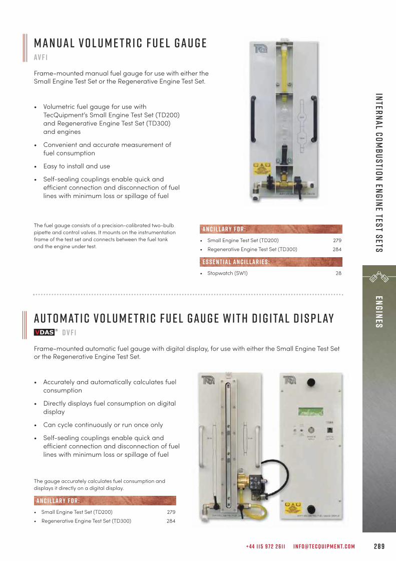
+ 4 4 1 1 5 9 7 2 2 6 1 1 I N F O @ T E C Q U I P M E N T. C O M 2 8 9
eNGINES Internal Com
bustion Engine Test Sets
A u t o m at i c V o l u m e t r i c F u e l G a u g e w i t h D i g i ta l D i s p l ayD V F 1
Frame-mounted automatic fuel gauge with digital display, for use with either the Small Engine Test Setor the Regenerative Engine Test Set.
• Accurately and automatically calculates fuelconsumption
• Directly displays fuel consumption on digitaldisplay
• Can cycle continuously or run once only
• Self-sealing couplings enable quick andefficient connection and disconnection of fuellines with minimum loss or spillage of fuel
The fuel gauge consists of a precision-calibrated two-bulbpipette and control valves. It mounts on the instrumentationframe of the test set and connects between the fuel tankand the engine under test.
M a n u a l V o l u m e t r i c F u e l G a u g eAV F 1
Frame-mounted manual fuel gauge for use with either theSmall Engine Test Set or the Regenerative Engine Test Set.
• Volumetric fuel gauge for use withTecQuipment’s Small Engine Test Set (TD200)and Regenerative Engine Test Set (TD300)and engines
• Convenient and accurate measurement offuel consumption
• Easy to install and use
• Self-sealing couplings enable quick andefficient connection and disconnection of fuellines with minimum loss or spillage of fuel
• Small Engine Test Set (TD200) 279• Regenerative Engine Test Set (TD300) 284
• Stopwatch (SW1) 28
E S S E N T IAL AN C I L LAR I E S :
AN C I L LAR Y F O R :
The gauge accurately calculates fuel consumption anddisplays it directly on a digital display.
• Small Engine Test Set (TD200) 279• Regenerative Engine Test Set (TD300) 284
AN C I L LAR Y F O R :

T E C Q U I P M E N T. C O M2 9 0
eNGI
NES
Inte
rnal
Com
bust
ion
Engi
ne T
est
Sets
• For use with TecQuipment’s Small EngineTest Set (TD200) and Regenerative EngineTest Set (TD300) and engines
• Includes powerful Windows®-basedsoftware specially designed for educationaluse
• Automatic calculation and real-time displayof p-q and p-V plots and other importantparameters
• Snapshot, replay and animation functions
• Accurate, clear animations of crank, piston,inlet and exhaust valve positions helpstudents visualise the engine cycle
L e a r n i n g o u t c o m e s :When used with suitable test engines, the analyserallows investigations into a variety of internalcombustion engine characteristics, including:• The thermodynamic cycle of an internal combustion
engine.• Calculation of indicated mean effective pressure and
indicated power.• Comparison of indicated mean effective pressure
and brake mean effective pressure.• Mechanical efficiency of the test engine.• Further work using exported data such as
combustion analysis.
The equipment consists of a hardware unit with connectorsand leads, plus Windows®-based data acquisition andanalysis software. The hardware consists of amicroprocessor-based signal conditioning unit, with high-speed PC interface, housed in a rugged, protectiveenclosure. It accepts and conditions signals from theCylinder Head Pressure Transducer (ECA101) and CrankAngle Encoder (ECA102), available separately. The cylinderpressure input includes a precision charge amplifier, with adigital thumb-wheel for calibration. As well as crank angleposition, the signal from the Crank Angle Encoder is alsoused to determine engine speed.
E n g i n e C y c l e A n a ly s e rE C A1 0 0
Hardware and software to measure internal combustion engine cylinder pressure and crank angle.
• Cylinder Head Pressure Transducer (ECA101)• Crank Angle Encoder (ECA102)• Suitable computer
• Modified Four-Stroke Petrol Engine (TD211) 282• Modified Four-Stroke Diesel Engine (TD212) 283• Four-Stroke Petrol Engine (TD301) 286• Four-Stroke Diesel Engine (TD302) 287
AN C I L LAR Y F O R :
E S S E N T IAL AN C I L LAR I E S :
T e c Q u i p m e n t o f f e r s a c o m p l e t e pa c k a g e : t h e E C A1 0 0 Sw h i c h i n c l u d e s t h e E C A1 0 0 , o n e E C A1 0 1 a n d o n e E C A1 0 2
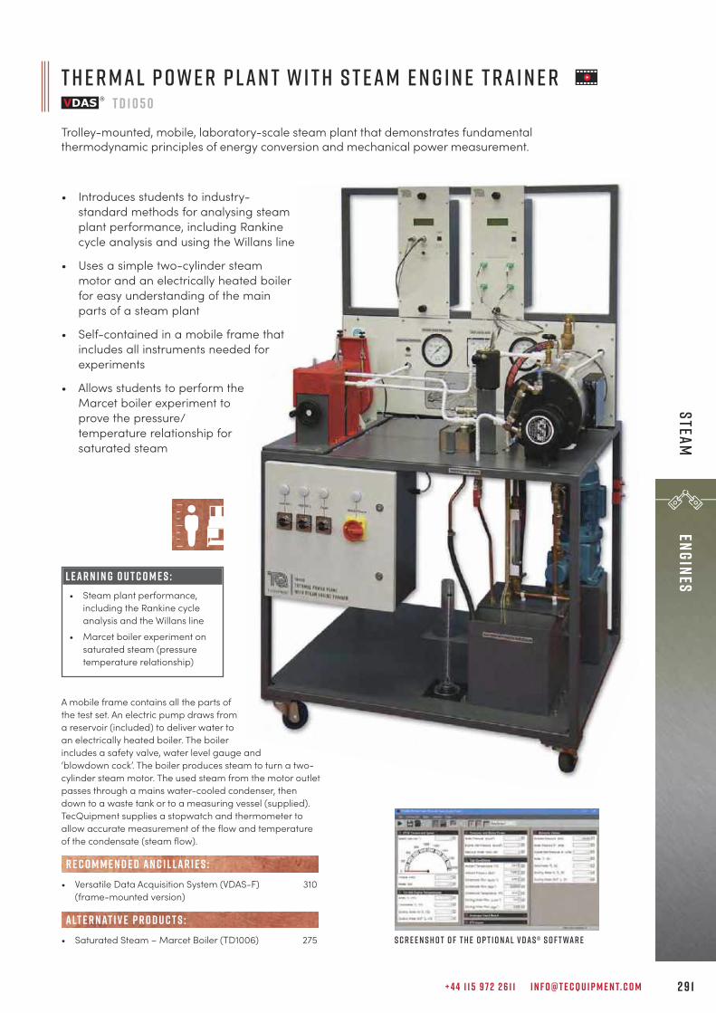
A mobile frame contains all the parts ofthe test set. An electric pump draws froma reservoir (included) to deliver water toan electrically heated boiler. The boilerincludes a safety valve, water level gauge and‘blowdown cock’. The boiler produces steam to turn a two-cylinder steam motor. The used steam from the motor outletpasses through a mains water-cooled condenser, thendown to a waste tank or to a measuring vessel (supplied).TecQuipment supplies a stopwatch and thermometer toallow accurate measurement of the flow and temperatureof the condensate (steam flow).
• Versatile Data Acquisition System (VDAS-F) 310(frame-mounted version)
• Saturated Steam – Marcet Boiler (TD1006) 275
R E C O M M E N D E D AN C I L LAR I E S :
alt e r nat i v e p r o d u c t s :
T h e r m a l P o w e r P l a n t w i t h S t e a m E n g i n e T r a i n e rT D 1 0 5 0
Trolley-mounted, mobile, laboratory-scale steam plant that demonstrates fundamentalthermodynamic principles of energy conversion and mechanical power measurement.
+ 4 4 1 1 5 9 7 2 2 6 1 1 I N F O @ T E C Q U I P M E N T. C O M 2 9 1
eNGINES Steam
• Introduces students to industry-standard methods for analysing steamplant performance, including Rankinecycle analysis and using the Willans line
• Uses a simple two-cylinder steammotor and an electrically heated boilerfor easy understanding of the mainparts of a steam plant
• Self-contained in a mobile frame thatincludes all instruments needed forexperiments
• Allows students to perform theMarcet boiler experiment toprove the pressure/temperature relationship forsaturated steam
S c r e e n s h o t o f t h e o p t i o n a l V D A S ® s o f t wa r e
L E A R N I N G O U T C O M E S :• Steam plant performance,
including the Rankine cycleanalysis and the Willans line
• Marcet boiler experiment onsaturated steam (pressuretemperature relationship)
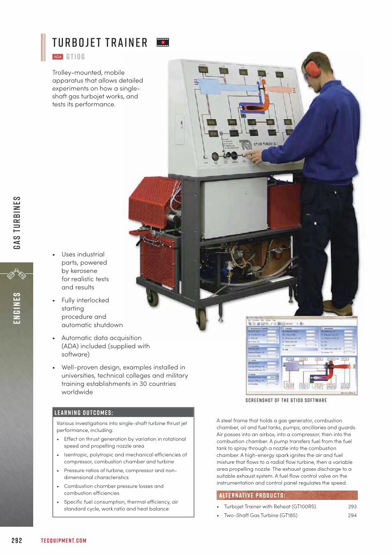
T E C Q U I P M E N T. C O M2 9 2
eNGI
NES
Gas
Turb
ines
L E A R N I N G O U T C O M E S :Various investigations into single-shaft turbine thrust jetperformance, including:• Effect on thrust generation by variation in rotational
speed and propelling nozzle area• Isentropic, polytropic and mechanical efficiencies of
compressor, combustion chamber and turbine • Pressure ratios of turbine, compressor and non-
dimensional characteristics• Combustion chamber pressure losses and
combustion efficiencies• Specific fuel consumption, thermal efficiency, air
standard cycle, work ratio and heat balance
A steel frame that holds a gas generator, combustionchamber, oil and fuel tanks, pumps, ancillaries and guards.Air passes into an airbox, into a compressor, then into thecombustion chamber. A pump transfers fuel from the fueltank to spray through a nozzle into the combustionchamber. A high-energy spark ignites the air and fuelmixture that flows to a radial flow turbine, then a variablearea propelling nozzle. The exhaust gases discharge to asuitable exhaust system. A fuel flow control valve on theinstrumentation and control panel regulates the speed.
• Turbojet Trainer with Reheat (GT100RS) 293• Two-Shaft Gas Turbine (GT185) 294
alt e r nat i v e p r o d u c t s :
T u rbo j e t T r a i n e rG T 1 0 0
Trolley-mounted, mobileapparatus that allows detailedexperiments on how a single-shaft gas turbojet works, andtests its performance.
• Uses industrialparts, poweredby kerosenefor realistic testsand results
• Fully interlockedstartingprocedure andautomatic shutdown
• Automatic data acquisition(ADA) included (supplied withsoftware)
• Well-proven design, examples installed inuniversities, technical colleges and militarytraining establishments in 30 countriesworldwide
S c r e e n s h o t o f t h e G T 1 0 0 s o f t wa r e

+ 4 4 1 1 5 9 7 2 2 6 1 1 I N F O @ T E C Q U I P M E N T. C O M 2 9 3
eNGINES Gas Turbines
L E A R N I N G O U T C O M E S :Turbine, reheat and nozzle tests to find key performanceinformation such as: • Specific thrust and fuel consumption• Pressure losses and ratios• Thermal, propulsive, isentropic and mechanical
efficiencies• Work and power• Thrust with and without reheat• How the variable area nozzle affects thrust
S c r e e n s h o t o f t h e G T 1 0 0 R S s o f t wa r e
Air passes into an air box, through a calibrated nozzle into acompressor, then into the combustion chamber. A pumptransfers fuel from the fuel tank to spray through a specialnozzle into the combustion chamber. A high-energy sparkignites the air and fuel mixture that flows to a radial flowturbine, then to the reheat section. It then passes through avariable area propelling nozzle. The exhaust gases thendischarge to a suitable exhaust system. A fuel flow controlvalve on the instrumentation and control panel regulatesthe turbine speed. A second high-energy spark in thereheat section ignites the reheat fuel. This creates asecondary burn (or afterburn) using some of the remainingoxygen in the hot exhaust gases leaving the turbine.
• Turbojet Trainer (GT100) 292• Two-Shaft Gas Turbine (GT185) 294
alt e r nat i v e p r o d u c t s :
T u rbo j e t T r a i n e r w i t h R e h e atG T 1 0 0 R S
Trolley-mounted, mobile apparatus that allows detailed experiments on how a single-shaft gasturbojet with reheat (afterburner) works, and tests its performance.
• Uses industrial parts, powered bykerosene for realistic tests andresults
• Fully interlocked startingprocedure and automaticshutdown
• Automatic Data Acquisition(ADA) included (suppliedwith software)
• Well proven design,examples installed inuniversities, technicalcolleges and militarytraining establishments in30 countries worldwide
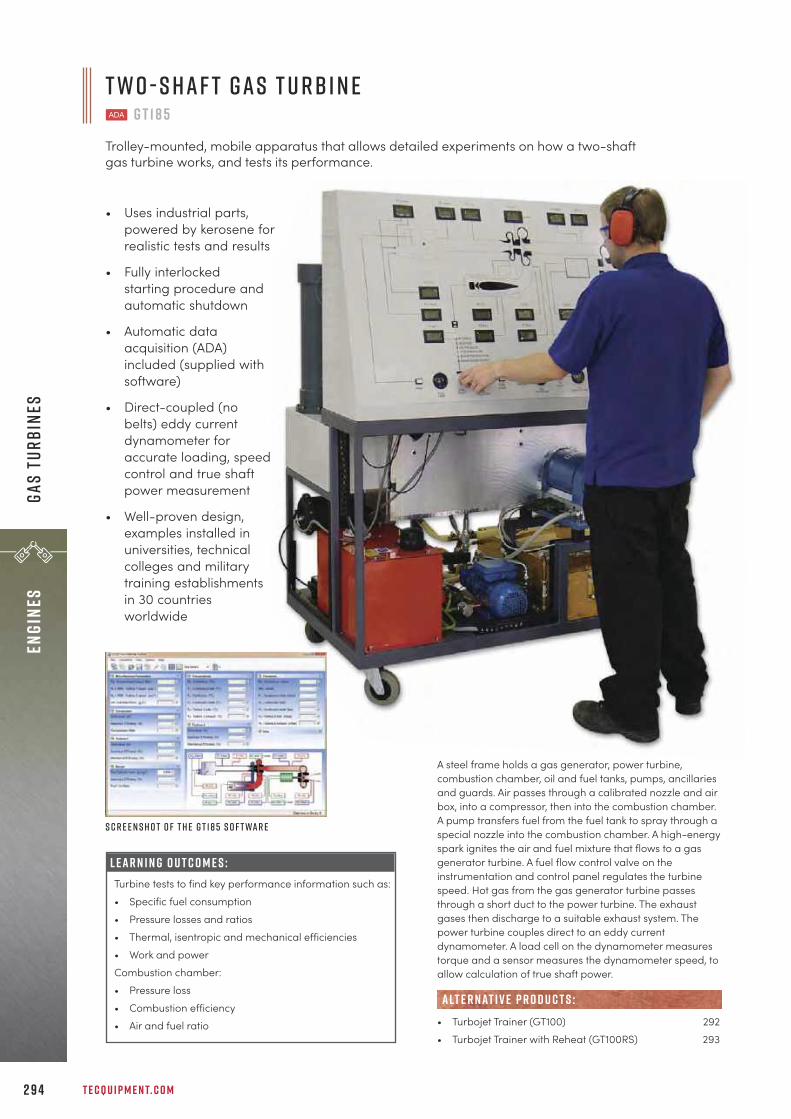
L E A R N I N G O U T C O M E S :Turbine tests to find key performance information such as: • Specific fuel consumption• Pressure losses and ratios• Thermal, isentropic and mechanical efficiencies• Work and powerCombustion chamber: • Pressure loss• Combustion efficiency• Air and fuel ratio
T E C Q U I P M E N T. C O M2 9 4
eNGI
NES
Gas
Turb
ines
T w o - S h a f t G a s T u rb i n eG T 1 8 5
Trolley-mounted, mobile apparatus that allows detailed experiments on how a two-shaftgas turbine works, and tests its performance.
• Uses industrial parts,powered by kerosene forrealistic tests and results
• Fully interlockedstarting procedure andautomatic shutdown
• Automatic dataacquisition (ADA)included (supplied withsoftware)
• Direct-coupled (nobelts) eddy currentdynamometer foraccurate loading, speedcontrol and true shaftpower measurement
• Well-proven design,examples installed inuniversities, technicalcolleges and militarytraining establishmentsin 30 countriesworldwide
S c r e e n s h o t o f t h e G T 1 8 5 s o f t wa r e
A steel frame holds a gas generator, power turbine,combustion chamber, oil and fuel tanks, pumps, ancillariesand guards. Air passes through a calibrated nozzle and airbox, into a compressor, then into the combustion chamber.A pump transfers fuel from the fuel tank to spray through aspecial nozzle into the combustion chamber. A high-energyspark ignites the air and fuel mixture that flows to a gasgenerator turbine. A fuel flow control valve on theinstrumentation and control panel regulates the turbinespeed. Hot gas from the gas generator turbine passesthrough a short duct to the power turbine. The exhaustgases then discharge to a suitable exhaust system. Thepower turbine couples direct to an eddy currentdynamometer. A load cell on the dynamometer measurestorque and a sensor measures the dynamometer speed, toallow calculation of true shaft power.
• Turbojet Trainer (GT100) 292• Turbojet Trainer with Reheat (GT100RS) 293
alt e r nat i v e p r o d u c t s :

+ 4 4 1 1 5 9 7 2 2 6 1 1 I N F O @ T E C Q U I P M E N T. C O M 2 9 5
Environmental Control
“It is gratifying indeed to work with a company with exemplary customer service such as yours.Thank you on behalf of the entire Department of Civil Engineering at Oregon Tech.
Pat r i c k K i l eO r e g o n i n s t i t u t e o f T e c h n o l o g y
e n v i r o n m e n t a l c o n t r o lc o o l i n g 2 9 7
R e f r i g e r at i o n 2 9 8
A i r C o n d i t i o n i n g 2 9 9
H VA C & R 3 0 0
h u m i d i t y 3 0 2

F u n d a m e n ta l s o f H VA C : The range provides thecapabilities to study the fundamental components of anHVAC course.
D ata A c q u i s i t i o n a s s ta n d a r d : Most products in therange come with TecQuipment’s Versatile Data AcquisitionSystem, offering high specification and great value.
I n d u s t r i a l a n d D o m e s t i c : With units covering airconditioning and cooling towers, students can study theelements of both industrial and domestic environmentalcontrol.
T E C Q U I P M E N T. C O M2 9 6
Envi
ronm
enta
l Co
ntro
l
The Environmental Control range offers teachingequipment covering the fundamental theories associatedwith thermodynamics, fluid mechanics and heat transfer.This enables students to understand environmental controlin the real industrial and consumer world. Experimentsallow students to explore the workings of cooling towers,refrigeration, air conditioning and humidity, utilisingpsychrometric and P-h charts.
A u t o m at i c d ata a c q u i s i t i o n Look at the products in this range that work withTecQuipment’s unique Versatile Data Acquisition System(VDAS®), page 310.
e n v i r o n m e n ta l c o n t r o lk e y f eat u r e s an d b e n e f i t s :

C o o l i n g T o w e r se c 1 0 0 0 V
Benchtop apparatus that demonstratesthe operation characteristics of anevaporative cooling tower.
+ 4 4 1 1 5 9 7 2 2 6 1 1 I N F O @ T E C Q U I P M E N T. C O M 2 9 7
Environmental Control Cooling
L E A R N I N G O U T C O M E S :How key variables affect the performance of a coolingtower, including:• Variation of water flow rate• Variation of air flow rate• Packing density and arrangement• Variation of water temperature• Energy and mass balance
• Includes TecQuipment’s Versatile DataAcquisition System VDAS® Onboard,featuring data acquisition via USB
• The EC1000V includes one column withpacking for immediate experimentationpotential
• Three extra interchangeable columns,containing different packing densities andarrangements, further extend experimentalcapabilities
• An additional interchangeable column withno packing demonstrates freefall cooling
A centrifugal pump delivers the heated water to a spraynozzle at the top of the column. The water sprays into thecolumn, passing over ‘packing’ inside the column andreturning to the heated water tank. The fan directs airupwards through the column in counter flow to the water,extracting the heat. Electronic sensors measure the air andwater flow, humidity, pressures and temperatures at keypoints, shown on clear, multi-line displays. This gives all
measurements needed to understand the evaporativecooling tower operation. A clear tube above the heatedwater tank allows the user to measure the water lost due toevaporation.
• Cooling Column Type A (EC1000a)• Cooling Column Type B (EC1000b)• Empty Cooling Column (EC1000c)• Packing Characteristics Column (EC1000d)
R E C O M M E N D E D AN C I L LAR I E S :
E C 1 0 0 0 a E C 1 0 0 0b
E C 1 0 0 0 c
S c r e e n s h o t o f t h e V D A S ® s o f t wa r e
S h o w n w i t h t h e Pa c k i n g C h a r a c t e r i s t i c sC o l u m n ( E C 1 0 0 0 d )
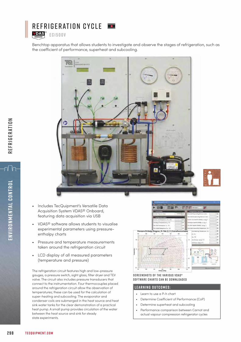
L E A R N I N G O U T C O M E S :• Learn to use a P-h chart• Determine Coefficient of Performance (CoP)• Determine superheat and subcooling• Performance comparison between Carnot and
actual vapour compression refrigerator cycles
T E C Q U I P M E N T. C O M2 9 8
Envi
ronm
enta
l Co
ntro
lRe
frig
erat
ion
r e f r i g e r at i o n c y c l ee c 1 5 0 0 v
Benchtop apparatus that allows students to investigate and observe the stages of refrigeration, such asthe coefficient of performance, superheat and subcooling.
• Includes TecQuipment’s Versatile DataAcquisition System VDAS® Onboard,featuring data acquisition via USB
• VDAS® software allows students to visualiseexperimental parameters using pressure-enthalpy charts
• Pressure and temperature measurementstaken around the refrigeration circuit
• LCD display of all measured parameters(temperature and pressure)
The refrigeration circuit features high and low-pressuregauges, a pressure switch, sight glass, filter dryer and TEVvalve. The circuit also includes pressure transducers thatconnect to the instrumentation. Four thermocouples placedaround the refrigeration circuit allow the observation oftemperatures; these can be used for the calculation ofsuper-heating and subcooling. The evaporator andcondenser coils are submerged in the heat source and heatsink water tanks for the clear demonstration of a practicalheat pump. A small pump provides circulation of the waterbetween the heat source and sink for steadystate experiments.
S c r e e n s h o t s o f t h e va r i o u s V D A S ®s o f t wa r e C h a r t s c a n be d o w n l o a d e d

+ 4 4 1 1 5 9 7 2 2 6 1 1 I N F O @ T E C Q U I P M E N T. C O M 2 9 9
Environmental Control Air Conditioning
a i r c o n d i t i o n i n g t r a i n e re c 1 5 0 1 V
Benchtop apparatus that allows students to investigate the fundamental principles of air conditioning,including enthalpy change in the air flow.
L E A R N I N G O U T C O M E S :• Learn to use P-h charts• Learn to use psychrometric charts• Determine Coefficient of Performance (CoP)• Determine superheat and subcooling• Determine enthalpy change in the air flow
• Includes TecQuipment’s Versatile DataAcquisition System VDAS® Onboard,featuring data acquisition via USB
• VDAS® software allows students to visualiseexperimental parameters usingpsychrometric charts
• Pressure and temperature measurementstaken around the refrigeration circuit
• Relative humidity and temperaturemeasured on either side of the evaporator
• LCD display of all measured parameters(relative humidity, temperature andpressure)
The unit features an air-cooled condenser unit connected toan evaporator located in an air duct. The air duct containsrelative humidity and temperature sensors on both sides. Asmall fan provides air flow down the duct; air flow rate canbe manually adjusted. The refrigeration circuit features highand low-pressure gauges, a pressure switch, sight glass,filter dryer and TEV valve. The circuit also includes pressuretransducers that connect to the instrumentation. Fourthermocouples placed around the refrigeration circuit allowobservation of temperatures; these can be used for thecalculation of superheating and subcooling.
S c r e e n s h o t s o f t h eV D A S ® s o f t wa r eC h a r t s c a n bed o w n l o a d e d
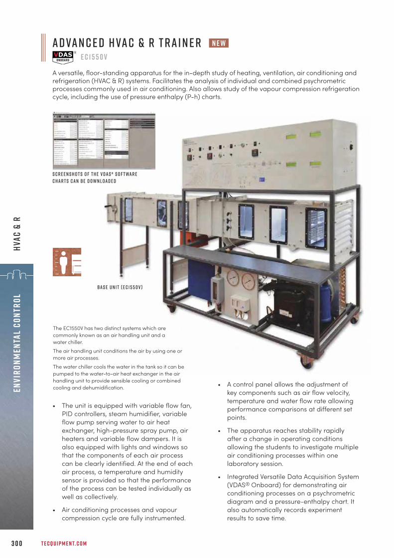
T E C Q U I P M E N T. C O M3 0 0
Envi
ronm
enta
l Co
ntro
lHV
AC &
R
A d va n c e d H VA C & R T r a i n e r e c 1 5 5 0 v
A versatile, floor-standing apparatus for the in-depth study of heating, ventilation, air conditioning andrefrigeration (HVAC & R) systems. Facilitates the analysis of individual and combined psychrometricprocesses commonly used in air conditioning. Also allows study of the vapour compression refrigerationcycle, including the use of pressure enthalpy (P-h) charts.
• The unit is equipped with variable flow fan,PID controllers, steam humidifier, variableflow pump serving water to air heatexchanger, high-pressure spray pump, airheaters and variable flow dampers. It isalso equipped with lights and windows sothat the components of each air processcan be clearly identified. At the end of eachair process, a temperature and humiditysensor is provided so that the performanceof the process can be tested individually aswell as collectively.
• Air conditioning processes and vapourcompression cycle are fully instrumented.
• A control panel allows the adjustment ofkey components such as air flow velocity,temperature and water flow rate allowingperformance comparisons at different setpoints.
• The apparatus reaches stability rapidlyafter a change in operating conditionsallowing the students to investigate multipleair conditioning processes within onelaboratory session.
• Integrated Versatile Data Acquisition System(VDAS® Onboard) for demonstrating airconditioning processes on a psychrometricdiagram and a pressure-enthalpy chart. Italso automatically records experimentresults to save time.
The EC1550V has two distinct systems which arecommonly known as an air handling unit and awater chiller. The air handling unit conditions the air by using one ormore air processes.The water chiller cools the water in the tank so it can bepumped to the water-to-air heat exchanger in the airhandling unit to provide sensible cooling or combinedcooling and dehumidification.
B a s e U n i t ( E C 1 5 5 0 V )
n e w
S c r e e n s h o t s o f t h e V D A S ® s o f t wa r eC h a r t s c a n be d o w n l o a d e d
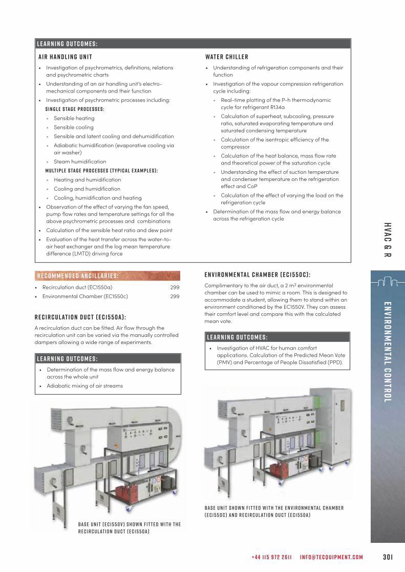
B a s e U n i t s h o w n f i t t e d w i t h t h e E n v i r o n m e n ta l c h a mbe r( E C 1 5 5 0 C ) a n d r e c i r c u l at i o n d u c t ( E C 1 5 5 0 a )
+ 4 4 1 1 5 9 7 2 2 6 1 1 I N F O @ T E C Q U I P M E N T. C O M 3 0 1
Environmental Control HVAC & R
L E A R N I N G O U T C O M E S :
L E A R N I N G O U T C O M E S : • Determination of the mass flow and energy balance
across the whole unit• Adiabatic mixing of air streams
• Recirculation duct (EC1550a) 299• Environmental Chamber (EC1550c) 299
R E C O M M E N D E D AN C I L LAR I E S :
L E A R N I N G O U T C O M E S : • Investigation of HVAC for human comfort
applications. Calculation of the Predicted Mean Vote(PMV) and Percentage of People Dissatisfied (PPD).
E n v i r o n m e n ta l c h a m b e r ( E C 1 5 5 0 c ) :Complimentary to the air duct, a 2 m3 environmentalchamber can be used to mimic a room. This is designed toaccommodate a student, allowing them to stand within anenvironment conditioned by the EC1550V. They can assesstheir comfort level and compare this with the calculatedmean vote.R e c i r c u l at i o n d u c t ( E C 1 5 5 0 a ) :
A recirculation duct can be fitted. Air flow through therecirculation unit can be varied via the manually controlleddampers allowing a wide range of experiments.
A i r h a n d l i n g u n i t• Investigation of psychrometrics, definitions, relations
and psychrometric charts• Understanding of an air handling unit’s electro-
mechanical components and their function• Investigation of psychrometric processes including:
S i n g l e S ta g e P r o c e s s e s :• Sensible heating• Sensible cooling• Sensible and latent cooling and dehumidification• Adiabatic humidification (evaporative cooling via
air washer)• Steam humidificationM u lt i p l e S ta g e P r o c e s s e s ( t y p i c a l E x a m p l e s ) :• Heating and humidification• Cooling and humidification• Cooling, humidification and heating
• Observation of the effect of varying the fan speed,pump flow rates and temperature settings for all theabove psychrometric processes and combinations
• Calculation of the sensible heat ratio and dew point• Evaluation of the heat transfer across the water-to-
air heat exchanger and the log mean temperaturedifference (LMTD) driving force
Wat e r C h i l l e r• Understanding of refrigeration components and their
function• Investigation of the vapour compression refrigeration
cycle including:• Real-time plotting of the P-h thermodynamic
cycle for refrigerant R134a• Calculation of superheat, subcooling, pressure
ratio, saturated evaporating temperature andsaturated condensing temperature
• Calculation of the isentropic efficiency of thecompressor
• Calculation of the heat balance, mass flow rateand theoretical power of the saturation cycle
• Understanding the effect of suction temperatureand condenser temperature on the refrigerationeffect and CoP
• Calculation of the effect of varying the load on therefrigeration cycle
• Determination of the mass flow and energy balanceacross the refrigeration cycle
B a s e U n i t ( E C 1 5 5 0 V ) s h o w n f i t t e d w i t h t h er e c i r c u l at i o n d u c t ( e c 1 5 5 0 a )
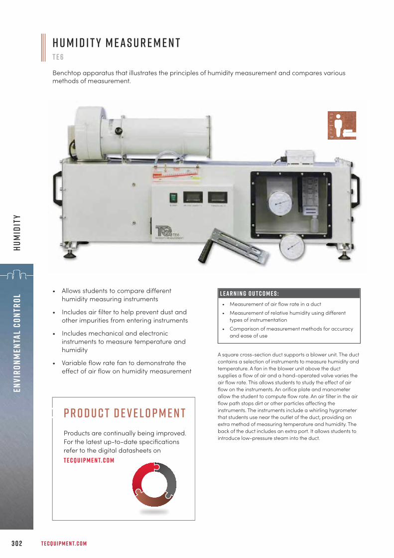
T E C Q U I P M E N T. C O M3 0 2
Envi
ronm
enta
l Co
ntro
lHu
mid
ity
L E A R N I N G O U T C O M E S :• Measurement of air flow rate in a duct• Measurement of relative humidity using different
types of instrumentation• Comparison of measurement methods for accuracy
and ease of use
• Allows students to compare differenthumidity measuring instruments
• Includes air filter to help prevent dust andother impurities from entering instruments
• Includes mechanical and electronicinstruments to measure temperature andhumidity
• Variable flow rate fan to demonstrate theeffect of air flow on humidity measurement
A square cross-section duct supports a blower unit. The ductcontains a selection of instruments to measure humidity andtemperature. A fan in the blower unit above the ductsupplies a flow of air and a hand-operated valve varies theair flow rate. This allows students to study the effect of airflow on the instruments. An orifice plate and manometerallow the student to compute flow rate. An air filter in the airflow path stops dirt or other particles affecting theinstruments. The instruments include a whirling hygrometerthat students use near the outlet of the duct, providing anextra method of measuring temperature and humidity. Theback of the duct includes an extra port. It allows students tointroduce low-pressure steam into the duct.
H u m i d i t y M e a s u r e m e n tT E 6
Benchtop apparatus that illustrates the principles of humidity measurement and compares variousmethods of measurement.
p r o d u c t d e v e l o p m e n tProducts are continually being improved. For the latest up-to-date specifications refer to the digital datasheets ont e cqu i p m e n t. c o m

+ 4 4 1 1 5 9 7 2 2 6 1 1 I N F O @ T E C Q U I P M E N T. C O M 3 0 3
Solar Energy
“The TecQuipment teaching solutions and scalable teaching equipment has allowed theThermal Engineering and Energy Department to provide training up to Masters degree levelwith continuous and undeniable quality.
p r o f e s s o r j e a n - n o Ë l b l a n c h a r di u t o r l e a n s , f r a n c e
s o l a r e n e r g ys o l a r p h o t o v o lta i c 3 0 5
s o l a r t h e r m a l 3 0 6

T E C Q U I P M E N T. C O M3 0 4
Sola
r En
ergy
s o l a r e n e r g yThe Solar Energy range offers teaching equipment for thecore principles of solar energy, including photovoltaic cells,flat plate solar thermal energy collectors and focusing solarenergy collectors. Students can learn about the efficienciesand limitations of each method of harnessing andconverting solar energy for use in the real world.
V e r s at i l e d ata a c q u i s i t i o n S y s t e m The Solar Energy products work with TecQuipment’s uniqueVersatile Data Acquisition System (VDAS®), page 310.
L o o k at o u r o t h e rr e l e va n t r a n g e s Other TecQuipment products link directly torenewable energy. For example, our M o d u l a r F l u i dP o w e r products (pages 142–156) include turbines toharness the energy in water. The A e r o d y n a m i c s andF l u i d M e c h a n i c s ranges include experiments todemonstrate how shapes affect air and water flow.These are essential tools for engineers whendesigning wind or water energy systems.
P h o t o v o lta i c , f o c u s i n g a n d f l at p l at e e n e r g yc o l l e c t i o n : Demonstrates three key methods used inharnessing solar energy.
a u t o m at i c d ata a c q u i s i t i o n : VDAS® is particularlyuseful when monitoring longer duration experiments.
s a f e a n d e a s y s e t- u p : Low temperatures, safeconnections and simple, hand-operated controls allowthe set up an experiment safely and quickly.
k e y f eat u r e s an d b e n e f i t s :

• Demonstrates the performance of a high-efficiency photovoltaic cell array andbattery storage system
• Includes solarimeter, charge controller andcontrol module with digital displays and DCoutputs
• Supplied with both high and low-capacitybatteries to allow students to investigatecharge and discharge cycle of the systemin a typical laboratory session as well aslonger cycles
• Includes three different types of electricalload
L E A R N I N G O U T C O M E S :• Performance of the solar panel• Demonstration of float mode• Demonstration of load cut
The TE4 uses a commercially available solar panel madefrom high-efficiency cells. The solar panel is on a wheeled,lightweight frame that allows adjustment of the panelangle, relative to the sun. A solarimeter on the framemeasures incident radiation. The panel recharges a choiceof two batteries through a charge controller. The chargecontroller recharges the battery at the correct rate ofcharge without damage to the battery. The frame holds ahigh-performance, deep-cycling battery in a storage box.The equipment also includes a second lower-rated battery.This allows students to examine the charge and dischargecycle of the system in a typical laboratory session.
S c r e e n s h o t o f t h e o p t i o n a l V D A S ® s o f t wa r e
+ 4 4 1 1 5 9 7 2 2 6 1 1 I N F O @ T E C Q U I P M E N T. C O M 3 0 5
Solar EnergySolar Photovoltaic
p h o t o v o lta i c c e l l st e 4
Floor-standing mobile apparatus with instrumentation,includes high and low-capacity batteries. It illustrates howeffective photovoltaic cells are in capturing solar energy.
• Versatile Data Acquisition System (VDAS-B) 310(benchtop version)
• Focusing Solar Energy Collector (TE38) 306• Flat Plate Solar Thermal Energy Collector (TE39) 307
alt e r nat i v e p r o d u c t s :
R E C O M M E N D E D AN C I L LAR I E S :

T E C Q U I P M E N T. C O M3 0 6
Sola
r En
ergy
Sola
r Th
erm
al
A highly polished, stainless steel parabolic reflector,supported on trunnion bearings on a turntable. Byadjusting the horizontal and vertical position of the reflector,students focus solar energy onto an energy collector. Theenergy collector is a brass cylinder with an embeddedthermocouple that measures the cylinder temperature. Toenable students to compare different concentration ratios,TecQuipment supplies four different sizes of energycollector. Also supplied is a removable transparent cover forthe collector, so students can study the properties ofshielded and unshielded collectors. Attached to the reflectorcarrier is a solarimeter (pyranometer) that measures theincident solar radiation.
F o c u s i n g S o l a r E n e r g y C o l l e c t o rT E 3 8
Floor-standing mobile apparatus that illustrates the workings of a focusing solar energy collector andallows students to study its performance. Supplied with four sizes of absorber.
• Mobile, self-containedfocusing solar energycollector speciallydesigned for educationaluse
• Demonstrates principles,advantages andlimitations of focusingsolar energy collectors
• Includes four differentsizes of collector forstudies of different energyconcentration ratios
• Removable transparentcover allows students tocompare properties ofshielded and unshieldedcollectors
• Versatile Data Acquisition System (VDAS-B) 310(benchtop version)
• Stopwatch (SW1) 28
• Photovoltaic Cells (TE4) 305• Flat Plate Solar Thermal Energy Collector (TE39) 307
alt e r nat i v e p r o d u c t s :
R E C O M M E N D E D AN C I L LAR I E S :
L E A R N I N G O U T C O M E S :• Demonstrations of the
performance, advantages andlimitations of a focusing solarenergy collector
• Understanding the effective useof the direct component of solarradiation
• Measurement of the efficiency ofthe collector with and without atransparent cover
• Measurement of the maximumpossible energy collectortemperature
S c r e e n s h o t o f t h e o p t i o n a l V D A S ® s o f t wa r e

+ 4 4 1 1 5 9 7 2 2 6 1 1 I N F O @ T E C Q U I P M E N T. C O M 3 0 7
Solar EnergySolar Therm
al
L E A R N I N G O U T C O M E S :• Efficiency of the collector• Efficiency and heat losses• Effect of collector angle
F l at P l at e S o l a r T h e r m a l E n e r g y C o l l e c t o rT E 3 9
Floor-standing, folding mobile apparatus with instrumentation that illustrates the workings of a flat platesolar energy collector and allows students to study its performance.
• Educational flat plate solar energycollector with full instrumentation
• Allows students to investigate the effective useof a renewable, environmentally friendlyenergy source
• Purpose designed and builtsolar panel for highquality
• Includes digitaldisplay of waterflow, radiationintensity andtemperaturesat differentpointsthroughout theapparatus
The panel has a thin sheet metal absorber, backed by risertubes and insulating material, to reduce heat loss to therear. A box with a clear cover encloses the panel, formingthe collector. To allow users to adjust its angle, the framehas a hinge. Cold mains water enters the collector. Sunlightenergy heats the water in the collector. The heated waterreturns to a pump that mixes it with the incoming coldwater. A pressure-sensitive valve allows the heated water toleave the equipment at the same rate as cold water entersit. A flow transducer measures the water flow rate and asolarimeter (or pyranometer) measures incident radiation.Thermocouples measure the water temperature at all theimportant points, and the shade temperature.
• Versatile Data Acquisition System (VDAS-B) 310(benchtop version)
• Photovoltaic Cells (TE4) 305• Focusing Solar Energy Collector (TE38) 306
alt e r nat i v e p r o d u c t s :
R E C O M M E N D E D AN C I L LAR I E S :
S c r e e n s h o t o f t h e o p t i o n a l V D A S ® s o f t wa r e
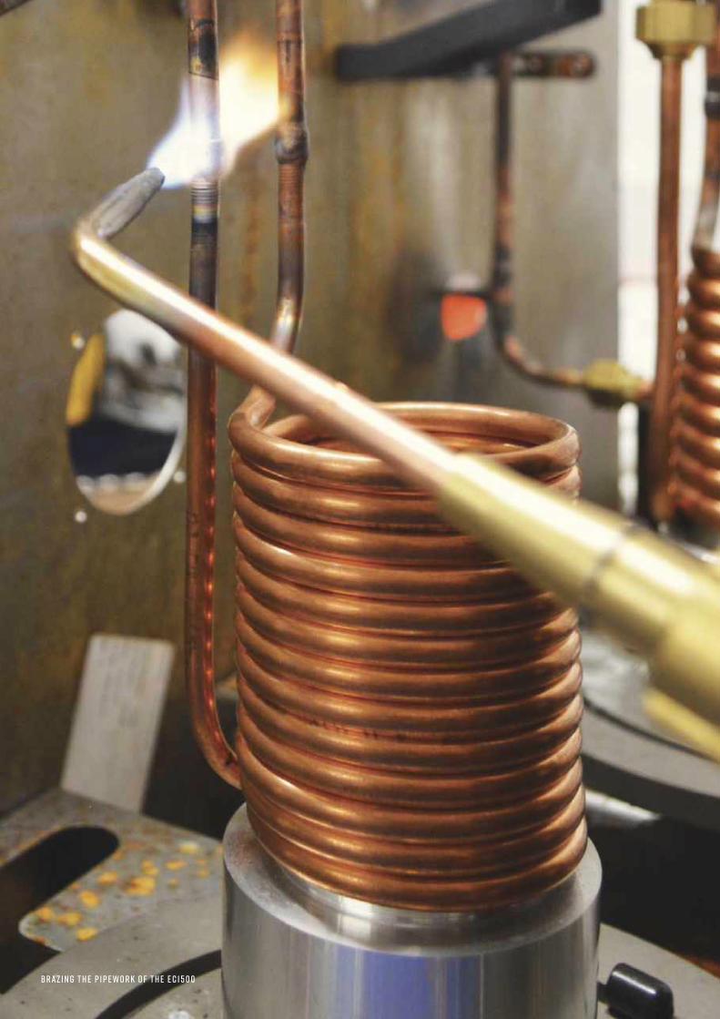
3 0 8
Sola
r En
ergy
Sola
r
B r a z i n g t h e p i p e w o r k o f t h e E c 1 5 0 0
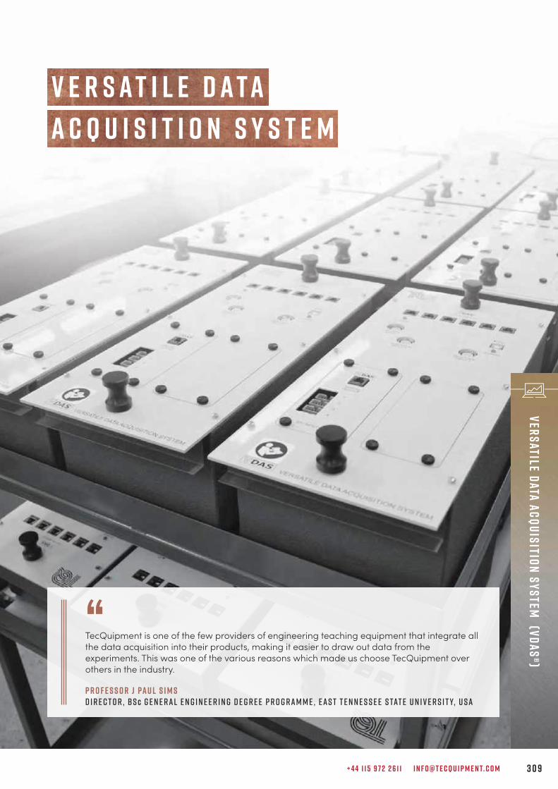
+ 4 4 1 1 5 9 7 2 2 6 1 1 I N F O @ T E C Q U I P M E N T. C O M 3 0 9
Versatile Data Acquisition System (VDAS®)
A c q u i s i t i o n S y s t e mV e r s a t i l e d a t a
“TecQuipment is one of the few providers of engineering teaching equipment that integrate allthe data acquisition into their products, making it easier to draw out data from theexperiments. This was one of the various reasons which made us choose TecQuipment overothers in the industry.
P r o f e s s o r J Pa u l S i m s D i r e c t o r , B S c G e n e r a l E n g i n e e r i n g d e g r e e p r o g r a m m e , E a s t T e n n e s s e e S tat e U n i v e r s i t y, U S A
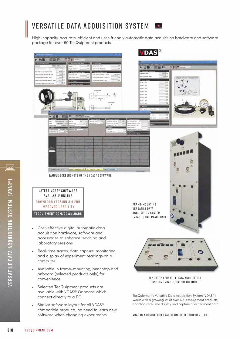
V e r s at i l e D ata A c q u i s i t i o n S y s t e mHigh-capacity, accurate, efficient and user-friendly automatic data acquisition hardware and softwarepackage for over 60 TecQuipment products.
T E C Q U I P M E N T. C O M3 1 0
Vers
atil
e Da
ta A
cqui
siti
on S
yste
m (V
DAS®
)
TecQuipment’s Versatile Data Acquisition System (VDAS®)works with a growing list of over 60 TecQuipment products,enabling real-time display and capture of experiment data.
B e n c h t o p V e r s at i l e D ata A c q u i s i t i o nS y s t e m ( V D A S - B ) i n t e r fa c e u n i t
V D A S i s a r e g i s t e r e d t r a d e m a r k o f T e c Q u i p m e n t Lt d
• Cost-effective digital automatic dataacquisition hardware, software andaccessories to enhance teaching andlaboratory sessions
• Real-time traces, data capture, monitoringand display of experiment readings on acomputer
• Available in frame-mounting, benchtop andonboard (selected products only) forconvenience
• Selected TecQuipment products areavailable with VDAS® Onboard whichconnect directly to a PC
• Similar software layout for all VDAS®
compatible products, no need to learn newsoftware when changing experiments
F r a m e - m o u n t i n gV e r s at i l e D ataA c q u i s i t i o n S y s t e m( V D A S - F ) i n t e r fa c e u n i t
L at e s t V D A S ® s o f t wa r eava i l a b l e o n l i n e
D o w n l o a d v e r s i o n 3 . 0 f o ri m p r o v e d u s a b i l i t y
t e c q u i p m e n t. c o m / d o w n l o a d s
S a m p l e s c r e e n s h o t s o f t h e V D A S ® s o f t wa r e

+ 4 4 1 1 5 9 7 2 2 6 1 1 I N F O @ T E C Q U I P M E N T. C O M 3 1 1
Versatile Data Acquisition System (VDAS®)
V DAS ® - c o m pat ibl eT e cQu i p m e n t p r o d u c t
V DAS ® i n t e r fac eu n i t
O u t p u ts i g nal s
Data
Data
E x p o r t e dData
R eal T i m eD i s p lay s
C har t s
Tab l e s o fdata
V DAS® O nBoar d
V D A S ® s h o w n w o r k i n g w i t h t h e F r e eV i b r at i o n s o f a C a n t i l e v e r ( T M 1 6 6 )e x p e r i m e n t
L abV I E W D ata A c q u i s i t i o nExperimental data from TecQuipment products can beacquired in real-time within National Instrument’sLabVIEW software environment. Most TecQuipmentVDAS® compatible products are supported by theVDAS®/LabVIEW software package which is freelyavailable from the TecQuipment website. LabVIEW usershave the flexibility to extend TecQuipment’s softwareto perform customised data processing, presentationand analysis.
F r e e U n l i m i t e dS o f t war e D o w n l oad s
P l u g an d p layo p e rat i o n
n o cal i b ra i t o n u s b c o n n e c t i v i t y
W h y c h o o s e V D A S ® ?
V D A S ® O nbo a r dProducts featuring the VDAS®
Onboard logo now haveTecQuipment’s Versatile DataAcquisition System integrated into the hardware of theproduct as standard.

T E C Q U I P M E N T. C O M3 1 2
Vers
atil
e Da
ta A
cqui
siti
on S
yste
m (V
DAS®
)
V D A S ® e n abl e d p r o d u c t s :A e r o d y n a m i c s• Subsonic Wind Tunnel (AF1300) 40• Subsonic Wind Tunnel (AF1450S)* 46• Subsonic Wind Tunnel (AF1600S)* 48• Nozzle Flow Apparatus (AF27) 59• Intermittent Supersonic Wind Tunnel (AF300) 60• Continuous Supersonic Wind Tunnel (AF302) 62
F l u i d M e c h a n i c s• Pipe Surge and Water Hammer (H405) 114• Flumes (FC300)* 120• Flumes (FC600)* 122• Centrifugal Pump Test Set (H47) 136• Advanced Series and Parallel Pumps (H53V)** 139• Two-Stage (Series and Parallel) Pumps (H83) 140• Centrifugal Pump Module (MFP101) 143• Axial Flow Pump Module (MFP102) 147• Positive Displacement Pump Module (MFP103) 148• Reciprocating Compressor Module (MFP104) 151• Centrifugal Compressor Module (MFP105) 152• Centrifugal Fan Module (MFP106) 153• Axial Fan Module (MFP107) 155• Pitot-Static Traverse (450 mm) (MFP107a) 156
M at e r i a l s T e s t i n g a n d P r o p e r t i e s• Thin Cylinder (SM1007) 161• Diaphragm (SM1008) 162• Thick Cylinder (SM1011) 163• Strain Gauge Trainer (SM1009) 164• Digital Strain Display (SM1010) 165• Torsion Testing Machine, 30 Nm (SM1001) 166• Rotating Fatigue Machine (SM1090V)** 167• Creep Machine (SM1006) 168• Benchtop Tensile Testing Machine (SM1002) 169• Universal Testing Machine (SM1000) 171• Unsymmetrical Cantilever Apparatus (SM1003) 188• Beam Apparatus (SM1004) 184• Euler Buckling Apparatus (SM1005) 186
T h e o r y o f M a c h i n e s• Air Bearing Apparatus (TE96) 225• Cam Analysis Machine (TM1021V)** 229• Balance of Reciprocating Masses (TM1022V)** 234• Geared Systems (TM1018) 232• Centrifugal Force (TM1005) 237• Governors (TM1027) 239• Free Vibrations of a Mass-Spring System (TM164) 244• Free Torsional Vibrations (TM165) 245• Free Vibrations of a Cantilever (TM166) 246• Free Vibrations of a Beam and Spring (TM167) 247• Free and Forced Vibrations (TM1016V)** 249
T h e r m o d y n a m i c s• Ideal Gasses –Boyle’s Law (TD1000) 253• Ideal Gasses – Gay-Lussac’s Law (TD1001) 254• Expansion of Perfect Gas (TD1004V)** 255• Filmwise and Dropwise Condensation and Boiling 256
(TE78)• Emissivity – Natural Convection and Radiation 257
(TD1011V)**• Unsteady State Heat Transfer (TD1009V)** 258• Heat Transfer Experiments (TD1002) 262• Free and Forced Convection (TD1005) 265• Benchtop Heat Exchangers (TD360) 266• Cross-Flow Heat Exchanger (TE93) 269• Radiant Transfer Experiments (TD1003) 270• Water-to-Air Heat Exchangers (TD1007) 271• Peltier and Seebeck Effect (TD1008) 273• Temperature Measurement and Calibration 274
(TD400)• Saturated Steam – Marcet Boiler (TD1006) 275
e n g i n e s• Small Engine Test Set (TD200) 279• Regenerative Engine Test Set (TD300) 284• Thermal Power Plant with Steam Engine Trainer 291
(TD1050)
e n v i r o n m e n ta l c o n t r o l• Cooling Towers (EC1000V)** 297• Advanced HVAC & R Trainer (EC1550V)** 298• Refrigeration Cycle (EC1500V)** 300• Air Conditioning Trainer (EC1501V)** 301
s o l a r E n e r g y• Photovoltaic Cells (TE4) 305• Focusing Solar Energy Collector (TE38) 306• Flat Plate Solar Energy Collector (TE39) 307
Search for VDAS® on our website for the latest list ofVDAS® compatible products.
t e c q u i p m e n t. c o m
* Is supplied with VDAS-F, VDAS-FC or VDAS-B as standard** Is supplied with VDAS® Onboard as standard

+ 4 4 1 1 5 9 7 2 2 6 1 1 I N F O @ T E C Q U I P M E N T. C O M 3 1 3
T h e f o l l o w i n g i t e m s a r e a n c i l l a r i e s t o s o m e o f t h e p r o d u c t s a n d p r o d u c t r a n g e s i n t h i s c ata l o g u e .S o m e w i l l o n ly w o r k w i t h T e c Q u i p m e n t p r o d u c t s , w h i l e o t h e r s w i l l a l s o w o r k a s g e n e r a l- p u r p o s el a b o r at o r y e q u i p m e n t.
P l e a s e n o t e : The specifications of these ancillary products are correct at the time of printing. They are designed or chosen to work with the correct TecQuipment products or product ranges. If it is intended that theseancillaries are to be used as general-purpose laboratory equipment, please check its datasheet or ask our experts atTecQuipment b e f o r e o r d e r i n g .
This symbol means that we keep an up-to-date This symbol means that TecQuipment or the local datasheet on our website (www.tecquipment.com). distributor must be contacted for the latest
specification.
P r e s s u r e I n s t r u m e n t s a n d E q u i p m e n t
C o m p r e s s o r C E 1 B
A laboratory-scale compressor providing ten litres a minute flowat a pressure of 3 bar (45 PSIG). Works with several TecQuipment products and is good forgeneral-purpose use.
C o n s u m a b l e s pa c k C K 1
A selection of jubilee clips, connectors, glass manifolds, caps,valves, tubes, weights, hangers and other consumables; allcommonly used on TecQuipment products.
O s c i l l o s c o p e s
D u a l B e a m S t o r a g eO s c i l l o s c o p e
H 4 0 5 a
A two-channel 50 MHz digital storage oscilloscope. Works with several TecQuipment products and is good forgeneral-purpose use.
O s c i l l o s c o p eO S 1
A dual-channel 50 MHz digital oscilloscope.Works with several TecQuipment products and is good forgeneral-purpose use.
O p t i c a l Ta c h o m e t e rO T 1
A hand-held, battery-powered optical tachometer with a digitaldisplay and a speed range of 3 to 99999 rev.min–1 (rpm). Itworks with reflective surfaces or stick-on reflective tape. Works with several TecQuipment products and is good forgeneral-purpose use.
S t r o b o s c o p e s a n d Ta c h o m e t e r s
S t r o b o s c o p eS T 1
A portable, mains-poweredstroboscope that gives 60 to 7,500flashes a minute in one continuousrange. Includes a display of flashspeed and works with an internal orexternal trigger. Works with several TecQuipmentproducts and is good for general-purpose use.
g e n e r a l- p u r p o s e a n c i l l a r i e s a n d i n s t r u m e n t s

D e v e l o p i n g e x p e r t i s e i n E l e c t r i c a l p o w e r s y s t e m s
A C A D E M I A i n d u s t r yr e s e a r c h
P r o t e c t i o n G e n e r at i o n T r a n s f o r m at i o n
T E C Q U I P M E N T. C O M3 1 4
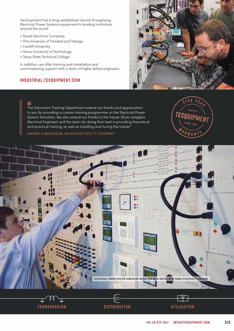
TecQuipment has a long-established record of supplying Electrical Power Systems equipment to leading institutions around the world:
• Saudi Electricity Company• The University of Trinidad and Tobago• Cardiff University• Hanoi University of Technology• Texas State Technical College
In addition, we off er training and installation and commissioning support with a team of highly skilled engineers.
The Dammam Training Department extend our thanks and appreciation to you for providing a custom training programme on the Electrical Power System Simulator. We also extend our thanks to the trainer (Ryan Langdon, Electrical Engineer) and the team for doing their best in providing theoretical and practical training, as well as installing and tuning the trainer.”
AHMED O BAHASSAN, SAUDI ELECTRICITY COMPANY
i n d u s t r i a l .t e c q u i p m e n t. c o m
T r a n s m i s s i o n D i s t r i b u t i o n U t i l i s at i o n
e l e c t r i c a l P o w e r S y s t e m S i m u l at o r w h i c h h a s b e e n i n s ta l l e d at S a u d i E l e c t r i c i t y C o m pa n y
+ 4 4 1 1 5 9 7 2 2 6 1 1 I N F O @ T E C Q U I P M E N T. C O M 3 1 5
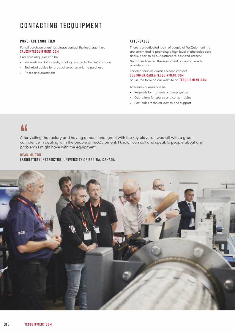
T E C Q U I P M E N T. C O M3 1 6
C o n ta c t i n g T e c Q u i p m e n t
A f t e r s a l e sThere is a dedicated team of people at TecQuipment thatare committed to providing a high level of aftersales careand support to all our customers, past and present.No matter how old the equipment is, we continue toprovide support.
For all aftersales queries please contact:c u s t o m e r . c a r e @ t e c q u i p m e n t. c o mor use the form on our website at: t e c q u i p m e n t. c o m
Aftersales queries can be:• Requests for manuals and user guides• Quotations for spares and consumables• Post-sales technical advice and support
P u r c h a s e e n q u i r i e sFor all purchase enquiries please contact the local agent or:S a l e s @ t e c q u i p m e n t. c o mPurchase enquiries can be:• Requests for data sheets, catalogues and further information• Technical advice for product selection prior to purchase• Prices and quotations
“After visiting the factory and having a meet-and-greet with the key players, I was left with a greatconfidence in dealing with the people of TecQuipment. I know I can call and speak to people about anyproblems I might have with the equipment.
D e a n M i lt o nL a b o r at o r y I n s t r u c t o r , U n i v e r s i t y o f R e g i n a , C a n a d a
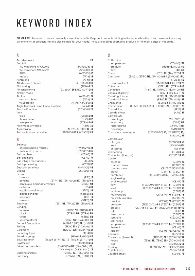
+ 4 4 1 1 5 9 7 2 2 6 1 1 I N F O @ T E C Q U I P M E N T. C O M 3 1 7
k e y w o r d i n d e x
AAerodynamics 2 9Aerofoil 150 mm chord NACA0012 (AF1300d) 4 2 150 mm chord NACA2412 (AF1300c) 4 2 S1210 (AF1300l) 4 2 tapped (AF18) 3 8Aeroplane (AF41) 5 4Afterburner (reheat) (GT100RS) 2 9 3Air bearing (TE96) 2 2 5Air conditioning (EC1550V) 3 0 0 , (EC1501V) 2 9 9Aircraft model 4 2Air flow (AF10–18) 3 1 around a bend (AF15) 3 6 visualisation (AF17) 3 7 , (AF80) 5 8Angle feedback (wind tunnel models) (AFA4) 4 4Antoine Equation (TD1006) 2 7 5Arch fixed (STR11) 2 0 4 three-pinned (STR9) 2 0 2 two-pinned (STR10) 2 0 3Archimedes Principle (H314) 1 2 6Aspect ratio (AF1125–AF1600) 3 9 – 4 9Automatic data acquisition (STR2000) 1 9 9 , (VDAS®) 3 1 0
BBalance of reciprocating masses (TM1022V) 2 3 4 static and dynamic (TM1002) 2 3 5Ball and beam (CE106) 7 2Ball and hoop (CE109) 7 7Bar linkage mechanisms (ES15) 2 5Batch processing (CE111) 8 2Bauschinger effect (SM1001) 1 6 6Beams (SM1005) 1 8 6Beam balance (ES3) 1 0 bending (STR4) 2 1 2 , (SM1000g) 1 7 3 , (TE16) 1 6 0 continuous and indeterminate (STR13) 2 1 4 deflection (ES4) 1 1 equilibrium of forces (STF5) 1 9 3 plastic bending (STR15) 2 1 0 reactions (ES3) 1 0 stresses (STR5) 2 1 3Bearings (ES17) 1 8 , (TM25) 2 2 8 , (TE96) 2 2 5Bending moment (STR2) 2 1 8 , (STR20) 2 2 0 plastic (STR15) 2 1 0 , (STR16) 2 1 1 stress (STR5) 2 1 3 unsymmetrical (STR7) 2 2 2 , (SM1003) 1 8 8Bernoulli’s equation (AF11) 3 2 , (H5) 9 8 , (H10) 9 9Boiling (TE78) 2 5 6 , (TD1006) 2 7 5Boltzmann (TD1003) 2 7 0 , (TD1011V) 2 5 7Boundary layer (AF14) 3 5Bourdon gauge (H3a) 9 5 , (H30) 1 0 0Bow’s Notation (ES2) 9 , (STF4) 1 9 3 , (STR8) 2 0 1 , (STR17) 2 0 5Boyle’s law (TD1000) 2 5 3Brinell hardness tests (SM1000e) 1 7 2 , (SM1002c) 1 7 0 ,
(SM1017) 1 8 1 , (MF40 MkII) 1 7 6Buckling of struts (STR12) 2 0 7 , (SM1005) 1 8 6Buoyancy (H2 MkII) 1 2 5 , (H314) 1 2 6
CCalibration temperature (TD400) 2 74 pressure (H3a) 9 5 , (H30) 1 0 0 flow (H40) 1 0 1Cams (ES12) 2 3 , (TM1021V) 2 2 9Cantilever (ES4) 1 1 , (STR4) 2 1 2 , (SM1004) 1 8 4 , (SM1009) 1 6 4 ,
(TE16a) 1 6 0 unsymmetrical (SM1003) 1 8 8 , (STR7) 2 2 2Catenary (STF2) 1 9 2 , (STR19) 2 0 6Cavitation (H47) 1 3 6 , (MFP101) 1 4 3 , (H400) 1 1 2Centres of gravity (ES2) 9 ,(H2 MkII) 1 2 5Centrifugal force (ES16) 2 2 , (TM1005) 2 3 7Centripetal force (ES16) 2 2 , (TM1005) 2 3 7Chain drive (ES11) 2 0 , (TM1018) 2 3 2Chezy factor (FC50) 1 1 6 , (FC80) 1 1 8 , (FC300) 1 2 0 , (FC600) 1 2 2Choked flow (AF27) 5 9Coandă effect (AF16) 3 7Compressor centrifugal (MFP105) 1 5 2 laboratory (CE1B) 3 1 3 reciprocating (MFP104) 1 5 1 two-stage (GT103) 2 7 6Computer control system (TE3300/06) 9 0 , (TE37DCS) 8 5 ,
(CE2000) 6 7Compression of a gas (TD1000) 2 5 3 tests (SM1000) 1 7 1 of springs (ES19) 1 4Condensing (TE78) 2 5 6Conduction (thermal) (TD1002) 2 6 2Control cascade (CE117) 8 3 coupled drives (CE108) 7 6 coupled tanks (CE105/CE105MV) 7 1 digital (CE111) 8 2 , (CE123) 8 1 distributed (TE3300/06) 9 0 , (TE37DCS) 8 5 engineering 6 5 engine speed (CE107) 7 3 flow (TE3300/03) 8 7 , (TE37) 8 4 , (CE117) 8 3 level (TE3300/04) 8 8 , (TE37) 8 4 , (CE117) 8 3 multi-loop (CE117) 8 3 multivariable (CE105MV) 7 1 , (CE108) 7 6 naturally unstable (CE106) 7 2 position (CE109) 7 7 , (CE106) 7 2 pressure (TE3300/02) 8 6 , (TE37) 8 4 , (CE117) 8 3 process (CE117) 8 3 , (TE37) 8 4 , (TE3300 series) 8 6 – 9 0 ratio (TE37) 8 4 servomotor (CE110) 7 8 software (CE2000) 6 7 split range (TE37) 8 4 temperature (TE3300/05) 8 9 , (TE37) 8 4 , (CE117) 8 3 thermal (CE103) 7 0 velocity (CE106) 7 2 , (CE109) 7 7Controller (CE120) 6 8Convection (thermal) (TD1002) 2 6 2 , (TD1011V) 2 5 7 forced (TD1) 2 5 9 , (TE93) 2 6 9 , (TD1005) 2 6 5 free (TD1005) 2 6 5Cooling (EC1000V) 2 9 7 , (EC1550V) 3 0 0Coriolis force (TM1017) 2 3 8Coupled drives (CE108) 7 6
P l e a s e n o t e : For ease of use we have only shown the main TecQuipment products relating to the keywords in this index. However, there maybe other similar products that are also suitable for your needs. These are listed as alternative products in the main pages of this guide.
T E C Q U I P M E N T. C O M3 1 8
Coupled tanks (CE105/CE105MV) 7 1Coupling (universal) (ES11) 2 0Crank motion (ES12) 2 3 , (ES14) 2 4Crank angle encoder (ECA102) 2 9 0Creep (SM1006) 1 6 8Critical whirl speed (TM1001) 2 3 1Curved bars (STR14) 2 1 6Cylinder head transducer (ECA101) 2 9 0 thick (SM1011) 1 6 6 thin (SM1007) 1 6 1 wind tunnel models (AF1300) 4 1 - 4 2 , (AF1450) 47 , (AF1600) 5 1
DDarcy’s law (H312) 1 3 0Davits (STR14) 2 1 6Diaphragm (SM1008) 1 6 2Differential pressure transducer (DP6) 47 , 5 0Digital control (CE111) 8 2 , (CE123) 8 1 interface (CE122) 6 9Discharge coefficient (H4) 1 0 8 , (H33) 1 1 0 , (Flumes) 1 1 6 – 1 2 4 ,
(H5) 9 8 , (H6) 9 7 , (H40) 1 0 1 over a notch (H6) 9 7Distributed control (TE3300/06) 9 0 , (TE37DCS) 8 5
(CE2000) 6 7Drag (air) (AF12) 3 3Drag coefficient (H410) 1 2 7Drive systems (TM1018) 2 3 2 , (ES11) 2 0Dropwise condensation (TE78) 2 5 6Dunkerley (TM1016V) 2 4 9 , (TM1001) 2 3 1Dynamometer hydraulic (TD200) 2 7 9 regenerative (TD300) 2 8 4 turbine (MFP101a) 1 4 4 universal (MFP100) 1 4 2
EElastic properties (ES19) 1 4 , (SM110) 1 5 9 , (SM1002) 1 6 9 , (TE16) 1 6 0Emissivity (TD1003) 2 7 0 , (TD1011V) 2 5 7Energy conversion (TD1050) 2 9 1 losses in pipes (H34) 1 0 5 potential and kinetic (ES9) 1 7 renewable (TE4) 3 0 5 , (TE38) 3 0 6 , (TE39) 3 0 7Engine cycle analyser (ECA100) 2 9 0 diesel (four-stroke) (TD202) 2 8 1 , (TD212) 2 8 3 , (TD302) 2 8 7 petrol (four-stroke) (TD201) 2 8 0 , (TD211) 2 8 2 , (TD301) 2 8 6 speed control (CE107) 7 3 steam (TD1050) 2 9 1 test set (regenerative) (TD300) 2 8 4 test set (small) (TD200) 2 7 9Engineering science 5Equilibrium (rigid body, forces, beam) (STF) 1 9 2 – 1 9 3Euler buckling (STR12) 2 0 7 , (SM1005) 1 8 6Exhaust gas calorimeter (TDX00a) 2 8 8Extensometer (SM1000d) 1 7 2 , (SM1002a) 1 6 9 , (MF40 MkII) 1 7 6
FFan axial (MFP107) 1 5 5 centrifugal (MFP106) 1 5 3Fatigue (SM1090V) 1 6 7Flat plate boundary layer (AF14) 3 5 , (AF1300f) 4 2 , (AF1450f) 47 impact of a jet (H8) 1 0 9
Flow channel (FC50) 1 1 6 , (FC80) 1 1 8 , (FC300) 1 2 0 , (FC600) 1 2 2 control (TE3300/03) 8 7 , (TE37) 8 4 , (CE117) 8 3 counter (TD360) 2 6 6 laminar and turbulent (H7) 1 0 3 , (H215) 1 0 7 measurement (H10) 9 9 , (H408) 1 0 6 , (H40) 1 0 1 , (H5) 9 8 meter calibration (H40) 1 0 1 orifice (through) (H4) 1 0 8 , (H33) 1 1 0 , (H40) 1 0 1 parallel (TD360) 2 6 6 permeable media (through) (H312) 1 3 0 transitional (H215) 1 0 7 visualisation (AF17) 3 7 , (AF80) 5 8 , (FC15) 9 5 , (H9) 1 1 3Flywheel (TM1018a) 2 3 3 , (ES9) 1 7Fluid mechanics 9 1Flumes (FC50) 1 1 6 , (FC80) 1 1 8 , (FC300) 1 2 0 , (FC600) 1 2 2Force display (digital) (STR1a) 1 9 9Forces concurrent, coplanar (STF4) 1 9 3 , (ES2) 9 equilibrium of (ES2) 9 , (ES3) 1 0 , (STF range) 1 9 1 non-concurrent (ES2) 9 , (STF4) 1 9 3 polygons (ES2) 9 , (STF4) 1 9 3 primary (TM1022V) 2 3 4 secondary (TM1022V) 2 3 4 triangles (ES2) 9 , (STF4) 1 9 3Fracture (energy) (TE15) 1 7 7Frame (portals) (STR16) 2 1 1 , (STR18) 2 1 7 , (STR20) 2 2 0Framework, indeterminate (STR17) 2 0 5Friction (ES8) 1 6 , (TE96) 2 2 5 , (TE98) 2 2 6 ,
(TE99) 2 2 7 , (TM25) 2 2 8 angle of lap (ES11) 2 0 fluid (H7) 1 0 3 , (H16) 1 0 4 , (H34) 1 0 5 , (H408) 1 0 6 pipe (H7) 1 0 3 , (H16) 1 0 4 , (H34) 1 0 5 , (H408) 1 0 6 rotational (ES17) 1 8 sliding (ES8) 1 6Froude Number (FC50) 1 1 6 , (FC80) 1 1 8 , (FC300) 1 2 0 , (FC600) 1 2 2Fuel gauge automatic volumetric (DVF1) 2 8 9 manual volumetric (AVF1) 2 8 9Fuzzy logic (CE2000) 6 7
GGases ideal (TD1000) 2 5 3 , (TD1001) 2 5 4 perfect (TD1004V) 2 5 5Gas generator (GT100) 2 9 2 , (GT100RS) 2 9 3 , (GT185) 2 9 4Gas turbine single-shaft (GT100) 2 9 2 , (GT100RS) 2 9 3 two-shaft (GT185) 2 9 4Gay-Lussac’s law (TD1001) 2 5 4Gears (ES13) 2 1 , (TM1018) 2 3 2Geneva mechanism (ES18) 2 6Governors (TM1027) 2 3 9Gyroscope (TM1004) 2 3 6
HHardness Brinell (MF40 MkII) 1 7 6 , (SM1000e) 1 7 2 , (SM1002c) 1 7 0 ,
(SM1017) 1 8 1 Rockwell (SM1015) 1 7 9 , (SM1017) 1 8 1 Vickers (SM1016) 1 8 0 , (SM1017) 1 8 1Hare’s tube (H314b) 1 2 7Heat exchangers cross-flow (TE93) 2 6 9 liquid to liquid (TD360) 2 6 6 water to air (TD1007) 2 7 1Heat pump (TD1008) 2 7 3Heat transfer 2 5 6 – 2 7 3Hele-shaw (H9) 1 1 3Hertzian contact (TE98) 2 2 6Hooke’s law (ES19) 1 4 , (SM1000f) 1 7 3 , (SM110) 1 5 9Humidity measurement (TE6) 3 0 2

+ 4 4 1 1 5 9 7 2 2 6 1 1 I N F O @ T E C Q U I P M E N T. C O M 3 1 9
Hydraulic bench (H1F) 9 3Hydraulic ram pump (H31) 1 3 5Hydrology (H311) 1 2 9 , (H312) 1 3 0 , (H313) 1 3 1Hydrostatics (H314) 1 2 6
IImpact tests (TE15) 1 7 7Inclined plane (ES8) 1 6Internal combustion engine test sets (TD200) 2 7 9 , (TD300) 2 8 4
JJet (air) attachment (AF16) 3 7Jet (water) impact of (H8) 1 0 9 trajectory (H33) 1 1 0Journal bearing (TM25) 2 2 8
LLadder logic (CE111) 8 2Laplace equation (H9) 1 1 3Level control (TE3300/04) 8 8 , (TE37) 8 4 , (CE117) 8 3Levers (ES3) 1 0Lift balance (AF1300z) 4 3 , (AF1300t) 4 4 ,(AF1450t) 47 , (AF1600t) 5 0Liquid slop (CE109) 7 7LMTD (logarithmic mean temperature difference) (TD360) 2 6 6
MMach number (AF27) 5 9 , (AF300) 6 0 , (AF302) 6 2Manometer multi-tube (AF10a) 3 8 , (AFA1) 5 2Marcet boiler (TD1006) 2 7 5Mass flux (AF13) 3 4Materials testing and properties 1 5 7Mechanisms (ES14) 2 4 , (ES18) 2 6Metacentric height (H2 MkII) 1 2 5Michell pad (TE99) 2 2 7Modulus of Rigidity (ES5) 1 2 , (SM1001) 1 6 6Moments primary (TM1022V) 2 3 4 principle of (ES3) 1 0 , (STF5) 1 9 3 secondary (TM1022V) 2 3 4Momentum flux (AF13) 3 4Motion (TM1017) 2 3 8 , (TM1018) 2 3 2 , (TM1021V) 2 2 9 ,
(TM1022V) 2 3 4 , (TM1002) 2 3 5 , (TM1004) 2 3 6 ,(TM1005) 2 3 7 , (TM1027) 2 3 9 , (TM1001) 2 3 1
NNozzle calibration (H40) 1 0 1 flow (supersonic) (AF27) 5 9 , (AF300) 6 0 , (AF302) 6 2 flow through (H4) 1 0 8 , (H33) 1 1 0 , (H40) 1 0 1
OOscillations (ES7) 1 5 , (TM161) 2 4 1 , (TM162) 2 4 2 ,
(TM164) 2 4 4 , (TM165) 2 4 5 , (TM166) 2 4 6 ,(TM167) 2 47 , (TM1016V) 2 4 9
Oscilloscope (OS1) 3 1 3 , (H405a) 3 1 3
PParabolic (STF2) 1 9 2 , (STR9) 2 0 2 , (STR10) 2 0 3 ,
(STR11) 2 0 4 , (STR19) 2 0 6Parallelogram of forces (ES2) 9 , (STF4) 1 9 3Peltier (TD1008) 2 7 3Pendulum (ES7) 1 5 , (TM161) 2 4 1 , (TM162) 2 4 2 , (TM163) 2 4 3Permeability tank (H312) 1 3 0Photovoltaic cells (TE4) 3 0 5Phugoid (AF41) 5 4
Pin-jointed framework (STR8) 2 0 1 , (STR17) 2 0 5Pipe friction (H7) 1 0 3 pressure loss (H16) 9 7 , (H34) 1 0 5 , (H408) 1 0 6 surge (H405) 1 1 4Pitching moment 4 1 , 4 4 , 4 6 , 47 , 4 9 , 5 0Pitot static traverse 4 1 , 47 , 5 0 , (MFP107a) 1 5 6Pitot tube flow meter (H40a) 1 0 2Poisson’s Ratio (SM1007) 1 6 1 , (SM1009) 1 6 4Polygon of forces (ES2) 9 , (STF4) 1 9 3Portal frames (STR16) 2 1 1 , (STR18) 2 1 7 , (STR20) 2 2 0Potential flow (H9) 1 1 3Pressure centre of (H11) 1 2 8 , (H314) 1 2 6 control (TE3300/02) 8 6 , (TE37) 8 4 , (CE117) 8 3 display (H47) 1 3 6 , (H83) 1 4 0 display (32-way) (AFA1) 5 2 distribution (AF15) 3 6 , (AF18) 3 8 , (AF1125–AF1600) 3 9 – 5 1gauge (calibration of) (H3a) 9 5 , (H30) 1 0 0 , (H314) 1 2 6 loss (in pipes) (H16) 1 0 4 , (H408) 1 0 6 , (H34) 1 0 5 measurement (H30) 1 0 0 of a gas (TD1000) 2 5 3 , (TD1001) 2 5 4Process trainer (CE117) 8 3Programmable logic controller (PLC) (CE123) 8 1 process (CE111) 8 2Pulleys (ES10) 1 9Pump axial (MFP102) 1 47 centrifugal (H47) 1 3 6 , (H52) 1 3 8 , (H53V) 1 3 9 ,
(H83) 1 4 0 , (MFP101) 1 4 3 gear (MFP103b) 1 4 9 hydraulic ram (H31) 1 3 5 piston (MFP103a) 1 4 9 positive displacement (MFP103) 1 4 8 series and parallel (H52) 1 3 8 , (H53V) 1 3 9 , (H83) 1 4 0 swash (MFP103d) 1 5 0 vane (MFP103c) 1 5 0
QQuick return mechanism (ES14) 2 4
RRadiant transfer (TD1003) 2 7 0Radiation (thermal) (TD1003) 2 7 0 , (TD1011V) 2 5 7Ratchet mechanism (ES18) 2 6Reciprocating masses (balance of) (TM1022V) 2 3 5Refrigeration (EC1000V) 3 0 0 , (EC1550V) 3 0 0Renewable energy 3 0 3Reynolds number (H215) 1 0 7Rockwell hardness tests (SM1015) 1 7 9 , (SM1017) 1 8 1Rotating fatigue (SM1090V) 1 6 7Round turbulent jet (AF13) 3 4
SSchlieren (AF300a) 6 1 , (AF302a) 6 3Scotch yoke (ES14) 2 4Screw jack (ES17) 1 8Sediment (FC80) 1 1 8 , (FC300) 1 2 0 , (FC600) 1 2 2 , (H311) 1 2 9Seebeck (TD400) 2 74 , (TD1008) 2 7 3Servo trainer (CE110) 7 8Shear centre (STR7) 2 2 2 , (SM1003) 1 8 8 double (SM1000j) 1 74 force (STR3) 2 1 9 modulus (SM1001) 1 6 6Shock waves (AF300) 6 0 , (AF302) 6 2 , (TE86) 1 1 5Simple harmonic motion (ES7) 1 5 , (TM161–TM167) 2 4 1 – 2 47Smoke generator (AFA11) 5 2 , (AF17) 3 7 , (AF80) 5 8S-N curve (SM1090V) 1 6 7

T E C Q U I P M E N T. C O M3 2 0
Solar energy 3 0 3 focusing (TE38) 3 0 6 flat-plate (TE39) 3 0 7 photovoltaic (TE4) 3 0 5Specific energy (FC50) 1 1 6 , (FC80) 1 1 8 , (FC300) 1 2 0 , (FC600) 1 2 2Specimens (MTT) 2 8 , (CP, RF, TH, TR) 1 8 2
(TL/TS, HTP, ML, HTB) 1 8 3 , (DS, ES) 1 8 2Spring coil (SM1000f) 1 7 3 elastic potential energy (ES9) 1 7 leaf (SM1000g) 1 7 3 testing (ES19) 1 4 , (SM110) 1 5 9Stability of a floating body (H2 MkII) 1 2 5 , (H314) 1 2 6Statics (STF) 1 8 9Steam motor (TD1050) 2 9 1 saturated (TD1006) 2 7 5Strain analysis (SM1007) 1 6 1 , (SM1008) 1 6 2 , (SM1009) 1 6 4 ,
(SM1011) 1 6 3 display (SM1010) 1 6 5 gauge kit (E19) 1 6 5 gauge trainer (SM1009) 1 6 4Stiffness of materials and structures (TE16) 1 6 0Stirred vessel (CE117) 8 3 , (TD360d) 2 6 8Stress analysis (SM1007) 1 6 1 , (SM1008) 1 6 2 , (SM1009) 1 6 4 ,
(SM1011) 1 6 3Stroboscope (ST1) 3 1 3Structures 1 9 5 software (STRS) 2 0 0 statically determinate (STR8) 2 0 1 , (STR9) 2 0 2 statically indeterminate (STR17) 2 0 5 test frame (STR1) 1 9 8Struts (SM1005) 1 8 6 , (STR12) 2 0 7Surface tension (H314a) 1 2 7Suspension bridge (STR19) 2 0 6 cable (STF2) 1 9 2Sway (STR18) 2 1 7 , (STR20) 2 2 0
TTachometer optical (OT1) 3 1 3Tapped aerofoil (AF18) 3 8Temperature control (CE117) 8 3 , (TE3300/05) 8 9 , (TE37) 8 4 measurement and calibration (TD400) 2 74Tensile tests (ES6) 1 3 , (MF40 MkII) 1 7 6 , (SM1000) 1 7 1 ,
(SM1002) 1 6 9Test specimens (MTT) 2 8 , (CP, RF, TH, TR) 1 8 2
(TL/TS, HTP, ML, HTB) 1 8 3 , (DS, ES) 1 8 2Theory of machines 2 2 3Thermal control (CE103) 7 0 , (CE117) 8 3 , (TE3300/05) 8 9Thermodynamics 2 5 1Thermoelectric (TD1008) 2 7 3Thermometer (TD400) 2 74Toggle (ES12) 2 3Torsiometer (SM1001a) 1 6 7Torsion (ES5) 1 2 , (TE16b) 1 6 0 , (SM1001) 1 6 6 , (STR6) 2 2 1
Triangle of forces (STF4) 1 9 3 , (ES2) 9Truss (redundant) (STR17) 2 0 5Turbines Francis (H18) 1 3 2 , (MFP101d) 1 4 6 gas (GT100) 2 9 2 , (GT100RS) 2 9 3 , (GT185) 2 9 4 Pelton (H19) 1 3 3 , (MFP101b) 1 4 5 propeller (MFP101c) 1 4 5Turbojet trainer (GT100) 2 9 2 with afterburner (GT100RS) 2 9 3Turbulent jet (AF13) 3 4
UUnsteady state heat transfer (TD1009V) 2 5 8
VVelocity coefficients (H33) 1 1 0 of sound (H405) 1 1 4 , (TE86) 1 1 5profile (AF13) 3 4 , (AF14) 3 5 , (H40a) 1 0 2Venturi flume (FC50) 1 1 6 , (FC80) 1 1 8 , (FC300) 1 2 0 , (FC600) 1 2 2 meter (H5) 9 8 , (H10) 9 9 , (H40b) 1 0 2Versatile data acquisition system (VDAS®) 3 1 0Vibration (TM160) 2 4 0 , (TM1016V) 2 4 9Vickers hardness tests (SM1016) 1 8 0 , (SM1017) 1 8 1Viscosity (H314) 1 2 6 , (H410) 1 2 7Vortex (H13) 1 1 1
WWater hammer (TE86) 1 1 5 , (H31) 1 3 5 , (H405) 1 1 4Wave generator (FC80) 1 1 8 , (FC300) 1 2 0 , (FC600) 1 2 2Wedge (ES17) 1 8Weight set (WT) 2 8 , (WTL) 2 8Weirs (H6) 9 7 , (FC50) 1 1 6 , (FC80) 1 1 8 ,
(FC300) 1 2 0 , (FC600) 1 2 2Weston differential pulley (ES10) 1 9Wheel and axle (ES10) 1 9Whirling of shafts (TM1001) 2 3 1Wind tunnel flight demonstration (AF41) 5 4 flow visualisation (AF17) 3 7 , (AF80) 5 8 modular (AF10–AF18) 3 1 –3 8 subsonic (AF1125) 3 9 , (AF1300) 4 0 , (AF1450S) 4 6 ,
(AF1600S) 4 8 supersonic (continuous) (AF302) 6 2 supersonic (intermittent) (AF300) 6 0Worm drive (ES13) 2 1Wohler (SM1090V) 1 6 7
YYoung’s modulus (ES4) 1 1 , (TE16) 1 6 0 , (SM1007) 1 6 1 ,
(SM1009) 1 6 4 , (SM1002) 1 6 9 , (SM1000) 1 7 1 ,(SM1004) 1 8 4 , (STR4) 2 1 2
ZZiegler/Nichols (CE105/MV) 7 1

+ 4 4 1 1 5 9 7 2 2 6 1 1 I N F O @ T E C Q U I P M E N T. C O M 3 2 1
p r o d u c t l i s t
AA F 1 0 Modular Air Flow Bench 31A F 1 1 Bernoulli’s Equation 32A F 1 2 Drag Force 33A F 1 3 Round Turbulent Jet 34A F 1 4 Boundary Layer 35A F 1 5 Flow Around a Bend 36A F 1 6 Coandă Effect and Jet Flow 37A F 1 7 Flow Visualisation 37A F 1 8 Tapped Aerofoil 38A F 2 7 Laval Nozzle Flow Apparatus 59A F 4 1 Flight Demonstration Wind Tunnel 54A F 8 0 Flow Visualisation Wind Tunnel 58A F 3 0 0 Intermittent Supersonic Wind Tunnel 60A F 3 0 0 a Schlieren Apparatus 61A F 3 0 2 Continuous Supersonic Wind Tunnel 62A F 3 0 2 a Schlieren Apparatus 63A F 1 1 2 5 Benchtop Subsonic Wind Tunnel 39A F 1 3 0 0 Subsonic Wind Tunnel 40A F 1 4 5 0 S Subsonic Wind Tunnel 46A F 1 6 0 0 S Subsonic Wind Tunnel 48AV F 1 Manual Volumetric Fuel Gauge 289
CC E 1 B Compressor 313C E 1 0 3 Thermal Control Process Apparatus 70C E 1 0 5 / M V Coupled Tanks Apparatus 71C E 1 0 6 Ball and Beam Apparatus 72C E 1 0 7 Engine Speed Control Apparatus 73C E 1 0 8 Coupled Drives Apparatus 76C E 1 0 9 Ball and Hoop Apparatus 77C E 1 1 0 Servo Trainer 78C E 1 1 1 PLC Process 82C E 1 1 7 Process Trainer 83C E 1 2 0 Controller 68C E 1 2 2 Digital Interface 69C E 1 2 3 PLC Trainer 81C E 2 0 0 0 Control Software 67
DD V F 1 Automatic Volumetric Fuel Gauge 289
EE 1 9 Strain Gauge Kit 165E C 1 0 0 0 V Cooling Towers 297E C 1 5 0 0 V Refrigeration Cycle 298E C 1 5 0 1 V Air Conditioning Trainer 299E C 1 5 5 0 V Advanced HVAC & R Trainer 300E C A 1 0 0 Engine Cycle Analyser 290E S 1 Work Panel 8E S 2 Forces Kit 9E S 3 Moments Kit 10E S 4 Deflection of Beams and Cantilevers Kit 11E S 5 Torsion of Circular Sections Kit 12E S 6 Tensile Tester Kit 13E S 7 Simple Harmonic Motion Kit 15E S 8 Friction and Inclined Plane Kit 16E S 9 Potential and Kinetic Energy Kit 17E S 1 0 Pulley Kit 19E S 1 1 Drive System Kit 20E S 1 2 Cam, Crank and Toggle Kit 23E S 1 3 Gear Trains Kit 21E S 1 4 Simple Mechanisms Kit 24E S 1 5 Bar Linkages Kit 25E S 1 6 Centrifugal Force Kit 22E S 1 7 Rotational Friction Kit 18
E S 1 8 Additional Mechanisms Kit 26E S 1 9 Spring Tester Kit 14E S F Engineering Science Full Set 7E T L Trays and Lids 27E S T Storage Unit 27E S X Spare Parts Kit 28
fF C 1 5 Flow Visualisation 95F C 5 0 2.5-Metre Flume 116F C 8 0 Sediment Transport Channels 118F C 3 0 0 Flumes 120F C 6 0 0 Flumes 122
GG T 1 0 0 Turbojet Trainer 292G T 1 0 0 R S Turbojet Trainer with Reheat 293G T 1 0 3 Two-Stage Compressor Test Set 276G T 1 8 5 Two-Shaft Gas Turbine 294
HH 1 F Digital Hydraulic Bench 93H 2 M K I I Metacentric Height and Stability 125H 3 a Calibration of a Bourdon Pressure Gauge 95H 4 Flow Through an Orifice 108H 5 Bernoulli’s Theorem 98H 6 Discharge over a Notch 97H 7 Friction Loss in a Pipe 103H 8 Impact of a Jet 109H 9 Hele-Shaw Apparatus 113H 1 0 Flow Measurement Methods 99H 1 1 Centre of Pressure 128H 1 3 Vortex Apparatus 111H 1 6 Losses in Piping Systems 104H 1 8 Francis Turbine 132H 1 9 Pelton Turbine 133H 3 0 Pressure Measurement Bench 100H 3 1 Hydraulic Ram Pump 135H 3 3 Jet Trajectory and Orifice Flow 110H 3 4 Pipework Energy Losses 105H 4 0 Flow Meter Calibration 101H 4 0 a Pitot Tube 102H 4 0 b Venturi Flow Meter 102H 4 0 c Orifice Flow Meter 102H 47 Centrifugal Pump Test Set 136H 5 2 Series and Parallel Pumps 138H 5 3 Variable Speed Series and Parallel Pumps 139H 8 3 Two-Stage (Series and Parallel) Pumps 140H 2 1 5 Osborne Reynolds Apparatus 107H 3 1 1 Liquid Sedimentation Apparatus 129H 3 1 2 Permeability, Flow Nets and Darcy’s Law 130H 3 1 3 Hydrology and Rainfall Apparatus 131H 3 1 4 Hydrostatics and Properties of Fluids 126H 4 0 0 Cavitation in a Venturi 112H 4 0 5 Pipe Surge and Water Hammer 114H 4 0 5 a Dual Beam Storage Oscilloscope 313H 4 0 8 Fluid Friction Apparatus 106H 4 1 0 Viscosity and Particle Drag 127
MM F 4 0 M K I I Materials Laboratory with Data Capture 176M F P 1 0 0 Universal Dynamometer 142M F P 1 0 1 Centrifugal Pump Module 143M F P 1 0 1 a Turbine Dynamometer 144M F P 1 0 1 b Pelton Wheel (Turbine) 145M F P 1 0 1 c Propeller Turbine 145
This is a list of our main line items so some ancillary products may not appear. Please refer to the main line item to find any ancillaries(for example, to find AF80a look at AF80). Alternatively, check our website at t e c q u i p m e n t. c o m or contact our expert Sales team.

T E C Q U I P M E N T. C O M3 2 2
M F P 1 0 1 d Francis Turbine 146M F P 1 0 2 Axial Flow Pump Module 147M F P 1 0 3 Positive Displacement Pump Module 148M F P 1 0 3 a Piston Pump 149M F P 1 0 3 b Gear Pump 149M F P 1 0 3 c Vane Pump 150M F P 1 0 3 d Swash Plate Pump 150M F P 1 0 4 Reciprocating Compressor Module 151M F P 1 0 5 Centrifugal Compressor Module 152M F P 1 0 6 Centrifugal Fan Module 153M F P 1 0 6 a Pipe Flow and Nozzle Kit 154M F P 1 0 7 Axial Fan Module 155M F P 1 0 7a Pitot Static Traverse (450 mm) 156
OO S 1 Oscilloscope 313O T 1 Optical Tachometer 313
SS M 1 1 0 Hooke’s Law and Spring Rate 159S M 1 0 0 0 Universal Testing Machine 171S M 1 0 0 0 e Brinell Indenter 172S M 1 0 0 0 f Coil Spring 173S M 1 0 0 0 g Beam and Leaf Spring 173S M 1 0 0 0 H Cupping Experiment 174S M 1 0 0 0 j Double Shear Experiment 174S M 1 0 0 0 k Disc Spring Experiment 175S M 1 0 0 1 Torsion Testing Machine – 30 Nm 166S M 1 0 0 2 Benchtop Tensile Testing Machine 169S M 1 0 0 2 c Brinell Hardness Test Set 170S M 1 0 0 3 Unsymmetrical Cantilever Apparatus 188S M 1 0 0 4 Beam Apparatus 184S M 1 0 0 5 Euler Buckling Apparatus 186S M 1 0 0 6 Creep Machine 168S M 1 0 0 7 Thin Cylinder 161S M 1 0 0 8 Diaphragm 162S M 1 0 0 9 Strain Gauge Trainer 164S M 1 0 1 0 Digital Strain Display 165S M 1 0 1 1 Thick Cylinder 163S M 1 0 1 5 Rockwell Hardness Tester 179S M 1 0 1 6 Vickers Hardness Tester 180S M 1 0 1 7 Universal Hardness Tester 181S M 1 0 9 0 Rotating Fatigue Machine 167S T 1 Stroboscope 313S T F 1 Statics Work Panel 191S T F 2 Suspension Cable Demonstration 192S T F 3 Equilibrium of a Rigid Body 192S T F 4 Equilibrium of Forces 193S T F 5 Equilibrium of a Beam 193S T R 1 Structures Test Frame 198S T R 1 a Digital Force Display 199S T R 2 Bending Moments in a Beam 218S T R 3 Shear Force in a Beam 219S T R 4 Deflection of Beams and Cantilevers 212S T R 5 Bending Stress in a Beam 213S T R 6 Torsion of Circular Sections 221S T R 7 Unsymmetrical Bending and Shear Centre 222S T R 8 Pin-Jointed Frameworks 201S T R 9 Three-Pinned Arch 202S T R 1 0 Two-Pinned Arch 203S T R 1 1 Fixed Arch 204S T R 1 2 Euler Buckling of a Column 207S T R 1 3 Continuous and Indeterminate Beams 214S T R 1 4 Curved Bars and Davits 216S T R 1 5 Plastic Bending of Beams 210S T R 1 6 Plastic Bending of Portals 211S T R 1 7 Redundant Truss 205S T R 1 8 Frame Deflections and Reactions 217S T R 1 9 Simple Suspension Bridge 206S T R 2 0 Bending Moments in a Portal Frame 220S T R 2 0 0 0 Automatic Data Acquisition Unit 199S T R S Structures Software 200
TT D 1 Forced Convection Heat Transfer 259T D 2 0 0 Small Engine Test Set 279T D 2 0 1 Four-Stroke Petrol Engine 280T D 2 0 2 Four-Stroke Diesel Engine 281T D 2 1 1 Modified Four-Stroke Petrol Engine 282T D 2 1 2 Modified Four-Stroke Diesel Engine 283T D 3 0 0 Regenerative Engine Test Set 284T D 3 0 1 Four-Stroke Petrol Engine 286T D 3 0 2 Four-Stroke Diesel Engine 287T D 3 6 0 Benchtop Heat Exchangers Service Module 266T D 3 6 0 a Concentric Tube Heat Exchanger 267T D 3 6 0 b Plate Heat Exchanger 267T D 3 6 0 c Shell and Tube Heat Exchanger 268T D 3 6 0 d Jacketed Vessel with Coil and Stirrer 268T D 4 0 0 Temperature Measurement and Calibration 274T D 1 0 0 0 Ideal Gases – Boyle’s Law 253T D 1 0 0 1 Ideal Gases – Gay Lussac’s Law 254T D 1 0 0 2 Heat Transfer Experiments Base Unit 262T D 1 0 0 2 a Linear Heat Conduction Experiment 263T D 1 0 0 2 b Radial Heat Conduction Experiment 263T D 1 0 0 2 c Extended Surface Heat Conduction Exp 264T D 1 0 0 2 d Conductivity of Liquids and Gases Exp 264T D 1 0 0 3 Radiant Transfer Experiments 270T D 1 0 0 4 V Expansion of Perfect Gas 255T D 1 0 0 5 Free and Forced Convection 265T D 1 0 0 6 Saturated Steam – Marcet Boiler 275T D 1 0 0 7 Water-to-Air Heat Exchanger 271T D 1 0 0 8 Peltier and Seebeck Effect 273T D 1 0 0 9 V Unsteady State Heat Transfer 258T D 1 0 1 1 Emissivity – Natural Convection and Radiation 257T D 1 0 5 0 Thermal Power Plant with Steam Engine Trainer 291T D X 0 0 a Exhaust Gas Calorimeter 288T E 4 Photovoltaic Cells 305T E 6 Humidity Measurement 302T E 1 5 Energy Absorbed at Fracture 177T E 1 6 Stiffness, Bending and Torsion 160T E 3 7 Control and Instrumentation Study Station 84T E 3 7 D C S Distributed Control System 85T E 3 8 Focusing Solar Energy Collector 306T E 3 9 Flat-Plate Solar Thermal Energy Collector 307T E 3 3 0 0 / 0 2 Pressure Process Training System 86T E 3 3 0 0 / 0 3 Flow Process Training System 87T E 3 3 0 0 / 0 4 Level Process Training System 88T E 3 3 0 0 / 0 5 Temperature Process Training System 89T E 3 3 0 0 / 0 6 Computer Control System 90T E 7 8 Filmwise and Dropwise Condensation and 256 Boiling T E 8 6 Water Hammer Apparatus 115T E 9 3 Cross-Flow Heat Exchanger 269T E 9 6 Air Bearing Apparatus 225T E 9 8 Hertzian Contact Apparatus 226T E 9 9 Michell Pad Apparatus 227T M 2 5 Journal Bearing Demonstration 228T M 1 6 0 Free Vibrations Test Frame 240T M 1 6 1 Simple and Compound Pendulums 241T M 1 6 2 Filar Pendulums 242T M 1 6 3 Centre of Percussion 243T M 1 6 4 Free Vibrations of a Mass-Spring System 244T M 1 6 5 Free Torsional Vibrations 245T M 1 6 6 Free Vibrations of a Cantilever 246T M 1 6 7 Free Vibrations of a Beam and Spring 247T M 1 0 0 1 Whirling of Shafts and Critical Speed 231T M 1 0 0 2 Static and Dynamic Balancing 235T M 1 0 0 4 V Gyroscope 236T M 1 0 0 5 Centrifugal Force 237T M 1 0 1 6 V Free and Forced Vibrations 249T M 1 0 1 7 Coriolis Force 238T M 1 0 1 8 Geared Systems 232T M 1 0 2 1 V Cam Analysis Machine 229T M 1 0 2 2 V Balance of Reciprocating Masses 234T M 1 0 2 7 Governors 239
VV D A S Versatile Data Acquisition System 310


T E C Q U I P M E N T. C O M3 2 4
Repeatability and longevity are just a couple of the reasons whythe University of Regina keeps returning to TecQuipment forengineering teaching equipment. This University in the Canadianprovince of Saskatchewan has been purchasing TecQuipmentteaching products from the company since the late 1960s. Within the faculty of Engineering and Applied Sciences,Laboratory Instructor Dean Milton runs a Fluid Mechanicslaboratory, with laboratory sessions for students studying degreecourses in Environmental Engineering, Industrial Engineering andPetroleum Engineering.Over the years, they have purchased five generations ofTecQuipment’s hydraulic bench and associated experiments.Their first-generation Hydraulic Bench, introduced in the late1960s, is still in fully functional order.
E q u i p m e n t t h at l a s t s a w o r k i n g l i f e t i m eThe five-year warranty offered with TecQuipment productstells only part of the story. Detailed manuals that covermaintenance, as well as teaching guidelines, theory andworkbooks for students, give academics the details required toperform routine maintenance. The support provided by localsales agents and the TecQuipment Customer Service team atTecQuipment’s headquarters, ensure problems get solved, nomatter how long the product has been in service.Milton captured why they choose TecQuipment’s products:
T h e U n i v e r s i t y o f R e g i n aR e t u r n s t o T e c Q u i p m e n tD e c a d e A f t e r D e c a d e
“Repeatability when it comes to running experiments to provetheory, is the number one reason we stick with these products.I know that my students are going to get good, consistentreliable results. I also know they are going to last. The fact thatequipment the University bought over half a century ago is stillworking says it all. This isn’t just because they are designedand built really well, it’s also down to these products beingreally good to maintain.”

+ 4 4 1 1 5 9 7 2 2 6 1 1 I N F O @ T E C Q U I P M E N T . C O M
T e c Q u i p m e n tE x p a n d sC a p a b i l i t y w i t hA c q u i s i t i o n o fA s s e t s f r o mC u s s o n sT e c h n o l o g y
This year TecQuipment will be expanding the range ofteaching products it offers as a result of the 2019acquisition of certain assets of Cussons Technology Ltd. Cussons Technology was founded in 1876, and has a long-standing reputation for providing educational teachingproducts for thermodynamics, automotive technology,fluid mechanics, process control, theory of machines andapplied mechanics. The acquisition of this technology alsoencompasses teaching products for understandingalternative energy technology including wind, tidal andsolar energy. The intellectual property for all of theseproducts is now owned by TecQuipment and will beincrementally incorporated into the company’s productportfolio during a phase of product enhancement.Visit t e c q u i p m e n t . c o m / c u s s o n s for all the latest updates onCussons Technology Engineering Educational Divisionproducts by TecQuipment.
A g e n t s a r o u n d t h e w o r l dMilton talked highly of the local TecQuipment agent in Canada,AYVA Educational Solutions:“The AVYA experience is great! Their post-sale technical supportis unparalleled.” TecQuipment works with 60 plus agents around the world,supported by a strong team of export personnel based in the UKheadquarters.Modular products make incremental investment easy anddecrease laboratory set-up time Many products within the Fluid Mechanics range fromTecQuipment are modular. Not only does this mean thatinvestments can be done incrementally, but it also makeslaboratory set-up time quicker and easier. Milton commented:
The University of Regina recently purchased eight of the newestdigital hydraulic benches from TecQuipment. While many of theirolder benches were still in good functioning order, the decisionwas made to update to the latest model, with digital flow andcapacity measurement capabilities, which ultimately means thatexperiments can be performed much more quickly. The olderunits have been donated to a local college. With the hydraulicbenches, the University uses the following experiments:
• Impact of a Jet• Friction Loss in a Pipe• Discharge Over a Notch• Flow Measurement Methods and the Bernoulli’s Theorem.
U p g r a d e s t o i n c r e a s e t h e p r o d u c t ’ s l i f e t i m e As new product upgrades have been made available, theUniversity of Regina has been quick to seize these opportunitiesto extend the life of their products. Their Losses in PipingExperiment purchased in the 1990s was recently upgraded withan electronic pressure measurement system. This has improvedthe accuracy of the experiment results and eliminated the use ofmercury in the apparatus.
E n g i n e e r i n g u n d e r s t a n d i n g f o r l o c a l e n v i r o n m e n t a lc h a l l e n g e sMilton was explaining how in Canada the region experiencesmany challenges with infiltration of water into the basements ofbuildings. In response to this, the University purchased theHydrology and Rainfall apparatus that simulates rain andmoving storms over a permeable medium. It also demonstrateshydrology phenomenon, such as erosion caused by water flowand watersheds for simulated islands with rainfall and well flows.
F a c t o r y v i s i tTecQuipment encourages people from around the world to visittheir factory in Nottingham, UK where the equipment is designedand manufactured all under one roof.Milton noted that:
“I’m often running two laboratory sessions at one time in twodifferent rooms. Being able to use the base module like thehydraulic bench and quickly be able to switch out theexperimental modules makes running a tight schedule oflaboratory sessions possible. With a few of my ownmodifications, like adding quick connects and valves, I canmake this changeover even slicker.”
“After visiting the factory and having a meet and greet withthe key players, I was left with a great confidence in dealingwith the people of TecQuipment. I know I can call and speakto people about any problems I might have with theequipment.”
3 2 5

TecQuipment Ltd, Bonsall Street, Long Eaton, Nottingham NG10 2AN, UK
Product Catalogue 2020
T E C Q U I P M E N T . C O M
p r o d u c t c a t a l o g u e 2 0 2 0E n g i n e e r i n g E x c e l l e n c e i n E d u c a t i o n