Product - Catalogue - Dorner Conveyors
412
Corporate Product Catalogue Connecting Possibilities ™
-
Upload
khangminh22 -
Category
Documents
-
view
0 -
download
0
Transcript of Product - Catalogue - Dorner Conveyors
CorporateProduct
Catalogue
www.flexmove.com
Cor
pora
te P
rodu
ct C
atal
ogue
Connecting Possibilities™FlexMove System (M) Sdn Bhd645387-A
128, Jalan Permatang Damar Laut,
Bayan Lepas, 11960 Penang, Malaysia
T +604 626 2948F +604 626 2871E [email protected]
Dorner Mfg.Corp.
975 CottonwoodAve,
Hartland, WI 53029, USA
T +1 262.367.7600

INDEXCONTENT
Introduction & Product Overview 06 - 19
Technical Data 20 - 31
Conveyor Transfer Bridge 301 - 318
Installation Guide & Maintenance 379 - 406
Index 407 - 411
Copyright FlexMove ® 2016
The contents of this publication are the copyright of the publishers and may not be reproduced (even extracts)
unless permission is granted. Every care has been taken to ensure the accuracy of the information but no liability
can be accepted for any errors or omissions.
The right is reserved to make design modifications
Patents
Essential parts of the FlexMove product range are protected by patents and design regulations.
Drawings are made to European standards.
SEPTEMBER 2016
SM 83mm Stainless Steel Conveyor System
SMCB / SMCC-160 - - - - - - - - - - - - - 334SMDD - - - - - - - - - 338 - 339SMIE-A85 - - - - - - - - - - - - - 340SAHBS-90M - - - - - - - - - - - - - 340SACS-50x70 - - - - - - - - - - - - - 341SMWB - - - - - - - - - 342 - 343SMHB - - - - - - - - - 343 - 344SMVB - - - - - - - - - 345 - 346SBSM - - - - - - - - - - - - - 346
SG Stainless Steel Conveyor
SGRR-19 / 12 - - - - - - - - - - - - - 368SGDT-18x150 - - - - - - - - - - - - - 368SGDT-18x200 - - - - - - - - - - - - - 368SGRS-18 - - - - - - - - - - - - - 369SGRL-18x110C - - - - - - - - - - - - - 369SGRL-18x160C - - - - - - - - - - - - - 369SGRD-12x80 / 12x130 - - - - - - - - - - - - - 370SGRK-12 / 12x80A - - - - - - - - - - - - - 370SGRK-12x130A - - - - - - - - - - - - - 370SGRK-18x40A - - - - - - - - - - - - - 371SGRK-18x60A - - - - - - - - - - - - - 371SGR - - - - - - - - - - - - - 371SGRK-18x130A - - - - - - - - - - - - - 371SGRC-18x110C - - - - - - - - - - - - - 371SGRC-18x160C - - - - - - - - - - - - - 371SGRF-A35 / A110 - - - - - - - - - - - - - 372SGRL-18x110CA - - - - - - - - - - - - - 375SGRL-18x160CA - - - - - - - - - - - - - 375SGRF-42x18V / SGRD-18A - - - - - - - - - - - - 374SGRB-40x18 - - - - - - - - - - - - - 375SGRB-40x20 - - - - - - - - - 375 - 376SGRB-18x18 - - - - - - - - - - - - - 377SGRB-18x20 - - - - - - - - - - - - - 377SGRB-20x20 - - - - - - - - - - - - - 377SGRX-18x20 - - - - - - - - - - - - - 377SGRX-18x18 - - - - - - - - - - - - - 377SGRX-20x20 - - - - - - - - - - - - - 377SG Guide Rail Assembly - - - - - - - - - - - - - 378
Introduction - - - - - - - - - - - 06 - 19Technical Data - - - - - - - - - - - 20 - 31Installation Guide - - - - - - - - - 381 - 398
SC 103mm Stainless Steel Conveyor System
SCCB / SCCC-160 - - - - - - - - - - - - - 348SCDD - - - - - - - - - - - - - 351SCIE-A105 - - - - - - - - - - - - - 352SAHBS-90C - - - - - - - - - - - - - 352SACS-50x70 - - - - - - - - - - - - - 353SCWB - - - - - - - - - 354 - 355SCHB - - - - - - - - - 355 - 356SCVB - - - - - - - - - 357 - 359SBSC - - - - - - - - - - - - - 359
SMZ 85mm Stainless Steel conveyor system
SMZCB - - - - - - - - - - - - - 360SMZDD - - - - - - - - - - - - - 361SMZIE85-130 - - - - - - - - - - - - - 362SMZWB - - - - - - - - - - - - - 363SMZHB - - - - - - - - - - - - - 364SMZVE - - - - - - - - - - - - - 365
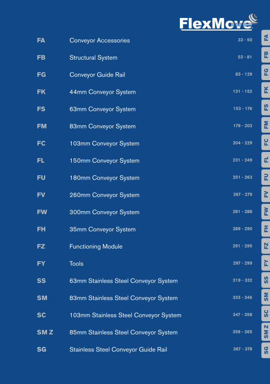
FA Conveyor Accessories
FB Structural System
FG Conveyor Guide Rail
FK 44mm Conveyor System
FS 63mm Conveyor System
FM 83mm Conveyor System
FC 103mm Conveyor System
FL 150mm Conveyor System
FU 180mm Conveyor System
FV 260mm Conveyor System
FW 300mm Conveyor System
FH 35mm Conveyor System
FZ Functioning Module
FY Tools
SS 63mm Stainless Steel Conveyor System
SM 83mm Stainless Steel Conveyor System
SC 103mm Stainless Steel Conveyor System
SM Z 85mm Stainless Steel Conveyor System
SG Stainless Steel Conveyor Guide Rail
33 - 50
53 - 81
83 - 129
131 - 152
153 - 176
179 - 203
204 - 229
231 - 249
251 - 263
267 - 279
281 - 288
289 - 290
291 - 295
297 - 299
319 - 332
333 - 346
347 - 358
359 - 365
367 - 378
FAF
BF
GF
KF
SF
MF
CF
LF
UF
VF
WF
HF
ZF
YS
SS
MS
CS
M Z
SG

QualityFlexibilityEfficiencyEco-Friendly

FlexMove® is built upon these 4 main virtues that are embodied in everything we do. With a mission to strive for exceptional superiority in intelligent integrated transportation systems, we aim to fulfill the ever-changing demands of the global market.
This is why we are committed to deliver more possibilities that extend beyond your expectations. We make things happen for you, we connect possibilities to let you achieve the best for your business.

06
Quallity, Flexibility, Efficiency, Eco-friendly.FlexMove® is built upon these 4 main virtues that are embodied in everything we do. With a mission to strive for exceptional
superiority in intelligent integrated transportation systems, we aim to fulfill the ever-changing demands of the global
market. This is why we are committed to deliver more possibilities that extend beyond your expectations. We make
things happen for you, we connect possibilities to let you achieve the best for your business.
Quality with innovative solutions
At FlexMove®, we believe in delivering precision in our
products and services, there’s simply no compromising in
the quality of our products and services. We make it our
business to understand your needs and requirements. This
is to ensure that our continuous R&D effort for
technological breakthrough enables your business to
maintain its competitive advantage while delivering more
value to your customers.
To this end, our non-compromising team of engineers aims
to innovate and be the pioneers in the integrated
transportation systems industry.
Efficiency for all businesses
At end of the day, all businesses depend on their bottom
lines. Results, that’s all that matters and FlexMove® has
continuosly raised and set the benchmark to cater to the
needs and budgets of various industries.
We work towards ensuring optimal results for businesses
with our cost-efficient systems that afford you with vast
layout capability, minimal component variation, design
simplicity, effective space utilization, enhanced
productivity, low maintenance and user-friendliness.
With FlexMove®, you can be assured of flexibility that allows
your business to expand possibilities even further.
Flexibility in fulfilling infinite potential
Today’s dynamic business environment requires
businesses to constantly evolve all the time with
technology and new customer requirements. With this in
mind, FlexMove® Intelligent Transportation System
(FITS™) is designed to get the best out of your investment
and realize the unlimited potential of your business.
Suitable for all industries, the unique FITS™ employs a
side-flexing plastic chain, allowing horizontal turns and
elevation changes within a single continuous run, taking
flexibility as you know it to a higher level.
With Quality, Fexible, Efficient and Eco-friendly solutions, Connecting Possibilities™ is made easy with FlexMive®.
Eco-Friendly for a better future
In our quest for technological advancement, we are always
conscious of the need to be sensitive to our environment.
The R&D team at FlexMove® is constantly reviewing and
sourcing for the most eco-friendly materials for our
products and services as we believe that we play an
important role in ensuring the well-being of our
environment. The use of energy-saving products,
recyclable packing materials, systematic coding of product
material to facilitate recovery and recycle processes
adopted in our processes contributes to our eco-friendly
focus to ensure that your choice of our solutions is the
right choice for your business and for our environment.

07FlexMove® Product Catalogue
Industries ServedFlexMove® is designed as an ultimate solution for transportation systems
in all manufacturing industries. The system provides a good platform for
future expansion and re-layout capability. With our in-depth knowledge and
experience in transportation systems backed by our well established
worldwide marketing and services network, we are confident in providing
solutions to your problems. The following list depicts our extensive
experience in the industries:
Food, Beverage & Dairy industryBiscuit, bread, instant noodle & soup, candy, cereal, cheese, chewing
gum, soft drink, sugar, yogurt, glass & PET bottles, ice-cream, butter,
juice, metal & paper cans, milk powder, pet food, snack, chocolate, coffee,
confectionery, frozen food, etc.
Automotive & Machine Part IndustryAir and oil filters, gear wheel, bearings, piston, casting part, power window
motor, compressor, spark plug, front and back lights, speedomester and
electronic instrument, fuel pump, etc.
Electronic & Electrical IndustryAudio and video appliances, LCD and electronic display, battery, mobile
phone, compact disc, substrate, computer parts, bulbs, electrical
instrument, CRT, hard disc drive, etc.
Personal Product, Medical & Pharmaceutical IndustryAerosol can, perfume, baby oil, pills, body lotion, detergent, cosmetics,
shampoo, dental equipment, shower cream, dental floss, soap, deodorant,
syringe, eye care products, surgical instruments and supplies, health
supplement, toothpaste, lipstick, etc.
Paper Converting & Packaging IndustryTissue roll, bags, kitchen towel, boxes, diapers, bundles, sanitary
napkins, etc.

08
Paper ConvertingSolutions
FlexMove® is a provider of robust and efficient custom integrated handlingsolutions for numerous industries including paper converting; namely theproduction of toilet rolls, kitchen towels, tissue papers (in stacks or boxes),diapers and sanitary napkins.
The flexibility in the design of our high-speed handling solutions allows for easyassembly and integration with new or existing production equipment.Standardized modular components offer customers the option to expand thesystem in order to adhere to future requirements. Diverter merger and linebalancing systems in our handling solutions ensure a constant flow of productswithout backlog from any log saw or wrapper for optimal line balancing andutilization.
Should space be a constraint, our paper converting conveyors can beconfigured in single or multi-lane with horizontal and vertical lines, freeing upspace on the procuction floor for other heavy machinery and equipment.Products may also be elevated above machine-level to optimize space.
09FlexMove® Product Catalogue
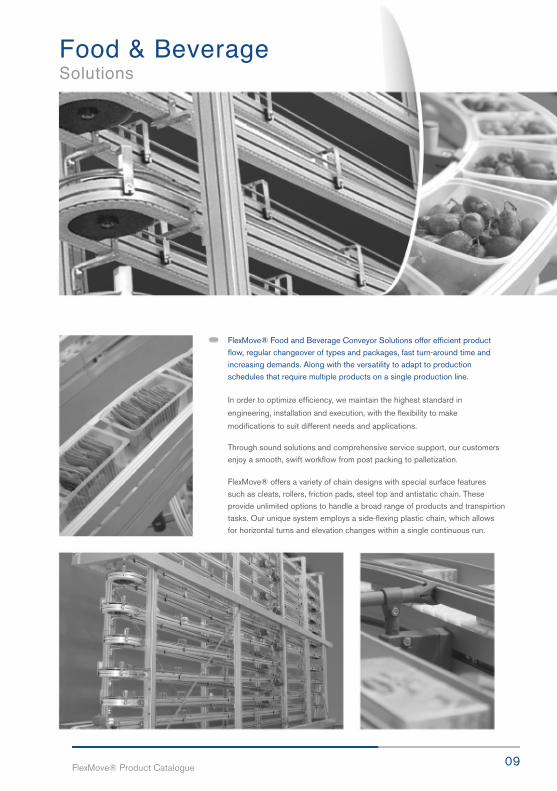
Food & BeverageSolutions
FlexMove® Food and Beverage Conveyor Solutions offer efficient productflow, regular changeover of types and packages, fast turn-around time andincreasing demands. Along with the versatility to adapt to productionschedules that require multiple products on a single production line.
In order to optimize efficiency, we maintain the highest standard in
engineering, installation and execution, with the flexibility to make
modifications to suit different needs and applications.
Through sound solutions and comprehensive service support, our customersenjoy a smooth, swift workflow from post packing to palletization.
FlexMove® offers a variety of chain designs with special surface featuressuch as cleats, rollers, friction pads, steel top and antistatic chain. Theseprovide unlimited options to handle a broad range of products and transpirtiontasks. Our unique system employs a side-flexing plastic chain, which allowsfor horizontal turns and elevation changes within a single continuous run.

10
Pallet AssemblySolutionsThere are 3 essential characteristics that an assembly line
must have in order to meet the demands of today’s
dynamic manufacturing environment: it must be robust
enough to weather demanding production schedules;
versatile enough to adapt to changes in variables such as
product size, shape, production volume and packaging
type; and flexible enough to be reconfigured for future
expansion plans and production requirements.
FlexMove® Pallet Assembly Solutions are designed to
facilitate the palletization of products from the same
category with similar sizes. Products are placed on a
1 Intermediate Drive
4 Wheel Bend 5 Vertical Bend 6 Diverter
2 Idler End 3 Rotary
standrad-sized pallet that runs through an assembly
process via a FlexMove® conveyor system. This gives
customers the flexibility of palletizing products of various
sizes on the same conveyor system.
FlexMove® Pallet Assembly Solutions can be configured in
single track, twin-track or multi-track systems. Combine
that with our proprietary sub-assembly modules such as
pallet stopper, pallet lifter, pallet transfer, pallet rotator,
pllet stackers and de-stackers to achieve a total
integrated pallet assembly system.
11FlexMove® Product Catalogue
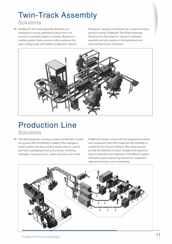
Twin-Track AssemblySolutions
Production LineSolutions
FlexMove® Twin-track Assembly Solutions areemployed to convey palletized products from oneprocess or assembly station to another. Based on amodular system, these solutions offer customers theease of plug & play with flexible configuration options.
The ideal production conveyor system should have a simpleset-up and offer the flexbility to adapt to the changes inproduct types and sizes, product quality and mix, volumeand cycle, packaging format and process, marketingstrategies, market priorities, market demands and trends.
FlexMove® system comes with pre-engineered modulesand components that offer customers the versatility tocustomize their line according to their needs and yetprovide the flexibility for future changes and expansion.Ease of assembly and integration of FlexMove® systemeliminates costly engineering intervention, equipmentdisposal and lower cost of ownership.
Production capacity is maximized as a result of minimalproduct routing. FlexMove® Twin-Track AssemblySolutions are well suited for manual or automaticassembly and test systems in the automotive andelectrical/electronics industries.

12
FlexMove® manages production logistics through the collaboration of keycomponents that include a computer integrated manufacturing software(CIM), scanner, barcode system, aas well as radio-frequency identilfication(RFID) for product scanning, identification and verification.
Once products are scanned, identified and verified by the CIM system,they will then be sorted according to their respective procuct lanes prior topackaging to eliminate prodcut mix up, human error and handlingproblems. To optimize productivity, our flexible solutions allow control ofproduction processes and are designed to meet changing wirkflowdemands.
The FlexMove® Intelligent Logistics Solutions: an efficient network of sorter,Diverter, stopper, elevators, lowerators, lifters and stacker/de-stackersystems powered by an intelligent transportation system.
Integrated AutomationSolutions

13FlexMove® Product Catalogue
FlexMove® creates value for customers by combining our proprietaryautomation solutions with intelligent transportation systems. A total integratedsolution that is a result of the sound partnership between automation solutionsand product transportation system such as product conveying, diverting andmerging, sorting, accumulating, lifting and a standard production software _
tailor-made to the customer’s needs.
The ease of interfacing and integration with existing production machines and
equipment through hardware or software is essential. Our systems provide
complete support to ensure better control of products and processes, which
allows for easy mounting of automation solutions on the FlexMove®
Transportation System.
FlexMove® systems optimize space utilization, freeing up space on theproduction
floor for heavy machinery.
Intelligent LogisticsSolutions
14
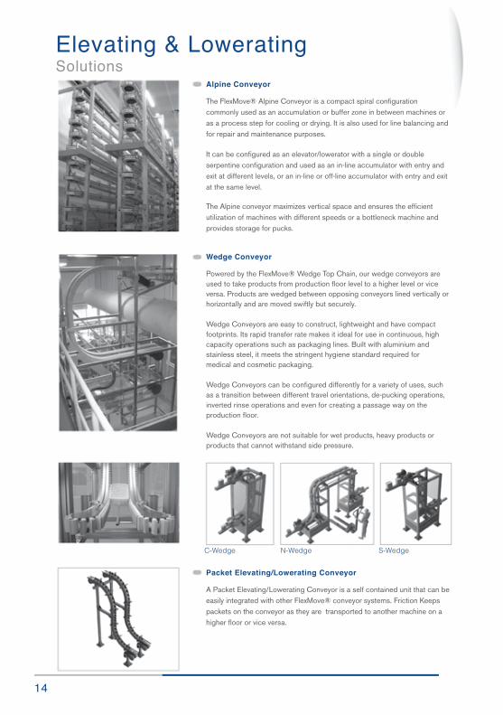
Wedge Conveyor
Powered by the FlexMove® Wedge Top Chain, our wedge conveyors areused to take products from production floor level to a higher level or viceversa. Products are wedged between opposing conveyors lined vertically orhorizontally and are moved swiftly but securely.
Wedge Conveyors are easy to construct, lightweight and have compactfootprints. Its rapid transfer rate makes it ideal for use in continuous, highcapacity operations such as packaging lines. Built with aluminium andstainless steel, it meets the stringent hygiene standard required formedical and cosmetic packaging.
Wedge Conveyors can be configured differently for a variety of uses, suchas a transition between different travel orientations, de-pucking operations,inverted rinse operations and even for creating a passage way on theproduction floor.
Wedge Conveyors are not suitable for wet products, heavy products orproducts that cannot withstand side pressure.
Alpine Conveyor
The FlexMove® Alpine Conveyor is a compact spiral configurationcommonly used as an accumulation or buffer zone in between machines oras a process step for cooling or drying. It is also used for line balancing andfor repair and maintenance purposes.
It can be configured as an elevator/lowerator with a single or doubleserpentine configuration and used as an in-line accumulator with entry andexit at different levels, or an in-line or off-line accumulator with entry and exitat the same level.
The Alpine conveyor maximizes vertical space and ensures the efficientutilization of machines with different speeds or a bottleneck machine andprovides storage for pucks.
Packet Elevating/Lowerating Conveyor
A Packet Elevating/Lowerating Conveyor is a self contained unit that can beeasily integrated with other FlexMove® conveyor systems. Friction Keepspackets on the conveyor as they are transported to another machine on ahigher floor or vice versa.
C-Wedge N-Wedge S-Wedge
Elevating & LoweratingSolutions

At FlexMove®, we believe in delivering precision in our products andservices, there’s simply no compromising in the quality of our procucts and services. We make it our business to understand your needs andrequirements. This is to ensure that our continuous R&D effort for technological breakthrough enables your business to maintain its competitive advantage while delivering more value to our customers.
To this end, our non-compromising team of engineers aims to innovateand be the pioneers in the integrated transportation systems industry.
16
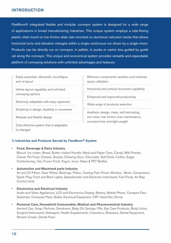
INTRODUCTION
FlexMove® integrated flexible and modular conveyor system is designed for a wide range
of applications in broad manufacturing industries. This unique system employs a side-flexing
plastic chain travel on low friction slide rails mounted on aluminium extrusion tracks that allows
horizontal turns and elevation changes within a single continuous run driven by a single motor.
Products can be directly run on conveyor, in pallets, in pucks or carton box guided by guide
rail along the conveyor. This unique and economical system provides versatile and expandable
platform of conveying solutions with unlimited advantages and features:
Easily assemble, dismantle, reconfigureand re-layout
Infinite layout capability and unlimitedconveying options
Extremely adaptable with easy expansion
Simplicity in design, flexibility in movement
Modular and flexible design
Cost effective system that is adaptableto changes
Minimum components variation and maximize space utilization
Horizontal and vertical movement capability
Enhanced and improved productivity
Wide range of products selection
Aesthetic design, clean, self-lubricating,low noise, low friction, less maintenance,corrosion-free and light weight
1) Industries and Products Served by FlexMove ® System
• Food, Beverage & Dairy Industry Biscuit, Ice cream, Bread, Butter, Instant Noodle, Metal and Paper Cans, Candy, Milk Powder, Cereal, Pet Food, Cheese, Snacks, Chewing Gum, Chocolate, Soft Drink, Coffee, Sugar, Confectionery, Tea, Frozen Food, Yogurt, Juice, Glass & PET Bottles
• Automotive and Machined parts Industry Air and Oil Filters, Gear Wheel, Bearings, Piston, Casting Part, Power Window, Motor, Compressor, Spark Plug, Front and Back Lights, Speedometer and Electronic Instrument, Fuel Pump, Air Bag Control Units
• Electronics and Electrical Industry Audio and Video Appliances, LCD and Electronics Display, Battery, Mobile Phone, Compact Disc, Substrate, Computer Parts, Bulbs, Electrical Equipment, CRT, Hard Disc Drives
• Personal Care, Household Consumable, Medical and Pharmaceutical Industry Aerosol Can, Soap, Perfume, Deodorant, Baby Oil, Syringe, Pills, Eye Care Products, Body Lotion, Surgical Instruments, Detergent, Health Supplements, Cosmetics, Shampoo, Dental Equipment, Shower Cream, Dental Floss

17FlexMove® Product Catalogue
• Paper Converting and Packaging Tissue Paper, Toilet Paper Roll, Diapers, Bags, Bundles, Kitchen Towels, Sanitary Napkins, Carton Boxes
2) Basic System Selection
FlexMove® provides a wide selection of chain sizes to cover a wide variety of product sizes and shapes.In order to select the right chain size to use in your application, consider the following selection criteria:
• Product Dimensions A product can be wider than conveyor chain in two or three times the width of the chain as long as the center of gravity of product falls within the chain width. Extra supporting guide rails are required and testing are recommended.
• Product Weight Product weight is important in chain selection as each chain has its maximum traction force. Traction force calculation is required when there are several heavy products to be conveyed, and the traction force will be increased further if the products are accumulated on the conveyor.
• Conveyor Functions Available Most of the conveyor functions are available in all the FlexMove® conveyor series. However there are differences with regard to the chain types, drive unit and idler unit variants. Selection of drive type is important as different drives have different traction forces.
• Technical Calculation It is important to calculate total load on conveyor based on product weight, distance between prod- ucts, accumulation distance and conveyor length of the system. The frequency of start /stop, chain tension and service factor are important. If the calculated capacity is higher than the selected drive and chain series, the conveyor should be shorten or select system with high capacity.
• Floor Space Available Consideration of floor space available and utilization of smallest foot print for conveyor layout.
• Compatibility With Other Machines In certain applications, interfacing and integrating with other automation equipments can be made much easier by using FlexMove® Conveyor system sizes rather than other sizes.
PRODUCT OVERVIEW
18
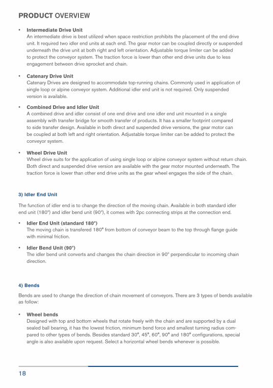
PRODUCT OVERVIEW
• Intermediate Drive Unit An intermediate drive is best utilized when space restriction prohibits the placement of the end drive unit. It required two idler end units at each end. The gear motor can be coupled directly or suspended underneath the drive unit at both right and left orientation. Adjustable torque limiter can be added to protect the conveyor system. The traction force is lower than other end drive units due to less engagement between drive sprocket and chain.
• Catenary Drive Unit Catenary Drives are designed to accommodate top-running chains. Commonly used in application of single loop or alpine conveyor system. Additional idler end unit is not required. Only suspended version is available.
• Combined Drive and Idler Unit A combined drive and idler consist of one end drive and one idler end unit mounted in a single assembly with transfer bridge for smooth transfer of products. It has a smaller footprint compared to side transfer design. Available in both direct and suspended drive versions, the gear motor can be coupled at both left and right orientation. Adjustable torque limiter can be added to protect the conveyor system.
• Wheel Drive Unit Wheel drive suits for the application of using single loop or alpine conveyor system without return chain. Both direct and suspended drive version are available with the gear motor mounted underneath. The traction force is lower than other end drive units as the gear wheel engages the side of the chain.
3) Idler End Unit
The function of idler end is to change the direction of the moving chain. Available in both standard idlerend unit (180º) and idler bend unit (90º), it comes with 2pc connecting strips at the connection end.
• Idler End Unit (standard 180º) The moving chain is transfered 180° from bottom of conveyor beam to the top through flange guide with minimal friction.
• Idler Bend Unit (90º) The idler bend unit converts and changes the chain direction in 90º perpendicular to incoming chain direction.
4) Bends
Bends are used to change the direction of chain movement of conveyors. There are 3 types of bends availableas follow:
• Wheel bends Designed with top and bottom wheels that rotate freely with the chain and are supported by a dual sealed ball bearing, it has the lowest friction, minimum bend force and smallest turning radius com- pared to other types of bends. Besides standard 30°, 45°, 60°, 90° and 180° configurations, special angle is also available upon request. Select a horizontal wheel bends whenever is possible.

19FlexMove® Product Catalogue
PRODUCT OVERVIEW
• Horizontal Bends An alternative to wheel bends, horizontal bends are useful in conditions requiring large space, long products with large turning radius and twin – track bends applications. It has higher friction compare to wheel bend. Larger radius is recommended for lower friction and stress on slide rail.
• Vertical Bends A vertical bend provides vertical change of conveyor moving direction. It can be used either as con- vex or concave bends. Vertical bends increase the tension in the chain and cause higher stress on the slide rail. Avoid using more than four 90° vertical bends in one conveyor.
5) Slide Rail
A slide rail provides low friction and wear resistance track for chain to slide on. It is mounted to aconveyor beam via screw or rivet. Various types of slide rails are available that cater to differentrequirements like normal operation, high speed, high load, conductive and accumulation applications.
6) Conveyor Beams
Conveyor beams are made of anodized aluminium extrusion that comes in standard length of 3meter section. T-slot flexibly allow drives, idlers, bends, guide rail bracket, leg support and other accessoriesto be connected using connecting strips or bolts and nuts. Aluminium extrusion has advantages of highstrength and light weight. 2 connecting strips are required for joining.
7) Guide Rail Assembly System
Guide rail components are used to guide and contain products throughout the conveyor system andprevent them from falling off the conveyor. FlexMove® provides a comprehensive range of guide rails, covers and brackets either fixed or adjustable to cover many specialized product sizes and shapes.
8) Structural System
FlexMove® structural support system consists of support beams, support brackets, foots and end caps that are interconnected to form robust support structure for every conveying need.
9) Conveyor Accessories
FlexMove® offers a wide selection of conveyor accessories from special bolt & nuts, brackets, connect-ing strips, rivets, rollers, T-slot cover to washers for inter-connection between modules and components.

20
TECHNICAL DATAMaterials
Material FIexMove Parts
POM (PolyOxyMethylene)
POM Conductive (PolyOxyMethylene)
Polyamide PA + Glass fibre
PVC, Polyvinyl Chloride
HDPE, High Density Polyethylene
PVDF, Polyvinylidene fluoride
TPE, Thermoplastic Elastomer
UHMW-PE, Ultra High Molecular Weight Polyethylene
Steel, powder coated
Aluminium, extruded & anodized
PA, Polyamide
Steel, electro-zinc plated
Conveyor Chain, rollers
Conductive chain
Drive sprocket, idler wheel
T-slot cover
Slide rail, guide rail
Slide Rail
Chain insert for friction top and wedge top
Slide Rail, drive and idler steering guides
Foot, connecting plate
Angle bracket, beam support bracket, conveyor beam, support beam, guide rail, distance tube,fixed and adjustable side guide bracket, spacer
Chain pivot, side guide bracket, side guide sup-port, drive and idler steering guide, end caps, wheel guide
Bolts and nuts, connecting strips, foot connecting strip

21FlexMove® Product Catalogue
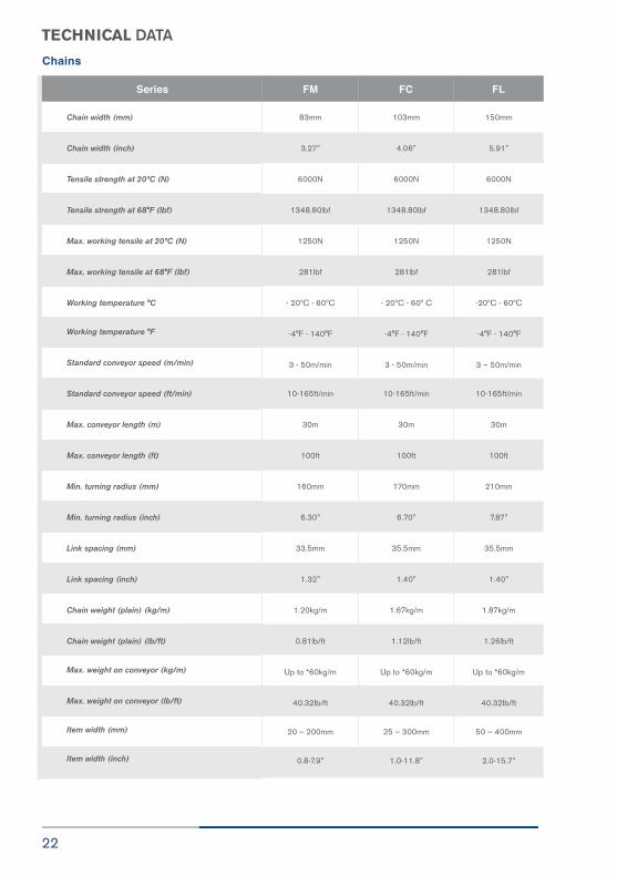
TECHNICAL DATA
Series FH FK FS
Chains
Chain width (mm)
Chain width (inch)
Tensile strength at 20ºC (N)
Tensile strength at 68°F (lbf)
Max. working tensile at 20ºC (N)
Max. working tensile at 68°F (lbf)
Working temperature °C
Working temperature °F
Standard conveyor speed (m/min)
Standard conveyor speed (ft/min)
Max. conveyor length (m)
Max. conveyor length (ft)
Min. turning radius (mm)
Min. turning radius (inch)
Link spacing (mm)
Link spacing (inch)
Chain weight (plain) (kg/m)
Chain weight (plain) (lb/ft)
Max. weight on conveyor (kg/m)
Max. weight on conveyor (lb/ft)
Item width (mm)
Item width (inch)
35mm
1.38”
1000N
224.80lbf
180N
40.46lbf
- 20ºC - 60º C
-4°F - 140°F
3 - 30m/min
10-100ft/min
3m
10ft
N/A
N/A
12.7mm
0.50”
0.33kg/m
0.19ib/ft
Up to * 30kg/m
6.72lb/ft
35 - 500mm
(For Multiple Track)
1.4-19.7”
44mm
1.73”
4000N
899.20lbf
500N
112.40lbf
-20ºC - 60ºC
-4°F - 140°F
3 – 50m/min
10-165ft/min
30m
100ft
150mm
5.91”
25.4mm
1.00”
0.63kg/m
0.43lb/ft
Up to *30kg/m
26.16lb/ft
15 - 100mm1.4-19.7”
0.6-4.0”
63mm
2.48”
4000N
899.20lbf
500N
112.40lbf
-20ºC - 60ºC
-4°F - 140°F
3 – 50m/min
10-165ft/min
30m
100ft
150mm
6.30”
25.4mm
1.00”
0.75kg/m
0.50lb/ft
Up to *30kg/m
26.16lb/ft
15 – 140mm
0.6-5.5”
TECHNICAL DATA
22
Chains
Series FM FC FL
Chain width (mm)
Chain width (inch)
Tensile strength at 20ºC (N)
Tensile strength at 68°F (lbf)
Max. working tensile at 20ºC (N)
Max. working tensile at 68°F (lbf)
Working temperature °C
Working temperature °F
Standard conveyor speed (m/min)
Standard conveyor speed (ft/min)
Max. conveyor length (m)
Max. conveyor length (ft)
Min. turning radius (mm)
Min. turning radius (inch)
Link spacing (mm)
Link spacing (inch)
Chain weight (plain) (kg/m)
Chain weight (plain) (lb/ft)
Max. weight on conveyor (kg/m)
Max. weight on conveyor (lb/ft)
Item width (mm)
Item width (inch)
83mm
3.27”
6000N
1348.80lbf
1250N
281lbf
- 20ºC - 60ºC
-4°F - 140°F
3 - 50m/min
10-165ft/min
30m
100ft
160mm
6.30”
33.5mm
1.32”
1.20kg/m
0.81lb/ft
Up to *60kg/m
40.32Ib/ft
20 – 200mm
0.8-7.9”
103mm
4.06”
6000N
1348.80lbf
1250N
281lbf
- 20ºC - 60º C
-4°F - 140°F
3 - 50m/min
10-165ft/min
30m
100ft
170mm
6.70”
35.5mm
1.40”
1.67kg/m
1.12lb/ft
Up to *60kg/m
40.32Ib/ft
25 – 300mm
1.0-11.8”
150mm
5.91”
6000N
1348.80lbf
1250N
281lbf
-20ºC - 60ºC
-4°F - 140°F
3 – 50m/min
10-165ft/min
30m
100ft
210mm
7.87”
35.5mm
1.40”
1.87kg/m
1.26lb/ft
Up to *60kg/m
40.32Ib/ft
50 – 400mm
2.0-15.7”
TECHNICAL DATA
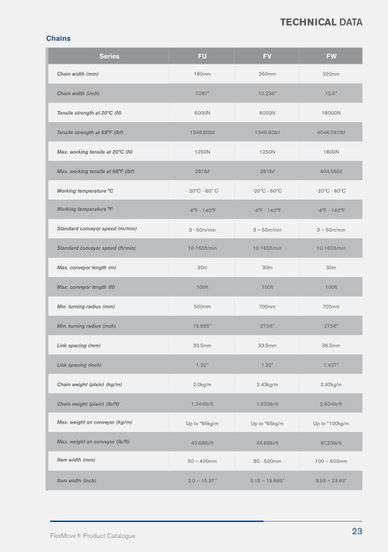
23FlexMove® Product Catalogue
Chains
Series FU FV FW
Chain width (mm)
Chain width (inch)
Tensile strength at 20ºC (N)
Tensile strength at 68°F (lbf)
Max. working tensile at 20ºC (N)
Max. working tensile at 68°F (lbf)
Working temperature °C
Working temperature °F
Standard conveyor speed (m/min)
Standard conveyor speed (ft/min)
Max. conveyor length (m)
Max. conveyor length (ft)
Min. turning radius (mm)
Min. turning radius (inch)
Link spacing (mm)
Link spacing (inch)
Chain weight (plain) (kg/m)
Chain weight (plain) (lb/ft)
Max. weight on conveyor (kg/m)
Max. weight on conveyor (lb/ft)
Item width (mm)
Item width (inch)
180mm
7.087”
6000N
1348.80Ibf
1250N
281Ibf
- 20ºC - 60º C
-4°F - 140°F
3 - 50m/min
10-165ft/min
30m
100ft
500mm
19.685’’
33.5mm
1.32’’
2.0kg/m
1.344Ib/ft
Up to *65kg/m
43.68Ib/ft
50 – 400mm
2.0 – 15.37’’
260mm
10.236”
6000N
1348.80Ibf
1250N
281Ibf
-20ºC - 60ºC
-4°F - 140°F
3 – 50m/min
10-165ft/min
30m
100ft
700mm
27.56”
33.5mm
1.32”
2.43kg/m
1.633lb/ft
Up to *65kg/m
43.68lb/ft
80 - 500mm
3.15 – 19.685”
320mm
12.6”
18000N
4046.561lbf
1800N
404.66lbf
-20ºC - 60ºC
-4°F - 140°F
3 – 50m/min
10-165ft/min
30m
100ft
700mm
27.56”
36.5mm
1.437”
3.92kg/m
2.634lb/ft
Up to *100kg/m
67.20lb/ft
100 – 600mm
3.93 – 23.63”

24
TECHNICAL DATA
Chain strength and expansion vs. temperature
Temperature ºC
-20
0
20
40
60
80
100
120
Tensile strength factor
1.2
1.1
1.0
0.9
0.8
0.6
0.5
0.3
Linear expansion %
-0.4
-0.2
0.1
0.2
0.5
0.8
1.0
1.3
Resistance to chemicalFlexMove® components can withstand continuous contact with most chemicals. However, it is recommended
to avoid:
• Acids with pH less than 4 • Bases with pH higher than 9
The following table specifies the resistance of several material used in the conveyor on selected chemicals
Legend1 = Very good 2 = Good 3 = Moderate resistance
4 = Not recommended 5 = No data available
Material
Acids:
Acetic acid
Benzoic acid
Citric acid
Chromic acid
Hydrofluoric acid
Hydrochloric acid
Hydro cyanic acid
Nitric acid
Phosphoric acid
Sulphuric acid
Tartaric acid
Basic compounds:
Ammonia
Calcium hydroxide
Caustic soda
Potassium hydroxide
Salts:
Potassium bicarbonate
Potassium permanganate
Sodium cyanic
Sodium hydrochloride
Acid salt
Basic salt
Neutral salt
2
2
2
3
2
1
1
2
4
2
4
3
2
2
2
2
2
1
1
1
1
-
-
-
-
-
-
-
1
1
4
4
-
-
-
1
1
1
1
2
2
2
2
1
1
1
1
-
-
1
-
2
4
3
4
3
3
3
4
4
4
4
4
4
4
3
4
4
2
4
4
4
4
4
4
4
2
3
1
2
1
1
1
2
4
1
2
1
-
-
-
-
-
-
-
-
-
1
-
2
4
2
3
4
3
1
3
3
3
1
AcetalPOM
Polyamide PA
AluminiumAL
High-densityPolyethylene
HDPE
ThermoplasticElastomer
TPE

Today’s dynamic business environment requires businesses to constantly evolve all the time with technology and new customer requirements. With this in mind, FlexMove® intelligent transportation system (FITS™) is designed to get the best out of your investment and realize the unlimited potential of your business.
Suitable for all industries, the unique FITS™ employs a side-flexing plastic chain, allowing horizontal turns and elevation changes within a single continuous run, taking flexibility as you know it to a higher level.

26
TECHNICAL DATA
Chains
MaterialAcetalPOM
PolyamidePA
AluminiumAL
High-densityPolyethylene
HDPE
ThermoplasticElastomer
TPE
Organic compounds and solvents:
AcetoneBenzene
Butyl alcohol
Carbon disulphide
Chloroform
Ethyl acetate
Ethyl alcohol
Heptane
Methyl alcohol
Methyl ethyl ketone
Nitrobenzene
Phenol
Gasses:
Carbon dioxideCarbon monoxide
ChlorineHydrogen sulphide
Sulphur dioxide
Others:
Beer
Fruit juices
Gasoline
Milk
Oil
Vinegar
1
1
1
1
1
1
2
2
2
1
1
2
2
3
2
2
2
3
-
-
-
-
-
-
1
2
1
1
1
1
32
23
2
11
41
3
11
32
2
--
--
-
11
11
1
11
2
1
1
1
1
2
1
1
2
3
11
2
1
1
1
1
2
1
1
2
3
44
2
3
4
2
1
2
1
4
3
2
33
-
-
-
-
-
-
-
4
-
-
11
1
1
-
1
1
-
2
2
1
1
Note: the table above is valid for temperature range up to 60ºC and it is to be considered as guideline only.
Furthermore, precautions should be taken when using cleaning agents. If you are in doubt on the material to
withstand your special environment, you should go for chemical testing or contact our local distributor.
Friction CoefficientFriction coefficients between chain and slide rails are 0.10 _ 0.15. the friction coefficients between chain and
products are as follow:
Static ElectricityThe standard plastic materials used for conveyors have low
electrical conductivity. So, static electricity can build up in the
conveyor. When a conveyor is running under normal environ-
ment (20ºC and humidity 60%) without load, the static electric-
ity build up should be around the following figures:
Temperature LimitsThis conveyor system can operate continuouslyin an environment of between - 20ºC to 60ºC.The conveyor can withstand up to 100ºC for ashort period (washing, rinsing).
With the introduction of anti-static material for slide rail andchain, it shall meet the requirement for electronic industry.
Product Plain Chain
Steel (dry)
Steel (lubricated)
Glass (dry)
Glass (lubricated)
Aluminium
Plastic
Wood and paper
Above the drive unit
Idler end
Above the wheel bend
Above the straight section
1800-2500V
400-500V
400-500V
250-350V
0.15-0.25
0.10-0.15
0.15-0.20
0.10-0.15
0.15-0.25
0.15-0.25
0.15-0.30

27FlexMove® Product Catalogue
TECHNICAL DATA
Sound LevelNormally, noise level is higher during the run-in period. The noise level should go down after few days of operation. Generally noiselevel will increase proportionally to the conveyor speed. Typically, the noise level reading in dB should be around the follwing:
Chain Tension CalculationCalculation is necessary to determine the maximum chain tension on a particular conveyor configuration design, theresults are used to decide :
• Drive unit capacity • Tension limit of conveyor chain
For short, light and low speed applications, the tension limit of the chain normally far exceeds the actual requirement ofthe application. If you are in doubt, always calculate.
Drive Unit Output Capacity, P(W) requirement depend on:• Traction force F (N) • Chain speed V (m/min)
Tocalculate power, the equation is P = 1/60 (F x V)
There are several drive unit designs, the maximum permissible traction force on each type of drive unit as below:
Chain Tension LimitChain tension limit can be derived from the diagram on the next page. It is dependent on various operating conditions, the ac- tual calculation result should be reduced by service factor. Conveyors with high frequency of start/stop will have a high servicefactor but this could be reduced by providing a frequency inverter incorporated with start/stop function.
It is not advisable to operate a conveyor with more than 20 starts/stops per hour. If your application must operate this way,please consult FlexMove®.
ChainConveyor Speed M/min
FT
FH
FK
FS
FM
FC
FL
FU
FV
FW
5
56
56
56
55
59
62
64
64
64
64
10
58
58
58
59
62
66
68
66
67
68
20
65
65
65
68
70
74
76
75
75
76
30
70
70
70
71
77
81
83
79
80
83
40
-
-
74
75
78
85
87
86
86
87
Drive unit type
Operating conditions Service factor
Maximum traction force in Newton (N)
End
Intermediate
Catenary
Low speed (<15m/min) & max. 1 start/stop per hour
Low speed & max. 10 start/stop per hour
Low speed & max. 20 start/stop per hour
High speed (>15m/min) & max 20 start/stop per hour
1.0
1.2
1.4
1.6
FH
180
-
180
FT
400
-
-
FK
500
200
500
FS
500
200
500
FM
1250
200
1250
FC
1250
200
1250
FL
1250
200
1250
FU
1250
Nil
Nil
FV
1250
Nil
Nil
FW
1250
Nil
Nil

28
TECHNICAL DATA
Bend FactorsBend factors must be considered and calculated at every plain chain. It depends on the angle of the bend α in radians and friction coefficient µ between chain and slide rails. In application when conveyor is dry and clean, the friction coef-ficient µ is close to 0.1.
The bend factor is important to calculate since the frictional force of a plain bend depends not only on the weight of chainand product but also the actual the tension throughout the bend. The result an additional pressure force of the chaintowards the conveyor beam directed toward the center of the bend. Since the chain tension varies throughout theconveyor, calculation of this additional pressure force is complicated. The highest values are present at the pulling sideof the drive unit and virtually zero at the chain inlet. Using bend factor is the easiest way of including added friction inthe plain bend for both horizontal and vertical into the calculation. Always use wheel bend unless for exceptional cases.If using plain bend is a must, the combined plain bends angle should not more than 180º, unless it is for a very short and lightapplication.
8º inclined is the maximum a product could convey for plain chain whereas friction top chain could take up to 30º
Calculation
FlexMove® chain tension calculation could be simplified as follow:
Divide the conveyor in sections, each containing a straight part and up to the next plain bend (horizontal or vertical).
First section should be from the end furthest away from the drive unit.
Wheel bends are considered equivalent to straight section. A conveyor with wheel bend but without plain bend shouldbe considered as one straight section. Calculate the force caused by gravity load of the return chain.
Calculate the forces caused by transport friction, accumulation and gravity in the first section and multiply with bendfactor. Repeat the step above on each section of the conveyor until the last section with the drive unit. The result of thecalculation indicates the amount of traction force required to move the conveyor.
Traction force, the chain tension is caused by several components such as:
• Friction between unloaded chain and slide rail for example on the return chain.
• Friction between loaded chain and slide rails.
• Friction between accumulating products and top surface of chain.
• Gravity force acting on products and top surface of chain.
• Additional friction in horizontal and vertical bend.
Traction force F requires to move the chain depends on the following factors:
• Conveyor length (L)
• Product gravity load / m, Transport (gp)
• Product gravity load / m, Accumulation (gpa)
• Chain gravity load / m (gc)
• Friction coefficient, chain / slide rail (µc)
• Friction coefficient, chain / products (µp)
• Incline angle (A)
• Bend factor for horizontal plain bend and vertical bend (α)
Bend type, horizontal or vertical plain bend
30º1
45º
60º1
90º1
Bend factor α
.2
1.3
.4
.6

gc + gp
F
A
F
gc + gp
F
gc + gp gpa
29FlexMove® Product Catalogue
TECHNICAL DATA
Diagram AHorizontal conveyor without accumulation.Therefore, F = L (gc + gp) m
Diagram BIncline without accumulation.Therefore, ,F = L (gc + gp) (µc . Cos A + Sin A)
Diagram CIIncline with accumulation.Therefore, , F = L (gc + gp) m + g
Note:
If the traction force exceeds the chain or drive unit capacity, therefore:
*Shorten the conveyor or re-layout if possible.
*Break the conveyor into two conveyor with individual drive unit.

30
TECHNICAL DATA
Calculation ExampleHorizontal conveyor with a 90º horizontal plain bend and a 90º wheel bend.
Calculation DataConveyor series = FM
Conveyor speed, V = 10m/min
Start/stop = 15/hour
Total length = 12.4m
Friction coefficient, µc = 0.1
Friction coefficient, µp = 0.2
Chain weight, gc = 11.8 N/m
Transport product weight, gp (2kg/m) = 19.62 N/m
Accumulation product weight, gpa (14(2kg)/m) = 274.68 N/m
Section L1 F1 = [F0 + L1 ( gc + gp ) µc] kα1
= [0+5.8(11.8+19.62)0.1]1.6
= 29.16N
Section L2F2 = F1 + [L2a ( gc + gpa ) µc + L2b ( gc + gp )] µc + ( L2a.gpa.µp )
= 29.16+[2(11.8+274.68)+4.6(11.8+19.62)]0.1+(2*274.68*0.2)
Ftotal = 210.78 N
Comparison
The calculation result can now compared with the
maximum chain tension for 10m/min is 900N and for
12.4m of conveyor is 1000N. Divide the service fac
tor for 15 start/stop of 1.4. so the actual permission
chain tension limit is 900/1.4 = 643N
31FlexMove® Product Catalogue
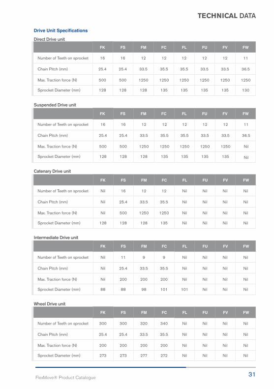
TECHNICAL DATA
Drive Unit Specifications
Direct Drive unit
Suspended Drive unit
Catenary Drive unit
Intermediate Drive unit
Wheel Drive unit
FK
FK
FK
FK
FK
FS
FS
FS
FS
FS
FM
FM
FM
FM
FM
FC
FC
FC
FC
FC
FL
FL
FL
FL
FL
FU
FU
FU
FU
FU
FV
FV
FV
FV
FV
FW
FW
FW
FW
FW
Number of Teeth on sprocket
Chain Pitch (mm)
Max. Traction force (N)
Sprocket Diameter (mm)
Number of Teeth on sprocket
Chain Pitch (mm)
Max. Traction force (N)
Sprocket Diameter (mm)
Number of Teeth on sprocket
Chain Pitch (mm)
Max. Traction force (N)
Sprocket Diameter (mm)
Number of Teeth on sprocket
Chain Pitch (mm)
Max. Traction force (N)
Sprocket Diameter (mm)
Number of Teeth on sprocket
Chain Pitch (mm)
Max. Traction force (N)
Sprocket Diameter (mm)
16
25.4
500
128
16
25.4
500
128
Nil
Nil
Nil
128
Nil
Nil
Nil
88
300
25.4
200
273
16
25.4
500
128
16
25.4
500
128
16
25.4
500
128
11
25.4
200
88
300
25.4
200
273
12
33.5
1250
128
12
33.5
1250
128
12
33.5
1250
128
9
33.5
200
98
320
33.5
200
277
12
35.5
1250
135
12
35.5
1250
135
12
35.5
1250
135
9
35.5
200
101
340
35.5
200
272
12
35.5
1250
135
12
35.5
1250
135
Nil
Nil
Nil
Nil
Nil
Nil
Nil
101
Nil
Nil
Nil
Nil
12
33.5
1250
135
12
33.5
1250
135
Nil
Nil
Nil
Nil
Nil
Nil
Nil
Nil
Nil
Nil
Nil
Nil
12
33.5
1250
135
12
33.5
1250
135
Nil
Nil
Nil
Nil
Nil
Nil
Nil
Nil
Nil
Nil
Nil
Nil
11
36.5
1250
130
11
36.5
Nil
Nil
Nil
Nil
Nil
Nil
Nil
Nil
Nil
Nil
Nil
Nil
Nil
Nil
Infinite
Cost Effective
Improved
Low Friction

33FlexMove® Product Catalogue
FAConveyorAccessories
FA

34FlexMove reserves the right to make alteration without prior notification Every care has been taken to ensure the accuracy of the
information contained in this catalogue but no liability can be accepted for any error or omissions.
FA SERIES
FAH B S-40
FAH B S-60
FAH B S-80
Horizontal beam support bracket - Aluminium
Horizontal beam support bracket - Aluminium
Horizontal beam support bracket - Aluminium
UOM : pc
For 40mm horizontal crossing support beam
UOM : pc
For 64mm horizontal crossing support beam
UOM : pc
For 80mm horizontal crossing support beam
Mounting : FATB-20(1) , FALN-M8(1) , FAHB-M8 x16(1) , FASN-M8(1) , FAFW-M8 (2)
Mounting : FATB-20(2) , FALN-M8(2), FAHB-M8 x16(1) , FASN-M8(1) , FAFW-M8 (3)
Mounting : FATB-20(2) , FALN-M8(2), FAHB-M8 x16(2) , FASN-M8(2) , FAFW-M8 (4)

35FlexMove® Product Catalogue
FA SERIES
FAVB S-60K
FAVB S-60S
FAVB S-80S
Vertical beam support bracket - Aluminium
Vertical beam support bracket - Aluminium
Vertical beam support bracket - Aluminium
UOM : pc
For FK conveyor with 64mm vertical support beam
UOM : pc
For FS conveyor with 80mm vertical beam support
Mounting : FATB-20(2) , FALN-M8(2) , FAHB-M8 x16(2) , FASN-M8(2) , FAFW-M8 (4)
UOM : pc
For FS conveyor with 64mm vertical beam support Mounting : FATB-20(2) , FALN-M8(2) , FAHB-M8 x16(2) , FASN-M8(2) , FAFW-M8 (4)
Mounting : FATB-20(2) , FALN-M8(2) , FAHB-M8 x16(2) , FASN-M8(2) , FAFW-M8 (4)
FA

36FlexMove reserves the right to make alteration without prior notification Every care has been taken to ensure the accuracy of the
information contained in this catalogue but no liability can be accepted for any error or omissions.
FA SERIES
FAVB S-60M
FAVB S-80M
FAVB S-60C
Vertical beam support bracket - Aluminium
Vertical beam support bracket - Aluminium
Vertical beam support bracket - Aluminium
UOM : pc
For FM conveyor with 64mm vertical support beam
UOM : pc
For FM conveyor with 80mm vertical beam support
UOM : pc
For FC conveyor with 64mm vertical beam support
Mounting : FATB-20(2) , FALN-M8(2) , FAHB-M8 x16(2) , FASN-M8(2) , FAFW-M8 (4)
Mounting : FATB-20(2) , FALN-M8(2) , FAHB-M8 x16(2) , FASN-M8(2) , FAFW-M8 (4)
Mounting : FATB-20(2) , FALN-M8(2) , FAHB-M8 x16(2) , FASN-M8(2) , FAFW-M8 (4)

FA SERIES
FAVB S-80C
FAVB S-80L
Vertical beam support bracket - Aluminium
Vertical beam support bracket - Aluminium
UOM : pc
For FC conveyor with 80mm vertical beam support
UOM : pc
For FL conveyor with 80mm vertical beam support
Mounting : FATB-20(2) , FALN-M8(2) , FAHB-M8 x16(2) , FASN-M8(2) , FAFW-M8 (4)
Mounting : FATB-20(2) , FALN-M8(2) , FAHB-M8 x16(2) , FASN-M8(2) , FAFW-M8 (4)
FA

38FlexMove reserves the right to make alteration without prior notification Every care has been taken to ensure the accuracy of the
information contained in this catalogue but no liability can be accepted for any error or omissions.
FA SERIES
FAVB S-60KV
FAVB S-60SV
FAVB S-80SV
Vertical beam support bracket with slot - Aluminium
Vertical beam support bracket with slot - Aluminium
Vertical beam support bracket with slot - Aluminium
UOM : pc
For FK conveyor with 64mm vertical support beam
UOM : pc
For FS conveyor with 64mm vertical beam support
UOM : pc
For FS conveyor with 80mm vertical beam support
Mounting : FATB-20(2) , FALN-M8(2) , FAHB-M8 x16(2) , FASN-M8(2) , FAFW-M8 (4)
Mounting : FATB-20(2) , FALN-M8(2) , FAHB-M8 x16(2) , FASN-M8(2) , FAFW-M8 (4)
Mounting : FATB-20(2) , FALN-M8(2) , FAHB-M8 x16(2) , FASN-M8(2) , FAFW-M8 (4)

39FlexMove® Product Catalogue
FA SERIES
FAVB S-60MV
FAVB S-80MV
FAVB S-60CV
Vertical beam support bracket with slot - Aluminium
Vertical beam support bracket with slot - Aluminium
Vertical beam support bracket with slot - Aluminium
UOM : pc
For FM conveyor with 64mm vertical support beam
UOM : pc
For FM conveyor with 80mm vertical beam support
UOM : pc
For FC conveyor with 64mm vertical beam support
Mounting : FATB-20(2) , FALN-M8(2) , FAHB-M8 x16(2) , FASN-M8(2) , FAFW-M8 (4)
Mounting : FATB-20(2) , FALN-M8(2) , FAHB-M8 x16(2) , FASN-M8(2) , FAFW-M8 (4)
Mounting : FATB-20(2) , FALN-M8(2) , FAHB-M8 x16(2) , FASN-M8(2) , FAFW-M8 (4)
FA
40FlexMove reserves the right to make alteration without prior notification Every care has been taken to ensure the accuracy of the
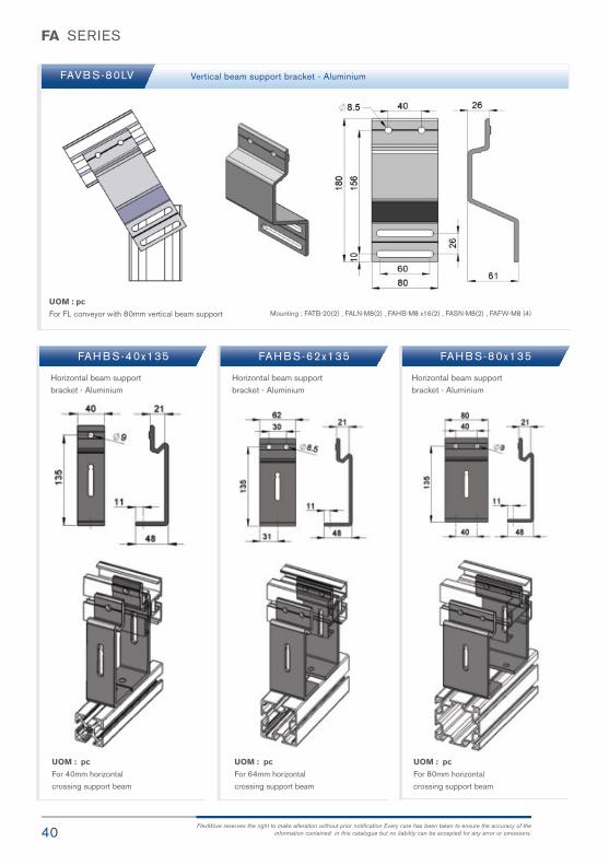
information contained in this catalogue but no liability can be accepted for any error or omissions.
FA SERIES
FAVB S-80LV
FAH B S-40x135 FAH B S-62x135 FAH B S-80x135
Vertical beam support bracket - Aluminium
UOM : pc
For FL conveyor with 80mm vertical beam support Mounting : FATB-20(2) , FALN-M8(2) , FAHB-M8 x16(2) , FASN-M8(2) , FAFW-M8 (4)
Horizontal beam support bracket - Aluminium
Horizontal beam support bracket - Aluminium
Horizontal beam support bracket - Aluminium
UOM : pc
For 40mm horizontal
crossing support beam
UOM : pc
For 64mm horizontal
crossing support beam
UOM : pc
For 80mm horizontal
crossing support beam

41FlexMove® Product Catalogue
FA SERIES
FAAL-64
FAAL-80
Alpine beam support bracket - Aluminium
Alpine beam support bracket - Aluminium
UOM : pc
For support of 180° wheel bend with 64mm vertical beam support
UOM : pc
For support of 180° wheel bend with 80mm vertical beam support
Mounting : FAHB-M8 x16(4) , FASN-M8(4) , FAFW-M8 (4)
Mounting : FAHB-M8 x16(6) , FASN-M8(6) , FAFW-M8 (6)
FA

42FlexMove reserves the right to make alteration without prior notification Every care has been taken to ensure the accuracy of the
information contained in this catalogue but no liability can be accepted for any error or omissions.
FA SERIES
FASR-25 HDPE slide rail - White “Normal Application”
“Low Friction , suitable for accumulation”
“Lowest Friction , suitable for accumulation”
“ High abrasive and High load ”
“For Static sensitive products”
“ Static conductive ”
“For Abrasive application“
UHMW-PE slide rail - White
Special PE slide rail - Blue
PAPE slide rail - Grey
Conductive slide rail - Black
Conductive slide rail - Black
PVDF slide rail - White
FASR-25T
FASR-25A
FASR-25CD
FASR-25P
FASR-25
FASR-25U
FASR-25X
FASR-25U
FASR-25X
FASR-25T
FASR-25A
FASR-25CD
FASR-25P
UOM : 25meter / roll
UOM : 50pcs / pk UOM : 50pcs / pk
FASLR-4x6 Aluminium rivet for slide Rail Nylon Set screw for slide railFASLS-M5

43FlexMove® Product Catalogue
FA SERIES
FASR-25KA
FASR-25KU
FASR-25K
FASR-25KA
FASR-25KU
FASR-25K
Conductive slide rail
UHMW-PE slide rail
HDPE slide rail
UOM : 25meter / roll
UOM : 50pcs / pk
FASLS-M3 Nylon Set screw for slide rail
FA
44FlexMove reserves the right to make alteration without prior notification Every care has been taken to ensure the accuracy of the
information contained in this catalogue but no liability can be accepted for any error or omissions.
FA SERIES
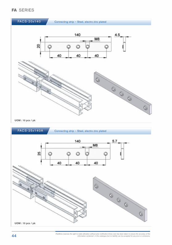
FACS-20x140
FACS-25x140A
Connecting strip – Steel, electro zinc plated
Connecting strip – Steel, electro zinc plated
UOM : 10 pcs / pk
UOM : 10 pcs / pk

45FlexMove® Product Catalogue
FA SERIES
FACS-25x160 Connecting strip – Steel, electro zinc plated
UOM : 10 pcs / pk
UOM : 25 meter / roll
FASC-25
FASC-3P
T-Slot Cover – Soft PVC ( 25 meter / Roll )
T-Slot Cover – Rigid PVC ( 3 meter / Length )
FA

46FlexMove reserves the right to make alteration without prior notification Every care has been taken to ensure the accuracy of the
information contained in this catalogue but no liability can be accepted for any error or omissions.
FA SERIES
FASN-M6
FASN-M8
M6 Square Nut for Outer Slot – Steel, electro zinc plated
M8 Square Nut for Inner Slot- Steel, electro zinc plated
UOM : 50 pcs / pack
UOM : 50 pcs / pk
UOM : 50 pcs / pk
FATB-20
FATB-35
FATB-53
FATB-71
T-bolt, L = 20 – Steel, zinc plated
T-bolt, L = 35 – Steel, zinc plated
T-bolt, L = 53 – Steel, zinc plated
T-bolt, L = 71 – Steel, zinc plated

47FlexMove® Product Catalogue
FA SERIES
FASL-M8 Spring Leaf Nut M8 for 40x40, 64x64 , 40x80, 80x80 Support Beam - Steel, zinc plated
FA F W - M 8 FA L N - M 8M8 Flat washer- Steel, zinc plated M8 Lock Nut- Steel, zinc plated
UOM : 50 pcs / pk
UOM : 50 pcs / pk UOM : 50 pcs / pk
FAHB- M8 x 16
FAHB-M8 x 20
Hex bolt, L = 16 – Steel, zinc plated
Hex bolt, L = 20 – Steel, zinc plated
UOM : 50 pcs / pk UOM : 50 pcs / pk
FAC W - M 8 Countersunk washer - POM
FA

48FlexMove reserves the right to make alteration without prior notification Every care has been taken to ensure the accuracy of the
information contained in this catalogue but no liability can be accepted for any error or omissions.
FA SERIES
FAFR-35
FAFR-18
FAFR-11
Free roller – POM
Free roller - POM
Free roller - POM
UOM : 10 pcs / pk
UOM : 10 pcs / pk
UOM : 10 pcs / pk

49FlexMove® Product Catalogue
FA SERIES
FASR-75x15
FASR-75x19P
FAFR-75
Sponge roller, Sponge rubber
PVC Roller c/w POM core & Screw
Belt Pulley – Polyamide
UOM : 10 pcs / pk
UOM : 10 pcs / pk
UOM : 10 pcs / pk
FA

50FlexMove reserves the right to make alteration without prior notification Every care has been taken to ensure the accuracy of the
information contained in this catalogue but no liability can be accepted for any error or omissions.
FA SERIES
FA E C - D H FA E C - W HEnd cap for drive shaft - Polyamide End cap for wheel – Polyamide
UOM : 10 pcs / pk UOM : 10 pcs / pk

At end of the day, all businesses depend on their bottom lines. Results, that’s all that matters and FlexMove® has continuously raised and set the benchmark to cater to the needs and budgets of various industries.
We work towards ensuring optimal results for businesses with our cost-efficient systems that afford you with 01 vast layout capability, 02 minimal component variations, 03 design simplicity, 04 effective space utilization, 05 enhanced productivity, 06 low maintenance and 07 userfriendliness. With FlexMove®, you can be assured of flexibility that allows your business to expand possibilities even further.

Wide Range
Clean
Simplicity
Economical

53FlexMove® Product Catalogue
FBStructuralSystem
FB

54FlexMove reserves the right to make alteration without prior notification Every care has been taken to ensure the accuracy of the
information contained in this catalogue but no liability can be accepted for any error or omissions.
FB SERIES
FB SB-40x40
FB SB-64x64
Support Beam 40x40 – Aluminium Anodized
Support Beam 64x64 – Aluminium Anodized
UOM : 3 meter / length
UOM : 3 meter / length
55FlexMove® Product Catalogue
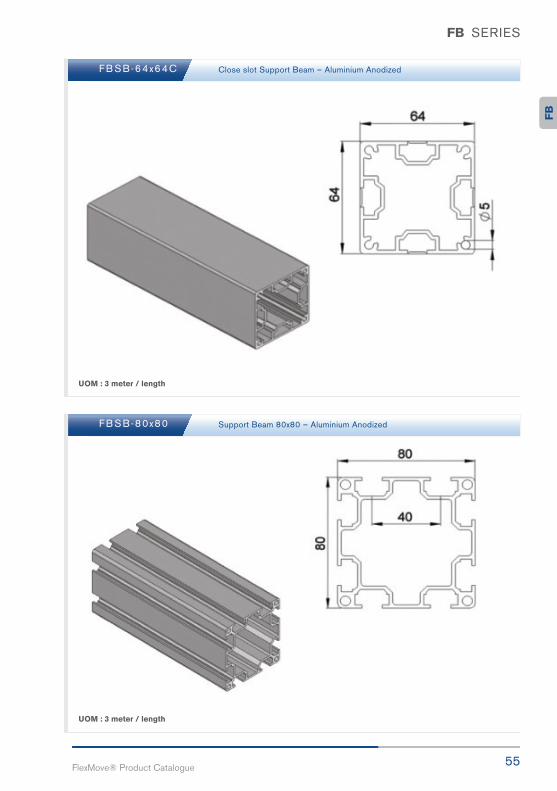
FB SERIES
FB SB-64x64C
FB SB-80x80
Close slot Support Beam – Aluminium Anodized
Support Beam 80x80 – Aluminium Anodized
UOM : 3 meter / length
UOM : 3 meter / length
FB
56FlexMove reserves the right to make alteration without prior notification Every care has been taken to ensure the accuracy of the
information contained in this catalogue but no liability can be accepted for any error or omissions.
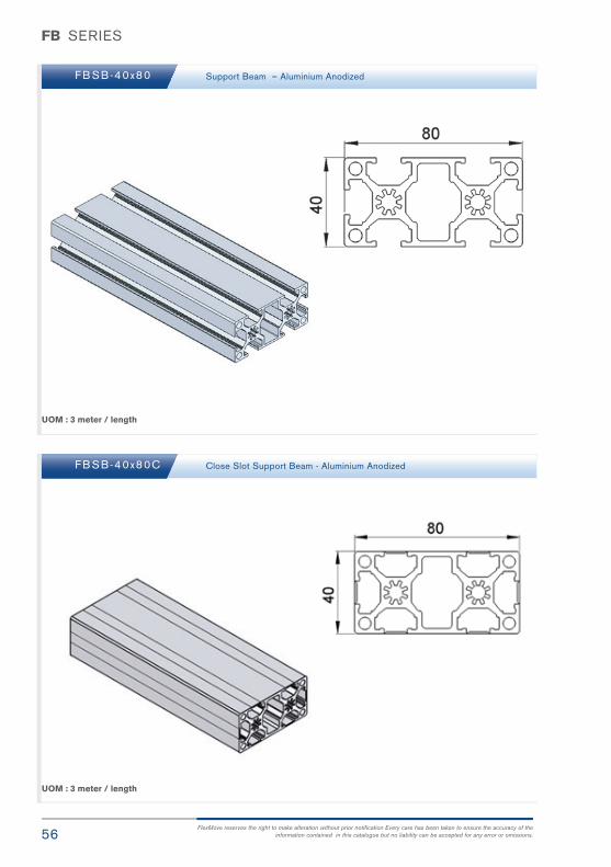
FB SERIES
FB SB-40x80
FB SB-40x80C
Support Beam – Aluminium Anodized
Close Slot Support Beam - Aluminium Anodized
UOM : 3 meter / length
UOM : 3 meter / length

57FlexMove® Product Catalogue
FB SERIES
FB EC-40x80
FB EC-40
End Cap. 40x80mm Support Beam - Polyamide
End Cap , 40x40mm Support Beam - Polyamide
UOM : 10 pcs / pk
UOM : 10 pcs / pk
FB

58FlexMove reserves the right to make alteration without prior notification Every care has been taken to ensure the accuracy of the
information contained in this catalogue but no liability can be accepted for any error or omissions.
FB SERIES
FB EC-64
FB EC-80
End cap , 64x64mm Support Beam - Polyamide
End cap , 80x80mm Support Beam - Polyamide
UOM : 10 pcs / pk
UOM : 10 pcs / pk
59FlexMove® Product Catalogue
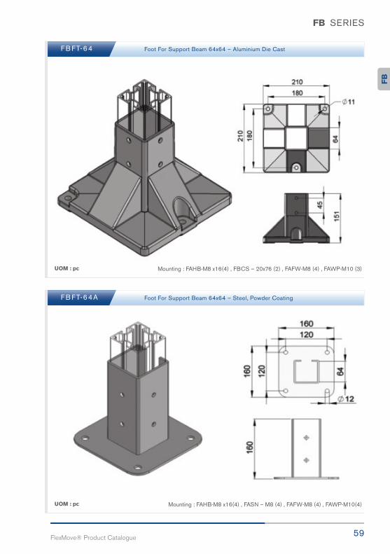
FB SERIES
FB FT-64
FB FT-64A
Foot For Support Beam 64x64 – Aluminium Die Cast
Foot For Support Beam 64x64 – Steel, Powder Coating
UOM : pc
UOM : pc
Mounting : FAHB-M8 x16(4) , FBCS – 20x76 (2) , FAFW-M8 (4) , FAWP-M10 (3)
Mounting : FAHB-M8 x16(4) , FASN – M8 (4) , FAFW-M8 (4) , FAWP-M10(4)
FB

60FlexMove reserves the right to make alteration without prior notification Every care has been taken to ensure the accuracy of the
information contained in this catalogue but no liability can be accepted for any error or omissions.
FB SERIES
FB FT-64B
FB CS-20x76
Foot For Support Beam 64x64 – Aluminium
Connecting Strip For Foot – Steel, Electro Zinc Plated
UOM : pc
UOM : 10pcs / pk
Mounting : FACS-M6 x 20 (4) , FAWP-M10 (4)

61FlexMove® Product Catalogue
FB SERIES
FB CS-20x96 Connecting Strip For Foot 80x80mm– Steel, Electro Zinc Plated
UOM : pc
FB

62FlexMove reserves the right to make alteration without prior notification Every care has been taken to ensure the accuracy of the
information contained in this catalogue but no liability can be accepted for any error or omissions.
FB SERIES
FB FT-64TP
FB FT-64B P
Tripod Foot For FBSB-64x64 - Polyamide , Glass Fiber reinforced
Bipod Foot For FBSB-64x64 - Polyamide , Glass Fiber reinforced
Plastic Pad, screws and clamps included
Plastic Pad, screws and clamps included
UOM : pc
UOM : pc
63FlexMove® Product Catalogue
FB SERIES
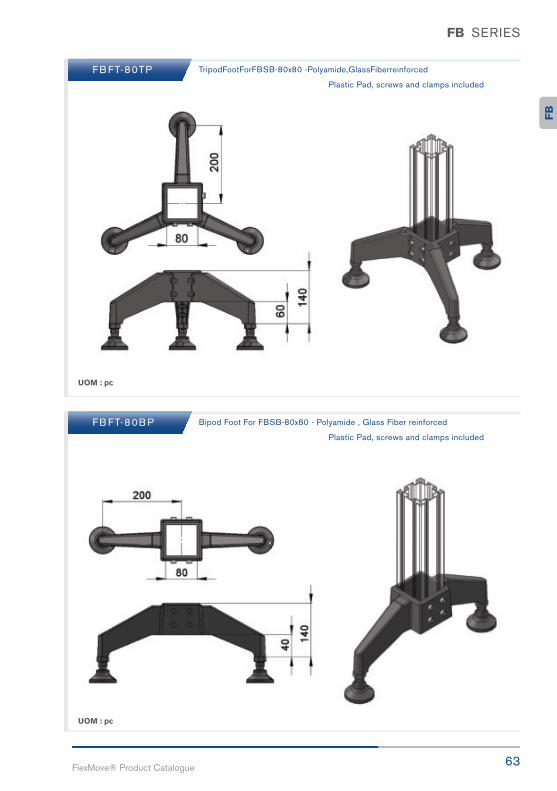
FB FT-80TP
FB FT-80B P
TripodFootForFBSB-80x80 -Polyamide,GlassFiberreinforced
Bipod Foot For FBSB-80x80 - Polyamide , Glass Fiber reinforced
Plastic Pad, screws and clamps included
Plastic Pad, screws and clamps included
UOM : pc
UOM : pc
FB
64FlexMove reserves the right to make alteration without prior notification Every care has been taken to ensure the accuracy of the
information contained in this catalogue but no liability can be accepted for any error or omissions.
FB SERIES
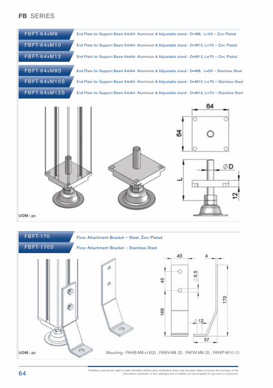
FB FT-64xM8
FB FT-64xM10
FB FT-64xM12
FB FT-64xM8S
FB FT-64xM10S
FB FT-64xM12S
FB FT-170
FB FT-170S
End Plate for Support Beam 64x64- Aluminium & Adjustable stand - D=M8, L=50 – Zinc Plated
End Plate for Support Beam 64x64- Aluminium & Adjustable stand - D=M10, L=75 – Zinc Plated
End Plate for Support Beam 64x64- Aluminium & Adjustable stand - D=M12, L=75 – Zinc Plated
End Plate for Support Beam 64x64- Aluminium & Adjustable stand - D=M8, L=50 – Stainless Steel
End Plate for Support Beam 64x64- Aluminium & Adjustable stand - D=M10, L=75 – Stainless Steel
End Plate for Support Beam 64x64- Aluminium & Adjustable stand - D=M12, L=75 – Stainless Steel
Floor Attachment Bracket – Steel, Zinc Plated
Floor Attachment Bracket – Stainless Steel
UOM : pc
UOM : pc Mounting : FAHB-M8 x16(2) , FASN-M8 (2) , FAFW-M8 (3) , FAWP-M10 (1)

65FlexMove® Product Catalogue
FB SERIES
FB FT-80A
FB FT-80B
Foot For Support Beam 80x80 – Steel, Powder Coating
Foot For Support Beam 80x80 – Steel, Powder Coating
UOM : pc
UOM : pc
Mounting : FAHB-M8 x16(4) , FASN-M8 (4) , FAFW-M8 (4) , FAWP-M10 (4)
Mounting : FAHB-M8 x16(8) , FBCS – 20 x 96 (4), FAFW-M8 (8) , FAWP-M10(4)
FB
66FlexMove reserves the right to make alteration without prior notification Every care has been taken to ensure the accuracy of the
information contained in this catalogue but no liability can be accepted for any error or omissions.
FB SERIES
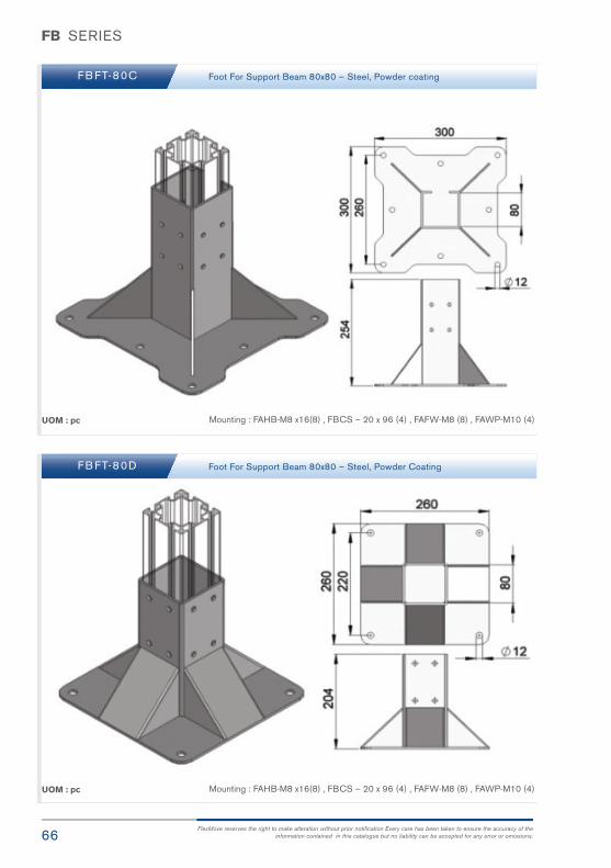
FB FT-80C
FB FT-80D
Foot For Support Beam 80x80 – Steel, Powder coating
Foot For Support Beam 80x80 – Steel, Powder Coating
UOM : pc
UOM : pc
Mounting : FAHB-M8 x16(8) , FBCS – 20 x 96 (4) , FAFW-M8 (8) , FAWP-M10 (4)
Mounting : FAHB-M8 x16(8) , FBCS – 20 x 96 (4) , FAFW-M8 (8) , FAWP-M10 (4)

67FlexMove® Product Catalogue
FB SERIES
FB CP-40T
FB CP-40L
T Connecting Plate for Support Beam 40x40- Steel, Zinc Plated
L Connecting Plate for Support Beam 40x40- Steel, Zinc Plated
UOM : pc
UOM : pc
Mounting : FAHB-M8 x16(4) , FASN-M8 (4) , FAFW-M8 (4)
Mounting : FAHB-M8 x16(4) , FASN-M8 (4) , FAFW-M8 (4)
FB

68FlexMove reserves the right to make alteration without prior notification Every care has been taken to ensure the accuracy of the
information contained in this catalogue but no liability can be accepted for any error or omissions.
FB SERIES
FB CP-64T
FB CP-64L
T connecting Plate for Support Beam 64x64 – Steel, Zinc Plated
L Connecting Plate for Support Beam 64x64- Steel, Zinc Plated
UOM : pc
UOM : pc
Mounting : FAHB-M8 x16(4) , FASN-M8 (4) , FAFW-M8 (4)
Mounting : FAHB-M8 x16(4) , FASN-M8 (4) , FAFW-M8 (4)

69FlexMove® Product Catalogue
FB SERIES
FB CP-80T
FB CP-80L
T connecting Plate for Support Beam 80x80 – Steel, Zinc Plated
L Connecting Plate for Support Beam 80x80- Steel, Zinc Plated
UOM : pc
UOM : pc
Mounting : FAHB-M8 x16(8) , FASN-M8 (8) , FAFW-M8 (8)
Mounting : FAHB-M8 x16(8) , FASN-M8 (8) , FAFW-M8 (8)
FB

70FlexMove reserves the right to make alteration without prior notification Every care has been taken to ensure the accuracy of the
information contained in this catalogue but no liability can be accepted for any error or omissions.
FB SERIES
FB CP-40V
FB CP-64V
FB CP-80V
45 ° connecting Plate for Support Beam 40x40 – Steel, Zinc Plated
45 ° connecting Plate for Support Beam 64x64 – Steel, Zinc Plated
45 ° connecting Plate for Support Beam 80x80 – Steel, Zinc Plated
UOM : pc
UOM : pc
UOM : pc
Mounting : FAHB-M8 x16(4) , FASN-M8 (4) , FAFW-M8 (4)
Mounting : FAHB-M8 x16(4) , FASN-M8 (4) , FAFW-M8 (4)
Mounting : FAHB-M8 x16(8) , FASN-M8 (8) , FAFW-M8 (8)

71FlexMove® Product Catalogue
FB SERIES
FB RX-20A
FB RX-20B
FB RX-20C
90° Inner Joint Strip – Steel, Zinc Plated
90° Outer Joint Strip – Steel, Zinc Plated
90° Inner Joint Strip – Steel, Zinc Plated
UOM : 10 pcs / pk
UOM : 10 pcs / pk
UOM : 10 pcs / pk
FB

72FlexMove reserves the right to make alteration without prior notification Every care has been taken to ensure the accuracy of the
information contained in this catalogue but no liability can be accepted for any error or omissions.
FB SERIES
FBAB-32x40
FBAB-32x60
FBAB-32x80
Angle Bracket for Support Beam 40x40 - Aluminium
Angle Bracket for Support Beam 64x64 - Aluminium
Angle Bracket for Support Beam 80x80 - Aluminium
UOM : pc
UOM : pc
UOM : pc
Mounting : FAHB-M8 x20(2) , FASN-M8 (2) , FAFW-M8 (2)
Mounting : FAHB-M8 x20 (2) , FASN-M8 (2) , FAFW-M8 (2)
Mounting : FAHB-M8 x20 (4) , FASN-M8 (4) , FAFW-M8 (4)

73FlexMove® Product Catalogue
FB SERIES
FBAB-40L
FBAB-60L
Angle Bracket for Support Beam 40x40 - Aluminium
Angle Bracket for Support Beam 64x64 - Aluminium
UOM : pc
UOM : pc
Mounting : FAHB-M8 x 16 (4) , FASN-M8 (4) , FAFW-M8 (4)
Mounting : FAHB-M8 x 16 (4) , FASN-M8 (4) , FAFW-M8 (4)
FB

74FlexMove reserves the right to make alteration without prior notification Every care has been taken to ensure the accuracy of the
information contained in this catalogue but no liability can be accepted for any error or omissions.
FB SERIES
FBAB-80L
FBAB-40x80A
Angle Bracket for Support Beam 80x80 - Aluminium
Angle Bracket for Support Beam 40x40, 64x64, 40x80 - Aluminium Die Cast
UOM : pc
UOM : pc
Mounting : FAHB-M8 x 16 (6) , FASN-M8 (6) , FAFW-M8 (6)
Mounting : FAHB-M8 x 20 (4) , FASN-M8 (4) , FAFW-M8 (4)
75FlexMove® Product Catalogue
Conveyor Support Structure
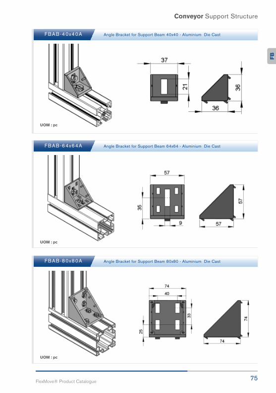
FBAB-40x40A
FBAB-64x64A
FBAB-80x80A
Angle Bracket for Support Beam 40x40 - Aluminium Die Cast
Angle Bracket for Support Beam 64x64 - Aluminium Die Cast
Angle Bracket for Support Beam 80x80 - Aluminium Die Cast
UOM : pc
UOM : pc
UOM : pc
FB

76FlexMove reserves the right to make alteration without prior notification Every care has been taken to ensure the accuracy of the
information contained in this catalogue but no liability can be accepted for any error or omissions.
FB SERIES
FB EC-40x40A
FB EC-64x64A
FB EC-80x80A
End Cap for FBAB-40x40A angle bracket - Polyamide
End Cap for FBAB-64x64A angle bracket - Polyamide
End Cap for FBAB-80x80A angle bracket - Polyamide
UOM : pc
UOM : pc
UOM : pc

77FlexMove® Product Catalogue
FB SERIES
Single Support Structure with enclosure beam FK, FS, FM, FC
Double Lane Support Structure FK, FS, FM, FC, FL
FB

78FlexMove reserves the right to make alteration without prior notification Every care has been taken to ensure the accuracy of the
information contained in this catalogue but no liability can be accepted for any error or omissions.
Conveyor Support Structure
Single Support Structure FL
Alpine Support Structure FK, FS, FM, FC, FL

79FlexMove® Product Catalogue
Conveyor Support Structure
Double Support Structure FK, FS, FM, FC
Multi Lane Support Structure FK, FS, FM, FC, FL
FB

80FlexMove reserves the right to make alteration without prior notification Every care has been taken to ensure the accuracy of the
information contained in this catalogue but no liability can be accepted for any error or omissions.
Conveyor Support Structure
Double Support Structure FK, FS, FM, FC
Multi Lane Double Layer Support Structure FK, FS, FM, FC, FL
81FlexMove® Product Catalogue
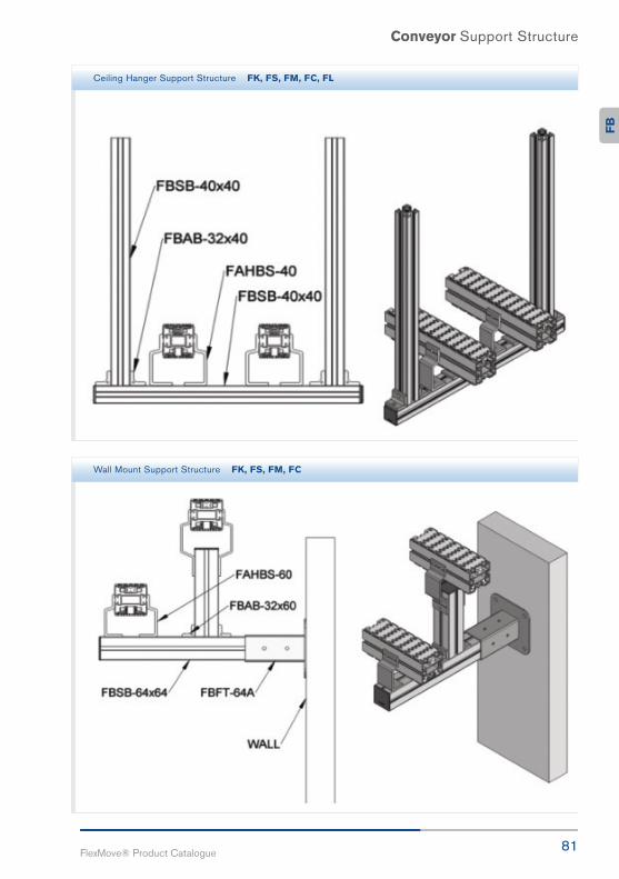
Conveyor Support Structure
Ceiling Hanger Support Structure FK, FS, FM, FC, FL
Wall Mount Support Structure FK, FS, FM, FC
FB
High Speed
Balancing
Multi Lane
Optimize

FGConveyorGuide Rail
83FlexMove® Product Catalogue
FG

84 FlexMove reserves the right to make alteration without prior notification Every care has been taken to ensure the accuracy of theinformation contained in this catalogue but no liability can be accepted for any error or omissions.
FG SERIES
FG DT-70
FG DT-80
FG DT-100
FG DT-150
FG DT-200
FG DT-250
FGG R-18X100
FGG R-18X150
FGG R-18X200
FGG R-18X250
FGG R-18X300
Distance Tube, L = 70mm - Aluminium
Distance Tube, L = 80mm - Aluminium
Distance Tube, L = 100mm - Aluminium
Distance Tube, L = 150mm - Aluminium
Distance Tube, L = 200mm - Aluminium
Distance Tube, L = 250mm - Aluminium
18mm Tube, L = 100mm - Aluminium
18mm Tube, L = 150mm - Aluminium
18mm Tube, L = 200mm - Aluminium
18mm Tube, L = 250mm - Aluminium
18mm Tube, L = 300mm - Aluminium
UOM : 10 pcs / pk
UOM : 10 pcs / pk
UOM : 10 pcs / pk UOM : 10 pcs / pk
F G E C - 1 8 F G E C - 2 0End cap. 18mm Tube - Polyamide End cap , Distance Tube - Polyamide
85FlexMove® Product Catalogue
FG SERIES
UOM: 50pcs / pk
UOM : 10 pcs / pk
UOM : 10 pcs / pk
UOM : 10 pcs / pk
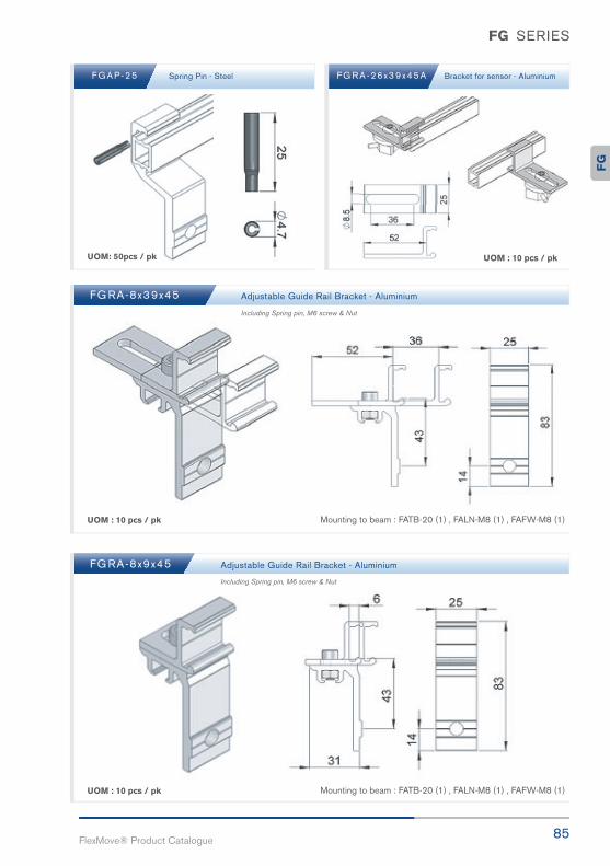
F G A P - 2 5 F G R A - 2 6 x 3 9 x 4 5 ASpring Pin - Steel Bracket for sensor - Aluminium
FG RA-8x39x45
FG RA-8x9x45
Adjustable Guide Rail Bracket - Aluminium
Adjustable Guide Rail Bracket - Aluminium
Mounting to beam : FATB-20 (1) , FALN-M8 (1) , FAFW-M8 (1)
Including Spring pin, M6 screw & Nut
Including Spring pin, M6 screw & Nut
Mounting to beam : FATB-20 (1) , FALN-M8 (1) , FAFW-M8 (1)
FG

86FlexMove reserves the right to make alteration without prior notification Every care has been taken to ensure the accuracy of the
information contained in this catalogue but no liability can be accepted for any error or omissions.
FG SERIES
UOM : 10 pcs / pk
UOM : 10 pcs / pk
UOM : 10 pcs / pk
FG RA-26x39x45
FG RA-26x9x45
FG R B-16x54
Adjustable Guide Rail Bracket - Aluminium
Adjustable Guide Rail Bracket - Aluminium
Fixed Guide Rail Bracket - Aluminium
Mounting to beam : FATB-20 (1) , FALN-M8 (1) , FAFW-M8 (1)
Mounting to beam : FATB-20 (1) , FALN-M8 (1) , FAFW-M8 (1)
Mounting to beam : FATB-20 (1) , FALN-M8 (1) , FAFW-M8 (1)
Including Spring pin, M8 screw & nut
Including Spring pin, M8 screw & nut
Including Spring pin.
87FlexMove® Product Catalogue
FG SERIES
UOM : 10 pcs / pk
UOM : 10 pcs / pk
UOM : 10 pcs / pk
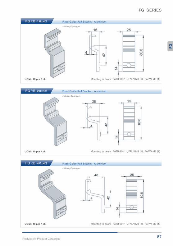
FG R B-16x42
FG R B-28x42
FG R B-40x42
Fixed Guide Rail Bracket - Aluminium
Fixed Guide Rail Bracket - Aluminium
Fixed Guide Rail Bracket - Aluminium
Mounting to beam : FATB-20 (1) , FALN-M8 (1) , FAFW-M8 (1)
Mounting to beam : FATB-20 (1) , FALN-M8 (1) , FAFW-M8 (1)
Mounting to beam : FATB-20 (1) , FALN-M8 (1) , FAFW-M8 (1)
Including Spring pin.
Including Spring pin.
Including Spring pin.F
G

88FlexMove reserves the right to make alteration without prior notification Every care has been taken to ensure the accuracy of the
information contained in this catalogue but no liability can be accepted for any error or omissions.
FG SERIES
UOM : 10 pcs / pk
UOM : 10 pcs / pk
UOM : 10 pcs / pk
FG R B-49x42
FG R B-53x42
FG R B-90x42
Fixed Guide Rail Bracket - Aluminium
Fixed Guide Rail Bracket - Aluminium
Fixed Guide Rail Bracket - Aluminium
Mounting to beam : FATB-20 (1) , FALN-M8 (1) , FAFW-M8 (1)
Mounting to beam : FATB-20 (1) , FALN-M8 (1) , FAFW-M8 (1)
Mounting to beam : FATB-20 (1) , FALN-M8 (1) , FAFW-M8 (1)
Including Spring pin.
Including Spring pin.
Including Spring pin.
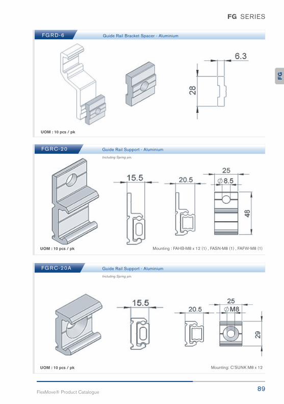
89FlexMove® Product Catalogue
FG SERIES
UOM : 10 pcs / pk
UOM : 10 pcs / pk
UOM : 10 pcs / pk
FG R D-6
FG RC-20
FG RC-20A
Guide Rail Bracket Spacer - Aluminium
Guide Rail Support - Aluminium
Guide Rail Support - Aluminium
Mounting : FAHB-M8 x 12 (1) , FASN-M8 (1) , FAFW-M8 (1)
Mounting: C’SUNK M8 x 12
Including Spring pin.
Including Spring pin.F
G

90FlexMove reserves the right to make alteration without prior notification Every care has been taken to ensure the accuracy of the
information contained in this catalogue but no liability can be accepted for any error or omissions.
FG SERIES
UOM : 10pcs / pk
UOM : 10pcs / pk
FG R B-16x42C
FG R B-16x52C
Guide Rall Bracket - Polymide
Guide Rall Bracket - Polymide
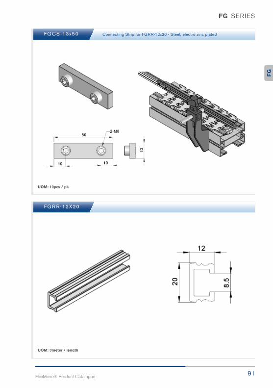
91FlexMove® Product Catalogue
FG SERIES
UOM: 10pcs / pk
UOM: 3meter / length
FGCS-13x50
FG R R-12X20
Connecting Strip for FGRR-12x20 - Steel, electro zinc plated
FG
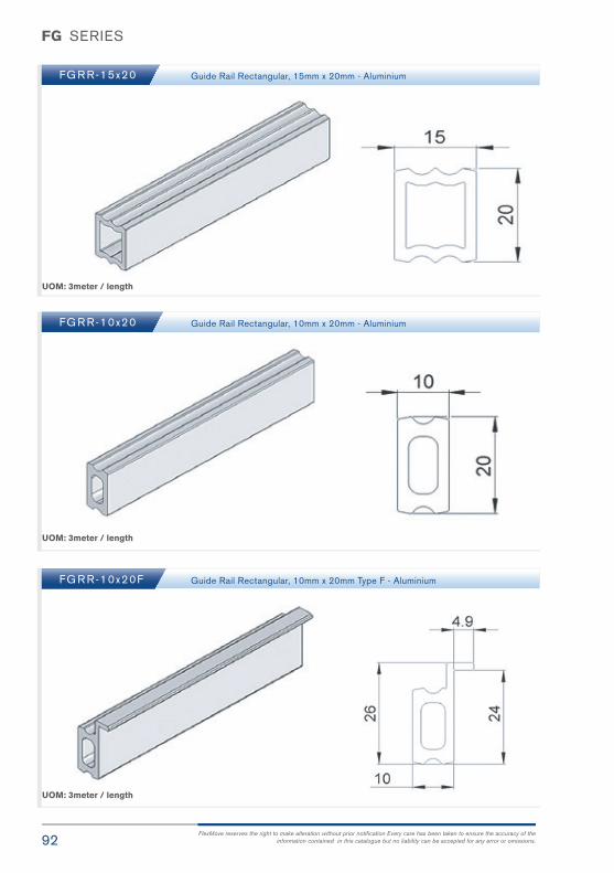
92FlexMove reserves the right to make alteration without prior notification Every care has been taken to ensure the accuracy of the
information contained in this catalogue but no liability can be accepted for any error or omissions.
FG SERIES
UOM: 3meter / length
UOM: 3meter / length
UOM: 3meter / length
FG R R-15x20
FG R R-10x20
FG R R-10x20F
Guide Rail Rectangular, 15mm x 20mm - Aluminium
Guide Rail Rectangular, 10mm x 20mm - Aluminium
Guide Rail Rectangular, 10mm x 20mm Type F - Aluminium

93FlexMove® Product Catalogue
FG SERIES
UOM: 3meter / length
UOM: 3meter / length
UOM: 3meter / length
FG R R-15X20P
FG RT-3x33
Guide Rail Rectangular, 15mm x 20mm – HDPE
Guide Rail Cover - HDPE
FG RT-3x23
FG RT-3x23A
Guide Rail Cover - HDPE
Guide Rail Cover – HDPE ( Conductive )
FG

94FlexMove reserves the right to make alteration without prior notification Every care has been taken to ensure the accuracy of the
information contained in this catalogue but no liability can be accepted for any error or omissions.
FG SERIES
UOM: 3meter / length
UOM: 3meter / length
UOM: 10pcs / pk
FG RT-3x50
FG R R-15x40
FG EC-15x40
Guide Rail Cover - HDPE
Guide Rail Rectangular, 15mm x 40mm – Aluminium
End Cap for FGRR-15x40 - Polyamide

95FlexMove® Product Catalogue
FG SERIES
UOM: 3meter / length
UOM: 10pcs / pk
UOM: 10pcs / pk
FGVG-3
FG EC-15x20
Special V Guide - Aluminium
End Cap for FGRR-15x20 - Polyamide
FG RC-100
FG RC-60
Rail Connecting – Aluminium L = 100mm , B = 50mm
Rail Connecting – Aluminium L = 60mm , B = 30mm F
G

96FlexMove reserves the right to make alteration without prior notification Every care has been taken to ensure the accuracy of the
information contained in this catalogue but no liability can be accepted for any error or omissions.
FG SERIES
UOM: 10pcs / pk
UOM: 10pcs / pk
UOM: 10pcs / pk
FG EC-10x20
FG RT-15x20
FG RJ-10x20
End Cap for FGRR-10x20 & FGRR10x20F - Polyamide
Connecting Plug for FGRR-15x20 - Polyamide
Connecting Plug for FGRR-10x20 & FGRR-10x20F - Polyamide

97FlexMove® Product Catalogue
FG SERIES
UOM: 3meter / length
UOM: 10pcs / pk
UOM: 3meter / length
FG EC-30D
FG R S-18
FG R S-15x20
30° End Cap for FGRR-15x20 - Polyamide
Guide Rail Support - Polyamide
Guide Rail Support - Polyamide
FG

98FlexMove reserves the right to make alteration without prior notification Every care has been taken to ensure the accuracy of the
information contained in this catalogue but no liability can be accepted for any error or omissions.
FG SERIES
UOM: 10pcs / pk
UOM: 10pcs / pk
FG R S-18F Guide Rail Support - Polyamide
FG R L-18x110C
FG R L-18x160C
Guide Rail Support, L = 110mm - Polyamide
Guide Rail Support, L = 160mm - Polyamide
To be used directly with guide rail bracket support FGRF- 42 x 18V or FGRB-18 x 20

99FlexMove® Product Catalogue
FG SERIES
UOM: 10pcs / pk Suitable for use with cross connector FGRB-18 x18 and FGRF – 42 x 18V
FG RC-18x110C
FG RC-18x160C
Double Guide Rail Support, L = 110mm - Polyamide
Double Guide Rail Support, L = 160mm - Polyamide
UOM: 10pcs / pkSuitable for use with cross connector FGRB-18 x18 and a crossing
18 mm aluminum tube above the double track.
FG R K-18x40A
FG R K-18x60A
FG R K-18x80A
FG R K-18x130A
Guide Rail Support, L = 40mm - Polyamide
Guide Rail Support, L = 60mm - Polyamide
Guide Rail Support, L = 80mm - Polyamide
Guide Rail Support, L = 130mm - Polyamide
FG

100FlexMove reserves the right to make alteration without prior notification Every care has been taken to ensure the accuracy of the
information contained in this catalogue but no liability can be accepted for any error or omissions.
FG SERIES
FG R L-18x110CA
FG R L-18x160CA
Guide Rail Support, L = 110mm - Polyamide
Guide Rail Support, L = 160mm - Polyamide
UOM: 10pcs / pk Suitable for use with cross connector FGRK – 18 x 80 / 130 / 40A / 60A / 80A /130A

101FlexMove® Product Catalogue
FG SERIES
FGRF-42x18V Guide Rail Bracket – Polyamide
UOM: 10pcs / pk
To be used with :
- FGGR - 18 x * 100 - FGRL - 18 x 110C / 160C - FGRC - 18 x 110C / 160C
For use with guide rail bracket support FGRF -42 x 18V
Spacer for FGRF-42x18V - Polyamide Spacer for FGRF-42x18V - Polyamide Spacer for FGRF-42x18V - Polyamide
FGRD-18A FGRD-6A FGRD-6C
UOM: 10pcs / pk UOM: 10pcs / pk UOM: 10pcs / pk
FG

FG SERIES
FGRF-A35
FGRF-A110
FGRF-DP
Guide Rail Bracket A35 – Polyamide
Guide Rail Bracket A110 – Polyamide
FGRF Dummy Plug
UOM: 10pcs / pk
UOM: 10pcs / pk
To be used with guide rail support . For 1-2 guide rail levels.
To be used with guide rail support . For 1-4 guide rail levels.
UOM: 10pcs / pk
102FlexMove reserves the right to make alteration without prior notification Every care has been taken to ensure the accuracy of the
information contained in this catalogue but no liability can be accepted for any error or omissions.

103FlexMove® Product Catalogue
FG SERIES
FGRB-40x18 Guide Rail Bracket, D = 18mm - Polyamide
FGRB-40x20 Guide Rail Bracket, D = 20mm - Polyamide
UOM: 10pcs / pk
FG

FG SERIES
FGRB-40x15x20 Guide Rail Bracket - Polyamide
UOM: 10pcs / pk
104FlexMove reserves the right to make alteration without prior notification Every care has been taken to ensure the accuracy of the
information contained in this catalogue but no liability can be accepted for any error or omissions.

105FlexMove® Product Catalogue
FG SERIES
FGRB-6B Spacer for FGRB-40x ## - Polyamide
UOM: 10pcs / pk
For use with guide rail bracket support:
FGRB – 40 x 18 / 20
FGRB – 40 x 15 x 20
FG

FG SERIES
UOM: 10pcs / pk
106FlexMove reserves the right to make alteration without prior notification Every care has been taken to ensure the accuracy of the
information contained in this catalogue but no liability can be accepted for any error or omissions.
FGRB-18x18 Guide Rail Bracket, ØA = 18mm, ØB = 18mm - Polyamide
FGRB-18x20 Guide Rail Bracket, ØA = 18mm, ØB = 20mm - Polyamide
FGRB-20x20 Guide Rail Bracket, ØA = 20mm, ØB = 20mm - Polyamide
FGRB-18x20T Guide Rail Bracket, ØA = 18mm - Polyamide
FGRB-20x20T Guide Rail Bracket, ØA = 20mm - Polyamide
UOM: 10pcs / pk

107FlexMove® Product Catalogue
FG SERIES
UOM: 10pcs / pk
FGRX-18x20 90° Corner Connector - Polyamide
FGRX-18x18 90° Corner Connector, ØA = 18mm, ØB = 18mm - Polyamide
FGRX-20x20 90° Corner Connector, ØA = 20mm, ØB = 20mm - Polyamide
UOM: 10pcs / pk
UOM: 10pcs / pk
FGRX-15x20 90° Corner Connector - Polyamide
For use with : FGGR – 18 x 100 / 150 / 200 / 250 / 300 FGDT – 70 / 80 / 100 / 150 / 200 / 250
For use with : FGGR – 18 x 100 / 150 / 200 / 250 / 300 FGDT – 70 / 80 / 100 / 150 / 200 / 250
For use with : FGRR – 15 x 20 / 20 P
FG

FG SERIES
108FlexMove reserves the right to make alteration without prior notification Every care has been taken to ensure the accuracy of the
information contained in this catalogue but no liability can be accepted for any error or omissions.
FGSP-DT Distance Tube Spacer - POM
FGRB-16x54 Fixed Guide Rail Assembly
UOM: 10pcs / pk
Guide RailBracket
FGRB-16X54
FGRB-16X54
FGRB-16X54
FGRB-16X54
FGRB-16X54
Series D (mm) H (mm)W (mm)
B = 0W (mm)B = 6.3
W (mm)B = 12.6
W (mm)B = 18.9
FK
FS
FM
FC
FL
45
65
85
105
150
26
26
20
20
20
41.7
61.7
81.7
101.7
146.7
54.3
74.3
94.3
114.3
159.3
66.9
86.9
106.9
126.9
171.9
79.5
99.5
119.5
139.5
184.5
B Spacer = FGRD-6

109FlexMove® Product Catalogue
FG SERIES
Guide RailBracket
FGRB-16X42
FGRB-16X42
FGRB-16X42
FGRB-16X42
FGRB-16X42
Series D (mm) H (mm)W (mm)
B = 0W (mm)B = 6.3
W (mm)B = 12.6
W (mm)B = 18.9
FK
FS
FM
FC
FL
45
65
85
105
150
14
14
8
8
8
41.7
61.7
-
-
-
54.3
74.3
94.3
114.3
159.3
66.9
86.9
106.9
126.9
171.9
79.5
99.5
119.5
139.5
184.5
Guide RailBracket
FGRB-28X42
FGRB-28X42
FGRB-28X42
FGRB-28X42
FGRB-28X42
Series D (mm) H (mm)W (mm)
B = 0W (mm)B = 6.3
W (mm)B = 12.6
W (mm)B = 18.9
FK
FS
FM
FC
FL
45
65
85
105
150
14
14
8
8
8
65.8
85.8
105.8
125.8
170.8
78.4
98.4
118.4
138.4
183.4
91
111
131
151
196
103.6
123.6
143.6
163.6
208.6
B Spacer = FGRD-6
B Spacer = FGRD-6
FGRB-28x42 Fixed Guide Rail Assembly
FGRB-16x42 Fixed Guide Rail Assembly
FG

FG SERIES
110FlexMove reserves the right to make alteration without prior notification Every care has been taken to ensure the accuracy of the
information contained in this catalogue but no liability can be accepted for any error or omissions.
FGRB-40x42 Fixed Guide Rail Assembly
FGRB-49x42 Fixed Guide Rail Assembly
B Spacer = FGRD-6
B Spacer = FGRD-6
Guide RailBracket
FGRB-40X42
FGRB-40X42
FGRB-40X42
FGRB-40X42
FGRB-40X42
Series D (mm) H (mm)W (mm)
B = 0W (mm)B = 6.3
W (mm)B = 12.6
W (mm)B = 18.9
FK
FS
FM
FC
FL
45
65
85
105
150
14
14
8
8
8
90.6
110.6
130.6
150.6
195.6
103.2
123.2
143.2
163.2
163.2
115.8
135.8
155.8
175.8
220.8
128.4
148.4
168.4
188.4
233.4
Guide RailBracket
FGRB-49X42
FGRB-49X42
FGRB-49X42
FGRB-49X42
FGRB-49X42
Series D (mm) H (mm)W (mm)
B = 0W (mm)B = 6.3
W (mm)B = 12.6
W (mm)B = 18.9
FK
FS
FM
FC
FL
45
65
85
105
150
14
14
8
8
8
107.8
127.8
147.8
167.8
212.8
120.4
140.4
160.4
180.4
225.4
133
153
173
193
238
145.6
165.6
185.6
205.6
250.6
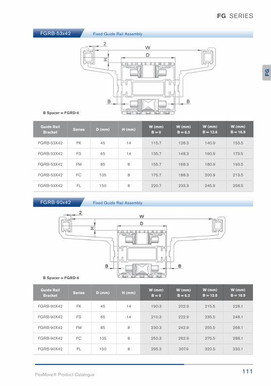
111FlexMove® Product Catalogue
FG SERIES
B Spacer = FGRD-6
B Spacer = FGRD-6
FGRB-90x42 Fixed Guide Rail Assembly
FGRB-53x42 Fixed Guide Rail Assembly
Guide RailBracket
FGRB-53X42
FGRB-53X42
FGRB-53X42
FGRB-53X42
FGRB-53X42
Series D (mm) H (mm)W (mm)
B = 0W (mm)B = 6.3
W (mm)B = 12.6
W (mm)B = 18.9
FK
FS
FM
FC
FL
45
65
85
105
150
14
14
8
8
8
115.7
135.7
155.7
175.7
220.7
128.3
148.3
168.3
188.3
233.3
140.9
160.9
180.9
200.9
245.9
153.5
173.5
193.5
213.5
258.5
Guide RailBracket
FGRB-90X42
FGRB-90X42
FGRB-90X42
FGRB-90X42
FGRB-90X42
Series D (mm) H (mm)W (mm)
B = 0W (mm)B = 6.3
W (mm)B = 12.6
W (mm)B = 18.9
FK
FS
FM
FC
FL
45
65
85
105
150
14
14
8
8
8
190.3
210.3
230.3
250.3
295.3
202.9
222.9
242.9
262.9
307.9
215.5
235.5
255.5
275.5
320.5
228.1
248.1
268.1
288.1
333.1
FG

FG SERIES
112FlexMove reserves the right to make alteration without prior notification Every care has been taken to ensure the accuracy of the
information contained in this catalogue but no liability can be accepted for any error or omissions.
FGRB Mixed Guide Rail Mixed Guide Rail Assembly
Guide RailBkt Left
FGRB-28X42
FGRB-28X42
FGRB-28X42
FGRB-28X42
FGRB-28X42
FGRB-28X42
FGRB-28X42
FGRB-28X42
FGRB-28X42
FGRB-28X42
FGRB-28X42
FGRB-28X42
FGRB-28X42
FGRB-28X42
FGRB-28X42
FGRB-28X42
FGRB-28X42
FGRB-28X42
FGRB-28X42
FGRB-28X42
FGRB-40X42
FGRB-40X42
FGRB-53X42
FGRB-90X42
FGRB-40X42
FGRB-40X42
FGRB-53X42
FGRB-90X42
FGRB-40X42
FGRB-40X42
FGRB-53X42
FGRB-90X42
FGRB-40X42
FGRB-40X42
FGRB-53X42
FGRB-90X42
FGRB-40X42
FGRB-40X42
FGRB-53X42
FGRB-90X42
10.4
10.4
10.4
10.4
10.4
10.4
10.4
10.4
10.4
10.4
10.4
10.4
10.4
10.4
10.4
10.4
10.4
10.4
10.4
10.4
22.8
31.4
35.3
72.4
22.8
31.4
35.3
72.4
22.8
31.4
35.3
72.4
22.8
31.4
35.3
72.4
22.8
31.4
35.3
72.4
45
45
45
45
65
65
65
65
85
85
85
85
105
105
105
105
150
150
150
150
14
14
14
14
14
14
14
14
8
8
8
8
8
8
8
8
8
8
8
8
FK
FK
FK
FK
FS
FS
FS
FS
FM
FM
FM
FM
FC
FC
FC
FC
FL
FL
FL
FL
78.2
86.8
90.7
127.8
98.2
106.8
110.7
147.8
118.2
126.8
130.7
167.8
138.2
146.8
150.7
187.8
183.2
191.8
195.7
232.8
C1(mm)
Guide Rail BktRight
C2(mm)
SeriesD
(mm)H
(mm)W (mm)
D + C1 + C2

113FlexMove® Product Catalogue
FG SERIES
B Spacer = FGRD-6
B Spacer = FGRD-6
FGRA-26x39x45 Adjustable Guide Rail Assembly
FGRA-8x39x45 Adjustable Guide Rail Assembly
Guide RailBracket
Guide RailBracket
FGRA-8x39x45
FGRA-8x39x45
FGRA-8x39x45
FGRA-8x39x45
FGRA-8x39x45
Series
Series
D (mm)
D (mm)
H (mm)
H (mm)
W (mm) min B = 0
W (mm) min B = 12.6
W (mm) maxB = 0
W (mm) maxB = 12.6
W (mm) minB = 6.3
W (mm) minB = 18.9
W (mm) maxB = 6.3
W (mm) maxB = 18.9
FK
FS
FM
FC
FL
45
65
85
105
150
17
17
11
11
11
0
0
86
106
156
12.2
32.2
90
110
155
0
0
86
106
156
24.8
44.8
102.6
122.6
167.6
Guide RailBracket
FGRA-26x39x45
FGRA-26x39x45
FGRA-26x39x45
FGRA-26x39x45
FGRA-26x39x45
Series D (mm) H (mm)W (mm) min
B = 0W (mm) max
B = 0W (mm) min
B = 6.3W (mm) max
B = 6.3
FK
FS
FM
FC
FL
45
65
85
105
150
24
24
18
18
18
28.8
48.8
68.8
88.8
133.8
100.8
120.8
140.8
160.8
205.8
41.4
61.4
81.4
101.4
146.4
113.4
133.4
153.4
173.4
218.4
FG
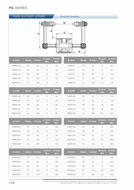
FG SERIES
114FlexMove reserves the right to make alteration without prior notification Every care has been taken to ensure the accuracy of the
information contained in this catalogue but no liability can be accepted for any error or omissions.
FGRS-18 & FGDT- & FGRR- Guide Rail Assembly
A (mm)
FGRR-100
FGRR-100
FGRR-100
FGRR-100
FGRR-100
FK
FS
FM
FC
FL
45
65
85
105
150
17
17
17
17
17
35
35
35
30
30
Series D (mm)H (mm)
MinH (mm)
Max
A (mm)
FGRR-150
FGRR-150
FGRR-150
FGRR-150
FGRR-150
FK
FS
FM
FC
FL
45
65
85
105
150
17
17
17
17
17
85
85
80
80
80
Series D (mm)H (mm)
MinH (mm)
Max
A (mm)
FGRR-200
FGRR-200
FGRR-200
FGRR-200
FGRR-200
FK
FS
FM
FC
FL
45
65
85
105
150
17
17
17
17
17
135
135
130
130
130
Series D (mm)H (mm)
MinH (mm)
Max
A (mm)
FGRR-250
FGRR-250
FGRR-250
FGRR-250
FGRR-250
FK
FS
FM
FC
FL
45
65
85
105
150
17
17
17
17
17
185
185
180
180
180
Series D (mm)H (mm)
MinH (mm)
Max
B (mm)
FGDT-70
FGDT-70
FGDT-70
FGDT-70
FGDT-70
FK
FS
FM
FC
FL
45
65
85
105
150
0
0
16
36
81
65
85
105
125
170
Series D (mm)W (mm)
MinW (mm)
Max
B (mm)
FGDT-100
FGDT-100
FGDT-100
FGDT-100
FGDT-100
FK
FS
FM
FC
FL
45
65
85
105
150
0
0
16
36
81
125
145
165
185
230
Series D (mm)W (mm)
MinW (mm)
Max
B (mm)
FGDT-150
FGDT-150
FGDT-150
FGDT-150
FGDT-150
FK
FS
FM
FC
FL
45
65
85
105
150
0
0
16
36
81
225
245
265
285
330
Series D (mm)W (mm)
MinW (mm)
Max
B (mm)
FGDT-200
FGDT-200
FGDT-200
FGDT-200
FGDT-200
FK
FS
FM
FC
FL
45
65
85
105
150
0
0
16
36
81
325
345
365
385
430
Series D (mm)W (mm)
MinW (mm)
Max

115FlexMove® Product Catalogue
FG SERIES
Guide Rail Assembly
A (mm)
FGRL-18x110C
FGRL-18x110C
FGRL-18x110C
FGRL-18x110C
FGRL-18x110C
FK
FS
FM
FC
FL
45
65
85
105
150
14
14
14
14
14
70
70
65
65
65
Series D (mm)H (mm)
MinH (mm)
Max
A (mm)
FGRL-18x160C
FGRL-18x160C
FGRL-18x160C
FGRL-18x160C
FGRL-18x160C
FK
FS
FM
FC
FL
45
65
85
105
150
14
14
14
14
14
120
120
115
115
115
Series D (mm)H (mm)
MinH (mm)
Max
B (mm)
FGDT-70
FGDT-70
FGDT-70
FGDT-70
FGDT-70
FK
FS
FM
FC
FL
45
65
85
105
150
23
43
63
83
128
110
130
150
170
215
Series D (mm)W (mm)
MinW (mm)
Max
B (mm)
FGDT-100
FGDT-100
FGDT-100
FGDT-100
FGDT-100
FK
FS
FM
FC
FL
45
65
85
105
150
23
43
63
83
128
170
190
210
230
275
Series D (mm)W (mm)
MinW (mm)
Max
B (mm)
FGDT-150
FGDT-150
FGDT-150
FGDT-150
FGDT-150
FK
FS
FM
FC
FL
45
65
85
105
150
23
43
63
83
128
270
290
310
330
375
Series D (mm)W (mm)
MinW (mm)
Max
B (mm)
FGDT-200
FGDT-200
FGDT-200
FGDT-200
FGDT-200
FK
FS
FM
FC
FL
45
65
85
105
150
23
43
63
83
128
370
390
410
430
475
Series D (mm)W (mm)
MinW (mm)
Max
FGRL-18x110C & FGDT-70
FGRL-18x110C & FGDT-100
FGRL-18x110C & FGDT-150
FGRL-18x110C & FGDT-200
FGRL-18x160C & FGDT-70
FGRL-18x160C & FGDT-100
FGRL-18x160C & FGDT-150
FGRL-18x160C & FGDT-200
FG
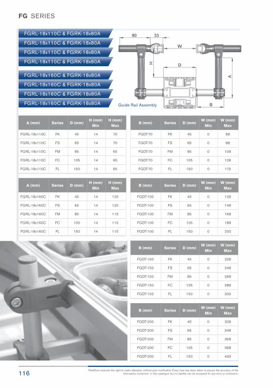
FG SERIES
116FlexMove reserves the right to make alteration without prior notification Every care has been taken to ensure the accuracy of the
information contained in this catalogue but no liability can be accepted for any error or omissions.
FGRL-18x110C & FGRK-18x80A
FGRL-18x110C & FGRK-18x80A
FGRL-18x110C & FGRK-18x80A
FGRL-18x110C & FGRK-18x80A
FGRL-18x160C & FGRK-18x80A
FGRL-18x160C & FGRK-18x80A
FGRL-18x160C & FGRK-18x80A
FGRL-18x160C & FGRK-18x80A Guide Rail Assembly
A (mm)
FGRL-18x110C
FGRL-18x110C
FGRL-18x110C
FGRL-18x110C
FGRL-18x110C
FK
FS
FM
FC
FL
45
65
85
105
150
14
14
14
14
14
70
70
65
65
65
Series D (mm)H (mm)
MinH (mm)
Max
A (mm)
FGRL-18x160C
FGRL-18x160C
FGRL-18x160C
FGRL-18x160C
FGRL-18x160C
FK
FS
FM
FC
FL
45
65
85
105
150
14
14
14
14
14
120
120
115
115
115
Series D (mm)H (mm)
MinH (mm)
Max
B (mm)
FGDT-70
FGDT-70
FGDT-70
FGDT-70
FGDT-70
FK
FS
FM
FC
FL
45
65
85
105
150
0
0
0
0
0
68
88
108
128
173
Series D (mm)W (mm)
MinW (mm)
Max
B (mm)
FGDT-100
FGDT-100
FGDT-100
FGDT-100
FGDT-100
FK
FS
FM
FC
FL
45
65
85
105
150
0
0
0
0
0
128
148
168
188
233
Series D (mm)W (mm)
MinW (mm)
Max
B (mm)
FGDT-150
FGDT-150
FGDT-150
FGDT-150
FGDT-150
FK
FS
FM
FC
FL
45
65
85
105
150
0
0
0
0
0
228
248
268
288
333
Series D (mm)W (mm)
MinW (mm)
Max
B (mm)
FGDT-200
FGDT-200
FGDT-200
FGDT-200
FGDT-200
FK
FS
FM
FC
FL
45
65
85
105
150
0
0
0
0
0
328
348
368
388
433
Series D (mm)W (mm)
MinW (mm)
Max
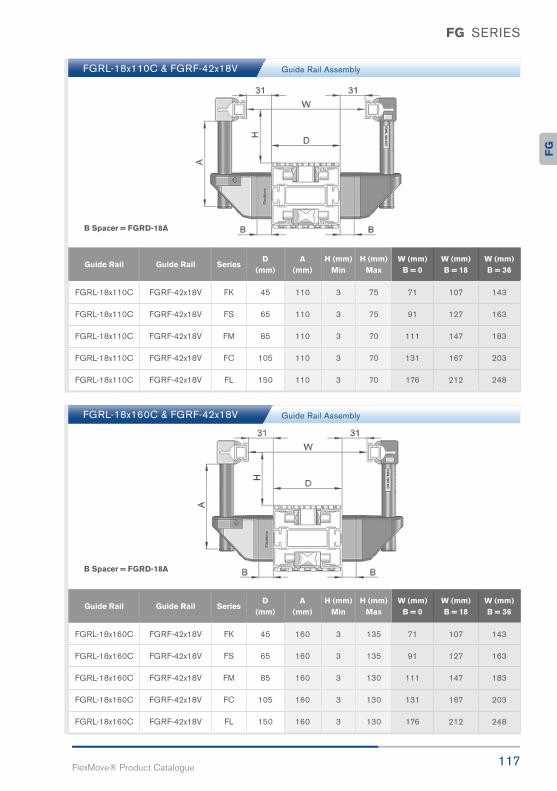
117FlexMove® Product Catalogue
FG SERIES
FGRL-18x110C & FGRF-42x18V
FGRL-18x160C & FGRF-42x18V
Guide Rail Assembly
Guide Rail Assembly
B Spacer = FGRD-18A
B Spacer = FGRD-18A
Guide Rail
FGRL-18x160C
FGRL-18x160C
FGRL-18x160C
FGRL-18x160C
FGRL-18x160C
Guide RailA
(mm)Series
D(mm)
H (mm)Min
H (mm)Max
W (mm)B = 0
W (mm) B = 18
W (mm)B = 36
FGRF-42x18V
FGRF-42x18V
FGRF-42x18V
FGRF-42x18V
FGRF-42x18V
160
160
160
160
160
FK
FS
FM
FC
FL
45
65
85
105
150
3
3
3
3
3
135
135
130
130
130
71
91
111
131
176
107
127
147
167
212
143
163
183
203
248
Guide Rail
FGRL-18x110C
FGRL-18x110C
FGRL-18x110C
FGRL-18x110C
FGRL-18x110C
Guide RailA
(mm)Series
D(mm)
H (mm)Min
H (mm)Max
W (mm)B = 0
W (mm) B = 18
W (mm)B = 36
FGRF-42x18V
FGRF-42x18V
FGRF-42x18V
FGRF-42x18V
FGRF-42x18V
110
110
110
110
110
FK
FS
FM
FC
FL
45
65
85
105
150
3
3
3
3
3
75
75
70
70
70
71
91
111
131
176
107
127
147
167
212
143
163
183
203
248
FG

FG SERIES
118FlexMove reserves the right to make alteration without prior notification Every care has been taken to ensure the accuracy of the
information contained in this catalogue but no liability can be accepted for any error or omissions.
FGRF-42x62-A110 & FGRK-18x80A
FGRF-42x62-A35 & FGRK-18x80A
Guide Rail Assembly
Guide Rail Assembly
B Spacer = FGRD-18A
B Spacer = FGRD-18A
Guide Rail
FGRF-42x62-A110
FGRF-42x62-A110
FGRF-42x62-A110
FGRF-42x62-A110
FGRF-42x62-A110
Guide RailW minB = 0
SeriesD
(mm)W minB = 18
W minB = 36
W maxB = 0
W maxB = 18
W maxB = 36
FGRK-18x80A
FGRK-18x80A
FGRK-18x80A
FGRK-18x80A
FGRK-18x80A
0
0
7
27
72
FK
FS
FM
FC
FL
45
65
85
105
150
3
23
43
63
108
39
59
79
99
144
61
81
101
121
166
97
117
137
157
202
133
153
173
193
238
Guide Rail
FGRF-42x62-A35
FGRF-42x62-A35
FGRF-42x62-A35
FGRF-42x62-A35
FGRF-42x62-A35
Guide RailW minB = 0
SeriesD
(mm)W minB = 18
W minB = 36
W maxB = 0
W maxB = 18
W maxB = 36
FGRK-18x80A
FGRK-18x80A
FGRK-18x80A
FGRK-18x80A
FGRK-18x80A
0
0
7
27
72
FK
FS
FM
FC
FL
45
65
85
105
150
3
23
43
63
108
39
59
79
99
144
61
81
101
121
166
97
117
137
157
202
133
153
173
193
238
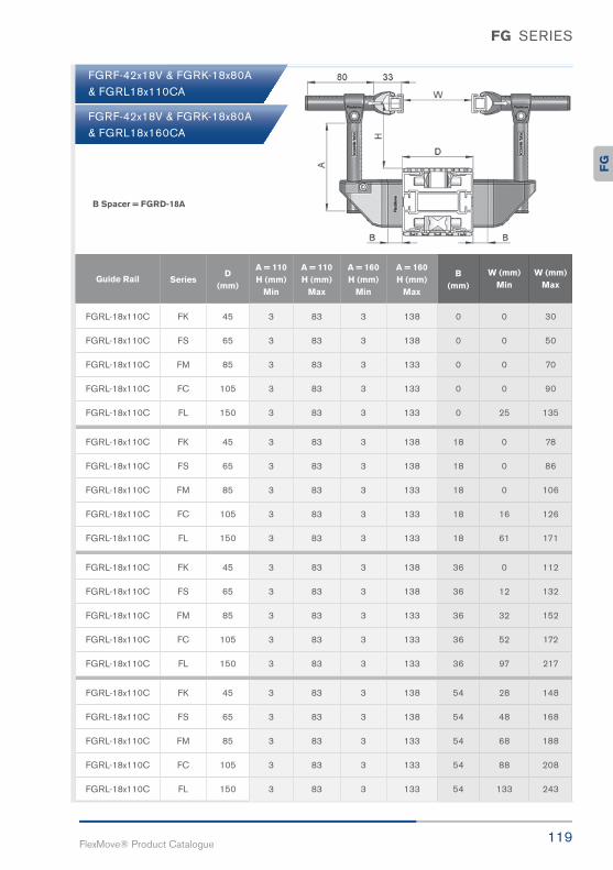
119FlexMove® Product Catalogue
FG SERIES
Guide Rail
FGRL-18x110C
FGRL-18x110C
FGRL-18x110C
FGRL-18x110C
FGRL-18x110C
FGRL-18x110C
FGRL-18x110C
FGRL-18x110C
FGRL-18x110C
FGRL-18x110C
FGRL-18x110C
FGRL-18x110C
FGRL-18x110C
FGRL-18x110C
FGRL-18x110C
FGRL-18x110C
FGRL-18x110C
FGRL-18x110C
FGRL-18x110C
FGRL-18x110C
FK
FS
FM
FC
FL
FK
FS
FM
FC
FL
FK
FS
FM
FC
FL
FK
FS
FM
FC
FL
3
3
3
3
3
3
3
3
3
3
3
3
3
3
3
3
3
3
3
3
0
0
0
0
0
18
18
18
18
18
36
36
36
36
36
54
54
54
54
54
0
0
0
0
25
0
0
0
16
61
0
12
32
52
97
28
48
68
88
133
138
138
133
133
133
138
138
133
133
133
138
138
133
133
133
138
138
133
133
133
30
50
70
90
135
78
86
106
126
171
112
132
152
172
217
148
168
188
208
243
SeriesA = 160H (mm)
Min
A = 160H (mm)
Max
B(mm)
W (mm)Min
W (mm)Max
83
83
83
83
83
83
83
83
83
83
83
83
83
83
83
83
83
83
83
83
3
3
3
3
3
3
3
3
3
3
3
3
3
3
3
3
3
3
3
3
45
65
85
105
150
45
65
85
105
150
45
65
85
105
150
45
65
85
105
150
A = 110H (mm)
Max
A = 110H (mm)
Min
D(mm)
B Spacer = FGRD-18A
FGRF-42x18V & FGRK-18x80A& FGRL18x110CA
FGRF-42x18V & FGRK-18x80A& FGRL18x160CA
FG

FG SERIES
120FlexMove reserves the right to make alteration without prior notification Every care has been taken to ensure the accuracy of the
information contained in this catalogue but no liability can be accepted for any error or omissions.
FGRF-42x18V FGRS-18 & FGDT-150
FGRF-42x18V FGRS-18 & FGDT-200
Guide Rail Assembly
Guide Rail Assembly
B Spacer = FGRD-18A
B Spacer = FGRD-18A
Guide Rail
FGRS-18
FGRS-18
FGRS-18
FGRS-18
FGRS-18
Guide RailA
(mm)Series
D(mm)
H (mm)Min
H (mm)Max
W (mm)B = 0
W (mm) B = 18
W (mm)B = 36
FGDT-150
FGDT-150
FGDT-150
FGDT-150
FGDT-150
150
150
150
150
150
FK
FS
FM
FC
FL
45
65
85
105
150
3
3
3
3
3
90
90
85
85
85
24
44
64
84
129
60
80
100
120
165
96
116
136
156
201
Guide Rail
FGRS-18
FGRS-18
FGRS-18
FGRS-18
FGRS-18
Guide RailA
(mm)Series
D(mm)
H (mm)Min
H (mm)Max
W (mm)B = 0
W (mm) B = 18
W (mm)B = 36
FGDT-200
FGDT-200
FGDT-200
FGDT-200
FGDT-200
200
200
200
200
200
FK
FS
FM
FC
FL
45
65
85
105
150
3
3
3
3
3
140
140
135
135
135
24
44
64
84
129
60
80
100
120
165
96
116
136
156
201

121FlexMove® Product Catalogue
FG SERIES
FGRB-40x18 & FGRK-18x80 Guide Rail Assembly
B Spacer = FGRD-6B
Guide Rail
FGRB-40x18
FGRB-40x18
FGRB-40x18
FGRB-40x18
FGRB-40x18
FGRB-40x18
FGRB-40x18
FGRB-40x18
FGRB-40x18
FGRB-40x18
FGRB-40x18
FGRB-40x18
FGRB-40x18
FGRB-40x18
FGRB-40x18
FGRB-40x18
FGRB-40x18
FGRB-40x18
FGRB-40x18
FGRB-40x18
FK
FS
FM
FC
FL
FK
FS
FM
FC
FL
FK
FS
FM
FC
FL
FK
FS
FM
FC
FL
45
65
85
105
150
45
65
85
105
150
45
65
85
105
150
45
65
85
105
150
0
0
0
15
60
0
0
7
27
72
0
0
19
39
84
1
21
31
51
96
55
75
95
115
160
67
87
107
127
172
79
99
119
139
184
91
111
131
151
196
SeriesD
(mm)
W (mm)Min
W (mm)Max
0
0
0
0
0
6
6
6
6
6
12
12
12
12
12
18
18
18
18
18
80
80
80
80
80
80
80
80
80
80
80
80
80
80
80
80
80
80
80
80
FGRK-18x80
FGRK-18x80
FGRK-18x80
FGRK-18x80
FGRK-18x80
FGRK-18x80
FGRK-18x80
FGRK-18x80
FGRK-18x80
FGRK-18x80
FGRK-18x80
FGRK-18x80
FGRK-18x80
FGRK-18x80
FGRK-18x80
FGRK-18x80
FGRK-18x80
FGRK-18x80
FGRK-18x80
FGRK-18x80
B(mm)
A(mm)
Guide Rail
FG

FG SERIES
122FlexMove reserves the right to make alteration without prior notification Every care has been taken to ensure the accuracy of the
information contained in this catalogue but no liability can be accepted for any error or omissions.
Bottling Guide Rail Assembly
Double Track Guide Rail Assembly
Bottles Handling
Cans Handling

123FlexMove® Product Catalogue
FG SERIES
Duo-Layer Guide Rail Assembly
Extra Bottom Guide Rail Assembly
Box Handling
Carton Box Handling
FG

FG SERIES
124FlexMove reserves the right to make alteration without prior notification Every care has been taken to ensure the accuracy of the
information contained in this catalogue but no liability can be accepted for any error or omissions.
Width Adjustment Guide Rail Assembly
Width Adjustment Guide Rail Assembly
Packaging Box Handling
Container Handling

125FlexMove® Product Catalogue
FG SERIES
Width & Height Adjustable Guide Rail Assembly
Width & Height Adjustable Guide Rail Assembly
Width & Height Adjustable Guide Rail Assembly
Box Handling
Cans Handling
Pucks Handling
FG

FG SERIES
126FlexMove reserves the right to make alteration without prior notification Every care has been taken to ensure the accuracy of the
information contained in this catalogue but no liability can be accepted for any error or omissions.
Pallet Assembly Line Guide Rail
Cassette Guide Rail Assembly
Electronic Assembly Handling
Disc Drive Cassette Handling
Width Adjustable Guide Rail Assembly Box Handling

127FlexMove® Product Catalogue
FG SERIES
Width & Height Adjustable Guide Rail Assembly
Width & Height Guide Rail Assembly
Small Box Guide Rail Assembly
Packaging Box Handling
Paper Converting Handling
Small Box Handling
FG

FG SERIES
128FlexMove reserves the right to make alteration without prior notification Every care has been taken to ensure the accuracy of the
information contained in this catalogue but no liability can be accepted for any error or omissions.
FGRB-16x42 Assembly
FGRB-40x42 Assembly
FGRB-53x42 Assembly
FGRB-28x42 Assembly
FGRB-49x42 Assembly
FGRB-90x42 Assembly

129FlexMove® Product Catalogue
FG SERIES
FGRB-16x54 Assembly
FGRA-26x39x45 Assembly
Twin Track Pallet Guide Rail Assembly
Guide Rail Assembly
FGRA-6x9x45 Assembly
Pallet Handling
FG

130FlexMove reserves the right to make alteration without prior notification Every care has been taken to ensure the accuracy of the
information contained in this catalogue but no liability can be accepted for any error or omissions.
Compact
Neat Design
Versatile
Modular

131FlexMove® Product Catalogue
FK44mmConveyorSystem
FK

132FlexMove reserves the right to make alteration without prior notification Every care has been taken to ensure the accuracy of the
information contained in this catalogue but no liability can be accepted for any error or omissions.
FK Series is a compact and neat design for small items and fast transportation.
It is also used for twin track application for pallet assembly line.
FK Series Characteristic
Beam Width: 45mm
Product Width: Refer to Guide Rail Assembly
Accessories Needed
Slide Rail Required: FASR-25K OR FASR-25KU
Slide Rail Colour: White Or Natural Colour
Slide Rail Material: HDPE OR UHMW-PE
Slide Rail Rivet: FASLS-M3
Connecting strip is used to connect 2 beams.
Connecting Strip: FACS-20x140
Conveyor Beam FKCB-3
Conveyor Half Beam FKCB-3H
UOM: 3 Meter / Length
UOM: 3 Meter / Length
FK SERIES
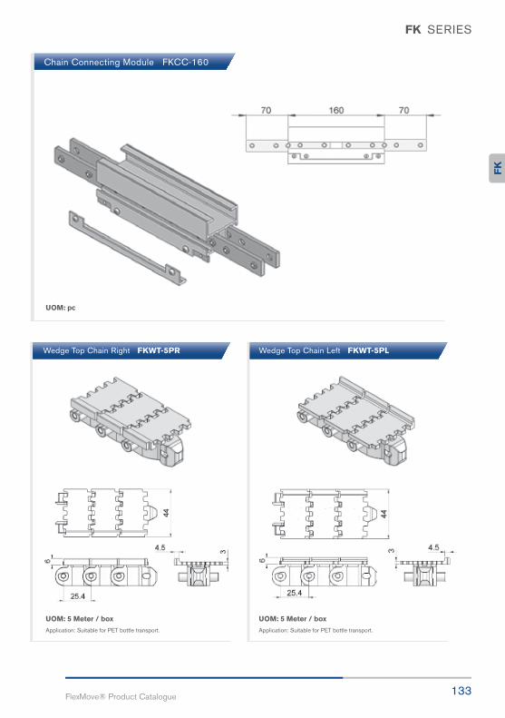
133FlexMove® Product Catalogue
UOM: pc
UOM: 5 Meter / box
Application: Suitable for PET bottle transport.
UOM: 5 Meter / box
Application: Suitable for PET bottle transport.
Chain Connecting Module FKCC-160
Wedge Top Chain Right FKWT-5PR Wedge Top Chain Left FKWT-5PL
FK SERIES
FK

FK SERIES
134FlexMove reserves the right to make alteration without prior notification Every care has been taken to ensure the accuracy of the
information contained in this catalogue but no liability can be accepted for any error or omissions.
Chain Common Data
Packaging: 5m per box
Pitch: 25.4mm
Width: 44mm
Tensile Strength at 20ºC: 4000N
Colour: White & Black (Conductive)
Material :-
Chain: White Acetal / POM
Pivot: Polyamide
Pivot Pin: Stainless Steel
Insert (Wedge & Friction): TPE Grey
Standard Plain Chain FKPC-5 Conductive Chain FKPC-5CD
UOM: 5 Meter / box
Application: Suitable for horizontal and slope< 5° transport of products with accumulation.
UOM: 5 Meter / box
Application: Suitable for transport product inslope > 5° but ≤ 30° without accumulation.
UOM: 5 Meter / box
Application: Suitable for transport of staticsensitive product.
UOM: 5 Meter / box
Application: Vertical Wedge transportation of products.
UOM: 5 Meter / box
Application: Vertical Wedge transportationof products.
Friction Top Chain FKFT-5 Wedge Top Chain FKWT-5C Wedge Top Chain FKWT-5D

135FlexMove® Product Catalogue
FK SERIES
UOM: 5 Meter / box
Application: Suitable to transport light weight,fragile and scratch sensitive product.
UOM: 5 Meter / box
Application: Suitable to transport metalproducts in accumulation.
UOM: 5 Meter / box
Application: Suitable to transport metalproducts in accumulation.
UOM: 5 Meter / box
Application: Suitable for vertical transportof product with no accumulation.
h = 3
h = 5
h = 9
Flocked Chain FKFK-5 Hardened Steel Top Chain FKST-5 S/steel Top Chain FKST-5S
Cleat Top Chain-G FKCT-5G-h-L#
FK
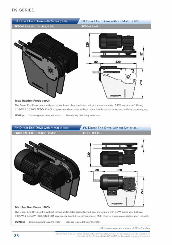
136FlexMove reserves the right to make alteration without prior notification Every care has been taken to ensure the accuracy of the
information contained in this catalogue but no liability can be accepted for any error or omissions.
FK SERIES
FK Direct End Drive with Motor (LEFT)
FK Direct End Drive with Motor (RIGHT)
FKDD-320-0.25L1, 0.37L1, 0.55L1
FKDD-320-0.25R1, 0.37R1, 0.55R1
FKDD-320-0L1
FKDD-320-0R1
FK Direct End Drive without Motor (LEFT)
FK Direct End Drive without Motor (RIGHT)
Max Traction Force : 500N
The Direct End Drive Unit is without torque limiter. Standard attached gear motors are with SEW motor size 0.25kW,
0.37kW & 0.55kW. FKDD-320-0L1 represents direct drive without motor. Multi channel drives are available upon request.
UOM: pc Chain required 2-way: 0.8 meter Slide rail required 2-way: 0.5 meter
Max Traction Force : 500N
The Direct End Drive Unit is without torque limiter. Standard attached gear motors are with SEW motor size 0.25kW,
0.37kW & 0.55kW. FKDD-320-0R1 represents direct drive without motor. Multi channel drives are available upon request.
UOM: pc Chain required 2-way: 0.8 meter Slide rail required 2-way: 0.5 meter
SEW gear motors are products of SEW Eurodrive

137FlexMove® Product Catalogue
FK SERIES
FK Direct End Drive with Motor (LEFT)
FK Direct End Drive with Motor (RIGHT)
FKDD-250-0.25L, 0.37L, 0.55L
FKDD-250-0.25R, 0.37R, 0.55R
FKDD-250-0L
FKDD-250-0R
FK Direct End Drive without Motor (LEFT)
FK Direct End Drive without Motor (RIGHT)
Max Traction Force : 400N
The Direct End Drive Unit is without torque limiter. Standard attached gear motors are with SEW motor size is 0.12kW.
FKDD-250-0L represents direct drive without gear motor. Multi channel drives are available upon request.
UOM: pc Chain required 2-way: 0.55 meter Slide rail required 2-way: 0
Max Traction Force : 400N
The Direct End Drive Unit is without torque limiter. Standard attached gear motors are with SEW motor size is 0.12kW.
FKDD-250-0R represents direct drive without gear motor. Multi channel drives are available upon request.
UOM: pc Chain required 2-way: 0.55 meter Slide rail required 2-way: 0
SEW gear motors are products of SEW Eurodrive
FK

138FlexMove reserves the right to make alteration without prior notification Every care has been taken to ensure the accuracy of the
information contained in this catalogue but no liability can be accepted for any error or omissions.
FK SERIES
SEW gear motors are products of SEW Eurodrive
FK Direct End Drive with Motor GP (LEFT)
FK Direct End Drive with Motor GP (RIGHT)
FKDD-GP-0.25L, 0.37L, 0.55L
FKDD-GP-0.25R, 0.37R, 0.55R
FKDD-GP-0L
FKDD-GP-0R
Max Traction Force : 500N
The Direct End Drive Unit GP is used for vertical wedge conveyor. Standard attached gear motors are with SEW motor size
0.25kW, 0.37kW & 0.55kW. FKDD-GP-0L represents direct drive without gear motor. FKDD-GP drives are used for vertical
wedge conveyor.
UOM: pc Chain required 2-way: 0.8 meter Slide rail required 2-way: 0.5 meter
Max Traction Force : 500N
The Direct End Drive Unit GP is used for vertical wedge conveyor. Standard attached gear motors are with SEW motor
size 0.25kW, 0.37kW & 0.55kW. FKDD-GP-0R represents direct drive without gear motor. FKDD-GP drives are used for
vertical wedge conveyor.
UOM: pc Chain required 2-way: 0.8 meter Slide rail required 2-way: 0.5 meter

139FlexMove® Product Catalogue
FK SERIES
SEW gear motors are products of SEW Eurodrive
FK Suspended End Drive with Motor (LEFT)
FK Suspended End Drive with Motor (RIGHT)
FKSD-0.25L1, 0.37L1, 0.55L1
FKSD-0.25R1, 0.37R1, 0.55R1
FKSD-0L1
FKSD-0R1
FK Suspended End Drive without Motor (LEFT)
FK Suspended End Drive without Motor (RIGHT)
Max Traction Force : 500N
The Suspended End Drive Unit is with torque limiter. Standard attached gear motors are with SEW motor size 0.25kW,
0.37kW & 0.55kW. FKSD-0L1 represents direct drive without gear motor.
UOM: pc Chain required 2-way: 0.8 meter Slide rail required 2-way: 0.5 meter
Max Traction Force : 500N
The Suspended End Drive Unit is with torque limiter. Standard attached gear motors are with SEW motor size 0.25kW,
0.37kW & 0.55kW. FKSD-0R1 represents direct drive without gear motor.
UOM: pc Chain required 2-way: 0.8 meter Slide rail required 2-way: 0.5 meter
FK

140FlexMove reserves the right to make alteration without prior notification Every care has been taken to ensure the accuracy of the
information contained in this catalogue but no liability can be accepted for any error or omissions.
FK SERIES
SEW gear motors are products of SEW Eurodrive
FK Direct Intermediate Drive with Motor (LEFT)
FK Direct Intermediate Drive with Motor (RIGHT)
FKID-DD-0.25L1, 0.37L1, 0.55L1
FKID-DD-0.25R1, 0.37R1, 0.55R1
FKID-DD-0L1
FKID-DD-0R1
Max Traction Force : 200N
The Direct Intermediate Drive Unit is without torque limiter. Standard attached gear motors are with SEW motor size
0.25kW, 0.37kW & 0.55kW. FKID-DD-0L1 represents direct drive without gear motor. Maximum traction force for FKID-DD
is lower than FKDD and FKSD.
UOM: pc Chain required 2-way: 1.2 meter Slide rail required 2-way: 1.1 meter
Max Traction Force : 200N
The Direct Intermediate Drive Unit is without torque limiter. Standard attached gear motors are with SEW motor size
0.25kW, 0.37kW & 0.55kW. FKID-DD-0R1 represents direct drive without gear motor. Maximum traction force for FKID-DD
is lower than FKDD and FKSD.
UOM: pc Chain required 2-way: 1.2 meter Slide rail required 2-way: 1.1 meter
FK Direct Intermediate Drive without Motor (LEFT)
FK Direct Intermediate Drive without Motor (RIGHT)

141FlexMove® Product Catalogue
FK SERIES
SEW gear motors are products of SEW Eurodrive
Max Traction Force : 200N
The Suspended Intermediate Drive Unit is with torque limiter. Standard attached gear motors are with SEW motor size
0.25kW, 0.37kW & 0.55kW. FKID-SD-0L1 represents suspended drive without gear motor. Maximum traction force for
FKID-SD is lower than FKDD and FKSD.
Max Traction Force : 200N
The Suspended Intermediate Drive Unit is with torque limiter. Standard attached gear motors are with SEW motor size
0.25kW, 0.37kW & 0.55kW. FKID-SD-0R1 represents suspended drive without gear motor. Maximum traction force for
FKID-SD is lower than FKDD and FKSD.
FK Suspended Intermediate Drive with Motor (LEFT)
FK Suspended Intermediate Drive with Motor (RIGHT)
FKID-SD-0.25L1, 0.37L1, 0.55L1
FKID-SD-0.25R1, 0.37R1, 0.55R1
FKID-SD-0L1
FKID-SD-0R1
FK Suspended Intermediate Drive without Motor (LEFT)
FK Suspended Intermediate Drive without Motor (RIGHT)
UOM: pc Chain required 2-way: 1.2 meter Slide rail required 2-way: 1.1 meter
UOM: pc Chain required 2-way: 1.2 meter Slide rail required 2-way: 1.1 meter
FK

142FlexMove reserves the right to make alteration without prior notification Every care has been taken to ensure the accuracy of the
information contained in this catalogue but no liability can be accepted for any error or omissions.
FK SERIES
SEW gear motors are products of SEW Eurodrive
FK Suspended Catenary Drive with Motor (LEFT)
FK Suspended Catenary Drive with Motor (RIGHT)
FKCD-SD-0.25R, 0.37R, 0.55R
FKCD-SD-0L
FKCD-SD-0R
UOM: pc Chain required 1-way: 1.4 meter Slide rail required 1-way: 1.0 meter
UOM: pc Chain required 2-way: 1.4 meter Slide rail required 2-way: 1.0 meter
FK Suspended Catenary Drive without Motor (LEFT)
FK Suspended Catenary Drive without Motor (RIGHT)
FKCD-SD-0.25L, 0.37L, 0.55L
Max Traction Force : 500N
The Suspended Catenary Drive Unit is with torque limiter. Standard attached gear motors are with SEW motor size
0.25kW, 0.37kW & 0.55kW. FKCD-SD-0L represents direct drive without gear motor.
Max Traction Force : 500N
The Suspended Catenary Drive Unit is with torque limiter. Standard attached gear motors are with SEW motor size 0.25kW,
0.37kW & 0.55kW. FKCD-SD-0R represents direct drive without gear motor.

143FlexMove® Product Catalogue
FK SERIES
SEW gear motors are products of SEW Eurodrive
Max Traction Force : 200N
The Drive Wheel Drive Unit is without torque limiter. Standard attached gear motors are with SEW motor size 0.25kW,
0.37kW & 0.55kW. FKWD-DD-0M represents direct drive without gear motor. Maximum traction force for FKWD-DD
is lower than FKDD and FKSD.
Max Traction Force : 200N
The Suspended Wheel Drive Unit is with torque limiter. Standard attached gear motors are with SEW motor size 0.25kW,
0.37kW & 0.55kW. FKWD-SD-0M represents direct drive without gear motor. Maximum traction force for FKWD-SD
is lower than FKDD and FKSD.
FK Direct Wheel Drive with Motor
FK Suspended Wheel Drive with Motor
FKWD-DD-0.25, 0.37, 0.55
FKWD-SD-0.25R1, 0.37R1, 0.55R1
FKWD-DD-0M
FKWD-SD-0R1
FK Direct Wheel Drive without Motor
FK Suspended Wheel Drive without Motor
UOM: pc Chain required 1-way: 0.7 meter Slide rail required 1-way: 0.7 meter
UOM: pc Chain required 1-way: 0.7 meter Slide rail required 1-way: 0.7 meter
FK

144FlexMove reserves the right to make alteration without prior notification Every care has been taken to ensure the accuracy of the
information contained in this catalogue but no liability can be accepted for any error or omissions.
FK SERIES
FK Idler End-200
FKIE-200
UOM: pc Chain required 2-way: 0.8 meter Slide rail required 2-way: 0

145FlexMove® Product Catalogue
FK SERIES
FK Wheel Bend 180°
FK Wheel Bend 90°
FKWB-180R150A
FKWB-90R150A
UOM: pc Chain required 2-way: 1.3 meter Slide rail required 2-way: 1.0 meter
UOM: pc Chain required 2-way: 0.7 meter Slide rail required 2-way: 0.7 meter
UOM: pc Chain required 2-way: 0.8 meter Slide rail required 2-way: 0.6 meter
FK Wheel Bend 60° FKWB-60R150AF
K

146FlexMove reserves the right to make alteration without prior notification Every care has been taken to ensure the accuracy of the
information contained in this catalogue but no liability can be accepted for any error or omissions.
FK SERIES
FK Wheel Bend 45°
FK Wheel Bend 30°
FK Wheel Bend 5° - 180°
FKWB-45R150A
FKWB-30R150A
UOM: pc Chain required 2-way: 0.6 meter Slide rail required 2-way: 0.6 meter
Example for FK Wheel Bend Ordering
- Wheel bend, Ø° ± 1°
- FKWB-Ø°R150A
If an angle of 65° is needed for wheel bend,
so the ordering part number is
FKWB-65R150A
The outer bend is assembled using connecting strip(FACS-20x140). Angle of Ø° must be indicatedwhen ordering.
UOM: pc Chain required 2-way: 0.5 meter Slide rail required 2-way: 0.6 meter
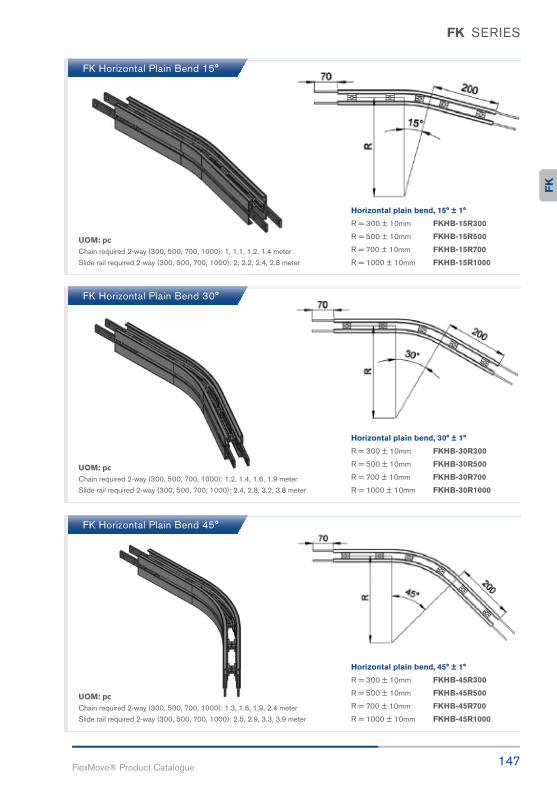
147FlexMove® Product Catalogue
FK SERIES
FK Horizontal Plain Bend 15°
FK Horizontal Plain Bend 30°
FK Horizontal Plain Bend 45°
UOM: pc Chain required 2-way (300, 500, 700, 1000): 1, 1.1, 1.2, 1.4 meter
Slide rail required 2-way (300, 500, 700, 1000): 2, 2.2, 2.4, 2.8 meter
UOM: pc Chain required 2-way (300, 500, 700, 1000): 1.2, 1.4, 1.6, 1.9 meter
Slide rail required 2-way (300, 500, 700, 1000): 2.4, 2.8, 3.2, 3.8 meter
UOM: pc Chain required 2-way (300, 500, 700, 1000): 1.3, 1.6, 1.9, 2.4 meter
Slide rail required 2-way (300, 500, 700, 1000): 2.5, 2.9, 3.3, 3.9 meter
Horizontal plain bend, 15° ± 1°
R = 300 ± 10mm FKHB-15R300
R = 500 ± 10mm FKHB-15R500
R = 700 ± 10mm FKHB-15R700
R = 1000 ± 10mm FKHB-15R1000
Horizontal plain bend, 30° ± 1°
R = 300 ± 10mm FKHB-30R300
R = 500 ± 10mm FKHB-30R500
R = 700 ± 10mm FKHB-30R700
R = 1000 ± 10mm FKHB-30R1000
Horizontal plain bend, 45° ± 1°
R = 300 ± 10mm FKHB-45R300
R = 500 ± 10mm FKHB-45R500
R = 700 ± 10mm FKHB-45R700
R = 1000 ± 10mm FKHB-45R1000
FK

148FlexMove reserves the right to make alteration without prior notification Every care has been taken to ensure the accuracy of the
information contained in this catalogue but no liability can be accepted for any error or omissions.
FK SERIES
FK Horizontal Plain Bend 60°
FK Horizontal Plain Bend 90°
UOM: pc Chain required 2-way (300, 500, 700, 1000): 1.5, 1.9, 2.3, 2.9 meter
Slide rail required 2-way (300, 500, 700, 1000): 2.9, 3.7, 4.6, 5.8 meter
UOM: pc Chain required 2-way (300, 500, 700, 1000): 1.8, 2.4, 3.0, 4.0 meter
Slide rail required 2-way (300, 500, 700, 1000): 3.5, 4.8, 6.0, 8.0 meter
Horizontal plain bend, 60° ± 1°
R = 300 ± 10mm FKHB-60R300
R = 500 ± 10mm FKHB-60R500
R = 700 ± 10mm FKHB-60R700
R = 1000 ± 10mm FKHB-60R1000
Horizontal plain bend, 90° ± 1°
R = 300 ± 10mm FKHB-90R300
R = 500 ± 10mm FKHB-90R500
R = 700 ± 10mm FKHB-90R700
R = 1000 ± 10mm FKHB-90R1000
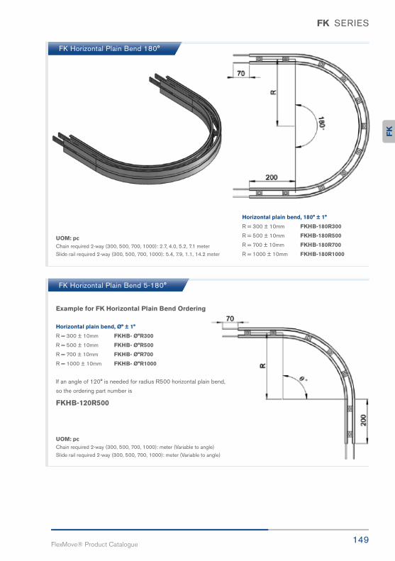
149FlexMove® Product Catalogue
FK SERIES
FK Horizontal Plain Bend 180°
UOM: pc Chain required 2-way (300, 500, 700, 1000): 2.7, 4.0, 5.2, 7.1 meter
Slide rail required 2-way (300, 500, 700, 1000): 5.4, 7.9, 1.1, 14.2 meter
UOM: pc Chain required 2-way (300, 500, 700, 1000): meter (Variable to angle)
Slide rail required 2-way (300, 500, 700, 1000): meter (Variable to angle)
Horizontal plain bend, 180° ± 1°
R = 300 ± 10mm FKHB-180R300
R = 500 ± 10mm FKHB-180R500
R = 700 ± 10mm FKHB-180R700
R = 1000 ± 10mm FKHB-180R1000
Horizontal plain bend, Ø° ± 1°
R = 300 ± 10mm FKHB- Ø°R300
R = 500 ± 10mm FKHB- Ø°R500
R = 700 ± 10mm FKHB- Ø°R700
R = 1000 ± 10mm FKHB- Ø°R1000
FK Horizontal Plain Bend 5-180°
Example for FK Horizontal Plain Bend Ordering
If an angle of 120° is needed for radius R500 horizontal plain bend,
so the ordering part number is
FKHB-120R500
FK

150FlexMove reserves the right to make alteration without prior notification Every care has been taken to ensure the accuracy of the
information contained in this catalogue but no liability can be accepted for any error or omissions.
FK SERIES
FK Vertical Bend 5° FKVB-5R300
UOM: pc Chain required 2-way: 0.4 meter Slide rail required 2-way: 0.8 meter
FK Vertical Bend 10°
FK Vertical Bend 15°
FKVB-10R300
FKVB-15R300
UOM: pc Chain required 2-way: 0.5 meter Slide rail required 2-way: 0.9 meter
UOM: pc Chain required 2-way: 0.5 meter Slide rail required 2-way: 1.0 meter

151FlexMove® Product Catalogue
FK SERIES
FK Vertical Bend 20°
FK Vertical Bend 30°
FKVB-20R300
FKVB-30R300
UOM: pc Chain required 2-way: 0.6 meter Slide rail required 2-way: 1.1 meter
UOM: pc Chain required 2-way: 0.8 meter Slide rail required 2-way: 1.6 meter
UOM: pc Chain required 2-way: 0.7 meter Slide rail required 2-way: 1.3 meter
FK Vertical Bend 45° FKVB-45R300
FK
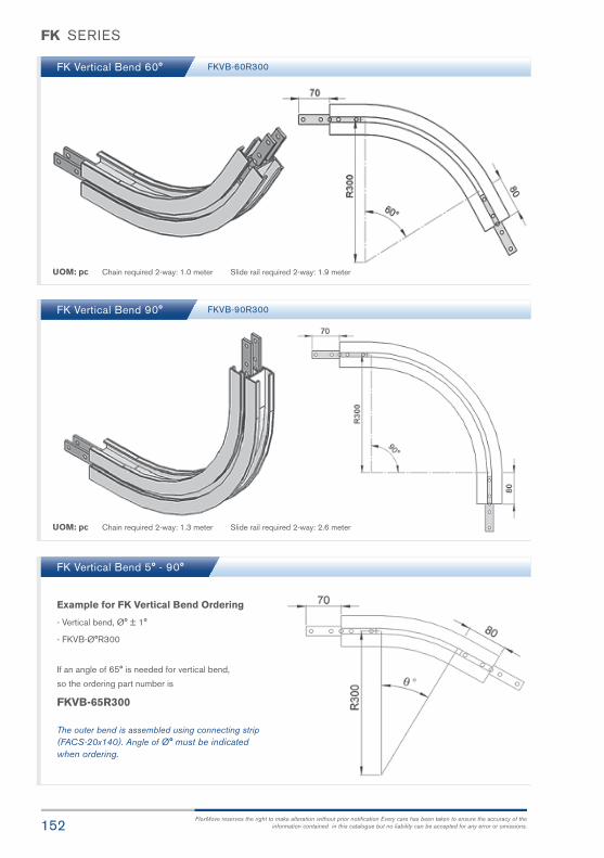
152FlexMove reserves the right to make alteration without prior notification Every care has been taken to ensure the accuracy of the
information contained in this catalogue but no liability can be accepted for any error or omissions.
FK SERIES
FK Vertical Bend 60° FKVB-60R300
UOM: pc Chain required 2-way: 1.0 meter Slide rail required 2-way: 1.9 meter
FK Vertical Bend 90°
FK Vertical Bend 5° - 90°
FKVB-90R300
UOM: pc Chain required 2-way: 1.3 meter Slide rail required 2-way: 2.6 meter
If an angle of 65° is needed for vertical bend,
so the ordering part number is
FKVB-65R300
Example for FK Vertical Bend Ordering
- Vertical bend, Ø° ± 1°
- FKVB-Ø°R300
The outer bend is assembled using connecting strip(FACS-20x140). Angle of Ø° must be indicatedwhen ordering.

153FlexMove® Product Catalogue
FS63mmConveyorSystem F
S
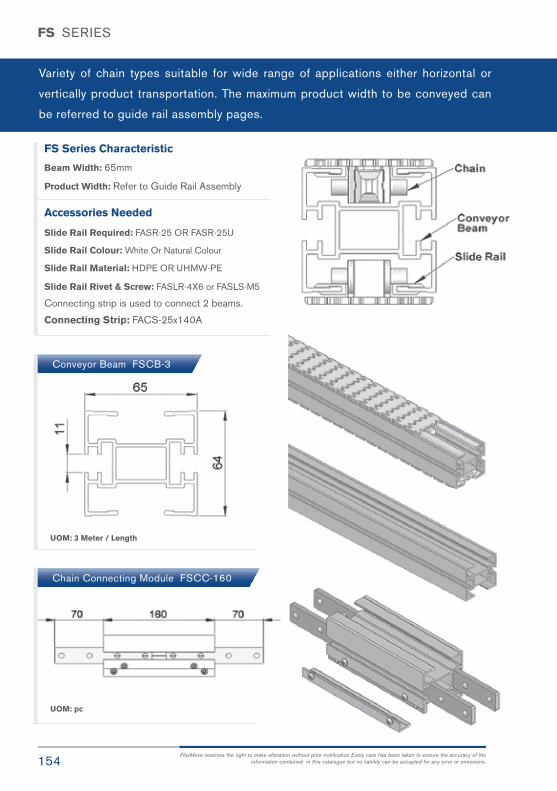
154FlexMove reserves the right to make alteration without prior notification Every care has been taken to ensure the accuracy of the
information contained in this catalogue but no liability can be accepted for any error or omissions.
FS SERIES
Variety of chain types suitable for wide range of applications either horizontal or
vertically product transportation. The maximum product width to be conveyed can
be referred to guide rail assembly pages.
FS Series Characteristic
Beam Width: 65mm
Product Width: Refer to Guide Rail Assembly
Accessories Needed
Slide Rail Required: FASR-25 OR FASR-25U
Slide Rail Colour: White Or Natural Colour
Slide Rail Material: HDPE OR UHMW-PE
Slide Rail Rivet & Screw: FASLR-4X6 or FASLS-M5
Connecting strip is used to connect 2 beams.
Connecting Strip: FACS-25x140A
Conveyor Beam FSCB-3
Chain Connecting Module FSCC-160
UOM: 3 Meter / Length
UOM: pc

155FlexMove® Product Catalogue
FS SERIES
The above chain is FSCT-5A17-L1, 1 link
cleated top chain with alternate of 1 link
of plain chain.
Note: # = 1, 2, 3, 4, 5.....20
Standard Plain Chain FSPC-5 Universal Chain FSUC-5
UOM: 5 Meter / box
Application: Suitable for horizontal and slope< 5° transport of products with accumulation.
UOM: 5 Meter / box
Application: Vertical Wedge transportation ofproducts. (Heavy Duty).
UOM: 5 Meter / box
Application: Universal Link With M3 Nut,Suitable for attached customer cleat or fixture
UOM: 5 Meter / box
Application: Vertical Wedge transportationof products.
Wedge Top Chain FSWT-5A Wedge Top Chain FSWT-5C Wedge Top Chain FSWT-5D
UOM: 5 Meter / box
Application: Vertical Wedge transportationof products.
Chain Common Data
Packaging: 5m per box
Pitch: 25.4mm
Width: 63mm
Tensile Strength at 20ºC: 4000N
Colour: White & Black (Conductive)
Material :-
Chain: White Acetal / POM
Pivot: Polyamide
Pivot Pin: Stainless Steel
Insert (Wedge & Friction): TPE Grey
Example for FSCT-5A17-L## = 1 cleated top chain with alternateof # link of plain chain
FS
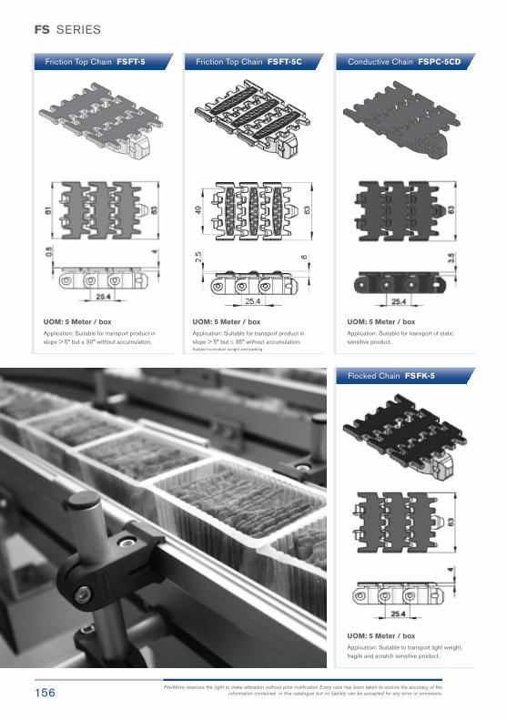
156FlexMove reserves the right to make alteration without prior notification Every care has been taken to ensure the accuracy of the
information contained in this catalogue but no liability can be accepted for any error or omissions.
Friction Top Chain FSFT-5CFriction Top Chain FSFT-5 Conductive Chain FSPC-5CD
Flocked Chain FSFK-5
UOM: 5 Meter / box
Application: Suitable for transport product inslope > 5° but ≤ 35° without accumulation.Subject to product weight and packing
UOM: 5 Meter / box
Application: Suitable for transport product inslope > 5° but ≤ 30° without accumulation.
UOM: 5 Meter / box
Application: Suitable for transport of staticsensitive product.
UOM: 5 Meter / box
Application: Suitable to transport light weight,fragile and scratch sensitive product.
FS SERIES

157FlexMove® Product Catalogue
UOM: 5 Meter / box
Application: Suitable for vertical transport ofproduct with no accumulation.
UOM: 5 Meter / box
Application: Suitable for conveying ferromagneticproducts in slope.
# = 1, 2, 3, 4, 5.....20 # = 1, 2, 3, 4, 5.....20
# = 1, 2, 3, 4, 5.....20
UOM: 5 Meter / box
Application: Suitable for vertical transport ofproduct with no accumulation.
UOM: 5 Meter / box
Application: Suitable for conveying ferromagneticproducts in slope.
UOM: 5 Meter / box
Application: Suitable Cigarette transport.
UOM: 5 Meter / box
Application: Suitable for Cigarette transport.
Cleat Top Chain-A FSCT-5A17-L# Cleat Top Chain-A FSCT-5A30-L# Cleat Top Chain-B FSCT-5B
Cleat Top Chain-C FSCT-5C Magnet Top Chain FSMT-5 Magnet Top Chain FSMT-5-L#
FS SERIES
FS
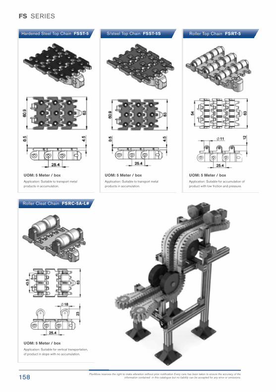
158FlexMove reserves the right to make alteration without prior notification Every care has been taken to ensure the accuracy of the
information contained in this catalogue but no liability can be accepted for any error or omissions.
FS SERIES
S/steel Top Chain FSST-5SHardened Steel Top Chain FSST-5 Roller Top Chain FSRT-5
UOM: 5 Meter / box
Application: Suitable to transport metalproducts in accumulation.
UOM: 5 Meter / box
Application: Suitable to transport metalproducts in accumulation.
UOM: 5 Meter / box
Application: Suitable for accumulation ofproduct with low friction and pressure.
Roller Cleat Chain FSRC-5A-L#
UOM: 5 Meter / box
Application: Suitable for vertical transportation,of product in slope with no accumulation.

159FlexMove® Product Catalogue
FS SERIES
FS Direct End Drive with Motor (LEFT)
FSDD-A65-0.25L, 0.37L, 0.55L FSDD-A65-0L
FS Direct End Drive without Motor (LEFT)
Max Traction Force : 500N
The Drive End Drive Unit is without torque limiter. Standard attached gear motors are with SEW
motor size 0.25kW, 0.37kW & 0.55kW. FSDD-A65-0L represents direct drive without gear motor.
Multi channel drives are available upon request.
UOM: pc Chain required 2-way: 0.8 meter Slide rail required 2-way: 0.5 meter
Max Traction Force : 500N
The Direct End Drive Unit is without torque limiter. Standard attached gear motors are with SEW
motor size 0.25kW, 0.37kW & 0.55kW. FSDD-A65-0R represents direct drive without gear motor.
Multi channel drives are available upon request.
FS Direct End Drive with Motor (RIGHT)
FSDD-A65-0.25R, 0.37R, 0.55R FSDD-A65-0R
FS Direct End Drive without Motor (RIGHT)
UOM: pc Chain required 2-way: 0.8 meter Slide rail required 2-way: 0.5 meter
SEW gear motors are products of SEW Eurodrive
FS

160FlexMove reserves the right to make alteration without prior notification Every care has been taken to ensure the accuracy of the
information contained in this catalogue but no liability can be accepted for any error or omissions.
FS SERIES
SEW gear motors are products of SEW Eurodrive
FS Direct End Drive with Motor GP (LEFT)
FS Direct End Drive with Motor GP (RIGHT)
FSDD-A65GP-0.25L, 0.37L, 0.55L
FSDD-A65GP-0.25R, 0.37R, 0.55R
FSDD-A65GP-0L
FSDD-A65GP-0R
FS Direct End Drive without Motor GP (LEFT)
FS Direct End Drive without Motor GP (RIGHT)
UOM: pc Chain required 2-way: 0.8 meter Slide rail required 2-way: 0.5 meter
UOM: pc Chain required 2-way: 0.8 meter Slide rail required 2-way: 0.5 meter
Max Traction Force : 500N
The Direct End Drive Unit GP is used for vertical wedge conveyor. Standard attached gear motors are with
SEW motor size 0.25kW, 0.37kW & 0.55kW. FSDD-A65GP-0R represents direct drive without gear motor.
FSDD-GP drives are used for vertical wedge conveyor.
Max Traction Force : 500N
The Direct End Drive Unit GP is used for vertical wedge conveyor. Standard attached gear motors are with
SEW motor size 0.25kW, 0.37kW & 0.55kW. FSDD-A65GP-0L represents direct drive without gear motor.
FSDD-GP drives are used for vertical wedge conveyor.
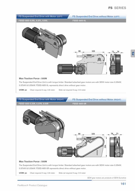
161FlexMove® Product Catalogue
FS SERIES
SEW gear motors are products of SEW Eurodrive
FS Suspended End Drive with Motor (LEFT)
FSSD-A65-0.25L, 0.37L, 0.55L FSSD-A65-0L
FS Suspended End Drive without Motor (LEFT)
UOM: pc Chain required 2-way: 0.8 meter Slide rail required 2-way: 0.5 meter
FS Suspended End Drive with Motor (RIGHT)
FSSD-A65-0.25R, 0.37R, 0.55R FSSD-A65-0R
FS Suspended End Drive without Motor (RIGHT)
UOM: pc Chain required 2-way: 0.8 meter Slide rail required 2-way: 0.5 meter
Max Traction Force : 500N
The Suspended End Drive Unit is with torque limiter. Standard attached gear motors are with SEW motor size 0.25kW,
0.37kW & 0.55kW. FSSD-A65-0L represents direct drive without gear motor.
Max Traction Force : 500N
The Suspended End Drive Unit is with torque limiter. Standard attached gear motors are with SEW motor size 0.25kW,
0.37kW & 0.55kW. FSSD-A65-0R represents direct drive without gear motor.
FS

162FlexMove reserves the right to make alteration without prior notification Every care has been taken to ensure the accuracy of the
information contained in this catalogue but no liability can be accepted for any error or omissions.
FS SERIES
SEW gear motors are products of SEW Eurodrive
FS Direct Intermediate Drive with Motor (LEFT)
FS Direct Intermediate Drive with Motor (RIGHT)
FSID-DD-0.25L1, 0.37L1, 0.55L1
FSID-DD-0.25R1, 0.37R1, 0.55R1
FSID-DD-0L1
FSID-DD-0R1
FS Direct Intermediate Drive without Motor (LEFT)
FS Direct Intermediate Drive without Motor (RIGHT)
UOM: pc Chain required 2-way: 1.2 meter Slide rail required 2-way: 1.1 meter
UOM: pc Chain required 2-way: 1.2 meter Slide rail required 2-way: 1.1 meter
Max Traction Force : 200N
The Direct Intermediate Drive Unit is without torque limiter. Standard attached gear motors are with
SEW motor size 0.25kW, 0.37kW & 0.55kW. FSID-DD-0R1 represents direct drive without gear motor.
Maximum traction force for FSID-DD is lower than FSDD and FSSD.
Max Traction Force : 200N
The Direct Intermediate Drive Unit is without torque limiter. Standard attached gear motors are with
SEW motor size 0.25kW, 0.37kW & 0.55kW. FSID-DD-0L1 represents direct drive without gear motor.
Maximum traction force for FSID-DD is lower than FSDD and FSSD.

163FlexMove® Product Catalogue
FS SERIES
SEW gear motors are products of SEW Eurodrive
Max Traction Force : 200N
The Suspended Intermediate Drive Unit is with torque limiter. Standard attached gear motors are with
SEW motor size 0.25kW, 0.37kW & 0.55kW. FSID-SD-0R1 represents suspended drive without gear motor.
Maximum traction force for FSID-SD is lower than FSDD and FSSD.
Max Traction Force : 200N
The Suspended Intermediate Drive Unit is with torque limiter. Standard attached gear motors are with
SEW motor size 0.25kW, 0.37kW & 0.55kW. FSID-SD-0L1 represents suspended drive without gear motor.
Maximum traction force for FSID-SD is lower than FSDD and FSSD.
FS Suspended Intermediate Drive with Motor (LEFT)
FSID-SD-0.25L1, 0.37L1, 0.55L1 FSID-SD-0L1
FS Suspended Intermediate Drive without Motor (LEFT)
UOM: pc Chain required 2-way: 1.2 meter Slide rail required 2-way: 1.1 meter
FS Suspended Intermediate Drive with Motor (RIGHT)
FSID-SD-0.25R1, 0.37R1, 0.55R1 FSID-SD-0R1
FS Suspended Intermediate Drive without Motor (RIGHT)
UOM: pc Chain required 2-way: 1.2 meter Slide rail required 2-way: 1.1 meter
FS

164FlexMove reserves the right to make alteration without prior notification Every care has been taken to ensure the accuracy of the
information contained in this catalogue but no liability can be accepted for any error or omissions.
FS SERIES
SEW gear motors are products of SEW Eurodrive
FS Combined Direct Drive & Idler (LEFT)
FS Combined Direct Drive & Idler (RIGHT)
FSCDI-DD-0.25L1, 0.37L1, 0.55L1
FSCDI-DD-0.25R1, 0.37R1, 0.55R1
FSCDI-DD-0L1
FSCDI-DD-0R1
UOM: pc Chain required 2-way: 1.6 meter Slide rail required 2-way: 1.0 meter
UOM: pc Chain required 2-way: 1.6 meter Slide rail required 2-way: 1.0 meter
Max Traction Force : 500N
The Combine Direct End Drive Unit is without torque limiter. Standard attached gear motors are with SEW motor
size 0.25kW, 0.37kW & 0.55kW. FSCDI-DD-0L1 represents direct drive without gear motor.
Max Traction Force : 500N
The Combine Direct End Drive Unit is without torque limiter. Standard attached gear motors are with SEW motor
size 0.25kW, 0.37kW & 0.55kW. FSCDI-DD-0R1 represents direct drive without gear motor.

165FlexMove® Product Catalogue
FS SERIES
SEW gear motors are products of SEW Eurodrive
FS Combined Suspended Drive & Idler (LEFT)
FSCDI-SD-0.25L1, 0.37L1, 0.55L1 FSCDI-SD-0L1
FS Combined Suspended Drive & Idler (RIGHT)
FSCDI-SD-0.25R1, 0.37R1, 0.55R1 FSCDI-SD-0R1
UOM: pc Chain required 2-way: 1.6 meter Slide rail required 2-way: 1.0 meter
UOM: pc Chain required 2-way: 1.6 meter Slide rail required 2-way: 1.0 meter
Max Traction Force : 500N
The Combine Suspended End Drive Unit is with torque limiter. Standard attached gear motors are with SEW motor
size 0.25kW, 0.37kW & 0.55kW. FSCDI-SD-0L1 represents suspended drive without gear motor.
Max Traction Force : 500N
The Combine Suspended End Drive Unit is with torque limiter. Standard attached gear motors are with SEW motor
size 0.25kW, 0.37kW & 0.55kW. FSCDI-SD-0R1 represents direct drive without gear motor.
FS

166FlexMove reserves the right to make alteration without prior notification Every care has been taken to ensure the accuracy of the
information contained in this catalogue but no liability can be accepted for any error or omissions.
FS SERIES
SEW gear motors are products of SEW Eurodrive
FS Suspended Catenary Drive with Motor (LEFT)
FS Suspended Catenary Drive with Motor (RIGHT)
FSCD-SD-0.25L, 0.37L, 0.55L FSCD-SD-0L
FSCD-SD-0R
UOM: pc Chain required 1-way: 1.4 meter Slide rail required 1-way: 1.0 meter
UOM: pc Chain required 1-way: 1.4 meter Slide rail required 1-way: 1.0 meter
Max Traction Force : 500N
The Suspended Catenary Drive Unit is with torque limiter. Standard attached gear motors are with
SEW motor size 0.25kW, 0.37kW & 0.55kW. FSCD-SD-0L represents direct drive without gear motor.
Max Traction Force : 500N
The Suspended Catenary Drive Unit is with torque limiter. Standard attached gear motors are with
SEW motor size 0.25kW, 0.37kW & 0.55kW. FSCD-SD-0R represents direct drive without gear motor.
FS Suspended Catenary Drive without Motor (LEFT)
FS Suspended Catenary Drive without Motor (RIGHT)
FSCD-SD-0.25R, 0.37R, 0.55R
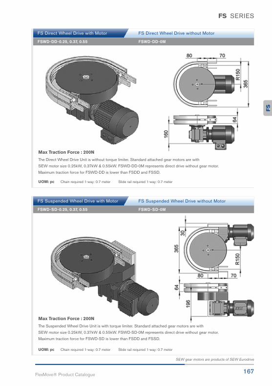
167FlexMove® Product Catalogue
FS SERIES
SEW gear motors are products of SEW Eurodrive
Max Traction Force : 200N
The Suspended Wheel Drive Unit is with torque limiter. Standard attached gear motors are with
SEW motor size 0.25kW, 0.37kW & 0.55kW. FSWD-SD-0M represents direct drive without gear motor.
Maximum traction force for FSWD-SD is lower than FSDD and FSSD.
Max Traction Force : 200N
The Direct Wheel Drive Unit is without torque limiter. Standard attached gear motors are with
SEW motor size 0.25kW, 0.37kW & 0.55kW. FSWD-DD-0M represents direct drive without gear motor.
Maximum traction force for FSWD-DD is lower than FSDD and FSSD.
FS Direct Wheel Drive with Motor
FSWD-DD-0.25, 0.37, 0.55 FSWD-DD-0M
FS Direct Wheel Drive without Motor
UOM: pc Chain required 1-way: 0.7 meter Slide rail required 1-way: 0.7 meter
FS Suspended Wheel Drive with Motor
FSWD-SD-0.25, 0.37, 0.55 FSWD-SD-0M
FS Suspended Wheel Drive without Motor
UOM: pc Chain required 1-way: 0.7 meter Slide rail required 1-way: 0.7 meter
FS

168FlexMove reserves the right to make alteration without prior notification Every care has been taken to ensure the accuracy of the
information contained in this catalogue but no liability can be accepted for any error or omissions.
FS SERIES
FS Idler End-65
FS Idler End-200
FS Idler Bend
FSIE-A65
FSIE-200
FSIB-206
UOM: pc Chain required 2-way: 0.8 meter Slide rail required 2-way: 0.5 meter
UOM: pc Chain required 2-way: 0.7 meter Slide rail required 2-way: 0
UOM: pc Chain required 1-way: 0.6 meter Slide rail: 0 meterNote: Cannot be used with return chain

169FlexMove® Product Catalogue
FS SERIES
FS Wheel Bend 180°
FS Wheel Bend 90°
FS Wheel Bend 60°
FSWB-180R150A
FSWB-90R150A
FSWB-60R150A
UOM: pc Chain required 2-way: 1.3 meter Slide rail required 2-way: 1.0 meter
UOM: pc Chain required 2-way: 0.8 meter Slide rail required 2-way: 0.6 meter
UOM: pc Chain required 2-way: 0.7 meter Slide rail required 2-way: 0.7 meter
FS

170FlexMove reserves the right to make alteration without prior notification Every care has been taken to ensure the accuracy of the
information contained in this catalogue but no liability can be accepted for any error or omissions.
FS SERIES
FS Wheel Bend 45°
FS Wheel Bend 30°
FS Wheel Bend 5° - 180°
FSWB-45R150A
FSWB-30R150A
UOM: pc Chain required 2-way: 0.6 meter Slide rail required 2-way: 0.6 meter
UOM: pc Chain required 2-way: 0.5 meter Slide rail required 2-way: 0.6 meter
If an angle of 65° is needed for wheel bend,
so the ordering part number is
FSWB-65R150A
Example for FS Wheel Bend Ordering
- Wheel bend, Ø° ± 1°
- FSWB-Ø°R150A
The outer bend is assembled using connecting strip(FACS-25x140A). Angle of Ø° must be indicatedwhen ordering.

171FlexMove® Product Catalogue
FS SERIES
FS Horizontal Plain Bend 15°
FS Horizontal Plain Bend 30°
FS Horizontal Plain Bend 45°
UOM: pc Chain required 2-way (300, 500, 700, 1000): 1, 1.1, 1.2, 1.4 meter
Slide rail required 2-way (300, 500, 700, 1000): 2, 2.2, 2.4, 2.8 meter
UOM: pc Chain required 2-way (300, 500, 700, 1000): 1.2, 1.4, 1.6, 1.9 meter
Slide rail required 2-way (300, 500, 700, 1000): 2.4, 2.8, 3.2, 3.8 meter
UOM: pc Chain required 2-way (300, 500, 700, 1000): 1.3, 1.6, 1.9, 2.4 meter
Slide rail required 2-way (300, 500, 700, 1000): 2.5, 2.9, 3.3, 3.9 meter
Horizontal plain bend, 15° ± 1°
R = 300 ± 10mm FSHB-15R300
R = 500 ± 10mm FSHB-15R500
R = 700 ± 10mm FSHB-15R700
R = 1000 ± 10mm FSHB-15R1000
Horizontal plain bend, 30° ± 1°
R = 300 ± 10mm FSHB-30R300
R = 500 ± 10mm FSHB-30R500
R = 700 ± 10mm FSHB-30R700
R = 1000 ± 10mm FSHB-30R1000
Horizontal plain bend, 45° ± 1°
R = 300 ± 10mm FSHB-45R300
R = 500 ± 10mm FSHB-45R500
R = 700 ± 10mm FSHB-45R700
R = 1000 ± 10mm FSHB-45R1000
FS

172FlexMove reserves the right to make alteration without prior notification Every care has been taken to ensure the accuracy of the
information contained in this catalogue but no liability can be accepted for any error or omissions.
FS SERIES
FS Horizontal Plain Bend 60°
FS Horizontal Plain Bend 90°
UOM: pc Chain required 2-way (300, 500, 700, 1000): 1.5, 1.9, 2.3, 2.9 meter
Slide rail required 2-way (300, 500, 700, 1000): 2.9, 3.7, 4.6, 5.8 meter
UOM: pc Chain required 2-way (300, 500, 700, 1000): 1.8, 2.4, 3.0, 4.0 meter
Slide rail required 2-way (300, 500, 700, 1000): 3.5, 4.8, 6.0, 8.0 meter
Horizontal plain bend, 60° ± 1°
R = 300 ± 10mm FSHB-60R300
R = 500 ± 10mm FSHB-60R500
R = 700 ± 10mm FSHB-60R700
R = 1000 ± 10mm FSHB-60R1000
Horizontal plain bend, 90° ± 1°
R = 300 ± 10mm FSHB-90R300
R = 500 ± 10mm FSHB-90R500
R = 700 ± 10mm FSHB-90R700
R = 1000 ± 10mm FSHB-90R1000

173FlexMove® Product Catalogue
FS SERIES
FS Horizontal Plain Bend 180°
FS Horizontal Plain Bend 5° - 180°
UOM: pc Chain required 2-way (300, 500, 700, 1000): 2.7, 4.0, 5.2, 7.1 meter
Slide rail required 2-way (300, 500, 700, 1000): 5.4, 7.9, 1.1, 14.2 meter
UOM: pc Chain required 2-way (300, 500, 700, 1000): meter (Variable to angle)
Slide rail required 2-way (300, 500, 700, 1000): meter (Variable to angle)
Horizontal plain bend, 180° ± 1°
R = 300 ± 10mm FSHB-180R300
R = 500 ± 10mm FSHB-180R500
R = 700 ± 10mm FSHB-180R700
R = 1000 ± 10mm FSHB-180R1000
Horizontal plain bend, Ø° ± 1°
R = 300 ± 10mm FSHB- Ø°300
R = 500 ± 10mm FSHB- Ø°500
R = 700 ± 10mm FSHB- Ø°700
R = 1000 ± 10mm FSHB- Ø°1000
If an angle of 120° is needed for radius R500 horizontal plain bend,
so the ordering part number is
FSHB-120R500
Example for FS Horizontal Plain Bend Ordering
FS
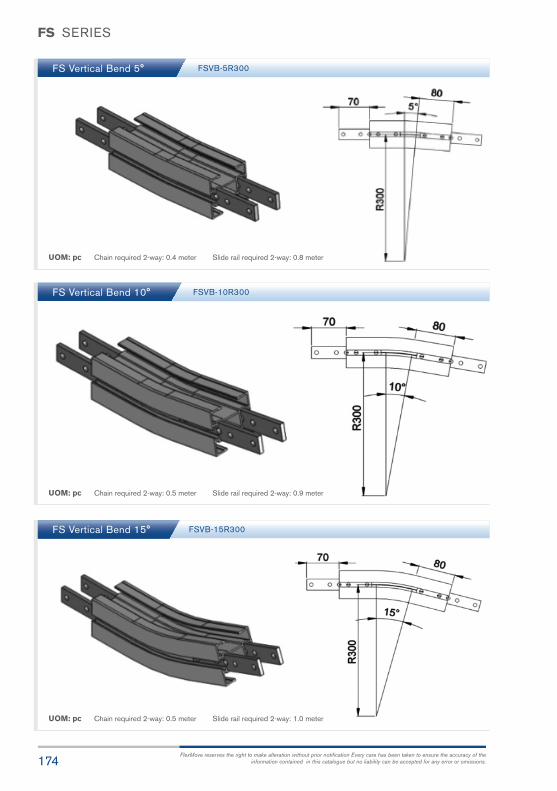
174FlexMove reserves the right to make alteration without prior notification Every care has been taken to ensure the accuracy of the
information contained in this catalogue but no liability can be accepted for any error or omissions.
FS SERIES
FS Vertical Bend 5°
FS Vertical Bend 10°
FS Vertical Bend 15°
FSVB-5R300
FSVB-10R300
FSVB-15R300
UOM: pc Chain required 2-way: 0.4 meter Slide rail required 2-way: 0.8 meter
UOM: pc Chain required 2-way: 0.5 meter Slide rail required 2-way: 0.9 meter
UOM: pc Chain required 2-way: 0.5 meter Slide rail required 2-way: 1.0 meter
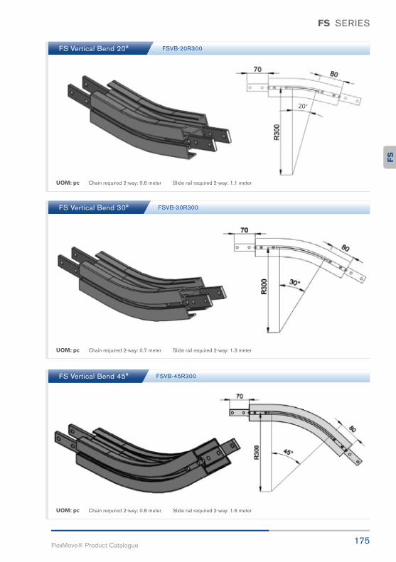
175FlexMove® Product Catalogue
FS SERIES
FS Vertical Bend 20°
FS Vertical Bend 30°
FS Vertical Bend 45°
FSVB-20R300
FSVB-30R300
FSVB-45R300
UOM: pc Chain required 2-way: 0.6 meter Slide rail required 2-way: 1.1 meter
UOM: pc Chain required 2-way: 0.7 meter Slide rail required 2-way: 1.3 meter
UOM: pc Chain required 2-way: 0.8 meter Slide rail required 2-way: 1.6 meter
FS

176FlexMove reserves the right to make alteration without prior notification Every care has been taken to ensure the accuracy of the
information contained in this catalogue but no liability can be accepted for any error or omissions.
FS SERIES
FS Vertical Bend 60°
FS Vertical Bend 90°
FSVB-60R300
FSVB-90R300
UOM: pc Chain required 2-way: 1.0 meter Slide rail required 2-way: 1.9 meter
UOM: pc Chain required 2-way: 1.3 meter Slide rail required 2-way: 2.6 meter
FS Vertical Bend 5° - 90°
If an angle of 65° is needed for vertical bend,
so the ordering part number is
FSVB-65R300
Example for FS Vertical Bend Ordering
- Vertical bend, Ø° ± 1°
- FSVB-Ø°R300
The outer bend is assembled using connecting strip(FACS-25x140A). Angle of Ø° must be indicatedwhen ordering.

In our quest for technological advancement, we are always conscious of the need to be sensitive to our environment. The R&D team at FlexMove® is constantly reviewing and sourcing for the most eco-friendly materials for our products and services as we believe that we play an important role in ensuring the well-being of our environment.
The use of energy-saving products, recyclable packing materials, systematic coding of product materials to facilitate recovery and recycleprocesses adopted in our processes contributes to our eco-friendly focus to ensure that your choice of our solutions is the right choice for your business and for our environment.

Capacity
Connecting
Environment
Coefficients

179FlexMove® Product Catalogue
FM83mmConveyorSystem
FM

180FlexMove reserves the right to make alteration without prior notification Every care has been taken to ensure the accuracy of the
information contained in this catalogue but no liability can be accepted for any error or omissions.
FM SERIES
Variety of chain type suitable for wide range of applications either horizontal or
vertically product transportation. Capacity higher than FK and FS. The maximum
product width to be conveyed can be referred to guide rail assembly pages.
FM Series Characteristic
Beam Width: 85mm
Product Width: Refer to Guide Rail Assembly
Accessories Needed
Slide Rail Required: FASR-25 OR FASR-25U
Slide Rail Colour: White Or Natural Colour
Slide Rail Material: HDPE OR UHMW-PE
Slide Rail Rivet & Screw: FASLR-4X6 or FASLS-M5
Connecting strip is used to connect 2 beams.
Connecting Strip: FACS-25x140A
Conveyor Beam FMCB-3
Chain Connecting Module FMCC-160
UOM: 3 Meter / Length
UOM: pc

181FlexMove® Product Catalogue
FM SERIES
Chain Common Data
Packaging: 5m per box
Pitch: 33.5mm
Width: 83mm
Tensile Strength at 20ºC: 6000N
Colour: White & Black (Conductive)
Material :-
Chain: White Acetal / POM
Pivot: Polyamide
Pivot Pin: Stainless Steel
Insert (Wedge & Friction): TPE Grey
Example for FMCT-5A17-L## = 1 cleated top chain with alternateof # link of plain chain
The above chain is FMCT-5A17-L1, 1 link
cleated top chain with alternate of 1 link
of plain chain.
Note: # = 1, 2, 3, 4, 5.....20
Standard Plain Chain FMPC-5 Conductive Chain FMPC-5CD
UOM: 5 Meter / box
Application: Suitable for horizontal and slope< 5° transport of products with accumulation.
UOM: 5 Meter / box
Application: (Safety Chain) Suitable for transportproduct in slope > 5° but ≤ 30° withoutaccumulation.
UOM: 5 Meter / box
Application: Suitable for transport of staticsensitive product.
UOM: 5 Meter / box
Application: Suitable for transport product in slope > 5° but ≤ 30° without accumulation.
Safety Chain FMPC-5V Safety Chain Friction Top FMFT-5V Friction Top Chain FMFT-5
UOM: 5 Meter / box
Application: (Safety Chain) Suitable for horizontal andslope < 5° transport of products with accumulation.
FM
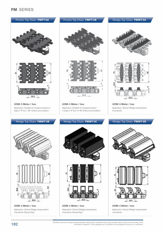
182FlexMove reserves the right to make alteration without prior notification Every care has been taken to ensure the accuracy of the
information contained in this catalogue but no liability can be accepted for any error or omissions.
FM SERIES
Friction Top Chain FMFT-5BFriction Top Chain FMFT-5A Wedge Top Chain FMWT-5A
UOM: 5 Meter / box
Application: Suitable for transport productin slope > 5° but <= 40° without accumulation.
UOM: 5 Meter / box
Application: Suitable for transport product inslope > 5° but ≤ 30° without accumulation.
UOM: 5 Meter / box
Application: Vertical Wedge transportationof products (Heavy Duty)
UOM: 5 Meter / box
Application: Vertical Wedge transportationof products.
UOM: 5 Meter / box
Application: Vertical Wedge transportationof products (Heavy Duty)
UOM: 5 Meter / box
Application: Vertical Wedge transportationof products.
Wedge Top Chain FMWT-5B Wedge Top Chain FMWT-5C Wedge Top Chain FMWT-5D

183FlexMove® Product Catalogue
FM SERIES
UOM: 5 Meter / box
Application: Suitable for conveying offerromagnetic products in slope.
UOM: 5 Meter / box
Application: Suitable for conveying offerromagnetic products in slope.
UOM: 5 Meter / box
Application: Suitable to transport metal products in accumulation.
UOM: 5 Meter / box
Application: Universal Link With M6 Nut,Suitable for attached customer cleat or fixture.
UOM: 5 Meter / box
Application: Suitable to transport light weight,fragile and scratch sensitive product.
UOM: 5 Meter / box
Application: Suitable to transport metal productsin accumulation.
Magnet Top Chain FMMT-5 Magnet Top Chain FMMT-5-L# Flocked Chain FMFK-5
Hardened Steel Top Chain FMST-5 Stainless Steel Top Chain FMST-5S Universal Chain FMUC-5
# = 1, 2, 3, 4, 5.....20
FM

184FlexMove reserves the right to make alteration without prior notification Every care has been taken to ensure the accuracy of the
information contained in this catalogue but no liability can be accepted for any error or omissions.
FM SERIES
Roller Cleat Chain FMRC-5A-L#Roller Top Chain FMRT-5 Roller Cleat Chain FMRC-5B-L#
UOM: 5 Meter / box
Application: Suitable for vertical transportationof product in slope with no accumulation.
UOM: 5 Meter / box
Application: Suitable for accumulation ofproduct with low friction and pressure.
UOM: 5 Meter / box
Application: Suitable for vertical transport ofproduct with no accumulation.
UOM: 5 Meter / box
Application: Suitable for vertical transportationof product in slope with no accumulation.
UOM: 5 Meter / box
Application: Suitable for vertical transport ofproduct with no accumulation.
Cleat Top Chain FMCT-5A17-L# Cleat Top Chain FMCT-5A30-L#
# = 1, 2, 3, 4, 5.....20 # = 1, 2, 3, 4, 5.....20
# = 1, 2, 3, 4, 5.....20 # = 1, 2, 3, 4, 5.....20

185FlexMove® Product Catalogue
FM SERIES
UOM: 5 Meter / box
Application: Suitable for horizontal and slope < 5°transport of products with accumulation.
UOM: 5 Meter / box
Application: Suitable for transport product inslope > 5° but <= 30° without accumulation.(Subject to product weight and Packing)
UOM: 5 Meter / box
Application: Suitable for transport product inslope > 5° but <= 35° without accumulation.(Subject to product weight and Packing)
UOM: 5 Meter / box
Application: Suitable for transport product inslope > 5° but <= 35° without accumulation.(Subject to product weight and Packing)
UOM: 5 Meter / box
Application: Suitable for horizontal and slope< 5° transport of products with accumulation.
Safety Chain with rollers FMPC-5VR Safety Chain Friction Top with rollers FMFT-5VR Safety Chain Friction Top with rollers FMFT-5VR-C
Plain Chain with rollers FMPC-5R Friction Top Chain FMFT-5C
FM

186FlexMove reserves the right to make alteration without prior notification Every care has been taken to ensure the accuracy of the
information contained in this catalogue but no liability can be accepted for any error or omissions.
FM SERIES
SEW gear motors are products of SEW Eurodrive
FM Direct End Drive with Motor (LEFT)
FM Direct End Drive with Motor (RIGHT)
FMDD-A85-0.25L, 0.37L, 0.55L FMDD-A85-0L
FMDD-A85-0R
UOM: pc Chain required 2-way: 0.8 meter Slide rail required 2-way: 0.5 meter
UOM: pc Chain required 2-way: 0.8 meter Slide rail required 2-way: 0.5 meter
FM Direct End Drive without Motor (LEFT)
FM Direct End Drive without Motor (RIGHT)
FMDD-A85-0.25R, 0.37R, 0.55R
Max Traction Force : 1250N
The Direct End Drive Unit is without torque limiter. Standard attached gear motors are with
SEW motor size 0.25kW, 0.37kW & 0.55kW. FMDD-A85-0L represents direct drive without
gear motor. Multi channel drives are available upon request.
Max Traction Force : 1250N
The Direct End Drive Unit without torque limiter. Standard attached gear motors are with
SEW motor size 0.25kW, 0.37kW & 0.55kW. FMDD-A85-0R represents direct drive without
gear motor. Multi channel drives are available upon request.

187FlexMove® Product Catalogue
FM SERIES
SEW gear motors are products of SEW Eurodrive
FM Direct End Drive with Motor GP (LEFT)
FMDD-A85GP-0.25L, 0.37L, 0.55L FMDD-A85GP-0L
FM Direct End Drive without Motor GP (LEFT)
UOM: pc Chain required 2-way: 0.8 meter Slide rail required 2-way: 0.5 meter
FM Direct End Drive with Motor GP (RIGHT)
FMDD-A85GP-0.25R, 0.37R, 0.55R FMDD-A85GP-0R
FM Direct End Drive without Motor GP (RIGHT)
UOM: pc Chain required 2-way: 0.8 meter Slide rail required 2-way: 0.5 meter
Max Traction Force : 1250N
The Direct End Drive Unit GP is used for vertical wedge conveyor. Standard attached gear motors are with
SEW motor size 0.25kW, 0.37kW & 0.55kW. FMDD-A85GP-0L represents direct drive without gear motor.
Max Traction Force : 1250N
The Direct End Drive Unit GP is used for vertical wedge conveyor. Standard attached gear motors are with
SEW motor size 0.25kW, 0.37kW & 0.55kW. FMDD-A85GP-0R represents direct drive without gear motor.
FM

188FlexMove reserves the right to make alteration without prior notification Every care has been taken to ensure the accuracy of the
information contained in this catalogue but no liability can be accepted for any error or omissions.
FM SERIES
SEW gear motors are products of SEW Eurodrive
FM Suspended End Drive with Motor (LEFT)
FM Suspended End Drive with Motor (RIGHT)
FMSD-0.25L1, 0.37L1, 0.55L1 FMSD-0L1
FMSD-0R1
UOM: pc Chain required 2-way: 0.8 meter Slide rail required 2-way: 0.5 meter
UOM: pc Chain required 2-way: 0.8 meter Slide rail required 2-way: 0.5 meter
FM Suspended End Drive without Motor (LEFT)
FM Suspended End Drive without Motor (RIGHT)
FMSD-0.25R1, 0.37R1, 0.55R1
Max Traction Force : 1250N
The Suspended End Drive Unit is with torque limiter. Standard attached gear motors are with SEW motor
size 0.25kW, 0.37kW & 0.55kW. FMSD-0L1 represents direct drive without gear motor.
Max Traction Force : 1250N
The Suspended End Drive Unit is with torque limiter. Standard attached gear motors are with SEW motor
size 0.25kW, 0.37kW & 0.55kW. FMSD-0R1 represents direct drive without gear motor.
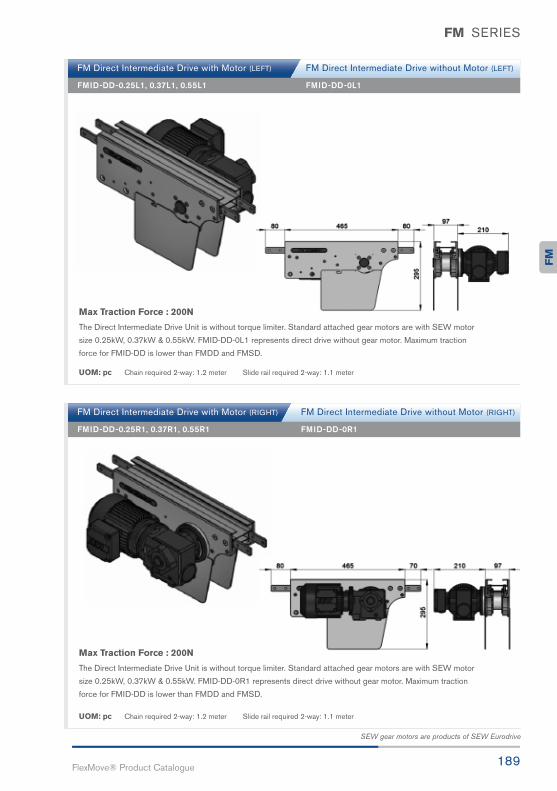
189FlexMove® Product Catalogue
FM SERIES
SEW gear motors are products of SEW Eurodrive
FM Direct Intermediate Drive with Motor (LEFT)
FMID-DD-0.25L1, 0.37L1, 0.55L1 FMID-DD-0L1
FM Direct Intermediate Drive without Motor (LEFT)
UOM: pc Chain required 2-way: 1.2 meter Slide rail required 2-way: 1.1 meter
FM Direct Intermediate Drive with Motor (RIGHT)
FMID-DD-0.25R1, 0.37R1, 0.55R1 FMID-DD-0R1
FM Direct Intermediate Drive without Motor (RIGHT)
UOM: pc Chain required 2-way: 1.2 meter Slide rail required 2-way: 1.1 meter
Max Traction Force : 200N
The Direct Intermediate Drive Unit is without torque limiter. Standard attached gear motors are with SEW motor
size 0.25kW, 0.37kW & 0.55kW. FMID-DD-0R1 represents direct drive without gear motor. Maximum traction
force for FMID-DD is lower than FMDD and FMSD.
Max Traction Force : 200N
The Direct Intermediate Drive Unit is without torque limiter. Standard attached gear motors are with SEW motor
size 0.25kW, 0.37kW & 0.55kW. FMID-DD-0L1 represents direct drive without gear motor. Maximum traction
force for FMID-DD is lower than FMDD and FMSD.
FM

190FlexMove reserves the right to make alteration without prior notification Every care has been taken to ensure the accuracy of the
information contained in this catalogue but no liability can be accepted for any error or omissions.
FM SERIES
SEW gear motors are products of SEW Eurodrive
FM Suspended Intermediate Drive with Motor (LEFT)
FM Suspended Intermediate Drive with Motor (RIGHT)
FMID-SD-0.25L1, 0.37L1, 0.55L1 FMID-SD-0L1
FMID-SD-0R1
UOM: pc Chain required 2-way: 1.2 meter Slide rail required 2-way: 1.1 meter
UOM: pc Chain required 2-way: 1.2 meter Slide rail required 2-way: 1.1 meter
FM Suspended Intermediate Drive without Motor (LEFT)
FM Suspended Intermediate Drive without Motor (RIGHT)
FMID-SD-0.25R1, 0.37R1, 0.55R1
Max Traction Force : 200N
The Suspended Intermediate Drive Unit is with torque limiter. Standard attached gear motors are with SEW motor
size 0.25kW, 0.37kW & 0.55kW. FMID-SD-0L1 represents suspended drive without gear motor. Maximum traction
force for FMID-SD is lower than FMDD and FMSD.
Max Traction Force : 200N
The Suspended Intermediate Drive Unit is with torque limiter. Standard attached gear motors are with SEW motor
size 0.25kW, 0.37kW & 0.55kW. FMID-SD-0R1 represents suspended drive without motor. Maximum traction force
for FMID-SD is lower than FMDD and FMSD.

191FlexMove® Product Catalogue
FM SERIES
SEW gear motors are products of SEW Eurodrive
FM Combined Direct Drive & Idler (LEFT)
FMCDI-DD-0.25L1, 0.37L1, 0.55L1 FMCDI-DD-0L1
UOM: pc Chain required 2-way: 1.6 meter Slide rail required 2-way: 1.0 meter
FM Combined Direct Drive & Idler (RIGHT)
FMCDI-DD-0.25R1, 0.37R1, 0.55R1 FMCDI-DD-0R1
UOM: pc Chain required 2-way: 1.6 meter Slide rail required 2-way: 1.0 meter
Max Traction Force : 1250N
The Combine Direct End Drive Unit is without torque limiter. Standard attached gear motors are with SEW motor
size 0.25kW, 0.37kW & 0.55kW. FMCDI-DD-0L1 represents direct drive without gear motor.
Max Traction Force : 1250N
The Combine Direct End Drive Unit is without torque limiter. Standard attached gear motors are with SEW motor
size 0.25kW, 0.37kW & 0.55kW. FMDI-DD-0R1 represents direct drive without gear motor.
FM
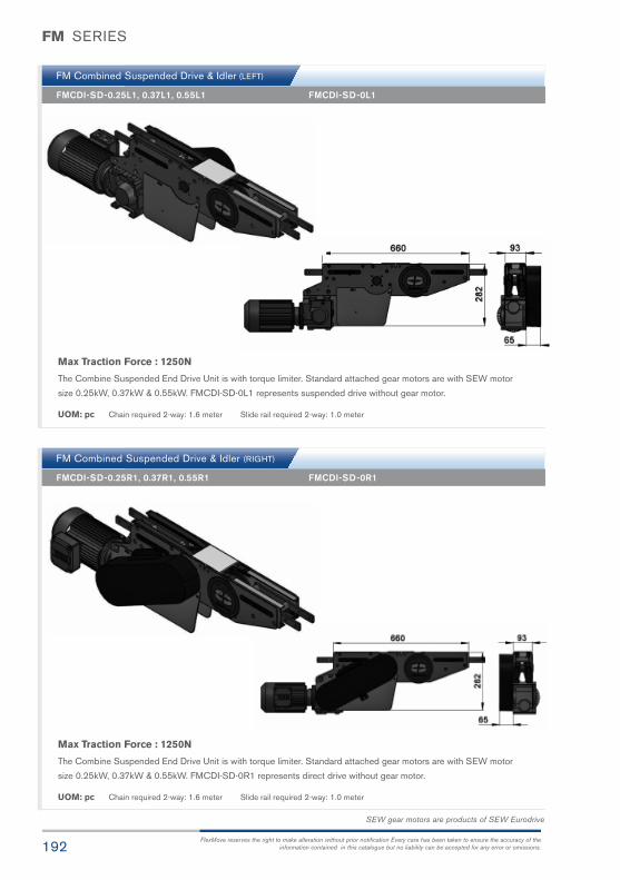
192FlexMove reserves the right to make alteration without prior notification Every care has been taken to ensure the accuracy of the
information contained in this catalogue but no liability can be accepted for any error or omissions.
FM SERIES
SEW gear motors are products of SEW Eurodrive
FM Combined Suspended Drive & Idler (LEFT)
FM Combined Suspended Drive & Idler (RIGHT)
FMCDI-SD-0.25L1, 0.37L1, 0.55L1 FMCDI-SD-0L1
FMCDI-SD-0R1
UOM: pc Chain required 2-way: 1.6 meter Slide rail required 2-way: 1.0 meter
UOM: pc Chain required 2-way: 1.6 meter Slide rail required 2-way: 1.0 meter
FMCDI-SD-0.25R1, 0.37R1, 0.55R1
Max Traction Force : 1250N
The Combine Suspended End Drive Unit is with torque limiter. Standard attached gear motors are with SEW motor
size 0.25kW, 0.37kW & 0.55kW. FMCDI-SD-0L1 represents suspended drive without gear motor.
Max Traction Force : 1250N
The Combine Suspended End Drive Unit is with torque limiter. Standard attached gear motors are with SEW motor
size 0.25kW, 0.37kW & 0.55kW. FMCDI-SD-0R1 represents direct drive without gear motor.

193FlexMove® Product Catalogue
FM SERIES
SEW gear motors are products of SEW Eurodrive
FM Suspended Catenary Drive with Motor (LEFT)
FMCD-SD-0.25L, 0.37L, 0.55L FMCD-SD-0L
UOM: pc Chain required 1-way: 1.4 meter Slide rail required 1-way: 1.0 meter
FM Suspended Catenary Drive with Motor (RIGHT)
FMCD-SD-0.25R, 0.37R, 0.55R FMCD-SD-0R
UOM: pc Chain required 1-way: 1.4 meter Slide rail required 1-way: 1.0 meter
Max Traction Force : 1250N
The Suspended Catenary Drive Unit is with torque limiter. Standard attached gear motors are with SEW motor
size 0.25kW, 0.37kW & 0.55kW. FMCD-SD-0L represents suspended drive without gear motor.
Max Traction Force : 1250N
The Suspended Catenary Drive Unit is with torque limiter. Standard attached drive are with SEW motor size
0.25kW, 0.37kW & 0.55kW. FMCD-SD-0R represents suspended drive without motor.
FM Suspended Catenary Drive without Motor (LEFT)
FM Suspended Catenary Drive without Motor (RIGHT)
FM
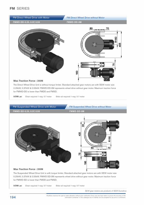
194FlexMove reserves the right to make alteration without prior notification Every care has been taken to ensure the accuracy of the
information contained in this catalogue but no liability can be accepted for any error or omissions.
FM SERIES
SEW gear motors are products of SEW Eurodrive
FM Direct Wheel Drive with Motor
FM Suspended Wheel Drive with Motor
FMWD-DD-0.25, 0.37, 0.55 FMWD-DD-0M
FMWD-SD-0M
UOM: pc Chain required 1-way: 0.7 meter Slide rail required 1-way: 0.7 meter
UOM: pc Chain required 1-way: 0.7 meter Slide rail required 1-way: 0.7 meter
FMWD-SD-0.25, 0.37, 0.55
Max Traction Force : 200N
The Direct Wheel Drive Unit is without torque limiter. Standard attached gear motors are with SEW motor size
0.25kW, 0.37kW & 0.55kW. FMWD-DD-0M represents wheel drive without gear motor. Maximum traction force
for FMWD-DD is lower than FMDD and FMSD.
Max Traction Force : 200N
The Suspended Wheel Drive Unit is with torque limiter. Standard attached gear motors are with SEW motor size
0.25kW, 0.37kW & 0.55kW. FMWD-SD-0M represents wheel drive without gear motor. Maximum traction force
for FMWD-SD is lower than FMDD and FMSD.
FM Direct Wheel Drive without Motor
FM Suspended Wheel Drive without Motor

195FlexMove® Product Catalogue
FM SERIES
FM Idler End 85
FM Idler End-315
FMIE-A85
FMIE-315
UOM: pc Chain required 2-way: 0.8 meter Slide rail required 2-way: 0.5 meter
UOM: pc Chain required 2-way: 0.7 meter Slide rail required 2-way: 0
FM Idler Bend FMIB-300
UOM: pc Chain required 1-way: 0.6 meter Slide rail: 0 meterNote: Cannot be used with return chain
FM
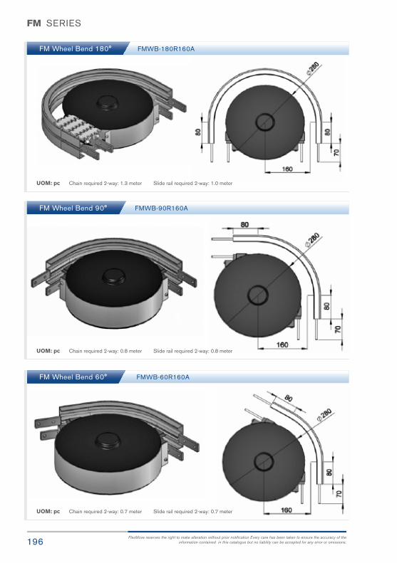
196FlexMove reserves the right to make alteration without prior notification Every care has been taken to ensure the accuracy of the
information contained in this catalogue but no liability can be accepted for any error or omissions.
FM SERIES
FM Wheel Bend 180°
FM Wheel Bend 90°
FM Wheel Bend 60°
FMWB-180R160A
FMWB-90R160A
FMWB-60R160A
UOM: pc Chain required 2-way: 1.3 meter Slide rail required 2-way: 1.0 meter
UOM: pc Chain required 2-way: 0.8 meter Slide rail required 2-way: 0.8 meter
UOM: pc Chain required 2-way: 0.7 meter Slide rail required 2-way: 0.7 meter

197FlexMove® Product Catalogue
FM SERIES
FM Wheel Bend 45°
FM Wheel Bend 30°
FM Wheel Bend 5° - 180°
FMWB-45R160A
FMWB-30R160A
UOM: pc Chain required 2-way: 0.7 meter Slide rail required 2-way: 0.6 meter
UOM: pc Chain required 2-way: 0.5 meter Slide rail required 2-way: 0.6 meter
If an angle of 65° is needed for wheel bend,
so the ordering part number is
FMWB-65R160A
Example for FM Wheel Bend Ordering
- Wheel bend, Ø° ± 1°
- FMWB-Ø°R160A
The outer bend is assembled using connecting strip(FACS-25x140A). Angle of Ø° must be indicatedwhen ordering.
FM

198FlexMove reserves the right to make alteration without prior notification Every care has been taken to ensure the accuracy of the
information contained in this catalogue but no liability can be accepted for any error or omissions.
FM SERIES
FM Horizontal Plain Bend 30°
FM Horizontal Plain Bend 45°
FM Horizontal Plain Bend 15°
UOM: pc Chain required 2-way (300, 500, 700, 1000): 1, 1.1, 1.2, 1.4 meter
Slide rail required 2-way (300, 500, 700, 1000): 2, 2.2, 2.4, 2.8 meter
UOM: pc Chain required 2-way (300, 500, 700, 1000): 1.2, 1.4, 1.6, 1.9 meter
Slide rail required 2-way (300, 500, 700, 1000): 2.4, 2.8, 3.2, 3.8 meter
UOM: pc Chain required 2-way (300, 500, 700, 1000): 1.3, 1.6, 1.9, 2.4 meter
Slide rail required 2-way (300, 500, 700, 1000): 2.5, 2.9, 3.3, 3.9 meter
Horizontal plain bend, 15° ± 1°
R = 300 ± 10mm FMHB-15R300
R = 500 ± 10mm FMHB-15R500
R = 700 ± 10mm FMHB-15R700
R = 1000 ± 10mm FMHB-15R1000
Horizontal plain bend, 30° ± 1°
R = 300 ± 10mm FMHB-30R300
R = 500 ± 10mm FMHB-30R500
R = 700 ± 10mm FMHB-30R700
R = 1000 ± 10mm FMHB-30R1000
Horizontal plain bend, 45° ± 1°
R = 300 ± 10mm FMHB-45R300
R = 500 ± 10mm FMHB-45R500
R = 700 ± 10mm FMHB-45R700
R = 1000 ± 10mm FMHB-45R1000

199FlexMove® Product Catalogue
FM SERIES
FM Horizontal Plain Bend 60°
FM Horizontal Plain Bend 90°
UOM: pc Chain required 2-way (300, 500, 700, 1000): 1.8, 2.4, 3.0, 4.0 meter
Slide rail required 2-way (300, 500, 700, 1000): 3.5, 4.8, 6.0, 8.0 meter
UOM: pc Chain required 2-way (300, 500, 700, 1000): 1.5, 1.9, 2.3, 2.9 meter
Slide rail required 2-way (300, 500, 700, 1000): 2.9, 3.7, 4.6, 5.8 meter
Horizontal plain bend, 90° ± 1°
R = 300 ± 10mm FMHB-90R300
R = 500 ± 10mm FMHB-90R500
R = 700 ± 10mm FMHB-90R700
R = 1000 ± 10mm FMHB-90R1000
Horizontal plain bend, 60° ± 1°
R = 300 ± 10mm FMHB-60R300
R = 500 ± 10mm FMHB-60R500
R = 700 ± 10mm FMHB-60R700
R = 1000 ± 10mm FMHB-60R1000 FM

200FlexMove reserves the right to make alteration without prior notification Every care has been taken to ensure the accuracy of the
information contained in this catalogue but no liability can be accepted for any error or omissions.
FM SERIES
FM Horizontal Plain Bend 180°
UOM: pc Chain required 2-way (300, 500, 700, 1000): 2.7, 4.0, 5.2, 7.1 meter
Slide rail required 2-way (300, 500, 700, 1000): 5.4, 7.9, 1.1, 14.2 meter
UOM: pc Chain required 2-way (300, 500, 700, 1000): meter (Variable to angle)
Slide rail required 2-way (300, 500, 700, 1000): meter (Variable to angle)
Horizontal plain bend, 180° ± 1°
R = 300 ± 10mm FMHB-180R300
R = 500 ± 10mm FMHB-180R500
R = 700 ± 10mm FMHB-180R700
R = 1000 ± 10mm FMHB-180R1000
Horizontal plain bend, Ø° ± 1°
R = 300 ± 10mm FMHB- Ø°R300
R = 500 ± 10mm FMHB- Ø°R500
R = 700 ± 10mm FMHB- Ø°R700
R = 1000 ± 10mm FMHB- Ø°R1000
FM Horizontal Plain Bend 5° - 180°
If an angle of 120° is needed for radius R500 horizontal plain bend,
so the ordering part number is
FMHB-120R500
Example for FM Horizontal Plain Bend Ordering
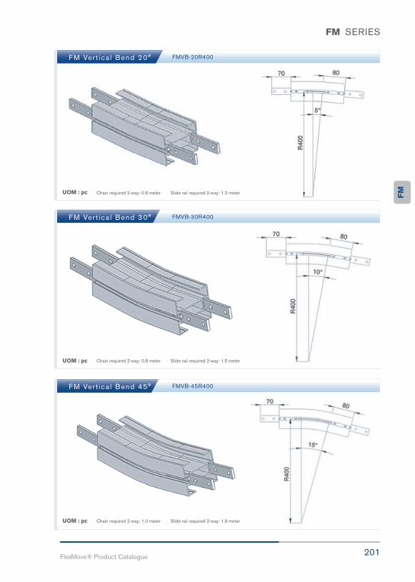
201FlexMove® Product Catalogue
FM SERIES
FM Ver t ica l Bend 20°
FM Ver t ica l Bend 30°
FM Ver t ica l Bend 45°
FMVB-20R400
FMVB-30R400
FMVB-45R400
UOM : pc
UOM : pc
UOM : pc
Chain required 2-way: 0.6 meter Slide rail required 2-way: 1.2 meter
Chain required 2-way: 0.8 meter Slide rail required 2-way: 1.5 meter
Chain required 2-way: 1.0 meter Slide rail required 2-way: 1.9 meter
FM

202FlexMove reserves the right to make alteration without prior notification Every care has been taken to ensure the accuracy of the
information contained in this catalogue but no liability can be accepted for any error or omissions.
FM SERIES
FM Ver t ica l Bend 20º
FM Ver t ica l Bend 30°
FM Ver t ica l Bend 45°
FMVB-20R400
FMVB-30R400
FMVB-45R400
UOM : pc
UOM : pc
UOM : pc
Chain required 2-way: 0.6 meter Slide rail required 2-way: 1.2 meter
Chain required 2-way: 0.8 meter Slide rail required 2-way: 1.5 meter
Chain required 2-way: 1.0 meter Slide rail required 2-way: 1.9 meter

203FlexMove® Product Catalogue
FM SERIES
FM Ver t ica l Bend 60°
FM Ver t ica l Bend 90°
FM Ver t ica l Bend 5° - 90°
FMVB-60R400
FMVB-90R400
UOM : pc
UOM : pc
Example for FM Vertical Bend Ordering
- Vertical bend, Ø° ± 1°
- FMVB-Ø°R400
If an angle of 65° is needed for vertical bend,so the ordering part number is
FMVB-65R400
The outer bend is assembled using connecting strip (FACS-25x140A). Angle of “Ø°” must be indicatedwhen ordering.
Chain required 2-way: 1.2 meter Slide rail required 2-way: 2.4 meter
Chain required 2-way: 1.6 meter Slide rail required 2-way: 3.2 meter
FM

Exquisite
Environment
Possibilities

205FlexMove® Product Catalogue
FC103mm ConveyorSystem
FC

206FlexMove reserves the right to make alteration without prior notification Every care has been taken to ensure the accuracy of the
information contained in this catalogue but no liability can be accepted for any error or omissions.
FC SERIES
Variety of chain type suitable for wide range of applications either horizontal or
vertically product transportation. Capacity higher than FK, FS, FM. The maximum
product width to be conveyed can be referred to guide rail assembly pages.
FC Series CharacteristicBeam Width: 105mm
Product Width: Refer to Guide Rail Assembly
Accessories NeededSlide Rail Required: FASR-25 OR FASR-25U
Slide Rail Colour: White Or Natural Colour
Slide Rail Material: HDPE OR UHMW-PE
Slide Rail Rivet & Screw: FASLR-4X6 or FASLS-M5
Connecting strip is used to connect 2 beams.
Connecting Strip: FACS-25x140A
Conveyor Beam FCCB-3
Chain Connecting Module FCCC-160
UOM : 3 Meter / Length
UOM: pc
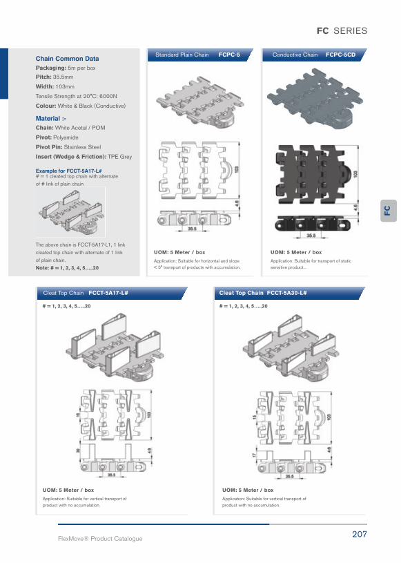
207FlexMove® Product Catalogue
FC SERIES
Chain Common DataPackaging: 5m per box
Pitch: 35.5mm
Width: 103mm
Tensile Strength at 20°C: 6000N
Colour: White & Black (Conductive)
Material :-Chain: White Acetal / POM
Pivot: Polyamide
Pivot Pin: Stainless Steel
Insert (Wedge & Friction): TPE Grey
Example for FCCT-5A17-L## = 1 cleated top chain with alternate
of # link of plain chain
The above chain is FCCT-5A17-L1, 1 link
cleated top chain with alternate of 1 link
of plain chain.
Note: # = 1, 2, 3, 4, 5…..20
UOM: 5 Meter / box
Application: Suitable for horizontal and slope< 5° transport of products with accumulation.
UOM: 5 Meter / box
Application: Suitable for vertical transport ofproduct with no accumulation.
# = 1, 2, 3, 4, 5…..20 # = 1, 2, 3, 4, 5…..20
UOM: 5 Meter / box
Application: Suitable for vertical transport ofproduct with no accumulation.
UOM: 5 Meter / box
Application: Suitable for transport of staticsensitive product...
Standard Plain Chain FCPC-5
Cleat Top Chain FCCT-5A17-L# Cleat Top Chain FCCT-5A30-L#
Conductive Chain FCPC-5CD
FC

208FlexMove reserves the right to make alteration without prior notification Every care has been taken to ensure the accuracy of the
information contained in this catalogue but no liability can be accepted for any error or omissions.
FC SERIES
Roller Top Chain FCRT-5 Roller Cleat Chain FCRC-5A-L# Roller Cleat Chain FCRC-5B-L#
UOM: 5 Meter / box
Application: Suitable for accumulation of product with low friction and pressure.
UOM: 5 Meter / box
Application: Suitable for vertical transportationof product in slope with no accumulation.
UOM: 5 Meter / box
Application: Suitable for vertical transportationof product in slope with no accumulation.
Magnet Top Chain FCMT-5 Magnet Top Chain FCMT-5-L#
UOM: 5 Meter / box
Application: Suitable for conveying of fer-romagnetic products in slope.
UOM: 5 Meter / box
Application: Suitable for conveying of fer-romagnetic products in slope.

209FlexMove® Product Catalogue
FC SERIES
Friction Top Chain FCFT-5
Friction Top Chain FCFT-5B Friction Top Chain FCFT-5C
Friction Top Chain FCFT-5A
UOM: 5 Meter / box
Application: Suitable for transport product inslope > 5 ° but ≤ 30 ° without accumulation.
UOM: 5 Meter / box
Application: Suitable for transport product inslope > 5 ° but ≤ 40 ° without accumulation.
UOM: 5 Meter / box
Application: Suitable for transport product in of slope > 5 ° but ≤ 30 ° without accumulation.
UOM: 5 Meter / box
Application: Suitable for transport product in of slope > 5 ° but ≤ 35 ° without accumulation.
FC

210FlexMove reserves the right to make alteration without prior notification Every care has been taken to ensure the accuracy of the
information contained in this catalogue but no liability can be accepted for any error or omissions.
FC SERIES
Hardened Steel Top Chain FCST-5 S/steel Top Chain FCST-5S Flocked Chain FCFK-5
UOM: 5 Meter / box
Application: Suitable to transport metal prod-ucts in accumulation.
UOM: 5 Meter / box
Application: (Safety Chain ) Suitable for ihorizontal and slope < 5° transport of prod ucts with accumulation.
UOM: 5 Meter / box
Application: (Safety Chain ) Suitable for ihorizontal and slope < 5 ° but ≤ 30 ° without accumulation.
UOM: 5 Meter / box
Application: (Safety Chain ) Suitable for ihorizontal and slope < 5 ° but ≤ 35 ° without accumulation.
UOM: 5 Meter / box
Application: Suitable to transport metal prod-ucts in accumulation.
UOM: 5 Meter / box
Application: Suitable to transport light weight, fragile and scratch sensitive product.
Safety Chain FCPC-5V Safety Chain Friction Top FCFT-5V Safety Chain Friction Top FCFT-5V-C

Excellent
Meticulous
Omniscient
Vanguard

FlexMove® is designed as an ultimate solution for transportation system in manufacturing industries. The system provides a good platform for future expansion and re-layout capability.
With our in-depth knowledge and experience in transportation system backed by our well established worldwide marketing and services network, we are confident in providing solutions to your problems.

213FlexMove® Product Catalogue
FC SERIES
FC Direct End Drive with Motor (LEFT)
FC Direct End Drive with Motor (RIGHT)
FCDD-A105-0.25L, 0.37L, 0.55L
FCDD-A105-0.25R, 0.37R, 0.55R
FCDD-A105-0L
FCDD-A105-0R
FC Direct End Drive without Motor (LEFT)
FC Direct End Drive without Motor (RIGHT)
Max Traction Force : 1250N
The Direct End Drive Unit is without torque limiter. Standard attached gear motors are with SEW motor size0.25kW, 0.37kW & 0.55kW. FCDD-A105-0L represents direct drive without gear motor. Multi channel drives are are available upon request.
Max Traction Force : 1250N
The Direct End Drive Unit is without torque limiter. Standard attached gear motors are with SEW motor size 0.25kW, 0.37kW & 0.55kW. FCDD-A105-0R represents direct drive without gear motor. Multi channel drives are available upon request.
UOM : pc
UOM : pc
Chain required 2-way : 0.8 meter Slide rail required 2-way: 0.5 meter
Chain required 2-way : 0.8 meter Slide rail required 2-way: 0.5 meter
SEW gear motors are products of SEW Eurodrive
FC

214FlexMove reserves the right to make alteration without prior notification Every care has been taken to ensure the accuracy of the
information contained in this catalogue but no liability can be accepted for any error or omissions.
FC SERIES
FC Suspended End Drive with Motor (LEFT)
FC Suspended End Drive with Motor (RIGHT)
FCSD-A105-0.25L, 0.37L, 0.55L
FCSD-A105-0.25R, 0.37R, 0.55R
FCSD-A105-0L
FCSD-A105-0R
FC Suspended End Drive without Motor (LEFT)
FC Suspended End Drive without Motor (RIGHT)
Max Traction Force : 1250N
The Suspended End Drive Unit is with torque limiter. Standard attached gear motors are with SEW motor size 0.25kW, 0.37kW & 0.55kW. FCSD-A105-0L represents suspended drive without gear motor.
Max Traction Force : 1250N
The Suspended End Drive Unit is with torque limiter. Standard attached gear motors are with SEW motorsize 0.25kW, 0.37kW & 0.55kW. FCSD-A105-0R represents direct drive without gear motor.
UOM : pc
UOM : pc
Chain required 2-way : 0.8 meter Slide rail required 2-way: 0.5 meter
Chain required 2-way : 0.8 meter Slide rail required 2-way: 0.5 meter
SEW gear motors are products of SEW Eurodrive
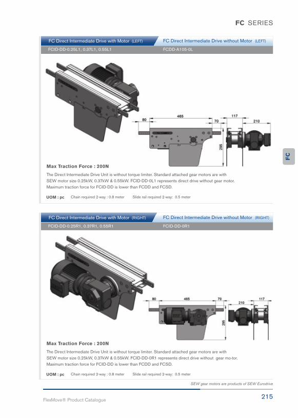
215FlexMove® Product Catalogue
FC SERIES
FC Direct Intermediate Drive with Motor (LEFT)
FC Direct Intermediate Drive with Motor (RIGHT)
FCID-DD-0.25L1, 0.37L1, 0.55L1
FCID-DD-0.25R1, 0.37R1, 0.55R1
FCDD-A105-0L
FCID-DD-0R1
FC Direct Intermediate Drive without Motor (LEFT)
FC Direct Intermediate Drive without Motor (RIGHT)
Max Traction Force : 200N
The Direct Intermediate Drive Unit is without torque limiter. Standard attached gear motors are with SEW motor size 0.25kW, 0.37kW & 0.55kW. FCID-DD-0L1 represents direct drive without gear motor. Maximum traction force for FCID-DD is lower than FCDD and FCSD.
Max Traction Force : 200N
The Direct Intermediate Drive Unit is without torque limiter. Standard attached gear motors are with SEW motor size 0.25kW, 0.37kW & 0.55kW. FCID-DD-0R1 represents direct drive without gear mo tor. Maximum traction force for FCID-DD is lower than FCDD and FCSD.
UOM : pc
UOM : pc
Chain required 2-way : 0.8 meter Slide rail required 2-way: 0.5 meter
Chain required 2-way : 0.8 meter Slide rail required 2-way: 0.5 meter
SEW gear motors are products of SEW Eurodrive
FC

216FlexMove reserves the right to make alteration without prior notification Every care has been taken to ensure the accuracy of the
information contained in this catalogue but no liability can be accepted for any error or omissions.
FC SERIES
FC Suspended Intermediate Drive with Motor (LEFT)
FC Suspended Intermediate Drive with Motor (RIGHT)
FCID-SD-0.25L1, 0.37L1, 0.55L1
FCID-SD-0.25R1, 0.37R1, 0.55R1
FCID-SD-0L1
FCID-SD-0R1
FC Suspended Intermediate Drive without Motor (LEFT)
FC Suspended Intermediate Drive without Motor (RIGHT)
Max Traction Force : 200N
The Suspended Intermediate Drive Unit is with torque limiter. Standard attached gear motors are with SEW motor size 0.25kW, 0.37kW & 0.55kW. FCID-SD-0L1 represents suspended drive without gear motor. Maximum tractionforce for FCID-SD is lower than FCDD and FCSD.
Max Traction Force : 200N
The Suspended Intermediate Drive Unit is with torque limiter. Standard attached gear motors are with SEW motorsize 0.25kW, 0.37kW & 0.55kW. FCID-SD-0R1 represents suspended drive without gear motor. Maximum traction force for FCID-SD is lower than FCDD and FCSD.
UOM : pc
UOM : pc
Chain required 2-way : 0.8 meter Slide rail required 2-way: 0.5 meter
Chain required 2-way : 0.8 meter Slide rail required 2-way: 0.5 meter
SEW gear motors are products of SEW Eurodrive

217FlexMove® Product Catalogue
FC SERIES
FC Combined Direct Drive & Idler (LEFT)
FC Combined Direct Drive & Idler (RIGHT)
FCCDI-DD-0.25L1, 0.37L1, 0.55L1
FCCDI-DD-0.25R1, 0.37R1, 0.55R1
FCCDI-DD-0L1
FCCDI-DD-0R1
Max Traction Force : 1250N
The Combine Direct End Drive Unit is without torque limiter. Standard attached gear motors are with SEW motorsize 0.25kW, 0.37kW & 0.55kW. FCCDI-DD-0L1 represents direct drive without gear motor.
Max Traction Force : 1250N
The Combine Direct End Drive Unit is without torque limiter. Standard attached gear motors are with SEW motor size 0.25kW, 0.37kW & 0.55kW. FCCDI-DD-0R1 represents direct drive without gear motor.
UOM : pc
UOM : pc
Chain required 2-way : 1.6 meter Slide rail required 2-way: 1.0 meter
Chain required 2-way : 1.6 meter Slide rail required 2-way: 1.0 meter
SEW gear motors are products of SEW Eurodrive
FC
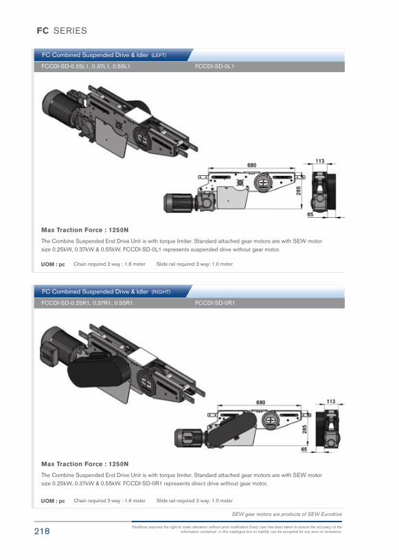
218FlexMove reserves the right to make alteration without prior notification Every care has been taken to ensure the accuracy of the
information contained in this catalogue but no liability can be accepted for any error or omissions.
FC SERIES
FC Combined Suspended Drive & Idler (LEFT)
FC Combined Suspended Drive & Idler (RIGHT)
FCCDI-SD-0.25L1, 0.37L1, 0.55L1
FCCDI-SD-0.25R1, 0.37R1, 0.55R1
FCCDI-SD-0L1
FCCDI-SD-0R1
Max Traction Force : 1250N
The Combine Suspended End Drive Unit is with torque limiter. Standard attached gear motors are with SEW motor size 0.25kW, 0.37kW & 0.55kW. FCCDI-SD-0L1 represents suspended drive without gear motor.
Max Traction Force : 1250N
The Combine Suspended End Drive Unit is with torque limiter. Standard attached gear motors are with SEW motor size 0.25kW, 0.37kW & 0.55kW. FCCDI-SD-0R1 represents direct drive without gear motor.
UOM : pc
UOM : pc
Chain required 2-way : 1.6 meter Slide rail required 2-way: 1.0 meter
Chain required 2-way : 1.6 meter Slide rail required 2-way: 1.0 meter
SEW gear motors are products of SEW Eurodrive

219FlexMove® Product Catalogue
FC SERIES
FC Suspended Catenary Drive with Motor (LEFT)
FC Suspended Catenary Drive with Motor (RIGHT)
FCCD-SD-0.25L, 0.37L, 0.55L
FCCD-SD-0.25R, 0.37R, 0.55R
FCCD-SD-0L
FCCD-SD-0R
FC Suspended Catenary Drive without Motor (LEFT)
FC Suspended Catenary Drive without Motor (RIGHT)
Max Traction Force : 1250N
The Suspended Catenary Drive Unit is with torque limiter. Standard attached gear motors are with SEW motor size 0.25kW, 0.37kW & 0.55kW. FCCD-SD-0L represents suspended drive without gear motor.
Max Traction Force : 1250N
The Suspended Catenary Drive Unit is with torque limiter. Standard attached gear motors are with SEW motor size 0.25kW, 0.37kW & 0.55kW. FCCD-SD-0R represents suspended drive without gear motor.
UOM : pc
UOM : pc
Chain required 1-way : 1.4 meter Slide rail required 1-way: 1.0 meter
Chain required 1-way : 1.4 meter Slide rail required 1-way: 1.0 meter
SEW gear motors are products of SEW Eurodrive
FC

220FlexMove reserves the right to make alteration without prior notification Every care has been taken to ensure the accuracy of the
information contained in this catalogue but no liability can be accepted for any error or omissions.
FC SERIES
FC Direct Wheel Drive with Motor
FC Suspended Wheel Drive with Motor
FCWD-0.25, 0.37, 0.55
FCWD-SD-0.25, 0.37, 0.55
FCWD-DD-0M
FCWD-SD-0M
FC Direct Wheel Drive without Motor
FC Suspended Wheel Drive without Motor
Max Traction Force : 200N
The Direct Wheel Drive Unit is without torque limiter. Standard attached gear motors are with SEW motor size0.25kW, 0.37kW & 0.55kW. FCWD-DD-0M represents wheel drive without gear motor. Maximum traction forcefor FCWD-DD is lower than FCDD and FCSD.
Max Traction Force : 200N
The Suspended Wheel Drive Unit is with torque limiter. Standard attached gear motors are with SEW motor size0.25kW, 0.37kW & 0.55kW. FCWD-SD-0M represents wheel drive without motor. Maximum traction force for FCWD-SD is lower than FCDD and FCSD.
UOM : pc
UOM : pc
Chain required 1-way : 0.7 meter Slide rail required 1-way: 0.7 meter
Chain required 1-way : 0.7 meter Slide rail required 1-way: 0.7 meter
SEW gear motors are products of SEW Eurodrive

221FlexMove® Product Catalogue
FC SERIES
FC Idler End-105
FC Idler End-308
FC Idler Bend
FCIE-A105
FCIE-308
FCIB-350
UOM : pc
UOM : pc
UOM : pcNote:
Chain required 2-way : 0.8 meter Slide rail required 2-way: 0.5 meter
Chain required 2-way : 0.7 meter Slide rail required 2-way: 0
Chain required 1-way : 0.6 meter Slide rail: 0 meter
Cannot be used with return chain
FC
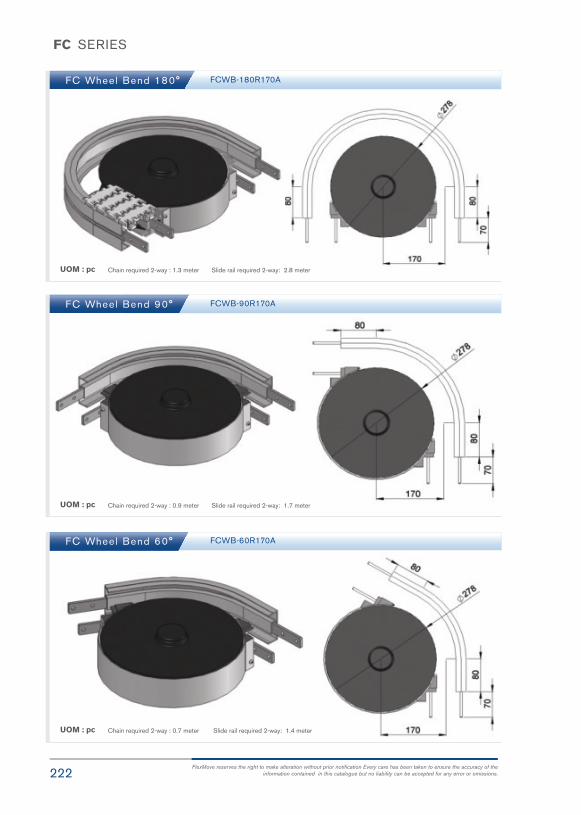
222FlexMove reserves the right to make alteration without prior notification Every care has been taken to ensure the accuracy of the
information contained in this catalogue but no liability can be accepted for any error or omissions.
FC SERIES
FC Wheel Bend 180°
FC Wheel Bend 90°
FC Wheel Bend 60°
FCWB-180R170A
FCWB-90R170A
FCWB-60R170A
UOM : pc
UOM : pc
UOM : pc
Chain required 2-way : 1.3 meter Slide rail required 2-way: 2.8 meter
Chain required 2-way : 0.9 meter Slide rail required 2-way: 1.7 meter
Chain required 2-way : 0.7 meter Slide rail required 2-way: 1.4 meter

223FlexMove® Product Catalogue
FC SERIES
FC Wheel Bend 45°
FC Wheel Bend 30°
FC Wheel Bend 5° - 180°
FCWB-45R170A
FCWB-30R170A
UOM : pc
UOM : pc
Chain required 2-way : 0.6 meter Slide rail required 2-way: 1.2 meter
Chain required 2-way : 0.5 meter Slide rail required 2-way: 1.0 meter
Example for FC Wheel Bend Ordering
- Wheel bend, Ø° ± 1°
- FCWB-Ø°R170A
If an angle of 65° is needed for wheel bend, so the ordering part number is
FCWB-65R170A
The outer bend is assembled using connecting strip (FACS-25x140A). Angle of Ø° must be indicated when ordering.
FC
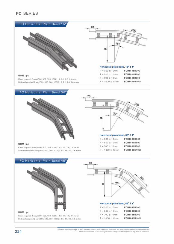
224FlexMove reserves the right to make alteration without prior notification Every care has been taken to ensure the accuracy of the
information contained in this catalogue but no liability can be accepted for any error or omissions.
FC SERIES
FC Hor izonta l Pla in Bend 15°
FC Hor izonta l Pla in Bend 30°
FC Hor izonta l Pla in Bend 45°
UOM : pcChain required 2-way (300, 500, 700, 1000) : 1, 1.1, 1.2, 1.4 meter
Slide rail required 2-way(300, 500, 700, 1000): 2, 2.2, 2.4, 2.8 meter
UOM : pcChain required 2-way (300, 500, 700, 1000) : 1.2, 1.4, 1.6, 1.9 meter
Slide rail required 2-way(300, 500, 700, 1000): 2.4, 2.8, 3.2, 3.8 meter
UOM : pcChain required 2-way (300, 500, 700, 1000) : 1.3, 1.6, 1.9, 2.4 meter
Slide rail required 2-way(300, 500, 700, 1000): 2.5, 2.9, 3.3, 3.9 meter
Horizontal plain bend, 15° ± 1°
R = 300 ± 10mm FCHB-15R300
R = 500 ± 10mm FCHB-15R500
R = 700 ± 10mm FCHB-15R700
R = 1000 ± 10mm FCHB-15R1000
Horizontal plain bend, 30° ± 1°
R = 300 ± 10mm FCHB-30R300
R = 500 ± 10mm FCHB-30R500
R = 700 ± 10mm FCHB-30R700
R = 1000 ± 10mm FCHB-30R1000
Horizontal plain bend, 45° ± 1°
R = 300 ± 10mm FCHB-45R300
R = 500 ± 10mm FCHB-45R500
R = 700 ± 10mm FCHB-45R700
R = 1000 ± 10mm FCHB-45R1000
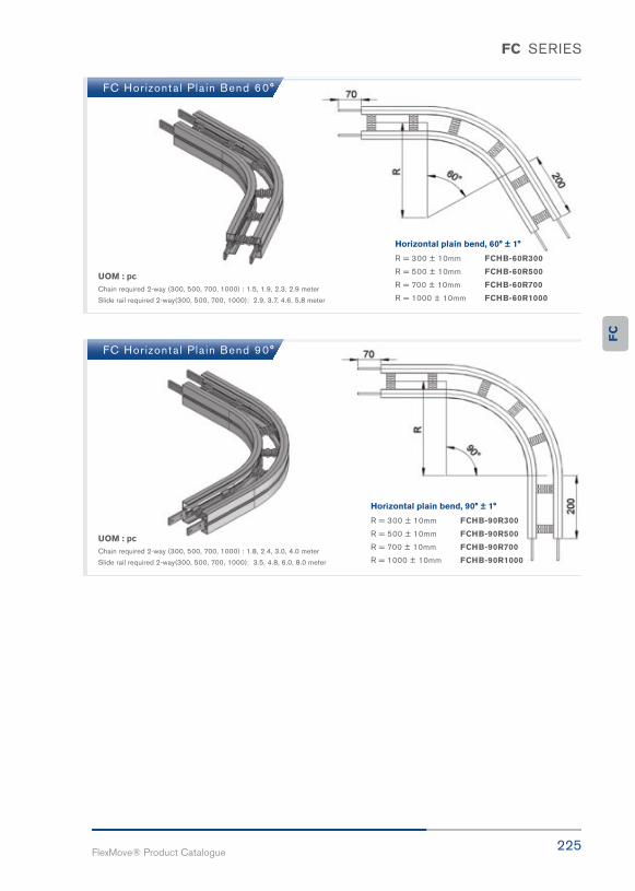
225FlexMove® Product Catalogue
FC SERIES
FC Hor izonta l Pla in Bend 60°
FC Hor izonta l Pla in Bend 90°
UOM : pcChain required 2-way (300, 500, 700, 1000) : 1.5, 1.9, 2.3, 2.9 meter
Slide rail required 2-way(300, 500, 700, 1000): 2.9, 3.7, 4.6, 5.8 meter
UOM : pcChain required 2-way (300, 500, 700, 1000) : 1.8, 2.4, 3.0, 4.0 meter
Slide rail required 2-way(300, 500, 700, 1000): 3.5, 4.8, 6.0, 8.0 meter
Horizontal plain bend, 60° ± 1°
R = 300 ± 10mm FCHB-60R300
R = 500 ± 10mm FCHB-60R500
R = 700 ± 10mm FCHB-60R700
R = 1000 ± 10mm FCHB-60R1000
Horizontal plain bend, 90° ± 1°
R = 300 ± 10mm FCHB-90R300
R = 500 ± 10mm FCHB-90R500
R = 700 ± 10mm FCHB-90R700
R = 1000 ± 10mm FCHB-90R1000
FC

226FlexMove reserves the right to make alteration without prior notification Every care has been taken to ensure the accuracy of the
information contained in this catalogue but no liability can be accepted for any error or omissions.
FC SERIES
FC Hor izonta l Pla in Bend 180°
FC Horizontal Plain Bend 5° - 180°
UOM : pcChain required 2-way (300, 500, 700, 1000) : 2.7, 4.0, 5.2, 7.1 meter
Slide rail required 2-way(300, 500, 700, 1000): 5.4, 7.9, 1.1, 14.2 meter
Horizontal plain bend, 180° ± 1°
R = 300 ± 10mm FCHB-180R300
R = 500 ± 10mm FCHB-180R500
R = 700 ± 10mm FCHB-180R700
R = 1000 ± 10mm FCHB-180R1000
Example for FC Horizontal Plain Bend Ordering
Horizontal plain bend, Ø° ± 1°
R = 300 ± 10mm FCHB- Ø°R300
R = 500 ± 10mm FCHB- Ø°R500
R = 700 ± 10mm FCHB- Ø°R700
R = 1000 ± 10mm FCHB- Ø°R1000
If an angle of 120° is needed for radius R500 horizontal plainbend, so the ordering part number is
FCHB-120R500
UOM : pcChain required 2-way (300, 500, 700, 1000) : meter (variable to angle)
Slide rail required 2-way(300, 500, 700, 1000): meter (variable to angle)
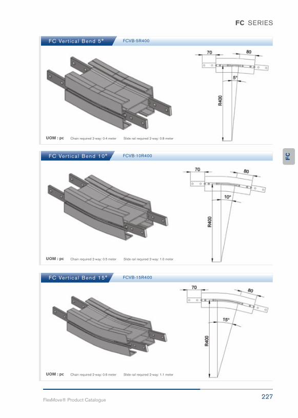
227FlexMove® Product Catalogue
FC SERIES
FC Ver t ica l Bend 5°
FC Ver t ica l Bend 10°
FC Ver t ica l Bend 15°
FCVB-5R400
FCVB-10R400
FCVB-15R400
UOM : pc
UOM : pc
UOM : pc
Chain required 2-way: 0.4 meter Slide rail required 2-way: 0.8 meter
Chain required 2-way: 0.5 meter Slide rail required 2-way: 1.0 meter
Chain required 2-way: 0.6 meter Slide rail required 2-way: 1.1 meter
FC
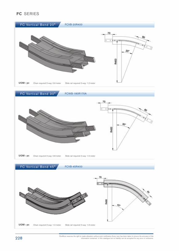
228FlexMove reserves the right to make alteration without prior notification Every care has been taken to ensure the accuracy of the
information contained in this catalogue but no liability can be accepted for any error or omissions.
FC SERIES
FC Ver t ica l Bend 20°
FC Ver t ica l Bend 30°
FC Ver t ica l Bend 45°
FCVB-20R400
FCWB-180R170A
FCVB-45R400
UOM : pc
UOM : pc
UOM : pc
Chain required 2-way: 0.6 meter Slide rail required 2-way: 1.2 meter
Chain required 2-way: 0.8 meter Slide rail required 2-way: 1.5 meter
Chain required 2-way: 1.0 meter Slide rail required 2-way: 1.9 meter
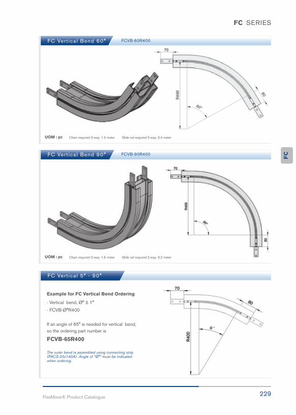
229FlexMove® Product Catalogue
FC SERIES
FC Ver t ica l Bend 60°
FC Ver t ica l Bend 90°
FC Ver t ica l 5° - 90°
FCVB-60R400
FCVB-90R400
UOM : pc
UOM : pc
Chain required 2-way: 1.2 meter Slide rail required 2-way: 2.4 meter
Chain required 2-way: 1.6 meter Slide rail required 2-way: 3.2 meter
Example for FC Vertical Bend Ordering
- Vertical bend, Ø° ± 1°
- FCVB-Ø°R400
If an angle of 65° is needed for vertical bend, so the ordering part number is
FCVB-65R400
The outer bend is assembled using connecting strip (FACS-25x140A) .Angle of “Ø°” must be indicatedwhen ordering.
FC

Standard
Guide
Support
Connected

231FlexMove® Product Catalogue
FL150mm ConveyorSystem
FL
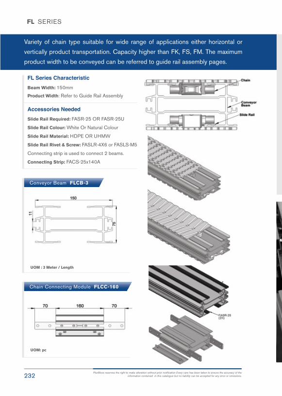
232FlexMove reserves the right to make alteration without prior notification Every care has been taken to ensure the accuracy of the
information contained in this catalogue but no liability can be accepted for any error or omissions.
FL SERIES
Variety of chain type suitable for wide range of applications either horizontal or
vertically product transportation. Capacity higher than FK, FS, FM. The maximum
product width to be conveyed can be referred to guide rail assembly pages.
FL Series CharacteristicBeam Width: 150mm
Product Width: Refer to Guide Rail Assembly
Accessories NeededSlide Rail Required: FASR-25 OR FASR-25U
Slide Rail Colour: White Or Natural Colour
Slide Rail Material: HDPE OR UHMW
Slide Rail Rivet & Screw: FASLR-4X6 or FASLS-M5
Connecting strip is used to connect 2 beams.
Connecting Strip: FACS-25x140A
Conveyor Beam FLCB-3
Chain Connecting Module FLCC-160
UOM : 3 Meter / Length
UOM: pc

233FlexMove® Product Catalogue
FL SERIES
Chain Common DataPackaging: 5m per box
Pitch: 35.5mm
Width: 150mm
Tensile Strength at 20°C: 6000N
Colour: White & Black (Conductive)
Material :-Chain: White Acetal / POM
Pivot: Polyamide
Pivot Pin: Stainless Steel
Insert (Wedge & Friction): TPE Grey
Example for FLRC-5B-L## = 1 cleated top chain with alternate
of # link of plain chain
The above chain is FLRC-5B-L1, 1 link
cleated top chain with alternate of 1 link
of plain chain.
Note: # = 1, 2, 3, 4, 5…..20
UOM: 5 Meter / box
Application: Suitable for horizontal and slope< 5° transport of products with accumulation.
UOM: 5 Meter / box
Application: Suitable for transport of staticsensitive product.
UOM: 5 Meter / box
Application: Suitable for transport product inslope > 5 ° but ≤ 30 ° without accumulation.
Standard Plain Chain FLPC-5 Conductive Chain FLPC-5CD
Conductive Chain FLFT-5
FL

234FlexMove reserves the right to make alteration without prior notification Every care has been taken to ensure the accuracy of the
information contained in this catalogue but no liability can be accepted for any error or omissions.
FL SERIES
Roller Top Chain FLRT-5V
Roller Cleat Chain FLRC-5B-L#
Roller Cleat Chain FLRC-5A-L#
Cleat Top Chain FLCT-5A30-L#
UOM: 5 Meter / box
Application: Suitable for accumulation ofproduct with low friction and pressure..
UOM: 5 Meter / box
Application: Suitable for vertical transportation ofproduct in slope with no accumulation.
UOM: 5 Meter / box
Application: Suitable for vertical transportation of product in slope with no accumulation.
UOM: 5 Meter / box
Application: Suitable for vertical transportation ofproduct in slope with no accumulation.
# = 1, 2, 3, 4, 5…..20
# = 1, 2, 3, 4, 5…..20# = 1, 2, 3, 4, 5…..20

235FlexMove® Product Catalogue
FL SERIES
Standard Plain Chain-V FLPC-5V
Safety Chain Friction Top FLFT-5V
UOM: 5 Meter / box
Application: (Safety Chain) Suitable for horizontal andslope < 5° transport of products with accumulation.
UOM: 5 Meter / box
Application: (Safety Chain ) Suitable for transport
prouct in slope > 5 ° but ≤ 30 ° without accumulation.
SEW gear motors are products of SEW Eurodrive
FL

Fastidious
Lasting
Effective

237FlexMove® Product Catalogue
FL SERIES
FL Direct End Drive with Motor (LEFT)
FL Direct End Drive with Motor (RIGHT)
FLDD-A150-0.25L, 0.37L, 0.55L
FLDD-A150-0.25R, 0.37R, 0.55R
FLDD-A150-0L
FLDD-A150-0R
FL Direct End Drive without Motor (LEFT)
FL Direct End Drive without Motor (RIGHT)
Max Traction Force : 1250N
The Direct End Drive Unit is without torque limiter. Standard attached gear motors are with SEW motor size 0.25kW, 0.37kW & 0.55kW. FLDD-A150-0L represents direct drive without gear motor. Multi channel drives areavailable upon request.
Max Traction Force : 1250N
The Direct End Drive Unit is without torque limiter. Standard attached gear motors are with SEW motor size0.25kW, 0.37kW & 0.55kW. FLDD-A150-0R represents direct drive without gear motor. Multi channel drives areavailable upon request.
UOM : pc
UOM : pc
Chain required 2-way : 0.8 meter Slide rail required 2-way: 0.5 meter
Chain required 2-way : 0.8 meter Slide rail required 2-way: 0.5 meter
SEW gear motors are products of SEW Eurodrive
FL

238FlexMove reserves the right to make alteration without prior notification Every care has been taken to ensure the accuracy of the
information contained in this catalogue but no liability can be accepted for any error or omissions.
FL SERIES
FL Suspended End Drive with Motor (LEFT)
FL Suspended End Drive with Motor (RIGHT)
FLSD-A150-0.25L, 0.37L, 0.55L
FLSD-A150-0.25R, 0.37R, 0.55R
FLSD-A150-0L
FLSD-A150-0R
FL Suspended End Drive without Motor (LEFT)
FL Suspended End Drive without Motor (RIGHT)
Max Traction Force : 1250N
The Suspended End Drive Unit is with torque limiter. Standard attached gear motors are with SEW motor size 0.25kW,0.37kW & 0.55kW. FLSD-A150-0L represents suspended drive without gear motor.
Max Traction Force : 1250N
The Suspended End Drive Unit is with torque limiter. Standard attached gear motors are with SEW motor size 0.25kW, 0.37kW & 0.55kW. FLSD-A150-0R represents suspended drive without gear motor.
UOM : pc
UOM : pc
Chain required 2-way : 0.8 meter Slide rail required 2-way: 0.5 meter
Chain required 2-way : 0.8 meter Slide rail required 2-way: 0.5 meter
SEW gear motors are products of SEW Eurodrive

239FlexMove® Product Catalogue
FL SERIES
FL Combined Direct Drive & Idler (RIGHT)
FL Combined Direct Drive & Idler (LEFT)
FLCDI-DD-0.25R1, 0.37R1, 0.55R1
FLCDI-DD-0.25L1, 0.37L1, 0.55L1
FLCDI-DD-0R1
FLCDI-DD-0L1
Max Traction Force : 1250N
The Combine Direct End Drive Unit is without torque limiter. Standard attached gear motors are with SEW motor size 0.25kW, 0.37kW & 0.55kW. FLDI-DD-0R1 represents direct drive without gear motor.
Max Traction Force : 1250N
The Combine Direct End Drive Unit is without torque limiter. Standard attached gear motors are with SEW motor size 0.25kW, 0.37kW & 0.55kW. FLCDI-DD-0L1 represents direct drive without gear motor.
UOM : pc
UOM : pc
Chain required 2-way : 1.6 meter Slide rail required 2-way: 1.0 meter
Chain required 2-way : 1.6 meter Slide rail required 2-way: 1.0 meter
SEW gear motors are products of SEW Eurodrive
FL

240FlexMove reserves the right to make alteration without prior notification Every care has been taken to ensure the accuracy of the
information contained in this catalogue but no liability can be accepted for any error or omissions.
FL SERIES
FL Combined Suspended Drive & Idler (LEFT)
FL Combined Suspended Drive & Idler (RIGHT)
FLCDI-SD-0.25L1, 0.37L1, 0.55L1
FLCDI-SD-0.25R1, 0.37R1, 0.55R1
FLCDI-SD-0L1
FLCDI-SD-0R1
Max Traction Force : 1250N
The Combine Suspended End Drive Unit is with torque limiter. Standard attached gear motors are with SEW motor size 0.25kW, 0.37kW & 0.55kW. FLCDI-SD-0L1 represents suspended drive without gear motor.
Max Traction Force : 1250N
The Combine Suspended End Drive Unit is with torque limiter. Standard attached gear motors are with SEW motor size 0.25kW, 0.37kW & 0.55kW. FLCDI-SD-0R1 represents direct drive without gear motor.
UOM : pc
UOM : pc
Chain required 2-way : 1.6 meter Slide rail required 2-way: 1.0 meter
Chain required 2-way : 1.6 meter Slide rail required 2-way: 1.0 meter
SEW gear motors are products of SEW Eurodrive

FL SERIES
FL Idler End-150
FLIE-A150
UOM : pc Chain required 2-way : 0.8 meter Slide rail required 2-way: 0.5 meter
FL
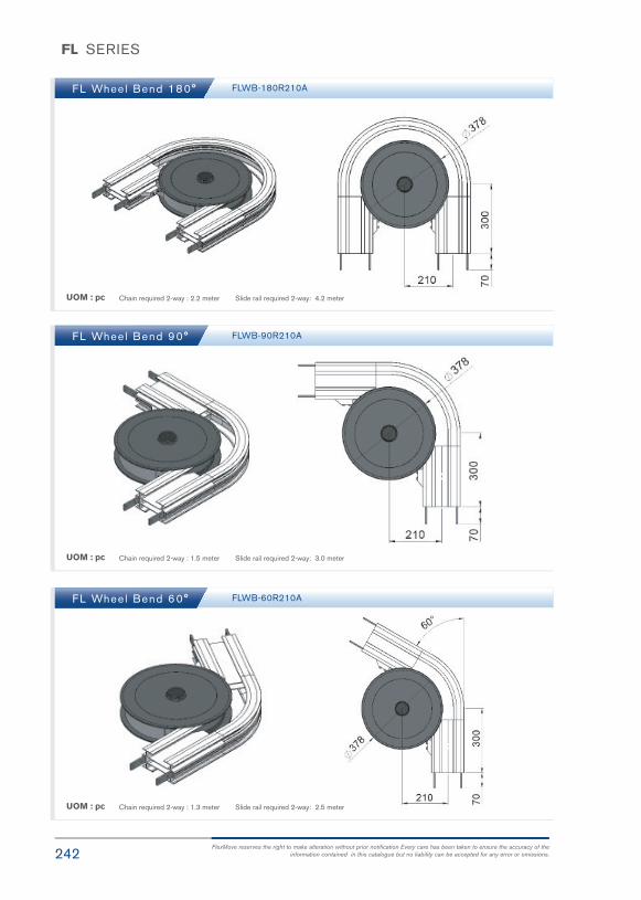
242FlexMove reserves the right to make alteration without prior notification Every care has been taken to ensure the accuracy of the
information contained in this catalogue but no liability can be accepted for any error or omissions.
FL SERIES
FL Wheel Bend 180°
FL Wheel Bend 90°
FL Wheel Bend 60°
FLWB-180R210A
FLWB-90R210A
FLWB-60R210A
UOM : pc
UOM : pc
UOM : pc
Chain required 2-way : 2.2 meter Slide rail required 2-way: 4.2 meter
Chain required 2-way : 1.5 meter Slide rail required 2-way: 3.0 meter
Chain required 2-way : 1.3 meter Slide rail required 2-way: 2.5 meter

243FlexMove® Product Catalogue
FL SERIES
FL Wheel Bend 45°
FL Wheel Bend 30°
FL Wheel Bend 5° - 180°
FLWB-45R210A
FLWB-30R210A
UOM : pc
UOM : pc
Chain required 2-way : 1.4 meter Slide rail required 2-way: 2.6 meter
Chain required 2-way : 1.1 meter Slide rail required 2-way: 2.1 meter
Example for FL Wheel Bend Ordering
- Wheel bend, Ø° ± 1°
- FLWB-Ø°R210A
If an angle of 65° is needed for wheel bend, so the ordering part number is
FLWB-65R210A
The outer bend is assembled using connecting strip (FACS-25x140A). Angle of Ø° must be indicatedwhen ordering.
FL
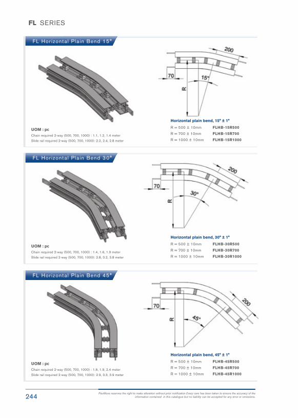
244FlexMove reserves the right to make alteration without prior notification Every care has been taken to ensure the accuracy of the
information contained in this catalogue but no liability can be accepted for any error or omissions.
FL SERIES
FL Hor izonta l Pla in Bend 15°
FL Hor izonta l Pla in Bend 30°
FL Hor izonta l Pla in Bend 45°
UOM : pcChain required 2-way (500, 700, 1000) : 1.1, 1.2, 1.4 meter
Slide rail required 2-way (500, 700, 1000): 2.2, 2.4, 2.8 meter
UOM : pcChain required 2-way (500, 700, 1000) : 1.4, 1.6, 1.9 meter
Slide rail required 2-way (500, 700, 1000): 2.8, 3.2, 3.8 meter
UOM : pcChain required 2-way (500, 700, 1000) : 1.6, 1.9, 2.4 meter
Slide rail required 2-way (500, 700, 1000): 2.9, 3.3, 3.9 meter
Horizontal plain bend, 15° ± 1°
R = 500 ± 10mm FLHB-15R500
R = 700 ± 10mm FLHB-15R700
R = 1000 ± 10mm FLHB-15R1000
Horizontal plain bend, 30° ± 1°
R = 500 ± 10mm FLHB-30R500
R = 700 ± 10mm FLHB-30R700
R = 1000 ± 10mm FLHB-30R1000
Horizontal plain bend, 45° ± 1°
R = 500 ± 10mm FLHB-45R500
R = 700 ± 10mm FLHB-45R700
R = 1000 ± 10mm FLHB-45R1000
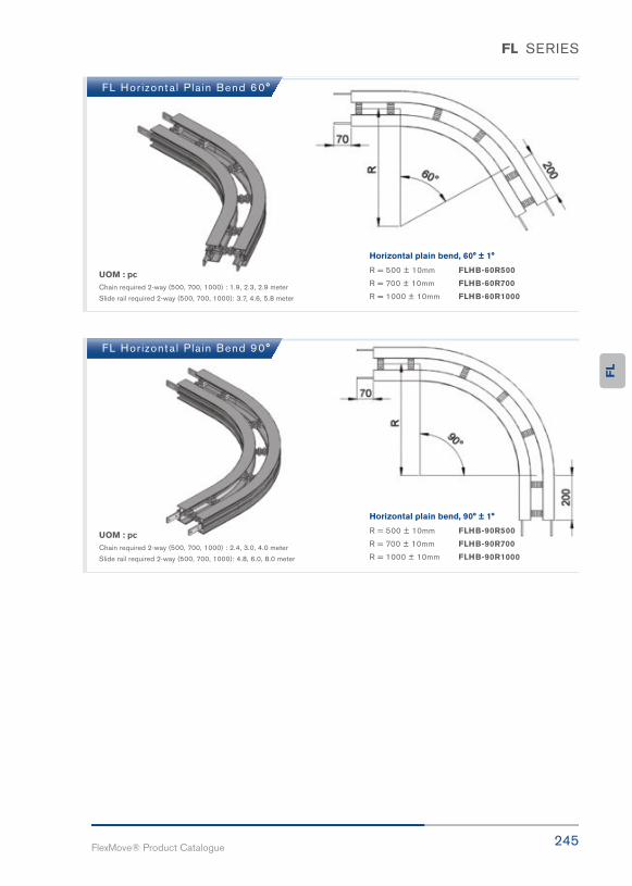
245FlexMove® Product Catalogue
FL SERIES
FL Hor izonta l Pla in Bend 60°
FL Hor izonta l Pla in Bend 90°
UOM : pcChain required 2-way (500, 700, 1000) : 1.9, 2.3, 2.9 meter
Slide rail required 2-way (500, 700, 1000): 3.7, 4.6, 5.8 meter
UOM : pcChain required 2-way (500, 700, 1000) : 2.4, 3.0, 4.0 meter
Slide rail required 2-way (500, 700, 1000): 4.8, 6.0, 8.0 meter
Horizontal plain bend, 60° ± 1°
R = 500 ± 10mm FLHB-60R500
R = 700 ± 10mm FLHB-60R700
R = 1000 ± 10mm FLHB-60R1000
Horizontal plain bend, 90° ± 1°
R = 500 ± 10mm FLHB-90R500
R = 700 ± 10mm FLHB-90R700
R = 1000 ± 10mm FLHB-90R1000
FL

246FlexMove reserves the right to make alteration without prior notification Every care has been taken to ensure the accuracy of the
information contained in this catalogue but no liability can be accepted for any error or omissions.
FL SERIES
FL Hor izonta l Pla in Bend 180°
FL Hor izonta l Pla in Bend 5° - 180°
UOM : pcChain required 2-way (500, 700, 1000) : 4.0, 5.2, 7.1 meter
Slide rail required 2-way (500, 700, 1000): 7.9, 1.1, 14.2 meter
Horizontal plain bend, 180° ± 1°
R = 500 ± 10mm FLHB-180R500
R = 700 ± 10mm FLHB-180R700
R = 1000 ± 10mm FLHB-180R1000
Example for FL Horizontal Plain Bend Ordering
Horizontal plain bend, Ø° ± 1°
R = 500 ± 10mm FLHB- Ø°R500
R = 700 ± 10mm FLHB- Ø°R700
R = 1000 ± 10mm FLHB- Ø°R1000
If an angle of 120° is needed for radius R500 horizontal plain bend, so the ordering part number is
FLHB-120R500
UOM : pcChain required 2-way (500, 700, 1000) : meter (variable to angle)
Slide rail required 2-way (500, 700, 1000): meter (variable to angle)

247FlexMove® Product Catalogue
FL SERIES
FL Ver t ica l Bend 5°
FL Ver t ica l Bend 10°
FLVB-5R500
FLVB-10R500
UOM : pc
UOM : pc
Chain required 2-way: 0.5 meter Slide rail required 2-way: 0.9 meter
Chain required 2-way: 0.5 meter Slide rail required 2-way: 1.0 meter
FL

248FlexMove reserves the right to make alteration without prior notification Every care has been taken to ensure the accuracy of the
information contained in this catalogue but no liability can be accepted for any error or omissions.
FL SERIES
FL Ver t ica l Bend 15°
FL Ver t ica l Bend 20°
FLVB-15R500
FLVB-20R500
UOM : pc
UOM : pc
Chain required 2-way: 0.6 meter Slide rail required 2-way: 1.2 meter
Chain required 2-way: 0.7 meter Slide rail required 2-way: 1.4 meter
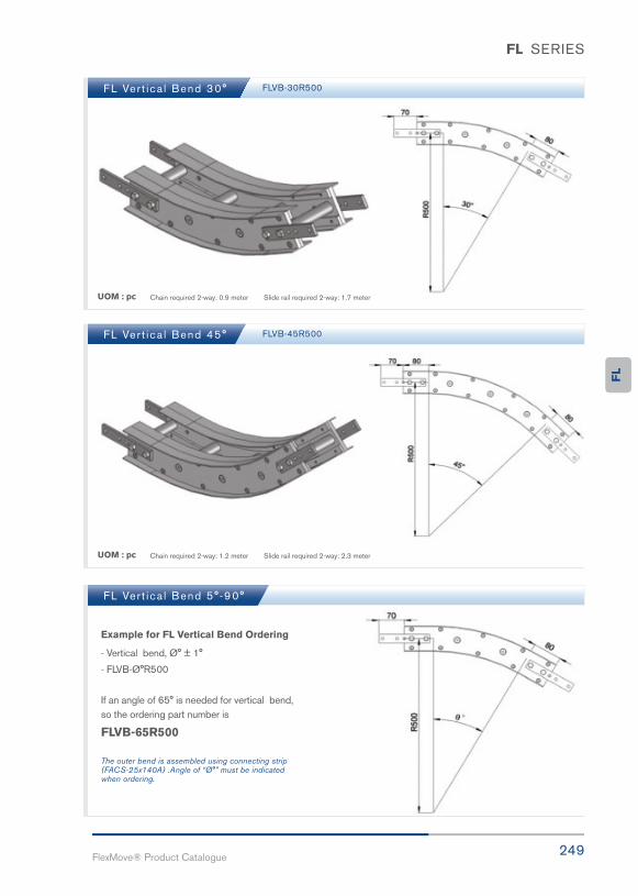
249FlexMove® Product Catalogue
FL SERIES
FL Ver t ica l Bend 30°
FL Ver t ica l Bend 45°
FL Ver t ica l Bend 5° -90°
FLVB-30R500
FLVB-45R500
UOM : pc
UOM : pc
Chain required 2-way: 0.9 meter Slide rail required 2-way: 1.7 meter
Chain required 2-way: 1.2 meter Slide rail required 2-way: 2.3 meter
Example for FL Vertical Bend Ordering
- Vertical bend, Ø° ± 1°
- FLVB-Ø°R500
If an angle of 65° is needed for vertical bend, so the ordering part number is
FLVB-65R500
The outer bend is assembled using connecting strip (FACS-25x140A) .Angle of “Ø°” must be indicatedwhen ordering.
FL

Calculation
Friction
Accumulation
Gravity

251FlexMove® Product Catalogue
FU180mm ConveyorSystem
FU

252FlexMove reserves the right to make alteration without prior notification Every care has been taken to ensure the accuracy of the
information contained in this catalogue but no liability can be accepted for any error or omissions.
FU SERIES
Variety of chain type suitable for wide range of applications either horizontal or
vertically product transportation. The maximum product width to be conveyed
can be referred to guide rail assembly pages.
FU180 Series CharacteristicBeam Width: 179mm
Product Width: Refer to Guide Rail Assembly
Accessories NeededSlide Rail Required: FASR-25 , FASR-25U , FASR-25X
Slide Rail Colour: White Or Natural Colour
Slide Rail Material: HDPE , UHMW OR SPECIAL PE
Slide Rail Rivet & Screw: FASLR-4X6 or FASLS-M5
Connecting strip is used to connect 2 beams.
Connecting Strip: FACS-25x140A
Conveyor Beam FUCC-300Conveyor Beam FUCB-3
UOM : 3 Meter / Length UOM : 3 Meter / Length

253FlexMove® Product Catalogue
FU SERIES
Chain Common DatePackaging: 5m per box
Pitch: 33.5mm
Width: 175mm
Tensile Strength at 20ºC: 6000N
Colour: White & Black (Conductive)
Friction Reducing Roller Chain
PATENT PENDING
Plain Chain FUPC-5
Roller Plain Chain FUPC-5R
UOM : pc
UOM : pc
Application: Suitable for horizontal and slope < 5º transport of products with accumulation.
Application: Suitable for horizontal and slope < 5º transport of products with accumulation.
FU
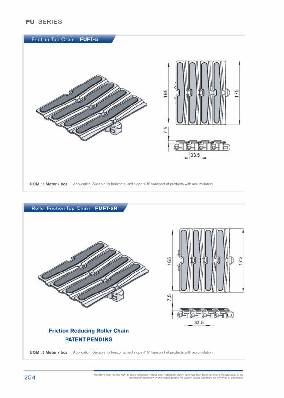
254FlexMove reserves the right to make alteration without prior notification Every care has been taken to ensure the accuracy of the
information contained in this catalogue but no liability can be accepted for any error or omissions.
FU SERIES
Friction Top Chain FUFT-5
Roller Friction Top Chain FUFT-5R
UOM : 5 Meter / box
UOM : 5 Meter / box
Application: Suitable for horizontal and slope < 5º transport of products with accumulation.
Application: Suitable for horizontal and slope < 5º transport of products with accumulation.
Friction Reducing Roller Chain
PATENT PENDING

255FlexMove® Product Catalogue
FU SERIES
FU Direct End Drive with Motor (RIGHT)
FU Direct End Drive with Motor (LEFT)
FUDD-A180-025R, 0.37R, 0.55R
FUDD-A180-025R, 0.37L, 0.55L
FUDD-A180-0R
FUDD-A180-0L
Max Traction Force : 1250N
The Direct End Drive Unit is without torque limiter. Standard attached gear motors are with SEW motor size0.25kW, 0.37kW & 0.55kW. FUDD-A180-0R represents direct drive without gear motor. Multi channel drives areavailable upon request.
Max Traction Force : 1250N
The Direct End Drive Unit is without torque limiter. Standard attached gear motors are with SEW motor size0.25kW, 0.37kW & 0.55kW. FUDD-A180-0L represents direct drive without gear motor. Multi channel drives areavailable upon request.
UOM : pc Chain required 2-way : 0.8 meter Slide rail required 2-way: 0 meter
UOM : pc Chain required 2-way: 0.8 meter Slide rail required 2-way: 0 meter
SEW gear motors are products of SEW Eurodrive
FU

256FlexMove reserves the right to make alteration without prior notification Every care has been taken to ensure the accuracy of the
information contained in this catalogue but no liability can be accepted for any error or omissions.
FU SERIES
FU Suspended Drive with Motor (RIGHT)
FU Suspended Drive with Motor (LEFT)
FUSD-A180-025R, 0.37R, 0.55R
FUSD-A180-0.25L, 0.37L, 0.55L
FUSD-A180-0R
FUSD-A180-0L
Max Traction Force : 1250N
The Direct End Drive Unit is without torque limiter. Standard attached gear motors are with SEW motor size0.25kW, 0.37kW & 0.55kW. FUSD-A180-0R represents direct drive without gear motor. Multi channel drives areavailable upon request.
Max Traction Force : 1250N
The Direct End Drive Unit is without torque limiter. Standard attached gear motors are with SEW motor size0.25kW, 0.37kW & 0.55kW. FUSD-A180-0L represents direct drive without gear motor. Multi channel drives areavailable upon request.
UOM : pc Chain required 2-way : 0.8 meter Slide rail required 2-way: 0 meter
UOM : pc Chain required 2-way: 0.8 meter Slide rail required 2-way: 0 meter

257FlexMove® Product Catalogue
FU SERIES
FU Idler End 180 FUIE-A180
SEW gear motors are products of SEW Eurodrive
UOM : pc Chain required 2-way: 0.8 meter Slide rail required 2-way: 0.5 meter FU

258FlexMove reserves the right to make alteration without prior notification Every care has been taken to ensure the accuracy of the
information contained in this catalogue but no liability can be accepted for any error or omissions.
FU SERIES
FU Hor izonta l Pla in Bend 30°
FU Hor izonta l Pla in Bend 45°
FU Hor izonta l Pla in Bend 60°
UOM : pcChain required 2-way ( 500, 700, 1000) : 2.2 , 2.4 , 2.7 meter
Slide rail required 2-way( 500, 700, 1000): 5.4 , 6.3, 7.5 meter
UOM : pcChain required 2-way ( 500, 700, 1000) : 2.5 , 2.8, 3.2 meter
Slide rail required 2-way( 500, 700, 1000): 6.5, 7.7 , 9.6 meter
UOM : pcChain required 2-way ( 500, 700, 1000) : 2.7, 3.1 , 3.8 meter
Slide rail required 2-way( 500, 700, 1000): 7.5, 9.2, 12.0 meter
Horizontal plain bend, 30° ± 1°
R = 500 ± 10mm FUHB-30R500
R = 700 ± 10mm FUHB-30R700
R = 1000 ± 10mm FUHB-30R1000
Horizontal plain bend, 45° ± 1°
R = 500 ± 10mm FUHB-45R500
R = 700 ± 10mm FUHB-45R700
R = 1000 ± 10mm FUHB-45R1000
Horizontal plain bend, 60° ± 1°
R = 500 ± 10mm FUHB-60R500
R = 700 ± 10mm FUHB-60R700
R = 1000 ± 10mm FUHB-60R1000
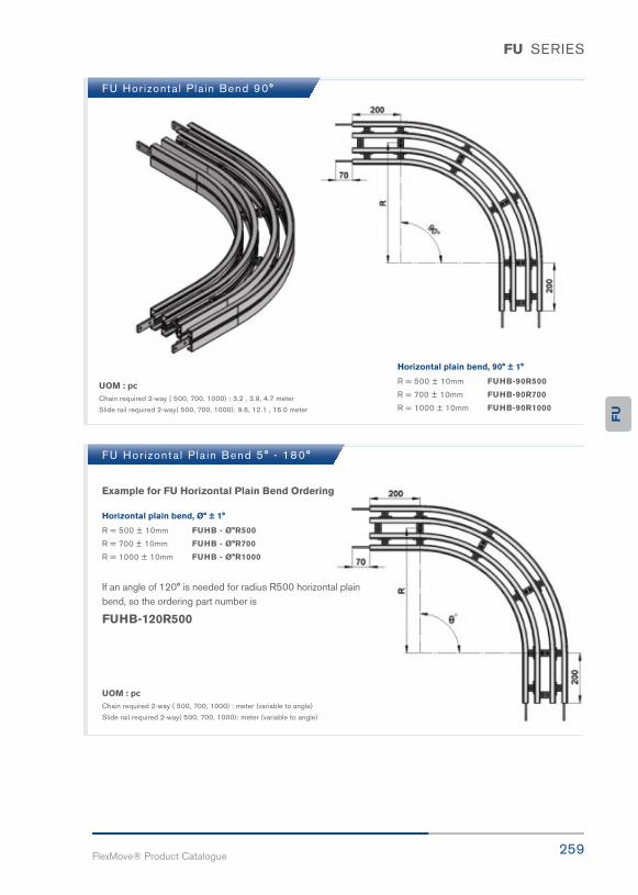
259FlexMove® Product Catalogue
FU SERIES
FU Hor izonta l Pla in Bend 90°
UOM : pcChain required 2-way ( 500, 700, 1000) : 3.2 , 3.9, 4.7 meter
Slide rail required 2-way( 500, 700, 1000): 9.6, 12.1 , 16.0 meter
Horizontal plain bend, 90° ± 1°
R = 500 ± 10mm FUHB-90R500
R = 700 ± 10mm FUHB-90R700
R = 1000 ± 10mm FUHB-90R1000
FU Hor izonta l P la in Bend 5° - 180°
Example for FU Horizontal Plain Bend Ordering
Horizontal plain bend, Ø° ± 1°
R = 500 ± 10mm FUHB - Ø°R500
R = 700 ± 10mm FUHB - Ø°R700
R = 1000 ± 10mm FUHB - Ø°R1000
If an angle of 120° is needed for radius R500 horizontal plain bend, so the ordering part number is
FUHB-120R500
UOM : pcChain required 2-way ( 500, 700, 1000) : meter (variable to angle)
Slide rail required 2-way( 500, 700, 1000): meter (variable to angle)
FU

260FlexMove reserves the right to make alteration without prior notification Every care has been taken to ensure the accuracy of the
information contained in this catalogue but no liability can be accepted for any error or omissions.
FU SERIES
FU Ver t ica l Bend 5°
FU Ver t ica l Bend 10°
FUVB-5R400
FUVB-10R400
UOM : pc
UOM : pc
Chain required 2-way: 0.4 meter Slide rail required 2-way: 1.6 meter
Chain required 2-way: 0.5 meter Slide rail required 2-way: 1.9 meter

261FlexMove® Product Catalogue
FU SERIES
FU Ver t ica l Bend 15° FUVB-15R400
UOM : pc Chain required 2-way: 0.6 meter Slide rail required 2-way: 2.2 meter
FU Ver t ica l Bend 20° FUVB-20R400
UOM : pc Chain required 2-way: 0.6 meter Slide rail required 2-way: 2.5 meter
FU

262FlexMove reserves the right to make alteration without prior notification Every care has been taken to ensure the accuracy of the
information contained in this catalogue but no liability can be accepted for any error or omissions.
FU SERIES
FU Ver t ica l Bend 30° FUVB-30R400
UOM : pc Chain required 2-way: 0.8 meter Slide rail required 2-way: 3.0 meter
FU Ver t ica l Bend 45° FUVB-45R400
UOM : pc Chain required 2-way: 1.0 meter Slide rail required 2-way: 3.9 meter

263FlexMove® Product Catalogue
FU SERIES
FU Ver t ica l Bend 60°
FU Ver t ica l Bend 90°
FU Ver t ica l Bend 5° - 90°
FUVB-60R400
FUVB-90R400
UOM : pc
UOM : pc
Chain required 2-way: 1.2 meter Slide rail required 2-way: 4.7 meter
Chain required 2-way: 1.6 meter Slide rail required 2-way: 6.4 meter
Example for FU Vertical Bend Ordering
- Vertical bend, Ø° ± 1°
- FUVB-Ø°R400
If an angle of 65° is needed for vertical bend, so the ordering part number is
FUVB-65R400
The outer bend is assembled using connecting strip (FACS-25x140A).Angle of “Ø°” must be indicated when ordering.
FU

Integrated Solutions • Product Conveying
• Diverting
• Merging
• Sorting
• Accumulating

FlexMove® creates value for customers by combining our proprietary automation solutions with intelligent transportation systems.
A total integrated solutions that is as result of the sound partnership between automation solutions and product transportation system such as product conveying, diverting and merging, sorting, accumulating, lifting and a standard software-tailor-made to the customer’s needs.
Quick
Popular
Widespread
Advanced

267FlexMove® Product Catalogue
FV260mm ConveyorSystem
FV
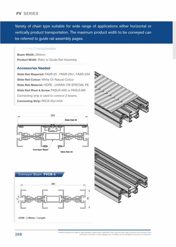
268FlexMove reserves the right to make alteration without prior notification Every care has been taken to ensure the accuracy of the
information contained in this catalogue but no liability can be accepted for any error or omissions.
FV SERIES
Variety of chain type suitable for wide range of applications either horizontal or
vertically product transportation. The maximum product width to be conveyed can
be referred to guide rail assembly pages.
Conveyor Beam FVCB-3
UOM : 3 Meter / Length
FV Series CharacteristicBeam Width: 260mm
Product Width: Refer to Guide Rail Assembly
Accessories NeededSlide Rail Required: FASR-25 , FASR-25U , FASR-25X
Slide Rail Colour: White Or Natural Colour
Slide Rail Material: HDPE , UHMW OR SPECIAL PE
Slide Rail Rivet & Screw: FASLR-4X6 or FASLS-M5
Connecting strip is used to connect 2 beams.
Connecting Strip: FACS-25x140A

269FlexMove® Product Catalogue
FV SERIES
Chain Common DatePackaging: 5m per box
Pitch: 33.5mm
Width: 255mm
Tensile Strength at 20ºC: 6000N
Colour: White & Black (Conductive)
Friction Reducing Roller Chain
PATENT PENDING
Plain Chain PVPC-5
Roller Plain Chain FVPC-5R
UOM : 5 Meter / box
UOM : 5 Meter / box
Application: Suitable for horizontal and slope < 5° transport of products with accumulation.
Application: Suitable for horizontal and slope < 5° transport of products with accumulation.
FV

270FlexMove reserves the right to make alteration without prior notification Every care has been taken to ensure the accuracy of the
information contained in this catalogue but no liability can be accepted for any error or omissions.
FV SERIES
Friction Top Chain FVFT-5
Roller Friction Top Chain FVFT-5R
UOM : 5 Meter / box
UOM : 5 Meter / box
Application: Suitable for horizontal and slope < 5° transport of products with accumulation.
Application: Suitable for horizontal and slope < 5° transport of products with accumulation.
Friction Reducing Roller Chain
PATENT PENDING
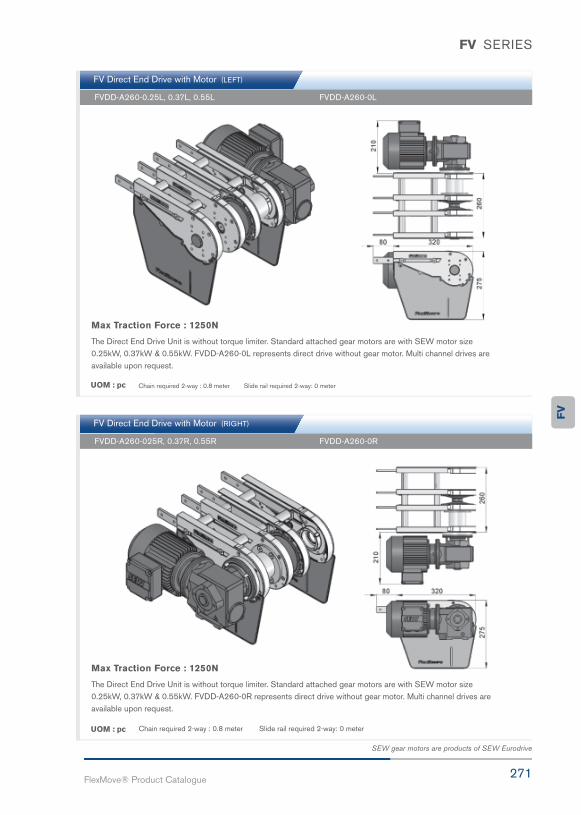
271FlexMove® Product Catalogue
FV SERIES
FV Direct End Drive with Motor (RIGHT)
FV Direct End Drive with Motor (LEFT)
FVDD-A260-025R, 0.37R, 0.55R
FVDD-A260-0.25L, 0.37L, 0.55L
FVDD-A260-0R
FVDD-A260-0L
Max Traction Force : 1250N
The Direct End Drive Unit is without torque limiter. Standard attached gear motors are with SEW motor size0.25kW, 0.37kW & 0.55kW. FVDD-A260-0R represents direct drive without gear motor. Multi channel drives areavailable upon request.
Max Traction Force : 1250N
The Direct End Drive Unit is without torque limiter. Standard attached gear motors are with SEW motor size0.25kW, 0.37kW & 0.55kW. FVDD-A260-0L represents direct drive without gear motor. Multi channel drives areavailable upon request.
UOM : pc Chain required 2-way : 0.8 meter Slide rail required 2-way: 0 meter
UOM : pc Chain required 2-way : 0.8 meter Slide rail required 2-way: 0 meter
SEW gear motors are products of SEW Eurodrive
FV

272FlexMove reserves the right to make alteration without prior notification Every care has been taken to ensure the accuracy of the
information contained in this catalogue but no liability can be accepted for any error or omissions.
FV SERIES
FV Direct End Drive with Motor (RIGHT)
FV Direct End Drive with Motor (LEFT)
FVSD-A260-025R, 0.37R, 0.55R
FVSD-A260-0.25L, 0.37L, 0.55L
FVSD-A260-0R
FVSD-A260-0L
Max Traction Force : 1250N
The Direct End Drive Unit is without torque limiter. Standard attached gear motors are with SEW motor size0.25kW, 0.37kW & 0.55kW. FVSD-A260-0R represents direct drive without gear motor. Multi channel drives areavailable upon request.
Max Traction Force : 1250N
The Direct End Drive Unit is without torque limiter. Standard attached gear motors are with SEW motor size0.25kW, 0.37kW & 0.55kW. FVSD-A260-0L represents direct drive without gear motor. Multi channel drives areavailable upon request.
UOM : pc Chain required 2-way : 0.8 meter Slide rail required 2-way: 0 meter
UOM : pc Chain required 2-way : 0.8 meter Slide rail required 2-way: 0 meter

273FlexMove® Product Catalogue
FV SERIES
FV Idler End 260 FVIE-A260
Chain Connecting Module FVCC-300
UOM : pc
UOM : pc
Chain required 2-way : 0.8 meter Slide rail required 2-way: 0.5 meter
SEW gear motors are products of SEW Eurodrive
Beam section for chain installation.
FV

274FlexMove reserves the right to make alteration without prior notification Every care has been taken to ensure the accuracy of the
information contained in this catalogue but no liability can be accepted for any error or omissions.
FV SERIES
FV Hor izonta l Pla in Bend 30°
FV Hor izonta l Pla in Bend 45°
FV Hor izonta l Pla in Bend 60°
UOM : pcChain required 2-way ( 700, 1000) : 1.6, 1.9 meter
Slide rail required 2-way( 700, 1000): 6.3, 7.5 meter
UOM : pcChain required 2-way ( 700, 1000) : 1.9, 2.4 meter
Slide rail required 2-way( 700, 1000): 7.7 , 9.6 meter
UOM : pcChain required 2-way ( 700, 1000) : 2.3, 2.9 meter
Slide rail required 2-way( 700, 1000): 9.2, 12.0 meter
Horizontal plain bend, 30° ± 1°
R = 700 ± 10mm FVHB-30R700
R = 1000 ± 10mm FVHB-30R1000
Horizontal plain bend, 45° ± 1°
R = 700 ± 10mm FVHB-45R700
R = 1000 ± 10mm FVHB-45R1000
Horizontal plain bend, 60° ± 1°
R = 700 ± 10mm FVHB-60R700
R = 1000 ± 10mm FVHB-60R1000

275FlexMove® Product Catalogue
FV SERIES
FV Hor izonta l Pla in Bend 90°
UOM : pcChain required 2-way ( 700, 1000) : 3.0, 4.0 meter
Slide rail required 2-way( 700, 1000): 12.1 , 16.0 meter
Horizontal plain bend, 90° ± 1°
R = 700 ± 10mm FVHB-90R700
R = 1000 ± 10mm FVHB-90R1000
FV Hor izonta l P la in Bend 5° - 180°
Example for FV Horizontal Plain Bend Ordering
Horizontal plain bend, Ø° ± 1°
R = 700 ± 10mm FVHB - Ø°R700
R = 1000 ± 10mm FVHB - Ø°R1000
If an angle of 120° is needed for radius R700 horizontal plainbend, so the ordering part number is
FVHB -120R700
UOM : pcChain required 2-way ( 700, 1000) : meter (variable to angle)
Slide rail required 2-way( 700, 1000): meter (variable to angle)
FV

276FlexMove reserves the right to make alteration without prior notification Every care has been taken to ensure the accuracy of the
information contained in this catalogue but no liability can be accepted for any error or omissions.
FV SERIES
FV Ver t ica l Bend 5°
FV Ver t ica l Bend 10°
FVVB-5R400
FVVB-10R400
UOM : pc
UOM : pc
Chain required 2-way: 0.4 meter Slide rail required 2-way: 1.6 meter
Chain required 2-way: 0.5 meter Slide rail required 2-way: 1.9 meter

277FlexMove® Product Catalogue
FV SERIES
FV Ver t ica l Bend 15° FVVB-15R400
UOM : pc Chain required 2-way: 0.6 meter Slide rail required 2-way: 2.2 meter
FV Ver t ica l Bend 20° FVVB-20R400
UOM : pc Chain required 2-way: 0.6 meter Slide rail required 2-way: 2.5 meter
FV

278FlexMove reserves the right to make alteration without prior notification Every care has been taken to ensure the accuracy of the
information contained in this catalogue but no liability can be accepted for any error or omissions.
FV SERIES
FV Ver t ica l Bend 30° FVVB-30R400
UOM : pc Chain required 2-way: 0.8 meter Slide rail required 2-way: 3.0 meter
FV Ver t ica l Bend 45° FVVB-45R400
UOM : pc Chain required 2-way: 1.0 meter Slide rail required 2-way: 3.9 meter
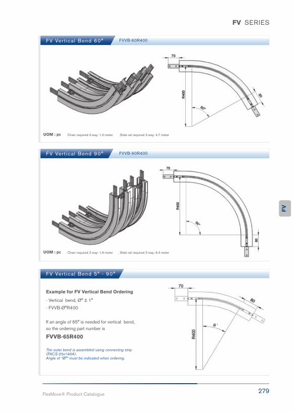
279FlexMove® Product Catalogue
FV SERIES
FV Ver t ica l Bend 60°
FV Ver t ica l Bend 90°
FV Ver t ica l Bend 5° - 90°
FVVB-60R400
FVVB-90R400
UOM : pc
UOM : pc
Chain required 2-way: 1.2 meter Slide rail required 2-way: 4.7 meter
Chain required 2-way: 1.6 meter Slide rail required 2-way: 6.4 meter
Example for FV Vertical Bend Ordering
- Vertical bend, Ø° ± 1°
- FVVB-Ø°R400
If an angle of 65° is needed for vertical bend, so the ordering part number is
FVVB-65R400
The outer bend is assembled using connecting strip (FACS-25x140A).Angle of “Ø°” must be indicated when ordering.
FV

FW300mm ConveyorSystem
281FlexMove® Product Catalogue
FW

282FlexMove reserves the right to make alteration without prior notification Every care has been taken to ensure the accuracy of the
information contained in this catalogue but no liability can be accepted for any error or omissions.
FW SERIES
Variety of chain types suitable for wide range of applications either horizontal or
vertically product transportation. The maximum product width to be conveyed be
can be referred to guide rail assembly pages.
Chain Connecting Module FWCC-300
Conveyor Beam FWCB300-3
FW Series CharacteristicBeam Width: 320mm
Product Width: Refer to Guide Rail Assembly
Accessories NeededSlide Rail Required: FASR-25 OR FASR-25U
Slide Rail Colour: White Or Natural Colour
Slide Rail Material: HDPE OR UHMW-PE
Slide Rail Rivet & Screw: FASLR-4X6 or FASLS-M5
Connecting strip is used to connect 2 beams.
Connecting Strip: FACS-25x140A
UOM: pc
UOM : 3 Meter / Length
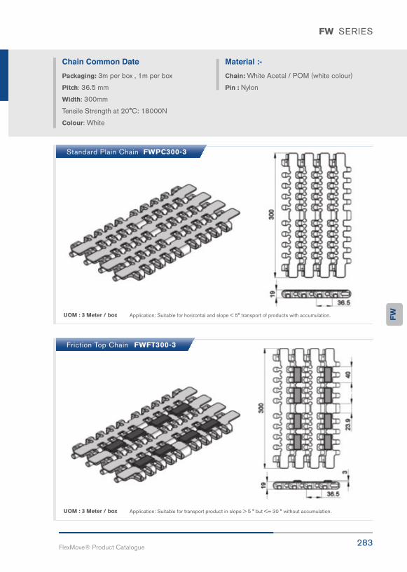
283FlexMove® Product Catalogue
FW SERIES
Chain Common DatePackaging: 3m per box , 1m per box
Pitch: 36.5 mm
Width: 300mm
Tensile Strength at 20°C: 18000N
Colour: White
Material :-Chain: White Acetal / POM (white colour)
Pin : Nylon
Standard Plain Chain FWPC300-3
Friction Top Chain FWFT300-3
UOM : 3 Meter / box
UOM : 3 Meter / box
Application: Suitable for horizontal and slope < 5° transport of products with accumulation.
Application: Suitable for transport product in slope > 5 ° but <= 30 ° without accumulation.
FW

284FlexMove reserves the right to make alteration without prior notification Every care has been taken to ensure the accuracy of the
information contained in this catalogue but no liability can be accepted for any error or omissions.
FW SERIES
FW Direct End Drive with Motor (RIGHT) FW Direct End Drive without Motor (RIGHT)
FW Direct End Drive with Motor (LEFT) FW Direct End Drive without Motor (LEFT)
FWDD-0.25R, 0.37R, 0.55R
FWDD-0.25L, 0.37L, 0.55L
FWDD-0R
FWDD-0L
Max Traction Force : 1250N
The Direct End Drive Unit is without torque limiter. Standard attached gear motors are with SEW motorsize 0.25kW, 0.37kW & 0.55kW. FWDD-0R represents direct drive without gear motor. Multi channeldrives are available upon request.
Max Traction Force : 500N
The Direct End Drive Unit is without torque limiter. Standard attached gear motors are with SEW motorsize 0.25kW, 0.37kW & 0.55kW. FWDD-0L represents direct drive without gear motor. Multi channeldrives are available upon request.
UOM : pc Chain required 2-way :0.8 meter Slide rail required 2-way: 0.4 meter
UOM : pc Chain required 2-way :0.8 meter Slide rail required 2-way: 0.4 meter
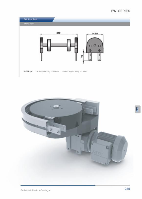
285FlexMove® Product Catalogue
FW SERIES
FW Idler End
FWIE-300
UOM : pc Chain required 2-way : 0.42 meter Slide rail required 2-way: 0.0 meter
FW
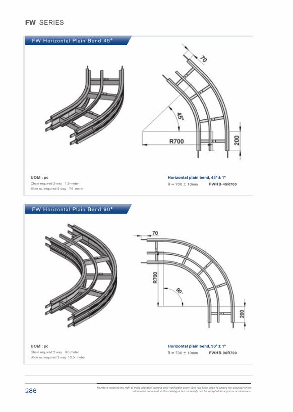
286FlexMove reserves the right to make alteration without prior notification Every care has been taken to ensure the accuracy of the
information contained in this catalogue but no liability can be accepted for any error or omissions.
FW SERIES
FW Hor izonta l Pla in Bend 45°
FW Hor izonta l Pla in Bend 90°
UOM : pcChain required 2-way 1.9 meter
Slide rail required 2-way 7.6 meter
UOM : pcChain required 2-way 3.0 meter
Slide rail required 2-way 12.5 meter
Horizontal plain bend, 45° ± 1°
R = 700 ± 10mm FWHB-45R700
Horizontal plain bend, 90° ± 1°
R = 700 ± 10mm FWHB-90R700
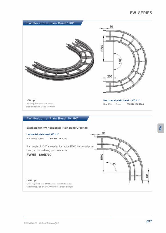
287FlexMove® Product Catalogue
FW SERIES
FW Hor izonta l Pla in Bend 180°
FW Hor izonta l Pla in Bend 5-180°
UOM : pcChain required 2-way 5.2 meter
Slide rail required 2-way 21 meter
Horizontal plain bend, 180° ± 1°
R = 700 ± 10mm FWHB-180R700
Example for FW Horizontal Plain Bend Ordering
Horizontal plain bend, Ø° ± 1°
R = 700 ± 10mm FWHB - Ø°R700
If an angle of 120° is needed for radius R700 horizontal plainbend, so the ordering part number is
FWHB -120R700
UOM : pcChain required 2-way R700 : meter (variable to angle)
Slide rail required 2-way R700 : meter (variable to angle)
FW

288FlexMove reserves the right to make alteration without prior notification Every care has been taken to ensure the accuracy of the
information contained in this catalogue but no liability can be accepted for any error or omissions.
FW SERIES
FW Ver t ica l Bend 30° FWVB-30R500
UOM : pc Chain required 2-way : 0.8 meter Slide rail required 2-way: 4.2 meter
FW Ver t ica l Bend 5° - 90°
Example for FW Vertical Bend Ordering
- FW Vertical Bend, Ø° ± 1°
- FWVB-Ø°R500
If an angle of 40° is needed for vertical bend, so the ordering part number is
FWVB-40R500
The outer bend is assembled using connecting strip (FACS-25x140A). Angle of “Ø°” must be indicatedwhen ordering.

289FlexMove® Product Catalogue
FH35mm ConveyorSystem
FH

290FlexMove reserves the right to make alteration without prior notification Every care has been taken to ensure the accuracy of the
information contained in this catalogue but no liability can be accepted for any error or omissions.
FH SERIES
FH Series is a compact and neat design for Twin track application for pallet
assembly line.
Conveyor Beam FHCB-3
Standard Plain Chain FHPC-5
FH Series CharacteristicBeam Width: 45mm
Accessories NeededSlide Rail Required: FASR-25C OR FASR-25S
Slide Rail Colour: White
Slide Rail Material: HDPE
Slide Rail Rivet & Screw: FASLR-3X6
Connecting strip is used to connect 2 beams.
Connecting Strip: FACS-20x140
UOM : 3 Meter / LengthApplication: Suitable for horizontal and slope< 5° transport of products with accumulation.

291FlexMove® Product Catalogue
FZFunctioningModule
FZ

292FlexMove reserves the right to make alteration without prior notification Every care has been taken to ensure the accuracy of the
information contained in this catalogue but no liability can be accepted for any error or omissions.
FZ SERIES
FZWA-660A
FZWA-950A
FZG B-903 FZG B-904
Width Adjustment Actuator 660mm
Width Adjustment Actuator 950mm
Angle Gear Unit-3 direction Angle Gear Unit – 4 direction
UOM : Unit
UOM : Unit
UOM : Unit UOM : Unit
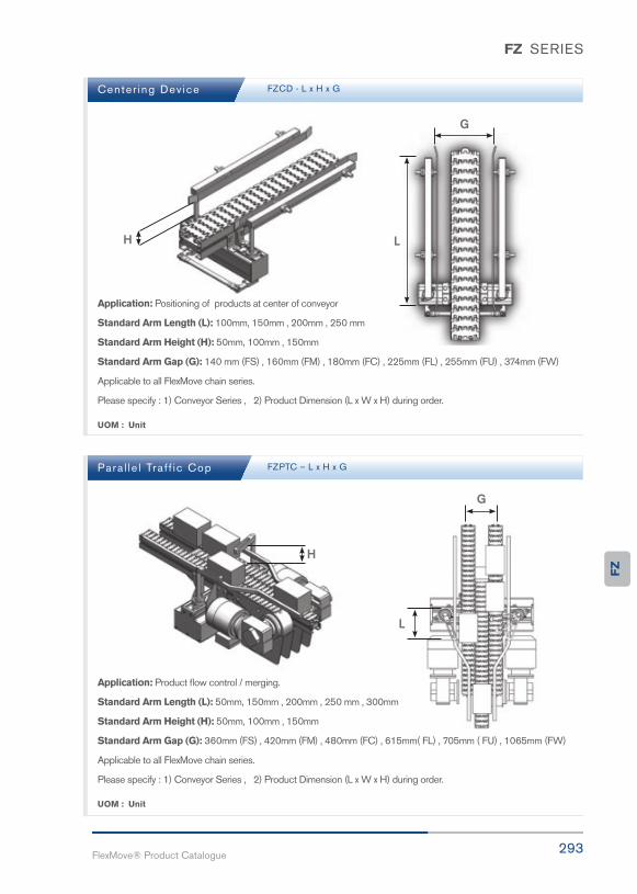
293FlexMove® Product Catalogue
FZ SERIES
Center ing Dev ice
Para l le l Tra f f ic Cop
FZCD - L x H x G
FZPTC – L x H x G
UOM : Unit
UOM : Unit
Application: Positioning of products at center of conveyor
Standard Arm Length (L): 100mm, 150mm , 200mm , 250 mm
Standard Arm Height (H): 50mm, 100mm , 150mm
Standard Arm Gap (G): 140 mm (FS) , 160mm (FM) , 180mm (FC) , 225mm (FL) , 255mm (FU) , 374mm (FW)
Applicable to all FlexMove chain series.
Please specify : 1) Conveyor Series , 2) Product Dimension (L x W x H) during order.
Application: Product flow control / merging.
Standard Arm Length (L): 50mm, 150mm , 200mm , 250 mm , 300mm
Standard Arm Height (H): 50mm, 100mm , 150mm
Standard Arm Gap (G): 360mm (FS) , 420mm (FM) , 480mm (FC) , 615mm( FL) , 705mm ( FU) , 1065mm (FW)
Applicable to all FlexMove chain series.
Please specify : 1) Conveyor Series , 2) Product Dimension (L x W x H) during order.
FZ

294FlexMove reserves the right to make alteration without prior notification Every care has been taken to ensure the accuracy of the
information contained in this catalogue but no liability can be accepted for any error or omissions.
FZ SERIES
Angle Tra f f ic Cop
Adjustment S ide gu ide
FZPTC – L x H x G
FZASG – H x W
UOM : Unit
UOM : Unit
Application: Product flow control / merging.
Standard Arm Length (L): 100mm, 150mm , 200mm , 250 mm
Standard Arm Angle (A): 45° , 90°
Applicable to all FlexMove chain series.
Please specify : 1) Conveyor Series , 2) Product Dimension (L x W x H) , 3) Diverting Angle during order.
Application: Manual adjustable guide rail for multiple product size
Standard Arm Height (H): 100mm, 150mm , 200mm , 250 mm
Adjustable Width (W): 65mm , 85mm , 105mm , 150mm , 225mm , 300 mm
Applicable to all FlexMove chain series.
Please specify : 1) Conveyor Series , 2) Product Dimension (L x W x H)
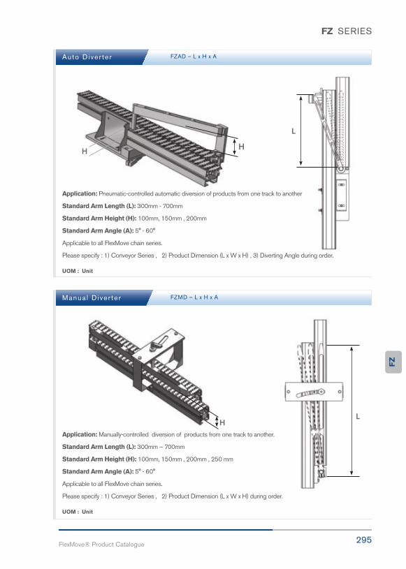
295FlexMove® Product Catalogue
FZ SERIES
Auto Diver ter
Manua l D iver ter
FZAD – L x H x A
FZMD – L x H x A
UOM : Unit
UOM : Unit
Application: Pneumatic-controlled automatic diversion of products from one track to another
Standard Arm Length (L): 300mm - 700mm
Standard Arm Height (H): 100mm, 150mm , 200mm
Standard Arm Angle (A): 5° - 60°
Applicable to all FlexMove chain series.
Please specify : 1) Conveyor Series , 2) Product Dimension (L x W x H) , 3) Diverting Angle during order.
Application: Manually-controlled diversion of products from one track to another.
Standard Arm Length (L): 300mm – 700mm
Standard Arm Height (H): 100mm, 150mm , 200mm , 250 mm
Standard Arm Angle (A): 5° - 60°
Applicable to all FlexMove chain series.
Please specify : 1) Conveyor Series , 2) Product Dimension (L x W x H) during order.
FZ

Gently
Efficiently
Dust-free
Smooth
297FlexMove® Product Catalogue
FYTools
FY
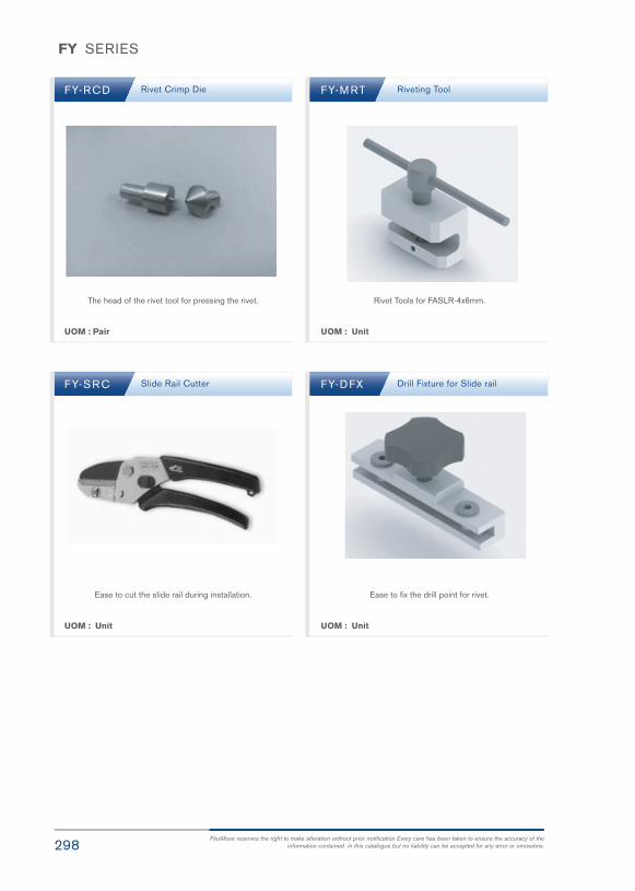
298FlexMove reserves the right to make alteration without prior notification Every care has been taken to ensure the accuracy of the
information contained in this catalogue but no liability can be accepted for any error or omissions.
FY SERIES
FY-RCD
FY-SRC
FY-M RT
FY-DFX
Rivet Crimp Die
Slide Rail Cutter
Riveting Tool
Drill Fixture for Slide rail
The head of the rivet tool for pressing the rivet.
Ease to cut the slide rail during installation.
Rivet Tools for FASLR-4x6mm.
Ease to fix the drill point for rivet.
UOM : Pair
UOM : Unit
UOM : Unit
UOM : Unit

299FlexMove® Product Catalogue
FY SERIES
FY-F_C IT/CRT FZG B-903
FY-RT
Angle Gear Unit-3 direction
Riveting Tool
Tools for mounting the slide rail towards the beam.
-FY-FK-CIT/CRT for FK series-FY-FS-CIT/CRT for FS series-FY-FM-CIT/CRT for FM series-FY-FCL-CIT/CRT for FC series/FL series-FY-FU-CIT/CRT for FU series-FY-FW-CIT/CRT for FW Series
Tools for mounting the slide rail towards the beam.
-FY-FKMT for FK series-FY-FSMT for FS series-FY-FMMT for FM series-FY-FCMT for FC series/FL series-FY-FUMT for FU series-FY-FWMT for FW series
Rivet Tools for slide rail.
UOM : Unit UOM : Unit
UOM : Unit
FY

Characteristic
Possibilities
Series
Transportation

301FlexMove® Product Catalogue
ConveyorTransferBridge
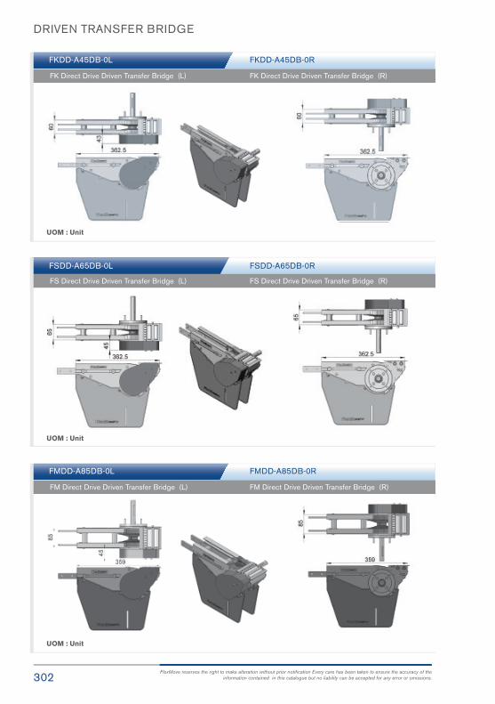
302FlexMove reserves the right to make alteration without prior notification Every care has been taken to ensure the accuracy of the
information contained in this catalogue but no liability can be accepted for any error or omissions.
DRIVEN TRANSFER BRIDGE
FKDD-A45DB-0L
FSDD-A65DB-0L
FMDD-A85DB-0L
FKDD-A45DB-0R
FSDD-A65DB-0R
FMDD-A85DB-0R
FK Direct Drive Driven Transfer Bridge (L)
FS Direct Drive Driven Transfer Bridge (L)
FM Direct Drive Driven Transfer Bridge (L)
FK Direct Drive Driven Transfer Bridge (R)
FS Direct Drive Driven Transfer Bridge (R)
FM Direct Drive Driven Transfer Bridge (R)
UOM : Unit
UOM : Unit
UOM : Unit
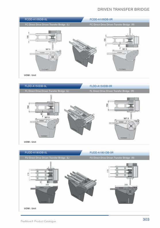
303FlexMove® Product Catalogue
DRIVEN TRANSFER BRIDGE
FCDD-A105DB-0L
FLDD-A150DB-0L
FUDD-A180DB-0L
FCDD-A105DB-0R
FLDD-A150DB-0R
FUDD-A180-DB-0R
FC Direct Drive Driven Transfer Bridge (L)
FL Direct Drive Driven Transfer Bridge (L)
FU Direct Drive Driven Transfer Bridge (L)
FC Direct Drive Driven Transfer Bridge (R)
FL Direct Drive Driven Transfer Bridge (R)
FU Direct Drive Driven Transfer Bridge (R)
UOM : Unit
UOM : Unit
UOM : Unit

DRIVEN TRANSFER BRIDGE
FVDD-A260-DB-0L
FWDD-A300DB-0L
FVDD-A260-DB-0R
FWDD-A300DB-0R
FV Direct Drive Driven Transfer Bridge (L)
FW Direct Drive Driven Transfer Bridge (L)
FV Direct Drive Driven Transfer Bridge (R)
FW Direct Drive Driven Transfer Bridge (R)
UOM : Unit
UOM : Unit
304FlexMove reserves the right to make alteration without prior notification Every care has been taken to ensure the accuracy of the
information contained in this catalogue but no liability can be accepted for any error or omissions.

305FlexMove® Product Catalogue
DRIVEN TRANSFER BRIDGE
FSIE-A65DB-L
FMIE-A85DB-L
FCIE-A105DB-L
FSIE-A65DB-R
FMIE-A85DB-R
FCIE-A105DB-R
FS Idler End Driven Transfer Bridge (L)
FM Idler End Driven Transfer Bridge (L)
FC Idler End Driven Transfer Bridge (L)
FS Idler End Driven Transfer Bridge (R)
FM Idler End Driven Transfer Bridge (R)
FC Idler End Driven Transfer Bridge (R)
UOM : Unit
UOM : Unit
UOM : Unit

DRIVEN TRANSFER BRIDGE
FLIE-A150DB-L
FUIE-A180DB-L
FLIE-A150DB-R
FUIE-A180DB-R
FL Idler End Driven Transfer Bridge (L)
FU Idler End Driven Transfer Bridge (L)
FL Idler End Driven Transfer Bridge (R)
FU Idler End Driven Transfer Bridge (R)
UOM : Unit
UOM : Unit
306FlexMove reserves the right to make alteration without prior notification Every care has been taken to ensure the accuracy of the
information contained in this catalogue but no liability can be accepted for any error or omissions.

307FlexMove® Product Catalogue
END TRANSFER BRIDGE
FVIE-A260DB-L
FWIE-A300DB-L
FVIE-A260DB-R
FWIE-A300DB-R
FV Idler End Driven Transfer Bridge (L)
FW Idler End Driven Transfer Bridge (L)
FV Idler End Driven Transfer Bridge (R)
FW Idler End Driven Transfer Bridge (R)
UOM : Unit
UOM : Unit

FREE ROLLER TRANSFER BRIDGE
FKDD-A45TB-0L
FSDD-A65TB-0L
FMDD-A85TB-0L
FKDD-A45TB-0R
FSDD-A65TB-0R
FMDD-A85TB-0R
FK Direct Drive Free Roller Transfer Bridge (L)
FS Direct Drive Free Roller Transfer Bridge (L)
FM Direct Drive Free Roller Transfer Bridge (L)
FK Direct Drive Free Roller Transfer Bridge (R)
FS Direct Drive Free Roller Transfer Bridge (R)
FM Direct Drive Free Roller Transfer Bridge (R)
UOM : Unit
UOM : Unit
UOM : Unit
308FlexMove reserves the right to make alteration without prior notification Every care has been taken to ensure the accuracy of the
information contained in this catalogue but no liability can be accepted for any error or omissions.
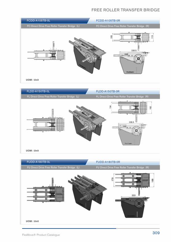
309FlexMove® Product Catalogue
FREE ROLLER TRANSFER BRIDGE
FCDD-A105TB-0L
FLDD-A150TB-0L
FUDD-A180TB-0L
FCDD-A105TB-0R
FLDD-A150TB-0R
FUDD-A180TB-0R
FC Direct Drive Free Roller Transfer Bridge (L)
FL Direct Drive Free Roller Transfer Bridge (L)
FU Direct Drive Free Roller Transfer Bridge (L)
FC Direct Drive Free Roller Transfer Bridge (R)
FL Direct Drive Free Roller Transfer Bridge (R)
FU Direct Drive Free Roller Transfer Bridge (R)
UOM : Unit
UOM : Unit
UOM : Unit

FREE ROLLER TRANSFER BRIDGE
FVDD-A260TB-0L
FWDD-A300TB-0L
FVDD-A260TB-0R
FWDD-A300TB-0R
FV Direct Drive Free Roller Transfer Bridge (L)
FW Direct Drive Free Roller Transfer Bridge (L)
FV Direct Drive Free Roller Transfer Bridge (R)
FW Direct Drive Free Roller Transfer Bridge (R)
UOM : Unit
UOM : Unit
310FlexMove reserves the right to make alteration without prior notification Every care has been taken to ensure the accuracy of the
information contained in this catalogue but no liability can be accepted for any error or omissions.

311FlexMove® Product Catalogue
FREE ROLLER TRANSFER BRIDGE
UOM : Unit UOM : Unit
UOM : Unit UOM : Unit
UOM : Unit UOM : Unit
FSIE-A65TB FSTB-A65
FMIE-A85TB FMTB-A85
FCIE-A105TB FCTB-A105
FS Idler Free Roller Transfer Bridge
FM Idler Free Roller Transfer Bridge
FC Idler Free Roller Transfer Bridge
Transfer bridge c/w roller for FSIE-A65Transfer bridge c/w roller for FSDD-A65-0LTransfer bridge c/w roller for FSDD-A65-0R
Transfer bridge c/w roller for FMIE-A85Transfer bridge c/w roller for FMDD-A85-0LTransfer bridge c/w roller for FMDD-A85-0R
Transfer bridge c/w roller for FCIE-A105Transfer bridge c/w roller for FCDD-A105-0LTransfer bridge c/w roller for FCDD-A105-0R
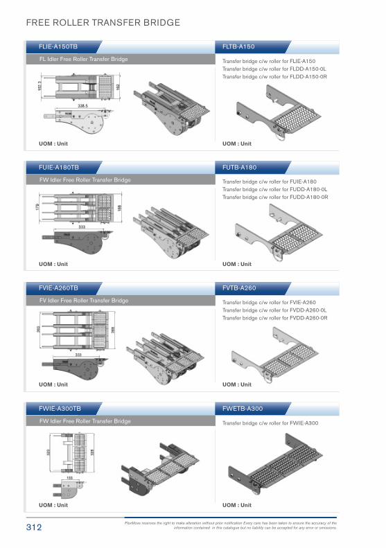
FREE ROLLER TRANSFER BRIDGE
UOM : Unit UOM : Unit
UOM : Unit UOM : Unit
UOM : Unit
UOM : Unit
UOM : Unit
UOM : Unit
FLIE-A150TB FLTB-A150
FUIE-A180TB FUTB-A180
FVIE-A260TB
FWIE-A300TB
FVTB-A260
FWETB-A300
FL Idler Free Roller Transfer Bridge
FW Idler Free Roller Transfer Bridge
FV Idler Free Roller Transfer Bridge
FW Idler Free Roller Transfer Bridge
Transfer bridge c/w roller for FLIE-A150Transfer bridge c/w roller for FLDD-A150-0LTransfer bridge c/w roller for FLDD-A150-0R
Transfer bridge c/w roller for FUIE-A180Transfer bridge c/w roller for FUDD-A180-0LTransfer bridge c/w roller for FUDD-A180-0R
Transfer bridge c/w roller for FVIE-A260Transfer bridge c/w roller for FVDD-A260-0LTransfer bridge c/w roller for FVDD-A260-0R
Transfer bridge c/w roller for FWIE-A300
312FlexMove reserves the right to make alteration without prior notification Every care has been taken to ensure the accuracy of the
information contained in this catalogue but no liability can be accepted for any error or omissions.

313FlexMove® Product Catalogue
END TRANSFER BRIDGE
FKDD-A45EB-0L
FSDD-A65EB-0L
FMDD-A85EB-0L
FKDD-A45EB-0R
FSDD-A65EB-0R
FMDD-A85EB-0R
FK Direct Drive End Free Roller Bridge (L)
FS Direct Drive End Free Roller Bridge (L)
FM Direct Drive End Free Roller Bridge (L)
FK Direct Drive End Free Roller Bridge (R)
FS Direct Drive End Free Roller Bridge (R)
FM Direct Drive End Free Roller Bridge (R)
UOM : Unit
UOM : Unit
UOM : Unit

END TRANSFER BRIDGE
FCDD-A105EB-0L
FLDD-A150EB-0L
FUDD-A180EB-0L
FCDD-A105EB-0R
FLDD-A150EB-0R
FUDD-A180EB-0R
FC Direct Drive End Free Roller Bridge (L)
FL Direct Drive End Free Roller Bridge (L)
FU Direct Drive End Free Roller Bridge (L)
FC Direct Drive End Free Roller Bridge (R)
FL Direct Drive End Free Roller Bridge (R)
FU Direct Drive End Free Roller Bridge (R)
UOM : Unit
UOM : Unit
UOM : Unit
314FlexMove reserves the right to make alteration without prior notification Every care has been taken to ensure the accuracy of the
information contained in this catalogue but no liability can be accepted for any error or omissions.

315FlexMove® Product Catalogue
END TRANSFER BRIDGE
FVDD-A260EB-0L
FWDD-A300EB-0L
FVDD-A260EB-0R
FWDD-A300EB-0R
FV Direct Drive End Free Roller Bridge (L)
FW Direct Drive End Free Roller Bridge (L)
FV Direct Drive End Free Roller Bridge (R)
FW Direct Drive End Free Roller Bridge (R)
UOM : Unit
UOM : Unit
UOM : Unit
FWDEB-A300
End transfer bridge c/w roller for FWDD-A300-0LEnd transfer bridge c/w roller for FWDD-A300-0R
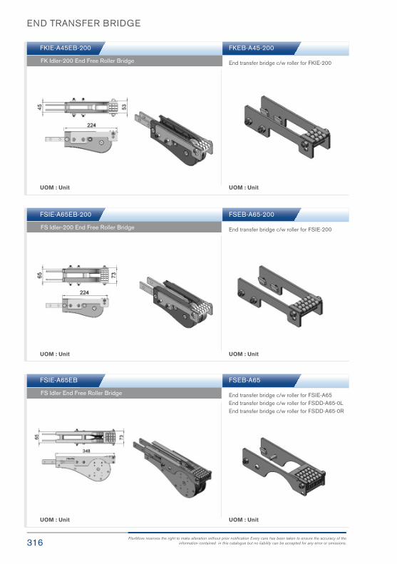
END TRANSFER BRIDGE
UOM : Unit
UOM : Unit
UOM : Unit
UOM : Unit
UOM : Unit
UOM : Unit
FKIE-A45EB-200
FSIE-A65EB-200
FSIE-A65EB
FKEB-A45-200
FSEB-A65-200
FSEB-A65
FK Idler-200 End Free Roller Bridge
FS Idler-200 End Free Roller Bridge
FS Idler End Free Roller Bridge
End transfer bridge c/w roller for FKIE-200
End transfer bridge c/w roller for FSIE-200
End transfer bridge c/w roller for FSIE-A65End transfer bridge c/w roller for FSDD-A65-0LEnd transfer bridge c/w roller for FSDD-A65-0R
316FlexMove reserves the right to make alteration without prior notification Every care has been taken to ensure the accuracy of the
information contained in this catalogue but no liability can be accepted for any error or omissions.

317FlexMove® Product Catalogue
END TRANSFER BRIDGE
UOM : Unit
UOM : Unit
UOM : Unit
UOM : Unit
UOM : Unit
UOM : Unit
FMIE-A85EB
FCIE-A105EB
FLIE-A150EB
FMEB-A85
FCEB-A105
FLEB-A150
FM Idler End Free Roller Bridge
FC Idler End Free Roller Bridge
FL Idler End Free Roller Bridge
End transfer bridge c/w roller for FMIE-A85End transfer bridge c/w roller for FMDD-A85-0LEnd transfer bridge c/w roller for FMDD-A85-0R
End transfer bridge c/w roller for FCIE-A105End transfer bridge c/w roller for FCDD-A105-0LEnd transfer bridge c/w roller for FCDD-A105-0R
End transfer bridge c/w roller for FLIE-A150End transfer bridge c/w roller for FLDD-A150-0LEnd transfer bridge c/w roller for FLDD-A150-0R

END TRANSFER BRIDGE
UOM : Unit
UOM : Unit
UOM : Unit
UOM : Unit
UOM : Unit
UOM : Unit
FUIE-A180EB
FVIE-A260EB
FWIE-A300EB
FUEB-A180
FVEB-A260
FWEB-A300
FW Idler End Free Roller Bridge
FV Idler End Free Roller Bridge
FW Idler End Free Roller Bridge
End transfer bridge c/w roller for FUIE-A180End transfer bridge c/w roller for FUDD-A180-0LEnd transfer bridge c/w roller for FUDD-A180-0R
End transfer bridge c/w roller for FVIE-A260End transfer bridge c/w roller for FVDD-A260-0LEnd transfer bridge c/w roller for FVDD-A260-0R
End transfer bridge c/w roller for FWEB-A300
318FlexMove reserves the right to make alteration without prior notification Every care has been taken to ensure the accuracy of the
information contained in this catalogue but no liability can be accepted for any error or omissions.

319FlexMove® Product Catalogue
SS63mm StainlessSteel ConveyorSystem
SS

320FlexMove reserves the right to make alteration without prior notification Every care has been taken to ensure the accuracy of the
information contained in this catalogue but no liability can be accepted for any error or omissions.
SS SERIES
Variety of chain type suitable for wide range of applications either horizontal or
vertically product transportation.
Conveyor Beam SSCB Conveyor Beam SSCC-160
FV Series CharacteristicBeam Width: 65mm
Product Width: Refer to Guide Rail Assembly
Accessories NeededSlide Rail Required: FASR-25 OR FASR-25U
Slide Rail Colour: White Or Natural Colour
Slide Rail Material: HDPE OR UHMW
Slide Rail Rivet: FASLS-M5
Connecting strip is used to connect 2 beams.
Connecting Strip: SACS-50x75
UOM : 3 Meter / Length UOM : 3 Meter / Length

321FlexMove® Product Catalogue
SSIE-320Idler End
SAHBS-90SHorizontal
Beam Support
TripodStructure
SSDD-RDirect Drive
SS SERIES
SS

322FlexMove reserves the right to make alteration without prior notification Every care has been taken to ensure the accuracy of the
information contained in this catalogue but no liability can be accepted for any error or omissions.
SS SERIES
Chain Common DataPackaging: 5m per box
Pitch: 25.4mm
Width: 63mm
Tensile Strength at 20°C: 4000N
Colour: White & Black (Conductive)
Material :-Chain: White Acetal / POM
Pivot: Polyamide
Pivot Pin: Stainless Steel
Insert (Wedge & Friction): TPE Grey
Example for FCCT-5A17-L## = 1 cleated top chain with alternate
of # link of plain chain
The above chain is FSCT-5A17-L1, 1 link
cleated top chain with alternate of 1 link
of plain chain.
Note: # = 1, 2, 3, 4, 5…..20
UOM: 5 Meter / box
Application: Suitable for horizontal and slope < 5° transport of products with accumulation.
UOM: 5 Meter / box
Application: Suitable for transport product inslope > 5 ° but ≤ 30 ° without accumulation.
UOM: 5 Meter / box
Application: Suitable for accumulation ofproduct with low friction and pressure.
UOM: 5 Meter / box
Application: Vertical Wedge transportationof products.
UOM: 5 Meter / box
Application: Suitable to transport metalproducts in accumulation.
Standard Plain Chain FSPC-5
Friction Top Chain FSFT-5
Roller Top Chain FSRT-5
Wedge Top Chain FSWT-5A S/steel Top Chain FSST-5S
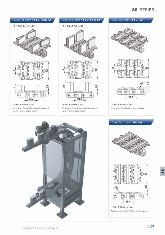
323FlexMove® Product Catalogue
SS SERIES
UOM: 5 Meter / box
Application: Suitable for vertical transport ofproduct with no accumulation.
UOM: 5 Meter / box
Application: Suitable for vertical transport ofproduct with no accumulation.
UOM: 5 Meter / box
Application: Suitable Cigarette transport.
UOM: 5 Meter / box
Application: Suitable for Cigarette transport.
Cleat Top Chain-A FSCT-5A17-L# Cleat Top Chain-A FSCT-5A30-L# Cleat Top Chain-B FSCT-5B
Cleat Top Chain-C FSCT-5C
# = 1, 2, 3, 4, 5…..20 # = 1, 2, 3, 4, 5…..20
SS

324FlexMove reserves the right to make alteration without prior notification Every care has been taken to ensure the accuracy of the
information contained in this catalogue but no liability can be accepted for any error or omissions.
SS SERIES
SS Direct End Drive with Motor (LEFT)
SS Direct End Drive with Motor (RIGHT)
SSDD-A65-0.25L, 0.37L, 0.55L
SSDD-A65-0.25R, 0.37R, 0.55R
SSDD-A65-0L
SSDD-A65-0R
SS Direct End Drive without Motor (LEFT)
SS Direct End Drive without Motor (RIGHT)
Max Traction Force : 500N
The standard Direct End Drive Unit is without torque limiter. Standard attached gear motors are with SEW motor size0.25kW, 0.37kW & 0.55kW. SSDD-A65-0L represents direct drive without motor. Multi channel drives available upon request.
Max Traction Force : 500N
The standard Direct End Drive Unit is without torque limiter. Standard attached gear motors are with SEW motor size 0.25kW,0.37kW & 0.55kW. SSDD-A65-0R represents direct drive without motor. Multi channel drives available upon request.
UOM : pc
UOM : pc
Chain required 2-way : 0.8 meter Slide rail required 2-way: 0.5 meter
Chain required 2-way : 0.8 meter Slide rail required 2-way: 0.5 meter
SEW gear motors are products of SEW Eurodrive

325FlexMove® Product Catalogue
SS SERIES
SS Direct End Drive with Motor GP (RIGHT)
SS Direct End Drive with Motor GP (LEFT)
SSDD-A65GP-025R, 0.37R, 0.55R
SSDD-A65GP-0.25L, 0.37L, 0.55L
SSDD-A65GP-OR
SSDD-A65GP-0L
SS Direct End Drive without Motor GP (LEFT)
SS Direct End Drive without Motor GP (RIGHT)
Max Traction Force : 500N
The Direct End Drive GP is used for vertical wedge conveyor Standard attached gear motors are with SEW motor size 0.25kW, 0.37kW & 0.55kW. SSDD-A65GP-0R represents direct drive without motor.
Max Traction Force : 500N
The Direct End Drive GP is used for vertical wedge conveyor. Standard attached gear motors are with SEW motorsize 0.25kW, 0.37kW & 0.55kW. SSDD-A65GP-0L represents direct drive without motor.
UOM : pc
UOM : pc
Chain required 2-way : 0.8 meter Slide rail required 2-way: 0.5 meter
Chain required 2-way : 0.8 meter Slide rail required 2-way: 0.5 meter
SEW gear motors are products of SEW Eurodrive
SS

326FlexMove reserves the right to make alteration without prior notification Every care has been taken to ensure the accuracy of the
information contained in this catalogue but no liability can be accepted for any error or omissions.
SS SERIES
SS Idler End-A65
SAHBS-90S
SSIE-A65
SS Horizontal beam support bracket – Stainless Steel
UOM : pc
UOM : pc
Chain required 2-way : 0.8 meter Slide rail required 2-way: 0.5 meter
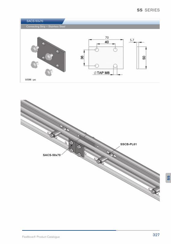
327FlexMove® Product Catalogue
SS SERIES
SACS-50x70
Connecting Strip – Stainless Steel
UOM : pc
SS
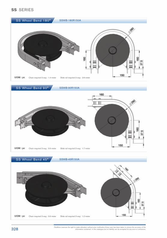
328FlexMove reserves the right to make alteration without prior notification Every care has been taken to ensure the accuracy of the
information contained in this catalogue but no liability can be accepted for any error or omissions.
SS SERIES
SS Wheel Bend 180°
SS Wheel Bend 90°
SS Wheel Bend 45°
SSWB-180R150A
SSWB-90R150A
SSWB-45R150A
UOM : pc
UOM : pc
UOM : pc
Chain required 2-way : 1.4 meter Slide rail required 2-way: 2.8 meter
Chain required 2-way : 0.9 meter Slide rail required 2-way: 1.7 meter
Chain required 2-way : 0.6 meter Slide rail required 2-way: 1.2 meter

329FlexMove® Product Catalogue
SS SERIES
SS Wheel Bend 5° - 180°
Example for SS Wheel Bend Ordering
- Wheel bend, Ø° ± 1°
If angle of 65° is needed for wheel bend, so the ordering part number is
SSWB-65R150
The outer bend is assembled using connecting strip (SACS-50x75).Angle of Ø° must be indicated when ordering.
SS Hor izonta l Pla in Bend 30°
SS Hor izonta l Pla in Bend 45°
UOM : pcChain required 2-way (500, 700) : 1.4, 1.6 meter
Slide rail required 2-way( 500, 700): 2.8, 3.2 meter
UOM : pcChain required 2-way (500, 700) : 1.6, 1.9 meter
Slide rail required 2-way(500, 700): 2.9, 3.3 meter
Horizontal plain bend, 30° ± 1°
R = 500 ± 10mm SSHB-30R500
R = 700 ± 10mm SSHB-30R700
Horizontal plain bend, 45° ± 1°
R = 500 ± 10mm SSHB-45R500
R = 700 ± 10mm SSHB-45R700
SS
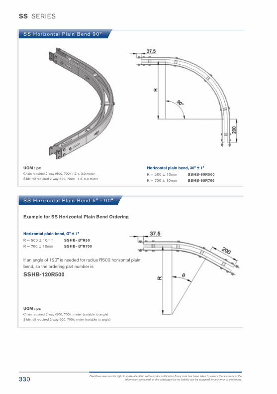
330FlexMove reserves the right to make alteration without prior notification Every care has been taken to ensure the accuracy of the
information contained in this catalogue but no liability can be accepted for any error or omissions.
SS SERIES
SS Hor izonta l Pla in Bend 90°
UOM : pcChain required 2-way (500, 700) : 2.4, 3.0 meter
Slide rail required 2-way(500, 700): 4.8, 6.0 meter
Horizontal plain bend, 30° ± 1°
R = 500 ± 10mm SSHB-90R500
R = 700 ± 10mm SSHB-90R700
SS Hor izonta l Pla in Bend 5° - 90°
Example for SS Horizontal Plain Bend Ordering
Horizontal plain bend, Ø° ± 1°
R = 500 ± 10mm SSHB- Ø°R50
R = 700 ± 10mm SSHB- Ø°R700
If an angle of 120° is needed for radius R500 horizontal plain bend, so the ordering part number is
SSHB-120R500
UOM : pcChain required 2-way (500, 700) : meter (variable to angle)
Slide rail required 2-way(500, 700): meter (variable to angle)

331FlexMove® Product Catalogue
SS SERIES
SS Ver t ica l Bend 5°
SS Ver t ica l Bend 15°
SS Ver t ica l Bend 30°
SSVB-5R300
SSVB-15R300
SSVB-30R300
UOM : pc
UOM : pc
UOM : pc
Chain required 2-way: 0.4 meter Slide rail required 2-way: 0.8 meter
Chain required 2-way: 0.6 meter Slide rail required 2-way: 1.1 meter
Chain required 2-way: 0.8 meter Slide rail required 2-way: 1.5 meter
SS

332FlexMove reserves the right to make alteration without prior notification Every care has been taken to ensure the accuracy of the
information contained in this catalogue but no liability can be accepted for any error or omissions.
SS Ver t ica l 5° - 90°
Example for SS Vertical Bend Ordering
- Vertical bend, Ø° ± 1°
If angle of 25° is needed for vertical bend, so the ordering part number is
SSVB-25R300
The outer bend is assembled using connecting strip (SACS-50x75).Angle of Ø ° must be indicated when ordering.
SS Tr ipod Suppor t St ructure SBSS-HXXXX, H=500, 1000, 1500
SS SERIES

333FlexMove® Product Catalogue
SM
SM83mm StainlessSteel ConveyorSystem

334FlexMove reserves the right to make alteration without prior notification Every care has been taken to ensure the accuracy of the
information contained in this catalogue but no liability can be accepted for any error or omissions.
SM SERIES
Variety of chain type suitable for wide range of applications either horizontal or
vertically product transportation.
Conveyor Beam SMCB Conveyor Beam SMCC-160
SM Series CharacteristicBeam Width: 85mm
Product Width: Refer to Guide Rail Assembly
Accessories NeededSlide Rail Required: FASR-25 OR FASR-25U
Slide Rail Colour: White Or Natural Colour
Slide Rail Material: HDPE OR UHMW
Slide Rail Rivet: FASLS-M5
Connecting strip is used to connect 2 beams.
Connecting Strip: SACS-50x75

335FlexMove® Product Catalogue
SMIE-320Idler End
SAHBS-90MHorizontal
Beam Support
TripodStructure
SMDD-RDirect Drive
SM SERIES
SM
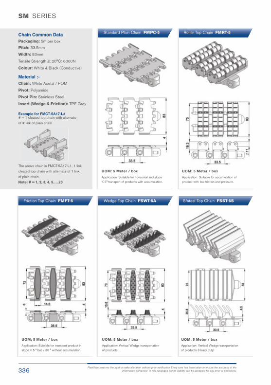
336FlexMove reserves the right to make alteration without prior notification Every care has been taken to ensure the accuracy of the
information contained in this catalogue but no liability can be accepted for any error or omissions.
SM SERIES
Chain Common DataPackaging: 5m per box
Pitch: 33.5mm
Width: 83mm
Tensile Strength at 20°C: 6000N
Colour: White & Black (Conductive)
Material :-Chain: White Acetal / POM
Pivot: Polyamide
Pivot Pin: Stainless Steel
Insert (Wedge & Friction): TPE Grey
Example for FMCT-5A17-L## = 1 cleated top chain with alternate
of # link of plain chain
The above chain is FMCT-5A17-L1, 1 link
cleated top chain with alternate of 1 link
of plain chain.
Note: # = 1, 2, 3, 4, 5…..20
UOM: 5 Meter / box
Application: Suitable for horizontal and slope < 5° transport of products with accumulation.
UOM: 5 Meter / box
Application: Suitable for transport product inslope > 5 ° but ≤ 30 ° without accumulation.
UOM: 5 Meter / box
Application: Suitable for accumulation ofproduct with low friction and pressure.
UOM: 5 Meter / box
Application: Vertical Wedge transportationof products.
UOM: 5 Meter / box
Application: Vertical Wedge transportationof products (Heavy duty)
Standard Plain Chain FMPC-5
Friction Top Chain FMFT-5
Roller Top Chain FMRT-5
Wedge Top Chain FSWT-5A S/steel Top Chain FSST-5S

337FlexMove® Product Catalogue
SM SERIES
UOM: 5 Meter / box
Application: Suitable for vertical transport ofproduct with no accumulation.
UOM: 5 Meter / box
Application: Suitable for vertical transport ofproduct with no accumulation.
Cleat Top Chain FMCT-5A30-L# Cleat Top Chain FMCT-5A17-L#
# = 1, 2, 3, 4, 5…..20 # = 1, 2, 3, 4, 5…..20
SM
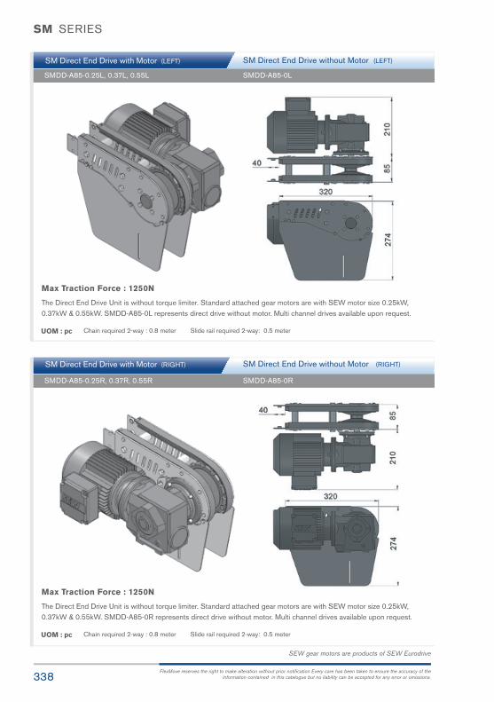
338FlexMove reserves the right to make alteration without prior notification Every care has been taken to ensure the accuracy of the
information contained in this catalogue but no liability can be accepted for any error or omissions.
SM Direct End Drive with Motor (LEFT)
SM Direct End Drive with Motor (RIGHT)
SMDD-A85-0.25L, 0.37L, 0.55L
SMDD-A85-0.25R, 0.37R, 0.55R
SMDD-A85-0L
SMDD-A85-0R
SM Direct End Drive without Motor (LEFT)
SM Direct End Drive without Motor (RIGHT)
Max Traction Force : 1250N
The Direct End Drive Unit is without torque limiter. Standard attached gear motors are with SEW motor size 0.25kW,0.37kW & 0.55kW. SMDD-A85-0L represents direct drive without motor. Multi channel drives available upon request.
Max Traction Force : 1250N
The Direct End Drive Unit is without torque limiter. Standard attached gear motors are with SEW motor size 0.25kW,0.37kW & 0.55kW. SMDD-A85-0R represents direct drive without motor. Multi channel drives available upon request.
UOM : pc
UOM : pc
Chain required 2-way : 0.8 meter Slide rail required 2-way: 0.5 meter
Chain required 2-way : 0.8 meter Slide rail required 2-way: 0.5 meter
SEW gear motors are products of SEW Eurodrive
SM SERIES
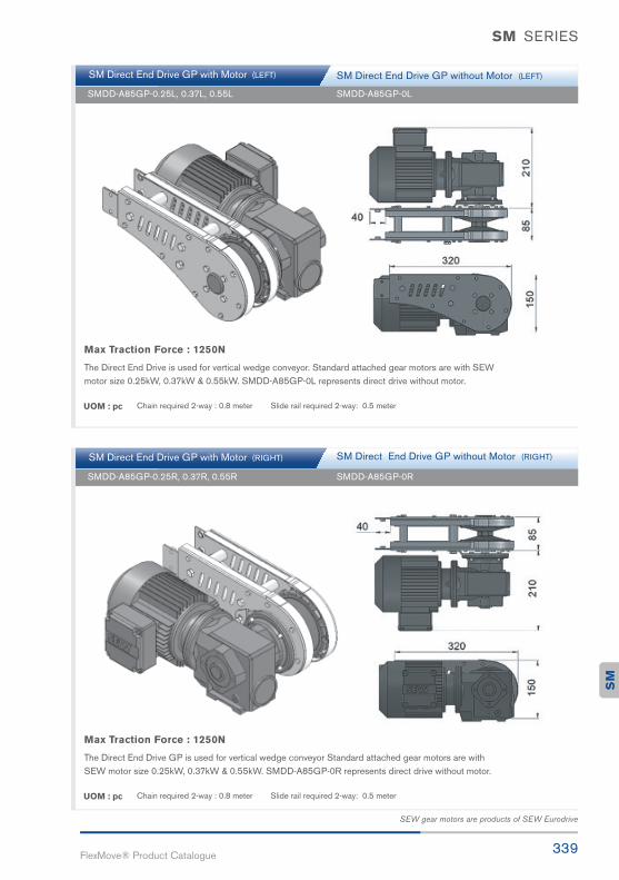
339FlexMove® Product Catalogue
SM Direct End Drive GP with Motor (RIGHT)
SM Direct End Drive GP with Motor (LEFT)
SMDD-A85GP-0.25R, 0.37R, 0.55R
SMDD-A85GP-0.25L, 0.37L, 0.55L
SMDD-A85GP-0R
SMDD-A85GP-0L
SM Direct End Drive GP without Motor (LEFT)
SM Direct End Drive GP without Motor (RIGHT)
Max Traction Force : 1250N
The Direct End Drive GP is used for vertical wedge conveyor Standard attached gear motors are with SEW motor size 0.25kW, 0.37kW & 0.55kW. SMDD-A85GP-0R represents direct drive without motor.
Max Traction Force : 1250N
The Direct End Drive is used for vertical wedge conveyor. Standard attached gear motors are with SEWmotor size 0.25kW, 0.37kW & 0.55kW. SMDD-A85GP-0L represents direct drive without motor.
UOM : pc
UOM : pc
Chain required 2-way : 0.8 meter Slide rail required 2-way: 0.5 meter
Chain required 2-way : 0.8 meter Slide rail required 2-way: 0.5 meter
SEW gear motors are products of SEW Eurodrive
SM
SM SERIES
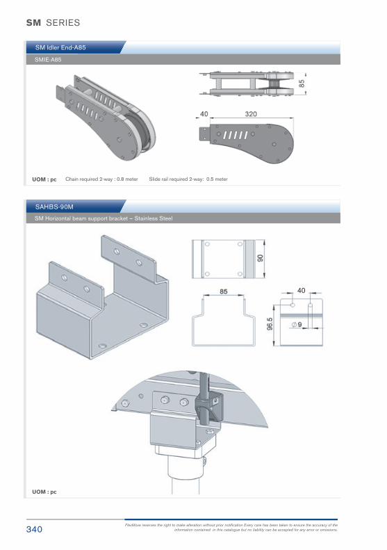
340FlexMove reserves the right to make alteration without prior notification Every care has been taken to ensure the accuracy of the
information contained in this catalogue but no liability can be accepted for any error or omissions.
SM Idler End-A85
SAHBS-90M
SMIE-A85
SM Horizontal beam support bracket – Stainless Steel
UOM : pc
UOM : pc
Chain required 2-way : 0.8 meter Slide rail required 2-way: 0.5 meter
SM SERIES
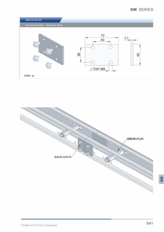
341FlexMove® Product Catalogue
SACS-50x70
Connecting Strip – Stainless Steel
UOM : pc
SACS-50X70S
M
SM SERIES

342FlexMove reserves the right to make alteration without prior notification Every care has been taken to ensure the accuracy of the
information contained in this catalogue but no liability can be accepted for any error or omissions.
SM Wheel Bend 180°
SM Wheel Bend 90°
SM Wheel Bend 45°
SMWB-180R160A
SMWB-90R160A
SMWB-45R160A
UOM : pc
UOM : pc
UOM : pc
Chain required 2-way : 1.4 meter Slide rail required 2-way: 2.8 meter
Chain required 2-way : 0.9 meter Slide rail required 2-way: 1.7 meter
Chain required 2-way : 0.6 meter Slide rail required 2-way: 1.2 meter
SM SERIES

343FlexMove® Product Catalogue
SM Wheel Bend 5° - 180°
Example for SM Wheel Bend Ordering
- Wheel bend, Ø° ± 1°
If angle of 65° is needed for wheel bend, so the ordering part number is
SMWB-65R160
The outer bend is assembled using connecting strip (SACS-50x75).Angle of Ø° must be indicated when ordering.
SM Hor izonta l Pla in Bend 30°
SM Hor izonta l Pla in Bend 45°
UOM : pcChain required 2-way (500, 700) : 1.4, 1.6 meter
Slide rail required 2-way( 500, 700): 2.8, 3.2 meter
UOM : pcChain required 2-way (500, 700) : 1.6, 1.9 meter
Slide rail required 2-way(500, 700): 2.9, 3.3 meter
Horizontal plain bend, 30° ± 1°
R = 500 ± 10mm SMHB-30R500
R = 700 ± 10mm SMHB-30R700
Horizontal plain bend, 45° ± 1°
R = 500 ± 10mm SMHB-45R500
R = 700 ± 10mm SMHB-45R700
SM
SM SERIES

344FlexMove reserves the right to make alteration without prior notification Every care has been taken to ensure the accuracy of the
information contained in this catalogue but no liability can be accepted for any error or omissions.
SM Hor izonta l Pla in Bend 90°
UOM : pcChain required 2-way (500, 700) : 2.4, 3.0 meter
Slide rail required 2-way(500, 700): 4.8, 6.0 meter
Horizontal plain bend, 90° ± 1°
R = 500 ± 10mm SMHB-90R500
R = 700 ± 10mm SMHB-90R700
SM Hor izonta l Pla in Bend 5° - 90°
Example for SM Horizontal Plain Bend Ordering
Horizontal plain bend, Ø° ± 1°
R = 500 ± 10mm SMHB-ØR500
R = 700 ± 10mm SMHB-ØR700
If angle of 70 is needed for radius R500 horizontalplain bend, so the ordering part number is
SMHB-70R500
UOM : pcChain required 2-way (500, 700) : meter (variable to angle)
Slide rail required 2-way(500, 700): meter (variable to angle)
SM SERIES

345FlexMove® Product Catalogue
SM Ver t ica l Bend 5°
SM Ver t ica l Bend 15°
SM Ver t ica l Bend 30°
SMVB-5R400
SMVB-15R400
SMVB-30R400
UOM : pc
UOM : pc
UOM : pc
Chain required 2-way: 0.4 meter Slide rail required 2-way: 0.8 meter
Chain required 2-way: 0.6 meter Slide rail required 2-way: 1.1 meter
Chain required 2-way: 0.8 meter Slide rail required 2-way: 1.5 meter
SM
SM SERIES

346FlexMove reserves the right to make alteration without prior notification Every care has been taken to ensure the accuracy of the
information contained in this catalogue but no liability can be accepted for any error or omissions.
SM Ver t ica l 5° - 90°
Example for SM Vertical Bend Ordering
- Vertical bend, Ø° ± 1°
If angle of 25° is needed for vertical bend, so the ordering part number is
SMVB-25R400
The outer bend is assembled using connecting strip (SACS-50x75).Angle of Ø ° must be indicated when ordering.
SM Tr ipod Suppor t St ructure SBSM-HXXXX, H=500, 1000, 1500
SM SERIES

347FlexMove® Product Catalogue
SC103mm StainlessSteel ConveyorSystem
SC

348FlexMove reserves the right to make alteration without prior notification Every care has been taken to ensure the accuracy of the
information contained in this catalogue but no liability can be accepted for any error or omissions.
SC SERIES
Variety of chain type suitable for wide range of applications either horizontal or
vertically product transportation.
Conveyor Beam SCCB Conveyor Beam SCCC-160
SC Series CharacteristicBeam Width: 105mm
Product Width: Refer to Guide Rail Assembly
Accessories NeededSlide Rail Required: FASR-25 OR FASR-25U
Slide Rail Colour: White Or Natural Colour
Slide Rail Material: HDPE OR UHMW
Slide Rail Rivet: FASLS-M5
Connecting strip is used to connect 2 beams.
Connecting Strip: SACS-50x75

349FlexMove® Product Catalogue
SCIE-320Idler End
SAHBS-90MHorizontal
Beam Support
TripodStructure
SCDD-RDirect Drive
SC SERIES
SC

350FlexMove reserves the right to make alteration without prior notification Every care has been taken to ensure the accuracy of the
information contained in this catalogue but no liability can be accepted for any error or omissions.
Chain Common DataPackaging: 5m per box
Pitch: 35.5mm
Width: 103mm
Tensile Strength at 20°C: 6000N
Colour: White & Black (Conductive)
Material :-Chain: White Acetal / POM
Pivot: Polyamide
Pivot Pin: Stainless Steel
Insert (Wedge & Friction): TPE Grey
Example for FCCT-5A17-L## = 1 cleated top chain with alternate
of # link of plain chain
The above chain is FCCT-5A17-L1, 1 link
cleated top chain with alternate of 1 link
of plain chain.
Note: # = 1, 2, 3, 4, 5…..20
UOM: 5 Meter / box
Application: Suitable for horizontal and slope < 5° transport of products with accumulation.
UOM: 5 Meter / box
Application: Suitable for transport product inslope > 5 ° but ≤ 30 ° without accumulation.
UOM: 5 Meter / box
Application: Suitable for accumulation ofproduct with low friction and pressure.
UOM: 5 Meter / box
Application: Suitable for vertical transportof product with no accumulation.
UOM: 5 Meter / box
Application: Suitable for vertical transportof product with no accumulation.
Standard Plain Chain FCPC-5
Friction Top Chain FCFT-5
Roller Top Chain FCRT-5
Cleat Top Chain FCCT-5A17-L# Cleat Top Chain FCCT-5A30-L
SC SERIES
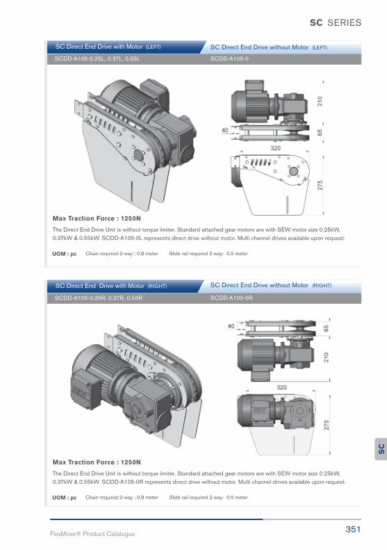
351FlexMove® Product Catalogue
SC Direct End Drive with Motor (RIGHT)
SC Direct End Drive with Motor (LEFT)
SCDD-A105-0.25R, 0.37R, 0.55R
SCDD-A105-0.25L, 0.37L, 0.55L
SCDD-A105-0R
SCDD-A105-0
SC Direct End Drive without Motor (LEFT)
SC Direct End Drive without Motor (RIGHT)
Max Traction Force : 1250N
The Direct End Drive Unit is without torque limiter. Standard attached gear motors are with SEW motor size 0.25kW, 0.37kW & 0.55kW. SCDD-A105-0R represents direct drive without motor. Multi channel drives available upon request.
Max Traction Force : 1250N
The Direct End Drive Unit is without torque limiter. Standard attached gear motors are with SEW motor size 0.25kW,0.37kW & 0.55kW. SCDD-A105-0L represents direct drive without motor. Multi channel drives available upon request.
UOM : pc
UOM : pc
Chain required 2-way : 0.8 meter Slide rail required 2-way: 0.5 meter
Chain required 2-way : 0.8 meter Slide rail required 2-way: 0.5 meter
SC SERIES
SC
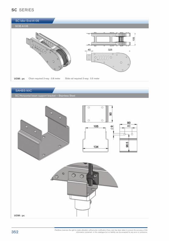
352FlexMove reserves the right to make alteration without prior notification Every care has been taken to ensure the accuracy of the
information contained in this catalogue but no liability can be accepted for any error or omissions.
SC Idler End-A105
SAHBS-90C
SCIE-A105
SC Horizontal beam support bracket – Stainless Steel
UOM : pc
UOM : pc
Chain required 2-way : 0.8 meter Slide rail required 2-way: 0.5 meter
SC SERIES
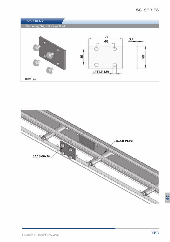
353FlexMove® Product Catalogue
SACS-50x70
Connecting Strip – Stainless Steel
UOM : pc
SC SERIES
SC

354FlexMove reserves the right to make alteration without prior notification Every care has been taken to ensure the accuracy of the
information contained in this catalogue but no liability can be accepted for any error or omissions.
SC Wheel Bend 180°
SC Wheel Bend 90°
SC Wheel Bend 45°
SCWB-180R170A
SCWB-90R170A
SCWB-45R170A
UOM : pc
UOM : pc
UOM : pc
Chain required 2-way : 1.4 meter Slide rail required 2-way: 2.8 meter
Chain required 2-way : 0.9 meter Slide rail required 2-way: 1.7 meter
Chain required 2-way : 0.6 meter Slide rail required 2-way: 1.2 meter
SC SERIES
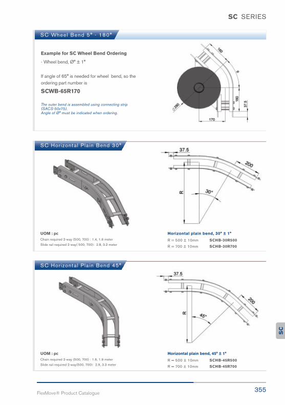
355FlexMove® Product Catalogue
SC Wheel Bend 5° - 180°
Example for SC Wheel Bend Ordering
- Wheel bend, Ø° ± 1°
If angle of 65° is needed for wheel bend, so the ordering part number is
SCWB-65R170
The outer bend is assembled using connecting strip (SACS-50x75).Angle of Ø° must be indicated when ordering.
SC Hor izonta l Pla in Bend 30°
SC Hor izonta l Pla in Bend 45°
UOM : pcChain required 2-way (500, 700) : 1.4, 1.6 meter
Slide rail required 2-way( 500, 700): 2.8, 3.2 meter
UOM : pcChain required 2-way (500, 700) : 1.6, 1.9 meter
Slide rail required 2-way(500, 700): 2.9, 3.3 meter
Horizontal plain bend, 30° ± 1°
R = 500 ± 10mm SCHB-30R500
R = 700 ± 10mm SCHB-30R700
Horizontal plain bend, 45° ± 1°
R = 500 ± 10mm SCHB-45R500
R = 700 ± 10mm SCHB-45R700
SC SERIES
SC

356FlexMove reserves the right to make alteration without prior notification Every care has been taken to ensure the accuracy of the
information contained in this catalogue but no liability can be accepted for any error or omissions.
SC Hor izonta l Pla in Bend 90°
UOM : pcChain required 2-way (500, 700) : 2.4, 3.0 meter
Slide rail required 2-way(500, 700): 4.8, 6.0 meter
Horizontal plain bend, 90° ± 1°
R = 500 ± 10mm SCHB-90R500
R = 700 ± 10mm SCHB-90R700
SC Hor izonta l Pla in Bend 5° - 90°
Example for SC Horizontal Plain Bend Ordering
Horizontal plain bend, Ø° ± 1°
R = 500 ± 10mm SCHB-ØR500
R = 700 ± 10mm SCHB-ØR700
If angle of 70 is needed for radius R500 horizontalplain bend, so the ordering part number is
SCHB-70R500
UOM : pcChain required 2-way (500, 700) : meter (variable to angle)
Slide rail required 2-way(500, 700): meter (variable to angle)
SC SERIES

357FlexMove® Product Catalogue
SC Ver t ica l Bend 5°
SC Ver t ica l Bend 15°
SC Ver t ica l Bend 30°
SCVB-5R400
SCVB-15R400
SCVB-30R400
UOM : pc
UOM : pc
UOM : pc
Chain required 2-way: 0.4 meter Slide rail required 2-way: 0.8 meter
Chain required 2-way: 0.6 meter Slide rail required 2-way: 1.1 meter
Chain required 2-way: 0.8 meter Slide rail required 2-way: 1.5 meter
SC SERIES
SC

358FlexMove reserves the right to make alteration without prior notification Every care has been taken to ensure the accuracy of the
information contained in this catalogue but no liability can be accepted for any error or omissions.
SC Ver t ica l 5° - 90°
Example for SC Vertical Bend Ordering
- Vertical bend, Ø° ± 1°
If angle of 25° is needed for vertical bend, so the ordering part number is
SCVB-25R400
The outer bend is assembled using connecting strip (SACS-50x75).Angle of Ø ° must be indicated when ordering.
SC Tr ipod Suppor t St ructure SBSC-HXXXX, H=500, 1000, 1500
SC SERIES

359FlexMove® Product Catalogue
SMZ85mm StainlessSteel ConveyorSystem
SM
Z

360FlexMove reserves the right to make alteration without prior notification Every care has been taken to ensure the accuracy of the
information contained in this catalogue but no liability can be accepted for any error or omissions.
SMZ SERIES
Variety of chain type suitable for wide range of applications either horizontal or
vertically product transportation.
SC Series CharacteristicBeam Width: 85mm
Product Width: Refer to Guide Rail Assembly
Accessories NeededSlide Rail Required: FASR-25, FASR-25U, FASR-25X
Slide Rail Colour: White Or Natural Colour
Slide Rail Material: HDPE OR UHMW
Slide Rail Rivet: FASLS-M5
Connecting strip is used to connect 2 beams.
Connecting Strip: SACS-50x75
Conveyor Beam SMZCB
PATENTED

361FlexMove® Product Catalogue
SMZ SERIES
SMZ 85 Direct End Drive with Motor (RIGHT)
SMZ 85 Direct End Drive with Motor (LEFT)
SMZDD-85-0.25R, 0.37R, 0.55R
SMZDD-85-0.25L, 0.37L, 0.55L
SMZDD-85-0R
SMZDD-85-0L
SMZ 85 Direct End Drive without Motor (LEFT)
SMZ 85 Direct End Drive without Motor (RIGHT)
Max Traction Force : 1250N
The Direct End Drive Unit is without torque limiter. Standard attached gear motors are with SEW motor size 0.25kW, 0.37kW & 0.55kW. SMZDD-85-0R represents direct drive without motor. Multi channel drives available upon request.
Max Traction Force : 1250N
The Direct End Drive Unit is without torque limiter. Standard attached gear motors are with SEW motor size 0.25kW,0.37kW & 0.55kW. SMZDD-85-0L represents direct drive without motor. Multi channel drives available upon request.
UOM : pc
UOM : pc
Chain required 2-way : 0.8 meter Slide rail required 2-way: 0 meter
Chain required 2-way : 0.8 meter Slide rail required 2-way: 0 meter
SEW gear motors are products of SEW Eurodrive
SM
Z
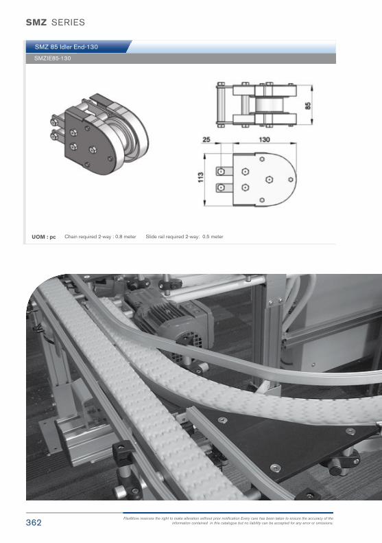
362FlexMove reserves the right to make alteration without prior notification Every care has been taken to ensure the accuracy of the
information contained in this catalogue but no liability can be accepted for any error or omissions.
SMZ 85 Idler End-130
SMZIE85-130
UOM : pc Chain required 2-way : 0.8 meter Slide rail required 2-way: 0.5 meter
SMZ SERIES

363FlexMove® Product Catalogue
SMZ Wheel Bend 180°
SMZ Wheel Bend 90°
SMZ Wheel Bend 45°
SMZWB-180R160
SMZWB-90R160
SMZWB-45R160
UOM : pc
UOM : pc
UOM : pc
Chain required 2-way : 1.4 meter Slide rail required 2-way: 2.8 meter
Chain required 2-way : 0.9 meter Slide rail required 2-way: 1.7 meter
Chain required 2-way : 0.6 meter Slide rail required 2-way: 1.2 meter
SMZ SERIES
SM
Z
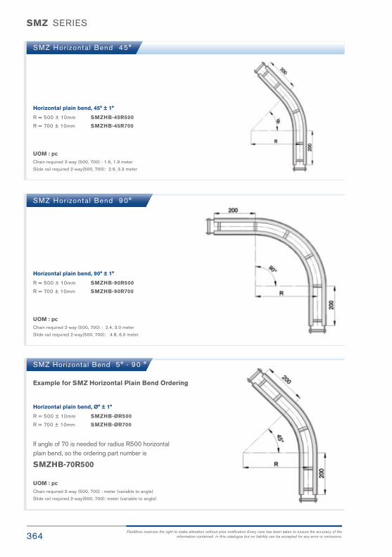
364FlexMove reserves the right to make alteration without prior notification Every care has been taken to ensure the accuracy of the
information contained in this catalogue but no liability can be accepted for any error or omissions.
SMZ Horizontal Bend 5° - 90 °
SMZ Hor izonta l Bend 90°
SMZ Hor izonta l Bend 45°
Example for SMZ Horizontal Plain Bend Ordering
Horizontal plain bend, Ø° ± 1°
R = 500 ± 10mm SMZHB-ØR500
R = 700 ± 10mm SMZHB-ØR700
If angle of 70 is needed for radius R500 horizontalplain bend, so the ordering part number is
SMZHB-70R500
Horizontal plain bend, 90° ± 1°
R = 500 ± 10mm SMZHB-90R500
R = 700 ± 10mm SMZHB-90R700
Horizontal plain bend, 45° ± 1°
R = 500 ± 10mm SMZHB-45R500
R = 700 ± 10mm SMZHB-45R700
UOM : pcChain required 2-way (500, 700) : meter (variable to angle)
Slide rail required 2-way(500, 700): meter (variable to angle)
UOM : pcChain required 2-way (500, 700) : 2.4, 3.0 meter
Slide rail required 2-way(500, 700): 4.8, 6.0 meter
UOM : pcChain required 2-way (500, 700) : 1.6, 1.9 meter
Slide rail required 2-way(500, 700): 2.9, 3.3 meter
SMZ SERIES

365FlexMove® Product Catalogue
SMZ Ver t ica l Bend 5°
SMZ Ver t ica l l Bend 30°
SMZ Ver t ica l l Bend 5° - 90 °
SMZVB-5R400
SMZVB-30R400
UOM : pc
UOM : pc
Chain required 2-way : 0.4 meter Slide rail required 2-way: 0.8 meter
Chain required 2-way : 0.8 meter Slide rail required 2-way: 1.5 meter
Example for SMZ Vertical Bend Ordering
- Vertical bend, Ø° ± 1°
If angle of 25° is needed for vertical bend, so the ordering part number is
SMZVB-25R400
The outer bend is assembled using connecting strip (SAZCS-50x76).Angle of Ø° must be indicated when ordering.
SMZ SERIES
SM
Z
Twin-Track
Maximized
Automotive
Electronics

367FlexMove® Product Catalogue
SGStainless SteelConveyor
SG

368FlexMove reserves the right to make alteration without prior notification Every care has been taken to ensure the accuracy of the
information contained in this catalogue but no liability can be accepted for any error or omissions.
SG SERIES
SG DT-18x150 D = 19mm L = 150
SG R R-19 D = 19mm
SG DT-18x200 D = 19mm L= 200
SG R R-12 D = 12mm
Distance Tube – Stainless Steel
Guide Rail Tube – Stainless Steel
Distance Tube – Stainless Steel
Guide Rail Tube – Stainless Steel
UOM: 10pcs / pk
UOM: 6meter / length
UOM: 3meter / length
FG R R-15X20P Guide Rail Rectangular, 15mm x 20mm – HDPE

369FlexMove® Product Catalogue
SG SERIES
SG R L-18x110C
SG R L-18x160C
Guide Rail Support, L = 110mm - Polyamide
Guide Rail Support, L = 160mm - Polyamide
UOM: 10pcs / pk
SG R S-18 Guide Rail Support - Polyamide
Stainless Steel Screw and nuts
Stainless Steel Screw and nuts
UOM: 10pcs / pk
SG

370FlexMove reserves the right to make alteration without prior notification Every care has been taken to ensure the accuracy of the
information contained in this catalogue but no liability can be accepted for any error or omissions.
SG R K-12x80A
SG R D-12x80
SG R K-12
SG R K-12x130A
SG R D-12x130
Guide Rail Support, L = 80mm - Polyamide
Guide Rail Clamp Rod, L = 80mm – S/Steel
Guide Rail Clamp - Polyamide
Guide Rail Support, L = 130mm - Polyamide
Stainless Steel Screw and nuts
Guide Rail Clamp Rod, L = 130mm – S/Steel
Stainless Steel Screw and nuts
Stainless Steel Screw and nuts
UOM: 10pcs / pk
UOM: 10pcs / pk
UOM: 10pcs / pk
SG SERIES

371FlexMove® Product Catalogue
SG RC-18x110C
SG R K-18x40A
SG R K-18x80A
SG RC-18x160C
SG R K-18x60A
SG R K-18x130A
Double Guide Rail Support, L = 110mm - Polyamide
Guide Rail Support, L = 40mm - Polyamide
Guide Rail Support, L = 80mm - Polyamide
Double Guide Rail Support, L = 160mm - Polyamide
Guide Rail Support, L = 60mm - Polyamide
Guide Rail Support, L = 130mm - Polyamide
Stainless Steel Screw and nuts
Stainless Steel Screw and nuts
UOM: 10pcs / pk
UOM: 10pcs / pk
SG SERIES
SG

372FlexMove reserves the right to make alteration without prior notification Every care has been taken to ensure the accuracy of the
information contained in this catalogue but no liability can be accepted for any error or omissions.
SG R F-A35
SG R F-A110
Guide Rail Bracket Support A35 – Polyamide
Guide Rail Bracket Support A110 – Polyamide
Stainless Steel Screw and nuts
Stainless Steel Screw and nuts
UOM: 10pcs / pk
UOM: 10pcs / pk
SG SERIES

373FlexMove® Product Catalogue
SG R L-18x110CA
SG R L-18x160CA
Guide Rail Support, L = 110mm - Polyamide
Stainless Steel Screw and nuts
Guide Rail Support, L = 160mm - Polyamide
UOM: 10pcs / pk
UOM: 10pcs / pk
SG SERIES
SG

374FlexMove reserves the right to make alteration without prior notification Every care has been taken to ensure the accuracy of the
information contained in this catalogue but no liability can be accepted for any error or omissions.
SG R F-42x18V
FG R D-18A
Guide Rail Bracket – Polyamide
Spacer for SGRF-42x18V - Polyamide
Stainless Steel Screw and nuts
UOM: 10pcs / pk
UOM: 10pcs / pk
SG SERIES

375FlexMove® Product Catalogue
SG R B-40x18
SG R B-40x20
Guide Rail Bracket, D = 18mm - Polyamide
Stainless Steel Screw and nuts
Guide Rail Bracket, D = 20mm - Polyamide
UOM: 10pcs / pk
SG SERIES
SG

376FlexMove reserves the right to make alteration without prior notification Every care has been taken to ensure the accuracy of the
information contained in this catalogue but no liability can be accepted for any error or omissions.
FG R D-6B Spacer for SGRB-40x18 , SGRB-40x20 - Polyamide
UOM: 10pcs / pk
SG SERIES

377FlexMove® Product Catalogue
SG R B-18x18
SG RX-18x20
SG RX-18X20
SG R B-20x20
SG RX-20x20
SG R B-18x20
SG RX-18x18
Guide Rail Bracket, ØA = 18mm, ØB = 18mm - Polyamide
90° Corner Connector, ØA = 18mm, ØB = 20mm - Polyamide
90° Corner Connector - Polyamide
Guide Rail Bracket, ØA = 20mm, ØB = 20mm - Polyamide
90° Corner Connector, ØA = 20mm, ØB = 20mm - Polyamide
Guide Rail Bracket, ØA = 18mm, ØB = 20mm - Polyamide
90° Corner Connector, ØA = 18mm, ØB = 18mm - Polyamide
Stainless Steel Screw and nuts
Stainless Steel Screw and nuts
Stainless Steel Screw and nuts
UOM: 10pcs / pk
UOM: 10pcs / pk
UOM: 10pcs / pk
SG SERIES
SG

378FlexMove reserves the right to make alteration without prior notification Every care has been taken to ensure the accuracy of the
information contained in this catalogue but no liability can be accepted for any error or omissions.
SG Guide Ra i l Assembly
SG Guide Ra i l Assembly
SG SERIES

379FlexMove® Product Catalogue
Installation Guide &Maintenance

380
INTRODUCTION
The main purpose of this manual is to help self-building end users, with little or no prior
experience, to assemble a FlexMove conveyor system. Each chapter includes detailed
instructions and pictures showing how to assemble the different parts. Most pictures in
the manual include parts from the FS conveyor system, but all instructions are applica ble
to the FH, FK, FS, FM, FC and FL.
Document DispositionThe document is divided into the following five main parts:
• Installation site preparations • Tools and fasteners
• Assembly • Start-up and testing
Initial Assembly PlanningSystematic working planning is required:
• IFully understand and study the assembly drawing.
• Ensure the necessary tools are ready.
• Ensure all the parts and materials are well prepared according to parts list.
• Enough space for conveyor installation is important.
• Ensure the floor is even and so the foot can be properly attached on the floor.
Assembly OrderDuring the conveyor assembly work, feet the following items can be used as a checklist.
• Cut all beams into desired length. • Mount drive and idler unit at the end of the conveyor.• Connect all feet and structural beams.
• Check any obstruction of the conveyor with a short piece of chain.• Mount conveyor beam support brackets.
• Assemble and mount necessary chain into the conveyor.• Tighten the slip clutch with suitable friction.
• Mount guide rail and other accessories required onto the conveyor.
• Mount slide rail onto the conveyor beam
• Read the final preparations at the end of this manual.
• Loosen the slip clutch at the drive unit.
• Assemble conveyor beams and mount them onto the support structure.
General toolsTo assemble a FlexMove ® conveyor, you may need most of the tools listed on the following page. Not all are essential, but they will make your work easier and efficient.

381FlexMove® Product Catalogue
INSTALLATION GUIDE
Hand Tools
• Wrench
• Slide rail cutter
• Set of metric Allen keys
• Counter sunk bit
• Measuring Tape
• Chain inserting / Removing Tools
• Drill fixtures for slide rail
• Riveting Tool
• In addition, the tools listed below can be useful:
• Files
• M8 Ratcheting Socket wrench
• Screw driver
• Pliers
• Knife (cutting off plastic screw head or burr of slide rail)
• Soft head hammer
• Clamping tools (for chain installation and dismantling)
• Level
Power Tools
• Hand drill
• Drill bit (of fixing slide rail)
TOOLS

382
INSTALLATION GUIDE
Fastener
Standard FastenersM8 = Washer, Counter sunk,Cap screw, Nut, Log nut.
M6 = Washer, Counter sunk,Cap screw, Nut, Log nut.
Square nut can be slotted into T-slot of FlexMove conveyorand support beams.
They do not stay in place invertical positions and haveto be inserted from the endof beam. Remember to putin a sufficient number beforecompleting the assembly.
Connecting strips are used for joining end to end ofbeams. Use Allen key and setscrews when attaching theconnecting strip to the beam.
T-bolts can be entered from the beam side, and when turned 90 degree they will stay in place after tightening with nuts and washers. The indication groove in the T-bolt should be at 90 degree to the conveyor T-slot. T-bolts are used when attaching support brackets, guide rails and drip trays to the conveyor beam. Do not use T-bolts with support beams!
Square Nut
Connecting Strip T-bolt
Cutting FlexMove® BeamIf you have ordered 3m beams, they will need to be cut into suitable lengths before assembly.Study your drawing to determine the beam lengths required before cutting.
• Saw requirements The circular cross-cut saw used for aluminum profile cutting must be equipped with a carbide tip head saw circulating at a high speed for nice and clean cuts. The saw should have the abil- ity of cutting the largest profile in one single cutting action.
• Working site You should use a special area for cutting beams in order to keep the assembly area clean.
• Quality of cut If burrs are evident, they must be removed prior to assembly. Make sure the cut is straight for proper assembly. All safety precautions issued by the cutting saw manufacturer should be followed at all times.
! All safety precautions issued by the cutting saw manufacturer should be follow at all the times.
The basic FlexMove® conveyor structure consists of five component groups:
• Support structure
• Conveyor beams, straight sections and bends
• Drive and idler units
• Chains
• Guide rail assembly components
• Other accessories

383FlexMove® Product Catalogue
INSTALLATION GUIDE
Foot Installation
Conveyor InstallationConveyor beams are mounted on to the support structure by means of support brackets.There are three different types of conveyor beam support brackets. They all serve the samepurpose but are connected to the structural beams in different ways.
Step 1
Insert hex head screws and washers into the holes on the side of the foot.
Use the screws to fasten footconnecting strips or square nut to the inner side of the foot.
Slide the connecting strips or square nutsinto the structural beam T-slots.
Raise the beam from the bottom of the footapproximately 40-50 mm, to allow for height adjustment later in the assembly.
Horizontal beam supportbrackets (60mm or 80mm)are used for horizontal supportstructure mounted to 64x64mm or 80x80mm support beams.
These brackets can also beused as drip tray connectors.
Vertical beam support brackets are used with vertical support beams andare made from aluminum.
Alpine beam support brackets are used in multi-level alpine conveyor system. This type brackets are used for connecting two parallel conveyor beams to an 80 mm vertical support beam.
Tighten the screws using a wrench.
Step 2
Step 3
Option 1 Option 2
Option 3
Step 4
The first step in the assembly process is to assemble the support structure, which consists of feet, sup port beams and beam support brackets. Most conveyor support designs are based on vertical support beams, combined, if necessary, with horizontal support beams. There are also a number of different feet and beam support brackets, so check which ones are suitable to use in your application.
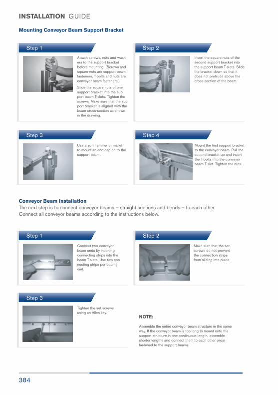
384
INSTALLATION GUIDE
Mounting Conveyor Beam Support Bracket
Step 1
Step 3
Step 1 Step 2
Step 3
Step 4
Step 2
Attach screws, nuts and wash ers to the support bracket before mounting. (Screws and square nuts are support beam fasteners, T-bolts and nuts are conveyor beam fasteners.)
Slide the square nuts of one support bracket into the sup port beam T-slots. Tighten the screws. Make sure that the sup port bracket is aligned with the beam cross-section as shown in the drawing.
Use a soft hammer or mallet to mount an end cap on to the support beam.
Connect two conveyor beam ends by inserting connecting strips into thebeam T-slots. Use two con necting strips per beam joint.
Make sure that the set screws do not prevent the connection stripsfrom sliding into place.
Tighten the set screws using an Allen key.
NOTE:
Assemble the entire conveyor beam structure in the same way. If the conveyor beam is too long to mount onto the support structure in one continuous length, assemble shorter lengths and connect them to each other once fastened to the support beams.
Mount the first support bracket to the conveyor beam. Pull the second bracket up and insert the T-bolts into the conveyor beam T-slot. Tighten the nuts.
Insert the square nuts of the second support bracket into the support beam T-slots. Slide the bracket down so that it does not protrude above the cross-section of the beam.
Conveyor Beam InstallationThe next step is to connect conveyor beams – straight sections and bends – to each other. Connect all conveyor beams according to the instructions below.
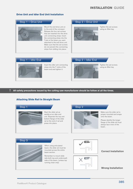
385FlexMove® Product Catalogue
INSTALLATION GUIDE
Drive Unit and Idler End Unit Installation
Attaching Slide Rail In Straight Beam
Step 1 – Drive Unit
Step 1
Step 1 – Idler End
Step 3
Correct Installation
Wrong Installation
Mount the end drive unit on to the end of the conveyor: Release the four set screws that are inserted into the drive unit connecting strips. Insert the connecting strips into the T-slot of the beam you want attached to the end drive unit. Make sure that the set screws do not prevent the connecting strips from sliding into place.
Start the slide rail as sembly at an idler end unit. Separate the top and bottom flange of the slide rail at the end of rail and press into place.
Insert the idler unit connecting strips into the T- slots of the beam end and tighten it.
When using articulated beam, the slide rail must be mounted across the entire beam section.
Remember to mount slide rails both top and underneath side of the beam. (unless top running chain only)
Tighten the set screws using an Allen key.
Make sure the slide rail is proper mounted and snaps onto the beam.
Please identify the longerflange of the slide rail must always face inner of the beam.
Tighten the set screws using an Allen key
Step 2 – Drive Unit
Step 2
Step 2 – Idler End
! All safety precautions issued by the cutting saw manufacturer should be follow at all the times.

386
INSTALLATION GUIDE
Slide Rail End Installation at Conveyor Beam
Slide Rail Installation At Wheel Bend
Step 1
Step 1 – In feed Wheel Bend (New Type A)
Step 3
Step 3
Step 2
Step 2 – Out feed Wheel Bend (New Type A)
Cut both slide rail ends in a 45° angle. The beginning of a new slide rail (in the direc tion of travel) must cut back a small angle.
Cut the slide rail end in flat. Make sure there is no gap created at the plastic molding part. The step is applied onto out feed as well.
Do not place two slide rail joints opposite each other.Make sure there is a distanceof at least 100 mm betweenthem to make the chain runsmoother.
This does not apply to slide railthat begins by an idler unit or after a drive unit, where joinsare always parallel.
In the outer bend, make sure that the slide rail is properly connected to theconveyor beam profile.
Try to let the slide rail run in as continuous lengths as possible byreducing number of breaks, except in circumstances stated below:
• It is recommended to use short slide rails (2–3m) where chemicals may have an effect on the slide rail composition.
• It is important to cut the slide rail and allow for elongation in high load areas. Cutting is required in wheel bends (see following page), at idler units and where the conveyor will be heavily loaded, espe cially at drive unit. This prevents the slide rail from stretching out and entering into the drive unit, which may block the chain movement.
• Never join slide rail in horizontal or vertical bends, since forces are higher on the slide rail in these sections. Instead, place the joint before the bend.
• Avoid joining slide rails on top of conveyor beam joints.
Allow a space of ap-proximately 2mm to 5mmbetween two slide railends. The travel directionis indicated by arrow.
Follow Step 1.
Horizontal Plain Bends and Vertical BendIn plain bends with small radius and vertical bend, the slide rail for the inner bend should be cut so that it is only 10mm wide in the bend. This is to prevent an uneven slide rail surface.Stretch the rail while mounting
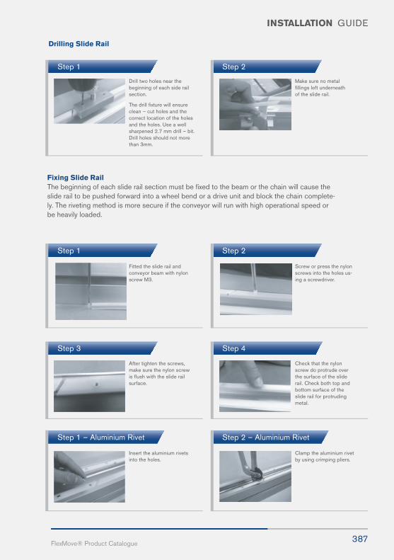
387FlexMove® Product Catalogue
INSTALLATION GUIDE
Step 1
Step 1
Step 3
Step 1 – Aluminium Rivet
Step 2
Step 2
Step 4
Step 2 – Aluminium Rivet
Drill two holes near thebeginning of each side railsection.
The drill fixture will ensureclean – cut holes and the correct location of the holesand the holes. Use a wellsharpened 2.7 mm drill – bit.Drill holes should not morethan 3mm.
Fitted the slide rail and conveyor beam with nylonscrew M3.
After tighten the screws, make sure the nylon screwis flush with the slide railsurface.
Insert the aluminium rivets into the holes.
Make sure no metal fillings left underneath of the slide rail.
Screw or press the nylon screws into the holes us-ing a screwdriver.
Check that the nylon screw do protrude over the surface of the sliderail. Check both top and bottom surface of theslide rail for protrudingmetal.
Clamp the aluminium rivet by using crimping pliers.
Fixing Slide RailThe beginning of each slide rail section must be fixed to the beam or the chain will cause the slide rail to be pushed forward into a wheel bend or a drive unit and block the chain complete-ly. The riveting method is more secure if the conveyor will run with high operational speed orbe heavily loaded.
Drilling Slide Rail
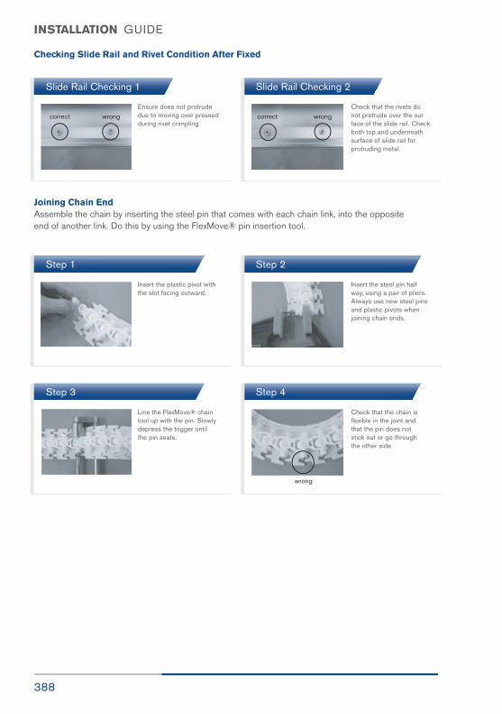
388
INSTALLATION GUIDE
Checking Slide Rail and Rivet Condition After Fixed
Slide Rail Checking 1
Step 1
Step 3
Slide Rail Checking 2
Step 2
Step 4
Ensure does not protrude due to moving over pressed during rivet crimpling
Insert the plastic pivot with the slot facing outward.
Line the FlexMove® chain tool up with the pin. Slowly depress the trigger until the pin seats.
Check that the rivets do not protrude over the sur face of the slide rail. Checkboth top and underneath surface of slide rail for protruding metal.
Insert the steel pin half way, using a pair of pliers.Always use new steel pins and plastic pivots when joining chain ends.
Check that the chain is flexible in the joint and that the pin does not stick out or go through the other side
Joining Chain EndAssemble the chain by inserting the steel pin that comes with each chain link, into the oppositeend of another link. Do this by using the FlexMove® pin insertion tool.

389FlexMove® Product Catalogue
INSTALLATION GUIDE
Step 1
Step 3
Step 5
Step 1
Step 3
Step 2
Step 4
Step 6
Step 2
Step 4
Insert the chain into the underside of the drive unit. Make sure the chain will be moving inthe correct direction, as indicated by the arrowlocated at the side of all chain links.
Join 5 meter lengths of chain when necessary.
Make sure the chain can be pulled arevisible 2 chain pins.
Loosen the screws on the beam section flanges.
Clamp the chain to the beam profile. Use theFlexMove® chain tool to remove a steel pin from the chain, so that two linksare separated.
Feed the chain along the conveyor by pulling it through the idler unit and back to the drive unit.
Tension the chain and remove links if neces sary, so that the chain will exhibit some slack at the drive unit. Put in the stain less steel pin at the hole provided at drive unit and join the chain.
After removing the neces sary chain, pull the chain and make sure that there is1 inch of gaps is available.
Remove the flange so that the chain becomes accessible.
Remove excess links and use the chain tool to put the chain back together again.
Chain Installation at Drive UnitMake sure that the slip clutch is released allowing the drive shaft to turn freely.
Chain Assembly at Chain Connecting Module F..CC
390
INSTALLATION GUIDE
Length Adjustment of the Conveyor Chain End drive units, catenary drive units
1 Adjustment of the conveyor chain is carried out at the
drive end of the conveyor.
2 The transmission guard cover must be removed from the drive unit and to disengaged the slip cluth or remove the transmission chain. The conveyor chain should now be free to travel within the conveyor
beam profile.
3 Catenary protection plates should also be removed to allow easy access for the conveyor chain pin inser-
tion tool.
4 The conveyor chain should be tensioned within the conveyor system by pulling down the conveyor chain at the chain catenary in the underside of the drive unit. Clamp across the conveyor chain to trap the
1 Conveyors which have no conveyor chain slack should be assembled with a special section of conveyor beam (F..CC), which allows the chain to be easily inserted and adjusted for tension. (See previous page.)
1 After removal of the outer aluminium profile, the con- veyor chain can be pulled out of the wheel bend disc. Lift the chain upwards.
2 Remove chain links using the pin insertion tool.
Guide rails are used to guide products being conveyed, and also to prevent them from falling off the conveyor. Guide rails are supported by guide rail brackets attached to the sides of the conveyor beam. Follow the mounting instruc- tions for the type of bracket used in your application.
Brackets should be placed approximately 500 to 1000 mm apart depending on the type of product and wheter the product be accumulated.
If brackets are spaced at further distances than 1000 mm, there is a possibility that guide rails will become deformed due to excessive force.
The pictures below show one possible way to assemble guide rail brackets. The examples shown on the following page are assembled in a similar way.
In a wheel bend drive, the outer aluminium profile can be removed by loosening the set screws in the beam
connecting strips. The slide rail must be fitted to allow the removal of this section.
2 Remove the lower part of this conveyor beam section
by releasing the four screws.
3 Lift the chain from this section of the beam and clamp the conveyor chain as described above. Adjust the chain tension as for end and catenary drive units.
3 New steel pins and plastic pivots must be used when rejoining chain ends.
4 The tensioned chain can now be pulled back into position on the bend guide disc, and the outer pro- file put into place.
chain on to the beam profile. The clamp should be placed over the edges of the drive unit to reduce the risk of damage to the aluminum profile.
5 Remove all slack links from the conveyor chain using the pin insertion tool.
6 Rejoin the conveyor chain using a new steel pin and plastic pivot.
7 Remove the chain clamp and replace the catenary protection plate and transmission chain. The slip clutch should also be reset.
8 Replace the transmission guard cover. The conveyor is now ready for operation.
Intermediate drive units, horizontal bend drive units
Guide Rail System Installation
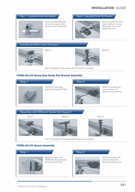
391FlexMove® Product Catalogue
INSTALLATION GUIDE
Step 1 – Adjustable Guide Rail Bracket
Assembly with Different Guide Rail Support
Step 2 – Adjustable Guide Rail Bracket
Fasten an adjustable guide rail bracket support to the conveyor beam using T-bolt.
Option 2Option 1
Option 1 Option 2 Option 3
Note: Only tighten all the screws when the position is justified.
Note: Only tighten all the screws when the position is justified.
Attach the guide rail to the clamp. Tighten the screw. Remember; do not over tighten the screw.
FGRB-48x12V Heavy Duty Guide Rail Bracket Assembly
FGRB-48x12V Spacer Assembly
Step 1
Step 1
Assembly with Different Guide Rail Support
Step 2
Step 2
Attach the spacer onto FGRB-48x12V and preparethe bracket with T-bolt.
Prepare the heavy duty guide rail bracket with T-bolt.
Attach the bracket onto conveyor beam and tighten with long wrench.
Attach the bracket onto conveyor beam and tighten with long wrench.

392
INSTALLATION GUIDE
Step 1 - Method 1
Step 1 – Method 2
Step 1 – Fixed Guide Rail Bracket
Assembly with Different Guide Rail Support
Step 2 - Method 1
Step 2 – Method 2
Step 2 – Fixed Guide Rail Bracket
Open the upper and lower caps and prepare theFGRB-40 heavy duty guiderail bracket with T-bolt.
Open the upper and lower caps and prepare the FGRB-40 heavy dutyguide rail bracket withT-bolt.
Fasten a fixed guide rail bracket support to the con- veyor beam using T-bolt.
Attach the bracket onto conveyor beam and tighten with long wrench.
Attach the bracket onto conveyor beam and tighten with longwrench. After this,close both caps of thebracket.
Attach the guide rail to the bracket. Clamp thespring pin into the slot between bracket and guide rail to fixed theposition.
FGRB-40x18, FGRB-40x20 and FGRB-40x15x20 Heavy Duty Guide Rail Bracket Assembly
Fixed Guide Rail Bracket Installation
Option 1
Note: Tighten all the screws when the position is justified. Remember to assemble the upper and lower caps onto the bracket
Option 2

393FlexMove® Product Catalogue
INSTALLATION GUIDE
Guide Rail Connecting Installation
Guide Rail Cover Installation
Step 1 – Rail Connecting
Step 3 – Rail Connecting
Step 1
Step 2 – Rail Connecting
Step 4 – Connecting Plug
Step 2
First, fully slot the guide rail sleeve into either oneof the guide rail profilethat you are going to join.
Finally, move the guide rail sleeve into second profile. Tighten when the location is justified.
To prevent products from being scratched, a plastic guide rail cover can be snapped on to the inside ofthe guide rail.
Now, align these 2 profiles closely in parallel.
Connecting plugs are pressed into two guide rail ends with soft hammer.
Make sure that all cover joints are smooth, so that products do not get caught or damaged. Do not join covers on top of guide rail joints.

394
FK SLIDE RAIL INSTALLATION GUIDE
Drilling Slide RailThe holes must be drilled at the leading edges of the joint pieces , in the direction of the travel,to hold the slide rail in place when the conveyor is in use.
Step 1
Step 2
Step 3
Identify the. direction of chain travel and the cutting slope of the slide rail. This is the correctway to set up the drill point
Please make sure the drill fixture is fully attachedto the conveyor beam.
Make sure the slide rail is proper mounted and snaps onto the beam. Please identify that the longer flange of the slide rail must always face inner of the beam.
Correct Installation Wrong Installation
This is wrong way to set up the drill point. The cutting angle of the slide rail is less than 90 degree.
This is the incorrect position if there is a gap between the conveyor beam with the drill fixture.

395FlexMove® Product Catalogue
INSTALLATION GUIDE
Plug Beam EndsEnsure that end caps have been fitted to all aluminium profile ends. The beam profiles should be deburred before fixing end caps. It may be necessary to fix the cap into position using a soft-faced hammer.
Anchor feet to the floorAfter the assembly of all components it may be necessary to anchor the conveyor support feet to the floor. Use a type of fastener that is right for the kind of floor where the conveyor is installed.
Instability of the conveyor during operation may result in a dangerous operating environment or damage the conveyor components.
Other preparations
• Adjust the height of the structural beam if necessary.
• Make sure that the installation is stable and that all screws have been properly tightened.
• Use a plummet and/or water-level to make sure that the construction is not askew.
• Make sure that all electrical equipment and power supply are properly connected.
• Make sure that the conveyor is running in the correct direction before starting the conveyor! Never run the conveyor with tightened slip clutch until you have ensured that the running direction is correct.
• Tighten the slip clutch to a suitable friction.
• Make sure that the transmission cover is attached to the drive unit.
• In pallet installations, make sure that all pneumatic equipment is properly connected.
Remember that conveyor chains should always be pulled, not pushed, by the drive unit.
Final Preparations
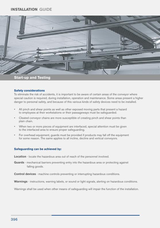
396
INSTALLATION GUIDE
Safety considerationsTo eliminate the risk of accidents, it is important to be aware of certain areas of the conveyor where special caution is required, during installation, operation and maintenance. Some areas present a higherdanger to personal safety, and because of this various kinds of safety devices need to be installed.
• All pinch and shear points as well as other exposed moving parts that present a hazard to employees at their workstations or their passageways must be safeguarded.
• Cleated conveyor chains are more susceptible of creating pinch and shear points than plain chain.
• When two or more pieces of equipment are interfaced, special attention must be given to the interfaced area to ensure proper safeguarding.
• For overhead equipment, guards must be provided if products may fall off the equipment for some reason. The same applies to all incline, decline and vertical conveyors.
Safeguarding can be achieved by:
Location - locate the hazardous area out of reach of the personnel involved.
Guards - mechanical barriers preventing entry into the hazardous area or protecting against falling goods.
Control devices - machine controls preventing or interrupting hazardous conditions.
Warnings - instructions, warning labels, or sound or light signals, alerting on hazardous conditions.
Warnings shall be used when other means of safeguarding will impair the function of the installation.
Start-up and Testing
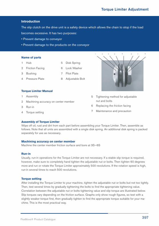
397FlexMove® Product Catalogue
Torque Limiter Adjustment
Introduction
The slip clutch on the drive unit is a safety device which allows the chain to stop if the load
becomes excessive. It has two purposes:
• Prevent damage to conveyor
• Prevent damage to the products on the conveyor
Name of parts
1 Hub 5 Disk Spring
2 Friction Facing 6 Lock Washer
3 Bushing 7 Pilot Plate
4 Pressure Plate 8 Adjustable Bolt
Torque Limiter Manual
1 Assembly
2 Machining accuracy on center member
3 Run-in
4 Torque setting
Assembly of Torque LimiterWipe off oil, rust and dirt from each part before assembling your Torque Limiter. Then, assemble as follows. Note that all units are assembled with a single disk spring. An additional disk spring is packed separately for use as necessary.
Machining accuracy on center memberMachine the center member friction surface and bore at 3S~6S
Run-inUsually, run-in operations for the Torque Limiter are not necessary. If a stable slip torque is required, however, make sure to completely hand tighten the adjustable nut or bolts. Then tighten 60 degrees more and run or rotate the Torque Limiter approximately 500 revolutions. If the rotation speed is high, run-in several times to reach 500 revolutions.
Torque settingAfter installing the Torque Limiter to your machine, tighten the adjustable nut or bolts but not too tightly. Then, test several times by gradually tightening the bolts to find the appropriate tightening value. Correlation between the adjustable nut or bolts tightening value and slip torque are illustrated below. Slip torques vary depending on the friction surface. Graphs only show rough figures, so test with a slightly weaker torque first, then gradually tighten to find the appropriate torque suitable for your ma-chine. This is the most practical way.
5 Tightening method for adjustable nut and bolts
6 Replacing the friction facing
7 Maintenance and precaution
398
INSTALLATION GUIDE
Tightening method for adjustable nut or boltsThe adjustable nut for Torque Limiter is a hexagon head nut. Tighten it with a spanner wrench to the rated angle then bend the lock washer to prevent the adjustable nut from loosening.
The adjustable nut has 3 adjustable bolts. Place the pilot plate and disk spring in contact with each oth-er, and tighten the adjustable nut manually until there is no backlash between their faces. Then retighten the adjustable bolts to the appropriate angle.
Replace the friction facingChange the friction facing when they reach roughly half the thickness of dimension described above.1.25mm for L250. Before replacing the friction facing, each part must be completely free of oil, rust and dirt. Also, reassemble the Torque Limiter according to the structure drawing.
Maintenance and precautions after the replacement procedurePeriodically inspect the torque setting, for the initial torque setting may be affected by changes in fric-tion, ambient temperature, humidity and other conditions.
Replace the friction facing and bushing if they wear. Their replacement parts are in stock.
Keep the Torque Limiter free from water and oil. This will maintain the effectiveness of torque and pre-vent the equipment or load from falling and causing serious accidents.
Safety
• Before carrying out maintenance, make sure there is no load or turning force applied to the machine.
• Inspect operation periodically for overloads.
• Comply with Ordinance on Labor Safety and Hygiene 2-1-1 general standards.
• Comply with this manual when conducting unit installation, removal, maintenance and inspection.
• Read this manual thoroughly before servicing the unit, and handle the unit correctly.
• Design the equipment so that it can tolerate load and rotational force when overloaded.
• Mechanical parts may wear depending on the rotation speed and slipping time. Check the operation
periodically, and contact us for any mechanical failure.
• This manual is an essential part of the unit, and it should remain with the unit at all times including
when redistributed.
! WARNING!
! CAUTION!
399FlexMove® Product Catalogue
Start-up and Maintenance Schedule
The chains are made of acetal resin which has an excellent combination of strength, wear,
chemical resistance, impact strength and temperature range.
Chain failures like breakage and high wear might occur if the actual pull is higher than the
permissible chain limit. There is also high risk of slip-stick effect if the conveyor is running at high
chain tension.
The chain running on the right direction is very important. The chain top and bottom is like an
arrow and the conveyor must travel toward the arrow. The chain should run without pre-tension.
Pre-tension might result in uncontrolled chain pull and lead to chain failure.
For this reason, it is important that there is a visible chain slack at the bottom of the drive unit
when the conveyor is running.The chain has good impact strength a broken link is a sign that
something is wrong along the conveyor. Frequent failures are broken cleat link caused jamming
at the loading or unloading of the conveyor.
Slide rail lubricationLubrication of the surface between the slide rail and chain will result in low coefficient of friction, less noise and linger running life. It is especially applicable for plain bend. But, it is not compulsory as the chain and slide rail materials are self-lubricant.
WearThe degree of wear on a conveyor depends on a number of factors, such as:
• Running time • Chemicals
• Load, contact pressure • Foreign particles, e.g. chips, grinding
• Speed particles, broken glass, sand, sugar
• Product accumulation • Temperature
• Sharp or rough products • Plain bends
Try to minimize the running time for the conveyor by stopping it when there is no transport. Multiple hori-zontal and vertical plain bends in a conveyor will often result in increased wear. One reason is that the friction losses are large in plain bends. Also, the contact surface between chain and slide rail is small and the chain pull is acting towards the slide rail in the bends.
Chain ElongationAcetal resin is an elastic material. In addition to the elastic elongation, the chain will exhibit elongation because of material creeping. The magnitude of chain elongation will depend on the chain tension.
The chain elongation will show up at the bottom of the drive unit. Too much of the chain slack may cause high wear at the drive unit entry point. Chain slack of up to 150mm is acceptable during normal running but any slack longer than that is not advisable.
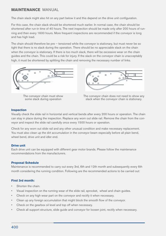
400
MAINTENANCE MANUAL
The chain slack might also hit on any part below it and this depend on the drive unit configuration.
For this case, the chain slack should be shortened much earlier. In normal case, the chain should be shortened after run-in time of 40 hours. The next inspection should be made only after 200 hours of run-ning and then every 1600 hours. More frequent inspections are recommended if the conveyor is long and has high load.
The chain should therefore be pre – tensioned while the conveyor is stationary, but must never be so tight that there is no slack during the operation. There should be no appreciable slack on the chain when the conveyor is stationary. If there is too much slack, there will be excessive wear on the chain guides and the chain. This could be a risk for injury. If the slack on the conveyor chain is unacceptably high, it must be shortened by splitting the chain and removing the necessary number of links.
Inspection Visually check the slide rail in horizontal and vertical bends after every 200 hours or operation. The chain can stay in place during the inspection. Replace any worn out slide rail. Remove the chain from the con-veyor and inspect the slide rail carefully once every 1500 hours or operation.
Check for any worn out slide rail and any other unusual condition and make necessary replacement. You must also clean up the dirt accumulation in the conveyor beam especially before all plain bend, wheel bend, drive unit and idler end.
Drive unitEach drive unit can be equipped with different gear motor brands. Please follow the maintenance recommendations from the manufacturers.
Proposal ScheduleMaintenance is recommended to carry out every 3rd, 6th and 12th month and subsequently every 6th month considering the running condition. Following are the recommended actions to be carried out:
First 3rd month:
• Shorten the chain.
• Visual inspection on the running wear of the slide rail, sprocket, wheel and chain guides.
• Check on any high wear part on the conveyor and rectify it when necessary.
• Clean up any foreign accumulation that might block the smooth flow of the conveyor.
• Check on the gearbox oil level and top off when necessary.
• Check all support structure, slide guide and conveyor for loosen joint, rectify when necessary.
The conveyor chain must showsome slack during operation
The conveyor chain does not need to show any slack when the conveyor chain is stationary.

401FlexMove® Product Catalogue
MAINTENANCE MANUAL
First 6th month:
• Shorten the chain.
• Visual inspection on the running wear of the slide rail, sprocket, wheel and chain guides.
• Clean up any foreign accumulation that might block the smooth flow of the conveyor.
• Check on the gearbox oil level and top off when necessary.
• Check all support structure, side guide and conveyor for loosen joint, rectify when necessary.
First 12th month:
• Shorten the chain.
• Visual inspection on the running wear of the slide rail, sprocket, wheel and chain guides.
• Clean up any foreign accumulation that might block the smooth flow of the conveyor.
• Check on the gearbox oil level and top off when necessary.
• Check all support structure, side guide and conveyor for loosen joint, rectify when necessary.
Checking Slide railThe condition of the slide rails is fundamental to the functioning of the installation. It is essential that these are in good condition. The function of the slide rails is to reduce the friction between the chains and the conveyor beam during operation.
Checking Slide rail with the conveyor chain in place
The slide rail needs to be checked after every 200 hours’ operation. Carry on the check while on astationary condition with the chain in place.
• Check the screwing points on the slide rail
• Check the joints section on the slide rail.
• Check that the nylon screw is fit and does not protrude over the surface of the slide rails.
• Check that the nylon screw is fit and do not protrude over the surface of the slide rail.
• Check that the joint sections are not deformed.
Correct Configuration of joints

402
MAINTENANCE MANUAL
Deformed Joints Checking the slide rail, conveyor chain has been removed
The slide rail need to be checked once in a year or after 1500 hours’ operation. The chain should be re moved from the conveyor beam in order to check the slide rail carefully for the condition of wear and the screwing.
Horizontal bends need to be checked carefully after every 400 hours’ operation, since these are the places subjected to more friction loads.
• Carry out the same checks as the “checking slide rails with the conveyor chains in place”.• Check the wear and tier condition for the slide rail.
Remarks
Check the inner slide rail in horizontal bends carefully, since the frictions here are particularly high. The conveyor chain interfaces more on the inner slide rail compared to the outer slide rail.
• Check the slide rail for scratches and notches.
• Replace the slide rail and the the fastening parts if necessary.
• Clean the conveyor chain and check the condition of the chains as well.
• Tidy the conveyor beam.
Protective and safety devicesSafety devices should be checked at regular intervals.
• Check the motor cover for the chain transmission.
• This motor cover must always be in place when the conveyor is operating.
• Check that the drive cover is always in place when the chain is moving on the drive unit.
• Drive unit should always have a chain cover to protect the safety of the users. Checked that the chain cover plates are in place, and the chain does not slacken enough to hang below the plates.
• Check that the chain cover for the conveyor chain on the intermediate drive units and the catenary drive units.
• There may be others types of cover and protective plates in your installation, and these must also be checked.
Motor cover for the bicycle chain transmission
Drive Cover to cover the chain slag for suspended drive unit

403FlexMove® Product Catalogue
MAINTENANCE MANUAL
SafeguardingAll pinch and shear points as well as other exposed moving parts that present a hazard to users are recommended to be safe guarded. Cleat conveyor chain is more susceptible of creating pinch and shear points than plain chain.
When two or more pieces of equipment are interfaced, special attention must be given to the inter-faced area to ensure proper safeguarding.
For overhead conveyor, guards must be provided if products fall off the conveyor for some reason. The same applies to all incline, decline and vertical conveyors.
ConsiderationsWhen correctly applied, the conveyor components are safe to use or maintain. It is however necessaryfor those responsible to design, installation, operation and maintenance to be aware of certain areas when special caution is required:
End drive unitThe chain slack of a normal direct drive must be maintained during the system lifetime.
Idler unitThe opening between links when they turn around idler could be a risk. The idler end should not be accessible during conveyor operation.
Catenary drive unitThe bridge area where the chain goes down should not be accessible during conveyor operation.

404
MAINTENANCE MANUAL
Symptom
Jerky running
Drive unit is run-ning, conveyorchain is not running
Motor overheat-ing on drive unit
Noise
Abnormal wear of plastic parts
Clutch Ratchet-ing or slipping
Cause
- Damage or badly fitted slide rail.
- Wrongly adjusted slip clutch.
- Worn transmission parts.
- Conveyor chain is too tight or loose.
- Dirty conveyor
- Inspect and replace as necessary.
- Check and adjust slip clutch.
- Check/replace transmission chain, chain
drive sprocket.
- Tension conveyor chain correctly.
- Clean conveyor chain/slide rail.
- Check adjustment of slip clutch.
- Check and replace if necessary.
- Check the free running of the conveyor
chain.
- Check and fit.
- Remove products from conveyor and test
run.
- Check actual conveyor load against
recommended loading. If possible break
to more drives.
- Check output shaft seal and area around
motor/gearbox interface.
- Clean the conveyor chain with warm water
50 degree.
- Check/replace drive unit.
- Check the free running of the conveyor
chain, especially in slide rail joints.
- Check actual load against recommended
loading.
- Lengthen/shorten conveyor chain
- Remove products from conveyor and test
run.
- Check the free running of the conveyor
chain.
- Check actual conveyor load against
recommended loading. If possible break
the conveyor into more drives.
- Check against recommended temperature
for conveyor.
- Replace the broken section of chain.
- Avoid load buildup by running conveyor
continuously.
- Do not manually surge load conveyor.
- Refer to ratchet clutch adjustment in
Maintenance.
- Review belt and repair or replace as
required.
- Reverse conveyor placing ball of
newspaper or a rag on belt to act as wipe
out for accumulated material.
- Wrongly adjusted slip clutch.
- Friction discs in slip clutch are worn or
contaminated.
- Damage/badly fitted slide rail.
- Transmission products are not fitted.
- Conveyor overloaded.
- Gearbox oil leaking.
Dirty conveyor.
- Worn or damaged bearings in drive
unit.
Damage/badly fitted slide rail.
- Excessive conveyor speed.
- Incorrect conveyor chain tension.
- Conveyor overloaded.
Ambient temperature too high.
- Foreign object dropped on the con
veyor chain.
- Excessive or accumulated load.
- Improper ratchet clutch tensioning.
- Damaged or missing chain assembly
parts.
- Accumulation of conveyed material or
foreign objects inside of casing.
Corrective action

405FlexMove® Product Catalogue
MAINTENANCE MANUAL
Replacement of worn part – conveyor chain
Removal of Conveyor ChainRemoving the worn part of the conveyor chain by using the FlexMove® pin insertion/removal tool. Makesure that the slip clutch is released allowing the drive shaft to turn freely.
Step 1
Step 3
Step 2
Step 4
Ensure that the power supply for the drive motor is discon-nected.
Split the chain by removing the pin using the pin inser-tion/ removal tool.
Disengage the motor from the drive unit before remov-ing the worn parts of theconveyor chain.
Pull out the conveyor chain.
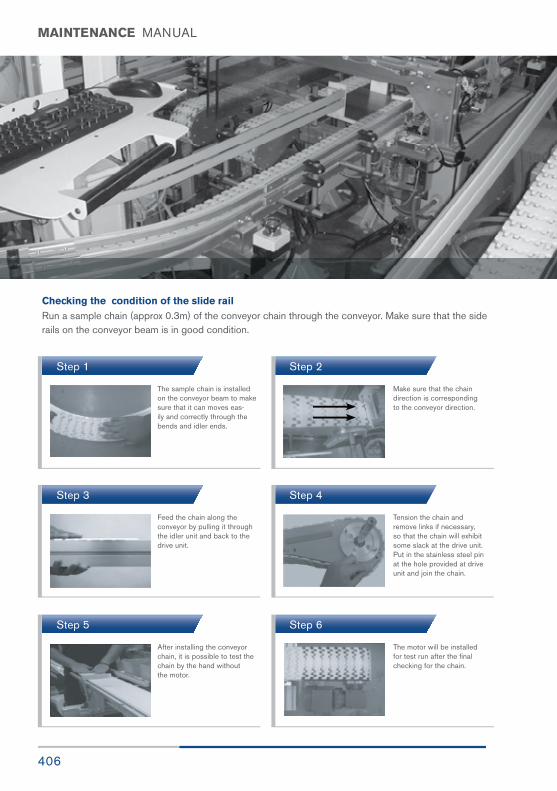
406
MAINTENANCE MANUAL
Checking the condition of the slide railRun a sample chain (approx 0.3m) of the conveyor chain through the conveyor. Make sure that the side rails on the conveyor beam is in good condition.
Step 1
Step 3
Step 5
Step 2
Step 4
Step 6
The sample chain is installed on the conveyor beam to make sure that it can moves eas-ily and correctly through the bends and idler ends.
Feed the chain along the conveyor by pulling it through the idler unit and back to the drive unit.
After installing the conveyor chain, it is possible to test thechain by the hand without the motor.
Make sure that the chain direction is corresponding to the conveyor direction.
Tension the chain and remove links if necessary, so that the chain will exhibit some slack at the drive unit. Put in the stainless steel pin at the hole provided at drive unit and join the chain.
The motor will be installed for test run after the final checking for the chain.

407FlexMove® Product Catalogue
INDEX
FA Conveyor Accessories
FAHBS-40 / 60 / 80 - - - - - - - - - - - - - 34FAVBS-60K / 60S / 80S - - - - - - - - - - - - - 35FAVBS-60M / 80M / 60C - - - - - - - - - - - - - 36FAVBS-80C / 80L - - - - - - - - - - - - - 37FAVBS-60KV / 60SV - - - - - - - - - - - - - 38FAVBS-80SV - - - - - - - - - - - - - 38FAVBS-60MV / 80MV - - - - - - - - - - - - - 39FAVBS-60CV -- - - - - - - - - - - - - 39FAVBS-80LV - - - - - - - - - - - - - 40FAHBS-40 x 135 - - - - - - - - - - - - - 40FAHBS-62 x135 - - - - - - - - - - - - - 40FAHBS-80 x 135 - - - - - - - - - - - - - 40FAAL-64 / 80 - - - - - - - - - - - - - 41FASR-25 / 25U / 25T / 25CD - - - - - - - - - - - 42FASR-25X / 25A / 25P - - - - - - - - - - - - - 42FASLR-4x6 , FASLR-M5 - - - - - - - - - - - - - 42FASR-25KA / 25KU / 25K - - - - - - - - - - - - - 43FASLS-M3 - - - - - - - - - - - - - 43FACS-20x140 / 25x140A - - - - - - - - - - - - - 44FACS-25x160 - - - - - - - - - - - - - 45FASC-25 / FASC-3P - - - - - - - - - - - - - 45FASN-M6 / M8 - - - - - - - - - - - - - 46FATB-20 / 35 / 53 / 71 - - - - - - - - - - - - - 46FASL-M8 - - - - - - - - - - - - - 47FACW-M8 - - - - - - - - - - - - - 47FAFW-M8 - - - - - - - - - - - - - 47FALN-M8 - - - - - - - - - - - - - 47FAHB-M8x16 / M8x20 - - - - - - - - - - - - - 47FAFR-35 / 18 / 11 - - - - - - - - - - - - - 48FASR-75x15 / 75x19P - - - - - - - - - - - - - 49FAFR-75 - - - - - - - - - - - - - 49FAEC-DH / WH - - - - - - - - - - - - - 50
FG Conveyor Guide Rail
FGDT-70 / 80 - - - - - - - - - - - - - 84FGDT-100 / 150 - - - - - - - - - - - - - 84FGDT-200 / 250 - - - - - - - - - - - - - 84FGGR-18X100 / 18X150 - - - - - - - - - - - - - 84FGGR-18X200 / 18X250 - - - - - - - - - - - - - 84FGGR-18X300 - - - - - - - - - - - - - 84FGEC-18 / 20 - - - - - - - - - - - - - 84FGAP-25 - - - - - - - - - - - - - 85FGRA-26x39x45A - - - - - - - - - - - - - 85FGRA-8x39x45 - - - - - - - - - - - - - 85FGRA-8x9x45 - - - - - - - - - - - - - 85FGRA-26x39x45 - - - - - - - - - - - - - 86FGRA-26x9x45 - - - - - - - - - - - - - 86FGRB-16x54 - - - - - - - - - - - - - 86FGRB-16x42 / 28x42 - - - - - - - - - - - - - 87FGRB-40x42 - - - - - - - - - - - - - 87FGRB-49x42 - - - - - - - - - - - - - 88FGRB-53x42 / 90x42 - - - - - - - - - - - - - 88FGRD-6 - - - - - - - - - - - - - 89FGRC-20 / 20A - - - - - - - - - - - - - 89FGRB-16x42C - - - - - - - - - - - - - 90FGRB-16x52C - - - - - - - - - - - - - 90
FGCS-13x50 - - - - - - - - - - - - - 91FGRR-12x20 - - - - - - - - - - - - - 91
FGRR-15x20 - - - - - - - - - - - - - 92FGRR-10x20 / 10x20F - - - - - - - - - - - - - 92FGRR-15X20P - - - - - - - - - - 93 / 368FGRT-3x23 / 3x23A - - - - - - - - - - - - - 93
FBFT-64xM12S - - - - - - - - - - - - - 64FBFT-170 / 170S - - - - - - - - - - - - - 64FBFT-80A / 80B - - - - - - - - - - - - - 65FBFT-80C / 80D - - - - - - - - - - - - - 66FBCP-40T / 40L - - - - - - - - - - - - - 67FBCP-64T / 64L - - - - - - - - - - - - - 68FBCP-80T / 80L - - - - - - - - - - - - - 69FBCP-40V / 64V / 80V - - - - - - - - - - - - - 70FBRX-20A / 20B / 20C - - - - - - - - - - - - - 71FBAB-32x40 / 32x60 - - - - - - - - - - - - - 72FBAB-32x80 - - - - - - - - - - - - - 72FBAB-40L / 60L - - - - - - - - - - - - - 73FBAB-80L / 40x80A - - - - - - - - - - - - - 74FBAB-40x40A - - - - - - - - - - - - - 75FBAB-64x64A - - - - - - - - - - - - - 75FBAB-80x80A - - - - - - - - - - - - - 75FBEC-40x40A - - - - - - - - - - - - - 76FBEC-64x64A - - - - - - - - - - - - - 76FBEC-80x80A - - - - - - - - - - - - - 76
FB Structural System
FBSB-40x40 / 64x64 - - - - - - - - - - - - - 54FBSB-64x64C / 80x80 - - - - - - - - - - - - - 55
FBSB-40x80 / 40x80C - - - - - - - - - - - - - 56FBEC-40x80 / 40 - - - - - - - - - - - - - 57
FBEC-64 / FBEC-80 - - - - - - - - - - - - - 58FBFT-64 / 64A - - - - - - - - - - - - - 59
FBFT-64B - - - - - - - - - - - - - 60FBCS-20x76 - - - - - - - - - - - - - 60
FBCS-20x96 - - - - - - - - - - - - - 61FBFT-64TP / 64BP - - - - - - - - - - - - - 62
FBFT-80TP / 80BP - - - - - - - - - - - - - 63FBFT-64xM8 - - - - - - - - - - - - - 64
FBFT-64xM10 / 64xM12 - - - - - - - - - - - - - 64FBFT-64xM8S / 64xM10S - - - - - - - - - - - - - 64

408
INDEX
FGRT-3x33 - - - - - - - - - - - - - 93FGRT-3x50 / FGRR-15x40 - - - - - - - - - - - - 94FGEC-15x40 - - - - - - - - - - - - - 94FGVG-3 - - - - - - - - - - - - - 95FGEC-15x20 - - - - - - - - - - - - - 95FGRC-100 / 60 - - - - - - - - - - - - - 95FGRJ-15x20 / 10x20 - - - - - - - - - - - - - 96FGEC-10x20 -- - - - - - - - - - - - - 96FGEC-30D & FGRS-18 / 15x20 - - - - - - - 97FGRS-18F - - - - - - - - - - - - - 98FGRL-18x110C / 18x160C - - - - - - - - - - - - 98FGRC-18x110C - - - - - - - - - - - - - 99FGRC-18x160C - - - - - - - - - - - - - 99FGRK-18x40A / 18x60A - - - - - - - - - - - - - 99FGRK-18x80A / 18x130A - - - - - - - - - - - - - 99FGRL-18x110CA - - - - - - - - - - - - - 100FGRL-18x160CA - - - - - - - - - - - - - 100FGRF-42x18V - - - - - - - - - - - - - 101FGRD-18A / 6A / 6C - - - - - - - - - 101 / 374FGRF-A35 / A110 / DP - - - - - - - - - - - - - 102FGRB-40x18 / 40x20 - - - - - - - - - - - - - 103FGRB-40x15x20 - - - - - - - - - - - - - 104FGRD-6B - - - - - - - - - 105 / 376FGRB-18x18 / 18x20 - - - - - - - - - - - - - 106FGRB-20x20 / 18x20T - - - - - - - - - - - - - 106FGRB-20x20T - - - - - - - - - - - - - 106FGRX-18X20 / 18x18 - - - - - - - - - - - - - 107FGRX-20x20 / 15x20 - - - - - - - - - - - - - 107FGSP-DT - - - - - - - - - - - - - 108FGRB-16x54 - - - - - - - - - - - - - 108FGRB-16x42 / 28x42 - - - - - - - - - - - - - 109FGRB-40x42 / 49x42 - - - - - - - - - - - - - 110FGRB-53x42 / 90x42 - - - - - - - - - - - - - 111FGRB Mixed Guide Rail - - - - - - - - - - - - - 112FGRA-8x39x45 - - - - - - - - - - - - - 113FGRA-26x39x45 - - - - - - - - - - - - - 113FGRS-18 & FGDT & FGRR - - - - - - - - - - - - 114FGRL-18 x 110C - - - - - - - - - - - - - 115FGDT-70/100/150/200 - - - - - - - - - - - - - 115FGRL-18 x 160C - - - - - - - - - - - - - 115FGDT-70/100/150/200 - - - - - - - - - - - - - 115FGRL-18 x 110C - - - - - - - - - - - - - 116FGRK-18 x 80 A - - - - - - - - - - - - - 116FGRL-18 x 160C - - - - - - - - - - - - - 116FGRK-18 x 80A - - - - - - - - - - - - - 116FGRL-18 x 110C - - - - - - - - - - - - - 117FGRF-42 x 18V - - - - - - - - - - - - - 117FGRL-18 x 160C - - - - - - - - - - - - - 117FGRF -42 x 18V - - - - - - - - - - - - - 117FGRF-42 x 62-A110 - - - - - - - - - - - - - 118FGRK-18 x 80A - - - - - - - - - - - - - 118FGRF-42 x 62-A 35 - - - - - - - - - - - - - 118
FGRK-18 x 80A - - - - - - - - - - - - - 118FGRF-42 x 18V - - - - - - - - - - - - - 119FGRK-18 x 80A - - - - - - - - - - - - - 119FGRL-18 X 110CA/160CA - - - - - - - - - - - - 119FGRF-42 x 18V FGRS-18 - - - - - - - - - - - - - 120FGDT-150 - - - - - - - - - - - - - 120FGRF-42 x 18V - - - - - - - - - - - - - 120FGRS-18 & FGDT-200 - - - - - - - - - - - - - 120FGRB-40 x 18 - - - - - - - - - - - - - 121FGRK-18x80 - - - - - - - - - - - - - 121
FK 44mm Conveyor System
FKCB-3 / 3H - - - - - - - - - - - - - 132
FKCC-160 - - - - - - - - - - - - - 133FKWT-5PR / 5PL - - - - - - - - - - - - - 133FKPC-5 / 5CD - - - - - - - - - - - - - 134FKFT-5 / FKWT-5C / 5D - - - - - - - - - - - - - 134FKFK-5 / FKST-5 / FKST-5S - - - - - - - - - - - 135
FKCT-5G-h-L# - - - - - - - - - - - - - 135FKDD - - - - - - - - - 136 - 138FKSD - - - - - - - - - - - - - 139FKID - - - - - - - - 140 - 141FKCD - - - - - - - - - - - - - 142FKWD - - - - - - - - - - - - - 143
FKIE-200 - - - - - - - - - - - - - 144FKWB - - - - - - - - - 145 - 146FKHB - - - - - - - - - 147 - 149FKVB - - - - - - - - - 150 - 152
FS 63mm Conveyor System
FSCB-3 - - - - - - - - - - - - - 154FSCC-160 - - - - - - - - - - - - - 154
FSPC-5 - - - - - - - - - 155 / 322FSUC-5 - - - - - - - - - - - - - 155FSWT-5A / 5C / 5D - - - - - - - - - 155 / 322FSFT-5 - - - - - - - - - 156 / 322
FSPC-5CD - - - - - - - - - - - - - 156FSFK-5 - - - - - - - - - - - - - 156FSCT-5A17-L# - - - - - - - - - 157 / 323FSCT-5A30-L# - - - - - - - - - 157 / 323FSCT-5B / 5C - - - - - - - - - 157 / 323FSMT-5 / 5-L# - - - - - - - - - - - - - 157
FSST-5 / 5S - - - - - - - - - 158 / 322FSRT-5 - - - - - - - - - 158 / 322FSRC-5A-L# - - - - - - - - - - - - - 158FSDD - - - - - - - - - -159 - 160FSSD - - - - - - - - - - - - - 161
FSID - - - - - - - - - 162 - 163FSCDI - - - - - - - - - 164 - 165
FSCD - - - - - - - - - - - - - 166
FSWD - - - - - - - - - - - - - 167

409FlexMove® Product Catalogue
INDEX
FCFK-5 / FCPC-5V - - - - - - - - - - - - - 210FCFT-5V / FCFT-5V-C - - - - - - - - - - - - - 210FCDD - - - - - - - - - - - - - 213FCSD - - - - - - - - - - - - - 214FCID - - - - - - - - - 215 - 216FCCDI - - - - - - - - - 217 - 218FCCD - - - - - - - - - - - - - 219FCWD -- - - - - - - - - - - - 220FCIE-105 / 308 - - - - - - - - - - - - - 221FCIB-350 - - - - - - - - - - - - - 221FCWB -- - - - - - - - - 222 - 223FCHB - - - - - - - - - 224 - 226FCVB - - - - - - - - - 227 - 229
FSIE-65 / 200 - - - - - - - - - - - - - 168
FSIB-206 - - - - - - - - - - - - - 168FSWB - - - - - - - - - 169 - 170FSHB - - - - - - - - - 171 - 173FSVB - - - - - - - - - 174 - 176
FC 103mm Conveyor System
FCCB-3 - - - - - - - - - - - - - 206FCCC-160 - - - - - - - - - - - - - 206
FCPC-5 / 5CD - - - - - - - - - 207 / 350FCFT-5 - - - - - - - - - 209 / 337FCCT-5A17-L# - - - - - - - - - 207 / 350FCCT-5A30-L# - - - - - - - - - 207 / 350
FCRT-5 - - - - - - - - - 208 / 350FCRC-5A-L# / 5B-L# - - - - - - - - - - - - - 208FCMT-5 / 5-L# - - - - - - - - - - - - - 208FCFT-5 / 5A / 5B / 5C - - - - - - - - - - - - - 209FCST-5 / 5S - - - - - - - - - - - - - 210
FM 83mm Conveyor System
FMCB-3 - - - - - - - - - - - - - 180
FMCC-160 - - - - - - - - - - - - - 180FMPC-5 / 5CD / 5V - - - - - - - - - 181 / 334FMFT-5 / 5V - - - - - - - - - 181 / 336FMFT-5A / 5B - - - - - - - - - - - - - 182
FMWT-5A / 5B - - - - - - - - - -182 / 336FMWT-5C / 5D - - - - - - - - - - - - - 182FMMT-5 / 5-L# - - - - - - - - - - - - - 183FMFK-5 - - - - - - - - - - - - - 183FMST-5 / 5S - - - - - - - - - - - - - 183FMUC-5 - - - - - - - - - - - - - 183FMRT-5 - - - - - - - - - 184 / 336FMRC-5A-L# / 5B-L# - - - - - - - - - - - - - 184FMCT-5A17-L# - - - - - - - - - 184 / 337
FMCT-5A30-L# - - - - - - - - - 184 / 337FMPC-5VR - - - - - - - - - - - - - 185FMFT-5VR - - - - - - - - - - - - - 185
FMFT-5VR-C - - - - - - - - - - - - - 185FMPC-5R - - - - - - - - - - - - - 185FMFT-5C - - - - - - - - - - - - - 185
FMDD - - - - - - - - - 186 - 187
FMSD - - - - - - - - - - - - - 188FMID - - - - - - - - - 189 - 190FMGDI - - - - - - - - - 191 - 192FMGD - - - - - - - - - - - - - 193FMWD - - - - - - - - - - - - - 194FMIE-85 / 315 - - - - - - - - - - - - - 195FMIB-300 - - - - - - - - - - - - - 195
FMWB - - - - - - - - - 196 - 197FMHB - - - - - - - - - 198 - 200FMVB - - - - - - - - - 201 - 203
FL 150mm Conveyor System
FLCB-3 - - - - - - - - - - - - - 232FLCC-160 - - - - - - - - - - - - - 232FLPC-5 / 5CD - - - - - - - - - - - - - 233FLFT-5 - - - - - - - - - - - - - 233FLRT-5V - - - - - - - - - - - - - 234
FLRC-5A-L# / 5B-L# - - - - - - - - - - - - - 234FLCT-5A30-L# - - - - - - - - - - - - - 234FLPC-5V / FLFT-5V - - - - - - - - - - - - - 235FLDD - - - - - - - - - - - - - 237
FLSD - - - - - - - - - - - - - 238FLCDI - - - - - - - - - 239 - 240FLIE-150 - - - - - - - - - - - - - 241FLWB - - - - - - - - - 242 - 243FLHB - - - - - - - - - 244 - 246
FLVB - - - - - - - - - 247 - 249
FU 180mm Conveyor System
FUCB-3 / FUCC-300 - - - - - - - - - - - - - 252FUPC-5 / 5R - - - - - - - - - - - - - 253FUFT-5 / 5R - - - - - - - - - - - - - 254
FUDD - - - - - - - - - - - - - 255FUSD - - - - - - - - - - - - - 256FUIE-A180 - - - - - - - - - - - - - 257FUHB - - - - - - - - - 258 - 259
FUVB - - - - - - - - - 260 - 263
FV 260mm Conveyor System
FVCB-3 - - - - - - - - - - - - - 268FVPC-5 / 5R - - - - - - - - - - - - - 269FVFT-5 / 5R - - - - - - - - - - - - - 270
FVDD - - - - - - - - - - - - - 271FVSD - - - - - - - - - - - - - 272FVIE-A260 - - - - - - - - - - - - - 273FVCC-300 - - - - - - - - - - - - - 273FVHB - - - - - - - - - 274 - 275FVVB - - - - - - - - - 276 - 279

410
INDEX
FW 300mm Conveyor System
FWCB300-3 - - - - - - - - - - - - - 282FWCC-300 - - - - - - - - - - - - - 282FWPC300-3 - - - - - - - - - - - - - 283FWFT300-3 - - - - - - - - - - - - - 283FWDD - - - - - - - - - - - - - 284FWIE - - - - - - - - - - - - - 285FWHB - - - - - - - - - 286 - 287FWVB - - - - - - - - - - - - - 288
Conveyor Transfer Bridge
FKDD-A45DB - - - - - - - - - - - - - 302FSDD-A65DB - - - - - - - - - - - - - 302FMDD-A85DB - - - - - - - - - - - - - 302FCDD-A105DB - - - - - - - - - - - - - 303FLDD-A105DB - - - - - - - - - - - - - 303FUDD-A180DB - - - - - - - - - - - - - 303FVDD-A260DB - - - - - - - - - - - - - 304FWDD-AA300DB - - - - - - - - - - - - - 304FSIE-A65DB - - - - - - - - - - - - - 305FMIE-A85DB - - - - - - - - - - - - - 305FCIE-A105DB - - - - - - - - - - - - - 305FLIE-A105DB - - - - - - - - - - - - - 306FUIE-A180DB - - - - - - - - - - - - - 306FVIE-A260DB - - - - - - - - - - - - - 307FWIE-A300DB - - - - - - - - - - - - - 307FKDD-A45TB - - - - - - - - - - - - - 308FSDD-A65TB - - - - - - - - - - - - - 308
FMDD-A85TB - - - - - - - - - - - - - 308
FCDD-A105TB - - - - - - - - - - - - - 309
FLDD-A150TB - - - - - - - - - - - - - 309
FUDD-A180TB - - - - - - - - - - - - - 309
FVDD-A260TB - - - - - - - - - - - - - 310
FWDD-A300TB - - - - - - - - - - - - - 310
FSIE-A65TB/FSTB-A65 - - - - - - - - - - - - - 311
FMIE-A85TB/FMTB-A85 - - - - - - - - - - - - - 311
FCIE-A105TB/FCTB-A-105 - - - - - - - - - - - 311
FLIE-A150TB/FLTB-A150 - - - - - - - - - - - - - 312
FUIE-A180TB/FUTB-A180 - - - - - - - - - - - - - 312
FVIE-A260TB/FVTB-A260 - - - - - - - - - - - - - 312
FWIE-A300TB/FWTB-A300 - - - - - - - - - - - 312
FKDD-A45EB - - - - - - - - - - - - - 313
FSDD-A65EB - - - - - - - - - - - - - 313
FMDD-A85EB - - - - - - - - - - - - - 313
FCDD-A105EB - - - - - - - - - - - - - 314
FLDD-A150EB - - - - - - - - - - - - - 314
FUDD-A180EB - - - - - - - - - - - - - 314
FVDD-A260EB - - - - - - - - - - - - - 315
FWDD-A300EB - - - - - - - - - - - - - 315
FWDEB-A300 - - - - - - - - - - - - - 315
FKIE-A45EB-200/FKEB-A45EB-200 - - - 316
FSIE-A65EB-200/FSEB-A65EB-200 - - - - - 316
FSIE-A65EB/FSEB-A65EB - - - - - - - - - - - 316
FMIE-A85EB/FMEB-A85EB - - - - - - - - - - 317
FCIE-A105EB/FCEB-A105EB - - - - - - - - -- 317
FLIE-A150EB/FLEB-A150EB - - - - - - - - -- 317
FUIE-A180EB/FUEB-A180EB - - - - - - - - - 318
FVIE-A260EB/FVEB-A260EB - - - - - - - - 318
FWIE-A300EB/FWEB-A300EB - - - - - - - - 318
FZ Functioning Module
FZWA-660A / 950A - - - - - - - - - - - - - 292FZGB-903 / 904 - - - - - - - - - - - - - 292FZCD - L x H x G - - - - - - - - - - - - - 293FZPTC - L x H x G - - - - - - - - - - - - - 293FZATC - L x A - - - - - - - - - - - - - 294FZASG - H x w - - - - - - - - - - - - - 294FZAD - L x H x A - - - - - - - - - - - - - 295FZMD - L x H x A - - - - - - - - - - - - - 295
SS 63mm Stainless Steel Conveyor System
SSCB / SSCC-160 - - - - - - - - - - - - - 320SSDD - - - - - - - - - 324 - 325SSIE-A65 - - - - - - - - - - - - - 326SAHBS-90S - - - - - - - - - - - - - 326SACS-50x70 - - - - - - - - - - - - - 327SSWB - - - - - - - - - - - - - 328SSHB - - - - - - - - - 329 - 330SSVB - - - - - - - - - 331 - 332SBSS - - - - - - - - - - - - - 332
FY Tools
FY-RCD / FY-MRT - - - - - - - - - - - - - 298FY-SRC / FY-DFX - - - - - - - - - - - - - 298FY-F_CIT/CRT - - - - - - - - - - - - - 299FY-F_MT / FY-RT - - - - - - - - - - - - - 299
FH 35mm Conveyor System
FHCB-3 - - - - - - - - - - - - - 290FHPC-5 - - - - - - - - - - - - - 290

INDEXCONTENT
Introduction & Product Overview 06 - 19
Technical Data 20 - 31
Conveyor Transfer Bridge 301 - 318
Installation Guide & Maintenance 379 - 406
Index 407 - 411
Copyright FlexMove ® 2016
The contents of this publication are the copyright of the publishers and may not be reproduced (even extracts)
unless permission is granted. Every care has been taken to ensure the accuracy of the information but no liability
can be accepted for any errors or omissions.
The right is reserved to make design modifications
Patents
Essential parts of the FlexMove product range are protected by patents and design regulations.
Drawings are made to European standards.
SEPTEMBER 2016
SM 83mm Stainless Steel Conveyor System
SMCB / SMCC-160 - - - - - - - - - - - - - 334SMDD - - - - - - - - - 338 - 339SMIE-A85 - - - - - - - - - - - - - 340SAHBS-90M - - - - - - - - - - - - - 340SACS-50x70 - - - - - - - - - - - - - 341SMWB - - - - - - - - - 342 - 343SMHB - - - - - - - - - 343 - 344SMVB - - - - - - - - - 345 - 346SBSM - - - - - - - - - - - - - 346
SG Stainless Steel Conveyor
SGRR-19 / 12 - - - - - - - - - - - - - 368SGDT-18x150 - - - - - - - - - - - - - 368SGDT-18x200 - - - - - - - - - - - - - 368SGRS-18 - - - - - - - - - - - - - 369SGRL-18x110C - - - - - - - - - - - - - 369SGRL-18x160C - - - - - - - - - - - - - 369SGRD-12x80 / 12x130 - - - - - - - - - - - - - 370SGRK-12 / 12x80A - - - - - - - - - - - - - 370SGRK-12x130A - - - - - - - - - - - - - 370SGRK-18x40A - - - - - - - - - - - - - 371SGRK-18x60A - - - - - - - - - - - - - 371SGR - - - - - - - - - - - - - 371SGRK-18x130A - - - - - - - - - - - - - 371SGRC-18x110C - - - - - - - - - - - - - 371SGRC-18x160C - - - - - - - - - - - - - 371SGRF-A35 / A110 - - - - - - - - - - - - - 372SGRL-18x110CA - - - - - - - - - - - - - 375SGRL-18x160CA - - - - - - - - - - - - - 375SGRF-42x18V / SGRD-18A - - - - - - - - - - - - 374SGRB-40x18 - - - - - - - - - - - - - 375SGRB-40x20 - - - - - - - - - 375 - 376SGRB-18x18 - - - - - - - - - - - - - 377SGRB-18x20 - - - - - - - - - - - - - 377SGRB-20x20 - - - - - - - - - - - - - 377SGRX-18x20 - - - - - - - - - - - - - 377SGRX-18x18 - - - - - - - - - - - - - 377SGRX-20x20 - - - - - - - - - - - - - 377SG Guide Rail Assembly - - - - - - - - - - - - - 378
Introduction - - - - - - - - - - - 06 - 19Technical Data - - - - - - - - - - - 20 - 31Installation Guide - - - - - - - - - 381 - 398
SC 103mm Stainless Steel Conveyor System
SCCB / SCCC-160 - - - - - - - - - - - - - 348SCDD - - - - - - - - - - - - - 351SCIE-A105 - - - - - - - - - - - - - 352SAHBS-90C - - - - - - - - - - - - - 352SACS-50x70 - - - - - - - - - - - - - 353SCWB - - - - - - - - - 354 - 355SCHB - - - - - - - - - 355 - 356SCVB - - - - - - - - - 357 - 359SBSC - - - - - - - - - - - - - 359
SMZ 85mm Stainless Steel conveyor system
SMZCB - - - - - - - - - - - - - 360SMZDD - - - - - - - - - - - - - 361SMZIE85-130 - - - - - - - - - - - - - 362SMZWB - - - - - - - - - - - - - 363SMZHB - - - - - - - - - - - - - 364SMZVE - - - - - - - - - - - - - 365

CorporateProduct
Catalogue
www.flexmove.com
Cor
pora
te P
rodu
ct C
atal
ogue
Connecting Possibilities™
128, Jalan Permatang Damar Laut,
Bayan Lepas, 11960 Penang, Malaysia
T +604 626 2948F +604 626 2871E [email protected] Dorner Holding Company
975 CottonwoodAve,
Hartland, WI 53029, USA
T +1 262.367.7600
© FlexMove System (M) Sdn. Bhd. 645387-A. 2017. All Rights Reserved. 851-837-FM-EN REV A - 0717