Product catalogue 2010 welding, cutting and more...
41
Product catalogue 2010 welding, cutting and more... www.kemper.eu
-
Upload
khangminh22 -
Category
Documents
-
view
5 -
download
0
Transcript of Product catalogue 2010 welding, cutting and more...

Product catalogue 2010
welding, cutting and more...
www.kemper.eu

Protective welding equipment
· Regulations ...................................... 168
· Welding curtains ..................... 169 - 171
· Welding strip curtains ............. 172 - 173
· Welding protection strips ........ 174 - 178
· Mounting system for curtains and welding protection strips .. 179 - 186
· Wand- und Säulenschwenkarme .............. 187 - 188
· Mobile protection screens ....... 189 - 191
· Sound insulating partitioning wall system ............................. 195 - 196
· Equipment for schools ..................... 197
· Trennwandsystem ........................... 198
· Hallenabtrennung ............................ 198
· Kabinen .................................. 199 - 202
· Rigid screens ................................... 203
· Protection cabins for robotic systems ........................... 204
166 |
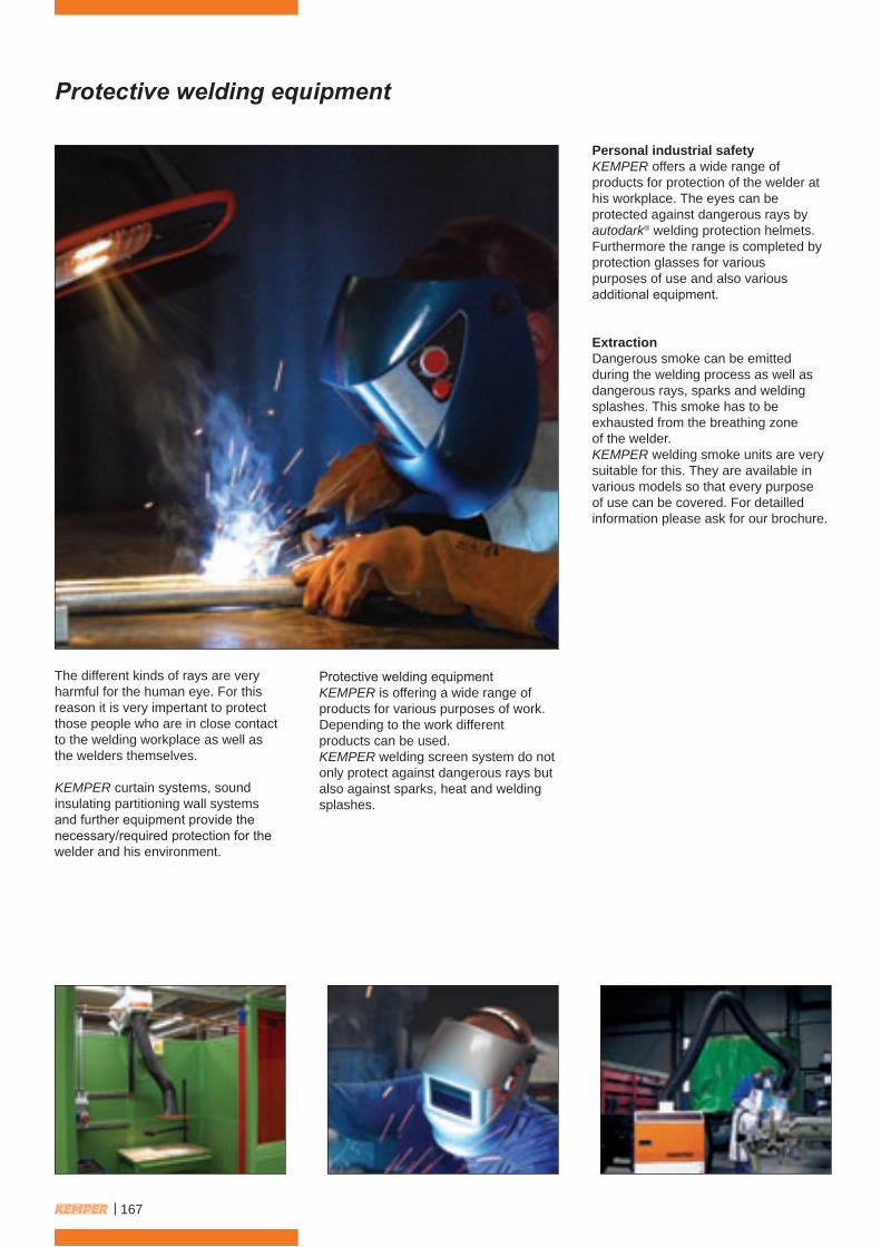
Protective welding equipment
The different kinds of rays are veryharmful for the human eye. For thisreason it is very impertant to protectthose people who are in close contactto the welding workplace as well asthe welders themselves.
KEMPER curtain systems, soundinsulating partitioning wall systemsand further equipment provide thenecessary/required protection for thewelder and his environment.
Protective welding equipmentKEMPER is offering a wide range ofproducts for various purposes of work.Depending to the work differentproducts can be used.KEMPER welding screen system do notonly protect against dangerous rays butalso against sparks, heat and weldingsplashes.
Personal industrial safetyKEMPER offers a wide range ofproducts for protection of the welder athis workplace. The eyes can beprotected against dangerous rays byautodark® welding protection helmets.Furthermore the range is completed byprotection glasses for variouspurposes of use and also variousadditional equipment.
ExtractionDangerous smoke can be emittedduring the welding process as well asdangerous rays, sparks and weldingsplashes. This smoke has to beexhausted from the breathing zoneof the welder.KEMPER welding smoke units are verysuitable for this. They are available invarious models so that every purposeof use can be covered. For detailledinformation please ask for our brochure.
| 167

Regulations
ScopeThis standard specifies safetyrequirements for transparent weldingcurtains, strips and screens to be usedfor shielding off workplaces from theirsurrounding where welding processesare taking place. They are designedto protect people from hazardous radiantemissions from welding arcs and spatter.Welding curtains, strips and screensspecified in this standard are not intendedto replace welding filters.Appropriate welding filters for intentionalviewing of welding arcs from a distanceof less than 2 m are specified in EN 169.The present standard is not applicable forwelding processes where laser radiation isused.Darker curtains or screens can be usedfor mutual separation of adjacentworkplaces for reasons of comfort.
DefinitionsFor the purposes of this standard, thefollowing definition apply.
TransparentCurtains, strips and screens areconsidered transparent if they allowvisibility of the workplace. This does notimply that they are glass clear.For definitions, also see EN 165.
RequirementsTransparent welding curtains, strips andscreens consisting of different materialsshall comply with all requirements foreach individual material at any part of thedevice.For optical test methods see EN 167.
TransmittanceThe luminous transmittance rv, based onthe spectral distribution of illuminant Aaccording to ISO/CIE 10526, shall begreater than 0,0001 %. Scattered lightdiffused within 1° of the direction of theincident radiation shall be included in themeasurement.The spectral transmittance in thewavelength range between 210 nm and313 nm shall be less than 0,002 % and inthe wavelength range between 313 nmand 400 nm less than 3 %.In the wavelength range from 400 nm to1.400 nm the hazard level G shall be lessthan 1.
ReflectanceWhen measured with an Ulbricht sphere,the spectral reflectance between 230 nmand 400 nm shall be less than 10 %.The luminous reflectance shall beless than 10 % (based on the spectraldistribution of standard illuminant A).
UV-stabilityThe relative change of the luminoustransmittance due to the test in clause6 of EN 168 shall not be greaterthan +/- 20 %.
MarkingIn order to be able to identify and usewelding curtains, strips and screens areintended, they shall be permanentlymarked.
KEMPER guarantees,
that all welding curtains and welding strips offered in thiscatalogue confirm to EN 1598.
Vreden, march 2010���KEMPE
R Q
UALITY WARRA
NTY
168 |

Welding curtains
Example:of a welding curtain systemW 4.000 x D 2.000 x H 2.000 mmwith welding curtain S9, dark green, matt,ground clearance 200 mm:
3 x column for 1“ pipe Part No. 70 180 105 2 x 6 m 1“ pipe, Part No. 70 190 144 3 x wall mounting plate for 1“ pipe, Part No. 70 190 135 9 x sets of metal hooks for 1“ pipe, (84 pieces), Part No. 70 120 10910 x welding curtains S9, dark green, matt, H 1.800 x W 1.300 mm, Part No. 70 100 1015 x end caps for 1“ pipe Part No. 70 190 133
Example:of a welding curtain systemW 4.000 x D 2.000 x H 2.000 mmwith welding curtain S9, dark green, matt,ground clearance 200 mm:
3 x column for C-profile, Part No. 70 180 101 2 x 6 m C-Profil, Part No. 70 124 106 3 x wall mounting plate for C-profile, Part No. 70 190 113 5 x end caps for C-profile, Part No. 70 120 107 7 x sets of metal hooks (70 pieces), Part No. 70 120 112 10 x welding curtains S9, dark green, matt, H 1.800 x W 1.300 mm, Part No. 70 100 101
Metal hook suspended welding curtains for 1“ pipe
Sliding hook suspended welding curtains for C-profile
| 169

Welding curtains
Welding curtain S9, dark green, matt, EN 1598
Part No. Dimensions Weight70 100 100 H 1.600 x W 1.300 mm 1,30 kg70 100 101 H 1.800 x W 1.300 mm 1,50 kg70 100 102 H 2.000 x W 1.300 mm 1,60 kg70 100 103 H 2.200 x W 1.300 mm 1,70 kg70 100 104 H 2.400 x W 1.300 mm 1,90 kg70 100 105 H 2.600 x W 1.300 mm 2,00 kg70 100 106 H 2.800 x W 1.300 mm 2,20 kg70 100 107 H 3.000 x W 1.300 mm 2,30 kg70 100 121 Custom size
The curtains have reinforced edges with strengthened eyelets spaced 21 cm apart on the top edge.To connect the curtains there are additional fasteners located on the outer edges.The material has a thickness of 0,4 mm.The curtains can be suspended either with metal hooks on a pipe or with sliding hooks in a C-profile.A horizontal movement of the curtains is possible for both alternatives.
Part No. 70 100 100 - 70 100 121
Part No. 70 100 300 - 70 100 321
Part No. 70 100 400 - 70 100 421
Part No. 70 110 600, 70 110 610, 70 110 620, 70 110 630
Welding curtain S4, light green, EN 1598
Part No. Dimensions Weight70 100 300 H 1.600 x W 1.300 mm 1,30 kg70 100 301 H 1.800 x W 1.300 mm 1,50 kg70 100 302 H 2.000 x W 1.300 mm 1,60 kg70 100 303 H 2.200 x W 1.300 mm 1,70 kg70 100 304 H 2.400 x W 1.300 mm 1,90 kg70 100 305 H 2.600 x W 1.300 mm 2,00 kg70 100 306 H 2.800 x W 1.300 mm 2,20 kg70 100 307 H 3.000 x W 1.300 mm 2,30 kg70 100 321 Custom size
Welding curtain, red, EN 1598
Part No. Dimensions Weight70 100 400 H 1.600 x W 1.300 mm 1,30 kg70 100 401 H 1.800 x W 1.300 mm 1,50 kg70 100 402 H 2.000 x W 1.300 mm 1,60 kg70 100 403 H 2.200 x W 1.300 mm 1,70 kg70 100 404 H 2.400 x W 1.300 mm 1,90 kg70 100 405 H 2.600 x W 1.300 mm 2,00 kg70 100 406 H 2.800 x W 1.300 mm 2,20 kg70 100 407 H 3.000 x W 1.300 mm 2,30 kg70 100 421 Custom size
Welding curtains 600 up to 1.300 °Ccustomized, with eyelets at the top
Part No. Dimensions Temperature70 110 600 H 1.400 x W 1.000 mm Up to 600 °C70 110 610 H 1.400 x W 1.000 mm Up to 850 °C70 110 620 H 1.400 x W 1.000 mm Up to 1.150 °C70 110 630 H 1.400 x W 900 mm Up to 1.300 °C
€30,5033,0037,4041,2045,6049,1055,0059,20
per m² 22,60
€30,5033,0037,4041,2045,6049,1055,0059,20
per m² 22,60
€30,5033,0037,4041,2045,6049,1055,0059,20
per m² 22,60
€36,0052,8073,8080,90
170 |

Protection curtains
Protection curtain S0, transparentTransparent protection curtain protects against dust, draft, moisture and grinding sparks.
Pivoting self retracting cable reel for curtains
Suitable for welding curtains with a maximum width of 8,00 m. The welding curtain issuspended on the straightened cable.The welding curtain can be gathered and the complete cable retracted to allow easyaccess to the welding area.
Part No. Description Weight70 110 101 For curtains 13,00 kg
Part No. Dimensions Weight70 100 500 H 1.600 x W 1.300 mm 1,30 kg70 100 501 H 1.800 x W 1.300 mm 1,50 kg70 100 502 H 2.000 x W 1.300 mm 1,60 kg70 100 503 H 2.200 x W 1.300 mm 1,70 kg70 100 504 H 2.400 x W 1.300 mm 1,90 kg70 100 505 H 2.600 x W 1.300 mm 2,00 kg70 100 506 H 2.800 x W 1.300 mm 2,20 kg70 100 507 H 3.000 x W 1.300 mm 2,30 kg70 100 521 Custom size
Part No. 70 100 500 - 70 100 521
€30,5033,0037,4041,2045,6049,1055,0059,20
per m² 22,60
€433,10
| 171

Welding strip curtains
Metal hook suspended welding strip curtains for 1“ pipe
Sliding hook suspended welding strip curtains for C-profile
Example:of a welding curtain systemW 4.000 x D 2.000 x H 2.000 mmwith welding strip curtain S9, dark green, matt,ground clearance 200 mm:
3 x column for 1“ pipe Part No. 70 180 105 2 x 6 m 1“ pipe, Part No. 70 190 144 3 x wall mounting plate for 1“ pipe, Part No. 70 190 135 7 x sets of metal hooks for 1“ pipe, (70 pieces), Part No. 70 120 10920 x welding curtains S9, dark green, matt, H 1.800 x W 570 mm, Part No. 70 250 1015 x end cap for 1“ pipe Part No. 70 190 133
Example:of a welding curtain systemW 4.000 x D 2.000 x H 2.000 mmwith welding strip curtain S9, dark green, matt,ground clearance 200 mm:
3 x column for C-profile, Part No. 70 180 101 2 x 6 m C-Profil, Part No. 70 124 106 3 x wall mounting plate for C-profile, Part No. 70 190 113 5 x end caps for C-profile, Part No. 70 120 107 7 x sets of metal hooks (70 pieces), Part No. 70 120 112 20 x welding curtains S9, dark green, matt H 1.800 x W 570 mm, Part No. 70 250 101
172 |
Welding strip curtains
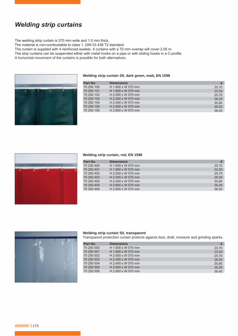
Welding strip curtain S9, dark green, matt, EN 1598
Part No. Dimensions70 250 100 H 1.600 x W 570 mm70 250 101 H 1.800 x W 570 mm70 250 102 H 2.000 x W 570 mm70 250 103 H 2.200 x W 570 mm70 250 104 H 2.400 x W 570 mm70 250 105 H 2.600 x W 570 mm70 250 106 H 2.800 x W 570 mm
The welding strip curtain is 570 mm wide and 1,0 mm thick.The material is non-combustable to class 1, DIN 53 438 T2 standard.The curtain is supplied with 4 reinforced eyelets. 4 curtains with a 70 mm overlap will cover 2,05 m.The strip curtains can be suspended either with metal hooks on a pipe or with sliding hooks in a C-profile.A horizontal movement of the curtains is possible for both alternatives.
Welding strip curtain, red, EN 1598
Part No. Dimensions70 250 400 H 1.600 x W 570 mm70 250 401 H 1.800 x W 570 mm70 250 402 H 2.000 x W 570 mm70 250 403 H 2.200 x W 570 mm70 250 404 H 2.400 x W 570 mm70 250 405 H 2.600 x W 570 mm70 250 406 H 2.800 x W 570 mm
Welding strip curtain S0, transparentTransparent protection curtain protects against dust, draft, moisture and grinding sparks.
Part No. Dimensions70 250 500 H 1.600 x W 570 mm70 250 501 H 1.800 x W 570 mm70 250 502 H 2.000 x W 570 mm70 250 503 H 2.200 x W 570 mm70 250 504 H 2.400 x W 570 mm70 250 505 H 2.600 x W 570 mm70 250 506 H 2.800 x W 570 mm
€20,7023,3025,7028,3030,8035,2038,40
€20,7023,3025,7028,3030,8035,2038,40
€20,7023,3025,7028,3030,8035,2038,40
| 173
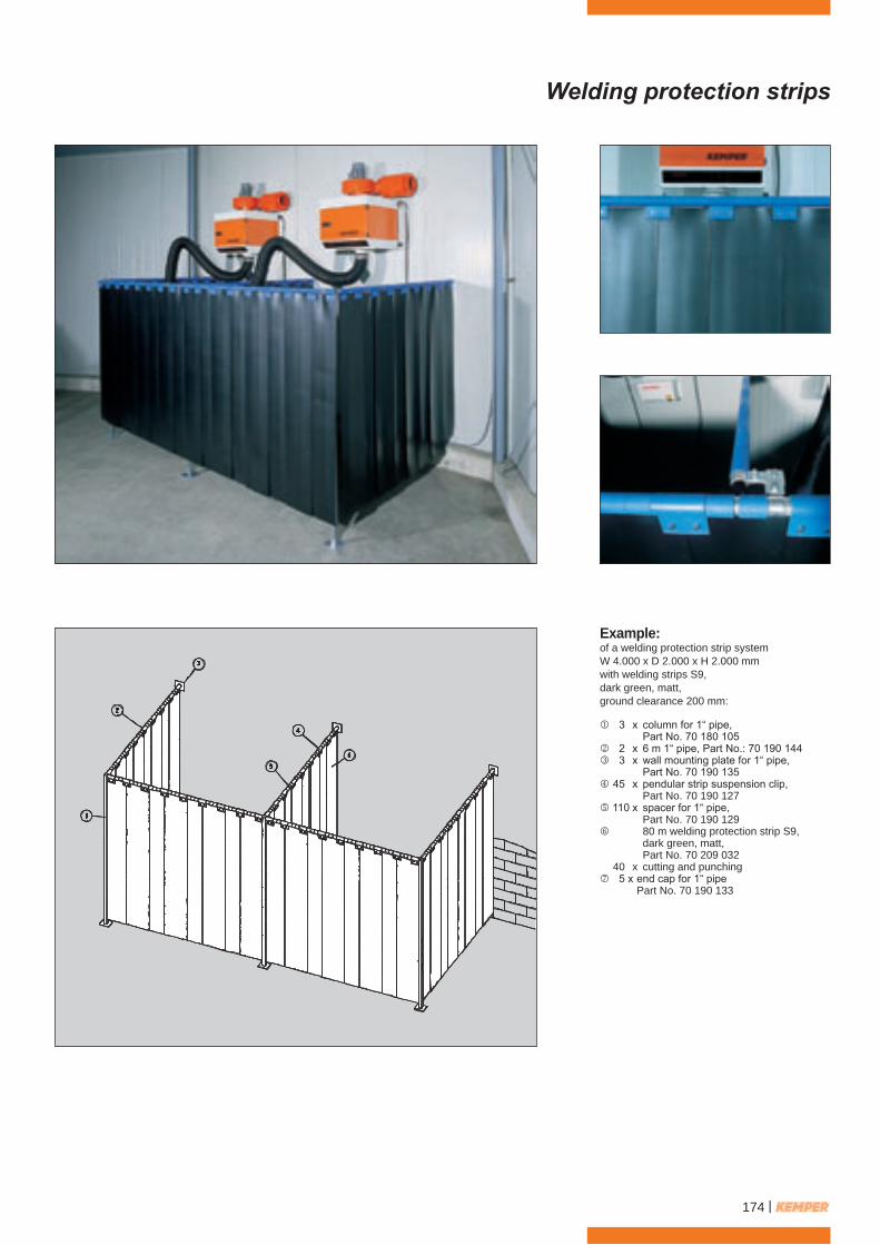
Welding protection strips
Example:of a welding protection strip systemW 4.000 x D 2.000 x H 2.000 mmwith welding strips S9,dark green, matt,ground clearance 200 mm:
3 x column for 1“ pipe, Part No. 70 180 105 2 x 6 m 1“ pipe, Part No.: 70 190 144 3 x wall mounting plate for 1“ pipe, Part No. 70 190 135 45 x pendular strip suspension clip, Part No. 70 190 127 110 x spacer for 1“ pipe, Part No. 70 190 129 80 m welding protection strip S9, dark green, matt, Part No. 70 209 032 40 x cutting and punching5 x end cap for 1“ pipe Part No. 70 190 133
174 |

Lateral sliding welding protection strips
Example:of a lateral sliding welding protectionstrip systemW 4.000 x D 2.000 x H 2.000 mmwith welding protection strips S9,dark green, matt,ground clearance 200 mm:
3 x column for 1“ pipe, Part No. 70 180 105 1 x 6 m 1“ pipe, Part No. 70 190 144 3 x wall mounting plate for 1“ pipe, Part No. 70 190 135 2 x 6 m C-profile, Part No. 70 124 106 4 x end cap for C-profile, Part No. 70 120 1074 x travelling device for 1“ pipe, Part No. 70 190 148 1 x 6 m 1“ pipe, Part No. 70 190 144 4 x end cap for 1“ pipe, Part No. 70 190 133 45 x pendular strip suspension clip, Part No. 70 190 127 110 x spacer for 1“ pipe, Part No. 70 190 129 80 m welding protection strip S9, dark green, matt Part No. 70 209 032 40 x cutting and punching 6 x universal rail fixing device for C-profile Part No. 70 190 112
| 175
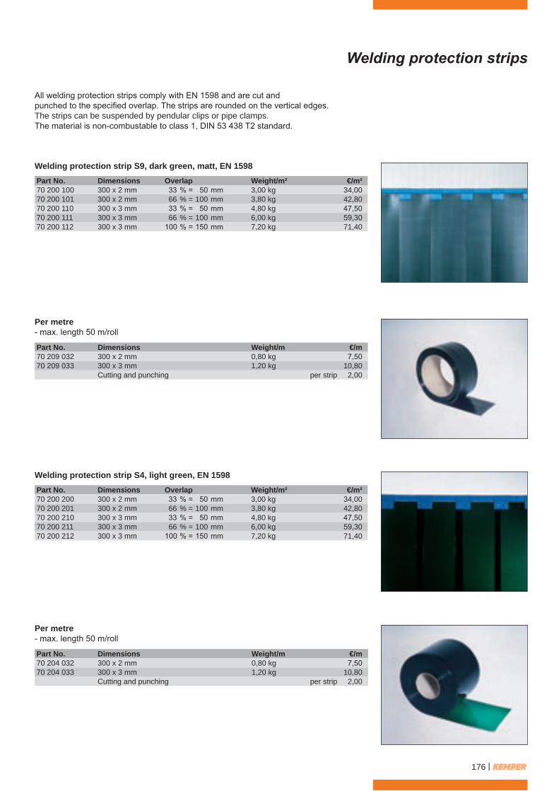
Welding protection strips
All welding protection strips comply with EN 1598 and are cut andpunched to the specified overlap. The strips are rounded on the vertical edges.The strips can be suspended by pendular clips or pipe clamps.The material is non-combustable to class 1, DIN 53 438 T2 standard.
Welding protection strip S9, dark green, matt, EN 1598
Per metre- max. length 50 m/roll
Per metre- max. length 50 m/roll
Welding protection strip S4, light green, EN 1598
Part No. Dimensions Overlap Weight/m²70 200 100 300 x 2 mm 33 % = 50 mm 3,00 kg70 200 101 300 x 2 mm 66 % = 100 mm 3,80 kg70 200 110 300 x 3 mm 33 % = 50 mm 4,80 kg70 200 111 300 x 3 mm 66 % = 100 mm 6,00 kg70 200 112 300 x 3 mm 100 % = 150 mm 7,20 kg
Part No. Dimensions Weight/m70 209 032 300 x 2 mm 0,80 kg70 209 033 300 x 3 mm 1,20 kg
Cutting and punching
Part No. Dimensions Weight/m70 204 032 300 x 2 mm 0,80 kg70 204 033 300 x 3 mm 1,20 kg
Cutting and punching
Part No. Dimensions Overlap Weight/m²70 200 200 300 x 2 mm 33 % = 50 mm 3,00 kg70 200 201 300 x 2 mm 66 % = 100 mm 3,80 kg70 200 210 300 x 3 mm 33 % = 50 mm 4,80 kg70 200 211 300 x 3 mm 66 % = 100 mm 6,00 kg70 200 212 300 x 3 mm 100 % = 150 mm 7,20 kg
€/m²34,0042,8047,5059,3071,40
€/m7,50
10,80per strip 2,00
€/m7,50
10,80per strip 2,00
€/m²34,0042,8047,5059,3071,40
176 |

Welding protection strips
Welding protection strip, red, EN 1598
Per metre- max. length 50 m/roll
Per metre- max. length 50 m/roll
Welding protection strip, UV resistant, bronze, EN 1598
Part No. Dimensions Overlap Weight/m²70 200 400 300 x 2 mm 33 % = 50 mm 3,00 kg70 200 401 300 x 2 mm 66 % = 100 mm 3,80 kg70 200 410 300 x 3 mm 33 % = 50 mm 4,80 kg70 200 411 300 x 3 mm 66 % = 100 mm 6,00 kg70 200 412 300 x 3 mm 100 % = 150 mm 7,20 kg
Part No. Dimensions Weight/m70 202 032 300 x 2 mm 0,80 kg70 202 033 300 x 3 mm 1,20 kg
Cutting and punching
Part No. Dimensions Weight/m70 203 032 300 x 2 mm 0,80 kg70 203 033 300 x 3 mm 1,20 kg
Cutting and punching
Part No. Dimensions Overlap Weight/m²70 200 500 300 x 2 mm 33 % = 50 mm 3,00 kg70 200 501 300 x 2 mm 66 % = 100 mm 3,80 kg70 200 510 300 x 3 mm 33 % = 50 mm 4,80 kg70 200 511 300 x 3 mm 66 % = 100 mm 6,00 kg70 200 512 300 x 3 mm 100 % = 150 mm 7,20 kg
€/m²34,0042,8047,5059,3071,40
€/m7,50
10,80per strip 2,00
€7,50
10,80per strip 2,00
€34,0042,8047,5059,3071,40
| 177

Protection strips
The KEMPER-pendular suspension clip(patented)
Protection strip S0, transparentTransparent protection strip protects against dust, draft, moisture and grinding sparks.
Per metre- max. length 50 m/roll
The big disadvantage of commonstrip suspensions and spacers arethat they can only be mounted tothe rail before erection.After this, every single strip needsto be mounted to the stripsuspensions with nuts and bolts,which is a complicated and timeconsuming procedure.
The folding KEMPER suspensionclip offers a much easier and timesaving installation.The clips are delivered open andafter finishing the installation ofthe rail system the suspensionclip can simply be folded aroundthe rail.Subsequent to this, every singlestrip can easily be inserted intothe suspension clip and held inplace by special retaining rivits.The spacers work on the sameprinciple.
Part No. Dimensions Overlap Weight/m²70 200 300 300 x 2 mm 33 % = 50 mm 3,00 kg70 200 301 300 x 2 mm 66 % = 100 mm 3,80 kg70 200 310 300 x 3 mm 33 % = 50 mm 4,80 kg70 200 311 300 x 3 mm 66 % = 100 mm 6,00 kg70 200 312 300 x 3 mm 100 % = 150 mm 7,20 kg70 200 321 300 x 5 mm 66 % = 100 mm 9,50 kg70 200 322 300 x 5 mm 100 % = 150 mm 12,50 kg
Part No. Dimensions Weight/m70 201 032 300 x 2 mm 0,80 kg70 201 033 300 x 3 mm 1,20 kg70 201 035 300 x 5 mm 1,90 kg70 201 044 400 x 4 mm 2,00 kg
Cutting and punching
€/m²34,0042,8047,5059,3071,4098,10
117,70
€/m7,50
10,8020,2022,00
per strip 2,00
178 |
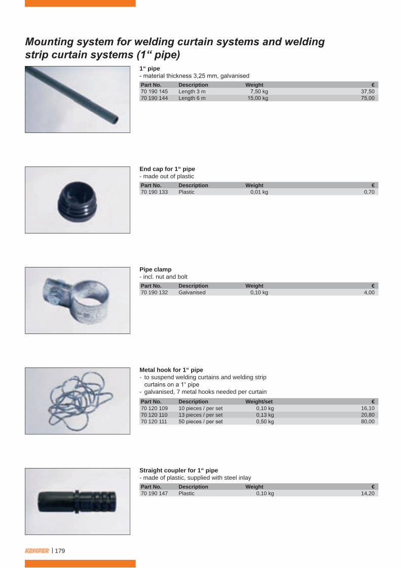
Mounting system for welding curtain systems and weldingstrip curtain systems (1“ pipe)
1“ pipe- material thickness 3,25 mm, galvanised
End cap for 1“ pipe- made out of plastic
Pipe clamp- incl. nut and bolt
Straight coupler for 1“ pipe- made of plastic, supplied with steel inlay
Metal hook for 1“ pipe- to suspend welding curtains and welding strip curtains on a 1“ pipe- galvanised, 7 metal hooks needed per curtain
Part No. Description Weight70 190 145 Length 3 m 7,50 kg70 190 144 Length 6 m 15,00 kg
Part No. Description Weight70 190 133 Plastic 0,01 kg
Part No. Description Weight70 190 132 Galvanised 0,10 kg
Part No. Description Weight70 190 147 Plastic 0,10 kg
Part No. Description Weight/set70 120 109 10 pieces / per set 0,10 kg70 120 110 13 pieces / per set 0,13 kg70 120 111 50 pieces / per set 0,50 kg
€37,5075,00
€0,70
€4,00
€14,20
€16,1020,8080,00
| 179
Mounting system for welding curtain systems and weldingstrip curtain systems (1“ pipe)
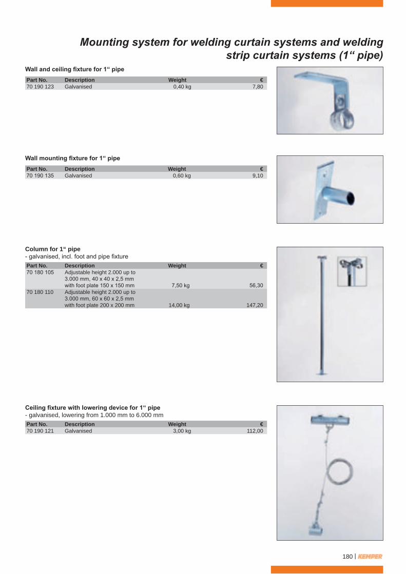
Wall and ceiling fixture for 1“ pipe
Wall mounting fixture for 1“ pipe
Column for 1“ pipe- galvanised, incl. foot and pipe fixture
Ceiling fixture with lowering device for 1“ pipe- galvanised, lowering from 1.000 mm to 6.000 mm
Part No. Description Weight70 190 123 Galvanised 0,40 kg
Part No. Description Weight70 190 135 Galvanised 0,60 kg
Part No. Description Weight70 180 105 Adjustable height 2.000 up to
3.000 mm, 40 x 40 x 2,5 mmwith foot plate 150 x 150 mm 7,50 kg
70 180 110 Adjustable height 2.000 up to3.000 mm, 60 x 60 x 2,5 mmwith foot plate 200 x 200 mm 14,00 kg
Part No. Description Weight70 190 121 Galvanised 3,00 kg
€7,80
€9,10
€112,00
€
56,30
147,20
180 |

Mounting system for welding curtain systems and weldingstrip curtain systems (C-profile)
C-profile, 40 x 40 x 2,5 mm- material thickness 2,5 mm, galvanised
90°-elbow for C-profile- galvanised, 40 x 40 x 2,5 mm
Straight coupler for C-profile
T-coupler for C-profile
End cap for C-profile
Sliding hooks for C-profile- to suspend welding curtains and welding strip curtains on a C-profile- made of plastic, 7 sliding hooks needed per curtain
Part No. Description Weight70 124 107 Length 3 m 7,50 kg70 124 106 Length 6 m 15,00 kg
Part No. Description Weight70 124 102 Radius: 400 mm 2,60 kg70 124 103 Radius: 1.000 mm 3,90 kg
Part No. Description Weight70 190 105 Galvanised 0,65 kg
Part No. Description Weight70 190 107 Galvanised 1,30 kg
Part No. Description Weight70 120 107 Plastic 0,01 kg
Part No. Description Weight/kit70 120 112 10 pieces / per set 0,10 kg70 120 117 13 pieces / per set 0,13 kg70 120 113 50 pieces / per set 0,50 kg
€39,6079,30
€151,10120,30
€13,90
€37,10
€1,10
€16,1020,8080,00
| 181

Mounting system for welding curtain systems and weldingstrip curtain systems (C-profile)
Wall fixture for double-C-profile
Side wall fixture for C-profile
Side wall fixture for double-C-profile
Wall fixture for C-profile
Ceiling fixture for C-profile
Ceiling fixture for double-C-profile
Part No. Description Weight70 190 138 Galvanised 1,90 kg
Part No. Description Weight70 190 115 Galvanised 0,68 kg
Part No. Description Weight70 190 117 Galvanised 1,30 kg
Part No. Description Weight70 190 113 Galvanised 1,30 kg
Part No. Description Weight70 190 108 Galvanised 0,40 kg
Part No. Description Weight70 190 110 Galvanised 0,80 kg
€25,50
€18,80
€33,40
€16,40
€14,00
€26,30
182 |
Mounting system for welding curtain systems and weldingstrip curtain systems (C-profile)
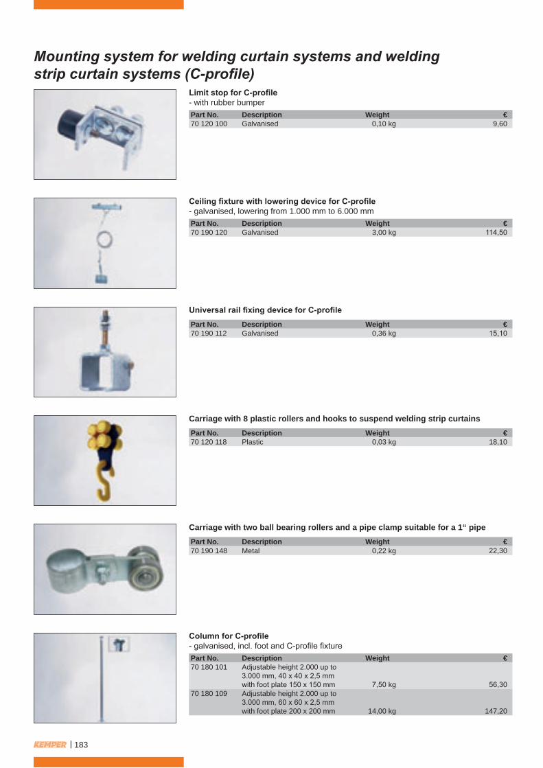
Limit stop for C-profile- with rubber bumper
Ceiling fixture with lowering device for C-profile- galvanised, lowering from 1.000 mm to 6.000 mm
Carriage with 8 plastic rollers and hooks to suspend welding strip curtains
Universal rail fixing device for C-profile
Column for C-profile- galvanised, incl. foot and C-profile fixture
Carriage with two ball bearing rollers and a pipe clamp suitable for a 1“ pipe
Part No. Description Weight70 120 100 Galvanised 0,10 kg
Part No. Description Weight70 190 120 Galvanised 3,00 kg
Part No. Description Weight70 120 118 Plastic 0,03 kg
Part No. Description Weight70 190 112 Galvanised 0,36 kg
Part No. Description Weight70 180 101 Adjustable height 2.000 up to
3.000 mm, 40 x 40 x 2,5 mmwith foot plate 150 x 150 mm 7,50 kg
70 180 109 Adjustable height 2.000 up to3.000 mm, 60 x 60 x 2,5 mmwith foot plate 200 x 200 mm 14,00 kg
Part No. Description Weight70 190 148 Metal 0,22 kg
€9,60
€114,50
€18,10
€15,10
€
56,30
147,20
€22,30
| 183

Mounting system for welding protection strips
Welding protection strip fixture setThe complete set consists of all the necessary parts required for the suspension ofwelding protection strips for a specified width. This set includes 1“ pipe, pendularsuspension clips, spacers, end caps and wall or ceiling brackets.
Lateral sliding welding protection strip fixture setThe 1“ pipe with welding protection strips is laterally sliding within a C-profile.The complete set consists of all necessary parts for the required width and includes1“ pipe, C-profile, travelling device, suspension clips, spacers, limit stopper, end capsor wall and ceiling brackets.
Pendular clip for a 1“ pipe including fixture nuts and bolts- made of plastic (5 pieces per set)
Spacer for 1“ pipe- made of plastic (10 pieces per set)
Pipe clamp for 1“ pipe
Carriage with 8 plastic rollers and hooks to suspend welding strip curtains
Part No. Description Weight70 190 127 Plastic 0,08 kg
Part No. Description Weight70 190 129 Plastic 0,02 kg
Part No. Description Weight70 190 128 Galvanised 0,20 kg
Part No. Description Weight70 120 118 Plastic 0,03 kg
Part No. Overlap Weight/m²70 500 100 33 % = 50 mm 4,00 kg70 500 101 66 % = 100 mm 4,50 kg70 500 102 100 % = 150 mm 5,00 kg
Part No. Overlap Weight/m²70 510 100 33 % = 50 mm 7,00 kg70 510 101 66 % = 100 mm 7,50 kg70 510 102 100 % = 150 mm 8,00 kg
€28,1030,7034,50
€126,70129,30133,10
€/piece3,50
€/piece0,60
€2,60
€18,10
184 |

Mounting system for welding protection strips
Overlap 33 %
Overlap 66 %
The drawing and table below show theexact quantity of parts required, based onthe total width of welding protectionstrips.
Attention: Fixed installation: only wall and ceiling fixtures (no travelling devices) Lateral sliding installation: C-profile = double curtain width Wall and ceiling fixtures for C-profile = 2 x travelling devices
The drawing and table below show theexact quantity of parts required, based onthe total width of welding protectionstrips.
Attention: Fixed installation: only wall and ceiling fixtures (no travelling devices)
Lateral sliding installation: C-profile = double curtain width
Wall and ceiling fixtures for C-profile = 2 x travelling devices
Curtain width andpipe length mm 55
0
800
1.05
0
1.30
0
1.55
0
1.80
0
2.05
0
2.30
0
2.55
0
2.80
0
3.05
0
3.30
0
3.55
0
3.80
0
4.05
0
4.30
0
4.55
0
4.80
0
5.05
0
5.30
0
5.55
0
5.80
0
6.05
0
6.30
0
6.55
0
6.80
0
7.05
0
7.30
0
7.55
0
7.80
0
welding strips pieces 2 3 4 5 6 7 8 9 10 11 12 13 14 15 16 17 18 19 20 21 22 23 24 25 26 27 28 29 30 31
suspension clips pieces 3 4 5 6 7 8 9 10 11 12 13 14 15 16 17 18 19 20 21 22 23 24 25 26 27 28 29 30 31 32
spacers pieces 3 6 9 12 15 18 21 23 26 29 32 35 38 41 43 46 49 52 55 58 61 64 66 69 72 75 78 81 84 87
ceiling fixtures ortravelling devices pieces 2 2 2 2 2 2 2 3 3 3 3 3 3 3 4 4 4 4 4 4 4 4 5 5 5 5 5 5 5 5
Curtain width andpipe length mm 50
0
700
900
1.10
0
1.30
0
1.50
0
1.70
0
1.90
0
2.10
0
2.30
0
2.50
0
2.70
0
2.90
0
3.10
0
3.30
0
3.50
0
3.70
0
3.90
0
4.10
0
4.30
0
4.50
0
4.70
0
4.90
0
5.10
0
5.30
0
5.50
0
5.70
0
5.90
0
6.10
0
6.30
0
welding strips pieces 2 3 4 5 6 7 8 9 10 11 12 13 14 15 16 17 18 19 20 21 22 23 24 25 26 27 28 29 30 31
suspension clips pieces 3 4 5 6 7 8 9 10 11 12 13 14 15 16 17 18 19 20 21 22 23 24 25 26 27 28 29 30 31 32
spacers pieces 2 4 6 8 10 12 14 16 17 19 21 23 25 27 29 31 33 35 36 38 40 42 44 46 48 50 52 54 55 57
ceiling fixtures ortravelling devices pieces 2 2 2 2 2 2 2 2 3 3 3 3 3 3 3 3 3 3 4 4 4 4 4 4 4 4 4 4 5 5
maximum distance between each support: 2.000 mm
pipe clamp suspension clipspacer
welding protection strip
50 mm overlap = 33 %
1" pipe 100
100
300
150
maximum distance between each support: 2.000 mm
pipe clamptravelling device C-profile
suspension clipspacer
welding protection strip
100 mm overlap = 66 %
1" pipe100 100
300
| 185

The drawing and table below show theexact quantity of parts required, based onthe total width of welding protectionstrips.
Attention: Fixed installation: only wall and ceiling fixtures (no travelling devices) Lateral sliding installation: C-profile = double curtain width Wall and ceiling fixtures for C-profile = 2 x travelling devices
Overlap 100 %
Curtain width andpipe length mm 45
0
600
750
900
1.05
0
1.20
0
1.35
0
1.50
0
1.65
0
1.80
0
1.95
0
2.10
0
2.25
0
2.40
0
2.55
0
2.70
0
2.85
0
3.00
0
3.15
0
3.30
0
3.45
0
3.60
0
3.75
0
3.90
0
4.04
0
4.20
0
4.35
0
4.50
0
4.65
0
4.80
0
welding strips pieces 2 3 4 5 6 7 8 9 10 11 12 13 14 15 16 17 18 19 20 21 22 23 24 25 26 27 28 29 30 31
suspension clips pieces 4 5 6 7 8 9 10 11 12 13 14 15 16 17 18 19 20 21 22 23 24 25 26 27 28 29 30 31 32 33
spacers pieces 1 2 3 4 5 6 7 8 9 10 11 11 12 13 14 15 16 17 18 19 20 21 22 23 23 24 25 26 27 28
ceiling fixtures ortravelling devices pieces 2 2 2 2 2 2 2 2 2 2 2 3 3 3 3 3 3 3 3 3 3 3 3 3 4 4 4 4 4 4
Mounting system for welding protection strips
Cutting and punching of welding protection stripsPart No. Description70 210 033 Cutting and punching for clips and an overlap of 33 %70 210 066 Cutting and punching for clips and an overlap of 66 %70 210 100 Cutting and punching for clips and an overlap of 100 %
Part No. Description70 211 033 Cutting and punching for pipe clamps and an overlap of 33 %70 211 066 Cutting and punching for pipe clamps and an overlap of 66 %70 211 100 Cutting and punching for pipe clamps and an overlap of 100 %
maximum distance between each support: 2.000 mm
pipe clamp suspension clipspacer
welding protection strip150 mm overlap = 100 %
1" pipe 100 50
300
€2,002,002,00
€2,002,002,00
186 |

Pivoting arm, wall-mounted or incl. column
Pivoting arm for welding curtains, wall-mounted- powder coated, incl. C-profile 40 x 40 x 2,5 mm
Pivoting arm for welding curtains, incl. column- consisting of a pivoting arm and a suitable column to mount on the floor- powder coated, incl. C-profile 40 x 40 x 2,5 mm- height of columns: for 2.000 up to 4.000 mm pivoting arms = 2.500 mm for 5.000 up to 6.000 mm pivoting arms = 3.400 mm
Pivoting arm for welding curtains and welding protection strips, incl. column- consisting of a pivoting arm and a suitable column to mount on the floor- powder coated, incl. 1“ pipe- height of columns: for 2.000 up to 4.000 mm pivoting arms = 2.500 mm for 5.000 up to 6.000 mm pivoting arms = 3.400 mm
Pivoting arm for welding curtains and welding protection strips, wall-mounted- powder coated, incl. 1“ pipe
Part No. Description70 700 250 Length 2.000 mm70 700 251 Length 3.000 mm70 700 252 Length 4.000 mm70 700 253 Length 5.000 mm70 700 254 Length 6.000 mm
Part No. Description Height at lower edge of extension arm70 700 650 Length 2.000 mm 2.165 mm70 700 651 Length 3.000 mm 2.165 mm70 700 652 Length 4.000 mm 2.165 mm70 700 653 Length 5.000 mm 2.215 mm70 700 654 Length 6.000 mm 2.215 mm
Part No. Description Height at lower edge of extension arm70 700 655 Length 2.000 mm 2.050 mm70 700 656 Length 3.000 mm 2.050 mm70 700 657 Length 4.000 mm 2.050 mm70 700 659 Length 5.000 mm 2.100 mm70 700 660 Length 6.000 mm 2.100 mm
Note: Additional guy wire is provided only for pivoting arms with length of 5 m and 6 m.
Part No. Description70 700 255 Length 2.000 mm70 700 256 Length 3.000 mm70 700 257 Length 4.000 mm70 700 258 Length 5.000 mm70 700 259 Length 6.000 mm
Note: Additional guy wire is provided only for pivoting arms with length of 5 m and 6 m.
€652,50806,80
1.063,001.383,001.522,00
€1.356,001.452,002.572,002.816,002.931,00
€652,50806,80
1.063,001.383,001.522,00
€1.356,001.452,002.572,002.816,002.931,00
| 187

Locking swivel arms for mounting on walls and pillars
Locking swivel arms with a telescopic facilityfor mounting on walls and pillars
Locking swivel arms for mounting on walls and pillarsPart No. Description131 2634 Locking swivel arms for mounting
on walls and pillars, 1,5 m131 3036 Locking swivel arms for mounting
on walls and pillars, 2,0 m131 2647 Wall bracket
Locking swivel arms with a telescopic facilityfor mounting on walls and pillars
Part No. Description131 3262 Locking swivel arms with a telescopic facility
for mounting on walls and pillars , 1,0 m131 3263 Locking swivel arms with a telescopic facility
for mounting on walls and pillars , 1,5 m131 3264 Locking swivel arms with a telescopic facility
for mounting on walls and pillars , 2,0 m131 2647 Wall bracket
Locking swivel arms that can be mounting on walls and pillars offer the possibility of hanging welding curtains and strips so that people in the vicinity are protected from dangerousradiation, welding arcs and splashes.
The advantage of this type of swivel arm is that it can be locked. This prevents the arm from being accidentally nudged to one side, endangering personnel. The lock is released by pulling on a chain.
These locking swivel arms are available in lengths of 1,5 m and2,0 m. They can be attached to a pillar or a bracket on the wall.
Locking swivel arms with a telescopic facility for mounting on walls and pillars offer not only a means of hanging curtains or strips, but also the possibility of pushing the hanging together by telescoping the arm.
In addition to the advantages of locking swivel arms, this ver-sion has the added flexibility of being telescopic. This allows access to a partitioned area to be created despite the arm being locked, without actually releasing the lock.
The telescopic function is easily operated using a chain with which the telescopic arm is easily pulled and pushed back.
These locking swivel arms with a telescopic facility are available in lengths of 1,0 m, 1,5 m and 2,0 m. They can be attached to a pillar or a bracket on the wall.
€
565,00
685,00139,00
€
695,00
815,00
945,00139,00
188 |

1-panel mobile protective screen with curtainCircular steel tube construction, with blue epoxy-powder coating.The curtain is stretched between the top and the bottom strut of the frame.Complete kit, ready to assemble. Conform to EN 1598.Width: 1,45 m, height: 1,90 m (ground clearance 100 mm).
1-panel mobile protective screen with curtainStable construction out of box section 60 x 30 mm with blue epoxy-powder coating.The curtain is attached to the construction by means of metal hooks.Complete kit.Width: 2,10 m, height: 1,83 m, ground clearance: 165 mm.With accessories: set of castors: height: 1,92 m, ground clearance: 250 mm
3-panel mobile protective screen with curtainStable construction out of box section 60 x 30 mm with blue epoxy-powder coating.The curtain is attached to the construction by means of metal hooks.Complete kit.Width: 3,80 m (central panel 2,10 m + 2 swivelling arms, 0,85 m each),height: 1,83 m, ground clearance: 165 mm.With accessories: set of castors: height: 1,92 m, ground clearance: 250 mm.
Part No. Description70 600 301 With welding curtain S9, dark green,
matt EN 159870 600 302 With welding curtain S4, light green
EN 159870 600 304 With welding curtain, red
EN 159870 600 303 With welding curtain S0, transparent
against dust, moisture
Part No. Description70 600 500 With welding curtain S9, dark green,
matt EN 159870 600 501 With welding curtain, red
EN 159870 600 503 With welding curtain S4, light green
EN 159870 600 699 Accessories:
Set of castors, consisting of fourguide roller, two with brakes
Part No. Description70 600 550 With welding curtain S9, dark green,
matt EN 159870 600 551 With welding curtain, red
EN 159870 600 552 With welding curtain S0, transparent
against dust, moisture70 600 699 Accessories:
Set of castors, consisting of fourguide roller, two with brakes
Mobile protection screens
€
112,00
112,00
112,00
112,00
€
299,40
299,40
299,40
32,00
€
339,40
339,40
339,40
32,00
| 189

Mobile protection screens
1-panel mobile protection screen with welding strip curtainStable construction out of box section 60 x 30 mm with blue epoxy-powder coating.The welding strip curtain is 570 mm wide and 1,0 mm thick. The strip curtain ismounted to the frame by metal hooks.Complete kit.Width: 2,10 m, height: 1,83 m, ground clearance: 165 mm.With accessories: set of castors: height: 1,92 m, ground clearance: 250 mm.
3-panel mobile protection screen with welding strip curtainStable construction out of box section 60 x 30 mm with blue epoxy-powder coating.The welding strip curtain is 570 mm wide and 1,0 mm thick. The strip curtain ismounted to the frame by metal hooks.Complete kit.Width: 3,80 m (central panel 2,10 m + 2 swivelling arms, 0,85 m each),height: 1,83 m, ground clearance: 165 mm.With accessories: set of castors: height: 1,92 m, ground clearance: 250 mm.
Part No. Description70 600 701 With welding strip curtain S9, dark green,
matt EN 159870 600 702 With welding strip curtain, red
EN 159870 600 703 With welding strip curtain S0, transparent
against dust, moisture70 600 699 Accessories:
Set of castors, consisting of fourguide roller, two with brakes
Part No. Description70 600 664 With welding curtain S9, dark green,
matt EN 159870 600 665 With welding strip curtain, red
EN 159870 600 699 Accessories:
Set of castors, consisting of fourguide roller, two with brakes
€
327,90
327,90
327,90
32,00
€
391,90
391,90
32,00
190 |

Mobile protection screens
1-panel mobile welding protection strip screenStable construction out of box section 60 x 30 mm with blue epoxy-powder coating.The welding protection strips are mounted to the frame by suspension clips andspacers.Complete kit.Width: 2,10 m, height: 1,83 m, ground clearance: 470 mm.With accessories: set of castors: height: 1,92 m, ground clearance: 555 mm.
3-panel mobile welding protection strip screenStable construction out of box section 60 x 30 mm with blue epoxy-powder coating.The welding protection strips are mounted to the frame by suspension clips andspacers.Complete kit.Width: 3,80 m (central panel 2,10 m + 2 swivelling arms, 0,85 m each),height: 1,83 m, ground clearance: 470 mm.With accessories: set of castors: height: 1,92 m, ground clearance: 555 mm.
Part No. Description70 600 600 With welding protection strip S9, dark green,
matt 300 x 2 mm, EN 159870 600 601 With welding protection strip S9, dark green,
matt 300 x 3 mm, EN 159870 600 602 With welding protection strip, red
300 x 2 mm, EN 159870 600 603 With welding protection strip, red
300 x 3 mm, EN 159870 600 604 With welding protection strip, S0, transparent
300 x 2 mm70 600 605 With welding protection strip, S0, transparent
300 x 3 mm70 600 699 Accessories:
Set of castors, consisting of fourguide roller, two with brakes
Part No. Description70 600 650 With welding protection strip S9, dark green,
matt 300 x 2 mm, EN 159870 600 651 With welding protection strip S9, dark green,
matt 300 x 3 mm, EN 159870 600 652 With welding protection strip, red
300 x 2 mm, EN 159870 600 653 With welding protection strip, red
300 x 3 mm, EN 159870 600 654 With welding protection strip, S0, transparent
300 x 2 mm70 600 655 With welding protection strip, S0, transparent
300 x 3 mm70 600 699 Accessories:
Set of castors, consisting of fourguide roller, two with brakes
€
390,90
414,80
390,90
414,80
390,90
414,80
32,00
€
476,50
525,70
476,50
525,70
476,50
525,70
32,00
| 191

192 |

| 193

Partitioning wall systems
194 |

The KEMPER sound insulatingpartitioning wall system can be built into any design combination due to different modular elements.
The modular elements consist ofperforated plates, which are finishedwith UV-ray absorbend powder coating.Each element consists of perforatedplates and a filling of compressedmineral wool according to DIN 4102, which is also finished with UV-rayabsorbent powder coating.
Out of these components it is easy toconstruct complete welding bays, inwhich exhaust arms could be mounted.
The outside facing columns can be fittedwith different mounting devices forcurtains, welding strips, etc...
Sound insulating partitioning wall systems
| 195

The picture shows an example which components are required to build a
wall system. The components have a width of 500 mm or 1.000 mm.
Certainly we can assist you forconstruction of your desired system.
Other dimensions on request.
Sound insulating partitioning wall systems
No. Part No. Description 141 0193 Column 1 fold
powder coated 141 0197 Column 2 fold 180°
powder coated 141 0196 Column 2 fold 90°
powder coated 141 0198 Column 3 fold
powder coated 141 0199 Column 4 fold
powder coated 131 1304 Bottom strut, length 420 mm
powder coated 131 0912 Bottom strut, length 920 mm
powder coated 131 1305 Centre strut, length 420 mm
powder coated 131 0911 Centre strut, length 920 mm
powder coated 131 0910 Finishing strut
powder coated144 0326 Sound insulating element
1.000 x 1.000 x 50 mm144 0443 Sound insulating element
1.000 x 500 x 50 mm131 0950 Mounting bracket for
KEMPER telescopic/exhaust arm131 0913 Bracket
galvanised
€
41,50
81,40
94,30
124,30
186,90
20,90
28,30
30,00
56,60
58,30
138,80
76,30
248,50
3,40
196 |

Equipment for schools
KEMPER soundproofing and partition wall systems are also available for schools and training workshops.
The booths consist of perforated plates that are coated with a UV inhibitor.The soundproofing material used isa biodegradable mineral wool witha carcinogenicity index of 40 (Ki 40)rendering it safe (see Technical Rules for Hazardous Substances (TRGS) 905), and non-flammable according to DIN 4102.
Additionally, the mineral wool platesare coated on both sides with black fibreglass fleece material.
The individual components are bolted together to form stable welding booths, on which extraction or telescopic arms can be mounted.
Different versions of the booths allow students to be observed either through a window or through the entrance to the booth. The openings can be separated either through a fixed curtain system or one that can be pushed to one side.
| 197

Wall partitioning system
Workshop partitioning
This example shows differentpossibilities of construction withmodular elements.
Certainly we can assist you forconstruction of your desired system.
If you want a work area to bepartitioned as far up as the ceiling,our workshop partitioning is the answer.
The pictures show how two walls with protective windows and sliding doors form a new room in a workshop.
We are of course happy to help with the planning.
198 |

Booth
Using KEMPER soundproof partitioning systems, it is possible to erect fully enclosed booths within a manufacturing facility. The individual plates can be supplied either in a perforated sheet version, or, for improved sound insulation, from perforated sheet on the inside and solid sheet on the outside.
Naturally we can assist you inplanning the booths to meet your requirements.
The grinding booths are availablein the following versions:
1. Enclosed booth with a double-hinged door
The roof of the booth consists of two segments. The double-hinged doors can be secured with a bolt and the door can be locked.
2. Enclosed booth with hinged door
The basis of the roof is a solid framework and next to the hinged door is a window with a pane of clear Perspex. The hinged door can be locked.
3. Enclosed booth with double sliding door
The roof of the booth consists of box elements and the entire cabin is mainly constructed from standard partitioning elements. The double sliding window is made of clear Perspex.
4. Enclosed booth with sliding door
The construction of this booth is based on standard components and a roof of frame segments. The sliding doorfeatures a red protective pane at the top.
| 199

Single components
Supports with ground clearance (100 mm)Height: 2.120 mm
Supports with ground clearance (100 mm)Height: 3.130 mm
Supports without clearanceHeight: 2.020 mm
Supports without ground clearanceHeight: 2.530 mm
Supports with ground clearance (100 mm)Height: 2.630 mm
Part No. Description141 0193 1-way support141 0502 1-way support with square tube141 0196 2-way support 90°141 0197 2-way support 180°141 0501 2-way support with 180° square tube141 0198 3-way support141 0199 4-way support
Part No. Description141 0417 1-way support141 0548 1-way support with square tube141 0418 2-way support 90°141 0415 2-way support 180°141 0549 2-way support with 180° square tube141 0585 3-way support141 0898 4-way support
Part No. Description141 0683 1-way support141 0663 1-way support with square tube141 0474 2-way support 90°141 0473 2-way support 180°141 0662 2-way support with 180° square tube141 0666 3-way support
Part No. Description141 0433 1-way support141 0488 1-way support with square tube141 0434 2-way support 90°141 0435 2-way support 180°141 0662 2-way support with 180° square tube141 0436 3-way support
Part No. Description141 0223 1-way support141 0525 1-way support with square tube141 0363 2-way support 90°141 0597 2-way support 180°141 0895 2-way support with 180° square tube141 0897 3-way support141 0896 4-way support
€41,50
117,0094,3081,40
128,90124,30186,90
€49,50
138,50117,90101,80159,80155,20229,80
€61,20
171,20141,50122,10189,30186,40274,80
€39,50
112,5089,8077,50
126,50118,10
€49,40
141,80112,4096,90
159,80147,60
200 |

Supports without ground clearance Height: 3.030 mm
Intermediate rails
Cover
Sound insulation plates
Window frames with window (red pane)
Part No. Description131 1304 Lower intermediate rails 25 x 55 x 25 x 2 x 420 mm 131 0912 Lower intermediate rails 25 x 55 x 25 x 2 x 920 mm 131 1305 Middle intermediate rails 25 x 55 x 25 x 2 x 420 mm 131 0911 Middle intermediate rails 25 x 55 x 25 x 2 x 920 mm
Part No. Description131 1399 Cover 30 x 62 x 30 x 2 x 510 mm 131 0963 Cover 30 x 62 x 30 x 2 x 1.010 mm 131 1427 Cover 30 x 62 x 30 x 2 x 1.520 mm 131 0910 Cover 30 x 62 x 30 x 2 x 2.020 mm 131 1653 Cover 30 x 62 x 30 x 2 x 3.030 mm
Part No. Description144 0443 Sound insulation plate, perforated sheet on both sides,
1.000 x 500 x 50 mm 144 0326 Sound insulation plate, perforated sheet on both sides,
1.000 x 1.000 x 50 mm 144 0669 Sound insulation plate, perforated / solid sheet, 1.000 x 500 x 50 mm 144 0666 Sound insulation plate, perforated / solid sheet, 1.000 x 1.000 x 50 mm
Part No. Description141 0529 Window frames with window, red pane, 1.000 x 500 mm 141 0438 Window frames with window, red pane, 1.000 x 1.000 mm
Single components
Part No. Description141 0899 1-way support141 0570 1-way support with square tube141 0794 2-way support 90°141 0844 2-way support 180°141 0900 2-way support with 180° square tube141 0901 3-way support
€31,8043,2049,5058,3074,80
€
76,30
138,8076,30
138,80
€369,80482,30
€59,20
166,20134,90116,30192,50177,20
€19,8028,3038,5056,60
| 201

Booth entrance with movable strips
Booth entrance with fixed element and movable strips
Booth entrance with fixed element and movable door
Part No. Description95 000 003 000 Booth entrance for booths with movable 2 m strips
Strips 1,8 m, 33 % overlap, dimensions 300 x 2 mm
Part No. Description95 000 003 100 Booth entrance for 2 m booths with fixed element
including windows and movable stripsStrips 1,8 m, 33 % overlap, dimensions 300 x 2 mm
Part No. Description95 002 002 000 Booth entrance for 2 m booths with fixed element and
movable door
Single components
Mounting socket for KEMPER extraction / telescopic arm
Part No. Description131 0950 Mounting socket for KEMPER extraction / telescopic arm
€248,50
€
549,00
€
1.185,00
€
1.980,00
202 |
Rigid screens
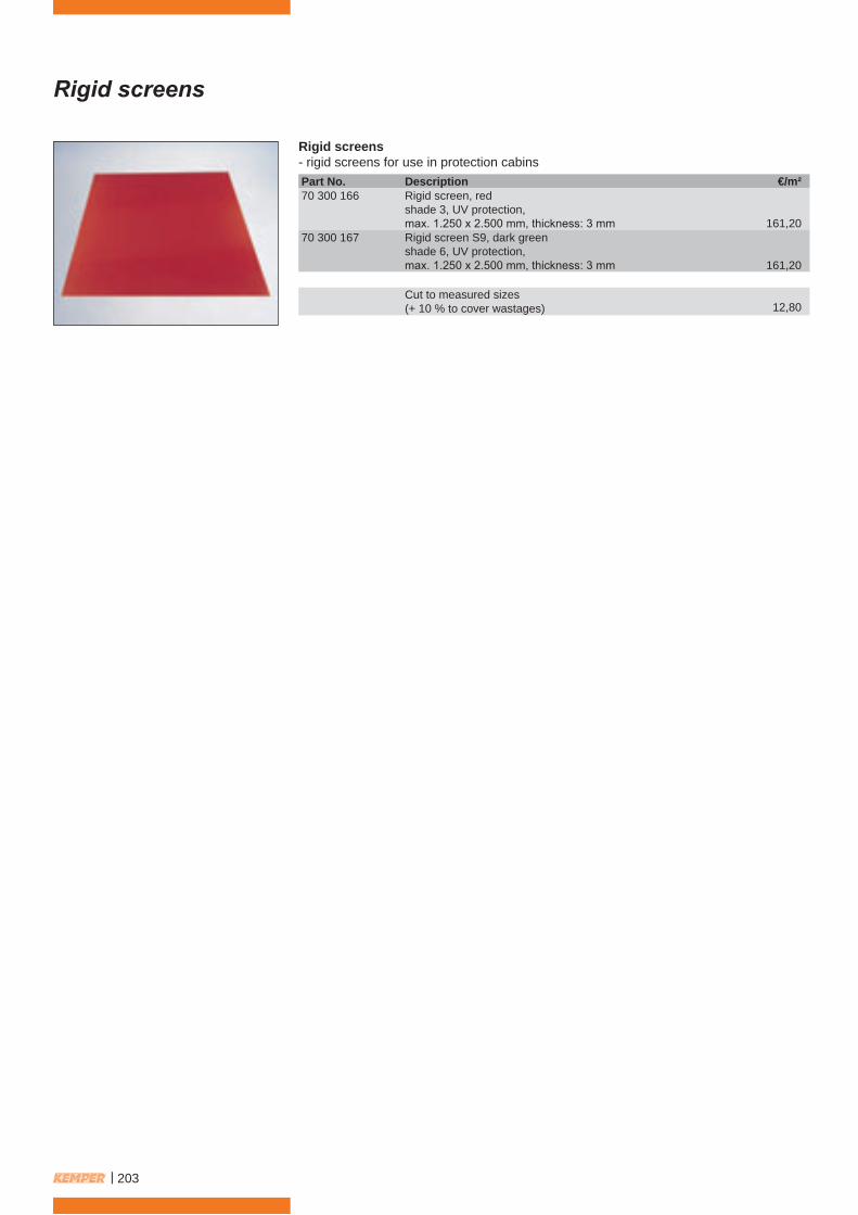
Rigid screens- rigid screens for use in protection cabinsPart No. Description70 300 166 Rigid screen, red
shade 3, UV protection,max. 1.250 x 2.500 mm, thickness: 3 mm
70 300 167 Rigid screen S9, dark greenshade 6, UV protection,max. 1.250 x 2.500 mm, thickness: 3 mm
Cut to measured sizes(+ 10 % to cover wastages)
€/m²
161,20
161,20
12,80
| 203
Protection cabins for robotic/laser systems
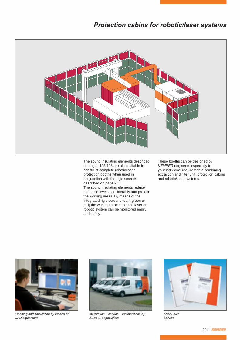
The sound insulating elements describedon pages 195/196 are also suitable toconstruct complete robotic/laserprotection booths when used inconjunction with the rigid screensdescribed on page 203.The sound insulating elements reducethe noise levels considerably and protectthe working areas. By means of theintegrated rigid screens (dark green orred) the working process of the laser orrobotic system can be monitored easilyand safely.
Planning and calculation by means ofCAD equipment
Installation – service – maintenance byKEMPER specialists
After-Sales-Service
These booths can be designed byKEMPER engineers especially toyour individual requirements combiningextraction and filter unit, protection cabinsand robotic/laser systems.
204 |
Your distributor:
Par
t No.
691
243
7-4
· Prin
ted
on e
colo
gica
lly b
enefi
cial
pap
er.
All prices are exclusive of the current VAT.
Priced catalogue items will be deliveredcarriage paid, within the EU (mainland),incl. packaging. For orders below a net price of1.000 €, a standard carriage charge of 17,50 €ex. VAT, for packaging, insurance and carriagewill be raised.
All orders are subject to our conditions of sale.Price and technical specifications are subject tochange without notice. We do not accept anyliability for misprints. With the publication of thisprice list, all former price list loose there validity.The technical specifications stated in ourcatalogue are subject to change withoutnotice. This catalogue is protected by copyrightand remains our property.
This catalogue can be reclaimed at anytime.Reprints, or partial reprints can only beaccepted with written authorisation by KEMPER.
KEMPER GmbH · Von-Siemens-Straße 20 · D-48691 VredenTel. +49 (0) 2564/68- 0 · Fax +49 (0) 2564/68-120 · [email protected] · www.kemper.eu