
Procurement of INFRASTRUCTURE PROJECTS - DOTr
252
PHILIPPINE BIDDING DOCUMENTS (As Harmonized with Development Partners) Procurement of INFRASTRUCTURE PROJECTS Government of the Republic of the Philippines Fourth Edition December 2010
-
Upload
khangminh22 -
Category
Documents
-
view
4 -
download
0
Transcript of Procurement of INFRASTRUCTURE PROJECTS - DOTr

PHILIPPINE BIDDING DOCUMENTS (As Harmonized with Development Partners)
Procurement of INFRASTRUCTURE
PROJECTS
Government of the Republic of the Philippines
Fourth Edition December 2010
2
TABLE OF CONTENTS
SECTION I. INVITATION TO BID .................................................................................... 3
SECTION II. INSTRUCTIONS TO BIDDERS .................................................................... 4
SECTION III. BID DATA SHEET ................................................................................... 33
SECTION IV. GENERAL CONDITIONS OF CONTRACT ............................................ 38
SECTION V. SPECIAL CONDITIONS OF CONTRACT ................................................. 70
SECTION VI. SPECIFICATIONS .................................................................................... 73
SECTION VII. DRAWINGS .......................................................................................... 220
SECTION VIII. BILL OF QUANTITIES ...................................................................... 221
SECTION IX. BIDDING FORMS .................................................................................. 222

3
Section I. Invitation to Bid

4
INVITATION TO BID FOR ILOILO CITY PHILIPPINE COAST GUARD DISTRICT STATION
The Department of Transportation and Communications (DOTC), through its Bids and Awards Committee (BAC) invites contractors registered with and classified by the Philippine Contractors Accreditation Board (PCAB) to join in the procurement of the herein project:
1.
Name of Project/Location
Brief Description
Source of Fund
ABC/Duration
IAC Registration
Minimum Equipment Requirement
(OWNED)
:
:
:
:
:
:
ILOILO CITY PHILIPPINE COAST GUARD DISTRICT STATION
Construction of PCG District Station
Iloilo City
CY 2011
Php 10,595,842.23 / 180 Calendar Days
Small B for Vertical Structures
1- Plate Compactor
1 - Bagger Concrete Mixer
1 - Concrete Vibrator
1 - Bar Cutter
1- Water Tank Truck
1 - Backhoe
1- Payloader
1- Welding Machine
1- Abrasive Cutting Machine
1- Grinding Machine
1- 40KVA Generator Set
2 - Electric Drill
1- Service Vehicle
l.s - Minor Tools
The schedule of procurement activities are shown below: Advertisement/Posting of Invitation to Bid May 18, 2012 Issuance of Bid Tender Documents May 18 – June 07, 2012 Pre-Bidding Conference May 25, 2012, 9:00 a.m., at Unit 167, 16th Floor, The
Columbia Tower, Ortigas Ave., Mandaluyong City. Submission and Receipt of Bids The deadline for submission and receipt of bids is June
07, 2012, until 9:00 a.m. only at Unit 167, 16th Floor, The Columbia Tower, Ortigas Ave., Mandaluyong City. Bids may be submitted before the June 07, 2012 deadline at Unit 153, 15th Floor.
Opening of Bids June 07, 2012, 9:00 a.m., Unit 167, 16th Floor Prospective bidders must have completed a similar contract with a value at least 50% of the ABC within the last 10 years and have key personnel and equipment available for the prosecution of the contract.
Republic of the Philippines DEPARTMENT OF TRANSPORTATION AND COMMUNICATIONS

5
The Bid Documents/Forms will be made available at Unit 153, The Columbia Tower Bldg., Ortigas Avenue, Mandaluyong City, upon payment of a non-refundable amount of P35,000.00 to the DOTC Cashier. It may also be downloaded free of charge from the website of the Philippine Government Electronic Procurement System (PhilGEPS) and at DOTCmain.gov.ph provided that the bidders shall pay the fee for the Bidding Documents not later than the submission of bids.
The DOTC reserves the right to reject any or all bids, and accept the offer most advantageous to the Government. The DOTC assumes no responsibility whatsoever to compensate or indemnify bidders for any expenses incurred in the preparation of the bid.
ATTY. JOSE PERPETUO M. LOTILLA Undersecretary for Legal and Chairman, Bids and Awards Committee

6
Section II. Instructions to Bidders

7
TABLE OF CONTENTS
A. GENERAL .................................................................................................................... 9
1. Scope of Bid .................................................................................................................. 9 2. Source of Funds ............................................................................................................. 9
3. Corrupt, Fraudulent, Collusive, and Coercive Practices ............................................. 9 4. Conflict of Interest ...................................................................................................... 11
5. Eligible Bidders ........................................................................................................... 12 6. Bidder’s Responsibilities ............................................................................................ 13
7. Origin of GOODS and Services ................................................................................. 15 8. Subcontracts................................................................................................................. 15
B. CONTENTS OF BIDDING DOCUMENTS ................................................................. 15
9. Pre-Bid Conference ..................................................................................................... 15 10. Clarification and Amendment of Bidding Documents ............................................. 16
C. PREPARATION OF BIDS........................................................................................... 16
11. Language of Bids ........................................................................................................ 16 12. Documents Comprising the Bid: Eligibility and Technical Components ............... 17
13. Documents Comprising the Bid: Financial Component ........................................... 19 14. Alternative Bids ........................................................................................................... 19
15. Bid Prices ..................................................................................................................... 20 16. Bid Currencies ............................................................................................................. 21
17. Bid Validity ................................................................................................................. 21 18. Bid Security ................................................................................................................. 21
19. Format and Signing of Bids ........................................................................................ 23 20. Sealing and Marking of Bids ...................................................................................... 24
D. SUBMISSION AND OPENING OF BIDS .................................................................... 24
21. Deadline for Submission of Bids ............................................................................... 24 22. Late Bids ...................................................................................................................... 25
23. Modification and Withdrawal of Bids ....................................................................... 25 24. Opening and Preliminary Examination of Bids ........................................................ 25
E. EVALUATION AND COMPARISON OF BIDS .......................................................... 26
25. Process to be Confidential .......................................................................................... 26 26. Clarification of Bids .................................................................................................... 27
27. Detailed Evaluation and Comparison of Bids ........................................................... 27 28. Post Qualification ........................................................................................................ 28

8
29. Reservation Clause ...................................................................................................... 29
F. AWARD OF CONTRACT ........................................................................................... 30
30. Contract Award ........................................................................................................... 30 31. Signing of the Contract ............................................................................................... 31
32. Performance Security .................................................................................................. 31 33. Notice to Proceed ........................................................................................................ 32
9
A. General
1. Scope of Bid
1.1. The Procuring Entity as defined in the Bid Data Sheet (BDS), invites bids for the construction of Works, as described in Section VI. Specifications. The name and identification number of the Contract is provided in the BDS.
1.2. The successful bidder will be expected to complete the Works by the intended completion date specified in SCC Clause 1.16.
2. Source of Funds
The Procuring Entity has a budget or has applied for or received funds from the Funding Source named in the BDS, and in the amount indicated in the BDS. It intends to apply part of the funds received for the Project, as defined in the BDS, to cover eligible payments under the Contract for the Works.
3. Corrupt, Fraudulent, Collusive, and Coercive Practices
3.1. Unless otherwise specified in the BDS, the Procuring Entity, as well as bidders and contractors, shall observe the highest standard of ethics during the procurement and execution of the contract. In pursuance of this policy, the Funding Source:
(a) defines, for purposes of this provision, the terms set forth below as follows:
(i) "corrupt practice" means behavior on the part of officials in the public or private sectors by which they improperly and unlawfully enrich themselves, others, or induce others to do so, by misusing the position in which they are placed, and includes the offering, giving, receiving, or soliciting of anything of value to influence the action of any such official in the procurement process or in contract execution; entering, on behalf of the Procuring Entity, into any contract or transaction manifestly and grossly disadvantageous to the same, whether or not the public officer profited or will profit thereby, and similar acts as provided in Republic Act 3019;
(ii) "fraudulent practice" means a misrepresentation of facts in order to influence a procurement process or the execution of a contract to the detriment of the Procuring Entity, and includes collusive practices among Bidders (prior to or after Bid submission) designed to establish bid prices at artificial, non-competitive levels and to deprive the Procuring Entity of the benefits of free and open competition;
(iii) “collusive practices” means a scheme or arrangement between two or more bidders, with or without the knowledge of the

10
Procuring Entity, designed to establish bid prices at artificial, non-competitive levels; and
(iv) “coercive practices” means harming or threatening to harm, directly or indirectly, persons, or their property to influence their participation in a procurement process, or affect the execution of a contract;
(v) “obstructive practice” is
(aa) deliberately destroying, falsifying, altering or concealing of evidence material to an administrative proceedings or investigation or making false statements to investigators in order to materially impede an administrative proceedings or investigation of the Procuring Entity or any foreign government/foreign or international financing institution into allegations of a corrupt, fraudulent, coercive or collusive practice; and/or threatening, harassing or intimidating any party to prevent it from disclosing its knowledge of matters relevant to the administrative proceedings or investigation or from pursuing such proceedings or investigation; or
(bb) acts intended to materially impede the exercise of the inspection and audit rights of the Procuring Entity or any foreign government/foreign or international financing institution herein.
(b) will reject a proposal for award if it determines that the bidder recommended for award has engaged in corrupt or fraudulent practices in competing for the Contract; and
(c) will declare a firm ineligible, either indefinitely or for a stated period of time, to be awarded Contract funded by the Funding Source if it at any time determines that the firm has engaged in corrupt or fraudulent practices in competing or, or in executing, a Contract funded by the Funding Source.
3.2. Further, the Procuring Entity will seek to impose the maximum civil, administrative, and/or criminal penalties available under the applicable laws on individuals and organizations deemed to be involved in any of the practices mentioned in Instructions to Bidders (ITB) Clause 3.1(a).
3.3. Furthermore, the Funding Source and the Procuring Entity reserve the right to inspect and audit records and accounts of a contractor in the bidding for and performance of a contract themselves or through independent auditors as reflected in the GCC Clause 34.

11
4. Conflict of Interest
4.1. All bidders found to have conflicting interests shall be disqualified to participate in the procurement at hand, without prejudice to the imposition of appropriate administrative, civil, and criminal sanctions. A Bidder may be considered to have conflicting interests with another Bidder in any of the events described in paragraphs (a) through (c) and a general conflict of interest in any of the circumstances set out in paragraphs (d) through (g) below:
(a) A Bidder has controlling shareholders in common with another Bidder;
(b) A Bidder receives or has received any direct or indirect subsidy from any other Bidder;
(c) A Bidder has the same legal representative as that of another Bidder for purposes of this Bid;
(d) A Bidder has a relationship, directly or through third parties, that puts them in a position to have access to information about or influence on the bid of another Bidder or influence the decisions of the Procuring Entity regarding this bidding process. This will include a firm or an organization who lends, or temporarily seconds, its personnel to firms or organizations which are engaged in consulting services for the preparation related to procurement for or implementation of the project if the personnel would be involved in any capacity on the same project;
(e) A Bidder submits more than one bid in this bidding process. However, this does not limit the participation of subcontractors in more than one bid;
(f) A Bidder who participated as a consultant in the preparation of the design or technical specifications of the goods and related services that are the subject of the bid; or
(g) A Bidder who lends, or temporary seconds, its personnel to firms or organizations which are engaged in consulting services for the preparation related to procurement for or implementation of the project, if the personnel would be involved in any capacity on the same project.
4.2. In accordance with Section 47 of the IRR of RA 9184, all Bidding Documents shall be accompanied by a sworn affidavit of the Bidder that it is not related to the Head of the Procuring Entity, members of the Bids and Awards Committee (BAC), members of the Technical Working Group (TWG), members of the BAC Secretariat, the head of the Project Management Office (PMO) or the end-user unit, and the project consultants, by consanguinity or affinity up to the third civil degree. On the part of the bidder, this Clause shall apply to the following persons:
(a) If the Bidder is an individual or a sole proprietorship, to the Bidder himself;
12
(b) If the Bidder is a partnership, to all its officers and members;
(c) If the Bidder is a corporation, to all its officers, directors, and controlling stockholders; and
(d) If the Bidder is a joint venture (JV), the provisions of items (a), (b), or (c) of this Clause shall correspondingly apply to each of the members of the said JV, as may be appropriate.
Relationship of the nature described above or failure to comply with this Clause will result in the automatic disqualification of a Bidder.
5. Eligible Bidders
5.1. Unless otherwise indicated in the BDS, the following persons shall be eligible to participate in this Bidding:
(a) Duly licensed Filipino citizens/sole proprietorships;
(b) Partnerships duly organized under the laws of the Philippines and of which at least seventy five percent (75%) of the interest belongs to citizens of the Philippines;
(c) Corporations duly organized under the laws of the Philippines, and of which at least seventy five percent (75%) of the outstanding capital stock belongs to citizens of the Philippines;
(d) Cooperatives duly organized under the laws of the Philippines, and of which at least seventy five percent (75%) of the interest belongs to citizens of the Philippines; and
(e) Persons/entities forming themselves into a JV, i.e., a group of two (2) or more persons/entities that intend to be jointly and severally responsible or liable for a particular contract: Provided, however, that, in accordance with Letter of Instructions No. 630, Filipino ownership or interest of the joint venture concerned shall be at least seventy five percent (75%): Provided, further, that joint ventures in which Filipino ownership or interest is less than seventy five percent (75%) may be eligible where the structures to be built require the application of techniques and/or technologies which are not adequately possessed by a person/entity meeting the seventy five percent (75%) Filipino ownership requirement: Provided, finally, that in the latter case, Filipino ownership or interest shall not be less than twenty five percent (25%). For this purpose Filipino ownership or interest shall be based on the contributions of each of the members of the joint venture as specified in their JVA.
5.2. The Procuring Entity may also invite foreign bidders when provided for under any Treaty or International or Executive Agreement as specified in the BDS.
5.3. Government Corporate Entities may be eligible to participate only if they can establish that they (a) are legally and financially autonomous, (b) operate

13
under commercial law, and (c) are not dependent agencies of the GOP or the Procuring Entity.
5.4. (a) Unless otherwise provided in the BDS, the Bidder must have completed, within ten (10) years from the submission of bids, a single contract that is similar to this Project, equivalent to at least fifty percent (50%) of the ABC adjusted to current prices using the National Statistics Office consumer price index.
(b) For Foreign-funded Procurement, the Procuring Entity and the foreign government/foreign or international financing institution may agree on another track record requirement, as specified in the BDS.
For this purpose, contracts similar to the Project shall be those described in the BDS, and completed within the period stated in the Invitation to Bid and ITB Clause 12.1(a)(iii).
5.5. The Bidder must submit a computation of its Net Financial Contracting Capacity (NFCC) or a Commitment from a Universal or Commercial bank to extend a credit line in its favor if awarded the contract for this project (CLC).
The NFCC, computed using the following formula, must be at least equal to the ABC to be bid:
NFCC = [(Current assets minus current liabilities) (K)] minus the value of all outstanding or uncompleted portions of the projects under ongoing contracts, including awarded contracts yet to be started coinciding with the contract for this Project.
Where:
K = 10 for a contract duration of one year or less, 15 for a contract duration of more than one year up to two years, and 20 for a contract duration of more than two years.
The CLC must be at least equal to ten percent (10%) of the ABC for this Project. If issued by a foreign bank, it shall be confirmed or authenticated by a Universal or Commercial Bank. In the case of local government units (LGUs), the Bidder may also submit CLC from other banks certified by the Bangko Sentral ng Pilipinas (BSP) as authorized to issue such financial instrument.
6. Bidder’s Responsibilities
6.1. The Bidder or its duly authorized representative shall submit a sworn statement in the form prescribed in Section IX. Bidding Forms as required in ITB Clause 12.1(b)(iii).
6.2. The Bidder is responsible for the following:
(a) Having taken steps to carefully examine all of the Bidding Documents;
14
(b) Having acknowledged all conditions, local or otherwise, affecting the implementation of the contract;
(c) Having made an estimate of the facilities available and needed for the contract to be bid, if any;
(d) Having complied with its responsibility to inquire or secure Supplemental/Bid Bulletin/s as provided under ITB Clause 10.3.
(e) Ensuring that it is not “blacklisted” or barred from bidding by the GOP or any of its agencies, offices, corporations, or LGUs, including foreign government/foreign or international financing institution whose blacklisting rules have been recognized by the GPPB;
(f) Ensuring that each of the documents submitted in satisfaction of the bidding requirements is an authentic copy of the original, complete, and all statements and information provided therein are true and correct;
(g) Authorizing the Head of the Procuring Entity or its duly authorized representative/s to verify all the documents submitted;
(h) Ensuring that the signatory is the duly authorized representative of the Bidder, and granted full power and authority to do, execute and perform any and all acts necessary and/or to represent the Bidder in the bidding, with the duly notarized Secretary’s Certificate attesting to such fact, if the Bidder is a corporation, partnership, cooperative, or joint venture;
(i) Complying with the disclosure provision under Section 47 of the Act in relation to other provisions of Republic Act 3019; and
(j) Complying with existing labor laws and standards, if applicable.
Failure to observe any of the above responsibilities shall be at the risk of the Bidder concerned.
6.3. The Bidder, by the act of submitting its bid, shall be deemed to have inspected the site, determined the general characteristics of the contract works and the conditions for this Project and examine all instructions, forms, terms, and project requirements in the Bidding Documents.
6.4. It shall be the sole responsibility of the prospective bidder to determine and to satisfy itself by such means as it considers necessary or desirable as to all matters pertaining to this Project, including: (a) the location and the nature of the contract, project, or work; (b) climatic conditions; (c) transportation facilities; (c) nature and condition of the terrain, geological conditions at the site communication facilities, requirements, location and availability of construction aggregates and other materials, labor, water, electric power and access roads; and (d) other factors that may affect the cost, duration and execution or implementation of the contract, project, or work.
15
6.5. The Procuring Entity shall not assume any responsibility regarding erroneous interpretations or conclusions by the prospective or eligible bidder out of the data furnished by the procuring entity.
6.6. Before submitting their bids, the Bidders are deemed to have become familiar with all existing laws, decrees, ordinances, acts and regulations of the Philippines which may affect the contract in any way.
6.7. The Bidder shall bear all costs associated with the preparation and submission of his bid, and the Procuring Entity will in no case be responsible or liable for those costs, regardless of the conduct or outcome of the bidding process.
6.8. Bidders should note that the Procuring Entity will only accept bids only from those that have paid the nonrefundable fee for the Bidding Documents at the office indicated in the Invitation to Bid.
7. Origin of GOODS and Services
There is no restriction on the origin of Goods, or Contracting of Works or Services other than those prohibited by a decision of the United Nations Security Council taken under Chapter VII of the Charter of the United Nations.
8. Subcontracts
8.1. Unless otherwise specified in the BDS, the Bidder may subcontract portions of the Works to an extent as may be approved by the Procuring Entity and stated in the BDS. However, subcontracting of any portion shall not relieve the Bidder from any liability or obligation that may arise from the contract for this Project.
8.2. Subcontractors must submit the documentary requirements under ITB Clause 12 and comply with the eligibility criteria specified in the BDS. In the event that any subcontractor is found by the Procuring Entity to be ineligible, the subcontracting of such portion of the Works shall be disallowed.
8.3. The Bidder may identify the subcontractor to whom a portion of the Works will be subcontracted at any stage of the bidding process or during contract implementation. If the Bidder opts to disclose the name of the subcontractor during bid submission, the Bidder shall include the required documents as part of the technical component of its bid.
B. Contents of Bidding Documents
9. Pre-Bid Conference
9.1. (a) If so specified in the BDS, a pre-bid conference shall be held at the venue and on the date indicated therein, to clarify and address the Bidders’ questions on the technical and financial components of this Project.
(b) The pre-bid conference shall be held at least twelve (12) calendar days before the deadline for the submission of and receipt of bids. If the Procuring Entity determines that, by reason of the method, nature, or complexity of the

16
contract to be bid, or when international participation will be more advantageous to the GOP, a longer period for the preparation of bids is necessary, the pre-bid conference shall be held at least thirty (30) calendar days before the deadline for the submission and receipt of bids, as specified in the BDS.
9.2. Bidders are encouraged to attend the pre-bid conference to ensure that they fully understand the Procuring Entity’s requirements. Non-attendance of the Bidder will in no way prejudice its bid; however, the Bidder is expected to know the changes and/or amendments to the Bidding Documents as recorded in the minutes of the pre-bid conference and the Supplemental/Bid Bulletin.
9.3. Any statement made at the pre-bid conference shall not modify the terms of the bidding documents unless such statement is specifically identified in writing as an amendment thereto and issued as a Supplemental/Bid Bulletin.
10. Clarification and Amendment of Bidding Documents
10.1. Bidders who have purchased the Bidding Documents may request for clarification(s) on any part of the Bidding Documents or for an interpretation. Such a request must be in writing and submitted to the Procuring Entity at the address indicated in the BDS at least ten (10) calendar days before the deadline set for the submission and receipt of Bids.
10.2. Supplemental/Bid Bulletins may be issued upon the Procuring Entity’s initiative for purposes of clarifying or modifying any provision of the Bidding Documents not later than seven (7) calendar days before the deadline for the submission and receipt of Bids. Any modification to the Bidding Documents shall be identified as an amendment.
10.3. Any Supplemental/Bid Bulletin issued by the BAC shall also be posted on the Philippine Government Electronic Procurement System (PhilGEPS) and the website of the Procuring Entity concerned, if available. Unless, otherwise provided in the BDS, it shall be the responsibility of all Bidders who secure the Bidding Documents to inquire and secure Supplemental/Bid Bulletins that may be issued by the BAC. However, bidders who have submitted bids before the issuance of the Supplemental/Bid Bulletin must be informed and allowed to modify or withdraw their bids in accordance with ITB Clause 23.
C. Preparation of Bids
11. Language of Bids
The Bid, as well as all correspondence and documents relating to the Bid exchanged by the Bidder and the Procuring Entity, shall be written in English. Supporting documents and printed literature furnished by the Bidder may be in another language provided they are accompanied by an accurate translation in English certified by the appropriate embassy or consulate in the Philippines, in which case the English translation shall govern, for purposes of interpretation of the Bid.
17
12. Documents Comprising the Bid: Eligibility and Technical Components
12.1. Unless otherwise indicated in the BDS, the first envelope shall contain the following eligibility and technical documents:
(a) Eligibility Documents –
Class "A" Documents:
(i) Registration certificate from the Securities and Exchange Commission (SEC), Department of Trade and Industry (DTI) for sole proprietorship, or Cooperative Development Authority (CDA) for cooperatives, or any proof of such registration as stated in the BDS;
(ii) Mayor’s permit issued by the city or municipality where the principal place of business of the prospective bidder is located;
(iii) Statement of all its ongoing and completed government and private contracts within ten (10) years from the submission of bids, including contracts awarded but not yet started, if any. The statement shall include, for each contract, the following:
(iii.1) name of the contract;
(iii.2) date of the contract;
(iii.3) contract duration;
(iii.4) owner’s name and address;
(iii.5) nature of work;
(iii.6) contractor’s role (whether sole contractor, subcontractor, or partner in a JV) and percentage of participation;
(iii.7) total contract value at award;
(iii.8) date of completion or estimated completion time;
(iii.9) total contract value at completion, if applicable;
(iii.10) percentages of planned and actual accomplishments, if applicable;
(iii.11) value of outstanding works, if applicable;
(iii.12) the statement shall be supported by the notices of award and/or notices to proceed issued by the owners; and
(iii.13) the statement shall be supported by the Constructors Performance Evaluation System (CPES) rating sheets,
18
and/or certificates of completion and owner’s acceptance, if applicable;
(iv) Unless otherwise provided in the BDS, valid Philippine Contractors Accreditation Board (PCAB) license and registration for the type and cost of the contract for this Project;
(v) Audited financial statements, showing, among others, the prospective total and current assets and liabilities, stamped “received” by the BIR or its duly accredited and authorized institutions, for the preceding calendar year which should not be earlier than two (2) years from the date of bid submission;
(vi) NFCC computation or CLC in accordance with ITB Clause 5.5; and
Class "B" Document:
(vii) If applicable, valid Joint Venture Agreement (JVA) or, in lieu thereof, duly notarized statements from all the potential joint venture partners stating that they will enter into and abide by the provisions of the JVA in the instance that the bid is successful shall be included in the bid.
(b) Technical Documents –
(i) Bid security as prescribed in ITB Clause 18. If the Bidder opts to submit the bid security in the form of:
(i.1) a bank draft/guarantee or an irrevocable letter of credit issued by a foreign bank, it shall be accompanied by a confirmation from a Universal or Commercial Bank; or
(i.2) a surety bond accompanied by a certification coming from an authorized Insurance Commission that a surety or insurance company is authorized to issue such instrument;
(ii) Project Requirements, which shall include the following:
(ii.1) Organizational chart for the contract to be bid;
(ii.2) List of contractor’s personnel (viz, project Manager, Project Engineers, Materials Engineers, and Foremen), to be assigned to the contract to be bid, with their complete qualification and experience data; and
(ii.3) List of contractor’s equipment units, which are owned, leased, and/or under purchase agreements, supported by certification of availability of equipment from the equipment lessor/vendor for the duration of the project; and
19
(iii) Sworn statement in accordance with Section 25.2(b)(iv) of the IRR of RA 9184 and using the form prescribed in Section IX. Bidding Forms.
13. Documents Comprising the Bid: Financial Component
13.1. Unless otherwise stated in the BDS, the financial component of the bid shall contain the following:
(a) Financial Bid Form in accordance with the form prescribed in Section IX. Bidding Forms; and
(b) Any other document related to the financial component of the bid as stated in the BDS.
13.2. (a) Unless indicated in the BDS, all Bids that exceed the ABC shall not be accepted.
(b) Unless otherwise indicated in the BDS, for foreign-funded procurement, a ceiling may be applied to bid prices provided the following conditions are met:
(i) Bidding Documents are obtainable free of charge on a freely accessible website. If payment of Bidding Documents is required by the procuring entity, payment could be made upon the submission of bids.
(ii) The procuring entity has procedures in place to ensure that the ABC is based on recent estimates made by the engineer or the responsible unit of the procuring entity and that the estimates are based on adequate detailed engineering (in the case of works) and reflect the quality, supervision and risk and inflationary factors, as well as prevailing market prices, associated with the types of works or goods to be procured.
(iii) The procuring entity has trained cost estimators on estimating prices and analyzing bid variances. In the case of infrastructure projects, the procuring entity must also have trained quantity surveyors.
(iv) The procuring entity has established a system to monitor and report bid prices relative to ABC and engineer’s/procuring entity’s estimate.
(v) The procuring entity has established a monitoring and evaluation system for contract implementation to provide a feedback on actual total costs of goods and works.
14. Alternative Bids
14.1. Alternative Bids shall be rejected. For this purpose, alternative bid is an offer made by a Bidder in addition or as a substitute to its original bid which may be

20
included as part of its original bid or submitted separately therewith for purposes of bidding. A bid with options is considered an alternative bid regardless of whether said bid proposal is contained in a single envelope or submitted in two (2) or more separate bid envelopes.
14.2. Bidders shall submit offers that comply with the requirements of the Bidding Documents, including the basic technical design as indicated in the drawings and specifications. Unless there is a value engineering clause in the BDS, alternative bids shall not be accepted.
14.3. Each Bidder shall submit only one Bid, either individually or as a partner in a JV. A Bidder who submits or participates in more than one bid (other than as a subcontractor if a subcontractor is permitted to participate in more than one bid) will cause all the proposals with the Bidder’s participation to be disqualified. This shall be without prejudice to any applicable criminal, civil and administrative penalties that may be imposed upon the persons and entities concerned.
15. Bid Prices
15.1. The contract shall be for the whole Works, as described in ITB Clause 1.1, based on the priced Bill of Quantities submitted by the Bidder.
15.2. The Bidder shall fill in rates and prices for all items of the Works described in the Bill of Quantities. Bids not addressing or providing all of the required items in the Bidding Documents including, where applicable, bill of quantities, shall be considered non-responsive and, thus, automatically disqualified. In this regard, where a required item is provided, but no price is indicated, the same shall be considered as non-responsive, but specifying a "0" (zero) for the said item would mean that it is being offered for free to the Government.
15.3. All duties, taxes, and other levies payable by the Contractor under the Contract, or for any other cause, prior to the deadline for submission of bids, shall be included in the rates, prices, and total bid price submitted by the Bidder.
15.4. All bid prices for the given scope of work in the contract as awarded shall be considered as fixed prices, and therefore not subject to price escalation during contract implementation, except under extraordinary circumstances as specified in GCC Clause 48. Price escalation may be allowed in extraordinary circumstances as may be determined by the National Economic and Development Authority in accordance with the Civil Code of the Philippines, and upon the recommendation of the Procuring Entity. Furthermore, in cases where the cost of the awarded contract is affected by any applicable new laws, ordinances, regulations, or other acts of the GOP, promulgated after the date of bid opening, a contract price adjustment shall be made or appropriate relief shall be applied on a no loss-no gain basis.

21
16. Bid Currencies
16.1. All bid prices shall be quoted in Philippine Pesos unless otherwise provided in the BDS. However, for purposes of bid evaluation, bids denominated in foreign currencies shall be converted to Philippine currency based on the exchange rate prevailing on the day of the Bid opening.
16.2. If so allowed in accordance with ITB Clause 16.1, the Procuring Entity for purposes of bid evaluation and comparing the bid prices will convert the amounts in various currencies in which the bid price is expressed to Philippine Pesos at the exchange rate as published in the BSP reference rate bulletin on the day of the bid opening.
16.3. Unless otherwise specified in the BDS, payment of the contract price shall be made in Philippine Pesos.
17. Bid Validity
17.1. Bids shall remain valid for the period specified in the BDS which shall not exceed one hundred twenty (120) calendar days from the date of the opening of bids.
17.2. In exceptional circumstances, prior to the expiration of the bid validity period, the Procuring Entity may request Bidders to extend the period of validity of their bids. The request and the responses shall be made in writing. The bid security described in ITB Clause 18 should also be extended corresponding to the extension of the bid validity period at the least. A Bidder may refuse the request without forfeiting its bid security, but his bid shall no longer be considered for further evaluation and award. A Bidder granting the request shall not be required or permitted to modify its bid.
18. Bid Security
18.1. The bid security in the amount stated in the BDS shall be equal to the percentage of the ABC in accordance with the following schedule:
Form of Bid Security Amount of Bid Security (Equal to Percentage of the ABC)
(a) Cash or cashier’s/manager’s check issued by a Universal or Commercial Bank.
Two percent (2%)
(b) Bank draft/guarantee or irrevocable letter of credit issued by a Universal or Commercial Bank: Provided, however, that it shall be confirmed or authenticated by a Universal or Commercial Bank, if issued by a foreign bank.
(c) Surety bond callable upon demand issued by a surety or Five percent (5%)

22
insurance company duly certified by the Insurance Commission as authorized to issue such security; and/or
(d) Any combination of the foregoing.
Proportionate to share of form with respect to total amount of
security
For biddings conducted by local government units, the Bidder may also submit bid securities in the form of cashier’s/manager’s check, bank draft/guarantee, or irrevocable letter of credit from other banks certified by the BSP as authorized to issue such financial statement.
18.2. The bid security should be valid for the period specified in the BDS. Any bid not accompanied by an acceptable bid security shall be rejected by the Procuring Entity as non-responsive.
18.3. No bid securities shall be returned to bidders after the opening of bids and before contract signing, except to those that failed or declared as post-disqualified, upon submission of a written waiver of their right to file a motion for reconsideration and/or protest. Without prejudice on its forfeiture, Bid Securities shall be returned only after the bidder with the Lowest Calculated Responsive Bid has signed the contract and furnished the Performance Security, but in no case later than the expiration of the Bid Security validity period indicated in ITB Clause 18.2.
18.4. Upon signing and execution of the contract, pursuant to ITB Clause 31, and the posting of the performance security, pursuant to ITB Clause 32, the successful Bidder’s Bid security will be discharged, but in no case later than the Bid security validity period as indicated in ITB Clause 18.2.
18.5. The bid security may be forfeited:
(a) if a Bidder:
(i) withdraws its bid during the period of bid validity specified in ITB Clause 17;
(ii) does not accept the correction of errors pursuant to ITB Clause 27.3(b);
(iii) fails to submit the requirements within the prescribed period, or a finding against their veracity, as stated in ITB Clause 28.2;
(iv) submission of eligibility requirements containing false information or falsified documents;
(v) submission of bids that contain false information or falsified documents, or the concealment of such information in the bids in order to influence the outcome of eligibility screening or any other stage of the public bidding;
23
(vi) allowing the use of one’s name, or using the name of another for purposes of public bidding;
(vii) withdrawal of a bid, or refusal to accept an award, or enter into contract with the Government without justifiable cause, after the Bidder had been adjudged as having submitted the Lowest Calculated and Responsive Bid;
(viii) refusal or failure to post the required performance security within the prescribed time;
(ix) refusal to clarify or validate in writing its bid during post-qualification within a period of seven (7) calendar days from receipt of the request for clarification;
(x) any documented attempt by a bidder to unduly influence the outcome of the bidding in his favor;
(xi) failure of the potential joint venture partners to enter into the joint venture after the bid is declared successful; or
(xii) all other acts that tend to defeat the purpose of the competitive bidding, such as habitually withdrawing from bidding, submitting late Bids or patently insufficient bid, for at least three (3) times within a year, except for valid reasons.
(b) if the successful Bidder:
(i) fails to sign the contract in accordance with ITB Clause 31;
(ii) fails to furnish performance security in accordance with ITB Clause 32.
19. Format and Signing of Bids
19.1. Bidders shall submit their bids through their duly authorized representative using the appropriate forms provided in Section IX. Bidding Forms on or before the deadline specified in the ITB Clause 21 in two (2) separate sealed bid envelopes, and which shall be submitted simultaneously. The first shall contain the technical component of the bid, including the eligibility requirements under ITB Clause 12.1, and the second shall contain the financial component of the bid.
19.2. Forms as mentioned in ITB Clause 19.1 must be completed without any alterations to their format, and no substitute form shall be accepted. All blank spaces shall be filled in with the information requested.
19.3. The Bidder shall prepare an original of the first and second envelopes as described in ITB Clauses 12 and 13. In addition, the Bidder shall submit copies of the first and second envelopes. In the event of any discrepancy between the original and the copies, the original shall prevail.

24
19.4. The bid, except for unamended printed literature, shall be signed, and each and every page thereof shall be initialed, by the duly authorized representative/s of the Bidder.
19.5. Any interlineations, erasures, or overwriting shall be valid only if they are signed or initialed by the duly authorized representative/s of the Bidder.
20. Sealing and Marking of Bids
20.1. Bidders shall enclose their original eligibility and technical documents described in ITB Clause 12, in one sealed envelope marked “ORIGINAL - TECHNICAL COMPONENT”, and the original of their financial component in another sealed envelope marked “ORIGINAL - FINANCIAL COMPONENT”, sealing them all in an outer envelope marked “ORIGINAL BID”.
20.2. Each copy of the first and second envelopes shall be similarly sealed duly marking the inner envelopes as “COPY NO. ___ - TECHNICAL COMPONENT” and “COPY NO. ___ – FINANCIAL COMPONENT” and the outer envelope as “COPY NO. ___”, respectively. These envelopes containing the original and the copies shall then be enclosed in one single envelope.
20.3. The original and the number of copies of the Bid as indicated in the BDS shall be typed or written in indelible ink and shall be signed by the bidder or its duly authorized representative/s.
20.4. All envelopes shall:
(a) contain the name of the contract to be bid in capital letters;
(b) bear the name and address of the Bidder in capital letters;
(c) be addressed to the Procuring Entity’s BAC identified in ITB Clause 10.1;
(d) bear the specific identification of this bidding process indicated in the Invitation to Bid; and
(e) bear a warning “DO NOT OPEN BEFORE…” the date and time for the opening of bids, in accordance with ITB Clause 21.
20.5. If bids are not sealed and marked as required, the Procuring Entity will assume no responsibility for the misplacement or premature opening of the bid.
D. Submission and Opening of Bids
21. Deadline for Submission of Bids
Bids must be received by the Procuring Entity’s BAC at the address and on or before the date and time indicated in the BDS.

25
22. Late Bids
Any bid submitted after the deadline for submission and receipt of bids prescribed by the Procuring Entity, pursuant to ITB Clause 21, shall be declared “Late” and shall not be accepted by the Procuring Entity.
23. Modification and Withdrawal of Bids
23.1. The Bidder may modify its bid after it has been submitted; provided that the modification is received by the Procuring Entity prior to the deadline prescribed for submission and receipt of bids. The Bidder shall not be allowed to retrieve its original bid, but shall be allowed to submit another bid equally sealed, properly identified, linked to its original bid marked as “TECHNICAL MODIFICATION” or “FINANCIAL MODIFICATION” and stamped “received” by the BAC. Bid modifications received after the applicable deadline shall not be considered and shall be returned to the Bidder unopened.
23.2. A Bidder may, through a letter of withdrawal, withdraw its bid after it has been submitted, for valid and justifiable reason; provided that the letter of withdrawal is received by the Procuring Entity prior to the deadline prescribed for submission and receipt of bids.
23.3. Bids requested to be withdrawn in accordance with ITB Clause 23.1 shall be returned unopened to the Bidders. A Bidder may also express its intention not to participate in the bidding through a letter which should reach and be stamped by the BAC before the deadline for submission and receipt of bids. A Bidder that withdraws its bid shall not be permitted to submit another bid, directly or indirectly, for the same contract.
23.4. No bid may be modified after the deadline for submission of bids. No bid may be withdrawn in the interval between the deadline for submission of bids and the expiration of the period of bid validity specified by the Bidder on the Financial Bid Form. Withdrawal of a bid during this interval shall result in the forfeiture of the Bidder’s bid security, pursuant to ITB Clause 18.5, and the imposition of administrative, civil, and criminal sanctions as prescribed by RA 9184 and its IRR.
24. Opening and Preliminary Examination of Bids
24.1. The BAC shall open the first bid envelopes of Bidders in public as specified in the BDS to determine each Bidder’s compliance with the documents prescribed in ITB Clause 12. For this purpose, the BAC shall check the submitted documents of each bidder against a checklist of required documents to ascertain if they are all present, using a non-discretionary “pass/fail” criterion. If a bidder submits the required document, it shall be rated “passed” for that particular requirement. In this regard, bids that fail to include any requirement or are incomplete or patently insufficient shall be considered as “failed”. Otherwise, the BAC shall rate the said first bid envelope as “passed”.
24.2. Unless otherwise specified in the BDS, immediately after determining compliance with the requirements in the first envelope, the BAC shall
26
forthwith open the second bid envelope of each remaining eligible bidder whose first bid envelope was rated “passed”. The second envelope of each complying bidder shall be opened within the same day. In case one or more of the requirements in the second envelope of a particular bid is missing, incomplete or patently insufficient, and/or if the submitted total bid price exceeds the ABC unless otherwise provided in ITB Clause 13.1(b), the BAC shall rate the bid concerned as “failed”. Only bids that are determined to contain all the bid requirements for both components shall be rated “passed” and shall immediately be considered for evaluation and comparison.
24.3. Letters of withdrawal shall be read out and recorded during bid opening, and the envelope containing the corresponding withdrawn bid shall be returned to the Bidder unopened. If the withdrawing Bidder’s representative is in attendance, the original bid and all copies thereof shall be returned to the representative during the bid opening. If the representative is not in attendance, the Bid shall be returned unopened by registered mail. The Bidder may withdraw its bid prior to the deadline for the submission and receipt of bids, provided that the corresponding letter of withdrawal contains a valid authorization requesting for such withdrawal, subject to appropriate administrative sanctions.
24.4. If a Bidder has previously secured a certification from the Procuring Entity to the effect that it has previously submitted the above-enumerated Class “A” Documents, the said certification may be submitted in lieu of the requirements enumerated in ITB Clause 12.1(a), items (i) to (vi).
24.5. In the case of an eligible foreign Bidder as described in ITB Clause 5, the Class “A” Documents enumerated in ITB Clause 12.1(a) may be substituted with the appropriate equivalent documents, if any, issued by the country of the foreign Bidder concerned.
24.6. Each partner of a joint venture agreement shall likewise submit the documents required in ITB Clauses 12.1(a)(i) and 12.1(a)(ii). Submission of documents required under ITB Clauses 12.1(a)(iii) to 12.1(a)(vi) by any of the joint venture partners constitutes compliance.
24.7. A Bidder determined as “failed” has three (3) calendar days upon written notice or, if present at the time of bid opening, upon verbal notification within which to file a request for reconsideration with the BAC: Provided, however, that the request for reconsideration shall not be granted if it is established that the finding of failure is due to the fault of the Bidder concerned: Provided, further, that the BAC shall decide on the request for reconsideration within seven (7) calendar days from receipt thereof. If a failed Bidder signifies his intent to file a request for reconsideration, the BAC shall keep the bid envelopes of the said failed Bidder unopened and/or duly sealed until such time that the request for reconsideration or protest has been resolved.
E. Evaluation and Comparison of Bids
25. Process to be Confidential

27
25.1. Members of the BAC, including its staff and personnel, as well as its Secretariat and TWG, are prohibited from making or accepting any kind of communication with any bidder regarding the evaluation of their bids until the issuance of the Notice of Award, unless n the case of ITB Clause 26.
25.2. Any effort by a bidder to influence the Procuring Entity in the Procuring Entity’s decision in respect of Bid evaluation, Bid comparison or contract award will result in the rejection of the Bidder’s Bid.
26. Clarification of Bids
To assist in the evaluation, comparison and post-qualification of the bids, the Procuring Entity may ask in writing any Bidder for a clarification of its bid. All responses to requests for clarification shall be in writing. Any clarification submitted by a Bidder in respect to its bid and that is not in response to a request by the Procuring Entity shall not be considered
27. Detailed Evaluation and Comparison of Bids
27.1. The Procuring Entity will undertake the detailed evaluation and comparison of Bids which have passed the opening and preliminary examination of Bids, pursuant to ITB Clause 24, in order to determine the Lowest Calculated Bid.
27.2. In evaluating the Bids to get the Lowest Calculated Bid, the Procuring Entity shall undertake the following:
(a) The detailed evaluation of the financial component of the bids, to establish the correct calculated prices of the bids; and
(b) The ranking of the total bid prices as so calculated from the lowest to highest. The bid with the lowest price shall be identified as the Lowest Calculated Bid.
27.3. The Procuring Entity's BAC shall immediately conduct a detailed evaluation of all bids rated “passed,” using non-discretionary “pass/fail” criterion. The BAC shall consider the following in the evaluation of bids:
(a) Completeness of the bid. Unless the ITB specifically allows partial bids, bids not addressing or providing all of the required items in the Schedule of Requirements including, where applicable, bill of quantities, shall be considered non-responsive and, thus, automatically disqualified. In this regard, where a required item is provided, but no price is indicated, the same shall be considered as non-responsive, but specifying a "0" (zero) for the said item would mean that it is being offered for free to the Procuring Entity; and
(b) Arithmetical corrections. Consider computational errors and omissions to enable proper comparison of all eligible bids. It may also consider bid modifications if expressly allowed in the BDS. Any adjustment shall be calculated in monetary terms to determine the calculated prices.

28
27.4. Based on the detailed evaluation of bids, those that comply with the above-mentioned requirements shall be ranked in the ascending order of their total calculated bid prices, as evaluated and corrected for computational errors, discounts and other modifications, to identify the Lowest Calculated Bid. Total calculated bid prices, as evaluated and corrected for computational errors, discounts and other modifications, which exceed the ABC shall not be considered, unless otherwise indicated in the BDS.
27.5. The Procuring Entity’s evaluation of bids shall only be based on the bid price quoted in the Financial Bid Form
27.6. Bids shall be evaluated on an equal footing to ensure fair competition. For this purpose, all bidders shall be required to include in their bids the cost of all taxes, such as, but not limited to, value added tax (VAT), income tax, local taxes, and other fiscal levies and duties which shall be itemized in the bid form and reflected in the detailed estimates. Such bids, including said taxes, shall be the basis for bid evaluation and comparison.
28. Post Qualification
28.1. The Procuring Entity shall determine to its satisfaction whether the Bidder that is evaluated as having submitted the Lowest Calculated Bid (LCB) complies with and is responsive to all the requirements and conditions specified in ITB Clauses 5, 12, and 13.
28.2. Within a non-extendible period of three (3) calendar days from receipt by the Bidder of the notice from the BAC that it submitted the LCB, the Bidder shall submit the following documentary requirements:
(a) Tax clearance per Executive Order 398, Series of 2005;
(b) Latest income and business tax returns in the form specified in the BDS;
(c) Certificate of PhilGEPS Registration; and
(d) Other appropriate licenses and permits required by law and stated in the BDS.
Failure of the Bidder declared as LCB to duly submit the requirements under this Clause or a finding against the veracity of such, shall be ground for forfeiture of the bid security and disqualification of the Bidder for award.
28.3. The determination shall be based upon an examination of the documentary evidence of the Bidder’s qualifications submitted pursuant to ITB Clauses 12 and 13, as well as other information as the Procuring Entity deems necessary and appropriate, using a non-discretionary “pass/fail” criterion.
28.4. If the BAC determines that the Bidder with the Lowest Calculated Bid passes all the criteria for post-qualification, it shall declare the said bid as the Lowest Calculated Responsive Bid, and recommend to the Head of the Procuring
29
Entity the award of contract to the said Bidder at its submitted price or its calculated bid price, whichever is lower, subject to ITB Clause 30.3.
28.5. A negative determination shall result in rejection of the Bidder’s Bid, in which event the Procuring Entity shall proceed to the next Lowest Calculated Bid to make a similar determination of that Bidder’s capabilities to perform satisfactorily. If the second Bidder, however, fails the post qualification, the procedure for post qualification shall be repeated for the Bidder with the next Lowest Calculated Bid, and so on until the Lowest Calculated and Responsive Bid is determined for contract award.
28.6. Within a period not exceeding seven (7) calendar days from the date of receipt of the recommendation of the BAC, the Head of the Procuring Entity shall approve or disapprove the said recommendation. In the case of government owned and government-owned and/or -controlled corporations (GOCCs) and government financial institutions (GFIs), the period provided herein shall be fifteen (15) calendar days.
29. Reservation Clause
29.1. Notwithstanding the eligibility or post-qualification of a bidder, the Procuring Entity concerned reserves the right to review its qualifications at any stage of the procurement process if it has reasonable grounds to believe that a misrepresentation has been made by the said bidder, or that there has been a change in the Bidder’s capability to undertake the project from the time it submitted its eligibility requirements. Should such review uncover any misrepresentation made in the eligibility and bidding requirements, statements or documents, or any changes in the situation of the Bidder which will affect its capability to undertake the project so that it fails the preset eligibility or bid evaluation criteria, the Procuring Entity shall consider the said Bidder as ineligible and shall disqualify it from submitting a bid or from obtaining an award or contract.
29.2. Based on the following grounds, the Procuring Entity reserves the right to reject any and all Bids, declare a Failure of Bidding at any time prior to the contract award, or not to award the contract, without thereby incurring any liability, and make no assurance that a contract shall be entered into as a result of the bidding:
(a) if there is prima facie evidence of collusion between appropriate public officers or employees of the Procuring Entity, or between the BAC and any of the bidders, or if the collusion is between or among the bidders themselves, or between a bidder and a third party, including any act which restricts, suppresses or nullifies or tends to restrict, suppress or nullify competition;
(b) if the Procuring Entity’s BAC is found to have failed in following the prescribed bidding procedures; or
(c) for any justifiable and reasonable ground where the award of the contract will not redound to the benefit of the Government as follows:
30
(i) If the physical and economic conditions have significantly changed so as to render the project no longer economically, financially or technically feasible as determined by the head of the procuring entity;
(ii) If the project is no longer necessary as determined by the head of the procuring entity; and
(iii) If the source of funds for the project has been withheld or reduced through no fault of the Procuring Entity.
29.3. In addition, the Procuring Entity may likewise declare a failure of bidding when:
(a) No bids are received;
(b) All prospective bidders are declared ineligible;
(c) All bids fail to comply with all the bid requirements or fail post-qualification; or
(d) The bidder with the Lowest Calculated Responsive Bid refuses, without justifiable cause to accept the award of contract, and no award is made.
F. Award of Contract
30. Contract Award
30.1. Subject to ITB Clause 28, the Procuring Entity shall award the contract to the Bidder whose Bid has been determined to be the Lowest Calculated and Responsive Bid (LCRB).
30.2. Prior to the expiration of the period of Bid validity, the Procuring Entity shall notify the successful Bidder in writing that its Bid has been accepted, through a Notice of Award received personally or sent by registered mail or electronically, receipt of which must be confirmed in writing within two (2) days by the LCRB and submitted personally or sent by registered mail or electronically to the Procuring Entity.
30.3. Notwithstanding the issuance of the Notice of Award, award of contract shall be subject to the following conditions:
(a) Submission of the following documents within the prescribed period from receipt by the Bidder of the notice that it has the Lowest Calculated and Responsive Bid:
(i) Valid JVA, if applicable, within ten (10) calendar days;
(ii) Valid PCAB license and registration for the type and cost of the contract to be bid for foreign bidders, within thirty (30)

31
calendar days, if allowed under a Treaty or International or Executive Agreement mentioned in ITB Clause 12.1(a)(iv);
(b) Posting of the performance security in accordance with ITB Clause 32;
(c) Signing of the contract as provided in ITB Clause 31; and
(d) Approval by higher authority, if required.
31. Signing of the Contract
31.1. At the same time as the Procuring Entity notifies the successful Bidder that its Bid has been accepted, the Procuring Entity shall send the Contract Form to the Bidder, which Contract has been provided in the Bidding Documents, incorporating therein all agreements between the parties.
31.2. Within ten (10) calendar days from receipt of the Notice of Award, the successful Bidder shall post the required performance security, sign and date the contract and return it to the Procuring Entity.
31.3. The Procuring Entity shall enter into contract with the successful Bidder within the same ten (10) calendar day period provided that all the documentary requirements are complied with.
31.4. The following documents shall form part of the contract:
(a) Contract Agreement;
(b) Bidding Documents;
(c) Winning bidder’s bid, including the Technical and Financial Proposals, and all other documents/statements submitted;
(d) Performance Security;
(e) Credit line in accordance with ITB Clause 5.5, if applicable;
(f) Notice of Award of Contract; and
(g) Other contract documents that may be required by existing laws and/or specified in the BDS.
32. Performance Security
32.1. To guarantee the faithful performance by the winning Bidder of its obligations under the contract, it shall post a performance security within a maximum period of ten (10) calendar days from the receipt of the Notice of Award from the Procuring Entity and in no case later than the signing of the contract.
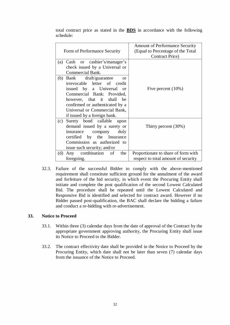
32.2. The performance security shall be denominated in Philippine Pesos and posted in favor of the Procuring Entity in an amount equal to the percentage of the
32
total contract price as stated in the BDS in accordance with the following schedule:
Form of Performance Security Amount of Performance Security (Equal to Percentage of the Total
Contract Price) (a) Cash or cashier’s/manager’s
check issued by a Universal or Commercial Bank.
Five percent (10%)
(b) Bank draft/guarantee or irrevocable letter of credit issued by a Universal or Commercial Bank: Provided, however, that it shall be confirmed or authenticated by a Universal or Commercial Bank, if issued by a foreign bank.
(c) Surety bond callable upon demand issued by a surety or insurance company duly certified by the Insurance Commission as authorized to issue such security; and/or
Thirty percent (30%)
(d) Any combination of the foregoing.
Proportionate to share of form with respect to total amount of security
32.3. Failure of the successful Bidder to comply with the above-mentioned requirement shall constitute sufficient ground for the annulment of the award and forfeiture of the bid security, in which event the Procuring Entity shall initiate and complete the post qualification of the second Lowest Calculated Bid. The procedure shall be repeated until the Lowest Calculated and Responsive Bid is identified and selected for contract award. However if no Bidder passed post-qualification, the BAC shall declare the bidding a failure and conduct a re-bidding with re-advertisement.
33. Notice to Proceed
33.1. Within three (3) calendar days from the date of approval of the Contract by the appropriate government approving authority, the Procuring Entity shall issue its Notice to Proceed to the Bidder.
33.2. The contract effectivity date shall be provided in the Notice to Proceed by the Procuring Entity, which date shall not be later than seven (7) calendar days from the issuance of the Notice to Proceed.

33
Section III. Bid Data Sheet

34
Bid Data Sheet
ITB Clause
1.1 The PROCURING ENTITY is Department of Transportation and Communications (DOTC).
The name of the Contract is Iloilo City Philippine Coast Guard District Station (Construction of PCG District Station).
The identification number of the Contract is [insert identification number of the contract].
2
The Funding Source is:
The Government of the Philippines (GOP) through DOTC CY 2011 Infrastructure Fund in the amount of Fifteen Million Pesos (P 15,000,000.00).
The name of the Project is Iloilo City Philippine Coast Guard District Station (Construction of PCG District Station).
3.1 No further instructions.
5.1 No further instructions.
5.2 Bidding is restricted to eligible bidders as defined in ITB Clause 5.1.
5.4.(a) Completed and similar projects from 2002 to 2011.
For this purpose, similar contracts shall refer to Building Projects.
8.1 Subcontracting is not allowed.
8.2 Not applicable.
9.1 The DOTC will hold a pre-bid conference for this Project on May 25, 2012, 9:00am at Unit 167,16th Floor, The Columbia Tower, Ortigas Avenue, Brgy. Wack-Wack, Mandaluyong City.
10.1 The Procuring Entity’s address is:
Department of Transportation and Communications Unit 164, The Columbia Tower, Ortigas Avenue, Brgy. Wack-Wack, Mandaluyong City Hon. JOSE PERPETUO M. LOTILLA Undersecretary and Chairperson Bids and Awards Committee Tel. No. (02)724-1728, Fax No. (02)725-6609

35
10.3 No further instructions.
12.1
The first envelope shall contain the eligibility and technical documents stated in the ITB Clause.
12.1(a)(i) No other acceptable proof of registration is recognized.
12.1(a)(ii) Valid and current Mayor’s Permit.
12.1(a)(iii) 1. Duly signed Statement of all Ongoing Government & Private Construction Contracts including contracts awarded but not yet started (SF-INFR-15).
2. Duly signed Statement of all Completed Government & Private Construction Contracts which are similar in nature (SF-INFR-16).
12.1(a)(iv) Valid PCAB license and registration for the type and cost of the contract for this project. For JV, provide a JV license issued by PCAB.
The IAC Registration for this project is Small B for Vertical Structures.
12.1(b)(ii)(ii.2) List of Contractors Personnel to be assigned to the contract to be bid with their respective curriculum vitae showing, among others, their educational attainment, professional qualification and experiences (SF-INFR-48), as follows:
1. Project Manager 2. Civil Engineer 3. Architect (applicable only for vertical projects) 4. Materials Engineer (duly accredited by DPWH) 5. Safety Officer (with certificate of training in occupational safety and health) Duly signed Statement of Availability of Key Personnel and Equipment (SF-INFR-18).
12.1(b)(ii)(ii.3) List of Contractor’s Equipment OWNED (pls. see Invitation to Bid), assigned to the Proposed Contract (SF-INFR-49).
13.1 Checklist of Financial Components:
1. Bid Prices in the bill of quantities in the prescribed form. 2. Detailed estimates including summary sheet indicating the unit prices of construction materials, labor rates and equipment rentals used in coming up with the bid, and 3. Cash flow by quarter and payment schedules.

36
13.1(b) The ABC is Ten Million Five Hundred Ninety-Five Thousand Eight Hundred Forty-Two Pesos and Twenty-Three Centavos (P 10,595,842.23). Any bid with a financial component exceeding this amount shall not be accepted.
14.2 No further instructions.
14.2 No further instructions.
16.1 The bid prices shall be quoted in Philippine Pesos.
17.1 Bids will be valid until One Hundred Twenty (120) calendar days from the date of the opening of bids.
18.1 The bid security shall be in the following amount:
1. The amount of Two Hundred Eleven Thousand Nine Hundred Sixteen Pesos and Eighty-Four Centavos (P 211,916.84), if bid security is in cash, cashier’s/manager’s check, bank draft/guarantee or irrevocable letter of credit;
2. The amount of Five Hundred Twenty-Nine Thousand Seven Hundred Ninety-Two and Eleven Centavos (P 529,792.11), if bid security is in Surety Bond; or
3. Any combination of the foregoing proportionate to the share of form with respect to total amount of security.
18.2 The bid security shall be valid until One Hundred Twenty (120) calendar days from the date of the opening of bids.
18.25 The first line should read “The bid security SHALL be forfeited”.
20.3 Each Bidder shall submit One (1) original and Two (2) copies of the first and second components of its bid.
21 The address for submission of bids is Unit 167, The Columbia Tower, Ortigas Avenue, Brgy. Wack-Wack, Mandaluyong City.
The deadline for submission of bids is June 07, 2012, 9:00am.
24.1 The place of bid opening is at DOTC, Unit 167, The Columbia Tower, Ortigas Avenue, Mandaluyong City.
The date and time of bid opening is June 07, 2012, 9:00am.
24.2 No further instructions.
27.3(b) Bid modification is not allowed.
27.4 No further instructions.

37
28.2(b) The Bidders must submit manually filed tax returns or tax returns filed through the Electronic Filing and Payments System (EFPS) for the year 2011.
NOTE: The latest income and business tax returns are those within the last six months preceding the date of bid submission.
28.2(d) Additional document:
1. Valid Certificate of Registration indicating the Tax Identification Number and photocopy of TIN Card.
31.4(g) Construction schedule and S-curve, manpower schedule, construction methods, equipment utilization schedule, construction safety and health program duly approved by the Department of Labor and Employment, and PERT/CPM.
32.2 The performance security shall be in the following amount:
1. The amount of (10% of the total contract amount), if performance security is in cash, cashier’s/manager’s check, bank draft/guarantee or irrevocable letter of credit;
2. The amount of (30% of the total contract amount), if performance security is in Surety Bond; or
3. Any combination of the foregoing proportionate to the share of form with respect to total amount of security.

38
Section IV. General Conditions of Contract
39
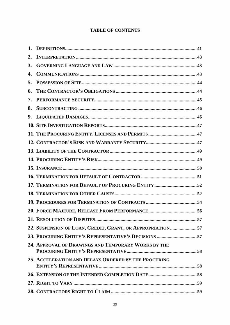
TABLE OF CONTENTS
1. DEFINITIONS............................................................................................................. 41
2. INTERPRETATION .................................................................................................... 43
3. GOVERNING LANGUAGE AND LAW ..................................................................... 43
4. COMMUNICATIONS ................................................................................................. 43
5. POSSESSION OF SITE ............................................................................................... 44
6. THE CONTRACTOR’S OBLIGATIONS ................................................................... 44
7. PERFORMANCE SECURITY..................................................................................... 45
8. SUBCONTRACTING .................................................................................................. 46
9. LIQUIDATED DAMAGES .......................................................................................... 46
10. SITE INVESTIGATION REPORTS ............................................................................ 47
11. THE PROCURING ENTITY, LICENSES AND PERMITS ........................................ 47
12. CONTRACTOR’S RISK AND WARRANTY SECURITY.......................................... 47
13. LIABILITY OF THE CONTRACTOR ........................................................................ 49
14. PROCURING ENTITY’S RISK.................................................................................. 49
15. INSURANCE ............................................................................................................... 50
16. TERMINATION FOR DEFAULT OF CONTRACTOR .............................................. 51
17. TERMINATION FOR DEFAULT OF PROCURING ENTITY ................................... 52
18. TERMINATION FOR OTHER CAUSES .................................................................... 52
19. PROCEDURES FOR TERMINATION OF CONTRACTS .......................................... 54
20. FORCE MAJEURE, RELEASE FROM PERFORMANCE ........................................ 56
21. RESOLUTION OF DISPUTES .................................................................................... 57
22. SUSPENSION OF LOAN, CREDIT, GRANT, OR APPROPRIATION ...................... 57
23. PROCURING ENTITY’S REPRESENTATIVE’S DECISIONS ................................. 57
24. APPROVAL OF DRAWINGS AND TEMPORARY WORKS BY THE PROCURING ENTITY’S REPRESENTATIVE .......................................................... 58
25. ACCELERATION AND DELAYS ORDERED BY THE PROCURING ENTITY’S REPRESENTATIVE ................................................................................. 58
26. EXTENSION OF THE INTENDED COMPLETION DATE ........................................ 58
27. RIGHT TO VARY ...................................................................................................... 59
28. CONTRACTORS RIGHT TO CLAIM ....................................................................... 59

40
29. DAYWORKS ............................................................................................................... 59
30. EARLY WARNING .................................................................................................... 59
31. PROGRAM OF WORK .............................................................................................. 60
32. MANAGEMENT CONFERENCES ............................................................................. 60
33. BILL OF QUANTITIES .............................................................................................. 61
34. INSTRUCTIONS, INSPECTIONS AND AUDITS ........................................................ 61
35. IDENTIFYING DEFECTS .......................................................................................... 61
36. COST OF REPAIRS ................................................................................................... 61
37. CORRECTION OF DEFECTS .................................................................................... 62
38. UNCORRECTED DEFECTS ...................................................................................... 62
39. ADVANCE PAYMENT ............................................................................................... 62
40. PROGRESS PAYMENTS ............................................................................................ 63
41. PAYMENT CERTIFICATES ...................................................................................... 63
42. RETENTION ............................................................................................................... 64
43. VARIATION ORDERS ............................................................................................... 64
44. CONTRACT COMPLETION ...................................................................................... 66
45. SUSPENSION OF WORK ........................................................................................... 66
46. PAYMENT ON TERMINATION ................................................................................ 67
47. EXTENSION OF CONTRACT TIME ......................................................................... 68
48. PRICE ADJUSTMENT ............................................................................................... 69
49. COMPLETION ........................................................................................................... 69
50. TAKING OVER .......................................................................................................... 69
51. OPERATING AND MAINTENANCE MANUALS...................................................... 69
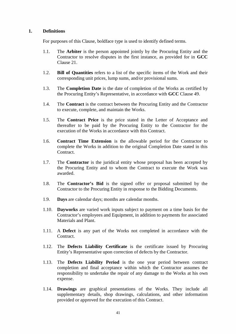
41
1. Definitions
For purposes of this Clause, boldface type is used to identify defined terms.
1.1. The Arbiter is the person appointed jointly by the Procuring Entity and the Contractor to resolve disputes in the first instance, as provided for in GCC Clause 21.
1.2. Bill of Quantities refers to a list of the specific items of the Work and their corresponding unit prices, lump sums, and/or provisional sums.
1.3. The Completion Date is the date of completion of the Works as certified by the Procuring Entity’s Representative, in accordance with GCC Clause 49.
1.4. The Contract is the contract between the Procuring Entity and the Contractor to execute, complete, and maintain the Works.
1.5. The Contract Price is the price stated in the Letter of Acceptance and thereafter to be paid by the Procuring Entity to the Contractor for the execution of the Works in accordance with this Contract.
1.6. Contract Time Extension is the allowable period for the Contractor to complete the Works in addition to the original Completion Date stated in this Contract.
1.7. The Contractor is the juridical entity whose proposal has been accepted by the Procuring Entity and to whom the Contract to execute the Work was awarded.
1.8. The Contractor’s Bid is the signed offer or proposal submitted by the Contractor to the Procuring Entity in response to the Bidding Documents.
1.9. Days are calendar days; months are calendar months.
1.10. Dayworks are varied work inputs subject to payment on a time basis for the Contractor’s employees and Equipment, in addition to payments for associated Materials and Plant.
1.11. A Defect is any part of the Works not completed in accordance with the Contract.
1.12. The Defects Liability Certificate is the certificate issued by Procuring Entity’s Representative upon correction of defects by the Contractor.
1.13. The Defects Liability Period is the one year period between contract completion and final acceptance within which the Contractor assumes the responsibility to undertake the repair of any damage to the Works at his own expense.
1.14. Drawings are graphical presentations of the Works. They include all supplementary details, shop drawings, calculations, and other information provided or approved for the execution of this Contract.
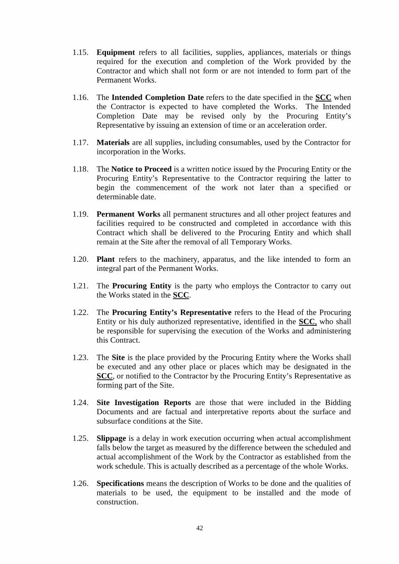
42
1.15. Equipment refers to all facilities, supplies, appliances, materials or things required for the execution and completion of the Work provided by the Contractor and which shall not form or are not intended to form part of the Permanent Works.
1.16. The Intended Completion Date refers to the date specified in the SCC when the Contractor is expected to have completed the Works. The Intended Completion Date may be revised only by the Procuring Entity’s Representative by issuing an extension of time or an acceleration order.
1.17. Materials are all supplies, including consumables, used by the Contractor for incorporation in the Works.
1.18. The Notice to Proceed is a written notice issued by the Procuring Entity or the Procuring Entity’s Representative to the Contractor requiring the latter to begin the commencement of the work not later than a specified or determinable date.
1.19. Permanent Works all permanent structures and all other project features and facilities required to be constructed and completed in accordance with this Contract which shall be delivered to the Procuring Entity and which shall remain at the Site after the removal of all Temporary Works.
1.20. Plant refers to the machinery, apparatus, and the like intended to form an integral part of the Permanent Works.
1.21. The Procuring Entity is the party who employs the Contractor to carry out the Works stated in the SCC.
1.22. The Procuring Entity’s Representative refers to the Head of the Procuring Entity or his duly authorized representative, identified in the SCC, who shall be responsible for supervising the execution of the Works and administering this Contract.
1.23. The Site is the place provided by the Procuring Entity where the Works shall be executed and any other place or places which may be designated in the SCC, or notified to the Contractor by the Procuring Entity’s Representative as forming part of the Site.
1.24. Site Investigation Reports are those that were included in the Bidding Documents and are factual and interpretative reports about the surface and subsurface conditions at the Site.
1.25. Slippage is a delay in work execution occurring when actual accomplishment falls below the target as measured by the difference between the scheduled and actual accomplishment of the Work by the Contractor as established from the work schedule. This is actually described as a percentage of the whole Works.
1.26. Specifications means the description of Works to be done and the qualities of materials to be used, the equipment to be installed and the mode of construction.

43
1.27. The Start Date, as specified in the SCC, is the date when the Contractor is obliged to commence execution of the Works. It does not necessarily coincide with any of the Site Possession Dates.
1.28. A Subcontractor is any person or organization to whom a part of the Works has been subcontracted by the Contractor, as allowed by the Procuring Entity, but not any assignee of such person.
1.29. Temporary Works are works designed, constructed, installed, and removed by the Contractor that are needed for construction or installation of the Permanent Works.
1.30. Work(s) refer to the Permanent Works and Temporary Works to be executed by the Contractor in accordance with this Contract, including (i) the furnishing of all labor, materials, equipment and others incidental, necessary or convenient to the complete execution of the Works; (ii) the passing of any tests before acceptance by the Procuring Entity’s Representative; (iii) and the carrying out of all duties and obligations of the Contractor imposed by this Contract as described in the SCC.
2. Interpretation
2.1. In interpreting the Conditions of Contract, singular also means plural, male also means female or neuter, and the other way around. Headings have no significance. Words have their normal meaning under the language of this Contract unless specifically defined. The Procuring Entity’s Representative will provide instructions clarifying queries about the Conditions of Contract.
2.2. If sectional completion is specified in the SCC, references in the Conditions of Contract to the Works, the Completion Date, and the Intended Completion Date apply to any Section of the Works (other than references to the Completion Date and Intended Completion Date for the whole of the Works).
3. Governing Language and Law
3.1. This Contract has been executed in the English language, which shall be the binding and controlling language for all matters relating to the meaning or interpretation of this Contract. All correspondence and other documents pertaining to this Contract which are exchanged by the parties shall be written in English.
3.2. This Contract shall be interpreted in accordance with the laws of the Republic of the Philippines.
4. Communications
Communications between parties that are referred to in the Conditions shall be effective only when in writing. A notice shall be effective only when it is received by the concerned party.

44
5. Possession of Site
5.1. On the date specified in the SCC, the Procuring Entity shall grant the Contractor possession of so much of the Site as may be required to enable it to proceed with the execution of the Works. If the Contractor suffers delay or incurs cost from failure on the part of the Procuring Entity to give possession in accordance with the terms of this clause, the Procuring Entity’s Representative shall give the Contractor a Contract Time Extension and certify such sum as fair to cover the cost incurred, which sum shall be paid by Procuring Entity.
5.2. If possession of a portion is not given by the date stated in the SCC Clause 5.1, the Procuring Entity will be deemed to have delayed the start of the relevant activities. The resulting adjustments in contact time to address such delay shall be in accordance with GCC Clause 47.
5.3. The Contractor shall bear all costs and charges for special or temporary right-of-way required by it in connection with access to the Site. The Contractor shall also provide at his own cost any additional facilities outside the Site required by it for purposes of the Works.
5.4. The Contractor shall allow the Procuring Entity’s Representative and any person authorized by the Procuring Entity’s Representative access to the Site and to any place where work in connection with this Contract is being carried out or is intended to be carried out.
6. The Contractor’s Obligations
6.1. The Contractor shall carry out the Works properly and in accordance with this Contract. The Contractor shall provide all supervision, labor, Materials, Plant and Contractor's Equipment, which may be required. All Materials and Plant on Site shall be deemed to be the property of the Procuring Entity.
6.2. The Contractor shall commence execution of the Works on the Start Date and shall carry out the Works in accordance with the Program of Work submitted by the Contractor, as updated with the approval of the Procuring Entity’s Representative, and complete them by the Intended Completion Date.
6.3. The Contractor shall be responsible for the safety of all activities on the Site.
6.4. The Contractor shall carry out all instructions of the Procuring Entity’s Representative that comply with the applicable laws where the Site is located.
6.5. The Contractor shall employ the key personnel named in the Schedule of Key Personnel, as referred to in the SCC, to carry out the supervision of the Works. The Procuring Entity will approve any proposed replacement of key personnel only if their relevant qualifications and abilities are equal to or better than those of the personnel listed in the Schedule.
6.6. If the Procuring Entity’s Representative asks the Contractor to remove a member of the Contractor’s staff or work force, for justifiable cause, the
45
Contractor shall ensure that the person leaves the Site within seven (7) days and has no further connection with the Work in this Contract.
6.7. During Contract implementation, the Contractor and his subcontractors shall abide at all times by all labor laws, including child labor related enactments, and other relevant rules.
6.8. The Contractor shall submit to the Procuring Entity for consent the name and particulars of the person authorized to receive instructions on behalf of the Contractor.
6.9. The Contractor shall cooperate and share the Site with other contractors, public authorities, utilities, and the Procuring Entity between the dates given in the schedule of other contractors particularly when they shall require access to the Site. The Contractor shall also provide facilities and services for them during this period. The Procuring Entity may modify the schedule of other contractors, and shall notify the Contractor of any such modification thereto.
6.10. Should anything of historical or other interest or of significant value be unexpectedly discovered on the Site, it shall be the property of the Procuring Entity. The Contractor shall notify the Procuring Entity’s Representative of such discoveries and carry out the Procuring Entity’s Representative’s instructions in dealing with them.
7. Performance Security
7.1. Within ten (10) calendar days from receipt of the Notice of Award from the Procuring Entity but in no case later than the signing of the contract by both parties, the Contractor shall furnish the performance security in any the forms prescribed in ITB Clause 32.2.
7.2. The performance security posted in favor of the Procuring Entity shall be forfeited in the event it is established that the Contractor is in default in any of its obligations under the Contract.
7.3. The performance security shall remain valid until issuance by the Procuring Entity of the Certificate of Final Acceptance.
7.4. The performance security may be released by the Procuring Entity and returned to the Contractor after the issuance of the Certificate of Final Acceptance subject to the following conditions:
(a) There are no pending claims against the Contractor or the surety company filed by the Procuring Entity;
(b) The Contractor has no pending claims for labor and materials filed against it; and
(c) Other terms specified in the SCC.
7.5. The Contractor shall post an additional performance security following the amount and form specified in ITB Clause 32.2 to cover any cumulative

46
increase of more than ten percent (10%) over the original value of the contract as a result of amendments to order or change orders, extra work orders and supplemental agreements, as the case may be. The Contractor shall cause the extension of the validity of the performance security to cover approved contract time extensions.
7.6. In case of a reduction in the contract value or for partially completed Works under the contract which are usable and accepted by the Procuring Entity the use of which, in the judgment of the implementing agency or the Procuring Entity, will not affect the structural integrity of the entire project, the Procuring Entity shall allow a proportional reduction in the original performance security, provided that any such reduction is more than ten percent (10%) and that the aggregate of such reductions is not more than fifty percent (50%) of the original performance security.
7.7. Unless otherwise indicated in the SCC, the Contractor, by entering into the Contract with the Procuring Entity, acknowledges the right of the Procuring Entity to institute action pursuant to Act 3688 against any subcontractor be they an individual, firm, partnership, corporation, or association supplying the Contractor with labor, materials and/or equipment for the performance of this Contract.
8. Subcontracting
8.1. Unless otherwise indicated in the SCC, the Contractor cannot subcontract Works more than the percentage specified in ITB Clause 8.1.
8.2. Subcontracting of any portion of the Works does not relieve the Contractor of any liability or obligation under this Contract. The Contractor will be responsible for the acts, defaults, and negligence of any subcontractor, its agents, servants or workmen as fully as if these were the Contractor’s own acts, defaults, or negligence, or those of its agents, servants or workmen.
8.3. Subcontractors disclosed and identified during the bidding may be changed during the implementation of this Contract, subject to compliance with the required qualifications and the approval of the Procuring Entity.
9. Liquidated Damages
9.1. The Contractor shall pay liquidated damages to the Procuring Entity for each day that the Completion Date is later than the Intended Completion Date. The applicable liquidated damages is at least one-tenth (1/10) of a percent of the cost of the unperformed portion for every day of delay. The total amount of liquidated damages shall not exceed ten percent (10%) of the amount of the contract. The Procuring Entity may deduct liquidated damages from payments due to the Contractor. Payment of liquidated damages shall not affect the Contractor. Once the cumulative amount of liquidated damages reaches ten percent (10%) of the amount of this Contract, the Procuring Entity shall rescind this Contract, without prejudice to other courses of action and remedies open to it.
47
9.2. If the Intended Completion Date is extended after liquidated damages have been paid, the Engineer of the Procuring Entity shall correct any overpayment of liquidated damages by the Contractor by adjusting the next payment certificate. The Contractor shall be paid interest on the overpayment, calculated from the date of payment to the date of repayment, at the rates specified in GCC Clause 40.3.
10. Site Investigation Reports
The Contractor, in preparing the Bid, shall rely on any Site Investigation Reports referred to in the SCC supplemented by any information obtained by the Contractor.
11. The Procuring Entity, Licenses and Permits
The Procuring Entity shall, if requested by the Contractor, assist him in applying for permits, licenses or approvals, which are required for the Works.
12. Contractor’s Risk and Warranty Security
12.1. The Contractor shall assume full responsibility for the Works from the time project construction commenced up to final acceptance by the Procuring Entity and shall be held responsible for any damage or destruction of the Works except those occasioned by force majeure. The Contractor shall be fully responsible for the safety, protection, security, and convenience of his personnel, third parties, and the public at large, as well as the Works, Equipment, installation, and the like to be affected by his construction work.
12.2. The defects liability period for infrastructure projects shall be one year from contract completion up to final acceptance by the Procuring Entity. During this period, the Contractor shall undertake the repair works, at his own expense, of any damage to the Works on account of the use of materials of inferior quality within ninety (90) days from the time the Head of the Procuring Entity has issued an order to undertake repair. In case of failure or refusal to comply with this mandate, the Procuring Entity shall undertake such repair works and shall be entitled to full reimbursement of expenses incurred therein upon demand.
12.3. Unless otherwise indicated in the SCC, in case the Contractor fails to comply with the preceding paragraph, the Procuring Entity shall forfeit its performance security, subject its property(ies) to attachment or garnishment proceedings, and perpetually disqualify it from participating in any public bidding. All payables of the GOP in his favor shall be offset to recover the costs.
12.4. After final acceptance of the Works by the Procuring Entity, the Contractor shall be held responsible for “Structural Defects”, i.e., major faults/flaws/deficiencies in one or more key structural elements of the project which may lead to structural failure of the completed elements or structure, or “Structural Failures”, i.e., where one or more key structural elements in an infrastructure facility fails or collapses, thereby rendering the facility or part

48
thereof incapable of withstanding the design loads, and/or endangering the safety of the users or the general public:
(a) Contractor – Where Structural Defects/Failures arise due to faults attributable to improper construction, use of inferior quality/substandard materials, and any violation of the contract plans and specifications, the contractor shall be held liable;
(b) Consultants – Where Structural Defects/Failures arise due to faulty and/or inadequate design and specifications as well as construction supervision, then the consultant who prepared the design or undertook construction supervision for the project shall be held liable;
(c) Procuring Entity’s Representatives/Project Manager/Construction Managers and Supervisors – The project owner’s representative(s), project manager, construction manager, and supervisor(s) shall be held liable in cases where the Structural Defects/Failures are due to his/their willful intervention in altering the designs and other specifications; negligence or omission in not approving or acting on proposed changes to noted defects or deficiencies in the design and/or specifications; and the use of substandard construction materials in the project;
(d) Third Parties - Third Parties shall be held liable in cases where Structural Defects/Failures are caused by work undertaken by them such as leaking pipes, diggings or excavations, underground cables and electrical wires, underground tunnel, mining shaft and the like, in which case the applicable warranty to such structure should be levied to third parties for their construction or restoration works.
(e) Users - In cases where Structural Defects/Failures are due to abuse/misuse by the end user of the constructed facility and/or non–compliance by a user with the technical design limits and/or intended purpose of the same, then the user concerned shall be held liable.
12.5. The warranty against Structural Defects/Failures, except those occasioned on force majeure, shall cover the period specified in the SCC reckoned from the date of issuance of the Certificate of Final Acceptance by the Procuring Entity.
12.6. The Contractor shall be required to put up a warranty security in the form of cash, bank guarantee, letter of credit, GSIS or surety bond callable on demand, in accordance with the following schedule:
Form of Warranty Minimum Amount in
Percentage (%) of Total Contract Price
(a) Cash or letter of credit issued by Universal or Commercial bank: provided, however, that the letter of credit shall be confirmed or authenticated by a Universal or Commercial bank, if issued by a
Five Percent (5%)

49
foreign bank
(b) Bank guarantee confirmed by Universal or Commercial bank: provided, however, that the letter of credit shall be confirmed or authenticated by a Universal or Commercial bank, if issued by a foreign bank
Ten Percent (10%)
(c) Surety bond callable upon demand issued by GSIS or any surety or insurance company duly certified by the Insurance Commission
Thirty Percent (30%)
12.7. The warranty security shall be stated in Philippine Pesos and shall remain effective for one year from the date of issuance of the Certificate of Final Acceptance by the Procuring Entity, and returned only after the lapse of said one year period.
12.8. In case of structural defects/failure occurring during the applicable warranty period provided in GCC Clause 12.5, the Procuring Entity shall undertake the necessary restoration or reconstruction works and shall be entitled to full reimbursement by the parties found to be liable for expenses incurred therein upon demand, without prejudice to the filing of appropriate administrative, civil, and/or criminal charges against the responsible persons as well as the forfeiture of the warranty security posted in favor of the Procuring Entity.
13. Liability of the Contractor
Subject to additional provisions, if any, set forth in the SCC, the Contractor’s liability under this Contract shall be as provided by the laws of the Republic of the Philippines.
14. Procuring Entity’s Risk
14.1. From the Start Date until the Certificate of Final Acceptance has been issued, the following are risks of the Procuring Entity:
(a) The risk of personal injury, death, or loss of or damage to property (excluding the Works, Plant, Materials, and Equipment), which are due to:
(i) any type of use or occupation of the Site authorized by the Procuring Entity after the official acceptance of the works; or
(ii) negligence, breach of statutory duty, or interference with any legal right by the Procuring Entity or by any person employed by or contracted to him except the Contractor.
(b) The risk of damage to the Works, Plant, Materials, and Equipment to the extent that it is due to a fault of the Procuring Entity or in the
50
Procuring Entity’s design, or due to war or radioactive contamination directly affecting the country where the Works are to be executed.
15. Insurance
15.1. The Contractor shall, under his name and at his own expense, obtain and maintain, for the duration of this Contract, the following insurance coverage:
(a) Contractor’s All Risk Insurance;
(b) Transportation to the project Site of Equipment, Machinery, and Supplies owned by the Contractor;
(c) Personal injury or death of Contractor’s employees; and
(d) Comprehensive insurance for third party liability to Contractor’s direct or indirect act or omission causing damage to third persons.
15.2. The Contractor shall provide evidence to the Procuring Entity’s Representative that the insurances required under this Contract have been effected and shall, within a reasonable time, provide copies of the insurance policies to the Procuring Entity’s Representative. Such evidence and such policies shall be provided to the Procuring Entity’s through the Procuring Entity’s Representative.
15.3. The Contractor shall notify the insurers of changes in the nature, extent, or program for the execution of the Works and ensure the adequacy of the insurances at all times in accordance with the terms of this Contract and shall produce to the Procuring Entity’s Representative the insurance policies in force including the receipts for payment of the current premiums.
The above insurance policies shall be obtained from any reputable insurance company approved by the Procuring Entity’s Representative.
15.4. If the Contractor fails to obtain and keep in force the insurances referred to herein or any other insurance which he may be required to obtain under the terms of this Contract, the Procuring Entity may obtain and keep in force any such insurances and pay such premiums as may be necessary for the purpose. From time to time, the Procuring Entity may deduct the amount it shall pay for said premiums including twenty five percent (25%) therein from any monies due, or which may become due, to the Contractor, without prejudice to the Procuring Entity exercising its right to impose other sanctions against the Contractor pursuant to the provisions of this Contract.
15.5. In the event the Contractor fails to observe the above safeguards, the Procuring Entity may, at the Contractor’s expense, take whatever measure is deemed necessary for its protection and that of the Contractor’s personnel and third parties, and/or order the interruption of dangerous Works. In addition, the Procuring Entity may refuse to make the payments under GCC Clause 40 until the Contractor complies with this Clause.

51
15.6. The Contractor shall immediately replace the insurance policy obtained as required in this Contract, without need of the Procuring Entity’s demand, with a new policy issued by a new insurance company acceptable to the Procuring Entity for any of the following grounds:
(a) The issuer of the insurance policy to be replaced has:
(i) become bankrupt;
(ii) been placed under receivership or under a management committee;
(iii) been sued for suspension of payment; or
(iv) been suspended by the Insurance Commission and its license to engage in business or its authority to issue insurance policies cancelled; or
(v) Where reasonable grounds exist that the insurer may not be able, fully and promptly, to fulfill its obligation under the insurance policy.
16. Termination for Default of Contractor
16.1. The Procuring Entity shall terminate this Contract for default when any of the following conditions attend its implementation:
16.2. Due to the Contractor’s fault and while the project is on-going, it has incurred negative slippage of fifteen percent (15%) or more in accordance with Presidential Decree 1870, regardless of whether or not previous warnings and notices have been issued for the Contractor to improve his performance;
16.3. Due to its own fault and after this Contract time has expired, the Contractor incurs delay in the completion of the Work after this Contract has expired; or
16.4. The Contractor:
(a) abandons the contract Works, refuses or fails to comply with a valid instruction of the Procuring Entity or fails to proceed expeditiously and without delay despite a written notice by the Procuring Entity;
(b) does not actually have on the project Site the minimum essential equipment listed on the Bid necessary to prosecute the Works in accordance with the approved Program of Work and equipment deployment schedule as required for the project;
(c) does not execute the Works in accordance with this Contract or persistently or flagrantly neglects to carry out its obligations under this Contract;
(d) neglects or refuses to remove materials or to perform a new Work that has been rejected as defective or unsuitable; or

52
(e) sub-lets any part of this Contract without approval by the Procuring Entity.
16.5. All materials on the Site, Plant, Equipment, and Works shall be deemed to be the property of the Procuring Entity if this Contract is rescinded because of the Contractor’s default.
17. Termination for Default of Procuring Entity
The Contractor may terminate this Contract with the Procuring Entity if the works are completely stopped for a continuous period of at least sixty (60) calendar days through no fault of its own, due to any of the following reasons:
(a) Failure of the Procuring Entity to deliver, within a reasonable time, supplies, materials, right-of-way, or other items it is obligated to furnish under the terms of this Contract; or
(b) The prosecution of the Work is disrupted by the adverse peace and order situation, as certified by the Armed Forces of the Philippines Provincial Commander and approved by the Secretary of National Defense.
18. Termination for Other Causes
18.1. The Procuring Entity may terminate this Contract, in whole or in part, at any time for its convenience. The Head of the Procuring Entity may terminate this Contract for the convenience of the Procuring Entity if he has determined the existence of conditions that make Project Implementation economically, financially or technically impractical and/or unnecessary, such as, but not limited to, fortuitous event(s) or changes in law and National Government policies.
18.2. The Procuring Entity or the Contractor may terminate this Contract if the other party causes a fundamental breach of this Contract.
18.3. Fundamental breaches of Contract shall include, but shall not be limited to, the following:
(a) The Contractor stops work for twenty eight (28) days when no stoppage of work is shown on the current Program of Work and the stoppage has not been authorized by the Procuring Entity’s Representative;
(b) The Procuring Entity’s Representative instructs the Contractor to delay the progress of the Works, and the instruction is not withdrawn within twenty eight (28) days;
(c) The Procuring Entity shall terminate this Contract if the Contractor is declared bankrupt or insolvent as determined with finality by a court of competent jurisdiction. In this event, termination will be without compensation to the Contractor, provided that such termination will not prejudice or affect any right of action or remedy which has accrued or will accrue thereafter to the Procuring Entity and/or the Contractor.

53
In the case of the Contractor's insolvency, any Contractor's Equipment which the Procuring Entity instructs in the notice is to be used until the completion of the Works;
(d) A payment certified by the Procuring Entity’s Representative is not paid by the Procuring Entity to the Contractor within eighty four (84) days from the date of the Procuring Entity’s Representative’s certificate;
(e) The Procuring Entity’s Representative gives Notice that failure to correct a particular Defect is a fundamental breach of Contract and the Contractor fails to correct it within a reasonable period of time determined by the Procuring Entity’s Representative;
(f) The Contractor does not maintain a Security, which is required;
(g) The Contractor has delayed the completion of the Works by the number of days for which the maximum amount of liquidated damages can be paid, as defined in the GCC Clause 9; and
(h) In case it is determined prima facie by the Procuring Entity that the Contractor has engaged, before or during the implementation of the contract, in unlawful deeds and behaviors relative to contract acquisition and implementation, such as, but not limited to, the following:
(i) corrupt, fraudulent, collusive, coercive, and obstructive practices as defined in ITB Clause 3.1(a), unless otherwise specified in the SCC;
(ii) drawing up or using forged documents;
(iii) using adulterated materials, means or methods, or engaging in production contrary to rules of science or the trade; and
(iv) any other act analogous to the foregoing.
18.4. The Funding Source or the Procuring Entity, as appropriate, will seek to impose the maximum civil, administrative and/or criminal penalties available under the applicable law on individuals and organizations deemed to be involved with corrupt, fraudulent, or coercive practices.
18.5. When persons from either party to this Contract gives notice of a fundamental breach to the Procuring Entity’s Representative in order to terminate the existing contract for a cause other than those listed under GCC Clause 18.3, the Procuring Entity’s Representative shall decide whether the breach is fundamental or not.
18.6. If this Contract is terminated, the Contractor shall stop work immediately, make the Site safe and secure, and leave the Site as soon as reasonably possible.
54
19. Procedures for Termination of Contracts
19.1. The following provisions shall govern the procedures for the termination of this Contract:
(a) Upon receipt of a written report of acts or causes which may constitute ground(s) for termination as aforementioned, or upon its own initiative, the Procuring Entity shall, within a period of seven (7) calendar days, verify the existence of such ground(s) and cause the execution of a Verified Report, with all relevant evidence attached;
(b) Upon recommendation by the Procuring Entity, the Head of the Procuring Entity shall terminate this Contract only by a written notice to the Contractor conveying the termination of this Contract. The notice shall state:
(i) that this Contract is being terminated for any of the ground(s) afore-mentioned, and a statement of the acts that constitute the ground(s) constituting the same;
(ii) the extent of termination, whether in whole or in part;
(iii) an instruction to the Contractor to show cause as to why this Contract should not be terminated; and
(iv) special instructions of the Procuring Entity, if any.
The Notice to Terminate shall be accompanied by a copy of the Verified Report;
(c) Within a period of seven (7) calendar days from receipt of the Notice of Termination, the Contractor shall submit to the Head of the Procuring Entity a verified position paper stating why the contract should not be terminated. If the Contractor fails to show cause after the lapse of the seven (7) day period, either by inaction or by default, the Head of the Procuring Entity shall issue an order terminating the contract;
(d) The Procuring Entity may, at anytime before receipt of the Bidder’s verified position paper described in item (c) above withdraw the Notice to Terminate if it is determined that certain items or works subject of the notice had been completed, delivered, or performed before the Contractor’s receipt of the notice;
(e) Within a non-extendible period of ten (10) calendar days from receipt of the verified position paper, the Head of the Procuring Entity shall decide whether or not to terminate this Contract. It shall serve a written notice to the Contractor of its decision and, unless otherwise provided in the said notice, this Contract is deemed terminated from receipt of the Contractor of the notice of decision. The termination
55
shall only be based on the ground(s) stated in the Notice to Terminate; and
(f) The Head of the Procuring Entity may create a Contract Termination Review Committee (CTRC) to assist him in the discharge of this function. All decisions recommended by the CTRC shall be subject to the approval of the Head of the Procuring Entity.
19.2. Pursuant to Section 69(f) of RA 9184 and without prejudice to the imposition of additional administrative sanctions as the internal rules of the agency may provide and/or further criminal prosecution as provided by applicable laws, the procuring entity shall impose on contractors after the termination of the contract the penalty of suspension for one (1) year for the first offense, suspension for two (2) years for the second offense from participating in the public bidding process, for violations committed during the contract implementation stage, which include but not limited to the following:
(a) Failure of the contractor, due solely to his fault or negligence, to mobilize and start work or performance within the specified period in the Notice to Proceed (“NTP”);
(b) Failure by the contractor to fully and faithfully comply with its contractual obligations without valid cause, or failure by the contractor to comply with any written lawful instruction of the procuring entity or its representative(s) pursuant to the implementation of the contract. For the procurement of infrastructure projects or consultancy contracts, lawful instructions include but are not limited to the following:
(i) Employment of competent technical personnel, competent engineers and/or work supervisors;
(ii) Provision of warning signs and barricades in accordance with approved plans and specifications and contract provisions;
(iii) Stockpiling in proper places of all materials and removal from the project site of waste and excess materials, including broken pavement and excavated debris in accordance with approved plans and specifications and contract provisions;
(iv) Deployment of committed equipment, facilities, support staff and manpower; and
(v) Renewal of the effectivity dates of the performance security after its expiration during the course of contract implementation.
(c) Assignment and subcontracting of the contract or any part thereof or substitution of key personnel named in the proposal without prior written approval by the procuring entity.
56
(d) Poor performance by the contractor or unsatisfactory quality and/or progress of work arising from his fault or negligence as reflected in the Constructor's Performance Evaluation System (“CPES”) rating sheet. In the absence of the CPES rating sheet, the existing performance monitoring system of the procuring entity shall be applied. Any of the following acts by the Contractor shall be construed as poor performance:
(i) Negative slippage of 15% and above within the critical path of the project due entirely to the fault or negligence of the contractor; and
(ii) Quality of materials and workmanship not complying with the approved specifications arising from the contractor's fault or negligence.
(e) Willful or deliberate abandonment or non-performance of the project or contract by the contractor resulting to substantial breach thereof without lawful and/or just cause.
In addition to the penalty of suspension, the performance security posted by the contractor shall also be forfeited.
20. Force Majeure, Release From Performance
20.1. For purposes of this Contract the terms “force majeure” and “fortuitous event” may be used interchangeably. In this regard, a fortuitous event or force majeure shall be interpreted to mean an event which the Contractor could not have foreseen, or which though foreseen, was inevitable. It shall not include ordinary unfavorable weather conditions; and any other cause the effects of which could have been avoided with the exercise of reasonable diligence by the Contractor.
20.2. If this Contract is discontinued by an outbreak of war or by any other event entirely outside the control of either the Procuring Entity or the Contractor, the Procuring Entity’s Representative shall certify that this Contract has been discontinued. The Contractor shall make the Site safe and stop work as quickly as possible after receiving this certificate and shall be paid for all works carried out before receiving it and for any Work carried out afterwards to which a commitment was made.
20.3. If the event continues for a period of eighty four (84) days, either party may then give notice of termination, which shall take effect twenty eight (28) days after the giving of the notice.
20.4. After termination, the Contractor shall be entitled to payment of the unpaid balance of the value of the Works executed and of the materials and Plant reasonably delivered to the Site, adjusted by the following:
(a) any sum to which the Contractor is entitled under GCC Clause 28;
57
(b) the cost of his suspension and demobilization;
(c) any sum to which the Procuring Entity is entitled.
20.5. The net balance due shall be paid or repaid within a reasonable time period from the time of the notice of termination.
21. Resolution of Disputes
21.1. If any dispute or difference of any kind whatsoever shall arise between the parties in connection with the implementation of the contract covered by the Act and this IRR, the parties shall make every effort to resolve amicably such dispute or difference by mutual consultation.
21.2. If the Contractor believes that a decision taken by the PROCURING ENTITY’s Representative was either outside the authority given to the PROCURING ENTITY’s Representative by this Contract or that the decision was wrongly taken, the decision shall be referred to the Arbiter indicated in the SCC within fourteen (14) days of the notification of the PROCURING ENTITY’s Representative’s decision.
21.3. Any and all disputes arising from the implementation of this Contract covered by the R.A. 9184 and its IRR shall be submitted to arbitration in the Philippines according to the provisions of Republic Act No. 876, otherwise known as the “ Arbitration Law” and Republic Act 9285, otherwise known as the “Alternative Dispute Resolution Act of 2004”: Provided, however, That, disputes that are within the competence of the Construction Industry Arbitration Commission to resolve shall be referred thereto. The process of arbitration shall be incorporated as a provision in this Contract that will be executed pursuant to the provisions of the Act and its IRR: Provided, further, That, by mutual agreement, the parties may agree in writing to resort to other alternative modes of dispute resolution.
22. Suspension of Loan, Credit, Grant, or Appropriation
In the event that the Funding Source suspends the Loan, Credit, Grant, or Appropriation to the Procuring Entity, from which part of the payments to the Contractor are being made:
(a) The Procuring Entity is obligated to notify the Contractor of such suspension within seven (7) days of having received the suspension notice.
(b) If the Contractor has not received sums due it for work already done within forty five (45) days from the time the Contractor’s claim for payment has been certified by the Procuring Entity’s Representative, the Contractor may immediately issue a suspension of work notice in accordance with GCC Clause 45.2.
23. Procuring Entity’s Representative’s Decisions

58
23.1. Except where otherwise specifically stated, the Procuring Entity’s Representative will decide contractual matters between the Procuring Entity and the Contractor in the role representing the Procuring Entity.
23.2. The Procuring Entity’s Representative may delegate any of his duties and responsibilities to other people, except to the Arbiter, after notifying the Contractor, and may cancel any delegation after notifying the Contractor.
24. Approval of Drawings and Temporary Works by the Procuring Entity’s Representative
24.1. All Drawings prepared by the Contractor for the execution of the Temporary Works, are subject to prior approval by the Procuring Entity’s Representative before its use.
24.2. The Contractor shall be responsible for design of Temporary Works.
24.3. The Procuring Entity’s Representative’s approval shall not alter the Contractor’s responsibility for design of the Temporary Works.
24.4. The Contractor shall obtain approval of third parties to the design of the Temporary Works, when required by the Procuring Entity.
25. Acceleration and Delays Ordered by the Procuring Entity’s Representative
25.1. When the Procuring Entity wants the Contractor to finish before the Intended Completion Date, the Procuring Entity’s Representative will obtain priced proposals for achieving the necessary acceleration from the Contractor. If the Procuring Entity accepts these proposals, the Intended Completion Date will be adjusted accordingly and confirmed by both the Procuring Entity and the Contractor.
25.2. If the Contractor’s Financial Proposals for an acceleration are accepted by the Procuring Entity, they are incorporated in the Contract Price and treated as a Variation.
26. Extension of the Intended Completion Date
26.1. The Procuring Entity’s Representative shall extend the Intended Completion Date if a Variation is issued which makes it impossible for the Intended Completion Date to be achieved by the Contractor without taking steps to accelerate the remaining work, which would cause the Contractor to incur additional costs. No payment shall be made for any event which may warrant the extension of the Intended Completion Date.
26.2. The Procuring Entity’s Representative shall decide whether and by how much to extend the Intended Completion Date within twenty one (21) days of the Contractor asking the Procuring Entity’s Representative for a decision thereto after fully submitting all supporting information. If the Contractor has failed to give early warning of a delay or has failed to cooperate in dealing with a delay, the delay by this failure shall not be considered in assessing the new Intended Completion Date.

59
27. Right to Vary
27.1. The Procuring Entity’s Representative with the prior approval of the Procuring Entity may instruct Variations, up to a maximum cumulative amount of ten percent (10%) of the original contract cost.
27.2. Variations shall be valued as follows:
(a) At a lump sum price agreed between the parties;
(b) where appropriate, at rates in this Contract;
(c) in the absence of appropriate rates, the rates in this Contract shall be used as the basis for valuation; or failing which
(d) at appropriate new rates, equal to or lower than current industry rates and to be agreed upon by both parties and approved by the Head of the Procuring Entity.
28. Contractor's Right to Claim
If the Contractor incurs cost as a result of any of the events under GCC Clause 13, the Contractor shall be entitled to the amount of such cost. If as a result of any of the said events, it is necessary to change the Works, this shall be dealt with as a Variation.
29. Dayworks
29.1. Subject to GCC Clause 43 on Variation Order, and if applicable as indicated in the SCC, the Dayworks rates in the Contractor’s Bid shall be used for small additional amounts of work only when the Procuring Entity’s Representative has given written instructions in advance for additional work to be paid for in that way.
29.2. All work to be paid for as Dayworks shall be recorded by the Contractor on forms approved by the Procuring Entity’s Representative. Each completed form shall be verified and signed by the Procuring Entity’s Representative within two days of the work being done.
29.3. The Contractor shall be paid for Dayworks subject to obtaining signed Dayworks forms.
30. Early Warning
30.1. The Contractor shall warn the Procuring Entity’s Representative at the earliest opportunity of specific likely future events or circumstances that may adversely affect the quality of the work, increase the Contract Price, or delay the execution of the Works. The Procuring Entity’s Representative may require the Contractor to provide an estimate of the expected effect of the future event or circumstance on the Contract Price and Completion Date. The estimate shall be provided by the Contractor as soon as reasonably possible.
60
30.2. The Contractor shall cooperate with the Procuring Entity’s Representative in making and considering proposals for how the effect of such an event or circumstance can be avoided or reduced by anyone involved in the work and in carrying out any resulting instruction of the Procuring Entity’s Representative.
31. Program of Work
31.1. Within the time stated in the SCC, the Contractor shall submit to the Procuring Entity’s Representative for approval a Program of Work showing the general methods, arrangements, order, and timing for all the activities in the Works.
31.2. An update of the Program of Work shall the show the actual progress achieved on each activity and the effect of the progress achieved on the timing of the remaining work, including any changes to the sequence of the activities.
31.3. The Contractor shall submit to the Procuring Entity’s Representative for approval an updated Program of Work at intervals no longer than the period stated in the SCC. If the Contractor does not submit an updated Program of Work within this period, the PROCURING ENTITY’s Representative may withhold the amount stated in the SCC from the next payment certificate and continue to withhold this amount until the next payment after the date on which the overdue Program of Work has been submitted.
31.4. The Procuring Entity’s Representative’s approval of the Program of Work shall not alter the Contractor’s obligations. The Contractor may revise the Program of Work and submit it to the Procuring Entity’s Representative again at any time. A revised Program of Work shall show the effect of any approved Variations.
31.5. When the Program of Work is updated, the Contractor shall provide the Procuring Entity’s Representative with an updated cash flow forecast. The cash flow forecast shall include different currencies, as defined in the Contract, converted as necessary using the Contract exchange rates.
31.6. All Variations shall be included in updated Program of Work produced by the Contractor.
32. Management Conferences
32.1. Either the Procuring Entity’s Representative or the Contractor may require the other to attend a Management Conference. The Management Conference shall review the plans for remaining work and deal with matters raised in accordance with the early warning procedure.
32.2. The Procuring Entity’s Representative shall record the business of Management Conferences and provide copies of the record to those attending the Conference and to the Procuring Entity . The responsibility of the parties for actions to be taken shall be decided by the PROCURING ENTITY’s

61
Representative either at the Management Conference or after the Management Conference and stated in writing to all who attended the Conference.
33. Bill of Quantities
33.1. The Bill of Quantities shall contain items of work for the construction, installation, testing, and commissioning of work to be done by the Contractor.
33.2. The Bill of Quantities is used to calculate the Contract Price. The Contractor is paid for the quantity of the work done at the rate in the Bill of Quantities for each item.
33.3. If the final quantity of any work done differs from the quantity in the Bill of Quantities for the particular item and is not more than twenty five percent (25%) of the original quantity, provided the aggregate changes for all items do not exceed ten percent (10%) of the Contract price, the Procuring Entity’s Representative shall make the necessary adjustments to allow for the changes subject to applicable laws, rules, and regulations.
33.4. If requested by the Procuring Entity’s Representative, the Contractor shall provide the Procuring Entity’s Representative with a detailed cost breakdown of any rate in the Bill of Quantities.
34. Instructions, Inspections and Audits
34.1. The Procuring Entity’s personnel shall at all reasonable times during construction of the Work be entitled to examine, inspect, measure and test the materials and workmanship, and to check the progress of the construction.
34.2. If the Procuring Entity’s Representative instructs the Contractor to carry out a test not specified in the Specification to check whether any work has a defect and the test shows that it does, the Contractor shall pay for the test and any samples. If there is no defect, the test shall be a Compensation Event.
34.3. The Contractor shall permit the Funding Source named in the SCC to inspect the Contractor’s accounts and records relating to the performance of the Contractor and to have them audited by auditors appointed by the Funding Source, if so required by the Funding Source.
35. Identifying Defects
The Procuring Entity’s Representative shall check the Contractor’s work and notify the Contractor of any defects that are found. Such checking shall not affect the Contractor’s responsibilities. The Procuring Entity’s Representative may instruct the Contractor to search uncover defects and test any work that the Procuring Entity’s Representative considers below standards and defective.
36. Cost of Repairs
Loss or damage to the Works or Materials to be incorporated in the Works between the Start Date and the end of the Defects Liability Periods shall be remedied by the

62
Contractor at the Contractor’s cost if the loss or damage arises from the Contractor’s acts or omissions.
37. Correction of Defects
37.1. The Procuring Entity’s Representative shall give notice to the Contractor of any defects before the end of the Defects Liability Period, which is One (1) year from project completion up to final acceptance by the Procuring Entity’s.
37.2. Every time notice of a defect is given, the Contractor shall correct the notified defect within the length of time specified in the Procuring Entity’s Representative’s notice.
37.3. The Contractor shall correct the defects which he notices himself before the end of the Defects Liability Period.
37.4. The Procuring Entity shall certify that all defects have been corrected. If the Procuring Entity considers that correction of a defect is not essential, he can request the Contractor to submit a quotation for the corresponding reduction in the Contract Price. If the Procuring Entity accepts the quotation, the corresponding change in the SCC is a Variation.
38. Uncorrected Defects
38.1. The Procuring Entity shall give the Contractor at least fourteen (14) days notice of his intention to use a third party to correct a Defect. If the Contractor does not correct the Defect himself within the period, the Procuring Entity may have the Defect corrected by the third party. The cost of the correction will be deducted from the Contract Price.
38.2. The use of a third party to correct defects that are uncorrected by the Contractor will in no way relieve the Contractor of its liabilities and warranties under the Contract.
39. Advance Payment
39.1. The Procuring Entity shall, upon a written request of the contractor which shall be submitted as a contract document, make an advance payment to the contractor in an amount not exceeding fifteen percent (15%) of the total contract price, to be made in lump sum or, at the most two, installments according to a schedule specified in the SCC.
39.2. The advance payment shall be made only upon the submission to and acceptance by the Procuring Entity of an irrevocable standby letter of credit of equivalent value from a commercial bank, a bank guarantee or a surety bond callable upon demand, issued by a surety or insurance company duly licensed by the Insurance Commission and confirmed by the Procuring Entity.
39.3. The advance payment shall be repaid by the Contractor by an amount equal to the percentage of the total contract price used for the advance payment.

63
39.4. The contractor may reduce his standby letter of credit or guarantee instrument by the amounts refunded by the Monthly Certificates in the advance payment.
39.5. The Procuring Entity will provide an Advance Payment on the Contract Price as stipulated in the Conditions of Contract, subject to the maximum amount stated in SCC Clause 39.1.
40. Progress Payments
40.1. The Contractor may submit a request for payment for Work accomplished. Such request for payment shall be verified and certified by the Procuring Entity’s Representative/Project Engineer. Except as otherwise stipulated in the SCC, materials and equipment delivered on the site but not completely put in place shall not be included for payment.
40.2. The Procuring Entity shall deduct the following from the certified gross amounts to be paid to the contractor as progress payment:
(a) Cumulative value of the work previously certified and paid for.
(b) Portion of the advance payment to be recouped for the month.
(c) Retention money in accordance with the condition of contract.
(d) Amount to cover third party liabilities.
(e) Amount to cover uncorrected discovered defects in the works.
40.3. Payments shall be adjusted by deducting therefrom the amounts for advance payments and retention. The Procuring Entity shall pay the Contractor the amounts certified by the Procuring Entity’s Representative within twenty eight (28) days from the date each certificate was issued. No payment of interest for delayed payments and adjustments shall be made by the Procuring Entity.
40.4. The first progress payment may be paid by the Procuring Entity to the Contractor provided that at least twenty percent (20%) of the work has been accomplished as certified by the Procuring Entity’s Representative.
40.5. Items of the Works for which a price of “0” (zero) has been entered will not be paid for by the Procuring Entity and shall be deemed covered by other rates and prices in the Contract.
41. Payment Certificates
41.1. The Contractor shall submit to the Procuring Entity’s Representative monthly statements of the estimated value of the work executed less the cumulative amount certified previously.
41.2. The Procuring Entity’s Representative shall check the Contractor’s monthly statement and certify the amount to be paid to the Contractor.
41.3. The value of Work executed shall:

64
(a) be determined by the Procuring Entity’s Representative;
(b) comprise the value of the quantities of the items in the Bill of Quantities completed; and
(c) include the valuations of approved variations.
41.4. The Procuring Entity’s Representative may exclude any item certified in a previous certificate or reduce the proportion of any item previously certified in any certificate in the light of later information.
42. Retention
42.1. The Procuring Entity shall retain from each payment due to the Contractor an amount equal to a percentage thereof using the rate as specified in ITB Sub-Clause 42.2.
42.2. Progress payments are subject to retention of ten percent (10%), referred to as the “retention money.” Such retention shall be based on the total amount due to the Contractor prior to any deduction and shall be retained from every progress payment until fifty percent (50%) of the value of Works, as determined by the Procuring Entity, are completed. If, after fifty percent (50%) completion, the Work is satisfactorily done and on schedule, no additional retention shall be made; otherwise, the ten percent (10%) retention shall again be imposed using the rate specified therefor.
42.3. The total “retention money” shall be due for release upon final acceptance of the Works. The Contractor may, however, request the substitution of the retention money for each progress billing with irrevocable standby letters of credit from a commercial bank, bank guarantees or surety bonds callable on demand, of amounts equivalent to the retention money substituted for and acceptable to the Procuring Entity, provided that the project is on schedule and is satisfactorily undertaken. Otherwise, the ten (10%) percent retention shall be made. Said irrevocable standby letters of credit, bank guarantees and/or surety bonds, to be posted in favor of the Government shall be valid for a duration to be determined by the concerned implementing office/agency or Procuring Entity and will answer for the purpose for which the ten (10%) percent retention is intended, i.e., to cover uncorrected discovered defects and third party liabilities.
42.4. On completion of the whole Works, the Contractor may substitute retention money with an “on demand” Bank guarantee in a form acceptable to the Procuring Entity.
43. Variation Orders
43.1. Variation Orders may be issued by the Procuring Entity to cover any increase/decrease in quantities, including the introduction of new work items that are not included in the original contract or reclassification of work items
65
that are either due to change of plans, design or alignment to suit actual field conditions resulting in disparity between the preconstruction plans used for purposes of bidding and the “as staked plans” or construction drawings prepared after a joint survey by the Contractor and the Procuring Entity after award of the contract, provided that the cumulative amount of the Variation Order does not exceed ten percent (10%) of the original project cost. The addition/deletion of Works should be within the general scope of the project as bid and awarded. The scope of works shall not be reduced so as to accommodate a positive Variation Order. A Variation Order may either be in the form of a Change Order or Extra Work Order.
43.2. A Change Order may be issued by the Procuring Entity to cover any increase/decrease in quantities of original Work items in the contract.
43.3. An Extra Work Order may be issued by the Procuring Entity to cover the introduction of new work necessary for the completion, improvement or protection of the project which were not included as items of Work in the original contract, such as, where there are subsurface or latent physical conditions at the site differing materially from those indicated in the contract, or where there are duly unknown physical conditions at the site of an unusual nature differing materially from those ordinarily encountered and generally recognized as inherent in the Work or character provided for in the contract.
43.4. Any cumulative Variation Order beyond ten percent (10%) shall be subject of another contract to be bid out if the works are separable from the original contract. In exceptional cases where it is urgently necessary to complete the original scope of work, the Head of the Procuring Entity may authorize a positive Variation Order go beyond ten percent (10%) but not more than twenty percent (20%) of the original contract price, subject to the guidelines to be determined by the GPPB: Provided, however, That appropriate sanctions shall be imposed on the designer, consultant or official responsible for the original detailed engineering design which failed to consider the Variation Order beyond ten percent (10%).
43.5. In claiming for any Variation Order, the Contractor shall, within seven (7) calendar days after such work has been commenced or after the circumstances leading to such condition(s) leading to the extra cost, and within twenty-eight (28) calendar days deliver a written communication giving full and detailed particulars of any extra cost in order that it may be investigated at that time. Failure to provide either of such notices in the time stipulated shall constitute a waiver by the contractor for any claim. The preparation and submission of Variation Orders are as follows:
(a) If the Procuring Entity’s representative/Project Engineer believes that a Change Order or Extra Work Order should be issued, he shall prepare the proposed Order accompanied with the notices submitted by the Contractor, the plans therefore, his computations as to the quantities of the additional works involved per item indicating the specific stations where such works are needed, the date of his inspections and investigations thereon, and the log book thereof, and a detailed estimate of the unit cost of such items of work, together with his
66
justifications for the need of such Change Order or Extra Work Order, and shall submit the same to the Head of the Procuring Entity for approval.
(b) The Head of the Procuring Entity or his duly authorized representative, upon receipt of the proposed Change Order or Extra Work Order shall immediately instruct the technical staff of the Procuring Entity’s to conduct an on-the-spot investigation to verify the need for the Work to be prosecuted. A report of such verification shall be submitted directly to the Head of the Procuring Entity or his duly authorized representative.
(c) The, Head of the Procuring Entity or his duly authorized representative, after being satisfied that such Change Order or Extra Work Order is justified and necessary, shall review the estimated quantities and prices and forward the proposal with the supporting documentation to the Head of Procuring Entity for consideration.
(d) If, after review of the plans, quantities and estimated unit cost of the items of work involved, the proper office of the procuring entity empowered to review and evaluate Change Orders or Extra Work Orders recommends approval thereof, Head of the Procuring Entity or his duly authorized representative, believing the Change Order or Extra Work Order to be in order, shall approve the same.
(e) The timeframe for the processing of Variation Orders from the preparation up to the approval by the Head of the Procuring Entity concerned shall not exceed thirty (30) calendar days.
44. Contract Completion
Once the project reaches an accomplishment of ninety five (95%) of the total contract amount, the Procuring Entity may create an inspectorate team to make preliminary inspection and submit a punch-list to the Contractor in preparation for the final turnover of the project. Said punch-list will contain, among others, the remaining Works, Work deficiencies for necessary corrections, and the specific duration/time to fully complete the project considering the approved remaining contract time. This, however, shall not preclude the claim of the Procuring Entity for liquidated damages.
45. Suspension of Work
45.1. The Procuring Entity shall have the authority to suspend the work wholly or partly by written order for such period as may be deemed necessary, due to force majeure or any fortuitous events or for failure on the part of the Contractor to correct bad conditions which are unsafe for workers or for the general public, to carry out valid orders given by the Procuring Entity or to perform any provisions of the contract, or due to adjustment of plans to suit field conditions as found necessary during construction. The Contractor shall immediately comply with such order to suspend the work wholly or partly.

67
45.2. The Contractor or its duly authorized representative shall have the right to suspend work operation on any or all projects/activities along the critical path of activities after fifteen (15) calendar days from date of receipt of written notice from the Contractor to the district engineer/regional director/consultant or equivalent official, as the case may be, due to the following:
(a) There exist right-of-way problems which prohibit the Contractor from performing work in accordance with the approved construction schedule.
(b) Requisite construction plans which must be owner-furnished are not issued to the contractor precluding any work called for by such plans.
(c) Peace and order conditions make it extremely dangerous, if not possible, to work. However, this condition must be certified in writing by the Philippine National Police (PNP) station which has responsibility over the affected area and confirmed by the Department of Interior and Local Government (DILG) Regional Director.
(d) There is failure on the part of the Procuring Entity to deliver government-furnished materials and equipment as stipulated in the contract.
(e) Delay in the payment of Contractor’s claim for progress billing beyond forty-five (45) calendar days from the time the Contractor’s claim has been certified to by the procuring entity’s authorized representative that the documents are complete unless there are justifiable reasons thereof which shall be communicated in writing to the Contractor.
45.3. In case of total suspension, or suspension of activities along the critical path, which is not due to any fault of the Contractor, the elapsed time between the effective order of suspending operation and the order to resume work shall be allowed the Contractor by adjusting the contract time accordingly.
46. Payment on Termination
46.1. If the Contract is terminated because of a fundamental breach of Contract by the Contractor, the Procuring Entity’s Representative shall issue a certificate for the value of the work done and Materials ordered less advance payments received up to the date of the issue of the certificate and less the percentage to apply to the value of the work not completed, as indicated in the SCC. Additional Liquidated Damages shall not apply. If the total amount due to the Procuring Entity exceeds any payment due to the Contractor, the difference shall be a debt payable to the Procuring Entity.
46.2. If the Contract is terminated for the Procuring Entity’s convenience or because of a fundamental breach of Contract by the Procuring Entity, the Procuring Entity’s Representative shall issue a certificate for the value of the work done, Materials ordered, the reasonable cost of removal of Equipment, repatriation of the Contractor’s personnel employed solely on the Works, and the
68
Contractor’s costs of protecting and securing the Works, and less advance payments received up to the date of the certificate.
46.3. The net balance due shall be paid or repaid within twenty eight (28) days from the notice of termination.
46.4. If the Contractor has terminated the Contract under GCC Clauses 17 or 18, the Procuring Entity shall promptly return the Performance Security to the Contractor.
47. Extension of Contract Time
47.1. Should the amount of additional work of any kind or other special circumstances of any kind whatsoever occur such as to fairly entitle the contractor to an extension of contract time, the Procuring Entity shall determine the amount of such extension; provided that the Procuring Entity is not bound to take into account any claim for an extension of time unless the Contractor has, prior to the expiration of the contract time and within thirty (30) calendar days after such work has been commenced or after the circumstances leading to such claim have arisen, delivered to the Procuring Entity notices in order that it could have investigated them at that time. Failure to provide such notice shall constitute a waiver by the Contractor of any claim. Upon receipt of full and detailed particulars, the Procuring Entity shall examine the facts and extent of the delay and shall extend the contract time completing the contract work when, in the Procuring Entity’s opinion, the findings of facts justify an extension.
47.2. No extension of contract time shall be granted the Contractor due to (a) ordinary unfavorable weather conditions and (b) inexcusable failure or negligence of Contractor to provide the required equipment, supplies or materials.
47.3. Extension of contract time may be granted only when the affected activities fall within the critical path of the PERT/CPM network.
47.4. No extension of contract time shall be granted when the reason given to support the request for extension was already considered in the determination of the original contract time during the conduct of detailed engineering and in the preparation of the contract documents as agreed upon by the parties before contract perfection.
47.5. Extension of contract time shall be granted for rainy/unworkable days considered unfavorable for the prosecution of the works at the site, based on the actual conditions obtained at the site, in excess of the number of rainy/unworkable days pre-determined by the Procuring Entity in relation to the original contract time during the conduct of detailed engineering and in the preparation of the contract documents as agreed upon by the parties before contract perfection, and/or for equivalent period of delay due to major calamities such as exceptionally destructive typhoons, floods and earthquakes, and epidemics, and for causes such as non-delivery on time of materials, working drawings, or written information to be furnished by the Procuring
69
Entity, non-acquisition of permit to enter private properties within the right-of-way resulting in complete paralyzation of construction activities, and other meritorious causes as determined by the Procuring Entity’s Representative and approved by the Head of the Procuring Entity. Shortage of construction materials, general labor strikes, and peace and order problems that disrupt construction operations through no fault of the Contractor may be considered as additional grounds for extension of contract time provided they are publicly felt and certified by appropriate government agencies such as DTI, DOLE, DILG, and DND, among others. The written consent of bondsmen must be attached to any request of the Contractor for extension of contract time and submitted to the Procuring Entity for consideration and the validity of the Performance Security shall be correspondingly extended.
48. Price Adjustment
Except for extraordinary circumstances as determined by NEDA and approved by the GPPB, no price adjustment shall be allowed. Nevertheless, in cases where the cost of the awarded contract is affected by any applicable new laws, ordinances, regulations, or other acts of the GOP, promulgated after the date of bid opening, a contract price adjustment shall be made or appropriate relief shall be applied on a no loss-no gain basis.
49. Completion
The Contractor shall request the Procuring Entity’s Representative to issue a certificate of Completion of the Works, and the Procuring Entity’s Representative will do so upon deciding that the work is completed.
50. Taking Over
The Procuring Entity shall take over the Site and the Works within seven (7) days from the date the Procuring Entity’s Representative issues a certificate of Completion.
51. Operating and Maintenance Manuals
51.1. If “as built” Drawings and/or operating and maintenance manuals are required, the Contractor shall supply them by the dates stated in the SCC.
51.2. If the Contractor does not supply the Drawings and/or manuals by the dates stated in the SCC, or they do not receive the Procuring Entity’s Representative’s approval, the Procuring Entity’s Representative shall withhold the amount stated in the SCC from payments due to the Contractor.

70
Section V. Special Conditions of Contract

71
Special Conditions of Contract
GCC Clause
1.16 The Intended Completion Date is One Hundred Eighty (180) calendar days (inclusive of rainy/unworkable days).
1.21 The Procuring Entity is the Department of Transportation and Communications (DOTC), Unit 167, The Columbia Tower, Ortigas Avenue, Brgy. Wack-Wack, Mandaluyong City.
1.22 The Procuring Entity’s Representative is the Project Manager concerned.
1.23 The Site is located at Iloilo City.
1.27 The Start Date is the 7th day after acceptance of NTP of winning bidder.
1.30 The Works consist of Construction of PCG District Station.
2.2 No further instructions.
5.1 The Procuring Entity shall give possession of all parts of the Site to the Contractor upon the date of effectivity of contract.
6.5 The Contractor shall employ the following Key Personnel:
Project Manager
Civil Engineer Architect (applicable only for vertical projects)
1 Materials Engineer (accredited by DPWH) 1 Safety Officer
7.4(c) No further instructions.
7.7 No further instructions.
8.1 No further instructions.
10 The site investigation reports are: Not Applicable.
12.3 No further instructions.
12.5 In case of permanent structures, such as buildings of types 4 and 5 as classified under the National Building Code of the Philippines and other structures made of steel, iron, or concrete which comply with relevant structural codes (e.g., DPWH Standard Specifications), such as, but not limited to, steel/concrete bridges, flyovers, aircraft movement areas, ports, dams, tunnels, filtration and treatment plants, sewerage systems, power plants, transmission and communication towers, railway system, and other similar permanent structures: Fifteen (15) years.
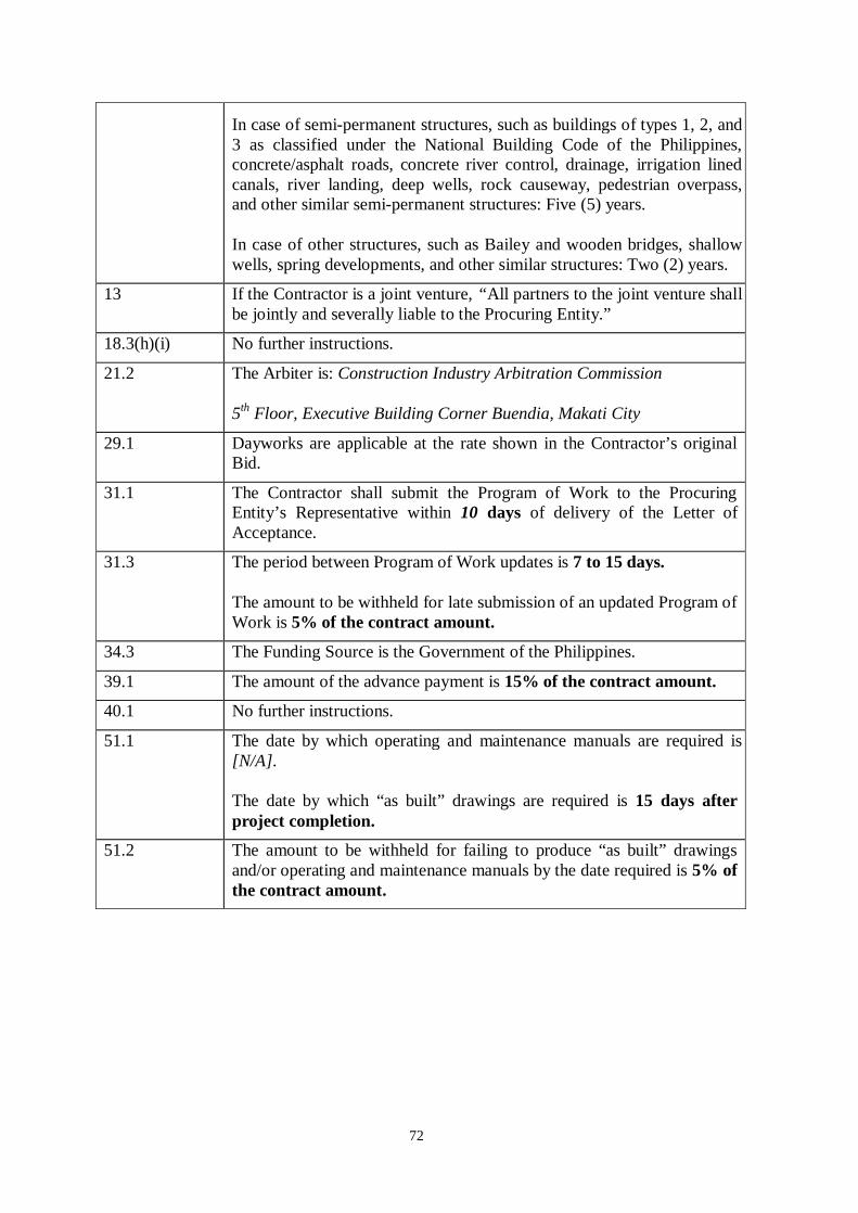
72
In case of semi-permanent structures, such as buildings of types 1, 2, and 3 as classified under the National Building Code of the Philippines, concrete/asphalt roads, concrete river control, drainage, irrigation lined canals, river landing, deep wells, rock causeway, pedestrian overpass, and other similar semi-permanent structures: Five (5) years.
In case of other structures, such as Bailey and wooden bridges, shallow wells, spring developments, and other similar structures: Two (2) years.
13 If the Contractor is a joint venture, “All partners to the joint venture shall be jointly and severally liable to the Procuring Entity.”
18.3(h)(i) No further instructions.
21.2 The Arbiter is: Construction Industry Arbitration Commission
5th Floor, Executive Building Corner Buendia, Makati City
29.1 Dayworks are applicable at the rate shown in the Contractor’s original Bid.
31.1 The Contractor shall submit the Program of Work to the Procuring Entity’s Representative within 10 days of delivery of the Letter of Acceptance.
31.3 The period between Program of Work updates is 7 to 15 days.
The amount to be withheld for late submission of an updated Program of Work is 5% of the contract amount.
34.3 The Funding Source is the Government of the Philippines.
39.1 The amount of the advance payment is 15% of the contract amount.
40.1 No further instructions.
51.1 The date by which operating and maintenance manuals are required is [N/A].
The date by which “as built” drawings are required is 15 days after project completion.
51.2 The amount to be withheld for failing to produce “as built” drawings and/or operating and maintenance manuals by the date required is 5% of the contract amount.

73
Section VI. Specifications

74
Name of Project : ILOILO CITY PCG DISTRICT STATION Construction of PCG District Station Location : Iloilo City Duration : One Hundred Eighty (180) Calendar Days (inclusive of rainy/unworkable days) Source of Fund : CY 2011
SCOPE OF WORK
The project covers the following scope of works which shall be done in accordance with the approved plans, specifications and provisions of contract, to wit;
A. CONSTRUCTION OF PCG STATION BUILDING
I. SITEWORKS. This covers the supply of labor, materials and equipment for the excavation,
backfill, embankment, soil poisoning and preparation of gravel bed for column footings, wall footings, slab on fill, septic vault, cistern tank and also the preparation of batter board. (Pls. refer to plans)
II. CONCRETE WORKS. This covers the supply of labor, materials and equipment necessary to complete the works as shown in the plans and as specified herein; Concreting of column footings, wall footings, slabs, beams, columns, stairs and
ramp, Fabrication and installation of reinforcing steel bars, Fabrication of forms and installation of scaffolding, Construction of cistern tank including application of waterproofing, Construction of catch basins, and Septic tank. (Pls. refer to plans)
III. MASONRY WORKS. This covers the supply of labor, materials and equipment necessary for the laying of 6” thick CHB for exterior and interior walls. This also covers the installation of reinforcing steel bars and plastering of the CHB walls. (Pls. refer to plans)
IV. CARPENTRY WORKS. This covers the supply of labor, materials, equipment and incidental items necessary to complete the works as shown in the plans and as specified herein; Installation of ¼” thk. Fiber cement board on 2”x2” wood joist/hanger, Installation of ¼” thk. marine plywood on 2”x2” wood joist/hanger and all other
related works needed for the completion of the project. (Pls. refer to plans)
V. ARCHITECTURAL FINISHES. This covers the supply of labor, materials and equipment necessary to complete the works as shown in the plans and as specified herein; Laying of 400mm x 400mm Granite Tiles (synthetic), Painting of interior and exterior walls (3 coats), ceiling (3 coats) & all areas subject
for such, Application of waterproofing with concrete topping, Installation of phenolic board and granite counter top,

75
Installation and fabrication of railings and ladder rung and all other related works needed for the completion of the project. (Pls. refer to plans)
VI. DOORS, WINDOWS AND ACCESSORIES. This covers the supply of labor, materials, and incidental items necessary for the installation of twenty eight (28) units of doors and thirty three (33) units of windows at specified location of the building. (Pls. refer to plans)
VII. PLUMBING, SANITARY AND DRAINAGE WORKS. This item covers the provision of labor,
materials and tools necessary to complete the installation of all plumbing fixtures including its accessories, water lines, sewer lines, and connection to the existing water supply and all other related works needed for the completion of the project. This also includes the provision of one (1) unit elevated water tank (2793 gallons capacity), one (1) unit membrane tank (133 gallons capacity) and one unit 1.0Hp booster pump. (Pls. refer to plan)
VIII. ELECTRICAL WORKS. This covers the supply of labor, materials, equipment and tools
necessary to complete the installation of lighting fixtures including all its accessories, wiring devices and boxes, wires and conduits, electrical rough-ins, telephone system and accessories, cable TV system and accessories, panel boards and circuit breakers and all other related works needed for the completion of the project. This also includes the provision of one (1) unit 3.0TR split type ACU, five (5) units 1.5HP window type ACU, five (5) units 1.0HP window type ACU and seven (7) units hand dryer with shockproof resistant plastic housing. (Pls. refer to plan)
SPL-1 TEMPORARY FACILITIES. The contractor shall supply the following provisions within seven (7) calendar days upon receipt of the Notice to Proceed (NTP);
A. STAFF HOUSE. A PMO Staff House on rental basis that includes the supply of kitchen utensils, bed and beddings and to be exclusively by DOTC-PMO in supervising the project. Payment of water and electric bill shall be the responsibility of contractor for the entire duration of the project.
B. SERVICE VEHICLE. This covers the provision of service vehicle of at least 2008 model, air-con, in good running condition and updated registration on a rental basis including driver and twelve (12) liters of fuel per day for the exclusive use of the DOTC Engineer supervising the project for the period of seventy two (72) calendar days. The said vehicle shall be subject to prior approval of the Area Manager.
C. CONSTRUCTION OF ACCESS BRIDGE
103 REMOVAL OF STRUCTURES AND OBSTRUCTIONS. This item covers the supply of labor and equipment necessary in the removal of a portion of concrete gutter on the existing pier that will be affected by the construction of the access bridge. (Pls. refer to plans)

76
104 EXCAVATION AND DISPOSAL. This item covers the supply of labor and equipment in the excavation and disposal of all earth materials prior to placement of rocks for the grouted riprap. (Pls. refer to plans)
405 CONCRETE WORKS. This item covers the supply of labor, materials and equipment necessary for the construction of concrete column footings and column posts with a minimum concrete strength of 4,500psi. All works shall be done in accordance with the approved plans and specifications. Provision of reinforcing steel bars and formworks shall be included under this item. (Pls. refer to plans)
602 GROUTED RIPRAP. This item covers the supply of labor, materials and equipment necessary to complete the construction of grouted riprap utilizing Class II Rocks. All works shall be done in accordance with the approved plans and specifications. (Pls. refer to plans)
403 METAL WORKS. This item covers the supply of labor, materials and equipment necessary for the completion of all metal works indicated in the approved plans. All works should be done in accordance with the approved plans and specifications. Provision and formation of scaffoldings shall also be included under this item. (Pls. refer to plans)
201 AGGREGATE BASE COURSE. This item covers the supply of labor, materials and equipment necessary for the laying, spreading and compaction of all aggregate base course materials. (Pls. refer to plans)
307 PORTLAND CEMENT CONCRETE PAVEMENT. This item covers the supply of labor, materials and equipment necessary in laying 0.20 m. thick concrete pavement for the entire length of the project. Design strength for concrete structure shall be 4000 psi. Supply fabrication and installation of reinforcing bars and forms are included under this item. (Pls. refer to plans)
D. CONSTRUCTION OF CHB FENCE WITH GATES
ITEM I SITEWORKS. This covers the supply of labor, materials and equipment for the excavation, backfill, and preparation of gravel bed for column footings and wall footings, preparation of batter board and all other works needed for the completion of the projects. (Pls. refer to plans)
ITEM II CONCRETE WORKS. This item covers the casting of concrete for column footings, column posts and wall footings for the construction of CHB fence. (Pls. refer to plans)
ITEM III MASONRY WORKS. This item covers the installation of 6” thick Concrete Hollow Blocks with tooled joint finish and its reinforcement as indicated in the approved plans.
ITEM IV METAL WORKS. This item covers the fabrication and installation of 2” diameter G.I. Pipe Schedule 40 with five (5) strands of barbed wire and 10mm diameter DRSB as indicated in the approved plans.

77
SPL-2 CONSTRUCTION OF SECURITY GATES. This covers the supply of labor, materials, equipment and tools necessary to complete the construction of security gates, two (2) units 2.3x4.1m. metal gate 1 and one (1) unit 2.3x1.0m. metal gate 2, and all other related works needed for the completion of the project. (Pls. refer to plan)
The contractor shall be responsible for all laboratory, material testing and survey instruments necessary in the project implementation. Expenses for the said testing shall be incorporated in the contractor’s overhead cost and shall not be considered as pay item.

78
GENERAL SPECIFICATION INTRODUCTION PROJECT DESCRIPTION The Project for the development of identified site at ______________________________. The following division of work shall be undertaken. D I V I S I O N I SITEWORKS II CONCRETE WORKS III MASONRY WORKS IV STEEL WORKS V CARPENTRY WORKS VI THERMAL AND MOISTURE PROTECTION WORKS VII DOORS, WINDOWS & GLASS AND ACCESSORIES VIII ARCHITECTURAL FINISHES IX PLUMBING, SANITARY & DRAINAGE WORKS X ELECTRICAL WORK GENERAL REQUIREMENTS SCOPE OF WORK
The work includes the furnishing of all materials, labor, plans, tools and equipment and performing all operations necessary for the complete construction of PCG District Station and other appurtenant structures and facilities, all in accordance with the plans and specifications and subject to the terms and conditions of the contract documents.
LOCATION OF THE PROJECT
The proposed projects to be located at Iloilo City indicated in the location and site plan.
SITE WORKS 1.1 SITE PREPARATION 1.1.1 GENERAL
The Work under this Section shall include complete demolition work timbering, clearing, grubbing, scalping, obliteration of roadways, clean up and disposal of all debris and other objectionable matter and grading work as directed by the Construction Officer.
1.1.2 REQUIREMENTS
Demolition in work shall consist of complete removal/demolition of the existing office and other obstruction.

79
Timbering shall consist of felling and disposal of all trees specifically indicated to be removed. No timbering shall be done until each tree to be removed has been physically marked for removal by the Construction Officer. Trees marked for removal shall be felled in such a manner as not to injure other trees, fences, wires, buildings and facilities which are to remain. All damage to remaining trees, plants or facilities resulting from such timbering shall be repaired by the Contractor at no additional cost to the Government. All resulting stumps shall be left clean and free from sharp protuberances and shall not extend more than 30 cm above ground surface.
Cleaning shall consist of the removal and disposal of all stumps, vines, bush, grass, roots, vegetation, fences, rocks, masonry and debris within the limits and rights-of-way of the project.
Disposal of non-combustible waste shall be accomplished by removal from job-site by the Construction Officer. In no case shall the Construction Officer, prior to commencement of operation, or permission from the property owner, such permission to include the site location, method of disposal and any restrictions or conditions that may form part of the agreement between the Contractor and the Owner. The Contractor shall save the Government from any claim arising or resulting from such disposal operations.
Burning shall be accomplished at site without damage to nearby trees, buildings or other facilities by flames, smoke or ash. All applicable regulations shall be complied with such burning. Permission by the Construction Officer to accomplish burning shall not be construed as to relieve the Contractor of determining and complying with such regulations. All fires shall be kept under constant and adequate attendance and fire control measures and devices shall be sufficient in quantity to control all blazes. In the event that conditions are unsuitable for burning waste, at the option of the Contractor, combustible material may be disposed by other means, provided that prior approval of the Construction Officer is obtained.
The grading work shall be done after clearing the site of stumps, roots, grass, etc. Grading work shall be general smoothening the ground surface of the site such as covering holes left by stumps, etc. and leveling sharp and steep grades.
1.2 EXCAVATING AND GRADING 1.2.1 GENERAL
Work under this section shall be subject to the requirements of applicable paragraphs of the General Conditions of Contract.
1.2.2 WORK INCLUDED
This work includes labor, materials, and equipment necessary for excavating and grading as required in the Drawings and as specified herein. This, in general, includes cleaning and removal of grass, trees, and loose stones, and excavation for foundations, footings, septic vault, and rough and finish grading.

80
1.2.3 MATERIALS
Factory fill material shall be of the materials approved by the Construction Officer, and shall be of the type that has obtained its optimum moisture contents.
Unsatisfactory fill materials are Fill Materials that are too wet or too soft, as determined by the Construction Officer, and deficient in providing a stable subgrade or foundation of structures or pavements.
Selected backfill materials shall consist of sand, stone, gravel or screened stoned, uniformly graded and free from soft or unsound particles or other objectionable materials. Sieve analysis shall conform with ASTM C136, and shall conform to the following gradation limits:
Passing 3/8 inch sieve - 100% Passing No. 4 sieve - 85-100% Passing No. 100 sieve - 0-10% Passing No. 200 sieve - 0-3% 1.2.4 WORKMANSHIP 1.2.4.1 STAKING OUT
The Contractor shall stake cut lines and corners. He shall build batter boards and shall locate first and second floor lines in relation to existing grades. Lines and levels shall be approved by the Construction Officer or his representative before excavation is started.
The Contractor shall construct two permanent benchmarks of previously known elevations near the site of construction for purpose of determining any settlement that may occur during the construction.
1.2.4.2 EXCAVATION
Excavation shall be executed in a careful manner to proper depths. No excavation shall be carried below elevations indicated on Drawings unless made necessary by existing conditions. Claims for extras will not be allowed for excavations not authorized by the Construction Officer.
Excavated materials shall be transported to and placed in fill areas within work limits. Unsatisfactory materials encountered within established subgrades as shown or 0.30m below grade shall be replaced with satisfactory materials as specified.
Surplus excavated materials not required for fill or embankment shall be disposed of in designated waste or spoil areas. Unsatisfactory excavated materials shall be disposed in designated waste or spoil areas. Excavated materials shall be performed to provide proper drainage at all times. Materials required for fill, in excess of that produced by excavation within the grading limits, shall be excavated from approved borrow areas.
Excavation shall be left clean and clear of loose material.

81
1.2.4.3 WATER AND DRAINAGE Contractor shall do everything necessary for keeping water out of excavations and away from building during construction.
1.2.4.4 BACKFILL
Backfill shall be installed against foundation walls in not more than 2” or 50mm. Backfill shall be carefully tamped. Debris shall not be used for backfilling.
1.2.4.5 GRADING
Finish grading shall include areas with limits shown on plot plan. Grades shall be reformed to easy contours in accordance with Drawings.
1.3 SOIL POISONING 1.3.1 GENERAL
Whenever the Scope of Work includes soil poisoning, the work shall include furnishing of labor, materials, and equipment to complete all poisoning works.
1.3.2 MATERIALS
Soil Poisons, Soil poisons shall be water-based emulsions. Any of the following may be used: 1. Chlordane - 1% Concentration 2. Benzene Hexachloride - 0.8% Gamma Isomer Concentration 3. Dieldrin - 0.5% Concentration 4. Aldrin - 0.5% Concentration 5. Heptachor - 0.5% Concentration 1.3.2.1 SAMPLE AND TEST
A sample of the concentrated toxicant shall be tested.
At least two samples of working solution shall be tested for every 10,000 square feet or 1,000 square meters of treated area.
Samples shall be submitted, analyzed and tested by an approved testing laboratory. Tests shall be paid for by the Contractor. The results shall be submitted to the Construction Officer.
1.3.2.2 DELIVERY, STORAGE, AND PROTECTION
Chemicals shall be delivered to the job site in factory sealed containers with the manufacturer’s brand and name clearly marked. Chemicals shall be stored, handled, and applied in accordance with the directions in the manufacturer’s label.

82
1.3.3 WORKMANSHIP 1.3.3.1 SITE INSPECTION
A general survey and through examination of the entire premises shall be undertaken in order to fully understand all existing conditions and to determine the location and existence of subterranean termite colonies.
1.3.3.2 APPLICATION
Soil poison working solution shall be applied by means of pressure spray, soil injector, or when specified by direct pouring.
Live termite mounds found within the premises shall be exterminated by destroying the mounds and/or introducing soil poison working solution into mounds.
Soil poisoning work shall not begin until all preparations for slab placement have been completed.
Soil poisons shall not be applied when soil of fill is excessively wet or immediately after heavy rains to avoid surface flow of soil poison solution from the application site.
After grading and leveling the soil in the ground, gravel bed shall be set preparatory to the pouring of concrete at every 10.76 sq.ft. (Square Meter) floor footing area shall be flooded or soaked with soil poison working solution.
Every 3.28 linear feet (linear meter) of excavation for footing retaining wall and other foundation work shall be thoroughly drenched and saturated with soil poison working solution before pouring of concrete.
The solution shall be applied to all areas immediately below expansion joints, control joints and all areas where slab will be penetrated by pipe and other construction features.
Masonry wall resting on grades shall have their voids treated with 1 gallon of soil poison working solution per 5 linear feet (1.52 linear meter) of wall. Poison shall be poured directly into below spaces.
Prior to landscaping of lawn, every linear meter of building perimeter and of three-meter width shall be saturated with soil poison working solution.
Earth fill shall be treated thoroughly. As soon as fill is compacted and leveled, every one square meter area shall be drenched with soil poison working solution.
1.3.4 GUARANTEE
Upon completion and acceptance of the work, the Owner shall be furnished with a written guarantee stating that termite control is guaranteed for a period of 10 years

83
and that regular inspections are to be done by the guarantor to ensure the quality of their work.
1.4 TOPSOILING AND SODDING 1.4.1 GENERAL
The Contractor shall furnish all labor, materials, equipment and incidentals necessary for the supply, delivery and placement of topsoil and sodding, and shall maintain all planted areas up to the termination of Contract.
All exposed areas and unpaved within the limits of the perimeter fence shall be final graded with topsoil and sodded as specified herein except where noted otherwise on the Drawings.
1.4.2 SUBMITTALS
The contractor shall submit to the Construction Officer for approval representative samples of topsoil to be used prior to any topsoil haulage. Topsoil delivered to the site that is in the opinion of the Construction Officer as inferior to the approved submitted samples shall be removed and disposed of offsite at no cost to the Owner.
The Construction Officer may request submittal of sod samples for approval or may elect to inspect the place of sod procurement.
1.4.3 MATERIALS 1.4.3.1 TOP SOIL
Topsoil shall be natural fertile soil containing a large amount of humus or organic matter, add shall be representative of soils in the locally capable of supporting a luxuriant plant growth.
The topsoil shall be reasonably free from clay, brush, weeds, roots, general debris, stones and any objects larger than 25mm in diameter.
1.4.3.2 WEED ERADICATOR AND SOIL FUMIGANT
Weed eradicator and soil fumigant shall be sodium methyl ditch carbonate for eradication of weeds, geminating weed seeds, fungi, insects and soil pests. Strength or dosage application shall be as recommended by the manufacturer. Soluble fertilizer shall be standard.
1.4.3.3 SOLUBLE FERTILIZER
Soluble fertilizer shall be standard commercial complete fertilizer containing nitrogen, phosphorus, and potash in 10-10-10 to 10-12-10 percent by weight minimum ratio, respectively, and shall be readily soluble in water.
1.4.3.4 UREA FERTILIZER
Urea fertilizer shall be standard Fertilizer commercial type, and shall conform to the following specification:

84
Total nitrogen ----------------- 38 percent minimum Insoluble nitrogen ------------- 27-28 percent A.I. value ----------------------- 47-55 percent Urea nitrogen ------------------ 5 percent maximum Particle size -------------------- All material shall pass 10-mesh sieve Less than 1 percent may be retained. 1.4.3.5 GRASS SOD
Sod shall consist of a heavy thickly matted growth of living grass that is relatively dormant during the dry season, but capable of renewed growth thereafter. Sod shall be free of weeds or undesirable plants, large stones, or other objects larger than 25mm in diameter. When the sod is procured grass height shall not exceed 120mm. And there shall be sufficient soil adhering to the roots to support grass growth.
1.4.4 EXECUTION 1.4.4.1 SURFACE
After areas to be topsoil have been Preparation cleared, grubbed and/or brought to grades shown on the Drawings, but prior to dumping and spreading of the topsoil, the entire area shall be inspected and approved by the Construction Officer. All areas found excessively compacted. Irrespective of the cause shall be loosened to a depth of at least 150mm to permit bonding with the topsoil.
1.4.4.2 TOPSOIL SPREADING 1.4.4.2.1 Placing
Topsoil shall not be placed when the surged is excessively wet, extremely dry, or where the areas have not been finally graded. The topsoil shall be dumped in piles uniformly spaced and shall be spread evenly over the entire area to provide a minimum depth of 150mm. Low spots, pockets or ridges in the surface that will cause the accumulation or pounding of water shall be filled and regraded to a uniform slope as indicated on the Drawings.
1.4.4.2.2 Cleanup
After the topsoil has been spread and graded as required the surface shall be raked clear of all large stones, roots and other loose material which shall be gathered and disposed of offsite. Topsoil and other extraneous material spilled on paved areas shall be promptly swept up and removed.
1.4.4.2.3 Compaction
Topsoil shall be compacted with alight roller to a depth of about 100mm. Any erosion, irregularity of grade, or damage to the surface

85
of the topsoil shall be repaired to the satisfaction of the Construction Officer prior to any sodding work.
1.4.4.2.4 Weed Eradication and Soil Fumigation
Topsoil shall be maintained in a moistened condition by fine spraying without pudding or erosion to the desired depth for a period of five (5) to seven (7) days. This is to stimulate the germination of weed seeds. Weed eradicator and soil fumigant shall then be applied at the rate of one (1) liter to 55-110 liters of water for every 10 square meters.
1.4.4.2.5 Pre-Fertilization
Not less than 15 days after the applicant of the weed eradicator and soil fumigant, soluble fertilizer shall be uniformly spread at a rate of 2 kilograms of 10-10-10 fertilizer per 100 square meters of topsoil. After spreading, the pre-fertilizer shall be kept well moistened without puddles or erosion until the fertilizer has been dissolved. Pre-fertilization shall be applied to all areas prepared for sodding.
1.4.4.3 SODDING
Sod shall be cut into squares or into rectangular sections. Rectangular sections may vary in length but shall be of equal width and of a size that will permit lifting and rolling without breaking. Care shall be exercised to retain native soil on the roots during the process of stripping, transporting and planting. Dumping from vehicles will not be permitted. During delivery and while in stacks, sod shall be kept moist. Sod damaged by handling or by other causes will be rejected.
The surface of the area to be sodded shall be loosened and brought to a reasonably fine texture to a depth of approximately 20mm. The bed upon which the sod is to be placed shall be moistened to the loosened depth, if not naturally, sufficiently moist, and the sod shall be placed thereon within 24 hours after having been out.
Sod shall be laid smoothly, edge to edge with staggered joints. Sod shall be pressed firmly into contact with the bed so as to eliminate all air pockets, provide a true and even surface and ensure knitting without displacement of the sod or determination of the surfaces of sodded areas.
Unless otherwise required the sod on slopes shall be laid horizontally beginning at the bottom of the slopes and working upwards when placing sod occur checks or similar constructions, the length of the strips shall be laid at right angles to the direction of flow of the water. On all slopes steeper than one vertical to three horizontal the sod shall be pegged with stakes, 200-300mm in length, spaced as required by the nature of the soil and the steepness of slope. Stakes shall be driven flush with the bottom of grass blades.
After the sodding operation has been completed, the areas shall be rolled lightly to obtain an even surface free from depressions and high points.
86
Edges shall be trimmed and true to line and grade indicated on the Drawings.
After placing and rolling, the sodded areas shall be soaked with water to a depth at about 50mm and thereafter shall be watered as required to establish and maintain plant growth.
Any area that becomes guilded or otherwise damaged shall be repaired to the satisfaction of the Construction Officer.
Thirty days after sodding, urea fertilizer shall be applied uniformly at a rate of 5 kilograms of fertilizer per 100 square meters of area. After application, the area shall be kept well moistened.
1.4.4.5 MAINTENANCE
The Contractor shall maintain the sodded area as required and as directed by the Construction Officer up to the date of completion of the Contract. Maintenance shall include watering, fertilizing, weeding, cutting, repairing and replacement.
The Contractor is expected to turn over the site with a heavy, uniform, grass cover free of weeds of any other objectionable plant growth.
Any area that becomes guilded or otherwise damaged shall be repaired to the satisfaction of the Construction Officer. Areas where sodding does not provide a satisfactory growth shall be replaced with new topsoil and sodding as required.
The sodded areas shall be routinely watered as required.
Sodded areas shall be protected against vehicular/pedestrian traffic or other construction activity by means of barricades shall remain in place until final acceptance.
1.5 CONCRETE CULVERT PIPE 1.5.1 GENERAL
Whenever Concrete Culvert Pipes are indicated in the Plans, this work shall consist of furnishing reinforced and non-reinforced concrete culvert pipes of the sizes and dimensions indicated on the drawings, conforming to the specifications and the directions of the Construction Officer.
1.5.2 MATERIALS
The fabrication of the pipes shall conform to the specification of ASHO Designation M 170. The Construction Officer reserves the right to inspect and test the pipes delivered for use in the work. Defects that are discovered after acceptance of delivery of the pipes but before installation of the pipe shall be cause for rejection without additional cost to the Government. Mortar for pipe joints shall be composed
87
of one (1) part Portland cement and two (2) parts sand, and shall conform to the requirements of item RC 100: Plain and Reinforced Concrete.
1.5.3 WORKMANSHIP
Trenching for concrete culvert pipes shall conform to, and shall be payable under, item EX 100: Excavation. The pipe trench shall be excavated to the depth, grade and width established by the Construction Officer. In material considered satisfactory by the Construction Officer, the pipes may be laid directly on the trench bed shaped to the form of the pipes for at least 10 per centum of their outside diameters. In rock or hardpan and other material considered unsatisfactory by the Construction Officer, the trench bed shall be excavated 30 centimeters deeper and the required selected or granular material shall be laid to bed the pipes. In preparing the pipe bed, recesses for pipe bells shall be provided. Pockets of unsuitable material shall be removed and replaced with approved selected or granular material.
Pipes shall be carefully laid, with hubs up-graded, ends fully and closely joint, true to the lines and grades required. After one length of pipe is laid, the lower portion of the hub shall be primed with mortar on the inside sufficient enough to bring the inner surfaces of the next pipe flushed and even those of the previous one. The remainder of the joint on the inside shall then be filled with mortar and then struck off to a smooth finish. The outside of the joint shall also be filled with mortar, and excess mortar shall be used to form a bead all around the outside of the joint. After the initial set of the outside mortar, it shall be protected from air and sun by thoroughly wetted burlap or earth.
The pipes shall be tested for undue settlement and for watertightness of joints, before backfilling the trench. Unsatisfactorily work shall be corrected without additional cost to the Government. Backfilling shall conform to, and shall be payable under, item BF 100: Filling and Backfilling. The mortar joints shall have set sufficiently prior to backfilling. Backfilling shall be brought up, in uniform 15-centimeter layer on both side and over the line of pipes, to the finished grade. Compaction shall be accompanied by sprinkling with water to obtain at least 95% relative compaction.
1.5.4 METHODS OF MEASUREMENT AND BASIS OF PAYMENT
For purposes of progress payments, concrete pipes installed complete in place in accordance with drawings, these specifications, or as directed by the Engineer shall be paid for the total length in linear meters according to size and kind, measured along the axis of the pipes.
The quantities measured as provided above and accepted for payment shall be paid for the purposes of progress payments only at the unit price per linear meter of the kind and size of concrete pipes, in which price and payments shall constitute full compensation for furnishing or manufacturing of the pipes, for hauling and installing, for bedding and jointing, and for all other headwalls and other structures are excluded from the payment prescribed herein. Final payment shall not exceed the total amount for this work item shown in the Proposal Schedule.

88
When the Proposal Schedule does not provide separate payment for work herein specified, full compensation therefore shall be considered as included in the lump sum contract price for Exterior Drainage System within the purview of items PS 100.
1.6 ROADWAYS AND PAVING 1.6.1 GENERAL
Whenever Roadways and Paving are called for in the Plans, the Contractor shall furnish all labor, materials, equipment and incidentals for the construction of new pavement, sidewalks, gutters and curbs, and for the restoration of existing pavement, sidewalks, gutters and curbs, as shown on the Drawings and as specified herein. The Construction Officer may direct the Contractor to excavate and repave additional areas to those indicated.
1.6.2 STANDARD SPECIFICATION REFERENCE
Except as otherwise specified herein, materials and construction shall be in accordance with the “Republic of the Philippines, Department of Public Highways, General Specifications for Roads and Bridges, 1976.”
ASTM D1559 Resistance to Plastic Flow of Bituminous Mixture Using Marshall Apparatus. 1.6.3 MATERIALS
Granular subbase and base course materials shall be as specified under Items 300, 301, and 302 of the General Specifications. Grading requirements shall be as follows:
Sub-base Standard Sieve Size Percent Passing 75.00 mm 100 37.50 mm 80 - 100 9.50 mm 45 - 100 4.75 mm 30 - 85 2.00 mm 15 - 65 0.425 mm 5 - 35 0.075 mm 0 - 15 Base Standard Sieve Size Percent Passing 25.00 mm 100 19.00 mm 75 - 100 7.75 mm 40 - 60 2.00 mm 25 - 45 0.425 mm 12 - 25 0.075 mm 5 - 12 Concrete shall meet the requirements for structural concrete.
For asphalt concrete, under Item 401 of General Specifications, aggregate grading shall be Class B. Test specimens of the job-mix formula shall be prepared and tested

89
in accordance with the design procedures given for the Marshall Method of Mix design, and shall meet the requirements given below when tested in accordance with ASTM D1559. Marshall Stability N 3300 min Flow, 0.25 mm 8 - 46
Percent voids in total mix 3 - 5 Use 75-blows/end compaction
The job-mix formula shall be submitted for the Construction Officer’s approval that may change the aggregate grading and bitumen content to improve the quality of the mix.
For Gravel surfacing material, under Item0 407 of General Specifications 1 grading requirements shall be as follows:
Standard Sieve Size Percent Passing 25.00 mm 100 19.00 mm 85 - 100 9.50 mm 60 - 100 4.75 mm 50 - 85 2.00 mm 40 - 70 0.425 mm 25 - 45 0.075 mm 10 - 25 1.6.4 WORKMANSHIP 1.6.4.1 SUBGRADE
Following clearing, grubbing and preparation stripping of topsoil the subgrade shall be prepared by sprinkling and rolling with a steel roller until the subgrade is completed to 90 percent of optimum. Subgrade in cut areas shall be scarified to a depth of 0.15 m and recompacted at a moisture content slightly above the optimum. Areas that require common fill to raise to sub-grade elevations shown on the Drawings shall be filled except that no lift shall be thicker than 150 mm. Where existing sub-grade materials have been disturbed, or are in the opinion of the Construction Officer unsuitable for subgrade, the materials shall be removed as directed and shall be replaced with common fill and shall be compacted. No subbase material for new restored pavement shall be placed until the Construction Officer has inspected and approved the subgrade.
1.6.4.2 SUBBASE AND BASE COURSE MATERIALS
Aggregate Base Course shall be placed and compacted as shown on the Drawings, and as required in - Aggregate Base Course. The finish base course shall not vary more than 1.5 centimeters above or below the set grade at any point. Any area that does not conform to the grading requirements shall be reworked and recompacted.

90
1.6.4.3 PORTLAND CEMENT CONCRETE PAVEMENT See - Portland Cement Concrete Pavement.
1.6.4.4 SIDEWALKS
All sidewalks disturbed during the course of the work shall be restored to their original condition. New sidewalks shall be 21 Map concrete.
New concrete pavement shall be in accordance with - Concrete of the General Specifications.
Concrete pavement to be removed shall be up to vent lines cut by an abrasion saw. Where existing reinforcing steel is removed it shall be replaced with equivalent steel bars.
Concrete curbs and gutters shall be constructed as indicated on plans. All exposed concrete edges shall be finished with an edging tool having a 1-cm radius.
1.7 CONCRETE CURB AND GUTTER 1.7.1 GENERAL
Whenever indicated in the plans, this work shall consist of concrete curb or combined curb and gutter, constructed at the locations and to the dimensions, shape shown on the drawings and specified herein or as directed by the Construction Officer.
1.7.2 MATERIAL
Concrete shall be of the class of strength shown on the drawings and shall conform to the requirements of Plain and Reinforced Concrete. Pre-molded filler for expansion joints shall conform to the specifications of AASHO M-33 and poured filler for intermediate construction joints shall be of mixed asphalt and mineral filler or mixed asphalt and rubber filler conforming to the specifications of AASHO M-89, with asphalt having a penetration (77oF, 100gr., 5 specs.) within the range of 30 to 50 and a softening point of not less than the range of 30 to 50 and a softening point of not less than 90oC (200oF). Steel reinforcement, if any, shall conform to the specifications of ASTM Designation: A615, Grade 40.
1.7.3 WORKMANSHIP
Formwork for concrete placing shall be constructed upon the prepared base previously completed in accordance with the requirements of Aggregate Base Course. Forms shall be smooth on the side placed next to the concrete and shall have a true smooth upper edge. The depth of forms for back of curbs shall be equal to the full depth of the curb, and the depths of the face of the forms for curbs shall be equal to the full-face height of the curb. Forms shall be rigid enough to withstand the pressure of fresh concrete without distortion, and shall be thoroughly cleaned and coated with form oil to prevent adherence of concrete. Setting of forms shall
91
conform to the required dimensions and to the alignment and grade shown on the drawings. Stakes shall be positioned to hold the form rigidly in place and clamps, spreaders, and braces shall be additionally placed where necessary to enhance rigidly in the forms. Benders or thin plank forms cleaned together may be used on curves, grade changes, or for curb returns. In constructing curbs, entrances shall be provided for driveways, with dimensions shown on the drawings or designated by the Construction Officer. Dowels and reinforcements shall be of the size, shape and spacing shown on the drawings.
The curb and gutter shall be constructed in uniform segments not more than 5 meters in length, except where shorter segments are required to coincide with the location of weakened plane or contraction joints in the adjacent concrete pavement, or for closure, but no segment shall be less than 2 meters long. The poured joint shall be formed by sheet templates that will give the required joint thickness and that are cut to the cross-section of the curb or the combined curb or gutter. The templates are set carefully normal to the line of curb and to plane of gutter and held firmly in place until the concrete has set sufficiently to hold its shape. They are removed shortly after the curb face form is removed, but before all the other forms are removed. Expansion joints shall be formed with pre-molded joint maternal, likewise placed normal to line or curb and to plane of gutter, cut and shaped to the cross-section of the curb and gutter, and positioned at locations shown on the drawings.
Concrete shall be placed and consolidated in the forms without segregation. Prior to the removal of the forms, the surface of concrete shall be shaped true to grace by means of a straight edge float preferably 3 meters long, operated longitudinally over the surface of the concrete. For clamps and braces shall have been so positioned as not to interfere with the operation of this float. Immediately after the removal of the front curb forms, the face of the curb shall be floated and trowelled smooth. No plastering will be permitted and the finishing shall be accomplished by simply floating the green concrete, accompanied by careful wetting. Minor defects shall be repaired with mortar containing one part Portland cement and two parts of fine aggregate. Corners and edges shall be rounded to the radii shown on the drawings. Surface irregularities in excess of 6 millimeters in 3 meters shall be considered as cause for rejection of segment, which shall be removed and replaced without additional cost to the government.
Removal of the rest of the forms may be done after 24 hours that the concrete is placed, but proper protection shall be made by the Contractor to prevent injury or damage to the finished concrete. After finishing and sufficient hardening to the concrete curb or the combined concrete curb and gutter, curing shall be immediately done by any method specified under Plain and Reinforced Concrete. Backfilling next to the curb shall be performed and paid for under the provisions of Filling and Backfilling.
1.7.4 METHOD OF MEASUREMENT AND BASIS OF PAYMENT
For purposes of progress payments, the quantity to be paid for shall be the total length in linear meters of concrete curb and gutter, completed and measured in place. Measurement shall be made along the face of the curb, whether the portion

92
being measured is straight or curved. No deductions shall be made for flattening of curbs at entrances.
The quantity of curb or combined curb and gutter as measured above shall be paid for purposes of progress payments only at the unit price bid per linear meter, in which price and payment shall constitute full compensation for all materials, labor, plant, equipment, tools and incidentals necessary to complete the work. Inclusive of form work, concrete placing, finishing, shaping, curing, joining, etc. Final payment shall not exceed the total amount for this work item as shown in the Proposal Schedule.
CONCRETE WORKS 2.1 CONCRETE 2.1.1 GENERAL
The Contractor shall furnish all labor, materials, equipment and incidentals necessary for the construction of all concrete work including reinforcing steel, forms, water stops and miscellaneous related items such as wall sleeves, anchor bolts and embedded items specified under other sections.
2.1.2 STANDARD SPECIFICATION REFERENCE
The following Standards are referred to:
ASTM C31 Making and Curing Concrete Test Specimens in the Field ASTM C33 Concrete Aggregates ASTM C39 Compressive Strength of Cylindrical Concrete Specimens ASTM C42 Obtaining and Testing Drilled Cores and Sawed Beams of Concrete ASTM C94 Ready-Mixed Concrete ASTM C143 Slump of Portland Cement Concrete ASTM C150 Portland Cement ASTM C231 Air Content of Freshly Mixed Concrete by the Pressure Method ASTM C260 Air-Entraining Admixtures for Concrete ASTM C494 Chemical Admixtures for Concrete ACI 301 Specifications for Structural Concrete for Buildings ACI 347 Recommended Practice for Concrete Form Work
2.1.3 GENERAL PROVISION
Concrete shall be site mixed or transit-mixed as produced by a plant acceptable to the Construction Officer.
When a small mixer is used, concrete placed under such conditions shall be mixed for not less than 1½ minutes after all the materials are in the mixer drum.
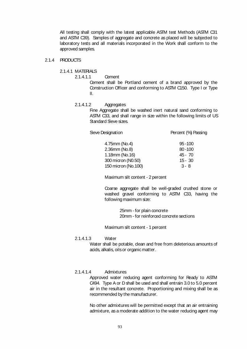
93
All testing shall comply with the latest applicable ASTM test Methods (ASTM C31 and ASTM C39). Samples of aggregate and concrete as placed will be subjected to laboratory tests and all materials incorporated in the Work shall conform to the approved samples.
2.1.4 PRODUCTS 2.1.4.1 MATERIALS 2.1.4.1.1 Cement
Cement shall be Portland cement of a brand approved by the Construction Officer and conforming to ASTM C150. Type I or Type II.
2.1.4.1.2 Aggregates
Fine Aggregate shall be washed inert natural sand conforming to ASTM C33, and shall range in size within the following limits of US Standard Sieve sizes.
Sieve Designation Percent (%) Passing 4.75mm (No.4) 95 -100 2.36mm (No.8) 80 -100 1.18mm (No.16) 45 - 70 300 micron (N0.50) 15 - 30 150 micron (No.100) 3 - 8
Maximum silt content - 2 percent Coarse aggregate shall be well-graded crushed stone or washed gravel conforming to ASTM C33, having the following maximum size: 25mm - for plain concrete 20mm - for reinforced concrete sections Maximum silt content - 1 percent
2.1.4.1.3 Water
Water shall be potable, clean and free from deleterious amounts of acids, alkalis, oils or organic matter.
2.1.4.1.4 Admixtures
Approved water reducing agent conforming for Ready to ASTM C494. Type A or D shall be used and shall entrain 3.0 to 5.0 percent air in the resultant concrete. Proportioning and mixing shall be as recommended by the manufacturer.
No other admixtures will be permitted except that an air entraining admixture, as a moderate addition to the water reducing agent may

94
be employed if the water reducing agent does not give 3.0 to 5.0 percent air, but only with prior approval of the Construction Officer. Such air-entraining admixture shall comply with ASTM C260 and shall be compatible with the water reducing agent and have no chemical reaction between them in one solution.
The total entrained air measured at the discharge from the truck shall be a maximum 3.0 percent for finished slabs and 3.5 to 5.0 percent for all other concrete. Air shall be measured in accordance with the Pressure Method. ASTM C231.
If pumping concrete is approved by the Construction Officer then additional admixtures maybe submitted for the approval.
2.1.4.1.5 Grout
Where a non-shrink or expanding type grout be called for in the Drawings or specified herein an “expandable” compound, as approved by the Construction Officer, will be added to the cement grout mixture.
2.1.4.2 QUALITY OF CONCRETE
The actual development of mix proportions composed of Portland cement, admixtures, aggregates and water to produce concrete which conforms to the specific requirements shall be determined by means of prior laboratory tests performed by the Contractor with the approved constituents to be used in the Work.
2.1.4.2.1 Proportioning
Well advance of placing any concrete, the Contractor shall discuss with the Construction Officer the source of materials and concrete mixture he proposes to use. Representative samples of aggregate and cement and their test results shall be furnished to the Construction Officer.
The Contractor shall allow ample time to develop a proposed design mix or to modify the proposed design mix within the limits of these Specifications whenever, in the opinion of the Construction Officer, it becomes necessary or desirable.
The following minimum compressive strengths, water cement ratios and cement factors as indicated in Table A shall apply for regular and pumped concrete.
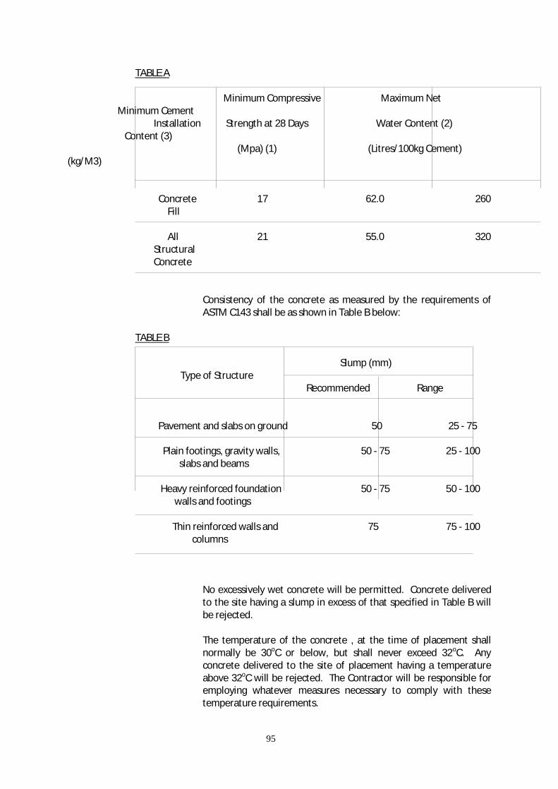
95
TABLE A Minimum Compressive Maximum Net Minimum Cement Installation Strength at 28 Days Water Content (2) Content (3) (Mpa) (1) (Litres/100kg Cement) (kg/M3)
Concrete 17 62.0 260 Fill All 21 55.0 320 Structural Concrete
Consistency of the concrete as measured by the requirements of ASTM C143 shall be as shown in Table B below:
TABLE B
Slump (mm) Type of Structure Recommended Range
Pavement and slabs on ground 50 25 - 75 Plain footings, gravity walls, 50 - 75 25 - 100 slabs and beams Heavy reinforced foundation 50 - 75 50 - 100 walls and footings Thin reinforced walls and 75 75 - 100 columns
No excessively wet concrete will be permitted. Concrete delivered to the site having a slump in excess of that specified in Table B will be rejected.
The temperature of the concrete , at the time of placement shall normally be 30oC or below, but shall never exceed 32oC. Any concrete delivered to the site of placement having a temperature above 32oC will be rejected. The Contractor will be responsible for employing whatever measures necessary to comply with these temperature requirements.

96
2.1.4.3 FORM WORK
The contractor shall design, furnish and install all form works and supports required to confine the concrete and shape it to the lines shown in the Drawings. Forms will be required for any concrete surface that slopes more than 15o from the horizontal. Form design shall conform to ACI 347. Forms shall have sufficient strength to withstand the pressure resulting from placement and vibration of the concrete and shall be sufficiently tight to prevent loss of mortar from the concrete.
Forms shall be made of either steel or new approved lumber and shall be free from roughness and imperfections.
Steel forms, if used shall be steel plate not less than 4mm thick. All bolt and rivet heads shall be countersunk. Clamps, pins or other connecting devices shall be designed to hold the forms rigidly together and to allow removal without injury to the concrete. The joints between the metal sheets shall be smooth and as nearly perfect as practicable. Use of forms with dents, buckled areas or other surface irregularities, or the burning of holes for form ties will not be permitted.
Form ties encased in concrete, other than those specified in the following paragraph, shall be designed such that after removal of the projecting part, no metal shall be within 25mm of the face of the concrete. That part of the tie to be removed shall be at least 12.5mm in diameter, or shall be provided with a wood or metal cone with at least 12.5mm in diameter and 25mm long. Form ties in concrete exposed to view shall be the cone-washer type. Through bolts or common wire shall not be used for from ties.
Form ties exposed exterior walls shall be as specified in the preceding paragraph except that the cones shall be of approved wood of plastic.
The Contractor shall assume full responsibility for the adequate design of all forms. However, any forms which in the opinion of the Construction Officer are unsafe or inadequate in any respect may at anytime be condemned by the Construction Officer, additional forms are necessary to maintain the progress schedule, such additional forms shall be provided by the Contractor at his own expense.
An approved colorless mineral fill conforming to ASTM D1500, free of kerosene and with a viscosity of not less than 250 seconds at 100 Fahrenheit and a flash point not less than 300oF.
2.1.5 EXECUTION
2.1.5.1 MIXING OF CONCRETE
Mixing of ready-mixed or transit-mixed concrete shall conform to ASTM C94, and the requirements herein, and as approved by the Construction Officer.
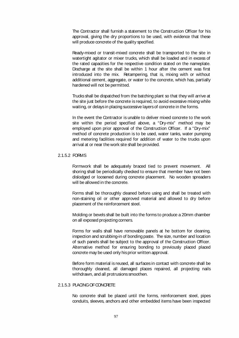
97
The Contractor shall furnish a statement to the Construction Officer for his approval, giving the dry proportions to be used, with evidence that these will produce concrete of the quality specified.
Ready-mixed or transit-mixed concrete shall be transported to the site in watertight agitator or mixer trucks, which shall be loaded and in excess of the rated capacities for the respective condition stated on the nameplate. Discharge at the site shall be within 1 hour after the cement was first introduced into the mix. Retampering, that is, mixing with or without additional cement, aggregate, or water to the concrete, which has, partially hardened will not be permitted.
Trucks shall be dispatched from the batching plant so that they will arrive at the site just before the concrete is required, to avoid excessive mixing while waiting, or delays in placing successive layers of concrete in the forms.
In the event the Contractor is unable to deliver mixed concrete to the work site within the period specified above, a “Dry-mix” method may be employed upon prior approval of the Construction Officer. If a “Dry-mix” method of concrete production is to be used, water tanks, water pumping and metering facilities required for addition of water to the trucks upon arrival at or near the work site shall be provided.
2.1.5.2 FORMS
Formwork shall be adequately braced tied to prevent movement. All shoring shall be periodically checked to ensure that member have not been dislodged or loosened during concrete placement. No wooden spreaders will be allowed in the concrete.
Forms shall be thoroughly cleaned before using and shall be treated with non-staining oil or other approved material and allowed to dry before placement of the reinforcement steel.
Molding or bevels shall be built into the forms to produce a 20mm chamber on all exposed projecting corners.
Forms for walls shall have removable panels at he bottom for cleaning, inspection and scrubbing-in of bonding paste. The size, number and location of such panels shall be subject to the approval of the Construction Officer. Alternative method for ensuring bonding to previously placed placed concrete may be used only his prior written approval.
Before form material is reused, all surfaces in contact with concrete shall be thoroughly cleaned, all damaged places repaired, all projecting nails withdrawn, and all protrusions smoothen.
2.1.5.3 PLACING OF CONCRETE
No concrete shall be placed until the forms, reinforcement steel, pipes conduits, sleeves, anchors and other embedded items have been inspected
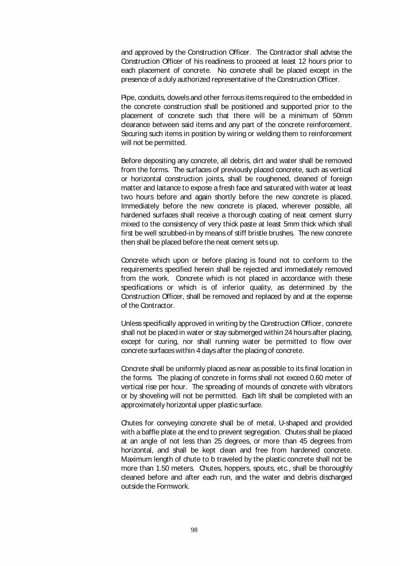
98
and approved by the Construction Officer. The Contractor shall advise the Construction Officer of his readiness to proceed at least 12 hours prior to each placement of concrete. No concrete shall be placed except in the presence of a duly authorized representative of the Construction Officer.
Pipe, conduits, dowels and other ferrous items required to the embedded in the concrete construction shall be positioned and supported prior to the placement of concrete such that there will be a minimum of 50mm clearance between said items and any part of the concrete reinforcement. Securing such items in position by wiring or welding them to reinforcement will not be permitted.
Before depositing any concrete, all debris, dirt and water shall be removed from the forms. The surfaces of previously placed concrete, such as vertical or horizontal construction joints, shall be roughened, cleaned of foreign matter and laitance to expose a fresh face and saturated with water at least two hours before and again shortly before the new concrete is placed. Immediately before the new concrete is placed, wherever possible, all hardened surfaces shall receive a thorough coating of neat cement slurry mixed to the consistency of very thick paste at least 5mm thick which shall first be well scrubbed-in by means of stiff bristle brushes. The new concrete then shall be placed before the neat cement sets up.
Concrete which upon or before placing is found not to conform to the requirements specified herein shall be rejected and immediately removed from the work. Concrete which is not placed in accordance with these specifications or which is of inferior quality, as determined by the Construction Officer, shall be removed and replaced by and at the expense of the Contractor.
Unless specifically approved in writing by the Construction Officer, concrete shall not be placed in water or stay submerged within 24 hours after placing, except for curing, nor shall running water be permitted to flow over concrete surfaces within 4 days after the placing of concrete.
Concrete shall be uniformly placed as near as possible to its final location in the forms. The placing of concrete in forms shall not exceed 0.60 meter of vertical rise per hour. The spreading of mounds of concrete with vibrators or by shoveling will not be permitted. Each lift shall be completed with an approximately horizontal upper plastic surface.
Chutes for conveying concrete shall be of metal, U-shaped and provided with a baffle plate at the end to prevent segregation. Chutes shall be placed at an angle of not less than 25 degrees, or more than 45 degrees from horizontal, and shall be kept clean and free from hardened concrete. Maximum length of chute to b traveled by the plastic concrete shall not be more than 1.50 meters. Chutes, hoppers, spouts, etc., shall be thoroughly cleaned before and after each run, and the water and debris discharged outside the Formwork.

99
Pumping of concrete will be permitted only with the approval of the Construction Officer, and under the following conditions:
a. The Construction Officer will inspect the pumping equipment and hose prior to placement of concrete. Any equipment, hose, or appurtenances not functioning properly, or which are otherwise unacceptable to the Construction Officer shall be replaced before pumping operations are started.
b. A fully operable standby complete concrete pumping unit shall be available at the site during any pumping of concrete.
c. The minimum diameter of hose or conduit shall be 100mm.
d. Aluminum conduits for conveying of concrete will not be permitted.
In the walls or columns of considerable height, the concrete shall be placed in such a manner as to prevent segregation and accumulation of hardened concrete on the forms or the reinforcement steel located above the concrete mass. In no case shall the free fall of concrete be permitted to exceed 1.50 meters below the ends of hoppers, chutes, ducts, tremies, hoses or “windows” in wall forms, without special approval of the Construction Officer.00
Where water stop type construction joints are provided, special care shall be taken to ensure that the concrete is properly worked by rotting and vibration around the water stops to produce watertight joints, particularly in the case of horizontal water stops in slabs where the concrete must be in complete contact with the underside surfaces before any concrete is poured on the upper surfaces of the water stop.
Water stops shall be accurately positioned and securely held in place, and shall be protected at all times to prevent damage or displacement. Any damage to, or displacement of water stops shall be corrected by the Contractor to the satisfaction of the Construction Officer.
2.1.5.4 TAMPING AND VIBRATING
During and immediately after depositing the concrete, compaction shall be carried out by experienced operators using high-speed internal mechanical vibrators. Care shall be taken to ensure that vibration is continued long enough to produce optimum consolidation but without permitting segregation of the aggregates or migration of air.
At least one vibrator shall be used for every 8 cubic meters of concrete placed per hour and, in addition, two spare vibrators in operating condition shall be available on the site.
Vibrators including suitable tamping bars or forked tools shall be supplemented by proper wooden spade pudding adjacent to forms and

100
rodding around embedded fixtures to remove trapped air bubbles, and to prevent honeycombing.
2.1.5.5 CURING AND PROTECTION
It is the intent of these Specifications and to obtain properly cured concrete. The Protection basic requirement of proper curing is to maintain continuous moist surface from the time of placing the concrete until the end of curing period. All details of the Contractor’s curing procedures and materials used shall be subject to the C9onstruction Officer’s approval. The use of curing compounds may be acceptable but shall require prior approval in writing by the Construction Officer.
The Contractor shall protect all concrete work against injury from the elements and defacements of by nature during construction operations.
All exposed surfaces including finished surfaces shall be treated immediately after concrete has been poured, to provide continuous moist curing for at least 7 days. Walls and vertical surfaces may be covered with continuously saturated burlap or kept moist by other approved means. Horizontal surfaces, slabs, etc., shall be pounded to a depth of 15mm or kept continuously wet by means of sprinklers or other approved methods.
Formed surfaces shall be thoroughly soaked with water at least twice each day until the forms are removed.
Where finishing of concrete surfaces is performed before the end curing period, the concrete shall under no circumstances be permitted to dry out and shall be kept continuously damp by means of a fog spray of water from the time the concrete has been placed until the end of the curing period.
2.1.5.6 REMOVAL OF FORMS
The Contractor shall not remove any forms for at least 48 hours or until the concrete has attained a strength of at least 30 percent of the ultimate strength. This is equivalent to approximately 50 day-degrees of moist-curing. Day-degree represents the total number of day’s times the average daily air temperature in oC at the surface of the concrete, e.g. 2 days at an average temperature of 25oC equals 50 day-degrees. Forms for beams and slabs shall not be stripped for at least 150 day-degrees and supports shall not be removed until the concrete has attained at least 60 percent to the specified 28-day strength and is capable of safely supporting its own weight. Construction live loads shall not be placed upon it until the concrete has attained its specified 28-day strength.
Forms shall be stripped such that they will not damage the concrete. Notwithstanding the specified minimum stripping times mentioned above the Contractor is ultimately responsible for the safely of all structures.

101
2.1.5.7 REPAIR OF DEFECTIVE CONCRETE
Defective or honeycombed areas, as determined by the Construction Officer, shall be chipped down to at least 25mm deep into sound concrete by means of chisels or chipping hammers. If honeycombs around reinforcement steel, a clear space at least 10mm wide shall be chipped all around the steel.
For areas than 40mm deep, the patch may be made for filling form tie holes, etc.
Thicker repairs will required build-up in successive 40mm deep mayers on successive days, and each layer shall be applied with neat cement paste as described in paragraph 2 above.
For very deep patches the Construction Officer may order the use of a non-shrink grout, with or without the addition of pea gravel. The materials shall be composed of 1 to 1½ cement/sand mortar without non-shrink grout components to prevent rust staining of the surface. After hardening, the patch shall be rubbed as for filling form-tie voids.
All exposed concrete surfaces and adjoining work stained by spilling or leakage of concrete shall be cleaned to the satisfaction of the Construction Officer.
All cracks that appear in the concrete prior to acceptance of the work shall be “veed” and filled with sealant.
2.1.5.8 EVALUATION AND ACCEPTANCE
After the removal of the forms any concrete, judged by the Construction Officer as defective and beyond repair, shall be rejected, demolished and replaced with new concrete in a manner acceptable to the CO. The evaluation and acceptance of concrete shall be in accordance with Chapter 17 of ACI Standard 301.
2.1.5.9 INSPECTION
Installation of reinforcing steel, pipes, sleeves, anchors and other embedded items, batching, mixing, transportation, placing, curing and finishing of concrete shall at all times be subject to the inspection of the Construction Officer.
No concrete shall be placed without prior notice to and approval of the Construction Officer.
2.1.5.10 FIELD CONTROL Sets of four (4) field control cylinder specimens will be taken at random by the Construction Officer, in conformity with ASTM C31. Generally, approximately one (1) per 50 cubic meters, but not less than one (1) set per day will be made during concreting operations.
102
Two (2) cylinders will be tested after 7 days and two cylinders after 28 days. Compressive tests, in accordance with the Standard test described in ASTM Method C39, will be performed by a laboratory acceptable to the owner, and paid directly by the Contractor.
The Contractor shall provide the concrete for the test cylinders and such auxiliary personnel and equipment needed to take the test specimens.
2.1.5.11 FIELD TESTING
Should the average strength of the 28-day test specimens be less than that specified in Table A, the Construction Officer may require drilled core samples from the portion of the structure which was determined by him to represent the deficient 28-day test specimens.
If the strength of any of the drilled core samples is less than the minimum requirements shown in Table A, the Construction Officer may direct the Contractor to strengthen or replace the portions of the structure concerned at the Contractor’s expense, and the Construction Officer’s satisfaction
Drilled core samples shall be taken and tested in accordance with ASTM C42 except that they shall have an L/D ratio of not less than 1.25 prior to capping for testing. All core samples so tested shall be tested in a saturated state.
All costs associated with the cutting and preparing of drilled core samples shall be done by the Contractor. Testing of the drilled core samples shall be at the expense of the Contractor.
Slump tests, entrained air measurements, temperature, and testing of admixtures will be made in the field by the contractor at his own expense in the presence of the Construction Officer.
2.2 CONCRETE REINFORCEMENT 2.2.1 GENERAL 2.2.1.1 SCOPE OF WORK
The Contractor shall furnish, fabricate and install all steel bar and tie wire, clips, supports, chairs and spaces required for the reinforcement of concrete, as shown on the Drawings and/or specified herein.
2.2.1.2 STANDARD SPECIFICATION REFERENCE
The following Standards are referred to:
ASTM A82 Cold Drawn Steel Wire for Concrete Reinforcement ASTM A497 Welded Deformed Steel Wire Fabric for Concrete Reinforcement ASTM A615 Deformed Billet Steel Bars for Concrete Reinforcement
ASTM 315 Manual of Standard Practice for Detailing Reinforced Concrete Structures
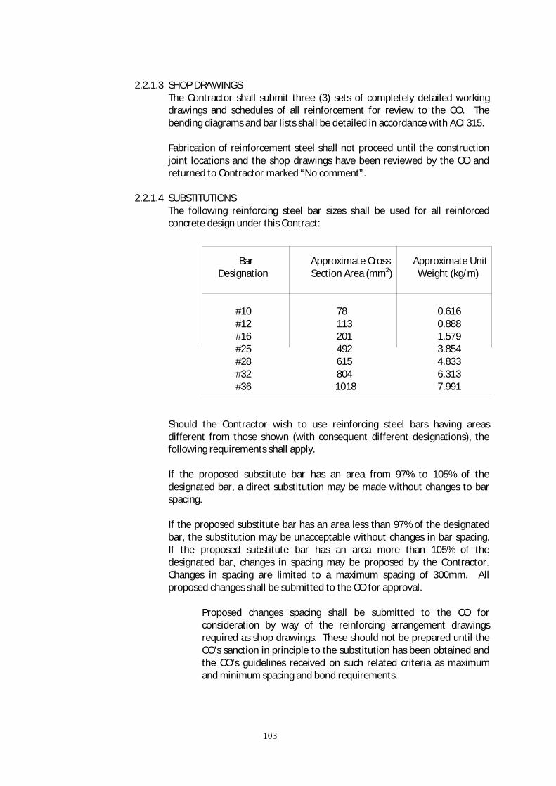
103
2.2.1.3 SHOP DRAWINGS
The Contractor shall submit three (3) sets of completely detailed working drawings and schedules of all reinforcement for review to the CO. The bending diagrams and bar lists shall be detailed in accordance with ACI 315.
Fabrication of reinforcement steel shall not proceed until the construction joint locations and the shop drawings have been reviewed by the CO and returned to Contractor marked “No comment”.
2.2.1.4 SUBSTITUTIONS
The following reinforcing steel bar sizes shall be used for all reinforced concrete design under this Contract:
Bar Approximate Cross Approximate Unit Designation Section Area (mm2) Weight (kg/m) #10 78 0.616 #12 113 0.888 #16 201 1.579 #25 492 3.854 #28 615 4.833 #32 804 6.313 #36 1018 7.991
Should the Contractor wish to use reinforcing steel bars having areas different from those shown (with consequent different designations), the following requirements shall apply.
If the proposed substitute bar has an area from 97% to 105% of the designated bar, a direct substitution may be made without changes to bar spacing.
If the proposed substitute bar has an area less than 97% of the designated bar, the substitution may be unacceptable without changes in bar spacing. If the proposed substitute bar has an area more than 105% of the designated bar, changes in spacing may be proposed by the Contractor. Changes in spacing are limited to a maximum spacing of 300mm. All proposed changes shall be submitted to the CO for approval.
Proposed changes spacing shall be submitted to the CO for consideration by way of the reinforcing arrangement drawings required as shop drawings. These should not be prepared until the CO’s sanction in principle to the substitution has been obtained and the CO’s guidelines received on such related criteria as maximum and minimum spacing and bond requirements.

104
Approval by the CO of bar size substitution does not relieve the Contractor from other specified requirements including steel grade and bar deformations.
2.2.2 PRODUCTS 2.2.2.1 MATERIALS
Reinforcement steel shall be deformed, new billet steel bars conforming to ASTM A615, grade 40 substantially free from mill scale, rust, grease or other foreign matter.
Rail-steel bars will not be permitted in the work.
Reinforcement steel shall bear a mill identification symbol, and shall be tagged with the size and mark number so that different types may be identified and shall be stored off the ground to protect the steel moisture and dirt, until placed in final position.
Steel wire for tying reinforcing and water-stops shall conform to ASTM A82.
Welded wire fabric for concrete reinforcement shall conform to ASTM A497. Welded intersections shall be spaced no further apart than 40cm in the direction of the principal reinforcement.
2.2.3 EXECUTION 2.2.3.1 FABRICATION OF REINFORCEMENT
Reinforcement steel shall be accurately formed to the dimensions shown on the shop drawings and bar schedules.
All reinforcing bars shall be bent cold around a pin with a free revolving collar having a diameter proportional to the diameter of the bar of not less than the following:
a. Two times for stirrups. b. Six times for bars up to and including 25mm diameter. c. Eight times for bars over 25mm diameter.
Reinforcement steel shall not be straightened nor rebent. Bars with kinks or bends not shown on the Drawings will not be accepted.
2.2.3.2 INSTALLATION OF REINFORCEMENT
Reinforcing bars shall be accurately placed as shown on the Drawings and in accordance with the shop drawings and schedules. The reinforcing bars shall be secured against displacement with annealed iron wire ties of minimum 1.5mm diameter or suitable clips at the intersections.
105
Except as otherwise indicated on the Drawings, reinforcement steel shall be installed with a clearance for concrete cover follows:
a. Concrete placed directly on earth 75mm b. Formed surfaces in contact with the soil, water or exposed to the water 50mm c. Concrete cover of main reinforcement steel for columns and beams 50mm d. Walls not in contact with the soil, water or exposed to the weather 40mm e. Underside of slabs over water surfaces but not in contact with the water 50mm f. All other slab surfaces 25mm
No reinforcing bars shall be welded.
All reinforcing bars in slabs shall be supported on concrete cubes or chairs of the correct height, containing soft steel wires embedded therein for fastening to the reinforcement steel. Such spacers or chairs shall have a minimum compressive strength of 21 Mpa.
Reinforcing bars for vertical surfaces in beams, columns and walls shall be properly and firmly positioned from the forms by means of stainless steel (tipped) boisters or other equal methods approved by the CO.
Reinforcement steel projecting from structures that are to be concreted or where concrete has already been poured shall not be bent out of its correct position.
Lapping of reinforcing bars shall be as indicated on the Drawings.
Before being placed in position, reinforcing bars shall be thoroughly cleaned of rust, scale, dirt and other coating. When there is delay in placing of concrete after reinforcing bars are in place, bars shall be re-inspected and cleaned when necessary.
MASONRY WORKS 3.1 GENERAL 3.1.1 SCOPE OF WORK
The work includes furnishing all labor, materials, and services. Equipment, plant and other facilities and the satisfactory performance of all work necessary to complete all cement and masonry work shown in the plans and specified herein.
The work under this section shall include but not be limited to the following:
106
3.1.1.1 CONCRETE HOLLOW BLOCK WALLS
3.1.1.2 MASONRY REINFORCING BARS FOR CONCRETE BLOCKS
3.1.1.3 GROUTING
3.1.1.4 CONNECTING WALL ANCHORS, TIES, BOLTS AND
RELATED EMBEDDED ITEMS;
3.1.1.5 INSTALLATION ONLY OF FRAMES FOR DOORS, WINDOWS, LOUVERS, STEEL LINTELS AND RECESSED FIXTURES;
3.1.2 STANDARD SPECIFICATION REFERENCES The following Standards are referred to: ASTM C32 Concrete Aggregates ASTM C90 Hollow Load-Bearing Concrete Masonry Units ASTM C144 Aggregate for Masonry Mortar ASTM C150 Portland Cement SAO No.15-2 Standardization of Concrete Hollow Blocks 3.1.3 PROTECTION OF MATERIALS
All materials for the work of this section shall be delivered, stored and handled so as to preclude damage of any nature. Manufactured materials, such as cement, shall be delivered and stored in their original containers, plainly marked with identification of material and maker. Materials in broken containers, or in packages showing watermarks or other evidence of damage, shall not be used and shall be removed from the site.
3.1.4 SAMPLES
The contractor shall submit to the CO for approval samples of concrete blocks, and also information on the cement and sand such as chemical analysis of cement and the sieve analysis of sand.
3.2 MATERIALS 3.2.1 CEMENT
Cement shall be normal Portland cement conforming to ASTM Specifications C150, Type I. Masonry cements shall not be used. One color of cement shall be used throughout the Work.
3.2.2 SAND FOR MORTAR
Sand shall be clean, durable particles, free from injurious amounts of organic matter. The sand conform to ASTM Specifications C144 or C33 as required. Sand for grout shall conform to ASTM Specifications C144 or C33 as required.

107
3.2.3 WATER
Water shall be free from injurious amounts of oils, acids, alkalis, organic matter, and shall be clean and fresh.
3.2.4 CONCRETE HOLLOW BLOCKS (CHB)
3.2.4.1 CLASSIFICATION Concrete block shall conform to ASTM C90, Grade N, and/or to the Philippine Bureau of Standards SAO No. 15-2. The load bearing concrete blocks, Type I, shall be divided into the following two classifications;
3.2.4.1.1 Class A, for use in exterior walls below grade and for exterior walls above grade that may be exposed to the weather.
3.2.4.1.2 Class B, for general use in walls above grade not exposed to the weather.
3.2.4.2 MANUFACTURING REQUIREMENTS
Concrete hollow blocks shall be manufactured to the requirements as shown in Table I.
TABLE I
MINIMUM COMPRESIIVE STRENGTH MAXIMUM WATER MAXIMUM MOISTURE (Mpa) ABSORPTION CONTENT (1% of Total CLASS (kg/cum.) Absorption) AVERAGE OF FIVE INDIVIDUAL AVERAGE OF FIVE (5) AVERAGE OF (5) SAMPLES SAMPLE SAMPLES FIVE (5) SAMPLES
A 6-9 5.5 240 40 B 4-8 4.1 240 40
Aggregate for concrete blocks shall consist of sand and evenly graded pea gravel conforming to ASTM C33. All concrete hollow blocks shall be even textured with straight and true edges, wet steam cured for at least 18 hours and then air cured in covered storage for not less than 28 days before delivery to the job site.
Units when received at the construction site shall be stacked so as to provide air circulation, and shall be protected from the weather. The moisture content of hollow blocks when laid shall not exceed 35 percent of total absorption.

108
3.2.4.3 DIMENSIONS
The actual dimensions of the concrete hollow blocks shall be as shown in Table II below.
TABLE II NOMINAL DIMENSIONS (mm) ACTUAL DIMENSIONS (mm) Width Height Length Width Height Length 100 200 400 92 194 397 150 200 400 143 194 397 200 200 400 194 397
No overall dimension shall differ from the specified actual dimensions by more than 3mm.
3.2.4.4 MINIMUM FACE SHELL AND WEB THICKNESS
The following dimensions shown in Table III below shall apply for minimum face and web thickness:
TABLE III NOMINAL WIDTH (mm) MINIMUM FACE SHELL MINIMUM WEB THICKNESS THICKNESS (mm) (mm) 100 19 19 150 25 25
200 32 25 3.3 MORTAR MIXES
Masonry mortar for setting blocks shall be in the proportion of 1 part cement to 3 parts sand or as otherwise approved by CO. Mortars shall be mixed with water in an amount compatible with workability ingredients shall be accurately measured by volume in boxes especially constructed for the purpose by the Contractor. Mixing shall be done immediately before usage, and the Contractor shall use the Dry-Mix method. In the Dry-Mix method, the materials for each batch shall be well fumed together until the even color of the mixed dry materials indicates that the cementitious material has
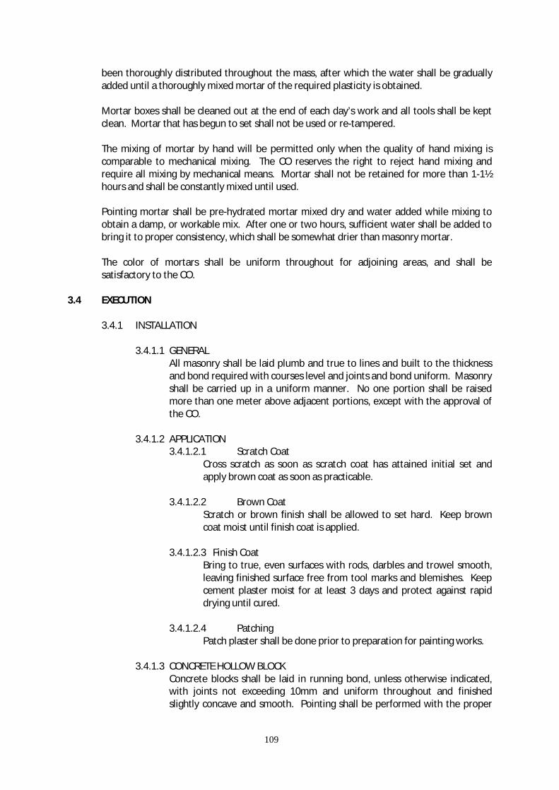
109
been thoroughly distributed throughout the mass, after which the water shall be gradually added until a thoroughly mixed mortar of the required plasticity is obtained. Mortar boxes shall be cleaned out at the end of each day’s work and all tools shall be kept clean. Mortar that has begun to set shall not be used or re-tampered. The mixing of mortar by hand will be permitted only when the quality of hand mixing is comparable to mechanical mixing. The CO reserves the right to reject hand mixing and require all mixing by mechanical means. Mortar shall not be retained for more than 1-1½ hours and shall be constantly mixed until used. Pointing mortar shall be pre-hydrated mortar mixed dry and water added while mixing to obtain a damp, or workable mix. After one or two hours, sufficient water shall be added to bring it to proper consistency, which shall be somewhat drier than masonry mortar. The color of mortars shall be uniform throughout for adjoining areas, and shall be satisfactory to the CO.
3.4 EXECUTION 3.4.1 INSTALLATION 3.4.1.1 GENERAL
All masonry shall be laid plumb and true to lines and built to the thickness and bond required with courses level and joints and bond uniform. Masonry shall be carried up in a uniform manner. No one portion shall be raised more than one meter above adjacent portions, except with the approval of the CO.
3.4.1.2 APPLICATION
3.4.1.2.1 Scratch Coat Cross scratch as soon as scratch coat has attained initial set and apply brown coat as soon as practicable.
3.4.1.2.2 Brown Coat Scratch or brown finish shall be allowed to set hard. Keep brown coat moist until finish coat is applied.
3.4.1.2.3 Finish Coat
Bring to true, even surfaces with rods, darbles and trowel smooth, leaving finished surface free from tool marks and blemishes. Keep cement plaster moist for at least 3 days and protect against rapid drying until cured.
3.4.1.2.4 Patching
Patch plaster shall be done prior to preparation for painting works.
3.4.1.3 CONCRETE HOLLOW BLOCK Concrete blocks shall be laid in running bond, unless otherwise indicated, with joints not exceeding 10mm and uniform throughout and finished slightly concave and smooth. Pointing shall be performed with the proper

110
tools to a dense and neat finish. Finger pointing will not be allowed. All blocks shall be laid in a full bed of mortar applied to shell and webs. Apply mortar to the vertical joints of blocks that have already been set in the wall and all contact faces of the unit to be set. Each unit shall be placed and shoved against the previously laid block so as to produce a well compacted vertical mortar joint for the whole shell thickness. Intersecting bearing walls shall be tied together with metal ties at 0.80 meter vertical spacing. Bends of tie and reinforcing bars shall be embedded in cells filled with mortar.
All necessary block cutting shall be neatly done by saws.
Control joints shall be installed at the locations noted and detailed on the Drawings. The joints shall be raked out to a depth 20mm for the full height of the walls and caulked. The maximum length between joints shall be 10 meters if not shown otherwise on the Drawings, or directed by the CO.
All horizontal and vertical reinforcing bars shall be anchored at a minimum of 20 bar diameter into the concrete walls, columns, slabs and girders.
Joints made at the intersection of block walls with structural concrete and all door, window and louver frames and where indicated shall be filled with mortar grout and pointed.
Unless otherwise shown on the Drawings, install all door, window and louver frames using screws and expansion shields, and set all frames tightly against the masonry walls.
3.4.1.4 CONCRETE HOLLOW BLOCK TO BE PLASTERED
Concrete block wall which are to be plastered shall be laid in running bond. Joints are to left rough to assist in the bounding of plaster. Otherwise, concrete block masonry shall conform to the previous paragraph 2- Concrete Hollow Block.
3.4.1.5 CONCRETE HOLLOW BLOCK TO BE TOOLED JOINTED
Concrete block walls to be tooled jointed as indicated on the Drawings shall be laid in stack bond with uniformly maintained joints not exceeding 13mm. All joints shall be tooled smooth to a stripped finish as soon as the mortar has set sufficiently. No cold chiseling will be permitted. Finishes shall be as indicated in the Drawings.
3.4.2 LINTELS, TIES AND MISCELLANEOUS ITEMS
The Contractor shall build in all miscellaneous items specified in other sections to be set including frames, lintels, reinforcing steel, electrical boxes and fixtures, sleeves, anchors and other miscellaneous items. All anchorage attachments and bonding devices shall be set so as to prevent slippage and shall be completely covered with mortar.

111
3.4.3 GROUTING
Grout and cement mortar for setting structural columns, railings, frames in walls and where otherwise required shall be done with mortar of 1 part cement to 1 part sand. Before placing grout thoroughly clean all surfaces. Grout shall be tamped into place with a blunt tool to fill the entire void. In the event space does not permit tamping, the Contractor shall build the necessary forms and place the grout by pouting from one side only. When grout is placed by pouring, a head of grout shall be maintained in the form. Grout shall be kept wet for three days and after the temporary supports or adjusting wedges are removed, the empty spacer shall be grouted and the surrounding grout pointed.
3.4.4 CLEANING
All exposed masonry work shall be thoroughly cleaned. Mortar smears and droppings on concrete block walls shall be dry before removal with a trowel. Masonry work may be cleaned using a mild muriatic acid solution.
3.4.5 STORAGE AND HANDLING
Masonry units shall be handled with care to prevent chipping and breakage. Storage piles, stacks or bins shall be so located as to avoid being disturbed or shall be barricaded to protect chase materials from damage due to construction operations and traffic. Masonry units shall be stacked on platforms and covered or stored in any other approved manner that will insure the protection these materials from weather. Cement and lime shall be stored off the ground under watertight cover and away from sweating walls and other damp surfaces until ready for use. Damaged or deteriorated materials shall be removed the premises.
STRUCTURAL STEEL WORKS
4.1 DESCRIPTION
The work includes the furnishing of all labor, materials, equipment and transportation required to complete fabrication, delivery and erection of all structural steel indicated in the drawings and herein specified.
4.2 REFERENCE
The following publications of the issues listed below, but referred to thereafter by basic designation only, form part of this specification to the extent indicated by the reference thereto:
American Institute of Steel Construction (AISC) Publications:
Code of Standard Practice for Steel Buildings and Bridges, dated September 1, 1976.
Manual of Steel Construction - 7th Edition, including Supplements 1,2 and 3.

112
American National Standards Institute (ANSI) Publications: B27.2 Plain Washers American Society for Testing and Materials (ASTM) Publications: A27 or A148 Cast Steel A36 Structural Steel A53 Steel Pipe
A12-73 Zinc (Hot-Galvanized) Coating on Products Fabricated from Rolled, Pressed and Forged Steel Shapes, Plates, NBA’s and Strips.
A153-73 Zinc-Coating (Hot Dip) on iron and Steel Hardware.
A307-76B Carbon Steel Externally & Internally Threaded Standard Fasteners.
A325-76C High Strength Bolts for Structural Steel Joints, including suitable Nuts and Plain Hardened Washers.
A550-77 Cold-Formed Welded and Seamless Carbon Structural Tubing in Rounds and Shapes.
American Welding Society (AWS) Publications: A5.1 Welding Electrodes C1.1-75 Structural Welding Code 4.3 REQUIREMENT
In conformance with the General Conditions, the Contractor is required to furnish a certificate from the manufacturer or producer, certifying that all materials or products delivered to the job site meet the measurements specified herein.
4.4 SHOP DRAWINGS
The Contractor shall submit shop drawings to the Construction Engineer for approval in accordance with the General Conditions. Shop Drawings shall consist of all shop and erection details. All members and connection for any portion of the structure shown or not shown on the contract drawings shall be detailed by the fabrication and indicated on the shop symbols in accordance with the American Welding Society (AWS) Structural Welding Code.
4.5 MATERIALS
Materials shall conform to the respective publications and other requirements specified herein and as shown, and shall be the approved products of manufacturers regularly engaged in the manufacture of such products.

113
Structural Steel shall conform to ASTM A36. Structural Tubing shall conform to ASTM A500 or A501. Steel Pipe shall conform to ASTM A53, Grade b.
Cast Steel, except as specified otherwise, and shall conform to ASTM A27 or A148, as applicable. Castings to be welded shall be of composition suitable for welding under field conditions.
High Strength Bolts, including Nuts and Washers, shall conform to ASTM A325.
Plain Washers, other those in contact with high strength bolt heads and nuts shall conform to ASNI Standard B27.2, Type B.
Welding Electrodes and Rods shall conform to AWS A5.1, E60XX series.
Zinc Coating for threaded products shall conform to ASTM A153 and ASTM A123 for structural shapes.
Materials shall be delivered, stored, handled and installed in a manner to protect them from all damage curing the entire construction period. Storage conditions shall be approved by the Construction Officer in accordance with the General Conditions.
4.6 FABRICATION 4.6.1 GENERAL
Structural Steelworks material shall be in accordance with the applicable provisions of these specifications. Fabrications and assembly shall be done in the shop to the greater extent possible. Structural siteworks, except surfaces of steel to be encased in concrete and surfaces of friction-type high-strength bottled connections, shall be prepared for painting in accordance with the section entitled PAINTING and primed with paint material specified. All materials shall be cleaned and straight. If straightening is necessary, it shall be done by a process and in a manner that will not damage the material.
Shearing, Flame cutting, and Chipping, shall be done carefully and accurately. Flame-cut edges of members shall have all knicks removed. The top and bottom surfaces of base plates, cap plates of columns and pedestals, sole plates, and masonry plates shall be planned, or be hot straightened, and parts of members in contact with them shall be faced. Sole plates of beams and girders shall have full contact with the flanges. Compression joints, depending upon contact bearing, shall have bearing surfaces machined to a common plane after the members are completed. Bolts shall not be made or enlarged by burning. Members that cannot be fitted up properly by cutting with a saw or by reaming holes to a maximum holes elongation of 3mm larger than the nominal diameter will be rejected unless other correction is approved by the Construction Officer. Gas cutting (Flame cutting) shall be done by the use of mechanically guided torch. The use of a gas torch in the field will not be permitted on any major member in the structural framing under stress, and shall be

114
subject to the approval of the Construction Officer. The radius of re-entrant flame cut fillets shall not be less than 13mm, and all burned edges shall be finished by grinding.
4.6.2 WELDED CONSTRUCTION
Welding on structural steelworks and tubular structures shall be done in accordance with the applicable standards for welding of AWS Code D1.1.
4.6.2.1 QUALIFICATION OF WELDERS
Welding work shall only be performed by certified welders qualified in accordance with the requirements of the AWS D1.1.
4.6.2.2 PROCEDURES
Welding procedures, type of electrodes, and type of equipment required for the work shall be in accordance with the applicable provisions of AWS D1.1. Type of electrodes to be used shall be compatible with the metal to be welded.
4.6.3 BOLTED CONSTRUCTION
Holes for bolts shall be 1.5mm larger than the nominal diameter of bolt. Holes shall be clean cut, without torn or rugged edges. Outside burrs resulting from reaming or drilling shall be removed. Bolt holes shall be at right angles to the member. The slope of bolted parts in contact with the bolt head shall not exceed 1:20 with respect to a plane normal to the bolt axis. Where the surface of a bolted part has a slope of more than 1:20, a beveled washer shall be used to compensate for lack of parallelism.
4.6.3.1 COMMON BOLTS
Bolts transmitting shear shall be threaded to which a length that is not more than one thread will be within the grip of the metal and the bolt shall be of such length that they will extend entirely through the nuts, with the beveled end outside of the nut. Bolt heads and nuts shall be drawn tight against the work with a suitable wrench. Bolt threads shall be tapped with a hammer while the nut being tightened.
4.6.3.2 HIGH-STRENGTH STEEL BOLTS
The allowable working stresses for high-strength steel bolts shall be as given in ASTM A325. Bolted parts shall not be solidly together when assembled and shall not be separated by gaskets or any other interposed compressible materials. When assembled, all joints surfaces, including those adjacent to the bolts heads, nuts, or washers, shall be free of scale, except tight mill scale, and shall also be free of burrs, dirt, and other foreign material that would prevent seating of the parts. Contact surfaces within the friction type of joints shall be free fasteners in the joint are tight, at least the minimum bolt tension shown in ASTM A325, for the size of fastener used. Threaded bolts shall be tightened with properly calibrated wrenches or by the “turn-of-the nut” method. Any bolt tightened by the calibrated wrench method (or
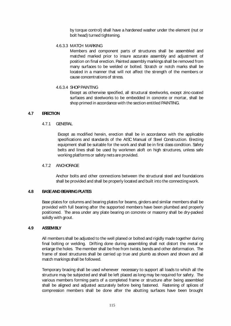
115
by torque control) shall have a hardened washer under the element (nut or bolt head) turned tightening.
4.6.3.3 MATCH MARKING
Members and component parts of structures shall be assembled and matched marked prior to insure accurate assembly and adjustment of position on final erection. Painted assembly markings shall be removed from many surfaces to be welded or bolted. Scratch or notch marks shall be located in a manner that will not affect the strength of the members or cause concentrations of stress.
4.6.3.4 SHOP PAINTING
Except as otherwise specified, all structural steelworks, except zinc-coated surfaces and steelworks to be embedded in concrete or mortar, shall be shop primed in accordance with the section entitled PAINTING.
4.7 ERECTION 4.7.1 GENERAL
Except as modified herein, erection shall be in accordance with the applicable specifications and standards of the AISC Manual of Steel Construction. Erecting equipment shall be suitable for the work and shall be in first class condition. Safety belts and lines shall be used by workmen aloft on high structures, unless safe working platforms or safety nets are provided.
4.7.2 ANCHORAGE
Anchor bolts and other connections between the structural steel and foundations shall be provided and shall be properly located and built into the connecting work.
4.8 BASE AND BEARING PLATES
Base plates for columns and bearing plates for beams, girders and similar members shall be provided with full bearing after the supported members have been plumbed and properly positioned. The area under any plate bearing on concrete or masonry shall be dry-packed solidly with grout.
4.9 ASSEMBLY
All members shall be adjusted to the well planed or bolted and rigidly made together during final bolting or welding. Drifting done during assembling shall not distort the metal or enlarge the holes. The member shall be free from twists, bends and other deformation. The frame of steel structures shall be carried up true and plumb as shown and shown and all match markings shall be followed.
Temporary bracing shall be used whenever necessary to support all loads to which all the structure may be subjected and shall be left placed as long may be required for safety. The various members forming parts of a completed frame or structure after being assembled shall be aligned and adjusted accurately before being fastened. Fastening of splices of compression members shall be done after the abutting surfaces have been brought
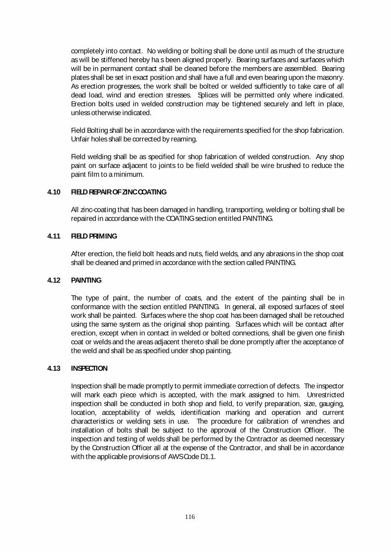
116
completely into contact. No welding or bolting shall be done until as much of the structure as will be stiffened hereby ha s been aligned properly. Bearing surfaces and surfaces which will be in permanent contact shall be cleaned before the members are assembled. Bearing plates shall be set in exact position and shall have a full and even bearing upon the masonry. As erection progresses, the work shall be bolted or welded sufficiently to take care of all dead load, wind and erection stresses. Splices will be permitted only where indicated. Erection bolts used in welded construction may be tightened securely and left in place, unless otherwise indicated.
Field Bolting shall be in accordance with the requirements specified for the shop fabrication. Unfair holes shall be corrected by reaming.
Field welding shall be as specified for shop fabrication of welded construction. Any shop paint on surface adjacent to joints to be field welded shall be wire brushed to reduce the paint film to a minimum.
4.10 FIELD REPAIR OF ZINC COATING
All zinc-coating that has been damaged in handling, transporting, welding or bolting shall be repaired in accordance with the COATING section entitled PAINTING.
4.11 FIELD PRIMING
After erection, the field bolt heads and nuts, field welds, and any abrasions in the shop coat shall be cleaned and primed in accordance with the section called PAINTING.
4.12 PAINTING
The type of paint, the number of coats, and the extent of the painting shall be in conformance with the section entitled PAINTING. In general, all exposed surfaces of steel work shall be painted. Surfaces where the shop coat has been damaged shall be retouched using the same system as the original shop painting. Surfaces which will be contact after erection, except when in contact in welded or bolted connections, shall be given one finish coat or welds and the areas adjacent thereto shall be done promptly after the acceptance of the weld and shall be as specified under shop painting.
4.13 INSPECTION
Inspection shall be made promptly to permit immediate correction of defects. The inspector will mark each piece which is accepted, with the mark assigned to him. Unrestricted inspection shall be conducted in both shop and field, to verify preparation, size, gauging, location, acceptability of welds, identification marking and operation and current characteristics or welding sets in use. The procedure for calibration of wrenches and installation of bolts shall be subject to the approval of the Construction Officer. The inspection and testing of welds shall be performed by the Contractor as deemed necessary by the Construction Officer all at the expense of the Contractor, and shall be in accordance with the applicable provisions of AWS Code D1.1.
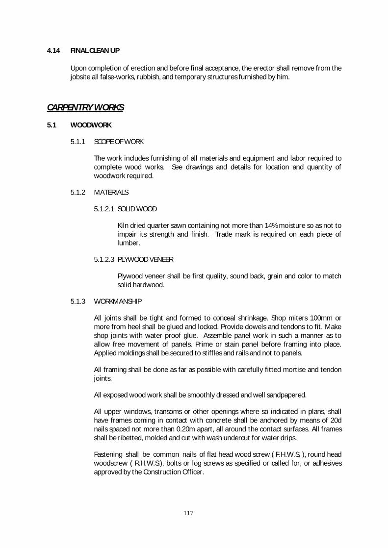
117
4.14 FINAL CLEAN UP
Upon completion of erection and before final acceptance, the erector shall remove from the jobsite all false-works, rubbish, and temporary structures furnished by him.
CARPENTRY WORKS
5.1 WOODWORK
5.1.1 SCOPE OF WORK
The work includes furnishing of all materials and equipment and labor required to complete wood works. See drawings and details for location and quantity of woodwork required.
5.1.2 MATERIALS
5.1.2.1 SOLID WOOD
Kiln dried quarter sawn containing not more than 14% moisture so as not to impair its strength and finish. Trade mark is required on each piece of lumber.
5.1.2.3 PLYWOOD VENEER
Plywood veneer shall be first quality, sound back, grain and color to match solid hardwood.
5.1.3 WORKMANSHIP
All joints shall be tight and formed to conceal shrinkage. Shop miters 100mm or more from heel shall be glued and locked. Provide dowels and tendons to fit. Make shop joints with water proof glue. Assemble panel work in such a manner as to allow free movement of panels. Prime or stain panel before framing into place. Applied moldings shall be secured to stiffles and rails and not to panels.
All framing shall be done as far as possible with carefully fitted mortise and tendon joints.
All exposed wood work shall be smoothly dressed and well sandpapered.
All upper windows, transoms or other openings where so indicated in plans, shall have frames coming in contact with concrete shall be anchored by means of 20d nails spaced not more than 0.20m apart, all around the contact surfaces. All frames shall be ribetted, molded and cut with wash undercut for water drips.
Fastening shall be common nails of flat head wood screw ( F.H.W.S. ), round head woodscrew ( R.H.W.S.), bolts or log screws as specified or called for, or adhesives approved by the Construction Officer.
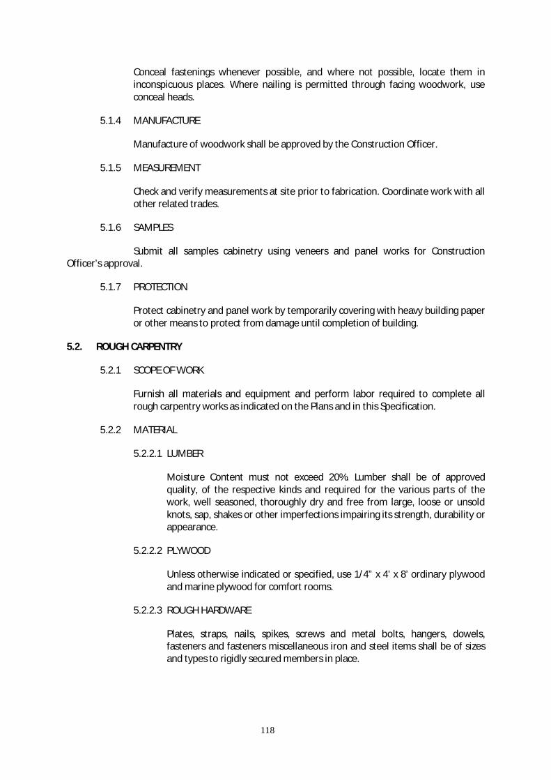
118
Conceal fastenings whenever possible, and where not possible, locate them in inconspicuous places. Where nailing is permitted through facing woodwork, use conceal heads.
5.1.4 MANUFACTURE
Manufacture of woodwork shall be approved by the Construction Officer.
5.1.5 MEASUREMENT
Check and verify measurements at site prior to fabrication. Coordinate work with all other related trades.
5.1.6 SAMPLES
Submit all samples cabinetry using veneers and panel works for Construction Officer’s approval.
5.1.7 PROTECTION
Protect cabinetry and panel work by temporarily covering with heavy building paper or other means to protect from damage until completion of building.
5.2. ROUGH CARPENTRY
5.2.1 SCOPE OF WORK
Furnish all materials and equipment and perform labor required to complete all rough carpentry works as indicated on the Plans and in this Specification.
5.2.2 MATERIAL
5.2.2.1 LUMBER
Moisture Content must not exceed 20%. Lumber shall be of approved quality, of the respective kinds and required for the various parts of the work, well seasoned, thoroughly dry and free from large, loose or unsold knots, sap, shakes or other imperfections impairing its strength, durability or appearance.
5.2.2.2 PLYWOOD
Unless otherwise indicated or specified, use 1/4” x 4’ x 8’ ordinary plywood and marine plywood for comfort rooms.
5.2.2.3 ROUGH HARDWARE
Plates, straps, nails, spikes, screws and metal bolts, hangers, dowels, fasteners and fasteners miscellaneous iron and steel items shall be of sizes and types to rigidly secured members in place.

119
5.2.3 STORAGE
Stack framing for lumber and plywood to insure against deformation and maintain proper ventilation.
Protect lumber and plywood from hazardous elements.
Lumber in contact with concrete or masonry shall be coated with asphalt.
5.2.4 WORKMANSHIP
5.2.4.1 FRAMING
Framing shall be cut square on bearings, close fitted, accurately set to required lines and levels and rigidly secured in place, plane and dress side frames that will received the wallboards or sidings.
5.2.4.2 FURRING AND NAILERS
Wood furring and nailers shall be in accordance with detail drawings. Where not indicated on the Plans or mentioned herein, furring strips shall be 1” x 2” spaced at 16” on center both ways. Fasten wood furring securely by expansion bolts other approved device at every two (2) feet on centers. Wood plugs shall not be used.
5.2.4.3 WOOD STUD PARTITION
All wood partitions indicated in the drawings shall be of the material specified and constructed in accordance with detailed drawings.
For plywood partitions use 6mm thick, unless otherwise shown on the drawings. Tanguile plywood shall be “A” class quality. Plywood shall be as shown on the drawings with its corresponding thickness and V-cut joints as indicated.
Plywood partitions shall be nailed on 50 x 50 x 50 x 100mm Apitong salt-treated spaced 400mm. o.c. with joints shown on the drawings and shall be done together with all trimmings, casings for openings, copings, and baseboards, in accordance with the provisions of the preceding paragraph.
Door trims (casings) and moldings shall be of the lumber sizes shown on detailed drawings.
5.2.5 SCHEDULES
Treated Apitong or Tanguile lumber shall be used for:
Vertical and horizontal studding of wood partitions.
Ceiling nailers and ceiling joints (if required).
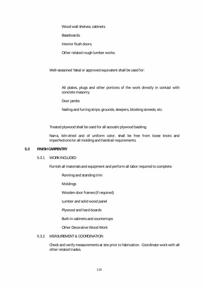
120
Wood wall shelves, cabinets.
Baseboards.
Interior flush doors.
Other related rough lumber works.
Well-seasoned Yakal or approved equivalent shall be used for:
All plates, plugs and other portions of the work directly in contact with concrete masonry.
Door jambs
Nailing and furring strips, grounds, sleepers, blocking screeds, etc.
Treated plywood shall be used for all acoustic plywood backing.
Narra, kiln-dried and of uniform color, shall be free from loose knots and imperfections for all molding and handrail requirements.
5.3 FINISH CARPENTRY
5.3.1 WORK INCLUDED
Furnish all materials and equipment and perform all labor required to complete:
Running and standing trim
Moldings
Wooden door frames (if required)
Lumber and solid wood panel
Plywood and hard-boards
Built-in cabinets and countertops
Other Decorative Wood Work
5.3.2 MEASUREMENT & COORDINATION
Check and verify measurements at site prior to fabrication. Coordinate work with all other related trades.
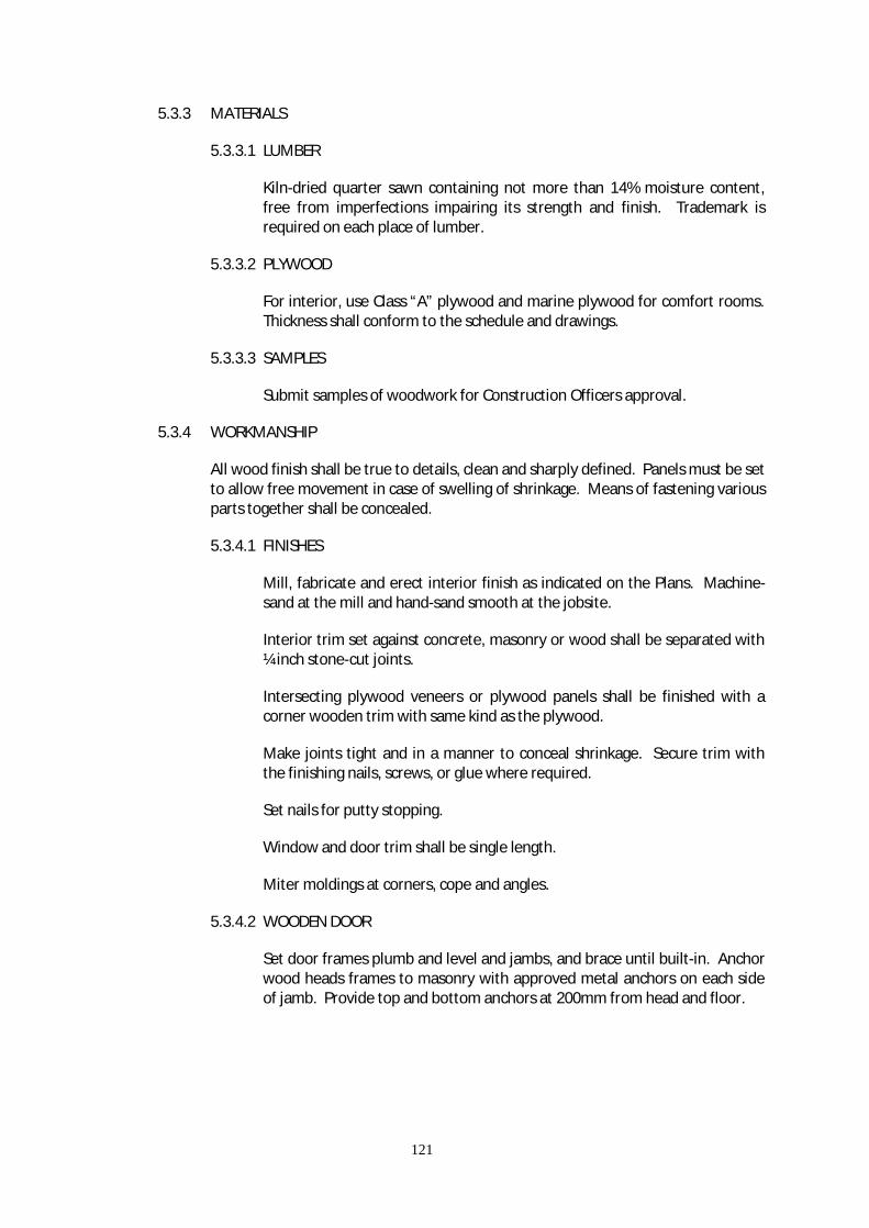
121
5.3.3 MATERIALS
5.3.3.1 LUMBER
Kiln-dried quarter sawn containing not more than 14% moisture content, free from imperfections impairing its strength and finish. Trademark is required on each place of lumber.
5.3.3.2 PLYWOOD
For interior, use Class “A” plywood and marine plywood for comfort rooms. Thickness shall conform to the schedule and drawings.
5.3.3.3 SAMPLES
Submit samples of woodwork for Construction Officers approval.
5.3.4 WORKMANSHIP
All wood finish shall be true to details, clean and sharply defined. Panels must be set to allow free movement in case of swelling of shrinkage. Means of fastening various parts together shall be concealed.
5.3.4.1 FINISHES
Mill, fabricate and erect interior finish as indicated on the Plans. Machine-sand at the mill and hand-sand smooth at the jobsite.
Interior trim set against concrete, masonry or wood shall be separated with ¼ inch stone-cut joints.
Intersecting plywood veneers or plywood panels shall be finished with a corner wooden trim with same kind as the plywood.
Make joints tight and in a manner to conceal shrinkage. Secure trim with the finishing nails, screws, or glue where required.
Set nails for putty stopping.
Window and door trim shall be single length.
Miter moldings at corners, cope and angles.
5.3.4.2 WOODEN DOOR
Set door frames plumb and level and jambs, and brace until built-in. Anchor wood heads frames to masonry with approved metal anchors on each side of jamb. Provide top and bottom anchors at 200mm from head and floor.

122
MOISTURE AND THERMAL PROTECTION
6.1 ROOFING 6.1.1 DESCRIPTION
The work includes installation of pre-painted Rib-type Long-span roofing complete with hardware and accessories.
6.1.2 GENERAL
The work includes furnishing all materials and requirements performing all operations to provide a long span corrugated twin ribbed roofing and miscellaneous roofing works as required to provide an acceptable installation. Surfaces to which metal formed roofing sheets are to be applied shall be thoroughly cleaned and prepared, free from any defects that may affect the application. Metal formed roofing shall be locked and lapped and installed as applicable. Specific installation details shall be in accordance with manufacturer’s recommended installation practice.
Metal formed roofing and sheets and accessories shall be carefully handled at all times in strong and handling to prevent damage to the surfaces, edges and ends and shall be slightly elevated for drainage.
Metal formed roofing and sheets and accessories shall be delivered to the site in the original sealed container or packages bearing the manufacturer’s name and brand designated where materials are covered by a reference specification number, type and class as applicable.
6.1.3 INSTALLATION
Lay and install the first sheet with the turned down edge towards the outside of the area to be covered. Overlap the next sheet to the previous sheet in such a manner that the exposed edge is turned down and the covered edge is turned up. Side up fasteners should be done by rivets and washers spaced from 300 mm to 450 mm on centers.
Care should be exercised in the proper anchorage of all roof frames.
Ridge strips for ridge rolls and ridge flashings are attached to the roofing sheets by means of rivets. Other flashings are to be fabricated from plain sheets of the same materials as the roofing in accordance with details and/or site requirements. These are also attached to roofing sheets by means of rivet.
6.1.4 TEMPORARY PROTECTION
Metal formed roofing sheet surfaces requiring protection from stains, discoloration, surface abrasion and other construction abuses shall be suitably protected in accordance with the manufacturer’s recommendations.

123
6.1.5 FINAL CLEARING
Upon completion, the Contractor shall clean the metal formed roofing sheets surfaces and drain line of burrs, leaves, stones and other foreign matter that may impair the flow of water. Surface shall be kept clean by periodic inspection.
6.2 RADIANT HEAT BARRIER 6.2.1 SCOPE OF WORK The Contractor shall furnish and install all labor and material to complete the work. 6.2.2 MATERIAL 6.2.2.1 RADIANT BARRIER
Radiant Barrier shall be fire retardant aluminum foil for roof insulation. It shall have a 6 layer fire retardant double-sided aluminum foil laminate with superior radiant heat barrier properties. It shall be tearproof, waterproof and possesses the following properties.
Elongation : 150% ASTM D882 Water Vapor Transmission : Greater than 5000 Mns/g ASTM E96-E Water Vapor Permeance : Less than 0.20 ng/Ns Less than 0.004 (Perms) ASTM E96-E Tensile Strength : M.D. 6.6 KN/m D.D. 5.0 KN/m C.D. 4.7 KN/m ASTM 828 Puncture Resistance : 1.0 Joules T.APPA T800 Reflectivity : 86% ASTM E466-71 Emissivity : 5% Roll Size : 1.25m x 60m = 75.00 sq.m. Weight : 200 g/m2 Thickness : 0.190mm Total R-Value (M2K/W) : 1.72 Fire Retardant BS476 : Part 6 Class 0

124
Part 7 Class 1 6.2.3 WORKMANSHIP
The product shall be delivered to the site in its original package or container bearing the manufacturers name and brand designation.
All materials shall be installed by skilled and selected workmen familiar with the aforementioned product.
6.2.4 INSTALLATION
The installation shall have a joint overlap of 75mm. It shall be unrolled foil down length of roof from ridge.
For further information, see manufacturer’s specifications.
6.3 ELASTOMERIC WATERPROOFING MEMBRANE 6.3.1 SCOPE OF WORK
The Contractor shall furnish and install all materials and labor required to provide waterproofing on designated locations.
6.3.2 MATERIAL
Elastomeric waterproofing membrane shall be liquid applied single component and made by a reputable manufacturer.
6.3.3 PREPARATION
All surfaces to be waterproofed should be clean, sound and dry. Concrete surfaces should have a light steel-trowel followed by a fine hair-broom or equivalent finish that is dry and free from dust, oil and other contaminants. Remove all high spots. Moss and lichen must be removed physically followed by treatment with fungal wash down through and allow to dry. Lattence should be removed from concrete by grit blasting, wire brushing or water jet blasting and allowing to dry; For installation procedure and other information, see manufacturer’s specification.
DOORS, WINDOWS AND GLASS WORKS
7.1 VINYL DOOR SYSTEM
7.1.1 SCOPE OF WORK
Furnish and install all labor and materials to complete all vinyl doors and jambs (hinges included)
as shown on the drawings and as specified herein.

125
7.1.2 GENERAL REQUIREMENT
Doors shall be of the quality and workmanship acceptable to the Officer. Doors shall be of the size and type indicated in the schedules and as specified herein guarantee finished doors against twisting, warping, cracking and such other defects due to construction and installation for a period of three hundred sixty hundred sixty days after final acceptance of the building.
7.1.3 INSTALLATION
Hinged doors shall be hung plumbed and fitted accurately allowing 1.5 mm clearance at the jambs and heads and 3 mm over thresholds. Clearance at the bottom of doors having no threshold shall be 9 mm. Lock stiles of doors 35 mm thick and thicker shall be leveled 3 mm. Knob locks and latches shall be installed 964 mm from the finished floors to the center.
7.2 METAL / WOODEN FLUSH DOORS
7.2.1 SCOPE OF WORK
Furnish and install all labor and materials to complete all metal flush doors as shown on the drawings and as specified herein.
7.2.2 GENERAL REQUIREMENT
Doors shall be of the quality and workmanship acceptable to the Construction Officer. Doors shall be of the size and type indicated in the schedules and as specified herein. Guarantee finished doors against rust, twisting, and such other defects due to construction and installation for a period of three hundred sixty days after final acceptance of the building.
7.2.3 SHOP DRAWINGS AND INSPECTIONS
Shop drawings showing fabrication and installation details of doors shall be prepared prior to manufacture and submitted to the Architect for approval.
After shop fabrication and before painting of doors, the work shall be inspected under attendance of the Construction Officer and Inspection reports shall be submitted to him/her.
7.3 METAL ROLL-UP DOOR
7.3.1 SCOPE OF WORK
The work includes deliver and installation metal roll-up door, complete with hardware and accessories.
7.3.2 GENERAL REQUIREMENT
Roll-up doors shall be spring counter-balanced, over-head ceiling type and shall be designed for use on exterior opening and/or as indicated. Door shall be mechanically
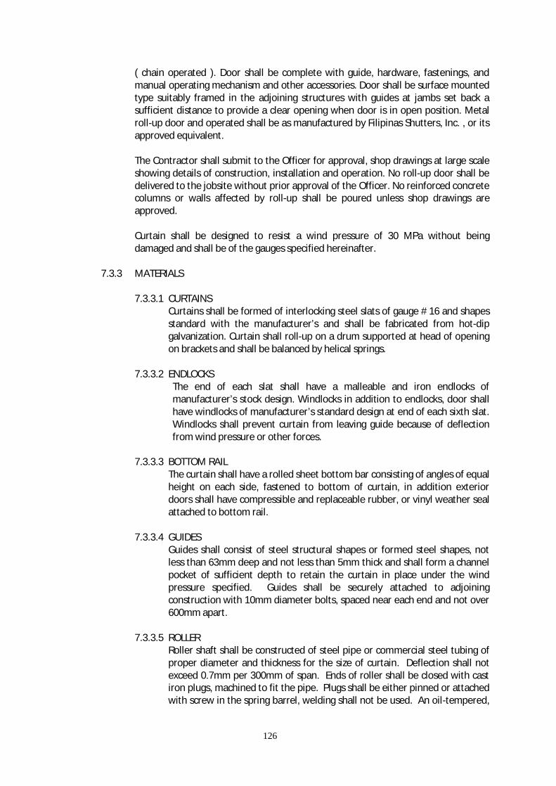
126
( chain operated ). Door shall be complete with guide, hardware, fastenings, and manual operating mechanism and other accessories. Door shall be surface mounted type suitably framed in the adjoining structures with guides at jambs set back a sufficient distance to provide a clear opening when door is in open position. Metal roll-up door and operated shall be as manufactured by Filipinas Shutters, Inc. , or its approved equivalent. The Contractor shall submit to the Officer for approval, shop drawings at large scale showing details of construction, installation and operation. No roll-up door shall be delivered to the jobsite without prior approval of the Officer. No reinforced concrete columns or walls affected by roll-up shall be poured unless shop drawings are approved. Curtain shall be designed to resist a wind pressure of 30 MPa without being damaged and shall be of the gauges specified hereinafter.
7.3.3 MATERIALS
7.3.3.1 CURTAINS Curtains shall be formed of interlocking steel slats of gauge # 16 and shapes standard with the manufacturer’s and shall be fabricated from hot-dip galvanization. Curtain shall roll-up on a drum supported at head of opening on brackets and shall be balanced by helical springs.
7.3.3.2 ENDLOCKS
The end of each slat shall have a malleable and iron endlocks of manufacturer’s stock design. Windlocks in addition to endlocks, door shall have windlocks of manufacturer’s standard design at end of each sixth slat. Windlocks shall prevent curtain from leaving guide because of deflection from wind pressure or other forces.
7.3.3.3 BOTTOM RAIL
The curtain shall have a rolled sheet bottom bar consisting of angles of equal height on each side, fastened to bottom of curtain, in addition exterior doors shall have compressible and replaceable rubber, or vinyl weather seal attached to bottom rail.
7.3.3.4 GUIDES
Guides shall consist of steel structural shapes or formed steel shapes, not less than 63mm deep and not less than 5mm thick and shall form a channel pocket of sufficient depth to retain the curtain in place under the wind pressure specified. Guides shall be securely attached to adjoining construction with 10mm diameter bolts, spaced near each end and not over 600mm apart.
7.3.3.5 ROLLER
Roller shaft shall be constructed of steel pipe or commercial steel tubing of proper diameter and thickness for the size of curtain. Deflection shall not exceed 0.7mm per 300mm of span. Ends of roller shall be closed with cast iron plugs, machined to fit the pipe. Plugs shall be either pinned or attached with screw in the spring barrel, welding shall not be used. An oil-tempered,

127
helical, counter-balancing steel spring, capable of producing sufficient torque to assure easy operation of the door curtain the roller. At least 80% of the door weight shall be counter-balanced at any position.
7.3.3.6 BRACKETS
Brackets shall be fabricated of heavy cast iron or steel, designed to close the ends of roller shaft housing and to form a supporting ring for hood. Bracket hubs or shaft plugs shall be equipped with pre-lubricated ball bearings, shielded or sealed.
7.3.3.7 HOOD
Hood shall be constructed at least 24 gauge metal, formed to fit contour of end brackets and reinforced with steel rods or rolled beads at top and bottom edges.
7.3.3.8 LOCKS
Locking devise shall be provided and shall be included in the master keying.
7.3.3.9 OPERATING CHAIN Operating chain shall be of design and strength to prevent stretching and to provide a comfortable hand grip and shall be heavily galvanized.
7.3.3.10 GEARS
Gears shall be of the best grade gray iron, cast teeth machine molded from machine-cut patterns.
7.3.4 INSTALLATION
Roll-up door shall be installed by the manufacturer or his authorized representative, in accordance with approved shop drawings and manufacturers direction. All anchors and inlets for guides, brackets and other work shall be located accurately. Upon completion, doors shall be weather tight and shall be free from twist or distortion and shall be lubricated and properly adjusted to operate freely.
7.3.5 FIELD PAINTING
Painting steel member shall be as specified under the Section entitled Painting. 7.4 STEEL WINDOWS 7.4.1 GENERAL REQUIREMENT
All steel windows shall be products of reputable and nationally known manufacturers approved by the Construction Officer. Unless otherwise indicated, all window frames shall be constructed to withstand a minimum 1225 N/sq.m., windload with the sashes in closed position. Windows shall be designed for glazing from outside with continuous glazing heads.
The Contractor shall submit to the Officer shop drawings for approval showing design, elevation of windows, full of size sections of sash, frames and mullion, hardware, construction and assembly details. Details of anchorage, erection,

128
proposed location and method of jointing and splicing of the unit to be installed shall be clearly shown. Fabrication shall not commence until these shop drawings have been submitted and approved.
7.4.2 MATERIALS
Window members shall be low-carbon, new hot-rolled steel frame. Vent sections shall be Zee-bars not less than 25mm in depth or 3mm in thickness for light section 32mm depth for heavy sections. All members shall be special sections hot-rolled from new billet steel. Munitions when required shall be 22mm x 32mm rolled tee sections.
7.4.3 CONSTRUCTION
Corners of frames and vents shall be miltered and electrically welded, exposed surfaces ground smooth.
Munitions shall be attached to frame or vent members by means of mortise tendon joints and riveted. Muntin intersections shall be of inter-locking design with flush interior surfaces.
Hinges shall have bronze-to-steel contact surfaces throughout. Hinge pins shall be steel, rustproof.
Double, full contact weathering shall be provided between vents and frames around the entire perimeter of each vent.
Windows shall be designed for glazing from the outside with angle glazing clips and steel sash putty. All unit shall be prepared for and supplied with necessary standard hardware.
7.4.4 HARDWARE
Hardware for doors and windows shall be acceptable foreign or local products of the types, material, sizes and mechanism as indicated on the drawings, and shall be free from any mark or other defect. For Construction Officer’s approval. Manufacturers of hardware items shall be as listed below or approved equals:
Yale, Schlage or equivalent for locksets, door closed. Yale, Alona, Shows or equivalent for hinges.
Samples of each type of hardware shall be submitted to the Architectural approval.
Hinges and door closers shall be the type size and capacity as indicated on the drawings, however, the Contractor shall verify each hardware item as to weight and other load of doors and windows, and minor modifications may be made without change in construction cost.
Each vent shall be a solid bronze, polished, cam locking handle and strike.
129
7.4.5 SHOP FINISH
All windows shall be given one shop coat of approved rust inhibitive of the type standard with the steel window manufacturer.
7.4.6 GLAZING
Glazing shall be as specified under the Section entitled GLASS AND GLAZING. 7.4.7 PAINTING Refer to the Section entitled PAINTING. 7.4.8 PROTECTION AND CLEANING
The Contractor shall be responsible for protecting the windows during construction and for cleaning at the completion of the building.
7.5 GLASS GLAZING 7.5.1 SCOPE OF WORK
This section of work includes furnishing of glass and labor required to complete all glass and glazing works.
7.5.2 MATERIALS 7.5.2.1 PLATE GLASS
Plate glass used shall be mechanically ground and polished, distortion-free surfaces. Use where good vision is required.
7.5.2.2 FLOAT GLASS
Manufacture by “floating” continuous ribbon of molten glass onto a bath of molten tin where it is reheated to obtain a flat, fire-polished finish. It is than allowed to cool to a degree permitting it to be drawn on rollers in a long oven and then annealed.
7.5.2.3 SHEET GLASS
Drawn either vertically or horizontally into sheets, then cut to size. Characterized by fire-polished surfaces with some inherent wave or distortion usually prominent in one direction.
7.5.2.4 MIRROR
Silvering quality float glass, ¼ inch thick, recommended specifically for high humidity usage, double silvered produced by a coat of electro-deposited copper. Furnish with edges polished, in one place unless otherwise, indicated on the drawing or approved.
7.5.2.5 GRADING Grade AA - Intended for uses where superior quality is required.
130
Grade A - Intended for selected glazing. Grade B - Intended for general glazing. 7.5.2.6 GLAZING MATERIALS Mastic - elastic compounds and non-skid compound. Putties - wood sash putty and metal sash putty Sealants: Synthetic polymer - based sealants - resilient or non-resilient type. Performed caskets - Compression type, structural type. 7.5.3 WORKMANSHIP
Glass for glazing shall be cut and finished by grinding accurately to true sizes to set with equal bearing on the entire width of pane. Glass shall be set properly with glazing putty and angle glazing chips for windows, and with glazing beads for doors.
7.5.3.1 SAMPLES AND SUBMITTALS
Submit samples of panel glass not less other than 2” x 3” and glazing materials in lengths not less than 6” for Construction Officer’s approval. Submit manufacturer’s specifications and recommendations for glazing conditions specified herein. Submit certificates of compliance, certifying conformity with requirements of this specification.
7.5.3.2 DELIVERY
All glass shall be carefully packed for transportation, exercising reasonable precaution to insure avoidance of damage during transit. Care shall be insured in unloading, unpacking and storage on arrival at jobsite to avoid damage. Deliver all glazing accessory materials in manufacturer’s original unopened containers, clearly marked as to their contents.
7.5.3.3 STORAGE
Store all materials at the job site, in a manner assuring its safety from all forms of damage. Protect glass from soiling, condensation, etching, etc. Follow manufacturer’s recommendations properly.
7.5.3.4 GLAZING
Prevent glass from all contact with metal or any hard or sharp materials by use of resilient shims placed at quarter points. Use resilient sealants. Use stops in sizes permitting a “good grip” onto the glass. Install glass only in opening that are rigid, plumb and square. Allow sufficient clearance at edges of glass to compensate for its expansion or for some settlement of the building. Clearance should be ¼ from edge to frame and 1/8” for face, markings, banners, posters and other decal shall not be spelled directly to glass surface as these could cause thermal stress. Removal of party of glazing compound smears from glass shall be performed by the glazing contractor during the materials normal work life. Failure to do so may result in damage to the glass.

131
ARCHITECTURAL FINISHES 8.1 CEMENT FINISHES 8.1.1 SCOPE OF WORK
This work includes furnishing of all materials, equipment and labor, and other facilities necessary to complete all scored cement finish.
8.1.2 MATERIALS
Normal Portland Cement conforming to ASTM Standard C150.
Sand shall be hard, sharp, well washed, siliceous, clean and free from deleterious materials conforming to ASTM Specifications C40.
8.1.3 WORKMANSHIP
Thoroughly clean concrete surface of all dirt, dust, oil patches and other foreign matters. Apply the 1:2 mix cement mortar, trowelled and leveled in accordance with the required slope in the plane. After the mortar has hardened initially, apply scored finish in accordance with the approved sample.
8.2 CEMENT MORTAR 8.2.1 GENERAL
Plastering work shall be properly coordinated with the work of other trades. The work of other trades shall be adequate protected from damage during plastering operations. Finishing work shall be protected with a covering of heavy Kraft waterproof paper or other approved protective covering with lapped and sealed joints. Scaffolding shall be amply strong, well braced, tied, securely and inspected regularly. Overloading on scaffolding shall not be permitted.
8.2.2 DELIVERY, STORAGE AND HANDLING OF MATERIALS
Manufactured materials shall be delivered in the manufacturer’s original unbroken packages or containers which are labeled plainly with the manufacturer’s names and brands. Cementitious materials shall be kept dry until ready to be used. They shall be stored off ground under cover and away from seating walls and other damp surfaces.
8.2.3 MATERIALS
Portland cement shall conform to the Standard Specifications ASTM C-150, Type 1, latest edition.
Sand shall be hard, sharp, well-washed, siliceous, clean and free from deleterious materials, conforming with ASTM C-40.

132
Water shall be fresh, clean and free from organic matter, acids and alkalis. 8.2.4 MIXTURE
Plaster materials, specified on a volumetric basis, shall be measured accurately in approved containers that will insure the specified proportion. Measuring materials with shovels ( shovel count ) shall not be permitted. Mortar for plastering shall be mixed in the proportion by volume of one part Portland Cement, 3 parts sand and 25% part hydrated lime. Mortar for finish coat shall be of the same proportioning as specified for plastering expect that proportion of sand be increased to not more than 4 parts.
8.2.5 WORKMANSHIP
Plastering work shall be finished level, plumb, square and true with a tolerance of 0.30mm to 3.00mm, without waves, cracks, blisters, pits, crazings, discoloration’s, projections, or other imperfections. Plastering work shall be formed carefully around angles, contours, and well up to screeds. Special care shall be taken to prevent sagging and consequent dropping of applications. There shall be no visible junction marks in the finish coat where one day’s work adjoining another.
8.2.6 APPLICATION
Surfaces to receive plaster shall be cleaned of all projections, dust, loose particles, grease bond breeders and other foreign matter. Plaster shall not be applied directly to (a) concrete masonry surfaces that have been coated with bituminous compound (b) surfaces that have painted materials or previously plastered. Before the plaster work is started, masonry surfaces shall be wetted thoroughly with fog spray of clean water to produce a uniformly moist condition. Metal grounds, corner beads, screed and other accessories shall be checked carefully for alignment before work is started.
Brown coat shall be applied with sufficient pressure to fill the grooves in hollow block of concrete to prevent air pockets and secure a good bond. Brown coat shall be lightly scratched and broomed. Each coat of cement plaster shall be kept moist for 48 hours after application and then allowed to dry.
Finished coat shall be applied until after brown coat has seasoned for 7 days. Just before application of the finished coat, brown coat shall again be evenly moistened with fog spray. Finished coat shall be floated first to a true and even surfaces then trowelled in a manner that will force the sand particles down into the plaster. Plastered surfaces shall be smooth and free from rough areas, trowel marks, checks and blemishes. Thickness of plaster shall be 3/8” on vertical concrete and on masonry.
8.2 PLAIN CEMENT WITH FLOOR HARDENER 8.3.1 SCOPE OF WORK

133
This work includes furnishing all labor, materials, equipment, and other facilities, and the satisfactory performance of all work necessary to complete all plain cement with floor hardener work specified herein.
8.3.2 MATERIALS
Floor hardener shall be non-rusting and on titanium base, to provide extreme hard and highly abrasion and impact resistant floors. It shall be monolithic bonded with base concrete, impact resistant, oil and grease resistant., dense and non-porous, free from rust-stain, easy to install and highly abrasion resistant. Verify color.
8.3.3 WORKMANSHIP
8.3.3.1 DELIVERY Materials shall be delivered to the site in their original packages of containers bearing the manufacturers name and brand designation.
8.3.3.2 PREPARATION
Floor hardener shall be prepared and applied strictly in accordance with the manufacturer’s printed instruction. Flat troweling shall be done keeping the trowel flat and only after the surface has sufficiently set, a second and flat trowelling shall be done. Continue trowelling process until the desired surface finish is achieved.
8.3.3.3 CONSUMPTION
Heavy duty : 4 - 6 kg/sq.m. Floor Hardener 4 - 6 kg/sq.m. Cement 8.4 TILE WORKS 8.4.1 SCOPE OF WORK
Furnish materials and equipment and perform labor required to complete installation of 200mm. x 200mm. x 6.5mm thk. Vitrified and glazed Ceramic Tiles for flooring and walls respectively, 300mm. x 300mm. x 8mm. thk. Vitrified Ceramic Tiles and 50mm. x 200mm. x 6.5mm. thk. red bricks. See drawings and details for location and extent of work required.
8.4.2 SAMPLES
Submit samples of floor and wall tiles, and countertop marble slab including all required beads and moldings to the C.O. before purchase for approval as to quality and shade or color.
8.4.3 DELIVERY OF MATERIALS
Deliver all materials in original cartons and containers with labels intact and seals unbroken.

134
8.4.4 MEASUREMENT AND COORDINATION
The Contractor shall coordinate with other trades involved before starting finishing work. He shall protect works of other trades from damage while finishing works is in progress. Tile work shall not be started until roughing-ins for plumbing and electrical work have been completed and tested.
8.4.5 PROTECTION OF FINISHED WORK
Cover floors with heavy building paper before foot traffic is permitted over finished tile floors. Lay board walkways on floors to be used as passageways.
8.4.6 PRODUCTS 8.4.6.1 BRICK TILES
Bricks shall be 50mm. x 200mm. x 6.5mm. thk. Natural red colored brick. It shall be installed with the 2” side exposed.
Glazed Wall Tiles - standard glaze bright or matte glazed. Square edge or cushion edge with integral spacers approximately 8 millimeters (5/16 inch.) thick.
Vitrified Unglazed Floor Tile - standard grade unglazed natural clay type dust-pressed or extruded approximately 6 millimeters (¼ inch) thick.
Accessories- soap holders and paper holders shall be recessed type to follow color specified.
Vinyl floor tile wherever indicated in the drawing shall be 2.4mm thick, Kentile, Armstrong for Vinyl Floor Tile. Verify color and design.
Marble tiles for counter top shall be locally produced tiles of the size, grade, shade or color specified herein. It must be free from imperfections that will affect its quality, appearance and strength after polishing.
8.4.6.2 GROUT MATERIALS
Portland Cement Grout:
Scratch Coat : 1 part portland cement to 5 parts damp sand to 1/5 part hydrate lime.
Mortar Bed : 1 part portland cement to 5 parts sand to ½ part hydrated lime.
Bond Coat : Neat portland Cement paste.
8.4.7 EXECUTION 8.4.7.1 APPLICATION OF SCRATCH COAT
Thoroughly dampen, but do not saturate surfaces of masonry or concrete walls before applying the scratch coat. Surface areas shall appear slightly
135
damp. Allow no free water on the surface. On masonry, first apply a thin coat with great pressure then bring it out sufficiently to compensation for the major irregularities on the masonry surfaces to a thickness of not less than 6 millimeters (¼ inch) at any point. On surfaces not sufficiently rough to provide good mechanical key, dash on the first coat with a whisk broom or fiber brush using a strong whipping motion. Do not trowel or otherwise disturb mortar applied by dashing until it has hardened. Evenly rake scratch coats, but not dash coats, to provide good mechanical key for one (1) subsequent coat before the mortar has fully hardened.
8.4.7.2 FLOOR TILE INSTALLATION ON MORTAR BED
Before spreading the setting bed, establish lines of borders and center the fieldwork in both directions to permit the pattern to be laid with a minimum of cut tiles. Clean concrete sub-floor then moisten but not soak. Afterwards, sprinkle dry cement over the surface and spread the mortar on the setting bed. Mix mortar 1 part Portland Cement to 3 parts sand. Tamp to assure good bond over the entire areas and screed to provide a smooth and level bed at proper height and slope. Pitch floor drain as required. After setting bed has been set sufficiently to be worked over, sprinkle dry cement over surface and lay tile. Keep tile joints parallel and straight and lay tile. Keep tile joints parallel and straight over the entire area by using straight edges. Tamp the tile solidly on to the bed, using wood blocks of size to endure solid bedding free from depressions. Lay tiles from center lines outward and make adjustments at walls.
8.4.7.3 WALL TILE INSTALLATION ON MORTAR BED
Before application of mortar bed, dampen the surface of scratch coat evenly to obtain uniform suction. Use temporary or spot grounds to control the thickness of the mortar bed. Fill out the mortar bed even with the ground and rod it to a true plane. Apply the mortar bed over an area no greater than what can be covered with tiles while the coat is still plastic. Allow no single application or mortar to be 19 millimeters (3/4 inch) thick. Completely immerse glazed wall tile in clean water and soak it at least 1/2 hour. After removal, stack tile on edge long enough to drain off excess water. Re-soak and drain individual tiles that dry along edges. Allow a bond coat 0.80 millimeters to 1.6 millimeters coats of paint over the shop prime coat. Touch up all exposed metal with anti-rust.
8.4.7.4 VINYL TILE INSTALLATION
The surface to which flooring is to be applied shall be thoroughly dried, cleaned and leveled. Brush apply primer at a rate of 0.40 liter/m2 to base surfaces and leave to dry for more than 24 hours. Lay tiles in accordance to approved layout drawings with tiles aligned to axis of the room and with proper border widths. All completion, tile surfaces shall be cleaned and thoroughly polished by applying two coats of wax in accordance with directions of the manufacturer of the tile employed.
8.4.7.5 MARBLE INSTALLATION
Bedding Bedding mortar shall consists of one (1) part portland cement to three (3) parts sand mix thoroughly until required consistently is reached.
136
Horizontal
Bedding mortar setting bed is spread, thoroughly clean concrete or masonry surface, making sure that it is free from dust or dirt accumulation and thoroughly moisten it with clean, fresh water. Spread mortar until surface of mortar setting bed is absolutely true and even in place, either leveled or uniformly sloped for drainage, ad required. Place at one operation as large an area as can be covered with tiles before mortar reaches its initial setting.
Vertical
Where tiles are to be applied to masonry construction thoroughly clean and directly moisten surface before applying scratch coat. Properly moisten scratch coat or plumb coat, when there is one, prior to placing of tiles. Spot scratch coat or plumb coat when there is one, with pieces of tiles mortared in place to accurately indicate plane of tile when wall is finished. Butter each tile with setting mortar applied as butter coat, consisting of one (1) part portland cement, one half (½) to one (1) part lime putty and three (3) parts sand. Cover back of each tile with setting mortar and bring to plumb and true surface flush with spot tiles previously mortared in place into scratch or plumb coat to indicate plane of finished wall.
Polishing Surface
After all marble slabs had been laid it shall be wet ground with an electric grinding machine to a smooth, even surface. For vertical surfaces use an electric sanding machine. Use No.24 grit abrasive stone for the initial rubbing follow by No. 80 grit abrasive stone.
Finishing Final rubbing shall be done by the use of abrasive stone no coarser than No.80 grit. and shall remove scratches and produce a true surface. The finish surface, after final grinding and rubbing shall not show a wave exceeding one thirty second (1/32) of an inch, when tested with steel straight edge, three (3) feet long. After final grinding, it shall be thoroughly cleaned and left in a finished polished condition using an electric buffing machine.
8.4.7.6 CLEANING
The contractor shall clean all paints, spots, daubs, oil and stain in their entirely from all similar items and leave the work in perfect condition upon completion, satisfactory in every respect to the Owner and the Construction Officer.
8.4.7.7 GUARANTEE
The Contractor shall guarantee his work in strict accord with the requirements for “Guarantee” as set forth in the General Conditions of the Contract Documents.
137
8.5 PAINTING SPECIFICATIONS 8.5.1 WORK INCLUDED
The work includes furnishing of all labor, painting equipment, scaffolding, protective coverings and materials, including those classified more in particulars as paint, hereinafter.
“Paint” as referred in this specifications shall mean and include the surface finish treatment consisting of any, all or some of the following items, primers, fillers, body and final coats, emulsions, vanish, stain or enamels.
8.5.2 WORK NOT INCLUDED
All ornamental metal works such as those of aluminum, stainless steel, brass except where otherwise required.
All shop and prime coats specified as part of the work of other trades.
All held painting of electrical and mechanical equipment, all piping including painting of pipe classification color designation.
All finished surfaces like washout finish, glazed tiles, glass, plastic, etc.
8.5.3 GENERAL REQUIREMENT
The Contractor shall examine the specifications for the various other trades and shall thoroughly familiarize himself with all of the items and surfaces of work to be included.
The Contractor shall protect the work of all other trade against damage or injury by the Contractor’s employees, or by the materials, tools or utensils used in connection with the work. The Contractor shall at his own expense repair all wok damaged as a result of the prosecution of this Contract.
8.5.4 MATERIALS
All paint materials to be used shall meet the requirement of the Products Standard Agency (Department of Trade and Industry).
Painting materials shall be by BOYSEN, DUTCH BOY or equivalent.
The manufacturer’s certificate of origin and quality shall be submitted to the Construction Officer for inspection and approval before using any of the paint materials herein specified.
Paint materials such as linseed oil, shellac, turpentine, etc., shall be pure, of highest quality and should bear identifying label on container.
The use of white zinc (lithopone) shall not be allowed.
138
Finish paint, in general, shall be as prepared by paint manufacturers, and no mixing at site shall be permitted.
8.5.5.1 TINTING COLOR
Tinting colors for oil paints shall be colors in oil, ground in pure linseed oil, and of highest grade obtainable. Acri- color for all water emulsion paints.
Color pigments shall be used to produce the exact shades of paint which shall conform to the approved color scheme of the finished coat. The first coat shall be white.
8.5.5.2 READY MIXED
With the exception of ready mixed materials in original containers, all mixing shall be done at jobsite. No materials are to be reduced or changed except as specified by manufacturer of said material.
8.5.5 DELIVERY AND STORAGE OF MATERIALS
All materials shall be delivered to the jobsite in manufacturer’s factory sealed materials containers with the manufacturer’s brand and name clearly marked and intact. All materials shall be stored only in one place assigned for this purpose, and such storage shall be kept clean and neat and all damage hereto, or its surroundings, shall be made good. All necessary precautions shall be taken in the storage of paints, oils, etc. to prevent fires by complying with all applicable fire prevention and safety ordinances. Paints shall be kept covered at all times.
8.5.6 WORKMANSHIP
8.5.6.1 INSPECTION OF SURFACE TO BE PAINTED
The Contractor shall inspect all surfaces to be painted and all defected shall be remedied before starting work. Commencing of work by the Contractor indicates his acceptance of the surface. No work shall be started unless the Contractor shall have made certain as to the dryness of surfaces. Tests shall be made in the presence of the Construction Officer or his authorized representative, to verify dryness of surface to painted.
8.5.6.2 SURFACE
All concrete shall be allowed to weather for Preparation at least one (1) month before painting. Clean all surfaces to be painted and varnished of loose dirt and dust before painting is started. Do the customary amount of sanding in the Construction Officer’s opinion to produce a surface suitable to receive paint or varnish. Inspect all surfaces with regard to their suitability to receive a finish. In the event that the imperfection due to materials of workmanship shall appear on any surface after the application of paint, the cost of any correction shall be bom by the contractor. Damage to any painted or varnished
139
finish due to carelessness or negligence of their crafts shall be corrected. Touch all knots, pitch streaks and sappy spots with approved sealer. putty nail-holes, cracks, after the first coat with non-shrinking putty of a color to match that to the finish.
8.5.6.3 PREPARATION OF METAL SURFACES
Wash all metal surfaces with mineral sprints or detergents to remove any dirt or grease before applying materials. Where rust or scale is present, wire brush or sandpaper clean before painting. Treat rusty portions with Metal Etching Solution # 71 or approved equivalent. Rinse and let dry.
8.5.6.4 PREPARATION OF EXTERIOR AND INTERIOR CONCRETE WALLS
Prepare masonry surface to be painted by removing all dirt, dust, oil and grease stains and efflorescence. Treat with masonry Neutralizer # 44 or approved equivalent. Mix one liter of Masonry Neutralizer with 16 liters of water, then apply liberally by brush and let dry overnight before rinsing with water. Let dry.
8.5.6.5 PREPARATION OF WOODWORK
Woodwork that is to have a finished of treatment, whether executed as field Woodwork work or shop finished, shall be smooth and free from raised grain or other surface imperfections that would affect its appearance, and shall be slightly sanded or steel wooled between coats or finishes. All woodwork shall be sanded lightly with #100 sandpaper between coats. Paint shall be thoroughly dried before sanding.
Before applying succeeding coats, primers and undercoats shall be complete Integral and performing the function for which they are specified. Properly prepare and touch up all scratches, abrasions, or any other disfigurement and remove any foreign matter before proceeding with the following coat.
Do not apply final coat on interior work until other trades are finished with their work in any given area in normal sequence and all materials and debris removed and the premises left in satisfactory broom-clean condition as approved.
8.5.6.6 PREPARATION OF CONCRETE MORTAR SURFACE
Concrete or cement mortar surfaces shall be thoroughly dried before painting and shall be cleaned by brushing of dirt or deposits of foreign materials. Forous concrete surfaces shall be treated with a synthetic emulsion clear

140
sealer, polyvinyl chloride or epoxy sealed as suited for the base material. Cracks and holes shall be filled with putty, polyvinyl chloride or epoxy sealed as suited for the base material. Cracks and holes shall be filled with putty, polyvinyl chloride putty or epoxy putty. Monolithic concrete or porous concrete surfaces shall be putted with cement filler, synthetic emulsion putty, polyvinyl chloride putty or epoxy putty, and the putty scraped off to a smooth surface. Use putty that is compatible with the surface to be painted and the paint materials. When required, the surfaces shall be sanded with sandpaper # 120-180.
8.5.6.7 PROTECTION OF HARDWARE AND ACCESSORIES
Remove or protect hardware, hardware accessories, plates, lighting fixtures and similar items placed prior to painting, and reposition or remove protection upon completion of each space. Disconnect equipment adjacent to walls, where necessary, move to permit painting of wall surfaces, and following completion of painting, replace and reconnect.
Paint backsides of access panels, removable or hinged covers and the like.
8.5.6.8 MIXING
Painting Contractor shall provide galvanized iron pans of suitable size in which all mixing pails shall be placed. No mixing shall be permitted outside these pans where rust inhibitive painting at the jobsite is not practicable, the surfaces shall be given 2 coats of rust-inhibitive paint at the fabrication shop.
Immediately after delivery of metal materials to the site, all marred or other defective paint coat shall be remedied by touch-up painting.
Field painting shall be applied after installation or fabrication and when welding has been completed. Welded portions shall be cleaned of deposits of foreign materials and given 2 coats of rust-inhibitive paint, provided that portions where painting after installation is not practicable, they shall be painted before installation.
Rust inhibitive paint may be applied by dipping.
Hole Filling
Deep holes, indented portions and large services of wood doors and wood furnishing shall be spot leveled with filling putty. Each application of putty shall be kept thin and additional coats be applied after the previous coat has been dried, resulting in a smooth surface which will not thin

141
down. Sand-papering over putty not dried nor hardened shall not be allowed.
Application of Putty
Putty shall be applied to denied portions, services and irregularities with wood or metal spatulas to a thin coat and to meet the surface conditions. After putty coat has dried, the surfaces shall be sanded with # 120-180 sandpaper to a smooth surface by repetitive sanding.
Sealing
When coloring is required for base wood surfaces which are subject to irregular absorption, base wood surfaces shall be sealed. Sealing shall be done by brush applying sealing compound uniformly or by spraying, sealing compound with a spray gun to a thin coat.
Wood Filling
Wood filling compound shall be applied into holes with a brush of hard bristles or a wood spatula and surplus filling compound shall be scraped off. After leaving for a short period and when the compound is still sticky, the surface shall be rubbed with cotton waste or rough cloth in the direction perpendicular to grain of the wood and finish wiped with soft cloth.
Care shall be taken not to leave surplus filling compound at corners and moldings.
When coating is made for wood filling, the surface shall be finished wiped carefully nor to remove colored coat and not to leave surplus compound.
After wood filling and when required time has elapsed, setting of wood filling shall be performed by brush applying setting compound uniformly or by thin application with a spray gun.
8.5.6.9 APPLICATION
All painting and varnish work shall be done in workmanlike manner by skilled house painter and varnished only.
All materials shall be evenly applied so as to form a film of uniform thickness, free from sags, runs, crawls, or other defects. Paint shall be thoroughly stirred so as to have the pigment evenly in suspension while paint is being applied.
In general and unless otherwise specified, and/or instructed by the Construction Officer due to actual conditions on the job, no less than 24 hours time shall elapse between application of succeeding coats. Each coat of paint shall be

142
allowed to dry thoroughly and inspected for approval before the succeeding coat is applied..
No painting shall be done in damp weather.
Except where otherwise noted or specified, all paints shall be applied in three (3) coats.
No work shall be done under conditions unsuitable for the production of good results. No painting or varnishing on woodwork shall be done while plastering is in process of drying.
Surfaces which can not be satisfactorily finished on the number of coats specified shall have additional coats, or such preparatory coats and subsequent coats as may be required to produce satisfactory finished work at the expense of the Contractor.
All parts of molding and ornaments shall be left clean and true to details.
All finishes shall be uniform as to sheen color and texture except when glazing is required.
Brush Painting
Painting brush including roller brush shall be the products manufactured for application of specific type painting materials and shall be of proper shape with bristles suited for use at the painting locations.
Brush painting shall be executed uniformly with special care at joints of colors, caved or convicted corners and with true brush marks, free from unpainted portions, drippings, flows, bubbles or other defective works.
Spray Painting
Spray gun application shall be used where indicated in the color scheme schedule.
Spray painting shall be executed with spray painting guns suited for the use Spray painting shall be performed carefully so that smooth planes with uniform paint coats are attained, free of unpainted portions, paint irregularities, flows, drippings, bubbles or other defective works.
Rust-inhibitive Painting for Ferrous
Rust-inhibitive paint shall be applied immediately after removal of dirt, oil and rust.

143
8.5.7 PAINT FINISHES ITEM REMARKS Exterior and Interior Concrete Walls Apply one (1) coat of Permacoat Flat Latex #701 or approved equivalent as primer/sealer by brush or roller. Let dry for 2 hours before re-coating.
Putty cracks, crevices and surface defects with Acrytex
Cast #1711 or approved equivalent using putty knife. Let dry, sand and spot prime puttied area with primer.
Apply two (2) coats Permacoat Latex Topcoat (Permacoat Semi-Gloss # 715 or approved equivalent, Off-White)
by brush or roller. Allow 2 hours drying in between
coats.
Interior / Exterior Woodwork 1st Coat : Flat wall Enamel # 800 or approved equivalent. Putty : Plasolux Glazing Putty # 311 or approved equivalent.
2nd and
3rd Coats : Semi-Gloss Enamel # 200 or approved equivalent Off-White.
All Metal Works Primer : Red Lead Primer # 37 or approved equivalent.
Topcoat : Quick Drying Enamel # 600 or
approved equivalent Accent Color.

144
8.5.8 SAMPLE
Before ordering material, sample applications of each type of finish and color shall be submitted to the Architect for approval.
8.5.9 CLEANING The Contractor shall clean all paints, spots, daubs, oil and stain in their
entirely from all similar items and leave the work in perfect condition upon completion, satisfactory in every respect to the Owner and the Construction Officer.
8.5.10 GUARANTEE
The Contractor shall guarantee his work in strict accord with the requirements for “Guarantee” as set forth in the General Conditions of the Contract Documents.
8.6 SCHEDULE OF FINISHES 8.6.1 EXTERIOR 8.6.1.1 Roof : GA 24 pre-painted Rib-Type Longspan roofing sheets w/ pre- fabricated/ pre-painted Ridge/ Hip roll # Ocean Blue color, DN Hi- Rib 1030 or approved equivalent. 8.6.1.2 Canopy/ Eaves Ceiling : 1.20m. x 2.44m. x 6.5mm thk. Marine Plywood ceiling board w/ 25mm. x 25mm. KD Roof Vent Slats w/ Aluminum Wire Mesh screen. 8.6.1.3 Fascia Board : 25mm. x 300mm. KD Wooden Fascia Board, Quick Drying Enamel Paint Finish, #680 C. Brown, Boysen or approved equivalent. 8.6.1.4 Walls : Plain Cement Plaster wall facing, Semi-Gloss Latex Paint Finish,#715, w/ Latex Colors-Beige, Boysen or approved equivalent. 8.6.1.5 Plantbox : 50mm. x 200mm. x 6.5mm. thk. Red Bricks on scratch coated surface. 8.6.1.6 Door : 6.5mm. thk Clear Glass Door on Aluminum Frames w/ 6.5mm. thk. Clear Glass
145
Transom on Aluminum Head and Jambs, Analok finish. Wooden Flush Door ( 6.5mm. thk. Marine Plywood Facing ) on wooden Head and Jambs. Quick Drying Enamel #680- C. Brown, Boysen or approved equivalent. 8.6.1.7 Windows : 5mm. thk. Clear Glass on Steel Casement and Awning type Windows. 8.6.1.8 Flooring at Entry Porch : 200mm. x 200mm. x 6.5mm. thk. Vitrified Ceramic Tile , Sandy White. 8.6.2 INTERIOR 8.6.2.1 STAFF ROOM 8.6.2.1a Floor : 300mm. x 300mm. x 6.5mm. thk. vitrified Ceramic Tile , Pastel Peach color. 8.6.2.1b Walls : Plain Cement Plaster facing, Semi-gloss Latex paint finish,#715 Latex Colors- Warm Gray, Boysen or approved equivalent. 8.6.2.1c Ceiling : 6.5mm. thk. Ord. Plywood Ceiling Board w/ Curt6ain Cove, Exposed steel truss : Paint finish (verify color) 8.6.2.1d Thermal Insulation system under the roof. 8.6.2.2 OFFICE AREA 8.6.2.2a Floor : 2.6mm vinyl composition tiles 8.6.2.2b Walls : Paint finish with wall base 8.6.2.2c Ceiling: 60cm x 60cm acoustic board on based suspended grid ceiling system. 8.6.2.3 COMFORT ROOM 8.6.2.3a Floor : 20cm x 20cm non-skid unglazed tiles 8.6.2.3b Walls : 20cm x 20cm glazed tiles 8.6.2.3c Ceiling: painted ¼thk. marine plywood (v-cut joint) 8.6.2.3d Counter Top: Marble tiles(verify color & design) 8.6.2.3e Partitions: floor mounted high pressure laminated partitions 8.6.2.4 STAIRS 8.6.2.4a Steps : 30cm x 60cm marbles tiles(verify color & design with copper nosing. 8.6.2.4b Handrail: stainless steel.
146
8.6.2.5 DOORS 8.6.2.5a Offices : Vinyl Panels. 8.6.2.5b Comfort Rooms: Vinyl with louvers. PLUMBING 9.1 SCOPE OF WORK
The Contractor shall complete the plumbing and drainage system as shown on the Plans and as specified herein in accordance with the National Plumbing Code of the Philippines and all other applicable local codes.
The Contractor shall execute his branch of work completely, even though some requirements are not contained the specification or indicated on the Plan.
The Contractor shall furnish and perform all skilled and unskilled labor, as well as all materials, piping, fittings, valves, fixtures and appliances necessary and required in doing and completing the entire plumbing and drainage installation. All excess materials, refuse, etc., are to be removed from the premises by him upon completion of his contract.
9.2 MATERIALS
All material, piping, fittings, valves, fixtures and appliances hereinafter specified and shown on the Plans and those which are essential and have not been specified shall be new and of the highest grade and quality, free from defects, such as breaks, flaws, or other imperfections. 9.2.1 STORM DRAIN
The storm drain is to be constructed of concrete pipe and fittings as indicated in the plans and extended from the connection in the street on the base of all catch basins as shown on the Plan. The joints are to be made of cement mortar consisting of a 50%-50% cement and sand mix. 9.2.1.1 DRAINAGE PIPES
Plain concrete drain pipe and fittings, T & G for 10-20 centimeters (4” to 8”) diameter conforming to ASTM C-14-58; and reinforced concrete drain pipes and fittings for 10 and larger, centrifugal cast of vibrated, T & G conforming to ASTM C-76-59.
9.2.1.2 JOINTING MATERIAL Use the part cement to two (2) parts sand in proportion,
with yarning. 9.2.1.3 DOWNSPOUT, FITTINGS AND CONNECTIONS PVC pipes as indicated in Plans.
147
9.2.1.4 ROOF DRAINS Cast iron body, with removable lock type mushroom dome strainer clamping collar with Integral gravel guard, corrosion resistant clamping bolts, bronze expansion joint with graphite asbestos packing . Inside caulk connections, similar or equal to “Josam” Series No. 480, “Zum” Model No. Z-125-6 or equal size as indicated on the drawings.
9.2.1.5 AREA DRAIN - CATCH BASIN
Load-bearing concrete hollow blocks (CHB) Jackbilt or equal, or reinforce concrete with R.C. grating covers as shown on the drawings.
9.2.1.6 MANHOLES
Manholes for the drainage lines outside the building shall be precast R.C. sections with galvanized steel ladder rungs and cast-iron frame and cover.
9.2.1.7 BUILDING STORM DRAIN CONNECT TO MAINS
Use concrete wye branch and cleanout, T & G or by the use of junction boxes.
9.2.2 SOIL-WASTE-VENT LINE
All soil stacks are to be constructed of Waste Vent 4” (100mm), unless otherwise indicated on the Plans. Unplasticized Polyvinyl chloride (PVC) pipe and fittings shall be well supported and extended through the roof with at least 150mm from the roof surface. All waste pipes are to be constructed of PVC manufactured by Neltex, Moldex or approved equals.
The soil, waste, and vent myst be provided with cleanouts to make them accessible, and when completed be subjected to a water test in the presence of a local authority and the Construction Officer.
All drains installed in connection with waterproofed roofs shall be equipped with a clamping device.
When drains are installed in connection with membrane waterproofing, a sheet of 454 grams (16 oz.) copper sheet 30 centimeters square (1 square foot) shall be placed between the layers in an approved manner with hot asphalt, bonded to the membrane.
9.2.2.1 SEWER PIPE
Plain concrete sewer pipes and fittings, B & S for 100 to 200 millimeters (4” to 8”) diameter conforming to ASTM C-14-59 and reinforced concrete sewer pipes and fittings for 300mm (12”) and larger, B & S centrifugal cast or vibrated conforming to ASTM C-76-59T.
148
9.2.2.2 YARNING MATERIALS Use Oakum for B & S joint with cement mortar filling the remaining annular space.
9.2.2.3 SEWER JUNCTION BOX
Reinforced concrete with precast concrete cover as shown on the drawings.
9.2.2.4 SOIL AND WASTE PIPES
Use uPVC pipes as called for in the Plans. 9.2.2.5 VENT PIPES
Cast iron soil pipes service weight or uPVC as indicated on the Plans.
9.2.2.6 SHOWER AND FLOOR DRAINS
Use high grade strong, tough and even grained metals. No shower or floor drains must be on the way of people who may step on them.
9.2.3 WATER DISTRIBUTION SYSTEM
The building service is to be extended from the city main with Polyvinyl Chloride (PVC) pipe of extra strong quality and laid on a shelf in the trench of the storm drainage. It is to be equipped with a corporation stop, a curb stop with stop box extended flush with the grade and a meter stop.
9.2.3.1 SERVICE PIPE FROM EXISTING WATER MAIN
Either galvanized iron pipe ASTM schedule 40 with tar coating or approved equivalent as indicated on the Plan.
9.2.3.2 PIPES FOR COLD WATER LINE AND TOILET ROUGHING-IN
Galvanized iron (G.I.) pipes Schedule 40 and/or PVC as indicated on the Plans.
9.2.3.3 FIRE LINES OR STAND PIPES
G.I. Pipes Screwed Fittings shall be bended galvanized malleable iron, 1.72 Mpa (250 Psi) working pressure.
9.2.3.4 UNIONS
Unions on ferrous pipes shall be malleable iron and shall conform to the requirements of U.S. Federal Specifications WW-U0-531, Type B zinc-coated.
9.2.4 PLUMBING AND FIXTURE TRIM
Plumbing and fixture trim shall be provided complete with fittings. Exposed traps and supply pipes for all fixtures and equipment shall be connected to the rough piping systems at the wall unless otherwise indicated. Floor plates, wall plates and escutcheons shall be as required by the fixtures specified. Straps shall be provided at each fixtures. Plumbing fixture
149
compound shall be fixed for fixture connections between earthen ware fixtures and flanges on soil pipe. Closet bolts shall be not less than 8m. The exposed piping, fittings and trimmings shall be chromium-plated or nickel-plated brass with polished bright surfaces. For all water closets use Saniwares VENTURA Model No. PF 3554 FV, color verify.
For all urinal, use Saniwares WASHBROOK Model No. PF 6500, color verify.
For countertop lavatories use Saniwares MELISSA Model No. PF 1008-UR vitreous china, oval shaped lavatory, color verify.
9.2.5 VALVES
Use Jenkin, Walworth, Kennedy, Crane, Red & White, or approved equivalent.
9.2.6 DRAINS
Use Zurn, Josam, Jay R. Smith, Wade, Metma or approved equivalent/
9.2.7 G.I. PIPES AND FITTINGS
Use Bethlehem Steel, U.S. Steel, Youngstown, Super Industrial Corporation, Goodyear or approved equivalent.
9.2.8 PVC PIPES AND FITTINGS Use Neltex, Emerald, Atlanta, Moldex or approved equivalent.
9.3 SUBMITTALS
Submit samples of fixtures and pipes to Construction Officers (CO) prior to installation. Also submit working drawings upon the dictated of the CO.
9.4 WORKMANSHIP
All materials installed are to be concealed in building partitions wherever possible. All piping must be substantially supported to overcome sagging and be so arranged that it may be easily drained.
9.5 INSTALLATION
9.5.1 STORM DRAINAGE SYSTEM
Provide a complete system of storm drainage piping for all roofs, set-back areas, parking areas and canopies. Connect to the house drainage system at the building wall.
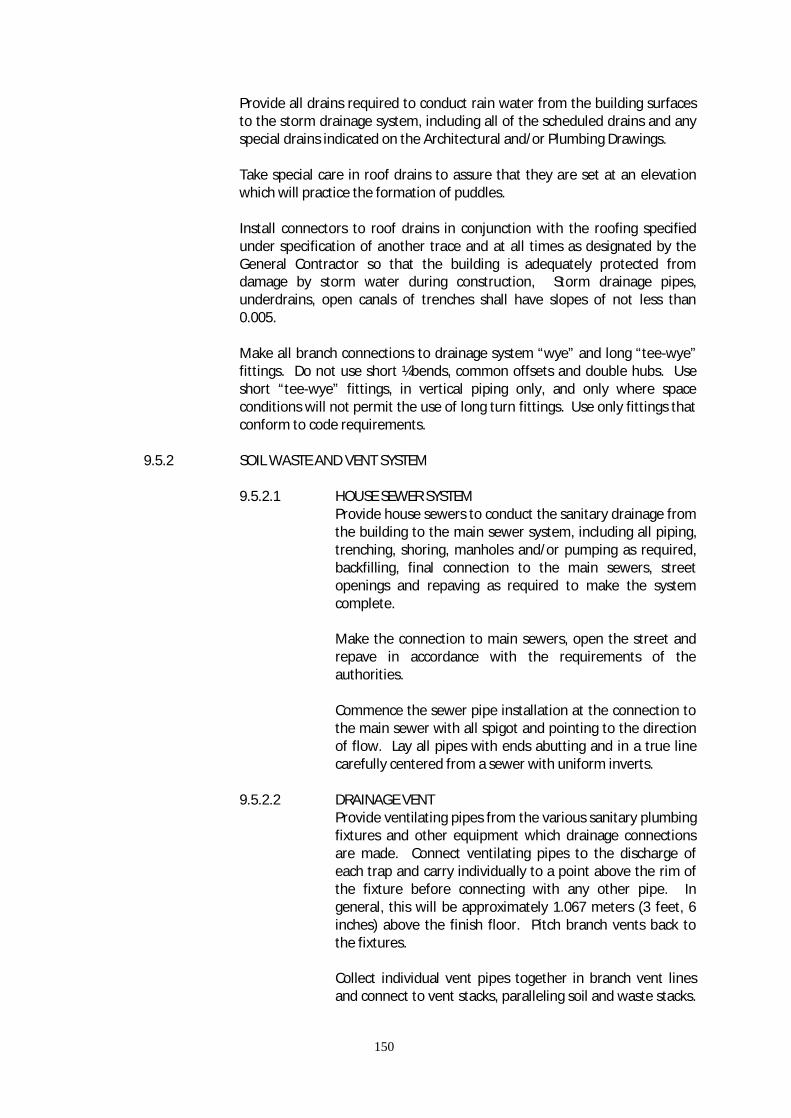
150
Provide all drains required to conduct rain water from the building surfaces to the storm drainage system, including all of the scheduled drains and any special drains indicated on the Architectural and/or Plumbing Drawings. Take special care in roof drains to assure that they are set at an elevation which will practice the formation of puddles. Install connectors to roof drains in conjunction with the roofing specified under specification of another trace and at all times as designated by the General Contractor so that the building is adequately protected from damage by storm water during construction, Storm drainage pipes, underdrains, open canals of trenches shall have slopes of not less than 0.005. Make all branch connections to drainage system “wye” and long “tee-wye” fittings. Do not use short ¼bends, common offsets and double hubs. Use short “tee-wye” fittings, in vertical piping only, and only where space conditions will not permit the use of long turn fittings. Use only fittings that conform to code requirements.
9.5.2 SOIL WASTE AND VENT SYSTEM 9.5.2.1 HOUSE SEWER SYSTEM
Provide house sewers to conduct the sanitary drainage from the building to the main sewer system, including all piping, trenching, shoring, manholes and/or pumping as required, backfilling, final connection to the main sewers, street openings and repaving as required to make the system complete. Make the connection to main sewers, open the street and repave in accordance with the requirements of the authorities. Commence the sewer pipe installation at the connection to the main sewer with all spigot and pointing to the direction of flow. Lay all pipes with ends abutting and in a true line carefully centered from a sewer with uniform inverts.
9.5.2.2 DRAINAGE VENT Provide ventilating pipes from the various sanitary plumbing fixtures and other equipment which drainage connections are made. Connect ventilating pipes to the discharge of each trap and carry individually to a point above the rim of the fixture before connecting with any other pipe. In general, this will be approximately 1.067 meters (3 feet, 6 inches) above the finish floor. Pitch branch vents back to the fixtures. Collect individual vent pipes together in branch vent lines and connect to vent stacks, paralleling soil and waste stacks.

151
Whenever possible, vent stack offsets shall be made with 45 degree fittings. Vent stacks shall be connected to adjacent soil stacks at the base of the stacks. Extend the tops of ventilating stacks independently through the roof or collect together and run through the roof in series of larger pipes, as shown on the drawings. Provide roof couplings at a level 45 millimeters (18 inches) above the finished roof to receive flashings.
9.5.3 COLD WATER SYSTEM
Provide a complete cold water distribution system to supply water to all fixtures, water consuming equipment and valve outlets for the use of other Trades.
The system shall include the required meters and meter accessories.
The water supply system shall be complete with all pipe fittings, valves, meters, trenching, shoring, backfilling, mains, risers, branches, air chambers, controls, hangers, anchors, protective painting, insulation, tests, and the like, all as shown on the drawings, as hereinafter specified and in accordance with the regulations of authorities having jurisdiction.
Provide all metering devices, strainers, test connectors, etc., as required by the authorities and shall obtain approval of the installation without additional cost to the Owner.
Use materials as scheduled.
All equipment used in this system shall have capacities as scheduled.
Adjust all fixtures stops so that flush valves, faucets, etc., function quietly and efficiently before final acceptance by the Owner.
Provide tapping valves, curb valves, boxes and signs where required by the authorities having jurisdiction.
Provide all pipes, fittings, valves, street openings, excavation, backfill, repaving and the like, required to make the system complete.
9.6 TEST 9.6.1 STORM DRAINAGE SYSTEM TEST
The entire drainage and venting system shall have all the necessary openings which can be plugged to permit the entire system to be filled with water to the level of the highest stack vent and/or vent stack above the roof.
The system shall hold this water for a full thirty (30) minutes during which time there shall be no drop more than 100 millimeters (4 inches). If and
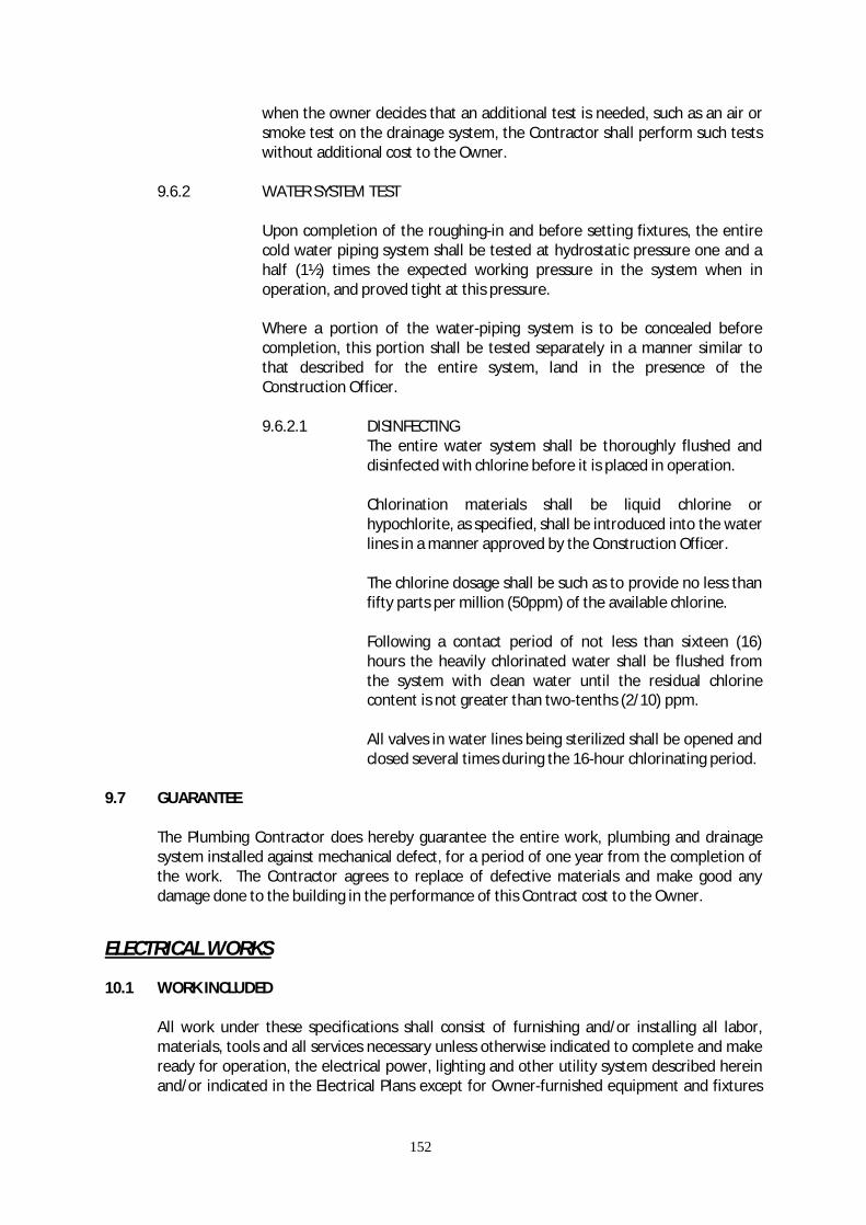
152
when the owner decides that an additional test is needed, such as an air or smoke test on the drainage system, the Contractor shall perform such tests without additional cost to the Owner.
9.6.2 WATER SYSTEM TEST
Upon completion of the roughing-in and before setting fixtures, the entire cold water piping system shall be tested at hydrostatic pressure one and a half (1½) times the expected working pressure in the system when in operation, and proved tight at this pressure.
Where a portion of the water-piping system is to be concealed before completion, this portion shall be tested separately in a manner similar to that described for the entire system, land in the presence of the Construction Officer.
9.6.2.1 DISINFECTING
The entire water system shall be thoroughly flushed and disinfected with chlorine before it is placed in operation.
Chlorination materials shall be liquid chlorine or hypochlorite, as specified, shall be introduced into the water lines in a manner approved by the Construction Officer.
The chlorine dosage shall be such as to provide no less than fifty parts per million (50ppm) of the available chlorine.
Following a contact period of not less than sixteen (16) hours the heavily chlorinated water shall be flushed from the system with clean water until the residual chlorine content is not greater than two-tenths (2/10) ppm.
All valves in water lines being sterilized shall be opened and closed several times during the 16-hour chlorinating period.
9.7 GUARANTEE
The Plumbing Contractor does hereby guarantee the entire work, plumbing and drainage system installed against mechanical defect, for a period of one year from the completion of the work. The Contractor agrees to replace of defective materials and make good any damage done to the building in the performance of this Contract cost to the Owner.
ELECTRICAL WORKS
10.1 WORK INCLUDED
All work under these specifications shall consist of furnishing and/or installing all labor, materials, tools and all services necessary unless otherwise indicated to complete and make ready for operation, the electrical power, lighting and other utility system described herein and/or indicated in the Electrical Plans except for Owner-furnished equipment and fixtures
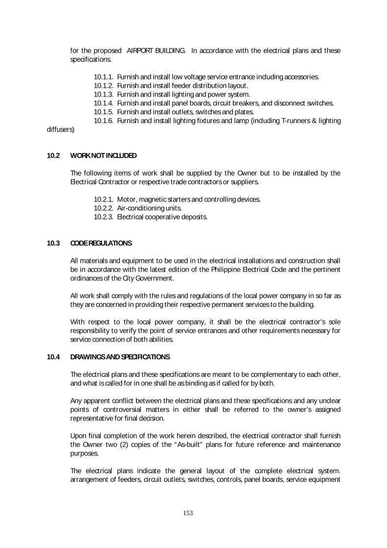
153
for the proposed AIRPORT BUILDING. In accordance with the electrical plans and these specifications.
10.1.1. Furnish and install low voltage service entrance including accessories. 10.1.2. Furnish and install feeder distribution layout. 10.1.3. Furnish and install lighting and power system. 10.1.4. Furnish and install panel boards, circuit breakers, and disconnect switches. 10.1.5. Furnish and install outlets, switches and plates. 10.1.6. Furnish and install lighting fixtures and lamp (including T-runners & lighting diffusers) 10.2 WORK NOT INCLUDED
The following items of work shall be supplied by the Owner but to be installed by the Electrical Contractor or respective trade contractors or suppliers.
10.2.1. Motor, magnetic starters and controlling devices. 10.2.2. Air-conditioning units. 10.2.3. Electrical cooperative deposits. 10.3 CODE REGULATIONS
All materials and equipment to be used in the electrical installations and construction shall be in accordance with the latest edition of the Philippine Electrical Code and the pertinent ordinances of the City Government.
All work shall comply with the rules and regulations of the local power company in so far as they are concerned in providing their respective permanent services to the building.
With respect to the local power company, it shall be the electrical contractor’s sole responsibility to verify the point of service entrances and other requirements necessary for service connection of both abilities.
10.4 DRAWINGS AND SPECIFICATIONS
The electrical plans and these specifications are meant to be complementary to each other, and what is called for in one shall be as binding as if called for by both.
Any apparent conflict between the electrical plans and these specifications and any unclear points of controversial matters in either shall be referred to the owner’s assigned representative for final decision.
Upon final completion of the work herein described, the electrical contractor shall furnish the Owner two (2) copies of the “As-built” plans for future reference and maintenance purposes.
The electrical plans indicate the general layout of the complete electrical system. arrangement of feeders, circuit outlets, switches, controls, panel boards, service equipment

154
and other work. Field verification of the scale dimensions on plane must be made, since actual locations, distances and levels will be governed by actual field conditions.
The Electrical Contractor shall check architectural, structural and plumbing plans be necessary to resolve such conflicts, the Electrical Contractor shall notify the Architect and secure approval and agreement on necessary adjustments before installation is started.
10.5 PERMITS AND INSPECTION
The Electrical Contractor shall obtain all necessary permits and certificates of electrical inspection from the proper government authorities concerned, required both for the performance of the work involved and the operation of the system upon completion of the work.
The Electrical Contractor shall pay all necessary electrical fees for the securing of the above-mentioned permits and certificates of electrical inspection.
The Electrical Contractor shall as his own expense, reproduce the electrical plans for work to the necessary scale and size, complete them with the necessary information and requirements as required by the government authorities concerned with approving such plans.
The Electrical Contractor shall coordinate with the local power company regarding the power facilities and secure approval of the power requirements.
10.6 MATERIALS AND WORKMANSHIP
All materials to be installed shall be brand new, unused and shall in every case to be the best where such standard have been established for the particular type of materials used.
Only skilled workmen using proper tools and equipment shall be employed during the entire course of the installation work. All workmanship shall be of the best quality, all work to be done in accordance with the best engineering practice of the trade involved.
10.7 WIRING METHOD
Branch circuit installation for lighting and power layout shall be done polyvinyl chloride pipes (PVC) exposed, inside drop ceiling, wooden and concrete partitions, using NELTEX, ATLANTA EMERALD or approved equal.
All auxiliary layout shall be in uPVC pipes using NELTEX or ATLANTA, EMERALD or approved equal.
Branch circuit layout run underground or embedded in concrete slab shall also be in PVC pipes.
Low voltage service entrance and all feeders shall be in Rigid Steel Conduit (RSC) using PUSAN, KSP of approved equal.
Use flexible metal pipe for connection between junction boxes inside ceiling and lighting fixtures and ceiling fans with standard fittings.

155
All conduits shall be standard mild steel; hot galvanized or sherardized with an interior coating. Conduits shall be 15mm minimum nominal diameter or otherwise as indicated in the Drawings.
All conduits shall be laid during the construction and shall be concealed in ceiling. All boxes, cabinets and other equipment shall be installed flush-mounted unless specified otherwise. All underground conduits shall be encased in concrete with minimum thickness of 10mm around conduit, and when outside the building, be reinforced sufficiently with steel bars.
All boxes for lighting outlets, convenience outlets, tumbler switches and other devices shall be galvanized and approved products of reputable manufacturers. Outlet boxes shall be 1.5mm thick (Gauge 16). Ceiling and wall outlet boxes shall be 10mm octagonal. Boxes for wall, 50mm x 100m x 55mm deep, locally made. Cut ends of conduits shall be reamed and cleaned to remove burr and sharp edges. Threads cut on conduits shall be the same thread dimensions as factory cut conduit threads. Conduit joints shall be made straight and true. Elbows and offsets and changes in direction of runs and shall be uniform. Bends shall be made without chinking or destroying the cross-sectional contours of the conduits. Conduit terminals shall be provided at outlet boxes and cabinets with locknuts and bushing. Conduits shall be continuous from outlet and from outlet to pull boxes and cabinets in the manner that the conduit system shall be electrically continuous.
Where conduit runs are exposed, they shall be supported at an interval of 1.52m maximum with proper clamps and bolts or expansion shields or other means of support.
Wires shall be manufactured by PHELP DODGE PHILS., AMERICAN WIRE AND CABLE or approved equivalent. Use one brand only.
All splices taps, junction in wires larger than 8.0 sq.mm. shall be done with solderless connectors or suitable sizes properly insulated with rubber tapes and protected by friction tapes, so that the insulation strength shall at least be equal to the insulation of the conductors they join.
Smallest size of wire to be used for lighting and power unless otherwise indicated shall be 3.5sq.mm.
10.8 FEEDERS
Feeders shall be laid out in accordance with the riser diagram shown in the electrical plans.
Unless otherwise specified type THW wires shall be used for feeder lines. The wires and conduits sizes shown in the electrical plans shall be the minimum sizes to be used.
10.9 WALL SWITCHES AND RECEPTACLES
Suitable single pale tumbler switches and three way switches of the flush type shall be NATIONAL brand. Japanese brand or approved equal, to be furnished and installed by the electrical contractor as indicated in the electrical plans. Wall switches intended to control more than 500 watts load shall be rated Amperes, 300 volts.

156
Ordinary convenience outlets shall be duplex flush type, 2 wires, 15 Amperes, 250 volts; NATIONAL brand. Japan made or approved equal. Heavy duly convenience outlets shall be rated 250 volts, 2 wires, 20 Amperes. All wall plates for switches, receptacles, telephone outlets and blank cover shall be National brand, practidesign or approved equal. Wall tumbler switches shall be installed 1.40m above finish floor level. Wall convenience outlets shall be installed 0.30m above finish floor or above the baseboard where there are baseboards.
10.10 MAIN SWITCHES AND PANEL BOARDS
The Electrical Contractor shall furnish and install main distribution panel, lighting panel boards as shown in the drawings. The cabinets for the above must be of standard sizes and gauge. Locally assembled by FUJI HAYA ELECTRIC CORP., WESTINGHOUSE or approved equal. Main circuit breakers for power and lighting panel boards shall be 250 volts, AC and shall be quick break, FUJI brand, Japan made WESTINGHOUSE or approved equal. Safety disconnect switches shall be fusible type as manufactured by EVER, or approved equal.
10.11 LIGHTING FIXTURES
Install all lighting fixtures and lamps as specified and shown on plans. Fluorescent lamps shall be 48 inches, 48 watts, standard cool white or daylight with minimum light output of 3,000 lumens. Use normal power factor ballast, 250V. All fluorescent fixtures housing shall be of US Gauge 22 minimum. Submit one (1) sample of each type of fixtures to the Architect for approval prior to manufacturing and installation.
10.12 WATER PUMP
The electrical contractor shall install a complete wiring and conduit for the system including circuit breaker.
The water pump and accessories such as electric motor, magnetic starter, electrode water level controller and others are supplied and installed by others.

157
10.13 GUARANTEE
The electrical contractor shall guarantee his work for a period of one (1) year form the date of acceptance of the Owner, with which time, he shall repair any defects and failures in any part of the system and replace defective materials, except those to the Owner.
10.14 “AS BUILT” DRAWINGS
Upon completion and before first acceptance of the work, the contractor shall prepare at his own expense and submit to the Architect “as built” drawings indicating in all detail the actual as-built conditions of the work required.
11.0 LANDSCAPING 11.1 SCOPE OF WORK
This work includes furnishing of all labor, materials, equipment and incidentals for the supply, delivery, placement and maintenance of garden soil, grasses and specified plants.
11.2 SUBMITTALS
The Contractor shall submit to the Construction Officer for approval representative samples of garden soil and plants to be used. Garden soil, grasses and plants delivered to the site that is in the opinion of the Construction Officer as inferior to the approved samples shall be removed and disposed of offsite at no cost to the Owner.
11.3 WORKMANSHIP
Landscaping works shall be done by skilled workers of gardeners of qualified landscape contractors. Garden soil, grass and plants (specifically santan and various kinds of hedges) shall be maintained up to the date of turn over and acceptance of the project (completion of the project). Maintenance shall include watering, fertilizing, weeding, cutting, repairing and replacement. Landscaped area shall be left clean and free from loose materials and excess soil, leaves and other matters.

158
ITEM 103 – REMOVAL OF STRUCTURES AND OBSTRUCTIONS
103.1 DESCRIPTION This Item shall consist of removal, wholly or in part, and satisfactory disposal of all buildings, fences, structured, old pavements, abandoned pipe lines, and any other obstructions which are not designated or permitted to remain, except for the obstruction to be removed and disposed of under other items in the Contract. It shall also include the salvaging of designated materials and back-filling the resulting trenches, holes, and pits. 103.2 CONSTRUCTION REQUIREMENTS 103.1.1 GENERAL The Contractor shall perform the work described above, within and adjacent to the roadway, runway on Government land or easement, as shown on the Plans or as directed by the Engineer. All designated salvable material shall be removed, without unnecessary damage, in sections or pieces which may readily transported, and shall be stored by the Contractor at specified places on the project or as otherwise shown in the Special Provisions. Perishable material shall be handled as designated in Sub-section 100.2.2. Nonperishable material may be disposed of outside the limits of view from the project with written permission of property the material is placed. Copies of all agreements with property owners are to be furnished to the Engineer. Basements or cavities left by structure removal shall be filled with acceptable material to the level of the surrounding ground and, if within the prism of construction, shall be compacted to the required density. 103.1.2 REMOVAL OF BRIDGES, CULVERTS AND OTHER DRAINAGE STUCTURES. Bridges, culverts and other drainage structures in use by traffic shall not be removed until satisfactory arrangements have been made to accommodate traffic. The removal of existing culverts within embankment areas will be required only as necessary for the installation of new structures. Abandoned culverts shall be broken down, crushed and sealed or plugged. All culverts sections removed, which are not designated for stockpiling or relaying, shall become the property of the contractor and be removed from the project or disposed of in a manner approved by the Engineer. Blasting and other operations necessary for the removal of an existing structure or obstruction, which may damage new construction, shall be completed prior to placing the new work, unless otherwise provided in the Special Provisions. 103.1.3 REMOVAL OF PIPES OTHER THAN PIPE CULVERTS. Unless otherwise provide, all pipes shall be carefully removed and every precaution taken to avoid breakage or damage. Pipe to be re-laid shall be removed and stored when necessary so that there will no loss or damage before relaying. The Contractor shall replace sections lost from storage or damage by negligence, at his own expense. 103.1.4 REMOVAL OF PAVEMENT, SIDEWALKS, CURBS, ETC. All concrete pavement, base course, sidewalks, curbs, gutter, etc., designated for removal, shall be:
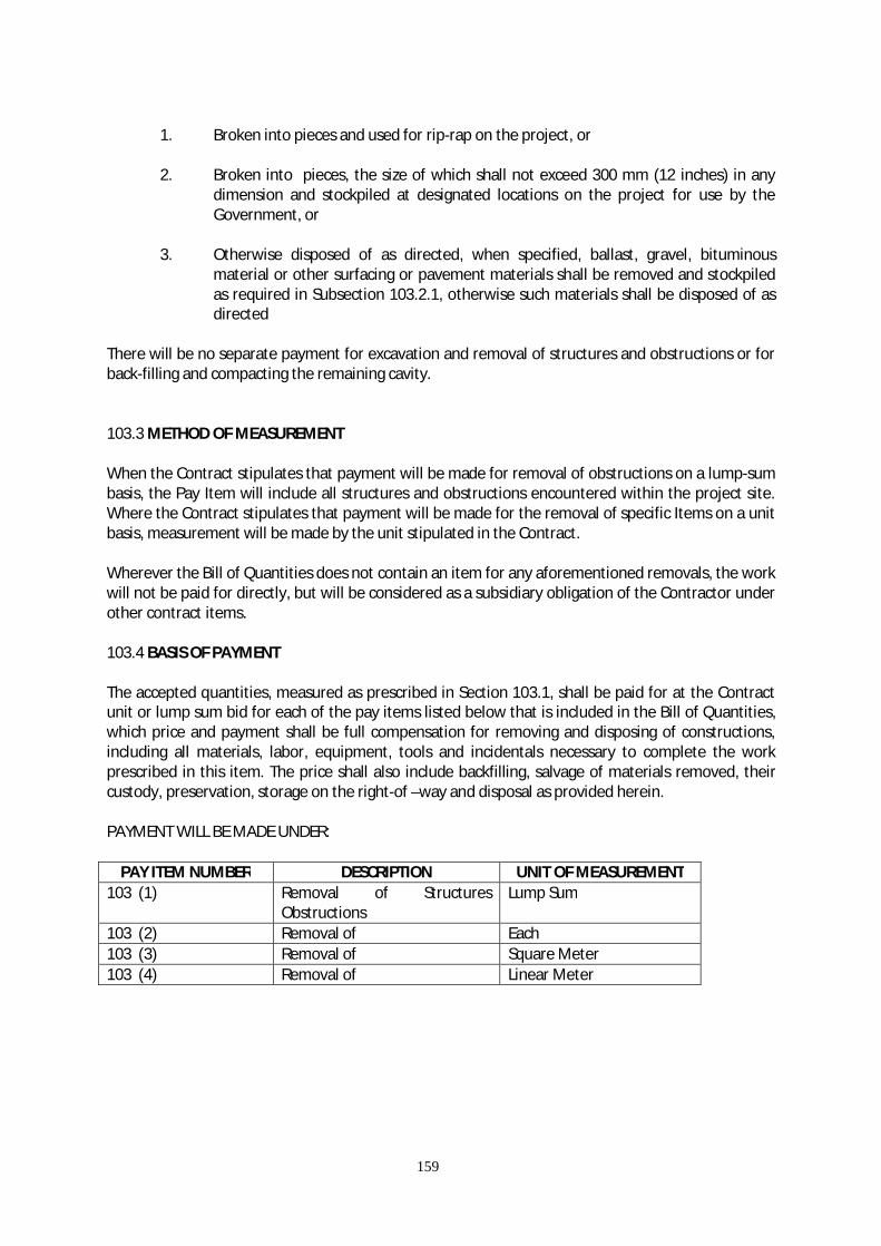
159
1. Broken into pieces and used for rip-rap on the project, or 2. Broken into pieces, the size of which shall not exceed 300 mm (12 inches) in any
dimension and stockpiled at designated locations on the project for use by the Government, or
3. Otherwise disposed of as directed, when specified, ballast, gravel, bituminous
material or other surfacing or pavement materials shall be removed and stockpiled as required in Subsection 103.2.1, otherwise such materials shall be disposed of as directed
There will be no separate payment for excavation and removal of structures and obstructions or for back-filling and compacting the remaining cavity. 103.3 METHOD OF MEASUREMENT When the Contract stipulates that payment will be made for removal of obstructions on a lump-sum basis, the Pay Item will include all structures and obstructions encountered within the project site. Where the Contract stipulates that payment will be made for the removal of specific Items on a unit basis, measurement will be made by the unit stipulated in the Contract.
Wherever the Bill of Quantities does not contain an item for any aforementioned removals, the work will not be paid for directly, but will be considered as a subsidiary obligation of the Contractor under other contract items. 103.4 BASIS OF PAYMENT
The accepted quantities, measured as prescribed in Section 103.1, shall be paid for at the Contract unit or lump sum bid for each of the pay items listed below that is included in the Bill of Quantities, which price and payment shall be full compensation for removing and disposing of constructions, including all materials, labor, equipment, tools and incidentals necessary to complete the work prescribed in this item. The price shall also include backfilling, salvage of materials removed, their custody, preservation, storage on the right-of –way and disposal as provided herein. PAYMENT WILL BE MADE UNDER:
PAY ITEM NUMBER DESCRIPTION UNIT OF MEASUREMENT 103 (1) Removal of Structures
Obstructions Lump Sum
103 (2) Removal of Each 103 (3) Removal of Square Meter 103 (4) Removal of Linear Meter

160
ITEM 104 EXCAVATION
104.1 DESCRIPTION This item shall consist of excavation, removing and satisfactorily disposing of all materials within the limits of the work required to conduct the landing strips, runways, taxiways, aprons, intermediate, and other areas of drainage, building construction, parking or other purposes in accordance with these specifications and in conformity with the dimensions and typical section shown on the plans and with the lines and grades established by the Engineer. All suitable material taken from excavation shall be used in the formation of embankment, sub-grade, and back filling as indicated on the plans or as directed by the Engineer. When the volume of the excavation exceeds that required to construct the embankments to the grades indicated, the excess shall be used to grade the areas of ultimate development or constructing the fill to the grades indicated, the deficiency shall be supplied from borrow sources at locations within the airport or other authorized areas. 104.2 CLASSIFICATION All material excavated shall be defined as “Unclassified Excavation” unless, in the proposal form, prices are asked and bids are taken for “Solid Rock Excavation” and “Common Excavation”. “Unclassified Excavation” shall include all excavation performed under this item regardless of the material encountered. “Solid Rock Excavation” when provided in the proposal shall include all solid rock in ledges, in bedded deposits, in unstratified masses, and conglomerate deposits which are firmly cemented they present all the characteristics of solid rock and which cannot be removed without drilling and blasting. All boulders contain a volume of more than 0.5 cubic meter will be classified as “Solid Rock Excavation”, “Common Excavation”, when provided in the proposal, shall include all solid excavation not included in “Solid Rock Excavation”. Frozen condition of any of the different classified materials taken from excavation does not constitute a basis for a calm for higher classification or for extra work on the part of the contractor. 104.3 CONSTRUCTION METHODS 104.3.1 General The rough excavation shall be carried to the necessary depth to obtain the specified depth of sub-grade classification shown on the plans. Likewise, on embankments, the depth of sub-grade densification shall be as shown on the plans. Should the Contractor, through negligence or other fault, excavate below the designated lines, he shall replace the excavation with approved materials, in an approved materials, in an approved manner and condition at his own expense. The Engineer shall have complete control over the excavation, moving, placing, and disposition of all material and shall determine the suitability of material to be placed in embankments. All material determined unsuitable should be disposed of in waste areas or as directed. Topsoil shall not be used in fills or in sub-grades should be disposed of in waste areas or as directed. The Contractor shall inform and satisfy himself to as to the character, quantity and distribution of all materials to be excavated. No payment will be made for any excavated material, which is used for purpose other than those designated. All spoil areas shall be leveled to a uniform line and section and shall present a neat appearance before project acceptance. The surface elevation of adjacent or contiguousable areas of the airport. Those areas outside the pavement in which the top layer of soil material becomes compacted due to hauling or to any other activity of the contractor, shall be scarified and disc harrowed or plowed to a
161
depth of 100 mm, as directed, to loosen and pulverized the soil. It is necessary to interrupt existing surface drainage, conduits, utilities, or similar underground structure, or parts thereof, the contractor shall be responsible for and shall take all necessary precautions to protect and preserve or provide temporary services. When such facilities are encountered, the contractor shall notify the Engineer, who shall arrange for their removal, if necessary. The contractor at his own expense, satisfactorily repair all damage to such facilities or structures which may result from any at his operations during the period of the contract. 104.3.2 Excavation Excavation shall be performed as indicated on the contract plans to the lines, grades, and elevation shown or as directed by the Engineer, and shall be made so that the requirements for formation of embankment can be followed. No excavation or stripping shall be started until the Engineer shall have taken cross-sectional elevations and measurement of the existing ground surface, and has staked out the proposed work. All material encountered within the limits indicated shall be removed and disposed as of directed. When directed, temporary drains and drainage ditches shall be installed to intercept or divert surface water, which mat affect the work. When selected grading is specified or required as indicated on the plans, the placed in the embankment and pavement sub-grades as determined from the solid profile and soil characteristics. This material shall be deposited within the designated areas of the airport as shown on the plans or as directed by the Engineer. If, at the time of excavation, it is possible to place any material in its proper section of the permanent construction, it shall be stockpiled in approved areas for later use. Rock, shale, hardpan, loose rock, boulders, or other material unsatisfactory for landing strips, sub-grades, runways shoulders, intermediate areas or any areas intended for turning shall be excavated to a minimum depth of 300 mm, or to depth specified by the Engineer, below the contemplated surface of the sub-grade or the designated grades. Muck, peat, matted roots, or other suitable material for sub-grade foundation, shall be removed to the depth specified, to provide a satisfactory foundation. Unsatisfactory materials shall be disposed at locations designated by the Engineer. All materials excavated shall be paid at the contract unit price per cubic mater for “Unclassified Excavation”, “Common Excavation”, or Solid Rock Excavation”, as the case maybe, when classification for the last two items is provided in the proposal. The portion so excavated shall be refilled with suitable selected material is specified, obtained from the grading operations or borrow area and thoroughly compacted by rolling. The necessary refilling will constitute a part of the embankment. Where trenching out is done to provide for a course of pavement, the depth thus created shall be ditched at frequent intervals to provide adequate drainage. The contractor shall make the grade to avoid haul will not be permitted. The right is reserve to make minor adjustment or revisions in lines or grades, if found necessary, as the work progresses due to discrepancies in the plans or to obtain satisfactory construction. Over-break including slides, is that portion of any material displaced or loosen beyond the finish work as planned or authorized by the Engineer. The Engineer shall determine if the displaced of such material was unavoidable and his decision shall be final. All over-break shall be removed by the contractor and disposed as directed; however, payment will not be made under for the removal and disposal of over-break which the Engineer determines as avoidable. Unavoidable over-break will be classified as ‘Unclassified Excavation”, except when the contract provides for the classification of “Common Excavation”, or “Solid Rock Excavation”, in which case unavoidable over-breakage from slides will be classified as such. The removal of existing structures and utilities required to permit orderly progress of work will be accomplished by local agencies, unless otherwise shown on the plans. All existing foundations shall be excavated for at least 60 mm below the top of the sub-grade and the material disposed as directed.

162
All foundations thus excavated shall be backfill with suitable material and compacted. In cut areas, the sub-grade under areas to be paved shall be compacted to the depths and to the densities at optimum moisture as shown on the plans or as specified in the specification, or when not otherwise shown or specified, to a minimum depth of 150mm and to a density of not less than 95%, for cohesive soils, and 100% for non-cohesive soils, the maximum density at optimum moisture as determined by the compaction control tests specified in FAA T-611. Any suitable materials encountered shall be removed and paid for as specified. No payment or measurement for payment will be made for suitable materials remove, manipulated and replaced in order to obtain density. Any removal, manipulation, aeration, replacement, and re-compaction of suitable materials necessary to obtain the required density shall be considered as incidental to the excavation and embankment operation, and shall be performed by the contractor at no additional cost to the project. Stones or rock fragments larger than 100mm in their greatest dimension will not be permitted in the top 150mm of the sub-grade. The finished grading operations conforming to the typical cross-section shall be completed and maintained at least 300 meters ahead of the paving operations. In cuts, all loose or protruding rocks on the back slope shall be barred loose or otherwise removed to line or finished grade of slope. All cut and fill slopes shall be uniformly dressed to the slopes, cross section, and alignment shown on the plans or as directed by the Engineer. Blasting when necessary will be permitted only when proper precautions are taken for the protection and safety of all persons, the work, and the property. All damage done to the work or property shall be repaired at the contractor’s expense. All operations of the contractor in connection with the transportation, storage, and use of explosives shall be approved by the Engineer. Any approval given will not relieve the contractor of his responsibility in blasting operations. 104.3.3 Borrow Excavation When provided for in the proposal, borrow excavation shall consist of excavation made from borrow areas within the limits of the airport property outside the normal grading limits, or the airport property from which borrow may be obtained will be designated. Borrow Excavation shall be made only at these designated locations within the horizontal and vertical limits as staked or as directed. On completion of the borrow operations, the borrow area shall be finished to a neat and uniform grade acceptable to the Engineer. When borrow sources are outside the boundaries of the airport property it shall be the Contractor’s responsibility to locate and obtain the supply, subject to the approval of the Engineer. The Contractor shall notify the Engineer, sufficiently in advance of the beginning of excavation, so necessary measurements and test can be made. All objectionable material shall be disposed of as directed. All borrow pits shall be opened up immediately to expose the vertical face of various product. Borrow pits shall be excavated to regular lines to permit accurate measurement and shall be drained and left in a neat and presentable condition with all slopes dressed uniformly. The borrow excavation shall be handled and placed as specified in these specifications for excavation. 104.3.4 Ditch Excavation Ditch excavation shall consist of excavating for drainage ditches such as intercepting, inlet or outlet, temporary levee construction, or any other type as designed or as shown on the plans. The work shall be performed in the proper sequence with the other construction. The location of all ditches or levees shall be established on the ground. All satisfactory material shall be placed in fills;
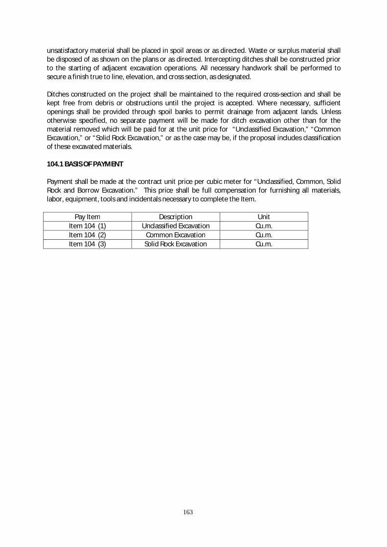
163
unsatisfactory material shall be placed in spoil areas or as directed. Waste or surplus material shall be disposed of as shown on the plans or as directed. Intercepting ditches shall be constructed prior to the starting of adjacent excavation operations. All necessary handwork shall be performed to secure a finish true to line, elevation, and cross section, as designated. Ditches constructed on the project shall be maintained to the required cross-section and shall be kept free from debris or obstructions until the project is accepted. Where necessary, sufficient openings shall be provided through spoil banks to permit drainage from adjacent lands. Unless otherwise specified, no separate payment will be made for ditch excavation other than for the material removed which will be paid for at the unit price for “Unclassified Excavation,” “Common Excavation,” or “Solid Rock Excavation,” or as the case may be, if the proposal includes classification of these excavated materials. 104.1 BASIS OF PAYMENT Payment shall be made at the contract unit price per cubic meter for “Unclassified, Common, Solid Rock and Borrow Excavation.” This price shall be full compensation for furnishing all materials, labor, equipment, tools and incidentals necessary to complete the Item.
Pay Item Description Unit Item 104 (1) Unclassified Excavation Cu.m. Item 104 (2) Common Excavation Cu.m. Item 104 (3) Solid Rock Excavation Cu.m.
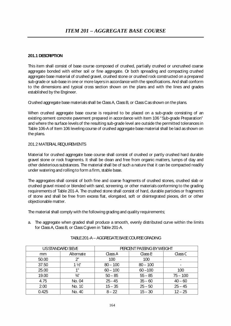
164
ITEM 201 – AGGREGATE BASE COURSE
201.1 DESCRIPTION This item shall consist of base course composed of crushed, partially crushed or uncrushed coarse aggregate bonded with either soil or fine aggregate. Or both spreading and compacting crushed aggregate base material of crushed gravel, crushed stone or crushed rock constructed on a prepared sub-grade or sub-base in one or more layers in accordance with the specifications. And shall conform to the dimensions and typical cross section shown on the plans and with the lines and grades established by the Engineer. Crushed aggregate base materials shall be Class A, Class B, or Class C as shown on the plans. When crushed aggregate base course is required to be placed on a sub-grade consisting of an existing cement concrete pavement prepared in accordance with Item 106 “Sub-grade Preparation” and where the surface levels of the resulting sub-grade level are outside the permitted tolerances in Table 106-A of Item 106 leveling course of crushed aggregate base material shall be laid as shown on the plans. 201.2 MATERIAL REQUIREMENTS Material for crushed aggregate base course shall consist of crushed or partly crushed hard durable gravel stone or rock fragments. It shall be clean and free from organic matters, lumps of clay and other deleterious substances. The material shall be of such a nature that it can be compacted readily under watering and rolling to form a firm, stable base. The aggregates shall consist of both fine and coarse fragments of crushed stones, crushed slab or crushed gravel mixed or blended with sand, screening, or other materials conforming to the grading requirements of Table 201-A. The crushed stone shall consist of hard, durable particles or fragments of stone and shall be free from excess flat, elongated, soft or disintegrated pieces, dirt or other objectionable matter. The material shall comply with the following grading and quality requirements; a. The aggregate when graded shall produce a smooth, evenly distributed curve within the limits
for Class A, Class B, or Class C given in Table 201-A.
TABLE 201-A – AGGREGATE BASE COURSE GRADING
US STANDARD SIEVE PERCENT PASSING BY WEIGHT mm Alternate Class A Class B Class C
50.00 2” 100 100 - 37.50 1 ½” 80 – 100 80 – 100 - 25.00 1” 60 – 100 60 –100 100 19.00 ¾” 50 – 85 55 – 85 75 – 100 4.75 No. 04 25 - 45 35 – 60 40 – 60 2.00 No. 10 15 – 35 25 – 50 25 – 45
0.425 No. 40 8 – 22 15 – 30 12 – 25

165
0.075 No. 200 2 – 9 8 –15 5 – 12 b. The course aggregate material retained on a 4.75mm (No. 4) sieve shall consist of material of
which not less than 50% by weight shall be crushed particles, having a minimum of one fractured face.
c. The course aggregate retained on a 4.75mm (No.4) sieve shall have a percentage of wear by the
Los Angeles Abrasion Test AASHTO T96 of not more than 40% for crushed and 50% for uncrushed.
d. The material shall have a loss of less than 12% when subject to five cycles of sodium sulfate
soundness test according to AASHTO T104. e. The sand equivalent determined according to AASHTO T176 should not be less than 50. f. The material passing the 19mm (3/4”) sieve shall have a minimum soak CBR value of 80% tested
according to AASHTO T 193. The CBR value shall be obtained at the maximum dry density determined according to AASHTO T 180.
The portion of material passing the 0.425mm (No. 40) sieve shall have a liquid limit of not more than 25 and a plasticity Index of not more than 6 as determined by AASHTO T89 and 90 respectively. The crushed slab shall be air-cooled, blast furnace slag and shall consist of angular fragment reasonably clean and free of thin, elongated or soft pieces, dirt or other objectionable matter. It shall weigh not less than 1120 kilogram per cubic meter as determined by AASHTO T19. The method used in the production of crushed gravel shall be such that the fractured particles occurring in the finished product shall be as nearly constant and uniform as practicable and shall result in at least the specified percentage of material retained on a No. 4 mesh sieve having one or more fractured faces. If necessary, to meet his requirements or to eliminate and excess of fine uncrushed particles, the gravel shall be screened before crushing. All stone, rocks and boulders of inferior quality in the pit shall be wasted. All material passing the No. 4 mesh sieve produced in the crushing operation of either stone, slag or gravel shall be incorporated in the base material to the extent permitted by the gradation requirements. The final gradation decided on within the limits designated in the table shall be well graded from coarse to fine and shall not vary from the low limit on one sieve to the high on the adjacent sieves, or vice versa. The amount of the fraction of material passing the No. 200 mesh sieve shall not exceed one-half the fraction passing the No. 40 mesh sieve. The selection of any gradation shown in Table 155-A shall be such that the maximum size aggregate used in any course shall be not more than two-thirds the thickness of the layer of the course being constructed.

166
201.2.1 FILLER FOR BLENDING The filler in addition to the naturally present in the base course material, is necessary for satisfactory bonding of the material, for changing the soil constant of the material passing the No. 40 mesh sieve or for correcting the gradation to the limitations of the specified gradation, it shall be uniformly blended with the base course material at the crushing plant or at the mixing plant. The material for such purpose shall be obtain from sources approved by the Engineer and shall be of the specified gradation. The additional filler may be composed of sand but the amount of sand shall not exceed 20% by weight of the total combined base aggregate. All sand shall pass a No. 4 mesh sieve and not more than 5% by weight shall pass a No. 200 mesh sieve. 201.3 CONSTRUCTION METHODS 201.3.1 OPERATION IN PITS AND QUARRIES All works involved in cleaning and the Contractor shall perform stripping pits and quarries, including handling of unsuitable materials. All material shall be handled in a manner that shall secure a uniform and satisfactory base product. The base course material shall be obtained from approved sources. 201.3.2 EQUIPMENT All equipment necessary for the proper construction on this work shall be available at the project site, in first class working condition, and approved by the Engineer before construction is permitted to start. 201.3.3 PREPARING UNDERLYING COURSE The underlying course shall be checked and accepted by the Engineer before placing and spreading operations are started. Any ruts or soft, yielding places due to improper drainage conditions, hauling or any other cause, shall be corrected and rolled to the required density before the base course is placed thereon. Grade control between the edges of the pavement shall be accomplished by graded stakes, steel pins, or forms placed in lanes parallel to the centerline of the pavement at intervals sufficiently close at string line or check boards may be placed between the stakes, pins or forms. 201.3.4 METHODS OF PRODUCTION a. PLANT MIX. When provided in the proposal, or when selected by the contractor and approved
by the Engineer, the base material shall be uniformly blended or mixed in an approved plant. The mixing plant shall include bins for storage and batching of the aggregates, pumps and tanks for water, and batch mirror of either pugmill or drum type. All mineral aggregates shall be batch into the mixer by weight. The agitation shall be such that a thorough dispersion of moisture is obtained. The Engineer shall fix the size of the batch at time of mixing. The base course material produced by combining two or more materials from different sources shall be mixed in a mixing plant described herein. The mixture material shall be at satisfactory moisture content to obtain maximum density.
167
b. TRAVEL PLANT. When the use of travelling plant is allowed, the plant shall blend and mix the materials to meet these specifications. It shall accomplish a thorough mixing in one trip. The agitation shall be such that the dispersion of the moisture is complete. The machine shall move at uniform rate of speed and this speed shall be regulated to fix the mixing time. If a window-type travel plant is employed for mixing, the aggregate shall be placed in windrows parallel to the pavement centerline.
The windrow volume shall be sufficient to cover exact areas as planned. The windrow contents shall produce a mixture of the required gradation and bonding quantities. If a travel plant is used which the type that mixes previously spread aggregates in-place, the material shall have been spread in such thickness and proportions as may be handled by the machine to develop a base course of the thickness of each layer and of the gradation required. With either type of equipment, the mixed material shall be of a satisfactory moisture content to obtain the maximum density.
c. PROPORTIONING OR BLENDING IN-PLACE. When the base materials are to be proportioned and
mixed or blended in place, the different layers shall be placed and spread with the relative proportions of the components of the mixture being designated by the Engineer. The base aggregate shall be deposited and spread evenly over the first layer. They shall be thoroughly mixed and blended by means of the approved graders, discs, harrows, rotary tiller, or a machine capable of combining these operations, supplemented by other suitable equipment if necessary. The mixing shall continue until the mixture is uniform throughout and accepted by the Engineer. Areas of segregated material shall be corrected by the addition of needed material by re-mixing. Water shall be uniformly applied, prior and at the proper moisture content. When the mixing and blending have been completed, the material shall be bladed and dragged, if necessary, until smooth surface is obtained, true to the line and grade.
d. MATERIALS OF PROPER GRADATION. When the entire base coarse materials from coarse to fine
be secured in a uniform well-graded condition and contains approximately the proper moisture, such approved material may be handled directly to the spreading equipment. The material may be obtained from gravel pits, stockpiles or produced from a crushing and screening plant with the proper blending. The material from these sources shall meet the requirements for gradation, quality and consistency. The base material shall be at satisfactory moisture content to obtain maximum density. Any minor deficiency or excess of moisture content may be corrected by surface sprinkling or by aeration. In such instances, some mixing or manipulation may be required immediately proceeding the rolling to obtain the required moisture content. The final operation shall be blading or gragging, if necessary, to obtain a smooth uniform surface to line and grade.
201.3.4 METHODS OF SPREADING a. The aggregate base material that is correctly proportioned, has been processed in a plant, shall
be placed on the prepared underlying course and compacted in layers of the thickness shown in the plans. The depositing and spreading of the material shall commence were designated and shall progress continuously without breaks. The material shall be deposited and spread in lanes on a uniform layer without segregation of size to such loose depth when compacted, the layer shall have the required thickness. The base aggregate shall be spread by spreader boxes or other approved devices having positive thickness controls that shall spread the aggregate in the required amount to avoid or minimize the need for hand manipulating. Dumping from vehicles in piles, which require re-handling shall not be permitted. Hauling over the uncompacted base course shall not be permitted.
168
b. The aggregate base material that has been processed in a traveling plant, or mixed and blended
in-place, shall be spread in a uniform layer of required depth and width and to the typical cross-section. The spreading shall be by self-powered blade grader, mechanical spreader or other approved method. In spreading, care shall be taken to prevent cutting into the underlying layer. The material shall be bladed until a smooth uniform surface is obtained, true to line and grade.
c. The base course shall be constructed in neither a layer not less than 62mm nor more than
112mm of compacted thickness. The aggregate as spread shall be on uniform grading with no pockets of fine or coarse materials. The aggregate, unless otherwise permitted by the Engineer, shall not be spread more than 1,670 square meters in advance of the rolling. Any necessary sprinkling shall be kept within these limits. No materials shall be placed in snow or on soft, muddy or frozen coarse.
When more than one layer is required, the construction procedure described herein shall apply similarly to each layer. The Engineer shall make tests to determine the maximum density and the proper moisture content of the base material and this information will be available to the Contractor. The base material shall be at a satisfactory moisture content when rolling is started and by any minor variation prior to or during rolling shall be corrected by sprinkling or by aeration if necessary. During the mixing and spreading process, sufficient caution shall be exercised to prevent the incorporation of sub-grade, sub-base, or shoulder material in the base course mixture. 201.3.5 FINISHING AND COMPACTING After spreading, the aggregate shall be thoroughly compacted by rolling. The rolling progress gradually from the side to the center of the lane under construction or from one side toward previously placed material by lapping uniformly each preceding rear wheel track by one half the width of such truck. Rolling shall continue until the aggregate is thoroughly set, the interstices of the material reduced to a minimum, and until creeping of the material ahead of the roller is no longer visible. Rolling shall continue until the base material has been compacted to not less than 100% density as determined by the compaction control tests specified to AASHTO T 180 and AASHTO T 99. Blading and rolling shall be shall be done alternately, as required or directed, to obtain a smooth, even and uniformly compacted base. The course shall not be rolled when the underlying course is soft or yielding or when the rolling causes undulation in the base course. When the rolling develops irregularities that exceed 9mm when tested with a 5m straightedge, the irregular surface shall be loosened, refilled with the same kind of material as that used in constructing the course, and rolled again as required. In area inaccessible to rollers, the base course material shall be tampered thoroughly with mechanical tampers. 201.3.6 Surface Test After the course has been completely compacted, the surface shall be tested for smoothness and accuracy of grade and crown. Any portion lacking the required smoothness or failing in accuracy of grade or crown shall be scarified, re-shaped, re-compacted and otherwise manipulated as the Engineer may direct until the required smoothness and accuracy are obtained. The finished surface shall not vary more than 9mm from a 5m straightedge when applied to the surface parallel with, and a right angel to the centerline.

169
201.3.7 THICKNESS The thickness of the base course shall be determined by depth tests or cores taken at intervals in such manner that each test shall represent no more than 250 square meters. When the base deficiency is more than 12.5mm, the Contractor shall correct such areas by scarifying, adding satisfactory base mixture, rolling, sprinkling reshaping and finishing in accordance with these specification. The Contractor shall replace at his expense, the base material where borings have been taken for test purpose. 201.3.8 TRIAL SECTION Same as Item 200.3.10, Aggregate Sub-base Course. 201.3.9 PROTECTION Work on the base course shall not be accomplished when the sub-grade is wet. Hauling the equipment may be routed over completed portions of the base course, provided no damage results and provided that such equipment is routed over the full width of the base course to avoid rutting or uneven compaction. However, the Engineer shall have full and specific authority to stop all hauling over completed or partially completed base course when, in his opinion, such hauling is causing damage. The Contractor at his own expense shall repair any damage resulting to the base course from rutting equipment over the base coarse. 201.3.10 MAINTENANCE Following the completion of the base course, the Contractor shall perform all the maintenance work necessary to keep the base course in condition satisfactory for priming, the surface shall be kept clean, and free from foreign material. The base course shall be properly drained at all times. If cleaning is necessary, or if the prime coat becomes disturbed, any work or restitution necessary shall be performed at the expense of the Contractor. Before preparation begins for the application of the surface treatment for a surface course, the base course shall be allowed too partially dry until the average moisture content of the full depth base mixture. The drying shall not continue to the extent that the surface of the base becomes dusty with consequent loss of binder. If during the curing period the surface of the base dries fast, it shall be kept moist by sprinkling until such time as the prime coat is applied as directed. 201.4 METHOD OF MEASUREMENT The quantity of aggregate base course to paid for, either crushed or uncrushed as required in the proposal, shall be the number of cubic meters of base course material placed, bonded, and accepted in the completed base course. The quantity of base course material shall be measured in final position base upon depth tests, or cores taken as directed by the Engineer. Or at the rate of 1 depth test for each 250 square meters of base course, or by means of average areas on the complete work computed from elevations to the nearest 0.003 meter. On individual depth measurements, thickness more than 0.0125 meter in excess of the shown on plans shall be considered as specified thickness plus 0.0125 meter in computing the quantity for payment. Base material shall not be included in any other excavation quantities.
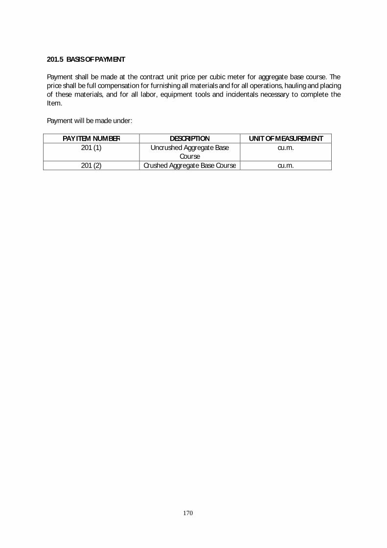
170
201.5 BASIS OF PAYMENT Payment shall be made at the contract unit price per cubic meter for aggregate base course. The price shall be full compensation for furnishing all materials and for all operations, hauling and placing of these materials, and for all labor, equipment tools and incidentals necessary to complete the Item. Payment will be made under:
PAY ITEM NUMBER DESCRIPTION UNIT OF MEASUREMENT 201 (1) Uncrushed Aggregate Base
Course cu.m.
201 (2) Crushed Aggregate Base Course cu.m.

171
ITEM 307 – PORTLAND CEMENT CONCRETE PAVEMENT (Plain and Reinforced)
307.1 DESCRIPTION This item shall consist of pavement composed of Portland Cement Concrete, with or without reinforcement as specified on a prepared sub-base or base course in accordance with these specifications. And shall conform to the thickness and typical cross-section as shown on the plans and with the lines and grades established by the Engineer. 307.2 MATERIALS Fine aggregate for concrete shall consist of natural sand, stone, screening or other inert materials with similar characteristics or combination thereof, having hard, strong and durable particles approved by the Engineer. It shall not contain more than three (3) mass percent of materials passing the 0.075mm (No. 200 sieve) by washing nor more than one (1) percent each sieve of clay lumps or shale. The use of beach sand will not be allowed without the approval of the Engineer. If fine aggregate is subjected to five (5) cycles of the sodium sulfate soundness test, the weighted loss shall not exceed ten (10) mass percent. The fine aggregate shall be free from injurious amounts of organic impurities. If subjected to the colorimatic test for organic impurities and a color darker than the standard is produced, it shall be rejected. However, when tested for the effect of organic impurities of strength of mortar by AASHTO T71, the fine aggregate may be used if the relative strength within 7 days and 28 days in not less than 95%. The fine aggregate shall be well graded from coarse to fine and shall conform to Table 307-1.
Table 307 – 1 GRADATION FOR FINE AGGREGATE
SIEVE DESIGNATION PERCENTAGE PASSING BY WEIGHT mm inches 9.50 3/8 100 4.75 No. 04 95 – 100 1.18 No. 16 45 – 80 0.30 No. 50 5 – 30 0.50 No. 100 0 – 10
307.2.1 COARSE AGGREGATE It shall consist of crushed stone, gravel, gravel, blast furnace slag, or other approved inert materials of similar characteristics, or combination thereof, having hard, strong, durable pieces and free from any adherent coatings.
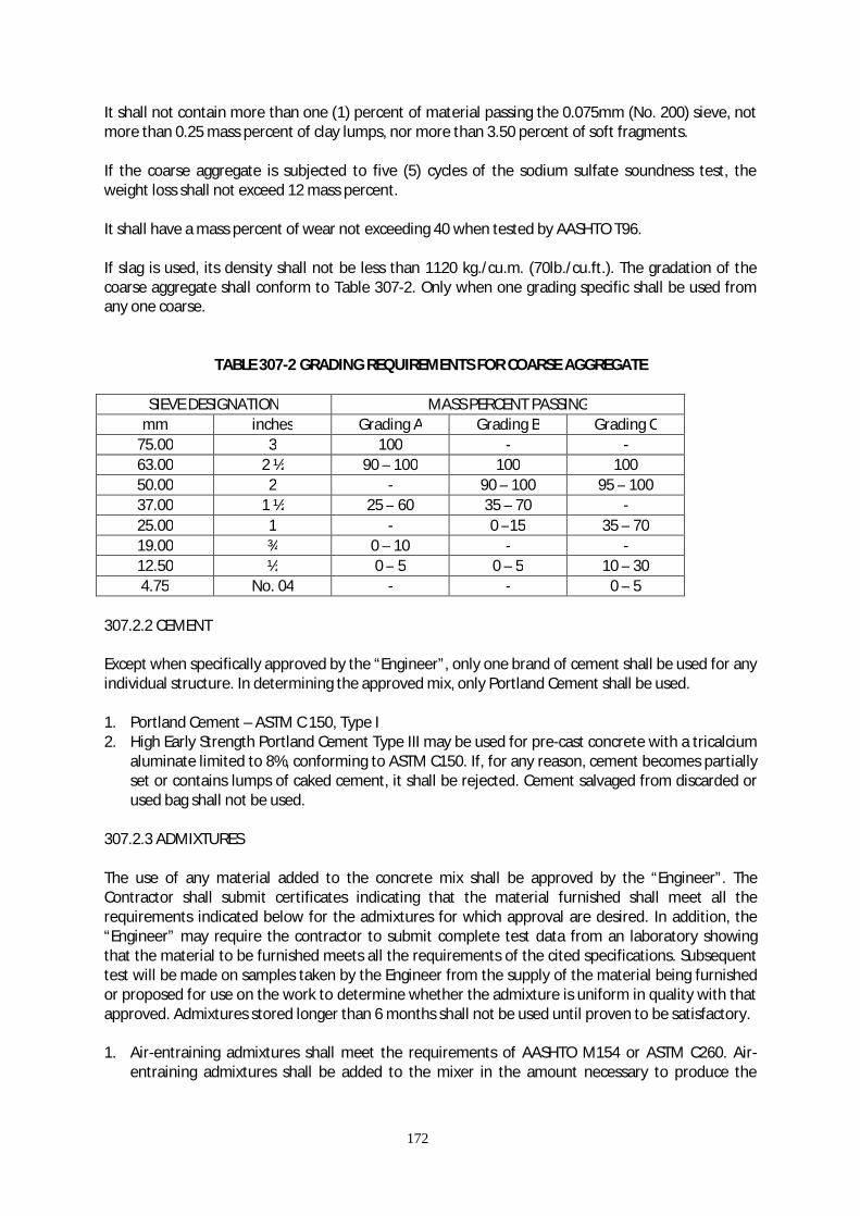
172
It shall not contain more than one (1) percent of material passing the 0.075mm (No. 200) sieve, not more than 0.25 mass percent of clay lumps, nor more than 3.50 percent of soft fragments. If the coarse aggregate is subjected to five (5) cycles of the sodium sulfate soundness test, the weight loss shall not exceed 12 mass percent. It shall have a mass percent of wear not exceeding 40 when tested by AASHTO T96. If slag is used, its density shall not be less than 1120 kg./cu.m. (70lb./cu.ft.). The gradation of the coarse aggregate shall conform to Table 307-2. Only when one grading specific shall be used from any one coarse.
TABLE 307-2 GRADING REQUIREMENTS FOR COARSE AGGREGATE
SIEVE DESIGNATION MASS PERCENT PASSING mm inches Grading A Grading B Grading C
75.00 3 100 - - 63.00 2 ½ 90 – 100 100 100 50.00 2 - 90 – 100 95 – 100 37.00 1 ½ 25 – 60 35 – 70 - 25.00 1 - 0 –15 35 – 70 19.00 ¾ 0 – 10 - - 12.50 ½ 0 – 5 0 – 5 10 – 30 4.75 No. 04 - - 0 – 5
307.2.2 CEMENT Except when specifically approved by the “Engineer”, only one brand of cement shall be used for any individual structure. In determining the approved mix, only Portland Cement shall be used. 1. Portland Cement – ASTM C 150, Type I 2. High Early Strength Portland Cement Type III may be used for pre-cast concrete with a tricalcium
aluminate limited to 8%, conforming to ASTM C150. If, for any reason, cement becomes partially set or contains lumps of caked cement, it shall be rejected. Cement salvaged from discarded or used bag shall not be used.
307.2.3 ADMIXTURES The use of any material added to the concrete mix shall be approved by the “Engineer”. The Contractor shall submit certificates indicating that the material furnished shall meet all the requirements indicated below for the admixtures for which approval are desired. In addition, the “Engineer” may require the contractor to submit complete test data from an laboratory showing that the material to be furnished meets all the requirements of the cited specifications. Subsequent test will be made on samples taken by the Engineer from the supply of the material being furnished or proposed for use on the work to determine whether the admixture is uniform in quality with that approved. Admixtures stored longer than 6 months shall not be used until proven to be satisfactory. 1. Air-entraining admixtures shall meet the requirements of AASHTO M154 or ASTM C260. Air-
entraining admixtures shall be added to the mixer in the amount necessary to produce the
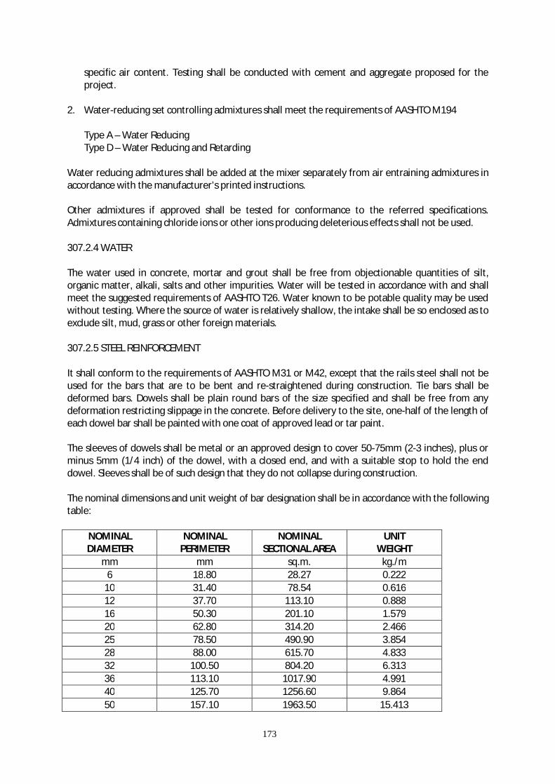
173
specific air content. Testing shall be conducted with cement and aggregate proposed for the project.
2. Water-reducing set controlling admixtures shall meet the requirements of AASHTO M194
Type A – Water Reducing Type D – Water Reducing and Retarding
Water reducing admixtures shall be added at the mixer separately from air entraining admixtures in accordance with the manufacturer’s printed instructions. Other admixtures if approved shall be tested for conformance to the referred specifications. Admixtures containing chloride ions or other ions producing deleterious effects shall not be used. 307.2.4 WATER The water used in concrete, mortar and grout shall be free from objectionable quantities of silt, organic matter, alkali, salts and other impurities. Water will be tested in accordance with and shall meet the suggested requirements of AASHTO T26. Water known to be potable quality may be used without testing. Where the source of water is relatively shallow, the intake shall be so enclosed as to exclude silt, mud, grass or other foreign materials. 307.2.5 STEEL REINFORCEMENT It shall conform to the requirements of AASHTO M31 or M42, except that the rails steel shall not be used for the bars that are to be bent and re-straightened during construction. Tie bars shall be deformed bars. Dowels shall be plain round bars of the size specified and shall be free from any deformation restricting slippage in the concrete. Before delivery to the site, one-half of the length of each dowel bar shall be painted with one coat of approved lead or tar paint. The sleeves of dowels shall be metal or an approved design to cover 50-75mm (2-3 inches), plus or minus 5mm (1/4 inch) of the dowel, with a closed end, and with a suitable stop to hold the end dowel. Sleeves shall be of such design that they do not collapse during construction. The nominal dimensions and unit weight of bar designation shall be in accordance with the following table:
NOMINAL DIAMETER
NOMINAL PERIMETER
NOMINAL SECTIONAL AREA
UNIT WEIGHT
mm mm sq.m. kg./m 6 18.80 28.27 0.222
10 31.40 78.54 0.616 12 37.70 113.10 0.888 16 50.30 201.10 1.579 20 62.80 314.20 2.466 25 78.50 490.90 3.854 28 88.00 615.70 4.833 32 100.50 804.20 6.313 36 113.10 1017.90 4.991 40 125.70 1256.60 9.864 50 157.10 1963.50 15.413
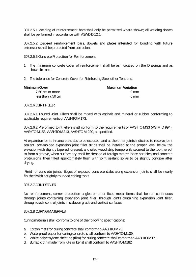
174
307.2.5.1 Welding of reinforcement bars shall only be permitted where shown; all welding shown shall be performed in accordance with ASWD D 12.1. 307.2.5.2 Exposed reinforcement bars, dowels and plates intended for bonding with future extensions shall be protected from corrosion. 307.2.5.3 Concrete Protection for Reinforcement 1. The minimum concrete cover of reinforcement shall be as indicated on the Drawings and as
shown in table. 2. The tolerance for Concrete Cover for Reinforcing Steel other Tendons. Minimum Cover Maximum Variation
7.50 cm or more 9 mm less than 7.50 cm 6 mm
307.2.6 JOINT FILLER 307.2.6.1 Poured Joint Fillers shall be mixed with asphalt and mineral or rubber conforming to applicable requirements of AASHTO M173. 307.2.6.2 Preformed Joint Fillers shall conform to the requirements of AASHTO M33 (ASTM D 994), AASHTO M153, AASHTO M213, AASHTO M 220, as specified. At expansion joints in concrete slabs to be exposed, and at the other joints indicated to receive joint sealant, pre-molded expansion joint filler strips shall be installed at the proper level below the elevation with slightly tapered, dressed, and oiled wood strip temporarily secured to the top thereof to form a groove, when surface dry, shall be cleaned of foreign matter loose particles, and concrete protrusions, then filled approximately flush with joint sealant so as to be slightly concave after drying. Finish of concrete joints: Edges of exposed concrete slabs along expansion joints shall be nearly finished with a slightly rounded edging tools. 307.2.7 JOINT SEALER No reinforcement, corner protection angles or other fixed metal items shall be run continuous through joints containing expansion joint filler, through joints containing expansion joint filler, through crack-control joints in slabs on grade and vertical surfaces. 307.2.8 CURING MATERIALS Curing materials shall conform to one of the following specifications: a. Cotton mats for curing concrete shall conform to AASHTO M73. b. Waterproof paper for curing concrete shall conform to AASHTO M139. c. White polyethylene sheeting (film) for curing concrete shall conform to AASHTO M171. d. Burlap cloth made from jute or kenaf shall conform to AASHTO M182.

175
e. Liquid membrane forming compounds for curing concrete shall conform to AASHTO M148, Type 2 (all resin base). Or Fed. Spec. TT-C-800, Type 2.
307.2.9 STORAGE OF CEMENT AND AGGREGATE 1. Cement: Immediately upon receipt at the site, the cement shall be stored separately in a dry
weatherproof properly ventilated structure, with adequate provisions for prevention or absorption of moisture. The floor shall be raised from the ground. Provisions for storage shall be ample, and the shipments of cement as received shall be separately stored in such a manner as to allow the earliest deliveries to be used first and to provide easy access for identification and inspection of each shipment. Storage building shall have a capacity for storage of a sufficient quantity of cement to allow sampling at least twelve (12) days before the cement is to be used. The cement most likely to have been exposed to moisture or stored in bags for more than 3 months shall not be used unless proven by test to be in good condition. Stored cement shall meet the test requirements at any time after storage when the “Engineer” orders retest. At the time of use, all cement shall be free flowing and free of lumps.
2. Aggregates: Stored and handled to ensure good drainage to prevent segregation and the
inclusion of foreign materials. The “Engineer” may require the coarse aggregate to be separated into two or more sizes. Different sizes of aggregate shall be stored in separate bins or in separate stockpiles sufficiently remote from each other to prevent the materials at the edges of the stockpiles from becoming intermixed.
307.3 PROPORTIONING, CONSISTENCY AND STRENGTH OF CONCRETE 307.3.1 CONCRETE MIX PROPORTIONING The Contractor shall prepare the design mix based on the absolute volume method as outlined in the American Concrete Institute (ACI) Standard 211.1, “Recommended Practice for Selecting Proportions for Normal and Heavyweight Concrete”. Prior to the start of paving operations and after approval of all material to be used in the concrete, the Engineer shall determine the proportions of materials to be used to produce the specified strength. Trial design batches and testing to meet requirements in the class of concrete specified shall be the responsibility of the Contractor. Test for slump, unit weight and air content shall be performed in the field in the presence of the PMO. Trial mix shall be designed for maximum permitted slump and air content. The temperature of concrete in each trial shall be reported. For each water cement ratio at least three samples for each test age shall be made and cured in accordance with AASHTO T22, AASHTO T97 and AASHTO T177. 307.3.1.1 Entrained-Air Content: Air-entrainment shall be produced by adding an air-entraining agent at the mixer. Air content volume shall be maintained at 5 to 7 percentage as determined by AASHTO T152 or ASTM C231. 307.3.1.2 “Engineer” shall determine from laboratory test of the materials to be used, tested by the Contractor, the cement content and proportions of aggregates and water that will produce a workable concrete having a slump between 40 and 75mm if not vibrated or between 10 and 40mm if vibrated, and a flexural strength of not less than 3.80 Mpa (550 psi) when tested by the third point method or 4.50 Mpa (650 psi) when tested by the midpoint method; or a compressive strength of

176
24.1 Mpa (3,500 psi) when tested at 28 days in accordance with AASHTO T97, T177, or AASHTO T22 respectively. 307.3.2 SELECTION OF PROPORTIONS For each portion of the structure, proportions shall be selected so that maximum permitted water-cement ratio is not exceeded and so as to produce an average strength (fc’) by the amount indicated below. When the production facility has a standard deviation record determined in accordance with ACI 214, based on 30 consecutive strength tests of similar mixture strength. The average strength used as a basis for selecting proportioning shall exceed the specified strength, fc’, by at least: 1) 30 kg/sq.m. if standard deviation is less than 20 kg/sq.cm. 2) 40 kg/sq.m. if standard deviation is 20 to 30 kg/sq.cm. 3) 50 kg/sq.m. if standard deviation is 30 to 40 kg/sq.cm. 4) 60 kg/sq.m. if standard deviation is 40 to 50 kg/sq.cm. 5) if the standard deviation exceed 50 kg/sq.cm. or if a standard deviation record is not available,
proportions shall be selected to produce an average strength of at least 70 kg/sq.cm. greater than the specified strength.
307.3.3 STRENGTH OF CONCRETE Strength of concrete shall meet the following requirements: 1) The average of any 5 consecutive strength tests at the end of 28 days shall have an average
strength equal or greater than the specified strength. 2) Not more than 15% of the samples tested at the end of 28 days shall have an average strength
less than the specified strength specimens, which are obviously defective shall not be considered in the determination of strength.
3) When it appears that the test specimens will fail to conform to the requirements for strength,
“Engineer” shall have the right to order changes in the concrete sufficient to increase the strength. When a satisfactory relationship between 7-day and 28-day strength has been established and approved, the 7-day test results may be used as an indication of the 28-day strength.
Corrective measures to remedy deficiencies in aggregate gradation shall be used only in written approval of the “Engineer” 307.3.4 CONSISTENCY (SLUMP) Test shall be made in conformance with AASHTO T119, unless otherwise specified by the “Engineer”, slump shall be within the following limits.
STRUCTURAL ELEMENT SLUMP FOR VIBRATED CONCRETE Minimum, mm Maximum, mm Pre-cast concrete 50 70 Wall column and grade beam, 25cm. max. thick
50 70
Lean concrete 70 100 Pavement 10 40
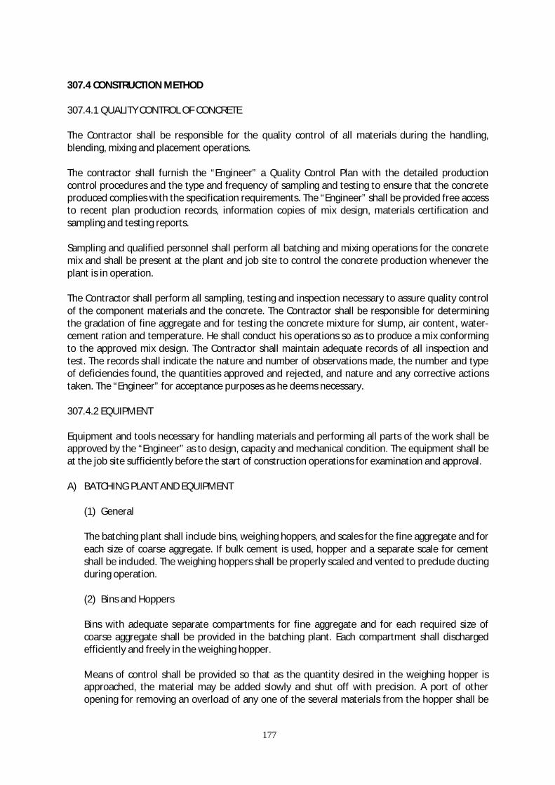
177
307.4 CONSTRUCTION METHOD 307.4.1 QUALITY CONTROL OF CONCRETE The Contractor shall be responsible for the quality control of all materials during the handling, blending, mixing and placement operations. The contractor shall furnish the “Engineer” a Quality Control Plan with the detailed production control procedures and the type and frequency of sampling and testing to ensure that the concrete produced complies with the specification requirements. The “Engineer” shall be provided free access to recent plan production records, information copies of mix design, materials certification and sampling and testing reports. Sampling and qualified personnel shall perform all batching and mixing operations for the concrete mix and shall be present at the plant and job site to control the concrete production whenever the plant is in operation. The Contractor shall perform all sampling, testing and inspection necessary to assure quality control of the component materials and the concrete. The Contractor shall be responsible for determining the gradation of fine aggregate and for testing the concrete mixture for slump, air content, water-cement ration and temperature. He shall conduct his operations so as to produce a mix conforming to the approved mix design. The Contractor shall maintain adequate records of all inspection and test. The records shall indicate the nature and number of observations made, the number and type of deficiencies found, the quantities approved and rejected, and nature and any corrective actions taken. The “Engineer” for acceptance purposes as he deems necessary. 307.4.2 EQUIPMENT Equipment and tools necessary for handling materials and performing all parts of the work shall be approved by the “Engineer” as to design, capacity and mechanical condition. The equipment shall be at the job site sufficiently before the start of construction operations for examination and approval. A) BATCHING PLANT AND EQUIPMENT
(1) General The batching plant shall include bins, weighing hoppers, and scales for the fine aggregate and for each size of coarse aggregate. If bulk cement is used, hopper and a separate scale for cement shall be included. The weighing hoppers shall be properly scaled and vented to preclude ducting during operation. (2) Bins and Hoppers
Bins with adequate separate compartments for fine aggregate and for each required size of coarse aggregate shall be provided in the batching plant. Each compartment shall discharged efficiently and freely in the weighing hopper. Means of control shall be provided so that as the quantity desired in the weighing hopper is approached, the material may be added slowly and shut off with precision. A port of other opening for removing an overload of any one of the several materials from the hopper shall be

178
provided. Weighing hoppers shall be constructed to eliminate accumulations of tar materials and to discharge fully. (3) Scales
The scales for weighing aggregates and cement shall be of either the beam or the springless dial type. They shall be accurate within 0.50% throughout their range of use. When beam-type scales are used, provisions, such as “tell-tale” dial, shall be made for indicating to the operator that the required load in the weighing hopper is being approached. A device on the weighing beams shall clearly indicate critical position. Poises shall be designed to be locked in any position and to prevent unauthorized change. The weight beam and “tell-tale” device shall be in full view of the operator while charging the hopper, and he shall have convenient access to all controls. (4) Recorders
An accurate recorder shall produce a graphical or digital record of the scale reading after each of the aggregates and cementing materials have been discharged (return to zero reference). The weights or volumes of water and admixtures shall also be recorded if batched at a central batching plant. Each recorder shall be housed in a cabinet, which shall be capable of being locked. The charts or tapes shall clearly indicate the different types of mixes used by stamped letters, numerals colored ink or other suitable means. It shall be so marked that variations in batch weights of each type of mix can be readily observed. All weighing, indicating, recording and control equipment shall be sufficiently protected against exposures to dust, moisture and vibration so that there is no interference with proper operation of the equipment. The recorder weights or volumes when compared to the weights or volumes actually batched shall be within the following limits of accuracy.
Materials Percent Cement 1 Water 1 Aggregate 2 Admixture 3 (5) Water Batcher and Dispenser for Admixtures
Equipment for batching water and admixtures shall be provided at the batching plant or included with the paving mixer or truck mixers as required for the type of plant used.
(a) Water Batchers: A suitable water measuring device shall be provide which will be capable of
measuring the mixing water within the specified requirements for each batch. The mechanism for delivering water to the mixers shall be such that leakage will not occur when the valves are closed. The filling and discharge valves for the water bather shall be so interlocked that the discharge valve is fully closed.
(b) Dispensers: An accurate mechanical device for measuring and dispensing each admixture
shall be provided. Each device shall be capable of ready adjustment to permit varying of the
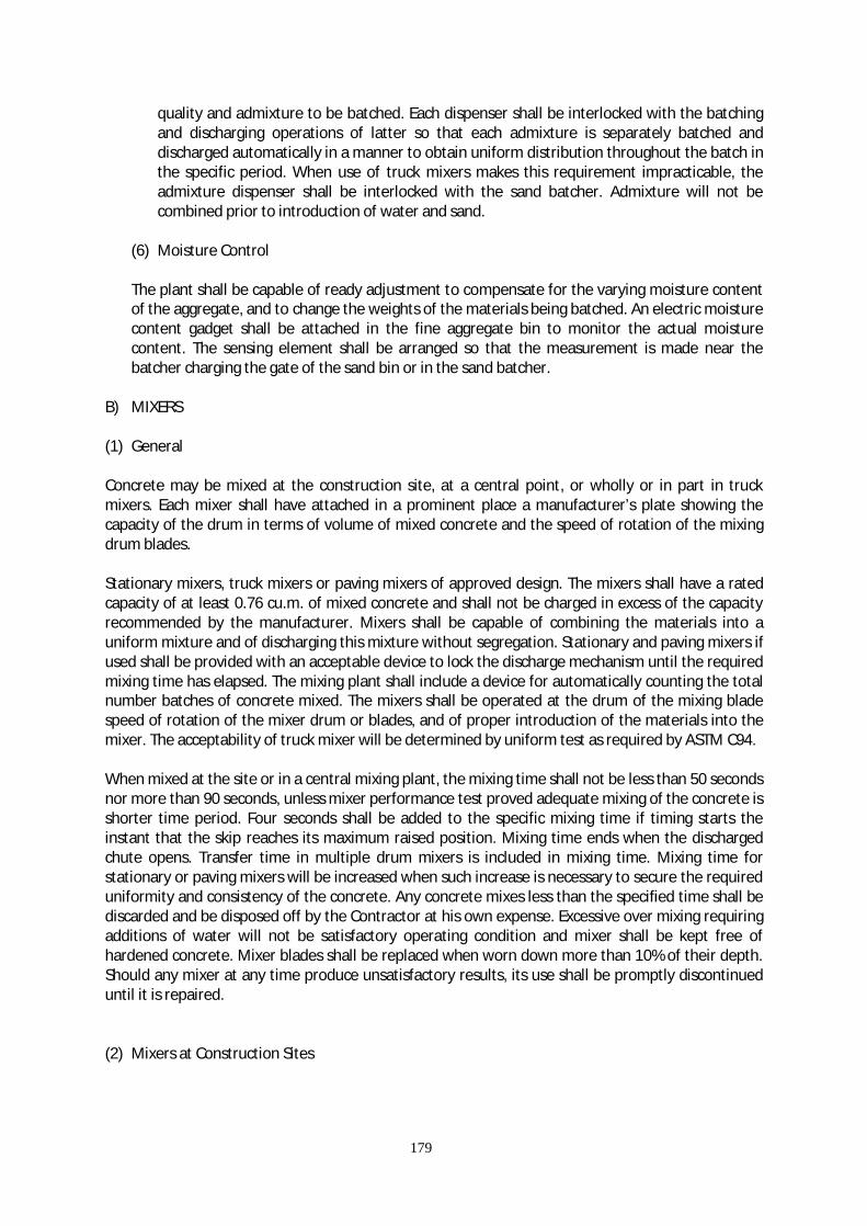
179
quality and admixture to be batched. Each dispenser shall be interlocked with the batching and discharging operations of latter so that each admixture is separately batched and discharged automatically in a manner to obtain uniform distribution throughout the batch in the specific period. When use of truck mixers makes this requirement impracticable, the admixture dispenser shall be interlocked with the sand batcher. Admixture will not be combined prior to introduction of water and sand.
(6) Moisture Control The plant shall be capable of ready adjustment to compensate for the varying moisture content of the aggregate, and to change the weights of the materials being batched. An electric moisture content gadget shall be attached in the fine aggregate bin to monitor the actual moisture content. The sensing element shall be arranged so that the measurement is made near the batcher charging the gate of the sand bin or in the sand batcher.
B) MIXERS (1) General Concrete may be mixed at the construction site, at a central point, or wholly or in part in truck mixers. Each mixer shall have attached in a prominent place a manufacturer’s plate showing the capacity of the drum in terms of volume of mixed concrete and the speed of rotation of the mixing drum blades. Stationary mixers, truck mixers or paving mixers of approved design. The mixers shall have a rated capacity of at least 0.76 cu.m. of mixed concrete and shall not be charged in excess of the capacity recommended by the manufacturer. Mixers shall be capable of combining the materials into a uniform mixture and of discharging this mixture without segregation. Stationary and paving mixers if used shall be provided with an acceptable device to lock the discharge mechanism until the required mixing time has elapsed. The mixing plant shall include a device for automatically counting the total number batches of concrete mixed. The mixers shall be operated at the drum of the mixing blade speed of rotation of the mixer drum or blades, and of proper introduction of the materials into the mixer. The acceptability of truck mixer will be determined by uniform test as required by ASTM C94. When mixed at the site or in a central mixing plant, the mixing time shall not be less than 50 seconds nor more than 90 seconds, unless mixer performance test proved adequate mixing of the concrete is shorter time period. Four seconds shall be added to the specific mixing time if timing starts the instant that the skip reaches its maximum raised position. Mixing time ends when the discharged chute opens. Transfer time in multiple drum mixers is included in mixing time. Mixing time for stationary or paving mixers will be increased when such increase is necessary to secure the required uniformity and consistency of the concrete. Any concrete mixes less than the specified time shall be discarded and be disposed off by the Contractor at his own expense. Excessive over mixing requiring additions of water will not be satisfactory operating condition and mixer shall be kept free of hardened concrete. Mixer blades shall be replaced when worn down more than 10% of their depth. Should any mixer at any time produce unsatisfactory results, its use shall be promptly discontinued until it is repaired. (2) Mixers at Construction Sites

180
Mixing shall be in an approved mixer capable of combining the aggregates, cement and water into a thoroughly mixed and uniform mass within the specified mixing period, and of discharging and distributing the mixture without segregation on the prepared grade. The mixer shall be equipped with an approved timing device, which will automatically lock discharge lever when the drum has been charged and release it at the end of mixing. The device shall be equipped with a bell or other suitable warning device adjusted to give clearly audible signal each time the locked is release. In case of failure of the timing device, the mixer may be used for the balance of the day while it is being prepared, provided that each batch is mixed 90 seconds. The mixer shall be equipped with a suitable non re-settable bath counter, which shall correctly indicate the number of batches mixed. (3) Central Plant Mixers Mixers for central plant mixing (plant mixer, revolving drum type mixers, single opening revolving truncated drum mixer at one end and discharging at the other end) shall have attached thereto into a prominent place by the manufacturer, a metal plate(s) on which is plainly marked the various uses for which the equipment is designed, the nominal capacity (cu.m.) of the drum or container in terms of the volume of the mixing central plant mixers shall be equipped with an acceptable timing device that will not permit the batch to be discharge until the specified mixing time has elapsed. The water system for a central mixer shall be either a calibrated measuring tank or meter and shall be cleaned at suitable intervals. They shall be examined daily for changes in condition due to accumulation of hard concrete or mortar or the wear blades. The pick-up and throwover blade shall be replaced when they have worn down 19mm or more. The Contractor shall provide the “Engineers” with a copy of the manufacturer’s design showing dimensions and arrangements of blades in reference to original height and depth. (4) Truck Mixers and Truck Agitators Truck mixers used for mixing and hauling concrete, truck and truck agitators used for hauling central-mixed concrete, shall conform to the requirements of AAHTO M157. (5) Non-Agitators Trucks Non-agitating hauling equipment shall conform to the requirements of AASHTO M157. C) FINISHING EQUIPMENT (1) Finishing Machine The finishing machine shall be equipped with at least two oscillating type transverse screeds. (2) Vibrators Vibrator for full width vibration of concrete paving slabs, may be either the surface pan type or internal type with either immersed tube or multiple spuds. They may be mounted on a separate carriage. They shall not come in contract with the joint, load transfer devices, sub-grade or side. D) FORMS Straight side forms shall be made of metal having thickness of not less than 5mm and shall be furnished in sections not less than 3mm length. Form shall have a depth equal to the prescribed
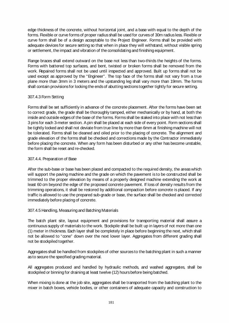
181
edge thickness of the concrete, without horizontal joint, and a base with equal to the depth of the forms. Flexible or curve forms of proper radius shall be used for curves of 30m radius less. Flexible or curve form shall be of a design acceptable to the Project Engineer. Forms shall be provided with adequate devices for secure setting so that when in place they will withstand, without visible spring or settlement, the impact and vibration of the consolidating and finishing equipment. Flange braces shall extend outward on the base not less than two-thirds the heights of the forms. Forms with battered top surfaces, and bent, twisted or broken forms shall be removed from the work. Repaired forms shall not be used until inspected and approved. Built up forms shall not be used except as approved by the “Engineer”. The top face of the forms shall not vary from a true plane more than 3mm in 3 meters and the upstanding leg shall vary more than 19mm. The forms shall contain provisions for locking the ends of abutting sections together tightly for secure setting. 307.4.3 Form Setting Forms shall be set sufficiently in advance of the concrete placement. After the forms have been set to correct grade, the grade shall be thoroughly tamped, either mechanically or by hand, at both the inside and outside edges of the base of the forms. Forms shall be staked into place with not less than 3 pins for each 3-meter section. A pin shall be placed at each side of every point. Form sections shall be tightly locked and shall not deviate from true line by more than 6mm at finishing machine will not be tolerated. Forms shall be cleaned and oiled prior to the placing of concrete. The alignment and grade elevation of the forms shall be checked and corrections made by the Contractor immediately before placing the concrete. When any form has been disturbed or any other has become unstable, the form shall be reset and re-checked. 307.4.4. Preparation of Base After the sub-base or base has been placed and compacted to the required density, the areas which will support the paving machine and the grade on which the pavement is to be constructed shall be trimmed to the proper elevation by means of a properly designed machine extending the work at least 60 cm beyond the edge of the proposed concrete pavement. If loss of density results from the trimming operations, it shall be restored by additional compaction before concrete is placed. If any traffic is allowed to use the prepared sub-grade or base, the surface shall be checked and corrected immediately before placing of concrete. 307.4.5 Handling, Measuring and Batching Materials The batch plant site, layout equipment and provisions for transporting material shall assure a continuous supply of materials to the work. Stockpile shall be built up in layers of not more than one (1) meter in thickness. Each layer shall be completely in place before beginning the next, which shall not be allowed to “cone” down over the next lower layer. Aggregates from different grading shall not be stockpiled together. Aggregates shall be handled from stockpiles of other sources to the batching plant in such a manner as to secure the specified grading material. All aggregates produced and handled by hydraulic methods, and washed aggregates, shall be stockpiled or binning for draining at least twelve (12) hours before being batched. When mixing is done at the job site, aggregates shall be transported from the batching plant to the mixer in batch boxes, vehicle bodies, or other containers of adequate capacity and construction to

182
properly carry the volume required. Partitions separating batches shall be adequate and effective to prevent spilling from one compartment to another while in transit or while being dumped. When bulk cement is used, the Contractor shall use a suitable method of handling the cement from weighing hopper or transporting container or into the batch itself for transportation to the mixer, such as chute, boot or other approved device, to prevent loss of cement. The device shall be arranged to provide positive assurance of the actual presence in each batch of the entire cement content specified. Bulk cement shall be transported to the mixer in light compartments capable of carrying the full amount of cement required for each batch, of if permitted between the fine and coarse aggregate. When cement is placed in contact with the aggregates, batches may be rejected unless mixed with in one and one-half (1 ½) hours of such contract. 307.4.6 Mixing Concrete Concrete may be mixed at the work site in a central mix plant or in truck mixers. The mixers shall be on an approved type and capacity. Mixing time shall be measured from the time all materials, except water, are emptied into the drum. Ready-mixed concrete shall be mixed and delivered in accordance with the requirements of AASHTO M 157, except that the minimum required revolutions at the mixing speed for transit-mixed concrete may be reduced to not less than the recommended by the mixer manufacturer shall be indicated in the manufacturer’s serial plate attached to the mixer. Mixing time shall conform to the requirements indicated under Item Mixer. The volume of concrete mix per batch shall not exceed the mixer’s nominal capacity in cubic meter, as shown on the manufacturer’s standard rating plate on the mixer, except that an overload up to 10% above the mixers nominal capacity may be permitted provided concrete test data for strength, segregation, and uniform consistency are satisfactory and provided no slippage of concrete takes place. The batch shall be charged into the drum so that the portion of the mixing water shall enter in advance of the cement and aggregates. The flow of water shall be uniform and all water shall be in the drum by the end of the first 15 seconds of the mixing period. The throat of the drum shall be kept free of such accumulations as may restricts the free flow of materials into the drum. Mixed concrete from the central mixing plant shall be transported in truck mixers, truck agitators or non-agitating trucks specified in sub-section EQUIPMENT. Mixing time as indicated in sub-section MIXER may be reduced during hot weather or under other conditions contributing to quick hardening of the concrete. Re-tempering concrete by adding water or by other means will not be permitted, except that when concrete is delivered in truck mixers, additional water may be added to the batch materials and additional mixing performed to increase the slump to meet the specified requirement, if permitted by the “Engineer”, provided all these operations are performed with in the specified slump limits at time of placement shall not be used. Admixtures for increasing the workability or for accelerating the setting of concrete will be permitted only when specifically approved by the “Engineer”. 307.4.7 Limitation of Mixing No concrete shall be mixed, placed, or finished with insufficient light, unless adequate and approved artificial lighting system is operated. During not weather, the “Engineer” may require steps to be

183
taken to prevent temperature of the mixed concrete from exceeding the specified maximum requirements. Concrete not placed within 90 minutes from the time the ingredients were charged to the mixing drum or that has developed initial set shall not be used. Re-tampering of concrete, which has partially hardened, that is, re-mixing with or without additional cement, aggregate, or water shall not be permitted. 307.4.8 Placing of Concrete Concrete shall be deposited in such a manner to require minimal re-handling. Unless truck mixers, truck agitators or non-agitating hauling equipment are equipped with means to discharge concrete without segregation of the materials. The concrete shall be unloaded into an approved spreading device and mechanically spread on the grade in such a manner as to prevent segregation of the materials. Placing shall be continuous between transverse joints without the use of intermediate bulkheads. Necessary hand spreading shall be done with shovels, not rakes. Workmen shall not be allowed to walk in freshly mixed concrete with boots or shoe coated with earth on foreign substances. When concrete is to be deposited adjoining a previously constructed lane of pavement and when mechanical equipment will be operated upon the existing lane of pavement, the concrete shall be at least 10 days old and approval shall be obtained from the Engineer. If only finishing equipment is carried on the existing lane, paving in adjoining lanes may be permitted after 3 days, if approved by the “Engineer”. Concrete shall be thoroughly consolidated against and along the faces of all forms and along full length and both sides of all joint assemblies by means of vibrators inserted in the concrete. Vibrators shall not be permitted to come in contact with a join assembly, the grade, or a side form. In no case shall the vibrator be operated longer than 15 seconds in any one location. Concrete shall be deposited as near to expansion and contraction joints as possible without disturbing them but shall not be dumped from the discharge bucket or hopper unto a joint assemble. Should any concrete materials fall on or be worked into the surface of a complete slab they shall be removed immediately by approved methods. 307.4.9 Test Specimen Following the placing of concrete, it shall be stuck-off to the cross section shown on the plans and to an elevation such that when the concrete is properly consolidated and finished, the surface of the pavement shall be at elevation shown on the plans. When reinforced concrete pavement is placed in two layers, the bottom layer shall be stuck-off to such length and depth that the sheet of fabric or bar may be laid full-length on the concrete on its final position without further manipulation. The reinforcement shall then be placed directly upon the concrete, after which the top layer of the concrete shall be placed, struck-off and screened. Any portion of the bottom layer of the concrete which has been placed more than 30 minutes without being covered with the top layer shall be removed and replaced with freshly mixed concrete at the Contractor’s expense. When reinforced concrete is placed in one layer, the reinforcement may
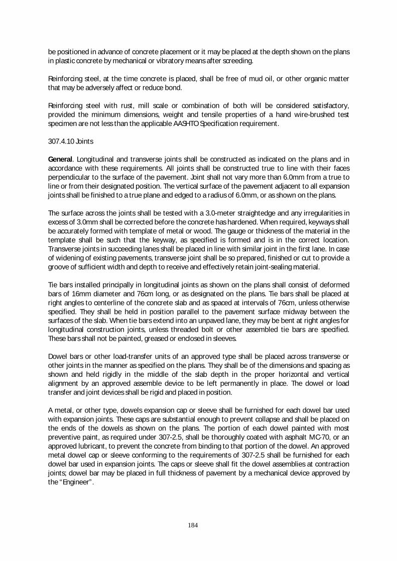
184
be positioned in advance of concrete placement or it may be placed at the depth shown on the plans in plastic concrete by mechanical or vibratory means after screeding. Reinforcing steel, at the time concrete is placed, shall be free of mud oil, or other organic matter that may be adversely affect or reduce bond. Reinforcing steel with rust, mill scale or combination of both will be considered satisfactory, provided the minimum dimensions, weight and tensile properties of a hand wire-brushed test specimen are not less than the applicable AASHTO Specification requirement. 307.4.10 Joints General. Longitudinal and transverse joints shall be constructed as indicated on the plans and in accordance with these requirements. All joints shall be constructed true to line with their faces perpendicular to the surface of the pavement. Joint shall not vary more than 6.0mm from a true to line or from their designated position. The vertical surface of the pavement adjacent to all expansion joints shall be finished to a true plane and edged to a radius of 6.0mm, or as shown on the plans. The surface across the joints shall be tested with a 3.0-meter straightedge and any irregularities in excess of 3.0mm shall be corrected before the concrete has hardened. When required, keyways shall be accurately formed with template of metal or wood. The gauge or thickness of the material in the template shall be such that the keyway, as specified is formed and is in the correct location. Transverse joints in succeeding lanes shall be placed in line with similar joint in the first lane. In case of widening of existing pavements, transverse joint shall be so prepared, finished or cut to provide a groove of sufficient width and depth to receive and effectively retain joint-sealing material. Tie bars installed principally in longitudinal joints as shown on the plans shall consist of deformed bars of 16mm diameter and 76cm long, or as designated on the plans. Tie bars shall be placed at right angles to centerline of the concrete slab and as spaced at intervals of 76cm, unless otherwise specified. They shall be held in position parallel to the pavement surface midway between the surfaces of the slab. When tie bars extend into an unpaved lane, they may be bent at right angles for longitudinal construction joints, unless threaded bolt or other assembled tie bars are specified. These bars shall not be painted, greased or enclosed in sleeves. Dowel bars or other load-transfer units of an approved type shall be placed across transverse or other joints in the manner as specified on the plans. They shall be of the dimensions and spacing as shown and held rigidly in the middle of the slab depth in the proper horizontal and vertical alignment by an approved assemble device to be left permanently in place. The dowel or load transfer and joint devices shall be rigid and placed in position. A metal, or other type, dowels expansion cap or sleeve shall be furnished for each dowel bar used with expansion joints. These caps are substantial enough to prevent collapse and shall be placed on the ends of the dowels as shown on the plans. The portion of each dowel painted with most preventive paint, as required under 307-2.5, shall be thoroughly coated with asphalt MC-70, or an approved lubricant, to prevent the concrete from binding to that portion of the dowel. An approved metal dowel cap or sleeve conforming to the requirements of 307-2.5 shall be furnished for each dowel bar used in expansion joints. The caps or sleeve shall fit the dowel assemblies at contraction joints; dowel bar may be placed in full thickness of pavement by a mechanical device approved by the “Engineer”.
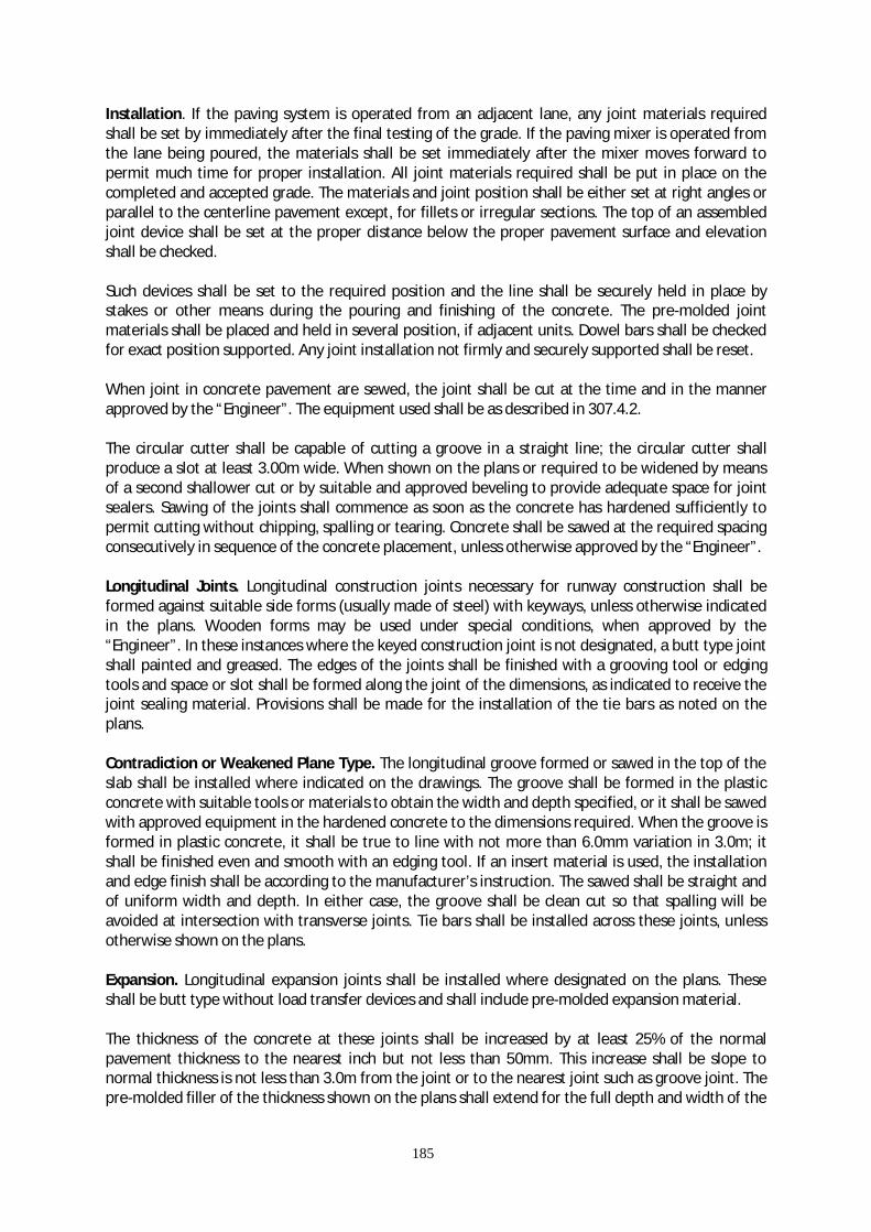
185
Installation. If the paving system is operated from an adjacent lane, any joint materials required shall be set by immediately after the final testing of the grade. If the paving mixer is operated from the lane being poured, the materials shall be set immediately after the mixer moves forward to permit much time for proper installation. All joint materials required shall be put in place on the completed and accepted grade. The materials and joint position shall be either set at right angles or parallel to the centerline pavement except, for fillets or irregular sections. The top of an assembled joint device shall be set at the proper distance below the proper pavement surface and elevation shall be checked. Such devices shall be set to the required position and the line shall be securely held in place by stakes or other means during the pouring and finishing of the concrete. The pre-molded joint materials shall be placed and held in several position, if adjacent units. Dowel bars shall be checked for exact position supported. Any joint installation not firmly and securely supported shall be reset. When joint in concrete pavement are sewed, the joint shall be cut at the time and in the manner approved by the “Engineer”. The equipment used shall be as described in 307.4.2. The circular cutter shall be capable of cutting a groove in a straight line; the circular cutter shall produce a slot at least 3.00m wide. When shown on the plans or required to be widened by means of a second shallower cut or by suitable and approved beveling to provide adequate space for joint sealers. Sawing of the joints shall commence as soon as the concrete has hardened sufficiently to permit cutting without chipping, spalling or tearing. Concrete shall be sawed at the required spacing consecutively in sequence of the concrete placement, unless otherwise approved by the “Engineer”. Longitudinal Joints. Longitudinal construction joints necessary for runway construction shall be formed against suitable side forms (usually made of steel) with keyways, unless otherwise indicated in the plans. Wooden forms may be used under special conditions, when approved by the “Engineer”. In these instances where the keyed construction joint is not designated, a butt type joint shall painted and greased. The edges of the joints shall be finished with a grooving tool or edging tools and space or slot shall be formed along the joint of the dimensions, as indicated to receive the joint sealing material. Provisions shall be made for the installation of the tie bars as noted on the plans. Contradiction or Weakened Plane Type. The longitudinal groove formed or sawed in the top of the slab shall be installed where indicated on the drawings. The groove shall be formed in the plastic concrete with suitable tools or materials to obtain the width and depth specified, or it shall be sawed with approved equipment in the hardened concrete to the dimensions required. When the groove is formed in plastic concrete, it shall be true to line with not more than 6.0mm variation in 3.0m; it shall be finished even and smooth with an edging tool. If an insert material is used, the installation and edge finish shall be according to the manufacturer’s instruction. The sawed shall be straight and of uniform width and depth. In either case, the groove shall be clean cut so that spalling will be avoided at intersection with transverse joints. Tie bars shall be installed across these joints, unless otherwise shown on the plans. Expansion. Longitudinal expansion joints shall be installed where designated on the plans. These shall be butt type without load transfer devices and shall include pre-molded expansion material. The thickness of the concrete at these joints shall be increased by at least 25% of the normal pavement thickness to the nearest inch but not less than 50mm. This increase shall be slope to normal thickness is not less than 3.0m from the joint or to the nearest joint such as groove joint. The pre-molded filler of the thickness shown on the plans shall extend for the full depth and width of the
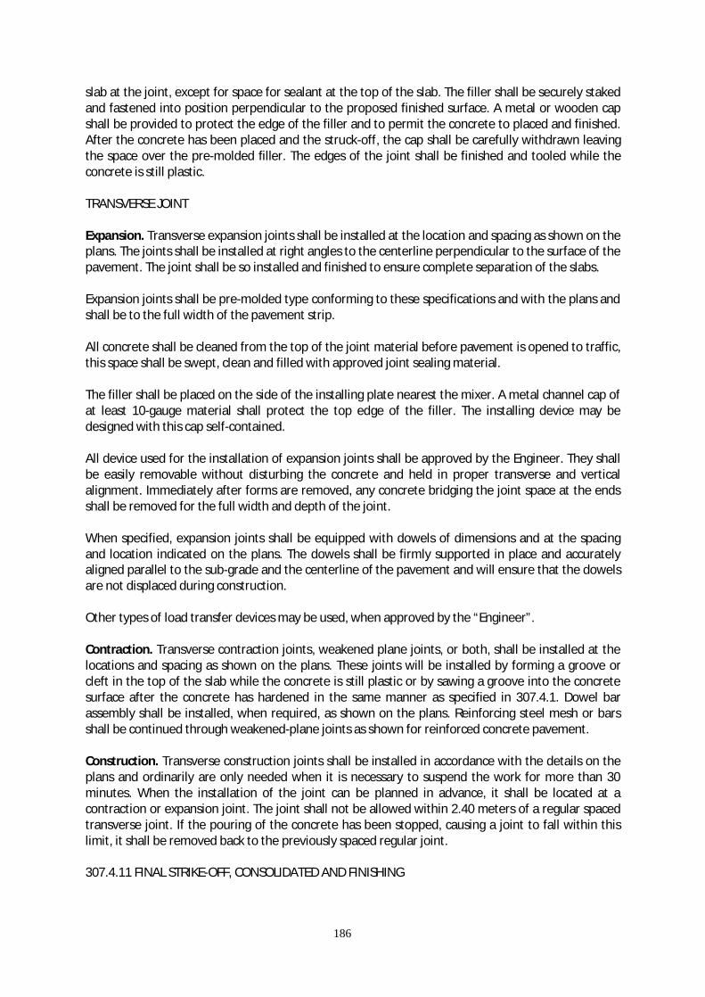
186
slab at the joint, except for space for sealant at the top of the slab. The filler shall be securely staked and fastened into position perpendicular to the proposed finished surface. A metal or wooden cap shall be provided to protect the edge of the filler and to permit the concrete to placed and finished. After the concrete has been placed and the struck-off, the cap shall be carefully withdrawn leaving the space over the pre-molded filler. The edges of the joint shall be finished and tooled while the concrete is still plastic. TRANSVERSE JOINT Expansion. Transverse expansion joints shall be installed at the location and spacing as shown on the plans. The joints shall be installed at right angles to the centerline perpendicular to the surface of the pavement. The joint shall be so installed and finished to ensure complete separation of the slabs. Expansion joints shall be pre-molded type conforming to these specifications and with the plans and shall be to the full width of the pavement strip. All concrete shall be cleaned from the top of the joint material before pavement is opened to traffic, this space shall be swept, clean and filled with approved joint sealing material. The filler shall be placed on the side of the installing plate nearest the mixer. A metal channel cap of at least 10-gauge material shall protect the top edge of the filler. The installing device may be designed with this cap self-contained. All device used for the installation of expansion joints shall be approved by the Engineer. They shall be easily removable without disturbing the concrete and held in proper transverse and vertical alignment. Immediately after forms are removed, any concrete bridging the joint space at the ends shall be removed for the full width and depth of the joint. When specified, expansion joints shall be equipped with dowels of dimensions and at the spacing and location indicated on the plans. The dowels shall be firmly supported in place and accurately aligned parallel to the sub-grade and the centerline of the pavement and will ensure that the dowels are not displaced during construction. Other types of load transfer devices may be used, when approved by the “Engineer”. Contraction. Transverse contraction joints, weakened plane joints, or both, shall be installed at the locations and spacing as shown on the plans. These joints will be installed by forming a groove or cleft in the top of the slab while the concrete is still plastic or by sawing a groove into the concrete surface after the concrete has hardened in the same manner as specified in 307.4.1. Dowel bar assembly shall be installed, when required, as shown on the plans. Reinforcing steel mesh or bars shall be continued through weakened-plane joints as shown for reinforced concrete pavement. Construction. Transverse construction joints shall be installed in accordance with the details on the plans and ordinarily are only needed when it is necessary to suspend the work for more than 30 minutes. When the installation of the joint can be planned in advance, it shall be located at a contraction or expansion joint. The joint shall not be allowed within 2.40 meters of a regular spaced transverse joint. If the pouring of the concrete has been stopped, causing a joint to fall within this limit, it shall be removed back to the previously spaced regular joint. 307.4.11 FINAL STRIKE-OFF, CONSOLIDATED AND FINISHING

187
Sequence. The sequence of operations shall be strike-off and consolidation, floating and removal of laitance, straight edging, and final surface finish. The addition of superficial water to the surface of the concrete to assist in finishing operations generally will not be permitted. If the application of water to the surface is permitted, it shall be applied as a fog spray by means of approved spray equipment. Finishing Joints. The concrete adjacent to joints shall be compacted or firmly placed without voids or segregation against the joint material; it shall be firmly placed without voids or segregation under and around all load transfer devices, joint assembly units, and other features designed to extend into the pavement. Concrete adjacent to joints shall be mechanically vibrated as required in 307.4.7. After the concrete has been placed and vibrated adjacent to the joints as required in 307.4.7, the finishing machine shall be operated in a manner to avoid damage or misalignment of joints. If uninterrupted operations of the finishing machine, to, over, and beyond the joints causes segregation of concrete, damage to or misalignment of the joints, the finishing machine shall be stopped when the front screed is approximately 20 cm from the joint. Segregated concrete shall be removed from the front of and off the joint; the front screed shall be lifted and set directly on top of the joint and the forward motion of the finishing machine shall be resumed. When the second screed is closed enough to permit the excess mortar in front of it to flow over the joint, it shall be lifted and carried over the joint. Thereafter, the finishing machine may be run over without lifting the screeds, provided there is no segregated concrete immediately between the joint and the screed or on top of the joint. MACHINE FINISHING Non-Vibratory Method. The concrete shall be spread as soon as it is placed and it shall be struck-off and screed by an approved finishing machine. The machine shall go over each area as many times and at such intervals as necessary to give the proper compaction and to leave a surface of uniform texture. Excessive operation over a given area shall be avoided. The tops of the forms shall be kept clean by an effective device attached to the machine and the travel of the machine on the forms shall be maintained true without lift, wobbling or other vibration tending to affect the precision finish. During the first pass of the finishing machine, a uniform ridge of concrete shall be maintained ahead of the front screed for its entire length. Vibratory Method. When vibration is specified, the vibrators for full-width vibration of concrete paving slabs shall meet the requirement specified in 307.4.2 (c)(2). If uniform and satisfactory density of the concrete is not obtained by the vibratory method at joints, along forms, at structures, and throughout the pavement, the contractor will be required to furnish equipment and methods that will produce pavement conforming to the specifications. All provisions in sub-paragraph (1) above not in conflict with the provisions for the vibratory method shall govern. Hand Finishing. Unless otherwise specified, hand finishing methods will not be permitted, except under the following conditions; Narrow widths or areas of irregular dimensions where operation of the mechanical equipment is impractical may be finished by hand methods.

188
Concrete, as soon as placed, shall be struck-off and screed. An approved portable screed shall be used. A second screed shall be provided for striking-off the bottom layer of concrete when reinforcement is used. The screed for the surface shall be at least 60cm longer than the maximum width of the slab to be struck-off. It shall be of approved design, sufficiently rigid to retain its shape, and shall be constructed either of metal or of suitable material, shed with metal. Consolidation shall be attained by the use of a suitable vibrator or other approved equipment. Floating. After the concrete has been struck-off and consolidated, it shall be further smoothed, trued and consolidated by means of a longitudinal float, using one of the following methods as specified or permitted: 1. Hand Method. The hand operated longitudinal float shall be not less than 350mm in length and
350mm in length and 150mm in width, properly and warping. The longitudinal float, operated from foot bridges resting on the side forms and spanning but not touching the concrete, shall be work with sawing motion, while held in a floating position parallel to the runway centerline of the pavement shall be in successive advances of not more than one half the length of the float. Any excess water or soupy material shall be wasted over the side forms on each pass.
2. Alternative Mechanical Method. As an alternative to 307.4.1. (e)(2) above, the contractor may
use any machine composed of a cutting and smoothing float(s), suspended from the guided rigid frame. Four or more visible wheels riffing on and constantly in contact with the side forms shall carry the frame.
If necessary, following one of the preceding methods of floating, long handed floats having blades not less than 1.5mm in length and 0.150mm in width may be used to smoothed and fill in open-textured area in pavement. Long handled floats shall not be used to float the entire surface of the pavement in lieu of, or supplementing, one of the preceding methods of floating. When strike-off and consolidation are done by hand and the crown of the pavement will not permit the use of the longitudinal float, the surface shall be floated transversely by means of the long-handled float. Care shall be taken not to work the crown out of the pavement by a straightedge 10 feet or more in length. Successive drags shall be lapped one-half the length of the blade. Straightedge Testing and Surface Correction. After the floating has been completed and the excess water removed, but while the concrete is still plastic. The surface of the concrete shall be tested for trueness with a 5-meter straight edge. For this purpose the contractor shall furnish and use an accurate 5-meter straight edge swung from handles 900mm longer than one half the width of the slab. The straight edge shall be held in contact with the surface in successive positions parallel to the centerline and the whole area gone over from one side of the slab to the other, as necessary. Advancing shall be in successive stages of not one-half the length of the straight edge. Any depressions shall be immediately filled with freshly mixed concrete, struck-off, consolidated and refinished. Special attention shall be given to assure that the surface across joints meets the requirements for the smoothness. Straight edge testing and surface corrections shall continue until the slab conforms to the required grade and cross-section. Final Finish. The surface of a runway shall be finished with either a broom finish or a belt finish. Taxiways, aprons, and other pavements may be finished with wither a broom finish, a belt finish, or a drag finish.

189
Broom Finish. If the surface texture is to be broom finish, it shall be applied when the water sheen has practically disappeared. The broom shall be drawn from the center to the edge of the pavement with adjacent strokes slightly overlapping. The brooming operation shall be uniform in appearance and not mote than 3.0mm in depth. Brooming shall be completed before the concrete is in such operation. The surface thus finished shall be free from rough and porous areas, irregularities, and depression resulting from improper handling of the broom. Broom shall be of quality, in size, and construction and shall be operated to produce a surface finish meeting the approval of the “Engineer”. Subject to the approval of the “Engineer”, the Contractor may be permitted to substitute mechanical brooming in lieu of the manual brooming as herein described. Belt Finish. If the surface texture is to be a belt finish, when straight edging is completed and water sheen has practically disappeared and just before the concrete becomes non-plastic, the surface shall be belted with 2-ply canvass belt not less than 200mm wide at least 900mm longer than the pavement width. Hand belts shall have suitable handles to permit controlled, uniform manipulation. The belt shall be operated with short stroke transverse to the centerline and a rapid advance parallel to the centerline. Drag Finish. If the surface texture is to be a drag finish, a drag shall be used; it shall consist of seamless strip of damp burlap or cotton fabric, and it shall produce a uniform surface of gritty texture dragging it longitudinally along the full width of pavement. For pavement 16 feet or more in width, the drag shall be mounted on a bridge, which travel on the form. The dimensions of the drag shall be such that a strip of burlap of fabric at least 900mm wide is not in contact with the full width, of the pavement surface while the drag is used. The drag shall be approximately 150mm wider than the upper layer. The drag shall be maintained in such a condition that the resultant surface is of uniform appearance and reasonably free from grooves over 1.50mm in depth. Drag that cannot be cleaned shall be discarded and substituted. Edging at Forms and Joints. After the final finish, but before the concrete has taken its initial set, the edges of the pavement along each side of each slab, on each side of transverse expansion joint, formed joints, transverse construction joints, and emergency construction joints shall be worked with an approved tool rounded to the radius required by the plans. A well-defined and continuous radius shall be produced and a smooth dense, mortar finish obtained. Tilting of the tool during use shall not unduly disturb the surface of the slab. At all joints any tool marks appearing on the adjacent to the joints shall be eliminated by brooming the surface. In doing this rounding of the edge shall not be disturbed. All concrete on top of the joint filler shall be completely removed. All joints shall be tested with straightedge before the concrete has set, and correction shall be made if only one side of the joint is higher than the other or if they are higher than the other or if they are higher or lower than the adjacent slabs. 307.4.12 Surface Test. As soon as the concrete has hardened sufficiently, the pavement shall be tested with 5-meter straight edge or other specified device. Areas showing high spots of more than 6mm but not exceeding 12.5mm in 5-meter shall be when marked immediately ground with approved grinding tool to an elevation where the area or spot will not show surface deviations in excess of 6mm when tested with 5-meter straight edge. Where the departure from correct cross section exceeds 12.50mm, the pavement shall be removed and replaced by and at the expense of the contractor.
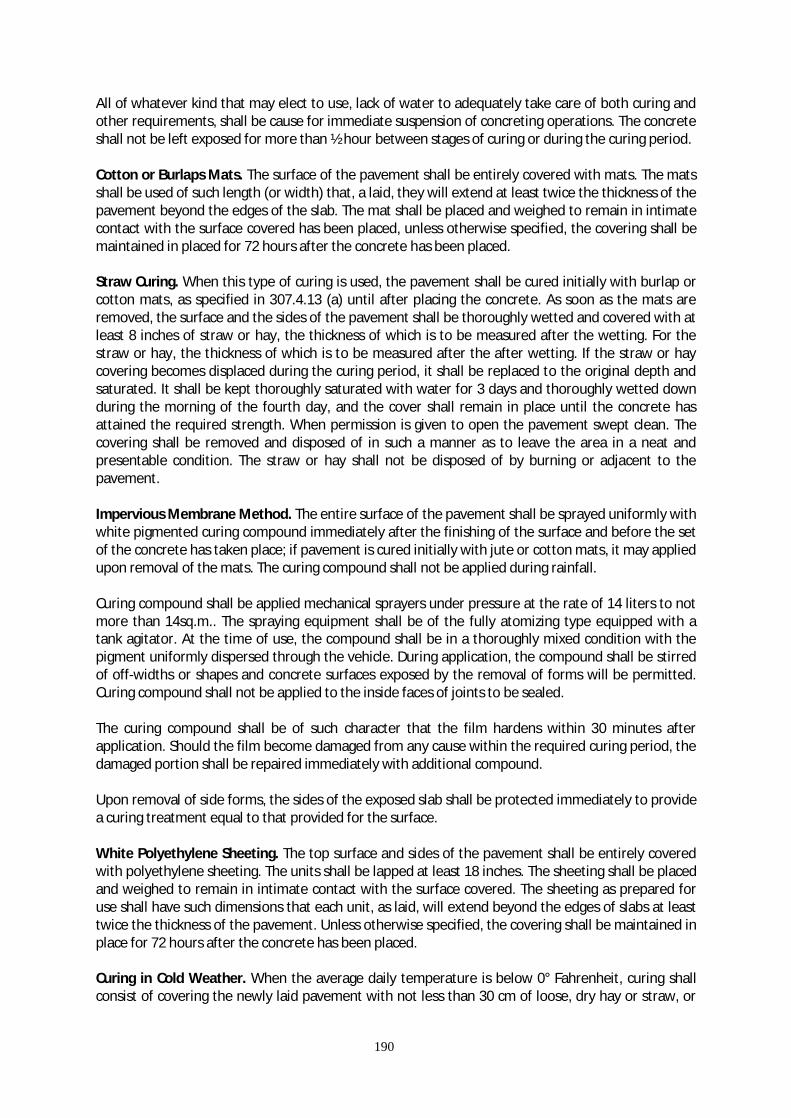
190
All of whatever kind that may elect to use, lack of water to adequately take care of both curing and other requirements, shall be cause for immediate suspension of concreting operations. The concrete shall not be left exposed for more than ½ hour between stages of curing or during the curing period. Cotton or Burlaps Mats. The surface of the pavement shall be entirely covered with mats. The mats shall be used of such length (or width) that, a laid, they will extend at least twice the thickness of the pavement beyond the edges of the slab. The mat shall be placed and weighed to remain in intimate contact with the surface covered has been placed, unless otherwise specified, the covering shall be maintained in placed for 72 hours after the concrete has been placed. Straw Curing. When this type of curing is used, the pavement shall be cured initially with burlap or cotton mats, as specified in 307.4.13 (a) until after placing the concrete. As soon as the mats are removed, the surface and the sides of the pavement shall be thoroughly wetted and covered with at least 8 inches of straw or hay, the thickness of which is to be measured after the wetting. For the straw or hay, the thickness of which is to be measured after the after wetting. If the straw or hay covering becomes displaced during the curing period, it shall be replaced to the original depth and saturated. It shall be kept thoroughly saturated with water for 3 days and thoroughly wetted down during the morning of the fourth day, and the cover shall remain in place until the concrete has attained the required strength. When permission is given to open the pavement swept clean. The covering shall be removed and disposed of in such a manner as to leave the area in a neat and presentable condition. The straw or hay shall not be disposed of by burning or adjacent to the pavement. Impervious Membrane Method. The entire surface of the pavement shall be sprayed uniformly with white pigmented curing compound immediately after the finishing of the surface and before the set of the concrete has taken place; if pavement is cured initially with jute or cotton mats, it may applied upon removal of the mats. The curing compound shall not be applied during rainfall. Curing compound shall be applied mechanical sprayers under pressure at the rate of 14 liters to not more than 14sq.m.. The spraying equipment shall be of the fully atomizing type equipped with a tank agitator. At the time of use, the compound shall be in a thoroughly mixed condition with the pigment uniformly dispersed through the vehicle. During application, the compound shall be stirred of off-widths or shapes and concrete surfaces exposed by the removal of forms will be permitted. Curing compound shall not be applied to the inside faces of joints to be sealed. The curing compound shall be of such character that the film hardens within 30 minutes after application. Should the film become damaged from any cause within the required curing period, the damaged portion shall be repaired immediately with additional compound. Upon removal of side forms, the sides of the exposed slab shall be protected immediately to provide a curing treatment equal to that provided for the surface. White Polyethylene Sheeting. The top surface and sides of the pavement shall be entirely covered with polyethylene sheeting. The units shall be lapped at least 18 inches. The sheeting shall be placed and weighed to remain in intimate contact with the surface covered. The sheeting as prepared for use shall have such dimensions that each unit, as laid, will extend beyond the edges of slabs at least twice the thickness of the pavement. Unless otherwise specified, the covering shall be maintained in place for 72 hours after the concrete has been placed. Curing in Cold Weather. When the average daily temperature is below 0° Fahrenheit, curing shall consist of covering the newly laid pavement with not less than 30 cm of loose, dry hay or straw, or

191
equivalent protective curing authorized by the “Engineer”, which shall be retained in place for 10 days. Admixture for curing temperature control may be used only when authorized by the “Engineer”. When concrete is being placed and the air temperature may be expected to drop below 35° Fahrenheit, a sufficient supply of straw, hay, grass or other suitable blanketing material shall be provided along the work. Any time the temperature may be expected to reach the point during the day or night, the material so provided shall be spread over the pavement to the sufficient depth to prevent freezing of the concrete. The period of time such protection shall be maintained must not be less than 10 days. The Contractor shall be responsible for the quality and strength of the concrete placed during cold weather, and any concrete injured by frost action shall be removed and replaced at the Contractor’s expense. 307.4.13 Removing Forms. Unless otherwise specified, the forms shall not be removed from freshly placed concrete until it has set for at least 12 hours, except where auxiliary forms are used temporarily in widened areas. Forms shall be removed carefully to avoid damage to the pavement. After the forms have been remove, the sides of the slab shall be cured as outlined in one of the methods indicated in 307.4.12. Major honeycomb areas shall be considered as defective work and shall be removed and replaced. Any area or section so removed shall not be less than 3.0 meters in length not less than the full width of the lane involved. When it is necessary to remove and replace a section of pavement, any remaining portion of the slab adjacent to the joints that is less than 3.0 meters in length shall also be removed and replaced. 307.4.14 Sealing Joints. The joints in the pavement shall be sealed in accordance with Item 907. 307.4.15 Protection of Pavement The Contractor shall protect the pavement and its appurtenances against both public traffic caused by his own employees and agents. This shall include watchmen to direct traffic and the erection and maintenance of warning signs, lights, pavement bridges, or crossovers, etc. The plans or special provisions will indicate the location and type of device or facility required to protect the work and provide adequately for traffic. Any damage to the pavement occurring prior to the final acceptance and within the guarantee period shall be replaced or the pavement replaced at the Contractor’s expense. 307.4.16 Opening to Traffic. The “Engineer” shall decide when the pavement shall be opened to traffic. The pavement shall not be opened to traffic for at least 14 days after the concrete has been placed or until the strength has been attained for service use. Prior to opening, the pavement shall be cleaned. For the purpose of establishing an adjusted unit price for pavement, units to be considered separately are defined as 300 lineal metes of pavement in each paving lane starting from the end of the pavement bearing the smaller station number. The last unit in each lane shall be 300 meters plus the fractional part of the 300 meters remaining. When the measurement of the core from a unit is not deficient more than 5mm from the plane thickness, full payment will be made. When such measurement id deficient more than 5mm and not more than 25mm from the plan thickness, two

192
additional cores at intervals not less than 90 meters shall be taken and used in the average thickness for that unit. An adjusted unit price as provided in 307.5.1 (b) will be paid. Other areas such as intersections, entrances, crossovers, ramps, etc., shall be considered as one unit, and the thickness of each unit will be determined separately. Small irregular unit areas may be included as part of another unit. At such points as the “Engineer” may select in each unit, one core shall be taken for each 83.5 square meters of pavement, or fraction thereof, in the unit. If the core is deficient in thickness by more than 5mm but not more than 25mm from the plan thickness, two additional cores shall be taken from the areas represented and the average of the three cores determined. If the average measurement of these three cores is not deficient by more than 5mm from the plan thickness, full payment will be made. If the thickness of the three cores is deficient by more than 5mm but not more than 25mm from the plan thickness, an adjusted unit price, as provided in 307.5.1 (b), will be paid for the area represented by these cores. In calculating the average thickness of the pavement, measurements which are in excess of the specified thickness by more than 5mm shall be considered as specified thickness plus 5mm, and measurements which are less than the specified thickness by more than 25mm shall not be included in the average. When the measurement of any core is less than the specified thickness by more than 25-mm, the actual thickness of the pavement in this area shall be determined by taking additional cores at not less than 3-meters intervals parallel to the centerline in each direction from the affected location, until each direction from the affected location, until in each direction a core has found deficient by more than 25-mm. Areas found deficient in thickness by more than 25-mm shall be evaluated by the “Engineer” and, if in his judgment the deficient areas warrant removal, they shall be removed and replaced with concrete of the thickness shown on the plans. Exploratory cores for deficient thickness will not be used in average for adjusted unit price. 307.5 METHOD OF MEASUREMENT The quantity to be paid for shall be the number of square meters of either plain or reinforced pavement as specified in place, completed and accepted, less deductions as hereinafter required for deficient thickness. 307.6 BASIS OF PAYMENT 307.6.1 General The accepted quantities of concrete pavement will be paid for at the contract unit price per square meter which price and payment shall be full compensation for furnishing and placing of all materials, including any dowels, steel reinforcement and joint material, provided however, that for any pavement found deficient in the thickness by more that 5-mm, but not more than 25-mm, only the reduced price stipulated below shall be paid. No additional payment over the unit contract bid price shall be made for any pavement which has an average thickness in excess of that shown on the plans. Payment will be made under:
PAYMENT NUMBER DESCRIPTION UNIT OF MEASUREMENT 307 Portland Cement Concrete Square Meter
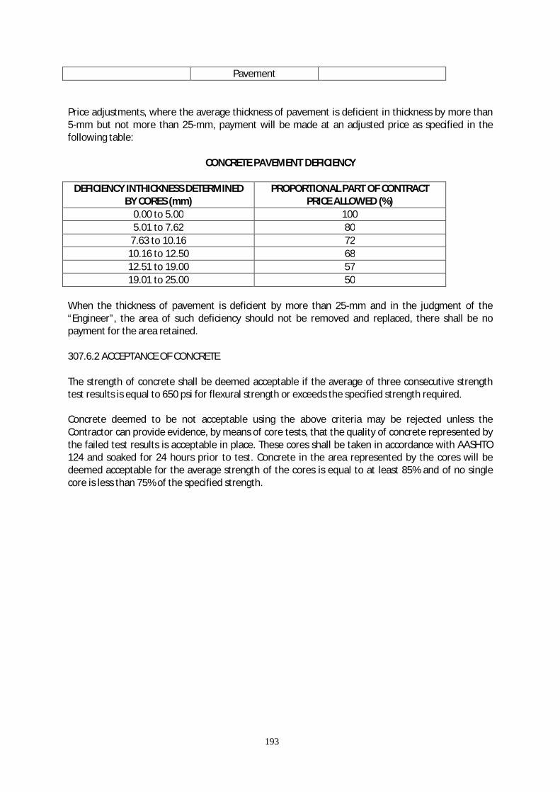
193
Pavement Price adjustments, where the average thickness of pavement is deficient in thickness by more than 5-mm but not more than 25-mm, payment will be made at an adjusted price as specified in the following table:
CONCRETE PAVEMENT DEFICIENCY
DEFICIENCY INTHICKNESS DETERMINED BY CORES (mm)
PROPORTIONAL PART OF CONTRACT PRICE ALLOWED (%)
0.00 to 5.00 100 5.01 to 7.62 80
7.63 to 10.16 72 10.16 to 12.50 68 12.51 to 19.00 57 19.01 to 25.00 50
When the thickness of pavement is deficient by more than 25-mm and in the judgment of the “Engineer”, the area of such deficiency should not be removed and replaced, there shall be no payment for the area retained. 307.6.2 ACCEPTANCE OF CONCRETE The strength of concrete shall be deemed acceptable if the average of three consecutive strength test results is equal to 650 psi for flexural strength or exceeds the specified strength required. Concrete deemed to be not acceptable using the above criteria may be rejected unless the Contractor can provide evidence, by means of core tests, that the quality of concrete represented by the failed test results is acceptable in place. These cores shall be taken in accordance with AASHTO 124 and soaked for 24 hours prior to test. Concrete in the area represented by the cores will be deemed acceptable for the average strength of the cores is equal to at least 85% and of no single core is less than 75% of the specified strength.
194
ITEM 405 – CONCRETE WORKS
405.1 SCOPE OF WORK This Section includes all cast-in-place and pre-cast concrete and related works required under these Specifications, except Portland Cement Concrete Pavement. 405.2 GENERAL PROVISIONS Concrete shall consist of mixture of Portland Cement, fine aggregate, coarse aggregate, admixtures when specified, and water mixed in the proportions specified or approved by the Engineer. The following publications of the issued, listed below, but referred to thereafter by basic designation only, form a part of this Specification to the extent indicated by the reference thereto: 1. American Concrete Institute ( ACI ), Standard:
ACI 211.1 Recommended Practice for Selecting Proportions for Structural Concrete.
ACI 214 Recommended Practice for Evaluation of Compressive Test Results of Field Concrete.
ACI 305 Recommended Practice for Hot Weather Converting
ACI 315 Manual of Standard Practice for Detailing Concrete Structure
ACI 318 Building Code Requirements for Reinforced Concrete, with Commentary
2. American Society for Testing and Materials ( ASTM ) Publications:
A 82 Cold-Drawn Steel Wire for Concrete Reinforcement
A 185 Welded Steel Wire Fabric Concrete Reinforcement
A 615 Deformed and Plain Billet-Steel Bars for Concrete Reinforcement.
A 616 Rail-Steel Deformed and Plain Bars for Concrete Reinforcement
A 617 Axle-Steel Deformed and Plain Bars for Concrete Reinforcement
C 31 Making and Curing Concrete Test Specimens in the field
C 33 Concrete Aggregate
C 39 Compressive Strength of Cylindrical Concrete Specimens
C 42 Drilled Cores and Sawed Beams of Concrete, obtaining and testing
C 94 Ready-Mixed Concrete
C 143 Slump of Portland Cement Concrete

195
C 150 Portland Cement
C 171 Sheet Materials for Curing Concrete
C 172 Sampling Fresh Concrete in the ASTM Publication
C 173 Air Content of Freshly Mixed Concrete by the Volumetric Method
C 192 Making and Curing Concrete Test Specimens in the Laboratory C 231 Air Content of Freshly Mixed Concrete by the Pressure Method
C 260 Air-Entraining Admixture for Concrete C 309 Liquid Membrane-Forming Compounds for Curing Concrete
C 494 Chemical Admixture for Concrete
C 1751 Preformed Expansion Joint Fillers for Concrete Paving and Structural Construction.
(Non-extruding and Resilient Bituminous Types ) 3. American Welding Society ( AWS )
D.12.1 Welding Reinforcing Steel, Metal Inserts and Connections in Reinforced Concrete Construction.
4. Philippine Standard (PS) 681 – 04 .02, 1975
DSB 275 Steel Bars for Concrete Reinforcement 405.3 SUBMITTALS Refer to General and Special Requirements of the Contract. Test Reports and Certificates shall be furnished for approval before delivery of certified or testes materials to the Project Site. 405.4 CLASSES OF CONCRETE AND USAGE 405.4.1 STRENGTH REQUIREMENTS: Concrete of the various classes indicated and as required under other sections, and unless specified in the plan shall be proportioned and mixed for the following strength:
Class Size of Aggregate (mm)
Specified Compressive Strength 28 days f’c = kg/sq.cm.
A-A 25 420 A 40 240 B 40 210 C 50 175
Seal 25 240

196
In addition to the above, the maximum permissible water-cement ratio by weight shall not be greater than 0.55 unless otherwise the Engineer. 405.4.2 USAGE Concrete of the various classes to be used shall be as follows: 1. Class A-A concrete: For pre-stressed concrete structures and members. 2. Class A concrete: For pre-cast structure, superstructures and heavily reinforced substructures
which include slabs beams, walls, girders, columns, arch ribs, box culverts, reinforce abutments, retaining walls, reinforced footings and foundation of buildings.
1. Class B concrete: Footings, pedestals, foundation of equipment, retaining wall, curb, slab on
grade, pipe bedding gravity walls, unreinforced or with only a small amount of reinforcement. 2. Class C concrete: Leveling concrete. 3. Class Seal: Concrete deposited in water 405.4.3 Additives acceptable to the Engineer shall be used for all reinforced concrete structures exposed to salt water action. 405.5 MATERIALS 405.5.1 CEMENT Except when specifically approved by the Engineer only one brand of cement shall be used for any individual structure. In determining the approved mix, only Portland Cement shall be used. 1. Portland Cement: ASTM C 150, Type I 2. High-Early Strength Portland Cement Type III may be used for pre-cast concrete. Cement Type III
shall conform to ASTM C 150 with a tricalcium aluminate limited to 8 percent. 405.5.2 ADMIXTURES Shall conform to the following: 1. Air-Entraining Admixtures: ASTM C 260 2. Admixture other than air-entraining agent shall conform to ASTM C 494. 3. Admixture containing chloride ions, or other ions producing deleterious effects, shall not be
used. 405.5.3 AGGREGATES:
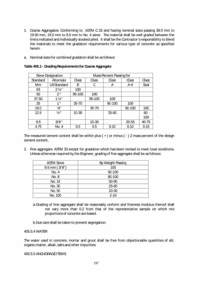
197
1. Coarse Aggregates: Conforming to ASTM C 33 and having nominal sizes passing 38.0 mm to
19.00 mm, 19.0 mm to 9.5 mm to No. 4 sieve. The material shall be well graded between the limits indicated and individually stocked piled. It shall be the Contractor’s responsibility to blend the materials to meet the gradation requirements for various type of concrete as specified herein.
a. Nominal sizes for combined gradation shall be as follows: Table 405.1 - Grading Requirements for Coarse Aggregate
Sieve Designation Mass Percent Passing for Standard Alternate Class Class Class Class Class
Mm US Standard B C A A-A Seal 63 2 ½ “ 100 50 2 “ 95-100 100
37.50 1 ½ “ 95-100 100 25 1 “ 35-70 90-100 100
19.0 ¾” 35-70 90-100 100 12.5 ½ “ 10-30 25-60 90-
100 9.5 3/8 “ 10-30 20-55 40-70
4.75 No. 4 0.5 0.5 0.10 0.10 0.15 The measured cement content shall be within plus ( + ) or minus ( - ) 2 mass percent of the design cement content. 2. Fine aggregate: ASTM 33 except for gradation which has been revised to meet local conditions.
Unless otherwise required by the Engineer, grading of fine aggregate shall be as follows:
ASTM Sieve By Weight Passing 9.5 mm ( 3/8”) 100
No. 4 90-100 No. 8 80-100
No. 16 50-90 No. 30 25-60 No. 50 10-30
No. 100 2-10
a. Grading of fine aggregate shall be reasonably uniform and fineness modulus thereof shall not vary more than 0.2 from that of the representative sample on which mix proportions of concrete are based.
b. Due care shall be taken to prevent segregation. 405.5.4 WATER The water used in concrete, mortar and grout shall be free from objectionable quantities of silt, organic matter, alkali, salts and other impurities. 405.5.5 ANCHORAGE ITEMS:

198
a. Dowels for anchoring mechanical items to concrete shall be of manufacturer’s standard and of
types required to engage with the anchors to be provided and installed therein under other sections of these Specifications and shall be subject to the approval of the Engineer.
b. Slots shall be dovetail-type, of not lighter than 24-gauge zinc-coated steel, with filler that
prevents concrete or water from entering and that can be easily removed or punctured for installing anchors.
c. Inserts for suspended ceilings: Wire inserts for attachment of wire hangers for suspended
ceilings shall not be lighter than 7-gauge zinc-coated steel wire. When flat iron or steel hangers are to be used zinc-coated inserts of the same section shall be set in the concrete.
d. Inserts for bolt hangers shall be of malleable iron or of cast of wrought steel. Inserts for bolt
hangers shall either be threaded or slotted as required by the types of hanger to be used. Threaded inserts shall have integral lugs to prevent turning.
405.5.6 CURING MATERIALS: a. Impervious Sheet Materials: ASTM C 171, type optional except that polyethylene film, of used,
shall be white opaque. b. Burlap of commercial quality, non-staining type, consisting of 2 layers opaque. c. Inserts for suspended ceilings: Wire inserts for attachment of wire hangers for suspended
ceilings not be lighter than 7-gauge zinc-coated steel wire. When flat iron or steel hangers are to be used zinc-coated inserts to the same section shall be set in the concrete.
d. Inserts for bolt hangers shall be of malleable iron or of cast of wrought steel. Inserts for bolt
hangers shall either be treated or slotted as required by the types of hanger to be used. Threaded inserts shall have integral lugs to prevent turning.
405.5.7 FORM MATERIALS: Coatings and Ties are specified under 405.5.14, Form work of this Specification. 405.5.8 REINFORCEMENT a. Deformed Bars conforming to PS 681-04.02 ( DSB 275 ); 1975 First Revision, or conforming to Bar
Reinforcement of Item 401-Reinforcing Steel. b. Mesh Reinforcement conforming to JIS G 3551 or equivalent. 405.5.9 EXPANSION JOINT FILLER: Preformed joint filler conforming to ASTM 17521, type and class suitable for the use intended. 405.5.10 VAPOR BARRIER: a. Asphalt-saturated waterproof reinforced draft paper.
199
b. Polyethylene sheeting shall not be less than 0.2 mm nominal thickness.
405.5.11 WATERSTOPS SHALL BE OF THE FOLLOWING: Copper conforming to ASTM B 370, 567 gms weight: or stainless steel conforming to ASTM A 167, type 304 L, finish 2D or equivalent, annealed 0.94 mm nominal thickness. 405.6 SAMPLES AND TESTING Testing except as otherwise specified herein, shall be performed by an approved testing agency as proposed by the Contractor and approved by the Engineer at no additional cost to the Government.
Cement: Sampled either at the mill or at the site of the work and tested by an approved independent commercial national testing laboratory at no additional cost to the Government. Certified copies of laboratory test reports shall be furnished for each lot of cement and shall include all test data, results, and certificates that the sampling and testing procedures are in conformance with the Specifications. No cement shall be used until notice has been given by the Engineer that the test results are satisfactory. Cement that has been stored, other than in bins at the mills, for more than 3 months after delivery to the Site shall be retreated before use. Cement delivered at the Site and later fond under test to be unsuitable shall not be incorporated into the permanent works.
Aggregate: Tested as prescribed in ASTM C33. Reinforcement: Certified copies of mill certificate of tests shall accompany deliveries of steel
bar reinforcement. If requested by the Engineer additional testing of the materials shall be made at the Contractor’s expense.
Concrete Tests: Provide for test purposes, one set of the test specimens taken under the
instruction of the Engineer from each 75 cu. m. or fraction thereof of each class of concrete placed or at least one set of test specimens shall be provided for each class of concrete placed in each 8-hour shift. Each shall consist of three test specimens, and shall be made from a separate batch. Samples shall be secured in conformance with ASTM C172. Test specimen shall be made, cured, and packed for shipment in accordance with ASTM C31. Cylinders will be tested by and at the expense of the Contractor in accordance with ASTM C39. Test specimens will be evaluated separately, by the Engineer for meeting strength level requirements for each with CONCRETE QUALITY of ACI 318 . The standard age of test shall be 28 days, but 7 days tests may be used, with the permission of the Engineer, provided that the relation between the 7-day and 28-day strengths on the concrete is established by tests for the materials and proportions used. When samples fail to conform to the requirements for strength, the Engineer shall have the right to order a change in the proportions of the concrete mix for the remaining portions of the work at no additional cost to the Government.
Test of Hardened Concrete in or Removed from the Structure: When the result of the
strength tests of the control specimens indicates in the concrete as placed does not meet the Specifications requirements or where there is other evidence that the quality of the concrete is below the specification

200
requirements, test on core of in-place concrete shall be made in conformance with ASTM C 42.
a. Core specimens shall be obtained by the Contractor and shall be tested. Any
deficiency shall be corrected; if the Contractor elects, he may submit a proposal for approval that a load test is made. If the proposal is approved, the Contractor and the test results evaluated by the Engineer in conformance with 20 of ACI 318 shall make the load test. The cost of the load tests shall be borne by the Contractor. If any concrete shows evidence of failure during the load test or fails the load test as evaluated the deficiency shall be corrected in a manner approved by the Engineer at no additional cost to the Government.
Admixtures: All admixtures shall be tested and those that have been in storage at the
project Site for longer than 6 months shall not be used until proved by retest to be satisfactory.
a. Air-Entraining Admixtures: Tested for conformance to the referenced
specification under which it is furnished. The testing shall be conducted with cement and aggregate proposed for the project.
b. Other admixtures if approved, tested for conformance to the referenced
specifications under which it is furnished. The testing shall be conducted with cement and aggregate proposed for the Project.
405.7 STORAGE Storage accommodation for concrete materials shall be subject to approval and shall afford easy access for inspection and identification of each shipment in accordance with test reports.
Cement: Immediate upon receipt at the Site, the Cement shall be stored separately in a dry weather tight, properly ventilated structure, with of adequate provisions for prevention or absorption of moisture. Cement bags should not be stacked more than 13 bags high. The cement most likely to have been exposed to moisture or stored in bags for more than 3 months shall not be used unless proven by test to be in good condition.
Aggregate: Stored to assure good drainage, to preclude inclusion of foreign matter, and to
preserve the gradation. 405.8 FORMWORK Forms: Designed, constructed, and maintained so as to insure that, after removal, the
finished concrete members will have true surfaces, free of offset, waving or bulges, and will conform accurately to the indicated shapes, dimensions, .lines, elevation, and positions in the plan. Form surfaces that will be contact with concrete shall be thoroughly cleaned before each use.
405.8.1 DESIGN Studs and wale shall be spaced to prevent deflection of form materials. Forms and joints shall be sufficiently tight to prevent leakage of grout and cement paste during placing of concrete. Juncture

201
of formwork panels shall occur at vertical control joints, and construction joints. Forms placed on successive units for continuous surfaces shall be fitted in accurate alignment to assure smooth completed surface free from irregularities and signs of discontinuity. Temporary opening shall be arranged to wall and where otherwise required to facilitate cleaning and inspection. Forms shall be readily removable without impact, shock, or damage to the concrete. 405.8.2 CONCRETE SURFACES TO BE EXPOSED Form surfaces that will be in contact with concrete shall be of materials that is non reactive with concrete and that will produce concrete surfaces equivalent in smoothness and appearance to that produced by new 1.2 x 2.4 meters plywood panels approved by the Engineer. Smaller size panels shall be used only where required by opening on the above architectural lines or joints, with each area less than 1.2 meters wide formed with single panel accurately cut to the required dimensions. Cut surfaces shall be smooth and treated with form coating. Panel joints that will being contact with concrete shall be smooth and free of offset. Form materials with defects that will impair the texture and appearance of finish surfaces shall not be used. Form lining, if used, shall be installed over solid backing. Column forms shall be made with a minimum number of joints. 405.8.3 CONCRETE SURFACES TO BE UNEXPOSED Form surfaces that will be in contact with concrete shall be sound, tight lumber or other material producing equivalent finish. 405.8.4 SAMPLE CONCRETE PANELS Before constructing structural formwork, sample concrete panel for exposed or painted concrete shall be constructed and approved for smooth finish specified in paragraph FINISHES OF CONCRETE OTHER THAN FLOOR SLABS. The panel shall not be less than 1.8 meter long by 1.2 meter high. Concrete shall be of the approved design mix. Forms shall include a typical joint between form panels. Sample panels shall show tie-hole patching and smooth finish. Sample panels shall be constructed at approved locations, not as part of the structure, and shall be protected from construction operations, weather, and other damage until acceptance of the completed concrete work. The approved sample panel shall be representative of the smooth concrete finish required in the work. 405.8.5 Form Ties shall be factory-fabricated, removable or snap-off metal ties of design that it will not allow form deflection and will not spall concrete upon removal. Solid backing shall be provided for each tie. Ties shall be fitted with devices that will leave holes in the concrete surface no less than 9 mm nor more than 2.5 mm in diameter and of depth not less than 25 mm. The portions of the tie remaining in the concrete after removal of the exterior parts shall not project beyond the surface of the concrete and shall be at least 38 mm back from any surface of the concrete that will be exposed, painted, damp-proofed, water-proofed, or receive direct applications of plaster. Bolts and rods that are to be completely withdrawn shall be coated with a non-staining bond breaker. 405.8.6 CHAMFERING External corners of columns, girders, beams, foundation wall projecting beyond overlaying masonry, and other external corners that will be exposed shall be chamfered, beveled or rounded, not less

202
than 19 mm, by molding in the forms unless the drawings specifically state that chamfering is to be omitted. 405.8.7 COATINGS Forms for exposed surfaces shall be coated with form oil or form-release agent before reinforcement is placed. The coating shall be a commercial formulation of satisfactory and proven performance that will not bond with, stain, or adversely affect concrete surfaces, and will not impair subsequent treatment of concrete surfaces depending upon or adhesion nor impede the wetting of surfaces to be cured with water or curing compounds. The coating shall be used as recommended in the manufacturer’s printed or written instructions. Forms for unexposed surfaces may be wet with water in lieu of coating immediately before placing of concrete. Surplus coating on form surfaces and coating on reinforcement steel and construction joints shall be removed before placing concrete. 405.8.8 Removal of forms shall be in a manner to insure complete safety of the structure after the following conditions have been met. Where structural as a whole is supported on shores, forms for beam and girder sides, columns, and similar vertical structural members may be removed after 24 hours, provided concrete is sufficiently hard not to be injured thereby. Supporting forms of shoring shall not be removed until structural members have acquired sufficient strength to support safely their own weight and any construction and/or storage load to which they may be subjected, but in no case shall they be removed in less than 7 days, nor shall forms used for curing be removed before expiration of curing period except as specified in paragraph CURING. Care shall be taken to avoid spalling the concrete surface or damaging concrete edges. Wood forms shall be completely removed.
a. Control Tests: Results of suitable control tests will be used as evidence that concrete has attained sufficient strength to permit removal of supporting forms. Cylinders required for control tests shall be provided in addition to those otherwise required by the specifications. Test specimens shall be removed from molds at end of 24 hours and stored near to the structure as possible at points of sampling, shall receive insofar as practicable the same protection from the elements during curing as given in those portions of the structure which they represent, and shall not be removed form the structure for transmittal to the laboratory prior to expiration of three-fourths of the proposed period before removal of forms. Supporting forms or shoring shall not be removed until control-test specimens have attained strength of at least 15.68 Mpa. The newly unsupported portions of the structure shall not be subject to heavy construction or material loading.
b. Tie-Rods to be entirely remove from the wall shall be loosened 24 hours after concrete is
placed, and form ties, except for a sufficient number to hold forms in place, may be removed at that time. Ties wholly withdrawn from wall shall be pulled toward the face that will be concealed from view in the permanent work.
405.9 REINFORCEMENT 405.9.1 REINFORCEMENT Fabricated to shapes and dimensions shown and shall be placed where indicated. Reinforcement shall be of loose or flaky rust and mill scale, or coating, and any other substance that would reduce

203
or destroy the bond. Reinforcing steel reduce in section shall not be used. After any substantial delay in the work, previously placed reinforcing steel for future binding shall be inspected and cleaned. Reinforcing steel shall not be bent or straightened in a manner injurious to the steel or concrete. Bars with kinks or bends not shown on the Drawing shall not be placed. The use of heat to bend or straighten reinforcing steel shall not be permitted. Bars shall removed as necessary to avoid interference with other reinforcing steel, conduits, or embedded items. If bars are move more than one bar diameter, the resulting arrangement of bars including additional bars necessary to meet structural requirement shall be approved before concrete is places. In slabs, beams, and girders, reinforcing steel shall not be spliced at points of maximum stress unless otherwise indicated. Unless otherwise shown on the Drawing, laps or splices shall be 40 times the reinforcing bar diameter. 405.9.2 The nominal dimensions and unit weights of bar designation shall be in accordance with the
following table: Nominal Diameter Nominal Perimeter
(mm) Nominal Sectional
Area (sq.mm) Unit Weight
(Kg/m) 6 mm 18.8 28.27 0.222
10 mm 31.4 78.54 0.616 12 mm 37.7 113.10 0.888 16 mm 50.3 201.10 1.579 20 mm 62.8 314.2 2.466 25 mm 78.5 490.9 3.854 28 mm 88.0 615.7 4.833 32 mm 100.5 804.2 6.313 36 mm 113.1 1017.9 7.991 40 mm 125.7 1256.6 9.864 50 mm 157.1 1963.5 15.413
405.9.3 Wire-mesh reinforcement shall be continuous between crack control joints in slabs on grade and shall be continuous between expansion joints in other slabs. Laps shall be at least one full mesh plus 50 mm staggered to avoid continuous lap in either direction, and securely wired or clipped with standard clips. 405.9.4 Dowels in slabs on grade shall be installed at right angles to construction joints and expansion joints. Dowels shall be accurately aligned parallel to the finished surface, and shall be rigidly held in place and supported during placing of the concrete. One end of dowels shall be oiled or greased. 405.9.5 Tie bard on grade shall be placed at right angles to construction joints. Tie bars shall be accurately aligned parallel to the finished surface, and shall be rigidly held in place and supported during placing of the concrete. 405.9.6 Supports shall be provided in conformance with ACI 315 and ACI 318 unless otherwise indicated or specified. Wire ties, when used, shall be a 16-gauge black annealed wire and shall have end pointing away from the form.
a. For slabs on grade: Reinforcement shall be supported on pre-cast structure units spaced at intervals required by size of reinforcement used, to keep reinforcement the minimum height specified or indicated above the underside of slab or footing.
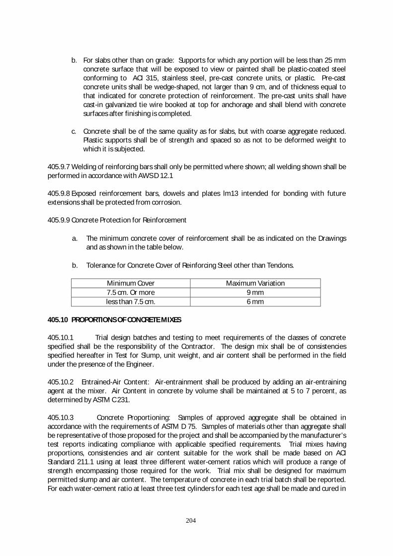
204
b. For slabs other than on grade: Supports for which any portion will be less than 25 mm
concrete surface that will be exposed to view or painted shall be plastic-coated steel conforming to ACI 315, stainless steel, pre-cast concrete units, or plastic. Pre-cast concrete units shall be wedge-shaped, not larger than 9 cm, and of thickness equal to that indicated for concrete protection of reinforcement. The pre-cast units shall have cast-in galvanized tie wire booked at top for anchorage and shall blend with concrete surfaces after finishing is completed.
c. Concrete shall be of the same quality as for slabs, but with coarse aggregate reduced.
Plastic supports shall be of strength and spaced so as not to be deformed weight to which it is subjected.
405.9.7 Welding of reinforcing bars shall only be permitted where shown; all welding shown shall be performed in accordance with AWS D 12.1 405.9.8 Exposed reinforcement bars, dowels and plates lm13 intended for bonding with future extensions shall be protected from corrosion. 405.9.9 Concrete Protection for Reinforcement
a. The minimum concrete cover of reinforcement shall be as indicated on the Drawings and as shown in the table below.
b. Tolerance for Concrete Cover of Reinforcing Steel other than Tendons.
Minimum Cover Maximum Variation 7.5 cm. Or more 9 mm less than 7.5 cm. 6 mm
405.10 PROPORTIONS OF CONCRETE MIXES 405.10.1 Trial design batches and testing to meet requirements of the classes of concrete specified shall be the responsibility of the Contractor. The design mix shall be of consistencies specified hereafter in Test for Slump, unit weight, and air content shall be performed in the field under the presence of the Engineer. 405.10.2 Entrained-Air Content: Air-entrainment shall be produced by adding an air-entraining agent at the mixer. Air Content in concrete by volume shall be maintained at 5 to 7 percent, as determined by ASTM C 231. 405.10.3 Concrete Proportioning: Samples of approved aggregate shall be obtained in accordance with the requirements of ASTM D 75. Samples of materials other than aggregate shall be representative of those proposed for the project and shall be accompanied by the manufacturer’s test reports indicating compliance with applicable specified requirements. Trial mixes having proportions, consistencies and air content suitable for the work shall be made based on ACI Standard 211.1 using at least three different water-cement ratios which will produce a range of strength encompassing those required for the work. Trial mix shall be designed for maximum permitted slump and air content. The temperature of concrete in each trial batch shall be reported. For each water-cement ratio at least three test cylinders for each test age shall be made and cured in

205
accordance with ASTM C 39. From these test results, a curve shall be plotted showing the relationship water-cement ratio and strength. 405.10.4 Average Strength: For each portion of the structure, proportions shall be selected so that the maximum permitted water-cement ration is no exceeded and so as to produce an average strength to exceed the specified strength fc’ by the amount indicated below. Where production facility has a standard deviation record determined in accordance with ACI 214, based on 30 consecutive strength tests of similar mixture proportions as proposed it shall be used in selecting average strength. The average strength used as the basis for selecting proportions shall exceed the specified strength fc’ by at least:
1. 30 kg/sq. cm. If standard deviation is less than 20 kg/sq. cm. 2. 40 kg/sq. cm. If standard deviation is 20 to 30 kg/sq. cm. 3. 50 kg/sq. cm. If standard deviation is 30 to 40 kg/sq. cm. 4. 60 kg/sq. cm. If standard deviation is 40 to 50 kg/sq. cm. 5. If the standard deviation exceed 50 kg. Sq. cm. Or if a standard deviation record is not
available, proportions shall be selected to produce an average strength of at least 70 kg/sq. cm. Greater than the specified strength.
405.10.5 Corrective additions to remedy deficiencies in aggregate gradation shall be used only on written approval of the Engineer. 405.4.17,6 Slump: Tests shall be made in conformance with ASTM C 143, and unless otherwise specified by the Engineer slump shall be within the following limits:
Structural Element Slump for Vibrated Concrete
Minimum Maximum Pre-cast Concrete 5 cm 7 cm Wall, column and grade beam, 25cm maximum thickness
5 cm 7 cm
All other concrete 5 cm 10 cm Lean Concrete 10 cm 20 cm
405.11 BATCHING AND MIXING 405.11.1 The Contractor shall provide a semi-automatic or better batching plant and concrete
mixing equipment having a sufficient capacity to satisfy concrete placement requirements. 405.11.2 B ATCHING PLANT 1. Arrangement: Separate bins or compartment shall provided for each size or classification of
aggregate and for bulk Portland cement. The compartments shall be of ample size and so

206
constructed that the materials will be maintained separately so that the flow of each material into its batcher is stopped automatically when the designated weight has been reached.
2. Aggregates may be weighed in separate weigh batches with individual scales, or cumulatively on
one weigh batcher with one scale. Bulk cement shall be weighed on a separate scale in a separate weigh batcher. Water may be measured by weight or by volume. If measured by weight, it shall not be weighed cumulatively with another ingredient. Batching controls shall be so interlocked that the charging mechanism cannot be opened until the scales have returned to zero. These requirements can be satisfied when actuated by one or more starting mechanism.
A semi-automatic batcher control shall start the weighing operation of each material and stop automatically when the designated weight of each material has been reached and interlocked in such a manner that the discharge device cannot be actuated until the indicated material is within the applicable to tolerance. The plant shall be arranged so as to facilitate the inspection of all operations at all times. Suitable facilities shall be provided for obtaining representative samples of aggregate from each of the bin of compartments for test purposes. Delivery of materials from the batching equipment shall be within the following limits of accuracy.
Materials Percent Cement 1 Water 1
Aggregate 2 Admixtures 3
3. Water Bather and dispenser for Admixtures: Equipment for batching water and admixtures shall
be provided at the batching plant or included with the paving mixer or truck mixers as required for the type of plant used.
a. Water Batchers: A suitable water measuring device shall be provided which will be capable
of measuring the mixing water within the specified requirements for each batch. The mechanism for delivering water to the mixers shall be such that leakage will not occur when the values are closed.
The filling and discharge valves for the water batcher shall be so interlocked that the discharge valve cannot be opened before the filling valve is fully closed.
b. Dispensers: An accurate mechanical device for measuring and dispensing each admixture
shall be provided. Each device shall be capable of ready adjustment to permit varying of the quantity of admixture to be batched. Each dispenser shall be interlocked with the batching and discharging operations of the water so that each admixture is separately batched and discharge automatically in a manner to obtain uniform distribution throughout the batch in the specified mixing period. When use of truck mixers makes this requirement impracticable, the admixture dispenser shall be interlocked with the sand batcher. Admixtures will not be combined prior to introduction into water or sand.
3. Moisture Control: The plant shall be capable ready adjustment to compensate for the
varying moisture contents of the aggregate, and to change the weights of the materials being batched. An electric moisture meter shall be provided for measurement of moisture content in the fine aggregate. The sensing element shall be arranged so that the measurement is made near the batcher charging gate of the sand bin or in the sand batcher.

207
4. Scales: Adequate facilities shall be provided for the accurate measurement and control of each of the material entering each batch of concrete. The weighing equipment shall conform to the applicable requirements of National Bureau of Standard Handbook 44 or other international standard for scale except that the accuracy shall be within 0.2 percent of scale capacity. The Contractor shall provide standard test weights and any other auxiliary equipment required for checking the operating performance of each scale or other measuring device. Each weighing unit shall include visible springless dial which shall indicate the scale load at all stages of the weighing operation, or shall include a beam scale with a beam balance indicator which will show the scale in balance at zero load and at any beam setting. The indicator shall have an over and under travel equal to at least 5 percent of the capacity of the beam. The weighing equipment shall be arranged so that the plant operator can conveniently observed all dials or indicators.
6. Recorders: a. An accurate recorder or recorders shall produce a graphical or digital record of the scale reading
after each of the aggregates and cementing materials have been batched prior to delivery to the mixer and after the batchers have been discharged ( return to zero reference ). The weights or volume of water and admixtures shall also be recorded if batched at a central batching plant.
b. The recorder shall be housed in a cabinet which shall be capable of being locked. c. The charts or tapes shall clearly indicate the different types of mixes used by stamped letters,
numerals, colored ink or by other suitable means. d. The charts or tapes shall be so marked that variations in batch weights of each type of mix can
be readily observed. e. The charts of tapes shall show time of day ( stamped or pre-printed ) at intervals of not more
than 15 minutes f. The recorded charts or tapes shall become the property of the PMO. g. The recorders shall be placed in a position. Convenient for observation by the plant operator and
the PMO. h. All weighing, indicating, recording and control equipment shall be sufficiently protected against
exposures to dust, moisture and vibration so that there is no interference with proper operation of the equipment.
i. The recorded weights or volumes when compared to the weights or volumes actually batched
shall be within the following limits of accuracy.
Materials Percent Cement 2 Water 2
Aggregate 4 Admixtures 6

208
405.11.3 CONCRETE MIXERS Stationary mixers, truck mixers, or paving mixers of approved design. The mixers shall have a rated capacity of at least 0.76 cu. m. of mixed concrete, and shall not be charged in excess of the capacity recommended by the manufacturer. Mixers shall be capable of combining the material into a uniform mixture and of discharging this mixture without segregation. Stationary and paving mixers if used shall be provided with an acceptable device to lock the discharge mechanism until the required mixing time has elapsed. The mixing plant shall include device for automatically counting the total number of batches of concrete mixed. The mixers shall be operated at the drum or mixing blade speed designated by the manufacturer on the name plate. The mixing period specified herein are predicated on proper control of the speed of rotation of the mixer drum or blades, and on proper introduction of the materials into the mixer. The acceptability of truck mixers will be determined by uniformity tests as required by ASTM C 94, the mixing time for stationary or paving mixers will be increased when such increase is necessary to secure the required uniformity and consistency of the concrete. Excessive over-mixing requiring additions of water will not be permitted. The mixers and mixer drums shall be maintained unsatisfactory operating condition and mixer shall be kept free of hardened concrete. Mixer blades shall be replaced when worn more than 10 percent of their dept. Should any mixer at any time produce unsatisfactory results, its use shall be promptly discontinued until it is repaired. 1. Stationary Mixers: The mixing time for each batch after all solid materials are in the mixer,
provided that all of the mixing water is introduced before one-fourth of the mixing time has elapsed, shall be one minute for mixers having a capacity of 0.76 cu. m. and for mixers of larger capacities the mixing time shall be increased by 15 second for each additional 0.76 cu. m. or fraction thereof concrete mixed. When stationary mixer is used for partial mixing of the concrete (shrink mixed) the mixing time in the stationary mixer may be reduced to the minimum necessary to item the ingredients (about 30 seconds).
2. Truck Mixers: Conform to the requirements of ASTM C94 including requirements or
uniformity of concrete. When a truck mixer is used either for complete mixing (transit mixed) or to finish the partial mixing done in a stationary mixer, in absence of uniformity test data, each batch of concrete shall be mixed not less than 70 nor more than 100 revolutions of the drum at the rate of rotation designated by the manufacturer of the equipment as mixing speed and at the capacity designated in ASTM C94. If the batch is at least 0.38 cu. m. less than the rated capacity, in the absence of uniformity test data, the number of revolutions at mixing speed may be reduced to not less than 50. Any additional mixing shall be done at the speed designated by the manufacturer of the equipment at agitating speed. Each truck shall be equipped with two counters from which it shall be possible to determine the number of revolutions at mixing speed and the number of revolutions at agitating speed.
3. Vehicles used in transporting materials from the batching plant to the mixers shall have bodies
or compartments of adequate capacity to carry the materials and to deliver each batch, separate and intact to the mixer. Bulk cement shall be transported from the batching plant to the mixers in separate closed boxes or compartments, or shall be transported, mixed with the aggregates or placed between layers of aggregates in batch trucks having windproof and rain-proof covers as weather conditions require. Concrete containing batched cement and aggregates shall be placed within the time specified in paragraph: Time interval between mixing and placing under paragraph PLACING CONCRETE. Serially numbered tickets shall be provided for each delivery of batched cement and aggregates and before discharging any batch in mixer. Tickets shall be stamped by time clock to show date and time the loading of each truck was completed. One ticket shall be given to the Engineer before discharging any batch into the mixer.
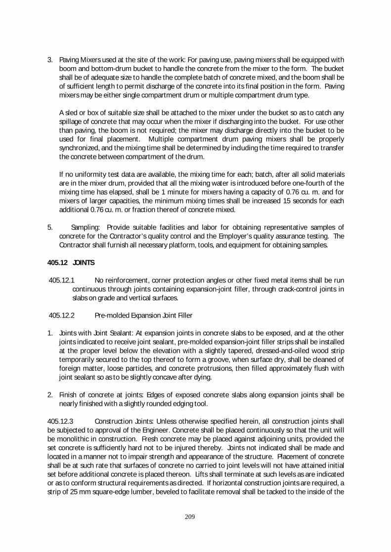
209
3. Paving Mixers used at the site of the work: For paving use, paving mixers shall be equipped with
boom and bottom-drum bucket to handle the concrete from the mixer to the form. The bucket shall be of adequate size to handle the complete batch of concrete mixed, and the boom shall be of sufficient length to permit discharge of the concrete into its final position in the form. Paving mixers may be either single compartment drum or multiple compartment drum type.
A sled or box of suitable size shall be attached to the mixer under the bucket so as to catch any spillage of concrete that may occur when the mixer if discharging into the bucket. For use other than paving, the boom is not required; the mixer may discharge directly into the bucket to be used for final placement. Multiple compartment drum paving mixers shall be properly synchronized, and the mixing time shall be determined by including the time required to transfer the concrete between compartment of the drum. If no uniformity test data are available, the mixing time for each; batch, after all solid materials are in the mixer drum, provided that all the mixing water is introduced before one-fourth of the mixing time has elapsed, shall be 1 minute for mixers having a capacity of 0.76 cu. m. and for mixers of larger capacities, the minimum mixing times shall be increased 15 seconds for each additional 0.76 cu. m. or fraction thereof of concrete mixed.
5. Sampling: Provide suitable facilities and labor for obtaining representative samples of
concrete for the Contractor’s quality control and the Employer’s quality assurance testing. The Contractor shall furnish all necessary platform, tools, and equipment for obtaining samples.
405.12 JOINTS 405.12.1 No reinforcement, corner protection angles or other fixed metal items shall be run
continuous through joints containing expansion-joint filler, through crack-control joints in slabs on grade and vertical surfaces.
405.12.2 Pre-molded Expansion Joint Filler 1. Joints with Joint Sealant: At expansion joints in concrete slabs to be exposed, and at the other
joints indicated to receive joint sealant, pre-molded expansion-joint filler strips shall be installed at the proper level below the elevation with a slightly tapered, dressed-and-oiled wood strip temporarily secured to the top thereof to form a groove, when surface dry, shall be cleaned of foreign matter, loose particles, and concrete protrusions, then filled approximately flush with joint sealant so as to be slightly concave after dying.
2. Finish of concrete at joints: Edges of exposed concrete slabs along expansion joints shall be nearly finished with a slightly rounded edging tool.
405.12.3 Construction Joints: Unless otherwise specified herein, all construction joints shall be subjected to approval of the Engineer. Concrete shall be placed continuously so that the unit will be monolithic in construction. Fresh concrete may be placed against adjoining units, provided the set concrete is sufficiently hard not to be injured thereby. Joints not indicated shall be made and located in a manner not to impair strength and appearance of the structure. Placement of concrete shall be at such rate that surfaces of concrete no carried to joint levels will not have attained initial set before additional concrete is placed thereon. Lifts shall terminate at such levels as are indicated or as to conform structural requirements as directed. If horizontal construction joints are required, a strip of 25 mm square-edge lumber, beveled to facilitate removal shall be tacked to the inside of the
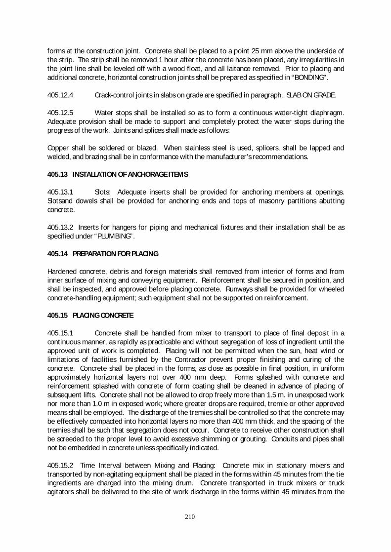
210
forms at the construction joint. Concrete shall be placed to a point 25 mm above the underside of the strip. The strip shall be removed 1 hour after the concrete has been placed, any irregularities in the joint line shall be leveled off with a wood float, and all laitance removed. Prior to placing and additional concrete, horizontal construction joints shall be prepared as specified in “BONDING”. 405.12.4 Crack-control joints in slabs on grade are specified in paragraph. SLAB ON GRADE. 405.12.5 Water stops shall be installed so as to form a continuous water-tight diaphragm. Adequate provision shall be made to support and completely protect the water stops during the progress of the work. Joints and splices shall made as follows: Copper shall be soldered or blazed. When stainless steel is used, splicers, shall be lapped and welded, and brazing shall be in conformance with the manufacturer’s recommendations. 405.13 INSTALLATION OF ANCHORAGE ITEMS 405.13.1 Slots: Adequate inserts shall be provided for anchoring members at openings. Slotsand dowels shall be provided for anchoring ends and tops of masonry partitions abutting concrete. 405.13.2 Inserts for hangers for piping and mechanical fixtures and their installation shall be as specified under “PLUMBING”. 405.14 PREPARATION FOR PLACING Hardened concrete, debris and foreign materials shall removed from interior of forms and from inner surface of mixing and conveying equipment. Reinforcement shall be secured in position, and shall be inspected, and approved before placing concrete. Runways shall be provided for wheeled concrete-handling equipment; such equipment shall not be supported on reinforcement. 405.15 PLACING CONCRETE 405.15.1 Concrete shall be handled from mixer to transport to place of final deposit in a continuous manner, as rapidly as practicable and without segregation of loss of ingredient until the approved unit of work is completed. Placing will not be permitted when the sun, heat wind or limitations of facilities furnished by the Contractor prevent proper finishing and curing of the concrete. Concrete shall be placed in the forms, as close as possible in final position, in uniform approximately horizontal layers not over 400 mm deep. Forms splashed with concrete and reinforcement splashed with concrete of form coating shall be cleaned in advance of placing of subsequent lifts. Concrete shall not be allowed to drop freely more than 1.5 m. in unexposed work nor more than 1.0 m in exposed work; where greater drops are required, tremie or other approved means shall be employed. The discharge of the tremies shall be controlled so that the concrete may be effectively compacted into horizontal layers no more than 400 mm thick, and the spacing of the tremies shall be such that segregation does not occur. Concrete to receive other construction shall be screeded to the proper level to avoid excessive shimming or grouting. Conduits and pipes shall not be embedded in concrete unless specifically indicated. 405.15.2 Time Interval between Mixing and Placing: Concrete mix in stationary mixers and transported by non-agitating equipment shall be placed in the forms within 45 minutes from the tie ingredients are charged into the mixing drum. Concrete transported in truck mixers or truck agitators shall be delivered to the site of work discharge in the forms within 45 minutes from the

211
time that ingredients are discharge into the mixing drum. Concrete shall be placed in the forms within 15 minutes after discharge from the mixer at the job site. 405.15.3 Hot Weather Requirements: Temperature of concrete during the period of mixing transport and or placing shall not be permitted to rise above 16 degree celsius. Any batch of concrete which had reached a temperature greater that 35 degree celcius any time in the aforesaid period shall not be placed but shall be rejected, and shall not thereafter be used in any part of the permanent works. 1. Control Procedures: Provide water cooler facilities and procedures to control or reduce the temperature of cement, aggregates and mixing handling equipment to such temperature that, at all times during mixing, transporting, handling and placing, the temperature of the concrete shall not be greater than 36 degree celsius. 2. Cold Joints and Shrinkage: Where cold joints tend to form or where surfaces and dry too rapidly or plastic shrinkage cracks ten to appear, concrete shall be kept moist by fog sprays and other approved means, applied shortly after placement, and before finishing. 3. Supplementary Precautions: When the aforementioned precautions are not sufficient to satisfy the requirements herein above, they shall be supplemented by restricting work to evening or night. Procedure shall conform to American Concrete Institute Standard ACI 305. 405.15.4 Earth-foundation placement: Concrete footings, exterior slabs and exterior foundations receiving equipment to machinery shall be placed upon undisturbed surfaces conforming to Section EXCAVATION FILLING, AND BACKFILLING. The surfaces shall be clean free from mud and water. Waterproof paper, polythylene sheeting of nominal 0.4mm minimum thickness shall be laid over dry or impervious surfaces receiving concrete. Such material is of a type specified for curing concrete except that the polythylene sheet may be other than white. The concrete footings and exterior slabs and foundation may be placed directly over impervious surfaces that are thoroughly moistened by not muddy at the time concrete is placed. 405.15.5 Conveying Concrete by Chute, Conveyor or Pump: chute, conveyor, or pump may convey Concrete if approved in writing. In requesting approval, the Conctractor shall submit his entire plan of operation from time of discharge of concrete from the mixer to final placement in the forms, and the steps to be taken to prevent the formation of cold joints, in case the transporting of concrete by chute, conveyors and pump shall be capable of expeditiously placing concrete at the rate most advantageous to good workmanship. Approval will not be given for chutes of conveyors requiring changes in the concrete materials or design mix for efficient operation. 1. Chutes and Conveyors: Chutes shall be of steel or steel lined wood, round in cross section rigid
in construction, and protected from overflow. Conveyors shall be designed and operated and chute sections shall be set to assure a uniform flow of concrete from mixer to final place of deposit without segregation or ingredients, loss of mortar, or change of slump. The discharge portions of each chute or convey shall be provide with a device to prevent segregation. The chute and conveyor shall be thoroughly cleaned before and after each run. Waste material and flushing water shall be discharged outside the forms.
2. When using tilted chutes, the inclination should not be flatter than (1) vertical and two (2)
horizontal. From the outlet/mouth of the chute to the concrete surface the maximum allowable height shall be 1.50m.

212
3. Pumps shall be operated and maintained so that a continuous stream of concrete is delivered into the forms without air pocket. segregation or change in slump. When pumping is completed concrete remaining in the pipeline shall be ejected, and wasted without contamination of concrete already placed. After each operation, equipment shall be thoroughly cleaned and the flushing water shall be splashed outside the forms.
405.5.16 Placing concrete through reinforcement: Where congestion of the steel or other conditions will make placing or compactions of concrete difficult, a layer of mortar shall be first deposited in forms to a depth of approximately 25 cm. Mortar proportions shall be the same as the concrete minus the coarse aggregate. 405.16 COMPACTION 405.16.1 Immediately after placing, each layer of concrete vibrator supplemented by hand spading, rodding, and tamping. Tappings or other external vibration of forms will not be permitted unless specifically approved by the Engineer. Vibrators shall not be used to transport concrete inside forms. Internal vibrators submerged in concrete shall maintain speed of not less than 7,000 impulses per minute. The vibrating equipment shall be at all times being adequate in number of units and power to properly consolidate all concrete. 405.16.2 Spare units shall be on hand as necessary to ensure such adequacy. Duration of vibrating equipment shall be limited to time necessary to produce satisfactory consolidation without causing objectionable segregation. The vibrator shall not be inserted into lower coursed that have begun to set. Vibrators shall be applied at uniformly spaced points not further apart than the visible effectiveness of the machine. 405.17 BONDING Before depositing new concrete on or against concrete that has set, the surfaces of the set concrete shall be thoroughly cleaned so as to expose the coarse aggregate and be free of laitance, coatings, foreign matter and loose particles. Forms shall be re-tightened. The cleaned surfaces shall be moistened, but shall be without free water when concrete is placed. 405.18 SLABS ON GRADE 405. Capillary water barrier or sub-grade shall conform. Section EXCAVATION AND BACKFILLING FOR BUILDINGS. 405.18.2 Vapor Barrier: Immediately prior to placing concrete, the capillary water barrier or sub-grade under slabs within the building shall be covered with a vapor barrier. Punctures and tears shall be patched. Edges shall be lapped not less than 100 mm and end joints shall be lapped not less than 150 mm. Edges and lapped joints shall be sealed with a pressure sensitive tape, not less than 50 mm wide, compatible with the membrane. 405.18.3 Concrete shall be compacted, screeded to grade, and prepared for the specified finish. Concrete shall be placed continuously so that each unit of operation will be monolithic in construction. Concrete shall be placed in alternate check-board pattern termination at crack-control
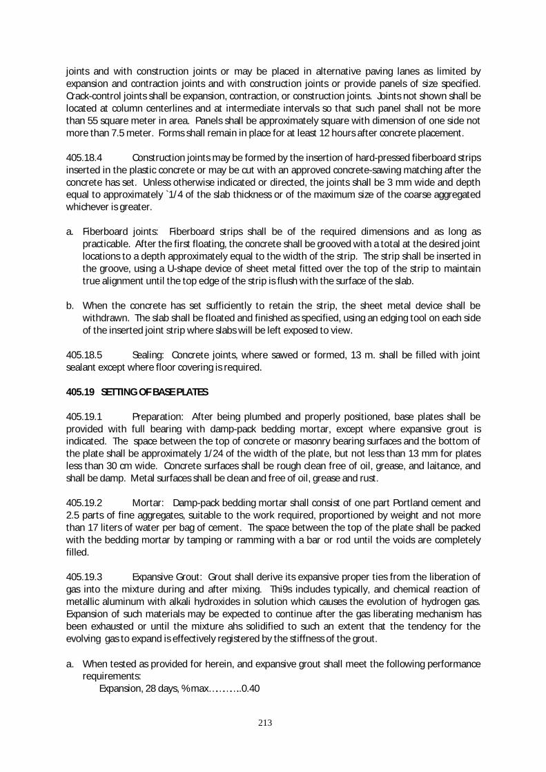
213
joints and with construction joints or may be placed in alternative paving lanes as limited by expansion and contraction joints and with construction joints or provide panels of size specified. Crack-control joints shall be expansion, contraction, or construction joints. Joints not shown shall be located at column centerlines and at intermediate intervals so that such panel shall not be more than 55 square meter in area. Panels shall be approximately square with dimension of one side not more than 7.5 meter. Forms shall remain in place for at least 12 hours after concrete placement. 405.18.4 Construction joints may be formed by the insertion of hard-pressed fiberboard strips inserted in the plastic concrete or may be cut with an approved concrete-sawing matching after the concrete has set. Unless otherwise indicated or directed, the joints shall be 3 mm wide and depth equal to approximately `1/4 of the slab thickness or of the maximum size of the coarse aggregated whichever is greater. a. Fiberboard joints: Fiberboard strips shall be of the required dimensions and as long as
practicable. After the first floating, the concrete shall be grooved with a total at the desired joint locations to a depth approximately equal to the width of the strip. The strip shall be inserted in the groove, using a U-shape device of sheet metal fitted over the top of the strip to maintain true alignment until the top edge of the strip is flush with the surface of the slab.
b. When the concrete has set sufficiently to retain the strip, the sheet metal device shall be
withdrawn. The slab shall be floated and finished as specified, using an edging tool on each side of the inserted joint strip where slabs will be left exposed to view.
405.18.5 Sealing: Concrete joints, where sawed or formed, 13 m. shall be filled with joint sealant except where floor covering is required. 405.19 SETTING OF BASE PLATES 405.19.1 Preparation: After being plumbed and properly positioned, base plates shall be provided with full bearing with damp-pack bedding mortar, except where expansive grout is indicated. The space between the top of concrete or masonry bearing surfaces and the bottom of the plate shall be approximately 1/24 of the width of the plate, but not less than 13 mm for plates less than 30 cm wide. Concrete surfaces shall be rough clean free of oil, grease, and laitance, and shall be damp. Metal surfaces shall be clean and free of oil, grease and rust. 405.19.2 Mortar: Damp-pack bedding mortar shall consist of one part Portland cement and 2.5 parts of fine aggregates, suitable to the work required, proportioned by weight and not more than 17 liters of water per bag of cement. The space between the top of the plate shall be packed with the bedding mortar by tamping or ramming with a bar or rod until the voids are completely filled. 405.19.3 Expansive Grout: Grout shall derive its expansive proper ties from the liberation of gas into the mixture during and after mixing. Thi9s includes typically, and chemical reaction of metallic aluminum with alkali hydroxides in solution which causes the evolution of hydrogen gas. Expansion of such materials may be expected to continue after the gas liberating mechanism has been exhausted or until the mixture ahs solidified to such an extent that the tendency for the evolving gas to expand is effectively registered by the stiffness of the grout. a. When tested as provided for herein, and expansive grout shall meet the following performance
requirements: Expansion, 28 days, % max…………..0.40

214
min…………. 0.03
b. It will be the Contractor’s responsibility to supply the necessary manufacturer’s certificates. 405.20 FINISHES OF CONCRETE 405.20.1 Within 12 hours after forms are removed, surface defects shall be remedied as specified herein. Temperature of the concrete, ambient air and mortar during remedial work including curing shall be above 10 deg, celsius. Fine and loose material shall be removed. Honeycomb, aggregate pockets, voids over 13 mm in diameter, and holes left by the rods or bolts shall be cut out to solid concrete, reamed, thoroughly wetted brush-coated with neat cement grout, and filled with mortar. Mortar shall be a stiff mix of 1 part portland cement to not more than 2 parts fine aggregate passing the No. 16 mesh sieve, and minimum amount of water. The color of the mortar shall be match the adjoining concrete color. Mortar shall be thoroughly compacted in place. Holes passing entirely through walls shall be completely filled from the inside face by forcing mortar through to the outside face. Holes which do not pass entirely through wall shall be packed full. Patchwork shall be finished flush and in the same plane adjacent surfaces. Exposed patchwork shall be finish to match adjoining surfaces in texture and color. Patchwork shall be damp cured for 72 hours. Ambient temperature shall be not less than 10 deg. Celsius. Dusting of finish surfaces with dry material or adding water to concrete surfaces will not be permitted. 405.21 CONCRETE FINISHES FOR SLABS 405.21.1 Slabs Receiving Concrete Paving: After concrete is placed and consolidated slab shall be screeded or struck off. No further finish is required. 405.21.2 Smooth Finish: Required only where specified; screed concrete and float to required level with no coarse aggregate visible. After surface moisture has disappeared and laitance has been remove, the surface shall be finished by float and steel trowel. 405.21.3 Broom Finish: Required for paving, stairs and landing; the concrete shall be screeded and floated to required finish level with no coarse aggregate visible. After the surface shall be float finished to an even, smooth finish. The floated surfaces shall be broomed with a fiber bristle brush in a direction transverse to the direction of the main traffic. 405.21.4 Tolerance: Smooth and broom finished surfaces shall be true to plane with no deviation in excess of 3 mm in any direction when tested with a 3 m straight edge. 405.22 FINISHES OF CONCRETE OTHER THAN FLOOR SLABS 405.22.1 Within 12 hours after forms are removed, surface defects shall be remedied as specified herein. Honeycomb, aggregate, pockets, voids over 12 mm in diameter, and holes left by the rods or bolts shall be cut out to solid concrete, reamed, thoroughly wetted, brush-coated with neat cement grout, and filled with mortar. Mortar shall be a stiff mix of 1 part Portland cement to not more than 2 parts fine aggregate passing the No. 16 mesh sieve, and minimum amount of water using white Portland cement for all or part of the cement so that when dry, the color of the mortar shall match the adjoining concrete color. Mortar shall be thoroughly compacted in place. Holes passing entirely through walls shall be completely filled from the inside face by forcing mortar through to the outside face. Holes that do not pass entirely through the wall shall be packed full. Patch-work shall be damp-cured for 72 hours. Protruding portions of bar supports shall be ground flush with concrete surfaces that will be exposed, painted, or plastered directly.
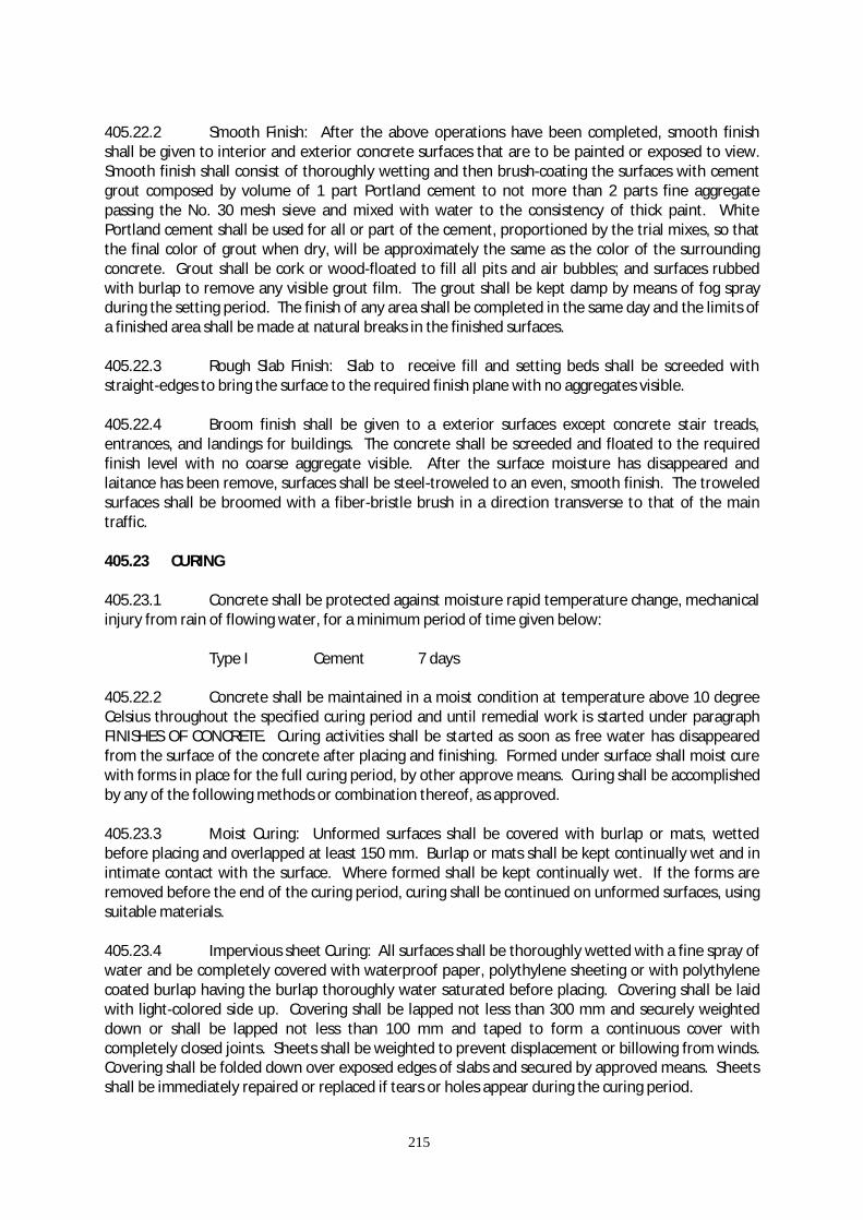
215
405.22.2 Smooth Finish: After the above operations have been completed, smooth finish shall be given to interior and exterior concrete surfaces that are to be painted or exposed to view. Smooth finish shall consist of thoroughly wetting and then brush-coating the surfaces with cement grout composed by volume of 1 part Portland cement to not more than 2 parts fine aggregate passing the No. 30 mesh sieve and mixed with water to the consistency of thick paint. White Portland cement shall be used for all or part of the cement, proportioned by the trial mixes, so that the final color of grout when dry, will be approximately the same as the color of the surrounding concrete. Grout shall be cork or wood-floated to fill all pits and air bubbles; and surfaces rubbed with burlap to remove any visible grout film. The grout shall be kept damp by means of fog spray during the setting period. The finish of any area shall be completed in the same day and the limits of a finished area shall be made at natural breaks in the finished surfaces. 405.22.3 Rough Slab Finish: Slab to receive fill and setting beds shall be screeded with straight-edges to bring the surface to the required finish plane with no aggregates visible. 405.22.4 Broom finish shall be given to a exterior surfaces except concrete stair treads, entrances, and landings for buildings. The concrete shall be screeded and floated to the required finish level with no coarse aggregate visible. After the surface moisture has disappeared and laitance has been remove, surfaces shall be steel-troweled to an even, smooth finish. The troweled surfaces shall be broomed with a fiber-bristle brush in a direction transverse to that of the main traffic. 405.23 CURING 405.23.1 Concrete shall be protected against moisture rapid temperature change, mechanical injury from rain of flowing water, for a minimum period of time given below: Type I Cement 7 days 405.22.2 Concrete shall be maintained in a moist condition at temperature above 10 degree Celsius throughout the specified curing period and until remedial work is started under paragraph FINISHES OF CONCRETE. Curing activities shall be started as soon as free water has disappeared from the surface of the concrete after placing and finishing. Formed under surface shall moist cure with forms in place for the full curing period, by other approve means. Curing shall be accomplished by any of the following methods or combination thereof, as approved. 405.23.3 Moist Curing: Unformed surfaces shall be covered with burlap or mats, wetted before placing and overlapped at least 150 mm. Burlap or mats shall be kept continually wet and in intimate contact with the surface. Where formed shall be kept continually wet. If the forms are removed before the end of the curing period, curing shall be continued on unformed surfaces, using suitable materials. 405.23.4 Impervious sheet Curing: All surfaces shall be thoroughly wetted with a fine spray of water and be completely covered with waterproof paper, polythylene sheeting or with polythylene coated burlap having the burlap thoroughly water saturated before placing. Covering shall be laid with light-colored side up. Covering shall be lapped not less than 300 mm and securely weighted down or shall be lapped not less than 100 mm and taped to form a continuous cover with completely closed joints. Sheets shall be weighted to prevent displacement or billowing from winds. Covering shall be folded down over exposed edges of slabs and secured by approved means. Sheets shall be immediately repaired or replaced if tears or holes appear during the curing period.

216
405.23.5 Membrane-forming Curing Compound: Before applying curing compound, tops of joints that are to receive sealant shall be tightly closed with temporary material to prevent entry of the compound and to prevent moisture loss during the curing period. The compound shall be applied on damp surfaces as soon as the moisture film has disappeared. The curing compound shall be applied by power spraying using a spray nozzle equipped with a wind guard. The compound shall be applied in a two-coat, continuous operation at a coverage of not more than 10 sq. m. per liter for each coat. When application is made by hand sprayers the second coat shall be applied in a direction approximately at right angles to the direction of the first coat, the compound shall form a uniform, continuous, adherent film that shall not check, crack, or peel and shall be free from pinholes or other imperfections. Surfaces subjected to rain fall within 3 hours after compound has been applied, or surface damaged by subsequent construction operations within the curing period, shall be immediately re-sprayed at the rate specified above. Membrane forming curing compound shall not be used on surface that depends on adhesion of bonding to the concrete. Membrane forming curing compound shall not used on surfaces that are maintained at curing temperature with free steam. Where membrane-forming curing compounds are permitted, permanently exposed surfaces shall be cured by use of a non-pigmented membrane-forming curing compound containing a fugitive dye. Where non-pigmented type curing compounds are used, the concrete surface shall be shaded from the direct rays of the sun for the curing period. Surfaces coated with curing compound shall be kept free of foot and vehicular traffic, and from other courses of abrasion and contamination during the curing period. 405.24 SETTING BEDS Required over slabs for floor finished other than concrete are covered under other sections of these specifications in which the floor finish is specified. 405.25 METHOD OF MEASUREMENT The quality of structural concrete to be paid for will be the final quantity placed and accepted in the completed structure. No deduction will be made for the volume occupied by pipe less than 100 mm (4 inches) in diameter or by reinforcing steel, anchors, conduits, weep holes, or expansion joint materials. 405.26 BASIS OF PAYMENT The accepted quantities, measured as prescribed in Section 405.25, shall be paid for at the contract unit price for each of the pay items listed below, that is included in the Bill of Quantities. Payment shall constitute full compensation for furnishing, placing and finishing concrete including all labor, equipment, tools and incidentals necessary to complete the work prescribed in this item. Payment will be under:
Item No. Description Unit of Measurement
405 (1) Concrete Class A-A Cu. m. 405 (2) Concrete Class A Cu. m. 405 (3) Concrete Class B Cu. m. 405 (4) Concrete Class C Cu. m. 405 (5) Seal Concrete Cu. m.

217
ITEM 602 - RIPRAP AND GROUTED RIPRAP
602.1 DESCRIPTION This Item shall consist of the furnishing and placing of rip-rap with or without grout as the case may be, with or without filter backing, furnished and constructed in accordance with this Specification and to the lines and grades and dimensions shown on the Plans. 602.2. MATERIAL REQUIREMENTS 602.2.1 STONES Stones for rip-rap shall consist of rock as nearly rectangular in section as is practical, except that rip-rap of Class A may consist of round natural stones. The stones shall be sound, tough, durable, dense, resistant to the action of air and water, and suitable in all respects for the purpose intended. Stones for rip-rap shall be one of the following classes as shown on the Plans or determined by the Engineer.
Class A - Stones ranging from a minimum of 15 kg to a minimum of 25 kg with at least 50 percent of he stones weighing more than 20 kg. Class B - Stones ranging from a minimum of 30 kg to maximum of 70 kg with at least 50 percent of the weighing more than 50 kg. Class C - Stones ranging from a minimum of 60 kg to a maximum of 100 kg with at least 50 percent of the stones weighing more than 80 kg. Class D - Stones ranging from a minimum of 100 kg to a maximum of 200 kg with at least 50 percent of the stones weighing more than 150 kg.
Sound pieces of broken concrete obtained from the removal of the approval of the Engineer. 602.2.2 FILTER MATERIAL Where required, the rip-rap shall be placed on a filter layer to prevent fine embankment materials to be washed out through the voids of the face stones. The grading of the filter material shall be as specified on the Plans, or in the Special Provisions. If not so specified, it will be required that D15 of the filter is at least 4 times the size D85 for the embankment material, here D15 percent and D85 percent, respectively, passing (by mass) in a grain size analysis. Fine aggregate passing grading requirements for Item 405, Structural Concrete, will satisfy foregoing requirements. 602.2.3 MORTAR Mortar for grouted rip-rap shall consist of sand, cement and water conforming to the requirements given under Item 405, Structural Concrete, mixed in the proportion of one part cement to three parts sand by volume, and sufficient water to produce a thick but fluid mortar.
218
602.2.4 FILTER MATERIAL The rip-rap shall be placed on a filter layer to prevent fine embankment material to be washed out through the voids of the face stones. The grading of the filter material shall be as specified on the Plans. If not specified, it will be required that D15 of the filter is at least 4 times as large as D15 for the underlying embankment materials, and not more than 4 times the size D85 for the embankment material, where D15 and D85 are the particle diameters corresponding to 15 percent and 85 percent, respectively, passing (by weight) in a grain size analysis. 602.3 CONSTRUCTION REQUIREMENTS 602.3.1 Excavation The bed for rip-rap shall be excavated to the required depths and properly compacted, trimmed and shaped. The riprap shall be founded in a toe trench dug below the depth of scour as shown on the Plans or as ordered by the Engineer. The toe trench shall be filled with stone of the same class as that specified for the rip-rap, unless otherwise specified. 602.3.2 Placing Stones placed below the water line shall be distributed so that the minimum thickness of the rip-rap is not less than specified. Stones above the water line shall be placed by or individually by machines. They shall be laid with close, broken joints and shall be firmly bedded into the slope and against the adjoining stones. Each stone shall be laid with its longest axis perpendicular to the slope in close contact with each adjacent stone. The rip-rap shall be thoroughly rammed into place as construction progresses and the finished surfaces shall present an even, tight surface. Interstices between stones shall be filled with small broken fragments rammed into place. Unless otherwise provided, rip-rap shall have the following minimum thickness, measured perpendicular to the slope:
Class A - 300 mm Class B - 500 mm Class C - 60 mm Class D - 800 mm
The surface of rip-rap shall not vary from the theoretical surface by more than 100mm at any point. 602.3.3 Grouting When grouted riprap is specified, stones shall be placed by hand, or individually by machine as specified for riprap place above the water line. The spaces between the stones shall then filled with cement mortar as specified in Subsection 504.2.3, Mortar. Sufficient mortar shall be used to completely fill all voids, except that the face surface of the stones shall be left exposed. Grout shall be placed from bottom to top of the surface swept with a stiff broom. After grouting is completed, the surface shall be cured as specified in Item 405, Structural Concrete for a period of at least three days. 602.4 METHOD OF MEASUREMENT

219
The quantities to be measured for payment shall be the number of cubic meters of rip-rap or grouted rip-rap, as the case may be, including stones placed in the toe trench laid in position and accepted. Filter layer of the granular material, when required shall be measured separately by the cubic meter in place and accepted. The computation of the quantities will be based on the volume within the limiting dimensions designated on the Plans or as determined by the Engineer. 602.5 BASIS OF PAYMENT The quantities measured as provided above shall be paid for at the contract unit price, respectively, for each of the pay item listed below and shown in the Bid Schedule, which price and payment shall be full compensation for excavation and preparation of the bed, for furnishing and placing all materials including backfill, and all labor, equipment, tools and incidentals necessary to complete the item. Payment will be made under:
PAY ITEM NUMBER DESCRIPTION UNIT OF MEASUREMENT 602 (1) Riprap, Class A Cubic meter 602 (2) Riprap, Class B Cubic meter 602 (3) Riprap, Class C Cubic meter 602 (4) Riprap, Class D Cubic meter 602 (5) Grouted Rip-rap,Class A Cubic meter 602 (6) Grouted Rip-rap,Class B Cubic meter 602 (7) Grouted Rip-rap,Class C Cubic meter 602 (8) Grouted Rip-rap,Class D Cubic meter 602 (9) Filter layer of granular
material Cubic meter

Section VII. Drawings
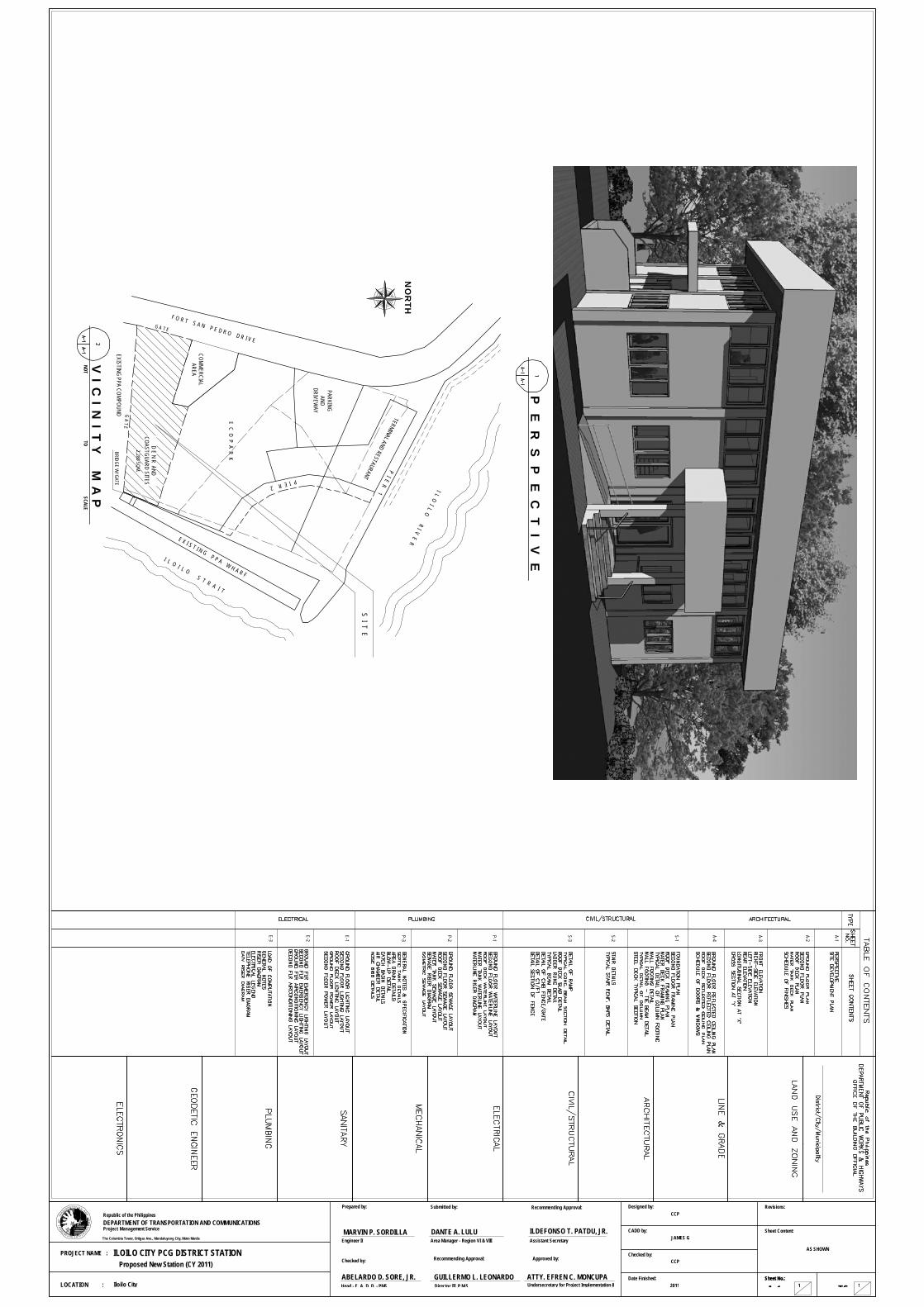
E C O P A R K
D E N R ANDCOASTGUARD SITES
COMMERCIALAREA
I L O I L O S T R A I T
I L O I L O R I V E R
P I E R 1
TERMINAL AND RESTAURANT
PARKINGAND
DRIVEWAY
F O R T S A N P E D R O D R I V E
E X I S T I N G P P A W H A R F
S I T E
NO
RTH
V I C
I N I T
Y M
A P
NOTSCALE
TO
2,280 SQM.
EXISTING PPA COMPOUND
G A T E
BRIDGE W/ GATE P I E R 2
G A T E
PS
R A
F
N
ART
MT
OT
NE
O
O
CD
N
ATRA
NOIT
P
CIN
U
AE D S N OI T
MM
Sheet Content:
Revisions:
Sheet No.:Sheet No.:
TS 1A-1
CCP
JAMES G
CCP
2011
ILDEFONSO T. PATDU, JR.
Recommending Approval:
Checked by:
Prepared by: Designed by:
CADD by:
Checked by:
Date Finished:
Assistant Secretary
Head - E. A. D. D. - PMS
Engineer II
Approved by:
ABELARDO D. SORE, JR.
MARVIN P. SORDILLAThe Columbia Tower, Ortigas Ave., Mandaluyong City, Metro Manila
Project Management ServiceDEPARTMENT OF TRANSPORTATION AND COMMUNICATIONSRepublic of the Philippines
LOCATION :
PROJECT NAME :
1
A-1
A-2
A-3
S-1
E-1
P-1
P-2
A-4
S-2
E-2
E-3
P-3
GUILLERMO L. LEONARDO
Recommending Approval:
Director III, P.M.SIloilo City
ILOILO CITY PCG DISTRICT STATIONProposed New Station (CY 2011)
P E
R S
P E
C T
I V E
S-3
AS SHOWN
ATTY. EFREN C. MONCUPAUndersecretary for Project Implementation &
Submitted by:
Area Manager - Region VI & VIIIDANTE A. LULU
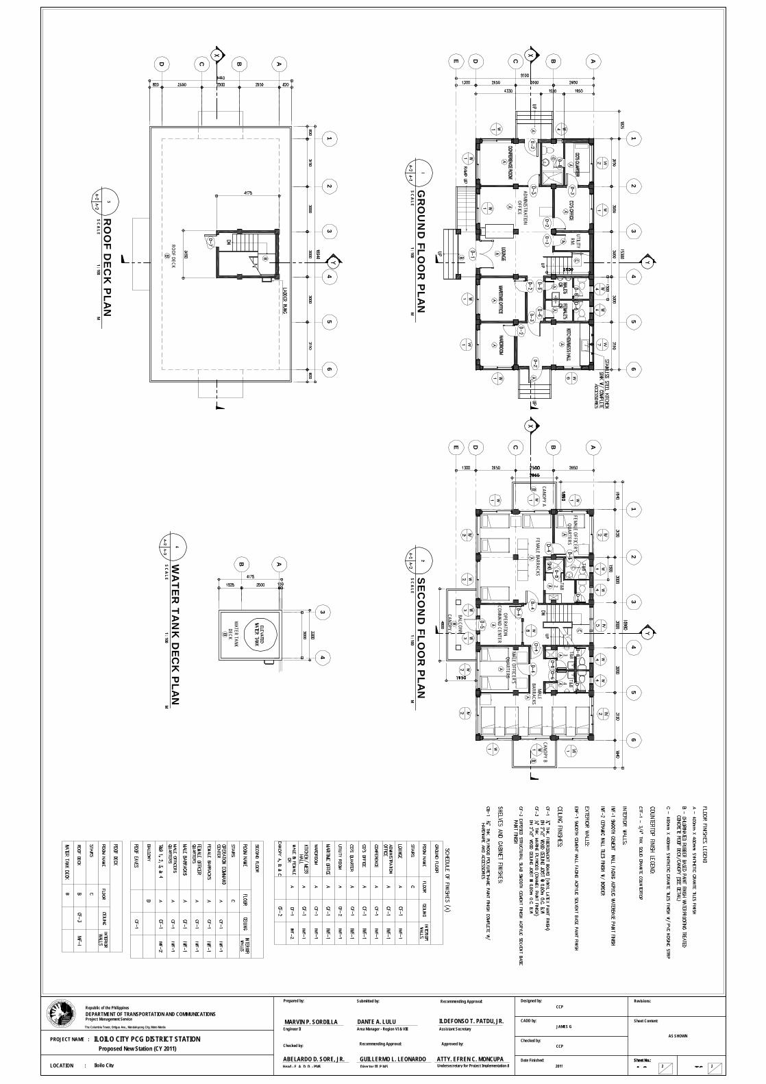
12
34
56
ABCDE
GR
OU
ND
FL
OO
R P
LA
NS C A L E
M1 : 100
UTILITYRM.
ADMINISTRATIONOFFICE
12
34
56
ABCDE
OPERATIONCOMMAND CENTER
FEMALE BARRACKS
FEMALE OFFICER'SQUARTERS
T&B1
MALE OFFICER'SQUARTERS
MALEBARRACKS
SE
CO
ND
FL
OO
R P
LA
NS C A L E
M1 : 100
T&B3T&B4
T&B2
BALCONY
CANOPY ACANOPY B
CANOPY C
12
34
56
ABCD
ROOF DECK
RO
OF D
EC
K P
LA
NS C A L E
M1 : 100
34
ABWA
TE
R T
AN
K D
EC
K P
LA
NS C A L E
M1 : 100
WATER TANK
DECK
PS
R A
F
N
ART
MT
OT
NE
O
O
CD
N
ATRA
NOIT
P
CIN
U
AE D S N OI T
MM
Sheet Content:
Revisions:
Sheet No.:Sheet No.:
TS 2A-2
Designed by:
CADD by:
Checked by:
Date Finished:
The Columbia Tower, Ortigas Ave., Mandaluyong City, Metro Manila
Project Management ServiceDEPARTMENT OF TRANSPORTATION AND COMMUNICATIONSRepublic of the Philippines
Iloilo CityLOCATION :
PROJECT NAME :
Proposed New Station (CY 2011)
2
CCP
JAMES G
CCP
2011
AS SHOWNILOILO CITY PCG DISTRICT STATION
ILDEFONSO T. PATDU, JR.
Recommending Approval:
Checked by:
Prepared by:
Assistant Secretary
Head - E. A. D. D. - PMS
Engineer II
Approved by:
ABELARDO D. SORE, JR.
MARVIN P. SORDILLA
GUILLERMO L. LEONARDO
Recommending Approval:
Director III, P.M.SATTY. EFREN C. MONCUPAUndersecretary for Project Implementation &
Submitted by:
Area Manager - Region VI & VIIIDANTE A. LULU

ED
CB
A
RIG
HT
SID
E E
LE
VA
TIO
NS C A L E
M1 : 100
12
34
56
FR
ON
T E
LE
VA
TIO
NS C A L E
M1 : 100
65
43
21
S C A L ER
EA
R E
LE
VA
TIO
N1 : 100
M
AB
CD
E
LE
FT
SID
E E
LE
VA
TIO
NS C A L E
M1 : 100
12
34
56
LO
NG
ITU
DIN
AL S
EC
TIO
N A
T 'X
'MS C A L E
1 : 100
ED
CB
A
CR
OS
S S
EC
TIO
N A
T 'Y
'S C A L E
M1 : 100
PS
R A
F
N
ART
MT
OT
NE
O
O
CD
N
ATRA
NOIT
P
CIN
U
AE D S N OI T
MM
Sheet Content:
Revisions:
Sheet No.:Sheet No.:
TS 3A-3
Designed by:
CADD by:
Checked by:
Date Finished:
The Columbia Tower, Ortigas Ave., Mandaluyong City, Metro Manila
Project Management ServiceDEPARTMENT OF TRANSPORTATION AND COMMUNICATIONSRepublic of the Philippines
LOCATION :
PROJECT NAME :
3Iloilo City
Proposed New Station (CY 2011)
CCP
JAMES G
CCP
2011
AS SHOWNILOILO CITY PCG DISTRICT STATION
ILDEFONSO T. PATDU, JR.
Recommending Approval:
Checked by:
Prepared by:
Assistant Secretary
Head - E. A. D. D. - PMS
Engineer II
Approved by:
ABELARDO D. SORE, JR.
MARVIN P. SORDILLA
GUILLERMO L. LEONARDO
Recommending Approval:
Director III, P.M.SATTY. EFREN C. MONCUPAUndersecretary for Project Implementation &
Submitted by:
Area Manager - Region VI & VIIIDANTE A. LULU

RE
FL
EC
TE
D C
EIL
ING
PLA
NS C A L E
M1 : 100
GR
OU
ND
FLO
OR
12
34
56
ABCDECANOPY C
CANOPY ACANOPY B
RE
FL
EC
TE
D C
EIL
ING
PLA
NS C A L E
M1 : 100
RO
OF D
EC
K
34
AB
RE
FL
EC
TE
D C
EIL
ING
PLA
NS C A L E
M1 : 100
SE
CO
ND
FLO
OR
12
34
56
ABCDE
SC
HE
DU
LE
OF D
OO
RS
& W
IND
OW
SS C A L E
M1 : 50
PS
R A
F
N
ART
MT
OT
NE
O
O
CD
N
ATRA
NOIT
P
CIN
U
AE D S N OI T
MM
Sheet Content:
Revisions:
Sheet No.:Sheet No.:
TS 4A-4
Designed by:
CADD by:
Checked by:
Date Finished:
The Columbia Tower, Ortigas Ave., Mandaluyong City, Metro Manila
Project Management ServiceDEPARTMENT OF TRANSPORTATION AND COMMUNICATIONSRepublic of the Philippines
LOCATION :
PROJECT NAME :
4Iloilo City
Proposed New Station (CY 2011)
CCP
JAMES G
CCP
2011
AS SHOWNILOILO CITY PCG DISTRICT STATION
ILDEFONSO T. PATDU, JR.
Recommending Approval:
Checked by:
Prepared by:
Assistant Secretary
Head - E. A. D. D. - PMS
Engineer II
Approved by:
ABELARDO D. SORE, JR.
MARVIN P. SORDILLA
GUILLERMO L. LEONARDO
Recommending Approval:
Director III, P.M.SATTY. EFREN C. MONCUPAUndersecretary for Project Implementation &
Submitted by:
Area Manager - Region VI & VIIIDANTE A. LULU

12
B A
12
CO'S QUARTER TOILET PLAN
CO'S QUARTER TOILETSECTIONAL ELEVATION
45
FEMALE CRMALE CR
B A
45
MALE / FEMALE TOILET PLAN
MALE / FEMALE TOILETSECTIONAL ELEVATION
23
45
B
T&B 1
T&B 3T&B 4
T&B 2
A
23
45
FEMALE BARRACK'S TOILETPLAN
MALE BARRACK'S TOILETPLAN
FEMALE BARRACK'S TOILETSECTIONAL ELEVATION
MALE BARRACK'S TOILETSECTIONAL ELEVATION
DE
TA
IL O
F T
OIL
ET
S C A L EM
1 : 50
56
A
DE
TA
IL O
F K
ITC
HE
N C
OU
NT
ER
S C A L EM
1 : 20
A
S E
C T
I O N
A T
' X '
P L
A N
PS
R A
F
N
ART
MT
OT
NE
O
O
CD
N
ATRA
NOIT
P
CIN
U
AE D S N OI T
MM
Sheet Content:
Revisions:
Sheet No.:Sheet No.:
TS 4aA-4a
Designed by:
CADD by:
Checked by:
Date Finished:
The Columbia Tower, Ortigas Ave., Mandaluyong City, Metro Manila
Project Management ServiceDEPARTMENT OF TRANSPORTATION AND COMMUNICATIONSRepublic of the Philippines
LOCATION :
PROJECT NAME :
4aIloilo City
Proposed New Station (CY 2011)
CCP
JAMES G
CCP
2011
AS SHOWNILOILO CITY PCG DISTRICT STATION
ILDEFONSO T. PATDU, JR.
Recommending Approval:
Checked by:
Prepared by:
Assistant Secretary
Head - E. A. D. D. - PMS
Engineer II
Approved by:
ABELARDO D. SORE, JR.
MARVIN P. SORDILLA
GUILLERMO L. LEONARDO
Recommending Approval:
Director III, P.M.SATTY. EFREN C. MONCUPAUndersecretary for Project Implementation &
Submitted by:
Area Manager - Region VI & VIIIDANTE A. LULU

EXISTING
PIERC
ON
CR
ETE SURFACE
GR
OU
TEDC
LASS II ROCKS
GR
OU
TEDC
LASS II ROCKS
SOIL EM
BANKMENT
EXISTING
PIERC
ON
CR
ETE SURFACE
GR
OU
TEDC
LASS II RO
CKS
1001.51000
10001000
10001000
10001001.5
8003
GR
OU
TED C
LASS IIR
OC
KS
3064
GR
OU
TED C
LASS IIR
OC
KS
EXISTING
SLOPE
RO
CKS
EXISTING
SLOPE
RO
CKS
EXISTING
PPA PIER
SEA BED
1000
1000
11001000
10001000
10001000
10001100
8200
15% TRAN
SITION
AGG
REG
ATE BASE COURSE
CF
CF
CF
200600
200MM
THK PCCP
1-C4X7
1-C8X18
1500
1553
1
1
2800
SEA BED
15% TRAN
SITION
AGG
REG
ATE BASE COURSE
CF
TRU
SS 1
TRU
SS 1
TRU
SS 1
C8X18
C8X18
C8X18
C8X18
C8X18
C8X18
C8X18
C8X18
C8X18
C8X18
C8X18
C8X18
1032.94997.71033.36
1500
1500
1553
1500
3526.52000.04
TOP O
F PCCP
1
1
500
707.11
1000
707.11
3317.89
2006001553
707.11
1000500
707.11
1
1
7775
10001000
10001000
10001000
1000712.41
1-C4X7
1-C4X7
1-C4X7
1-C4X7
1-C8X18
SECTIO
N TH
RU
A-A'/TRU
SS 1 DETAIL
SCALE 1:50
SECTIO
N TH
RU
B-B'SC
ALE 1:50
ACC
ESS BRID
GE PLAN
SCALE 1:50
AA'
BB'
C'C
3064
1000200
1-C8X18
318
10MM
∅ D
RSB STRUT
10MM
∅ D
RSB STRUT
@ 300M
M SPACING
WELD
ED TO
C8X18
1-C4X7
SECTIO
N TH
RU
C-C
'& C
F DETAIL
SCALE 1:25
EXISTING
PIER ELEVATIO
N
3064
1000
1-C8X18
1-C8X18
2-C8X18
2-C8X18
1-C8X18
1-C8X18
1-C8X18
1-C8X18
2-C8X18
2-C8X18
2-C8X18
2-C8X18
D'D
SECTIO
N TH
RU
D-D
'SC
ALE 1:25
PCCP
PCCP
PCCP
12MM
∅ D
RSB @
200MM
SPACIN
G BO
THWAYS
TOP & BO
TTOM
1-C8X18
10MM
∅ D
RSB STRUT
@ 300M
M SPACING
WELD
ED TO
C8X18
PCCP
200203
1500MX1500M
300
7-16MM
∅ D
RSB BO
THWAYS
BOTTO
M BARS
10MM
∅ TIE BARS @
200MM
SPACING
4-20MM
MAIN BAR
300MM
X400MM
COLUM
N
10
ABUTM
ENT PR
OTEC
TION
SSC
ALE 1:30
ABUTM
ENT
ABUTM
ENT
ABUTM
ENT
SEA BED
2800
SEE DET.-A
SEE DET.-B
SEE DET.-E
SEE DET.-A
SEE DET.-B
REFER
TO DET.-C
SEE DET.-D
SEE DET.-C

Sheet Content:The Columbia Tower, Ortigas Ave., Mandaluyong City, Metro Manila
DEPARTMENT OF TRANSPORTATION AND COMMUNICATIONS
PHILIPPINE COAST GUARD STATION PROJECT
La Paz, Iloilo City
P
MT R
TN
E
A
CIN
U
AE D S N OI T
M
PROJECT NAME :
OPSN
ART
F
CD
N
ATRA
NOIT
O
Republic of the Philippines
O M
Project Management Service
LOCATION :
Checked by:
CADD by:
Designed by:
Date Finished:
Revisions:
Sheet No.:
Approved by:Checked by:
Prepared by:
Engineer III
Undersecretary for Project
PROPOSED ACCESED BRIDGE
ALEXANDER B. FELIX
Head-E.A.D.D., PMSABELARDO D. SORE, JR.
ILDEFONSO T. PATDU, JR.Assistant Secretary
Recommending Approval:
Recommending Approval:
GUILLERMO L. LEONARDODirector III, P.M.S.
ATTY. EFREN C. MONCUPA
Implementation & Special
DANTE A. LULUArea Manager, Visayas
Submitted by:
225MM
36
18
8-SLOTTED
ELLIPTICAL H
OLE︵
18MM
X36MM
︶
385X225X25MM
THK BASE PLATE
WITH
8-SLOTTED
ELLIPTICAL H
OLE︵
18MM
X36MM
8-50X50X10MM
THK STEEL PLATE
WITH
18MM
∅ HO
LE
75 25
2-C8X18
129.95
95.4496.0895.7650 50
5050
385
25MM
THK BASE PLATE
PRO
VIDE N
ECESSARYLEVELLIN
G G
ROUT
8-16MM
∅ A325 ︵
GALVAN
IZED︶DRILLED &
CH
EMIC
AL ANC
HO
RED BOLT
8-16MM
∅ A325
DR
ILLED & C
HEM
ICAL ANCHO
REDBO
LT︵H
ILTI OR
APPRO
VED EQUAL︶
NU
T & WASHER
8-50X50X10MM
THK STEEL PLATE
WITH
18MM
∅ HO
LE
CH
EMIC
AL BOND
︵HILTI OR APPROVED EQUAL︶
1/4
1/4''1'' @
3"
1/4
C8X18
1'' @ 2"
300
400
129.95
95.4496.0895.7650 50
5050
8-16MM
∅ A325︵
GALVANIZED︶
ANC
HO
RED
BOLT
385X225X25MM
THK BASE PLATE
1/4
1/4''1'' @
3"
2-C8X18
200
203
702520180
PCCP
10MM
∅ D
RSB STRUT
@ 300M
M SPACING
C8X18
C4X7
STEEL PLATEAN
CH
OR
BOLT
OTH
ER M
ETALS
: A242/A36 HO
T DIP G
ALVANIZED
: A572/A588/A36 HO
T DIP G
ALVANIZED
: A325 HO
T DIP G
ALVANIZED
: A36 HO
T DIP G
ALVANIZED
ITEMASTM
STAND
ARD
NO
TE
: A242/A36 HO
T DIP G
ALVANIZED
C8X18
1/4
50X40X6MM
THK C
ON
NECTING
PLATE
50X40X6MM
THK C
ON
NECTING
PLATE
95X50X6MM
THK C
ON
NECTING
ANGLE
95
50
WELD
ING
: AS SUITABLE
8-16MM
∅ A325︵
GALVANIZED︶
ANC
HO
RED
BOLT ASSEM
BLY
LEVELLING NUT
20MM
THK LEVELLING
GRO
UT
1/4
1'' @ 2"
PRO
VIDE 10M
M TH
K CLEARANCESEALAN
T FILLED
2-C8X18
2-C8X18
1/4
1/4
1'' @ 2"
1/4
1'' @ 2"
1/4
1/4
PCCP
2-C8X18
1-C8X18
1-C8X18
1-C8X18
1-C4X7
1-C4X71-C4X7
10
EXISTING
PPA PIER
1/4
1/4
1'' @ 2"
2-C8X18
1-C8X18
DET-A
SCALE 1:5
DET-B
SCALE 1:5
DET-C
SCALE 1:8
DET-D
SCALE 1:8DET-E
SCALE 1:8
10MM
∅ A325︵
GALVANIZED︶
FOR
ALL BOLTS
10MM
∅ A325︵
GALVANIZED︶
FOR
ALL BOLTS
10MM
∅ A325︵
GALVANIZED︶
FOR
ALL BOLTS
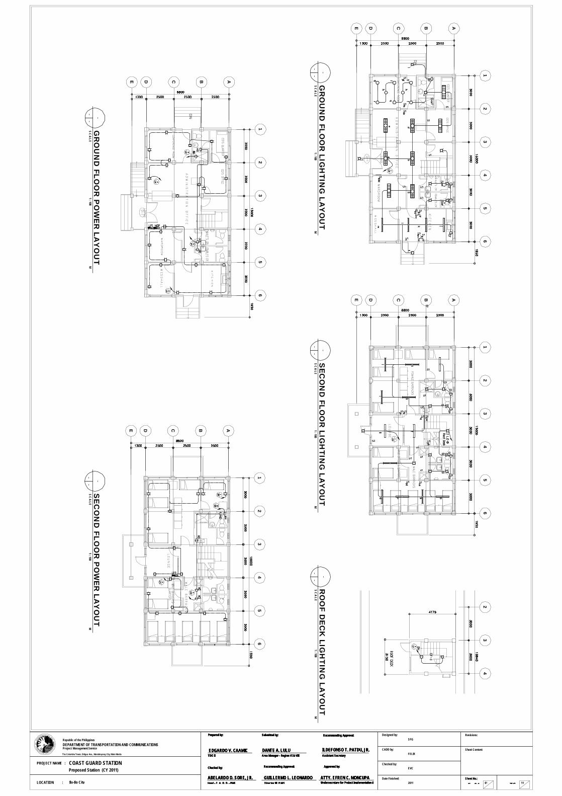
12
34
56
ABCDE
DN
12
34
56
ABCDE
12
34
56
ABCDE
DN
12
34
56
ABCDE
GR
OU
ND
FL
OO
R L
IGH
TIN
G L
AY
OU
TS C A L E
M1 : 100
SE
CO
ND
FL
OO
R L
IGH
TIN
G L
AY
OU
TS C A L E
M1 : 100
SE
CO
ND
FL
OO
R P
OW
ER
LA
YO
UT
S C A L EM
1 : 100G
RO
UN
D F
LO
OR
PO
WE
R L
AY
OU
TS C A L E
M1 : 100
23
4
RO
OF D
EC
K L
IGH
TIN
G L
AY
OU
TS C A L E
M1 : 100
PS
R A
F
N
ART
MT
OT
NE
O
O
CD
N
ATRA
NOIT
P
CIN
U
AE D S N OI T
MM
Sheet Content:
Revisions:
Sheet No.:Sheet No.:
TS01 11E- 01
SFG
FELIX
EVC
2011
Designed by:
CADD by:
Checked by:
Date Finished:
The Columbia Tower, Ortigas Ave., Mandaluyong City, Metro Manila
Project Management ServiceDEPARTMENT OF TRANSPORTATION AND COMMUNICATIONSRepublic of the Philippines
Ilo-Ilo CityLOCATION :
PROJECT NAME : COAST GUARD STATIONProposed Station (CY 2011)
ILDEFONSO T. PATDU, JR.
Recommending Approval:
Checked by:
Prepared by:
Assistant Secretary
Head - E. A. D. D. - PMS
Approved by:
ABELARDO D. SORE, JR.
EDGARDO V. CAAMIC
GUILLERMO L. LEONARDO
Recommending Approval:
Director III, P.M.SATTY. EFREN C. MONCUPAUndersecretary for Project Implementation &
Submitted by:
Area Manager - Region VI & VIIIDANTE A. LULU
TDO IIILDEFONSO T. PATDU, JR.
Recommending Approval:
Checked by:
Prepared by:
Assistant Secretary
Head - E. A. D. D. - PMS
Approved by:
ABELARDO D. SORE, JR.
EDGARDO V. CAAMIC
GUILLERMO L. LEONARDO
Recommending Approval:
Director III, P.M.SATTY. EFREN C. MONCUPAUndersecretary for Project Implementation &
Submitted by:
Area Manager - Region VI & VIIIDANTE A. LULU
TDO II

12
34
56
ABCDE
DN
12
34
56
ABCDE
MM
M
12
34
56
ABCDE
DN
MM
M
M
M M
12
34
56
ABCDE
GR
OU
ND
FL
OO
R E
ME
RG
EN
CY
LIG
HT
ING
LA
YO
UT
S C A L EM
1 : 100S
EC
ON
D F
LO
OR
EM
ER
GE
NC
Y L
IGH
TIN
G L
AY
OU
TS C A L E
M1 : 100
GR
OU
ND
FL
OO
R A
IR-C
ON
DIT
ION
ING
LA
YO
UT
S C A L EM
1 : 100S
EC
ON
D F
LO
OR
AIR
-CO
ND
ITIO
NIN
G L
AY
OU
TS C A L E
M1 : 100
PS
R A
F
N
ART
MT
OT
NE
O
O
CD
N
ATRA
NOIT
P
CIN
U
AE D S N OI T
MM
Sheet Content:
Revisions:
Sheet No.:Sheet No.:
TS02 12E- 02
Designed by:
CADD by:
Checked by:
Date Finished:
The Columbia Tower, Ortigas Ave., Mandaluyong City, Metro Manila
Project Management ServiceDEPARTMENT OF TRANSPORTATION AND COMMUNICATIONSRepublic of the Philippines
LOCATION :
PROJECT NAME :
SFG
EVC
2011Ilo-Ilo City
COAST GUARD STATIONProposed Station (CY 2011)
FELIXILDEFONSO T. PATDU, JR.
Recommending Approval:
Checked by:
Prepared by:
Assistant Secretary
Head - E. A. D. D. - PMS
Approved by:
ABELARDO D. SORE, JR.
EDGARDO V. CAAMIC
GUILLERMO L. LEONARDO
Recommending Approval:
Director III, P.M.SATTY. EFREN C. MONCUPAUndersecretary for Project Implementation &
Submitted by:
Area Manager - Region VI & VIIIDANTE A. LULU
TDO IIILDEFONSO T. PATDU, JR.
Recommending Approval:
Checked by:
Prepared by:
Assistant Secretary
Head - E. A. D. D. - PMS
Approved by:
ABELARDO D. SORE, JR.
EDGARDO V. CAAMIC
GUILLERMO L. LEONARDO
Recommending Approval:
Director III, P.M.SATTY. EFREN C. MONCUPAUndersecretary for Project Implementation &
Submitted by:
Area Manager - Region VI & VIIIDANTE A. LULU
TDO II

PS
R A
F
N
ART
MT
OT
NE
O
O
CD
N
ATRA
NOIT
P
CIN
U
AE D S N OI T
MM
Sheet Content:
Revisions:
Sheet No.:Sheet No.:
TS02 13E- 03
Designed by:
CADD by:
Checked by:
Date Finished:
The Columbia Tower, Ortigas Ave., Mandaluyong City, Metro Manila
Project Management ServiceDEPARTMENT OF TRANSPORTATION AND COMMUNICATIONSRepublic of the Philippines
LOCATION :
PROJECT NAME :
- Duplex C
onvenience Outlet, 16A
, 250V G
rounding - Universal Type
- 2 x 40W Fluorescent Fixtures, Box Type
- Three-Lever Tumbler S
witch. Subscript denotes
light or lights controlled.
- Two-Lever Tum
bler Switch. S
ubscript denotes light or lights controlled.
- Lighting and Power Panel
- Exaust Fan Outlet, 16A, 250V
- 1-1x22W C
ompact Flourescent Lam
p
- Ground
- Circuit B
reaker
- Circuit R
un
- Service Entrance
M- K
WH
R M
eter
LE
GE
ND
- 1 x 40W Fluorescent Fixtures, Box Type
- 1-1x22W Pin Light, (6 inch Ø
with square glass cover)
- Hand D
ryer Outlet, 16A, 250V
- Ceiling M
ounted Exuast Fan Outlet, 16A, 250V
- Switch, Exuast Fan O
utlet, 16A, 250V
- Em
ergency Light, Dual Lam
p
- Split-Package Type Air-Conditioning (O
utdoor) U
nit for 3.0 TR A
ir-conditioner with 30A, 250V
EC
B protection.
- Air-C
onditioning Unit O
utlet, 16A, 250V G
rounding - Universal Type.
- Window
Type Air-conditioning U
nit Motor
Rating as per indicated in the plan.
M
- Three-way Sw
itch
- One Tum
bler Switch
- 2 x 40W Fluorescent Fixtures, recessed m
ounting w
ith egg-crate type aluminum
diffuser and mirrorized
reflector (30 x 120 mm
). Subscript denotes switch
or controller.- 1 x 40W
Fluorescent Fixtures, recessed mounting
with egg-crate type alum
inum diffuser and m
irrorized reflector (30 x 120 m
m). Subscript denotes sw
itch or controller.
M
1. All electrical installations herein shall conform
with the provisions
of the latest edition of the Philippine Electrical C
ode; the rules and regulations of the national and local authorities concerned in the enforcem
ent of electrical laws pertaining to the practice of
electrical engineering and the requirement of the local utility
company.
2. All electrical w
orks herein shall be done under the strict supervision of a duly license professional electrical engineer or a registered electrical engineer or a registered m
aster electrician.
3. Unless otherw
ise indicated in the plan, the minim
um size of
conductor and conduit shall be 2.0 mm
² and 15mm
Ø for m
etallic tubing and or 20m
m Ø
for polyvinyl chloride conduit.
4. All service/electrical equipm
ent such as: safety switches,
panelboards, transformers, m
etallic boxes and cabinets, racew
ays, etc., shall be properly grounded as provided in the C
ode.
5. Service entrance shall be 1Ø
, 3-Wire, 230V, 60H
z.
6. All m
aterials to be used shall be brand new and of the
approved type for both location and purpose intended to, subject to the approval of the designer/engineer.
GE
NE
RA
L N
OTE
S
CO
MPU
TATIO
N:
CK
TN
O.
LOA
D D
ES
CR
IPTION
VO
LTV
AA
MP
ER
EC
B R
ATIN
GS
IZE O
F WIR
ES
AND
CO
ND
UIT
AT
MD
PP
OLE
RIS
ER
DIA
GR
AM
TE
LE
PH
ON
E R
ISE
R D
IAG
RA
MNOT
SCALETO
CA
TV
RIS
ER
DIA
GR
AM
NOTSCALE
TO
CK
TN
O.
LOA
D D
ES
CR
IPTION
VO
LTV
AA
MP
ER
EC
B R
ATIN
GS
IZE O
F WIR
ES
AND
CO
ND
UIT
AT
LP-1
PO
LE
CO
MPU
TATIO
N:
CK
TN
O.
LOA
D D
ES
CR
IPTION
VO
LTV
AA
MP
ER
EC
B R
ATIN
GS
IZE O
F WIR
ES
AND
CO
ND
UIT
AT
LP-2
PO
LE
CO
MPU
TATIO
N:
SFG
EVC
2011Ilo-Ilo City
COAST GUARD STATIONProposed Station (CY 2011)
FELIXILDEFONSO T. PATDU, JR.
Recommending Approval:
Checked by:
Prepared by:
Assistant Secretary
Head - E. A. D. D. - PMS
Approved by:
ABELARDO D. SORE, JR.
EDGARDO V. CAAMIC
GUILLERMO L. LEONARDO
Recommending Approval:
Director III, P.M.SATTY. EFREN C. MONCUPAUndersecretary for Project Implementation &
Submitted by:
Area Manager - Region VI & VIIIDANTE A. LULU
TDO IIILDEFONSO T. PATDU, JR.
Recommending Approval:
Checked by:
Prepared by:
Assistant Secretary
Head - E. A. D. D. - PMS
Approved by:
ABELARDO D. SORE, JR.
EDGARDO V. CAAMIC
GUILLERMO L. LEONARDO
Recommending Approval:
Director III, P.M.SATTY. EFREN C. MONCUPAUndersecretary for Project Implementation &
Submitted by:
Area Manager - Region VI & VIIIDANTE A. LULU
TDO II

12
34
56
ABCDE
12
34
56
ABCDE
WA
TE
RLIN
E L
AY
OU
TS C A L E
1 : 100 MTS
GR
OU
ND
FLO
OR
WA
TE
RLIN
E L
AY
OU
TS C A L E
1 : 100 MTS
SE
CO
ND
FLO
OR
12
34
56
ABCD
WA
TE
RLIN
E L
AY
OU
TS C A L E
1 : 100 MTS
RO
OF D
EC
K
WA
TE
RL
INE
RIS
ER
DIA
GR
AM
NOTSCALE
TO
PP
PP
CIS
TE
RN
TA
NK
DE
TA
ILS C A L E
M1 : 30
SE
CTIO
N
P L
A N
34
AB
WA
TE
RLIN
E L
AY
OU
TS C A L E
1 : 100 MTS
WA
TE
R T
AN
K D
EC
K
AIR
VE
NT
PIP
E D
ET
AIL
NOTSCALE
TO
OV
ER
FL
OW
DE
TA
ILS C A L E
M1 : 20
PS
R A
F
N
ART
MT
OT
NE
O
O
CD
N
ATRA
NOIT
P
CIN
U
AE D S N OI T
MM
Sheet Content:
Revisions:
Sheet No.:Sheet No.:
TS 138P-1
CCP
AHRQ
CCP
2011
Designed by:
CADD by:
Checked by:
Date Finished:
The Columbia Tower, Ortigas Ave., Mandaluyong City, Metro Manila
Project Management ServiceDEPARTMENT OF TRANSPORTATION AND COMMUNICATIONSRepublic of the Philippines
LOCATION :
PROJECT NAME :
JMG
AS SHOWN
31Iloilo City
ILOILO CITY PCG DISTRICT STATIONProposed New Station (CY 2011)
ILDEFONSO T. PATDU, JR.
Recommending Approval:
Checked by:
Prepared by:
Assistant Secretary
Head - E. A. D. D. - PMS
Engineer II
Approved by:
ABELARDO D. SORE, JR.
MARVIN P. SORDILLA
GUILLERMO L. LEONARDO
Recommending Approval:
Director III, P.M.SATTY. EFREN C. MONCUPAUndersecretary for Project Implementation &Special Concerns
Submitted by:
Area Manager - Region VI & VIIIDANTE A. LULU

12
34
56
ABCDE
12
34
56
ABCDE
SE
WA
GE
LA
YO
UT
S C A L E1 : 100 MTS
GR
OU
ND
FLO
OR
SE
WA
GE
LA
YO
UT
S C A L E1 : 100 MTS
SE
CO
ND
FLO
OR
34
AB
12
34
56
SE
WA
GE
LA
YO
UT
S C A L E1 : 100 MTS
RO
OF D
EC
K
SE
WA
GE
LA
YO
UT
S C A L E1 : 100 MTS
WA
TE
R T
AN
K D
EC
K
SE
WA
GE
RIS
ER
DIA
GR
AM
NOTSCALE
TO
PS
R A
F
N
ART
MT
OT
NE
O
O
CD
N
ATRA
NOIT
P
CIN
U
AE D S N OI T
MM
Sheet Content:
Revisions:
Sheet No.:Sheet No.:
TS 139
CCP
AHRQ
CCP
2011
Designed by:
CADD by:
Checked by:
Date Finished:
The Columbia Tower, Ortigas Ave., Mandaluyong City, Metro Manila
Project Management ServiceDEPARTMENT OF TRANSPORTATION AND COMMUNICATIONSRepublic of the Philippines
LOCATION :
PROJECT NAME :
P-2
JMG
AS SHOWN
SE
WA
GE
LA
YO
UT
S C A L E1:50 MTS
ISO
ME
TR
IC
32Iloilo City
ILOILO CITY PCG DISTRICT STATIONProposed New Station (CY 2011)
ILDEFONSO T. PATDU, JR.
Recommending Approval:
Checked by:
Prepared by:
Assistant Secretary
Head - E. A. D. D. - PMS
Engineer II
Approved by:
ABELARDO D. SORE, JR.
MARVIN P. SORDILLA
GUILLERMO L. LEONARDO
Recommending Approval:
Director III, P.M.SATTY. EFREN C. MONCUPAUndersecretary for Project Implementation &Special Concerns
Submitted by:
Area Manager - Region VI & VIIIDANTE A. LULU
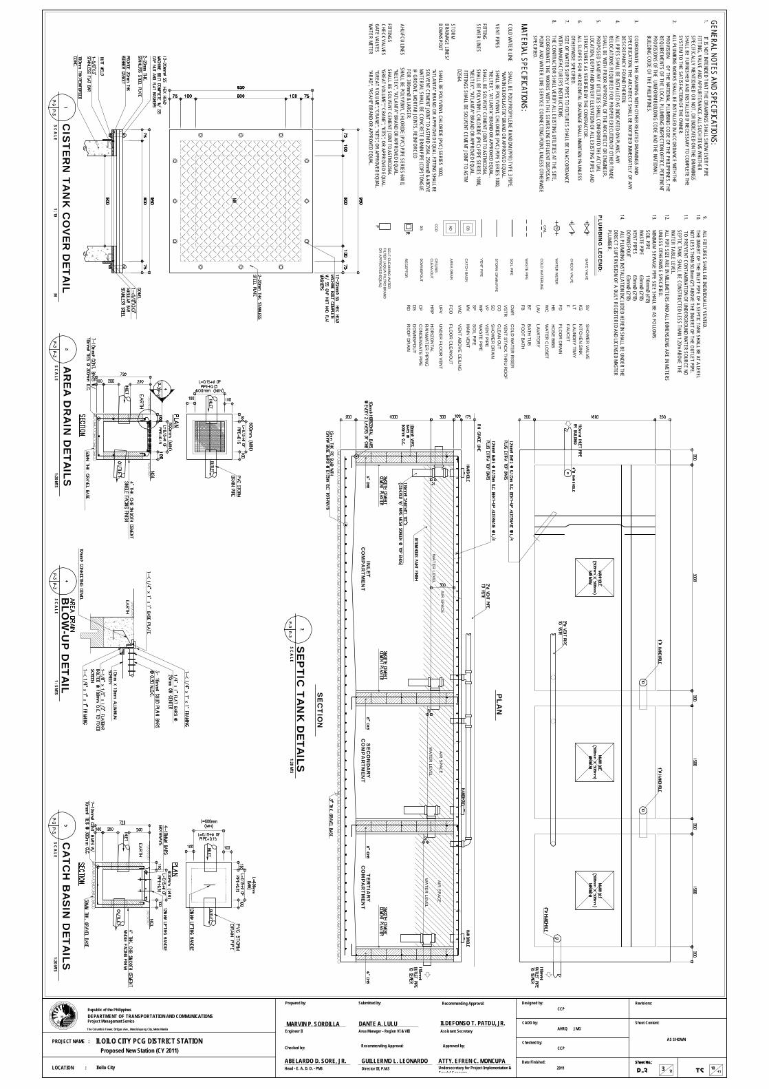
PL
AN
SE
CT
ION
SE
PT
IC T
AN
K D
ET
AIL
SS C A L E
1:20 MTS
INLE
TC
OM
PA
RT
ME
NT
SE
CO
ND
AR
YC
OM
PA
RT
ME
NT
CO
MP
AR
TM
EN
TT
ER
TIA
RY
WA
TER
LEVELW
ATE
R LEVEL
WA
TER
LEVEL
AIR
SPAC
EA
IR S
PACE
AIR
SPAC
E
CA
TC
H B
AS
IN D
ET
AIL
SS C A L E
1:20 MTS
AR
EA
DR
AIN
DE
TA
ILS
S C A L E1:20 MTS
BLO
W-U
P D
ET
AIL
S C A L E1 : 5 MTS
CIS
TE
RN
TA
NK
CO
VE
R D
ET
AIL
S C A L EM
1 : 10
PS
R A
F
N
ART
MT
OT
NE
O
O
CD
N
ATRA
NOIT
P
CIN
U
AE D S N OI T
MM
Sheet Content:
Revisions:
Sheet No.:Sheet No.:
TS 1310
CCP
AHRQ
CCP
2011
Designed by:
CADD by:
Checked by:
Date Finished:
The Columbia Tower, Ortigas Ave., Mandaluyong City, Metro Manila
Project Management ServiceDEPARTMENT OF TRANSPORTATION AND COMMUNICATIONSRepublic of the Philippines
LOCATION :
PROJECT NAME :
P-3
JMG
AS SHOWN
33
GENERAL NOTES AND SPECIFICATIONS:1.
IT IS NOT INTENDED THAT THE DRAWINGS SHALL SHOW
EVERY PIPEFITTING, VALVE AND APPURTENANCE. ALL SUCH ITEMS W
HETHER SPECIFICALLY MENTIONED OR NOT, OR INDICATED ON THE DRAW
INGSSHALL BE FURNISHED AND INSTALLED IF NECESSARY TO COMPLETE THESYSTEM TO THE SATISFACTION OF THE OW
NER.2. ALL PLUMBING W
ORKS SHALL BE INSTALLED IN ACCORDANCE WITH THE
PROVISION OF THE NATIONAL PLUMBING CODE OF THE PHILIPPINES, THE
REQUIREMENTS OF THE LOCAL PLUMBING INSPECTION OFFICE, PERTINENTPROVISIONS OF THE UNIFORM BUILDING CODE AND THE NATIONAL BUILDING CODE OF THE PHILIPPINES.
3. COORDINATE THE DRAW
ING WITH OTHER RELATED DRAW
INGS ANDSPECIFICATION. THE ARCHITECT SHALL BE NOTIFIED IMMEDIATELY OF ANYDESCREPANCY FOUND THEREIN.
4. ALL PIPES SHALL BE INSTALLED AS INDICATED ON PLANS, ANY RELOCATIONS REQUIRED FOR PROPER EXECUTION OF OTHER TRADESHALL BE W
ITH PRIOR APPROVAL OF THE ARCHITECT OR ENGINEER.5.
PROPOSED SANITARY UTILITIES SHALL CONFORM TO THE ACTUAL LOCATION, DEPTH AND INVERT ELEVATION OF ALL EXISTING PIPES ANDSTRUCTURES AS VERIFIED BY THE CONTRACTOR.
6. ALL SLOPES FOR HORIZONTAL DRAINAGE SHALL MAINTAIN 1% UNLESSOTHERW
ISE SPECIFIED.7.
SIZE OF WATER SUPPLY PIPES TO FIXTURES SHALL BE IN ACCORDANCE
WITH MANUFACTURER'S INSTRUCTIONS.
8.THE CONTRACTOR SHALL VERIFY ALL EXISTING UTILITIES AT THE SITE,COORDINATE THE W
ORKS WITH THE SEW
ER LINE EFFLUENT DISPOSALPOINT AND W
ATER LINE SERVICE CONNECTING POINT, UNLESS OTHERWISE
SPECIFIED.
MATERIAL SPECIFICATIONS:COLD W
ATER LINE SHALL BE POLYPROPYLENE RANDOM (PPR) TYPE 3 PIPE,
"WAVIN EKOPLLASTIK" BRAND OR APPROVED EQUAL.
VENT PIPES SHALL BE POLYVINYL CHLORIDE (PVC) PIPE SERIES 1000, "NELTEX", "ATLANTA" BRAND OR APPROVED EQUAL..
FITTINGSHALL BE SOLVENT CEMENT JOINT TO ASTM D2564.
SEWER LINES
SHALL BE POLYVINYL CHLORIDE (PVC) PIPE SERIES 1000,"NELTEX", "ATLANTA" BRAND OR APPROVED EQUAL. FITTINGS SHALL BE SOLVENT CEMENT JOINT TO ASTM D2564.
STORMDRAINAGE LINES/DOW
NSPOUT SHALL BE POLYVINYL CHLORIDE (PVC) SERIES 1000, "ATLANTA" BRAND OR APPROVED EQUAL. FITTING SHALL BESOLVENT CEMENT JOINT TO ASTM D 2564. 250mmØ & ABOVEMATERIAL SHALL BE CONCRETE DRAIN PIPE (CDP) TONGUE@
GROOVE, MORTAR JOINTS, REINFORCEDFOR 300mmØ & LARGER.
AHU/FCU LINES SHALL BE POLYVINYL CHLORIDE (PVC) PIPE SERIES 600 II,"NELTEX", "ATLANTA" BRAND OR APPROVED EQUAL.
FITTINGS SHALL BE SOLVENT CEMENT JOINT TO ASTM D2564.
CHECK VALVES "GREAT VOLUME"," CRANE", "KITS", OR APPROVED EQUAL.GATE VALVES
"GREAT VOLUME","CRANE", "KITS", OR APPROVED EQUAL.W
ATER METER "ARAD", "ASAHI" BRAND OR APPROVED EQUAL.
PL
UM
BIN
G LE
GE
ND
:
M
WC
LAV
FDCO
KS
CB
GA
TE V
ALVE
CH
EC
K V
ALVE
WA
TER
METER
CO
LD W
ATER
LINE
WA
STE
PIPE
SO
IL PIPE
VE
NT PIPE
CA
TCH
BASIN
WATER
CLO
SET
LAVATO
RY
FLOO
R D
RAIN
CLE
AN O
UT
KITC
HEN
SIN
K
ADA
RE
A D
RAIN
HO
SE BIBB
HB
SH
OW
ER
VALVE
SV
STO
RM
DR
AIN PIPE
LTLAU
ND
RY
TRAY
FAUC
ETFSD
SH
OW
ER
DR
AINV
ENT PIPE
VPWP
WAS
TE P
IPESP
SO
IL PIPEM
VM
AIN VEN
T
VEN
T STACK TH
RU
RO
OF
BTB
ATH TU
B
CW
R
CO
LD W
ATE
R R
ISER
CW
L
CC
OC
EILIN
GC
LEA
N O
UT
CP
CO
ND
EN
SATE PIPE
HR
PH
OR
IZON
TALR
AINW
ATER P
IPIN
GD
SD
OW
NS
POU
T
FBFO
OT BATH
RE
CE
PTOR
VAC
VEN
T ABO
VE C
EILIN
G
FCO
FLOO
R C
LEAN
OU
T
UN
DER
FLOO
R VEN
TU
FV
F
SE
LF CLE
AN
ING
WATER
FILTER
(AQ
UA
FILTRO
BRAN
DO
R A
PP
RO
VE
D EQ
UAL)
VSTR
9. ALL FIXTURES SHALL BE INDIVIDUALLY VENTED.10. THE INVERT OF THE INLET PIPE OF A SEPTIC TANK SHALL BE AT A LEVEL
NOT LESS THAN 50.8mm (2") ABOVE THE INVERT OF THE OUTLET PIPE.11. TO PREVENT CONTAMINATION OF UNDERGROUND W
ATER SOURCE NOSEPTIC TANK SHALL BE CONSTRUCTED LESS THAN 1.20m ABOVE THEW
ATER TABLE LEVEL.12.
ALL PIPE SIZE ARE IN MILLIMETERS AND ALL DIMENSIONS ARE IN METERSUNLESS OTHERW
ISE SPECIFIED.13. MINIMUM SEW
AGE PIPE SIZE SHALL BE AS FOLLOWS:
SOIL PIPE 110mmØ (4"Ø)
WASTE PIPE
63mmØ (2"Ø)VENT PIPES
63mmØ (2"Ø)DOW
NSPOUT 63mmØ (2"Ø)
14. ALL PLUMBING INSTALLATION INCLUDED HEREIN SHALL BE UNDER THEDIRECT SUPERVISION OF A DULY REGISTERED AND LICENSED MASTERPLUMBER.
DS
DO
WN
SPO
UT
RD
RO
OF D
RAIN
Iloilo City
ILOILO CITY PCG DISTRICT STATIONProposed New Station (CY 2011)
ILDEFONSO T. PATDU, JR.
Recommending Approval:
Checked by:
Prepared by:
Assistant Secretary
Head - E. A. D. D. - PMS
Engineer II
Approved by:
ABELARDO D. SORE, JR.
MARVIN P. SORDILLA
GUILLERMO L. LEONARDO
Recommending Approval:
Director III, P.M.SATTY. EFREN C. MONCUPAUndersecretary for Project Implementation &Special Concerns
Submitted by:
Area Manager - Region VI & VIIIDANTE A. LULU
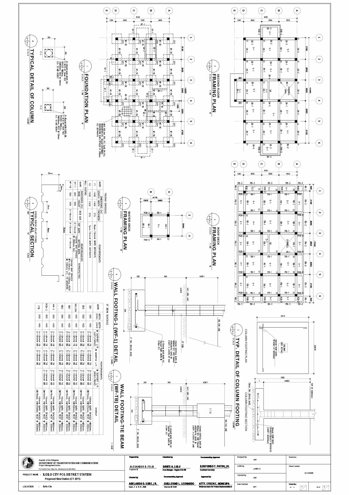
12
34
56
FO
UN
DA
TIO
N P
LA
NS C A L E
M1 : 100
ABCDE
TY
PIC
AL
DE
TA
IL O
F C
OLU
MN
S C A L E1:20 MTS
C-1
C-2
TY
P. D
ET
AIL
OF C
OLU
MN
FO
OT
ING
S C A L E1:20 MTS
CO
LUM
N FO
OTIN
G SE
CTIO
NC
OLU
MN
FOO
TING
PLAN
WA
LL F
OO
TIN
G-1
(WF-1
) DE
TA
ILS C A L E
1 : 10 MTS
WA
LL F
OO
TIN
G-T
IE B
EA
M(W
F-T
B) D
ET
AIL
S C A L E1 : 10 MTS
TY
PIC
AL
SE
CT
ION
NOTSCALE
STE
EL D
EC
K (F
LA
T-T
YP
E)
TO
12
34
56
FR
AM
ING
PLA
NS C A L E
M1 : 100
RO
OF D
EC
K
ABCDE
12
34
56
FR
AM
ING
PLA
NS C A L E
M1 : 100
SE
CO
ND
FLO
OR
ABCDE
34
AB
FR
AM
ING
PLA
NS C A L E
M1 : 100
WA
TE
R D
EC
K
PS
R A
F
N
ART
MT
OT
NE
O
O
CD
N
ATRA
NOIT
P
CIN
U
AE D S N OI T
MM
Sheet Content:
Revisions:
Sheet No.:Sheet No.:
TS 5S-1
ABF
JAMES G
ABF
2011
Designed by:
CADD by:
Checked by:
Date Finished:
The Columbia Tower, Ortigas Ave., Mandaluyong City, Metro Manila
Project Management ServiceDEPARTMENT OF TRANSPORTATION AND COMMUNICATIONSRepublic of the Philippines
LOCATION :
PROJECT NAME : ILOILO CITY PCG DISTRICT STATIONProposed New Station (CY 2011)
1Iloilo City
AS SHOWN
ILDEFONSO T. PATDU, JR.
Recommending Approval:
Checked by:
Prepared by:
Assistant Secretary
Head - E. A. D. D. - PMS
Approved by:
ABELARDO D. SORE, JR.
ALEXANDER B. FELIX
GUILLERMO L. LEONARDO
Recommending Approval:
Director III, P.M.SATTY. EFREN C. MONCUPAUndersecretary for Project Implementation &
Submitted by:
Area Manager - Region VI & VIIIDANTE A. LULU ILDEFONSO T. PATDU, JR.
Recommending Approval:
Checked by:
Prepared by:
Assistant Secretary
Head - E. A. D. D. - PMS
Approved by:
ABELARDO D. SORE, JR. GUILLERMO L. LEONARDO
Recommending Approval:
Director III, P.M.SATTY. EFREN C. MONCUPAUndersecretary for Project Implementation &
Submitted by:
Area Manager - Region VI & VIIIDANTE A. LULU
Engineer III
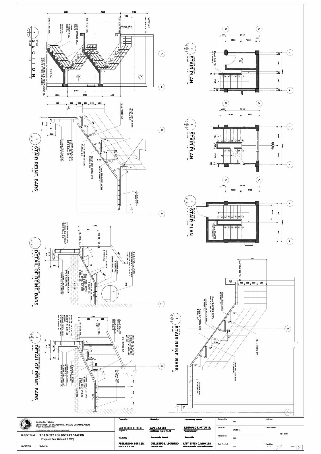
34
AB
ST
AIR
PLA
NS C A L E
M1 : 50
34
AB
34
AB
GR
OU
ND
FLO
OR
ST
AIR
PLA
NS C A L E
M1 : 50
SE
CO
ND
FLO
OR
ST
AIR
PLA
NS C A L E
M1 : 50
RO
OF D
EC
K
BA
S E
C T
I O N
S C A L EM
1 : 50
STA
IR
AB
ST
AIR
RE
INF. B
AR
SS C A L E
M1 : 20
TY
PIC
AL
ST
AIR
RE
INF. B
AR
SS C A L E
M1 : 20
TY
PIC
AL
AB
1
DE
TA
IL O
F R
EIN
F. B
AR
SS C A L E
M1 : 20
TY
PIC
AL S
IDE
EN
TR
AN
CE
/EX
IT S
TA
IR
E
DE
TA
IL O
F R
EIN
F. B
AR
SS C A L E
M1 : 20
FR
ON
T E
NT
RA
NC
E/E
XIT
STA
IR
PS
R A
F
N
ART
MT
OT
NE
O
O
CD
N
ATRA
NOIT
P
CIN
U
AE D S N OI T
MM
Sheet Content:
Revisions:
Sheet No.:Sheet No.:
TS 6S-2
Designed by:
CADD by:
Checked by:
Date Finished:
The Columbia Tower, Ortigas Ave., Mandaluyong City, Metro Manila
Project Management ServiceDEPARTMENT OF TRANSPORTATION AND COMMUNICATIONSRepublic of the Philippines
Iloilo CityLOCATION :
PROJECT NAME :
Proposed New Station (CY 2011)
2
ABF
JAMES G
ABF
2011
AS SHOWNILOILO CITY PCG DISTRICT STATION
ILDEFONSO T. PATDU, JR.
Recommending Approval:
Checked by:
Prepared by:
Assistant Secretary
Head - E. A. D. D. - PMS
Approved by:
ABELARDO D. SORE, JR.
ALEXANDER B. FELIX
GUILLERMO L. LEONARDO
Recommending Approval:
Director III, P.M.SATTY. EFREN C. MONCUPAUndersecretary for Project Implementation &
Submitted by:
Area Manager - Region VI & VIIIDANTE A. LULU ILDEFONSO T. PATDU, JR.
Recommending Approval:
Checked by:
Prepared by:
Assistant Secretary
Head - E. A. D. D. - PMS
Approved by:
ABELARDO D. SORE, JR. GUILLERMO L. LEONARDO
Recommending Approval:
Director III, P.M.SATTY. EFREN C. MONCUPAUndersecretary for Project Implementation &
Submitted by:
Area Manager - Region VI & VIIIDANTE A. LULU ILDEFONSO T. PATDU, JR.
Recommending Approval:
Checked by:
Prepared by:
Assistant Secretary
Head - E. A. D. D. - PMS
Approved by:
ABELARDO D. SORE, JR. GUILLERMO L. LEONARDO
Recommending Approval:
Director III, P.M.SATTY. EFREN C. MONCUPAUndersecretary for Project Implementation &
Submitted by:
Area Manager - Region VI & VIIIDANTE A. LULU ILDEFONSO T. PATDU, JR.
Recommending Approval:
Checked by:
Prepared by:
Assistant Secretary
Head - E. A. D. D. - PMS
Approved by:
ABELARDO D. SORE, JR. GUILLERMO L. LEONARDO
Recommending Approval:
Director III, P.M.SATTY. EFREN C. MONCUPAUndersecretary for Project Implementation &
Submitted by:
Area Manager - Region VI & VIIIDANTE A. LULU
Engineer III

SE
CT
ION
DE
TA
ILNOT
SCALETO
TY
P. C
ON
CR
ETE
BE
AM
23
23
DE
RA
MP
SE
CT
ION
S C A L EM
1 : 40
RA
MP
PL
AN
S C A L EM
1 : 40
23
DE
FO
UN
DA
TIO
N P
LA
NS C A L E
M1 : 40
RA
MP
DE
TA
IL O
F R
EIN
F. B
AR
S
34
LA
DD
ER
RU
NG
DE
TA
ILS C A L E
M1 : 40
AB
TY
PIC
AL
SLA
B D
ET
AIL
S C A L EM
1 : 20
RO
OF D
EC
K
CL
AT
SU
PP
OR
TA
T M
ID S
PA
NB
EA
M S
EC
TIO
N A
-AB
EA
M S
EC
TIO
N B
-B
B-B
A-A
A-A
CA
NT
ILIV
ER
BE
AM
SE
CT
IOM
TY
PIC
AL F
LO
OR
BE
AM
/RO
OF
BE
AM
/GIR
DE
R S
EC
TIO
N
TY
PIC
AL
DE
TA
IL O
F B
EA
MS C A L E
1 : 20 MTS
DE
TA
IL O
F C
HB
FE
NC
E/S
TE
EL G
AT
ES C A L E
M1 : 50
E L
E V
A T
I O N
P L
A N
200
2400800250
200P L A
N
200
800
200
DE
TA
IL O
F C
1/F
1S C A L E
M1 : 20
S E
C T
I O N
DE
TA
IL O
F F
EN
CE
S C A L E1 : 20
S E
C T
I O N
PS
R A
F
N
ART
MT
OT
NE
O
O
CD
N
ATRA
NOIT
P
CIN
U
AE D S N OI T
MM
Sheet Content:
Revisions:
Sheet No.:Sheet No.:
TS 7S-3
Designed by:
CADD by:
Checked by:
Date Finished:
The Columbia Tower, Ortigas Ave., Mandaluyong City, Metro Manila
Project Management ServiceDEPARTMENT OF TRANSPORTATION AND COMMUNICATIONSRepublic of the Philippines
Iloilo CityLOCATION :
PROJECT NAME :
Proposed New Station (CY 2011)
3
ABF
JAMES G
ABF
2011
AS SHOWNILOILO CITY PCG DISTRICT STATION
ILDEFONSO T. PATDU, JR.
Recommending Approval:
Checked by:
Prepared by:
Assistant Secretary
Head - E. A. D. D. - PMS
Approved by:
ABELARDO D. SORE, JR.
ALEXANDER B. FELIX
GUILLERMO L. LEONARDO
Recommending Approval:
Director III, P.M.SATTY. EFREN C. MONCUPAUndersecretary for Project Implementation &
Submitted by:
Area Manager - Region VI & VIIIDANTE A. LULU ILDEFONSO T. PATDU, JR.
Recommending Approval:
Checked by:
Prepared by:
Assistant Secretary
Head - E. A. D. D. - PMS
Approved by:
ABELARDO D. SORE, JR. GUILLERMO L. LEONARDO
Recommending Approval:
Director III, P.M.SATTY. EFREN C. MONCUPAUndersecretary for Project Implementation &
Submitted by:
Area Manager - Region VI & VIIIDANTE A. LULU ILDEFONSO T. PATDU, JR.
Recommending Approval:
Checked by:
Prepared by:
Assistant Secretary
Head - E. A. D. D. - PMS
Approved by:
ABELARDO D. SORE, JR. GUILLERMO L. LEONARDO
Recommending Approval:
Director III, P.M.SATTY. EFREN C. MONCUPAUndersecretary for Project Implementation &
Submitted by:
Area Manager - Region VI & VIIIDANTE A. LULU ILDEFONSO T. PATDU, JR.
Recommending Approval:
Checked by:
Prepared by:
Assistant Secretary
Head - E. A. D. D. - PMS
Approved by:
ABELARDO D. SORE, JR. GUILLERMO L. LEONARDO
Recommending Approval:
Director III, P.M.SATTY. EFREN C. MONCUPAUndersecretary for Project Implementation &
Submitted by:
Area Manager - Region VI & VIIIDANTE A. LULU
Engineer III
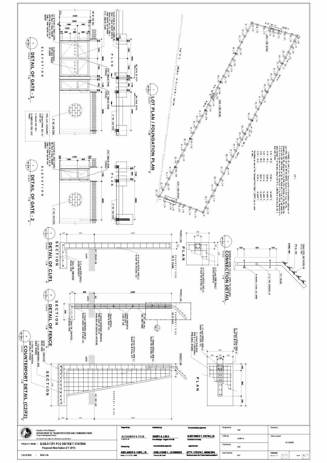
DE
TA
IL O
F G
AT
E - 1
S C A L EM
1 : 50
E L
E V
A T
I O N
P L
A N
E L
E V
A T
I O N
P L
A N
DE
TA
IL O
F G
AT
E - 2
S C A L EM
1 : 50
1300
850 2400
200200
250
P L A
N
200
800
300 300
150
2400850200
200
800
P L A
N
200
800
200
DE
TA
IL O
F C
1/F
1S C A L E
M1 : 20
S E
C T
I O N
DE
TA
IL O
F F
EN
CE
S C A L EM
1 : 20
S E
C T
I O N
CO
UN
TE
RFO
RT
DE
TA
IL (C
2/F
2)
S C A L EM
1 : 20
S E
C T
I O N
LO
T P
LA
N / F
OU
ND
AT
ION
PLA
NS C A L E
M1 : 300
CO
NN
EC
TIO
N D
ET
AIL
S C A L EM
1 : 10
BA
RB
ED
WIR
E T
O G
.I. PIP
E T
O C
OLU
MN
PS
R A
F
N
ART
MT
OT
NE
O
O
CD
N
ATRA
NOIT
P
CIN
U
AE D S N OI T
MM
Sheet Content:
Revisions:
Sheet No.:Sheet No.:
TS 7aCW-1
Designed by:
CADD by:
Checked by:
Date Finished:
The Columbia Tower, Ortigas Ave., Mandaluyong City, Metro Manila
Project Management ServiceDEPARTMENT OF TRANSPORTATION AND COMMUNICATIONSRepublic of the Philippines
Iloilo CityLOCATION :
PROJECT NAME :
Proposed New Station (CY 2011)
1
ABF
JAMES G
ABF
2011
AS SHOWNILOILO CITY PCG DISTRICT STATION
ILDEFONSO T. PATDU, JR.
Recommending Approval:
Checked by:
Prepared by:
Assistant Secretary
Head - E. A. D. D. - PMS
Approved by:
ABELARDO D. SORE, JR.
ALEXANDER B. FELIX
GUILLERMO L. LEONARDO
Recommending Approval:
Director III, P.M.SATTY. EFREN C. MONCUPAUndersecretary for Project Implementation &
Submitted by:
Area Manager - Region VI & VIIIDANTE A. LULU ILDEFONSO T. PATDU, JR.
Recommending Approval:
Checked by:
Prepared by:
Assistant Secretary
Head - E. A. D. D. - PMS
Approved by:
ABELARDO D. SORE, JR. GUILLERMO L. LEONARDO
Recommending Approval:
Director III, P.M.SATTY. EFREN C. MONCUPAUndersecretary for Project Implementation &
Submitted by:
Area Manager - Region VI & VIIIDANTE A. LULU ILDEFONSO T. PATDU, JR.
Recommending Approval:
Checked by:
Prepared by:
Assistant Secretary
Head - E. A. D. D. - PMS
Approved by:
ABELARDO D. SORE, JR. GUILLERMO L. LEONARDO
Recommending Approval:
Director III, P.M.SATTY. EFREN C. MONCUPAUndersecretary for Project Implementation &
Submitted by:
Area Manager - Region VI & VIIIDANTE A. LULU ILDEFONSO T. PATDU, JR.
Recommending Approval:
Checked by:
Prepared by:
Assistant Secretary
Head - E. A. D. D. - PMS
Approved by:
ABELARDO D. SORE, JR. GUILLERMO L. LEONARDO
Recommending Approval:
Director III, P.M.SATTY. EFREN C. MONCUPAUndersecretary for Project Implementation &
Submitted by:
Area Manager - Region VI & VIIIDANTE A. LULU
Engineer III

221
Section VIII. Bill of Quantities
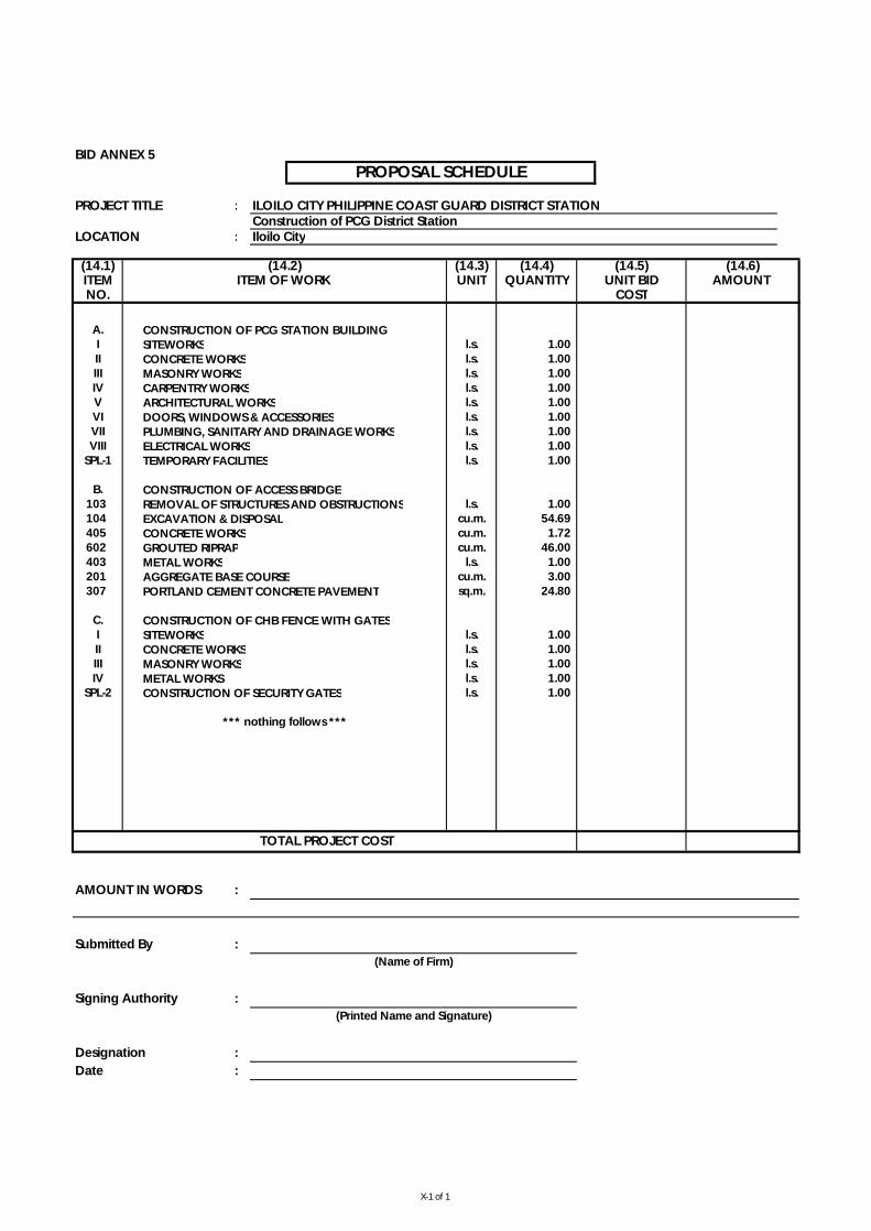
BID ANNEX 5
PROJECT TITLE : ILOILO CITY PHILIPPINE COAST GUARD DISTRICT STATIONConstruction of PCG District Station
LOCATION : Iloilo City
CONSTRUCTION OF PCG STATION BUILDINGSITEWORKSCONCRETE WORKSMASONRY WORKSCARPENTRY WORKSARCHITECTURAL WORKSDOORS, WINDOWS & ACCESSORIESPLUMBING, SANITARY AND DRAINAGE WORKSELECTRICAL WORKSTEMPORARY FACILITIES
CONSTRUCTION OF ACCESS BRIDGEREMOVAL OF STRUCTURES AND OBSTRUCTIONSEXCAVATION & DISPOSALCONCRETE WORKSGROUTED RIPRAPMETAL WORKSAGGREGATE BASE COURSEPORTLAND CEMENT CONCRETE PAVEMENT
CONSTRUCTION OF CHB FENCE WITH GATESSITEWORKSCONCRETE WORKSMASONRY WORKSMETAL WORKS CONSTRUCTION OF SECURITY GATES
AMOUNT IN WORDS :
Submitted By :
Signing Authority :
Designation :Date :
PROPOSAL SCHEDULE
(14.1) (14.2) (14.3) (14.4) (14.5)
I l.s. 1.00 A.
(14.6)ITEM ITEM OF WORK UNIT QUANTITY UNIT BID AMOUNT NO. COST
IV l.s. 1.00 V l.s. 1.00
II l.s. 1.00 III l.s. 1.00
VIII l.s. 1.00 SPL-1 l.s. 1.00
VI l.s. 1.00 VII l.s. 1.00
(Printed Name and Signature)
TOTAL PROJECT COST
(Name of Firm)
*** nothing follows ***
103 l.s. 1.00 104 cu.m. 54.69
B.
403 l.s. 1.00 201 cu.m. 3.00
405 cu.m. 1.72 602 cu.m. 46.00
C.I l.s. 1.00
307 sq.m. 24.80
IV l.s. 1.00 SPL-2 l.s. 1.00
II l.s. 1.00 III l.s. 1.00
X-1 of 1
222
Section IX. Bidding Forms
TABLE OF CONTENTS
Bid Form........................................................................................................................................ 223
Form of Contract Agreement ......................................................................................................... 225
Omnibus Sworn Statement ............................................................................................................ 227

223
Bid Form
Date: _________________________
IAEB1 No: ______________________
To: [name and address of PROCURING ENTITY]
Address: [insert address]
We, the undersigned, declare that:
(a) We have examined and have no reservation to the Bidding Documents, including Addenda, for the Contract [insert name of contract];
(b) We offer to execute the Works for this Contract in accordance with the Bid and Bid Data Sheet, General and Special Conditions of Contract accompanying this Bid;
The total price of our Bid, excluding any discounts offered in item (d) below is: [insert information];
The discounts offered and the methodology for their application are: [insert information];
(c) Our Bid shall be valid for a period of [insert number] days from the date fixed for the Bid submission deadline in accordance with the Bidding Documents, and it shall remain binding upon us and may be accepted at any time before the expiration of that period;
(d) If our Bid is accepted, we commit to obtain a Performance Security in the amount of [insert percentage amount] percent of the Contract Price for the due performance of the Contract;
(e) Our firm, including any subcontractors or suppliers for any part of the Contract, have nationalities from the following eligible countries: [insert information];
(f) We are not participating, as Bidders, in more than one Bid in this bidding process, other than alternative offers in accordance with the Bidding Documents;
(g) Our firm, its affiliates or subsidiaries, including any subcontractors or suppliers for any part of the Contract, has not been declared ineligible by the Funding Source;
(h) We understand that this Bid, together with your written acceptance thereof included in your notification of award, shall constitute a binding contract between us, until a formal Contract is prepared and executed; and
(i) We understand that you are not bound to accept the Lowest Evaluated Bid or any other Bid that you may receive.
1 If ADB, JICA and WB funded projects, use IFB.

224
Name:
In the capacity of:
Signed:
Duly authorized to sign the Bid for and on behalf of:
Date: ___________
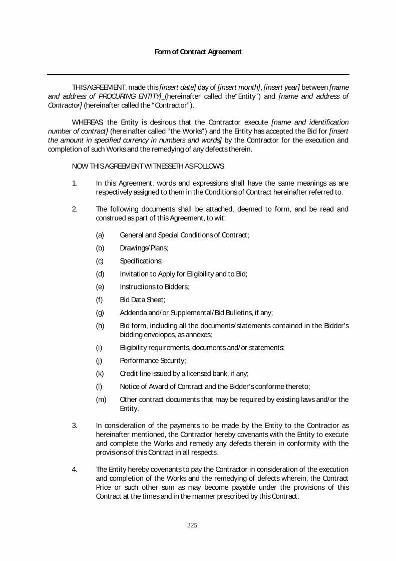
225
Form of Contract Agreement
THIS AGREEMENT, made this [insert date] day of [insert month], [insert year] between [name and address of PROCURING ENTITY] (hereinafter called the“Entity”) and [name and address of Contractor] (hereinafter called the “Contractor”).
WHEREAS, the Entity is desirous that the Contractor execute [name and identification number of contract] (hereinafter called “the Works”) and the Entity has accepted the Bid for [insert the amount in specified currency in numbers and words] by the Contractor for the execution and completion of such Works and the remedying of any defects therein.
NOW THIS AGREEMENT WITNESSETH AS FOLLOWS:
1. In this Agreement, words and expressions shall have the same meanings as are respectively assigned to them in the Conditions of Contract hereinafter referred to.
2. The following documents shall be attached, deemed to form, and be read and construed as part of this Agreement, to wit:
(a) General and Special Conditions of Contract;
(b) Drawings/Plans;
(c) Specifications;
(d) Invitation to Apply for Eligibility and to Bid;
(e) Instructions to Bidders;
(f) Bid Data Sheet;
(g) Addenda and/or Supplemental/Bid Bulletins, if any;
(h) Bid form, including all the documents/statements contained in the Bidder’s bidding envelopes, as annexes;
(i) Eligibility requirements, documents and/or statements;
(j) Performance Security;
(k) Credit line issued by a licensed bank, if any;
(l) Notice of Award of Contract and the Bidder’s conforme thereto;
(m) Other contract documents that may be required by existing laws and/or the Entity.
3. In consideration of the payments to be made by the Entity to the Contractor as hereinafter mentioned, the Contractor hereby covenants with the Entity to execute and complete the Works and remedy any defects therein in conformity with the provisions of this Contract in all respects.
4. The Entity hereby covenants to pay the Contractor in consideration of the execution and completion of the Works and the remedying of defects wherein, the Contract Price or such other sum as may become payable under the provisions of this Contract at the times and in the manner prescribed by this Contract.

226
IN WITNESS whereof the parties thereto have caused this Agreement to be executed the day and year first before written.
Signed, sealed, delivered by the (for the Entity)
Signed, sealed, delivered by the (for the Contractor).
Binding Signature of PROCURING ENTITY
________________________________________________
Binding Signature of Contractor
_____________________________________________
[Addendum showing the corrections, if any, made during the Bid evaluation should be attached with this agreement]

Omnibus Sworn Statement
REPUBLIC OF THE PHILIPPINES ) CITY/MUNICIPALITY OF ______ ) S.S.
A F F I D A V I T
I, [Name of Affiant], of legal age, [Civil Status], [Nationality], and residing at [Address of Affiant], after having been duly sworn in accordance with law, do hereby depose and state that:
1. Select one, delete the other: If a sole proprietorship: I am the sole proprietor of [Name of Bidder] with office address at [address of Bidder]; If a partnership, corporation, cooperative, or joint venture: I am the duly authorized and designated representative of [Name of Bidder] with office address at [address of Bidder];
2. Select one, delete the other: If a sole proprietorship: As the owner and sole proprietor of [Name of Bidder], I have full power and authority to do, execute and perform any and all acts necessary to represent it in the bidding for [Name of the Project] of the [Name of the Procuring Entity]; If a partnership, corporation, cooperative, or joint venture: I am granted full power and authority to do, execute and perform any and all acts necessary and/or to represent the [Name of Bidder] in the bidding as shown in the attached [state title of attached document showing proof of authorization (e.g., duly notarized Secretary’s Certificate issued by the corporation or the members of the joint venture)];
3. [Name of Bidder] is not “blacklisted” or barred from bidding by the Government of the Philippines or any of its agencies, offices, corporations, or Local Government Units, foreign government/foreign or international financing institution whose blacklisting rules have been recognized by the Government Procurement Policy Board;
4. Each of the documents submitted in satisfaction of the bidding requirements is an authentic copy of the original, complete, and all statements and information provided therein are true and correct;
5. [Name of Bidder] is authorizing the Head of the Procuring Entity or its duly authorized representative(s) to verify all the documents submitted;
6. Select one, delete the rest: If a sole proprietorship: I am not related to the Head of the Procuring Entity, members of the Bids and Awards Committee (BAC), the Technical Working Group, and the BAC Secretariat,
the head of the Project Management Office or the end-user unit, and the project consultants by consanguinity or affinity up to the third civil degree; If a partnership or cooperative: None of the officers and members of [Name of Bidder] is related to the Head of the Procuring Entity, members of the Bids and Awards Committee (BAC), the Technical Working Group, and the BAC Secretariat, the head of the Project Management Office or the end-user unit, and the project consultants by consanguinity or affinity up to the third civil degree; If a corporation or joint venture: None of the officers, directors, and controlling stockholders of [Name of Bidder] is related to the Head of the Procuring Entity, members of the Bids and Awards Committee (BAC), the Technical Working Group, and the BAC Secretariat, the head of the Project Management Office or the end-user unit, and the project consultants by consanguinity or affinity up to the third civil degree;
7. [Name of Bidder] complies with existing labor laws and standards; and
8. [Name of Bidder] is aware of and has undertaken the following responsibilities as a Bidder: a) Carefully examine all of the Bidding Documents;
b) Acknowledge all conditions, local or otherwise, affecting the implementation of the
Contract;
c) Made an estimate of the facilities available and needed for the contract to be bid, if any; and
d) Inquire or secure Supplemental/Bid Bulletin(s) issued for the [Name of the Project].
IN WITNESS WHEREOF, I have hereunto set my hand this __ day of ___, 20__ at ____________,
Philippines. _____________________________________ Bidder’s Representative/Authorized Signatory
[JURAT]
* This form will not apply for WB funded projects.


Standard Form Number: SF-INFR-15 Revised on: July 29, 2004
Statement of all Ongoing Government & Private Construction Contracts including contracts awarded but not yet started
Business Name : ___________________________________________________
Business Address : ___________________________________________________
Name of Contract/Location
Project Cost
a. Owner Name b. Address
c. Telephone Nos.
Nature of Work
Contractor’s Role a. Date Awarded b. Date Started
c. Date of Completion
% of
Accomplishment Value of Outstanding
Works Description
% Planned Actual
Government
Private
Note: This statement shall be supported with: Total Cost
1 Notice of Award and/or Contract
2 Notice to Proceed issued by the owner
3 Certificate of Accomplishments signed by the owner or Project Engineer
Submitted by : ___________________________________________________ (Printed Name & Signature)
Designation : ___________________________________________________
Date : ___________________________________________________
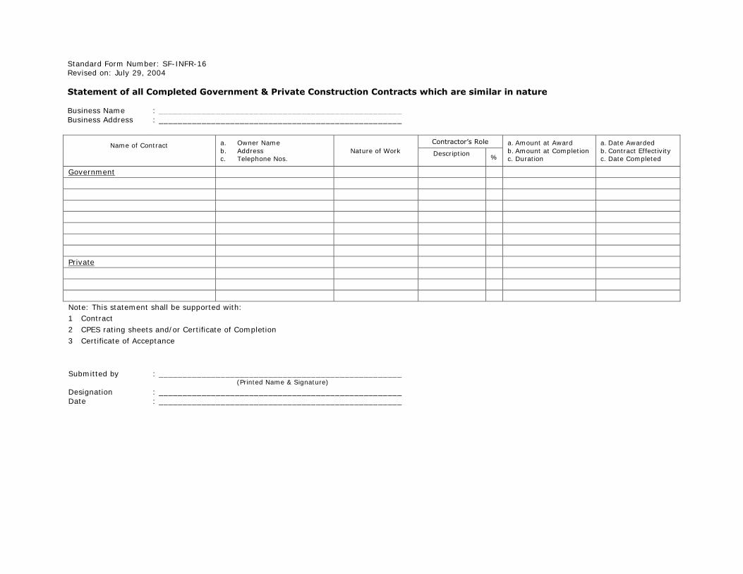
Standard Form Number: SF-INFR-16 Revised on: July 29, 2004
Statement of all Completed Government & Private Construction Contracts which are similar in nature
Business Name : ___________________________________________________
Business Address
: ___________________________________________________
Name of Contract
a. Owner Name
b. Address c. Telephone Nos.
Nature of Work
Contractor’s Role a. Amount at Award
b. Amount at Completion c. Duration
a. Date Awarded
b. Contract Effectivity c. Date Completed
Description
%
Government
Private
Note: This statement shall be supported with:
1 Contract
2 CPES rating sheets and/or Certificate of Completion
3 Certificate of Acceptance
Submitted by : ___________________________________________________ (Printed Name & Signature)
Designation : ___________________________________________________
Date : ___________________________________________________

Standard Form Number: SF-INFR-18
Revised on: July 29, 2004
Statement of Availability of Key Personnel and Equipment
(Date of Issuance)
HON. JOSE P. DE JESUS
Secretary Department of Transportation & Communications
The Columbia Tower, Ortigas Avenue
Mandaluyong City
Attention : The Chairman Bids and Awards Committee
Dear Sir / Madame:
In compliance with the requirements of the DOTC-BAC for the bidding of the __(Name of the Contract)__, we certify that __(Name of the Bidder)__ has in its employ key personnel, such
as project managers, civil engineers, architect, materials engineers and safety officer, who
may be engaged for the construction of the said contract.
Further, we likewise certify the availability of equipment that __(Name of the Bidder)__ owns,
and/or has under purchase agreements, that may be used for the construction contracts.
Very truly yours,
(Name of Representative)
(Position)
(Name of Bidder)

Standard Form Number: SF-INFR-48 Revised on: August 11, 2004
Qualification of Key Personnel Proposed to be Assigned to the Contract
Business Name : ___________________________________________________
Business Address : ___________________________________________________
___________________________________________________
Project Manager Civil Engineer Materials Engineer Safety Officer Architect
1
Name
2
Address
3
Date of Birth
4
Employed Since
5
Experience
6
Previous Employment
7
Education
8
PRC License
Minimum Requirements : Project Manager
: Civil Engineer
: Materials Engineer
: Safety Officer
: Architect (applicable only for vertical projects)
Note : Attached individual resume, PRC License of the (professional) personnel, Certificate of DPWH Accreditation, and
Certificate of Training in Occupational Safety and Health
Submitted by : _________________________
(Printed Name & Signature)
Designation : _________________________
Date : _________________________
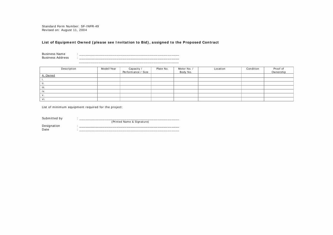
Standard Form Number: SF-INFR-49 Revised on: August 11, 2004
List of Equipment Owned (please see Invitation to Bid), assigned to the Proposed Contract
Business Name : ___________________________________________________ Business Address : ___________________________________________________
___________________________________________________
Description Model/Year Capacity /
Performance / Size
Plate No. Motor No. /
Body No.
Location Condition Proof of
Ownership
A. Owned i. ii. iii. iv. v. vi.
List of minimum equipment required for the project:
Submitted by : ___________________________________________________ (Printed Name & Signature) Designation : ___________________________________________________ Date : ___________________________________________________