Proceedings of the Symposium on Inservice Testing of Pumps ...
470
NUREG/CP--01 Ii TI91 002343 ................. mLf_2_ ........ I I II J I IIIII I III II IIII [-" ......... I Proceedings of the Symposium on Inservice Testing of Pumps and Valves tteld at Hyatt Regency Hotel Washington, DC August 1-3, 1989 [ ....... ._ __ -i [IUIIIlll I I ......... iii I I " IIII III Manuscript Completed: August 1990 Date Published: October 1990 Sponsored by Office of Nuclear Reactor Regulation U.S. Nuclear Regulatory Commission Washington, DC 20555 Board of Nuclear Codes and Standards of the American Society of Mechanical Engineers 345 East 47th Street New York, NY 10017 Proceedings prepared by Idaho National Engineering Laboratory EG&G Idaho, Inc. Idaho Falls, ID 83415 NRC FIN A6812 DISCLAIMER Ttfis report was prepared as an account o1' work sponsored by an agency of the United States = Government. Neither the United St'.,tes Government nor any agency thereof, nor an), of their employees, makes any warranty, express or implied, or assumes any legal liability or responsi- bility for the accuracy, cempleteness, or usefu!ness of any informat_u,., apparalus, product, or process disclosed, or represents that its use would not infringe privutely owned rights. Refer- ence hereir_to any specific commercial product, proces,_,or service by trade name. trademark, manufact,_rer, _'¢ otherwise does not necessarily constitute or imply its endorsement, recom- mendation, or favoring by the United States Government or any agency thereof. The views and opinions of authors expressed herein do not necessarily state or reflect those of the United States Government or any agency thereof. Dtglt]IBtJ i!OtO Or Tl_,,S jinr'r,,,,,.'-, LIMJTEB,., -- ....... ., ,.., c;, ,r 18 I.IN _-- =7, __- _1,' , "
-
Upload
khangminh22 -
Category
Documents
-
view
0 -
download
0
Transcript of Proceedings of the Symposium on Inservice Testing of Pumps ...
NUREG/CP--01 Ii
TI91 002343
................. mLf_2_ ........ I I II J I IIIII I III II IIII [-" ......... I
Proceedings of the Symposiumon Inservice Testingof Pumps and Valves
tteld at Hyatt Regency HotelWashington, DCAugust 1-3, 1989
[ ....... ._ __ -i [IUIIIlll I I ......... iii I I " IIII III
Manuscript Completed: August 1990Date Published: October 1990
Sponsored byOffice of Nuclear Reactor RegulationU.S. Nuclear Regulatory CommissionWashington, DC 20555
Board of Nuclear Codes and Standards
of the American Society of Mechanical Engineers345 East 47th StreetNew York, NY 10017
Proceedings prepared byIdaho National Engineering LaboratoryEG&G Idaho, Inc.Idaho Falls, ID 83415NRC FIN A6812 DISCLAIMER
Ttfis report was prepared as an account o1'work sponsored by an agency of the United States= Government. Neither the United St'.,tes Government nor any agency thereof, nor an), of their
employees, makes any warranty, express or implied, or assumes any legal liability or responsi-bility for the accuracy, cempleteness, or usefu!ness of any informat_u,., apparalus, product, orprocess disclosed, or represents that its use would not infringe privutely owned rights. Refer-ence hereir_to any specific commercial product, proces,_,or service by trade name. trademark,manufact,_rer, _'¢ otherwise does not necessarily constitute or imply its endorsement, recom-mendation, or favoring by the United States Government or any agency thereof. The viewsand opinions of authors expressed herein do not necessarily state or reflect those of theUnited States Government or any agency thereof.
Dtglt]IBtJi!OtOOr Tl_,,Sjinr'r,,,,,.'-, LIMJTEB,., --....... .,,..,c;, ,r 18 I.IN _--
=7, __-_1,' , "

ABSTRACT
The 1990 Symposium on Inservice Testing of Pumps :tnd Valves, jointly spotxsored bythe Board on Nuclear Codes and Stzuxtards of the American Society of Mechanical Engi-neers ,and by the Nuclear Regulator s' Commission, provided a thrum for the discussion ofcurrent programs and methods for inservice testing at nuclear power plants. The sympo-sium ,.alsoprovided an opportunity to discuss the need to improve inservice testing in orderto ensure the reliable pertbrmance, of pumps and valves. The participation of industry repre.sentatives, regulators, and consultants resulted in the discussion of z: broad spectrum ofidea.,;,and perspectives regarding the improvement ofinservice testing of pumps and valvesat nuclear power plants.
: iii
ORGANIZING COMMITTEE
Kevin Ennis
ASME Symposium Coordinator
Robert J. Masterson, P.E.EAS Energy Services
Joel D. PageU.S. Nuclear Regulatory Commission
Horace K. Shaw
U.S. Nuclear Regulatory Commission
Ted SullivanU.S. Nuclear Regulatory Commission
John ZudansFlorida Power & Light

ACKNOWLEDGMENTS
The editors acknowledge the dedication of the authors and panel members for their in-valuable contribution to the success of the symposium. Special thanks is extended to TadMarsh, the symposium moderator; to Robert Dick, Ed Jordan and Larry Cbockie who madethe symposium opening addresses; and to Commissioner Kenneth Rodgers who gave the
keynote address. Appreciation is expressed to the symposium organizing committee: KevinEnnis, John Zudans, Roberl Masterson, Ted Sullivan, Horace Shaw, and Joel Page. Grati-tude is expressed to Gall Marcus and Tom Scarbrough for their special ass_tstanc,e in taskscrucial to the success of the symposium.
_lI IiI_i111111..... II' tl Ill' Illl,I II IIi_ I qlrll_,l,,_t '
DISCLAIMER AND EDITORIAL COMMENT
Statements and opinions advanced ha papers presented at the ASME_RC Symposiumon Inservice Testing of Pumps and Valves are to b_."understood as individual expressions oftheir authors and not those of the Americlm Sociel ,, of Mechanical Engineers nor the U.S.Nuclear Regulatory Commission.
The papers have been unaltered other than to put then_ into a standard format and to re-size and upgrade the legibility of some graphics, ll_e transcription of the question and an-swer periods following each paper presentation, and the panel discussions following eachpresentation section, have been edited for somewhat better economy of flow, and the namesof specific panel members and attendees (and references to such) have been dropped fromthe questions and answers.
vi
CONTENTS
ABSTRACT ........................................................................... iii
ORGANIZING COMMITTEE iv
ACKNOWLEDGMENTS ................................................................ v
DISCLAIMER AND EDITORIAL COMMENT ................................................ vi
August 1, 1989
PRESESSION ADDRESSES
Greetings, Tad Marsh, Symposium Moderator, U.S. Nuclear Regulatory Commission ................. 3
Welcoming Address,Robert L. Dick, Chairman, Board of Nuclear Codes and Standards,Dt&ePower ... 5
Opening Remarks, Ed Jordan, Director,AEOD, U.S.Nuclear Regulatory Commission ................ 7
History of Valveand Pump Testing and Section XI, Larry J. Chockie, Past Chairman,ASME Section Xi Committee, Chockie Consultants ............................................ 9
Keynote Address, Kenneth C. Rogers, Commissioner, U. S. Nuclear Regulatory Commission ........... 13
PLANNED SESSION PAPERS
Part 1: Genetic Considerations For Pump IST Programs
Introduction to ASME/ANSI OMa-1988, Part 6 - "Inservice Testing of Pumps inLight-Water Reactor Power Plants," and "Technical Differences Between Part 6 and ASMESection VI, Subsection IWP,John J. Zudans ................................................. 25
Introduction toASME/ANSI OMa-1989a Part 6 Basis of the New Vibration MeasurementCriteria and Requirements of Part 6, Lawrence Sage ........................................... 59
Diagnostics Used on Power Generation Pumps, Kevin R. Guy .................................... 77
Perspectives on Pump Testing and Inspection Requirements in Nuclear Plants, Joel Page, Patricia Eng ... 95
Mechanical Predictive Analysis Methodology at Virginia Electric and Power Nuclear Stations,Joe DeMarco, W.E. Cleveland ............................................................ 103
_ Panel Discussion: The Purpose of Pump IST Programs - Availability and Reliability,R. Baer, J. Zudans, L. Sage, K. Guy,J. Page, P. Eng, J. DeMarco, W.Cleveland ..................... 127
August 2, 1989
Part 2: Pump Testing Techniques and Limitations
Enhance Pump Reliability Through Improved Inser,'ice Testing,James J. Healy .................... 139
Measurements of Vibrational Parmneters for Pump Testing, j. Howard Maxwell ..................... 145
vii
IL __

Low-Flow Operation and Testing of Pumps m Nucle_u Plant, William Greenstreet 153
Corrective Measures for Utility Pump Low Flow Hydraulic Instability, ElemerMaKay, Ph.D ............ 165
Panel Discussion: IST Of Pumps: Experience And Les:;ons Learned7: ttoyle. J. !tealy, ,I. Mczvwell, W. Greenstreet and E. MaKav . ................................... 201
Part 3" Generic Considerations For Valve IST Programs
Introduction to OM-I 0 Techniczd Differences Between IWV and OM-105, Thomas 1;'.11oyle ........... 215
Generic Considerations for Inservice Testing of Valves, Robert E. Martel I11 ........................ 223
NRC Experience with Pump and Valve hlservice Testing Progr:unsClair B. Ransom, R. Scott Hartley, N. Bradley Stockton, lh,rbert C. Rockhold 233
NRC Perspective and Experience on Valve Testing, Dr. Plackeel Eapen ............................. 243
Panel Discussion: The Purpose of Valve IST Programs - Availability And ReliabilityJ. Zudans, T. Hoyle, R. Martel, C. Ransom, P. Eapen ........................................... 247
August 3, 11.989
Part 4: Valve Testing Techniques and Limitations
In Situ Testing of Motor-Operated Valves in Nuclear Power Plants, Owen O. Rothberg ........... ..... 257
Check Valve Designs and Disa.ssembly for the Purpose of IST, John F. Higgins, Stephen M. McLean ..... 263
Diagnostics Of Stroke Timing Test For Power Operated Valves, Gart 3, Galbreath, Jim Witherspoon ..... 273
How Check Valves Fail, John Ozol ......................................................... 289
Panel Discussion: IST of Valves; experience and Lessons LearnedT. Sullivan, O. Rothberg, S. McLean, J. Higgins, J. Ozol, J. Witherspoon ........................... 301
August 2, 1989
OPEN SESSION PAPERS
Digital Computer Ana.lysis of Inservice Testing Data in Accordance with ASME Code_Jack I;:.Nicholas, Jr. ..................................................................... 319
The Impact of ASME O&M Staodard on Operating Nuclear Power Plants, C. Wesley Rowley, P.E ....... 329
Advanced Valve Motor Operator Diagnostic System M.C.S.A./V'MODS, Claude Thibault, Ph_ ....... 335
Certification Testing of Safety Relief Valves, GeraMR. Carbonneau, P.E ............................ 347
As_ssment of the Eflectiveness of ASME Section XI Pump and Valve Surveilhmce Testing,John lr. l-tosler .......................................................................... 359
Motor Operated Valve Stroke Timing; Is There Value?, Ken Green, Francis Rosch, Jr., TedNeckowicz ... 379
Use of a Valve Operation "lest and Evaluation System to Enhance Valve Reliability, DavidA. Lowry ..... 389
.,,
VII!
ii,,,lUplll_l_l ,_, .... , , ,,,l_"rll_' ,ii IIF i_'_ _l_rl'PI' 1
A Computerized Data Base Management Program for Inservice Testing of Pumps and Valves,Stephen J. Coleman, David Mazliach, P.E .................................................... 399
Automated IST Program, W. Mark Wright, P.E .................................................... 407
Full Scale Valve Qualification and Flow Interruption Testing Provides Insights on IndustryMotor (_erator Sizing Shortcomings and Diagnostic Testing Limitations,Robert Steele, Jr., Kevin G. DeWall ......................................................... 421
A Photoelectrically Actuated, Motor-Operated Valve Stroke Timer and Stroke Time Data Analysisand Evaluation Techniques, Peter R. Wohld, P.E .............................................. . 437
Actuator Setup and Diagnostics for Pneumatic-Operated Valves, J. H. Mutchler, P. E., 7".P. Jaeger ....... 441
August 3, 1989
An Engineered Inspection Program to Meet 1990 and Beyond, Glenn D. Shuster ..................... 449
Acoustic/N_gnetic Test Techniques for Verifying Operation of Check Valves, John W. McElroy ......... 457
Additional Contribution to the Pump Testing Session on Wednesday, August 2, MCP-Shaft CrackDetection in ISAR-2 PWR by Frequency-Selective Vibration Monitoring,R. Sunder, D. Wach, R. Heinbuc,h, J. Irlbeck .................................................. 467
CLOSING REMARKS
Larr3,Chockie .......................................................................... 471
Joel Page .............................................................................. 4'72
Tom Hoyle ............................................................................ 473
JohnZudans ........................................................................... 474
Ted Sullivan ........................................................................... 475
JohnBaste ............................................................................ 476
TadMarsh .............................................................................. 478
APPENDIX A_AUTHOR AFFILIATION .................................................. A-I
APPENDIX B--ATTENDANCE LIST ..................................................... B-1
ix

PRESESSION ADDRESSES
PROCEEDINGS OF THE SYMPOSIUM ONINSERVICE TESTING OF PUMPS AND VALVES
HELD AUGUST 1-3, 1989, AT THEHYATT REGENCY HOTEL IN WASHINGTON D.C.
GREETINGSTAD MARSH, SYMPOSIUM MODERATOR
CHIEF,MECHANICAL ENGINEERING BRANCHU.S. NUCLEAR REGULATORYCOMMISSION
Good morning. My name is Tad Marsh. I am the of the speaker's presentations. Please put down on theChief of the Mechanical Engineering branch in the cards your name, your company and your question.NRC and I am the symposium moderator. It is good to When you have a question, when you have your cardsee so many of us here.I thhd¢it isan indicationof the filled out, raise your hand up and somebody from theimpo"rtanceof the issue and it is also an indication of AS/vIEstaffwill pick up the card and bring it up to thethe need for a symposium of this sort. front podium where the moderator for that session will
hold the card until it's time for it to be answered.
The NRC is trying different ways of communication Please put down your name and affiliation. That's ira-with the industry and this is just one different way,and portant, because we want to know from whom theif it is successful I think we should think about contin, questions came so if we need to get back to you, weuing this typeof endeavor, lt appears to be successful, can.We welcome your suggestions. If there are any thingsthat we can dobetter, or differently,please let me or the Wealso are taking minutes, as youcan tell. The pur-ASME know at any point either during or after the pose for taking the minutes is we are going to publishconference, a NUREG at the end of this symposium. The NUREG
will have in it the papers, the questions and answers. ItI have got a few administrative details I would like will have the discussion sessions, lt will have summa-
to get to. If you wish to rece;ve calls, or if you need to ries by thepanel members at the end of the discussion.let your office know where you are, the phone numberfor the hotel is 737- 1234,and ask them to contact you The NUREG will includea list of attendees. I under-at the NRC/ASME symposium at the Regency desk, stand many have been asking for a list of attendees be-and that will get you right out here. cause thereare so many, widely interestedpeople. That
will come out with the NUREG at the end of the sym-Some of you are wondering, I am sure, what the posium. We look for the NUREG to be published no
; little red apple means on your little name tags. Thered later than six months after the symposium.apple means that you're okay for .,inner tonight. Pleasebe aware there's a cash bar this evening at 5:30 before We are also going to have in the NUREG thethe dinner, speeches that are being given by us and also, this eve-
: ning, by Commissioner Rogels.If there's a problem, if you think that you have paid
but you don't have a red apple, please talk to the desk Youcantell by your flier the plan for the closing wasand we will see if we can get that squared away. There tohaveJohn Basile, the ViceChair=nanof the Subcom-aren't very many places available, if any,but if youdo rnitteeon Performance Testing and O&M, and myselfwish to go, contact the Regency desk. give closing comments at the end of the symposium.
We felt we wanted to change that. We wanted to bringYou should ali have cards--3 x 5 or slightly larger in the various sessions in more detail, sowe're going to
cards, various colors. No color-coding. Just make sure ask that the session moderators participate in that clos-you have cards. The purpose of those cards is for you ing session itself. So, rather than there being two peo-to write down your questionsof eiLherthe sgeakers in- pie, there'll be six pe_apleup here at the enu, each onedividually or of the panel sessions followhig each one of which will give their own perspective. So we
3=
wanted to bring the session perspectives in themselves, tion. There was not enough dialogue between the in-rather than just two people, dustry itself, various successful ways of accomplishing
the code requirements. In general, there just wasn't1 want to spend just a minute talking about the enough importance given to what we think now is an
papers, authors and the Organizing Committee. The extremely important area.Organizing Committee did a super job for this sympo-
sium. They had a tough job because they had to, on We hope things are changing. They are changing, asvery short order, choose topics lhat were known to be. evidenced by a couple of things. First, we have newof high interest to the industry, to the NRC, to the code standards -- ASME, OM6 and OMI0. You're
AS/vIE, then choose authors that are known to be ex- going to bear about those two code standards today.pert in those areas, then contact the authors, ask for ab-
stracts, get the papers and turn it ali around quickly. Also, there is new genetic commurAcations. GenericLetter 89--04, Genetic Letter 89-10, both of which re.
Normally this type of symposium could take two late to inservice testing. It's generic guidance, that hasyears to get this kind of thing organized by going open been needed for a long time. The workshops them-paper discussion, submitting them, review and that selves that we held on Letters 89-04 and "hal -;cewilltype of thing. But there was a need -- a pressing need hold on Letters 89-10 are further evidence of the need
to have a symposium of tb..issort within a year. to communicate generically what the NRC wants,needs, and expects--what the code requirements are
So we chose a way, and the certain way was to ali about.choose papers, authors and get the papers iri quickly,but we realize that there are.other papers that are just asinteresting and just as technically imporrmt, and that's We recognize that this sYmPosium is further evi-why we have an open session being offered tomorrow dence, we think, of the need for generic communica-afternoon, tion and the need for expressing opinions and
experiences to further put IST on a better footing.
The views that are being expressed by the authors inthese papers don't represent the views of the Organiz- In short, we want to understand the problems you'veing Committee, nor the ASME, nor of the NRC. It's had ha those areas so that new directions we nay takeimportant to realize that. These are topicsthat have are done properly through more efficient and effective
inservice testing.been of known interest, but they haven't received anyblessing, per se, from the various organizations.
So, the overall purpose of this symposium is to pro-
Why are we having this symposium? Just briefly, I vide a forum for the exchange of technical, policy, andwould like to characterize the past with respect to in- regulatory information in a free and open atmosphere.
: service testing as having too tittle communicationbe-tweenthe industry, the NRC, the ASME and utilities. I would like to also -- and this is a large crowd and
there isn't a whole lot of time allowed for discussion
The NRC on its part didn't clarify the IST require- after each paper, but to the extent possible, share yourments. We didn't give out genetic guidance on what views, your experiences, your opinions, because whenprograms were to have in them nor on relief requests, those become known, that will make a successful sym-
--: We dicha't give out guidance on progn-amimplementa- posium, when we hear as much ii_edback as possible.
WELCOMING ADDRESSASME O&M STANDARD AND BPVC SECTION XI INTERFACE
ROBERT L. DICK, CHAIRMANBOARD OF NUCLEAR CODES AND STANDARD
(DUKE POWER COMPANY)
Good morning. On behalf of the Bo_d on Nuclear The planning committee chose the titles and authorsCodes and Standards of the American Society of to strike a balance between the regulatory and the in-Mechanical Engineers, I am certainly pleased to wel- dustry perspectives. The planning committee realizedcome you to the ASME/N'RC Symposium on the Inser- that many topics of interest to hu'ge segments of the nu,vice Testing of Pumps and Valves. clear industry were not covered m the Planned ?_,essJon
and therefore issueda call fbr papers.
Also,Iwanttoextendaspecialwelcometothoseof
you who are here from the international community. The result of that is file Open Session, and during theWe have with us today representatives from Canada, Open Session speakers will present technical papers onfrom England, from Germany, from Japan, and from topics that are related to inservice testing. These papersSweden. And for this symposium we have gathered were solicited from across the entire nuclear industry.about 315 attendees and 31 authors. These individuals The 15 papers to be pmsemed are the response to the
represem utilities, service organizations, manufactur- committee's call for papers.ers and insurance and inspection agencies, and, ofcourse, the regulatory authorities. The Open Session covers a vmJety of topics, and I
encourage you to stop by the session on Wednesday to
With the number of attendees and the diversity of in- listen to any of the presentations that may be of interestterests that is represented, we have ali of the ingredi- to you.ents that should be necessary to make this symposium
Ali the papers being presented over the next fewa success.days stem at least in pm_ from regulatory ",rodcode re-quirements. I am sure you ,'diknow that the code re-
About a year ago, the NRC asked our Board on Nu- quirements for inservice testing of pumps and valvescleat"Codes and Standards to co--sponsor a symposium have changed over the past 19 years.to discuss industry concerns on inservice testing. The
: ASME also viewed the symposium as an opportunity ASME's activity in this area staa'ted with Section XIto present the new O&M Parts 6 and 10, which re.placed Subsections IWP and IWV of Section XI. of the boiler and pressure vessel code. Section XI,originally titled Rules for Inservice Inspection of
Nuclear Reactor Cooling Systems, was first published- Weil, it took a lot of work from both the ASME and in 1970.
the NRC, but the result is 31 technical papers to be
. presented over the next few days. In an effort to respond to the needs of the nuclear in-dustry, a number of new articles were added to Section
The Symposium Committee consisted of NRC, XI in the 1971 edition. Two of those new articles, IWPAS/vIE, and industry personnel. They picked 16 topics and IWV, contain requirements for the tunctional test-that they felt would be of interest to almost everyone in ing of pumps and valves.the nuclear industry, and this series of papers and the
four p,'mel discussions have been grouped into what is Also during the early 1970s, we recognized the needbeing called the Plaxmed Session. to develop standards tbr more than just inservice in-
_- spection. So, in 1975 the Board on Nuclear Codes and= During the Planned Session a series of four papers Standards established a new main committee to devel--_ will be presented on each of four general topics. These op a series of standards to help ensure the safe opera-=_
four topics are genehc considerations for pump inser, tion of nuclear plants.vice testing programs, pump testing techniques andlimitations, genetic considerations for valve inservice That committee was the Operation and Maintenancetesting programs, and valve testing techniques and (O&M) Committee. Its charter was to develop codes
- limitations, and stardards for the safe and efficient operation ,and
- 5=
..1"-li
maintenance of nuclear power plants. These 'ro comolidate the _wo documents, the Subcomm',t-documents wot;ld focus on st_lctural and functional tee on Nuclear Inservice inspection and the Operationadequacy, and Maintenance Main Committee have set up an
O&M Section 7.., joint transition task group.
Then in the 1980s, fineBoard on Nuclear Codes and
Standards began ,an effort to simplify the codes and The joint task group has been charged with develop-st.andards process, to consolidate related codes and ilJg a proposal to address a dire_.five from the Board onstandards and ts address the growing needs of the Nuclear Codes and Standards. This directive calls fornuclear industry, us to "_cognize that the Operation and Maintenar,.ce
Committee is the appropriate committee to establish
The board directed its O&_A Committee to develop inser,,ice testing requireme_':_ and to proceed withinserviee testing requirements for pumps and valves making the O&M standard stand on its own, with thebased on the existing reouirements in Subsections lWP objective of eventual deletion of IST fromSection XI."and IW'V of Section Xi.
Currently, the goal of the joint task group is to pub-After several years of work, the O&M Committee's lish a two-part document consisting of an mservice
work.ag group on pumps and valves and Section Xl's testing code and a standard guidebook. The target dateworking group on pun ps and valves agreed to a for completing this effo.tt is July 1990. Furt_er, it isproposal ,and sent ihat through the ASME approval intended that the inservice testing code will eventuallyprocess, have a direct reference in the Code oi ,=ederal
Regulations. LThe pro,+_",sal'added Part 6 _Jnd10 to the O&M stan-
dard and replaced tlm det_,iled req,firements in Subsec- The test group is under the able leadership of Eddons IWP and IWV with a simple _eference to the Wdlizanson, a retired senior vice president of design,appropriate part of the O&M standard. Southern Cor_pany Services and a past-chairman of
the O&M C._mmittee.
The revision to the O&M standard was accom-
plished in the OMA 1988 aral OMB 1989 Addenda to Another on-going task for the Operation and M,-un-that standard. The revision to Section XI was included tenance Main Committee is the maintenance of thein the 1988 Addenda to that ,section of the boiler code. published inservice testing requirements. This mainte-
Th_e revisions completed the first st_p tow"rd sepa- nance is accomplished by revising published require-
rating the inservice testing _quirements frcm the itr. merits to reflect tecltmological developments and userservice inspectior_ requirements, feedback. :.,,
User feedback comes from people in industry whoWith the Intern revisions to the O&M standard anduse the standard and then write to ASME with ques-Section ,XI, the inser,,ice testing requirements weretions and suggested revisions.
split into two parts. Specific technical requirements for
the scope of the testing program, test requirements, Ali users of ASME Codes and Standards should beand methods and records were transferred to the O&.M
standard. Section XI retained the pzogrammatic aware _at all ASME committees meet regularly toconsider written requests for interpretation of the pub-
requiaements, fished rules and suggestions for possible revisions, andali of you are encouraged to submit proposed changes
Programmatic _equirements include placing pump that you feel would etflaance our national standards.and valve inservice testing and Section XI inservice in-
spe_Mon plan, and include the duties and responsibili- User feedback is the pr;'_meinput used by ali ASMEties of the thin-party inspector, committees to revise their codes and standards, The
best way for committee members to under.;tand theTo add_.ss all the code requirements, IST personnel proble s and concerns of tM industry is to interact di-
must u_ two documents: Section XI of the boiler and rectly with people ha the industry.pressure vessel code and Parts 6 and 10 of the. O&Mstandard. Having these requirements in two distinct Also, the best way to ensure that codes and stm_-doctmaents poses some difficulty for the u_r of ASME dards are interpreted correctly is to have committeecodes and standards, arm eventually we will address members explain the requirements directly to thethat situation, users.
One way to encourage the exchange of ideas During ourthree days here in Washington we shouldthrough user feedback is through a symposium such as accomplish two things. First, you should learn aboutties, mad over the next fe_,'days you will be listening :o the new O&M requirements, solutions to inservicea number of presentatJ.ons, some of which will be testing problems and, hopefully, problems to avoid. _given by O&M Committee members.
Second, tile Codes and Standards community shouldAlso, one responsibility that we placed on the O&M learn where improvements are needed in our stan-
Committee members who are present is to bring back dards. With these two goals in mind, please rememberan understarMing of what should be done to improve that we invite your comments and suggestions on howtheir documents. This symposium is intended to create the O&M standards can be made more useful andan environment in which members of the nuclear pow- effective.er industry can focus their thinking and discussion of
pump mad valve inservice testing. Finally, on behalf of Jerrold Dewe:Lse, Chairman of
Those making presentations will be highl! _zhting the Operation mid Maintenance Main Committee, andthe Board on Nuclear Codes and Standards, I hope youcurrent problems, accomplishments, and concerns re,
garding inservice testing of pumps and valves, and we enjoy the symposium and that you find it professional-in the Codes and Standards community invite your ly rewarding.comments and suggestions, which we will use to writemore effective and useful standar,'ls for the industry. Thank you very much.
OPENING REMARKSED JORDAN, DIRECTOR
ZEOI'), U.S. NUCLEAR REGULATORY COMMISSION
lt is a pleasure to be here. Tad did not warn me there Industry and regulators must find ways to substan-might be questions aflerward. I would like to ask some tially improve the responsiveness of inservice testingquestions and then _'etanswers back out of this session, guides and standards development to meet industa'y
needs, and to satisfy the regulatory concerns for
II really is a pleasure to welcome you to the ASMF_..- implemen_.-fion.NRC Symposium on Inservice Testing of Pumps andValves. This symposium continues the open dialogue The basis for my views follows from my eight yearsbetween the NRC and the industry to discuss technical of experience as an inspector in an NRC regional of.issues, rice, four years a_ a member of the ASME Operations
and Maintenance Committee, as a charter member andcurrent chairman of the Committee to Review Generic
I am here in piace of Jim Taylor, the Acting Execu- Requirements, and currently as director of the Officetive Director for Operations. Jim asked me to convey for Analysis and Evaluation of Operational Data.Irisregrets that he is unable to be here because of acon..
qict with a commission meeting. I think there is an op- As an inspector, I observed the lack of guidance and= tindstic note. The commission meeting ,.'_on the status standards to aid development of IST programs. As a
of the EPRI design requirements for advanced light member of the Operations and Maintenance Commit-water reactors, tee, I experienced the frustrations of trying to get good
= practices incorporated into proposed standards, as wellas the seemingly endless reviews, noodles° and delaysI share Mr. Taylor's interest and support of IST pro-in issuance and implementation.grams and welcome the opportunity to discuss my
views with you today. I have a perspective that hasplaced me with a strong view that the sum of regulato- I have seen OM 6 and 10 in many drafts, and I regretry and industry efforts in the area of inservice testing that I participated in some of the delays. I think it is lm-has not measured up, either in implementation or pro- portant that we generate ways to get these thingsgram content and quality, to the needs of the 1980s, through the process much more rapidly.
-- and there is evidence it will lag the needs of the 1990s.As a member of CRGR, I review backfit consider-
ations of NRC staff efforts to address current genericNormally, when a regulator speaks to you, he either technical issues that in many cases should have been
provides praise and strokes, or he challenges you. I resolved by more timely industry action.drink at 'Oilspoint you know where I anl
I As a director of AEOD, I get telephone calls from
With a continuing lag between the transfer of les- the NRC operations center in the middle of the night. sons from this technology into industry codes and stun- about pumps and valves that don't function properly,
dards, regulatory actions such as [;,.dletins and generic and I subsequently review analyses, of events that were__ letters will likely continue at their current pace. compounded by problems with valves and pumps.
Would you believe I keep a tabulation of pump andi What can both the regulator and industry do to lm- valve figures by my phone? Weil, anyway, my staff
prove the situation? Wouldn't it be better if industry does, and they provide me with infinite varieties ofstandards could replace many of the NRC actions? failures, and they initiate recommendations that often-That is tie theme of my discussion today. The fact that times find their way tc_you in some form regardingyou are here indicates you are interested in effect-ing corrective actions that should be taken.
: improvements.
These problems are real, arid yet, from my oversight- I have examined fl_ available preprints of papers for of the NRC program for performance indicators, I ac-
this symposium, and I arn heartened by their technical knowledge that since 1984 safety performance of U.S.quail .ty,am11recognize ,andappreciate the industry ac- nuclear poweT plants has improved significantly. Heretions they were drawn from, are the strokes.
9 ._-=7
2 -_

The evidence includes reduced scram rate, fewer I believe the NRC you see today is both tough andsignificant evener, fewer safety system actuations, demanding and responsive to indusu3' concerns. Forfewer safety system failures, and in 1988some decline example, the NRC is receptive to changes in test fie-in forced outage rates. Industry. action is doing this. quencies where excessive test reduce availability andHowever, I don't attribute much of it to the industry may be hard on equipment.initiatives in IST. Dc you?
Utilities must have a program they believe will truly
Analysis of the data so far in 1989 indicates the lm- improve equipment reliability,and the NRC must haveproving trend may haveflattened out. For instance,for assurance that the program wdl be implemented, thescram reductions many of the easy things have been tests are meaningful, and equipment will be restored toaccomplished at your plants. When you lookat the ma- full operability.
J jor contributors by rmclear steam supplier, youcan seeThe genetic lessons are apparent and must be com-that systems like feed water control (whJ¢'hthen con-
municated. This requires not only good guidance andtri_,uted a large fraction of scrams in i_,84) are nolonger dominant, procedures, but support at the highest levels of the or-
ganization, and clear assignments of responsibility to
Now,the causesare distributed more widely. There- highly trained and motivatedprofessionals. Your oper.• fore, improvements in safety performance are more ating staff must be provided with equipment that will
likely through broad programs rather than narrow work when called upon.system--orientedfixes.
Too often, we find instances in which the operatingI am certain that a strong IST program aimed at en- staffs have learned to live with accumulating equip-
suring reliable operation of important pumps and ment deficiencies. They should not accept it, and theyvalves can add to the level of safety at your plants and should not have :.o.improve overall plant availability. Such a program,
- combined with an effective maintenance program and Industry and regulators do continue to find nev, fail-an aggressive root cause and corrective action activity ure modes or weaknesses in test programs through ex-ensure continued success, perience. Two such examples are the determination in
1985 that motor--operated valve stroke testing was in-effective in ensuring valves will operate under acci-If you will indulge me, I will briefly substantiate my
: concerns about IST implementation and program deft- dent conditions, and the recognition in 1986 thatciencies from information collected from certain of my centrifugal pumps m_ybe degraded by extended or ac-office's activities, cumulated operation under low-flow conditions that
results in impeller suction recirculation.
NRC ha_ included, IST program review and diag- The concern is that although much good work hasnostic team evaluations since its outsetabout two years been done, these issues are not yet fully resolved, and
- ago. Examples of certain .safety_y_ternvalves listed in the technical lessons are not _ct codified.IST programs were not tested. Safety-related pump
_ tests that were outside acceptance criteria limits speci- Industry actions and response tu motor--operatedfled in the testprocedures were not recognized as non- valves and check valve programs illustrate both theconforming. Deviation reports were not prepared, strengths and shortcomings of improvement efforts.Programs fc,r tracking and trending test results did not The motor-operated valve effort II'_roughNUMARC,exist. And reverse flow testing of check valves was INPO, and NUMAC have utilized experts in small
: inadequate. And these are picked from various groups to develop guidance covering both detaileddiagnostics, procedures and broad elements for comprehensive
, motor-operated valve programs. I have reviewed this= The NRC shares the blame because,of a backlog of guidance, and it is excellent.
review and approval of submitted IST programs thatled to uncertainties about the status of the programs. Also, developments of diagnostic signature tracingOne of me purposes of the diagnostic is to look also at equipment have been highly beneficial. Tt',eseactionsthe NRC's programs and identify where we have con- were taken following BulletJa 85-03 that required re-
: tributezl to the problem. This finding provided an im- examination and testing of _aotor--operated ',alves in: petus for issuance of Genetic Le.tter 89-04, Gui"dance high-pressure applications.
on Developing Acceptable Inservice Testing Pro-grams, in Aprilof this year to eliminate the obstacles to Unfortunately, industry has been reluctant to pro-IST programimplementation, vide a mechanism for implementation of appropriate
!
-_ 10 r
-

elements of this new guidance, and NRC recently is- recognize problems if the tests are valid and sufficientsued Generic Letter 89--10 that requires and extends with respect to operability.the te,;ting to aU sat'e_y-related vzflve:_.
l also believe upgrades in maintenance program:_Fhe check v_dve efforts by INPO and EPRI were will contribute. Improvements in maintenance are ex-
significant advances but, again, the general approach peered to improve component reliabili W and reduce re-appears insufficient to ensure implementation of good curring problems. These go hand in hand.
._ progr:uns across the country. Perhaps this is the tYic-
tion point between industry and the regulator. I would like to summarize _mdrestate some ques-tions for your consideration during this symposium.
Industry is content when technical guidance is de- Although plant safety performance has shown im-veioped in any form, preferably not a regulation. The provement since 1984, I seriously question whether
the contribution of IST to those improvements is asregulator is uneasy miless _ere is a high likelihood ev-ery plant will abide by the new solution, hence, a regu- large as it should be and could be.latory requirement. If we do less will industry do
o more? If we do more, will industry do less? When did you last feel industry codes ar_ standardsdevelopment had been thoroughly responsive to new
There is another activity underway that should help teclmical issues related to IST? Are we doing the bestthe regulator and industry focus attention on systems, possible job of IST for equipment and operatingcomponents, and activities that have the greatest s',d_ty plants? Will another event in an operating plant related
to IST deficiencies ca'ase further public loss oi, confi-impact. Over the next tlu'ee years, an individual plantdence in the nuclear power option? Assuming a contin-examination wili be performed at each plant, which
zunounts to a PRA. This program will resul¢ in identifi- ued improvement in operating pertbnnancc of existing
: cation of the most risk-significant event sequences on phmts, will industry codes and stand_uds, particularly- the _nost important systems, components and IST, be ready for another generation oi'nuclear plants
activities. ' if economics and environmental considerations com-bine to favor this alternative?
Rest assured, these system and component lists will And, finally, I w_mt to leave the message that NRC. include pumps ,and valves as the active components, considers it essenti',d that ,'meffective IST progranl be
Failure rates for t,ho_ active components must be fed in place at each operating plant. IST must be an inte-. into the PRA. For years we have used values from ge.. grated program and a changing program as new- nefic tables because of insufficient plant data. Weil, knowledge and events dictate.
witt, over 1,000 reactor years of experience, real-world data is in vogue.
: Our objective should be to find ways |o expedite de.-velopment and sharing of experience and expertise,
How does your plant's component ftfilure rate look and the IST guidance should be codified in a more: with respect to tabular values often used? How does it timely fashion.
look with respect to other plants using same or similar- components'? What contribution is IS"I" and your__ NPRDS intbrmation maki_g to assess, maintain and I believe ii is preferable to have an induestry solution
__ improve that component re.liability? Are you satisfied'? rather O_anan NRC solution./ST is not a regulatory--: exercise. An effective IST program should result in in-
creased safety as a result of improved compox_znt andIf a component's perforrnance appears lower than system reliability plu'_ economic savings from ira-
many of your associates', have you asked what their proved availability :_ each plant.- recipe is? If your performance appears better, have you
shared your recipe for success through participation inO&M froma code committee? I applaud the actions t_en to separate - '-
Section XI and cause it to stand _done. We should look-: fo_,ard for further ways to streamline lhe process lo
There c:u_ be no .,;ecret recipes for this industry to meet the challenges of the 1980s and the 1991)s, ;tnd- continue to improve satety performance. IST can help beyond. Thank you.
- II
|
HISTORY OF VALVE AND PUMP TESTING AND SECTION XILARRY J. CHOCK/E, PAST CHAIRMAN
ASME SECTION XI COMMITTEE, CHOCKIE CONSUL TANTS
'lq_ismorning I have chosen a topic that would allow Back in the late sixties when several nuclear plantsus to start on the history of pump and valve testing and were in operation, the technical specifications in-Section ,'Q.Now, as you can see, ! am somewhat older cluded a section addressing inservice inspection and
than the average of the group in this crowd. I have also inservice testing for those plants. The problem, how-retired as Chairman of the Section XI committee. And ever, was that no two were ;dike, even for plants thatI have also retired as Chairman of the Board on were being built by tt_e same comprmy or even thoseNuclear Codes and Standards. wlfich were supposedly replicate plants on the same
site, the technical specifications did not provide simi-
= I have, however, written a couple ot' chapters for a lar tesfng programs.' book recently published on the history of the develop-: ment of the U.S. Nuclear Codes and Standards, which As such, the industry and the Atomic Energy Com-
is published by Elsevier, and compares our nuclear mission flaternamed the Nuclear Regulatory Cornmis-codes and standards with those developed in Germany, sion) decided we ougiJt to do something about it, andGreat Britain, France, Japan, China, and a couple of the simplest solution would be to put an industry group
" other countries as weil. together under ANSI N-45 sponsorship and a similarcommittee under the AEC. We would see what we
" I think it is important that this symposium begin could make out of the proposed testing prognuns.with the understanding of what Section XI attempted
to accomplish by putting pump and valve testing into Weil, the industry group met for six months and theAEC (NRC) group met for six months, and then wethe Code and build upon that, because, if you attempt to
use the Code for purposes for which it was not written, combined the two gr0_ps and determined what was the
you can oftentimes get into difficulty, best route to take. It turned out the two groups, propos-als were vet;, very similar, in the proposed content of
Now, before I get into the history of Section XI, I the suggested inservice inspection and testing pro-would like to make a point--and I'll use the example g:rams. Actually, there were only tbur points of differ-of using the Codes for construction of nuclear power ence between the groups that had to be negotiated.plants, particularly the BWR where I worked for Gen- The .purpose behind Section XI at that time w,xs to
- eral Electric. We had about 650 engineers who, from provide a program that would validate the provisionsmy perspective, wanted to use the Section III Code for of the Atomic Energy Act of 19,_,_ mainly the provi-everything they did. That justified their design, their sion that the failure of the nuclear reactor pressure yes-choice of materials, etc., arid, therefore, if they fol- sel would be an incredible event---by definition. Inlowed Section/II, no one could criticize them. other words, the vessel would not be permitted to f;til,
,andthat provision was used in this country by the de.-However, when you start using Section IU for such signers of the reactor pressure vessels and the plant.
- things as designing a float gauge to measure the level Also, it was used throughout the world, and still is.of fluid in a tank, it won't float. If you use Section H1
to make a rotameter to measure low flows such as in Supporting that provision, i.e. file vessel would not
systems transferring fluid from one tank to another, the fail, led to quite a few things. First, the designers had torotameter can not send the magnetic pulses through the use the very best materials to build the pressure vessel,thick wall of the pipe. I had 54 examples of these kinds and the design must be by analysis so the designersof problems to try to keep the engineers on track. The could postulate every possible operating condition attdmessage is don't use the code where it isn't supposed accident scenario and design the reactor vessel suchto be used. Use it for its purpose, that it coukl accommodate each and every condition.
= During the discussions during the open forum hele, One of the accommodations, too, was a very goodI intend to insert a few remarks where some of the uses program of inspecting arrd testing the vessel as _t wasof the Code are not as the Section XI Committee being manufactured._inspecting it, reinspecting it,
__ intended, particularly as the rules for pump and valve nondestructively and physic,'dly_and linaUy continue
£ testing were developed. So let me get back to the inspecting and testing it throughout its service life withhistory. 100 percent testing 100 percent of the time.
_.d 13

You will tind then, that in the construction Code, shut the reactor down safely and to mitigate the conse-Section III, and in the lnservice Inspection Code, quences of,an accident.Section XI, both address the nuclear reactor vessel as a
superior element in the nuclear pl_mt---denaanding our Now, as things evolve over time, words sometimesundivided attention, change and result in different meanings. We had some
difficulty way back when in trying to define suchwords as "safe,y-related," "safety-related function,"Section X.q, for example, in _'Mres_inE the reactor
vessel requires 100 percent of ',dithe tests, 100 percent "essential to safety." These words meant differentof ali the inspections, 100 percent of the time, and re- things to different people, and they still do, unfortu-peated over and over throughout the se_'ice life of the nately. I see Bob Bosnak smiling, b. ,ause he and I are
vessel, whereas everything else in the plant gets simply both on Section III and that committee has never yeta sampling program. The vessel is the target of been able to even define a "piping system."Section XI.
Weil, Section XI had its share of difficulties too, be-cause when we started we were under the ANSI N-45,
So, when it came to the need for the designers to yet we determined "Handy Hannah Hints" as the ANSIprotect the integrity of the reactor pressure vessel they :_tandards were regarded at the,time. To make the docu-
put in a number of so-called emergency safety sys- merit mandatory, we needed to move the whole opera-tems, or engineered safety systems, some called them tion under the auspices of the ASME Boiler andengineered safeguard systems. These systems had one Pressure Vessel Code, because the jurisdictions--thatpurpose only, and that was to protect the reactor pres- is, ali of the states--already had laws on their bookssure vessel during any perturbation of the operating that adopted the Code as the requirements for the con-conditions or during accident events. As such, these struction and the continued testing and maintenance ofsystems generally stand idle during the operation of pressure-retaining equioment in their jurisdictions, ltthe plant "andare to bring it down safely or to mitigate wag assumed in the early sixties the states would takethe consequences of an accident. "l'he designers r,lso an active role in periodically examining and testing thechose to provide triple redundancy for these systems; compone_)ts in a nuclear plant, lt has not turned outin other words, there were three systems available to ;__atway though. The NRC is the main enforcer of thedo the job, even though only one system would be Section XI Code.necessary.
The point I now make is that to help ensure the in-
Now, actually, there were not always three identical tegrity of the pressure-retaining ability of the nuclearsystems, but there were other sy,_tems which could be reactor pressure vessel requires the functional testingcalled upon and provide triple redundancy to perform or performance testing of pumps and valves in thethe required function of shutting down the reactor emergency safeguard systems.s',ffely.
Research programs were coming along at the time,
The Section XI committee mandated ali kinds of the late sixties and early seventies, such as the heavy
nondestructive and testing programs for the reactor section steel program, HSST, addressing that one im-__ vessel, and some sampling programs of inservice ex- portant subject_the quality of that pressure vessel.
aminations and tests for the pressure-retaining piphag How possible is failure? How sure are we that failuresystems, plm_ps and v_dves, etc. But when it came to of that vessel would be an incredible event? We had thethese emergency safeguard systems, they sat idle ali Rasmussen studies and the fault-tree analysis.
. the time, no fluid, no flow, no pressure. They had to befunctional when called upon. Yes, we began to put numbers on the potential prob-
ability of a failure and what kind of a failure the vessel=- failure would be. And considering nuclear vessels_ How do we ensure that the systems are going to op- aroutad the world, we are now talking in hundred of
erate when necessary? The committee chose to address thousands of vessel-years of operation, and we knowthe active components in those systems, which hap- the numbers for the probability of failure and whatpened to be the pumps arid valves, and test them peri- kind of failure it would be,.odicaliy to provide a high degree of assurance that
those systems would operate when called upon. The reactor vessel failures will not be cataclysmic orcatastrophic. They will simply be leak-before-break-
age words in the initial editions of Section XI, and type failures. We are ali pretty convinced of that. Butthey are there still today, state that the purpose is to that does not mitigate the necessity of continuing to
14
.... ,r, "',_' 'IPlP_'"" , i, ,, itri r, i,i, , ' '' Ill_;, "all_ 'lnmllr...... "' 'l'q' ' "'
ensure that those s',d'ety features in the plant and the As the Section XI rules have been implementedsalety functions ofthoseengineered safeguard systems since the early seventies, the real questions have be-are working; for their function, or failure to function, come which are the pumps and which are the valves towas "alsoconsidered irl the analysis of potential vessel be included in tile pump and valve testing program. Se-failures. And so, we had the necessity to include the lecting the pumps did not appear to be too difficult,performance testing of pumps and valves in the engi- since it is those pumps connected to tile emergencyneered safeguard systems in Section XI, to help ensure bus. The main coolant pumps are not connected to thethe maintenance of integrity of the reactor pressare emergency bus, for example, and they are not neededvessel, to shut down the reactor either, so obviously you can
leave those out.
Again, the Section X1 committee tbund themselvesin a dilemma when it joined ASME to make the rules When it comes to valves, the situation and the solu-mandatory through automatic adoption by the jufisdic- tion is not so simple, because out of a population thatlions and adoption by the,NRC. "I_ ASME Boiler and normally exceeds 11,000 valves in any one plant, howPressure Vessel Code did not address the operational do you select those that are necessary to shut the plantaspects of pressure-retaining equipment, only the down safely?pressure-retaining ability, and we had to go to the vari-ous boards and councils in the structure of the ASME Again, such words as "important to safety," fhe "Qto get pemfission to include pump and valve testing in List," "safety-related," etc., simply do not mean theSection XI. Approval was obtained in 1972, and the same thing to ali people. Our committee has even hadnext published addeuda, the Summer of 1973, included to define such terms as "active" and "passive" as theythe two l_ew subsections on pump testing and valve pertain to valves, and include the definitions in thetesting. Code itself. Helping to define the purpose the valves
are to accomplish, and decisions as to what parametersAbout the time the two new subsections on pumps are to be measured, are subjects this symposium can
and valves were included in Section XI, a new ASME well address.
committee was formed to provide standards for the op-erability of other equipment in a nuclear plant. This What are we really addressing? Dc we need to gonew committee was named Operation and Mainte- further than simply shutting the reactor down safely,nance, and the jurisdiction for the operability of the mitigate the consequences of an accident? Are wepumps and valves included in Section XI was trans- looking at operations, such as the NRC's new geneticferred to the O&M committee, with the understanding letter suggests_the testing of pumps and valves tothat improved rules for pump and valve testing would keep the plant operating safely? Because if pumps and
- be developed by O&M and referenced in Section XI valves necessary to keep the plant operating safely isfor mandatory enforcement. Again, the targets were the subject, then we have an entirely different popula-those pumps and valves required to shut the reactor tion of pumps and valves than those addressed by See-down safely and mitigate the consequences of an tion XI, those required to shut the reactor down.accident.
-- So, I wish you luck, I will be here throughout the
Additionally, the O&M Committee was to address symposium. I will insert my comments where I think=
standards for other equipment, such as air and gas they are appropriate, and I see today that we are turn-treatment, operation of nuclear cranes, etc. ing this whole industry over to a younger group, a
younger generation, and some of the policies and phi-
Weil, I've spoken pretty much without looking at losophies that us old-timers have included in the codesmy notes. I did prepare a paper, lt was provided to you and standards are subject to revision. But remember,
: in your handout, and my comments, along with the pa- Section XI was not written to include the testing ofper should establish that this conference should not such valves as those in the heating and ventilatingoverlook the importance of the. testing of the pumps ducts to the control room, nor diesel fuel transferand valves necessary to shut the reactor down safely pumps. Don't attempt to use the Code far purposes forand lo rnitigate the consequences of an accident, which it was not writ'en. Thank you kindly.
15
4
KEYNOTE ADDRESSINSERVICE TESTING - A CAUTION AND A CHALLENGE
KENNETH C. ROGERS, COMMISSIONERII. S. NUCLEAR REGULATORY COMMISSION
L
Good evening, ladies and gentlemen. I'm delighted whole area of inservice inspection and testing is there-to be here tonight to offer you some of my thoughts and fore a frtfitful one for application of a systems ap-observations on the important subject ofinservice test- proach to openttions.ing (IST).
First, given the fact that several groups are hwolved
= First, I want to commend you on this joint NRC- with inspection .andtesting at the plant, it is imperativeASME conference and on the topics you are coveting that effective lines of cormnunication are establishedin it. Given the breadth and depth of the papers being between these g_oups. Secondly, communicat;.oa mustpresented, and the number of experts on this subject extend to other groups, particularly corporate person-here tonight, I wi!I not presume to give you au in- nel and _e maintenance staff at the plant. Communi-
° depth teclmical dissertation on IST. Rather, I want to cation must start with the planning for testing andoffer you a caution and a challenge. I will include just inspection activities, an,_;extend through comnmnica-enough technical details to validate my points, but I don of the results, feedback on impact of the results,
_ will leave it to you to consider these in greater de,all and continual updating on changes in equipment orsometime during your three days here. procedures of one activity that may have an effec', on
• other activities. The importance of testing of pumps
- Before I turn to my specific thoughts on IST, I and valves to the planning of preventive maintenance=
_ would like first to provide you with my observations progranls and the scheduling of corrective mainte-on the overall relationships among various inspection nance activities is particularly noteworthy, and re-and testing activities at nuclear power plants, aswellas quires continuing attention to successfultheir relationships to other activities. As you are fully communicztion.aware, a large amount of inspection and testing is re-quired to be conducted at nuclear power plants. By establishing effective communication lines, it
' Among these requirements are tbgse associated with should be possible to conduct inspection 'and testing ininservice inspection, inservice testing, and Technical a coordinated manner that provides assurance that
- Specification surveillance. The focus of each of these stnlctures, systems, and components important to theefforts is quite distinct. For example, inservice inspec- safe operation of the plant are capable of peffoz_ing
-_ don is intended to provide assurance of the stnlctural their safety functions, both individually and collec-integrity of important components within the plant; in.. lively. In the case of inservice testing, there must addi-service testing provides assurance of the operability of tionally be the assurance thai there is adequatepumps and valves that are important to the safety of the operational redundancy to assure plant safety duringplant; and Technical Specification surveillance is di- the testing,rected at the overall operability of safety systems.
I believe there is no question that ]ST can be a valu-
Each inspection and testing effort should be impor- able and important tool in diagnosing the condition of_
tant for the safe operation of the nuclear power plant selected nuclear power plant components during plant=: and one effort can not suostitute for another. Further, operation, lt is essential that when compone_ts must be; these efforts often require plant persomlel with differ- tested under operating conditions, the IST program
_- ent experfi,,se, but they cannot be conducted in isola- permits monitoring of component status without inter-
- tion. Ali of them impact directly on the maintenance rupting the operation of the plant. IST certainly hasand operations activities of a nuclear power plant, and proven its worth in a number of applications. Further-
-_ to some extent, on each other, lt strikes me that the more, there is a significant reservoir of new and largely=
=
- 17
=
untapped methods of non-invasive, testing that could of hardware or software in isolation (and t._ largelyconsiderably expand the scope and value of IST. neglect the people component altof,,',ther). We have
discovered that this insular v;.ewis: :riously deficient,On the other hand, inservice testing has not been and a number of the more significant problems
without some problems and shortcomings. For exam- experienced at ,auclear power plants are a direct con-pie, certain IST methods currently in use have limita- sequence of someone having ignored the fact that tak-tions which, if not f?lly understood and corrected, canresult in testing which is largely without value, and ing action on one component of a power plant cansometimes affect a totally different component orwhich carl lead to a false sense of security, testingwhich can degrade equipment, or even testing which system.
can put the plant at risk. There have, unfortunately, In the first place, this means that care must be takenbeen cases in the past where IST methods having such th,',; testing in itself does not put the plant at risk.shortcomings have been used. As these limitations Whenever testing interfereswith the functionality of ahavecomz to light, appropriate actions have been insti- component, one must examine the vulnerability of thetuted to correct them. Nevertheless, case histories em- plant to the system being tested. Probabilistic riskphasize a ne_l to understand potential negative effects asse-snmentsmay be helpful in establishing the neces-of IST on components. In addition, organizational and sary confidence that the plant will remain in a safeprocedural wea1:nesseshave Le.enfound in IST pro- condition.grams that have caused concern for the safety of the
plant. Further, this means that IST activities must be morecarefully coordinated with ali the other major activities
The caution then is toavoid inadequateor detrimen- in the plant, particularly with operations and mainte-ta11ST resulting from (1) the misusr,of testing meth- nance. Planning for IST activity, as well as inspectionods; or (2) ineffective implementatioo of IST activity, should take account of expected operationsprograms; or (3)testing that puts the plant at risk. The and maintenance activities. Inservice testing and main-challenge is to seek and select testing methods that will tenance havea common goal of providing assuranceofaccomplish the intended objectives of IST. the :)perability of plant components; therefore, the
licensee organizations responsible for these systemsLet me discuss some of my specific concerns, re- activities must be closely coordinated. Further,
view some of the on-going developmt,nts in this area, inservice testing can provide valuable information toand then consider some possible areas for expansion the maintenance organization. Maintenance planningand further development, and scheduling should, therefore, reflect information
on component status derived from IST. Feedback onW_AK.t_ESSI=S OF CURREN']" the uses oflST results can help improve IST programs.
IS'[' P[::_¢_)GR_ [_[S Changes, such as changes in IST procedures that mightaffect maintenance activities, or changes in mainte-nance procedures that might affect IST activities, must
As I see it, current IST programs are limited by the be promptly communicated.fact that they do not address problems from a systems
point of view,but rather focus on individual pumps and Now, turning to some of the deficiencies that havevalves in isolation from the rest of the plant. This has been identified for specific tests, I want to highlightresulted in both general problems in making the great- problems involving inservice testing of pumps inest possible use of IST,and in specific deficiencies in mini-flow conditions, testing of motor-operatedthe testing of certain components. I will discuss both valves (MOVs), and testing of check valves. Whileareas, these problems are being corrected through changes to
First, however, let me say a few words about my requirements, they are useful to review because theyview of the importance of a systems approach at nu- provide strongevidence of the consequences of havingclear power plants. A nuclear power plant is a very developed IST requirements without sufficientlarge and complex system, lt involves extensive hard- recognition of the syste.msaspects of the situation.ware, software, and people. The hardware itself is acomplex array of components, such as pipes, and me- Tile Pump Mini-Flow Problemchanical and electrical systems. Major componentssuch as pumps and valves are systems in themselves, Fir::t, let us consider the testing of pumps used inas well as being parts of larger systems. By the nature safety applications.Such testing is required by Sectionof our training in particular engineering disciplines, we XI of the ASME Boiler and Pressure Vessel Code andhave become accustomed to viewing individual pieces plant Technical Specifications on a schedule, for the
18
most part, oi' once every 3 months. For some pumps In addition to concerns ['or damage to hardware(such as those in the auxiliary, feedwater system) this caused by improper inservice testing, the implemetlta-testing is performed through use of small recirculation tion and procedural aspects of inservice Icsd g al thelines that have a capacity of 5 to 10 percent of full plants have been a source rf' problems. For example,pump flow. Recently, some examples have been iden- incorrect setting oi" operating switches in MOVs hastiffed where such operation resulted in damage to led to instances where the operators were unable tosafety-related equipment. Therefore, in May of 1988 open or close those valves electrically. One such in-NRC issued Bulletin No. 88-04, "Potential Safety Re- stance involved a complete loss of feedwater in 1985 allated Pump Loss." In this bulletin, the NRC identified the Davis-Besse nuclear power plant when MOVs intwo potential miniflow concerns. The filst concern in- the auxiliary feedwater system could not be reopenedvolves the potential for the dead-heading Of one or electrically afler their inadvertent closure, On the othermore pumps in safety-related systems that have a hand, at Millstone Unit 3 in February of tlFtisyear, duemini-flow line common to them or other piping con- to incorrect torque switch settings an MOV in the safe-figurations that do not preclude pump-to-pump inter, ty injection line could not be closed electrically underaction during mini-flow operation. A second concern full line flow following an inadvertent safety injectionis whether Or not the installed mini-flow capacity is actuation, Generic Letter 89--10 will ensure that the in-adequate for even a single pump in operation. Bulletin service testing conducted at the plants provides assur-No. 88--04 requests licensees to evaluate their systems ance, through testing or acceptable alternative means,for potential mini-flow problems and to identify nec- that safety-related MOVs will operate under suchessary modifications and an appropriate implementa- conditions.tion schedule.
With respect to check valves, experience has also re-
Valve Problems vealed the need to improve inservice testing at theplants. Following several check valve failure,,;, theCommission began a series of inspections to evaluate
There are thousands of valves in a nuclear power the effectiveness of inservice testing of check v_dvesplant. Probably several htmdred of them are crucial to and to monitor the progress of tlm industry in resolvingthe integrity of me defense barrier for the isolation of the concern for check valve reliability. Two particular
_ leaks and the prevention of release of radiation to the problems found during these inspections are (1) thepublic. To manage a system of such complexity, the omission from the IST program of many check valvestechnical procedures for testing valves should be based important to the safety of the plant and (2) the fact thaton fundamental principles of mechanical and eleclrical testing was not always conducted iria manner allowingengineering. Unfortunately, this does not seem to be verification of the ability of the check valves to per-the case. In particular, valve _ttings have generally form their safety functions. The NRC issued a:n Infor-
-- been established in isolation. As a result, the valves marion Notice (No. 88-70) in August 1988 thatmay not always be able to perform s',ffety functions as discussed these findings,intended, and the IST performed may be, misleading.
Sound engineering pnnciples suggest to me that valve NRC and Industry Efforts todiagnosis must treat the valve as a system in _tself aswell as a component of a larger system, and valve set- improve IST Programsrings must reflect the full range of conditions the valve
may experience. The NRC is working to improve the guidance pro-vided to the licensees on the proper establishment of
For v_,dves,as opposed to pumps, the issue is not so IST programs. One example of this effort is Genetic-= much one of rapid damage as il is of cumulative wear Letter 89-4)4, "Guidance on Developing Acceptable
and tear from testing. When that wear and tear catmot in,service Testing Programs," issued on April 3 of thisbe related to an identifiable benefit from such testing, year. Genetic Letter 89-10, which I mentioned earlier,the need for improved testing methods is, in my opin- is also part of this effort. Additional guidance is beingion, compelling. For MOVs, for example, some studies planned.have shown that the required stroke-time test is of lim-ited value, and that the more frequent operation re.. Industry groups have "alsorecognized the need to
_- quired by the testing process results in accumulated improve inservice testing. The Institute of Nuclearwear to the valve seats. These concerns were recently Power Operations (INPO) has increased its emphasisdocumented for MOVs in NRC Generic Letter 89-10, on inservice testing. For example, on October 15, 1986"Safety--Related Motor-Operated Valve Testing and INPO issued Significant Operating Exl_rience ReportSurveillance." (SOER) 86-3, "Check Valve Failures or Degradation."
19
That SOER provides a summary of the methods avail- The industry has been investigating new methods toable to detect check valve failures and degradation, improve inservice testing. For example, MOV signa-and recommends that preventive maintenance proce- ture tracing techniques have been developed that pro-dures be established in a test and inspection program vide methods of analyzing the condition andfor check valves in several selected systems, operability of a valve. These techniques can be used to
predict possible future MOV problems. Many plantshave employed them with varying degrees of success.
Wah respect to MOVs, INPO has I:,en performing NRC's Office of Nuclear Regulatory Research,inspections that als_ include inservice testing of these through its Valve Performance Program, is currentlyvalves at plant sites. Further, INPO prepared a summa- validating the use of motor sig.Aature monitoring. Pre-ry description of the key elements needed for a com- lirninary results indicate that motor signature instru-
prehensive MOV program, highlighting aspects of mentation provides valid informatio_l for the periodicinservice te_dng such as procedures, training, the needfor assuring operability under design basisconditions, readjustment of MOVs to ensure their operability.
and use of diagnostic equipment. With respect to check valves, a variety of tectmiqueshave been used by the industry inthe past to detemiine
The Electric Power Research Institute (EPRI) has valve condition, including visual, acoustic, and radio-also been involved with the industry efforts to impror: graphic m, _*,hods.Now, the industry is evaluating addi-
inzervice testing. For example, a report identified as tional n.,w techniques. One such is Checkmate byEPRI NP-5479, "Application Guidelines for Check MOVATS. which provides an ultrasonic signature ofValves in Nuclear Power Plants," was issued in valve disc movement. Another is a portable high ener-January 1988. That report included information on gy radiography technique (MINAC.--6) by Schonbergmethods to evaluate check valve degradation. EPRI is Radiation Corporation. Finally, radioactive tracing ofpreparing similar application guidelines for MOVs the valve hinge and disc is a newly identified techniquewhich are expected to be issued later this year. which merits further investigation.
NRC, through its Nuclear Plant Aging ResearchIn an effort to improve the standards for inservice Program, is also evaluating advanced monitoring
testing, the industry, with NRC participation, has de. methods. Current areas of effort include acoustic sig-veloped ASME Operation and Maintenance standards nature analysis, ultrasonics, and radiography. AcousticOM-6 for ptunps and OM-10 for valves as a replace- emission monitoring is being investigated for valvemerit for those, requirements in Section XI. A number leakage as well as valve condition. Pressure noise andof you here tonight have been associated with the de- magnetic flux are also being stud_ed, A draft final re-velopment of these new standards, you should be • port on these areas, including recomnlendations for ac-proud of your efforts. While these are some problems tion by the NRC staff and industry, is scheduled forin these standards that the NRC and you are working October 1989. NRC is also evaluating the use of visualtogether to resolve, I believe the industry's use of the inservice inspection teclmiques to detect check valvenew standards will improve the quality and overall degradation, such as boroscopic inspection of valveusefukJess of IST. internals.
Possible Innovations in IST In April 1989, nuclear utility representatives formeda Nuclear Industry Check Valve Group (NIC) ibr theexchange of technical information relating to the
There are a number of newer, nozr--invasive testing application, maintenance, and testing of check valves.arid surveillance techniques that can provide ir_aproved Twenty-seven nuclear utilities are currently NICdiagnostic information and can avoid some of the members. An objective of NIC is to provide a vehicleshortcomings of testing that are caused by testing re- for utility communication on check valve issues toquirements to turn equipment on and off or disturb the INPO, NUMARC, ASME, and a mechanism for' mak-operating systein in some other way. These advanced ing recommendations tbr the resolution of generic is-techniques include monitoring of vibrations and/or sues. Plans are for NIC to monitor regulatory andacoustic emissions and other such "signals" from oper- industry requirements for check valves and the actualating equipment. Both NRC and industry are engaged practices by its members on application, maintenance,in a variety of efforts to develop and validate such and testing. N/C is also intended to provide a forum fortechniques as replacements or add-ons to IST pro- the identification, evaluation, and development ofgrams at nuclear power plants. Let me cite a few of guideline,; for the use of non-intrusive examinationthese initiatives, methods.
20

CONCLUSION that address the known sho.comings in current ISTmethods.There is an opportunity for strong industryleadershipin this area, as well _s aneed for continued
I want to encourage the further development of in- NRC efforts which address regulatory issues.service testing and surveillance techniques by NRC
and our licensees, both in improving existing tech- However, no method, new or old, can be truly effec-niques and in developing new ones, The correction of rive unless it is implemented fuUy ,and properly. Nu-deficiencies in existing techniques is important to clearpower plants managements must be aggressive inassuring that IST is able to realize the positive contri- implementing the guidelines and recommendationsbutions to safety it was designed for, without inadver- from INPO and EPR1. lt is important that individual li-tently degrading safety or operability, and without censees review their IST programs to determine whereputting the plant at risk during the testing procedure, improvements can be made, such as by developing bet-The development of new techniques to replace or en- ter engineered test conditions and by incorporatinghance existing IST methods is important to achieving new testing methods for monitoring component condi-the full potential oflST in providing a capability to de- tion. Further, licensees need to assure that their IST is
termine the status of critical pumps and valves without effectively integrated with other key activities in theirshutting down an operating piant, plants. In particular, IST can provide important infor-
mation for the effective implementation of mainte-Taken together, the improvement of existing tech- nance programs. Therefore, I3T activities must be
niques and the development of rlew ones have the po- closely coordinated and effectively integrated withtent/al to benefit the industry significantly in in ..proved maintenance activities, both for long--term planning ofsafety, reliability and efficiency of operations. The maintenance programs, and for short-term schedulingsafety concern is, of comse, particularly important. As of specific maintenance actions. IST offers the best po-I have discussed, thereis a potential benefit to safety in tential for focusing maintenance toward the most criti-reducing the stresses to safety systems that some exist- cad areas by identifying degradation of importanting IST techniques have caused. In the future, we need equipment early enough to be able to program theto learn from our mistakes and try to do a better job of maintenance into the next planned outage. This canexamining proposed new methods and their uses be- help assure safety without having to routinely perform
- fore they are put into effect so as to assure that they do maintenance on equipment where it is not yet neces-not have arty inadvertent negative impacts on s_.tbty, sary, or worse, having equipment fail, thus necessitat-
" either by impairing the ability of critical components ing a costly unplanned plant shutdown and an urgentto perform their safety functions during the test, or by need for corrective maintenance.introducing damage or wear to components that couldcause them to fail later. To this end, the work being In conclusion, I hope that, during the course of thisdone by the NRC and industry is most encouraging. I, symposium, you will be addressing some of these top-therefore, urge you to support the efforts underway by ics, and that, in your continued technical work you willthe various industry groups to develop and validate be able to move toward an improved and expanded usenew IST methods and to prepare industry, guidelines of IST.
- 21
i
FLANNED SESSION PAPERS
PART 1"GENERIC CONSIDERATIONSFOR PUMP IST PROGRAMS
23

INTRODUCTION TO ASME/ANSI OMA-1989A= PART 6- "INSERVICE TESTING OF PUMPS IN
LIGHT-WATER REACTOR POWER PLANTS" ANDTECHNICAL DIFFERENCES BETWEEN PART6
AND ASME SECTION VI, SUBSECTION IWPJOHN J. ZUDANS
FLORIDA POWER & LIGHT COMPANY
ABSTRACT Part 6 and 10 Goals andObjectives
ASME/ANSI OMa-1988 I."art6, developed overthe The O&M Working Group on Pumps and Valveslast ten years has recently been adopted by the Boiler was directed to review ASME Section XI IWP and
and Pressure Vessel Code, Section XI. Tiff:,new stan- IWV, "anduse the lessom learned from past implemen-dard provides inservice testing requirements for cer- tation, to develop new O&M standaxds. One goal oftam Class 1, 2, and 3 pumps utilized in nuclear power the Working Group was to develop stazadards whichplants and replaces ASME Section XI, Subsection could be more easily followed and yet enhanced the
. IWE Tiffs paper provides background information on most important aspects of tile current standards. AnyFaa 6, higtdights the significant changes to pump test- changes that were proposed were approved on sounding requirements, and provides the philosophy asso- technical, documented basis.ciated with the new requi.rements.
Most nuclear plant technical specifications require. utilities to obtain specific written approval from the
ASME O&M STANDARDS ON Nuclear Regulatory Commission (NRC) for any devi-
PUMP AND VALVE TESTING ations from the Code.This hasbeen very dimcult for= both the nuclear plant operators m_d the NRC, who
must review and approve each deviation. For example,- if a utility wants to determine flow rate of a pump by
Ba e kg ro u n d measuring the change in level of a tank divided by timeinstead of measuring flow directly, then the utility
must request relief from Code requirements. This situ-Nuclear power plains are.required by Federal regu- ation arises when there is no installed flow irrstru-
lation __0 CPR 50.55a(g)] to test celtain ASME Code ments--usually for small pumps. Whenever possibleClass 1, 2 and 3 pumps und "valves in accordance with these standards have been revised to reflect current
: AS/vIE Section Xq of the Boiler ,and Pressure Vessel testing practices and the requirements have beenCode. The Board of Nuclear Codes and Standards de- changed to reduce requests for relief, keeping in mind
" cided daat nuclear pump and valve testing should be regulatory, approval precedent.. performed i,a accordance with an Operation and Main-- tenance (O&M) Standard. With that in mind a working At first glance, one would think OM--6 and OM-10= group was formed, approximately I0 years ago, under are quite simil_ _o the IWP and IWV ,sections that they
the Operatiom and Maintenance Committee, with the replace. However, on closer inspection, an haservice: objective to develop new and ,separate standards for the test (IST) engineer will note many significant differ-
inservice testing of pumps atri valves, ences. The remainder of this article will look at the-
ditterences between IWP and Part 6. Specific detaiLsregarding ali changes made are contained in=
The new O&M pump and v',dve standards (Paxt 6 Attachment 1.,andPart 10) have just been publisl,,ed as the 1989a ad-
--- dendum of ASME/ANSI OM-1987 Operation and An Dye)view of Changes in Part 6. Part6,1ikeitsMaintenance of Nuclear Power Plants. These new predecessor IWP, specified that pumps which performstandards are referenced in the _988 addendum of Sec- a safety-relaled fur_ction in shutting down the reactor
= don XI and replace Subsection IWP ard IWV of that or in mitigating the consequences of an accident shall__ ttv_.l't_E; lklJl_II _tl_+,llr_tff. _ t'..,.._l++_.l, l,tU'cv+ v',,..l t ,LtII.IL _ ,_.'Ol+J'_" t_l+_'t,..'+ ll_',.It It,It,Jtl+=ll t_,,'+t..,lltl_::t
25
to only ASME Class 1, 2 and 3 pumps, as does IWP. tical line shaft pump bearings are normallyPart 6 requires ,ali pumps which perform a safety func- inaccessible. For these reasons, the hydraulic accep-tion to be tested, lt is not expected that this change will tance criteria for these pumps has been made moreadd many new pumps to IST programs. The testing en- conservative by increasing the alert and required ac-sures that pumps function correctly with regard to both tion ranges from 0.93 to 0,95 and 0.90 to 0.93 times thethe hydraulic and mechanic',d condition.s. For the hy- reference value, respectively.draulic conditions, the pumps' differential pressureand flow rate are compared to a reference value. Any Deleted Requirements. Several parameters are nodeviations over certain lirnits must be reviewed, and if longer required to be measured by Part 6. Bearing tem-the deviations are not within the acceptance limits of perature, inlet pressure and lube oil level or pressurethe standard, corrective action must be taken. Similar- are no longer requLred. Bearing temperature, if moni-ly, the mechanical condition of the pumps are deter- tored continuously, is an excellent indicator of bearingmined by measuring vibration levels while the pump is degradation. However, yearly readings have not prov-running and comparing these levels to a reference vat- en beneficial. The other two parameters were droppedue. A key element of this standard is to set reference because they did not provide useful, trendable testvalues when the pumps are known to be operating data. The parameters were included originally as ahelpacceptably, to the operators to ensure the pump was not damaged
during testing.Mode of Vibration Measurement. Section XI
IWP specified vibration levels to be measured in the Dry Sump Pumps. Part 6 specifically addressesdisplacement mode and compared to its reference vat- testing of pumps which are installed in dry sumps. Inue. Part 6 is similar in that the vibration levels must be the past, some utilities have been "bumping" thesecompared to previously established reference values, pumps quarterly. That is, they start the pump'_ dry. ThisHowever, Part 6 includes acceptance criteria based on pump test is detrimental to the pump and serves no use-vibration velocity ,as well as vibration displacement, ful purpose. These pumps must now be tested at leastVelocity measurements are usually superior to dis- every two years. The owner will have to make provi-placement measurements in determining severity of sions for supplying the necessary fluid inventory forvibration and are widely used by the nuclear industry, the test.Vibration severity is determined by the amplitude ofthe vibration and the frequency at which it occurs. For Future Chsnges. At the February 1989 ASMEexample, a pump might vibrate with one mil "peak to Board on Nuclear Codes and Standards meeting, a mo-peak" at 1800 rpm and experience no problems. How- tion was passed to recognize that me Operations andever, if the same pump were vibrating one mil at a fm.- Maintenance Committee is the appropriate committeequency of 18,000 rpm, 1Ox the operating spe.cd, the to establish inservice testing requirements. The O&Mpump would be expected to fail. Velocity is a function is to proceed with making OM- 1987 stand on its own,of'both amplitude and frequency, and thus a good indi- with the objective of eventual deletion of inservicecation of severity. Displacement is only dependent on testing from Section XI. An 0 & M/Section XI Jointamplitude. If one measures vibration displacement and Transition Task Group has been organized to imple-assumes the amplitude is at rotating speed, a gross un- merit this change.der'estimation of the severity of LlXreading will occur
if the. amplitude is re;dly at a high frequency. These Tlm O&M working group on pump and valve test-changes to Part 6 will ,allow the use of velocity without ing is actively considering further improvements tohaving to request relief from the NRC. these standards. The areas for imt,rovemet_t have been
recommended by industry as well as regulatory bodies.For very slow speed pumps, the vibration accep- Task gzoups and action plans have been established for
tance criteria is _;iven io_mils displacement. At these the higher priority issues and results should be forth-low speeds, displacement is a better it_licator of degra- coming. Some of the pump issues being comidered in-dation than vel,._city. The displacement may be very elude; improvements in mini-flow acceptance criteria,lm'ge while the velc_city is quite low, and thus equip- hydraulic acceptance criteria, trending, and analysisment damage could be occurring 9roblems, while ver- time limits - 96 hour criteria.
:_ 26
'_l_ I1' Ilr'_ll!q'qlp_ll TrlpRIgI,, I'_i_ 1rill'lp ......... rl_ll'llP,,Tnlllrl a ....... lilq,l'l ',.Iil,.,qiIir ........ ,,,, nHFll_,_.,, P1 Illl"llilllllPI ,I; 'll_,'la .... I' ,I, ,,,lH pill [ PI 'p llllll[JlH'l",lp, III
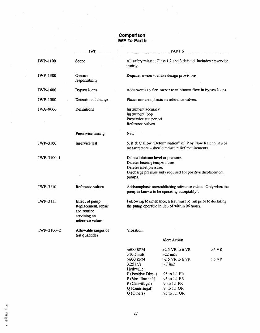
ComparisonIWP,To Part 6
IWP PART 6
IWP-1100 Scope Ali safety- related; Class 1,2 and 3 deleted. Includes preselwicetesting,
IW'P- 1300 Owners Requires owner to make design provisions.responsibility
IWP-1400 Bypass lt,ops Adds words to alert owner to minimum flow in bypass loops.
IWP-1500 Detection of change Places more emphasis on reference valves.
IWA-9000 Definitions Instrument accuracyImtrument ioopPreservice test periodReference valves
Pre_rvice testing New
IWP-3100 Inservice test 5. B & C allow "Determination" oi" P or [qow Rate in lieu of
measurement - should reduce relief requirements.
IWP-3100--1 Delete lubricant level or pressure.Deletes bearing temperatures.Deletes inlet pressure.Discharge pressure only required for positive displacementpumps,
IVCP-3110 Reference values Addsemphasis on establishing refe re.ncevalues "Only when thepump is known to be operating acceptably".
IWP-3111 Effect of pump Following Maintenance, a test must be run prior to declaringReplacement, repair the pump operable in lieu of within 96 hours.and routim
servicing onreference values
IWP-3100-2 Allowable ranges of Vibration:test quantifies
Alert Action
<600 RPM >2.5 VR to 6 VR >6 VR>10.5 mils >22 mils>600 RPM >2.5 VR to 6 VR >6 VR
3.25 in/s >.7 in/sHydraulic:P (Positive Displ.) .93 to 1,1 PRP (Vert. line shfi) .95 to 1.1 PRP (Centrifugal) ,9 to 1.1 PRQ (Centrifugal) .9 to i.1 QRQ (Others) .95 to 1.1 QR
&J
=-- 27
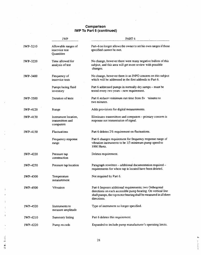
ComparisonIWP To Part 6 (continued) ,
IWP PART 6
IWP.-3210 Allow able ranges of Part-6 no longer allows the owner to set tris own ranges if thoseinservice test specified cannot be met.Quantities
IWP-3220 Time allowed for No change, however there were many negative ballots of tiffsanalysis of test subject, and this area will get more review with possible
changes.
IWP-3400 Frequency of No change, however there is an INPO concern on this subjectinservice tests wtfich will be addressed in the first addenda to Part 6.
Pumps lacing fluid Part 6 addressed pumps in normally dry sumps - must beinventory tested every two years -new requirement.
IWP-3500 Duration of tests Part 6 reduces minimum run time from fiv "ainutes totwo minutes.
IWP.-4120 Range Adds provisions for digital measurements.
IWP-4130 Instrument location, Eliminates ta'ansmitte_,'sand computers - primary concern istransmitters and response not transmission of signal.
computers
IWP--4150 Fluctuations Part 6 deletes 2% requirement on fluctuations.
Frequency response Part 6 changes requirement tbr frequency response range ofrange vibration instruments to be 1/3 minimum pump speed to
1rg)0 Hertz.
IWP--4220 Pressure tap Deletes requirement.cor_stmction
IWP--4230 Pressure tap location Paragraph rewritten --additional documentation required -requirements ibr where tap is located have been deleted.
IWP--4300 Temperature Not required by Part 6.measurement
IWP-4500 Vibration Part 6 Imposes additiona! requirements; two Orthogonaldirec_ons on each accessible pump bearing, On vertical line
--- shaft pumps, the top motor bearing shall be measured in all threedireoions.
IWP--4520 Instruments to Type of instrument no longer specified.
measure amplitude_
a
IWP--6210 Summary listing Part 6 deletes this requirement.
; IWP-6220 Pump records Expanded to include pump manufacturer's operating limits.
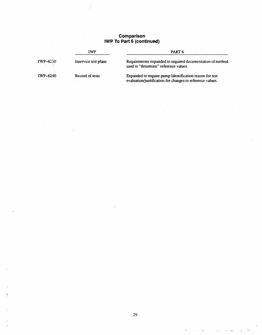
ComparisonIWP To Part 6 (continued)
IWP PART 6
IWP-6230 Irhservicetestplans Requirements expanded to required documentation of methodused to"determine" reference values.
i
IWP--6240 Record of tests Expanded to require pump Identification reason for testevaluation/justification for changes to reference values.
29
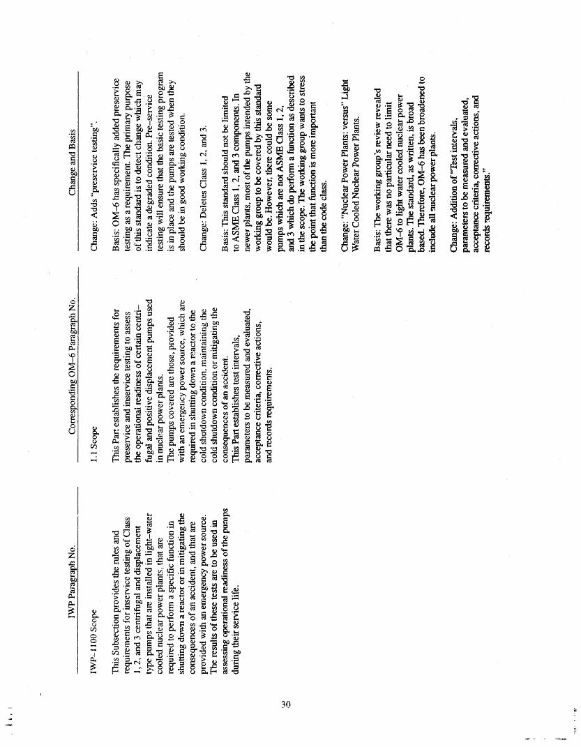
_ ' __._._ _.__.o ._"__._o
- _ _._ _ ._.__ .__ o _.__._
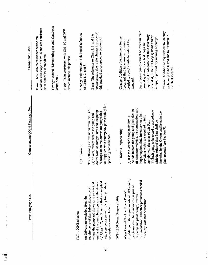
31
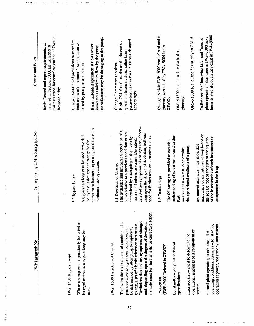
32
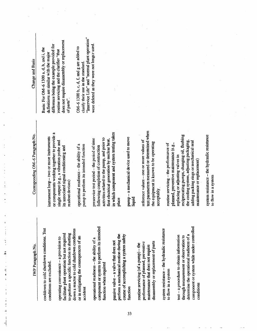
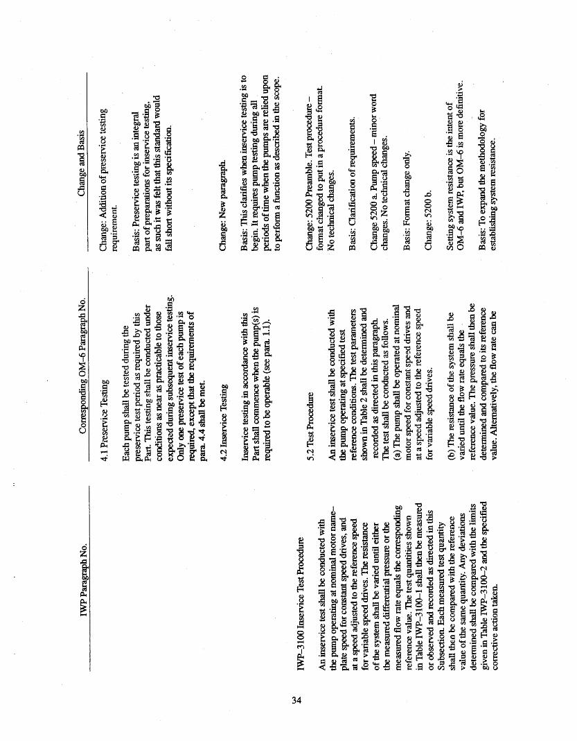
34 ,
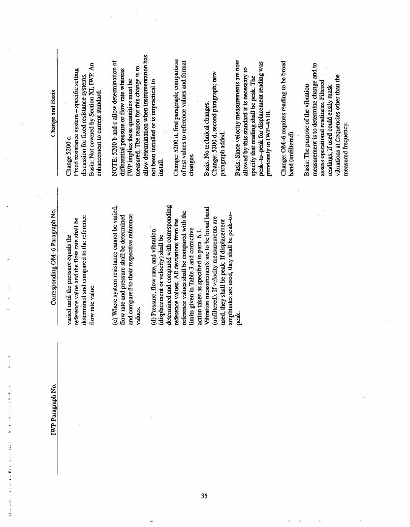
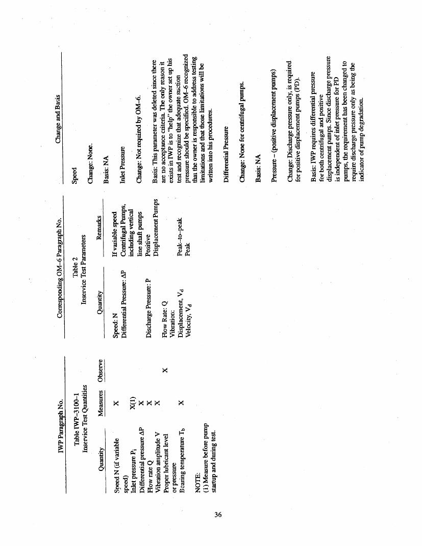
C_
c_
36
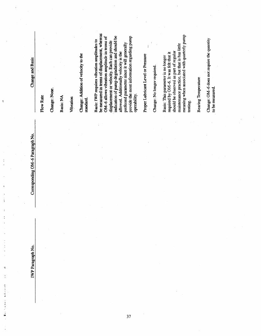
r,
37
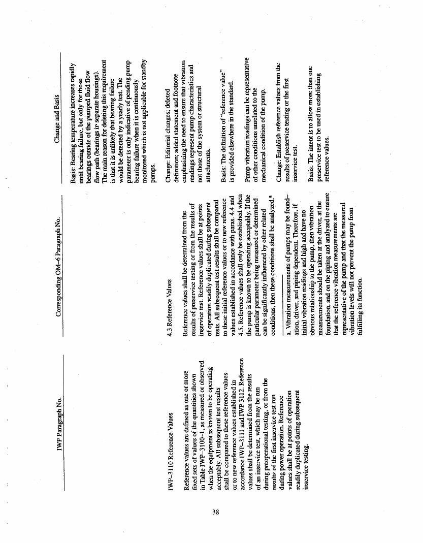
38
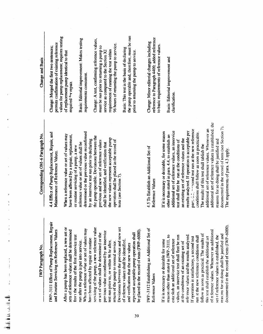
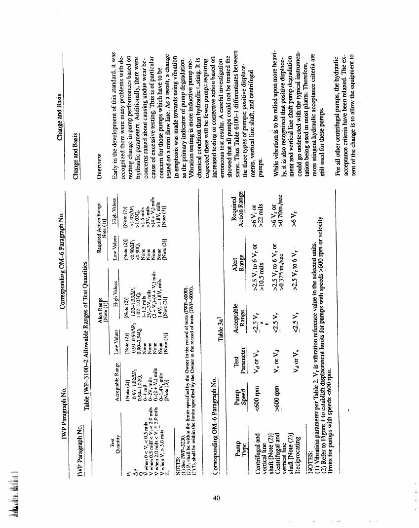
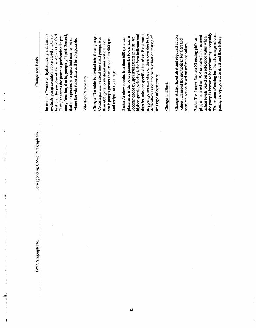
-_ c_Z
l
i
4]
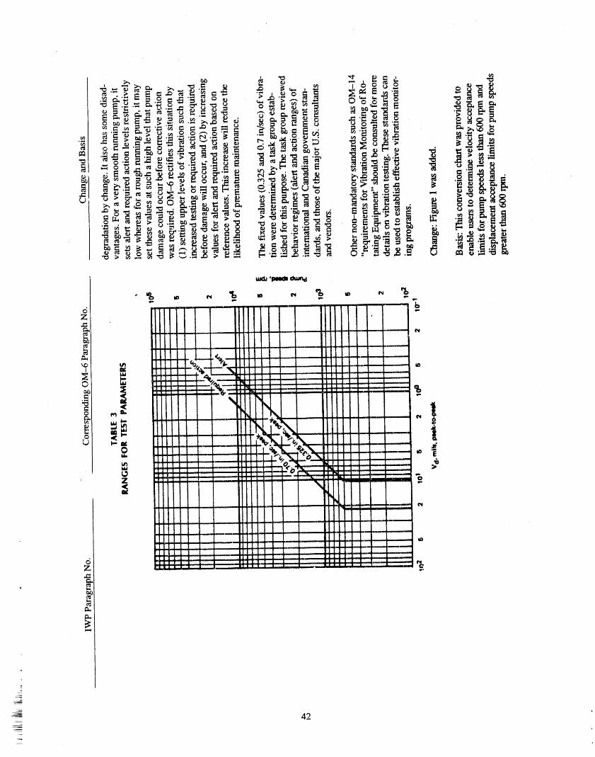
_- 42
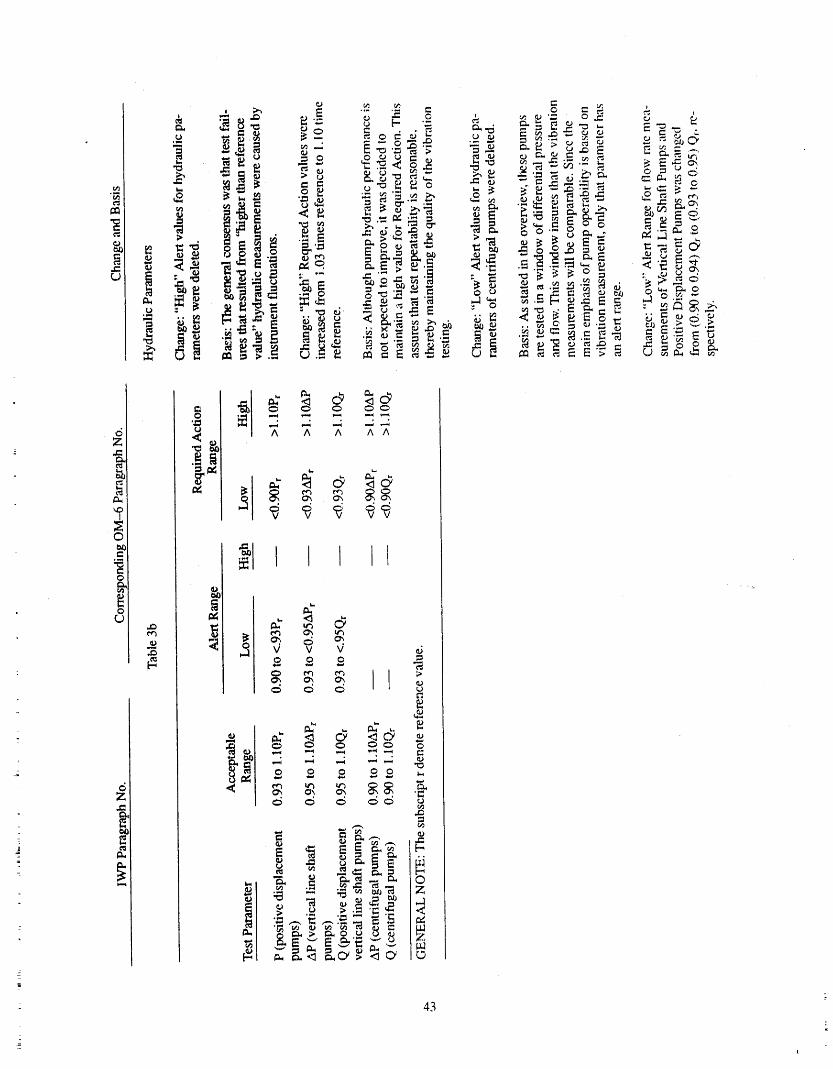
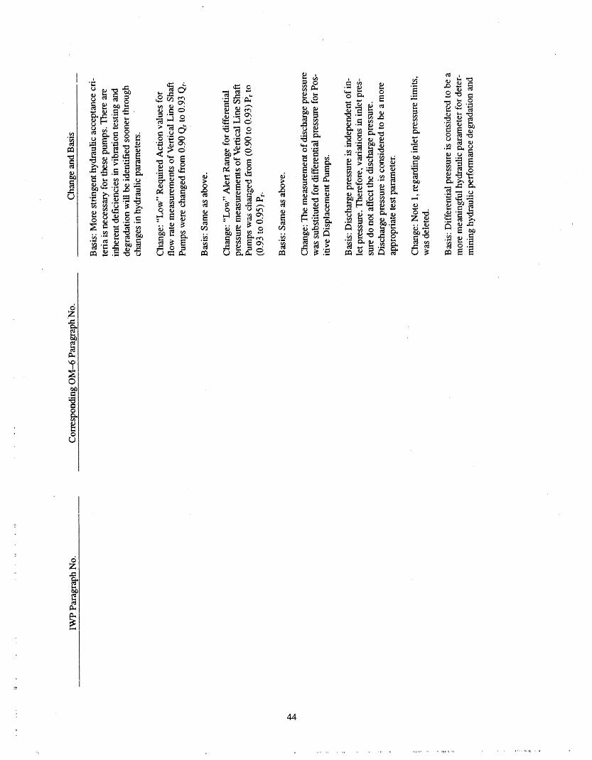
6Z
©
o
_5Zd;l
44
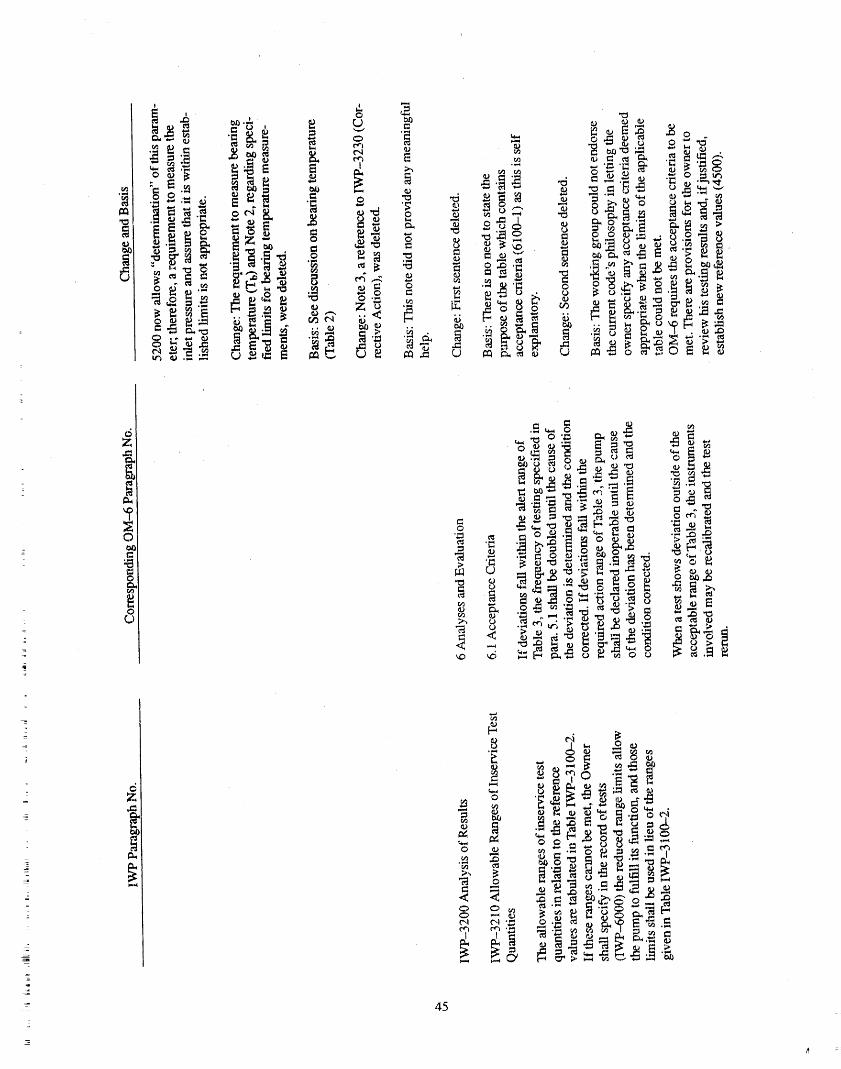
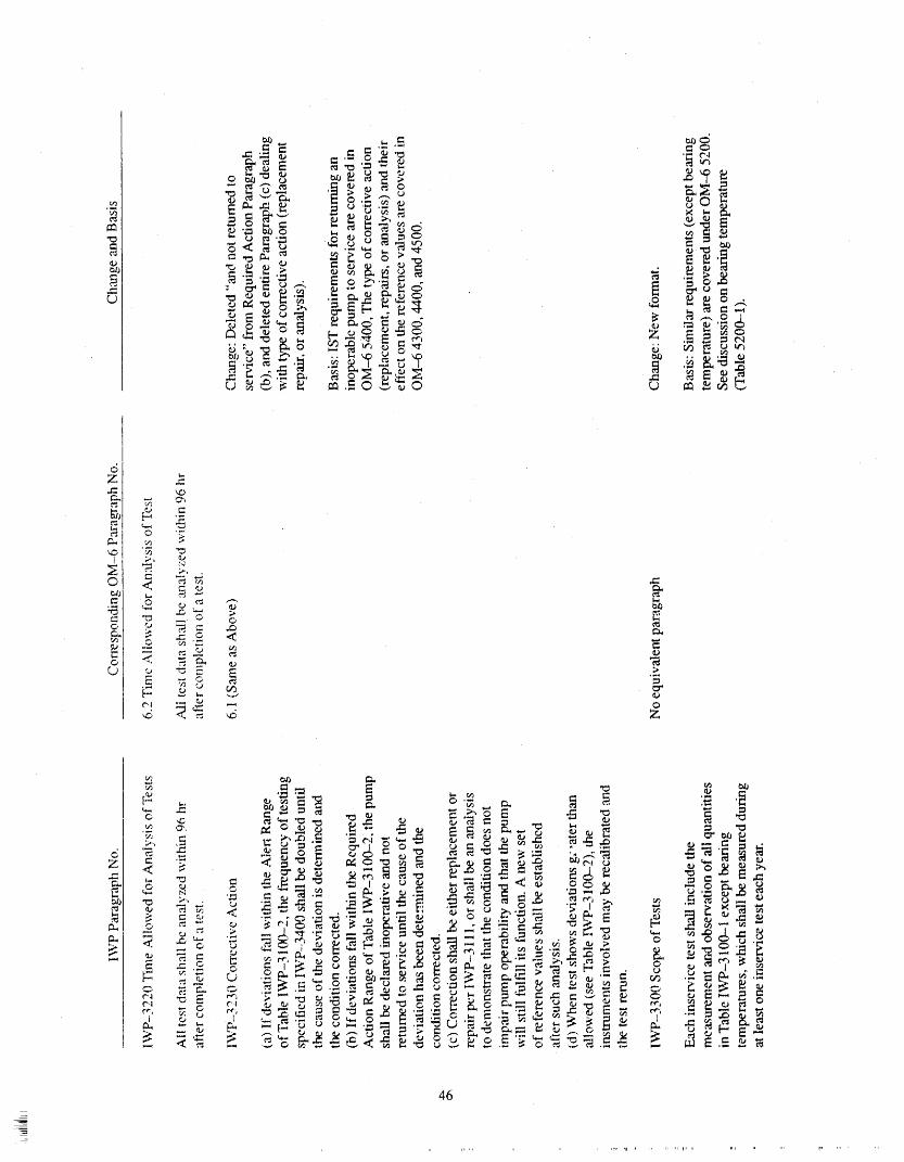
46
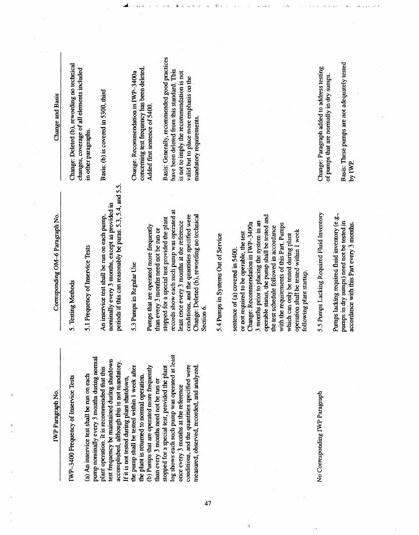
47
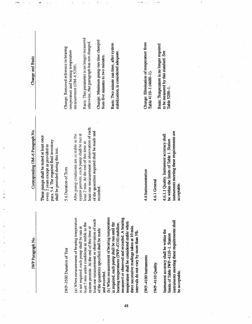
,_,II

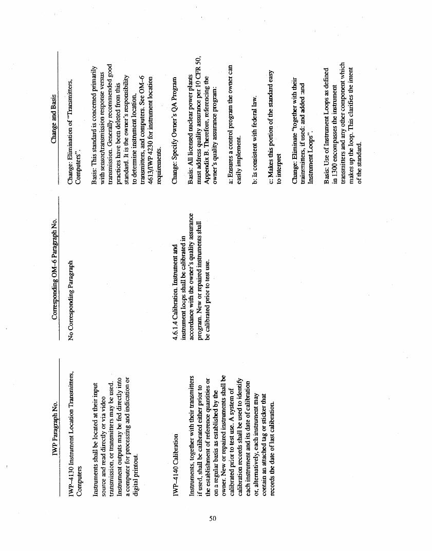
5O
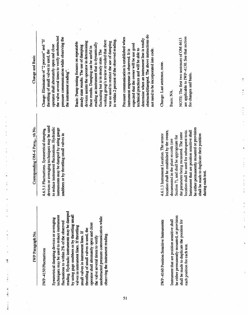
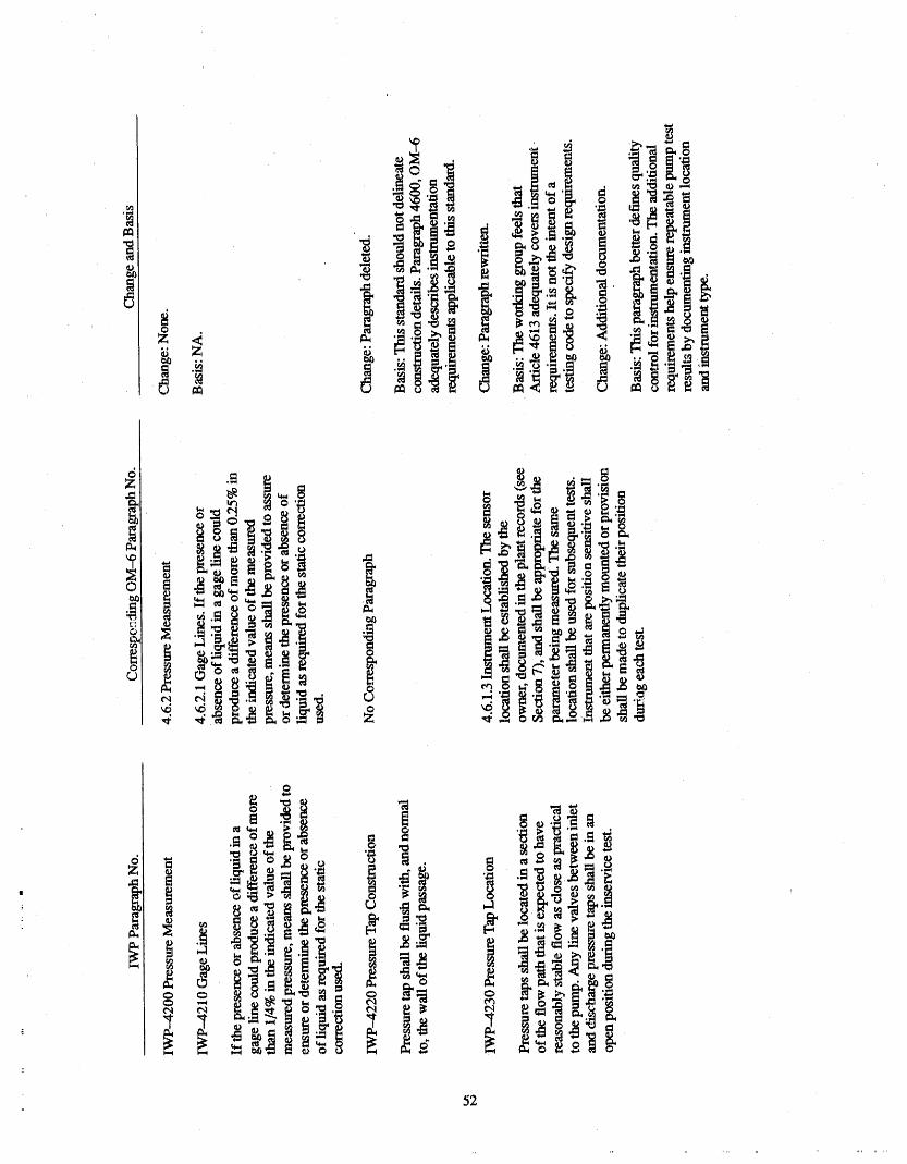
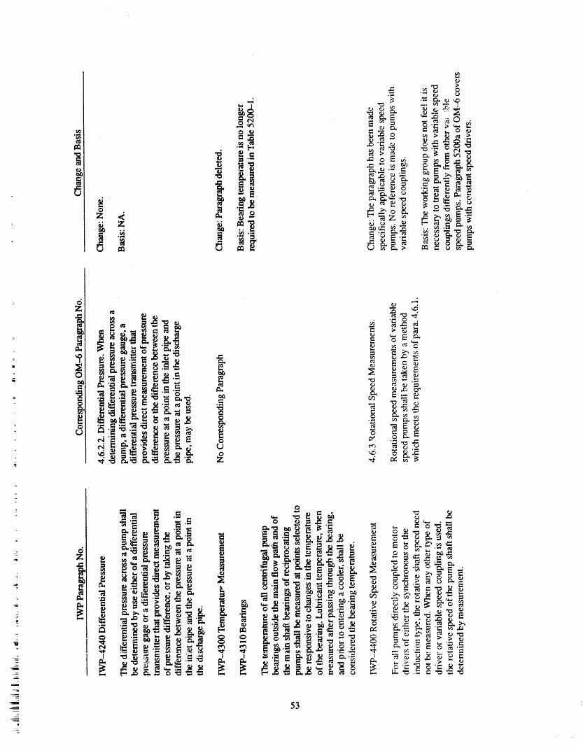
=
_- _._,_
_- 53
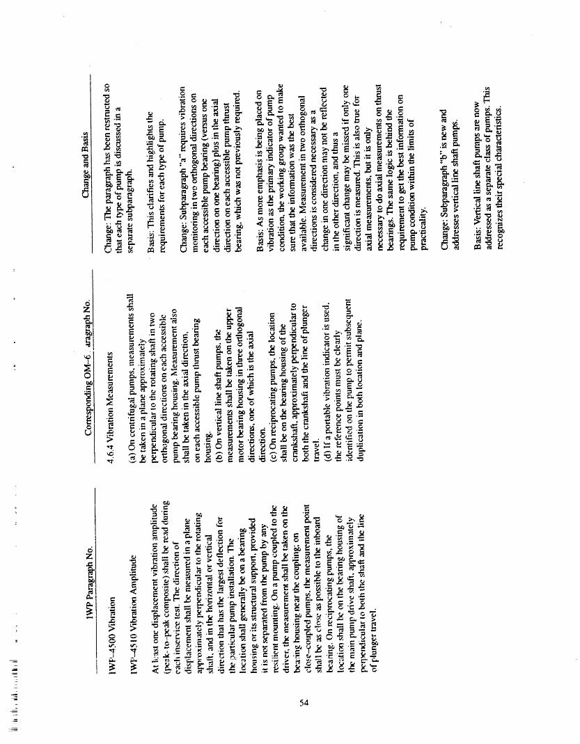
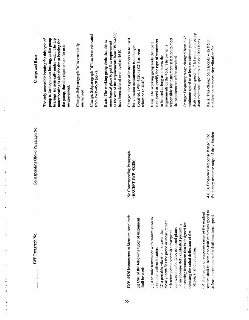
c,,o
oz
6
INTRODUCTION TO ASME/ANSI OMA-1988, PART 6BASIS OF THE NEW VIBRATION MEASUREMENT CRITERIA AND
REQUIREMENTS OF PART 6LAWRENCE SAGE
ILLINOIS DEPARTMENT OF NUCLEAR SAFETY
ACKNOWLEDGMENTS , BACKGROUND
When the 0 & M Working Group on Pumps andThe author would like to thank the other members of Valves first started writing Part 6 as a replacement for
the Task Group on Vibration Monitoring of the Work- ' Subsection IWP of Section XI, a decision was madeingGroup on Pumps and Valves. Particular thanks are that the new standard should, to the greatest extent pus-extended to Mr. J. D. Page, the Task Group Chairman sible, have a sound technical basis. This was particu-and Mr. W. L Green.street. This paper owes much to larly important in tile area of vibration measurement,the Task Group report, primarily authored by these two The vibration measurement criteria and requirementsgentlemen. The other Task Group members were: oflWP have not changed since IWP was added to Sec-R. Fehlau, R. Jacobstine, and R. S. Kolflat. The author tion XI in 1974. The vibration criteria contained inwould also like to thank the staff of the Illinois Depart- IWP were derived from experience, and were not sup-
ment of Nuclear Safety who helped in the preparation ported by a technical basis.of this paper.
When the Working Group started ieviewhag IWP, it
became apparent that the vibration criteria needed re-
INTRODUCTION vision. Industry. consensus was that, in most cases, vi-bration velocity gave the best overall indication ofmachine condition. Many utilities were using vibration
An ideal pump would produce no vibration because velocity in pleventative and predictive maintenanceali the energy would go to pumping liquid. In practice, programs. IWP required (and still requires) vibrationvibration occurs when the pump's elements react to be measured as displacement. This required utilitiesagainst each other and energy is dissipated, to take an additional, and ha their view, useless mea-
surement. This was the greatest impetus for change inthe vibration measurement criteria of IWP.
As a pump wears, changes in its dynamic propertiesbegin to occur. These changes are reflected in an in- A Task Group on Vibration Monitoring was formed.
: crease in vibration energy. This increased vibration en- "I'_ Task Group was asked to make recommendations
ergy may excite resonances and put extra dynamic to the Working Group on Pumps and Valves on vibra-forces on bearings causing more weax. Cause and ef- tion measurement criteria and _quirements. The rec-fect reirfforce each otheL and lead ultimately to break- ommendations of that Task Group have fomled the
down. By measuring the vibration at the pump basis for the vibration measurement criteria and re-elements which restrain the dynamic forces, such as quirements of Part 6. This paper draws heavily on the
" bearing housings, the health of the pump can be in- work of that Task Group.ferred. This is the basis for using vibration for pumpcondition monitoring. CLASSIFICATIONS OF PUMPS
USED IN NUCLEAR POWER- Tiffs paper describes the basis of the new vibration PLANTS
measurement criteria and requirements in Part 6, "In-service Testing of Pumps in Light-Water Reactor As the first step in preparation of the new vibrationPower Plants." The topics coveted are" the back- measurement criteria and requirements of Part 6, the
. ground of why this change was necessary, classifica- types of pumps encountered in nuclear power plantsdon of pumps typically used in nuclear power plants, a were analyzed. Typical applications zmdtypes of pumps
- survey of vibration criteria, and the rationale for the were reviewed. The results of this review served a two--new vibration measurement criteria and requirements fold purpose; it provided a basis forcategorizingpumpsin Part 6. A list of references and a bibliography are and assigning appropriate classifications,and it gave maalso included, indication of the scope of coverage of the Standard.
59z_

The collectedissummari,.edinTable1.T ble2 VlB RATION CRITERIAwas derived from the maximuni vmiances in Table 1.
Table 2 lists ranges of data for each type of pump andclassifies each type of pump in accordance with the Next, various vibration standards in current useguidance given irl ISO 2372, Annex A. ! It can be seen were reviewed. Standards for evaluating machine con-that ali the centrifugal pumps fall into Class III. Recip- dition based on vibration levels take two forms. Somerotating pumps are Class V. This result indicated that it standards ev_duate equipment based on a set of abso-would be possible to specify one set of vibration crite- lute criteria, usually in the form of a vibration severityria for ali c_entrifugal pumps, chart. Other standards evaluate equipment based on
Table 1. Nuclear power plant pumps
Speed Horse .Flow Discharge Pressure Description
Type Class (rpm) Power (gpm) (psig) of Devices
Vertical IIIline shaft 300-900 300--750 To 8000 BWR service water
- 1800/3600 275 3215 100 PWR. recirculationSpray insideContaimnent
1800/3600 293 3000 100 PWR recirculationsprayOutside containment
1800 500 11500 55 PWR service water
o Centrifugal
Vertical III 1800/3600 500-1000 7700 182 PWR residualheatremoval
1800/3600 500-1000 4270 290 BWR core spray1800/3600 500-1000 150 2735 PWR lrdghhead
safety injection
1800/3600 500-1000 3000 300 PWR low head safetyInjection
Horizontal III 1800/3600 500--1300 1500 1000 Service. not specified
(motor or 1800/4500 460--4600 to 4500 1000--2200 Service not
turbine specified- driven) 180013600 223 3000 100 PWR Containment
Spray1800/4260 340 1255-1430 PWR Auxiliary
,, Feed Water3600 800 4000 250 BWR RHR service
water
Reciprocating V200 200 130 5000 PWR charging520 75 50 1150 BWR standby liquid
control
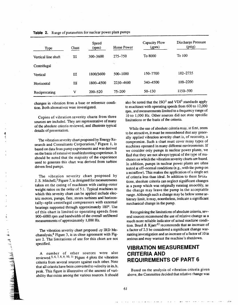
Table 2. Range of parameters for nuclear power plant pumps
Speed Capacity Flow Discharge PressureType Class (rpm) Horse Power (gpm) (psig)
Vertical line shaft III 300-3600 275-750 To 8000 To 100
Centrifugal "
Vertical III 1800/3600 500-1000 150--7700 182-2735
Horizontal III 1800-4500 2230--4600 340--4.500 100-2200
Reciprocating V 200-520 75-200 50-130 1150-500
changes in vibration from a base or reference condi, also be noted that the ISO I and VDI 5 standards applytion. Both alternatives were investigated, to machines with operating speeds from 600 to 12,000
rpm, and measurements limited to a frequency range of
Copies of vibration severity cha_'ts from three 10 to 1,000 Hz. Other sources did not state specificsources are included. They are representative of many limitations or the basis of the criteria.of the absolute criteria reviewed, and illustrate typicaldetails of presentation. While the use of absolute criteria mayl at first, seem
4 to be attractive, it must be remembered that any gener-
.The vibration severity chart proposed by Energy Re- ally applied vibration severity chart is, of necessity, asearch and Consultants Corporation, 2 Figure 1, is compromise. Such a chart must cover many types ofbased on data from pump experiments and was derived machines operated in many different environments. Ifon the basis of extensive troubleshooting experience. It we consider only pumps in nuclear power plants, weshould be noted that the majority of the experience End that they are not always typical of the type of ma-used to generate this chart was derived from turbine chines on which the vibration severity charts are based.driven feed pumps. In addition, pumps in nuclear power plants are often
tested at off-normal conditions (e.g., with the pump on: a miniflow). This makes the application of a single set
The vibration severity chart proposed by of criteria less than ideal. In addition to these limlt_t
J. S. Mitchell, 3Figure 2, is designed for measurements tions, absolute caiteria can neglect significant changestaken on the casing of machines with casing-rotor in a pump which was origin',dly running smoothly, asweight ratios on the order of 5:1. Typical machines to the change may leave the pump in the acceptablewhich this severity chart can be applied haclude elec- range. Although such a change may be below some ar-tric motors, pumps, fans, steam turbines and horizon- bitrary limit, it may, nonetheless, indicate a significanttally-split centrifugal compressors with external mechanical change in the pump.bearings supported through approximately 180°. Use
: of this chart is limited to operating speeds from Recognizing the limitations of absolute criteria, sev-- 900--6000 rpm and bandwidth of the overall unfiltered eral sources recommend the use of relative change as a
measurements of approximately 1,000 Hz. much more reliable indicator of actual maclfine condi-
tion. Bruel & Kjaer 12recommends that an increase ofThe vibration severity chart proposed 0y IRD Me- a factor of 2.5 be considered a significant change war-
chanalysis, 4 Figure 3, is in close agreement with Fig- ranting investigation and an increase of a factor of 10 is__ ure 2. The limitations of use for this chart are not serious and may warrant the machine's shutdown.= specified.
VIBRATION MEASUREMENTA number of other sources were also CRITERIA AHD
reviewed.S, 6, 7_8, 9, 10, 11Figure ,4 plots the vibrationcriteria fi'om several sources against each other. Note REQUIREMENTS OF PART 6that all criteria have been converted to velocity in in./s,peak. This figure i_sillustrative of the amount of vari- Based on the analysis of vibration criteria givenability that exists among the various sources. It should above, the Committee decided that relative change was
61
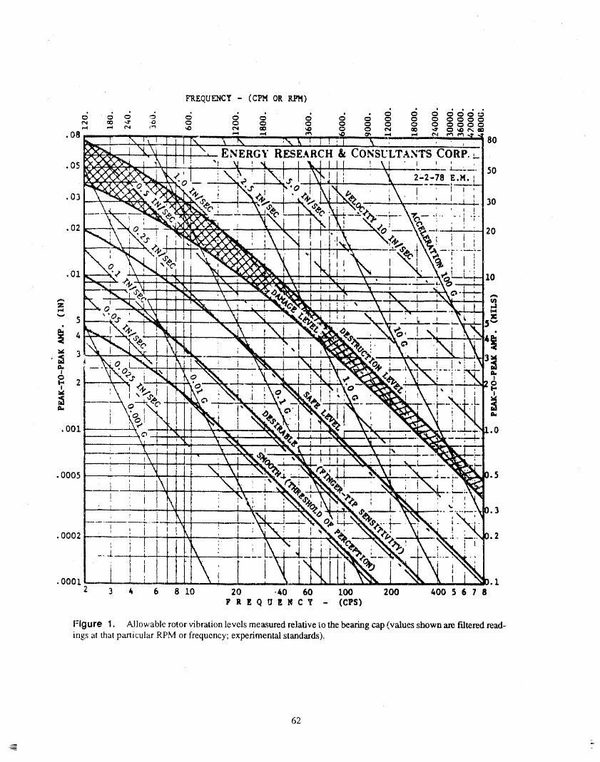
62
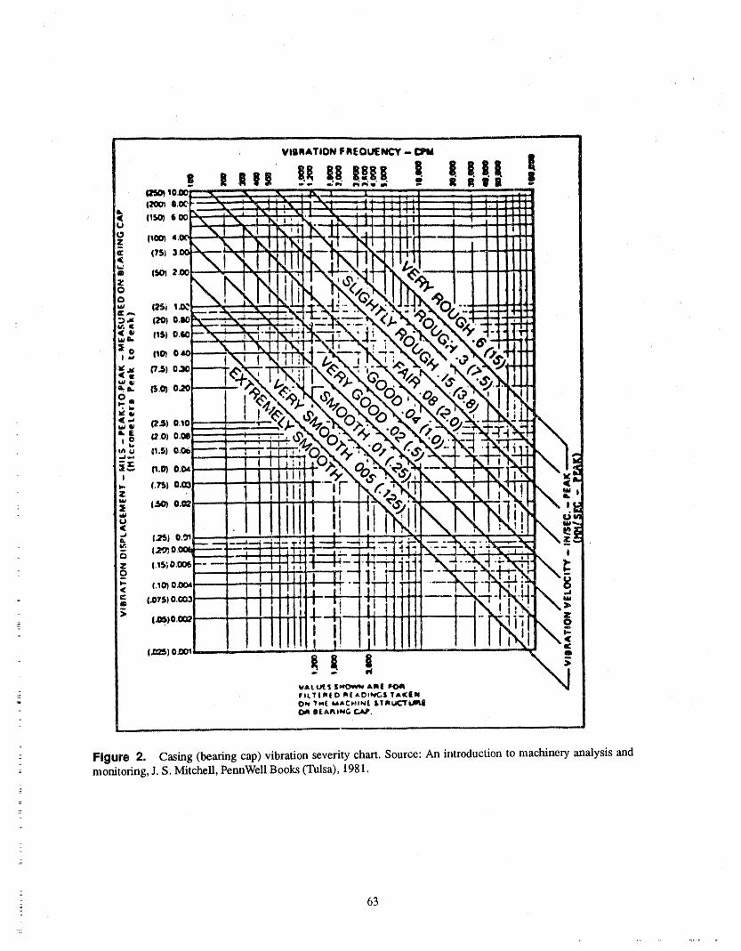
Figure 2. Casing (bearing cap) vibration severity chart. Source: An introduction to machinery analysis and-
monitoring, J. S. Mitchell, PennWell Books (Tulsa), 1981.
63
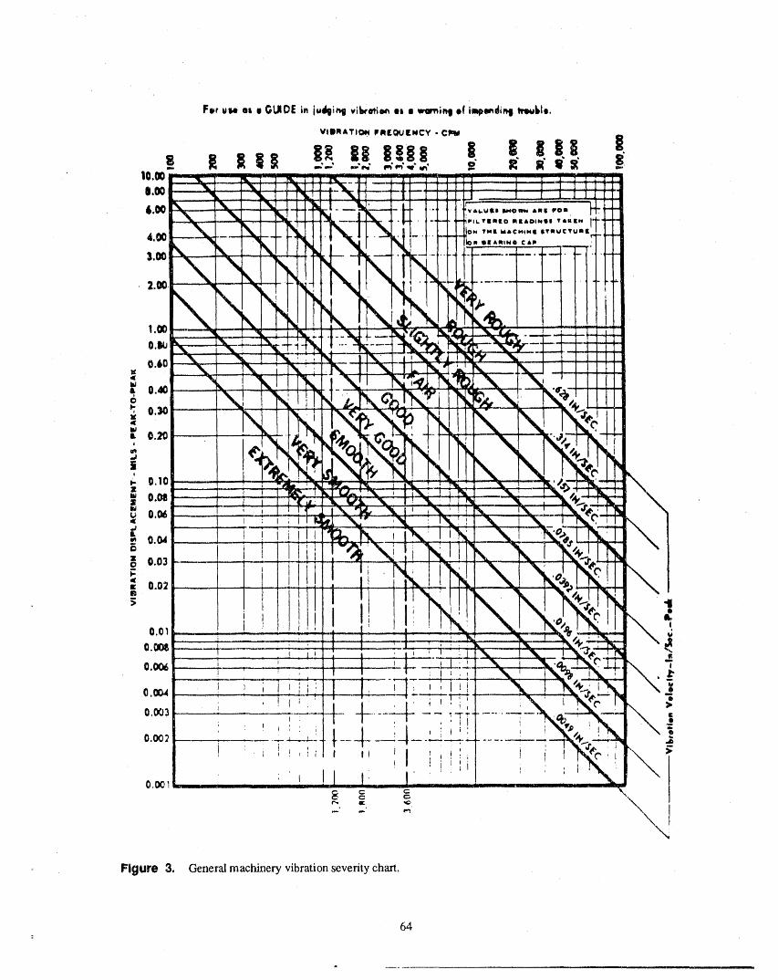
Figure 3, General machinery vibration severity chart.
64

65

the best indicator of actual pump health for nuclear tion" ranges, lt also became obvious that there waspower plant pumps, Examination of the ISO 23721 and some general agreement on the maximum permissibreVD120565 standards show that a change of one quality vibration. Table 3 is an attempt to derive "Alert" andclass (e.g., A to B) represents an increase in vibration "Required Action" ranges from the data of Figure 4.by a factor of 2,5 and a change of two quantity classes Figure 5 is the same ,asFigure 4, except that the "Alert"(e,g,, A to C) represents an increase in vibration by a and "Required Action" ranges of Table 3 are plottedfactor of 6.3, Such a change could lake a pump from and the vibration limits oi' Pm 6 are included. While"Allowable" to "Not Permissible", many of the sources were in general agreement, there
was not agreement on specific numbers.
The factors of change used in Part 6 were set comer- For centri_gal pumps, limits were developed basedvatively at 2.5 tiraes the reference value for "Alert" on machines classified as Class III according to theand 6 times the reference value for "Required Action", ISO Standard, and a consensus of the other standardsThis is reflected in Table 3 of Part 6. One other advan- reviewed. The limits of Part 6 were chosen as
lage of using a relative change criteria is that it is 0.325 in,/s for "Alert" and 0,70 in./s for "Requiredapplicable, with no modifications, to vibration mea- Action". These limits were set somewhat liberally insurements made in any units which use a linear scale, recognition of the fact that pumps in nuclear power
plants are not always tested under normal operatingThe Committee also felt that there are vibration lev- (i.e., full flow) conditions and that relative criteria
e_ above which no pump should he operated, When the were also being applied. Because of the unique natureCommittee looked at ali the available sources it found of reciprocating pumps, no limit was set for the maxi-some difficulty in translating the various terminologies mum permissible vibration. This may eventuallyused into the Code format of"Alert" _"Required Ac- change as additional data becomes available.
Tabl_ 3. Vibration criteria "Alert"and "Required Action" ranges
Behavior Regimes a
Source Alert Range Action Required Range
1. Canadian Govemment Specification 0.394 <= V <= 0.71 V > 0.'.rl(pumps > 5 hp) lI
2. Energy Research and Consultants 0.25 <= V <= 0.75 V > 0.75Corp. (ERCO) 2
3, Gulf Oil Canada, Ltd. 8 0.3 <= V <= 0.5 V > 0.5
4. IRD Mechanalysis 4 0.314 <= V <= 0.628 V > 0.628
5. ISO 2372 !, VDI 25065 0.25 <= V <= 0.628 V > 0.628
6. J.S. Mitchell 3 0.3 <= V <= 0.6 V > 0.6
7. Materials Testing Institute (MTI) 0,2 <= V <= 0.6 V > 0.6
8. Rathbone 7 0.2 <= V <= 0.45 V > 0.45=
9. Shell Chemicals, U.K. 7 0.47 <= V <= 0.75 V > 0.75
10. Vibra-Metrics, Inc. 9 0.19 <= V <= 0.48 V > 0.48
a. Units are velocity in in./s, peak.
2
66
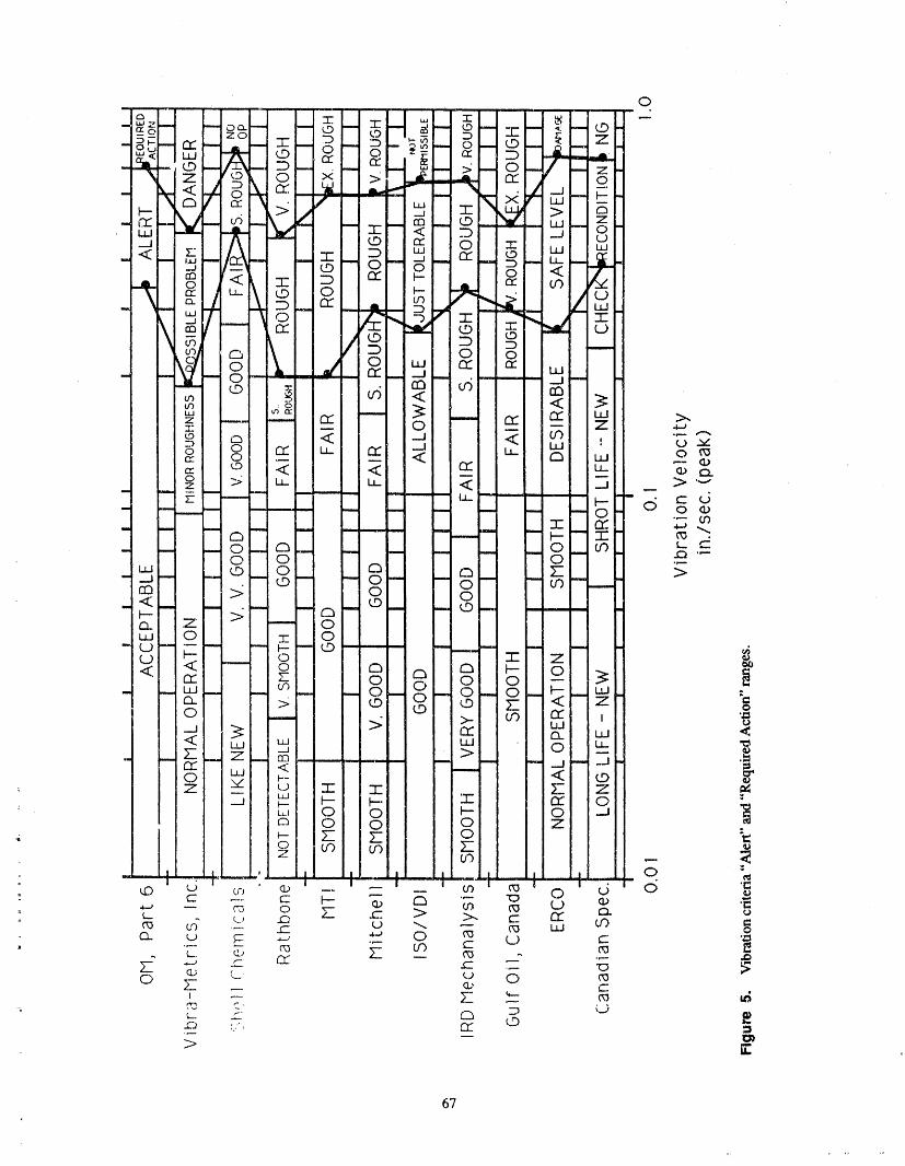
67

Although vibration velocity is generally considered should eliminate or decrease the number of "falsethe best measure of pump health, displacement is a alarms". The incorporation of Part 6 inlo plant surveil-better indicator of pump health for pumps which oper- lance programs will mark a significant increase inate at low speed. The Committee chose to use 600 rpm, pump operational readiness.the lower limit of use for the ISO standard as the transi-
tion. The vibration limits for displacement are set at REFI_RENC_10.5 mils for "Alert" and 22 mils for "Requirext Ac-tion", the equivalent of 0.325 in./s and 0.70 in./s at 1. International Standards Organization Stalxtard"600 Hz. lt should be noted that Part 6 does not require "Mechanical Vibration of Machines with Operat-the use of displacement for pumps which normally op- ing Speeds from 10 to 200 rps - Basis for Specify-orate below 600 rpm and velocity for pumps which ing Evaluation Standards," ISO 2372, Firstnormally operate above 600 rpm. Part 6 indicates that Edition- 1974-11--01.displacement is preferred for pumps which normallyoperate below 600 rpm and velocity is preferred for 2. E. Makay, and O. Szamody "Survey of Feed Pumppumps which normally operate 600 rpm, Outageq," EPRI FP-754, April 1978.
3. J.S. Mitchell, An Introduction to MachineryThe number and location of the required measure- Analysis and Monitoring, PennWell Books
ments has also been changed. On centrifugal pumps, (Tulsa), 1981.vibration is now required to be measured in two ort-hoginal directions perpendicular to the rotating shaft 4. General Machinery Vibration _verity C'hart, IRDon ali accessible pump bearings. A measurement is Mechanalysis, 1975.also required in the axial direction on pump thrustbearings. For vertical line shaft pumps, the point of 5. Verlin Deutscher Ingenieure: "Beurteilung dermeasurement has been defined as the upper motor Einwirkung Mechanischer Schwingungen aufdenbearing and measurement is now required in all three Menschen," VDI Standard 2056, October 1954.directions. These changes are in agreement with the lit-erature aral experience. No change has been made in 6. R.L. Eshleman, "Machinery Vibration Stan-the vibration measurement requirements for recipro- dards," Vibration Institute Draft Report, 1986.
. cating pumps. 7. E. Downham, and R. Woods "The Rationale ofMonitoring Vibration on Rotating Machinery in
Another change in Part 6 is a clear definition of the Continuously Operating Process Plant," ASMEtype ofmeasurement to be taken. Velocity is measured Paper No. 71-Vibr-96, 1971.as peak (ra_her than rms) and displacement measuredas peak-to-peak (rather than peak, average or rms). 8. S. Maten, "Program Machine Maintenance byThis is the general practice m the United States and Measuring Vibration Velocity," Hydrocarbon Pro-Carmda. In Europe, rms is generally used. The use of cess'ing, September 1970, pp 291,296.
_- peak and peak-_o--peak measurements tends to piacemore emphasis on transitory changes in vibration. The 9. "Machinery Fault Analysis Guide AN-103,"frequency range of these measurements is now from Vibra-Met.rics, Inc., February 1981.1/3 pump operating speed to at least I000 Hz.
10. H.P. Bloch, Practical Machinery Management forProcess Plants, Volume 1 Improving Machinery
-- CONCLUSION Reliability, Gulf Publishing Company (Houston),1982.
This paper has atltempted to show ,hat ',he new vibra- 11. Canadian Government Spedfications CDA/MS/tion measurement criteria "andrequirements contained NVSH 1-0-7, Specification for Vibration Limitsin Part 6 have a tec .hnically sound basis. Tl_e use of the for Maintenancenew criteria will increase our level of confidence that
pumps which are monitored in accord:dace with Part 6 12. Machine Health Monitoring, Bruel and Kjaer,are truly ready to perform their intended function when First -Edition, 1984.needed. In addition, the new requirements will de-crease tl_ burden on utilities which cun_ently use a vi- BIBLIOGFIAPH¥bra!io_ ,,.,e_r'_c.ityba._ed predictive maintenanceprogram. Changes _nthe measurement of hydraulic pa- Adams, M. L., "Large Unbalance Vibrauon Analystsrameters made possible by the new vibration criteria of Steam Turbine Generators," Electric Power
_: 68
' ', ,_ ,,r, ,_1 , ,, ,,
Research Institute, CS-3716, Research Project Bently, D. E. "Shaft Vibration Measurement _mdAnal-1648-5, September 1984. ysis Techniques," Noise and Vibration Control World-
wide, Vol..14, No. 3, April 1983.
"A Guide for Developing Maintenance Programs inElectric Power Plants," Electric Power Research Insti- Berggren, J. C., "Malfunction Diagnosis of Rolling
tute, NP-3416, Research Project 2166-1, May 1984. Element Bearings," Abstract: Monsanto Company,Dayton, OH, 1982.
Alfredson, R. J, "A Computer Based System for Con-dition Monitoring," Reliability of Large Machines Blake, M. P.: "Vibration Severity," Report to Commit-(Symposium), Sydney, Australia, June 1982. tee ANSI 52-55, 1970.
"An Integrated Approach to Economical, Reliable, Blake, M. P.: "Standards and Tables," Vibration andSafe Nuclear Power Production," Albuquerque, New Acoustic Measurement Handbook, Spartan Books,
Mexico: U. S. Department of Energy, ALO-IOII, New York, I972.June 1982.
Blake, M. P.: "New Vibration Standards for Electric
Arruda, J. R. E, H. I. Weber and 0. E. Zampieri, "Con- Motors," Hydrocarbon Processing, Vol. 45,No. 3, 1966.dition Monitoring of Large Francis "I_rbine and Gen-erators on Hydro Power Stations," Energ Elletr SaoPaulo, Brazil, 1982. Boatfield, R., "Vibration and Overspeed Monitoring,"
Noise and Vibration Control Worldwide, Vol. 13,March 1982.
Arseneault, J, "Predictive Maintenance Monitoring us-ing T.E.C. Model 1310 Smart Meter and Intelli-TrendSoftware Package as an Extension to the New Bonissone, P. P., "Expert Systems: The Theory andBrunswick Electric Power Commission Vibration Applications of an Emerging Teclmology," Vibration
Monitoring Program," October 1984. Institute, June 1984.
Borhaug, J. E., "Increased Machinery ReliabilityAvakyan, V. A., G. A. Martirosyan and S. A. Sargsyan, Through Vibration Monitoring and Paralysis," TAPPI"An Automated Vibration-Diagnostic System for Eng. Conference, San Francisco, CA, 1978.
- Electric-MachineDefects," Elektroteknika Vol. 51,
No. 3, 1980. Borhaug, J. E., and J. S. Mitchell, "New Tool forVibration Analysis," Hydrocarbon Processing,
Azevedo, S. G., J. V. Candy and D. L. Lager, "On-Line November 1972.Failure Detection of Vibrating Structures," ASME.
Conference on Mechanical Vibration and Noise, Borhaug, J. E., and J. S.,/vfitcbell, "Widened Frequen-Hartford, Connecticut, September 20-23, 1981. cy Range is Improving Today's Machinery Vibration
Analysis," Power, Vol. 317, No. 3, March 1973.- Bannister, R. L., J. C. Bellows and R. L. Osborne,
= "Steam-Turbine Generators On-Line Monitoring Bosmans, R. E, "Detection and Early Diagnosis ofand Availability," Mechanical Engineering, Potential Failures of Rotating Machinery," AS/vIEVol. 105, 1983. PaperNo. 81, 1981.
_
Barn, P.S. "Moaitor Your Tudoine/Gei_rator to Assure Boyd, J., and H. N. Kaufman, '_he Causes and tl_Operational Integrity," Power, May 1981. Control of Electrical Currents In Bearings," Lubrica-
tion Engineering, January 1959.= Baxter, R. L. "Vibration Tolerances for Industry," The
American Society of Mechanical Engineers, Braithwaite, K. G. "Selecting an Automatic Machin-67-PEM-14, 1967. ery Condition Monitor System," Energy Processing/
--- Canada, November--December 1977.-
Benanli, A., C. Frigeri, A. Macchi, T. Rossini, and M.Marine.Hi, "Analysis of'rurbogenerator Operation De- Braun, S. G., "The Signature Analysis of Sonic Bear-fe.,3._o_ !1_ R.a_sisof q_..eirVibra!o:_ Behavior." E,erg ing Vihrnfion_." IEEE Tran.s't_c'tirm:Jn ._'cmit'x'rJnd III.
Elattr, Vol. 59, No. 10, Rome, Italy, 1982. trasonics, Vol. SU-27, No. 6, November 1980.
-_ 69
Broch, J. T., Mechanical Vibration and Shock Mea- Dimarogonas, A. D., and C. A. Papadopoulos, "Vibra-stn'ement, 2nd ed. Denmark: Bruel & Kjaer, 1980. tion of Cracked Shafts in Bending," Journal of Sound
and Vibration, Vol. 91, No. 4, 1983,
Brokenshire, R. E., "In-Service Identification of Fail-
ing Power Plant Auxiliary Machines Through Vibra- Dodd, V. R., and J. R. East, "Vibration Surveillancetion Analysis," Engineering Research Department - Now Covers Minor Equipment," Oil and Gas Journal,The Detroit Edison Company, August 1982. January 1982.
Dodd, V, R., R. M. Dubner and W. J. Caruso, "SteamBrokenshire, R. E., "Outline of Diagnostic Vibration Turbine Diaphram Failure," ASME 75-PET-49,Analysis System to be Employed on the Monroe Pow- September 197S.er Plant Rotating Machinery," The Detroit Edison Co.
Engineering Research Department, November 1981. Dodd, V. R., "Shaft-Alignment Monitoring CutCosts," Oil and Gas Journal, September 1972.
Canada, R. G., R. H. Greene and P. J. Craig, "A State-
of-the-Art Monitoring and Diagnostic Program for Dodd, V. R., "Condition Monitoring of Major Turbo-Main Steam Turbines in Commercial Power Plants," machinery Cuts Costs Over 4Year Period," Oil andVibration Institute, June 1984. Gas Journal, March 1984.
Catlin, J. B., "Improved Maintenance of Machinery Elbestawi, M. A., T. Loewen and D. E Lau, "Condi-Through "Baseline" Vibration Measurements," Trans. tion Monitoring of Rotating Equipment," ResearchoftheASME, J. of Engr. Ind., Vol. 95, No. 4, 1973. Review - Ontario Hydro, Toronto, Ontario,
Canda, 1982.
Cempel, C., "Diagnostically Oriented Measures of Vi- Eshleman, R. L., and D. Jones, "Vibration Analysisbroacoustical Process," Journal of Sound Vibration, and Balancing of a 192 MW Turbine Generator," Vi-Vol. 74, No. 4, December 1980. bration Institute, June 1984.
Chaturvedi, G. K., and D. W. Thomas, "Adaptive Eshleman, R. L., "Identification and Correction ofNoise Cancelling and Condition Monitoring," Journal Machinery Vibration Problems," Sound and Vibration,of Sound and Vibration, Vol. 76, No. 3, July 1981. Vol. 15, No. 4, April 1981.
Clark, L. E, "Practical Condition Monitoring of Rotat- Finley, R. W., "Machinery Monitoring by Ultrasonic
ing Machblery Using Vibration Analysis," Procedures Accelerometry," Society of Chemical Ind., London,of'Orr-Line Surveillance and Monitoring of Plant Reli- England, September 1980.
ability, London, England, September 1980.Fishman, B., "International Standardization -- Me-chanical 'Vibration arKtShock," The Shock and Vibra-
Collacott, R. A., Vibration Monitoring and Diagnosis, tion Digest, Vol. 4, No. 8, 1972oLondon: George Godwin Limited, 1979.
Fitch, J. C. "Crucial and Healthy," Prod. Eng., Vol. 30,
Corley, J. E., "A Vibration Monitoring Program Using No. 9, September 1983.Microcomputers," Vibration Institute, June 1984.
Fox, R. L., "Successful Vibration Analysis Tech-
Curami, A., and F. Di Pasquantonio, "An On-Line niques," TAPPI, Vol. 62, No. 3. March 1979.Computer System as an Aid to Solving Rotor DynamicProblems," Energ Elletr, Vol. 59, 1982. Gunter, E. J., and W. U Sharp, "Minicomputer Aids
Rotor Research," Industrial Research & Development,
May 1981.D'Ans, G., and G. Pleeck, "Diagnosing Mechanical
Failures Through the Vibration Monitoring of Turbo- Halloran, J. D., and G. K. M.ruk, "'lyric"roprocessorsgroups," International Conference on t.arge High Volt- and Remote Machinery Evaluation," Hydrocarbonage Electric Systems, Paris, France, September 1982. Processing, January 1981.
Digital Signal Analysis Using Digital Filters and FFT Hammons, T. J., "Electrical Damping and its Effect on-- UI1 _O 1 JLdlZDI-U_I_ Tec ues, DeoJnark, & r,.jael . Accumulative i"ittl_u_ mnl.nCHoJtuJ_ •uloltlt_-
70
Generator Shafts Following Worst-Case Supply Sys- Hydraulic Institute Standard, "Vibration Limits oftem Disturbances," IEEE Trans, Power Appar. Syst., Centrifugal Pumps," Eleventh Edition, CentrifugalVol. PAS-lO2, No. 2. June 1983. Pump Section, VI, Application Standards B.-74--1,
May, 1967.
Harker, R. G., and W. E. Cronquist, "The lmpact ofMicroprocessors on Rotating Machinery Data Acqui- Improving Machinery Reliability, Houston: Gull"sition and Diagnostic Information Systems," The Publistfing Company, 1982.American Society of Mechanical Engineers, 1982.
International Standards Organization Standard, "Me-
Harker, R. G., and W. E. Cronquist, "The Impact of chanical Vibration of Maclfines with Operating SpeedsMicroprocessors on Rotating Machinery Data Acqui- from 10 to 200 rps - Basis for Specit_,ing Evaluationsition and Diagnostic Information Systems," 27th In- Standards," ISO/DIS 2732, 1972.ternational Gas Turbine Conference and Exhibit,
London, England, 1983. Jackson, C., "Alignment of P,otating Equip.most,"Natl. Pet. Refiners Assoc. Tech. Paper, January 1974.
Harrington, T. P., S. P. Roblyer, and H. Toffer, "Vibra-tion Monitoring Using a Computer Network Ap- Jackson, C., "Care in Installing, Maintaining Rc_tatir_gproach," The American Society of Mechanical Equipment Keeps Big Methanol Plant ()_ Line," "l'heEngineers, 1983. Oil and Gas Journal, Vol. 72, No. 51, DecemI_x.'ri 974.
Harris, C. M., and C. E. Crede, Shock and Vibration Jackson, C., "Cold and Hot Alignment q_chniques ofHandbook. 2nd ed. McGraw-Hill, Inc., 1976. Turbomachinery," Prtr;. of Turbomachinery Sympo-
sium, Second, College Station, TX, October 1973.
Harvey, R. E., "Vibration Analysis: A Powerful Instru-ment for Cutting Downtime," Iron Age, Vol. 225, No. Jackson, C., "Design Audit, Testing & Commissioni_g23, August 1982. of Two 9000 Horsepower Centrifug;tl Air Comprc:gsor
Trains," ASME 78-PET--48, Novemb;:r 1978.
Hauser, G., "A New Analysis Procedure for Noise ,and Jackson, C., "Experiences in Commissioning :t 22 MWVibration Diagnosis of Rotating Machinery," Vibra-
Turbine Generator- Coupling Unbalance, Oil Whirl,tion Rotating Mactfinery Second International Confer-and Secondary Resonance," Vibration In,,;titute,
ence, Cambridge, UK, September 1980. June !984.
Hitchen, I. R., "Vibration Monitoring for Rotating Ma- Jackson, C., "Guidelines for Improving Rotatingchinery," Measurement and Control, Vol. 13, EquipmentReliability,"HydrocarbonProcessing, Vol.March 1980. 60, No. 9, September 1981.
Hodge, J. M., T. Miller, A. Roberts and J. G. Steel, Jackson, C., "How to Prevent Pump Cavitation," tly.."Generator Monitoring Systems in the United King- drocarbon Processing, Vol. 52. No. 5, May 1973.dom," International Conference on Large High Volt-
age Electric Systems, Paris, France, September 1982. Jackson, C., "How to Prevent Turbomacifinery Thn_slFailures," ltydrocarbon Processing, Vol. 54, No. 6,
Holman, J. P., Experimental Methods for Engineers, June 1975.McGraw-Hill, Inc., 1978.
=
Jackson, C., "Inst'ali Compressors for High Availabil-Houghton, J. R., "Shock Spectrum Ratios Applied to ity," Hydrocarbon Processing, Vol. 5 7, No. I 1,the Comparison of Pulse Signatures," Transactions of November 1978..
the ASME, Vol. 102, January 1980.
Jackson, C., "Optimize Your Vibration Analy,sis Pro-" Hudachek, R. J., and V. R, Dodd, "Refinery- cedures," Hydrocarbon Processing, Vol. 54, No. I,
Machinery Surveillance and Diagnostic Program Pays Januar?./1974." Off," The Oil and Gas Journal, Vol. ,"4, No. 42, Octo-
ber 1976. Jackzon, C., "Petrochemical Experience Wilh Vibra-mn " ''tion alysls, IEEE Petroleum and Chemistry Indus-
Hundal, M. S., "Mechat_cal Signature Analysis," The try Conference, Twentieth Annual, Itou_tor_, "I'c.xas.- University of Vermont, 1982. September 1973.
71

Jackson, C., "Techniques for Alignment of Rotating Maxwell, A. S., "Some Considerations In AdoptingEquipment," Hydrocarbon Processing, Vol. 55, No. 1, Machinery Vibration Standards," Vibration Institute,January 1976. June 1984.
Jackson, C., '"/'hree Years Experience with Rotating Maxwell, J. H., "Induction Motor Magnetic Vibra-Equipment in a Large Methanol Plant," ASME tion," Vibration Institute, June 1964.74--PET-12, September 1974.
McElroy, J. W., "Vibration Signature Analysis at tile
Jackson, C., "Turbomachines: How to Avoid Operat- Eddystone Plant of Philadelphia Electric," Vibrationing Problems, Hydrocarbon Processing, Vol. 59, No. Institute, June 1984.11, November 1979.
McHugh, J. D., "Vibration Measurements - Principles
Jones, K., "Examples of Digital Analysis for Rotating and Practices as Applied to General Electric HeavyMachinery," Noise & Vibration Control Worldwide, Duty Gas Turbines," Vibration Institute, June 1984.Vol. 14, 1983.
McGraw, M. G,, "Availabi ity: Key to Reliable Ser-
Kidd, H. A., "Development of a Case Vibration Mea- vice," Electrical World, December 1983.surement System for the DC-990 Gas Turbine," Jour-nal of Engineering for Power, 84-GT-143, 1984. "Mechanical Signature Analysis (MSA) at the 8th Vi-
bration Conference," Journal of Mechanical Design,
King, J. 0., and N. Goodman, "Preventive Mainte- Vol. 104, April 1982.nance Keeps Compressor Engines At Peak Efficien-cy," Oil atut Gas Journal, April 1982. Meinhold, T. F., "Measuring and Analyzing Vibra-
tion," Plant Engineering, Vol. 33, No. 20,October 1979.
Kozak, L., and G. Wald, "Utility Considerations forTurbine Supervisory Instrumentation," The AmericanSociety of Mechanical Engineers, October 1981. Meyer, L. D., E F. Ahlgren and B. Weichbrodt, "An
Analytic Model for Ball Bearing Vibrations to PredictVibration Response to Distributed Defects," Journal of
Kubiak, J. A., A. Rothhirsch L., and Jorge Aguirre R., Mechanical Design, Vol. 102, April 1980."An Algorithm of Fault Diagnosis for Turbine Genera-tor Operations," Vibration Institute, June 1984.
Mitchell_ J. S., "Bearing Diagnostics: An Overview,"Proc. of the ASME Symposium Diagnosing Machin-
Leon, R. L., "A Doppler Tec|mique t_r Detecting and ery Health, San Francisco, CA, December 1978.Locating Excessively Vibrating Blades in a Running
Turbine," Abstract: Franklin Research Center, Phila- Mitchell, J. S., "Designing a Surveillance System,"delphia, PA. 1980. Power, Vol. 121, No. 3, March 1977.
Lortie, L. J., "Philosophy of Diagnosis," Technology Mitchell, J. S., "Efficient Machinery Screening ibr Im-Interchange - Research No. 1, The Vibrafon Institute,Chicago, April, 1974. proved On-Line Performance," Sound and Vibration,September 1984.
"Machinery Condition Monitoring and Trending Sys- Mitchell, J. S., "Examination of Pump Cavitation,tem," Structur',d Measurement Systems, July 1983. Gear Mesh and Blade Performance Using External Vi-
bration Characteristics," Proc. of Turbomach, Symp.,"Malting Sense of Vibration Measurements," Wavelek Fourth, College Station, TX, October 19'75.Rockland Scientific, Inc., July 1981.
Mitchell, J. S., "Justitj, ing the Cost of Monitoring Sys-Maten, S., "New Vibration Velocity Standards," Hy- terns for Power-Plant Equipment," Power, Vol. 121,drocarbon Processing, 1967. No. 8, August 1977.
Maten, S., "Velt'x:ity Criteria for Machine Vibration," Mitchell, J. S., "Monitoring the Complex VibrationVibration and Acoustic Measurement Handbook, Characteristics of Bladed Machinery," Power, Vol.Spartan Books, New York, 1972, p. 267. 121, No. 7, July 1977.
=
72

Mitchell, J. S., "Putting Vibration and Other Operating Osuagwu, C. C., and D. W. Thoron,;, "Effect of Inter-Variables to Work in a Monitoring System," Power, Modulation and Quasi-Periodic Instability in thel/bi. 121, No. 5, May 1977. Diagnosis of Rolling Element Incipient Defect,"
Transactions of the ASME, Vol. 104, April 1982.
Mordfin, L., B. E Payne and S. Edelman, "EnhancedReliability and Reproductivity of Measurements of trees, R. K., and L. Enochson, Applied Time SeriesMachinery Vibrations," U.S. National Bureau of Start- Analysis, Voi. 1" Basic Tectmiques, New York: Johndards, September, 1980. Wiley & Sons., Inc., 1978.
Pandit, S. M., H. Suzuki, and C. Ii. Kahng, "Applica-Morton, P. G., and J. H. Johnson, "The Use and Inter- tion of Data Dependent Systems to Diagnostic Vibra-pretation of Vibration Measurements," Tribology Int., tion Analysis," Journal of Mechanical Design,October 1980. April 1980.
Morris, D. J., and H. C. Gabler, Development of a Parvis, E. and Appendino, M., "Large Size Turbogen-Reactor Coolant Pump Monitoring and Diagnostic erator Foundations - Dynamic Problems and Con.sid-System - Semi-Annual Progress Report: December eration on Designing," Ente Nationale per l'Energia1981 May 1982, United States Department of-Energy, Electrica, Department of Milan, Steam Power PlantDF_,--AC02-79ET34019, OctOber 1982. Design, Eng. and Constr. Div. "_Milan, Italy, 1966.
Muller, C., "Analyzing Turbomachinery Problems: "PEMEC 80," Factory Management & MaintenanceSometimes a Signature is Not Enough," In Tech, Vol. Engineering Conference, Birmingham, England,28, No. 10, October 1980. November 1980.
Muster, D., "History of Standardization in Mechanical Philips, G. J., "Rotating MaChinery Rolling ElementVibration and Shock," J. Acoustical Society of Bearing Performance Monitoring Using the Fiber Op-
tic Method," hat. Conf. on Rel. Stress Analysis andAn_,'rica, Vol. 48, No. 1, 1970. Failure Prey., August 1982.
Nagano, S., M. Tari, M. Nakano, K. Ito_ and Y. Uto, Piety, K., and L. Hamrick, "An Advanced Rotating"Early Detection of Excessive Coil Vibration in High-. Machinery Surveillance and Diagnostic System hn-Voltage Rotating Electric Machines," IEEE Power plementation at the Grand Gulf Nuclear Station," Vi-
: Eng. Soc. Summer lvieet., July 1981. bration Institute, June 1984.
Nelson, W. E., "Maintenance Techniques for Turbo- Piety, K. R., W. M. Bentley, ",rodA. C. Collette, "Tem-machinery," Hydrocartmn Processing, January 1980. povary Sensor Mounting Techniques h_r Large Scale
Manual Predictive Maintenance Programs," Vibration
-i Nordmann, R., "Modal Parameter Identification and Institute, May 1985.Sensitivity Analysis in Rotating Machinery," Energ.Elettr., Vol. 59, No. 10 Suppl., 1982. Plummer, M. C., "Suggested Improvements in the
Measurement of Pump Vibration for In-Service In-spection," American Society of Mechanical Engi-
__ Odi--Owei, S., and B. E. Okah-Avae, "On-Line Moni- neers, San Francisco, California, December 1978.toting: Its Scope and Promise in Developing Coun-tries," Procedures of On-Line Surveillance and
Monitoring of Plant Reliability, London, England, Randall, R. B., Application of B & K Equipment to= Frequency Analysis, 2nd ed. Denmark, Bruel &
September 1980. Kjaer, 19'77.
On-Line Monitoring and Diagnostics Systems for Ranftl, R. M., "R & D Productivity," 2nd cd. LosGenerators, Electric Power Research Institute, Angeles, Hughes Aircraft Company, 1978.NP-902, Research Project 970-1, September 1979.
. Ray, A. G., "Monitoring Rolling Contact Bearings Un-Gsbome, R. L., "Turbine Generator Control and Diag- der Adverse Conditions," Proc. of Vibration Rotating
-- nostic Systems," Electric Energy Conference, Machinery, Second Intl. Conf., Cambridge, UK,Melbourne, Australia, Ociober 1981. September 1980.
-
73
_
Rea.son, J._"On-Line Diagnostics Cut Engine Mainle- Sperry, R. E., and J. R. Hull, "Factors Aftbcting Tur-nance," Power, January 1980, bine Generator Reliability," TAPPI 55, No. 11,
November 1971.
"Report on EquiPment Availability for the Thirteen-
Year Period, 1960-1972," EEi Publication No. 73-46, Steele, J. M., and N. E Rieger, "Coping With VibratoryDecember 1973 Stress," Machine Design, Vol. 54, No. 22, September
1982.Richards, E. J., "Energy Input, Vibrational Level and
Machinery Noise; Some Simple Relationships," Steele, M. E,, R, A. Ashen and L. G. Knight, "An Elec-ASME 8 I-DET-96, September 1981. trical Method ,for Condition Monitoring of Motors,"
IEEE Conference, London, England, 1982.Rieger, N. E, _mdA. L. Wicks, "Measurement of Non-steady Forces in Three Turbine Stage Geometrics Us-ing the Hydraulic Analogy," Journal of Engineering Suryana.rayan, S., "The Role of Vibration Measure-jot Power, Vol. lO0, October 1978. ment and Analysis in Maintenance Engineering," J.
Inst. Eng, India, Part ND, Vol. 62, No. 2, May 1982.
Rieger, N. E, "Rotor-Bearing Dynamics - State-of--the-A_rl," Rochester Inst. of Technol., 1977. Technical Assessment Guide, Electric Power Research
Institute, PS--1201-SR, July 1976.
Rosenberg, L. T., "Abnormal Vibration Problems inLarge Turbine-Driven Generators and Their Solu- The Shock and Vibration Bulletin, Part I, Naval Re'lions," IEEE Trans. Power Appar. Syst., Vol. PAS-101, search Laboratory, Washington, D. C., May 1982.No. 10, October 1982.
Toyota, T., K. Maekawa and S. Nakashima, "Automat-"Rotating Machinery Trending and Diagnostic Sys- ic Diagnosis for Malfunctions of Rotating Machinestenl," Structural Measurement Systems, September by Fault-Matrix," Bulletin of the Japan Society of Pre-1983. cision Engineering, Vol. 16, Number 2, June 1982.
Sacchi, G., tu_dB. Moro, "Vibratory Problems on Gas Volin, R. H., "Techniques and Applications of Me.Turbines Rotors," Energ. Ellettr., Vol. 59, No. 10, chanical Signature Analysis," Shock and Vib. Dig.,
, 1982. Vol. 11, No. 9, September 1979.
SchnJttger, J, R., "Monitoring Mechanical VibrationsVerlin Deutscher Ingenieure, "Beurteihmg der Einwir-
Using a Histogram Recorder," lnt. J. Fatigue, Vol. 5, kung Mechanischer Schwingungen auf den Mens-No. 3, Jttly 1983. chen," VDI Standard 2056, October 1954.
Scientific-Atlanta, San Diego Group, "MachineryCondition Monitoring, A Report to the Power Genera- Vucetic, A., M. Butkovic, and I. Sktric, "The Size oftion Industry," 1984. Turbo-Generating Sets and Permissible Vibrations,"
Energ. Elettr., Vol., 59, No. 10, 1982,
Shevchuk, G. J. and P. Thullen, "Flexural Vibrations of
Rotating Electromagnetic Shields," Journal of Me- Wu, S. M., T. H. Tobun, Jr., and M. C. Chow, "Signa-chanical Design, Vol. 101, J,3Jiuary 1979. ture Analysis for Mechanical Systems via Dynamic
Data System (DDS) Monitoring Tectufique," JournalSmiley, R, G., "Rotating Machinery: Monitoring and of MechanicalDesign, April 1980.Fault Diagnosis," Sound and Vibration, Vol. 17, 1983.
Xistris, G. D., and G. K. Boast, "On a Digital Ap-Sohre, J. S., "Turbomactfinery Problems: Causes ,and proach to the Analysis of Mechanical System Re-Cures," Hydrocarbon Processing, Vol. 56, sponse Sign',ds,"Proc. of Theory Mac[tines Mech., 5thNo. 12, 1977. World Conference, Montreal, Canada, July 1979.
74
ATTENDEE- PANEL QUESTION AND ANSWER PERIOD(EDITED; ATTENDEE QUESTIONS AND PANEL/AUTHOR
RESPONSES NOT IDENTIFIED BY NAME:')
Question 1 Question 3
When 0.70 in. per second or tile required action r,'mgeIn reg,-u'dlo instrument loop accuracies, what compo-is not achievable during baseline testing, what are tt_enents are to be included irl the overall accuracy, plus oralternatives?minus two percent. For example, a flow loop is re-
quired to have a plus or minus two percent accuracy.Does this include flow indicator, flow transmitter, Response 3square root converter, and flow element? Please con-
I think the only alternative is to go to the NRC with asider that the flow element is usually not very accurate.relief request if you have a pump that is nomaally run-
Response 1 ning at greater than 0.70 in. per second.
Question 4In the past, the Code always considered the instrumentaccuracy in the ranges that are in the standard. I do rec- 4.6.12(b) states, "Digital instruments shag be selectedognize that there are some inaccuracies in the wiring such that the reference value ._hMlnot exceed 70 per-and in the whole system of instruments that you need cent of the calibrated range of the instrtunent." Whereto consider to get the total accuracy, did the 70 percent come from and why doesn't the
Code specify ata accuracy in terms of percent of read-
i I would add that, perhaps more than absolute accuracy, ing rather than restricting the calibration range of thewhat we're interested in is repeatability, and in that instrument?
- case things like your flow element are not as much of aproblem. Response 4
-: Question 2 I think two things were operative in our decisions. The70 percent essend,'dly comes from the way Section XI
handled digital instrumentation when they brought thatHas the NRC/ASME resolved their differences in hy- in for pressure testing, and the only idea is you don'tdraulic pump parameters; i.e., 1.1 times reference val- want to overrange the instrument if you happen toue for delta P and Q being an acceptable range? come up with something you are not expecting.
Response 2 The reason we state things for other instruments as apercent of ftdl scale is that is the way you usually buyan instrumem_percent of full scale. That, perhaps,We still have some differences of opinion in that area.
We had a detailed two--day meeting with the NRC in would not be appropriate in digital instruments. I thinkWashington about two months ago where it was de- that is something we probably should take a look at.
cided that, on the part of the Code folks on the working Question 5- group, we would be looking al a task group that would
try to see how we can best serve this concern. Larry- Sage is the chairman of that task group. For a given pump flow rate test how can one account
for a response that is better than the baseline test?
We are currently asking if an alternative is to test Response 5pumps during refueling outages with a very detailed
= test setup and d_en do the same qu,'u'terly test in addi- ] don't believe that tu_increase in pump perform_mce ation, with less emphasis on operability but more eta- should be interpreted as implying there is anything
-_ phasis on the fact that the pump does start and pump- wrong with the pump, first of all. You may be askingfluid, why people were concerned when we had the 1.03 ac-
lion range before.I think the important thing tbr everyone to know is that
: the NRC and the ASME have sat down and discussed It's true that, for many reasons, you could not gel thethis. There is a let of communication about this item. meter reference value, and you could go above the
-al
75
reference value during the test. I believe that response that would be encountered if they had to mitigate thedifference could be indicative of the test setup, consequences of au accident.
There may be something wrong with the way the test Atthe same time, I think that a standard that would es-has been arranged in such case. Examples of that tablish operability would require more than what anwould be a misalignment in the loop. You change the operationalreadiness standard wouldprovide, which isresistance; you can get a different result, what Part 6 is.
We in the code believe that when you have a higher- Question 7than-what-you--e;_pect type of value, you should relyon a parameter that is more indicative of conditioning, A small retbrence value for vibration yieldsa small op-such as vibration, rather than the other parameter tode- erable range for the pump. For example, VRequals .01clare a piece of equipment inoperable or have to go in. per secondgives an alert range of 0.025 in. per sec-into a limiting condition of operation, ond, The example shows that a smoothly running
pump canbe subject tocorrective action. Has the com-Question 6 mittee addressed this?
lt was stated in effect that OM 6 should not be used to Response 7determine operability until that operability has beeninitially established. Please discuss the intent of this Yes,we have. It is our belief that, even though it maystatement and how the working group intends toestab- be a small level on an absolute scale, a change of anlish the initial satisfactory operation, order of magnitude of six or something (which would
get you into the required action range) is veryResponse 6 significant.
The reason I make that statement is that I have a fer- Whether or not it is significant on an absolute scale,vent feeling that Part 6 in the way it is written right that was one of the things we didn't like about the ab-now cannot necessarily establish operability. We are solute scale. Youcould have significantchanges in me-not asking people to test to the safety limits or the chanical condition without needing to go and find outsafety parameter limits, such as of flow or pressure, why you have that change.
76
DIAGNOSTICS USED ON POWER GENERATION PUMPS
KEVlN R. GUYSENIOR PRODUCTION ENGINEER
GIBSON GENERATING STATIONPUBLIC SERVICE INDIANA
P.O. 'BOX 408. OWENSVILLE, INDIANA 47665
BIOGRAPHY einea with eliminating ali the little equipment prob-lems no one has taken the time to solve. During thistime period, a vast amount of learrfing will take piace.
Kevin R. Guy is a Senior Production Engineer at the The learning stage will impact the engineer assigned toGibson Generating Plant of Public Service Indiana, head the program, ali people in contact with thewhere he is supervisor of the Predictive Maintenance program, ",rodthe plant itself.Department. Guy has more than ten years of experi-
ence in vibration analysis. He holds a B.S. degree in The initial stages of the program will ,'dso be costlyMechanical Engineering Technology from Purdue with the purchase of equipment and the increase inUniversity. A member of ASME and the Vibration In- maintenance costs. The misnomer encountered with
stitute, Guy also serves on the Board of Editors of the the birth of a Predictive Maintenance Program is it will: Shock and Vibration Digest. save money immediately. This is totally false. 'The pro-z
gram will irfitially increase the cost of plant mainte-ABSTRAt,;T nanc_ while you eliminate problems found during the
early stages of your program. Management people are
Setting up a periodic vibrational monitoring pro- usually shocked by this, and it usually results in some-gram by the use of electronic data loggers. Acquired one saying, "This program doesn't work," or "Wedata will be analyzed and evaluated to determine pump never had this problem until we started Predictivecondition. Measuring frequency, reporting procedures Maintenance." The best advice is to keep m,'magementand conditions of mechanical components will be personnel informed as to ali the possible consequencesdiscussed in detail based on an actual case study, involved with starting programs.
iNTRODUCTION INVESTIGATION=
The first priority is tO determine which pumps areThe majority of people thii_k of predictive mainte- going to be set up on a Predictive Maintenance Pro-
nance as a glorified vibration program. While they are gram. I recommend the person in charge of the I-'redic-correct in the assumption that vibration data is that tive Maintenance Program look over your yearly
- backbone of the program, there is much more to pre- availability reports and see what pumps have led todictive maintenance. Predictive maintenance is: vibra- your unit derates. If the trend holds true, you will findtion data collection, vibration analysis, testing, that boiler feed pumps and pump drives will be theengineering, maintenance and quality control ali greatest cause of your plant derales. Once you deter-wrapped up into one program. The goal of this pro- mine what your target pumps will be, investigationgram is to increase the unit availability and reliability must begin into what has been the major cause of thewhile lowering the maintenance costs. This paper will problems.discuss the procedures necessary to start a successful
? Predictive Maintenance program for power plant I recommend the engineer responsible for predictivepumps, maintenance review the maintenance history on boiler
_ feed pumps and their drivers for a period of five years." The one item everyone needs to be aware of is that _Ilaiswill allow for a large enough time period to see
Predictive Maintenance Programs don't happen over- any trends in equipment problems. Looking five years
: night; they occur over time. The normal time period is will give the engineer enough data to see if there arethree to five years. The first several years is going to be any repeat problems. These problems should be logged
- 77c_

down and used in gozd setting for the program which ' Equipment Categorywill be discussed later. Breakdown
Or=cethe investigation into which pumps will be t,'tr- The next priority is to divide your pumps up intogeted for predictive maintenance is complete and the categories corresponding to their importance to thepast maintenance history of these pumps has been re- plant operation. Group #1 will be any capability reduc-searched, you are now able to move on to the setup of ing pumps (i.e. boiler feed pumps). These pumpsthe program. One thing never to forget while perform- should be monitored every two to four weeks. Group
ing predictive maintenance: Don't expect the diagnos- #2 will be any pumps that have a redundant backuptic equipment to f'md all your problems or solve them (i.e. main condensate pumps). These pumps should befor you. The diagnostic equipment will help you keep monitored every four to eight weeks. Finally, Group #3tabs on your equipment health; but, you still need to is any miscellaneous pumps that don't fall into the firstunderstand how the equipment works and what its two groups (i.e. LPSW backwash pumps). Thesefunction is. The initial problems will be equipment re- pumps should be monitored every eight to twelvelated. However, later in the program many vibration weeks,problems are operational or system related. A lack of
understaIv.ting in this area will lead to many unsolved While breaking down the pumps inr° their individu-._ problems, al groups, you need to also break them down into infor-
mal groups on how they are designed and mounted.
STEPS TO PROGRAM SETUP Figures5 to 8 show various examples of horizontally_- and vertically mounted designs. Knowing how equip-
ment is mounted will give some insight into possible
Equipment File Packages problems encountered when troubleshooting pumps. ItWill also allow you to start a case history file on pump-ing problems encountered with different types of
: The first item of business in setting up a program is mounting schemes. Case histories will be discussedto learn a.s much about the equipment as you can. This later in this paper.will entail putting together an Equipment File Pack-
a_gc,.The eqtfipment file package will be the fiE'ststep in Monitoring Equipmentthe learning process on how the equipment operates
_: at, ' ',,hat its function is in the system. Appendix 1 con- This can be a very difficult part ofyour program, ortains a generic Equipment Information Sheet. This it can be very easy. If you have done your job when fill-sheet will contain ali the pertinent information re- ing out the equipment file package, you should havequired'for analysis, b',.dancing and alignment. The in- developed a feel as to what the past pump problemsformation required ibr this sheet will not be readily have been. Knowing what the past problems have beenavailable in the early stages, so you will be constantly will allow you to look for problems previously experi-adding to it as intbm_ation becomes available. Exam- enced, Armed with tiffs infommtion, you should nowpies of this would be the critical speed and balancing be able to look into different types of monitoringinformation that will become available after balancing programs.is performed on the equipment and bode plots are gen-
erated. Aligtmaent tolerances may also fall into this If this i_ the first Predictive Maintenance Program" category if the equipment tEM is trying to sell his ser- you or your plant has been involved in, be very careful
vices. Ali other information required to fill these when choosing the type of equipment you will utilize.sheets out should be done while setting up the I do not recommend building an on--line monitoring
- progr,'un, system to do the job unless You have had several years=. of vibration data to design your system against. I rec-
The cquipmer.t file package should also contain ommend thatdata loggers or tape recorders, in con-prints of the equipment layout (Figures 1 &Figure 2), junction with FlaT analyzers, be utilized.driver ;u_ddriven, alor,g with foundation mfomaation.These prints :;hould be reduce5 down into a basic Data loggers are excellent for taking periodic data,schetue a.s in Figure 3. Also needed is a pump curve and the software that accompanies the loggers allow
- (Figure 4). This should compile ",.dithe basic informa- you to trend vibration data and other equipment pa-tic,n required to do a basic analysis if a vibration rameters. They will allow you totake signatures, alongproblem comes up. with the overall readings, if this is what you require._
- 78
.2"
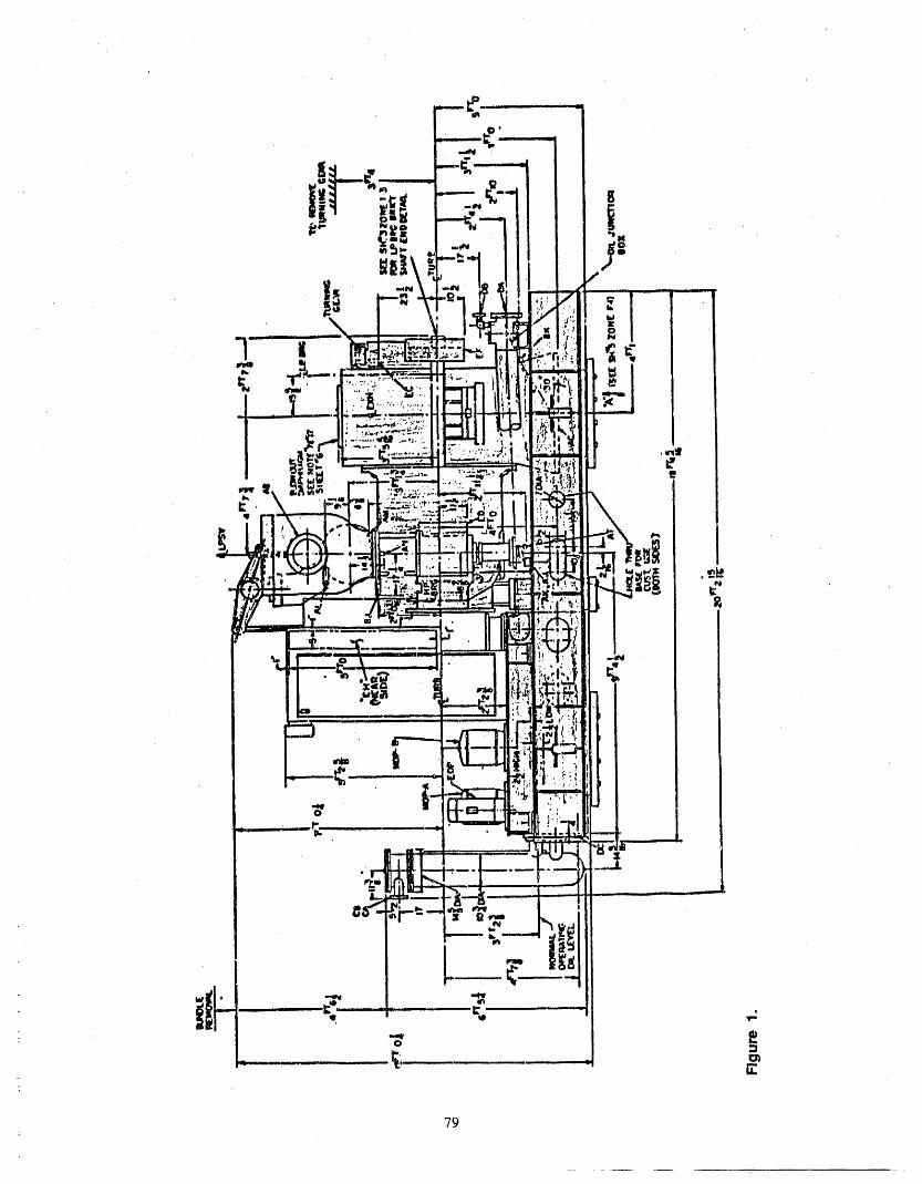
79
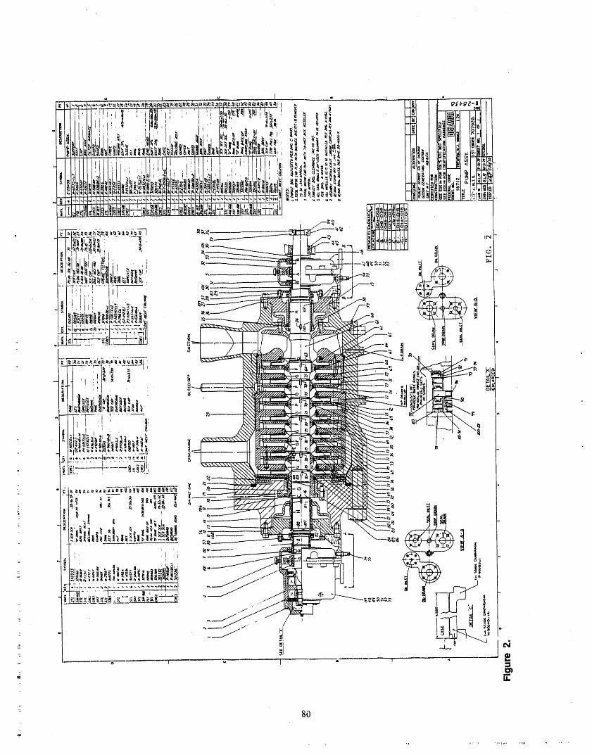
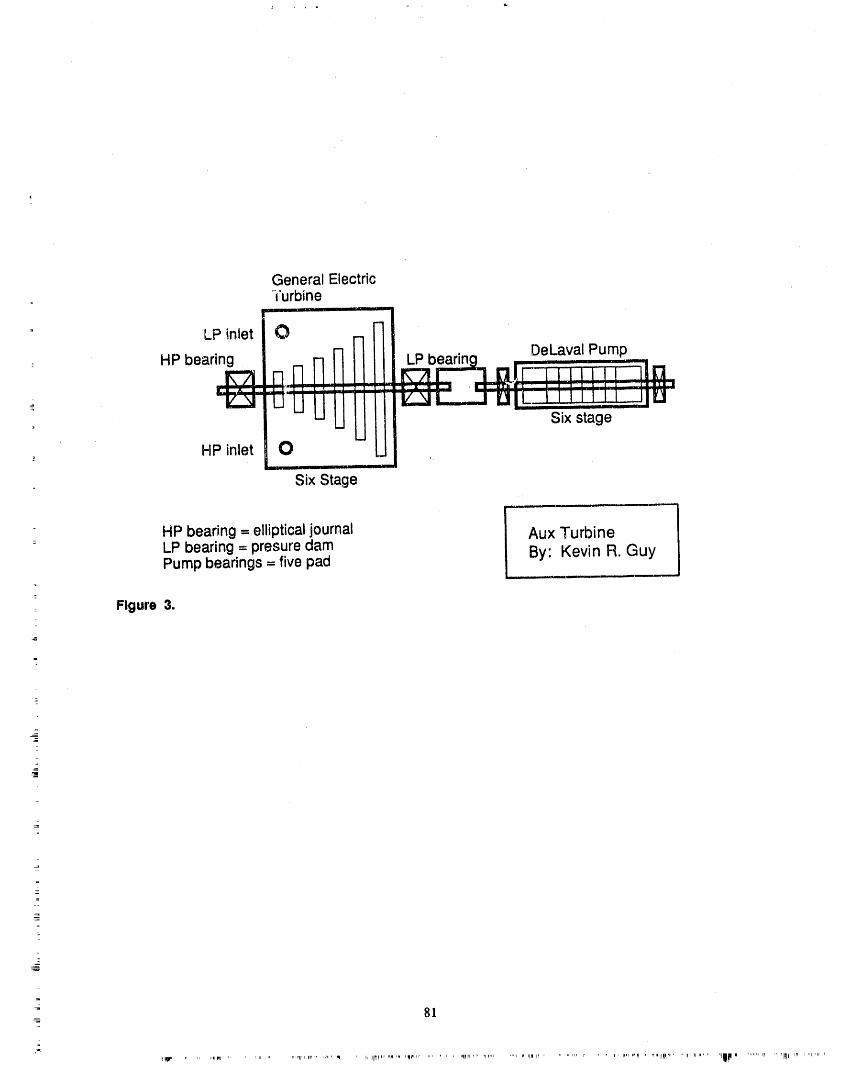
General ElectricTurbine
' DeLaval Pump: HP bearing LP bearing __ ....... .
,,r-/11. ' _-"z+,i_... ,.J-_+F,-1.7 I_J__::__in• ! JL__J I l+ I l ! • :_ l :111__ I __J ]IILi.lJ
L s,xstage; PIPinlet 0 _ ,,
Six Stage
L
HP bearing = elliptical journal Aux Turbine= LP bearing = presure clam
Pump bearings = five pad By' Kevin R. Guy
z Figure 3.
l
=
=+
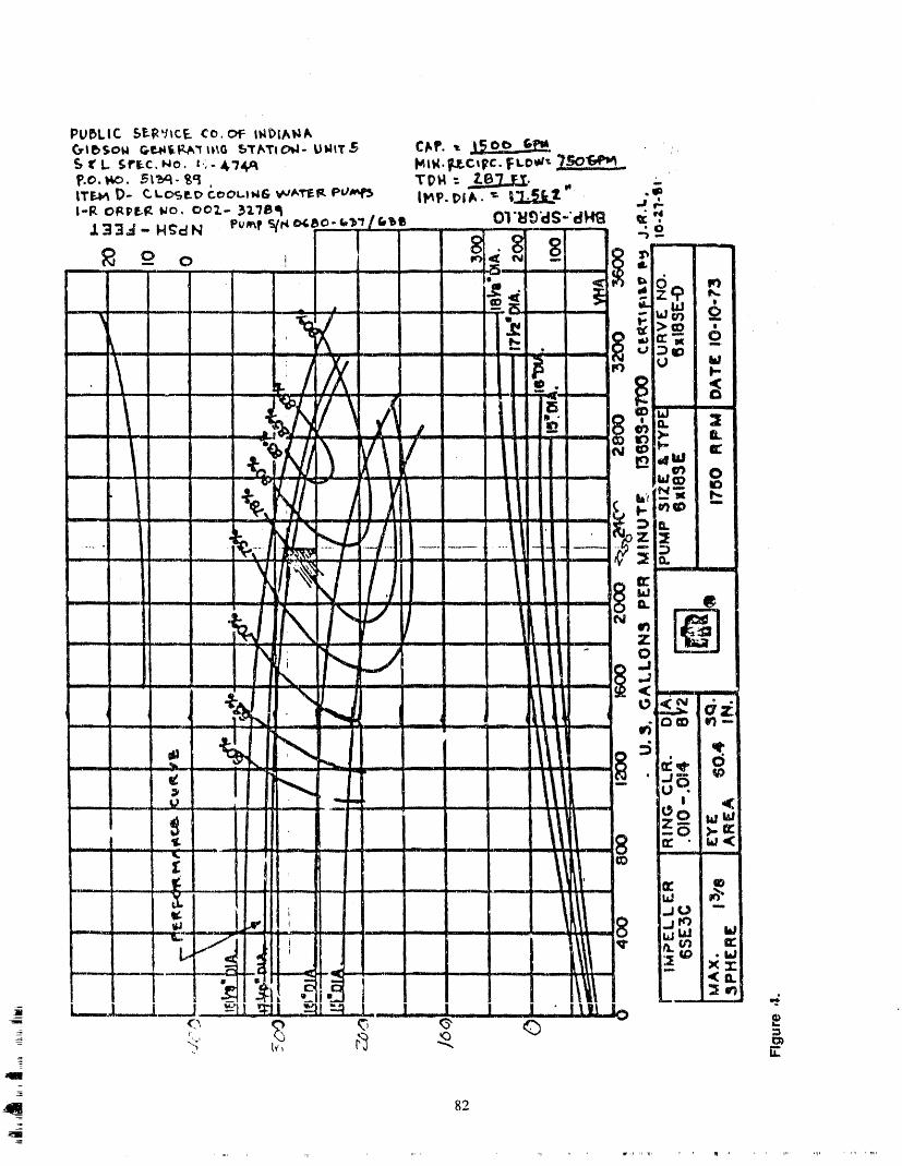
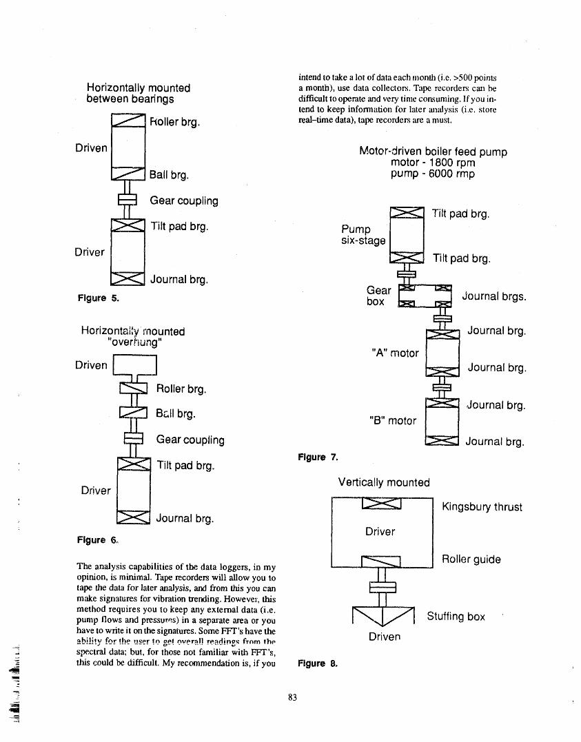
intend to rake a let of data each month (i.e. >500 pointsHorizontally mounted a month), use data collectors. Tape recorders can lye
between bearings difficult to operate and very time consuming. If you in-tend to keep information for later an_dysis (i.e. store
_ Roller real-time data), tat_ recorders are a must.brg.
Driven Motor-driven boiler feed pumpmotor - 1800 rpm
Ball brg. pump - 6000 rmp
Gear couplingTilt pad brg.
Tilt pad brg. Pumpsix-stage
Driver Tilt pad brg.
Journal brg.
Gear Journal brgs.Figure 5. box
Horizontally mounted Journal brg."overrtung"
"A" motor
Driven [ ! Journal brg.
= _ Roller brg.Journal brg.
B&IIbrg. "B" motor
Gear coupling Journal brg.Tilt pad brg. Figure7.
Driver Vertically mounted
' _"-- Kingsbury thrust_ Journal brg.
: DriverFigure 6o
._ Roller guide
The analysis capabilities of the data loggers, in my -.--.----opinion, is minimal. Tape, recorders will allow you totape the data for later analysis, and #ore this you canmake signatures for vibration trending. However, this
method requires you to keep any external data (i.e. r_-- 1- ,,,_pump llows and pressures) in a separate area or you , -..a/ , Stuffing boxhave to write it on the signatures. Some FFT's have the Driven_hility fnr rh,,",_,r tn gel nvc,r:all rP,:tding._frnm lhPspectral data; but, for those not familiar with FFT's,
this could be difficult. My recommendation is, if you Figure 8.I
2
_ 83
,Sll
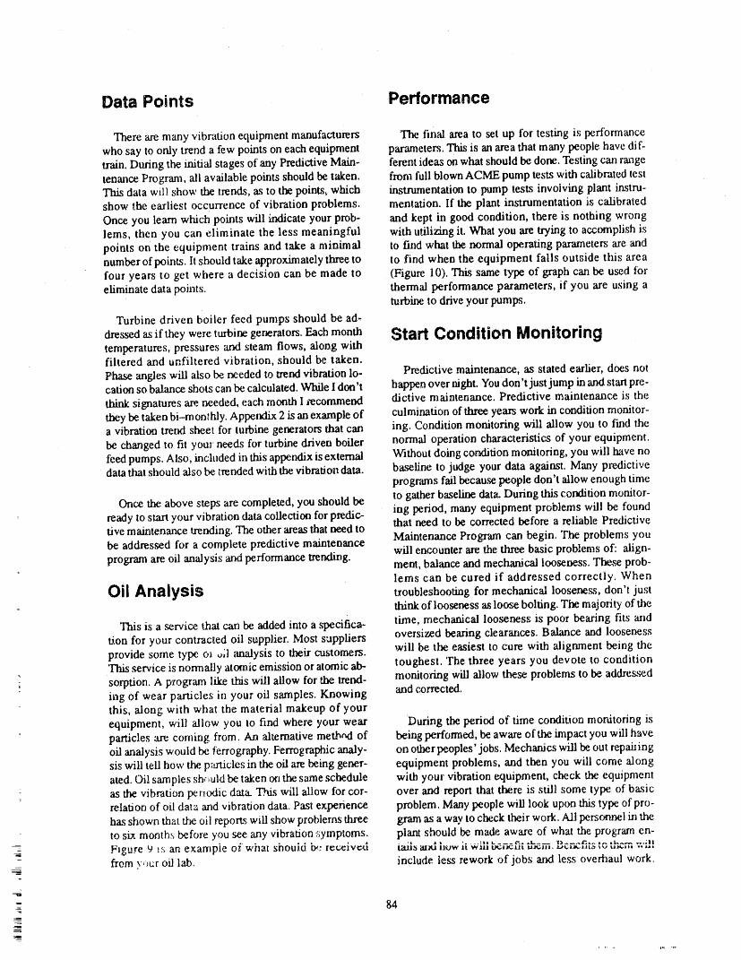
Data Points Performance
There are many vibration equipment manufacturers The final area to set up for testing is performancewho say to only trend a few points on each equipment parameters. This is an area that many people have dif-train. During the initial stages oi' any Predictive Main- ferent ideas on what should be done. Testing can rangetenance Program, ali available points should be taken, from full blown ACME pump tests with calibrated testThis data will show the trends, as to the points, which instrumentation to pump tests involving plant instru-show the earliest occurrence of vibration problems, mentation. If the plant instrumentation is calibratedOnce you learn which points will Lr_icate your prob- and kept in good condition, there is nothing wronglems, then you can eliminate the less meaningful with utilizing it. What you are trying to accomplish ispoints on the equipment trains and take a minimal to find what the normal operating parameters are andntlmber of points, lt should take approximately three to to find when the equipment falls outside this areafour years to get where a decision can be made to (Figure l 0). This same type of graph can be used foreliminate data points, thermal performance parameters, if you are using a
turbine to drive your pumps.
Turbine driven boiler feed pumps should be ad,
dressed as if they were turbine generators. Each month Start Condition Monitoringtemperatures, pressures and steam flows, along withfiltered and unfiltered vibration, should be taken.Phase angles wiU also be re.eded to trend vibration 1o- Predictive maintenance, as stated earlier, does notcation so b',dance shots can be calculated. While I don't happen over nighL You don't just jump in and start pre-
think signatures are. needed, each month I recommend dictive maintenance. Predictive maintenance is thethey be taken bi-monthly. Appendix 2 is an example of culmination of three years work in condition monitor-a vibration trend sheet for turbine generators that can ing. Condition monitoring will allow you to find thebe changed to fit your needs for turbine driven boiler normal operation characteristics of your equipment.teed pumps. Also, included in this appe.ndix is external Without doing condition monitoring, you will have nodata that should also be _rended with the vibration data. baseline to judge your data against. Many predictive
programs fail because people don't allow enough timeto gather baseline data. During this condition monitor-
Once the above steps are completed, you should beready to start your vibration data collection for predic- ing period, many equipment problems will be foundthat need to be corre.cted before a reliable Predictivetive maintenance trending. The other areas that need tobe addressed for a complete predictive maintenance Maintenance Program can begin. The problems you
will encounter are the three, basic problems of: align-program are oil analysis and performance trendit_g.ment, balance and mechanical looseness. These prob-lems can be cured if addressed correctly. When
Oil Analysis troubleshooting for mechanical looseness, don't just-- drink of looseness as loose bolting. The majority of the,
This is a _rvice that can be added into a specifica- time, mechanical looseness is poor bearing fits andt/on for your contracted oil supplier. Most suppliers oversized bearing clearanoes. Balance and looseness
will be the easiest to cure with alignment being theprovide some type o_ _;l _malysis to their customers.This service is normally atomic emission or atomic ab- toughest. The three years you devote to conditionsorption. A program like this will allow for the trend- monitoring will allow these problems to be addresseding of wear panicles in your oil samples. Knowing and corrected.this, along with what the material makeup of yourequipment, will allow you to find where your wear During the period of time condition monitoring isparticles ",arecoming from. An alternative metbad of being performed, be aware of the impact you wtll haveoil analysis would be #errography. Ferrographic analy- on other peoples' jobs. Mechanics will be out repaiiingsis will tell how the p:_ticles in the oil are being gener- equipment problems, and then you will come alongated. Oil samples sh_uld be taken on the same schedule with your vibration c_quipment, check the equipmentas the vibration periodic data. This will ",al.lowfor cor- over and report that ttzre is still some type of basicrelation of oil data and vibration data. Past experience problem. Many people will look up<nathis type of pro-has shown that the oil reports will show problems three g,ram as a way to check their work. Ali perscnmel in theto sin months before you see any vibration symptoms, plant should be made aware of what the program en-_F_gt,re_.9 _s an exarnpie oiwhat should it.: received iail_ axal ',_owii w_,.........tm_t_t_".L.._u_,,.,.,,,_,,,,_ .... r. .......,_, ,.,,,.,,,t"..... ..,_,"_
- from v,_ur oil 1_. include tess rework of jobs an_ less overhaul work._
84
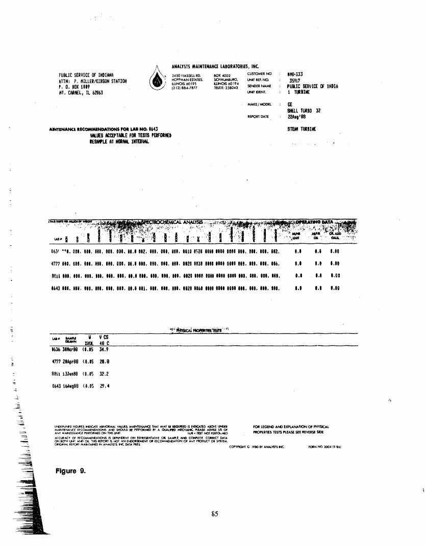
,A ANALYSTSMAINTENANCELABORATORIES,INC.FUBLICSERVICEOF INDIANA /_\\, 2450HASSELtRO. _OX,OO2 CUSTOMERNO. . $M0-333
AITNI P HILLER/GIBSON STATION _._._i> HOFFMAN ESTATES, SCHALJ;W_JBURG, UNIT REF.NO : 3S917
' ILLINOIS 60195 IU,INOIS 60194
f,0. P0Xi009 (312) 884.7877 TUEX:258043 SENDERNA_ : PUKIC SERVI_OF'INDIAHT.C_Li IL6L_63 U_TraNT. : ! IURIINE
. _VWKE/MOBIL:SIELLTURBO32
REPORT DATE : 22Aq_08
: llINTmAN¢i lllCOMMINDATIONSFOil Uti IN_ 1643 STF,Ill TMDIN(• .
W4.1_SACIIPTAILEF011TEm PEIF011iED
_WPLE AT N01ML IWIIIWW. ,. .... .,
: _" '"I ." .:". ':'.-_'_'_C'',';._,I.'."_.I"I?:,% "_"- ...... "" : ..... i"'.:l , ! i ::l.,C" "_',i_ ', i.' _>i._"'"l.n,,;_a :i..-!''II I....i'":l"I ."I".71',,""'".,.'>- -"..-....'.........,:16,_#"_I,011,III,III,III,III,II,III2,III,III,III,IIIII£;_IfillIIII1011III,III,III,II2, I,I I,I I,II
4?77 iii, III. 000. III, III, III, It,I IlO. IlO. III, Ilio 012010300010ltil 0010IlO. I|l. Iii, 016. 0o1 l,I toIO
II_li III, III. III, Iii. Iii, III, II.l IIO. iii, Iii, Iii, 002t lilt ItlO lilt ltll III, Iii, III, lilo 0o0 I.I I,O0
0643IlO, 000, Iii, III, IIOo III, il,i Iii. III, III, lito OI2I 1160 10000111I001 Ill, IlO, til, Iii, I,I 0,1 0,00
: ii, _ W VCSDRAWN lt/0L 40 C
06_ 3111m't!810,0_ 34,9
4???21Air88 (I,OS 29,1t
- B01t tgln811 (O,OS 32,2
064315AvoBO(0,05 _,4_
_
=.T.
UNt_ILIhlFD F_,3Ultl[5W,iDICATI AI_NCWRMALVA,LL/_5_MA,INTi:_ THAT MAY IHEIL'I["QUORI_I_ INOtCATID AIIOVI UNO(R _ LEGEND AND EXPLANATION C)F PHYSK:ALMAINTENANCE I_ICOMMENO, kTIONS AND SHOb'_D I_ PI_RFO_R_N'_DBY A QUALIFIEO MECHANIC P_I_ A(WIS_ US OF
----= ANY _,_TENAN'-_ _nr.oRt._o ON IM_ iNT. NAi - II[ST t,K3T I'ERFO_.V_D PROPkRTI_S TESTS PLEA_ SEE REVER_E SIDE
ACCiJ#A,CY O_ RECOMMENOATIONS IS DEPtf',_D,ENT ON ItEHtE._ENTATIVE OIL SAMPtE ,AM) Ct'WIPt|TF.. CORRECT DAYA--ON BOTH L/_I XI,K) OiL THtr,REPC_T IS ;,/OI AN EMDOiI_'_MENT C_I RECOM/_NOkTIC)N O@ kh'Y f,"_K_)4J'CTOH SY'_T[M,
- C_i_,INAL REPORTMAINTAii_D IN ANALYSIS, INK'..{_k?A PIUE_ CC_Y,_tC..d,tT C, 1900 OY ANA,_V'GT5K. FORM h_ 200415'66)
__ Figure 9.
_5
..
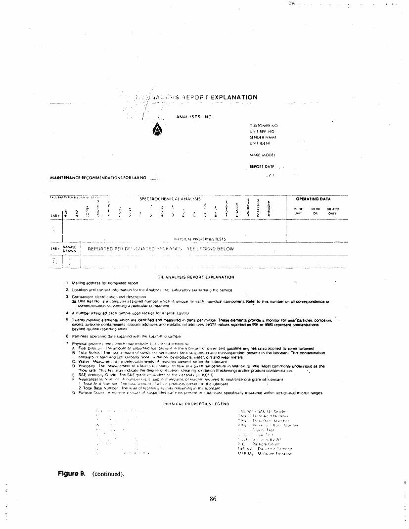
,_,,_,l,i ......
/r
,_, ,,_'4/,:.,17,tS :k¢_©RF EXPLANATION
/PI ' ( J
, .. /.., . ANAL YSTS INC.
C USIOtAER NOUNII REF NO
SENDE R NAM[
UNtl IDE,_ I
MAKE MODEl
REPORT DATE
.i.iMAINTENANCE RECOMMENDATIONS FOR LAB NO ............
_A_,,i._t_.H..b,,L:,,..',_,,,,_i;7,','W-......... SPECTROCHEMICAL ANAL{,SIS I OPEIIATING DATA
t_
..I....................t ;................." ....................................'i......................J........----t...................."..........................
PH ¢!_I('./.,{PROPERTIES TESTS
tall. S,_MPt[ ! REPOR'TED PEF( [_F'. (_'J.TED I;I-F.KAF.J[I'.._ . F5£_:!"[ EGIk'N() BELOWDRAWN !
-.--.-Tt--T...............................................................................±:"_L_2.;_.._i..............................................................
OIL ANALYSIS REPORT EXPLANATION
1 Ivtadirxg aoOresB for cOrnptelocl fer.,('_l
2 Le.i,r_hon r'tr_Oconlil(.l lrdorrrlahon r_ l_i(: A_taiy,,tS. Inr; L.;tbr_ral()r/ i,,t_lOtrTilr_g lhc '.,t_rvlce
3. CornDorier_l _Oenhhca!lon ac,rf descrff,,tlofl
_i_.grill llnl NO 15 a c;_'_rnl;ul(tt JSS,g_8,c1number #_r.Ch ,_,ur.que tor l_._t(.;hir_OivlOuitl compo¢lenl. Baler lo lhllt number on aJl co_tettlxinaencecommunicah(.in rCf._/_c@trl,l'_a _Jl_'llLl.bllit (,o/T.,[J(._rle.t3|.
4. A numbe( ass,gned eacr_",amp;e wpon te_.elpltor IrdefflalCOf1|tol
5 Twenty rrlelalhc el_tT_liiI8 |rh,eh ate iOe.ntlfi_l and measured _n paris per mflflon Theli_ ele_tli p,rovk:_ ii mo_ffoq for weli"pilrli(;kit, con'ol, io,n,CWOflS, ittrl_._'ne conlatii_nanls cootltril _}Oit,ve5 ilrlO rr_elalhc c_l adddriie_, NOTE,valu_ll repo_le_l iii _l Oi"9_ ra,p¢ltlMtnl IX)fl¢4_ltlltit_$b_9_yOr_lrOu|lr_e, reporllri 0 llmll5
6. Perl*nenl O_D+falll'l() (.1_.11&5Ui'.,_)ht_'OWlIllll*'l(._ S_JDITIII|(_*]_;,ilrnpie
7 Ph75t£._tl ptOls_'f_¢i(:,_lS ,,,,r ,'. "_lh_ty Ifl¢liJ(_l_' i_iL_l iri:., l_f;,l I !13ilrtfJ 10A Fuel Oilul.,.,_ li-.,(,+_lrTirJillll OI bntJUtrdtc_ h,e' I;_l_',.,l,.-r_l,r_ li'llt, tl btiLilrll 5( (.Ji_'_,l':laii(J _it_toIil3e eiiglrle'_ (also _lpplle0 lo _ Iurt)lri_)ii TOl&l _olldf. TbP. Ir)l_i arr,_,_nl Oi Sol,d5 C,rlt+!_ltl,irldllOri I.)OIP, ",llf.l.)tJfl(ll,KJ /llfl(J riO_'lSU_._:l'lt_J, pi'tr Iii |h_a lul3_iCliril, Thrl CoiilanlinllhO'ri
COrl_15t5 ,:._1ri,3r4 ,_lf_,OSO f I',;_ift)_JC,,llfiE#|Jt '_i,r_l_tlIc.i't Dy'pI_KIUCI5. ¢f_ller, dill ar_l l_f rrtlal5C r W_l @r ' hA_(.,o_'efrw_l,I lth d,81#_.l,dDiOl_Vl_it_ i'_( fl'iOibllJle [.if#ff%.orll_llhlii lh,(-,,Iubfi_.,,ilrll
O Vlfl4Dc_511y lr_e fTle_lS,uferTI4_.l"tlOI 7#htsK_',l tl.tbifit;ltlot£ !I": tIOW _tl Li I_lt'f._fl lertip_tf_lufe tri feilic_ Io lime Mofil ccHl'lt_l,c;<tl_ur_fBh_d,(J d1_li'MI'JlOW file TflIb l_'_t rr@y It'i_lC_tllJ tPte. Oi't'_lt_,IPOI dilull,'?)_. 5P_e_iflt'lg.OIti_tll_ri (lh#Ckenli'VII) ittlOIoi l)i'O¢lucI GrTll,itlttifi,itl_(l_'t , ,
E SAE Vte-F_oSil/ O';_Jf' Thf: SAE _ '_. . '} a.,C' o'i,llvalFw'l rfl |ro '|,lE,rob|lie Cii 100" CF Nt±ulrahZal_c_r, Idl,rlil_._f J r, _/,,l;.t/ I. nl./( ,_.I;0 ,f', rr.lih'i_Lt;rd:. 0 t (etfier ,tK.luire_J li',, r}eulrahze _ gram Oti'll,lt;_lCDdl,nl
1 TOt,ii ,_l_t /J l'dliflll'_j 't l_lt IC_I_t ,l$11flLihl ()l itr.il._l( [_#'_(_lil*_+l,l.l[,f_,,liL,fil irl lii(| IUb.flC,Eltil !
2 l'o1al B41se tqiJl*r_lt:l,t lrilf I('t'l(.t.IOI fei_lf-ri.l'._ii;ll_llltlllv , flail ;'jlFI riq iii !rl_ iUbflC.l_lt31O Pilfltt:l#j _.E)ilftl A fhjfl'l¢,flr-lit , ,r_f t Of _lt.IC,_j_t't.'}f:Cl iv/r_t']lClf..r, plr)¶J:_ll iii ii IljbflC,4JFil ,li[>fJ(]lflC_llly frle,_tsute_J wllhlfl |,_Lv.l_t_l,,!ltt#i_fTllCrOr-i flrlt_a,_i,
PHYSILTAL Pr_()PERTIES LEGENO
_ , ' . ' ' 'J_.£ 'lCr. "_At. C),i(_;i,}eI ' tl,_f,_ T£,t,'t: Ac. <*,Pi,i'r,l'ol.r
',, " ;'t; • T,s!; : (_;l<,' ld _e_r,¢ t
_1,_1 , ,,li ",' I
, ':,,l.l, (_,,i,, ;; {.%//rll, C. Pa_hcir. r_r_lr,'
' ' rq f'JIF ii',_/ _'?,("t 'r !';E c, tit'r, ql t
,' " ,' _ " , !.4rP,Alrj !,t,l',{;.if(, Fm¢81,C.r,
Figure g, (continued).
86J :

<
1 2 3 4 5 6 7 8
Time (weeks)
Figure 10,
Since the equipment is being monitored, you can per- 2. Symptoms:form overhauls on an as-needed basis instead of a
scheduled basis. One thing you will still have to do is A description of the initial finding and anythe routine preventive maintenance (i.e. oil changes abnormal external visual findings.
and pack'ing adjustments). 3. Test Data and Observations:
Case Histories Tell what you are trying to accomplish withyour test and what the priorities are.=
4. Corrective Action:' Documentation of equipment is essential for analy-
sis of problems and records of past solved problems. In detail, describe the firdings along with theThese reports me also good for showing plant manage- recommendatiom for repair of the problem.
_ ment what you have accomplished. During the initialperiod of your program, you will be highly visible; 5. Results:
= however, after a period of time when the initial prob-lems are solved, y _r visibility will drop drastically. A brief discussion of the repair findings.There is another more important factor to be consid-ered; training. People don't tend to stay in one job all 6. Conclusion:
. theirlitb. They are promoted orleave for other reasons. Describe how weil the problem wasSomething is needed to train newer employees and diagnosed and what can be done to improveassmt the analyst when troubleshooting. The case his- the diagnostics, and solution. Here is also thetory will fiH this need. The case history should be di- piace to recommend unprovements in anal-vided into six parts: ysis equipment and maintenance repair
practices.
. 1. Problem: CONCLUSION
Discuss how the problem was found and Setting P:edictive Maintenance Programs up is not b
incl,adea description of the equipment, difficult if it is done in logical older. 'Ire key thing is to
87
lay a finn foundation in which to build your program be avoided. While they train you on how to use theiro'_.I recommend that you start slowly and be conserva- equipment, tile training tends to be a sales pitch.
tire. Don't try to grow too fast or get into analysisproblems that are above your ability. The most impor- Predictive Maintenance Programs can be a very im-
tant thing to ensure a successful program is to have portant cost saving addition to your plant maintenancedepartment. Public Service Indiana's Gibson Genexat-
dedicated people. Many managers believe this pro- ing Station has deferred over 125,000 manhours ofgram can be mn with PeOPle who devote only part time equipment overhauls over the past four years. This isto it; it is a full time job. Part timers do not spend well over $2,000,000 dollars in labor cost savings toenough time on the job to become proficient in analy- the plant budget. Looking at what it costs to run thesis. Also, don't skimp on training. Allow the people in- program against what it saves equates to approximate.volved in the program to attend classes on vibration ly 38 percent return on their investment each year theanalysis. I recommend that equipment vendor training program has been in place (program is four years old).
x
88m
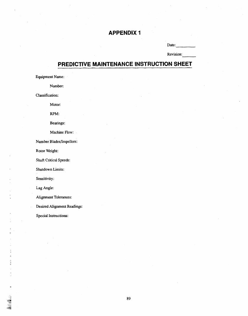
APPENDIX 1
Date:
Revision:
PREDICTIVE MAINTENANCE INSTRUCTION SHEET
Equipment Name:
Number:
Classification:
Motor:
RPM:
Bearings:
Machine Flow:
Number Blades/Impellers:
Rotor Weight:
Shaft Critic_d Speeds:
Shutdown Limits:
_ Sensitivity:
Lag Angle:
, Alignment Tolerances:
Desired Alignment Readings:
Special Instructions'2
89

APPENDIX 2 (1 OF 3)

APPENDIX 2 (2 OF 3)
Bearings Vibration Meted Oil Drain
1,
,
5_
• 6.
7,
10.
ii
91
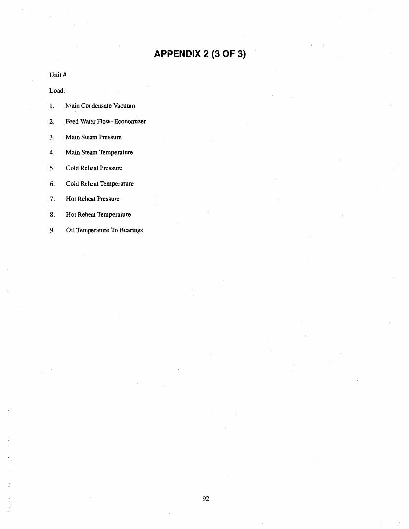
APPENDIX 2 (3 OF 3)
Unit #
Load:
1. M',fin Condensate Vacuum
2. Feed Water How-Economizer
3. Main Steam Pressure
4. Main Steam Temperature
5. Cold Reheat Pressure
6. Cold Reheat Temperature
7. Hot Reheat Pressure
8. Hot Reheat Tempemlure
9. Oil Temperature To Bearings
92
ATTENDEE- PANEL QUESTION AND ANSWER PERIOD(EDITED; ATTENDEE QUESTIONS AND PANELAUTHOR
RESPONSES NOT/DENTIFIED BY NAME)
Question 1 beating, frequencies, and immediately you'll thinkyour bearings are bad, and you'll start tOtake your
Can you discuss the value of taking hydraulic data for bearings out.determining pump degradation? Do you view vibra-tion data as essentially sufficient tor this purpose, or do I tlfink hydraulic data is needed, whether it is just pump
you regard hydraulic data as a necessary complement suction and discharge pressures, or you actually go outto vibration data, and why? and get flows. We take suction discharge pressures
monthly, and then we try twice a year to do acva',dper.formancc tests, just with flow meters, not necessarily a
nesponse 1 fuU-blown ASME test.
I think you really need the hydraulic data. If you have We had found that we we_e urmecessafily replacing agot equipment, pumps that have roller bearings in lot of bearings because we weren't looking at the per,them, a lot of times if you start cavitating the pumps formance of the pumps. And I think a lot of peopleslightly, you will get slight roller bearing frequencies, make that mistake at the beginning of their vibrationIf you go out and take vibration data, you'll think your program. That is, they look at only the mechanical
i- bearings are going bad, whether you spike energy HFD equipment itself, _ integrity. They see a problem andor any of the other th/ngs these data collectors do. Or automaticaUy think it is bearings, and that is not neces-even if you look on an FFT, you'll start to see roller sadly correct. So I recommend hydraulic data, too.
_
=
- 93 '
PERSPECTIVES ON PUMP TESTINGAND iNSPECTION REQUIREMENTS IN NUCLEAR PLANTS
JOEL D. PAGE, PATRICIAL. ENGUNITED STATES NUCLEAR REGULATORY COMMISSION
WASHINGTON, D. C. 20555ASME/NFIC SYMPOSIUM
, PART ONEPERSPECTIVES ON PUMP TESTING AND INSPECTION
REQUIREMENTS IN NUCLEAR PLANTS
=
_Joel PageTask Manager
Office of Nuclesr Regulatory ResearchU.S. Nuclear Regulatory Commission
ABSTRACT NRC SUPPORT OF PUMPINSERViCE TEST CODE
t
T_ paperdescriessomeof_c's pastexprienc_s DEVELOPMENTrelated to pump testing in accordance with SubsectionIWP of the ASME Code, Section XI. Also discussedare NRC's role in the development of pump testing Inservice Testing (IST) requirements for. certain
= standards, insights gained through NRC evaluations of pumps in light water cooled nuclear power facilitiesIST programs and o desirable direction for future were incorporated into the Code of Federal
• Regulations, Title 10, Part 50 (i.e., "10 CFR 50" orpump testing. "the Regulations") in 1976. Since that time the Regu-
lations have reti_renced the AS/vIE Code, Section XI,
This paper was prepared by an employee Subsection IWP ("the Code") for pump testing, lt isof d_e United States Nuclear Regulatory expected that Part 6 of ASME/ANSI OM will soon re-
= Commission. It presents information that piace Subsection IWP as the pump test code to b_' used.does not currently represent an agreed-
upon staff position. NRC has neither ap- The NRC has consistently participated actively in: proved nor disappzoved its technical ASME industry consensus code development in the
content, area of inservice pump testing.
INTRODUCTION MINIFLOW CONFUSION - THE° VICIOUS CIRCLES= It has long been the goal of most persons involved
with pump testing in LI. S. commercial nuclear plants circle Oneto eliminate, or at least minunize, unnecessary surveil-
lance testing; including the testing of pumps. MostNRC representatives agree that meaningful testing and As previously stated, pump testing in accordance
= exercising of pumps should be optimized. However, with the Code was incorporated by xeference into the
the supporting role of providing component exercise Regulations in 1976. At that time the testing specifiedshould not be underestimated, lt minimizes problems in the Code was required on a monthly basis, which
= associated with stagnant equipment, such as dxying out was in agreement with the system--oriented pump testof seals or packing, brinneling of bearing surfaces, schedules required by "custom" plant techn_:alaccumulation of debris, etc. specifications.
95

Duringthatfirst three years of implementation, there If miniflow test repeatability is indeed a problemwas a growing sentiment within the industry that which is due to the,lack of throttling capabilities, it fur-pumps were being overtested and that the monthly fie- ther supports the need tohave both flowrate and differ-queneyof testing wa._resulting in unacceptably accel- ential pressure irLstrument_sinstalled in the miniflowcrated pump degradation, particularly for pinups that fine. This will enable the test personnel to develop awere being tested on miniflow. Although this percep- small segment of the pump hydraulic performancetion was not supported by specific data, the AS/VIE curve to which acceptanc_trite,ria can be applied. ThisSectionXI CodeCommittee proposed that this test fie- approachis somewhat synonymouswith that which isquency be changed to quarterly (i.e., testing at three fiequenflyapplied to inserviee tests performed in themouth intervals in lieu of every month). The NRC "normal" flow paths of certain systems which cannotconcurred with the new proposed test interval by be fixed at certain flowrates due to their constantly va-endorsing the W'mter1979 Addenda to the Code. tying demands. To furtherenhance the quality of hy-
draulic data, instruments installed to accommodate
Later in the 1980s concerns began to arise with re- IST should have "range" capabilities only slightlyspect to the adequacyofminiflow recirculation lines to higher than the reference values.support various pump safety functions, including 10CFRPart21 notifications by some pump manufaemr- FUTURE DIRECTIONSers, which indicated potential safety concerns. The
feRC respondedto these concerns by the issuanceof Better Tests vs. Increased Testseveral Information Notices2,3,5and Bulletins1,4.Ingeneral, these documents addressed various facets of Frequency"low-flow" or "no-flow" degradation of pumps.However, industry response to the NRC Bulletin Both Subsection IW'Pof Section XI and Part 6 of88--04 did not indicate that abnormal pump degrada.. ASME/ANSI OM require that the test frequency betion was attributable to miniflow operation during doubled for a pump that has reached the alert range.in,servicetesting. Although thksincreased test frequencyprovides some
measure of "on demand"reliability andalso providesASME/ANSI OM Part 6 is now a published doc'a- additionalexercise, a bettermethod of determining the
meritand the AS/vIEO&M WorkingGroup on Pumps reasons for the change in pump condition could beandValves hasnow isolated individualareasthat arein more meaningful. For instance,,by taking good testneed of furtherdevelopment. Therefore, it is row pos- data when performing baseline tests, which includessible to assimilate and evaluate more specific data to both filtered (frequency dependent) and unfilteredsupport any needed changes. Futm'echanges to pump (fiequeacy independent)vibration velocity data, apes-test st_adards should, where possible, be based on sibility exists to betterdetermine why thepumphas en-
: "hard" _ta, ratherthan just perceptions, tered the alert range. From that an analysis can beperformedto determine the need for corrective action,
Circle Two ratherthanshnply keeping the pump on an increasedfieqtw.ncyof testing.
Throu#_outthe19S0stheNRChascomistentlyre. Improved Hydraulicquired that hydraulic instrumentation must be pro-vialedfor IST, and only granted relief from this Code MoasurQmGntsreqment on an interim basis until thenecessary in-stmmentation could be installed. Overthis sameperi- Inaddition toimprovingthe qualityof vibrationmea-od most utilities have maintained the position that suremeats, the addition of accurate and repeatable hy-ptunp _.iniflow lines are "fixed resistance"; therefore, draulic instrumentation to pump test flow loops,them is no technical need to install flow measuringin- particularlyin miniflowtest loops, will furtherenhaw,estruments (i.e., the flowrate will always be the same thequality ofpump testing and minimize thedata "scat-
: for a specific differential pressure), ter" which industry representatives have continuallybeen plagued with. This is especiaI_) important for
However, more recently it has been noted by at least mini_flewtest loops, because the head-flow curves ofone utility that since pump miniflow linesrarely have somepumpsareflat in the.area related to lowflow per-throttling capabilities, neitherflow net pressurv canbe, ation;therefore,the establishmentofa_liable value forfixed; and that this makes test repeatability difficult to fiowrate will enhance the entire test for hydraulic per-accomplish due to the highly sensitive nature oi' the fonnance.In addition,aspreviously stated, flow gaugesflow Ln.stnunentationfrom small changes inpressure, to be used in miniflow recirculation lines should have
IB
96
.... _ ' "_" ,', -"li _t'_P _.11., I,IIl,_i¢lrl', .... _l_lr " le ii ' ,tlr t_,,, pr, ,, ,11, r_ II'l ,rlvrl,,I' ,Ntl, II , _llrlt, rl] ,rlIiilpr_q. ¢t_llrlpllI '1 lPI'1' _,l'_l 'qlll'lr 'III
a range only slightly higher than expected flow mtes to 3. USNRC Information Notice No. 87-59,minimize fluctuations. "Potential RHR Pump Loss," Novernber 17, 1987
REFERENCES4. USNRC Bulletin No. 88-04, "Potential Safety-
1. USNRC Inspection and Enforcement Bulletin No. Related Pump Loss," May 5, 198886--01, "Minimum Flow Logic Problems ThatCould Disable RHR Pumps," May 23, 1986
5. USNRC Infonrtation Notice. No. 89--08, "Pump _'.
2. USN'RC Inspection and Enforcement Information Damage Caused by Low Flow Operation,"Notice No. 86-39, "Failure of RHR Pump Motors January 26, 1989and Pump Internals," May 20, 1986
PART TWOPUMP INSERVICE TESTING
INSPECTION REQUIREMENTS
Pa_trlcla EngResident Inspector,. Region III
U.S. Nuclesr Regulatory Commission
ABSTRACT selected sites 'were conducted. Follow-up inspectionscontinue to be performed; however, this paper will
This session will discuss NRC In,service Testing fIST) only address those inspections in which the authorinspection requirements delineated in 1 and E Inspec- participated"tion Module 73756, "Inservice Testing of Pumps andValves." A brief discussion of IST inspection findingsrelated to pump testing, including common problems After the _'st few inspections, it became clear thatwith IST program implementation identified during guidance regarding the inspection of IST program im-
plementation was necessary to insure that ali plant.,; inIST inspections in Region III during the period1983-1986, will also be included, each region were evaluated in a coxtsistent manner. As
a result, a draft itmpection module was initially drafted
This paper was prepared by an employee in 1985. This draft considered inspection experiencesgathered from Regiom II and III over a two year peri-
of the United States Nuclear RegulatoryCommission on her own time apart from od. Requirements of the ASME Code, Section XI, us-
ing editions from 1974 through 1980, and Iheher regular duties. NRC has neither ap- appropriate addenda, were reviewed and translatedproved nor disapproved its technical con- into viable inspection line items. Once the medule wastent. drafted, it was validated during the next few IST in-
spections, lt subsequently was submitted to NRCINSPECTION HISTORY Headquarters for review and comment. Inspection
Module 73756, "Inservice Testing of Pumps andIn 1983, Re#on 111 began the systematic perform- Valves," was issued for use by the Commission on
ance of Inservice Testing (IST) inspections by regiott- March 16, 198'7.based inspectors. As a result, two inspectors from theDivision of Reaclor Safety were assigned to peffomaIST ir_-pections and to determine the status of irnple- Copies of the inspection module '-areavailable formentation of IST programs across the Region. This pa- your information ,andmay be obtained from the NRCper will focus primarily on experiences with the Public Document Room. It should be noted tha_ theinservice testing of pumps, module references a number of interpretations of spe-
cific IST issues which have surfaced in the past. The
Systematic iix_.'-vice testing inspections in Region referenced rnemoranda were attached to _minspectionIII began in early 1984. Region DI inspectors also as- repo_ for LaSalle County Station in 1985. This essen-sisted with IST inspections in Regions .LIand V. By tially placed the, referenced material in the NRC Public1986 almost all the plants in Region III had been in- Document Room. They ire, tN_refore, available to thespected at least once and follow-up inspections at public.
PERFORMANCE OF IST 1. Review ofreliefrequests to determine wheth-
INSPECTIONS erthe relief requests are valid, make sense anddo not circumvent the Code requirementswithin the constraintsof plant operations, l'he
NRC IST inspections are generally unannounced; tectmical justification for selected relief re-however, proposed inspection dates are discussed quests from Code requirements is reviewedamong the inspectio:l staff, the appropriate Division of and, if questionable, is discussed with the rest-Reactor Project (DRP) section chief and the resident dent inspectors, the appropriate EMEB re-inspectors for the plant m question. A_:v specific con- viewer and the licensee. The inspectors alsocerns identified by the resident inspectors are added to look into the review status of selected relief re-the inspection scope. The inspector also informs tt_ quests which have been implemented prior toIST program reviewer in Mechanical Engineering Commission approval. Past experience hasBranch of the Office of Nuclear Reactor Regulation shown that confusion regarding reliefrequests(EMEB) of the upcoming inspection. Occasionally, occurs roughly ever), second inspection.field observafiom can clarify concerns stemming fromthe EMEB review of the licensee's IST prograan.
2. If possible, inspectors observe at least one
If practical, the IST inspector(s) will obtain a copy pump and one valve test. By observing testof the latest IST program, including reliefrequests and performance, the inspector can generallycopies of related correspondence between the licensee assess the effectiveness o f IST. In casesand EMEB, prior to performance of the inspection, where no testing is scheduled during the. in-Relief requests are then reviewed against Section XI spection, an in-depth review of test recordsrequirements ;ts well as other applicable regulations, and associated documentation is pertbrmed.
If there are two IST inspectors, testing may beAt this point, specific areas of inspection focus are observed from the control room and at the
identified, pump simultaneously. In some cases correla-tion of the. two activities have not effectively
The inspection usually lasts a week. First, the ad- supported test conduct.ministrative controls regarding test scheduling, testequipment and basic program implementation are
assessed. Next, the conduct of testing is reviewed. Ft- An inspector can determine whether lST is un-n_y, actu-,d testing is observed. Approximately 40% derstood and treated seriously by observingof an IST inspection is spent on the review of pump test activities. Generally, licensee personneltesting, conducting tl_ test know that IST testing is re-
quired, but they may not be aware flint ISTASME Code interpretations and clarifications of testing determines component operability and
Section XI requirements play an important role during associated teclmical specifications apply. InIST inspections and NRC inspectors have discovered several cases, test personnel have been un.thai obtaining such interpretations tha'ough the normal aware that test measuring equipment used forand appropriate ASME committee chain can he very the inservice testing of pumps such as stop-time consuming. This can significantly delay resolution watches, vibrometer and tachometers requireof an inspector's concem. In some cases, particularly periodic calibration to traceable standards.where a given issue may have genetic implications, theEMEB has provided technical assistance and support toregional inspectors. 3. Last, but not least, test records, including pe-
ripheral documents which interface with testdocumentation, are reviewed. These can in-
INSPECTION EXPERIENCES clude,but m_enot limited to, instrumentationcalibration records for both lne.rmanently in-
The goal of the inspection is to ascertain whether the stalled and portable test instrumentation, andlicetxsee is conducting its IST program in accordance unit start-up records. In most cases, the ISTwith the Code, witkin the boundaries of tlm Technical test is also used to determine component op-Specifications and in a conservative manner. Recog- erability for returning the pump to service af-nizing that IST programs are intended to identify ter an outage. A fairnumber ofconcert_s wereequipment degradation prior to component failure, the identified related to inconsistent or poor re-inspector is charged with the review of at lea.st three cord keeping. At least two such concernsthing.,;,: resulted in violations.
98
x_
INSPECTION FINDINGS hasdegradeddespite that IST testdata indicating thatthe pump was operating satisfactorily. Several li-
During the period November 19_.', through censees had designated ,.anindividual solely to \,ibra-November 1986,.[ST inspections were perfomled at 18 tion monitoring both wilhin and beyond the Codeof the 19 power plant sites located within Region III. requirements. Generally, this individual is a memberOf these 18 sites, three plants experienced repeat in- of the technical staff who interfaces with both the IST
coordinator and the maintenance department.spections. Results of this three-year effort were:23 violations and a fair number of unresolved and openitems. Items related to the inservice testing of pumps Some licensees schedule preventive maintenance
for pumps based on inservice testing test data. Identi-fall into a few broad categories, fled trends in any of the test parameters can trigger
work requests to disassemble and inspect a specificOf the 23 violations, 8 were issued for inadequate ornonexistent procedures governing the conduct and pump. Several licensees periodically rebuild pumpsimplementation :,f the IST program, 7 were issued for regardless of whether or not IST data indicates anyuse of improperly calibrated or noncontrolled test pump degradation.equipment, 7 were issued for use of test methodologyat direct variance with Code requirements and without In some cases, two sets of reference values are main-an associated relief request, and 1 was issued for rained for a given pump. This has been helptul in thoseirretrievable test documentation, cases where refueling outages run beyond schedule.
Specifically, pumps which draw their suction from the
Several unresolved items regarding documentation suppression pool in a boiling water reactor may havetwo sets of valid reference vz'!ues, one for normal oper-or specification of those tests which verify or establish
new reference v,'dues and use of nonstandard pump ating suppression pool level and one for refueling pooltesting acceptance criteria were also identified. The level. This allows performance of inservice testing at
either of the two pool levels and can alleviate delays inlatter items were referred to EMEB for evaluation.unit start-up _esulting from the lack of valid pumptests.
Since 1986, two violations have been issued in
Region III for failure tr.,maintain the points wherepump vibration data is obtained. In both cases, the CONCLUSIONpumps in question were painted as part of the materialcondition improvement program, and the dots Generally speaking, the administration and ira-identifying vibration data points were painted over. plementation of IST programs in Region III has im-
proved greatly since the first round of inspections. As
P UMP TESTING G O0 D many planks are approaching orhave begun their secondten-year inservice testing interval, programs a_ being
PRACTICES upgraded and improved. This is evident from the
decrease in violations issued for IST programSeveral good practices were identified during the deficiencies.
1983-1986 IST inspections. Briefly, these were:
(1) obt',dning vibration spectra fi)r ali pump bearings in Inservice testing data can be used as evidence ofall three orthogonal directions, (2) periodic rebuild of pump reliability. Care must be taken to insure thatpumps regardless of test data trends, and (3) use of other pTlartt_._ivities do not compromise the inservicemore than one set of reference values for certain testing progr_,,. Maintenance of thorough test recordspumps, and associated documentation can be very helpful
when evaluating whether a given coml.,_nent willGenerally, the vast majority of licensees are measur- continue to be operable and to identify component
ing vibrafioii in velocity. Given _he current available degradation as it ages. l! is therefore important that 1STtechnology, it_struments used to obtain vibration data programs, test procedures and associated imtrumentsfor IST testing can simultaneously obtain velocity and be periodically upgraded to insure that tie reliability ofdisplacement. 'bration spectra. In some cases, this pumps can be determined by the prudent inservicedata haz been very useful in clarifying whether a pump testing of pumps.
99
m ......... _i llllk,,, illh ,, II,, iIi_,i,..... IHII_,L..... _ ,,
ATTENDEE- PANEL QUESTIONS AND ANSWERS(EDITED; ATTENDEE QUESTIONS AND PANEL/AUTHOR
RESPONSES NOT IDENTIFIED BY NAME)
Question 1 Response 2
DO you have an example of good trending pmgr_uns? You are quite familiar with the working group and youknow we are still searching for that answer. But as I re-called earlier, I was discussing the industry responses
Response 1 to Bulletin 88---04, and there were several in there that
actually included some vibration data, mini-flow andIt's pretty straight,'_rward. Y,_agraph the data, you do nolr.-mini-flow, and there was absolutely no diffe1_encea curve fit and a least _uares analysis, and you keep ata in the two.excruciating file. Not only do you keep the data of thetest, but why the test was performed, and then you So my _,uess is that it is a mixed bag; that you're, goinggraph ali the paraaneters, to find some where yes, it is indeed a problem, and
even in the bag where it is not meaningful, I think
It is basically common sense. But it is attention to de- you're going to find that splits into two also. You'retail, and it is done with an eye toward diagnosing what going to find that in one of them what you are doing is
may be wrong with a given component. You know actually masking your _eal vibration, and in the othermuch better than ] do what will determine what is you axe actually causing it. In other words, what you
wrong with a given component, and those are the pa- are doing is actually causing so much damage that yourameters you should trend. But I have seen some are in fact reading something that is quite dangerous."trending" where ali they did was just keep the lastpage of the test procedure and stick it in a file. That is I'm saying that is what we are going to find, but wenot a trend; that is a file. really need the data from people. I certainly have read
the data, even in small mini-flows, where they saidthere is no difference at "allbetween 90 percent best ef-
Comment on Question 1 ficiency and 15 percent best efficiency. So it may be
pump-specific.The working group ha.sa task group that is looking intowhat is a good trending program. I think a good trend- Question 3ing program has to involve statistical methods on howto analyze data that are continuous, measurable, And I What is NRC's position on allowing a utility to changethink what we are doing there is to try to come up with its tech spec pump testing frequency from monthly toa system in which you do plot pohats, but you calculate quarterly to conform with Section XI and OM 6 re-upper and lower control limits, you understand how tluired frequency? Does a tech spec change _quest thedata behaves around a mean, and you know when you proper vehicle?have a problem_tbr example, when too many data areon the upper side or the lower side of the mean. And Response 3that kirnl of information, I think, is rightly developed
in the working group that is interested in furthering the Weil, I fftink my answer would be to contact the licens-trending objectives, ing project manager.
There is some question whether just plotting is go:xi Question 4enough, zmdI believe that it is not. But I think we need
When changing a reference value, should it be doneto work as an industry toward trending, and we need touse statistical methtxls that are, available ,and used by based on the first test after maintenance, or can it be
many other industries to do this kind of work. developed using a cumulation of data points?
Question 2 Response 4
Weil, I personally believe that the first test after main-Are vibration measurements of a pump during mini- tenance is very important, whether it be pumps orflow testing, meaningful data tbr pump evaluation--- valves. Of course, we're talking pumps in _his particu-especially in regard to calling a pump operable? lar section. However, it isn't a Iequirement for OM 6.
100

I know we're certainly going to be looking into it. I be- Wejust use the first set of data to find out if there is anylieve we earmarked about 20 items to be looked at by major problem, and either shut the pump down or gothe working group, and I believe that one of them is back in.test _ffter maintenance, asking how important is thatfirst test. But the second set of data we keep for trending pur-
poses. We do keep the first set of data so we can haveAnd so all I can say right now is we haven't answered something to compare it to if the vibration 24 hours lat-that, Ii is,just my personal belief. Yes, it is a very, very er goes up. But otherwise, we always use the 24-hourimportant test to base it on. If you were to base it on a data. And we found that is a let better. We usually getseries, I just wouldn't feel good about it; and I can't 30 to 40 percent lower amplitudes because of a break-even give you the technical reason, lt's just a gut in period.feeling.
Comment on Question 4Comment on Question 4
I just have one comment on that. I agree, but we haveOne thing, I've noticed, after we overhaul our pumps to remember that in the nuclear plants the majority ofor are working With people after the overhaul, we al- the pumps we are looking at are pumps that only oper-ways take ata initi',d set of vibration data, usually spec- ate when we are testing them. They ,arebasically stand-trum, and then 24 hours later we would usually take by pumps, so we don't have that 24-hour break-in runanother set. The second set of data is the one we go by. to go back to.
101

MECHANICAL PREDICTIVE ANALYSIS METHODOLOGYVIRGINIA ELECTRIC AND POWER NUCLEAR STATIONS
VIRGINIA ELECTRIC AND POWER CORPORATIONJOE DEMARCO, STAFF ENGINEER
PRECISION MECHANICAL ANALYSIS, INC.14/.E. CLEVELAND, PRESIDENT
ABSTRACT made to purchase the MECHANITRAK(tm) Predic-tive Maintenance System which was designed by a
The purpose of this paper is todescribe,the unique, Florida basedcompany, namely Precision MechanicalAnalysis, Inc. or PMA. The MECHANITRAK(tm)comprehensive Predictive Maintenance programsystem was implemented at ali four nuclear units and isimplemented at Virginia Power's two nuclear plants.
The program is unique because of it's thoroughness described hemin.
and because of the advanced tracking and trending We found that most Predictive Maintenance Pro-
techniques implemented, grams incorporated a single method of nondestructivetesting. The Predictive Maintenance Program at both
INTRODUCTION Surryand North Anna Nuclear Plants is unique be-cause it integrates the three best aforementioned indi.
Today's manufacturing costs and continuously ris- cators of potential mechanical problems into oneing maintenance costs are requiring the Nuclear Indus- computerized system. This is an important concept be-try to utilize ali of the technologies available cause some mechanical problems will not be detectedconcerning predictive maintenance. At Virginia Power as early when using only selected testing methods.we have incorporated several state of the art technolo-gies into one synergistic system enabling Its to forecast We have also incorporated an onsite contaminateda machine's present and future mechanical condition, oil analysis program. This service is also unique toTo ac_:omplishthis goal, we have utilized the threepri- PMA and is performed with their personnel on amary indicators of potential mechanical problems, regularly scheduled basis.namely vibration analysis, lubrication analysis, ,andbearing temperature trending, in a truly effective, com- The Predictive Maintenance program at Virginiaputerized predictive maintenance program. Addition- Power is still evolving. For instance, while currentlyally, we have a variable scheduling program with utilizing some thermography, future plans call for it'sspecialized features and a report-generation program incorporation into the overall program.with abuilt-in word processor. Thesystemalso has theabilitytoprint reports, past and present, and to produce VIBRATION SPECTRUManindividualmachine'sreporthistory. ANALYSIS AND TRENDING
Predictive Maintenance efforts started with a pilot The two types of vibration analysis commonly usedpro/gain in 1982at the North Anna Power Station.The in Predictive Maintenance are Over'til vibration read-results of this pilot program were veo, successful and ings (unfiltered) and Spectrum Analysis (filtered).easily justified funding for further efforts. Starting late Spectrum Analysis, the method utilized by the ME-in 1983, a predictive maintenance laboratory was es- CHANITRAK(tm) System, has many advantages overtablished and manned with two Senior Engineering unfiltered readings.The major difference is that until-Technicians. They not only performed the predictive teredx'eadingswill give oc,ly the machine's general op-analysis program for North Anna, but they also per- erating condition, while Spectrum Analysis is moreformed mechanical troubleshooting for boththe North exact, pinpointing the specific problem. UnfilteredAnna and Surry Facilities. Presently both North Anna readings will show the exislence of an.irregulwity, butand Surry have predictive,analysis technicians, equip- without Spectrum Analysis exploratory maintenancemerit, and labs. In December of 1985, a decision was may be required to uncover the exact problem.
]03
lt is necessary to establish a vibration baseline histo- computer ag,mast a predetermined amplitudery for each machine to be incorporated in the Predic- established by the system.tire Maintenance program. Vibration spectrums are
established in duee positions on each beating on a giv- • The atnplitude for each predominant frequen-en machine; specifically: horizontal, vertical, and axial cy of the new reading is trended by the com-positions, puter and "Out of Alert" or' "Out of Alarm"
projections are made. In order to forecast orEach accelerometer reading point is marked on each predict the future amplitudes, three types of
bearing by epoxying accelerometer bases. This insures statistical regression analysis techniques arethat the .readings are consistently taken in the stone performed.place ' on the bearing which allows proper data
comparison. • During the establishment of the original I:ase-lines every amplitude of each predominant
Discrete frequency spectral analysis is performed on frequency is compared by the computereach bearing and position in the following manner. On against a predetermined tolerance.the original baseline, the ten (10) highest amplitudesand associated frequencies are digitally stored by the • If a problem frequency in the past vibrationcomputer for each measuring point. There is a vast spectrum is now missing, the change is noted.amount of data gathered for the fibration aspec_ of theprogram alone and for that reason we utilize the com-puter software to point out the exceptions rather than ® The RMS value "overall" vibrationthe rules. If the machine's history is consistent'with the amplitude is calculated for each vibrationunit's acceptable baseline (i.e. within predetermined spectrum. The percent increase and/or de-tolerances) there is no need for thrther evaluation. This crease is determined, then compared againstpractice greatly reduces the amount of time required the baseline overall amplitude levels. Toler-by the technician to review the data. ances are automatically set by the computer
software for the following types of exception
The following software functions are used as a basis reporting.to "flag" tlx exceptions rather than the rules and com-puter comparisons are performed in the following - Alert levelmmlner"
- Alarm level
® Any new frequency that is r_rv-existent in theoriginal baselines. - Percent increase from the previous
reading
• "Alert" ranges which are established in ac-- Percent increase from the averagecordance with the baseline data for each pre-
reading.dominant frequency. In setting these ranges,any previous baselines are comparedfor theentirehistoryofthemachine. LUBRiCATiON ANALYSIS AND
TRENDING• ,'Alarm" ranges which are established in ac-
cordance with the baseline data for each pre- In order to insure ;,roper identification for each ofdominant flequency. In setting these ranges, the oil samples the computer program produces pre-any previous baselines are compared for the
printed labels which are attached to the oil sampleentire history of the machine, bottle for each scheduled oil sample. The computer
program prints the following information on the• "Low" ranges which are established in accor- labels:
dance with the baseline data for each predom-inant frequency. In setting these ranges, artyprevious baselines are compared for the Reservoir Descriptionentire history of the machine.
® Reservoir Description
• The amplitude for each predominant frequen-cy of the new reading is compared by the ,, Reservoir I.D. (lab identification)
104
• Blank space to write in the date the sample Water %was taken Total Acid Number (TAN)
• Blank space to fill in number of hours lube Series 3:has been in service Spectrometric metals
Viscosity@ 100degrees CThe following is a list of the most common lubrica- Solids %
tion test_that can be performed on the oil samples, lt Water %should be noted that not ali of the tests listed in this Total BaseNumber (TBN)section are performed on each reservoir sampled. The Fuel %cost would be prohibiuve and ali tests listed are aet
necessm_,.A custom testing package was specified for lPR:each reservoir which was contingent on the sump ca- Series 1
pacity, criticality of the unit, type of system that was Particle count or DR ferrographybeing lubricated, t tc. Infrared analysis
Direct reading emission spectrometric analysis 2PR:
Direct-Reading (DR) ferrography Series 2Particle count or DR ferrography
Particle counting Infrared analysis3PR:
Micro--Ferrography (Mb")or "Full" Fermgraphy Series 3
Particle count or DR ferrographyMacro--Contamination Infrared analysis
Physical testing The science of lubricant analysis is becoming moreLube chemistry and more complex, and for that reason we have listed
each of the testing techniques and stated "Why ThisMicropal_h Testis Needed":
Infraredabsorptionspectroscopy(lR) Metallo-Particulate Studies
Karl Fischer water test - measured in parts per Direct Roaring Emission Spectroscopy. Moni-million toring metal deposition in lubricants at up to 10 mi-
crons (micrometers) size, essentially addressesFoaming tests "rubbing" wear regimenof equipmentcondition moni-
toring. Abnormal readings may trigger a request forA more detailed list with the associated ASTM testing Palticle Counting, Analytical Ferrography or Micro-techniques is presented on the following page. Patch Study to further resolv* matters.
The most important tests can generally be divided Cont_mimnt metals (abrasives, coolant additives,into the following packages. From this list a starting etc.) r,,,aybe ,'letected, provided they are not abovepoint can be chosen foreach reservoir being tested to 10 microns in size.which other needed tests can be added.
Additive metals are detected, primarily to monitorTest Packages: consistency in product, as opposed to additive
effectiveness or strength.Series 1:
Spectrometric Metals Particle Counting. Measures particulates from 5 toViscosity@ 40 degrees C ;40microns in size, picking up where emission spec-Solids % troscopy leaves off, and addressing the "fatigue" wearW_tex'% regimen of equipment condition monitoring. Particu-
larly appropriate for units with on-board filtration.Series 2: Abnormal readings may trigger a request for Analyti-
Spectrometric Metals cal Ferrography or Micrcr--PatchStudy.Particle Count-Viscosity@ 40 degrees C ing also measures non-metallic particulates in theSolids % ._40 micron ,range.
105

Test Description ASTM #
Ash % D482Base # D2896Cetane number (calculation only) D976ChlorideCloud point D2500Color test D1500
Copper Corrosion D130Distillation D86
Ferrography (analytical)Ferrography (direct reading)Fire point (flashpoint required) D92Flash point D92
" Foam test D892Freeze pointFuel % D3524
Glycol (positive/negative)Gravimetric solidsGravity (API) D287Infrared(fixed points/single beam)Insolubles - coagulated pentane D893Insolubles - coagulated toluene D893Insolubles - uncoagulated pentane D893Insolubles - uncoagulated toluene D893Micro--organism(positive/negative)Micro-studyNitrate - parts per millionParticle count (5 - 40 microns)Pensky-Martens D93Pour point (cloud point required) D97Silicates - parts per millionSolids % D91
Spectrometric metals (19 metals)Sugar (positive/negative)Sulfated ash D874Sulfur % D1552To,,alacid # D664Total base # D664
Viscosity index (calculationonly) D2270Viscosity@ 100C 13445Viscosity@40 C D445Water and sediment % D1796Water % by distillation D95Water % (estimate)Water- part per million (Karl Fischer) D1744
106
Caution: Water contamination precludes a valid par- gests that one should consider additional testing as aticle count; only size, not identification, is possible supplement t_ emission spectroscopy.with particle counting.
Summary: It is evident there are several approaches to =
AnalyticalFerrography.A slide is made wherein detecting, monitoring and evaluating particulates andwear metals in lubes, lt is important to recognize thatmagnetic materials (essentially iron-based) are
systematically magnetized, ordered (large to small) no one test "does it all". This fact must be consideredand cured for viewing under microscope. This allows when selecting a "routine" testing package.determination of the nature and shape of particulateswhich, in turn, often disclose the Casual effect (e.g., Lube Chemistry Testsspiral cuttings usually denote abrasive wear).
Infrared Absorption Spectroscopy (lR). Tbi,_
Although magnets do not affect brass, aluminum test addresses Organic (nonmetallic) aspects-of theand nonmetallic particulates, some quantity of these lube, which includes some additives, lube oxidationmaterials, if present in the lube, will precipitate onthe products, nitration products, coolant/water contamina-slide simply from gravity's effect. The fact that they tion,and differentiationbetween synthetic and mineralare random, and the ability to see their color or other lubes.characteristic features, allows further inferences to be.drawn, rather than limiting one to only ferrous (iron-
based) materials. Large abrasive chunks, for example, Typicalwhichwould defini:ely escape emission spectroscopy, WaveFunctional LGTH Group Absorbancea
and which might exceed the particle counter's detec-
tion capability (if the particle count were rich in abra- 2.8 "HYD 2": water contamination 0.000--0.010sires, but not too far off normal in total) can often be (emulsified)detected.
3.5 "C--H"'. hydrocarbon < 1.000This test is highly recommended before making a (mineral lube confirm)
decision to inspect (or not inspect) a piece of equip-ment, because it provides visual feedback to augment 5.8 "OXY": oxidation 0.000-0.050other tests which are inferential in nature. (or synthetic confirm)
Direct-Reading (DR) Ferrography. An abbre- 6.2 "NIT": nitration 0.000--0.050viated form of ferrography which ONLY addressesferrous pan.icles.Magnetic separation is again used to 9.6 "HYD": Glycol 0.020--0.100differentiate between "fatigue-oriented" wear (15+ (or synthetic confirm)microns) and "rubbing" wear (< 15 microns) reportedas "L" and "S" (for I_',rgeand Small) resl_,cdvely. Asthe ratio of L:S and the qta_t_ty of L + S changes, in- a. Absorbance refers to specific wavelengths of light inferences are made. Abnormal readings may trigger a the infrared spectral region which the functionalgrouprequest for Analytical Ferrography or Micro-Patch impedes. The greater the absorbance, the greater theStudy. concentration.
Micro--Patch Study. The lube is f'dteredonto a til- Water: As in any test for water, confirmation by in-ter patch and viewed through a stereo microscope. Par- frared signifies a need for action, provided the sampleticles of approximately 0.5 microns and greater are was representative. "lest is sensitive to as little as 0.1%trapped on the filter. Testis best applied for identifying water.nonmetal containinates, e.g., abrasives, fibers, rust, ox-
idation solids, etc. Abnormal findings may trigger a Hydrocarbon: Mineral lubes are basically carbon andrequest for Analytical Ferrography. hydrogen atoms linked together, hence the name "hy-
drocarbon". This value is expected to be high, verify-Special Note: Rotary (non-reciprocating) equipment ing the presence of mineral lube. If the lube is acan show a tendency to develop abnormal levels of synthetic containing atoms/molecules in addition to"fatigue-oriented" wear particles without an accumu- hydrocarbons, this number will be appreciably lowerlation of "rubbing" wear particles. This strongly sug- than mineral lubes (perhaps 0.6 to 0.9). If synthetic
107
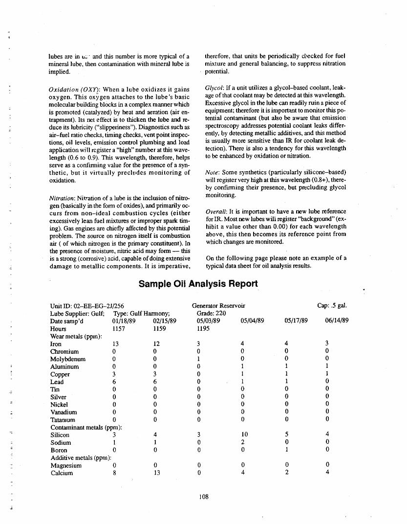
lubes are in uz- and this number is more typical of a therefore, that units be periodically checked for fuelmineral lube, then contamination with mineral lube is mixture and general balancing, to suppress nitrationimplied, potential.
Oxidation (OXY): When a lube oxidizes it gains Glycol: If a unit utilizes a glycol-based coolant, leak-oxygen. This °xygen attaches to the lube's basic age of that coolant may be detected at this wavelength.molecular building blocks in a complex manner which Excessive glycol in the lube can readily ruin a piece ofis promoted (catalyzed) by heat and aeration (air en- equipment; therefore it is important to monitor this po-
• trapment). Its net effect is to thicken the lube and re. tential contaminant (but also be aware that emissionduce its lubricity ("slipperiness"). Diagnostics such as spectroscopy addresses potential coolant leaks differ-air-fuel ratio checks, timing checks, vent point inspec- ently, by detecting metallic additives, and this methodtions, oil levels, emission control plumbing and load is usually more sensitive than lR for coolant leak de-application wiU register a "high" number at this wave- tection). There is also a tendency for this wavelengthlength (0.6 to 0.9). This wavelength, therefore, helps to be enhanced by oxidation or nitration.serve as a confirming value for the presence of a syn-thetic, but it virtually precludes monitoring of Note: Some synthetics (particularly silicone-based)oxidation, will register very high at this wavelength (0.8+), there-
by confirming their presence, but precluding glycol
Nitration: Nitration of a lube is the inclusion of nitro- monitoring.
gen (basically in the form of oxides), and primarily oc-- curs from non-ideal combustion cycles (either Overall: lt is important to have a new lube reference
excessively lean fuel mixtures or improper spark tim- for IR. Most new lubes wili register "background" (ex-ing). Gas engines are chiefly affected by this potential hibit a value other than 0.00) for each wavelengthproblem. The source on nitrogen itself is combustion above, this then becomes its reference point from
air ( of which nitrogen is the primary constituent). In which changes are monitored.the presence of moisture, nitric acid may form -- thisis a strong (corrosive) acid, capable of doing extensive On the following page please note an example of adamage to metallic components. It is imperative, typical data sheet for oil analysis results.
:_ Sample 0il Analysis Report•
Unit ID: 02-EE--EG-2J/256 Generator Reservoir Cap: .5 gal.
Lube Supplier: Gulf; Type: Gulf Harmony; Grade: 220Date samp'd 01/18/89 02/15/89 05/03/89 05/04/89 05/17/89 06/14/89Hours l 157 1159 1195
Wear metals (ppm):Iron 13 12 3 4 4 3Chromium 0 0 0 0 0 0
Molybdenum 0 0 1 0 0 0-- Aluminum 0 0 0 1 1 1
Copper 3 3 0 1 1 ILead 6 6 0 1 1 0'I'm 0 0 0 0 0 0Silver 0 0 0 0 0 0
-- Nickel 0 0 0 0 0 0Vanadium 0 0 0 0 0 0Tatamum 0 0 0 0 0 0
Contaminant metals (ppm):Silicon 3 4 3 10 5 4
-- Sodium 1 1 0 2 0 0: Boron 0 0 0 0 1 0
- Additive metals (ppm):Magnesium 0 0 0 0 0 0Calcium 8 13 0 4 2 4
r
108

Sample Oil Analysis Report (continued)
Barium. 7 7 0 0 0 0
l_'losphomus 324 233 16 19 24 1Zil_c 15 18 4 6 11 8
N_'_metallic cont.SG,lids% vol. 0.2 0.1 <.1 <.l 0.2 <.1Water % vol, <.1 <.1 <.1 <.1 <.1 <.1Lube data
Vis,@ 40 reg. C 15_ 146 152 151 143 138To_al acid number 0.64 0._4 0.06 0.12 0.12 0.32Other tests results:InfraredWater 0.000 0,000 0.002 0.003 0.003 0.001
Hydrocarbo_ 1.006 1.017 1.008 1.001 0.982 0.981Oxidation 0.003 0.002 0.003 0.003 0.000 0.002Nitration 0.006 0.004 0.b95 0.003 0.000 0.000
Glycol 0.039 0.042 0.034 0.0a9 0.032 0.039DR FenographyLarge particles 136. 134. 5.4 76.6 78.8 176.
Small particles 56.6 59.,_, 2.6 25.6 49.8 82.2
This lubricant is satisfactory for continued usage
Onsite Radioactive Lubricant are very t__vlaboratories which possessboththe necessary licenses to transport and handle ratioac-
Analysis five materials and the necessary equipment and exper-rise to determine the condition of the anit and
Changing the lubricants in radioactivel_r contami- lubricant. Those, few laboratories who canI_rovide thisnated systems is a very cosily proposition_n nuclei," service usually have an extremely long tt:maroundpower plants. In 'addition to the basic expense of r_- time (weeks, even months) and the costs invo_,,ed areplacing the lubricant and the man-hours involved, usually prohibitive (usually in excess of $1000 l_rthere i.salso the ever increasing co_t of low level waste sample). Tl_refore, we analyze these off samples on-storage and the ALARA considerations, site and obtain a complete analysis of the condition of
the unit and lubricant within 24 hours.
The u_d lubricant contains a wealth of information
concerning the unit's mechanical condition and operat-ing environment. Equipment maintenance, planned BEARING TEMPERATURE
outages, and oil changes can be scheduled and ANALYSIS AND TRENDINGperformed ba_edon tl_ condition of the u_'d lubricant.
The location of these units in high-rad areas, as well A bearing temperature baseline is established foras their importance to plant production, make down- each bearing on each machine that is incorporated inrene for maintenance extremely expensive in mms of the Predictive Maintenance pregram. The bearingmaintenance costs, lost production, and radiation housing temperatures are taken and recorded at theexposttre, same time the vibration spectrums are recorded
and subsequ atly entered into the sameTherefore, the sensible alternative to routine oil MECHANITRAK(tm) progrean. The temperature data
changes and unexpected catastrophic eqmpment manipulation works on the same principle as the vibra-f_..dluresof contaminated systems is laboratory analysis tion and lubricant analysis, by flagging the exceptionsof the lubricant to determine, its condition and suitabil- rather than the rule. The temperatures are digitallyity for continued usage, as well a.s the mechanical con- stored in the computer's memory and compared in thedition of the unit itself', following maturer to determine, the exceptions:,
109=
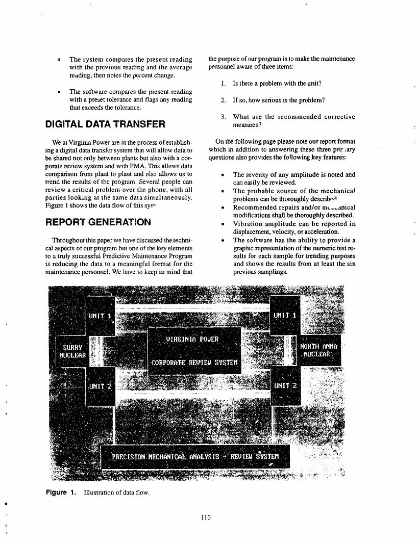
® The system compares the present reading the purpose of our program is to make the maintenancewith the previous reading and the average personnel aware of three items:rending, then notes the t_,cent change.
1. Is there a problem with the unit?
, The software compares the present readingwith a preset tolerance and flags any reading 2. If so, how serious is the problem?that exceeds the tolerance.
3. What are the recommended corrective
DIGITAL DATA TRANSFER measures? r_
We at Virginia Power are in the process of establish- On the following page please note our report formating a digital data transfer system that will allow data to which in addition to answexing these three prir aarybe shared not only between plants but also with a cor- questions ,also provides the following key features:porate review system and with PMA. "I_s allows datacomparison from plant to plant and also allows us to • The severity of any amplitude is noted a_dtrend the results of the program. Several people can can easily be reviewed.review a critical problem over the phone, with ali + The probable source of the mechanicalparties looking at the same data simultaneously, problems can be thoroughly describ_¢t
Figure 1 shows the data flow of this sys ,_ • Recommended repairs and/or mt..,,,anicalmodifications shall be thoroughly described.
REPORT GENERATION • Vibration amplitude can be reported indisplacement, velocity, or acceleration.
Throughout this paper we have discussed the techni- • The software has the ability to provide aca!.aspects of our program but one of the key elements graphic representation of the numeric test re-to a truly successful Predictive Maintenance Program suits for each sample for trending purposesis reducing the data to a meaningful format for the and shows the results from at least the sixmaintenance personnel. We have to keep in mind that previous samplings.
,i_ ,
Figure 1. IUustration of data flow.
110
3
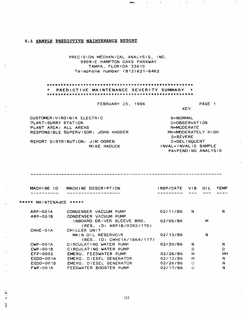
5.1 SAMPLE PREDICTIVE MAINTENANCE REPORT
PRECISION MECHANICAL ANALYSIS, INC.5909-E HAMPTON OAKS PARKWAY
• TAMPA, FLORIDA 33610Telephone number (813)621-6463
= PREDICTIVE MA I NTENANCE SEVER ITY S,UMMARY =:::::::::::::::::::::::::::::::::::::::::::::::::::::
FEBRUARY 25, 1986 PAGE 1KEY
CUSTOMER,VIRGINIA ELECTRIC N=NORMALPLAN? : SURRY S'rATION O=OBSERVATIONPLANT AREA= ALL AREAS M=MODERATERESPONSIBLE SUPERVISOR: JOHN HADDER MH=MODERATELY HIGH
S=SEVEREREPORT DISTRIBUTION= JIM OGREN D=DEI. INQUENT
MIKE HADUCK INVAL=INVALID SAMPLEPA=PENDING ANALYSIS
MACHINE lD MACHINE DESCRIPTION INSP/DATE VlB OIL TEMP
_==zz MAINTENA,_CE =====
ARP-OO1A CONDENSER VACUUM PUMP 02/11/86 N NARP-OO1B CONDENSER VACUUM PUMP
INBOARD DRIVER SLEEVE BRG. 02/05/86 M(RES. lD: ARP1B/0392/175)
CHHE-O1A CHILLER UNIT'MAIN OIL RESERVOIR 02/13/86 N
(RES. lD: CHHEIA/1864/117)CWP--OO1A CIRCULATING WATER PUMP 02/20/86 N NCWP-OO1B CIRCULATING WATER PUMP D D
: EFP-O002 EMERG. FEEDWATER PUMP 02/26/86 M MHEGDG-OO1A EMERG. DIESEL GENERATOR 02/12/86 M N
. EGDG-OOIB EMERG. DIESEL GENERATOR 02/26/86 © NFWP-OO1A FEEDWATER BOOSTER PUMP 02/17/86 0 N
=
- 111_

PRECISION MECHANICAL ANALYSIS, INC.5909-E HAMPTON OAKS PARKWAY
TAMPA, FLORIDA 33610T_iephone number (813)621-6463
= PREDICTIV_ MAINTENANCE SEVERITY REPORT z
FEBRUARY 25, 1986 PAGE 1
CUSTOM.A: VIRGINIA ELECTRICPLANY: SURRY STATIONPLANT AREA= ALL AREASRESPONSIBLE SUPERVISOR: JOHN HADDER
REPORT DISTRIBUTION= dIM OGRENMIKE HADUC'_
MACHINE lD MACHINE DESCRIPTION
==z=, MAINTENANCE ==_==
ARP-OO1B CONDENSER VACUUM PUMP .... SEVERITY CODE= MINBOARD DRIVER ELEEVE BRG.---- RES lD :ARP1B/0392/l?5
The Tin and Lead content have increased during this sampling
period, This i;tdicates wear in the sleeve bearing, We suggestthe _earing be in_pected at the next possible opportunity.In the interim, however, this unit will be closely monitored,
EFP-O002 EMERG, FEEDWATER PUMP .... SEVERITY CODE= M
There was a constOerable increase in the temperature readingon the inboard turbine bearing from 120 deg. F to 156 deg. F.The vibration levels have also increased on this same bearing'The unit is presently scheduled to be re-baselined three daysprior to the upcoming outage and a detaile_ report: will beissue_ at that time. The packing was also leaking on the in-board and outboarO 9ump bearings.
112
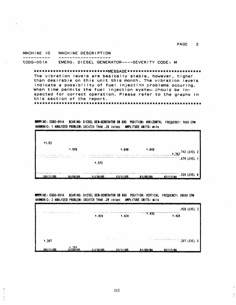
PAGE 2
MACHINE lD MACHINE DESCRIPTION
E@DG-001A EMERG. DIESEL GENERATOR ..... SEVERITY CODE= M
=============================SS==============================
The vibration levels are basically stable, however, higherthan desirable on this unit this month, The vibration levels
indicate a possibility of fuel injection problems occuring.When time permits the fuel injection syste_,_ 3hould be in-spected for correct operation. Please refer to the graphs inthis section of the report.
lllR_lmE:EGDG-OO1ABEARING:OIESELGER-G[NERAT_OBBROPOSITION=HORIZOITALFREOUEHCY:9000CPMHARtlONIC:I ANALYZEDPROBLEM:GREATERTHAN.2B in/sec kNPLITUOEUNITS=mils
__.... LJL._J__ llll _ J [ I .... ._ _lllll .- IIII li ._ II ............ LII_JL_ J l ................... ...... L_..JmL.L
,I .03
1.84B =.848 t.848...................................................................................................._.,.._.6,3'?42 LEVEL2;;.L;:::::::::::::::::::::::::'L;. ..;..i ..
...................................................................................................................................6?9 LEVELt=.5?2
_O/tt/SA,' IO/OQ/R_ It/la/RA _ I_/II/RK _S& 0_1t2186 .339 LEVEL0
11_9ftUE:E_G-OOIA BEARIIG;DIESELGEI-,GENERATOROBBRG POSITION:VERTICALFREOUENCY;18000C_HARMONIC:2 A|ALYZEDPROBLEM:GREATERTHAW.28 in/sec _PLITUDEUNITS:mils_.___._J.l_.___i _, ...... _____Jlllll_i_.._i._ _.'i___ Ill . _]11 JL II ; 11i__J_]................ I r ....... _' . __ I III ___ rl_
.435 LEVEL2................................................................................................................ v':'43_......................................
i.424 _.424 m,424
=.307............................................... .307 LEVEL0
_ O_/ltlii_ 507_)_.8E ..... I II1OIPIE 123 t tlllK OI/Oil/li& _ 0_11_18f_................................................................................................ 1..........
113
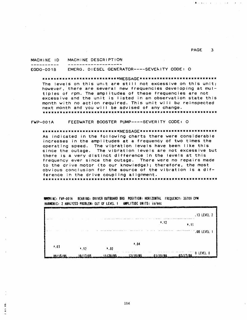
' iii , IL , ,
PAGE 3
MACHINE lD MACHINE DESCRIPT!ON
EGDG-OO1B EMERG. DIESEL GENERATOR .... SEVERITY CODE: O
z_z==_=z_,_=z=,zzz_==zz,==MESSAGEZ=_z==z=_=zzzzz=z*=zzz,=_The levels on this unit are still not excessive on this unit;however, there are several new frequencies developing at mul-tiples of rpm. The amplitudes of these frequencies are notexcessive and the unit is listed in an observation state thismonth with no action required. This unit will be reinspectednext month and you will be advised of any change.
FWP-OO1A FEEDWATER BOOSTER PUMP .... SEVERITY CODE= O
::==::::::=:::::,=:=::::::ZMESS:GE:,:z,:::::,::::z**::*z:::z:
As indicated in'.the following charts there were considerableincreases in the amplitudes at a frequency of two times theoperating speed. The vibration levels have been like thissince the outage. The vibration levels are net excessive butthere is a very distinct difference in tile levels at thisfrequency ever since the outRge. There were no repairs madeto the drive motor (to our knowledge); therefore, the mostobvious conclusion for the source of the vibration is a dif-
ference in the drive coupling alignment.
fi_t_INE: F_P-OOIA BEARING:DRIVEROUTBOARDBRGPOBITIO#:HORIZONTALFREQUENCY:35?00CPMHARMONIC:2 ANALYZEDPROBLEM:OUTOFLEVEL! _IIPLITUOEUNITS: in/secIilllqlNIml_::_ ....... I . LJI.rlIIU. _ L ......... J_ . I_1111_. __-- I I. III I _. LIII ........ l ..... 1 .... i _._ . .__i.._ --__
.13 LEVEL2
=.12=,I;
.................................................................................................................. .08 LEVEL
=.04=.03 ' .02 ' .02
.......... / .........
__ 114
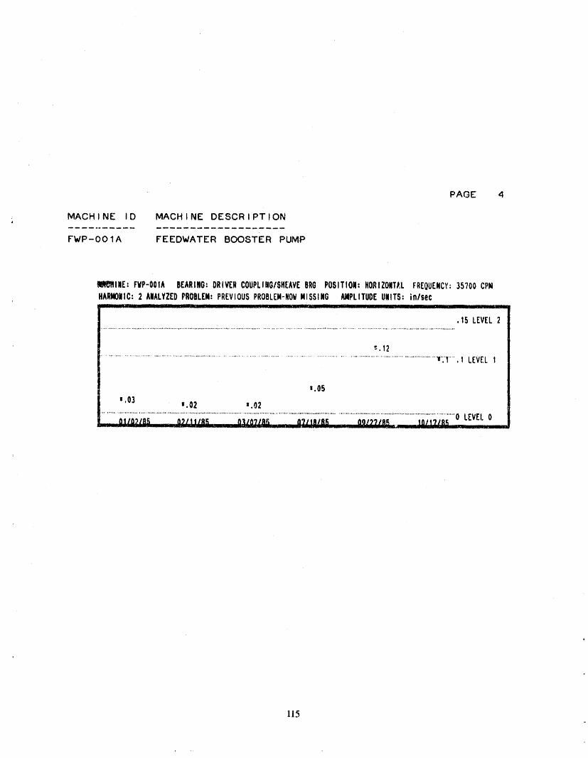
PAGE 4
; MACHINE lD MACHINE DESCRIPTION
FWP-OO1A FEEDWATER BOOSTER PUMP
_ll_JBlllE:FYP-OOIA BEARING:DRIVERCOUPLIMG/SHEAVEBRGPOSITION:HORIZOMT/IFREOUENCY:35700CPMHkRMONIC:2 ANALYZEDPROBLEM:PREVIOUSPROBLEM-NOWMISSING _PLITUDEUNITS:inlsec............ . .__ILl. I __J_. I ILL.. - r llllll II - __ II I ................ 1._
.15 LEVEL2..................... , .......................... , ....................... '......................................... ,......................... , ............................................... , ........ ,, ........ ,,.,o
"-.12....._..............................................................................................................................................................................._':1.....1 LEVEL1
=,05=,03
=.02 =.02......... ..... ..... .................. ......... ............... ................., .....,,....., . ..o o,,,, ...., ,,; o.,,, ,
O?ItR/AE u, "J.......................... -- ............................. "........ '+_--_L______Z _Z ......._ _.... 1 ..... ._...
115
PAGE 5
DELINQUENT REPORT
THE FOLLOWING ITEMS WERE NOT INSPECTED AS SCHEDULED DURINGTHIS INSPECTION PERIOD . PLEASE NOTE THE APPLICABLE REASONWHY EACH ITEM WAS NOT INSPECTED.
MACHINE lD MACHINE DESCRIPTION
=_:== MAINTENANCE =_=_
CWP-OO1B CIRCULATING WATER PUMP
This unit was out of service for maintenance. The motor was
being disassembled at Tampa Armature Works for a pre-outageinspection.
116
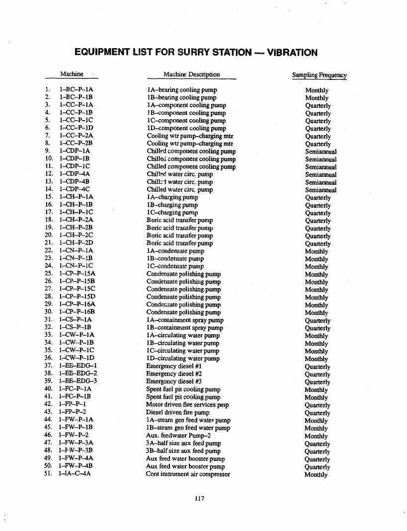
EQUIPMENT LIST FOR SURRY STATION -- VIBRATION
Machine ' Machine Description SamPling Frequency
1. 1-BC-P-1A lA-bearing cooling pump Monthly2. 1-BC--P-IB 1B-bearing cooling pump Monthly3. 1-CC-P-1A 1A-component cooling pump Quarterly4, 1.-CC-P-1B JB--component cooling pump Quarterly.5. I-CC-P- 1C 1C-component cooling pump QuarterlyQuarterly6. 1-CC-P-ID lD-component cooling pump7.. 1--CC-P-2A Cooling wtr pump-charging mtr Quarterly8. I--CC-P-2B Cooling wtr pump-charging mtr QuarterlySemiannual9. 1--CDP-1A Chilled component cooling pump Semiannu',d10. 1-.CDP-1B Chilled component cooling pump Semiannual11. 1-CDP-1 C Chilled componem cooling pump Semiannual12. 1--CDP--4A Chill_. water circ. pump Semiannual13. 1--CDP--4B Chill_.'l water circ. pump Semiannual
14. 1-CDP---4C Chilled water circ. pump Quarterly15. 1-CH-P-IA lA-charging pump16. 1--CH-P-1B 1B--charging pump Quarterly17. 1--CH-P-1C lC-charging pump QuarterlyQuarterly18. I--CH-P-2A Boric acid transfer pump19. 1--CH-P-2B Boric acid transfer pump Quarterly20. 1--CH-P-2C Boric acid transfer pump Quarterly21. 1--CH-P-2D Boric acid transfer pump Quarterly22. 1--CN-P-lA lA--condensate pump MonthlyMonthly23. 1--CN-P-1B 1B-.condensate pump Monthly24. 1-CN--P-lC lC-condensate pump Monthly25. 1--CP-P-15A Condensate polishing pump26. 1-CP-P-15B Condensate polishing pump Monthly27. 1--CP-P-15C Condensate polishing pump Monthly28. 1--CP-P-15D Condensate polishing pump, Monthly29. 1-CP-P-16A Conder_zate polishing pump Monthly30. 1-CP-P-16B Condensate polishing pump MonthlyQuarterly31. 1--CS-P-lA lA-containment spray pump32. I-CS--P-1B 1B--containment spray pump Quarterly33. 1--CW-P-1A lA-circulating water pump Monthly34. 1--CW-P-IB 1B-circulathag water pump Monthly35. 1-.CW-P-1C lC-circulating water pump MonthlyMonthly36. 1-CW-P-1D lD--circulating water pump Quarterly37. I-EE,-EDG--1 Emergency diesel #138. I-EE,-EDG--2 Emergency diesel #2 Quarterly39. 1-EE,-EDG-3 Emergency diesel #3 Quarterly40. I-FC-P-1A Spent fuel pit cooling pump Monthly,11. I-FC--P-1B Spent fuel pit cooling pump Monthly42. 1-FP-P-1 Motordriven fire services prop QuarterlyQuarterly43. I-FP-P-2 Diesel driven fire pump44. 1-FW-P-lA lA-steam gen feed water pump Monthly45. 1-FW-P-IB 1B-steam gen feed water pump Monthly46. 1-FW-P-2 Aux. feedwater Pump-2 Monthly47. 1-FW-P-3A 3A-half size aux feed pump Quarterly48. 1-F W-P-3B 3B--half size aux feed pump QuarterlyQuarterly49. 1-FW-P--4A Aux feed water booster pump50. 1-FW-P-4B Aux feed water booster pump Quarterly51. 1-IA--C--4A Cont instrument air compressor Monthly
117
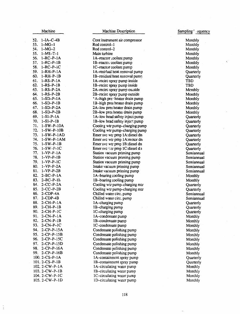
Machine MachineDescription Sampling r
52. 1-IA--C-4B Cont instrumentair compressor Monthly53. 1-MG-1 Rod control-1 Monthly54. 1-MG-2 Rod control-2 Monthly55. 1-MS-T-1 Main turbine Monthly56. 1-RC-P-lA lA-reactor coolant pump Monthly57. 1-RC-P-1B 1B-reacto, coolant pump Monthly58. 1-RC-P-iC lC-reactor coolant pump Monthly59. 1-RH-P-lA lA-residual heat removal pump Quarterly60. 1-RH-,P-1B 1B-residual heat removal purer, Quarterly61. I-RS-P-lA 1A-recirc spray pump inside TBD62. 1-RS-P-1B 1B-recirc spray pump inside TBD63, I-RS-P-.2A 2A-recitespraypumpoutside Menthly64, I-RS-P-2B 2B-rccircspraypumpoutside Monthly65. I-SD-P-IA 'A-highpre-heaterdrainpump Monthly66. I-SD--P-IB IB-highprosheaterdrainpump Monthly67. I-SD-P-2A 2A-lowpresheaterdrainpump Monthly68. I--SD-P-2B 2B-lowpresheaterdrainpump Monthly69. 1--SI-P-lA lA-low head safety inject pump Quarterly70. 1--SI-P-1B 1B-low head safety inject pump Quarterly71. 1-SW-P-10A Coolirg wtr pump--chargingpump Quarterly72. 1-SW-P-10B Cooling wtr pumlr-charging pump Quarlsrly73. 1.-SW-P-lAD Emer svc wtr pmp lA:diesel dn Quarterly74. 1-SW-P--1AM Emer svc wtr pmp lA:motor dn Quarterly75. 1--SW-P-1B Emer svc wtr pmp 1B:diesel dn Quarterly76. 1-SW-P-lC Emer svc :',tr pmp lC:diesel dn Quarterly77. I-VP-P--IA Stationvacuumprimingpump Semiannual78. 1-VP-P-1B Station vacuum priming pump Semiannual79. 1-VP-P-1C Station vacuum priming pump Semiannual80. I'VP-P-2A Intake vacuum priming pump Semiannual81. 1-VP-P-2B Intake vacuum priming pump Semiannual82. 2-BC-P-1A 1A-be_ng cooling pump Monthly83. 2-BC-P-1I_ 1B-bearing cooling pump Monthly84, 2-CC-P.-2A Cooling wtr pump--charging mtr Quarterly85. 2--CC-P-2B Cooling wtr pump--charging mtr Quarterly86. 2--CDP-4A Chilled water ch'c. pump Semiannual87. 2-CDP-4B Chilled water circ. pump Semiannual88. 2-CH-P-1A lA-charging pump Quarterly89. 2-CH-P-1B 1B--chargingpump Quarterly90. 2--CH.-P-1C lC--charging pump Quarterly91. 2.-CN-P-lA lA-condensate pump Monthly92. 2-CN-P-1B 1B--condensatepump Monthly93. 2-CN-P-lC 1C-conden_te pump Monthly94. 2-CP-P-15A Condensate polishing pump Monthly95. 2-CP-P-15B Condensate polishing pump Monthly96. 2-CP--P-15C Condensate polishing pump Monthly97. 2-CP-P-15D Condensate polishing pump Monthly98. 2-CP-P-16A Condensate polishing pump Monthly99. 2-CP-P-16B Condensate polishing pump Monthly100. 2-CS-P-1A 1A-containment spray pump Quarterly101, 2-CS-P-1B 1B-containment spray pump Quarterly102. 2-CW-P-1A 1A--circulating water pump Monthly103.2-CW-P-1B 1B--circulatingwater pump Monthly104. 2--CW-P- 1C 1C--circulatingwater pump Monthly105.2--CW-P-1D 1D-circulating water pump Monthly
118
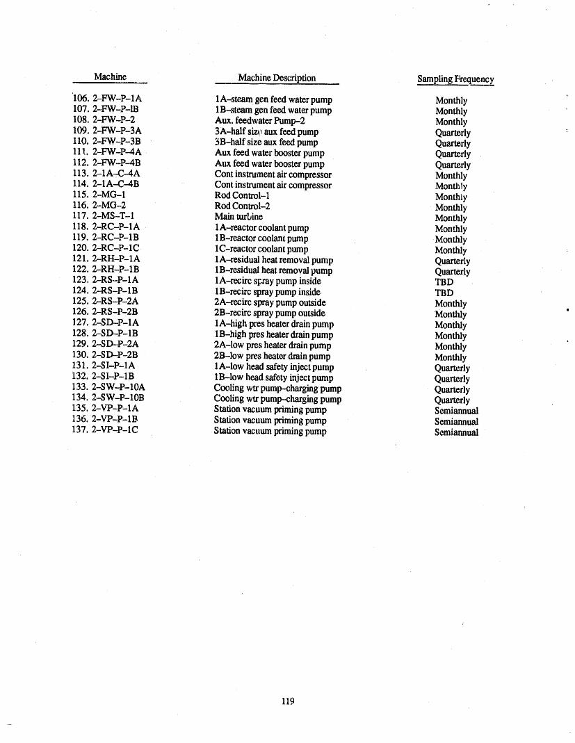
Machine MachineDescription SamplingFreq_
'106. 2-FW-P-lA lA-steam gen feed waterpump Monthly107. 2-FW-P-1B 1B-steam genfeed waterpump Monthly108. 2-FW-P-2 Aux. feedwaterPump-2 Monthly109.2-FW-P-3A _ 3A-half size;aux feedpump Quarterly :110. 2-FW-P-3B 3B-half size aux feedpump Quarterly111. 2-FW-P--4A Auxfeed waterboosterpump Quarterly112. 2-FW-P-4B Aux feedwater boosterpump Quarterly113.2-1A-C--4A Cont instrumentaircompressor Monthly114. 2-1A-C--4B Cont instrumentair compressor Monthly115. 2-MG-1 Rod Control-1 Monthiy116. 2-MG-2 Rod Control-2 Monthly117.2-MS-T-1 Mainturbine Monthly118. 2-RC-P-lA 1A-reactor coolantpump Monthly119. 2-RC-P-1B 1B-reactorcoolant pump Monthly120. 2-RC-P-1C 1C-reactor coolantpump Monthly121.2-RH-P-lA 1A-residual heat removal pump Quarterly122. 2-RH-P-1B 1B-residual heat removalpump Quarterly123, 2-RS-P-lA 1A-recirc s_ray pump inside TBD124. 2-RS-P-1B 1B-retire spray pump inside TBD125.2-.RS-P-2A 2A-recirc spray pump outside Monthly126. 2-RS-P-2B 2B-retire spray pump outside Monthly127, 2-SD--P-lA lA-high pres heater drain pump Monthly128. 2--SD--P-1B 1B-high pres heaterdrain pump Monthly129.2-,SD-P-2A 2A-low pres heater drain pump Monthly130. 2--SD--P-2B 2B-low pres heater drain pump Monthly131.2-SI-P-lA lA-low headsafetyinject pump Quarterly132. 2--SI-P-1B 1B-low head safety injectpump Quarterly133.2-SW-P-10A Cooling wtrpump-chargingpump Quarterly134. 2-.-SW-P-10B Cooling wtr pump-chargingpump Quarterly135. 2-VP-P-1A Station vacuumprimingpump Semiannual136. 2-VP-P-1B Stationvacuumprimingpump Semiannual137. 2-VP-P-1C Stationvacuum primingpump Semiannual
119
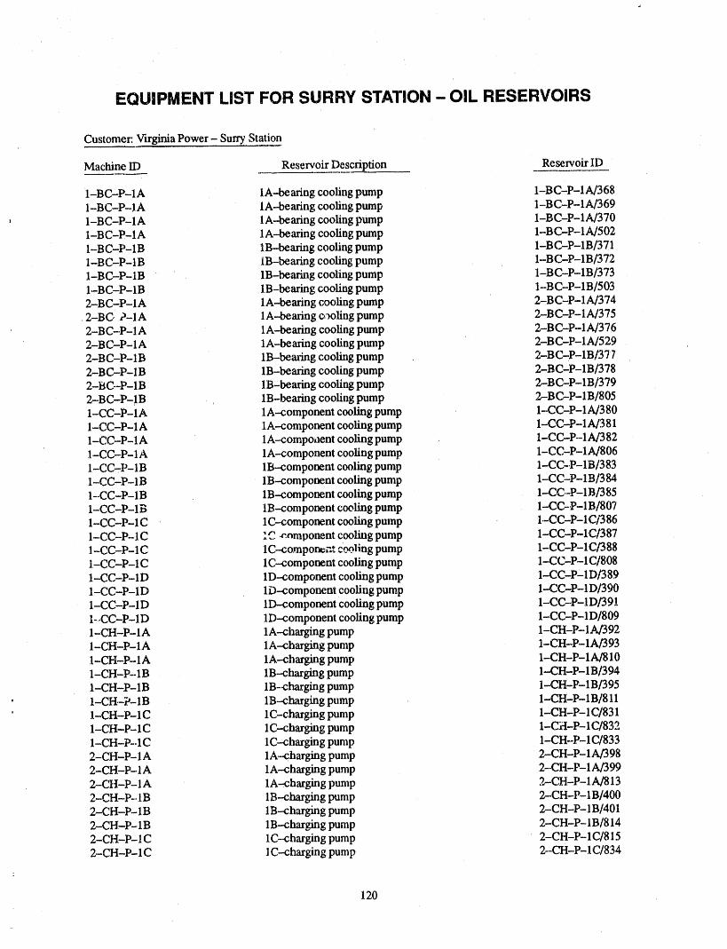
/
EQUIPMENT LIST FOR SURRY STATION- OIL RESERVOIRS
Customer: Virginia Power - Surry Station
Machine lD Reservoir Description Reservoir ID
1-BC-P-1A 1A-bearing cooling pump 1-BC-P-1 A/3681-BC-P-1A IA--beanng cooling pump 1-BC-P-1A/3691-BC-P-IA IA--beanng cooling pump 1-BC-P-1A/3701-B C-P-1A 1A--bearing cooling pth'np 1-B C-P- 1A/502I-BC'P-1B 1B-bearing cooling pump 1-BC-P-1 B/3711-BC-P-IB IB-bearing cooling pump 1-BC-P-1B/3721-B C-P-1B 1B-beanng cooling pump 1-B C-P-1B/3731-B C-P-1B 1B-bearing cooling pump 1,-BC-P-1B/5032-BC-P-IA 1A--beanng cooling pump 2-BC-P-1A/374
,2-BC, P-lA lA--bearing c,'_olingpump 2-BC-P-lbJ3752-BC-P-I A lA-bearing cooling pmnp 2-BC-P-1A/3762-BC-P-1A lA--bearing cooling pmnp 2-BC-P-IAI529 q
2-BC-P-1B 1B-bearing cooling pump 2-BC-P-1B/3772-BC-P-1B 1B-bearing cooling pump 2-BC-P-1B/3782-BC--P-1B 1B,bearmg cooling pump 2-BC-P-1B/3792-BC-P-1B 1B-bearing cooling pump 2-BC-P-1B/8051-CC-P-1A lA-component cooling pump 1--CC-P-1A/380I-CC-P-1A 1A--component cooling pump 1-CC-P--1A/3811-CC-P-1A 1A--compoilent cooling pump 1-CC-P-1A/3821-CC-P-I A lA-component cooling pump 1-CC-P-1A/8061--CC-P-1B 1B--component cooling pump 1-CC-P-1B/3831-CC-P-1B 1B--component cooling pump 1-CC-P-1B/384I'CC-P-IB 1B--component cooling pump 1-CC--P-1B/3851-CC-P-I B 1B-component cooling pump I-CC-P-1 B/807
•1-CC-P-1C 1C--component cooling pump 1.-CC-P-1 C/3 861-CC-P-1C "" _nmponent cooling pump 1-CC-P-1C/3871-CC-P-1C 1C--componec," c_!ing pump 1-CC-P-1C/388I-CC-P-1C lC-component cooling pump 1-CC-P-1C/8081-CC-P-1D lD--component cooling pump 1-CC-P'1D/3891-CC-P-1D lD-component cooling pump 1-CC-P-1 D/3901-CC-P-1D lD-component cooling pump 1--CC-P-ID/3911-_CC-P-1D lD-component cooling pump 1-CC-P-1D/8091-CH-P-IA lA-charging pump 1-CH-P-1A/3921-CH-P-1A lA-charging pump 1-CH-P-1A/3931-CH-P- lA lA-charging pump 1-CH-P- 1A/8101-CH-P-1B 1B-charging pump 1-CH-P-1B/394I-CH-P-1B 1B-charging pump 1-CH-P-1B/3951-CH-P-1B 1B--charging pump 1-CII-P-1B/8111-CH-P- 1C 1C-charging pure p 1--CH-P- 1(2/8311-CII-P-1C 1C-charging pump 1-CH-P-1 (2/8321-CH-P-.1C lC-char[cng pump 1-CH-P-1(2/8332-CH-P-IA lA--charging pump 2-CH-P-1A/3982-CH-P- 1A 1A--charging pump 2--CH-P- 1A/3992-CH-P-1 A lA-charging pump 2,-CH-P-1A/8132-CH-P--1B 1B--charging pump 2--CH-P-1B/4002-CH-P- IB 1B-charging pump 2-CH-P- 1B/4012--CH-P-1B 1B--charging pump 2-CH-P-1B/8142-CH-P-I C 1C--charging pump 2-CH-P- 1C/8152-CH-P- 1C 1C-charging pump 2--CH-P- 1C/834
120

Customer: Virginia Power - Surry Station
Machine lD Reservoir Description Reservoir ID
2-CH-P- 1C 1C-charging pump 2-CH-P- l C/835I-CN-P- 1A 1A-condensate pump I-CN-P- 1A/4041-CN-P-I A IA-condensate pump I-CN-P-I A/4051-CN-P- 1B 1B-condensate pump 1..-CN-P- 1B/4061--CN-P- 1B 1B-condensate pump I-CN-P-.1 B/407I-CN-P- 1C 1C-condemate pump 1-CN-P- 1t2/4081-CN-P- 1C 1C.condensate pump 1-CN-P- 1C/409
2--CN-P-I A 1A-condensate pump 2-CN-P- 1A/4102-CN-P- 1A 1A--condensate pump 2-CN-P- 1A/41 l2-CN-P- 1B 1B-condensate pump 2-CN-P- 1B/4122-CN-P- 1B 1B--condensate pump 2-CN-P-1B/4132-CN-P- 1C IC-condensate pump , 2-CN-P- 1(2/4142--CN-P-lC lC--condensate pump 2-CN-P-1C/415I-CS-P- 1A 1A--containme nt spray pump 1-CS-P- 1A/4161-CS---P- 1A lA--containment spray pump I-CS-P-1A/4171-CS--P-lA lA--containment spray pump 1-CS-P-lA/8161-CS-P-1B 1B-containment spray pump I-CS-P- 1Bl4181-CS-P-1B 1B--containment spray pump 1-CS-P-1B/4191-CS-P- 1B 1B-containment spray pump 1-CS--P- 1B/8172-CS-P- 1A 1A-containment spray pump 2-CS-P- 1A/4202--CS--P- 1A 1A-containment spray pump 2-CS-P- 1A/4212-CS--P- 1A 1A-containment spray pump 2-CS---P- 1A/8182-CS--P- 1B 1B--containmetat spray pump 2-CS-P- 1B/4222-CS-P- 1B 1B--containment spray pump 2-CS-P- 1B/4232--CS-P-1B 1B--containment spray pump 2-CS-P-IB/8191-(,'W-P- 1A 1A--circulating water pump 1-CW-P-, 1A/4241-( .'W-P- 1A 1A--circulating water pump 1-CW-P- 1A/4251-( .'W-P- 1B 1B-circul ating water pump I-CW--P- 1B/4261--(.'W-P-1B 1B--circulating water pump 1-CW-P-IB/4271-4 ',W-P- 1C 1C.-circulating water pump I-CW-P- 1C/428
' 1-4 _W-P-1C 1C--c_culating water pump 1-CW-P- 1C/4291--47W-P- 1D lD-circulating water pump 1-CW-P-1 D/4301-CW--P- 1D 1D-circulating water pump 1-CW-P- 1D/4312-.CW-P-1A 1A--circulating water pump 2.-CW-P-1 A/4322-_ 'W-P- lA 1A--circulating water pump 2-CW-P-- 1A/4332-(2W'p- 1B 1B-circulating water pump 2--CW-P-1 B/4342-4.'W-P-1B 1B-circulating water pump 2-CW-P-,-1 B/4352-(.'W-P- 1C 1C--circulating water pump 2--CW-P- 1C/4362-q .'W-P--1C 1C--circulating water pump 2-CW-P- 1C/4372-4 _W-P- 1D 1D--circulating water pump 2--CW-P- 1D14382.-4 ,'W-P- 1D 1D-circulating water pump 2--CW-P-1 D/4391-FW-P-lA 1A.-steam gen feed water pump 1-FW-P-lA/4401-FW-P-1B IB-steam gen feed water pump 1-FW-P-1B/zl,412-FW-P-lA lA-steam gen feed water pump 2-FW-P-lA/4462-FW-P-1B 1B-steam gen feed water pump 2--FW-P-1B/447I-FW-P-3A 3A--half size aux feed pump I-FW-P-3AI4421-FW-P.-3A 3A-half size aux feed pump 1-FW-P-3A/4431-FW-P-3A 3A--half size aux feed pump 1-FW-P-3,_8201-FW-P-3B 3B-half size aux feed pump I.-FW-P-3B/_IA
1-FW-P-3B 3B-half size aux feed pump I-FW-P-3B/,445I-FW-P-3B 3B-half size aux feed pump 1-FW-P-3B/821
. 2-FW-P-3A 3A-half size aux feed pump 2-FW-P-3A,/448
121
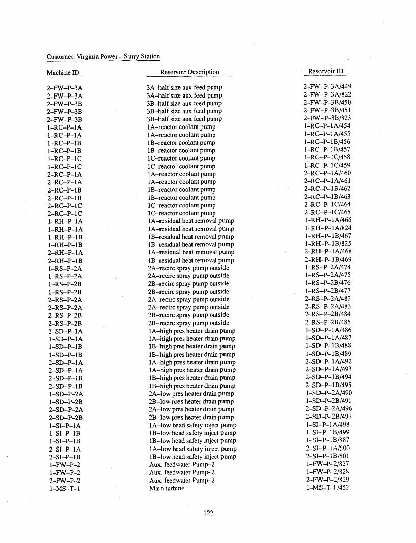
Customer: Virginia Power- Surry Station
Machine II) Reservoir Description Reservoir lD
2-FW-P-3A 3A-half size aux feed pump 2-FW-P-3A/4492-P'W-P-3A 3A-half size aux feed ptunp 2-FW-P-3A/8222-FW-P-3B 3B-half size aux feed pump 2-FW-P-3B/4502"FW-P-3B 3B-half size aux feed pump 2-FW-P-3B/4512-FW-P_3B 3B-half size aux feed pump 2-FW-P-3B/8231-RC-P-I A 1A-reactor coolant pump I-RC-P-I A/4541-RC-P-1A 1A-reactor coolant pump 1-RC-P- 1A/4551-RC-P-IB IB-reactor coolant pump 1-RC-P-1 B/4561-RC-P-.1B 1B-reactor coolant pump I-RC-P- 1B/4.571-RC-P-1C 1C-reactor coolant pump I-RC-P-i C/4581-RC-P-lC 1C-reacto: coolant pump 1-RC-P-1 C/4592-RC-P-lA 1A-reactor coolant pump 2-RC--P-1 A/4602-RC-P-1A 1A-reactor coolant pump 2-RC-P- IA/4612-RC-P-I B 1B-reactor coolant pump 2-RC-P-1 B/462
2-RC-P-1B 1B-reactor coolant pump 2-RC-P-1 B/4632-RC-P-1C 1C-reactor coolant pump 2-RC-P-I C/4642-RC-P-1C 1C-reactor coolant pump 2-R C-P-I C/4651-RH-P-lA lA-residual heat removal pump 1-RH-P-I A/4661-RH-P-lA lA-residual heat removal pump 1-RH'P-1A/8241-RH-P-1B 1B-residual heat removed pump 1-RH-P-lB/4671-RH-P--1B 1B-residual heat removal pump 1-RH-P-1B/8252-RH-P-lA lA-residual heat reraoval pump 2-RI-I-P-1 A/4682-RH-P-1B 1B-residual heat removal pump 2-RH-P-I B/4691-RS-P-2A 2A-recirc spray pump outside I-RS-P-2A/4741-RS--P'2A 2A-recirc spray pump outside I-RS--P-2A/4751-RS-P-2B 2B-recirc spray pump outside 1-RS-P--2B/4761-RS--P-2B 2B-recirc spray pump outside I-RS-P-2B/4772-RS-P-2A 2A-recirc spray pump outside 2-RS-P--2A/4822-RS-P-2A 2A-recirc spray pump outside 2-RS--P-2A/4832-RS-P-2B 2B-recirc spray pump outside 2-RS-P-2B/4842-RS-P-2B 2B-recirc spray pump outside 2-RS--P-2B/4851-SD-P-lA lA--high pres heater drain pump 1-SD--P-lA/4861-SD-P-lA lA--high pres heater drain pump I-SD--P-lA/4871-SD--P-1B 1B-high pres heater drain pump 1-SD-P- 1B/4881.-SD-P-I B 1B-high pres heater drain pump 1-SD-P-1 B/4892--SD-P-1A lA-high pres heater drain pump 2-SD--P- 1A/4922-SD-P- 1A 1A-hi gh pres he ater drain pu mp 2-SD--P- 1A/4932-SD-P.-1B IB-high pres heater dr_,finpump 2_D-P-1 B/4942-SD-P- 1B 1B-high pres heater drain pump 2--SD-P- 1B/4951-SD--P-2A 2A-low pres heater drain pump I-SD--P-2A/4901--SD--P-2B 2B-low pres heater drain pump 1-SD--P-2B/4912-SD-P-2A 2A-low pres heater drain pump 2-SD--P-2A/4962-SD-.P-2B 2B-low pres heater drain pump 2-SD-P-2B/4971--SI-P-lA lA-low head safety inject pump 1-SI-P-I A/4981-SI-P-1B IB-low head safety inject pump 1-SI-P-1B/4991-SI-P-1B 1B-low head safety inject pump 1-SI-P-1B/8872-SI-P-lA lA-low headsafety inject pump 2-SI-P-lA/5002-SI-P-I B lB.-low head safety inject pump 2-SI-P-1B/501I-FW-P-2 Aux. feedwater Pump-2 1-FW-P-2/8271-FW-P-2 Aux. feedwater Pump--2 1-FW-P--2/8282-FW-P-2 Aux. feedwater Pump--2 2-FW-P-2/8291-MS--T-I Main turbine 1-MS--T-1/452
122
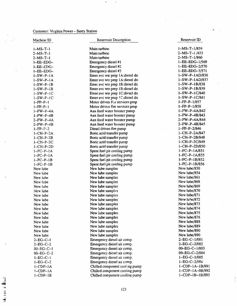
Customer: Virginia Power- Surry Station,,
Mactfine ID Reservoir Description Reservoir ID
I-MS-T-1 Main turbine 1-MS.--T-I/8592'MS-T-1 Main turbine 2-MS-T-I/4532-MS-T-I Main turbine 2-MS-T-I/860I-EE-EDG- Emergency diesel #1 1-EE,-EDG-1/569I-EE-EDG- Emergency diesel #2 1-EE--EDG-2/570I-EF_EDG- Emergency diesel #3 1-EE--EDG-3/571I-SW-P-lA Emer src wtr pmp lA:diesel dsa 1-SW-P-lAD/8361-SW-P-I A Emer svc wtr pmp lA:diesel dn 1-SW-P-lAD/837I-SW-P-1B Eme: svc vctrpmp IB:diesel dn 1--SW'P-1B/838I-SW-P- 1B Emer svc wtr pmp 1B:diesel dn 1-SW-P-1 B/8391-SW-P-I C Emer svc wtr pmp lC:diesel dn I-SW-P-lC/840
,,¢... •
1-SW-P-IC Emer svc wtr prop w....diesel dn 1-SW-P-lC/841I-FP-P-1 Motor driven fi;e services prop 1.-FP-P-1/857J-FP-P-1 Motor driven fire services prop 1-FP-P- 1/8581-F'W-P--4A Aux feed water booster pump I-FW-P-4A/842I-FW-P--4B Aux feed water booster pump I-FW-P--4B/8432-FW-P-4A Aux feed water booster pump 2-FW-P.-4A/8442-FW-P-.4B Aux feed water booster pump 2-FW-P.-4B/8451-FP-P-2 Diesel driven fire pump 1-FP-P-2/8461-CH-P-2A Boric acid transfer pump 1-CH-P-2A/8471-.CH-P-2B Boric acid transfer pump 1-CH'P-2B/848I-CH-P--2C Boric acid transfer pump 1-CH-P-2C/8491-CH-P'2D Boric acid transfer pump 1-CH-P-2D/8501-FC-P-1A Spent fuel pit cooling pump 1-FC-P-1A/8511-FC-P- 1A Spent fuel pit cooling pump 1-FC-P-1 A/8551-FC--P-1B Spent fuel pit cooling pump 1-FC-P-1 B/8521-FC-P--1B Spent fuel pit cooling pump 1-FC-P-1B/856New lube New lube samples New lube/830New lube New lube samples New lube/854New lube New lube samples New lube/861New lube New lube samples New lube/868New lube New lube samples New lube/869New lube New lube samples New lube/870New lube New lube samples New lube/871New lube New lube samples New lube/872New lube New lube samples New lube/873New lube New lube samples New lube/874New lube New lube samples New lube/875New lube New lube samples New lube/876New lube. New lube samples New lube/888New lube New lube samples New lube/889New lube New lube samples New lube/890New lube New lube samples New lube/890
-EG-C- 1 Emergency diesel air comp. 2-EG-C- 1/(301, 2-EG-C-2 Emergency diesel air comp. 2-EG--C-2/002
00--EG-C- 1 Emergency diesel air comp. 00--EG-C- 1/00300--EG-C-2 Emergency diesel air comp, 00-EG-C-2/01M1-EG-.-C-1 Emergency diesel air comp. 1-EG--C--1/0051-EG--C-2 Emergency die.eel air comp. I-EG-.C-2/0061-CDP-I A Chi[led component cool ing pump I-CDP-1A-1 B/891]-CDP-lA C'b_iUedcomponent cooling pump I-CDP-1A---0B/8921--CDP-1B Chilled component cooling pump 1-CDP- 1B- 1B/893
_
!23

Customer. Virginia Power- Surry Station
Mach/ne rD Reservoir Description Reservoir ID
1-CDP-1B Chilled component cooling pump 1-CDP-1B--0B/8941-CDP- 1C Chilled component cooling pump I-CDP- 1C- 1B/8951-CDP- 1C Chilled component cooling pump 1-CDP- 1C--0B/896
SUMMARY data, oil analysis, temperature readings, and past writ-ten recommendations) literally at his finger tips. The
Predictive maintenacce is the most logical and c_.t- program needs to include more than one method ofeffective method of maintaining plant equipment, slm- testing, such as combining a vibration analysis, oilply because maintenance and oil changes are analysis, and temperature analysis into one prograna.
With these ingredients a Predictive Maintenance Pro-performed on an as-needed basis only. In most casesthe money saved from eliminating unneeded oil gram can be an indispensable managerial tool. Mainte-changes alone justifies a Predictive Maintenance nance scheduling and ordering of replacement parlsProgram. can be done well in advance.. Instead of an unexpected
forced shutdown of a critical piece of equipment, the
There are ma_,y types of Predictive Maintenance maintenance personnel will be aware of any mechani-Programs that ca_ be established. To be effective, the cal problems and can properly plan and schedule theuse of computers is needed to handle the vast amounts repairs accordingly. At Virginia Power, Predictiveof data quickly and with accuracy. This aiso enables Maintenance has enabled us to shit_ from a Reactive tothe analyst to have ali of the available data (fibration a Proactive maintenance department.
124
,71 Hl1 'l]rll)_Hll '' '1' ra , lirl ,,',lIW11ml[',' ,) I1' 'l ' ' ," I][P' ' " ' rsr_lrl,,,rla,l_rll rl ...... r),,ll .... 11311 ',," irl _!,)vq,)qb,, ,,I_F, rl_I " '111'1]]1'"_
ATTENDEE- PANEL QUESTIONS AND ANSWERS(EDITED; ATTENDEE QUESTIONS AND PANEL/AUTHOR
RESPONSES NOT IDENTIFIED B Y NAME)
Question I Response 3
Arethe safety-related pumps in the plants covered by We have and we have not. That is a difficult one. Bythe program you describe? And, if not, why? the program, we record bearing temperatures at the
Response 1 same point on the bearing cap each time vibrationreadings were taken, and that is on a monthly basis.
Yes, the safety-related pumps are included. We have There are a let of variables for temperature trending.got predictive analysis groups at each station at Surry And I cannot say that we have detect_l a problemand North Anna, and they consist of two engineering solely on the basis of bearing temperature trending.
However, we have not discounted it yet, and we stilltechs per station, continue to include it.
Wefound early on that we had a let oftrend data on the
balance,--ofplant equipment, and not a whole let on As I mentioned, we basically used pyrometers. At thisthe safety-related equipment, primarily because, that point, we are looking at some infrared guns as weil.e_uipment was run on the back shift when operations But we are still continuing to include bearing tempera-could more easily schedule it. ture trending.
With the advent of the digital data recordersand data Question 4takers, what we have done is trainedour operators and
revised our PTs so that the operators capture that data. Does your methodology employ monitoring of pumpThey record on the PT the unf'tlterexlreadingsthat the hy&aulic parameters? If not, why not?code requires, and the data are then transfen-edover tothe predictive analysis groups, so we have a corre-sponding spectrum to the unfiltered readings. Response 4
I cannot speak for the IST portion of VirginiaPower; IQuestion 2 mT_,speakingfrom a maintenance standpoint of predic-
t/ve analysis, Welook ata let of things when we are outHow do you choose your discrete frequencies? How there recording data. We do record pump suction andwould you piace OM 6 limits on a continuous, versus discharge pressures as part of trouble-shooting. That isdiscrete, frequency and spectrum analyzer? why we are there, lt is not included in the trend pro-
Response 2 gram at this time.
The discrete frequencies are chosen by the system. It In addition to that, normally when an inspection is per-starts out wi',,hthe highest 10amplitudes ona particular formed for the predictive maintenance progrmn, it isscale in a frequency range. The,,,, if a new frequency performed at the sametime aperformance test ora sur-comes into play, it starts automatically trending veillance procedure is performed.that, too.
So, any predictive maintenance effort should be done
The OM 6 limits how you would do that--I do not simultaneously with the surveillance procedures soknow that we would particularly want to trend equip- that you know you have that same consistency to trackmerit on a discrete frequency basis. You have several the data. In theearlier session, I heard a question aboutfrequencies that will be oscillating, for example. You low flow,and that can def'mitelyaffect the pump. Andwould have ali of the equipment in the plant either h_ it can really mess up the readings if you are not _v.allyan alarm or alert stage continuously if _.oudid apply caxeful,OM 6 limits to a discrete frequency pattern.
So, we have to be concerned about the hydraulic pa-Question 3 rameters of the particular unit. And the best way to do
that, from a predictive maintenance standpoint, is toHave you had good results by doing temperature ensure that the readings are taken concurrently withanalysis? the performance test.
125
PANEL DISCUSSION: THE PURPOSE OF PUMP IST PROGRAMS-AVAILABILITY AND RELIABILITY
R. BAER (MODERATOR)J. ZUDANS, L. SAGE, K. GUY, J. PAGE, P. ENG, J. DEMARCO,
W. CLEVELAND
Question 1 (Pump Operability) Question 2 (Deferred MaintenanceManhours)
OM 6 andregulatoryrequirements effectively require How were themanhoursthatwere "deferred"numbersthatpumpsbedeclaredinoperableata specific level of detcmdnedat Gibson?pump vibration.What criteria do you use to require
pumpshutdown? Whatis yourassessment of the OM Resportse 26 vibrationlevel limits?
Panelist To give a little background,theway we de-ferlhc manhoursat Gibson,andtheyarcstartingto do
Response I this throughoutthe PSI system,is thatevery six weeksI receive a list_a preventivemaintenancereportthat
Panelist I personallyam notfamiliar with the OM6 tells mc six weeks in advancewhatequipm_._is to bestandard.But,as forvibrationlevels, I do notjust look scheduledto beoverhauled.at the overall vibrationlevel, I look at the spectrum,and I also look at what the pump performance is. I Wethenpull outthe pastvibrationtrends,and thepastthink it is too difficult to come up with one genetic off trend, and also perform a performancetest if it is a
pump. And we assemble that into an informationlevel for vibration, whether it is in velocity, steelers- package with a cover letter that is routed through thetion, or displacement, plant.
I think it's something you have to look at overall. For It was felt that I was getting involved in toomany areasballpark equipment, if it is running at less than I should not have been involved in. So, we decided we600 rpm, we usually use 6 mils for shutdown limit. If it would let the supervisors and superintendentsin theiris running at over 1,000 rpm, our shutdown limit is respective area have input into what equipment weusually 0.5 or 0.6 in. per ,second,overall. We do not deferred. And what we do is put this file package to-necessarily shut down if the once per rev does not gether. We tell them what the vibration overall read-reach 0.6, It is the overall levels that we are more con- ings are, whether we are in good shape, excellentcerned about. In fact, we have shut pumps down that shape, poor shape, what the oil reports indicate, and
then what the performance levels are.have been runnhlgdown to0.2 and 0.3 inches per sec-
ond, depending on what the problem was in the spec- We make a recommendation, then, whether theytrum, and depending on what the pump flow was.should overhaul the equipment,or whetherthey shoulddefer it for another year. And ff they should not over-
CommentonQuestion1 haulit anddeferit, maybeweneedtochangeabearing,rework a coupling, or the like. Then we will route thatthrough the plant.
Panell[t For the velocity anyway, that is fairly closeto what we have used as the action level for OM 6--the Then what we do is on Wednesday of the week beforerequired action, Again, we have to keep in rabidthat the work is scheduled, we have a meeting in the after-the pumps we are looking at are not run ali the time; noon at 2:00. And we sit down and go over each item
• they run only, basically, whenwe are testing them, and that is scheduled formaintenance the following week.often they are run on minimum flows. At that time we determine, based on what the superin-
tendents and the people in the plant felt about my rec-ommendation, whether they go along with me or they
So, you would expect to see slightly different vibration change and decide to overhaul it.criteria for the overall specu'um of pumps than youwould for pumps that are normally running and in At the end of that, we determine how many manhoursservice, were determined for overhaul. Say we take a bottom
127_
ash pump. It takes about 160 manhoursto overhaul where you are in the requiredaction range, you mustthat,If we decide thatis not neededto be overhauled, takecorrectiveaction.we will take that 160 manhoursandrededicate that to
someareawherewe needthework.Or, if we donot Question 4 (Identified Pump Failuresneed the work, then we will put them on preparingfor Due to Vibration)outages'or work that is coming up in the future.
OM 6 equates an increase in vibrational energy withSo, essentially, it is a one for one. Wedo not really do pumpdegradation. Have any pumpfailure modes beenaway with the manhours; we just redirect them to identified that are characterized by a decreased noisewhere they areneeded. It's a more effective use of our signature prior to failure? And, if so, how are suchmoney, cases covered by OM 6?
Question 3 (Pump Operability) Response 4
IWP 3230(c) allowed analysis to be done to demon- Panelist I think we determined therearesome; I can-strate that the---condition doe.snot impair pump oper- not give you specifics on what they are. But what Iability. Is this to mean the additional set of reference think we have come to realize is that anything thatvalues of section 4500? If not, it does not seem clear would not show up on vibration or show up as a de-why 3230(c) was dropped from OM 6. crease in vibration level would probably be severe
enough to cause you to see a marked change in yourResponse3 hydraulicmeasurements also.
Panelist First of all, the membersof the working Question 5 (OM-6 Acc_'_ptanceCriteriagroup decided that if you are in the required action Range)range after doing your test, and you have decided that
you are in tile requiredaction range, thereis no alterna- In your comparison of IWP and OM 6, you state thattive but to declare the pump inoperable.That is the bet- the ownercan no longer set his own acceptanceranges.tom line. Question one, who now sets the new ranges? Question
two, where does it (OM 6) say this?If you are in the required action range, but stil.!meetsafety system requirements, that is outside, again, of
Response 5the scopeof this code. The code is not there so you canmeet the safety system requirements. They are to de-tect degradation and take corrective action on detect- Psnellsl I think the way the new code reads, it omitsing degradation, the statementthat the owner canset these new rangesif
he cannotmeet the acceptance criteria ranges specified
If you say that you are meeting safety system requi_, in the code.ments but have a degraded pump, you neverthelesshave said that the pump is inoperable. We deliberately took that sentence out because we be-
lieve it maynot be appropriate to do that. However, if
Many pumpsare put into systems andcan delivermore you want to set a new range, I assume that you couldwrite a relief request for that. The code previously al-: than what the system requires to mitigate the conse-
quence of the accident. Nevertheless, the testing is lowed youto go ahead and set new ranges without hay-there todetect degradation. And once you identify that ing to request relief or anything like that.you sre in a required action range, you must take cor-rective action. And that means you must declare it I think, again, this is probably a more conservative sp-inoperable and you must go into your limiting condi- preach, because we believe the ranges are adequate astions of operation for your plant unti!you carl correct they are.tileproblem.
QUESTION 6 (Reference Points for
The Code did not want to dealany morewith an uncle- Vertical Pumps)fined specification that allowed lots of interpretationconcerning when to declare something inoperable. What statisticaldata were used to justify more restric-This is not my personal feeling necessarily, but I think _,ivereference points for vertical and centrifugalit is correct to say that if you are degraded to the point pumps?
128-
z
F

Response 6 Take surveys, I know they're a pain to fill out, but it'sgood information for us, and it helps us to write thesecodes and standards.
Panell_ Weil, it is not more restrictive for centrifu-
gal pumps. That is essentially the base case. It is more Panelist There is a very good EPRI report out. Irestrictive on the hydraulic measurements for vertical don't have the number off the top of my head, but itline shaft pumps. Those are the pumps with a long was a research project that instrumented a number ofshaft suspended impeller type. And it has beenour ex- the pumps of this type and showed that you can mea-perience--very much my experience--that those sorts sure at the pumphouse, and yousee absolutely nothing.of pumps do not show degradation in vibration, So that
is why the hydraulic parameters were set fighter there. Voice I disagree that hydraulics is the resolution tothe problem.
Response 6 Panelist Propose an alternative. I mean, youhave vi-bration, you have hydraulics. I don't know of anything
Panelist Approximately in the 1974 to 1976r_nge, else that we're looking at.we identified, while I was working for the NRC, aproblem with deep--draftpumps and the use of the vi- Panelist I will say one more time for the benefit ofbration criteria in the code. The typical measuring others that may not have heard my personal feeling;point for vibration on deep-draft pumps was at the dis- that is, that I have looked at the pumps that we have atcharge housing for the pump, a very long distance ha St. Lucie and TUrkey point, and I've looked at themost cases from the actual impellers and bearings that ranges that are specified in OM 6, and I do not believeare in the pump. that I had one case where the pump actually fell into
the required action range from past data that we'vetaken using the new acceptance criteria.
Wefelt thatany vibration occurring in the bell housing
of thepump near the impellers was being attenuated by I completely endorse your recommendation that we getthe shaft and the cclumn elements. And so you really lots of data and can compare it, In the past we have notwere not doing a good vibration characterization for gotten that much data to support, but I think this is anthat particular pump. attempt on the people and the code to try to prevent
problems tor the industry. And in lieu of something
In fact, some tests were performed at one utilitywhere else, I personally would continue to support thisvibration looked fine; and upon disassembly of those position.particular pumps, there was severe degradation to thepoint where the pump had essentially destroyed itself. Panollst We did a detailed analysis on a fire safety
pump at one particular utility, which I will keep to my-self, but what did is we put underwater probes on the
At this point I was convinced, but had to convince oth- shaft segments between the bearing supports, and weers, that we might want to pay more attention to hy- also put accelerometers down at the bottom of thedraulics. Nevertheless, since these pumps are normally housing. And the vibration levels looked just fine upalways run ;aurecirc., I am not sure that hydraulics are on the top of the motor, all over the top of the motor.helping us that much. But we did want to goto slightly Everything looked just fine, but what we found wasstricter hydraulic criteria in lieu of other techniques, that there was over 80 mils of deflection between the
bearings, and there's a tttree-inch thick report that we
The only way that measurements could be made in the issued that particular client.lower section of the pump or with vibrationequipmentthat could withstand submersion and that kind of And so I lost a lot of faith from that particular instanceequipment at that time, and I think even now, is rather as far as measuring vibration on the top of the unit tounreliable, in terms of life. So, that's ldnd of the history determine the condition of what is going on 80 feetof where this came from. into the ground.That is a real-life thing that happened,
and it's hard to believe that we would have 80 mils.worth of deflection on the shaft, and ali the vibration
The code people are putting out a lot of surveys. If you levels up on the top were just fine. That really tookdon't take them seriously, things are going to get more piace two or three yearsago.
: conservative. And if we don't get data for the industry,you have to realize things are going to get tighter and Panelist 1had an experience with a vertical shaft. Itighter outthere, had a 45-degree shaft, and I won't tell you the
129=
=
manufacturer,but I've since found out they've done Response 7this severaltimes.I don't know if it'splanned or not,buttheutilitykept snappingshafts,andwe were taking Panelist If I look at thetablesfor acceptableranges,vibrationratingsup on the motorand getting accept- those are my ranges.If you look at the table, ! guess itable readings,600 rpmmotor,vibratorreadingsat less has ranges thatyou canfit withinfor flow, right'?than 2 mils.
Attendee Youhavea range for flow anda rangefordelta p. Maybe I'm being too strict on myself, but I
We tooka good pumpout of the groundanddidsome thoughtI was supposedto putoneor the otherrightonbump testing on it, and suspected a natural frequency, the reference value and then apply the other ranges toDidn't find anything. Found the mode shar)es.Put the the parameter that was allowed to vary, either the flowpump back in the ground andran it with instrumented or delta p, whichever one I didn't specify.probes, and we wiped out the probes. They were
gapped out at 70 mils, Panelist I think you are right. And my view is thatyou need to set your procedure thebest that you can for
We took it back out, did some more bump testing, and your plant, and then if that deviates from the accept-able ranges in the standard, then you might have toaskdid a modal analysis on it, and found out that the man- for some relief.
ufacturer on their cutlass bearings put every one at anode point, so, you know, at little or no support. Iwould have liked to have put accelerometers on the But I think you are right. I think it's difficult to get itcasing and seen what the casing was doing. But that's right on the money each time.typicalmI talked to other people and foundout thesame thing, that it will scare you if you put probes Panelist I think theseranges should be set in the pro-
cedure, set to X flow plus or minus something. I don'tunderwater, know what the NRC's comment on that would be, how
they would view that, or whether they're.going to in-Panelist We did the same thing on a unit that we sist upon you being right on. And I don't know if any-tested, and we found the same thing, that they had the one here wants to comment on that.bearings on the node points as far as the modal analysiswas concerned. Panelist It is the real world, and you can't get it right
on any one number. And generally speaking, if thereisn't a defined range_you take a look at the instrument
Question 7 (Range on Reference accuracy,a plusor minusfive percent.I'm notgoingtoValues) quibble over something like that.
Atterldoo I haven't had anyone quibble over it yet.The way we're running the test now, you are supposed Weset our own spec for whatever we're trying to fix at,to set a given flow rate or a given delta p by adjusting plus or minus 0.5 percent, which is exceedingly tightthe system valves or throttling something, and it says for a lot of our insu'umentation and systems, and noset it exactly at the reference. It doesn't give a band, one has quibbled over it yet. Butas longas it is not spe-plus or min,s anything, cified, youare alwaysat the mercy of whatever inspec-
tor comes down. And some of them are reasonable,
The problem arises both when you are trying to set a and some of them are not.speed on, say, a turbine--driven pump to a rc2erence
Panelist Weil, I,m very glad you brought this pointspeed, again with noband given. You have a digital ta-up, and hopefully the Code Committee will take care
chometer. The spec might be 2000, and you can play of that.with it aliday long, and you can adjust anywhere from1995 to2005, but you never will peg it right on 2000.
Question 8 (Accounting for InstrumentInaccuracies)
If we don't giv_ ::._:;;ex_out to the people doing the test,they will come up with their own, whether you want Is it acceptable to establish a low required action rangethem to or not. And that samekind of problem happens for a ptmapat 90 percent of reference flow and/or pres-when you try to peg flow, (_:delta p, or any other pa- sure if there exists only a 10percent design margin be-rameter. You always need, when you are working in tweenthe systemdesign requhements and actual pumpthe real world witha real system, a range of some sort. performance, or is it necessary to restrict the low
- 130_
required action range to account for the worst case of repaired it. During the repair we saw some vibrationinstrument accuracy of plus or minus two percent such problems where there had been some rubbing on thethat low required action range would be at 92 percent impeller, so we decided to put the probes on, and sub-of reference flow or pressure? sequently did the oil analysis and found out the bear-
ings were put in the wrong place.
Generally, how do we take into account instrument in-accuracies when establishing required action ranges? They've been pretty consistent about it. I know ofAnd maybe that is the broader question to ask. other pumps that they've done the same thing with, so
they are consistent. That's about ali you can say.Response 8
Panelist lt didn't happen that way on the one wePanelist The answer to the secondpart is yes, do the worked on, because we were very meticulous, lt was asecond part. Adjust your acceptable action ranges in brand-new pump that was assembled. Every shaft wasaccordance with taking into the calculation the accu- measured for runout to make sure it was straight.racy of your instruments,and if you come up with 0.92 Every bearing clearance was checked. The impelleras the limit your system needs to meet, you need to clearances were okay.meet that. In other words, we're assuming that 0.9 will
always meet system requirements for shutting down The pump performed properly hydraulically, but wetheplant or mitigating theconsequence of accidents. If found that there was a large amount of deflection be-it does not meet that, you must up your requiredaction tween the cutlass bearings on the shaft, and that was at-range, tributable to the reason why they had consistent shaft
failure and bearing failure in the unit. Our report wentPanelist OM 6 or Section XI does not address the back to the manufacturer, and they redesigned the unitfa_.tof what do you have to meet for, your tech spec or as a result of the tests that we performed.FSAR commitment for pump flow. And that is some-
thing tJtat we're talking to the NRC about right now. Panelist I will add, in the case that I observed, weAnd it may lead to changes hl the code in the future, had a natural frequency of' the column of 900 rpm onbut tbr right now that is a whole separate test, so don't an 1800 rpm pump. Every bearing carbon insert wasget the two tests confused, missing after the test, and there was significant degra-
dation of the lower journa] bearings of the two-stageAtlendee I concur with that. I just had an inspection, housing. And the pump was still pumping, and thereand we had to put a tech spec reference in. And you was a quarter-inch cut in the shaft near the bottom ofreallyneed to separateout your tech spec value and test the housing. And all through this the vibration was justfrom the others and just stick with an IST and an IST fine.format. Otherwise, you can get ina little trouble.
Question 10 (Fixed Flow Rate)Question 9 (Hydraulic Performance ofDegraded Pumps)
For mini-recirc flow testing with mini-flow recirc
During the experiments you just described, describing lines that are instrumented for flow, what constitutes"fixed flow" when there is no capability to adjust
specific vertical line shaft pumps with very high vibra- flow? In other words, what is the allowable deviationtion problems, was the degraded condition of these for flow rate from reference flow rate?pumps also manifested as diminished hydraulic per-formance at the time of your experiment?
' Response 10
Response 9
Panelist As far as I know, it has already been an-Parlellst Yes, we did note it. The pump flow seemed swered. You have no adjustment. You may develop atobe off quite a bit, and there was quite a bit of wear on smaller curve just based upon the fluctuations in thatthe impellers. We determined that from putting some mini--flowretire line. But you can not do without ad-testgauges on and doing some poorman's pump calcu- justments, because you don't have an adjustment. Solation, and noticed the flow was down around you simply compare the two values against the8,000 gpm. And so we pulled the pump out and allowable values.
1'21 .
Question 11 (IWP Reduced Range see if it is really a problem, or is it just something theLimits) pump's working in or whatever?
Article IWP 3210 states that reduced range limits can Panelist I wouldjust say, and I have a bit of a dis-be specified in lieu of Table IWP 3110-2 limits if the agreementon what should be done, that this is a change3100-2 limits cannot be met. Is it the intent of this ar- we are looking at right now. I believe there are situa-title to allow the establishment of less conservative tions where it is notappropriate to do a repair becauselimits such asa low requiredaction rangeset at 85 per- you are in the action range, that it may be somethingcent of reference value instead of the code allowable that is not hurting thepump, but you still needto inves.90 percent of reference value? If this is not the intent, tigate it, and that is the point. And I don't know what'splease explain what the intent is. going to happen; that is to say, there are some differ-
ences of opinion.
Response 11 Paneilst If deviations fall within the required actionrange, Table 3, "the pump shall be declared inoperable
Panelist I guess the OM 6 peoplejust said 90 percent until the cause of the deviation has been determinedwas the minimum, and the condition corrected." That doesn't mean to me
that I have to take it apart unless I find that necessary.Question 12 (OM.-6 Required Action For example, if the mounting bolts came loose duringRange) the las. cycle of operation, I now find out that it's a
mounting problem, and I retighten it, and I bring itback in. I don't have to go and do anything else aboutA value of 0_01in. per second, a value of greater thanit. But the way the code is written right nowmand I6 VOR would only result in a vibration level of 0.06.understand your point, I think, completely--.you haveHowever, corrective action would be required. Isn't itto go into an inoperable status.likely that any maintenance performed on the pump
would probably result in making the vibration of thepump worse? Attendee That was the question. Maybe when the
task group is considering this position that is some-thing we'll have to take inlx_consideration for people
Response 12 who have pumps that are very smooth-running. Anytime you state a position, there is always the "what if I
Panelist I think it is our feeling that if you have that have this condition," Ijust thought it was maybesome.big of a change in your vibration, even though it is still thing that you could consider up front by this taskat a fairly low level, something Imschanged signifi- group.cantly mechanicaUy with the pump, and you should at
least investigate it. And at that point, I would say per- Panelist lt puts the inspector inan incredible bind thesonally you would want to do spectral analysis and way that it stands. For example, if you've got a pumpmaybe some other things to see why you are getting that has got 0.01, and then you come up with 0.06, Ithis increase. So you might not want to go ahead and trot out to your plant armed with my OM 6 and sayjust pull the pump apart, but something has changed "oh, we.II,the pump's inoperable. If the pump's inoper.that you really have to take a look at. able, why aren't you in your tech spec LCO," and off
we go to the races.Attendee On what you said before, my question is,that based upon what the Panel has_tid aboutonce you I understand that similar situations for--I know we'reget toa limit, then you are in a required action range, supposed tobe talking about pumps, but the only anal.and you have to do something to repah' that pump. I ogy I can come upwith is for fast-acting valves, valvesdon't know what option you have allowed by OM 6, that stroke in one mcond, and maybe that day the guyother than doing the repair on that pump, to declare it hasa sore thumb and so when he hitsthe button, he willinoperable, because no matter what you do, you would hit it a little bit slower or a little bit fast, and ali of astill be in the required action range, sudden wham, the valve is inoperable. And so that
might be something that you can add to your lookoutGoing along with that other response, you might be in list.a situation where ff you do maintenance on the pump,you will end up worse off than when you started. Is Panelill! I believe we would still end up with thethere something you did like monitor it more closely to pump being inoperable until you did some sort of
132
analysis,sayyes. I've looked atit, and I know why it's Response 13changed,and it's okay.But you still have to do thatini-tial inoperabilityuntilyoucan makethatdecision. Panelist There's really nothing in the code that
wouldpreventyou fromtakingthe referencewhenyouAttendee Iagree,withyouthere.Iagree,inoperable, initiallyrunandthenruninfor24 hoursandtakeButmy pointisthatmaintenancemightnotbethe anothersetofreferencevalues.answer.Andbytheearlierdiscussionitfeltlikereallythat'syouronlyoptionontheOM document,andIjust IbelievetheNRC wouldacceptitifyouaredoingthinkthatneedstobeaddressed, somethinglikethat.Theproblemcomesifitisapump
thathastorunon a recircline,andyoucan'tdo a
PaneUstltisgoingtobeaddressed,lthasbeennoted 24-hourrun-in,thenyouareprettywellstuck.by HowardMaxwellveryclearly,andactuallyhe
Panelist Conversely, there is a requirement that younoted several possible changes to that very aspect.cannot stay at power unless you do another test afterdoing maintenance. You have to do something right
I think he had threemean reference values for different after you complete your corrective action to demon-reasons on pumps, lt goes against the basicphilosophy swate that the pump is, again, reading the same or anthat the taskgroup on vibration monitoring used when adequate refe_nce value. And I agree that a test afterwe set up thatcriteria, that we woulduse achangefrom establishing an initial reference value would be goodreference as being the primary criteriaand theabsolute to break in.values as the backup criteria. However, after Mr.
Maxwell put in his comments, our initial response was Now,I'm not apump expert, but as I remember, it mayjust that it is againstour basic philosophy,and we think not take 24 hours to stabilize some type of modifica-people can live with it. At least we think rightnow,the tions to a pump. It may take much less time. And soway it is written, maybe some of the experts could tell us about that.
We are already thinking about reforming a task group Attendee We had to replace an impeller and bear-on vibration, and who's going to be on it I'm not sure. ings, and normally the auxiliary feed water pumps areHowever, that is one of the very first items that will be only run on recirc. What we found is that after two orlooked at. three of our routine tests the levels haddropped and we
used that as a justification for doing another referenceAtiendoe That's one of the things that spurred my value test so that we reset the values down so we werequestion. He wrote a paper acouple of years ago about getting meaningful alert and action values.vibration and absolute limits. Andone of the things hedid say, if it was a very smooth running pump, that if So, you don't necessarily have to doa 24-hour run.you do maintenance,unless you are in a factorycondi- You can just wait. And if your trend shows a decreasetion, chances are you might make it worse if it's low from the original reference test and then levels out,already, then you can say mypumphas worn in and_astify run-
ning another reference test.
Question 13 (VibrationalReferenceDam) PanelistAt someofthefacilitieswe monitorthe
AsstatedbythePanel,itisbettertotakevibrationref- bearingtemperaturesontheunitaftermaintenanceandafterthebearingtemperaturesstabilize.Thatnormally
ere..cedataafterthepump hasrunforapproximately givesthepump a sufficientamountoftimetorunso24hours.Innuclearplantsmanypumpsareinastand- thateverythingisnormalized,ratherthanlettingitrunbyconditionandarenotruninpriortoobtainingbase-linedata.By takingreferencedatapriortoa24-hour fora24-hourperiod.
run-inaren'twe puttingourselvesatriskfortalcing Thatensuresalsothatthetemperaturesarenotexecs-data that may notbe repeatable in future IST tests7 sive on the unit aftera rebuildand that the thrust clear-
ances are set properly and so forth, and so we useComment on Question 13 temperature as a criterion,and when the temperatures
normalize for so many consecutive readings over aIf a typical test is only two minutes or five minutes, it given period of time, then we know that the unit isis many years before you could even approach stabilized and we use that as a criteria rather than time.24 hours, and in many cases I don't think the utilitywill want to run on mini flow which is what'srequired Panelist When I stated earlier about the 24 hours,through the mini flow line for24 hours, that is, for several reasons, normal. I think in
133|
95 percent of the items we check immediately after PanemlstHere's another one. If you are replacingoverhaul. As soon as you turn it on, you are going to your impeller, then I would say that that does not nec-know if there is a problem or not. The 24-.hour period essarily hold true, because an impeller can have a sig-is so the guys who don't llke to stay up until four nificant change in hydraulic performance and theo'clock, can come back in the morning and take the pump will be just fine. But if you are just replacingdataagain.That'sprobablyrealistic, bearings,thenyoushouldcomeprettyclosetotheold
referencevalueswiththis,andIwouldn'tapplyany
Butifyoudon'tknowthere'saproblemwhenyoumm plusorminus10percentcriteria.iton--andIusetemperaturealso.Oncetemperatureisstabilized,yourdataisgoingtobeprettyconsistentfor IthinkthatthatwouldbeanNRC itemofscrutiny.you, Why didyougoaheadandestablishnewcriteriawhen
youonlyreplacedbearingsortightenedupsomebolts
Question 14 (Vertical Pump Hydraulic orprepareda sealor thosekindsof examples.
Parameters) Butyoucouldrunintohavingtoestablishnew refer-encevalueswhendealingwithpartsthataffecthy-
Do the more restrictive hydraulic parameters for verti- draulic performance.cal line shaft pumps apply for those pumps whose
casingsarcnotsubmergedandareaccessibleforvibra- Question 16 (Flow Measurability of BoricLionmonitoring7 Acid Pumps)
Response 14 Plantshaving boric acid pumps in their ISTprogramtypicallyhaveproblemswithflowmeasurabilityand
PanolistIwouldsayno.Thosecriteriadonotapply repeatability.Hasanyonefounda viablesolutiontotothosepumpsbecauseyoucangetprettyclosetothe thisproblem?bearingsthere.
PanelistTheonlytimethatIhaveeverlookedattheMostofthevibrationmeasurementsonothercentrifu- inservicete_;tingofa boricacidtransferpump,theygalpumpsaremaderightonthecasing,ontheflange, wereattemptingtouse---andIsayattemptingtouse--andsoifyoucandoessentiallythesamethingwhere ultrasonicflowmeters,andtheyhadseveralproblems,thebearingsarenearthatlocation,thenIwouldsay Iknowwhatthecodecommittee'sopinionisofultra-thatthatdoesnotapply.Butitwouldhavetobebased sonicflowmeters.Idonotknowwhatanybodyelse'son acase-by-casetypeofevaluationlikeaclose opinionisofultrasonicflowmeters,buttheyarevery,coupledvolutepump.It'svertical,butitisnotadeep- verydifficulttoplaywith.Theyareverydifficulttolinedshaftpump,andsoIwouldsaythatthatdoesnot calibrate.apply.
Ifoundthatthelicenseebasicallysaid,theydon'tget
Question15 (lWPReferenceValues) emergencypowerandtheypulledthemoutofthepro-gram because theydo not mitigate the consequences ofan accident; so they said.The ASME Code allows that, following maintenance,
the old reference values may be verified rather thansetting new reference values. Does the old _eference Panelist We had lots of debates on changing the usehave to exactly match the test data to be considered of emergency power, and I think this is an exampleverified, or is there an old reference that can be used? where the words we ended up with are a let better, lt
talks about the function of those pumps.
Also, what documentation is necessary to record re- If those pumps don't perform one of those functions ofconfirmation of old reference values? mitigatingan accident or being needed to shut the reac.
tordown, it doesn't have to be included in the IST pro-Response 15 gram. And, I don't think anyone ought to be punished
because they put a pump on the emergency powerPanelist I would say--and this is purely personal source, frankly.opinion--if you are still in the acceptable range, that'sprobably good enough. But, again, that is just personal Panelist Just looking at the IWP being on the emer-opinion, gency power source is not the only criteria for putting
134

it in. You don't have to put in every pump that is on The intent, though--and this is my personal opinion--emergency power, is that we needto matTymany of the maintenance prac-
tices, preventive maintenance measures with IST inThat is just ilke a screening criteria. If it isn't, then it's the future, because then we will really be doing pre-out. But because it is doesn't mean it's in. vention by prediction, which is a very favorite term
that a lot of what the Code was there for.
Psnellst We've seen cases where plants have had toadd boric acid transfer pumps into their IST system. Some of the parameters are hard, when you are doingThat's not unusual. If you need the shutdown margins, mini recirc pump testing. It's hard to detect degrada-you have to have that system in. tion in that mode, But, I think that we're going in the
right direction with the new standards.
But we run into the same kiP_ of questions that you aregiving us. How do you measure this thing7 We may no_,be there yet, as evidenced by the number
of tasks that we are facing on the working group right
In cases like that, we've said use tank volumes, time now trying to identify ways that we can improve themeasurements. Use whatever other techniques you can existing new standard.to measure that kind of flow.We understand that typeof problem, but there are other techniquesyou can use. Our eyes are open. We are very happy to receive aliConcentration changes, volume changes, and tanks, comments and we are very happy, I think,,to work on
them. But I can't say with 100 percent surety that I
Question 17 (Effectiveness of Pump IST have any data that say that IST is effective in everyProgram) case identifyingpump problems.
Panelist I think the purpose of IST is something veryModerator Wouldone of the panel care to talk about different than plant availability and reliability. I thinkwhether the IST program, as a whole, has been helpful the sort of program that Virginia Power is doing isin cutting down the instances where pumps were de- great, but that sort of program doesn't mean a lot whenclared inoperable for other reasons and, therefore, the pumpis only run when you test it. That's fine for aavoidedoutages, or is it just something extra to do and pump that makes money for you, but not for a stand-bywithout much benefit? pump.
flesponse 17 And our ISTis really just f,_rstand-by pumps, and it isto make sure that they will perform their safety func-
Panelist First of all, let me go back to the other com- tion and not to make sure they will be enhancing plantment that we didn't get to talk about, which is, should availability or reliability.the IST be used for operability.
Panelist Since 1983, the most notable change thatI think that question has to be considered with respect I've seen in NRC Region III is a change in focus. Ito how the tech specs are being used today to invoke realize that electric power plants, nuclear powerthe requirements of the IST programs. While I'm not plants, are there to make money. I think we ali knowgoing to answer that question, because I don't have the that.answer, I think it is a very important issue that needs to
be considered, with regard to whether IST programs But, there is a subtle change in plant personnel. Now,have reduced unplanned days off line, and have in- there is more concern; there's more cohesiveness aboutcreasedreliability of pumps, a given component rather than, let's make electricity.
I think that data are pretty scarce. Whether that is true, Don't get me wrong. It's still let's make eleclricity, butI think there are cases where IST has identified pumps the care and the forethought that are put into the writ-that have been degraded and correctiveaction has been ing of surveillance test procedures and whether or nottaken without having to shut the plant down. they definitively identify component degradation prior
to catastrophic failure is another question.Some of those cases are in multiple pump systemswhere you only need two or three, and one completely _ But the change in philosophy with the members of thefails, which is kind of a gross type thing. But we have, plant's staff I see as very encouraging. It is somethingI think, identified some cases where vibration has that supports the safe operation, and I am beginning tohelped, get a sense of the commitment to safe operations aside
135

Jfrom just operations to make money. And so, that is the O&M committee t_._work on stroke timing andalsovery heartening,and that's just a comment, on valve operability and valve testing.
Attendee I'm a memberof the O&M 6 and 10work- And, also, in the future we're going to be issuing a
ing group,and I'm also a memberof somevarious task ptmapparameter questionnaire to the utilities to furthergroups. One ofthe task groups is on stroketiming.I am help in getting our informationout.also vice chairman now of a new special task groupjust formed, I'm vice chairman with chairman Larry Panelist I certainly endorse that statement. The com-
mittee truly attempts to come up with consensus start-Sage on the response to the April NRC meeting in re-gard to a lot of questions on various aspects and what dards. There's a lot of knowledge out in the industry,we need to do in the future of IST. and most of the membersof the workinggroups and
subcommittees and the main committee are utility orarchitect/engineerpeople.
There are some various task groups like stroke timing
that need information from the utilities to aid in com- And the way to get your thoughts and Your opinionsing up with a new guideline on what specifics we're, factored in is, number one, volunteer to be on a work-going to take for stroke timing, ing group. Someone will give you a yes almost assur-
edly. And the other alternative is what that gentlemanI Mppen to have some forms along with us on a ques- just suggested, let your views be known. Fill outtionnaire,and I would likesome of the utilitymembers questionnairesand get your expertise factored into theto plea_ take them and fill them out, It will furtheraid process.
136
PLANNED SESSION PAPERS
PART2: PUMP TESTING TECHNIQUES AND LIMITATIONS",,,,
137
ENHANCE PUMP RELIABILITY THROUGHIMPROVED INSERVICE TESTING
JAMES J. HEALYSTONE AND WEBSTER ENGINEERING CORPORATION
INTRODUCTION with the averageage ot"nuclearplants increasing,thelarge numberof nuclear plantsirl opcradontoday,and the even greater number of safety system pumps
Periodic testing of Dmaps inst'died in nuclear power installed and subject to periodic testing, problems re-plant safety systems has long been used to verify the lated to performance failure are to be expected. Thereoverall readiness of the pump, its driver, and its support appears to be evidence that much of the testing thatsystems to respond _osafety (:,:;_ands, demonstrate me- was meant to determine the operational readiness ofchanical soundness, and prove hydraulic capability. Al- the pumps may actually be causing excessive wear andd,'unage to the equipment. The number of reports sial-though the pump testing programs used in most ing that pumps are degrading to performance levelsoperating plants test some, or part of, the fluid system,including heat exchangers and various types of valves, with minimum margins is increasing. Questions areclearly the major focus of such testing is on tlmperform- being raised about the type of tests being run, their fre-ance of the pump. ASME Section XI, Subsection IWP, quency, the diagnostic tools used to assess the per-loservice Testing of Pumps in Nuclear Power Plants, formance of the pumps, and the overall design ofhas been the basis lhr such test programs and describes systems, lt appears that existing guidelines are not ade-various parameters that should be monitored. ANSI/ quate. Testing programs seem to produce results of va-ASME PM-6 has taken the place of Subsection IWP, rying accuracy and occasionally the testing itself_mdhas changed a number of test ranges and shifted the results in equipment damage or failure, which is con-focus of testing for centrifugal pumps from hydraulic trary to the objectives of the program.
criteria it :m emphasis on changes in mechattical crite- The purpose ofinservice testing of pumps, as defmedria, such as vibration levels. EPRI has undertaken a by Subsection IWP-1100, is to produce results "to bestudy _oassess the effectiveness of existing testing pro- used in assessing operational readiness of the pumpsgrams to accurately monitor and predict performance during their service life". Without further guidance,ch,'mges before either pump perfommnce degrades or compliance with the above requirements has resulted inan actual failure occurs. Anticipated changes in in._r., the design of fluid systems that makes it difficult to as-vice testing techniques are directed towards enhancing sess the performance and operational eadiness ofthe validity of test data, ensuring its repeatability, and pumps not tested at, or near, flaeirorigina design basisavoiding deterioration of the pump assembly. There is conditions. Many fluid systems were no< designed to
o a new-found interest in test programs of ali types that comply with the intent of test criteria. Resvlts of somehas oc_.urred, in pan, because of an increase in reported test programs produce data that make effective diagno-pump degradation and pump failure, sis difficult. Repeatability of data is a persistent prob-
lem. On occasions, _comeform of pump damage hasInservice testing of pumps, which has long been a occtmed with little, if any, evidence of change in test
basis for assuring operability, has apparently produced parameters, either mechanical or hydraulic.an opposite effect; namely, the appearance of a reduc-tion in reliability. Perhaps there needs to be a clearer distinction be-
tween inservice hydraulic and mechanical testing.
Discussion Methods should be directed towards producing thenecessary evidence of capability without being ummc-
Recent experience has shown that an increasing essarily intrusive to plant personnel nor damaging tothe equipment.number of safety-related pumps, many with little run-
ning time, are beginning to fail. Qt,estions that are To improve pump testing programs in nuclear ser-being raised include: are safety-related pumps less re- vice, we need to review some of the major characteris-liable than other t3rl:eSof pumps in power plants, are tics of pumps that lend, or do riot lend, themselves tothe testing programs themselves the cause of such mservice testing. Since inservice testing is intended toproblems, and, in d_e final anaJysis are the prognm_s h_ show the respon_ of equipment to safety demands, aspiace not sensitive to de,.ecting actual performance ca- well as proof of performance, attention should be
= pabiiiiy t, _:iJm_gc:_i, vital patnaneicls? io_.u_cu..... u_ ilic cictllctJt_.............. ul S_,'Slt?iii u_,_;,:-- "-,,J.,,-"can=
139
-

enhance pump testing by improving the reliability of margin is a direct measure of the existingtest results, minimizing the stress on the pump and its pump's capability over the minimum re-associated components, and produce averifiable record quired for safety.of performance.
• The arrangement for testing the equipment
To ensure a clearer focus, let u_ look at the pump as- under conditions as close as possible to thosesembly itself, the pump/sysp:m, arid discuss some of required oy story analyses.the problems, possible solutions, and a summary of theimpact of these solutions. Temporary or test arrangements test only the pump
and may not reflect the actual system demand.The following pump characteristics need to be
considered: To enhance pump reliability we need to expand onthe following points which were mentioned earlier.
1. Pumps are designed to operate, not to remainidle. Infrequent operation at any flow, but es- 1. The frequency of pump testing and the dura-pecially flows other than design, often is tion of inservice tests, by themselves, shouldmore stressful than continuous operation or not result in degradation of either mechanicalno operation at all. or hydraulic performance. If the pump, its
driver, and support auxiliaries have been spe-
2. Pumps are hydraulically designed usually to cified properly for the required design condi-operate over a wide range of flows but per- tions, as well as the type of testing necessaryform best at, or near, their best efficiency to prove inservice capability, testing will notpoint of flow. harm a pump. Because of time and manpower
restraints, inservice tests occur on a regular
3. Performance of "identical pumps" varies schedule, but usually last for only a briefperi-from pump to pump, even when they are built od of time. Let's consider the followingat the same time. Performance of the same points:
pump can vary from test to test. AlthougaPoint 1 -- Frequency Of Tests --. pumps, asmanufactured to exacting tolerances, no two
• pumps are ever exactly the same; therefore, well as any other rotating piece of equipmentnot in service, tend to suffer from the problemsmall performance variations should be ex-
pected, of rotor sag. Rotor sag is particularly severewhere bearing spans are great ana, due to spe-cific service conditions, shaft diarneters are
4. Routine maintenance of the pump or its parts small and internal clearances are tight. Longcan, and does, alter some variables that aremonitored in test programs. The design of the periods of in operation affect the performance
of a pump since inoperation often leads to__ system and the acceptance criteria for testing
should recognize these variations, premature internal wear and possible bearingwear or failure, possible gasket leaks, and theunavoidable issue of internal corrosion, Frc-
The. goals of enhanced pump inservic.e testing must quent tests minimize the degree of rotor sagrecognize the above pump characteristics, and provide an earlier signal of pump prob-
lems. _ solution to this problem would beThe emphasis on pump capability (flow and head) is to open up internal clearances. Although the
high because, for many systems, a pump's capacity and efficiency would fall, the reliability of thedeveloped head are the only verifiable elements of a pump would be measurably improved.system's perfonnance. The adequacy of a pump to per-
= form _nitially, and over a long-term basis, in the event Point 2 --- Duration Of Testing _ any bear-of a safety incident must be sustained and demon- ing, after being left idle in standby orsWdted over the life of the plant, emergency service, requires time after starl-
ing to initiate proper oil flow and to achieve aThe need to improve a test program is also depen- stable running temperature. Shortened tests
:- dent onthe following: prevent the establishment of stable: conditions, both mechanical and hydraulic,
• The amot;nt of margin, or excess capacity, and can result in degraded mechanical andth._t ,_s, lele in ,_it}'u_r ll_ nJlmn ar eveltam "rhic hydrznlie r_rt_rmanc._.
'III
-- 140
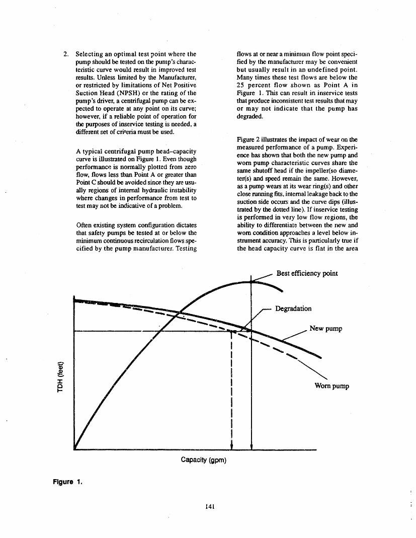
2. Selecting an optimal test point where the flows at or near a minimum flow point speci-pump should be tested on the pump's charac- fled by the manufacturer may be convenientteristic curve would result in improved test but usually result in an undefined point.results. Unless limited by the Manufacturer, Many times these test flows are below theor restricted by limitations of Net Positive 25 percent flow shown as Point A inSuction Head (NPSH) or the rating of the Figure 1. This can result in inservice testspump's driver, a centrifugal pump can be ex- that produce inconsistent test results that maypected to operate at any point on its curve; or may not indicate that the pump hashowever, if a reliable point of operation for degraded.the purposes of _aservice testing is needed, adifferent set of criteria must be used.
Figure 2 illustrates the impact of wear on themeasured performance of a pump. Experi-
A typical centrifugal pump head-capacity eace has shown that both tile new pump andcurve is illustrated on Figure 1. Even though
worn pump characteristic curves share theperformance is nonnaUy plotted from zero
same shutoff head if the impeller(so diame-flow, flows less than Point A or greater than ter(s) and speed remain the same. However,PointC should be avoided since,theyare usu- as a pump wears at its wear ring(s) and otherally regions of internal hydraulic instability close running fits,internal leakage back to tilewhere changes in performance from test to suction side occurs and the curve dips (illus-test may not be indicative of a problem, trated by the dotted line). If inservice testing
is performed in very low flow regions, theOften existing system configuration dictates ability to differentiate between the, new andthat safety pumps be tested at or below the worn condition approaches a level below in-minimumcontinuous recirculation flowsspe- stzument accuracy. This is particularly true ifcified by the pump manufacturer. Testing the head capacity curve is flat in the area
Best efficiency point
Degradation
Capacity(gpm)
Figure 1.
.
141
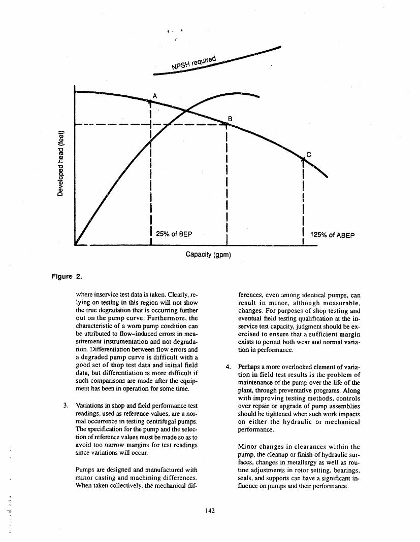
A
I B_u mm lu_ mim
o
g
I I co> I I I
I I II I
I I I 125%OfABEP25% of BEP
Capacity (gpm)
Figure 2.
where inservice test data is taken. Clearly, rc- ferences, even among identical pumps, canlying on testing in this region will not show result in minor, although measurable,the true degradation that is occurring further changes. For purposes of shop testing andout on the pump curve. Furthermore, the eventual field testing qu_dification at the in-characteristic of a worn pump condition can service test capacity, judgment should be ex_be, attributed to flow-induced errors in mea- ercised to ensure that a sufficient marginsurement instrumentation and not degrada- exists to permit both wear art normal varia-tion. Differentiation between flow errors and don in performance.a degraded pump curve is difficult with a
good set of shop test data and initial field 4. Perhaps a more overlooked element of varia-data, but differentiation is more difficult if tion in field test results is the problem ofsuch comparisons are made after the, equip- maintenance of the pump over the life of themeat has been in operation for some time. plant, through preventative programs. Along
with improving testing methods, controls3. Variations in shop and field performance test over repair or upgrade of pump assemblies
readings, used as reference values, are a nor- should be tightened when such work impactsmal occurrence in testing centrifugal pumps, on either the hydraulic or mechanicalThe specification for the pump and the selec- performance.don of reference values must be made so as to
avoid too narrow margins for test readings Minor changes in clearances within the° since variations will occur, pump, the cleanup or fiJ_h of hydraulic sur-
faces, changes in metallurgy as well as rou-Pumps are designed and manufactured with tine adjustments in rotor setting, bearings,
, minor casting and machining differences, seals, and supports can have a significant in-When taken collectively, the mec "hanical dif- fluence on pumps ,'rodtheir performance.
142_
.
An attempt has been made through the evolution of and field, lnservice testing for performance in the fieldANSI/ASME OM--6 to improve the credibility of in- usually results in lost performance unless the pump isservice testing by employing a greater reliance on tested at its design conditions and properly maintained.monitoring mechanical parameters, such as vibrationlevels, after a pump has been initially installed and If a pump has been hydraulically designed withbaselined. Although it is true that a pump's noise level ample capacity margin and properly constructed foror vibration can change due to upset or distress, years the range of fluid conditions when exposed to local en-of experience have shown that noise level or vibration vironmental elements, the pump will not lose perform-monitoring is not a predictable signal of loss in per- ante ff run at its design conditions or not run at all.formance or unminent failure. A heavy duty pump, or
one over-constructed for the service, may show no Demandmeasurable sign of distress due to damage or wear,
either in initial testing or inservice testing if tests are Overall system response to a safety indicationperformed at off-design points. It is far easier to estab- should be the focus for future testing. Measurement oflish nominal hydraulic performa_me levels for pumps performance margins ha fluid systems for componentsthat are predictable and repeatable than to quantify a other than pumps, such as piping, valves, and heat ex-level of mechanical ruggedness for evaluation that en- changers should be undertaken to demonstrate whereabies vibration or noise measurements alone to signal additional system margins can be found.a change in performance.
Continued inservice testing should focus on theTo improve the quality of test results required from proper response of',dl the components within a system.
inservice testing of pumps, a new level of standards Due to the complexity of controls and instrumentation,should be considered, errors ha circuitry pose a greater risk to safety system
function than the small loss of pump capacity thatCONCLUSIONS could occurdue to performance testing.
Enhancement of pump testing to assure safety func- SUMMARYtrans should encompass program elements that address
the needs of the pump and the system. Many compo- To enhance pump testing programs, i.e,, to reducenents must respond properly and perform satisfactorilyfor a system to function, pump degradation and demonstrate overall perform-ance margins, additional test/demonstration programs
should be studied to determine the extentof marDnhaIn recognizing the mechanical and hydraulic charac- other system components. Determination of such mar.
teristics of pumping equipment and systems, thereshould be a clea.rer distinction between performance gins could reduce the burden of pump tests.
and demand capability. For many plants, changing test line sizing and ar-rangement, relocation of instruments, and requalifying
Performance pump performance will be a major undertaking. Over-all, however, enhanced testing procedures will lead to
Routine testing of a pump at less than design condi- a significant reduction in deviations in pump perform-tions introduces both uncertainty ha results and the po- ance, reduction hapump damage and failure, increasedtential for damage. Performance capability, including level of confidence in pump and system response andmargins, should be installed at the time of initial de- capability, and eventually a higher level of assurancesign criteria and acceptance testing both in the shop in plant safety.
143
ATTENDEE- PANEL QUESTIONS AND ANSWERS(EDITED; ATTENDEE QUESTIONS AND PANEL/AUTHOR
RESPONSES NOT IDENTIFIED BY NAME)
Quntlon q machinesareontheragged edgeof demonstratinghy-draulic performance or mechanical performance,
I agree with everything you are saying upthexebasi. we're going to see continuedhigh failurerates.cally, exceptmy onequestionis thatpumpsate failing,circulatingat a highrate. Why does the industrydata There's a controversy still circulating aroundaboutsupporta high failurerate? what a minimumflow is. Manufacturersarewrestling
withthe problemonly becauseof what this is going to
Responu 1 meanto thepopulationwherepresentlyit's installed.
PerhapsI see it a little bit more intimatelybecauseofWe'll listen toapresentationlateron todayconcerning my day-to-day involvementwith thepumpingindus-failurerates.I thinkI'd like to put it into two catego- tryas well as withthe userindustry.But withoutbeingdes. The failureof pumps is two-fold. It fails to pro- able to give you numbersandcite statistics,I thinkweduce either a certain required capacity or head, will all probablysee the same reportsas well as thedependingon either tech spec requirements,andthen areasthatarecomingin aboutwhy pumpsare failing.there'sthe failureof the pumpmechanically.
I thinkthe bottom line is that pumps arc failing be-I thinkwe've ',diseen the documentationof a disturb- cause we're notoperatingthem the way they werede-ing rateof failureof auxiliaryfeedwaterpumpsathigh signed to operate,_Jidwe're not conveying back intohead per stage in the sprit case or barreltype pumps thedesign of thesystemsand thedesign of thepumpsthathave been working at very low minimumflows, whatwe expectedthem todo.Again, the failureis qualitative.
I don't think ali hope is lost. I think we can retrofitI thinkEPRI,as well as otherpeopleperhaps,will be thesesystemsandvasty improvetheperformanceandpresentingthe datalateron thatindicate the failureis almostto thepoint withouteliminatingoperatorerrorthere.I thinkwe know it's there,andIthinkwe suspect get tothepointwherethesepumpsareasreliableasthethatunless we do someL_ng to recognize why these balanceof plantequipmentthatis runcontinuously.
= 144
J
,'=,,'_'fll"" ,1'1=,,',"'q,""Illl_',II" "" ' II'1'__II '_r

MEASUREMENTS OF VIBRATIONAL ,PARAMETERSFOR PUMP TESTING
J. HOWARD MAXWELL"ARIZONA PUBLIC SERVICE
ABSTRACT rotates with the rotor and so at a single point on thebearing appears as a sinusoid with a frequency equal tothe speed of the machine. The frequencies of vibrationDetermining a pump's condition by vibration mea-are important parameters and are usually denoted assurement requires an understanding of the generated
forces, the equations of motion of the machine's struc- multiples or harmonics or the running speed of tlm ma-chine. For example, the unbalance force, is a Ixrpm fie-ture, and the effect that instrumentation has on the mea-
surements. Unbalance, misalignment, bearing damage, quency force. The forces on the rotor from theoff design operation (miniflow, cavitation), and other coupling are both radial "andaxial and can be once permachinery problems generate forces inside the machine revolution, twice per revolution, or higher multiples
(i:e. 1 x rpm, 2 x rpm, etc). These forces are resistedwhich usually can be inferred by the motion of the out-side of the machine. These forces are usually generated by the radial and thrust bearings.on the rotor and may cause damage to the rotor or bear-
The forces on the rotor from the fluid are more com-ings by wear, overload, or fatigue. These forces alsocause motion of the structure of the machine which can plicated. The torque from the rotor is resisted by the
mass of the fluid, and generates not only resistingbe measured as displacement, velocity, or acceleration.Within certain limits, this vibration can be used in care- torque but also radial and axial forces. These dynamic
forces are not sinusoidal at a single frequency, a,sis thegorizing the,severity of the machine's condition.unbalance force, but are random. The frequency bandof this random "noise" extends from zero Hertz (cycles
The measurement system including the transducer,conditioning electronics, calculation choices, and per second) to a frequency dependent onthe velocity of
the fluid. "Theamplitude of the force is largest at the lowmeasurement electronics will significantly affect theend and decreases at higher fiequencies. The upper fre-results. Transducers, with some distortion, transform
vibration into electronic signals. Various parameters quency of any significant amplitude ranges from 20 ormay be calculated from the resulting wave forms, in- 30 Hz for a feed pump at miniflow to 100 Hz for a
Reactor Coolant Pump at higher than design flow. Be-cluding four different kinds of amplitude. The wave-cause the velocity and acceleration vectors on the fluidform can be Fourier transformed, and the resultant
spectra analyzed ibr amplitudes and frequencies, align with the pump internals at the design flow, the am.plitude of the radial flow forces is minimum at designflow. At mini.flow or lower there is extreme misalign-
VIBRATION BASICS ment of the fluid forces to the pump internals whichcauses the radial flow forces to be large.
The forces in a pump which can lead to vibration
come from either the driver through torque and mo- As the impeller vane approaches a diffuser or cut-ments on the coupling, oz from other sources in the ma- water in the pump, a pressure pulse is generated. Thechine's environment, e.g. nearby pumps, pressure frequency of these pulses is called the vane passingpulsations in the fluid, etc. ']'he torque applied by the frequency, 1 x VP, and is the least common denomi-driver causes rotation of the rotor and is opposed by nat0r of the number of the vanes and diffuser vanesforces on the rotor from tl_ fluid, times the rpm.
The rotation of the rotor produces centrifugal forces The random flow induced forces and the vane pass-and forces at the coupling. The centrifugal force is pro- ing forces are resisted by the bearings, but they are alsopoaional to the square of the speed, the mass of the ro- transmitted to the pump case, the piping, and the fluidtor and the distance between the mass center and the up anddown stream of the pump. Any of these mechani-rotational center. Tiffs "unbalance" force is perpendic, cal or fluid structures can amplify the forces through theulm" to the axis of spin and is resisted by the bearings mechanism of a resonance discussed below, and thenand the structures that support the bearing. The force reintrodt_ce large forces onto the rotor or pump case.
a. Arizona Public Service, Palo Verde Nuclear Generating Station
145
_
The bearings also have some rotation. The lubricant F = kTx+ cv + m (1)
in a sleeve bearing rotates at approximately
0.42 x rpm. Under certain circumstances large mo- k = spIing stiftness [pounds/inch]tions can be generated at this frequency. Roller ele-ment bearings have rollers and cages which rotate at m = mass [pounds-sec^2/inch]
speeds different from the rotor. Faults in these ele- c = damping [pound-see/inch]ments can generate their own frequencies or can mod-
ulate the rotor's vibration including multiples of x = displacement [inches]l xrpm. The bearings, especially sleeve bearings arenon-linear. This means that they act as frequency mix- v = velocity [inches/second]ers and can generate new frequencies which are multi-
pies or Sum and differences of the flequencies of the a = acceleration [inches/second^2]
applied threes. F = exciting iorce [pounds] .
If the force is a sinusoid, then the equation can beAs an example, consider a simple involute-type solved for x as"
pump operating at 1800 rpm, with ball-bearings, 5 im-
peller vanes operated at mim-flow. The following fie- F = f'sin(wt) (2)quencies of forces would be expected:
x = f*sin(wt-P)/_lr[(c*w)^2+(k-m*w^2Y,2] (3)
® 0--20 Hz random where:
• 0,4 x rpm (approximately) bearing cage pass
,, 1 x rpm unbalance and misalignment P = Atn(c*w/(k-m*w^2)) in radians
• 2 x rpm misalignment or bearings
• 3 x rpm misalignrnent or bearings w = frequency in radians per second
,, 3-6 x rpm ball pass (not an even multiple) t = time in secomLs .
: • 5 x rpm vane passing.Note that the displacement is a sine wave whose am-
These forces are transmitted from the rotor through plitude and phase change with frequency. Secondly,
the bearings to the supporting structure, or through the notice tl'mt if w=0 then A=f/k which is a simple springfluid to the case to the supporting structure. These motion. Also, when w=0, the phase (time lag between
the force and tl_ displacement) is 0. If the fiequency isforces are dynm'nic'and affect the structures throughvery high then m'w^2 is much larger than k, and
which they pass. If relative motion occurs between two (m'w^2)^2 is much larger than (c'w)^2 so the dis-structures (shaft and bearing for example) then wear placement becomes only a function of the frequencywill occur. The forces will also cause flexing. Moder- ,'uxl the mass. Figure 1 shows a plot of displacementate flexing will cause fatigue, antt large motions will versus frequency.cause overload failure. The motion, or vibration, of a
piece of the structure is what we measure to estimate Figure 1 shows the effect of fi'equency and dampingthe forces, wear, and fatigue of the various structures in on the amplitude of vibration. The phase also changes,
--- the machine, Because the forces originate on the rotor, getting larger as a proportion oi :t',c i_riod as the fre-the motion of the rotor is usually the largest motion in quency increases. At large frequencies, the time lag ap-the machine. As the forces move through the bearings proaches 0.5 of the period or 180 degrees. The
: and other structures of the machine, the motions are at- frequency where the maximum vibration occurs istenuated, sometimes amplified, and distorted, called a natural frequency, a resonance, or in rotating
equipment a critical speed. The damping m typical ma-chinery ranges from 0.3 for journal bearings to .005 for
Et_O_TIONS OF MOTION OF A welded structure_.
STRUCTURE Because velocity is the derivative of displacementand acceleration is the derivative of velocity, the
The equation of motion for a single degree of free- motion of the structure can be measured and described
duro system is' by any of the three terms. The relatiortships are'
146

Figure 1.
d = A'sin(wt+P) (4) 10,000 rpm velocity is usu',dly used to monitor for ma-chine condition. So, tbr most power plant machines,
v = A*w*sin(wt+P+PI) (5) and for most problems, velocity is the appropriatemeasure. There is one important exception to this rule.
a = A*w^2*sin(wt+P+2*P]) (6) Sensors which directly monitor the shaft motion, suchas shaft riders and proximity displacement sensors, ,are
Note that the velocity is shifted 90 degrees and mul- closer to the generated forces than bearing housingtiplied by w, and that the acceleration is shifted by 180 readings and suffer less distortion. They also measuredegrees and multiplied by w^2. a displacement which can be directly compared to the
bearing clearance. These advantages outweighs the in-
The choice of the units to be used is dependent on convenience of using a displacement measure and cal-the objective of the person making the measurement, culating alarms from the equivalent velocity.in determining the condition of machinery there are
four basic conditions we wish to detect: contact be- SIGNAL ANALYSIS BASICStween rotating and stationary parts, overload, fatigue,and wear. Contact between the rotor and stator is ob-
viously a function of the displacement of the rotor and The vibration transducer transforms the structurethe relative internal clearance. Overload is function of motion to a time varying signal. This signal is usually
the force applied and, as seen above, is the sum of interpreted in the time domain, i.e. as a waveform. Wa-
functions of displacement, velocity and acceleration, veforms that do not have any random components ,areHowever, for very low frequencies the displacement analyzed as a combination of simple sine waves. Each
sine wave h_s three parameters as _en in Figure 2: theterm is very much larger than the other two. At veryhigh frequencies the acceleration term is the highest, frequency or period, the amplitude, and the time lag or
: and the force as a percent of yield is much higher than phase.the displacement as a percent of the internal
clearances. A in the equation in Figure 2, is the amplitude zeroto peak (0-p)..This measure is usually used for acceler-
Between the "low" and "high" frequencies the dis- ation and velocity signals. The double amplitude 2A,placement is small compared to internal clearances, or peak to peak (p-p), is usually used for displacementand acceleration or inertial forces are small, so the signals. In Europe, and for signals with a random com-
main effects of the motion are wear and fatigue. Wear ponent, the Root-Mean-Squared measure is used. Foris related to energy which is proportional to velocity a single sine wave tie amplitude rms equals 0.707'A.squared. In addition, fatigue (force times cycles) is Rarely is the average value of 0.5*A used. The rela-proportional to velocity, tionship between the difterent measures given here are
only for single sine waves. For the more usual cornbi-
The definition of "very high" and "very low" is nations seen in vibration, the relationship become,ssomewhat subjective, but machines which operate be- more complicated.low 600 rpm are usually measured in displacement,
and machines above 10,000 rpm are usually measured The term w in Figure 2, is the frequency in radiansin acceleration. In the speed range between 600 and per second, lt is usually converted into Hertz (Hz) or
lt4/
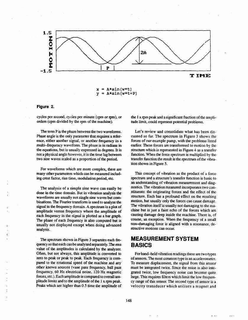
1,5 •
0
0Z I P I-1.5
•r i t,,
X = A,sin(w't,)y = A*sin(w*t+P)
' Flgure 2.
cycles per second, cycles per minute (cpm or rpm), or the 1x rpm peak and a significant fraction of the ampli-orders (cpm divided by the rpm of the machine), tude limit, could representpotential problems.
The term P is the phase between the two waveforms. Let's review and consolidate what has been dis-Phase angle is the only parameter that requires a refer- cussed so far. The spectrum in Figure 3 shows theence, either another signal; or another frequency in a forces of our example pump, with the problems listedmulti--frequency waveform. The phase is in radians in earlier. These forces are transformed to motion by thetlm equations, but is usually expressed in degrees, lt is structure which is represented in Figure 4 as a transfernot a physical angle however, it is the time lag between function, When the force spectrum is multiplied by thetwo sine waves scaled as a proportion of the period, transfer function the result is the spectnma of the vibra-
tion shown in Figure 5.
For waveforms which are more complex, there axemany other parameters which can be measured includ' This concept of vibration as the product of a forceing crest factor, rise time, modulation period, etc. spectrum and a structure's transfer function is basic to
an understanding of vibration measurement and diag-
The analysis of a simple sine wave can easily be nostics. The vibration measured incorporates two con-done in the time domain. But in vibration analysis the stituents: the originating forces and the effect of thewaveforms are usuaUy not single sine waves but com- structure. Each has a profound effect on the resulting
binations. The Fourier transform is used to analyze the motion, but usually only the forces can cause damage.: signal in the frequency domain. A spectrum is a plot of The vibration itself is usually not damaging to the ma-
amplitude versus frequency where the amplitude of chine but is just a faint echo of the forces which areeach frequency in the signal is plotted as a bar graph, causing damage deep inside the machine. There is, ofThe phase of each frequency is also computed but is course, an exception, when the frequency of a smallusually not displayed except when doing advanced non--damaging force is aligned with a resonance, de-analysis, structive motions can occur.
The spectrum shown in Figure 3 separates each fire- MEASUREMENT SYSTEMquencysothateachcanbeanalyzedseparately.Themis BASICSvalue of the amplitudes is calculated by the analyzer.
Often, but not always, dais amplitude is converted to For hand-held vibration readings there are two typeszero to peak or peak to peak. Each firequency is com- of sensors. The most common type is an accelerometer.pared to the rotational speed of the machine and any To measure displacement, the signal from this sensorother _iown sources (vane pass frequency, ball pass must be integrated twice. Since the noise is also inte-frequency, 60 Hz electrical noise, 120 Hz magnetic grated twice, low frequency noise can become quiteforces, etc.). Each amplitude is compared to overall am- large. This reqttires filters which limit the low frequen-plitude lianits and to the amplitude of the I x rpm peak. cy range of this sensor. The second type of sensor is a
- Peaks which are higher than 0.5 time tlae amplitude of velocity transducer which utilizes a magnet and
- 148
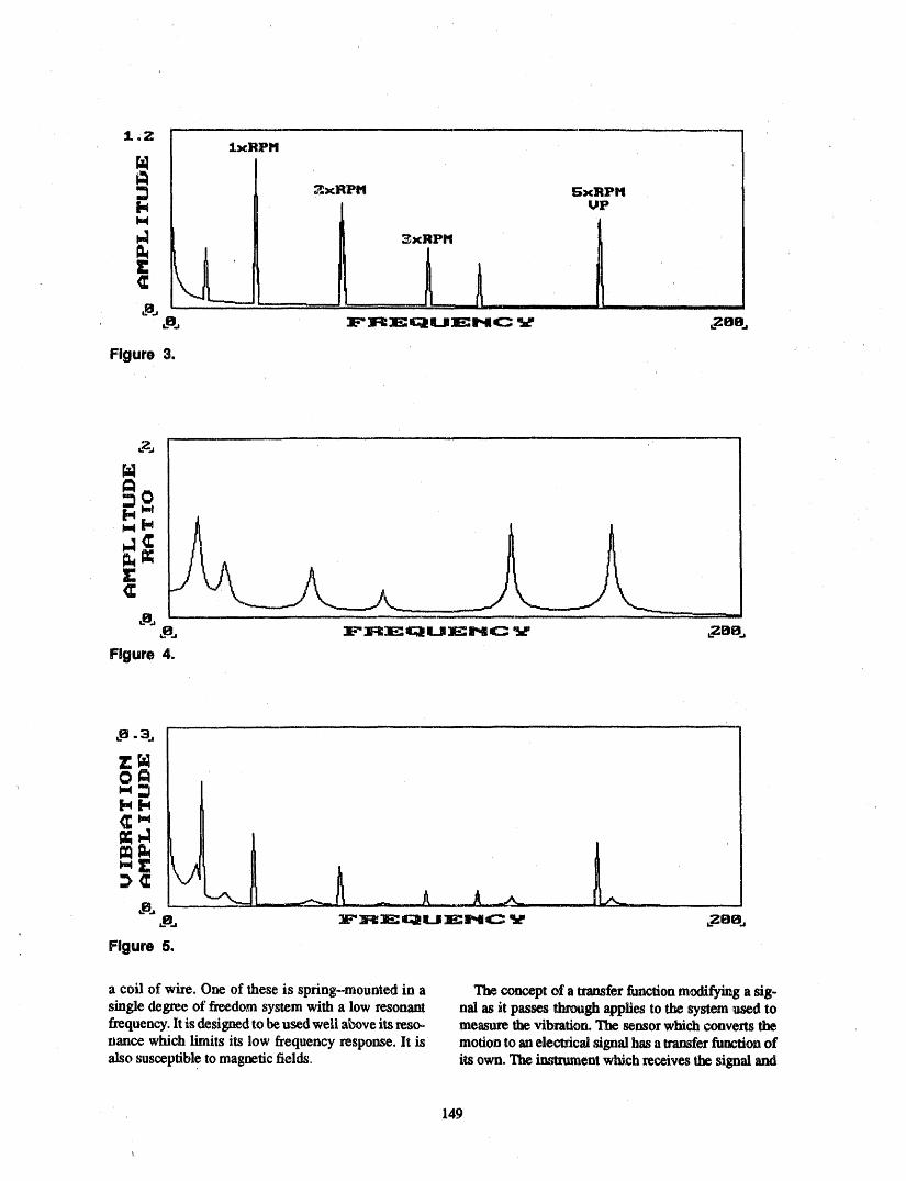
i.ZIxRPM
2xRPM S;xRPMUP
. t.-- :. j ..... : ....
i_mm = _L ,[ . L.... IIIIII I
,..o., :aL=':W_ c;I U:EHC _ _08.,
Figure 3,
Figure 4.
0
_., :F:R:E=Ca_U:Ear',eC _ ,.zoo..,
Figure 5.
a coil of wire. One of these is spring-mounted in a The concept of a transferfunctionmodifying asig-single degree of freedomsystem with a low resonant nal as it passes throughappliesto the system used tofrequency.Itis designedto beused well a_oveits reso- measme the vibration.The sensorwhich convertsthenance which limits its low frequency response. It is motionto an electricalsignalhas a transferfunctionofalso susceptibletO magneticfields, its own. The insmunem which receives the signal and
149
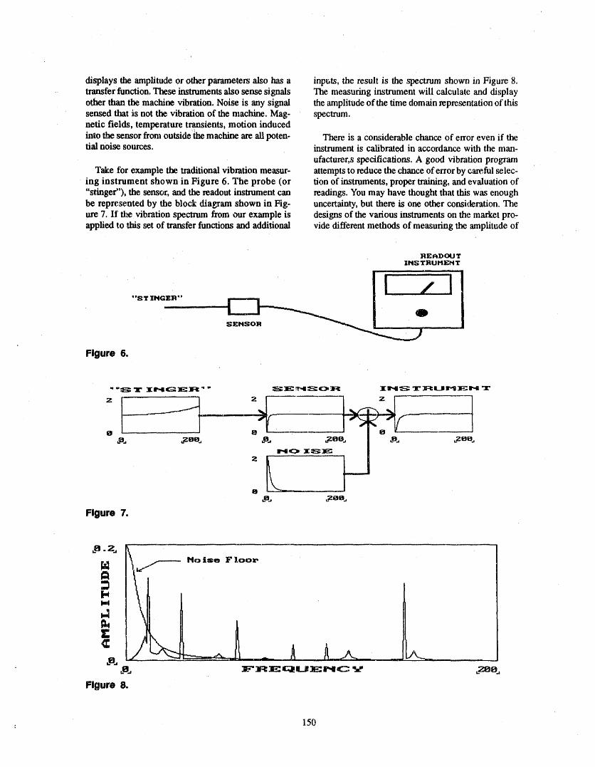
displays the amplitude or other parameters also has a inputs, the result is the spectrum shown in Figure 8,transfer function. These instruments also sense signals The measuring instrument will calculate and displayother than the machine vibration. Noise is any signal the amplitude of the lime domain representation of thissensed tlmt is not the vibration of the machine. Mag- spectrum.netic fields, temperature transients, motion inducedinto the sensor from outside fl_emachine are ali poten- There is a considerable chance of error even if thetial noise sources, instrument is calibrated in accordance with the man-
ufacturer, s specifications. A good vibration programTake for example the laaditional fibration measur- attempts to reduce the chance of error by careful selec,
ing instrument shown in Figure 6. The probe (or tion of instruments, proper training, and evaluation of"stinger"), the sensor, and the readout instrument can readings. You may have thought that this was enoughbe represented by the block diagram shown in Fig- uncertainty, but there is one other consideration. Theure 7. If the vibration spectrum from our example is designs of the various instruments on the market pro-applied to lifts set of transfer functions and additional vide different methods of measuring the amplitude of
READOUTIHS TRUHEH Y
"ST ING'_-R °' ....
..... 0 .....
Figure 6.
" "S T I_4GEJ_ " " SE_',I:S:O']:I I_4S T]:¢i.JrlEl"4 T
------.----__ _'_ __,_m '
o - --- a ,- • ,7-e ,zea.,
8 --_-
Figure 7.
No lse F loox.
E¢
Figure 8.
150
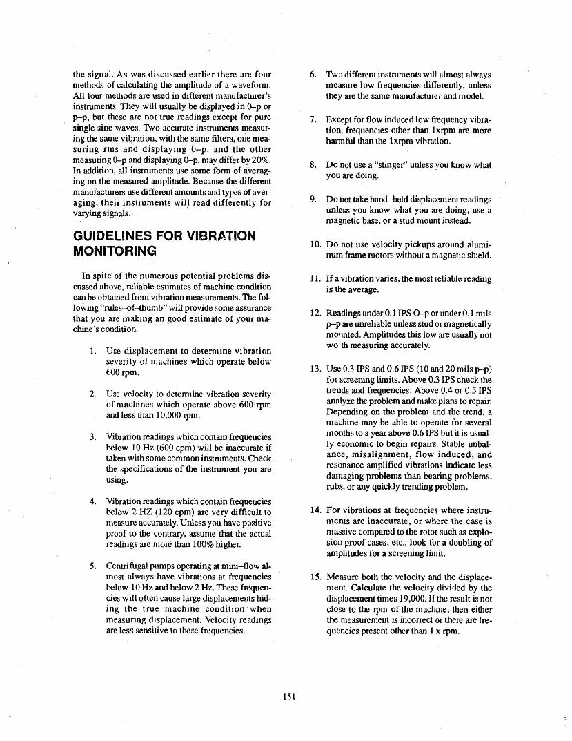
the signal. As was discussed earlier there are four 6. Two different instruments will almost alwaysmethods of calculating the amplitude of a waveform, measure low frequencies differently, unlessAI1 four methods are used in different manufacturer's they are the same manufacturer and model.instruments. They will usually be displayed in 0--p or
p--p, but these are not true readings except for pure 7. Except for flow induced low frequency vibra-single sine waves. Two accurate instruments measur- tion, frequencies other than ixrpm are moreing the same vibration, with the same filters, one mea- harmful than tile lxrpm vibration.suring rms and displaying 0-p, and the other
measuring 0-p and displaying 0-p, may differ by 20%, 8. Do not use a "stinger" unless you lalow whatIn addition, all instruments use some form of averag-ing on the measured amplitude. Because the different you are doing.manufacturers use different amounts madtypes of aver-aging, their instruments will read differently for 9. Do not take hand-held displacement readingsvarying signals, unless you know what you are doing, use a
magnetic base, or a stud mount instead.
GUIDELINES FOR VIBRATIONMONITORING 10. Do not use velocity pickups around alumi-num frame motors without a magnetic shield.
In spite of the numerous potential problems dis- 11. If a vibration varies, the most reliable readingcussed above, reliable estimates of machine condition is the average.can be obtained from vibration measurements. The fol-
lowing "rules--of-thumb" will provide some assurance 12. Readings under 0.1 IPS O-p or under 0.1 milsthat you are making an good estimate of your ma-chine's condition, p--p are unreliable unless studor magnetically
mo,rated. Amplitudes this low ,areusually notwo_lh measuring accurately.
1. Use displacement to determine vibrationseverity of machines which operate below600 rpm. 13. Use 0.3 IPS and 0.6 [PS (10 and 20 mils p---p)
tbr screetfing limits. Above 0.3 IPS check the
2. Use velocity to determine vibration severity trends and frequencies. Above 0.4 or 0.5 IPSof machines which operate above 600 rpm analyze the problem and make plans to repair.and less than 10.000 rpm. Depending on the problem and the trend, a
• machine may be able to operate for several
3. Vibration readings which contain frequencies months to a year above 0.6 IPS but it is usual-below 10 Hz (600 cpm) will be inaccurate if ly economic to begin repairs. Stable unbal-
ance, misalignment, flow induced, andtaken with some common instruments. Checkresonance amplified vibrations indicate lessthe specifications of the instrument you are
using, damaging problems than bearing problems,rubs, or any quickly trending problem.
4. Vibration readings which contain frequenciesbelow 2 HZ (120 cpm) are very difficult to 14. For vibrations at frequencies where instru-measure accurately. Unless you have positive merits are inaccurate, or where the case isproof to the contrary, assume that the actual massive compared to the rotor such as explo-readings are more than 100% higher, sion proof cases, etc., look for a doubling of
amplitudes for a screening limit.
5. Centrifugal pumps operating at mini-flow al-most always have vibrations at frequencies 15. Measure both the velocity and the displace- 'below 10 Hz and below 2 Hz. These frequen- ment. Calculate the velocity divided by thecies will often cause large displacements hid- displacement times 19,000. If the result is noting the true machine conditionwhen close to the rpm of the machine, then eithermeasuring displacement. Velocity readings tlm measurement is incorrect or there ate fre-are less sensitive to these frequencies, quencies p_sent other than 1 x rpm.
151

A'i'rENDEE- PANELQUESTIONS AND ANSWERS(EDITED; ATTENDEE QUESTIONS AND PANELAUTHOR
RESPONSES NOT IDENTIFIED BY NAME)
Question1 very smallstingeratlessthanhalfan inchordirectlywith the probe on the bearing housing.
I'm having a little trouble figuring out how you canequate and use this specific frequency information that For slow speed readings, where you are going to beyou were displaying and apply it to the OM--6or IWP measuring in mils, you canget significant lowfrequen-program.How do you sum ali those pieces up and ap- cy errorsbecause,youcan't hold your handexactly stillplyit tothe simplistic specs t_t arein thoseprograms7 and you are takingvery small readings. So, we use• magnets, but magnets are tricky.You have to be re,al
careful with them, make sure they don't rock. They areResponse I not usable abovea certain vibrationamplitudebecause
they'll shake themselves off. So you may even need toAs I said when I started out, I'm not talkingabout any hand hold the magnet on there if your amplitudes areaof the OM standards.This is just machinery practice, little higher.
I think that there's a problem with the current stan- Question 3dards, in that they don't address the analysis or diag-nosticsof the speclrums.We nevermakeany decisions OM--6states that the vibration spectrum shall be fromon balance-_f-plant equipment without looking at the one-third minimum pump speed to 1,000 Hz. Has thespectrums tosee ifwe can't figure outwhat's going on. committee considered reducing the range to suit oper-
ating conditions at the discretion of the licensee?Yourun into instrumentproblems, humanerrors. It's aflow problem, it's not a vibration problem,andgoing Reaponse 3withanoverallamplitudeisgoodforscreening.
I guess, at the discretion of the licensee, no. That hasWhat we do in our balance-of-plant equipment is use not been considered yet.0.3 and 0.6 LPSas can"screening limits, but we don'ttake any drastic decisions without looking at the Question 4spectrum.
With the Inteletron system we use, we are able to use aQuestion 2 spectrum range of anything we select, from zero to
400, zero to 1,000.The resolution of the equipment in-
What are the best methods of attaching the stinger to creases if we reduce that spectrum.the motor pumpbearing?Someutilities usemagnetstomount the accelerometer during the test. Other utilities Because of our equipment limitations, is it acccpLable
to go ahead and use the zero to 400, or L_there an 800usebuttons, spectrum?
Response 2 Response 4
Weil, the stinger rod is normally something like an From a technical point of view, I like taking an until-eight-inch aluminum rod that screws into the sensor, tered overall value, and that would be up to 1,000 Hz.and that is usually h_mdheld.Stingers arevery.bad be- Some instruments provide that.cause of their resonant fre_luency.
Some instruments are limited by the same frequencyThere's no good answer to how to mount it. From a range you have for your spectrum.That's what it lookstechnical point of view, the best wayis to stud mount it like for the overall instrument use. So, we need to getinaccordance with an API 678 standard,but that is, ex- the benefit of both of those, lt turns out tobe ahigh fre-cept for permanent accelerometers, hard to do and it's quency that's outside our normal analysis range.hard to keep your surfaces clean. For general machin-
-_ cry monitoring thereis an acceptablecompromise,and We go for the overall. And that happens enough timesthat is to use handheld probes without the stinger. In that I think it's worthwhile taking an overall from aother words, you put the accelerometer either with a low frequency, up to a_ut 1,000Hz.
152
LOW-FLOW OPERATION AND TESTING OF PUMPSIN NUCLEAR PLANTS.
W.L. GREENSTREETOAK RIDGE NATIONAL LABORATORY
P.O. BOX 2009OAK RIDGE, TENNESSEE 37831-8063
ABSTRACT clear Plant Aging Research Program sponsored by theU.S. Nuclear Regulatory Commission. These sludiesled to a review of low-flow operation and testing of
Low-flow operation of centrifugal pum0s intro-centrifugal pumps and their consequences; the resultsduces hydraulic instability and other factors that cml are the basis for the discussions herein.
cause damage to these machines. The resulting degra-
dation has been studied and recorded for pumps in A centrifugal pump is designed for best perform-electric power plants. The objectives of this paper are ance at a specific combination of capacity, head, andto (1) describe, the damage-producing phenomena, in- ,speed, that is, the best efficiencypoint (BEP). At theeluding their sources and consequences; (2) relate
design or BEP flow rate, the fl_id motion is compatiblethese observations to expectations for damage caused with the physical contours of the hydraulic passagesby low flow operation of pumps in nuclear power and is therefore well-behaved. However, careful con-
plants; 'and(3) assess the utility of low-flow testing, sideration must be giver, to the operating range for agiven application to minimize undesirable effects of
Hydraulic behavior during low-flow operation is off-design flows.reviewed for a typical centrifugal pump stags, and the
damage-producing mechanisms are described. Pump During operation "andtesting, flow rates can be onmonitoring practices, in conjunction with pump per- tlm order of 5 to 15% of BEP flow. These flow rates
fommnce characteristics, are considered; experience stem from system bypass lines being sized to limit thedata are reviewed; and the effectiveness of low-flow temperature rise. of the pump without regard to hydrau-surveillance monitoring is examined. Degradation lic behavior effects. Deterioration resulting from low-caused by low-flow operation is shown to be an lm- flow hydraulic instability influences was notpollant factor, and low-flow surveillance testing is considered until relatively recently.shown to [re inadequate.
For reduced flow, the larger the percentage of BEPflow, the better it is for the pump. In well-engineered
INTRODUCTION pumps, 25 to 35% is sufficient to avoid the dangerous
range of off--design operating flow. However, for someThis paper is an outgrowth of studies on auxiliary pumps, any flow below 50% of BEP capacity may
feedwater pumps that were conduded under the Nuo cause severe vibration.
a. Research spomored by Office of Nuclear Regulatory Research, U.S. Nuclear Regulatory Commission underImeragency Agreement 40-551-75 with the U.S. Department of Energy under Contract DE-AC05-840R21400with Martin M,'uietta Energy Systems, Inc.
t t._,l ,b.._..o,u_,ott._,.tJt _r _ -.,..tt,t.rt, l_._tUql_., _ • .t'_ d I t..t,,d ,t--UVV,,), %.J}.I'_IGt_U I./_ ,LYI,f,,LIUII J.VJtCll &_tL..tt ,L.i,lJl_l_y O_tl_lllb t
Inc. for the U.S. Depatx.mem of Energy.__
=
153
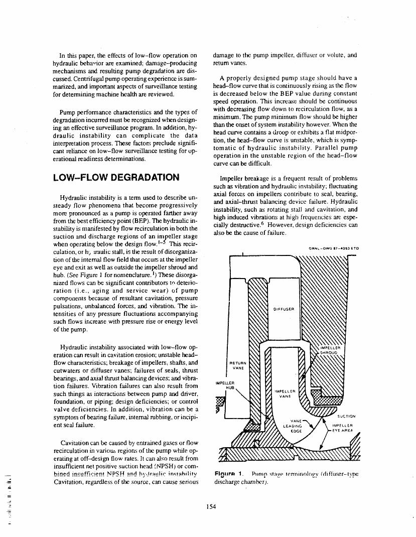
In this paper, the effects of low-flow operation on damage to the pump impeller, diffuser or volute, andhydraulic behavior are ex,'unined; damage--producing return vanes.mechanisms and resulting pump degradation are dis-cussed. Centrifugal pump operating experience is sum- A properly designed pump stage should have amarized, and important aspects of surveillance testing head--flow curve that is continuously rising as the flowfor determining machine health are reviewed, is decreased below the BEP value during constant
speed operation. This increase should be continuous
Pump performance characteristics and the types of with decreasing flow down to recirculation flow, as adegradation incurred must be recOgnized when design- minimum. The pump minimum flow should be highering an effective surveillance program. In addition, hy.. than the onset ofsystem instability however. When thedraulic instability can complicate the data head curve contains a droop or exhibits a flat midpor-interpretation process. These factors preclude signifi- tion, the head-flow curve is unstable, which is syrup-cant reliance on low-flow surveillance testing for op- tomatic of hydraulic instability. Parallel pumperational readi_ss determinations, operation in the unstable region of the head-flow
curve can be difficult.
LOW-FLOW DF:GRADATION Impeller breakage is a frequent result of problem,,_such as vibration and hydraulic instability; fluctuating
Hydraulic instability is a term used to describe un- axial forces on impellers contribute to ._al, bearing,steady flow phenomena that become progressively and axial-thrust balancing device failure. Hydraulicmore pronounced as a pump is operated farther away instability, such as rotating st'ali and cavitation, andfrom the best efficiency point (BEP). The hydraulic in- high induced vibration.s at high frequencies are espe-stability is manifested by flow recirculation in both the cially destructive. 6 However, design deticiencies canalso be the cause of failure.suction and discharge regions of an impeller stagewhen operating below the design flow. !-5 This rech'-.culation, or h) n'aulic stall, is the result of disorganiza- o_,,t.-owQe7-,2_ _rt_tion of the internal flow field that occum at the impellereye and exit as well as outside the impeller shroud and
hub. (See F'igure 1 tbr nomenclature. 1)These disorga- .,,,.,
nized flows can be significant contributors tn deterio- _ration (i.e., aging and service wear) of pump ---components because of resultant cavitation, pressure ,,,pulsations, unbalanced forces, and vibration. The in- _.._tensities of any pressure fluctuations accompanying _._such flows increase with pressure rise or energy level ,_- _\
of the pump. ,'_,'_
Hydraulic instability as,,;ociated with low-flow op- -_eration can result in cavitation erosion; unstable head ....flow characteristics; breakage of impellers, shafts, and _ErUR, ,_._
VANE '_x_, raJ
cutwaters or diffuser vanes; failures of seals, thrust ...
bearings, and axial thrust balancing device.,;; and vibra- """IMPELLER '= " "
Lion failures, Vibration failures can also result from .ua, "'"such things as interactions between pump "and driver, ._,,j "_ _.,_ 7/ ,mPEt.t.er_,_ x ",, vANE
foundation, or piping; design deficiencies; or control _ _N_valve deficiencies. In addition, vibration can be a ,..,,,
symptom of bearing failure, internal rubbing, or incipi- ,... N,_."_k, sur_r,onent seal fadure. /'X t.eAt_,_,_ ,M_F.ut._._
_F_EA
/_ EDGE
recirculation in ,,,ariou.,_region.,_of the pump while op- 7'_erating at off-design flow rates. It caw also result from ,,.,,..,insufficient net positive suction I'_eadfNPSH) or com-bined in.,:'uf.C,.cien!NPS_H _nd by,_ir_u!ic im:!nhility Fl_l_r_ 1. P_rr_p rt:,ga lerminoir_dy (dif'fu._r-t,,_e
" Cavitation, regardless of the source, can cause serious discharge chamber).--7t--
I
_- 154
_
_
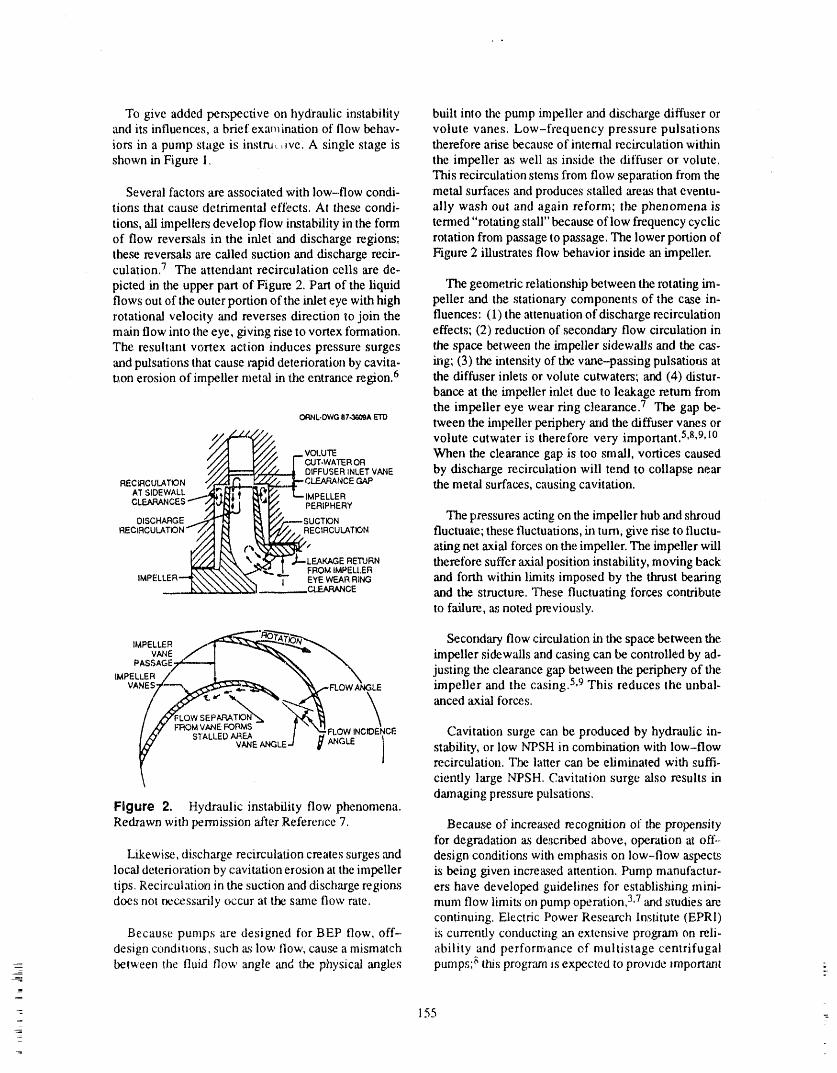
To give added perspective on hydraulic instability built into the pump impeller and discharge diffuser orand its influences, a brief examination of flow behav- volute vanes. Low-frequency pressure pulsationsiors in a pump stage is instru,+, ive. A single stage is therefore arise because of internal recirculation withinshown in Figure 1. the impeller as well as inside tile diffuser or volute.
This recirculation stems from flow separation from theSeveral factors are associated with low-flow condi- metal surfaces and produces stalled areas that eventu-
tions that cause detrimental eftects. At these condi- ally wash out and again reform; the phenomena is
tions, ali impellers develop flow instability in the form termed "rotating stall" because of low frequency cyclicof flow reversals in the inlet and discharge regions; rotation from passage to passage. The lower portion ofthese reversals are called suction and discharge recir- Figure 2 illustrates flow behavior inside an impeller.culation. 7 The attendant recirculation cells are de-
picted in the upper part of Figure 21Part of the liquid The geometric relationship between the rotating im-flows out of the outer portion of the inlet eye with high peller and the stationary components of the case in-rotational velocity and reverses direction lo join the fluences: (1)the attenuation of discharge recirculationmain flow into the eye, giving rise to vortex formation, effects; (2) reduction of secondary flow circulation inThe resultant vortex action induces pressure surges the space between the impeller sidewalls and t_. cas-and pulsations that cause rapid deterioratiotl by cavita- rag; (3) the intensity of the vane-passing pulsations atuon erosion of impeller metal in the entrance region. 6 the diffuser inlets or volute cutwaters; ar_:!(4) distur-
bance at the impeller inlet due to le_age return fromthe impeller eye wear ring clearance. 7 The gap be-o_+L.owa,r.,.',_Am'Otween the impeUer periphery and the diffuser vanes or
__._, volute cutwater is therefore very important. 5,8,9,1°'_/ vot.urE When the clearance gap is too small, vortices caused
7 CUT-WATEROR_/,')__ DIFFUSERINLETVANE by discharge recirculation will tend to collapse near
REC_CULATfON _:t__.@CLEARANCE GAP the metal surfaces, causing cavitation.AT SIDEWALL _IR._ l [_'jl_,,_, L--IMPELLER
DISCHARGE_....-7M [N_W/,----SUC'r_ON The pressures acting on the impeller hub and shroud
RECIRCULATION _ ff _ ,.__R?CIRCULA'I'ION fluctuate; these fluctuations, in turn, give rise to fluctu-
._ ( ating ne_.axial forces on the impeller. The impeller will
' i KN_ \ _,,L--LEAKAGE RETURN therefore suffer axial position instability, moving back_'_,\\\_'_'_.. I FROM IMPEU.ER
IMPELLER NNN.\_N,,'K'N -'*i- EYEWEAFIRIbK3 and forth within limits imposed by the thrust bearing__ __ " __CE and the structure. These fluctuating forces contribute
to failure, as noted previously.
__.,,. Secondary flow circulation in the space between theIMPELLER j,,_'__" _VANE,f I _ -'_ "_ impeller sidew',dls arid casing can be controlled by ad-
1 ",,.\ \ justing the clearance gap between the periphery of tileIMPELLER ,/ { %_ \
VANES___ _-FLOWA_IGL E impeller and the casing.5,9 This reduces the unbal-anced axial forces.
/ ,_ r,'r,.,_,:(_,_,_ / "_'FLOWINCIDENCE Cavitation surge can be produced by hydraulic in-• stability, or low NTSH in combination with low-flow
recirculation. The latter can be eliminated with suffi-
ciently large NPSH. Cavitation surge also results ind_naging pressure pulsations.
Figure 2. Hydraulic instability flow phenomena.
Redrawn with permission after Reference 7. Because of increased recognition of the propensityibr degradation as de,scribed above, operation at off-
Likewise, discharge recirculation creates surges and design conditions with emphasis on low--flow aspectslocal deterioration by cavitation erosion at the impeller ks being given increased atlention. Pump manufactur-tips. Recirculation in the suction and discharge regions ers have developed guidelines for establishing mini-does not _cessarily occur at the same flow rate. mum flow limits on pump operation, 3,7and studies are
continuing. Electric Power Research Institute (EPRI)Because pumps are designed for BEP flow, off- is currently conducting an extensive program on reli-
design conditions, such as low flow, cause a mismatch ability and performance ef multistage centrifugal=_ between the fluid ilo,,,,, angle and dae physical angles pumps; i;mis program is expected to provide mlportant
1
_" 155 =
_
7=
information on low-flow operation. A study on the in- Ns range from 741 to 3080; an examination of hi#r-fluence of surveillance testing at low flow on failure of and low--pressure safety injection, containment spray,
emergency pumps in nuclear power plants was recent- and auxiliary feedwater (AFW) pump data for a singlely completed by EPRI. II PWR plant gave a Ns range from 1000 to 1850. The
range of estimated maximum Ns values for pumps in
lt was noted earlier that intensifies of pressure fluc- engineered safety feature and safety-related systemstuations accompanying disorganized flows increase of boiling water reactors (BWRs) 14range from 500 towith pressure rise or energy level of the pump. Other 4000. Cooper et al9 gave Ns = 1503 as a typical valuefactors that influence low-flow pump performance for feed pumps discussed in Reference 15. Hence, forand minimum continuous stable flow (MCSF) are spe- many centrifugal pumps in nuclear plants, it can be as-cific speed Ns and suction specific speed Nss..The most sumed that the characteristic curves will approximatecritical factors are power intensity and Nss. 3 The those shown on the left and in the center of the upperpower intensity is a function of the brake horsepower portion of Figure 3.(bhp) per stage; a power intensity factor Fpi can bedefined by Characteristic curves for an electric-motor-driven
AFW pump are given in Figure 4. The value of Ns is
Fpi = (bhp/stage)/(impeller diameter) 3. 1174. Note that the characteristic curves tend to corre-spond to those shown on the left side of Figure 3, withthe head-flow curve being stable.
Small pumps having low Fpi are least likely to suf-
fer damage from hydraulic instability, lhlmp degradation results in head-flow curves suchas those shown in Figure ztbeing 'altered as shown
Ns is a reference number that describes the hydraulic schematically in Figure 5(a). The degraded perform-features of a pump, whether of the radial, semiaxial, or ance curve is depicted by the solid line that is based onpropeller type. The, Ns is related to the pump speed N the assumption of constant leakage between stages. 12(rpm). the full-capacity flow Q (gpm), and the head This assumption also yields the comparison ofper stage H (ft), with each being the BEP value; thus, degraded vs nondegraded performance for high NsNs = N(Q°'5)/I-I °'75. Ns affects flow separation from pumps shown in Figure 5(b). Compare the dashedvanes and backflow in the impeller. The backflow curve of Figure 5(b) with the H curve in the upper fightdriving force increases with increased Ns. of Figure 3. The latter curve applies to predominantly
mixed to axial flow pumps; the indications are that
N_ is used to categorize, impeller suction design and safety-related pumps with high Ns are fewer in num-performance characteristics and is related to the net ber than those having intermediate Ns.positive suction head required (NPSHR) rather than H
as in the case of N_..Thus, N_ is given by the following Monitoring Detailsexpression:
The results emphasize the importance of factoringN_ = N(Qc)°'5/(NPSHR) 0'75 . details of centrifugal pump performance into the de-
sign of programs for detecting, tracking, and assessing
The capacity Qe is per impeller eye, and the quanti- aging and _rvice-wear degradation. Measurements ofties in tlm equation are BEP values. As N_ increases, pressure and flow at flow rates approaching shutoffdothe hnpeller tends to become mote susceptible to inlet not allow meaningful assessment of degradation forvane flow separation. 3 pumps with performance curves like those shown in
Figure 5(a). However, it is important that flow as well
MONITORING aspressure measurement be taken at low flows be-cause pressure and flow are essentially independent insuch cases. This means that a zero flow condition
Pump characteristics. Ns net only influences low- could otherwise gc undetected.flow pump performance, it is important in characteriz.ing pumps; 12Figure 1 demonstrates this fact. Shown Operation at flow rates above MCSF is required toare sets of characteristic curves, that is, head H, effi- provide margin for avoiding failure. Reliable opera-
ciency E, and power input P, vs flow rate; efficiency tion below this level is not possible. 9 Determinations(with flow rate as a parameter); and impeller shape (ra- of the highest flow rates at which off-design recircu-dial to axial flow) as functions ofNv Refe_nce 13 in- lating flows occur have been derived from tesl data. 3
dicates that pumps used in engineered safety feature These curves provide relationships between Nss and........... ,e ........... '_.._ ..t .... ., .......... ,rr_t'trr_..,, L. ............ _ "t_t_"n ,t'l..,.., C_, 'L,tt"_O'lt_ t_,._,._,,lA,,,,.l,,,.v t$_,-_ _,,,._,t,-.
. _btCllib U£ pl_b3UlltL_U Wdt_Tl l_llt,,,,ttAlb _r VVg'_] l.llalV_ O,.Itl _l_k,,tlt ,t..,l._l laVw¢ IUs Jtva_,.t_,z _...uta,,a,_.u_..allt. b u*u
156
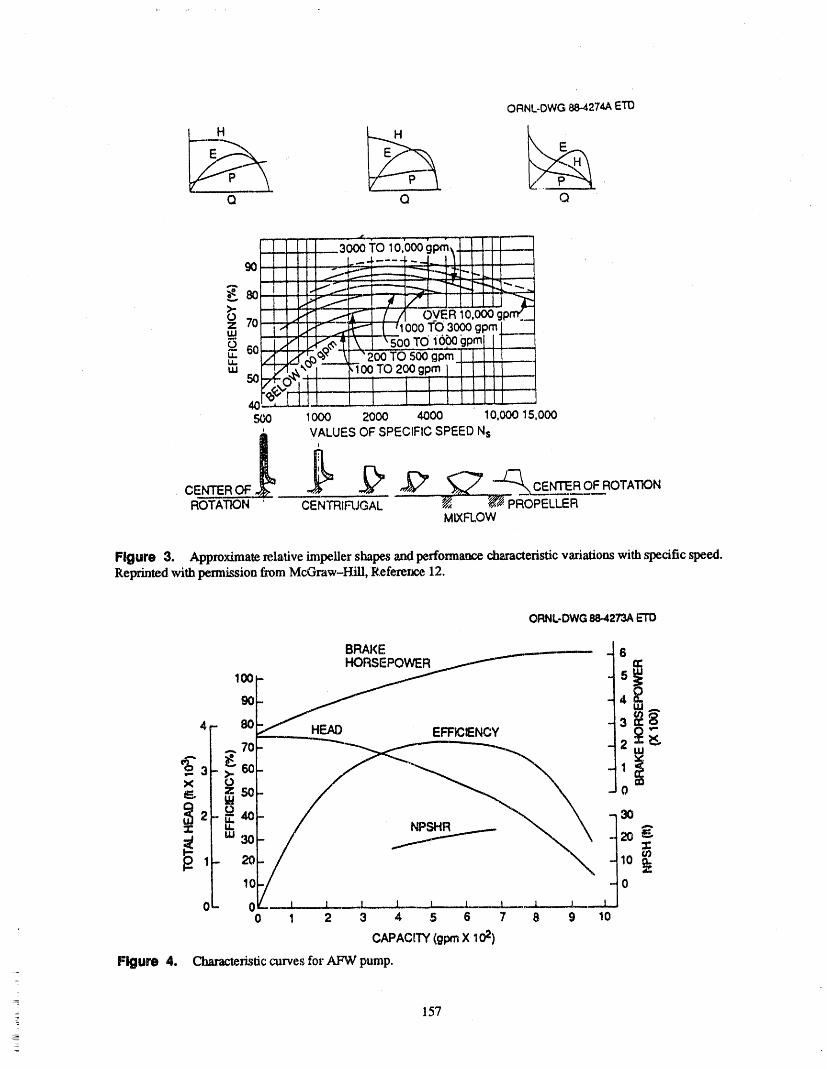
ORNL-DWG88-4274AETD
• _ _ _ '
__t, . ,Q Q Q
,r_O0 1000 2000 4000 10,00015,000
,_ VALUES OF SPECIFICSPEED NsROTATKDN - CENTRIFUGAL _ -_RoPEL-_R'---'-
MIXFLOW
Figure 3. Approximaterela_ve impeller shapesandperformancecharacteristicvariationswith specificspeed.Reprinted with permission from McGraw-Hill, Reference 12.
ORNL-DWG88-4273AE'TD
BRAKE 6
1 -
'" ao E ENCY -
0 m
lr-- 10
0 _- 10L _L.----_L.._-_.L_.__..L._._.=.L._I
0
00 1 2 3 4 5 6 7 8 9 10
CAPACtTY(_ X102)Figure 4. Clmmcteristiccurvesfor AFW pump.
S
157
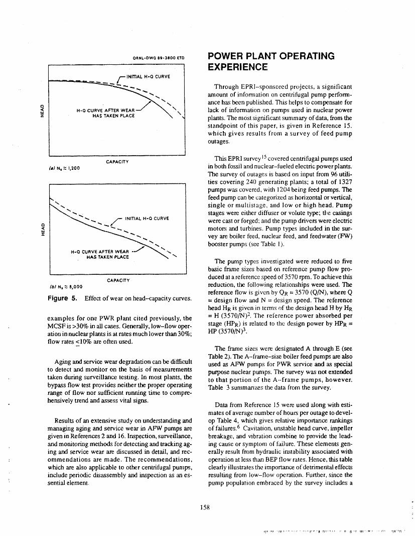
o,,L.owo,o.3800cTo POWER PLANT OPERATINGEXPERIENCE
/'--INITIAL H-O CURVE
__ Through EPRI-sponsored projects, a significant
amount of information on centrifugal pump perform-ance has been published. This helps to compensate for
¢3 H-O CURVE AFTER WEAR _ \ lack of information on pumps used in nuclear powerHASTAKENPLACE plants. The most signific=mt summary ofdata, from thestandpoint of this paper, is given in Reference 15.which gives results from a survey of feed pumpoutages.
i
CAPACITY This EPRI survey 15covered centrifugal pumps used¢,.JN, z _,200 in both fossil and nuclear.-fueled electric power plants.
The survey of outages is based on input from 96 utili-ties coveting 240 generating plants; a total of 1327pumps was covered, with 1204 being feed pumps. The
,,. feed pump can be categorized as horizontal or vertical,
',.,_..., single or multistage, and low or high head. Pump_""" ".- stages were either diftuser or volu_e type; the casings
"_,.L_ '_.._, _ INITIAL H-Q CURVE
< _,,,...._..... _ were cast or forged', and the pump drivers were electricmotors _mdturbines. Pump types included in the sur-
-"''_-__ ,,. _. vey are. boiler feed, nuclear feed, and feedwater (FW)
wEA_ /_-.._ ,,. booster pumps (see Table 1).H-QCURVEHAsTAKENAFTERPLACE_ "_-
The pump typesinvemigated were reducedto fivebasic frame sizes based on refelence pump flow pro-
CAPAOT¥ duced at a reference speed of 3570 rpm. To achieve thisrb/N, z 8,000 reduction, the following relationships were used. 'The
reference flow is given by QR = 3570 (Q/N), where QFigure 5. Effect of wear on head--capacity curves. = design flow and N = design speed. The reference
head HR is given in terms of the design head H by HR
examples for one PWR plant cited previously, lhe = H (3570/N) 2. The referer_ce power absorbed per= MCSF is >30% in ali cases. Generally, low-flow oper- stage (HPR) is related to the design power by I-lPR =
ation in nuclear plants is at rates much lower than 30%; I-It' (3570/N) 3.flow rates <10% are often used.
- The tiame sizes were designated A through E (see"Fable 2). "I'l'_eA-frame-size boiler feed pumps are also
Aging and service wear degradation can be difficult used as AFW pumps for PWR service and as specialto detect and monitor on the basis of measurements
purpose nuclear pumps. The survey was not extendedtaken during surveillance testing. In most plants, tl_ to that portion of the A-frame pumps, however.bypass flow test provides neither the proper operating Table 3 summarizes the data from the survey.range of flow nor sufficient running time to compre-
hensively trend and assess vital signs. Data from Reference 15 were used 'along with esti-mates of average number of hours per outage to devel-
Results of an extensive study on understanding and op Table 4, which gives relative impo_aance ranldngsmanaging aging and service wear in AFW pumps are of failures. 6 Cavitation, unstable head ctu've, impellergiven in References 2 and 16. Inspection, surveillance, breakage, arid vibration combine to provide the lead-,and monitoring methods lhr detecting and tracking ag- ing cause or symptom of f_dlure. These elements gen-ing and service, wear are discussed in detail, and rec- erally result from hydraulic instability associated with
__ ommendations are made. T'he recommendations, operation at less than BEP flow rates. Hence, this tablewhich are also applicable to other centrifugal pumps, clearly illustrales the importance of detrimental effectsinclude periodic disassembly a_] inspection as an es- resulting from low-flow operation. Further, since the
_- senti'd element., pump population embraced by the survey includes a
158
_lrel _w,er ,iql, lt, ,r ,,, ,p_. ,,_ 'llr'rM 'qll Irlllrl_ "'' H _rll'1III _lr q_tlt' i,vp,. ,,, IIM ,.llllr'p_l II"
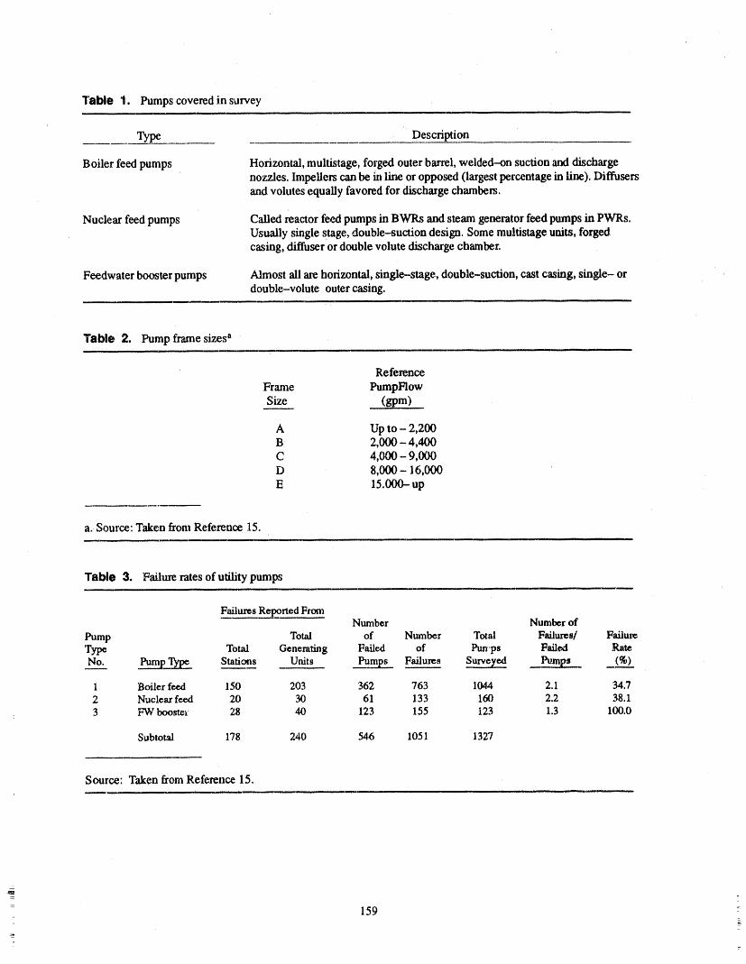
Table 1. Pumps covered in survey
Type Description
Boiler feed pumps Horizontal, multistage, forged outer barrel, welded-on suction and dischargenozzles. Impellers can be in line or opposed (largest percentage in line). Diffusersand volutes equally favored for discharge chambers.
Nuclear feed pumps Called reactor feed pumps in BW1Ls and steam generator feed pumps in PWRs.Usually single stage, double-suction design. Some multistage units, forgedcasing, diffuser or double volute discharge chamber.
Feedwater booster pumps Almost ali are horizontal, single-stage, double-suction, cast casing, single- ordouble-volute outer casing.
Table 2. Pump frame sizes a
Reference
Frame PumpFlowSize (gpm)
A Up to - 2,200B 2,000 -4,400C 4,000 - 9,000D 8,000 - 16,000E 15.000- up
a. Source: Taken from Reference 15.
Table 3. Failure rates of utility pumps
Failures Reported FromNumber Number of
Pump Total of Number Total Failures/ FailureType Total Generating Failed of Pun,ps F_dlexl Rat_No_..:_. ___._p..q.___. Stations Units _.__ Failures Survey',,ed Pum_ (%)
1 Boiler feed 1.SO 203 362 763 1044 2. I 34.72 Nuclear feed 20 30 61 133 160 2.2 38.13 FW boo_t¢_ 28 40 123 155 123 1.3 100.0
Subtotal 178 240 546 1051 1327
Source: Taken from Reference 15.
= 1592_
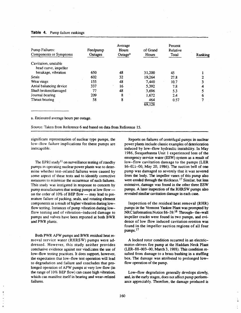
Table 4. Pump failure rankings
Average PercentPump F_dlures: Feedpump Hours of Grand RelativeComponents or Symptoms Outages Outage" Hours Total Ranking
Cavitation, unstable
head curve, impellerbreakage, vibration 650 48 31,200 45 1
Seals 602 32 19,264 27.8 2Wear rings 155 48 7,440 10.7 3Axial balancing device 337 16 5,392 7.8 4Shaft broken/damaged 77 48 3,696 5.3 5Journal bearing 209 8 1,672 2.4 6Thrust bearing 58 8 464 0.57 7
69,128
a. Estimated average hours per outage.
Source: Taken from Reference 6 and based on data from Reference 15.
significant representation of nuclear type pumps, the Reports on failures of centrifugal pumps in nuclearlow-flow failure implications for these pumps are power plants include classic examples of deteriorationinescapable, induced by low-flow hydraulic instability. In May
1986, Susquehanna Unit 1 experienced loss of theemergency service water (ESW) system as a result of
The EPRI studyll on surveillance testing of standby low-flow cavitation damage to the pumps (LERpumps in operating nuclear power plants was to deter- 86-02;I-00, May 20, 1986). The suction bell of onemine whether test-related failures were caused by pump was damaged so severely that it was severedsome aspect of these tests and to identify corrective from the body. The impeller vanes of this pump alsomeasures to minimize the occurrence of such failures, were eroded through the thickl_SS. 17 Similar, but less
This study was instigated in response to concern by extensive, damage was found in the other three ESWpump manufacturers that testing pumps at low flow m pumps. A later inspection of the RHRSW pumps alsoon the order of 10%of BF.,Pflow -- may lead to pre- revealed similar cavitation damage in each case.mature failure of packing, seals, and rotating elementcomponents as a result of higher vibration during low- Inspection of the residual heat removal (RHR)flow testing. Instances of pump vibration during low- pumps in the Vermont Yankee Plant was prompted byflow testing and of vibration-induced damage to NRC Information Notice 86-39.18 Through-the-wallpumps and valves have been reported at both BWR impeUer cracks were found in two pumps, and evi-and PWR plants, dence of low flow induced cavitation erosion was
found in the impeller suction regions of ali fourpumps. 17
Both PWR AFW pumps and BWR residual heat re-moval service water (RHRSW) pumps were ad- A locked rotor condition occurred in an electric-dressed. However, this study neither provides motor-driven fire pump at the Haddam Neck Plantconclusive evidence against nor vindicates the use of (LER-88--003-00, March 3, 1988). This condition re-low-flow testing practices, lt does support, however, suited from damage to a brass bushing in a stuffingthe expectation that low-flow test operation will lead box. The damage was attributed to prolonged low-to degradation and failure and concludes that pro- flow operation of the pump.longed operation of AF%Vpumps at very low flow (inthe range of 10% BEP flow) can cause high vibration, Low-flow degradation generally develops slowly,which can manifest itself in bearing and wear-related and, in the early stages, does not affect pump perform-failures, ance appreciably, Therefore, the damage produced is
|
160L
not easily detectable. Damage such as erosion, fatigue 3. C.C. Heald andR. Palgrave, "Bacldlow Con-cracking, and nondisabling breakage in pump stages trol Improves Pump Performance," Oil andcannot be observed without disassembly of the.pump. Gas Journal, Vol. 83, No. 8, February 25,Surveillance examination of pumps, as usually prnc- 1985, pp. 96-105.riced, thus leads to high probabilities that this type ofdegradation will go undetected until pump or system 4. P. Cooper, "Centrifugal Pump Hydraulic De-failure occurs and ability :toperform the required safe- sign Fundamentals," presented at Second In-ty function is lost. ternational Pump Symposium and Short
Course, Texas A&M University, April 29,
CONCLUSIONS 1985.
5. E. Makay and J. A. Barrett, "Changes in Hy-
Hydraulic instability from low-flow operation gives draulic Component Geometries Greatly In-rise to degradation mechanisms that, if allowed to per- creased Power Plant Availability andsist, will cause damage to the pump internals andeven- Reduced Maintenance Cost: Case Histories,"tually lead to failure. The intensifies of the degradation Proceedings of the 1st Inter- National Pumpmechanisms are functions of the energy per stage and Symposium, 'Texas A&M University, Maythe specific speed. Manifestations of hydraulic- 1984, pp. 8597.instability-induced effects are cavitation erosion;unstable head-flow characteristics; breakage of impel- 6. J.D. Donfee, et al., Feed Pump Hydrauliclets, shahs, and cutwaters or diffuser vanes; failures of Performance and Design Improvement," Vol.seals, thrust bearings, and axial-thrust balancing de. ] and 2. EPRI CS-2322, March 1982, pp.vices; and vibration failures. S--7.22- 2-11.
The deterioration that occurs develops slowly, and, 7. Bingham-W'dlamette Company, "Guide forin the early stages, changes in pump performance are Minimum Flow Operation of Pumps," Tech-not perceptible. Head and flow data arc not reliable in- nical Bulletin No. 68, Rev. 0, November 18,dicators of health because head vs capacity curves, in 1982.many instances, exhibit very little change at low flows 8. S.E. Pace, "EPRI Research on Boiler Feed-
(especially as shut--off flow is approached) because of water Pump Reliability and Performance,"degradation. Also, damage, such as erosion, cracking, presented to Power Generation Committee,and nondisabling breakage in pump stages, cannot be, Association of Edison Illuminating Compan-observed without pump disassembly and inspection, ies, February 6, 1986.Finally, hydraulic instability can complicate the data
interpretation process. These factors combine to pre- 9. P. Cooper, et al., "Minimum Continuousclude placing reliance on low-flow testing for opera- Stable Flow in Feed Pumps," Symposium
: tional readiness determinations and establish periodic Proceedings: Power Plant Pumps, EPRIdisassembly and inspection as a necessary element in CS--5857, June 1988, pp. 2-97 - 2-132.surveillance testing programs.
10. P. Cooper, "Hydraulics and Cavitation," Sym-REFERENCES postu,. Proceedings: Power Plant Pumps,
EPRI CS-5857, June 1988, pp 4-109 -
1. E.A. Bulanowski and J. A. Silvaggio, Jr., 4-149.
"Boiler Feed Pump Vibrations," presented at 11. F.J. MoUems, et al., Failures Related to Sur-the Short Course on Vibration in Pumps and veiUance Testing of Standby Equipment, Vol-Hydraulic Turbines, University of Virginia, ume 1: Emergency Pumps, EPRI NP--4264,July 31-August 2, 1985. Volume 1, October 1985.
]
2. M.L. Adams and E. Makay, Aging and 12. I.J. Karassik and R. Carter, Chap. 17 and 26,Service Wear of AuMliary Feedwater Pumps Centrifugal Pumps, Selection, Operation andfor PWR Nuclear Power Plants. Volume I Maintenance, E W. Dodge Corp., New York,Operating Experience and Failure Identifies. 1960_lion, NUREG CR-4597. Vol. 1 (ORNL--
6193/V1), Martin Marietta Energy Systems, 13. D. M. Kitch, "Pump Selection and Applic_-Inc., Oak Ridge National Lab., July 1986. lion in a Pressurized Water Reactor F.lectric
161

Generating Plant,"Proceedings of the Second Assessments and Monitoring Method Eva lua.International Pump Symposium, Houston, tions, NUREG/CR-4597, Volume 2May 1985, Ed. J. C. Bailey, Turbomachinery (ORNL-6282/V2), Martin Marietta EnergyLaboratories, Texas A&M University, 1985, Systems, Inc., Oak Ridge National Lab., Junepp. 47-57. 1988.
14. E J. Molerus, et al., Qualification of Active 17. W. L. Greenstreet, Martin Marietta Energy
Mechanical Equipment for Nuclear Plants, Systems, Inc., Oak Ridge National Lab.,per-EPRI NP-3877. March 1985. sonal communication with C. Hsu, U.S. Nu -'
clear Regulatory Commission, January 11,15. E. Makay and O. Szamody, Survey of Feed 1989.
Pump Outages, EPRI FP754, April 1978.18. U.S. Nuclear Regulatory Commission, IE 1n-
16. D.M. Kitch, et al., Aging and Service Wear of formation Notice No. 86-39: "Failures of
Auxiliary Feedwater Pumps for PWR RHR Pump Motors and Pump Internals,"Nuclear Power Plants. Volume 2 Aging May 20, 1986.
162 :_
ATTENDEE- PANEL QUESTIONS AND ANSWERS(EDITED; ATTENDEE QUESTIONS AND PANEL/AUTHOR
RESPONSES NOT IDENTIFIED BY NAME)i
Question 1 operatewithoutexceedingtilenoiseandvibrationlim-itsimpomdby API specification61,sixthedition.It's
You hadonegraphor chartup therethatshowedfor a verycrediblesource.typeA, B, andC differentpumps.What'sthesourceofthat,andcanwe usethatsourceasbeingcredible?Is Question 2thatapublisheddocument?
Response I On multiple stage pumps, is there one stage that ismore susceptible to difficulty, damage, or problems
That is in a publisheddocument.It'sreferencedin the thananotherstagedue to operationatlow flow_like thepaper.I don't have the number,but it was in a paper firststage or the last stage?writtenby C. C. HeraldandR. Paul Graveof Ingersol
Rand. You may wonder how the curves were Response 2determined.
The minimum continuous stable flow determined in No, therehas not been adifferentiationmadebetweenthat diagramis the lowest flow at which a pump can stages in a single pump.
• v ,.,,,
CORRECTIVE MEASURES FOR UTILITY PUMP LOW FLOWHYDRAULIC INSTABILITY"
ELEMEFI MAKAY, PH.D.ENERGY RESEARCH & CONSULTANT8 CORP.
900 OVERTON AVENUE MORRISVILLE PA, 19067TELEPHONE: (215) 295-2850
ABSTRACT • Thrust bearing, Balancing device, Cou-pling and Structural failure due to axialvibration (Shuttling) of therotor.
Diagnostics and corrective actions are presented forvarious types of damages "andfailure modes mainly for
• Journal bearing damage due to largenuclear safety related pumps. These pump types are: Hydraulic forces and incorrect bearing
geometry.• Nuclear Aux. and Nuclear Feedwater
Pumps (Multi-stage, Horizontal) • Impeller and Diffuser/Volute damagesdue to large Hydraulic forces and/or in-
• I-IPSI and Charging Pumps (Multi-.stage, correct impeller to diffuser/voluteHorizontal) geometry.
• Impeller eye (Inlet) caviation damage• Reactor Feed (BWR), Steam Generator due to incorrect impeller inlet geometry
Feed (PWR), LPSI and Booster Pumps or flow condition.(Single Stage, Double Suction,
Horizontal) ,, Incorrect materials, hardness and heat-treatment, etc.
• RHR and Core Spray Pumps (SingleStage, Single and Double Suction, "llaecases discussed are shown before or during fail-Vertical) ures and are supported by measurements and perform-
ance evaluation after corrective actions. Actual designmodifications are shown.
• Primary Coolant Pumps (PCP) and Circ.
Pumps (S,_ngle Stage, Single Suction, List of References are given for detailed evaluationVertical) of the corresponding teclmology background for the
cases discussed.Solutions to "Hydraulically" induced unstable
forces arediscussed in the flow operating mode. Some POWER PLANT PUMP
examples are given in the mn-out mode (LOCA). TROUBLE-SHOOTINGDamagesd_cussedstemfromge,,ence,,_riQg STATE OF THE ART OVERVIEW
design (Designer under-estimated the Hydraulic force
magnitudes), manufacturing errors, incorrect over- INTRODUCTIONhauling, assembly arv:l operating procedures. Cases
presented are narrowed down to the following The sizes of electric generating stations grew rapid-symptoms, components, or technologies: ly in the late 60's. Large nuclear plants were under
construction, getting closer to start-up. The sizes of• Shaft breakage at typical locations due to units being designed grew almost daily without the
Hydraulic forces, design and benefit of operating experience in the smaller sizes.manufacturing errors. The demand for very large size feed pumps (without
a. Presented at the ASME/NRC Symposium on "Inservice Testing of Pumps and Valves" on August 1-3, 1989in Washington, D. C.
165
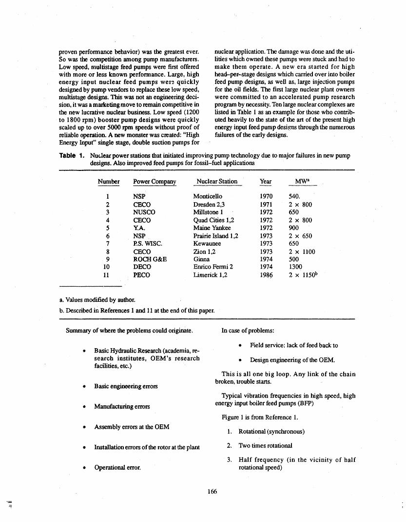
proven performance behavior) was the greatest ever. nuclear application. The damage was done and the uti-So was the competition among pump manufacturers, lities which owned these pumps were stuck and had toLow speed, multistage feed pumps were first offered make them operate. A new era started for highwith more or less known performance, Large, high head-per-stage designs which carried over into boilerenergy input nuclear feed pumps were quickly feed pump designs, as well as, large injection pumpsdesigned by pump vendors to replace these low speed, for the oil fields, The first large nuclear plant ownersmultistage designs. This was not an engineering deci- were committed to an accelerated pump researchsion, it was a marketing move to remain competitive in programby necessity. Ten large nuclear complexes arethe new lucrative nuclear business. Low speed (1200 listed in Table 1 as an example for those who contrib-to 1800 rpm) booster pump designs were quickly uted heavily to the state of the art of the present highscaled up to over 5000 rpm speeds without proof of energy input feed pump designs through the numerousreliable operation. A new monster was created: "High failures of the early designs.Energy Input" ,single stage, double suction pumps for
Table 1. Nut,lear power stations that initiated improving pump technology due to major failures in new pumpdesigns. Also improved feed pumps for fossil-fuel applications
Number Power Company Nuclear Station Year MW"
1 NSP Monticello 1970 540.
2 CECO Dresden 2,3 1971 2 x 8003 NUSCO Millstone 1 1972 650
4 CECO Quad Cities 1,2 1972 2 x 8005 Y,A. Maine Yankee 1972 900
6 NSP Prairie Island 1,2 1973 2 × 6507 ES. WISC. Kewaunee 1973 650
8 CECO Zion 1,2 1973 2 x 11009 ROCI-I G&E Ginna 1974 500
10 DECO Enrico Fermi 2 1974 1300
11 PECO Limerick 1,2 1986 2 x 1150b
a. Values modified by author_
b. Described in References 1 and 11 at the end of this paper.
Summary of where, the problems could originate. In case of problems:
• Field service: lack of feed back to• Basic Hydraulic Research (academia, re,-
search institutes, OEM's research • Design engineering oft he OEM.facilities, etc.)
This is ali one big loop. Any link of the chainbroken, trouble starts.
® Basic engineering errors
Typical vibration frequencies in high speed, high
• Manufacturing errors energy input boiler feed pumps (BFP)
Figure 1 is from Reference 1.
• Assembly errors at the OEM 1. Rotational (synchronous)
• Installation errors of the rotor at the plant 2. Two times rotational
3. Half frequency (in the vicinity of half• Operational error, rotational speed)
166
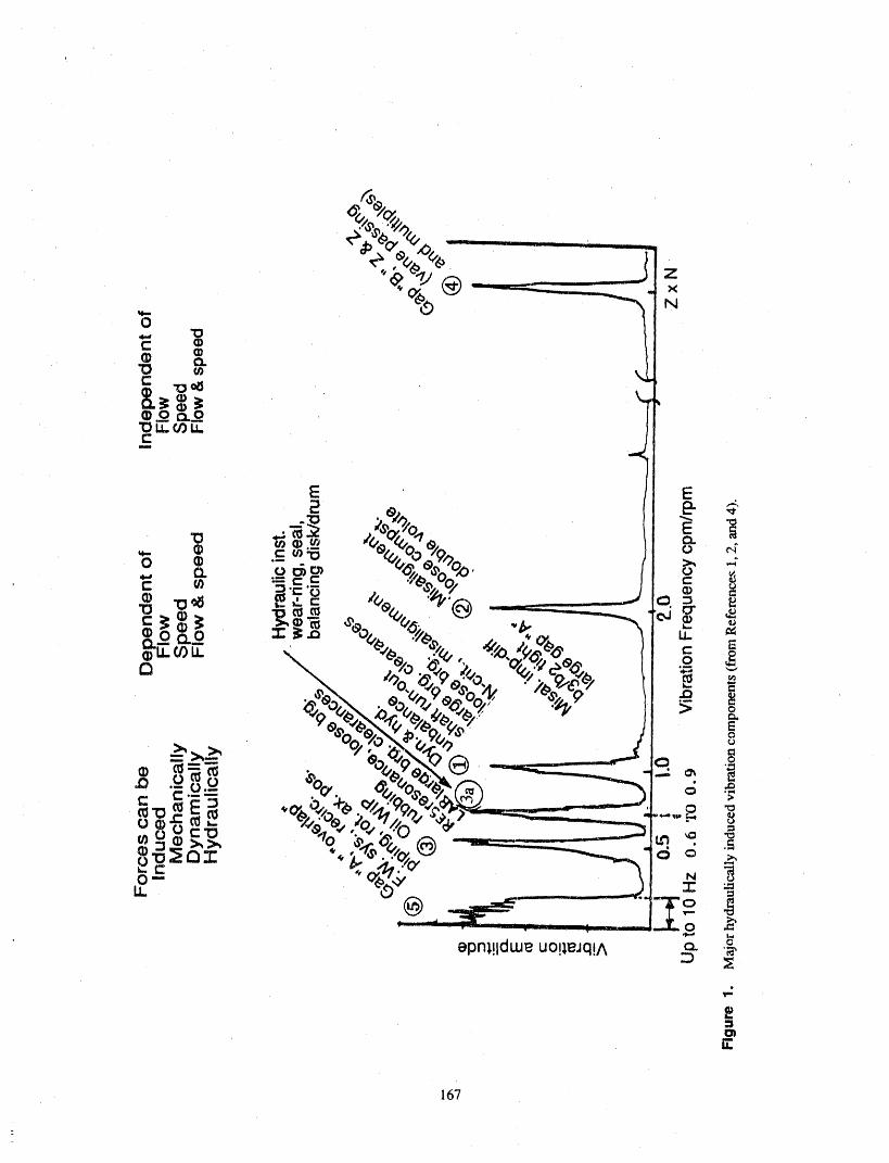
167
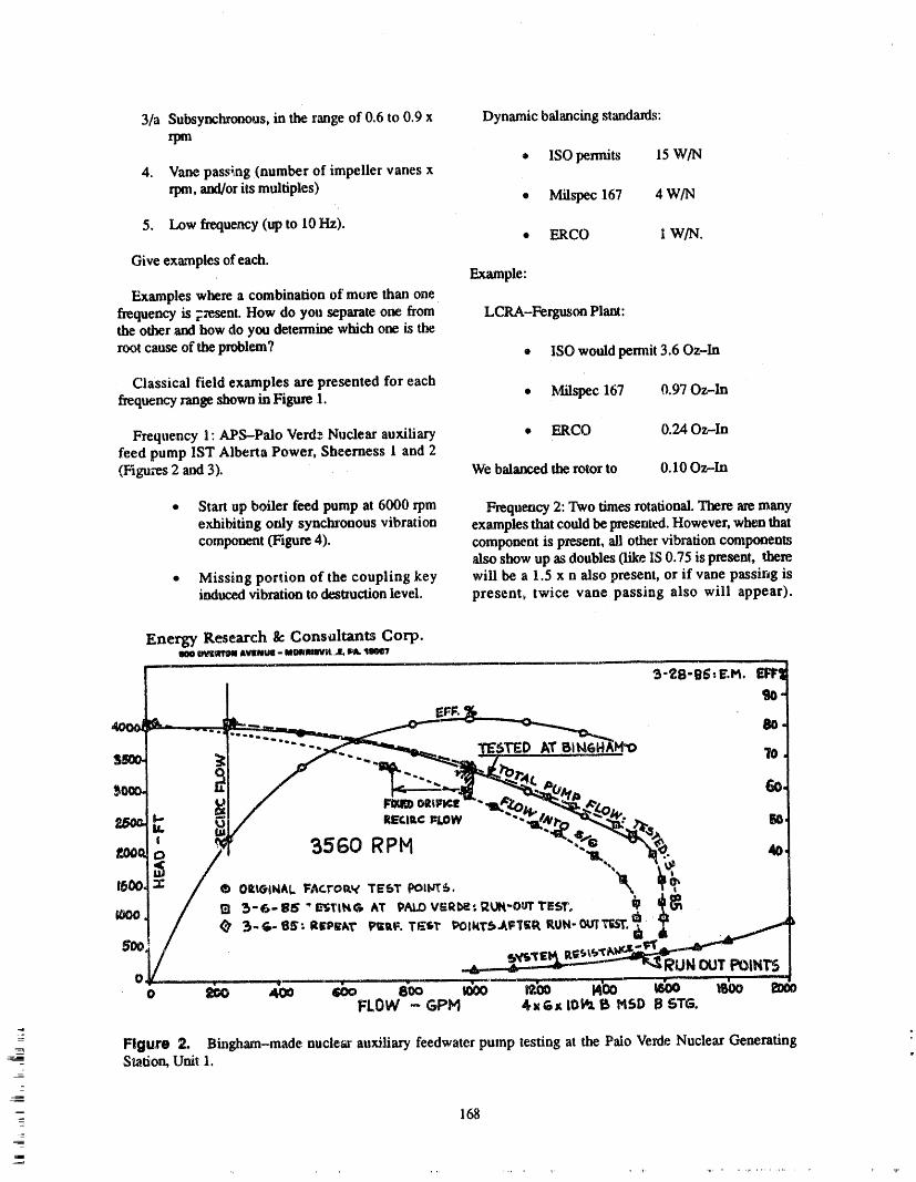
3/a Subsynchronous,in the rangeof 0.6 to 0.9 x Dynamic balancingstandards:rpm
• ISO permits 15 W/N4. Vane passing (number of impeller vanes x
rp|, and/orits multiples)• Milspec 167 4 W/N
5. Low frequency (up to 10 Hz).• ERCO 1 W/N.
Give examplesof each.Example:
Examples where a combination of more than onefrequency is 7zesent.How do you separateone from LCRA-FergusonPlant:the other and how do you determine which one is the
rootcause of the problem? ® ISO wouldpermit 3.60z-In
Classical field examples are presented for eachfrequency rangeshown in Figure1. • Milspec 167 0.97 Oz-In
Frequency 1: APS-Palo Verd_Nuclear auxiliary • ERCO 0.24 Oz-Infeed pump IST Alberta Power, Sheerness 1 and 2(Figures 2 and 3). We balanced the rotorto 0.10 Oz-In
* Start up boiler feed pump at 6000 rp| Frequency2: Twotimesrotational.There are manyexhibiting only synchronous vibration examples that couldbe presented. However,when thatcomponent(Figure 4). component is present, ali other vibration components
also show up as doubles0ike IS 0.75 is present, there* Missing portion of the coupling key will be a 1.5 x n also present, or if vane passir_g is
inducedvibrationto destructionlevel, present, twice vane passing also will appear).

Frequency 3: In the vicinity of 1/2 x rpm rotor Frequency 4: Vane passing (no. of impeller vanesdynamic instability. Not permissible to any degree, x rpm)Self excited vibration, destructive, will result indestruction of the rotor.
Frequency 5: Low frequency vibration below 10 Hz.
Frequency 3/A' Hydraulic instability. Four Many things can excite this frequency such asexamples are given between frequency ratios of 0.6 foturlation, piping, turbine drive governor, etc. But weand 0.92. are talking about pumps, hence give some pump
examples how the pump can develop this frequency.
3/13' Borderline case at and around 0.6 this could be
dynamic or hydraulic _tabi_b' or the combination oi Combination of frequencies 1 to 5' Sheerness andboth. This is one of the most difficult cases. Ferguson me excellent examples.
• 169
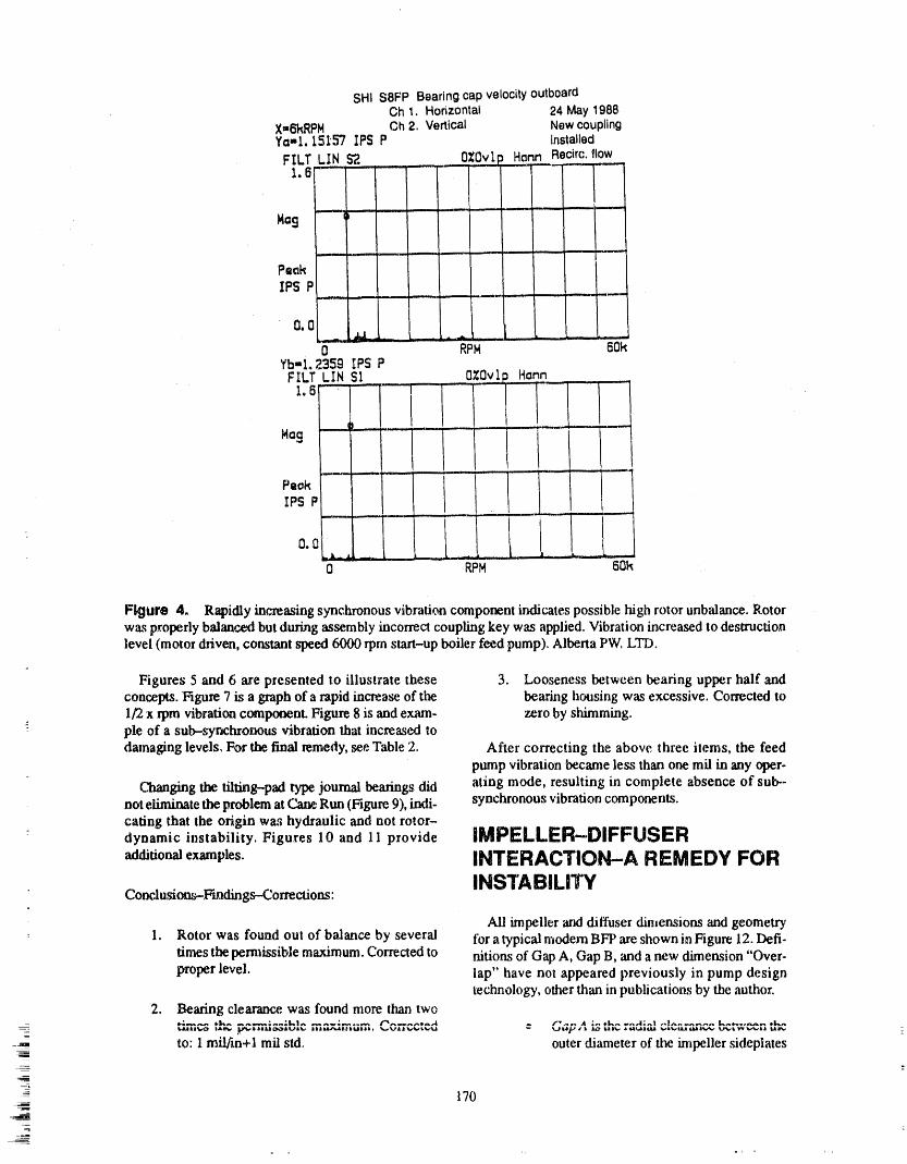
SIll S8FP BearingcapvelocityoutboardCh 1. Horizontal 24 May1988
X=6kRPH Ch2, Vertical NewcouplingYa=l, 151'57 IP$ P Installed
1.6'-- F-! '' ' .....' .....
Ma9 - 6.... ----- ........ It
IPS P ....
0 RPM " 80kYb-l 235g IPS PFILT LIN SI 0Z0vlp Harm ii i ----
1.6 /I1'1..........'Hag u__ .... [
_ ,0.0 !k_-__ _ I ...... -,----
0 RPM 6Ok ,,,
Figure 4, Rapidly increasing synchronous vibration component indicates possible high rotor unbalance. Rotorwas properly balanced but during assembly incorrect coupling key was applied. Vibration increased to destructionlevel (motor driven, constant speed 6000 rpm start-up boiler feed pump). Alberta PW. LTD.
Figures 5 and 6 are presented to illustrate these 3. Looseness between bearing upper half andconcepts. Figure 7 is a graph of a rapid increase of the bearing housing was excessive. Corrected to1/2 x rpm vibration comptmenL Figure 8 is and exam- zero by shimming.
-: pie of a sub-syncl_onous vibration that increased todamaging levels, For the final remedy, see Table 2. After correcting the above three items, the feed
pump vibration became less than one rail in any oper-
C 'hanging the tilting-pad type journal bearings did ating mode, resulting in complete absence of sub--not diminate the problem at Cam Run (Figure 9), indi- synchronous vibration components.caring that the origin wa,_ hydraulic and not rotor-
: dynamic instability. Figures 10 and 11 provide IMPELLER-DIFFUSER
additional examples. INTERACTION-A REMEDY FOR
Conrausio -rains -Corre=io : INSTABILITYAli impeller aral diffuser dimensions and geometry
: 1. Rotor was found out of balance by several for a typical modem BFP are shown in Figure 12. Deft-times the pem_tssible maximum. Corrected to nitions of Gap A, Gap B, and a new dimension "Over-proper level, lap" have not appeared previously in pump design
technology, other than in publications by the author.
2. Bearing clearance, was found more than two/'va,., A ;¢, _1_,. _.,,41;,_l ,._.-..,.._,.,...,, &,,.,..,,,,_,., ¢1_,_
¢,,U=15,,*_ t,_ml.,, _..==il.a_l_a_.. I|IM-.n_|.t.IUIII. '_...vl.t_.,_l,'_.Jt
-__-- to: 1 mil/in+l rail sid. outer diameter of dm impeller sideplates!
-- 170__-
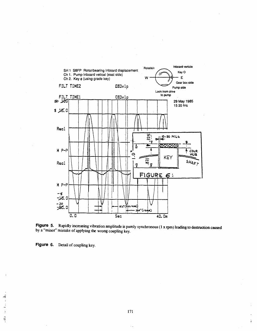
Rotation InboardverticleSH 1 S8FP Rotor/bearing inboard displacement _ KeyOCh 1. Pump inboard vetical (east side)Ch 2. Key ¢ (using grade key) W .... E
Gearboxside
FILT TIHE2 OZOvip Pumps_aLookfromdrive
topumpFILT TIHEI OZOvl_
so_ ........... I I - ' 'i--" 29May198s
$ ,_, 0; = } _' 15 20 hrs
...==-.- .,.---. i = t
- ' / i/ _ / I/IA _ . _
i.,,,., i.,_ ,iii i --
' /1 f _, ,,,o-,o,_,L,
HP-PI " =,
v ...........__. 7I-,_ ',., _
/ I-I
-,,_,o -.-.--_-- ; .........-3o v ! "_/ i I A • •
'-._ i....--i,s;.'__=.¢_=r_ I V;r,o'.o _....... _ L .._ , -- _o'O,_,h:_,,...... , ..
O,0 Sac 40, Om
Figure 5, Rapidly increasing vibrationamplitude is purely synchronous(1 x rpm) leadingto destruction causedby a "minor" mi._takeof applying the wrong coupling key.
Figure 6. Detailof couplingkey,
171_
E.

BENTLY 300 PPd< TYPE
10.1I
MAIN BFP 1OO7o
i_ N = 2 , 310 RPM
H NO. 1 BRG: O.B.
P =30. 000 HP
! I5. r .........
I
I ,1
0.O. |. 3. 4.
CPM/RPM
l=lgure , 7. Rapid increase ef the 1/2 x rpm vibration component measured at the main boiler leed pump O.B. The
j_mu_l bearing did nov. permit the unit to go on-line. This component was already over 10 mils at 3,100 rpm.Operating speed atfullload is over 5,000 rpm.
(hub and shroud) and the inner diameter damping developed by the impeller,of the diffuser channel sideplates, given damping of rotor motion, pump by-in inches or more commonly in mils draulic stability, and feedwater system(e.g., 50 rail = 0.050 in,.)Usually, this di. stabili_.mensioa does no_exist in volute designs,proving that its importance was notpreviously recognized. • Rotor a_rialpositioning actually means
centering the hydraulic channels of the
impeller exit and diffuser inlet. Figure 13shows various configurations, ranging
• Overlap. The ardal "Overlap" of Gap Afrom good to very poor.is the useful axial length of the small hy-
draulic lr,tssage between the impeUer anddiffuser/volute sideplates. The recogni- • Ratio (b3/b2) of the hydraulic widths oftion of its major technological signifi- diffuser inlet (b3) to impeller exit (b2) iscance in pump hydraulic design is a very critical for rotor axial positioning Amajor breakthrough. It has a very great general rule in diffuser-type pump by-controlling effect on both the static and draulic design calls for this ratio to have
_ Oyrxamiccomponents of the a.xJalthrust a minimum value of not legs than 1.15.
172
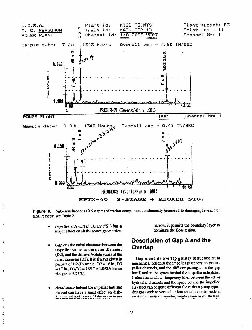
L.'3.R.A. Plant ld: HISC POINTS F'lant-subs_t: F3
T. C. FERGUSON _ Train id: MAIN E_FP lE: Point id: IIiiK Channml id: I/B CASE-_)ERT Channel No: iPOWER PLANT _ ====
S_,,pI_ date: 70UL 11343 Hour_._ Overall z_mp = C_.62 IN/SEC
i
I_: _ 'N
@,3@I. •
i,T Io .. e, ,,, m e I ,, =, e, mm m . o m . . . .. m ., .,_
" . J4
o _P_EQU_CY{£uents/Hinx ._1)POWER PLANT HOR Channel No: 1
Sample datP.: 7 aUL 1348 Hour',_L, Overall amp = 0.41 IN/SEC
0.1sn f""' ............ "" :-t
J.hi'F_IIIPj_I'(£uents,,'14inx .@1)
HPTX-Z_0 3-STAGE + KTCKER STG.
Figure 8. Sub-synchronous (0.6 x rpm) vibration component continuously._ncreased to damaging levels. Forfinal remedy, see Table 2.
® Impeller sidewall thickness ("S") has a narrow, ii permits l_e boundary layer tomajor effect on ali the above geometries, dominate the flow region.
Description of Gap A and the• Gap B is the radial clearance betw_n the
impeller vanes at the outer diameter Overlap(D2), and the d_'f_ser/volutevanesat theinner diameter (D3). ItLs always given in Gap A and its overlap greatly influence fluid
percent of D2 (Example: D2 = 16 in., D3 mechanical action at the impellerperiphery,in the ira-= 17 in., D3/D2 = 16/17 = 1.0625; hence pellet channels, and )he diffuser passages, in the gap
the gap is 6.25%). _tself, and in the space behind the impeller sideplates.lt also acts as a low-fiequency filter between the activehydraulic channels and the space behind the impeller.
• Axial space behind the _apeller hub and Its effect can be quite different for various pump types,shroud can have a great effect on disk- designs (such as vertical or horizontal, double-suction¢.;,.,.;,.,,, ..1,_,.A I,,ooa,. 1¢ tl_ .._.,-_ ;e t,_ nr elnalo-e,u'Hnn irnru_]lo.r. _inolo. ,_tage or mnllti._taPe.
173
=
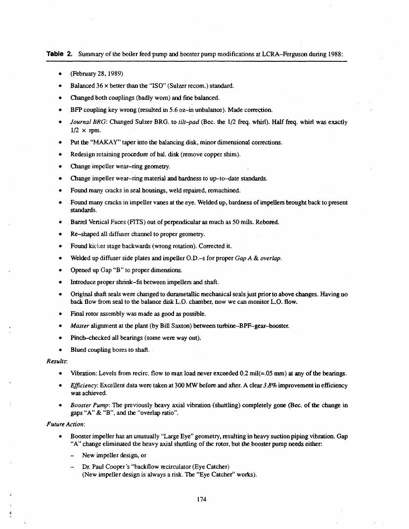
Table 2, Summary of the boiler feed pump and booster pump modifications at LCRA-Ferguson during 1988:
• (February 28, 1989)
• Balanced 36 x better than the "ISO" (Sulzer recom,) standard.
• Changed both couplings (badly worn) ',axt fine balanced.
• BFP coupling key wrong (resulted in 5.6 oz-in unbalance). Made correction. ,
• Journal BRG: Changed Sulzer BRG. to tilt-pad (Bec. the 1/2 freq. whirl). Half freq. whirl was exactlyI/2 x rpm.
• Put the "MAKAY" taper into the balancing disk, minor dimensional corrections.
• Redesign retaining procedure of bal. disk (remove copper skim).
® Change impeller wear-ring geometry.
• Change impeller wear-ring material and hardness to up-to-date standards.
• Found many cracks in seal housings, weld repaired, remachined.
• Found many cracks in impeller vanes at the eye. Welded up, hardness of impellers brought back to presentstandards.
• Barrel Vertical Faces (FITS) out of perpendicular as much as 50 mils. Rebored.
• Re-shaped ali diffuser channel to proper geometry.
• Found kic_:er stage backwards (wrong rotation). Corrected it.
• Welded up diffuser side plates and impeller O.D.-s for proper Gap A & overlap.
: ® Opened up Gap "B" to proper dimensions.
• Introduce. proper shrink-fit between impellers and shaft.
• Original shaft seals were changed to durametaUic mechanical seals just prior to above changes. Having noback flow from seal to the balance disk L.O. chamber, now we can monitor L.O. flow.
• Final rotor assembly was made as good as possible.
• Master alignment at the plant (by Bill Saxton) between turbine-BPF--gear-booster.
• Pinch--checked ali bearings (some were way out).
• Blued coupling bores to shaft.
Results:
• Vibration: Levels from recirc, flow to max load never exceeded 0.2 rail(=.05 nun) at any of the bearings.
• Efficiency: Excellent data were taken at 300 MW before and after. A clear 3.8% improvement in efficiencywas achieved.
• Booster Pump: The previously heavyaxial vibration (shuttling) completely gone (Bec. of the change ingaps "A" & "B", and the "overlap ratio".
Future Action:
• Booster impeller has an unusually "Large Eye" geometry, resulting in heavy suction piping vibration. Gap"A" change eliminated the heavy axial shuttling of the rotor, but the booster pump needs either:
- New impeller design, or
- Dr. Paul Cooper's "backflow recirculator (Eye Catcher)(New impeller design is always a risk. The "Eye Catcher' works).
174
z
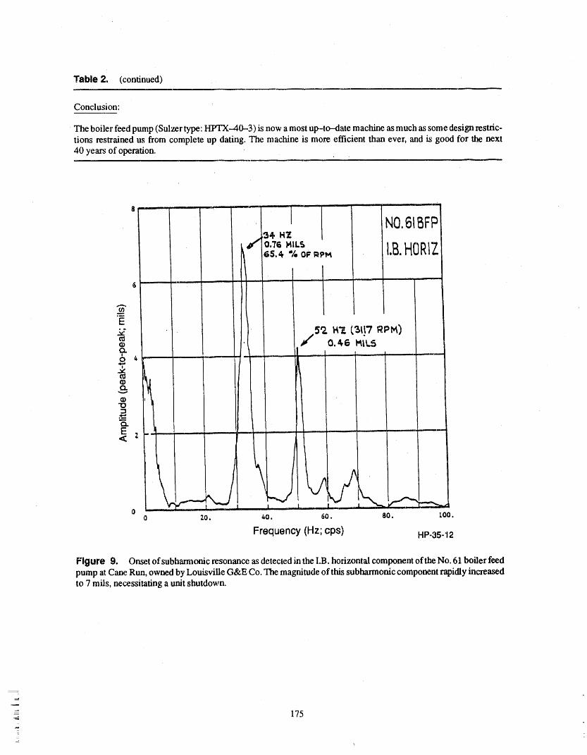
Table 21 (continued)
Conclusion:
The boiler feed pump (Sulzer type: H_rx-40--3) is now a most up-to-date machine as much as some design restric-tions restrained us from complete up dating. The machine is more efficient than ever, and is good for the next40 years of operation.
8 i , ]
• 1 NO.61BFP
f o7_M,Ls 13.HORIZi 6s._ % oFmPM
, ,,
_ ii iii i iiii
E.5_., W'/. (,3117 RPM)
0 _ -'*r'
°1= LE , ,< z
|
00 7.0. 40. GO. 80. 100.
Frequency(Hz;cps) HP-35-12
Figure 9. Onset ofsubharmonic resonance as detected in the I.B. horizontal component of the No. 61 boiler feedpump atCane Run, ownedby Louisville G&E. Co.The magnitudeoi'this subharmoniccomponentrapidly increasedto 7 mils, necessitatinga unit shutdown.
-_ 175
z.
5,
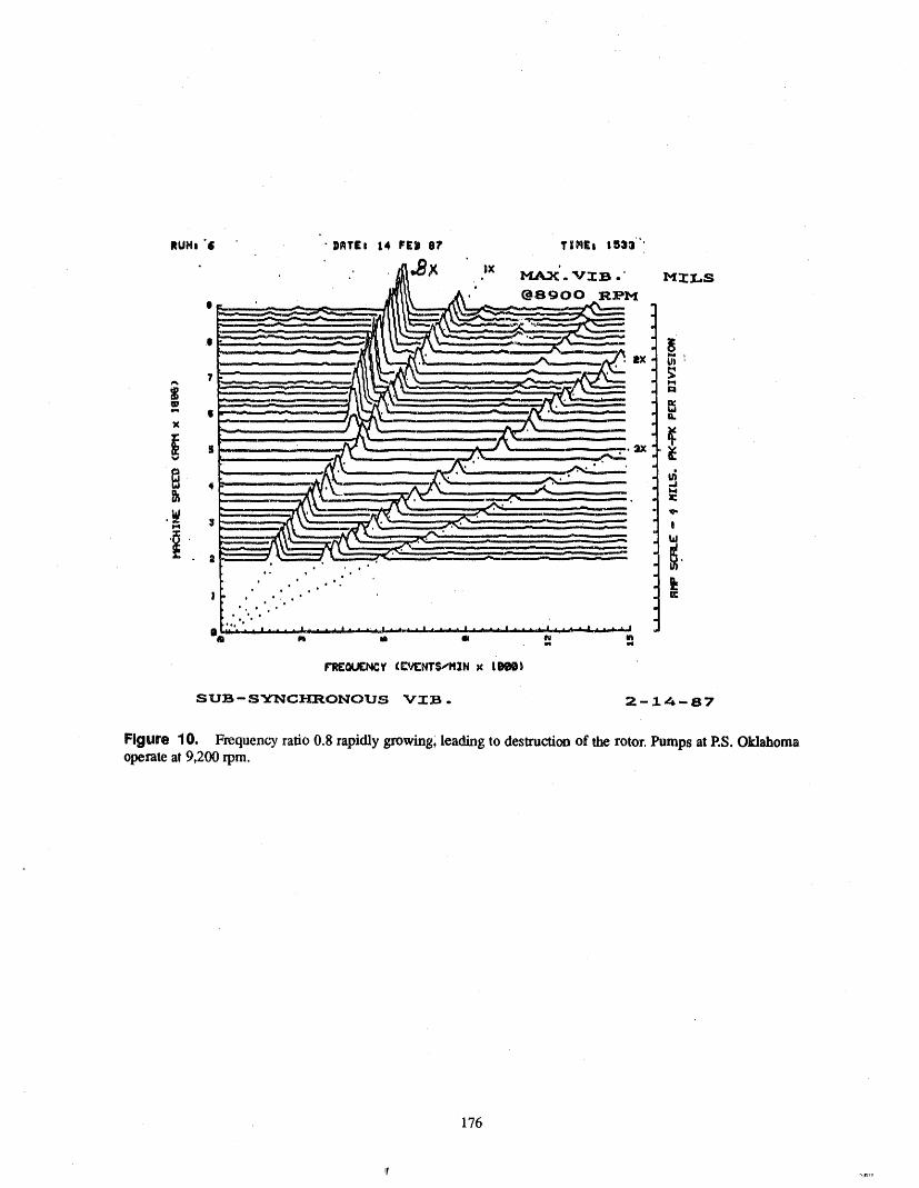
Figure 10. Frequencyratio0.8rapidlygrowing,leadingto destructionof therotor. Pumps at P.S.Oklahomaoperateat9,200rpm.
176
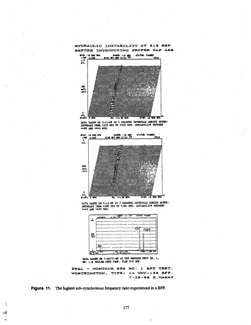
177_

Figure 12. Correct rotor position, correct Ga r'.s "A" and "B", correct overlap ratio, impeller and diffusercenterl/ne to centerline, and axial thrust normal in ali flow conditions.
light or heavy rotor configurations ), Ns, Ss, and energy effective solution in eliminating hydraulic instabilityper stage. It is most significant for higtr-energy pumps caused by low flow. Neither concept is recognized, un-such as BFP's, NFP's, and high-head feedwater derstood, or accepted by most hydraulic designers.boostei pumps. Current pump design philosophy is very conservative,
especially for utility applications.Gap A is an effective filter for high amplitude re-
sponses at very low frequencies (up to 10 Hz) for The comprehension and physical visualization ofhigh-_nergy-input pumps. Its effect diminishes as Ss the Gap A and its overlap is not as simple and apparentincreases. The high energy concentration shifts toward as that of Gap B (Figure 12). The complexity of the in-the impeller eye at flows below BEP because of the teractions between flows at the impeller exit, diffuserdominating action of flow recirculation at the eye. flow reversal, boundary layer effect, creation of a newWhen the Ss is very high, as in inducers, the Backflow flow pattern in Gap A, and the influence of the radialCatcher of Cooper 13 is very effective for eliminating gap and its overlap in the axial directions is beyondlow-frequency flow oscillations and stabilizing the simple visualization. The interaction between the im-
bead curve at lower flows. There is a region between peller exit and diffuser inlet geometry and their con-low flows and high flows where bofl_ the Overlap and nection with the effect of Gap B is a complexthe Backflow Catcher can be effective. Probably the phenomenon. Publications on this subject are verycombination of the two concepts would offer the most limited.
178
_
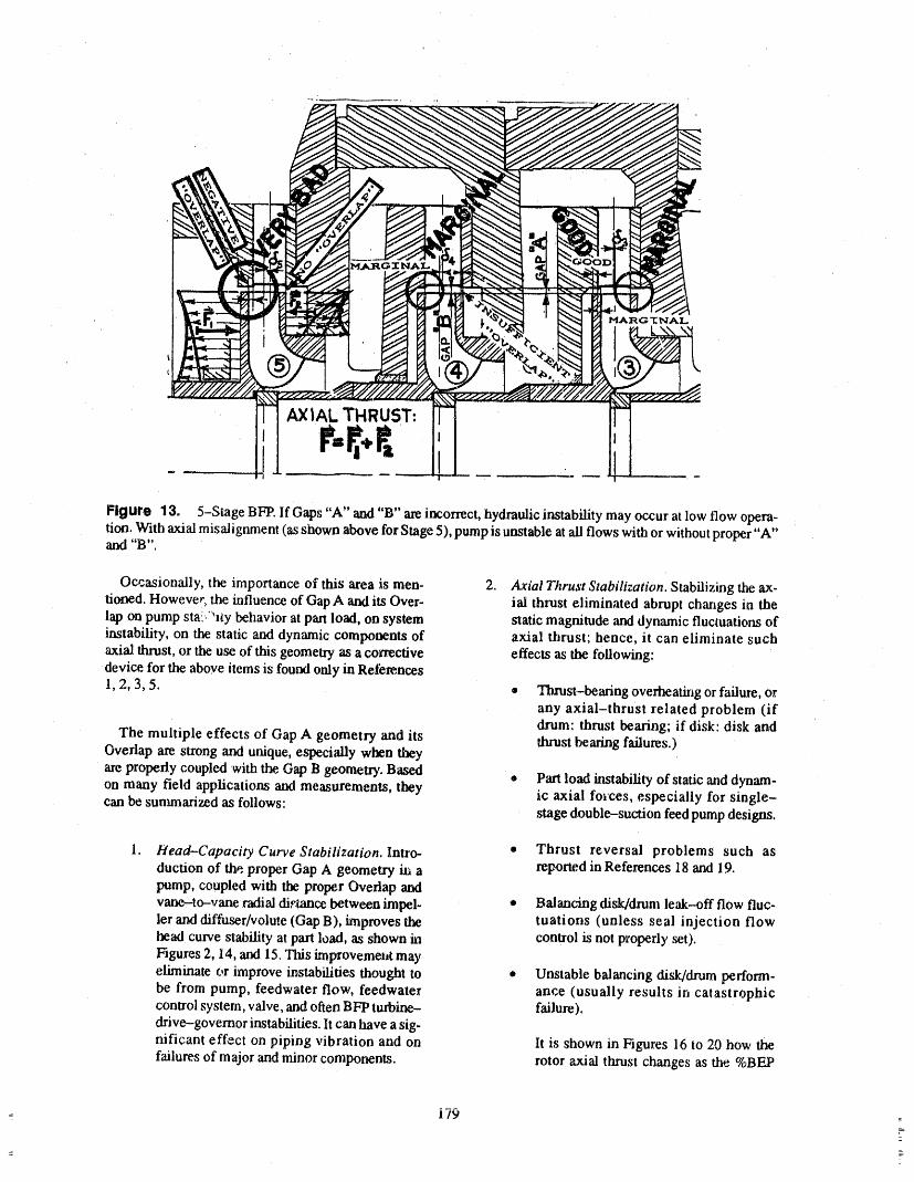
i
•Figure 13. 5-Stage BFP. If Gaps "A" and "B" ale incorrect, hydraulic instability may occur at low flow opera-tian. With axial misalignment (as shown above for Stage 5), pump is unstable at ali flows with or without proper "A"a_ "B ".
Occasionally, the importance of this area is men- 2. Axial Thrust Stabilization. Stabilizing the ax-tinned. However_ the influence of Gap A and its Over- ial thrust eliminated abrupt changes in thelap on pump sta!,?_l_y behavior at part load, on system static magnitude and dynamic fluctuations ofinstability, on the static and dynamic components of axial thrust; hence, it can eliminate suchaxial thrust, or the use of this geometry as a corrective effects as the following:device for the above items is found only in Reti_rences
1, 2, 3, 5. ® Thrust-bearing overheating or failure, orany axial-thrust related problem (ifdrum: thrust bearing; if disk: disk and
The multiple effects of Gap A geometry and its thrust bearing failures.)Overlap are strong and unique, especi',dly when theyare properly coupled with the. Gap B geomelD'. Based • Part load instability of static and dynam-on many field applications and measurements, they ic axial forces, especially for single-can be sunmaarized as follows: stage double-suction feed pump designs.
1. Head-Capacity Curve Stabilization. Intxo- • Thrust reversal problems such asduction of the proper Gap A geometry i_ a reported in References 18 and 19.pump, coupled with the proper Overlap andvane-to-vane radial die,trice between impel- • Balancing disk/drum leak--off flow fluc-
ler _ diffuser/volute (Gap B), improves the tuations (unless seal injection flowhead curve stability at pan load, as shown in control is not properly ,set).Figures 2, 14, and 15. This improvemet,t mayeliminate or improve instabilities thought to • Unstable balancing disk/drum perform-be from pump, feedwater flow, feedwater ante (usually results in catastrophiccontrol system, valve, and often BFP turbine- failure).drive-governor instabilities, lt can have a sig-nificant effect on piping vibration and on lt is shown in Figures 16 to 20 how thefailures of major and minor components, rotor axial thrust changes as the %BF_
i79

27--JUN-76 18 : 15 C_N,--INBD2 E.M.
II I j J I illll iq .... • . i _ _-- i 8
,_ Nill .... | .... | .... I.i. --| ..... '__.--iii.,I I I I I I
I I l I l III'
I I I I I I |H II I I I I I Iq I I I I t Iv -- ---'-----.------_-.___.___,__. ____ 6.I I i I I I
I I I I I I-" " I I I I I . I
I I I I ,'_ I_ II I I I I . I
I
_i i I I I I I'1
Ill ,- J... I I ; I iI I I I I Il ' i I I J J ..A I
I I _ I I _ I I I _ I I _ I I _ I I I_ I -- I 2
,_ I,. l I I I II I ", I I I I
' " "": '. ' ' n,I II,- t I, I .
0 .
O. 80 160 240 320 400 480 560 640.
_REQUENCY - HZ
F_ur® 14. Growing vibration amplitude of an g-stage boiler t_ed pump at vane-passing frequency is followedby rubbing induced partial fxvquency (0.55 x rpm) vibration component (Reference 1).
21 i i _ iI_ .... I --- ii i [ j
(B) C_GES MADE AFTER FAIL_E:
I, INCREASED _ELLER/DIFFUSER CLEARANCE (FR_ IZ TO 6Z)
2. C_NG_ JOURNAL B_INGS TO TILT-P_ TYPE I
A 3 DYNAMICBALANCINGOF ROTOR
1.
,_ 4. ALIGN PUMP AND DRIVE _,
. I
z
*k3 L 3'1 1Ol II iF Ill i , i _. ,
O, 0,5 1.0 2,0 3.0 Z X N_ VIB_TION FREQ_-- CPS/_CHINE SPEED-_S
Figure 1S. Multi-stage boiler fce,d pump shaft vibration history before failure and after proper modificationswere introduce_.
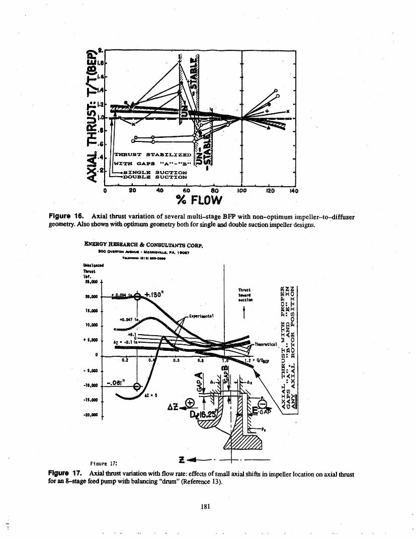
181
_
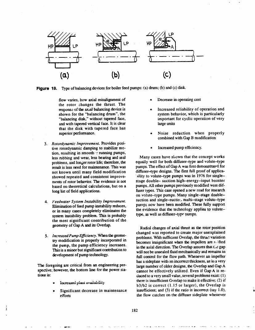
• _ LP
Ca) CblFigure 18. Typeof balancing devices for boiler feed pumps: (a) drum; (b) and (c) disk.
flow varies, how axial misalignment of ® Decrease in operating costthe rotor :hanges the thrust. The
response of the axial balancing device is • Increased reliability of operation andshown for the "balancing drum", the system behavior, which is particularly"balancing disk," without tapered face, important for cyclic operation of veryand with tapered vertical |'ace. It is clear large unitsthat the disk with tapered face has
superior performance. • Noise reduction when properlycombined with Gap B modification
3. Rotordynamic Improvement. Provides posi-tive rotordynamic damping to stabilize mo- • Increased pump efficiency.tion, resulting in smooth_'r running pumps,less rubbing and wear, less bearing and seal Many cases have shown that the concept worksproblems, ,andlonger rotor fife; therefore, the equally well for both diffuser-type and volute-typeresult is less need for maintenance. This was pmnps. The effect of Gap A was first demonstrated for
not known until many field modification diffuser_ype designs. The first full proof of applica-showed repeated and consistent improve- fility to volute-type pumps was in 1976 for single-.ments of rotor behavior. The evidence is not stage double- suction high-energy-input boosterbased on theoretical calculations, but on a pumps. Ali other pumps previously modified were dif-
long fist of field applications, f-usertypes. This case opened a new road for researchon volute--type pumps. Many single-stage double-
4. Feedwater System Instability Improvement. suction and single-suctio:_ ntulti-stage volute-t3'peElimination of feed pump instability reduces, pmnps now have been modified. These fully supportor in many cases completely eliminates the the evidence that the technology applies tO volute-system instability problem. This is probably type, as well as diffuserqype oumps.the most significant contribution of the
geometry of Gap A and its Overlap. Radi,,'dchanges of axial thrust as the rotor positionchanged was reported to create major unexplained
5. lncreasedPump Efficiency. When the geome., problems. With sufficient Overlap, the thrus_ variationtry modification is properly incorporated in becomes insignificant when the impellers are _ iftedthe pump, the pump efficiency increases.This is a minor but significant contribution to in the axial direction. 'Ihe Overlap assures that t'..e gapwill net be unsealed fluid mechanically and remains indevelopment of pump technology, full control for the flow path. Whenever an impeller
has a sideplate with an incorrect thickness, as in a veryThe foregoing are critical from an engineering per- large number of older designs, the Overlap aral Gap Aspective; however, the bottom line for the power sta- cannot be effectively utilized° Even if Gap A is re..tions is: duced to a very small value, several problems exist: (1)
........ ,.... there is insufficient Overlap to make it effective: (2) if• im,"ge',tsedplaui nvaxtau,mty b3/b2 is correct ( 1.15 or larger), the Overlap is
• Significant decrease in maintenance h_sufticient; and (3) if the ratio is incorrect (say 1.0), :-efforts the flow catches on the diffuser sideplate whenever
" 182
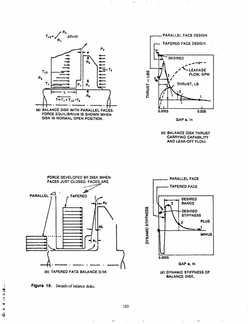
Ra PARALLEl. FACE DESIGNT,a- p2,rdr "----
_,fR, P;L _-- TAPEREDFACEDESIG'_. "'
*--- L-----i,./I,_ ,,'L. LEAKAGET.. --=--___. .--_T. _ I/_ ,t F,ow.QPM
Po #,
T: _ F R: _ _ /THRUST, LB
7 - _, _ ,_'-'__ _ I ."_
(a) 3ALANCE DISK WITH PARALLEL FACES. 0;0005 0.008;ORCE EQUILIBRIUM IS SHOWN WHENHSK IN NORMAL OPEN POSITION. GAP e, In
(c) BALANCE DISK THRUSTCARRYING CAPABILITYAND LEAK-OFF FLOW.
FORCE DEVELOPED BY DISK WHEN .... PARALLELFACEFACES JUST CLOSED. FACES ARE
..IJ .----- TAPERED FACE
PARALLEL . , ,. TAPERED I J -----'---_d DESIRED
muj _.. _ DESIRED= -. \ [ STIFFNESSu_u. L-,_ , _ -' PLUS
<_Z_>. _ " MINUS0.0005
GAP e0 In
(b) TAPERED FACE BALANCE D_K (d) DYNAMIC STIFFNESS OFBALANCE DISK.
Figure 19. Details of balam_ disks.,11
183_

_+ I_.III I OAP 1.4101'ff fINCH(51 ++.+I o.tm=|O+ I,,S+s
Flgure 20. Balancing disks (a) without taper between factm (if thrust increases above a certain load, dLsk col-
lapses. Major rotor failure Lsunavoidable); (b) with taper load carrying capability, keeps increasing, prevents failureof rotor. Balancing drum is a constant dxrust design. If thrust changes (+ or-) thrust bearing will take the extra load.
: Thrust bearing cannot take the increased load between point 2 and 3, or _ decreased load between points 1 and 2.
Actual field data: disk without taper failed five times, Drum design would have failed more. Introduction of taperprevented further f_ilures (Reference 9).
therets axialmisalignmem,causingthrustreversaland thicknessof not less than 318inch is recommended,large vibration amplitudes, preferably 1/2 inch on large feed pumps. The...available
axial clearance behind the impeller sideplates also mustS d it:__y ............ "-'--" ..... t...:__ t...... ;,,..,..0I .... Pa,-.;+.,, ,'.l++.+,,rmr.-.+,,,r,_tlvine_mm,'mI#11142:If_ _'I_ULtII+Vl Ig+lllltli_1%$1LII,U%, IIII- _ ,_,,,,,m,..l_illa,u+.mw,_,. L _..,,_._i....+
pellet sioeplate at the O.D., or specify a very thin side- fluid _ctio_ and reduces pump efficiency. Axial float
plate. This reduce.; the effectiveness of the gap, A wall of tlm rotor may also become a problem.
i
" 184
=
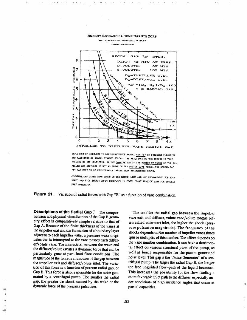
IJ , , sJ,Ct i_ ,,, [IJ , IJ, = iz,, kJ, , ,_ ,
ENERGY RESEARCH & CONSULTANTS CORP,
O_KHTON AVrNUF MO_UI_,WLL£ PA 1_67
TlC.E¢_*Oeql;{21_l 2(_':_U_ I
Figure 21. Variationofradi',dforceswithGap "B" asafunctionofvanecombination.
Descriptions O!the RadialGap - The compr_- The smallertheradialgap betweentheimpellertensionandphysicalvisualizationoftheGap B geom. vaneexitand diffuser,volutevane/volut_tongue(of-
etr] effect is comparatively simple relative to that of ten called cu,twater) inlet, the higher the shock (pres-
Gap A. Because of the finite thickness of the vanes at sure pulsation magnitude). The frequency of the
the impeller exit atzl the formation of a boundary layer shocks depends on the number of impeller vanes timesadjacent to each impeller vane, a pressure w',_ origi- rpm or multiples of this number. The effect depends onnares that is interrupted as the vane passes each diffus- the vane number combination It can have a detrimen-
erNolute vane. The imeracdon between the wake _nd tall effect on various structural pans of the pump, asthe diffuser/vol, te creates a dynamic force that can beparticularly great at pan-load flow conditions. The well as being responsible for the pump-generatedmagnitude of the force is a function of the gap hetween noise level, This gap is the "Noise Generator" of a cen-the impeller exit and diffuser/volu_e inlet. The varia- trifugal pump. The larger the radial Gap B, the longer
the free unguided flow-p_th of the liquid becomes.tion of this force is a function of percent radial gap, orGap B. This force is also responsible for the noise gen- This increases the possibility for the flow finding aerated by a centrifugal pump. The smaller the radial more favorable inlet path to'the diffuser, especially un-gap, the greater the shock caused by the wake or the der conditions of high incidence angles that occur at ,:dynamic force of the pressure pulsation, partial capacities.
185

S . S . D. S . NUCLE.AR FEED PI.IIvIP-DIFF . TYPE.... 7" 'I _ .... g',,.-...'r--"-". , , ,,,,, ...... _T,,'"_T ,,, " ' _ "t .............. -'__r_
Z--,6X Z',=9
GAP "B'''2 . 9Z
I o 0 GAP "A"_,0. 040"
MILS REACTOR AT 81_ POWER
o. o --_-_g--" _" ; .....--i ..... i ....- _|------1 ----f-----t "-'-_- t. _-_-zoo. 2o0. 3oo. ,4oo.
FREQUENCY - I_Z (CPS)
Figure 22. Damaging vibration amplitude at vane passing frequency of a large nuclear feed pump due to theunfavorable impeller diffuser re,he combination (6 and 9).
For a higlv--energy, high-speed BFP, the gap must • Reduction of vibration and pressure pul-
not be less ttmn a certain minimum value to minimize sation amplitude at vane-passing fre-the dynamic forces. A smaller gap can induce forces quency, reducing failure rate, andthat fracture components such as diffuser vane tips, reducing maintenance. The fatiguing el-impeller side.plates, diffuser retaining bolts, etc., and fect of this phenomenon is a leadingcause failure of ma,ny other minor and major cause of various failure mode, includingcomponents internal and external to the pump. shaft breakages.
An impeller is more likely to fail if its natural fm- . Reduction of vibration amplitudes at oth-quency cointfides with the vane-passing f-requency or er than vane-passing frequency,its multiples. This natural frequency can be determined especially at synchronous (rpm) frequen-
: only be measurements, which unfortunately can be cy. When rubbing excites a subsynch.ro-made only after the impeller has been designed and nous component ibr a flexible rotor, themanufactured, The amount of shrink-fit applied be- vibration can be eliminated by applyingtween the impeller hub and the shaft also influences the proper radiM gap.the _equency.
• Substantial noise reduction is a direct re-While the results from the application of Gap A are
suit of an enlarged radial gap.vezy powerful, it is mainly effective for higlr-energy-input centrifugal pumps. The effect of Gap B, howev-
: er, is universally valid and effective for any pump type, • Elimination of diffuser vane-inlet cavi°.any specific speed (N,) or suction specific speed (S_), tation and of breakage of diffuser inletand any application. Of course, the. failure rate caused tips. This is one of the most commons
, by an incorrect radial gap between the vanes is highest symptoms of a tight Gap B for high-and most noticeable for highoenergy feed pumps, energy-input applications.
When a tight. Gap B is increased to the "preferred" • Reduction of impeller stlucture f',dluressize, the. following are. some of the most notable lm- at the impeller periphery. A reinforced -provements of this geometry corrective modifications: impeller structure had several more
= 186
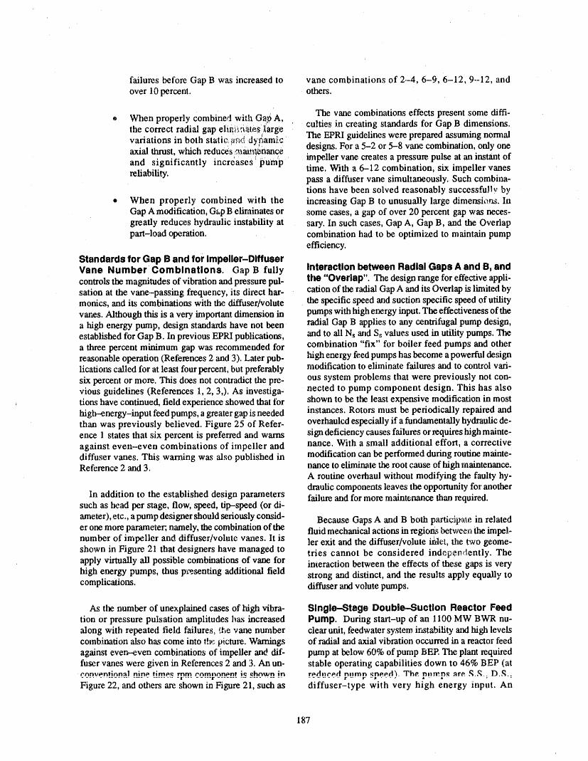
failures before Gap B was increased to vane combinations of 2.-4, 6-9, 6-12, 9--12, andover 10 percent, others,
' . ( . ".t. When properly combmet wade (_,i_._A, The vane combinations effects present some diffi-the correct radial gap eiiv_ii,_iates._,arge cu!ties in creating standards for Gap B dimensions,
.... " _, , . The EPRI guidelines were prepared assuming normalvariations m both statt_'_t._;t<,dyf!am_c,axial thrust, wlaich reduc6s._'_ai_._i_nance designs. For a 5-2 or 5-8 vane combination, only one
and significantly increases _i_um'p impeller vane creates a pressure, pulse at an instant oftime. With a 6--12 combination, six impeller 'vanes
reliability, pass a diffuser vane simultaneously. Such combina-tions have been solved reasonably success full_, by
• When properly combined with the increasing Gap B to unusually large dimensions. InGap A modification, G_,pB elitlainates or some cases, a gap of over 20 percent gap was neces-greatly reduces hydraulic instability at sary. In such cases, Gap A, Gap B, and the Overlappart-load operation, combination had to be optimized to maintain pump
efficiency.
Standards for Gap B and for Impeller-DiffuserVane Number Combinations. Gap B fully Interaction between Radial Gaps A and B, andcontrols the magnitudes of vibration and pressure pul- the "Overlap". The design range for effective appli-sation at the vane-pa_ing frequency, its direct bar- cation of the radial Gap A and its Overlap is limited bymonics, and its combinations with the diffuser/volute the specific speed and suction specific speed of utility
vanes. Although this is a very important dimension in pumps with high energy input. The effectiveness of thea high energy pump, design standards have not been radial Gap B applies to any centrifugal pump design,established for Gap B. In previous EPRI publications, and to ali Ns and Ss values used in utility pumps. Thea three percent minimum gap was recommended for combination "fix" for boiler feed pumps and otherreasonable operation (Refexences 2 and 3). Later pub- high energy feed pumps has become a powerful designlications called for at least four percent, but preferably modification to eliminate failures and to control vari-
ous system problems that were previously not con-six percent or more. This does not contradict the pre-vious guidelines (References 1, 2, 3,). As investiga- nected to pump component design. This has alsodons have continued, field experience showed that tbr shown to be the least expensive modification in mosthigh--energy-input feed pumps, a greater gap is needed instances. Rotors must be periodically repaired andthan was previously believed. Figure 25 of Refer- overhauled especially if a fundamentally hydraulic de-ence 1 states that six percent is preferred and warns sign deficiency causes failures or requires high mainte-against even-even combinations of impeller and nance. With a small additional effort, a correctivediffuser vanes. This warning was also published in modification can be pertbrmed during routine mainte-Reference 2 and 3. nance to eliminate the root cause of high maintenance.
A routine overhaul without modifying the faulty hy-draulic components leaves the opportunity for another
In addition to the established design paranaeters failure and for more maintenance than required.such as head per stage, flow, speed, tip-speed (or di-ameter), etc., a pump designer should seriously consid- Because Gaps A and B both par6cip_e in relateder one more parameter, namely, the combination of the fluid mechanical actions in regions between the impel-number of impeller and diffuser/volute vanes. It is lcr exit and the diffuser/volute irl,le't, the two geome-shown in Figure. 21 that designers have managed to tries cannot be considered inde_;,e_dently. Theapply virtually ali possible combinations of vane for interaction between the effects of these gaps is veryhigh energy pumps, thus px'e.senting additional field strong and distinct, and the results apply equally tocomplications, diffuser and volute pumps.
As the. number of unexplained cases of high vibra- Single--Stage Double-Suction Reactor Feedtion or pressure pulsation amplitudes has increased Pump. During start-up of an 1100 MW BWR nu-along with repeated field failures, the vane number clear unit, feedwater system instability and high levelscombination 'also has come into th_ 9_cture. Warnings of radial and axial vibration occurred in a reactor feedagainst even-even combinations of impeller and dif- pump at below 60% of pump BEP. "Die plant requiredfuser vanes were given in References 2 and 3. An un- stable operating capabilities down to 46% BEP (att-nn_.r_rttlc_n_l nin_ tlm_,_ mm CO.m.rnO_nC_n.t" i_ _hnwn in r_dne_.tt primp ._pP.P.rl'_.The. pnw.,p,_ are. ,q.,_.. D.,q.................................. II...................................... ," .... ":
Figure 22, and others are shown in Figure 21, such as diffuser-type with very high energy input. An
187
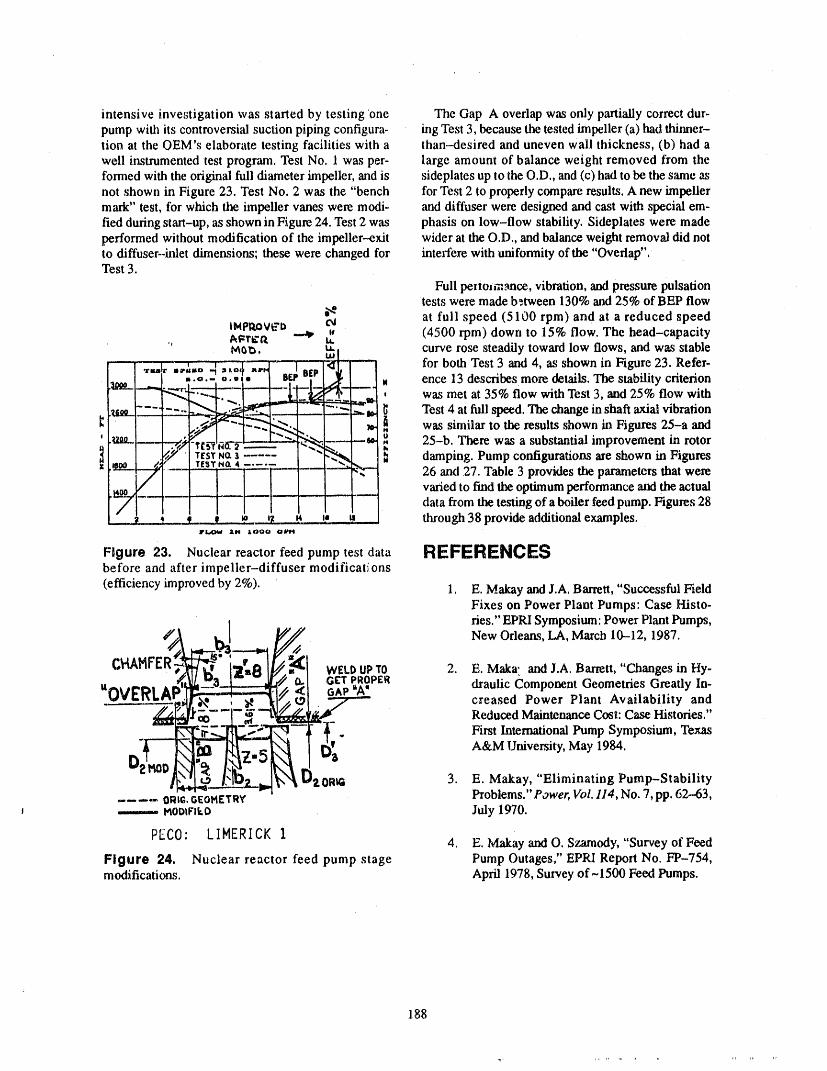
intensive investigation was 'started by testing 'one The Gap A overlap was only partially correct dur-pump with its controversial suction piping configura- ing Test 3, because the tested impeller (a) had thinner-tion at the OEM's elaborate testing facilities with a than-desired and uneven wall thickness, (b) had awell instrumented test program. Test No. 1 was per- large amount of balance weight removed from theformed with the original full diameter impeller, and is sideplates up to the O.D., and (c) had to be the same asnot shown in Figure 23. Test No. 2 was the "bench for Test 2 to properly con_pare results. A new impellermark" test, for which the impeller vanes were modi- and diffuser were designed and cast with special em-fled during start-up, as shown in Figure 24. Test 2 was phasis on low-flow stability. Sideplates were madeperformed without modification of the impeller--exit wider at the O.D., and balance weight removal did notto diffuser-inlet dimensions; these were changed for interfere with uniformity of the "Overlap".Test 3.
Full penotmance, vibration, and pressure pulsationtests were made b_tween 130% and 25% of BEP flow
at full speed (5100 rpm) and at a reduced speed, (4500 rpm) down to 15% flow. The head-capacity., A_I'¢II _ li.
I_ ta. curve rose steadily toward low flows, and was stable' W
_ _ i ! | ......... ,I_|r .,.,,,,o ".,o,1 ,,,,,, I . for both Test 3 and 4, as shown in Figure 23. Refer-T_ "1 . BEr
-.,,.= 0.,,- 8o' . ence 13 describes more details. The stability criterion
__.J.., __ =,, , was met at 35% flow with Test 3, and 25% flow with_ _ Test 4 at full speed. The change in shaft axial vibrationI_:aLi......--.._--__,5_-.-._----,--- .=,--b
' .:_" 2"-- .__ ___ o 25-b. There was a substantial improvement in rotor
damping. Pump configurations are in FiguresN_a4 _--'...-7- ... _ 26 and 27. Table 3 provides the parameters that were
varied to find tlm optimum performance and the actualdata from the testing of a boiler feed pump. Figures 28
___2.__2..._= _.._t a, | vt i, a through 38 provide additional examples.IIP_ I&N AO00 'Olll¢'l
Figure 23. Nuclear reactor feed pump test data i:IEFERENCE$before and after impeller-diffuser naodifications(efficiency improved by 2%). 1. E. Makay and J.A. Barrett, "Successful Field
Fixes on Power Plant Pumps: Case I-Iisto-ties." EPRI Symposium: Power Plant Pumps,
:_ _ New Orleans, LA, March 10--12, 1987.C_'U_HP"E _'-y_:1[_ WELl:>UPTO 2. E. Maka. and J.A. Barrett, "Changes in Hy-// 0.. GIL'TpROPER
anVg'*, AD"II_'- "w _..n__..n._,,dr__ //o< G^P "A' draulic Component Geometries Greatly In-
creased Power Plant Availability and
'# ' Reduced Maintenance Cost: Case Histories."First International Pump Symposium, Texas
D_H,01 [N,_ - A&M Urtiversity, May 1984.
2 x_ b'_ 2,0R_ 3. E. Makay, "Eliminating Pump-Stability.... ORIG.G£OMETRY' Problems." Power, Vol. 114, No. 7, pp. 62-63,i.... MODtFikO July 1970.
PEC0' LIMERICK 1 4. E. MakayandO. Szarnody, "Survey of Feed
Figure 24. Nuclear reactor feed pump stage Pump Outages," EPRI Report No. FP-754,modifications. April 1978, Survey of ~ 1500 Feed Pumps.
188

4700 RPH FLOW " 6,000 GPM (37%)
4000RPH FLOW-zeooGPH_Z0%)
__l:-N__il I I_[ LI
_HAFT AXIAL VlB, = 0,042 IN =42 IHIL$
Figure 25a L_w fzequency axial shuttling of high speed S.S., D.S. feed pump rotor. Vibration levels normal at"BEP" with the thrust bearing setting of 12 to 14 mils, shaft movement clearly 'visible below 50% flow. Maximumaxial vibration level is 42 mils with reduced speed.
5200 RPH FLOW- 3_PI"I (m'/.O_FBEP)
_.il I 1 I I=] I ; ! T i l i l I I I'l I LI L_L.L,Jg V3 _'i=; .t LI I I t J I I I _7 i i I !,]q L! ! !_tjL'_-T--[ [.FT 1' ".1 | ] ] ) ] ] I I I l ['li 1 l J_i..... _j*l I,I I.I I i 17] I l 1 11 I I I I.£J ILL_,/ i 1-1111!] ! I I I I I ,1 I I I I,l ! I i I_'t
Figure 25b, Axial vibration of pump gready reducedfrom 42 mils to 5 mils maximum (at iull speed) after theimpeller exit to diffuser inlet geometry redesignedwith Gap "A' below 50 mils and Gap 'B" over20% radial gap
Figure 25. Axial vibration of rotor before and after Gap "A" modification (see Figures 23 and 24)(Reference 2).
189
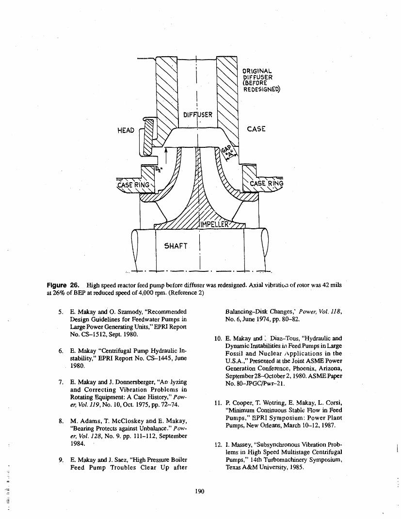
II 0 ' IX
' ____//.,_ I_p,ELLER,;_'?71'__
Figure 26. Ngh speed reactor feed pump before diffuser was .redesigned. Axial vibratio_ of rotor was 42 milsat 26% of BEP at reduced speed of 4,000 rpm. (Reference 2)
5. E. Makay and O. Szamody, "Recommended Balancing-Disk Changes,' Power, Vol. 118,Design Guidelines for Feedwater Pumps in No. 6, June 1974, pp. 80°°82.Large Power Generating Units," EPRI Report
No. CS--1512, Sept. 1980. 10. E. Makay and - Diaz-Tous, "Hydraulic andDynamic Instabilities ga Feed Pumps in Large
6. E. Makay "Centrifugal Pump Hydraulic In- Fossil and Nuclear/_,pplications in thestability," EPRI Report No. CS--1445, June U.S.A.," Presented at the Joint ASME Power1980. Generation Conference, Phoenix, Arizona,
September 28--October 2, 1980. ASME Paper7. E. Makay and J. Donnersberger, "ADJyzAng No. 80--JPOC/Pwr-21.
and Correcting Vibration Problems inRotating Equipment: A Case History," Pow-er, Vol. 119, No. 10, Oct. 1975, pp. 72-74. 11. P. Cooper, T. Wotring, E. Makay, L. Corsi,
"Minimum Continuous Stable Flow in Feed
8. M. Adams, T. McCloskey and E. Makay, Pumps," EPRI Symposium: Power Plant"Bearing Protects against Unbalance." P ow- Pumps, New Orleans, March 100012,1987.er, Vol. 128, No. 9. pp. 111-112, September
: 1984. 12. I. Massey, "Subsynchronous Vibration Prob-lems in High Speed Multistage Centrifugal t
9. E. M',d_ay and J. Saez, "High Pressure Boiler Pumps," 14rh Turbomachinery Symposium,' Feed Pump Troubles Clear Up after Texas A&MUniversity, 1985.
_-
- 190-2
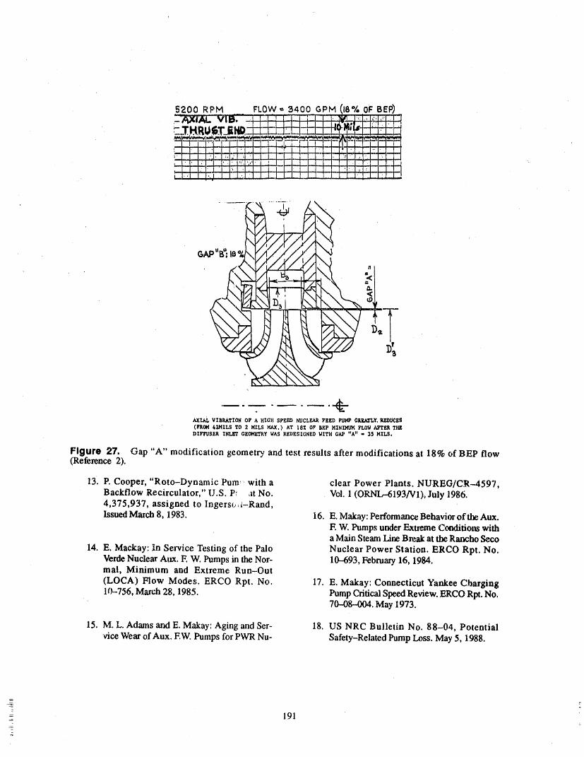
r --
/I
?
,.
.AXId_ VIBRATION OF A HIGH SPEED NUCLEAR FEED PUI4P QNY, RZDUCES
(FR0_f 42MILS TO 2 MILS I_J(. ) AT 18_; OF BEP HIHIMI/K FLOW AJPTER THE
DIFFUSER IXIJ_ GEOMETRY WAS REDESIGNED WITH C_P "A" - 35 MILS.
Figure 27. Gap "A" modification geometry and test results after modifications at 18% of BEP flow(Reference 2).
13. P. Cooper, "Roto-Dynamic Pure," with a clear Power Plants. NUREG/CR--4597,Backflow Recirculator," U.S. P: at No. Vgl. 1 (ORNIr6193]V1), July 1986.4,375,937, assigned to Ingersoll-Rand,
Issued March 8, 1983. I6. E. Makay: Performance Behavior of the Aux.E W. Pumps under Extreme Conditions witha Main Steam Line Bn=,akat the Rancho Se.co
14. E. Mackay: In Service Testing of the Palo Nuclear Power Station. ERCO Rpt. No.Verde Nuclear Aux. E W. Pumps in the Nor- 10-.693, February 16, 1984.mal, Minimum and Extreme Run-Out
(LOCA) Flow Modes. ERCO Rpt. No. 17. E. Makay: Connecticut Yankee Charging1¢_-756, March 28, 1985. Pump Critical Speed Review. ERCO RI_. No.
70-08--004. May 1973.
15. M. L. Adams and E. Makay: Aging and Ser- 18. US NRC Bulletin No. 88-04, Potential
vice Wear of Aux. EW. Pumps for PWR Nu- Safety-Related Pump Loss. May 5, 1988.
191
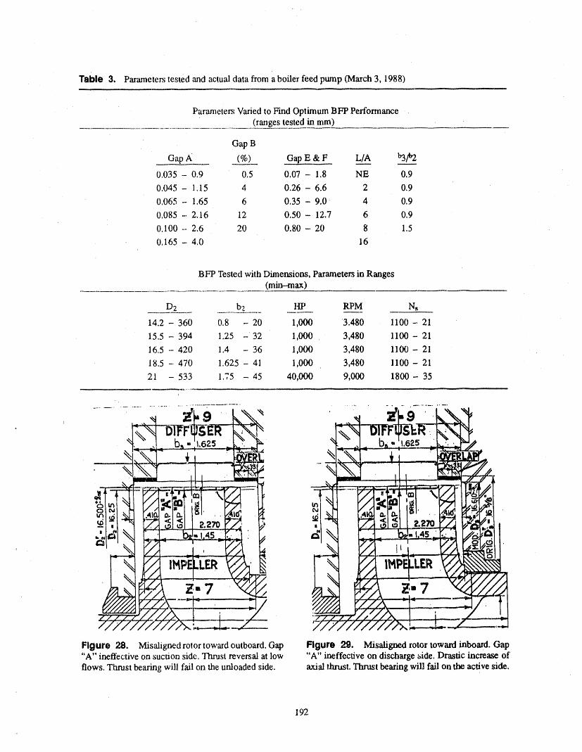
Table 3, Parameters tested and actual data from a boiler feed pump (March 3, 1988)
Parameters Varied to Find Optimum BFP Performance(ranges tested in mm)
Gap B
Gap A (%) Gap E & F L/A _.._.__
0.035 - 0.9 0.5 0.07 - 1.8 NE 0.9
0,045 - 1,15 4 0.26 - 6.6 2 0.9
0.065 - 1.65 6 0.35 - 9,0 4 0.9
0,085- 2,.16 12 0,50- 12.7 6 0.9
0,100- 2.6 20 0.80- 20 8 1.50.165- 4,0 16
BFP Tested with Dimensions, Parameters in Ranges(rain-max)
D2 b'z III' RPM Ns
14.2 - 360 0,8 - 20 1,000 3.480 1100 - 21
15.5 - 394 1.25 -32 1,000 3,480 1100- 21
16,5 - 420 1.4 - 36 1,000 3,480 11(_- 21
18.5 -470 1,625 - 41 1,000 3,480 1100- 21
21 - 533 1.75 -45 40,000 9,000 1800- 35
f
Figure 28. Misaligned rotor toward outboard. Gap Figure 29. Misaligned rotor toward inboard. Gap"A" ineffective on suction side. Thrust reversal at low "A" ineffective on discharge _ide. Drastic increase of'flows, Thrust bearing will fail on the unloaded side. axial thrust. Thrust bearing will fail on tl_ active side,
192
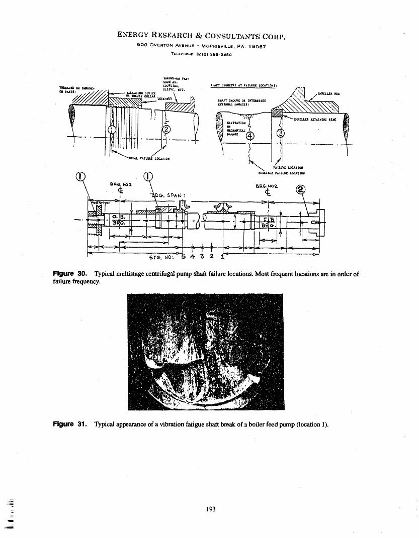
ENERGY RESEARCH _ CONSULTANTS CORP.900 OVERTON AVENUE - MOFIRISVILLE, PA, 19067
TliLt.P#ICItla: _2|5) 2_,2_150
SI_.UI.'K.4X_ P_TSUCU_ i
TIII_[D Cii SI@,U_: _,.' // SL[[',/[, riC, __ ...." ""' /////i_J_-- '_""°,<v_,', _ xt, "_:1 -._,'L,.._,
,_ =.<><,,,.,,.-_,_, /._,._1 .......
SU,t4,rlll,,lll, i LOCATIOHPAII.UIU_I_TIOM
IrOMIIM..ZWklI.LIIZ_TI(_
7_. _ lo.lB.31 _- i _ i t ..L
J
Figure 30, Typical multistagecentrifugalpump shaft failure locations. Most frequent locations arein orderoffailure frequency.
Figure 31. Typical appearanceof a vibration fatigue shaft breakof a boiler feed pump(location 1).
193
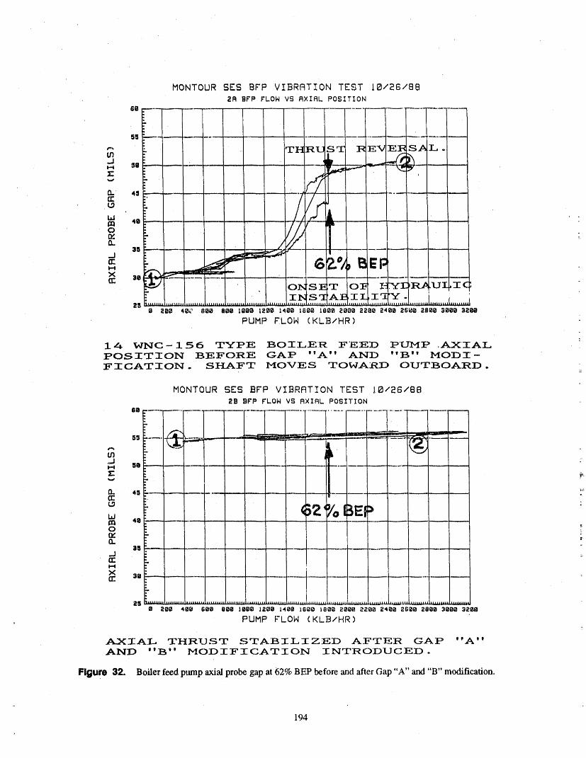
14 WNC- 156 TYPE BOILEIR FEED PUMP ,AXIALPOSITION BEFORE GAP "A" AND "B" MODI-FICATION- SHAFT MOVES TOWARD OUTBOARD.
MONTOUR EES BFP VIBRP3TION TEST 10/26/88
2B BFP FLOW VS RXIAL POSITION
....... ......- I ;i
s_ ----, _ _ ..----- :_ _ _ .-_:_ --' .... '.-.-..-,,,.,,,,,._.__
"" : _ / '_--" _m _ i1,', =,.,,J
_, _e _ ..............................z: i _-,,., ..-13. 4S ' - ........ _ .............. _"
,,
i,iI:1:1 40 ...............................
35 ..... :............._113:: - I>(
- . .... : .....
• 2e0 4e0 see eeo ,e00 ,aee ,_oe ,s_o teee aeoe _.aeo_4ee as00 280e3000 32_PUMP FLON (KLB/HR)
_IAL _HRUST STABILIZED AFTER GAP "A"AND "B" MODIFICATION INTRODUCED.
FiGure 32. Boiler feed. pump axial probe gap at 62% BE2 before and after Gap "A" and "B" modification.
194
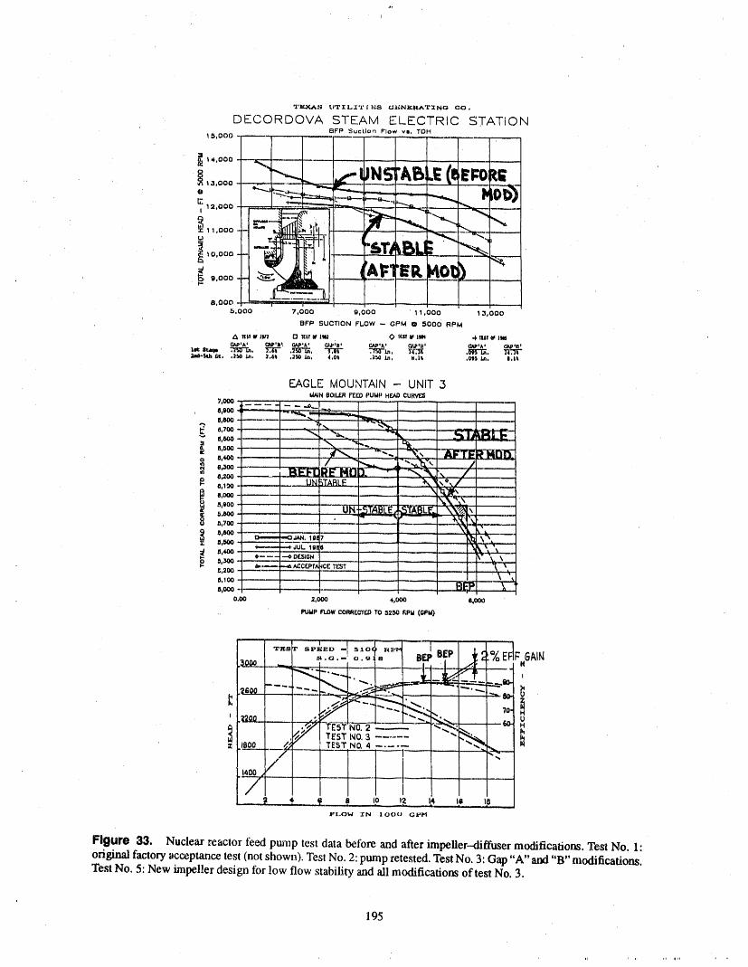
"1'li_S I.;TIL2"Y I 1.1:-_I ClI_NIIII_'I'ING GO .
DECORDOVA STEAM ELECTRIC STATIONBFP Suoilon Flow vu, TDH
1 5,000 .. ......... _! ........ --
' i .....
,.,ooo t,J :ABidEf_c _;
I0,000
,.ooo . -.- ___......... .,5.000 74000 9,000 ' 1 1,000 1 3,000
BFP SUCTION FLOW -- GPM Q 5000 RPM
A 1111'II111_1 O l_i! I_ 1'1_ 0 lf.ll _ lm -4"IU! tll ltlS(_P'A' G_'lb _,^, O/_i';B; ¢.,Oul_'a+ _'_+
_.-T(";_d-Sch 6¢, .2bO in. 2.6_ o_ in, 4.0t ,_ in. B,lt .OS5 in. 1.14
EAGLE MOUNTAIN 1 UNITI_N BOILF.RFEEDPUMP HEAOCURVES
7°000 - - ,...,-_ •..... _.,I,It00 -_.w_. _ _,.._ ..........
F ,,,00 '<'"",,. _,. N u_B{L_-I!,11_0 .,
_,,_o......... /_,z00
_,,_o :--o''- .-oDeB_ONII,300
,,200 _,,,,,--.,-- -.._ ACCt3_rAiCE 7I:ST "_ ,
5.100 --I_,000 i '"
0.00 2,000 #°000 @,000
PUUP FLOWCoRRrc'It_ TO 52_0 KPM (C,PM)
T-_t-_° -I°,° _ _ ,,__ / ..o.- o. _EFFGAIN
?0- !
i-"r-- _ -- _ :-- ,, ! ....
-- _ , _, i_ ,9 _p !._ !_ t, mFLOW 3_N I 000 GPH
Figure 33. Nuclear_eaclor teed pump test data bCfo_ and after impeller-<lif:fusermodificafiom. Tesl No. ]:original factoryacceptancetest (notshown).Tesi No. :2:pump_forested.TestNo. 3:Gill:)"A" alxl "B" modifications.Test No. 5: New impeller design for low flow stability and ali modifications of test No. 3.
195
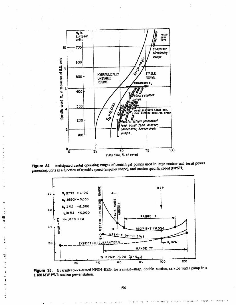
196
......... .... II' ' fl ...... _11' ......... _ I _ll_lll .... III _ II lR II '' I _r 'rqPIl_l_lplrl'lllrl IpI I _ I I_l_ ....... ql' 1'lllllll,q'lII "" Illlllll Ipl_llNIr 'Hrll IIlllllllll II'

OYER.kP
Figure 36. Recirculating flow pattern h_ the meridional plane at part loM (at or below the onset of hydraulicimtabitity).
THIS DRWG. IS TO SCALE ( x 0 . 8 reduct ion ) i - I 0- 80
MADE AS AN IMPRINt" FROM THE ACTUAL DIFF. E. MAKAY
PWFUSER VANE TIPS
.jt" _ ......... _'_, BR_'_ OFF WHERECAVITA1 ,."'4 DAMAGE
WAS HF.AVIE51
• Figure 37. Origin of failure mechanism: flow incidence angle induced stall. Four identical failures at PECO'sFxidystone PW Station between 1976 and 1"78. No failure since diffuser vm_es cut back to the point of bre_age.Two similar failure_ at l_giPCO's Sc 'hal'fferNo. 15 Station. Vanes breke a_the same location. Eighteen idemical fail,.ures at other statiom. Same modification remedied ",dicases. (For more details, see EPRI Report FP-754, pp. 4-5and ,Rgme 10.)
197
_Il'r)' "II_ ...... " "_'I I' qlll-
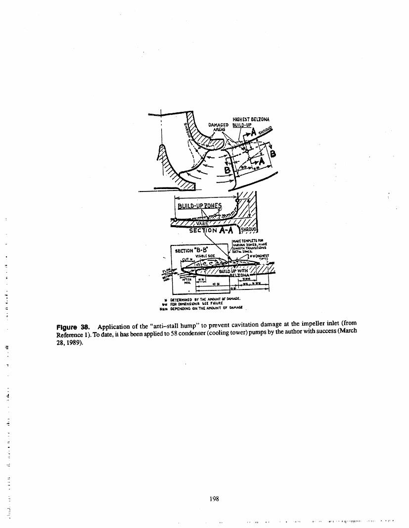
'_ HIGHEST8E_L_'OI_,
CLZ,',_ v_e, / / / / i/1II]• ° j _ I tl_--- ._"_i/t / /I
Sec' N A-A• "_ 114AIf_Tr,_i%_r£
-.-...L .... J,,. " I VilillOi#l ltlINit I'tAl(l
-- " • / • d y,,T / • / "
lt DETE'RI'II_ED BY THE .,II_¢OUHTDF llnl.t1_ FI_ DtMEN$1OI_S ifl FIIJRI
'K'.)I_, D_PINDtNG ON THE N_UNT OF'
_
Figure 38. Application of the "anti-stall hump" to prevent cavitation damage at the impeller inlet (fromReference 1).To date, il hasbeen appliedto 58 condenser (cooling tower)pumpsby the author withsuccess (March
e 28, 1989).
- 198

ATTENDEE- PANEL QUESTIONS AND ANSWERS(EDITED; ATTENDEE QUESTIONS AND PANELAUTHOR
RESPONSES NOT IDENTIFIED BY NAME)
No Questiom/COtnments
7
- 199
PANEL DISCUSSION:IST OF PUMPS; EXPERIENCE AND LESSONS LEARNED
T. HOYLE MODERATORPANEL MEMBERS: J. HEALY, J. MAXWELL, W. GREENSTREET, AND E. MAKAY
QuestionI (Mini-Flowon Pumps) andwedo testthem,Canheatexchangercanimprove_egmdationof a pump?
lt has been strongly suggested dmttestingatlow flowwill,cause pumpfailures.The examplesof some pump Response 2failures causedby low flow operation were for servicewaist type pumps, which run a lot, Parl_llst Testing a heat exchanger for flow cal_city
is one thing. My experience has been that without atrue measurement of what the heat transfer coefficient
My understanding of _e phenumenon is that it is along-texm degradationmechanism. Comz,sting apump on the UA of a heat exchanger is, there may be somefor 30 minutes every three months at low flow; will assumptions based upon a safety analysis that, to per-th_ result in failure or damage to the pump?This only form a certain dutyof rejecting heat, you needa certainadds up to 80 hours of run time ha40 years, amount of flow.
Youre_ly don't know whether or not even without aResponse 1 certain amount of fouling factor, a certain percentage
of tubes plugged--whether you really need 10,000 orPllll_llllt There are many replies along that vein to 8,000 or 6,000 gallons a minute.88-04; that is, the pumpcan run a,certain period tomini flow. One has to look at that in light of current I worked with a number of spec'.'_lists at Stone &knowledge. Webster in Boston, and one of my associates is a heat
excimnger specialist. He's been in the industry forIt's very tiff'cult to say how long a pump can operate 30 years and very glibly and very candidly relates toin mini flow because of the forces and thhags that are me stories that, typically, manufacturers of heat ex.there and that are not there, changers really don't know how many tube,s they can
lose _ what the true UA of a heatexchanger is.How can you considex an isolation operation at miniflow when your pump is degradedbut not to the point Indeed, to ensure margin there's a tendency to over-of failure at anyflow that you have. load the surface area toensure that, if it wasa contrac-
tual problem later on, they wouldn't be caught short. In
A gre.atdeal of failureis caused by fatigue, and fatigue a way, this is whatpump manufacturersdo. We have ais something that happens slowly. For example, if you design flow and a design head.consider something in fatigue you nave a crack initia-
A manufacturer rarely designs an impeller or trims antionphaseandacrackpropagationphase.Onceyouhaveacrackyoucanseethatthere'saproblem.You impellertogetthatpointrightonthemoney.Whethercanmeasurethecrackpointsorwhatever, itbethehydraulicinstitutestandardsIbrpumpsor
HTRI forheatexchangers,thereisalwaysthetoler-
Butuptothatpoint,whichisa majorportionoflife, anceabovethedesignguaranteepointbeforethatyou have no way to know, really, how much damage pmr_por heat exchanger can be accepted.
hasoccurred. So, you maybe fight _mt your pump will It's been my experience that we know a lot moreabout- operate that period of dme,but you may be wrong ff the magnitudeof that tolerance onpumps, and we hap-: you haven't got the history fight, and you could have
failure within that small amount of time at mini flow. pen to know very little at ali about the magnitude oftolerance on heat exchangers." So it's a difficult question toanswer.
Based upon what I know tobe the sizing criteria, how-Question 2 (Pump Testing) ever, I suspect that if we are able to do more field test-
: ing or shop testing, indeed we might find that the heatlt was state,d that pumpdegradations can be corrected exchanger to reject a certain heat load.- which is ourby heat exchanger performance, lt was also stated that objective, obviously_to pass somany million Btus anheat exchangers can't be tested. They can be tested, hour, that we might not need the 10,000 gallons. We
201
might be able to get away, let's say, with8,000 gallons tion plant or amunicipal obligation where if there wasa minute by looking at it that way. a two--pumpsystem and you had a problem with theA
pump, you'd be expected to start the B pump while youIf the pump is only sized for 10,000gallonsa minute or were powering down the A pump, a transition whichslightly larger than that, it's like taking money out of might take ali of five or ten minutes.one pocket and putting it in theother. Insteadof havingreal pump margin, what you might find yourself living No c,ae knew that we were going to be testing nuclearwith is system margin, which gets back to the thrust of plants for weeks, months, and sometimes years. I canOM-20 and other aspects of'what we've been talking cite Stone & Webster's experience at Shoreham. Atabout the last couple of days or so. least a decade's worth of testing has been applied to
some of these pumps without any service whatsoever.
The margin can exist in several places. It can either I think when you look at the amount of time spent atexist in the control valve type of system,pump or heat minimum flow,no one could have imagined what thatexchanger. The focus of what we've been talking could me,ma.As pumps in the nuclear plants got biggerabout, is looking at aUthemargin thatexisLson apump and bigger, the high-energy density levels spokenand finding in some cases that it's wanting, aboutmwhereby we're exposing these impellers and
shafts, sometimes very limber shafts, very high radialI think if we find systems that are wanting, and we're deflections--were unanticipated, because in the pastinlooking for greater margins, we should look in the the '50s and '60s we never accumulated any runningareas that we haven't looked at in the past. time on top of this.
=
So, it's a proposal based upon knowing how heat ex- And the further enhancement of this argument I'd likechangers are designed, and it's a challenge for those to propose is that no one ever expected to qualify awho th/nk they have a problem to go back to find out pump on minimum flow: (a) we weren't expected towhether or not it's 10, 15,or 20%. But I believe you'll run at min flow, and (b) we weren't expected to qual-find a lot more than you'll ever find inpumps, ify. You buy a pump for 10,000 gallons a minute at
2,000 feet a head, such as a reactor. That's the pointQuestion3 (Designof Mini-Flow Pumps) thatyoudemonstratebeforethepumpis shipped.
I think we've been spending a lot of time looking at theIt has been stated that our pumps are failing because problems at the low end and trying to qualify thingsthey weren't designed to be mn on slandby and testingin mini flow. that no one ever imagined.
Can we redesign these pumps? The answer is yes inI believe purchase specifications stated these condi- many instances. It's more difficult to redesign ations when the pumps were bought. Why weren't they 14--stagesplit case auxiliary feedwater pump than adesigned to these conditions? Isn't itpossible todesign three. But within cet,_ainparameters, ifwe cancommu-apump to normally run at low flow arIdyet have high nicate the need to demonstrate, or the need to spendflow capabilities? 90% of the pump's life at 20% flow, there's a chance
: that we can go back and ensure that notonly mechani-Response 3 callythe ptmlp doesn't destroy itself or degrade itself,
but also ,-e can have greater confidence that the pump: Panelist I agree. I'm partly in the maim, perhaps as is pertbrming as well as it should there, as well as at: other people, of writing these design specifications, design flows which are higher than the minirntmlflow.
I hope that addresses the issues. I think we've learnedBut if we take ourselves back 15and 20 years, we find
a lot in the last 15 to 20 years.that there might have been lines in our data sheets or
: ourspecificationsaskingforminimumflow.Wedidn't Question 4 (Vibration Dataon Verticalthen know, and certainly the manufacturers were no Pumps)smarter than us, as to what that meant.
- It was stated yesterday that vibration data on verticalTypically, in a multi--pump system when you go to an pumps is near useless. Do you agree?Inger_l Rand or ByronJackson--and I'm not singlingout any manufacturers, even thoughI can see some of Could the value of the vibration data be increased bythem in the audience---what they were looking at is takingshaft proximity probe data inadditionor insteadtypically what they would expect to see in a cogenera- of casing vibration?
202
Response 4 Response 5
Panelist For pumps where the impeller is 20 or 30 Panelist Generally, I prefer accelerometers. Velocityfeet below the upper _aring, you can wreck the pump transducers have the advantage that youonly integratewithout being able to tell anything in the vibration. The once if you are going to measure mils, and for low frc-only way to detect problems there is to put probes in quencies that's generallyhelpful. But generally, acc.el-the water. That has been done for a certain amount of erometers go toa lower frequency range. They have notesting,but ii is really _fficult to do. moving parts and tend to be more,reliable for that rea-
son, and in a lot of eases they're smaller. To try to getYoucan pick up some failuresby taking data at the top a small velocity transducer, you wind up only beingof themotororas close down to thestuffing boxas you able to use it in thehorizontal direction or vertical di-can get, but it is reaily hard to tell what's going on rection because of the spring loading. So generally Idown on a pump in that situation, prefer accelerometers.
Panollst It's been my experience thatvertical wetpit Question 6 (OM-6 Instrumentpumps that we've been talking about, or deep draft Calibration)vertical--there may be a rare exception---but it's been
my experience very few of them spend any amount of In your opinion, (a) is the requirement in OM-6 totime in minimum flow. have the instrumentationcalibrated to one-dlird of the
lowest running speed with the specified accuracy real-if you arc looking at a safety-related service water ly necessary, and (b) would a range of from 10 topump that is normally in service, the minimum flow 100Hz be more realistic in view of the usual calibra-happens to be a turndown of about 2 to 1.The pump is tion facility capability?designed for 16,000 gallons a minute, lt might come
down to 8,000. So, that is a rare problem for a vertical Response 6pump, if it is in either normal operation or even in
standby where it spends ali of its time at or near design Panelist I'm not sure that I can answer a questionflow. about what the philosophy is behind OM-6. When you
specify the accuracy of a vibration transducer,a vibra-Another interesting thing is that we alsolook at a num- tion monitoring system, you can't just say I want 5%ber of ranges we've been talking about. The OM-6 accuracy. You have to specify half a dozen differentstandard talks about pumps operating at less than 600 numbers, including frequency response. What do yourpm. Again, unless there's a rare example, I don't mean by frequency response?know of an end-stamped or safety-related piece of
equipment that runs at 600 rpm. Ninety-nine point Generally in the electronic industry, frequency re-ninepercent of themrun between 1,800and 5,000rpm. sponse is measured by 3 db points. Youcan have 3 dbSo,in a way,that kindof limits the field of concern that on voltage or you can have 3 db on power, which turnswe're talking about when it comes to vibration also. out to be on voltage if you have a 3 db power, a 60 db
: We're looking ata narrow class of typicaUyhorizontal voltage; that's a 2 to 1 or 50% decrease. So I'm notpumps_either single or multiple stage, an occasional sure if _ey want 5% across the entire frequency range,one-. or two-stage vertical that might only see service or they want 5% at the calibration frequency and 3 dbat test line capacity, across the entire frequency range. It's a problem.
Panelist By the way,the slow-speed pumps are gen- It is possible to measure very low frequencies aecu-emily the reciprocating pumps, and thereare a number rately, but it's not easy. You have to use seismic trans-of those, ducers. They get to be big transducers or fox'cevoltage
type transducers. It's difficult. The National Bureau ofQuestion 5 (Accelerometer Versus Standardsonly calibrates down to 5Hz, so --if you areVoloclty Transducers) going to calibrate lower than that_you have to do
something exotic in your calibration lab. So, it gets to- Could yeu comment on accelerometer versus velocity be a real problem madI'm not sure whether the Com-
transducers for casing measurements_advantages and mittee would like to address whether OM-6 hasdisadvantages? thought of that or what they're plarming on.
203

Panelist I want to comment on the "down to 10Hz" teristics. You can still get very good data at lowcomment, frequencies.
As you can see on this chart, that item 5, which goes up The example Igave earlier in my paper of that charg-to 10 Hz, turned out to be the biggest headache in the ing pump---that's a3.3 Hz pump---andwe were able tolarge nuclear pumps and boiler feed pumps. When get good data there, and good data at 10 Hz. Evenmost people take measurements, they go down to 60 though we may not be getting 5% accuracy, you cancpm, 10 Hz, and they don't measure below that. That still tellwhat's going on with the pump if you are.care-sometimes turns out tobe the most important barome- ful and pay attention.ter in troubleshooting that pump. I wantto kind of cau-tion those people who take measurements down to So, I'm not sure that it's necessary to maintain the 5%,only li_Hz, because frequenciesbelow 10HZmayalso but you have to be careful that you are not using aindicate problems with that pump, and ff you only go transducer that rolls off so fast you are not going todown to I0 Hz you don't see the problem, pick up any of those low frequencies.
Panelist Let mejust give a little bit of background. Question 8 (Instrumentation of Low FlowThe reason for the one-third of the lowest running Pumps)speed is that we really wanted to pick up the one--half
times running speed, andto ensure that we hadthat we The question is concerning low flow rate pumps, inwent to one--third, particular diesel generator fuel oil transfer pumps.
These pumps are usually overdesigned to begin with,Generally,we hadnever discus,_e.,dthe problems in the 300 to400% pumpsgpm.working group of what happens on some of these re-
ciprocal pumps where you get very low speeds. So, With a flow rate at 20 to 22 gpm, slight instrument in-that's an item that we have on our agenda to relook at. accuracies can cause the test data to fall outside the ac-We're reformulating the task group on vibration, and ceptable and alert range.we're hoping to look at some of these areas, as well asthe one that we discussed yesterday that was also onour agenda, should we have a minimum that you have What is the best way tohandl_ this?A reliefrequest? If
so, what range is acceptable?to worry about. If you have a 0.01 or can youjust sayanything below that youare not going to worry about.
Response 8
We'regoing tobe looking at more of those in detail inthe working group in the next months. Panelist Again, I think we're looking at an unusual
application. Diesel generator fuel oil transfer pumps
Question 7 (Instrument Accuracy) happento be typically rotary positive displacementpumps,and I think yot_.'vegot yourself aCatch-22.
As OM-6 requiresthe total loop accuracy of digitalvi- If they are centrifugal, then I would wonder why thebration instrumentationto be 5% over the calibrated refete_|eeflow isas high as it is if the pumpis 400% itsrange, in your opinion is this an absolute accuracy re- rating. I've run across both kinds of pumps. If they'requirement? Can it be met? centrifugal and the pump is rated, if the design flow of
the pump is 22 gallons a minute andyou only need 5 orResponse7 6, why are we demonstrating capabilityat 22 gallons?
Panelist Let me answer the questionof can it be met. I'd like to have the questioner clarify this because rveYes, it can be met. lt is not easy. It is very hard. runacross theother styleof pump, which is a PD. Posi-
tive displacement, of course, is a function of speed. If
Is it necessary? I don't think it's necessary. Especially, the motorruns at one speed, then you are forced to runifyou are using relative standards and looking for a 2.5 at _2 gallons per minute even though you only need 5change or a six times change, and you are using an in- or 6. So any small perturbation of back pressure or lift,strument that has a good repeatability or a single d(_- or whatever it happens tobe with the fluid that day,cansign of instrument where ali the transducers have the cause you to get a blip in data.same low-frequency roll-off characteristics and diemeters have the same low frequency roll--off charac- Attendee It's a positive displacement pump.
204
r, ,, ipr_iiiI II
Panelist That'stheproblem,then.It wouldappear Question 9 (Low Energy Pumps)that a relief request would be the way to go. I can'timaginetheargumentbeinganythingotherthanac- Mostofyourexamplesrefertohigh/energymulti-ceptingitifthepump isthreetofourtimesthesize. stagepumps,suchasreactorcoolantorasteamgenera-Why youwouldhavetobedemonstratingeither20, torfeedpumps.However,safety-relatednuclear21,or22 gallonsa minutesoconsistentlythatyou pumpsarenormallymoderateperformancepumps.couldn'tavoida deviationoutsidethatwindow,espe-ciallyff the pumpis threetofour times the size it ne,ed Do you agree, and would you discuss this point7be7
Response9Attendee We canavoidthedeviation,butIguessIshouldhavesavedthatquestionforlaterthisafternoon Par_llM Yes,youareright.Butremember,atthebe,-whenwe havetheNRC andsaywhatisanacceptable ginningIsaidthereasonIbringinthehigh-energyin-range, putpump isbecausewe concludeclearlyon those
pumpswhattheproblemsare.So,whenyoulookatthe
When youaretalking22gpm,youdon'thavein|]ehto low-energyinputsorlower-energyinputpump,it'splaywith. verydifficulttopindownwhattheproblemisifyou
developaproblem.Thelow-flowandlow-frequencyproblemdoescomeupwithlow--energyinputpumps.
Panell_ Ithinkthisquestionisreallygoodnotonly Also,asamatteroffact,thelow-energyinputpumpsforpositivedisplacementbutforanylowheadpump, haveoneadditionalvibrationcomponentthere,sameIt reallyhas to do with whereyou starthavingafairly as the zero-to-lO-Hz but generated at the impellerlow differentialpressureacross apump. Youaretalk- eye.Thatwe don'thaveatleastinthelarge-energyin-ingaboutverysmallamounts.IfyouhaveaDP of25 putboilerfeedpumps,butit'seasiertojudgeifyoupsi,youtakeafewpercentofthatandthat'snotmuch lookat,1,500Ire'geenergyinputhigh-speedboileratall.Youstarttalkingintherangeof0.5,0.3asbeing feedpumpsandconcludewhatbreakstheshaftorwhathow muchoveryoucangoforanacceptancecriteria, thosevibrationcomponentscomefrom.Thenyougo
tolow-energyinputpumps,andinsteadofbeinginthe,: That's always going to be a concern, and I think you dark and trying to outguess what the problemis, your
haveacoupleofoptions.Oneistoinstallbettertestin- conclusionisbasedonthelargeenergyinputpumps.strumentation,andtwoisthereliefrequest. Butallthosecomponentsarepreseminthosepumps.
Atten_ (NRC) This is a difficult issue to dealwith. Now most of the zero-to--lO-Hz components are not_- We havehada numberofreliefrequeststhatcomein noticedon thoselow-energyinputs.Theyarenotas
alongtheselines.One thingthatmakes itdifficultis damaging.Perhapsyoucanrmltwo,three,fouryearsthat we almostneverhavearticulatedverywell what is with thatkind of componenLwhile a boiler feed pumpactually going on. Why is it that the ranges canrot be would have failed in 10minutes.met? That puts us in an impossible situation, becausewe can't process a relief request if we don't know But thebiggest problem is thatpeopledon't measure it.physically what the reasonis thatthe test is behaving Yourvelocity pickup doesn't go down that far. You
: the way it is. Irrespectiveof first, it meets the defini- have the IRI) (manufacturerof vibration monitoringtion. The other question is if you know what's going equipment)equipment that goes only down to 10 Hz.on, we need to know why the test is adequate fordem- So you skipthat area. It'sthere. Youjustdon'tnotice it.
onstmting the conditionof the pump. Obviously, you are.right. It is notas obvious and is notas damaging, but it is there.
What I'd like to avoid is a situation where we say that
the solution is througha relief requestwithout us hay- Panelist When we look atboiler feeds or largereac-ing the opportunityto knowwhat's going on. Weneed torfeedsors_ generatedfeeds(inanuclearplant,ato know why the test that is being done is accomplish, reactorfeed pumpor a steam generatedfeed is one, oring the intended objectives, two stages, with energy levels of about 5,000 horse-
power per stage) we can't just jump over to a split caseIpersonallydon'tthinkjustsayingthatthere'sawide orasmall,auxiliaryfeedwaterpumporchargingpumpmarginbetweenwhatthesystemneedsandwhatthe byjustlookingatenergydensity,becausethere'sptmkpcandeliveristheanswer,becausethatdoesn't anotherfactorthatcreepsintothis.Thatisspecifictellme whattheconditionofthepump is. speed.
= 205
When you look at an auxiliary feedwater pump which the shop and test it in the field and we never run it, themight be a 500-horsepower pump, it might have any- onlyconcern that I have about pumps is whether or notwhere between eight to ten stages. So, horsepower per they will respond to the demand to come up to speed,stage is low, but younow introduce the other phenome- and that's not a pump problem. It's a problem with anon, which is the rotodynamics problem. Supporting a motor or a turbine or an engine, something that pushes14--,10-, or an 8--stagepump witha large bearing span or pulls the pump.introduces dynamic problems and mechanical prob-lems that the high--energy pump doesn't really have If, however, we are convinced that we have to do test-but the three stages or twoor even five stages on a fos- ing, then to ensure that we have adequate results thatsil plant are more related to what we'd refer toas a stif- can mean something and at the same time don't de-fer shaft pump, maybe nota stiff shaft pump design, stroy the very machine that we're trying to protect,
then we have todo full-flow testing. But tojump from
But some of the problems thatare incurredat low-flow the need to test, the issue is something that I don't feelwork are more readily on a multi-stage pump with a that I can quote to.greater bearing span witha smaller shaft diameter perpound of horsepower or per pound of pump, let's say, Question 11 (Low Flow Testing)where it's a lot more sensitive even if the energy levelis lower per stage, especially if the bulk of the time the Since low-flow pump testing is of little value and canauxiliary feedwater pump is back on minimum flow cause damage, doyou recommend suspending the test-and run infrequendy, ing until full-flow testing can be accomplished?
A boiler feed pump that comes up once or twice a year Response 11running ator near BEP,or perhaps at night if the cyclecomes down, creams one kind of aproblem. But I don't Panelist Youshould monitor so that you are in con-believe if you were to put that on a scale it would trol of the situation and it doesn't control you. I wouldweigh equal to what happens with a pump that is like to see you get away from mini-flow, but I don't
-: started monthly, quarterly, or the bearing span might think that's going to hold true in every case.
be twice as great as the pump that has one--tenth the Panelist But concerning mini flow testing, I have tohorsepower. So, in my experience, it's more than just admit, many times when I test pumps out there I getenergy level per stage, very annoyed by the NRC's request to test the pumps
in such extreme conditions.Question 10 (Full Flow Versus Mini-FlowTesting) I have one hereat Palo Verde. In this particu"larcase we
had to test the minimum flow and we had to show that
Should utilities be designing full flow test lines and in case of a LOCA condition the pump would survive.getting away from mini flow test lines on Section XI I said let's test the pump for LOCA when we have apumps? LOCA, but don't purposely ruin the pump.
Response 10 On the other hand, I was very happy that we had toper-form this test, because within a year.these,pumps hadtwo miserable failures, both at Palo Verde and at the
Panelist From ali the evidence that I have found, I Texas South Project, Houston Lighting and Power. Ifwould agree that you needto test near desigr, flow. It's youdid not request such extreme conditions, we wouldnot always possible, but certainly you should test not have yet debugged the design, lt was clearly a de-
" above minimumcontinuous stable flow. I think that's a sign problem in the pump.° clear point.
So I'm torn between the two. At once I'm annoyedthatPanelist I'm probably not qu:iified to speak to this I have to run such tests. On the other hand, it debugsbecause it is a regulatory position as to whether or not the pump.pumps have to be tested at all. But without soundingtoo comical I'd like us ali to remember that pumps, if Now my thought would be.--again, I don't represent1
they're designed correctly,probably won't wear if you anyone here; I'm just speaking for myself--once we- don't runthem. So, it's not like the '58Buick that you debug the unit, I would prefer not to run the pumps in
have in the driveway where if youkeep it up on blocks those e,.treme conditions. As a matter of fact, if it wereit will last for 20or 30 years. But if we design a quality up to me I would .saybump test the pump, don't run itproductand we build a quality productand we _st it in for 30 minutes, because what are you trying to do?
-
206
The important thing is when we need the pump, we Panelist I think on the other side of the fence, withoutwant to make sure that the pump will startup and will mentioning units, there are pumps that continuallypump. But again, I'm noauthority. I'm onlyexpressing have maintenance problems, auxiliary feedwatermy opinion. In many cases these extreme conditions pumps that come down annually or have bearingdid do some good to usby debugging the pump. cracking. There is a clear indication of the pump tell-
ing you that that style (whether it be that manufacturer
Attendee (NRC)I want to clarify first that it's not the size, or construction) just can't tolerate that service.
NRC's position that plants need to test on minimum I think in those cases we need to upgrade metallurgy.flow. That's not our requirement. I think that's a sys- We need to upgrade designs, change the internal fitstem result. If you are looking at technical '_pecifica-tions that talk about the flow that needs to be exhibited within the pumps, and make them less tolerant. But I
don't think we should suspend this testing until and un-when you are on minimum flow, that is there because less we put full flow testing in, because there are someplants ,est in thatcondition and a value had to be speci- Fumps out there that can take it. Then the only issuefled, and that's why it's in the technical specifications, becomes hydraulic proof.
It's notan NRC requirement that plants test in mini- Question12 (TemperatureAffectsonmum flow. Just the opposite. We would prefer plants Failures)do meaningful testing, and if that means full flow,byali means do that. Whatever we can do to entice the The data and failures discussed come from boiler feedCode to go that way, to entice plants to put in full flow pump and RHR pumps. Both types of pumps spendloops, do that. In fact, when we review advanced reac- many hours pumping fluids that are hot.tors, we're discouraged to see that there isn't any ad-vancement in piping systems. There isn't any addition Does temperature of the fhfidbeing pumped play a roleto full-flow loops. We're in the same kind of configu- in the damage or failures? Please explain how the fluidration that we've always been in, which is the mini- temperature has been addressed in your research.mum flow. That's the wrot,g way to go. By ali means,design your plants so that you can test them at thebest Response 12point available.
Panelist The fluid temperaturedoes come into play.We know in particular it comes into play in Zhe
Panelist If I can be allowed a P.S. on this, I have NPSHR, so it can have an influence. I amnot sure thatbeen privileged to witness the testing of pumps that the temperature played an important role in the feed-have been installed for the last 15 to 20 years, and Idrink the root thought behind the question is whether water pump failures that I gave as examples.or not we should suspend this testing. Perhaps I
Panelist Temperature comes into the picture. Duringtouched on this. I'd like to elaborate a little bit more onwarmup defommtion it can be.a problem, and we face
my original opening remarks earlier this morning. So seizure problems. The boiler feed pumps, if they areunless we treat ali centrifugal pumps the same way,then we're going to be surprised that some of them fail. turbine driven, are put on turning gear. When you get
ready to start up, you are on turning gear 5 to 10rpm,I think we really almost have to treat pumps like and you increase the temperature from ambient to, say,people. I can cite some examples: my experience at 420 degrees or 350 degrees.Ft. Calhoun, where some pumps imve been run for
14 years on minimum flow. Yougo through a period when the shaft and the barrelare both iri such a mode that the pump will seize. Sei-
Now the only thing that we're uncertain _.bout is zure is a very serious problem. The impeller eye and=-- whether or not the pumps were able to go to design the impeller bearing must be of a certain material, and
flow and make design head. Recent testing has demon- the basic rule is that they must be at least 10 Rockwellstrated that the pumps can do that, but the bottom line C difference in hardness. Certe,in materials are whatis thatthe pumps installed in that plant run as periodi- we call s,Azure proof or nongalling, but if you usetally as it has been for the last 17years, has sustained common materials, seizure is indeed a very seriousabsolutely no failures. 'There have been no wearing problem for ali the feed pumps, especially if the boilerfailures, no shaft failures, no diffuser failures, no bear- feed pump has many stages, like 6, 8, 10, and then sei-
_ h 'ing failures. If L.atsth ::way the pump is designed and zure is the main result of temperature- caused prob-"unning, then it's thatpump and that plant that can ap- lems. The majority of them are seizures on the turningparently sustain and tolerate that service, gear.
207
Question 13 (Instrumentation of Panelist Thereis a very,importantpointin measur-Mini-Flow Lines) ing flow in recirculationlines whenyou have a charac.
teristic curvesuch as he's describedbecauseyou don'tknow whetheryou have flow at all, and it's very ira-
Please talk more aboutthe necessity (or lackof it) or portantthatyou do have flow.The line canbe clogged.desirabilityof installing minimumflow line flow in-
strumentation. It was indicatedyesterdaythatNRC Question 14 (Consistent Instrumentationthinksit shouldbe installedforIST purposes, of Pumps)
Response 13 Since,as smWxl,therecanbeallegedvariationin thereadingsobtained by different vibrationinstruments
Pane,sl If minimumflow is a severely reducedper- dueto differentways of determiningthepeak-to-peak¢entage of the design flow whetherit be an auxiliary values, should thecode addresscontrolsto ensure thatfeed waterpumpor a similarpumpwhere the rise to instrumentswithequivalentresponsearealways usedshutoffresults in a pumpcurvethat is essentially flat to measurevibrationon safety-relatedpumps7fromzero flow to perhapsas high as 50%of BEP,it's
been my experiencethat,even if you put aflow trans- This is importmRbecausechanginginstrumentscouldmitrerof any kindinthatline, theindicationis goingtO allowa degradedpumpto go undetected.becyclical.It will varyali overtheplaceasthesystemtriesto f'mda home.So,thereading,oventhoughyouare going to get a reading of minimum flow, if the Response 14pump is designedfor300 gpmbutthe curveis flatto ashigh as 150andtheminimumflow is 50 gallonsarain- Panellet I wouldlike to emphasizethatwhen we dc-
: ute, the readingwill bejumpingali over theplace, per- velop Code rules they arc really minimum re_luire-hapsbetween25 to75 gallonsa minute.It's like asking ments. It's ve,T difficult to get a consensus standardfive people forareadingandyou get six answers,lt de- through the system. There are so manypeople, and
-_ pendsuponyourviewpoint,how you arelooking atthe theyhaven'tali heardthe discussions.So,we generallygaugeor if it'sa digitaloutput.I don'tthinkmeasuring have minimum requirements. It is up to the owner.
° an unstablepoint should give you a warmmadfuzzy Manytimes the licenseehas to know whatequipmentfeeling, he's using, and when pumptesting or valve testing or
: any other testing,we have to know what we're doing
I think the issue is eitherwe design thepumpsto runat andwe have to beconsistent.minimumflow mad,moreimportantly,if we're actuallyout todemonstrateoperabilityononehand,which is re- I thinkwe mustlook atpumptestingorany other test-sponse,andthenperformance,we shouldn'tbe testing ingthisway andkeepin mindwhat we're doing.We'reat minimumflow atall. placing more emphasis on the reference values. The
reasonwe're doingthatis we wantpeople tobeconsis-lentin theirtest methods. Someof this you aregoing to
So, byputting aninstrumentin theminimumflow path know whenyouget your test results. Ifyour testresultsto perhaps enhance our data, if I can be allowed to say start jumping ali over, you are going to find out thatthis, is a nickel tin fora dollarproblem, so long as you
you haven't done your test right,andthatshould showare way back on the flat endof the pump curve. I think up. So if you have an instrument like this and youas has been pointed out, the only example oi', if you change it, I think you will see I/1odifference, and youwill, exception to this rule are the high specific speed know that you need to take some action.pumps. These again are the large circulating waterpumps where the curve shape leads itself to the con-stantlyrising characteristicto shutoff.By and large, Question 15 (Identifying Pumpthe bulk of the centrifugals, whether they be ali radial Degradation)
= or mixed flow that we find in nuclear service, just
don't lend themselves, if the minimum flow is a flow How could we identify pump degradation by using: or another when the pump is operating at the low end ptmlp head curves for the pumps that nonnally run on
of the curve, the flatportion of the pump curve?
-_ So the bottom line is I don't really think it enhances The second partof the question is how close could we- anything. In fact, it may actually contributeto the un- get to the pump shutoff head and pump runout to-- certainty as to what the pump is doing, performpumpoperability?
208
.... [ .... I,. 11 ,I '1 _11 I li [ lI _ J ,J ' , , I ,Irl 'VI ] J)lfIl'l'J ' I
Rosportse 15 particular pump design. It's been my experience thatwe shouldavoid minimum fie"' where thecurve is flat.
Panol_ I don't know of a pump application where From a pump designer's stmadpoint,we really shouldthe pump issized and required tor un on the fiatportion be looking at points where the curve is dropping ini-of the cm_e, or the de.signflow happens to be I think tiaUyto the left of BEP so that you have a o2screetin.the isst_s that I+m aware of r;late back to testing at _rsection between a system curve, whether it be aminimum flow or testing at flows where the curve is manual, a test line, or the actual system itself, whereflat. I'd be in_rest_i inknowing wnere ame.nufacturea" insteadof getting a low side of an infinite number ofwas ask_ to design in the flat region only. flows for a given head, you've got one head for one
flow.
One wouldexpectthatthetypicalapplicatirmofapump wouldplace the pump's desi_ flow which is at Typically,our ruleis that we'd like to f'mdan intersee-be,st efficiency---one would hope that!t_ application rien wherethe head is about2 to 3% less than shutoff,requirement for the system would be somewhere near if I'm looking to the left of best efficiency. To the right,that. That's not always the case. lt typically is a In'ob- certainly again I would stress that we would want tolena on auxiliary feedwater Dunps where the pump's recommc_tdto the vendor that we may be doing this. IBEP flow might be actually _otl_r i. or 20% to the woul,'texpect to be able to say, generally, that pumpsfight of whe_ the applicationflow happens lobe. are generally stable to about 115% of their best
efficiency flows.
Again, it's a function of the specific _peed and theapplicationof the pump. But I'd be curious to fm¢lthe If you need to go beyond 115 to 120 to 125, then Iapplication where the pt_npwhichwould have perhaps would recommend that we consult our pump designera best efficiency of some 600 gallons a minute, the toensurethat the pump is equally stable far to the fightpump specificity being 600, wlmre the sca'viceor the of best efficiency as we would expect it to be stable tosystem flow was so low that it would be in the flat re- ',heleft of best efficiency, t_Jt asa general rule, my ex-glen, say perhaps 300 to250 gallons a minute. I'd cea'- perience is that you can ge to at least 15% past BEPtainly like to know a little bit more about the and zxpect to get areliable, stable, repeatable point ofapplication because this type of characteristic is not perfmmance.that which you typically fredin anuclearpump ina nu-clearplant.Themare charac_'isticcurvesfor pumus Question 16 (Restrictionson Runningthatare typically found in balanceof pla_, and this Pumps In Mlnl-Flow)usually isn t a problem, at least not in my e_tgerience,madI don't know if anyone else can speak to it. Do the pump manufacturers adequately define the re-
strictions to running various pumps on minimumPa_'@lk_ If you look at the pump curves in figure 33, flow? More precisely, how should they providethis in-
+ you can see amt therewas abad droop in the curve be- formation and how shouldthey state it?-fore the pump was modified. Themodificationcom+.pletcly removed the droop. The modification involved Response 16installinga rir_gin the pumpvolute to change its shapeandthe size of the gap. Panelist I'll reply by referring to replies from
- 88--04. Usually, the plants go back to the vendor andIf the volute shape is improper, there's a _oss mis- get his recommendation as far as minimum flow isalignment, but ff the geometry is not c_m_,ctthe flow concerned. Many of the replieshave comeback sayingshoots back from the diffuser behind the impeller side youcan operate at a given number of hours at that flowplau_,and that e_ergy loss is the cause of the humpon rate,the pump curve. It's ali fluid mechanical, and it's thehy:lraulic instability caused losses. I really wish I knew what was behind their decision,
because you can't; ._ke that decision in isolation. YouPsnollSt There was a second pan of this question, haveto take.into account the remainder of _heoperat-
: which askshow close should we get to the pump shut- haghistoryof the pump in order to do that, and you alsooff head and pump runout to perform ptmapoperabil- have to have a very good knowledge of the forces and
- ity, testing, and is this we're talking r_ally beyond the so forth that m'eimposed on the pump when you oper-a] best efficiency point, ate at minimum flows.
= Panelist Again, it will be a function of the pump and I am not aware that one is able to calculate forces thatthe size of the pump and the curve shape and the are imposed on the impeller or on the shaft at
209
41
(_ ...... tl rc ii<lr ,+_, el ' ' II .... J,l_ , , jj,r . ,a 'I'P? 'Fir I_1 P ' _15 vi, rl,tl ' ii, til rl I_ i 1, i]lllpj .q:_i_l ,, ,Ill'lipI ,_ ,P*li, lr , PIrll , , ,., qlTfft,,,i
minimumflowconditions.Fordesignflow,of course Question 17 (Flow Instability Effects)theydomakethosecalculations,=_'Idthatgivesthemaway topredictwhatlifeoneshouldexpectfroma DoesOM-6 providethelatitudetoallowforflowin-pump.Butatminimumflowit'snotcleartornehow stabilityeffectscreatedbytestingpumpsonminimumtheydothatorevenwhethertheycan. flowpass;forexample,inducedvibrationsatgreater
than0.325in.persecondduetooperationclosetoPanelist It's beenmy experiencethatmanufacturers shutoffhead.doknowhowtocalculatea numberof factors.We'vetalkedaboutthemuptothispoint.We'vetalkedabout Response17recirculationat theeyeof the impeller,reeirculationsthat just showed vane tips. There'salso been a logof Panelist No, at this time the standard does not allowwork done to calculate the radial thrust on impellersso thaLYou would be in the alert range at that level. So Ithat ff we look at differentiatingbetween the point that guess the answer is just no.I've been exposed to over the last 15 years--if we can
differentiate between saying minimum flow, and Question 18 (Flow Instability Effects)clearly make it understood that we're looking mini-
A let of excellent work has occurred to identify flowmum intermittent flow or minimumcon_mc , flow.instability concerns. Are pump vendors involved? Ifso, is there any indication that they are cart;'- ' ; useI think the word "intermittent" or "con,....as" wasof their products in unstable regions. The Code
missing from the specification_ in the past. The man- cautions that owners need to check with vendors?ufacturers u_eatedthe minimal flow issue as if it was a
However, if they are not involved, the industry mayminimal flow on a boiler feed pump on a 300 mega- suffer.watt fossil plant or on pumps that they 'hadexperience
with inearlier generations. I thi,'tkifyou pose the ques- Response 18tion two ways, you'll get two completely different an-
swers, intermittent being perhaps minutes. Once in a Panelist When I see a pump failure problem, oz'sys-while a minimum continuous would be a reading that tem problem, usually the vendor is involved, lt wasn't
__. can be sustained continuously, so 20 years ago. Peopleweren't used toan outsider be-inga consultant other than the pump vendor. Normally,
Atlendee Shouldn't they be more clear what inter- consultants were consultant only to the vendor,Every-mittent means precisely? thing was kept in great secrecy. That is changed. Nor-
mally, we prefer to work with the utilities, like thePanelist My opinion is we shouldn't ask for inter- work I showed you and the Limerick nuclear feedmittent flow requirements. I think you'U get into sub- pump.Wedid it as a complete unifomateam. As a mat-jective evaluations. You' 11go to three or four ter of fact, when I worked on that pump I had the feel-engineers. You'll get five and six different answers be.. ing that I was employed by them, because they treatedcause it will be a function of the age of the machine, me as if I were one of them.the ,.speedof the machine, the horsepower,etc.
The flow instability problem was a long, long road for= It's been our experience if we insist on only one term, me to persuade them that it is there; ii is a nasty prob-
minimum continuous, and make it clear that this is an lem. Lots of testing has been done and there is agree-operating point where the pump could spend 8,000 hr ment on the hydraulic instability. It applies to
° a year, you'll get a completely different answer from Delaveau and the others. As a matter of fact, we havethe vendor, and he knows more about what that flow European pump vendors involved in our research. Sohappens tobe. the answer is yes, it's a fairly accelerated research.
It's very subjective to talk intermittent unless you can So _,,lereare three parties involved there: the pumpsay it's five minutes once a day, five miv,utes once a vendor, the otility,and then the consultant. And the ex-
-_ month, orfive minutes once a year. But since we don't change of information is very free in this area becauseknow what that is and it can vary from site to site or we ali realize that it's a very damaging, very nasty, not
- from job to job, it would probably be safer not toeven well-understood fluid mechanical problem. You can-enter the realm of intermittent if you are going to pro- not calculate it. You l',ave to test it, and then later oi,tecta vital piece of equipment in the plant because it you have to depend on statistical data if you need it.
: only enters into the subjective evaluation and the per- But I have aet seen anyone yet who could calculate it.serialevaluationthatmay notbesubstantiatedbycal. Thereareacoupleofcomputerprogramsavailableout
- culations or actual test data. on the market, and to give you one example, one
210
_, _ ilL,llllll, , ,td, llt,,
computerprogramcalculatedonsetofhydraulicinsta- derstanditandtheywillreligiouslyapplyittosomebilityat45%,andwhenwe testedthepump theresult otherpump oritdoesn'tapply.Sothereisnosetrule,was 85%. Youcanlookatsomeofmy publications,andItryto
cautioneverybody.Don'tuseitwithoutthinkingthisIfthatisaccurateenoughforyouandifyoucallthata pump may bedifferentthanthat.You can'tusethecalculation,thenIacceptit.ButIhavetoadmitIdon't samerulefora diffuserpumpasforavalutcpump,orknow how to calculate it, and I have not yet met any- if the specification reads 1,200you cannot use a speci-
, one who guesses 20%. I guess 86 7o.And if we get 50% fication that was written for a 2,000.then it's half and half.
Normally, the specifications are written for that '.artic-Question 19 (Replacement Pump ularapplication,andit will changefrom applicatior_:,toSpecifications) application.
When si,,.x:ffyingreplacement or newpumps for safety Partell_ Iagree on avoiding specifying design fea-class applications, what c#xle and/or specs give guid- tru'esof a pump.ance to ensure impellervalute geometry and impeller-to-diffuser spacing of the gap? Are there any TypicaUy,working for an architect engineer, wedesignreferences? systems, and we write performance specifications.
Every now and then we might get into ',hedesign of a
• Response 19 particularpumpbyspecifyingabcari:Jgtypeoracou-plingtype.Butwhenitgetsdowntothehydraulicdc,.
PaneElstMoreandmorecompmliesarespecifying sign,themoreyouputintothespecastowhatyouthinkthesenumbers,likedistancebetweentheimpellerand youwant--evenwithallofthepapersoverthelastfivethediffuser,thegapA.Butit'sabcgimting,andIhave ortenyears--themoreyouwillfindthat.youwillbenotseentoomany ofthemunlessIwas personally takingresponsibilityforthatpump orfindingthattheinvolvedbeforetheyfinishedtipthespecs.We have manufacturer'sown tmiqueexperiencerunscounte,rtoso-calledspecificationguidelinespublishedbythe that.So Ithinkwe shouldfocuson performanceElectric Power Research Institute, but we were very specifications---that specifya design flow,designhea_t,careful not to call it a specification guideline because and other specific performance data. The other designwho are we to put down exactly the specifications, lt detail, I think should be left in the hands of the turbomay apply to a class of pump and people will misun- machinery designers.
211
PLANNED SESSION PAPERS
; PART 3: GENERIC CONSIDERATIONS FOR VALVE IST PROGRAMS
.!
213--
INTRODUCTION TO OM-.10TECHNICAL DIFFERENCES BETWEEN IWV AND OM-10
THOMAS F. HO YLEWASH!NGTON PUBLIC POWER SUPPLY SYSTEM
ABSTRACT Mo,_t nuclear t, lant technical specifications requirethe uti.lity to obtain specific written relief from the Nu-clear Regulatory Commission (NRC) for any devi-
ASME/ANSI OMa - 1988 Part 10, developed over ations from the Code. This has been very difficult forthe last ten years has recently been adopted by the both the nuclear pl_lt otx;rators and the NRC, whoBoiler and Pressure Vessel C'_de, Section XI. This new must review and approve each deviation. For example,
" standard will provide new inservice testing require- if a utility wants to determine flow rate by the changemerits for valves and replaces IWV. The paper will in level of a rank divided by time instead of measuringhighlight the significant changes to valve testing flow directly, then me utili;y must request relief from
, requirements, and provide _he philosophy behind the Code requirements. This situation arises when there isnew requirements, no installed flow instruments---usually for small
pumps. The working group has tried to incorporale al-
Background temative testing imo the standard when plant condi-tions make some testing impractic;d.
Nuclear power plants are required by Federal Regu- At fi_'st glance, one would think OM-6 and OM-10lation [10 eFR 50.55a(g)] to test certain ASME Code are qmte similar to the IWP _mdIWV sections that theyClass 1, 2 and 3 pumps and valves in accordance with replace. However, on closer inspection, an inser',ice
: ASME Section XI of the Boiler and Pressure Vessel test (IST) engineer will note many significa;_tCode. The Board of Nuclear Codes and Standards differences. These differences will make IST programscreated an organization, Operations and M,'fintenance based on O&M P_m 6 and Pan 10 easier to implement.(O&M), whose charter was to develop st,'md,'uds for The remainder of this article 'will look at thesetesting of components for nuclear power plants. 'The differences in detail.working group on Pumps and Valves under directions
from the O&M Main Committee was to take Section Overview of Part 10 ChangesXI IWP and IWV and use them as the starting point fornew standards for inservice testing of pumps andv,'dves. The_ new st',mdards were lo replace IWP and A,; with Part 6, the new valve testing standard,
; Part 10, has increased the scope of testing to ali valves
: IWV of Section XI. which perform a safety function, regardless of con-struction code. Additiomdly, _my safety relief valve
The new O&M pump and valve standards (Part 6 which protectt¢ a system performing a safety thncfionand Part 10) have just been published as the 1988a ad- must also be tested. This part will require additional
. dendum of ASME/ANSI OM-1987 Operation and non-ASME valves to be tested. The expansion ofMaintenaaace of Nuclear Power Plants. These new
scope is .justified in that each important valve requiredstandards are referenced in the 1988 addendum of for accident mitigation should requk,'e testing.
" Section XI and re,piace Subsection IWP and IWV of
: that code. Each nuclear utility must submit an inservice testing_- program to the Nuclear Regulatory Commission al the
: Part 6 and 10 Goals and start of each ten-year gnterval. If there are parts of die
Objectives Code(or standard) which the licensee has determined- to be impractic',d, Federal law requires the I.,icensee to_ demonstrate the basis of this detemlination to the satis-
The O&M working group on Pumps ,andValves was faction of the NRC. One of the prime goals of thedirected to review Section XI IWP and IWV, and use working group at the onset of OM-I() development1ithe lessons learned to develop new O&M st,'mdards, was to lessen the number of relief requesls required.One go;d of the working group was to develop start- This goal was particularly true for valve testing.dards which could be more easily followed and yet=_.
contain ali of the importan! aspects of the cunent Two areas which should require fcwerreliefrequests=- Code. is in Section 4.2.1.2. Exercising Requirements for
215
Ca.'f:gory A and B Valves, and 4.3.2.2, Exercising Re- additional leakage testing for the pressure isolationquirements forCheck Valves. These sections were writ- function in accordance with Part 10.ten specifically to allow testing at v,-u'ious frequencies
depending otaplant conditions. For example, safety in.. Relief Valve Testingjection valves according to NRC guidance should not betested ever), tinge months if testing these valves couldput the reactor in a less safe condition. Sections 4.2.1.2 Pan 10 requires certain relief valve,,; to be tested per,and 4.3.2.2 allow testing at refueling outages ill'testing ASME OM-1. This standard, which is Part I ofcannot practicably be done during operation or at cold OM-1987, has been specifically written for testing ofshutdown, nuclear power plant relief valves,
EarBer versions of Section X1 require, relief valveStroke Testing testing in accordance with PTC'25.3. This standard
was written for testing at the manufacturer's facility
One of the major tests for valves in both Section XI and is very di fficult to apply to an operating powerand OM-10 is stroke testing. In the past, valve testing plant.results were required to be compared to the last test,and if the stroke time increased more than 25 % (or Other. Table 1 of lnservice Test Requirements of
50 % depending upon stroke time), the test frequency Part 10 has been expanded from the correspondingwas increased until tlm condition was corrected or the Section XI tables. This table now more clearly identi-
valve was determined to be acceptable as is. Contrary ties required valve inservice tests. It specifies each testto this philosophy, OM-10 requires a valve's test re- and clearly defines when a test is required.suits to be compared to a reference value. As withpump testing, a reference value is established when the. The records and reports section has also changed.valve is operating acceptably. Then each test is com- The records requirement._ for Part 10 have been in-pared to this reference value. This way, a slowly de- creased but are consistent with what is required forgrading condition must be corrected instead of pump testing in Pan 6.possibly being acceptable under Section XI rules.
Future ChangesThe acceptance standards for valves have also been
narrowed. For exiunple, a fast acting motor operated At the February 1989 ASME Board on Nuclearvalve must stroke within _+25% of iLsreference value Codes 'and Standards meeting, a motion was passed toinstead of wittdn +50% of the last test. recognize that the Operations and Maintenance Com-
mittee is the appropriate committee to establish utser-
It i_ expected that this new acceptance criteria will vice testing requirements. The O&M CommiRee is to: make stroke time testing of power operated valves proceed with m'alfng OM-1987 stand on iu_ !,;wnwith
more effective in assuring operability, the objective of eventual deletion of inservice testingfrom Section XI when appropriate. The O&M MainCommittee at its March 1989 meeting approved a rest-
Containment Isolation Valves lutionto organize ataskgroup which would detemfinewhat changes would be necessary to implement this
One area of inservice testing is the testing of con- change. The standard for testing snubbers (OM--4) is-: tainment isolation valves. These important valves affected in the same manner as are the pump (OM-6),• must isolate the reactor containment in case of an acci- valve (OM-I 0), and relief valve (OM-1) standards.
dent. Federal law (10 CFR 50) requires, via SectionXI, that valves which must be leak-tight (i.e. contain- Other, Table 1 of Inservice Test Requirements ofment ise.!afion valves) be tested under the owner's in- Part 10 has been expanded from the corresponding
- service testing program. This s,_me 10 CFR 50 in Section XI tables. This table now more clearly identi-Appendix J also contains rules for leakage rate testing f.:es required valve izaervice tests. It specifies each testof containment isolation valves. In an attempt to slm- and clearly defines when a test is required.plify the IST Programs, Part 10 requires those valveswhose only function is containment isolation to be The records and repo_ls section has also changed.tested in accordance, with Appendix J only. However, The records requirements for Pan 10 have been in-_
if a containment isolation valve also functiorhs as a creased but are consistent with what is required for; pressure isolation v;dve, then the valve would require pump testing in Part 6.
-_ 216
---__
........... iii................ I/] ........... lilt "_" ,........ I,'lP' ' r,,,a, ',s, II'l_p¢l Ilm_l,l¢",_llrII lr ,,,IIjFI,,,,,,,'_,l,'w,ln, _lr,, , llll[l[l,,,l(1,pllllllfa ,,i ll,, r, ,i,71, _i = i, , ,111,N "
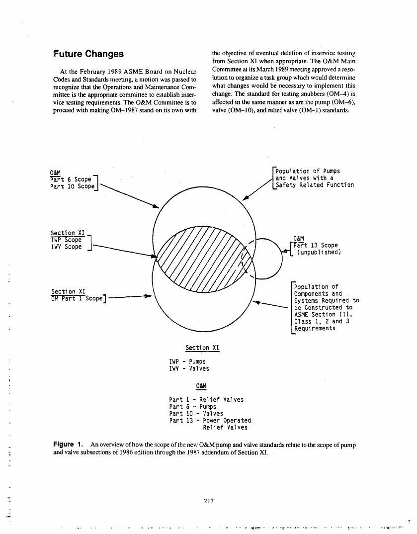
Future Changes the objective of eventual deletion of in,service testingfrom Section XI when appropriate. The O&M Main
At the February 1989 ASME Board on Nuclear Committee at itsMarch 1989meeting approved areso-Codes and Standards meeting, a motion was passed to lution to organize a task group which would determinerecognize that the Operations and Maintenance Com- what changes would be necessary to implement thismittee is the appropriate committee to establish inser- change. The standard for testing snubbers (OM-4) isvice testing requirements. The O&M Committee is to "affected in the same manner as are the pump (OM-6),proceed with making OM-1987 stand on its own with valve (OM-10), and relief valve (OM-I) statxlards.
O&M FPopulation of Pumps
l_a_t6 Scope-I S' and Valves with a
Part 10 Scope] Lsafety Related Function
Section XI
O&MIWV Scope 13 Scope
(unpublished)
Section XI Population of
Components and
Par("l-Scope]-------'--_ Systems Required tobe Constructed toASME Section III,Class i, 2 and 3
+ Requirements,m
Section XI
" IWP - PumpsIWV - Valves
O&M
Part i - Relief ValvesPart 6 - Pumps
+ Part 10 - Valves
,Part13 - Power OperatedRelief Valves
Figure 1. An overview of how the scope of the new O&M pump and valve stmadards relate to the scope of pumpand valve subsections of 1986 edition through the 1987 addendum of Section XI,
-_ 217
_._7
,Illr, rl,ill+ rl ...... Ir III"I_l'f ,I_II' "7 ....

Table 1. Comparison of IWV to OM-IO
IWg OM-10
IWV-I100 Scope Ali safety related va.Ires included deletes Class 1,2,and 3. IWV requires testing of all Class 1, 2, or 3
pressure relief devices. OM-10 only requires testingof those which protect a system which performs a
= safety related function.
IWA-9000 Definitions Obturator
Prese_vice test periodReactor coolant system pressureIsolationReference values
IWg/-2100 Categories of valves OM-10 ties the function of the valve tothe scopestatement for purposes of classification.
IWV-3100 Preservice testing Clarifies that preservice testing is required prior to thetime the valve is "required" to operate.
IWV-3200 Valve replacement, repair and maintenance Places more emphasis on reference values. Devi-ations shall be identified, analyzed and documented.
IWV-3300 Valve position indicator verification Requires, where practicable, to observe flow or othersuitable parameter to verify obturator movement.
Inservice tests New requirement - valve testing program shall com-mence when valves are required to operate per 1100.
Reference values New paragraph - places emphasis on referencevalues. "Shall only be established when valve is
- known to be operating acceptably.
'ro F.stablish an
+ additional set of New paragraph- tight controls on: reference values how reference values are established.
IWV-3411 Test frequency Change "at least every threemonths" to "nominally every three montlxs".
z
IWV-3412 Exercising procedure Paragraph rearranged in logical order. Must sta_ cold=
shutdown testing within 48 hours or complete ali-- cold shutdown tests._
IWV-3413 Power operated valves Adds requirement t.,_atany abnormality or erratic- action be recorded and evaluated for corrective
action._
: IWV-3410 Valves in systems out Changes required testing from of service. "within 30days" to "within three months."
__ 218
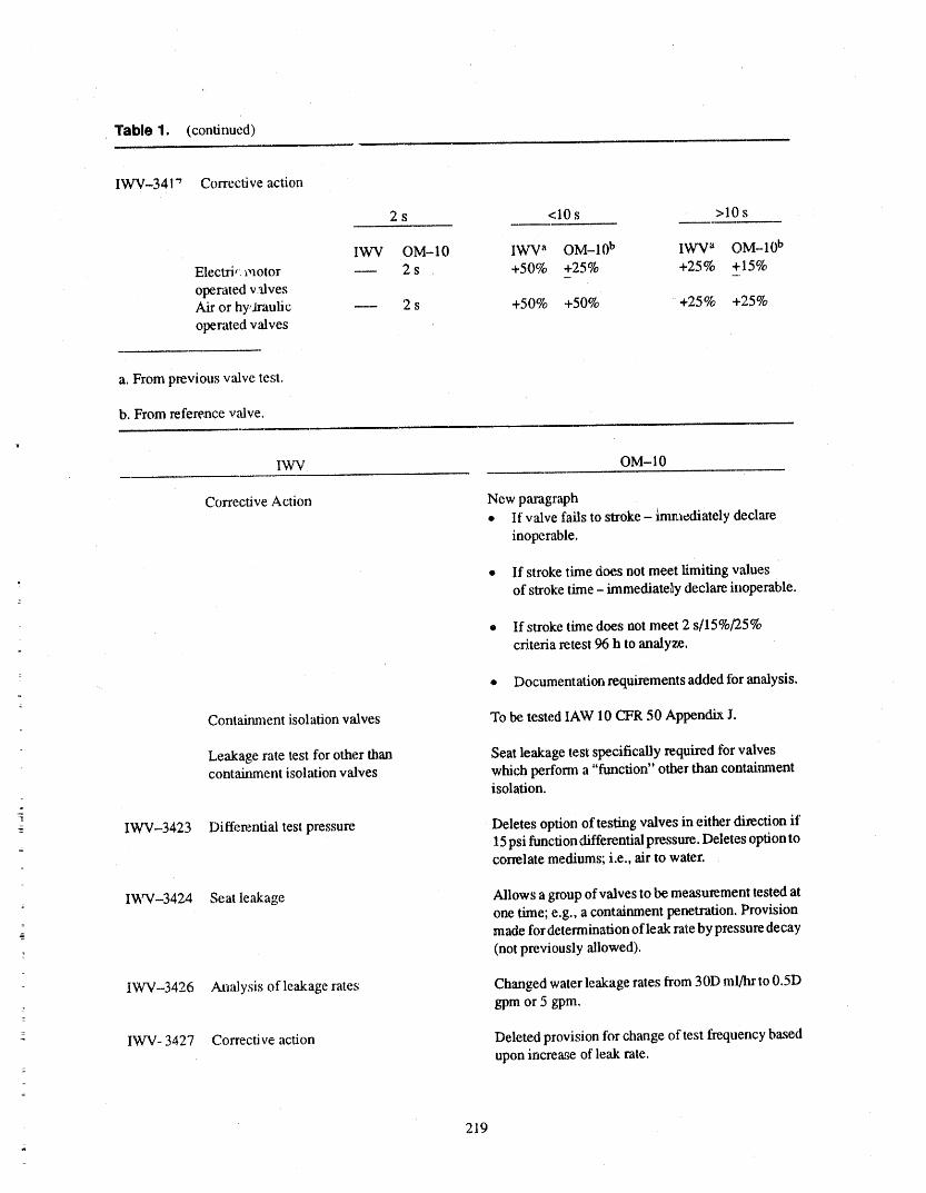
Table 1. (continued)
IWV-341"r Corrective action
2s <10s >10s
IWV OM-10 IWV a OM-10 b IWV a OM-10 b
Electrir motor -- 2 s +50% +25% +25% +15%
operated valvesAir or hy,.traulic -- 2 s +50% +50% +25% +25%
operated valves
a. From previous valve test.
b, From reference v,-dve.
IWV OM-IO
Corrective Action New paragraph• If valve fails to stroke - hnmediately declare
inoperable.
• If stroke time does not meet limiting values
of stroke time - immediately declare inoperable.
• If stroke time does not meet 2 s/15%/25%
criteria retest 96 h to analyze.
• Documentation requirements added for analysis.
Containment isolation valves To be tested lAW 10 CFR 50 Appendix J.
Leakage rate test for other than Seat leakage test specifically required for valvescontainment isolation valves which perform a "function" other than contairunent
isolation.
• IWV-3423 Differential test pressure Deletes option oftes_lg valves in either direction if15psi function differential pressure. Deletes option tocorrelate mediums; i.e., air to water.
IWV-3424 Seat leakage Allows a group of valves to be measurement tested atone time; e.g., a containment penetration. Provision
;._ made for determination of leak rate by pressure decay: (not previously allowed).
IWV-3426 Analysis of leakage rates Changed water leakage rates from 30D ml/Iu' to 0.5Dgpm or 5 gpm.
z IWV- 3427 Corrective action Deleted provision for change of test frequency based
upon incre -aseof leak rate.
219
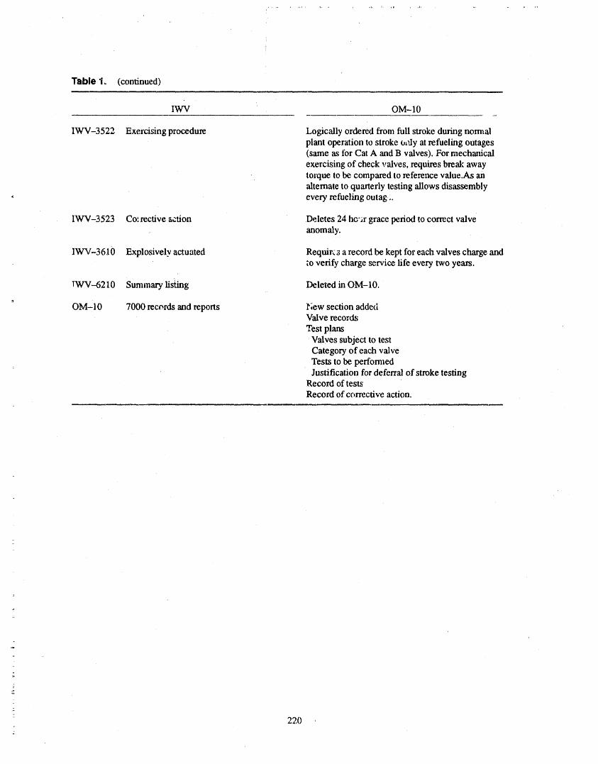
Table 1° (continued)
IWV OM-IO
IWV-3522 Exercising procedure Logically ordered from full stroke during normalplant operation to stroke o_flyat refueling outages(same as for Cat A and B valves), For mechanical
exercising of check valves, requires break awaytorque to be compared to reference value.As analternate to quarterly testing allows disassembly
, every refueling outag ;.
IWV-3523 Co: rective action Deletes 24 ho'ar grace period to correct valveanomaly.
IW'V-3610 Explosively actuated Requir¢s a record be kept for each valves charge andto verify charge service life every two years.
tW'V-6210 Summary lis_Jng Deleted in OM-10.
OM-10 7000 records and reports l_;ewsection addedValve records
Test plansValves subject to testCategory of each valveTests to be peffomaedJustification for deferral of stroke testing
Record of testsRecord of corrective action.
2202
ATTENDEE- PANEL QUESTIONS AND ANSWERS(EDITED; ATTENDEE QUESTIONS AND PANELAUTHOR
RESPONSES NOT IDENTIFIED B Y NAME)
Question I Panel Thatisa definitionwecanworkfromto de_endtesting or not testing components inthe plant. But it is
Please define an OM.-10accident, safety function, and a fairly narrow definition of an accident because someFSARs don't discuss flooding issues in Chapter 15.safety equipment. If we can't nail down the scope, we
can't tell where to start otu' test program. They're discussed elsewhere in the FSAR. So, if weare going to work with Chapter 15 accidents, I wouldhatefor someone to come up and ask about other com-
Response I ponents that are not covered by Chapter 15 accidentsor required for Chapter 15 accidents.
I absolutely agree, However, it is not OM-10 that de-cides. It is you, astheowner,that hasto decide.You Question 2have to know exactly what equipment is required to
performin an accidentconditionor tomitigatean aeci- Someolderplantshavedesign basisadvanceconsider-dent.Youhave to knoweverysystem designedto mifi- ation andsafety-relatedfunctions based on the capa-gate an accident,analyze that system, and determine bility to shut down and maintain thereactor in hotthe safety function of every pump andvalve, shutdown, not cold shutdown. When reviewing IST
submittals and preparing IST submittals, what consid..Once you know that, the program is fairly easy. The eration, if any, is given to submittals fromplants whosetough par_ is knowing the design basis of your plant, original design basis accident analysis was based onStart with the FSAR, which is d_esystem concept, and hot shutdown and maintaining the reactor in hot
' then go down to specific components within the sys- shutdown.tem or connecting systems.
Are IST submittals reviewed based on ASME SectionComment XI and O&M standards only, which require safety-
related functions as a specific function in shutting
As far as using the FSAR to define an accident since down reactors to the cold shutdown condition?the word "accident" is used only in the Code---inspec-tors asked me ifa tuberupture of aheat exchanger (ser- Response 2
" vice water component heat exchanger) was anThe NRC does recognize hot shutdownconditions foraccident, and are the valves to isolate that heat ex-
_ changer required, plants licensed to hot shutdown. For reviews the rea-: son we base the questions and our considerations on
cold shutdown is that cold shutdown is the only mode= In the past we have used the accidents, as discussed in specifically addressed in Section XI. If you look in
Chapter 15of the FSAR, as a basis for an ISTprogram. IWV, it specifically states the equipment required to
Dl$cusslon shut the plant down to the cold shutdowncondition.
However, if your plant is licensed to hot shutdown, thePanel That is correct. Those are exactly the accidents NRC will look at that to evaluate your program anddiscussed by the NRC. grant relief for your relief request.
221
GENERIC CONSIDERATIONS FOR INSERVICETESTING OF VALVES
ROBERT E. MARTEL lib
ABSTRACT shutting down the reactor to the cold shutdown condi-tion or in mitigating the consequences of an accident.
The issues dealing with valve reliability in the Nu-clear Industry have increased substantially over the Today the utility industry and the NRC realize thatpast few years. As a result, any papers, studies, and current testing maintenance requirements may not beproposed industry changes have been published on this comp_'ehensive enough (References 1 to 9) to providesubject by Electric Power Research Institute (EPRI), informationon valve degradation. As you heard fromInstitute of Nuclear Power Operations (INPO), utilities Tom Hoyle and John Z_ldans previousiy, the valveand the Nuclear Regulatory Commission (NRC). testing methods and requirements have come a longWhile the cure to these problems are in the embryonic way since the mid-sixties and the ANSI N45 Com-slate, industry has made great strides in their commit- mittee (Figure, 1). Through the Committee on Opera-
tions P",dMaintenance :O&M), the Working Group: ment to maintenance, testing, and identifying the root
cause of valve problems. This paper briefly describes (WG) on pumps and ve,ves with individu',ds from utili-where tLe industry is today and where we may go ties, the NRC, research groups, consulting companies,
: tomorrow. Generic considerations for Inservice 'rest- and manufacturers are improving test criteria for as-
ing (IST) of valves will be, addressed in accordance sessing operational readiness. Valve degradation andwith recently approved SERs, Industry problems, and operational readiness go hand in hand.regtflatory directions as follows:
A total of 35 of the 108 plants as of this writing have
,, Full flow testing of check valves approved safety Evaluation Reports (SERs) on theirSection XI programs. Due to the dynamic effects of thecode and utilities gaining experience in testing many
,, Back flow testing of check valveschanges (relief requests) are being submitted to updateprograms. Despite the ntunber of approved SERs, the
• Containment isolation valves NRC has ev',duated ali IST programs and performedIST reviews through a list of drafled questions. Unfor-
• Pressure isolation valves tunately, utilities are skeptical to act on items throughreviews and inspections that are not specified in SERs.
® Power operated relief valves However, with instances such as check valve failures
(sticking open or discs coming loose) ",nadMOV fail-• Stroke testing ures (torque switch, limit switch, spring pack failures)
the industry and the NRC are faced with we_d_neSsesin
o Timing rapid-acting valves IST programs and operational readiness that camaot betolerated.
• IST program scope.VALVETESTING
BACKGROUNDThe results of IST programs ,-u_based on a number
Nuclear power plants are currently mandated in ac- of different variables, i.e., experience level of theiro cor "dance with 10 CFR 50.55a(g) to perform periodic people, tin,races available, type of diagnostic equip-
surveillaace tests on safety-related valves per the ment available, number of people available, and man-.ASME Boiler and Pressure vessel code, Section XI, agement commitment to excellence. This does not
Subsection IWV. These tests are intended to provide imply that the IST people at this symposium are not ininfom_ation for assessing operational readiness of search of excellence to the lelter of their code edition
-- components reqtdred to perfoml a specific function in and addenda, lt is important to realize thai plant
.
a. Roberl E. Mallei II/, P.E., Senior Staff Engineer, New H,'mlpshire Yankee, Seabrook SI;_tion.
223
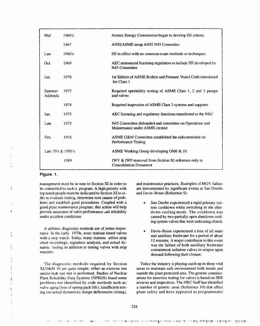
Mid 1960's Atomic Energy Commission began to develop ISI criteria
1967 ANSI/ASME setup ANSI N45 Committee
Late 1960's ISI in effect with no common exam methods or techniques
Oct. 1969 AEC announced licensing regulation to include ISI developed byN45 Committee
J'an. 1970 1st Edition of ASME Boilers and Pressure Vessel Code introducedfor Class 1
Summer 1973 Required operability testing of ASME Class 1, 2 and 3 pumpsAddenda and valves
1974 Required inspection of ASME Class 3 systems and supports
jlan. 1975 AEC licensing and regulatory functions transferred to the NRC
]Late 1975 N45 Committee disbanded and committee on Operations andMaintenance under ASME created
Feb. 1976 AS/VIE O&M Committee established the subcommittee on
Performance Testing
,Late 70's & 1980's ASME Working Group developing OM6 & 10
1989 IWV & IWP removed from Section XI reference only toConsolidation Document
Figure 1.
management must be in tune to Section XI in order to and maintenance practices. Examples of MOV failurebe committed to such a program. A high priority with are demonstrated by significant events at San Onofretop notch people must be dedicated to Section XI in or- and Davis-Besse (Reference 9):der to evaluate testing, determine root causes ofprob-
- lems and establish good procedures. Coupled with a • San Onofre experienced a rapid primary sys-good plant maintenance program, this action will help tem cooldown while switching to the shut-
" pre,vide assur_mce ofv;dve performance ,tld reliability down cooling mode. The cooldown wasunder accident conditions, caused by two partially open shutdown cool-
ing system valves that were indicating closed.
A utilities, diagnostic methods are of prime impor-• Davis-Besse experienced a loss of ali main: rance. In the early 1970s, most stations timed valves
with a stop watch. Today, many stations utilize slxip and auxiliary feedwater for a period of aboutch_trt recordings, signature analysis, and actual dy- 12 minutes. A major contributor to this event
was the failure of both auxiliary feedwaternamic testing in addition to timing valves with stop contaimnent isolation valves to reopen uponwa'lches, demand following their closure.
The diagnostic methods required by Section Today the industry is playing catch up in these vitalXI/O&M 10 are quite simple; either ml exerci_ test areas to maintain saf_ environment both inside andand/or leak rate test is perfbrmed. Studies of Nuclear outside the plant protected area. The generic consider-Plant Reliability Data Systems (NPRDS) found some ations for inservice testing for valves is based on SER
:_ problems not identified by code methods such as; reviews and inspections. The NRC Staffhas identifiedvalve aging (loss of spring pack life); insufficient test- a number of generic areas (Reference 10) that affecting (no actual dynaJnics); design deficiencies (sizing), plant safecy and have appeared as programmatic
224
weaknesses in past IST or other NRC inspections. In veritlcation of flow rates through the individual valvesorder tc) remedy these generic IST problems, clarify and is not a valid thll--stroke exercise.the :;tatus of current progr,'uns with respect to the Tech-
nical Specification requirement, _md to alleviate the Other alternatives for testing check valves haveproblem with respect to review of program re.visions, been allowed by the NRC (Reference 2) and the gener-the NRC with comments from the industry proposes ic letter. One exanlple is utilizing a sampling disas-the fbUowing policy and guidal_ce' sembly/inspection program. At each disassembly, it
_ should be verified that the disassembled valveis cepa-
GENERIC ISSUES ble of full stroking and its' internals ale structurallysound (no loose or corroded parts). In the event that thedisassembled valve's full-stroke capability is in ques-
Full Flow Testing of Check tion, ali valves in this group shall be disassembled.
Valves and Alternatives The ASSE Working Group is reviewing checkvalve disassembly xs a future technical change to the
.... The ASSE Code requires check valves to be exer., valve standard. Check valve disassembly i_ a highcised to the positions in which they perform their safe- priority in the areas of loose, corroded, anti worn pints.ty functions. The Commission feels a check valve's ASSE X1 and OMi0 lacks direction in the area of vi-full--stroke to the open position may be verified by sual inspection during dis;lssembly.passing the maximum required accident cond'don
flow through the valve; anything less would be consid- Back Flow Testing of Cheekered a part-stroke exercise. There are many situationswhere this requirement is physically impractical and Valvesoverly restrictive: An example would be when the
maximum required accident flow is at pump run out Section XI requires that Category C check valvesflow, This is physically impractical. (valves that are self-actuated in response to a system
characteristic) performing a safety function in the
PERSONAL PERSPECTIVE closedposition to prevent reverse flow be tested in amanner that proves the disks travel to the seat promptlyon cessation or reversal of flow. In addition, for Care-
-_: Some check valves can be shown full open at much gory A/C check valves (valves that have a specifiedlower flow rates than those ot the design conditions. If leak rate limit and are self-actuated in response to athe check valve could be shown to be open at a lower system characteristic), seat leakage must be limited toflow rate by comparing differential pressure across the a specific maximum amount in the closed position forvalve to a baseline when the valve was known to be fulfillment of their function. Verification that a Cate.,
operating acceptably, this should qualify as a accept- gory C valve is in the closed position can be done byable method. Additionally, there, are new techniques visual observation, by an electrical signal initiated by awhich are currently being marketed which claim to position-indicating device, by observation of appro-show check valve position such as MOVATS, Inc. priate pressure indication in the system or by otherCheckmate. positive means. Examples of check valves that per-
form a safety function in the closed position that are
There is a condition in many plants where flow is di- frequently omitted from IST programs are:rected through parallel paths. Flow is balanced througheach of the parallel lines by a throttled valve which is . Main feedwater header check valvesadministratively controlled. These parallel paths have
been carefully balanced to ensure equal flow is pro- * Pump discharge check valves _n parallelvided through each line. Most plants administratively pumpscontrol throttled valves by locking or removing the
handwheels. Due to special precautions taken, it was ,_ Keep full check v_dvesthe consensus of the ASSE Working Group that theselines should not require individual flow rate of thebranch line to be measured to take credit for a full . Check valves in steam supply lines tostroke of the check valve. Genetic Letter No. 89--04 turbine-driven AFW pumps
(Reference 10) states: Knowledge of only the total
-_ flow through multiple parallel lines does not provide ® Main steam non-retum valves
225
® CVCS volume control tank outlet check since 1979have a full leak test requirements and limit-valves, ing conditions for operation (LCOs). The plants li-
censed prior to 1979 fall into several categories. Some
PERSONAL PERSPECTIVE pre-1979 plants have a full list of PIVs along with leaktest requirements and LCOs in the plant TechnicalSpecifications.Somepre-1979 plantshaveorgyEvent
Leak testing as a method of back flow testing of V PIVs in the plant Technical Specifications. Somecheck valves should be recommended. The commis- pre-1979 plants have no Technical Specification re-sion and industry should specifically address back quirements regarding PIVs and therefore are not leakflow testing of two or more check valves in series. This testing any P1Vs.is a significant problem from a testing standpgint.
Ali PIVs listed in plant Technical SpecificationsUtilities choose to disassemble one of two check should be listed in the IST program as Category A or
valves in series while che _¢k,ing for seat leakage rather _dC valves. The Technical Specification requirementsthan adding a test connection between the two valves, should be referenced in the IST program.lt is important to know which valve is preventing back-flow and if there is valve degradation, however, we Fv®ni V PIVs. Event V PIVs are defined as twomust look at long-term solutions and not always take check valves in series at a low pressure/RCS interface
" the easiest way out. More _mportant in tl_s i_ue is, whose failure may result in a Loss of Coolant Accidentdoes the removal of one check valve so that you can (LOCA) that bypasses contairmmnt. Event V refers totest only the remaining one improve nuclear safety? the scenario described for this event in the
WASH-1400 study.
At a EPRI Power Plant Valve Symposium in On April 20, 1981, NRC issued "Orders" to 32October 1988 (Reference 8), a paper submitted by Wil- PWRs and 2 BWRs which required these licensees toliam Suslick of Duke Power on Acoustic Emission conduct leak rate testing of their PIVs, based on plant-Monitoring of Check Valve Performance takes a step specific NRC supplied lists of PIVs, and requiredin the fight direction toward not disassembling check licensees to modify their technical specificationsvalves. Mr. Sl_slick and his co-author, Brian A. accordingly. These orders are known as the "Event VMcDermott conclude based on test results to date, Orders" and the valves listed therein are the "Event V"
: "acoustic emission monitoring of installed cheek PIVs.valves may be performed to monitor for tapping or in-
stability. Acoustic emission monitoring will greatly re- Based upon the results of 'recent inspections it hasduce the number of valves that need to be been determined the following implementation prob-
_. disassembled for inspection." This paper and others lem still exists with respect to testing of PIVs: Thewill be produ, zd by EPRI in a study on Pump and staffhasdeterminedinsome cases the procedures wereValve S|_rveillance Test OptimiT,ation sometime this inadequate to assure these valves are individually leakyear. tested and evaluated against the leakage limits speci-
_ fled iri the,Technical Specifications, In other cases the
Pressure isolation Valves procedures were adequate but were not being fol-lowed. Specifically, some check valves were tested in
= series as opposed to individually and some checkGenotal. lh'essure isolation valves (PIVs)are defined valves were not tested when required (i.e., for one
= as two normally closed valves in ,series that isolate the plant inspected, whenever primary pressure was with-= reactor coolant system (RCS) from an attached low in 100 psig of the system design pressure on the low
pressure system. PIVs arelocated at ali RCS low pres- pressure side of the check valve).sttre system interfaces. 10 CFR 50,2 contains the defi-
nition of the Reactor t3oolant Pressure Boundary Licensees should review their testing procedures to(RCPB). In most cases PIVs are within the reactor ensure the Event V PIVs are not leak rate tested incoolant pressure boundary. In a few cases the staff has series.allowed individual licensees to consider a valve in an
interfacing high pressure. PERSONAL PERSPECTIVE
• Class 2 pipe as a PIV. The following summary is The main concernis that in many casesPIVs arenot= h._,a ,,r_n the.._taff.._review of Iesoon,._ to Generic individually tested. Since the concern is "in series test-....... .t" " • .
Leaer 87--06, Periodic Verification of Leak Tight In- ing of valves," the industry should endorse the position
: tegt _tyof Pressure Isolation Valves. Ali plants licensed of testing these valves individu;dly. =
_- 226
iii ,i ,,, Ji
Limiting Values of Full-Stroke Times for Power PERSONAL PERSPECTIVEOperated Valves IWV-3413(a) of the ASME Code re-quires that the licensee specify the limiting value of Even though the WG had no comments on this sec-full-stroke time of each power operated valve. The tion, some utilities officially responded, lt was felt thecorrective actions oflWV-3417(b) shauld be followed ASME Code states that values are to be determined by
when these limiting values are exceeded. The Code the plant owner [IWV3414(a)]. Valve su'oke times aredoes not provide any requh'ements or guidelines for es- established individually and are based on the time thattablishing these limits nor does it identify the relation- is required for the valve to perform its satbty functionship that should exist between these limits and any unless otherwise specified by a Technical Specifica-functional operating limits identified for the relevant tion requirement. Establishing a valve stroke time lira-valves in the plant Techr.ical Specifications or Safety it based on a average (reference) stroke time is notAnalysis Report (SAR). defined in the present edition of the ASME Code and
would render the corrective action requirements speci-fied in IWV-3417 useless.
The primary reason for measuring the full-stroketimes of power operated valves is to detect valve deg- lt is understood that the above reference stroke timeradation. The function of the limiting value of full- method of as_ssing v',dve performance is specified instroke time is to establish a value for taking corrective OM--I 0 but this method is a substantially different
action on a degraded valve before the valve reaches the practice than what is presently specified in the Codepoint where there is a high probability of failure to per- and would require licensees to revamp existing pro-form its safety function if called upon. The NRC has, grains to comply.therefore, established the position described below re-garding limiting v',dues of full-stroke time for power Stroke Time Measurements foror atedvaaves. Rapid-Acting Valves
" The Code requiresthefollowing for power operatedThe limiting value of full-stroke time should be valves with stroke times 10 seconds or less: (a) limit-
based on _ v,,dve reference or average stroke time ofa valve when it is known to be in good condition and ing values of fullstroke times shall be specified[IWV-3413(a)], (b) valve stroke times shall be mea-operating properly. The limits should be a reasonable sured to the [at least] nearest second [IWV-3413(b)]deviation from this reterence stroke time based on the and (c) if the stroke time increases by 50% or morevalve size, valve type, and actuator type. The deviation
from the previous test [or from a reference value] thenshould not be so restrictive that it results in a valve be-the test frequency shall be increased to once each
ing declared inoperable due to reasonable stroke time month until corrective action is taken [IWV-3417(a)].
variations. However, the deviation used to es,ablish Paragraph IWV-3417(b) specifies corrective actionsthe limit should be conservative enough that corrective that must be taken.action would be taken for a valve that may not perform
its' intended function. Most plants have many power operated valves thatnomaally stroke in two seconds or less and they en-counter difficulty in applying the 50% increase of
When the functional operating limit for a valve stroke time corrective action requirements for theseidentified in the plant Technical Specifications or SAR valves. The purpose of this requirement is to detect aralis less than the value established using the above evaluate degradation of a valve. For valves with strokeguidelines, the appropriate Technical Specification or times in this range, much of the difference in strokeSAR limit should be used as the limiting value of full- times from test to test comes from inconsistencies in
= stroke time. The limiting v',due of full-stroke time for the operator or timing device used to gather the data.a valve should not exceed a Technical Specification or These differences are compounded by rounding the re-SAR limit specifiu'd for that valve, suits as allowed by the Code. Thus, the results may not
be representative of actual valve degradation.
When the functional operating limit for a valve The following discussion illustrates the problemidentified in the plant Technical Specifications or SAR that ma), exist when complying with the Code requi,e-is greater than the value established using the above merits for many of these rapid-acting v',dves:guidelines than the limiting value of full-stroke time
- should be based on the above criteria instead of the A valve with a measured stroke time of
plant Tecb.nic'_.l.qr_cificatic_rtg or ,qAR 1.49 s during one test (rounded to 1 s). and
L-
227
;+,111,_+=P,ll........ II ll, l ..... llrlpl .... i, ipl', ,,,rll,I....... ,',,Ipr_ ""lll'l'I'llll+_llll'r"_:i_!IIl...... pi" Pr"ll'lll'tlp'rNlnlr'"PPm"l]ils..... ',IH_'lrI ',nlllp'll]I_' 'T'P]Ir"IIP_I'''' +'Iril_'_

a measured stroke time during the follow- ACTION statement. These ACTION statemems gen-ing test of 1.51 s (rounded to 2 s) would eraUy have a time period after which, if the equipmentexceed the 50% criteria and would require is still inoperable, the plant is required to undergoan increased tiequency of testing until cor- some specific action such as commence plantrective action is taken. This can result shutdown.
from a stroke time difference of 0,02 s,
which is usually not indicative of signifi, The potential exists for a conflict between the afore-cant valve degradation, mentioned data analysis interval versus the Technical
Specification ACTION statement time period. SectionPower operated valveswith normal stroke XI, IWP-6_0 requires the reference values, limits,times of 2 s or less are referred to by the and acceptance criteria to be included in the test plansstaff' as "rapid-acting valves," Relief may or recozds of tests. With this information available, thebe granted from the requirements of Sec- shift individual(s) responsible for conducting the. testtion XI, Paragraph IWV-3417(a)for these (i.e., shift supervisor, reactor operator) should be ablevalves provided the licensee assigns a to make a timely determination as to whether or notmaximum limiting value of full-stroke data meets the requirements.time of 2 s to these valves and, upon ex-ceeding this limit, declares the,valve inop- When the data is determined to be within the Re-erable and takes corrective action in quired Action Range of Table IWP-3100--2, the pumpaccordance with IWV-3417(b). is inoperable and the Technical Specification ACTION
statement time starts. The provisions in IWP-3230(d)Licensees are required to either comply to recalibrate the instruments involved and rerun thewith the Code stroke timing requirements test to show the pump is still capable of fulfilling itsor the staff's rapid-acting valve position function are an alternative to replacement or repair, notstated above. Since this represents a devi- an additional action that can be taken before declaringadon from the Code requirements, a relief the pump inoperable.request must be included in the IST pro-gram. This relief may be requested for any The above position, which has been stated in termsor "aliof the rapid-acting valves in the IST of pump testing, is equally valid for valve testing.program.
In summary, it is the staff's p_ition that as soon as
PERSONAL PERSPECTIVE the data is recognizedasbeing within theRequiredAc-tion Range for pumpsor exceeding the limiting value
Assigning a maximum limiting value for rapid- of full-stroke time for valves, the associated compo..acting valves is more conservative than the Code and is nent must be declared inoperable and the Technicalconsistent with OM-10 By doing so, a valve can be Specification ACTION time must be started.timed to the nearest 1/20 or 1/100 of a second which is
common practice. PERSONAL PERSPECTIVE
Starting Point for T]me Period in lt is believed that 96 hours was put into the Code inthe 1970s to account for a long weekend when re-
Technical Specification Action sou_s were not available for analysis. Today, someStatements utilities put the acceptance criteria in their test proce-
dta'es to avoid potential conflicts..lh any case, it is im-
ASME Section XI, IWP-3220, states: "All test data perative to know ail safety limits and assure
: shall be analyzed within 96 hours after completion of a operational readiness when necessary.test." IWP-3230(c) states, in part, "If the deviationsfail within the 'Required Action Range' of Table Containment Isolation ValvesIWP-3100--2, the pump shall be declaredinoperative ....." The NRC would like to see ali Containment Isola-
tion Valves (CIVs) that are 10 CFR 50, Appendix J,In many cases, pumps or valves covered by ASME, Type C, leak-testing included in the lS'r program as
- Section XI, Subsections IWP and IWV, are also in sys- Category A or A/C valves. The, Staff has determinedterns covered by Technical Specifications and, if de- that the le',& test procedures and requirements for con-
_ clared inoperable, would result in the plant entering an tainment isolation valves specified in Appendix J are=
z
_. 228=
equivalent to the requirements of IWV-3421_ thru IST Program Scope34.25 (see the white paper for corresponding OM para-
grapl_s). The licensee must also comply with the Anal- The NRC Staff has taken the position that 10 CFRysis of Leakage Rates and Corrective Action 50.55a(g) requires ali valves performing a safety-re-requirements of Paragraph IWV-3,426 and 3427(a). lated function to be included in the IST program and
tested in accordance with the ASME Code, Section XI.
IW%'-3427(b) specifies additional requirements on This position is consistent with IEB 85-03 Supple-increased test frequencies for valve sizes of six inches merit 1 as stated previously. In Supplement 1, the termand larger and repairs or replacement over the require- "safety-related" refers to those systems and compo-ments of IWV-3427(a). Based on input from many nents that are relied upon to lemain functional duringutilities and staff review of testing data at some plants, and following design basis events to ensure (i) the in'the usefulness of IWV-3427(b) does not justify the tegrity of the reactor coolant pressure boundary, (ii) theburden of complying with this requirement. Since this capability to shut down the reactor and maintain it in aposition represents a deviation from the Code require- safe shutdown condition, and (iii) the capability to pre-ments, it should be documented in the IST program, vent or mitigate the consequences of accidents that
could result in potential offsite exposures comparable
PERSONAL PERSPECT|VE to tlm 10 CFR Part 100 guidelines. The definition fol-lows closely with the new scope statement of OM-I 0The Working Group felt the standard should not be
Over the past five years, tlm commission has been limited to ASME Class 1, 2, ",rod3 componen_ In theconsistent in allowing the utilities to use their Appen- newer ASME Hl plants, most of the valves intent_ _1bydix J program to meetthe requirements of IWV-3421 the Working Group to be covered by this stanaardthru IWV-3425, At the same time, the commission has
would already be covered. However, there are usuallyrequired utilities to specifically comply with some valves which are not ASME Class 1, 2, or 3
IW'V-3426 and IWV-3427a while allowing relief which do perform functions described in the scope.from 3427b. The reason for requiting compliance with The Working Group stressed the point that function isIWV-3426 & 3427a was that Section XI is a compo- more important than the code class. This point wasnent test code and, therefore, each cx_mponent (valve) well documented in the WG white paper.should be treated on an individual basis.
PERSONAL PERSPECTIVEThe Industry at tlm same time felt that containment
isolation valve testing was subject to dual testing re- Today, industry does not believe the regulation re.-quirements of Appendix J and Section XI. The Indus- quires ali safety related valves be included in IST pro-try, via the OM-10 Standard, has changed the grams. Instead, the utilities feel that the regulationphilosophy by requiring only Appendix J testing for requires only certain ASME valves to be tested as spe-CIVs. The basis of this change is: (a) adequate re- tiffed in Section XI, Subsection IWV of the ASMEquirements exist in Apperdix J to ensure public safety, Boiler and Pressure Vessel Code. Based on the pre-(b) the only function of these valves is containment vious definition provided and discussions with theisolation; therefore, relying on Appendix J program NRC during SER reviews (References 2,3), it is be-must be specifically tailored due to the plant's design, lieved that the gap on safety-related definitions isThere ate exceptions taken to Appendix J programs narrowing.which must be granted by the commission.
The. first addenda to ASME/ANSI OMa- 1987 pub-: Anotber reason to allow ali CW testing to be done in lislmd in February, 1989 does not specify Class 1, 2,
accordance with Appendix J is to avoid conflicting and 3 valves in its scope statement. Tlm new Opera-"- regulatory requirements. For example, the generic let- tions and Maintenance Standard onValves; OMa Part
ter requires ali valves with a safety-related function to 10, does not address safety class. Part 10 does addressbe tested and allows the testing to be in accordance active and passive valves in a IST progrmn that are re-with Appendix J for IWV-3421 - 3425 requirements, quired to perform a specific function in shutting downHowever, there are a number of valves which are safe- a reactor to the cold shutdown condition, in maintain-
: ty-related but are exempt from Appendix J require- ing the cold shutdown condition, or in mitigating thements. The Conlairm_ent Systems Branch within the consequences of an accident.NRC would have reviewed these exemptions and ap-proved them. Under this generic letter, which is pre- • Examples of valves that may be required forpared under the Mechanical Engineering Branch, these shutdown and accident mitigation m'e often
: valves would have to be tested, erroneously omitted _om IST programs are:
-_ 229=
- Valves in emergency diesel generator air sembly or an approved (relief request) sam-start and cooling water systems piing disassembly inspection program.
Review the design basis to include ali safety-
- Valves in fuel oil transfer systems for related valves into the IST program with re-emergency diesel generators spect to Genetic Letter No, 89--04.
'- BWR scram system valves ® Back Flow Testing of Check Valves
- Control room chilled water system - Review the check valves that perform apumps & valves safety function in the closed position and
are erroneously omitted from IST-. Accumulator motor operated isolation programs.
valves, ox"accaJmulator vent valves• Pressure Isolation Valves
- Pressurizer auxiliary spray system
valves - Utilities should review their testing pro-cedures to ensure PIVs are not leak rate
- Valves in the emergency flow path tested in series.
- Cont,'ol valves that have a required fail- ® Limiting Valves of Full-Stroke Times forsafe position. Power Operated Valves Utilities should be
comparing average stroke times with "Ii_chni-Currently, many of the valves listed above are not cat Specifications and SAR limits, however,
being tested by some utilities. The implementation corrective aclat_nsaflWV-3417(b)should beschedule should make provisions tbr this and allow an followed when limiting values are exceeded.
° adequate amount of time to put testing procedures in
piace. It is very important to gel plant operations input , Stroke Tune Measurement for Rapid-Actingwith a good understanding of the design basis when Valvesdebating the safety-related issue. Unfortunately, theearly ANSI B31.1 plants do not have well documenteddesign basis and will require, major backfit work for - Relief may be ga'anted from the require-
ments of Section XI, Paragraphcompany engi_ering groups. A benefit to this will be IWV-3417(a) for rapid-acting valvesa better understanding of plant design and upgraded provided the licensee assigns a maxi-documentation.
mum limiting value of full-stroke timeof 2 seconds to these valves and, upon
- _UM[_IARY exceeding this limit, declares the valve_- inoperable and takes corrective action in__ To summarize, the current industry initiatives have accordance with IWV-3417(b).
_- identified areas where emphasis is needed to h-nprove
IST valve performance and reliability, long-tezm reli- • Starting Point for Time Period in Technicalability is dependent on comprehensive valve progr, uns Specification Action Statementswhich include the genetic issues raised in this paper.
= The sole purpose of raising these issues in a Genetic - The pressurizer PORV block valvesLetter is to clarify and update ali IST programs with should be included in IST programs as an
: the latest safety concerns to alleviate problems with re- NRC augmented requirement and testedspect to review of program revisions, to code requirements.
-; _1[::_1::_|_ [_UE _U[_MA_Y . Containment Isolation Valves
• Full Flow Testing oi. Check V',dves and Alter- - Ali containment isolation valves that are, natives A check valve's full-s_roke to the Appendix J, Type C, leak tested should
open position may be verified by passing the be included in the IST program asmaximum required accident condition flow Category. A or A/C valves or relief mustflarough the valve. The alternative is disas- be granted by the Commission.
2.5U
=,
• IST Program Scope 5. United States Nuclear Regulatory Commis-sion, IE Bulletin No. 85-03' "Motor-
- Review the design basis to include ali Operated Valve Common Mode Failuressafety-related valves into the IST pro- During Plant Transients Improper Switchgram with respect to Generic Letter No. Settings," November 15, 1985.89-04.
6. United States Nuclear Regulatory Commis-
R_F:ERENCES sion, lE Bulletin No. 85-03, Supplement 1'MotorOperated Valve Common Mode Fail-ures During Plant Transients Due to Improper
1. EPRI Application Guidelines for Check Switch Settings, April 1988.Valves in Nuclear Power Plants. Palo Alto,
CA' Electric Power Research Institute, 7. United States Nuclear Regulatory Commis_.January 1988 - NP 5479. sion, E. J. Brown and E S. Ashe, "Inoperable
Motor-Operated Valve Assemblies Due to2. Safety Evaluation Report Pump and Valve In- Premature Degradation of Motors and/or
service Testing Program Seabrook Station hnproper Limit Switch/Torque Swilch Ad-Unit 1. Idaho Falls, Idaho; EG&G Idaho, justment," AEOD/E305, April 13, 1983.Inc., August 1986- Fin No. 46811 for
USNRCWashington, DC20555. 8. EPRI Power Plant Valves Symposium,Charlotte, North Carolina: Electric Power
3. Safety Evaluation Report Pump and Valve In- Research Institute, October 1988.service Testing Program Millstone Nuclear
Power Station, Unit III. Idaho National Engi- 9. United States Nuclear Regulatory Commis-neering Laboratory, EG&G Idaho Falls, sion, NUREG-I18g, "Loss of Main and Aux-
Idaho, November 1987 Fin No. A6812 for iliary Feedwater Event at the Davis-BesseUSNRC Washington, DC 20555. Plant on June 9, 1985."
4. A Review of Motor-Operated Valve Per- 10. United States Nuclear Regulatory Commis-formance. Office tbr Analysis and Evaluation sion, Generic Letter No. 89--04: "Guidanceof Operational Data, USNRC, December on Developing Acceptable In,service Testing1986, AEOD/C603. Programs," April 3, 1989.
=
!
231
ATTENDEE- PANEL QUESTIONS AND ANSWERS(EDITED; ATTENDEE QUESTIONS AND PANELAUTHOR
RESPONSES NOT IDENTIFIED BY NAME)
Question I a meaningfulleakagecriteriaassignedto t_e valve;that is, how much back flow back leakage will com-
This report was based on the original draft of generic promise the valve's function789--04,not therecent 89--04.
Response 2One of the areas of my concern is the ISI programscope. A lot of the words, safety-related valves, andthe list you includedare no longer covered fc;r89--04. Again, if you don't know the design, if you don't knowI think that is veryclear to a lot of people. Forexample, what your tech specs say, it is difficult for me todiesel-generator systems are not part of 89-04. respond. When we did our SER reviews, we reviewed
what was required for safety and what was needed to
The last part of 89--04,part 11,is veryambiguous. Part make a system function. Leakage has a lot to do withof the meetings we had with the Commission origi- that.naUydef'medthese systems which are not per 10C_t;Rregulations, that the utilities were asked to put in. So Wejust went ttuough it on our RHR system. I think wepeople who have diesel generator ab' start systems in- were allowed a magnanimous amount of leakage, asstalled don't have to have them, and that should be far as our RI-IRvalves were c.oncemed. But for everyclear to a lot of people, system it is difficult toput a number on leakage.
I think these equipment lists should be updated to the Commentnew generic letter.
Response I Due to a recent tx'currence at Crystal River, where anauxiliary feedwater check valve leaked back and
Youare correct. I do have a copyof the latest letter,and caused overtemperature conditions upstream of theit does include BWR scram valves, control room valve which exceeded the piping design limits, thechilled water, system pumps and valves, accumulated NRC has taken a closer look at that situation. Theymotor operation isolation valves, auxiliary pressurizer have come to the conclusion that there may be situa-spray valves, boric acid valves in emergencyIx)ration, tions where valves have been categorized as B or C,control valves that have a required failsafe position, but their leakage limit is of greater concern than just
preventinga gro_sdiversionof flow or agross leakage.
: UnfortunateJy, the argument you will have to defendwith the NRC is in respect to the diesel and air stop If there is a specific leakage value of concern on a par-valves, valves in minimum flow lines, titular valve and that leakage is fairly small, the NRC
has taken the position that the valves may be recatego-Question2 rize_ as either A or AC, as appropriate, and may be
=" leak tested toensure that they will perform their safetyIn the situation where a check valve functions as a bar- functions to prevent the backflow or leakage past therier between ahigh and a low pressure system, how is valve.
=
_
z_
-: 232
NRC EXPERIENCE WITH PUMP AND VALVEINSERVICE TESTING PROGRAMS ,
,,
IDAHO NATIONAL ENGINEERING LABORATORYEG&G IDAIqO, INC.
IDAHO FALLS, IDAHO 83415CLAIR B. RANSOM (EG&G IDAHO)
R, SCOTT/-IARTLEY (EG&G IDAHO),N. BRADLEY STOCKTON (EG&G_IDAHO)HERBERT C. ROCKHOLD (EG&G IDAHO)
,i
ABSTRACT service testing (IST) programs for over 10 years.During this interval, detailed technical reviews havebeen performed on Over one hundred nuclear plmat IST
This paper presents a discussion of the experience, of programs. These reviews have generated det',dled re-NRC and their contractors in reviewing pump and quests foz additional information, which were used asvalve inservice testing (IST) programs. Topics that agendas for working meetings between NRC, INEL,will be discussed include the overall purpose of an IST and licensee representativesl The result of these meet-program to assure continued component operability ings has been IST program resubmittals upon whichand to meet the NRC's regulatory requirements, gen- Safe .tyEvaluation Reports have been written. This pro-eral information that should be addres_d in tl_ IST tess has brought about substantial interface and dis-program, and the level of technical detail needed to cussions on the topic of inservice testing between themeet the licensee's and NRC's objectives. Other topics NRC, the INEL, and the. nuclear industry in general.that will be addressed include the experience with the, This has resulted in the identification of problem areasdiverse quality of IST programs, scope of past NRC which are frequently encountered during inserviceprogram reviews, problem areas encountered, and a testing, lt has also given those involved much insightdiscussion of frequently omitted systems and concerning the identification of pertinent pumps andcomponents, valves, the types of information that should be in-
cluded in an IST program, and the level of detail need-NRC EXPERIENCE WITH PUMP ed to evaluate deviations from and ',alternativesto the
AND VALVE INSERVICE, ASM_ Section XI requirements.
TESTING PROGRAMS" While the requirements for inservJce testing have
INTRODUCTION _n in effect since 1976, there are still many areas thatneed improvement. Many IST programs are submittedto the NRC Ibr review in which components that per-
-: In 1976 the NRC adopted the requirements of the fonn a safety function are excluded and inadequateASME Boiler and Pressure Vessel Code, Section XI, technical information is provided. Further, many jusfi-for the routine imervice testing of safety related pumps fications for cold shutdown testing and requests forand valves. The Code of Federal Regulations has en- relief are,incomplete or inadequate..dorsed various editions and addenda of this Code
through the years as these have changed armlevolved.
Ali commercial nuclear facilities are required to per- in addition, several general problem areas have be-. form routine testing of these components as identified come evident during the review and evaluation of nu-
in the Code to verify their operationalreadiness and merous IST program submittals. These have hamperedmonitor for degradation, the NRC's review and approval process tbr IST pro-
grams. They are the result of differences in mterpreta-
The NRC, with technical support from the Idaho don of the (.'ode requirements, inadequate infomiadon__ National Engineering Laboratory (INEL), has per- regarding inservice testing, or special considerations
fomaed reviews and evaluations of pump and valve in- not addressed by the Code.
- 233
PURPOSE,OF INSERVICE 1. Mitigating the consequences of an accident,
TESTING 2. Shutdown of tile reactorto the cold shutdowncondition, or
The purpose of inservice testing is to assess theoperational readiness of individual safety related 3. Maintaining the reactor in a safe shutdownpumps and valves and to determine whether degrade- condition.tion has occurred. The intent is to ascertain if a compo-
nent's operational parameters provide reasonable Section XI, Paragraphs IWP-1200 and IWV-1200,assurance that it will perform its safety function when specifically exempt some components from testingcalled upon. The Section XI testing is component such as Valves used only for operating conveniencespecific and is not intended to verify the operability of (such as manual vent, drain, instrument, and testcomplete safety systems. Conversely, system oper- valves), valves used for system control (such as pres-ability testing does not necessmOJyprovide assurance sure regulating waives), and valves used only for main-of the future operational readiness of the individual tenance. However, control valves that are required tocomponents in those systems, ' perform a specific safety function as identified above,
are not exempted from inservice testing. Examples of
Section XI testing and acceptance criteria are de- such valves could include the residual heat removalsigned to monitor component condition and require (RHR) heat exchanger bypass valves, control valves incorrective action when there is indication of excessive the diesel cooling water, and control valves in chilled
water systems,degradation. Corrective actions are required when acomponent's measured test parameters are outside ofthe allowable ranges (i.e., into either the "alert" or the Syslerns and Components
: "required action" range). Components may be put on WhichAre Often Overlookedincreased surveillance testing or declared inoperableand be repaired or replaced even if the system can stillmeet its operability requirements. IST programs frequently do not contain some of the
pumps and valves that perform specific safety func-tions. The following list, while not all-inclusive, gives
Inservice testing of pumps and valves must comply examples of bo_ pressurized water reactor (PWR) and
with 10 CFR 50.55a, whdch identifies the provisions boiling water reactor (BWR) subsystems and compo- 1: for licensees to request relief from the requirements of nents that are occasionally overlooked when preparing
the Code as well as the criteria utilized by the NRC to IST programs. This list uses the most commonly usedevaluate those requests, terms for components, subsystems, _mdsystems. How-
ever, terminology may vary from plant to plant. It
CONTENTS OF INSERVICE should be recognized that the following systems orcomponents are not necessarily safety related and
TESTING PROGRAMS CodeClass1,2,or3foralipla.ts.=_-
General PRESSURIZED WATERREACTORS
-'- Subsections IWP-1100 and IWV.-1100 of SectionXI of the ASME Boiler and Pressure Vessel Code de- • Power--operated relief valves and associated
fine tee scope of the IST program for pumps and block valvesvalves. Both Section XI and 10 CFR 50.55a(g)specify
Code Class 1, 2, and 3 pumps and valves, which per- • Reactor coolant system high point ventform a specific safety function, as tho_ required to be valves
_- included.
- • Any proposed flow path utilized for long-
- On the basis of 10 CFR 50.55a(g), the NRC Staff term core cooling and/or safely-grade shut-: may require irzservice testing of ASME Code Class 1, down
2, and 3 pumps and v',dves, in addition to those in-cluded in the IST program, if these components are re- • Reactor coolant system pressure boundaryquired to perform a specific function in fluefollowing: isolation valves
234_

® Steam generator atmospheric relief or dump • Emergency diesel generator fuel oil storagevalves and transfer
• Auxiliary feedwater turbine steam supply • Emergency diesel generator external coolingcheck valves water
• Emergency boration flow paths • Emergency die_l generator air start
• Containment spray additive tank valves • Control room ventilation including coolingwater
• Containment isolation valves• Instrument air or nitrogen supply to the main
• Containment combustible gas control steam isolation valve accumulator
• Instrument air or nitrogen supply to the auto-, Spent Fuel Pool Cooling System matic depressurization valve accumulator
• Emergency diesel generator fuel oil storage • Traversing incore probe squib and ball valvesand transfer
• Spent Fuel Pool Cooling System• Emergency diesel generator external cooling
water • Post-Accident Sampling System.
• Emergency diesel generator air start CONS|DERAT|ONS FOR
COMPLETE INSERVICE• Controlroomventilationinclu g cooling TESTING PROGRAMwater
• Instrument/plant air supply to safety related The following information should be consideredvalves during the preparation of an IST program, lt also pro-
o vides a discussion on the recommended level of detail
• Post-accident sampling containment isola- and considerations for presenting relief requests and--- tion valves, cold shutdown test justifications,
The IST program should include a list of ali safety: BOILING WATER REACTORS related pumps and valves that undergo inservioe test-
ing as required by 10 CFR 50.55a. This list should
• Automatic depressurization valve vacuum clearly identify the, components, the testing requiredbreakers by Section XL and the testing that is actu',dly being
perfonned. Licensees have found that pump and valve
= • Pressure boundary isolation valves listing tables are a convenient way to organize andpresent this information.
• MSIV leakage control The pump and valve listing tables can be used to en-__ sure that ,'di identified components receive the spect-
• Reactor Core Isolation Cooling System fled testing at the stipulated testing intervals. Thetables can also tm used in the development of compo-,
-_ • Containment isolation valves including ex- nent test schedules and for schedule adju,;tments due tocess flow check valves changes in plant operating conditions.
• Containment combustible gas control Pump Listing Table
_ • Containment pressure suppression and vents The pump listing table should contain the following- information for each pump that performs a safety
® Porfion._ of the Control Rod Drive System function. The information comprises headings and a
235
-
description of the text that should be included under P&ID Number: This should be the unique identi-each heading, tier for the system P&ID on which each valve is
shown.
IST Program Revision or Revision Date: Includethe program revision number or revision number and Coordinates: These should be the coordinates ondate on each page. Each revised program that is sub- the listed P&ID where each pertinent valve is located.mitred should be distinguished by a specific revisionnumber. Valve Type: The valve type (i,e., gate, globe, check,
relief) should be identified in this column. The valve
System: Identify the plant system in which the type is an essential item in determining the valve care-pumps are located or give a brief description of the gory, which establishes the required testing (refer to: Table IWV-3700-1).pump,
Valve Size: Valve size should be specified in inchesPump Identification: A unique identifier should or decimal ft'action of ar_inch of nominal valve size.
be provided for each pump included in the IST pro-
gram. This identifier should be used consistently in ali Actuator Type: Valve actuator type (i.e., motor, so-plant IST documentation, such as system piping and lenoid, stir, hydxaulic, self) should be liste,_. This isinstrumentation drawings (P&IDs), test procedures, used in conjunction with v',dve type and function to
: and relief requests. determine the Code category and the required testing,
P&ID Number: This should be the unique identi- Code Category: Code category, sis defined in: fier for the system P&ID on which each pump is IWV-2100, should be included in the table. The valve
shown, category determines the Section XI subsections that• are applicable for a particular vsdve (i.e., IWV-3400
Coordinates: This should be the coordinates on the for Category A and B valves, IWV-3500 for Category
listed P&ID where each ideotified pump is located. C valves, and IWV-3600 for Category D valves).
i
Test Parameters: '/'he table should address each of Active/Passive: The valve listing table should indi-
: the seven in-service test quantities that are identified care whether a valve is active or passive, as defined inin Section XI, Table IWP-3100-I. The licensee should IWA--9000, Valves that naay be out of their safety posi-
t identify whether that parameter is being measured or tion during _'outine power operation, would have to+" obse1_,ed for each pump in the IST program. Footnotes change position to perform their safety function and
can be used to identify factors affecting testing. Relief cannot be considered passive valves, even if their nor-mal position is their s,'ffety function position. Testingrequests should be provided where the testing cannot
be performed as required, requirements vary based on this classification. TableIWV-3700--1 indicates that Category A passive valvesshould be leak-rate tested, but rio exercise test is re-
Valve L.isting Tat>lo quired. Note 1 for this table states that no test isrequired tbr Category B, C, and D passive valves.
The valve listing tables should contain the tbllowinginformation foreach valve that performs a safety func- Safety Position: The safety function position(s) oftion. The information comprises headings and a de- a valve should be indicated on the valve listing table.scription of t_ _xt that sllould be, included under each For valves that per_brm a ,_afety fimction in both openheading, and closed positions, both positions should be indi-
cated on the table. This is important for power oper-ated valves which mu_t have their stroke times-
System: Identify the plant system in which the measured as they are exercised to their safety function
- valves are located, position(s) as well as for check valves because theymust be exercised to the position or positions required
-- Valve Mentification: A uifique identifier should be to fulfill their function (refer to IWV-3522), The s',ffe--_ provided for each valve included in tl_ IS'/?program, ty function position(s) of the check valves affect
This identifier should be used consistently in all plant whether the valve should be full--stroke exercisedIST documentation, such as system P&IDs, test open, exercSsedclosed (verify reverse flow closure), orprocedures, and relief' requests, both fidl--stroke exercised open and closed.
236
,¢11 i, ,, ,_ , , ilJl i_r i,,1 ,, iil_l ,lp+lr IIII ' +r , rqp rq rl'lP'll
Tests Perfi)rmed' The table should show the tests Concerns such as damage to equipment, hazards tothat should be performed on each valve in the program, personnel, _mdpossible plaint trip should be thoroughlyThis list is the central focus of the valve testing pro- addressed. The,;e coocems should clearly demonslrategram. _ms, the information should clearly show what the impracticality of performing the required testingtests are being performed for each valve [e.g., leak- quarterly for both full--stroke ;rod, ii' applicable, parl-rate testing according to IWV.-3420, fail-safe actuator stroke.testing according to IWV-3415, valve remote positionindicator verification according to/WV-3300, v,'dve The licensee should ,also specify the method of test-stroke time measurement according to IWV-3413(b)]. ing thai will be performed and the test frequency for
the _fffected valves. For example, certain valves will be
Test Frequency' Closely related to the type of test part_troke exercised open quarterly using the pump'sis the test flequency. The Code specifies the test Ire- minimum flow patti and full-stroke exercised withquency; however, performing the testing at this flow into the reactor coolant system during cold shut,frequency is sotnetimes impractical. As a restflt, relief downs and refueling outages. Fun.her, the frequency ofc_mbe requested or a cold shutdown justification can be, testing should not be presented iri a mariner which cartprovided. The table should show the actual test Ire- be considered conditional. For ex,'unple, an IST pro-
.quer_:y for each required vzdve test. gram might indicate that certain valves wiU be exer..cised during cold shutdowns when the reactor coolant 'pumps can be stopt_d, lt is unclear in this example
Relief Requests: When it is impractical to comply whether the pumps will be stopped for inservice test-with the Code requirements, 10 CPR 50.55a(a)(3) ing of valves during each cold shutdown or just duringstates that the NRC can grant relief "andauthorize alter- those cold shutdowns when cor_litions permit stoppingnative testing in lieu of that specified by tlm Code. To the reactor coolant pumps. If there are vldid concernsobtain NRC approval of a deviation from a Code re- that prevent full-stroke exercising valves during coldquirernent, where the condition ks not specifically ad- shutdowns, then relief must be requested from thedressed in Attachment 1 of NRC Generic Letter 89--04, Code requirements.the licensee must submit a request for relief as part of
their IST program. Ifa component is tested consistent n qtDe_ues_s for Relief From Codewith the positions taken in Attactunent 1 of Genetic
Letter 89-4)4 as an "alternative to the Code require- Requirementsmerits, this situation should be noted in the IST pro-
: gram and approval is granted through the Genetic For the licensee to obtain relief from the require-Letter, provided the adequacy of the proposed ',alternate ments specified in the ASME Code, Section XI, Sub-testing for detecting degradation is justified as dis- sections IWP and IWV, a request for relief must becussed in the Generic Letter. These deviations firm the submitted to the NRC tbr review and approval unlessCode should be.identified for each applicable valve in the alternate testing is consistent with the positionsthe valve listing table using a unique identifier for each taken in Attachment I o'i Generic Letter 89-04.deviation.
'I he licensee has the responsibility of providing the
,Cold Shutdown Justifications technical basis which demonstrates that the,proposedalternative provides an equivalent level of safety, per-fonnance of the Code required testing would result in
Section XI, Paragraphs IWV-3412(a) and 3522, a hardship without a compensating increase in safety,permit exercising valves during cold shutdowns if ex- or that complying with the Code requirements is irn-ercising the valves quarterly during power operation is practical. The discussion should thoroughly addressimpractical. The Code requires the licensee to identify specific technical concerns such as damage to equip-the valves to be tested at cold shutdowns. The NRC re- ment, hazaads to personnel, or the,possibility of a plantquires technical justifications demonstrating the trip and should present the proposed alternative test-impracticality of quarterly testing to be provided in the ing. It should also present the bases to support that theIS'/' program. Cold shutdown justifications for each proposed alternative testing will accomplish theapplicable valve should be identified in the valve purpose of irmervice testing discussed above.listing table.
When references are made to testing components asThe justification should address the specific techni- identified in the Final Safety Analysis Report, Techni-
c',d concerns that make quarterly part-stroke and/or cal Specifications, or other plant documents, the ISTfull-stroke exercising of these valves impractical, program should be self contained and include a
237
2-
i

description of the proposed testing frequency and component operability and unless the burden of themeth(_dology. Code testing outweighs the benefit of increased assur-
ance of component or,'erability, the Code testing should
The following are examples of bases fbr not com- be performed as required.plying with Code requirements which if presented in arequest for relief may result in the granting of relief The fact that testiI_L,r:c,_essitates removing a redun-(these are valid bases for relief, however, relief dant safety system train from service ii_not a valid ba-
requests should provide more specific technical de- sis for relief from the Code. ,_s long i_ the length oftail): time required to perform the testing is less than the al-
lowed out of service time of the Technical Specifi-
a Compliance with the Code requirements cation action statement before commencing plantwould be a hardship and would not provide shutdown, the testing should be performed. Singlebetter intbrmation for evaluating a parameter failures are not postulated concurrent with taking athan the information currently available. For component or train out of service for testing. If the test-example, installing a gage with a range of ing takes a train or system out of,service and places thethree times the reference value or less to com- plant in a condition so that the design bases cannot be
ply with IWP--4120 may not provide any bet- met, the testing may be temporarily postponed to coldter accuracy or readability than is provided by shutdown. However, if this situation exists, the appro-the presently installed instrument, priateness of the design and testing should be
evaluated and corrected as necessary.
® Performance of quarterly or cold shutdown Relief requests should propose alternate testing thattesting as required by the Code could result in provides reasonable acceptance criteria for the testa high probability of causing personnel harm data or a mechanism to determine component degrada-due to high temperature environment, high tion. For example, licensees frequently request reliefradiation levels, high energy steam or fluid from measuring the,hydraulic parameters for the emer-systems, etc. ALARA concerns may present a gency diesel fuel oil transfer system due to the lack ofsuitable justification; however, the licensee instaUed instrumentation. They propose to test systemshould prov._de information about the general components by demonstrating that the system is capa-area radiation field, any local hot spots, plant ble ofperfornaing its intended design function. This al-radiation limits and stay times, and the ternate test does not necessarily evaluate theamount of exposure that would be received mechanical or hydraulic condition of the pumps or theby persormel performing the testing, condition of system valves.
® Quarterly or cold shutdown testing as re- Many systems have components whose design isquired by the Code could result in a high well in excess of system requirements. The componentprobability of causing equipment damage, could meet the system requirements and be degraded
_: For example, isolating cooling water flow to sufficiently that its future operability is questionable.a pump required to remain operating could For example, the above mentioned fuel oil transferresult ha overheating and subsequent damage pump may normally produce a flow of 25 gpm whileto the pump. only 12 gpm is necessary to meet system safety
demands, ffthe output of the pump dropped to 13 gpm,a, The licensee may propose to adopt a new it meets system requirements; however, it is seriously
technology for testing components. This new degraded and may fail during subsequent operations.technology should provide a result either Therefore, the satisfactory performance of a systemequivalent to or better than that required by test with an acceptance criteria of 12 gpm would notthe Code. For example, pump vibration mea- provide a reasonable alternative to Code testing.
surements in units of velocity generally pro-vide a betterindication of pump degradation PAST EXPI::RII::NCI::WITH
as opposed to measurements taken in INSERVICE TESTINGdisplacement units as required by the Code.
PROGRAMSInconvenience is not a suitable justification for de-
viating from the Code requirements. Any testing During the review of licensee IST programs and re-
places a burden on the licer_see. However, unless the quests for relief from the Section XI requirements, thealternative testing provides adequate assurance of NRC and their contractors have identified several
238
,_' ,1'!1,_....... roll" "' " II..... 'q,, milli..... ,rl, ' Illllr alIi1[,,,rl "q]_l' ,r'll III1'',IIM"I1,,,,*,,,'lr'li ,',_ I,i,llt,,_l[,Ipq..... IIIl('!lIlll'l'l]lll'v'IlCp_'I_llr'"
problem areas. Some relate to the quality of informa- the closed position only by performing a leak test.tion provided to the NRC ibr reviewing and evaluating What is the appropriate frequency for exercising theserequests for relief while others relate to interpretations valves?of Section XI requirements and their implementation.In an effort to address the significant problem areas Some power operated valves perform a safety func-that have been identified, the NRC has issued Generic tion in both the open and closed position. Since differ-Letter 89-04 and followed with Regional meetings ent failure mechanisms can affect these valves as theywith the nuclear utility industry. Other concerns that are stroked in each direction, must they be exercisedhave been identified, which are not addressed in the and timed in both directions?
generic letter, are listed below. Resolutions of theseconcerns should be developed by the ASME Code or Many valves can be exercised only during cold shut-the NRC Staff as appropriate, down periods. If one of these valves exceeds the
"alert" stroke time limit during exercising at cold shut-
There are many valves, which are identified to be down, monthly testing is required until corrective ac-tested only during cold shutdowns. However, for short tion is taken. This could require returning the plant todur_ation cold shutdowns it may not be possible to test the cold shutdown mode monthly to test the valve.all those Valves without delaying the plant's return to Should these valves be repaired or replaced prior to
power. Should ali valves identified to be tested at cold r_tuming the plant to power?shutdown be tested during each cold shutdown?
How accurate should stroke time measurements be
Most boiling water reactor plants inert theh' contain- and is rounding of stroke times to the nearest secondments with nitrogen to reduce the chance of a hydro- required?gen explosion during an accident. De-inertingcontainment during each cold shutdown to allow per- Many pneumatically operated valves have attendantsonnel entry for pump or valve testing would be costly, solenoid valves that must operate for the main processtime consuming, and could delay the plant's return to valve to function (stroke) correctly. Should testing be
: power. Should the containment of BWRs be de- performed on these solenoid valves separate frominerted during each cold shutdown solely to facilitate testing of the associated process valve?
inservice testing? Section XI, Paragraph IWV-3300 states that"Valves with remote position indicatoxs shall be ob-
Section XI recognizes test frequencies of quarterly, served at least once every two years to verify that valveannually, cold shutdown and biannually. The NRC tee- operation is accurately indicated." When it is imprac-ognizes other frequencies for inservice testing of com- tic,al to directly ob_rve a valve to determine the accu-ponents and plant technical specifications allow an racy of its position indication, what other positiveinterval margin of 25% for surveillances. What are the methods can be employed?frequencies at which pumps and valves should betested and should the technical specification allowable What testing needs to be performed on relief valves_
margins be applied to those test intervals? whose only function is to protect piping systems from: overpressurization due to thermal expansion of
Emergency diesel generating systems have been de- trapped fluid?o termined to perform a safety function. What compo-
nents in the diesel generator subsystems should receive Many BWRs have experienced difficulties testingindividual inservice testing to assess their condition automatic depressurization system (ADS)valves.
: and verify theix operational readiness? Further, should What is the appropriate test method and frequency forthere be differences in the way skid-mounted and these valves?nonskid-mounted components axe treated?
Many plants have experienced difficulties testingSeveral plants have series check valves with no pro, pressurizer power operated relief valves (PORVs).
visions to individually verify the closure of either se- What testing should be performed on these valves andries valve. What testing should be performed to at what frequency?individually verify the operational readiness of each ofthese series check valves? NUREG 0737 requires plants to have a post-accid-
ent sampling system for accident assessment. Post ac-
Many plants have check valves, both inside and out- cident, this system performs a safety function to helpside of the, reactor containment, that can be verified in mitigate the consequences of the accident. However,
239
A
most of the valves in the system arenot CodeClass 1, subsequently the differential pressure across these2, or 3. Whatinservice testingshouldbe performedon pumps?valves in thissystem?
Some pumpshaveno provisionfordirectmeasure-Operationof the reactorcoolant pumpsduringcold ment of bearingtemperatureas requhedby the Code.
shutdownsprec-Judesthetestingof certainvalves in the Measurements taken on the casing, which in manyseal water and component cooling water systems, cases is the only accessible point,can be affectedby aShould _ reactor coolantpumps be stopped during largevarietyof externalfactorsunrelatedto the condi-each cold shutdown solely to permit the testing of fion of the bearing.Whattestingshouldbe performedthese valves7 on these pumps insteadof the annualmeasurementof
theirbearingtemperature7, Some pl_ts have containment penetrationswith
multiplevalvesbranching:froma,commonheaderat {_ONC[-.USIONthe containmentinterface, Often it is notpracticalto
perform a seat leakagetest on individualvalves. How Throughthe ]ST programreview process,the NRCshould leakage limitsbe assigned to a groupof these andtheircontractorshaveobtainedsignificantinsightvalves to assess the operational readiness of the regarding the currentindustrypracticesas well as theindividualvalves? problems associatedwithinservicetestingof safety re-
lated pmnpsandvalves atnuclearfacilities. CellainlyMany _fety relatedpumpsdo not have an observ- one of the major problems with reviewing IST pro-
able or measurablelubricantlevel or pressure due to grams has been insufficient information and an ade-the pump bearing design. How should licensees quate level of detail in the cold shutdown testaddress thissituation in theirIST progr_s? justificationsandreliefrequests.Another,has beenthe
perception that system tests meet the requirementsof= Many pumpsare in systems where the sy_em de- Section XI forcomponenttesting. Otherproblems in-q sign prevents reestablishing reference conditions clude the lack of published guidance available to Ii-: during inservice testing.Can variablevalues of flow censees prepa_ingIST progrmnsubmittalsaswell as a
rate anddifferentialpressuxe be used to evaluate the variety of concernsrelative to interpretationsandim-operatioaal readines_of these pumps7 plementationof the Code requirements.The greaterat-
tention given to ]ST should result in increased andMany pumps, such as deep draft service water perhaps more focused dialogue that wil_ lead to solu-
pumps, have no provision for the direct measurement tions to the problems attendant to impll ,nentat/on ofof inlet pressure. What alternate methods should be inservice testing and remit in increase¢ assurance ofused to determinethe inlet pre.ssureto these pumps and operability of nuclearpower plant IXUnF_andvalves.
- 2,o,0
, ' _ '1'/'0 I, a, ,, _lI,,' ql,, ,[I ,u ..... , I _[al,,,l_lllpl[," II q,,[_s.... ,m ,, I[,1_1.... ,,s till:' _ 'llqlMIl' r_Pqlllll,7' ,n/, iI -
ATTENDEE- PANEL QUESTIO,NS AND ANSWERS(EDITED; ATTENDEE QUESTIONS AND PANELAUTHOR
RESPONSES NOT IDENTIFIED BY NAME)
Question 1 Question 2
Should equipment required to maintain the environ.Premise Generic Letter 89-10 extendsthe MOV mentalqualificationof safetysystemsbeconsideredsafety-relatedvalvescopetoincludeIx)sitionchange:. "requited"foraccidentindicationandbeincludedinablev_Iveswhichwouldaffecttheoperationofreactor theISTprogram?The specificexampleI'dliketosafetysystems.Example:Normallyopenfeedwater bringupto,seeifDM- I0considereditisatVermontisolationvalvescouldconceivablyisolateBWR high Yankee.ThewatercleanupsystemisnotintheISTpressurecoreinjectionandRCIC systems.Many of program,exceptforthevalvesthatisolateitfromthethesevalveswerenotconsideredsafetyrelatedin vesselinanaccident.accordancewiththedesignbasisofmostplants.
However,onceitisisolated,checkvalvesareinstalled
Qu_tlon tsasimilarscopechangelacingconsidered inthesystemincaseofa systembreaktopreventout-totheoverallvalveISTprogramrequirementsrevel- flowfromthesystem,andthatoutflowwouldaffectoped in response to Genetic Letter 89-04? the equipment qualification of systems in the area.
So since it is not a direct accident mitigator, but mayResponse 1 affect the qualification of other systems, should that
reallybe in the IST scope?
On a tct of these issues I cannot speak for the NRC, soI'm giving my opinion in ali of these cases. I belie',e Response 2that thevalves you identifiedin yourquestion, if thoaevalves are passive valves andperformno active safety I wouldthink yes.function,will still beconsideredpassive valves for in-servicetesting. Comment
I'd have to think about that specific example a little_- In that case, the only testing that might be required more, but we have requiredlicensees to include that
wouldbe a remoteposition indicationvenfeation orsomething of that.nature, type of equipment in their IST programs.
Forexample, consider active valves in a cooling waterI think, as far as Generic Letter 89-10 is concerned, system to _u_air cooler tbr a safety-related pump. If
= they are looking ata way to block out those valves so you take credit for that safety-related ptunp, you havethey will not be mispositioned to disenable ,safetysys- to have cooling water to the air cooler, so you do notterns. At least that is what I understandfrom yourques- damage the pump prior to taking credit for its use.don.
o Comment
Comment I think this would fall into about the same situation. Ifa failure of those valves could compromise other
I'll go along with the same interpretation. I think we safety-related equipment, they should be included inought to trot that issue as a201 typeof situation from the IST program and tested to theCode requirements.theold construction days. If a"nonsafety--relatedcom-pone,at" has a potential to compromise theintegrity of Question3the safety--related component, prudence dictates thatwe are to take care in maintaining that component in How does cooling the fuel pool fall under the scope of
- such a way that the effect will be minimum. It doe,s not IST? For most stations this systemdoes notmitigate anhave to be in the_IST program, but there should be accident, as clef'mealin the FSAR. How does the NRC
- .',.# .._..,._t.m'_ll;_# thai _t'_m_nt ;n a l._l;_'hla, ;tte/if-v tla_, _v_t_m a_ h_.in tyre_.irPxt nnde.r the. _.ne frf
fashion so it will be _ere when you need it. IST7
=m
--- 241
Response 3 if you boil the pool down and expose the fuel. Thatwould be an accident in and of itself if you had the
I can't answer that other than discussing a couple of right type of failures.programs. I started at Maine Yankee, which was aB31.1 plant, and could not coordinate the relationship. The testing of that system is identified in the standard
review plan, NUREG 0800, and the NRC has taken theI was convinced when I left that if we wanted to get a position that the inservice testing program was the
licertsed program, we had to include it. But I certainly most appropriate vehicle for performing the testing re-concurwithyou. And you certainly canhave an aecl- quired by that document.dentfromafuelpool.
CommentComment
Panel There may be someadditional componentsin
Panel Rather than mitigating a Chapter 15 accident, the requirements that requize augmented inservice test-you can mitigate an accident such as an off-site release ing. Generally, I think we have discussed what shouldof radiation. If you have a problem from inadequate be in these programs and not. However, I think thiscooling, you can have off-_site release of the radiation question needs some additional communication.
=
I_z
m_rj
r
_7---- 242
.... ,.... i, _1__.... III " '" = ' PI" " "al"'IPP_"' ' r_ ' lr...... _ I' ,ali ,q, lp,if ' ' ql rl'' ' ._,lll'_lll 1' -
NRC PERSPECTIVE AND EXPERIENCE ON VALVETESTINGDR. P.K. EAPEN, SECTION CHIEF, REGION I
UNITEDSTATES NUCLEAR REGULATORY COMMISSION
INTRODUCTION 1.DefenseinDepth
Testing of safety related valves is one of the major The staff strongly believed that the valve testingactivities at commercial nuclear power plants. In addi- program is an integral part of Defense in Depth.tion to Technical Specification, valve testing is re- Valvesat a nuclear plant assure that the three barri-quirexlin 10CFR 50.55a mad 10CFR 50 Appendix J. ers namely clad, Reactor Coolant System and theNRC inspectors (both residentand specialists) spend a containment are intact, Improper and inadequatetesting of a crucial valve can severelychallenge andconsiderable amountof time in following the valve test disable anyone of the above boundaries. Examplesactivities as part of their routine business. In the past, are containment isolation valves, pressure isolationdepending on a licensee's organizational structure, a valves and various valves in the ECCS systzms.valve could be tested more than three times to verifyconformance with Technical Specifications, 10 CFR The IST program for valves enables a licensee to
detect degradation and prevent deterioration during50.55a, and 10 CFR 50 Appendix J. The regulatory operation. This assures operability with a high de-reviewers were isolated from each other.Licensee test
personnel were also not communicating among them- gree of reliability. Additionally, it will precludeselves. As a result, NRC inspectors found that certain accidents caused by component failures.valves in the IST program were inadequately tested.The typical licensee response was to say that this valve A well established IST program will verify the de-is exempted from testing under Appendix J. Others sign features of a valve that are essential for the safewould say that the technical specification does not operation of facility. This program will be estab-
lished by carefully selected mid trained personnelrequire fast closure of a valve in question under effective supervision.The insights gained on
thecomponents from testing will be used todevelopIn addition to the above, the inspectors had to deal quality maintenance program and emergency pro-
with exemption requests that were not dispositioned by cedures. In_rvice testing of v',dveswould provide athe NRC. In the seventies there was a gentlemen's safety net and minimize the incidents that will com-agreement toallow the licensee to do the testing in ac-cordance with the exception, without waiting for the ponents the integrity of systems that are required toNRC approval. Needless to say when the new NRC in- protect the operators and the public. Inservice test-ingof valves will also assureadditional system suchspection procedurewas issued in March 1989/br lm- as the ECCS will function when needed.
: plementation, the Regional inspectors had extremelydifficult time to cope with the "gray" areasof valvetesting. 2. Design Basis and Safe_. Related Function
: In August 1987, NRCRegion I was reorganized and IST program generally verifies the component's_ the special test program sectionwas established to per- ability to perform the design basis required safetyrelated functions. This requires the test personnel to
form inspections in the IST area. This section was be _owledgeable about the design basis and safety: chartered to optimize resources and develop a mean- related function of the valve. Unfortunately, a good
ingful inspection plan. The perspectives and insightsused in the development of a detailed inspectionplan is many test personnel and NRC inspectors areoverlydiscus._xl below, concerned about the operation of the valve and they
often forget the safety related design f_nction com-2 pletely. Therefore the regional staff concluded that
PerspectiveonValveTesting the IST inspector shoulddevelopa goodunder-standing of the safety function of the valve being
The inspection objective was to determine whether selected for inspection.valve testing was conducted in accordance with regu-latory requirements and licensee commitments. The This will enable the inspector to discuss the safetyregional staff used the followingperspectives todevel- significance of identified concerns, if any, with theep a detailed inspection plan to accomplish the above ,licensees and theNRC management. Unfortunately
_ objective, in the past, neither the inspector nor the licensee
243
personnel knew the design function of the compo- inspection Methodsnentat the timeof the inspection and at times enor-mousresources were expended by the licensee andthe NRC to dispositionamatterof little or no safety RegionI used three different typesof impections tosignificance. Our inspectors study the FSAR and assessthe implementationof ISTprograms.The firstthe system description togain thisknowledge. This andthe shortestinspectionis to sendan inspectorfor aknowledge is especiallyhandywhen onejudges the day or two to review IST organization,programsandfull open functionof avalve usingits ability to pass implementation incidental to another routine
inspection.thedesignflow.ltalsohelpsourinspectorstorepre-sentthe safety significanceof enforcementmatters.
Next type of inspectionis to dispatcha specialist to3. Probabilistic Risk Analysis (PRA) reviewselected aspectsand componentsin detailfor a
week whenknownproblems exist in limited areas.NRC inspectionis a samplingprocess. We need toselect components with significantsafety function. The third haspectionis amajoreffort which utilizesPlantspecific or genericPRAis used to select com- resources from contractors and headquarters and itponents that contribute maximumto the core melt reviews several system and assures overall programprobability. Mequacy.
Failuremodes of such componentsarefurther sm- During the past two years, ali of the above in-died using failure analysis and the information spection were identifying significant safety concernsavailablein LERsandNPRDsdatabank.The infor- in Region I.mariongathered fromthe PRAleased studywill be
used to judge the adequacy of technical require- Our instructionto the inspectors was to assess thements for testingthecomponent.Selection of com- valve testing adequacy using the IWV Sections en-ponents in this manner enabled our inspectors to dorsedby the licensee including applicableapprovedfocus our inspectioninpotentiallyweak andvulner- andrequestedexemption.However,if a genuinesafetyable areasof the plant, concernis identified in approvedor requestedexemp-
tion area,,;,aOjon.,;were taken promptly to correct the4. SALP Attributes safety concern.
Our inspectors are now trainedto review the IST inspection Experiencesprogramimplementationand makeassessmentsus-ing the SALP attributes.In otherwords ourinspec.tors assess managementinvolvement,adequacyof Region I inspection effortwas instrumentalin refo-technical resolution, enforcement history, re- c-usinglicem_e attention in the IST area. Since the re-sponsiveness to NRC initiatives, staffing, training giondid notperfom_detailed i_tions inthis areainand qualification of personnel and other SALP the early 80's, the licensee attention was diminishing.attributes using carefully ,selectedtesting activity. Each of the inspection conducted to date identified
violatiom or weaknesses. The concem of these viola-This usually forms the basis of the inspector's tions ranged from uncontrolled ISTprograms to inop-SALP input at the end of the inspection, erable check valvesthat resultedin a civil penalty. The
region and NRC headquarters gained first handinfor-In summary, our inspection plan requires the in- mation about the problems in the IST area. We alsospector to assess valve testing activities from vari- believe that these inspections assisted us to developous angles using safety, reliability and regulatory meaningful and practical positions in genericattributes, letter 89--04.
244

ATTENDEE- PANELQUESTIONS AND ANSWERS(EDITED; ATTENDEE QUESTIONS AND PANEL/AUTHOR
RESPONSES NOT IDENTIFIED BY NAME)
No Questiom/Comments
" 2,45
PANEL DISCUSSION: THE PURPOSE OF VALVE IST PROGRAMS-AVAILABILITYAND RELIABILITY
J. ZUDANS (MODERATOR), T. HOYLE, R. MARTEL, C. RANSOM, P. EAPEN
Question I (Documentation of CommentHasanybodysofarincorporatedOM-6 orDeviations) OM-10 into theirprogram?Hasanybodydonethatso
far?
The new OM standardrefers to the proper documents- (A show of hands.)lionof deviations.Whatdoes theNRCconsiderproperdocumentation7 Whenyou do that,if you takean exceptionto portions
of the standard,be sureto statewhatyou are doingand
Response I how what you are doing is equal to or better than thestandard.
I can give you our perspective, as inspectors,when we Our inspectors will be looking foradoctunent like theinspect a plant. Wesend knowledgeable people, indus- tech spec interpretation. A let of plants have tech spectry experienced people, and as far as I'm concerned, if interpretations in their control room. In an argumentyou can make a logical and technically sound argu- between an inspector and operating personnel, the techment to our inspectors, that is definitely good in my spec h_terpretationprovides information to the inspec-
' books, tors. Most of the inspectors, to the best of my knowl-edge, will go along with the tech spec interpretation.
We ought to have good documentation. Base the facts So we can probably make the same thing happen if weon the design basis requirements and the operational have difficulty with certainportions of the OM-6 andrequirements of a particular component. If you can do OM-10 standard. If you can do that in a prudent man-that, no one is going to find fault with your conclusions net and if you canput it under the docket, that wouldbe
even better because headquarters would get an oppor-and assumptions, tunity to review and comment on it.
Question 2 (Definition of Continued Question 3 (Inclusion of Relief Valves In=
Testing) OM-10)
OM-10 states that cold shutdown testing shall com- Isn't it the intentof the new OM-10 scope statement tomence within 48 hours and continue until all testing is include relief valves designed for component protec-
= completed or the plant is ready to return to power, tion, as well as those designed for system protection;What does the term "continue" mean: (a) procedure that is, in-line pump motor cooler relief valves?performance testing back toback; (b) one test per shift;(c) onetestperday? Response 3
Response 2 I think the answerhasto beyes, it includesbothofthose. If it is required, asstated in the standard,to pro-
= tect the system or portions thereof, it is required to beI don't think this requiJ'ement could be stated that in tested. So either of those would have to be tested.documents such asOM-6 and OM-10, but I think the
" inspectors will be looking tbr a reasonable and good Question 4 (Full Flow Testing of Checkfaith effort to performas muchtestingas reasonably Valves)possible.
_. Regarding Generic Letter 89-04 requirements for fullIf you are making a reasonable and good faith effort, I flow testing of check valves, acknowledging that ther_
-- don't think anyone will have any problem with what is no Code requirement for accuracy of instruments_
you are doing. But if you are delaying and dragging used to measure check valve flow, is it necessary toyour feet, the inspectors will probably be bothered knowthe accuracy of the instruments, whatever it may_
by that. be, and compensate the flow for the maximum design=
247
accident condition referred to in the generic letter by would know why you are doing it and why it is rcic-this amount to ensure that the check valve is passing vantwith respect to designthe required flow given the worst case accident
condition? Panelist I have one more commenton that. When weare dealing with instruments, we haveto recognize that
Response 4 they have some inherent characteristics, like theseflow meters. We are not going to get a 2 percent flowmeter ali the time. We may be lucky to get 5 or 10 per-
Pane,st I'm not sure the,NRC is going to like what cent, depending on the piping configuration. ThereI say, but my position would be no, because you are may not be enough straight pipe toget good flow.Eventrying to show thevalve is fullopen. Youare not trying with a questionable amount, we are trying to show thatto prove that the flow meets any kind of a tech spe, the equipment is operating acceptably,It was never thelimit, which is the intentof these tests, intent of the code to try to prove safety performance,
and I think we need tobe careful about this. Otherwise
Panelist On theother hand, ff your error in theaccu- we aregoing tocreate a situationwherewe could neverracy of the flow measurement is significant enough to satisfy evez_body and would go well above what thecall attention to the assumption that you are meeting Code and standards were written to.the accident flow, I think thatwould require some scru.
tiny, but I don't know what that inaccuracy is. Question5 (Parallel Branch Path FullFlow)
Panelist I agree.If youraccuracyisclosetotheaccu-racy limits included in IWP for testing pumps, I don'ti
think the NRC would have any problem with using Reading your personal perspective in full flow testingthose instruments to verify a flow-through valve, of check valves gives the impression that you, as wellHowever, if you are talkingabout an instrument accu- as the AS/vIE working group, feel that verification ofrate to plus or minus 10percent, then you are right on full flow of parallel branch paths is not required. Ourthe borderline for the flow through the valve. I think technical specifications are strict regarding the flow
: there is a concern because there would be a serious through these parallel lines, ECCS, and the verifica-question whether the valve is, in fact, opening suffi- rienof flow if there is a change to the system; that is,ciently to perform its safetyfunction, throttle valve repositioning, pump impeller change._
OUt,etC.
Panel!st I'd like to add one morething. It looks like
the industry would like the NRC to be prescriptive.As Do you or the ASME working group members haveit is, I think the NRC has rea._nable regulation on the justification for not measuring branch line flow rates,books, especially in 10CFR50, Appendix B, pre,w,rib- and instead measuring full flow header flows? If not,ing what ought to be your test control, where do you get your basis for your opinion onbranch
line flow measuring?
- Youare to developa procedt_'e that is appropriate for
= the test and to make sure that adequate controls are in Response 5: piace. If we abide by that, the responsibility is strictly
on the industry, and you could regulate yourselves, If
J the NRC tried to regulate avery prescriptivestandard, Number one, I didn't try to mi_i"trodyou. Basically it iswe maycause the industryand the NRC a big problem, something that we ali have todo. Generic Letter 89--04So my plea to you will be tostay within the confines of saysknowledge of only the total flow through multipleyour own quality assurance requirement. Make up parallel lines does not provide verification of flow
- your own mind anddetermine what it is that you have rates through the individual valves and is not a valid- to do with that particular instrument and have justifi, full stroke test. This is something that we, as a utility,- able and defendable documentation on what you're are wrestling withalso. lt ali balanced, and thatis good
doing, enough.We don't really want to char _e,but we will beputting in flow measuring devices, as I'm sure most of
If you did that,the regulators would be happy,and you, youwill. No one said that this was going to be easy. Ifas the utility,would also be happy because you would I misleadyou by .sayingthat I don't want to do it or we
_- know exactly the whys and wherefore of the test and are not going to do it or we have justification, that isthe accuracyof that instrument.Andon top of that, you nottrue.-
_
__
248
........ ,,_I, ......... q.... ,lr .... rH', ,, r, rll"'II' ' IPl Fl'l'II"m ' ' IIlllr'IP.... lPHr' r_Illlq' _rll lll_l_ljI _iIlrl , 'fl' 'Ill _IIII_ " llll'li_q1_'IIlll' ii....... ,,, ,, II
Wearenotdoingit now. Weareusing theold method; letter,if you modifyff,e reliefrequest,it willhave tobebalanceit and fromloop to loop verifythat thereare submittedforreview.safe margins. We will be pu_ g in some sort of flowdevice. In thiscase, theNRC'sposition on sampledisassembly
is thatit can be used to demonstrate thereverseclosurePanelist I don't believe the ASME workinggroup because you are observing the valve disk on the seat. Itever intended that you do not measure individual cannot be used as leak testing to verify the integrity.branch flow lines if you need to measure those branchflow lines, In other words, if it is a category A valve, the disas-
semblydoes not lake the piace of leak testing, but canI think this issue is one that affectsa let of people. Spe- be used to verify reverse closure.cificaily, it mayaffectpeople who haveparallel branch
lines that can only be measured by the header flow be- Attendee (NRC) I'd like to amplify that. There is acause they have no flow instrumentationand ability to hierarchyarticulated in our "road show" meetings con-isolate different parallel paths of the loop. cerning sample disassembly or the process of disas-
sembly. We don't really do this as a test. It is aI do have a problem verifying that my check valve is maintenance procedure, and we received a number ofpassingthe tight accident flow in some plants, questions about whether or not disassembly could be
used in lieu of full flow testing when full flow testingPanelist In some cases the accident analysis takes was possible.credit for injection through ali the parallel branches,and if only the header flow is measured, you cannot We said that disassembly is not a one-for-one substi-verify that the system meets the safety analysis. It is tute in situations where the test can be performed.not a case of redundancy or loss of redundancy. It is a
case of not meeting the safety analysis. In most cases, We articulated that both in terms of forward flow andit is extremely important to verify the flow through reverse flow testing.each parallelpath,
" Question 7 (Relationship of IST to ISI)Question 6 (Disassembly in Lieu ofTesting)
Is it the opinion of the panel that the inservi,,e testingprogram is totally independent of the inservice in-
-- Isa sample disas_mbly andinspection of check valve spectingprogram, which is prepared using the Regula-an acceptable test for back flow of check valves? tory Guide 1.26mid NUREG 0800 guidelines?
3
If so, can an approved relief request which already per- Specifically, do ISI boundaries include all valves andmits another method for testing such a leak be revised pumps to be included in the IST program?
_- toallow a choice between the two methods?=
Wouldthis relief requestbe preapproved,basedon the Response 7positions in GenericLetter89-04?
Panelist I think our feeling on this is, yes, they are
I can unequivocally state that I have been told that ii independent, and the criteria are not necessarily theyou write a new relief request it will not be approved same criteria as specified in the standard or the Code.by the generic letter. Only the old ones are approved.
Panelist Unanimous agreement.
Response 6-_ Comment
Panelist Forany positions that fall within the discus-
sion of attachment 1 of Generic Letter 89-434, relief Attendee There is not a unanimous view of yourcan be ap_oved, stated purpose of IST; that is, determining whether
degradation has occurred. This is an addedbenefit if-_ As discussed, for a relief request that does not fall you can get ii. Verification of operationalreadiness is
within the guidance of attachment I of the generic the basic purpose.
249
Panelist Some of the tests identified by Section XI Attendee No. The shutdown cooling system is re-were specifically designed for detecting degradation, quired to be operable when you shut dowx_,but thelike the stroke time limits on power operated valves. LPSI pumps that are tested during operation would notThe leak rates of category A valves provide a trending be required to be tested when you shut down.device to project corrective action based on the in-crease in leak rate, That is looking at degradation. Panelist For the valves obviously, they would.
Where dee,s it say that pumps are not required to be
Also, some of the hydraulic measurements for pumps tested?(flow rate and Jifferential pressure) are measured todetect hydraulic degradation of the pump, while vibra- It says thatpumps in systems Outof service need,notbetion is measured to detect mechanical degradation in a tested,but if the pump is in service, you need to test it,pump bearing, and that's still in service.
Degradation is an essential part of the IST testing. I Basically, if it is in regular use, you would have to rundon't think operational readiness is the only area of the tests. I don't think you can get out of testing. Thatconcern, is certainly not the intent.
Question 8 (Cold Shutdown Testing of Panelist Maybe we need to clarify that issue, and Iwould invite you tosend a letter to the chairman of the
Pumps and Valves) working group asking for a clarification in that area. Ithink that is a very positive comment that you interpret
Why the difference in philosophy between pump and something a little bit differently than what wevalve testing? intended.
Panelist IWP 3400 states, after recommending aIWP 3400 and OM--6 stated that pump testing during schedule of every three months during normal plantshutdownperiods is not required. IWV and OM-10 do operation, that this test frequency be maintained dur-not address continued testing of valves that are nor- ing the shutdown periods if this can reasonably be ac-really testedduring operation during plant shutdown complished, although it is not mandatory.periods.
I think that the NRC hopes that you do maintain thatResponse 8 frequency.
Question 9 (NRC and Licensee" Panelist I don't think that is correct. Let me read
__ what this section from OM-10, Part 10 says: "Valves Manpower)and systems out of service. Where a valve anda systemdeclared inoperableare not required tobe operable, the The NRC has indicated that they evaluate the limita-exercise in test schedule need not be followed. Within tions of theirreso|trces inmaking decisions as to wherethree months prior toplacing the systemin an operable andin what areas inspections will be conducted.status,the valve shall be exercised."
" Doe.sthat same consideration apply to evaluation ofThe same philosophy is used for both pump and valve the licensee's resotu'cesto respond to NRC concern?testing.
_- Response 9= Attendee But pump testing specifically says thatyou=
---_ don't have to test a pump when the plant is shut down, No. Remember, if I understand the intent of the ques-whether it is required to be in operation or not, where tion, we do consider resources. That is one Qf'the fac-the valve testing does not address that. tors that goes into where and when we are going to
_ inspect.Panellgt It says, in a system declared inoperable and
= not requked to be operable, the exercise in test sched- That is by no means the predominant factor. The pri-ule need not be followed. Isn't that saying the same mary responsibility is yours. We are not going to do a
_- thing? 100percent inspection. You have to make thatdecision_- ,_
° 250
,r
,,,, ,,, ,, ,, ,,, _J_ n ,_,, 'l_,n' ,'1 '_qrl' PP ,' 'pS '1'

of what your resources will allow irl responding to our Panelist One example in our plant is the breathing airinitiatives, in responding to our genetic letters, in re- line going through the containment that has a checksponding to our information requests, and in negoti- valve. That is closed before the plant starts up. Theations with the project manager, I think that is a containment isolation valves are check valves that arereasonable thing todo within limits and constraints, basically passive for the time that the plant is operat-
ing, They will not perform any safety function in the
For example, in responding the Generic Letter 89--04, accident, except to stay closed.resources will have to be expended, lt is reasonable tostate to your project manager that other safety-related Question 11 (Stroke Testingwork must be done that will cause a reasonable delay. Multi-Solenold Valves)lt doesn't mean it is going tobe accepted, but I do think
it is something reasonable to approach the NRC with. For valves with multiple safety-related solenoids,should the valve be stroked quarterly using ali safety
Question 10 (Check Valve/Relief Valve solenoids, or is engineered safeguards testing at eachClassification) refueling outage sufficient? Note, safeguard testing
times the valve with ali solenoids.
The subject of classifyinga check valve or relief valve Response 11as passive appears to be interpreted differently atdifferent utilities?
Parlellst My feeling is that you wouldhave to request
Response 10 relief to do anything other than test with ali solenoids.
Panelist I agree. If you can demonstratean impracti-Panelist My interpretation of a passive valve is one cality or hardship for testing ali solenoids quarterly,that need notchange position to perform a safety func- then thereis a good chance that reliefcould be granted.tion. A passive valve is used only during the shutdown But otherwise you would have to either perform theperiods for maintenance or during startup, such as a full testing quarterly or get approved relief,bypass valve for the feedwater system. Once the plant
isoperational,noaccidentanalysisacceptscreditforit Question 12 (NRC Acceptance of OM-6changingpositions. Parameters)
However,if a valveisnormallyin onepositionbutpe-riodically,during operation, changes to the nonsafety- In the past, EG&G/NRC review of IST programs ad-related position, an accident would cause that valve to dressing pump testing to OM-6 parameters has notchange positions toperformits function; therefore, it is been accepted.not a passive valve, lt is an active valve. Just because avalve is normally open and a safety position is open, One, what is the status of NRC view of OM-6doesn't make the valve passive. If the valve may be re- parameters?quired to change positions to perform its safety func-
- tion, it is an active valve. Two, is it still based on individual justification and atlower parameters?
Panelist My opinion is quite similar, in that I look at_ check valves in this kind of a program. Even though Response 12" they don't have an active safety function, they are go-- ing to open normally. Therefore, they almost always Panelist The staff accepts OM-6 for the vibration: have to be considered active.Evenif theonly time they measurement program. As far as the other limits (dif-
are used is during the shutdown period, they are still ferential pressure and flow), the staff does not acceptactive, unless they are in their proper position before those limits. You have to request relief based on indi-you start up and they are not going to move for the vidual pump requirements stated in Section XI of IWP.duration. You cannot just go to the OM-6.
r.
-- 251
other points of difference between OM-6 and Panelist Thatis correct.Section XI _ will have to be addressed individu-ally. The staffhasindicatedthattheywill acceptthevi- Attend_ I can'tpicturea case wherewe wouldsaybrationmoastu'omontprogramfromOM-6. thatitexceeds those ranges,butourmaximumlimit is
higher than that, so it is inoperative.We are already
Question 13 (OM--10,Section4,2.1.8, sayingthatwe lookedat thetimeand thisisourmaxi-mumlimit. I am having trouble understandingwhat
"Stroke Time") theanalysis is going to accomplish.
is the stroketimeacceptancecriteriaof OM-10, See- There are many plants whose maximum limitingtion 4.2.1.8, intended as alert or maximum limit stroke time is much, much higher than the normalcriteria? stroketimeof the valve. I'm talldngabouta 15-second
valve with a 60-second limiting stroke time. UnderIf it is maximum limit, why is the option given to those conditionsyou would have difficultyjustifyinganalyze within 96 hours or declare inoperable 60 seconds.immediately7 GenericLetter89--04 statesthe require-ments to declare inoperableimmediately. Pal_list But that is more of aquestion,accordingto
the genetic letter,why the maximumlimit is so high.
Response 13 Panelist You,couldstill havea limitingstroketimethat is slightly higher than 50 percent or 25 percent
Panelist I can answer that if you give me a little bit of above yourreference value.For example, a 12-secondhelp. I want to make sure I am answering the right valve could have a 20-second limiting stroke time, andquestions. No, this is not intended to be a maximum at that point if 18seconds is the stroke time, you mightlimit. These are the limits of plus or minus 15percent, have to analyze, but you wouldn't have to declare itplus or minus 25 percent, etc. These are intended more inoperable.as an alert limit, and that is why there is a 96 hourperiod toanalyze it. The philosophybehind this is we want to allow some
time for testing techniquesor other things that may in-
There are two types of stroke limes. One is called the fluence results, and that is the idea. First of all, youlimiting stroke time, or the maximum beyond which havemet your maximum limits. You havealready told
: you must declare a valve inoperable. If you go beyond me that. You have run your test, you have met your: that limiting stroke time, you mustdeclare the tempo- maximumlimiLTherefore, you say I know the system
nent inoperable, is still operable, but I do have a problem. The time al.lows you to rerunthe test and to look at the testing re-
= The _.eptance criteriaare stated in4.2.1.4, as the lim- suits to see if that performance is acceptable. Youiting stroke time. The important thing to note is that might say yes, marginally so, oryou might sayno, it islimiting stroke time is usually abit higher than 4.2.1.8 unacceptable, and then you have to declare it inopera-
_- criteria, tive. It allows you some time.
Attendee So it is just more or less intended as--: Attendee Can you picture an analysis that says the
valve is inoperativeon stroke time, but the stroke time Panelist As an alert.does not exceed the maximumtime?
Attendee Making you look at it seriously.Panelist Yes. Your question asked about 4.2.1.8,which is not the maximum limit. 4.2.1.4 is the maxi- Another Attendee When we did this change? As I
_ mum limit. If you exceed that 4.2.1.4, you are fight, rememberit, the analysis was not that you were still= The valve is declared inoperative immediately, as below your maximum stroke time, so you were okay.= stated in 4.2.1.9. But if you exceed that 25 or 50 per- The analysis had to answer why this valve changed by
cent from a reference value, but less than th,_.maxi- 25 percent.mum value that is set, then you have the 96 hours.
= So you don't have an analysis. Just because the strokeAttendee At that point, you can do an analysis like time is less than the maximum stroke time doesn'tthe analysis already done, saying that it is okay up to mean an analysis, though. You have to say why this
= the maximum limit, changed.That is the analysis.
252

$o it's a different analysis than what you're talking fact, the case. Let me readfrom the white paper.Weabout.It'snotthe analysisof the system and thevalve talkedaboutchangingthat.in the system. It's the analysis of why did the valvechange. It says, "If a valvedoes not meet the acceptancecrite-
ria of 5218, actmge has occurred. If the c"hangeis ac.Attendee The reason I asked is that the maximum ceptable, the:analysis will show that. If not, thenlimits should be based on a reasonable deviation, But corrective action should be taken. An increa,_.d frc-what is a reasonable deviation? quency of testing will not improve the situation and
maycause additionaldamage to the valve." So we def-
Youare setting a limit based tna reasonable deviation, initely did pull that out, and that is the reason.If _itexce,eds that limit, it is inoperative. It should beone limit. We are also adding an alert rangenow. Question 15 (Parallel Path Full Flow
Testing)
Other Attendee It isnotanalertrangeif youcannotexplainwhyit changed.Theyarenotmaximumlimits For thecaseof parallelpathfull flowtesting,canyoubecauseyoucanuseananalysistosaywhy it changed, commentontheuseofanalyticaltechniquestodemon-Maybe your analysis says there was no flow when the strate that total flowcan provide,adequate indicationofbaseline,was done and there is flow now. That may be individual branch line performance; that is, degrada-a good reason for change, tion in any one branch line can be detected using total
flow7
Panelist Essentially there are tin'celimits. Youhavea systemoperability limit. If you bought afive--second I can tea you that we attempted that atmy utility,but itvalve that has60 seconds tochange position, you have was not easy because we tried to sense the change ina system operability limit of 60 seconds. If you have a flow from possibly one check valve being partiallyvalve that normally strokes in five seconds, youhave a closed and the kind of reaction from that pump.plus or minus limit to determine if it is okay.
I would say that it is not going to be fruitful in my
Then you have a reasonable limit, which could not be mind, but I will pass it on.60 seconds for a five--secondvalve. It might be 10 seg-onds, or whatever. Youhave a reasonable limit based Respon_ 15on the normal data scatter,and if you exceed that limityou conclude that the valve is seriously degrad_ andyou should declare it inoperable. So you have three If you did provide empirical data that demonstrated
you could predict or make that determination accu-limits, rately, I'm sure the NRC would review that data,
Question 14 (Quarterly Stroke Test) But it wouldbeverydifficult, andtodateno onehas: successfully providedthe adequate data or information
In effect, the O&M document drops the monthly test- to demonstrate this.ing by putting it in an alert range, if I understand thesensecorrectly.I have96hourstoeithersetanewlimit Question16 (Functionsof CategoryA/Cor do an evaluation, if the stroke time is okay,and then Valve)test it next quarter?
Does an AC valve have two safety functions: one, toResponse 14 shut on cessationof flow,and two, to be leaktight?
That appears to be true. Therefore, does this valverequire testing in the closedpositionquarterly and quantitative leak testing at least
Comment every two years?=
Or does this valve have one safety function, being
On the 'lastcomment aboutdropping the monthly test- leaktight; which would require only quantitative leaking, for the increased frequency testing, that was, in testing at least every two years7
253
,, rlNP rlrl, ..... M lHJ r_r

Response16 its categoryA function,
However, if the valve is an active valve and has an ac-That depends on whether it is an active or passive tlve safety function other than just this category, thenvalve, If it is an A passive, then it has one function, and YOUmust exercise it _uarterlyand leak test it every re-that is to prevent thereverse flow---or to prevent flow fueling outage, or as req_'ezl by the 10 CFR Part 50through the valve, lt only need be leak tested to verify Appendix J program.
254
PLANNED SESSION PAPERS
: PART 4: VALVE TESTING TECHNIQUES AND LIMITATIONS
- 255
IN SITU TESTING OF MOTOR--OPERATEDVALVES IN NUCLEAR POWER PLANTS
OWEN O.ROTHBERG,_SENIOR TASK MANAGERENGINEERING ISSUES BRANCH
DIVISION OF SAFETY ISSUE RESOLUTIONOFFICE OF NUCLEAR REGULATORY RESEARCH
U. S. NUCLEAR REGULATORY COMMISSIONWASHINGTON, DC 20555
NOTICE suiting NRC recommendations to the nuclear industry.The critical problem is that MOVs have been experi-
The views expressed in this paper are not necessarily encing high failure rates when caUed upon to operatethose of the U.S. Nuclear Regulatory Commission. against pressure or flow. The major root-causesinclude:The NRC has neither approved nor disapproved thetechnical content of this paper. Neither the UnitedStates Government nor any agency thereof, or any of 1. Defective parts or sub-components
their employees, makes any warranty, expressed or im-
plied, or ag ..nes any legal liability or responsibility 2. Misadjustment of switches or componentsfor any third party's use, or the results of such use, of
any information, apparatus, product or process dis- 3. Poor coordination, on a lite cycle basis, of de-closed in this paper, or represents that its use by such sign, installation, maintenance, and testingthird party would not infringe privately owned fights.
ABSTRACT 4. Vague maintenance, test, and failure analysisprocedures
This paper presents a perspective of the slams ofm _tu 5. Ignorance of the design basis parameters thattesting of motor operated valves in nuclear power
control MOV size and adjustment.plants. The objectives of in situ testing are discussed.A short history of in situ testing of motor-operated
valves in nuclear plant applications is offered. Recent Motor--operated valves are to be found in most fluid
4 developments regarding in situ testing are discussed systems of every commercial nuclear po weI plant. Thefollowed by a perspective on needed research and vast majority of ML.V operators in the United States
-- development, are made by Limitorque Corporation of Lynchberg,Virginia. Most of the remainder are made by Rotork
: IN SITU TESTING OF MOTOR- Controls Incorporated of Rochester, New York. Inmost cases, identical MO'Vs are installed in the parallel
' OPERATEDVALVESIN trains of safety systems. Where two MOVs are in-NUCLEAR POWER PLANTS stalled in a trait, of a particular safety systemto act as
two valves in series they are usually identical. MOVs
Motor-operated valve (MOV) failures and the sub- in parallel trains are usually served by identical power'_ sequent consequences have been concerns of the Nu- and control systems and have similar operating envi-
clear Regulatory Commission and its staff for some. ronmeuts. These MOVs are serviced by the same per-time. Reports, Bulletins, Circulars, and Notices dating sonnel and procedures for each particular plant.at least as far back as 1972 document failures and re- "fl}erefore, MOVs are especially subject to generic and
a. Semor Task Manager, Office of Nuclear Regulatory Research, U.S. Nuclear Regulatory Comrnissio_.=
±
257
common mode problems. Since the reliable position- methods should provide plant operators with tech..ing of valves in a nuclear ,_wer plant is critical to the niques that will verify that each MOV has the ability tosafe and economical operation of the plant, generic meet design basis requirements and allow diagnosis ofMOV problems are a serious concern, anomalies as weil. Such in situ testing may not be pos-
sible, depending on a number of considerations, some
The MOV operators in nuclear plants are close of which are discussed below.adaptations of a commercial design originally devel-oped in the late 1930s. _ design has evolved, but the In spite of these limitations, the NRC staff has ft-
: basic concept of a torque-limited motorized gear box cused attention on in situ testing primarily because vir-remains. The equipment design has not changed radi- tually ali of the components are in piace andcally over the years. Several problems arose in the operational. Initially, the focus on in situ testing devel-application of the operator design to nuclear power oi:red when it was recognized that the then existingplants, some of which were not recognized for some MOV operability test was inadequate and would havetime thereafter. Problems that are inconvenient in the to be modified.
commercial field are intolerable in nuclear powerplants. For example, spring pack relaxation has only The assumption was made, and still remains to be
= recently been recognized as a significant problem m completely proven, that in situ testing can be used asthe industry. Improperly loaded spring packs can the primary tool to maintain assurance of design basisdisable an operator or cause damage to a valve, operability. This assumption was bolstered by the
emerging signature analysis techniques that made it
MOVs are subject to loads and stresses from the possible to diagnose misadjustments, internal damage,or wear without extensive disassembly. The assump-control systems and power systems that serve them, as
= well as from the fluid systems in which they serve, tion was weakened, however, by results of recent fullMOVs are, subject to partial damage or degradation scale blowdown tests that were recently conducted un=that will leave tbem operable for normal or no--load der NRC sponsorship. The blowdown test results indi-situations, but may cause failure at design basis care that some of the extrapolation techniques thatdemands, were used to predict MOV operability under design
basis conditions may be unconservative. This may bedue to the limitations of the existing diagnostic equip-
° MOVs are somewhat unique as a class of compo- ment as well as the variables associated with convert-
nents, because they exist at a junction of several sys- ing torque to tlu'ust in the MOV operator. The designterns and other components that must ali work in order basis conditions modeled in the NRC blowdown testsfor tl_ MOVs to function properly and without dam- were extremely severe. Signature analysis diagnosticage. There are a number of effects that can operate el- techniques, as they evolve, may provide reliable ex-ther individually or synergistically and that can trapolations for less severe conditions. Certainly, sig-prevent an MOV from functioning, either partially or natme analysis techniques are valuable to maintainfully, normal service operability of MOVs.
=: • _ In situ testing is only one aspect of a comprehensive A proper in situ test of an MOV should provide ob-program to assure the operability of MOVs under ali jective assurance of future operability under the re-
_- required conditions. The role of in situ testing of quired conditions. The ASME Code (Section XI)MOVs is burdened by several factors. First, the testing stroke-timing test, that is the test mandated bythat can be done in a nucleaJ" plant is limited by safety 10CFR50.55a(9), does not provide such assurance.and plant operational considerations. Second, there is That test indicates that a MOV may be capable ofmov-
: an implicit assumption, justified or not, that a panic- ing for a particular stroke, but provides little informa-ular component that is in place has been properly tion about future operability. The Section XIdesigned, fabricated, and installed, stroke-timing test is almost always conducted under
__ no-load (no flow or no differential pressure) condi-= In situ testing may indicate that a MOV is deterio- tions. Very little information about wear, misadjust-
== rated or inoperable, but may not be able to provide ali ment, excessive loadings, broken parts, deteriorated- of the information needed to verify design basi:_oper- parts, etc., can be gathered from the stroke--timing test.
ability. If the assumption of design basks operability is In several instances MOVs have been left inoperable._ to be validated by in situ testing, then appropriate after a stroke--timing test and only found to be inoper-- methods must be available. The methods may be able when called upon to fimction later. Such a situa-Z
sc.m_..eu.,ha_.4if/_mnt than tlmse used for the detection of tion is obviously unsatisfactory but, until the recentdegradations or other anomalies. Thus, the in situ test development of signature analysis techniques, tlaere
258
were few in situ testing options available. Disassembly age, stem lubrication, and spring pack adjustment,is not a particularly attractive option because the de- among others are ali pertinent. Load duration and in-graded condition might not be detected and the MOV tensity may be a major consideration. The individualcould be reassembled incorrectly, and combined effects of such conditions are not
completely understood.
The advent of a system to record and allow subse-quent detailed analysis of pertinent MOV electrical A number of safety-related MOVs are ball, plug, orand load parameters was truly innovative. The recog- butterfly types and, as such, do not require the devel-nition that such data could provide insights into the opment of thrust in the valve stem in order to operate.misadjustments and deteriorated conditions that might These types of MOVs do not depend on the adjustmentoccur in the working mechanisms of an MOV was a of a torque switch in order to achieve proper closure
position of the valve. The majority of MOVs coveredsignificant milestone, by Bulletin 85-03 are gate or globe valves. These
MOVs usually develop thrust in the valve stem duringSignature analysis diagnostic techniques provide operation. The extension of design basis operability
unique insights into the on-line performance charac- verification to ali safety-related MOVs is expectedteristics of an MOV and allow detection of wear_dete- with the forthcoming publication of a NRC generic let-rioration, or rnisadjustment without majordisassembly ter. This will place several additional MOV typesof the equipment. The technology is developing rap- under closer examination and it is expected that prob-idly. For example, on-line monitoring of MOV operat- lems other than those that have been previously identi-ing parameters is expected to become available in the fled will be brought to our attention. These newnear future, problems may require additional or modified testing
and evaluation schemes.
The first signature analysis diagnostic system forMOVs became available just about the time of the Alternatives and supplements to in situ testing in-Davis-Besse incident that prompted the development clude bench testing and prototype testing,. Environ-of BuUetin 85--03 by the NRC. That signature amalysis mental qualification tests provide a data base of
-_ system was originally intended to serce as a diagnostic prototype test information. The environmental qualifi-tool for misadjustments or degraded conditions. The cation tests do not seem to provide much informationsystem was adapted by the vendor to accommodate the about testing of the complete MOV as an operationalneed lo verify design basis operability by means of an unit under design basks conditions or, for that matter,in situ test that would allow extrapolation from the any conditions where the MOV is subject to pressureconditions that were encountered at the time of a par- or flow loads. Other prototype tes_ include those per-titular test to design basis conditions. The basic as- formed by valve manufacturers under various ANSI
sumption was that a linear relationship exists between st_xlards, the EPRI/Marsh'all PORV block valve tests,thrust, torque, and motor load. A direct, ff not perfectly a number of proprietary tests performed in the U.S. andlinear, relationship has been verified to exist between other countries, and the tests conducted by the NRC as
: motor load and operator torque. However, tlm relation- part of the resolution of Generic Issue 87, "Failure ofship of torque and thrust, as applied to motor--o_rated HPCI Steam Line Without Isolation." Ali of these testsgate valves, is not well understood. The usual practice may provide some needed information, however the
° in the industry has been to provide sufficient torque to detailed information needed to predict design basis be-envelope the losses that occur in the operator when it havior of a particular MOV will probably not beconverts thrust to torque. It was discovered that the conveniently available.loses may not have been conservatively estimated in_
the usual engineering methodology. "Ihe various diag- Bench tests refer to tests performed on an MOV thatnostic syaem vend_rs are now developing strategies is removed from its installed location, or perhaps prior
_. and hardware to measure thrust directly. There appear to installation. Such tests may be conducted by a v.,dve_ to be other factors such as the number of strokes and vendor prior to shipment, or by a licensee prior to in-: time between strokes that "affect the thrust developed stallation, or as part of a maintenance program. One re-
by a MOV. Ag'fin, it s_.dllremains to be shown that re- cent innovation ks the use of a device to sinmlate forcequired thrust can be reliably extrapolated fi'c_n a test and/or torque on a valve stem in order to adjust andconducted at less than design basis conditions (either load test the operator. ,Several such devices me now be-
- in situ or prototype) because of the variability of the ing used in the industry. Even if the loads do not dupli-thrust developed by the operator. Factors such as valve cate design basis load condition.,;, the use of such testsstem design, valve trim material, number of strokes, provide some insights about the behavior of the opera-
: !L.me.._ee.n. _r_es. t.e:r.n.rr_-rnt.!|re-; ve_rin_ siT_: volt- tor under load. U_ of such testing, in par'diel with use-
259
-

of suitable diagnostic equipment, is far superior to the The NRC staff will soon produce a Temporary In-Section XI stroke-timing test. struction to assist inspectors in making uniform judge-
ments about licensee compliance with theThe action statements in Bulletin 85-03 were fo- recommendations of the generic letter on MOVs. In
cused primarily on switch setting adjustment. The lm- addition, the staff plans to sponsor workshops on theplication was that switch adjustment was ali that was NRC generic letter. NRC staffmembers may attend in-necessary in order to assure design basis operability, dustry sponsored meetings and workshops if invited..The NR C generic letter that extends the scope of Bulle- The efforts by NUMARC, EPRI/NMAC, IN-PO, li-tin 85-03 to all safety--related MOVs contains virtual- censees, and various vendors have produced a large
ly the same emphasis in the first few action statements, amount of information in a very short _ne concerningHowever, it is now known (due hapart to industry ac- the particular problems of motor-operated valves. Alitions taken irl response to Bulletin 85-03) that design of these efforts represent an educational process for thebasis operability is influenced by a number of other industry that must continue if the problems describedfactors besides switch settings. Tlaree of these items above are to be solved. A coordinated effort involvingaxe of particular concern. First, MOVs may not be the use of shared information might prove to be cost-sized properly to meet design basis requirements. It be- effective for the industry as a whole. The problems as-came apparent to NRC that many licensees did not sociated with the production and use of proprietaryhave complete design basis information on all safety- information could be difficult to overcome, however.related MOVs. Second, the steps taken in an effort to q[he industry would also profit greatly by an increasedas,sure design basis operability might compromise the awareness by utility managers of the technical issuesoperability of the MOV at conditions other than those associated with in situ testing and maintenance in gen-considered for the design basis. For example, torque eral, as well as some awareness of MOV operation andswitch settings made to assure MOV closure against associated problems in particular.design basis flow could, under certain conditions,cause damage to the valve or operator at no-load con- The results of the recent research on MOVs, as wellditions that may be encountered, for example, during a as the increase in meaningfid testing, can be expectedstroke test. Third, a number of misadjustments, de- to suggest genetic hardware improvements in not onlygladed conditions, material problems and design deft- the test equipment but in the operatol_ and valves asciencies not related to switch settings have been weil. The NRC efforts under the Aging Research Pro..identified, gram and toward the resolution of Generic Issue 87
have provided some useful data. Improvements in Iu-Ali of these items are at least mentioned in the new brication technology, valve trim materials, operator
NRC generic letter, however, the guidance provided mechanical operation, and motor design might be rea-for resolution is necessarily vague. The problem of de- sonably expected from future industry effolts. Further,termining what capability is needed in order to meet it has already been observed that the industry efforts ondesign basis force requirements should be fairly maintenance programs have resulted in increasedstraightforward, lt may be somewhat complicated and coordination of MOV in situ testing and maintenance.expensive to make the needed hardware changes in the The competing demands of design basis operabilityplants. The competing demands of design basis oper- and normal or no-load operability .remain to be re-.ability and normal or no-load operational require- solved. Testing methods that will demonstrate designmerits may also not be easily resolved without basis operability of installed equipment need to behardware changes and could be difficult to resolve at developed and improved.all. The problems associated with misadjustments, ma-terial deficiencies and degraded conditions will require This paper was written from the point of view of oneexcenent coordination within the industry, as well as who is somewhat familiar with the particular problemseducation of all concerned. F'mally, it will probably be and history of motor-operated valves. For those whoexpensive for the industry to research design basis op- may be interested in a description of the equipment anderability parameters, particularly at older plants, but some of the various problems associated with MOVs,there is no alternative to this effort, a short bibliography is provided.
.
. . ....... ,
26O
BIBLIOGRAPHY a Key to Power Plant Reliability," PowerEngineering Magazine, July 1988.
Greenstreet, W. L., G. A. Murphy, and D. M. Eissen- O'Kcefe, William, "Special Report - Monitoringberg, Aging ",rodService Wear of Electric Motor Oper- Valve Actuator Performance," Power Magazine, Julyated Valves Used in Engineering Safety Feature 1988.Systems of Nuclear Power Plants," NUREG/
CR--4380, Volume 1, ORNL-6170/V1, June 1985. Rittenhouse, R. C,, "Valves: Keeping the Critical LinkHealthy," Power Engineering Magazine, January
Jones, Charles R., "Valve Operation and Maintenance 1989.
261
, ppl_,, ,_,nr '"
ATTENDEE- PANELQUESTIONS AND ANSWERS(EDITED; ATTENDEE QUESTIONS AND PANEL/AUTHOR
RESPONSES NOT IDENTIFIED B Y NAME)
Question 1 the information out in the Federal Register, much aswe did for the "road shows" on Generic Letter 89-04.
When will the temporary instruction be produced toassist inspectors in making uniform judgments about Our current plans, though, are for the end oflicensee compliance with Generic Letter 89-10, and September. Keep checking with your project manag-will it be availableto licensees? That is the first part. ers, who will issue the information, as well as the
Federal Register.
The second question is when will NRC-sponsoredworkshopsbegin? Question 2
Response I Whatkindof adjustmentsdoyoumeanwhenensuringthatthehighloadsrequiredtoovercomemaximumde-sign basisconditionswill notdamagevalvesunder
The second part of the f'u'stquestion is, "will the in. static no--loadconditions?structions be available l_ licensees?" Absolutely. Ali
of our NRC documentation is available to the public. Response 2
We discussed the timing of the temporary instruction The valve manufacturer has an obligation to furnish awhen wetxoduced the genetic letter. Wede, ideAthat it valve that will withstand a certain force. As I under-should be produced in about a year from the issue of stand the way these things work, the valve manufac-the genetic letter. As you may or may not know, the tm'er chooses or has the actuator manufacturer choosetiming listed in the genetic letter is that licensees are an operator thatwill close the motor operator under theasked to reply within six months of receiving the ge- worst case conditions of flow and pressure. It is ad-neric letter as to when they will or will not complywith justed so that the operator, when closing under no-what it request. And their program is to be in piace load, will not exceed the forces that the valve canand operationalwithin five years. Their outline is to be withstand.inpiace within a year. We think that if we have the in.
structionsout within a year, that is rea,son,able.Wewill There may be valves in the plant that could be dam-be glad to hear from industry if they think it isn't, aged, if they were closed under no--loadconditions us-
ing the full force of the motor operator. If you adjustComment me force that the motor operator delivers so that it will
notdamage the valve, it is possible that it will notcloseWe have not completed formal plans for conducting under design basis conditions of flow. That has to bethe workshops. When we are at that point, we will put determined for each particular motor operator.
CHECK VALVE DESIGNS AND DISASSEMBLYFOR THE PURPOSE OF IST
JOHN F. HIGGINSSTEPHEN M. MCLEAN
PLANT ENGINEERING DIVISIONIMPELL CORPORATION
NORCROSS, GEORGIA 30092
ABSTRACT gram was given to check valve testing, inspection,maintenance programs, and design applicatiom rela-tive to other valves used in Nuclear Power Plants. The
The objective of this paper is to discuss problems check valve failures in 1985 which resulted in the
encountered by the Nuclear Utilities when faced with INPO review and publication of SOER 86-3 caused ancheck valve disassembly. INPO Significant Operating increased awareness of the importance of check valvesExperience Report (SOER 86-3) was developed in re- in the industry. Prior to these events, power plants hadsponse to the increased failme of check valves impor- been required to perform testing and maintenance acti-tant to plant operation. Most recently the NRC has vities on check valves covered by the Appendix 3 andissued Generic Letter 89-04, "Guidance on Develop- ASME B&PVCode Section XI Programs. However, itingAcceptable Inservice Testing Programs." This was not until this new, increased awareness that plantgeneric letter re--emphasizes the importance of com- check valves were given the same priority as other vi.pliance with 10 CFR 50,55a(g) and highlights areas of tal components such as motor operated valvesinadequacies in the current scope and methods of test- (MOVs). The industry response to the check valve is:.ing. The NRC in the text of this generic letter clearly sue was to initiate an effort to develop a check valveestablishes disassembly and inspection as a preferredaltemative when full flow testing of check valves is not program on an individual utility basis.practical. Additional clarification is presented on the
inspection criteria during disassembly and sampling A comprehensive check valve program involvestechniques. With greater emphasis being placed on uti- long term testing, inspection, and maintenance to en-lities to implemem SOER 86-3 recommendations, Ge- sine operability and facilitate trending degradation ofneric Letter 89-04 and ASME Boiler and Pressure the valves. As a minimum, utilities have been includ-
Vessel (B&PV) Code Section XI IWV testing/ mg safety related check'valves and those check valvesinspection requirements, several areas of difficulty flintare important to plant operations in the program.have been identified. To address these recommenda-
tions/requirements each utility is attempting to devel-
op its own check valve program. The catalyst for including a cheek valve for disas-sembly has been an application review, identification4i
This program approach identifies the necessity of of valves with a high incidence of failure, or the inabil-verifying proper check valve application and establish- ity of a symem configuration to allow full flow (i.e.,ing au adequate preventive maintenance, program. An full-stroke) testing. Verification of full-stroke forintegral part of this program would include check check valves is a requirement of ASME B&PVvalve testing. One of the most common methods for Section XI IHV. Disassembly and inspection has beotesting check valve performance has been disassembly come a vital element of the cheek valve program toand inspection, trend degradation and verify operability when other
methods are not possible or practical.
This paper will outline the methods and problemsassociated with check valve disassembly andinspection. Disassembly and inspection provides the most posi-
: five means of determiifing check valve condition. Po-i
INTRODUCTION tential problems of valve flutter, loose retainingfasteners, improper disc orientation, corrosion, etc. canbe observed (See Figure 1). Unlike non-intrusive
Until the issuance of, and events contributing to methods of inspection, disassembly provides a visual_1 SOER B6-3, little attention outside of the IST pro- benchmark of incipient degradation and weal;
263_
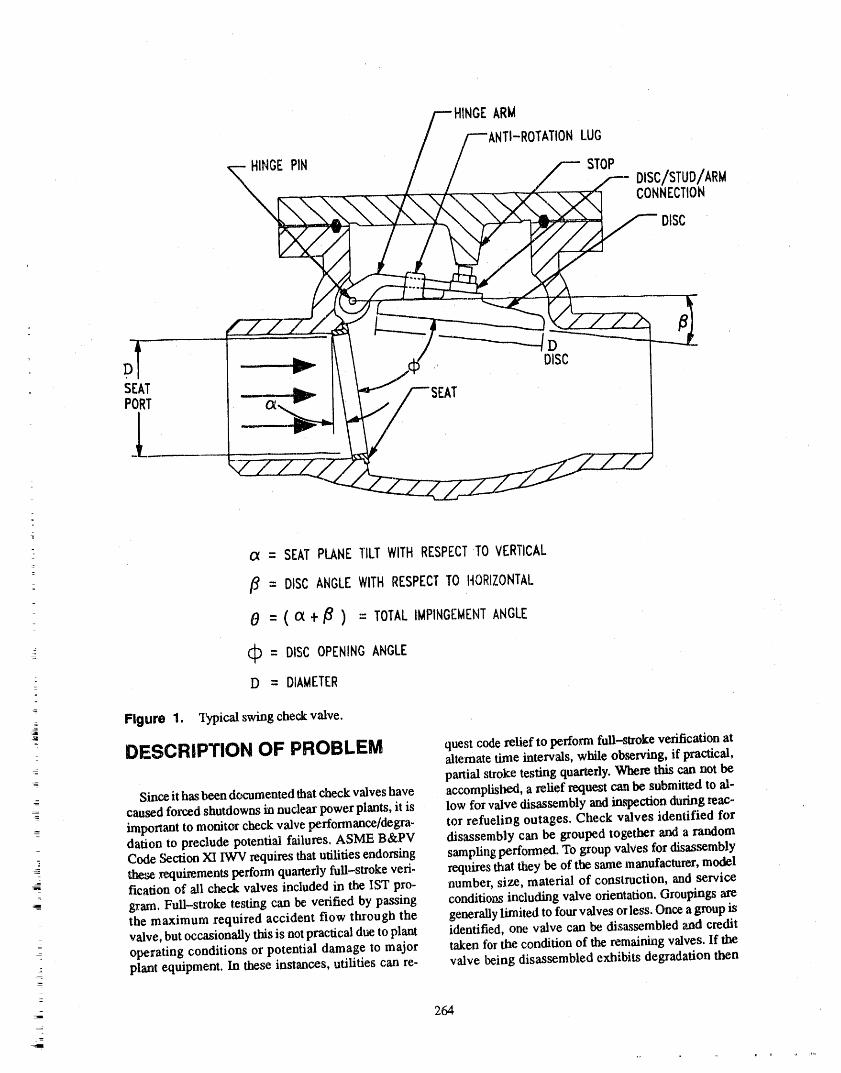
HINGEARM
DTATIONLUG
HINGEPIN STOP
DISC/STUD/ARMCONNECTION
DISC
D _ f, DISCSEATPORT _ AT
l
a, = SEATPLANETILTWITHRESPECTTO VERTICAL
/_ = DISCANGLEWITHRESPECTTO HORIZONTAL
6 = ( oc + _ ) = TOTALIMPINGEMENTANGLE
C:_= DISCOPENINGANGLE_
: D = DIAMETER
_j, Figure 1. "13rpicalswing check valve.
DESCRIPTION OF PROBLEM questcoderelief toperformfull-strokeverificationatalternate time intervals, while observing, if practical,partial stroke testing quarterly. Wherethiscannot be
- Since it hasbeen documentedthat checkvalves have accomplished, a relief request can be submitted to al-caused forced shutdowns in nuclear powerplants, it is low for valve disassembly and in,q)ectionduringrene-
__ important to monitor check valve performance/degra- tor refuelit)g outages. Check valves identified fordation to preclude potential failures. ASME B&PV disassembly can be grouped together and a randomCode Section XI IWV requires that utilities endorsing sampling performed. To group valVesfor disas_mbly
_ these re_luimmentsperformquarterly full-stroke veri- requires that they be of the same manufacturer,model- fication of ali check valves included in the IST pro- number, size, material of construction, and service
gram. FuU-stroke testing can be verified by passing conditions including valve orientation. Groupings arethe maximum required accident flow through the generally limited to four valves orless. Once a group isvalve, but occasionally this is notpractical due toplant identified, one valve can be disassembled and credit
--: operating conditions or potential damage to major taken for the condition of the _emaining valves. If the; plant equipment. In these instances, utilities can rc- valve being disassembled exhibits degradation then
-
264
, r ii 11 ,r IHII
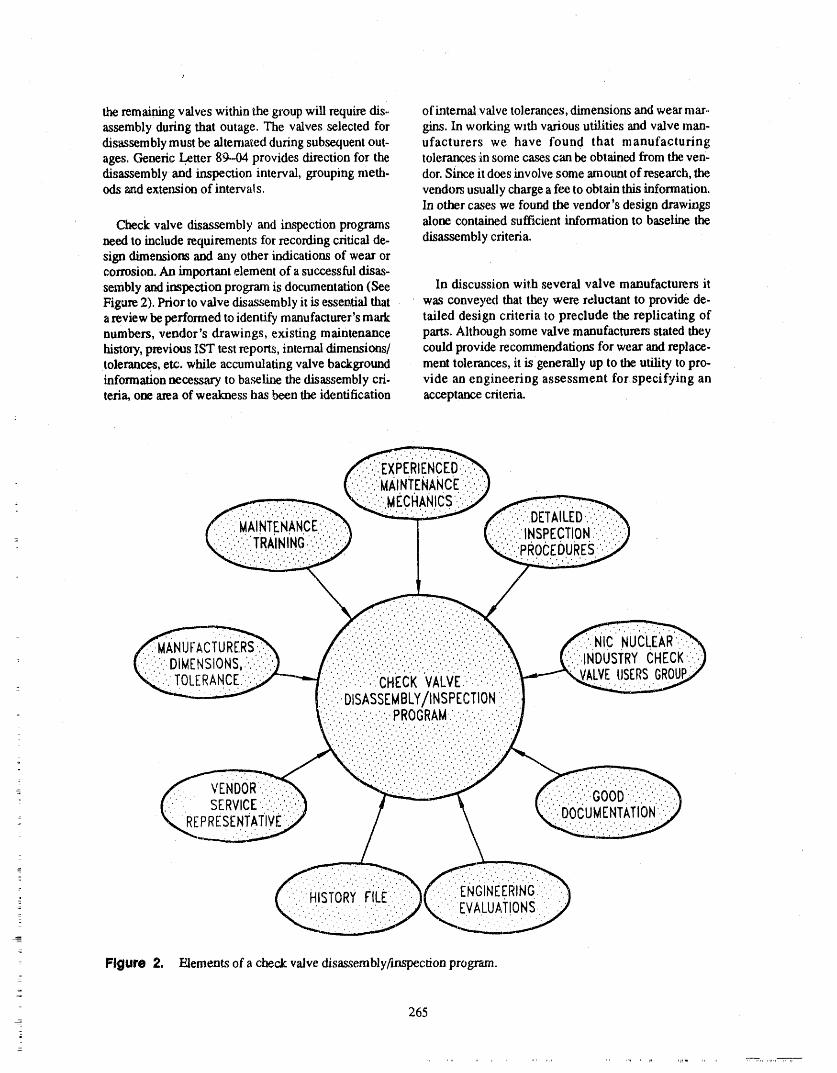
the remaining valves withinthe groupwill require dis" ofintemal valve tolerances, dimensions and wear mar..assembly during that outage. The valves selected for gins. In working with various utilities and valve man-disassemblymustbe alternated duringsubsequentout- ufacturers we have found that manufacturingages. Generic Letter 89.-04provides direction for the tolerances in some casescan be obtained from the yen-disassembly and inspection interval, groupingmeth. dor. Since it does involve some amount of research,theods _mdextetLsionof intervals, vendors usually charge a fee to obtain this information.
In other cases we found the vendor's design drawings
Check valve disassembly and inspection programs alone contained sufficient information to baseline theneed to include requirements tbr recording criticalde- disassembly criteria.sign dimensions and any other indications of wear orcorrosion. An important element of a successful disas-sembly and inspection program is documentation (See In discussion with several valve manufacturers itFigure 2).Prior tovalve disassembly it is essential that was conveyed that they were reluctant to provide de-areview be performed to identify manufacturer's mark tailed design criteria to preclude the replicating ofnumbers, vendor's drawings, existing maintenance parts. Although some valve manufacturers stated theyhistoa'y,previous IST test reports, internal dimensions/ could provide reconunendations for wear and replace-tolerances, etc. while accumulating valve background merit tolerances, it is generally up to the utility topro-information necessary to baseline the disassembly cri- vide an engineering assessment for specifying anteria,one areaof weakness has been the identification acceptance criteria.
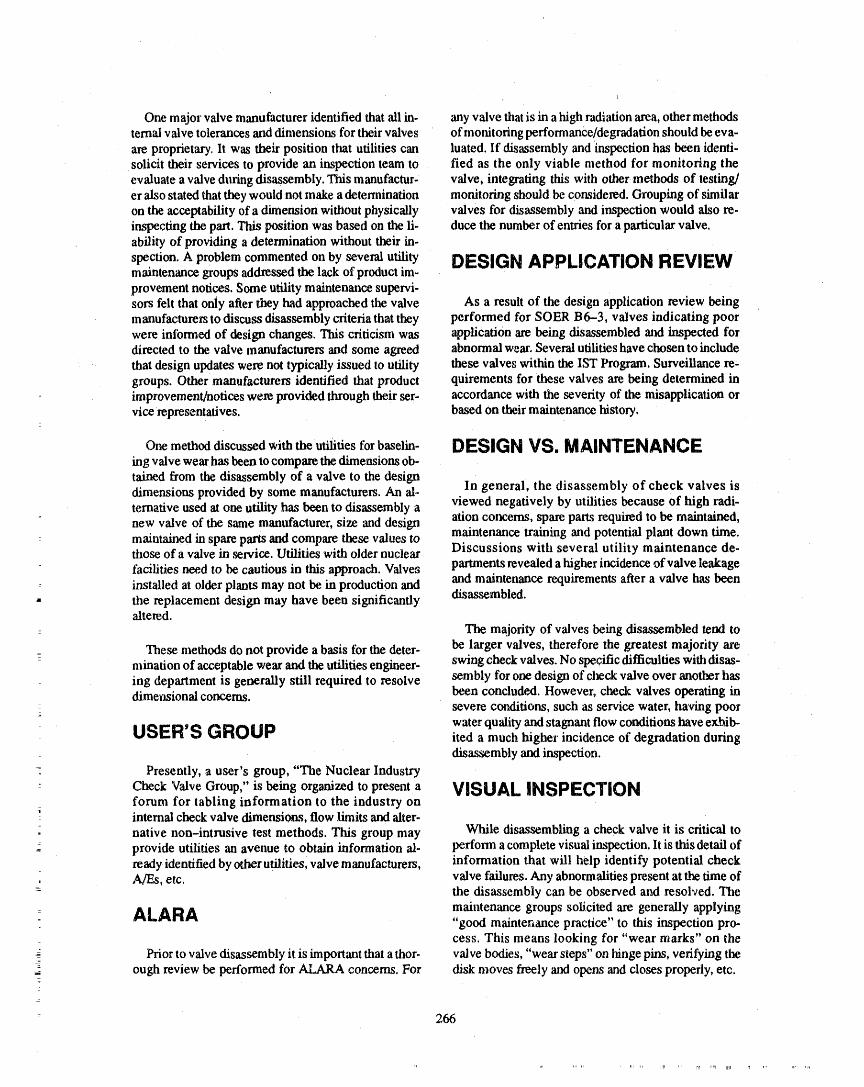
One major valve manufacturer identified that ali in- any valve that is in a high radiation area, other methods
ternal valve tolerances and dimensions for their valves of monitoring performance/degradation should be eva-are proprietary. It was their position that utilities can luated. If disassembly and inspection has been identi-solicit their services to provide an inspection team to fled as the only viable method for monitoring theevaluate a valve during disassembly. This manufactur- valve, integrating this with othermethods of testing/er also stated thatthey would not make a determination monitoring should be considered. Grouping of similaron the acceptability of a dimension without physically valves for disassembly and inspection would also re.inspecting the part. This position was based on the Ii- duce the number of entries for a particular valve.ability of providing a determination without their in-
spection. A problem commented on by several utility DESIGN APPLICATION REVIEWmaintenance groups addressed the lack of product im-
provement notices. Some utility maintenance supervi-sors felt that only after they had approached the valve As a result of the design application review beingmanufacturers to discuss disassembly t,_teria that they performed for SOER B6-3, valves indicating poorwere informed of design changes. This criticism was application are being disassembled and inspected fordirected to the valve manufacturers and some agreed abnormal weal'. Several utilities have chosen to include
that design updates were not typically issued to utility these valves within the IST Program. Surveillance re-groups. Other manufacturers identified that product quirements for these valves are being determined inimprovement/notices were provided through their ser- accordance with the severity of the misapplication or
vice representatives, based on their maintenance history.
One methoddiscussedWith the utiiities for baselin- DESIGN VS. MAINTENANCEing valve wear has been to compare the dimensiom ob-
tained from the disassembly of a valve to the design In general, the disassembly of check valves isdimensions provided by some manufacturers. An al-viewed negatively by utilities because of high radi-temative used at one utility has been to disassembly a
new valve of the same manufacturer, size and design ation concerns, spare parts required to be maintained,maintenance training and potential plant down time.nlaintained in spare parts and compare these values to
those of a valve in service. Utilities with older nuclear Discussions with several utility maintenance de-
facilities need to be cautious in this approach. Valves partments revealed a higher incidence of valve leakage: installed at older plants may not be in production and and maintenance requirements after a valve has been- the replacement design may have been significantly disassembled.
altered.: The majority of valves being disassembled tend to
: These methods do not provide a basis for the deter- be larger valves, therefore the greatest majority aremination of acceptable wear and the utilities engineer- swing check valves. No specific difficulties with disas-ing department is generally still required to resolve sembly for one design of check valve over another hasdimensional concerns, been concluded. However, check valves operating in
severe conditions, such as service water, having poorwater quality and stagnant flow conditiom have exhib-
USER'S GROUP Red a much higher incidence of degradation duringdisassembly and inspection.
= Presently, a user's group, "The Nuclear Industry_
Check Valve Group," is being organized to present a VISUAL INSPECTIONforum for tabling information to the industry on
: internal check valve dimensions, flow limits and alter-
- native non-intrusive test methods. This group may While disassembling a check valve it is critical to: provide utilities an avenue to obtain information al- perform a complete visual inspection. It is this detail of
ready identified by other utilities, valve manufacturers, information that will help identify potential check= A/F,, etc. valve failures. Any abnormalities present at the time of
- the disassembly can be observed and resolved. Themaintenance groups solicited are generally applying
ALARA "good maintenance practice" to this inspection pro-cess. This means looking for "wear marks" on the
Prior to valve disassembly it is important that a thor- valve bodies, "wear steps" on hinge pins, verifying the2- ough review be performed for ALARA concerns. For disk moves freely 'and opens and closes properly, etc.
: 266
In several plants, maintenance work orders utilize a guideline and it is referenced on the Disassembly/checklist for inspection criteria. (See Figure 3). The Inspection checklist. Engineering support is requestedchecklist includes a list of ali valve parts the mechanic if anything is found that the mechanic or QC inspectorand QC inspector will inspect. Comments on the con- feel requires further evaluation. Engineering woulddition of the valve noting any indications of wear, crG- evaluate the deficiencies and determine the cause. Ifsign. corrosion or damage are recorded. One utility has the deficiency indicates abnormal wear, Engineeringdeveloped a generic maintenance guideline to high- would perform an application review of the valve. Thelight the areas of concern for visual inspection. This application review would identify improper valve lo-guideline discalsses possible problems and the poten- cation or type. If the deficiency is caused by normaltial root causes. The mechanics are trained on this wear, Engineering would determine if the wear is
NOTE: N/A SECTIONSOF THISCHECKLISTNOTAPPLICABLE.ATTACHCHECKLISTTOTHEMWR,
/-H_t//--_-_OTA_ _o
.... ,, _.... _ CONNEeI'IO_
' _---I_ ,
VALVEMARKNUMBER MAINTENANCEREQUESTNUMBER
,
VENDORDATA(THISTYPICALLYWOULDBERECORDEDPRIORTO DISASSEMBLYTO IDENTIFYSPAREPARTS,DRAWINGS,ETC,)
MANUFACTURERMODELNUMBER
SIZEPURCHASEORDERNUMBER
1
- ,
NOTE: PRIORTODISASSEMBLY,REVIEWMAINTENANCEPROCEDURE1-MP-*** FORDETAILS. OF VISUALINSPECTIONCRITERIA.VISUALLYINSPECTTHEVALVE'SINTERNAL
COMPONENTS,RECORDANYDEFICIENCIESOBSERVEDTO THECOMMENTSECTION. ANDNOTIFYTHEMAINTENANCESUPERVISORANDSYSTEMENGINEER.
1. HINGEPIN/BUSHING2. HINGEARM3. ANTI-ROTATIONLUGS4. BACKSTOP5. DISK/STUD/ARMCONNECTION/FASTENERS
"- 6. DISK: 7. VALVEBODY
Figure 3. Example of a checklist to record visual inspection of valve internals.
267
,i,
f
RESULTSOF ITEMSI THRU 7i
INITIAL, DATE
8.PERFORMA BLUECHECK OF THE VALVEDISK/SEATTO MEASURESEATINGSURFACECONTACT.
RESULTSOF BLUECHECK
k__INITIAL DATE
GENERALCOMMENTS-
\PERFORMEDBY \ -_
. INITIAL DATE
* Q. C. INSPECTOR \, -' INITIAL DATE
* REQUIREDIF VALVEIS SAFETYRELATED._
Figure 3. (continued).-
z
268
,, . ,i,r...... rl,r rl ,,, ,q_n

within the service limits of the valve. In cases where determination made regarding repair/replacement andservice limits are not available, it would be Engineer- the inspection intewal for the valve.ing's responsibility to specify allowable wear for thattype of valve or possible design modifications. The Since tile vendor data required to make this programdrawbacks in this practice are existing manpower re- complete is not always available, a typical check valvestraints imposed on Engineering during an outage and program would rely on good maintenance practice po-potential plant delays waiting for an Engineering licies and sound engineering judgment. Without hav-response, ing design dimensions and wear tolerances to baselinet
a valve'sdegradation, the program must include in-
Maintenance planning can reduce the above men. spection procedures that require detailed documen-tioned drawbacks by reviewing valves scheduled for _ tation of a valve's condition. Also, good maintenancedisassembly befo,'e an outage. This allows any valve training and experienced maintenance mechanics are a
= with a poor maintenance history to be identified to En- key part of a successful disassembly/inspectiongineering for an application review and identification program.of service limits.
As the engineering manager of one valve manufac-turer stated, "a lot can be learned about a (check) valve
Often the process of visual inspection has been tim- just from looking at the internals." Although this isn'tited to removing the bonnet, verifying free movement the ideal situation this method can be very helpful pro-of the disk and a cursory observation for missing or vided it is accompanied by experienced maintenanceloose parts. As discussed, observations such as gouges mechanics, good maintenance training, quality inspec-
• on the internal valve casting can provide warning of don procedures, and detailed docmnentation.design misapplication prior to a valve failure.
When a check valve has been disassembled the op-As previously mentioned, some check valve man- erability of the valve should be verified (i.e., disc prop-
_ ufacturers are providing technical services to perform erly seats and moves freely). Each internal part of thevalve inspections. Inspection services from the vendor valve should be evaluated and commented on. Mea-are beneficial to the utility when critical dimensions surements of valve wear should be recorded where
and tolerances cannot be obtained. The disadvantage is practical (i.e., seat surface, excessive play, bushingthat the utility becomes dependent on the vendor and wear. etc). Any abnormalities noted during the in-without vendor support is unable to establish a pro- spection should be documented and evaluated bygram that measures valve wear to determine service engineering.limits.
A check valve disassembly/inspection pwgram that
_IJI_A_Y does not include manufacturers wear tolerances anddesign dimensions can be as effective as the program
: that includes these benefits. Regardless of whether theIn summary, the ideal check valve program would design and wear data is available, the same level of
include a historyof every valve in the program. The documentation should apply to each valve inspection.history would include the manufacturer's critical de- Initially, not having the manufacturer's parameterssign dimensions and tolerances, or, as a minimum, ser- will make it more difficult to benchmark a valves wear.
vice limits. Each valve disassembly would be included Using good maintenance practices and proceduresthein the history file and a checklist would be completed current condition of a valve can be evaluated to allow
for each inspection. The checklist (See Figure 3) for baselining degradation. Data recorded during a= would include a list of ali valve parts and a series of valve disassembly should be evaluated against pre-
questions associated with each part. The questions vious inspections to establish a trending program.would not only require the recording of critical dimen-
sions, but would also look at the general condition of The utility should continue to work with the man-the part. ufacturer when questions arise concerning valve wear
or abnormalities found during the inspection process.For example, when looking at a hinge pin from a Even if the vendor i,,_reluctant to provide valve design
swing check valve, in addition to measuring the pin di- and]or wear data, it is in his best interest to provideameter, indications of step changes, corrosion, etc. support for his product.should also be noted. In some cases, photographs of thevalve internals would be helpful. The documented re- As non-intrusive testings (e.g, Acoustical, Ultra-suits of a valve inspection should be reviewed and a sonic, Magnetic Particle, Radiography, etc.) develop,
_
269
_¢ ..... , i niI, ,,l_i J
utilities may be capable of supplemen_ng their disas,, Operations, Sigtfificant Operating Experi-sembly programs with this technology. At this time, ence Report 86--3, October 15, 1986.tlm general industr_ feeling is a limited confidence inany of the existing non-intrusive test methods. 2. Application Guidelines for Check Vah, es in
Nuclear Power Plants, Palo Alto, CA; Elec-tric Power Research Institute, EPRI
The results of the research for this paper strongly NP-5479. Januaxy 1988.suggest that atpresent the most viable method of deter-
mining check valve condition is disassembly. Recog- 3. Check Valve Application Manual and User'snizing tile maintenance concerns expressed by the Guide, Raleigh. NC: Rockwell International,utilities, to m,_et tlm requirements of ASME B&PV Bulletin V-303, June 1988.Code Section XI, disassembly looks to be the best
method. 4. Guidance on Developing Acceptable lnser.vice Testing Programs, Generic Letter B9-04
_EFERENCE_ United States Nuclear Regulatory Commis_sion, April 3. 1989.
1. Check Valve Failures or Degradation, 5. Nuclearlndustry Check Valve GroupMeetingAtlanta, Georgia: Institute of Nuclear Power Agenda for Apri119-20.1989, May 1, 1989.
x
J
m
270
...................... _" '"' '"llr, ,'_,...... ,,,,i ipl_llj, _,,,
ATTENDEE- PANEL QUESTIONS AND ANSWERS(EDITED; ATTENDEE QUESTIONS AND PANEL/AUTHOR
RESPONSES NOT/DENT/FED BY NAME)
Question 1 Question 2
Whatisanacceptablelevelofinspectiontoascertain Iam intcrcste,d inwhatwe needtodoinIST.Arcthereoperationalreadinessofa checkvalve?Isvisual otherimplicationsofcheckvalveproblems,suchasenoughordoesa dimensionalinspectionimprovetheabilitytomakesuchadetermination7 severewear?
ResponseI AccordingtotheCode,dowe needtogobeyondavi-sualinspection?
Our research indicatedthat dimensionalanalysis
wouldbean improvementto the program.It would Response2supplement strictly vistml inspection. However, theCede requests simply verifying that the valve fullstrokes tlu°oughits operation. The answer to your question is in the genetic letter.
271
p
DIAGNOSTICS OF STROKE TIMING TESTFOR POWER OPERATED VALVES
GARRY GALBREATHJ/M WITHERSPOON
DUKE POWER COMPANY
ABSTRACT • Compm_tivevalve times for similar valvesinsimilar applications. We initially looked ateach valve with blinders on, determining
The paper provides a historical perspective of the whether it met the code, Now we look at theapplication of valve stroke timing since the early corresponding valves on the other units, as1970s and bow the issues have evolved. An assessment well as similar design valves, and see if theof bow effective valve stroke timing is in finding and times are consistent. If not, we may have a
predicting problems is discussed. Research findings problem.will be presented regarding the complete test andmaintenance history of a small, random sample of dif- • Air-operated valves which are activated fromferent types of valves, highlighting where the industry multiple solenoids. Should you ttse the samemay be heading in the future, solenoid each time? Ate the times different
when using different solenoids?
INTRODUCTION • Timing from limit-switch to limit-switch vs.timing from actuator to limit-switch. Weoriginally made the argumem that limit-to--
1would like to talk to you this morning about valve limit was a better test, since we could usestroke timing. When we first got involved in this area automatic triggering for the timing. We feltabout 15 yr ago, we took a pretty simplistic approach that by using a consisteiat trigger point, weto timing valves. This approach has changed over the would have a better chance of' detectingyears as our experience has grown. I would like to cov- c 'hanges. The NRC agreed with us, at least oner three aspects of valve timing today, and I hope that Catawba, because they approved our SERthis perspective will be of benefit to you. with tiffs relief written into it. However, this
is a continuing sensitive issue.
o First, I want to cover some history. Where did valve • Retest issues_We have had to examine ourtiming come from, ',rodhow has ii changed over the approach to post-maintenance retest evalua-years. Second, I want to take a look at what valve tions. For example, if work is done that wouldtiming is doing for us. Its surprising how little data affect the bleed-off rate for an air actuated
, exists m a retrievable form which would let us know valve, the stroke time is probably affected,"- how effective valve liming is. We have done some se- and the valve should be retested. I think we
lective research on our own te_ history, and I will coy- are doing a better job now of identifying theseer what we have found. Finally, I wmat to touch on types of situatiom.
where we are going with valve stroke timing. The shun I'm sure there are lots more, but these are just some
answer is that no one knows for sure, but there are examples of the types of issues that have arisen. I'msome interesting possibilities, sure that any of you who administer these programs
= have seen the..same types of issues,As i'm sure you have ali experienced, in _ surveil-
lance area, we _end to get watched from time to time. CURRENTDATAQuality Assurance, INPO, and the NRC ali audit us,
= and in addition, we sometimes find things on our own Now lets move on to something potentially more in-'i that we don't feel comfortable with. teresting, namely, what's valve stroke timing doing for
us, anyway? This is an obvious question, yet we don't
In theiaterest ofbrevity, I want to share just a few of seem to have a ready answer. Most people who havethe issues that have been brought up over the years re- been involved with valve timing for a few years have
garding valve tinting, which I hope will demonstrate opiniom, but rarely is the data available to back up thethat this is not as simple as it looks at the outset: opinions.
_-- 273
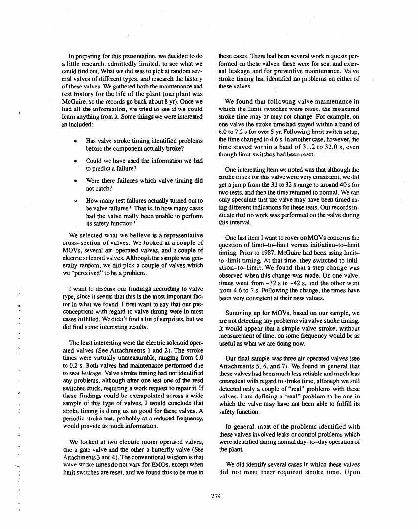
In preparing for this presentation, we decided to do these cases. There had been several work requests per-a little research, admittedly limited, to see what we formed on these valves, these were for seat and exter-
could find out. What we did was to pick at random sev- nal leakage and for preventive maintenance. Valveeral valves of different types, and research the history stroke timing had identified no problems on either ofof these valves. We gathered both the maintenance and these valves.test history for the life of the plant (our plant wasMcGuire, so the records go back about 8 yr). Once we We found that following valve maintenance inhad ali the information, we tried to see if we could which the limit switches were reset, the measured
learn anything from it. Some things we were interested stroke time may or may not change. For example, onin included: one valve the stroke time had stayed within a band of
6.0 to 7.2 s for over 5 yr. Following limit switch setup,
® Has valve stroke timing identified problems the time changed to 4.6 s. In another case, however, thebefore the component actually broke? time stayed within a band of 31.2 to 32.0 s, even
though limit switches had been reset.• Could we have used the infomaation we had
to predict a failure? One interesting item we noted was that although the
• Were there failures which valve timing did stroke times for this valve were very consistent, we didnot catch? get a jump from the 31 to 32 s range to around 40 s for
two tests, and then the time returned to normal. We can
o How many test failures actually turned out to only speculate that the valve may have been timed us-be valve failures? That is, in how many cases ing different indications for these tests. Our records in-had the valve really been unable to perform dicate that no work was performed on the valve duringits safety function? this interval.
We selected whm we believe is a representative One last item I want to cover on MOVs concerns the
cross-section of valves. We looked at a couple of question of limit-to-limit versus initiation-to-limitMOVs, several air-operated valves, and a couple of timing. Prior to 1987, McGuire had been using limit-electric solenoid valves. Although the sample was gen- to-limit timing. At that time, they switched to initi-eraUy random, we did pick a couple of valves which ation-to-limit. We found that a step change waswe "perceived" to be a problem, observed when tiffs change was made. On one valve,
times went ft'ore -32 s to .-42 s, and the other wentI want to discuss our findings according to valve f_om 4.6 to 7 s. Following the change, the times have
type, since it seems that this is the most important fac- been very consistent at their new values.__ tor in what we found. I first want to say that our pre-
conceptions with regard to valve timing were in most Summing up for MOVs, based on our sample, wecases fulfilled. We dicha't find a lot of surprises, but we are not detecting any problems via valve stroke timing.did firm some interesting results. It would appear that a simple valve stroke, without
measurement of time, on some frequency would be asThe least interesting were the electric solenoid oper- useful as what we are doing now.
-" ated valves (See Attachments 1 and 2). The stroke
times were virtually unmeasurable, ranging from 0.0 Our final sample was three air operated valves (seeto 0.2 s. Both valves had maintenance performed due Attachments 5, 6, and 7). We found in general thatto seat leakage. Valve stroke timing had not identified these valves had been much less reliable ',rodmuch less
any problems, although after one test one of the reed consistent with regard to stroke dme, although we stillswitci_s stuck, requiring a work request to repair it. If detected only a couple of "real" problems with these
" these findings could be extrapolated across a wide valves. I am def'ming a "real" problem to be one insample of this type of valves, I would conclude that which the. valve may have not been able to fulfill itsstroke tinning is doing us no good for timse valves. A safety function.periodic stroke test, probably at a reduced frequency,
would provide as much information. In general, most of the problems identified withthese, valves involved leaks or control problems which
We looked al two electric motor operated valves, were identified during normal day-to-day operation ofone a gate valve and the other a butterfly valve (,See the plant.Attachments 3 and 4). The conventional wisdom is that
_ valve stroke times do not vary for EMOs, except when We did identify several cases in which these valves-: limit switches are reset, and we found tiffs to be true in did not meet their required stroke t_me. tJpon
274
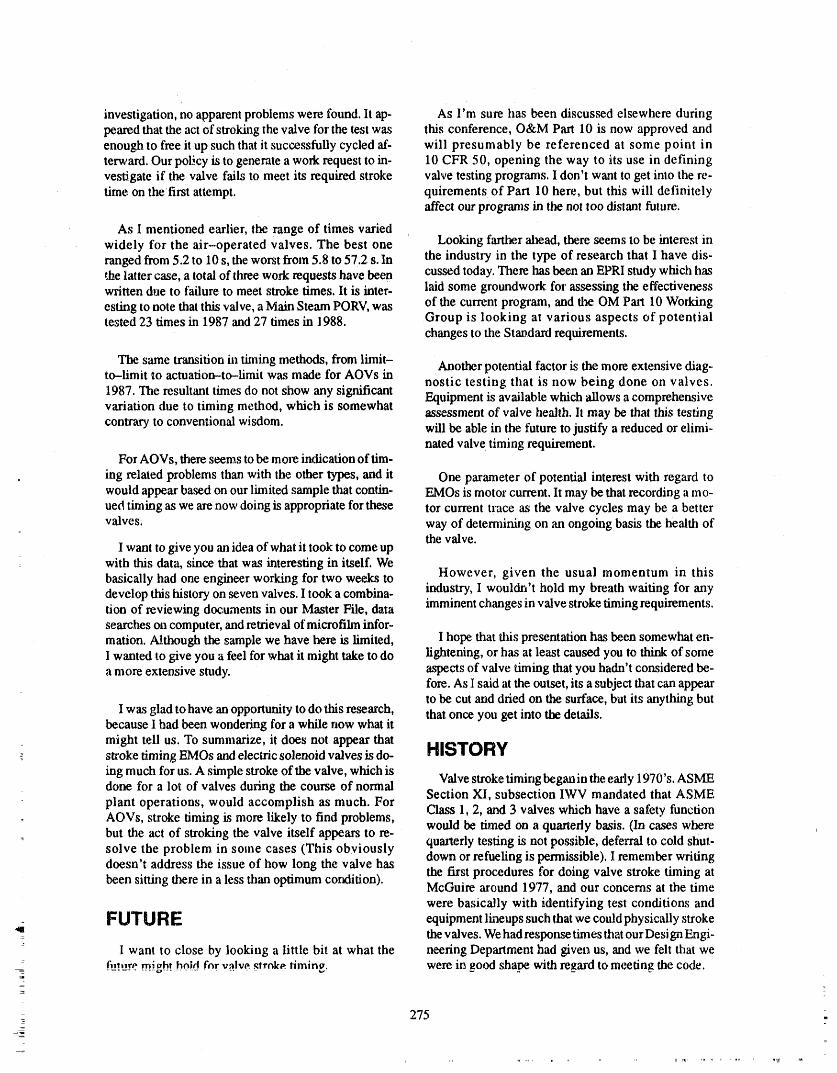
investigation, no apparent problems were found, lt ep- As I'm sure has been discussed elsewhere duringpealed that the act of strokhag the valve for the test was this conference, O&M Part 10 is now approved andenough to free it up such that it successfully cycled at'- will presumably be referenced at some point inte_,ard. Our pol.;.cyis to generate a work request to in- 10 CFR 50, opening the way to its use in definingvestigate if the valve fails to meet its required stroke valve testing programs. I don't want to get into the re-rime on the first attempt, quirements of Part 10 here, but this will definitely
affect our programs in the not too distant future.
As 1 mentioned earlier, the range of times variedwidely for the air-operated valves. The best one Looking farther ahead, there seems to be interest inranged from 5.2 to 10 s, the worst from 5.8 to 57.2 s. In the industry in the type of research that I have dis-
latter case, a total of three work requests have been cussed today. There Imsbeen an EPRI study which haswritten due to failure to meet stroke rimes. It is inter- laid some groundwork for assessing the effectiveness
of the current program, and tl_ OM Part 10 Workingesting to note that this valve, a Main Steam PORV, wastested 23 times in 1987 and 27 times in 1988. Group is looking at various aspects of potential
changes to the Standard requirements.
The same transition in _ning methods, from limit-Another potential factor is the more extensive diag-
to-limit to actuation-to-lirtfit was made for AOVs in nostic testing that is now being done on valves.1987. The resultant times do not show any significant Equipment is available which allows a comprehensivevariation due to timing method, which is somewhat assessment of valve health. It may be that this testingcontrary to conventional wisdom, will be able in the future to justify a reduced or elimi-
nated valve timing requirement.For AOVs, there seems to be more indication of rim-
ing related problems than with the other types, and it One parameter of potential interest with regard towould appear based on our limited sample that contin- EMOs is motor current. It may be that recording a mo-ued timing as we are now doing is appropriate for these tor current trace as the valve cycles may be a bettervalves, way of detemfining on an ongoing basis the health of
the valve.I want to give you an idea of what it took to come up
with this data, since that was interesting in itself. Webasically had one engineer working for two weeks to However, given the usual momentum in thisdevelop this history on seven valves. I took a combine- industry, I wouldn't hold my breath waiting for anytion of reviewing documents in our Master File, data imminent changes in valve stroke timing requirements.searches on computer, and remeval of microfilm infor-marion. Although the sample we have here is limited, I hope that this presentation has been somewhat en-I wanted to give you a feel for what it might take to do lightening, or has at least caused you to think of somea more extensive study, aspects of valve timing that you hadn't considered be-
fore. As I said at the outset, its a subject that can appearto be cut and dried on the surface, but its anything but
I was glad to have an opportunity to do tiffs research, that once you get into the details.because I had been wondering for a while now what itmight tell us. To summarize, it does not appear thatstroke timing EMOs and electric solenoid valves isdo- HISTORYing much for us. A simple stroke of the valve, which isdone for a lot of valves during the course of normal Valve stroke timing began in the early 1970's. ASME
plant operations, would accomplish as much. For Section XI, subsection IWV mandated that ASMEAOVs, stroke timing is.more likely to find problems, Class 1, 2, and 3 valves which have a safety function
would be timed on a quarterly basis. (In cases wherebut the act of stroking the valve itself appears to re- quarterly testing is not possible, deferral to cold shut-solve the problem in some cases (This obviously down or refueling is permissible). I remember writingdoesn't address the issue of how long the valve has the fit'st procedures for doing valve stroke timing atbeen sitting there in a less than optimum cotdition). McGuire around 1977, and our concerns at the time
were basically with identifying test conditions and
,a F_UTU _ _ equipment lineups such that we could physically stroke: the valves. We had response times that our Design Engi-
I want to close by looking a little bit at what the neering Department had given us, and we felt that we_ fi__!ure..m.igh!bo!d fnr valve ,qlrc_ka.firnin_, were in good shape with regard to meeting the code.
275 _-
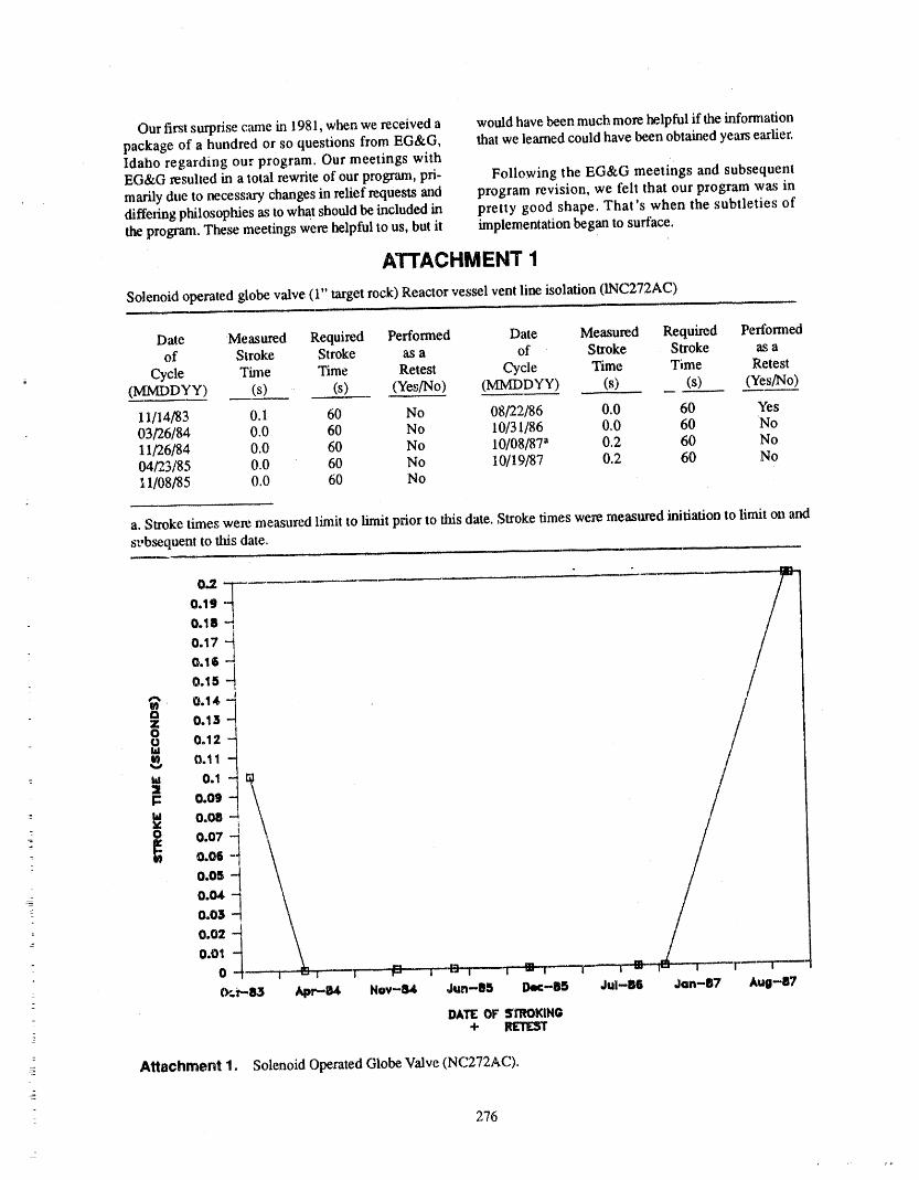
Our first surprise came in 198 I, when we received a would have been much more helpful if the infonnationpackage of a hundred or so questions from EG&G, that we learned could have been obtained years earlier.Idaho regarding our program. Our meetings withEG&G resulted in a total rewrite of our program, pri- Following the EG&G meetings and subsequentmarily due to necessary changes in relief requests and program revision, we felt that our program was indiffeling philosophies as to what should be included in pretty good shape. That's when the subtleties ofthe program. These meetings were helpful to us, but it implementation began to surface.
ATTACHMENT 1
Solenoid operated globe valve (1" target rock) Reactor vessel vent line isolation (INC272AC)
Date Measured Required Performed Date Measured Required Perlbrmedof Stroke Stroke as a of Stroke Stroke as a
, Cycle Tune Time Retest Cycle Time Time Retest(MMDDYY) (s) (s) (Yes/No) (MMDDYY) (s) (s) (Yes/No)
11/14/83 0.1 60 No 08/22/86 0.0 60 Yes03/26/84 0.0 60 No 10/31/86 0,0 60 No11/26/84 0.0 60 No 10/08/87 a 0.2 60 No04/23/85 0.0 60 No 10/19/87 0.2 60 No11/08/85 0.0 60 No
a. Stroke times were measured limit to limit prior to this date. Stroke times were measl_red initiation to limit on ands_.,bsequent to this date.
0,.2-
0.19 --0.18 -0.17 -
0.16 -0.15 -
"_ 0.14 -Qz 0.13
0.12I_ 0.11
01i0.09
- la 0.08- o 0.07
0.060.050.040.03
" 0.02
0.01
0 - l f " -_- I = i - r--= _...... r-- i = !
: (P.F'.83 ApP--84 Nov-B4 Jun--B5 De¢-85 JuI-B6 Jan-B7 Aug-B7-
DATEOF STROKING- + RETEST
Attachment 1. Solenoid OperatedGlobe,Valve (NC2?2AC).
276
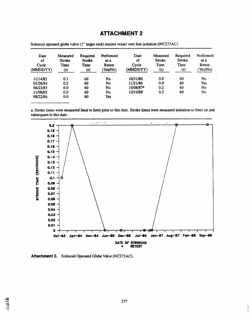
ATTACHMENT 2
Solenoid operated globe valve (1" target rock)reactor vessel vent fine isolation (INC273AC),
Date Measured Required Perfomaed Date Measured Required Performedof Stroke Stroke as a of Stroke Stroke as a
Cycle Time 'Iime Retest Cycle Time Time Retest(MMDDYY) (s) (s) (Yes/No) (MMDDYY) (s) (s) (Yes/No)
11/14183 0.1 60 No 10/31/86 0.0 60 No03/26/84 0.2 60 No 11/21/86 0.0 60 YestM/23/85 0.0 60 No 10/08/87 a 0.2 60 No11/08/85 0.0 60 No 10/19188 0.2 60 No08/22/86 0.0 60 Yes
a. Stroke times were measured limit to limit prior to this date. Stroke limes were measured initiation to limit on andsubsequent to this date.
................ •
0.2 "0.1g
0.180.170.1G
0.15
t32: 0.13
0.1.20.11
ta 0.1X
,u 0.08
0.070.06
0.050.04
O.C30.020.01
0
0¢t'-83 Ape-li4 Nov-84 Jun-85 Dec-85 Jul-II_ Jan-B7 Aug-87 Feb-B8 $op-!18
DATEOF STROKING+
Attachment 2. Solenoid Operated Globe Valve (NC273AC).
---- 277 =

ATTACHMENT3
Electric motor operated gate valve (8" Walworth) NS pump discharge containment isolation (INS15B)
Date Measured Requi_d Performed Date Measured Required Performedof Stroke Stroke as a of Stroke Stroke as a
Cycle Time Time Retest Cycle Time Time Retest(MMDDYY) (s) (s) (Yes/No) (MMDDYY) (s) (s) (Yes/No)
03/26/81 6.8 10 No 06/16/85 6_2 10 No06/17/81 7.2 10 No 08/30/85 6,0 10 No09/23/81 7,2 10 No 11/18/85 6.2 10 No12/30/81 6,8 10 No 02/12/86 6.2 10 No04/07/82 7.2 10 No 05/12/86 6.2 10 No07/07/82 6.8 10 No 08/23/86 6.0 10 No10/08/82 7.2 10 No 11/13/86 6.2 10 No01/10/83 6.8 10 No 11/18/86 4.6 10 Yes04/I0/83 6.6 10 No 12/15/86 4.6 10 No07/13/83 6.8 10 Yes10/04/83 7.2 10 No 05/18/87 a 7.2 10 No12/12/83 6.8 10 No 08/13/87 7.1 10 No04/03/84 6.2 10 No 10/29/87 7.0 l0 Yes
: 05/16/84 6.2 10 Yes 11/17/87 6.8 10 No06/27/84 6.2 10 No 02/15/88 6.6 10 No09/19/84 6.2 10 No 02/13/88 6.4 10 No12/05/84 6.0 10 No 08/18/88 6.6 10 No03/01/85 6.2 10 No 11/14/88 6.8 10 No
a. Stroke times were measured limit to limit plior to tiffs date. Stroke times were measured initiation to limit on ",rod-- subsequent to this date.
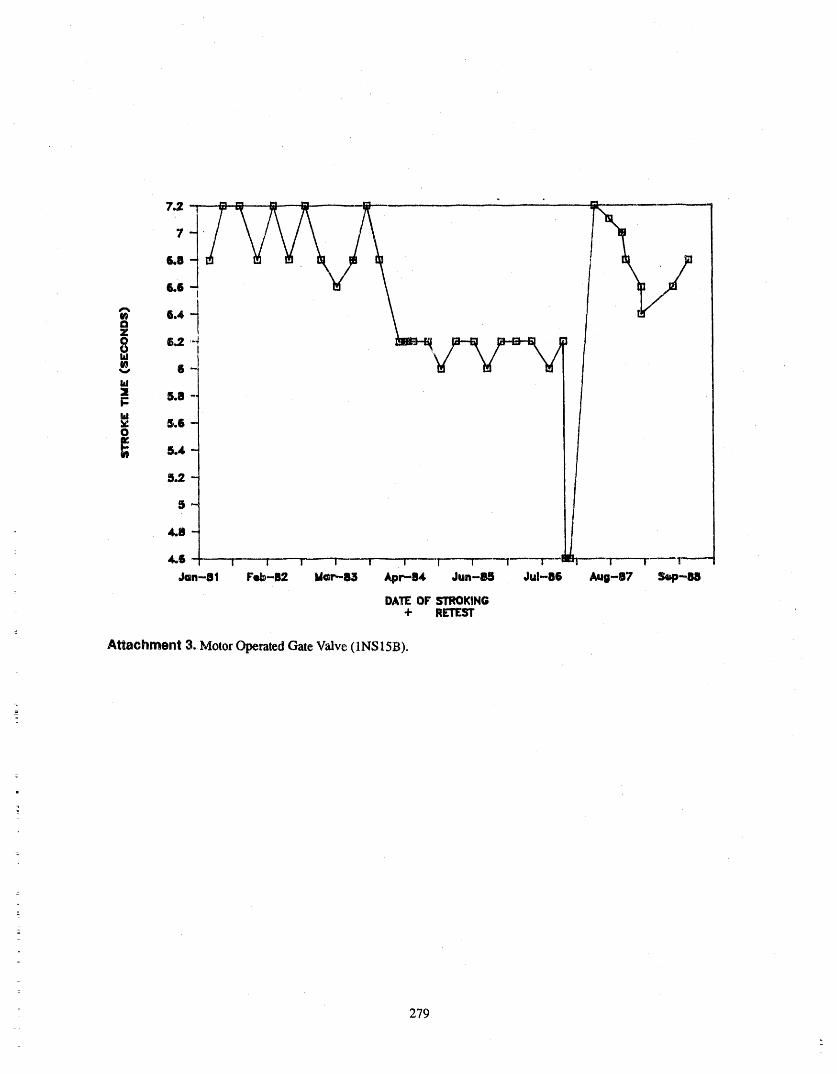
: 279
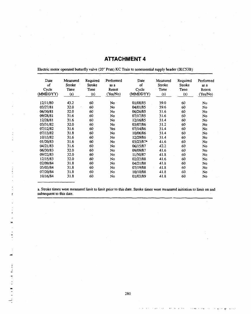
ATTACHMENT 4
Electric motor operated butterfly valve (20" Pratt) KC Train to nonessential supply header (IKC53B)
Date Measm'ed Required Performed Date Measured Required Performedof Stroke Stroke as a of Stroke Stroke a_ a
Cycle 'Time Time Retest Cycle Time Time Retest(MMDDYY) (s) (s) (Yes/No) (MMDDYY) (s) (s) (Yes/No)
12/11/80 43,2 60 No 01/08/85 39.0 60 No03/27 r81 32,0 60 No 04/01/85 39,6 60 No06/30 ¢81 32,0 60 No 06/26/85 31,6 60 No09/28 ¢81 31,6 60 No 07/.17/85 31.6 60 No12/28 ¢81 31,6 60 No 12/16/85 31.4 60 No03/31 ¢82 32,0 60 No 03/07/86 31,2 60 No07/12 ¢82 31,6 60 Yes 07/14/86 31,4 60 No07/13 ¢82 31,8 60 No 10/06/86 31,4 60 No10/13/82 31.6 60 No 12/29/86 31.4 60 No01/20/83 31,6 60 No 03/23/87" 41,6 60 No04/21/83 31,6 60 No 06/15/87 42,2 60 No06/30/83 32.0 60 No 09/09/87 41.6 60 No09/22/83 32.0 60 No 11/30/87 41.8 60 No12/15/83 32,0 60 No 02/23/88 41.6 60 No02/09/84 31,8 60 No 04/21/8 8 41,8 60 No05/03/84 3 ! .8 60 No 07/19/88 zt1.8 60 No07/20/84 31,8 60 No 10/10/'88 41.8 60 No
: 10/16/84 31,8 60 No 01/03/89 ztl,8 60 No
a. Stroke times were measured limit to limit prior to this date. Stroke times were measured initiation to limit ota and-_- subsequent to this date,
,,. . .., , . . ,, ,, ,.
2
z
280-
n lT ..... le" r II ' rlFIl' _1 II i '_1 .... _nll_ ,i 1111111, i, gll lt II[11r IIi H iiI
r _
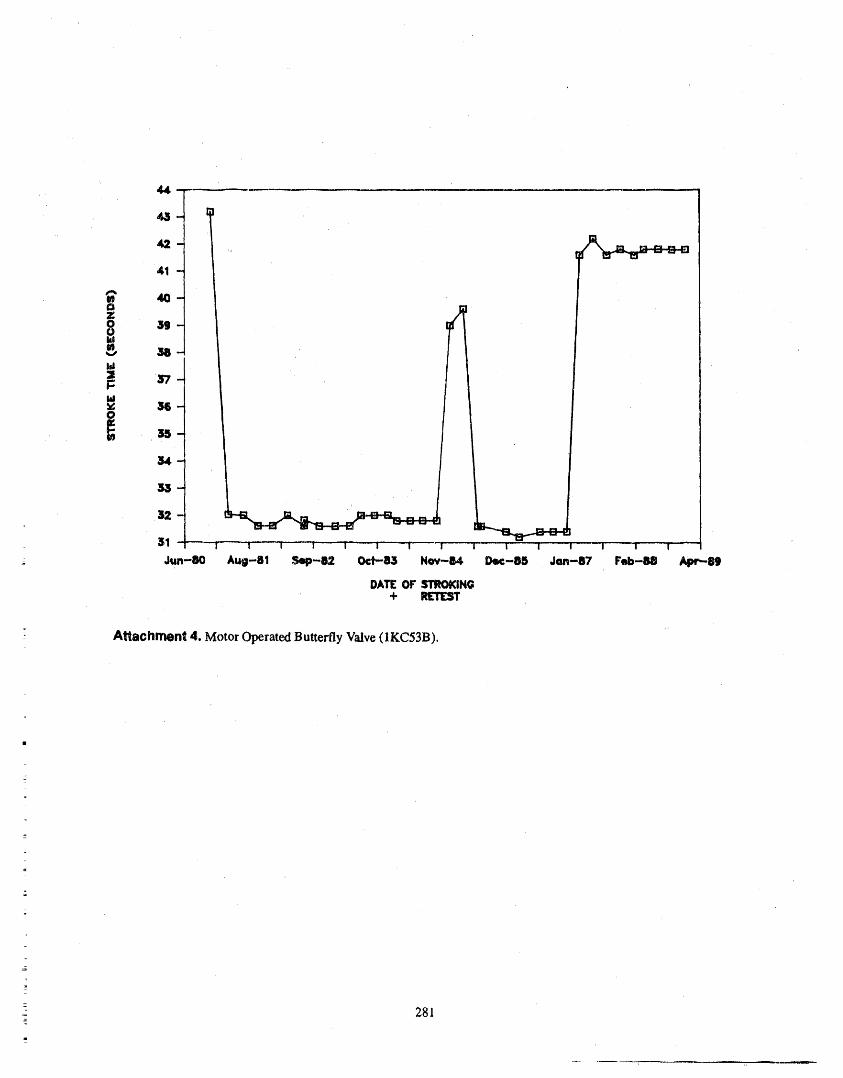
=
ARachment 4. Motor Operated ButterflyValve (1KC53B).
-- 281
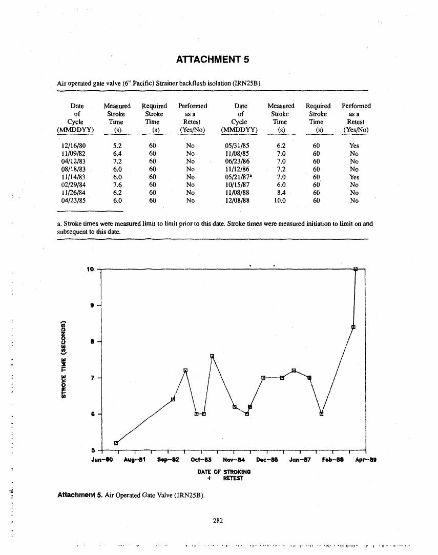
ATTACHMENT 5
Air operated gate valve (6" Pacific) Strainer backflush isolation (lRN25B)
Date Measured Required Performed Date Measured Required Performedof Stroke Stroke _ a of Stroke Stroke as a
Cycle Time Time Retest Cycle Time Time Retest(MMDDYY) (s) (s) (Yes/No) (MMDDYY) (s) (s) (Yes/No)
12/16/80 5.2 60 No 05/31/85 6.2 60 Yes11/09/82 6.4 60 No 11/08/85 7.0 60 No04/12/83 7.2 60 No 06/23/86 7.0 60 No08/18/83 6,0 60 No I 1/12/86 7,2 60 No11/14/83 6.0 60 No 05/21/87 a 7.0 60 Yes02:29/84 7.6 60 No 10/15/87 6,0 60 No
... 11/26/84 6.2 60 No 11/08/88 8.4 60 No04/23/85 6.0 60 No 12/08/88 10,0 60 No
a. Sta'oke times were measured limit to limit prior to this date, Stroke times were measured initiation to limit on andsubsequent to this date.
10 -Is-J
In
= ld
5 -"----'I-----F"-"W_-I" _i- -I....i i ....i......._ i-- i --I-_
Jun-80 Aug-81 $4p--82 0ct-83 Nov-B4 Doc-85 Jan-a7 Feb-88 Apr--Sg
DATEOF Sll_KIN(l+ RETEST
- Attachment5. Air Operated Gate Valve (1RN25B).
- 282
,r ........... r, , ,1_" 1lPTM rill1 I_ll Irll ............. [_lf¢, ,III ,i ,¢_1 I_....... ''_l'/ ' l_ .... ) J/li III _l$ , jl ,lllll$ , iii I1_/i, I I ! /I/llj/llllll, i_1, ,,ii II1_ III) )1) II i lJlr ...... f,l, q
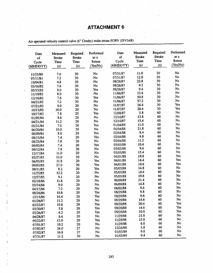
' ATTACHMENT 6
Air operated velocity control valve (6" Crosby) m_in steam PORV (1SVIAB)
Date Me_ured Required Performed Date Measured Required Performedof Stroke Stroke as a of Stroke Stroke as a
Cycle Time Time Retest Cycle Time Time Retest(MMDDYY) (s) (s),, (Yes/No) (MMDDYY). (s) (s) (Yes/No)
11/25/80 7.6 30 No 07/31/87 11,0 30 No07/11/81 7.2 30 No 07/31/87 12.8 30 No10/04/81 4.8 30 No 08/28/87 22.8 30 No03/16/82 7.6 30 No 08/28/87 9,2 30 No05/15/82 8.0 30 Yes 08/28/87 9.4 30 No11/19/82 8.0 30 No 11/06/87 12.6 30 No12/16/82 7.6 30 Yes 11/06/87 50.8 30 No04/21/83 7.2 30 No 11/06/87 57.2 30 No07/21/83 8,0 20 No 11/07/87 26.4 30 Yes10/13/83 30.0 20 No 11/07/87 20.4 30 Yes10/17/83 7.8 20 Yes 12/08/87 5.8 60 No01/05/84 8,6 20 No 12/10/87 13.8 60 No04/21/84 11.2 20 No 12/10/87 1514 60 No05/21/84 7.6 20 Yes 01/04/88 11.0 60 No06/20/84 10.0 20 No 01/04/88 21.8 60 No08/09/84 8.0 20 Yes 02/04/88 8,4 60 No08/15/84 7.4 20 Yes 02/04/88 9.8 60 No08/23/84 7.0 20 No 02/04/88 11.2 60 No09/03/84 7.4 20 Yes 03/03/88 10,4 60 No09/12/84 7.8 20 No 03/03/88 9.6 60 No12/17/84 11.0 20 No 03/03/88 15.4 60 No02/27/85 12.0 20 No 04/01/88 19.8 60 Yes06/03/85 11.8 20 Yes 04/01/88 14.4 60 Yes09/03/85 27.0 20 Yes 04/01/88 10.6 60 Yes09/11/85 8.2 20 Yes 05/03/88 14.8 60 No11/25/8.5 12.2 20 No 05/03/88 i0.4 60 No12/27/85 9.1 20 No 05/05/88 19,8 60 No02/18/86 11.8 20 No 06/09/88 21.4 60 No03/24/86 9.0 20 No 06/09/88 14.8 60 No04/17/86 7.2 20 No 08/02/88 9.6 60 No08/26/86 10.8 20 Yes 08/29/88 9.8 60 No12/15/86 10.4 20 Yes 08/29/88 9.6 60 No01/26/87 11.2 20 No 08/29/88 14.4 60 No03/23/87 10.8 20 Yes 09/20/88 20.4 60 Yes_
03/30/87 5.8 20 Yes 09/20/88 14.6 60 Yes03/26/87 6.2 20 Yes 09/20/88 10.0 60 Yes04/28/87 6.6 20 No 11/29/88 21,0 60 No
: 05/22/87 13.0 20 Yes 11/29/88 15,0 60 No07/01/87 10.2 20 No 11/29/88 6,0 60 No07/02/87 24.0 27 No 12/26/88 5.8 60 No07/02/87 16.8 27 No 01/03/89 9.8 60 No07/31/87 11.2 30 No 01/03/89 9.4 60 No
i
283

r_ 40-Z8ld
ld 39-
O- ' i ' i i .... T .... S , .... ," I" 'm "'¢ "t _ t ' l ,' --1-"--Jun-OO Aug-81 Sep-82 0ct-83 Nov-S& I)_-85 Jan-87 Pcb-88 Apr-89
DATE:OF"STROKING, + RETEST
Attachment 6. Air Ol_rated Relief Valve (1SVIAB),
284

' ATTACHMENT7
Air operated butterfly valve (20" Fisher) KC HX outlet temperature control (IIGN_9A)
Date Measured Required Performed Date Measured Required Performedof Stroke Stroke as a of Stroke Stroke as a
Cycle Time Time Retest Cycle Time Time Retest(MMDDYY) (s) (s) (Yes/No) (MMDDYY) (s) (s) (Yes/No)
12/17/b0 1.2 60 No 12/22/86 0.8 60 No08/12/81 0.8 60 No 03/25/87 1.0 60 Yes10/20/82 0.8 60 No 06/11/87 3.5 a 60 No1M,/15/83 0.8 60 No 09/03/87 2.2 60 No
° 07/19/83 0.4 60 No 11/01/87 4.2 60 Yes09/27/83 1.6 60 No 11/03/87 2.6 60 Yes,,,,__,8/83 0,4 60 No 11/07/87 2.2 60 No
: t_I/01/84 0.8 60 Yes 11/25/87 2.4 60 No.. 02/16/84 0.8 60 No 11/25/87 2.4 60 Yes-_ 05/03/84 1,4 60 No 01/29/88 2,4 60 Yes: 07/05/84 1.2 60 No
10/16/84 1.2 60 No 02/17/88 2.2 60 No01/10/85 1.0 60 No 04/19/88 2.8 60 No
- 04/01/85 1.0 60 No 04/21/88 2.8 60 No06] !8/8 5 1.4 60 Yes 07/14/88 1.8 60 No07/02/85 1.2 60 No 08/15/88 1.6 60 Yes-
" 09/25/85 1.4 60 No 10/14/88 1.4 60 Yes12/11/85 1.2 60 No 10/05/88 1.8 60 No03/27/86 1.0 60 Yes 11/17/88 4.0 60 Yes07/10/86 1.0 60 No 11/29/88 3.8 613 Yes
_- 10/15/86 0.8 60 No 12102/88 3.2 60 Yes
= a. Stroke times were measured limit to limit prior to this date, Stroke times were measured initiation to limit on and= subsequent to this date.
_
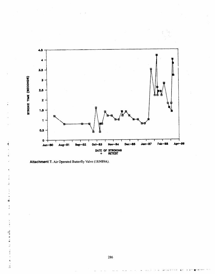
4-
I:: 2
: 0 '----'F'----I------I- .... i I _ i _ i i | i i i - I _-[]
= Jt,m-IlO Aug-Bl 5iip--82. CiVil3 Nov-R4 I:hi_-',_ Jon-,87 Fe4)-M Apr,-O4}
DATE:OF STROKING+ _
Attachrr_nt 7. Air Operated Butterfly Valve (1RN89A).
2

ATTENDEE- PANEL QUESTIONS AND ANSWERS(EDITED; ATTENDEE QUESTIONS AND PANELAUTHOR
RESPONSES NOT IDENTIFIED BY NAME)
No Questiom/Comments
287
_z
HOW CHECK VALVES FAILJOHN OZOL
, COMMONWEALTH EDISONROOM 35 WEST, P.O. BOX 767
CHICAGO, IL 60690
' ABSTRACT uremechanisms possible for check v',dves, but themost significant ones are the. following:
Because of the five check _'alve failures at1. The minimum velocity required to lift theSan Onofre Unit 1 on November 21, 1985, the NRC is.
disc to the fuU-.open and stable position.sued NUREG-1190. This NUREG discussed the rea-sons for the failures of the five check valves "andhowthe check valve failures induced water hammer to the 2. The minimum L/D's from upstream distur-
feedwater system. In parallel effort INPO issued bances.Significant Operating Experience Report SOER 86-3on October 15, 1986. This SOER discussed the 3. Vortex shedding from the valve ,seat ring and
the trailing edge of the valve disc.San Onofre Unit 1 check valve failures as well as pre---- viously issued SER's, lE Information Notices, SER's
and information on industry experience with check 4. High velocity tl_rough the valve seat.valves.
5. Control valve and orifice cavitation.
As a result of the. above effort, the Nuclear Industry
Owner Group formed a task force to address the issue 6. Water hammer in piping systems.of check valve failures, "anddeveloped and Lssued anApplication Guidelines for check valves as EPRI 7. Pump induced pulsations.NP-5479 Project This publication provides guidelinesfor proper application and correct design of specific Items 1 and 2 will not be discussed in this papercheck valves, since an excellent and complete discussion oi' them is
given in References 1 to 9.
° The purpose of this paper is to enhance the above in-formation and explain many of the subtle ",nrl salient Tbe most common problem associated with checkfeatures of check valve failures and theiz' effects on the valve failures is due to system flow oscillations or sys-
- piping systems, tem piping vibrations; these oscillations and vibrationsinduce check valve component wear and thus the
This paper will discuss and give examples of check valve components may fail. The seven aboveitems are either singularly or collectively responsible
= I Check valve vibration modes for the following type of physically damaged check• valves:
2. Check valve failure modes 1. Disc separated from hinge arm-=
3. Check valve effects on the piping system 2. Disc stud broken
4. Case histories to illustrate the problems. 3. Disc nut loose
INTRODUCTION 4. Disc partial/)' open
2 Check valve failures continue to occur in nucleax 5. Disc caught on inside of seat ring
- power plants, causing concern for plant availabilityand integrity, To identify various failure mechanisms 6. Antirotation lug lodged under hinge ann
for root cause ;malysis, one has to understand the manydifferent failures of ,check valves. There are many fzul- 7. Cracked dis, sea_ ring, and bushings
--'- 289
iir Hol...... ' r, "m I_ tHr_ _.,,=H' ' _' 1' IITt,q,.l'llHl' iii F ',ell" Ir,,,rl_' ,ql r rl_ lr 'l_ ' ' _f '_iMH b rll .......Ir._r" ,,",lTllr'" ,,,'ll,_'r'_r, ,'_'_','"]_71_q_rT'_''rl"_'Tirr-'m
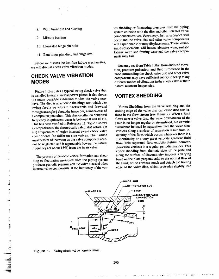
8. Worn hinge pin and bushing tex shedding or fluctuating pressures from the pipingsystem coincide with the disc and other internal valve
9. Missing bushing components Natural Frequency, then a resonance willoccur and the valve disc and other valve components
10. Elongated hinge pin holes will experience vibratory displacements. These vibrat-ing displacements will induce abrasive wear, surface
11. Bent hinge pin, disc, and hinge ann fatigue wear, and fretting wear and the valve compo-nents may fail,
Before we discuss the last five failure mechanisms,we will discuss check valve vibration modes. One may see from Table 1, that flow-induced vibra-
tion, pressure pulsation, and fluid turbulence in the
CHECK VALVE VIBRATION zonesurrounding the checkvalve disc andothervalvecomponents may have sufficient energy to set up many
MODES different modes of vibrations in the check valve at their
natural resonant frequencies.Figure 1 illustrates a typical swing check valve that
is installed in many nuclear power plants; it also shows VORTEX SHEDDINGthe many possible vibration modes the valve mayhave. The disc is attached to t/m binge arm which can
swing freely or vibrate backwards and forward Vortex Shedding from the valve seat ring and thethrough ataangle ¢ about the hinge pin, as in the case of trailing edge of the valve disc can cause disc oscilla-a compound pendulum. This disc oscillation or natural tions in the flow stream (see Figure 2). When a fluidfrequency in quiescent water is between 0 and 10 Hz. flows over a valve disc, the wake downstream of theThis has been verified in Reference 11. Table 1 shows plate is no longer regular or s_,_atnlined, but exhibitsa comparison of the theoretically calculated natural (in turbulence induced by separation from the valve disc.
: air) frequencies of major intemal swing check valve Vortices along a surface of separation result from in-components for different size valves. The "added stability of the flow, which occurs whenever there is amass" eft'ect of the water on the valve components can- discontinuity or a very great velocity gradient fluidnot be neglected and it appreciably lowers the natural flow. This separated flow exhibits distinct counter-frequency (or about 15%) from the in air value, clockwise, vortices in a regular, periodic manner. This
vortex shedding from alternate sides of the plate andThe process of periodic vortex formation and shed- along the surface of discontinuity imposes a varying
ding or fluctuating pressures from the piping system force on the plate perpendicular to the normal flow ofproduces periodic pressures on the valve disc and other the fluid; or the vortices attach and detach the Wailingintemal valve components. If the frequency of the vor- edge of the valve disc, which protrudes slightly into
2
=_ /- Ht,QsA..
_; / FANTI-ROTATION LUG,_.t.o. ,t. /- sro,\ / / /..--O,=C/=rUO/A,.
_ ---.. ILL.-. °°"°I_ BLEAT
_ Figure 1. Swing check valve nomenclature.
-=1 290
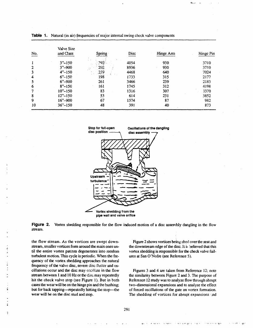
Table 1. Natural (in air) ,fxequencies of major intemal swing check valve components
Valve Size
No.__:. ,and Class S_p._fin__g Dis.__cc Hinge Arm Hinge Pin,,
', ' 7
1 Y'-- 150 ,)297./',, 4054 930 3710
2 3"-900 ;, '29y_ 8936 930 37.104"-150 , 2:_;9 4468 640 70243
4 6"-150 198 1733 315 21775 6"-900 261 3466 239 2183
6 8"-150 161 1745 312 4,1987 10"-150 83 1316 307 33708 12"-150 53 614 231 38529 16"--900 67 1574 87 98210 36--150 48 391 40 873
Stopforfull-open Oscillationsofthedangling
dlscposition----_ dlscassembly7
Uturbulence"_ _ _
--- ": I- "'-_'IL_ "-"--"'-- "-_!" -" --IF" -..--..--.__-_
pipewallandvslveorifice
Figure 2. Vortex sheddingresponsible for the flow inducedmotion of a disc assembly dangling in the flowstream,
=
the flow stream. As the vortices are swept down- Figure 2 shows voltioes being sh_,_over the seat arid=
sla'eam, smaller vortices form around the main ones un- the downstream edge of the disc. II i_,!xflieved that this
_, di the endre vortex paKem degenerates into random vortex shedding is responsible for the check valve fail-turbulent motion. This cycle is periodic. When the fie- ures at San O'Nofre (see Reterence 5).quency of the volaex shedding approaches the naturalfrequency oftbe valve disc, severe disc flutter and os-
-I cillations occur and the disc may o._cillate in the flow Figures 3 and 4 are taken from Reference 12; note_Z_ stream between I and 10 Hz or the disc; may repeatedly the similarity between Figure, 2 and 3. The purpose of
hit the check valve stop (see Figure 1). But in both Reference, 12 study was to analyze flow through abruptcases the wear will be on the hinge pin and the bushing; two--dimensional expansions and to analyze the effect
--; but for back tapping.--repeatedly hitting the stop---the of forced oscillations of the gate on vortex formation.wear will be on the disc stud and stop. The shedding of vortices for abrupt expansions ;,,hd
+:
291
......... I.... lliNP llIirllh li I_ _' '' .... irll, t_ ..... III.... ilii,I ,
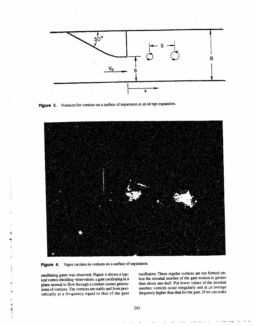
b
H ,m, , ,, i,i ................ , ,i, ....... % ' ' . U i I I ii iiii ii
L ..... __ _,
Figure 3. Notation for vortices on a surface of separation at an abrupt expansion.
::am
o Figure 4. Vapor cavities in vortices on a surface of.separation.=
_
_illadng gates was observed; Figure 4 shows a typ- oscillation. These regular vortices are not formed un-ical vortex shedding ,'_bservation: a gate oscillating in a less the strouhal number of the gate motion is greaterplane normal to flow through a conduit causes genera- than about one-.half_ For lower values of the strouhaltiotls of vortices. The vomces are stable and form peri- number, vORtiCeSoccur irregularly and at an averageodically at a fre;quency equal to that of the gate h-equency higl_r than that for the gate. If we can make
292
.... rlr TIll,,,, IIIi ',111_
the analogy between an oscillating check valve disc CONTROL VALVE AND ORIFICEand an oscillating gate, then the Reference 12 experi-ments would imply that check valve disc oscillations CAVITATIONare caused by vortex shedding.
Control valve and orifice cavitation and its effects
Figure 5 illustrates actual test data (plot of velocity on piping systems have induced cost of many millionsofdoUars to the utilities. For example, cavitation mayas a function of valve opening) for two different swing
check valves. Note the scatter of test data at valve limit the flow through the valve and thus the valve ts
openings of approximately 94 to 100% for the 16 in. undersized; cavitation may cause material damage tocheck valve. Note also, that when the valve disc moves valve parts, trim, or v,'dve body, or erodes dowmlream
from 94 to 100% opening the flow will change from piping and thus the valve or piping leaks; and cavita-3.5 to 9 fps which corresponds to an instantaneous tion may cause noise and vibration, which may causechangein velocity of 5.5 fps. This velocity change will major damage or destruction to equipment such asproduce a high pressure rise in the piping system; valve positioners, actuators, pipe supports and some-known as a water hammer wave, If the valve disc is times to other downstream control and check valves.
open 100%, but because of system flow perturbationsthe disc moves to tlm 94% open position, then the flow Cavitation is a two-stage phenomenon, but thewill change from 9 to 5.5 fps; this will also generate a mechanism by which it can be initiated in a controlwater hammer wave. If this process is repeated many valve oran orifice is best described by considering thetimes, the check valve will be tapping the back stop sequence of events as the pressure drop across a valveand wear will occtrr at the hinge pin and disc stop. This increases while the inlet pressure remains constant.valve is highly unstable, probably due to some vortex Consider the flow of cold water through a valve. Theshedding, maximum water velocity is at the minimum cross sec-
tion area known as the vena contracta, just downstreamfrom the valve orifice. As the pressure drop across the
HIGH VELOCITY THROUGH valveincreases, so doesthe flow rate and "alsothe wa-
THE VALVE SEAT ter velocity at the vena contracta. By BemoulIi's equa-tion, this causes a decrease in pressure at the venacontracta. As pressure drop increases, so does the flow
-: High velocity through the check valve may induce until the static pressure at the vena contracta is belowdisc tapping by allowing the disc to unseat from the the vapor pressure of the water. At this point, water va-backstop and then repeatedly impact the stop. This is podzation starts and vapor bubbles are produced.due to vortex shedding cavitation. Figure 6 shows ac-
tual test data for a 12 in. swing check valve; the figure In the second stage of cavitation, the water bubblesshows that incipient cavitation started at about 30 fps. move into a region where the existing pressure exceedsAt this flow rate the valve is only 80° open. Note that the water vapor pressure in a larger volume that is theit takes approximately 40 fps to actually or fully open downstream valve body or pipe. This allows the waterthe valve. For this valve, the upstream test pressure stream to decelerate and regain a portion or the lost
J
was 90 psig..The disc oscillation is due to downstream pressure. Since the vapor carmot exist at this higherpipe wall-pressure fluctuations Which are induced by pressure, the bubbles collapse into the liquids state,cavitation collapse. Pressure fluctuations due to cavi- and thus produce cavitation.tation may reach a maximum value of six time that of
non-cavitating flow. Further increase in pressure differential across thez
valve increases the number of water bubbles that col-
_- As an interesting example, one utility experienced lapse in the downstream side of the valve and produceseat damage and hinge pin wear due to low flows more cavitation. Eventually, a point is reached atthrough their check valves in the RHR system. After which any further increase of pressure differential does
-_ e_tensive engineering analysis and studies, they in- not increase flow, and the v',dve chokes; this point rep-
_. stalled new cheek valves with reduced port area to in- resents severe cavitation.crease the flow velocity to 25 fps; and thus, keep thedisc fully open. The new check valves also had mteg,ral Also, it is _:.ssentialto review supercavitation and itshinge ann and disc. But after eight months of opera- effect on valves and piping. When supercavitation tc-
lion, they found premature hinge pin wear. This disc curs, the valve and pil_ for several diameters down-= oscillation was due to vortex cavitation at high flow stream are completely filled with water vapor. When_. velocities; it also extended their outage, this happens,the valve and adjacent pipe may not be
293
lql[ ..... _I Igp ,,II_I,IIII ..... rf," ,lr....... ,..... ,,'npp'r,,,r,1"'_P',l....._,,,,, ,r,,_!pn'_,,,,_r',' rl'_ n'"_l'l_In'lllll"''IIUen'":HI'III_""'II'""IIIpai'I,?'I'I'' ,n, rli_ll,[ll:l!l]llll......
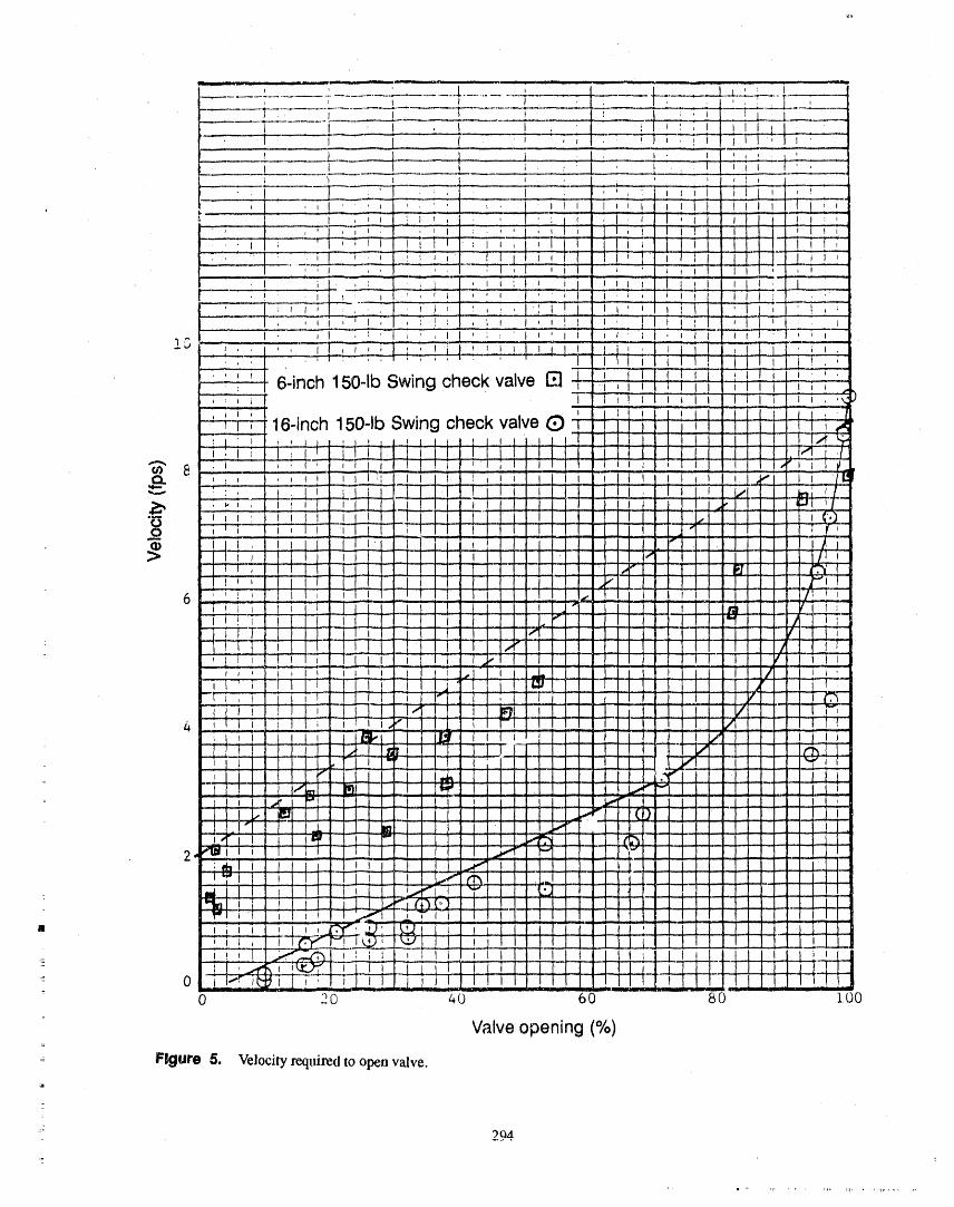
i i i i
I! i
pl ; I
0o 20 4o 6o +o loo
Valveopening(%)=
Figure 5. Velocityrequired to open valve.
_:: 294
li ,, ,I+ ' + ' ',, llnrl k r' '_F Pl"1'
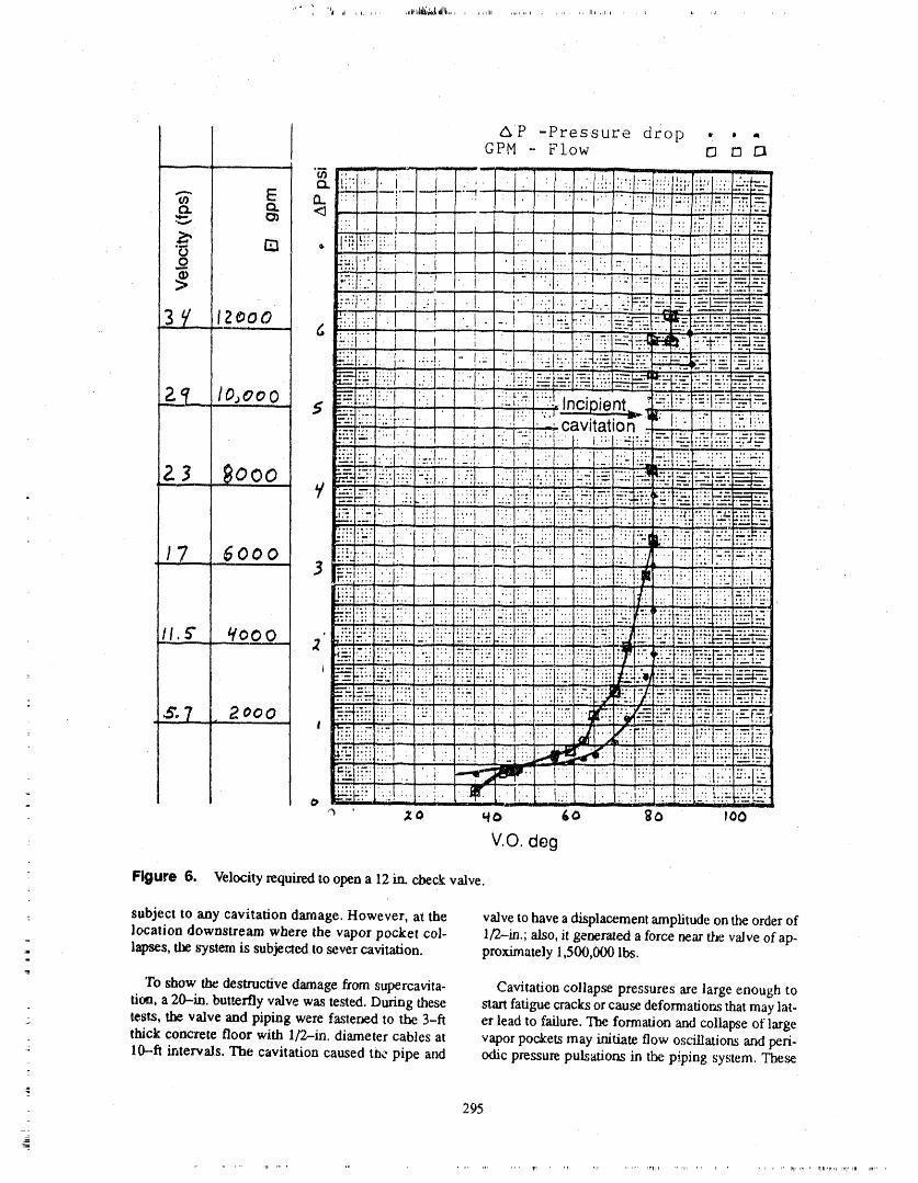
I _P -Pressure dzop • . .GPM - Flow [] /:3/:3
"'o,,, _ ,: _.....: J_ !/ •J:":r'!_:/"i'!r_iiil_i:_'-'.'I_-
F:....i;.,,.:_ii i!_,i' ' { i I
IF-_F..-._: I " " i i- _,I,.:I.:__.i:i-i.::._.r--.__:i!-__. __, ,,, j ....... i ....
' I,: .... :...._ _-...............;---'--_i-_-'_:-_i_-,.'_.l.-...'.!:"..I..:.-l-i-.l?,._"Z:--_--iii-L::--i-_.-i-_-': ::i::
1.2.,'_ l o,_,_o -_t{:i;l_:;t::'..1 / _P.:t_-4"..!i__:.-".l-_-_!!.:!,..incioient..'-_;t!#;..-;l%_.=-: '_cavitation-i I:: ;:.l.i:.:-,:!i'._
:_ ---_t:_-i!4...... "ii. 5" qooo :: :-:'ii_i;i:_::l!:!:i':!!li:_-i_lli!i::_:i_!iilii!_i_i:,.,_:: ::::.....:===:,-.-.-_-_..... , ...... ,;:.';. ,_._ u
"-'_l._T: :;2" i ;: :_:: :;:: ;:': ;"; ':': :':' ":: :':'i '": ;;;; -"_ '""'"_'
. - ......... I'" I......... I ..... , ....... _.... '-: :::' ':" E-
....... _'" ,,,. _ i "':';' ", :'_t::"L,_ --_ , ...... : ,.,,,,,,.,,,..,,,,..._
_ ' ::_. 1:_l;i: ' ' :_....i_:_,.:t.!,:.:.:,,: .tii__== ,:-:'. _:'.,-zr-:-'
- V.O. deg
Flgure 6. Velocityrequired to open a 12in. check valve.
: subject to any cavitation damage. However, at the valve to have a displacement amplitude on the order of: location downstream where the vapor pocket col- 1/2-m.; also, it generated a force near O._evalve of ap-,, lapses, the system is subjected to sever cavitation, proximately 1,500,000 lbs.
To show the destructive damage from supercavita- Cavitation collapse pressures are large enough totion, a 20--in. butterfly valve was tested. During these start fatiguecracks or cause deformations that may lat-
_. tests, the valve and piping were fastened tot he 3-ft er lead to failure. The formation and collapse of largethick concrete floor with 1/2-in. diameter cables at vapor pockets may initiate flow oscillations and peri-10--fl intervals. The cavitation caused tt_epipe and odic pressm¢ puls_ons in the piping system. These
g-_
295_

q
pressure pulsations may be tbrcing functions for pip- velocity of sound in water and tile elasticity of the pipe.ing vibrations and check valve disc oscillations (See The magnitude of the pressure rise depends on the rateTable 1 for the possible modes of vibrations). They of velocity reduction, the magnitude of the change inmay also set up acoustic resonances in the piping sys- velocity, and the velocity of wave propagation.tems and check valve parts.
The pressure wave (or series of pressure waves)For example, see INPO(SER1-84) for "Vibration travel upstream to the origin of pressure and are re-
Failures of Safety-Related Valves." This SER dis- flected from there back toward the point of flow re-cusses the following valve failures: striction. The pressure waves continue oscillating until
tile energy is dissipated by friction, pipe deflection, or
• Yoke had pulled away from bonnet in extreme cases, equipment destruction. Most expla-nations of water hammer involve the rapid closing of avalve, which indeed causes water hammer. However,
• Bent valve stems water hammer is caused by the rapid change in veloc,ity no matter what mechanism causes the rapid change.
• Valve disc separated from stem For example, an instantaneous change in velocity ofonly 9 fps for a 12,--in.schedule 80 steel pipe produces
• Loss of valve packing a pressure rise of approximately 522 psi. A pressurewave near this magnitude traveling at 4300 f-ps,hitting
• Cracked welds on saddle check valves and other pipe obstructions can bedamaging.
• Motor casting failedThrough the review of plant water hammer experi-
• Motor bolts sheared ences (see References 13, 14, 15, 16)seven severemechanisms have been identified, these are:
• Stern key was sheared, i. Condensation collapse in steam pipe after ini-tially injecting steam inl:o subcooled water
Ali of the above problems are due to control valve (water cannon).cavitation (Reference 17).
2. Steam and subcooled water interactions in
But more recently, NRC issued "Information Notice horizontal and near horizontal pipes.No. 89--01" Valve Body Erosion." This also is a cavita-
tion problem. 3. Subcooled water flow into a vertical initiallysteamfilled pipe.
As one can see from the above, cavitation induced
problems are not only dangerous, but also costly. 4. Hot water entering lower pressure line with=
: subsequent flashed steam bubble collapse.In conclusion, control valve and orifice cavitation
induced pipe vibrations may be responsible for some 5, Steam propelled water slug flow.of the reported check valve failures. Therefore, it isrecommended, that ',tilcheck valves downstream from 6. Rapid valve operation.cavitating valves and orifices should be inspected. One
- should not use Criteria 1 and 2 of the Introduction of 7. Water column separation and rejoiningthis paper for selecting check valves for inspection.
Wilkinson made a survey of water hammer inci-
WATER HAMMER IN PIPING den=(Reference 15) he t'oui_J35 casesof failure, ofwhich about 30 were gate valves. He also made a sur-
SYSTEMS vey of American Nuclear Power Stauoi_s'" water ham-mer incidents (See Table 2). Also, Reference 14 has
Water hammer is caused by the sudden change in re- documented 281 water hammer events.- locity of water. The kinetic exrergy of the moving water- is transformed imo pressure energy. At the point of What can be concluded from the above water ham-
sudden velocity destruction, a pressure wave (or a se- mer experiences is that, so_e of the water hammerries of pressure waves) is generated and travels up- events are responsible for check valve disc f,'filures; for2
stream at a very high velocity that depends upon the example, bent hinge pin_ _sc, and hinge arm.
296,li

Table 2. Water hammer incidents in nuclear stations
Site Ty._..____ Fault location Assumed cause Damage etc.
Indian Point PWR 450 mm leed pipe, Water slug propelled Fracture of pipe,19 mm wall by steam followed drop water loss,thickness in water level after a flooding, damage
trip to containment
San Onofre PWR Feed? Lack of venting? Hangers damaged,fotlowed a trip due to safety injectionLP blade failure valve actuation
failure
Ginna PWR Feed Valve plug broke and Pipe supportsshut off flow damaged
Dresden 2 BWR Steam line to Water slug on re- Broken pipeECCS turbine instatement after supports damaged
maintenance and trip snubbers and pipe
Quad Cities 1 BWR CW system Sudden closure of Burst rubber pipe2540 mm butterfly valve joint. Flooding
caused damage to17 pumps
Beznau PWR Hammer in steam Debris in feed valve m
line causing boiler flooding
Dresden 3 BWR Feed Sudden partial feed Pipe supports" valve closure, damaged, control
cause unknown lines broken
Nine Mile BWR -- Lack of venting andPoint condensate drainage
Palisades PWR -- -- Seismic piperestraint failed
BWR ECCS Lines empty on pump 62 mm movement ofstart header. Minor
damage
BWR Residual heat Inadequate venting Pipe supportsremoval system damaged valve
actuator failed
- Fitzpatrick BWR Service water Lines not full on Pipe damagesystem pump startup supports broken
Cook I PWR. Feed -- Hydraulic-" snubbers damaged
Browns Ferry BWR Turbine steam line -- Components damaged
Tihange PWR Feed Water slug following Nonedrop in water level
297
iii1|1 ,_lr , rill , ql 'lii i(_ -¢lVm , ,li , ', rl ,lr,'l " i,i , _ , ,, ,,,1'_ , (i
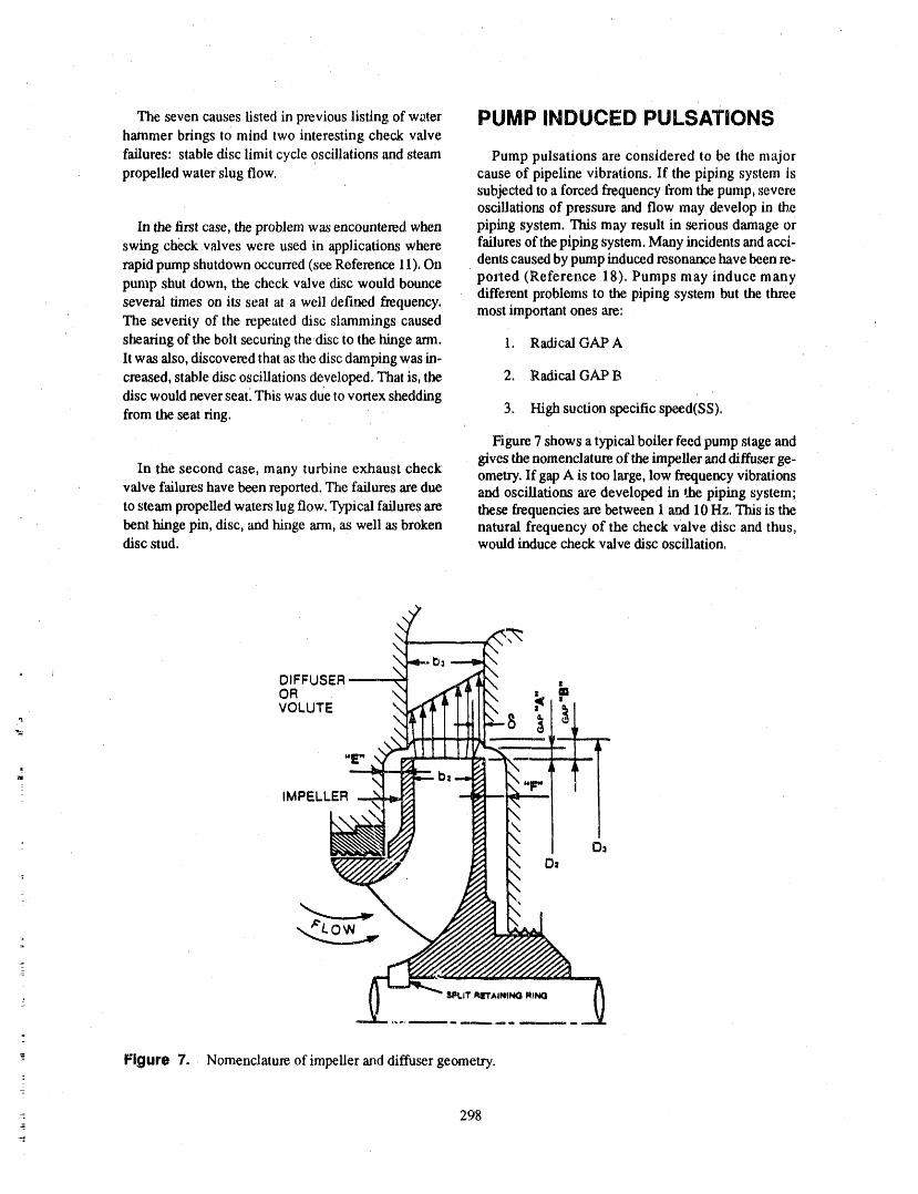
The seven causes listed in previous listing of w_ter PUMP INDUCED PULSATIONShammer brings to mind two interesting check valve
failures: stable disc limit cycle oscillations and steam Pump pulsations are considered to be the majorpropelled water slug flow. cause of pipeline vibrations. If the piping system is
subjected to a forced frequency from the pump, severeoscillations of pressure and flow may develop in the
In the first case, the problem was encountered when piping system. This may result in serious damage or
swing check valves were used in applications where failures of the piping system. Many incidents mid acci-rapid pump shutdown occurred (see Reference 11), On dents caused by pump reduced resonance have been re-
pump shut down, the check valve disc would bounce ported (Reference 18). Pumps may induce manydifferent problems to the piping system but the three
several times on its seat at a well defined frequency, most important ones are:The severity of the repeated disc slammings caused
shearing of the bolt securing thedisc to the hinge ann. 1. Radical GAP Alt was also, discovered that as the disc damping was in-
creased, stable disc oscillations developed. That is, the 2. Radical GAP Bdisc would never seat. This was due to vortex shedding
from the seat ring. 3. High suction specific speed(SS).
Figure 7 shows a typical boiler feed pump stage andgives the nomenclature of the impeller and diffuser ge-
In the second case, many turbine exhaust check ometry. If gap A is too large, low frequency vibrationsvalve failures have been reported. The failures are due and oscillations axe developed in _ piping system;to steam pmpeUed waters lug flow. Typical failures are these frequencies are between 1 and 10 Hz. This is thebenl hinge pin, disc, and hinge ann, as well as broken natural frequency of the check Valve disc and thus,disc stud. would induce check valve disc oscillation.

If gap B is too small, a strong shock is generated these pumps. This flow instability will increase as tileeach time that an impeller vane passes a diffuser vane flc'u decreases below design flow, For trLissame prob-inlet or, in a volute type pump, a volute tongue. The lena, NRC issued Bulletin 88-04, The above points
distinct frequency of this pressure shock is equal to the have been the subject of an excellent discussion bypump rpm thnes the number of impeller vanes. For a Dr, Makay (Reference 18-20),
6--vane impeller operating at 5409 rpm, the vane pass- , :ing frequency is 540 Hz. This frequency may very eas-ily interact with one of the check valve modes (see As a second example, becausecheck valves, control'Fable 1) and thus, would resonate the check valve to valves, and actuator components downstream of thedestruction, boiler pump extraction piping were failing, which re-
quired extensive maintenance, an analysis was per-formed. Measurements showed that fluid pressure
As an example, Figure 8 shows a GAP A and pulsations were the probable driving mechanism forGAP B hydraulically induced instability, Note the the mechanical vibrations observed on the extraction
peak to peak pressure pulsations of up to 150 psi. lines of the pumps. The vibrations were generated byThese pressure pulsations may be destructive to any the interaction of high pressure pulsations within thecheck valve downstream of rids pump. GAP A and B fluid and mechanical resonances in the piping. Themodification corrected the problem, pressure pulsations originated at the interstage dis-
charge of the boiler feedwater pumps and were in-Impellers with high suction specific speed (higher duced by the blade passage of the pump's third stage
" than 10,000) induce hydraulic instabilities in the pip- impeller, Analysis showed that the pulsations could being system; flow oscillation between 1-10 Hz. This reduced by installing hydraulic acoustic filters in thepressure oscillation would also induce check valve extraction line of each pump; and Figure 10 shows thedisc oscillation, Figure 9 shows the operating range of results.
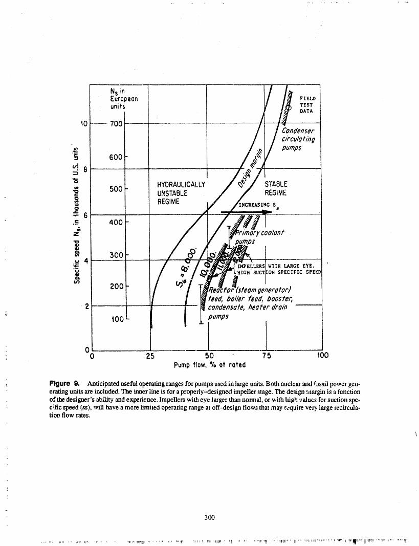
00 25 50 75 100
Pump flow, % of rated
Figure g. Anticipateduseful operatingrangesforpumpsusedin large units.Both nucleaz'and fossil powergen-eratingunits are included. The inner line is fora properly--designedimpellerstage. The design :aargin is a functionof the designer's ability and experience. Impellerswith eye largerthan normal, orwith hilz_,values forsuction spe-c[fic speed (_), will have a more limited operatingrange atoff-design flows that may r,_quirevery large recircula-ti_. flow rates.
30O
,_,,,r,,_qlltlIllrrqr...... lr',, W=,llpl'' 'r,l_,' rill "llllll;_'' nlr_I ,r,,,l_,_,qlI, '"'"' 'Hlrl'II''''''' 1II......rllrl,I,,_,,,,,,,r,,,,I,_'=,,,r ,,_l'mMIW,r'"'l'llri'_rll'",l=..... i1,,,i,=,, '_"''I'11,'
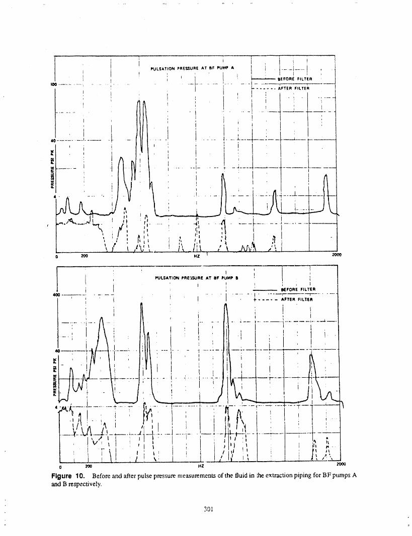
i I _ i i !I IIIU L_AT ION PRIE'_;;_URE AT _ I: II'U{It_iP A l i_ ........ !e..... i ¸
! ; ! ' uEFO._FI_TF,R
,oo............ ........................; 1......... L....... iF.RF,_.,! : i
i: z
40 ........... J........... ; .l
, ._.,_L;._. I
o 2tR " HZ _ " 2O0O
I q T lPULSATION I*RE';SURE AT BF PUMP B ' / . I
I ! I , , IBEFORE FILTER
....... I.... _. ' _.........400 _ .... I .... AFTER FILTER
I
--;- r ....... i
C,u ", !v _! _ , ! , ,
__L__L____'._,' ' / I, _ ________....__ ! I ', _...._ ___.___,___0 200 HZ _00
Figure 10. Before and after pulse pressure measurements of the.fluid in _ extraction piping for BF pumps Aand B respectively.

CASE HISTORY TO cessivewear,andcorrosion.Figures13to16showtypical damagefound. Interestingly therewasnohinge
ILLUSTRATE THE PROBLEMS pi_v,,e_ (see Figure 16).
The check valve installation can be seen in (Fig-The pump discharge through discharge valve con-
figmation is shown in Figure 11 and a typical installed ure 11 to 12) and consists of an 8--in. check valve withinlet of a 4 x 8 reducer and a 4 in. elbow. The mini-check valve is shown in Figure 12. The diesel genera-mum velocity through the Dresden check valves was 7tor trip events of October 23 ._nd November 19 oc-
curred due to high generat_r cooling jacket fps while through the Quad Cities it was 12 fps. Failuretemperature, indicating that there was insufficient of these check valves was probably due to threecooling flow to the diesel generator heat exchanger factors:from the diesel g_aerator cooling water pumps. Thecooling water pump discharge check valves were dis- 1, Possible low flow velocity through the valveassembled and found damaged, The valve discs had which induced valve disc shamming againstbecome disconnected and lodged in the valve the backstop.discharge.
2. Pump start up water hammer induced by
Because of the above problem, six swing check pumping water into a voided pipe line; thisvalves in the di.scharge side of the DGCWP system would induce disc slamming against thewere inspected; three from Dresden and three from backstop. Figure 14 shows the washerQuad Cities. Ali six check valves had failed. The partially bent.valves were 8-in. swing check valves mounted hori-zontaUy. The failures involved broken hinge arms, ex- 3. Possible pump instabiihy problems.
Diesel Jacke_Cooling Water /_
5 ft. above , 36-inch Effluent Collector Line[ Hx CL !
cn___] :
I t •El I to2 _ inch !reducer
Heat !i Exchanger _#7 + To Discharge Canal
-
eh 1-._ Crib Housereducer
[ 8 X 4 inch reducer
- , 'I Check _._._/l Valye LJPumpi
Figure 11. Diesel generator cooling water system.
302
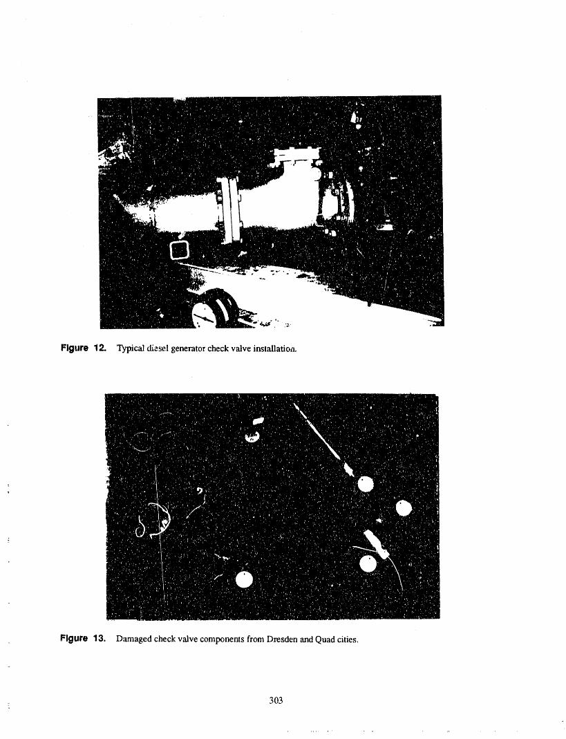
Figure 12. Typical diesel generator check v,'dve installatioa.
Figure 13. Damaged check v,'dve components from Dresden and Quad cities.
: 303
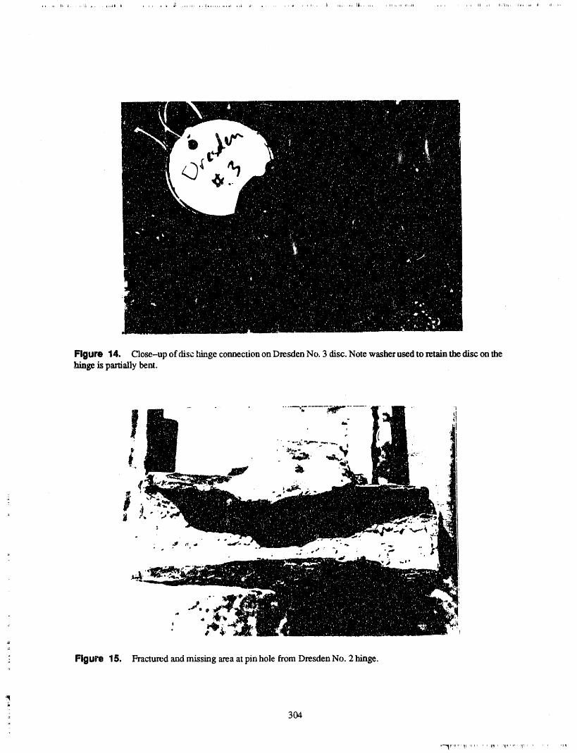
Figure 14. Close-up of disc tfinge connection on Dresden No. 3 disc. Note washer used to retain the disc on thehinge kspartially bent.
, t
,j
" Figure 15. Fractured and missing area at pin hole from Dresden No. 2 hinge.
304
*-_r,_r,,r*r_t ,_,rt, ' ' rtp' '11"'"' I'1_.....
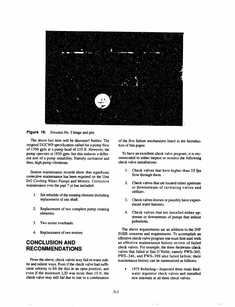
Figure 16. Dresden No. 3 hinge and pin.
The above last item will be discussed fimher. The of the five failure mechanisms listed in the Introduc-
original DGCWP specification called for a pump flow lion of this paper.of 1304 gpm at a pump head of 210 ft. However, thepump operates at 1850 gpm, but this induces a differ- To have an excellent check valve progrmn, it is rec-ent sort of a pump instability. Namely cavitation and ommended to either inspect or monitor the followingthus, high pump vibrations, check valve installations:
1. Check valves that have higher than 25 fpsStation maintenance records show that significant flow through them.corrective maintenance has been required on the Unit
DG Cooling Water Pumps and Motors. Corrective 2. Check v',dves that are located either upstreammaintenance over the past 7 Tr has included: or downstream of cavitating valves and
orifices.1. Six rebuilds of the rotating element including
replacement of one shaft. 3. Check valves known or possibly have experi-enced water hammer.
2. Replace, meat of two complete pump rotatingelements. 4. Check valves that are installed either up-
stream or downstream of pumps that induce
3. Two motor overhauls, pulsations.
The above requirements are. an addition to the INP4. Replacement of two motors. SOER concerns and requirements. To accomplish an
effective check valve program one must first start withCONCLUSION AND an effective maintenance history review of failed
RECOMMENDATIONS check valves. For example, the three feedwater checkvalves that failed at San O'Nofre, namely FWS-345,FWS-346, and FWS-398 also failed before; their
From the above, check valves may fail in many sub- maintenance history can be summarized as follows:tie and sal/ent ways. Even if the check valve had suffi-
cient velocity to lift the disc in an open position, and ® 1975 Refueting--lnspectcxt three main feed-even if the minimum L/D was more than 10 ft, the water regulator check valves and installedcheck valve may still fail due to one or a combination new internals in ",illthree check valves.
365

• 1977 Refueling--Inspected and installed new tions, Presented at INPO Check Valve Work-internals in all three check valves, shop, October 1986.
• 1978 Refueling--Inspecled ali three check 10. D.S. Weaver and EA. Adubi, "Flow Visual-valves, found no problems, cleaned parts, and ization Studies of Check Valve Vibrations,"
Proceedings of the Fourth Biennial Sympo-reassembled valves, sium on Turbulence in Liquids, Science Press,
Princeton, New Jersey, 1975.• 1980 Refueling--Inspected "ali three check
valves, replaced cotter pins, washers ",rodnuts 11. D.S. Weaver and F.A. Adubi, "Flow Induced
on flappers, and reassembled. Vibrations of a Hydraulic Valve and TheirEliminations," Journal of Fluids Engineer-
REFERENCES ing,Transactionsof theASME, Vol 100,June1978.
1. Application Guidelines for Check Valves inNuclear Power Plants, EPRI NP.-5479, Elec- 12. D.W. Appel and C.L. Sanford, "A Study oftric Power Research Institute, Palo Alto, CA, Flow Through Abrupt Two Dimensional Ex-
January 1988. pansions," Stud. in Eng. Mech., Rep.7, U. of•Kansas. 1961.
2. Prediction of Check Valve Perfommnce and
Degradation in Nuclear Power Plant Systems, 13. "Workshop on Water Hammer in NuclearNUREG/CR-5159, Nuclear Regulatory Power Plants," EPRI conducted at Boston,
Commission, Washington, D.C., April 1988. July 9th and 10rh, 1986.
3. "Check Valve Failures or Degradation," Sig- 14. "Water Hammer Prevention, .Mitigation, andnificant Operating Experience Report Accommodation Task 1 Plant Water Hamm_r(SOER), No.86--3, October 1986. Experience," Research Project 2856 3.
15. D.H. W'dkinsz)n;' .'Water Hammer Phenomena4. INPO Workshop on Check Valves, October in Thermal Power Station Feed Water Sys-
1986. tems," Proc. Inst. Mech. Engrs., Vol. ]94.
5. C. Chiu and M.S. Kalsi, "Failure Analysis of 16. R. Uffer, "Nuclear Plant Water Hammer-Swing Check Valves San Onofre Nuclear Current Status," AS/vIE, 87-PUP-17.Generation Site- Unit 1," NRC Docket
No.50-206, April 1986. 17. '*Power Plant Valves Symposium," EPRI,Conducted at Kansas City, Missouri,
6. C. Cb.iu and M.S. Kalsi, "Plant Availability August 1987.Improvement by Eliminating Disc Vibrations
! in Swing Check Valves," ASME Paper 18. E. Makay and J.A. Barrett, "Changes in Hy-No.86-JPGC-NE,-6, October 1986. draulic Component Geometries Gready In-
creased Power Plant Availability and7. J.E. Sununu, "Wear in Check Valves Due to Reduced Maintenance Cost; Case Histories,"
Flow Induced Motion," M.S. Thesis, Massa- F'trst International Pump Symposium, Texaschusetts Institute of Technology, May 1987. A & M University, May 1984.
8. J.A. Statton, Modification Based on Stability 19. E. Makay and J.A. Barrett, "Field Experienceand Wear Studies, presented at INPO Check Brings Help to Embattled Pump Users,"
Valve Workshop, October 1986. Power, July 1987.
9. W_.I.Rahmeyer, Application .,y'Check Valves 20. E. Makay, "Eliminating Pump Stability Prob-with Unsteady and Nonunifo.rm Flow Condi- iems," Power, July 1970.
-- 306
ATTENDEE- PANEL QUESTIONS AND ANSWERS(EDITED; ATTENDEE QUESTIONS AND PANEL/AUTHOR
RESPONSES NOT IDENTIFIED BY NAME)
Comment I I spoke with Weaver. He did an analysis for an actu',dinstallation. And if you use dampers, he says how the
we are having problems with feedwater check valves, valve manufacturers perceive the dampers incorrectly,back leakage problems, lt seems to be a genericproblem.
Limit cycling on a high energy bumping system mayIn my paper I referenced Weaver's work. in Canada. He explain some of the. back leakage problems and alsocalls it limit cycling. If the check valve is shut down, it any cracks on your disc. The. type of damage is dis-will go into the seat and oscillate, cussed in my paper. But that is an interesting point
because we are having problems with the feedwaterSometimes it will just go limit cycling, that is open in system check valves, back leakage, high energy_the seat a:xl come back in four or five degrees, something worth looking at.
307
=1='"II1 .,rn " ,v, , ,r','mrqn'_,'" h,,lP"ln _r,'ipp-''I "
PANEL DISCUSSION: IST OF VALVES; EXPERIENCEAND LESSONS LEARNED
T. SULLIVAN(MODERATOR), O. ROTHBERG, S..MCLEAN,J. H/GGINS, J. OZOL, J. WITHERSPOON
Question I (Relationship Between Butofcourse,aproblemwiththatiscomingupwithanGL 89-10 and GL 89-04) accepted criteriafor signatureanalysis. I am not sure
that therereally is an alternative at this point, and I'" don'tknow ff thereis an alternativeforAOVs.
Please discuss therelationshipbetween the MOV ge-
nodelettezandGenericLetter89-04.Are theyclosely Question 3 (Check Valve Inspection)tiedtogether, or aretheyindependent?
Can we say, at this time, whether there is any case of,Resporlse 11 check valves which havebeen inspected,whichdid not
need to be inspected?
It is an administrativenightmare.They were obviously Response 3conceived independently, As I understand 89-04, itdeals with the ASME Code testing. 89-10 deals pri.marily with a specific problem that we have with Wehave not seen that in our research for the paper,normotor--operat_ valves.Right now I am hesitating be- is there enough industry experience on a particularcause I seea lot ofproblems. Potentially,it maynot be class or application.However, the NIC group indicateda good idea to stroke testmotor--operated valves peri- that they may accumulate that kind of information toodieally. TheASME Codesaysyou should. Wewrote disseminate it to the utilities.the generic letter assuming that the stroke timing testswouldcontinue.The Germansdon'tparticularlycare Commentfor the stroke timing test,But theGermans usea lot of
"self-lubricating materials." I would just like to add, thatif it works,don't fix it. Butto apply fllat, we do have to gather initial data.
Youhave this administrative problem. 89--04 is asso-ciated with the ASME Code,andtheASME Codeis Question4 (CheckValveInspection)mandawxlby10CFR 50.55,andthereb a problemof
compliance. Whereas, 89-10 is driven by a fact of life, Could we clarify whether there isn't enough informa-a problem we have with motor-operated valves. So I tion because the data doesn't exist orbecause they aredon't know that there is a conflict. I know that I would
finding problemswith every application that they looklike to see the actions done that 89-10 talks about, into?
Question 2 (Alternatives to Stroke Response 4Testing)
our researchdidnot cometoaconclusionon that.We
Conceptually,what would be an alternative to the ox- didn't specifically look for it. So now, Iwill talk aboutisting standard,which might improve stroke time test- our personal knowledge on the subject. Disassembliesing for MOVs and AOVs? have _metimes indicated problems, sometimes they
have not. Whether there is enough information on apartictflar class or design or application to take a ge-
Respontm 2 neric relief request, I do not know that knowledge isavailable today, although it maybe.
As I stated,I amnot surethat stroketimetestingis ap- Commentpropriate for electric motor-operated valves orsolenoid-operated valves. An alternative might be to
derive a stroke time out of a signature analysis for I want to mention something about disassembly ofvalves, valves. The valve manufacturers indicate that if there
309
is a problem with a particular valve, maintenance re- Response 6 ....cords will show a repeat problem.
If I implied that disassembly was the only method of
If we consult maintenance records, we may be able to verifying proper function of the check valve, I did nottake valves off our Program. For example, the valve mean to imply that. The Code says that full flow test-that failed at San Onofre had no lifting force. The disc ing is the method to test check valves, Disassemblywas ali the way horizontal. But many people use the and inspection mc Ferf_,,-'rnediffuU flowtesting cannotsame type of valve in power service. That valve had be performed.had no problems whatsoever. Looking at the mainte-nance records closely, if you eliminate ali of your re- The other part of the question is, "Are other non-cutting problems, then youcan cut back the frequency invasive methods acceptable and useful?" Some utili-of inspection. And incidentally,in San Onofre case, ties now utilize non-intrusive methods. I don't knowthey took 48 valves apart after the five failures and of any particular non-intrusive method that is widelyfound no problems with the 48 valves. Other stations accepted, although the NIC group is evaluating that.have disassembled many valves and found no prob- Their charter includes the evaluation of the currentlems with them. non-intrusive methods.
The next part of the question is, "If no problems areQuestion 5 (Vortex Shedding on Check foundandsystemparametersdonotchange, canfutureValves) inspections be eliminated?" You have to live to the
Code. You can use that as a basis for a relief request.Generic Letter 89--04has specific instructions as to the
If a check valve is properly and fully back seated, does inspection interval and frequency.vortex shedding present a problem with di_ oscilla-
tion? Is your answer based on actual field results and Commentobservations?
Panelist Disassembly can be utilized only when fullResponse 5 flow, i.e., full stroke, testing can not be performed.
Panelist We need to distinguish between testing andI'll give you an interesting story that really happened maintenance. I think disassembly is basically a mainte-in a power station. The original problem was a worn- nance procedure, and I think this presentation con-down mainpin. There was not enough minimal veloc- cerned taking valves apart for different purposes. Butity, so the disc was oscillating. The personnel put in a in either case disassembly is basically a maintenancenew valve arid reduced the port. Now there was high procedure that we are following, albeit a disassemblyvelocity through the valve. The valve had a 25-feet- for the generic letter purposes where the valve isper-second maximum velocity. The pin was worn stroked manually, lt is really not a test.down, andthat definitely was bom a vortex. If the disc
is stuck further and further in the stream, a different Weneed to get the most out of testing we can, whetherson of vortexing occurs. I have seen this from other it is partial or full flow.I also think that, whether or notdissertation work. Perhaps acousLicscould distinguish a full flow test can be done, valves needto be looked atthis vortex. I believe that we could use acoustics to internally on some occasions. The best way to find outpick up the sound, what the condition of the valve is to take it apart.
Question 6 (Cheek Valve Disassembly) Different things are going on here. Weneed tobe clearabout testing for operability purposes versus mainte-nance, to tell what is going on inside the valve.
Oneof thespeakersimpliedthattheonly wayto prop- Question7 (CheckValveDisassembly)¢rly determine that check valves function properly isdisassembly. Are non-invasive methods acceptableand useful? If no problems are found and system pa- Wc,uld inspection procedures for a check valve be dif-rametersdo not change,can future inspections be elim- ferent for a valve that is normally open during opera-thaW.xi?If not, what are your reasons? tion versus one that is normally closed?
310

Response7 But you will not detect erosion/corrosion problemsand minor wear of the valve by full flow test. The re-suits of further inspections and the literature indicate
No, the disas._embly procedure simply identifies a that the best way to test a check valve is seat leakagevisual inspection of the valve. I don't see that you test. For example, if the disc shimmies, it will wearoffwould differentiate a procedure between whether the one side. Then if it catches, it will drop a little bit. Andvalve was in a normally open or normally closed the valve does not pass the seat leakage test, the testposition, will pick up something. Look at each individual valve
design. Now, incidentally, Commonwealth EdisonQuestion 8 (Check Valve Disassembly) contractedanarchitectengineertodoa Europeansur-
vey on check valves. Wedid the survey in the Germanway. The Germans have a dedicated team of people
It appears that check valve disassembly and inspection that ge out and take valves apart periodically to lookatprovide some information that cannot be determined them and replace ali the parts.by non- intrusive testing, such as the existence of
valve component corrosion, erosion, wear, chatter, If there is a chronic problem with a check valve, theymisalignment, and general mechanical integrity, will install a larger check valve than line size. PerhapsShould this testing be performed on ali check valves one of the reasons is water hammer, because the wavesperiodically, or are the disadvantages and costs too are slowed down. They have a dedicated group of peo-great? pie who know what to do and how to do it. I know it is
quite costly, but it seems to work for them. In my opin-Response 8 ion, the seat leakage test is number one, and next
would be flow testing. With these, you will pick upperhaps 50 percent of the problems.
Some utilities have performed an application review
similar to the EPRI application guideline for the check Comrl'lentvalves in their program. As a result of that review,those valves that indicate a potential problem areadded to the disassembly and inspection list. That Panelist It sounds like there are two diverse issueseliminates the need to go in and look at every check here. One would be check valve reliability. Youmaybevalve. The review identifies only the potentialproblem evaluating it in accordance with the SeER 86--03orancheck valves. EPRI application guideline review. And, then the re-
quirements for testing from ASME Section XI.Section XI wouldn't endorse necessarily ali the re-
Comment 8 quirements of an application review....
Panelist I'd agree that you do not want to overtask There are two things to look for in disassembly,check valve reliability and testing requirements forthe system by including valvesrandom;y into the pro- Section XI.
gram, because disassembly is certainly costly, as men-tioned in the question. Again, if the"e is r,o method totestvia full flow, you woulddisassemble.O_ona case Question9 (FlowTestat CheckValves)by case basis, if the utility identifies valves that havehad repeat failures and chooses to investigate them It was just mentioned that you may be able to pick upthrough disassembly, that may be aI_propriate.But you 50percent of the problems doing flow testing. I wouldcertainly would not want to add any great number of like more information about the parameters measuredvalves into the program, and the problems that can be found i:y flow testing.
Panelist Let's saythat I takea valve,I donotknow Response9itscondition,andI flowtestit. Andif I donotknowthepositionindication,I getmy full flow throughit, al- Yes,that is a toughone.Thereasonis that it hastodothough the valve may be open only 60 percent.What if with the gain. For example, in a high gain valve, thethe valve has been damaged previously. Youweald not steep curve, if the pinwears down just a little bit, it willpick that up. Now, if it is a linearcheck valve where the drop and suddenly increase or decrease the flow. ThisCv is proportional, a full flow test would go "alithe way is in normal operation. The valve is working, but itup and the valve should reseat. Youcould say that you may be affecting your system hydraulically. The plantmay infer something from it. people pick up a vibration problem, perhaps a
311
i
damaged snubberor something else. If this valve is and stuck in the line. We don't know how long thoseflow checked, what will it tell you? It is going to tell valves were stuckin the line.you that the disc swings up and down, goes open,closed, and passes flow through it. However, a flow Weran the system anditworked.It is an interestingex-check does notpickup thatthepin is worn down a little ample. The only time you worry is if you lose a diskbiL that may block the line.
Now, the next question is, how far can the pin wear I know one fossil station that lost a disk. Itjimmied indown? We really don't know. Youwould have to do a an elbow and restrictedflow to such a degree that itstress and strain analysis on the pin. In fossil stations, was cavitating the elbow. 'I_e fitters went by and said,I have seen valves damaged badly and chewed to something is wrong, ali this noise coming from the el-pieces, madthey back leak once ina while but, they run bow. The next outage, they cut the line out and found athe system, check valve disk, there. And the system was running.
So it is not intuitive. But if you do a full flow test, you
Now, what is interesting about a fossil station is that can say the system works, but it does not necessarilytheir systems have much more energy than a nuclear follow. Then you can say perhapsyou have no m_orstation, lt seems to work. If the valve is leaking, or if a damage to your valve. So we should do some tests.problem is found they just replace the whole valve. How much damage can a check valve lake before it is
picked up? This is a problem of experimenting.
But I havenot seen any correlation. The physical ques-tion is, what can you get by flow testing?What does it The only people I know in the United States doing
work like this are Professors TuUis and Rameyer attell you? If you do not get your full flow through, youhave a problem. The valve is stuck somehow. The Utah State, Professor Martin at Georgia Tech, and avalve could be stuck in the body. My opinion is to use professor at MIT.seat leak tests. Those are excellent. It is hard toimagine a seat leak test not picking up a problem. But What we should do is fund research to use a damagedfor corrosion or erosion, the only way you would find valve, run full flow through, and see what happens, ltthat is to take the valve apart and look at it. would probably run a few million dollars, which in a
country of our size should be no problem, lt would bea worthy experiment, lt would settle the issue. That is
QuestionI0 (FlowTestof CheckValves) the whole point.
Wetalk in theregulatoryarenaaboutpartial flow test- Question11 (Flow Test of Check Valves)ingandfull flow testing.I wonderif youcancomment
on what you see to be the value of either oneor both of Can you tell me _v probability of a valve that is par-them? tinilyopen going to the full _pen position? Is thereany
estimate of that?Do you get anything that is really worthwhile from go-
ing to the extratroubleto do a full flow test asopposed Response 11to a partial flow test?
Response 10 Panelist I would say from my experience, if a valve= passes a partial flow test, it will pass the full flow test.
The best way to know is through a flow gain curve, but: We know that if you do a full flow test, the valve will those are hard to come by. Then you can get the Cvand
do what it is supposedto do, which means passing the put a pressure gauge across it. You can actually calcu-flow needed for emergency conditions. That is late it accurately.guaranteed. And we should do those tests. Now weknow our system is functioning properly,and that is But we do not have flow testing. Most of the checkwhatwe are alter. If we can put the full flow through a valve manufacturers do not flow test their valves.
= p_ly damaged valve, we have satisfied the ,safetyconditions. But when you counter-phrase the question asking can
I guarantee the valve is not damaged, I am saying thereMany times these valves will work even though they are some situations where it may be damaged and passare damaged, Such as San Onofre's case, or the a flow test. But I am saying also that the damage mightDresden problem, where the disks were sheared off be minor, but could ruin the system.
312
Paneilltit So )ou are saying thin you get some assur- We have asked industaywhat they use to look at checkance, but it is 5:21no: a substitute for making sure by valve__underreal time radiography.Only two compan-an actual test that it ca,apass the design flow? ies have said they have done any of this testing. One
response was f,'-in Pacific Gas & Electric, Their re-Panelll_ Right. suits have been favorable. The cost of this particular
,t),peof testing would probably be morethan any utilityComment would spend. The particular mc_hodthat we evaluated
shows some good promise, though it is beyond the
Attendl_ Before, we.decide to disassemble a check scope of one utility using it, unlessit is one application,because of cost.
vM,,e, often we acoustically monitor it to see if'we candetemline if the pm is rattling or there is any tapping,anythingof thatnat_e. And whateverwe detectwill Question14 (RadlographlngValves)gointomakingthedecisionof wh_therornotweoughtto disas.ee.xnblethe che,:kvalw_.. What power supply are you working with?
Question 12 (Radiographlng.Valves) Response 14
Is there any evidence tha_ adiogr_phing_valve can beuseful in assessing i,.scondition or position? They told us that it would probably take 4 kV.Gae par-
ticularcompany told us it maytake up to4 kV for them
Response 12 to beable to read a 16-inch tilting disc check valve. Ithink we weretalking to themabout a 160-pound valve.
At Pacific Gas & Electric we have done some radio- A committee called the Non-Intn_sive Examinationgraphic examinations of check valves and have fairly Committee went out to ali non-intrt:sive vendors, in-successfully determined the internal conditions of
, eluding Real " macRadiography, and obtained this in-those valves. That is, we have le,en able to observe the formation, l_'youcome to our meeting in August, thereconfigurations of the nuts on some of the valves and will be sometalk about that, what we rec_,ivedfrom thethe position of thediscs on those. And Ithink it is a rea- vendors, and other information available.sortable effort if you do it properly.
Question 13 (Radlographlng V_l,ms) Comment
Haveyou beenable todo that kindof examinadon with We haven't radiogr_phed check valves, per se, butweflow through the valve? have radiographed some small valves to determine
valve position with excellent results, We had no prob-Response 13 lem at ali seeing the disc position.
Theseradiographic examinations were conducted with So, I think th_ ,samething would work.flow in the valve with the disc full back seated. There
could be distortion in the flow stream,andwiggling of Question 15 (Oversize Check Valves)the di_ itself that will blur the geometry of the discand nut assembly. But if it is fully b_ackseated againstthe valve, you can get some good indications of the The impression was given during the talk thata largerstate of the internal disc assembly, The only problem valve is sometimes installed ina line. This is p_bablywith that, of course, is the radiation level needed for the wrong way to go. I think that a check valve shouldthat a_xlthe restrictions of p"Lantpersonnel around the be installed with a flow velocity of 7 to 20 feet perarea. But (_herthan that, from a technical standpoint, it second.is perfectly feasible.
Resp_.._se 15,Comment
lt is a good question. I agree with you 100percent. ButI _r the chairman of the nucl.earindustry check valve that is what the Germans do. Our AE told us that. Wegroup. One of the items we're going to look al under asked why the Gemxans are doing this, because theyphase one.of our test program is real time radiography, are good in hydraulics. There are two reasons.
313
L
The numberone reason is theclassical water hammer Commentproblem with the check valve. If the valve is shut
down, the valve come_ down. If a reverseflow occurs, That was a very good point. Incidentally,when youthat is, a high velocity_veerse flow through the check startupyourmain feedsystems, you startupwith yourvalve, then it closes and tremendous water hammer small valves bypassing--you put in a bypasscontrolwaves occur thatmight do damageto yoursystem in valve to yourfeed system. You startand run theplant --terms of supports, the big check valves will start oscillatingright off the
seat. That is right.However, if a larger body is used, in the case of the
Germans, the velocity coming into the body is much I believe the EPRI guidelines addresspart of it, but thatlower. Now it is protected against water hammer, that is I_omethingthat is worthy of note. I agreewith himis the water hammer induced by the check valve when 100 percent that perhaps we should build bypasses. Ia pump is shut down. still don't know why the Germans are putting in larger
valves. When they have a problem today, they will putNow, I do agree with your philosophy.Seven f_.-°to 20 in a larger check valve. But he is right.feet per second is a very good velocity, and the onlyreasonthattheGermansmightuseo largersizeis,per- Question 16 (Detection of Check ValveImps,toalleviatewaterhamm- _,line. And I was Failures)mentioned that a system's _. ..amer induces fail-
ure to yourcheck valves. That is the opposite problem. It appears that position verification by means of full
Cnmment flow or seat leakage is preferred by the NRC.
Have you had experience where the ft,li flow and seatCould I add something to that? Usually the way these leakage tests pass their test acceptance criteria andthings were designed in the olddays---and the olddays later found the check valve borderline or falling apart?are not that old--nobody sized check valves. Wehave. If so, how do you detect this?
The piping system was sized and then the check valves Response 16were added the same size as the pipe.The criterion thathas been around with several manufacturers for years I've known a couple of cases from other utilities' expe-uses an equation, with different equations for swing riences where they did pass the seat leak test and thechecks and tilting discs. But generally, the minimum valve was, in fact, failed. I believe one of those was avelocity that has been used to keep acheck valve open broken bolt. You're 100 percent correct and I reallyis 7 feet per second. In most cooling water systems can'tanswer that question. But I would saythe best wewith heat exchangers, you try to keep the velocky low, have is seat leakage testing and I have great faith in it.so you normally size the piping for 4 to 7. Youare al-ready having a problem. What does the valve do, how does it fail, what will the
test pick up? Ali the failure mechanisms in the EPRIFor the feedwatei_system, you are looking at 10 to 20 guidelines and elsewhere may damage it, but the discon the other side of the spectrum. And for safety- will drop ,somehowor cock, that is, tilt. For example,related components, like certain RHR systems, flow the limitcycling one, you'll crack the disc. If you haverates range from 15percent of design point ali the way a cracked disc, a partial crack across the seating sur-up to the design point and beyond, face,you are not going topass the leak rate test. Or ifit
is a fine crack, perhaps you will. But that is rare. I arn
No one check valve will furnish that range of flows, talkingabout the probability of passing the seat leak-Normally, piping systems in plants, i,cluded too large age test..And with a damaged valve it is highly un-valves in the cooling water system, likely,although it does haPlXm.
In a mainsystem, like a feedor a condensate system, it Commentwas not as bad. In a safety-related system that nor..really was dormant except for tests, the valves were Parlelisl Yc,a are indicating that yutl havefound prob-grossly oversized, too. So that is why it is strange that lems and you are asking how to detect it. I guess Ithey would say they would put a bigger valve in a would like to ask you, for the cases that you are men-smaller line. tioning, how did you de_tectit?
314
" It"
Altende4 In this Fxticular instance, there were a People are really trying. They worked very hard at it.couple of indicators. First, due to questionabledesign They rancomputer codes and did everything else. Butthe check valve chattering could be heard in line. peoplejust do not know. lt is reallycomplicated. So we
just have to learn how to live with that.
Also, leakage was detected, during inservice condi-tions and this was in a critical cileck valve, a PWR Panelist So are you saying, that from a design appli-pressure isolation valve. When I specified acceptance cations point of view this is an extremely tough pcob-criteria, that is a one gnm seat leakage criteria. And the lem to come to grips with?full qow was design accident full flow requirements.
Panelist That is the r_roblem.In one:case I know, inPanelist You said you heard the valve chattering, a duocheck, there are pin and bushing_ with mayberight? Bact -tapping or hitting the body, the disc? 20 thousandths clearance, lt will shut off once in a
while. If you analyze the valves, were they not de-Attendee I think it was back-tapping, signed to take shock waves like this. But people are
trying to do the besL
Panelist Any time you hear that, you may have aproblem. So you found the problem. And it is that subtle. We are talking about 20 thou-
sandths clearance, a duocheck for example.
Question 17 (Check Valve Disassembly)Panelist What about steam cutting?
If check valve disassembly inspection is consideredmaintenance, not testing, how is the requirement/'or Panelist When the disc is off its seat, very high velo-retes_g after maintenance satisfied? cities come through. In one case, if soft seals are not
dovetailed, they will be cut out, sucked out from highvelocities as the disc comes open. With very high (or
Response 17 jet) velocity, the forces change. The higher velocity,the lower force you have.
Panelist Basically, ff you are taking the valve apartbecause you can not do full flow testing, for post- And I have seen where the soft seat is pulled out par-maintenance testing, verify that the valve is capable of tially, because it is not dovetailed, lt is rectangular.'passing that flow, i.e., a partial flow, after the mainte- That is how they sealed it. lt is a manufacturingnance activity has been completed, process. Some of these problems are manufacturing
process. But the bottom line is that peogl_,are reallyAttond_ What about check valves that pass steam? trying to design.How big a problem do we have with steam?Some bigproblems have been encountered in the industry. Can Panelist Yes. ! have seen problems with steamwe talk about inspection results and non-intrusive valves, and it is a situation of the v',dvenot being sizedmethods? properly.
: Panelist I know of acouple of failure incidents.Inel- The same equation used for water could generally bedentally, what I covered was strictly water hydraulics, used for steam, lt is a fimction of specific volume. TheHowever, in steam I know the big main steam check problem is twofold: one, if the valve jiLsthappens tovalves lost a disc a couple of times, it fell off, back-, drop into the fight flow velocity regime at normal flow,tapping, same problem, minimum flow velocity or the problem comes when you are starting up and shut-high turbulence, ting down, when you are in a transient situation, be.
cause you staxtburping the valve. But 0,_eother p_u'tofThis does happen, yes. The same EPRI guidelines al)- it is a valve on the exhaust from a turbine, a safety-ply to steam.And you can also get steam hammer from related valve, and.a situation where the valvewas sizedthe system. One utility actually lost a main steam disc. tbr LOCA flow and testedat 15percent flow monthly.And inone case, they had a realrefined design, and the Originally,a swing check valve was not suited _brthatvalve manufacturer took a patent out on the design, particular service, and the valve destroyed itself. Andwhich was a _ring pack behind the disc to ab_rb the it was not a function that the valve was a bad design.shock as the valve opens up. A few years later the disc The valve was a very good design, lt was just beingfell off on a main steam check valve, used for something it wa.,m'tintended to be used for.
315
Panelist That i.,.'a very good point. Many times the designers, if they are creative, knowthat the pinhole will float. Now, if the pinhole is
Rameyer produced an excellent ctuweon the stability 50 percent open floating slowly,it is not going toaffectof check valves in terrns of the flow ranges. He and the valve. If it is right off the seat, you will start slam-other manufacturers has said that a check valve can be ruing. Then the back-tap is solid, and as velocity in-oscillated midstream, creases, another instability curve occttrs. I should have
copied that curve from WilliamRameyer's paper. So ifyou get his curve, that is the best we have. We should
Actually, it is supposed to float from the pin, such as look at the ranges he stated. If we are too low we maytheDresden valves.Our people at Dresden tookout the have a problem, if we are in a middle range we arecheck valves last outage and found problems with okay, if we are ve,'yhigh, it may be unstable for testingthem. However, there was no pin damage, and we purposes. When you do your flow tests, listen to theknow there is oscillation. We can hear it mI..v_ng.That ,,alve, put acoustics on it, see if yt,a hear it tapping.is a,. ",:ample. That is a very good point.
_I6-

OPEN SESSION PAPERS
317
DIGITAL COMPUTER ANALYSIS OF INSERVICE TESTING DATAIN ACCORDANCE WITH ASME CODE
JACK R. NICHOLAS, JR.ASSISTANT GENERAL MANAGER- NUS CORPORATION
FIELD OPERATIONS AND TRAINING DIVISION
ABSTRACT Requirements (ali revisions)includingthose recently developed under OM/6 andOM/10 committee spomorship.
Inservice Testing (IST) requirement_ for nuclear-powered generating plants demand accuracy and atten-tion to detail in order to meet regulatory standards and SOTA State Of The AsI_A generic term whichto avoid unnecessary plant shutdowns. The use of refers t; what is possible with today'scomputers and microprocessor--based data collectors technology in management of (in this
case) Inservice Testing.can be extremely helpful in eliminating human error.The primary functions of the hardware are to effective-ly collect, transfei; analyze, trend and archive the thou- INTRODUCTIONsands of bytes of data generated in performing thesetests. TI_ paper win discuss electronically managing
The purpose of this paper is to define "State Of TheIST data and illustrate how human error can be _e-Art" methodology in obtaining, analyzing, trending,duced by systematic programming of the entire
process using technology which is currently available, storing, and relrieving data involved in the ISTrequirements.
SUMMARY In 1987, a comprehensive hardware and softwaresystem was custom designed by a Florida based com-
Sources of repeated human error in the Inservice pany, Precision Mechanical Analysis, Inc., to assist aTesting process can Ix'. reduced significantly through nearby utility in meeting its IST requirements. 'Thisthe use of electronic data processhlg systems and pro- "State Of The Art" system, designed for compliancegrams which are now available on the mazket. As these with ASME Section XI Code requirements for nuclearsystems become more sophi_cated and plant instal- plant pump and ,,alve testing, has been implementedlations are modified to accommodate them, many by the utility.other advantages, such as reduced stay times in hazard-
ous areas can be realized. Today only a smailsegment CURRENT IST METHODOLOGYof the utility industry is benefiting from these newdevelopments.
Presently, the Inservice Testing procedures at most
; ACKNOWLEDGMENTS nuclear facilities require manual entry (on paper) byt_mtechmcian onto a log or data sheet. After the data
are on paper, they will be reviewed by the appropriateIllustrations are provided courtesy of Precision personnel 'and then either tiled or manually entered
_ Mechanical Analysis, Inc. and are copyright 1988. into a computer system.
- NOMENCLATURE The IST process is normally carried out as follows:
EDP Electronic Data Processing---Manage • An IST procedure is prepared, approved, andmeat of information via automated means, issued by the utility.
-: usually by microprocessors and/or
= computers. • The data are collected by technicians who in-- te_Jret the procedures, insure plant condi-
IET lmervice TestingwIn this case for pumps tions, mid take the readings (i.e., which pieceand valves in accordance with ASME of equipment, what type of reading, whichCode Section XI Pump and Valve Testing location on the equipment, etc.).
• The technicians then interpret the readings. Section XI including the latest PM/6 and(i.e., which scale on the instrument to use, PM/10 requirements (i.e., overall vibrationwhat type of measuring unit to use, etc.), readings, flow andpressure).
• The readings are u'ansferred to paper, written ,, In addition to storing data necessary to com-out manually, p!ete procedures, the SOTA system should
also allow the user to store more complete• The IST engineers then review the completed machine data (i.e., vibration spectrums,
procedures and associated data. notes, etc.). In fact, the system should be pro-grainedto collect additional information au-
, If the plant has computer data storage and tomatically. For instance, diagnostic dataanalysis capabilities, the data are once again couldbe taken onlyon readings that areout of
tolerance, completely independent of thetransferred manually, this time into acomputer data format, technician. In other words, if a particular vi-
bration wading is found to be "out of alert"the.digital collection unit would automatical-
Opportunities abound for human error in a manual ly take a vibration spectrum.system such as previously described. The critical in-formation will be interpreted twice, then manually
,, Data should be transmitted via automatic,transferred, then transferred again in many cases.electronic means and not written out ortrans-
Many times those steps in theprocess which require ferred manually at any point in the system,interpretation, translation and review are addressed once entered. In this system human error
would be minimized,throughtraining programs and the utilization of a sec-ond person toconfirm that steps are performedcorrect-ly (i.e., dual verification), Training and dual * The SOTA system snuuld h;,ve the ability toconfirmation do not addressthe fundamentalproblems review tens of thousands of bytes of data andperpetuated byperforming this process manually, call onlyexception data to theattention of the
IST engineer.
THE STATE C'FTHE ARTMETHODOLOGY • In addition to producing completed
procedure/datasheet printoutsandexceptionreports, the system should include full data
A properly implemented computerizedIST system manipulation and comparison capabilitieswill offerthe follow_.ngbenefits: and have the ability to produce a variety of
reports.- The digital collection unit will actually guide
the technician to the properequipment,to the • The data storage methods shouldbe compat-proper location on theequipment and will in- ible with the main stream of technology andstnmt him/her as to position of the reading,if should easily interface with other softwarepertinent, packages.This would allow the use of future
diagnostic packages that might be available• Sign--offs for completion of specific proce- later.
dure steps can be verified and raored for fu-
rore recall. Training and qualifications of the OPERATION STEPS OF THE ISTtechnician foreachprocedurecan be verified. PROCESS UTILIZING EDP
• Though the technician taking the readingswill know immediately if the reading is out of The "State Of The Art" apwoach should follow atolerance, field interpretation should be kept systematic methodologyde,scribed as follows:at aminimum.
• A computer generated version of the,proce-• The system should have the ability todigital- dure in ASCII (American StandardCode for
ly collect the different types of data moni- Information Interchange) format is put intotored under ali revisions of ASME Code the computercontaining the IST software.
320
l
'1,, Ifllfl,l,i ,v , _ ,
* The IST engineer then utilizes the softwareto THREE MAJOR COMPONENTS
specify the characteristics of the data points OF THE SOTA IST SYSTEMto be collected according to the procedure.These characteristics are location of the
This methodologyis brokendown into three majorpoint, pointI.D., description,unit of measure,tolerances,etc. categories:
o These procedures with their defined points • Automated Procedure Management---Settingare then electronicaUy down-loaded to a digi- up point models. Each point represents one
reading. Several points make up one proce-tel collection unit. dure. With automated procedure management
' the procedures are easily created, modified. The digital collection unit then directs the and replicated in the computer,
technician to the equipment to be measured,
on a machine-by-machine and point-by- • Digital Data Collection---Vibration, pressure.,point basis, flow rates, and any other type of data that can
be measured are collected and recorded.
® The technician operating the data collector Ideally, the reading is taken and recorded
places the probe as dh_ected by the unit which electronically, with no keyboard operation.then obtains the data. Any equipment which Meters, gauges, and vibration instrumentsdoes not output electronic data must have its with electrical signal transmission capabili-individual gauges and meters read by the ties, requiring only the insertion or other con-technician and entered via the keyboard on nection of a probe, are the most error-freethe collector, installations.
, Having taken the measurement, there is t_oin- * Computerized Tracking, Trending, andterpretation of the readings by the tecb_fician Reporting_The computer reduces the data,because the digital collection unit knows builds histories, compares the histories andwhat type reading is beingtakea, what unit of reports any readings outside presetmeasme is in use and that data are electroni- tolerances.
, cally entered. However, if the reading is in the
"Men" or "action" range, the unit notifies the A closer look at each of these three parts is con-technician by displaying data and tolerances rained in the following paragraphs, along with samplein both digital and graphic fonnat, computer screens from a SOTA program which is
presently in use in a nuclear power plant.
* 'The collected data are then electronicallyup-loaded to the IST computer. Automated Procedure
: Management. The computer reduces the data, provides an
exception report (listing trot of tolerance and A SOTA system supplies the operator with a com-missed points), prints out completed proce- piete menu driven, automated sub program to set updures (if desired), and stores the data histories points for data collection "andtrending in _ computer.for future, reference or comparisons. We will call this sub program "The Model Manager"
(an example is shown in Figuie 1).® For purposes of review or reporting, the
SOTA system will print out graphs and charts Point models _ defined for each point. A point: illustrating and comparing a history of the model is essentially a formula for each point that is
readings with static descriptive data, "Men" collected and interpreted. The model tells the system: levels, "action" levels, baseline readings, the what type of measurement is being considered, (i.e.,
statistical mean, standard deviation and other vibration, pressure, etc.), what unit of measure is used,criteria, and what the tolerances are ("alert" and "action" lev-
els) for the point. Some types of readings, like aThe major advantages of this systematic approach pressure measurement, will have a high and low
are that human factors are taken into account and the "alert" and "action"; other readings will have just onepotential for error reduced. "alert" and one "action" tolerance.
321
The Model Managel' will link any rules (e.g., completely eliminates the necessity for any manualTechnical Specifications) to the points that are comparison of the data.monitored.
Once all of the data are entered into the uni', the
technician is notified that the procedure has been t,:)m-Digital Data Collection pleted and the technician(s) performing the procedure
will be required to enter a personal code to identify
The 6ata collection unit and associated probes are who performed the procedure.selected by an authorized tc,zhnician. He/she checksthe laboratory calibration stickers attached to each When the technician returns to the control room, thecomponent to assure completion within _ last cali- recorti_ng device will be connected to the interface ofbration cycle. Steps are executed to down--loadthe the IST computer. The data are then transferred intoprocedure(s) scheduled to be, conducted from the IST the computer part of the system for tracking, trending,computer to the data collector, reporting, storage and l'apid recall/retrieval.
Modem data collection units also permit a simple, Computerized Tracking,informal calibration check ofcerl_in functions, such as Trending, and Reportingthe vibration data probe and associated circuitry. Thefibration probe is at_ar,hed to a "shaker" which l',as acurrent laboratory calibration. A reading is then taken After the data are entered into the computer systemon the "shaker" in _ same manner as during data col- the _ppropriate personn6", are notified by the system
that the procedure has been satisfied and if there arelection on a rotating machine in the plant. In this way "alert" or '"action" concerns.the "shaker" signal is automatically transferred to t_unit with no interpretation by the technician. After the
"Alert" or "action" tolerances can be changed by thesignal is transferred, the unit then either approves or
disapproves its own calibration. This type of check IST Supervisor if the reference values _trechanged byhelps assure that the unit is in calibration for each and rebaselining, or the method in which the values are cal-
culated is changed through the model manager. Securi-every procedure. In future programs the temperaturedata collection probe and circuit could also be checked ty levels should be included to prevent unauthorizedusing an appropriate calibration device, access.
Once the data have been transferred into the com-
When taking the vibration readings for the proce- purer system they will be entered into a trending pro-dure, the technician is instructed by the data collector gram that will allow data plotting for a selected timeas to which location and in which position to piace the interval.accelerometer. When the accelerometer is in piace, he
simply presses a button and the vibration signal is au- The system can virtually eliminate ali paperwork
tomatically transferred to the unit. This is done with no presently involved with IST procedures. However, theinterpretation by the technician. He can read the level data are always available and can be printed at anyrecorded and is notified if it exceeds the "alert" or "ac- time. The entire completed procedure orthe trend (his-tion" tolerances. The same is true of any other type of tory) for any machine can be produced with just a fewreading (pressure, flow, etc.) taken with a direct con- keystrokes.netting probe to sensors transmitting electronic
signals. The main data base for the IST system would bemaintained in the control room to enable the Shift Su-
After each data collection step of the procedure is pervisor to have immediate access to the procedurecompleted, an internal comparison is performed to ira- histories for any safety related component.mediately tell the technician if that particular portion
of the procedure is satisfactory. If the reading is in any Automate digital commtmication packages shouldway inconsistent with what the data collection imit is be available which allow the data to be accessed fromexpecting, the technician is notified and then has the any normal work station within the plant.option to either continue or take corrective action.
The procedure schedules should also be computer-
This system will tell the technician instantly the sta- ized to insure that the procedures are performed ontus of the machine while he is still at the machine, lt schedule.
322

Options Made Possible by reading. This gives positive identificatio,t of the pointwhere the reading is taken.
SOTA Methodology
Future programs would allow the use of bar codes; Sigrr--offs can also be performed via bar codes, thusthis would further guar-onteeproper readings and elim- providing positive identification of the plant personnelinate the need for dual verification. In this implemen- peffomling the procedures.tation, the technician would have to scan a bar code at
the proper location before being allowed to take the If desired, manual input can be locked out entirely.
Figure 1. This is an example of the model manager which is used to create, view, edit and replicate the tbrmuladescribing a specific point.
323
J
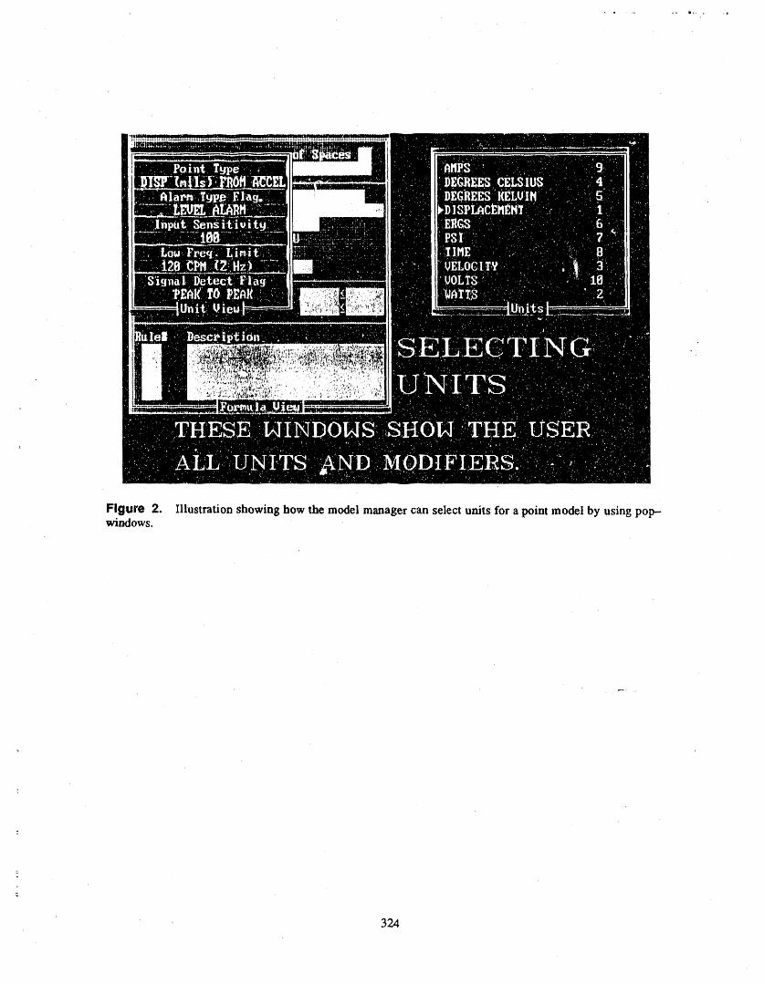
Figure 2. Illustration showing how the model manager can select units for a point model by using pop--windows.
324
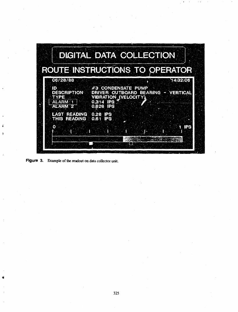
Figure 3. Example of the readout on data collector unit.
325
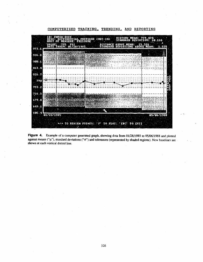
COMPUTERIZED TRACKING, TRENDING, AN___DDREPORTING
....... ] ................ i ................................. t""_"::::'_:_"::!---....i..............._i--'.........................---.i............!============================================================..... "_i .............. '..............:-:.-:-:..--:..- .... _ ..........____
' '. i !l
Figure 4, Example of a computer generated graph, showing dma from 01/28/1985 to 05/06/1988 and plottedagainst means ("it"), standard deviations ("&') and tolerances (represented by shaded regions). New baseline,,; are .,shown at each vertical dotted litre.
326
ATTENDEE- PANEL QUESTIONS AND ANSWERS(EDITED; ATTENDEE QUESTIONS AND PANELAUTHOR
RESPONSES NOT IDENTIFIED BY NAME)
Question 1 who is assigned to do it. In this case, the person as-signed to enter the data was not a technical person, and
When you implemented systems, such as your exam- we had to teach her how to do a let of the entry. But inpie from Crystal River, how long did it take to work the end, she was very, ve_Tknowledgeable of the infer-
out the bugs, load the data base, and make this a usable marion and able to retrieve, handle, and manage it very
approach? effectively. So it depends upon who is assigned to ac-
Response 1 tually get the information and put it in, how muchtraining that person needed and what they are trying to
It takes anywhere from weeks to months, depending on do with inservice testing.
327

THE IMPACT OF ASME O&M STANDARD ON OPERATING NUCLEARPOWER PLANTS
C. WESLEY ROWLEY, P.E.a
ABSTRACT • The secondO&.M Part issued(m 1981) wasfor the iaservice momtoring program to de-tect significant loss of axial preload at the
This paper discusses the origin and mission of thecorebarrel's uppersupportflange in PWRs
O&M Committal, the Pans of the OM Standard that it (OM-5).has issued to date, the Parts it plans to issue within the
next few years, and the status of regulatory enforce- . The third O&M Part issued (in 1982) was forment of its Parts. These. Parts include pump ",rodvalve the examination and testing of snubbersperformance testing, as weU as eighteen other topics. (OM--4). Notwithstanding the requirements
for preservice examination, inserv/ce exami-Origin of the OM Standard---In the late 1960s _he nation, and repairs & replacements as de-ASME decided to develop a Power Test Code (PTC) scribed in tile BPV Code Section XI
for the testing of nuclear pumps and valves. Before IWF-5000, this Partdefines the requirementsthese PTCs were issued a decision was made in the for periodic examination and testing of snub-early 1970s to transfer the requirements for pump and bers through the life of the,plant.valve testing into Section XI of the Boiler & PressureVessel Code. As a result parts rWP and IWV were first ® The fourth O&M Part issued (in 1982) waspublished in 1974. In 1975 the ASM]?, made the de- for the system performance and functiomdcision to create a new main committee to develop testing of closed cooling water systemsstandards for operating nuclear power plants. This (OM-2) to check the degraduation of thecommittee was named the "Operations and capability to transfer heat to a heat sink.Mah_tenance Committee" and its mission was:
s The fifth O&M Part issued (in 1982) pro-vided the general requirements for theTo identify, develop, maintain, and review
codes and standards that are c_msidered assessment of piping system vibration forBPV Code Section HI piping and applicablenecessary for the safe and efficient opera-
tion and maintenance of nuclear power ANSI classified systems (OM-3).
plants, particularly as they relate to strut- Note that most of these Parts now have either revision
tural and functional adequacy. 1 or 2 i,&suedthereby refining the requirements or guid-ance to the nuclear industry.
The intent for this committee w_s to take over the
testing of active components from BPV Code So far during the second decade of its existenceSection Xq. (198S-present), the O&M Committ_ has issues Part
for testing specific components.
Issued Parts to the OM Standard--During the firstde-. OM-6 was issued in 1988 to provide require-cade (1975-85) of its existence, the O&M Committee
issued standards that monitored or tested specific com- ments for the testing of pumps, which are re-qui_cd to perform a specific safety function
pomnats and systems. (in shutting down a reactor to cold shutdowncondition, maintaining the cold shutdown
o The first O&M Part issued (in 1981) was for condition, or in mitiga_lg the consequencesthe testing of pressure relief valves (OM-I). of an. accident). This standard was specifi-This Part was intended to test those relief cally developed to replace IWP in BPV Codevalves described by ASME Section III Class Section XI._,2,3 and which have a specific safety
function (in shutting down a reactor or in _ OM-7 was issued in 1988 to provide lequire-mitigating the consequences of an accident), meats for the development of procedures and
a. The author, C.W. Rowley, is an independent coas_dtant to the nuclear industry ham Cashiers,NC: he is alsoa member of the O&M Executive Committee and Chairman of its Task Oroup on Standards UtiLization.
; 329
the assessment of thermal expansion response • OM-18 Performance testing of electro-hy-to Class 12,3 piping systems and applicable draulically operated valve assemblies in nu-ANSI classified systems, clear power plants (excludes PORVs covered
by OM-13)
• OM-IO was issued in 1988 to provide re-
quirements for the testing of valves, which ® OM-20 Performance and fuuctional testingare required to perform a specific safety f-unc- criteria for ECCS in BWR nuclear powertion (in shutting down a reactor to the cold plantsshutdown condition, maintaining the cold
shutdown condition, or in mitigating the con- Historical Thrust of the GM StandardmTo discern the
sequences of an accident). This Part was spe- emphasis of the O&M Committee in its developmentcifically developed to replace IWV in BPV of Parts, it is inte/esting to categorize the various OMCode Section XI. Parts as follows:
• OM--16 was issued in 1989 to provide guid-ance relating to the testing and maintenance Specific Mechanicalof diesel drives which are required to perform Equipment System Progranm_aticOriented Oriented Orienteda specific safety function (in shutting down areactor or in mitigating the consequences ofan accident). OM-1 OM-10 OM-2 OM-3
OM--4 OM-I1 OM-15 OM-7
Parts Under Development to the OM Standard--Cur- OM-5 OM-13 OM-17 OM-12OM-6 OM-16 OM-20 OM-14
rently there are another eleven O&M Parts underdevelopment; a brief description of each follows: OM-8 OM--18OM-9 OM-19
• OM-8 Performance testing of MOV assem- So it is obvious that some 60% of the O&M Com-
bites u_d in nuclear power plants mittee effort to date has been directed toward specific
pieces of equipment or components. Of the twelve spe-• OM-9 Periodic inspection and performance cific equipment oriented Parts, note that at least five of
testing of radioactive material handling them (OM-6, -8_ -16, -18, -19) have an electricalcrams in nuclear power plants interface.
• OM-II General procedures for the asses- Potentially New Parts to the OM StandardmA number
sment of heat exchanger vibration in nuclear of nuclear plant problems can best be addressed via anpower plants additional Part to the OM Standard. Some topics under
current consideration are:• OM-12 Loose parts monitoring and diagnos-
tics for light water reactors • Service water systems
• OM--13 Performance testing and periodic: ' monitoring of power operated relief valve as- , Refueling systems
semblies in nuclear power plants• Check'valves
• OM-14 Guidelines for an in situ vibration
monitoring program for rotating equipment . Piping operabilityimpor! ant to nuclear power plants
• Heat exchangers• OM-15 Performance and functional testing
criteria for ECCS in PWR nuclear power__ plants f, Auxiliary feedwater systems.
,, OM-17 Periodic inspection and performance In the INPO Summary of Maintenance Activitiestesting of instalment air systems in nuclear dated July 21, 1988, the current "top equipment
power plants problems list" is as follows:
- 330
' ,,, a_',l_, ,,, ,,,,,,_,r, _lll"'_,r,_' ,, ...... qlllr"_',,_lilrIrl_r'11[_,,"1,...... IIIlll,,IJ''q..... _,r.......... _'tl_a....... fill' "[lI__ ,_I' _.... _'"'1[I'''p' "r_"'_ll'llllll_..... "I_"'_";Ir'''r _'_I"
• Feedwater control tation of this BNC&S mo_ion, hopefully to becompleted by the end of 1990.
• Motor operated valves OM--8Difference Between Codes, Standards, and Guide-
, Diesel-generators OM-16 lines--The ACME, as well as the other technical soci..edes, have not defined the differences between these
• Standby turbine driven pumps three terms very well. The O&M Committee is in the,process of developing definitions and meanings to
• Main turbines these three terms, perhaps as follows:
• Heat exchanger tubes • Code,--a document that is developed to beimplemented by a statutory or regulatory re-quirement; the requirements of the document
• Relief valves OM-1, must be implemented in its entirety.
• Piping ® Standard--a document that is developed tobe implemented on a voluntarily basis by the
, Instrument au' OM-17 plant owner/opexator; the requirements of thedocument must be implemented in its en-
, Checkvalves tirety, if ow_r/operator is to be credited forcompliance.
, Reactor coolant pumps
• Guideline---a document that is developed to® ac, converters, share, good technical practice with the indus-
try; the recommendations of the documentOf these twelve industry problem issues, the O&M may be ulilized in total or partiality, as de-
Committee already has four of them at least partially sired by the plant owner/operator. Com-covered by issued (OM-I and OM-16) and by pliance with a guideline is not usually adeveloping (OM-8 ar_l OM-17) Paris. source of credit to the owner/operator.
Regulatory Utilization of the OM Standard---The Implementation of the OM Statu_ard--To date the OMASME BPV C.,xle Section XI specifically references Standard has been or is planned to be implementedParts 1,4, 6, and 10 for requirements. Since Section XI mainly as a guideline by many nuclear power plants.is endorsed by 10 CFR 50.55a, these four parts are re-
quired to be used by nuclear power plants, depending Apparently few nuclear power plants have implem-on the following factors: ented any Part of the OM Standard as a "standard".
This topic is being looked at closely by the O&M, Exemptions approved by NRC Committee via their Task Force on Standards Utiliza-
tion. Morn information will become available over the
• IST interval for pumps and valves currently next year or so.in effect for a particular plant
A few plants, due to the "roll-over" of their IST in-, Specific plant tech spec snubber requirements terval (ten years) have been required to implement
versus adoption of OM.-4 OM-I and OM-.4 via Section XI, which is mandatedby the NRC and by some states. As more "roll-overs"
• Specific plant FSAR commitments, occur over the next few years, OM-6 and OM-IO will•also become mandatory (OM.--6 and OM-IO were, first
Recently the BNC&S (Board of Nuclear Codes and endorsed by the Section XI winter 1988 Addenda).
Standards) has approved a motion to wansfer the ISTprogram from Section XI to the O&M Committee. Will the fact that OM-I, OM-8, OM--16, andThis will require the NRC direct endorsement of the OM-17 address issues listed in the INPO "top equip-OM Standard vice Section XI for the IST (inservice merit problems list" have a catalyst effect on the imple-testing) Program. An O&M/Section XI Transition mentation of these documents as a "standard" vice aJoint Task Force is already working on the implemen- "guideline"? Some observations follow:
331

o Many people in the nuclear industry are not • 3rd vice-chrm---Dick McGaughy, VP atyet aware of the OM Standard Iowa Electric Light & Pwr
® The OM Standard does not yet have the visi- The ASME consensus process requires that no onebility of the BPV Code Section 111 and interest group have more than one third of the totalSection XI. main committee membership. The O&M Committee
has conformed to that rule, but keeps its owner/
This will probably change over the next few years, operator utility membership right atthe one third limit.In addition most O&M Committee members are utility
O&M Committee Management Team---The chairman and operations oriented by virtue of their experienceof the O&M Committee has always been a nuclear and training.utility officer:
Since NUMARC has been formed, the O&M Com..• 1st chairman--Wendell Johnson, VP at mittee llaises with the NUMARC staffto ensure com-
Yankee Atomic Electric plementary efforts. In addition O&M Main Committeemembers from INPO, EPRI, ANI, and NRC have
® 2nd chairman--Ed Williamson, Sr VP at helped to provide a comprehensive nuclear industrySouthern Company Svcs perspective.
• 3rd chairmanmJerrold Dewease, SI-VP at SUMMARYI.ouisiana Power & Light
: This has helped ensure that the products of the In summary the O&M Committee is very deter-O&M Committee are documents useful to the 54 mined to carry out its charter (mission) with effective
nuclear utilities with nuclear power plant operating nuclear industry leadership, so that the OM Standard
responsibility, will become a premier industry technical referencedocument for codes, standards, and guidelines.
In addition the vice--chairman of the O&M Commit-
tee 'has always been a nuclear utility executive. The O&M Committee and its sub-tier membership
represents the greatest resource of nuclear operationalq, 1st vice-chrm--Jolm Kufel, Millstone Plant expertise of any consensus code and standard orga-
Manager nization in the industry. As such it is dedicated to
producing useful, practical consensus standards lind,_ 2nd vice-chrm---Jim Stacey, Manager at guidelines thai serve the needs of the user (owner/
Yankee Atomic Electric operator) as well as the regulatory agencies.
332
ATTENDEE- PANEL QUESTIONS AND ANSWERS(EDITED; ATTENDEE QUESTIONS AND PANEL/AUTHOR
RESPONSES NOT IDENTIFIED B Y NAME)
Question ! Section XI, two members from theNRC representing_ thethirdpartyinspectionaspect.These,ninemembers
We havealreadYbeengrantedinterimapprovaltouse arechairedbyEd Williamson,whostoodupyesterdaya 1983editionofSectionXIforIWV andIWP.Since andwasintroduced.Theirapproachhasbeentodeter-theOM-6 and10standardshavenotyetbeenadopted minealltheproblemsinmakingthistransition.TheyintotheI0CFR 50,arewe goingtoneedtoresubmit havecompletedtheirreport,andthatreportwillbeanotherprogramandwaitforanotherSER? We have submittedtotheO&M CommitteeandSectionXIandnot received the one that we arc in right now, so I do theBoardof Nuclear Codesand Standardsin the nextnot understandhow we can use it. severalmonths, andthen it is a processof implement-
ing thatapproach.Basically ali the people on Table 1 forthe generic letterhave interim approval, but no SER. Basically it means deleting IWV, IWP, and Section
5,000 out of Section XI with a stroke of the pen. But it
Response1 alsomeansputtingintoO&M thekindof codesupportwordsthatmake it easyto usethesestandardsin a
Basically, sint;_the OM--6and 10 was just adopted in code--type sense. Then the NRC Ims to process theirthe Code 1988 addenda, and 10 eFR 50 has not yet word char_gesto 10CFR 50.55a. Our goal fight now isadopted that, there is no direct legal mechanism to sat- to have both Section XI and an O&M addendaLzsued,isfy. On the other hand, if you were to negotiate with which would transfer the IST program to O&M somethe NRC viayore"licensing organization, you might be time in 1990. We_rc sho,:_tingfor a new edition of theable to take credit for that. O&M code that will come out in the summer of 1990.
Question 2 That is our schedule goal. And then however long ittakes the NRC to process their 10 CFR change after
Yesterday, the transition committee between Section that may be anywhere from six to eighteen months.XI and O&M was briefly mentioned, and you men-tioned again this morning the effort to incorporate Question3O&M standardsdirectlyinto 10C_"R50.Couldyouelaborate on the transition team and what their You talked about feedwater. Are you developing adirection is? standard for feedwater stability7 Youmentioned it on
the graphs. Could you please talk about it7Response 2
Response 3TheBoardof NuclearCode.sandStandardspas_d aresolutionin Februarythattheywouldlike totransfer Thefeedwaterinstability waslistedon the INPO topthe inservice testing program fromSection XI over to dozenproblems. That is not currently one of the prob-O&M at some appropriatedate when we are ready for lem areas that O&M has addressed. But I will takeit. The first thing we did wasto create a transition team your comment to the task force on standards planningmade up of three members of O&M, three members of and see if they think it is appropriate.
=
333
i

ADVANCED VALVE MOTOR OPERATORDIAGNOSTIC SYSTEM
M.C,S.A./VMODSCLAUDE THIBAULT,PH.D
LYLE LABORATORIES7800 GOVERNORS DRIVE, WEST HUNTSVILLE, ALABAMA 35807
ABSTRACT remotely from the Motor Control Center (MCC) witha clamp-on ammeter.
This paper explains Wyle's new system for diagnos- Wyle's AVMODS comprises two complementarytics, signature analysis and direct measurement of ac- segments:tual load on Motor Operated Valves (MOV) in theclosed direction. The following topics are _scussed: 1. VMODS (Valve Motor Operator Diagnostic
System) is utilized to establish base line pa-
, System description rameters and was developed entirely by WyleLaboratories, Scientific Services and Sys-
e System capabilities ternsGroup.• Features.
2. M.C.S.A. (Motor Current Signature Analy-o The specific features of Wyle's system are: sis) has been developed by Oak Ridge Na-
tional Laboratories (ORNL) under the
• Measures directly the actual closing force au_ices of the NRC. Wyle is the ORNL Ii-. Easy to install censee for this technology.
° "Leap frog" working feature minimizes testtime VMODS Description
_, Capability of up to le-channel simultaneousinput and acquisition VMODS consists of several entities, mainly: (See
• Non--intrusive monitoring at a remote loca- VMODS Schematic,).tion (MCC)
: • High sensitivity and selectivity to a variety of * Sensors: clamp on ammeters, load washersmechanical disorders affecting MOV opera- and position transducers.tional readiness • Interconnect box
• Provision of use_l and trendable signature • Cable sets
features. • Data acquisition module• Computer/software/display.
INTRODUCTIONInterconnect Box
The Wyle Advanced Valve Motor Operator Diag-nostic System (AVMODS) approach and equipment Limit and Torque switch cables axe routed throughhas undergone over a year of development to provide a this junction box which is located near the valve and
-: relatively quick and non-intrusive capability to moni- allows for 250 feet of umbilical cable to be mn back totor, analyze and document the condition of motor oper- the Data Acquisition Module. The Motor current, mo-
tor voltage, stem travel, spring pack displacement andators on safety-related nuclear valves driven by anelectric motor. The system measure valve stem thrust load washer cables also feed through this box.directly. Data is also provided on ali limit switch andtorque switch operations, as well as, motor voltage and Data Acquisition Modulecurrent. Also, through detailed researchprograms, it
= has been determined that any mechanical perturbation The unit contains a Kistler charge amplifier andoccurring in the operation of a MOV (Motor Operated Simpson voltmeter and acts as a signal conditioner for
-_ Valve) can be detected in the motor current supplied to ali inputs to the computer. Ali ranges are selectedthe operator electric motor. This can be accomplished through this module mid input to it comes from the
_ 33_F
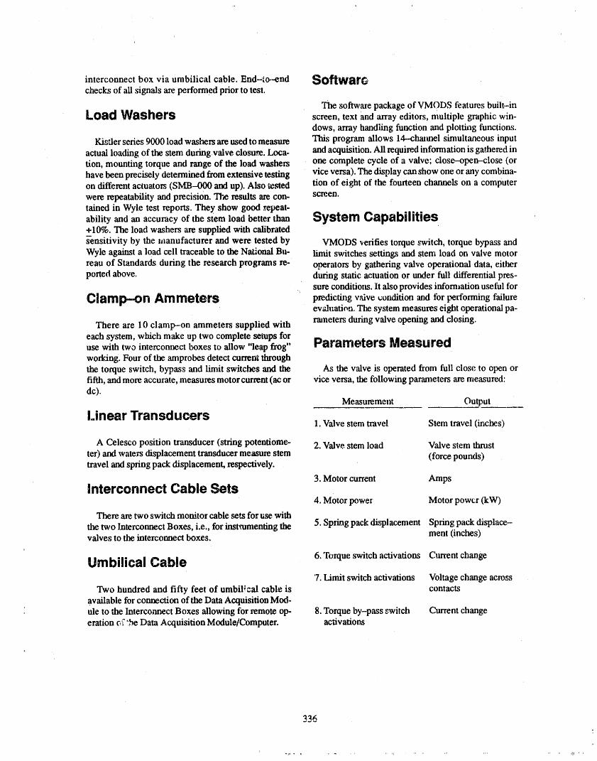
interconnect box via umbilical cable. End-_o.-end SoftwarGchecks of ali signals are performed prior to test.
The software package of VMODS features built-inLoad Washers screen, text and array editors, multiple graphic win-
dows, array handling function and plotting functions.
Kisfler series 9000 load washers are used to measure This program allows 14--chaimel simultaneous input
actual loading of the stem during valve closure. Loca- and acquisition. Ali required information is gathered inrien, mounting torque and range of the load washers one complete cycle of a valve; close--open-close (orhave been precisely determined from extensive testing vice versa). The display can show one or any combina-
on different actuators (SMB--000 and up). Also tested rien of eight of the fourteen channels on a computerwere repeatability and precision. The results are con- screen.rained in Wyle test reports. They show good repeat-
ability and an accuracy of the stem load better than System Capabilities+10%. The load washers are supplied with calibrateds'-ensitivity by the manufacturer and were tested by VMODS verifies torque switch, torque bypass andWyle against a load cell traceable to the National Bu- limit switches settings and stem load on valve motorreau of Standards during the research programs re- operators by gathering valve operational data, eitherported above, during static actuation or under full differential pres-
sure conditions, lt also provides infommtion useful for
Clarrl_-on Arrlmet_rs predicting valve t;ondition and for performing failureevaluation, Tie system measures eight operational pa-rmneters during valve opening and closing.
There are 10 clamp--on ammeters supplied witheach system, which make up two complete setups foruse with two interconnect boxes to allow "leap frog" Parameters Measuredworking. Four of the amprobes detect current throughthe torque switch, bypass and limit switches and tlm As the v',dve is operated from full close to open orfifth, and more accurate, measures motor current (ac or vice versa, the following parameters are measured:dc).
Measurement Output
Linear Transducers 1. Valve stem travel Stem travel (inches)
A Celesco position transducer (string potentiome- 2. Valve stem load Valve stem thrust
ter) and waters displacement transducer measure stem (force pounds)travel and spring pack displacement, respectively.
3. Motor current AmpsInterconnect Cable Sets
4. Motor power Motor power (kW)
There are two switch monitor cable sets for u_ with
the two Interconnect Boxes, i.e., for instrumenting the 5. Spzing pack displacement Spring pack displace-valves to the interconnect boxes, ment (inches)
Umbilical Cable 6. Torque switch activations Clm'ent change
7. Limit switch activations 'Voltage change acro,_s
Two hundred and fifty feet of umbilical cable is contactsavailable for connection of tlm Data Acquisition Mod-ule to the Interconnect Boxes allowing for remote ep- 8. Torque by-pass switch Current changeeration _'".be Data Acquisition Module/Computer. activatio_
336
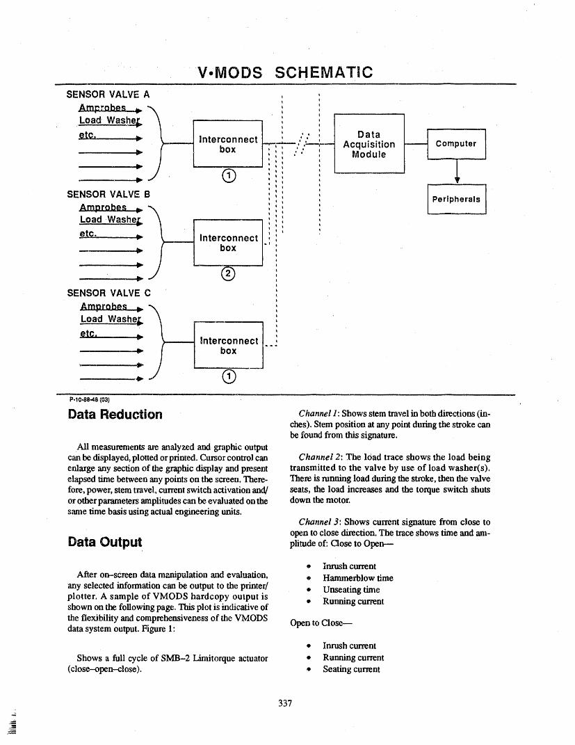
V.MODS SCHEMATICSENSOR VALVE A
Amprobes _._
Load Washe_ ' ,c-.. _-_
Interconnect L :: Data,.,a,,.,.,,,,.. i i
,,, ,, ,---_-- Acquisition Computerbox I , , ' " Module
I t
P. :
v I t
SENSOR VALVE B I ', Peripherals
Am_robes .._Load Washe_. t
- , :- I!etc _ Interconnect
box "
SENSOR VALVE C
Load. .Wa_she_
etc. _ Interconnect ...
P-1o,88.4a1031
Data Reduction c_..el ]: Showsstemtravelinbothdirections(in-ches).Stempositionatanypointduringthestrokecanbefoundfromthissignature.
Ali measu_ments areanalyzed and graphicoutputcanbe di_layed, plottedorprinted.Cursorcontrol can Channel 2: The 10adtrace shows the load beingenlargeany section of the graphicdisplay andpresent transmitted to the valve by use of load washer(s).elapsed time between any points on the screen. There- Thereis runningload duringthestroke, then the valvefore,power, stemtravel,currentswitch activationand/ seats, the load increasesand the torqueswitch shutsorotherparametersamplitudescanbeevaluatedonthe down themotor.same timebasis usingactualengineering units.
Channel 3: Shows currentsignaturefrom close toopen to close direction.The trace shows time andam-
DataOutput plitude of: Close to Open---
® InrushcurrentAfter on-screen data manipulationandevaluation, ® Hammerblowtime
any selected informationcan be output to the printed • Unseating timeplotter. A sample of VMODS hardcopy output is + Running currentshown on the following page.This plot is indicative of
the flexibility andcomprehensivenessof the VMODS Opento Close--datasystem output.Figure 1'
• Inrushcurrent
Shows a full cycle of SMB-2 Limitorque actuator • Running current(close-operr--close). + Seating current
337
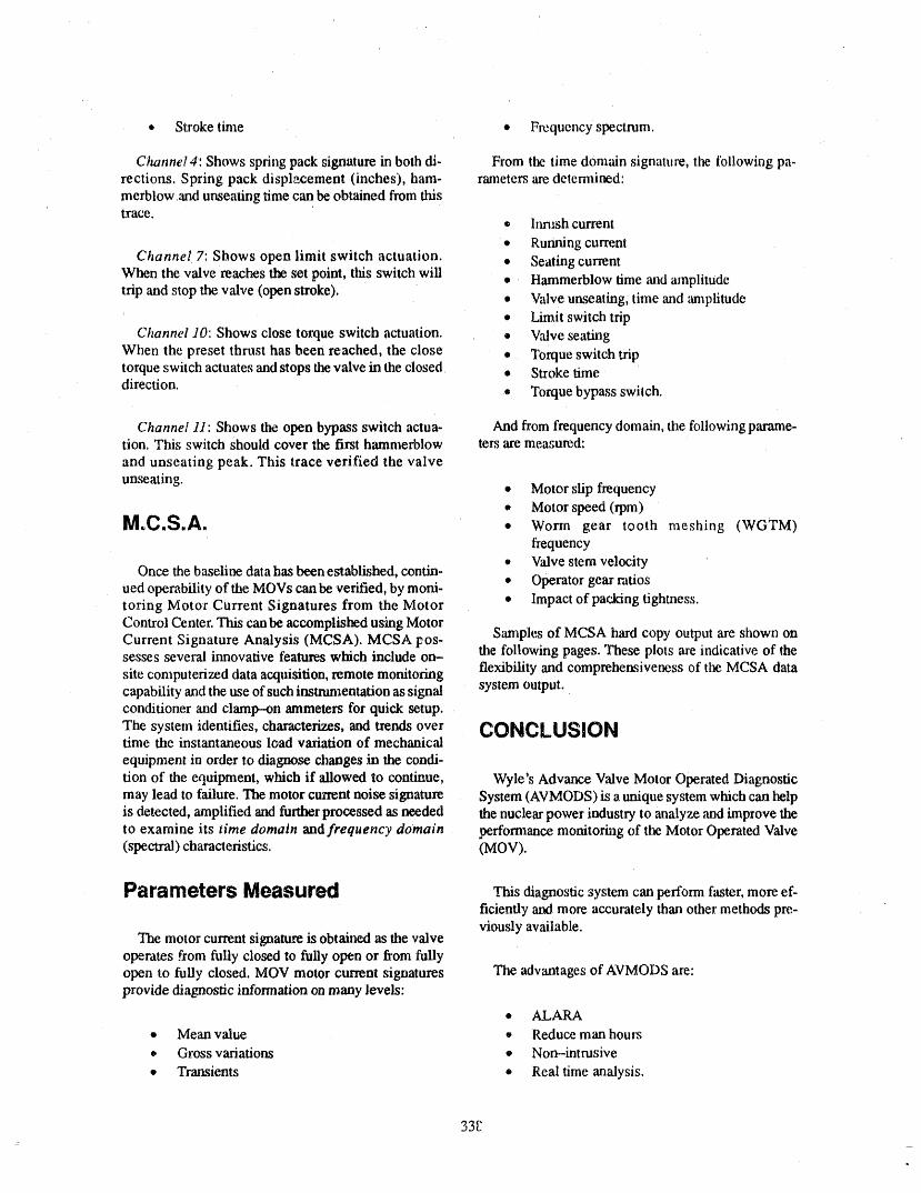
• Stroke time • Frequency spectrum.
Channel 4: Shows spring pack signature in both di- From the time domain signature, the following pa-rections. Spring pack displacement (inches), ham- rameters are detemained:merblow and unseating time can be obtained from thistrace.
• Inn.,sh current
+* Running currentChannel 7: Shows open limit switch actuation. • Seating current
When the valve reachesthe set point, this switch will • Hammerblow time and amplitude
trip and stop the valve (open stroke). • Valve unseating, time and tm_plitude• Limit switch trip
Channel ./0: Shows close torque switch actuation. ® Valve seating
When the preset thrust has been reached, the close • Torque switch triptorque switch actuates and stops the valve in the closed • Stroke time
direction. ® Torque bypass switch.
Channel 11: Shows the open bypass switch actua- And from frequency domain, the following parame-tion. This switch should cover the first hammerblow ters are measured:
and unseating peak. This trace verified the valve
unseating. • Motor slip frequency• Motor speed (rpm)
M.,C.S.A. e worm gear tooth meshing (WGTM)
frequency• Valve stem velocity
Once the baseline data has been established, contin-• Operator gear ratiosued operability of the MOVs can be verified, by moni-
toring Motor Current Signatures from the Motor • Impact of packing tightness.Control Center. This can be accomplished using MotorCurrent Signature Analysis (MCSA). MCSA pos- Samples of MCSA hard copy output are shown on
the following pages. These plots are indicative of thesesses several innovative features which include on-
site computerized data acquisition, remote monitoring flexibility and comprehensiveness of the MCSA datacapability and the use of such immm_entation as signal system output.conditioner and clamp--on ammeters for quick setup.
The system identifies, characterizes, and trends over CONCLUSIONtime the instantaneous load variation of mechanical
equipment in order to diagnose chaDges in the condi-
tion of the equipment, which if allowed to continue, Wyle's Advance Valve Motor Operated Diagnosticmay lead to failure. The motor current noise signature System (AVMODS) is a unique system which can helpis detected, amplified and further processed as needed the nuclear power industry to analyze and improve theto examine its time domain and frequency domain performance monitoring of the Motor Operated Valve(spectral) characteristics. (MOV).
Parameters Measured diagnostic system can perform faster, more ef-ficiently and more accurately than other methods pre-viously available.
The motor current signature is obtained as the valveoperates from fully closed to fully open or from fullyopen to fully closed. MOV motor current signatures The advantages of AVMODS are:provide diagnostic information on many levels:
• ALARA
• Mean value • Reduce man hom_
,, Gross variations # Non-intrusive
• Transients • Real time analysis.
33E
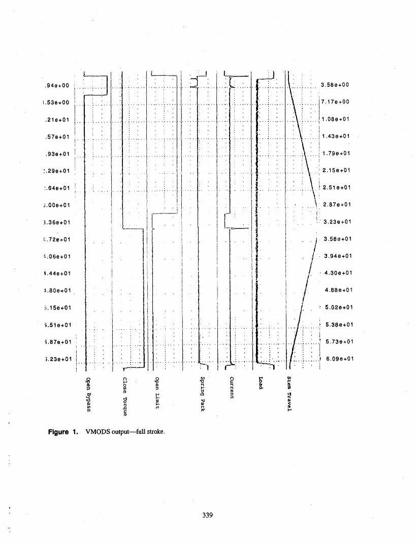
- 339
rJlli,, ,,
OPEN-CLOSE ST_O_E
S_4tch
___ _z.zs_ _r _._C._L_ .J
'0
E ._
,,T VAL tie SEA T/NG ....... _., _:} " T_J i
< 5 . ,
!
2- I '
oi
0 _0 20 30 40 50 .BOTZ_IE ZN SECONDS
:2 ,
" l'_ CLOSE-OPEN STROi_E'.0-
-- P"RUSLI _ _FSC._LE ]
"-" J [ L,_/t Swtc4 Tr,plQ. B-E
_,_ -- VALVE UV_ T/NG
"o 6.--o
_=
E 4< T
. ,,. , - .,. .......
0 10 20 30 40 50 60TIME IN SECONDS
Figure 2. Motor current signature-full stroke.
340

r
./,,
_L 5.6-
< ,II ' Valve Stem _Begins To Move
._,,ILy5,4"-
_ z;_-ctx(; : _; _ I
341

0, O_ 3C I
I
0. 002.01
_ .
13. o.co:_ "_
0.00:0
• 5 t8 2" 24 27 30Feequoncy in HZ
: Figure 4. Motorcurrentspect;mnanalysis(O-C stroke).
342

I , __...............-, Motor Ii current ....j'
III I ".,I ' ' , '
i
0 ' ,_.._L,,,.,j\.,J ,..,..,,_.,_......._...,_.._._r._.../L,JL_._,' 0 5 10 _5 20 25 ,30 35 ,_O
i ,.i
/ Vibration
i (motor-mounted_"'_ accolerometer)UJ i ......cl I '
= i_ T
I.LI> T
I
0 5 i0 i5 "2.0 25 30 35 40Freauency in Hz
Figure 5. Comparisonof motorcurrentandvibration.
343
• II ,-- •
ATTENDEE- PANEL QUESTIONS AND ANSWERS(EDITED; ATTENDEE QUESTIONS AND PANEIJAUTHOR
RESPONSES NOT IDENTIFIED BY NAME)
Qu_tlon I logic, and a lot of thebasic thrustof OM-6 and10, is inGenetic Letter 89-04 on inservice testing.
What are the pros and cons of the applicationon this The best way to get the OM-6 and 10 flavor into yourlatestMOV industryproblem go-around that we are in inservice testing programs to e_lsethe burden on youthe midst o17 and get it done quickly is to implement the genetic
letter. Then you have to wait for the regulation to en-Resl:_nllo 1 dorse OM-6 and 10. Now that process is nearing
completion.You are referring to ti_ Generic Letter 89-10. "lh me89-,10is the old85--03.89--10also ineludessomekind OM-6 and 10 and the regulation to endorse themof testing that is supposed to be performed. We want should be out for public comment within a couplethe valve to operatein design basis conditions which, months. The formalendorsementof OM--6and 10will89.-10 has highlighted oven more than 8.5--03.I think probably be out within eight to ten months. That really89-10 goes deeper into the number of valvesthat neeA overshadows the Generic Letter 89-04 schedule. Forto be testedandalso involves doing it in _tu, which re- most of you, the best approach is to look at 89--04,lookquires more tc,sting under delta P.It is veryhardtoday at the discussion that is in Attachment 1, and followto extrapolatea signature from staticconditionstl'tat Oioseareas.you can take to dynamic conditions, and I flainkthathas beea provenby hNELtests atWyle. If there is a specific part of OM-6 and I0 beyond At-
tachment 1 of the generic letter that you want to
The friction factor used commonly was 0.3, and in employ now,the only way to do tt_ is to includea re-some eases we know that it cango to 0.5. lief request in your response to the generic letter,
which is due in October. 'lhc request relief would usethe OM--6o_OM-10 philosophy, and thatmust be al>-
But it seems to me that the valve industry,even if we proved priorto implementationby the generic letter'sh_ve a good diagnosticsystem, does not know where process.we put the limit, how far we should go before we
shoulddo an overhauland maintenance on the valve. Question 3Also, _meone from KWU mentionedthat the more
you test a valve, tlmmore chanceyou lmve to destroy Our utility is on Table I of the generic letter, we havethat valve before you have to use it. Thatis true also. interim approvalfor a program already submitted ',hat
conforms with the 1983 edition of IW and IVP. How
So we hav_ seenthe resultof the EG&Otests, we have thencan we adoptlegally the DM-6 and 10 criteria?seen the weardown on theseats. But whether that hap-
pened when we were in static conditions or when we Response3wea_ m_derdynamic conditions,that is very tough to
know. After you get your SER, after you go through yourchanges, which means pn'x:eduralchanges and updat-
Question 2 ing your programto reflectthe SER andthosethingsthat are outstanding, if you then want to change toOM--6and 10, you have togo through the proc_s. YouHow can you pick up OM--6 and OM-10 now, even
though the regulationhasn'tendorsedit'? canupdateyourplantto the generic letter at anytimeyou want to, which means that after you get the SERit
Response2 should already reflect much of the generic letter any-way,because we were thinkingin theprocess whenwewrote the generic letter.
The regulatkmtoils you how to update,your plantto alatcz code version or to a different standard than the So your ,SERshould reflect much of the genericletterone that is officially in the regttlation. And the amwez thinking, and, hence, OM--6mad I0. But if there areis, it is anexemption from the regulation, and you can some aspects that you want to put into your program
__ apply for staffapp_oval.Theteehnical tlainkingandUae that go beyona your SER from OM-6 and i0, but
344
,,,, ,, .....

aren'treallyin Attachment1of thegenericletter, you exemption, and that is a difficult road. I would nothave_oapplyforrelief toemployspecific parts.If you recommendthat.The easiest road to takeis to do thearegoing to updateyourplanttoOM--6and10 intheir generic letter and then wait for the regulation toentirety after you get your SER, that would be an approveOM--6and 10.
345 =_
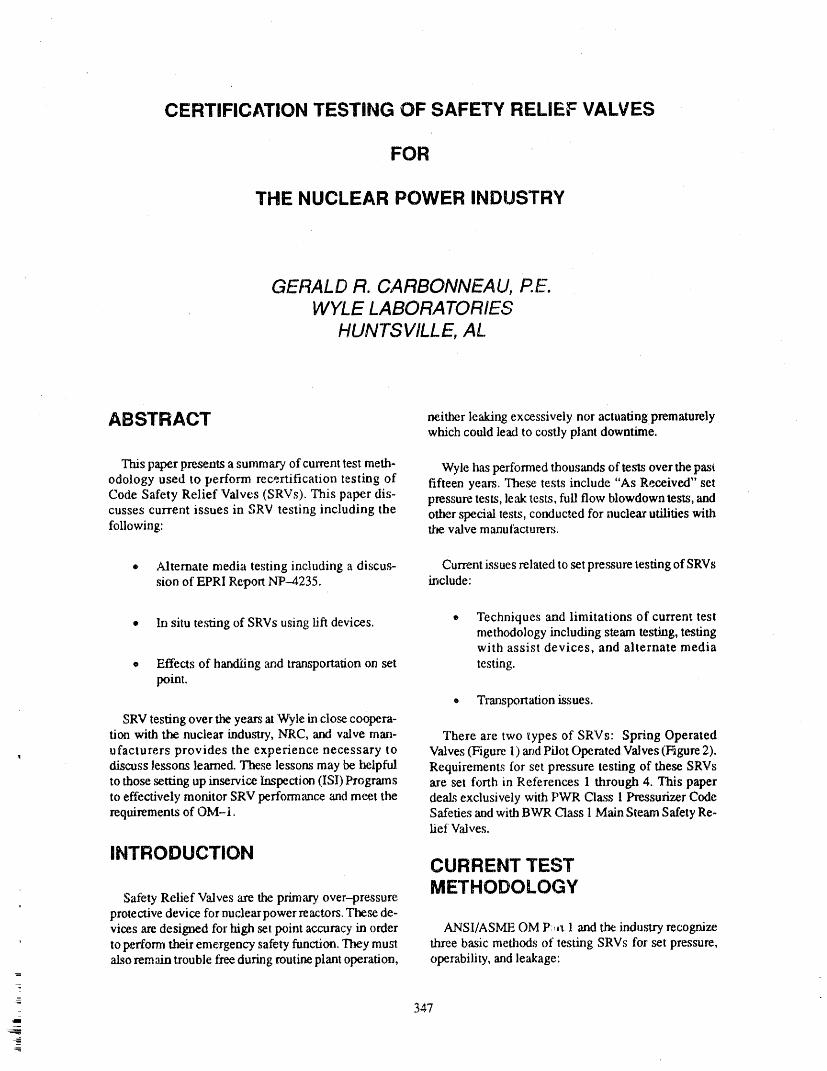
CERTIFICATION TESTING OF SAFETY RELIEF VALVES
FOR
THE NUCLEAR POWER INDUSTRY
GERALD R. CARBONNEAU, P.E.WYLE LABORATORIES
HUNTSVILLE, AL
ABSTRACT neither le',&ing excessively nor actuating prematurelywhich could lead to costly plant downtime.
This paper presents a summary of current test meth- Wyle has performed thousands of tests over the pastodology used to perform recertification testing of fifteen years. These tests include "As Received" setCode Safety Relief Valves (SRVs). Tlais paper dis- pressure tests, leak tests, full flow blowdown tests, andcusses current issues in SRV testing including the otter special tests, conducted for nuclear utilities withfollowing: the valve manufacturers.
® Alternate media testing including a discus- Current issues related to set pressure testing of SRVssion of EPRI Report NP-4235. include:
• In situ testing of SRVs using lift devices. + Techniques and limitations of current testmethodology including steam testing, testingwith assist devices, and alternate media
o Effects of handiing and transportation on set testing.point.
,b Transportation issues.
SRV testing over the years at Wyle in close cooper'a-tion with the nuclear industry, NRC, and valve man- There are two types of SRVs: Spring Operated
, ufacturers provides the experience necessary to Valves(Figure 1) and Pilot Operated Valves(Figure2).discuss lessons learned. These lessons may be helpful Requirements for set pressure testing of these SRVsto those setting up inservice Inspection (ISI) Programs are set forth in References 1 through 4. This paperto effectively monitor SRV performance and meet the deal.,; exclusively with PWR Class 1 Pressurizer Coderequirements of OM-1. Safeties and with BWR C'lass 1 Main Steam Safety Re-
lief Valves.
INTRODUCTION CURRENT TESTMETHODOLOGY
Safety Relief Valves are the prh'nary over-pressureprotective device for nuclearpower reactors. These de-vices are designed for high set point accuracy in order ANSI/ASME OM P:,,_ 1 and the industry recognizeto perfomt their emergency safety function. They must three basic methods of testing SRVs for set pressure,also remain trouble free during routine plant operation, operability, and leakage:
347!

LVDT
r
TC,3 ----
TC2 .--------- =
r " i __ ii=
Pressure
transducer
T1 = Steam temperature
T2 ,, Valve body temp.
T3 = Valve spring temp.
Figure 1. Test insmunentation -- spring operated SRV.
348
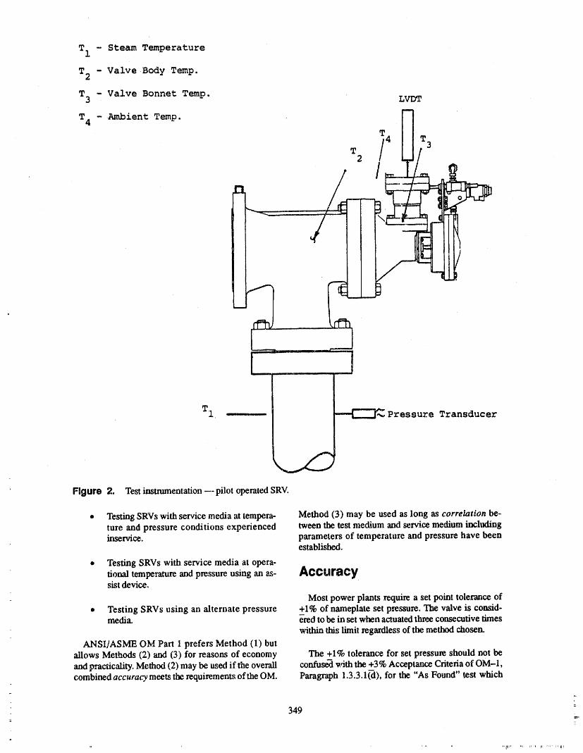
T1 - Steam Temperature
T2 - Valve •Body Temp.
T3 - Valve Bonnet Temp. LVDT
T4 -Ambient Temp. N
T i4 _ _3
_
[........... l
Figure 2. Test instnunentation --- pilot operated SRV.
• Testing SRVs with service media at tempera- Method (3) may be used as long as correlation be-ture and pressure conditions experienced tween the test medium and service medium inchflinginservice, parameters of temperature and pressure have been
established.
• Testing SRVs with service media at opera-fional temperature and pressure using an as- AccuracysL_;tdevice.
Most power plants require a set point tolerance of
• Testing SRVs using an alternate pressure +1% of nameplate set pressure. The valve is consid-media, e-redto be in set when actuated three consecutive times
within this limit regardless of the method chosen.
ANSI/ASME OM Part 1 prefers Method (1) butallows Methods (2) and (3) for rea,sons of economy The +1% tolerance for set pressure should not be
and practicality. Method (2) may be used if the overall confuse_l w/th the +3% Acceptance Criteria of OM-1,combined accuracy meets the requirements of the OM. Paragraph 1.3.3.1 (-d), for the "As Found" test which
_
349

triggers testing additional valves if valve set pressure the valve inlet to establish thermal stabilization. Fol-exceeds this limit, lowing thermal stabilization, the valve is checked for
leakage. Next, the steam pressure is increased at a con-
OM Part I states that the test method including in- trolled rate until the valve actuates. Additional actua-strumentation, test equipment, calibration, etc., must tions are performed with five-minute intervals
, be sufficiently accurate to perform its measurement between actuations. Set pressure adjustment may betask. Accuracy can be defined as the percent difference performed, if required. Finally, a post-test leak checkbetween an actual valve, XA, and a measured valve, is conducted.XM, i.e.
If rework is required, the valve is refurbished by themanufacturer or other repair agency following cool-
% Accuracy XA- XM= X 100 . down. At this time, ring settings and dimensionalXM clearances are checked. Finally, the valve is tested
again for recertification, if required, leak tested, then
OM Part 1 specifies an overall combined accuracy returned to the customer.of +2/-1% of nameplate set pressure resulting in an ac-tual set pressure within +1%/-2% of the measured Leak Checks. Three methods of leak checks ,arevalve, i.e., conducted:
0.99 X^ < XM < 1.02 X^ 1. Cold mirror leak check
2. Quantitative leak checkor
0.98 XM < XA < 1.01 XM 3. Nitrogen bubble leak check.
If no audible or visual leakage is immediately evi-Figure 3 depicts a Pressurizer Safety set pressure in dent, a cold (i.e. room temperature) mirror is inserted
the region of interest. Three set point measurements into the valve outlet and passed around the valveare plotted within the _+1% tolerance band required by seating surfaces. The mirror is then examined for con-most plants. This _+1% corresponds to _+25psi for a densate formation. If quantitative leakage is required,valve nameplate set pressure of 2500 psig. The dashed a condensing coil is connected to the valve outlet, andlines represent the limits of the overall combined accu- the condensate collected in a graduated cylinder. Thisracy. The actual set pressure value may lie anywhere method is not effective unless the bonnet area is sealed
within these limits, from the body bowl. If nitrogen bubbles are required tobe counted, the method of API Standard 527 is used.
Obviously, when selecting the test method, the over- Up to 100 bubbles per minute may be counted this way.all combined accuracy must be considered in order to This test is perfo.,med with GN2 with the valve at oper-have assurance that the actual set pressure values lie ating temperature or room temperature,within the desired limits. That is, if the tolerance of
+25 psi of nameplate is specified, then a method of Instrumentation. Prior to test, the valve is iastrum-m
testing including instrumentation that will deliver an ented to monitor the required test parametet,s. To pre.-accuracy on the order of +2.5 psi would be desirable, vent seat damage, spring-type valves are restricted at
the ,spindle to a lift of approximately 50/1000 inch. Pi-: Method 1. Although ali three methods have been or lot operated SRVs are flow restricted by inserting a: are in use at Wyle, depending on the requirement of the plug into the main seat outleL
customer, the most common is Method 1.
A Linear Variable Differential Transformer (LVDT)
A typical valve receives an initial receipt inspection, is installed on the spindle to measure, the valve lift. InThen the valve is tested "As Found" for set pressure, case of a pilot operated valve, the pilot disc is instrum-operability, and leakage. The valve is installed in the ented. The signal output is processed through condi-test cell in its normal operating position on a steam ac- tioning electronics to the recording device. LVDTs arecumulator. The valve is instrumented, insulated if re. calibrated using a micrometer prior to test. 1'he LVDTquired, and surrounded by an environmental box. verifies lift and provides a timing mark for set pointSteam at 90% of nameplate set pressure is applied to and reseat on the X-Y Plotter.
350
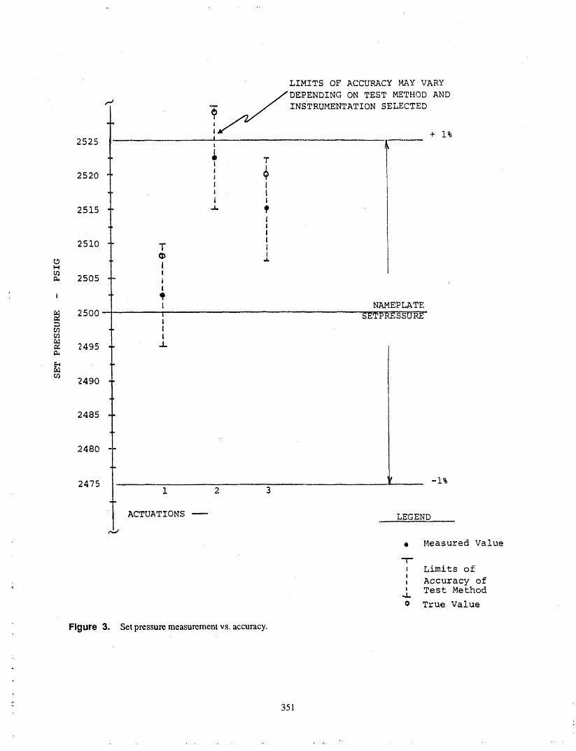
LIMITS OF ACCURACY MAY VARY
.__DEPENDING ON TEST METHOD AND
"_ INSTRUMENTATION SELECTED
m
i + 1%2525
2520 _i +i Ii Li I
2515 "_Iii
2510 T ti
t/l !2505 i
i
I NAMEPLATE
2500 -- i SETPRESSUR_-D i
2495 _-
m2490
2485
2480
2475 i 2 3
ACTUATIONS ---- LEGEND
+ Measured Value
-r"i Limits ofI
= t Accuracy of' Test Method.u
o True Value
Figure 3. Setpressu_measu_mentvs. ac_racy.
351
i,

K-Type thermocouples are installed on the valve (P + A P)s,i p,,,,=where, required. The number varies depending on the
valve and test procedure. Typically, file following pa- = (p 4- AP)r,.,_,_ ,_,,_ .... ,,,p= (1)rameters are monitored:
TESTING USING ASSIST• Steam inlet temperature as closeto the valve DEVICES
inlet as possible
Method 2
• Valve inlet neck Method 2 uses an assist device to test SRVs.This de-
vice can be used with the valve in place at operationcon_tlons of temperature and pressure, The assist de-
, Valve body vice is apneumatic or hydraulic cylinder which appliesa load to the valve spindle to assist the steam pressure
to overcome the spring force. The steam pressure is
• Valve spring (upper, middle and lower) measured by a test gage or pressure transducer, Theload is measured by a gage or load cell. The set pres-sure must then be calculated using a formula whichsums the forces acting on the valve spindle. These
• Valve spring ambient temperature.forces include the spring load, the load imposed bysteam pressure acting on the seat area, and the load
The, thermocouple output signal is monitored and applied by the assist device:
recorded by a data logger. Printouts are at one-minute Fs_,s + Fs,,,, + F^,,_,, = 0 (2)intervals and are used to monitor the valve during hea-
tup and stabilization. Set pressure is calculated as follows:
Accelerometers are used for testing pilot operated Set pressure = Steam pressure
SRVs. The accelerometer output is on an oscillograph
and is used to monitor valve stroke and response times + F^,_,,/AEfr,,_, ,_ (3)on the order of 10 milliseconds.
The effective seat area, A, is a factor which is usual-ly provided by the valve manufacturer and varies de-
. Valve ittlet steam pressure (and thus valve set pres- pending on the valve orifice size, disc flexibility, and
sure) is monitored using a pressure transducer. Follow- other factors. This is why we say that the set pressure ising signal conditioning, the output signal is processed a calculated value.
to the X-Y Plotter. A Heise test gage is also used in
parallel and for comparison purpose. Both instnnnents ACC U racyare calibrated end-to-end using a deadweight tester of
high accuracy prior to and following testing. Set pres- The theoretical accuracy (+AP)set of Method 2 cansure can be determined to an accuracy of +0.1% on the be formulated as:m
X-Y Plot by means of point calibration methods (See
Figure 4). Since the accuracy of the test results der CP 5: AP)s_ p=,=,, = (P 4- AP)s,,m p,,.,,=,,
pends entirely on the method used to measure and ,re-
cord set pressure and, in this method, the Pressure + (F +_ AF)A,aJ(A _ AA)se., a.,. (4)
(Psteam) is measured with a pressure transducer
(PTramducer),rather than a pressure gage, the accuracy The solution of this equation for + APset can be(+ At') of Method 1 can be expressed as: found in Appendix I.
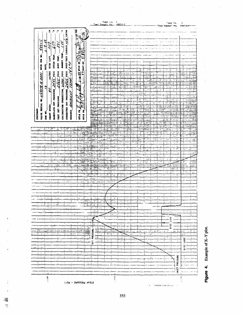

4- APs,, = 4- APs,=,,_ 4- AF/(A 5: /lA) hand, set pressures for nitrogen and steam then theynecessarily correlate. At Wyle, valves are tested onboth steam and nitrogen. We have seen valves which
4- AA/(A 4- AA) (F/A) (5) leak on nitrogen but do not leak on steam, and valveswhich leak on steam but are bubble tight on nitrogen
which demonstrates that the accuracy of Method 2 is for the same style valve. Some valves have nitrogenhighly dependent on the overall combined accuracies and steam set pressures which are close, others not
of + APSteam,+/IFAssist, and +/_a_Eff¢cfiv¢seatarea. close. The variance seen in the EPRI results leads one- - to ask if correlation exists in the first piace, lt goes
ALTERNATE MEDIA TESTING withoutsaying that anything which upsets this correla-tion, such as spring replacement, leakage or alignmentvalve, would require a re-establishment of the correla-
Method 3 tion by steam testing in order to comply withOM-1987, Part 1.
Method 3 of testing valves provides for the use of analternate media such as gas or water in piace of steam. TRANSPORTATIONTemperature must also be considered as the valve may
be tested at room temperature or heated in an environ- Regarding transportation, does removal expose themental enclosure. EPRI is proposing a method for al- SRV to risk during handling and shipment? What ef-ternate media testing of SRVs based on the results of a fect does transportation actually have on valve settest program reported in EPRI Test Report NP-4235. pressure performance? Let us look at two caseThe objective of this report is to establish a methodolo- histories.gy which would achieve correlation required by
OM- 1987, Part 1. A Dresser Pre_urizer Safety Valve, Model 31739A,NPSP 2495 psig, has been last tested in 1985. The "As
EPRI tested ten Crosby HB-86-BP Pressurizer Left" set pressures were 2486, 2475, and 2479 psig.Safety Valves designed for loop seal service. The The valve was returned Plant A where it remained invalves were tested for set pressure at various ambient storage as a backup spare and was not placed in ser-temperatures three ways: (1) gaseous nitrogen, (2) sat- vice. lt was returned to Wyle and retested on April 28,urated steam, and (3) using a lift device with steam at 1989. The "As Found" set pressures were 2498, 2489,90% set pressure. A matrix of ali the set pressures is and 2496 psig. Six years of storage and transport to andpresented in Appendix D of the EPRI Report. Much from Plant A, a distance of 2,560 miles, resulted in
: can be learned from studying these results, little difference.
In February 1988, Plant B dropped a valve on-site.Steam With Lift Device Thisvalve, a Crosby Pressurizer Safety Valve, Style
HB-BP, had been recently recertified at Wyle. The re-The variance between the results of testing on steam certification set pressures were 2482, 2502, and 2495
and the results of testing using a set device are notable, psig. Plant B decided to retest this valve. Upon returnThe datashow a +1% to +3.4% difference between the to Wyle, the valve was retested. The "As Found" settwo methods. We have already discussed the accuracy pressures were 2479, 2511, and 2520 psig. Again, littleof lift devices which is highly dependent on the known difference even after dropping.a_uracy of the effect seat area.
The data which exists does not support the claimNitrogen that travel causes set pressure drift provided the man-
ufacturers recommendation that the valves be shipped
The results of the alternate media nitrogen tests re- in a vertical position to preclude damage to the valveported by EPRI are also interesting. The set pressures internals, such as bending the spindle, be followed.for nitrogen vs. steam at ambient temperatures of
100°F vary from-3.4% to +3.8%. What is surprising is SUMMARYthe wide v,-u'iation between nitrogen and steam for theidentical type of valve. Why plus in some cases, minus Most plants still send their SRVs off-site for test.in others? In spite of the results, the EPRI report While handling and transportation pose some risk,claims to establish "correlation" for each specific case histories show that the valves are rugged enoughvalve. The problem is that this report assumes that a to withstand rids type of handling without upsetting thecorrelation exists in the first piace; that is, if one has at set pressure or producing leakage.
35,4
At Wyle, valves are exposed to inservice conditions 5, ASME PTC 25.2 - 1966, Safety and Reliefexperienced in the plant. The temperature profile and Valves with Atmospheric or Superimposedambient conditions are reproduced very accurately. Back Pressure Betbre Discharge.Valve set pressure testing is achieved by accurate mea-
sttrement of valve inlet steam pressure using a pressure 6, EPRI NP-4235, September 1985, Setpointtransducer system, calibrated prior to and after test by Testing of Safety Valves using Alternativea deadweight tester. Results are recorded on an X.-Y Test Methods.Plotter. Pressure can be determined to be nearest
+0,1% (i.e., 2,5 psi for Pressurizers, 1.5 psi for 7. ANSI/ASME PTC 1.9.1- 1985 Instruments
MSSVs), and Apparatus, Part 1, MeasurementUncertainty,
When the valve is returned to the plant, a high levelof confidence exists that when the valve goes back on-
line the valve will not leak or discharge prematurely 8. ANSI/ASME PTC 18.2 - 1964, Instrumentsand Apparatus, Part 2, Pressurewhile still remaining below the 3% level demanded by Measurement.the NRC.
REFERENCES BIOGRAPHY
1. ASME Boiler Pressure Vessel Code, GeraldR. Carbonneau is Manager of the Steam TestSection II/, Services Department at Wyle Laboratories, Huntsville,
Alabama. lte received his Bachelors degree in Aero-2. ASME Boiler Pressure Vessel Code, Section space Engineering from the University of Florida in
XI, Subsection IWV, Inservice Testing of 1970. Following four years in the military, Mr.Valves in Nuclear Power Plants. Carbonneau has had 15 years of profi_ssional, techni-
cal, and supervisory experience. Since 1980, Mr.
3. ASME/ANSI OM-1987, Operation and Carbonneau has been directly associated with testingMaintenance of Nuclear Power Plants. safety relief valves for the nuclear power industry.
4. ANSI/AS/vIE PTC 25.3 -- 1976, Safety and Mr. Carbonneau is a member of the ASME and is aRelief Valves_ Registered Professional Engineer.
355
APPENDIX I
CALCULATIONS
356
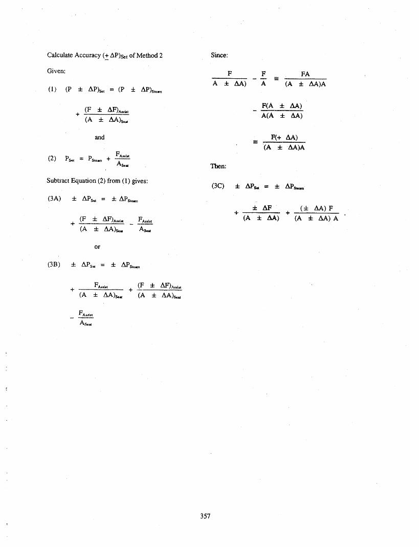
Calculate Accuracy (+ AP)sct of Method 2 Since:
Given: F F FA
A _ AA) A (A E AA)A(1) (p 4- AP)s,. = (P :k AP)st_,.
(F 5: AF)^.a. _ F(A ± AA)+ A(A ± AA)
(A _ AA)s_.,
arid _ F(+ AA)
(A 4-AA)AFAjji_
(2) Ps_ = Ps,._ +As_.. Then:
SubtractEquation(2)from(I)gives: (3C) 4- APs,,-- 4-'APs_
(3A) 4- APs,, = 5:APs,_
4" AF (+ AA) F% + .
(F 5: AF)^,.i,, F^.l,, (A 4- AA) (A 4- /LA)A+
(A + AA)S*., A_
or
(3B) 5: APs,, = 4- APs._
FA,._, (F 4- AF')A,_,t+ +
(A 5: AA)S*., (A 4- AA)s,_
357z

i
ATTENDEE- PANEL QUESTIONS AND ANSWERS(EDITED; ATTENDEE QUESTIONS AND PANEL/AUTHOR
RESPONSES NOT IDENTIFIED B Y NAME)
Question1 going to be testing on nitrogen, you have to demon-swate that tJaenitrogen setpressure that you tested it at
Do youhave any explanation why these valves demon- is equivalent or will result in a set pressure within thestrate different set point settings when, in fact, they tolerance established by the plant, plus or minus onewere not used at ali in the plant and werejust returned percent of nameplate set pressure, with steam under it.to them? , ,
And it is incumbent upon the owner doing the test toFrom a physical standpoint, with the repeatability of come up with that correlation, and that is what people 1measurements that you got from the first and second have been trying toachieve.series of tests, it doesn't make much engineering senseto me. Do youhave any explanation for that? Question 4
Response 1 With dmlift limited to 50 thousandths, do you get anyinformation at ali which is representative of the in-
A lot of the setpressure changes we see are an increase plant blowdown of the valve? That is, what is the re-in set pressure after a long time in storage, and thereare theories thatperhaps a bindingmk,espiace. That is, seat point, =nadis that a realistic reseat point?the valves lose some of their lubricity over a period oftime. The bondingphenomenon is well known, at least '_ Resporlse 4in the Target Rock valves regarding the stellite, wherethere is set point drift. Usually it is from valves inser- No. In thecase of spring--operatedvalves, no. We havevice, sometimes with differences as high as 200 psi. a full flow system that we have to go to in order toes-This is caused by a bonding of the two metals, which tablish blowdown. And in the case of pilot--operatedtakes more pressure to pull them apart, valves like Target Rock's, there is a con'elation which
has been established by test, where we havecorrelatedQuestion 2 or the valve manufacturer,Target Roe.l.:,has correlated
the limited flow testing with full flow testing blow-If youexercise the valve through some growing pains, downs. There is a "fable.you may not wind up with the same thing. But whenyou have taken it from a test facility, stored it under Question 5ambient conditions, and returned it, that I would sus-
pect would have a lesser effect. Could you please comment on a related matter, on the
Response 2 association between volume under the valve andaccu-racy of the test in regard to any of the three methods?
It is less, that is true, by ali order of magnitude, Response 5
Question 3Youwant to have sufficient volume under the valve in
You mentioned about the wide variations between ni- order to lift the valve. What we have seenon very, very
trogen and steam, that you need a correlation between small volumes where we have tested on gas, if thethe two. How do you obtain this correladon? What is valve does not lift completely,you will geta one-sided
, this correlation you are referring to? lifting of the disc.
Is that printed by the valve manufacturer or do you You do not have sufficient volume to blow the valvehave to do your own tests, or what? fuUopen. It also results in the LBDT trace is very weak
and it doesn't give you a good crisp lift and show youResponse 3 where the actual opening point may be.
The correlation is established by the OM. The idea is to As far as how much volume is required, I could not tellobtain a steam set pressure in the plant. But if you are you. Weusually use about 30 cubic feet of steam.
358
ASSESSMENT OF THE EFFECTIVENESSOF
ASME SECTION Xi PUMP AND VALVE SURVEILLANCE TE3TING
JOHN F. HOSLERPROJECT MANAGER
ELECTRIC POWER RESEARCH INSTITUTE
ABSTRACT ing low flow conditions. However, no assessmentcould be made regardingthe relationshipbetween alow flow test result obtainedundermini-flow condi-
The effectiveness of the pump and valve surveil- tions and actualpump degradation. The data were in-lance testingcurrentlyperformed in accordancev,ith sufficient to assess the effectiveness of DP/FlowASME Section XI requirements was assessed. The testing inpredicting futureflow anomalies.assessment was based on a pilot comparisonof actualinplantSect/on XI testing resultsto re.portedcompo-nent degradation/failure histories obtained from ACKNOWLEDGMENTSNPRDS for two nuclear units over a period of fouryears. The authorwouldlike to acknowledge thecontribu-
tions of the EPRIPump andValveSurveillanceT_st-An evaluation was performed on a component by ing Utility/Industry Task Group which, under the
component basisevaluating ,SectionX[ testingresults, chairmanship of Gan3_Galbmath(Duke Power Com-i.e., measuredstroke times, vibration levels, etc., for party) provided valuable guidance throughout the ef-ali pumps and valves for which component fort. The authoralso aclmowledges the contributionsdegradations/failureswere reported..Theintent was to of BruceHinkley, JohnMoran and RobertStanley ofdeterminetheextent to which specific testing methods Cygaa EnergyServices who compiled and evaluatedactually detected or predicted specific component the informationsummarizedherein.degradation types.
NOMENCLATUREq"hestatisticaldatabase (two plantsover fouryears)
was insufficient to allow finn conclusions. However, Pi Pump Inlet Pressuretheresultsdoprovideanindication of theeffectiveness
of specific Section XI tests in detecting/predicting DP DifferentialPressureacrosspumpspecific degradation/failmetypes.
Q Pump FlowrateThe ,seatleakage testing for valves was found to be
effective in detecting existing degradationbut couldV Pump VibrationDisplacementnot be trendedto predict future leakrates. Stroketime
testing of motor and air operated v,-,_veswas, ingeneral, ineffective in either detection of existing Tb Pump BearingTemperaturedegradationor p_edictionof incipient failure.
Pr Pump ReferenceInlet Pressure
Vibration testing (displacement) of pumps wasfound to be soauewhateffective in both detectionand Qr Pump ReferenceFlowrate
aat.alg_t.= AIh,'* _,1.0..Ihaa.lL'_- W¢ _ I, .Ih_,g ],lt _vjvT,l_.,'=..',_=_,,=_"a.= v_. a.a._:_.a.a v ,¢ a
: testing was foundto be somewhat effective in detect- DPr Pump ReferenceDifferentialPressure
359

INTRODUCTION • Horizontal turbinedriven centrifugal pumps
• Motor driven positive displacement pumps.Curt-early, utilities operating nuclear power plants
maintain pumps and valves in accordance with estab- APPROACHfished maintenance prograns. Such programs may in.volvepreventativemaintenanceactivitiesinvolving
periodicmaintenance,aswellas,predictivemainte- InordertoassesstheeffectivenessofSectionXInanceactionsinvolvinguseofsophisticateddiagnostic pump and valvesurveillancetestingcurrentlyper-
equipmenttoallowearlydetectionofcomponent formed,two nuclearunits(oneBWR andone PWR)wereselectedforevaluation.Over400pump andvalve
degradation, degradation/failure reports obtained from the NuclearPlant Reliability Data System (NPRDS) over the, time
In addition to these established maintenance pro- period 1985 through 1988 were analyzed to ascertaingrams, the Nuclear Regulatory Commission (NRC) re- the nature of the degradation and the method of detec.quires periodic surveillance tests to be performed on tion. For each component degradation/failure reported,safety-related pumps and valves. The NRC requires the previous surveillance test results for that compo-that such testing be performed in accordance with nent were analyzed to determine whether trends in pa-ASME Sect/on XI testing requirements for pumps and rameters measuxed during Section XI testing wouldvalves. Although such testing does provide some indi- have indicated an incipient degradation/failure.cationoftheavailabilityofthecomponentatthetime
oftest,itisprimarilyintendedtodetectdegradationin The intentwas toassesstheeffectivenessofeach
componentperformancepriortoan actualfailureon specificSectionXI testindetection/predictionof
demand, specificcomponentdegradation/failuretypes.
As hartofanongoingprogramtoimprovenuclear AnalysisofNPRDS narrativesandcrosscorrelation
plainpredictivemaintenancemethods,theElectric withSectionXI testingresultsallowedanassessmentPower Re.arch Institute,inconjunctionwithanin- oftheeffectivenessofspecifictestingmethodsindetec-
dustry advisory group, contracted with Cygna Eaergy tion of specific existing degradation/failure types.Services to conduct a pilot study to quantitativelyassess the effectiveness of ASME Section XI testing of For each component included in each plant's
pumps and valves in both detection of existing ,SectionXI testing program and for which degradationsdegradation and prediction of incipient failure. /failures were reported in NPRDS, time history plots
of measured Sectiou XI test parameters were devel-
oped coveting the entile period of evaluation. AnalysisThe results of this evaluation provide a basis for lc- of trends depicted in these plots allowed an assessment
curing future EPRI research on improved predictive of the effectiveness of trending specific Section XI test
maintenance testing methods, parameters in predicting incipient degradation/failure.
SCOPE ASSESSMENT OF SECTION XIVALVE ":ESTING
This project assessedSection XI testing =quire- EFFECTIVENESSments for motor and air operated valves and checkvalves. Hydraulically operated valves, safety reliefvalvesandvalveswhichm capabJeofonlyoneopera- Summary of Section XI Valvetion (Category D valves) were excluded from the Testing Requirementsstudy.
Each specific test required under ASME Section XI
Following a review of the population of pump/ was evaiuated for effectivene_ in detecting and or pre-driver types in IST programs, the following pmnp/ dieting degradation/failure. Section XI testing require-driver combinatioxks we_ included in the study: ments for valves are summarized in Table 1.
For the purpose of this study, the effectiveness of the• Vertical motor driven turbine pmnps stroke time, seat leakage and full stroke exercise tests
in detecting component degradation/failure was__ • Horizontal motor driven centrifugal pumps evaluated.
-- 360
=,_

Table 1, Summary of Section XI valve testing requirements
Valve PositionSeat Indication Full Stroke
Valve Type Stroke Time Leakage" Verification Exercise
Power operated 3 month 2 year 2 year 3 monthinterval interval interval interval
Check -- 2 year -- 3 month binterval interval
a. Only valves fbr which seat leakage is limited to a specific maximum amount in the closed position to fulfilltheir fimction are required to be leak tested.
b. For valves which cannot be full ,stroke exercised to the position required to fulf'tU their function during plantoperation they must be so exercised at each outage if outages are more than montlxs apart.
The following summarizes the acceptance criteria NPRDS Reported Valvefor each Section XI test required for valves: Degradations/FailuresStroke Titre. For power operated valves with nomi-
nal stroke times greater than 10 s, an increase in stroke Table 2 presents a summary of NPRDS reportedtime of greater than 25% from the previous test re. valve degradations/failures for the two units selected
quires an increase in testing frequency from 3 to over the period examined. A total of 349 valve degra-1 month intervals until corrective action is taken, dations/failmes were reported. Of these, 37% involved
motor operated valves, 28% air operated valves andFor valves with nominal stroke times of 10 s or less 9% check valves. The remaining degradations/failures
a stroke time increase of 50% requires the same in- primarily involved relief or hydraulically operatedcrease in testing frequency, valves, lt should be noted that many "degradations" re-
ported in NPRDS ase not ecru.al functional failures ofSeatLeakage(alicategoryAvalves).Maximum the component i.e. they would not affect its ability toallowable leakage rates are to be specified by the own- perform its intended function and that Section XI test-er based on functional requirements. Also, maydmum ing is not necessarily intended to detect ali degradationallowable leak rates are specified in Section XI as types. Examples of such "degradations" include pack-30XD (mi/rr) for water and 7.5XD (SCF/day) for air ing leaks and body to bonnet leaks.where D is the nominal valve size in inches.
For valves NPS 6 or larger, trending of theleakage Apparent Valve Degradation/rate is required. If a changein leakage rate relative to Failure Detection Efficiencythe last test reduces the margin to the maximum allow-able rate by 50% or more, the test frequency must be,
doubled. If, based on projection of 3 or more test Motor Operated Valves. Table 3 presents the ap-points, the leakage rate is expected at the next selni- parent degradation/failure detection efficiency foruled test to exceed the maximum permissible value by each Section XI test for ali reported motor operatedmore than 10%, the valve must be.replaced or repaired, valve degradation/failure types. The detection effi-
ciency is defined as the percentage of total reported de-Full Stroke Exercise. All safety related power ep- gradatious/failures of a given type. which were actuallycrated and check valves must be full (or if hnpracdcal detected by a specific Section XI test. From Table 3 itpart) stroke exercised to confirm operability. It should can be seen that the seat leakage test was relatively ef-be noted that in many cases demonstration of full/part fective in detecting seat leaks, bent stems and incorrectstroke capability for check valves is not practical aral limit switch settings. Although detection of a bentthe NRC gas allowed disassembly and inspection as an stem and/or incorrect limit switch settings are not ob-_,ll_,m_tiv_ In fidl/rnart etrr_ka a-emrrqelna ,ha.r,tiv_e_¢ tV,__,,ot I,_ot-,_g,_taot tM tl:'ac'*t _ha! th ,,,'_|,,a,..................... • ..................... ¢_- j-_ • , ,_t
_
- 361
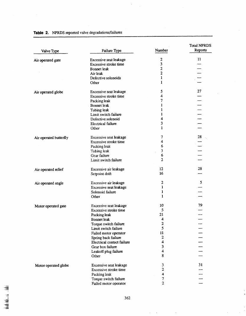
Table 2. NPRDS reported valve degradations/failures
Total NPRDS
Number ReportsValve Type Failure Type _
Air operated gate Excessive seat leakage 2 11Excessive stroke time 3Bonnet leak 2Air leak 2Defective solenoids 1Other 1
Air operated globe Excessive seat leakage 5 27Excessive stroke time 4
Packing leak 7 --Bonnet leak 1
Tubing leak 1 wLimit switch failure 1Defective solenoid 4 mElectrical failure 3Other 1 ---
Air operated butterfly Excessive seat leakage 7 28Excessive stroke time zt
Packing leak 6 wTubing leak 3Gear failure 6 mLimit switch failure 2
Air operated relief Excessive air leakage 12 28Setpoint drift 16 w
Air operated angle Excessive air leakage 2 5Excessive seat leakage 1Solenoid failure 1Other 1 w
Motor operated gate Excessive ,seatleakage 10 79Excessive stroke time 5
Packing leak 21 --Bonnet leak 4
Torque switch failure 2 --Limit switch failure 5
Failed motor operator 11 mSpring back failure 2 .-Electrical contact failure 4Gear box failure 3
Leakoff plug failure 4Other 8
Motor operated globe Excessive seat leakage 3 31Excessive stroke time 2
Packing leak 4 --Torque switch failure 7Failed motor operator 2
__
362
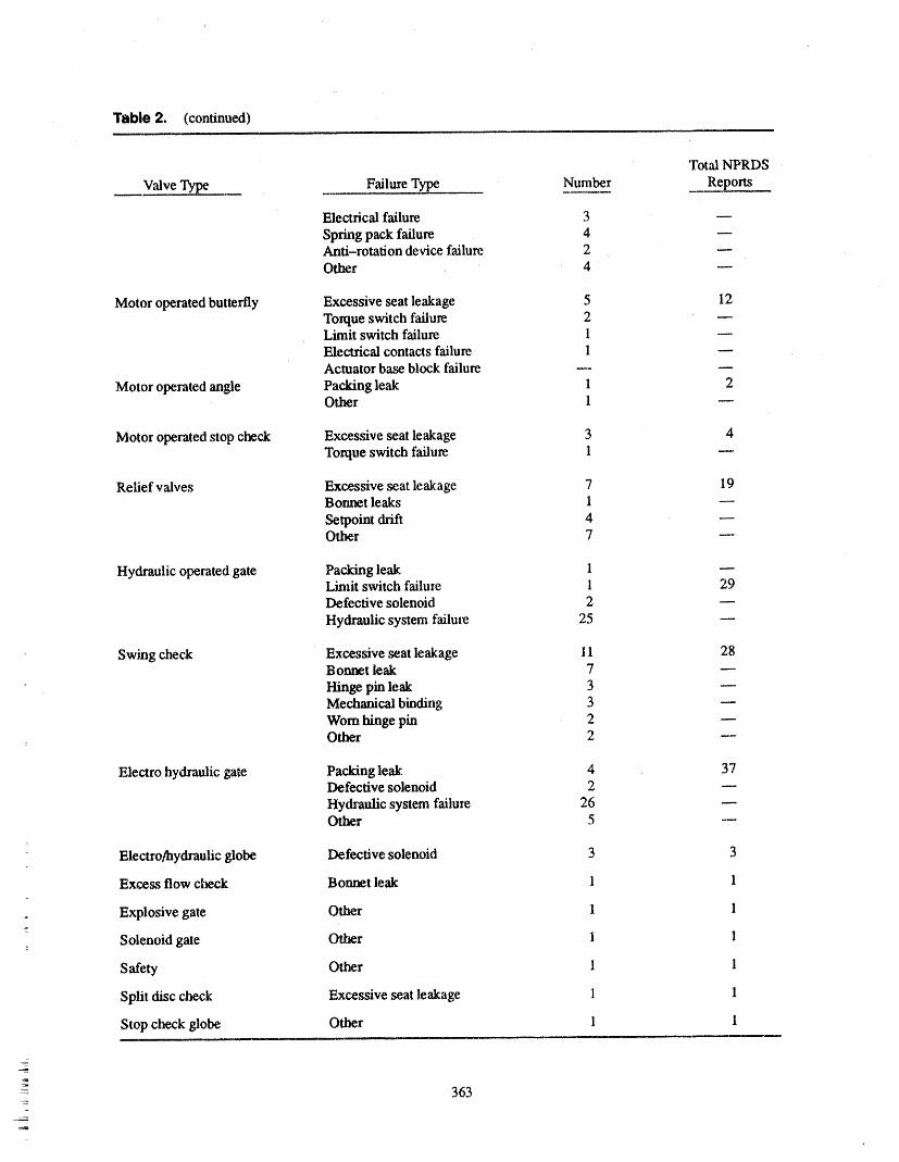
Table 2. (continued)
Total NPRDS ,
Valve Type Failure Type Number Reports
Electrical failure 3
Spring pack failure, 4Anti-rotation device failure. 2Other 4
Motor operated butterfly Excessive seat leakage 5 12Torque switch failure 2Limit switch failure 1Electrical contacts failure 1Actuator base block failure _
Motor operated angle Packing leak 1 2Other 1
Motor operated stop check Excessive seat leakage 3 4Torque switch failure 1
Relief valves Excessive seat leakage 7 19Bonnet leaks 1 --
Setpoint drift 4Other 7 ---
Hydraulic operated gate Packing leak 1Limit switch failure 1 29Defective solenoid 2
Hydraulic system failure 25
Swing check Excessive ,seat leakage 11 28Bonnet leak 7
Hinge pin leak 3Mechanical binding 3Worn hinge pin 2Other 2 ---
Electro hydraulic gate Packing leak 4 37Defective solenoid 2
Hydraulic system failure 26Other 5 --
Electro/hydraulic globe Defective solenoid 3 3
Excess flow check Bonnet leak 1 1
j Explosive gate Other 1 1
Solenoid gate Other I 1
Safety Other 1 1
Split disc check Excessive seat leakage 1 1
Stop check globe Other 1 1
- 363

Table 3. Apparent degradation/failure detection efficiency motor operated valves
Percent Detected
Stroke Seat
Failure Number of Time Leak Supplemental Plant
Type Failures Test Test Diagnostics Operation
Deteriorated packing 1 .... 1O0
Seat leak 19 -- 68 n 32
External leak 8 -- 12.5 --- 87.5
Tight packing 1 100 ....
Tight stem nut 1 50 -- w 50
Bent stem 2 _ 100 -- w
Packing leak 25 4 m __ 96
Incorrect T.S. setting 2 _ 50 -- 50
Worn gears 3 .... 100
Hydraulic lock ofspringpack 1 _ m _ 100
Motor failure 13 8 -- _ 92
Declutch mechanism 2 --. _ _ 100
Defective torque orlhnit switch 17 m 6 -- 94
Mechanical failure
springpack 5 -- -- 60 40
Contacts failure 5 20 m __ 80
Electrical componentfailure 11 .... 100
Anti-rotation device 2 .... 100
Other 6 17 17 -- 66
is operated and monitored during the performance of detecting contact failures. Stroke time testing was inef-the.test provides an opportunity to detect malfunctions fective in detecting ali other degradations/failuresother than seat leakage, reported. By fax, the majority of valve degradations/
: failures were detected during normal plant operation
The stroke time test was effec'dve in deter-ring tight and not during a Section XI test. Overall, stroke timepacking and a tight stern nut and somewhat effective in testing per say., resulted in minimal incremental
< 364
'qll' '1'1'I1" ' _ll .......... i,iii..... IIIN,O ", ..... _l_I'lI,_'l"l' ' iii"' ,'!'_"l'lr I,IlWlrlr",lIl,l,lltl'llll__r_lll",_,,'
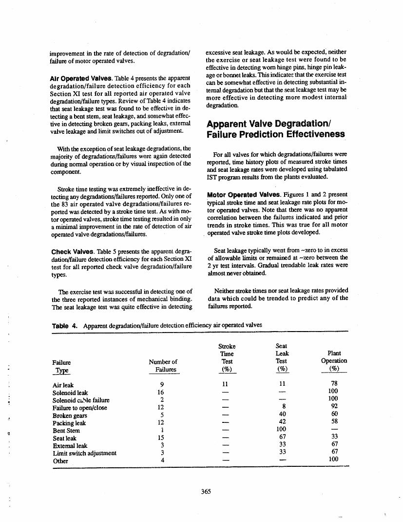
improvement in the rate of detection of degradation/ excessive seat leakage. As would be expeaed, neitherfailure of motor operated valves, the exercise or seat leakage test were found to be
effective in detecting worn hinge pins, hinge pin leak-
All' Operated Valves. Table ztpresents the apparent age or bonnet leaks. This indicate_ that the exercise testdegradation/failure detection efficiency for each can be somewhat effective in detecting substantial in-Section XI test for ali reported air operated valve ternal degradation but that the seat leakage test may bedegradation/failure types. Review of Table 4 indicates more effective in detecting more modest internalthat seat leakage test was found to be effective in de- degradation.reefing a beat stem, seat leakage, and somewhat effec-
tive in detectingbroken gears,pacldng leaks, external ApparentValveDegradation/valve leakage and lhnit switches out of adjustment. Failure Prediction Effectiveness
With the exception of seat leakage degradations, themajority of degradatiorts/failures were again detected For ali valves ibr which degradations/failures wereduring normal operation or by visual inspection of the reported, time history plots of measured stroke timescomponent, and seat leakage rates were developed using tabulated
IST program results from the plants evaluated.
Stroke time testing was extremely ineffective in de-tecting anydegradations/failuresreported.Only oneof Motor Operated Valves. Figures 1 and 2 presentthe 83 air operated valve degradations/failures re- typical stroke time and seat leakage rate plots for mo-ported was detected by a stroke time test. As with mo- tor operated valves. Note that there was no apparenttor operated valves, stroke dme testing resulted in only correlation between the failures indicated and priora minimal improvement in the rate of detection of air trends in stroke times. This was true for all motoroperated valve degradations/failures, operated valve stroke dme plots developed.
Check Valves, Table 5 presents the apparent degra- Seat leakage typically went from -.zero to in excessdarien/failure detection efficiency for each Section XI of allowable limits or remained at -,zero between thetest for all reported check valve degradation/failure 2 yr test intervals. Gradual trendable leak rates weretypes, almost never obtained.
The exercise test was successiitl in detecting one of Neither stroke times nor seat leakage rates provided
the three reported instances of mechanical binding, data which could be trended to predict any of theTbe seat leakage test was quite effective in detecting failures reported.
Table 4. Apparent degradation/failure detection efficiency air operated valves
Stroke SeatTime Leak Plant
Failure Number of Test Test Operation
_ Failures (%) (%__)_) (%)
= Air leak 9 11 11 78
= Solenoid leak. 16 m -- 100
.. Solenoid cable failure 2 m m 100Failure to open/close 12 -- 8 92Broken gears 5 _ 40 60Packing leak 12 -- 42 58Bent Stem 1 -- 100Seat leak 15 _ 67 33External leak 3 _ 33 67
Limit switch adjustment 3 _ 33 67Other 4 -- m 100
365
7_

Table 5. Apparent degradation/failure detection efficiency check valves
Percent Detected
SeatFailure Number of Exercise Leak Plant
, Failures Test Tes....._t Operation
Seat leakage 11 9 73 18Bonnet leak 7 -- -- I(30
Hinge pin leak 3 -- -- 100Mech. binding 3 33 -- 67
Worn hinge pin 2 -- -- 100aOther 2 -- -- 100
a. Found during disassembly/inspeCtion.
3" MOTOR OPERATED GATE VALVEHV-7258
24
23-
22 -
(,Jwt,,,'l
t_JX
_- 2t -
20-
Fai lure I_script it'm Dat_...._e
10 - A Failed to Close Duriaacj _ 09/16/87
: i18 _---11 1 ...... I ''l I 1 i "l I I 'l ' i" I T-----
Nov --84 Jun--85 Dec --85 Jul--86 Jo n--87 Au 9-87 F'eb--88 Se p-89.
TE_" DATE[3 CLOSII_; STROKE
Figure 1. Typical motor operatedvalve stroketime history.
366

Figure 2. Typical motor operated valve seat leakage history.
Air Operated Valves. Figures 3 and 4 present typi- sured as an alternative to verification of full/partialcal stroke time and seat leakage rate plots for air oper- stroke. Figure 5 presents a typical check valve seatated valves. Again, as shown in Figure 3, there was no leakage rate plot. Again, no correlation between re-apparent correlation between the failures indicated and ported leakage rate and reported failures were evidentprior trends in measured stroke times. This was true for and the data were too erratic to allow trending.
: ali air operated valve stroke time plots developed. Ingeneral, stroke times for air operated valves did dis-play a significantly higher level of variation than did ASSESSMENT OF PUMP
those for motor operatedvalves.This indicates thatal- TESTINGEFFECTIVENESSthough trendsin stroke times did not allow predictionof incipient failure, the stroketime may be sensitiveto
changes in air operated valve condition and/or air Summary of Section XI Testingsupply pressure variations. Requirements for Pumps
As shown in Figure 4, seat leakage rates behaved
essentially the same as for motor operated valves and Section XI testing requirement for pumps arewere not trendable to predict failure or excessive summarized in Table 6. Note that delta pressure (DP)
leakage. . and flow (Q) are not evaluated independently. Duringtesting, the operator generally sets the flow to equal the
Cheek Valves. Seat leakage rate is the only par=ne- reference value and compares the DP reading to theter which is measured during Section XI testing of allowables shown. The testing can, however, be donecheck valves, although flowrate is sometimes mea- by setting the DP and measuring the resulting flow.
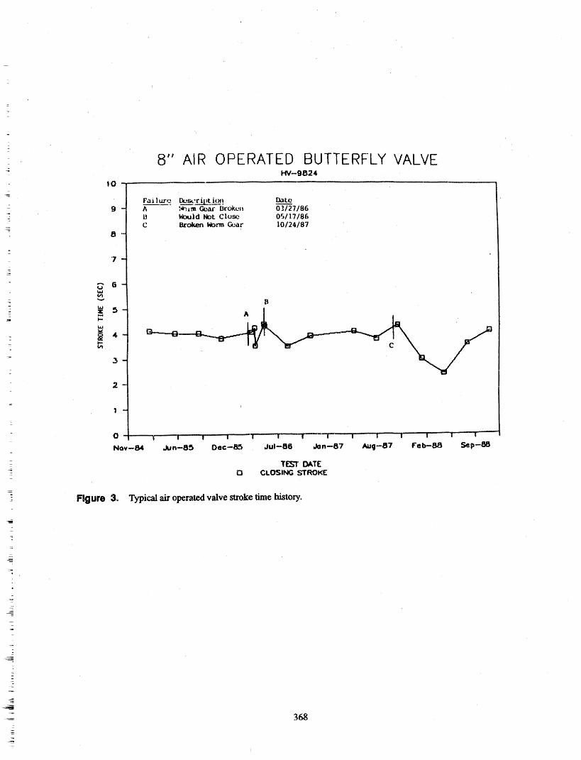
z
8" AIR OPERATED BUTTERFLY VALVEHV--9824
lO-
g-
: 9 - A I_,m Ge,._u"Broken 0]127186- li !_Id Not Close 05117186= C Broken Norm Gear 1012418"I
8-
=
7 --
_. s- A
o 4 - G"-"-'G-
: _
3-
2-
=
1 -
_ O I I w w...... I" ' i : 1"-"- w I I ' ! 1 I l
Nov--B4 Jun--85 Dec--8_ Jul--86 Jan--87 Aug--B7 Feb-B8 Sep--S8
- TE:_ DATEO CLOSlIqG _"rROKF"
: Figure 3_ Typicalairoperatedvalvestroketimehistory.
!-_
__
_
368_
--
4

8" AIR OPERATEIDBUTTERFLY VALVEHV--9_324
15
1 4 -
15-
1,2 -
1,1 -i
_," 1 -
m 0.9-O
_- 0.8-
_ o,7-
__ 0.6 i_ 0.5 -_
_ 0,4-
0.3-
02- g I0.1 -0 r" I I _' I I P I I I I 'f"
Jon--84 Aug--84 Feb---05 Sap--85 Mor--86 Oct--06 May--87 Nov--87 Jun--88 Dec--88
TEST DATE
Figure 4. Typical air operaled v_ve seat leakage hkstory.
i
369
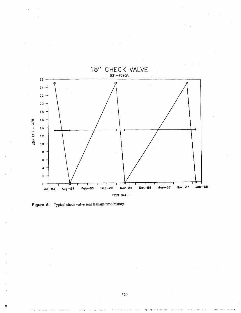
18" CHECK VALVEB21 --F01 OA
26
24
22
20
18
= 16htjt_
* 14I.,i,Jt--"
iii-- 10
8
6
4
2
0
Jon--84 Aug--84 Feb--85 Smp--85 Mor--86 Oct--88 May--87 Nov--87 Jun--88
TESt DATE
Figure 5. Typical check valve seat leakage time history.
370
iIF_ lit " 11111_,r]llp_l ii lilt1,, iq, ,1
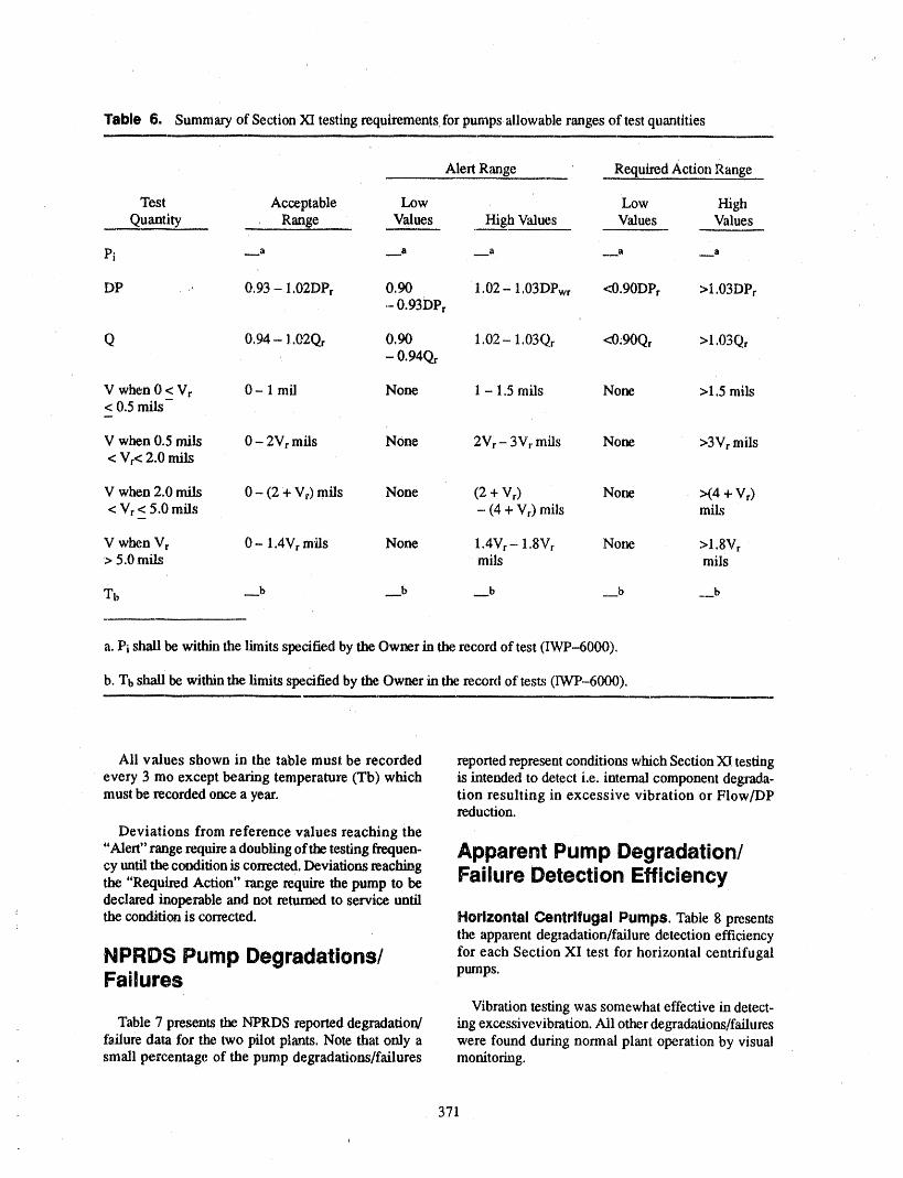
Table 6. Summary of Section XI testing requirements for pumps,allowable ranges of test quantities
Alert Range Required Action Range
Test Acceptable Low Low HighQuantity Range Values High Values Values Values
Pi __a __a __a __.a __a
DP ,+ 0,93 - 1,02DPr 0,90 1.02- 1,03DPwr <0.90DPr >I,03DPr- 0.93DPr
Q 0,94-1.02Qf 0.90 1.02-1.03Qr <:0.90Qr >l,03Qr- 0194Qr
V when 0 < Vr 0 - 1 mil None 1 - 1.5 mils None >1.5 mils< 0.5 mils
V when 0.5 mils 0 - 2Vr mils None 2Vr- 3Vr mils None >3Vr mils< Vr< 2.0 mils
V when 2.0 mils 0 - (2 + Vr) mils None (2 + Vr) None >(4 + Vr)< Vr < 5,0 mils - (4 + Vr) mils mils
V when Vr 0 - 1.4Vr mils Nolle 1.4Vr -. 1.8Vr None >1.8Vr> 5.0 mils mils mils
Tb __b __b __b __b _. b
a. Pi shall be within the limits specified by the Owner in the record of test (IWP-6000),
b. Tbshall be within the limits specified by the Owner in the record of tests (IWP-6000).
Ali values shown in the table must be recorded reported represent conditions which Section XI testingevery 3 mo except bearing temperature (Tb) which is intended to detect i.e. internal component degmda-must be recorded once a year. tion resulting in excessive vibration or Flow/DP
reduction,
Deviations from reference values reaching the
"Alert" rangerequirea doubling ofthe testingfrequen- Apparent Pump Degradation/cy untiltheconditioniscorrected,beviationsreaching Failure Detection Efficiencythe "Required Action" rawge require the pump to bedeclared inoperable and not returned to service until
+ the condition is corrected. Horizontal Centrifugal Pumps. Table 8 presents: the apparent degzadation/failure detection efficiency
NPRDSPumpDegradations/ for each Section XI test for horizontal centrifugal
Failures pumps.
Vibration testingwassomewhateffective in detect-Table 7 presents the N'PRDS reported degradation/ ing excessivevibration.Ali otherdegradations/failures
failure data for the two pilot plants. Note that only a were found during normal plant operation by visualsmall percentage of the pump degradatioms/failures monitoring.
= 371
q
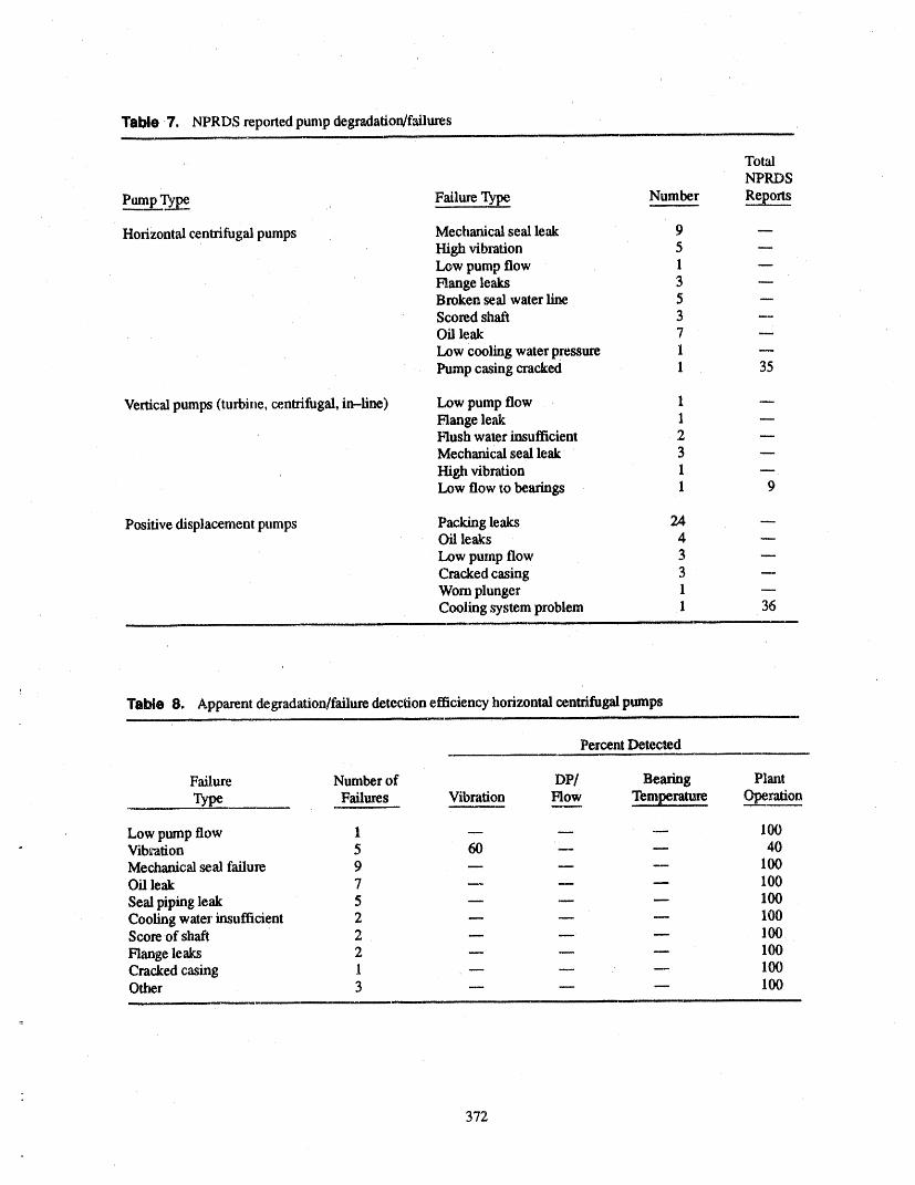
Tsble 7. NPRDS reported pump degradation/failures
. TotalNPRDS
Pump Ty_._. ,, Failure Type Number Reports
Holizont,'d centrifugal pumps Mechanical seal leak 9High vibration 5 --Low pump flow 1 --Flange leaks 3Broken seal water line 5Scored shaft 3 --Oil leak 7
Low cooling water pressure 1 --Pump casing cracked 1 35
Vertical pumps (turbine, centrifugal, in-fine) Low pump flow 1Flange leak 1 --Hush water insufficient 2Mechanical seal leak ' 3 --
High vibration 1 --Low flow to bearings 1 9
Positive displacement pumps Packing leaks 24 mOil leaks 4
,LOwpump flow 3Cracked casing 3 --Worn plunger 1Cooling system problem 1 36
Tsbio 8. Apparent degradation/failure detection efficiency horizontal centrifugal pumps
Percent Detected
Failure Number of DP/ Bearing Plant
Type Failures Vibration Flow Temperature Operation
Low pump flow 1 _ _ _ 100Vib_ation 5 60 -- 40Mechanical seal failure 9 -- -- -- 100Oil leak 7 .... 100
Seal piping leak 5 _ _ _ 100Cooling water insufficient 2 -- -- -- 100Score of shaft 2 m __ m 1O0
Flange leaks 2 m m -- 100Cracked casing 1 _ _ _ 100Other 3 m _ _ 100
372
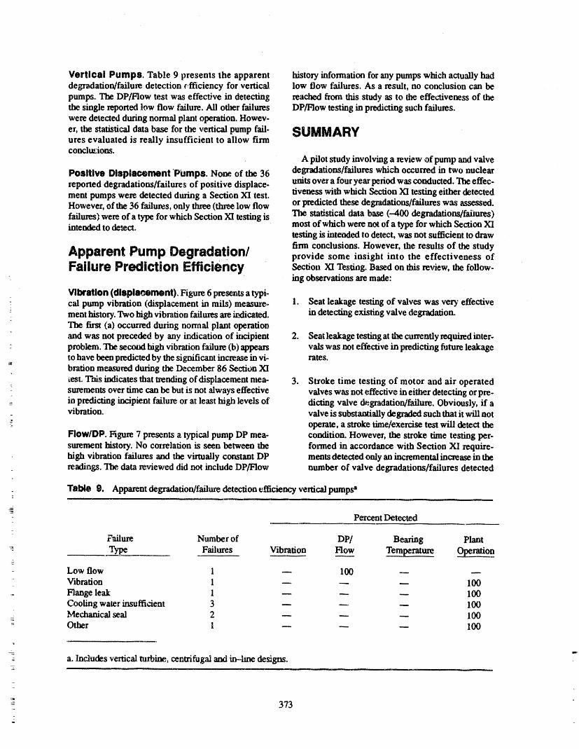
Vertical Pumps. Table 9 presents the apparent h/story information for any pumps which actually haddegradation/failure detection ¢_fficiency for vertical low flow failures. As a result, no conclusion can bepumps. The DP/Flow test was effective in detecting reached firom this study as to the effectiveness of thethe single reported low flow failure. Ali other failures DP/Flow testing in predicting such failures.were detected during normal plant operation. Howev-
er, the statisticaldata base for the vertical pump fail. SUMMARYures evaluated is really insufficient to allow firmconclusions.
A pilot study involving a review of pump and valve
Positive Displacement POmps. None of the 36 degradations/failureswhich occurred in two nuclearreported degradations/failures of positive displace- units over a four year period was conducted. The effec-
tiveness with which Section XI testing either detectedment pumps were detected during a Section XI test.However, of the 36 failures, only three (three low flow or predicted these degradations/failures was assessed.failures) were of a type for which Section XI testing is The statistical data base (--400 degradations/failures)intended to de_ect, most of which were not of a type for which Section XI
testing is intended to detect, was not sufficient to draw
firm conclusions. However, the results of the studyApparent Pump Degradation/ provide some insight into the effectiveness of
Failure Prediction Efficiency S_o=, XI Testing. Basedon this=view, the follow-ing observations are made:
Vibration (dlsplsc'Atment). Figure6 presentsatypi-cal pump vibration (displacement in mils) measure- 1. Seat leakage testing of valves was very effective
: meat history. Two high vibration failures are indicated, in detecting existing valve degradation.The first (a) occurred during nonnal plant operationand was not preceded by any indication of incipient 2. Seat leakage testing atthe currently required inter-problem. The,second high vibration failure (b) appears vals was not effective in predicting future leakageto have been predicted by the significant increase in vi- rates.bration measured during the December 86 Section XI
test, This indicates that trendingof disPlacement mea- 3. Stroke time testing of motor and air operatedsurements over time can be but is not always effective valves was not effective in either detecting or pre-
: in predicting incipient failure or at least high levels of dictiag valve degradation/failure. Obviously, if a_ vibration, valve is substantially degraded such that it will not
operate, a stroke time/exercise test will detect theFIow/DP. Figure 7 presents a typical pump DP mea- condition. However, the stroke time testing per-surement history. No cozrelation is seen between the formed in accordance with Section XI require-high vibration failures and the virtually constant DP meats detected only an incremental increase in thereadings. The,data reviewed did not include DP/Flow number of valve degradations/failures detected
o Table 9. Apparent degradation/failure detection efficiency vertical pumps a
Percent Detec_d
Failure Number of DP/ Bearing Plant
-= Type Failures Vibra___._tion FIo__ww Temperature Operation
Low flow 1 -- 100 --_
Vibration 1 .... 100Flange leak 1 -- -- -- I00Cooling water insuffi_ent 3 .... 100Mechanicalseal 2 _ _ _ 1O0
: Other 1 -- _ _ 100
a.Includesverticalturbine., centrifugalandin-.linedesigns.
: 373
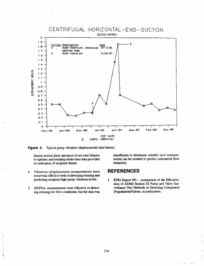
CENTRIFUGAL HORIZONTAL-END-SUCTION$22421 MPC93
2-
19 -FailureDescription Date i _.-- B
1 8 - A . High vibration,excessive 04---712186/
1 6 -' 9 Ilio.h vibratioh 01/06/87"/15-
1 4 -
"1,3 -
12 -;lE"" 1 1 --ntrW 1 --EtaJ
09 -
=" 08-
_ 07-
06-
05- _ A
04 -
O3 - ,,._
02 -
01 -
0 - - ! .... I I" 't ' 1 ..... I 1_ : I " 1 I I "-T'--'"7-- I ....
Nov.--84 Jun--B5 Dec-8_5 Jul-86 Jon--87 AuQ--87 feb-S8 _p--88
T_-'TOAI_E13 HORIZ VIBRATION
Figure 6, Typical pumpfibration (displacement)timehistory.
dur/ngnormal plant operation (even toud failures insufficient to determine whether such measure-to operate)and trending stroketime data prov/ded merits can be trended to predictsubstantial flowno/ndication of incipient failure, reduction.
4. Vibration (displacement) measurements were REFERENCESsomewhat effective both indetecting existing and
p.redicl_ngincipient high pump vibrationlevels. 1. EPRI ReportNP-, Assessment of the Effective-_ess of ASME Section XI Pump and Valve Sur-
5. DP/Flow measurements were effective in detect- veillance Test Methods in Detecting Componenting existing low flow conditions, but the data was Degradation/Failure, inpublication.
374
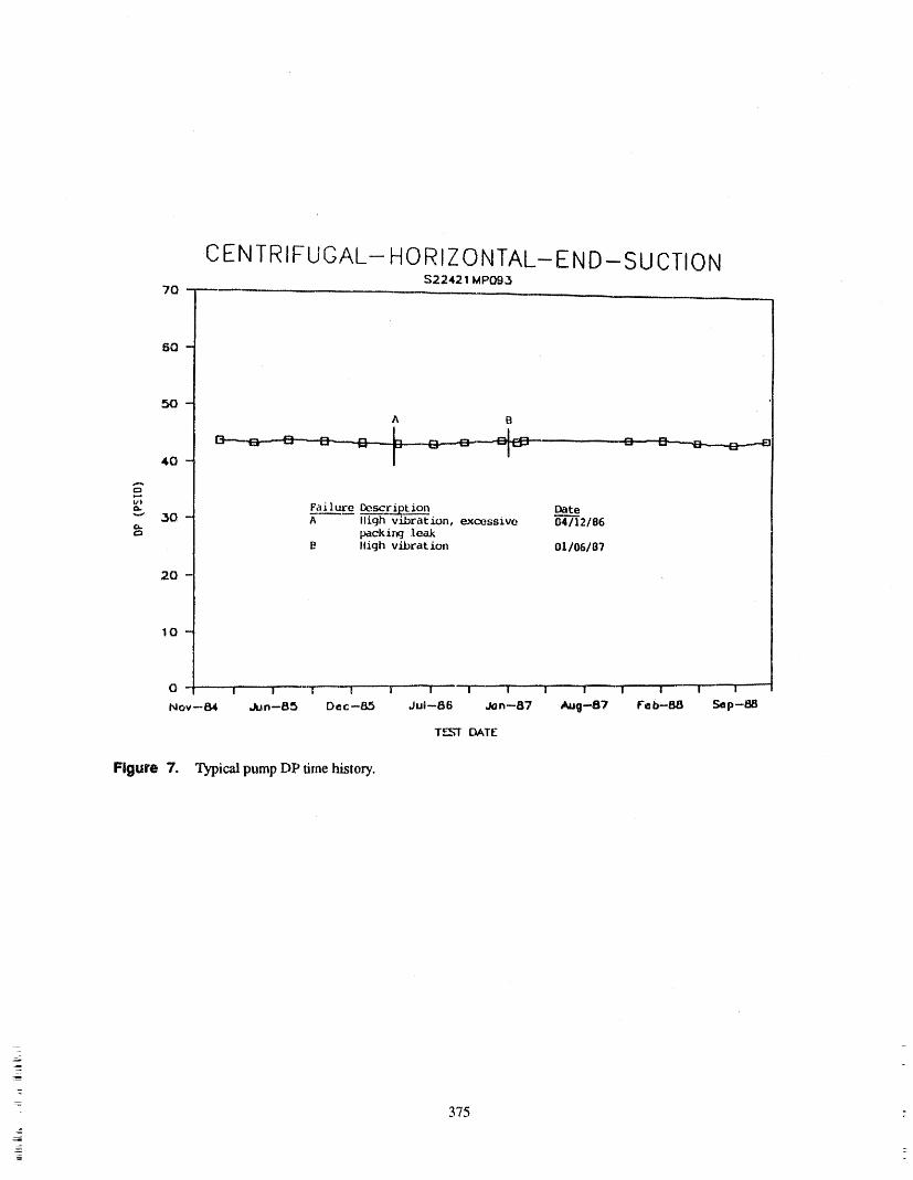
CENTRIFUGAL- HORIZONTAL- END- SUCTION$22421 MP09,3
7Q-
5Q-
A B
40- _ O-- O_--,B.-,--....B,_.,--E
a- F_i 1._e Be.scf ip_t ion Date"_ _0 - A llighvibration, excessive 04/'---]2186Ca.
packing leakIligh vibration 01/06/87
20- ,,
10-
0 '1 I ' ' _I .... I ......II --I " - i -i [ .... ! --] I .... I I --
NOV-84 Jun--85 Dec--&.5 JuI--B6 Jon--87 Aug--B7 F'eb-_l Se p-/:_
T,_r_-'TDATE
Figure 7. "l_ic,_! pump DP time history.
i
375
ATTENDEE- PANEL QUESTIONS AND ANSWERS(EDITED; ATTENDEE QUESTIONS AND PANELAUTHOR
RESPONSES NOT IDENTIFIED BY NAME)
Question I I think we can learn a little bit from the experience ofthe Europeans, The French and the Germans are not
Were either of the plants involved in the study using taking that approach. They do not go out and strokepump or valve diagnostic equipment, such as we have time test motor -operated valves. They have gooddemonstrated here, that is, the Vision program on maintenance programs. They do testing on a much lesspumps or MOVATS? frequent basis to confirm that a valve seems to work
today, but not from the standpoint of, does it work a
Response I little different than it did three months ago.
So I think we should think about the philosophy of sur-Panel Yes, they were. veiUance testing. This is a big NRC philosophical ap-
proach to evaluating what is going on in, not justAttendee Was that data reflected in the report'? pumps and valves, butali the components, and whether
that really makes sense ,alithe time.Panel One of the categories here is plant operation,
and we _o h',_ a category for supplemental diagnos- Question 2tics. Of the failures that were occurring, I can not say
how many of them were picked up during MOVATS How effective are the tests requhed by Section ,XI h_testing or some type of testing like that. providing a high degree of assurance that the valve will
operate the next time it is called upon to operate? Haslt may have been that in some cases there were actual that been included in the program? And are we detect-readouts during a supplemental diagnostic type test. In ing degradation, because, sure, you are going to havea let of cases, an NPRDS report does not say, we did a degradation.supplemental diagnostic test of this type and we have a
problem. It just says, we have a problem. Response 2
Comment One way I would propose that you measure that is,how many failures did we have and how many of them
I am also a member of the O&M Main Committee. Ac- did we catch by doing these tests? That was the firsttually, I found this presentation very depressing from a part of the study. The answer is, at lea.st in terms ofstandards development viewpoint. What it basically stroke time testing, it is a very, very sm'til pew.entage.points out is that for a vast majority of the require-meats that we have in the O&M standards, we cannot, Commentfrom that data, get any semblance of assurance that
what is happenhag in the nuclear plants is acceptable. Maybe that is the wrong parameter being measured.Perhaps we should look at another one if the goal of
I think that, based on the data that we have here, EPRI Section XI is to be accomplished.and the industry should, in fact, expand the sample of
the program to get a much larger data base, either to Now, if you are looking at degradation of valves forconfirm that the_ results are typical of the industry or, maintenance purpose_, that is adifferent subject, in myif not, then to come up with some recommendations to opinion.O&M and ASME on how we can improve the testingto get a better predictive methodology incorporated Question 4into the standards.
You had a suggestion that on a pilot study, you not useComment stroke time as your parameter in looking for degrada-
tion and operability, and you eliminate it.I think that there is a philosophy that, if you go out andcheck the valves and do some tests on them, you can Do you have a suggestion as to what you wouldsee things happening and you can therefore determine, substitute during that pilot study for monitoringif it is going to break, before it breaks, degra0.ataon'!
376

Response 4 not propose one. I think part of that would to lookingat other ways of doing it, hopefuUy as easy as stroke
It would be a good idea on that study to substitute sev- time testing.eral things and see how they ali work out. So I would
377
MOTOR OPERATED VALVESTROKE TIMING; IS THERE VALUE?KEN GREEN, G/LBERT/COMMONWEALTI-I, INC.
FRANCIS ROSCI-I,JR., GILBERT/COMMONWEALTH, INC.TED NECKOW/CZ, PHILADELPHIA ELECTRIC COMPANY
ABSTRACT The three most common power operated valve ac-tuator types found in safety related nuclear applica-tions are motor operated, air operated and solenoid
Both ASME Section XI, Subsection IWV and operated. This paper will address only motor operatedASME/ANSI OMa-1988, Part 10 require stroke fian- valves.ing of certain power operated valves. This requirement
is intended to detect valve degradation and sub_quent Factors Effecting Stroke Timesmaintenance,repair or replacementneeds.However,the adequacy of sUoke tuning, especially for motor op-erated valves, has met much skepticism in the industry. Many factors can effect stroke times. In fact, any
This paper will demonstrate that stroke timing for ac condition which changes the resistance to valve opera-motor operated valves is inadequate and provide a don will effect stroke time. Stem binding, lack of prop-non-intrusive testing alternative. It will also discuss er or dirty lubrication, corrosion, and overly tight
packing are some of the degradation mechanisms de-the value of stroke timing for dc motor operated tectable by increased stroke times. In 'addition, systemvalves, conditions such as flow rate, differential pressure and
temperature can also effect valve stroke times.
ACKNOWLEDGMENTSMotor Operated Valves
The authors would like to acknowledge SteveGallogly, and Brian Curry of Philadelphia Electric In the development, review and updating of inser-Company; Gerald Dolney and Jeffery Neyhard of vice testing programs, clients have often questionedNiagara Mohawk Power Corporation; and Vernon the requirement to measure stroke times on motor op-Ruppert of Gilbert/Commonwealth, Inc. for their con- crated valves because the valves are driven by syn-chronous motors, and would fail before the stroke timetributions towards this evaluation, increased by 25%.
INTRODUCTION Theapparent inadequacy of the test raised a numberof questions:
Tlm stroke timing of certain safety-related power ® How does degradation really effect strokeoperated valves is presently required by ASME time of motor operated valves?Section XI Subsection IWV and the future ASME/
ANSI OMa-1988, Part 10 (OM-10). , If stroke time is ineffective, is there some oth-er parameter that can be used to monitor
The theory behind valve stroke timing is based on degradation?the assumption that degradation mechanisms thatcau_ increases in the resistance of the valve to operate • Can testing of this other parameter becan be. detected by changes in the valve's stroke time. non-intrusive?Unfortunately, for some power operated valves such as
solenoid valves, normal stroke time is so short it is al- ® What about dc motor operated valves?most impossible to measure changes. For others, such
as ac motor operated valves, stroke time varies lit0e Howit Workswith changes in the resistance of the valve. A recentEPRI/Utility/Industry task group study has determinedthat current valve stroke timing procedures can pro- Regardless of the motor type (ac or dc) the workingvide little or no indication of valve degradation that of a motor operated valve is the same. Figure 1could cause failure, provides a simplified motor operator showing a lost
- 379..
_
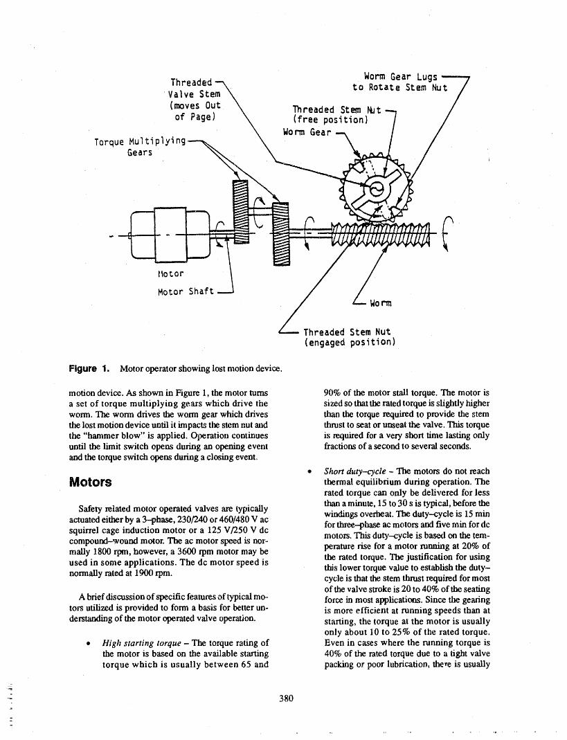
Worm Gear LugsThreaded to Rotate Stem Nut
'Valve Stem
(moves Out Threaded Stem _bt
of Page) (free position)Worm Gear
Torque MultiplyingGears
l_or_or
Motor ShaftWorm
Threaded Stem Nut
(engaged position)
Figure 1. Motor operator showing lost motion device.
motion device. As shown in Figure 1, the motor turns 90% of the motor stall torque. The motor isa set of torque multiplying gears which drive the sized so that the rated torque is slightly higherworm. The worm drives the worm gear which drives than the torque required to provide the stemthe lost motion device until it impacts the stem nut and thrust to seat or unseat the valve. This torquethe "hammer blow,' is applied. Operation continues is required for a very short time lasting onlyuntil the limit switch opens during an opening event fractions of a second to several seconds.and the torque switch opens during a closing event.
• Short duty-cycle - The motors do not reachMotors thermal equilibrium during operation. The
rated torque can only be delivered for less
Safety related motor operated valves are typically than a minute, 15 to 30 s is typical, before thewindings overheat. The duty-cycle is 15 minactuated either by a 3--phase, 230/240 or 460/480 V ac for three--phase ac motors and five min for dcsquirrel cage induction motor or a 125 V/250 V dc
motors. This duty--cycle is based on the tem-compound-wound motor. The ac motor speed is nor-maUy 1800 rpm, however, a 3600 rpm motor may be perature rise for a motor running at 20% ofused in some applications. The dc motor speed is the rated torque. The justification for using
this lower torque value to establish the duty-normally rated at 1900 rpm. cycle is that the stem thrust required for most
of the valve stroke is 20 to 40% of the seatingA brief discussion of specific features of typical mo.. force in most applications. Since the gearing
tors utilized is provided to form a basis for better un- is more efficient at running speeds than atderstanding of the motor operated v',flveoperation, starting, the torque at the motor is usually
only about 10 to 25% of the rated torque.,, High starting torque - The torque rating of Even in cases where the running torque is
the motor is based on the available starting 40% of the rated torque due to a tight valvetorque which is usually between 65 and packing or poor lubrication, there is usually
380

adequate margin against motor failure if the AC Motor Operated Valvesstroke time is a few minutes or less.
Because the ac motors are synchronous, stroke timee Totally enclosed non-ventilated (TENV) mo. will not vary significantly during changes in the
tor - TENV motor frames are used because a valve's operating resistance. This is demonstrated inventilating fan, which would increase motor the following example and laboratory test.size (inertia and weight), is not effective for
the cooling motor which operates for short in- Theoretical Example. Between normal testing of atervals. TENV motor frames are enclosed to valve, the packing is tightened to correct a leak. Theprevent the exchange of air between the in- tightening of the packing results in an increase in valveside and outside of the case, therefore, mak- ruaning torque from 2 to 4 ft-lbs. Based on Figure 2,ing tlm motor susceptible to over heating if this increase in torque would result in a decrease inoperated above design running currents, motor speed of approximately 20 rpm or 1%. Since
change of motor speed would result .in an equivalent• These motors are provided with thermal over- percentage change in stroke time, stroke time would
load devices, however, in accordance with increase by 1% or 0.3 s. Because stroke times are re-
Regulatory. Guide 1.105 these overloads are corded to 10% of the limiting valve stroke time pernormally bypassed on salary-related valves. IWV and to the nearest second per OM-10, this change
would not be detected. In fact, if the running torque in-
Motor Operating Valve Stroke creasedto themaximum torquevalue of 10 ft-lbs, thestroke time would only increase 17%, considerably be-
Timing low the 25% increase allowed by IWV and just overthe 15% limit imposed by OM-10. Furthermore, due
To demonstrate a slxoke time effectiveness, a theo- tothe short duty cycle and total enclosure design ofretical example will be provided for both ac and dc these motors operating at maximum torque wouldmotor operated valves. In addition, a laboratory test is probably cause the motor to either trip on thermalprovided for the ac motor operated valves, overload (if installed) or burn out.
Figure 2 "Speed vs. torque and current for typical As in Figure 2, the same increase in valve torque1800 rpm, 60 Hz, 3-phase, 230 V ac motor" and from 2 to 4 fi-lbs would result in an increase in motorFigure 3 "Speed vs. torque and current for typical current of approximately 1.6 amps or 38%. Tl_refore,250 V dc compound-wound motor" are provided as a motor current is much more sensitive to changes in thebasis for the theoretical examples. Although, these fig- valve's operating resLstance than stroke time.ures represent motors with a maximum torque of 10 ft-lbs and a running torque of 2 ft.-lbs, the relationship Laboratory Teat. The laboratory test was performed .between the characteristics is similar regardless of mo- on a 12" Walworth Gate Valve equipped with a Limi-
tor size. torque SMB-2 motor operatoL The test valve was con-nected to a MOVATS series 2150 analyzer with a
For both the ac and dc theoretical examples, the Simpson Amp Clamp Model 154--2 to measure run-valve stroke time is assumed to be 30 s at normal run- ning current. Since the valve was mounted in a test
ning torque with a limiting v',dve stroke time of 45 s. stand and not to any process piping, increases in valveBased on this stroke time, a 25% increase, for IWV and thrust were accomplished by adjusting the packing.an increase, or decrease, of 15% for OM-10 would oc- Due to limitations of resistance available by packing
° cur before any action would be required to be taken, adjustment the nameplate running current of 12 ampsBecause of tl_ different characteristics of ac and dc was not able to be achieved during the test, However,
motors, they will be discussed separately, the data obtained supports the theolelical conclusion.
381

j_ i,, .... ,,,, __
Rated Torque - 10 Ft-LbCurrent (At Rated Torque) = 11 Amps
Running Torque = 2 Ft-Lb (20% of Rated Torque)Current (At Running Torque) = 4.2 Amps
Locked Rotor Torque = 11 Ft-Lb .Locked Rotor Current = 23.8 Amps
li =-- t
Duty Cycle = 15 Minutes (Based on CurrentDrawn at Running Torque)
i _ ,, ,,_
Motor Data Courtesy of Limitorque
1800 ' , -
1600 - _.,
, -...,\\
1400 ........\\ Torque
1200 -- - ,.....%
Current -_
=. 1000 --------- , , •
=,_ 800 ...... -- "(,/,) --Y_"
\\
600 ,.....
400 -- - -..............
Running Rated----Torque Torque---
200 - , .........
0 _ 4 6 8 I0 12Torque (Ft-Lb)
0 4 8 12 ]6 20 24
Current (AMPS)
Figure 2. Speed vsto_ueandcurrentfortypicall800 _m,60 Hz, 3-phase, 230 V ac moto_
382
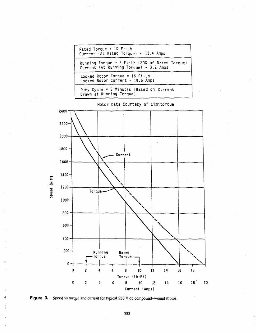
,, , r-- ,'
Rated Torque= i0 Ft-LbCurrent (At Rated Torque) = 12.4 Amps
,,,, --
Running Torque = 2Ft-Lb (20% of Rated Torque)Current (At Running Torque) - 3.2 Amps
Locked Rotor Torque = 16 Ft-LbLocked Rotor Current : 19.5 Amps
Duty Cycle = 5 Minutes (Based on CurrentDrawn ai:Running Torque)
Motor Data Courtesy of Limitorque
2400- \ ........ - .........\
2200
ZOO0....- _ ; , ....
1800 -
\_i-- Current1600 - \ ...... ,........
')\\... 1400
._ 1200 L ,, , _, . ___ ,,,,i......
&
I000 '_BOO ............
600 \
400 - ,,, _ _ .....
" Running Rated _"
cue Torque._.
0 2 4 6 8 10 12 14 16 IB
Torque (Lb-Ft)
0 2 4 6 8 I0 XZ 14 16 IB 20
Current (Ar_ps)
¢' Figure 3. Speed vs torque and current for typical 250 V dc compound-wound motor.
383
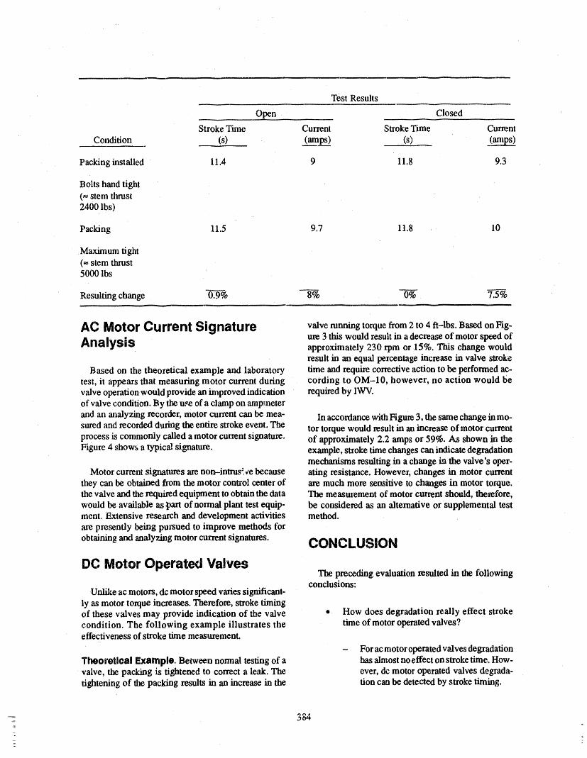
Test Results
Open Closed
Stroke Time Current Stroke Time Current
Condition (s) (amps) (s) (amps)
Packing installed 11.4 9 11.8 9.3
Bolts hand tight(= stem thrust2400 lbs)
Packing 11.5 9.7 11.8 10
Maximum tight
(= stem thrust5000 lbs
Resulting change 0.9---% 8% 0% 7.5%
AC Motor Current Signature valverunning torque from 2 to 4 ft-lbs. Basedon Fig-
Analysis ur_ 3 this would result in a decrease of motor speed ofapproximately 230 rpm or 15%. This change wouldresult in an equal percentage increase in valve stroke
Based on the theoretical example and laboratory time and require corrective action to be performed ac-test, it appears that measuring motor current during cording to OM-10, however, no action would bevalve operation would provide an improved indication required by IWV.of valve condition. By tlm u_ of a clamp on ampmeter
and an analyzing recorder, motor current can be mea- In accordance with Figure 3, the same change in mo-sured and recorded during the entire stroke event. The tor torque would result in an increase of motor currentprocess is commonly called a motor current signature, of approximately 2.2 amps or 59%. As shown in theFigure 4 shows a typical signature, example, stroke time changes can indicate degradation
mechanisms resulting in a change in the valve's oper-Motor current signatures are non--intrus" _e because at.ing resistance. However, changes in motor current
they can be ob ,tained from the motor control center of are much more _nsitive to changes in motor torque.the valve and the required equipment to obtain the data The measurement of motor current should, therefore,would be available as part of normal plant test equip- be considered as an alternative or supplemental testmento Extensive research and development activities method.are presendy being pursued to improve methods for
obtaining and analyzing motor current signatures. CONCLUSION
DC Motor Operated ValvesThe preceding evaluation resulted in the following
conclusions:Unlike ac motors, dc motor speed varies significant-
ly as motor torque increases. Therefore, stroke timingof these valves may provide indication of the valve • How does degradation really effect strokecondition. The following example illustrates the tune of motor operated valves?effectiveness of stroke time measurement.
- For ac motor operated valves degradation
Theoretical Example. Between normal testing of a has almost noeffect on stroke time. How-valve, the packing is tightened to correct a leak. The ever, dc motor operated valves degrada-tightening of the packing results in an increase in the tion can be detected by stroke timing.
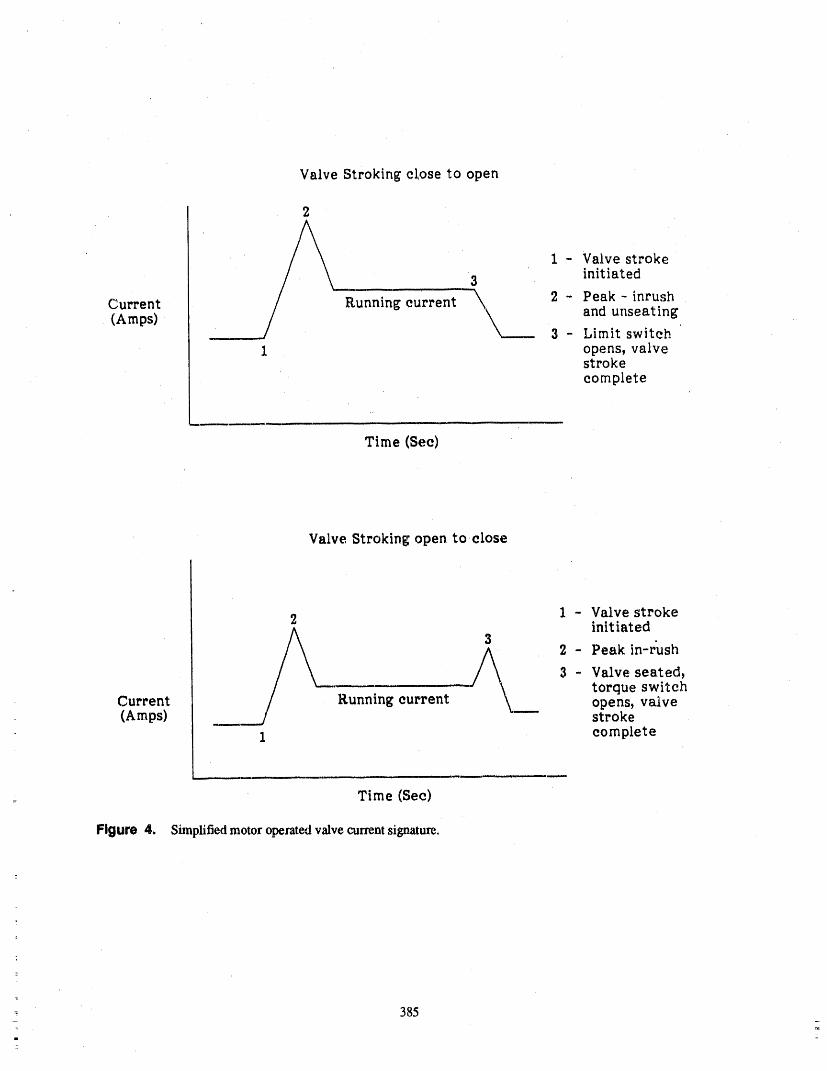
Valve Strokingcloseto open
2
1 - Valve stroke3 initiated
Current(Amps) J/ Running current-'____ 2- Peak-inrush
and unseating
/ 3 - Limit switch1 opens,valve
strokecomplete
Time (Sec)
Valve Stroking open to,close
2 1 - Valve strokeinitiated
3 2 - Peak in-r'ush
A\__ 3 - Valve seated,
- torque switchCurrent Running current opens, valve(Amps) ___ stroke
1 complete
L_
Time (Sec)
Figure 4. Simplified motor operated valve currentsignature.
1
385
mm
z

• If stroke time is ineffective, is there some - Because the speed of a dc motor changesother parameter that can be used to monitor as the motor torque changes, strokedegradation? timing does provide some indication of
valve degradation. However, the measur-
- Motol current signature analysis maybe ing of motor current would provide anan early indicator of valve degradation improved method of detection.for both ac and dc valves.
REFERENCES• Can testing of this other parameter be
non-intrusive? 1. ASME Boiler and Pressure Vessel Code.,: 1986 F.xlition - Section XI
- The performance of motor current signa-ture analysis appears to be non-intrusive 2. ASME/ANSI OMa 1988, Part 10because it can be accomplished from the
motor control center using normal plant 3. Application Guidelines for Motor Operatedtest equipment. Valves In Nuclear Power Plants (Draft);
August 1988; prepared by MPR Associates,• What about dc motor operated valves? Inc. for Electric Power Research Institute.
386
ATTENDEE- PANEL QUESTIONS AND ANSWERS(EDITED; ATTENDEE QUESTIONS AND PANEL/AUTHOR
RESPONSES NOT IDENTIFIED B Y NAME)
Comment1 Comment3
I have a comment, rather than a question, on your dc Attendee 1 We have been working on diagnosticsfor motor-operated valves for about four years, and w_.measurements, on dcmotor-driven valves. You areare about ready to issue a report that will be an NRCprobably aware that voltage, as well as current, play a
role in the speedof the dc motor. That is, a dc motor is NUREG report. I think it will probably be out in thenext couple of months, lt describes ali of the work wenot inherently a constant speed devi_e, as is an ac mo.
tor within limits, have done, both in identifying degradation and moni-toting methods. And we did spenda lot of time on mo-tor current signature analysis, lt is as useful as you
If you are going to use stroke time testing on dc mo. described. With regard to the issue of motor power or, tors, you will have to measure voltage as well as cur- load rather than current, I certainly agree that voltage
rent draw, because the motor will speed up and slow affects the result, If thereis a voltage drop, then motordown. If you do not account for that, you will get wild current will vary.variations that have nothing to do with theconditions
of the valve, I want to note that in this NUREG report it will benoted that there is another way of identifying motor
Presenter Yes, I understand. I agree withyou on that. load other than the motor power indication, and that isIn fact, the testing we are doing is measuring stroke the motor slip frequency. Using a Sl_Ct,'umanalyzer,time, ali we are doing is measuring stroke time, so it one can very easily measure the slipfrequency of an acmay be a problem. If our stroke time increases, like motor. That slip frequency is as sensitive as VI cosineyou said, it co,.ld be a fluctuation in our voltage, theta in identifying the load. In fact, it is the same. It is
basically measuring the same thing.
Hopefully, in a nuclear plant, with it being on battery Attenaee 2 Except that it costs you $100 per chipbuses, the voltage is fairly constant throughout thestroke event, and it costs you $1,000 for a signometer.
AltonOeel Weil, I agree, as a capital investment. ButComment 2 let me note that the motor current slip frequency is
measured truly non-intrusively. Ali it requires is aAttorldee A more sensitive parameter for ac--driven clip-on ammeter, whereas the chip must be installedactuators is the actuatorpower, which is voltage times on each valve and taken off or permanently installed,current times the phase angle between the two vectors, because you have to measure the voltage.And it is possible to buy a chip which will do thiscon-version for you quite cheaply, and you get an even Youhave toput a bypass around, and youhave to makemore _nsitive measure of the true power going into a physical attachment, whereas the motor currentthe actuator, rather than simply the current, probe is a clamp--on device or a current transformer,
which is truly non-intrusive. But those are cost-benefits that have to be worked out.Presenter Whatdoesit requiretodothat?Doesit re-
quire installing something? Can it be something that is Question 1-- installed that can monitor this,or how is it done?
I do agree with theauthor's paper.Maybe the NRC andAttendee 1 I think you can still do it back at thejune, maybe the Code people coulddiscuss this. Wehaveal.tion box and not on the actuator, ready looked at pump bearing temperatures and de-
cided theyare not reallyali that good tbr what we wantYou have got a three-phase wiring system. You have to accomplish. Maybe we should re-eva_uate why,got a clip--onammeter, which is looking at the current, even in the OM's, we are requiring valve stroke timeYou have another pair of wires looking at the voltage, when we re',dlydo not need them. Maybe we shouldThis little chip is doing the vector multiplication of look at these newer techniques that have been devel-voltage times current times the cosine of the phase oped, because it seems we are still down the road ofangle between them. sticking with old technically h_defensible methods of
387_=
measuring these parameters when the technology is surement. So therefore, you would still be able to takeleaving us behind, your requirements for tech spec surveillance or what-
ever to make sure a that valve does operate in its pre-The same goes for relief valve one percent p,-uameters, scribed time.Why are we sticking to one percent on 2500-poundv,-dves that depend on a big sgdr_g to keep it closed? Comment
Response 1 I agree that stroke time verifies operability. We arereading into this _egradation, as there are two separate
I think people in' ,lved with tT,..eO&M and the ASME things we are actually trying to accomplishCommittees have tt_be sensitive be_.ause there are a lot simultaneously.
of new technologies coming out. A lot of them havebeen tested and have been very successful, and some of Now, if we at River Bend started trying to put currentthem have identified more problems, or maybe there ,amp meters on ali the valves at the motor control cen-are problems in the methodology, ters, we would have to have twice as many personnel
hopscotching ali over the plant to try to book these
When you change a code or a standard, you are affect- things up, "andit would add a considerable anaount ofing a lot of plants, and you have to be very careful, time to our testing.They have to be very cautious on how they change that,because it is affecting the livelihood of many utilities, But if we implemented it as part of our maintenance,and the impact could be severe. We do not want to g/ve that could be done very easily. So if you start codifying_ibemsomething that is not going to work again, these things, I would just like to caution you that there
is operability, and there is also maintenance.
Comment "_ Comment
I am on the O&M Committee. I'm not on the OM-6I think the poi,_t should be made that ac motor-
and 10 working group, but I would like to commentoperated valves cannot, in any way, meet the operabil-
that they are very much interested in this new ity test of 25 percent.tectmology.
There is no way that they could fail that test, theoreti-I know for a fact that the Oak Ridge signature analysin cally aral practically. They can not slow down 25 per-is under consideration. So I do not want you to ttfink _nt. They will either stall or they wili operate. So yourthat the ASME is non--responsive to tiffs infonnation. statement is correct, but you should be tempered by the
OlJestlon 2 _ty of ac moto,,s.
CommentThe change you seem to be advocating on the stroke
time _ocurrent sounds very, very good. Some of what I notice that the curve you put on the overhead bad awe employ with MOVATS and other things could one percent change i_, ,_'peedgoing from synchronouswork, but has it been addressed how we go back to the to fttll load, In my experience, that is a much flatterFSAR and the tech spec time reaction ,quirements on curve than I nomlally see. I normally see a three to fivethose s,,stems? percent slip from synchronous. So I think you probably
chose the conservative side on the sl_p there.Response 2
But I think with a photoelectric timing <',:vice tha_ isNo, it has not. But it is a good point. If you do some accurate to 0.1 percent changes, you could start to de-kind of a signature analysis, you do measure the time. tect stroke time changes around one percent fairly ac-lt is measured electronically. From actual contact to curately. And I think it i ; possible to use the strokecontact, the time:wiU be measured by the recorder. So timing technique with better methods and enable deg-you would not really be throwing away the time mea- radation to be identified through that sysl.em.
388
,iii
USE OFA VALVE OPERATION TEST AND EVALUATION SYSTEMTO ENHANCE VALVE RELIABILITY
DAVID A. LOWRYVICE PRESIDENT, MARKETING AND SALES
LIBERTY TECHNOLOGY CENTER, INC.1100E. HECTOR STREET
CONSHOHOCKEN, PA 19428
ABSTRACT MOVs must be carefully adjusted to assure, oper-ability. Although marual operation is available as a
Power plant owners have emphasized the need for back-up technique if the/vlOV does not open or closeproperly, effectivene_ may be marginal in emergency
assuring safe, reliable operation of valves. While most conditions. Failures in MOVs may cripple or shutvalves must simply open or close, the mechanisms in- down a unit, causing costly, unscheduled downtime.volved can be quite complex. Motor operated valves
(MOVs) must be properly adjusted to assure operabil- An appreciable amount of MOVs in nuclear powerii),. Individual operator components determine the per- plants remain inactive for many months, yet must befortunate of the entire MOV. Failure in MOVs could
cripple or shut down a unit. Thus, a complete valve operable in an instant under design basis conditions.program consisting of design reviews, operational test- Due to demands in cer_tin fluid systems, some valves
get stroked much more frequently. These latter valves,ing, and preventive and predictive maintenance aetivi- which control vital fluid flows on a d_aly basis, haveties will enhance an owner's confidence level that hi,_
valves will operate as expected, gear wear patterns, spring pack deterio ration, mid stemtaper problems that can occur at a rate greater than that
Liberty's Valve Operation Test and Evaluation Sys- for inactive valves. When valves in this category can-not operate, they have an immediate financi',d impacttem (VOTES®) accurately measures stem thrust wifla- on the plant. Although system redundancy shouldout intruding on valve operation. Since mounting a allow safe fluid transfer, the chance exists that thestrain gage to a valve stem is a desirable but h'r.practi- sister valve will fail also, especially since it wascal way of obtaining precise stem tlu'ust, Liberty de- designed, set-up, and maintained in a similar manner.veloped a method to obtain identical data by placing a
strain gage sensor on the valve yoke. VOTES provides Moreover, a certain amount of valve testing is re-information which effectively eliminates costly, quired due to the IE Bulletin 85-03. In order to com-unscheduled downtime, plete these requirements quickly and accurately,
: VO.'7ES captures crucial electrical or mechanical sig-: This paper presents the results of iafie!d VOTES natures from the MOV components. By providing con-
testing. Tk_ system's proven ability to identify and elusive diagnostic information through a simple andcharacterize actuator and valve pefforman_ is demon- accurate MOV testing method, this system eliminatesstrafed. Specific topics of discussion inelud he ability unscheduled downtime and maintenance expenditures.of VOTES to ease a utility's lE Bulletin _,3---03con-
ccms and conclusively diagnose MOV components,, THE VOTES® CONCEPTData from s_atic and differential pressure testing are
_ presented. Technical, operational, and financial advan-tages resulting from VOTES technology are explored Liberty VOTES to accurately measure stem thrust,in detail, without intruding on valve operation. A study by the
Electric Power Research Institute (F_RI) determh_ed
BACKGROUND that".., the use uf strain gages attached to the stemwould be the mos( desirable method for accuratelymonitoring the dynamic events..." within a MOV.
Safe, reliable valves are important for successful op- Since moundng a stem gage is impractic_, Liberty: eration of power plants. Initially, regulatory pressures discovered that virtually identical data could be ob-
- p_t..,pt_u uuJ,u,rn tu v_.patuu mwr vmve p_-og_ams. "rainetlthough placing a swain gage device, force Sen-Today, however, maintenance, staffs highly value ali sor, on the valve yoke. VOTES obtains the true stempellinent infommtion on MOV per.fomtance, force acting on the valve stem by measuring the equal
__._.
-- 389
li'lH .... ,I_,' ,,,li_ir,,,,q, _i,lm,. ,,, , 'lWl'i ',"")" ,,i .... _,,,, _iiq, ,,, ,._ :ii . ,ilT_l)lllll , ,' li,,,_

and opposite reaction forces in the valve yoke (seeFigure 1). This same three method tbr the stem-yoke _1._ F_TI O N
combination applies independent of the actuator type:motor, air, or hydraulic. DIAM_'F_AL STRAIN
1LONGITUDINAL STRAIN
"'-_----_ ,---_..._ (Poisson's Ratio)
t{ _""-'--1 t_t_/[itil/;,','/_,-.__
L6._ STRESS
Figure 2.
__/ r_ ] The VOTES concept includes three primary compo-nents: signal conditioning box, breakout box, and por-table computer as well as seven sensors: Force Sensor,four switch current probes, motor current probe, and
_r_ 'IAL'_t. s_rc,_ accelerometer. The system gathers diagnostic data bysampling up to eight channels simultaneously, each at
Figure 1. 1000 times per second. This rate permits a frequencyresponse of 500 Hz to be maintained over the entirelength of the stroke.
The VOTF_; Force Sensor is calibrated by tempo-
rarily placing a National Bureau of Standards (NBS) The breakout box consolidates the seven sensor
traceable, diametrai strain measuring device on the cables into the main signal cable returning to the signalstem as fl_e valve is closed. Dunng closing, the stem conditioning box. This feature permits the signal con-"barrels" diametrally as it is compl_essed. This expan- ditioning box and portable computer to be located insion is convened into stem thrust. Calibration is com- either a low dose or no dose area up to 500 ft away. In-pleted by relating stem thrust measurement to the ternally, sound..-powered headphones allow the testerelectrical output from the Force Sensor (see Figure 2). at the valve to communicate with the tester at the
portable computer (see Figure 4).
Importantly, Force Sensor calibration occurs over IN-PLANT DIAGNOSTICthe same portion of the stem and on the same side ofthe stem and stem nut threads as utilized under normal TESTING
closure. Tests have been performed under both staticand differential pressure conditions to compare stem VOTES® has been used by a number of utilities forgage and Force Sensor (see Figure. 3). The results indi- multiple outage testing. The system h,xs proven verycare consistent capability of the Force Sensor to mea. effective in capturing the electrical and mechanicalsure stem forces encountered t_uring the.entire opening data required by maintenance engineers to charac2erizeor closing strokes. MOV performance.
390
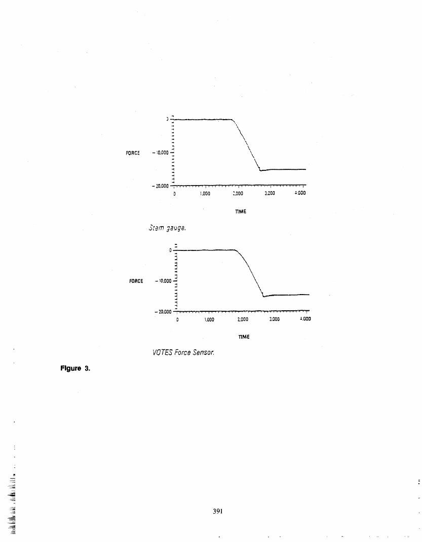
-= °
=,
\
-;oooo-: \
-20,000 i,", ...... "_'7,,, ',•'-fT,' ;, ....... , ........ i
0 _,000 ;,000 3,P.O0 ._,000
TIME
3t_m j2uge.
.'4
..{
d
3FORCE - 10.000-..,
.d
-- 20.000 7 ' "' ' ', , p'r'r "', ! , ,',", , , ; _ , ,7_P'f""P'P"fmP'_P, • • , , , , , ,"_ 1
0 1,000 2.000 3,000 .$.000
TIME
VOTES Force Sensor.
Figure 3.
=_
__=
391
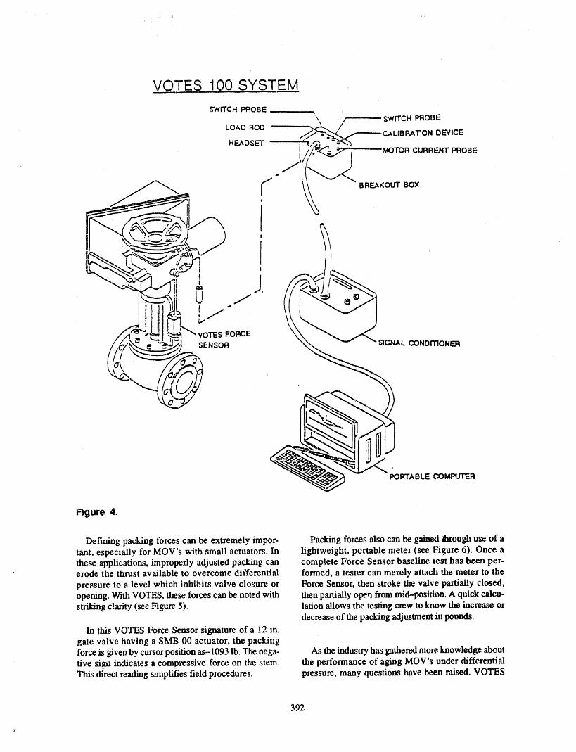
=,
PORTABLE COMPUTER
Figure 4.
Derming packing forces can be extremely impor- Packing forces also can be gained throughuse of atant, especially forMOV's with small actuators. In lightweight, portable meter (see Figure 6). Once athese applications, improperly adjusted packing can complete Force Sensor baseline test has been per-erode the thrust available to overcome differential formed, a tester can merely attach the meter to thepressure to a level which inhibits valve closure or Force Sensor, then stroke the valve partially closed,opening. With VOTES, these,forces can be noted with then partially ope.ri frommid-position. A quick calcu-strildngclarity (see Figure 5). lation allows the testing crew to know the increase or
decrease of the packing adjustmentin pounds.In ebis VOTES Force Sensor signature of a 12 in.
gate valve having a SMB 00 actuator, the packingforce is given by cursorposition as-1093 lb. Thenega- As the industryhas gathered more,knowledge abouttive si_maindicates a compressive force on the stem. the performance of aging MOV's under differentialThis direct reading simplifies field procedures, pressure, many questions have been raised. VOTES
392
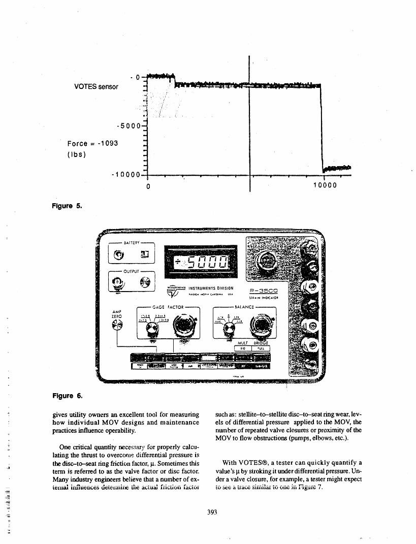
Figure 5.
Figure 6.
gives utility owners an excellent tool for measuring such as: stellite-to-stellite disc-to-seat ring wear, lev-" how individual MOV designs and maintenance els of differential pressure applied to the MOV, the
practices influenceoperability, ntunber of repeatedvalve closures orproximity of theMOVto flow obstruc6om (pumps,elbows, etc.).
:: Onecritical quantity necessary tbr properly calcu-lating the thrust to overcome differential pressure is
=_ the disc-to-seat ring friction factor,g. Sometimes this With VOTES®, a tester can quickly quantify aterm is referred to as the valve factor or disc factor, value's g by strokingit underdiffereotial pressure, Un-Many industry engineers believe that a number of ex- der a valve closure,,.(brexample, a tester might expecti_l-ll21tl II.LILIU_Lit_IT,_ U_L_'71111111_ _ _ILUi:IJ.t IIIi_LIUII/_"""'_-- ltClg,tUlt"..... tr.! _ _-i ila_ aliilllO.l L_) I,)llt,.7- 111 l'l_tll_;
393
-
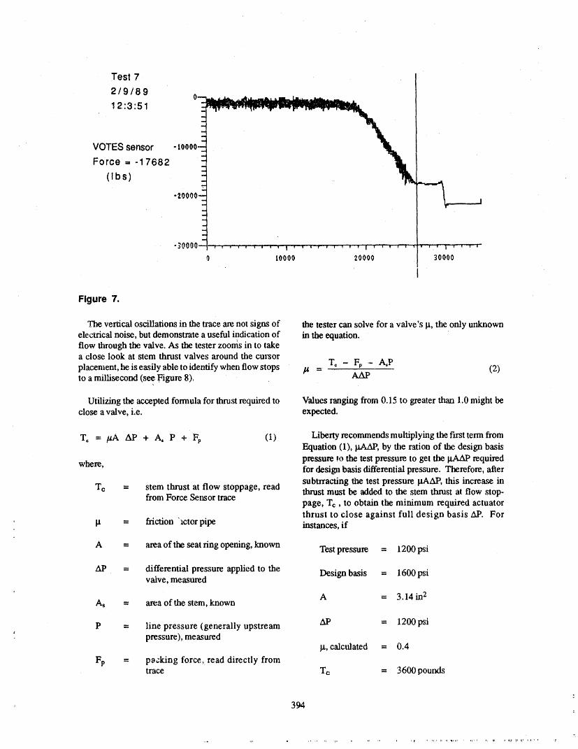
Test 7
2/9/89
12:3:51
VOTES sensor -
Force = -17682
(Ibs)
_00001.... , w , , , , , , v | , ,'"_ • , , T "V T I V i , _ T'_ ¼""T ,• I • _ T
0 tO000 20000 30000
Figure 7.
The vertical oscillations in the trace axe not signs of the, tester can solve for a valve's B, the only unknown
electrical noise, but demonstrate a useful indication of in the equation.flow through the valve. As the tester zoon_s in to takea close look at stem thrust valves around the cm'sor
T, - Fp .-A,Pplacement, he is easily able to identify when flow stops _u = (2)to a millisecond (see Figure 8). AAP
Utilizing the accepted formula for thrust required to Values ranging t_om 0.15 to greater than 1.0 might beclose a valve, i.e. expected.
T, = /_.AAP + A, P + F_, (1) Liberty recommendsmultiplyingthefirsttermfromEquation (1), BAAP, by the ration of the design basis
where, pressure _o the test pressure to get the RAAP requiredfor design basis differential pressure. Therefore, aftersubtrracting the test pressure }tAAP, this increase in
Tc = stem thrust at flow stoppage, read thrust must be added to the stem thrust at flow stop-from Force Sensor tracepage, 'rc, to obtain the minimum required actuatorthrust to close against full design basis AP. For
' la = friction "_ctorpipe instances, if
A = area of the seat ring opening, known Test pressure = 1200 psi
At' = differential pressure applied to the Design basis = 1600 psivalve, measured
As = area of the stem, known A = 3.14 in2
AP = 12,00psiP = line pressure (generally upstream: pressure), measured
_t, calculated = 0.4
Fp = packing force,, read directly fromtrace Tc = 3600 pout_is
= 394
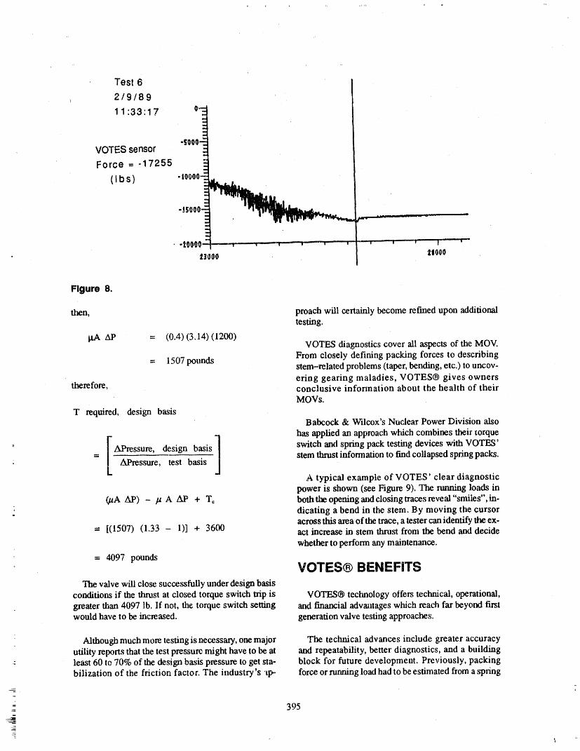
Test 6
2/9/89
1 1:33'17 °'E
-sooo-'_VOTES sensor _-Force = -17255 E
-t_;O00_ __
e,,,
tO000" ' '--.... i" _ " _ w "' w w w w v |
l_O00 21O00
Figure 8.
then, proach will certainly become refined upon additionaltesting.
gA Ap = (0.4)(3.14)(1200)VOTES diagnostics cover ali aspects of the MOV.
= 1507 pounds From closely defining packing forces to describingstem-related problems (taper, bending, etc.) to uncov-ering gearing maladies, VOTES® gives owners
therefore, conclusive information about the health of theirMOVs.
T required, design basisBabcock & Wilcox's Nuclear Power Division also
. has applied an approach which combines theil" torque
__ [ APressure, design basis I switch and spring pack testing devices with VOTES'= AJ_ressure, test basis stem thrust information to find collapsed spring packs.
A typical example of VOTES' clear diagnosticpower is shown (see Figure 9). 'II_e rutmiag loads in
_A A.P) - /t A AP + T_ both the opening and closing traces reveal "smiles", in-dicating a bend in the stem. By moving the cursoracross this area of the trace, a tester can identify lhe ex-
= [(1507) (1,33 - 1)] + 3600 act increase in stem thrust from the bend and decide
whether to perform any maintenance.
= 4097 poundsVOTES® BENEFITS
valve will close successfully under design basisconditions if the thrust at closed torque switch trip is VOTES® technology offers technical, operational,
greater than 4097 lb. If not, the torque switch setting and financial advantages which reach far beyond firstwould have to be increased, generation v,'dve testing approaches.
Although much more testing is necessary, one major The technical advances include greater accuracyutility reports that the test pressure might have to be at and repeatability, better diagnostics, and a buildingleast 60 |o 70% of the design basis pressure to get sta- block for future development. Previously, packingbilization of the friction factor. The industry's al>. force or running load had to be estimated from a spring
= 395
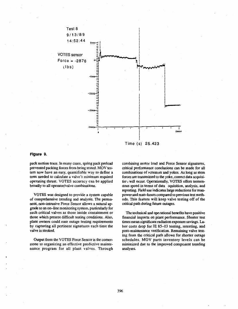
Test 8
9/13/89
14:52:44!,",t_,,'_I=t
"41
VOTES sensor ..._ ,----_u__'_--_ 'Force -2876 ,+'mt _,
I+..+oo1,.-.-_I I
.=I I_I I"tl I
;I4i
.-4
-4-1
e I 'II++°°
It
Time (s) 25.423
Figure 9.
pack motion trace. In many cases, spring pack preload combining motor load and Force Sensor signatures,prevented packing forces from being tested. MOV tes- critical performance conclusions can be made for aliters now have an easy, quantifiable way to define a combinations of actuators and yokes. As long as stemterm needed to calculate a valve's minimum required forces aretransmitted to tlmyoke, correct data acquisi-operating thrust. VOTES accuracy can be applied tio'_will occur. Operationally, VOTES offers tremen.broadly to all operator/valve combinations, aous speed in terms of data C_luisition,analysis, and
reporting. Field use indicates large reductions for man-VOTES was designed to provide a system capable power and man-qzourscompared toprevious test moth-
of comprehensive trending and analysis. The perma- ods. This feature will keep valve testing off of thenent, non--intrusive Force Sensor allows a natural up- criticalpath during future outages.grade to an on-line monitoring system, particularly forsuch critical valves as those inside containment or The technical and opezational benefits have positivethose which present difficult testing conditions. Also, financial impacts on plant performance. Shorter testplant owners could ease outage testing requirements times mean significant radiation exposure savings.La-
: by capturing ali pertinent signatures each time the bor costs drop for lE 85-03 testing, retesting, andvalve is stroked, post-maintenance verification. Remaining valve test-
ing from the critical path allows for shorter outageOutput from the VOTES Force Sensor is thecomer- schedules. MOV parts inventory levels can be
stone to organizing an effective predictive mainte- minimized due to the improved component trendingnance program for ali plant valves. Through analyses.
_=
396
A'I'I'ENDEE- PANEL QUESTIONS AND ANSWERS(EDITED; ATTENDEE QUESTIONS AND PANELAUTHOR
RESPONSES NOT IDENTIFIED BY NAME)
Question I of itself satisfy the generic letter.It has to be a con-ccrtcd effort by the utilities in orderto complete that
Wehave hearda numberof times todayaboutthe disc program.factornormallyIcing assumedto be 0.3.We heard0.5earlier. Now we are heating up to 0.75. This is for Question 3wedge gate valves.
Youdid not say too much about thz hardwarecon-Hasanybodyreally lookedatother technology,suchas nectcdto the valve harness. Is it a portablePC,or is itparallel slide valves, whore your VOTES system some sortof a wh_l-around typeof arrangement?wouldstill be able to pick upbent stems and the like?But as faras these high discfactors, theyarcnotpros- Response 3ent with those type of valve systems.
Actually,the VOTES 100system wouldbe hookedupResponse 1 toa small, portable,breakout box, which weighs about
threeand a half pounds, as well as a signal conditionerI candefer that to some people. I know that those par- _rtable computer. You make one connection to thetieular valves are used in some applications, but I am connector that is coming out of the drain plug and thatprobably notknowledgeable enough to tell you exactly will return to thebreakout box effectively. That is con-why they are not used more broadly. There may be nected to the signal conditioner and the portable com-some increased complexity, puter. You do not even have to take off the switch
cover. Youdo not interfere at ali with the operation orConlment theoperability of the valve during the test,
It would decrease the requirements of themotor opera.. So you would hook up the system, arm the system ef-mr tremendously, of course, if youdid not have such a fectively so it is ready to take data, and as soon as thehigh factor, valve is stroked, you would capture all that informa-
tion again from the force sensor, from the switch cur-Question 2 rent probes, and from the motor current probe.
That isthesecondtimeI haveseentodaythatyoursys- Question4temmeets the provisionsof Genetic Letter 89-10. Thegenetic letter, in the very front, says that the Commis- Could you please elaborate on the essential environ-sion is cencemed about current te'_ing capabilities. I mental data on the instrumentation? And how reliabledo not know that anybody knows .w to address that are the strain gauges or the attached equipment on thegenetic letter. Youhave a good to,,,_thatwill be helpful valve, as far as maintenance activities being done onin addressing the letter, but it is a teel, the valve, paint, grease, and that sort of thing.=
: I haveseena diagnosticsystemusedin thepast.This Response 4whole thing dependson a comprehensiveprogramanda technology or a system for using your teel. Ali the materials used inside the sensor have been
tested for ali those conditions that you just mentionedResponse2 in terms of radiation, and high temperature.
i
: I agree totally. Thecomment has to be, that a diagnos- The sensor is rated basically for 250 degrees long-tiesystem is only apart of aprogrammaticapproachby termand up to400--degree transients. Duke Power hasa utility to addressing the generic letter concerns, a few hundredof the,_ units installed at thevarious sta-which of course involves design engineeriv.g, mainte- tions right now. And we have not seen any significantnance,and proper trainingof the personnelwho are go- problems with maintenance interfering with the sen-ing to do the diagnostic testing. And certainly any sors themselves or any other extraneous material, such
__ diagnostic system, including Liberty's, catmot in and as shavings,otis, etc.
3_)7
A COMPUTERIZED DATA BASEMANAGEMENT PROGRAM FOR
INSERVICE TESTING OF PUMPS AND VALVES
STEPHEN JoCOLEMAN,/SI ENGINEERDAVlD MAZLIACH, P.E., VICE PRESIDENT
NDX CORPORATIONITASCA, ILLINOIS
INTRODUCTION react to component,and possibly plant failures. Giventhe nature of the current system, a computerized inser-vice testing data base management program would
This paper presents a desoiption of an ideal com- help to enhance the manual system which may expendputerized data base management program designed to vast resources on data management.control multiple plant and unit Inservice Testing (IST)
activities of ASME Section XI. The program is in- PROGRAMSTRUCTUREtended to relieve personnel of the necessity to manual-ly maintain inservice testing data in support of
technical requirements of Subsections IWP and IWV Figure 1 identifies a general structure of the soft-of the ASME Boiler and Pressure Vessel Code, Section ware, and provides a list of primary user menus neces-XI, "Rules for Inservice Testing of Nuclear Power sary for program function operation.Plant Components," Technical Specifications and
other references. These menus provide user interface to the data fieldsfor data entry, data maintenance and browse opera-
The philosophy of the program is to utilize basic tions. They also provide the user with options for testcomputer data base n_,_','_3ement techniques to coordi- result input and logging, component trending, data re-nate inservice testing data, create a methodology for porting, data queries, plotting and printing of charts
quick and easy input and output routines, and provide and graphs, word processing, general utility featurescomputerized test data storage and organization, com- and program setup and security options.ponent tracking and retrieval, report generation, trend-
ing and summarized test results. DATA BASE MANAGEMENT
PROGRAM_ From experience at a single unit BWR plant, it was
found that the manual system of data management ofinservice testhlg data may be cumbersome due to the In brief, the progra.n performs the follow_,nglarge volume of information that has to be collected functions:and recorded, thus wastet_l of valuable time.
1. Maintains a component "file" for each com-
During daily input of inservice testing data, the ap- ponent which must be tested according to thepropriate test data chart has to be located in the main requirements of the ASME Code or other ref-filing system, the new test data band plotted, new lim- erence. The fde contains a basic record withits calculated and evaluated, and possibly a new chart specific information and data pert,tining to
the component. The following is a list ofpos-drawn due to (end of page reached, new limits re-quired, change of s_,eillance, etc.), and the. old ch',m sible trend summaries:sent to the main file for storage purposes.
Valve Trend Summaries ,,
The legitimate intent of any inservice testing infor-marion storage program is to use the data stored to • Full stroke exercise test to the openidentify and correct potential problems rather than position
- 399
_
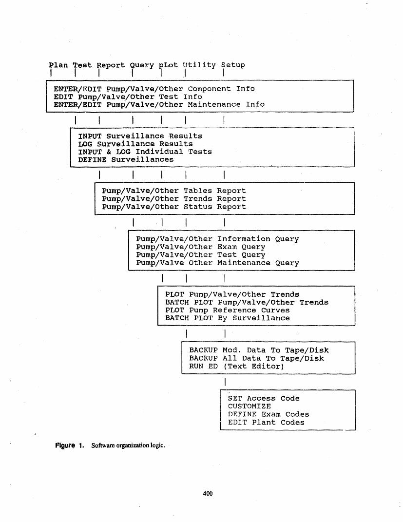
i
I • I _ IENTER/_:DIT Pump/Valve/other Component InfoEDIT Pump/Valve/Other Test InfoENTER/EDIT Pump/Valve/Other Maintenance Info
I I I I I I
INPUT Surveillance ResultsLOG Surveillance ResultsINPUT & LOG Individual TestsDEFINE Surveillances
I I I_ l I
Pump/Valve/Other Tables ReportPump/Valve/Other Trends ReportPump/Valve/Other Status Report
I I I I
Pump/Valve/Other Information QueryPump/Valve/Other Exam QueryPump/Valve/Other Test QueryPump/Valve Other Maintenance Query
I I I
PLOT Pump/Valve/Other TrendsBATCH PLOT Pump/Valve/Other TrendsPLOT Pump Reference CurvesBATCH PLOT By Surveillance
I I
BACKUP Mod. Data To Tape/DiskBACKUP All Data To Tape/DiskRUN ED (Text Editor)
I
SET Access Code ICUSTOMIZE
JDEFINE Exam CodesEDIT Plant Codes
Figurel. So_o__onlo_c.
4O0
• Full stroke exercise test to the closed individually or through a batch process where
position multiple tests ,are entered for ',til components.
• Containment isolation valve leak test 6. Generates pre-formatted and query-typestandard reports based on the general infor.
• Partial stroke exercise test marion in the main component files. These re-ports include a fist of:
• Check valve exercise test to the open
position . Component system inspection requirementsof AS/vIE Section XI,
• Check valve exercise test to the closed
position • Test data treads showing performance of ali
Pump Trend Suv,:maries components over a specified period of time.
• The currentstatus of ali unacceptable compo-• Flow rate nents in the Inservice Testing Program.
o Differential pressure• 7. Generates graphical inservice test trend plots
® Dischaa'ge pressure and reference curve plots from the test resultsdata entered in the component files.
• Horizontal vibration amplitudeTHE MENU SYSTEM
® Vertical vibration amplitude
Each of the menus group functional activities in the® Horizontal vibration velocity program. A description of the. types of functions each
menu holds is described below.• Vertical vibration velocity
' The Plan Menu• Motor speed
• Motor amperes The Plan Menu functions maintain component in-
formation in the program. This section provides the• Inlet pressure (running, static) specific data pertaining to the ct,mponent that is neces-
sary for submittal to the NRC. The Plan Menu docu-• Bearing temperature(upper, lower) merits the basic information on ali components
included in the Inservice Testing Program, aids in re-® Pre_ure/Flow sponse to NRC questions, and provides information
for diagnosing plant problems quickly.2. Maintains test files containing a record for
each required test performed on a component.The file contains the type of test being per- The Test Menuformed, and the frequency of testing.
One of the main purposes of the progranl is to keep
3. Maintains files containing a record of each track of inservice and reference tests for pumps and in-maintenance operation performed on a service tests for valves. The program uses a "batch"component, method of h_--putting tests, that is, inservice tests are
entered and collected on an input file screen, and then
4. Maintain.,_ a file for each surveillance in the "logged", as a group. 'Ialis section verifies the occur-
program. Surveillances are used 1tosimplify rence of an unacceptable or inoperable component,the entry ofinservice test data. A surveillance where, those components whose test results have ex-can consist of a mixture of any number of ceeded the alert or action required ranges.tests.
The Report Menu,, 5. Supports entry of inservice and reference
tests for pumps, inservice tests for valves and The Report Menu has functions for displaying and= other safety related test. Tests can be entered generating mu!ti-forrnatted reports based on the
a0!
component information stored in the main component data is maintained for Acceptable, Alert and Actionflies. The report function_ each have options for select- ranges for required examinations.ing various formats and ior selecting reports conV,fin-
ing only'those recordswhich match a set of selection INSERVICE TEST ENTRYcfitefla.
The automaticbatch entry andindividual entry ofThe Query Menu icetestsfor pumps,valves and other sdety re-
latedcomponentsis an importantpart of the program.The Query Menu has functions for printing or dis- The automatic batch entry process provides full screen
playing query type or impromptu reports based on se- direct input where tests can be entered quickly and ac-letted information stored in the main component files curately in a tabular form as shown in Figure 2.which match certain criteria. The query option interac-tively queries the file and directs the results to the Batch test data entry is used for two reasons:,printer, computer screen, or a user specified file. The
program groups queries according to the file from 1. It allows you to go back and double checkwlfich the information is drawn. (and correct, if necessary) each test entry for
accuracy before it is logged.The Plot Menu,
2. It cuts down on the time it takes to enter tests
The program is capable of producing several types (extra key stokes). You don't have to wait forof plots: a trend plot of a sequence of component in- a test to be logged before entering the nextservice tests, and a pump Pressure/Flow reference one. Once,stetted, the logging process is auto-curve. The plots can be displayed on the screen, or gen- matic, which means that you can go about
your business while the computer does theerated on an external plotter and/or printer.work.
The Utility Menu During the entry and logging process, ali necessarytest information records are entered and logged, and
The Utility Menu contains functions for maintain- the affected exam records are updated with new testing the various files in the program. Backing up the and status information. During this process, the pro-files can save ali of the data incltuled in the fi._esor the gram compares the.test value to the related Section XImost recent data entered. Regula_ backing up of files acceptance criteria that has been previously set up inreduces data loss problems, an exam records file.
The Setup Menu _ results are,compared and the program generatesa status report indicating whether the current test value
The Setup Menu contains functions to set up pro- is acceptable, in the alert range, or in the action range.gram and sc_eet_ entry codes, customize information This report can be reviewed by the IST Engineer tothat tailors the program to the particular computer en- verify occurrence of an unacceptable or inoperablevironment, define test types and/or change any of the component.
labels on reports in the program, create multiple unitcodes to support more than one unit at a tinte. GRAPHICAL OUTPUTS
COMPONENT TESTING The routines for generating a trend plot of a se-quence of inservice tests for a particular component
The program provides data fields for tracking and and a pump Pressure/How reference curve axe avail.main "tainingspecific Class 1, 2, and 3 pump _ motor able m the program. The type of graphics available toinfommtion, valve and actuator information and other the user include a screen, plotter or printer display.
safety _elated components. For each pump component,the Section XI allowable ranges of test quantities are The inservice test trend plots allow trends to be es.,maintained in the program. For each valve component, tablished for a series of tests showing comrmnent per-the Section XI requirements for allowable le_.kage formance over a specified period of time, and includerates, stroke time and motor operator infomlation are, a prediction of when component performance will be-maintained in the program. Component performance come unacceptable.
4_
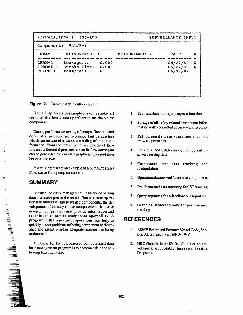
- -- m_W"::zc : : {_i__:: : ::::::: i , . ,.2' ....... ;: : , ,, ,_ :::: _ , t:-:T : z _" ,L ...... _...._..w____.,__
Surveillance # 100-100 SURVEILLANCE INPUT__:.::-..u._: _._:_ :_/::_:':..... 4,_. :r, _.... , ..... --:_" .................-:5 , : ::__ _L._u . 'I": __.___
Component: VALVE- 1
EXAM MEASUREMENT 1 MEASUREMENT 2 DATE R
LEAK-I Leakage... 0. 000 06/22/89 NSTROKE-1 Stroke Time. 0.000 06/22/89 NCHECK-1 Pass/Fail P 06/22/89
Figure 2. Batch test data entry example.
' Figure 3 represents an example of a valve stroke test 1. User interface to major program functionstrend of the last 9 tests performed on the valve
component. 2. Storage of ali safety related component infor,.marion with controlled accuracy and security
During performance testing of pumps, flow rate and" deferential pressure are two important parameters 3. Full screen data entry, maintenance and
which ,are measured to support trending of pump per,. browse operationsformance. From the reference measurements of flow
=
__ rate and differential pressure, a best fit flow curve plot 4. Individual and batch entry of component in-can be generated to provide a graphical representation service testing databetween the two.
5. Component test data tracking and= Figure 4 represents an example of a pump Pressure/ manipulation
Flow curve for a pump component.
__ 6. Operationalstatus verification of componentsSUMMARY
7. Pre-formatted data reporting for IST tracking
Because the daily management of in,service testing 8. Query reporting for miscellaneous reportingdata is a major part of the broad effort to assure opera-tional readiness of safety related components, the de-.
: velopment of an easy to use computerized data base 9. Graphical representations for performance-- management program may provide infommrion and trending.
-. techniques to assure component operability. Aprogram with these useful operations may help to REFERENCESquickly detect problems 'affecting component perform-
-_ ance and assess whether adequate margins are beh_g 1. ASME Boiler and Pressure Vessel Code, Sec-m abstained. LionXI, Subsections IWP & IWV.
__. .The basis for the full featured computerized data 2. NRC Generic letter 89--04, Guidance on De-
b,x_emanagement program is to accomrr .xlate the fol- veloping Acceptable Inservice Testinglowing basic activities: Programs.

4O4mtl
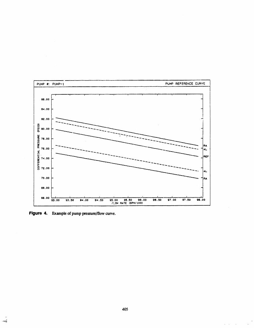
ATTENDEE- PANEL QUESTIONS AND ANSWERS(ED/TED; ATTENDEE QUEST/ONS AND PANELAUTHOR
RESPONSES NOT IDENTIFIED BY NAME)
Question 1 you are ablego in andmanually putyour reference val-ues in for alert and action rangers.
Howdoyouset yotu'referencevalues,youralert ranges, Question2your actionranges, and soforth,on yourtrending output
graphs?Is that menu--drivenor is itautomatically intor- How is your data entered? Do you record it in the fieldIx)ratedin theprogram7 How do you do that? and thencome back and enter it?
Response I Response 2
It is taken from the field and brought back to the com-In the examination section of the component record, purer and entered directly.
==
4O6

AUTOMATED IST PROGRAMW.MARK WRIGHT, P.E.,PRINCIPAL ENGINEER
SOFTWARE DEVELOPMENTEBASCO SERVICES. INC.
MEM=?ER:IEEE INSTITUTE OF ELECTRICAL & ELECTRONICS ENGI-NEERS
MEMBER: NCSE NORTH CAROLINA SOCIETY 0t- ENGINEERS
IABSTRACT shouldbeco.side,edminimumsystemco.tig,a-
tion. ISTBASE supports dot-matrix printers, laser
Therearetwo methodsusedtomanagea SectionXI printers,andplotters.program: Manual and Automated. The manual meth-od usually consists of hand written records of test re- Entry into the prag_am begins with tl_e user select-suits and scheduling requirements. This method while ing the path telling the computer where the data filesinitially lower in cost, results in problems later on in are stored. Next, the u_r must enter a valid passwordthe life of a plant as data continues to accumulate. Au- to proceed any fialher,tomation allows instant access to forty years of test re.
sults. Due to the lower cost and higher performance of PASSWORD MODULEtodays' personal computers, an automated method viaa computer program provides an excellent method formanaging the vast amount of data that accumulates ISTBASE has two levels of password protection.over the forty ),ear life of a plant. Throagh the use of a An initial password is required to gain access to thecomputer, special functions involving this data are program. With this password, the user can browse,
_ available, which through a manual method would not query, and run canned reports from the databases. Ahybe practical. This paper will describe some of the ad- changes, deletions, or additions require a second pass-vantages io using a computer program to manage the word along with an account nbmber. This password/Section XI IST program, account number combination is unique. Up to four
users, other than the,master level operator, can have ac-The ISTBASE consist,_ of program code and numer- cess to the program. A master level password/account
ous databases. "rbe source code is written and co',n- number controls the passwords/account numbers ofplied in CLIPPER (Un) language. Graphing routines the other four users. After entry into ISTBASE andare performed by dGE (un) graphics library. Graphs correctly entering the browse password, the user can
displayed in EGA form. Since it was estimated that enter the access control module. Entry into thismodulethe total complied code, would exceed 640K of ram, is only accessible to the master level operator through_
overlays through the use of modular programming entry of the master level password and account num_,were used to facilitate the DOS restrictions of 640K ber. This module will display the other four users,ram. The use of overlays still require the user to gain passwords, and account numbers along with the masteraccess to ISTBASE through the PASSWORD module, level operators information. The master level operator
,I The database files are designed to be compatible with can modify the other four u_rs passwords and account_
dBASE Hl+ (tm) data strucl_ttre.'l'his aUows transfer of numbe1_ as well as his own. If for some reason, the
. data between ISTBASE and other database managers/ master level password/account number is forgotten, a
applications. A math co-processor is utilized to speed 'back door' password and account number is available
up calculations on graphs ,,rodother mathematical cal- to reset the master level operator pa.ssword/accountculations. Program code and data flies require a hard number to some known value. The 'back door'
-, disk drive with at least 28 Meg capacity. While IST- password/account number becomes invalid after useBASE will execute on a 8088 based computer, an by scrambling the password/account number by a80286 computer with a 12 MHz operating speed known function.
_
-
_
407
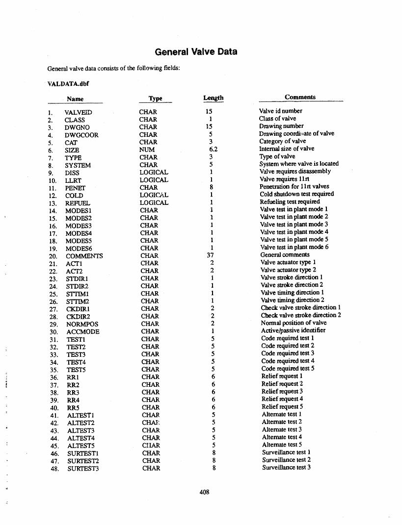
General Valve Data
General valve data consists of the following fields:
VALDATA.dbf
Name Type Length Comments
1. VALVEID CHAR 15 Valve id number2. CLASS CHAR 1 Class of'valve3. DWGNO CHAR 15 Drawing number4. DWGCOOR CHAR 5 Drawing coordi__ateof valve5. CAT CHAR 3 Category of valve6. SIZE _ 6.2 Internal size of valve7, TYPE CHAR 3 Type of valve8. SYSTEM CHAR 5 System where valve is located9. DISS LOGICAl, 1 Valve requires disassembly10. LLRT LOGICAL 1 Valve requires 1Irt11. PENET CHAR 8 Penetration for 11n valves12. COLD LOGICAL I Cold shutdown test required13. REFUEL LOGICAL 1 Refueling test _lui_d14. MODES 1 CHAR 1 Valve test in plant mode 115. MODES2 CHAR 1 Valve test in plant mode 216. MODES3 CHAR 1 Valve test in plant mode 317. MODES4 CHAR 1 Valve test in plant mode 418. MODES5 CHAR 1 Valve test in plant mode 519. MODES6 CHAR 1 Valve test in plant mode 620. COMMENTS CHAR 37 Ge_'a'al comments21. ACT1 CHAR 2 Valve actuator type 122. ACT2 CHAR 2 Valve actuator type 223. STDIR1 CHAR I V_ve stroke direction 124. STDIR2 CHAR 1 Valve stroke direction 225. STHM1 CHAR 1 Valve _ning direction 126. ST'I1M2 CHAR 1 Valve liming direction 227. CKDIRI CHAR 2 Cheek valve stroke direction 128. CKDIR2 CHAR 2 Check valve strokedirection 229. NORMPOS CHAR 2 Normal position of valve30. ACCMODE CHAR 1 Active/passive identifier31. TF_TI CHAR 5 Code required test 132. TEST2 CHAR 5 Code rcquhed test 233. TEST3 CHAR 5 Code requi_,_ test 334. TEST4 CHAR 5 Code requi.md test 435. TEST5 CHAR 5 Code required test 536. RR1 CHAR 6 Relief request 1
" 37. RR2 CHAR 6 Relief request 238. RR3 CHAR 6 Relief request 3
= 39. RR4 CHAR 6 Relief request 4- 40. RR5 CHAR 6 Relief request 5
41, ALTESTI CHAR 5 Alternate test 142, ALTEST2 CHAP, 5 Alternate test 2
i
43, ALTEST3 CHAR 5 Alternate test 344. ALTEST4 CHAR 5 Alternate test 4
° 45, ALTEST5 CIIAR 5 Alternate test 546. SURTEST1 CHAR 8 Surveillanee test 147. SURTF_T2 CHAR 8 Surveillance test 248. SURTEST3 CHAR 8 Surveillance test 3
408
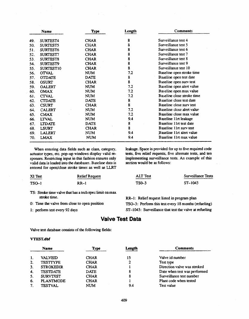
Name Type Length Comments
49. SURTEST4 CHAR 8 Surveillance test 450. SURTEST5 CHAR 8 Surveillance test 551. SURTEST6 CHAR 8 Surveillance test 652. SURTEST7 CHAR 8 Surveillance test 753. SURTEST8 CHAR 8 Surveillance test 854. SURTEST9 CHAR 8 Surveillance test 955. SURTESTI0 CHAR 8 Surveillance test 10
56. OTVAL NUM 7.2 Baseline open stroke time57. OTDATE DATE 8 Baseline open test date58. OSURT CHAR 8 Baseline open surv test59. OALERT NUM 7.2 Baseline open alert value60. OMAX NUM 7.2 Baseline open max value61. CTVAL NUM 7.2 Baseline close stroke time62. CTDATE DATE 8 Ba_line close test date63. CSURT CHAR 8 Baseline close surv test64. CALERT NUM 7.2 Baseline close alert Value65. CMAX NUM 7.2 Baseline close max value66. LTVAL NUM 9,4 Baseline 1Irt leakage67, LTDATE DATE 8 Baseline 1Irt test date68, LSURT CHAR 8 Baseline 1Irl. surv test69. LALERT NUM 9.4 Baseline 1Irt alert value70, LMAX NUM 9,4 Baseline llrt max value
When entering data fields such as class, category, leakage. Space is provided for up to five required codeactuator types, etc. pop--up windows display valid re- tests, five relief requests, five alternate tests, and tensponses. Restricting input in this fashion ensures only implementuig surveillance tests. An example of thisvalid data is loaded into the databases. Baseline data is section would be as tbllows:
entered for open/close stroke times as well as LI.,RT
XI Test Relief Request ALI" Test Surveillance Tests
TSO-.-1 RR-1 TS0--3 ST-1043
TS: Stroke time valve that has a tech spec limit onmax
stroke time. RR-1: Relief request listed in program plan
0: Tune the valve ft'ore close to open position TSO-3: Perform tl_s test every 18 months (refueling)
1: perform test every 92 days ST-1043: Surveillance that test the valve at refueling
Valve Test Data
Valve test database consists of the following fields:
VTEST.dbf
Name Type Length Comments
1. VALVEID CHAR 15 Valve id number
2. TES_E CHAR 2 Test type3. STROKEDIR CHAR 1 Direction valve was stroked
4. TESTDATE DATE 8 Date when test was performed5. SURV'I_.,ST CHAR 8 Surveillance test number6. PLANTMODE CHAR 1 Plant code when tested7. TESTVAL NUM 9.4 Test value
4O9
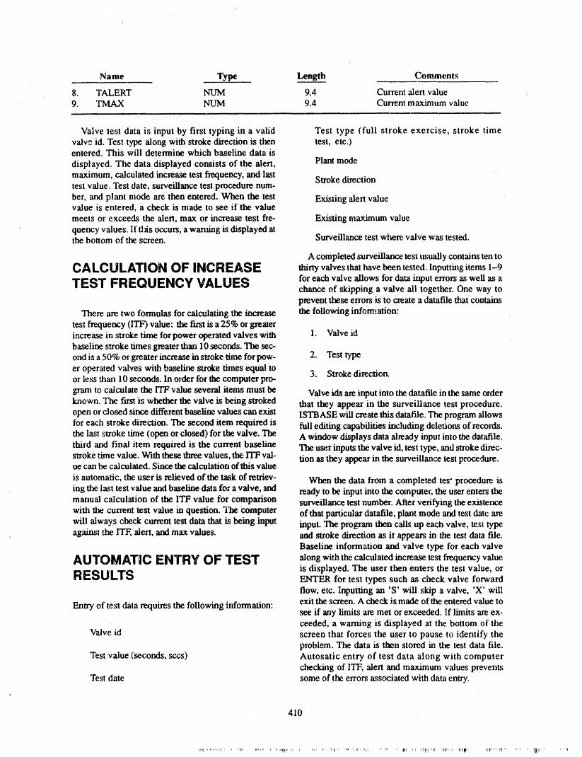
Name Type Length Comments
8. TALERT NUM 9.4 Current alert value9. TMAX NUM 9.4 Current maximum value
Valve test data is input by first typing in a valid Test type (full stroke exercise, stroke timevalve ld. Test type along with stroke direction is then test, etc.)entered. This will determine which baseline data is
displayed. The data displayed consists of the alert, Plant modemaximum, calculated increase test frequency, and last Stroke directiontest value. Test date, surveillance test procedure num-
ber, and plant mode are then entered. When the test Existing alert valuevalue is entered, a check is made to see if the valuemeets oz"exceeds the alert, max or increase test fre- Existing maximum value
quency values. If tiffs occurs, a warning is displayed atthe bottom of the screen. Surveillance test where valve was tested.
A completed surveillance, test usually contains ten toCALCULATIONOF INCREASE thirty valvesthat have been tested, lnputtingitems 1-9
TEST =FREQUENCY VALUES for each valve allows for data input errors as well as achance of skipping a valve ali together. One way toprevent these errors is to create a datafile that contains
There are two formulas for calculating the increase the following infommtion:
test frequency (II'F) value: tim first is a 25% orgreaterincrease in stroke time for power operated valves with 1. Valve idbaseline stroke times greater than 10 seconds. The ,sec-
ond is a 50% or greater increase in stroke _ne forpow- 2. Test typeer operated valves with baseline stroke times equal to 3. Stroke direction.or less than 10 seconds. In order for the computer pro-
gram to calculate the ITF value several items must be Valve ids are input into the datafile in the same orderknown. The first is whether the valve is being stroked that they appear in the surveillance test procedure.open or closed since different baseline values can exist ISTBASE will create this datafile. The program allowsfor each stroke direction. The second item required is full editing capabilities including deledom of records.the last stroke time (open or closed) for the valve. The. A window displays data already input into the datafile.third and final item required is the current baseline The user inputs the valve icl,test type, and stroke direc-stroke tmie value. With these three values, the ITF val- tion as they appear in the surveillance test procedure.ue can be calculated. Since the calculation of this value
is automatic, the user is relieved of the task of retriev- When the data from a completed tesi procedure ising tlm last test value and baseline data for a valve, and ready to be input into the computer, the user enters themanual calculation of the ITF value for comparison surveillance test number. After verifying the existencewith the current test value in question. The computer of that particular datafile, plant mode and test date arewill always check currem test data that is being input input. The program then calls up each valve, test type,against the ITF, alert, and max values, and stroke direction as it appears in the test data file.
Baseline information and valve type for each valve
AUTOMATIC ENTRY OF TEST along with the calculated increase test frequency value
RESULTS is displayed. The user then enters the test value, orENTER for test types such as check valve forwardflow, etc. Inputting an 'S' will skip a valve, 'X' will
Entry of test data requires the following information: exit the screen. A cheek is made of the entered value tosee if any limits are met or exceeded. If limits are ex-ceeded, a warning is displayed at the bottom of the
Valve id screen that forces the user to pause to identify theproblem. The data is then stored in the test data file.
Test value (seconds, sccs) Autosatic entry of test data along with computerchecking of ITF, alert and maximum values prevents
Test date some of the errors associated with data entry,
410
......... P I' Iii= _. I' lr i _l ii I i=_llj ,rl r_lll= rll= MI,_II = , I1_=1,11 jWj....... 1t11,
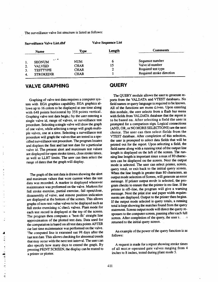
The surveillance valve list structure is listed as follows: "
Surveillance Valve List.dbf Valve Sequence List
Name Type Length Comments
1. SEONUM NUM 6 Sequence number2. VALVEID CHAR 15 Valve id number
3. TESTTYPE CHAR 2 Required test typezt. STROKEDIR CHAR 1 Required stroke direction '
VALVE GRAPHING QUERY
The QUERY module allows the user to generate re.
Graphing of valve test data requires a computer sys- ports from the VALDATA and VTEST databases. Notem with EGA graphics capability. EGA graphics al- field names or query language is required to be known.lows up to 16 colors to be displayed at one time along Ali of the functions are menu C_iven. Upon enteringwith 648 points horizontal by 358 points vertical, this module, the user selects from a flash bar menu
Graphing valve test data begir_ by the user entering a with fields from VALDATA database, that the report issingle valve id, range of valves, or surveillance test to be based on. After selecting a field the user isprocedure. Selecting a single valve will draw the graph prompted for a comparison sign. Logical connectionsof one valve, while selecting a range will graph multi- (AND, OR, or NO MORE SELECTIONS) are the nextpie valves, one at a time. Selecting a surveillance test choice. The user can then select fields from theprocedure will graph the valves that are tested in a spe- VTEST database. After completion of this selection,tiffed surveillance test procedure. The program locates the user is prompted to select data fields that will beand displays the first and last test date for a particular printed out for the report. Upon selecting a field, thevalve id. The present alert and ma._mum test values field name along with a running total of the output lineare displayed for open stroke times,close stroke times, length is displayed on the left of the screen. The run-as well as LLRT limits. The user can then select the ning line length is important since a max of 80 charac-
.range of dates that the graph will display, ters can be displayed on the screen. Next the outputmode is selected. The user can select printer, screen,query total, or exit back to the initial query screen.
graph of the test data is di'awn showing the alert When the line length is greater than 80 characters, anand maximum values that were current when the test output mode selection of Screen, will generate an error
i data was recorded. A marker is displayed wherever message. If printer output mode is selected, the pro-maintenance was performed on the valve. Markers for gram checks to ensure that the printer is on-line. If thefull stroke exercise, partial exercise, fail open/close, printer is off-line, the program will give a warningdisassembly of valve, and remote position indication message. Next the print size aral paper width require-are displayed at the bottom of the screen. This allows ments are displayed. Output to the printer then begins.
If the output mode mlected is query totals, a runninggraphs of non-test value valves to be displayed such asfull stroke exercising o£ check valves. Plant mode for total is kept showing the matches found from the query
each test record is displayed _t the top of the screen, statement. Screen output mode will direct the query re-The program then computes a 'best-fit' straight line spomes to the computer screen, pausing after each fullapproximation of the plotted test data. Data used for ,_ereen. After completion of the query, the user i= : _the computation is based on ali test data points AFI'F.,R returned to the initial query screen.the last time maintenance was performed on the valve.
_a "the computed line is extenaed out 98 days after the An exam.pie eft he power of the query function is aslast test date, This allows checking for abnormal trends follows:that may occur with the next test interval. The user canalso ,specify how many days to extend the graph. By A request is made for a report showing stroke timespressing PRINT SCREEN, the display can be routed to of ali mot'or-operated gate valves ranging from zt
__ a printer or plotter, inches to 8 inches, tested during plant mode 5.
411
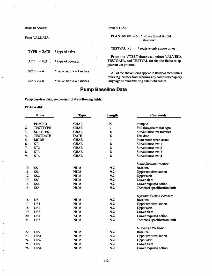
Items to Se_u'ch: From VTEST:
From VALDATA: PLANTMODE = 5 * valves tested at coldshutdown
TESTVAL > 0 * retrieve only stroke timesTYPE = GKI'E * type of valve
From the VTEST database, select VALVEID.
AC'I" = MO * type of operator TESTOATA, and TESTVAL for the the fields to ap-pear on the printout.
SIZF_> =4 * valve size > = 4 inches Ali ofthe above items appear in flashbar menus thusrelieving the user from learning any complicated query
SITF. < = 8 * valve size < = 8 inches language or remembering data field games.
Pump Baseline Data
Pump baseline database consists of the following fields:
PDATA.flbf
Name Type Length Comments
1. PUMPID CHAR 15 Pump id2. TESTTYPE C$-IAR 1 Full flow/recirc test type3. SURVTEST CHAR 8 Surveillance test number4. 'IT.,STDATE DATE 8 Test date5. MODE CHAR 1 Plant mode when tested6. ST1 CHAR 8 Surveillance test 17. ST2 CHAR 8 Surveillance test 28. ST3 CHAR 8 Surveillance test 39. ST4 CHAR 8 Sm'veillance test 4
Static Suction Pressure10. SS NUM 9.2 Baseline
11. SS 1 NUM 9.2 Upper required action12, SS2 NUM 9.2 Upper alert
: 13. SS3 NUM 9.2 Lower alert
14. SS4 NUM 9.2 Lower required action15. SS5 NUM 9.2 Technical specification limit
Dynamic Suction Pressure16. DS NUM 9,2 Baseline
17. DS 1 NUM 9.2 Upper required action18. DS2 NUM 9.2 Upper alert19. DS3 Nw.rM 9.2 Lower alert
20. DS4 I_UM 9.2 Lower required action21 DS5 NUM 9.2 Technical specification limit
Discharge Pressure22. DIS NUM 9.2 Baseline
23. DIS 1 NUlVl 9.2 Upper reqttired action24. DIS2 NUM 9.2 Upper alert25. DIS3 NUM 9.2 Lower alert
26. DIS4 NUM 9.2 Lower required action=
412
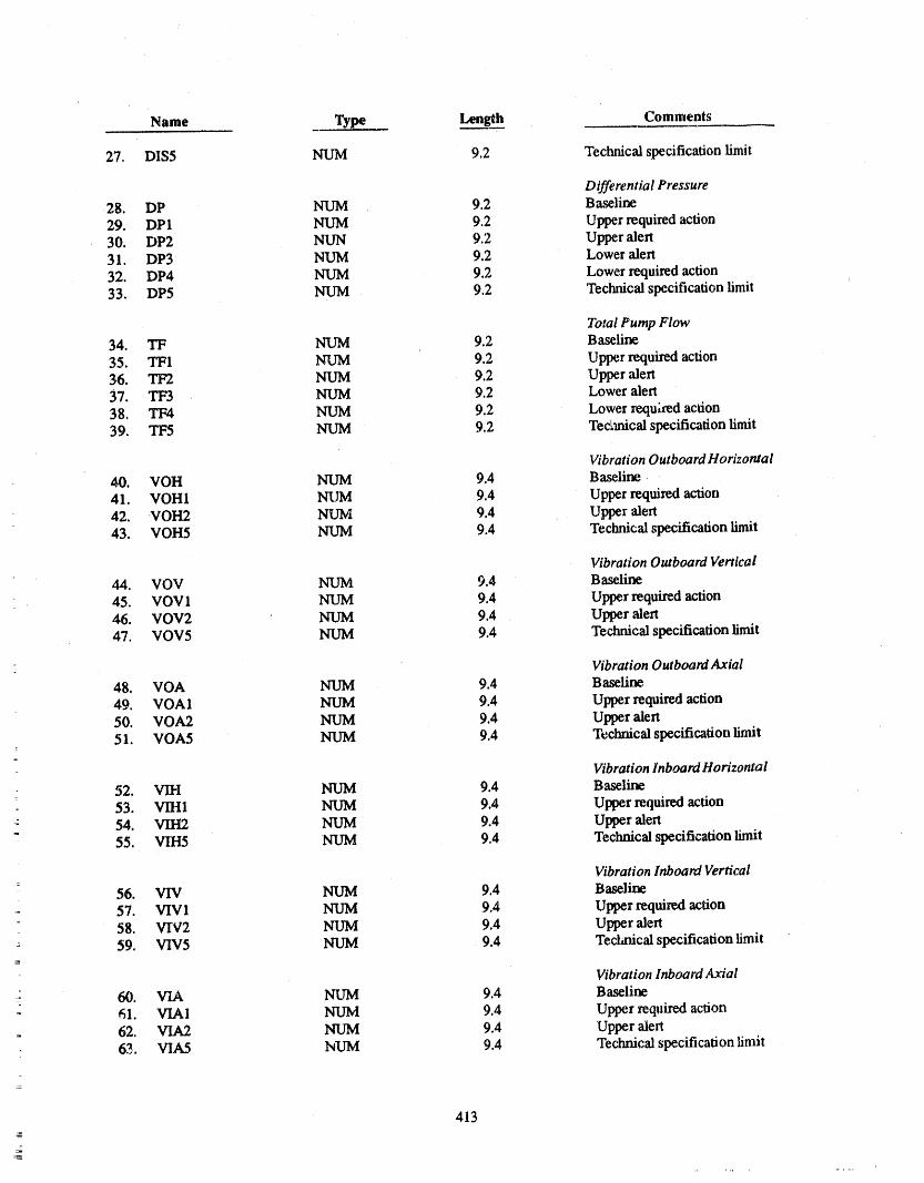
Name Type Length Comments
27. DIS5 NUM 9.2 Technical specification limit
Differential Pressure28. DP NUM 9.2 Baseline
29. DP1 NUM 9.2 Upper required action30. DP2 NUN 9.2 Upper alert31. DP3 NUM 9.2 Lower alert
32. DP4 NUM 9.2 Lower required action33. DP5 NUM 9.2 Technical specification limit
Total Pump Flow34. TF NUM 9.2 Baseline
35. TF1 NUM 9.2 Upper required action36. TF2 NUM 9.2 Upper alert37. TF3 NUM 9.2 Lower alert
38. TF4 NUM 9.2 Lower requhed action39. TF5 NUM 9.2 TecLmical specification limit
Vibration Outboard Horizontal40. VOH NUM 9.4 Baseline.
41. VOHI NUM 9.4 Upper required action42. VOH2 NUM 9.4 Upper alert43. VOH5 NUM 9.4 Technical specification limit
Vibration Outboard Vertical44. VOV NUM 9.4 Baseline
45. VOVl NUM 9.4 Upper required action46. VOV2 NUM 9.4 Upper alert47. VOV5 NUM 9.4 Technical specification limit
Vibration Outboard Axial48. VOA NUM 9.4 Baseline
49. VOA 1 NUM 9.4 Upper required action50. VOA2 NUM 9.4 Upper alert51. VOA5 NUM 9.4 Techrfical specification limit
Vibration Inboard Horizontal52. VIH NUM 9.4 Baseline
53. VIH1 NUM 9.4 Upper required action54. VIH2 NUM 9.4 Upper alert55. VIH5 NUM 9.4 Technicalspecificationlimit
VibrationInboardVertical
56. VIV NUM 9A Baseline
57. VIVI NUM 9.4 Upper required action58. VW2 NUM 9.4 Upper alert59. VIV5 NUM 9.4 Technical specification limit
Vibration Inboard Axial' 60. VIA NUM 9.4 Baseline
61. VIA1 NUM 9.4 Upper required action62. VIA2 NUM 9.4 Upper alert63. VIA5 hUM 9.4 Technical specification limit
413
-
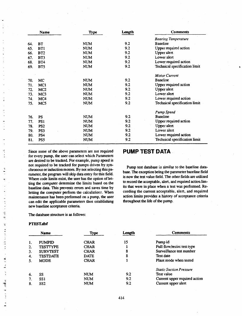
Name Type Lengt__hh Comments
Bearing Temperature64. BT NUM 9.2 Baseline
65. BTI NUM 9.2 Upper required action66. BT2 NUM 9.2 Upper alert67. BT3 NUM 9.2 Lower alert
: 68. BT4 NUM 9.2 Lower required action69. BT5 NUM 9.2 Technical specification limit
Motor Current70. MC NUM 9.2 Baseline
71. MC1 NUM 9.2 Upper required action72. MC2 NUM 9.2 Upper alert73. MC3 NUM 9.2 Lower alert
74, MC4 NUM 9.2 Lower required action75. MC5 NUM 9.2 Technical specification limit
Pump Speed76. PS N_UM 9.2 Baseline
77. PS1 NUM 9.2 Upper required action78. PS2 NUM 9.2 Upper alert79. PS3 NUM 9.2 Lower alert
80. PS4 NUM 9.2 Lower required action81. PS5 NUM 9.2 Techrtical specification limit
Since some of the above parameters are not required PUMP TEST DATA,tbr every pump, the user can select which Parametersare desired to be tracked. For example, pump ,_3eed is
not required to be tracked tbr pumps driven by syn- Pump test database _,ssimilar to the baseline data,-: chronous or induction motors. By not selecting this pa-
rameter, the program will skip data entt7 for this field, base. The exception being the parameter baseline field_- Where code limits exist, the user has the option of let- is now the test value field. The other fields are utilized
ting the computer determine the limits based on the to record the acceptable, alert, and required action lira-baseline data. This prevents errors and saves time by its that were in piace when a test was performed. Re-
- letting the computer perform the calculations. When cording the current acceptable, alert, and requiredmaintenance has been performed on a pump, the user action limits provides a history of acceptance criteriacan edit the applicable parameters thus establishing throughout the life of the pump.new baseline acceptance criteria._
- The database ,structure is as follows:
-_ PTEST.dbf:1
- Name Type Length Comments_
1. PUlVIPID CHAR 15 Pump id2. TES'ISrYPE CHAR 1 Full flow/recirc test type3. SURVTEST CHAR 8 Surveillance test number
- zt. TESTDATE DATE 8 Test date- 5. MODE CHAR 1 Plant mode when tested
Static Suction Pressureo 6. SS NUM 9.2 Test value
7. SS1 NUM 9.2 Current upper required ac_on8. SS2 NUM 9.2 Current upper alert
-
414
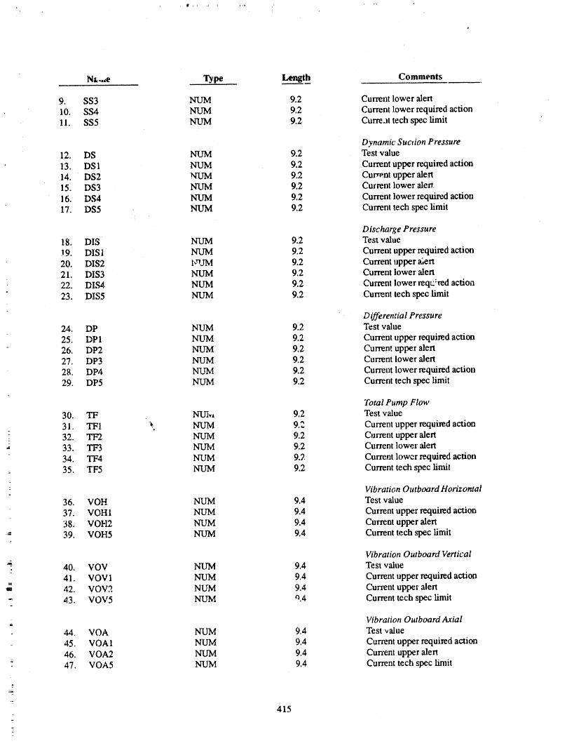
L
i
Nt,._e Type Length Comments
9. SS3 NUM 9.2 Current lower alert10. SS4 NUM 9.2 Current lower required action11. SS5 NUM 9.2 Cur're.lt tech spec limit
Dynamic Suction Pressure12. DS NUM 9.2 Test value13. DSI NUM 9.2 Current upper required action14. DS2 NUM 9.2 Current upper alert15. DS3 NUM 9.2 Current lower alert16. DS4 NUM 9.2 Current lower required action17. DS5 NUM 9.2 Current tech spec limit
Discharge Pressu re18. DIS NUM 9.2 Test value.!9. DIS1 NUM 9.2 Current upper required action20. DIS2 bndM 9.2 Current upper _ert21. DIS3 NUM 9.2 Current lower alert22. DIS4 NUM 9.2 Current lower l_eqt:'red action23. DIS5 NUM 9.2 Current tech spec limit
Differential Pressure24. DP NUM 9.2 Test value25. DP 1 NUM 9.2 Current tipper required action26. DP2 NUM 9.2 Current upper alert27. DP3 NUM 9.2 Current lower alert2g. DP4 NUM 9.2 Current lower required action29. DP5 NUM 9.2 Current tech spec limit
7btal Pump Flow
30. TF NUI,,, 9.2 Test value31. TFI _ NUM 9.2 Current upper required action
] 32. TF2 NUM 9.2 Current upper alert33. TF3 NUM 9.2 Current lower alert34. TF4 NUM 9.2 Current lower required action
= 35. TF5 NUM 9.2 Current tech spec limit
Vibration Outboard Horizontal
36. VOH NUM 9.4 Test value37. VOHI NUM 9.4 Current upper required action38. VOH2 NUM 9.4 Current upper alert39. VOH5 NUM 9°4 Current tech spec limit
Vibration Outboard Vertical
=• 40. VOV NUM 9.4 Test value41. VOV 1 NUM 9.4 Current upper required action42. VOV2 NUM 9.,_ Current upper alert
_" 43. VOV5 NUM _.4 Current tech spec limit
Vibration Outboard Axiali
44. VOA NUM 9.4 Test _,alue45. VOA 1 NUM 9.4 Current upper required action
46. VOA2 NUM 9.4 Current upper alert47. VOA5 NUM 9.4 Current tech spec limit
415
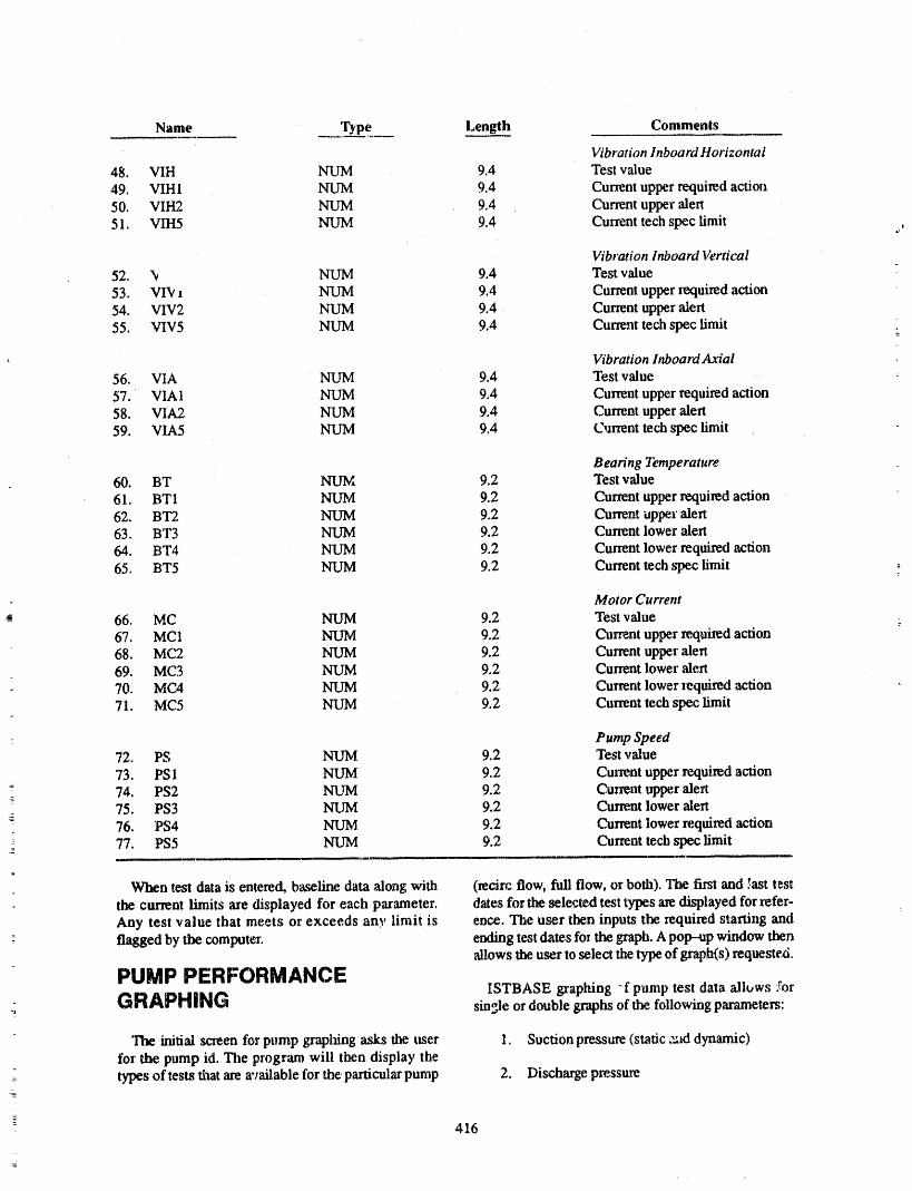
Name Type Length Comments
Vibration Inboard Horizontal
48. VIH NUM 9.4 Test value49. VIH 1 NUM 9.4 Current upper required action
• 50. VIH2 NUM 9.4 Current upper alert51. VIH5 NUM 9.4 Current tech spec limit
Vibration Inboard Vern'cal
52. '_ NUM 9.4 Test value53. VI'v i NUM 9.4 Current upper required action54. VIV2 NUM 9.4 Current upper alert
55. VIV5 NUM 9.4 Current tech spec limit _
Vibration Inboard Axial
56. VIA NUM 9.4 'rest value57. VIA1 NUM 9.4 Current upper required action58. VIA2 NUM 9.4 Current upper alert59. VIA5 NUM 9.4 Oarrent tech spec limit
Bearing Temperature60. BT NUM 9.2 Test value61. BT1 NUM 9.2 Current upper required action62. BT2 NUM 9.2 Current upper alert63. BT3 NUM 9.2 Cunent lower alert64. BT4 NUM 9.2 Current lower required action65. BT5 NUM 9.2 Current tech spec limit
Motor Current
66. MC NUM 9.2 Test value67. MCI NUM 9.2 Current upper required action68. MC2 NUM 9.2 Current upper alert69. MC3 NUlVl 9.2 Current lower alert70. MCA NUM 9.2 Current lower required action71. MC5 NUM 9.2 Current tech spec limit
Pump Speed72. PS NUM 9.2 'rest value73. PS 1 NUM 9.2 Cut_nt upper required action74. PS2 NUM 9.2 Ct_rent upper alert75. PS3 N3,JM 9.2 Current lower alerta76. PS4 NUM 9.2 Current lower required action77. PS5 NUM 9.2 Current tech spec limit
When test data is entered, baseline data along with (tecirc flow, full flow, or both). The first and 5ast test
the current limits are displayed for each parameter, dates for the selected test types are displayed for refer-Any test value that meets or exceeds any limit is ence. The user then inputs the required starting and
: flagged by the computer, ending test dates fo_ the graph. A pop-up window thenallows the user to select the type of graph(s) requestezi,
PU[_lP PI_RFORMANCE ISTBASE graphing -f pump test data allows YorGRAPHING single or double graphs of the following parameters:-_
The initial screen for pump graphing "asks the user 1. Suction pressure (static :'_d dynamic)
for the pump id. The program will then display thetypes of tests that are available for the particular pump 2. Discharge pressure
-- ,'16
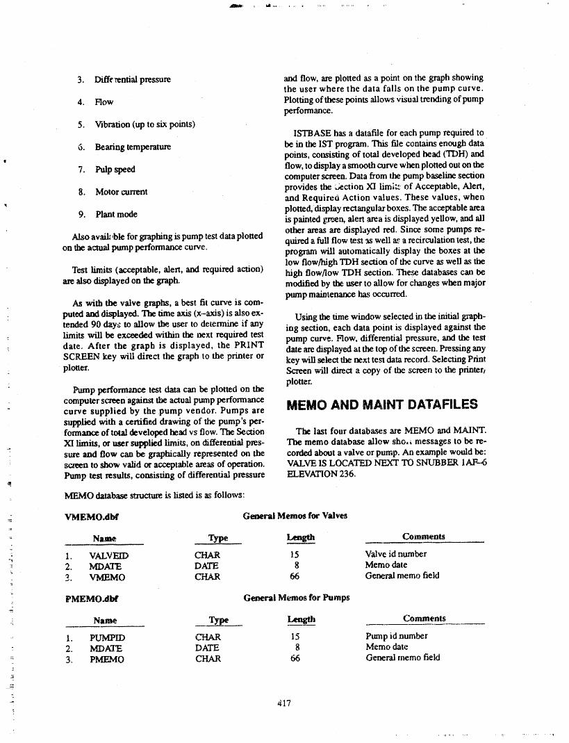
3. Diffe_ntial pressure _ flow, ase plotted as a point on the graph showingthe user where the data falls on the pump curve.
4. Flow Plotting of these points allows visual trending of pumpperformance.
5. Vibration (up to six points)ISTBASE has a datafile for each pump required to
6. Bearing temperature be in the IST program. This file contains enough datapoints, consisting of total developed head (TDH) and
7. Pulp speed flow, to display a smooth curve when plotted out on thecomputer screen. Data bom the pump baseline sectionprovides the _ection XI limitz of Acceptable, Alert,
8. Motor current and Require6 Action values. These values, whenplotted, display rectangular boxes. The acceptable area
9. Plant mode is painted gxv_n, alert area is displayed yellow, and aliother areas axe displayed red. Since some pumps re-
Also availt_ble for graphing is pump test data plotted quired a full flow test as well as a recirculation test, theon the actual pump performance curve. program will automatically display the boxes at the
low flow/high TDH section of the curve as well as theTest limits (acceptable, alert, and required action) high flow/low TDH section. 'Ilae_ databases can be.
are also displayed on the graph, modified by the user to allow for changes when major
pump mainte_ has occurred.As with the valve graphs, a best fit curve is com-
puted and displayed. The time axis (x-axis) is also ex- Using the time window selected in the initial graph-tended 90 days to allow the, u_r to determine if any ing section, each data point is displayed against thelimits will be exceeded within the next required test pump curve. Flow, differential pressure, and the testdate. After the graph is displayed, the PRINT date aredisplayed at the top of the screen. Pressing anySCREEN key will direct the graph to the printer or -keywill select the next te_ data record. Selecting Printplotter. Screen will direct a copy of the screen to the ptiater_
_ plotter.Pump performaace test data can be plotted on the
computer screenagainsttheactualpmnp performance MEMO AND MAINT DATAFILEScurve suppliedby thepump vendor.Pumps are
slq_plieMwitha certifieddrawingofthepump'sper-formanceoftotaldevelopedheadvsflow.The Section The lastfourdataba._sareMEMO and MAINT.XI limits, or user supplied limits, on differential pies- The memo dauLbase allow sho, _ messages to be re-sure and flow can be graphically represented on the corded about a 'valve or pump. An example would be:screen to show valid or acceptable areas of operation. VALVE IS LOCATF,D NEXT TO SNUBBER IAF--6Pump test results, comisdng of differential pressure ELEVATION 236.
: MEMO database sm.ructureis listed is as follows:
VMgMO.dbf General Memo, for Valves=
Nam¢_ Type _ Comments
- I. VALV'EID CHAR I5 Valve id number=,_
- 2. MDATE DATE 8 Memo date3. VMEMO CHAR 66 General memo field
=
PMEMO.dbit General Memos for Pumps_
_
Name Type Lengfll Comments
1. PUMPLD CHAR 15 Ptm_p id number- 2. MDATE DATE 8 Memo date: 3. PMEMO CHAR 66 General memo field2
- 417

The MAINT databases record when maintenance PACKING DUE TO BORATED WATER LEAK.
has bet_ performed on a valve or pump. A description When graphing test data, maintenance dates will befield is provided to describe the maintenance activity, marked on the screen.An example would be: TIGHTENED VALVE
MAINT database structure is listed as follows:
VMAINT.dbf Maintenance for Valves
Name Type Length Comments
1. VALVEID CHAR 15 Valve id number2. lv_-')ATE DATE 8 Maintenance date
3. VMAINT CHAR 66 M_' atenance description
PMAINT.dbf Maintenance for Pumps
Name Type Length Comments
1. PUMPID CHAR 15 Pump id number2. MDATE DATE 8 Maintenance date
3. PMAINT CI¢,_R 66 Maintenance description
ARCHIVE DATA establf_shed limits informs the user when test values areout of range. Graphing allows visual trending of test
Over the life of a plant, test dataliles can grow very data along with 'best fit' line extended past last testdate. The above described generic version of
large. A user might have a 10 year history of test re- ISTBASE has becn modified for some utilities to in-suits, but may only be interested in the last 3 years ofdata. In order to restrict the size of the test databases, dude scheduling capabilities, instrument calibrationan ARCHIVE routine allows the user to extract test databases, variable databases used for data input vali-
dation as well as conforming with ANSI/IEEE Start-data either by date, or by individual component. The dard 730-1984 "IEEE Standard for Software Qualityselected test data is then removed from the active data
bases and stored in separate databases. This 'arc:hived' Assurance Plans." Due to the lower cost and higherdam can be returned to the active database.s if required, performance of todays personal computers, an auto-
mated method of managing an IST program providessavings in time as well as greatly reducing personnel
CONCLUSION errorsin interpretation of test data.
Use of a personal computer greatly simplifies the re- CLIPPER is a registered trademark of Nantucketqui_d data handling of an Is'r program. Forty years of Corporation dGE is a regtstered trademark of Pinnacletest data can be manipulated into useful reports in Publishing dBASE III+ is a registered trademark ofminutes. Computer checking of input test data against Ashton--Tate.
418
ATTENDEE- PANEL QUESTIONS AND ANSWERS(EDITED; ATTENDEE QUESTIONS AND PANEL/AUTHOR
RESPONSES NOT IDENTIFIED BY NAME)
Question 1 timing was not really effective because it couldchange. So your results seem to be a little differentfi_m his.
In one of your early example charts, you had shown on" stroke timing a graph that kind of wiggled around. Is
that actualdataoi"is thisan exampleof somethingyou Response 2
did for demonstration purposes? Weil, that particular valve, when I was at Harris, was,
Response I problem.
But with the majority of the valves you see, it is goingThat is actual data. to be es_ntially a straight line .with small deviations.
That one was chosen because it is flashy. Like I men-Question 2 tioned on blowdown valves, those valves did range
from three to five seconds up to 30 when the plant wasOne of out earlier speakers gave a premise that stroke hot, until they fixed the problem with it.
z
FULL SCALE VALVE QUALIFICATION ANDFLOW INTERRUPTION TESTING PROVIDES INSIGHTS
ON INDUST;tY MOTOR OPERATOR SIZING SHORTCOMINGSAND DIAGNOSTIC TESTING LIMITATIONS
ROBERT STEELE, JR.KEVIN G. DEWALL
IDAHO NATIONAL ENGINEERING LABORATORYEG&G IDAHO, INC.
IDAHO FALLS, IDAHO 83415G. H. WEIDENHAMER AND H. W. WOODS, USNRC TECHNICAL
MONITORS
ABSTRACT INTRODUCTION
The INEL, under the sponsorship of the USNRC, is
Valve test programs sponsored by the United States performing research to help resolve specific generic is-Nuclear Regulatory Commission =CUSNRC) and con- sues and to provide information to develop and im-ducted by researchers from the Idaho National Engi- prove industry qualification, operating, andneering Laboratory (INEL) have yielded important maintenance standards for mechanical equipment.insights concerning motor-operated valve operator "l'hisresearch effort includes a program that tested thesizing and in situ testing. The most significant of these operability (opening and closing) of two full-scaletest programs was a full-scale, high-energy qual/fica- gate valves subjected to the high temperatures, hightion and flow-interruption gate valve test program pressures, and high flows of typical BWR line--breakconducted in the spr/ag of 1988. For this program, we conditions. The purpose of the test program was to
: modified two representative 6-in, 900-1b valve assem- support NRC efforts regarding Generic Issue 87blies to include a high--temperaag¢ load c¢11in each of (GI-87), "Failure of the HPCI Steam Line Without
_: the valve stems to directly measure stem thrust. Instru- Isolation." This paper summarizes the impact of thatmentation in the flow loop and on the motor operators test program on GI-87 and on mother highly visiblemeasured the important responses and parameters. At safety issue, Genetic Issue II.E.6.1 (GI-II.E.6.1),various times during the test program, each of the _r- "In Situ Testing of Valves," which represents the over-rently popular diagnostic test systems was installed to ali USNRC concern for valve operabiEty in nuclearmonitor the performa_'w.eof the valve motor operators, power plants. One effort in the resolution of GI-The valves were subjected tothe hydraulic and leakage II.E.6.1 is addressed by lE Bulletin 85-03, "Motor-
. testing requirements specified in ANSI B16.41 operated Valve Common Mode Failures During Plant(QV--4) ',rodto flow interruption (valve closure) testing Transients Due to Improper Switch Settings," azgl willat boiling water reactor (BWR) temperatures and pres- be further addressed by a proposed generic letter onsm,es at line break coaditiom. Results _ow that for the safety-related motor-operated valve testing andtested valves, the variables used in current industry surveillance.motor operator sizing e.quatio_ under--p_cdict actual
: valve thrust requirements at high temperature load- GI-87 applies to those process lines that communi-hags; for one valve design, the equation may need an care with the BWR primary system, pass through theadditional term to account for nonlineaz performance, containment, and contain normally open isolation
: Results also show that the thrusts needed to close the valves. Two steam supply lines and one hot water sup-valves were sem!five tc the fluid temperature, and that ply line meet these criteria: ti_ high-pressure cool_lt1
the results of testing at lower pressures, temTeratures, injection (HPCI) and the reactor core isolation coolingand flows cannot be extrapolated to design basis (PCIC) lines, and d_ reactor water cleanup (RWCU)conditions, line, respectively. The conce.m with these systems is
a. Work supported by the U.S. NuclearRegulatory Commission, Division of Engineering, Office of NuclearReg-ulatory Research, under DOE Contract No. DE--AC07-761D01570.
421

whether the contaimnent isolation valves will close in BACKGROUNDthe event of adownstrema pipe break.
Parallel with the lE Bulletin 8.5-03 work, the
lE Bulletin 85-03 requested the utilities [both pres- USNRC contracted the INEL to provide technical in-surized water reactor (PWR) plants and BWR plants] sights in support of USNRC efforts regarding GI-87,to develop and implement aprogram that would ensure which addresses the potendal failure of selected BWRthat switch settings on selected safety-related motor- process line isolation valves to close in the event of a
operated valves are chosen, set, and maintained eor- downstream pipe break. The initial INEL effort was torectly to accommodate the maximum differential determine what valves are installed in these applica-pressures expected on these valves during both normal tions, their sizes and manufacturers, what testing hadand abnormal events within the design basis. It is also been previously performed, and which system would
our understanding that the USNRC staff is considering be the highest risk to plant safety. Surveys identifieda generic letter that could expand the application of IE the flexible wedge carbon steel gate valve with a Limi-Bulletin 85-03 to ali safety related valves, including torque motor operator as the predominate valve in the
three systems (HPCI, RCIC, and RWCU) addressed bythose that might be mis'positioned. GI-87. The most common valve sizes are 4 in. for the
RCIC system, 6 in. for the RWCU system, and 10 in
To meet these new operating criteria, indu:_try de- for the HPCI system. A downstream break in theveloped new motor-operated valve diagnostic test RWCU system would represent the highest risk to theequipment and methods for in situ valve testing. One plant, zo it was decided that the initial flow isolationof the new requirements was that the valve control testing should provide information on valve operabil-switches be set correctly for the design basis loading ity questions associated with the RWCU system.for each valve. IE Bulletin 85-03 succeeded in signifi-
cantly improving the operability of the selected safe- To avoid duplication, we reviewed applicable testty-related valves because it caused the utilities to program_ that have been previously completed; that re-reanalyze the design basis load for the applicable mo- view showed that sufficient test information was nottor--operated valves and reset the controlswitches ac- available for thr st,pport Of the USNRC effort regard-cordingly. In many cases, these analyses were more ing GI-87. Among the test programs reviewed was thecomplete than the analyses in the original procure- Electrical Power Research Institute (EPR/) power-ments, and utilities reset the control switches in accor- operated relief valve/block valve testing at Duke Pow-
dance with the improved analyses, er in 1980. For applicabifity to GI-87, this programhad three shortcomings: (a) the block valves were
stainless steel as opposed to carbon steel; (b) the testsHowever, very little design basis testing of valves were go/no-go type tests where neither motor-oper-
had been conducted outside the plant, and the utilities ated valve thrust nor torque were measured; and (c) tlmgenerally c_araot test the valves at design basis condi- EPRI test medium was steam, which would be more
tions in the plant. This situation left the utilities relying applicable to HPCI and RCIC systems than to RWCUon valve motor operator switch settings that were systems. Also, Kraftwerkunion (KWU) of West Gcr-based on analyses of the _sign basis loadings. Utili- many had tested a3--in. stainless steel parallel disc gateties verified the tontue or thrust levels for each valve valve at blowdown flows for the Central Electric C-en-
through seat or back seat type loadings. The problem erating Board (CEGB), United Kingdom. Mechanicalwith this type of valve testing was that the motor oper- interference on the downstream disc prevented clo-ator is at full speed and is unloaded when the seat con- sure. KWU has performed full-flow interruption test-tact is made, and motor operator momentum ing on a large number of valve types; however, ourconstitutes a large part of the final measmed thrust or inil:_l contacts indicated that the information at that
torque. Such testing cannot verify the adequacy of the time was proprietary. Since that time, Bechtel andoriginal operator sizing or the correctness of the torque KWU have formed an alliance, and the information
switch setting. This problem is evidenced by the INEL may become more available.gate vah,e test results, which show that because of the
higher than anticipated friction factors at the disc guide GI-'7 Hot Water Valve Tostto valve body guide surfaces and the variabdity of thevalve stem--to-stem nut factor under load, the momen- Programrum and consequent high thrusts seen at low valveloadings will not be realized at higher loadings. "Ihus, We selected two 6-in., 900-1b class, flexit !e-wedgevalve operability verified under the lower loadings gale valves for testing. The design of the valves repre-cannot ensure operability at design basis loadings, sents a large portion of the isolation valves installed in
422
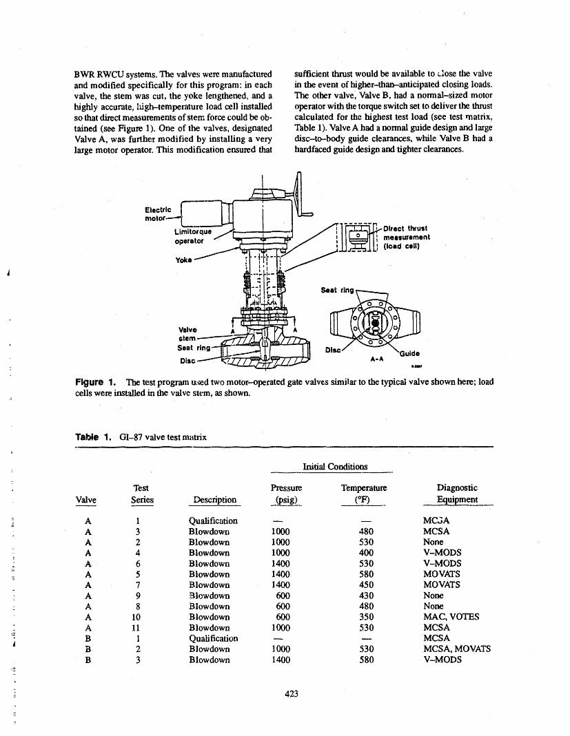
BWR RWCU systems. The valves were manufactured sufficient thrust would be available to _lose the valveand modified specifically for this program: in each in the event of higher-thatr-anticipated closing loads.valve, the stem was cut, the yoke lengthened, and a The other valve, Valve B, had a normal-sized motorhighly accurate., lfigh-temperature load cell installed operatorwith tile torque switch set to deliver the thrus!so that direct measurements of stem force could be ob- calculated for the highest test load (see test matrix,
tained (see Figure 1). One of the valves, designated "Fable 1). Valve A had a normal guide design and largeValve A, was further modified by installing a very disc-to-body guide clearances, while Valve B had alarge motor operator. This modification ensured that hardfaced guide design and fighter clearances.
Electric
Limitorque thrustmeasurement
operator' (load cell)
Yoke i
Seat ring _
+ w D_
Valve A A :or(
Seat rln
Disc A-A
Figure 1. The test program used two motor-operated gate valves similar to the typical valve shown here; loadcells were. installed ha the valve stem, as shown.
Table 1. GI-87 valve test matrix
+
Initial Conditions
z
Test Pressure Temperature Diagnostic
Valve Series Description (psig) (°F) Equipment
A 1 Qualification -- -- MC_AA 3 Blowdown 1000 480 MCSAA 2 Blowdown 1000 530 NoneA 4 Blowdown 1000 400 V-MODSA 6 Blowdown 1400 530 V-MODS
_ A 5 Blowdown 1400 580 MO VATSA 7 Blowdown 1400 450 MOVATS
• A 9 Blowdown 600 430 None- A 8 Blowdown 600 480 None
A 10 Blowdown 600 350 MAC, VOTES
A 11 Blowdown 1000 530 MCSA4
B 1 Qualification -- -- MCSAB 2 Blowdown 1000 530 MCSA, MOVATSB 3 Blowdown 1400 580 V-MODS
: 423

J
Table 1. (continued)
Initial Conditions
Test Pressure Temperature Diagnostic
Valve Serie___ss Descri_ (Psig) (°F) _ EquiPment
_ B 4 Blowdown 600 480 MACB 5 Blowdown 1000 530 V-MODS
MAC Limitorque Motor Actuator CharacterizerMCSA ORNL _Motor _Current Signature _AnalyeisMOVATS MOVATS, Inc. (Motor-Operated Valve Analysis and Test System)V-MODS WYLE Laboratori--es Valve Motor--Operat"orDiagnostic'Sys'i'em
VOTES Liberty Technology V--_ve OperatorT_est and-E_valuation-S_ystem
The flow loop and ;,nstrumentation are shown in As apart of each flow interruption test, the test valveFigure 2. The test system featured a large water tank, was opened against differential pressure with low flowheated and pressurized so that various system water and without flow and, w_n the test reservoir invento-conditions could be established and regulated through- ry permitted, was partially reopened after closure andout the valve cycle. The test program was designed to reclosed w_dahigh flow. The parametric flow interrup-determine valve operability and to measure the forces tion testing tor Valve A included varying both theneeded to close the valves (flow interruption)_ open starting pressure and the degree of fluid subcooling forthem under various system condition3, as listed in a given pressure. For Valve B, only the pressme was
Table I. The, 6-in. test valves were mounted in the test varied at a constant 10°F subcooling.loop, as shown in Figure 2 with appropriate instramen-tation for obtaining measurements of temperature,pressure, flow, motor current and voltage, and valve TEST RESULTSstem position. A fast acting, hydraulically operatedvalve was positioned so that when it was actuated, pipe
break flow through the test valve would be initiated Test results provide evidence for two concerns withand the system's fluid abruptly dumped to the atmo- motor--operated valves in nuclear power plants. First,
sphere. The flow loop included a small additional re- proper sizing of motor operators is complicated by thecirculation loop (not shown in Figure 2) that was used fact that the equation used for calculating the stemto heat the system to the initial temperature conditions force needed to close or open a gate valve does notbefore tests and to conduct low-flow valve testing, have terms for temperature, degree of fluid subcool-
ing, internal valve clearances, and the differences in: In addition to the load cell installed in the valve stem the opening and closing forces not accounted for by the
',nrl the, other instrumentation listed previously, instm- stem rejection tenn. Second, conducting effective in--mentation was provided by manufacturers of the more plant testing is very difficult because tlm tests cannotwidely used valve diagnostic systems, These |nanufac- be conducted at design basis conditions; even with theturers were invited to participate in the test program to valve loadings properly quantified, the results cannotvalidate the feasibility of extrapolating in situ plant be extrapolated to design basis conditions because the
=- diagnostic test results to design basis loadings. The final thrust varies depending on the extent to whichdiagnostic systems and their test participation are disc friction rather than disc seating causes the torqueshown in Table 1. spring to be compressed to torque switch trip and be-
causethe stem factor (an equation in the motor opera-Before the flow interruption portion of the test pro- tor sizing calculation that is used to predict stem thrust
= gram, both valves were subjected to the applicable hy- from motor operator torque) varies with tlm load/m.: draulic and leakage qualification tests outlined in posed during valve operation.
ANSI B16.41 (QV--4), the nuclear valve qualificationstandard. The purposes of these tests were to establishbaseli_ data and to ensure valve qualification before Valve Stem Force. Predicting the thrusts needed tothe valves were tested under high loads, open or close a gate valve is a critical step in sizing the
_
-_: 424
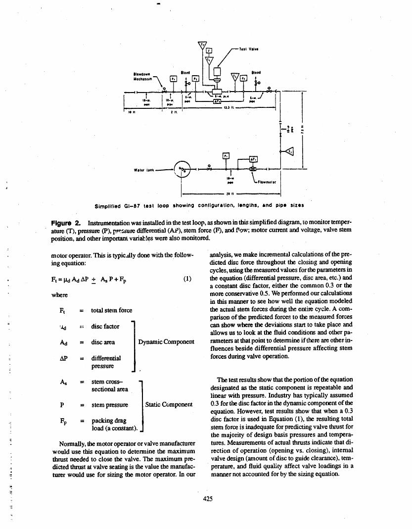
L
lilow4ewn filled old
---._ i ',,.R 1 _.
w,.f:.......[.,J2 =ji- Zlt.' ' ' _' ," le J! _J t 1_3 IL
'.... Flewmeter L
Simplified GI-87 test loop showing configuration, lengths, and pipe sizes
: Figure 2. Instrumentation was installed in.the test loop, as shown in this simplified diagram, to monitor temper-ature (T), pressure (P), p:_sure differential (At'), stem force (F), andPew; motor current and voltage, valve stemposition, and other important vari_les were also monitored.
z
motor operator. This is typicAly done with the follow- analysis, we make incremental calculations of the pre-: hagequation: dicted disc force throughout the closirJg and opening
cycles, using the measured values for the parametersha
- Ft = I_dAd AP + As P + Fp (1) the equation (differential pressure, disc area, etc.) and- a constant disc factor, either the common 0.3 or the
where more conservative 0.5. We performed our calculationsthis manner to see how well the equation modeled
Ft = total s_m force the actual stem forces during the entire cycle. A com-
= . parison of the predicted force,_to the measured forces: ,_ :: disc factor can show where the deviations start to take piace ,-rod
allows us to look at the fluid conditions and other pa-
Act = disc area Dynamic Component rameters at that point to determine if there are other in-fluences beside differential pressure affecting stem
At' = differential forces during valve operation.
_ pressure
As = stem cross- - The test results show that the portion of the equationsectional area designated as the static component is repeatable and
: linear with pressu_. Industry has typically assumed
P = stem pressure Static Component 0.3 for thedisc factor in the dynamic component of the: equation. However, test results show that when a 0.3
: Fp = packing drag disc factor is used in Equation (1), the resulting totalload (a constant), stem force is inadequate for predicting valve thrust for-
the majority of design basis pressures and tempera-
Normally, the motor operator or valve manufacturer tures. Measurements of actual thrusts indicate that di-would use this equation to determine the maximum rection of operation (opening vs. closing), internalthrust needed to close the valve. The maximum pre- valve design (amount of disc to guide clearance), tem-
_- dicted thrift at valve seating is the value the manufac- perature, and fluid quality affect valve loadings in a= turer would use for sizing the motor operator. In our manner not accotmted for by the sizing equation.
. 425
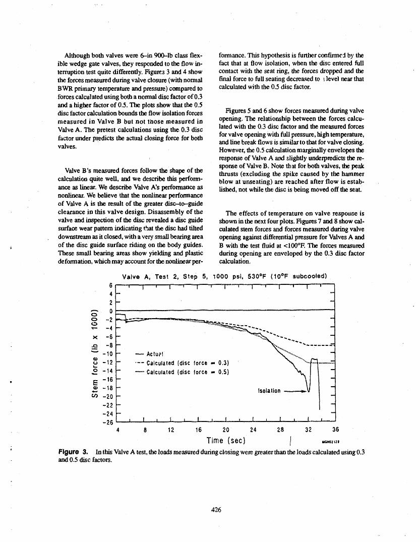
Although both valves were 6-in 900-1b class flex- fomlance. This hypothesis is further confirmed by theible wedge gate valves, they responded to the flow in- fact that at flow isolation, when the disc entered fullterruption test quite differently. Figu_s 3 and 4 show contact with the seat ring, the forces dropped and thethe forces measured during valve closure (with normal final force to full seating decreased to t level near that
BWR primary temperature and pressure) compared to calculated with the 0.5 disc factor.forces calculated using both a normal disc factor of 0.3
and a higher factor of 0.5. The plots show that the 0.5disc factor calculation hounds the flow isolation forces Figures 5 and 6 show forces measured during valve
measured in Valve B but not ribose measured in opening. The relationship between the forces calcu-
Valve A. The pretest calculations using the 0.3 disc lated with the 0.3 disc factor and the measured forces
factor under predicts the actual closing force for both for valve opening with full pressure, high temperature.,and fine break flows is similar to that for valve closing.
valves. However, the 0.5 calculation marginally envelopes the, response of Valve A avr slightly underpredicts the re-
sponse of Valve B. Note th at for both valves, the peakValve B's measured forces follow the shape of the thrusts (excluding the spike caused by the hammer
calculatitm quite well, and we describe this perform- blow at unseating) are reached after flow is estab-ance as linear. We describe Valve A's performance as fished, not while the disc is being moved off the seat.nonlinear. We believe that the nonlinear performanceof Valve A is the result of the greater disc-to-guide
clearance in this valve design. Disassembly of the The effects of temperature on valve response is
valve and inspection of the disc revealed a disc guide shown in the next four plots. Figures 7 and 8 show cal-sm'face wear pattern indicating that the disc had tilted culated stem forces and forces measured during valvedownstream as it closed, with a very small heating area opening against differential pressure for Valves A andof the disc guide surface riding on the body guides. B with the test fluid at <IO0°E The fo_r,es measured
These small bearing axeas show yielding and plastic during opening are enveloped by the 0.3 disc factordeformation, which may account for the nonlinear per- calculation.
Valve A, Test 2, Step 5, 1000 psi, 530°F (IO°F subcooled)642
o -2o.v-- -4
._ -8"" -10 - -- Actup1 "]
o° .... ,°,,c - \ ......t,., am
_o-,,i _. 0,,
-26 _4 8 12 16 20 24 28 32 36
Time (sec) [-: Figure 3. In this Valve A test, the loads measured during closing were greater than the loads calculated using 0.3
and 0.5 disc factors.
426

Valve B, Test 2, Step 5, 100'0 psi, 530 °F (10 °F subcooled)
6l-'! -i , , I ," ," '' i -'- , '' ,.... 'i........ ' l
4 F _2
r
0 ......
C> -2 __ "4 _'
- ---. Actual ............:":'_'"•"10 " " ..... --,,, "
o¢')¢__ -14"12........- "'- Calculated(diCalculated(diSCscfactorlaCt°r_: 0.5)0'3) ."""#..._...""""""_ -Iii,,,,. ,,,Q._I _
E "16 Isolation--' I ", _ -18co -20 -
-22 --24 --26- J _t , = ,, l , = 1 _i ! , = I I I,,, L
0 5 10 15 20 25 30 35
, Time (sec) _.0.,,,
Figure 4. Tb¢ respenseofValveB ismo_ linearthanthatofValveA; the,calculationusinga0.5discfactor
marginallyenvelopesthemeasuredload,butthe0.3calculationisnotconservative.
Vave A, Test 2, Step 6, 1000 psig, 530 °F
20.0 , I i' I _ ' 1 1-' l ':1 i- I i .....1- ' _ 'i_ i- :i , i I I.....='-I ':
m
' 0 10,0 _'-'-"-"'-_-"
= _m 010 1 , , ...... , :_ , "_'_',_, _ ,
,,-- ._-"-" Actual -
°="o-10.0 "'" Calculated(disc fact_)r,- 0.3}'*- ---Calculated (disc factor - 0.5)
i
-- (,o -20.0 -_.
-
- -30.0 ::::Z=::::=:_'j_.J_-I- , l , , 1 !_ ' _LL_-JI , , , I . I _ _ I , , _l-"_,: : 0 4 8 12 16 20 24 28
- Time (sec) i ,, ._=,,,I
: Figure 5. In this Valve A mst, peak thrustencountered during opening was measured not while the disc was
being lifted off the .seat,but well after flow was established.=
4- 427_
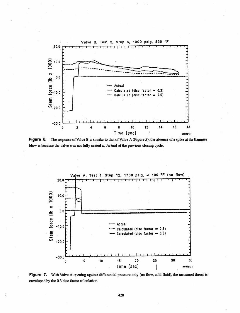
' Valve B, Tes_. 2, Step 6, 1000 psig, 530 °F20.0
o 10.0 - .-"'-" .......c>
X _m"._ 0.0_, ,
© --- Actu -¢,)
"-- Calculated (disc factor - 0.3) __°"10'0 --". Calculated(disc factor -- 0.5) '-E "
c__20.0
L.
-30.0 _0 2 4 6 8 10 12 14 16 18
Time (sec) ,' mo,.,
Figure 6o The response of Valve B issimilar to that of Valve A (Figure 5); the absence of a spike at the hammer
blow is because the valve was not fully seated at :he end of the previous closing cycle.
Valve A, Test 1, Step 12, 1700 psiQ, < 100 '°F (no flow)20.0 ""r"T--
- " i_ 10.0 -m,mllw
_ o.o -
1,w
u'- • " --- Act alo -10.0 -.... Calculated(disc factor - 0.3)
E " -- Calculated(disc factor - 0.5)m
-2o.o-'
-30.0' I J I., ! J..j.._!_l I., , t.! I .1., t i I t _ ! I I .I I J., I i i , t0 s 10 Is ._0 ,s a0 3s
Time (sec) I '_'_'"'
Figure 7. With Valve A opening against differential pressure only (no flow, cold fluid), the measured thrust is
enveloped by the 0.3 disc factor calculation.
+ • 428
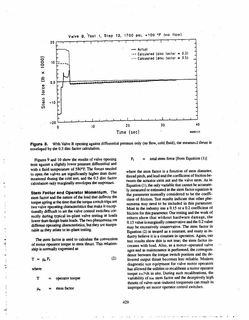
Valve B, "Test 1, Step 12, 1700 psi, <100 °F (no flow)
l i , , - i "i-' _'" ',-_, 'I _ ' T I _ I i..... l .....
_=.........-._ ' ---- Actual_ _ ' .-- Calculated (disc factor - ,3)
X
,g3
_" 0.0Cta,,,.,.
=.
._ -10
-200 lO 20 30 40
Time {sec) ' ,,,.,,,:_
Figure 8. V_,_thValve B opening against _fferential pressure only (no flow, cold fluid), the measuv=J thrust isenveloped by the 0,3 disc factor calculation.
" Figures 9 and 10 show the results of valve opening Ft = total stem force [from Equation (1)]tests against a slightly lower pressure differential andwith a fluid temperature of 580°E The forces neededto open the valves am significantly higher than those where the stein factox is a function of stem diameter,measured during the cold test, and the 0.5 disc factor thread pitch, and lead and the coefficient of friction be-calculation only m_ginally envelopes the responses, tween the actuator stem nut and the valve stem. As in
Equation (1), the only variable that cannot be accurate-
Stem Factor and Operator Momentum. The ly measuredorestimatedin the stemfactorequationisStemfactor andthenatureof the loadthat deflectsthe the parameter normally consideredto be the coeffi-
torque spring at the lime that the torque switch trips are cient of friction. Test results indicate that other phe-two valve operating characteristics that make it excep- nomena may need to be included in this parameter.
= tionally difficult to set the valve control switches eor- Most in the industry use a 0.15 or a 0.2 coefficient ofrectly during typical in-plant valve testing at loads fi_ction for this parameter. Our testing and the work of
: lower than design basis loads. The two.phenomena are others show that without hardware damage, thedifferent operating characteristics, butthey arc insepa- 0.15 valne is marginally conservative and the 0.2 value
may be excessively conservative. The stem factor intable as they relate to in-plant testing. Equation (2) is treated as a constant, and many in in-
The stem factor is used to calculate the conversion dustry believe it is a constant in operation. Again, ourtest _esults show this is not true; the stem factor in-
of motor operator torque to stem thrust. This relation- creases with load. Also, as a motor-operated valve: ship is normally expressed as ages and as maintenance is performed, the correspon-
dence between the torque switch position and the de-T = I_ Ft (2) livered output thrust becomes less reliable. Modern
-: diagnostic test equipment for valve motor operatorswhere has allowed the utilities to zecalibrate a motor operator
torque sw:.tch in situ. During such recalibrations, theT = operator torque variability of mt: stem factor and the deceptively high
thrusts of valve-seat-induced torqueouts can result in= stem factor improperly set motor operator control switches.
429
_11, ii 'li ,i ii11,11r , ,11,,, i'l_r Illl[l',

Valve A, Test 1, Step 19, 1650 psig, 580 °F (no flow)
20.0 I'I i i i I_,_"_| _ i'""! 'i'"'l "i' i i i" i I 'i i i | i ( s i i i-- _-'T T"m
m
o 10.0I_ amm,,== Q'
¢'_
"- .:- -/m ,
x o.o ...... :_ ___........ ,__,_,2_,__ 2_ "D
" "10.0 -,. ..,
E - --" Actual ..(_ ..1
.,-, " "'" Calculated(disc lector - 0.3), _ -20.0 " "-- ---" Calculated (disc factor ,.- 0.5) -
m
. ,--30.0 -jj ' ' j-I'll ' l__ I k, , ' I t , L L l , , I , ! l ,, _ 1 , I.J._0 5 10 15 20 25 30 35
Time (sec} .0=,,,
Figure 9. With an iucreasein fluid temperature,the measuredthms¢is not envelopedby the 0.3 disc _'ic6onfactor(compareFigun_7).
Valve B, Test 1, Step 19, 1650 psi, 580 °F (no flow)
: .--. ActualCalculated(disc factor =,
o .......Calculated (disc factor ,= 0.5)¢:> 10
tt
X | Sti " "ti i
.D tt "
"" 0 _ -_ "-"¢ I
L_
, O Iq_. - ..J
IE ,=.) -10 " I
I
iI
0 10 20 30 40
Time (see) ._.,,,.
, Figure 10, Wxth an i_'¢rease it)fluid temperature, the measured thrust is not enveloped by th_ 0.3 disc frictionfactor (compm-e Figure 8).
r
:
3;
--_ 430
,,1, ,,_, ,. r ,i ,, lr, ' IT41 ' rP 'I1" Irl ' q' ' ' I'1'I_I'1 Ir,llr I_ = I 'rlllF rll P
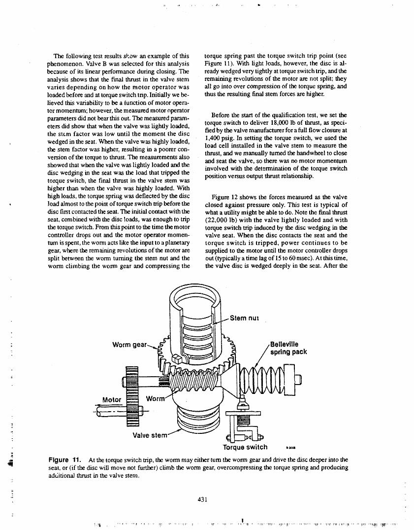
The following test results sl'.ow an example of this torque spring past the torque switch trip point (seephenomenon. Valve B was selected for this analysis Figure 11). With light loads, however, the disc is al-because of its linear performance during closing. The ready wedged very tightly at torque switch trip, and theanalysis shows that the final thrust in tlm valve stem remaining revolutions of the motor are not split; theyvaries depending on how the motor operator was ali go into over compression of the torque spring, andloaded before and at torque switch tnp. Initially we be- thus the resulting final stem forces are higher.lieved this variability to be a function of motor opera-tor momentum; however, the measured motor nperator
Before the start of the qualification test, we set theparameters did not bear this out. The measured param-eters did show that when the valve was lightly loaded, torque switch to deliver 18,000 lb of thrust, as speci-the stt.m factor was low until the moment the disc fled by the valve manufacturer for a full flow closure at
wedged in the seat. When the valve was highly loaded, 1,400 psig. In setting the torque switch, we used the' load cell installed in the valve stem to measure thethe stem factor was higher, resulting in a poorer con.. thrust, and we manually turned the handwheel to closeversion of the torque to thrust. The measurements also and seat the valve, so there was no motor momentum
showed that when the valve was lightly loaded and the. involved with the determination of the torque switchdisc wedging in the seat was the load that tripped the
position versus output thrust relationship.torque switch, the final thrust in the valve stem washigher than when the valve was highly loaded. With
high loads, the torque spring was deflected by the disc Figure 12 shows the forces measured as the valve• load almost to the point of torque switch trip before the closed against pressure only. Thi:; test is typical of
disc first contacted the seat. The initial contaa with the what a utility might be able to do. Note the tin'al thrustseat, combined with the disc loads, was enough to trip (22,000 lb) with the valve lightly loaded and withthe torque switch. From this point to the time the motor torque switch trip induced by the disc wedging in tlmcontroller drops out and the motor operator momen- valve seat. When the disc contacts the seat and theturn isspent, the worm acts like the input to a planetary torque switch is tripped, power continues to begear, where the remaining revolutions of the motor are supplied to the motor until the motor controller dropssplit between the worm turning the stem nut and the out (typicaUy atime lag of 15 to 60msec). At this time,worm climbing the worm gear and compressing the the valve disc is wedged deeply in the seat. After the
Stem nut
- Worm Bellevillespring pack
Motor
=- Valve stem
Torque switch ,_=
-_ Figure 11. At the torque switch trip, the worm may either turn the worm gear and drive the disc deeper into theseat, or (if the disc will move not further) climb the worm gear, overcompressing tlm torque spring and producingadditional thrust in the valve stern.
- 431
|!,l_ .... _ ,, ,r, n , , i, ,, iiiI....... 7 ' '_11'"' II ' 1' _11_.... , ...... " _11..... I,_," TI"'IT" J_llI_r' III......... rpl..... II!1_..... It_lr "'" I'l '_1'IItl .......... _','I_",,,l_,r_ll Irlll_l.... _11,
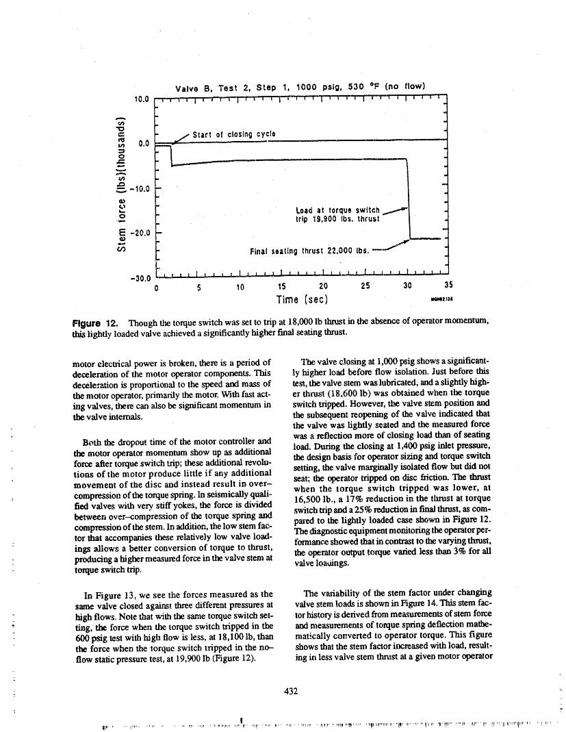
Valve B, Test 2, Step 1, 10.00 pslg, 530 °F (no flow)
10.0 _-_,-,'"l,', r_:_--r-r-r-_",',, 'I,,, "1'"'_'"' '""' ' ' ' ' 'i
"O
j/Start ofclosing cycle0.0 __ ----- .....
o ._
-10.0 .,m,G,)¢,'m
'.-. Load at torque switch _ .,.,.._o - trip 19,900 Ibs. thrust .=
E -20.0 '_m _ '=
" Final seating thrust 22,000 Ibs.-----"'_ "1
"30,0 L I._t L t I l____L_.,! J I .l I ! t t , t..! I J_J t 1 t_!,.t l I I I t I •
o s lo is ao as 30 3sTime (sec} ,,,-,,,-
Figure 12. Though the torque switch was set to trip at 18,0t30 lb thrust in the absence of operator m_nenmm,this lightly loaded valve achieved a significantly higher final seating thrust.
motor electrical power is broken, there is a period of The valve closing at 1,000 psig shows a significant-deceleration of the motor operator components. This ly higher load before flow isolation. Just before thisdeceleration is proportional to the speed and mass of tem, the valve stem was lubricated, and a slightly high-the motor operator, primarily the motor. With fast act. er thrust (18,600 Ib) was obtained when the torqueing valves, there can also be significant momentum in switch tripped. However, the valve stem position andthe valve internals, the subsequem reopening of the valve indicated that
the valve was lightly seated and the measured force
Both the dropout time of the motor controller and was a reflection more of closing load than of seatingthe motor operator momentum show up as additional load. During the closing at 1,400 psig inlet pressure,force after torque switch trip; these additional revolu- the design basis for operator sizing and torque switchtions of the motor produce little if any additional setting, the valve marginally isolated flow but did notmovement of the disc and instead result in over- seat; the operator tripped on disc friction. The thrust
compression of the torque spring. In seismically quali,, when the torque switch tripped was lower, atfled valves with very. stiff yokes, the force is divided 16,500 lb., a 17% reduction in the thrust at torquebetween over-compression of the torque spring and switch trip and a 25% reduction in final thrust, as com-compression of the stem. In addition, the low stem fac- pm'cd to the lightly loaded case shown in Figure 12.tor that accompanies these relatively low valve load- The diagnostic equipment monitoring the.operator per-ings allows a better conversion of torque to thrust, forrnance 'showed that in contrast to the varying thrust,producing a higher measured force in the valve stem at the operator output torque varied less than 3% for alitorque switch trip. valveloa_ings.
In Figure 13, we see the forces measured as the The variability of the stem factor under changingsame valve closed against three different pressures at valve stem loads is shown in Figure 14. This stem fac-high flows. Note that with the same torque switch set- tor history is derived fi'om measurements of stem forcering, the force, when the torque switch tripped in the and measurements of torque spring deflection mathe-600 psig test with high flow is less, at 18,100 lh, than matically converted to operator torque. This figurethe force when the torque switch tripped in the no-- shows that the stem factor increased with load, result-flow static pressure test, at 19,900 lb (Figure 12). ing in less valve stem thrust at a given motor operator
: 432 -
!¢,' ..... ,I':'"" ..... r .... ,l _,,rr, "lH' 'r11"_IP'qrlN' lllIq _ri" sq,_,, ' ,rtr , ..... qlr" ',IIllP, 'rlUll_=If' ' ",_¢'="Ul11',""r 'lln_l'llnp'i"llnPni' TIlll ''rlpi''''i' "ITrrl'ms 'll',:rll,' _,,,llP,, !hrI"rl,_, illTMVU'llrvlr",r"lrl'l""' "

Valve B, Step 5, Tests 4, 2, and 3 (line break flows)
5 ......," I' '' I" '' I _ - I......,....."I _-....f ' ¢'
0.0...._"
- I I ..=*--=,," _'" '_0 " II"_ ,_ ..._-=_-,._--_ - .... "'"_"'-._
. P" _ to,, "",L .
X "%'_ ".,,,..,. .
.o " _'x"_q> -..... ."'_ -10 - ......Valve B. 600 psig, 480 _F _ i -._'-' - - v_,voB.,ooo'p;_g.s3o.F _ ! :,_o : --Valve B, 1400 psig, 580 °F t'_'_ -
"" IT" -:E : Torque.,s,_oo2_"o.,) . Switch .... I=,._._tR.I00"" -;.- - 18,600-..[:_r_-.--:,._x._.;U3 -20 :" Irlp ' ".-' "
p,
__2S !:: I__ J- ' ....... I I -I .... I |. L-- l .l , l
0 5 lO tS 20 25 30 35
- Time (sec) ._o,,,,
_= Figure 13. As stem factor and operator xnomenmm are affected by increased loadings, the final thrust is less- even thoughthetorque switchsetting is tbe same.
: Valve B, 1400 psi, 580 °F,,, , ..... ,, , i , , , ,, ,
0 -- ' , I '..... I ' " I ..... ' I .... ' 1.... ' " .014_
__ o -.s- _ -.013 _
'Pm . "_ ,..,, v'_'''
x,r--_ X .0
+ ,e"_ .,4-----'_%_._ °""
"-" .... .012 o
Or"' - .,...-""_"'_'" -.. I.L.I_I
" e •c_O( ........ "*'"_
E S_em......=..:........ "_ ¢,--- m,,-15 .... " _ .011 --.
_ . ,....... _,," (,/3=
__ 2 0 _ .... [ ,. I , , ' L . J . I , - l ` - _ _ l : , ...... . 010'_ 20 z2 _4 2+ 28 30
Time (sec) "_'"'-
-: Figure 14. Calculations showthat dzesternfactor increasesw/rh load, reducing the available thrustat a giventorque.
-
- 433
I
torque. In this and other stem factor versus load dustry to take another look at the variables in the sizingcomparisons, it appears there may be a proportional re- equation, lt may be necessary to add new terms to thelationship between the increase in load and the in- equation or to increase the the disc factor to a very con-crease in stem factor, servative number to account for the missing terms.
CONC IIU_]ON_ When tests have determined the thrust needed to op-erate a valve at its design basis loading, utilities canuse one of several modem diagnostic systems to con-
i The disc factor of 0.3 typically used in industry is servatively set the motor operator control switches.not conservative for either of the valves tested. A disc They will have to account for the varying stem factorfactor of 0.5 marginaUy predicts the forces for Valve B and for the excessivelyhigh thrusts resulting fromfor both opening and closing. The response of Valve A seat-induced torque switch trips that occur with valveis enveloped bythe 0.5 disc factor during opening, but operation with low flow or no flow. However, thisnot during closing. Today's tools for analyzing valve method may exceed the allowable thrust on some valveresponse to loadings are not sophisticated enough to designs. Tiffs job will be easier and the result moredetect small design differences that make large re- conservative if both the valve torque and thrust can besponse differences. Temperature also affects the thrust measured when the switches are set. If further researchrequirements of these gate valves. These facts justify proves that there is aproportional relationship betweencontinued qualification testing of prototypical valves stem load and stem factor, the degree of conservatismlt design basis loadmg, s and point out the need for in.. can be reduced.
434__
I
AI-lr'ENDEE- PANEL QUESTIONS AND ANSWERS(EDITED; ATTENDEE OUESTIONS AND PANEL/AUTHOR
RESPONSES NOT IDENTIFIED BY NAME)
Comment 1 the torque thai has to be overcome, thereby taking atleast one factor out of the equation. Then, we have
You have found the friction factor to depend on the de- platxsfor some force type testing, where we take a mo-gree of subcooling of the gate v',dve flow interruption tor operator and try to drive just an empty stem into atests. We have found exactly the same as you in tests on cylinder set up to duplicate some of these flow levels.a parallel slide gate valve when testing to ANSI
B 16.,tl under flow interruption conditions for PWR At thepresent time our testing is concentrated on doingprimary circuit, where the degree of force depends on similar tests with additional valves and encompassingthe design of the valve, s, ,,amsystems, to verify this and to look at other valve
designs and see what else is happening here.Indeed, the disc can become sucked into the ,seat, so
that during the last critical five percent or so of closure This, of course, includes much better instrumentation
of the valve, the disc has to ride over the top of the ,seat, than we used before, so that we can study the phenom-and that gives you an apparently high friction enon of the stem factor.coefficient.
Question 2In addition, for flow interruption testing qualificationfor PWR, another feature that may well affect the ap-parent friction coefficient is the chemistry of the fluid. Considering the damage Chatwas done to these valves,The mason I say this is that we know that boric acid isolating flow under these ,severe high DP conditions,
does this raise any questions in your mh_dof the advis-goes through a maximum hiction coefficient at a tem-perature of about 300 to 350°C. ability of the requirement in the new genetic letter that
plants DP test ali their valves and then, after they have
Now, that additional friction factor, combined with the successfully completed this isolation, still consider thevalves operable?friction due to working at high temperature steam or
water conditiom, could well cause the actuator to stall.Response 2
Question 1
From our inspection of our valve B, the valve that didAre you planning any separate effects testing of force not chew itself up, I would have no problem with using
: stem factor using threaded stems and varying the thrust the valve again. It did not damage itself to the point- on them and matching the input torque to them at all? where I would consider it inoperable.
Response 1 The hard question comes in whether or not the valveyou have is a valve B or a valve A, linear or non-linear.
We have a test stand set up at our laboratory where we "Ihat is the point to be done in some sort of a prototypi-are looking into testing motor operators by controlling c_dtest.
A PHOTOELECTRICALLY ACTUATED,MOTOR-OPERATED VALVE STROKE TIMER
ANDSTROKE TIME DATA ANALYSIS
AND EVALUATION TECHNIQUESPETER R. WOHLD, P.E.
CHICAGO NUCLEAR CORPORATION2 SOUTH 580 ASHLEY DRIVE
GLEN ELLYN, IL 60137
ABSTRACT with theknowledge of'a goodbaselinestroke timeandwhere ,itrelatesto the motor perfom_ance curve,
Questions have been raised about the value of future stroke time changes can be very useful as amea-sure of continued satisfactory operation or of degrada-Motor-Operated Valve (MOV) stroke timing in nu-
- dear powerplants, and, reevaluations of requirements tion. A stroke time increase can be the key foz. in this area have recently been done by the ASME efficiently directing further test and maintenance re-
O&M Committee Working Group on Pumps and sources; a small or no change can be an indicator ofcontinued satisfactory operation.Valves. Quoting an August 12, 1988, submittal to the
Committee by W.L. Greenstr_et ft-ore Oak Ridge Na-From an evaluation of typical Alternating-tional Laboratories, "stroke time data, if made more
precise and carefully analyzed, can yield valuable cp- Current(ac) motor characteristic curves, it appears de-" erational readiness and diagnostic information." sirable to detect small changes in motor running speed
and stroke time of approximately !.0%. Hence, a timer
This paper presents a battery-powered, photoelec- with approximately 0.1% accuracy should be used. Fortxically actuated timer developed by the Chicago Nu- a 10 s stroke time, then, the repeatability of the _ech-
nique including the timer should be approximatelyclear Corporation for precLsion MOV stroke timing. 4-/-0.01 s. "Ihis may not be practical, due to the varia-The timer receives input from valve position indicat- tions in the light signal as an hlcaudescent bulb heatsing lights on tlm main control panel and can easily be
up, but, repeatability of +/-0.05 s appears achievableused with existing plant procedures. The paper also de- and will still allow detecting changes of 1.0% for most
_ scribes analysis and evaluation techniques to be valves.applied to the data in monitoring valve operability, The
= techniques described apply the data to specific valve While the timer times "light to light," the Code re-= operator charades, thereby increasing the quality quirement has. been interpreted to mean "switch to
of MOV operability assessm.,mts. Both ac and dc mo- light." For MOVs, this timing difference may be addedtor operators are comideted. It',rough the use of a stop watch or could be comidered
-- uninteresting in many cases.Effective Stroke Time Testing,
: The Timer_. Valve stroke timing is already =equired by _i_e
ASME Boiler _nd Pressme Vessel Code, Section XI, The timer is a trend held, battery--powered device.- and Title 10 of the Code of Federal Regulations. Fail. with a liquid crystal readout that has a range of from
ures to stroke am being identified through this require- 0.00 to 200.00 s. Sensors connected by leads from the- ment but partial or progressive valve degradations are timer are placed over the indicating lights, the device: not. While the timing is don_, why not get accurate reset, and the valve stroked. The coincident condition
- data that is suitable for effective operability ev',dua- of the indicating lights in mid stroke, either both on or-- tiotasand to detect degradations prior to expensive, to- both off', ts detected by the timer and the final stroke- ,:.:_,failure? This can be done by using an electronic time is indicated. A hold feature keeps the time from
:i:',,,.: with photosensitive inputs to monitor the OPEN/ changing while data is being recorded.= CLOSED 'fights near the valve control switch. The
-_ time measured is the time, the motor carries its load be- The repeatability of the stroke timing process is not: tween the sw, :ims that control the lights_ timer limited but is limited by the repeatability of the
_
_ 437
,,
sensed light leve_change from one stroke to the next. It relationship, the motor characteristic curve can be usedappears that +/0.05 s repeatability is readily achievable to determine the change in motor load and to quantita-and possibly down to +/-0.01 s with improved elec- tively assess the changes occurring in terms of avail-tronictriggering, able margin in the motor and operator. This is
explained further in the sections that follow.
To get an idea of stroke timing repeatability, a
twenty stroke experiment was performs, d, ten open and PeriodicTestingten closed, each stroke tbllowed closely by the pre-
vious one. A 3 in. gate valve was used, actuated, by an Valve load increases, motor degradation, or areduc-SMB-000, Lirnitorque operator that used a 1/3 hp, 220 lion in operator efficiency can ali result in a slowing ofV ac motor. No attempt was made to separate actual the motor. Without additional information, one can notstroke time changes from repeatability affects. The determine the cause.stroke timings ranged from 16.44 to 16.48 s, expressed
as 16.46, +/- 0.02's: Of the first 13 strokes, twelve tim- Hence, the best approach in using periodic stroke' ings did not deviate from 16.46 s. If the +/---0.02s range time test information may be in looking for a limit in
of the twenty strokes are attributed entirely to repeat- motor load change without trying to determine the
ability, then the percent repeatability error would be: cause until an arbitrary alarm point is reached. This isa matter of choice.
100 X (+/-0,02/16.48) = +/.-0.12 percent. (1)Periodic Test Analysis Example for en ac
MOV Stroke Time Relationship Motor-Operator. Assume the following characteris..
to Motor tics taken from an actual operator motor curve:
Torque
The theory of the stroke timing process presented (fl-lbs) rprn_ % Change Commentherein was developed by the Chicago Nuclear Corpo-ration, lt is based on using timing changes to detect 0 1800 0 Synchronous speedchanges in motor rpm and relate this to tile "speed vs. 3 1750 3 Motor ratingtorque" characteristic curve for the motor. An evalua- 6 1700 6
. don is then done to compare the motor torque change 9 1640 9to acceptable limits for the motor and operator. Be- 12 1570 13 .-cause of a fixed gearing relationship between valve 15 1420 21 Rated torquestem travel and motor rotation, it can be said that _he
mathematical integral of motor rpm with respect to The percent change indicated is the percent differ-time for a given stroke distance is a constant. For a ence from synchronous speed. Normally, the motorconstant motor running torque and supply voltage, mo- running speed should be within the motor rating whichtor rpm is constant, and the integral becomes, means the rpm should be between 1800 and 1750 rpm.
In this region and well beyond, per the table, a 3% re-
(rpm)(Stroke Tune) = K, (2) duction in rpm represents a torque change equivalentto the torque at 100% motor rating.
where the.comtant, K, represents the number of motor In this example for instance, if we wanted to detectrevolutions required to stroke the valve. If the valve a 1.5 fi-lb change in motor running load requirementload requirement changes or if.the efficiency of the ep.. (50% of the torque at 100% motor rating), we wouldcrater changes in converting motor torque to valve look for a 1.5% stroke time increase. This is a verystem load, the motor load and rpm will change accord- small change and the ability to relate this to theing to the motor characteristic curve, specific load changes may be masked by other affects
such as changes in available motor voltage and otherWhere Sl and $2 are the motor rpms andT1 andT2 affects.
are the respective stroke times, then according to
Equation 1, However, the motor characteristic curve chosen for
: this example was flatter than typical for many of the: (S1)(T1) = ($2)(T2), and (T2)/(T1) = (S1)/($2). (3) motors usexl in order to better understand the limits of
the system. A steeper curve would give larger stroke: From this relatiomhip, it is seen that a stroke time time changes to evaluate for the same percent change
change is inversely related to an rpm c .hange. From this in torque. This is obvious in the dc motor operator
_ 438
analysis, below. Also, a aetKI plot of the stroke time the operator in converting motor torque to stem thrustchanges and experience will help in determirfing the could be determined from an analysis of the data. Thesigz_ificance of stroke time changes identified, ultimate operator capability might then be determined
by comparing this to the margin left in the motor to
Periodic Test Analysis Example for a dc supply additional torque to the operator.Motor-Operator. Assumethe following from an ac-
tual operatormotor curve: PoSt Stem Packing Tightening Test. If stempacking tightening is required,with the increasedtim-
Torque ing accuracyit is possibleto measureandmeaningful-(ft-lbs) rpm % Change Comment ly assessthe affect of tightening by measuring stroke
times before and after.0 2600 0 No load speed
12 1800 31 Motor rating Automatic Data Collection,24 1350 48
36 1040 60 - Analysis, Trend Presentation,48 750 71 -- and Storage60 275 89 Rated torque
Comparing this data with the previous ac example Since the initial prototype timer was developed,shows a ten times difference in percent speed change Chicago Nuclear is proceeding with a laptop computergoing from no load to rated motor conditions. In the based timer that will use the timing principle devel-primary range of interest for motor running load the oped, but will store the timing data to a disk, automati-speed changes 31 percent for a load change from 0 to cally compare the stroke time to reference values,
initiate an immediate alarm if appropriate, and will be100% of motor rating. Hence, stroke timing accuracyand repeatability becomes much less of a limitation in capable of downloading the data to a host computer forthis example. For instance, if we want to detect a graphical presentation and trending.6 ft-lb change in motor running load requirement(50% of the torque at 100% motor rating, as for the ac CONCLUSIONexample), we weald look for a 15.5 % stroke time in-
crease. This is easily detected and typical of dc motors. A stroke timing teel has been developed that signifi.cantly improves the accuracy and repeatability of.
Other Possibilities valve stroke time test data. It can easily be incorpo-rated into existing plant procedures because if 'already
: Operator Capability Teel. If a valve has a signifi- existing timing requirements. Analysis and evaluationcant stem rejection load because of a high system pres- teclmiques are available to take advantage of this in-sure existing during testing, it may be possible to creased accuracy to more effectively monitor motor-detect the percent of motor load change due to the stem operated valve physical conditions; and, existingrejection load through measuring timing differences computer technology can be used to automate and effi-between opening and closing strokes. The efficiency of ciently handle the timing data.
z.
!
439

ATTENDEE- PANEL QUESTIONS AND ANSWERS(EDITED; ATTENDEE QUESTIONS AND PANEL/AUTHOR
RESPONSES NOT IDENTIFIED BY NAME) , ,
No Questions/Comments
440
ACTUATOR SETUP AND DIAGNOSTICS FORPNEUMATIC-OPERATED VALVES
J. H. MUTCHLER, P. E. AND7:.P.JAEGER
PRINCIPAL NUCLEAR ENGINEERSCOMBUSTION ENGINEERING, INC.
WINDSOR, CT 06095
INTRODUCTION ' methodology used to determine actuator setup criteriaconsiders packing gland forces, seat loads, leakage
: classifications, system pressure forces, and valve/In the past f_w years the Nuclear Power Generating actuator capabilities including spring rate
Industry has begun to realize the consequences of characteristics,valve misapplication, improper actuator setup, under-s_ed actuators and/or inadequate maintenance, The is-suance of several NRC and INPO information notice,s Basic valve, actuator an_ systems data are gathered
concerning v,,dve operation highlights these problems, and entered into a computerized valve software dataRecently, the NRC issued Information Notice 88-94, base for future reference and calculations. This pro-which reports that certain pneumatic-operated valves gzarn can then be operated on a personal computer tomay be equipped with undersized actuators which may Calculate baseline actuatorsetup criteria for the bench,not be capable of providing sufficient forces to proper- inherent and installed conditions (see Figure 1 for con-ly operate, seat or unseat the valve at maximum design vention and terminology). A significant feature of this
: methodology is that feedback from actual measuredconditions, conditions can be input into the program to validate or
correct for conservative estimates used to determineAdditionally, an industry-wide effort is in effect to the baseline actuator setup criteria. These criteria are
reduce packing gland leakage. Many valve manufac- presented in terms of actuator air pressure require-turers and packing vendors are offering packing im- ments versus valve position and a signature, trace. Ad-provements such as with the use of die-formed diti0nally, installed spring rates or actuator effectivegraphite ribbon packing. It appears that often these areas can be validated when this information cannot be
packing modifications are incorporated without proper verified through existing documentation.consideration of actuator sizing.
To use the actuator pressure data correctly, a thor-Corrective maintenance on valves to restore them to ough understanding of three basic terms is required.
their original condition is an approach that many valve The terms "bench", "inherent", and "installed" fullyrepair companies and utilities take. This approach ad- describe ali conditions which the actuator will experi-dresses the symptoms of problems, but often does not ence. Each of these three terms is discussed below,
consider root causes of problems. Original actuator with reference to Figures I and 2.sizing and setup criteria are based on estimates (in-
- tended to be conservative) of the forces acting on the- valve and actuator. These estimates are seldom vali- Bench Actuator Pressure ,V_tUngs. The "bench"
= dated following installation, operation and wear to condition refers to the actuator disconnected from the: ensure the valve can perform its intended function, valve. The purpose of setting up the actuator in the
bench condition (valve stem disconnected from actua-
tor stem) is to preload the actuator spring, verify the. The Solution spring comtant (K), and verify available spring travel
and margin available Over the original design settings.
A methodology has been developed to determine The spring preload provides the necessary force toactuator setup criteria and perform diagnostics on overcome packing friction (so thai the valve may re-pneumatic--operated valves. This type of diagnostic mm to its deenergized state by spring force alone), toevaluation on pneumatic--operated valves will ensure develop appropriate seat load for sealing (shut off) re-that the valve can pertbrm its intended function, pass quirements, to overcome the effects of system pressurein-service im-pections, and improve valve reliability on the unbalanced area on the valve plug, and to over-
_i resulting in an increased plant availability. The come positioner preload. The, application of the valve_
_
: 441.
_
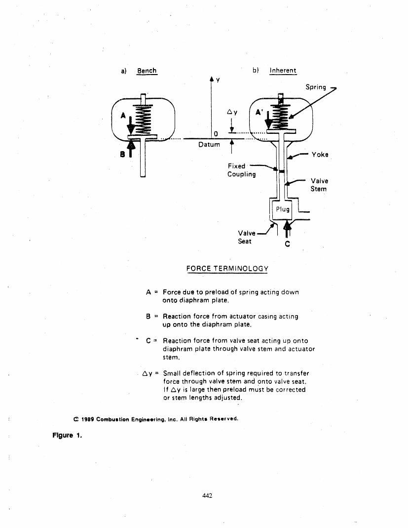
a) Bench b) Inherent=imm..,,.mn-=-=
LySpring
_yI
0 -_ ....
O;um Yoke
e° -CouplValveStem
Valve
Seat C
FORCE TERMINOLOGY
A = Force due to preload of spring acting downonto diaphram plate.
B = Reaction force from actuator casing actingup onto the diaphram plate,
" C = Reaction force from valve seat acting up ontodiaphram plate through valve stern and actuatorstem.
Ay = Small deflection of spring required to transferforce through valve stem and onto valve seat.If Gy is large then preload must be correctedor stem lengths adjusted.
: C_ 1989 Combustion Engineering, Inc. Ali Rights Reserved.
: Figure 1.
442
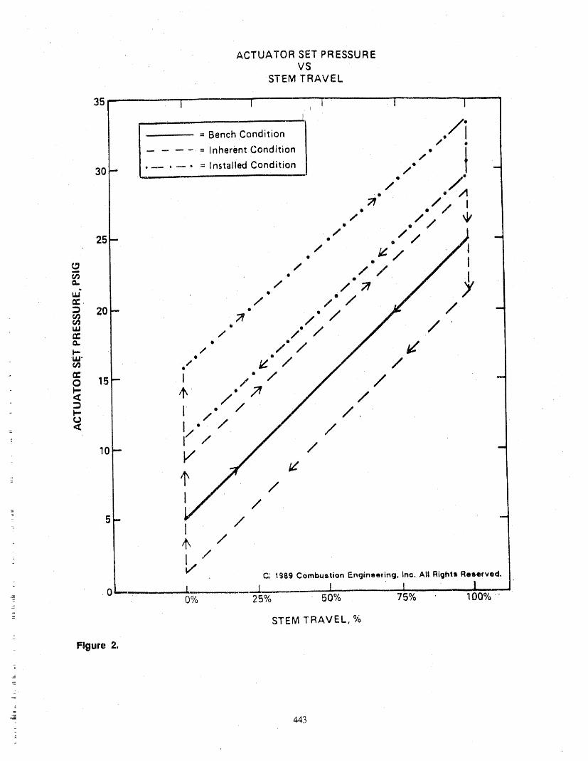
ACTUATOR SET PRESSUREVS
STEM TRAVEL
35"- I I "1 i
..... /i= Bench Condition ,
.... : Inherent Condition • // t..... = Installed Condition •
30- /
ml__ Q /;
/ .
25- ./ .// _11
= ./ ./ / / /"
o0- ;, / ._J.-" ./.'_ .x"_.,- ., ./ / / _'
=_o",5- ;" ./'_"/ ,/ 1/_" _' .//'_ /< /"
=,., // /, / // ' ,= < !/"
' _1 /. ' / / '
_o- I / '
_ 5- I /- ,t, /
C) 1989 Combustion Engineering, Inc. Ali Rights Reserved.
__ ' .0-- l 1 !' 0% 25% 50% 75% 100% "
- STEM TRAVEL, %_
Figure 2.
J 443
(e.g., throttling versus isolation service) is an impor- quired from the valve positioner and/or air system atrant factor to consider in determining seat loads, assumed operating differential pressures.
Inherent Actuator PresSure Settings. The "in- To perform theevaluation of a pneumatic-operatedherent" condition refers to the actuator coupled to the valve and determine the appropriate actuator settings,valve with atmospheric pressure on both sides of the a common reference point should be established tovalve plug. Al! spring preloadforces have been trans- serve as a foundation for the work. This referenceferred to the valve stem from off the bottom of the ac- point can be considered the basis for the evaluation and
tuator casing as in the bench condition (see Figure 1). it is important to understand when interpreting the re-As noted in the figure, if only a small deflection is re- suits. Refeience points should be established for sever-
quired to couple the valve, no adjustments will have to al important areas including spring available travel,be made. However, some valve designs include seat load, seat angle, flow direction, packing, actuatorcoupling of the valve as a contribution to preload. If preload, actuator mismatch, design bases (e.g., LOCAthis is the case the original preload will have to be cor- or MSLB) sizing considerations and the validity of therected for this mismatch. This can easily be done by in- documentation from which critical data base input pa-putting the actuator mismatch into the data base and rameters were obtained. A thorough understanding ofrecalculating new bench, inherent, and installed each of these considerations is required to determinesettings: appropriate actuator settings.
The pneumatic-operated valve diagnostic softwareThe purpose of calculating inherent actuator pres-sure settings is to verify proper valve stroke and to used is a multi-purpose en#meting and maintenance
compare actual packing friction values with those cal- teel. It is assembled in modular format so that it maybe applied as a stand-alone data base or expanded toculated previously from the data base input parame-
ters. lt should be realized that the only difference in perform actuator setpoint calculations and valve diag-these air pressure settings and those calculated in the nostics for a vaa_etyof valves. For example, the soft.bench condition should be the additional pressure re- ware is able to calculate actuator set-up for the various
combinations of actuator type, valve type, and flow di-quired to overcome packing friction in either the openor closed direction plus any adjustment made for ac- rections, for unbalanced globe valves with or withouttuator mismatch. Additionally, it is noted that these bellows seals, as described in Figure 3.factors will be present only when the valve plug isstarting to travel (overcoming static friction) or is One of the key features of the this software is itstravelling (dynamic friction). These friction forces re- diagnostic capability. In addition to the airpressure re-sult in a hysteresis loop around the reference bench qtfirements defined by the program for setting up thecondition (See Figure 2). actuator, there exists the capability of inputting ob-
served actuator performance data. Thiz input data 'al-lows diagnostics to be performed on the
The inherent set pressures provide an indication of valve/actuator. Actual spring rate, or actuator effectivethe pressure demand required from the valve posi-tioner and/or air system with atmospheric system area, packing friction, and system pressure force areconditions acting on the valve internals, amOng the information derived from the. input data.
Air pressure requirements are also compared to designpressures of the various control components and
Installed Condition. The "installed" condition rc- available air supply.fers to the valve in-Line, hot, with system pressure act-
ing on it and the actuatorcoupled to the valve. The data Evaluation of the actuator is based primarily onbase. provides calculated actuator air settings based on spring rate, spring available travel, actuator effectiveinput parameters at:d the unbalanced plug area. area and system pressure conditions. The results of the
baseline calculations, utilizing the necessary input pa-The actuator set pressures obtained from field mea- rameters, are used to make the final judgement on the
surements for the installed condition allow for both actuator. Design spring margin is the single best termempirical measurement of packing friction with the used to define the actuator's ability to perform its func-gland hot and the effect of system pressure forces, rien. Positive spring margins are desirable, however,
These field measurements can be input into the data excessive positive spring margins may be an indicationbase to correct for any difference between them and of an oversized actuator and should be given additionalthe values calculated. The installed actuator set pres- consideration for potential valve damage and controlsm'es provide an indication of the pressure demand re- stability, etc.
444
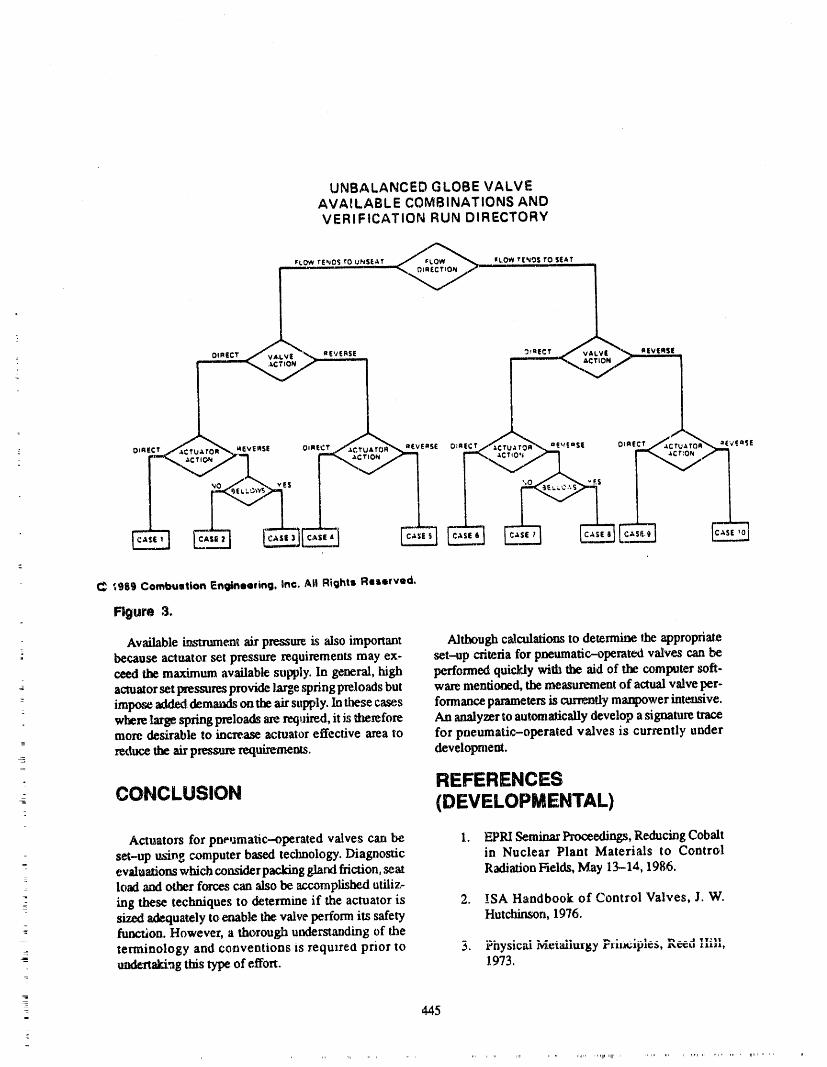
UNBALANCED GLOBE VALVEAVAILABLE COMBINATIONS ANDVERIFICATION RUN DIRECTORY
_Lo_wTE,_OSro UNSEAT _, ,,,,,¢LOWT[NOS__TO$E&T ___
C ;989 Combustion Entlinee_ing, Inc. Ali Rights Reserved.
Figure 3.
Available instrumentair pressureis alsoimportant Although calculationsto determine IJ_eappropriatebecauseactuator set pressurerequirementsmay ex- set--upcriteria for pneumatic--operatedvalves can becuedthe maximum available supply.In general,high performedquickly with the aid of the computersoft-actuator set pressures provide la.rge ,springpreloads but ware mentioned, the measurement of actual valve per-impose added demands on the ah"supply. In these case,s formance paran_ters is currently manpower intensive.where large spring pmloads axe required, it is therefore An analyzer to automatically develop a signature tracemore desirable to increase actuator effective area to for pneumatic-operated valves is currently under
= reducethe atr pressun_ requirements, development.
REFERENCESCONCLUSION (DEVELOPMENTAL)
Actuators for pneumatic-operated valves can be 1. EPRI Seminar Proceedings, Reducing Cobaltset-up using computer based technology. Diagnostic in Nuclear Plant Materials to Control
= evaluations which conskler packing gland friction, seat Radiation Fields, May 13-14, 1986.load and other forces can also be accomplished utiliz-
ing these techniques to determine if the actuator is 2. !SA Handbook of Control Valves, J. W.adequately to enable the valve perform its safety Hutchinson, 1976.
- function. However, a thorough uzglerstalvtmg of the
terminology and conventions is require0 prior to 3. Fhysicai _etaiiurgy r,=a;,p=¢_l geed ;',ill,- undectekt'ag this type of effort. 1973.
445=
4. EPRI Report, Valve Stem Packing 8. ANSI B16.104, "Control Valve Seat
Improvements, EPRI NP-4255 Feb. 1986. Le_age", 1976.
9. ASME Boiler and Pressure Vessel Code,5. Power Magazine, Special Report "Valves", Section XI.
Feb 1983.
10. MSS-SP61, Pressure Testing of Steel Valves.6. Power Magazine, Designing Nuclear Control
Valves, Oct 1974. _ONTACT
7. Actuator Selection, Gayle Barb, ISA-84, In- For details, contact Mr. John H. Mutchler orternational Conference and Exhibit, Houston, Mro Timothy P. Jaeger, Combustion Engineering,Texas, October 22-25, 1984. C.J.84-R780 1000 Prospect Hill Road, Windsor, CT 06095. Tele-
(Attached in Appendix. C). phone (203) 285-5468 or (203) 285--4286.
t

ATTENDEE- PANEL QUESTIONS AND ANSWERS(EDITED; ATTENDEE QUESTIONS AND PANEL/AUTHOR
RESPONSES NOT IDENTIFIED BY NAME)
No Questiom/Comments
447
m_
AN ENGINEERED INSPECTION PROGRAMTO MEET 1990 AND BEYOND
GLENN D. SHUSTER, MANAGERDIAGNOSTIC SERVICES
GENERAL PHYSICS CORPORATION
ABSTRACT ave and preventive maintenance methods, combinedwith Reliability Centered Maintenance techniques, has
improved the level of knowledge of the condition ofThe roots of ASME Section XI testing of compo- plant equipment at many utilities. This increased level
nents lie in the very first year of the, commercial nu- of knowledge generally exceeds the informationclear industry in the United States. With few gained as a result of the testing performed per ASMEexceptions, the content and overall goals of the testing Section XI on most plant components. Unfortunately,
program have not materially changed over the ensuing utility personnel are presently forced to implementyears. While the testing of equipment considered im- both programs, at increased cost and with little in-portant to safety has been performed at plants consis- crease in equipment reliability or availability.tont with the requirements of ASME Section XI, thereare other me_xJs not yet described in Section XI (or To compound this problem, implementation of thein the recently approved O&M standards) that can pro- Section XI testing 'hasthe concern of allowing compla-vide more effective measures of equipment reliability, cency regarding the condition of equipment tested, as-The paper defines an argument for the use of advanced suming that the testing will detect ali possible failuretechniques of testing applied in an integrated Reliabil- modes prior to their occurrence. With the goal of "as-ity Contemd Maintenance framework in lieu of simply sessing operational readiness," Section XI (andtesting safety-related components via ASME OM-6/10) is an intermediary role between the techni-Section XI. The paper presents the basis for an inte- cal requirements of ensuring that equipment meets thegrated testing program that would utilize industry fail- current operationalneeds (i.e., maintained in an "oper-ure data, tempered with plant-specific information, to able' condition) and ensuring that the equipment willdevelop a program of testing specific pumps and meet operational needs at some point in thefuture (i.e.,valves that would provide a maximum of component evaluation for degradation that could negatively affect
-: data with a minimum of component degradation and at operational at some later time). A given piece ofa minimum expenditure in equipment, time, and man- safety-related equipment at a nuclear plant can be sub-.i
power. The outline of the.testing program is provided, ject to a wide variety of _urveiUance testing, preven-¢
along with a sample of the methodology used to devel- five and predictive maintenance activities, as well as
op the scope and content of testing, an optional utility--generated condition-monitoringprogram. Performance of ali of these activities on a
Mr. Shusteris the Manager of Diagnostic Service,_ at specific piece of equipment may indeed verify ade-: General Physics Corpoxation and provides services in quate operation at the current time, but very few acO-
the areas of Valve Diagnostic Testing, Inservice Test vities have the capabifity of detecting specific
Programs, and Component Improvement Programs for degradation resulting in potential failure modes.
_: nuclear and fossil utilities. Mr. Shuster is a degreed nu-clear engineer,has ten years of nuclear plant experi- CONCERNS OVER THEence and has developed over 20 Inservice Testing PRESENT CONTENT OF
P,og_,slD,antypesof_|,clearrats. SECTION XI AND OM-6/10z_
AN ENGINEERED INSPECTION _senuy,AS_ SectionXireq,_res,amongothe,PROGRAM TO MEET 1990 AND tests,an evaluation of fl_ecurrent and future condition
of ali safety-related power-operated valves via anBEYOND e,Mu_o_ of the changes in valve full-stroke time. In
--: the case of valve condition, it is true that we can assess
-_ The present inservice testing progrmn in use at utili- the current condition of a valve based on a measure-ties across the country is based on use of ASME See-- ment of valve stroke time, but it has not been clear that
: tion XI subsections IWP and IWV, with editions future failures are adequately indicated by chm_ges in
ranging back to 1975. In the past decade, use ofpredic- valve stroke time° The current NRC concerns
449=
2
regarding the operability of motor-actuated valves un- Solenoid actuated valves have been a difficult prob-derline the level of doubt of stroke time measurements lem for Section XI and the industry to deal with appro-
to be an adequate measure of future valve condition. In priately in the context of a regular surveillance type. ofaddition, a recently cnnipleted EPRI project has cast test. Based on the control system position indication
additional doubt on the ability for stroke time measure- system, and general operational design of many ofments, taken alone, to provide adequate predictive in- these actuators, performing stroke time tests may notformation regarding potential valve failure, verify the current conditionofthese valves in a reason-
able fashion. Operational/functional leak tests to
Based on the type of valve actuator, changes in verify both position and leak rate through the valve arestroke time may or may not indicate anything about fu- one method of ensuring that these valves currently per-ture valve condition. Alternating current motor- form their required operational function, but they giveactuated valves will not see significant changes in no assurances regarding future, operability. Therefore,stroke time prior to complete valve failure, due to the measuring stroke time, even to the extent of ensuringrelatively constant speed of the actuating device, that the valve,_ stroke within 2 s or less (the "rapid-While it is true that verification of identical ac motor- acting" position taken by OM-10 and the NRC), will
actuator stroke time will aid in ensuring present actua- not provide us with assurance that the valves are ready
tor operability, it does not provide useful information to perform their intended function.regarding degradation modes in progress. The typicalstroke time data of an ac motor actuator shows a con-
stant stroke time ending in a sudden failure, with no Check valves provide nuclear industry with an ex-gentle or predictable rise to failure, h_deed the stroke treme challenge to monitor and evaluate actual valve
time at failure for these v',dves is typically infinite, performance and condition in a reasonable fashionsince the valve never completes i_ stroke. Therefore, over time. While valve disassembly is one method of
measurement of stroke time in ac motor-actuated performing this evaluation, it certa._y is not the meth-valves can assess current valve operability, but will od of choice in the industry. By using the "accident
give no useful data regarding degradation in progress design-basis" flow rate method promulgated by theThe reliability of the test goals is then to assess the NRC, in combination with a reverse flow leak test topresent status of the operability of the components un-
ensure integrity of the moving parts of the valve, rea-der test, not to assess or to predict the condition of the sonable assurance of the current condition of the checkvalve during the next scheduled test. The presentSection XI requirements specifying increased test fre- valve can be made, but effectively notlfing regardingquency based on a change in observed valve stroke degradation in progress can be. discovered. In addition,time will therefore not provide added assurance of ac- the concept of passing "partial" flow through the checkceptable component condition, valve as a method of assessing cunent valve condition
does not ,seem to provide even a limited assurance ofoperability unless care is taken when specifying the
Direct-current motor-actuated valves will identify test flow rate to be used. Therefore measurement ofcertain failure modes via stroke timing, but certainly check valve condition via monitoring of flow irt both
the concerns regarding adequate torque switch .set- directions through tim valve will provide assurance oftuags, correct actuator/motor configuration, etc. will current valve operability, but not of degradation in
still remain, progJess.
Air-actuated valves will generally show evidence of The results of this evaluation of concerns with the
some failure modes as a change in valve stroke time, content of Section XI inservice testing requirements isbut many cases have shown that slow constant degra- that, while some limited knowledge of current compo-dation of actuator moving parts is not the most com-mon cause of failure. Improper instrument air system nent condition can be gained via testing with Sec-maintenance, operation, or valve a_uator maintenance tion XI rules, most attempts to gauge futurehas been much more likely to cause failure of an air-- performance based on a simplistic condition asses-actuated valve than is the degradation that the equip- sment (e.g., valve stroke time) is not appropriate.ment is undergoing. Therefore a testing program that Therefore the results of Section XI testing should only
relies on predicting failure by measuring degradation be used to assess present condition of safety-relatedis not going to identify these system operation and equipment, and not as a method of uncovering compo-maintenance-related types of failure modes, nent degradation in progress.
450
Technical Specification mum acceptableperformance standards.Componentswhich fail Section XI requirements but do not meet
Interfaces Technical Specification limits should first have the testresults verified to ensure that human error or a random
The "operability" of a nuclear power plant is most event was not the cause. Once the validity of the dataclearly stated in plant Technical Specifications, which has been ensured, additional, more sophisticated testsoutlines the requirements that must be met to continue should be used to more fully define component condi-operation with some level of operable components, tion. At the end of this evaluation process, the compo-The impact of Section X1 on these l'equirements is to nent's condition should be assessed in light of the dataallow the licensee to assess the condition of specific generated, and a determination as to the operability ofplant equipment in order to make a determination re- the component be made. Keep in mind that during thisgarding the operability of a givensystem at the current entire process, the component can still meet itstime. In addition to testing required by Section XI, the intended function, as identified in plant TechnicalTechnical Specifications will identify the level of ac- Specifications.ceptable performance, of certain equipment when eva-luated by test. Levels of equipment performance not In summary of this first section, use of Section XImeeting these Technical Specification acceptable lev- testing alone, without recourse to other methods of ex-
= els result in an equipment condition which is "inoper- amination of component condition, cannot fully defitreable," regardless of the actual running condition of the either the operability or the actual condition of theequipment, component under test. This means that the ev',duation
of the true condition of the components under the
Section XI also requires that equipment be declared scope of Section XI will requite more rigorous testing/inoperable when unacceptable levels of performance examination/monitoring than is presently containedare identified. Unfortunately, these levels of perform- within Section XI (or OM--6/10) rules, We have dis.ance may not be identical, and therefon_ may come into cussed the application of Section XI rules in the con-conflict (i.e., a component which meets its Technical text of equipment operability versus prediction ofSpecification requirements, but does not meet Sec- failure. The remainder of this paper will tie these con-don XI). Pumps tested via Section XI often fall into cepts together, and establish the. necessity of an inte-this situation. Section XI also makes an evaluation of grated programmatic response to the question ofthe condition of power-operated valves based on a degradation measurement that is tailored to the specif-
__ change in stroke time from test to test. In addition, ic plant needs, condition,and practices.OM-10 evMuates the condition of the valve via a com-
: parison on stroke times from the initial valve baseline.,. An Alternative ins_actionIn either case, we are put in the position of declaring acomponent (and possible a system ) potentially inoper- p ro g ra m
= able based on the expectation that the component mayfail (i.e., may not meet its Technical Specification re- Based on the programs presently in piace at nuclear
quirements) at some future time. This determination is plants that could be used to verify the condition ofclearly not one to be made lightly, and should be based equipment and to trend its condition over time, theon more than one data point from one type of test. Even most appropriate area for this effort is with the scopeif the component "failure" does not cause plant shut- of the plant Preventive Maintenance (PM) Program.down, it does require initiating reports and documenta- This program would encompa_ the condition moni-tion (safety system inoperability, Licensee Events toting aspects of Section XI (and OM-6/10) withoutReports, Limiting Condition for Operation evalua- addressing the operability of components that is pres-dons, etc.) that will have little useful purpose if the ently the responsibility of the plant Technical Specifi-"failure" was spurious or random. By continuing this cation surveillance testing proggam. The end result ofprocess, we find ourselves "crying wolf" when analyz- this process would be to evaluate the condition of planting test data, with the expected eventual outcome of safety-related equipment and to trend, to the maxi-breeding complacency in response to data taken via mum practic',d extent, tho_ parameters that are indica-Section XI. tive of the actual condition of the equipment. This
- program of upgrading the condition of equipment is= In order to prevent this situation, components which based on use of a Reliability Centered Maintenance
meet their Technical Specification requirements but do philosophy that provides the specific goals of avail-not meet a requirement found in Section XI should be ability and reliability for each piece of plant equip-handled in a different fashion from those components mere, and then devises a componem-specific programwhich do not meet their Technical Specification mini- of condition monitoring, preventive maintenance
_
_
451
.
activities, and diagnostic testing to realize those spe- 3. Developmentcific goals,
zt. Implementation
The Use of RCM for Section XIEquipment 5. Evaluation anti revision.
When used to revise an existing PM program, thisHistorically, a non-systematic approach has often process logically functions to make the best use ofex-
been used to develop preventive maintenance (I'M) isting information and processes, ha many cases onlyprograms -- plant personnel would sit down and "de- revisions to existing program elements may be needed,sign" a program based on equipment manufacturers if at all. This systematic process will define what revi-recommendations ,and any federal requirements that sions are necessary to support a full integratedapplied. This failure to reflect a systematic definition reliability-based program. Table I summarizes theof PM program content has often resulted in genetic key activities associated with each of the five phases.program deficiencies, including not effectively and
economically realizing the inherent reliability of plant The heart of this systematic PM progrmn develop-equipment and systems, ment/revision process is the Reliability Centered
Maintenance (RCM) methodology. RCM offers a sys-
Manufacturers develop PM recommendations based tematic step-by-step process for identifying the equip-on certain assumptions relative to equipment duty merit and tasks for the preventive maintenancecycles, ambient conditions ',rodsystem parameters. No program in alogical manner, utilizing ali of the infer-matter how detailed an equipment specification, the marion and knowledge that can be brought to bear onequipment will never be operated precisely as the de- the problem. ReM is a proven technique that is the re-signer envisioned. The manufacturer is also not aware suit of 20 yr of research by maintenance planners in theof the criticality of the item to the operational capabili- air transport industry. It has been adopted by the mili-ty of the plant, therefore his recommended PM pro- tary services and is being introduced within the utilitygrain may not be totally appropriate. In some cases, as industry. RCM provides the methodology that can beexperienced at some nuclear power plants, and over- applied to a PM program and results in improvedemphasis of the manufacturers PM recommendations equipment reliability, while minimizing overall pro-can actually result in a program that is potentially too gram costs. The end result of these efforts, whenextensive, not cost-effective, and impacts negatively applied to appropriate plant systems and components,on ALARA progaam goals, can lead to overall improved plant, system, and com-
ponent availability.
This industry-wide lack of a systematic approach tomaintenance program developmenl, implementation Preventive Maintenance (PM) has many definitionsand revision has resulted in a broad spectrum of PM and variations in scope depending on the individualprogram practices across utilities. Some organizations plant operating philosophy. For the purposes of thishave created comprehensive programs that exceed any discussion, we use the INPO definition of Preventive
Maintenance as "predictive, periodic, and planned,existing requirements and reflect an obvious corporatemanagement commitment. At the other end of the maintenance actions taken to maintain a piece of
spectrum exist organizations that are apparently inter- equipment within design operating conditions and ex-ested only in satisfying minimum requhements. None- tend its life." Using this definition, Preventive Mainte-theless, the need to implement systematic approaches nance includes equipment condition monitoring andto maintenance program development and revision has diagnostic activities, periodically scheduled (time-been a major topic discussion in the power generation directed) maintenance activities, and activities plannedindustry in recent years and presents a major objective and performed prior to equipment failure, but does notfor many utilities, include corrective maintenance (CM) tasks (i.e., repair
and restoration activities for equipment thai has failedor is malfunctioning).
This systematic process of PM Program enhancement
includes five major phases: When properly implemented this systematic ap-
I. Objectives preach provides a number of distinct advantages:
1. lt provides a logical, consistent, and traceable2. Design methodology.

Table 1. Summary of PM program development/revision process activities
Phase No. Phase Title and Activities
1 Program Objectives
Evaluate existing program
Determine PM program objectivesDevelop PM program plfilosophyIdentify program performance indicatorsIdentify desired program enhancements
2 Program Design
Identify program functionsDevelop function spec, ficationsIdentify organization neededIdentify information transfers "andreportsDevelop integrated program design
3 Program Development
Develop/revise administrative proceduresDevelop PM program manualDevelop enhanced program implementation plan
_
4 Program Implementation
Prioritize systems for analysis= Conduct RCM analysis
Develop integrated PM task scheduleDevelop/revise PM task procedures
: Develop condition monitoring/perforrnance_ Monitoring programs
Establish equipment failure tracking program- Revise training ,
Evaluate PM spare parts requirements
5 Program Evaluation and Revision
Track performance indicators. Conduct general evaluations of program effectiveness
Conduct equipment-specific PM task effectiveness evaluationPerform proactive program review
2.. It provides the capability for using the PM 4. It produces a well-documented engineeringProgram to drive plant availability rather basis/'or applying PM resources lhat consid-
_ than merely react to it. ers the importance, functions, ax_l historicaland plausibk._ failure modes and effects of
: 3. It systematically prioritizes equipment based equipment in its operating environment.on calculated expected return and providesprocess feedback to improve the 5. lt can include aplant availability modelthat
-- priorifizafion, can predict those actions that result in the
=
453
_
greatest increase in system andplant upgraded and improved over time, to emure that theavailability, last advances indiagnostic testing and condition moni-
toting are appropriately incorporated. The latest tech-6. lt is self-analyzible in that whenevermainte- nology and methodology improvements available to
nance-related goals are not met, the spec ric the industry are reviewed Ibr potential future applica-cause can be pinPointed for re--analysis axM tion to the plant. In addition, inputs from personnel as-correction, sociated with PM program are used to identify
improvements related to program operation. This on-7. lt provides a methodology for continuing going improvement in a testing and evaluation pro-
evaluation and revision of the PM Program gram is critical to success in maintaining equipment inon a reactive and proactive basis to ensure its desu'ed state. Rather than implementing a testingthat it continues to meets its objectives, program and updating every decade, this living pro-
gram would provide continuous improvement in meth-
SUMMARY AND CONCLUSIONS _ andgoals. The single ,mostimportant factor in anyequipment condition upgrade program would remainwhat it is (or should be) today: an uncompromising
The result of this replacement of Section XI testing dedication to maintain the plant equipment in the bestwith a component-specifi c PM Program will ensurethat each component achieves the desired level ofreli- possible condition.ability and availability (effectively 100% for safety-related equipment within the scope of Section XI) that Regulatory approval of this type of program, as a re-was required by the RCM Program objectives for that placement for Section XI testing activities, can pres-equipment. In addition, the present resources utilized ently only be generated via an individual plant Requestto track and "forecast" the failure of equipment as re- for Relief, which undergoes extensive NRC reviewquired by Section XI would be utilized in a more effec- and evaluation before being granted. Based on the re-five effort, one that provides realistic inspection and cent attention placed on plant maintenance by thetesting programs for individual components, and takes NRC, an evaluation by the NRC of the potential bene-appropriate actions based on individually determined fits and problems in utilizing an engineered, com-component coaditions. Another benefit of this type of mitred RCM program as an alternative to Section XIengineered inspection program is that it is constantly component testing would seem appropriate.
ATTENDEE- PANEL QUESTIONS ANDANSWERS(EDITED; ATTENDEE QUESTIONS AND PANELYAUTHOR
RESPONSES NOT IDENTIFIED BY NAME)
Question 1 generally get implementedat the plant?In many plantsthis persongets in charge of that one, this person is in
You obviously are involved in developing commercial charge of that one, this person is in charge of that one,or traditional Section XI pump and valve programs, and we have a sort of muddled response to equipmentYouare obviously familiar withRCM programs, performance questions.
How do you see the two related together? Do you see The RCM program, which in thepresent context is go-them as two separateentities right now, or will rileybe ing tobe totally separate from the Section XI program.brought together, and how will other issues required by And I think this is the unfortunate reality_the RCMother programs be brought into this? program is going to be in piace of thatarea. It is will be
required to incorporate ali of those requirements in aResponse 1 unified front, and the unified front will identifyexactly
what the plant wants to do in response to those equip-This is an important point. How do the requirements ment questions.
455i

ACOUSTIC/MAGNETIC TEST TECHNIQUES FOR VERIFYING,OPERATION OF CHECK VALVES
JOHN W.MCELROYPHILADELPHIA ELECTRIC COMPANY
ABSTRACT Because of recent industry problems with the opera-tion of check valves, it has become essential to assure
proper valve performance through valve inspection.' Recent operating events im;olving check valve fail- The most common check valve is the "swing check".
ure in the nuclear power industry have raised specific Two other types are in use but are not as common---theissues on how to verify operability of check valves by "tilting disk" and the "lift check". The followinginspection. Philadelphia Electric has had a program to discussion focuses on the "swing check", but thedevelop test techniques mad procedures that can be techniques described apply to ali check valves.used to address those specific inspection issues. This
= paper discusses acoustic and magnetic techniques usedto measure check valve disk motion and internal im- The "swing check" valve is comprised of(Figure 1)
pacts resulting from the disk motion. Full stroke capa- the valve body, valve bonnet, hinge pin, hinge ann,disk, disk washer, disk nut, disk stop, and the disk seat.bility, internal worn parts, excessive fluttering, leak When the valve is in good condition in a properly de-tightness are ali detected and coi_im_ed by the acous-tic and magnetic techniques. These testing techniques signed use, the disk closes tightly against the disk seatcan be used to address certain INPO SOER 86--03 and preventing back le_age. When the valve opens, tight
clearances between internal parts allows proper disk= ASME code lnservice Testing requirements, motion and prevents excessive wear conditions. The
valve disk assembly will contact the stop during theBACKGROUND ope,_g and should come to rest on the stop.
I
Failures of a few check valves in applications direct- A valve with hltemal damage or in an inadequately related to safe shut down of a unit during nuclear design application may not close tightly against thepower plant operation led to a review of ali check valve disk seat and back leakage may occur. When the valvemaintenance actions and failures. INPO published the opens, wear on the hinge pin may cause the hinge pinresults in a Significant Operating Experience Report to rattle, wear on the hinge ,am may cause the arm to(SOER) number 86-03, "Check Valve Failures or rattle, and wear on the disk nut may cause the disk to
Degradation," in October 1986. SOER 86-03 con- wobble. Insufficient flow causes the di_ to fluctuatecluded that the major causes of check valve failures continuously and results in excessive wear on the
: were primarily misapplication and inadequate preven- hinge pin. If those fluctuations include impacting onrive maintenance. As a result of INPO's SOER, the the valve stop, excessive wear will occur on the disk
: utility industry worked with the Electric Power Re. nut and hinge arm assembly.= search Institute (EPRI) and formed a program to ad.
dress the needs of the industry. In 1988, EPRI issued a An inspection technique for check valves should bereport entitled "Application Guidelines for Check able to detect the following conditions:Valves in Nuclear Power Plants." This report providedguidelines recommending the use of non-intrusive hl- • Disk Positionspection techniques to verify proper operation of check
valves. There now exists in the nuclear industry a - Stroke time_. strong demand for an economical, viable means of
inspecting check valves to verify proper operation. - Fully open
CHECK VALVE DISCUSSION - Fully closed_
= A check valve operates by allowing flow in one di- - Intermediate positions: rection while preventing flow in the other. The check:_ valve has no external moving parts and, therefore, its - Flutter magnitude and frequency
position and integrity cannot be evaluated with normal-_ visual inspection methods without valve disassembly. - Contact with seats/stops
_
457
" ilia' "111' , 11 II rl ¢ ,,t, II 'I'll

Vartlcal Up
Centerllne Of Piping
I
BONNET - -_ l
SENSOR%'_[_ /BODY
WASHER
NUT
DISK STOPDISK
HINGE ARM
HINGEPIN
I
I
U Fluid Flow
Figure 1. Swing checkvalve.
• wearoftemalParts ACOUSTIC INSPECTION
- Hinge pin/bushing TECHNIQUES
: - Seat/di_ facing surfaces Acoustic techniques involve the detection ofstructural-borne noise emanating from the internal
_- - Disk to hinge ann connection workings of the valve. The technique involves the useof a piezoelectric crystal sensor, such as an accelerom-
;_ • Loose.or Missing Internal Parts eter mounted on the valve. Ali structural-home energywaves are detected by the acoustic sensor. Back-
= • Seat Leakage leakage through the closed disk--disk seat area causes
- Presenceof broitdbandfrequencyenergywaves to be input to thevalve stzucture as the fluid flows between the disk-
- Rate disk seat surfaces. These energy waves are detected as
458
al II,I .... '1I,iin'l.... rlf I ' Ilt
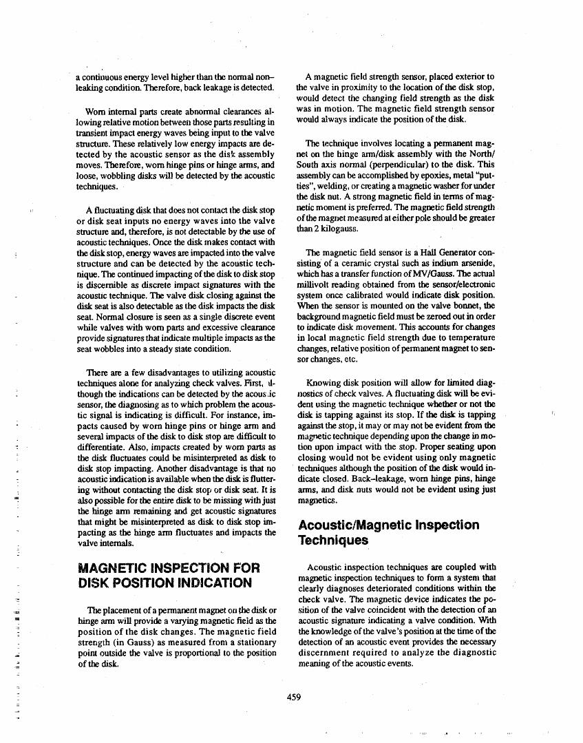
s
acontinuous energy level higher than the normal non- A magnetic field strength sensor, placed exterior toleaking condition. Therefore, back leakage is detected, the valve in proximity to the location of the disk stop,
would detect the changing field strength as the disk
Worn internalparts create abnormal clearances al- was in motion. The magnetic field strength sensorlowingrelative motion between those parts resulting in would always indicate the position of the disk.transient impactenergy waves being input tothe valvestnlcture. These relatively low energy impacts are de- The technique involves locating a permanent mag-tected by the acoustic sensor as the dis!,_assembly net on the hinge arm/disk assembly with the North/moves. Therefore, worn hinge pins or hinge arms, and South axis normal (perpendicular) to the disk, Thisloose, wobbling disks will be detected by the acoustic assembly can be accomplished by epoxies, metal "put-techniques, ties", welding, or creating a magnetic washer for under
the disk nut. A strong magnetic field in terms of mag-
A fluctuating disk that does not contact thedisk stop netic moment is preferred. The magnetic field strengthor disk seat inputs no energy waves into the v',dve of the magnet measured at eitherpole shouldbe greaterstructure and, therefore, is not detectable by the use of than2 kilogauss.acoustictechniques. Oncethe disk makes contactwith
_ the disk stop, energy waves are impacted into the valve The magnetic field sensor is a Hall Generator con-structure and can be detected by the acoustic tech- sisting of a ceramic crystal such as indium arsenide,nique.The continued impacting of thedisk to disk stop which has a transfer function of MV/Gauss. The actualis discernible as discrete impact signatures with the miUivolt reading obtained from the sensor/electronicacoustic technique. The valve disk closing against the system once calibrated would indicate disk position.disk se.atis also detectable as the disk impacts the disk When the sensor is mounted on the valve bonnet, theseat. Normal closure is seen as a single discrete event background magnetic field must be zeroed out in orderwhile valves with worn parts and excessive clearance to indicate disk movement. This accounts for changesprovide signatures that indicate multiple impacts asthe in local magnetic field strength due to temperatureseat wobbles into a steady state condition, changes, relative position of permanent magnet to sen-
sor changes, etc.
There are a few disadvantages to utilizing acoustictechniques alone,for analyzing check valves. First, d- Knowing disk position will allow for limited diag-
: though the indications can be detected by the acoustic nostics of check valves. A fluctuating disk will be evi-sensor, thediagnosing as to which problem the acous- dent using the magnetic technique whether or not thetic signal is indicating is difficult. For instance, lm- disk is tapping against its stop. If the disk is tapping ',_
pacts caused by worn hinge pins or hinge arm and against the stop, it may or may not be evident f_m theseveral impacts of the disk to disk stop are difficult to magnetic technique depending uponthechange inmo..differentiate. Also, impacts created by worn parts as tion upon impact with the stop. Proper seating upon
° the disk fluctuates could be misinterpreted as disk to closing would not be evident using only magneticdisk stop impacting. Another disadvantage is that no techniques althoughthe position of the disk would in.acousticindication is available when thedisk is flutter- dicate closed. Back-leakage, worn hinge pins, hingeing without contacting the disk stop or disk seat. lt is arms, and disk nuts would not be evident using just7.
also possible for the entire disk to be missing with just magnetics.the hinge arm remaining and get acoustic signatures
that might be misinterpreted as disk to disk stop lm- Acoustic/Magnetic Inspectionpacting as the hinge arm fluctuates and impacts thevalve internals. Techniques
_-
MAGNETIC INSPECTION FOR AcousticinspectiontecquesarecoupledwithDISK POSITION INDICATION magneticinspectiontechniquesto form a systemthat
clearly diagnosesdeterioratedconditionswithin thecheck valve. The magnetic device indicates the po..
Theplacement of a permanentmagnet on the disk or sition of the valve coincident with the detection of an= hinge arm will provide a varying magnetic fieldas the acoustic signature indicating a valve condition. With_ position of the disk changes. The magnetic field theknowledge of the valve's position at the time of the
strength (in Gauss) as measured from a stationary detection of an acoustic event provides the necessarypoint outside the valve is proportiormlto the position discernment required to analyze the diagnostic
_- of the disk. ' meaning of the acousticevents.
459=
i
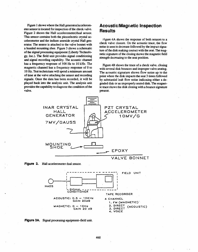
Figurei showswheretheHaUgenerator/accelerom- Acoustic/Magnetic Inspectioneter sensor is located for inspection of the check valve. ResultsFigure 2 shows the Hall accelerometer/dual ,sensor,.This sensor contains both the piezoelectric crystal ac-celerometer and the indium arsenide crystal Hall gen- Figure 4A shows the response of both sensors to aerator. The sensor is attached to .thevalve bonnet with check valve closure. On the acoustic trace, the flow
a bonded mounting shoe. Figure 3 shows a schematic noise is seen to decrease followed by the impact signa-of the signal processing equipment (Liberty Teclmolo- ture of the disk makingcontact with the _eat. The mag-
netic signature of the closing shows the magnetic fieldgy, Inc,), The field unit provides signal conditioning strength der.Teasing to the seat position.and signal recording capability. The acoustic channel
has a frequency response of 500 Hz to 10 khz, The Figure 4B shows the trace of a check valve, closingmagnetic channel has a frequency response of 0 to with several disk bounces and improper valve seating.10 Hz. Test technicians will spend a minimum amount The acoustic signature shows flow noise up to theof time at the valve attaching tl_ sensor and recording point where the disk impacts the seat 3 times tbllowedsignals. Once the data has been recorded, it will be by substantial leak flow noise indicating either a de-played back into the analysis unit. The analysis unit graded disk or an improperly seated disk. The magnet-provides the capability to diagnose the condition of the ic trace shows the disk closing with a bounce signaturevalve, present,
INAR CRYSTAL PZT CRYSTALHALL ACCELEROMETER
GENERATOR I OMV/G
7MV/GAUSS
MOUNTINGSHOE c_.....----_V I
EPO XY
VALVE BONNET
Figure 2. Hall accelerometer dual sensor,
........ I FIELD UNIT
I
HADS II_.SIGNAL JCONDITIONER
TAPE RECORDER
ACOUSTIC: 0.5 -- IOKHz 4 CHANNELGAIN 20dB
I.FM (MAGNETIC)'MAGNETIC: 0 -- IOHz 2. DIRECT (ACOUSTIC)GAIN 20 clB 3. DIRECT
4. VOICE
Figure 3A. Signal processing equipment-field unit.
460
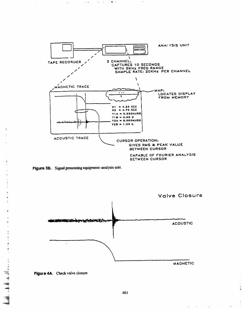
ANAl YSIS UNIT_ ........... "F--'---_
/ _TAPE RECORDER / 2 CHANNEL_
/ CAF'TURES 10 SECONDSs WITH 5KHz FREQ RANGE/
/ SAMPLE RATE: 20KHz PER CHANNEL/
/ \s \MAGNETIC TRACE
S
A_"P'-_'"_-_ _ --_..._--''AP:M
I xl = 4.25 SEC
_ X2 " 4.70 SEC_rl A '- 0.55(:;AUSS
YI B "_"0.05 O
_,,.,-4-.__- . -- Y2A = 0.OOGAUSS
l, f I """"°/
ACOUSTIC TRACE
CURSOR OPERATION:GIVES RMS &: PEAK VALUEBETWEEN CURSOR
CAPABLE OF FOURIER ANALYSIS- BETWEEN CURSOR
: Figure 3B. Sigmdp_o_ss_ng¢qmpment-analysis U_t.
=
=
Valve Closure
=
_ r ........... ACOUSTIC
- _ --
= u ,, ,
MAGNETIC
Figure 4A. Checkvalve cJosu_.
461
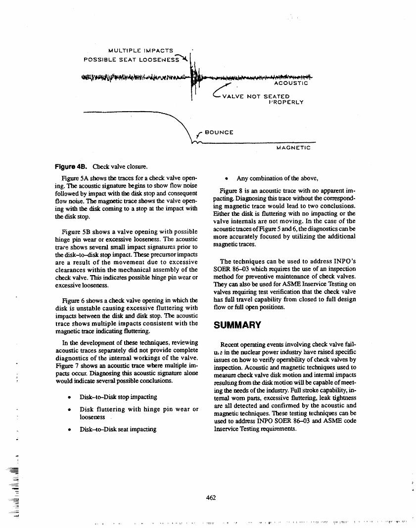
MULTIPLE IMPACTS
POSSIBLE SEAT LOOSEhlESS_'_ _l_,
PROPERLY
MAGNETIC
Figure 4B. C'he_ valve closure..
Figure 5A showsthe traces for a check valve open- • Any combinationof the above,ing..The acousticsignaturebeginsto showflow noisefollowed by impact with the disk stop and consequent Figure 8 is an acoustic trace with no apparent ira-flow noise. The magnetic trace shows the valve open- pacting. Diagnosing this Uace without the correspond-ing with the disk coming to a stop at the impact with ing magnetic trace would lead to two conclusions.the disk stop. Either the disk is fluttering with no impacting or the
valve internals are not moving. In the case of the
Figure 5B shows a valve opening with possible acoustic traces of Figure 5 and6,the diagnostics canbehinge pin wear or excessive looseness. The acoustic more accurately focused by utilizing the additionaltrace shows several small impact signatures prior to magnetic traces.the.disk-to-disk stop impact. These precursor impactsare a result of the movement due to excessive The techniques can be used to address INPO'sclearances within the mechanical assembly of the SOER 86-03 which requires the use of an inspectioncheck valve. This indicates possible hinge pin wear or method for preventive maintenance of check valves.excessive looseness. Tt_y can also be used for ASME Inservice Testing on
valves requiring test verification that the check valve
Figure 6 shows a c_eck valve opening in which the has full travel capability from closed to full designdisk is unstable causing excessive fluttering with flow or full open positions.impacts between the disk and disk stop. The acoustic
trace shows multiple impacts consistent with the SUMMARYmagnetic trace indicating fluttering.
In the development of these techniques, reviewing Recent operating events involving check valve fail-acoustic traces separately did not provide complete m _ in the nuclear power industry have raised specificdiagnostics of the internal workings of the valve, issues on how to verify operability of check valves byFigure 7 shows an acoustic trace where multiple lm- inspection. Acoustic and magnetic techniques used topacts ocx:ur. Diagnosing this acoustic signature alone me_,ure check valve disk motion and internal impacts
: would indicate several possible conclusions, resulting from the disk motion will be capable of meet-
ing _ needs of the industry. Full stroke capability, in-* Disk-to--Disk stop impacting ternal wom parts, excessive fluttering, leak tightness
• Disk fluttering with hinge pin wear or are ali detected and confirmed by the acoustic andlooseness magnetic techniques. These testing techniques can be
used to address INPO SOER 86--03 and ASME code
• Disk--to-Disk seat impacting Inservice'testing require.merits.
_I
I==m
w
- 462
=_1
, _Itllllr Ip_ ,' 111' ....... . vi " "' '' rlr_ ,'l'l" ' P'lpI, iir_ll,i_, ii ....... rl , ..... tlllp, _,liplurp'p
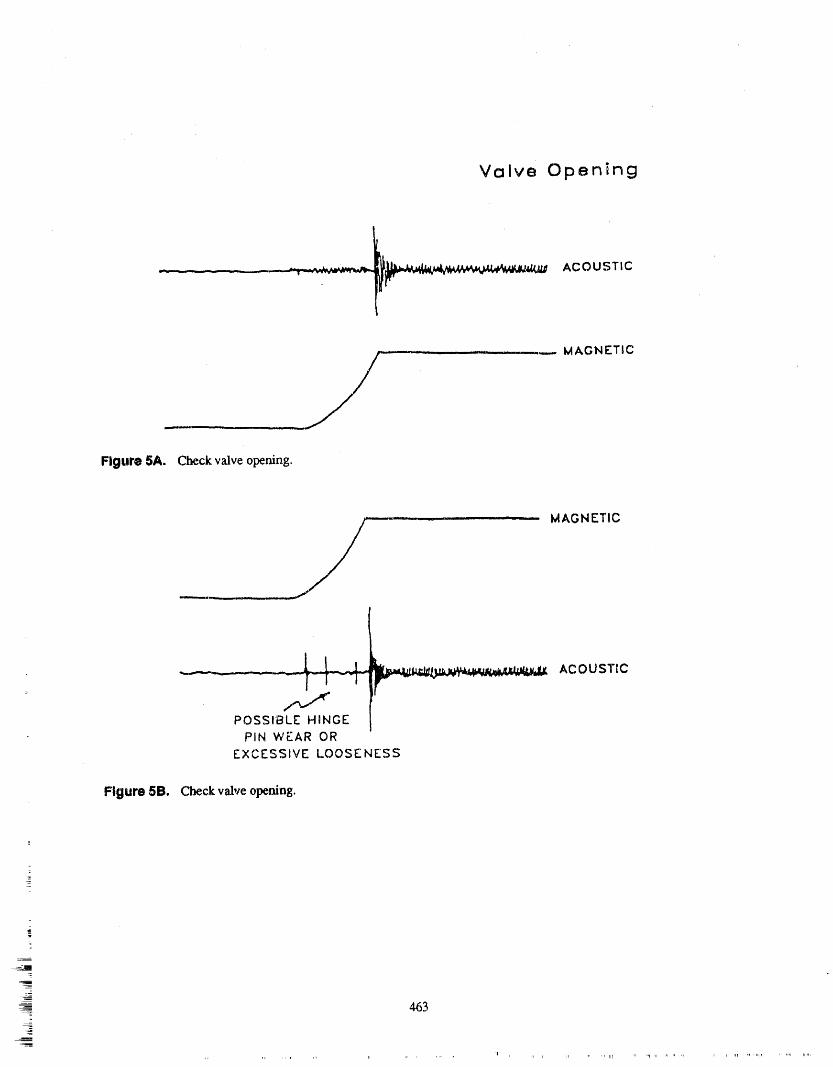
Valve Opening
________...... __: ACOUSTIC
.,.... MAGNETIC
Figure 5A. Check valve opening.
MAGNETIC
i _ _ _ LT III I I -- _ II
......__........ Lr_. ACOUSTICI
: PIN WEAR OREXCESSIVE LOOSENESS
Figure 5B. Check valve opening.
lm
463
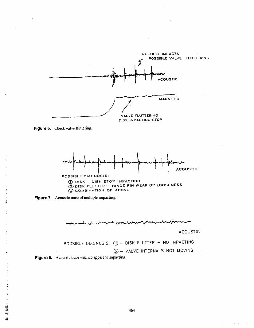
MULTIPLE IMPACTS
POSSIBLE VALVE FLUTTERING
, Y
MAGNETI
.... VALVE FLUTTERING
DISK IMPACTING 'STOP
Figure 6, Checkvalvefluttering.
'I " _' I AcOUST,CPOSSIBLE DIAGNOSIS:
O DISK- DISK STOP IMPACTING
___ DISK FLUTTER -- HINGE PiN WEAR OR LOOSENESSI: (_ COMBINATtON OF ABOVE
Figure 7, Acoustic traceof multiple impacting•i
_,_.__._.j_.___,_..,_
ACOUSTIC
POSSIBLE DIAGNOSIS" @- DISK FLUTTER - NO IMPACTING
" @- VALVE INTERNALS NOT MOVING
Figure 8. Acoustic tracewith no apparentimpacting._
=
464
ATrENDEE- PANEL QUESTIONS AND ANSWERS(EDITED; ATTENDEE QUESTIONS AND PANELAUTHOR
RESPONSES NOT IDENTIFIED BY NAME)
Question I valve, which is probably no more than 18 inches of' mat_:.,rial.
Hasanyworkbeendoneon plugtypecheckvalvessincethecarrottest;andifso,how successfulhasthat Youcanseetheattenuationbetweenthetwosignals.been? Now,if you were to gothose 18 inches through another
flange over two feet to the.next valve, you will findResponseI thatonesignalre_dlydoesnotmakeitovertotheother
one,asfarasimpact.What youdo getisincreasedNo,therehasnotbcen.Mostofourworkhasbeenwith backgroundnoisefromperturbationinthesystem,theswingchecks, anothercheckvalvecausingthebackgroundnoise,
whichiswhatwillbetheoscillatingandcausingtheTheacoustics_whatIpresentedtoyoutoday_wc pertm'bationinthestream.havebeendoinginthefield.Themagneticpartisade-
velopmenteffortthathasbeeninthelabandisjust We foundthatitdoesnotreallyaffectthediagnostics.nowabouttogetoutintothefield. Thereisaneffect,butitisnotasevereeffect.
=
Comment Attenaee Wouldthe leakagethenbchardertocheckforoneparticularvalve?
Iwouldliketopartlyanswerthequestionthatwasjustasked.We havestuckapermanentmagnetintoaledge PresentorIftheyareveryclosetogether,oneisleak.gatevalveandfoundthatwe couldseethemotionof ingseverelyandtheotherisnotleakingatall,someof_
the ledge coming up and down. So, I see absolutelyno that noise mightmakeit over to the second valve.reasonwhy adistantlook wouldnot showthe same re.suits. The work we did on the permanentmagnet in- But the same ratio of attenuation occurs from onestallation was done under a project for the NRC valve to thenext, so it wouldhave to be a very strongnuclearplantagingresearch program.In case theques- signal to affect a nearby valve. I can not say that theytion would be asked, we have checked the magnetic do not, so my answer to you is they have an effect butflux indicatorwith abrass, a stainlesssteel, anda mild I think it is a veryminimal effect.steel valve. The mild steel valve was a It-inch swingcheck valve with a one-inch thick flange. We were Here is what you do if you have two valves, you putable to easily detect a magnetic flux on the outsideof a two sensors on,and yousee this signal. Look at the onemagnetplacedinside,so that the limitationsassociated that is okay and the other one is leaking, and test bothwith the use of a magnetic steel couldbe overcome, of them before this one started leaking to get a base-
line. The next timeyou f'mdthatone signal is increasedAs a matter of fact, in some cases with the steel, we or piace the sensor over here to fred that this one hasfound a better signal because the ferrous material etl- really increased, so this one gets fixed f'trst.Then you
= letted the magnetic field and focuses it for you. repair that one, and a good logical decision would be. Whereas in a stainless or a brass valve, there is just no just to fix that one and see what you have afterwards._. foct_:ing._ Presontor We do not attempt to power brake the" Question 2 magnetics so that you essentially have a lx)sition indi-
cation that, each time you go back, you would expect- Have you had any problems with check valves in par- the same kind of value.
allel and monitoring both of them, as far as thefeedback'/ What we expect is to have is relative motion. If it is
moving and hitting another stop, the abrupt changes inResponse 2 themagneticsignalarewhatwe are',fftcr.
PresenterTheanswerisno.Thereisaproblem,but Topowerbrakethethingisthenextgenerationoftech-- it is not a severe problem. Let mc explain. There are nology development, so our intent now is not to
two sensors on the samevalve. There is an impact.You calibrate these things to indicate position forever. It iscan see the amplitude difference within the same to be a relative motion.
465
.
ADDITIONAL CONTRIBUTION TO THE PUMP TESTING SESSIONON WEDNESDAY, AUGUST 2
MCP-SHAFT CRACK DETECTION IN ISAR-2 PWRBY FREQUENCY-SELECTIVE VIBRATION MONITORING _
R. SUNDER AND D. WACHGESELLSCHAFT FUR REAKTORSICHERHEIT (GRS) MBH. 0-8046
GARCHINGR. HEINBUCH AND J. IRLBECK
BAYERNWERK AG, HEAD QUARTERS, D-8000 MUNCHENFEDERAL REPUBLIC OF GERMANY
SUMMARY ly progressed shaft crack (80%) was detectedbelow asleeve in the range of the lower shaft bearing. Withoutthese intensive inspection measures, the crack couldMid of December 1988 the utility operating thehave grown eventually to a prompt shaft rupture dur-ISAR-2 PWR decided to shutdown one of the four
main reactor coolant pumps (MCPs) for a non-planned ing ongoing plant operation.inspection. At that time, the overall shaft vibrationshad reached only 0.08 mm, distinctly below the first The full paper is being published in the technicalalert level of a standard vibration monitoring system, journalThe reason for this decision were abnormal trend
courses of several shaft vibration flequencies, whichPower Plant Engineering No. 4, August 1989.
had been monitored and provided by a novel com-puter-based surveillance system, the condition moni-toring system (COMOS) developed by GRS. On During the ASME/NI_. "?.-Symposium the highlightsJanuary 8, 1.989 the plant was started again to power of this recent successful 80% crack detection are pres-operafionafter aMCPshaftreplacement was finished, ented and explained by V. Bauernfeind of GRSDuring the following more detailed inspections, a fair- Garching.
t_
=
1
S.
_]
- 467
ATTENDEE- PANEL QUESTIONS AND ANSWERS 1(EDITED; ATTENDEE QUESTIONS AND PANEL/AUTHOR
RESPONSES NOT IDENTIFIED BY NAME)
Question 1 for vibration monitoring. They had a system for theoverallvibrationmonitoringof theprimarycircuit.
Why did you institutea shaftcrackdetectionprogram?Hadyou been failingcrackedshaftspreviously? They asked us whether we could do this job with thesystem. Itwas quiteeasy to do. Wehad only to putthe
signalson the systemand tomakesome changes in theResponsel software to takethe signals andto mal_ thisanalysis.
Presenter Yes.It was two events in thiscase, one nu- They didnothave to install new sensors.They didnotcleat power plant in Switzerlandand the other one in have to install a new system. They used the systemGermany. they had for vibration monitoring and made this
Mode 1 operationevery 90 minutes,two signals forAttond_ Where was the idea conceived? How did one of these pumpsor another.
, you get this idea?Note The remainderof the questionsand responsesin
Presenter From previous work that was done in this session were inaudible, and therefore,have notKSB. After this shaftcrack,we had to do something beenincluded.

CLOSING REMARKS
- 469
CLOSING REMARKSLARRY CHOCKIE
CHOCKIE CONSULTANTS
From the ASME perspective and from the Board on personnel together to continue to iron out theNuclear Codes and Standards, I did encourage our problems.Board to take a positive vote to establish this sympo-sium, co--sponsoredby the NRC and the ASME. Now, taking the advantage of this forum, I am going to
give you a couple of personal perspectives from some
By the measurements that we normally establish in 35 years in Codes and standards development¢onfin-how well a symposium such as this has been con- ing my remarks to pump and valve testing.ducted, we look at the attendance, the facilities, thequality of papers, and the interest in the presentations. The process of Codes and standards development is
: evolutionary. Things do change. Goals change. TheAS/VIEBoiler and Pressure Vessel Code is a safety
Attendance has been excellent, code. lt was designed toprovideassurance of the integ-: rity of that nuclear reactor pressure vessel.
Facilities, we've had a little difficulty with the audio
on a couple of occasions, but otherwise facilities were I amobserving a trend that we are performing tests thatalso excellent, will enhance predictive maintenance activities. That is
good. If pump and valve tests will provide that infer-Quality of papers. You each have a copy of them in marion, that is well and good.front of you. They are excellent also.
I am also observing that the trend is to include pumps
And of course, theinterest in presentations. Now, what and valves in the testing programs required for plantwe hadhere is something you seldom see. Usually in a operation.That also is good.symposium of this type tw_-thirds of the audience isout in the halls exchanging business cards and talking But I caution: Do not lose sight of the ASME Code's
- about other subjects. Not this one. They were ali in goal, to provide a high degree of assurance that the=. here listening to the papers. So the conclusion is, this pumps and valves necessary to shut down the reactor,
symposium has been excellent; An outstanding mitigate the consequence of an accident, are tested forsuccess, thatpurpose---that theywill operatewhen called upon.
A couple individual points, again from the perspective And as we move to include the new population ofpumps and valves, those,for plant operation, and pro-
of an officer of theASME Board.First, we met on this grams to assist predictive maintenance, I would advise= subject and encouraged setting up this symposium to extreme caution. Do not mix theoperation andmainte-
help those individuals who are notgetting the messagenance programs with the safety requirements of the
directly by participation on the Code committees Code.themselves.
It is very easy to put things in the Code, or the pro-Second, we would like to encourage the attendance at grams to meet the Code inyour plant, but ffthey do notour Code meetings, both O&M and Section XI of the work, it is difficult to take them back out.Code, we encourage your participation. ASME does
: offer dueprocess, you canget yourquestionsanswered As a formerofficer of the ASME, Iwould like to thankthrough the formal AS/VIEprocess, but that is rather Tad Marshof the NRC and Kevin Ennis of the ASMEtimeconsuming.Youcan do a let better by going to lhc for both their technical and administrative guidance,meetingsthemselves, andI encourage you. which made this symposiuma success.
_ Thirdly, I would recommend and encourage continu- Finally, the next O&M meeting is in Kansas City, theing this symposimn as a series, to bring the users, the week of September llth. I personally invite you.
: Code developers,and the regulatory and enforcement Thank you.=
i___
_.
471

' CLOSING REMARKSJOEL PAGE
• U.S. NUCLEAR REGULATORY COMMISSION
I've brokenthisSession1 into threeparts,asfollows: havethemanagementcommitment,youhaveanexcel.lent pump IST program.
The first part was put together by John Zudans andLarry Sage. They spoke from the White Paper, which They discussedthe use of filteredand unfiltered vibra-is a document that was put together by the O&M tion; the importance of customized lubrication analy-Working Group on Pumps and Valves. The White sis; bearing temperature measurements and trending;Paperexplains the differences between OM--6and the and when ali these are included, although it would notexisting ASME Section XI, Subsection IWP be realized overnight, you would ,seea cost effective-requirements. _ ness in three to five years.
The notable changes pointed out by Jolm Zudans were The last part was of Session 1 was put together byan increased emphasis on vibration testing, with less Patricia Eng and myself. Patricia discussed the inspec.emphasis on hydrauliccriteria, and he noted flint there tion aspects of IST. She discussed the IST inspectionhas been a notable change in the scope. That is, the moduleand many of the findings she fotmd during her
= OM-6 scope requires testing pumps based on their regional experience. Pat also pointed out that therefunctional requirements, as opposed to selecting were a lot of inconsistent practices being used.pumps based on ASME Code classifications.
She tabulated many Region III violations, and she
Iam), pointed out in the details of the vibration criteria pointed out what she considered to be very good prac.that we areasking people to monitor ali the accessible flees for inservice testing, including vibration spec-bearings on the pump inali the relevant directions. We trum testing and lube oil analysis. But I thought thefeel that is very important, as opposed to monitoring thing that stood out over and above her points was theonly one bearing in one direction, involvement of a system engineer inthe IST.
He also pointed out that we are emphasizing the use of When Ipresented my personal perspectives, I felt thatvelocity versus displacement testing, and that the Task our overall goals in the past ten years have been to ep-Group on Vibration Monitoring put together a tw_- timize inservice testing. That is, to take meaningfulp'baseapproach; with the fast phase based on a change data, to use predictive analysis, to maintain margins,from reference values, and the second based on abso- basically not to experience operational or test failures,_
lute values, to not forget the importance of exercise of the compo-nent, and to help the working group by providing good
For the second part of session, I have groupedtogether data; something that we can use for future develop-the presentations made by Kevin Guy and Bill ment ofthis code.Cleveland. They addressed both testing of non-nuclearand nuclear pumps. The amazing part was that I think I had a few specific examples of what I'd like to see inthey both said very similar things, the future. I think we should improve the quality of
pump vibration testing instead of just increasing testThe two most interesting aspects they presented were frequencies. Also, I think we do need to add vibration
__ the importance of tn'edictive diagnostics and the im- flow instrumentation where needed, even into theportance of management commitment. Where you recirculation loops.
=
_
_
_---_
472
CLOSING REMARKSTOM HO YLE
WASHINGTON PUBLIC POWER SERVICE SUPPLY
As I look over this session, afterI havea few minutes fartherthan the code in discussing spectralanalysis,toreflecton it, I thinkthe message thatstoodoutto mc the typesof measurement,and the typesof equipmentwas thatwe must beapproachingtestingfroman ¢ngi- we mustuse.neeringstandpoint.The common _ of continuitythateachauthorstressedwasthattestingmustbe done Wereally needto know the equipmentwe arc testing,in a mannerthat looks at the overall system, notonly the measuringequipment,and how they in_racL Hethepump,butalso thesystemwe are testing, discus,_dthe equationsof motionso tlmtwe couldsee
.. thatrelationshipbetter.Codesand Standardsspecify minimumrexlu_oments.What we are taUdngabout in many of these ca_._sis Dr, WilliamOreensu'ec_discussed Low Flow Opera.effectivepredictivemaintenanceandaUof theindustry tions and Testingof Pumps in NuclearPowerPlants,to be moreeffective in the testing, Wemust look very carefullyat therunningand testing
of pumps. Theremay be very significantdegradationThe first paper it, the session, by James Healy, occurringin these pumps. If at ali possible, we shoulddiscussed pump reliability. He stressed that we must be testing these pumps at thebest efficiency point.lookat the pump and the system together.
We, as owners, must be able to determine that ourHe discussed minimum flow testing and that, really, it equipment is operating and that we can test itis undefined. We need to look at it carefully and be effectively.careful of the results from minimum flow testing.
Dr. E!emer Makaydiscussed corrective measurementsIte also stressed a point about designerswho are maxi- that can be taken for low flow instability. He notes thatmizing efficiency and, therefore, minimizing margin, each pump must be considered as an individual pieceHe feels that margin is out there and does exist, but it of equipment, that each pump can be tuned up bymay be hidden, and we will have to find it.He also dis, changing critical clearances that can smooth out thecussed the concept that a pump is not a precision ma- pump performance curve.chine, and we can expect some problems withrepeatability. Also, I think an importantpoint that he stressed several
times was that we need to apply lessons learned onHoward Maxwell's paper on Measurements of Vibra- large pumps to the smaller pumps used in the nucleartionalParameters for Pump Testingreally went a step industry.
q
473

r
, CLOSING REMARKSJOHN ZUDAN$
FLOR/DA POWER & L/GHT
I viewed the session as a very good overview, botki plete, there are some inadequate relief requests; andfrom the new valve standard point of view, and the that we still have some inconsistent interpretations ofNRC's views of IST program reviews and the inspec- how we develop our programs. And I think that wastion techniques _hatthey're upgrading at this time. Veryinsightful.
Tom Hoyle presented the changes to Part 10, empha- Dr. Eapen from Region I provided us a philosophysized scope and reference value institution. We heard change in the inspectionprogram in the region, from aabout the newchanges with regard to the standard, and compliance-based program to a performance-basedwe generated significant discussion on stroke timing, one.check valves, and other issues discussed today.
We also heard that the inspection plans are being de-Bob Martel presented to us the genetic letter overview veloped based on ,_fety-related determinations andfrom the industry. I think it was a very healthy discus-sion. I particularly thank him because we had an addi- PRAs, and I thinkthat is very good.tional session with the Nuclear RegulatoryCommission in the evening, and I think we Wereable The inspectors will be asked to justify their findingsonto talkabout issues such as relief requests, the scope of safety significance,and I thir_kthat is healthy for aUofthe effort that the industry must now undertake, and us. And I hope that this type of approach becomes stan-other issues, dardized in the industry in ali the regions. In that way,
we ali will know betterwhat to expect.
Clair B. Ransom provided us a very insightful presen-tation on the observations of IST program reviews, So we had a technically sound session, as well as anidentified issues such as what they are finding_ administrative session, where we were able to see howgenerally that scope programs are not always corn- things are going tobe handled in the future.
474

CLOSING REMARKSTED SULLIVAN
U.S. NUCLEAR REGULATORY COMM/SS/ON
We had four papers, as youallknow from attending ther, called into question the value of stroke, timingas asession, The first one was given by Owen Rothberg, method for assessing valve conditions or predictingand Owen was talking about MOV problems, tte imminent failures.talked about some realized experience that gave evi-dence that Code testing hasnot been adequate to reveal He subs"tantiatedthis 'with data and with actual obser-certain cases where MOVs couldn't perform as they vations that failures are being found during otherwere intended, aspects of plant operation, rather than during the
He indicated, through a discussion of Generic testing phase.Letter 89-10 and what led up to it, that this is a designissue, a testing issue, and a maintenance issue. John Ozol brought a unique perspective to check
valves by talking about system-induced conditionsSteve McLean went on to talk about disassembly and thatcan cause problems with check valves. He gave usinspection of check valves,a very interesting area, one a number of examples and, therefore, gave us somethat led to a lot of questions in the panel discussion, He clues as to what to'look for.gave us a better understanding of what is involved indeveloping a successful program for evaluating valveconditions for this process of disassembly and He indicated that this area requires su'ong capabilitiesinspection, in design and application a_sessment, as well as
testing.
He _ndicatedsome of the benefits, some of the short-comings and difficulties, particularly the difficulty of These papers ali dealt with various aspects of the engi-determining original design information that you neeringprocess involved inkeeping components oper-really need when you complete valve disassembly able. The overaUobservation that I would like to makemaintenance, from this session was that design applications and
maintenance activities are ali closely linked to testing,• Jim Witherspoon talked about stroke time testing, and that none of these activities can be a substitute for
another somewhat controversial area in SectionXI. He the others.q
z
.!
4
__ 475
CLOSING REMARKSJOHN BAS/LE
VICE-CHAIRMAN OF ASME O&M SUBCOMMITTEE ON PERFORMANCE TEGT/NGCONSOLDATED ED/SON COMPANY
In my participationin this symposium, I tried to take new methods. Weil, I thinkfor the industrythis pres,the approachof first, how we, in the operations and cnrs anumberof challenges.Weneed tobecome moremaintenance code developmentcommittees, imProve innovative,andtodo thattakesa concentratedeffort todevelopmentof thecodes andstandardswe have been developnewprocgdures.workingon for these manyyears;andsecond,how we,the utilities who design and operate the stations, In looking at thepapers presentedin the open forum,enhance safe plant operations,which is our ultimate had we knownsome of those things a coupleof yearsobjective, ago, we wouldhave been a let better off. But thepoint
,, is; thereis a let of activityout there, Weought to findThe majorpurpose of a symposium of this type is the it andmake the best use of it.interchange of technical and programmaticinforma-tion, in thiscase for the inservic¢testingof pumpsand We need to establish methods to utilize new technol-valves. And I fcel verygood about it. ogy andnew methodologies in testingbeforethey be-
come official consensus-developed standards,so that
Ibelieve we have be,en verysuccessful. What i have they can beproven before we cast therequirements inseen is the number of questionsand the breadth of the concrete.issues that have been discussed, the active audienceparticipation, and the behind-the--scenes discussions And finally, there are operations and maintenance
standards being prepared fight now that are orientedby people with a common concern, bringing ustogether, I believe, to make this a very beneficial expe- toward testing plant systems, lt is incumbent upon usrience for each of us. who develop these standards to be very careful to en-
sure that we have thepump and valve standardsand the
As I sat through thepresentations yesterday, I realized system standards that properlycomplementeach other,that one method of communications that many do not so that they do, in fact, accomplish the challengerealize exists in rite Code process is, as mentioned by presented to us by the Commissioner.Mr. Chockie, the inquiry process, lt isutilized to get an
Ali of us here have resl._nsibilities to exercise greatofficial interpretation of the Code or standard rules.care in specifying requirements for inservice testing,so that we reinforce nuclear safety while not
In the AS/vIE/ANSIOperations and 'Maintenance1987 inadvertendy challenging the safe operation of ouredition of the standard,a set of procedures in the pref- plants.
= ace that tells you how to get official interpretations.
This inquiry process is for your use, and I would cer- I believe there are several challenges in meeting thattainly encourage you to use it. lt often will result in responsibility, First, those who participate in the start-
: some future changes in the s_ndards. Now, that is an dards development have to find better methods. Weofficial method, have to improve the use.abilityof the standardswe pre-
pare, and we need to speed up the process withoutThere is another way,and that is to get involved inde- losing the quality in that development.
• veloping the standards.Wealways have need for tech-nical expertise to participate in the standards Second, I believe the NRC has a real challenge on itsdevelopment. That involves a let of time for individu- hands, and that is to ensure that we keep our ultimateals, and you have to ensure that you have the manage- objective in mind of safe nuclear power plant opera-merit suPlx_ for your participation. If you have any tion, not just the compliance with rigidprocedures, ifinterest, I would be glad to hear about it. those procedures do not serve safe plant operation.
In Commissioner Rogers' challenge the other night, Third, I think we who are in utilities and operate thewe heard several things,He talked at great length about stations, who have the ultimate responsibility for safeapplyinga systems approachto our use of standards in nuclear operation_and that includes the design, thetesting the nuclear power plant_ that we operate. And operation, and the mah_tenanceof the stations.--havehe also suggested that we look outside the industry for to make our inservice testing serve us as one of the
-_ 476

primary methods we have to ensure nuclear safety in the experts, what is needed to have effective testingour operations, and to carrythat message to our senior management,so
that we will have the correct priorities and will haveAs I realized observing a number of the presentations, the necessary funds to carry out the testing needed towe have some challenges to ensure we understand, as ensure our safe operations.
,2
477 o-
--
CLOSING REMARKSTAD MARSH
SYMPOSIUM MODERA TORU.S. NUCLEAR REGULATORY COMMISSION
I would like to begin my part of this presentation by I also want to call to your attention, in case you havethanking the members of the ASMEstaff for theexcel- not noticed, to the spectrura of people that we havelent work they have done in pulling this together, here. We hod48 utilities of the 55 in the country. WeThere was a lot of behind-the-scenes work that had to hadali three ANI's. Wehad a representative of the na-take piace, and it could not have happened without tional board. We had consultants, a wide variety ofthem. consultants. We had file government plant operations
people. We had the regulatory authorities. We hadI would also like to thank the organizing committee. INta3 and NUMARC. We lind representatives of fiveThey had a difficult job. They had to pick papers and nations here.authors in a very short time. And toa large extent, the
This was a wide spectrum of people, and that waspapers you heard, the quality you heard, was their re-sponsibility.I want to thank them. another indication to me, at least, of success in com.
mtmication among us.
Of course, the authors themselves----Ithink the papers But we have work yet to do, and I think that theme hasthat we heard,the quality of thern,ate manner inwhich come through. I w_mtto start with the challenge to thethey were presented, was terrific, and they should be NRC. I think one of the high points for me was a state-specifically complimented, ment made by Kevin Guy in the presentation on inset-
vice or testing programs at a non-nuclear plant.I want to reflect for a moment on the ptL,'poseof this
symposium.Remember, I said at the beginningthat the He began his presentation by saying that what youpurpose was to provide a forum for the exchange of must have for effective testing is a management com-technical, code, regulatory, and related information, mitment. If you do not have a management commit-and it was designed to allow the utilities, theNRC, and ment, you will not have continuity of people. Youwillthe Code developers to share perspectives, philoso- not have resources. And you are bound to fail.phies, and technical information. I ask myself and askyou, if it was successful in that regard, and I answer And I believe that is true, based on the things I havethat I th_tk, yes, by ,severalmeasurements, seen aroundthe industry. I want to challenge the NRC
to continue the management commitment that it hasOne measurewe heard several times is the atlcndance, made.This symposium was widely attended, and until thelast session, we had the room filled, and attentive lis- There has not been a management commitment in thetening, too_People were taking notes and were ex- past. There is a management commitment now, and Ichanging information. That was excellent, see every indication that it continues.
We also saw, I think, the need for more dialogue. I I think we need tocontinueto be responsive to the vari-think because we had so many people here, because ous intbrmadon needs and relief requests from licens-they hung in there until the very endattentively, Shows ees. We heard this theme come through in questioDs
t_m you: When will you be able to process my reliefthe need for continuation of this type of thing, request? How responsive will you be? Is it going to
take you a month? Is it going to take you a year7Another measurement in my mind is the questions
themselves, the questions people posed to the panel Those are concerns that come from the past, and theymembers. And they were very insightful questions, are real concerns. I understand that, and I think wevery detailed questions, very hard-lo-answer ques- need to continue to work on being responsive to the re-dons, which is exactly what _ou want. lief re,quesLs.I believe we putin piace a method to help
. us be responsive. But we need to continue to be atten-That shows that there are problems. That shows the tire towards that.need for guidance, clarity of thought, new techniques.
_ ¢_- ,_t.,.,, ".... *k.......... In ,,_,, ,._;n,.t.. ¢,,¢ n,_ a.c_allantv l_hn 71iri,Jnc: l_rt'ulmht Iln _nnthPt- r.hnll_nge., th_t JR. t_
quality symposium, ensure coordination among the various NRC parties, __< y
478
including the primea'ybranch mechanical engineers, sary ingredient in the maintenance program and otherthe project managers, inspectors, and other technical activities, like plant life extension or advancedbranches associated with inservice testing, reactors.
I do not think you know,and I anl not sure whether you Youneed to look at problems ina systems context, andcould know, but you had a wide spectrum of NRC of- that is not an easy concept. When you think of a sys-fice:_here, too. Youhave had the Office of Research, tem, such as when the Commissioner was discussingProject Management, inspectors from ali five regions, systems and what this is ali about, you could think thatand, of course, the Mechanical Engineering Branch. could mean only the pumpand its hydraulic system.You had representatives of the Advisory Committeefor Reactor Safeguards. That is another measure, I lt is more detailed in my mind. lt involves the humanthink, of successand az_indication of need for the sym- being involved in testing that component, lt involves,posium end of the desire tbr coordination within the of course, the fluid circuit, lt involves the electricalNRC. components. It involves the testing environment and
the procedural environment.Weneed tocontinue to work with the ASME in devel-
oping and improving new ASME standards. That is a A valve is composed of many small part_,. What istheme we heard both here in this room and also in the going on in that valve to make it do its thing? And youhallways outside, need to do the right type of testing.
-_ Several people said to me: Why are we accepting this This is a challenge for, not just you, but for us. If we_- code in its current state? Weknow we can do better. We believe that certain types of testing are harmful tocom-
know there are better standards out there. Vibration ponents, are deleterious to plant safety or put the plantL
monitoringcan be better, at risk, we should fix that. That should be our first or-der of business. How do we do that? We take that on
It's true, we need to work on those standards to make ourselves. You s_'_,ouldtake that on with the AS/VIEandthem better. What you need to do as users of the start- with other representatives toensure that the standardsdards and what we need to do as endorsers of the start- themselves are doing what needs to be done.dar_ is to make sure thatthere is a process inpiace toget us to where we need to be. Now, the overall summary point, and I find it difficult
to summarize in a short way everything that has takenIndustry consensus documents are very in_portantdoc- place. Youhave lleard the main thoughts so far, I wantuments. They come from you, they flow through us, to ttmrtkyou for your atten'damceand for your interestand they result in s_ndazfls that are achievable stan- and for your desire to put inservice testing on the bestdards. That is why we need to continue to work in that possible footing._
proc_ss_: We ali share a common goal of safe nuclear power
I thinkwe also needto consider seriously more sympo- plants, even though our perspectives are certainly dfr.slums and workshops of this sort. I think the dialogue ferent. And we are going to disagree, on many occa.
= thathas taken piace herehas been crucial I think it has sions whether a certain component can be tested in a- been extremely important, certain way or whether something needs to be in the
scope.Now, I want to challenge you. I think you have heard
=- much of this, but I want to reiterate it. lt was a theme Wemay not agree. Weneed to understand each other's- that I began with. Inservice testing should not be con- perspectives. Weneed to have this dialogue. I think we._ siderealasjust one of those things that needs tobe done areaUonthe right trek, even thoughwe have work yet
in order to satisfy those guys back in Washington. In- to do.-_ service testingneeds tobe thought of as something that-" is extremely important to plant safety and as a re.ees- Thank you very much.=
- r
z_
:- 4.79-:

APPENDIX A
AUTHOR/SPEAKER AFFILIATION
APPENDIX A
AUTHOR/SPEAKER AFFILIATION
Be,sUe, John Eapen, Plackeel
Consolidated Edison Company U.S. Nuclear Regulatory CommissionIndian Point Unit 2 Washington, D.C. 20555Broadway and Bleakley Avenues
Buchanan, NY 10511 Eng, Patricia
U.S. Nuclear Regulatory Commission
Bauemfeind, Volker 799 Roosevelt RoadGes. f. Reactorsicherheit Glen Ellyn, IL 60137
: Carbonneau, Gerald R. Galbreath, Garry
Wyle Laboratories Duke Power Co.P.O. l:_ox077777 P.O. Box 33189, WC23C
Hunts dUe, AL 35807-7777 Charlotte, NC 28242
Chochie, Larry J. Green, KenChochie Consultants Gilbert/Commonwealth, Inc.
; 221 Condon Lane P.O. Box 1498Port Ludlow, WA 98365 Reading, PA 19603
' Cleveland, W.E. Greenstreet, WlUiamOak Ridge National Laboratory
Precision Mechanical Analysis, Inc. P.O. Box 2009
5909-C Hampton Oaks Parkway Oak Ridge, TN 37831-8063- Tampa, FL 33610
Guy, KevinColeman, Stephen Public Service of Indiana
-- NDX Corporation P.O. Box 475 P.O. Box 408
: Itasca, IL 60143 Owensville, IN 47665
DeMarco, Joseph Hartley, R. ScottVirginiaElectric and Power Co. EG&G Idaho, Inc.
2 Innsbrook Techrdcal Center P.O. Box 1625
=- Glen Allen, VA 23060 Idaho Falls, lD 83415
: DeWall, Kevin G. Healy, James J.-=
EG&G Idaho, Inc. Stone & Webster Engineering Corp.2 P.O. Box 1625, M/S 2406 245 Summer Street
_- Idaho Falls, lD 83415 Boston, MA 02107=
Dick, Robert L, Higgins, JohnDuke Power Company ]mpeH Corporation
-_ P.O. Box 33189 333 Research Court
Charlotte, NC 28242 Norcross, GA 30092_
3-- A-3

Hosler, Jolm E Mazliach, DavidElectric Power Research Institute NDX Corporation3412 Hillview Avenue P.O. Box 475Palo Alto, CA 94303 Itasca, IL 60143
McElroy, John W.Hoyle, ThomasE PtfiladelphiaElectric Co.Washington Public Power Supply System Old Eagle School and Swedesford Roads300 George WashingtonWay Valley Forge, PA 19482P.O. Box 968
Richland, WA 99352 McLean, StephenImpeU Corporation
Jaeger, Timothy P. 333 Research CourtCombustion Engineering, Corp. Norcross, GA 30092
1000 Prospect Hill Road Mutchler, J.H.Windsor, CT 06095 Combustion Engineering, Corp.
1000 Prospect Hill RoadJordan, Edward L. Windsor, CT 06095Office forEvaluation of Operational DataU.S. Nuclear Regulatory Commission Neckowicz, TedWashington, D.C. 20555 Gilbert/Commonwealth, Inc.
P.O. Box 1498
Lowry, David A. Reading, PA 19603 ,
Liberty Technology Center, Inc. Nicholas, Jack R., Jr.1100 East Hector Street NUS CorporationConshohocken, PA 19428 910 Clopper Road
P.O. Box 6032
Makay, Elemer Gaithersburg, MD 20878Energy Research & Consultants, Corp.900 Overton Avenue Ozol, JolmMortisville, PA 19067 Commonwealth Edison
Room 35 west, P.O. Box 767Chicago, IL 60690
Marsh, Tad
Mechanical Engineering Branch Page, JoelU.S. Nuclear Regulatory Commission U.S. Nuclear Regulatory CommissionWashington, D.C. 20555 Mail Stop NL/S 302
Washington, D.C. 20555
Martel, Robert E., P.E. Ransom, Clair B.Public Service of New Hampshire EG&G Idaho, Inc.P.O. Box 300 P.O. Box 1625Seabrook, NH 03874 Idaho Falls, lD 83415
Maxwell, J. Howard Rockhold, HerbertArizona Public Service EG&G Idaho, Inc.2504 WestNaranja Avenue P.O. Box 1625Mesa, AZ 85202 Idaho Falls, ID 83415
A--4
Rogers, Kenneth C. Stockton, N. BradleyU.S. Nuclear Regulatory Commission EG&G Idaho, Inc.Washington,D.C. 20555 P.O. Box 1625
Idaho Falls, ID 83415
Rosch, Francis, Jr. Sullivan, TedGilbert/Commonwealth, Inc. Mechanical Engineering BranchP.O. Box 1498Reading, PA 19603 U.S. Nuclear Regulatory Commission
Washington,D.C. 20555 ,
Rothberg, Owen Thibeault, ClaudeU.S. Nuclear Regulatory Commission WyleLaboratoriesMail Stop NL/S 302. P.O. Box 077777Washington, D.C. 20555 Huntsville, AL 35807-7777
Rowley, C. Wesley Witherspoon, JamesRowley Consultants Duke Power Co.P.O. Box 998 P.O. Box 33189, WC23CCasliers, NC 28717 Charlotte, NC 28242
Sage, Larry Wohld,Peter R.Illinois Department of Nuclear Safety ChicagoNuclear Corporation1035 Outer Park Drive 2 South 580 Astdey DriveSpringfield, IL 62704 Glen Ellyn, IL 60137
__ Wright, W. MarkShuster, Glenn D. Ebasco Services, Inc.General Physics Corporation Suite 275-19
: 6700 Alexander Bell Drive 875 Walnut StreetColumbia, MD 21046 Cary, NC 27511
Steele, Robert, Jr. Zudans, John J." EG&G Idaho, Inc. Florida Power and Light Company
P.O. Box 1625, M/S 2406 700 Universe Boulevard-_ Idaho Falls, ID 83415 Juno Beach, FL 33408
_
_

APPENDIX B
ATTENDANCE LIST
I

APPENDIX B
ATTENDANCE LIST
Michael Acker Consumers Power CompanyDr. D. Airey Central Electric Generating BoardMitch Albers MPR Associates, Inc.Charles W. Allison NBBPVIDavid C. Anderson H.M. Nuclear Install., Inspect., U.K.Don Anderson Northern States Power CompanyTommy Appelqvist Swedish NUC.Pwr. DirectorateRichard Aquilini IMPELL CorporationJohn A. Arhar Pacific Gas & Electric
Guy Aflollo U.S. N_¢lear Regulatory CommissionDave Army NUS CorporationDavid J. Ayers Babcock & WilcoxSteve Barreca Ontario HydroJoseph R. Bashista GPU NuclearA.G. Baston, P.E. Ontario HydroDennisBeach INPODouglas Beckner Babcock & WilcoxFred Bednar Westinghouse
- Mike Belford Southern Company ServicesJohn Bellows Signa Energy Services
Floyd A. Bensinger Anchor/Darling Valve CompanyRobert Bhaz Public Service Electric & GasR. Thomas Blanchard Northeast Nuclear EnergyRobert Bosnak U.S. Nuclear Regulatory CommissionRoger W. Boyce Factory MutualByron B. Bradley Indiana Michigan PowerDavid P. Brown Lake EngineeflngScott Buehler Iowa ElectricSid Bums Alabama Power CompanyNissen BursteinLarry L. Campbell Centerior Services CompanyPatricia Campbell Arkansas Power & Light-
WtUiamE. Campbell, Jr. U.S. Nuclear Regulatory Commission- Rudy Camper Babcock & Wilcox
Dennis Carlson Northern States PowerBill Cat-ml Boston EdisonBill Carsky Philadelphia Electric Company
: Don Casada Oak Ridge National LaboratoryJohn J. Chappel Anchor/Darling ValveCompanyGary Cappuccio Vermont Yankee Atomic
_. Augie Cardillo Northeast Utilities, Millstone Unit 3Achille Celio New York Power AuthorityPaul K Cervenka Oyster Creek Station
Timothy N. Chan Tennessee ValleyAuthority_!
B-3

Frank C. Chemy U.S. Nuclear Regulatory CommissionBrian D. Cherry Duquesne Light CompanyMathew Chiramal U:S. Nuclear Regulatory CommissionFrank Christopher Westinghouse Electric CorporationClifford A. Clark U.S. Nuclear Regulatory CommissionJohn M. Clauss NUTECH EngineersAlan S. Cohlmeyer IMPELL CorporationK.L. CoUins Kemper GroupFrazier P.Colon, P.E. JVS CorporationVincent J, Concel Centerior EnergyCater J. Conner Public Service Electric & GasRichard A. Cothren Cataract, Inc.Paul J. Crosby GPU NuclearPaul A. Croy Southern California EdisonBrian Curry Philadelphia Electric CompanyFrank Czysz Pennsylvania Power & LightN. Damjanovich Sargent & LundyWilliam E. Day Louisiana Power & LightJosaun Lee I:)eLawrence Connecticut Yankee AtomicKenneth C. Dempsey U.S. Nuclear Regulatory CommissionAdele DiBiasio IMPELL CorporationGerald M. Dolney Niagra MohawkJohn Dore Nuclear & Fossil Consultants
Charles L. Dunkerly Baltimore Gas & ElectricDavid Eissenberg Oak Ridge National LaboratoryJari Eklund University of TennesseeRichard Emrath Tennessee Valley AuthorityKevin Ennis American Society of Mechanical EngineersFrank Erlach Paul-Munroe ENERTECHKen Evans DrakePower CompanyWilliam S. Farmer U.S. Nuclear Regulatory CommissionRudoff Fehlau BW/lP InternationalMichael P. Ferrante American Nuclear InsurersFrederick W. Finger III Stone & WebsterEngineering Corp.Patrick Finnemore _sconsin Public Service CorporationJohe Flude NUS CorporationMike Fowlkes South Carolina Electric & GasJames Fuhrrnan Philadelphia ElectricDavid A. Gallino Gilbert Commonwealth, Inc.William Gates Alabama PowerDennis R. Gent Rochester Gas & Electric
Philip Gilbert Tennessee Valley AuthorityRichard Gimple Wolf Creek Nuclear StationCathy Gjermo Northern States Power CompanyJim Gleason WyleLaboratoriesDon Goodin Tennessee Valley AuthorityAlan Gort American Electric Power Services Corp.Ron Gosser Niagra MohawkKenneth W. Green Gilbert Commonwealth
B--4

W.D. Oreenlaw Crosby Valve & Gage CompanyH. Oregg U.S. Nuclear Regulatory CommissionDoug Groves Philadelphia Electric CompanyJeff L. Grzeszczak Commonwealth EdisonDeborah Oupta Delmarvo Power & LightScott Hadfleld Philadelphia Electric CompanyStan Hale Henze--Movats,Inc.David Hansen Yankee Atomic Electric CompanyJarnes R, Harkness Commonwealth EdisonBill Harper VirginiaPowerTerrmce Hawkins Alabama Power CompanyYuichi Hayashi Kansai Electric Power CompanyJohn J. Hayes U.S. Nuclear Regulatory CommissionPeter R. Herran Duke Power CompanyMike Hexemer General Electric
Larry Hinkle Wyle LaboratoriesWilliam C. Holston BaltimoreGas & Electric CompanyJames Holton Florida Power CorporationRichard H. HoranMark Horbaezewski Commonwealth EdisonJohn Y. Huang U.S, Nuclear Regulatory CommissionKent A. Huber BW/lP InternationalMarc P, Huber U.S. Nuclear Regulatory CommissionAlois J. Hubl Nebraska Public Power DistrictThomas Huerter American Electric Power
Donald R. Hyatt Goulds Pumps, Inc.Sherwyn Hyten Wyle LaboratoriesJacquelyn S. Jackson Tennessee Valley Authority
-_ Karl Jacob3 New York Power Authority- Jeffrey B. Jacobson U.S. Nuclear Regulatory Commission
Frank Jape U.S. Nuclear Regulatory Commission= Larry Jeffers Minerva Research
_- Charles Jenkins Machinery Diagnostics Services__ Dale J. Jones NUTECH Engineers
: Gregg E. Joss Rochester Gas & ElectricWavel Justice Systetn Energy Resources, Inc.Francis Kaminski Public Service Electric & GasGreg Kann New Hampshire Yankee Atomic1
Dave Kmauch IMPELL CorporationRichard Km'bach South Carolina Electric & Gas
Greg Kent Portland General ElectricRichard R. Kent Westinghouse
- Jerry Kemaghan Philadelphia Electric CompanyMorteza Khazrai Toledo Edison
_- Richard J. Kiessel U.S. Nuclear Regulatory CommissionJohn Kin Virginia PowerJames Kinsey VermontYankee Atomic
- Dave Kitch WestinghouseWilliam Kitfle Public Sercice Electric & Gas of NJ
B-5

GaryE. Knapp CommonwealthEdisonM.R.Knight GPU Nuclear CorporationAlbert Koeht Nuclear Energy Serviceswilliam K0hn Oak Ridge National LaboratoryZenon A. Krave_ Consolidated Edison of New YorkRobert C. Kryter Oak Ridge National LaboratoryLouis E Lake Public Service Electric & GasTom Lamporski General ElectricJohn Lance Yankee Atomic ElectricCompanyStephante Lane Arizona Public Service CompanyPaulA.LaPolnte Atwood& MorrillCompanyWilfred C. LaRocheUe HartfordSteam BoilerLarry Laspisa Commonwealth EdisonGreg Lauber IMPELL CorporationJames O. lx,e Duke Power CompanyRobert Lemberger Public Service Electric & GasYueh-Li C. Li U.S. Nuclear Regulatory CommissionMichael F. Lilley Rochester Gas & ElectricJohn I".Lindberg Pennsylvania Power& LightJvne Ling American Society of Mechanical EngineersRonald C.Lippy Omaha Public Power DistrictRichard Little Wyle LaboratoriesCharles A. Lizzotte Hartford Steam Boiler
A. Lopez U.S. Nuclear Regulatory CommissionWilliam Loweth Nortl!east Nuclear Energy CompanyTom Lyom Northeast Nuclear Energy CompanyRobertD. Magee WestinghouseElectric CorporationAlan J. Malone System Energy Resources, Inc.MichaelMancini LibertyTechnologyCenter,Inc.William D.Marriott
: Robert J. Ma,,_terson EAS Energy ServicesMike Matheson Modem Design ManagementCharles McCargar Westinghouse HanfordRichardD.McOuire NBBPVIBruceK.McLcod GeorgiaPowerCompanyRobert McWflliams Arkansas Power & LightP.G. McQuillan LimitorqueDavid R. McWemy Indiana Michigan PowerPeter Mehlhom Maine Yankee Atomic=
Scott E. Meyers Westinghouse Hanford CompanyMike Migliaecio IMPELL Corporation
-_ Kris Miller Florida Power & Light: Gilbert C. Millman U.S. Nuclear Regulatory Commission
Do_maMoeller American Electric Power Services Corp.Stephen E. Mohn Florida Power & LightDennis R. Muller UnitedEngineers& Constructors,Inc.
-- George Murphy OakRidge NationalLaboratoryPhilip J. Nagengast Ingersoll-RandCompanyMohinderL. Nayyar Bechtel Power Corporation
=

TedNeckowicz PhiladelphiaElectricCompany
DouglasB.Nickerson StressAnalysisAssociation,Inc.R.Niedzielski BaltimoreGas& ElectricCarterB.Nolan,P.E. EnereonServices,Inc.CarlE Obenchain EG&O Id_tho
GeorgeO'Conner BostonEdisonToddOswald McGuireNuclearStationDavidParcheln IllinoisPower
RobertI.Parry Stone& WebsterEngineeringCorp,P.J.Peden GroveEngineering,Inc.
EugenePerry ConsolidatedEdisonofNew YorkPeterPemoransky CamusCorporationChristopherPendleton PacificGas& ElectricCompanyKcithPocrtner U.S.NuclearRegulatoryCommission
Wadym Popow GPU NuclearBurtonE.Post HoustonLighting& PowerCompany
LcnPrivady U.S.NuclearRegulatoryCommissionJeromeProkop New YorkPowerAuthority
-" CharlesPuffer IMPELLCorporation- Dave Puterbaugh Minerva ,Research: David W.Pyatt U.S. NuclearRegulatoryCommission
W.A. Pysh Tcchno CorporationKevin L. Remington Florida Power & LightTerrenceE.Renton TER Services,Inc.
WayneRevels Duke Power CompanyJon S. Ressle OmahaPublicPower DistrictRich Rinaldi Public Service Electric & Gas of NJR.C. Rittenhouse Power Er,gineering
Douglas B. Ritter Pennsylvania Power & Light CompanyJohn Rivers Centerior Energy
- James C. Robinson Technology for Energy CorporationWilliam G. Robinson New York Power AuthorityMichael Robinson Baltimore Gas & Electric
Gary J. Roemer Union Electric CompanyShaft Rokerya New York Power AuthorityDaneRomine Henze,-Movats, Inc.ThomasRuggiero GPUNuclearGeorgeH.Ruiter WisconsinPublicServiceCorporation
_- VernonRuppert GilbertCommonwealth= Alan Russel MPR Associates,Inc.
Bob Ryan Henze--Movats,Inc.Joe Sabina Boston EdisonBernard E SaffeU Battelle
: Roger Sagmoe Commonwealth EdisonRoger I. Samson Stone & WebsterEngineering Corp.SteveSaunders SI_RI
ThomasG.Scarbrough U.S.NuclearRegulatoryCommission- ManfredJ.Schmidt BechtelKWU Alliance- JohnSchnack UnionElectricCompany
___ B--7
=;_.

George E. Schrader Consumers PowerJohn Schrader hadianaMichigan PowerBill Schubert Maine Yankee AtomicDeborah SchultzRocky A, Schultz Nebraska Public Power DistrictMichael Schwartz Portland General ElectricRonald Scott NBBPVIRus Severson General Energy Systems CorporationLawrence C. Shao U.S, Nuclear Regulatory CommissionDon Shaw Baltimore Gas & Electric CompanyHorace Shaw U,S. Nuclear Regulatory CommissionPatrick Sheldon Yankee Atomic Electric CompanyRichard Shelton Niagra Mohawk
Ray Shipley Babcock & WilcoxGlen Siry Gulf States UtilityJames F. Smith U.S. Nuclear Regulatory CommissionRobert F. Smith Philadelphia Electric CompanyRobert H. Smith Philadelphia Electric CompanyGirard E Snajder Quality Services CorporationScott E. Sparks U.S. Nuclear Regulatory CommissionArthur J. SpencerDonald Spencer Sulzer BinghamJim Stanley Philadelphia Electric CompanyThomas G. Staskal Wisconsin ElectricT.R. Stephens Indiana Michigan PowerJonas VoStrim,dtis JVS CorporationNeal Sullivan Portland General ElectricDennis M. Swann Southem Company ServicesC.V.Syx Georgia Power CompanyArthur Szczepartiec U.S. Nuclear Regulatory CommissionJames R. Tarbutton The Atlantic GroupHenry J. Thailer Pacific Gas & ElectricZach L, Taylor Duke Power CompanyMichael W.Taylor Baltimore Gas & ElectricGreg Thoraldson Northem States Power CompanyStephen Tingen U.S. Nuclear Regulatory CommissionPatrick A. Tobin Northern States Power CompanySofia Toth New York Power AuthorityTim Trask VermontYankee AtomicKenneth L. Trippel Houston Lighting & Power CompanyRichard H.Tuft Liberty Technology Center, Inc.Nancy Ulerich WestinghouseDilip R. Vadodaria American Electric PowerTom Waechter New Hampshire Yankee AtomicH.P. Walker Georgia Power CompanyDavid J. Wallace New York Power AuthorityClinton Walling Gulf States Utility
- David Walsh Wolf Creek Nuclear Operating Corp,Richard D. Walsh, Jr. Dresser Industries, Inc.
B-8

Mark Wm_er Philadelphia Electric CompanyThomas N. Weber Arizona Public Service Company
Gerald H. Weidenhamer U.S. Nuclear Regulatory Commission
Marty Weldman Yankee Atomic Electric CompanyHammie E. West The Atlantic Group
J,T. Wiggins Savannah River CompanyDavid A. Wi!liams Southern Company Services
Spencer W_lliam_, Jr. System Energy Resources, Inc.War_u A. Witt Union Electric CompanyKenneth R. Woodard New York Power Authority
Ken Worthington American Electric PowerRay Wu Atomic Energy Cotmcil, Repub. of ChinaRichard Youngk NAVSEADonald 7.ebrauakas Commonwealth Edison
Theodre G. Zyra Duquesne Light Company
=
=-
=
=__
_- _--9
$I:' ,ria.... "'II' _i#ll,_l' , ,'q ,,e ,,, q'l_' *,Ul_lll_l',rl, i_ll'h¢_' '",l'_i p'll' " llr _'rll lllr
• II I -- ' ] ........... I I III IIII
NRC FORM 335 U,S. NUCLEAR REGULATORY COMMISSION 1, REPORT NUMBERi2-89) (AIII_nKI by NRC, Add Vol,, Supp., Rev,,
ImclAddendumNumber=,if any.)= NRCM 1102, '
,nol,no_ BIBLIOGRAPHIC DATA SHEET(See instructions on the reverse) NUREG/C P-O 111
' '""'' .... ' ........."' " "'"' "' " " " EGG-26092,TITLE AND SUBTITLE
Proceedings of the Symposium on Inservice Testing ':,, _3, DATE REPORT PuBLIsHED
of Pumps and Valves , MONTH I' YEARHeld at the Hyatt Regency Hotel, Washington, DC October 1990August 1-3, 1990 4,FINORGRANT NUMBER
A6812
5,AUTHOR(S) ........................... 6,TYPE OF' REPORT
Jointly Sponsored: U.S. Nuclear Regulatory Commissionand Board of Nuclear Codes and Standards of the American Conference Proceedings
Soc iety of Mechanical Engineers 7,PERIODCOVEREDm,cl,mveOare_J
_',PERFORMING ORGANI'ZATIO'N- NAME AND ADDR ESs"(I,NRC, p.ovid.,,Oivi,ion.(_,riceor"'Reglo.,U,$,NuclurR_ut.mr),Cornml.lon,..d m.ilinoaddr,;_i'i_c'o.,rac'to,,pmvid,_• n#me rand mRiling _ddre,l_ J
EG&G Idaho, Inc.P.O. Box 1625
Idaho Falls, lD 83415
__ -- -- I I I[I I II
9. SPONSORING ORG._t_iZA'rIO'N' I_IAME AND ADDRESS '1, NRC. ,VPe "'S,...... above.";ii co,tr_,o,. I_,ovlde NRC Oivl, ion. Oltlc, or R,gto,. U.$. Nucle,t Reg,,/a,'orvCommi,,io,.,mhd ma//ing address, )
Division of Engineering TechnologyOffice of Nuclear Reactor Regulation
o U.S. Nuclear Regulatory Commission.
Washington, DC 20555,_ll,, ,,, , . I . J I II II _I I I_I _ - l
10. SUPPLEMENTARY NOTES
_ _i. ...... J I
i 1. ABSTRACT 1200words or less_
The 1990 Symposium on Inservice Testing of Pumps and Valves, jointly
sponsored by the Board on Nuclear Codes and Standards of the American
_ Society of Mechanical Engineers and by the Nuclear Regulatory Commission,
provided a forum for the discussion of current programs and methods for
inservice testing at nuclear power plants. The symposium also provided an
= opportunity to discuss the need to improve inservice testing in order to
ensure the reliable performance of p'_nps and valves. The partic.lpation of
: industry represe _atives, regulators and consultants resulted in the
discussion of a _ _oad spectrum of ideas and perspectives regarding the--
= improvement of inservice testing of pumps and valves at nuclear power
plants.
,i,i -::_ -iu _,_,_ ...._,,L,
" 12.KEVWOnDS/OE_TOR{ ali,_o,_;o_,o.._s,h_,_,,,,,,,,,,_._,_,,_,;_'_,';,,9,h,_po,,.J _3.ArAlLAInL,TYS_ATEMENT--_
-a Unlimited-
inservice tecting valve __ASS FCA_ON_:
- pvmp testing pump _T_.,_,_,_Unclassified
._ valve testing active components _;,R.,_o._
==- ASME Section XI, IWP and IWV nuclear power plants Unclassified i_=
•_ E"_ E_- PA G Es
I161 _PRICE '=
_= LIIIr -- ' l,_ I I ...... _.._ I ...... J I- . II -- .
_- NRC FORM 331', (2.89)