
preparatory survey report on the project for the improvement of ...
141
JAPAN INTERNATIONAL COOPERATION AGENCY TOKYO ENGINEERING CONSULTANTS CO., LTD. PREPARATORY SURVEY REPORT ON THE PROJECT FOR THE IMPROVEMENT OF WATER SUPPLY SYSTEM OF JUBA IN SOUTHERN SUDAN Ministry of Water Resources and Irrigation/ Government of Southern Sudan Southern Sudan Urban Water Corporation The Republic of Sudan March 2011 GE D J R 11 11 - 056
-
Upload
khangminh22 -
Category
Documents
-
view
3 -
download
0
Transcript of preparatory survey report on the project for the improvement of ...
JAPAN INTERNATIONAL COOPERATION AGENCY
TOKYO ENGINEERING CONSULTANTS CO., LTD.
PREPARATORY SURVEY REPORTON
THE PROJECT FOR THE IMPROVEMENT OFWATER SUPPLY SYSTEM OF JUBA
INSOUTHERN SUDAN
Ministry of Water Resources and Irrigation/ Government of Southern SudanSouthern Sudan Urban Water CorporationThe Republic of Sudan
March 2011
GED
JR 11
11-056

PREFACE
Japan International Cooperation Agency (JICA) decided to conduct the preparatory
survey on the Project for the Improvement of Water Supply System of Juba in Southern Sudan,
and organized a survey team headed by Mr. Naoto Tohda of Tokyo Engineering Consultants Co.,
Ltd. between June, 2010 to August, 2010.
The Survey team held a series of discussions with the officials concerned of the
Government of Sudan, and conducted field investigations. As a result of further studies in Japan,
the present report was finalized.
I hope that this report will contribute to the promotion of the project and to the
enhancement of friendly relations between our two countries.
Finally, I wish to express my sincere appreciation to the officials concerned of the
Government of Sudan for their close cooperation extended to the survey team.
March, 2011
Shinya Ejima
Director General,
Global Environment Department
Japan International Cooperation Agency

- 1 -
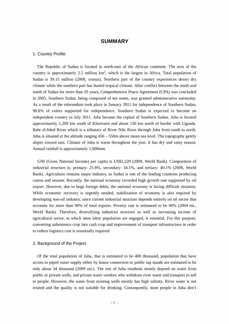
SUMMARY
1. Country Profile
The Republic of Sudan is located in north-east of the African continent. The area of the
country is approximately 2.5 million km2, which is the largest in Africa. Total population of
Sudan is 39.15 million (2008, census). Northern part of the country experiences desert dry
climate while the southern part has humid tropical climate. After conflict between the north and
south of Sudan for more than 20 years, Comprehensive Peace Agreement (CPA) was concluded
in 2005. Southern Sudan, being composed of ten states, was granted administrative autonomy.
As a result of the referendum took place in January 2011 for independence of Southern Sudan,
98.8% of voters supported for independence. Southern Sudan is expected to become an
independent country in July 2011. Juba became the capital of Southern Sudan. Juba is located
approximately 1,200 km south of Khartoum and about 130 km north of border with Uganda.
Bahr el-Jebel River which is a tributary of River Nile flows through Juba from south to north.
Juba is situated at the altitude ranging 450 – 550m above mean sea level. The topography gently
slopes toward east. Climate of Juba is warm throughout the year. It has dry and rainy season.
Annual rainfall is approximately 1,000mm.
GNI (Gross National Income) per capita is US$1,220 (2009, World Bank). Composition of
industrial structure is; primary: 25.8%, secondary: 34.1%, and tertiary: 40.1% (2008, World
Bank). Agriculture remains major industry, as Sudan is one of the leading countries producing
cotton and sesame. Recently, the national economy recorded high growth rate supported by oil
export. However, due to huge foreign debts, the national economy is facing difficult situation.
While economic recovery is urgently needed, stabilization of economy is also required by
developing non-oil industry, since current industrial structure depends entirely on oil sector that
accounts for more than 90% of total exports. Poverty rate is estimated to be 40% (2004 est.,
World Bank). Therefore, diversifying industrial structure as well as increasing income of
agricultural sector, in which most labor population are engaged, is essential. For this purpose,
converting subsistence crop into cash crop and improvement of transport infrastructure in order
to reduce logistics cost is essentially required.
2. Background of the Project
Of the total population of Juba, that is estimated to be 400 thousand, population that have
access to piped water supply either by house connection or public tap stands are estimated to be
only about 34 thousand (2009 est.). The rest of Juba residents mostly depend on water from
public or private wells, and private water vendors who withdraw river water and transport to sell
to people. However, the water from existing wells mostly has high salinity. River water is not
treated and the quality is not suitable for drinking. Consequently, most people in Juba don’t
- 2 -
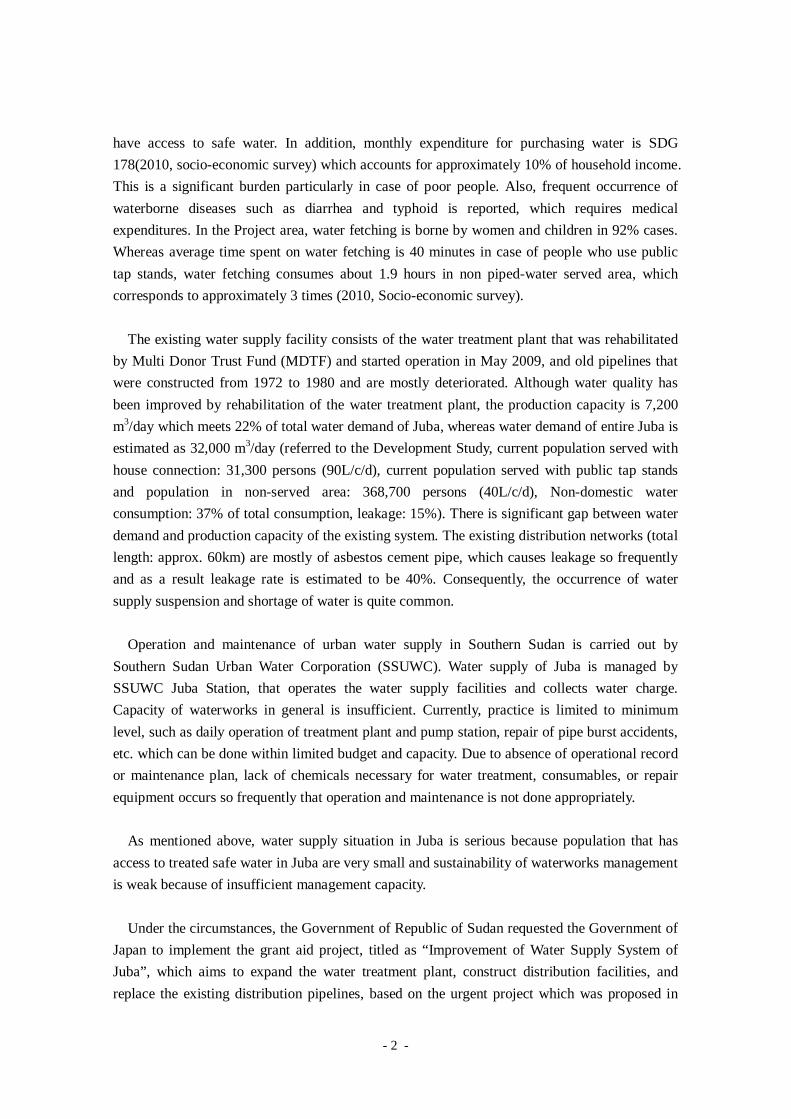
have access to safe water. In addition, monthly expenditure for purchasing water is SDG
178(2010, socio-economic survey) which accounts for approximately 10% of household income.
This is a significant burden particularly in case of poor people. Also, frequent occurrence of
waterborne diseases such as diarrhea and typhoid is reported, which requires medical
expenditures. In the Project area, water fetching is borne by women and children in 92% cases.
Whereas average time spent on water fetching is 40 minutes in case of people who use public
tap stands, water fetching consumes about 1.9 hours in non piped-water served area, which
corresponds to approximately 3 times (2010, Socio-economic survey).
The existing water supply facility consists of the water treatment plant that was rehabilitated
by Multi Donor Trust Fund (MDTF) and started operation in May 2009, and old pipelines that
were constructed from 1972 to 1980 and are mostly deteriorated. Although water quality has
been improved by rehabilitation of the water treatment plant, the production capacity is 7,200
m3/day which meets 22% of total water demand of Juba, whereas water demand of entire Juba is
estimated as 32,000 m3/day (referred to the Development Study, current population served with
house connection: 31,300 persons (90L/c/d), current population served with public tap stands
and population in non-served area: 368,700 persons (40L/c/d), Non-domestic water
consumption: 37% of total consumption, leakage: 15%). There is significant gap between water
demand and production capacity of the existing system. The existing distribution networks (total
length: approx. 60km) are mostly of asbestos cement pipe, which causes leakage so frequently
and as a result leakage rate is estimated to be 40%. Consequently, the occurrence of water
supply suspension and shortage of water is quite common.
Operation and maintenance of urban water supply in Southern Sudan is carried out by
Southern Sudan Urban Water Corporation (SSUWC). Water supply of Juba is managed by
SSUWC Juba Station, that operates the water supply facilities and collects water charge.
Capacity of waterworks in general is insufficient. Currently, practice is limited to minimum
level, such as daily operation of treatment plant and pump station, repair of pipe burst accidents,
etc. which can be done within limited budget and capacity. Due to absence of operational record
or maintenance plan, lack of chemicals necessary for water treatment, consumables, or repair
equipment occurs so frequently that operation and maintenance is not done appropriately.
As mentioned above, water supply situation in Juba is serious because population that has
access to treated safe water in Juba are very small and sustainability of waterworks management
is weak because of insufficient management capacity.
Under the circumstances, the Government of Republic of Sudan requested the Government of
Japan to implement the grant aid project, titled as “Improvement of Water Supply System of
Juba”, which aims to expand the water treatment plant, construct distribution facilities, and
replace the existing distribution pipelines, based on the urgent project which was proposed in
- 3 -
the Water Supply Master Plan prepared under the development study, “Juba Urban Water
Supply and Capacity Development Study, 2009”, carried out by Japan International Cooperation
Agency (JICA).
3. Summary of the Survey Results and Contents of the Project
(1) Commencement of the Preparatory Survey
JICA carried out the First Preparatory survey in February 2010, in order to confirm the
contents of the request and examine the components of the Grant Aid. As a result, it was
confirmed that increasing number of population need to have access to safe water urgently while
the ratio of population served by the piped water is currently estimated to be only about 8%.
Therefore, a basic policy was agreed to prioritize wide range of beneficiaries to be supplied with
safe treated water by means of public tap stands and water tanker. Necessity and priority of each
component of the requested item was also confirmed.
Based on the requested items confirmed in the First Preparatory Survey, JICA dispatched the
Second Preparatory Survey Team to Sudan from 23 June to 7 August 2010. After the field
survey and analysis in Japan, the appropriate scope of work as the Grant Aid Project was
examined and outline design and cost estimation was also prepared. In December 2010, a
mission to explain the contents of Draft Preparatory Survey Report was dispatched by JICA. As
a result of discussion with the Ministry of Water Resources and Irrigation/Government of
Southern Sudan (MWRI/GOSS) as the responsible ministry as well as SSUWC as the
implementing agency, contents of the Project were agreed and accepted in principle. This final
report is prepared based upon the above mentioned results of survey, analysis, and discussion.
(2) Overall Goal and Project Objective
The Government of Southern Sudan formulated “Water Policy, 2007” as the national supreme
plan in water sector in which the primary objective is to provide safe, affordable and reliable
urban water and sanitation services to the urban population on an equitable basis, including poor
and vulnerable groups. This Project is requested based on the water supply master plan which
was formulated through the technical assistance by the Japanese Government. The target of the
master plan is to provide safe and clean water supply to all Juba citizens by year 2025.
The overall goal of the Project is to improve living environment of the Project area through
improvement of water supply services in Juba. Therefore, implementation of this Project
contributes to promotion of the supreme plan of “Water Policy”. The objective of the Project is
to enable residents of Juba access to treated water, who still do not have access to safe water,
through public tap stands and water tankers, by means of increasing drinking water supply
- 4 -
capacity.
(3) Basic Policy
Priority under this Project is given to provision of treated safe water to wider areas in order
to contribute to water supply facility development plan by GOSS, which aims to improve water
supply situation of Juba. Given this, the basic policy of the Project is set to maximize the
number of beneficiaries by means of public tap stands and water tankers instead of individual
house connection.
Based on field survey and results of discussion, contents of the requests are examined. As a
result, the project components as shown in the following Table are agreed to be implemented
under the Japan’s Grant Aid.
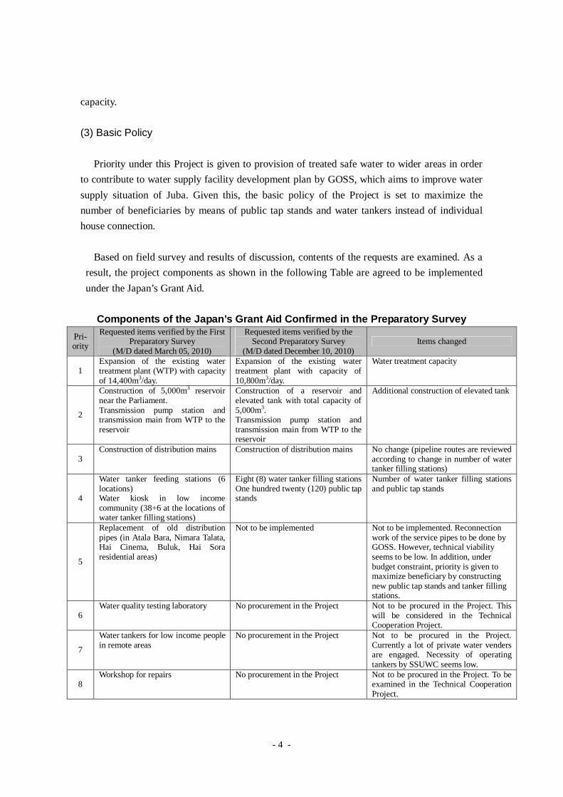
Components of the Japan’s Grant Aid Confirmed in the Preparatory SurveyPri-ority
Requested items verified by the FirstPreparatory Survey
(M/D dated March 05, 2010)
Requested items verified by theSecond Preparatory Survey
(M/D dated December 10, 2010)Items changed
1Expansion of the existing watertreatment plant (WTP) with capacityof 14,400m3/day.
Expansion of the existing watertreatment plant with capacity of10,800m3/day.
Water treatment capacity
2
Construction of 5,000m3 reservoirnear the Parliament.Transmission pump station andtransmission main from WTP to thereservoir
Construction of a reservoir andelevated tank with total capacity of5,000m3.Transmission pump station andtransmission main from WTP to thereservoir
Additional construction of elevated tank
3Construction of distribution mains Construction of distribution mains No change (pipeline routes are reviewed
according to change in number of watertanker filling stations)
4
Water tanker feeding stations (6locations)Water kiosk in low incomecommunity (38+6 at the locations ofwater tanker filling stations)
Eight (8) water tanker filling stationsOne hundred twenty (120) public tapstands
Number of water tanker filling stationsand public tap stands
5
Replacement of old distributionpipes (in Atala Bara, Nimara Talata,Hai Cinema, Buluk, Hai Soraresidential areas)
Not to be implemented Not to be implemented. Reconnectionwork of the service pipes to be done byGOSS. However, technical viabilityseems to be low. In addition, underbudget constraint, priority is given tomaximize beneficiary by constructingnew public tap stands and tanker fillingstations.
6Water quality testing laboratory No procurement in the Project Not to be procured in the Project. This
will be considered in the TechnicalCooperation Project.
7
Water tankers for low income peoplein remote areas
No procurement in the Project Not to be procured in the Project.Currently a lot of private water vendersare engaged. Necessity of operatingtankers by SSUWC seems low.
8Workshop for repairs No procurement in the Project Not to be procured in the Project. To be
examined in the Technical CooperationProject.
- 5 -
(4) The Entire Plan
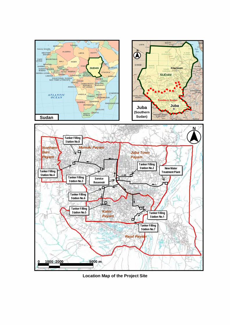
1) Water Service Area
The urbanized area of Juba, including whole areas of Juba town-Payam, Kator-Payam and
Munuki-Payam and a part (Gurai) of Northern Bari-Payam and two parts (Lologo and Gumbo) of
Rejaf-Payam where future urbanization is expected.
2) Target Year: 2015
3) Population Served: 355,400 persons
4) Unit Water Consumption(i) Domestic Water (Daily Life Water): 26 L/c/day
(ii) Non-Domestic Water: Not to be included in the Scope of the Project
(The priority is given to increase the ratio of population having access
to safe water and the objective of the Project is to supply domestic
water through public tap stands and water tankers.)
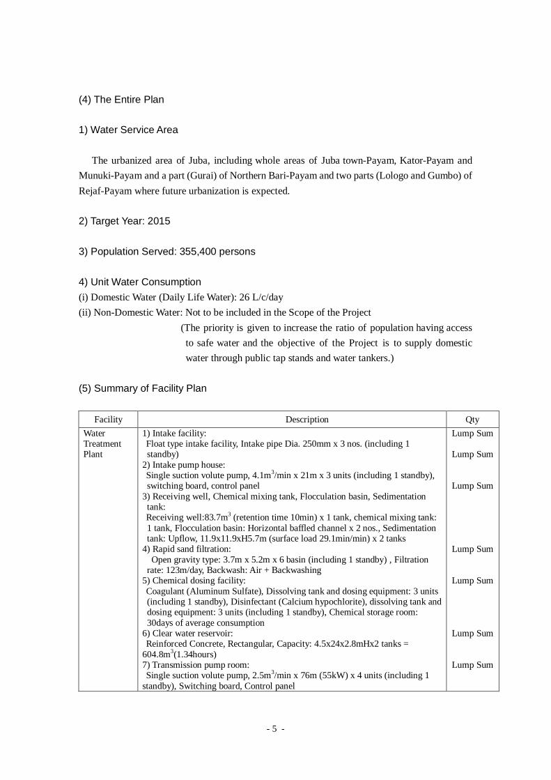
(5) Summary of Facility Plan
Facility Description Qty
WaterTreatmentPlant
1) Intake facility:Float type intake facility, Intake pipe Dia. 250mm x 3 nos. (including 1standby)
2) Intake pump house:Single suction volute pump, 4.1m3/min x 21m x 3 units (including 1 standby),switching board, control panel
3) Receiving well, Chemical mixing tank, Flocculation basin, Sedimentationtank:Receiving well:83.7m3 (retention time 10min) x 1 tank, chemical mixing tank:1 tank, Flocculation basin: Horizontal baffled channel x 2 nos., Sedimentationtank: Upflow, 11.9x11.9xH5.7m (surface load 29.1min/min) x 2 tanks
4) Rapid sand filtration:Open gravity type: 3.7m x 5.2m x 6 basin (including 1 standby) , Filtration
rate: 123m/day, Backwash: Air + Backwashing5) Chemical dosing facility:Coagulant (Aluminum Sulfate), Dissolving tank and dosing equipment: 3 units(including 1 standby), Disinfectant (Calcium hypochlorite), dissolving tank anddosing equipment: 3 units (including 1 standby), Chemical storage room:30days of average consumption
6) Clear water reservoir:Reinforced Concrete, Rectangular, Capacity: 4.5x24x2.8mHx2 tanks =
604.8m3(1.34hours)7) Transmission pump room:Single suction volute pump, 2.5m3/min x 76m (55kW) x 4 units (including 1
standby), Switching board, Control panel
Lump Sum
Lump Sum
Lump Sum
Lump Sum
Lump Sum
Lump Sum
Lump Sum
- 6 -
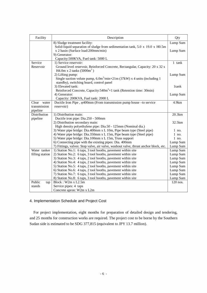
Facility Description Qty
8) Sludge treatment facility:Solid-liquid separation of sludge from sedimentation tank, 5.0 x 19.0 x H0.5mx 2 basin (Surface load:200mm/min)
9) Generator:Capacity:500KVA, Fuel tank: 5000 L
Lump Sum
Lump Sum
ServiceReservoir
1) Service reservoir:Ground level reservoir, Reinforced Concrete, Rectangular, Capacity: 20 x 32 xH4.0m x 2 tanks (5000m3 )
2) Lifting pump:Single suction volute pump, 6.0m3/min×21m (37kW) x 4 units (including 1standby), switching board, control panel
3) Elevated tank:Reinforced Concrete, Capacity:540m3×1 tank (Retention time: 30min)
4) Generator:Capacity: 200KVA, Fuel tank: 2000 L
1 tank
Lump Sum
1tank
Lump Sum
Clear watertransmissionpipeline
Ductile Iron Pipe , φ400mm (From transmission pump house –to servicereservoir)
4.9km
Distributionpipeline
1) Distribution main:Ductile iron pipe: Dia.250 - 500mm
2) Distribution secondary main:High density polyethylene pipe: Dia.50 - 125mm (Nominal dia.)
3) Water pipe bridge: Dia.400mm x L 10m, Pipe beam type (Steel pipe)4) Water pipe bridge: Dia.350mm x L 15m, Pipe beam type (Steel pipe)5) Water pipe bridge: Dia.100mm x L 15m, Truss support6) Connecting pipe with the existing pipes: Dia. 400mm7) Fittings, valves: Stop valve, air valve, washout valve, thrust anchor block, etc.
20.3km
32.5km
1 no.1 no.1 no.
Lump SumLump Sum
Water tankerfilling station
1) Station No.1: 6 taps, 3 tool booths, pavement within site2) Station No.2: 6 taps, 3 tool booths, pavement within site3) Station No.3: 4 taps, 2 tool booths, pavement within site4) Station No.4: 4 taps, 2 tool booths, pavement within site5) Station No.5: 4 taps, 2 tool booths, pavement within site6) Station No.6: 4 taps, 2 tool booths, pavement within site7) Station No.7: 6 taps, 3 tool booths, pavement within site8) Station No.8: 6 taps, 3 tool booths, pavement within site
Lump SumLump SumLump SumLump SumLump SumLump SumLump SumLump Sum
Public tapstands
Block : W2m x L2.5mService pipes: 4 tapsConcrete apron: W2m x L2m
120 nos.
4. Implementation Schedule and Project Cost
For project implementation, eight months for preparation of detailed design and tendering,
and 25 months for construction works are required. The project cost to be borne by the Southern
Sudan side is estimated to be SDG 377,815 (equivalent to JPY 13.7 million).
- 7 -
5. Project Evaluation
(1) Relevance
1) Beneficiaries and Population
Whereas the total population of Juba is estimated to be 400 thousand people (2009 estimate),
population served by the piped water system is estimated to be only 34 thousand people (2009).
Consequently, most of the people of Juba have no access to safe water.
Objective of the Project is that residents including poor people in the target areas, where the
existing water supply system does not provide services, will have access to safe water. The
population to be served by the Project is 355,300 persons. The ratio of population served in the
target year of 2015 is 52% while total population of the project area is estimated to be 679,600
(estimation by Development Study).
2) Project Objectives and Basic Human Needs (BHN)
Most of the Juba residents currently rely on water tankers that withdraw and distribute river
water without treatment or groundwater from public wells that are not suitable for drinking in
many cases. People are suffering from high risk of waterborne disease as well as high expenses
on buying water for domestic uses.
The Project aims to improve living environment of residents by supplying clean treated
water, which complies with Basic Human Needs of residents.
3) Operation and Maintenance Technique
The treatment process adopted in case of the proposed water treatment plant is same as the
process of the existing plant. Operation method is also designed based on manual operation at
site. In addition, the Technical Cooperation Project is undergoing along with this Project
implementation. Taking into account that capacity of staff-members in terms of operation and
maintenance and waterworks management will be developed on completion of the Grant Aid
Project, the current staff would be able to take care of proper operation and maintenance of the
project facilities.
4) Mid-Long Term Plan
In the “Expenditure Priorities & Funding Needs (2008-2011)” prepared by GOSS,
expenditures priorities are identified based on priority issues of Southern Sudan as well as
- 8 -
estimated costs, and development of water supply infrastructure is identified as the priority issue.
Therefore, the Project complies with the development policy of GOSS.
5) Profitability
As the beneficiaries of the Project are large number of population including poor people,
profitability is not an objective of the Project. As a result of affordability analysis by assuming
that operation and maintenance expenditures are to be covered by water revenue and calculating
unit cost and average price of water per cubic meter, it was concluded that expenses on water
can be significantly reduced compared to the current expenditure.
6) Social and Environmental Considerations
As a result of the environmental scoping carried out in this Preparatory Survey, serious
negative impact is not expected through the Project implementation (see Appendix-6). As
necessary measures to be taken to mitigate/minimize possible negative impacts caused by the
Project have been identified, with condition that these measures are to be taken, Environmental
Approval was issued by the Ministry of Environment/GOSS in February 2011.
7) Feasibility under the Japan’s Grant Aid Scheme
On condition that security situation will not deteriorate significantly, the Project is feasible
without particular difficulties.
(2) Effectiveness
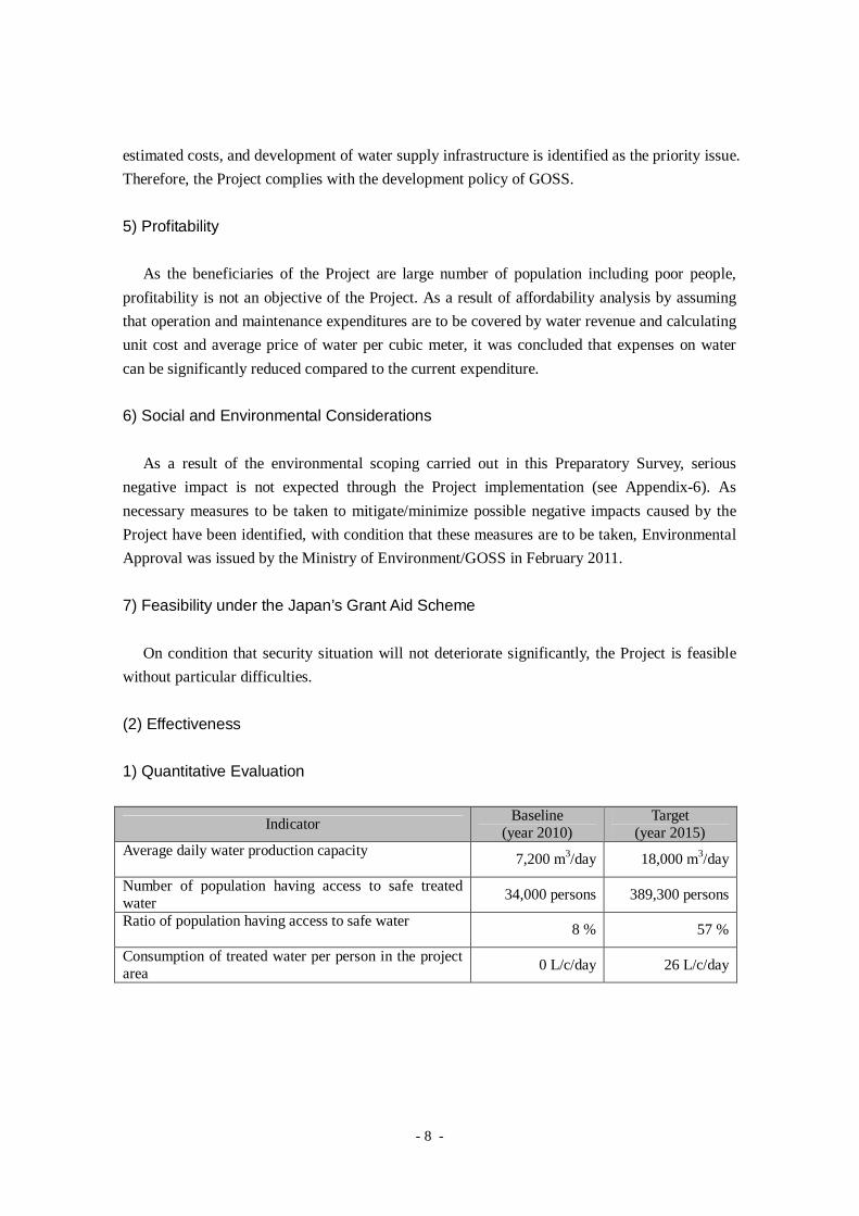
1) Quantitative Evaluation
IndicatorBaseline
(year 2010)Target
(year 2015)Average daily water production capacity
7,200 m3/day 18,000 m3/day
Number of population having access to safe treatedwater
34,000 persons 389,300 persons
Ratio of population having access to safe water8 % 57 %
Consumption of treated water per person in the projectarea
0 L/c/day 26 L/c/day
- 9 -
2) Qualitative Evaluation
(a) Whereas 56% of residents in non-served area of piped water experiences waterborne
diseases, such as diarrhea and typhoid (2010, Socio-economic survey), decrease in rate of
water borne disease is expected as a result of improving public health by use of safe and
stable water supply.
(b) Currently 92% of water fetching is borne by women and children. Time spend for water
fetching is 1.9 hours in average in the current non-served area, while that in current
served area with public tap stands is 40 minutes in average (2010, Socio-economic
survey). As a result of mitigating the hardship in water fetching, empowerment and job
creation for women as well as increased opportunity for children to study are expected.
(c) Since emergency connecting pipes shall be provided between the new and existing
facilities in order to supplement water supply in the existing system in accidental cases,
occurrence of water supply interruption can be mitigated. Consequently, it is expected to
improve reliability of the water supply services by the existing system, which serves the
current population of approx. 34,000.
As aforementioned, the Project will contribute to improve living environment of approx. 355
thousand people of Juba including poor residents. As positive effects are also expected, the
Project is evaluated to be relevant and effective to be implemented under the Japan’s Grant Aid.

0 1000 2000 5000 m
N
Munuki Payam
Juba TownPayam
NorthernBari
Payam
Kator
Payam
Rejaf Payam
New Water
Treatment Plant
Tanker Filling
Station No.7
Tanker Filling
Station No.4Service
Reservoir
Sudan
Tanker Filling
Station No.8
Tanker Filling
Station No.3
Tanker Filling
Station No.6
Tanker Filling
Station No.5 Tanker Filling
Station No.1
Tanker Filling
Station No.2
Juba(Southern
Sudan)
N
SUDAN
Southern Sudan
Juba
SUDAN
Khartoum
Location Map of the Project Site
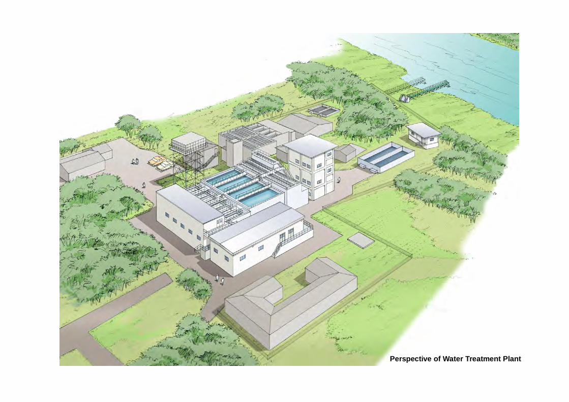
Perspective of Water Treatment Plant
i
PREPARATORY SURVEY REPORTON
THE PROJECT FOR THE IMPROVEMENT OFWATER SUPPLY SYSTEM OF JUBA
INSOUTHERN SUDAN
PREFACE
SUMMARY
Location Map of the Project Site
Perspective of Water Treatment Plant
C o n t e n t s
Chapter 1 Background of the Project1-1 Background....................................................................................................................1-1
1-2 Natural Conditions .........................................................................................................1-2
1-2-1 Project Site .............................................................................................................1-2
1-2-2 Meteorology ...........................................................................................................1-3
1-2-3 Hydrology ..............................................................................................................1-3
1-2-4 Groundwater...........................................................................................................1-4
1-2-5 Topography and Geology........................................................................................1-5
1-2-6 Flora Fauna and Ecosystem.....................................................................................1-5
1-3 Environmental and Social Considerations.......................................................................1-8
Chapter 2 Contents of the Project2-1 Basic Concept of the Project...........................................................................................2-1
2-1-1 Outline of the Project ..............................................................................................2-1
2-1-2 Outline of the Project ..............................................................................................2-1
2-2 Outline Design of the Japanese Assistance......................................................................2-3
2-2-3 Design Policy .........................................................................................................2-3
2-2-4 Basic Plan (Construction Plan)................................................................................2-8
2-2-5 Outline Design Drawing .......................................................................................2-34
2-2-6 Implementation Plan .............................................................................................2-36
2-2-6-1 Implementation Policy...................................................................................2-36
2-2-6-2 Implementation Conditions............................................................................2-36
2-2-6-3 Scope of Works .............................................................................................2-37
2-2-6-4 Consultant Supervision..................................................................................2-39
2-2-6-5 Quality Control Plan......................................................................................2-40
2-2-6-6 Procurement Plan ..........................................................................................2-40
ii
2-2-6-7 Operational Guidance Plan ............................................................................2-41
2-2-6-8 Soft Component (Technical Assistance) Plan .................................................2-42
2-2-6-9 Implementation Schedule ..............................................................................2-43
2-3 Obligations of the Recipient Country............................................................................2-44
2-4 Project Operation Plan..................................................................................................2-45
2-5 Project Cost Estimation ................................................................................................2-49
2-5-1 Initial Cost Estimation ..........................................................................................2-49
2-5-2 Operation and Maintenance Cost...........................................................................2-50
2-6 Other Relevant Issues...................................................................................................2-54
Chapter 3 Project Evaluation3-1 Recommendations ..........................................................................................................3-1
3-1-1 Prerequisite conditions for Implementation of the Project........................................3-1
3-1-2 Important Assumptions for Achievement of the Overall Goal ..................................3-1
3-2 Project Evaluation ..........................................................................................................3-2
3-2-1 Relevance ...............................................................................................................3-2
3-2-2 Effectiveness ..........................................................................................................3-4
A p p e n d i c e s
Appendix-1 Member List
Appendix-2 Study Schedule
Appendix-3 List of Parties Concerned
Appendix-4 Minutes of Discussion(M/D)
(1) Inception Report (30 June 2010)
(2) Explanation on Draft Report (10 December 2010)
(3) Technical Notes (4 August 2010)
Appendix-5 Socio-Economic Survey Results
Appendix-6 Environmental and Social Consideration
(1) Initial Environmental Examination
(2) Memorandum of Stakeholder Meeting
(3) Environmental Approval (February 2011)
(4) Permission on Land Use (December 2010)
Appendix-7 Outline Design Drawing
Appendix-8 Design Calculation
Appendix-9 Operation and Maintenance Cost
iii
List of Tables
Table 1-1 Requested Items ........................................................................................................1-2
Table 1-2 Monthly Rainfall (Year 2005- 2007)..........................................................................1-3
Table 1-3 Monthly Average Maximum / Minimum Temperature (2006) ....................................1-3
Table 1-4 Water Level of Bahr el-Jebel River at Water Treatment Plant .....................................1-4
Table 1-5 Expected adverse impacts of the Project during construction stage and proposed
mitigation measures...................................................................................................1-8
Table 1-6 Expected adverse impacts of the Project during operation stage and proposed
mitigation measures...................................................................................................1-9
Table 2-1 Outline of the Project ................................................................................................2-2
Table 2-2 Requested Items ........................................................................................................2-3
Table 2-3 Per Capita Water Consumption from Public Wells in Non -Served Areas
(presumed from the Socio-economic Survey) ..........................................................2-10
Table 2-4 Summary of Results of Social Survey in the Preparatory Survey (the Result
about Water-Consumption) ......................................................................................2-11
Table 2-5 Water Supply Volume Per Capita Per Day in this Project .........................................2-12
Table 2-6 Comparison on Unit Water Demand between the Master Plan and the Project ..........2-12
Table 2-7 Comparison on Alternatives of Water Treatment Plant Capacity...............................2-13
Table 2-8 Calculation on Number of Public Tap Stands and Water Tanker Filling Stations.....2-14
Table 2-9 Calculation on Water Supply Volume per Public Tap Stand and the Number of
Taps ........................................................................................................................2-16
Table 2-10 Calculation on Water Supply Volume per Tap in Water Tanker Filling Station and
the Necessary Number of Taps ................................................................................2-17
Table 2-11 River Flow/Water Level Observation and Design Water Intake Volume ...................2-18
Table 2-12 Outline of Water Supply Facility .............................................................................2-20
Table 2-13 Design Specifications for Water Intake Facilities .....................................................2-24
Table 2-14 Design Policy Based on the Issues in the Existing Facility .......................................2-25
Table 2-15 Design Specifications for Water Treatment Facilities ...............................................2-27
Table 2-16 Design Specifications for Service Reservoir ............................................................2-28
Table 2-17 Design Specifications for Pipelines..........................................................................2-31
Table 2-18 Design Specifications for Water Tanker Filling Station ............................................2-33
Table 2-19 Design Specifications for Public Tap Stands ............................................................2-34
Table 2-20 List of Outline Design Drawings .............................................................................2-34
Table 2-21 Scope of Works by the Both Governments...............................................................2-38
Table 2-22 Supplier Countries...................................................................................................2-40
Table 2-23 Outline of Operational Guidance by the Contractor..................................................2-41
Table 2-24 Project Implementation Schedule ............................................................................2-43
Table 2-25 Personnel Formation (example) by division in Juba Station after the Project’s
Implementation .......................................................................................................2-46
iv
Table 2-26 Responsibility of SSUWC and Third Party Undertakers (sample) ............................2-46
Table 2-27 Comparison on Management Systems for Public Tap Stands....................................2-47
Table 2-28 Summary Table of the Southern Sudan Side’s Apportionment Expenditures.............2-49
Table 2-29 Operation and Maintenance Cost of the Proposed Facility .......................................2-50
Table 2-30 Water Revenue Forecast ..........................................................................................2-51
Table 2-31 Examination on Retail Price ....................................................................................2-52
Table 2-32 Trial Calculation on Expenditures on Water Purchasing ...........................................2-53
List of Figures
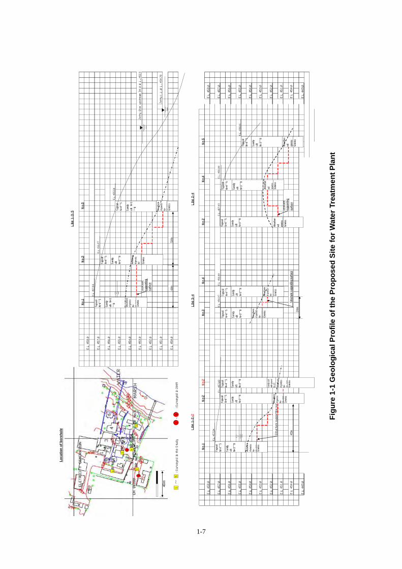
Figure 1-1 Geological Profile of the Proposed Site for Water Treatment Plant.............................1-7
Figure 1-2 Location Map of the Land Use Permission (Plot No.23) ..........................................1-10
Figure 2-1 Target Service Area of Water Supply .........................................................................2-8
Figure 2-2 Population Forecast and Population Served Planned in M/P and the Project ...............2-9
Figure 2-3 Available Land for Construction of New Water Treatment Plant ..............................2-15
Figure 2-4 Water Balance of the Water Supply System in the Project ........................................2-16
Figure 2-5 Water Supply System of the Project .........................................................................2-21
Figure 2-6 General Layout Plan................................................................................................2-22
Figure 2-7 Locations of Sites for Water Tanker Filling Station ..................................................2-32
Figure 2-8 Relocation of Tap Stand...........................................................................................2-34
Figure 2-9 Facilities to be removed and trees to be cut for the Project .......................................2-39
Figure 2-10 Management Entity of the Facilities Constructed in the Project................................2-45
v
Abbreviations
CES Central Equatoria State
GOSS Government of Southern Sudan
GTZ German Technical Cooperation
IDP Internal Disturbed Population
IEE Initial Environmental Examination
MDTF Multi-Donor Trust Fund
MOPI Ministry of Physical Infrastructure
MWRI Ministry of Water Resources and Irrigation
SDG Sudanese Pond
SSUWC Southern Sudan Urban Water Corporation
USAID United States Agency for International Development

CHAPTER 1 BACKGROUND OF THE PROJECT

1-1
Chapter 1 Background of the Project
1-1 Background
The Republic of Sudan is located in north-east of the African continent. The area of the
country is approximately 2.5 million km2, which is the largest in Africa. Total population of
Sudan is 39.15 million (2008, census). Northern part of the country experiences desert dry
climate while the southern part has humid tropical climate. After conflict between the north and
south of Sudan for more than 20 years, Comprehensive Peace Agreement (CPA) was concluded
in 2005. Southern Sudan, being composed of ten states, was granted administrative autonomy.
As a result of the referendum took place in January 2011 for independence of Southern Sudan,
98.8% of voters supported for independence. Southern Sudan is expected to become an
independent country in July 2011. Juba became the capital of Southern Sudan. Juba is located
approximately 1,200 km south of Khartoum and about 130 km north of border with Uganda.
Bahr el-Jebel River which is a tributary of River Nile flows through Juba from south to north.
Juba is situated at the altitude ranging 450 – 550m above mean sea level. The topography gently
slopes toward east. Climate of Juba is warm throughout the year. It has dry and rainy season.
Annual rainfall is approximately 1,000mm.
Based upon the Water Supply Master Plan which was prepared in the development study,
“Juba Urban Water Supply and Capacity Development Study, 2009” (hereinafter referred to as
“Development Study”), carried out by Japan International Cooperation Agency (JICA), the
Government of Republic of Sudan requested the Government of Japan to implement the grant
aid project, titled as “Improvement of Water Supply System of Juba”, which aims to expand the
water treatment plant, construct distribution facilities, and replace the existing distribution
pipelines as the urgent project.
In response to the request, the First Preparatory survey was carried out in February 2010, in
order to confirm the contents of the request and examine the components of the grant aid, by
collecting information such as, situation of water supply, capacity of the Southern Sudan Urban
Water Corporation (SSUWC) that is in charge of waterworks management, conditions of
procurement of materials and equipment, security conditions, etc. As a result, it was confirmed
that increasing number of population need to have access to safe water urgently to great extent,
while the rate of population served by the piped water is currently estimated to be only approx.
8%. And therefore, a basic policy was agreed to prioritize wide range of beneficiaries to be
supplied with safe treated water by means of public tap stands and water tanker. Necessity and
priority of each component of the requested item was also confirmed.
Based on the requested items confirmed in the First Preparatory Survey, the Second
Preparatory Survey was carried out from June 2010 in order to examine the appropriate scope of
1-2
work as the grant aid project, to prepare outline design and cost estimation. After examination of
appropriateness of the project component as the Japan’s grant aid project in terms of project
scale, project effect, etc., the contents of Draft Preparatory Survey Report was presented to and
discussed with the Ministry of Water Resources and Irrigation / Government of Southern Sudan
(MWRI/GOSS) as the responsible ministry as well as SSUWC as the implementing agency. As
a result, the project components as shown in Table 1-1 was finally agreed to be the scope of the
Japanese Grant Aid.
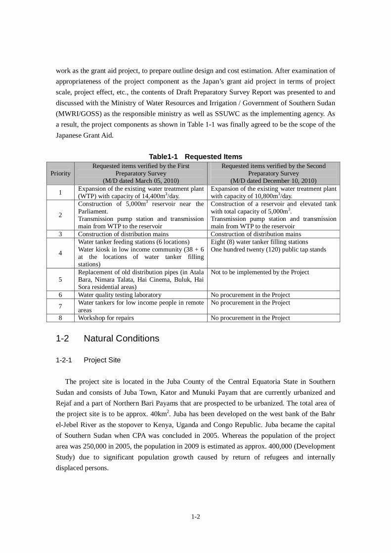
Table1-1 Requested Items
PriorityRequested items verified by the First
Preparatory Survey(M/D dated March 05, 2010)
Requested items verified by the SecondPreparatory Survey
(M/D dated December 10, 2010)
1Expansion of the existing water treatment plant(WTP) with capacity of 14,400m3/day.
Expansion of the existing water treatment plantwith capacity of 10,800m3/day.
2
Construction of 5,000m3 reservoir near theParliament.Transmission pump station and transmissionmain from WTP to the reservoir
Construction of a reservoir and elevated tankwith total capacity of 5,000m3.Transmission pump station and transmissionmain from WTP to the reservoir
3 Construction of distribution mains Construction of distribution mains
4
Water tanker feeding stations (6 locations)Water kiosk in low income community (38 + 6at the locations of water tanker fillingstations)
Eight (8) water tanker filling stationsOne hundred twenty (120) public tap stands
5Replacement of old distribution pipes (in AtalaBara, Nimara Talata, Hai Cinema, Buluk, HaiSora residential areas)
Not to be implemented by the Project
6 Water quality testing laboratory No procurement in the Project
7Water tankers for low income people in remoteareas
No procurement in the Project
8 Workshop for repairs No procurement in the Project
1-2 Natural Conditions
1-2-1 Project Site
The project site is located in the Juba County of the Central Equatoria State in Southern
Sudan and consists of Juba Town, Kator and Munuki Payam that are currently urbanized and
Rejaf and a part of Northern Bari Payams that are prospected to be urbanized. The total area of
the project site is to be approx. 40km2. Juba has been developed on the west bank of the Bahr
el-Jebel River as the stopover to Kenya, Uganda and Congo Republic. Juba became the capital
of Southern Sudan when CPA was concluded in 2005. Whereas the population of the project
area was 250,000 in 2005, the population in 2009 is estimated as approx. 400,000 (Development
Study) due to significant population growth caused by return of refugees and internally
displaced persons.
1-3
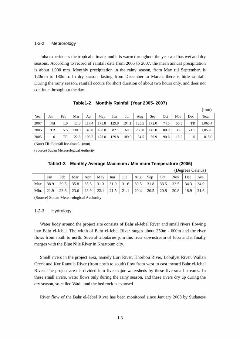
1-2-2 Meteorology
Juba experiences the tropical climate, and it is warm throughout the year and has wet and dry
seasons. According to record of rainfall data from 2005 to 2007, the mean annual precipitation
is about 1,000 mm. Monthly precipitation in the rainy season, from May till September, is
120mm to 180mm. In dry season, lasting from December to March, there is little rainfall.
During the rainy season, rainfall occurs for short duration of about two hours only, and does not
continue throughout the day.
Table1-2 Monthly Rainfall (Year 2005- 2007)(mm)
Year Jan Feb Mar Apr May Jun Jul Aug Sep Oct Nov Dec Total
2007 Nil 1.0 11.8 117.4 178.8 129.8 194.1 125.5 172.0 74.5 55.5 TR 1,060.4
2006 TR 5.5 130.0 40.8 188.0 82.1 60.5 265.0 145.0 80.0 35.5 21.5 1,053.0
2005 0 TR 22.8 103.7 173.0 129.8 189.0 34.5 56.9 90.6 15.2 0 815.0
(Note) TR=Rainfall less than 0.1(mm)
(Source) Sudan Meteorological Authority
Table1-3 Monthly Average Maximum / Minimum Temperature (2006)(Degrees Celsius)
Jan Feb Mar Apr May Jun Jul Aug Sep Oct Nov Dec Ave.
Max 38.9 39.5 35.8 35.5 31.3 31.9 31.6 30.5 31.8 33.5 33.5 34.3 34.0
Min. 21.9 23.6 23.6 23.9 22.1 21.5 21.1 20.4 20.5 20.8 20.8 18.9 21.6
(Source) Sudan Meteorological Authority
1-2-3 Hydrology
Water body around the project site consists of Bahr el-Jebel River and small rivers flowing
into Bahr el-Jebel. The width of Bahr el-Jebel River ranges about 250m - 600m and the river
flows from south to north. Several tributaries join this river downstream of Juba and it finally
merges with the Blue Nile River in Khartoum city.
Small rivers in the project area, namely Luri River, Khorbou River, Lobulyet River, Wallan
Creek and Kor Ramula River (from north to south) flow from west to east toward Bahr el-Jebel
River. The project area is divided into five major watersheds by these five small streams. In
these small rivers, water flows only during the rainy season, and these rivers dry up during the
dry season, so-called Wadi, and the bed rock is exposed.
River flow of the Bahr el-Jebel River has been monitored since January 2008 by Sudanese
1-4
Dam Implementation Unit. The location of flow measurement in river is right upstream of the
Juba Bridge. Based on the 45 monitored data at this location from January to September 2008,
the maximum and minimum flow in the same period are 1,125 m3/s (97.2 million m3/day) and
1,742 m3/s (150.5 million m3/day) respectively.
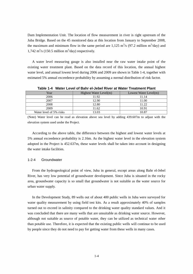
A water level measuring gauge is also installed near the raw water intake point of the
existing water treatment plant. Based on the data record of this location, the annual highest
water level, and annual lowest level during 2006 and 2009 are shown in Table 1-4, together with
estimated 5% annual exceedence probability by assuming a normal distribution of risk factor.
Table 1-4 Water Level of Bahr el-Jebel River at Water Treatment PlantYear Highest Water Level(m) Lowest Water Level(m)2006 11.92 11.142007 12.90 11.002008 12.80 11.222009 11.62 10.91
Water level of 5% risks 13.03 10.87
(Note) Water level can be read as elevation above sea level by adding 439.607m to adjust with the
elevation system used under the Project.
According to the above table, the difference between the highest and lowest water levels at
5% annual exceedence probability is 2.16m. As the highest water level in the elevation system
adopted in the Project is 452.637m, these water levels shall be taken into account in designing
the water intake facilities.
1-2-4 Groundwater
From the hydrogeological point of view, Juba in general, except areas along Bahr el-Jebel
River, has very low potential of groundwater development. Since Juba is situated in the rocky
area, groundwater capacity is so small that groundwater is not suitable as the water source for
urban water supply.
In the Development Study, 89 wells out of about 400 public wells in Juba were surveyed for
water quality measurement by using field test kits. As a result approximately 40% of samples
turned out to exceed in salinity compared to the drinking water quality standard values. And it
was concluded that there are many wells that are unsuitable as drinking water source. However,
although not suitable as source of potable water, they can be utilized as technical water other
than potable use. Therefore, it is expected that the existing public wells will continue to be used
by people since they do not need to pay for getting water from these wells in many cases.
1-5
1-2-5 Topography and Geology
Topography of Juba gently slopes from Kujur mountain (Jebel Körök: Mountain, altitude:
744 m) in the west toward Bahr el-Jebel River in the east (altitude: 450 m). The project area is
situated in alluvium formations of Bahr el-Jebel where gneiss outcrops are unevenly distributed.
There are five small streams that have water flow only during rainy season. Some areas along
Bahr el-Jebel River often get flooded during rainy season. The water supply area of the Project
is situated in the ground elevation range of 455m - 510m.
In the north of Juba, sedimentary gneiss is distributed covering Proterozoic gneisses.
Proterozoic gneisses are distributed around Juba. Also, Alluvium is found in narrow areas along
Bahr el-Jebel. Juba has hilly terrain and bedrocks are exposed at many places in the city. The
thickness of the alluvium of sand layer is confirmed to be approx. 8m in the old riverbed. And
terrace deposits are distributed in the area north of the airport.
In the Development Study (2009), mechanical boring survey was carried out by drilling two
boreholes at the proposed site for expansion of water treatment plant. From the survey, stratum
composition, geological analysis, groundwater level etc. has been identified. However,
information on relationship of supporting soil (N value of weathered gneiss = 79-300) is
insufficient in order to decide the structure and dimension of the proposed facility. Therefore,
mechanical boring along with plane survey has been conducted in this Study, in order to confirm
positions of the weathered gneiss at the construction site. The geological profile at the WTP site
is as shown in Fig. 1-1. The depth of the supporting bedrock was confirmed to be 4 – 6 m from
the ground level. Based on the existing geological formations, two types of foundation
structures are considered, either footing foundation by excavating 0.5-1.0m below surface of the
weathered gneiss, or pile foundation by penetrating the pile bottom 0.5-1.0m below the
weathered gneiss. In selecting the foundation structure, other conditions should be taken into
account, such as, high groundwater level (2.3m below the ground level) and constraint of
available land.
In case of the reservoir site, the supporting layer (weathered gneiss) is situated 2.5m below
the ground level. Spread foundation is proposed for foundation structure. Taking into account
that wide area of approx. 1,000m2 is required for the service reservoir (5,000 m3), test pit
excavation survey was carried out in order to identify position, distribution and slope of the
supporting layer prior to deciding design layout and height of the reservoir. As a result, it was
observed that bedrock is situated at relatively shallow level of 1.0-1.7m below the ground level.
1-2-6 Flora Fauna and Ecosystem
According to the vegetation maps of entire Sudan prepared by FAO, the original vegetation

1-6
of the project site was composed of savanna grassland and woodland. However, vegetation has
been significantly damaged during civil war. Although this area had relatively rich forest until
just 10 years ago, a lot of big trees have been cut down for military and fuel wood purposes. As
a result, the forest has been destroyed. Accordingly, wildlife including many small birds has
been lost. Currently, forest vegetation exists only in small stretches along the river bank.
Nevertheless, fruit trees, such as mango and papaya, and useful trees such as neem trees are
found throughout the city. In addition, in Bahr el-Jebel River, there are several species of
aquatic life such as, fish, alligators, waterfowl, etc.
1-7
E.L
458.0
E.L
457.0
E.L
456.0
E.L
455.0
E.L
454.0
E.L
453.0
Jet
ty(2
kmups
tream
)H
.H.W
.L..
452.
92
E.L
452.0
E.L
451.0
Jet
tyL..L
..W.L
..45
0.78
E.L
450.0
~:S
urve
yed
inth
eStu
dy
、:Surv
eye
din
2009
E.L
458.
0E.L
458.
0
E.L
457.
0E.L
.457.0
3E.L
456.9
7E.L
456.8
0E.L
.45
7.0
3E.L
.456.8
0E.L
457.
0
E.L
456.
0E.L
456.
0
E.L
455.
0E.L
455.
0
E.L
454.
0E.L
454.
0
E.L
453.
0E.L
453.
0
E.L
452.
0E.L
452.
0
Str
uctu
resu
ppo
rtin
gsu
rfac
e
E.L
451.
0E.L
451.
0
E.L
450.
0S
truct
ure
supp
ortin
gsu
rfac
eE.L
450.
0
20m
E.L
449.
0E.L
449.
0
Str
uctu
re
supp
ortin
g
surf
ace
45m
E.L
455
.54
No.5
Lin
e1-
3-5
No.3
No.5
50m
No.2
E.L
455.
54
No.1
E.L
457.5
4
E.L
456.
97
40m
No.4
Str
uctu
re
supp
ortin
g
surfa
ce
No.1
No.4
No.2
No.2
No.3
Loca
tion
ofbo
reho
le
Lin
e3-4
Lin
e1-
2-2
E.L
457.
54
Lin
e2-
4
Wea
ther
e
dg
neis
s
N=
79~3
00
Wea
ther
e
dgn
eis
s
N=
79~3
00
Gne
iss
Wea
ther
e
dgn
eiss
N=
79~
300
Top
soil
N=4
~5
San
dy
silt
N=3
~8
Wea
ther
e
dgn
eis
s
N=
79~3
00G
neis
s
Top
soil
N=
4~5
San
dy
silt
N=3
~8
Wea
ther
e
dgn
eiss
N=
79~
300
Gne
iss
Tops
oil
N=4
~5
San
dy
silt
N=3
~8
Wea
ther
e
dg
neis
s
N=
79~3
00G
neis
s
Top
soil
N=4
~5
San
dy
silt
N=3
~8
Gne
iss
Top
soil
N=
4~5
San
dy
silt
N=
3~8
Top
soil
N=4
~5
San
dy
silt
N=3
~8
Gne
iss
San
dyso
il
with
grav
el
N=
27
Top
soil
N=4
~5
San
dy
silt
N=3
~8
Wea
ther
e
dgn
eiss
N=
79~
300
Gne
iss
Tops
oil
N=4
~5
San
dy
silt
N=3
~8
Wea
ther
e
dgn
eiss
N=
79~3
00G
neis
s
Tops
oil
N=4
~5
San
dy
silt
N=3
~8
Wea
ther
ed gnei
ss
Gne
iss
Top
soil
N=4
~5
San
dy
silt
N=3
~8
Wea
ther
ed gnei
ssG
neis
s
40m
1
2
3
4
5
1
2
Top
soil
N=
4~5
San
dy
silt
N=
3~8
Wea
ther
ed gnei
ssG
neis
s
15
12 Figu
re1-
1G
eolo
gica
lPro
file
ofth
ePr
opos
edSi
tefo
rWat
erTr
eatm
entP
lant
1-8
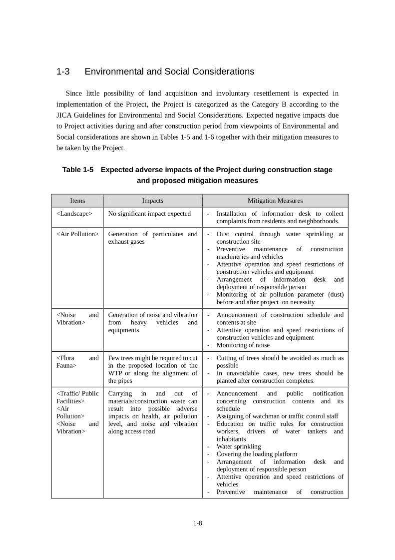
1-3 Environmental and Social Considerations
Since little possibility of land acquisition and involuntary resettlement is expected in
implementation of the Project, the Project is categorized as the Category B according to the
JICA Guidelines for Environmental and Social Considerations. Expected negative impacts due
to Project activities during and after construction period from viewpoints of Environmental and
Social considerations are shown in Tables 1-5 and 1-6 together with their mitigation measures to
be taken by the Project.
Table 1-5 Expected adverse impacts of the Project during construction stageand proposed mitigation measures
Items Impacts Mitigation Measures
<Landscape> No significant impact expected - Installation of information desk to collectcomplaints from residents and neighborhoods.
<Air Pollution> Generation of particulates andexhaust gases
- Dust control through water sprinkling atconstruction site
- Preventive maintenance of constructionmachineries and vehicles
- Attentive operation and speed restrictions ofconstruction vehicles and equipment
- Arrangement of information desk anddeployment of responsible person
- Monitoring of air pollution parameter (dust)before and after project on necessity
<Noise andVibration>
Generation of noise and vibrationfrom heavy vehicles andequipments
- Announcement of construction schedule andcontents at site
- Attentive operation and speed restrictions ofconstruction vehicles and equipment
- Monitoring of noise
<Flora andFauna>
Few trees might be required to cutin the proposed location of theWTP or along the alignment ofthe pipes
- Cutting of trees should be avoided as much aspossible
- In unavoidable cases, new trees should beplanted after construction completes.
<Traffic/ PublicFacilities><AirPollution><Noise andVibration>
Carrying in and out ofmaterials/construction waste canresult into possible adverseimpacts on health, air pollutionlevel, and noise and vibrationalong access road
- Announcement and public notificationconcerning construction contents and itsschedule
- Assigning of watchman or traffic control staff- Education on traffic rules for construction
workers, drivers of water tankers andinhabitants
- Water sprinkling- Covering the loading platform- Arrangement of information desk and
deployment of responsible person- Attentive operation and speed restrictions of
vehicles- Preventive maintenance of construction
1-9
Items Impacts Mitigation Measures
machineries and vehicles
<Solid Waste> Disposal of construction wasteand soil
- Promotion of reuse- Disposal at appropriate location such as landfill
site, etc.
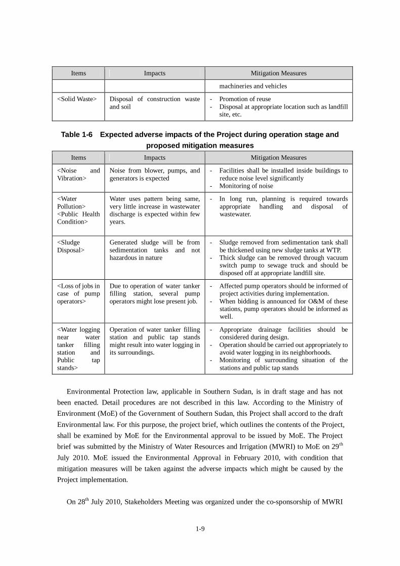
Table 1-6 Expected adverse impacts of the Project during operation stage andproposed mitigation measures
Items Impacts Mitigation Measures
<Noise andVibration>
Noise from blower, pumps, andgenerators is expected
- Facilities shall be installed inside buildings toreduce noise level significantly
- Monitoring of noise
<WaterPollution><Public HealthCondition>
Water uses pattern being same,very little increase in wastewaterdischarge is expected within fewyears.
- In long run, planning is required towardsappropriate handling and disposal ofwastewater.
<SludgeDisposal>
Generated sludge will be fromsedimentation tanks and nothazardous in nature
- Sludge removed from sedimentation tank shallbe thickened using new sludge tanks at WTP.
- Thick sludge can be removed through vacuumswitch pump to sewage truck and should bedisposed off at appropriate landfill site.
<Loss of jobs incase of pumpoperators>
Due to operation of water tankerfilling station, several pumpoperators might lose present job.
- Affected pump operators should be informed ofproject activities during implementation.
- When bidding is announced for O&M of thesestations, pump operators should be informed aswell.
<Water loggingnear watertanker fillingstation andPublic tapstands>
Operation of water tanker fillingstation and public tap standsmight result into water logging inits surroundings.
- Appropriate drainage facilities should beconsidered during design.
- Operation should be carried out appropriately toavoid water logging in its neighborhoods.
- Monitoring of surrounding situation of thestations and public tap stands
Environmental Protection law, applicable in Southern Sudan, is in draft stage and has not
been enacted. Detail procedures are not described in this law. According to the Ministry of
Environment (MoE) of the Government of Southern Sudan, this Project shall accord to the draft
Environmental law. For this purpose, the project brief, which outlines the contents of the Project,
shall be examined by MoE for the Environmental approval to be issued by MoE. The Project
brief was submitted by the Ministry of Water Resources and Irrigation (MWRI) to MoE on 29th
July 2010. MoE issued the Environmental Approval in February 2010, with condition that
mitigation measures will be taken against the adverse impacts which might be caused by the
Project implementation.
On 28th July 2010, Stakeholders Meeting was organized under the co-sponsorship of MWRI
1-10
and SSUWC. In the meeting, the following items were discussed and as a result, basic
consensus related to the project implementation has been reached among the Stakeholders.
Basic concept and outline of the Project
Predicted positive and adverse impacts caused by implementation of the Project
Mitigation measures to be taken against the adverse impacts
Confirmation on land use situation and ownership of the proposed sites for the
Project facilities
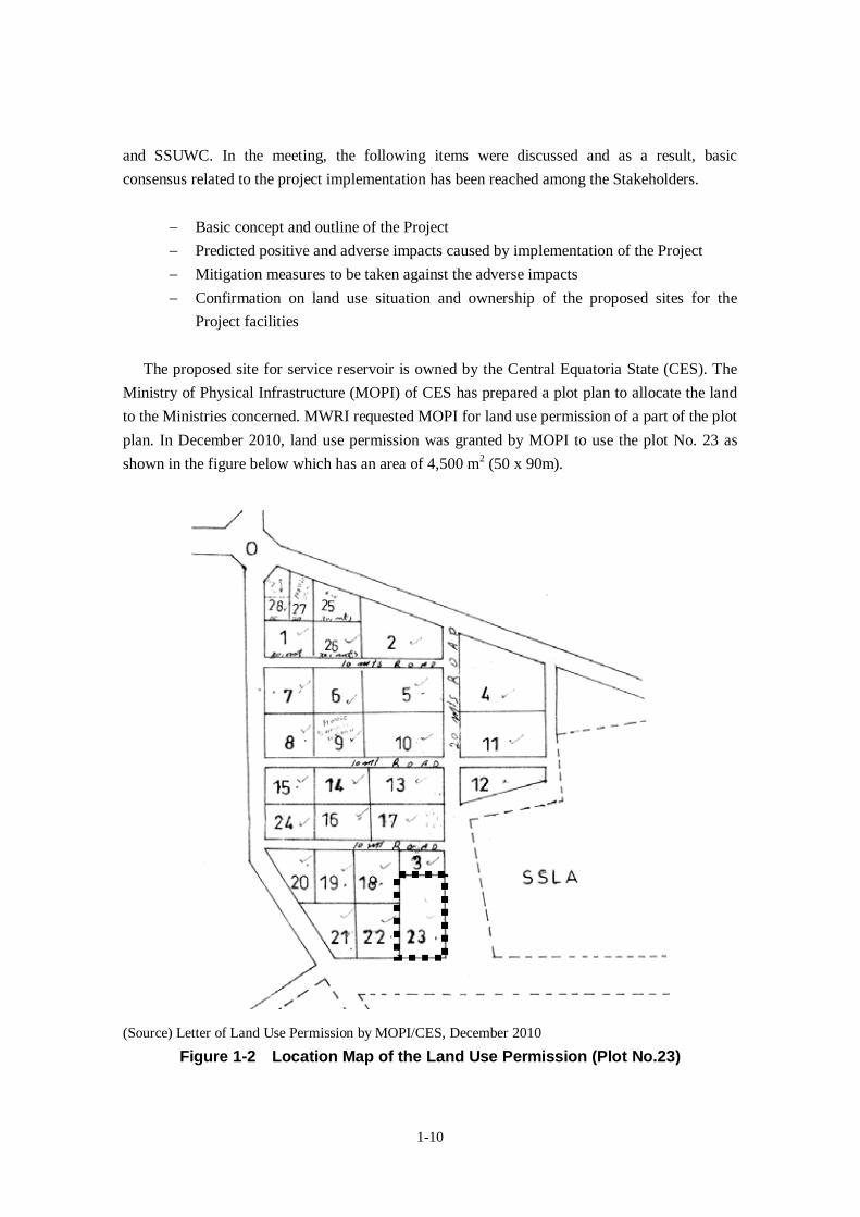
The proposed site for service reservoir is owned by the Central Equatoria State (CES). The
Ministry of Physical Infrastructure (MOPI) of CES has prepared a plot plan to allocate the land
to the Ministries concerned. MWRI requested MOPI for land use permission of a part of the plot
plan. In December 2010, land use permission was granted by MOPI to use the plot No. 23 as
shown in the figure below which has an area of 4,500 m2 (50 x 90m).
(Source) Letter of Land Use Permission by MOPI/CES, December 2010
Figure 1-2 Location Map of the Land Use Permission (Plot No.23)

CHAPTER 2 CONTENTS OF THE PROJECT

2-1
Chapter 2 Contents of the Project
2-1 Basic Concept of the Project
2-1-1 Outline of the Project
(1) Overall Goal and Project Objective
The Government of Southern Sudan formulated “Water Policy, 2007” as the national supreme
plan in water sector in which the primary objective is to provide safe, affordable and reliable
urban water and sanitation services to the urban population on an equitable basis, including poor
and vulnerable groups. This Project is requested based on the water supply master plan which
was formulated through the technical assistance by the Japanese Government. The target of the
master plan is to provide safe and clean water supply to all Juba citizens by year 2025.
The overall goal of the Project is to improve living environment of the Project area through
improvement of water supply service of Juba. And therefore, implementation of this Project
contributes to promotion of the supreme plan of “Water Policy”. The project objective is to
enable residents of Juba who have no access to safe water to access to treated water through
public tap stands and water tankers, by means of increasing drinking water supply capacity.
2-1-2 Outline of the Project
In order to achieve the project objective, water supply facilities will be constructed. As the
outputs of the project activities, the water production capacity will be augmented and water
transmission and distribution facilities will be constructed. The facilities to be constructed under
the Japan’s Grant Aid include water treatment plant, service reservoir, transmission/ distribution
facilities, public tap stands and water tanker filling stations. The outline of the Project is
summarized in the Project Design Matrix as shown in Table 2-1.
2-2
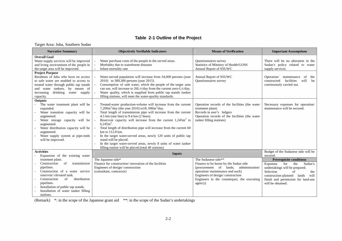
Table 2-1 Outline of the ProjectTarget Area: Juba, Southern Sudan
Narrative Summary Objectively Verifiable Indicators Means of Verification Important Assumptions
Overall GoalWater-supply services will be improvedand living environment of the people inthe target area will be improved.
- Water purchase costs of the people in the served areas.- Morbidity due to waterborne diseases- Infant mortality rate
Questionnaires surveyStatistics of Ministry of Health/GOSSAnnual Report of SSUWC
There will be no alteration in theSudan’s policy related to watersupply services.
Project PurposeResidents of Juba who have no accessto safe water are enabled to access totreated water through public tap standsand water tankers, by means ofincreasing drinking water supplycapacity.
- Water-served population will increase from 34,000 persons (year2010) to 389,300 persons (year 2015)
- Consumption of safe water, which the people of the target areacan use, will increase to 26L/c/day from the current zero-L/c/day.
- Water quality, which is supplied from public tap stands /tankerfilling stations, will meet the water-quality standards.
Annual Report of SSUWCQuestionnaires survey
Operation/ maintenance of theconstructed facilities will becontinuously carried out.
Outputs- The water treatment plant will be
expanded.- Water transition capacity will be
augmented.- Water storage capacity will be
augmented.- Water distribution capacity will be
augmented.- Water supply system at pipe-ends
will be improved.
- Treated-water production-volume will increase from the current7,200m3/day (the year 2010) to18, 000m3/day.
- Total length of transmission pipe will increase from the current4.5 km (one line) to 9.4 km (2 lines).
- Reservoir capacity will increase from the current 1,245m3 to6,245m3.
- Total length of distribution pipe will increase from the current 60km to 112.8 km.
- In the target water-served areas, newly 120 units of public tapstand will be placed.
- In the target water-served areas, newly 8 units of water tankerfilling station will be placed.(total 40 stations)
Operation records of the facilities (the watertreatment plant)Records in user’s ledgersOperation records of the facilities (the watertanker filling stations)
Necessary expenses for operation/maintenance will be secured.
InputsBudget of the Sudanese side will besecured.
Prerequisite conditions
Activities- Expansion of the existing water
treatment plant.- Construction of transmission
pipelines.- Construction of a water service
reservoir/ elevated tank.- Construction of distribution
pipelines.- Installation of public tap stands.- Installation of water tanker filling
stations.
The Japanese side*Finance for construction/ renovation of the facilitiesEngineers of design/ construction(consultant, contractor)
The Sudanese side**Finance to be borne by the Sudan side(procurement of lands, administration/operation/ maintenance and such)Engineers of design/ constructionEngineers in the counterpart, the executingagency)
Expenses for the Sudan’sundertakings will be prepared.Selection of theconstruction-planned lands willfinish and permission for land-usewill be obtained.
(Remark) *: in the scope of the Japanese grant aid **: in the scope of the Sudan’s undertakings
2-3
2-2 Outline Design of the Japanese Assistance
2-2-3 Design Policy
(1) Basic Policy
Priority of the Project is given to provide treated safe water to wider areas in order to
contribute to water supply facility development plan by GOSS, which aims to improve water
supply situation of Juba. Given this, the basic policy of the Project is set to maximize the
number of beneficiaries by means of public tap stands and water tankers instead of individual
house connection. In the Project, only domestic water demand is considered but non-domestic
water demand is not included.
The population served of the Project is set to be 355,300 as planned in the Water Supply
Master Plan formulated in the JICA Development Study (2009), in which the number of
population having access to clean water through public tap stands and water tankers in year
2015 are estimated.
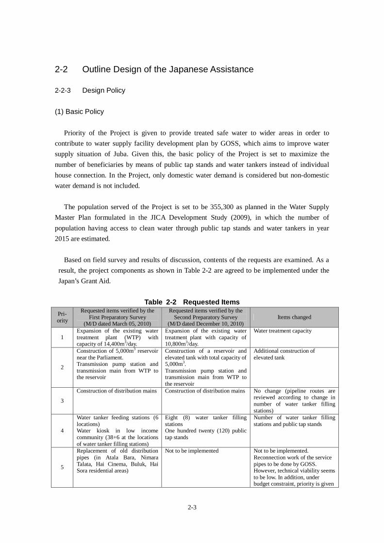
Based on field survey and results of discussion, contents of the requests are examined. As a
result, the project components as shown in Table 2-2 are agreed to be implemented under the
Japan’s Grant Aid.
Table 2-2 Requested ItemsPri-ority
Requested items verified by theFirst Preparatory Survey
(M/D dated March 05, 2010)
Requested items verified by theSecond Preparatory Survey
(M/D dated December 10, 2010)Items changed
1Expansion of the existing watertreatment plant (WTP) withcapacity of 14,400m3/day.
Expansion of the existing watertreatment plant with capacity of10,800m3/day.
Water treatment capacity
2
Construction of 5,000m3 reservoirnear the Parliament.Transmission pump station andtransmission main from WTP tothe reservoir
Construction of a reservoir andelevated tank with total capacity of5,000m3.Transmission pump station andtransmission main from WTP tothe reservoir
Additional construction ofelevated tank
3
Construction of distribution mains Construction of distribution mains No change (pipeline routes arereviewed according to change innumber of water tanker fillingstations)
4
Water tanker feeding stations (6locations)Water kiosk in low incomecommunity (38+6 at the locationsof water tanker filling stations)
Eight (8) water tanker fillingstationsOne hundred twenty (120) publictap stands
Number of water tanker fillingstations and public tap stands
5
Replacement of old distributionpipes (in Atala Bara, NimaraTalata, Hai Cinema, Buluk, HaiSora residential areas)
Not to be implemented Not to be implemented.Reconnection work of the servicepipes to be done by GOSS.However, technical viability seemsto be low. In addition, underbudget constraint, priority is given
2-4
Pri-ority
Requested items verified by theFirst Preparatory Survey
(M/D dated March 05, 2010)
Requested items verified by theSecond Preparatory Survey
(M/D dated December 10, 2010)Items changed
to maximize beneficiary byconstructing new public tap standsand tanker filling stations.
6Water quality testing laboratory No procurement in the Project Not to be procured in the Project.
This will be considered in theTechnical Cooperation Project.
7
Water tankers for low incomepeople in remote areas
No procurement in the Project Not to be procured in the Project.Currently a lot of private watervenders are engaged. Necessity ofoperating tankers by SSUWCseems low.
8Workshop for repairs No procurement in the Project Not to be procured in the Project.
To be examined in the TechnicalCooperation Project.
(2) Policy to Natural Environmental Conditions
- Juba is located in the area belonging to tropical zone, and has a mild climate all the year
around and comprises both rainy season and dry season. The rainfall lasts usually for 2 hours.
Due to heavy rainfall over a short period of time, there is fear that excavated areas for pipe
laying work are quickly flooded and, therefore, backfilled materials are washed away or
floating up of pipe materials may occur. Therefore, pipe laying work should be planned such
that after excavation, both piping work as well as backfilling work could finish within the
day.
- Monthly temperature of 2006 shows that the yearly average highest temperature is 34°C and
a yearly average lowest temperature is 21.6°C. Temperature difference is caused by high
temperature in the daytime and low temperature at night. In consideration of high
temperature, especially, concrete-casting/ concrete-curing work in hot weather should be
carefully controlled. Aggregates should be stocked so as to hold concrete’s temperature as
low as possible at the time of concrete mixing.
- The target service area of water supply is situated at the altitude ranging +455m to +510m
and in a terrain sloping gently in the direction of east-west. Water distribution can be feasible
to those areas as one whole water-served-area, by a flow method of natural gravity from
elevated water-tanks which will be constructed in the proposed reservoir site (altitude
+509m).
- In the northern part of Juba, sedimentary rocks are located over the Proterozoic. In the
neighborhood of Juba also, gneiss of the Proterozoic are located. In the narrow zone along
Bahr el-Jebel River, an alluvium exists. The target areas are located on a hilly terrain. At
some places in the city, bedrocks are cropping out. In pipe-laying work, in particular, cost
reduction should be considered by decreasing volume of rock-excavation work with shallow
depth of pipeline trenches.
- At the site of the proposed water treatment plant, an alluvium layer occurs, and weathered
gneiss exists at a depth of 4m - 6m underground, which will become a supporting layer.
2-5
Taking this situation into consideration, pile foundation structure is employed.
- Soundness of the ground at the service reservoir site is confirmed. Therefore, spread
foundation is employed.
(3) Policy to Socio-Economic Conditions
- Although security situation after CPA seems stable and referendum for independence was
peacefully completed in January 2011, the unrest situation will continue since some
conflicts reportedly still happens after February 2011 near border with North and internal
disturbance, etc. Special attention should be paid to security.
- In the midst of reconstruction after the conflict, in which a lot of projects such as
infrastructure construction projects are being developed, the current social situations are
very changeable. Careful consideration should be given to other construction projects that
are related to the facilities of this Project. Attention should be paid, in particular, to “Urban
Roads Rehabilitation Project in Juba” now under implementation. Almost all distribution
main pipelines will be laid alongside the roads planned in the above-mentioned project. The
pipeline route should be designed on assumption that the road-construction projects would
have been already completed.
- It has been already verified that the sites, which are proposed for public tap stands in this
Project, will be located in the lands of Payam’s administration along public roads. In many
cases, distribution secondary pipelines (pipelines running from diverging points on the
distribution main pipeline to public tap stands) will be laid mostly along unleveled and
unpaved roads. Therefore, there is a possibility that the line/shape of the present roads would
be reviewed in accordance with the road construction scheme in future. In such a case, there
is the possibility also that the distribution secondary pipelines, which are planned in this
Project, would deviate from the roads in the future. In this Project, at the time of detail design,
the road construction scheme of Payam should be examined and re-verified at Payam level.
To overcome this issue, high density polyethylene pipes (HDPE), which are flexible and
adaptable to probable changes in circumstance at the time of pipeline-construction, will be
adopted in case of the distribution secondary pipelines.
(4) Policy to Construction Situation/Procurement Situation
- In Southern Sudan, most industrial products such as constructional materials are imported
from the neighboring countries, Kenya and Uganda. BS (British Standard) is commonly
applied to most of the industrial standards for industrial products. In this Project too,
constructional materials are assumed to be procured from these neighboring countries. In
consideration of ease in quality-control as well as construction-work, BS should be primarily
considered. In cases when any product made under another international standard is used, its
compatibility with BS should be considered.
2-6
- Construction materials procurable at the job-site, are aggregate/ sand/ timber/ gasoline and
so on. All other construction materials (cement/iron bar/steel frame/ plywood/ pipe etc.) need
to be imported from foreign countries. In order to minimize transportation cost and shorten
procurement period, these materials shall be procured from neighboring countries of Kenya
or Uganda. The final decision shall be made after checking the quality and price.
- As most materials are to be imported, the transportation-cost will account for a large part in
procurement-cost. In addition, the procurement period will affect construction period. For
these reasons, method/route/period of transportation should be incorporated accurately into
construction schedule.
(5) Policy to Utilization of Local Contractor (Construction Company and Consultant)
- In Southern Sudan, infrastructure-construction projects, which are assisted mainly by
international donors, are being implemented. The contractors of those projects are
construction companies of Kenya/ Uganda/ the Sudan (i.e. united nation). In most of the
companies working on these projects, engineers and workers of foreign countries (including
the unified Sudan) are used. People of Southern Sudan are engaged in simple works. In this
Project also, the local people are planned to carry out simple works under the supervision
of foremen and technicians from other countries.
- In Southern Sudan, there is no contractor who has experience and capability in civil
engineering and architectural engineering works including waterworks. It could be possible
that a Japanese contractor would utilize such construction companies having employees of
foreign nationality, as its sub-contractors that have experiences and expertise of construction
works in the local conditions similar to Southern Sudan.
(6) Policy to Management/Maintenance
- Management/maintenance of waterworks will be carried out by SSUWC. As SSUWC’s
competence for operational management/financial management is generally low, in addition
to this Project’s implementation, Technical Cooperation Project by JICA is under
implementation. It is expected that on completion of the Technical Cooperation Project,
there would not be problems in maintenance of the facilities, because under the said Project
SSUWC will be supported for reinforcing its capability of operation and its water-charge
collection system, and will be supported for establishing an organization to manage the
public tap stands/water tanker filling stations, by the time of completion of this Project’s
facilities.
- At public tap stands, caretakers need to be always stationed to collect water charges. Both for
the sake of sun-shade/rain-shelter for the managers and for the purpose of preventing illegal
use when the caretaker is away, a shed-like house (kiosk) should be designed, which can
store water-meters, water-valves and record-books of water charges.
2-7
- At the water tanker filling stations too, a shed-like house should be constructed similarly as
in the case of the public tap stands, because caretakers will be stationed at all times to collect
water charges.
(7) Policy to Grade of Facilities and Equipment
- Since there is no design standard related to water supply facility in Sudan, those of donor
countries are applied in the past aid projects. “Design Guideline for Water Supply Facility
of Japan (2000)” is applied in facility design in the Project.
- For water quality standards, the Draft Drinking Water Quality Standard to be adopted in
Southern Sudan is applied.
- The water treatment plant, which will be constructed in this Project, will adopt the same
treatment method, in principle, as in the existing one. In operational process, there should be
consistency in maintenance technologies with the existing one.
- Control of pumps and machines should be by on-site operation only, similarly as in case of
the existing facilities. Operation of valves also should be by manual method, similar to the
existing facilities.
- As electricity-supply is very unstable, an emergency electricity-generator should be installed
at the water treatment plant and the service reservoir, respectively.
- In consideration of the policy that pipeline laying work should be of shallow laying method,
and in consideration of the situation that many pipelines would be laid in unpaved roads, the
ductile iron pipes (diameter 250mm or more) which have higher durability and ductility and
high density polyethylene pipes (diameter 200mm or less) which have greater flexibility
should be adopted.
(8) Policy to Construction Method/Procurement Method and Construction Period
- The implementation schedule of this Project depends on the assumption that the
Government’s Bond of Japan Type-B will be applied. Approximately, a period of 33 months
are expected from Detail Design to the Project’s completion (Detail Design: 8 months,
Construction: 25 months).
- For the facilities in the water treatment plant (sedimentation tank, filtration basin, clear water
reservoir), the service reservoir and the elevated tank and others, strictly water-tight concrete
structure is required. For this reason, construction management and quality-control should be
carefully scheduled in each process of concrete-work from compounding, mixing, conveying,
casting to curing.
- In planning construction processes, the procurement-period of construction machines and
materials should be taken into account. Main construction works includes treatment plant,
service reservoir and pipelines. Eight squads for construction of pipelines are planned in
order to harmonize with the work progress of the water treatment plant as well as service
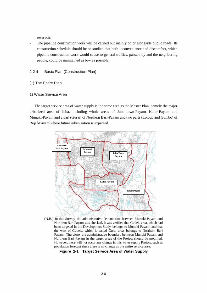
2-8
reservoir.
- The pipeline construction work will be carried out mainly on or alongside public roads. Its
construction-schedule should be so studied that both inconvenience and discomfort, which
pipeline construction work would cause to general traffics, passers-by and the neighboring
people, could be maintained as low as possible.
2-2-4 Basic Plan (Construction Plan)
(1) The Entire Plan
1) Water Service Area
The target service area of water supply is the same area as the Master Plan, namely the major
urbanized area of Juba, including whole areas of Juba town-Payam, Kator-Payam and
Munuki-Payam and a part (Gurai) of Northern Bari-Payam and two parts (Lologo and Gumbo) of
Rejaf-Payam where future urbanization is expected.
(N.B.) In this Survey, the administrative demarcation between Munuki Payam andNorthern Bari Payam was checked. It was verified that Gudele area, which hadbeen targeted in the Development Study, belongs to Munuki Payam, and thatthe west of Gudele, which is called Gurai area, belongs to Northern BariPayam. Therefore, the administrative boundary between Munuki Payam andNorthern Bari Payam in the target areas of the Project should be modified.However, there will not occur any change in this water supply Project, such aspopulation forecast since there is no change as the entire service area.
Figure 2-1 Target Service Area of Water Supply
Rejaf Payam
Kator Payam
Juba TownPayam
MunukiPayam
NorthernBari Payam
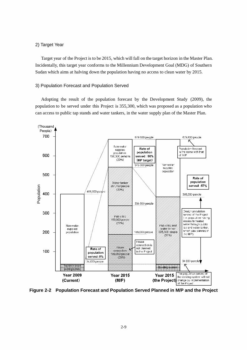
2-9
2) Target Year
Target year of the Project is to be 2015, which will fall on the target horizon in the Master Plan.
Incidentally, this target year conforms to the Millennium Development Goal (MDG) of Southern
Sudan which aims at halving down the population having no access to clean water by 2015.
3) Population Forecast and Population Served
Adopting the result of the population forecast by the Development Study (2009), the
population to be served under this Project is 355,300, which was proposed as a population who
can access to public tap stands and water tankers, in the water supply plan of the Master Plan.
Pop
ulat
ion
Figure 2-2 Population Forecast and Population Served Planned in M/P and the Project
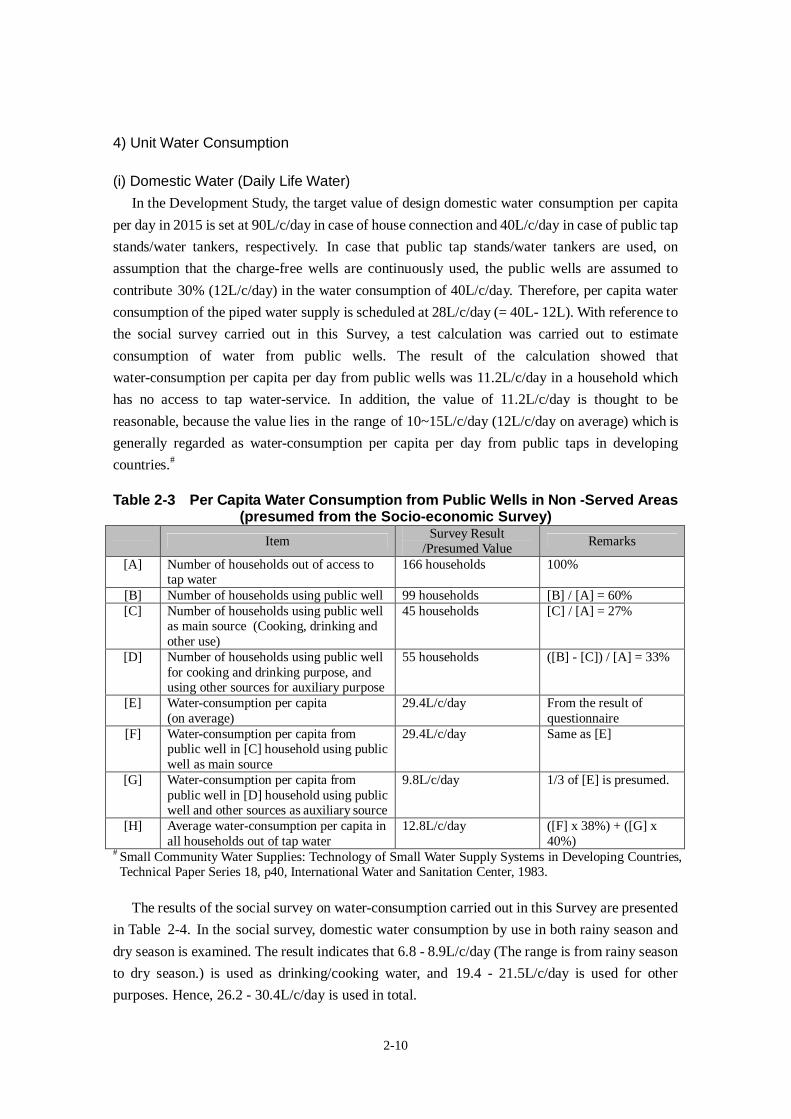
2-10
4) Unit Water Consumption
(i) Domestic Water (Daily Life Water)In the Development Study, the target value of design domestic water consumption per capita
per day in 2015 is set at 90L/c/day in case of house connection and 40L/c/day in case of public tap
stands/water tankers, respectively. In case that public tap stands/water tankers are used, on
assumption that the charge-free wells are continuously used, the public wells are assumed to
contribute 30% (12L/c/day) in the water consumption of 40L/c/day. Therefore, per capita water
consumption of the piped water supply is scheduled at 28L/c/day (= 40L- 12L). With reference to
the social survey carried out in this Survey, a test calculation was carried out to estimate
consumption of water from public wells. The result of the calculation showed that
water-consumption per capita per day from public wells was 11.2L/c/day in a household which
has no access to tap water-service. In addition, the value of 11.2L/c/day is thought to be
reasonable, because the value lies in the range of 10~15L/c/day (12L/c/day on average) which is
generally regarded as water-consumption per capita per day from public taps in developing
countries.#
Table 2-3 Per Capita Water Consumption from Public Wells in Non -Served Areas(presumed from the Socio-economic Survey)
ItemSurvey Result
/Presumed ValueRemarks
[A] Number of households out of access totap water
166 households 100%
[B] Number of households using public well 99 households [B] / [A] = 60%[C] Number of households using public well
as main source (Cooking, drinking andother use)
45 households [C] / [A] = 27%
[D] Number of households using public wellfor cooking and drinking purpose, andusing other sources for auxiliary purpose
55 households ([B] - [C]) / [A] = 33%
[E] Water-consumption per capita(on average)
29.4L/c/day From the result ofquestionnaire
[F] Water-consumption per capita frompublic well in [C] household using publicwell as main source
29.4L/c/day Same as [E]
[G] Water-consumption per capita frompublic well in [D] household using publicwell and other sources as auxiliary source
9.8L/c/day 1/3 of [E] is presumed.
[H] Average water-consumption per capita inall households out of tap water
12.8L/c/day ([F] x 38%) + ([G] x40%)
# Small Community Water Supplies: Technology of Small Water Supply Systems in Developing Countries,Technical Paper Series 18, p40, International Water and Sanitation Center, 1983.
The results of the social survey on water-consumption carried out in this Survey are presented
in Table 2-4. In the social survey, domestic water consumption by use in both rainy season and
dry season is examined. The result indicates that 6.8 - 8.9L/c/day (The range is from rainy season
to dry season.) is used as drinking/cooking water, and 19.4 - 21.5L/c/day is used for other
purposes. Hence, 26.2 - 30.4L/c/day is used in total.
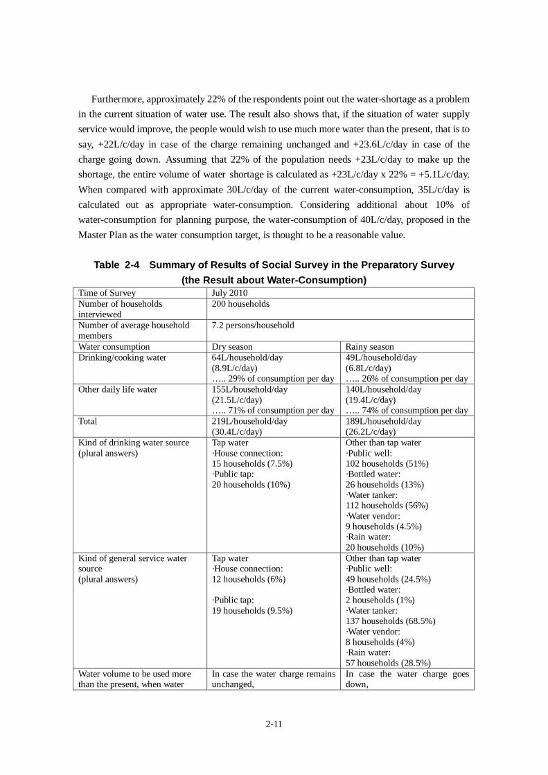
2-11
Furthermore, approximately 22% of the respondents point out the water-shortage as a problem
in the current situation of water use. The result also shows that, if the situation of water supply
service would improve, the people would wish to use much more water than the present, that is to
say, +22L/c/day in case of the charge remaining unchanged and +23.6L/c/day in case of the
charge going down. Assuming that 22% of the population needs +23L/c/day to make up the
shortage, the entire volume of water shortage is calculated as +23L/c/day x 22% = +5.1L/c/day.
When compared with approximate 30L/c/day of the current water-consumption, 35L/c/day is
calculated out as appropriate water-consumption. Considering additional about 10% of
water-consumption for planning purpose, the water-consumption of 40L/c/day, proposed in the
Master Plan as the water consumption target, is thought to be a reasonable value.
Table 2-4 Summary of Results of Social Survey in the Preparatory Survey(the Result about Water-Consumption)
Time of Survey July 2010Number of householdsinterviewed
200 households
Number of average householdmembers
7.2 persons/household
Water consumption Dry season Rainy seasonDrinking/cooking water 64L/household/day
(8.9L/c/day)….. 29% of consumption per day
49L/household/day(6.8L/c/day)….. 26% of consumption per day
Other daily life water 155L/household/day(21.5L/c/day)….. 71% of consumption per day
140L/household/day(19.4L/c/day)….. 74% of consumption per day
Total 219L/household/day(30.4L/c/day)
189L/household/day(26.2L/c/day)
Kind of drinking water source(plural answers)
Tap water·House connection:15 households (7.5%)·Public tap:20 households (10%)
Other than tap water·Public well:102 households (51%)·Bottled water:26 households (13%)·Water tanker:112 households (56%)·Water vendor:9 households (4.5%)·Rain water:20 households (10%)
Kind of general service watersource(plural answers)
Tap water·House connection:12 households (6%)
·Public tap:19 households (9.5%)
Other than tap water·Public well:49 households (24.5%)·Bottled water:2 households (1%)·Water tanker:137 households (68.5%)·Water vendor:8 households (4%)·Rain water:57 households (28.5%)
Water volume to be used morethan the present, when water
In case the water charge remainsunchanged,
In case the water charge goesdown,
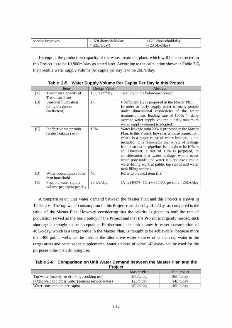
2-12
service improves +159L/household/day(+22L/c/day)
+170L/household/day(+23.6L/c/day)
Hereupon, the production capacity of the water treatment plant, which will be constructed in
this Project, is to be 10,800m3/day as stated later. According to the calculation shown in Table 2-5,
the possible water supply volume per capita per day is to be 26L/c/day.
Table 2-5 Water Supply Volume Per Capita Per Day in this ProjectItem Design Value Abstract
[A] Treatment Capacity ofTreatment Plant
10,800m3/day To study in the below-mentioned
[B] Seasonal fluctuation(daily maximumcoefficient)
1.0 Coefficient 1.2 is proposed in the Master Plan.In order to fairly supply water to many peopleunder dimensional restrictions of the watertreatment plant, loading rate of 100% (= dailyaverage water supply volume ÷ daily maximumwater supply volume) is adopted.
[C] Ineffective water ratio(water leakage ratio)
15% Water leakage ratio 20% is proposed in the MasterPlan. In this Project, however, a house connection,which is a major cause of water leakage, is notincluded. It is reasonable that a rate of leakagefrom distribution pipelines is thought to be 10% orso. However, a rate of 15% is proposed, inconsideration that water leakage would occurwhen poly-tanks and water tankers take turns inwater-filling work at public tap stands and watertank filling stations.
[D] Water consumption otherthan household
Nil Refer to the next item (ii).
[E] Possible water supplyvolume per capita per day
26 L/c/day [A] x (100% - [C]) ÷ 355,300 persons = 26L/c/day
A comparison on unit water demand between the Master Plan and this Project is shown in
Table 2-6. The tap water consumption in this Project runs short by 2L/c/day, as compared to the
value of the Master Plan. However, considering that the priority is given to both the rate of
population served as the basic policy of the Project and that the Project is urgently needed, such
shortage is thought to be acceptable. Furthermore, the unit domestic water consumption of
40L/c/day, which is a target value in the Master Plan, is thought to be achievable, because more
than 400 public wells can be used as the alternative water sources other than tap water in the
target areas and because the supplemental water sources of some 14L/c/day can be used for the
purposes other than drinking use.
Table 2-6 Comparison on Unit Water Demand between the Master Plan and theProject
Master Plan The ProjectTap water (mainly for drinking /cooking use) 28L/c/day 26L/c/dayPublic well and other water (general service water) 12L/c/day 14L/c/dayWater consumption per capita 40L/c/day 40L/c/day
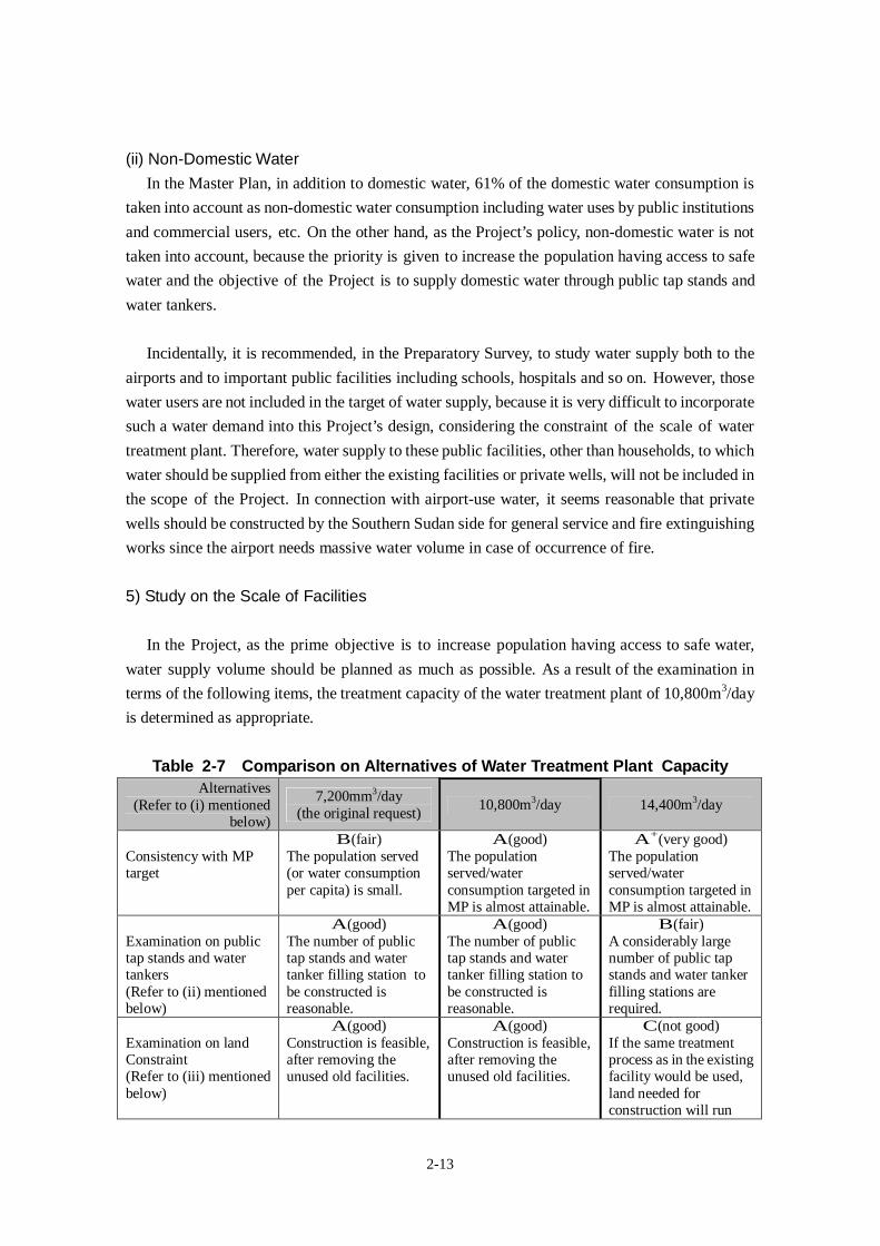
2-13
(ii) Non-Domestic WaterIn the Master Plan, in addition to domestic water, 61% of the domestic water consumption is
taken into account as non-domestic water consumption including water uses by public institutions
and commercial users, etc. On the other hand, as the Project’s policy, non-domestic water is not
taken into account, because the priority is given to increase the population having access to safe
water and the objective of the Project is to supply domestic water through public tap stands and
water tankers.
Incidentally, it is recommended, in the Preparatory Survey, to study water supply both to the
airports and to important public facilities including schools, hospitals and so on. However, those
water users are not included in the target of water supply, because it is very difficult to incorporate
such a water demand into this Project’s design, considering the constraint of the scale of water
treatment plant. Therefore, water supply to these public facilities, other than households, to which
water should be supplied from either the existing facilities or private wells, will not be included in
the scope of the Project. In connection with airport-use water, it seems reasonable that private
wells should be constructed by the Southern Sudan side for general service and fire extinguishing
works since the airport needs massive water volume in case of occurrence of fire.
5) Study on the Scale of Facilities
In the Project, as the prime objective is to increase population having access to safe water,
water supply volume should be planned as much as possible. As a result of the examination in
terms of the following items, the treatment capacity of the water treatment plant of 10,800m3/day
is determined as appropriate.
Table 2-7 Comparison on Alternatives of Water Treatment Plant CapacityAlternatives
(Refer to (i) mentionedbelow)
7,200mm3/day(the original request)
10,800m3/day 14,400m3/day
Consistency with MPtarget
B(fair)The population served(or water consumptionper capita) is small.
A(good)The populationserved/waterconsumption targeted inMP is almost attainable.
A+(very good)The populationserved/waterconsumption targeted inMP is almost attainable.
Examination on publictap stands and watertankers(Refer to (ii) mentionedbelow)
A(good)The number of publictap stands and watertanker filling station tobe constructed isreasonable.
A(good)The number of publictap stands and watertanker filling station tobe constructed isreasonable.
B(fair)A considerably largenumber of public tapstands and water tankerfilling stations arerequired.
Examination on landConstraint(Refer to (iii) mentionedbelow)
A(good)Construction is feasible,after removing theunused old facilities.
A(good)Construction is feasible,after removing theunused old facilities.
C(not good)If the same treatmentprocess as in the existingfacility would be used,land needed forconstruction will run
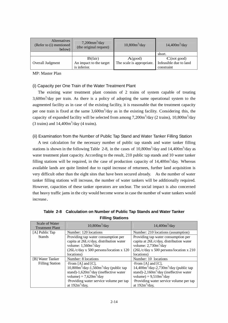
2-14
Alternatives(Refer to (i) mentioned
below)
7,200mm3/day(the original request)
10,800m3/day 14,400m3/day
short.
Overall JudgmentB(fair)
An impact to the targetis inferior.
A(good)The scale is appropriate.
C(not good)Infeasible due to landconstraint
MP: Master Plan
(i) Capacity per One Train of the Water Treatment PlantThe existing water treatment plant consists of 2 trains of system capable of treating
3,600m3/day per train. As there is a policy of adopting the same operational system to the
augmented facility as in case of the existing facility, it is reasonable that the treatment capacity
per one train is fixed at the same 3,600m3/day as in the existing facility. Considering this, the
capacity of expanded facility will be selected from among 7,200m3/day (2 trains), 10,800m3/day
(3 trains) and 14,400m3/day (4 trains).
(ii) Examination from the Number of Public Tap Stand and Water Tanker Filling StationA test calculation for the necessary number of public tap stands and water tanker filling
stations is shown in the following Table 2-8, in the cases of 10,800m3/day and 14,400m3/day as
water treatment plant capacity. According to the result, 210 public tap stands and 10 water tanker
filling stations will be required, in the case of production capacity of 14,400m3/day. Whereas
available lands are quite limited due to rapid increase of returnees, further land acquisition is
very difficult other than the eight sites that have been secured already. As the number of water
tanker filling stations will increase, the number of water tankers will be additionally required.
However, capacities of these tanker operators are unclear. The social impact is also concerned
that heavy traffic jams in the city would become worse in case the number of water tankers would
increase.
Table 2-8 Calculation on Number of Public Tap Stands and Water TankerFilling Stations
Scale of WaterTreatment Plant
10,800m3/day 14,400m3/day
Number: 120 locations Number: 210 locations (assumption)[A] Public TapStands Providing tap water consumption per
capita at 26L/c/day, distribution watervolume: 1,560m3/day(26L/c/day x 500 persons/location x 120locations)
Providing tap water consumption percapita at 26L/c/day, distribution watervolume: 2,730m3/day(26L/c/day x 500 persons/location x 210locations)
Number: 8 locations Number: 10 locations[B] Water TankerFilling Station ·From [A] and [C],
10,800m3/day-1,560m3/day (public tapstand)-1,620m3/day (ineffective watervolume) = 7,620m3/day·Providing water service volume per tapat 192m3/day,
·From [A] and [C],14,400m3/day-2,730m3/day (public tapstand)-2,160m3/day (ineffective watervolume) = 9,510m3/day·Providing water service volume per tapat 192m3/day,
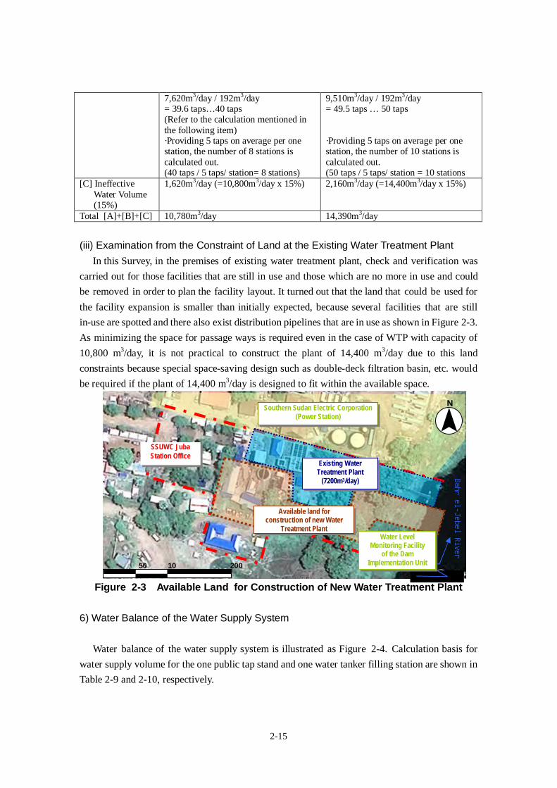
2-15
7,620m3/day / 192m3/day= 39.6 taps…40 taps(Refer to the calculation mentioned inthe following item)·Providing 5 taps on average per onestation, the number of 8 stations iscalculated out.(40 taps / 5 taps/ station= 8 stations)
9,510m3/day / 192m3/day= 49.5 taps … 50 taps
·Providing 5 taps on average per onestation, the number of 10 stations iscalculated out.(50 taps / 5 taps/ station = 10 stations
[C] IneffectiveWater Volume(15%)
1,620m3/day (=10,800m3/day x 15%) 2,160m3/day (=14,400m3/day x 15%)
Total [A]+[B]+[C] 10,780m3/day 14,390m3/day
(iii) Examination from the Constraint of Land at the Existing Water Treatment PlantIn this Survey, in the premises of existing water treatment plant, check and verification was
carried out for those facilities that are still in use and those which are no more in use and could
be removed in order to plan the facility layout. It turned out that the land that could be used for
the facility expansion is smaller than initially expected, because several facilities that are still
in-use are spotted and there also exist distribution pipelines that are in use as shown in Figure 2-3.
As minimizing the space for passage ways is required even in the case of WTP with capacity of
10,800 m3/day, it is not practical to construct the plant of 14,400 m3/day due to this land
constraints because special space-saving design such as double-deck filtration basin, etc. would
be required if the plant of 14,400 m3/day is designed to fit within the available space.
Figure 2-3 Available Land for Construction of New Water Treatment Plant
6) Water Balance of the Water Supply System
Water balance of the water supply system is illustrated as Figure 2-4. Calculation basis for
water supply volume for the one public tap stand and one water tanker filling station are shown in
Table 2-9 and 2-10, respectively.
50 10 200
Southern Sudan Electric Corporation(Power Station)
Available land forconstruction of new Water
Treatment Plant
SSUWC JubaStation Office
N
Bahrel-JebelRiver
Water LevelMonitoring Facility
of the DamImplementation Unit
Existing WaterTreatment Plant
(7200m3/day)
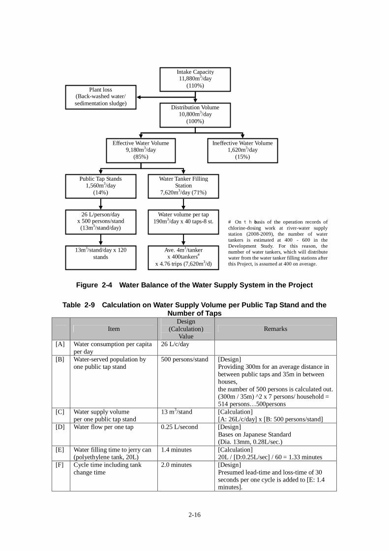
2-16
Figure 2-4 Water Balance of the Water Supply System in the Project
Table 2-9 Calculation on Water Supply Volume per Public Tap Stand and theNumber of Taps
ItemDesign
(Calculation)Value
Remarks
[A] Water consumption per capitaper day
26 L/c/day
[B] Water-served population byone public tap stand
500 persons/stand [Design]Providing 300m for an average distance inbetween public taps and 35m in betweenhouses,the number of 500 persons is calculated out.(300m / 35m) ^2 x 7 persons/ household =514 persons…500persons
[C] Water supply volumeper one public tap stand
13 m3/stand [Calculation][A: 26L/c/day] x [B: 500 persons/stand]
[D] Water flow per one tap 0.25 L/second [Design]Bases on Japanese Standard(Dia. 13mm, 0.28L/sec.)
[E] Water filling time to jerry can(polyethylene tank, 20L)
1.4 minutes [Calculation]20L / [D:0.25L/sec] / 60 = 1.33 minutes
[F] Cycle time including tankchange time
2.0 minutes [Design]Presumed lead-time and loss-time of 30seconds per one cycle is added to [E: 1.4minutes].
Distribution Volume10,800m3/day
(100%)
Effective Water Volume9,180m3/day
(85%)
Ineffective Water Volume1,620m3/day
(15%)
Public Tap Stands1,560m3/day
(14%)
Water Tanker FillingStation
7,620m3/day (71%)
26 L/person/dayx 500 persons/stand
(13m3/stand/day)
Water volume per tap190m3/day x 40 taps-8 st.
13m3/stand/day x 120stands
Ave. 4m3/tankerx 400tankers#
x 4.76 trips (7,620m3/d)
Intake Capacity11,880m3/day
(110%)Plant loss
(Back-washed water/sedimentation sludge)
# On the basis of the operation records ofchlorine-dosing work at river-water supplystation (2008-2009), the number of watertankers is estimated at 400 - 600 in theDevelopment Study. For this reason, thenumber of water tankers, which will distributewater from the water tanker filling stations afterthis Project, is assumed at 400 on average.
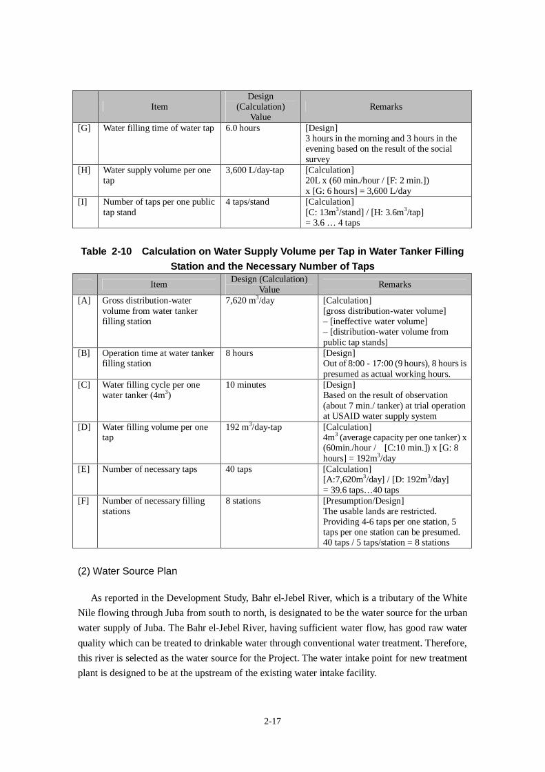
2-17
ItemDesign
(Calculation)Value
Remarks
[G] Water filling time of water tap 6.0 hours [Design]3 hours in the morning and 3 hours in theevening based on the result of the socialsurvey
[H] Water supply volume per onetap
3,600 L/day-tap [Calculation]20L x (60 min./hour / [F: 2 min.])x [G: 6 hours] = 3,600 L/day
[I] Number of taps per one publictap stand
4 taps/stand [Calculation][C: 13m3/stand] / [H: 3.6m3/tap]= 3.6 … 4 taps
Table 2-10 Calculation on Water Supply Volume per Tap in Water Tanker FillingStation and the Necessary Number of Taps
ItemDesign (Calculation)
ValueRemarks
[A] Gross distribution-watervolume from water tankerfilling station
7,620 m3/day [Calculation][gross distribution-water volume]– [ineffective water volume]– [distribution-water volume frompublic tap stands]
[B] Operation time at water tankerfilling station
8 hours [Design]Out of 8:00 - 17:00 (9 hours), 8 hours ispresumed as actual working hours.
[C] Water filling cycle per onewater tanker (4m3)
10 minutes [Design]Based on the result of observation(about 7 min./ tanker) at trial operationat USAID water supply system
[D] Water filling volume per onetap
192 m3/day-tap [Calculation]4m3 (average capacity per one tanker) x(60min./hour / [C:10 min.]) x [G: 8hours] = 192m3/day
[E] Number of necessary taps 40 taps [Calculation][A:7,620m3/day] / [D: 192m3/day]= 39.6 taps…40 taps
[F] Number of necessary fillingstations
8 stations [Presumption/Design]The usable lands are restricted.Providing 4-6 taps per one station, 5taps per one station can be presumed.40 taps / 5 taps/station = 8 stations
(2) Water Source Plan
As reported in the Development Study, Bahr el-Jebel River, which is a tributary of the White
Nile flowing through Juba from south to north, is designated to be the water source for the urban
water supply of Juba. The Bahr el-Jebel River, having sufficient water flow, has good raw water
quality which can be treated to drinkable water through conventional water treatment. Therefore,
this river is selected as the water source for the Project. The water intake point for new treatment
plant is designed to be at the upstream of the existing water intake facility.
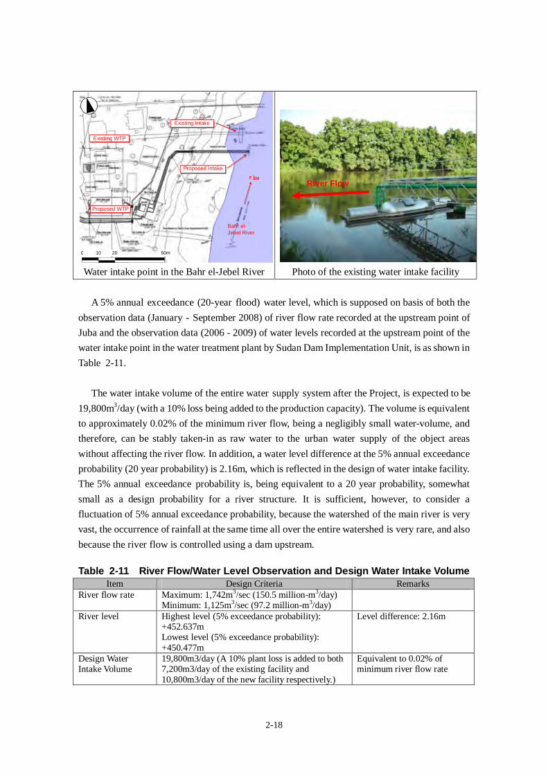
2-18
Proposed Intake
Existing Intake
0 10 20 50m
Flow
Proposed WTP
Existing WTP
Bahr el-Jebel River
Water intake point in the Bahr el-Jebel River Photo of the existing water intake facility
A 5% annual exceedance (20-year flood) water level, which is supposed on basis of both the
observation data (January - September 2008) of river flow rate recorded at the upstream point of
Juba and the observation data (2006 - 2009) of water levels recorded at the upstream point of the
water intake point in the water treatment plant by Sudan Dam Implementation Unit, is as shown in
Table 2-11.
The water intake volume of the entire water supply system after the Project, is expected to be
19,800m3/day (with a 10% loss being added to the production capacity). The volume is equivalent
to approximately 0.02% of the minimum river flow, being a negligibly small water-volume, and
therefore, can be stably taken-in as raw water to the urban water supply of the object areas
without affecting the river flow. In addition, a water level difference at the 5% annual exceedance
probability (20 year probability) is 2.16m, which is reflected in the design of water intake facility.
The 5% annual exceedance probability is, being equivalent to a 20 year probability, somewhat
small as a design probability for a river structure. It is sufficient, however, to consider a
fluctuation of 5% annual exceedance probability, because the watershed of the main river is very
vast, the occurrence of rainfall at the same time all over the entire watershed is very rare, and also
because the river flow is controlled using a dam upstream.
Table 2-11 River Flow/Water Level Observation and Design Water Intake VolumeItem Design Criteria Remarks
River flow rate Maximum: 1,742m3/sec (150.5 million-m3/day)Minimum: 1,125m3/sec (97.2 million-m3/day)
River level Highest level (5% exceedance probability):+452.637mLowest level (5% exceedance probability):+450.477m
Level difference: 2.16m
Design WaterIntake Volume
19,800m3/day (A 10% plant loss is added to both7,200m3/day of the existing facility and10,800m3/day of the new facility respectively.)
Equivalent to 0.02% ofminimum river flow rate
River Flow
2-19
The raw water quality exceeds the values of the water quality standard (the draft drinking
water quality standard in Southern Sudan) in the parameters of turbidity, iron, aluminum and
general bacteria. It was verified, according to the analyses of the treated water quality in the
existing water treatment plant in operation at present that these substances can be treated to level
under the standard value through application of the conventional water treatment methods of
flocculation, sedimentation and rapid filtration. The Development Study concludes that there is
no problem, although antimony was detected at a level somewhat exceeding the standard value.
Based on the re-examination by an authorized laboratory in Japan in the Survey, it was verified
that the river water is non-problematic as water source, since antimony value proved to be below
the detectable limit (0.002mg/L) in both the raw water and the treated water.
(3) Facility Plan
1) The Entire SystemAs the water service area of this Project is the currently non-served areas, all the facilities
which are to be expanded in this Project will be newly constructed. On the other hand, among the
existing water supply system, the main facilities such as treatment plant,
transmission/distribution facilities are now in service since they were rehabilitated by MDTF in
2009. However, most distribution pipelines include the asbestos cement pipes laid in 1970’s
which have never been replaced since they were laid. For this reason, a large ratio of leakage as
much as about 40% is estimated from the aged and decrepit pipelines. In addition, the water
service is very inefficient, because there is a large waste of water owing to a flat-rate tariff system,
and because it is forecasted that there is the non-revenue water ratio of approximately 60%
(assumed by the Development Study) including non-payment. As the current water supply
volume is lacking in capacity compared to the water demand, in case that the newly constructed
facilities are connected with the existing system, the distribution water volume to the people in
non-water-served coverage areas, who are the object in this Project, will diminish. For this reason,
the expanded facilities in this Project are, in principle, to be independent from the existing system.
Consequently, the facilities are to be newly constructed under the Project, except some facilities
in the existing water treatment plant. Water flow system and each facility of this Project are
outlined in Table 2-12 and Figure 2-5. The general layout plan is shown in the following page.
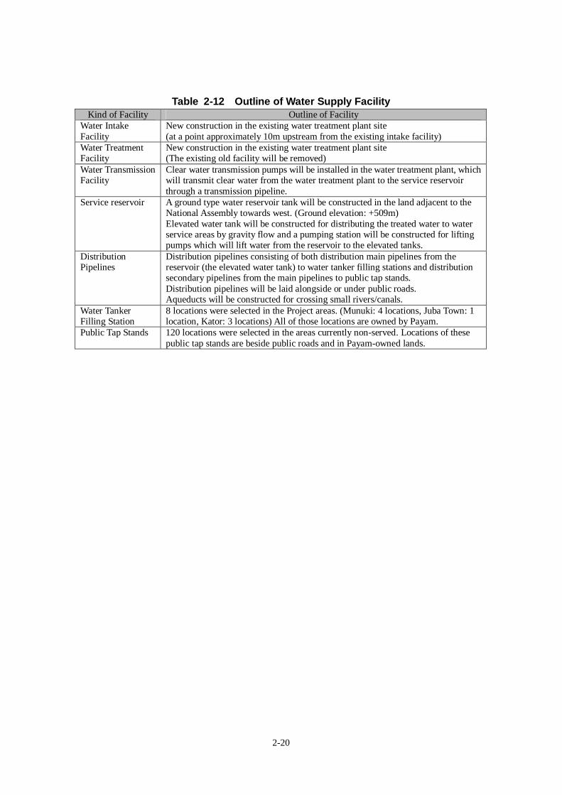
2-20
Table 2-12 Outline of Water Supply FacilityKind of Facility Outline of Facility
Water IntakeFacility
New construction in the existing water treatment plant site(at a point approximately 10m upstream from the existing intake facility)
Water TreatmentFacility
New construction in the existing water treatment plant site(The existing old facility will be removed)
Water TransmissionFacility
Clear water transmission pumps will be installed in the water treatment plant, whichwill transmit clear water from the water treatment plant to the service reservoirthrough a transmission pipeline.
Service reservoir A ground type water reservoir tank will be constructed in the land adjacent to theNational Assembly towards west. (Ground elevation: +509m)Elevated water tank will be constructed for distributing the treated water to waterservice areas by gravity flow and a pumping station will be constructed for liftingpumps which will lift water from the reservoir to the elevated tanks.
DistributionPipelines
Distribution pipelines consisting of both distribution main pipelines from thereservoir (the elevated water tank) to water tanker filling stations and distributionsecondary pipelines from the main pipelines to public tap stands.Distribution pipelines will be laid alongside or under public roads.Aqueducts will be constructed for crossing small rivers/canals.
Water TankerFilling Station
8 locations were selected in the Project areas. (Munuki: 4 locations, Juba Town: 1location, Kator: 3 locations) All of those locations are owned by Payam.
Public Tap Stands 120 locations were selected in the areas currently non-served. Locations of thesepublic tap stands are beside public roads and in Payam-owned lands.
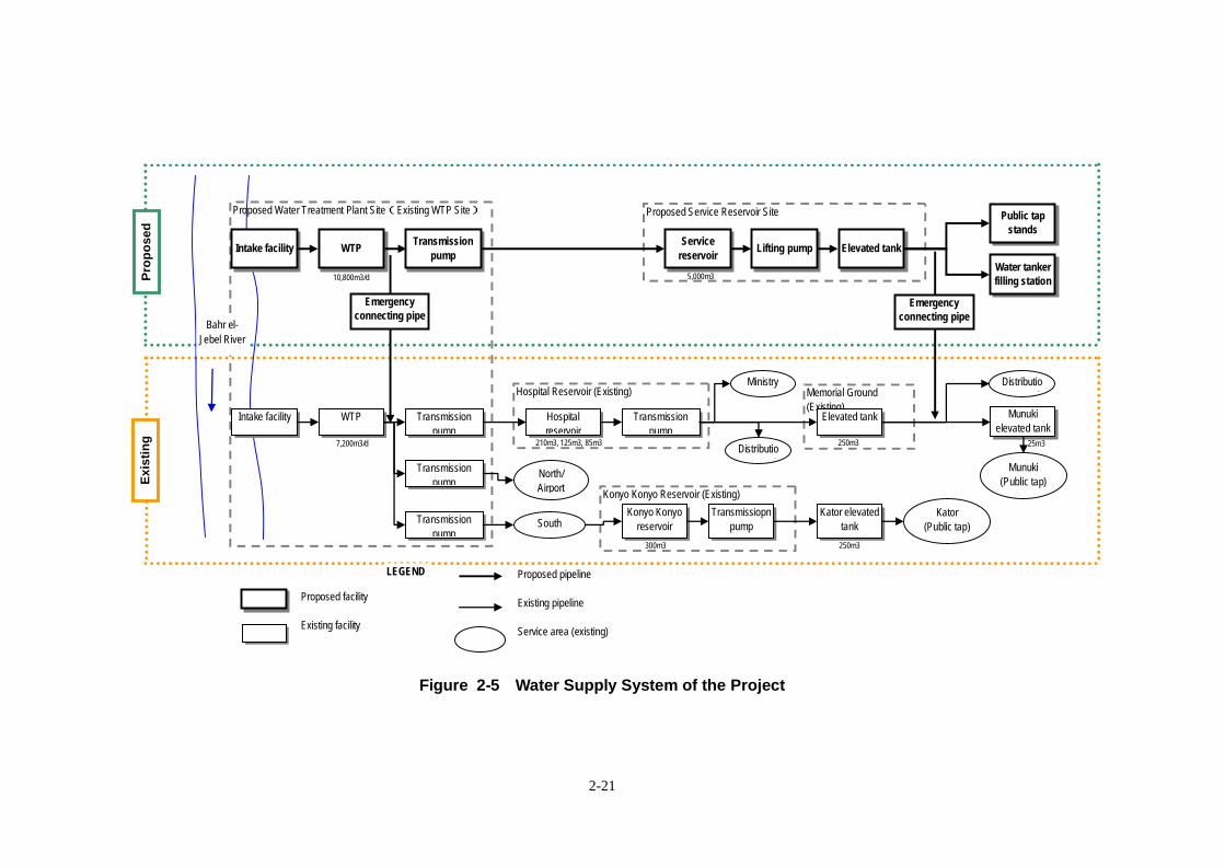
2-21
Exis
ting
Prop
osed
Konyo Konyo Reservoir (Existing)
Proposed Service Reservoir SiteProposed Water Treatment Plant Site(Existing WTP Site)
Memorial Ground
(Existing)
Hospital Reservoir (Existing)
Intake facility WTPTransmission
pump
Service
reservoirLifting pump Elevated tank
Intake facility WTP Transmission
pump
Transmission
pump
Elevated tankHospital
reservoir
Ministry
Distributio
n networkTransmission
pumpNorth/
Airport
Transmission
pumpSouth
Konyo Konyo
reservoir
Transmissiopn
pump
Kator elevated
tank
Kator
(Public tap)
Munuki
elevated tank
Munuki
(Public tap)
Distributio
n network
Water tanker
filling station
Bahr el-
Jebel River
Public tap
stands
Emergency
connecting pipe
Emergency
connecting pipe
Proposed facility
Existing facility
Proposed pipeline
Existing pipeline
Service area (existing)
LEGEND
10,800m3/d
7,200m3/d
5,000m3
210m3, 125m3, 85m3
300m3 250m3
250m3 25m3
Figure 2-5 Water Supply System of the Project
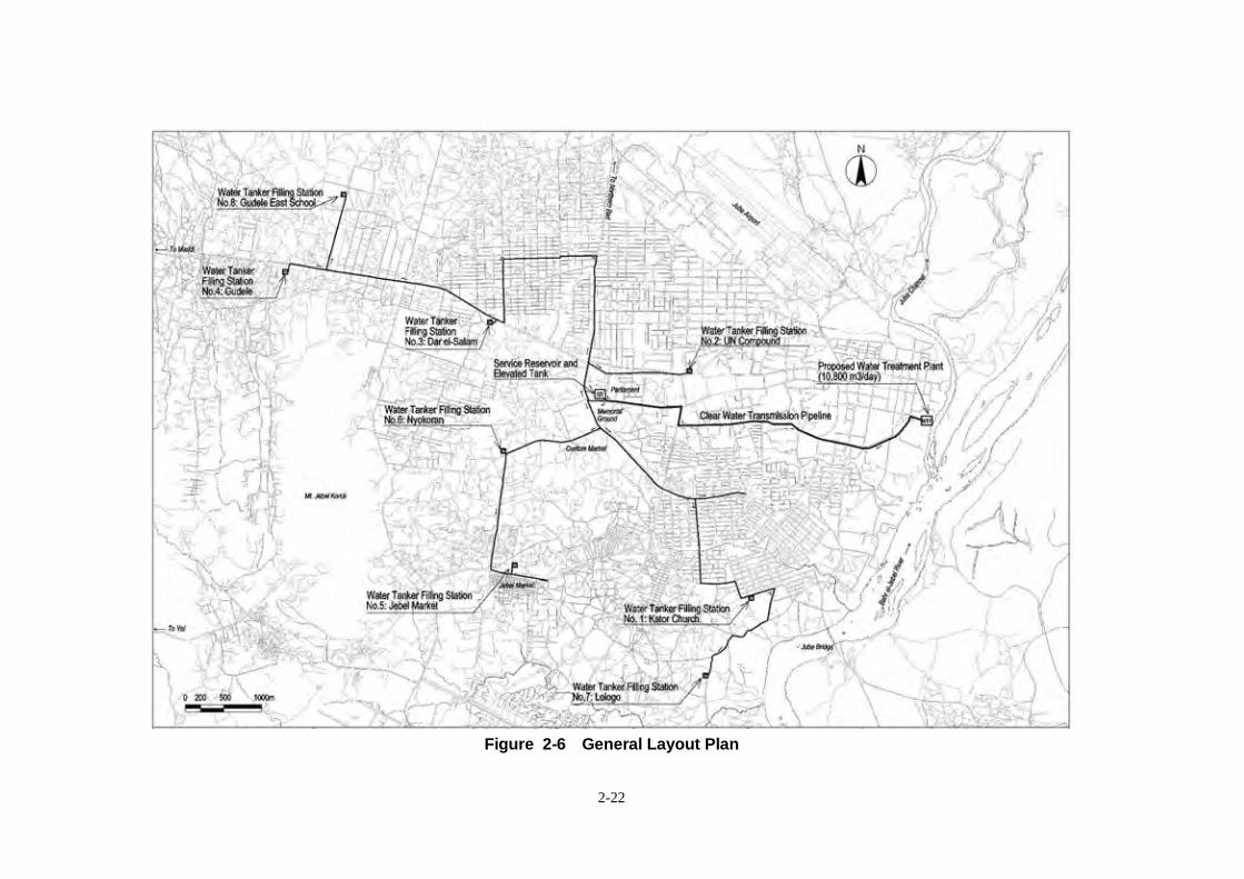
2-22
Figure 2-6 General Layout Plan
2-23
2) Water Intake Facility
(i) Policy to Utilization of the Existing FacilityThe capacity of the existing water intake facility was designed on basis of WTP capacity of
7,200m3/day. The diameter of the pipes in the existing water intake facility is not enough for
carrying new intake capacity. For this reason, a new intake facility will be constructed instead of
utilization of the existing facility.
(ii) Examination on Intake PointThere is a need to select an intake point within the land territory of the existing water treatment
plant (approximately 90m in the direction to the river). For the following reasons, a new water
intake site should be located at a point approximately 10m upstream of the existing water intake
facility:
- On the downstream side of the existing water intake facility, a water intake point is not
suitable, because sludge from the existing sedimentation tank is being discharged.
- On the nearest upstream side of the existing water intake facility, construction of a facility
is very difficult, because there stands a river-level observation facility.
- In the site on the 15m~80m upstream side of the existing water intake facility, there is thick
river sediment. A longer intake-bridge and a longer pipeline, if not constructed nearby the
existing water intake facility, will become un-economical.
(iii) Examination on Intake Method/Intake StructureIntake method is examined through comparison between (A) float method (same as the
existing facility) and (B) fixed pier method. From the results of the natural condition investigation,
the (B) fixed pier method is thought to be advantageous with the view-point of operational
management, because the fluctuation in river-level is as small as 2.2m. However, it is
apprehended that a new water intake point would be fixed on the upstream side of the existing
water intake facility, and an excavation work would heavily affect the existing water intake
facility downstream, and therefore, massive temporary work would be required. Under this
circumstance, the fixed pier method was judged as economically poor option. Consequently, the
(A) float method should be adopted, because this method, being economically advantageous, will
hardly affect the existing water intake facility at the time of the new construction. As water intake
pump, the ground type pump (horizontal centrifugal pump), being easy in maintenance, should be
adopted. In order to keep water on suction-side at the time of pump-stop, a foot-valve should be
installed at the mouth on suction side of the water intake pipe. Furthermore, in the existing water
intake facility, operators stop the pump and dive into water, in order to manually clear the
foot-valve of wooden debris and rubbish. For this reason, in this Project, the water intake pipe
should be provided with circular steel-made screen in order to prevent rubbish from sticking on
the pipe.
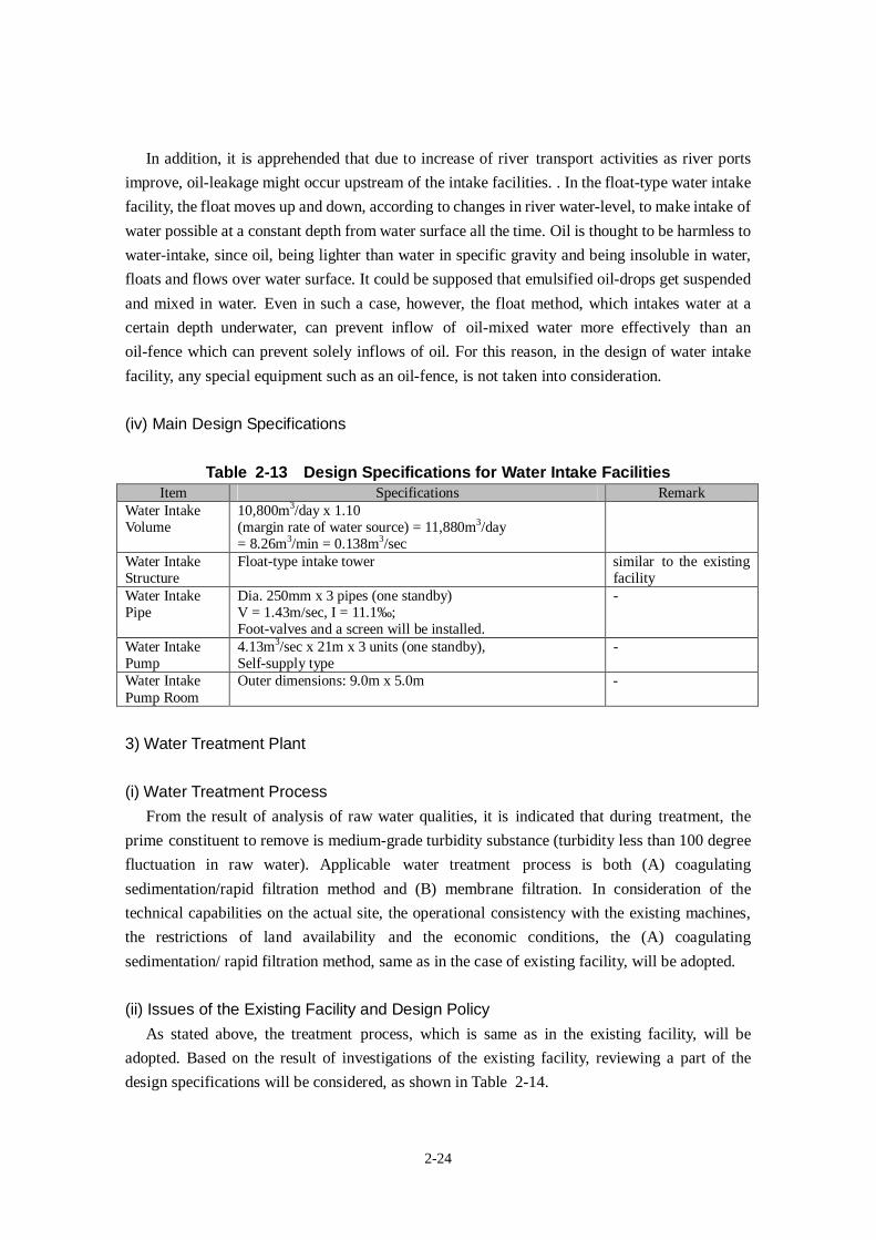
2-24
In addition, it is apprehended that due to increase of river transport activities as river ports
improve, oil-leakage might occur upstream of the intake facilities. . In the float-type water intake
facility, the float moves up and down, according to changes in river water-level, to make intake of
water possible at a constant depth from water surface all the time. Oil is thought to be harmless to
water-intake, since oil, being lighter than water in specific gravity and being insoluble in water,
floats and flows over water surface. It could be supposed that emulsified oil-drops get suspended
and mixed in water. Even in such a case, however, the float method, which intakes water at a
certain depth underwater, can prevent inflow of oil-mixed water more effectively than an
oil-fence which can prevent solely inflows of oil. For this reason, in the design of water intake
facility, any special equipment such as an oil-fence, is not taken into consideration.
(iv) Main Design Specifications
Table 2-13 Design Specifications for Water Intake FacilitiesItem Specifications Remark
Water IntakeVolume
10,800m3/day x 1.10(margin rate of water source) = 11,880m3/day= 8.26m3/min = 0.138m3/sec
Water IntakeStructure
Float-type intake tower similar to the existingfacility
Water IntakePipe
Dia. 250mm x 3 pipes (one standby)V = 1.43m/sec, I = 11.1‰;Foot-valves and a screen will be installed.
-
Water IntakePump
4.13m3/sec x 21m x 3 units (one standby),Self-supply type
-
Water IntakePump Room
Outer dimensions: 9.0m x 5.0m -
3) Water Treatment Plant
(i) Water Treatment ProcessFrom the result of analysis of raw water qualities, it is indicated that during treatment, the
prime constituent to remove is medium-grade turbidity substance (turbidity less than 100 degree
fluctuation in raw water). Applicable water treatment process is both (A) coagulating
sedimentation/rapid filtration method and (B) membrane filtration. In consideration of the
technical capabilities on the actual site, the operational consistency with the existing machines,
the restrictions of land availability and the economic conditions, the (A) coagulating
sedimentation/ rapid filtration method, same as in the case of existing facility, will be adopted.
(ii) Issues of the Existing Facility and Design PolicyAs stated above, the treatment process, which is same as in the existing facility, will be
adopted. Based on the result of investigations of the existing facility, reviewing a part of the
design specifications will be considered, as shown in Table 2-14.
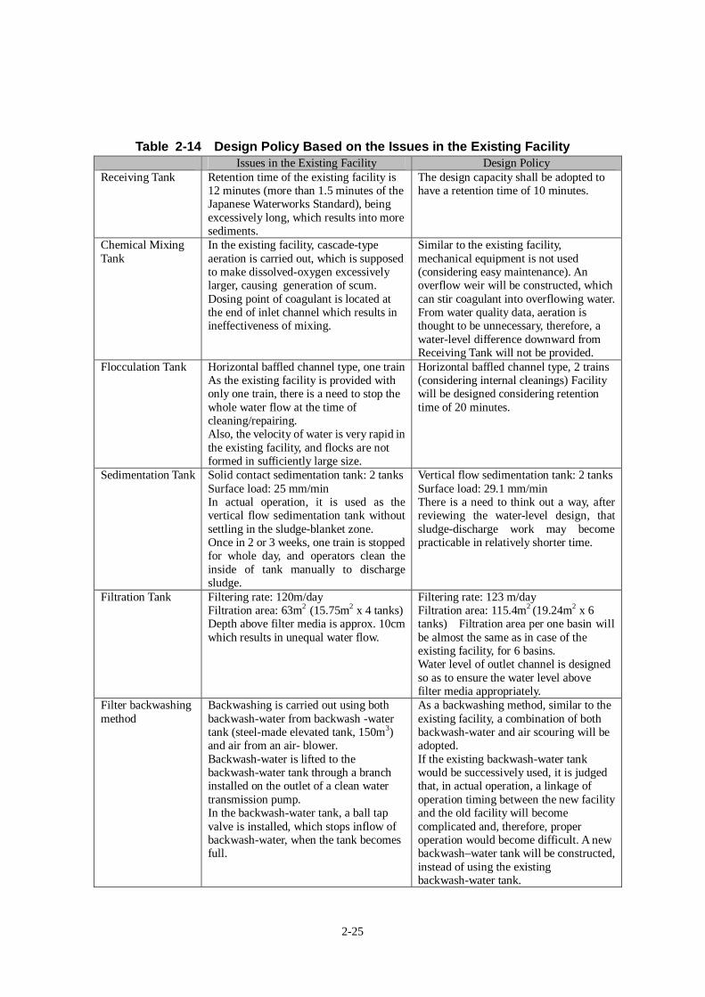
2-25
Table 2-14 Design Policy Based on the Issues in the Existing FacilityIssues in the Existing Facility Design Policy
Receiving Tank Retention time of the existing facility is12 minutes (more than 1.5 minutes of theJapanese Waterworks Standard), beingexcessively long, which results into moresediments.
The design capacity shall be adopted tohave a retention time of 10 minutes.
Chemical MixingTank
In the existing facility, cascade-typeaeration is carried out, which is supposedto make dissolved-oxygen excessivelylarger, causing generation of scum.Dosing point of coagulant is located atthe end of inlet channel which results inineffectiveness of mixing.
Similar to the existing facility,mechanical equipment is not used(considering easy maintenance). Anoverflow weir will be constructed, whichcan stir coagulant into overflowing water.From water quality data, aeration isthought to be unnecessary, therefore, awater-level difference downward fromReceiving Tank will not be provided.
Flocculation Tank Horizontal baffled channel type, one trainAs the existing facility is provided withonly one train, there is a need to stop thewhole water flow at the time ofcleaning/repairing.Also, the velocity of water is very rapid inthe existing facility, and flocks are notformed in sufficiently large size.
Horizontal baffled channel type, 2 trains(considering internal cleanings) Facilitywill be designed considering retentiontime of 20 minutes.
Sedimentation Tank Solid contact sedimentation tank: 2 tanksSurface load: 25 mm/minIn actual operation, it is used as thevertical flow sedimentation tank withoutsettling in the sludge-blanket zone.Once in 2 or 3 weeks, one train is stoppedfor whole day, and operators clean theinside of tank manually to dischargesludge.
Vertical flow sedimentation tank: 2 tanksSurface load: 29.1 mm/minThere is a need to think out a way, afterreviewing the water-level design, thatsludge-discharge work may becomepracticable in relatively shorter time.
Filtration Tank Filtering rate: 120m/dayFiltration area: 63m2 (15.75m2 x 4 tanks)Depth above filter media is approx. 10cmwhich results in unequal water flow.
Filtering rate: 123 m/dayFiltration area: 115.4m2 (19.24m2 x 6tanks) Filtration area per one basin willbe almost the same as in case of theexisting facility, for 6 basins.Water level of outlet channel is designedso as to ensure the water level abovefilter media appropriately.
Filter backwashingmethod
Backwashing is carried out using bothbackwash-water from backwash -watertank (steel-made elevated tank, 150m3)and air from an air- blower.Backwash-water is lifted to thebackwash-water tank through a branchinstalled on the outlet of a clean watertransmission pump.In the backwash-water tank, a ball tapvalve is installed, which stops inflow ofbackwash-water, when the tank becomesfull.
As a backwashing method, similar to theexisting facility, a combination of bothbackwash-water and air scouring will beadopted.If the existing backwash-water tankwould be successively used, it is judgedthat, in actual operation, a linkage ofoperation timing between the new facilityand the old facility will becomecomplicated and, therefore, properoperation would become difficult. A newbackwash–water tank will be constructed,instead of using the existingbackwash-water tank.
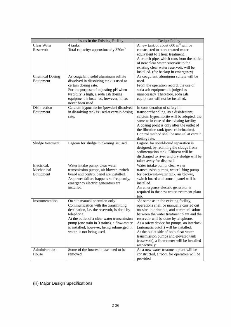
2-26
Issues in the Existing Facility Design PolicyClear WaterReservoir
4 tanks,Total capacity: approximately 370m3
A new tank of about 600 m3 will beconstructed to store treated waterequivalent to 1 hour treatment. .A branch pipe, which runs from the outletof new clear water reservoir to theexisting clear water reservoir, will beinstalled. (for backup in emergency)
Chemical DosingEquipment
As coagulant, solid aluminum sulfatedissolved in dissolving tank is used atcertain dosing rate.For the purpose of adjusting pH whenturbidity is high, a soda ash dosingequipment is installed, however, it hasnever been used.
As coagulant, aluminum sulfate will beused.From the operation record, the use ofsoda ash equipment is judged asunnecessary. Therefore, soda ashequipment will not be installed.
DisinfectionEquipment
Calcium hypochlorite (powder) dissolvedin dissolving tank is used at certain dosingrate.
In consideration of safety intransport/handling, as a disinfectant,calcium hypochlorite will be adopted, thesame as in case of the existing facility.A dosing point is only after the outlet ofthe filtration tank (post-chlorination).Control method shall be manual at certaindosing rate.
Sludge treatment Lagoon for sludge thickening is used. Lagoon for solid-liquid separation isdesigned, by retaining the sludge fromsedimentation tank. Effluent will bedischarged to river and dry sludge will betaken away for disposal.
Electrical,MechanicalEquipment
Water intake pump, clear watertransmission pumps, air blower, switchboard and control panel are installed.As power failure happens so frequently,emergency electric generators areinstalled.
Water intake pump, clear watertransmission pumps, water lifting pumpfor backwash-water tank, air blower,switch board and control panel will beinstalled.An emergency electric generator isrequired in the new water treatment planttoo.
Instrumentation On site manual operation onlyCommunication with the transmittingdestination, i.e. the reservoir, is done bytelephone.At the outlet of a clear water transmissionpump (one train in 3 trains), a flow-meteris installed, however, being submerged inwater, is not being used.
·As same as in the existing facility,operations shall be manually carried outon-site, in principle, and communicationbetween the water treatment plant and thereservoir will be done by telephone.As a safety device for pumps, an interlock(automatic cutoff) will be installed.At the outlet side of both clear watertransmission pumps and elevated tank(reservoir), a flow-meter will be installedrespectively.
AdministrationHouse
Some of the houses in use need to beremoved.
As a new water treatment plant will beconstructed, a room for operators will beprovided
(iii) Major Design Specifications
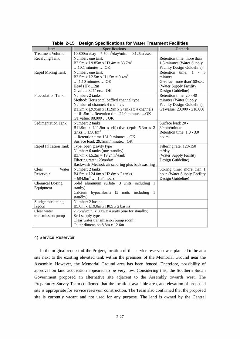
2-27
Table 2-15 Design Specifications for Water Treatment FacilitiesItem Specifications Remark
Treatment Volume 10,800m3/day = 7.50m3/day/min. = 0.125m3/sec.Receiving Tank Number: one tank
B2.5m x L9.85m x H3.4m = 83.7m3
…10.1 minutes … OK
Retention time: more than1.5 minutes (Water SupplyFacility Design Guideline)
Rapid Mixing Tank Number: one tankB2.5m x L2.5m x H1.5m = 9.4m3
… 1.10 minutes … OKHead (H): 1.2mG value: 347/sec… OK
Retention time: 1 - 5minutesG-value: more than150/sec.(Water Supply FacilityDesign Guideline)
Flocculation Tank Number: 2 tanksMethod: Horizontal baffled channel typeNumber of channel: 4 channelsB1.2m x L9.95m x H1.9m x 2 tanks x 4 channels= 181.5m3…Retention time 22.0 minutes….OKGT value: 88,000 … OK
Retention time: 20 - 40minutes (Water SupplyFacility Design Guideline)GT-value: 23,000 - 210,000
Sedimentation Tank Number: 2 tanksB11.9m x L11.9m x effective depth 5.3m x 2tanks… 1,501m3
…Retention time 181.9 minutes…OKSurface load: 29.1mm/minute… OK
Surface load: 20 -30mm/minuteRetention time: 1.0 - 3.0hours
Rapid Filtration Tank Type: open gravity typeNumber: 6 tanks (one standby)B3.7m x L5.2m = 19.24m2/tankFiltering rate: 123m/dayBackwash Method: air scouring plus backwashing
Filtering rate: 120-150m/day(Water Supply FacilityDesign Guideline)
Clear WaterReservoir
Number: 2 tanksB4.5m x L24.0m x H2.8m x 2 tanks= 604.8m3 …. 1.34 hours
Storing time: more than 1hour (Water Supply FacilityDesign Guideline)
Chemical DosingEquipment
Solid aluminum sulfate (3 units including 1stanby)Calcium hypochlorite (3 units including 1standby)
Sludge thickeninglagoon
Number: 2 basinsB5.0m x L19.0m x H0.5 x 2 basins
Clear watertransmission pump
2.75m3/min. x 80m x 4 units (one for standby)Self supply typeClear water transmission pump room:Outer dimension 8.8m x 12.6m
4) Service Reservoir
In the original request of the Project, location of the service reservoir was planned to be at a
site next to the existing elevated tank within the premises of the Memorial Ground near the
Assembly. However, the Memorial Ground area has been fenced. Therefore, possibility of
approval on land acquisition appeared to be very low. Considering this, the Southern Sudan
Government proposed an alternative site adjacent to the Assembly towards west. The
Preparatory Survey Team confirmed that the location, available area, and elevation of proposed
site is appropriate for service reservoir construction. The Team also confirmed that the proposed
site is currently vacant and not used for any purpose. The land is owned by the Central
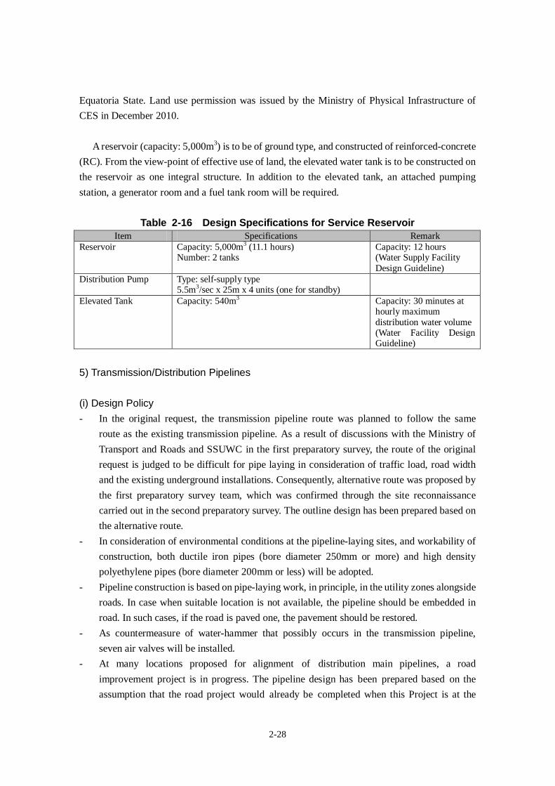
2-28
Equatoria State. Land use permission was issued by the Ministry of Physical Infrastructure of
CES in December 2010.
A reservoir (capacity: 5,000m3) is to be of ground type, and constructed of reinforced-concrete
(RC). From the view-point of effective use of land, the elevated water tank is to be constructed on
the reservoir as one integral structure. In addition to the elevated tank, an attached pumping
station, a generator room and a fuel tank room will be required.
Table 2-16 Design Specifications for Service ReservoirItem Specifications Remark
Reservoir Capacity: 5,000m3 (11.1 hours)Number: 2 tanks
Capacity: 12 hours(Water Supply FacilityDesign Guideline)
Distribution Pump Type: self-supply type5.5m3/sec x 25m x 4 units (one for standby)
Elevated Tank Capacity: 540m3 Capacity: 30 minutes athourly maximumdistribution water volume(Water Facility DesignGuideline)
5) Transmission/Distribution Pipelines
(i) Design Policy- In the original request, the transmission pipeline route was planned to follow the same
route as the existing transmission pipeline. As a result of discussions with the Ministry of
Transport and Roads and SSUWC in the first preparatory survey, the route of the original
request is judged to be difficult for pipe laying in consideration of traffic load, road width
and the existing underground installations. Consequently, alternative route was proposed by
the first preparatory survey team, which was confirmed through the site reconnaissance
carried out in the second preparatory survey. The outline design has been prepared based on
the alternative route.
- In consideration of environmental conditions at the pipeline-laying sites, and workability of
construction, both ductile iron pipes (bore diameter 250mm or more) and high density
polyethylene pipes (bore diameter 200mm or less) will be adopted.
- Pipeline construction is based on pipe-laying work, in principle, in the utility zones alongside
roads. In case when suitable location is not available, the pipeline should be embedded in
road. In such cases, if the road is paved one, the pavement should be restored.
- As countermeasure of water-hammer that possibly occurs in the transmission pipeline,
seven air valves will be installed.
- At many locations proposed for alignment of distribution main pipelines, a road
improvement project is in progress. The pipeline design has been prepared based on the
assumption that the road project would already be completed when this Project is at the
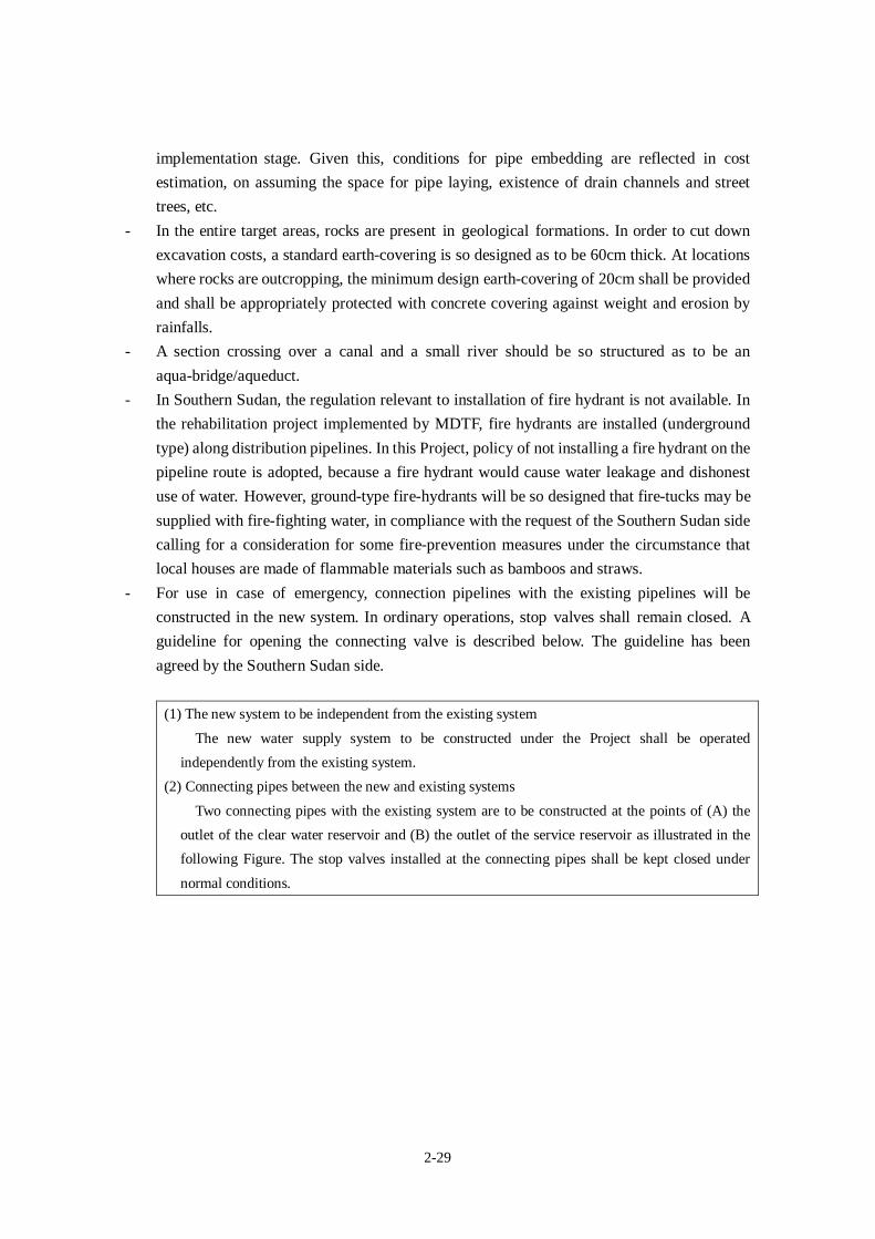
2-29
implementation stage. Given this, conditions for pipe embedding are reflected in cost
estimation, on assuming the space for pipe laying, existence of drain channels and street
trees, etc.
- In the entire target areas, rocks are present in geological formations. In order to cut down
excavation costs, a standard earth-covering is so designed as to be 60cm thick. At locations
where rocks are outcropping, the minimum design earth-covering of 20cm shall be provided
and shall be appropriately protected with concrete covering against weight and erosion by
rainfalls.
- A section crossing over a canal and a small river should be so structured as to be an
aqua-bridge/aqueduct.
- In Southern Sudan, the regulation relevant to installation of fire hydrant is not available. In
the rehabilitation project implemented by MDTF, fire hydrants are installed (underground
type) along distribution pipelines. In this Project, policy of not installing a fire hydrant on the
pipeline route is adopted, because a fire hydrant would cause water leakage and dishonest
use of water. However, ground-type fire-hydrants will be so designed that fire-tucks may be
supplied with fire-fighting water, in compliance with the request of the Southern Sudan side
calling for a consideration for some fire-prevention measures under the circumstance that
local houses are made of flammable materials such as bamboos and straws.
- For use in case of emergency, connection pipelines with the existing pipelines will be
constructed in the new system. In ordinary operations, stop valves shall remain closed. A
guideline for opening the connecting valve is described below. The guideline has been
agreed by the Southern Sudan side.
(1) The new system to be independent from the existing system
The new water supply system to be constructed under the Project shall be operated
independently from the existing system.
(2) Connecting pipes between the new and existing systems
Two connecting pipes with the existing system are to be constructed at the points of (A) the
outlet of the clear water reservoir and (B) the outlet of the service reservoir as illustrated in the
following Figure. The stop valves installed at the connecting pipes shall be kept closed under
normal conditions.
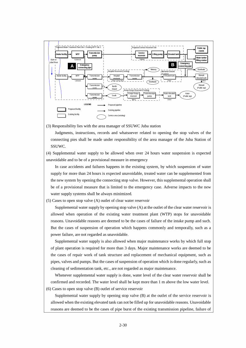
2-30
Konyo Konyo Reservoir (Existing)
Proposed Service Reservoir SiteProposed Water Treatment Plant Site(Existing WTP Site)
Memorial Ground
(Existing)
Hospital Reservoir (Existing)
Intake facility WTPTransmission
pump
Service
reservoirLifting pump Elevated tank
Intake facility WTP Transmission
pump
Transmission
pump
Elevated tankHospital
reservoir
Ministry
Distributio
n networkTransmission
pumpNorth/
Airport
Transmission
pumpSouth
Konyo Konyo
reservoir
Transmissiopn
pump
Kator elevated
tank
Kator
(Public tap)
Munuki
elevated tank
Munuki
(Public tap)
Distributio
n network
Water tanker
filling stationBahr el-
Jebel River
Public tap
stands
Emergency
connecting pipeEmergency
connecting pipe
Proposed facility
Existing facility
Proposed pipeline
Existing pipeline
Service area (existing)
LEGEND
10,800m3/d
7,200m3/d
5,000m3
210m3, 125m3, 85m3
300m3 250m3
250m3 25m3
(3) Responsibility lies with the area manager of SSUWC Juba station
Judgments, instructions, records and whatsoever related to opening the stop valves of the
connecting pies shall be made under responsibility of the area manager of the Juba Station of
SSUWC.
(4) Supplemental water supply to be allowed when over 24 hours water suspension is expected
unavoidable and to be of a provisional measure in emergency
In case accidents and failures happens in the existing system, by which suspension of water
supply for more than 24 hours is expected unavoidable, treated water can be supplemented from
the new system by opening the connecting stop valve. However, this supplemental operation shall
be of a provisional measure that is limited to the emergency case. Adverse impacts to the new
water supply systems shall be always minimized.
(5) Cases to open stop valve (A) outlet of clear water reservoir
Supplemental water supply by opening stop valve (A) at the outlet of the clear water reservoir is
allowed when operation of the existing water treatment plant (WTP) stops for unavoidable
reasons. Unavoidable reasons are deemed to be the cases of failure of the intake pump and such.
But the cases of suspension of operation which happens commonly and temporally, such as a
power failure, are not regarded as unavoidable.
Supplemental water supply is also allowed when major maintenance works by which full stop
of plant operation is required for more than 3 days. Major maintenance works are deemed to be
the cases of repair work of tank structure and replacement of mechanical equipment, such as
pipes, valves and pumps. But the cases of suspension of operation which is done regularly, such as
cleaning of sedimentation tank, etc., are not regarded as major maintenance.
Whenever supplemental water supply is done, water level of the clear water reservoir shall be
confirmed and recorded. The water level shall be kept more than 1 m above the low water level.
(6) Cases to open stop valve (B) outlet of service reservoir
Supplemental water supply by opening stop valve (B) at the outlet of the service reservoir is
allowed when the existing elevated tank can not be filled up for unavoidable reasons. Unavoidable
reasons are deemed to be the cases of pipe burst of the existing transmission pipeline, failure of
A B
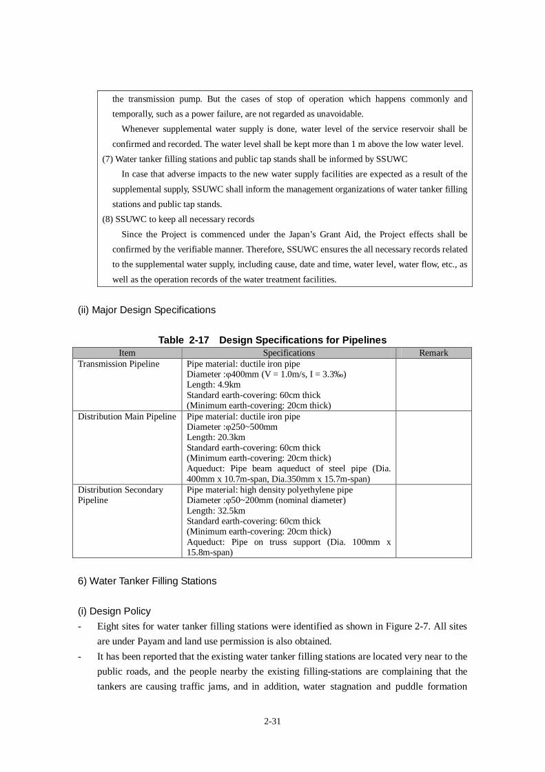
2-31
the transmission pump. But the cases of stop of operation which happens commonly and
temporally, such as a power failure, are not regarded as unavoidable.
Whenever supplemental water supply is done, water level of the service reservoir shall be
confirmed and recorded. The water level shall be kept more than 1 m above the low water level.
(7) Water tanker filling stations and public tap stands shall be informed by SSUWC
In case that adverse impacts to the new water supply facilities are expected as a result of the
supplemental supply, SSUWC shall inform the management organizations of water tanker filling
stations and public tap stands.
(8) SSUWC to keep all necessary records
Since the Project is commenced under the Japan’s Grant Aid, the Project effects shall be
confirmed by the verifiable manner. Therefore, SSUWC ensures the all necessary records related
to the supplemental water supply, including cause, date and time, water level, water flow, etc., as
well as the operation records of the water treatment facilities.
(ii) Major Design Specifications
Table 2-17 Design Specifications for PipelinesItem Specifications Remark
Transmission Pipeline Pipe material: ductile iron pipeDiameter :φ400mm (V = 1.0m/s, I = 3.3‰)Length: 4.9kmStandard earth-covering: 60cm thick(Minimum earth-covering: 20cm thick)
Distribution Main Pipeline Pipe material: ductile iron pipeDiameter :φ250~500mmLength: 20.3kmStandard earth-covering: 60cm thick(Minimum earth-covering: 20cm thick)Aqueduct: Pipe beam aqueduct of steel pipe (Dia.400mm x 10.7m-span, Dia.350mm x 15.7m-span)
Distribution SecondaryPipeline
Pipe material: high density polyethylene pipeDiameter :φ50~200mm (nominal diameter)Length: 32.5kmStandard earth-covering: 60cm thick(Minimum earth-covering: 20cm thick)Aqueduct: Pipe on truss support (Dia. 100mm x15.8m-span)
6) Water Tanker Filling Stations
(i) Design Policy- Eight sites for water tanker filling stations were identified as shown in Figure 2-7. All sites
are under Payam and land use permission is also obtained.
- It has been reported that the existing water tanker filling stations are located very near to the
public roads, and the people nearby the existing filling-stations are complaining that the
tankers are causing traffic jams, and in addition, water stagnation and puddle formation
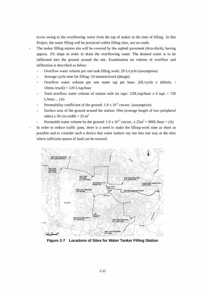
2-32
occur owing to the overflowing water from the top of tanker at the time of filling. In this
Project, the water filling will be practiced within filling sites, not on roads.
- The tanker filling station site will be covered by the asphalt pavement (4cm-thick), having
approx. 2% slope in order to drain the overflowing water. The drained water is to be
infiltrated into the ground around the site. Examination on volume of overflow and
infiltration is described as below:
- Overflow water volume per one tank filling work: 20 L/cycle (assumption)
- Average cycle time for filling: 10 minutes/truck (design)
- Overflow water volume per one water tap per hour: 20L/cycle x (60min. /
10min./truck) = 120 L/tap/hour
- Total overflow water volume of station with six taps: 120L/tap/hour x 6 taps = 720
L/hour… (A)
- Permeability coefficient of the ground: 1.0 x 10⁻³ cm/sec. (assumption)
- Surface area of the ground around the station: 50m (average length of two peripheral
sides) x 50 cm-width = 25 m2
- Permeable water volume by the ground: 1.0 x 10⁻³ cm/sec. x 25m2 = 900L/hour > (A)
- In order to reduce traffic jams, there is a need to make the filling-work time as short as
possible and to consider such a device that water tankers my run into one way at the sites
where sufficient spaces of land can be secured.
Figure 2-7 Locations of Sites for Water Tanker Filling Station
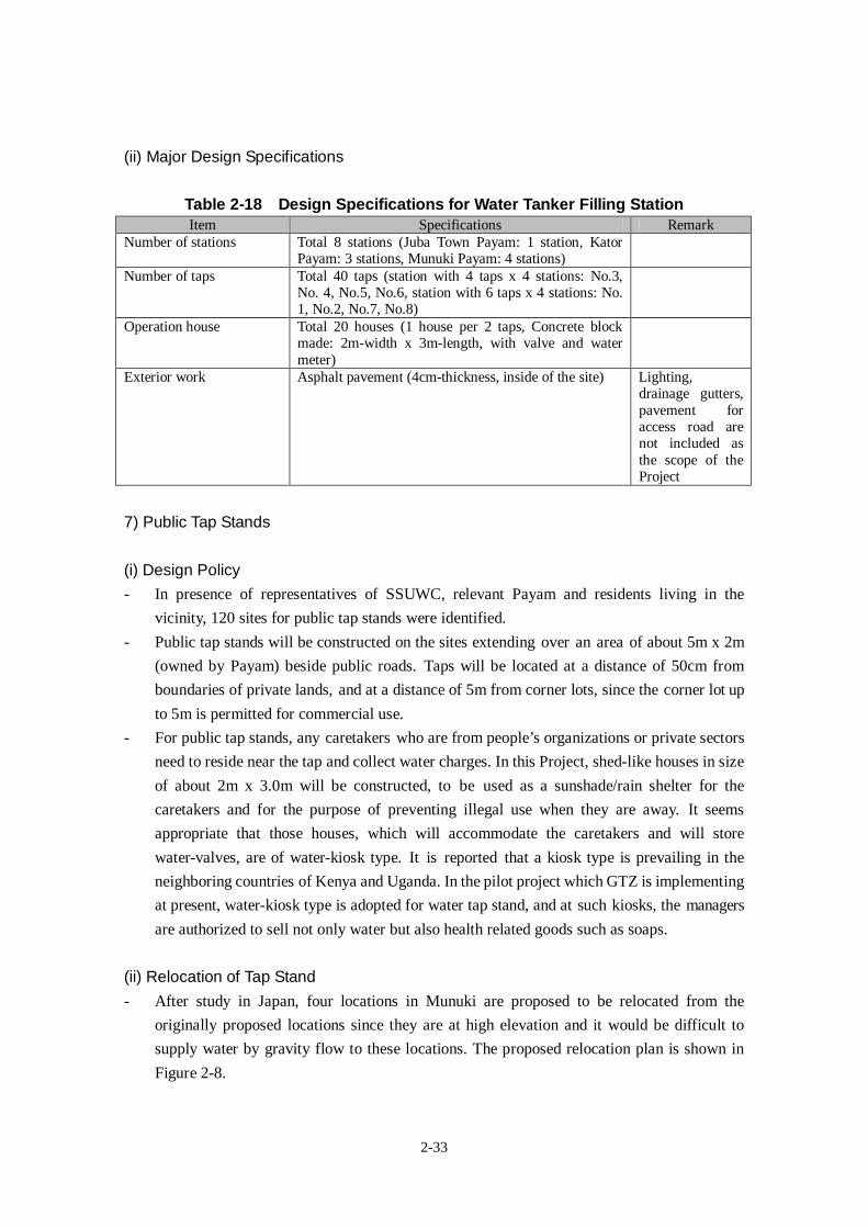
2-33
(ii) Major Design Specifications
Table 2-18 Design Specifications for Water Tanker Filling StationItem Specifications Remark
Number of stations Total 8 stations (Juba Town Payam: 1 station, KatorPayam: 3 stations, Munuki Payam: 4 stations)
Number of taps Total 40 taps (station with 4 taps x 4 stations: No.3,No. 4, No.5, No.6, station with 6 taps x 4 stations: No.1, No.2, No.7, No.8)
Operation house Total 20 houses (1 house per 2 taps, Concrete blockmade: 2m-width x 3m-length, with valve and watermeter)
Exterior work Asphalt pavement (4cm-thickness, inside of the site) Lighting,drainage gutters,pavement foraccess road arenot included asthe scope of theProject
7) Public Tap Stands
(i) Design Policy- In presence of representatives of SSUWC, relevant Payam and residents living in the
vicinity, 120 sites for public tap stands were identified.
- Public tap stands will be constructed on the sites extending over an area of about 5m x 2m
(owned by Payam) beside public roads. Taps will be located at a distance of 50cm from
boundaries of private lands, and at a distance of 5m from corner lots, since the corner lot up
to 5m is permitted for commercial use.
- For public tap stands, any caretakers who are from people’s organizations or private sectors
need to reside near the tap and collect water charges. In this Project, shed-like houses in size
of about 2m x 3.0m will be constructed, to be used as a sunshade/rain shelter for the
caretakers and for the purpose of preventing illegal use when they are away. It seems
appropriate that those houses, which will accommodate the caretakers and will store
water-valves, are of water-kiosk type. It is reported that a kiosk type is prevailing in the
neighboring countries of Kenya and Uganda. In the pilot project which GTZ is implementing
at present, water-kiosk type is adopted for water tap stand, and at such kiosks, the managers
are authorized to sell not only water but also health related goods such as soaps.
(ii) Relocation of Tap Stand- After study in Japan, four locations in Munuki are proposed to be relocated from the
originally proposed locations since they are at high elevation and it would be difficult to
supply water by gravity flow to these locations. The proposed relocation plan is shown in
Figure 2-8.
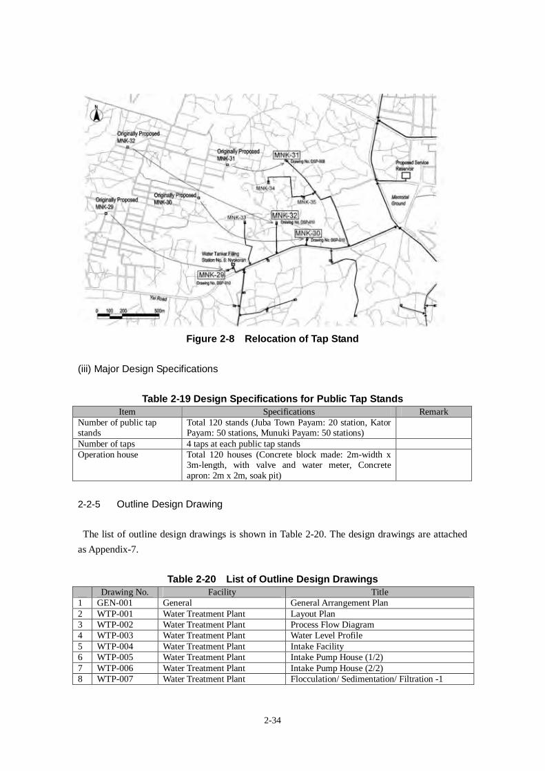
2-34
Figure 2-8 Relocation of Tap Stand
(iii) Major Design Specifications
Table 2-19 Design Specifications for Public Tap StandsItem Specifications Remark
Number of public tapstands
Total 120 stands (Juba Town Payam: 20 station, KatorPayam: 50 stations, Munuki Payam: 50 stations)
Number of taps 4 taps at each public tap standsOperation house Total 120 houses (Concrete block made: 2m-width x
3m-length, with valve and water meter, Concreteapron: 2m x 2m, soak pit)
2-2-5 Outline Design Drawing
The list of outline design drawings is shown in Table 2-20. The design drawings are attached
as Appendix-7.
Table 2-20 List of Outline Design DrawingsDrawing No. Facility Title
1 GEN-001 General General Arrangement Plan2 WTP-001 Water Treatment Plant Layout Plan3 WTP-002 Water Treatment Plant Process Flow Diagram4 WTP-003 Water Treatment Plant Water Level Profile5 WTP-004 Water Treatment Plant Intake Facility6 WTP-005 Water Treatment Plant Intake Pump House (1/2)7 WTP-006 Water Treatment Plant Intake Pump House (2/2)8 WTP-007 Water Treatment Plant Flocculation/ Sedimentation/ Filtration -1
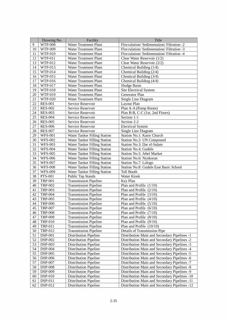
2-35
Drawing No. Facility Title9 WTP-008 Water Treatment Plant Flocculation/ Sedimentation/ Filtration -210 WTP-009 Water Treatment Plant Flocculation/ Sedimentation/ Filtration -311 WTP-010 Water Treatment Plant Flocculation/ Sedimentation/ Filtration -412 WTP-011 Water Treatment Plant Clear Water Reservoir (1/2)13 WTP-012 Water Treatment Plant Clear Water Reservoir (2/2)14 WTP-013 Water Treatment Plant Chemical Building (1/4)15 WTP-014 Water Treatment Plant Chemical Building (2/4)16 WTP-015 Water Treatment Plant Chemical Building (3/4)17 WTP-016 Water Treatment Plant Chemical Building (4/4)18 WTP-017 Water Treatment Plant Sludge Basin19 WTP-018 Water Treatment Plant Site Electrical System20 WTP-019 Water Treatment Plant Generator Plan21 WTP-020 Water Treatment Plant Single Line Diagram22 RES-001 Service Reservoir Layout Plan23 RES-002 Service Reservoir Plan A-A (Pump Room)24 RES-003 Service Reservoir Plan B-B, C-C (1st, 2nd Floors)25 RES-004 Service Reservoir Section 1-126 RES-005 Service Reservoir Section 2-227 RES-006 Service Reservoir Electrical System28 RES-007 Service Reservoir Single Line Diagram29 WFS-001 Water Tanker Filling Station Station No.1: Kator Church30 WFS-002 Water Tanker Filling Station Station No.2: UN Compound31 WFS-003 Water Tanker Filling Station Station No.3: Dar el-Salam32 WFS-004 Water Tanker Filling Station Station No.4: Gudele33 WFS-005 Water Tanker Filling Station Station No.5: Jebel Market34 WFS-006 Water Tanker Filling Station Station No.6: Nyokoran35 WFS-007 Water Tanker Filling Station Station No.7: Lologo36 WFS-008 Water Tanker Filling Station Station No.8: Gudele East Basic School37 WFS-009 Water Tanker Filling Station Toll Booth38 PTS-001 Public Tap Stands Water Kiosk39 TRP-001 Transmission Pipeline Key Plan40 TRP-002 Transmission Pipeline Plan and Profile (1/10)41 TRP-003 Transmission Pipeline Plan and Profile (2/10)42 TRP-004 Transmission Pipeline Plan and Profile (3/10)43 TRP-005 Transmission Pipeline Plan and Profile (4/10)44 TRP-006 Transmission Pipeline Plan and Profile (5/10)45 TRP-007 Transmission Pipeline Plan and Profile (6/10)46 TRP-008 Transmission Pipeline Plan and Profile (7/10)47 TRP-009 Transmission Pipeline Plan and Profile (8/10)48 TRP-010 Transmission Pipeline Plan and Profile (9/10)49 TRP-011 Transmission Pipeline Plan and Profile (10/10)50 TRP-012 Transmission Pipeline Details of Transmission Pipe51 DSP-001 Distribution Pipeline Distribution Main and Secondary Pipelines -152 DSP-002 Distribution Pipeline Distribution Main and Secondary Pipelines -253 DSP-003 Distribution Pipeline Distribution Main and Secondary Pipelines -354 DSP-004 Distribution Pipeline Distribution Main and Secondary Pipelines -455 DSP-005 Distribution Pipeline Distribution Main and Secondary Pipelines -556 DSP-006 Distribution Pipeline Distribution Main and Secondary Pipelines -657 DSP-007 Distribution Pipeline Distribution Main and Secondary Pipelines -758 DSP-008 Distribution Pipeline Distribution Main and Secondary Pipelines -859 DSP-009 Distribution Pipeline Distribution Main and Secondary Pipelines -960 DSP-010 Distribution Pipeline Distribution Main and Secondary Pipelines -1061 DSP-011 Distribution Pipeline Distribution Main and Secondary Pipelines -1162 DSP-012 Distribution Pipeline Distribution Main and Secondary Pipelines -12
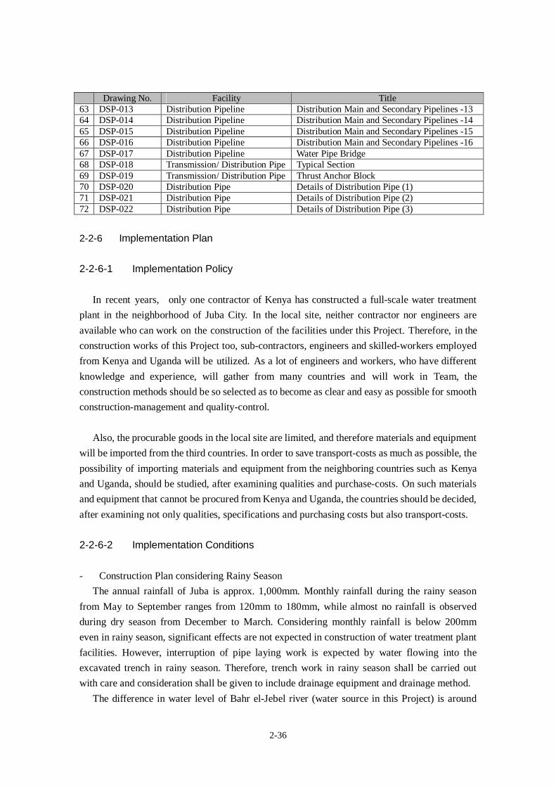
2-36
Drawing No. Facility Title63 DSP-013 Distribution Pipeline Distribution Main and Secondary Pipelines -1364 DSP-014 Distribution Pipeline Distribution Main and Secondary Pipelines -1465 DSP-015 Distribution Pipeline Distribution Main and Secondary Pipelines -1566 DSP-016 Distribution Pipeline Distribution Main and Secondary Pipelines -1667 DSP-017 Distribution Pipeline Water Pipe Bridge68 DSP-018 Transmission/ Distribution Pipe Typical Section69 DSP-019 Transmission/ Distribution Pipe Thrust Anchor Block70 DSP-020 Distribution Pipe Details of Distribution Pipe (1)71 DSP-021 Distribution Pipe Details of Distribution Pipe (2)72 DSP-022 Distribution Pipe Details of Distribution Pipe (3)
2-2-6 Implementation Plan
2-2-6-1 Implementation Policy
In recent years, only one contractor of Kenya has constructed a full-scale water treatment
plant in the neighborhood of Juba City. In the local site, neither contractor nor engineers are
available who can work on the construction of the facilities under this Project. Therefore, in the
construction works of this Project too, sub-contractors, engineers and skilled-workers employed
from Kenya and Uganda will be utilized. As a lot of engineers and workers, who have different
knowledge and experience, will gather from many countries and will work in Team, the
construction methods should be so selected as to become as clear and easy as possible for smooth
construction-management and quality-control.
Also, the procurable goods in the local site are limited, and therefore materials and equipment
will be imported from the third countries. In order to save transport-costs as much as possible, the
possibility of importing materials and equipment from the neighboring countries such as Kenya
and Uganda, should be studied, after examining qualities and purchase-costs. On such materials
and equipment that cannot be procured from Kenya and Uganda, the countries should be decided,
after examining not only qualities, specifications and purchasing costs but also transport-costs.
2-2-6-2 Implementation Conditions
- Construction Plan considering Rainy Season
The annual rainfall of Juba is approx. 1,000mm. Monthly rainfall during the rainy season
from May to September ranges from 120mm to 180mm, while almost no rainfall is observed
during dry season from December to March. Considering monthly rainfall is below 200mm
even in rainy season, significant effects are not expected in construction of water treatment plant
facilities. However, interruption of pipe laying work is expected by water flowing into the
excavated trench in rainy season. Therefore, trench work in rainy season shall be carried out
with care and consideration shall be given to include drainage equipment and drainage method.
The difference in water level of Bahr el-Jebel river (water source in this Project) is around
2-37
2m between dry and rainy seasons. In constructing water intake facility, due care shall be taken
to this water level change. In addition, Construction work in and along the river shall be avoided
in construction plan during the season of high water level in River from June to November.
- Concrete Work
The supplier of raw concrete is not available in the local site, therefore a batcher plant should
be constructed for the constructor’s own use. For the construction of the batcher plant, the
location should be selected such that it is easily accessible from the construction location of the
water treatment plant as well as reservoir. The treatment plant and reservoir being main
destinations of concrete for construction, proper selection of location for batcher plant will
facilitate easy transport of concrete within short time.
Cement should be procured from either Kenya or Uganda or the third countries, and the
aggregates from the local site. In either case, before actual use, their brands should be decided,
after examinations on qualities. As the actual site belongs to tropical zone, with a daily average
temperature of more than 25°C and a daily maximum temperature of about 35°C, the concrete
works that is suitable for hot weather, should be considered.
- Pipe Laying Work
Pipe laying work of transmission pipelines and distribution pipelines will be carried out
mainly on or alongside public roads. A construction plan should be so scheduled as to control
inconvenience and discomfort (traffic jams, noise, dust and others) as low as possible. In order to
advance the construction work smoothly, careful attention should be paid to such arrangements,
as explanations on the construction to the neighboring people as well as applications for
permission from the governmental authorities to the construction, and these activities should be
finished up before the construction starts.
As piping materials, which will be imported from the third countries, are voluminous, they
should be procured on divided lot basis, in consideration of available storage space at site. These
piping materials should be so appropriately ordered that there is no trouble in obtaining storage
sites and there would be no interruption in construction work owing to materials-shortage, under
constant checking up of both progress of construction and volume of stocks.
Along the roads in Juba City, pavement work, its incidental sidewalk construction work and
drainpipe laying work are in progress. In regard to locations for laying transmission pipelines and
distribution pipelines in this Project, there is a need to check up on existing situations of the
construction sites and on the existing data, when the construction starts, and to re-verify the
locations by trial excavation, as the need arises.
2-2-6-3 Scope of Works
The scope of works to be undertaken by the Japanese Government and the Southern Sudan
Government in implementation of the Project are as shown in the following Table 2-21.
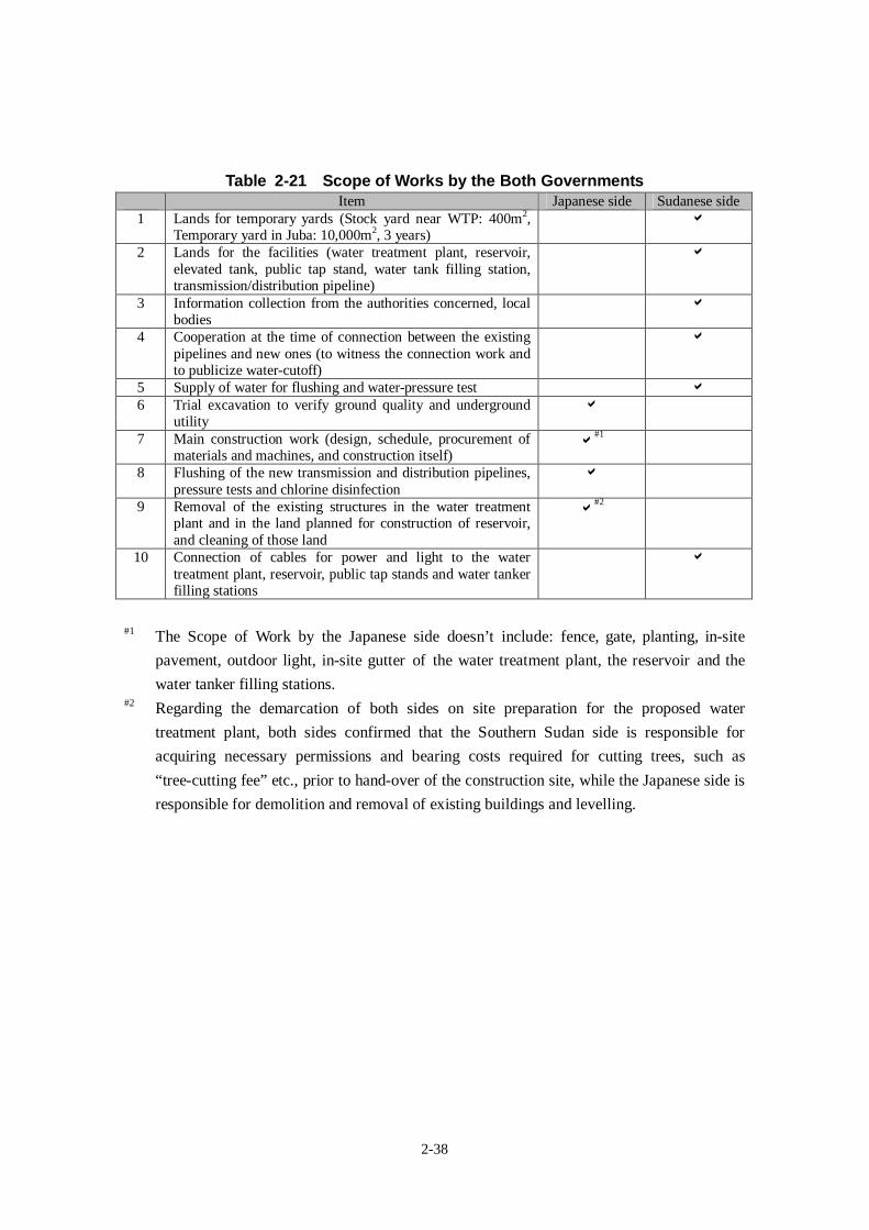
2-38
Table 2-21 Scope of Works by the Both GovernmentsItem Japanese side Sudanese side
1 Lands for temporary yards (Stock yard near WTP: 400m2,Temporary yard in Juba: 10,000m2, 3 years)
2 Lands for the facilities (water treatment plant, reservoir,elevated tank, public tap stand, water tank filling station,transmission/distribution pipeline)
3 Information collection from the authorities concerned, localbodies
4 Cooperation at the time of connection between the existingpipelines and new ones (to witness the connection work andto publicize water-cutoff)
5 Supply of water for flushing and water-pressure test
6 Trial excavation to verify ground quality and undergroundutility
7 Main construction work (design, schedule, procurement ofmaterials and machines, and construction itself)
#1
8 Flushing of the new transmission and distribution pipelines,pressure tests and chlorine disinfection
9 Removal of the existing structures in the water treatmentplant and in the land planned for construction of reservoir,and cleaning of those land
#2
10 Connection of cables for power and light to the watertreatment plant, reservoir, public tap stands and water tankerfilling stations
#1 The Scope of Work by the Japanese side doesn’t include: fence, gate, planting, in-site
pavement, outdoor light, in-site gutter of the water treatment plant, the reservoir and the
water tanker filling stations.#2 Regarding the demarcation of both sides on site preparation for the proposed water
treatment plant, both sides confirmed that the Southern Sudan side is responsible for
acquiring necessary permissions and bearing costs required for cutting trees, such as
“tree-cutting fee” etc., prior to hand-over of the construction site, while the Japanese side is
responsible for demolition and removal of existing buildings and levelling.
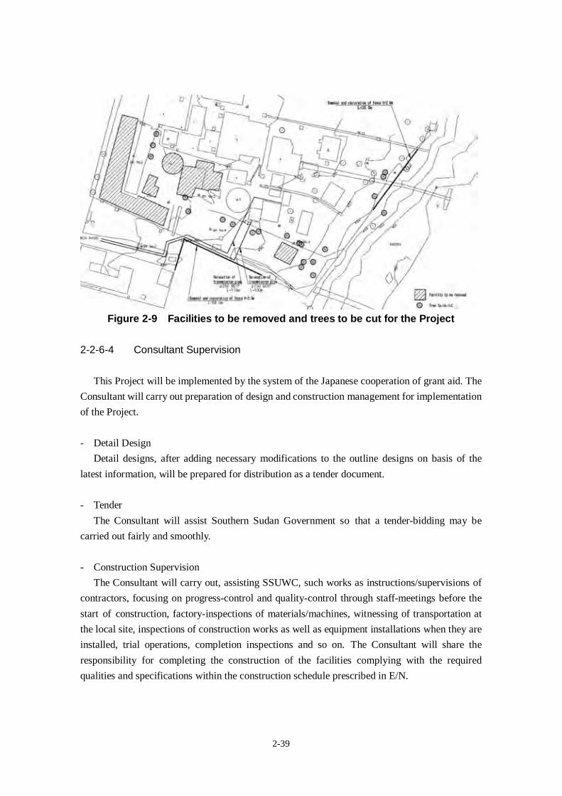
2-39
Figure 2-9 Facilities to be removed and trees to be cut for the Project
2-2-6-4 Consultant Supervision
This Project will be implemented by the system of the Japanese cooperation of grant aid. The
Consultant will carry out preparation of design and construction management for implementation
of the Project.
- Detail Design
Detail designs, after adding necessary modifications to the outline designs on basis of the
latest information, will be prepared for distribution as a tender document.
- Tender
The Consultant will assist Southern Sudan Government so that a tender-bidding may be
carried out fairly and smoothly.
- Construction Supervision
The Consultant will carry out, assisting SSUWC, such works as instructions/supervisions of
contractors, focusing on progress-control and quality-control through staff-meetings before the
start of construction, factory-inspections of materials/machines, witnessing of transportation at
the local site, inspections of construction works as well as equipment installations when they are
installed, trial operations, completion inspections and so on. The Consultant will share the
responsibility for completing the construction of the facilities complying with the required
qualities and specifications within the construction schedule prescribed in E/N.
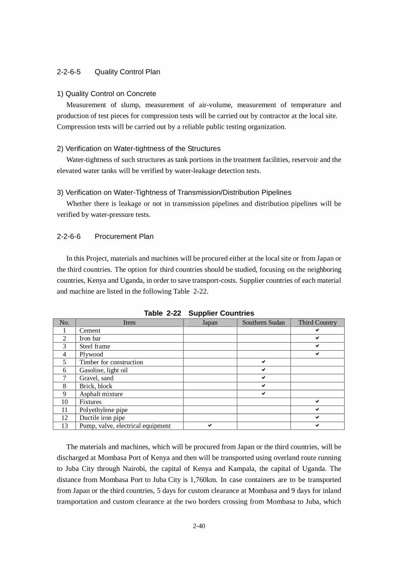
2-40
2-2-6-5 Quality Control Plan
1) Quality Control on ConcreteMeasurement of slump, measurement of air-volume, measurement of temperature and
production of test pieces for compression tests will be carried out by contractor at the local site.
Compression tests will be carried out by a reliable public testing organization.
2) Verification on Water-tightness of the StructuresWater-tightness of such structures as tank portions in the treatment facilities, reservoir and the
elevated water tanks will be verified by water-leakage detection tests.
3) Verification on Water-Tightness of Transmission/Distribution PipelinesWhether there is leakage or not in transmission pipelines and distribution pipelines will be
verified by water-pressure tests.
2-2-6-6 Procurement Plan
In this Project, materials and machines will be procured either at the local site or from Japan or
the third countries. The option for third countries should be studied, focusing on the neighboring
countries, Kenya and Uganda, in order to save transport-costs. Supplier countries of each material
and machine are listed in the following Table 2-22.
Table 2-22 Supplier CountriesNo. Item Japan Southern Sudan Third Country1 Cement
2 Iron bar
3 Steel frame
4 Plywood
5 Timber for construction
6 Gasoline, light oil
7 Gravel, sand
8 Brick, block
9 Asphalt mixture
10 Fixtures
11 Polyethylene pipe
12 Ductile iron pipe
13 Pump, valve, electrical equipment
The materials and machines, which will be procured from Japan or the third countries, will be
discharged at Mombasa Port of Kenya and then will be transported using overland route running
to Juba City through Nairobi, the capital of Kenya and Kampala, the capital of Uganda. The
distance from Mombasa Port to Juba City is 1,760km. In case containers are to be transported
from Japan or the third countries, 5 days for custom clearance at Mombasa and 9 days for inland
transportation and custom clearance at the two borders crossing from Mombasa to Juba, which
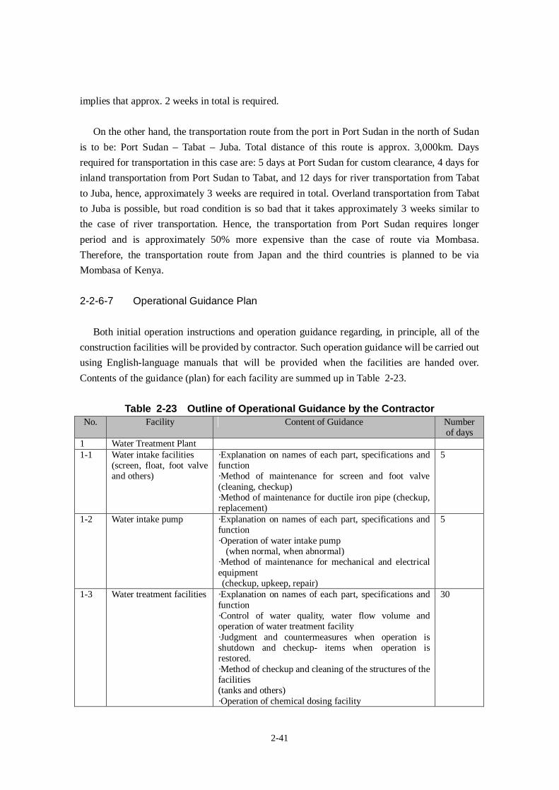
2-41
implies that approx. 2 weeks in total is required.
On the other hand, the transportation route from the port in Port Sudan in the north of Sudan
is to be: Port Sudan – Tabat – Juba. Total distance of this route is approx. 3,000km. Days
required for transportation in this case are: 5 days at Port Sudan for custom clearance, 4 days for
inland transportation from Port Sudan to Tabat, and 12 days for river transportation from Tabat
to Juba, hence, approximately 3 weeks are required in total. Overland transportation from Tabat
to Juba is possible, but road condition is so bad that it takes approximately 3 weeks similar to
the case of river transportation. Hence, the transportation from Port Sudan requires longer
period and is approximately 50% more expensive than the case of route via Mombasa.
Therefore, the transportation route from Japan and the third countries is planned to be via
Mombasa of Kenya.
2-2-6-7 Operational Guidance Plan
Both initial operation instructions and operation guidance regarding, in principle, all of the
construction facilities will be provided by contractor. Such operation guidance will be carried out
using English-language manuals that will be provided when the facilities are handed over.
Contents of the guidance (plan) for each facility are summed up in Table 2-23.
Table 2-23 Outline of Operational Guidance by the ContractorNo. Facility Content of Guidance Number
of days1 Water Treatment Plant1-1 Water intake facilities
(screen, float, foot valveand others)
·Explanation on names of each part, specifications andfunction·Method of maintenance for screen and foot valve(cleaning, checkup)·Method of maintenance for ductile iron pipe (checkup,replacement)
5
1-2 Water intake pump ·Explanation on names of each part, specifications andfunction·Operation of water intake pump
(when normal, when abnormal)·Method of maintenance for mechanical and electricalequipment(checkup, upkeep, repair)
5
1-3 Water treatment facilities ·Explanation on names of each part, specifications andfunction·Control of water quality, water flow volume andoperation of water treatment facility·Judgment and countermeasures when operation isshutdown and checkup- items when operation isrestored.·Method of checkup and cleaning of the structures of thefacilities(tanks and others)·Operation of chemical dosing facility
30
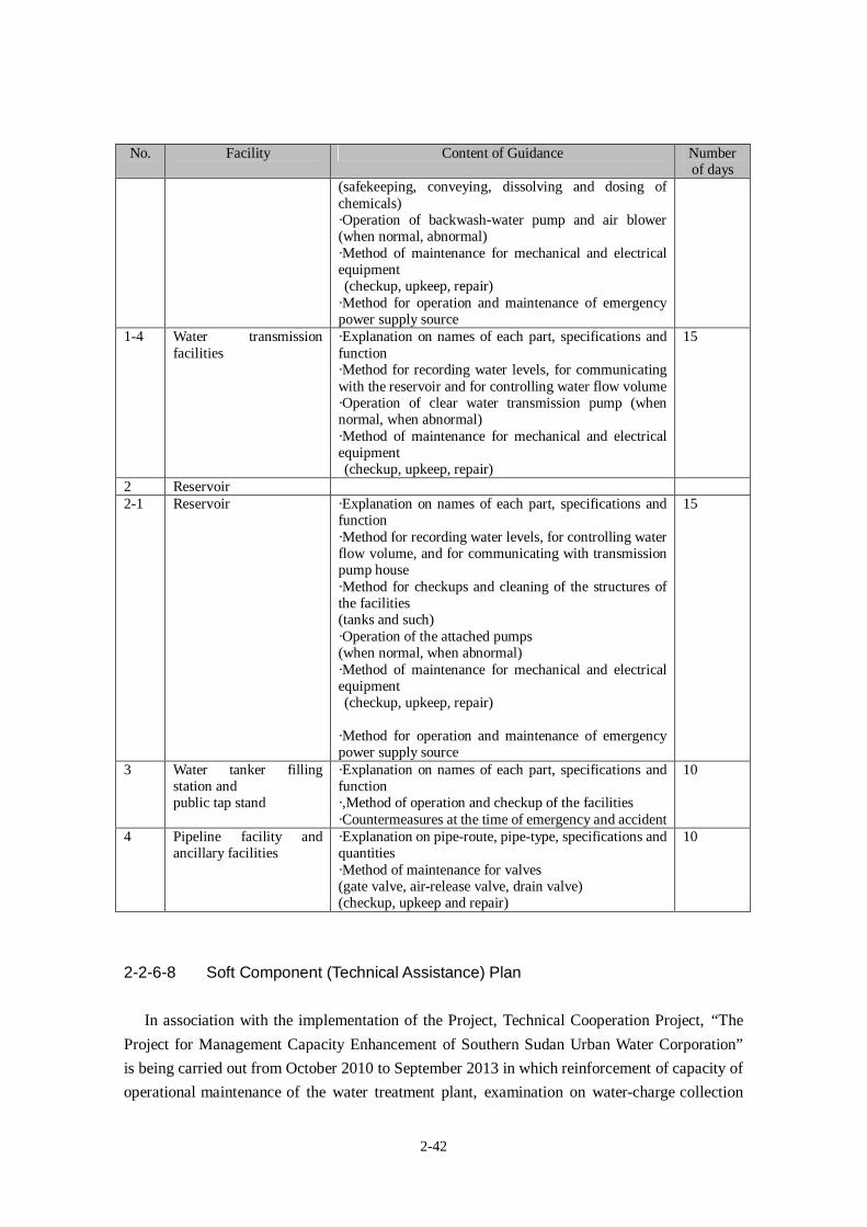
2-42
No. Facility Content of Guidance Numberof days
(safekeeping, conveying, dissolving and dosing ofchemicals)·Operation of backwash-water pump and air blower(when normal, abnormal)·Method of maintenance for mechanical and electricalequipment(checkup, upkeep, repair)
·Method for operation and maintenance of emergencypower supply source
1-4 Water transmissionfacilities
·Explanation on names of each part, specifications andfunction·Method for recording water levels, for communicatingwith the reservoir and for controlling water flow volume·Operation of clear water transmission pump (whennormal, when abnormal)·Method of maintenance for mechanical and electricalequipment(checkup, upkeep, repair)
15
2 Reservoir2-1 Reservoir ·Explanation on names of each part, specifications and
function·Method for recording water levels, for controlling waterflow volume, and for communicating with transmissionpump house·Method for checkups and cleaning of the structures ofthe facilities(tanks and such)·Operation of the attached pumps(when normal, when abnormal)·Method of maintenance for mechanical and electricalequipment(checkup, upkeep, repair)
·Method for operation and maintenance of emergencypower supply source
15
3 Water tanker fillingstation andpublic tap stand
·Explanation on names of each part, specifications andfunction·,Method of operation and checkup of the facilities·Countermeasures at the time of emergency and accident
10
4 Pipeline facility andancillary facilities
·Explanation on pipe-route, pipe-type, specifications andquantities·Method of maintenance for valves(gate valve, air-release valve, drain valve)(checkup, upkeep and repair)
10
2-2-6-8 Soft Component (Technical Assistance) Plan
In association with the implementation of the Project, Technical Cooperation Project, “The
Project for Management Capacity Enhancement of Southern Sudan Urban Water Corporation”
is being carried out from October 2010 to September 2013 in which reinforcement of capacity of
operational maintenance of the water treatment plant, examination on water-charge collection
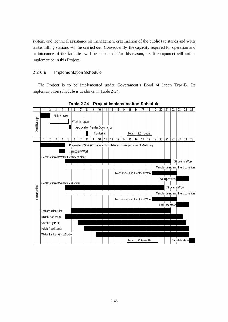
2-43
system, and technical assistance on management organization of the public tap stands and water
tanker filling stations will be carried out. Consequently, the capacity required for operation and
maintenance of the facilities will be enhanced. For this reason, a soft component will not be
implemented in this Project.
2-2-6-9 Implementation Schedule
The Project is to be implemented under Government’s Bond of Japan Type-B. Its
implementation schedule is as shown in Table 2-24.
Table 2-24 Project Implementation Schedule1 2 3 4 5 6 7 8 9 10 11 12 13 14 15 16 17 18 19 20 21 22 23 24 25
Field Survey
Work in Japan
Approval on Tender Documents
Tendering Total: 8.0 months
1 2 3 4 5 6 7 8 9 10 11 12 13 14 15 16 17 18 19 20 21 22 23 24 25
Preparatory Work (Procurement of Materials, Transportation of Machinery)
Temporary Work
Construction of Water Treatment Plant
Structural Work
Manufacturing and Transportation
Mechanical and Electrical Work
Trial Operation
Construction of Service Reservoir
Structural Work
Manufacturing and Transportation
Mechanical and Electrical Work
Trial Operation
Transmission Pipe
Distribution Main
Secondary Pipe
Public Tap Stands
Water Tanker Filling Station
Total: 25.0 months Demobilization
Det
ailD
esig
nC
onst
ruct
ion
2-44
2-3 Obligations of the Recipient Country
In the implementation of the Project, MWRI is responsible for facilitating the undertakings
below to be smoothly secured, collaborating with the signatory of the Grant Agreement and the
authorities concerned of the recipient side upon necessity:
(1) To secure the lands (including construction sites and access roads), clear the sites (service
reservoir/ elevated tank, water tanker filling stations and public tap stands)
(2) To provide temporary yard for construction to the Japanese Contractor (approx. 400 m2
nearby the water treatment plant for stockyard and approx. 10,000 m2 at an appropriate
location in Juba for stockyard and temporary works of the Contractor)
(3) To exempt taxes which may be imposed on the goods imported to the recipient country, to
ensure prompt customs clearance of the products and to assist the internal transportation of
the products in the recipient country.
(4) To ensure that custom duties, internal taxes and other fiscal levies which may be imposed
in the recipient country with respect to the purchase of the goods and the services be
exempted.
(5) To accord Japanese nationals whose services may be required in connection with the
supply of the goods and the services or such facilities as may be necessary for their entry
into the recipient country and stay therein for the performance of their work.
(6) To ensure that the facilities be maintained and used properly and effectively for the
implementation of the Project.
(7) To bear all the expenses, other than those covered by the Grant, necessary for the
implementation of the Project.
(8) To bear commissions paid to the Japanese bank for banking services based upon Banking
Arrangement (B/A); such as advising commission of Authorization to Pay (A/P) and
payment commission.
(9) To give due environmental and social considerations in the implementation of the Project.
(10) To provide power connection to the proposed facilities (water treatment plant: 500KVA,
service reservoir: 200KVA and water tanker filling stations)
(11) To provide information on underground utilities and to witness trial excavations at site,
where available
(12) To provide water free of charge for leakage testing of the tank structure, pressure testing
and flushing of transmission and distribution pipelines
(13) To assign counterpart staff necessary for the Project implementation, including members
from MWRI, SSUWC Headquarters, SSUWC Juba Station and duty-officers of Payams.
(14) To acquire necessary permissions and bear costs required for cutting trees on the
construction site of the water treatment plant.
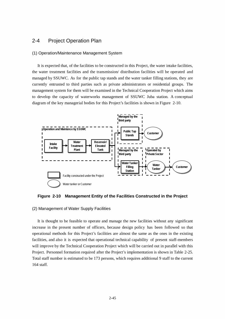
2-45
2-4 Project Operation Plan
(1) Operation/Maintenance Management System
It is expected that, of the facilities to be constructed in this Project, the water intake facilities,
the water treatment facilities and the transmission/ distribution facilities will be operated and
managed by SSUWC. As for the public tap stands and the water tanker filling stations, they are
currently entrusted to third parties such as private administrators or residential groups. The
management system for them will be examined in the Technical Cooperation Project which aims
to develop the capacity of waterworks management of SSUWC Juba station. A conceptual
diagram of the key managerial bodies for this Project’s facilities is shown in Figure 2-10.
Facility constructed under the Project
Water tanker or Customer
Operated by
Private Sector
Managed by the
third party
Managed by the
third party
Operation and Maintence by SSUWC
Intake
Facility
Water
Treatment
Plant
Reservoir/
Elevated
Tank
Water Tanker
Filling
Station
Public Tap
StandsCustomer
CustomerWater
Tanker
Figure 2-10 Management Entity of the Facilities Constructed in the Project
(2) Management of Water Supply Facilities
It is thought to be feasible to operate and manage the new facilities without any significant
increase in the present number of officers, because design policy has been followed so that
operational methods for this Project’s facilities are almost the same as the ones in the existing
facilities, and also it is expected that operational technical capability of present staff-members
will improve by the Technical Cooperation Project which will be carried out in parallel with this
Project. Personnel formation required after the Project’s implementation is shown in Table 2-25.
Total staff number is estimated to be 173 persons, which requires additional 9 staff to the current
164 staff.
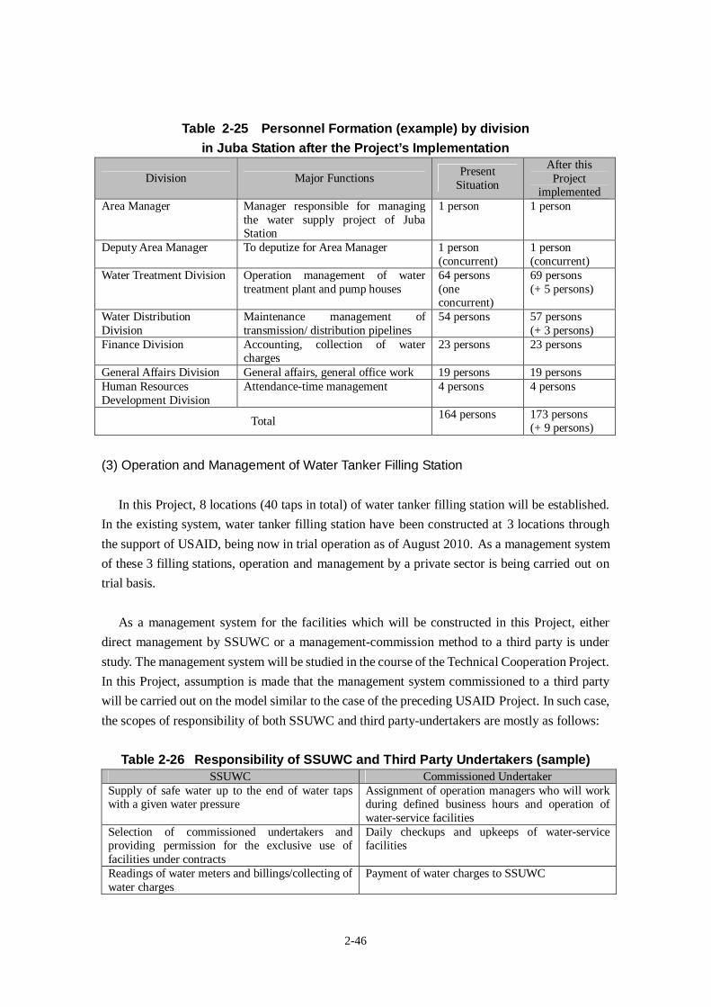
2-46
Table 2-25 Personnel Formation (example) by divisionin Juba Station after the Project’s Implementation
Division Major FunctionsPresent
Situation
After thisProject
implementedArea Manager Manager responsible for managing
the water supply project of JubaStation
1 person 1 person
Deputy Area Manager To deputize for Area Manager 1 person(concurrent)
1 person(concurrent)
Water Treatment Division Operation management of watertreatment plant and pump houses
64 persons(oneconcurrent)
69 persons(+ 5 persons)
Water DistributionDivision
Maintenance management oftransmission/ distribution pipelines
54 persons 57 persons(+ 3 persons)
Finance Division Accounting, collection of watercharges
23 persons 23 persons
General Affairs Division General affairs, general office work 19 persons 19 personsHuman ResourcesDevelopment Division
Attendance-time management 4 persons 4 persons
Total164 persons 173 persons
(+ 9 persons)
(3) Operation and Management of Water Tanker Filling Station
In this Project, 8 locations (40 taps in total) of water tanker filling station will be established.
In the existing system, water tanker filling station have been constructed at 3 locations through
the support of USAID, being now in trial operation as of August 2010. As a management system
of these 3 filling stations, operation and management by a private sector is being carried out on
trial basis.
As a management system for the facilities which will be constructed in this Project, either
direct management by SSUWC or a management-commission method to a third party is under
study. The management system will be studied in the course of the Technical Cooperation Project.
In this Project, assumption is made that the management system commissioned to a third party
will be carried out on the model similar to the case of the preceding USAID Project. In such case,
the scopes of responsibility of both SSUWC and third party-undertakers are mostly as follows:
Table 2-26 Responsibility of SSUWC and Third Party Undertakers (sample)SSUWC Commissioned Undertaker
Supply of safe water up to the end of water tapswith a given water pressure
Assignment of operation managers who will workduring defined business hours and operation ofwater-service facilities
Selection of commissioned undertakers andproviding permission for the exclusive use offacilities under contracts
Daily checkups and upkeeps of water-servicefacilities
Readings of water meters and billings/collecting ofwater charges
Payment of water charges to SSUWC
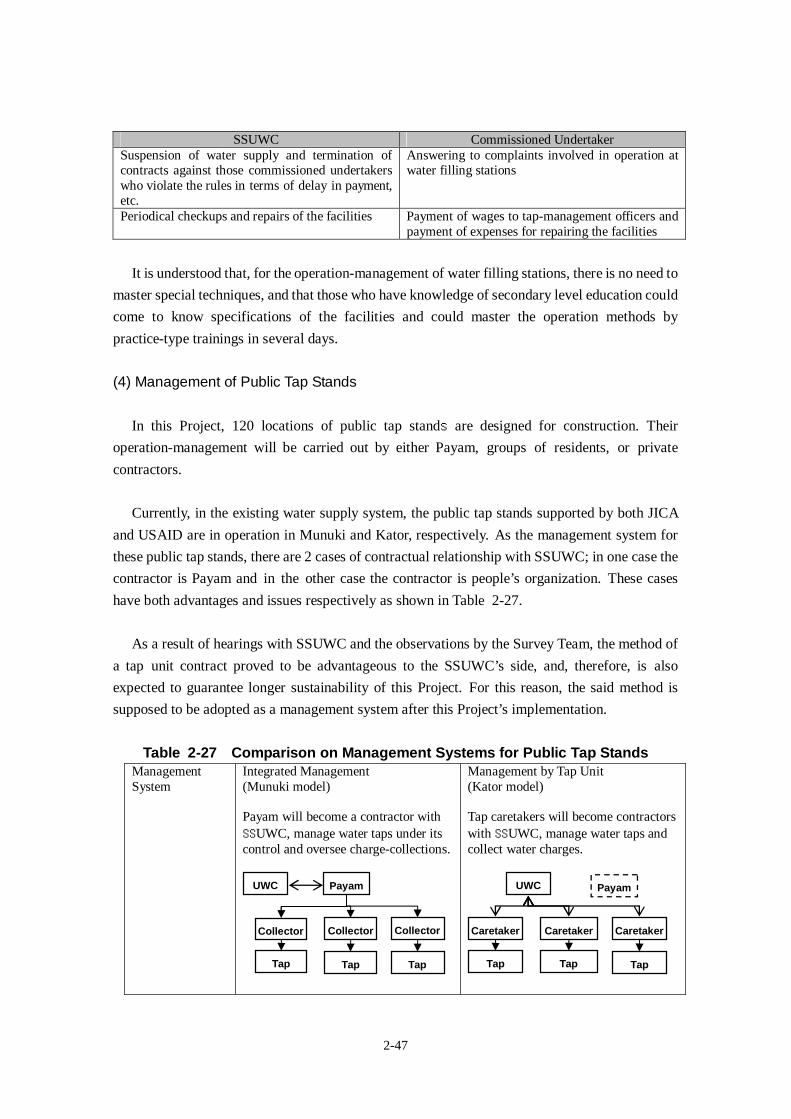
2-47
SSUWC Commissioned UndertakerSuspension of water supply and termination ofcontracts against those commissioned undertakerswho violate the rules in terms of delay in payment,etc.
Answering to complaints involved in operation atwater filling stations
Periodical checkups and repairs of the facilities Payment of wages to tap-management officers andpayment of expenses for repairing the facilities
It is understood that, for the operation-management of water filling stations, there is no need to
master special techniques, and that those who have knowledge of secondary level education could
come to know specifications of the facilities and could master the operation methods by
practice-type trainings in several days.
(4) Management of Public Tap Stands
In this Project, 120 locations of public tap stands are designed for construction. Their
operation-management will be carried out by either Payam, groups of residents, or private
contractors.
Currently, in the existing water supply system, the public tap stands supported by both JICA
and USAID are in operation in Munuki and Kator, respectively. As the management system for
these public tap stands, there are 2 cases of contractual relationship with SSUWC; in one case the
contractor is Payam and in the other case the contractor is people’s organization. These cases
have both advantages and issues respectively as shown in Table 2-27.
As a result of hearings with SSUWC and the observations by the Survey Team, the method of
a tap unit contract proved to be advantageous to the SSUWC’s side, and, therefore, is also
expected to guarantee longer sustainability of this Project. For this reason, the said method is
supposed to be adopted as a management system after this Project’s implementation.
Table 2-27 Comparison on Management Systems for Public Tap StandsManagementSystem
Integrated Management(Munuki model)
Payam will become a contractor with
SSUWC, manage water taps under itscontrol and oversee charge-collections.
Management by Tap Unit(Kator model)
Tap caretakers will become contractors
with SSUWC, manage water taps andcollect water charges.
UWC
Collector
Tap
Payam
Collector
Tap
Collector
Tap
UWC
Caretaker
Tap
Payam
Caretaker
Tap
Caretaker
Tap
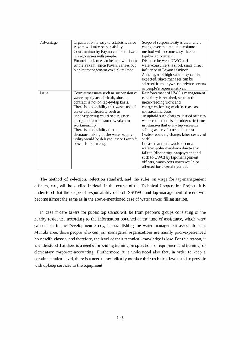
2-48
Advantage Organization is easy to establish, sincePayam will take responsibility.Coordination by Payam can be utilizedin negotiation with people.Financial balance can be held within thewhole Payam, since Payam carries outblanket management over plural taps.
Scope of responsibility is clear and achangeover to a metered-volumemethod will become easy, due totap-by-tap contract.Distance between UWC andwater-consumers is short, since directinfluence of Payam is minor.A manager of high capability can beexpected, since manager can beselected from anywhere, private sectorsor people’s representatives.
Issue Countermeasures such as suspension ofwater supply are difficult, since acontract is not on tap-by-tap basis.There is a possibility that waste-use ofwater and dishonesty such asunder-reporting could occur, sincecharge-collectors would weaken inworkmanship.There is a possibility thatdecision-making of the water supplyutility would be delayed, since Payam’spower is too strong.
Reinforcement of UWC’s managementcapability is required, since bothmeter-reading work andcharge-collecting work increase ascontracts increase.To uphold such charges unified fairly towater consumers is a problematic issue,in situation that every tap varies inselling water volume and in cost(water-receiving charge, labor costs andsuch).In case that there would occur awater-supply- shutdown due to anyfailure (dishonesty, nonpayment andsuch to UWC) by tap-managementofficers, water-consumers would beaffected for a certain period.
The method of selection, selection standard, and the rules on wage for tap-management
officers, etc., will be studied in detail in the course of the Technical Cooperation Project. It is
understood that the scope of responsibility of both SSUWC and tap-management officers will
become almost the same as in the above-mentioned case of water tanker filling station.
In case if care takers for public tap stands will be from people’s groups consisting of the
nearby residents, according to the information obtained at the time of assistance, which were
carried out in the Development Study, in establishing the water management associations in
Munuki area, those people who can join managerial organizations are mainly poor-experienced
housewife-classes, and therefore, the level of their technical knowledge is low. For this reason, it
is understood that there is a need of providing training on operations of equipment and training for
elementary corporate-accounting. Furthermore, it is understood also that, in order to keep a
certain technical level, there is a need to periodically monitor their technical levels and to provide
with upkeep services to the equipment.
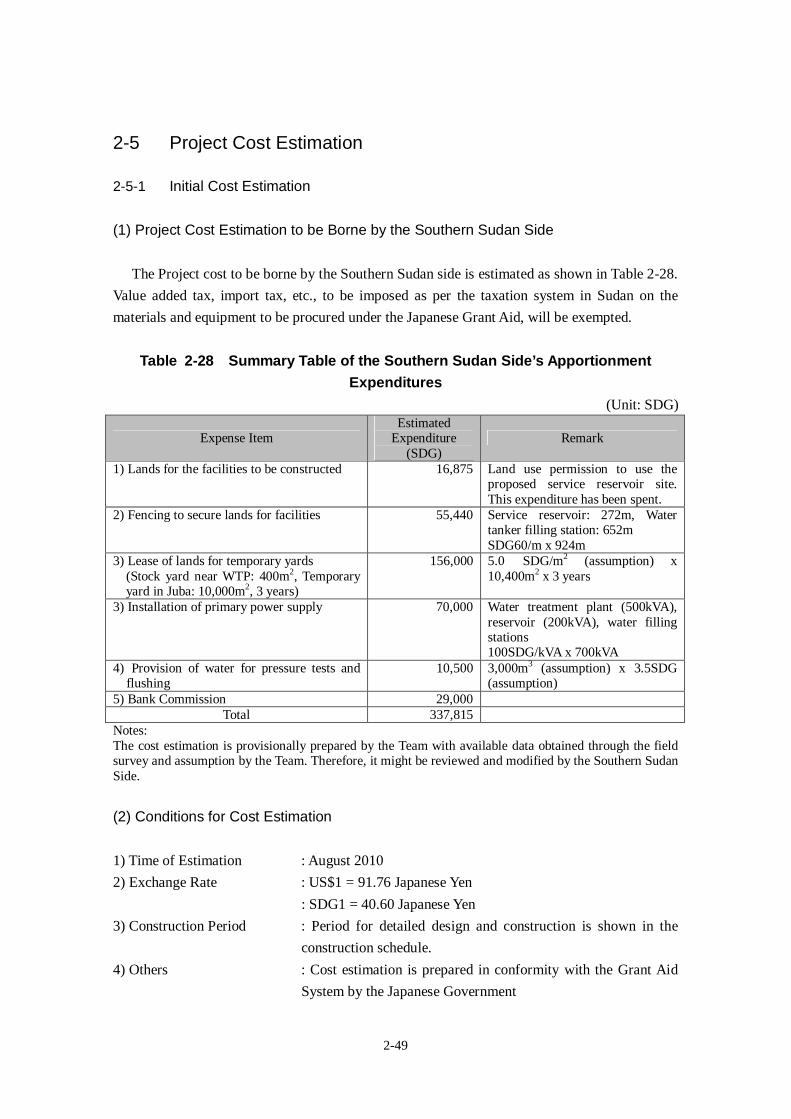
2-49
2-5 Project Cost Estimation
2-5-1 Initial Cost Estimation
(1) Project Cost Estimation to be Borne by the Southern Sudan Side
The Project cost to be borne by the Southern Sudan side is estimated as shown in Table 2-28.
Value added tax, import tax, etc., to be imposed as per the taxation system in Sudan on the
materials and equipment to be procured under the Japanese Grant Aid, will be exempted.
Table 2-28 Summary Table of the Southern Sudan Side’s ApportionmentExpenditures
(Unit: SDG)
Expense ItemEstimated
Expenditure(SDG)
Remark
1) Lands for the facilities to be constructed 16,875 Land use permission to use theproposed service reservoir site.This expenditure has been spent.
2) Fencing to secure lands for facilities 55,440 Service reservoir: 272m, Watertanker filling station: 652mSDG60/m x 924m
3) Lease of lands for temporary yards(Stock yard near WTP: 400m2, Temporaryyard in Juba: 10,000m2, 3 years)
156,000 5.0 SDG/m2 (assumption) x10,400m2 x 3 years
3) Installation of primary power supply 70,000 Water treatment plant (500kVA),reservoir (200kVA), water fillingstations100SDG/kVA x 700kVA
4) Provision of water for pressure tests andflushing
10,500 3,000m3 (assumption) x 3.5SDG(assumption)
5) Bank Commission 29,000Total 337,815
Notes:The cost estimation is provisionally prepared by the Team with available data obtained through the fieldsurvey and assumption by the Team. Therefore, it might be reviewed and modified by the Southern SudanSide.
(2) Conditions for Cost Estimation
1) Time of Estimation : August 2010
2) Exchange Rate : US$1 = 91.76 Japanese Yen
: SDG1 = 40.60 Japanese Yen
3) Construction Period : Period for detailed design and construction is shown in the
construction schedule.
4) Others : Cost estimation is prepared in conformity with the Grant Aid
System by the Japanese Government
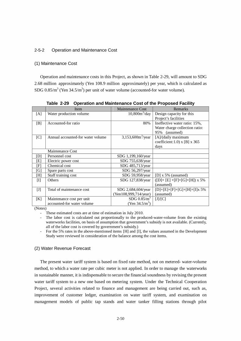
2-50
2-5-2 Operation and Maintenance Cost
(1) Maintenance Cost
Operation and maintenance costs in this Project, as shown in Table 2-29, will amount to SDG
2.68 million approximately (Yen 108.9 million approximately) per year, which is calculated as
SDG 0.85/m3 (Yen 34.5/m3) per unit of water volume (accounted-for water volume).
Table 2-29 Operation and Maintenance Cost of the Proposed FacilityItem Maintenance Cost Remarks
[A] Water production volume 10,800m3/day Design capacity for thisProject’s facilities
[B] Accounted-for ratio 80% Ineffective water ratio: 15%,Water charge collection ratio:95% (assumed)
[C] Annual accounted-for water volume 3,153,600m3/year [A]/(daily maximumcoefficient:1.0) x [B] x 365days
Maintenance Cost[D] Personnel cost SDG 1,199,160/year[E] Electric power cost SDG 755,638/year[F] Chemical cost SDG 485,713/year[G] Spare parts cost SDG 56,297/year[H] Staff training cost SDG 59,958/year [D] x 5% (assumed)[I] Others SDG 127,838/year ([D]+ [E] +[F]+[G]+[H]) x 5%
(assumed)[J] Total of maintenance cost SDG 2,684,604/year
(Yen108,999,714/year)[D]+[E]+[F]+[G]+[H]+[I]x 5%(assumed)
[K] Maintenance cost per unitaccounted-for water volume
SDG 0.85/m3
(Yen 34.5/m3)[J]/[C]
(Notes)- These estimated costs are at time of estimation in July 2010.- The labor cost is calculated out proportionally to the produced-water-volume from the existing
waterworks facilities, on basis of assumption that government’s subsidy is not available. (Currently,all of the labor cost is covered by government’s subsidy.)
- For the 5% rates in the above-mentioned items [H] and [I], the values assumed in the DevelopmentStudy were reviewed in consideration of the balance among the cost items.
(2) Water Revenue Forecast
The present water tariff system is based on fixed rate method, not on metered- water-volume
method, to which a water rate per cubic meter is not applied. In order to manage the waterworks
in sustainable manner, it is indispensable to secure the financial soundness by revising the present
water tariff system to a new one based on metering system. Under the Technical Cooperation
Project, several activities related to finance and management are being carried out, such as,
improvement of customer ledger, examination on water tariff system, and examination on
management models of public tap stands and water tanker filling stations through pilot
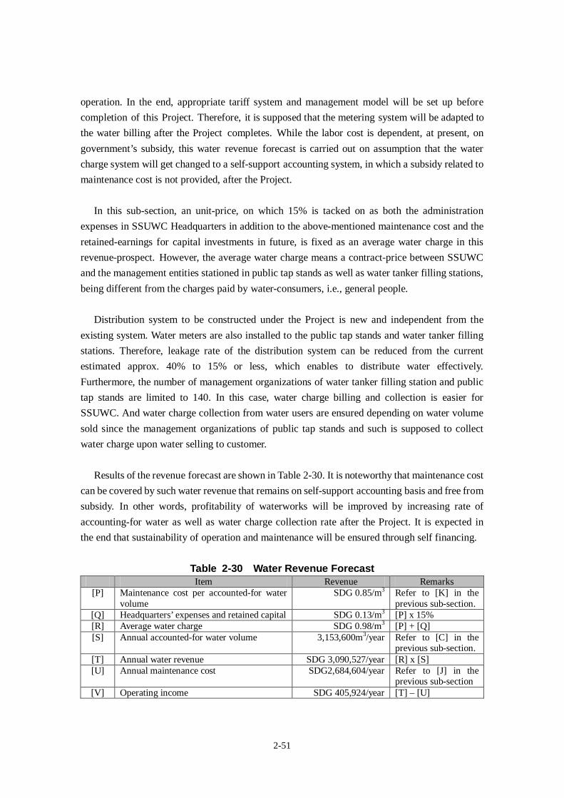
2-51
operation. In the end, appropriate tariff system and management model will be set up before
completion of this Project. Therefore, it is supposed that the metering system will be adapted to
the water billing after the Project completes. While the labor cost is dependent, at present, on
government’s subsidy, this water revenue forecast is carried out on assumption that the water
charge system will get changed to a self-support accounting system, in which a subsidy related to
maintenance cost is not provided, after the Project.
In this sub-section, an unit-price, on which 15% is tacked on as both the administration
expenses in SSUWC Headquarters in addition to the above-mentioned maintenance cost and the
retained-earnings for capital investments in future, is fixed as an average water charge in this
revenue-prospect. However, the average water charge means a contract-price between SSUWC
and the management entities stationed in public tap stands as well as water tanker filling stations,
being different from the charges paid by water-consumers, i.e., general people.
Distribution system to be constructed under the Project is new and independent from the
existing system. Water meters are also installed to the public tap stands and water tanker filling
stations. Therefore, leakage rate of the distribution system can be reduced from the current
estimated approx. 40% to 15% or less, which enables to distribute water effectively.
Furthermore, the number of management organizations of water tanker filling station and public
tap stands are limited to 140. In this case, water charge billing and collection is easier for
SSUWC. And water charge collection from water users are ensured depending on water volume
sold since the management organizations of public tap stands and such is supposed to collect
water charge upon water selling to customer.
Results of the revenue forecast are shown in Table 2-30. It is noteworthy that maintenance cost
can be covered by such water revenue that remains on self-support accounting basis and free from
subsidy. In other words, profitability of waterworks will be improved by increasing rate of
accounting-for water as well as water charge collection rate after the Project. It is expected in
the end that sustainability of operation and maintenance will be ensured through self financing.
Table 2-30 Water Revenue ForecastItem Revenue Remarks
[P] Maintenance cost per accounted-for watervolume
SDG 0.85/m3 Refer to [K] in theprevious sub-section.
[Q] Headquarters’ expenses and retained capital SDG 0.13/m3 [P] x 15%[R] Average water charge SDG 0.98/m3 [P] + [Q][S] Annual accounted-for water volume 3,153,600m3/year Refer to [C] in the
previous sub-section.[T] Annual water revenue SDG 3,090,527/year [R] x [S][U] Annual maintenance cost SDG2,684,604/year Refer to [J] in the
previous sub-section[V] Operating income SDG 405,924/year [T] – [U]
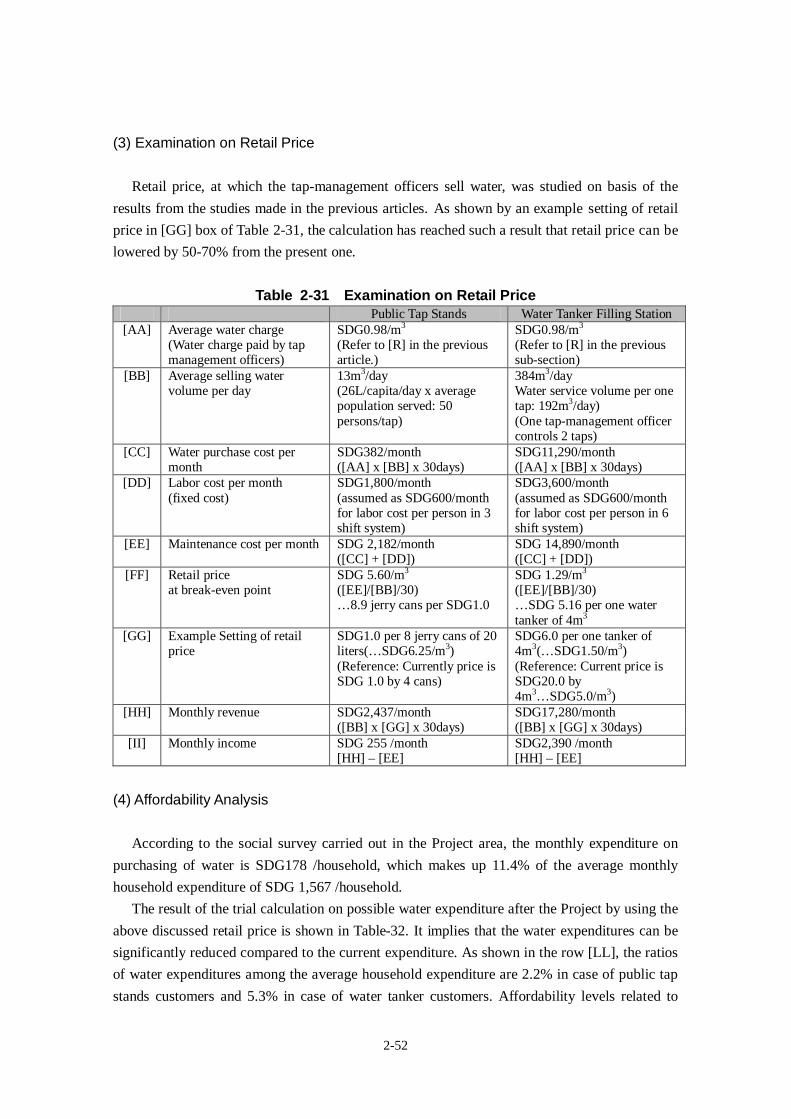
2-52
(3) Examination on Retail Price
Retail price, at which the tap-management officers sell water, was studied on basis of the
results from the studies made in the previous articles. As shown by an example setting of retail
price in [GG] box of Table 2-31, the calculation has reached such a result that retail price can be
lowered by 50-70% from the present one.
Table 2-31 Examination on Retail PricePublic Tap Stands Water Tanker Filling Station
[AA] Average water charge(Water charge paid by tapmanagement officers)
SDG0.98/m3
(Refer to [R] in the previousarticle.)
SDG0.98/m3
(Refer to [R] in the previoussub-section)
[BB] Average selling watervolume per day
13m3/day(26L/capita/day x averagepopulation served: 50persons/tap)
384m3/dayWater service volume per onetap: 192m3/day)(One tap-management officercontrols 2 taps)
[CC] Water purchase cost permonth
SDG382/month([AA] x [BB] x 30days)
SDG11,290/month([AA] x [BB] x 30days)
[DD] Labor cost per month(fixed cost)
SDG1,800/month(assumed as SDG600/monthfor labor cost per person in 3shift system)
SDG3,600/month(assumed as SDG600/monthfor labor cost per person in 6shift system)
[EE] Maintenance cost per month SDG 2,182/month([CC] + [DD])
SDG 14,890/month([CC] + [DD])
[FF] Retail priceat break-even point
SDG 5.60/m3
([EE]/[BB]/30)…8.9 jerry cans per SDG1.0
SDG 1.29/m3
([EE]/[BB]/30)…SDG 5.16 per one watertanker of 4m3
[GG] Example Setting of retailprice
SDG1.0 per 8 jerry cans of 20liters(…SDG6.25/m3)(Reference: Currently price isSDG 1.0 by 4 cans)
SDG6.0 per one tanker of4m3(…SDG1.50/m3)(Reference: Current price isSDG20.0 by4m3…SDG5.0/m3)
[HH] Monthly revenue SDG2,437/month([BB] x [GG] x 30days)
SDG17,280/month([BB] x [GG] x 30days)
[II] Monthly income SDG 255 /month[HH] – [EE]
SDG2,390 /month[HH] – [EE]
(4) Affordability Analysis
According to the social survey carried out in the Project area, the monthly expenditure on
purchasing of water is SDG178 /household, which makes up 11.4% of the average monthly
household expenditure of SDG 1,567 /household.
The result of the trial calculation on possible water expenditure after the Project by using the
above discussed retail price is shown in Table-32. It implies that the water expenditures can be
significantly reduced compared to the current expenditure. As shown in the row [LL], the ratios
of water expenditures among the average household expenditure are 2.2% in case of public tap
stands customers and 5.3% in case of water tanker customers. Affordability levels related to
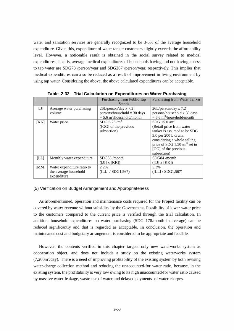
2-53
water and sanitation services are generally recognized to be 3-5% of the average household
expenditure. Given this, expenditure of water tanker customers slightly exceeds the affordability
level. However, a noticeable result is obtained in the social survey related to medical
expenditures. That is, average medical expenditures of households having and not having access
to tap water are SDG73 /person/year and SDG267 /person/year, respectively. This implies that
medical expenditures can also be reduced as a result of improvement in living environment by
using tap water. Considering the above, the above calculated expenditures can be acceptable.
Table 2-32 Trial Calculation on Expenditures on Water PurchasingPurchasing from Public Tap
StandsPurchasing from Water Tanker
[JJ] Average water purchasingvolume
26L/person/day x 7.2persons/household x 30 days= 5.6 m3/household/month
26L/person/day x 7.2persons/household x 30 days= 5.6 m3/household/month
[KK] Water price SDG 6.25 /m3
([GG] of the previoussubsection)
SDG 15.0 /m3
(Retail price from watertanker is assumed to be SDG3.0 per 200 L drum,considering a whole sellingprice of SDG 1.50 /m3 set in[GG] of the previoussubsection)
[LL] Monthly water expenditure SDG35 /month([JJ] x [KK])
SDG84 /month([JJ] x [KK])
[MM] Water expenditure ratio tothe average householdexpenditure
2.2%([LL] / SDG1,567)
5.3%([LL] / SDG1,567)
(5) Verification on Budget Arrangement and Appropriateness
As aforementioned, operation and maintenance costs required for the Project facility can be
covered by water revenue without subsidies by the Government. Possibility of lower water price
to the customers compared to the current price is verified through the trial calculation. In
addition, household expenditures on water purchasing (SDG 178/month in average) can be
reduced significantly and that is regarded as acceptable. In conclusion, the operation and
maintenance cost and budgetary arrangement is considered to be appropriate and feasible.
However, the contents verified in this chapter targets only new waterworks system as
cooperation object, and does not include a study on the existing waterworks system
(7,200m3/day). There is a need of improving profitability of the existing system by both revising
water-charge collection method and reducing the unaccounted-for water ratio, because, in the
existing system, the profitability is very low owing to its high unaccounted-for water ratio caused
by massive water-leakage, waste-use of water and delayed payments of water charges.
2-54
2-6 Other Relevant Issues
As a result of referendum, independence of the Southern Sudan was decided. Since this
Project is scheduled to be implemented during the transitional period of independence, special
attention shall be paid to political and security situations.
Taking into account the possibility that the signatory of the recipient country would be the
new government, the official procedures and undertakings required for smooth implementation
of the Project by the government shall be facilitated by assisting the relevant authorities of the
new country where legislation and implementing organization may not be well established in
the initial stage of the Project.
CHAPTER 3 PROJECT EVALUATION

3-1
Chapter 3 Project Evaluation
3-1 Recommendations
3-1-1 Prerequisite conditions for Implementation of the Project
(1) Land Acquisition and Securing the Site
All proposed construction sites have been confirmed to be public land and permitted to use
for construction of the facility. Since these sites are currently not secured by fence, it is
requested to protect the sites from any occupations or constructions other than facilities under
this Project. It is therefore recommended to stake out the lots to indicate government ownership
and conduct regular monitoring of the sites to prevent any physical occupation.
Provision of land for stockyard and temporary facilities (total area: approx. 10,400 m2) are
also requested to the Southern Sudan side. It shall be secured prior to implementation of the
Project.
(2) Undertakings of the Recipient Side
Budget arrangement shall be ensured to carry out the undertakings by the Southern Sudan
side appropriately and in timely manner.
(3) Security Situation
Since Southern Sudan is planned to be independent in July 2011 as a result of the referendum
in January 2011, instability of security situation is expected in that period. Therefore, security
situation is one of preconditions and it should not worsen significantly to implement the Project
smoothly.
3-1-2 Important Assumptions for Achievement of the Overall Goal
(1) Effective Use of Developed Capacity through the Technical Cooperation Project
Since capacity of SSUWC who carries out waterworks management, there is a necessity to
develop capacity of operation and maintenance of the water supply facility to be constructed
under the Project. For this purpose, “The Project for Management Capacity Enhancement of
Southern Sudan Urban Water Corporation in Southern Sudan” (hereinafter referred to as the
“Technical Cooperation Project”, is carried out by JICA along with this Project from October
2010 to September 2013. The Technical Cooperation Project aims to enhance capacity of
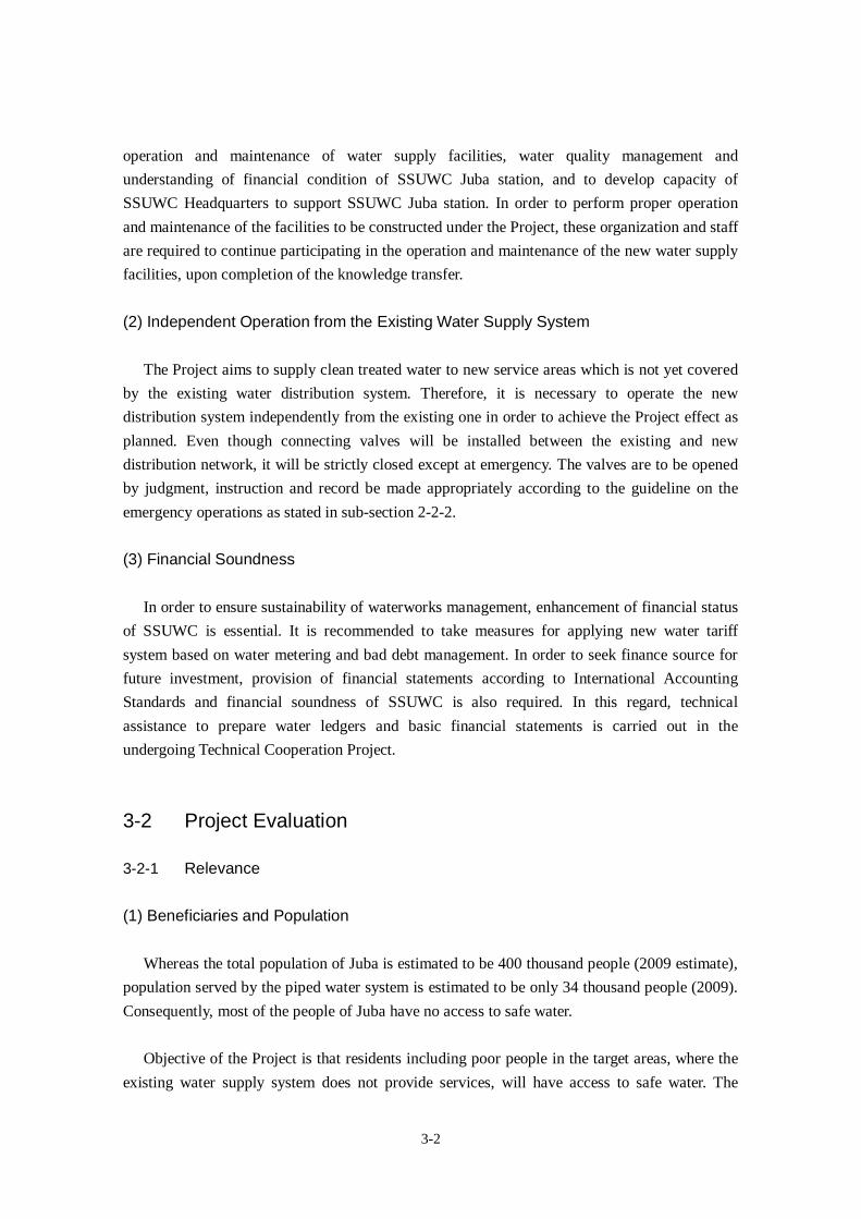
3-2
operation and maintenance of water supply facilities, water quality management and
understanding of financial condition of SSUWC Juba station, and to develop capacity of
SSUWC Headquarters to support SSUWC Juba station. In order to perform proper operation
and maintenance of the facilities to be constructed under the Project, these organization and staff
are required to continue participating in the operation and maintenance of the new water supply
facilities, upon completion of the knowledge transfer.
(2) Independent Operation from the Existing Water Supply System
The Project aims to supply clean treated water to new service areas which is not yet covered
by the existing water distribution system. Therefore, it is necessary to operate the new
distribution system independently from the existing one in order to achieve the Project effect as
planned. Even though connecting valves will be installed between the existing and new
distribution network, it will be strictly closed except at emergency. The valves are to be opened
by judgment, instruction and record be made appropriately according to the guideline on the
emergency operations as stated in sub-section 2-2-2.
(3) Financial Soundness
In order to ensure sustainability of waterworks management, enhancement of financial status
of SSUWC is essential. It is recommended to take measures for applying new water tariff
system based on water metering and bad debt management. In order to seek finance source for
future investment, provision of financial statements according to International Accounting
Standards and financial soundness of SSUWC is also required. In this regard, technical
assistance to prepare water ledgers and basic financial statements is carried out in the
undergoing Technical Cooperation Project.
3-2 Project Evaluation
3-2-1 Relevance
(1) Beneficiaries and Population
Whereas the total population of Juba is estimated to be 400 thousand people (2009 estimate),
population served by the piped water system is estimated to be only 34 thousand people (2009).
Consequently, most of the people of Juba have no access to safe water.
Objective of the Project is that residents including poor people in the target areas, where the
existing water supply system does not provide services, will have access to safe water. The
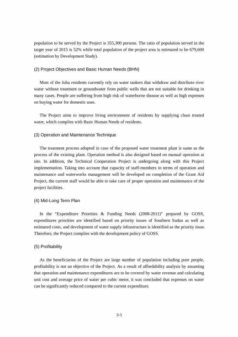
3-3
population to be served by the Project is 355,300 persons. The ratio of population served in the
target year of 2015 is 52% while total population of the project area is estimated to be 679,600
(estimation by Development Study).
(2) Project Objectives and Basic Human Needs (BHN)
Most of the Juba residents currently rely on water tankers that withdraw and distribute river
water without treatment or groundwater from public wells that are not suitable for drinking in
many cases. People are suffering from high risk of waterborne disease as well as high expenses
on buying water for domestic uses.
The Project aims to improve living environment of residents by supplying clean treated
water, which complies with Basic Human Needs of residents.
(3) Operation and Maintenance Technique
The treatment process adopted in case of the proposed water treatment plant is same as the
process of the existing plant. Operation method is also designed based on manual operation at
site. In addition, the Technical Cooperation Project is undergoing along with this Project
implementation. Taking into account that capacity of staff-members in terms of operation and
maintenance and waterworks management will be developed on completion of the Grant Aid
Project, the current staff would be able to take care of proper operation and maintenance of the
project facilities.
(4) Mid-Long Term Plan
In the “Expenditure Priorities & Funding Needs (2008-2011)” prepared by GOSS,
expenditures priorities are identified based on priority issues of Southern Sudan as well as
estimated costs, and development of water supply infrastructure is identified as the priority issue.
Therefore, the Project complies with the development policy of GOSS.
(5) Profitability
As the beneficiaries of the Project are large number of population including poor people,
profitability is not an objective of the Project. As a result of affordability analysis by assuming
that operation and maintenance expenditures are to be covered by water revenue and calculating
unit cost and average price of water per cubic meter, it was concluded that expenses on water
can be significantly reduced compared to the current expenditure.
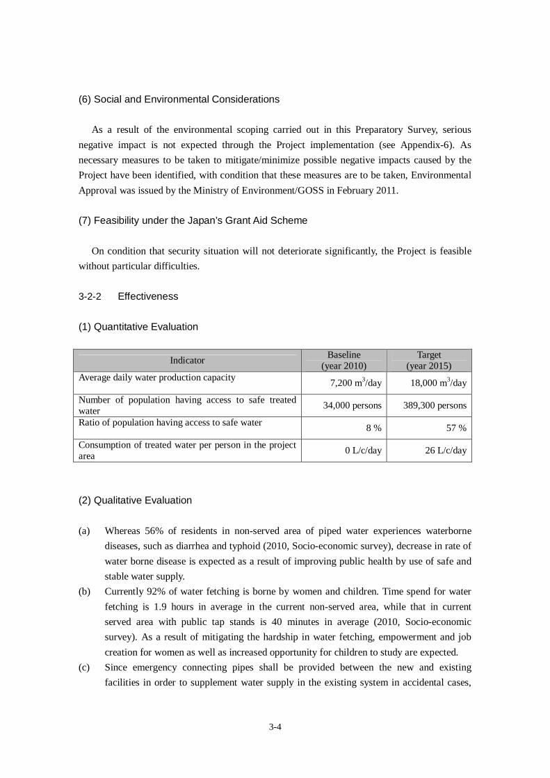
3-4
(6) Social and Environmental Considerations
As a result of the environmental scoping carried out in this Preparatory Survey, serious
negative impact is not expected through the Project implementation (see Appendix-6). As
necessary measures to be taken to mitigate/minimize possible negative impacts caused by the
Project have been identified, with condition that these measures are to be taken, Environmental
Approval was issued by the Ministry of Environment/GOSS in February 2011.
(7) Feasibility under the Japan’s Grant Aid Scheme
On condition that security situation will not deteriorate significantly, the Project is feasible
without particular difficulties.
3-2-2 Effectiveness
(1) Quantitative Evaluation
IndicatorBaseline
(year 2010)Target
(year 2015)Average daily water production capacity
7,200 m3/day 18,000 m3/day
Number of population having access to safe treatedwater
34,000 persons 389,300 persons
Ratio of population having access to safe water8 % 57 %
Consumption of treated water per person in the projectarea
0 L/c/day 26 L/c/day
(2) Qualitative Evaluation
(a) Whereas 56% of residents in non-served area of piped water experiences waterborne
diseases, such as diarrhea and typhoid (2010, Socio-economic survey), decrease in rate of
water borne disease is expected as a result of improving public health by use of safe and
stable water supply.
(b) Currently 92% of water fetching is borne by women and children. Time spend for water
fetching is 1.9 hours in average in the current non-served area, while that in current
served area with public tap stands is 40 minutes in average (2010, Socio-economic
survey). As a result of mitigating the hardship in water fetching, empowerment and job
creation for women as well as increased opportunity for children to study are expected.
(c) Since emergency connecting pipes shall be provided between the new and existing
facilities in order to supplement water supply in the existing system in accidental cases,

3-5
occurrence of water supply interruption can be mitigated. Consequently, it is expected to
improve reliability of the water supply services by the existing system, which serves the
current population of approx. 34,000.
As aforementioned, the Project will contribute to improve living environment of approx. 355
thousand people of Juba including poor residents. As positive effects are also expected, the
Project is evaluated to be relevant and effective to be implemented under the Japan’s Grant Aid.

Appendix-1 Member List
Appendix-2 Study Schedule
Appendix-3 List of Parties Concerned

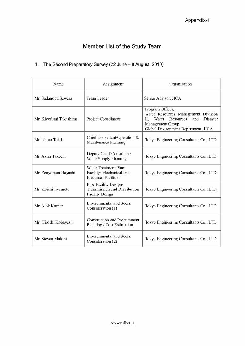
Appendix-1
Appendix1-1
Member List of the Study Team
1. The Second Preparatory Survey (22 June – 8 August, 2010)
Name Assignment Organization
Mr. Sadanobu Sawara Team Leader Senior Advisor, JICA
Mr. Kiyofumi Takashima Project Coordinator
Program Officer,Water Resources Management DivisionII, Water Resources and DisasterManagement Group,Global Environment Department, JICA
Mr. Naoto TohdaChief Consultant/Operation &Maintenance Planning
Tokyo Engineering Consultants Co., LTD.
Mr. Akira TakechiDeputy Chief Consultant/Water Supply Planning
Tokyo Engineering Consultants Co., LTD.
Mr. Zenyomon HayashiWater Treatment PlantFacility/ Mechanical andElectrical Facilities
Tokyo Engineering Consultants Co., LTD.
Mr. Koichi IwamotoPipe Facility Design/Transmission and DistributionFacility Design
Tokyo Engineering Consultants Co., LTD.
Mr. Alok KumarEnvironmental and SocialConsideration (1)
Tokyo Engineering Consultants Co., LTD.
Mr. Hiroshi KobayashiConstruction and ProcurementPlanning / Cost Estimation
Tokyo Engineering Consultants Co., LTD.
Mr. Steven MukibiEnvironmental and SocialConsideration (2)
Tokyo Engineering Consultants Co., LTD.
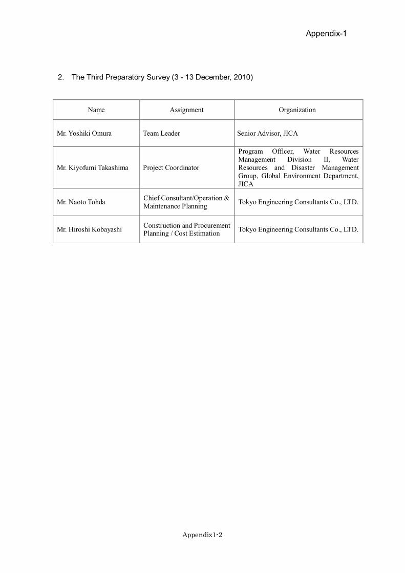
Appendix-1
Appendix1-2
2. The Third Preparatory Survey (3 - 13 December, 2010)
Name Assignment Organization
Mr. Yoshiki Omura Team Leader Senior Advisor, JICA
Mr. Kiyofumi Takashima Project Coordinator
Program Officer, Water ResourcesManagement Division II, WaterResources and Disaster ManagementGroup, Global Environment Department,JICA
Mr. Naoto TohdaChief Consultant/Operation &Maintenance Planning
Tokyo Engineering Consultants Co., LTD.
Mr. Hiroshi KobayashiConstruction and ProcurementPlanning / Cost Estimation
Tokyo Engineering Consultants Co., LTD.
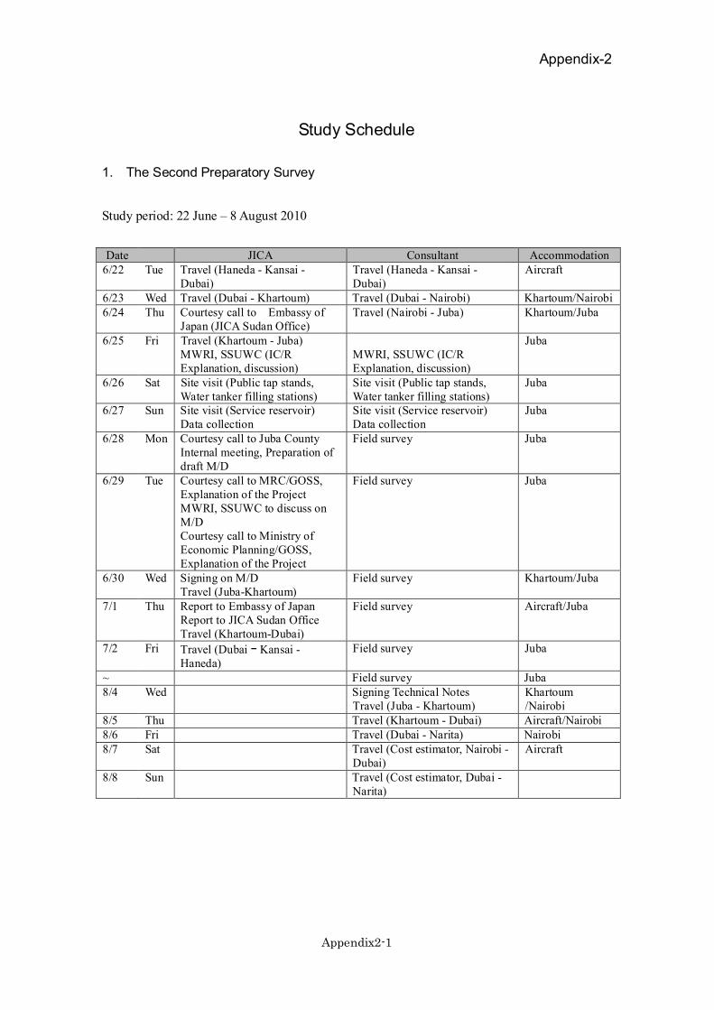
Appendix-2
Appendix2-1
Study Schedule
1. The Second Preparatory Survey
Study period: 22 June – 8 August 2010
Date JICA Consultant Accommodation6/22 Tue Travel (Haneda - Kansai -
Dubai)Travel (Haneda - Kansai -Dubai)
Aircraft
6/23 Wed Travel (Dubai - Khartoum) Travel (Dubai - Nairobi) Khartoum/Nairobi6/24 Thu Courtesy call to Embassy of
Japan (JICA Sudan Office)Travel (Nairobi - Juba) Khartoum/Juba
6/25 Fri Travel (Khartoum - Juba)MWRI, SSUWC (IC/RExplanation, discussion)
MWRI, SSUWC (IC/RExplanation, discussion)
Juba
6/26 Sat Site visit (Public tap stands,Water tanker filling stations)
Site visit (Public tap stands,Water tanker filling stations)
Juba
6/27 Sun Site visit (Service reservoir)Data collection
Site visit (Service reservoir)Data collection
Juba
6/28 Mon Courtesy call to Juba CountyInternal meeting, Preparation ofdraft M/D
Field survey Juba
6/29 Tue Courtesy call to MRC/GOSS,Explanation of the ProjectMWRI, SSUWC to discuss onM/DCourtesy call to Ministry ofEconomic Planning/GOSS,Explanation of the Project
Field survey Juba
6/30 Wed Signing on M/DTravel (Juba-Khartoum)
Field survey Khartoum/Juba
7/1 Thu Report to Embassy of JapanReport to JICA Sudan OfficeTravel (Khartoum-Dubai)
Field survey Aircraft/Juba
7/2 Fri Travel (Dubai Kansai -Haneda)
Field survey Juba
~ Field survey Juba8/4 Wed Signing Technical Notes
Travel (Juba - Khartoum)Khartoum/Nairobi
8/5 Thu Travel (Khartoum - Dubai) Aircraft/Nairobi8/6 Fri Travel (Dubai - Narita) Nairobi8/7 Sat Travel (Cost estimator, Nairobi -
Dubai)Aircraft
8/8 Sun Travel (Cost estimator, Dubai -Narita)
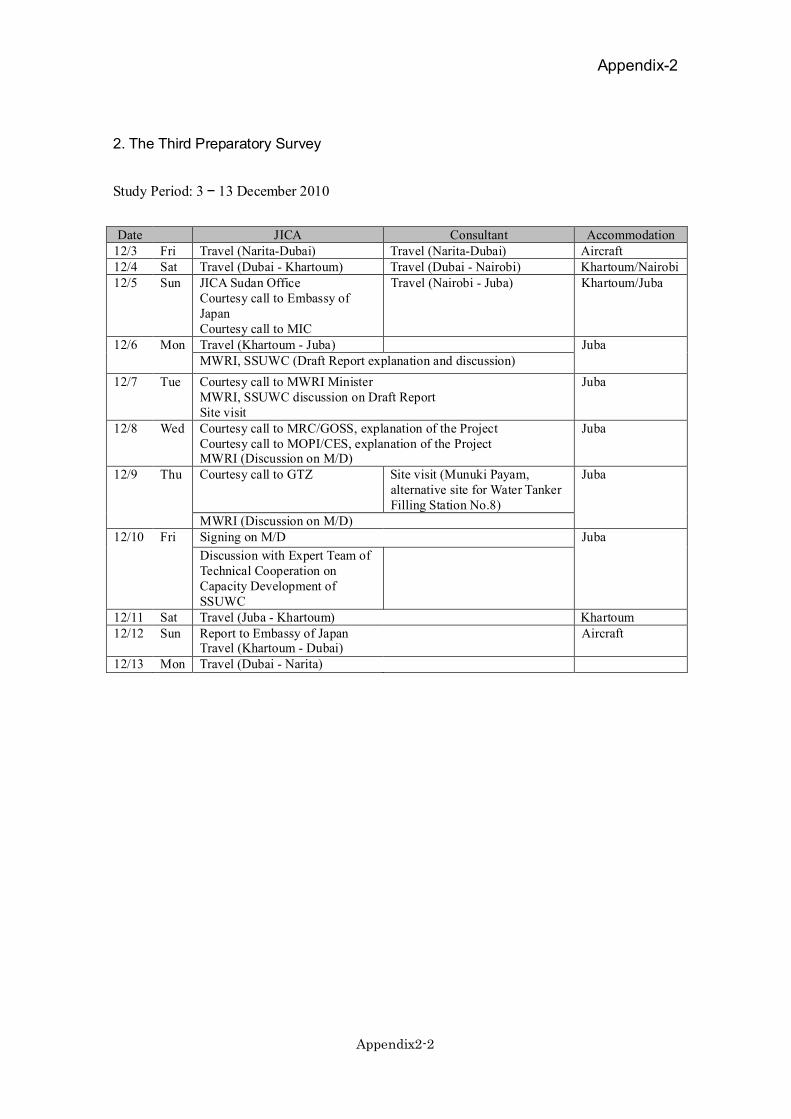
Appendix-2
Appendix2-2
2. The Third Preparatory Survey
Study Period: 3 13 December 2010
Date JICA Consultant Accommodation12/3 Fri Travel (Narita-Dubai) Travel (Narita-Dubai) Aircraft12/4 Sat Travel (Dubai - Khartoum) Travel (Dubai - Nairobi) Khartoum/Nairobi12/5 Sun JICA Sudan Office
Courtesy call to Embassy ofJapanCourtesy call to MIC
Travel (Nairobi - Juba) Khartoum/Juba
Travel (Khartoum - Juba)12/6 MonMWRI, SSUWC (Draft Report explanation and discussion)
Juba
12/7 Tue Courtesy call to MWRI MinisterMWRI, SSUWC discussion on Draft ReportSite visit
Juba
12/8 Wed Courtesy call to MRC/GOSS, explanation of the ProjectCourtesy call to MOPI/CES, explanation of the ProjectMWRI (Discussion on M/D)
Juba
12/9 Thu Courtesy call to GTZ Site visit (Munuki Payam,alternative site for Water TankerFilling Station No.8)
Juba
MWRI (Discussion on M/D)Signing on M/D12/10 Fri
Discussion with Expert Team ofTechnical Cooperation onCapacity Development ofSSUWC
Juba
12/11 Sat Travel (Juba - Khartoum) Khartoum12/12 Sun Report to Embassy of Japan
Travel (Khartoum - Dubai)Aircraft
12/13 Mon Travel (Dubai - Narita)
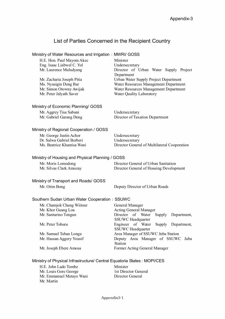
Appendix-3
Appendix3-1
List of Parties Concerned in the Recipient Country
Ministry of Water Resources and Irrigation:MWRI/ GOSS
H.E. Hon. Paul Mayom Akec MinisterEng. Isaac Liabwel C. Yol UndersecretaryMr. Laurence Muludyang Director of Urban Water Supply Project
DepartmentMr. Zacharia Joseph Pitia Urban Water Supply Project DepartmentMs. Nyasigin Deng Bar Water Resources Management DepartmentMr. Simon Otowny Awijak Water Resources Management DepartmentMr. Peter Jalyath Saver Water Quality Laboratory
Ministry of Economic Planning/ GOSS
Mr. Aggrey Tisa Sabuni UndersecretaryMr. Gabriel Garang Deng Director of Taxation Department
Ministry of Regional Cooperation / GOSS
Mr. George Justin Achor UndersecretaryDr. Salwa Gabriel Berberi UndersecretaryMs. Beatrice Khamisa Wani Director General of Multilateral Cooperation
Ministry of Housing and Physical Planning / GOSS
Mr. Moris Lomodong Director General of Urban SanitationMr. Silvas Clark Amozay Director General of Housing Development
Ministry of Transport and Roads/ GOSS
Mr. Otim Bong Deputy Director of Urban Roads
Southern Sudan Urban Water Cooperation:SSUWC
Mr. Chamjok Chung Wiitour General ManagerMr. Khor Guang Loa Acting General ManagerMr. Santurino Tongun Director of Water Supply Department,
SSUWC HeadquarterMr. Peter Toburu Engineer of Water Supply Department,
SSUWC HeadquarterMr. Samuel Taban Longa Area Manager of SSUWC Juba StationMr. Hassan Aggery Yousif Deputy Area Manager of SSUWC Juba
StationMr. Joseph Ebere Amosa Former Acting General Manager
Ministry of Physical Infrastructure/ Central Equatoria States : MOPI/CES
H.E. John Lado Tombe MinisterMr. Louis Gore George 1st Director GeneralMr. Emmanuel Matayo Wani Director GeneralMr. Martin
Appendix-3
Appendix3-2
Juba Town Payam
Mr. Mathew Ladu Payam DirectorMr. Dominic Pitia Payam Engineer
Kator Payam
Mr. Daniel Ali Payam Engineer
Munuki Payam
Mr. Alison Samuel Payam Engineer
Northern Bari Payam
Mr. Martin Deputy Payam DirectorMr. Isaac Kenyi Scopas Payam Officer
International Donors
Mr. Norbert Hagen GTZ expertMr. Josef Ehrmann GTZ expertMr. Kola Farakode Louis Berger Group (USAID SISP Water
and Sanitation Project)
Embassy of Japan in Sudan
Mr. Yoichi Nakashima CounselorMr. Murakami Secretary
JICA Sudan Office (Khartoum)
Mr. Kenichi Shishido Resident RepresentativeMr. Hideaki Matsuoka Project Formulation Advisor
JICA Southern Sudan Field Office
Mr. Yasuhiko Wada Deputy Resident RepresentativeMr. Kiyotaka Tamari Project Formulation AdvisorMr. Kensuke Oshima Project Formulation AdvisorMr. Jun Iijima Assistant Program Officer

Appendix-4 Minutes of Discussion(M/D)
(1) Inception Report (30 June 2010)
(2) Explanation on Draft Report (10 December 2010)
(3) Technical Notes (4 August 2010)

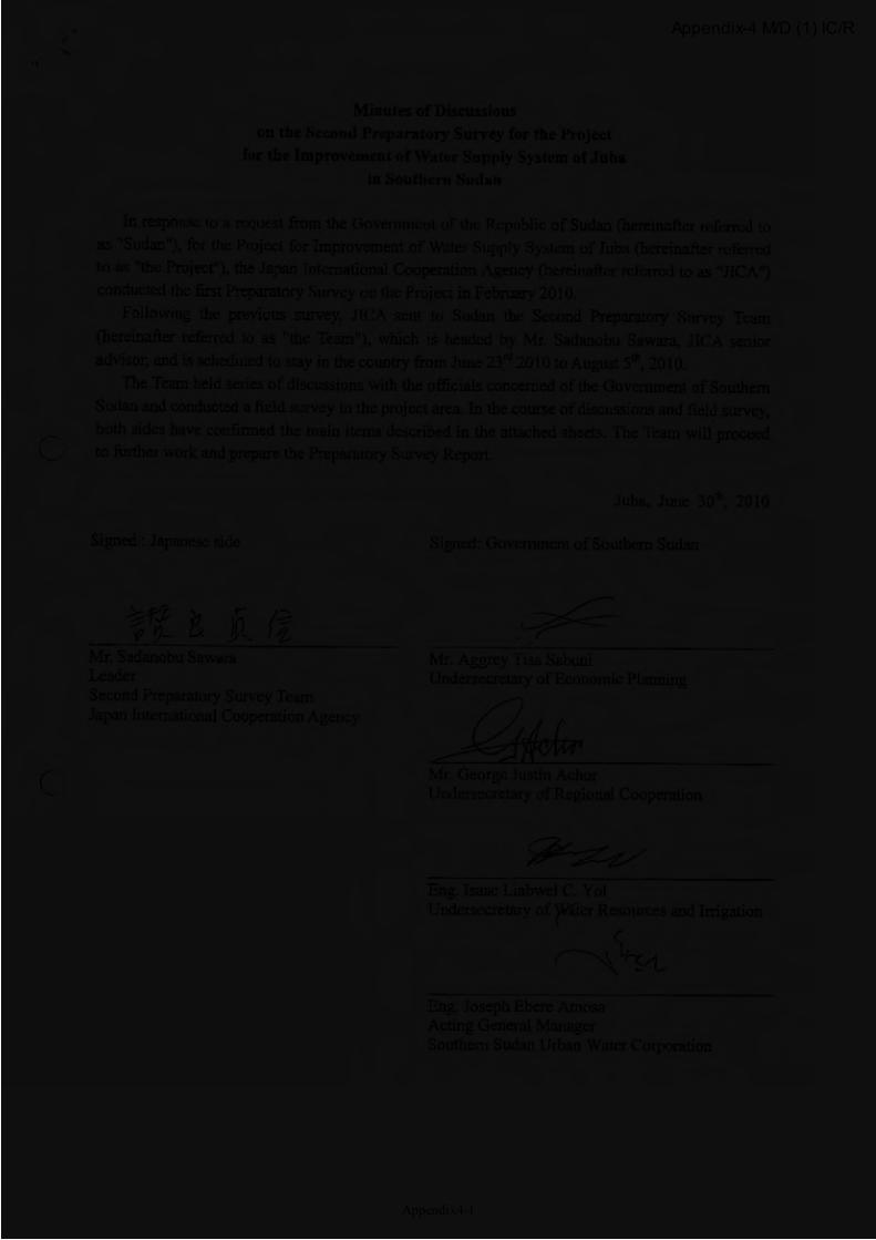
Appendix-4 M/D (1) IC/R
Appendix4-1
Appendix-4 M/D (1) IC/R
Appendix4-2
Appendix-4 M/D (1) IC/R
Appendix4-3
Appendix-4 M/D (1) IC/R
Appendix4-4
Appendix-4 M/D (1) IC/R
Appendix4-5
Appendix-4 M/D (1) IC/R
Appendix4-6
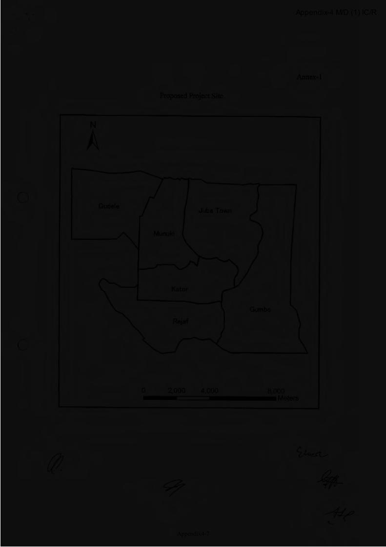
Appendix-4 M/D (1) IC/R
Appendix4-7

Appendix-4 M/D (1) IC/R
Appendix4-8
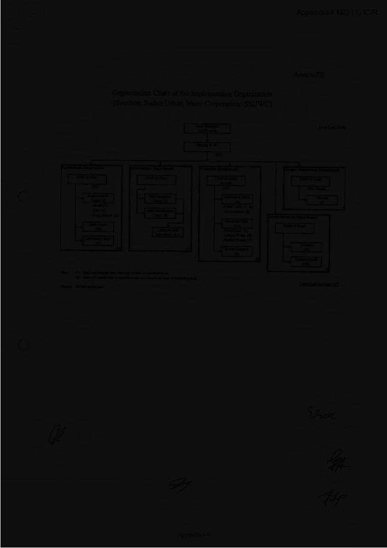
Appendix-4 M/D (1) IC/R
Appendix4-9

Appendix-4 M/D (1) IC/R
Appendix4-10
Appendix-4 M/D (1) IC/R
Appendix4-11
Appendix-4 M/D (1) IC/R
Appendix4-12

Appendix-4 M/D (1) IC/R
Appendix4-13
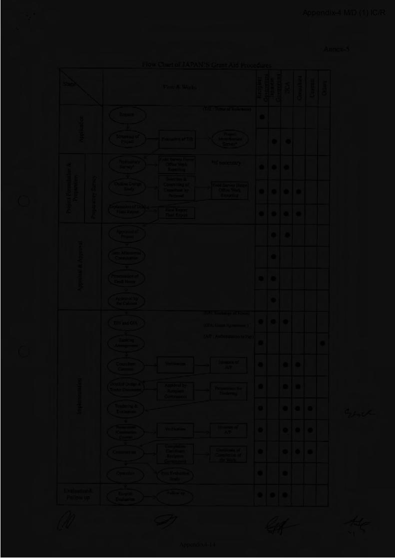
Appendix-4 M/D (1) IC/R
Appendix4-14
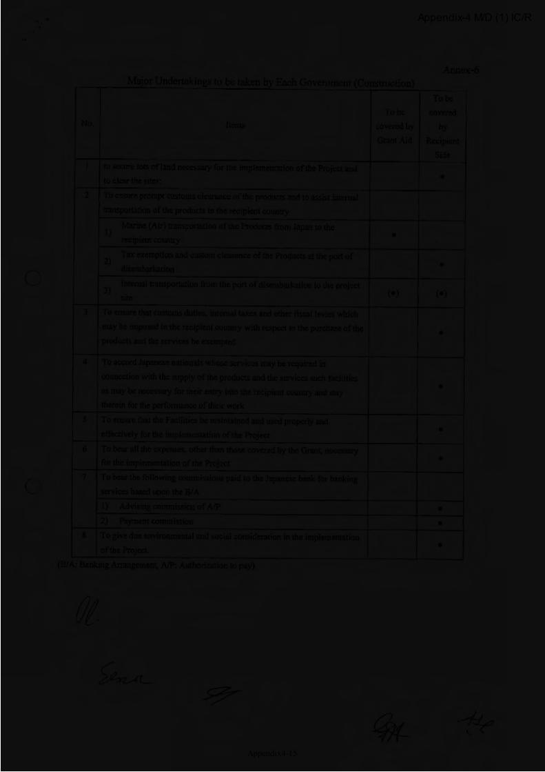
Appendix-4 M/D (1) IC/R
Appendix4-15
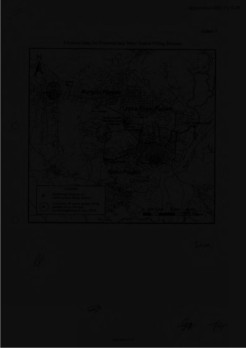
Appendix-4 M/D (1) IC/R
Appendix4-16
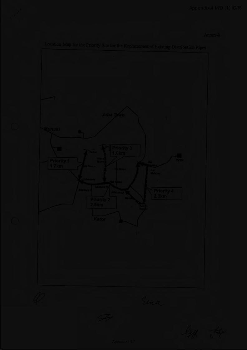
Appendix-4 M/D (1) IC/R
Appendix4-17

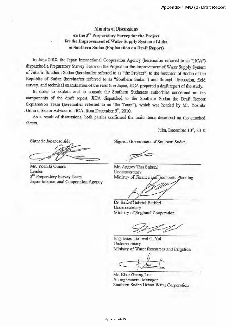
Appendix-4 M/D (2) Draft Report
Appendix4-19
Appendix-4 M/D (2) Draft Report
Appendix4-20
Appendix-4 M/D (2) Draft Report
Appendix4-21
Appendix-4 M/D (2) Draft Report
Appendix4-22
Appendix-4 M/D (2) Draft Report
Appendix4-23
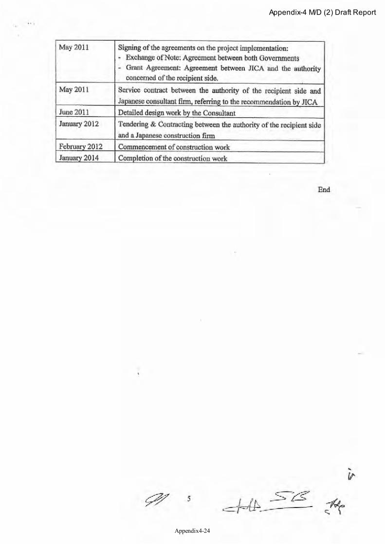
Appendix-4 M/D (2) Draft Report
Appendix4-24
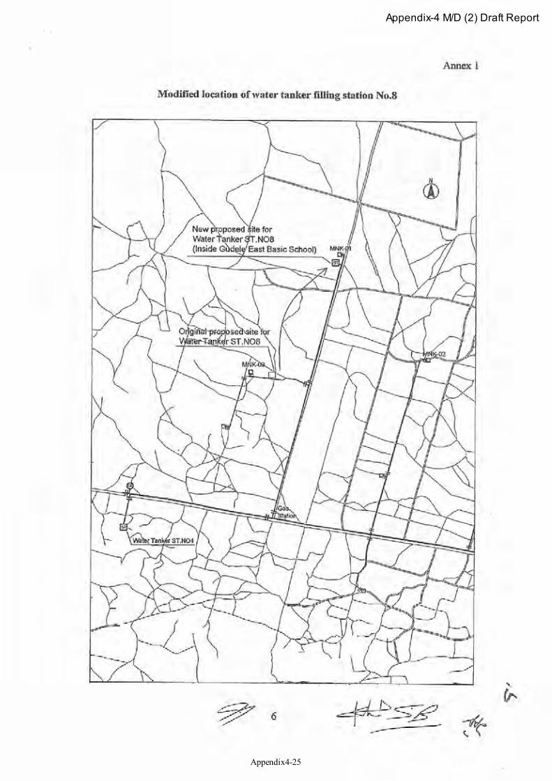
Appendix-4 M/D (2) Draft Report
Appendix4-25
Appendix-4 M/D (2) Draft Report
Appendix4-26
This page is closed due to the confidentiality.
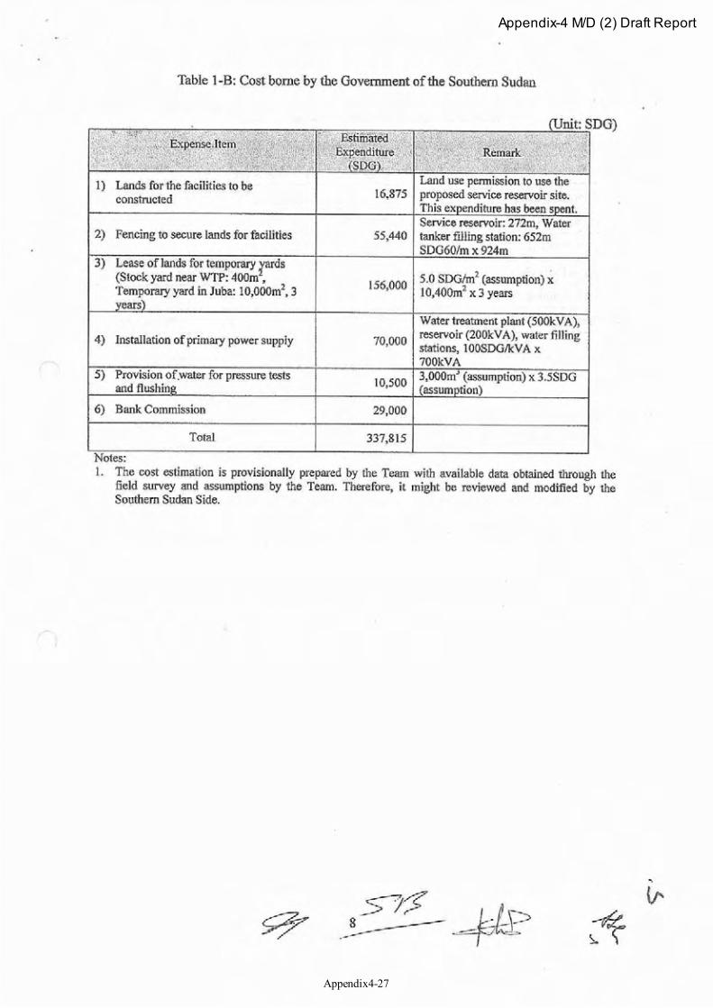
Appendix-4 M/D (2) Draft Report
Appendix4-27
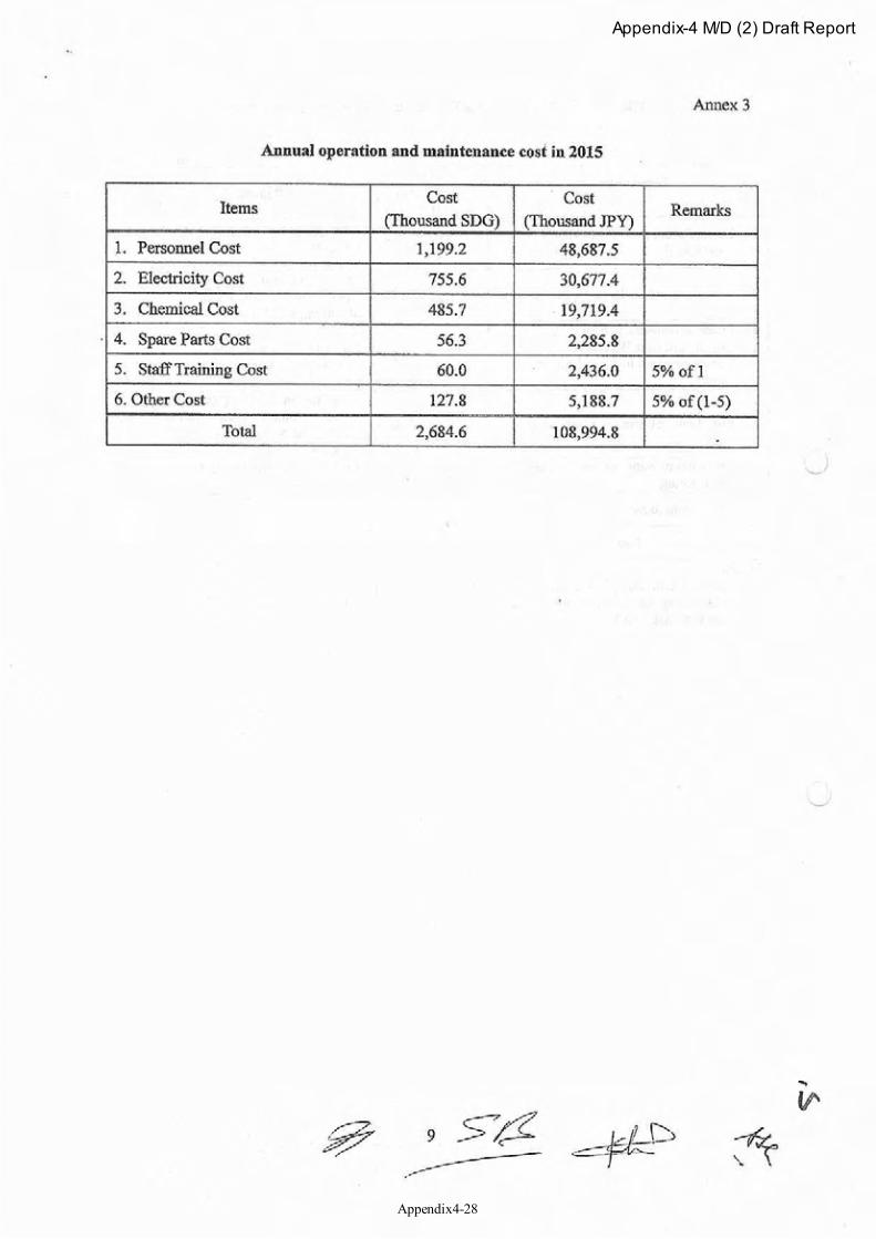
Appendix-4 M/D (2) Draft Report
Appendix4-28
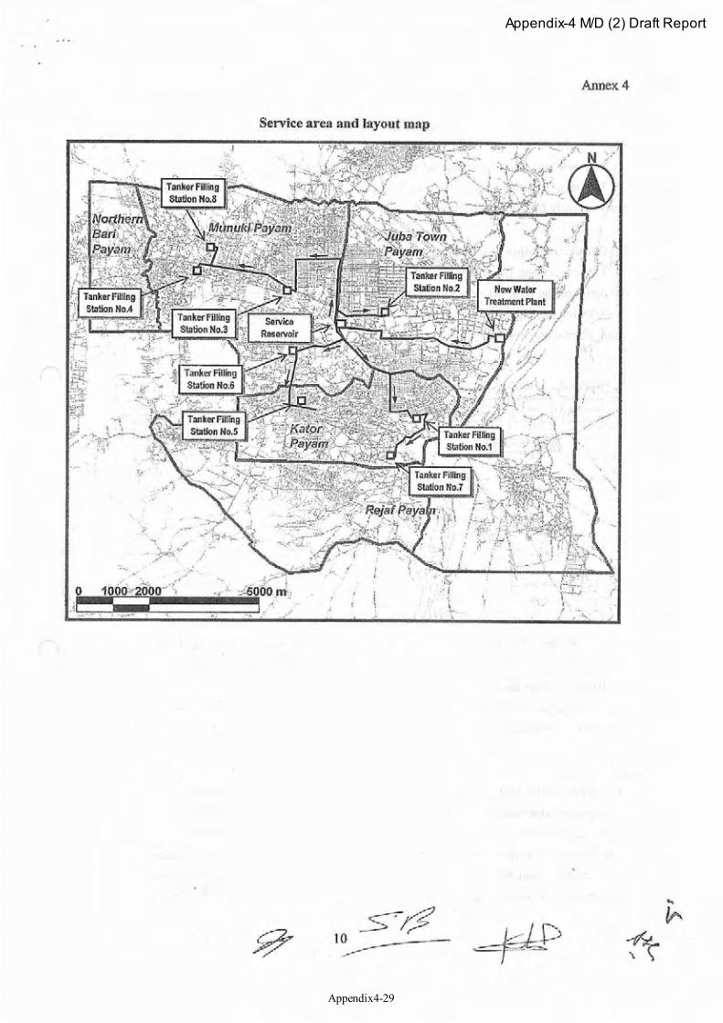
Appendix-4 M/D (2) Draft Report
Appendix4-29
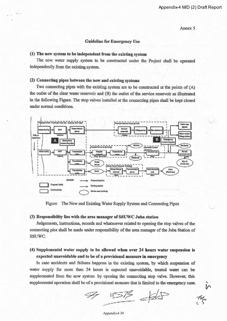
Appendix-4 M/D (2) Draft Report
Appendix4-30
Appendix-4 M/D (2) Draft Report
Appendix4-31
Appendix-4 M/D (2) Draft Report
Appendix4-32
Appendix-4 M/D (2) Draft Report
Appendix4-33