Predictable drill-free screw positioning with a graduated 3-dimensional radiographic-surgical guide:...
14
CLINICIAN’S CORNER Predictable drill-free screw positioning with a graduated 3-dimensional radiographic-surgical guide: A preliminary report Se ´ rgio Estelita, a Guilherme Janson, b Kelly Chiqueto, a Marcos Janson, c and Marcos Roberto de Freitas d Bauru, Brazil Introduction: Mini-implants are placed in restricted sites, requiring an accurate surgical technique. However, no systematic study has quantified technique accuracy to reliably predict the surgical risks. Therefore, a grad- uated 3-dimensional radiographic-surgical guide (G-RSG) was proposed, and its inaccuracy and risk index (RI) were estimated. Methods: The sample consisted of 6 subjects (4 male, 2 female), who used mini-implant anchorage. Ten drill-free screws (DFS) were placed by using the G-RSG. The central point of the mesiodistal septum width (SW) was the selected implant site on the presurgical radiograph. The distances between DFS and the adjacent teeth (5-DFS and 6-DFS) were measured to evaluate screw centralization and inaccuracy de- gree (ID). These distances were statistically compared by independent t tests, and inaccuracy was determined by the expression ID 5 (5-DFS – 6-DFS)/2, which represents deviation of the mini-implant’s final position re- garding the central point initially selected. Then SW, ID, and screw diameter (SØ) were combined to estimate the surgical risk with RI expressed by RI 5 SØ/SW – ID. Results: The 5-DFS and 6-DFS distances were not significantly different. The ID of the G-RSG was 0.17 mm. The low ID ensured a safe RI ( \1) in spite of the re- stricted SW. Conclusions: The G-RSG accuracy allowed fine prediction of the final DFS position in the inter- radicular septum, with a low RI, which is a helpful tool to estimate surgical risks. (Am J Orthod Dentofacial Orthop 2009;136:722-35) O rthodontic anchorage with mini-implants has been frequently used because it prevents un- wanted tooth movements and reduces the de- pendence on patient cooperation, increasing the predictability in attaining the treatment goals. 1-3 How- ever, current mini-implant failure rates of 10% to 20% are significant efficacy limitation of this anchorage sys- tem, 4-12 whereas the restricted anatomic dimensions of implant sites can limit mini-implant applicability because of increased surgical risks and complications, unfavorably influencing the risk-benefit rate. 11,13-18 It was demonstrated that a mini-implant placement technique without previous drilling is a surgical factor that reduces operating time, 19-21 improves primary sta- bility and holding power, 19,20,22-25 increases the inter- face between bone and screw, 22-24 and prevents bone overheating, 20,24,26-28 decreasing mini-implant mobility and failure risk. 24 From the point of view of this en- hanced clinical performance, drill-free screws (DFS) can be considered a significant advance in mini-implant design. 21,24,27 Furthermore, the clinical procedure to place DFS prevents tooth root damage from the surgical drill. 21,26,27,29 Although this seems encouraging for screw placement safety, it is well known that direct con- tact between self-drilling screws and a tooth root is unacceptable, because it can cause considerable cemen- tum and dentin injuries. 1,29-32 Thus, DFS placement success depends on correct positioning in the interradic- ular septum. Furthermore, injurious mini-implant place- ment and positioning are associated with screw failure 11,12,17,29,32-34 and possible inflammatory root re- sorption. 35,36 For these reasons, improperly placed mini-implants should be removed, and a replacement should be performed in another site. 29,31,37,38 Damaged tooth roots should not be moved because additional movement could exacerbate the situation. 39,40 a Graduate student, Department of Orthodontics, Bauru Dental School, Univer- sity of Sa ˜o Paulo, Bauru, SP, Brazil. b Professor and head, Department of Orthodontics, Bauru Dental School, University of Sa ˜o Paulo, Bauru, SP, Brazil. c Private practice, Bauru, Sa ˜o Paulo, Brazil. d Professor, Department of Orthodontics, Bauru Dental School, University of Sa ˜o Paulo, Bauru, SP, Brazil. The devices described in this article (G-RSG, CRP, and parallelometer) received a national patent license with the following patent number PI0802308-5, which was registered by INPI (National Institute for Industrial Property). The patent was required by the University of Sa ˜o Paulo, including as inventors the authors Se ´rgio Estelita and Guilherme Janson. The other authors report no commercial, proprietary, or financial interest in the products or companies described in this article. Reprint requests to: Se ´rgio Estelita, Department of Orthodontics, Bauru Dental School, University of Sa ˜o Paulo, Alameda Octa ´vio Pinheiro Brisolla 9-75, Bauru, Sa ˜o Paulo, 17012-901, Brazil; e-mail, [email protected]. Submitted, June 2007; revised and accepted, December 2007. 0889-5406/$36.00 Copyright Ó 2009 by the American Association of Orthodontists. doi:10.1016/j.ajodo.2007.12.028 722
Transcript of Predictable drill-free screw positioning with a graduated 3-dimensional radiographic-surgical guide:...
CLINICIAN’S CORNER
Predictable drill-free screw positioning witha graduated 3-dimensional radiographic-surgicalguide: A preliminary report
Sergio Estelita,a Guilherme Janson,b Kelly Chiqueto,a Marcos Janson,c and Marcos Roberto de Freitasd
Bauru, Brazil
Introduction: Mini-implants are placed in restricted sites, requiring an accurate surgical technique. However,no systematic study has quantified technique accuracy to reliably predict the surgical risks. Therefore, a grad-uated 3-dimensional radiographic-surgical guide (G-RSG) was proposed, and its inaccuracy and risk index(RI) were estimated. Methods: The sample consisted of 6 subjects (4 male, 2 female), who used mini-implantanchorage. Ten drill-free screws (DFS) were placed by using the G-RSG. The central point of the mesiodistalseptum width (SW) was the selected implant site on the presurgical radiograph. The distances between DFSand the adjacent teeth (5-DFS and 6-DFS) were measured to evaluate screw centralization and inaccuracy de-gree (ID). These distances were statistically compared by independent t tests, and inaccuracy was determinedby the expression ID 5 (5-DFS – 6-DFS)/2, which represents deviation of the mini-implant’s final position re-garding the central point initially selected. Then SW, ID, and screw diameter (SØ) were combined to estimatethe surgical risk with RI expressed by RI 5 SØ/SW – ID. Results: The 5-DFS and 6-DFS distances were notsignificantly different. The ID of the G-RSG was 0.17 mm. The low ID ensured a safe RI (\1) in spite of the re-stricted SW. Conclusions: The G-RSG accuracy allowed fine prediction of the final DFS position in the inter-radicular septum, with a low RI, which is a helpful tool to estimate surgical risks. (Am J Orthod DentofacialOrthop 2009;136:722-35)
Orthodontic anchorage with mini-implants hasbeen frequently used because it prevents un-wanted tooth movements and reduces the de-
pendence on patient cooperation, increasing thepredictability in attaining the treatment goals.1-3 How-ever, current mini-implant failure rates of 10% to 20%are significant efficacy limitation of this anchorage sys-tem,4-12 whereas the restricted anatomic dimensionsof implant sites can limit mini-implant applicability
a Graduate student, Department of Orthodontics, Bauru Dental School, Univer-
sity of Sao Paulo, Bauru, SP, Brazil.b Professor and head, Department of Orthodontics, Bauru Dental School,
University of Sao Paulo, Bauru, SP, Brazil.c Private practice, Bauru, Sao Paulo, Brazil.d Professor, Department of Orthodontics, Bauru Dental School, University of
Sao Paulo, Bauru, SP, Brazil.
The devices described in this article (G-RSG, CRP, and parallelometer) received
a national patent license with the following patent number PI0802308-5, which
was registered by INPI (National Institute for Industrial Property). The patent
was required by the University of Sao Paulo, including as inventors the authors
Sergio Estelita and Guilherme Janson. The other authors report no commercial,
proprietary, or financial interest in the products or companies described in this
article.
Reprint requests to: Sergio Estelita, Department of Orthodontics, Bauru Dental
School, University of Sao Paulo, Alameda Octavio Pinheiro Brisolla 9-75,
Bauru, Sao Paulo, 17012-901, Brazil; e-mail, [email protected].
Submitted, June 2007; revised and accepted, December 2007.
0889-5406/$36.00
Copyright � 2009 by the American Association of Orthodontists.
doi:10.1016/j.ajodo.2007.12.028
722
because of increased surgical risks and complications,unfavorably influencing the risk-benefit rate.11,13-18
It was demonstrated that a mini-implant placementtechnique without previous drilling is a surgical factorthat reduces operating time,19-21 improves primary sta-bility and holding power,19,20,22-25 increases the inter-face between bone and screw,22-24 and prevents boneoverheating,20,24,26-28 decreasing mini-implant mobilityand failure risk.24 From the point of view of this en-hanced clinical performance, drill-free screws (DFS)can be considered a significant advance in mini-implantdesign.21,24,27 Furthermore, the clinical procedure toplace DFS prevents tooth root damage from the surgicaldrill.21,26,27,29 Although this seems encouraging forscrew placement safety, it is well known that direct con-tact between self-drilling screws and a tooth root isunacceptable, because it can cause considerable cemen-tum and dentin injuries.1,29-32 Thus, DFS placementsuccess depends on correct positioning in the interradic-ular septum. Furthermore, injurious mini-implant place-ment and positioning are associated with screwfailure11,12,17,29,32-34 and possible inflammatory root re-sorption.35,36 For these reasons, improperly placedmini-implants should be removed, and a replacementshould be performed in another site.29,31,37,38 Damagedtooth roots should not be moved because additionalmovement could exacerbate the situation.39,40
Therefore, the significant advantages of the DFS designhave little or no clinical importance if it is mistakenlypositioned in the interradicular septum.
If complications and failures increase because ofimproperly positioned screws in the interradicular sep-tum, an accurate surgical guide should be used to directthe 3-dimensional (3D) course of the screw regardingadjacent tooth roots.5,41-43 Even though several 3D sur-gical guides for mini-implants have been described, nosystematic studies have measured their accuracy, and,consequently, surgical risks cannot be reliably pre-dicted.32,41-47 In this article, we propose a graduated3D radiographic-surgical guide (G-RSG) to predict thefinal DFS position in the interradicular septum, and itsaccuracy was evaluated to obtain a risk index (RI) forsafe mini-implant placement.
MATERIAL AND METHODS
The sample consisted of 6 subjects (4 male, 2female) with complete Angle Class II malocclusionand mean age of 18.68 6 5.68 years (range, 12.91-27.33 years). Four patients had bilateral Class II maloc-clusion, and 2 had Class II subdivision malocclusion.Orthodontic treatment was performed with 0.0223 0.028-in preadjusted edgewise appliances. The2-maxillary premolar extraction protocol was used tocorrect the bilateral Class II patients, and the Class IIsubdivision malocclusion patients were treated with 1maxillary premolar extraction.48 The Class II antero-posterior severity required absolute anchorage withmini-implants to obtain a Class I canine relationship.Thus, a total of 10 premolars were extracted in the sam-ple, and a corresponding number of DFS were placed inthe buccal alveolar bone between the maxillary first mo-lar and second premolar to anchor the anterior retractionforces. Six mini-implants were placed in the right side(4 male, 2 female), and 4 were placed in left side (3male, 1 female).
All DFS (SH 1514-07, Absoanchor, Dentos, Daegu,Korea) had the same dimensions (diameter, 1.5 mm;length, 7 mm) and were placed by the same surgeon,(S.E.), using a G-RSG and a coaxial radiographic posi-tioner (CRP) to obtain accurate and safe screw position-ing in the interradicular septum. The operation principlesand clinical procedures of G-RSG/CRP use are describedbelow.
Device principles
The G-RSG is a 0.045-in stainless steel telescopictube with a graduated horizontal scale soldered to theend of a vertical arm, which is attached to a horizontalarm by a Gurin lock. Both arms are made of 0.021 3
American Journal of Orthodontics and Dentofacial Orthopedics
Volume 136, Number 5
0.025-in stainless steel wire, allowing the G-RSG to beplaced in fixed orthodontic appliances (Fig 1, A and B).
The CRP uses bitewing positioner principles and hasa short free end of 5-mm, 0.040-in stainless steel wirethat is perpendicular to the film plane and parallel tothe cone locator arm (Fig 1, C and D). The CRP is usedto obtain the presurgical radiograph (G-RSG/CRP),guiding the x-ray through the tissues according to theG-RSG telescopic tube direction (Fig 1, E and F).
A parallelometer of 0.040-in stainless steel wire sol-dered parallel to a 0.12-in stainless steel tube is fittedinto the G-RSG telescopic tube to guide the screwdriver(G-RSG/parallelometer), making the screw placementpath coincident with the x-ray path (Fig 1, G and H).
Briefly, the narrow link established by the G-RSG be-tween radiographic (G-RSG/CRP) and surgical (G-RSG/parallelometer) procedures summarizes the G-RSGprinciples.
Clinical procedures
The implant site should be initially chosen accord-ing to mechanical needs and bone availability,49 requir-ing a diagnostic radiograph of the intended site.31 If thesurgical technique used to place the mini-implant ishighly accurate, the minimal mesiodistal width of theinterradicular septum should be about 2.5 to 3mm,14,38 because the DFS diameter should not besmaller than 1.5 mm,21,22,24,50 which is half or moreof the available space. However, sufficient interradicu-lar space is often considered improper because of an in-adequate radiographic technique, when dentalstructures are obliquely projected on the interradicularseptum32 (Fig 2). To avoid these mistaken interpreta-tions, bitewing principles should be preferentially ap-plied to evaluate bone availability in the interradicularseptum.51,52 Thus, an accurate radiographic evaluationof the intended interradicular septum should alwaysbe the first step of mini-implant placement.14
The sequential steps of DFS placement with G-RSGand CRP in the maxillary or the mandibular arch are asfollows.
1. The surgical materials are previously autoclaved,including the G-RSG, CRP, and parallelometer.The patient has presurgical prophylaxis with a so-dium bicarbonate jet for dental plaque removaland 0.12% chlorhexidine mouth rinse to reduce sur-gery contamination by oral microorganisms.39,53
2. A diagnostic radiograph is taken (Fig 3, A). How-ever, to place the screw with only 1 x-ray, a diagnos-tic radiograph can be taken with the G-RSG alreadypositioned. Thus, bone availability evaluation andplacement site selection can be done with the
Estelita et al 723
724 Estelita et al American Journal of Orthodontics and Dentofacial Orthopedics
November 2009
same radiograph. The G-RSG is attached to thefixed appliance, introducing the 0.021 3 0.025-inhorizontal arm in the 0.022 3 0.028-in bracket slots(Fig 3, B and B0); this allows mesiodistal adjust-
ments of the G-RSG position so that the centralpoint of the horizontal graduated scale is centeredon the interradicular septum according to clinicaljudgment. Scale position can be vertically changed
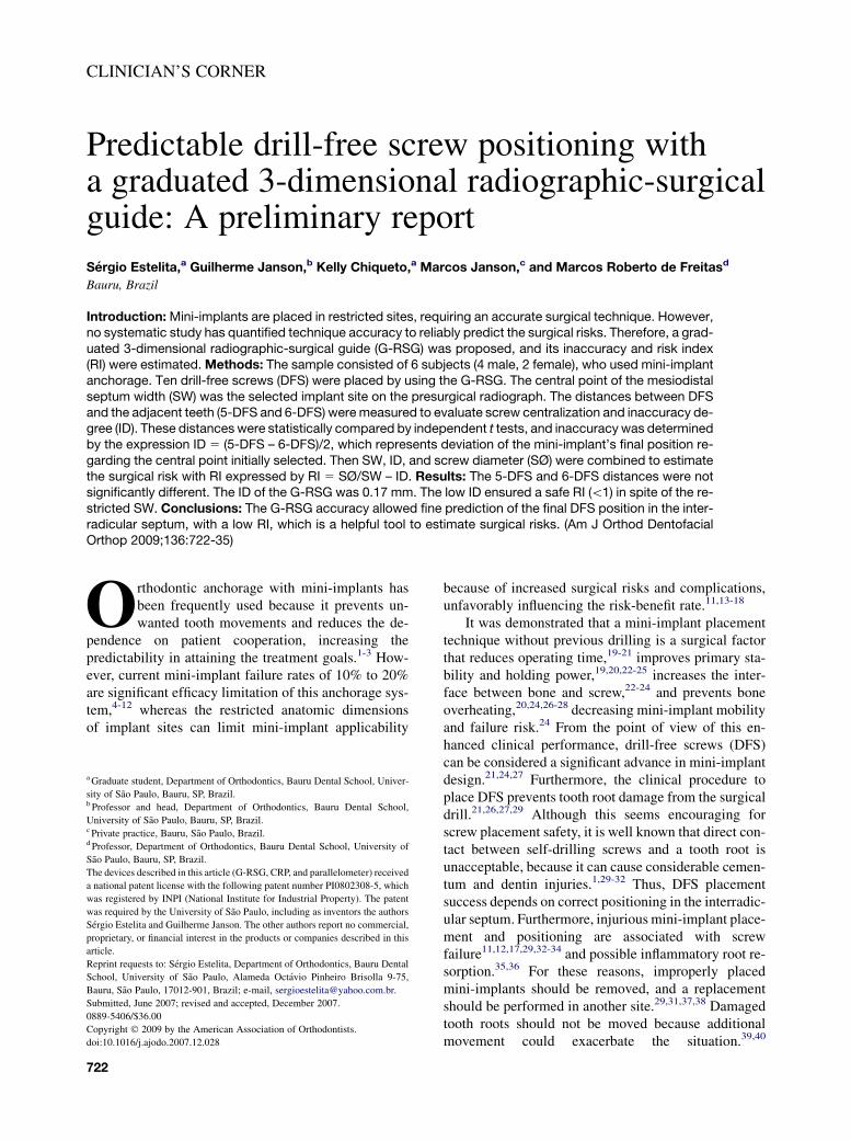
Fig 1. G-RSG/CRP principles. A, The G-RSG has a 0.040-in telescopic tube with a graduated scale.The vertical arm to which the telescopic tube is soldered is attached to a horizontal arm by a Gurinlock. B, The horizontal arm is made of a 0.021 3 0.025-in stainless steel wire, which allows attach-ment of the G-RSG to the fixed appliances. C, The CRP standardizes the presurgical radiographs ac-cording to bitewing positioner principles. D, A short free end of the 0.040-in stainless steel wire of 5mm in length, perpendicular to the film plane and parallel to the cone locator arm, allows the link be-tween the CRP and the G-RSG telescopic tube. E, The CRP free end is placed in the G-RSG tele-scopic tube, establishing coaxiality between the x-ray path and the telescopic tube direction. F,The G-RSG image is used to select an adequate implant site, where the graduated scale is not super-imposed over critical anatomic structures in this x-ray path. G, The screwdriver fits into the 0.12-inparallelometer tube, and its 0.040-in stainless steel wire is placed into the G-RSG telescopic tube,making screw placement direction coincident to the x-ray path. H, The radiographically selected im-plant site is clinically determined on the graduated scale by rotating the parallelometer around the G-RSG telescopic tube until the screw tip reaches the intended site, keeping the screwdriver directionunchanged. Subsequently, screwdriver rotation inside the parallelometer tube allows accurate DFSplacement in the selected implant site, according to the x-ray path.
American Journal of Orthodontics and Dentofacial Orthopedics Estelita et al 725Volume 136, Number 5
by sliding the vertical arm through the Gurin lock.Tube position can also be adjusted by torquingthe vertical or horizontal arm, although these mod-ifications are usually unnecessary when the archhas been aligned.
3. With the G-RSG centrally positioned on the interra-dicular septum, the short free end of the CRP is in-troduced into the telescopic tube, and the CRPspatial position, defined by the telescopic tube, isused to guide the x-ray tube to obtain the presurgi-cal radiograph (Fig 3, C and C0). Sequentially, theradiographic image of the G-RSG graduated scaleis taken as the reference to determine the centralpoint of the interradicular septum (Fig 3, D andD0). The scale mark coincident to the interradicularcentral point represents the most adequate implantsite, which can be clinically identified and trans-ferred to the alveolar mucosa with high accuracy.Briefly, the horizontal graduated scale is a radio-graphic and clinical reference to determine withonly 1 radiograph the exact site where the DFScan be safely placed.
4. After implant site selection, the stainless steel wireof the parallelometer is placed into the G-RSG tele-scopic tube, and the parallelometer tube is used toguide a screwdriver in a coincident direction withthe telescopic tube. Next, the screwdriver positionis adjusted horizontally on the scale marks, rotatingthe parallelometer around the telescopic tube to po-sition the DFS tip coincident with the selected im-plant site. When the screw tip is correctlypositioned in the selected site, the DFS is placedin the safe path defined by telescopic tube (Fig 3,E-F0). According to the surgeon’s preference, if
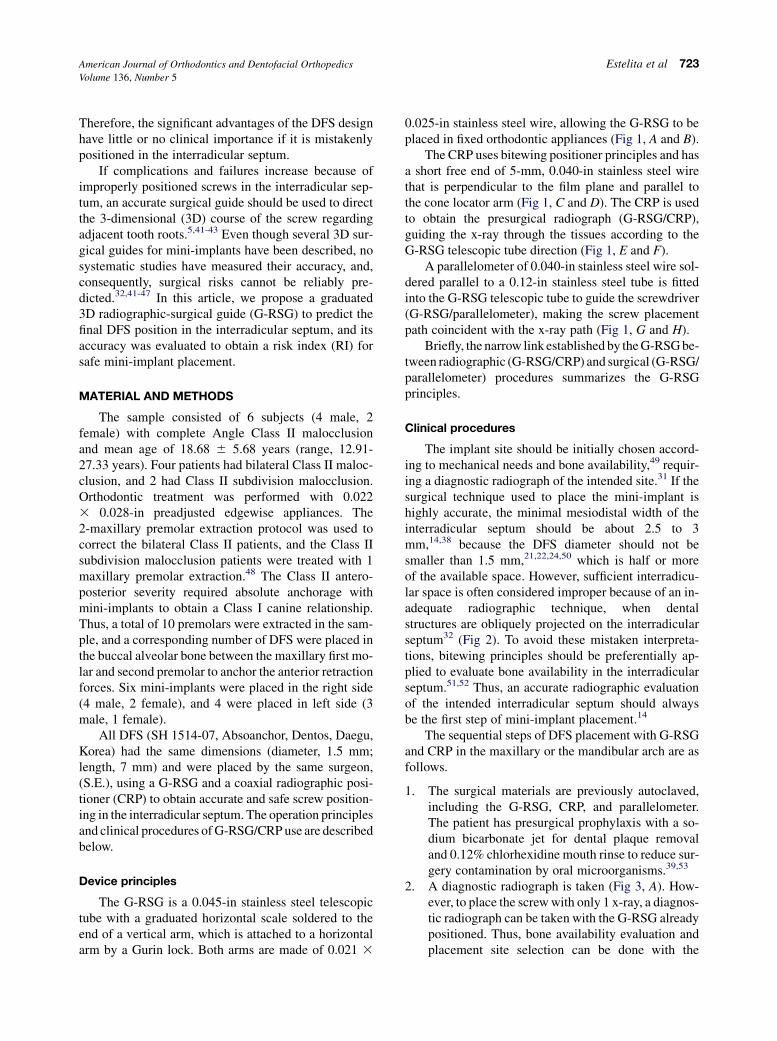
Fig 2. The periapical radiographic image shows inade-quate interradicular space for mini-implant placementbecause of an obliquely projected image. When thissame anatomic region had bitewing evaluation, itsmore orthogonal x-ray path prevented oblique root pro-jection on interradicular bone, showing the actual mesio-distal width of the interradicular septum. In this case, thesignificant changes in interproximal overlapping andtranspalatal bar position confirm the distinct x-ray pathsused to obtain the periapical and bitewing radiographs.
more than half of the screw length has alreadybeen placed, use of the G-RSG/parallelometer canbe suspended because the implant site and screwplacement path will not change.
5. Immediately after DFS placement, the CRP/G-RSG can be used again to obtain a standardizedfinal radiograph to evaluate the position of themini-implant regarding the adjacent anatomicstructures in this specific x-ray path (Fig 3, G andG0). Then the G-RSG is disconnected from the fixedappliance (Fig 3, H and H0), and the patient is in-structed to maintain satisfactory oral hygiene.9
Methods
To evaluate the accuracy of the G-RSG/CRP, post-surgical radiographs were digitized with a SprintScan35 Plus scanner (Polaroid, Boston, Mass) at 100% scaleand high resolution (675 dpi), allowing magnification of300% without image quality loss. Digital images werestored in tagged image file format (TIFF), and Photoshopsoftware (version 7.0, Adobe Systems, San Jose, Calif)was used for radiographic image measurements.54
The central point of the mesiodistal septum width(SW) is the most adequate and safe site for mini-implants. For this reason, placement of the DFS withthe G-RSG/CRP was aimed at the central point. Thescrew centralization degree regarding mesiodistal SWwas taken as the parameter to evaluate the accuracy ofthe G-RSG/CRP in predicting the postsurgical screwpositioning in the interradicular septum.
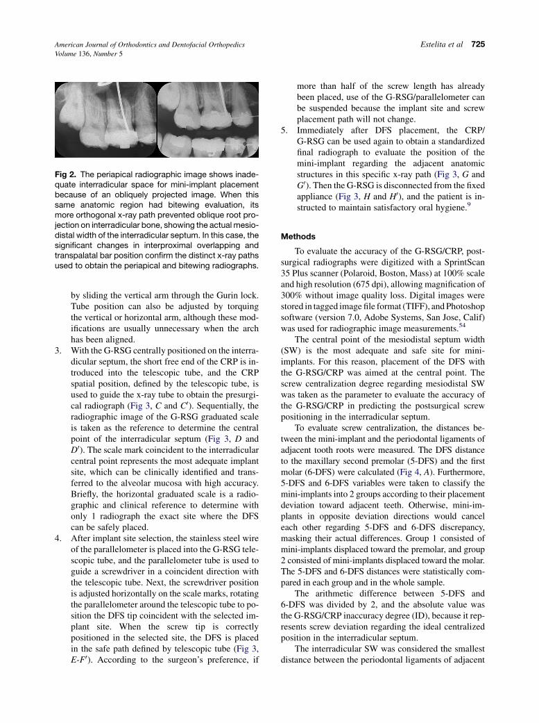
To evaluate screw centralization, the distances be-tween the mini-implant and the periodontal ligaments ofadjacent tooth roots were measured. The DFS distanceto the maxillary second premolar (5-DFS) and the firstmolar (6-DFS) were calculated (Fig 4, A). Furthermore,5-DFS and 6-DFS variables were taken to classify themini-implants into 2 groups according to their placementdeviation toward adjacent teeth. Otherwise, mini-im-plants in opposite deviation directions would canceleach other regarding 5-DFS and 6-DFS discrepancy,masking their actual differences. Group 1 consisted ofmini-implants displaced toward the premolar, and group2 consisted of mini-implants displaced toward the molar.The 5-DFS and 6-DFS distances were statistically com-pared in each group and in the whole sample.
The arithmetic difference between 5-DFS and6-DFS was divided by 2, and the absolute value wasthe G-RSG/CRP inaccuracy degree (ID), because it rep-resents screw deviation regarding the ideal centralizedposition in the interradicular septum.
The interradicular SW was considered the smallestdistance between the periodontal ligaments of adjacent
726 Estelita et al American Journal of Orthodontics and Dentofacial Orthopedics
November 2009
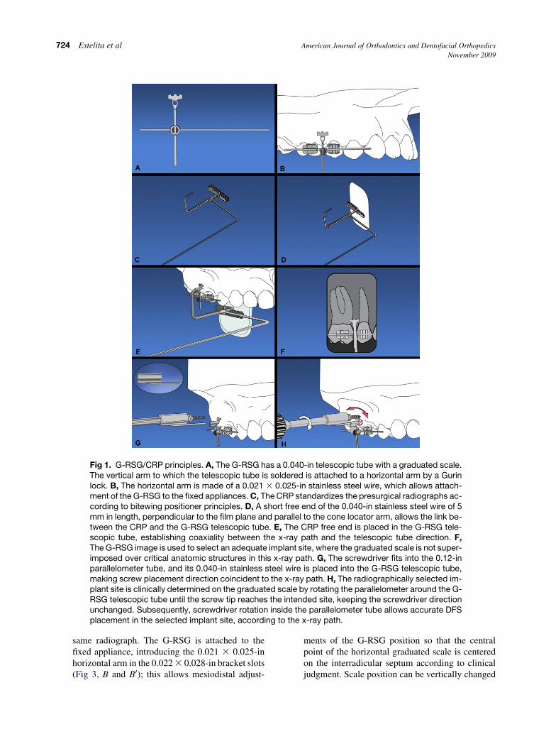
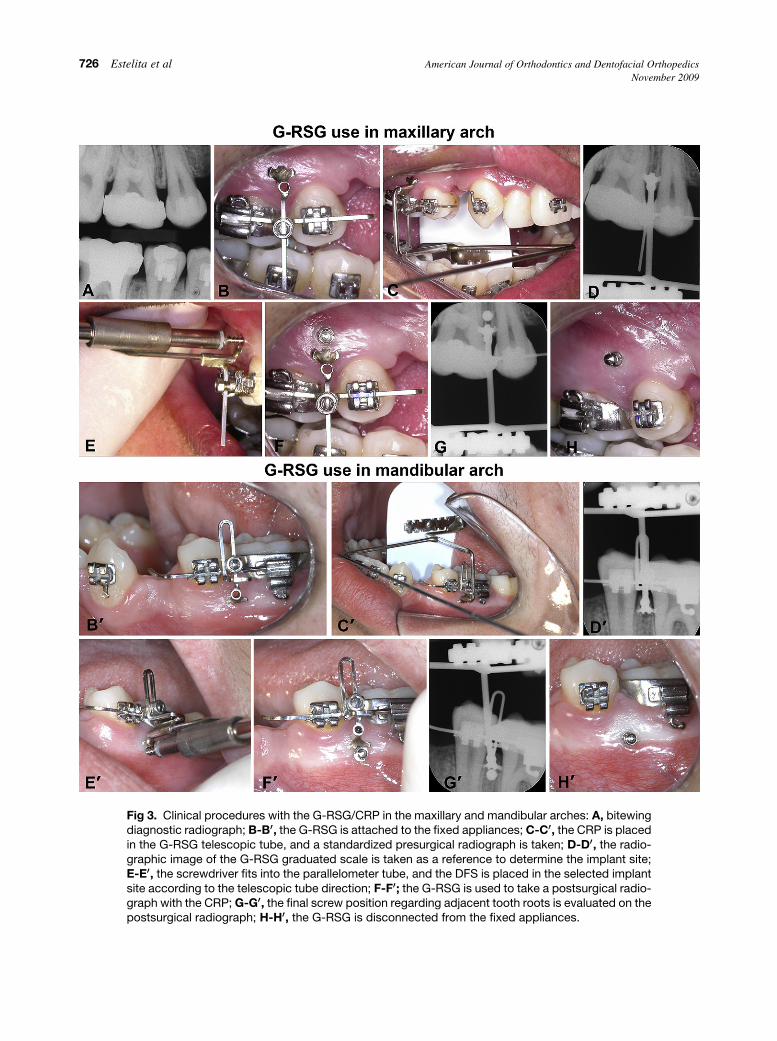
Fig 3. Clinical procedures with the G-RSG/CRP in the maxillary and mandibular arches: A, bitewingdiagnostic radiograph; B-B00, the G-RSG is attached to the fixed appliances; C-C00, the CRP is placedin the G-RSG telescopic tube, and a standardized presurgical radiograph is taken; D-D00, the radio-graphic image of the G-RSG graduated scale is taken as a reference to determine the implant site;E-E00, the screwdriver fits into the parallelometer tube, and the DFS is placed in the selected implantsite according to the telescopic tube direction; F-F00; the G-RSG is used to take a postsurgical radio-graph with the CRP; G-G00, the final screw position regarding adjacent tooth roots is evaluated on thepostsurgical radiograph; H-H00, the G-RSG is disconnected from the fixed appliances.
American Journal of Orthodontics and Dentofacial Orthopedics Estelita et al 727Volume 136, Number 5
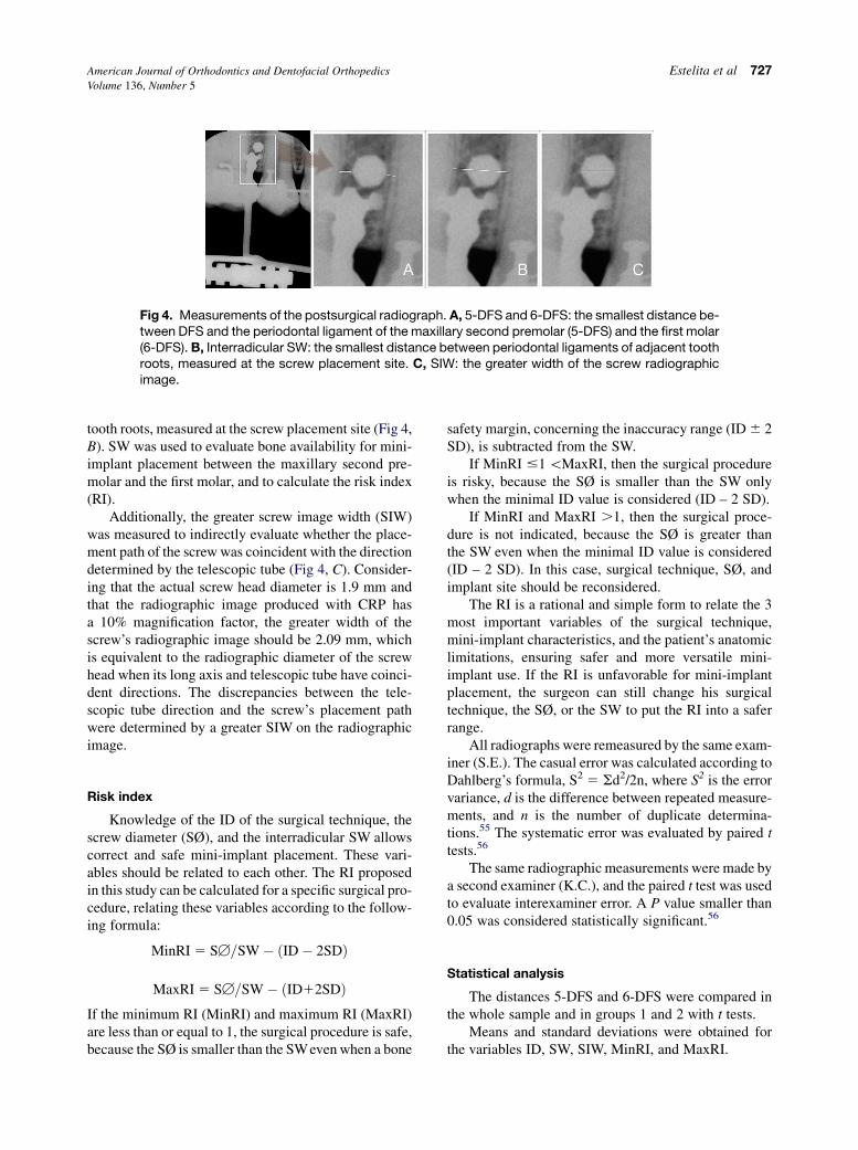
Fig 4. Measurements of the postsurgical radiograph. A, 5-DFS and 6-DFS: the smallest distance be-tween DFS and the periodontal ligament of the maxillary second premolar (5-DFS) and the first molar(6-DFS). B, Interradicular SW: the smallest distance between periodontal ligaments of adjacent toothroots, measured at the screw placement site. C, SIW: the greater width of the screw radiographicimage.
tooth roots, measured at the screw placement site (Fig 4,B). SW was used to evaluate bone availability for mini-implant placement between the maxillary second pre-molar and the first molar, and to calculate the risk index(RI).
Additionally, the greater screw image width (SIW)was measured to indirectly evaluate whether the place-ment path of the screw was coincident with the directiondetermined by the telescopic tube (Fig 4, C). Consider-ing that the actual screw head diameter is 1.9 mm andthat the radiographic image produced with CRP hasa 10% magnification factor, the greater width of thescrew’s radiographic image should be 2.09 mm, whichis equivalent to the radiographic diameter of the screwhead when its long axis and telescopic tube have coinci-dent directions. The discrepancies between the tele-scopic tube direction and the screw’s placement pathwere determined by a greater SIW on the radiographicimage.
Risk index
Knowledge of the ID of the surgical technique, thescrew diameter (SØ), and the interradicular SW allowscorrect and safe mini-implant placement. These vari-ables should be related to each other. The RI proposedin this study can be calculated for a specific surgical pro-cedure, relating these variables according to the follow-ing formula:
MinRI 5 SB=SW� ðID� 2SDÞ
MaxRI 5 SB=SW� ðID12SDÞIf the minimum RI (MinRI) and maximum RI (MaxRI)are less than or equal to 1, the surgical procedure is safe,because the SØ is smaller than the SWeven when a bone
safety margin, concerning the inaccuracy range (ID 6 2SD), is subtracted from the SW.
If MinRI #1 \MaxRI, then the surgical procedureis risky, because the SØ is smaller than the SW onlywhen the minimal ID value is considered (ID – 2 SD).
If MinRI and MaxRI .1, then the surgical proce-dure is not indicated, because the SØ is greater thanthe SW even when the minimal ID value is considered(ID – 2 SD). In this case, surgical technique, SØ, andimplant site should be reconsidered.
The RI is a rational and simple form to relate the 3most important variables of the surgical technique,mini-implant characteristics, and the patient’s anatomiclimitations, ensuring safer and more versatile mini-implant use. If the RI is unfavorable for mini-implantplacement, the surgeon can still change his surgicaltechnique, the SØ, or the SW to put the RI into a saferrange.
All radiographs were remeasured by the same exam-iner (S.E.). The casual error was calculated according toDahlberg’s formula, S2 5 Sd2/2n, where S2 is the errorvariance, d is the difference between repeated measure-ments, and n is the number of duplicate determina-tions.55 The systematic error was evaluated by paired ttests.56
The same radiographic measurements were made bya second examiner (K.C.), and the paired t test was usedto evaluate interexaminer error. A P value smaller than0.05 was considered statistically significant.56
Statistical analysis
The distances 5-DFS and 6-DFS were compared inthe whole sample and in groups 1 and 2 with t tests.
Means and standard deviations were obtained forthe variables ID, SW, SIW, MinRI, and MaxRI.
728 Estelita et al American Journal of Orthodontics and Dentofacial Orthopedics
November 2009
RESULTS
The casual errors were within acceptable levels, andthere were no significant systematic or interexaminer er-rors. Because of interexaminer agreement, only the firstexaminer’s measurements were used in this study.
The positioning of the DFS in the interradicular sep-tum had favorable centralization because there was nostatistically significant difference between 5-DFS and6-DFS in either the whole sample or separately in thegroups (Table I).
Means and standard deviations for ID, mesiodistalSW, SIW, MinRI, and MaxRI are shown in Table II.
DISCUSSION
Asscherickx et al33 emphasized that placement ofmini-implants in the alveolar process between toothroots is a critical procedure. For them, even if preventivemeasures are taken, such as an apical radiograph beforescrew placement, root damage can occur. To supply ac-curacy limitations during this critical procedure, a surgi-cal guide has been frequently indicated as the onlyalternative to obtain safe mini-implant place-ment.1,32,39,41-47,57,58
Before DFS, several surgical guides were proposedto direct the surgical drill during bone perforation, be-cause adequate final positioning of the mini-implantsregarding adjacent anatomic structures depends on thecorrect drill path into the bone, ensuring anatomic integ-rity.41,45-47 Because DFS placement does not requireprevious bone drilling, the final DFS position dependsonly on the screwdriver’s spatial position during place-ment. Thus, the need for a screwdriver guide is irrefut-able to ensure the integrity of anatomic structures withthis placement procedure.32,42-44
Accidents and complications
Frequently, conflicting reports about risks and com-plications of mini-implants are found in the literature.Recently, Wu et al32 showed that screw placement with-
Table I. Results of independent t tests between 5-DFSand 6-DFS distances
5-DFS 6-DFS
Group Mean SD Mean SD df P
Total sample (n 5 10) 0.22 0.41 0.16 0.33 18 0.725
Mini-implants displaced
toward premolar
(n 5 5)
0.02 0.33 0.30 0.33 8 0.225
Mini-implants displaced
toward molar (n 5 5)
0.42 0.41 0.02 0.29 8 0.116
out an accurate surgical guide results in a 20% rate ofinjuries during positioning. On the other hand, Melsenand Verna29 and Melsen53 do not use a surgical guideto place self-drilling mini-implants; they stated thatmini-implants placed in the periodontal ligament orthe tooth root should be removed and replaced in a dif-ferent site. Perhaps, it would be better not to drill in thepatient until the surgeon hits the interradicular septumbecause this is a questionable clinical procedure forplacing mini-implants. Mini-implant placement in theinterradicular septum is a critical procedure11-17,33,34
that usually requires an accurate surgical technique in-stead of an attempt/mistake method.32,41-47
Although DFS have made mini-implant placementsimpler,24 drill absence does not ensure tooth root integ-rity, and surgical complications and screw failures fromimproperly placed screws are difficulties still to be over-come.11,17,18 Wu et al32 demonstrated that the failure ratefrom direct contact between screw and root is high(20%), when less accurate surgical techniques are used.Cementum and dentin can be significantly damagedwhen mini-implants are screwed against the root surface(Fig 5). In these cases, the screw should be immediatelyremoved,29 and the tooth should not be moved for 3 to 4months until complete root and periodontium repair roreduce root resorption risks, although this increases treat-ment time.18,33,39 The screw should be replaced in the pa-tient, although root damage can happen again without anaccurate surgical technique.32,43 Screws placed in theperiodontal ligament have a greater failurerate.11,16,17,32,33 If a screw is lost and replacement is nec-essary, additional x-ray exposure is usually required, withadded surgery risks and radiation doses for the patient.
Correct screw positioning in the interradicular septumdepends on adequate selection of the implant site and thescrew placement path; otherwise, the integrity of adjacentanatomic structures cannot be ensured32,41-47 (Fig 6, Aand B). When the implant site is mistakenly selectedand the root surface is tangentially impinged by theDFS, the surgeon cannot always feel this injurious con-tact, and considerable root damage can occur with no no-ticeable clinical sign as shown in Figure 5, and tooth
Table II. Means and standard deviations of the variables
n 5 10
Variable Mean SD
ID 0.17 0.11
SW 2.45 0.65
SIW 2.07 0.06
MinRI 0.64 0.17
MaxRI 0.80 0.26
American Journal of Orthodontics and Dentofacial Orthopedics Estelita et al 729Volume 136, Number 5
injury can be seen only on the postsurgical radiographicimage.59-61 However, if greater tangential root contactproduces a perceptible screw placement difficulty, someauthors believe that the screw path can be redirected toavoid the detrimental contact1,5,31,32,37 (Fig 6, C). Never-theless, additional care should always be used with anychange in the screw path to prevent root injury, becausethe path change can save 1 tooth but compromise an ad-jacent tooth (Fig 6, C), or it can make the fit of themini-implant not tight enough, requiring a new site.31
Furthermore, the method of preventing root damage—with screw placement resistance and the surgeon’s feelas references—is questionable,31,35,36,59,60,62,63 becausecortical bone thickness and bone density can change sig-nificantly in different patients and anatomic sites, with
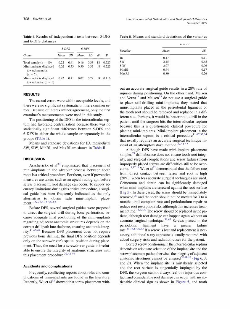
Fig 5. Root damage caused by iatrogenic screw place-ment. Postsurgical radiographic image suggests screwinjury on the distal root surface of the maxillary first pre-molar because of inaccurately selected implant site andscrew path. The root injury occurred with no noticeableclinical signs, and the professional could not feel the drillor screw contact with the tooth root, because the rootwas tangentially impinged, allowing drill and screw pen-etration without significant effort. The impingement sus-picion makes this tooth chosen for Class II extractiontreatment. After extraction, root damage can be clini-cally visualized. The damaged area was observed witha stereoscope (sv6 Stereozoom microscope, Zeiss,Thornwood, NY; original magnification 40 times), show-ing that, regardless of drill injury, direct contact betweenscrew thread and root during placement is enough toproduce marked lesions on the root surface.
various amounts of resistance even when the screw is be-ing correctly placed into the interradicularbone.8,16,49,64,65 On the other hand, when the root surfaceis radially impinged, DFS placement can be impeded orgreatly hampered, and the surgeon can easily feel theroot damage (Fig 6, D). In this case, the implant sitemust be redefined because path changes alone probablywill not solve the problem, and root damage and screwbreakage can occur if the surgeon forces the screw66
(Fig 6, D). The attempt to avoid root damage by just anes-thetizing the soft tissues around the implant site does notseem reliable,31,67 since false-positive signals are fre-quently described by patients during the surgical proce-dure, perhaps because of the close proximity betweenthe screw path and the periodontal tissues,11 which haveabundant sensory innervation.68 Clinical signs such asscrew resistance, surgeon feeling, and patient sensitivityare not negligible, but they depend on experience, skill,and personal judgment, which are not accurate for ensur-ing root integrity.13,43 Therefore, safe DFS placement inthe interradicular septum highly depends on an accuratesurgical technique. If inadequate DFS placement can in-crease external root resorption risks,18,33,39 screw failurerates,11,16,17,32,33 screw breakage risks,66 need of replace-ment,29 and, thus, increased radiation doses and treatmenttimes, then screw placement without an accurate methodshould be avoided, especially in restricted sites. Based onthese reasons, the G-RSG was proposed to place DFS inthe interradicular septum, and its accuracy and RI weredetermined.
G-RSG/CRP principles and applications
Screw placement accuracy is directly associatedwith radiographic standardization and surgical orienta-tion.32,41 A radiographic-surgical guide can establisha standardized link between radiographic and surgicalprocedures, assisting predictable positioning of thescrew in the interradicular septum.41 In the G-RSG,this link is a telescopic tube (Figs 1, A and B, and 3, Band B0) that guides x-ray and screw placement throughcoincident paths.
The coaxial relationship between the telescopic tubeand the radiographic positioner (G-RSG/CRP) duringthe presurgical radiograph makes the x-ray path coinci-dent to the telescopic tube direction (Figs 1, E, and 3, Cand C0). The radiographic image standardization ob-tained with this fixed relationshp between x-ray path,object, and film position shows the true spatial arrange-ment between the anatomic structures and the G-RSG inthis x-ray path, avoiding oblique projections and dis-torted images that can cause mistaken interpretations.32
Thus, with the G-RSG radiographic image as the

730 Estelita et al American Journal of Orthodontics and Dentofacial Orthopedics
November 2009
Fig 6. Usual errors during screw placement: A, the screw has an adequate insertion path, but rootdamage occurs because of inadequate implant site selection; B, in this case, the implant site is cor-rect, but an improper screw path was chosen, compromising root integrity; C, tangential root im-pingement can be corrected by changing the screw path, but root integrity of the adjacent toothcan be compromised; D, radial root impingement is a serious error that cannot be solved only bychanging the screw path; an adequate implant site must also be determined.
reference, an adequate implant site can be selectedwhere the graduated scale image is not superimposedon critical anatomic structures (Figs 1, F, and 3, D andD0). If a presurgical radiograph is taken without stan-dardization, the image cannot show the actual spatial ar-rangement between the surgical guide and the anatomicstructures, causing the surgeon to make a mistake aboutthe screw placement site (Fig 5).69 Thus, radiographicimage standardization, as provided by the G-RSG/CRP (Figs 1, E and F, and 3, C-D0), is essential in select-ing a correct implant site. Contrary to other usual radio-graphic positioners, the patient does not need to bite oruse muscular effort to stabilize the CRP during x-ray ex-posure; it is maintained in position by the G-RSG tele-scopic tube. The clinical procedures described toassemble the unit would be unlikely to produce signifi-cant forces to bend or distort the wires with such a trans-verse dimension and short length. Thus, significant G-RSG/CRP deformation does not occur, and radio-graphic image accuracy and reproducibility is ensured.
However, the correct selection of the implant site ona standardized radiographic image represents only a2-dimensional orientation, which is insufficient to en-sure safe placement because the screw path into thebone is undefined; for each 8� of variation from the ad-equate screw path, the tip of an 8-mm screw deviatesabout 1.04 mm (Fig 6, B). In a narrow interradicular sep-tum, this deviation amount can cause root damage andsurgical failure.11,17,32,33 With the G-RSG, the directlink between radiographic and surgical procedures al-lows the x-ray path in the presurgical radiograph toalso be used to place the DFS. Thus, the presurgical ra-diographic image can be used to predict final screw po-sitioning because the x-ray and the screw penetrate thetissues in the same path through adjacent anatomicstructures.32,41
For this reason, the parallelometer was created tomake the screwdriver direction coincident with thex-ray path defined by the G-RSG telescopic tube (Figs1, G, and 3, E and E0). Thus, the screw can be placed
American Journal of Orthodontics and Dentofacial Orthopedics Estelita et al 731Volume 136, Number 5
in the selected site according to an ideal x-ray path, pro-viding accurate and safe 3D surgical orientation withonly 1 radiographic exposure (Figs 1, G and H, and 3,E and E0). Moreover, the parallelometer rotation aroundthe telescopic tube allows slight variations in horizontalscrewdriver position to maintain its direction. The place-ment site previously chosen on the G-RSG image can al-ways be clinically selected on the graduated scale(Fig 1, H).
Some authors have suggested 2-dimensional surgicalguides for mini-implants.31,38,57,70 Because it is unlikelyto obtain surgical accuracy with only a 2-dimensionalsurgical guide orientation,5,43,71 a guide with 3D orienta-tion should be preferentially used.32,41-47 The surgicaltechniques suggested by Kim et al,43 Kitai et al,46 andFreudenthaler et al45 require computed tomographyand stereolithography machines, and increased com-plexity, cost, and radiation exposure to the patient. Cous-ley and Parberry,44 Morea et al,47 and Suzuki andBuranastidporn42 used surgical guides with 3D orienta-tion, although without presurgical radiographic stan-dardization. Wu et al32 suggested a surgical guide withan acrylic template to standardize the presurgical radio-graph, and the presurgical radiograph was cropped tomake a radiographic template for mini-implantplacement. More recently, Estelita et al41 developedthe 3D radiographic-surgical guide principle to placemini-implants in the interradicular septum, but that guidedid not allow placement of DFS. The G-RSG/CRP hasthe following differential characteristics: fine presurgicaland postsurgical radiographic standardization, accuratelink between radiographic and surgical procedure, grad-uated scale to select an adequate implant site with only 1standardized x-ray exposure, 3D screw placement orien-tation according to the x-ray path, low radiation dose tothe patient, satisfactory cost and risk-benefit rate, andhandy technology.
Although some authors advocate vertical angulationof the mini-implant regarding bone surface to avoid rootdamage and increase screw stability, systematic studieshave not sustained these speculations.31,72,73 Accordingto Park et al,9 there is no significant correlation betweena vertical placement angle of the screw and success rate.On the other hand, Kwak et al74 demonstrated that themean bone tissue thickness, which covers the buccalroot of the maxillary first molar and second premolar,was not greater than 1.8 and 3.5 mm in the midpointand the apex of the root, respectively. Thus, if the im-plant site is mistakenly defined regarding adjacent toothroots, and an 8-mm screw is vertically placed at 30� to40� with the tooth’s long axis, it would be unlikely toavoid root damage because the screw placement depthwould reach 4 to 5.12 mm.31 Furthermore, this vertical
placement angle is empirically determined, and, accord-ing to Herman et al,34 it is nearly impossible to deter-mine, causing inaccurate screw positioning that can beassociated with screw failure.11,17,32-34 Additionally,the thickest cortical bone was observed near the coronaland apical regions,64 where vertical placement is limitedby damage risks to the maxillary sinus.1,14,74 However,if the implant site is correctly defined and screw place-ment follows an adequate horizontal path, there is noreason to worry about vertical angulation. Therefore,a vertical placement angle does not seem to be a relevantfactor to ensure safe screw placement. Although thesuccess rate is independent of the vertical placement an-gle,9 it can depend on the horizontal placement angleand site, because these 2 variables are the most impor-tant in defining mini-implant position regarding adja-cent tooth roots11 (Fig 6, A and B). Thus, accuratesurgical techniques to place mini-implants should in-clude the correct selection of the site and the horizontalplacement path.
G-RSG/CRP accuracy
There is scientific evidence that the accuracy of thesurgical technique in placing mini-implants providessignificant advantages for success rate, stability, ortho-dontic mechanics, available implant sites, and surgicalrisks. The attached gingiva and the thickest corticalbone are 2 factors that increase success rate and stabilityof mini-implants,6,8,9,39 whereas screw proximity totooth roots is associated with screw failure.11,17,32-34
However, the attached gingiva and thicker corticalbone are in the coronal region, where the interradicularseptum is narrower,14-16,64 making screw placementa more critical procedure.11,17,32-34 The coronal regionof the interradicular septum is the most intended ana-tomic region for mini-implants because it allows ortho-dontic forces with a greater horizontal component,favoring mesiodistal tooth movement without excessiveload on the mini-implant.1 Therefore, accuracy is an es-sential requisite for mini-implants. The surgical risksare inversely proportional to accurancy of the surgicaltechnique; thus, accuracy can allow screw placementin more restricted sites,14 avoiding presurgical toothmovements to augment bone availability that increasetreatment time.15,29,31
If the interradicular septum is a restricted anatomicregion for a mini-implant, then it is correct to use the cen-tral point of the septum as the safest implant site, be-cause, with less available space, the screw should bemore centralized or equidistant regarding adjacent rootsto reduce surgical risks and screw failures.11,17,32,33 Ifthe mini-implant has a small displacement with the
732 Estelita et al American Journal of Orthodontics and Dentofacial Orthopedics
November 2009
orthodontic load,75 and proximity between the screw andthe periodontal ligament is directly associated withscrew failure,11,17,32,33 then the central point of the sep-tum is the best placement site.11 For this reason, the cen-tral point of the interradicular septum was used in thisstudy, and the accuracy of the G-RSG/CRP in predictingthe final screw position was evaluated by measuring thedistance between the mini-implant and the adjacent peri-odontal ligament (5-DFS 5 0.22 mm, 6-DFS 5 0.16mm). The results showed that screws were placed closeto the central point, with no significant difference be-tween 5-DFS and 6DFS, indicating high accuracy (TableI). However, this result does not represent the actualtechnique accuracy because 5-DFS and 6-DFS alwaystend to have convergent mean values when mini-im-plants displaced toward the molar are evaluated withthose displaced toward the premolar. For this reason,mini-implants displaced in opposite directions wereseparated into different groups, and, even so, intragroupcomparisons show no significant differences between5-DFS and 6-DFS, confirming satisfactory accuracy(Table I). Nevertheless, the lack of significant statisticaldifference does not mean that 5-DFS and 6-DFS have co-incident values and that inaccuracy technique is null.There was low ID (0.17 mm, Table II) that was notenough to make 5-DFS and 6-DFS significantly differ-ent. However, even knowing that the ID is low, it canbe clinically significant when the mesiodistal SW isrestricted. Thus, the 0.17-mm ID of the G-RSG/CRPtechnique should be understood as a necessary addi-tional bone safety margin that must always be presentto compensate for implant site error in the inaccuracyrange (0.17 mm 6 2 SD).
Because Liou et al75 recommend 2 mm of safetyclearance between mini-implant and dental root, a1.5-mm screw diameter should require 5.5 mm ofinterradicular SW to ensure root integrity, making mini-implants impossible in most sites. Fortunately, a signifi-cant displacement or tipping of mini-implants is notusual.2,76 In this study, the mean width of the interradic-ular septum between the maxillary second premolar andthe first molar was 2.45 mm (Table II); this was notmuch different from the 2.9 mm of SW in a study onbone availability in the interradicular septum with com-puterized tomography.14 This same study showed thatthe mean width of the interradicular septum on the max-illary buccal side was about 3 mm. The authors statedthat at least a 3.5-mm SW is necessary to safely placea screw with a 1.5-mm diameter, leaving a criticalbone safety margin of only 1 mm between the screwand the periodontal ligament. Considering only thesedata and the fact that adequate DFS resistance requiresat least a 1.5-mm screw diameter, the maxillary buccal
side should be considered improper for DFS.21,22,24,50
However, the authors emphasized that surgical riskscan be significantly decreased with accurate radio-graphic control and optimal surgical skill.14 The stan-dardized radiographic technique with CRP wasessential in this study to obtain safe mini-implant place-ment. Conversely, surgical skill is a questionable condi-tion to ensure safe screw placement and should not beconfused with surgical technique because skill can beconsidered an unmeasurable variable inherent in eachsurgeon,13 whereas technique can be systematically ap-plied and reproduced, and its accuracy can be numeri-cally quantified.32 This is a pertinent considerationbecause, according to this investigation, the low ID(0.17 mm) of the G-RSG/CRP technique allowed an in-terradicular septum with a 2.45-mm mean width to besafely used for a 1.5-mm diameter screw, maintainingan acceptable RI, in spite of the restricted bone safetymargin between the screw and the periodontal ligament(Table II). Furthermore, surgical complications can oc-cur even with experienced surgeons using an inaccuratesurgical technique,35,36,59,60,62,63 highlighting the im-portance of surgical technique on the surgeon’sskill.13,43
The measurement of the greater SIW (2.07 mm)showed a similar value regarding known screw headdiameter (2.09 mm) (Table II). This result demon-strates that x-ray and screw had a coincident pathdefined by the telescopic tube. Thus, the screw’s ra-diographic image only shows the exact contour ofthe screw head because the long axis of the screw,which represents its path in the interradicular sep-tum, is coincident with the x-ray path (Figs 1, Eand G, and 3 C, C0, E, and E0). This coincidence be-tween x-ray and screw path, by using the telescopictube, allows the screw to be safely placed in theinterradicular septum according to the presurgicalradiographic image, preventing root damage froman improperly selected site and placement angle(Fig 6, A and B).
Therefore, if the G-RSG/CRP can accurately defineimplant site and placement angle of the screw, its 3Dorientation can significantly reduce surgical risks andfailures.
Risk index
The risk-benefit rate of a procedure should be themost important parameter to indicate its use. If a surgicalprocedure has a high risk for the patient, an unfavorablerisk-benefit rate cannot justify it. However, this logicalthought has no clinical application if the risk of a surgi-cal procedure cannot be quantified. For this reason, the
American Journal of Orthodontics and Dentofacial Orthopedics Estelita et al 733Volume 136, Number 5
RI was proposed in this study to evaluate the surgicalrisks of mini-implant placement.
The primary requirement for mini-implant place-ment in the interradicular septum should be sufficientmesiodistal width to accommodate the screw thread di-ameter. Nevertheless, the greater the screw thread diam-eter in relation to the SW, the greater the surgical risk,requiring a surgical technique with a low ID. The ID ofthe surgical technique was combined with the data onSW and SØ to formulate an RI. The RI was considereddirectly proportional to screw diameter and inverselyproportional to the difference between SW and ID.
In this study the ID was 0.17 mm 6 0.11, and 2 SDwere used to determine maximum and minimum RIvalues. This low ID produced minimum and maximumRI values less than 1, despite the restricted SW. Thus,the RI shows that the accuracy of the surgical techniqueis an advantage in avoiding root damage because SW isinherent to the patient, and the DFS diameter cannot besignificantly changed. The DFS diameter should be be-tween 1.5 and 2 mm to prevent screw breakage withoutexcessively increasing screw diameter.21,22,24,50,77
Therefore, a surgical technique should be selected ac-cording to its accuracy, and the RI should be calculatedbefore mini-implant placement, informing the surgeonabout the risks of the procedure.
Although this preliminary report showed high accu-racy with the G-RSG/CRP technique, studies with morerepresentative samples should be performed. Addition-ally, we think that more studies should be performed toevaluate the accuracy of several surgical techniques cur-rently used to place mini-implants, because these sitesusually have restricted dimensions, and the RI is a ratio-nal option to reduce surgical accidents and complica-tions, increasing efficiency and success rate of thisemerging anchorage system. We are undertaking an ad-ditional study to evaluate DFS stability when placedwith the G-RSG/CRP.
CONCLUSIONS
The link of the G-RSG between the radiographicand surgical procedures ensures screw placement ac-cording to a safe x-ray path established in the presurgi-cal radiograph. As a result of this application, low IDand RI values were observed, allowing accurate predic-tion of the final DFS position in the interradicular sep-tum. The RI proposed in this study is a rewardingclinical and scientific tool for individual and systematicevaluations of the surgical risks.
We thank Dr. Hee-Moon Kyung, Dentos Inc, Daegu,Korea, for the generous donation of the mini-implantmaterials.
REFERENCES
1. Carano A, Velo S, Leone P, Giuseppe S. Clinical applications of
the miniscrew anchorage system. J Clin Orthod 2005;39:9-24.
2. Thiruvenkatachari B, Pavithranand A, Rajasigamani K,
Kyung HM. Comparison and measurement of the amount of an-
chorage loss of the molars with and without the use of implant
anchorage during canine retraction. Am J Orthod Dentofacial
Orthop 2006;129:551-4.
3. Yao CC, Lee JJ, Chen HY, Chang ZC, Chang HF, Chen YJ. Max-
illary molar intrusion with fixed appliances and mini-implant an-
chorage studied in three dimensions. Angle Orthod 2005;75:
754-60.
4. Cornelis MA, Scheffler NR, De Clerck HJ, Tulloch JF, Behets CN.
Systematic review of the experimental use of temporary skeletal
anchorage devices in orthodontics. Am J Orthod Dentofacial
Orthop 2007;131(Suppl):S52-8.
5. Chen CH, Chang CS, Hsieh CH, Tseng YC, Shen YS, Huang IY,
et al. The use of microimplants in orthodontic anchorage. J Oral
Maxillofac Surg 2006;64:1209-13.
6. Cheng SJ, Tseng IY, Lee JJ, Kok SH. A prospective study of the risk
factors associated with failure of mini-implants used for orthodontic
anchorage. Int J Oral Maxillofac Implants 2004;19:100-6.
7. Fritz U, Ehmer A, Diedrich P. Clinical suitability of titanium mi-
croscrews for orthodontic anchorage—preliminary experiences.
J Orofac Orthop 2004;65:410-8.
8. Miyawaki S, Koyama I, Inoue M, Mishima K, Sugahara T,
Yamamoto T. Factors associated with the stability of titanium
screws placed in the posterior region for orthodontic anchorage.
Am J Orthod Dentofacial Orthop 2003;124:373-8.
9. Park HS, Jeong SH, Kwon OW. Factors affecting the clinical suc-
cess of screw implants used as orthodontic anchorage. Am J
Orthod Dentofacial Orthop 2006;130:18-25.
10. Motoyoshi M, Hirabayashi M, Uemura M, Shimizu N. Recom-
mended placement torque when tightening an orthodontic mini-
implant. Clin Oral Implants Res 2006;17:109-14.
11. Kuroda S, Yamada K, Deguchi T, Hashimoto T, Kyung HM,
Takano-Yamamoto T. Root proximity is a major factor for screw
failure in orthodontic anchorage. Am J Orthod Dentofacial Orthop
2007;131(Suppl):S68-73.
12. Kuroda S, Sugawara Y, Deguchi T, Kyung HM, Takano-
Yamamoto T. Clinical use of miniscrew implants as orthodontic
anchorage: success rates and postoperative discomfort. Am J Or-
thod Dentofacial Orthop 2007;131:9-15.
13. Ishii T, Nojima K, Nishii Y, Takaki T, Yamaguchi H. Evaluation of
the implantation position of mini-screws for orthodontic treat-
ment in the maxillary molar area by a micro CT. Bull Tokyo
Dent Coll 2004;45:165-72.
14. Poggio PM, Incorvati C, Velo S, Carano A. ‘‘Safe zones’’: a guide
for miniscrew positioning in the maxillary and mandibular arch.
Angle Orthod 2006;76:191-7.
15. Schnelle MA, Beck FM, Jaynes RM, Huja SS. A radiographic
evaluation of the availability of bone for placement of miniscrews.
Angle Orthod 2004;74:832-7.
16. Deguchi T, Nasu M, Murakami K, Yabuuchi T, Kamioka H, Takano-
Yamamoto T. Quantitative evaluation of cortical bone thickness
with computed tomographic scanning for orthodontic implants.
Am J Orthod Dentofacial Orthop 2006;129:721.e7-12.
17. Deguchi T, Takano-Yamamoto T, Kanomi R, Hartsfield JK Jr,
Roberts WE, Garetto LP. The use of small titanium screws for or-
thodontic anchorage. J Dent Res 2003;82:377-81.
18. Kravitz ND, Kusnoto B. Risks and complications of orthodontic
miniscrews. Am J Orthod Dentofacial Orthop 2007;131(Suppl):
S43-51.
734 Estelita et al American Journal of Orthodontics and Dentofacial Orthopedics
November 2009
19. Alpert B, Gutwald R, Schmelzeisen R. New innovations in cranio-
maxillofacial fixation: the 2.0 lock system. Keio J Med 2003;52:
120-7.
20. Hibi H, Ueda M, Sakai M, Ikemori Y. Orthodontic anchorage sys-
tem using a locking plate and self-drilling screws. J Oral Maxillo-
fac Surg 2006;64:1173-5.
21. Heidemann W, Gerlach KL. Clinical applications of drill free
screws in maxillofacial surgery. J Craniomaxillofac Surg 1999;
27:252-5.
22. Heidemann W, Terheyden H, Gerlach KL. Analysis of the osse-
ous/metal interface of drill-free screws and self-tapping screws.
J Craniomaxillofac Surg 2001;29:69-74.
23. Heidemann W, Terheyden H, Gerlach KL. In vivo studies of
screw-bone contact of drill-free screws and conventional self-
tapping screws. Mund Kiefer Gesichtschir 2001;5:17-21.
24. Kim JW, Ahn SJ, Chang YI. Histomorphometric and mechanical
analyses of the drill-free screw as orthodontic anchorage. Am J
Orthod Dentofacial Orthop 2005;128:190-4.
25. Prager T, Holtgrave EA. Primary stability of self-drilling and con-
ventional screw implants for orthodontic anchorage [abstract].
J Dent Res 2003;82:2319.
26. Gibbons AJ, Hodder SC. A self-drilling intermaxillary fixation
screw. Br J Oral Maxillofac Surg 2003;41:48-9.
27. Heidemann W, Gerlach KL, Grobel KH, Kollner HG. Drill-free
screws: a new form of osteosynthesis screw. J Craniomaxillofac
Surg 1998;26:163-8.
28. Kerawala CJ, Martin IC, Allan W, Williams ED. The effects of op-
erator technique and bur design on temperature during osseous
preparation for osteosynthesis self-tapping screws. Oral Surg
Oral Med Oral Pathol Oral Radiol Endod 1999;88:145-50.
29. Melsen B, Verna C. Miniscrew implants: the Aarhus anchorage
system. Semin Orthod 2005;11:24-31.
30. Huja SS, Litsky AS, Beck FM, Johnson KA, Larsen PE. Pull-out
strength of monocortical screws placed in the maxillae and man-
dibles of dogs. Am J Orthod Dentofacial Orthop 2005;127:
307-13.
31. Kyung H, Park H, Bae S, Sung J, Kim I. Development of ortho-
dontic micro-implants for intraoral anchorage. J Clin Orthod
2003;37:321-8.
32. Wu JC, Huang JN, Zhao SF, Xu XJ, Xie ZJ. Radiographic and sur-
gical template for placement of orthodontic microimplants in in-
terradicular areas: a technical note. Int J Oral Maxillofac Implants
2006;21:629-34.
33. Asscherickx K, Vannet BV, Wehrbein H, Sabzevar MM. Root re-
pair after injury from mini-screw. Clin Oral Implants Res 2005;
16:575-8.
34. Herman RJ, Currier GF, Miyake A. Mini-implant anchorage for
maxillary canine retraction: a pilot study. Am J Orthod Dentofa-
cial Orthop 2006;130:228-35.
35. Driemel O, Staudenmaier R, Buch RS, Schusselbauer U,
Wagener H, Reichert TE, et al. Dental injuries due to miniplate os-
teosynthesis. Classification, treatment management, complica-
tions, and prognosis. Mund Kiefer Gesichtschir 2005;9:330-5.
36. Hommez GM, Browaeys HA, De Moor RJ. Surgical root restora-
tion after external inflammatory root resorption: a case report.
J Endod 2006;32:798-801.
37. Park H, Kwon T, Kwon O. Treatment of open bite with micro-
screw implant anchorage. Am J Orthod Dentofacial Orthop
2004;126:627-36.
38. Maino BG, Mura P, Bednar J. Miniscrew implants: the spider
screw anchorage system. Semin Orthod 2005;11:40-6.
39. Mah J, Bergstrand F. Temporary anchorage devices: a status
report. J Clin Orthod 2005;39:132-6.
40. Ne RF, Witherspoon DE, Gutmann JL. Tooth resorption. Quintes-
sence Int 1999;30:9-25.
41. Estelita Cavalcante Barros S, Janson G, Chiqueto K, de
Freitas MR, Henriques JF, Pinzan A. A three-dimensional radio-
graphic-surgical guide for mini-implant placement. J Clin Orthod
2006;40:548-54.
42. Suzuki EY, Buranastidporn B. An adjustable surgical guide for
miniscrew placement. J Clin Orthod 2005;39:588-90.
43. Kim SH, Choi YS, Hwang EH, Chung KR, Kook YA, Nelson G. Sur-
gicalpositioning of orthodontic mini-implants with guides fabricated
on models replicated with cone-beam computed tomography. Am J
Orthod Dentofacial Orthop 2007;131(Suppl):S82-9.
44. Cousley RR, Parberry DJ. Surgical stents for accurate miniscrew
insertion. J Clin Orthod 2006;40:412-7.
45. Freudenthaler J, Haas R, Bantleon HP. Bicortical titanium screws
for critical orthodontic anchorage in the mandible: a preliminary
report on clinical applications. Clin Oral Implants Res 2001;12:
358-63.
46. Kitai N, Yasuda Y, Takada K. A stent fabricated on a selectively
colored stereolithographic model for placement of orthodontic
mini-implants. Int J Adult Orthod Orthognath Surg 2002;17:
264-6.
47. Morea C, Dominguez GC, Wuo AV, Tortamano A. Surgical guide
for optimal positioning of mini-implants. J Clin Orthod 2005;39:
317-21.
48. Janson G, Dainesi EA, Henriques JF, de Freitas MR, de Lima KJ.
Class II subdivision treatment success rate with symmetric and
asymmetric extraction protocols. Am J Orthod Dentofacial Or-
thop 2003;124:257-64.
49. Lin JC, Liou EJ. A new bone screw for orthodontic anchorage. J
Clin Orthod 2003;37:676-81.
50. Paik CH, Woo YJ, Boyd RL. Treatment of an adult patient with
vertical maxillary excess using miniscrew fixation. J Clin Orthod
2003;37:423-8.
51. Nysether S, Hansen BF. Errors on dental bitewing radiographs.
Community Dent Oral Epidemiol 1983;11:286-8.
52. Zhang ZL, Yang X, Zhao Y. A study of errors of radiography in
10000 intraoral periapical radiographs. Shanghai Kou Qiang Yi
Xue 1995;4:142.
53. Melsen B. Mini-implants: where are we? J Clin Orthod 2005;39:
539-47.
54. Shin JY, Liu ZJ, King GJ. Trabecular organization in mandibular
osteodistraction in growing and maturing rats. J Oral Maxillofac
Surg 2005;63:77-86.
55. Dahlberg G. Statistical methods for medical and biological stu-
dents. New York: Interscience Publications; 1940.
56. Houston WJB. The analysis of errors in orthodontic measure-
ments. Am J Orthod 1983;83:382-90.
57. Bae S. Clinical application of micro-implant anchorage. J Clin
Orthod 2002;36:298-302.
58. Kyung SH, Choi JH, Park YC. Miniscrew anchorage used to pro-
tract lower second molars into first molar extraction sites. J Clin
Orthod 2003;37:575-9.
59. Fabbroni G, Aabed S, Mizen K, Starr DG. Transalveolar screws
and the incidence of dental damage: a prospective study. Int J
Oral Maxillofac Surg 2004;33:442-6.
60. Farr DR, Whear NM. Intermaxillary fixation screws and tooth
damage. Br J Oral Maxillofac Surg 2002;40:84-8.
61. Majumdar A, Brook IM. Iatrogenic injury caused by intermaxil-
lary fixation screws. Br J Oral Maxillofac Surg 2002;40:84.
62. Coburn DG, Kennedy DWG, Hodder SC. Complications with in-
termaxillary fixation screws in the management of fractured man-
dibles. Br J Oral Maxillofac Surg 2002;40:241-3.
American Journal of Orthodontics and Dentofacial Orthopedics Estelita et al 735Volume 136, Number 5
63. Kocaelli HA, Kaptan F, Kayahan B, Haznedaroglu F. Manage-
ment of the perforations due to miniplate application. J Endod
2006;32:482-5.
64. Kim HJ, Yun HS, Park HD, Kim DH, Park YC. Soft-tissue and
cortical-bone thickness at orthodontic implant sites. Am J Orthod
Dentofacial Orthop 2006;130:177-82.
65. Wilmes B, Rademacher C, Olthoff G, Drescher D. Parameters af-
fecting primary stability of orthodontic mini-implants. J Orofac
Orthop 2006;67:162-74.
66. Sung J, Kyung H, Bae S, Park H, Kwon O, McNamara JA. Micro-
implants in orthodontics. Paris, France: Editions SID; 2006.
67. Kravitz ND, Kusnoto B. Placement of mini-implants with topical
anesthetic. J Clin Orthod 2006;40:602-4.
68. Fukuda M, Tazaki M. Distribution of organized sensory nerve
endings in the human periodontal ligament. Bull Tokyo Dent
Coll 1994;35:133-7.
69. Potter BJ, Shrout MK, Harrell JC. Reproducibility of beam
alignment using different bite-wing radiographic techniques.
Oral Surg Oral Med Oral Pathol Oral Radiol Endod 1995;79:
532-5.
70. Herman RJ, Cope JB. Miniscrew Implants: IMTEC mini ortho
implants. Semin Orthod 2005;11:32-9.
71. Tseng YC, Hsieh CH, Chen CH, Shen YS, Huang IY, Chen CM.
The application of mini-implants for orthodontic anchorage. Int J
Oral Maxillofac Surg 2006;35:704-7.
72. Lee JS, Park HS, Kyung HM. Micro-implant anchorage for lin-
gual treatment of a skeletal Class II malocclusion. J Clin Orthod
2001;35:643-7.
73. Park HS, Bae SM, Kyung HM, Sung JH. Micro-implant anchor-
age for treatment of skeletal Class I bialveolar protrusion. J Clin
Orthod 2001;35:417-22.
74. Kwak HH, Park HD, Yoon HR, Kang MK, Koh KS, Kim HJ. To-
pographic anatomy of the inferior wall of the maxillary sinus in
Koreans. Int J Oral Maxillofac Surg 2004;33:382-8.
75. Liou EJ, Pai BC, Lin JC. Do miniscrews remain stationary
under orthodontic forces? Am J Orthod Dentofacial Orthop
2004;126:42-7.
76. Ohmae M, Saito S, Morohashi T, Seki K, Qu H, Kanomi R, et al. A
clinical and histological evaluation of titanium mini-implants as
anchors for orthodontic intrusion in the beagle dog. Am J Orthod
Dentofacial Orthop 2001;119:489-97.
77. Bohm B, Fuhrmann R. Clinical application and histological ex-
amination of the fami screw for skeletal anchorage—a pilot study.
J Orofac Orthop 2006;67:175-85.