Practice 1: Use of the ohmmeter, Voltmeter and Ammeter in measurements of D.C
21
Practice 1: Use of the ohmmeter, Voltmeter and Ammeter in measurements of D.C. 1CM15 INSTITUTO POLITÉCNICO NACIONAL | ESCOM Integrants: Miramontes Romero Alejandro Ortiz Ubaldo Ezequiel Felipe Figueroa del Prado Practice 1. Fundamental análisis of circuits
Transcript of Practice 1: Use of the ohmmeter, Voltmeter and Ammeter in measurements of D.C

Practice 1: Use of the ohmmeter,
Voltmeter and Ammeter in measurements
of D.C.
1CM15
INSTITUTO POLITÉCNICO NACIONAL | ESCOM
Integrants:
Miramontes Romero Alejandro
Ortiz Ubaldo Ezequiel
Felipe Figueroa del Prado
Practice 1.
Fundamental análisis of circuits

Practice 1: use of ohmmeter, ammeter and voltmeter
1
Index page
Objective………………………………………………………………………………………………………………………………………2
Equipment and materials……………………………………………………………………………………………………………..2
Theoretical introduction……………………………………………………………………………………………………………….2
Development of the practice………………………………………………………………………………………………………..3
Use of the Ohmmeter…………………………………………………………………………………………………………………..3
Use of voltmeter…………………………………………………………………………………………………………………………..4
Use of ammeter……………………………………………………………………………………………………………………………5
Simulations…………………………………………………………………………………………………………………………………..6
Calculus……………………………………………………………………………………………………………………………………….17
Questionnaire……………………………………………………………………………………………………………………………..19
Conclusion…………………………………………………………………………………………………………………………………..19
Image…………………………………………………………………………………………………………………………………………..20

Practice 1: use of ohmmeter, ammeter and voltmeter
2
Objective
The students will understand the proper handling of measurement instruments, so that at
the end of the practice, he must be able to:
Proper use of the digital ohmmeter
Proper use of the digital voltmeter.
Proper use of the digital ammeter.
EQUIPMENT MATERIAL
1 DIGITAL MULTIMETER 1 protoboard 1 SOURCE OF VARIABLE VOLTAGE 1 resistor of 1kΩ 4 TIPS BANANA-CAYMAN 1 resistor of 560Ω
2TIPS CAIMÁN-CAYMAN 1 resistor of 680Ω
1 resistor of 330Ω
Wire connection
Theoretical Introduction
The current or voltage can be measured by means of ammeters or voltmeters, figure 1
shows 2 common forms of meters; one of the analog meter has a needle that moves on a
calibrated scale whose angular deflection depends on the magnitude of the variable that
measures. While the other is a digital meter which shows a series of digits in the screen,
indicating the magnitude of the variable that measures. Figure 2 shows the symbols of the
voltmeters and ammeters that are used in the electrical circuit diagrams.
Figure 1. a) Analog meter b) Digital meter Figure 2. Symbol of each meter

Practice 1: use of ohmmeter, ammeter and voltmeter
3
To measure the current in the branch of a circuit, you must open this branch and the
ammeter should be inserted so that it is connected in series with the element from which
you want to know their current. It is said that two elements are in "series" if one end of one
joins with one end of the other, and there is no conductor connected to that union. The
current flowing through that path, necessarily pass through the current meter (ammeter).
To measure the voltage between two points, the voltmeter connects in parallel with the
electronic device from which you want to know the voltage drop. Two elements of two
terminals are connected in parallel if the terminals are connected one to the other
terminals. It doesn't matter if in these unions or not there is another connection. The
essential characteristic of a parallel connection, which, through the elements there is the
same voltage.
Development of the practice
Use of the ohmmeter.
Without energize any circuit element, measure the resistance value that presents each
resistor, as shown in figure 3 and fill in the table 1.
Figure 3. Connection of the Ohmmeter.
Ohmmeter

Practice 1: use of ohmmeter, ammeter and voltmeter
4
Table1. Measure of
resistive values.
Use of Voltmeter
Figure 4 shows how it should be to measure the voltage on an element. With the voltage
source off, install the circuit in figure 5. Once armed the circuit switch on the voltage source
and fill in the table 2.
Figure 4. Example of connection of voltmeter
Figure 5. Serial circuit
Resistance Measure with digital ohmmeter Value in the color codice
R1 327.3 Ω 330 Ω
R2 .986 k Ω 1k Ω
R3 560 Ω 560 Ω
R4 655 Ω 680 Ω
charge
voltmeter
schematic
Connection of the circuit in the protoboard

Practice 1: use of ohmmeter, ammeter and voltmeter
5
TABLE 2. MEASURE OF VOLTAGE
Use of ammeter
Figure 6 shows how you have to connect the ammeter for current measure in element.
Figure 6. Connection of the ammeter example.
Source of
voltage DIGITAL MULTIMETER MEASURED VALUES
R1 y R2
voltage
R1 voltage R2 voltage R1 y R2
voltage R1 voltage R2 voltage
E=1V 1.004 V 0.754 V 0.249 V 1 V .75 V .248 V
E=2V 2.075 V 1.559 V 0.516 V 2 V 1.5 V .496 V
E=3V 3.022 V 2.271 V 0.751 V 3V 2.25 V .744 V
E=4V 4.008 V 3.01 V 0.997 V 4 V 3.007 V .992 V
E=5V 5.20 V 3.90 V 1.29 V 5 V 3.759 V 1.24 V
E=6V 6.24 V 4.69 V 1.55 V 6 V 4.511 V 1.488 V
E=7V 7.27 V 5.46 V 1.80 V 7 V 5.263 V 1.736 V
E=8V 8.33 V 6.25 V 2.07 V 8 V 6.015 V 1.984 V
E=9V 9.31 V 6.99 V 2.32 V 9 V 6.766 V 2.233 V
E=10V 10.40 V 7.81 V 2.59 V 10 V 7.51 V 2.481 V
E=11V 11.48 V 8.60 V 2.86 V 11 V 8.27 V 2.729 V
q 12.5 V 9.38 V 3.11 V 12 V 9.022 V 2.977 V
ammeter
charge
ee
schematic Connection of the circuit in the protoboard

Practice 1: use of ohmmeter, ammeter and voltmeter
6
With the voltage source off, install the circuit in figure 7. Once armed the circuit
switch on the voltage source and fill in the table 3.
Table 3.measure of current.
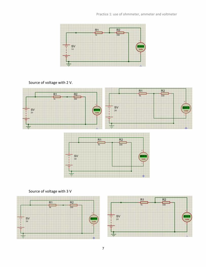
Simulations.
Use of voltmeter
Table 2.
Source of voltage with 1 V.
Source of
voltage Digital multimeter
Current
beetwen R1
y R2
Current in
R1 Current in
R2
E=1V 3.47 mA 1.49 mA 1.76 mA
E=2V 6.56 mA 3.06 mA 3.6 mA
E=3V 9.9 mA 4.5 mA 5.36 mA
E=4V 13 mA 6 mA 7.16 mA
E=5V 16.3 mA 7.46 mA 8.9 mA
E=6V 19.56 mA 8.93 mA 10.76 mA
E=7V 22.65 mA 10.45 mA 12.51 mA
E=8V 26.05 mA 11.85 mA 14.3 mA
E=9V 29.29 mA 13.36 mA 16.11 mA
E=10V 32.5 mA 14.87 mA 17.87 mA
E=11V 35.93 mA 16.39 mA 19.71 mA
E=12V 39.28 mA 17.9 mA 21.61 mA
Practice 1: use of ohmmeter, ammeter and voltmeter
7
Source of voltage with 2 V.
Source of voltage with 3 V

Practice 1: use of ohmmeter, ammeter and voltmeter
8
Source of voltage with 4 V.
Source of voltage with 5 V

Practice 1: use of ohmmeter, ammeter and voltmeter
9
Source of voltage with 6 V.
Source of voltage with 7V

Practice 1: use of ohmmeter, ammeter and voltmeter
10
Source of voltage with 8V
Source of voltage with 9 V

Practice 1: use of ohmmeter, ammeter and voltmeter
11
Source of voltage with 10 V
Source of voltage with 11V

Practice 1: use of ohmmeter, ammeter and voltmeter
12
Source of voltage with 12V

Practice 1: use of ohmmeter, ammeter and voltmeter
13
Use of Ammeter
Table 3.
Source of voltage with 1 V.
Source of voltage with 2V
Source of voltage with 3V

Practice 1: use of ohmmeter, ammeter and voltmeter
14
Source of voltage with 4V
Source of voltage with 5V
Source of voltage with 6V
Source of voltage with 7V

Practice 1: use of ohmmeter, ammeter and voltmeter
15
Source of voltage with 8 V
Source of voltage with 9 V
Source of voltage with 10 V

Practice 1: use of ohmmeter, ammeter and voltmeter
16
Source of voltage with 11V
Source of voltage with 12V

Practice 1: use of ohmmeter, ammeter and voltmeter
17
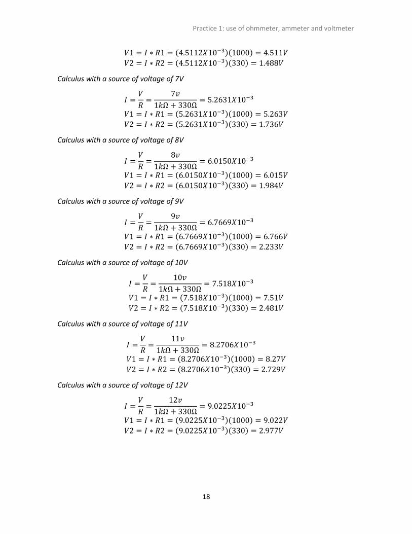
Calculus
Use of voltmeter
To calculate values of table 2. Voltage measure, we have to use the Ohm’s law.
Calculus with a source of voltage of 1V.
𝐼 =𝑉
𝑅=
1𝑣
1𝑘Ω + 330Ω= 7.518𝑋10−4
𝑉1 = 𝐼 ∗ 𝑅1 = (7.518𝑋10−4 ) (1𝐾) = .75 𝑉
𝑉2 = 𝐼 ∗ 𝑅2 = (7.518𝑋10−4 ) (330) = .248𝑉
Calculus with a source of voltage of 2 V
𝐼 =𝑉
𝑅=
2𝑣
1𝑘Ω + 330Ω= 1.5037𝑋10−3
𝑉1 = 𝐼 ∗ 𝑅1 = (1.5037𝑋10−3)(1𝐾) = 1.5𝑉
𝑉2 = 𝐼 ∗ 𝑅2 = (1.5037𝑋10−3)(330) = .496𝑉
Calculus with a source of voltage of 3V
𝐼 =𝑉
𝑅=
3𝑣
1𝑘Ω + 330Ω= 2.2556𝑋10−3
𝑉1 = 𝐼 ∗ 𝑅1 = (2.2556𝑋10−3)(1000) = 2.25𝑉
𝑉2 = 𝐼 ∗ 𝑅2 = (2.2556𝑋10−3)(330) = .744𝑉
Calculus with a source of voltage of 4V
𝐼 =𝑉
𝑅=
4𝑣
1𝑘Ω + 330Ω= 3.0075𝑋10−3
𝑉1 = 𝐼 ∗ 𝑅1 = (3.0075𝑋10−3)(1000) = 3.007𝑉
𝑉2 = 𝐼 ∗ 𝑅2 = (3.0075𝑋10−3)(330) = .992𝑉
Calculus with a source of voltage of 5V
𝐼 =𝑉
𝑅=
5𝑣
1𝑘Ω + 330Ω= 3.7593𝑋10−3
𝑉1 = 𝐼 ∗ 𝑅1 = (3.7593𝑋10−3)(1000) = 3.759𝑉 𝑉2 = 𝐼 ∗ 𝑅2 = (3.7593𝑋10−3)(330) = 1.24𝑉
Calculus with a source of voltage of 6V
𝐼 =𝑉
𝑅=
6𝑣
1𝑘Ω + 330Ω= 4.5112𝑋10−3
Practice 1: use of ohmmeter, ammeter and voltmeter
18
𝑉1 = 𝐼 ∗ 𝑅1 = (4.5112𝑋10−3)(1000) = 4.511𝑉 𝑉2 = 𝐼 ∗ 𝑅2 = (4.5112𝑋10−3)(330) = 1.488𝑉
Calculus with a source of voltage of 7V
𝐼 =𝑉
𝑅=
7𝑣
1𝑘Ω + 330Ω= 5.2631𝑋10−3
𝑉1 = 𝐼 ∗ 𝑅1 = (5.2631𝑋10−3)(1000) = 5.263𝑉 𝑉2 = 𝐼 ∗ 𝑅2 = (5.2631𝑋10−3)(330) = 1.736𝑉
Calculus with a source of voltage of 8V
𝐼 =𝑉
𝑅=
8𝑣
1𝑘Ω + 330Ω= 6.0150𝑋10−3
𝑉1 = 𝐼 ∗ 𝑅1 = (6.0150𝑋10−3)(1000) = 6.015𝑉 𝑉2 = 𝐼 ∗ 𝑅2 = (6.0150𝑋10−3)(330) = 1.984𝑉
Calculus with a source of voltage of 9V
𝐼 =𝑉
𝑅=
9𝑣
1𝑘Ω + 330Ω= 6.7669𝑋10−3
𝑉1 = 𝐼 ∗ 𝑅1 = (6.7669𝑋10−3)(1000) = 6.766𝑉 𝑉2 = 𝐼 ∗ 𝑅2 = (6.7669𝑋10−3)(330) = 2.233𝑉
Calculus with a source of voltage of 10V
𝐼 =𝑉
𝑅=
10𝑣
1𝑘Ω + 330Ω= 7.518𝑋10−3
𝑉1 = 𝐼 ∗ 𝑅1 = (7.518𝑋10−3)(1000) = 7.51𝑉 𝑉2 = 𝐼 ∗ 𝑅2 = (7.518𝑋10−3)(330) = 2.481𝑉
Calculus with a source of voltage of 11V
𝐼 =𝑉
𝑅=
11𝑣
1𝑘Ω + 330Ω= 8.2706𝑋10−3
𝑉1 = 𝐼 ∗ 𝑅1 = (8.2706𝑋10−3)(1000) = 8.27𝑉 𝑉2 = 𝐼 ∗ 𝑅2 = (8.2706𝑋10−3)(330) = 2.729𝑉
Calculus with a source of voltage of 12V
𝐼 =𝑉
𝑅=
12𝑣
1𝑘Ω + 330Ω= 9.0225𝑋10−3
𝑉1 = 𝐼 ∗ 𝑅1 = (9.0225𝑋10−3)(1000) = 9.022𝑉 𝑉2 = 𝐼 ∗ 𝑅2 = (9.0225𝑋10−3)(330) = 2.977𝑉
Practice 1: use of ohmmeter, ammeter and voltmeter
19
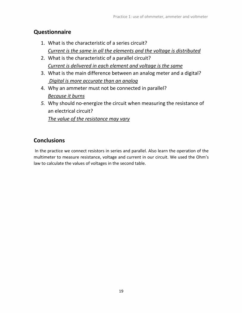
Questionnaire
1. What is the characteristic of a series circuit?
Current is the same in all the elements and the voltage is distributed
2. What is the characteristic of a parallel circuit?
Current is delivered in each element and voltage is the same
3. What is the main difference between an analog meter and a digital?
Digital is more accurate than an analog
4. Why an ammeter must not be connected in parallel?
Because it burns
5. Why should no-energize the circuit when measuring the resistance of
an electrical circuit?
The value of the resistance may vary
Conclusions
In the practice we connect resistors in series and parallel. Also learn the operation of the
multimeter to measure resistance, voltage and current in our circuit. We used the Ohm’s
law to calculate the values of voltages in the second table.

Practice 1: use of ohmmeter, ammeter and voltmeter
20