PowerBay™ - 4- Bay DataBank NAS Array - Verbatim Europe
24
PowerBay ™ 4- Bay DataBank NAS Array User Guide Version 2.0 English English
-
Upload
khangminh22 -
Category
Documents
-
view
3 -
download
0
Transcript of PowerBay™ - 4- Bay DataBank NAS Array - Verbatim Europe

PowerBay™
4- Bay DataBank NAS Array
User GuideVersion 2.0
EnglishEnglish
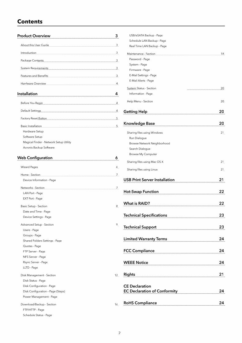
2
Product Overview 3
About this User Guide 3
Introduction 3
Package Contents 3g
System Requirements 3y q
Features and Benefi ts 3
Hardware Overview 4
Installation 4
Before You Begin 4g
Default Settings 4g
Factory Reset Button 5y
Basic Installation 5
Hardware Setup
Software Setup
Magical Finder - Network Setup Utility
Acronis Backup Software
Web Confi guration 6g
Wizard Pages 6g
Home - Section 7
Device Information - Page
Networks - Section 7
LAN Port - Page
EXT Port - Page
Basic Setup - Section 8p
Date and Time - Page
Device Settings - Page
Advanced Setup - Section 9p
Users - Page
Groups - Page
Shared Folders Settings - Page
Quotas - Page
FTP Server - Page
NFS Server - Page
Rsync Server - Page
LLTD - Page
Disk Management - Section 12g
Disk Status - Page
Disk Confi guration - Page
Disk Confi guration – Page (Steps)
Power Management - Page
Download/Backup - Section 16p
FTP/HTTP - Page
Schedule Status - Page
USB/eSATA Backup - Page
Schedule LAN Backup - Page
Real Time LAN Backup - Page
Maintenance - Section 18
Password - Page
System - Page
Firmware - Page
E-Mail Settings - Page
E-Mail Alerts - Page
System Status - Section 20y
Information - Page
Help Menu - Section 20p
Getting Help 20g p
Knowledge Base 20g
Sharing fi les using Windows 21g g
Run Dialogue
Browse Network Neighborhood
Search Dialogue
Browse My Computer
Sharing fi les using Mac OS X 21g g
Sharing fi les using Linux 21g g
USB Print Server Installation 21
Hot-Swap Function 22p
What is RAID? 22
Technical Specifi cations 23p
Technical Support 23pp
Limited Warranty Terms 24y
FCC Compliance 24p
WEEE Notice 24
Rights 21g
CE DeclarationEC Declaration of Conformity 24y
RoHS Compliance 24p
Contents
3
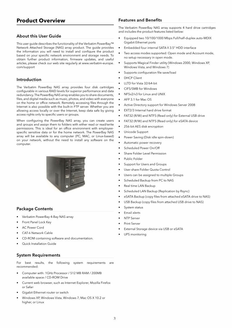
Product Overview
About this User Guide
This user guide describes the functionality of the Verbatim PowerBay™ Network Attached Storage (NAS) array product. The guide provides the information you will need to install and confi gure the product based on your specifi c network environment and storage needs. To obtain further product information, fi rmware updates, and useful articles, please check our web site regularly at www.verbatim-europe.com/support
Introduction
The Verbatim PowerBay NAS array provides four disk cartridges confi gurable in various RAID levels for superior performance and data redundancy. The PowerBay NAS array enables you to share documents, fi les, and digital media such as music, photos, and video with everyone on the home or offi ce network. Remotely accessing fi les through the Internet is also possible with the built-in FTP server. Whether you are allowing access locally or over the Internet, keep data safe by giving access rights only to specifi c users or groups.
When confi guring the PowerBay NAS array, you can create users and groups and assign them to folders with either read or read/write permissions. This is ideal for an offi ce environment with employee-specifi c sensitive data or for the home network. The PowerBay NAS array will be available to any computer (PC, MAC, or Linux-based) on your network, without the need to install any software on the computer.
Package Contents
• Verbatim PowerBay 4-Bay NAS array
• Front Panel Lock Key
• AC Power Cord
• CAT-6 Network Cable
• CD-ROM containing software and documentation.
• Quick Installation Guide
System Requirements
For best results, the following system requirements are recommended:
• Computer with: 1GHz Processor / 512 MB RAM / 200MB available space / CD-ROM Drive
• Current web browser, such as Internet Explorer, Mozilla Firefox or Safari
• Gigabit Ethernet router or switch
• Windows XP, Windows Vista, Windows 7, Mac OS X 10.2 or higher, or Linux
Features and Benefi ts
The Verbatim PowerBay NAS array supports 4 hard drive cartridges and includes the product features listed below:
• Equipped two 10/100/1000 Mbps Full/half-duplex auto-MDIX Gigabit Ethernet ports
• Embedded four internal SATA II 3.5” HDD interface
• Two access modes supported: Open mode and Account mode,no setup necessary in open mode.
• Supports Magical Finder utility (Windows 2000, Windows XP, Windows Vista, and Windows 7)
• Supports confi guration fi le save/load
• DHCP Client
• LLTD for Vista 32/64-bit
• CIFS/SMB for Windows
• NFSv2/v3 for Linux and UNIX
• AFP 3.1 for Mac OS
• Active Directory support for Windows Server 2008
• EXT2/3 Internal hard drive format
• FAT32 (R/W) and NTFS (Read only) for External USB drive
• FAT32 (R/W) and NTFS (Read only) for eSATA device
• 256-bit AES disk encryption
• Unicode Support
• Power Saving (Disk idle spin-down)
• Automatic power recovery
• Scheduled Power On/Off
• Share Folder Level Permission
• Public Folder
• Support for Users and Groups
• User share Folder Quota Control
• Users can be assigned to multiple Groups
• Scheduled Backup from PC to NAS
• Real time LAN Backup
• Scheduled LAN Backup (Replication by Rsync)
• eSATA Backup (copy fi les from attached eSATA drive to NAS)
• USB Backup (copy fi les from attached USB drive to NAS)
• System status
• Email alerts
• NTP Server
• Print Server
• External Storage device via USB or eSATA
• UPS monitoring

4
Hardware Overview
Front View
COMPONENT DESCRIPTION
1. Power Button • Press to power on.
• Press and hold for more than 5 seconds to power off.
2. Function Button USB One-Touch-Copy function is available when a USB storagedevice is connected to the PowerBay NAS array.
• Press momentarily to initiate fi le copy from external USB storage device to the PowerBay NAS array.
• Press and hold for more than 3 seconds to safely unmount the external USB device.
• When alarm buzzer is sounding, press button to cancel alarm.
3. USB Connector • One USB 2.0 (Type A) connector: USB Host port forconnecting an external USB storage device.
• Supports USB backup (copy fi les from attached USB drive to NAS array)
• Provides additional storage as a shared volume on the LAN (default name “USBDisk_1”)
• Supports USB Unlock Key for use with disk encryption
• Power: 5V/500mA max
4. Cartridge Key Lock • Turn key counterclockwise to the Lock position to lock allcartridges in place.
• Turn key clockwise to the Unlock position to unlock all cartridges.
5. Power LED The power button contains a colored LED to indicate power status.
• Solid Green = Device is Powered On
• Solid Red = Device is in Standby Mode with AC powerapplied
6. Status LED • Solid Green = Device operational status is Normal
• Blinking Green = Device is starting up or shutting down
• Solid Red = Device Error
7. Cartridge Lock • Slide locking button to the left to lock each cartridge.
• Slide locking button to the right to unlock each cartridge.
8. Cartridge LED Each HDD cartridge locking button contains a colored LED toindicate disk status:
• Solid Blue = Disk Ready
• Blinking Blue = Data Access Activity
• Blinking Red = Disk Error
• Solid Red = When all 4 cartridge LEDs are red indicatesLocked Encrypted Volume
Rear Panel (Connections)
COMPONENT DESCRIPTION
9. eSATA connector • One SATA-II (eSATA) connector for connecting externalstorage device.
• Supports eSATA backup (copy fi les from attached eSATA drive to NAS array)
• Provides additional storage as a shared volume on the LAN (default name “eSATA_1”)
• Supports mirror function between NAS array and attached eSATA drive
10. USB Connector USB Host Port. One USB 2.0 (Type A) connector; Power:5V/500mA max. Used for connecting
• USB Printer; or
• USB UPS Monitor. If the attached UPS detects a power failure,an automatic shutdown of the NAS array will be initiated by use of this feature. Compatible with the following UPS equipment:
- APC BACK-UPS ES BE500TW
- Powerware PW-3105
- Tripp-Lite SMART550USB
- Phoenixtec A-500Plus
11. RJ-45 Connectors Two Gigabit Ethernet ports.
• Port 1 (LAN): For connecting the PowerBay NAS array to LAN.This port supports Wake-On-LAN function.
• Port 2 (EXT): For real time backup to another PowerBay NAS array
12. Reset Button • Press and hold for more than 5 seconds to reset confi gurationto factory default settings
13. Cooling Fans • Exhaust ports for two cooling fans are provided.
14. AC PowerConnector
• For AC power cord
Installation
This section will walk you through the installation process. Placement of the device is very important. Do not place the device in an enclosed area such as a closet or cabinet.
Before You Begin
Please read and make sure you understand all the prerequisites for proper installation of your new device. Have all the necessary information and equipment on hand before beginning the installation.
Note: Capacity dependent on model. 1 MB = 1,000,000 bytes / 1 GB = 1,000,000,000 bytes / 1 TB = 1,000,000,000,000 bytes. Some capacity used for pre-loaded software, formatting and other functions, and thus is not available for data storage. As a result, and due to differing calculation methods, your operating systems may report as fewer megabytes/gigabytes/ terabytes.
Default Settings
The default values for the PowerBay NAS array are as follows:
• User Name is ‘admin’
• Password is blank

5
• LAN IP Address is 192.168.0.32
• LAN Subnet Mask is 255.255.255.0
Factory Reset Button
The device can be reset to the original factory default settings by using a ballpoint or paperclip to gently push down the reset button in the following sequence:
1. Ensure the device is powered on.
2. Press and hold the reset button for approximately 5 seconds.
3. The factory reset process should take around 1 to 2 minutes.
Remember that this will wipe out any settings stored in fl ash memory including user account information and LAN IP settings.
Basic Installation
Hardware Setup
This section provides unpacking and installation information for the PowerBay NAS array. Open the shipping carton for the PowerBay NAS array and carefully unpack its contents.
1. Ensure that a hard drive cartridge is inserted into each of the four mounting racks and that the cartridge locking buttons are in the left (locked) position.
2. Connect the supplied Ethernet cable to the LAN port located at the back of the device. Connect the other end of this cable to your network, either via a switch/router or via direct connection to your computer for confi guration.
3. Connect the supplied power cord to the rear of the PowerBay NAS array and to an AC power receptacle.
4. Press the Power button on the front of the PowerBay NAS array.The green status LED will begin to fl ash to indicate that the unit has initiated the power-on sequence.
5. Wait for the PowerBay NAS array to boot up and to auto-confi gure its connection on the network. Depending on your particular LAN confi guration and settings, this may take several minutes. The following protocols will be followed during auto-confi guration:
a. DHCP client is enabled by default. Therefore, your routeror other LAN equipment that is providing the DHCP service will automatically assign an IP address to the PowerBay NAS array and complete the network connection.
b. If no DHCP server is available on your network, thenthe PowerBay NAS array will take its default IP address of 192.168.0.32.
6. After successfully connecting to your network you will be able to discover the PowerBay NAS array on your network. Its defaultname is “PowerBay”.
7. Before you can see any PowerBay NAS array shared folders, you must fi rst set up user accounts, or at a minimum must assign read/write privileges for the default folder named Volume_1. This process is explained further below. Once this is done, you will be able to discover shared folders in network workgroup named “Workgroup”. In Windows go to My Network Places / Entire Network / Microsoft Windows Network / Workgroup, or in Mac OS X navigate to Go / Network.
To set up other user accounts, and to confi gure other basic system settings, you should continue setup using the web-based administration tool described in the next section.
Once the PowerBay NAS array is connected to your network and has been confi gured for your network environment, it can be accessed from any computer within the same subnet on your LAN. Furthermore,
more advanced users may choose to confi gure name servers (such as WIN servers or DNS servers) in order to access the PowerBay NAS array from a different subnet.
Software Setup
The included CD-ROM contains copies of the User Guide, as well as two software applications: 1) MagicalFinder, and 2) Acronis backup software.
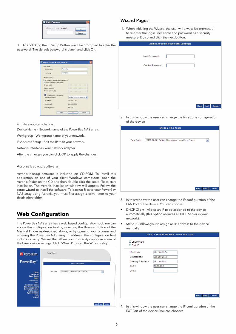
Magical Finder - Network Setup Utility
When fi rst powered on, during the initial boot sequence, the PowerBay NAS array will wait to be assigned an IP address via DHCP. If it does not receive a DHCP as¬signed IP address, by default it will have a self-assigned IP address of 192.168.0.32.
If your router assigns addresses automatically, your router’s manual will describe how to view the DHCP Lease List so you can see your drive’s assigned IP address. Alternatively, you can fi nd your drive’s IP address using the included Magical Finder utility that is provided on the product CD. If you are unfamiliar with the operation of your router, you may fi nd it easier to use the Magical Finder.
1. Open the Magical Finder Utility and allow it to search for thePowerBay NAS array.
2. After fi nding the PowerBay NAS array the utility will list the device’s IP address, MAC address and Device Name. (If the device is not listed on the initial scan you can press the Refresh button to initiate a Re-Scan)
You have three options:
• IP Setup Button: To enter the IP Address Setup.
• Folder Button: To open Windows Explorer to \\PowerBay.
• Browser Button: To link to the device web confi guration.
6
3. After clicking the IP Setup Button you’ll be prompted to enter the password (The default password is blank) and click OK.
4. Here you can change:
Device Name - Network name of the PowerBay NAS array.
Workgroup - Workgroup name of your network.
IP Address Setup - Edit the IP to fi t your network.
Network Interface - Your network adapter.
After the changes you can click OK to apply the changes.
Acronis Backup Software
Acronis backup software is included on CD-ROM. To install this application on one of your client Windows computers, open the Acronis folder on the CD and then double click the setup fi le to start installation. The Acronis installation window will appear. Follow the setup wizard to install the software. To backup fi les to your PowerBay NAS array using Acronis, you must fi rst assign a drive letter to your destination folder.
Web Confi guration
The PowerBay NAS array has a web based confi guration tool. You can access the confi guration tool by selecting the Browser Button of the Magical Finder as described above, or by opening your browser and entering the PowerBay NAS array IP address. The confi guration tool includes a setup Wizard that allows you to quickly confi gure some of the basic device settings. Click “Wizard” to start the Wizard setup.
Wizard Pages
1. When initiating the Wizard, the user will always be promptedto re-enter the login user name and password as a securitymeasure. Do so and click the next button.
2. In this window the user can change the time zone confi guration of the device.
3. In this window the user can change the IP confi guration of the LAN Port of the device. You can choose:
• DHCP Client - Allows an IP to be assigned to the deviceautomatically (this option requires a DHCP Server in yournetwork).
• Static IP - Allows you to assign an IP address to the devicemanually.
4. In this window the user can change the IP confi guration of the EXT Port of the device. You can choose:
7
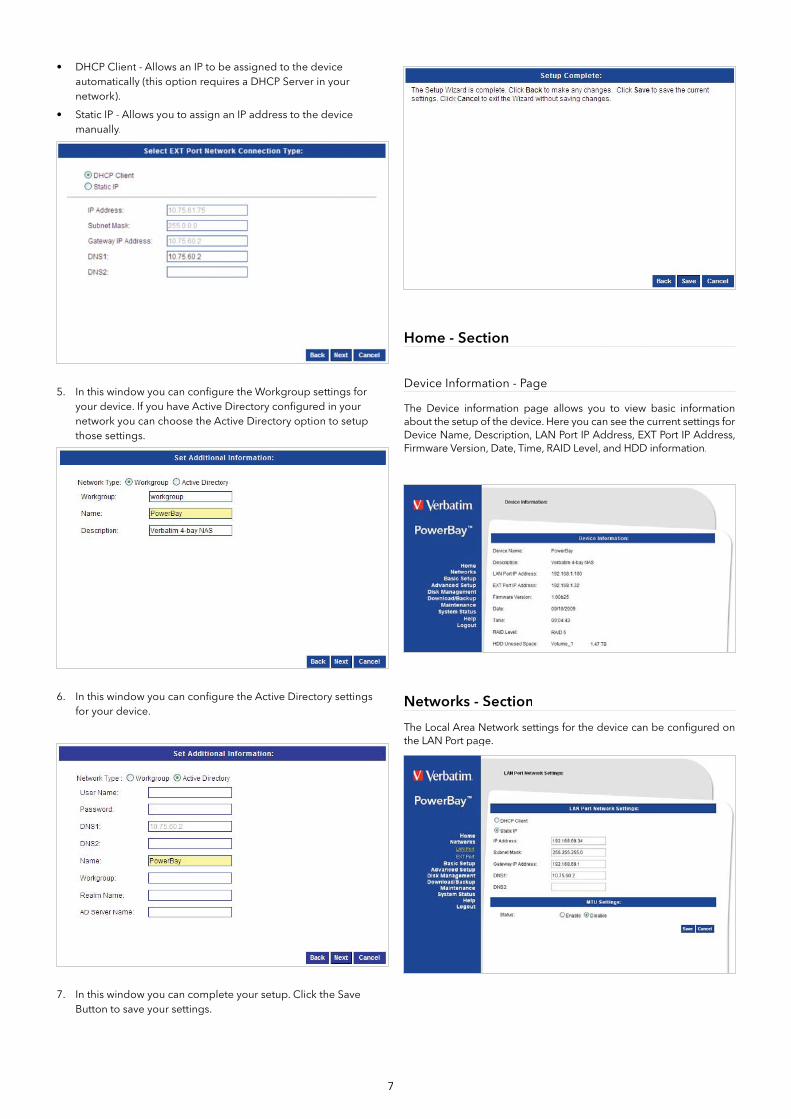
• DHCP Client - Allows an IP to be assigned to the device automatically (this option requires a DHCP Server in your network).
• Static IP - Allows you to assign an IP address to the device manually.
5. In this window you can confi gure the Workgroup settings for your device. If you have Active Directory confi gured in yournetwork you can choose the Active Directory option to setup those settings.
6. In this window you can confi gure the Active Directory settings for your device.
7. In this window you can complete your setup. Click the SaveButton to save your settings.
Home - Section
Device Information - Page
The Device information page allows you to view basic information about the setup of the device. Here you can see the current settings for Device Name, Description, LAN Port IP Address, EXT Port IP Address, Firmware Version, Date, Time, RAID Level, and HDD information.
Networks - Section
The Local Area Network settings for the device can be confi gured on the LAN Port page.
8
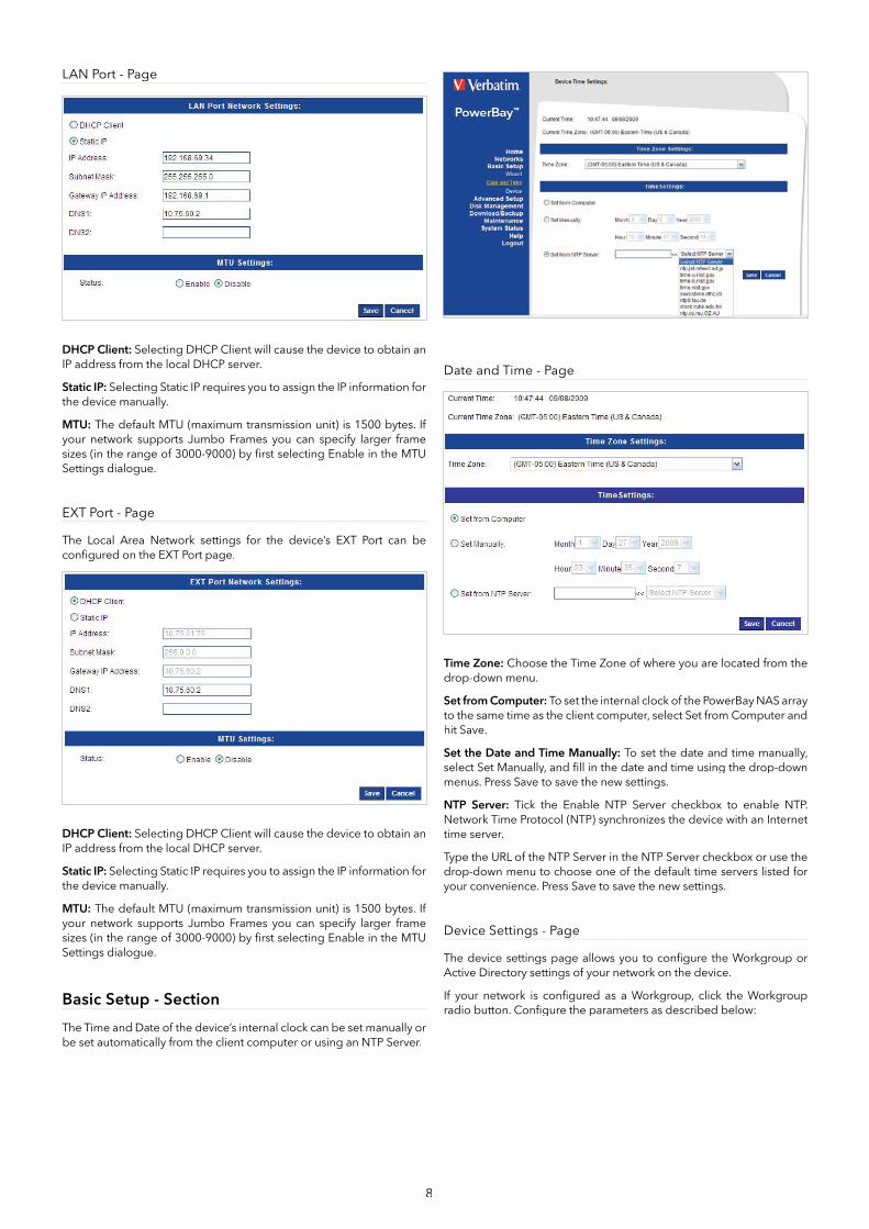
LAN Port - Page
DHCP Client: Selecting DHCP Client will cause the device to obtain an IP address from the local DHCP server.
Static IP: Selecting Static IP requires you to assign the IP information for the device manually.
MTU: The default MTU (maximum transmission unit) is 1500 bytes. If your network supports Jumbo Frames you can specify larger frame sizes (in the range of 3000-9000) by fi rst selecting Enable in the MTU Settings dialogue.
EXT Port - Page
The Local Area Network settings for the device’s EXT Port can be confi gured on the EXT Port page.
DHCP Client: Selecting DHCP Client will cause the device to obtain an IP address from the local DHCP server.
Static IP: Selecting Static IP requires you to assign the IP information for the device manually.
MTU: The default MTU (maximum transmission unit) is 1500 bytes. If your network supports Jumbo Frames you can specify larger frame sizes (in the range of 3000-9000) by fi rst selecting Enable in the MTU Settings dialogue.
Basic Setup - Section
The Time and Date of the device’s internal clock can be set manually or be set automatically from the client computer or using an NTP Server.
Date and Time - Page
Time Zone: Choose the Time Zone of where you are located from the drop-down menu.
Set from Computer: To set the internal clock of the PowerBay NAS array to the same time as the client computer, select Set from Computer and hit Save.
Set the Date and Time Manually: To set the date and time manually,select Set Manually, and fi ll in the date and time using the drop-down menus. Press Save to save the new settings.
NTP Server: Tick the Enable NTP Server checkbox to enable NTP.Network Time Protocol (NTP) synchronizes the device with an Internet time server.
Type the URL of the NTP Server in the NTP Server checkbox or use the drop-down menu to choose one of the default time servers listed for your convenience. Press Save to save the new settings.
Device Settings - Page
The device settings page allows you to confi gure the Workgroup or Active Directory settings of your network on the device.
If your network is confi gured as a Workgroup, click the Workgroup radio button. Confi gure the parameters as described below:

9
Workgroup: The Workgroup is used by Microsoft Windows Network to organize available network groups within the same network.
Name: The unique Name appears for other network services including shared libraries on iTunes and other media players. The name can be used to access your device from a web browser instead of using an IP address, for ex¬ample, http://powerbay.
By default the device name is “PowerBay”.
Description: This fi eld assigns a device description to help identify the device in the workgroup
If your network is confi gured in an Active Directory make sure the following conditions are true:
1. Ensure that the Time and Date is synchronized between the device and the Windows Active Directory server. The deviceand Active Directory server will only tolerate a maximum timedifference of 5 minutes.
2. Ensure that you can get the IP address of the 2008 AD serverfrom the DNS server. The DNS1 and DNS2 settings are the same as the LAN Setup. Please make sure this is working properly.
To confi gure the PowerBay NAS array to use Active Directory, click the Active Directory radio button and confi gure the parameters as described below:
User Name: Input the user name of an account setup on the Active Directory that requires access to the resources on the device.
Password: Input the password of the chosen Active Directory user account.
Name: Input a Domain Name Service (DNS) name for the PowerBay NAS array. If the device connecting to the PowerBay NAS array is a browser or logon server this will be the name that these services are advertised by.
Workgroup: Enter your Workgroup name here. The workgroup name should be the same as the computers on the network. Devices using the same workgroup will have additional fi le sharing methods available.
Realm Name: Input the FQDN (Fully Qualifi ed Domain Name) of the Active Directory Domain in this fi eld. This option specifi es the Kerberos realm to use.
AD Server Name: Input the name of the Active Directory Server in this fi eld. When the Windows user attempts to access the device at login
time, the device will connect to the 2008 AD Server and attempt to authenticate the given user with the given password.
Language Settings - Page
The web based confi guration tool for the PowerBay NAS array is confi gured at the factory to use English as its user interface language. The language settings page allows you to select a different user interface language.
Select Language: To use a different user interface language select an available option from the pull-down list. Click ‘Save’ to apply the new language selection.
Advanced Setup - Section
The PowerBay NAS array keeps track of data stored by its network users by managing the data’s destination folder (also referred to herein as a “shared folder” or simply a “share”). Furthermore, the PowerBay NAS array must keep track of who may read from, and write to, each folder. It does this by setting up user accounts and groups. A group is a collection of specifi c user accounts. When you assign access privileges to a new share you have the option of either making assignments for individual user accounts, or for an entire group of users at once by referring to the group’s name.
The default factory settings provide for no default user accounts or default groups. Though there is one default folder (named Volume_1), this folder has no default access privileges and so will not be accessible at fi rst. The simplest way to make the Volume_1 folder accessible is to use the web confi guration tool (Advanced Setup / Shared Folders) to defi ne the Volume_1 folder privileges as “Allow everybody read and write”.
The Users/Groups menu is used to create and manage user and group accounts. These are used for user access and read/write privileges for specifi ed fold¬ers on the network drive (using the Network Access menu), or to setup FTP access and privileges. When the device is connected to a Workgroup up to 128 users and 10 groups can be created. When the device is connected to an Active Directory a combined total of 10000 users and groups can be displayed. By default all users have read and write access to all newly created folders, but access rules can be created in the Network Access menu.
10
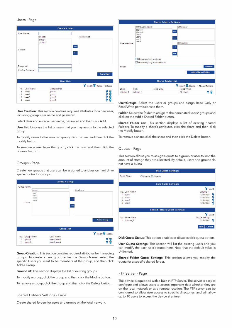
Users - Page
User Creation: This section contains required attributes for a new user, including group, user name and password.
Select User and enter a user name, password and then click Add.
User List: Displays the list of users that you may assign to the selected group.
To modify a user to the selected group, click the user and then click the modify button.
To remove a user from the group, click the user and then click the remove button.
Groups - Page
Create new groups that users can be assigned to and assign hard drive space quotas for groups.
Group Creation: This section contains required attributes for managing groups. To create a new group enter the Group Name, select the specifi c Users you want to be members of the group, and then click Add a Group.
Group List: This section displays the list of existing groups.
To modify a group, click the group and then click the Modify button.
To remove a group, click the group and then click the Delete button.
Shared Folders Settings - Page
Create shared folders for users and groups on the local network.
User/Groups: Select the users or groups and assign Read Only orRead/Write permissions to them.
Folder: Select the folder to assign to the nominated users/ groups and click on the Add a Shared Folder button.
Shared Folder List: This section displays a list of existing SharedFolders. To modify a share’s attributes, click the share and then click the Modify button.
To remove a share, click the share and then click the Delete button.
Quotas - Page
This section allows you to assign a quota to a group or user to limit the amount of storage they are allocated. By default, users and groups do not have a quota.
Disk Quota Status: This option enables or disables disk quota option.
User Quota Settings: This section will list the existing users and you can modify the each user’s quota here. Note that the default value is Unlimited.
Shared Folder Quota Settings: This section allows you modify the quota for a specifi c shared folder.
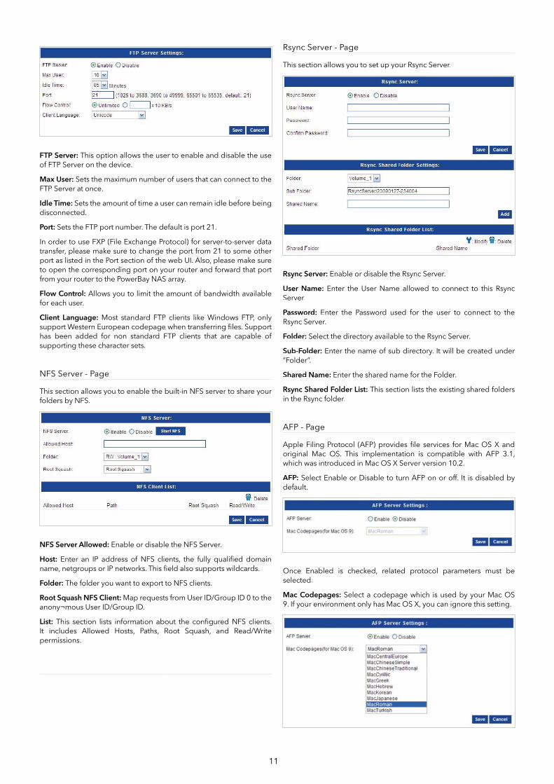
FTP Server - Page
The device is equipped with a built in FTP Server. The server is easy to confi gure and allows users to access important data whether they are on the local network or at a remote location. The FTP server can be confi gured to allow user access to specifi c directories, and will allow up to 10 users to access the device at a time.
11
FTP Server: This option allows the user to enable and disable the use of FTP Server on the device.
Max User: Sets the maximum number of users that can connect to the FTP Server at once.
Idle Time: Sets the amount of time a user can remain idle before being disconnected.
Port: Sets the FTP port number. The default is port 21.
In order to use FXP (File Exchange Protocol) for server-to-server data transfer, please make sure to change the port from 21 to some other port as listed in the Port section of the web UI. Also, please make sure to open the corresponding port on your router and forward that port from your router to the PowerBay NAS array.
Flow Control: Allows you to limit the amount of bandwidth available for each user.
Client Language: Most standard FTP clients like Windows FTP, only support Western European codepage when transferring fi les. Support has been added for non standard FTP clients that are capable of supporting these character sets.
NFS Server - Page
This section allows you to enable the built-in NFS server to share your folders by NFS.
NFS Server Allowed: Enable or disable the NFS Server.
Host: Enter an IP address of NFS clients, the fully qualifi ed domain name, netgroups or IP networks. This fi eld also supports wildcards.
Folder: The folder you want to export to NFS clients.
Root Squash NFS Client: Map requests from User ID/Group ID 0 to theanony¬mous User ID/Group ID.
List: This section lists information about the confi gured NFS clients. It includes Allowed Hosts, Paths, Root Squash, and Read/Write permissions.
Rsync Server - Page
This section allows you to set up your Rsync Server.
Rsync Server: Enable or disable the Rsync Server.
User Name: Enter the User Name allowed to connect to this Rsync Server.
Password: Enter the Password used for the user to connect to the Rsync Server.
Folder: Select the directory available to the Rsync Server.
Sub-Folder: Enter the name of sub directory. It will be created under“Folder”.
Shared Name: Enter the shared name for the Folder.
Rsync Shared Folder List: This section lists the existing shared folders in the Rsync folder.
AFP - Page
Apple Filing Protocol (AFP) provides fi le services for Mac OS X and original Mac OS. This implementation is compatible with AFP 3.1, which was introduced in Mac OS X Server version 10.2.
AFP: Select Enable or Disable to turn AFP on or off. It is disabled by default.
Once Enabled is checked, related protocol parameters must be selected.
Mac Codepages: Select a codepage which is used by your Mac OS9. If your environment only has Mac OS X, you can ignore this setting.
12
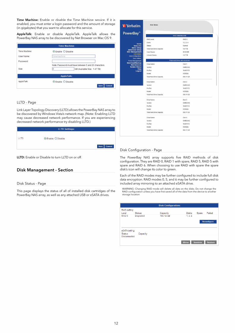
Time Machine: Enable or disable the Time Machine service. If it is enabled, you must enter a login password and the amount of storage (in gigabytes) that you want to allocate for this service.
AppleTalk: Enable or disable AppleTalk. AppleTalk allows the PowerBay NAS array to be discovered by Net Browser on Mac OS 9.
LLTD - Page
Link Layer Topology Discovery (LLTD) allows the PowerBay NAS array to be discovered by Windows Vista’s network map. (Note: Enabling LLTD may cause decreased network performance. If you are experiencing decreased network performance try disabling LLTD.)
LLTD: Enable or Disable to turn LLTD on or off.
Disk Management - Section
Disk Status - Page
This page displays the status of all of installed disk cartridges of the PowerBay NAS array, as well as any attached USB or eSATA drives.
Disk Confi guration - Page
The PowerBay NAS array supports fi ve RAID methods of disk confi guration. They are RAID 0, RAID 1 with spare, RAID 5, RAID 5 with spare and RAID 6. When choosing to use RAID with spare the spare disk’s icon will change its color to green.
Each of the RAID modes may be further confi gured to include full disk data encryption. RAID modes 0, 5, and 6 may be further confi gured to included array mirroring to an attached eSATA drive.
WARNING: Changing RAID mode will delete all data on the disks. Do not change the RAID confi guration unless you have fi rst saved all of the data from the device to another storage location.

13
RAID 0: RAID 0 (also called Striping) distributes data across all disks in a way which can improve throughput, while retaining full capacity. However, RAID 0 provides no fault tolerance so in case of possible failure of any disk, all data will be lost. Available capacity is the combined capacity of all four disk cartridges.
RAID 1 with Spare: RAID 1 (also called Mirroring) stores a duplicate set of data onto at least one other disk so that if one disk fails, all data can be recovered from the other disk. The PowerBay NAS array implements RAID 1 in a way that provides for even more redundancy, resulting in maximum fault tolerance. It does this by (a) using two drives as mirrors instead of just one, and (b) using the fourth drive as a spare. The spare drive will automatically rebuild as a fresh mirror whenever a failure of one of the other three drives is detected. Available capacity is equal to that of only one disk cartridge.
RAID 5: RAID 5 (Striping with distributed parity) combines three or more disks in a way that protects data against loss of any one disk. The storage capacity of the array is reduced by one disk. The PowerBay NAS array implements RAID 5 in one of two ways:
1. Select “RAID 5” to build a 4-disk array. Available capacity will be equal to that of three disk cartridges.
2. Select “RAID 5 with Spare” to build a 3-disk array. The fourth diskis used as a spare. The spare drive will automatically rebuild tocomplete a healthy 3-disk array whenever a failure of one of the other three drives is detected. Available capacity is equal to that of two disk cartridges.
RAID 6: RAID 6 (Striping with distributed dual parity) combines all fourdisks in a way that protects data against loss of any two disks. In the event of a single disk failure, the use of dual parity allows for time to rebuild the array safely without the data being at risk if an additional drive fails before the rebuild is complete. Available capacity is equal to that of two disk cartridges.
Array Mirroring to eSATA Drive
The full data of the PowerBay NAS array can be continuously copied to an attached eSATA drive. If a catastrophic failure of the NAS array occurs, the full data can be restored from the eSATA drive once the NAS array has been repaired or replaced. Array mirroring to eSATA is supported only in RAID modes 0, 5, and 6 and is NOT supported in RAID 1 with Spare or in RAID 5 with Spare. The capacity of the eSATA drive must be at least as large as the capacity of the NAS array.
If you want to use this function, please enable it during the fi rst time you confi gure the array.
When the mirror function is in use, the Disk Confi guration page will show the status of the mirror system, and will present action buttons to temporarily disable the mirror function (“Unmirror” Button) and to restore data from the eSATA drive to the NAS (“Restore” Button).
WARNING: When using the eSATA mirroring function, you MUST attach and power up the eSATA drive BEFORE you power up the PowerBay NAS array. This power-up sequence must be followed EACH TIME you power cycle the PowerBay NAS array. If you power up the PowerBay NAS array fi rst, and later attach and power up the eSATA drive, the eSATA drive will not be recognized as a mirror device, so the eSATA drive will no longer be synchronized to the NAS data.
Array Encryption
The PowerBay NAS array supports 256-bit Advanced Encryption Standard (AES) full disk encryption. Encryption may be enabled for any RAID mode. If eSATA mirroring is enabled, then data copied to the eSATA drive will also be encrypted.
If you want to use this function, please enable it during the fi rst time you confi gure the array.
Once the drive has been confi gured using encryption, the full array can thereafter be LOCKED or UNLOCKED using a password key. When the array is LOCKED it will not show up on the LAN as a shared volume and users cannot access it for storage. All four cartridge LED’s will remain red while the array is LOCKED. For convenience, several methods are provided to UNLOCK a LOCKED array:
1. Enter the NAS user interface and press UNLOCK on the Disk Confi guration page. You will be prompted to enter the password key string.
2. Insert a USB Key device into the front USB port of the PowerBay NAS array. This Key device may be either a fl ash drive or a harddrive, and must have been previously confi gured with the key fi le using the ‘Store Key in USB Drive’ procedure. Once the array is unlocked, the USB Key device may be removed.
3. Enter the NAS user interface and load the key fi le from acomputer on the LAN using the ‘Load” function on the Key Management page. This key fi le must have been previously stored onto the computer using the ‘Save’ function on the Key Management page. Alternatively, the key fi le might have beenpreviously e-mailed to a user using the ‘Mail’ function on the Key Management page.
NOTICE: When encryption is enabled, data transfer rates may be reduced.
14
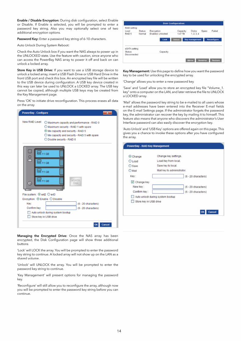
Enable / Disable Encryption: During disk confi guration, select Enable or Disable. If Enable is selected, you will be prompted to enter a password key string. Also you may optionally select one of two additional encryption options.
Password Key: Enter a password key string of 6-10 characters.
Auto Unlock During System Reboot:
Check the Auto Unlock box if you want the NAS always to power up in the UNLOCKED state. Use the feature with caution, since anyone who can access the PowerBay NAS array to power it off and back on can unlock a locked array.
Store Key in USB Drive: If you want to use a USB storage device to unlock a locked array, insert a USB Flash Drive or USB Hard Drive in the front USB port and check this box. An encrypted key fi le will be written to the USB device during confi guration. A USB key device created in this way can later be used to UNLOCK a LOCKED array. The USB key cannot be copied, although multiple USB keys may be created from the Key Management page.
Press ‘OK’ to initiate drive reconfi guration. This process erases all data on the array.
Managing the Encrypted Drive: Once the NAS array has beenencrypted, the Disk Confi guration page will show three additional buttons.
‘Lock’ will LOCK the array. You will be prompted to enter the password key string to continue. A locked array will not show up on the LAN as a shared volume.
‘Unlock’ will UNLOCK the array. You will be prompted to enter the password key string to continue.
‘Key Management’ will present options for managing the password key.
‘Reconfi gure’ will still allow you to reconfi gure the array, although now you will be prompted to enter the password key string before you can continue.
Key Management: Use this page to defi ne how you want the passwordkey to be used for unlocking the encrypted array.
‘Change’ allows you to enter a new password key.
‘Save’ and ‘Load’ allow you to store an encrypted key fi le “Volume_1.key” onto a computer on the LAN, and later retrieve the fi le to UNLOCK a LOCKED array.
‘Mail’ allows the password key string to be e-mailed to all users whose e-mail addresses have been entered into the Receiver E-mail fi elds on the E-mail Settings page. If the administrator forgets the password key, the administrator can recover the key by mailing it to himself. This feature also means that anyone who discovers the administrator’s User Interface password can also easily discover the encryption key.
‘Auto Unlock’ and ‘USB Key’ options are offered again on this page. This gives you a chance to invoke these options after you have confi gured the array.

15
Disk Confi guration – Page (Steps)
Here are the steps to confi gure all the hard drives (including an attached eSATA mirroring disk) to run on RAID 6.
Step 1: Select the desired RAID confi guration. In the example we chose RAID 6.
Step 2: Select the desired fi le system format. In the example we chose ext2.
Step 3: Decide whether you want to attach an external eSATA drive for dedicated use in saving a full duplicate of the data stored on your PowerBay NAS array. If you choose to use this eSATA Disk Mirror feature, check the Mirror option button located below the eSATA Disk icon in this dialogue. When the mirror feature is enabled, the eSATA Disk icon will have a blue frame around it. The eSATA Disk Mirror option is not available for the two RAID modes using a spare.
Click OK.
Step 4: You will be warned that doing this confi guration will erase allthe data from your hard drives. Click OK (if you want to proceed).
Step 5: The RAID confi guration will start. Please wait for it to complete fully before proceeding.
The new RAID settings will now show on the Hard Disk Confi guration page, including the change of the eSATA Disk’s status to “Synchronized”. If you select “Unmirror” but leave the external eSATA drive powered on and connected, the Status will change from “Synchronized” to “Connected”. To restore all data from the external eSATA drive to the NAS, hit the “Restore” button. The external eSATA drive capacity must be at least as large as the currently confi gured NAS RAID array.
Disk Utilities - Page
S.M.A.R.T. Test:
S.M.A.R.T. (Self-Monitoring, Analysis, and Reporting Technology) is a monitoring service that can diagnose the health status of a disk by analyzing certain disk attributes. The test result for each disk is shown at the right.
Scan Disk: Press the Scan Disk button to initiate a scan of all disks and attempt to detect and to list any errors found. This process can take a long time to complete.
Reformat: If you want to reformat the array, using the currently selected RAID mode, you may press the Reformat button. You will be warned that reformatting will erase all the data from your hard drives. Click OK (if you want to proceed).
16
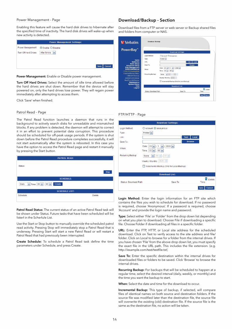
Power Management - Page
Enabling this feature will cause the hard disk drives to hibernate after the specifi ed time of inactivity. The hard disk drives will wake-up when new activity is detected.
Power Management: Enable or Disable power management.
Turn Off Hard Drives: Select the amount of idle time allowed before the hard drives are shut down. Remember that the device will stay powered on, only the hard drives lose power. They will regain power immediately after attempting to access them.
Click ‘Save’ when fi nished.
Patrol Read - Page
The Patrol Read function launches a daemon that runs in the background to actively search disks for unreadable and mismatched blocks. If any problem is detected, the daemon will attempt to correct it in an effort to prevent potential data corruption. This procedure should be scheduled for off-peak usage periods. If the system is shut down before the Patrol Read procedure completes successfully, it will not start automatically after the system is rebooted. In this case you have the option to access the Patrol Read page and restart it manually by pressing the Start button.
Patrol Read Status: The current status of an active Patrol Read task will be shown under Status. Future tasks that have been scheduled will be listed in the Schedule List.
Use the Start or Stop button to manually override the scheduled patrol read activity. Pressing Stop will immediately stop a Patrol Read that is underway. Pressing Start will start a new Patrol Read or will restart a Patrol Read that had previously been interrupted.
Create Schedule: To schedule a Patrol Read task defi ne the time parameters under Schedule, and press Create.
Download/Backup - Section
Download fi les from a FTP server or web server or Backup shared fi les and folders from computer or NAS.
FTP/HTTP - Page
Login Method: Enter the login information for an FTP site which contains the fi les you wish to schedule for download. If no password is required, choose ‘Anonymous’. If a password is required, choose ‘Account’ and provide the login name and password.
Type: Select either ‘File’ or ‘Folder’ from the drop down list dependingon what you plan to download. Choose File if downloading a specifi c fi le. Choose Folder if downloading all fi les in a specifi c folder.
URL: Enter the FTP, HTTP, or Local site address for the scheduled download. Click on Test to verify access to the site address and fi le/folder. Click on Local to browse for a folder from the internal drives. If you have chosen ‘File’ from the above drop down list, you must specify the exact fi le in the URL path. This includes the fi le extension. (e.g. http://example.com/test/testfi le.txt)
Save To: Enter the specifi c destination within the internal drives fordownloaded fi les or folders to be saved. Click ‘Browse’ to browse the internal drives.
Recurring Backup: For backups that will be scheduled to happen at a regular time, select the desired interval (daily, weekly, or monthly) and the time you want the backup to start.
When: Select the date and time for the download to occur.
Incremental Backup: This type of backup, if selected, will compare fi les of identical names on both source and destination folders. If the source fi le was modifi ed later than the destination fi le, the source fi le will overwrite the existing (old) destination fi le. If the source fi le is the same as the destination fi le, no action will be taken.
17
Schedule List: Pending or completed download events will be listed here. Current status is displayed for each event and there is an option to delete a download event at any time.
Schedule Status - Page
View the progress and status of currently scheduled downloads. Pending or completed download events will be listed here. Current download statistics, such as % completed and download speed, are displayed for each event. A refresh button is also provided to produce updated listings at any time.
Download was successful.
Download failed.
Download has not yet occurred.
Waiting.
Link fi le.
The fi le is downloading
USB/eSATA Backup - Page
Back up data from an attached USB drive or an attached eSATA drive to NAS.
Source: Choose the backup source, USB drive or eSATA drive.
Destination: Specify the NAS destination folder, either by entering the folder name directly or by browsing to the folder.
Method: Check the box “Keep Existing Files” to keep your older backed up data. When this box is left unchecked, your older data will be overwritten.
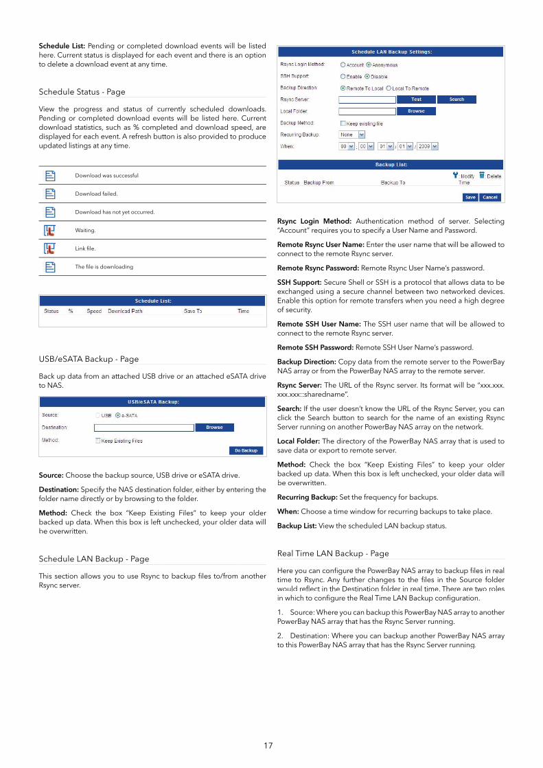
Schedule LAN Backup - Page
This section allows you to use Rsync to backup fi les to/from another Rsync server.
Rsync Login Method: Authentication method of server. Selecting “Account” requires you to specify a User Name and Password.
Remote Rsync User Name: Enter the user name that will be allowed to connect to the remote Rsync server.
Remote Rsync Password: Remote Rsync User Name’s password.
SSH Support: Secure Shell or SSH is a protocol that allows data to be exchanged using a secure channel between two networked devices. Enable this option for remote transfers when you need a high degree of security.
Remote SSH User Name: The SSH user name that will be allowed to connect to the remote Rsync server.
Remote SSH Password: Remote SSH User Name’s password.
Backup Direction: Copy data from the remote server to the PowerBayNAS array or from the PowerBay NAS array to the remote server.
Rsync Server: The URL of the Rsync server. Its format will be “xxx.xxx.xxx.xxx::sharedname”.
Search: If the user doesn’t know the URL of the Rsync Server, you can click the Search button to search for the name of an existing Rsync Server running on another PowerBay NAS array on the network.
Local Folder: The directory of the PowerBay NAS array that is used to save data or export to remote server.
Method: Check the box “Keep Existing Files” to keep your older backed up data. When this box is left unchecked, your older data will be overwritten.
Recurring Backup: Set the frequency for backups.
When: Choose a time window for recurring backups to take place.
Backup List: View the scheduled LAN backup status.
Real Time LAN Backup - Page
Here you can confi gure the PowerBay NAS array to backup fi les in real time to Rsync. Any further changes to the fi les in the Source folder would refl ect in the Destination folder in real time. There are two roles in which to confi gure the Real Time LAN Backup confi guration.
1. Source: Where you can backup this PowerBay NAS array to another PowerBay NAS array that has the Rsync Server running.
2. Destination: Where you can backup another PowerBay NAS array to this PowerBay NAS array that has the Rsync Server running.

18
Source Role: In order to confi gure this PowerBay NAS array in the Source Role, Rsync needs to be disabled on this PowerBay NAS array.
Create Task: Check this box to create a backup task.
Source Folder: The directory of the PowerBay NAS array, used to save data or export to remote server.
Destination IP: The IP address of the remote Rsync server. When you don’t have the IP address of the remote Rsync server you can use the Search button to search for the remote Rsync server using its hostname.
Destination Share-Name: Enter the destination share name.
Login Account: Check this box if you want to login anonymously. Uncheck this box if you want to manually confi gure the login account with a user name and password.
Name: When using a login account, enter the name that will be used for the remote Rsync server.
Password: When using a login account, enter the password that will be used to connect to the remote Rsync server.
Encrypted Transfer (SSH): If the remote Rsync server supports SSH (Secure Shell) transfer, check this box to enable.
Name: The name that will be used to encrypt the Rsync connection to the remote server.
Password: The password that will be used to encrypt the Rsync connection to the remote server.
Backup Option: Check this box if you want to retain the fi les in the remote server that do not exist in the Source Folder.
Backup List: This section allows you to view and manage the real time backup tasks.
Destination Role: In order to confi gure this PowerBay NAS array in the Destination Role, Rsync needs to be enabled on this PowerBay NAS array.
Rsync Server Ready: When enabling the Destination Role the PowerBay NAS array will only check if the Rsync Server is enabled and then reply if it is ready or not.
Maintenance - Section
The Password menu allows you to set a password for the admin account. It is recommended to set an admin account password when fi rst confi guring the device.
Password - Page
Password: Change the administrator’s password. Enter the current password, then the new password. When entering a non-null password, you must enter a password of at least 5 characters in length. Type in the new password again and click ‘Save’ to put the change into effect.
19
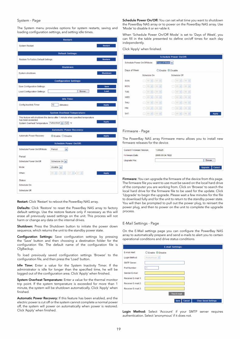
System - Page
The System menu provides options for system restarts, saving and loading confi guration settings, and setting idle times.
Restart: Click ‘Restart’ to reboot the PowerBay NAS array.
Defaults: Click ‘Restore’ to reset the PowerBay NAS array to factory default settings. Use the restore feature only if necessary as this will erase all previously saved settings on the unit. This process will not harm or change any data on the internal drives.
Shutdown: Press the Shutdown button to initiate the power down sequence, which returns the unit to the standby power state.
Confi guration Settings: Save confi guration settings by pressing the ‘Save’ button and then choosing a destination folder for the confi guration fi le. The default name of the confi guration fi le is CfgBackup.
To load previously saved confi guration settings ‘Browse’ to the confi guration fi le, and then press the ‘Load’ button.
Idle Time: Enter a value for the System Inactivity Timer. If the administrator is idle for longer than the specifi ed time, he will be logged out of the confi guration area. Click ‘Apply’ when fi nished.
System Overheat Temperature: Enter a value for the thermal monitor trip point. If the system temperature is exceeded for more than 1 minute, the system will be shutdown automatically. Click ‘Apply’ when fi nished.
Automatic Power Recovery: If this feature has been enabled, and the electric power is cut off or the system cannot complete a normal power off, the system will power on automatically when power is restored. Click ‘Apply’ when fi nished.
Schedule Power On/Off: You can set what time you want to shutdown the PowerBay NAS array or to power on the PowerBay NAS array. Use ‘Mode’ to disable it or en¬able it.
When ‘Schedule Power On/Off Mode’ is set to ‘Days of Week’, you can fi ll in the table presented to defi ne on/off times for each day independently.
Click ‘Apply’ when fi nished.
Firmware - Page
The PowerBay NAS array Firmware menu allows you to install new fi rmware releases for the device.
Firmware: You can upgrade the fi rmware of the device from this page. The fi rmware fi le you want to use must be saved on the local hard drive of the computer you are working from. Click on ‘Browse’ to search the local hard drive for the fi rmware fi le to be used for the update. Click ‘Upgrade’ to begin the upgrade. Please wait a few minutes for the fi le to download fully and for the unit to return to the standby power state. You will then be prompted to pull out the power plug, to reinsert the power plug, and then to power on the unit to complete the upgrade process.
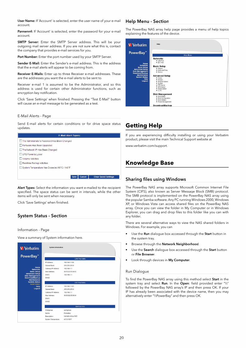
E-Mail Settings - Page
On the E-Mail settings page you can confi gure the PowerBay NAS array to automatically prepare and send e-mails to alert you to certain operational conditions and drive status conditions.
Login Method: Select ‘Account’ if your SMTP server requires authentication. Select ‘anonymous’ if it does not.
20
User Name: If ‘Account’ is selected, enter the user name of your e-mail account.
Password: If ‘Account’ is selected, enter the password for your e-mail account.
SMTP Server: Enter the SMTP Server address. This will be your outgoing mail server address. If you are not sure what this is, contact the company that provides e-mail services for you.
Port Number: Enter the port number used by your SMTP Server.
Sender E-Mail: Enter the Sender’s e-mail address. This is the address that the e-mail alerts will appear to be coming from.
Receiver E-Mails: Enter up to three Receiver e-mail addresses. These are the addresses you want the e-mail alerts to be sent to.
Receiver e-mail 1 is assumed to be the Administrator, and so this address is used for certain other Administrator functions, such as encryption key notifi cation.
Click ‘Save Settings’ when fi nished. Pressing the “Test E-Mail” button will cause an e-mail message to be generated as a test.
E-Mail Alerts - Page
Send E-mail alerts for certain conditions or for drive space status updates.
Alert Types: Select the information you want e-mailed to the recipient specifi ed. The space status can be sent in intervals, while the other items will only be sent when necessary.
Click ‘Save Settings’ when fi nished.
System Status - Section
Information - Page
View a summary of System information here.
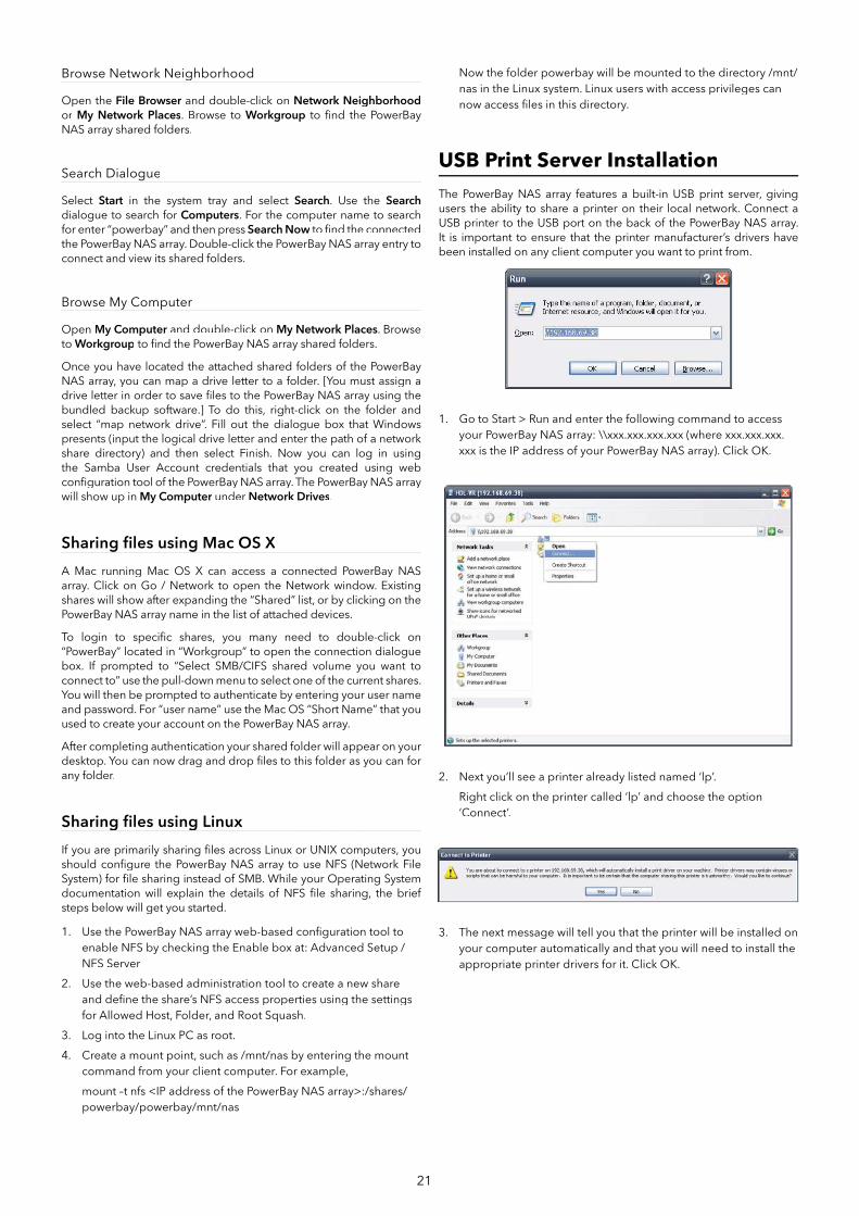
Help Menu - Section
The PowerBay NAS array help page provides a menu of help topics explaining the features of the device.
Getting Help
If you are experiencing diffi culty installing or using your Verbatim product, please visit the main Technical Support website at
www.verbatim.com/support.
Knowledge Base
Sharing fi les using Windows
The PowerBay NAS array supports Microsoft Common Internet File System (CIFS), also known as Server Message Block (SMB) protocol. The SMB protocol is implemented on the PowerBay NAS array using the popular Samba software. Any PC running Windows 2000, Windows XP, or Windows Vista can access shared fi les on the PowerBay NAS array. Once you can view the folder in My Computer or in Windows Explorer, you can drag and drop fi les to this folder like you can with any folder.
There are several alternative ways to view the NAS shared folders in Windows. For example, you can
• Use the Run dialogue box accessed through the Start button in the system tray.
• Browse through the Network Neighborhood.
• Use the Search dialogue box accessed through the Start button or File Browser.
• Look through devices in My Computer.
Run Dialogue
To fi nd the PowerBay NAS array using this method select Start in the system tray and select Run. In the Open: fi eld provided enter “\\”followed by the PowerBay NAS array’s IP and then press OK. If your IP has already been associated with the device name, then you may alternatively enter “\\PowerBay” and then press OK.
21
Browse Network Neighborhood
Open the File Browser and double-click on r Network Neighborhoodor My Network Places. Browse to Workgroup to fi nd the PowerBayNAS array shared folders.
Search Dialogue
Select Start in the system tray and select Search. Use the Searchdialogue to search for Computers. For the computer name to search for enter “powerbay” and then press Search Now to fi nd the connected wthe PowerBay NAS array. Double-click the PowerBay NAS array entry to connect and view its shared folders.
Browse My Computer
Open My Computer and double-click onr My Network Places. Browse to Workgroup to fi nd the PowerBay NAS array shared folders.
Once you have located the attached shared folders of the PowerBay NAS array, you can map a drive letter to a folder. [You must assign a drive letter in order to save fi les to the PowerBay NAS array using the bundled backup software.] To do this, right-click on the folder and select “map network drive”. Fill out the dialogue box that Windows presents (input the logical drive letter and enter the path of a network share directory) and then select Finish. Now you can log in using the Samba User Account credentials that you created using web confi guration tool of the PowerBay NAS array. The PowerBay NAS array will show up in My Computer under r Network Drives.
Sharing fi les using Mac OS X
A Mac running Mac OS X can access a connected PowerBay NAS array. Click on Go / Network to open the Network window. Existing shares will show after expanding the “Shared” list, or by clicking on the PowerBay NAS array name in the list of attached devices.
To login to specifi c shares, you many need to double-click on “PowerBay” located in “Workgroup” to open the connection dialogue box. If prompted to “Select SMB/CIFS shared volume you want to connect to” use the pull-down menu to select one of the current shares. You will then be prompted to authenticate by entering your user name and password. For “user name” use the Mac OS “Short Name” that you used to create your account on the PowerBay NAS array.
After completing authentication your shared folder will appear on your desktop. You can now drag and drop fi les to this folder as you can for any folder.
Sharing fi les using Linux
If you are primarily sharing fi les across Linux or UNIX computers, you should confi gure the PowerBay NAS array to use NFS (Network File System) for fi le sharing instead of SMB. While your Operating System documentation will explain the details of NFS fi le sharing, the brief steps below will get you started.
1. Use the PowerBay NAS array web-based confi guration tool to enable NFS by checking the Enable box at: Advanced Setup / NFS Server
2. Use the web-based administration tool to create a new share and defi ne the share’s NFS access properties using the settingsfor Allowed Host, Folder, and Root Squash.
3. Log into the Linux PC as root.
4. Create a mount point, such as /mnt/nas by entering the mount command from your client computer. For example,
mount –t nfs <IP address of the PowerBay NAS array>:/shares/powerbay/powerbay/mnt/nas
Now the folder powerbay will be mounted to the directory /mnt/nas in the Linux system. Linux users with access privileges can now access fi les in this directory.
USB Print Server Installation
The PowerBay NAS array features a built-in USB print server, giving users the ability to share a printer on their local network. Connect a USB printer to the USB port on the back of the PowerBay NAS array. It is important to ensure that the printer manufacturer’s drivers have been installed on any client computer you want to print from.
1. Go to Start > Run and enter the following command to accessyour PowerBay NAS array: \\xxx.xxx.xxx.xxx (where xxx.xxx.xxx.xxx is the IP address of your PowerBay NAS array). Click OK.
2. Next you’ll see a printer already listed named ‘lp’.
Right click on the printer called ‘lp’ and choose the option‘Connect’.
3. The next message will tell you that the printer will be installed on your computer automatically and that you will need to install the appropriate printer drivers for it. Click OK.
22
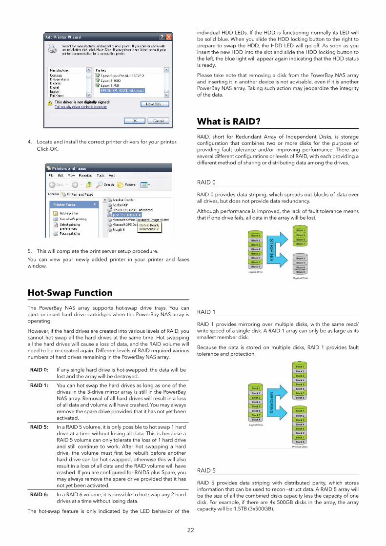
4. Locate and install the correct printer drivers for your printer.Click OK.
5. This will complete the print server setup procedure.
You can view your newly added printer in your printer and faxes window.
Hot-Swap Function
The PowerBay NAS array supports hot-swap drive trays. You can eject or insert hard drive cartridges when the PowerBay NAS array is operating.
However, if the hard drives are created into various levels of RAID, you cannot hot swap all the hard drives at the same time. Hot swapping all the hard drives will cause a loss of data, and the RAID volume will need to be re-created again. Different levels of RAID required various numbers of hard drives remaining in the PowerBay NAS array.
RAID 0: If any single hard drive is hot-swapped, the data will be lost and the array will be destroyed.
RAID 1: You can hot swap the hard drives as long as one of the drives in the 3-drive mirror array is still in the PowerBay NAS array. Removal of all hard drives will result in a loss of all data and volume will have crashed. You may always remove the spare drive provided that it has not yet been activated.
RAID 5: In a RAID 5 volume, it is only possible to hot swap 1 hard drive at a time without losing all data. This is because a RAID 5 volume can only tolerate the loss of 1 hard drive and still continue to work. After hot swapping a hard drive, the volume must fi rst be rebuilt before another hard drive can be hot swapped, otherwise this will also result in a loss of all data and the RAID volume will have crashed. If you are confi gured for RAID5 plus Spare, you may always remove the spare drive provided that it has not yet been activated.
RAID 6: In a RAID 6 volume, it is possible to hot swap any 2 hard drives at a time without losing data.
The hot-swap feature is only indicated by the LED behavior of the
individual HDD LEDs. If the HDD is functioning normally its LED will be solid blue. When you slide the HDD locking button to the right to prepare to swap the HDD, the HDD LED will go off. As soon as you insert the new HDD into the slot and slide the HDD locking button to the left, the blue light will appear again indicating that the HDD status is ready.
Please take note that removing a disk from the PowerBay NAS array and inserting it in another device is not advisable, even if it is another PowerBay NAS array. Taking such action may jeopardize the integrity of the data.
What is RAID?
RAID, short for Redundant Array of Independent Disks, is storage confi guration that combines two or more disks for the purpose of providing fault tolerance and/or improving performance. There are several different confi gurations or levels of RAID, with each providing a different method of sharing or distributing data among the drives.
RAID 0
RAID 0 provides data striping, which spreads out blocks of data over all drives, but does not provide data redundancy.
Although performance is improved, the lack of fault tolerance means that if one drive fails, all data in the array will be lost.
RAID 1
RAID 1 provides mirroring over multiple disks, with the same read/write speed of a single disk. A RAID 1 array can only be as large as its smallest member disk.
Because the data is stored on multiple disks, RAID 1 provides fault tolerance and protection.
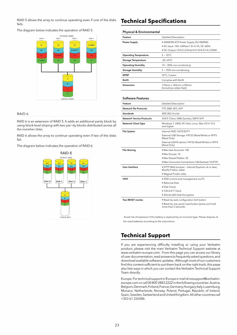
RAID 5
RAID 5 provides data striping with distributed parity, which stores information that can be used to recon¬struct data. A RAID 5 array will be the size of all the combined disks capacity less the capacity of one disk. For example, if there are 4x 500GB disks in the array, the array capacity will be 1.5TB (3x500GB).
23
RAID 5 allows the array to continue operating even if one of the disks fails.
The diagram below indicates the operation of RAID 5:
RAID 6
RAID 6 is an extension of RAID 5. It adds an additional parity block by using block-level striping with two par¬ity blocks distributed across all the member disks.
RAID 6 allows the array to continue operating even if two of the disks fail.
The diagram below indicates the operation of RAID 6:
Technical Specifi cations
Physical & Environmental
Feature Detailed Description
Power Supply • SANSHIN ATX Power Supply (SU-082RW)
• AC Input: 100~240Vac/1.8~0.7A; 50~60Hz
• DC Output:12/5/3.3/5Vdc/4.5/10/4.5/1A (124W)
Operating Temperature 5 ~ 35°C
Storage Temperature -20~60°C
Operating Humidity 10 ~ 85% non-condensing
Storage Humidity 5 ~ 95% non-condensing
MTBF 35°C, 5 years
RoHS Complies with RoHS
Dimension 170mm x 183mm x 230mm(Including rubber feet)
Software Features
Feature Detailed Description
Network fi le Protocols FTP, SMB, NFS, AFP
Standards IEEE 802.3/u/ab
Network Service Protocols DHCP Client, SMB (Samba), SMTP, NTP
Network Client Type Windows 7, 2000, XP, Vista; Linux; Mac OS X 10.2 and higher
File System Internal HDD: EXT2/EXT3
External USB Storage: FAT32 (Read/Write) or NTFS (Read Only)
External eSATA device: FAT32 (Read/Write) or NTFS (Read Only)
File Sharing • Max User Accounts: 128
• Max Groups: 10
• Max Shared Folders: 32
• Max Concurrent Connections:128 (Samba) /10 (FTP)
User Interface • HTTP Web browser – Internet Explorer v6 or later; Mozilla Firefox; Safari
• Magical Finder utility
HDD • HDD control and management via PC
• Reformat Disk
• Disk Check
• S.M.A.R.T Check
• 256-bit AES Disk Encryption
Two RESET modes • Reset by web confi guration GUI button
• Reset by rear panel reset button (press and hold more than 5 seconds)
Avoid risk of explosion if the battery is replaced by an incorrect type. Please dispose of
the used batteries according to the instructions.
Technical Support
If you are experiencing diffi culty installing or using your Verbatim product, please visit the main Verbatim Technical Support website at www.verbatim-europe.com. From this page you can access our library of user documentation, read answers to frequently asked questions, and download available software updates. Although most of our customers fi nd this content suffi cient to put them back on the right track, this page also lists ways in which you can contact the Verbatim Technical Support Team directly.
Europe: For technical support in Europe e-mail [email protected] or call 00 800 3883 2222 in the following countries: Austria, Belgium, Denmark, Finland, France, Germany, Hungary, Italy, Luxemburg, Monaco, Netherlands, Norway, Poland, Portugal, Republic of Ireland, Spain, Sweden, Switzerland and United Kingdom. All other countries call +353 61 226586.
24
Limited Warranty Terms
Verbatim Limited warrants this product to be free from defects in material and workmanship for a period of 2 years from date of purchase. This warranty excludes batteries. If this product is found to be defective within the warranty period, it will be replaced at no cost to you. You may return it with your original cash register receipt to the place of purchase or contact Verbatim.
Product replacement is your sole remedy under this warranty, and this warranty does not apply to normal wear or to damage resulting from abnormal use, misuse, abuse, neglect or accident, or to any incompatibility or poor performance due to the specifi c computer software or hardware used. VERBATIM WILL NOT BE LIABLE FOR DATA LOSS OR ANY INCIDENTAL, CONSEQUENTIAL OR SPECIAL DAMAGES, HOWEVER CAUSED, FOR BREACH OF WARRANTIES OR OTHERWISE. This warranty gives you specifi c legal rights and you may also have other rights which vary from state to state or country to country.
FCC Compliance
This equipment has been tested and found to comply with the limits for a Class B digital device, pursuant to Part 15 of the FCC Rules. These limits are designed to provide reasonable protection against harmful interference in a residential installation. This equipment generates, uses and can radiate radio frequency energy and, if not installed and used in accordance with the instructions, may cause harmful interference to radio communications. However, there is no guarantee that interference will not occur in a particular installation. If this equipment does cause harmful interference to radio or television reception, which can be determined by turning the equipment off and on, the user is encouraged to try to correct the interference by one or more of the following measures:
• Reorient or relocate the receiving antenna.
• Increase the separation between the equipment and receiver.
• Connect the equipment into an outlet on a circuit different fromthat to which the receiver is connected.
• Consult the dealer or an experienced radio/TV technician for help.
WEEE Notice
The Directive on Waste Electrical and Electronic Equipment (WEEE), which entered into force as European law on 13th February 2003, resulted in a major change in the treatment of electrical equipment at end-of-life.
The WEEE logo (shown at the left) on the product or on its box indicates that this product must not be disposed of or dumped with your other household waste. For more information about electronic and electrical waste equipment disposal, recovery, and collection points, please contact your local municipal household waste disposal service or shop from where you purchased the equipment.
Rights
Copyright © 2007 Verbatim Limited. No part of this document may be reproduced in any form or by any means, for any purpose, without the express written permission of Verbatim Corporation. All rights reserved. All other brands and product names referenced herein are property of their respective owners.
CE DeclarationEC Declaration of ConformityyIt is hereby declared that this product complied with the essential protection requirements of Council Directive 89/336/EEC and its amendments on the approximation of the laws of the Member States relating to electromagnetic compatibility.
This declaration applies to all specimens manufactured identical to the model submitted for testing/evaluation.
EN 55022: 1998 + A1: 2000 +A2: 2003
EN 61000-3-3:1995 + A1: 2001
EN 55024: 1998 + A1: 2001 + A2: 2003
IEC 61000-4-2: 1995 + A1: 1998 + A2: 2000
IEC 61000-4-3: 2002 + A1: 2002
IEC 61000-4-4: 1995 + A1: 2000 + A2: 2001
IEC 61000-4-5: 1995 + A1: 2000
IEC 61000-4-6: 1996 + A1: 2000
IEC 61000-4-8: 1993 + A1: 2000
IEC 61000-4-11: 1994 + A1: 2000
RoHS Compliance
This product is in compliance with Directive 2002/95/EC of the European Parliament and of the Council of 27 January 2003, on the restriction of the use of certain hazardous substances in electrical and electronic equipment (RoHS) and its amendments.
THIS DEVICE COMPLIES WITH PART 15 OF THE FCC RULES. OPERATION IS SUBJECT TO THE FOLLOWING TWO CONDITIONS:(1) THIS DEVICE MAY NOT CAUSE HARMFUL INTERFERENCE, AND(2) THIS DEVICE MUST ACCEPT ANY INTERFERENCE RECEIVED, INCLUDINGINTERFERENCE THAT MAY CAUSE UNDESIRED OPERATION.