Power supply noise aware workload assignment for multi-core systems
8
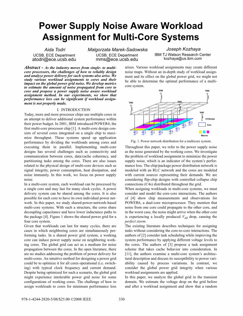
Abstract - As the industry moves from single- to multi- core processors, the challenges of how to reliably design and analyze power delivery for such systems also arise. We study various workload assignments to cores and their impact on the global power grid noise. We develop metrics to estimate the amount of noise propagated from core to core and propose a power supply noise aware workload assignment method. In our experiments, we show that performance loss can be significant if workload assign- ment is not properly made. I. INTRODUCTION Today, more and more processor chips use multiple cores in an attempt to deliver additional system performance within their power budget. In 2001, IBM introduced POWER4, the first multi-core processor chip [1]. A multi-core design con- sists of several cores integrated on a single chip to maxi- mize throughput. These systems speed up application performance by dividing the workloads among cores and executing them in parallel. Implementing multi-core designs has several challenges such as connectivity and communication between cores, data/cache coherency, and partitioning tasks among the cores. There are also issues related to the physical design of multi-core devices such as signal integrity, power consumption, heat dissipation, and noise immunity. In this work, we focus on power supply noise. In a multi-core system, each workload can be processed by a single core and may last for many clock cycles. A power delivery system can be shared among the cores. It is also possible for each core to have its own individual power net- work. In this paper, we study shared-power-network-based multi-core systems. With such a structure, the cores share decoupling capacitance and have lower inductance paths to the package [4]. Figure 1 shows the shared power grid for a four core system. Given that workloads can last for many cycles, there are cases in which neighboring cores are simultaneously per- forming tasks. In a shared power grid system, a working core can induce power supply noise on neighboring work- ing cores. The global grid can act as a medium for noise propagation between the cores. In the open literature, there are no studies addressing the problem of power delivery for multi-cores. An intuitive method for designing a power grid could be to optimize it for all cores operational (i.e. switch- ing) with typical clock frequency and current demand. Despite being optimized for such a scenario, the global grid might experience intolerable power grid noise for some configurations of working cores. The challenge of how to assign workloads to cores for minimum performance loss arises. Various workload assignments may create different noise maps. Without an in-depth study of workload assign- ment and its effect on the global power grid, we might not be able to determine the optimal performance of a multi- core system. Throughout this paper, we refer to the power supply noise as the noise generated by the working cores. We investigate the problem of workload assignment to minimize the power supply noise, which is an indicator of the system’s perfor- mance loss. The chip/package power distribution network is modeled with an RLC network and the cores are modeled with current sources representing their demands. We are considering flip-chip designs with controlled collapse chip connections (C4s) distributed throughout the grid. When assigning workloads in multi-core systems, we must consider and model the core-core interactions. The authors of [4] show chip measurements and observations for POWER6, a dual-core microprocessor. They mention that noise from one core could propagate to the other core, and in the worst case, the noise might arrive when the other core is experiencing a locally produced V dd drop, causing the perfect storm. The existing literature describes techniques for assigning tasks without considering the core-to-core interactions. The authors of [2] consider task scheduling while improving the system performance by applying different voltage levels to the cores. The authors of [3] propose a task assignment scheme that takes cache behavior into consideration. In [11], the authors examine a multi-core system’s architec- tural description and discuss its susceptibility to power vari- ability caused by process variations. In contrast, we consider the global power grid integrity when various workload assignments are applied. In this paper, we analyze the global grid in the transient domain. We estimate the voltage drop on the grid before and after a workload assignment and show that a random Fig. 1. Power network distribution for a multicore system. Vdd Vdd Vdd Vdd Macros Core C4 Bumps Vdd Power Supply Noise Aware Workload Assignment for Multi-Core Systems Aida Todri UCSB, ECE Department [email protected] Joseph Kozhaya IBM TJ Watson Research Center [email protected] Malgorzata Marek-Sadowska UCSB, ECE Department [email protected] 978-1-4244-2820-5/08/$25.00 ©2008 IEEE 330
Transcript of Power supply noise aware workload assignment for multi-core systems
Abstract - As the industry moves from single- to multi-core processors, the challenges of how to reliably designand analyze power delivery for such systems also arise. Westudy various workload assignments to cores and theirimpact on the global power grid noise. We develop metricsto estimate the amount of noise propagated from core tocore and propose a power supply noise aware workloadassignment method. In our experiments, we show thatperformance loss can be significant if workload assign-ment is not properly made.
I. INTRODUCTIONToday, more and more processor chips use multiple cores inan attempt to deliver additional system performance withintheir power budget. In 2001, IBM introduced POWER4, thefirst multi-core processor chip [1]. A multi-core design con-sists of several cores integrated on a single chip to maxi-mize throughput. These systems speed up applicationperformance by dividing the workloads among cores andexecuting them in parallel. Implementing multi-coredesigns has several challenges such as connectivity andcommunication between cores, data/cache coherency, andpartitioning tasks among the cores. There are also issuesrelated to the physical design of multi-core devices such assignal integrity, power consumption, heat dissipation, andnoise immunity. In this work, we focus on power supplynoise. In a multi-core system, each workload can be processed bya single core and may last for many clock cycles. A powerdelivery system can be shared among the cores. It is alsopossible for each core to have its own individual power net-work. In this paper, we study shared-power-network-basedmulti-core systems. With such a structure, the cores sharedecoupling capacitance and have lower inductance paths tothe package [4]. Figure 1 shows the shared power grid for afour core system.Given that workloads can last for many cycles, there arecases in which neighboring cores are simultaneously per-forming tasks. In a shared power grid system, a workingcore can induce power supply noise on neighboring work-ing cores. The global grid can act as a medium for noisepropagation between the cores. In the open literature, thereare no studies addressing the problem of power delivery formulti-cores. An intuitive method for designing a power gridcould be to optimize it for all cores operational (i.e. switch-ing) with typical clock frequency and current demand.Despite being optimized for such a scenario, the global gridmight experience intolerable power grid noise for someconfigurations of working cores. The challenge of how toassign workloads to cores for minimum performance loss
arises. Various workload assignments may create differentnoise maps. Without an in-depth study of workload assign-ment and its effect on the global power grid, we might notbe able to determine the optimal performance of a multi-core system.
Throughout this paper, we refer to the power supply noiseas the noise generated by the working cores. We investigatethe problem of workload assignment to minimize the powersupply noise, which is an indicator of the system’s perfor-mance loss. The chip/package power distribution network ismodeled with an RLC network and the cores are modeledwith current sources representing their demands. We areconsidering flip-chip designs with controlled collapse chipconnections (C4s) distributed throughout the grid.When assigning workloads in multi-core systems, we mustconsider and model the core-core interactions. The authorsof [4] show chip measurements and observations forPOWER6, a dual-core microprocessor. They mention thatnoise from one core could propagate to the other core, andin the worst case, the noise might arrive when the other coreis experiencing a locally produced Vdd drop, causing theperfect storm. The existing literature describes techniques for assigningtasks without considering the core-to-core interactions. Theauthors of [2] consider task scheduling while improving thesystem performance by applying different voltage levels tothe cores. The authors of [3] propose a task assignmentscheme that takes cache behavior into consideration. In[11], the authors examine a multi-core system’s architec-tural description and discuss its susceptibility to power vari-ability caused by process variations. In contrast, weconsider the global power grid integrity when variousworkload assignments are applied.In this paper, we analyze the global grid in the transientdomain. We estimate the voltage drop on the grid beforeand after a workload assignment and show that a random
Fig. 1. Power network distribution for a multicore system.
Vdd
Vdd Vdd
Vdd
Macros
Core
C4 Bumps
Vdd
Power Supply Noise Aware Workload Assignment for Multi-Core Systems Aida Todri
UCSB, ECE [email protected]
Joseph KozhayaIBM TJ Watson Research Center
Malgorzata Marek-SadowskaUCSB, ECE [email protected]
978-1-4244-2820-5/08/$25.00 ©2008 IEEE 330
assignment can lead to a significant performance loss. Wedevelop metrics to measure noise propagation from core tocore. We propose an assignment technique that takes intoaccount the power supply noise of the core and its inducednoise on the neighboring cores. We show that utilizingpower supply aware workload assignments provides signif-icant performance savings. The reminder of the paper is organized as follows. In Sec-tion II we describe the models. In Section III we show themotivational experiment. In Section IV we analyze thebase, core and global grids. In Section V we describe ourworkload assignment method, followed by experiments inSection VI and conclusions in Section VII.
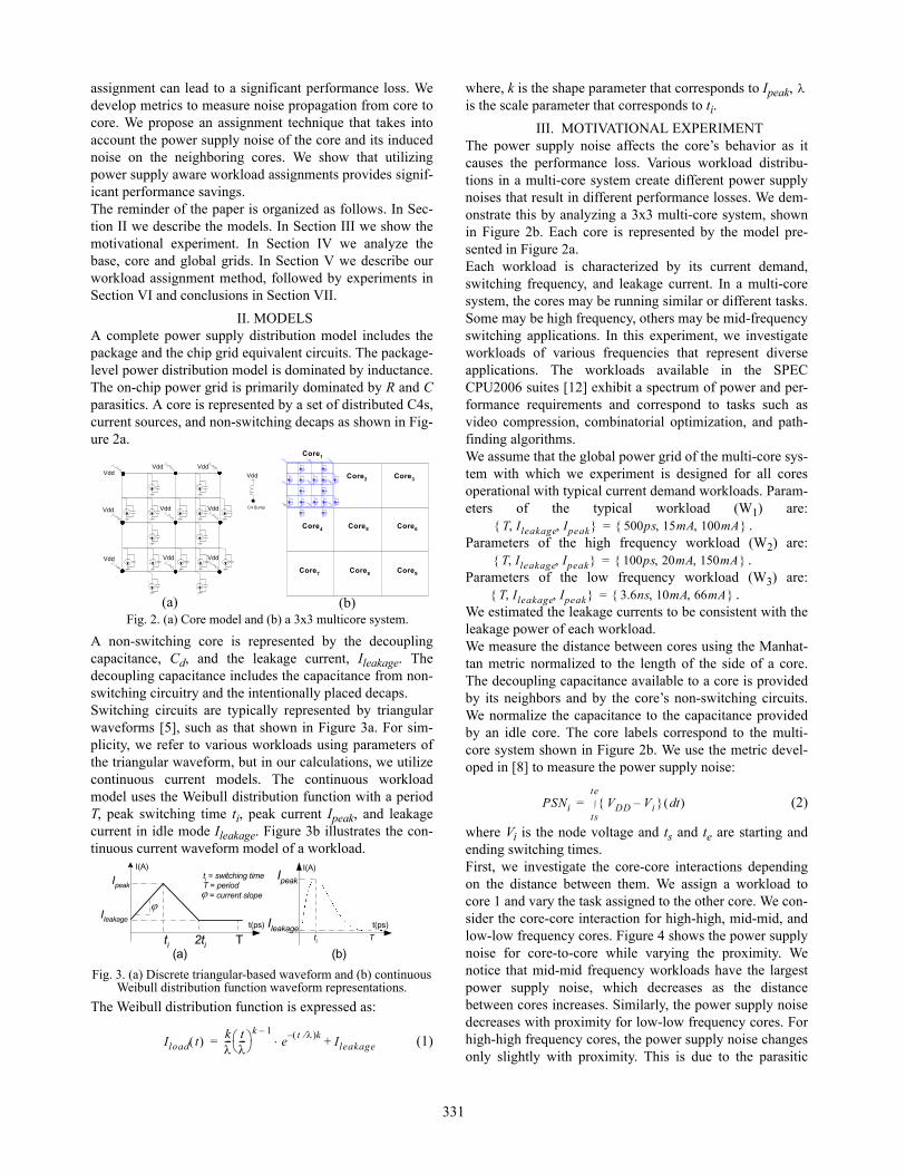
II. MODELSA complete power supply distribution model includes thepackage and the chip grid equivalent circuits. The package-level power distribution model is dominated by inductance.The on-chip power grid is primarily dominated by R and Cparasitics. A core is represented by a set of distributed C4s,current sources, and non-switching decaps as shown in Fig-ure 2a.
A non-switching core is represented by the decouplingcapacitance, Cd, and the leakage current, Ileakage. Thedecoupling capacitance includes the capacitance from non-switching circuitry and the intentionally placed decaps. Switching circuits are typically represented by triangularwaveforms [5], such as that shown in Figure 3a. For sim-plicity, we refer to various workloads using parameters ofthe triangular waveform, but in our calculations, we utilizecontinuous current models. The continuous workloadmodel uses the Weibull distribution function with a periodT, peak switching time ti, peak current Ipeak, and leakagecurrent in idle mode Ileakage. Figure 3b illustrates the con-tinuous current waveform model of a workload.
The Weibull distribution function is expressed as:
(1)
where, k is the shape parameter that corresponds to Ipeak, is the scale parameter that corresponds to ti.
III. MOTIVATIONAL EXPERIMENTThe power supply noise affects the core’s behavior as itcauses the performance loss. Various workload distribu-tions in a multi-core system create different power supplynoises that result in different performance losses. We dem-onstrate this by analyzing a 3x3 multi-core system, shownin Figure 2b. Each core is represented by the model pre-sented in Figure 2a.Each workload is characterized by its current demand,switching frequency, and leakage current. In a multi-coresystem, the cores may be running similar or different tasks.Some may be high frequency, others may be mid-frequencyswitching applications. In this experiment, we investigateworkloads of various frequencies that represent diverseapplications. The workloads available in the SPECCPU2006 suites [12] exhibit a spectrum of power and per-formance requirements and correspond to tasks such asvideo compression, combinatorial optimization, and path-finding algorithms.We assume that the global power grid of the multi-core sys-tem with which we experiment is designed for all coresoperational with typical current demand workloads. Param-eters of the typical workload (W1) are:
. Parameters of the high frequency workload (W2) are:
. Parameters of the low frequency workload (W3) are:
. We estimated the leakage currents to be consistent with theleakage power of each workload.We measure the distance between cores using the Manhat-tan metric normalized to the length of the side of a core.The decoupling capacitance available to a core is providedby its neighbors and by the core’s non-switching circuits.We normalize the capacitance to the capacitance providedby an idle core. The core labels correspond to the multi-core system shown in Figure 2b. We use the metric devel-oped in [8] to measure the power supply noise:
(2)
where Vi is the node voltage and ts and te are starting andending switching times. First, we investigate the core-core interactions dependingon the distance between them. We assign a workload tocore 1 and vary the task assigned to the other core. We con-sider the core-core interaction for high-high, mid-mid, andlow-low frequency cores. Figure 4 shows the power supplynoise for core-to-core while varying the proximity. Wenotice that mid-mid frequency workloads have the largestpower supply noise, which decreases as the distancebetween cores increases. Similarly, the power supply noisedecreases with proximity for low-low frequency cores. Forhigh-high frequency cores, the power supply noise changesonly slightly with proximity. This is due to the parasitic
Fig. 2. (a) Core model and (b) a 3x3 multicore system.
Vdd
Vdd
Vdd
Vdd
Vdd
Vdd
Vdd
C4 BumpVdd
VddVdd
(a) (b)
Core1
Core2 Core3
Core4 Core6Core5
Core7 Core8 Core9
I(A)
ti
Ileakage
T
ti = switching timeT = period = current slope
t(ps)
2ti
IpeakIpeak
Ileakage t(ps)
ti T
I(A)
(b)(a)
Fig. 3. (a) Discrete triangular-based waveform and (b) continuous Weibull distribution function waveform representations.
Iload t k--- t
--- k 1–
et – k Ileakage+=
T Ileakage Ipeak 500ps 15mA 100mA =
T Ileakage Ipeak 100ps 20mA 150mA =
T Ileakage Ipeak 3.6ns 10mA 66mA =
PSNi VDD Vi– td ts
te=
331

effects in the high frequency domain where inductancestarts playing an important role. In low frequencies, decapsdominate but their effects are mostly local and rapidlydecay when distance between the cores increases. Next, we investigate the impact of available decap onpower supply noise. This experiment is performed using asingle operational core at various locations. For example,core 1 has two immediately neighboring cores that can actas decap. Similarly, cores 3, 7, and 9 have two neighborcores that can act as decap. Cores 2, 4, 6, and 8 have threeimmediate neighbor cores and core 5 has four neighborcores to act as decap. Figure 5 shows the impact of decap on the power supplynoise for different frequency workloads. For the sameexperimental setup we vary the workload frequency and theamount of decap available. The worst case power supplynoise always happens at mid frequencies (closer to the reso-nant frequency), regardless of the amount of decap. Theamount of available decap moves the power supply noisecurves up or down, as illustrated in Figure 5. From theseexperiments we draw the following observations:Observation 1: Power Supply Noise and ProximityPower supply noise (PSN) from one core to the other isinversely proportional to the distance between them. As theproximity between cores increases, the induced PSNdecreases, thus the core-core interaction becomes weaker.Additionally, the frequency of the workloads affects thecore-core interactions. The power supply noise from twocores, both with high frequency workloads, tends to be thesame regardless of their proximity due to the inductiveeffects present. In low frequencies, the PSN decreases rap-idly with increasing proximity due to decap effects. Thedependency between PSN and proximity is an importantfactor in controlling power supply noise during workloadassignment. The assignment strategy should take into con-sideration the proximity between the cores and their opera-tional frequencies.Observation 2: PSN and DecapsPSN is inversely proportional to the amount of decap. Asthe amount of decap increases, the power supply noise
decreases, thus increasing the noise resilience of the core.This effect is well-known and widely used to suppress theamount of power supply noise. There are various worksthat investigate decap placement and sizing to controlpower supply noise on a single core [7]. Figure 5 illustratesthis effect. In a multi-core system, the operational core willexperience different amounts of decap depending on itslocation and its neighboring cores’ activities. The neighbor-ing cores can act as decaps to suppress the noise. Theassignment strategy should consider these factors.Observation 3: PSN and FrequencyWorkload frequency has an impact on power supply noise.We have observed that power supply noise is greater whenthe workload frequency is closer to the resonant frequencyof the system. This is also illustrated in Figure 5. The work-loads assigned to cores could differ in their application andswitching frequencies, thus some cores will experiencegreater power supply noise than others. The correlationbetween the power supply noise and workload frequenciesof the cores is shown in Figure 6. For shorter core-to-coredistances, in our experiments, for distances less than 2 (nor-malized Manhattan distance), high-low workload coreshave less power supply noise than low-mid workload cores.For distances greater than 2, low-mid workload cores havethe least power supply noise. The noise generated by thehigh-mid and high-low workloads changes slowly with dis-tance due to the inductive effects whereas the noise for low-mid cores decreases more rapidly due to the local decapeffects. We have observed similar effects for several workloadassignments with which we have experimented. When allcores are operational with the typical workload W1, thepower supply noise is within the allowed margin becausethe grid was optimized to accommodate such conditions. Inthe first assignment, cores 1, 2, and 4 are operational. In thesecond assignment, cores 1, 5, and 9 are operational. Weapply various frequencies to the cores and measure theirpower supply noises on operational cores. Table 1 shows comparisons of power supply noise for eachassignment. Assignment 1 has greater power supply noise
Fig. 4. Core-core interaction for high-high, mid-mid, and low-low frequency workloads.
Fig. 6. Power supply noise dependency on proximity for high-low, high-mid, and low-
mid frequency workloads.
Fig. 5. Power supply noise dependency on workload frequency and decap availability.
332
than assignment 2 for the same set of workloads. For exam-ple, assignment 1 with workloads W1-W2-W3 has the great-est power supply noise.
These observations motivate us to study the impact thatworkload assignments have on the power supply noise andto propose a power supply noise aware assignment strategyto minimize the power supply noise generated.In the next section, we analyze of the global grid to capturethe effects of proximity between cores, available decap, andworkload frequency.
IV. GRID ANALYSISIn this work, we assume that power delivery for a multi-core system consists of a power mesh with C4s, currentsources, and decaps distributed on the grid. Each core isreplicated many times to model the whole multi-core sys-tem structure as shown in figures 2a and 2b.
Each core consists of several blocks. Each block corre-sponds to a circuit bounded by a rectangle whose cornersare C4s. The base grid is a 2x2 grid between the neighbor-ing C4s along with the current sources representing the cir-cuit and decoupling capacitances. The core grid can beviewed as a collection of connected base grids. For exam-ple, a core can have many blocks such as cache, cpu, aluand decoders/drivers. We decompose the core grid intosmaller grids while maintaining the system’s behavior. Per-forming such decomposition allows us to analyze each basegrid separately and to reuse the results to analyze the coreand the whole global grid. Figures 7a and 7b illustrate thebase and core grids. The black dots on the grid representC4s. In this section, we perform detailed analyses of thebase, core, and global grids.
IV.1 Base Grid AnalysisIn this study, we assume the current sources and decouplingcapacitances in a core grid are uniformly distributed over
the core nodes. The decoupling capacitances of the basegrid are extracted from the corresponding circuits. Decapsare split proportionally among the neighboring bases. Cur-rent sources on the boundaries are treated similarly. Ouranalysis is also valid for non-uniform distribution of decapsand current sources. We assume their uniformity to simplifythe explanation.
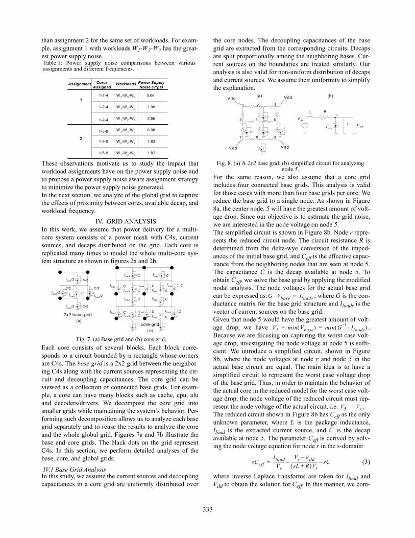
For the same reason, we also assume that a core gridincludes four connected base grids. This analysis is validfor those cases with more than four base grids per core. Wereduce the base grid to a single node. As shown in Figure8a, the center node, 5 will have the greatest amount of volt-age drop. Since our objective is to estimate the grid noise,we are interested in the node voltage on node 5. The simplified circuit is shown in Figure 8b. Node r repre-sents the reduced circuit node. The circuit resistance R isdetermined from the delta-wye conversion of the imped-ances of the initial base grid, and Ceff is the effective capac-itance from the neighboring nodes that are seen at node 5.The capacitance C is the decap available at node 5. Toobtain Ceff, we solve the base grid by applying the modifiednodal analysis. The node voltages for the actual base gridcan be expressed as: , where G is the con-ductance matrix for the base grid structure and Iloads is thevector of current sources on the base grid.Given that node 5 would have the greatest amount of volt-age drop, we have .Because we are focusing on capturing the worst case volt-age drop, investigating the node voltage at node 5 is suffi-cient. We introduce a simplified circuit, shown in Figure8b, where the node voltages at node r and node 5 in theactual base circuit are equal. The main idea is to have asimplified circuit to represent the worst case voltage dropof the base grid. Thus, in order to maintain the behavior ofthe actual core in the reduced model for the worst case volt-age drop, the node voltage of the reduced circuit must rep-resent the node voltage of the actual circuit, i.e. . The reduced circuit shown in Figure 8b has Ceff as the onlyunknown parameter, where L is the package inductance,Iload is the extracted current source, and C is the decapavailable at node 5. The parameter Ceff is derived by solv-ing the node voltage equation for node r in the s-domain:
(3)
where inverse Laplace transforms are taken for Iload andVdd to obtain the solution for Ceff. In this manner, we com-
Table 1: Power supply noise comparisons between variousassignments and different frequencies.
CoresAssigned
Assignment Workloads Power SupplyNoise (V*ps)
1
2
1-2-4
1-2-4
1-2-4
1-5-9
1-5-9
1-5-9
W3-W3-W3
W2-W2-W2
W1-W2-W3
W1-W2-W3
2.56
0.06
1.98
0.06
1.82
1.83
W3-W3-W3
W2-W2-W2
core grid
2x2 base grid(a)
( b)
CIload CIload
CIload
CIload
CIload
CIload
CIload
C
C/2
C/2
C/2
C/2
Iload/2
Iload/2
Iload/2
Iload/2Iload
CIloadCIload
CIload
CIload
CIload
CIload CIload
Fig. 7. (a) Base grid and (b) core grid.
Fig. 8. (a) A 2x2 base grid; (b) simplified circuit for analyzing node 5.
(b)
V dd
r
C
R
loa dI
L
+- C eff
Vdd Vdd
Vdd Vdd
2 3
4 5
(a)
6
7 8 9
1
G Vbase Iloads=
V5 min Vbase min G1–
Iloads = =
V5 Vr=
sCeff
Iload
Vr-----------
Vr Vdd–
sL R+ Vr---------------------------– sC–=
333
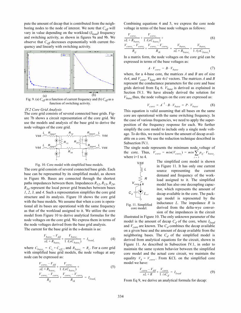
pute the amount of decap that is contributed from the neigh-boring nodes to the node of interest. We note that Ceff willvary in value depending on the workload (Iload) frequencyand switching activity, as shown in figures 9a and 9b. Weobserve that Ceff decreases exponentially with current fre-quency and linearly with switching activity.
IV.2 Core Grid AnalysisThe core grid consists of several connected base grids. Fig-ure 7b shows a circuit representation of the core grid. Weuse the models and analysis of the base grid to derive thenode voltages of the core grid.
The core grid consists of several connected base grids. Eachbase can be represented by its simplified model, as shownin Figure 8b. Bases are connected through the shortestpaths impedances between them. Impedances R12, R13, R24,R34 represent the local power grid branches between bases1, 2, 3, and 4. Such a representation simplifies the core gridstructure and its analysis. Figure 10 shows the core gridwith the base models. We assume that when a core is opera-tional all its bases are operational with the same frequencyas that of the workload assigned to it. We utilize the coremodel from Figure 10 to derive analytical formulas for thenode voltages on the core grid. We express them in terms ofthe node voltages derived from the base grid analysis.The current for the base grid in the s-domain is as:
(4)
where , and . For a core gridwith simplified base grid models, the node voltage at anynode can be expressed as:
(5)
Combining equations 4 and 5, we express the core nodevoltage in terms of the base node voltages as follows:
(6)
In a matrix form, the node voltages on the core grid can beexpressed in terms of the base voltages as:
(7)
where, for a 4-base core, the matrices A and B are of size4x4, and Vcore, Vbase are 4x1 vectors. The matrices A and Brepresent the conductance parameters for the core and basegrids derived from Eq 6. Vbase is derived as explained inSection IV.1. We have already derived the solution forVbase,thus, the node voltages on the core are expressed as:
(8)
This equation is valid assuming that all bases on the samecore are operational with the same switching frequency. Inthe case of various frequencies, we need to apply the super-position of the frequency response for each. We furthersimplify the core model to include only a single node volt-age. To do this, we need to know the amount of decap avail-able on a core. We use the reduction technique described inSubsection IV.1. The single node represents the minimum node voltage ofthe core. Thus, where i=1 to 4.
The simplified core model is shownin Figure 11. It has only one currentsource representing the currentdemand and frequency of the work-load assigned to it. The simplifiedmodel has also one decoupling capac-itor, which represents the amount ofdecap available in the core. The pack-age model is represented by theinductance L. The impedance R isderived from the delta-wye conver-sion of the impedances in the circuit
illustrated in Figure 10. The only unknown parameter of themodel is the amount of decap Cd of the core, where Iloadand Vcore are known. The Cd combines the decap availableon a given base and the amount of decap available from theneighboring bases. The Cd of the simplified model isderived from analytical equations for the circuit, shown inFigure 11. As described in Subsection IV.1, in order tomaintain the same system behavior between the simplifiedcore model and the actual core circuit, we maintain theequality . From KCL on the simplified coremodel we have:
(9)
From Eq 9, we derive an analytical formula for decap:
Fig. 9. (a) Ceff as a function of current frequency and (b) Ceff as a function of switching activity.
(a) (b)
Fig. 10. Core model with simplified base models.
R12
R24
R34
R13
Vdd
Vdd
Vdd
Vdd
L Rbase1
L Rbase3
Rbase2
Rbase4
L
L
VbaseiVdd–
sL Rbasei+
-----------------------------Vbasei
1 sCbasei
-----------------------------+ Iloadi=
CbaseiCri
Ceffi+= Rbasei
Ri=
VcoreiVdd–
sL Rbasei+
-----------------------------Vcorei
1 sCbasei
-----------------------------
VcoreiVcorej
–
Rij----------------------------------
VcoreiVcorek
–
Rik-----------------------------------
+ +
+ Iloadi=
Vcorei
sL Rbasei+
---------------------------Vcorei
1 sCbasei
-----------------------------
VcoreiVcorej
–
Rij----------------------------------
VcoreiVcorek
–
Rik-----------------------------------
+ +
+Vbasei
sL Rbasei+
---------------------------Vbasei
1 sCbasei
-----------------------------+=
A Vcore B Vbase=
Vcore A1–
B Vbase P Vbase= =
Vcore min Vcorei min pij Vbasej
j 1=
4
= =
Fig. 11. Simplified core model.
loadI
Vdd
L
R
C d
Vcore k
Vk Vcore=
Vcore Vdd–
sL R+----------------------------
Vcore
1 sCd----------------+ Iload=
334
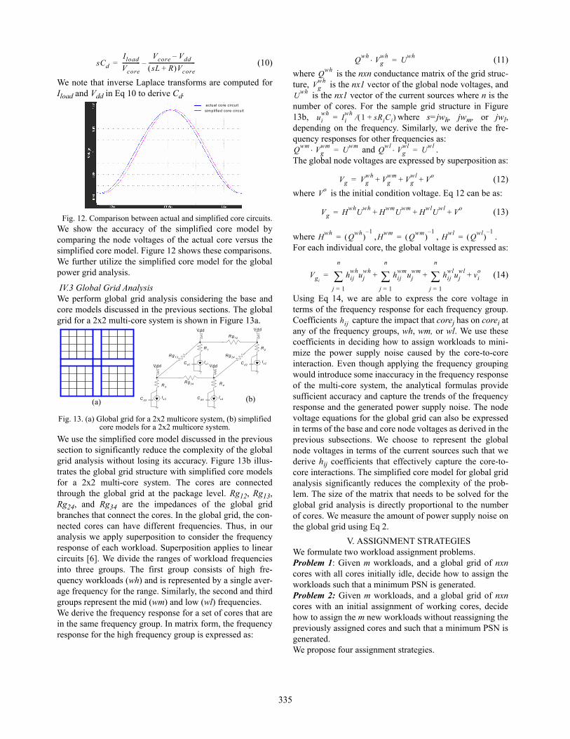
(10)
We note that inverse Laplace transforms are computed forIload and Vdd in Eq 10 to derive Cd.
We show the accuracy of the simplified core model bycomparing the node voltages of the actual core versus thesimplified core model. Figure 12 shows these comparisons.We further utilize the simplified core model for the globalpower grid analysis.
IV.3 Global Grid AnalysisWe perform global grid analysis considering the base andcore models discussed in the previous sections. The globalgrid for a 2x2 multi-core system is shown in Figure 13a.
We use the simplified core model discussed in the previoussection to significantly reduce the complexity of the globalgrid analysis without losing its accuracy. Figure 13b illus-trates the global grid structure with simplified core modelsfor a 2x2 multi-core system. The cores are connectedthrough the global grid at the package level. Rg12, Rg13,Rg24, and Rg34 are the impedances of the global gridbranches that connect the cores. In the global grid, the con-nected cores can have different frequencies. Thus, in ouranalysis we apply superposition to consider the frequencyresponse of each workload. Superposition applies to linearcircuits [6]. We divide the ranges of workload frequenciesinto three groups. The first group consists of high fre-quency workloads (wh) and is represented by a single aver-age frequency for the range. Similarly, the second and thirdgroups represent the mid (wm) and low (wl) frequencies.We derive the frequency response for a set of cores that arein the same frequency group. In matrix form, the frequencyresponse for the high frequency group is expressed as:
(11)
where is the nxn conductance matrix of the grid struc-ture, is the nx1 vector of the global node voltages, and
is the nx1 vector of the current sources where n is thenumber of cores. For the sample grid structure in Figure13b, where s=jwh, jwm, or jwl,depending on the frequency. Similarly, we derive the fre-quency responses for other frequencies as:
and .The global node voltages are expressed by superposition as:
(12)
where is the initial condition voltage. Eq 12 can be as:
(13)
where , , .For each individual core, the global voltage is expressed as:
(14)
Using Eq 14, we are able to express the core voltage interms of the frequency response for each frequency group.Coefficients capture the impact that corej has on corei atany of the frequency groups, wh, wm, or wl. We use thesecoefficients in deciding how to assign workloads to mini-mize the power supply noise caused by the core-to-coreinteraction. Even though applying the frequency groupingwould introduce some inaccuracy in the frequency responseof the multi-core system, the analytical formulas providesufficient accuracy and capture the trends of the frequencyresponse and the generated power supply noise. The nodevoltage equations for the global grid can also be expressedin terms of the base and core node voltages as derived in theprevious subsections. We choose to represent the globalnode voltages in terms of the current sources such that wederive hij coefficients that effectively capture the core-to-core interactions. The simplified core model for global gridanalysis significantly reduces the complexity of the prob-lem. The size of the matrix that needs to be solved for theglobal grid analysis is directly proportional to the numberof cores. We measure the amount of power supply noise onthe global grid using Eq 2.
V. ASSIGNMENT STRATEGIESWe formulate two workload assignment problems.Problem 1: Given m workloads, and a global grid of nxncores with all cores initially idle, decide how to assign theworkloads such that a minimum PSN is generated. Problem 2: Given m workloads, and a global grid of nxncores with an initial assignment of working cores, decidehow to assign the m new workloads without reassigning thepreviously assigned cores and such that a minimum PSN isgenerated.We propose four assignment strategies.
sCd
Iload
Vcore-------------
Vcore Vdd–
sL R+ Vcore----------------------------------–=
Fig. 12. Comparison between actual and simplified core circuits.
actual core circuit
simplified core circuit
Fig. 13. (a) Global grid for a 2x2 multicore system, (b) simplified core models for a 2x2 multicore system.
Is1C d1
C d3Is3 Is4C d4
C d2Is2
Rg12
Rg13
Rg34
Rg24
R 1 R 2
R 4R 3
Vdd Vdd
Vdd Vdd
(a) (b)
Qwh
Vgwh U
wh=
Qwh
Vgwh
Uwh
uiwh
Iiwh
1 sRiCi+ =
Qwm
Vgwm U
wm= Q
wlVg
wl Uwl
=
Vg Vgwh
Vgwm
Vgwl
Vo
+ + +=
Vo
Vg Hwh
Uwh
Hwm
Uwm
Hwl
Uwl
Vo
+ ++=
Hwh
Qwh
1–= H
wmQ
wm 1–
= Hwl
Qwl
1–=
Vgihij
whuj
wh
j 1=
n
hijwm
ujwm
j 1=
n
hijwl
ujwl
j 1=
n
vio
+ + +=
hij
335
V.I Simulated-Annealing-Based AssignmentBoth problems can be solved using a simulated-annealing-based algorithm. Simulated annealing is a well-known opti-mization technique widely used for various applications.We apply simulated annealing to explore the trade-offsbetween power supply noise, performance, and workloadassignments. The assignment vector Xi for problem 1 hasall its elements as variables, whereas in problem 2, the vec-tor Xi has some fixed elements due to the initial, existingassignment. The evaluation function is the power supplynoise obtained by using the node voltages expressed by Eq14 and the noise metric given by Eq2; the cooling rate is setas , where CR=0.92 and k is the coolingstep in the loop. For each temperature step, equilibrium isreached if there is no more change in the power supplynoise for a perturbed assignment configuration.
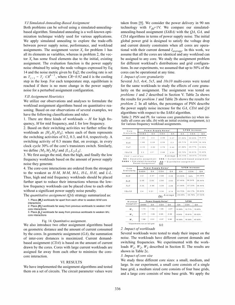
V.II Assignment HeuristicsWe utilize our observations and analyses to formulate theworkload assignment algorithms based on quantitative rea-soning. Based on our observations of several examples, wehave the following classifications and rules:1. There are three kinds of workloads -- H for high fre-quency, M for mid frequency, and L for low frequency.2. Based on their switching activities we further refine theworkloads as {H1,H2,H3}, where each of them representsthe switching activities of 0.2, 0.3, and 0.4, respectively. Aswitching activity of 0.3 means that, on average, in everyclock cycle 30% of the core’s transistors switch. Similarly,we define {M1,M2,M3} and {L1,L2,L3}.3. We first assign the mid, then the high, and finally the lowfrequency workloads based on the amount of power supplynoise they generate.4. The core-core interactions are ordered from the strongestto the weakest as H-M, M-M, M-L, H-L, H-H, and L-L.Thus, high and mid frequency workloads should be placedfurther apart to reduce their interactions whereas the low-low frequency workloads can be placed close to each otherwithout a significant power supply noise penalty.The quantitative assignment (QA) strategy summarized as:
We also introduce two other assignment algorithms basedon geometric distance and the amount of current consumedby the cores. In geometric assignment (GA), the summationof inter-core distances is maximized. Current demand-based assignment (CDA) is based on the amount of currentdrawn by the cores. Cores with large current workloads areassigned far away from each other to minimize the core-core interaction.
VI. RESULTSWe have implemented the assignment algorithms and testedthem on a set of circuits. The circuit parameter values were
taken from [9]. We consider the power delivery in 90 nmtechnology with Vdd=1V. We compare our simulated-annealing-based assignment (SABA) with the QA, GA, andCDA algorithms in terms of power supply noise. The initialglobal power grid is designed to satisfy the voltage dropand current density constraints when all cores are opera-tional with their current demand Iaverage. In this work, weassume that all the cores are identical and any workload canbe assigned to any core. We study the assignment problemfor different workload’s distributions and grid configura-tions. In our experiments, we assumed that up to 50% of thecores can be operational at any time.1. Impact of core granularitySeveral 3x3, 4x4, 5x5, and 10x10 multi-cores were testedfor the same workloads to study the effects of core granu-larity on the assignment. The assignment was tested onproblems 1 and 2 described in Section V. Table 2a showsthe results for problem 1 and Table 2b shows the results forproblem 2. In all tables, the percentages of PSN describethe power supply noise increase for the GA, CDA and QAalgorithms with respect to the SABA algorithm.
2. Impact of workloadsSeveral workloads were tested to study their impact on thenoise. The workloads have different current demands andswitching frequencies. We experimented with the work-loads W1, W2, W3 described in Section II. The results areshown in Table 2c.3. Impact of core sizeWe study three different core sizes: a small, medium, andlarge. In our experiment, a small core consists of a singlebase grid, a medium sized core consists of four base grids,and a large core consists of nine base grids. We apply the
Ti 1+ Ti CRk 1–=
Fig. 14. Quantitative assignment.
1. Place {Mi } workloads far apart from each other to weaken M-M coreinteractions2. Place {Hi } workloads far away from previous workloads to weaken H-Mcore interactions3. Place {Li } workloads far away from previous workloads to weaken M-Lcore interactions
S A B A = S i m u l a t e d A n n e a l i n g B a s e d A s s i g n m e n t
P o w e r S u p p l y N o i s e *
G A C D AS A B A G A C D A Q A
3 x 3
7 x 7
5 x 5
1 0 x 1 0
C o r eG r a n u l a r i t y
G A = G e o m e t r i c a s s i g n m e n t C D A = C u r r e n t d e m a n d b a s e d a s s i g n m e n t
1 9 . 4 7 %3 0 . 5 3 %2 1 . 0 5 %2 . 3 2 . 4 81 . 9 0
1 6 . 1 6 %
2 1 . 8 6 %
3 0 . 9 1 %
2 . 5 82 . 3 91 . 9 8 2 0 . 7 1 %
2 2 . 7 3 %
2 9 . 7 7 %2 . 6 22 . 1 5
2 . 2 2 . 8 8
3 0 . 3 0 %
2 . 7 9
2 . 7
1 2 . 5 6 %
1 5 . 4 5 %
% P S N i n c r e a s e
P S N * = u n i t ( V * p s )
Q A
2 . 2 7
2 . 3
2 . 5 4
2 . 4 2
Q A = Q u a n t i t a t i v e a s s i g n m e n t
A v e r a g e 3 0 . 9 1 %2 2 . 7 3 % 1 5 . 4 5 %
* E xp e r im e n ts ru n o n 3 x3 g rid
P o w e r S u p p ly N o is e *
G A C D AS A B A G A Q A
W 3
W o rk lo a dA s s ig m e n t *
W 1
W 2 3 5 .0 2 %1 5 .8 1 %
1 9 .6 5 %1 2 .7 1 %1 .9 51 .9 21 .7 3
4 0 .9 3 %1 9 .3 6 %2 .3 72 .3 11 .9 9
1 .9 3 2 .0 51 .7 7
% P S N
2 .0 7 1 0 .9 8 %
2 .3 9 9 .0 4 %
2 .8 0 1 6 .0 8 %
Q A C D A
Table 2: PSN and PL for various core granularities (a) when ini-tially all cores are idle, (b) with an initial existing assignment, (c)for various frequency workload assignments.
P o w e r S u p p l y N o i s e *
G A C D AS A B A G A C D A Q A
3 x 3
7 x 7
5 x 5
1 0 x 1 0
C o r eG r a n u la r i t y
2 2 . 3 5 %3 4 %2 3 .5 0 %2 .4 7 2 . 6 82 . 0
2 6 . 4 4 %
3 1 .5 6 %
3 9 .1 7 %
2 . 8 42 . 6 52 .0 8 2 7 .4 0 %
3 3 .7 5 %
3 7 .3 3 %2 .9 62 .2 5
2 . 4 3 . 3 4
3 6 .5 4 %
3 . 0 9
3 . 2 1
2 8 . 4 4 %
3 0 . 8 3 %
% P S N i n c r e a s e
Q A
2 .4 5
2 .6 3
3 .1 4
2 .8 9
A v e r a g e 3 6 . 7 6 %2 9 . 0 5 % 2 7 . 0 2 %
(a)
(b)
(c)
336
same workload to each core. We assume that execution of aworkload consumes the same amount of charge regardlessof the core size. The base grids are the same for all coresizes. Figures 15a and 15b show the power supply noiseversus frequency and switching activity for various coresizes. Large core sizes lead to less performance loss due toavailable decap.
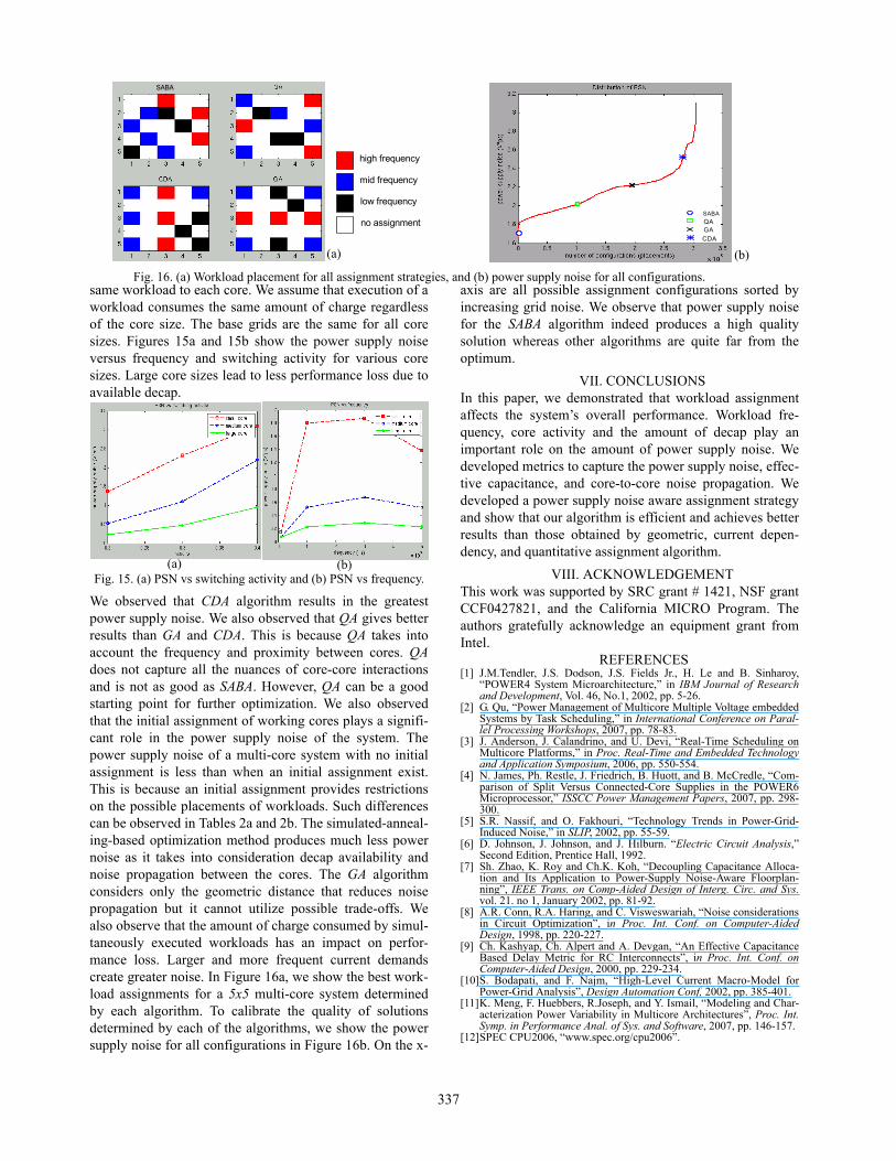
We observed that CDA algorithm results in the greatestpower supply noise. We also observed that QA gives betterresults than GA and CDA. This is because QA takes intoaccount the frequency and proximity between cores. QAdoes not capture all the nuances of core-core interactionsand is not as good as SABA. However, QA can be a goodstarting point for further optimization. We also observedthat the initial assignment of working cores plays a signifi-cant role in the power supply noise of the system. Thepower supply noise of a multi-core system with no initialassignment is less than when an initial assignment exist.This is because an initial assignment provides restrictionson the possible placements of workloads. Such differencescan be observed in Tables 2a and 2b. The simulated-anneal-ing-based optimization method produces much less powernoise as it takes into consideration decap availability andnoise propagation between the cores. The GA algorithmconsiders only the geometric distance that reduces noisepropagation but it cannot utilize possible trade-offs. Wealso observe that the amount of charge consumed by simul-taneously executed workloads has an impact on perfor-mance loss. Larger and more frequent current demandscreate greater noise. In Figure 16a, we show the best work-load assignments for a 5x5 multi-core system determinedby each algorithm. To calibrate the quality of solutionsdetermined by each of the algorithms, we show the powersupply noise for all configurations in Figure 16b. On the x-
axis are all possible assignment configurations sorted byincreasing grid noise. We observe that power supply noisefor the SABA algorithm indeed produces a high qualitysolution whereas other algorithms are quite far from theoptimum.
VII. CONCLUSIONSIn this paper, we demonstrated that workload assignmentaffects the system’s overall performance. Workload fre-quency, core activity and the amount of decap play animportant role on the amount of power supply noise. Wedeveloped metrics to capture the power supply noise, effec-tive capacitance, and core-to-core noise propagation. Wedeveloped a power supply noise aware assignment strategyand show that our algorithm is efficient and achieves betterresults than those obtained by geometric, current depen-dency, and quantitative assignment algorithm.
VIII. ACKNOWLEDGEMENTThis work was supported by SRC grant # 1421, NSF grantCCF0427821, and the California MICRO Program. Theauthors gratefully acknowledge an equipment grant fromIntel.
REFERENCES[1] J.M.Tendler, J.S. Dodson, J.S. Fields Jr., H. Le and B. Sinharoy,
“POWER4 System Microarchitecture,” in IBM Journal of Researchand Development, Vol. 46, No.1, 2002, pp. 5-26.
[2] G. Qu, “Power Management of Multicore Multiple Voltage embeddedSystems by Task Scheduling,” in International Conference on Paral-lel Processing Workshops, 2007, pp. 78-83.
[3] J. Anderson, J. Calandrino, and U. Devi, “Real-Time Scheduling onMulticore Platforms,” in Proc. Real-Time and Embedded Technologyand Application Symposium, 2006, pp. 550-554.
[4] N. James, Ph. Restle, J. Friedrich, B. Huott, and B. McCredle, “Com-parison of Split Versus Connected-Core Supplies in the POWER6Microprocessor,” ISSCC Power Management Papers, 2007, pp. 298-300.
[5] S.R. Nassif, and O. Fakhouri, “Technology Trends in Power-Grid-Induced Noise,” in SLIP, 2002, pp. 55-59.
[6] D. Johnson, J. Johnson, and J. Hilburn. “Electric Circuit Analysis,”Second Edition, Prentice Hall, 1992.
[7] Sh. Zhao, K. Roy and Ch.K. Koh, “Decoupling Capacitance Alloca-tion and Its Application to Power-Supply Noise-Aware Floorplan-ning”, IEEE Trans. on Comp-Aided Design of Interg. Circ. and Sys.vol. 21. no 1, January 2002, pp. 81-92.
[8] A.R. Conn, R.A. Haring, and C. Visweswariah, “Noise considerationsin Circuit Optimization”, in Proc. Int. Conf. on Computer-AidedDesign, 1998, pp. 220-227.
[9] Ch. Kashyap, Ch. Alpert and A. Devgan, “An Effective CapacitanceBased Delay Metric for RC Interconnects”, in Proc. Int. Conf. onComputer-Aided Design, 2000, pp. 229-234.
[10]S. Bodapati, and F. Najm, “High-Level Current Macro-Model forPower-Grid Analysis”, Design Automation Conf, 2002, pp. 385-401.
[11]K. Meng, F. Huebbers, R.Joseph, and Y. Ismail, “Modeling and Char-acterization Power Variability in Multicore Architectures”, Proc. Int.Symp. in Performance Anal. of Sys. and Software, 2007, pp. 146-157.
[12]SPEC CPU2006, “www.spec.org/cpu2006”.
SABA
high frequency
mid frequency
low frequency
no assignmentSABA
QAGA
CDA
(a) (b)
Fig. 16. (a) Workload placement for all assignment strategies, and (b) power supply noise for all configurations.
Fig. 15. (a) PSN vs switching activity and (b) PSN vs frequency. (b)(a)
337