
Power Quality Solution - Digital Asset Management - Siemens
40
Power Quality Solution www.siemens.co.in
-
Upload
khangminh22 -
Category
Documents
-
view
4 -
download
0
Transcript of Power Quality Solution - Digital Asset Management - Siemens
Power Quality Solution
www.siemens.co.in
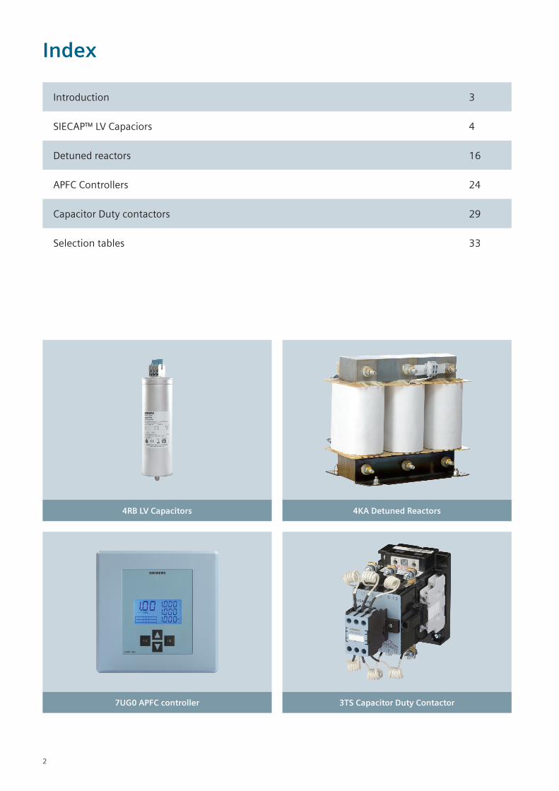
Index
Introduction 3
SIECAP™ LV Capaciors 4
Detuned reactors 16
APFC Controllers 24
Capacitor Duty contactors 29
Selection tables 33
4RB LV Capacitors
7UG0 APFC controller
4KA Detuned Reactors
3TS Capacitor Duty Contactor
2
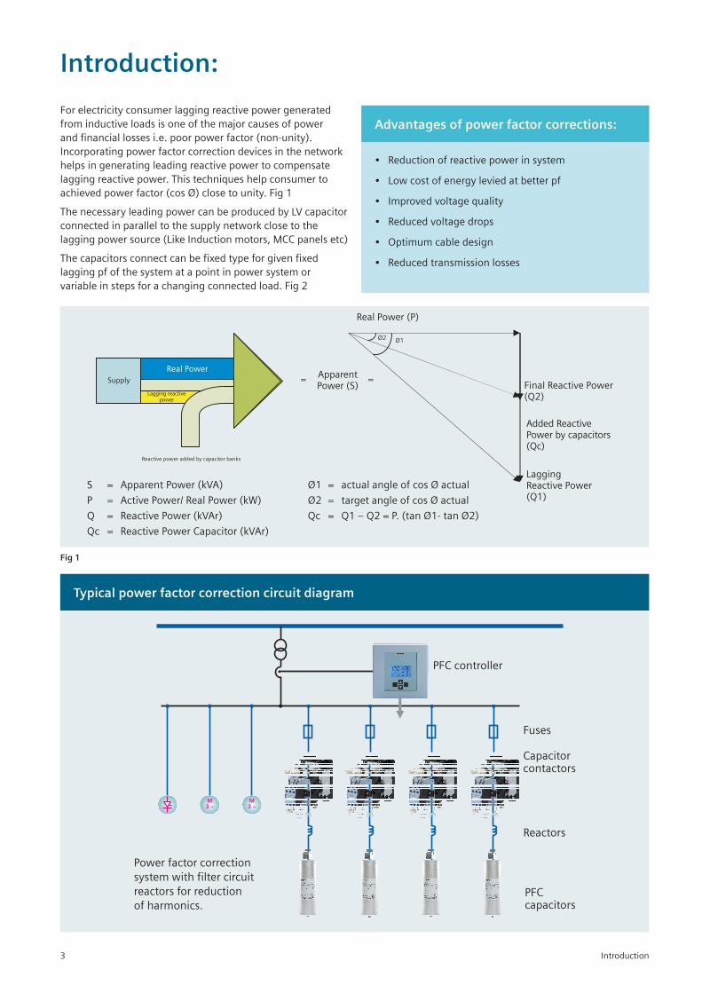
Introduction:
Supply
Real Power
Lagging reactivepower
Reactive power added by capacitor banks
Real Power (P)
= ApparentPower (S)
=
LaggingReactive Power(Q1)
Added ReactivePower by capacitors(Qc)
Final Reactive Power(Q2)
Ø2 Ø1
S = Apparent Power (kVA)
P = Active Power/ Real Power (kW)
Q = Reactive Power (kVAr)
Qc = Reactive Power Capacitor (kVAr)
Ø1 = actual angle of cos Ø actual
Ø2 = target angle of cos Ø actual
Qc = Q1 – Q2 = P. (tan Ø1- tan Ø2)
Advantages of power factor corrections:
• Reductionofreactivepowerinsystem
• Lowcostofenergyleviedatbetterpf
• Improvedvoltagequality
• Reducedvoltagedrops
• Optimumcabledesign
• Reducedtransmissionlosses
Fig 1
Typical power factor correction circuit diagram
Power factor correction
system with filter circuit
reactors for reduction
of harmonics.
M
3 –
M
3 –
PFC controller
Fuses
Capacitorcontactors
Reactors
PFCcapacitors
Introduction
Forelectricityconsumerlaggingreactivepowergeneratedfrominductiveloadsisoneofthemajorcausesofpowerandfinanciallossesi.e.poorpowerfactor(non-unity).Incorporatingpowerfactorcorrectiondevicesinthenetworkhelpsingeneratingleadingreactivepowertocompensatelaggingreactivepower.Thistechniqueshelpconsumertoachievedpowerfactor(cosØ)closetounity.Fig1
ThenecessaryleadingpowercanbeproducedbyLVcapacitorconnectedinparalleltothesupplynetworkclosetothelaggingpowersource(LikeInductionmotors,MCCpanelsetc)
Thecapacitorsconnectcanbefixedtypeforgivenfixedlaggingpfofthesystematapointinpowersystemorvariableinstepsforachangingconnectedload.Fig2
3
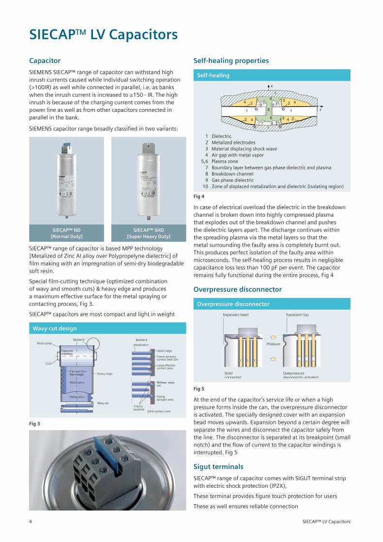
Capacitor
SIEMENSSIECAP™rangeofcapacitorcanwithstandhighinrushcurrentscausedwhileindividualswitchingoperation(>100IR)aswellwhileconnectedinparallel,i.e.asbankswhentheinrushcurrentisincreasedto≥150·IR.Thehighinrushisbecauseofthechargingcurrentcomesfromthepowerlineaswellasfromothercapacitorsconnectedinparallelinthebank.
SIEMENScapacitorrangebroadlyclassifiedintwovariants:
SIECAP™ ND [Normal Duty]
SIECAP™ SHD [Super Heavy Duty]
SIECAP™rangeofcapacitorisbasedMPPtechnology[MetalizedofZincAlalloyoverPolypropelynedielectric]offilmmakingwithanimpregnationofsemi-drybiodegradablesoft resin.
Specialfilm-cuttingtechnique(optimizedcombinationofwavyandsmoothcuts)&heavyedgeandproducesamaximumeffectivesurfaceforthemetalsprayingorcontactingprocess,Fig3.
SIECAP™capacitorsaremostcompactandlightinweight
Wavy cut design
Section A
Capacitorwindings
Metal spray
Core
Film and film-free margin
Metalization
Metalization
Heavy edge
Wavy cut
Section A
Without wavy cut
Solid contact zone
Crackspossible
Flame-sprayed area
Heavy edge
Flame-sprayedcontact area (Zn)
Large effectivecontact area
Metalization
Fig 3
SIECAP™ LV Capacitors
Self-healing properties
Self-healing
1 Dielectric 2 Metalizedelectrodes 3 Materialdisplacingshockwave 4 Airgapwithmetalvapor 5,6 Plasmazone 7 Boundarylayerbetweengasphasedielectricandplasma 8 Breakdownchannel 9 Gasphasedielectric 10 Zoneofdisplacedmetalizationanddielectric(isolatingregion)
Fig 4
Incaseofelectricaloverloadthedielectricinthebreakdownchannelisbrokendownintohighlycompressedplasmathatexplodesoutofthebreakdownchannelandpushesthedielectriclayersapart.Thedischargecontinueswithinthespreadingplasmaviathemetallayerssothatthemetalsurroundingthefaultyareaiscompletelyburntout.Thisproducesperfectisolationofthefaultyareawithinmicroseconds.Theself-healingprocessresultsinnegligiblecapacitancelosslessthan100pFperevent.Thecapacitorremainsfullyfunctionalduringtheentireprocess,Fig4
Overpressure disconnector
Overpressure disconnector
Fig 5
Attheendofthecapacitor’sservicelifeorwhenahighpressureformsinsidethecan,theoverpressuredisconnectorisactivated.Thespeciallydesignedcoverwithanexpansionbeadmovesupwards.Expansionbeyondacertaindegreewillseparatethewiresanddisconnectthecapacitorsafelyfromtheline.Thedisconnectorisseparatedatitsbreakpoint(smallnotch)andtheflowofcurrenttothecapacitorwindingsisinterrupted.Fig5
Sigut terminals
SIECAP™rangeofcapacitorcomeswithSIGUTterminalstripwithelectricshockprotection(IP2X),
Theseterminalprovidesfiguretouchprotectionforusers
Theseaswellensuresreliableconnection
SIECAP™ LV Capacitors4
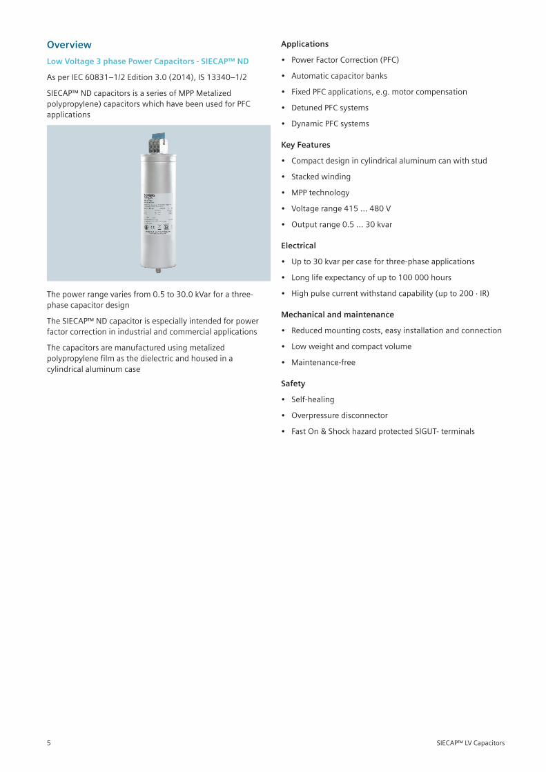
Overview
Low Voltage 3 phase Power Capacitors - SIECAP™ ND
AsperIEC60831–1/2Edition3.0(2014),IS13340–1/2
SIECAP™NDcapacitorsisaseriesofMPPMetalizedpolypropylene)capacitorswhichhavebeenusedforPFCapplications
Thepowerrangevariesfrom0.5to30.0kVarforathree-phasecapacitordesign
TheSIECAP™NDcapacitorisespeciallyintendedforpowerfactorcorrectioninindustrialandcommercialapplications
Thecapacitorsaremanufacturedusingmetalizedpolypropylenefilmasthedielectricandhousedinacylindricalaluminumcase
Applications
• PowerFactorCorrection(PFC)
• Automaticcapacitorbanks
• FixedPFCapplications,e.g.motorcompensation
• DetunedPFCsystems
• DynamicPFCsystems
Key Features
• Compactdesignincylindricalaluminumcanwithstud
• Stackedwinding
• MPPtechnology
• Voltagerange415…480V
• Outputrange0.5…30kvar
Electrical
• Upto30kvarpercaseforthree-phaseapplications
• Longlifeexpectancyofupto100000hours
• Highpulsecurrentwithstandcapability(upto200·IR)
Mechanical and maintenance
• Reducedmountingcosts,easyinstallationandconnection
• Lowweightandcompactvolume
• Maintenance-free
Safety
• Self-healing
• Overpressuredisconnector
• FastOn&ShockhazardprotectedSIGUT-terminals
SIECAP™ LV Capacitors5
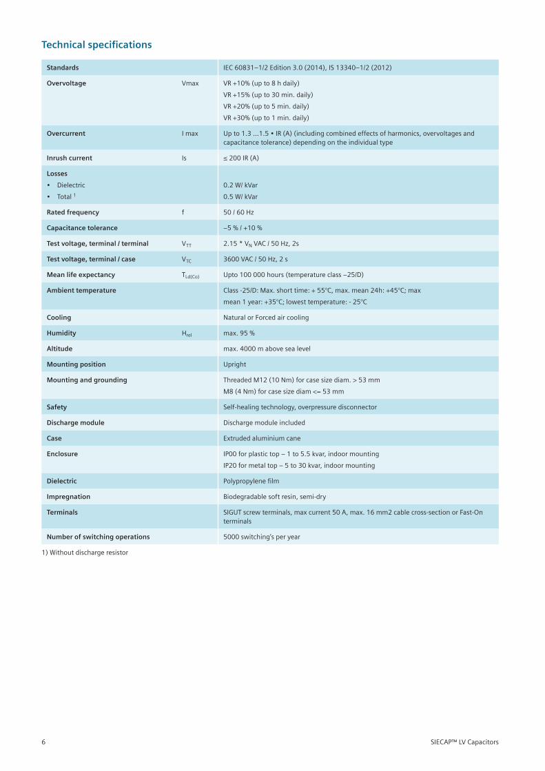
Technical specifications
Standards IEC60831–1/2Edition3.0(2014),IS13340–1/2(2012)
Overvoltage Vmax VR+10%(upto8hdaily)
VR+15%(upto30min.daily)
VR+20%(upto5min.daily)
VR+30%(upto1min.daily)
Overcurrent Imax Upto1.3…1.5•IR(A)(includingcombinedeffectsofharmonics,overvoltagesandcapacitancetolerance)dependingontheindividualtype
Inrush current Is ≤200IR(A)
Losses
• Dielectric
• Total1
0.2 W/ kVar
0.5W/kVar
Rated frequency f 50/60Hz
Capacitance tolerance –5%/+10%
Test voltage, terminal / terminal VTT 2.15*VNVAC/50Hz,2s
Test voltage, terminal / case VTC 3600VAC/50Hz,2s
Mean life expectancy TLd(Co) Upto100000hours(temperatureclass–25/D)
Ambient temperature Class-25/D:Max.shorttime:+55°C,max.mean24h:+45°C;max
mean1year:+35°C;lowesttemperature:-25°C
Cooling NaturalorForcedaircooling
Humidity Hrel max.95%
Altitude max.4000mabovesealevel
Mounting position Upright
Mounting and grounding ThreadedM12(10Nm)forcasesizediam.>53mm
M8(4Nm)forcasesizediam<=53mm
Safety Self-healingtechnology,overpressuredisconnector
Discharge module Dischargemoduleincluded
Case Extrudedaluminiumcane
Enclosure IP00forplastictop–1to5.5kvar,indoormounting
IP20formetaltop–5to30kvar,indoormounting
Dielectric Polypropylenefilm
Impregnation Biodegradablesoftresin,semi-dry
Terminals SIGUTscrewterminals,maxcurrent50A,max.16mm2cablecross-sectionorFast-Onterminals
Number of switching operations 5000switching’speryear
1)Withoutdischargeresistor
SIECAP™ LV Capacitors6
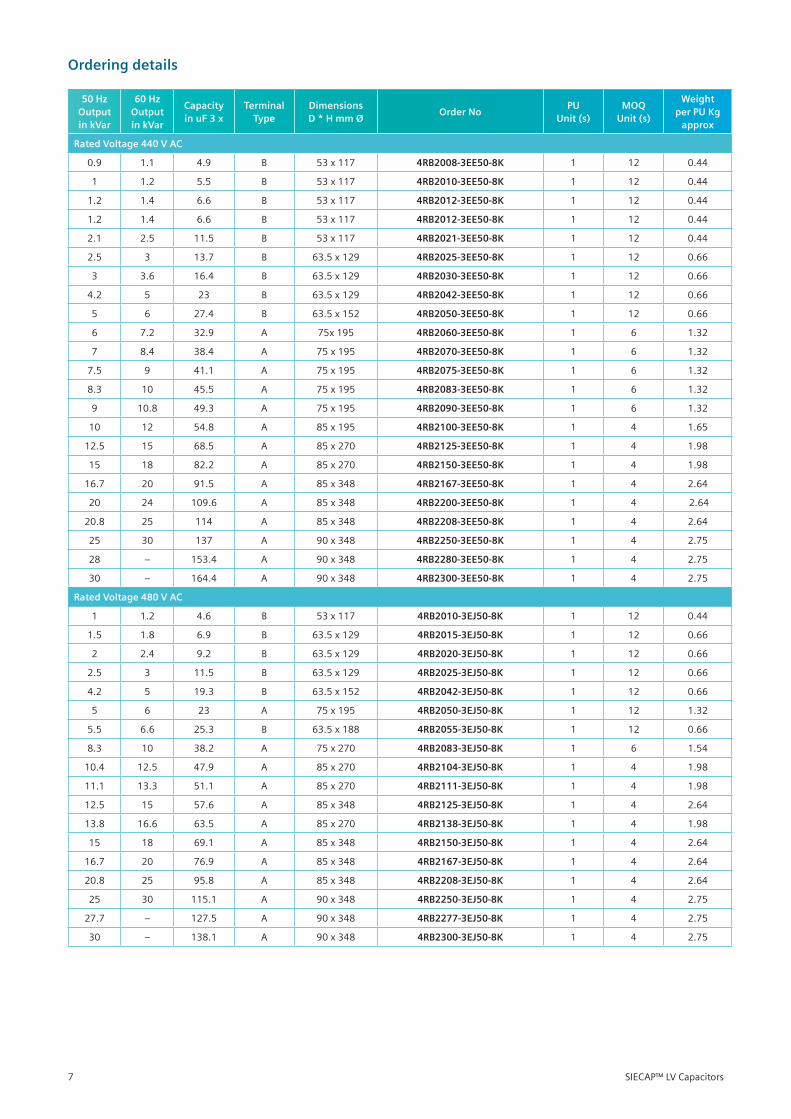
Ordering details
50 Hz Output in kVar
60 Hz Output in kVar
Capacity in uF 3 x
Terminal Type
Dimensions D * H mm Ø
Order NoPU
Unit (s)MOQ
Unit (s)
Weight per PU Kg
approx
Rated Voltage 440 V AC
0.9 1.1 4.9 B 53x117 4RB2008-3EE50-8K 1 12 0.44
1 1.2 5.5 B 53x117 4RB2010-3EE50-8K 1 12 0.44
1.2 1.4 6.6 B 53x117 4RB2012-3EE50-8K 1 12 0.44
1.2 1.4 6.6 B 53x117 4RB2012-3EE50-8K 1 12 0.44
2.1 2.5 11.5 B 53x117 4RB2021-3EE50-8K 1 12 0.44
2.5 3 13.7 B 63.5x129 4RB2025-3EE50-8K 1 12 0.66
3 3.6 16.4 B 63.5x129 4RB2030-3EE50-8K 1 12 0.66
4.2 5 23 B 63.5x129 4RB2042-3EE50-8K 1 12 0.66
5 6 27.4 B 63.5x152 4RB2050-3EE50-8K 1 12 0.66
6 7.2 32.9 A 75x195 4RB2060-3EE50-8K 1 6 1.32
7 8.4 38.4 A 75x195 4RB2070-3EE50-8K 1 6 1.32
7.5 9 41.1 A 75x195 4RB2075-3EE50-8K 1 6 1.32
8.3 10 45.5 A 75x195 4RB2083-3EE50-8K 1 6 1.32
9 10.8 49.3 A 75x195 4RB2090-3EE50-8K 1 6 1.32
10 12 54.8 A 85x195 4RB2100-3EE50-8K 1 4 1.65
12.5 15 68.5 A 85x270 4RB2125-3EE50-8K 1 4 1.98
15 18 82.2 A 85x270 4RB2150-3EE50-8K 1 4 1.98
16.7 20 91.5 A 85x348 4RB2167-3EE50-8K 1 4 2.64
20 24 109.6 A 85x348 4RB2200-3EE50-8K 1 4 2.64
20.8 25 114 A 85x348 4RB2208-3EE50-8K 1 4 2.64
25 30 137 A 90x348 4RB2250-3EE50-8K 1 4 2.75
28 – 153.4 A 90x348 4RB2280-3EE50-8K 1 4 2.75
30 – 164.4 A 90x348 4RB2300-3EE50-8K 1 4 2.75
Rated Voltage 480 V AC
1 1.2 4.6 B 53x117 4RB2010-3EJ50-8K 1 12 0.44
1.5 1.8 6.9 B 63.5x129 4RB2015-3EJ50-8K 1 12 0.66
2 2.4 9.2 B 63.5x129 4RB2020-3EJ50-8K 1 12 0.66
2.5 3 11.5 B 63.5x129 4RB2025-3EJ50-8K 1 12 0.66
4.2 5 19.3 B 63.5x152 4RB2042-3EJ50-8K 1 12 0.66
5 6 23 A 75x195 4RB2050-3EJ50-8K 1 12 1.32
5.5 6.6 25.3 B 63.5x188 4RB2055-3EJ50-8K 1 12 0.66
8.3 10 38.2 A 75x270 4RB2083-3EJ50-8K 1 6 1.54
10.4 12.5 47.9 A 85x270 4RB2104-3EJ50-8K 1 4 1.98
11.1 13.3 51.1 A 85x270 4RB2111-3EJ50-8K 1 4 1.98
12.5 15 57.6 A 85x348 4RB2125-3EJ50-8K 1 4 2.64
13.8 16.6 63.5 A 85x270 4RB2138-3EJ50-8K 1 4 1.98
15 18 69.1 A 85x348 4RB2150-3EJ50-8K 1 4 2.64
16.7 20 76.9 A 85x348 4RB2167-3EJ50-8K 1 4 2.64
20.8 25 95.8 A 85x348 4RB2208-3EJ50-8K 1 4 2.64
25 30 115.1 A 90x348 4RB2250-3EJ50-8K 1 4 2.75
27.7 – 127.5 A 90x348 4RB2277-3EJ50-8K 1 4 2.75
30 – 138.1 A 90x348 4RB2300-3EJ50-8K 1 4 2.75
SIECAP™ LV Capacitors7
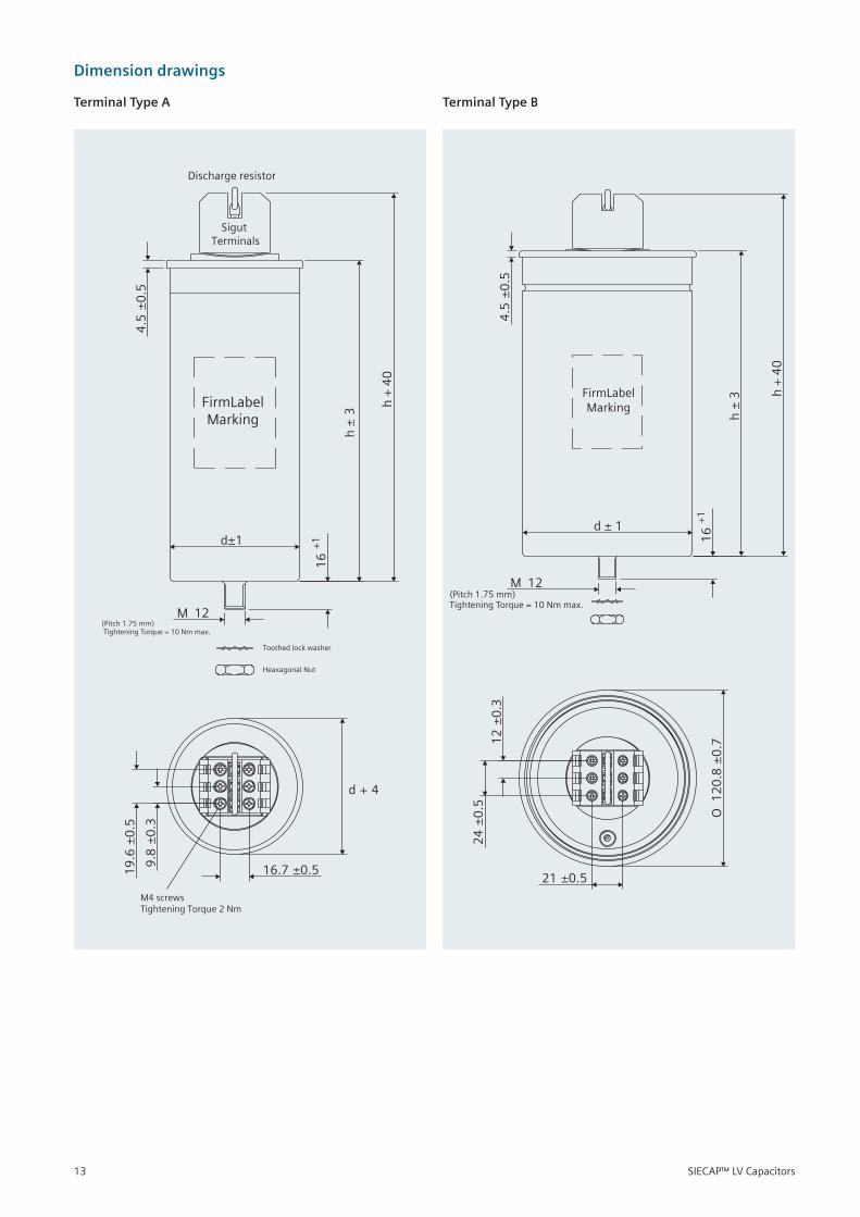
(Pitch
Toothed lock washer
Heaxagonal Nut
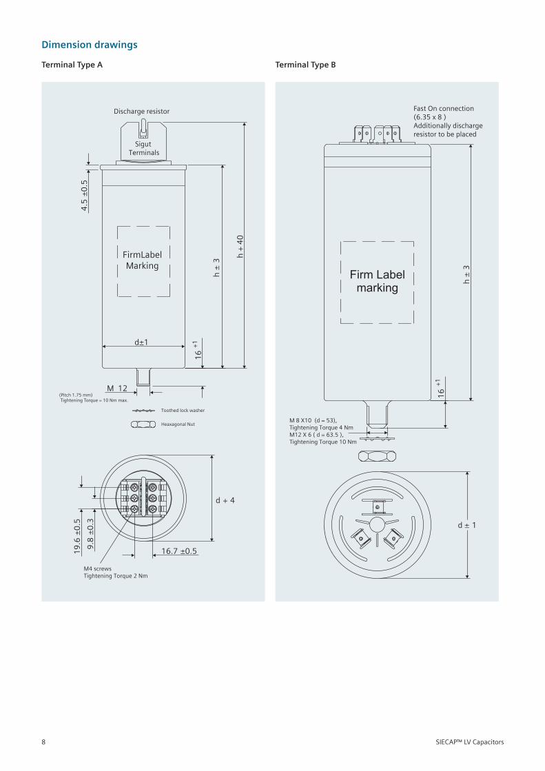
1.75 mm)Tightening Torque = 10 Nm max.
FirmLabelMarking
Discharge resistor
Sigut Terminals
d±1
12M
16
+1
16.
M4 screws Tightening Torque 2 Nm
7 ±
d + 4
0.59.8
±0
.3
19
.6±
0.5
4.5
±0
.5
h±
3
h+
40
Firm Labelmarking h
±3
d ± 1
16
+1
M 8 X10 (d = 53), Tightening Torque 4 NmM12 X 6 ( d = 63.5 ),Tightening Torque 10 Nm
Fast On connection(6.35 x 8 )Additionally discharge resistor to be placed
Terminal Type A Terminal Type B
Dimension drawings
SIECAP™ LV Capacitors8
Overview
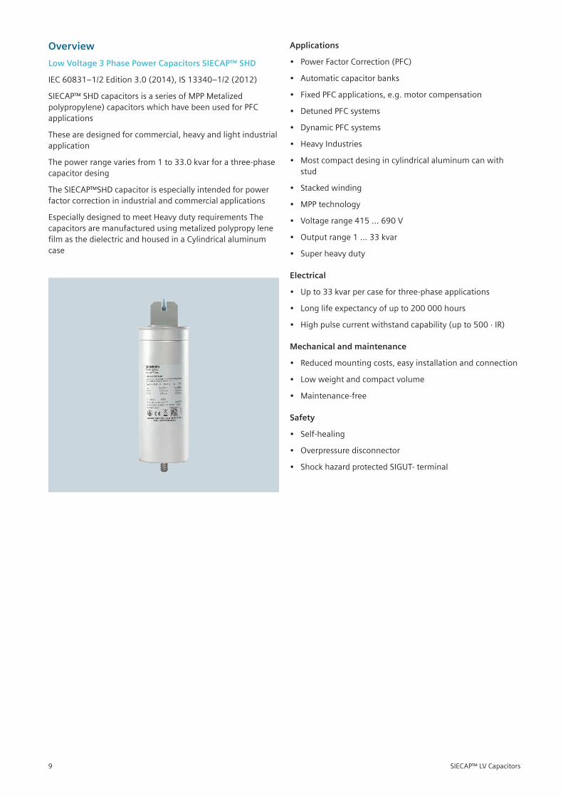
Low Voltage 3 Phase Power Capacitors SIECAP™ SHD
IEC60831–1/2Edition3.0(2014),IS13340–1/2(2012)
SIECAP™SHDcapacitorsisaseriesofMPPMetalizedpolypropylene)capacitorswhichhavebeenusedforPFCapplications
Thesearedesignedforcommercial,heavyandlightindustrialapplication
Thepowerrangevariesfrom1to33.0kvarforathree-phasecapacitor desing
TheSIECAP™SHDcapacitorisespeciallyintendedforpowerfactorcorrectioninindustrialandcommercialapplications
EspeciallydesignedtomeetHeavydutyrequirementsThecapacitorsaremanufacturedusingmetalizedpolypropylenefilmasthedielectricandhousedinaCylindricalaluminumcase
Applications
• PowerFactorCorrection(PFC)
• Automaticcapacitorbanks
• FixedPFCapplications,e.g.motorcompensation
• DetunedPFCsystems
• DynamicPFCsystems
• HeavyIndustries
• Mostcompactdesingincylindricalaluminumcanwithstud
• Stackedwinding
• MPPtechnology
• Voltagerange415…690V
• Outputrange1…33kvar
• Superheavyduty
Electrical
• Upto33kvarpercaseforthree-phaseapplications
• Longlifeexpectancyofupto200000hours
• Highpulsecurrentwithstandcapability(upto500·IR)
Mechanical and maintenance
• Reducedmountingcosts,easyinstallationandconnection
• Lowweightandcompactvolume
• Maintenance-free
Safety
• Self-healing
• Overpressuredisconnector
• ShockhazardprotectedSIGUT-terminal
SIECAP™ LV Capacitors9
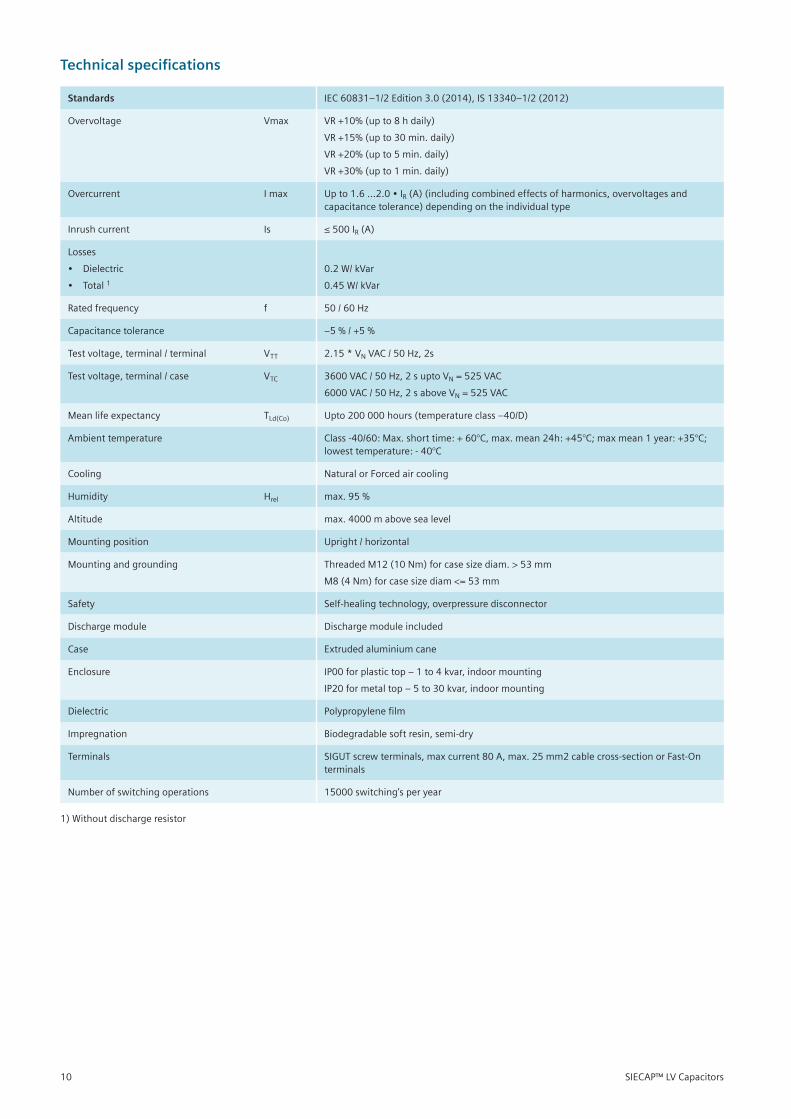
Technical specifications
Standards IEC60831–1/2Edition3.0(2014),IS13340–1/2(2012)
Overvoltage Vmax VR+10%(upto8hdaily)
VR+15%(upto30min.daily)
VR+20%(upto5min.daily)
VR+30%(upto1min.daily)
Overcurrent Imax Upto1.6…2.0•IR(A)(includingcombinedeffectsofharmonics,overvoltagesandcapacitancetolerance)dependingontheindividualtype
Inrushcurrent Is ≤500IR (A)
Losses
• Dielectric
• Total1
0.2 W/ kVar
0.45W/kVar
Ratedfrequency f 50/60Hz
Capacitance tolerance –5%/+5%
Testvoltage,terminal/terminal VTT 2.15*VNVAC/50Hz,2s
Testvoltage,terminal/case VTC 3600VAC/50Hz,2suptoVN=525VAC
6000VAC/50Hz,2saboveVN=525VAC
Meanlifeexpectancy TLd(Co) Upto200000hours(temperatureclass–40/D)
Ambienttemperature Class-40/60:Max.shorttime:+60°C,max.mean24h:+45°C;maxmean1year:+35°C;lowesttemperature:-40°C
Cooling NaturalorForcedaircooling
Humidity Hrel max.95%
Altitude max.4000mabovesealevel
Mountingposition Upright/horizontal
Mountingandgrounding ThreadedM12(10Nm)forcasesizediam.>53mm
M8(4Nm)forcasesizediam<=53mm
Safety Self-healingtechnology,overpressuredisconnector
Dischargemodule Dischargemoduleincluded
Case Extrudedaluminiumcane
Enclosure IP00forplastictop–1to4kvar,indoormounting
IP20formetaltop–5to30kvar,indoormounting
Dielectric Polypropylenefilm
Impregnation Biodegradablesoftresin,semi-dry
Terminals SIGUTscrewterminals,maxcurrent80A,max.25mm2cablecross-sectionorFast-Onterminals
Numberofswitchingoperations 15000switching’speryear
1)Withoutdischargeresistor
SIECAP™ LV Capacitors10
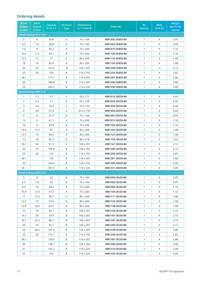
Ordering details
50 Hz Output in kVar
60 Hz Output in kVar
Capacity in uF 3 x
Terminal Type
Dimensions D * H mm Ø
Order NoPU
Unit (s)MOQ
Unit (s)
Weight per PU Kg
approx
Rated Voltage 415 V AC
5 6 30.8 A 75x164 4RB1050-3EB50-8K 1 4 0.95
6.3 7.6 38.8 A 75x164 4RB1063-3EB50-8K 1 4 0.95
7.5 9 46.2 A 75x200 4RB1075-3EB50-8K 1 4 1.16
10.4 12.5 64.1 A 75x200 4RB1104-3EB50-8K 1 4 1.16
12.5 15 77 A 85x200 4RB1125-3EB50-8K 1 4 1.48
15 18 92.4 A 85x200 4RB1150-3EB50-8K 1 4 1.48
20 24 123.2 B 100x207 4RB1200-3EB50-8K 1 4 2.13
25 30 154 B 116x192 4RB1250-3EB50-8K 1 4 2.65
28.1 - 173.1 B 116x207 4RB1281-3EB50-8K 1 4 2.86
30 - 184.8 B 116x207 4RB1300-3EB50-8K 1 4 2.86
33 - 203.3 B 116x224 4RB1330-3EB50-8K 1 4 3.09
Rated Voltage 440 V AC
1 1.2 5.5 E 53x117 4RB1010-3EE50-8K 1 4 0.44
2 2.4 11 E 53x129 4RB1020-3EE50-8K 1 4 0.44
3 3.6 16.4 E 53x129 4RB1030-3EE50-8K 1 4 0.44
4 4.8 21.9 E 63.5x152 4RB1040-3EE50-8K 1 4 0.66
5 6 27.4 A 75x164 4RB1050-3EE50-8K 1 4 0.95
7.5 9 41.1 A 75x200 4RB1075-3EE50-8K 1 4 1.16
10 12 54.8 A 75x200 4RB1100-3EE50-8K 1 4 1.16
10.4 12.5 57 A 85x200 4RB1104-3EE50-8K 1 4 1.48
12.5 15 68.5 A 85x200 4RB1125-3EE50-8K 1 4 1.48
15 18 82.2 A 85x218 4RB1150-3EE50-8K 1 4 1.62
16.7 20 91.5 B 100x207 4RB1167-3EE50-8K 1 4 2.13
20 24 109.6 B 100x207 4RB1200-3EE50-8K 1 4 2.13
25 30 137 B 116x192 4RB1250-3EE50-8K 1 4 2.65
28.1 - 154 B 116x207 4RB1281-3EE50-8K 1 4 2.86
30 - 164.4 B 125x192 4RB1300-3EE50-8K 1 4 3.09
33.1 - 181.4 B 116x224 4RB1331-3EE50-8K 1 4 3.09
Rated Voltage 480 V AC
5 6 23 A 75x164 4RB1050-3EJ50-8K 1 4 0.95
6.3 7.6 29 A 75x164 4RB1063-3EJ50-8K 1 4 0.95
8.3 10 38.2 A 75x200 4RB1083-3EJ50-8K 1 4 1.16
10.4 12.5 47.9 A 75x200 4RB1104-3EJ50-8K 1 4 1.16
11 13.2 50.7 A 85x200 4RB1111-3EJ50-8K 1 4 1.48
12.5 15 57.6 A 85x200 4RB1125-3EJ50-8K 1 4 1.48
13.8 16.6 63.5 A 85x200 4RB1138-3EJ50-8K 1 4 1.48
15 18 69.1 B 100x207 4RB1150-3EJ50-8K 1 4 2.13
16.7 20 76.9 B 100x207 4RB1167-3EJ50-8K 1 4 2.13
18.7 22.4 86.1 B 100x207 4RB1187-3EJ50-8K 1 4 2.13
20 24 92.1 B 100x207 4RB1200-3EJ50-8K 1 4 2.13
22 26.4 101.3 B 116x207 4RB1220-3EJ50-8K 1 4 2.86
25 30 115.1 B 116x192 4RB1250-3EJ50-8K 1 4 2.65
28.1 - 129.4 B 116x207 4RB1281-3EJ50-8K 1 4 2.86
30 - 138.1 B 125x192 4RB1300-3EJ50-8K 1 4 3.09
31 - 142.7 B 116x224 4RB1310-3EJ50-8K 1 4 3.09
33 - 152 B 116x224 4RB1330-3EJ50-8K 4 3.09
SIECAP™ LV Capacitors11
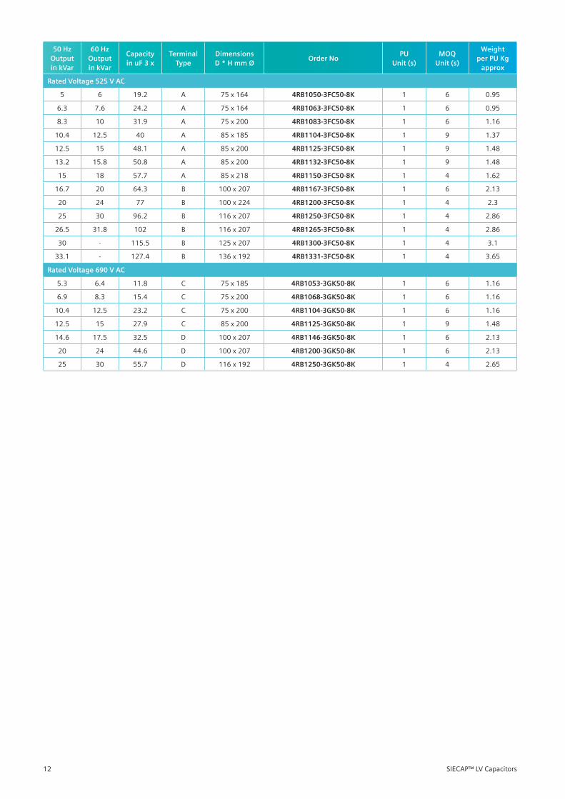
50 Hz Output in kVar
60 Hz Output in kVar
Capacity in uF 3 x
Terminal Type
Dimensions D * H mm Ø
Order NoPU
Unit (s)MOQ
Unit (s)
Weight per PU Kg
approx
Rated Voltage 525 V AC
5 6 19.2 A 75x164 4RB1050-3FC50-8K 1 6 0.95
6.3 7.6 24.2 A 75x164 4RB1063-3FC50-8K 1 6 0.95
8.3 10 31.9 A 75x200 4RB1083-3FC50-8K 1 6 1.16
10.4 12.5 40 A 85x185 4RB1104-3FC50-8K 1 9 1.37
12.5 15 48.1 A 85x200 4RB1125-3FC50-8K 1 9 1.48
13.2 15.8 50.8 A 85x200 4RB1132-3FC50-8K 1 9 1.48
15 18 57.7 A 85x218 4RB1150-3FC50-8K 1 4 1.62
16.7 20 64.3 B 100x207 4RB1167-3FC50-8K 1 6 2.13
20 24 77 B 100x224 4RB1200-3FC50-8K 1 4 2.3
25 30 96.2 B 116x207 4RB1250-3FC50-8K 1 4 2.86
26.5 31.8 102 B 116x207 4RB1265-3FC50-8K 1 4 2.86
30 - 115.5 B 125x207 4RB1300-3FC50-8K 1 4 3.1
33.1 - 127.4 B 136x192 4RB1331-3FC50-8K 1 4 3.65
Rated Voltage 690 V AC
5.3 6.4 11.8 C 75x185 4RB1053-3GK50-8K 1 6 1.16
6.9 8.3 15.4 C 75x200 4RB1068-3GK50-8K 1 6 1.16
10.4 12.5 23.2 C 75x200 4RB1104-3GK50-8K 1 6 1.16
12.5 15 27.9 C 85x200 4RB1125-3GK50-8K 1 9 1.48
14.6 17.5 32.5 D 100x207 4RB1146-3GK50-8K 1 6 2.13
20 24 44.6 D 100x207 4RB1200-3GK50-8K 1 6 2.13
25 30 55.7 D 116x192 4RB1250-3GK50-8K 1 4 2.65
SIECAP™ LV Capacitors12
Terminal Type A Terminal Type B
(Pitch
Toothed lock washer
Heaxagonal Nut
1.75 mm)Tightening Torque = 10 Nm max.
FirmLabelMarking
Discharge resistor
Sigut Terminals
d±1
12M
16
+1
16.
M4 screws Tightening Torque 2 Nm
7 ±
d + 4
0.59.8
±0
.3
19
.6±
0.5
4.5
±0
.5
h±
3
h+
40
(Pitch 1.75 mm)Tightening Torque = 10 Nm max.
FirmLabelMarking
d ± 1
12M
24
±0
.5
21 ±0.5
16
+1
12
±0
.3
O1
20
.8±
0.7
4.5
±0
.5
h±
3 h+
40
Dimension drawings
SIECAP™ LV Capacitors13
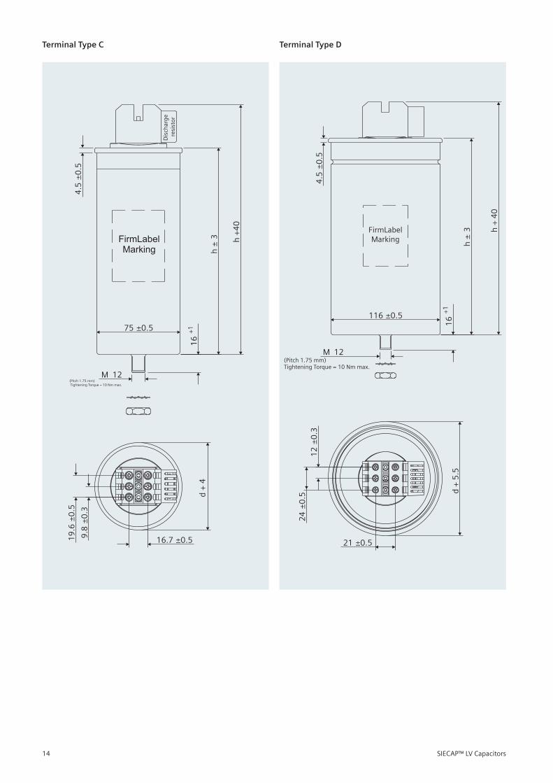
Terminal Type C Terminal Type D
(Pitch 1.75 mm)Tightening Torque = 10 Nm max.
FirmLabelMarking
75 ±0.5
12M
16
+1
d +
4
16.7 ±0.59.8
±0
.3
19
.6±
0.5
4.5
±0
.5
h±
3 h+
40
Dis
char
ge
resi
stor
(Pitch 1.75 mm)Tightening Torque = 10 Nm max.
FirmLabelMarking
116 ±0.5
12M
24
±0
.5
21 ±0.5
16
+1
12
±0
.3
d +
5.5
4.5
±0
.5
h±
3 h+
40
SIECAP™ LV Capacitors14
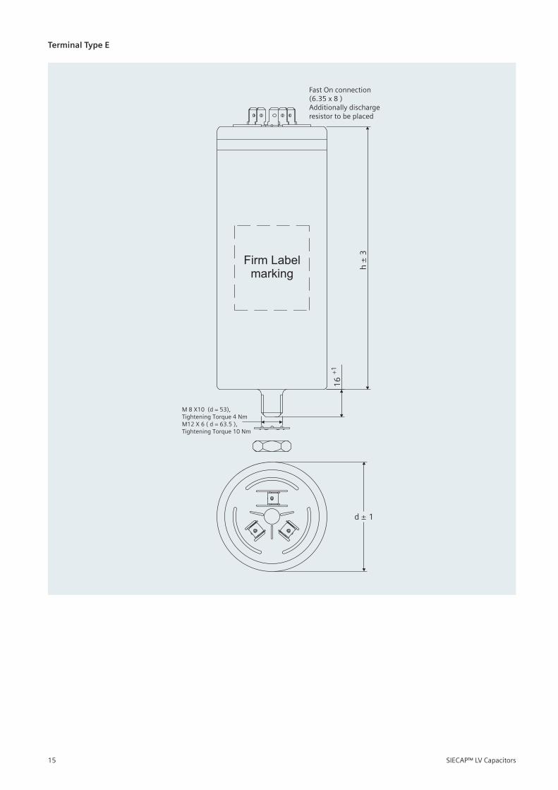
Terminal Type E
Firm Labelmarking h
±3
d ± 1
16
+1
M 8 X10 (d = 53), Tightening Torque 4 NmM12 X 6 ( d = 63.5 ),Tightening Torque 10 Nm
Fast On connection(6.35 x 8 )Additionally discharge resistor to be placed
SIECAP™ LV Capacitors15
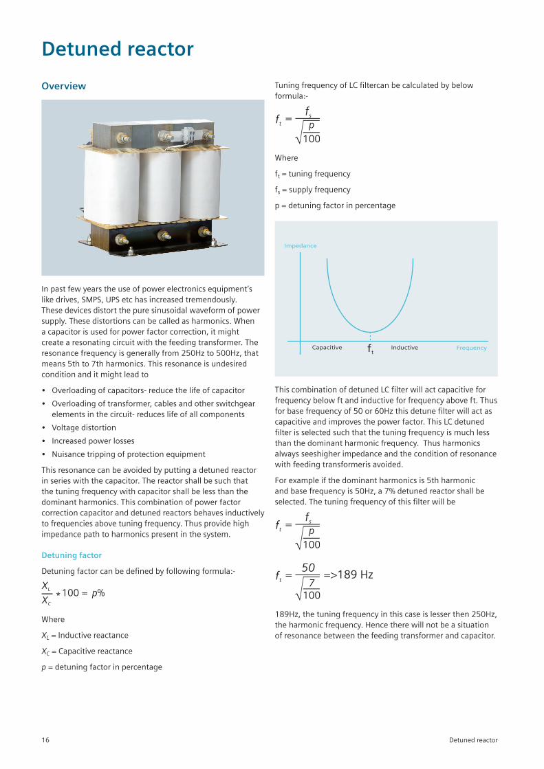
Overview
Inpastfewyearstheuseofpowerelectronicsequipment’slikedrives,SMPS,UPSetchasincreasedtremendously.Thesedevicesdistortthepuresinusoidalwaveformofpowersupply.Thesedistortionscanbecalledasharmonics.Whenacapacitorisusedforpowerfactorcorrection,itmightcreatearesonatingcircuitwiththefeedingtransformer.Theresonancefrequencyisgenerallyfrom250Hzto500Hz,thatmeans5thto7thharmonics.Thisresonanceisundesiredconditionanditmightleadto
• Overloadingofcapacitors-reducethelifeofcapacitor
• Overloadingoftransformer,cablesandotherswitchgearelementsinthecircuit-reduceslifeofallcomponents
• Voltagedistortion
• Increasedpowerlosses
• Nuisancetrippingofprotectionequipment
Thisresonancecanbeavoidedbyputtingadetunedreactorinserieswiththecapacitor.Thereactorshallbesuchthatthetuningfrequencywithcapacitorshallbelessthanthedominantharmonics.Thiscombinationofpowerfactorcorrectioncapacitoranddetunedreactorsbehavesinductivelytofrequenciesabovetuningfrequency.Thusprovidehighimpedancepathtoharmonicspresentinthesystem.
Detuning factor
Detuningfactorcanbedefinedbyfollowingformula:-
XL
XC
100 = p%
Where
XL = Inductive reactance
XC = Capacitive reactance
p = detuning factor in percentage
Detuned reactor
TuningfrequencyofLCfiltercanbecalculatedbybelowformula:-
ft
fs=p
100
Where
ft=tuningfrequency
fs=supplyfrequency
p = detuning factor in percentage
ftCapacitive Inductive Frequency
Impedance
ThiscombinationofdetunedLCfilterwillactcapacitiveforfrequencybelowftandinductiveforfrequencyaboveft.Thusforbasefrequencyof50or60Hzthisdetunefilterwillactascapacitiveandimprovesthepowerfactor.ThisLCdetunedfilterisselectedsuchthatthetuningfrequencyismuchlessthanthedominantharmonicfrequency.Thusharmonicsalwaysseeshigherimpedanceandtheconditionofresonancewithfeedingtransformerisavoided.
Forexampleifthedominantharmonicsis5thharmonicandbasefrequencyis50Hz,a7%detunedreactorshallbeselected.Thetuningfrequencyofthisfilterwillbe
ft
fs=p
100
ft
50=
7
100
=>189 Hz
189Hz,thetuningfrequencyinthiscaseislesserthen250Hz,theharmonicfrequency.Hencetherewillnotbeasituationofresonancebetweenthefeedingtransformerandcapacitor.
Detuned reactor16
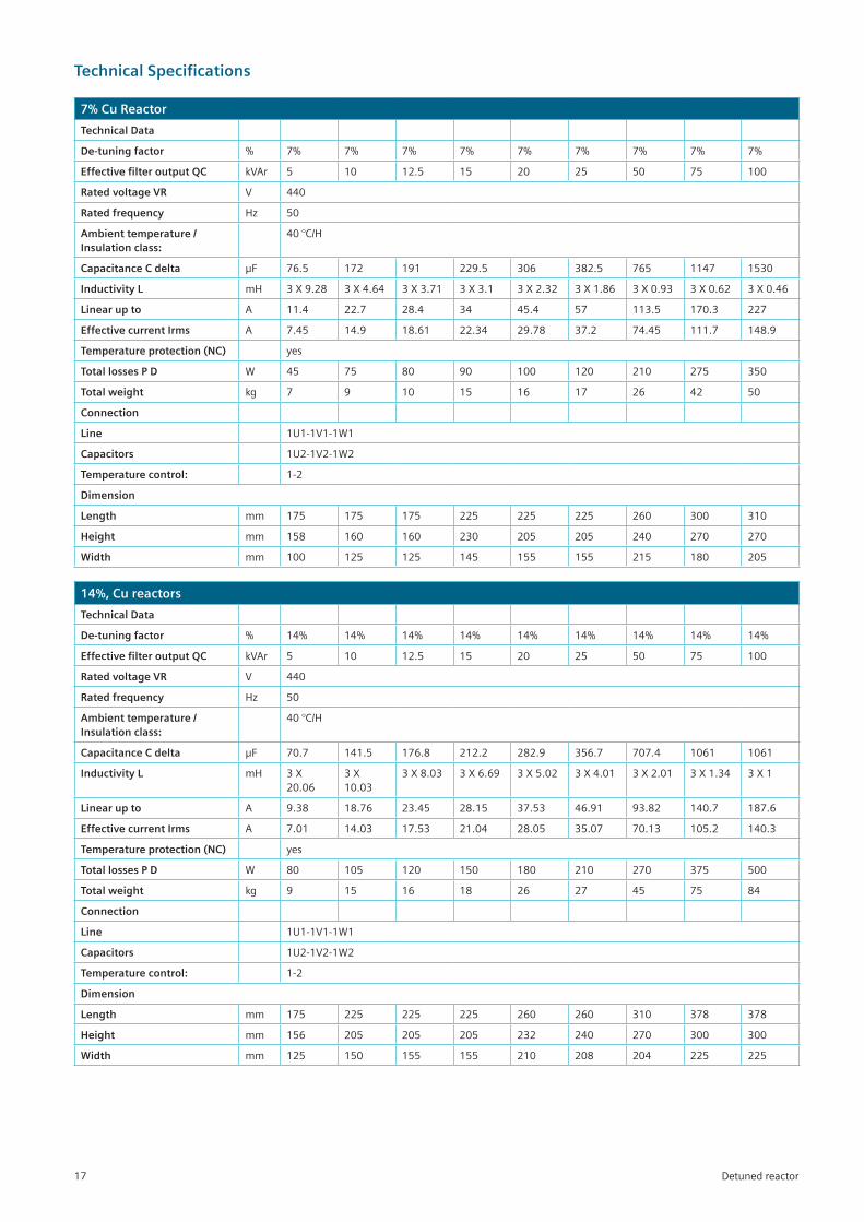
7% Cu Reactor
Technical Data
De-tuning factor % 7% 7% 7% 7% 7% 7% 7% 7% 7%
Effective filter output QC kVAr 5 10 12.5 15 20 25 50 75 100
Rated voltage VR V 440
Rated frequency Hz 50
Ambient temperature / Insulation class:
40°C/H
Capacitance C delta µF 76.5 172 191 229.5 306 382.5 765 1147 1530
Inductivity L mH 3X9.28 3X4.64 3X3.71 3X3.1 3X2.32 3X1.86 3X0.93 3X0.62 3X0.46
Linear up to A 11.4 22.7 28.4 34 45.4 57 113.5 170.3 227
Effective current Irms A 7.45 14.9 18.61 22.34 29.78 37.2 74.45 111.7 148.9
Temperature protection (NC) yes
Total losses P D W 45 75 80 90 100 120 210 275 350
Total weight kg 7 9 10 15 16 17 26 42 50
Connection
Line 1U1-1V1-1W1
Capacitors 1U2-1V2-1W2
Temperature control: 1-2
Dimension
Length mm 175 175 175 225 225 225 260 300 310
Height mm 158 160 160 230 205 205 240 270 270
Width mm 100 125 125 145 155 155 215 180 205
14%, Cu reactors
Technical Data
De-tuning factor % 14% 14% 14% 14% 14% 14% 14% 14% 14%
Effective filter output QC kVAr 5 10 12.5 15 20 25 50 75 100
Rated voltage VR V 440
Rated frequency Hz 50
Ambient temperature / Insulation class:
40°C/H
Capacitance C delta µF 70.7 141.5 176.8 212.2 282.9 356.7 707.4 1061 1061
Inductivity L mH 3X20.06
3X10.03
3X8.03 3X6.69 3X5.02 3X4.01 3X2.01 3X1.34 3X1
Linear up to A 9.38 18.76 23.45 28.15 37.53 46.91 93.82 140.7 187.6
Effective current Irms A 7.01 14.03 17.53 21.04 28.05 35.07 70.13 105.2 140.3
Temperature protection (NC) yes
Total losses P D W 80 105 120 150 180 210 270 375 500
Total weight kg 9 15 16 18 26 27 45 75 84
Connection
Line 1U1-1V1-1W1
Capacitors 1U2-1V2-1W2
Temperature control: 1-2
Dimension
Length mm 175 225 225 225 260 260 310 378 378
Height mm 156 205 205 205 232 240 270 300 300
Width mm 125 150 155 155 210 208 204 225 225
Detuned reactor
Technical Specifications
17
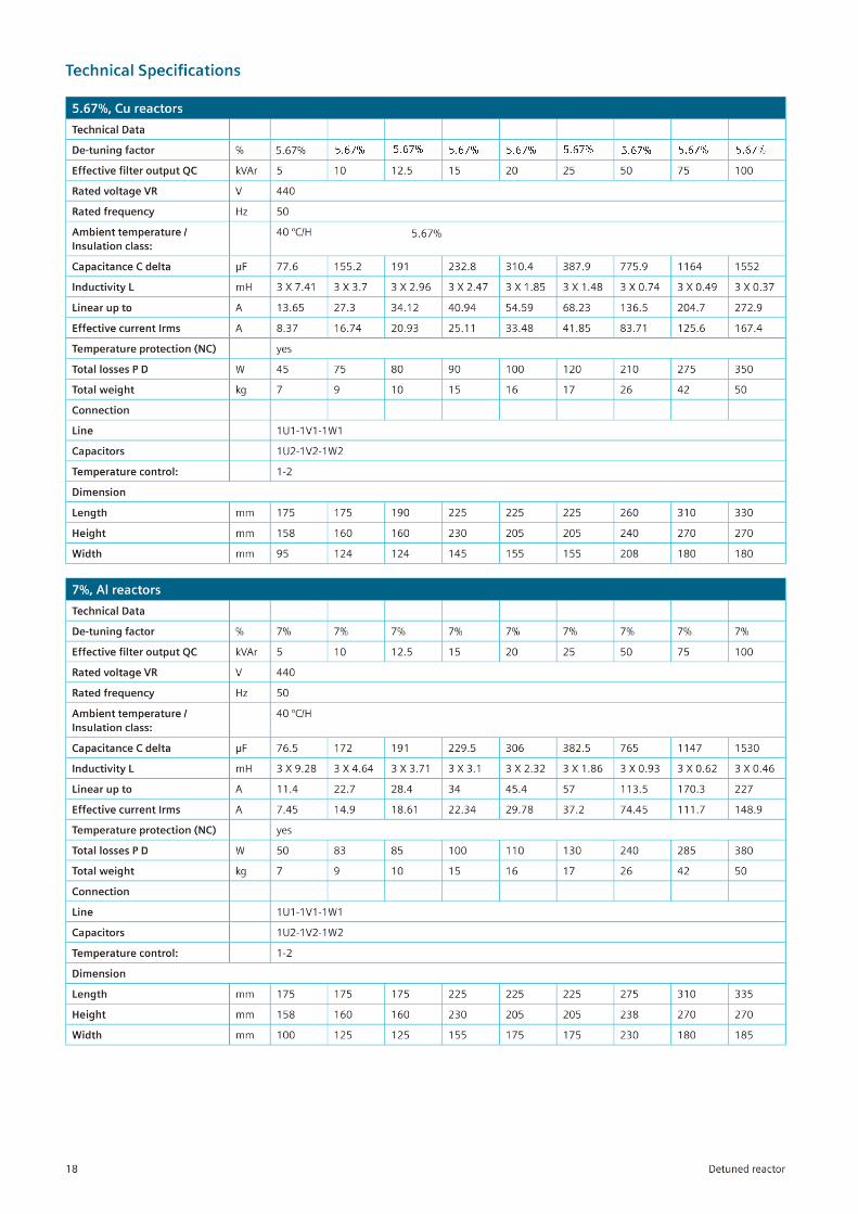
5.67%, Cu reactors
Technical Data
De-tuning factor % 14% 14% 14% 14% 14% 14% 14% 14% 14%
Effective filter output QC kVAr 5 10 12.5 15 20 25 50 75 100
Rated voltage VR V 440
Rated frequency Hz 50
Ambient temperature / Insulation class:
40°C/H
Capacitance C delta µF 77.6 155.2 191 232.8 310.4 387.9 775.9 1164 1552
Inductivity L mH 3X7.41 3X3.7 3X2.96 3X2.47 3X1.85 3X1.48 3X0.74 3X0.49 3X0.37
Linear up to A 13.65 27.3 34.12 40.94 54.59 68.23 136.5 204.7 272.9
Effective current Irms A 8.37 16.74 20.93 25.11 33.48 41.85 83.71 125.6 167.4
Temperature protection (NC) yes
Total losses P D W 45 75 80 90 100 120 210 275 350
Total weight kg 7 9 10 15 16 17 26 42 50
Connection
Line 1U1-1V1-1W1
Capacitors 1U2-1V2-1W2
Temperature control: 1-2
Dimension
Length mm 175 175 190 225 225 225 260 310 330
Height mm 158 160 160 230 205 205 240 270 270
Width mm 95 124 124 145 155 155 208 180 180
7%, Al reactors
Technical Data
De-tuning factor % 7% 7% 7% 7% 7% 7% 7% 7% 7%
Effective filter output QC kVAr 5 10 12.5 15 20 25 50 75 100
Rated voltage VR V 440
Rated frequency Hz 50
Ambient temperature / Insulation class:
40°C/H
Capacitance C delta µF 76.5 172 191 229.5 306 382.5 765 1147 1530
Inductivity L mH 3X9.28 3X4.64 3X3.71 3X3.1 3X2.32 3X1.86 3X0.93 3X0.62 3X0.46
Linear up to A 11.4 22.7 28.4 34 45.4 57 113.5 170.3 227
Effective current Irms A 7.45 14.9 18.61 22.34 29.78 37.2 74.45 111.7 148.9
Temperature protection (NC) yes
Total losses P D W 50 83 85 100 110 130 240 285 380
Total weight kg 7 9 10 15 16 17 26 42 50
Connection
Line 1U1-1V1-1W1
Capacitors 1U2-1V2-1W2
Temperature control: 1-2
Dimension
Length mm 175 175 175 225 225 225 275 310 335
Height mm 158 160 160 230 205 205 238 270 270
Width mm 100 125 125 155 175 175 230 180 185
Detuned reactor
Technical Specifications
18
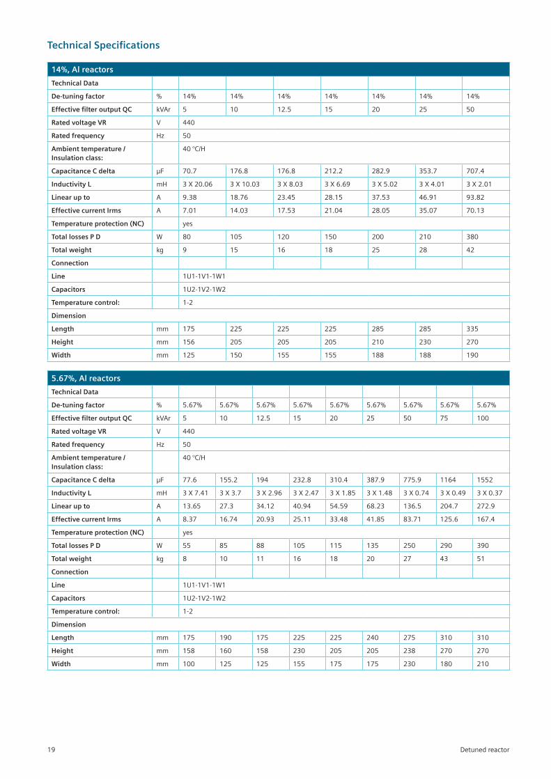
14%, Al reactors
Technical Data
De-tuning factor % 14% 14% 14% 14% 14% 14% 14%
Effective filter output QC kVAr 5 10 12.5 15 20 25 50
Rated voltage VR V 440
Rated frequency Hz 50
Ambient temperature / Insulation class:
40°C/H
Capacitance C delta µF 70.7 176.8 176.8 212.2 282.9 353.7 707.4
Inductivity L mH 3X20.06 3X10.03 3X8.03 3X6.69 3X5.02 3X4.01 3X2.01
Linear up to A 9.38 18.76 23.45 28.15 37.53 46.91 93.82
Effective current Irms A 7.01 14.03 17.53 21.04 28.05 35.07 70.13
Temperature protection (NC) yes
Total losses P D W 80 105 120 150 200 210 380
Total weight kg 9 15 16 18 25 28 42
Connection
Line 1U1-1V1-1W1
Capacitors 1U2-1V2-1W2
Temperature control: 1-2
Dimension
Length mm 175 225 225 225 285 285 335
Height mm 156 205 205 205 210 230 270
Width mm 125 150 155 155 188 188 190
5.67%, Al reactors
Technical Data
De-tuning factor % 5.67% 5.67% 5.67% 5.67% 5.67% 5.67% 5.67% 5.67% 5.67%
Effective filter output QC kVAr 5 10 12.5 15 20 25 50 75 100
Rated voltage VR V 440
Rated frequency Hz 50
Ambient temperature / Insulation class:
40°C/H
Capacitance C delta µF 77.6 155.2 194 232.8 310.4 387.9 775.9 1164 1552
Inductivity L mH 3X7.41 3X3.7 3X2.96 3X2.47 3X1.85 3X1.48 3X0.74 3X0.49 3X0.37
Linear up to A 13.65 27.3 34.12 40.94 54.59 68.23 136.5 204.7 272.9
Effective current Irms A 8.37 16.74 20.93 25.11 33.48 41.85 83.71 125.6 167.4
Temperature protection (NC) yes
Total losses P D W 55 85 88 105 115 135 250 290 390
Total weight kg 8 10 11 16 18 20 27 43 51
Connection
Line 1U1-1V1-1W1
Capacitors 1U2-1V2-1W2
Temperature control: 1-2
Dimension
Length mm 175 190 175 225 225 240 275 310 310
Height mm 158 160 158 230 205 205 238 270 270
Width mm 100 125 125 155 175 175 230 180 210
Detuned reactor
Technical Specifications
19
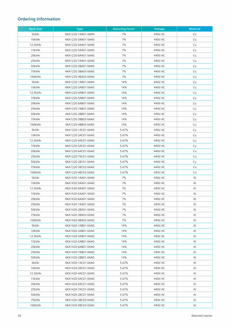
Ordering Information
Detuned reactor
Bank Size Type Detuning Factor Voltage Material
5kVAr 4KA1220-1AA01-0AA0 7% 440V AC Cu
10kVAr 4KA1220-3AA01-0AA0 7% 440V AC Cu
12.5kVAr 4KA1220-4AA01-0AA0 7% 440V AC Cu
15kVAr 4KA1220-5AA01-0AA0 7% 440V AC Cu
20kVAr 4KA1220-6AA01-0AA0 7% 440V AC Cu
25kVAr 4KA1220-7AA01-0AA0 7% 440V AC Cu
50kVAr 4KA1220-2BA01-0AA0 7% 440V AC Cu
75kVAr 4KA1220-3BA03-0AA0 7% 440V AC Cu
100kVAr 4KA1220-4BA03-0AA0 7% 440V AC Cu
5kVAr 4KA1220-1AB01-0AA0 14% 440V AC Cu
10kVAr 4KA1220-3AB01-0AA0 14% 440V AC Cu
12.5kVAr 4KA1220-4AB01-0AA0 14% 440V AC Cu
15kVAr 4KA1220-5AB01-0AA0 14% 440V AC Cu
20kVAr 4KA1220-6AB01-0AA0 14% 440V AC Cu
25kVAr 4KA1220-7AB01-0AA0 14% 440V AC Cu
50kVAr 4KA1220-2BB01-0AA0 14% 440V AC Cu
75kVAr 4KA1220-3BB03-0AA0 14% 440V AC Cu
100kVAr 4KA1220-4BB03-0AA0 14% 440V AC Cu
5kVAr 4KA1220-1AC01-0AA0 5.67% 440V AC Cu
10kVAr 4KA1220-3AC01-0AA0 5.67% 440V AC Cu
12.5kVAr 4KA1220-4AC01-0AA0 5.67% 440V AC Cu
15kVAr 4KA1220-5AC01-0AA0 5.67% 440V AC Cu
20kVAr 4KA1220-6AC01-0AA0 5.67% 440V AC Cu
25kVAr 4KA1220-7AC01-0AA0 5.67% 440V AC Cu
50kVAr 4KA1220-2BC01-0AA0 5.67% 440V AC Cu
75kVAr 4KA1220-3BC03-0AA0 5.67% 440V AC Cu
100kVAr 4KA1220-4BC03-0AA0 5.67% 440V AC Cu
5kVAr 4KA1420-1AA01-0AA0 7% 440V AC Al
10kVAr 4KA1420-3AA01-0AA0 7% 440V AC Al
12.5kVAr 4KA1420-4AA01-0AA0 7% 440V AC Al
15kVAr 4KA1420-5AA01-0AA0 7% 440V AC Al
20kVAr 4KA1420-6AA01-0AA0 7% 440V AC Al
25kVAr 4KA1420-7AA01-0AA0 7% 440V AC Al
50kVAr 4KA1420-2BA01-0AA0 7% 440V AC Al
75kVAr 4KA1420-3BA03-0AA0 7% 440V AC Al
100kVAr 4KA1420-4BA03-0AA0 7% 440V AC Al
5kVAr 4KA1420-1AB01-0AA0 14% 440V AC Al
10kVAr 4KA1420-3AB01-0AA0 14% 440V AC Al
12.5kVAr 4KA1420-4AB01-0AA0 14% 440V AC Al
15kVAr 4KA1420-5AB01-0AA0 14% 440V AC Al
20kVAr 4KA1420-6AB01-0AA0 14% 440V AC Al
25kVAr 4KA1420-7AB01-0AA0 14% 440V AC Al
50kVAr 4KA1420-2BB01-0AA0 14% 440V AC Al
5kVAr 4KA1420-1AC01-0AA0 5.67% 440V AC Al
10kVAr 4KA1420-3AC01-0AA0 5.67% 440V AC Al
12.5kVAr 4KA1420-4AC01-0AA0 5.67% 440V AC Al
15kVAr 4KA1420-5AC01-0AA0 5.67% 440V AC Al
20kVAr 4KA1420-6AC01-0AA0 5.67% 440V AC Al
25kVAr 4KA1420-7AC01-0AA0 5.67% 440V AC Al
50kVAr 4KA1420-2BC01-0AA0 5.67% 440V AC Al
75kVAr 4KA1420-3BC03-0AA0 5.67% 440V AC Al
100kVAr 4KA1420-4BC03-0AA0 5.67% 440V AC Al
20
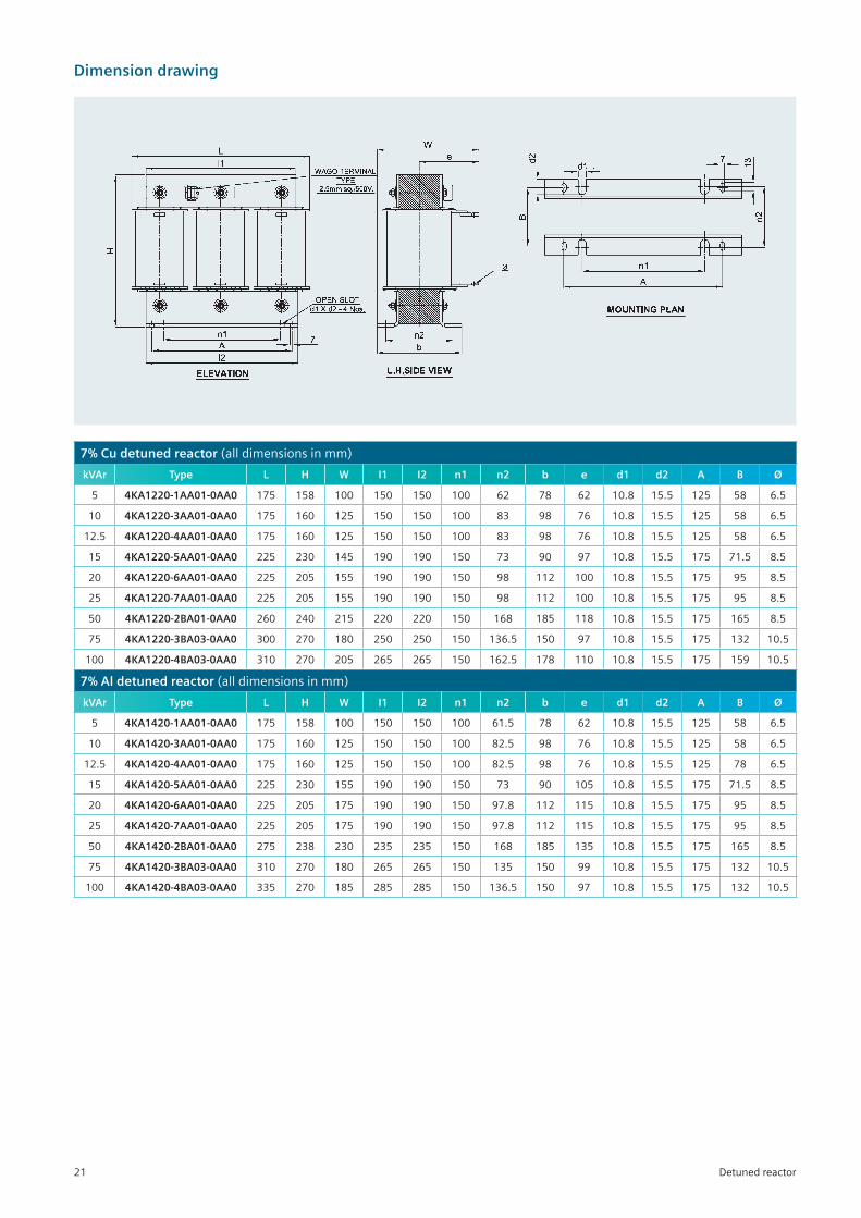
Dimension drawing
7% Cu detuned reactor (alldimensionsinmm)
kVAr Type L H W I1 I2 n1 n2 b e d1 d2 A B Ø
5 4KA1220-1AA01-0AA0 175 158 100 150 150 100 62 78 62 10.8 15.5 125 58 6.5
10 4KA1220-3AA01-0AA0 175 160 125 150 150 100 83 98 76 10.8 15.5 125 58 6.5
12.5 4KA1220-4AA01-0AA0 175 160 125 150 150 100 83 98 76 10.8 15.5 125 58 6.5
15 4KA1220-5AA01-0AA0 225 230 145 190 190 150 73 90 97 10.8 15.5 175 71.5 8.5
20 4KA1220-6AA01-0AA0 225 205 155 190 190 150 98 112 100 10.8 15.5 175 95 8.5
25 4KA1220-7AA01-0AA0 225 205 155 190 190 150 98 112 100 10.8 15.5 175 95 8.5
50 4KA1220-2BA01-0AA0 260 240 215 220 220 150 168 185 118 10.8 15.5 175 165 8.5
75 4KA1220-3BA03-0AA0 300 270 180 250 250 150 136.5 150 97 10.8 15.5 175 132 10.5
100 4KA1220-4BA03-0AA0 310 270 205 265 265 150 162.5 178 110 10.8 15.5 175 159 10.5
7% Al detuned reactor (alldimensionsinmm)
kVAr Type L H W I1 I2 n1 n2 b e d1 d2 A B Ø
5 4KA1420-1AA01-0AA0 175 158 100 150 150 100 61.5 78 62 10.8 15.5 125 58 6.5
10 4KA1420-3AA01-0AA0 175 160 125 150 150 100 82.5 98 76 10.8 15.5 125 58 6.5
12.5 4KA1420-4AA01-0AA0 175 160 125 150 150 100 82.5 98 76 10.8 15.5 125 78 6.5
15 4KA1420-5AA01-0AA0 225 230 155 190 190 150 73 90 105 10.8 15.5 175 71.5 8.5
20 4KA1420-6AA01-0AA0 225 205 175 190 190 150 97.8 112 115 10.8 15.5 175 95 8.5
25 4KA1420-7AA01-0AA0 225 205 175 190 190 150 97.8 112 115 10.8 15.5 175 95 8.5
50 4KA1420-2BA01-0AA0 275 238 230 235 235 150 168 185 135 10.8 15.5 175 165 8.5
75 4KA1420-3BA03-0AA0 310 270 180 265 265 150 135 150 99 10.8 15.5 175 132 10.5
100 4KA1420-4BA03-0AA0 335 270 185 285 285 150 136.5 150 97 10.8 15.5 175 132 10.5
Detuned reactor21
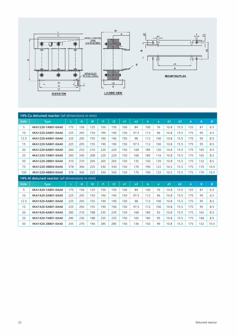
14% Cu detuned reactor (alldimensionsinmm)
kVAr Type L H W I1 I2 n1 n2 b e d1 d2 A B Ø
5 4KA1220-1AB01-0AA0 175 156 125 150 150 100 84 100 76 10.8 15.5 125 81 6.5
10 4KA1220-3AB01-0AA0 225 205 150 190 190 150 97.5 112 96 10.8 15.5 175 95 6.5
12.5 4KA1220-4AB01-0AA0 225 205 155 190 190 150 98 112 100 10.8 15.5 175 95 8.5
15 4KA1220-5AB01-0AA0 225 205 155 190 190 150 97.5 112 100 10.8 15.5 175 95 8.5
20 4KA1220-6AB01-0AA0 260 232 210 220 220 150 168 185 120 10.8 15.5 175 165 8.5
25 4KA1220-7AB01-0AA0 260 240 208 220 220 150 168 185 116 10.8 15.5 175 165 8.5
50 4KA1220-2BB01-0AA0 310 270 204 265 265 150 135 150 120 10.8 15.5 175 132 8.5
75 4KA1220-3BB03-0AA0 378 300 225 330 330 150 170 190 122 10.5 15.5 175 170 10.5
100 4KA1220-4BB03-0AA0 378 300 225 330 330 150 170 190 122 10.5 15.5 175 170 10.5
14% Al detuned reactor (alldimensionsinmm)
kVAr Type L H W I1 I2 n1 n2 b e d1 d2 A B Ø
5 4KA1420-1AB01-0AA0 175 156 125 150 150 100 84 100 76 10.8 15.5 125 81 6.5
10 4KA1420-3AB01-0AA0 225 205 150 190 190 150 97.5 112 96 10.8 15.5 175 95 6.5
12.5 4KA1420-4AB01-0AA0 225 205 155 190 190 150 98 112 100 10.8 15.5 175 95 8.5
15 4KA1420-5AB01-0AA0 225 205 155 190 190 150 97.5 112 100 10.8 15.5 175 95 8.5
20 4KA1420-6AB01-0AA0 285 210 188 235 235 150 168 185 92 10.8 15.5 175 165 8.5
25 4KA1420-7AB01-0AA0 285 230 188 235 235 150 165 185 95 10.8 15.5 175 168 8.5
50 4KA1420-2BB01-0AA0 335 270 190 285 285 150 136 150 99 10.8 15.5 175 132 10.5
Detuned reactor22
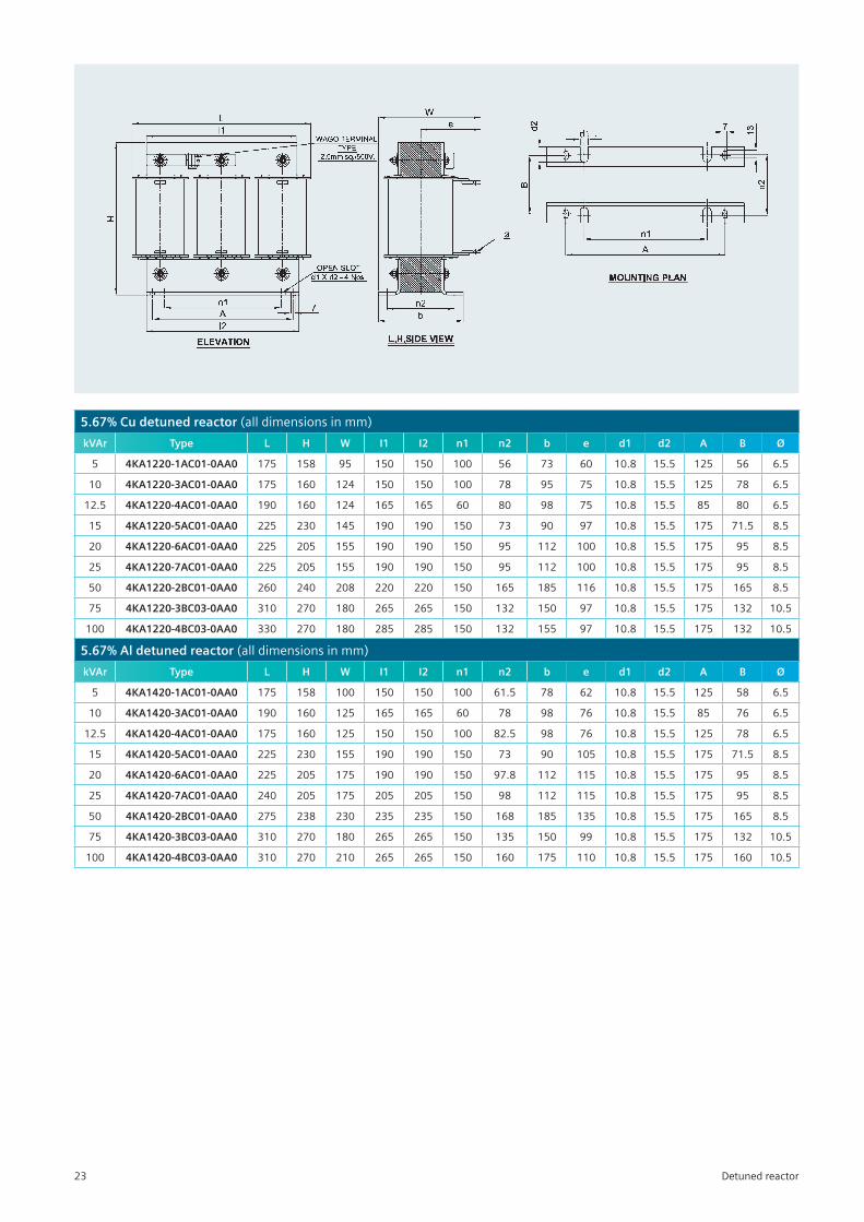
5.67% Cu detuned reactor (alldimensionsinmm)
kVAr Type L H W I1 I2 n1 n2 b e d1 d2 A B Ø
5 4KA1220-1AC01-0AA0 175 158 95 150 150 100 56 73 60 10.8 15.5 125 56 6.5
10 4KA1220-3AC01-0AA0 175 160 124 150 150 100 78 95 75 10.8 15.5 125 78 6.5
12.5 4KA1220-4AC01-0AA0 190 160 124 165 165 60 80 98 75 10.8 15.5 85 80 6.5
15 4KA1220-5AC01-0AA0 225 230 145 190 190 150 73 90 97 10.8 15.5 175 71.5 8.5
20 4KA1220-6AC01-0AA0 225 205 155 190 190 150 95 112 100 10.8 15.5 175 95 8.5
25 4KA1220-7AC01-0AA0 225 205 155 190 190 150 95 112 100 10.8 15.5 175 95 8.5
50 4KA1220-2BC01-0AA0 260 240 208 220 220 150 165 185 116 10.8 15.5 175 165 8.5
75 4KA1220-3BC03-0AA0 310 270 180 265 265 150 132 150 97 10.8 15.5 175 132 10.5
100 4KA1220-4BC03-0AA0 330 270 180 285 285 150 132 155 97 10.8 15.5 175 132 10.5
5.67% Al detuned reactor (alldimensionsinmm)
kVAr Type L H W I1 I2 n1 n2 b e d1 d2 A B Ø
5 4KA1420-1AC01-0AA0 175 158 100 150 150 100 61.5 78 62 10.8 15.5 125 58 6.5
10 4KA1420-3AC01-0AA0 190 160 125 165 165 60 78 98 76 10.8 15.5 85 76 6.5
12.5 4KA1420-4AC01-0AA0 175 160 125 150 150 100 82.5 98 76 10.8 15.5 125 78 6.5
15 4KA1420-5AC01-0AA0 225 230 155 190 190 150 73 90 105 10.8 15.5 175 71.5 8.5
20 4KA1420-6AC01-0AA0 225 205 175 190 190 150 97.8 112 115 10.8 15.5 175 95 8.5
25 4KA1420-7AC01-0AA0 240 205 175 205 205 150 98 112 115 10.8 15.5 175 95 8.5
50 4KA1420-2BC01-0AA0 275 238 230 235 235 150 168 185 135 10.8 15.5 175 165 8.5
75 4KA1420-3BC03-0AA0 310 270 180 265 265 150 135 150 99 10.8 15.5 175 132 10.5
100 4KA1420-4BC03-0AA0 310 270 210 265 265 150 160 175 110 10.8 15.5 175 160 10.5
Detuned reactor23
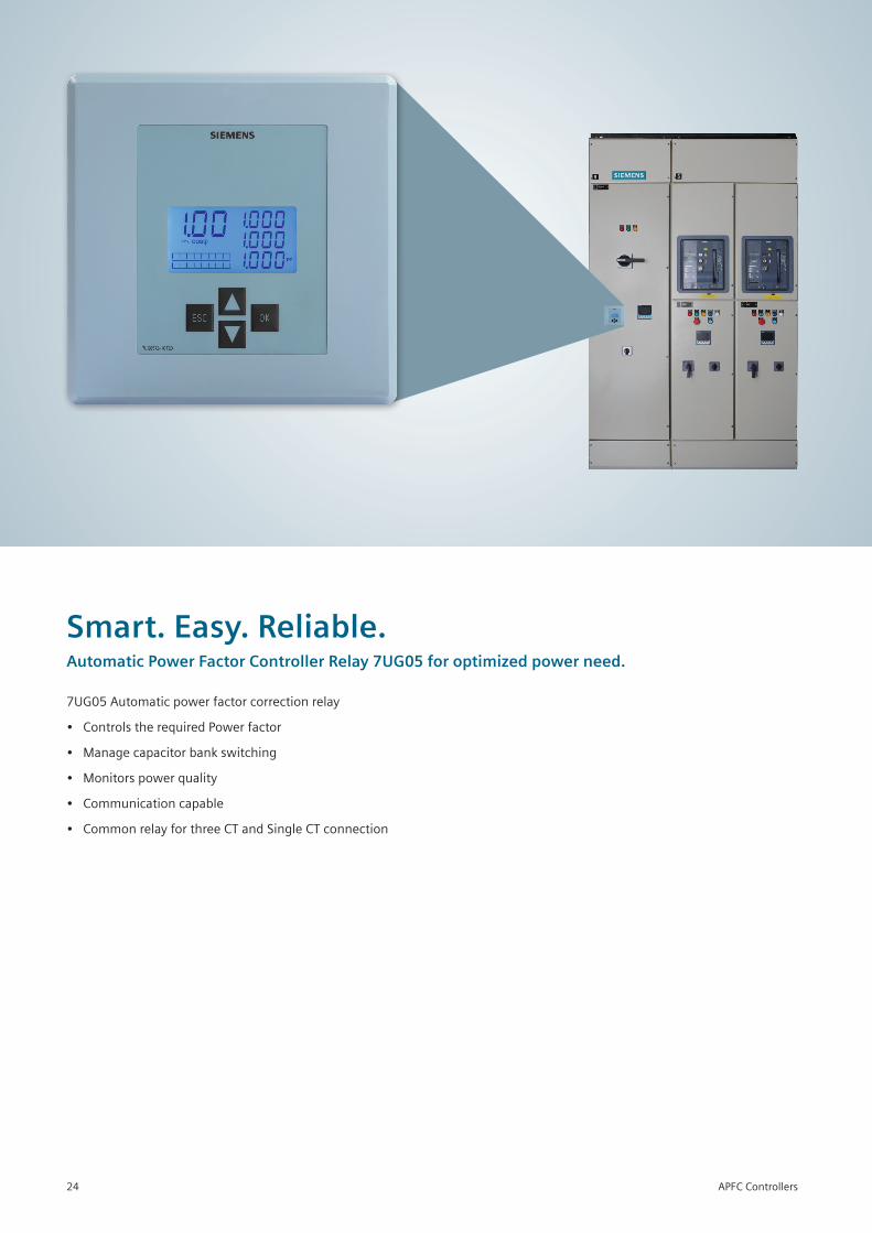
7UG05Automaticpowerfactorcorrectionrelay
• ControlstherequiredPowerfactor
• Managecapacitorbankswitching
• Monitorspowerquality
• Communicationcapable
• CommonrelayforthreeCTandSingleCTconnection
Smart. Easy. Reliable.Automatic Power Factor Controller Relay 7UG05 for optimized power need.
APFC Controllers24
Overview
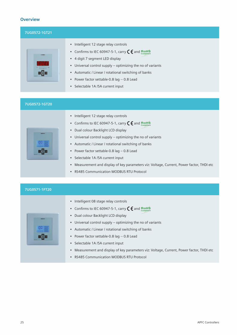
7UG0572-1GT21
• Intelligent12stagerelaycontrols
• ConfirmstoIEC60947-5-1,carry and RoHSCompliant
• 4digit7segmentLEDdisplay
• Universalcontrolsupply–optimizingthenoofvariants
• Automatic/Linear/rotationalswitchingofbanks
• Powerfactorsettable-0.8lag--0.8Lead
• Selectable1A/5Acurrentinput
7UG0572-1GT20
• Intelligent12stagerelaycontrols
• ConfirmstoIEC60947-5-1,carry and RoHSCompliant
• DualcolourBacklightLCDdisplay
• Universalcontrolsupply–optimizingthenoofvariants
• Automatic/Linear/rotationalswitchingofbanks
• Powerfactorsettable-0.8lag–0.8Lead
• Selectable1A/5Acurrentinput
• Measurementanddisplayofkeyparametersviz:Voltage,Current,Powerfactor,THDIetc
• RS485CommunicationMODBUSRTUProtocol
7UG0571-1FT20
• Intelligent08stagerelaycontrols
• ConfirmstoIEC60947-5-1,carry and RoHSCompliant
• DualcolourBacklightLCDdisplay
• Universalcontrolsupply–optimizingthenoofvariants
• Automatic/Linear/rotationalswitchingofbanks
• Powerfactorsettable-0.8lag--0.8Lead
• Selectable1A/5Acurrentinput
• Measurementanddisplayofkeyparametersviz:Voltage,Current,Powerfactor,THDIetc
• RS485CommunicationMODBUSRTUProtocol
APFC Controllers25
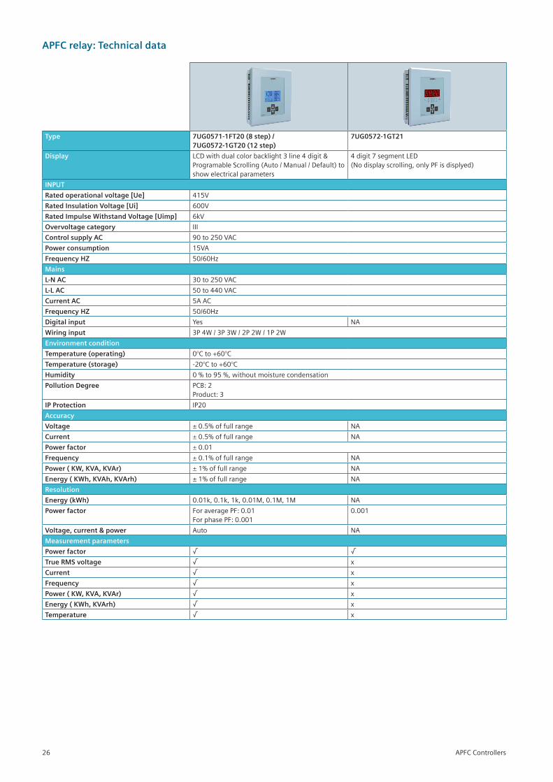
APFC relay: Technical data
Type 7UG0571-1FT20 (8 step) / 7UG0572-1GT20 (12 step)
7UG0572-1GT21
Display LCDwithdualcolorbacklight3line4digit&ProgramableScrolling(Auto/Manual/Default)toshowelectricalparameters
4digit7segmentLED (Nodisplayscrolling,onlyPFisdisplyed)
INPUT
Rated operational voltage [Ue] 415V
Rated Insulation Voltage [Ui] 600V
Rated Impulse Withstand Voltage [Uimp] 6kV
Overvoltage category III
Control supply AC 90to250VAC
Power consumption 15VA
Frequency HZ 50/60Hz
Mains
L-N AC 30to250VAC
L-L AC 50to440VAC
Current AC 5AAC
Frequency HZ 50/60Hz
Digital input Yes NA
Wiring input 3P 4W / 3P 3W / 2P 2W / 1P 2W
Environment condition
Temperature (operating) 0°Cto+60°C
Temperature (storage) -20°Cto+60°C
Humidity 0%to95%,withoutmoisturecondensation
Pollution Degree PCB:2Product:3
IP Protection IP20
Accuracy
Voltage ±0.5%offullrange NA
Current ±0.5%offullrange NA
Power factor ± 0.01
Frequency ± 0.1% of full range NA
Power ( KW, KVA, KVAr) ± 1% of full range NA
Energy ( KWh, KVAh, KVArh) ± 1% of full range NA
Resolution
Energy (kWh) 0.01k,0.1k,1k,0.01M,0.1M,1M NA
Power factor ForaveragePF:0.01ForphasePF:0.001
0.001
Voltage, current & power Auto NA
Measurement parameters
Power factor √ √
True RMS voltage √ x
Current √ x
Frequency √ x
Power ( KW, KVA, KVAr) √ x
Energy ( KWh, KVArh) √ x
Temperature √ x
APFC Controllers26
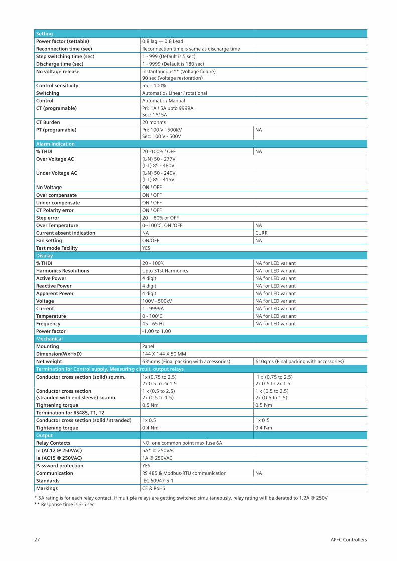
Setting
Power factor (settable) 0.8 lag --- 0.8 Lead
Reconnection time (sec) Reconnectiontimeissameasdischargetime
Step switching time (sec) 1-999(Defaultis5sec)
Discharge time (sec) 1 - 9999 (Default is 180 sec)
No voltage release Instantaneous**(Voltagefailure)90 sec (Voltage restoration)
Control sensitivity 55--100%
Switching Automatic/Linear/rotational
Control Automatic/Manual
CT (programable) Pri:1A/5Aupto9999ASec:1A/5A
CT Burden 20mohms
PT (programable) Pri:100V-500KVSec:100V-500V
NA
Alarm Indication
% THDI 20-100%/OFF NA
Over Voltage AC (L-N)50-277V(L-L)85-480V
Under Voltage AC (L-N)50-240V(L-L)85-415V
No Voltage ON/OFF
Over compensate ON/OFF
Under compensate ON/OFF
CT Polarity error ON/OFF
Step error 20--80%orOFF
Over Temperature 0--100°C,ON/OFF NA
Current absent indication NA CURR
Fan setting ON/OFF NA
Test mode Facility YES
Display
% THDI 20 - 100% NAforLEDvariant
Harmonics Resolutions Upto31stHarmonics NAforLEDvariant
Active Power 4 digit NAforLEDvariant
Reactive Power 4 digit NAforLEDvariant
Apparent Power 4 digit NAforLEDvariant
Voltage 100V-500kV NAforLEDvariant
Current 1 - 9999A NAforLEDvariant
Temperature 0-100°C NAforLEDvariant
Frequency 45-65Hz NAforLEDvariant
Power factor -1.00 to 1.00
Mechanical
Mounting Panel
Dimension(WxHxD) 144X144X50MM
Net weight 635gms(Finalpackingwithaccessories) 610gms(Finalpackingwithaccessories)
Termination for Control supply, Measuring circuit, output relays
Conductor cross section (solid) sq.mm. 1x(0.75to2.5)2x0.5to2x1.5
1x(0.75to2.5)2x0.5to2x1.5
Conductor cross section (stranded with end sleeve) sq.mm.
1x(0.5to2.5)2x(0.5to1.5)
1x(0.5to2.5)2x(0.5to1.5)
Tightening torque 0.5Nm 0.5Nm
Termination for RS485, T1, T2
Conductor cross section (solid / stranded) 1x0.5 1x0.5
Tightening torque 0.4Nm 0.4Nm
Output
Relay Contacts NO,onecommonpointmaxfuse6A
Ie (AC12 @ 250VAC) 5A*@250VAC
Ie (AC15 @ 250VAC) 1A@250VAC
Password protection YES
Communication RS485&Modbus-RTUcommunication NA
Standards IEC60947-5-1
Markings CE&RoHS
*5Aratingisforeachrelaycontact.Ifmultiplerelaysaregettingswitchedsimultaneously,relayratingwillbederatedto1.2A@250V**Responsetimeis3-5sec
APFC Controllers27
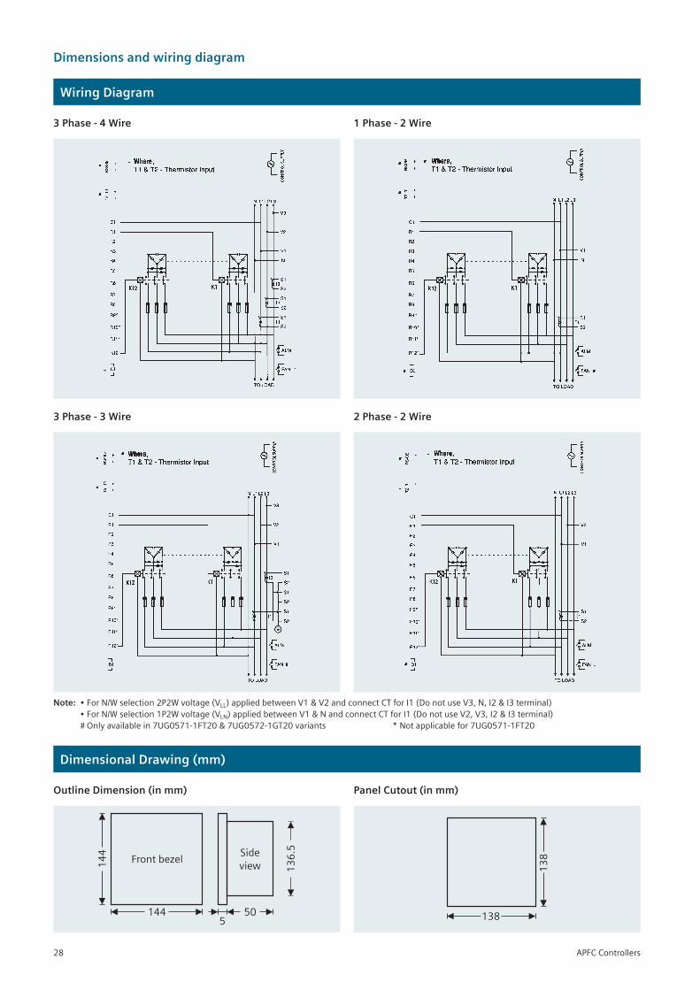
Dimensions and wiring diagram
Wiring Diagram
Dimensional Drawing (mm)
3 Phase - 4 Wire
3 Phase - 3 Wire
1 Phase - 2 Wire
2 Phase - 2 Wire
Outline Dimension (in mm) Panel Cutout (in mm)
Front bezel14
4
144
Side
view 13
6.5
505
13
8
138
Note: •ForN/Wselection2P2Wvoltage(VLL)appliedbetweenV1&V2andconnectCTforI1(DonotuseV3,N,I2&I3terminal) •ForN/Wselection1P2Wvoltage(VLN)appliedbetweenV1&NandconnectCTforI1(DonotuseV2,V3,I2&I3terminal) #Onlyavailablein7UG0571-1FT20&7UG0572-1GT20variants *Notapplicablefor7UG0571-1FT20
APFC Controllers28
Overview:
Formorethan125years,Siemenshasbeendevelopingandmanufacturingindustrialcontrolproducts.Weofferawideproductrangewhichcaterstofulfillthedemandofouresteemedcustomerswithsatisfactoryperformancelevelandimprovedreliability.Thenewrangeofcapacitordutycontactorhasbeenlaunchedtoprovideareliableandeconomicalsolutionforcapacitorswitchingapplications.
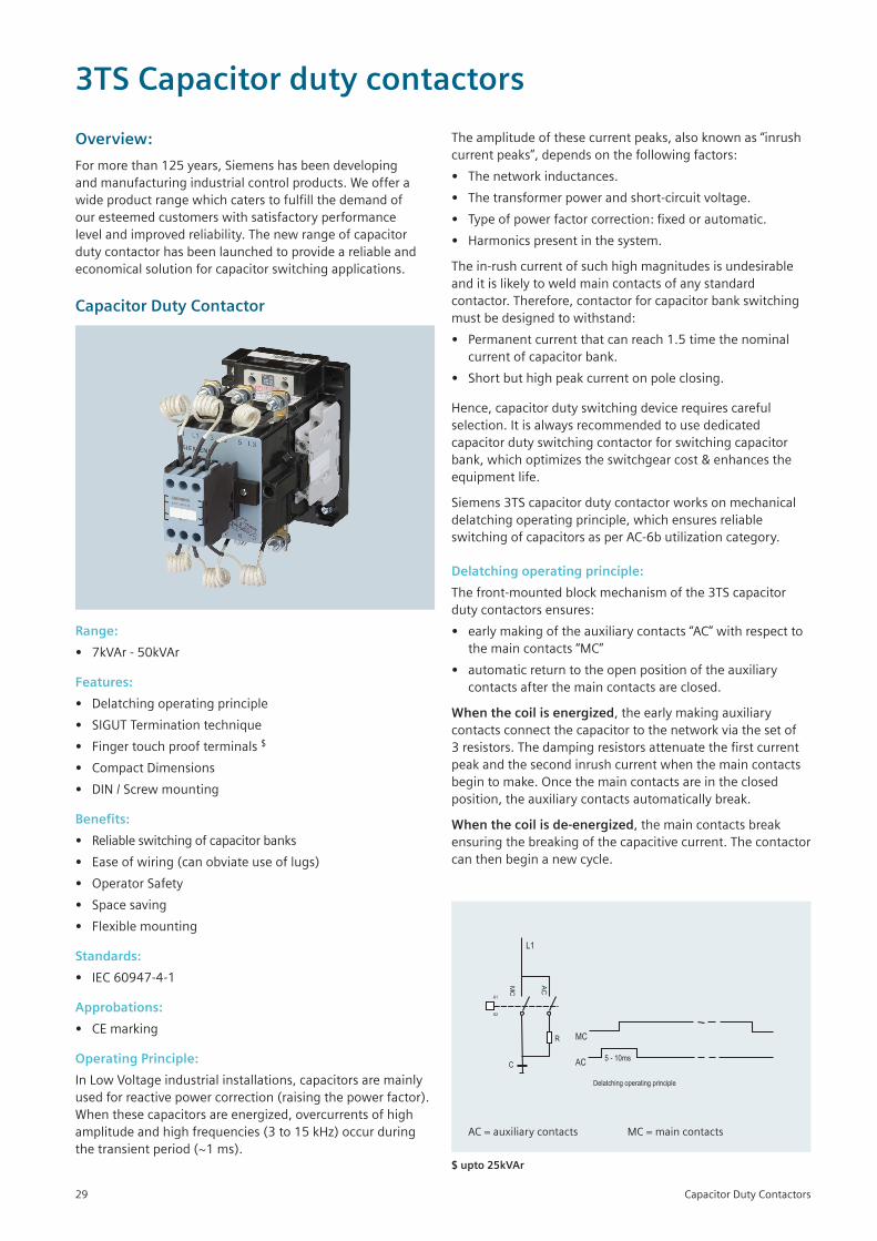
Capacitor Duty Contactor
Range:
• 7kVAr-50kVAr
Features:
• Delatchingoperatingprinciple
• SIGUTTerminationtechnique
• Fingertouchproofterminals$
• CompactDimensions
• DIN/Screwmounting
Benefits:
• Reliableswitchingofcapacitorbanks
• Ease of wiring (can obviate use of lugs)
• OperatorSafety
• Space saving
• Flexiblemounting
Standards:
• IEC 60947-4-1
Approbations:
• CEmarking
Operating Principle:
InLowVoltageindustrialinstallations,capacitorsaremainlyusedforreactivepowercorrection(raisingthepowerfactor).Whenthesecapacitorsareenergized,overcurrentsofhighamplitudeandhighfrequencies(3to15kHz)occurduringthetransientperiod(~1ms).
AC=auxiliarycontacts MC=maincontacts
$ upto 25kVAr
Theamplitudeofthesecurrentpeaks,alsoknownas“inrushcurrentpeaks”,dependsonthefollowingfactors:
• Thenetworkinductances.
• Thetransformerpowerandshort-circuitvoltage.
• Typeofpowerfactorcorrection:fixedorautomatic.
• Harmonicspresentinthesystem.
Thein-rushcurrentofsuchhighmagnitudesisundesirableanditislikelytoweldmaincontactsofanystandardcontactor.Therefore,contactorforcapacitorbankswitchingmustbedesignedtowithstand:
• Permanentcurrentthatcanreach1.5timethenominalcurrent of capacitor bank.
• Shortbuthighpeakcurrentonpoleclosing.
Hence,capacitordutyswitchingdevicerequirescarefulselection.Itisalwaysrecommendedtousededicatedcapacitordutyswitchingcontactorforswitchingcapacitorbank,whichoptimizestheswitchgearcost&enhancestheequipmentlife.
Siemens3TScapacitordutycontactorworksonmechanicaldelatchingoperatingprinciple,whichensuresreliableswitchingofcapacitorsasperAC-6butilizationcategory.
Delatching operating principle:
Thefront-mountedblockmechanismofthe3TScapacitordutycontactorsensures:
• earlymakingoftheauxiliarycontacts“AC”withrespecttothemaincontacts“MC”
• automaticreturntotheopenpositionoftheauxiliarycontactsafterthemaincontactsareclosed.
When the coil is energized,theearlymakingauxiliarycontactsconnectthecapacitortothenetworkviathesetof3resistors.Thedampingresistorsattenuatethefirstcurrentpeakandthesecondinrushcurrentwhenthemaincontactsbegintomake.Oncethemaincontactsareintheclosedposition,theauxiliarycontactsautomaticallybreak.
When the coil is de-energized,themaincontactsbreakensuringthebreakingofthecapacitivecurrent.Thecontactorcanthenbeginanewcycle.
Capacitor Duty Contactors
3TS Capacitor duty contactors
29
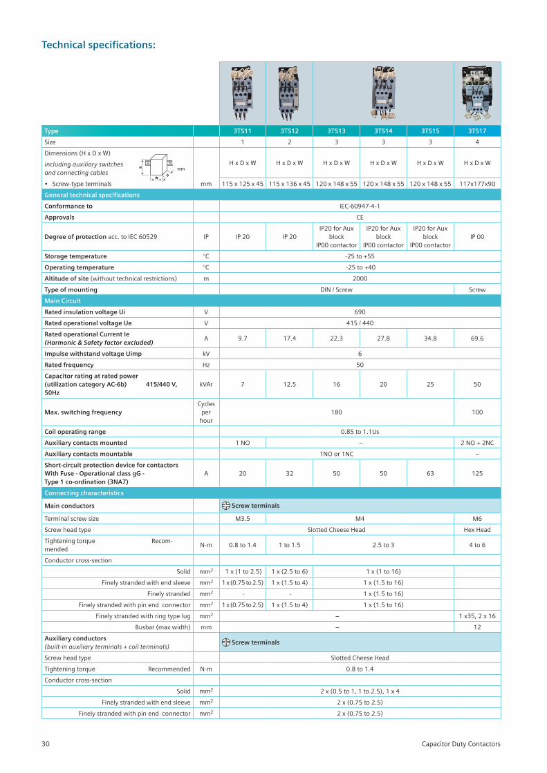
Technical specifications:
Type 3TS11 3TS12 3TS13 3TS14 3TS15 3TS17
Size 1 2 3 3 3 4
Dimensions(HxDxW)
HxDxW HxDxW HxDxW HxDxW HxDxW HxDxWincluding auxiliary switches and connecting cables
• Screw-typeterminals mm 115x125x45 115x136x45 120x148x55 120x148x55 120x148x55 117x177x90
General technical specifications
Conformance to IEC-60947-4-1
Approvals CE
Degree of protection acc.toIEC60529 IP IP 20 IP 20IP20forAux
block IP00 contactor
IP20forAuxblock
IP00 contactor
IP20forAuxblock
IP00 contactorIP 00
Storage temperature °C -25to+55
Operating temperature °C -25to+40
Altitude of site(withouttechnicalrestrictions) m 2000
Type of mounting DIN/Screw Screw
Main Circuit
Rated insulation voltage Ui V 690
Rated operational voltage Ue V 415/440
Rated operational Current Ie (Harmonic & Safety factor excluded)
A 9.7 17.4 22.3 27.8 34.8 69.6
Impulse withstand voltage Uimp kV 6
Rated frequency Hz 50
Capacitor rating at rated power (utilization category AC-6b) 415/440 V, 50Hz
kVAr 7 12.5 16 20 25 50
Max. switching frequencyCycles
per hour
180 100
Coil operating range 0.85to1.1Us
Auxiliary contacts mounted 1NO – 2NO+2NC
Auxiliary contacts mountable 1NOor1NC –
Short-circuit protection device for contactors With Fuse - Operational class gG - Type 1 co-ordination (3NA7)
A 20 32 50 50 63 125
Connecting characteristics
Main conductors Screw terminals
Terminalscrewsize M3.5 M4 M6
Screwheadtype SlottedCheeseHead HexHead
TighteningtorqueRecom-mended
N-m 0.8 to 1.4 1to1.5 2.5to3 4 to 6
Conductor cross-section
Solid mm2 1x(1to2.5) 1x(2.5to6) 1x(1to16)
Finelystrandedwithendsleeve mm2 1x(0.75to2.5) 1x(1.5to4) 1x(1.5to16)
Finely stranded mm2 - - 1x(1.5to16)
Finelystrandedwithpinendconnector mm2 1x(0.75to2.5) 1x(1.5to4) 1x(1.5to16)
Finelystrandedwithringtypelug mm2 – 1x35,2x16
Busbar(maxwidth) mm – 12
Auxiliary conductors (built-in auxiliary terminals + coil terminals) Screw terminals
Screwheadtype SlottedCheeseHead
TighteningtorqueRecommended N-m 0.8 to 1.4
Conductor cross-section
Solid mm2 2x(0.5to1,1to2.5),1x4
Finelystrandedwithendsleeve mm2 2x(0.75to2.5)
Finelystrandedwithpinendconnector mm2 2x(0.75to2.5)
Capacitor Duty Contactors30
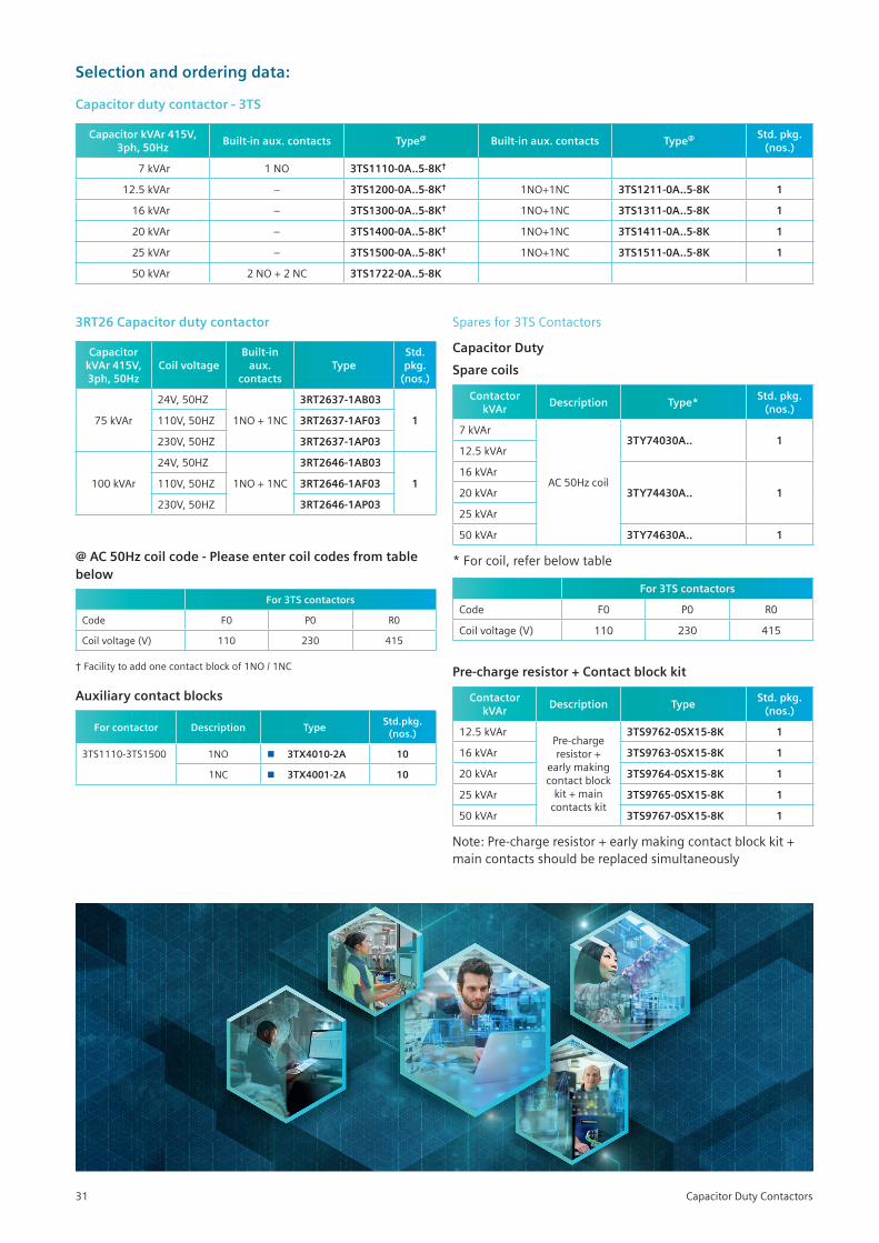
Selection and ordering data:
Capacitor duty contactor - 3TS
Capacitor kVAr 415V, 3ph, 50Hz
Built-in aux. contacts Type@ Built-in aux. contacts Type@ Std. pkg. (nos.)
7 kVAr 1NO 3TS1110-0A..5-8K†
12.5kVAr – 3TS1200-0A..5-8K† 1NO+1NC 3TS1211-0A..5-8K 1
16 kVAr – 3TS1300-0A..5-8K† 1NO+1NC 3TS1311-0A..5-8K 1
20 kVAr – 3TS1400-0A..5-8K† 1NO+1NC 3TS1411-0A..5-8K 1
25kVAr – 3TS1500-0A..5-8K† 1NO+1NC 3TS1511-0A..5-8K 1
50kVAr 2NO+2NC 3TS1722-0A..5-8K
3RT26 Capacitor duty contactor
Capacitor kVAr 415V, 3ph, 50Hz
Coil voltageBuilt-in
aux. contacts
TypeStd. pkg.
(nos.)
75kVAr
24V,50HZ
1NO+1NC
3RT2637-1AB03
1110V,50HZ 3RT2637-1AF03
230V,50HZ 3RT2637-1AP03
100 kVAr
24V,50HZ
1NO+1NC
3RT2646-1AB03
1110V,50HZ 3RT2646-1AF03
230V,50HZ 3RT2646-1AP03
Spares for 3TS Contactors
Capacitor Duty
Spare coils
Contactor kVAr
Description Type*Std. pkg.
(nos.)
7 kVAr
AC50Hzcoil
3TY74030A.. 112.5kVAr
16 kVAr
3TY74430A.. 120 kVAr
25kVAr
50kVAr 3TY74630A.. 1
*Forcoil,referbelowtable
For 3TS contactors
Code F0 P0 R0
Coil voltage (V) 110 230 415
Pre-charge resistor + Contact block kit
Contactor kVAr
Description TypeStd. pkg.
(nos.)
12.5kVArPre-chargeresistor +
earlymakingcontact block kit+main
contacts kit
3TS9762-0SX15-8K 1
16 kVAr 3TS9763-0SX15-8K 1
20 kVAr 3TS9764-0SX15-8K 1
25kVAr 3TS9765-0SX15-8K 1
50kVAr 3TS9767-0SX15-8K 1
Note:Pre-chargeresistor+earlymakingcontactblockkit+maincontactsshouldbereplacedsimultaneously
@ AC 50Hz coil code - Please enter coil codes from table below
For 3TS contactors
Code F0 P0 R0
Coil voltage (V) 110 230 415
†Facilitytoaddonecontactblockof1NO/1NC
Auxiliary contact blocks
For contactor Description TypeStd.pkg.
(nos.)
3TS1110-3TS1500 1NO 3TX4010-2A 10
1NC 3TX4001-2A 10
Capacitor Duty Contactors31
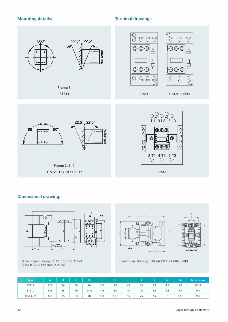
Mounting details:
Frame 1
3TS11
Frame 2, 3, 4
3TS12 / 13 / 14 / 15 / 17
Terminal drawing:
Dimensional drawing:
Type A B C D F G H J K øE M Term Screw
3TS11 125 74 60 10 115 78 45 60 35 4.8 48 M3.5
3TS12 136 85 70 14.5 115 85 45 75 35 4.8 51 M4
3TS13..15 148 85 63 18 120 103 55 75 45 5 62.5 M4
Dimensionaldrawing:7,12.5,16,20,25kVAr(3TS11/12/13/14/1500-0A..5-8K)
3TS12/13/14/153TS11
3TS17
Dimensionaldrawing:50kVAr(3TS1711-0A..5-8K)
Capacitor Duty Contactors32
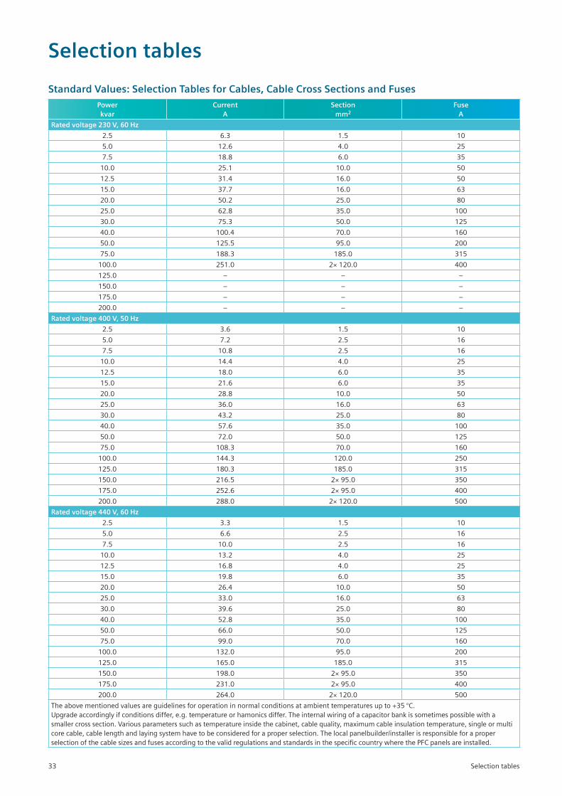
Standard Values: Selection Tables for Cables, Cable Cross Sections and FusesPower kvar
Current A
Section mm2
FuseA
Rated voltage 230 V, 60 Hz
2.5 6.3 1.5 10
5.0 12.6 4.0 25
7.5 18.8 6.0 35
10.0 25.1 10.0 50
12.5 31.4 16.0 50
15.0 37.7 16.0 63
20.0 50.2 25.0 80
25.0 62.8 35.0 100
30.0 75.3 50.0 125
40.0 100.4 70.0 160
50.0 125.5 95.0 200
75.0 188.3 185.0 315
100.0 251.0 2× 120.0 400
125.0 – – –
150.0 – – –
175.0 – – –
200.0 – – –
Rated voltage 400 V, 50 Hz
2.5 3.6 1.5 10
5.0 7.2 2.5 16
7.5 10.8 2.5 16
10.0 14.4 4.0 25
12.5 18.0 6.0 35
15.0 21.6 6.0 35
20.0 28.8 10.0 50
25.0 36.0 16.0 63
30.0 43.2 25.0 80
40.0 57.6 35.0 100
50.0 72.0 50.0 125
75.0 108.3 70.0 160
100.0 144.3 120.0 250
125.0 180.3 185.0 315
150.0 216.5 2×95.0 350
175.0 252.6 2×95.0 400
200.0 288.0 2× 120.0 500
Rated voltage 440 V, 60 Hz
2.5 3.3 1.5 10
5.0 6.6 2.5 16
7.5 10.0 2.5 16
10.0 13.2 4.0 25
12.5 16.8 4.0 25
15.0 19.8 6.0 35
20.0 26.4 10.0 50
25.0 33.0 16.0 63
30.0 39.6 25.0 80
40.0 52.8 35.0 100
50.0 66.0 50.0 125
75.0 99.0 70.0 160
100.0 132.0 95.0 200
125.0 165.0 185.0 315
150.0 198.0 2×95.0 350
175.0 231.0 2×95.0 400
200.0 264.0 2× 120.0 500
Theabovementionedvaluesareguidelinesforoperationinnormalconditionsatambienttemperaturesupto+35°C.Upgradeaccordinglyifconditionsdiffer,e.g.temperatureorhamonicsdiffer.Theinternalwiringofacapacitorbankissometimespossiblewithasmallercrosssection.Variousparameterssuchastemperatureinsidethecabinet,cablequality,maximumcableinsulationtemperature,singleormulticorecable,cablelengthandlayingsystemhavetobeconsideredforaproperselection.Thelocalpanelbuilder/installerisresponsibleforaproperselectionofthecablesizesandfusesaccordingtothevalidregulationsandstandardsinthespecificcountrywherethePFCpanelsareinstalled.
Selection tables
Selection tables
33
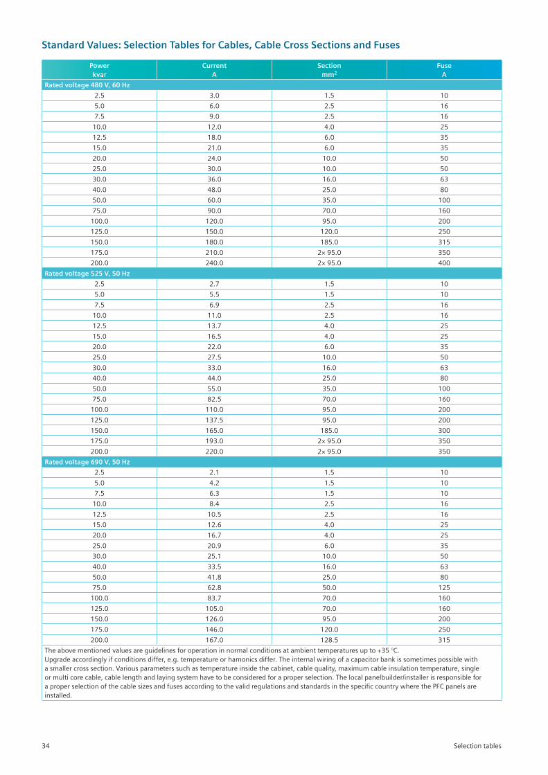
Standard Values: Selection Tables for Cables, Cable Cross Sections and Fuses
Power kvar
Current A
Section mm2
FuseA
Rated voltage 480 V, 60 Hz
2.5 3.0 1.5 10
5.0 6.0 2.5 16
7.5 9.0 2.5 16
10.0 12.0 4.0 25
12.5 18.0 6.0 35
15.0 21.0 6.0 35
20.0 24.0 10.0 50
25.0 30.0 10.0 50
30.0 36.0 16.0 63
40.0 48.0 25.0 80
50.0 60.0 35.0 100
75.0 90.0 70.0 160
100.0 120.0 95.0 200
125.0 150.0 120.0 250
150.0 180.0 185.0 315
175.0 210.0 2×95.0 350
200.0 240.0 2×95.0 400
Rated voltage 525 V, 50 Hz
2.5 2.7 1.5 10
5.0 5.5 1.5 10
7.5 6.9 2.5 16
10.0 11.0 2.5 16
12.5 13.7 4.0 25
15.0 16.5 4.0 25
20.0 22.0 6.0 35
25.0 27.5 10.0 50
30.0 33.0 16.0 63
40.0 44.0 25.0 80
50.0 55.0 35.0 100
75.0 82.5 70.0 160
100.0 110.0 95.0 200
125.0 137.5 95.0 200
150.0 165.0 185.0 300
175.0 193.0 2×95.0 350
200.0 220.0 2×95.0 350
Rated voltage 690 V, 50 Hz
2.5 2.1 1.5 10
5.0 4.2 1.5 10
7.5 6.3 1.5 10
10.0 8.4 2.5 16
12.5 10.5 2.5 16
15.0 12.6 4.0 25
20.0 16.7 4.0 25
25.0 20.9 6.0 35
30.0 25.1 10.0 50
40.0 33.5 16.0 63
50.0 41.8 25.0 80
75.0 62.8 50.0 125
100.0 83.7 70.0 160
125.0 105.0 70.0 160
150.0 126.0 95.0 200
175.0 146.0 120.0 250
200.0 167.0 128.5 315
Theabovementionedvaluesareguidelinesforoperationinnormalconditionsatambienttemperaturesupto+35°C.Upgradeaccordinglyifconditionsdiffer,e.g.temperatureorhamonicsdiffer.Theinternalwiringofacapacitorbankissometimespossiblewithasmallercrosssection.Variousparameterssuchastemperatureinsidethecabinet,cablequality,maximumcableinsulationtemperature,singleormulticorecable,cablelengthandlayingsystemhavetobeconsideredforaproperselection.Thelocalpanelbuilder/installerisresponsibleforaproperselectionofthecablesizesandfusesaccordingtothevalidregulationsandstandardsinthespecificcountrywherethePFCpanelsareinstalled.
Selection tables34
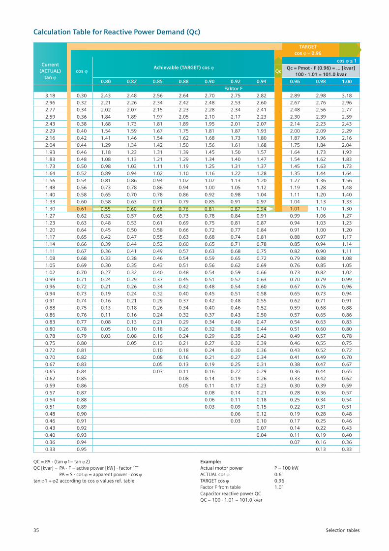
Calculation Table for Reactive Power Demand (Qc)
TARGETcos ϕ = 0.96
Current (ACTUAL)
tan ϕcos ϕ
Achievable (TARGET) cos ϕcos ϕ ≤ 1
QcQc = Pmot · F (0.96) = … [kvar]
100 · 1.01 = 101.0 kvar
0.80 0.82 0.85 0.88 0.90 0.92 0.94 0.96 0.98 1.00
Faktor F
3.18 0.30 2.43 2.48 2.56 2.64 2.70 2.75 2.82 2.89 2.98 3.18
2.96 0.32 2.21 2.26 2.34 2.42 2.48 2.53 2.60 2.67 2.76 2.96
2.77 0.34 2.02 2.07 2.15 2.23 2.28 2.34 2.41 2.48 2.56 2.77
2.59 0.36 1.84 1.89 1.97 2.05 2.10 2.17 2.23 2.30 2.39 2.59
2.43 0.38 1.68 1.73 1.81 1.89 1.95 2.01 2.07 2.14 2.23 2.43
2.29 0.40 1.54 1.59 1.67 1.75 1.81 1.87 1.93 2.00 2.09 2.29
2.16 0.42 1.41 1.46 1.54 1.62 1.68 1.73 1.80 1.87 1.96 2.16
2.04 0.44 1.29 1.34 1.42 1.50 1.56 1.61 1.68 1.75 1.84 2.04
1.93 0.46 1.18 1.23 1.31 1.39 1.45 1.50 1.57 1.64 1.73 1.93
1.83 0.48 1.08 1.13 1.21 1.29 1.34 1.40 1.47 1.54 1.62 1.83
1.73 0.50 0.98 1.03 1.11 1.19 1.25 1.31 1.37 1.45 1.63 1.73
1.64 0.52 0.89 0.94 1.02 1.10 1.16 1.22 1.28 1.35 1.44 1.64
1.56 0.54 0.81 0.86 0.94 1.02 1.07 1.13 1.20 1.27 1.36 1.56
1.48 0.56 0.73 0.78 0.86 0.94 1.00 1.05 1.12 1.19 1.28 1.48
1.40 0.58 0.65 0.70 0.78 0.86 0.92 0.98 1.04 1.11 1.20 1.40
1.33 0.60 0.58 0.63 0.71 0.79 0.85 0.91 0.97 1.04 1.13 1.33
1.30 0.61 1.01 1.10 1.30
1.27 0.62 0.52 0.57 0.65 0.73 0.78 0.84 0.91 0.99 1.06 1.27
1.23 0.63 0.48 0.53 0.61 0.69 0.75 0.81 0.87 0.94 1.03 1.23
1.20 0.64 0.45 0.50 0.58 0.66 0.72 0.77 0.84 0.91 1.00 1.20
1.17 0.65 0.42 0.47 0.55 0.63 0.68 0.74 0.81 0.88 0.97 1.17
1.14 0.66 0.39 0.44 0.52 0.60 0.65 0.71 0.78 0.85 0.94 1.14
1.11 0.67 0.36 0.41 0.49 0.57 0.63 0.68 0.75 0.82 0.90 1.11
1.08 0.68 0.33 0.38 0.46 0.54 0.59 0.65 0.72 0.79 0.88 1.08
1.05 0.69 0.30 0.35 0.43 0.51 0.56 0.62 0.69 0.76 0.85 1.05
1.02 0.70 0.27 0.32 0.40 0.48 0.54 0.59 0.66 0.73 0.82 1.02
0.99 0.71 0.24 0.29 0.37 0.45 0.51 0.57 0.63 0.70 0.79 0.99
0.96 0.72 0.21 0.26 0.34 0.42 0.48 0.54 0.60 0.67 0.76 0.96
0.94 0.73 0.19 0.24 0.32 0.40 0.45 0.51 0.58 0.65 0.73 0.94
0.91 0.74 0.16 0.21 0.29 0.37 0.42 0.48 0.55 0.62 0.71 0.91
0.88 0.75 0.13 0.18 0.26 0.34 0.40 0.46 0.52 0.59 0.68 0.88
0.86 0.76 0.11 0.16 0.24 0.32 0.37 0.43 0.50 0.57 0.65 0.86
0.83 0.77 0.08 0.13 0.21 0.29 0.34 0.40 0.47 0.54 0.63 0.83
0.80 0.78 0.05 0.10 0.18 0.26 0.32 0.38 0.44 0.51 0.60 0.80
0.78 0.79 0.03 0.08 0.16 0.24 0.29 0.35 0.42 0.49 0.57 0.78
0.75 0.80 0.05 0.13 0.21 0.27 0.32 0.39 0.46 0.55 0.75
0.72 0.81 0.10 0.18 0.24 0.30 0.36 0.43 0.52 0.72
0.70 0.82 0.08 0.16 0.21 0.27 0.34 0.41 0.49 0.70
0.67 0.83 0.05 0.13 0.19 0.25 0.31 0.38 0.47 0.67
0.65 0.84 0.03 0.11 0.16 0.22 0.29 0.36 0.44 0.65
0.62 0.85 0.08 0.14 0.19 0.26 0.33 0.42 0.62
0.59 0.86 0.05 0.11 0.17 0.23 0.30 0.39 0.59
0.57 0.87 0.08 0.14 0.21 0.28 0.36 0.57
0.54 0.88 0.06 0.11 0.18 0.25 0.34 0.54
0.51 0.89 0.03 0.09 0.15 0.22 0.31 0.51
0.48 0.90 0.06 0.12 0.19 0.28 0.48
0.46 0.91 0.03 0.10 0.17 0.25 0.46
0.43 0.92 0.07 0.14 0.22 0.43
0.40 0.93 0.04 0.11 0.19 0.40
0.36 0.94 0.07 0.16 0.36
0.33 0.95 0.13 0.33
0.55 0.60 0.68 0.76 0.81 0.87 0.94
QC=PA·(tanϕ1– tan ϕ2)QC[kvar]=PA·F=activepower[kW]·factor“F” PA=S·cosϕ=apparentpower·cosϕtan ϕ1 + ϕ2 according to cos ϕ values ref. table
Example:Actualmotorpower P=100kWACTUALcosϕ 0.61TARGET cos ϕ 0.96FactorFfromtable 1.01Capacitor reactive power QCQC=100·1.01=101.0kvar
Selection tables35
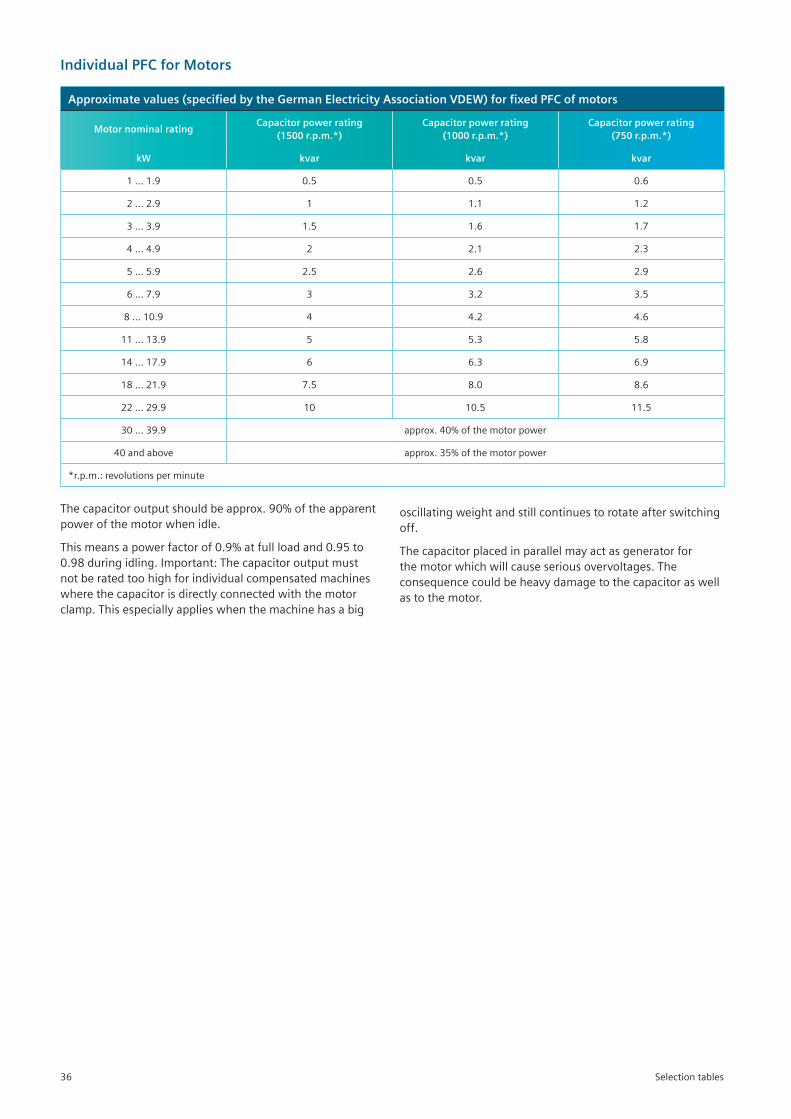
Individual PFC for Motors
Approximate values (specified by the German Electricity Association VDEW) for fixed PFC of motors
Motor nominal rating Capacitor power rating
(1500 r.p.m.*) Capacitor power rating
(1000 r.p.m.*) Capacitor power rating
(750 r.p.m.*)
kW kvar kvar kvar
1…1.9 0.5 0.5 0.6
2…2.9 1 1.1 1.2
3…3.9 1.5 1.6 1.7
4…4.9 2 2.1 2.3
5…5.9 2.5 2.6 2.9
6…7.9 3 3.2 3.5
8…10.9 4 4.2 4.6
11…13.9 5 5.3 5.8
14…17.9 6 6.3 6.9
18…21.9 7.5 8.0 8.6
22…29.9 10 10.5 11.5
30…39.9 approx.40%ofthemotorpower
40 and above approx.35%ofthemotorpower
*r.p.m.:revolutionsperminute
Thecapacitoroutputshouldbeapprox.90%oftheapparentpowerofthemotorwhenidle.
Thismeansapowerfactorof0.9%atfullloadand0.95to0.98duringidling.Important:Thecapacitoroutputmustnotberatedtoohighforindividualcompensatedmachineswherethecapacitorisdirectlyconnectedwiththemotorclamp.Thisespeciallyapplieswhenthemachinehasabig
oscillatingweightandstillcontinuestorotateafterswitchingoff.
Thecapacitorplacedinparallelmayactasgeneratorforthemotorwhichwillcauseseriousovervoltages.Theconsequencecouldbeheavydamagetothecapacitoraswellastothemotor.
Selection tables36
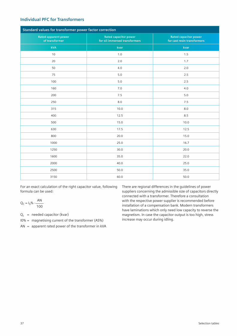
Individual PFC for Transformers
Standard values for transformer power factor correction
Rated apparent power of transformer
Rated capacitor power for oil immersed transformers
Rated capacitor powerfor cast resin transformers
kVA kvar kvar
10 1.0 1.5
20 2.0 1.7
50 4.0 2.0
75 5.0 2.5
100 5.0 2.5
160 7.0 4.0
200 7.5 5.0
250 8.0 7.5
315 10.0 8.0
400 12.5 8.5
500 15.0 10.0
630 17.5 12.5
800 20.0 15.0
1000 25.0 16.7
1250 30.0 20.0
1600 35.0 22.0
2000 40.0 25.0
2500 50.0 35.0
3150 60.0 50.0
Foranexactcalculationoftherightcapacitorvalue,followingformulacanbeused:
ANQC = I0%· 100
Qc = needed capacitor (kvar)
I0%= magnetisingcurrentofthetransformer(AS%)
AN = apparentratedpowerofthetransformerinkVA
Thereareregionaldifferencesintheguidelinesofpowersuppliersconcerningtheadmissiblesizeofcapacitorsdirectlyconnectedwithatransformer.Thereforeaconsultationwiththerespectivepowersupplierisrecommendedbeforeinstallationofacompensationbank.Moderntransformershavelaminationswhichonlyneedlowcapacitytoreversethemagnetism.Incasethecapacitoroutputistoohigh,stressincreasemayoccurduringidling.
Selection tables37

Notes
38

Notes
39
OrderNo.:109556591PQS _CC96112018
CustomerCareTollfreeno. 1800 209 0987Email:[email protected]
Product upgradation is a continuous process.Hence,datainthiscatalogissubjecttochangewithoutpriornotice.Forthelatestinformation,pleasegetintouchwithourSalesOffices.
SiemensLtd.Digital Factory Control Products R&DTechnologyCentre KalwaWorks,ThaneBelapurRoad,Thane-400601 Fax:+912233265627Formoreinformationcontacttollfree18002091800 E-mail:[email protected]
www.siemens.co.in
Your partnersSales offices:
Chennai4thFloor,ETAMountCentral SeethakathiBusinessCentre,MountRoad Chennai-600006 (:+914430474000Fax:+914430474080
Coimbatore1stFloor,“SenthilTowers”,1078,AvinashiRoad Coimbatore-641018 (:+914223076300Fax:+914223076310
GurgaonPlotNo.-78,Tower-B JagatjitIndustriesBuilding(JIL) OppositeSBIAcademy,Sector-18 Gurgaon-122015 (:+911242842000,3810200
Hyderabad5-9-19,4th&5thFloor,LaxmiNarasinhEstate Opp.SecretariatRoad,Saifabad Hyderabad-500004 (:+914030922500Fax:+914030923145
JaipurInternationalBusinessCenter,K14FirstFloor AshokMarg,AshokNagar,CScheme Jaipur - 302001 (:+911415152108Fax:+911412370482
Jamshedpur“RoshanTower”,MainRoad,Bistupur(2ndFloor) Jamshedpur-831001 (:+916576682201
Kolkata3rdFloor,43,ShantiPalli RashbihariBypassConnector Kolkata-700042,India (:+913330939000Fax:+913330939010
Lucknow510-511,5thFloor,ShalimarTitanium PlotNo.TC.G-1/1,VibhutiKhand GomtiNagar,Lucknow UttarPradesh226010 (:+915224031039
Haridwar FlatNo.204,ShivAsthalyAppartment PurshotyamVihar,Kankhal,Haridwar-249408 Mobile:+919889384222 E-mail:[email protected]
Hospet #727,LakshmiNarasimhaNilaya NearSurbhiKalyanaMantapa,Amaravathi Hospet-583203 Mobile:+919741114877 E-mail:[email protected]
Hosur PlotNo.12VishnuAnandamGalaxy ChittanapalliNallurVillage,Hosur-635109 Mobile:+918971200266 E-mail:[email protected]
Hubli PlotNo.8,AbhiNilay,ManjunathNagar GokulRoad,Hubli-30,Karnataka Mobile:+919945961052 E-mail:[email protected]
Jalandhar H.No.140,GroundFloor,DefenceColony Jalandhar,Punjab-144001 Mobile:+918427979870 E-mail:[email protected]
Jodhpur A-240,ShastriNagar,Jodhpur-342003 Mobile:+919929110493 E-mail:[email protected]
Kanpur FlatNo.702,PushpiApartments ShardaNagar,Kanpur-208025,UttarPradesh Mobile:+918802011478 E-mail:[email protected]
Khopoli SamarthanagarCo-opHsg.Soc. MogalwadiRoad,Khopoli Taluka-Khalapur,Dist.Raigad-410203 Mobile:+919867748975 E-mail:[email protected]
Kolhapur RSNo.84-1,PinacPrasad,FlatNo.A-35 NewPalaceRoad,Kolhapur-416006 Mobile:+919850836839 E-mail:[email protected]
Kota 406,ManglayatanAppartment NearJainTemple,BhimganjMandi Kota - 324002 Mobile:+919828419111 E-mail:[email protected]
Ludhiana H.No.1858,FirstFloor,Sector-32A Ludhiana-141008,Punjab Mobile:+919876047929 E-mail:[email protected]
Ludhiana R-115,NearDAVSchool SarabhaNagarExtPh-2,PakhowalRoad Ludhiana,Punjab-142022 Mobile:+919888484066 E-mail:[email protected]
Madurai Anirudhblock,F-Top3,VasudharaApartment 84,TPKMainRoad,Andalpuram Madurai-625003,TamilNadu Mobile:+919894617776 E-mail:[email protected]
Maraimalainagar No.11,AmbedkarStreet,SRSBuildings,UpstairsRagaDentalClinic,Potheri,Chennai-603203 Mobile:+919840392926 E-mail:[email protected]
Meerut D-205,AnsalCourtyard,RoorkeeBypass Modipuram,Meerut-250110,UP Mobile:+917619047999 E-mail:[email protected]
Mehsana Mr.PrabhakaranMudaliar Mobile:+919724753579 E-mail:[email protected]
MysoreNo.980,4thCross,6thMain BannimantapBlayout,SSNagar Mysore-570015 Mobile:+919611311645 E-mail:[email protected]
NaidupetaDoorNo.3-3-140,Raghavaiahpeta SriharikotaRoad,OpptoRaceSchool SullurpetaTown&Mandal,SPSRNelloreDistrict AP-524123 Mobile:+919840255185 E-mail:[email protected]
Nashik FlatNo402,”D”Wing,HariShrushti NearJoggingTrack,OppositeWNS,IndiraNagar Nashik-422009 Mobile:+919822193204 E-mail:[email protected]
Neemrana FlatNo.F111,AnantrajAashrayApartment PlotNo.236,JapaneseZone Neemrana-301705,Dist.-Alwar Mobile:+919650481919 E-mail:[email protected]
Patna A-53,5thFloor,KrishnaApartment,BoringRoad Patna - 800001 Mobile:+919641574289 E-mail:[email protected]
Pondicherry R.A.M.Paradise,IIFloor,No.4,2ndCross KambanNagar,Reddiarpalayam Puducherry-605010 Mobile:+919176609374 E-mail:[email protected]
Raipur 103RisabhRegency,NearShriMedishineHospital NewRajendraNagar,Raipur(CG)-492001 Mobile:+919425601849 E-mail:[email protected]
Rajkot301,SnowhillApartment NearGoldenSupermarket,AminMarg Rajkot-360007,Gujarat Mobile:+919909904993 E-mail:[email protected]
RanchiFlatNo.A-101,1stFloor,SundaramApartment KilburnColony,Hinoo,Ranchi Jharkhand-834002 Mobile:+918294052647 E-mail:[email protected]
Ahmedabad3rdFloor,PrernaArbour GirishColdrinksCrossRoads,Navrangpura Ahmedabad-380009 (:+917930927600Fax:+917930927699
BarodaGroundFloor,UrjaBhavan Opp.MakarpuraRailwayStation,Maneja Vadodara - 390 013 (:+912653957701Fax:+912653039190
Bengaluru1stFloor,JyotiMahal,No.49,St.MarksRd. Bengaluru-560001 (:+918033422000Fax:+918033424131
Bhubaneswar Unit:1102&1103,DLFCyberCity ChandakaIndustrialEstate,Patia,Bhubaneswar Odisha-751024
ChandigarhSCO188/191,3rdFloor,Sector-17C Chandigarh-160017 (:+911724690300Fax:+911724690399
Territory managers:AgraF7B,ACRDesireAppartment NearKargilPetrolPump,Sikandra Agra-282007,U.P. Mobile:+917665590333 E-mail:[email protected]
Aurangabad Mobile:+919673333024 E-mail:[email protected]
Belgavi Flatno-201,2ndFloor,HarimanorApartment 1stCross-BhagyaNagar,AngolExtension,Belgavi Karnataka590006 Tel.:+9108312495156 Mobile:+919740277991 E-mail:[email protected] Mobile:+918105254395 E-mail:[email protected]
Bharuch GoldB,804,SamruddhiResidency Opp.ZadeshwarBusStop,ZadeshwarRoad Bharuch-392011 Mobile:+919429037805 E-mail:[email protected]
Bhilai C/o.Mr.AnilDhusia QtrNo.4A,Street33,Sector-4 Bhilai-490001 Mobile:+917869922211 E-mail:[email protected]
BhopalFlat-102,Tower–JasmineNikhilNestles JatkheriHoshangabadRoad Bhopal,MP-462026 Mobile:+919711007466 E-mail:[email protected]
Boisar FlatNo.A-21,SaiSagarCHS,MAHADAColony ChitrayalayaRoad,Boisar-401506 Mobile:+919819231892 E-mail:[email protected]
Cochin JomerSymphony,33/2317,5thFloor Chalikkavattom,PonnurunniNorth,Vytilla Kochi-682019 Tel.:+914028611/22 Mobile:+919656690111 E-mail:[email protected]
Durgapur 6/15,BengalAmbuja (NearDurgapurCinemaHall),CitiCentre Durgapur - 713216 Mobile:+919051020207 E-mail:[email protected]
Gandhidham PlotNo.299,Ward3A,Adipur Gandhidham-370205,Gujarat Mobile:+919099010323 E-mail:[email protected]
Gorakhpur FlatNo.3B,3rdFloor,PlotNo.298 NearSawatriHosiptal,Purdilpur,VijayChowk Gorakhpur-273001,UP Mobile:+91917800960310 E-mail:[email protected]
Guwahati ShivalayaHousingSociety,FlatNo.B3A Bylane4,JoymatiNagar,Adabari,Pandu Guwahati-781012 Mobile:+91-9864110684 E-mail:[email protected]
MumbaiBusiness Centre-1 ThaneBelapurRoad,Thane-400601 (:+912239663000Fax:+912239663721
Nagpur4thFloor,LandMarkBuilding WardhaRoad,RamdasPeth Nagpur-440010 (:+917123093000Fax:+917123093111
PuneTowerB/701-705,ICCTradeTower 403A,SenapatiBapatRoad Pune - 411016 (:+912030466000Fax:+912030466060
Vishakhapatnam2ndFloor,30-8-47,LakshmiNarasimhaTowers BanuStreet,DabaGardens Visakhapatnam-530020 AndhraPradesh (:+918913050200Fax:+918913050222
Renukoot VijayGuptaBhawan,SwamiVivekanandColony Murdhawa,Renukoot-231217,U.P. Mobile:+919984500021 E-mail:[email protected]
Rourkela D/7,GafoorColony,GroundFloor NearLICOffice,UditNagar Rourkela-769012,Odisha Mobile:+919776967773 E-mail:[email protected]
Rudrapur ShantiViharColony,ChatarpurRoad Oppsoite–Dr.PandeyHospital Rudrapur-263153,Uttarakhand Mobile:+919839174578 E-mail:[email protected]
Salem Rajagiragham,LumbiniIllam,No.20 PalaniappaNagarHasthampatti,Salem-636007 Mobile:+918754922245 E-mail:[email protected]
Siliguri C/oRatanSaha GroundFloor,RajaRammohanRoyRoad BesideBabubhaiAttaMill,Hakimpara Siliguri-734001,WestBengal Mobile:+919932276294 E-mail:[email protected]
Sonepat H.No.1103,1stFloor,Sector-14 Sonepat,Haryana-131001 Mobile:+919855526122 E-mail:[email protected]
Sriperumbudur VillaNo.97,CasaGrandeFutura,ChengalpetRoad Sriperumbudur,KanchipuramDist-602105 Mobile:+919791045280 E-mail:[email protected]
Surat A604,StutiUniversal,GreenCityRoad Pal-Adajan,Surat-395009,Gujarat Mobile:+919712445504 E-mail:[email protected]
Trichy FlatNo.102,`B’Block,2ndFloor,VigneshEmpireApartments,SalaiRoad,Woraiyur,Trichy-620003 Mobile:+918056025127 E-mail:[email protected]
Trissur PlotNo.12,CherakekaranHouse,UnityNagar KuriachiraP.O,Thrissur,Kerala-680006 Mobile:+919947957839 E-mail:[email protected]
Udaipur A-39,NewAhinsapuri,Fatehpura Udaipur-313004 Mobile:+918696222212 E-mail:[email protected]
Vapi FlatNo.302,3rdFloor,Samrajya-IV RoyalResidency,GokulViharTownship CharwadaRoad,Taluka-Pardi,Dist.Valsad Vapi-396195 Mobile:+919825147957 E-mail:[email protected]
Vijayawada Mobile:+919948664228 E-mail:[email protected]