Power Optimization of Battery Charging System Using FPGA Based Neural Network Controller
11
Ankita Dhakate Int. Journal of Engineering Research and Applications www.ijera.com ISSN : 2248-9622, Vol. 4, Issue 8( Version 6), August 2014, pp.112-122 www.ijera.com 112 | Page Power Optimization of Battery Charging System Using FPGA Based Neural Network Controller Ankita Dhakate* *(Department of Electronics & Telecommunication, Symbiosis Institute of Technology, Pune-15 ABSTRACT This paper involves designing a small scale battery charging system which is powered via a photovoltaic panel. This work aims at the usage of solar energy for charging the battery and optimizing the power of the system. Implementation is done using Artificial Neural Network (ANN) on FPGA. To develop this system an Artificial Neural Network is trained and its result is further used for the PWM technique. PWM pulse generation has been done using Papilio board which is based on XILINX Spartan 3E FPGA. The ANN with PWM technique is ported on FPGA which is programmed using VHDL. This able to automatically control the whole charging system operation without requirement of external sensory unit. The simulation results are achieved by using MATLAB and XILINX. These results allowed demonstrating the charging of the battery using proposed ANN and PWM technique. Keywords- Photovoltaic battery charger, PWM, ANN, FPGA I. INTRODUCTION Renewable energy resources attract much more attention since today people are facing the problems of fossil fuel depletion and environmental imbalance associated with power generation. Among all the renewable resources, solar photovoltaic power generation is the most important and cleanest form of energy conversion available. Photovoltaic sources are fast growing and widely used in many applications such as battery charging, light sources, water pumping, satellite power systems, etc. Power optimization is more in demand today than at any other time. This is because power demand is constantly growing & now outstripping supply. This produces resultant deterioration of power quality i.e. irregular voltage which is mostly too high & sometimes too low. Photovoltaic system mainly consists of a PV panel which converts sunlight into direct current (D.C.) electricity. They have the advantage of being maintained and pollution free but their main drawbacks are high fabrication cost, low energy conversion efficiency, and nonlinear characteristics, a charging circuit for charging the battery and operation of the load, a charge controller is the heart of the PV systems. Traditionally battery have been used as a primary solution for power storage in solar power systems that are not connected to the electrical grid because off-grid homes need reliable power even at night, and solar panels are generally the most cost- effective way to generate it, but cannot provide on- demand power unless the sun is shining, which may not necessarily be when it is needed most. Therefore the solution is to capture it in batteries which can then be drawn upon later to provide power. This paper represents a method to build FPGA based neural network controller which is capable of super wising the charging / discharging process in order to ensure a long battery life. However, this system uses simple and powerful Pulse Width Modulation technique and Artificial Neural Network. The implementation and simulation of the proposed method uses Field Programmable Gate Array. PWM pulse generation has been done on a Papilio one 250 K which is based on XILINX Spartan 3E FPGA using VHDL code. The pulse width modulated (PWM) adaptive intelligent system has been designed and developed where the input DC power stored in the battery obtained through PV source. The traditional analog method for generating PWM pulses uses the comparison of two signals i.e. a high frequency carrier signal and sinusoidal wave as reference signal to set the desired output frequency and thus needed two signals to produce PWM signal. We can use Neural Network Controller to control the whole PV system for battery storage. The primary function of a FPGA based ANN charge controller in a stand-alone PV system is to maintain the battery at highest possible state of charge while protecting it from overcharge by the array and from over discharge by the loads. II. LITERATURE SURVEY In case of stand-alone system is usage, batteries are required for energy storage. Electricity generations of solar panels are strongly related with solar radiation intensity. However the intensity is not stable. Therefore, charge efficiency is a very important topic in solar systems. Charge controllers are designed to improve charge efficiency and safety. RESEARCH ARTICLE OPEN ACCESS
Transcript of Power Optimization of Battery Charging System Using FPGA Based Neural Network Controller
Ankita Dhakate Int. Journal of Engineering Research and Applications www.ijera.com
ISSN : 2248-9622, Vol. 4, Issue 8( Version 6), August 2014, pp.112-122
www.ijera.com 112 | P a g e
Power Optimization of Battery Charging System Using FPGA
Based Neural Network Controller
Ankita Dhakate* *(Department of Electronics & Telecommunication, Symbiosis Institute of Technology, Pune-15
ABSTRACT
This paper involves designing a small scale battery charging system which is powered via a
photovoltaic panel. This work aims at the usage of solar energy for charging the battery and optimizing the
power of the system. Implementation is done using Artificial Neural Network (ANN) on FPGA. To develop this
system an Artificial Neural Network is trained and its result is further used for the PWM technique. PWM pulse
generation has been done using Papilio board which is based on XILINX Spartan 3E FPGA. The ANN with
PWM technique is ported on FPGA which is programmed using VHDL. This able to automatically control the
whole charging system operation without requirement of external sensory unit. The simulation results are
achieved by using MATLAB and XILINX. These results allowed demonstrating the charging of the battery
using proposed ANN and PWM technique.
Keywords- Photovoltaic battery charger, PWM, ANN, FPGA
I. INTRODUCTION Renewable energy resources attract much more
attention since today people are facing the problems
of fossil fuel depletion and environmental imbalance
associated with power generation. Among all the
renewable resources, solar photovoltaic power
generation is the most important and cleanest form of
energy conversion available. Photovoltaic sources are
fast growing and widely used in many applications
such as battery charging, light sources, water
pumping, satellite power systems, etc.
Power optimization is more in demand today
than at any other time. This is because power demand
is constantly growing & now outstripping supply.
This produces resultant deterioration of power quality
i.e. irregular voltage which is mostly too high &
sometimes too low.
Photovoltaic system mainly consists of a PV
panel which converts sunlight into direct current
(D.C.) electricity. They have the advantage of being
maintained and pollution free but their main
drawbacks are high fabrication cost, low energy
conversion efficiency, and nonlinear characteristics, a
charging circuit for charging the battery and
operation of the load, a charge controller is the heart
of the PV systems. Traditionally battery have been
used as a primary solution for power storage in solar
power systems that are not connected to the electrical
grid because off-grid homes need reliable power even
at night, and solar panels are generally the most cost-
effective way to generate it, but cannot provide on-
demand power unless the sun is shining, which may
not necessarily be when it is needed most. Therefore
the solution is to capture it in batteries which can
then be drawn upon later to provide power.
This paper represents a method to build FPGA based
neural network controller which is capable of super
wising the charging / discharging process in order to
ensure a long battery life. However, this system uses
simple and powerful Pulse Width Modulation
technique and Artificial Neural Network. The
implementation and simulation of the proposed
method uses Field Programmable Gate Array. PWM
pulse generation has been done on a Papilio one 250
K which is based on XILINX Spartan 3E FPGA
using VHDL code. The pulse width modulated
(PWM) adaptive intelligent system has been designed
and developed where the input DC power stored in
the battery obtained through PV source. The
traditional analog method for generating PWM pulses
uses the comparison of two signals i.e. a high
frequency carrier signal and sinusoidal wave as
reference signal to set the desired output frequency
and thus needed two signals to produce PWM signal.
We can use Neural Network Controller to control
the whole PV system for battery storage. The primary
function of a FPGA based ANN charge controller in
a stand-alone PV system is to maintain the battery at
highest possible state of charge while protecting it
from overcharge by the array and from over
discharge by the loads.
II. LITERATURE SURVEY In case of stand-alone system is usage, batteries
are required for energy storage. Electricity
generations of solar panels are strongly related with
solar radiation intensity. However the intensity is not
stable. Therefore, charge efficiency is a very
important topic in solar systems. Charge controllers
are designed to improve charge efficiency and safety.
RESEARCH ARTICLE OPEN ACCESS
Ankita Dhakate Int. Journal of Engineering Research and Applications www.ijera.com
ISSN : 2248-9622, Vol. 4, Issue 8( Version 6), August 2014, pp.112-122
www.ijera.com 113 | P a g e
The primary function of a charge controller is to
protect the battery from overcharge and over
discharge in a stand-alone PV system [1].
Ullah et al. (1996) focused on the design of a
super-fast battery charger based on National’s
proprietary neural network based neural fuzzy
technology. They compared their method with
conventional fast chargers and indicate that their
method reduce the charging time [2]. Masheleni and
Carelse (1997) designed an intelligent charge
controller, incorporating an SGS–Thompson
microcontroller, ST62E20 and discussed the
advantages of such charge controllers [3].
Hsieh et al. (2001) proposed a fuzzy-controlled
active state of- charge controller (FC-ASCC) for
improving the charging behavior of a lithium–ion
(Li–ion) battery. In this method, a fuzzy-controlled
algorithm is built with the predicted charger
performance to program the charging trajectory faster
and to remain the charge operation in a proposed
safe-charge area (SCA). They increased the charging
speed about 23% [4].
Yi et al. (2007) presented a novel switch-mode
charger controller IC for improve the charging
efficiency of valve regulated lead-acid (VRLA)
battery and save its life. They achieved fast transient
response and the precisions of both constant current
and constant voltage charge modes met the
specifications well [5]. Chiang et al. (2009) presented
the modeling and controller design of the PV charger
system implemented with the single-ended primary
inductance converter (SEPIC) and gave a detailed
modeling of the SEPIC with the PV module input and
peak-current-mode control. The system has been
proved to be effective in the MPPT and power
balance control [6].
Tesfahunegn et al. (2011) proposed a new
solar/battery charge controller that combines both
MPPT and overvoltage controls as single control
function. They conducted two case studies in
Simulink /Simpower, first to evaluate the
performance of the designed controller in terms of
transient response and voltage overshoot. secondly,
realistic irradiance data is used to evaluate the
performance of the developed charge controller in
terms of parameters such as PV energy utilization
factor and overvoltage compared to the conventional
hysteretic on/off controller. They achieved good
transient response with only small voltage overshoot,
better in terms PV energy utilization and same level
of overvoltage control [7].
There are some applications which are use
MPPT controller [8,9,10]. Dakkak and Hasan (2012)
analyzed a charge controller based on microcontroller
in stand-alone PV systems and they conclude that
such systems reduce the power consumption for
charging battery and give flexibility to the
designer[11]. Karami et al. (2012) focused on the
load type and suggest new methods to reach the MPP
depending on the load state and the development of
the PV array mathematical model. They analyzed the
effect of temperature and irradiance on the battery
charger and showed the difference between the
direct-coupled and the indirect-coupled applications
of a PV panel [12].
The paper [13] suggests method to charge
lithium ion batteries by using solar power. MPPT
control system is implemented which allows fast and
safe charging by using pulse width modulator duty
cycle ratio control. It provides better performance
and efficiency. The voltage maximum power point
tracking (VMPPT) algorithm was used to see the
results for different conditions using MATLAB
Simulink and Pspice. The solar charger prototype is
designed by using PIC18F4585 microcontroller and
IC SG3524. The results are obtained by observing
system behavior for different conditions on load and
environment conditions.
In [14] authors have implemented the improved
PV module by using genetic algorithm. Artificial
neural network (ANN) was used to train the genetic
algorithm values. The maximum power point
tracking (MPPT) algorithm was used. The proposed
algorithm has been trained for different environment
conditions. 0.05% to 4.46% error percentage has
been observed which can be reduced by taking large
number of training data for ANN.
The paper [15] suggested a maximum power
point tracking algorithm using an artificial neural
network for a solar power system. The three layers
neural network and some simple activation functions
have been used for tracking the maximum power
point of the solar system. The overall design was
implemented on a low-cost PIC16F876 RISC-
microcontroller without external sensor unit
requirement. The designed system provide above
90% efficiency. The proposed artificial neural
network algorithm provides faster tracking speed as
compared to conventional tracking system.
In paper [16] the authors suggested two different
topologies of charger. The design is simulated by
using Proteus professional software. Both the
topologies were designed by using Atmega32
microcontroller. Pulse width modulation (PWM)
will be implemented on a MCU to control duty cycle
and voltage. The efficiency of designed system is
depending on duty cycle and voltage. When a battery
voltage reaches the regulation set point, the PWM
algorithm slowly reduces the charging current to
avoid heating of the battery. The designed system has
many benefits like reduce battery heating, increase
the charge acceptance of the battery etc.
In [17] the authors designed a solar power
management system (SPMS) for an experimental
unmanned aerial vehicle (UAV). The design consists
of three stages. First stage is power management

Ankita Dhakate Int. Journal of Engineering Research and Applications www.ijera.com
ISSN : 2248-9622, Vol. 4, Issue 8( Version 6), August 2014, pp.112-122
www.ijera.com 114 | P a g e
system, second stage is the battery management stage
and the final stage is power conversion stage. The
first stage is used to obtain maximum power from the
solar panels. The second stage is used to control and
monitor the charging and discharging process of
battery. The last and final stage is used for power
conversion. The overall power efficiency of the
system is depending on the combination of the
efficiency of all the three stages. The designed
system is mainly suitable for low power applications.
In [18] battery charge control system for
photovoltaic (PV) panel has been designed.
Maximum power point tracking algorithm was used
in the design which is used to solve the problem of
mismatch between the PV panels and the battery. The
system consists of microcontroller, buck bust
converter, resistive load and battery. GUI has also
been installed in the designed system.
Paper [19] describes battery charging system for
solar battery management system. This system
consists of buck-boost converter. Depending upon the
supply voltages from the solar panels the system
operates in different mode namely buck mode, buck
boost mode, or the boost mode. The MATLAB
Simulink simulation tool is used for verifying the
results. The buck-boost converter with
microcontroller is very important part of the designed
power management system.
In paper [20] the authors have suggested method
for the hybrid solar photovoltaic and wind power
system in Battery management with artificial
intelligence. Fuzzy logic and neural network are used
to utilize maximum battery. A MATLAB Simulink
model has been developed for power management
system. Neural network is better as compared to
fuzzy logic in battery power management system
during charging and discharging process.
In [21] a new control algorithm for battery
charging system has been developed by researchers.
It consists of buck-type dc/dc converter. The
proposed algorithm controls the charging and
discharging process by transforming the input of
buck-boost converter to the load controlled by
microcontroller. The proposed algorithm is simple
and flexible to use.
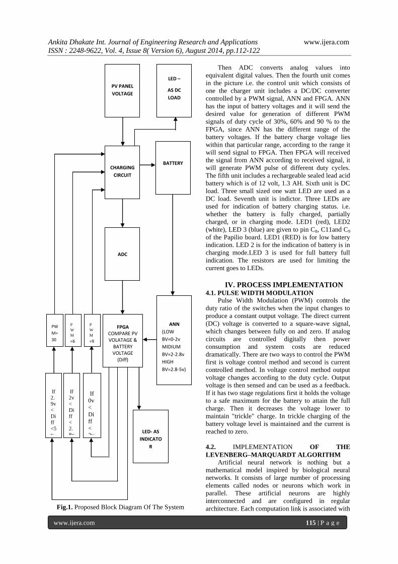
III. SYSTEM FLOWCHART A flowchart of the major functions of the system
is shown in fig 1.
3.1 System Process
The proposed system consists of seven units
namely photovoltaic panel, charging circuit, battery,
analog to digital converter, charge controller i.e.
(ANN with FPGA), DC load, indicator unit, each
with its own function. These units are connected in
accordance with the block diagram presented in fig 1.
The first unit i.e solar photovoltaic panel has a
rated power of 11 watt and rated voltage 17.2 volt,
rated current of 0.63 Amp. When solar (PV) panel is
placed in sunlight it gives maximum output. The
output of solar photovoltaic panel is given to the
second unit i.e. charging circuit which includes a DC-
DC converter controlled by a PWM signal. DC/DC
converter is formed by two switches. The output from
the voltage divider in charging circuit goes to ADC.
The Second voltage divider circuit is used for
sensing the battery voltage .The output of voltage
divider goes to ADC. PWM signal is computed from
the control unit.
Third unit is Analog to Digital converter. It is 8
bit 0809 ADC. Solar photovoltaic panel voltage and
battery voltage is given as feedback to the analog to
digital converter.
Ankita Dhakate Int. Journal of Engineering Research and Applications www.ijera.com
ISSN : 2248-9622, Vol. 4, Issue 8( Version 6), August 2014, pp.112-122
www.ijera.com 115 | P a g e
Fig.1. Proposed Block Diagram Of The System
Then ADC converts analog values into
equivalent digital values. Then the fourth unit comes
in the picture i.e. the control unit which consists of
one the charger unit includes a DC/DC converter
controlled by a PWM signal, ANN and FPGA. ANN
has the input of battery voltages and it will send the
desired value for generation of different PWM
signals of duty cycle of 30%, 60% and 90 % to the
FPGA, since ANN has the different range of the
battery voltages. If the battery charge voltage lies
within that particular range, according to the range it
will send signal to FPGA. Then FPGA will received
the signal from ANN according to received signal, it
will generate PWM pulse of different duty cycles.
The fifth unit includes a rechargeable sealed lead acid
battery which is of 12 volt, 1.3 AH. Sixth unit is DC
load. Three small sized one watt LED are used as a
DC load. Seventh unit is indictor. Three LEDs are
used for indication of battery charging status. i.e.
whether the battery is fully charged, partially
charged, or in charging mode. LED1 (red), LED2
(white), LED 3 (blue) are given to pin C8, C11and C9
of the Papilio board. LED1 (RED) is for low battery
indication. LED 2 is for the indication of battery is in
charging mode.LED 3 is used for full battery full
indication. The resistors are used for limiting the
current goes to LEDs.
IV. PROCESS IMPLEMENTATION 4.1. PULSE WIDTH MODULATION
Pulse Width Modulation (PWM) controls the
duty ratio of the switches when the input changes to
produce a constant output voltage. The direct current
(DC) voltage is converted to a square-wave signal,
which changes between fully on and zero. If analog
circuits are controlled digitally then power
consumption and system costs are reduced
dramatically. There are two ways to control the PWM
first is voltage control method and second is current
controlled method. In voltage control method output
voltage changes according to the duty cycle. Output
voltage is then sensed and can be used as a feedback.
If it has two stage regulations first it holds the voltage
to a safe maximum for the battery to attain the full
charge. Then it decreases the voltage lower to
maintain "trickle" charge. In trickle charging of the
battery voltage level is maintained and the current is
reached to zero.
4.2. IMPLEMENTATION OF THE
LEVENBERG–MARQUARDT ALGORITHM Artificial neural network is nothing but a
mathematical model inspired by biological neural
networks. It consists of large number of processing
elements called nodes or neurons which work in
parallel. These artificial neurons are highly
interconnected and are configured in regular
architecture. Each computation link is associated with
If
0v
<
Di
ff
<
2v
If
2.9v
<
Diff
<5
v
If
2v<
Di
ff <
2.
8v
ANN
(LOW
BV=0-2v
MIDIUM
BV=2-2.8v
HIGH
BV=2.8-5v)
FPGA
COMPARE PV VOLATAGE &
BATTERY VOLTAGE
(Diff)
ADC
PW
M=
30
%
P
W
M
=6
0%
P
W
M
=9
0
%
CHARGING
CIRCUIT
LED –
AS DC
LOAD
BATTERY
PV PANEL
VOLTAGE
LED- AS
INDICATO
R

Ankita Dhakate Int. Journal of Engineering Research and Applications www.ijera.com
ISSN : 2248-9622, Vol. 4, Issue 8( Version 6), August 2014, pp.112-122
www.ijera.com 116 | P a g e
weights carrying the information about the input
signal.ANN collective behavior is characterized by
their ability to learn, recall and generalize training
patterns or data similar to that of human brain. It is
called as an adaptive system since it changes its
structure during a learning phase and it is also used to
model complex relationships between inputs and
outputs or to find data pattern.
Function optimization problem is the difficulty
of artificial neural network learning, where best
network parameters i.e.(weights and biases) of the
network have to be find out in order to decrease the
network error. This means that some function
optimization techniques from numerical linear
algebra can be directly applied to network learning,
one of these techniques being the Levenberg–
Marquardt algorithm.
4.3. REASONS TO CHOOSE THE
LEVENBERG–MARQUARDT
ALGORITHM
1. It is a simple algorithm.
2. It does not require any external sensing units.
3. It is widely used for optimization.
4. By default, ANN network is train the data with
this algorithm in MATLAB Artificial Neural
Network Toolbox.
4.4 THE LEVENBERG – MARQUARDT
ALGORITHM
It is another method of determining the
minimum of a function to the Gauss-Newton method.
It also provides a numerical solution to the nonlinear
function minimizing problem over a space of
parameters. An ANN is called as an adaptive system
since it changes its structure based on external or
internal information that flows through the network
throughout the learning phase. The process of
learning is used to find a set of connections w that
gives a best mapping which means it fits the training
set well. Additionally, artificial neural networks can
be viewed as highly nonlinear functions which is
given in following form
F(x, w) = y ……………… (1)
Where,
X is the input vector of the network,
W are the weights of the network
Y is the corresponding output vector approximated
by the network.
4.4.1. Equations of Levenberg-Marquardt Algorithm
It is a very simple, but robust, method for
approximating a function. Basically, it consists in
solving the equation:
(JtJ + λI) δ = J
tE ……………… (2)
Where
J is the Jacobian matrix for the system
λ is the Levenberg's damping factor,
λ is the weight update vector that we want to find
E is the error vector containing the output errors for
each input vector used on training the network.
As stated earlier, the Levenberg-Marquardt
consists basically in solving (2) with
different λ values until the sum of squared error
decreases. So, each learning iteration (epoch) consist
of following basic steps:
1. Compute the Jacobian (by using finite
differences or the chain rule)
2. Compute the error gradient g = JtE
3. Approximate the Hessian using the cross product
Jacobian equation i.e. H = JtJ
4. Solve (H + λI)δ = g to find λ
5. Update the network weights w using λ
6. Recalculate the sum of squared errors using the
updated weights
7. If the sum of squared errors has not decreased,
then discard the new weights, and
increase λ using v and go to step 4.
8. Else decrease λ using v and stop.
The same method implemented internally by the
MATLAB Neural Network Toolbox .
4.4.2 TRAINING USING LM ALGORITHM IN
MATLAB
MATLAB i.e. matrix laboratory is a multi
paradigm numerical computing environment used for
matrix manipulations, plotting of functions and data,
implementation of algorithms. Its ANN toolbox is
used for training the large number of data, testing,
classification of the training data. Battery voltage
range is selected as input. Target range is nothing but
the PWM signals which ANN has to be send to the
FPGA.
For training and testing, code is written in
MATLAB (ANN Toolbox). In neural network
training, we have assign an input range from 0 to 5
(volt) varying with difference of 0.4 and target values
varies with difference of 1.This set of input and
target is forwarded to neural network for training. For
training purpose we are using a LM algorithm. To
train the data weight, bias, number of hidden layers
are assigned. Two hidden layers and ten hidden
neurons have been defined and the data is train with
LM algorithm. After training the mean square error is
calculated and response is shown. After training data
with LM algorithm we get range of various output
voltages.
Next step is to classify the range into three
classes i.e. low charge, medium charge and high
voltage charge of the battery. For this purpose we set
offset voltage and according to offset classify voltage
Ankita Dhakate Int. Journal of Engineering Research and Applications www.ijera.com
ISSN : 2248-9622, Vol. 4, Issue 8( Version 6), August 2014, pp.112-122
www.ijera.com 117 | P a g e
output into three classes i.e. 0v-2v, 2v-2.8 v, 2.8v-5v
voltage. The output of ANN is given to FPGA.
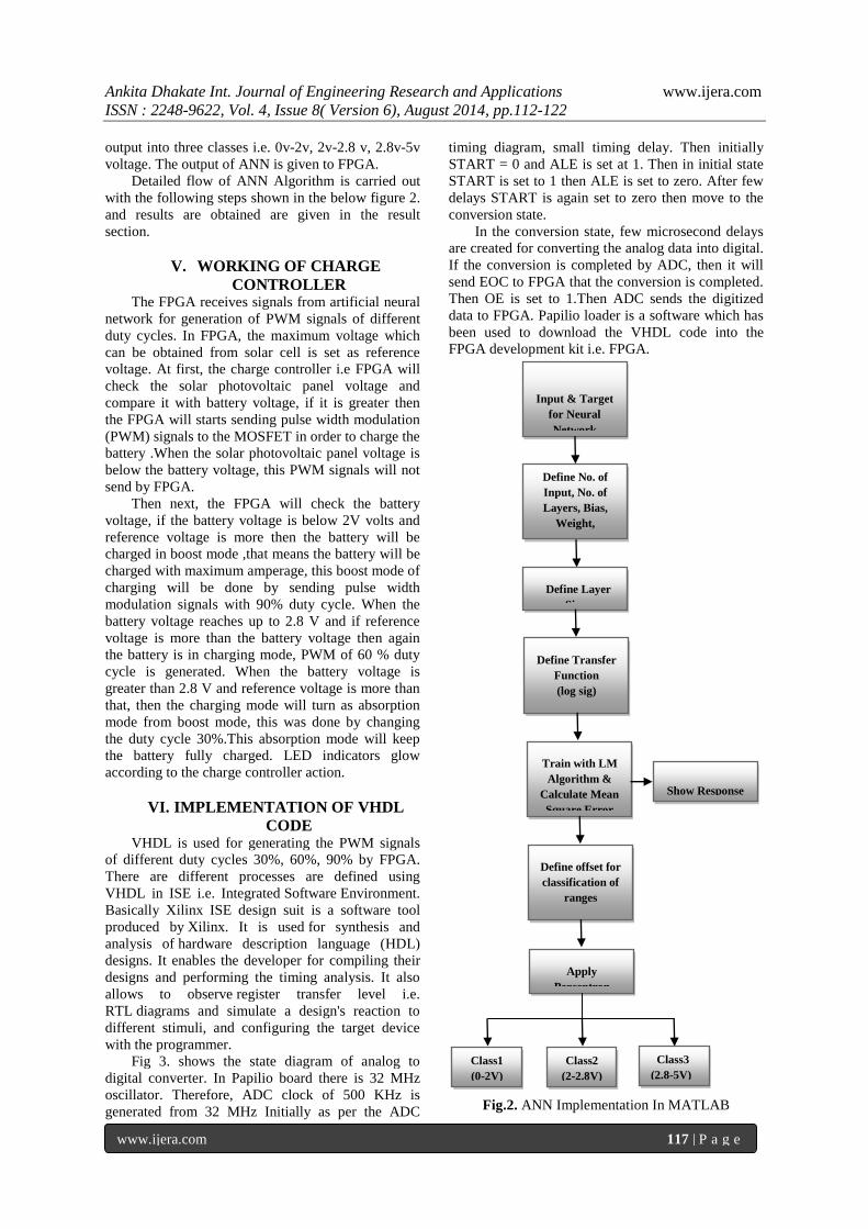
Detailed flow of ANN Algorithm is carried out
with the following steps shown in the below figure 2.
and results are obtained are given in the result
section.
V. WORKING OF CHARGE
CONTROLLER The FPGA receives signals from artificial neural
network for generation of PWM signals of different
duty cycles. In FPGA, the maximum voltage which
can be obtained from solar cell is set as reference
voltage. At first, the charge controller i.e FPGA will
check the solar photovoltaic panel voltage and
compare it with battery voltage, if it is greater then
the FPGA will starts sending pulse width modulation
(PWM) signals to the MOSFET in order to charge the
battery .When the solar photovoltaic panel voltage is
below the battery voltage, this PWM signals will not
send by FPGA.
Then next, the FPGA will check the battery
voltage, if the battery voltage is below 2V volts and
reference voltage is more then the battery will be
charged in boost mode ,that means the battery will be
charged with maximum amperage, this boost mode of
charging will be done by sending pulse width
modulation signals with 90% duty cycle. When the
battery voltage reaches up to 2.8 V and if reference
voltage is more than the battery voltage then again
the battery is in charging mode, PWM of 60 % duty
cycle is generated. When the battery voltage is
greater than 2.8 V and reference voltage is more than
that, then the charging mode will turn as absorption
mode from boost mode, this was done by changing
the duty cycle 30%.This absorption mode will keep
the battery fully charged. LED indicators glow
according to the charge controller action.
VI. IMPLEMENTATION OF VHDL
CODE VHDL is used for generating the PWM signals
of different duty cycles 30%, 60%, 90% by FPGA.
There are different processes are defined using
VHDL in ISE i.e. Integrated Software Environment.
Basically Xilinx ISE design suit is a software tool
produced by Xilinx. It is used for synthesis and
analysis of hardware description language (HDL)
designs. It enables the developer for compiling their
designs and performing the timing analysis. It also
allows to observe register transfer level i.e.
RTL diagrams and simulate a design's reaction to
different stimuli, and configuring the target device
with the programmer.
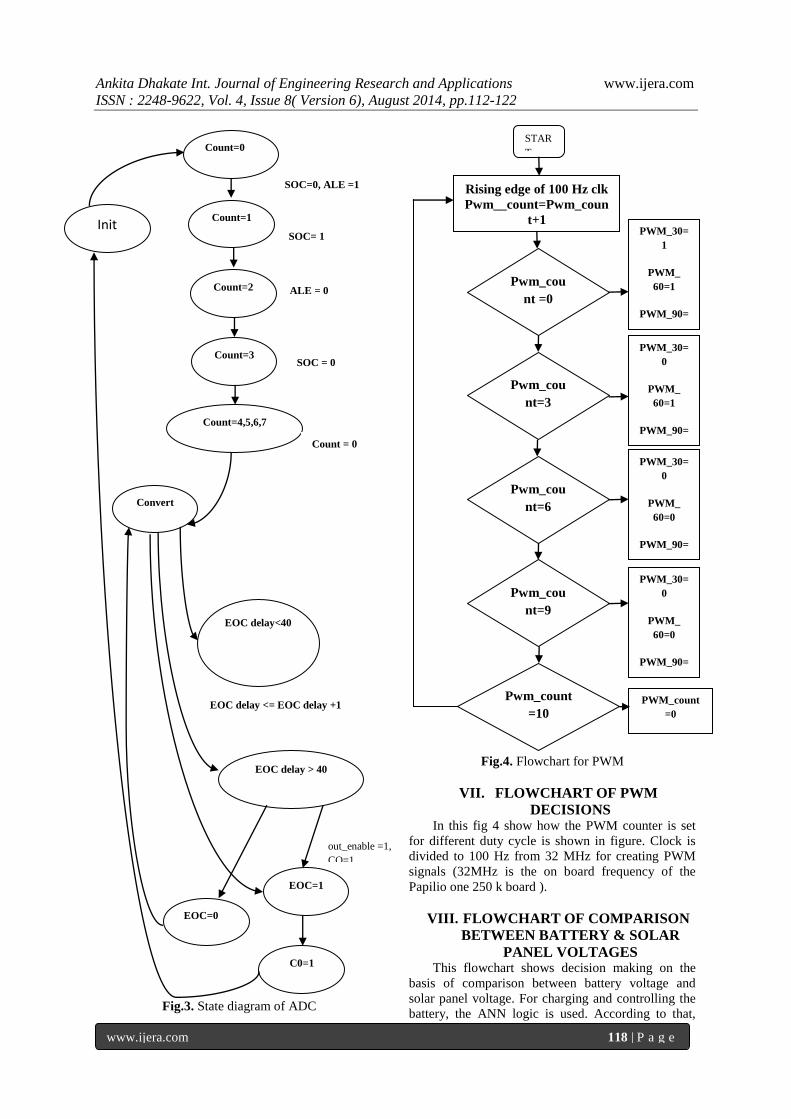
Fig 3. shows the state diagram of analog to
digital converter. In Papilio board there is 32 MHz
oscillator. Therefore, ADC clock of 500 KHz is
generated from 32 MHz Initially as per the ADC
timing diagram, small timing delay. Then initially
START = 0 and ALE is set at 1. Then in initial state
START is set to 1 then ALE is set to zero. After few
delays START is again set to zero then move to the
conversion state.
In the conversion state, few microsecond delays
are created for converting the analog data into digital.
If the conversion is completed by ADC, then it will
send EOC to FPGA that the conversion is completed.
Then OE is set to 1.Then ADC sends the digitized
data to FPGA. Papilio loader is a software which has
been used to download the VHDL code into the
FPGA development kit i.e. FPGA.
Fig.2. ANN Implementation In MATLAB
Apply
Perceptron
Define offset for
classification of
ranges
Show Response
Train with LM
Algorithm &
Calculate Mean
Square Error
Define Transfer
Function
(log sig)
Define Layer
Size
Define No. of
Input, No. of
Layers, Bias,
Weight,
Boolean Vector
Input & Target
for Neural
Network
Class2
(2-2.8V)
Class1
(0-2V)
Class3
(2.8-5V)
Ankita Dhakate Int. Journal of Engineering Research and Applications www.ijera.com
ISSN : 2248-9622, Vol. 4, Issue 8( Version 6), August 2014, pp.112-122
www.ijera.com 118 | P a g e
Fig.3. State diagram of ADC
Fig.4. Flowchart for PWM
VII. FLOWCHART OF PWM
DECISIONS In this fig 4 show how the PWM counter is set
for different duty cycle is shown in figure. Clock is
divided to 100 Hz from 32 MHz for creating PWM
signals (32MHz is the on board frequency of the
Papilio one 250 k board ).
VIII. FLOWCHART OF COMPARISON
BETWEEN BATTERY & SOLAR
PANEL VOLTAGES This flowchart shows decision making on the
basis of comparison between battery voltage and
solar panel voltage. For charging and controlling the
battery, the ANN logic is used. According to that,
Count=0
Count=1
Count=2
Count=3
Count=4,5,6,7
Convert
EOC delay<40
EOC delay > 40
EOC=1
EOC=0
C0=1
Init
SOC=0, ALE =1
SOC= 1
ALE = 0
SOC = 0
Count = 0
EOC delay <= EOC delay +1
out_enable =1,
CO=1
C0=1
Pwm_cou
nt =0
STAR
T
Rising edge of 100 Hz clk
Pwm__count=Pwm_coun
t+1
Pwm_cou
nt=3
Pwm_cou
nt=6
Pwm_cou
nt=9
Pwm_count
=10
PWM_30=
1
PWM_
60=1
PWM_90=
1
PWM_30=
0
PWM_
60=1
PWM_90=
1
PWM_30=
0
PWM_
60=0
PWM_90=
1
PWM_30=
0
PWM_
60=0
PWM_90=
0
PWM_count
=0

Ankita Dhakate Int. Journal of Engineering Research and Applications www.ijera.com
ISSN : 2248-9622, Vol. 4, Issue 8( Version 6), August 2014, pp.112-122
www.ijera.com 119 | P a g e
conditions will be applied for indication of the LEDs
and to switch on the load.
Fig.5. Comparison between Battery and solar panel
voltage
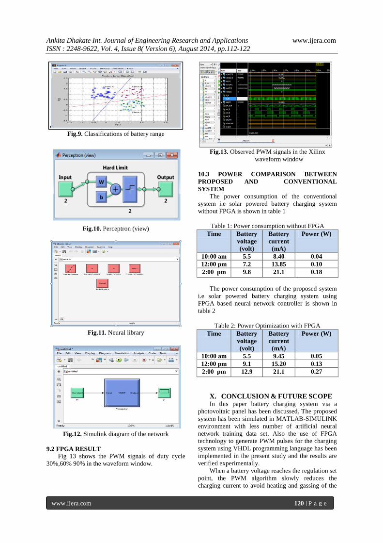
IX. RESULTS 9.1 RESULTS OF ANN
Fig 6 shows initial block diagram of the artificial
neural network having two hidden layers with zero
hidden neurons in MATLAB artificial neural network
toolbox.
Fig.6. Initial Block diagram of ANN
Fig 7 shows the custom neural network (view)
having two hidden layers and ten hidden neurons are
selected since it gives best performing network.
Fig.7. ANN block diagram with 10 hidden neurons
Fig 8 shows Neural network Training using
Levenberg Marquardt Algorithm.
Fig.8. Training of ANN
Fig 9 shows the classification of data (Battery
voltages). Class A is for battery low voltage range.
Class B is for battery medium voltage range. Class C
is for battery high voltage range.
Fig 10. shows the perceptron view of the network.
Fig 11. shows the neural library for creating the
SIMULINK diagram of the network.
Fig 12. shows the Simulink diagram of the network
which is used to generate VHD files from MATLAB
files.
Ankita Dhakate Int. Journal of Engineering Research and Applications www.ijera.com
ISSN : 2248-9622, Vol. 4, Issue 8( Version 6), August 2014, pp.112-122
www.ijera.com 120 | P a g e
Fig.9. Classifications of battery range
Fig.10. Perceptron (view)
Fig.11. Neural library
Fig.12. Simulink diagram of the network
9.2 FPGA RESULT
Fig 13 shows the PWM signals of duty cycle
30%,60% 90% in the waveform window.
Fig.13. Observed PWM signals in the Xilinx
waveform window
10.3 POWER COMPARISON BETWEEN
PROPOSED AND CONVENTIONAL
SYSTEM
The power consumption of the conventional
system i.e solar powered battery charging system
without FPGA is shown in table 1
Table 1: Power consumption without FPGA
Time Battery
voltage
(volt)
Battery
current
(mA)
Power (W)
10:00 am 5.5 8.40 0.04
12:00 pm 7.2 13.85 0.10
2:00 pm 9.8 21.1 0.18
The power consumption of the proposed system
i.e solar powered battery charging system using
FPGA based neural network controller is shown in
table 2
Table 2: Power Optimization with FPGA
Time Battery
voltage
(volt)
Battery
current
(mA)
Power (W)
10:00 am 5.5 9.45 0.05
12:00 pm 9.1 15.20 0.13
2:00 pm 12.9 21.1 0.27
X. CONCLUSION & FUTURE SCOPE In this paper battery charging system via a
photovoltaic panel has been discussed. The proposed
system has been simulated in MATLAB-SIMULINK
environment with less number of artificial neural
network training data set. Also the use of FPGA
technology to generate PWM pulses for the charging
system using VHDL programming language has been
implemented in the present study and the results are
verified experimentally.
When a battery voltage reaches the regulation set
point, the PWM algorithm slowly reduces the
charging current to avoid heating and gassing of the
Ankita Dhakate Int. Journal of Engineering Research and Applications www.ijera.com
ISSN : 2248-9622, Vol. 4, Issue 8( Version 6), August 2014, pp.112-122
www.ijera.com 121 | P a g e
battery. In addition, this method of solar battery
charging promises benefits from the PWM pulsing
such as: it reduces battery heating and automatically
adjusts battery aging and temperature effects in solar
systems.
In the present system, stationary solar panel is
used which gives less output and hence decrease the
efficiency. But by making use of solar tracker, we
can increase the efficiency of solar system. In this
proposed system fixed load is used but in the future
scope we can connect this system to variable loads
and verify the system results in terms of power
consumption and battery charge timing also we can
develop this prototype with large number of ANN
training data.
REFERENCES
Journal Papers [1] S. Harrington, J. Dunlop, Battery charge
controller characteristics in photovoltaic
systems, aerospace and Electronic Systems
Magazine, IEEE, Volume: 7, Issue: 8, p, 15
– 21, 1992.
[2] Z. Ullah, B. Burford, S. Rahman, Fast
Intelligent battery charging: neural-fuzzy
approach, WESCON/'95. Conference
record. 'Microelectronics Communications
Technology Producing Quality
Products Mobile and Portable
Power Emerging Technologies', 1995.
[3] H. Masheleni and X. F. Carelse,
Microcontroller-Based Charge Controller
for Stand-Alone Photovoltaic Systems,
Solar Energy, Vol. 61, No. 4, pp. 225–230,
1997.
[4] G. C. Hsieh L. R. Chen and K. S. Huang,
Fuzzy-Controlled Li–Ion Battery Charge
System with Active State-of-Charge
Controller, IEEE Transactions On
Industrial Electronics, Vol. 48, No. 3, 2001.
[5] Z. Yi, W. Xiaobo, Y. Xiaolang and H.
Shiming, A Novel Switch- Mode Charger
Controller IC for VRLA Batteries, The 33rd
Annual Conference of the IEEE Industrial
Electronics Society (IECON), Taipei,
Taiwan, 2007.
[6] S. J. Chiang, H.J. Shieh and M. C. Chen,
Modeling and Control of PV Charger
System with SEPIC Converter, IEEE
Transactions on Industrial Electronics, vol.
56, no.11, 2009.
[7] S. G. Tesfahunegn, P.J.S. Vie, O. Ulleberg
and T.M. Undeland, A simplified battery
charge controller for safety and increased
utilization in standalone PV applications,
International Conference on Clean Electrical
Power (ICCEP), 2011.
[8] C. Hua, J. Lin, C. Shen, Implementation of a
DSP-Controlled Photovoltaic System with
Peak Power Tracking, IEEE Transactions
On Industrial Electronics, V. 45, No. 1,
1998.
[9] C. R. Sullivan, M. J. Powers, A High-
Efficiency Maximum Power Point
Tracker for Photovoltaic Arrays in a Solar-
Powered Race Vehicle, Power Electronics
Specialists Conference, 1993.
[10] D. P. Hohm, M. E. Ropp, Comparative
Study of Maximum Power Point Tracking
Algorithms Using an Experimental,
Programmable, Maximum Power Point
Tracking Test Bed, Photovoltaic Specialists
Conference, 2000.
[11] M. Dakkaka and A. Hasana, “A charge
Controller Based on Microcontroller In
Stand-alone Photovoltaic Systems”, Energy
Procedia V. 19, pp. 87 – 90, 2012
[12] N. Karami, N. Moubayed and R. Outbib,
Analysis and implementation of an
adaptative PV based battery floating
charger, Solar Energy, (Accepted: 7 May
2012)
[13] Carlos Manuel Ferreira Santos, Optimized
Photovoltaic Solar Charger With Voltage
Maximum Power Point Tracking, PhD diss.,
Universidade Técnica de Lisboa, 2008.
[14] R. Ramaprabha, B.L. Mathur, Intelligent
Controller based Maximum Power Point
Tracking for Solar PV System, International
Journal of Computer Applications (0975 –
8887) Volume 12– No.10, January 2011
[15] Panom Petchjatuporn, Phaophak Sirisuk, A
Solar-powered Battery Charger with Neural
Network Maximum Power Point Tracking
Implemented on a Low-Cost PIC-
microcontroller, IEEE Power Electronics
and Drives Systems, 2005. Pp.507-510.
[16] Mohammed Shoaib1, V Nagaraj2, Novel
Battery Charging Control System for
Batteries Using On/Off and PWM
Controllers for Stand Alone Power Systems,
IOSR Journal of Electrical and Electronics
Engineering (IOSR-JEEE) e-ISSN: 2278-
1676,p-ISSN: 2320-3331, Volume 6, Issue 3
(May. - Jun. 2013), PP 44-52
[17] Jaw-Kuen Shiau, Member, Design of a Solar
Power Management System for an
Experimental UAV, IEEE der-ming ma pin-
ying yang geng-feng wang jhij hua gong
Tamkang University,
[18] Çınar, S. M., & Akarslan, E. (2012), Design
of an Intelligent Battery Charge Controller
for PV Panels, Journal of Engineering
Science and Technology Review, 5(4), 30-
34.
Ankita Dhakate Int. Journal of Engineering Research and Applications www.ijera.com
ISSN : 2248-9622, Vol. 4, Issue 8( Version 6), August 2014, pp.112-122
www.ijera.com 122 | P a g e
[19] Shiau, J. K., & Ma, C. W. (2013), Li-ion
battery charging with a buck-boost power
converter for a solar powered battery
management system. Energies, 6(3), 1669-
1699
[20] Raju, P., & Vijayan, S. Artificial
Intelligence based Battery Power
Management for Solar PV And Wind Hybrid
Power System.
[21] Lee, J. H., H. S. Bae, and Bo-Hyung Cho.,
Resistive control for a photovoltaic battery
charging system using a
microcontroller, Industrial Electronics,
IEEE Transactions on 55.7 (2008): 2767-
2775.
Books: [22] Samir Palnitkar, “Verilog HDL A Guide to
Digital Design and Synthesis Second
Edition” Pearson Publication India, IEEE
1364-2001 Compliant.
[23] Muhammad H. Rashid, “Power Electronics
Circuits Devices And Applications Third
Edition” Pearson Publication India.