Potential of Rapid Tooling in Rapid Heat Cycle Molding - MDPI
39
Citation: Huzaim, N.H.M.; Rahim, S.Z.A.; Musa, L.; Abdellah, A.E.-h.; Abdullah, M.M.A.B.; Rennie, A.; Rahman, R.; Garus, S.; Bloch, K.; Sandu, A.V.; et al. Potential of Rapid Tooling in Rapid Heat Cycle Molding: A Review. Materials 2022, 15, 3725. https://doi.org/10.3390/ma15103725 Academic Editor: Nicolas Sbirrazzuoli Received: 9 April 2022 Accepted: 12 May 2022 Published: 23 May 2022 Publisher’s Note: MDPI stays neutral with regard to jurisdictional claims in published maps and institutional affil- iations. Copyright: © 2022 by the authors. Licensee MDPI, Basel, Switzerland. This article is an open access article distributed under the terms and conditions of the Creative Commons Attribution (CC BY) license (https:// creativecommons.org/licenses/by/ 4.0/). materials Article Potential of Rapid Tooling in Rapid Heat Cycle Molding: A Review Nurul Hidayah Mohamad Huzaim 1 , Shayfull Zamree Abd Rahim 1,2, *, Luqman Musa 2,3 , Abdellah El-hadj Abdellah 4 , Mohd Mustafa Al Bakri Abdullah 2,3 , Allan Rennie 5 , Rozyanti Rahman 2,3 , Sebastian Garus 6 , Katarzyna Bloch 7 , Andrei Victor Sandu 8,9 , Petrica Vizureanu 8,10, * and Marcin Nabialek 7 1 Faculty of Mechanical Engineering and Technology, Universiti Malaysia Perlis, Arau 02600, Malaysia; [email protected] 2 Center of Excellence Geopolymer and Green Technology (CEGeoGTech), Universiti Malaysia Perlis, Kangar 01000, Malaysia; [email protected] (L.M.); [email protected] (M.M.A.B.A.); [email protected] (R.R.) 3 Faculty of Chemical Engineering and Technology, Universiti Malaysia Perlis, Kangar 01000, Malaysia 4 Laboratory of Mechanics, Physics and Mathematical Modelling (LMP2M), University of Medea, Medea 26000, Algeria; [email protected] 5 Lancaster Product Development Unit, Engineering Department, Lancaster University, Lancaster LA1 4YW, UK; [email protected] 6 Faculty of Mechanical Engineering and Computer Science, Cz ˛ estochowa Univerity of Technology, 42-201 Cz˛ estochowa, Poland; [email protected] 7 Department of Physics, Cz ˛ estochowa University of Technology, 42-201 Cz˛ estochowa, Poland; [email protected] (K.B.); [email protected] (M.N.) 8 Faculty of Materials Science and Engineering, Gheorghe Asachi Technical University of Iasi, 41 D. Mangeron Street, 700050 Iasi, Romania; [email protected] 9 Romanian Inventors Forum, Str. Sf. P. Movila 3, 700089 Iasi, Romania 10 Technical Sciences Academy of Romania, Dacia Blvd 26, 030167 Bucharest, Romania * Correspondence: [email protected] (S.Z.A.R.); [email protected] (P.V.) Abstract: Rapid tooling (RT) and additive manufacturing (AM) are currently being used in several parts of industry, particularly in the development of new products. The demand for timely deliveries of low-cost products in a variety of geometrical patterns is continuing to increase year by year. Increased demand for low-cost materials and tooling, including RT, is driving the demand for plastic and rubber products, along with engineering and product manufacturers. The development of AM and RT technologies has led to significant improvements in the technologies, especially in testing performance for newly developed products prior to the fabrication of hard tooling and low-volume production. On the other hand, the rapid heating cycle molding (RHCM) injection method can be implemented to overcome product surface defects generated by conventional injection molding (CIM), since the surface gloss of the parts is significantly improved, and surface marks such as flow marks and weld marks are eliminated. The most important RHCM technique is rapid heating and cooling of the cavity surface, which somewhat improves part quality while also maximizing production efficiencies. RT is not just about making molds quickly; it also improves molding productivity. Therefore, as RT can also be used to produce products with low-volume production, there is a good potential to explore RHCM in RT. This paper reviews the implementation of RHCM in the molding industry, which has been well established and undergone improvement on the basis of different heating technologies. Lastly, this review also introduces future research opportunities regarding the potential of RT in the RHCM technique. Keywords: rapid tooling; rapid heat cycle molding; additive manufacturing; injection molding process 1. Introduction Time to market is a critical aspect of product development strategies [1–3]. In general, speed is balanced with other factors such as functionality, innovation, or quality [4,5]. Materials 2022, 15, 3725. https://doi.org/10.3390/ma15103725 https://www.mdpi.com/journal/materials
-
Upload
khangminh22 -
Category
Documents
-
view
4 -
download
0
Transcript of Potential of Rapid Tooling in Rapid Heat Cycle Molding - MDPI

Citation: Huzaim, N.H.M.; Rahim,
S.Z.A.; Musa, L.; Abdellah, A.E.-h.;
Abdullah, M.M.A.B.; Rennie, A.;
Rahman, R.; Garus, S.; Błoch, K.;
Sandu, A.V.; et al. Potential of Rapid
Tooling in Rapid Heat Cycle Molding:
A Review. Materials 2022, 15, 3725.
https://doi.org/10.3390/ma15103725
Academic Editor: Nicolas Sbirrazzuoli
Received: 9 April 2022
Accepted: 12 May 2022
Published: 23 May 2022
Publisher’s Note: MDPI stays neutral
with regard to jurisdictional claims in
published maps and institutional affil-
iations.
Copyright: © 2022 by the authors.
Licensee MDPI, Basel, Switzerland.
This article is an open access article
distributed under the terms and
conditions of the Creative Commons
Attribution (CC BY) license (https://
creativecommons.org/licenses/by/
4.0/).
materials
Article
Potential of Rapid Tooling in Rapid Heat Cycle Molding:A ReviewNurul Hidayah Mohamad Huzaim 1, Shayfull Zamree Abd Rahim 1,2,*, Luqman Musa 2,3,Abdellah El-hadj Abdellah 4 , Mohd Mustafa Al Bakri Abdullah 2,3, Allan Rennie 5, Rozyanti Rahman 2,3 ,Sebastian Garus 6 , Katarzyna Błoch 7 , Andrei Victor Sandu 8,9 , Petrica Vizureanu 8,10,*and Marcin Nabiałek 7
1 Faculty of Mechanical Engineering and Technology, Universiti Malaysia Perlis, Arau 02600, Malaysia;[email protected]
2 Center of Excellence Geopolymer and Green Technology (CEGeoGTech), Universiti Malaysia Perlis,Kangar 01000, Malaysia; [email protected] (L.M.); [email protected] (M.M.A.B.A.);[email protected] (R.R.)
3 Faculty of Chemical Engineering and Technology, Universiti Malaysia Perlis, Kangar 01000, Malaysia4 Laboratory of Mechanics, Physics and Mathematical Modelling (LMP2M), University of Medea,
Medea 26000, Algeria; [email protected] Lancaster Product Development Unit, Engineering Department, Lancaster University,
Lancaster LA1 4YW, UK; [email protected] Faculty of Mechanical Engineering and Computer Science, Czestochowa Univerity of Technology,
42-201 Czestochowa, Poland; [email protected] Department of Physics, Czestochowa University of Technology, 42-201 Czestochowa, Poland;
[email protected] (K.B.); [email protected] (M.N.)8 Faculty of Materials Science and Engineering, Gheorghe Asachi Technical University of Iasi,
41 D. Mangeron Street, 700050 Iasi, Romania; [email protected] Romanian Inventors Forum, Str. Sf. P. Movila 3, 700089 Iasi, Romania10 Technical Sciences Academy of Romania, Dacia Blvd 26, 030167 Bucharest, Romania* Correspondence: [email protected] (S.Z.A.R.); [email protected] (P.V.)
Abstract: Rapid tooling (RT) and additive manufacturing (AM) are currently being used in severalparts of industry, particularly in the development of new products. The demand for timely deliveriesof low-cost products in a variety of geometrical patterns is continuing to increase year by year.Increased demand for low-cost materials and tooling, including RT, is driving the demand for plasticand rubber products, along with engineering and product manufacturers. The development of AMand RT technologies has led to significant improvements in the technologies, especially in testingperformance for newly developed products prior to the fabrication of hard tooling and low-volumeproduction. On the other hand, the rapid heating cycle molding (RHCM) injection method can beimplemented to overcome product surface defects generated by conventional injection molding (CIM),since the surface gloss of the parts is significantly improved, and surface marks such as flow marksand weld marks are eliminated. The most important RHCM technique is rapid heating and coolingof the cavity surface, which somewhat improves part quality while also maximizing productionefficiencies. RT is not just about making molds quickly; it also improves molding productivity.Therefore, as RT can also be used to produce products with low-volume production, there is a goodpotential to explore RHCM in RT. This paper reviews the implementation of RHCM in the moldingindustry, which has been well established and undergone improvement on the basis of differentheating technologies. Lastly, this review also introduces future research opportunities regarding thepotential of RT in the RHCM technique.
Keywords: rapid tooling; rapid heat cycle molding; additive manufacturing; injection molding process
1. Introduction
Time to market is a critical aspect of product development strategies [1–3]. In general,speed is balanced with other factors such as functionality, innovation, or quality [4,5].
Materials 2022, 15, 3725. https://doi.org/10.3390/ma15103725 https://www.mdpi.com/journal/materials

Materials 2022, 15, 3725 2 of 39
Today, with the emergence of various new technologies, global competition in productdevelopment is developing rapidly. In addition, various industries are constantly in searchfor the newest competitive technologies in order to meet rising demand, reduce costs, and beable to produce products in small batches, while ensuring high quality and the capability toreach sustainable development goals [6–8]. The rapid growth of RT technology in today’sglobal market requires rapid product development to replace conventional methods inorder to improve manufacturing processes, particularly for tooling fabrication [7–9]. RToffers a faster manufacturing speed that reduces cost and saves project time, which iscritical for successfully completing testing and moving into full production, as illustratedin Figure 1 [10].
Materials 2022, 15, x FOR PEER REVIEW 2 of 40
1. Introduction Time to market is a critical aspect of product development strategies [1–3]. In gen-
eral, speed is balanced with other factors such as functionality, innovation, or quality [4,5]. Today, with the emergence of various new technologies, global competition in product development is developing rapidly. In addition, various industries are con-stantly in search for the newest competitive technologies in order to meet rising de-mand, reduce costs, and be able to produce products in small batches, while ensuring high quality and the capability to reach sustainable development goals [6–8]. The rapid growth of RT technology in today’s global market requires rapid product development to replace conventional methods in order to improve manufacturing processes, partic-ularly for tooling fabrication [7–9]. RT offers a faster manufacturing speed that reduces cost and saves project time, which is critical for successfully completing testing and moving into full production, as illustrated in Figure 1 [10].
Figure 1. Summary of RT integration in manufacturing.
Regardless of the size of the industry, there will be times when immediate tooling is required to address certain issues. Moreover, an intermediate tooling system is re-quired while producing a small quantity of functional prototypes to test the perfor-mance of the product designed. Such a small volume of product is generally used as a market sample, evaluation requirement, and production process design [11,12]. Alt-hough 3D printing technologies are available to produce the prototype, the properties of the parts produced are far from the properties of the parts produced using actual manufacturing processes for mass production. Therefore, RT is definitely required in order to evaluate the actual performance of the product designed, especially related to the material properties.
For any scientific research, functional tools or prototypes need to be launched prior to mass production. These are not launched in a mass volume for the consumers but in a small amount for the researchers [11,13]. RT is extremely beneficial for this situation, as it allows the launching of the products in a short time. Furthermore, since the manufac-turing cost is low, users can get the products at a low price compared to the prices of those mass-produced using production tooling. This is why several new start-up or even big companies prefer using this tool to expand their revenue and achieve a competitive edge over fellow companies in the market.
Normally, mold-making or prototyping industries use mild steel or aluminum as material for the mold inserts in RT [14–16]. However, the use of these types of materials requires the same machining processes used to manufacture the production tooling such as computer numerical control (CNC), electrical discharge machining (EDM), and wire EDM machining, which are costly and time-consuming [6,17]. Recently, additive manufacturing (AM) was used to fabricate mold inserts for RT [9,18–21]. Typically, RT
Figure 1. Summary of RT integration in manufacturing.
Regardless of the size of the industry, there will be times when immediate tooling isrequired to address certain issues. Moreover, an intermediate tooling system is requiredwhile producing a small quantity of functional prototypes to test the performance of theproduct designed. Such a small volume of product is generally used as a market sample,evaluation requirement, and production process design [11,12]. Although 3D printingtechnologies are available to produce the prototype, the properties of the parts producedare far from the properties of the parts produced using actual manufacturing processesfor mass production. Therefore, RT is definitely required in order to evaluate the actualperformance of the product designed, especially related to the material properties.
For any scientific research, functional tools or prototypes need to be launched priorto mass production. These are not launched in a mass volume for the consumers but in asmall amount for the researchers [11,13]. RT is extremely beneficial for this situation, as itallows the launching of the products in a short time. Furthermore, since the manufacturingcost is low, users can get the products at a low price compared to the prices of thosemass-produced using production tooling. This is why several new start-up or even bigcompanies prefer using this tool to expand their revenue and achieve a competitive edgeover fellow companies in the market.
Normally, mold-making or prototyping industries use mild steel or aluminum asmaterial for the mold inserts in RT [14–16]. However, the use of these types of materialsrequires the same machining processes used to manufacture the production tooling such ascomputer numerical control (CNC), electrical discharge machining (EDM), and wire EDMmachining, which are costly and time-consuming [6,17]. Recently, additive manufacturing(AM) was used to fabricate mold inserts for RT [9,18–21]. Typically, RT uses a modelor prototype fabricated by AM technology as a pattern to form mold inserts, or moldinserts are directly manufactured through the AM method for a minimum number ofprototypes [8,22]. In industry, there are variety of RT technologies available, such as thecombined process of RT and AM to lessen the time for making the RT.
According to Huang et al. [23], RT differs from conventional tooling because the timerequired to manufacture tools is much quicker and it can be categorized as indirect or direct

Materials 2022, 15, 3725 3 of 39
processes. Direct tooling techniques use AM processes to directly manufacture mold insertswithout the need for a master pattern in the process [6,24–26]. The processes involvedin direct tooling are selective laser sintering (SLS), direct metal laser sintering (DMLS),fused deposition modeling (FDM), stereolithography (SLA), jetted photopolymer (PolyJet),and 3D printing (3D-P) [6,8,27,28]. On the other hand, indirect processes use AM partsas the master pattern to make a mold for castings or plastic molding processes. Theseprocesses include cast metal tooling, silicone molding, spray metal tooling, and 3D KelTooltooling [6,8,9,18,29].
Generally, mold inserts for RT produced using AM technologies such as SLS, FDM,SLA, PolyJet, and 3D-P exhibit low thermal and mechanical properties; therefore, they areprone to failure throughout the molding process [30–32]. On the other hand, the DMLSprocess is not suitable for a simple plastic part design as it is time-consuming compared tomachining processes. Moreover, for complex parts, DMLS has a few limitations for certainfeature designs. In addition, past research on RT mold inserts discovered that the stressimplemented in the mold inserts throughout the injection molding cycle has a significantimpact on mold life [6,17,33–35].
On the other hand, a new technology called rapid heat cycle molding (RHCM) hasbeen proven to eliminate weld line and molding defects in CIM, as well as the high glossysurface, by heating the core and/or cavity insert beyond the glass transition temperatureof the plastic resin [36–38]. Thus, by raising the mold temperature to the glass transitiontemperature, weld lines can be considerably eliminated [36,39–42].
Table 1 shows various types of RCHM technologies investigated by researchers toimprove weld line strength, tensile strength, and surface quality using various types ofRHCM technology such as electromagnetic induction heating, induction heating, hot oil,a combination of hot oil and induction heating, steam heating (vapor chamber), and electricheating in hard/production tooling.
Table 1. RCHM Technologies.
No. RHCM Technology Researchers
1 Electromagnetic induction heating Chen et al., 2006 [39]
2 Induction heatingHuang and Tai, 2009 [43];Huang et al., 2010 [44];Nian et al., 2014 [45]
3 Hot oil Huang and Tai, 2009 [43]
4 Combination of hot oil and induction heating Huang and Tai, 2009 [43]
5 Steam heating (vapor chamber) Tsai, 2011 [46];Wang, 2014 [47]
6 Electric heatingLi, 2016 [48];Xie, 2017 [49];Liu, 2020 [50]
Tosello et al. [51] investigated the impact of injection molding parameters on weld lineformation and strength reduction. According to the studies, the most important factor toreduce weld lines is increasing the mold temperature. Wang et al. [52] analyzed the heattransfer during heating and cooling phases of RHCM process. The results of productionshowed that the RHCM process completely eliminates the weld lines on the surface of theparts, and the surface gloss of the parts is also greatly improved. The influence of the RHCMprocess on part surface quality has been studied [40,42,50,53,54]. The results showed thatthe high cavity surface temperature near to the polymer’s glass transition temperature canassist in reducing surface roughness, significantly enhancing surface gloss, and eliminatingthe weld line. Studies have shown that, by using the RHCM process to eliminate weld lines,the surface roughness of molded parts can be significantly reduced. As a result, processessuch as spraying and coating can be eliminated, reducing energy, material, and production

Materials 2022, 15, 3725 4 of 39
costs while also protecting the environment [55–58]. Thus, it is being considered as apossible manufacturing technology in the plastic injection molding industry.
Therefore, this paper intends to provide a brief review on the role of RT technology inmanufacturing methods of tooling toward its potential in the RHCM technique. The reviewof the literature included previous studies that were conducted on the application of RHCMin the injection molding process, which has been well established and continues to improveon the basis of different heating technologies. In addition, most of the studies provedthat RT can be used to produce low-volume products. However, despite the potentialadvantages of RT in industry, there is a lack of studies and verification of the weld line andsurface quality of plastic molded parts. Furthermore, the potential of RHCM in RT has notbeen explored, despite the use of RT in CIM having been investigated and research havingbeen published. RT, on the other hand, is a great choice for low-volume production.
2. Injection Molding Process
The injection molding process is divided into several levels, i.e., operating cycles, in-cluding plasticization, filling, packing, and cooling [59–62]. The cooling stage is designatedas the most significant of all stages due to its critical factors in developing productivity andmolding quality, especially for complex molded parts [63–65]. Otherwise, defects such assink marks, shrinkages, residual stresses, and warpage can occur if not addressed [66–70].
Initially, the plastic pellets are heated by screw shearing and a feed pipe before beingplasticized to melt. The melt is then injected into the runner system to fill the mold cavities.After the cooling process, the molded part is ejected from the mold [38,71,72]. The quality offinal molded parts is uncontrollable because it is influenced by many factors in the injectionmolding process. Some important factors which may have an impact on the finishing arethe process parameters, mold design, and properties of plastic materials [52,73,74]. One ofthe factors that determines the quality of injection molded parts is the weld line [50,75,76].The weld line refers to the process in which the liquid material is divided into two ormore flows in the cavity during the injection process and merged together after a period oftime [51,77–79].
There are five main phases in the injection molding process which are melting, filling,packing, cooling, and demolding [80–82]. It is desirable to keep the filling and packingphases at a high temperature to promote polymer melt flow and enhance reproducibilityof the molded product [80,83,84]. A lower mold temperature is preferred during thesubsequent cooling phase to allow for rapid cooling of the polymer melt, which occupiesthe majority of the molding cycle time [47,80,85,86]. As a result, to improve part qualityand reduce molding cycle time, a dynamic mold temperature control system for rapidheating and cooling of the mold is required [80,83,87]. As shown in Figure 2, after the gateis solidified, the mold is cooled down rapidly by water to solidify and demold the polymerpart [88]. However, in the CIM, the mold temperature control technique uses a concurrentcooling method, where a constant-temperature coolant circulates in a cooling channel tocool the mold and polymer melt [80,89,90]. Even though RHCM gives a longer cycle time,it improves the strength, eliminates the weld line, and improves the surface quality (highglossy surface) [38,91,92].

Materials 2022, 15, 3725 5 of 39Materials 2022, 15, x FOR PEER REVIEW 5 of 40
Figure 2. The cycle in the RHCM process [88].
3. Rapid Tooling Today, with different kinds of new technologies, global product development
competition is becoming increasingly fierce. In addition, industries are constantly on the lookout for the latest technology that can compete to meet future demands, reduce costs, and produce small batches of high-quality products while also being able to meet sustainability goals [93]. In today’s market globalization, rapid tooling (RT) technolo-gies have been steadily evolving with the demand for rapid product development in order to substitute conventional methods for better manufacturing processes, particu-larly for tool manufacturing [8,94,95].
RT is the AM technology that refers to the manufacturing methods of tooling [94,96,97]. RT utilizes the AM model as a pattern to construct a mold, or the mold for a small volume of prototypes is made directly from the AM process [8,27,98–100]. There are a variety of RT technologies accessible in the industry, such as the combination process of RT and AM, to lessen the time for making tools. Chua et al. [98] investigated several of RT and AM technologies using direct processes for tool production. Never-theless, the majority of RT technologies implement indirect processes and models or master patterns produced by the AM process. According to Pouzada [101], there is an outline for the industry to take into consideration when choosing alternative produc-tion methods including RT, which includes a shorter delivery time, higher quality, shorter product development phase, and adaptation to global technology. This is a markedly new technique that has the potential to have a dramatic impact on the engi-neering practice, particularly during the product development stage, mostly in the cast-ing and plastic molding industries [95,102]. As supported by Boparai et al. [27] and Mendible et al. [6], RT is also among the rapid prototyping (RP) variants, which have been proven to be cost-effective and time-efficient for the development of RT.
According to Pontes et al. [103], RT differs from conventional tooling in that it takes much less time to fabricate tooling and can be classified into indirect or direct processes. Direct tooling techniques use AM processes to directly manufacture the molds without requiring a master pattern. The processes involved in direct tooling are SLS, DMLS, FDM, SLA, PolyJet, and 3D-P [8,96]. On the other hand, indirect processes utilize AM as master patterns to make a mold for castings. These processes include metal casting, resin casting, silicone rubber molding, and 3D KelTool process [6,97,100]. Jurkovic et al. [104] introduced the emergence of products and the evolution phase of RT technology that began in the early 1990s. Product design takes a long time. The
Figure 2. The cycle in the RHCM process [88].
3. Rapid Tooling
Today, with different kinds of new technologies, global product development competi-tion is becoming increasingly fierce. In addition, industries are constantly on the lookout forthe latest technology that can compete to meet future demands, reduce costs, and producesmall batches of high-quality products while also being able to meet sustainability goals [93].In today’s market globalization, rapid tooling (RT) technologies have been steadily evolv-ing with the demand for rapid product development in order to substitute conventionalmethods for better manufacturing processes, particularly for tool manufacturing [8,94,95].
RT is the AM technology that refers to the manufacturing methods of tooling [94,96,97].RT utilizes the AM model as a pattern to construct a mold, or the mold for a small volumeof prototypes is made directly from the AM process [8,27,98–100]. There are a variety ofRT technologies accessible in the industry, such as the combination process of RT and AM,to lessen the time for making tools. Chua et al. [98] investigated several of RT and AMtechnologies using direct processes for tool production. Nevertheless, the majority of RTtechnologies implement indirect processes and models or master patterns produced by theAM process. According to Pouzada [101], there is an outline for the industry to take intoconsideration when choosing alternative production methods including RT, which includesa shorter delivery time, higher quality, shorter product development phase, and adaptationto global technology. This is a markedly new technique that has the potential to have adramatic impact on the engineering practice, particularly during the product developmentstage, mostly in the casting and plastic molding industries [95,102]. As supported byBoparai et al. [27] and Mendible et al. [6], RT is also among the rapid prototyping (RP)variants, which have been proven to be cost-effective and time-efficient for the developmentof RT.
According to Pontes et al. [103], RT differs from conventional tooling in that it takesmuch less time to fabricate tooling and can be classified into indirect or direct processes.Direct tooling techniques use AM processes to directly manufacture the molds withoutrequiring a master pattern. The processes involved in direct tooling are SLS, DMLS,FDM, SLA, PolyJet, and 3D-P [8,96]. On the other hand, indirect processes utilize AM asmaster patterns to make a mold for castings. These processes include metal casting, resincasting, silicone rubber molding, and 3D KelTool process [6,97,100]. Jurkovic et al. [104]introduced the emergence of products and the evolution phase of RT technology thatbegan in the early 1990s. Product design takes a long time. The standards start from theconstruction of the workshop, involving applications of computer-aided construction andgeometric models, the rapid development of computer-oriented products (modeling and

Materials 2022, 15, 3725 6 of 39
simulation) and virtual product development, rapid prototyping, rapid tooling, and theproduct development digitization process.
As the quantity of RT technologies with numerous techniques has increased, there hasbeen a trend to categorize them, as can be seen in Figure 3. Indirect tools, direct tools, andcasting patterns can be distributed into the implemented groups [98]. After all, the divisionof these groups may change depending on AM’s capability to speed up the productionprocess. Some of the processes have been simplified with new technical capabilities, fromindirect tooling to direct tooling, such as the use of mold inserts in an epoxy mold systemrather than a conventional process [8]. In order to produce a good plastic injection mold,the selection of the material in mold making should be highly considered and understood.
Materials 2022, 15, x FOR PEER REVIEW 6 of 40
standards start from the construction of the workshop, involving applications of com-puter-aided construction and geometric models, the rapid development of computer-oriented products (modeling and simulation) and virtual product development, rapid prototyping, rapid tooling, and the product development digitization process.
As the quantity of RT technologies with numerous techniques has increased, there has been a trend to categorize them, as can be seen in Figure 3. Indirect tools, direct tools, and casting patterns can be distributed into the implemented groups [98]. After all, the division of these groups may change depending on AM’s capability to speed up the production process. Some of the processes have been simplified with new technical capabilities, from indirect tooling to direct tooling, such as the use of mold inserts in an epoxy mold system rather than a conventional process [8]. In order to produce a good plastic injection mold, the selection of the material in mold making should be highly considered and understood.
Figure 3. Classification of RT.
4. Materials for Injection Mold Several criteria need to be considered when selecting materials for the injection
mold, including cycle time, production volume, cost, maintenance, materials to be molded, part requirements, manufacturability, and life cycle costs [69,105,106]. Hard-ness, capability to achieve the requisite surface finish, corrosion resistance, wear re-sistance, thermal stability, and thermal conductivity are all important properties of a material to consider when designing an injection mold [69,107].
Metals are the most frequently used material in the industry due to high machin-ability, great variety of composition and properties, heat treatment possibility, and high thermal conductivity [69]. Steel and aluminum are often used, contingent on the pro-ject’s requirements [69]. To ensure chemical resistance, strength, and hardness, steels are often made of chromium and nickel alloys, which make it a more cost-effective op-tion [69]. On the other hand, aluminum alloy is a better thermal conductor than steel, reducing cycle time by up to 30% [69,107]. However, aluminum alloy molds only last
Figure 3. Classification of RT.
4. Materials for Injection Mold
Several criteria need to be considered when selecting materials for the injection mold,including cycle time, production volume, cost, maintenance, materials to be molded, partrequirements, manufacturability, and life cycle costs [69,105,106]. Hardness, capability toachieve the requisite surface finish, corrosion resistance, wear resistance, thermal stability,and thermal conductivity are all important properties of a material to consider whendesigning an injection mold [69,107].
Metals are the most frequently used material in the industry due to high machinability,great variety of composition and properties, heat treatment possibility, and high thermalconductivity [69]. Steel and aluminum are often used, contingent on the project’s require-ments [69]. To ensure chemical resistance, strength, and hardness, steels are often made ofchromium and nickel alloys, which make it a more cost-effective option [69]. On the otherhand, aluminum alloy is a better thermal conductor than steel, reducing cycle time by upto 30% [69,107]. However, aluminum alloy molds only last around 2000 cycles, whereassteel molds last at least 50,000 cycles, making them sturdier than aluminum molds [69,107].
The mechanical properties of mold products do not change proportionally to the ther-mal conductivities or temperature of the mold material. The thermal conductivities of moldmaterials differ significantly, but changes in the mechanical properties of injected productsfrom mold materials are barely noticeable. Steel mold material had four times the thermal

Materials 2022, 15, 3725 7 of 39
conductivity of aluminum mold material in one study. When molding materials withdifferent thermal conductivities were used, mechanical properties varied by 10–20% [108].
Usually, the mold is produced by a CNC machine with subtractive manufacturing.Harder materials including steel alloys necessitate specialized tools and further millingwork, increasing the cost of the injection mold, as well as the cost of plastic parts to beproduced [69].
4.1. Mold Base Material
A standard mold base is made up of four parts: the mold plate, the guide pin bushing,the return pin, and the screw. The mold plate is classified into two types according toits application: main plates (A plate and B plate) and structural plates (top clampingplate, bottom clamping plate, support plate, ejector plate, space block and runner stripperplate, etc.). Mold bases are made up of the A plate, B plate, and various structural platesassembled in a specific order [109].
The most common steel types used as mold base material are pre-hardened mold andholder steel, through hardening mold steel, and corrosion-resistant mold steel [110–112].The pre-hardened mold and holder steels are mainly utilized for large molds, molds that donot require high wear resistance, extrusion dies, and high-strength holder plates [110–112].These steels are usually supplied in a hardened and tempered state in the 270–400 HB rangeand do not require heat treatment [111]. Pre-hardened mold steel is usually utilized forlarge molds and medium production-run molds [111].
On the other hand, through hardened steels are mainly utilized for: long-term produc-tion, as well as specific molding materials with resistance to abrasion, high closing pressureor injection pressure, and suitability for high-pressure processes such as compression mold-ing [111]. This type of steel is supplied in a soft annealed state. It normally undergoesrough machining, stress relieving, semifinished machining, hardening and tempering tothe requisite hardness, finishing/grinding, and polishing or photoetching [111].
The choice of mold material may have an impact on the mold’s performance [111].Different people define performance differently in terms of mold life, plastic part quality,and productivity. Wear, surface defects, deformation, and corrosion wear may occur asa result of reinforced plastic or long service life, and surface defects may occur due topolishing or EDM defects in the mold manufacturing process [111], while a plastic part’squality is determined by its function, as well as its appearance. For highly polished molds,the choice of steel is significant. Steel should be clean and extremely low in impurities [111].Due to the uneven temperature of the mold, tolerance may occur, which of course largelydepends on the size and position of the cooling channel, as well as the mold materialchosen. Mold materials with high thermal conductivity, such as aluminums or copperalloys, can be used in some cases. Sometimes, it is even possible to achieve productivityby selecting mold materials. The most obvious situation is to choose a material with highthermal conductivity [111].
The mold material requirements depend on the number of injections, the plasticmaterial used, the mold size, and the desired surface finish; many different materialscan be used. The following basic mold material properties must be considered: strengthand hardness, toughness, wear resistance, cleanliness, corrosion resistance, and thermalconductivity [111].
A summary of the material properties commonly used as mold base materials is listedin Table 2. It can be seen that steel and aluminum are frequently used as mold base materialsas they have high thermal conductivity and hardness, meeting the requirements of moldbase materials in most studies [108,113,114].

Materials 2022, 15, 3725 8 of 39
Table 2. Physical and mechanical properties of mold base materials.
Type of Material Density(g/cm3)
Specific Heat(J/g·◦C)
ThermalConductivity
(W/m·K)
Hardness(HB) Authors
Aluminum (2000)series 2.78 0.869 139 135 Ozcelik et al.
[108]
AISI (1020) steel 7.87 0.486 51.9 170 Ozcelik et al.[108]
Aluminum (QC-10) 2.85 N/A 159.12 150–170 Raus et al.[113]
Copper Alloy (C18000) 8.81 N/A 225 94 Raus et al.[113]
Steel (PC-20) 7.87 N/A 34.59 264–331 Raus et al.[113]
Carbon steel AISI 1050 7.85 0.486 49.8 196 Tang et al.[114]
4.2. Mold Insert Material
There are different types of mold inserts materials used in the fabrication of molds forthe injection molding process. The fully hardened steel used for cavity and core inserts istypically held in a pre-hardened steel holder block (such as RoyAlloy or Ramax HH) [111].Hardened molds or cavity inserts, for example, in the 48–60 Rockwell C range, can improvewear resistance, deformation and indentation resistance, and polishability [111]. Whenusing filled or reinforced plastic materials, better wear resistance is particularly important.The ability to resist deformation and indentation in the cavity, gate area, and parting linecontributes to maintaining the quality of the part. When a high surface finish on the moldedpart is required, better polishability is significant [111].
Aluminum is also a preferred metal for the fabrication of industrial mold inserts,although its strength and wear resistance [115] lower the benefits of aluminum. A goodalternative for quick prototyping mold inserts is aluminum 6061-T6. It can be used veryquickly [115] and subjected to diamond turning [116]. Its low specific density makes themolding machine easy to manufacture, assemble, and install, consequently reducing theproduction costs [115]. However, its strength is lower than that of copper-coated berylliumor nickel steels [115].
Steel alloys are often used for the production of molds because of their resilience,reliable mold operation, and long service lives, whereas their high strength impedesmachinability and increases production costs [115]. Polishing of steel molds is oftennecessary [117,118]. Moreover, the rapid tool wear requiring the use of a special vibration-assisted cutting systems to reduce the cutting strength and wear in the tool [119] pre-vents steel alloys from being turned using a single point-diamond tool. Coating a nickellayer on steels can improve processability, but it also increases the cost and time ofmanufacturing [115]. The materials used for mold inserts in CIM, RHCM, and RT arediscussed in further detail in the next section.
4.2.1. Mold Inserts for Conventional Injection Molding
Mold making is an essential supplementary industry, and its related products corre-spond to more than 70% of consumer product components. The high demand for shorterdesign and manufacturing production lines, good dimensionality and product quality, andrapid changes in design has created bottlenecks in the mold industry [114]. It is a difficultprocess that necessitates the use of a skilled and experienced mold maker [114].
Mold maintenance requirements are reduced by ensuring that the core and cavitysurfaces maintain their original finishing for long operation cycles. Classic stainless steelis the best choice for unacceptable production of rust and high hygiene requirements,

Materials 2022, 15, 3725 9 of 39
such as in the medical industry, optical industry, and other industries requiring high-quality transparent parts [120]. Table 3 contains a summary of the physical and mechanicalproperties of mold insert materials commonly used in CIM. According to the summary inTable 3, steel is widely used as mold insert material in CIM due to its dimensional accuracy,surface finish, and productive capability required for plastic products [121].
Table 3. Physical and mechanical properties of mold insert materials for CIM.
Type of Material Density(g/cm3)
Specific Heat(J/g·◦C)
ThermalConductivity
(W/m·K)Authors
P20 mold steel 7.8 460 29 Nasir et al.[122]
AISI P20 7.85 460 34 Xiao andHuang [123]
P20 tool steel 7.86 N/A 41.5 Sateesh [124]
Tool steel SKD-61 7.76 460 25 Chiang andChang [121]
NAK80 (pre-hardened steel) 7.72 N/A 41.3 Chung [125]
(45–55 HRC, STAVAX)(pre-hardened steel) 7.8 460 16 Okubo et al.
[126]
4.2.2. Mold Inserts for Rapid Heat Cycle Molding
Mold materials must be specifically chosen due to the rapid heating and coolingcharacteristics of RHCM. Compared with CIM mold materials, there are at least threeadditional factors to consider when selecting materials for electric heating molds. First,as the temperature of a low-heat-capacity material changes easily, a mold material withthis characteristic is preferable for electrically heated RHCM. Secondly, because the moldrequires frequent heating and cooling, fatigue cracks caused by cyclic thermal stress aremore likely to appear on the surface of the cavity compared to other molding processes.Therefore, mold materials with a low thermal expansion coefficient and high thermalfatigue strength are needed.
Furthermore, due to the high mold temperature, several corrosive gases such ashydrogen chloride (HCl), hydrogen fluoride (HF), and sulfur dioxide (SO2) generatedby the melt decomposition will corrode the surface of the cavity. Thus, the cavity/corematerial must be highly corrosion-resistant. High-thermal-conductivity materials, such ascopper, copper alloys, and aluminum alloys, are often used as cooling plates for electricheating molds to enhance the cooling efficiency [127].
Steel is often chosen as the mold material. Steel has a lower heat transfer than alu-minum plates (due to its higher density and lower conductivity), although steel is morecommonly used in large series (often up to 106 cycles) because aluminum has poorermechanical properties under injection pressure (not only strength but also stiffness) [128].
Table 4 summarizes the physical and mechanical properties of the mold insert usedin the RHCM. A higher thermal conductivity of the cavity/core material results in higherheating and cooling efficiencies and a shorter molding cycle time [87].
Table 4. Physical and mechanical properties of mold insert materials for RHCM.
Type of Material Density(g/cm3)
Specific Heat(J/g·◦C)
ThermalConductivity
(W/m·K)Authors
Hot work tool steel(Vidar Superior) 7.78 460 30 Li et al. [55]
AISI P20 7.85 460 34 Wang et al. [87]

Materials 2022, 15, 3725 10 of 39
Table 4. Cont.
Type of Material Density(g/cm3)
Specific Heat(J/g·◦C)
ThermalConductivity
(W/m·K)Authors
AMPCO 940 8.71 380 208 Wang at al. [87]
CENA 1 7.78 495 22.9 Wang et al. [47]
4.2.3. Mold Inserts for Rapid Tooling
Rapid tooling is among the rapid prototyping applications in the manufacturingindustry. It allows building molds for small batch production products quickly and at lowcost. It can be divided into direct and indirect tooling, as well as hard and soft tooling.Direct tooling is attained directly through a rapid prototyping process which uses softmaterials (such as stereolithography materials) [3,9,15,129–131]. Several other tools aremade of hard materials, such as powder metal [9,132], while, in the indirect tooling method,a casting pattern is produced through a rapid prototyping process and then used to buildthe necessary tool. Aluminum-filled epoxy resin [103,133] is a prevalent soft materialbecause of its ease of use in fabricating mold inserts. Silicon rubber [134] is mostly used tomake indirect tools.
The tool life is the most important consideration for injection molds formed usingthe rapid tooling approach. Since rapid prototyping technologies have matured, toolsdirectly produced by rapid prototyping machines can accurately and precisely depict allthe specific details and features of the model. Nevertheless, certain soft rapid prototypingmaterials have lower thermal conductivity and are typically unable to withstand highinjection pressure and melt temperature [134]. Therefore, the lifespan of the tool is shorter.Even though additional processes such as metal laser sintering can be used to coat softmaterials with a layer of metal [135] to increase its hardness, they increase the difficulty ofthe manufacturing process. In contrast, epoxy resin is a commonly used material in indirecttooling method because it can be easily molded with the casting pattern. The addition ofmetal powder can significantly increase its hardness and thermal conductivity, therebyfurther extending its tool life. Nevertheless, it also makes the epoxy resin mold cavitybrittle. Thus, tools created through the indirect tooling method do not last long [9]. Someof the studies focusing on rapid tooling are presented in Table 5.
Tomori et al. [136] investigated the impact of mold performance and part quality onthe composite tooling board material formulation and processing parameters. A samplepreparedness flow chart is displayed in Figure 4. The boards were made of three ingredients:RP4037 (fluid), RP4037 hardener, and silicon carbide (SiC) filler (powder). Three levels oftooling board formulations were chosen for the six molds: 28.5, 34.7 and 39.9 wt.% of theSiC filler, along with two cutting speed levels (1.00 and 1.66 m/s). The variable parameterof this study was cutting speed, whereas the surface roughness of molded parts was theresponse variable. Since no apparent mold damage was found, the physical structure of themold was unaffected by SiC concentration and cutting speed. This finding concluded thatSiC concentration in the mold greatly impacts the surface roughness of the molded parts.In addition, the flexural strength increased (58.75 to 66.49 MPa) as SiC filler concentrationincreased, following a pattern similar to the mold material’s thermal conductivity. However,this investigation did not discuss the consequence of filler concentration on the weld line ofmolded parts.

Materials 2022, 15, 3725 11 of 39
Table 5. Research on mold inserts in RAPID TOOLING.
Researcher
EpoxyR
esin/Hardener
Particles/FillersU
sed
Filler(w
t.%)
WeightPercentage
of
ParticleSize
MechanicalTest
Roughness
(Ra)(µ
m)
Arithm
eticM
ean
FlexuralStrength(M
Pa)
Hardness
Test(RH
)
(W/m
·K)
ConductivityT
hermal
FatigueTest
TensileStrength
(MPa)
(MPa)
Com
pressiveStrength
(kgF/mm
2)V
ickersH
ardness,
ShoreD
Hardness
Test
Density
(g/cm3)
(mm
2/s)T
hermalD
iffusivity
SurfaceR
oughness
1. Tomori et al.(2004) [136]
• RP4037 (resin)• RP4037
(hardener)• SiC
• 28.5• 34.7• 39.9
N/A 1.03 to1.35
58.75 to66.49 N/A N/A N/A N/A N/A N/A N/A N/A N/A N/A
2.Senthilkumar
et al. (2012)[137]
• Araldite LY 556(resin) • Al
• 40• 45• 50• 55• 60
45–150µm
N/A N/A 69 to 89 3.97 to 5.39 15,786 to734 N/A N/A N/A N/A N/A N/A N/A
3.Srivastavaand Verma(2015) [34]
• PL-411 (resin)• PH-861
(hardener)
• Cu• Al
• 1• 5• 8• 10
N/A N/A N/A N/A N/A N/A <85 (pure epoxy) Cu = 65 at10 wt.%
Cu = 22.4at 8 wt.%. N/A N/A N/A N/A
4.Fernandeset al. (2016)
[35]
• RenCast 436(resin with Alfiller)
• Ren HY 150(hardener)
• Al • 21.4 N/A N/A N/A N/A N/A N/A
• Steel AISIP20 inserts =20.0 ± 4.5
• Epoxyresin/Alinserts =22.0 ± 5.0
N/A N/A
• Steel AISIP20inserts =66 ± 3.2
• Epoxyresin/Alinserts =61 ± 1.6
N/A N/A N/A
5Khushairi
et al. (2017)[138]
• RenCast CW 47(resin with Alfiller)
• Ren HY 33(hardener)
• Brass• Cu
• 10• 20• 30
N/A N/A N/A N/A
• Brass:10% = 1.18,20% = 1.21,30% = 1.37
• Cu:10% = 1.66,20% = 1.73,30% = 1.87
N/A N/A
• Brass:10% = 95.61,20% = 93.23,30% = 92.69
• Cu:10% = 80.83,20% = 81.51,30% = 73.17
N/A N/A
• Brass:10% = 1.85,20% = 2.01,30% = 2.22
• Cu:10% = 1.83,20% = 1.96,30% = 2.08
• Brass:10% = 0.644,20% = 0.657,30% = 0.740Cu:10% = 0.837,20% = 0.923,30% = 1.112
N/A
6 Kuo and Lin(2019) [139]
• TE-375 (Alfilled epoxyresin)
N/A N/A N/A N/A N/A N/A N/A N/A N/A N/A N/A N/A N/A N/A
• Averagemicrogroovedepth ofAl-filled epoxyresin was90.5%
• Averagemicrogroovewidth ofAl-filled epoxyresin was98.9%

Materials 2022, 15, 3725 12 of 39
Materials 2022, 15, x FOR PEER REVIEW 13 of 40
Tomori et al. [136] investigated the impact of mold performance and part quality on the composite tooling board material formulation and processing parameters. A sample preparedness flow chart is displayed in Figure 4. The boards were made of three ingredi-ents: RP4037 (fluid), RP4037 hardener, and silicon carbide (SiC) filler (powder). Three lev-els of tooling board formulations were chosen for the six molds: 28.5, 34.7 and 39.9 wt.% of the SiC filler, along with two cutting speed levels (1.00 and 1.66 m/s). The variable pa-rameter of this study was cutting speed, whereas the surface roughness of molded parts was the response variable. Since no apparent mold damage was found, the physical struc-ture of the mold was unaffected by SiC concentration and cutting speed. This finding con-cluded that SiC concentration in the mold greatly impacts the surface roughness of the molded parts. In addition, the flexural strength increased (58.75 to 66.49 MPa) as SiC filler concentration increased, following a pattern similar to the mold material’s thermal con-ductivity. However, this investigation did not discuss the consequence of filler concentra-tion on the weld line of molded parts.
Figure 4. Procedure for tooling board preparation [136].
Senthilkumar et al. [137] studied the mechanical behavior of aluminum (Al) particles added with epoxy resin. A specimen was cast using various percentages of Al filler mixed into the epoxy resin. Optical microscopy results showed that the distribution of Al parti-cles in the epoxy resin matrix was uniform. According to this finding, increasing the pro-portion of Al particles in epoxy resin matrix resulted in a significant increase in thermal conductivity (3.97 to 5.39 W/m·K) and hardness value (69 to 89 RHL). However, fatigue life of the specimen decreased from 15,786 to 734 cycles as the percentage of Al in the epoxy resin increased. The best proportion to improve mold durability and performance was 45–55 wt.% Al filler particle. This parameter improved in terms of hardness, fatigue life, and thermal conductivity by 72 RHL, 10,011 cycles, and 4.06 W/m·K, respectively. The fatigue life could be reduced by 36.58% for every 5 wt.% increase in Al filler particles, while the hardness value increased by 4.34%. Nonetheless, no further research has been conducted on flexural strength, compressive strength, tensile strength, and surface appearance of the produced molded parts.
Srivastava and Verma [34] carried out a study on the impact of particles on the me-chanical properties of reinforced epoxy resin composites containing Copper (Cu) and Al particles. Cu and Al particles were mixed separately in epoxy resin as fillers in different compositions (1, 5, 8, and 10 wt.%). The mechanical test results showed that Al-reinforced epoxy resin has great tensile properties, i.e., 104.5 MPa at 1 wt.%, while Cu filler epoxy resin composites performed the best in the hardness test (22.4 kgF/mm2 at 8 wt.%), with a compressive strength of 65 MPa at 10 wt.%. In addition, Cu-filled epoxy resin composites had a lower hardness than Al-filled composites, but still performed better than Al. This
Figure 4. Procedure for tooling board preparation [136].
Senthilkumar et al. [137] studied the mechanical behavior of aluminum (Al) particlesadded with epoxy resin. A specimen was cast using various percentages of Al fillermixed into the epoxy resin. Optical microscopy results showed that the distribution ofAl particles in the epoxy resin matrix was uniform. According to this finding, increasingthe proportion of Al particles in epoxy resin matrix resulted in a significant increase inthermal conductivity (3.97 to 5.39 W/m·K) and hardness value (69 to 89 RHL). However,fatigue life of the specimen decreased from 15,786 to 734 cycles as the percentage ofAl in the epoxy resin increased. The best proportion to improve mold durability andperformance was 45–55 wt.% Al filler particle. This parameter improved in terms ofhardness, fatigue life, and thermal conductivity by 72 RHL, 10,011 cycles, and 4.06 W/m·K,respectively. The fatigue life could be reduced by 36.58% for every 5 wt.% increase inAl filler particles, while the hardness value increased by 4.34%. Nonetheless, no furtherresearch has been conducted on flexural strength, compressive strength, tensile strength,and surface appearance of the produced molded parts.
Srivastava and Verma [34] carried out a study on the impact of particles on the me-chanical properties of reinforced epoxy resin composites containing Copper (Cu) and Alparticles. Cu and Al particles were mixed separately in epoxy resin as fillers in differentcompositions (1, 5, 8, and 10 wt.%). The mechanical test results showed that Al-reinforcedepoxy resin has great tensile properties, i.e., 104.5 MPa at 1 wt.%, while Cu filler epoxy resincomposites performed the best in the hardness test (22.4 kgF/mm2 at 8 wt.%), with a com-pressive strength of 65 MPa at 10 wt.%. In addition, Cu-filled epoxy resin composites had alower hardness than Al-filled composites, but still performed better than Al. This findingconcluded that tensile strength and wear loss decreased steadily as filler content increased,whereas hardness, compressive strength, and friction coefficient increased as Cu and Alfiller weight percentages increased. In short, the effect on the weld line on the surface ofthe molded parts was still lacking in this study.
Fernandes et al. [35] investigated the mechanical and dimensional features of moldedPP injection parts for rapid tooling in epoxy resin/Al inserts. The circular geometricalcomponent used for the work had a diameter of 140 mm and five central cavities connectedby a 2 mm diameter segment. The runner was 60 mm long, the entrance diameter was6.5 mm, and the draft angle is 2◦. In this study, a new hybrid mold made of epoxy resinand Al was used to inject polypropylene (PP) parts to test the proposed mold. Moreover,similar parts were injected using an AISI P20 (ordinary mold) steel mold, just like the realapplication. While the tensile strength at yield of the parts injected with epoxy resin/Alinserts (22.0 ± 5.0 MPa) was higher than that of the parts injected with injection steel AISIP20 inserts (20.0 ± 4.5 MPa), this difference was not statistically significant. Other properties(ultimate tensile strength, elongation at break, and modulus of elasticity) in epoxy resin/Al-

Materials 2022, 15, 3725 13 of 39
injected parts were lower than in steel AISI P20-injected parts. Furthermore, the ShoreD hardness of parts molded with AISI P20 steel inserts increased by 8.5% compared toepoxy/Al inserts. The geometric deviation of parts injected with AISI P20 steel moldshowed less shrinkage than parts injected using the epoxy/Al mold. According to thesefindings, epoxy/Al molding blocks could be a high-quality substitute for rapid tooling inthe production of small series of products. Moreover, the findings with regard to the effecton the weld line of molded parts produced was not discussed in this investigation.
Khushairi et al. [138] analyzed the mechanical and thermal properties of various Al-filled epoxy compositions with the addition of Cu and brass fillers. Different compositionsof brass and Cu filler were mixed in Al-filled epoxy (10, 20, and 30 wt.%). At the highestfiller composition, the density of brass and Cu was 2.22 g/cm3 and 2.08 g/cm3, respectively.Adding 30% Cu fillers to an epoxy matrix resulted in the highest average thermal diffusivity(1.12 mm2/s) and thermal conductivity (1.87 W/m·K), whereas adding brass had no effecton thermal properties. The compressive strength increased from 76.8 MPa to 93.2 MPa when20% brass filler was used, and from 76.8 MPa to 80.8 MPa when 10% Cu filler was used.Due to the presence of porosity, further addition of metal fillers reduced the compressivestrength. This finding concluded that fillers improve the mechanical, thermal, and densityproperties of Al-filled epoxy. Nonetheless, an extensive study on the surface appearance,particularly the weld line of the molded parts, is needed to analyze the quality of themolded part.
Kuo and Lin [139] investigated the manufacture of Fresnel lenses using rapid injectionmolding with liquid silicone rubber. The experiment was developed with RT and LSRparts for the development of a horizontal LSR molding equipment (Allrounder 370S 700–290, ARBURG). Al-filled epoxy resin could be used to produce injection molds for LSRinjection molding. The Al-filled epoxy resin mold’s average microgroove depth and widthhad replication rates of 90.5% and 98.9%, respectively. The average microgroove depthand width transcription rates of LSR molded parts were approximately 91.5% and 99.2%,respectively. The microgroove depth and width variations of LSR molded parts could becontrolled within ±1 µm. After 200 LSR injector test runs, the average surface roughness ofthe Al-filled epoxy resins improved by approximately 12.5 nm. However, further tests onthe tensile strength, compressive strength, hardness, and density, as well as observationsof the weld line, are required to understand the impact of rapid injection molding on theproposed mold in terms of the quality of the molded parts.
According to the above review, several aspects (flexural strength, hardness, thermalconductivity, tensile strength, compressive strength, density, thermal diffusivity, and surfaceroughness) are important in manufacturing new potential mold inserts material for theinjection molding process, as well as in the rapid tooling technique. However, mostprevious studies did not consider an observation of the surface appearance (weld line) ofthe molded parts when attempting to find the best proportion of materials in manufacturingmold inserts. Findings from previous research have shown that, by implementing a suitablematerial, mold inserts can achieve excellent machinability and high compressive strength,combined with sufficient toughness, good resistance to heat and wear, and high thermalconductivity. Nevertheless, the implementation of the rapid tooling technique in rapid heatcycle molding (RHCM) is yet to be investigated in terms of its contribution in the moldedparts produced.
5. Rapid Heat Cycle Molding
In conventional injection molding, the mold temperature is significantly lower thanthe glass transition temperature or melt temperature of the polymer to reduce the moldingcycle and enhance output efficiencies. Under such molding conditions, it is inevitable thatthe polymer melt will solidify prematurely during the filling stage, resulting in variousmolding defects such as short shots, flow marks, weld marks, jetting marks, swirl marks,and fiber-rich surfaces. In RHCM, rapid mold heating and cooling technology must beimplemented to heat the cavity surface in a reasonably wide temperature range. Before

Materials 2022, 15, 3725 14 of 39
performing melt filling in RHCM, the cavity surface is rapidly heated to a much highertemperature than CIM, typically above the glass transition temperature or polymer melttemperature. Therefore, the phenomenon of premature freezing of the polymer melt in thefilling stage can be eliminated in the RHCM, thereby eliminating the frozen layer formedin the CIM. As a result, RHCM will effectively resolve the aforementioned inherent CIMmolding defects. To shorten the molding cycle, the injection mold and shaped polymermelt cools faster in RHCM than in CIM after the filling stage [37].
Before the filling process in RHCM, the mold is rapidly heated to above the glasstransition temperature, and then molten plastic is injected into the cavity. The mold israpidly cooled after the filling stage to harden the molten plastic. After the cooling stage,the plastic parts are finally ejected [76]. The solid line in Figure 5 shows a demonstrativeexample of a mold temperature profile, where Tg denotes the material’s glass transitiontemperature. The heating time is indicated by the symbol th. The injection, packaging, andcooling times are denoted by the letters tinj, tp, and tc, respectively [76].
Materials 2022, 15, x FOR PEER REVIEW 15 of 40
the molded parts when attempting to find the best proportion of materials in manufactur-ing mold inserts. Findings from previous research have shown that, by implementing a suitable material, mold inserts can achieve excellent machinability and high compressive strength, combined with sufficient toughness, good resistance to heat and wear, and high thermal conductivity. Nevertheless, the implementation of the rapid tooling technique in rapid heat cycle molding (RHCM) is yet to be investigated in terms of its contribution in the molded parts produced.
5. Rapid Heat Cycle Molding In conventional injection molding, the mold temperature is significantly lower than the
glass transition temperature or melt temperature of the polymer to reduce the molding cycle and enhance output efficiencies. Under such molding conditions, it is inevitable that the polymer melt will solidify prematurely during the filling stage, resulting in various molding defects such as short shots, flow marks, weld marks, jetting marks, swirl marks, and fiber-rich surfaces. In RHCM, rapid mold heating and cooling technology must be implemented to heat the cavity surface in a reasonably wide temperature range. Before performing melt filling in RHCM, the cavity surface is rapidly heated to a much higher temperature than CIM, typically above the glass transition temperature or polymer melt temperature. There-fore, the phenomenon of premature freezing of the polymer melt in the filling stage can be eliminated in the RHCM, thereby eliminating the frozen layer formed in the CIM. As a re-sult, RHCM will effectively resolve the aforementioned inherent CIM molding defects. To shorten the molding cycle, the injection mold and shaped polymer melt cools faster in RHCM than in CIM after the filling stage [37].
Before the filling process in RHCM, the mold is rapidly heated to above the glass transition temperature, and then molten plastic is injected into the cavity. The mold is rapidly cooled after the filling stage to harden the molten plastic. After the cooling stage, the plastic parts are finally ejected [76]. The solid line in Figure 5 shows a demonstrative example of a mold temperature profile, where Tg denotes the material’s glass transition temperature. The heating time is indicated by the symbol th. The injection, packaging, and cooling times are denoted by the letters tinj, tp, and tc, respectively [76].
Figure 5. Example of mold temperature profile in RHCM [128].
6. RHCM versus Conventional Injection Molding The rapid heating cycle molding (RHCM) injection method has been used to over-
come product surface defects generated through conventional injection methods, such as
Figure 5. Example of mold temperature profile in RHCM [128].
6. RHCM versus Conventional Injection Molding
The rapid heating cycle molding (RHCM) injection method has been used to overcomeproduct surface defects generated through conventional injection methods, such as weldmarks and flow marks, by contrasting the advanced technology with conventional injectionmethods and products formed [56]. In this section, three comparisons are made in terms ofthe working process, mold design manufacture, and part quality.
The polymer melt is thoroughly combined during the injection molding processbecause RHCM uses high temperature, along with a rapid heating and cooling method.The melt flows much better than in the conventional injection method, with lower viscosity.The surface of the mold cavity is made with a high-gloss surface. As a result, the productsurfaces are bright and smooth as a mirror, with no weld marks or flow marks.
In general, the conventional injection molding process consists of five stages, namely,the plasticization stage of the polymer, the injection stage, the filling stage, the coolingstage, and the ejection stage. Once the polymer has been plasticized into a molten state,it is injected at a higher pressure and speed into the mold cavity through a nozzle. Fol-lowing the packing stage, the polymer melt is cooled to a low temperature using water.After that, the mold is opened, and an ejector pin is used to eject the polymer. At this point,the conventional injection molding process has completed one cycle before beginning thenext cycle [56].
In contrast to CIM, RHCM injection technologies can be classified into six phases.The stationary mold is heated prior to injecting the polymer melt into the mold cavity.
Materials 2022, 15, 3725 15 of 39
During this stage, the surface of the mold cavity is heated to the injected polymer’s glasstransition temperature. The cavity is then filled with the polymer melt. The cavity tempera-ture remains unchanged during the subsequent packing process until the cooling phasestarts. Cooling water is utilized as a coolant to preserve the mold and polymer melt insideit to a certain low temperature. The plastic part can now be ejected to complete the RHCMinjection cycle. The cavity surface is heated quickly again before the next injection processbegins. Then, the next RHCM cycle of injection starts [56].
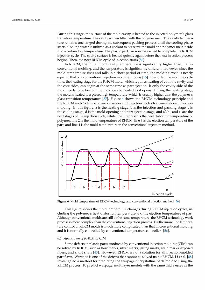
In RHCM, the initial mold cavity temperature is significantly higher than that inconventional molding, and the temperature is significantly different. However, since themold temperature rises and falls in a short period of time, the molding cycle is nearlyequal to that of a conventional injection molding process [55]. To shorten the molding cycletime, the heating stage for the RHCM mold, which requires heating of both the cavity andthe core sides, can begin at the same time as part ejection. If only the cavity side of themold needs to be heated, the mold can be heated as it opens. During the heating stage,the mold is heated to a preset high temperature, which is usually higher than the polymer’sglass transition temperature [87]. Figure 6 shows the RHCM technology principle andthe RHCM mold’s temperature variation and injection cycles for conventional injectionmolding. In this figure, a is the heating stage, b is the injection and packing stage, c isthe cooling stage, d is the mold opening and part ejection stage, and a’, b’, and c’ are thenext stages of the injection cycle, while line 1 represents the heat distortion temperature ofpolymer, line 2 is the mold temperature of RHCM, line 3 is the ejection temperature of thepart, and line 4 is the mold temperature in the conventional injection method.
Materials 2022, 15, x FOR PEER REVIEW 17 of 40
Figure 6. Mold temperature of RHCM technology and conventional injection method [56].
This figure shows the mold temperature changes during RHCM injection cycles, in-cluding the polymer’s heat distortion temperature and the ejection temperature of part. Although conventional molds are still at the same temperature, the RHCM technology work process is more complex than the conventional injection process. Furthermore, the temperature control of RHCM molds is much more complicated than that in conventional molding, and it is normally controlled by conventional temperature controllers [56].
6.1. Application of RHCM in CIM Some defects in plastic parts produced by conventional injection molding (CIM) can be
solved by RHCM, such as flow marks, silver marks, jetting marks, weld marks, exposed fibers, and short shots [43]. However, RHCM is not a solution for all injection-molded part flaws. Warpage is one of the defects that cannot be solved using RHCM. Li et al. [88] inves-tigated a method for predicting the warpage of crystalline parts molded using the RHCM process. To predict warpage, multilayer models with the same thicknesses as the skin–core structures in the molded parts were developed. The thicknesses of the layers varied with each molding process. The upper skin layer of each injection-molded part was heated on the stationary side. The prediction results were compared to the experimental results, which revealed that the average errors between predicted warpage and average experimental warpage were respectively 7.0%, 3.5%, and 4.4% in CIM, RHCM under a 60 °C heating mold (RHCM60), and RHCM under a 90 °C heating mold (RHCM90). Apart from that, the micro-structure and temperature in CIM were symmetrical along the thickness direction and asymmetrical in RHCM. The predicted warpage was influenced by crystallinity, and the warpage predicted with crystallinity was greater than the warpage predicted without crys-tallinity, especially in RHCM-molded parts.
Furthermore, Li et al. [48] investigated the effect of the weld line on the tensile strength of RHCM and CIM components. Tensile testing results showed that, for speci-mens with a weld line, the strength of the RHCM specimen was significantly higher than that of the CIM specimen due to the smaller dimensions and higher bonding strength of the weld line. Moreover, the RHCM specimen’s weld line was smaller than that of the CIM specimen. Furthermore, the two melt fronts that formed the weld line were welded together better due to the higher temperature and pressure in the RHCM process com-pared to the CIM process, resulting in a higher bonding strength of the weld line. The tensile strength of specimens without a weld line showed no discernible difference be-tween the two molding processes. In addition, a thin surface layer of material containing the V-notch at the weld line was removed from the RHCM and CIM parts to investigate
Figure 6. Mold temperature of RHCM technology and conventional injection method [56].
This figure shows the mold temperature changes during RHCM injection cycles, in-cluding the polymer’s heat distortion temperature and the ejection temperature of part.Although conventional molds are still at the same temperature, the RHCM technology workprocess is more complex than the conventional injection process. Furthermore, the tempera-ture control of RHCM molds is much more complicated than that in conventional molding,and it is normally controlled by conventional temperature controllers [56].
6.1. Application of RHCM in CIM
Some defects in plastic parts produced by conventional injection molding (CIM) canbe solved by RHCM, such as flow marks, silver marks, jetting marks, weld marks, exposedfibers, and short shots [43]. However, RHCM is not a solution for all injection-moldedpart flaws. Warpage is one of the defects that cannot be solved using RHCM. Li et al. [88]investigated a method for predicting the warpage of crystalline parts molded using theRHCM process. To predict warpage, multilayer models with the same thicknesses as the

Materials 2022, 15, 3725 16 of 39
skin–core structures in the molded parts were developed. The thicknesses of the layersvaried with each molding process. The upper skin layer of each injection-molded part washeated on the stationary side. The prediction results were compared to the experimentalresults, which revealed that the average errors between predicted warpage and averageexperimental warpage were respectively 7.0%, 3.5%, and 4.4% in CIM, RHCM undera 60 ◦C heating mold (RHCM60), and RHCM under a 90 ◦C heating mold (RHCM90).Apart from that, the microstructure and temperature in CIM were symmetrical along thethickness direction and asymmetrical in RHCM. The predicted warpage was influenced bycrystallinity, and the warpage predicted with crystallinity was greater than the warpagepredicted without crystallinity, especially in RHCM-molded parts.
Furthermore, Li et al. [48] investigated the effect of the weld line on the tensile strengthof RHCM and CIM components. Tensile testing results showed that, for specimens witha weld line, the strength of the RHCM specimen was significantly higher than that of theCIM specimen due to the smaller dimensions and higher bonding strength of the weld line.Moreover, the RHCM specimen’s weld line was smaller than that of the CIM specimen.Furthermore, the two melt fronts that formed the weld line were welded together better dueto the higher temperature and pressure in the RHCM process compared to the CIM process,resulting in a higher bonding strength of the weld line. The tensile strength of specimenswithout a weld line showed no discernible difference between the two molding processes.In addition, a thin surface layer of material containing the V-notch at the weld line wasremoved from the RHCM and CIM parts to investigate its effect on tensile properties.When compared to specimens with the original full thickness, thinned out specimens witha weld line showed improved tensile strength, while specimens without a weld line showeddecreased tensile strength.
On the basis of the results from the previous researchers [48,88], it can be said that theapplication of RHCM in CIM has a big impact on the molded part. Previous studies used thesame mold insert for both molding processes. The part molded by RHCM showed greaterwarpage predicted with crystallinity compared to that predicted without crystallinity.Additionally, the strength of the RHCM molded part was higher than that of the CIMmolded part with the same shape and size, while the weld line of the RHCM molded partwas smaller compared to that of the CIM molded part. Thus, it can be concluded that usingRHCM in CIM yields a significant difference in the molded parts produced, demonstratingthat RHCM produces a better result.
6.2. RHCM Technologies
Many studies have been performed to enhance the surface quality of plastic productsby optimizing the process parameters. Contrary to popular belief, optimized parameters donot eliminate defects, but improve the surface quality of the molded parts. It was recentlydiscovered that raising the mold surface temperature eliminates defects, increases flowlength, and improves surface quality [43,87,140–144]. RHCM is an innovative technologythat allows for dynamic mold temperature control during the injection molding process.RHCM technology requirements for the temperature of the heat distortion for the injectingpolymer should be met before the mold cavity is injected. At the ejected temperature,it must be quickly cooled down. The difference in the mold temperature is significant.Therefore, if the cooling and heating methods are the same as in conventional methods,the production cycle must be extended. The RHCM mold is heated and cooled rapidly toensure heating and cooling efficiency. Consequently, the structure of the mold differs froma conventional mold, as does the heating method. Companies such as Foreshot IndustrialCorporation, Taoyuan City, Taiwan and Letoplast S.R.O., Letovice, Czech Republic havedeveloped and applied RHCM technology, offering the benefits of a perfect product witha glossy surface that does not require painting [145,146]. Letoplast specializes in theproduction of visual and technical plastic parts made of PC-ABS, ABS, PP, PPE, PC, PA6,and other materials [146]. RHCM technology is used in plastic parts such as networkcommunication equipment computers/communications/consumer electronics, appearance

Materials 2022, 15, 3725 17 of 39
parts, and liquid crystal display televisions (LCD TVs) [145]. This technology allowsengineers, technologists, or mold designers to avoid unnecessary premature melt freezingthroughout the filling stage, which lowers the melt flow resistance and improves the moltenplastic filling capability [38].
Chang and Hwang [147] proposed an infrared heating method for the mold cavitysurface. For thermal surface condition assessment, a transient thermal simulation wasdeveloped. A change in the mold structure is not necessary with this method. This methodhas a high construction cost, and it is hard to consistently heat the longitudinal or com-plex mold cavity. Fischer et al. [148] investigated the effect of a locally different coolingbehavior on the injection molding process of semicrystalline thermoplastics. An innovativedynamically tempered mold technology with different temperature zones was investi-gated, allowing the production of thin-wall components with locally different componentproperties. The preliminary results showed that, by influencing the inner component prop-erties, significant differences in the optical and mechanical component properties could beachieved. On the other hand, Yao and Kim [142] evaluated the benefits of heating the moldsurface through the use of a thin metal coating and thermal insulation. Copper poles wereused to control the temperature by heating the thin metal layer. This method was shownto be efficient in terms of energy usage and temperature control. However, the complexcoating and tiny parts of the cavity make this process more challenging; in addition, thereare safety hazards, such as in the resistor layer’s insulation, with the resistor having alimited life time. Table 6 shows some of the studies conducted on RHCM technology.
Chen et al. [39] studied the feasibility, efficiency, and effects of induction heating on theweld line surface appearance for dynamic mold surface temperature control. A simulationand experiment were used to analyze the induction heating with the spiral coil coincidingwith the coolant cooling to evaluate its rapid heating/cooling ability and the uniformity ofthe mold plate surface temperature. Initially, ANSYS 3D thermal analysis was performedon a mold plate with a heating source to verify the analytical capabilities and accuracy.Then, induction heating was performed on the double-gate tensile sample mold to controlthe surface temperature of the acrylonitrile butadiene styrene (ABS) melt injection moldand determine its influence on the surface marking and weld line strength. From theresults, it was indicated that it took 3 s for the center temperature of the plate to rise from110 ◦C to 180 ◦C and 21 s to rise to 110 ◦C during induction heating and cooling, while,for the second heating/cooling cycle, it took 4 s to reach 200 ◦C and 21 s to return to 110 ◦C.The surface temperature of the mold plate could be elevated to around 22.5 ◦C and cooledto 4.3 ◦C. The study also proved that the temperature-controlled induction heating of themold surface also contributed to the elimination of surface markings and to enhancingthe strength of the weld line on injection molded ABS tensile bars. However, this studydid not yield a positive correlation between the heating time by induction heating and thetemperature distribution pattern on mold plates produced by the rapid tooling technique.Therefore, further investigation is required.

Materials 2022, 15, 3725 18 of 39
Table 6. Summary of research on RHCM technologies.
No. ResearcherPlastic
Material UsedParameter Settings Output Response Technology Used Material for
Mold InsertsType of Analysis
ResultSimulation Experiment
1 Chen et al.,2006 [39] ABS
• Heating stage(110–180 ◦C and110–200 ◦C)
• Cooling stage(180–110 ◦C and200–110 ◦C)
• Mold temperature(50 ◦C)
• Surface marks• Weld line strength
Electromagneticinduction heating AISI 4130 steel ANSYS Yes
• Heating times, 3–4 sfor mold surfacetemperature to risefrom 110 to 180 ◦Cand 200 ◦C, alongwith 21 s for coolingtime (return to110 ◦C)
• Eliminated thesurface marks of theweld line andenhanced thestrength of therelated weld line
2Huang and
Tai, 2009 [43] PMMA
• Mold temperature(25 ◦C)
• Cooling time (20 s)• Melt temperature
(260 ◦C)
• Mold surfacetemperature
• Replication heightsof LGP’smicrostructures
• Residual stress inLGP
N/A
Not specified
No Yes
• Induction heatingthe mold surface to110 ◦C could increasethe replication rate ofthe microstructure’sheight by up to 95%
• There was noresidual stress in theLGP produced byinduction heating
• Mold temperature(80 ◦C)
• Cooling time (20 s)• Melt temperature
(260 ◦C)
Hot oil No Yes
• Mold temperature(110 ◦C)
• Cooling time (20 s)• Melt temperature
(260 ◦C)
Combination ofhot oil and
induction heatingNo Yes
• Mold temperature(110, 130, and 150 ◦C)
• Cooling time (20 s)• Melt temperature
(260 ◦C)
Induction heating No Yes

Materials 2022, 15, 3725 19 of 39
Table 6. Cont.
No. ResearcherPlastic
Material UsedParameter Settings Output Response Technology Used Material for
Mold InsertsType of Analysis
ResultSimulation Experiment
3 Huang et al.,2010 [44] PMMA
• Injection speed(180–200 mm/s)
• Packing pressure(1st stage 50–70 Mpa,2nd stage 40 Mpa)
• Packing time (4–8 s)• Mold temperature
(60–80 ◦C)• Cooling time
(30–40 s)• Mold surface
temperature(110–150 ◦C)
• Power rates• Optimum
processingparameters
• Quality ofmicrofeatureheights and angles
Induction heating Ni No Yes
• Optimum processparameters: injectionspeed (180 mm/s)packing pressure(70 Mpa), packingtime (8 s), moldtemperature (70 ◦C),cooling time (30 s),and mold surfacetemperature(150 ◦C).
• Replication effect onmicrofeatures wassignificantlyimproved byinduction heating
4 Tsai, 2011 [46] ABS
• Two gates, cavitytemperature = 75 ◦C,no vapor chamber
• Two gates,cavity = 75 ◦Ctemperature, withvapor chamber
• Two gates, cavitytemperature = 110 ◦C,with vapor chamber
• One gate, cavitytemperature = 75 ◦C,no vapor chamber
• Tensile strengthSteam heating
(vapor chamber) P20 mould steel No Yes
• The two gate/vaporchamber system’stensile strengthincreased by 3.2%when preheatingtemperaturesincreased from 75 to110 ◦C
5 Wang, 2013[54]
• ABS/PPMAFiber-reinforcedplastic
• PP + 20%glass fiber
• Heating time (10, 20,30, 40, 50, and 60 s)
• Cooling time(20,30,40, 50,and 60 s)
• High- andlow-temperatureholding time (10 s)
• Weld line• Tensile strength
Electric heating(cartridge heater) AISI H13 ANSYS Yes
• RHCM process couldimprove the weldline factor for bothmaterials
• RHCM processreduced the tensilestrength of the partwithout weld line
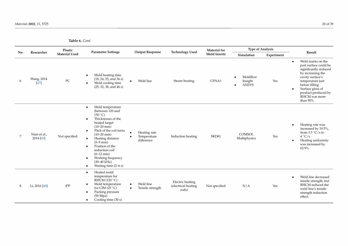
Materials 2022, 15, 3725 20 of 39
Table 6. Cont.
No. ResearcherPlastic
Material UsedParameter Settings Output Response Technology Used Material for
Mold InsertsType of Analysis
ResultSimulation Experiment
6 Wang, 2014[47] PC
• Mold heating time(18, 24, 25, and 36 s)
• Mold cooling time(25, 32, 38, and 46 s)
• Weld line Steam heating CENA1• Moldflow
Insight• ANSYS
Yes
• Weld marks on thepart surface could besignificantly reducedby increasing thecavity surface’stemperature justbefore filling
• Surface gloss ofproduct produced byRHCM was morethan 90%.
7 Nian et al.,2014 [45] Not specified
• Mold temperature(between 120 and150 ◦C)
• Thicknesses of theheated target(10–20 mm)
• Pitch of the coil turns(10–20 mm)
• Heating distance(5–9 mm)
• Position of theinduction coil(0–12 mm)
• Working frequency(30–40 kHz)
• Waiting time (2–6 s)
• Heating rate• Temperature
differenceInduction heating SKD61 COMSOL
Multiphysics Yes
• Heating rate wasincreased by 19.5%,from 3.3 ◦C/s to4 ◦C/s
• Heating uniformitywas increased by62.9%
8 Li, 2016 [48] iPP
• Heated moldtemperature forRHCM (120 ◦C)
• Mold temperaturefor CIM (25 ◦C)
• Packing pressure(50 Mpa)
• Cooling time (30 s)
• Weld line• Tensile strength
Electric heating(electrical heating
rods)Not specified N/A Yes
• Weld line decreasedtensile strength, butRHCM reduced theweld line’s tensilestrength reductioneffect.

Materials 2022, 15, 3725 21 of 39
Table 6. Cont.
No. ResearcherPlastic
Material UsedParameter Settings Output Response Technology Used Material for
Mold InsertsType of Analysis
ResultSimulation Experiment
9 Xie, 2017 [49]
PP
• Silicon insert surfacetemperature (20, 60,100, and 140 ◦C)
• Melt temperature(230 ◦C)
• Injection pressure(30 Mpa)
• Injection speed(60 mm/s)
• Screw back (20 mm)• Sample thickness
(0.6 mm)
• Weld line
Electric heating(thin-film
resistance heater,graphene coating)
Silicon insert(coated with
carbide-bondedgraphene)
N/A
Yes
• Width of weld lines:16.4 µm at 20 ◦C,11.24 µm at 60 ◦C,and 5.6 µm at 100 ◦C
• Weld linedisappearedcompletely at 140 ◦C
PS
• Silicon insert surfacetemperature (20, 40,80, and 100 ◦C)
• Melt temperature(200 ◦C)
• Injection pressure(30 Mpa)
• Injection speed(5 mm/s)
• Screw back (15 mm)• Sample thickness
(1 mm)
• Residual internalstress
• Replication fidelityYes
• Residual stressdecreased as thesurface temperatureof silicon insertincreased
• Coating the siliconinsert withcarbide-bondedgraphene couldimprove replicationfidelity
10 Liu, 2020 [50] PP with 30% shortglass fiber
• Melt temperature(240 ◦C)
• Injection pressure(60 Mpa)
• Injection velocity(45%)
• Packing time (9 s)• Packing pressure
(50 Mpa)• Mold heating
temperature(60/90/120 ◦C)
• Cooling time (30 s)
• Microstructure• Tensile properties• Surface quality
Electric heating(electrical heating
rods)Not specified Autodesk
Moldflow Yes
• Tensile strength ofRHCM parts reachedpeak at 60 ◦C moldheating temperature
• The sample’s surfacegloss increased asthe mold cavitysurface temperatureincreased, butdecreased as themold heatingtemperatureincreased above90 ◦C

Materials 2022, 15, 3725 22 of 39
Huang and Tai [43] studied the use of induction heating to rapidly heat the mold sur-face during the injection molding process, thereby improving the microstructure replicationeffect of light-guided plates (LGP). First, oil was used to heat the mold to 80 ◦C, and theninduction heating was used to heat the surface of the LGP mold above the glass transitiontemperature. Induction heating was implemented to achieve the high mold temperatureessential for the short filling stage throughout the microstructure replication process ofLGP, as well as to rapidly lower the mold temperature in the cooling process, allowingthe molded part to cool faster. The heating coil was a single copper wire used for smallarea heating. The geometry of the induction coil is presented in Figure 7. The moldedpart of PMMA plastic was a flat LGP of 40 mm × 30 mm, with length and width of 1 mm.Results from these studies showed that the induction heating system only achieved atemperature uniformity of 6.7–12.7 ◦C. In addition, the combination of an oil heater (80 ◦C)and an induction heating system (up to 110 ◦C) offered the best replication performance,significantly raising the replication ratio up to 95%, which was 6% higher than when themold was heated with an oil heater and 7.8% higher than when the mold was left unheated.Thus, these studies prove that induction heating can improve the LGP microstructure fillingefficiency. However, in this study, only the performance of the heating technology whenheating the mold surface was discussed, without further details on the strength and surfaceappearance (weld line) of the molded parts produced. Therefore, a further investigation ofthe correlation between heating technology and the properties of the molded part producedis required.
Huang et al. [44] used the same experimental setup as Huang and Tai [43] to performrapid induction heating on the surface of a 2 inch LGP mold, but with a different coildesign, using three-layered copper wire, to study the influence of high mold tempera-ture in induction heating, as shown in Figure 8, to enhance the replication rate of LGPmicrofeatures. The temperature profiles of the Ni heating plate used as the mold insertin 2 inch LGP were investigated in order to identify the optimal power rate setting in theinduction heating system; these temperature profiles correlated with the different powerrates. Additional testing was carried out to determine the efficiency of the optimal processparameters defined by the Taguchi method. The ANOVA results indicated that the mostsignificant parameters affecting the replication ability of microfeatures were the moldsurface temperature and injection speed. As the surface temperature of the mold increasedto 150 ◦C, the replication rate of the average nine-point height of the microfeatures and theaverage nine-point angle increased to 91.6% and 98.1%, respectively. However, the effectson the strength of the molded parts produced and the temperature distribution surface ofthe mold insert were not discussed in detail in this study.
Tsai et al. [46] reported the vapor chamber’s effect on part tensile strength, which wasmade using plastic (ABS) material in an injection molding process. This experiment wasdeveloped with a copper heat pipe of the flat-plate type. Water was used as the workingfluid. Then, to circulate the working fluid, a copper mesh formed using 50 µm wire with100/200 mesh pore and a solid copper cylinder with a diameter of 2 mm were used tosupport the vacuum and loading forces. The experiment used the shape of the specimenshown in Figure 9 for tensile testing. The experiment was conducted with two distinctmold designs, one with a single gate and another with two opposite gates. The cavitytemperature was used as a parameter in the experiment, while the output was the moldedpart’s tensile strength. As a result of the weld line, the tensile strength of the test partformed by the two gate/no vapor chamber heating system was 11.1% lower than thatof the test part formed by the one gate/no vapor chamber heating system (Figure 10).The two gate/vapor chamber system produced a fine weld line, as well as a tensile strength6.8% higher than that of the two gate/no vapor chamber system. Furthermore, the tensilestrength increased by 3.2% when the preheating temperature increased from 75 to 110 ◦Cin the two gate/vapor chamber system. Due to the extended fluid flow, the use of thevapor chamber heating system and the increase in the preheating temperature seeminglyimproved the tensile strength of parts molded with two opposing gates. However, despite

Materials 2022, 15, 3725 23 of 39
the fact that this study focused on conventional mold steel, additional research on the effectof heating on the mold insert produced by the rapid tooling technique should be considered.
Materials 2022, 15, x FOR PEER REVIEW 23 of 40
Figure 7. Induction coil’s geometry and dimensions.
Huang et al. [44] used the same experimental setup as Huang and Tai [43] to perform rapid induction heating on the surface of a 2 inch LGP mold, but with a different coil design, using three-layered copper wire, to study the influence of high mold temperature in induction heating, as shown in Figure 8, to enhance the replication rate of LGP micro-features. The temperature profiles of the Ni heating plate used as the mold insert in 2 inch LGP were investigated in order to identify the optimal power rate setting in the induction heating system; these temperature profiles correlated with the different power rates. Ad-ditional testing was carried out to determine the efficiency of the optimal process param-eters defined by the Taguchi method. The ANOVA results indicated that the most signif-icant parameters affecting the replication ability of microfeatures were the mold surface temperature and injection speed. As the surface temperature of the mold increased to 150 °C, the replication rate of the average nine-point height of the microfeatures and the aver-age nine-point angle increased to 91.6% and 98.1%, respectively. However, the effects on the strength of the molded parts produced and the temperature distribution surface of the mold insert were not discussed in detail in this study.
Unit: mm
Figure 7. Induction coil’s geometry and dimensions.
Materials 2022, 15, x FOR PEER REVIEW 24 of 40
Figure 8. The geometry and dimensions of induction coil.
Tsai et al. [46] reported the vapor chamber’s effect on part tensile strength, which was made using plastic (ABS) material in an injection molding process. This experiment was developed with a copper heat pipe of the flat-plate type. Water was used as the working fluid. Then, to circulate the working fluid, a copper mesh formed using 50 µm wire with 100/200 mesh pore and a solid copper cylinder with a diameter of 2 mm were used to support the vacuum and loading forces. The experiment used the shape of the specimen shown in Figure 9 for tensile testing. The experiment was conducted with two distinct mold designs, one with a single gate and another with two opposite gates. The cavity temperature was used as a parameter in the experiment, while the output was the molded part’s tensile strength. As a result of the weld line, the tensile strength of the test part formed by the two gate/no vapor chamber heating system was 11.1% lower than that of the test part formed by the one gate/no vapor chamber heating system (Figure 10). The two gate/vapor chamber system produced a fine weld line, as well as a tensile strength 6.8% higher than that of the two gate/no vapor chamber system. Furthermore, the tensile strength increased by 3.2% when the preheating temperature increased from 75 to 110 °C in the two gate/vapor chamber system. Due to the extended fluid flow, the use of the va-por chamber heating system and the increase in the preheating temperature seemingly improved the tensile strength of parts molded with two opposing gates. However, despite the fact that this study focused on conventional mold steel, additional research on the effect of heating on the mold insert produced by the rapid tooling technique should be considered.
Figure 8. The geometry and dimensions of induction coil.

Materials 2022, 15, 3725 24 of 39Materials 2022, 15, x FOR PEER REVIEW 25 of 40
Figure 9. Specimen of tensile testing [149].
Figure 10. SEM images of one gate and two opposite gates: (a) two opposite gates at the temperature of 75 °C at point O without vapor chamber system; (b) two opposite gates at the temperature of 75 °C at point O with vapor chamber system; (c) two opposite gates at the temperature of 110 °C at point O with vapor chamber system; (d) one gate at the temperature of 75 °C at point O without vapor chamber system [46].
The heating and cooling system designs of electric heating molds are critical for RHCM with electric heating because they directly affect the heating/cooling efficiency and temperature uniformity, which have a decisive influence on the molding cycle and part quality [127]. Electric heating in RHCM can be accomplished through the deployment of electrical heating rods and cooling tunnels in the stationary mold, which can be rapidly heated via electric heating prior to filling and cooled via circulating water after filling [50,88]. In another study, Wang et al. [54] investigated the thermal response of the electric heating with the deployment of a cartridge heater in rapid heat cycle molding, as well as
(a) (b)
(d) (c)
Figure 9. Specimen of tensile testing [149].
The heating and cooling system designs of electric heating molds are critical forRHCM with electric heating because they directly affect the heating/cooling efficiency andtemperature uniformity, which have a decisive influence on the molding cycle and partquality [127]. Electric heating in RHCM can be accomplished through the deployment ofelectrical heating rods and cooling tunnels in the stationary mold, which can be rapidlyheated via electric heating prior to filling and cooled via circulating water after filling [50,88].In another study, Wang et al. [54] investigated the thermal response of the electric heatingwith the deployment of a cartridge heater in rapid heat cycle molding, as well as its impacton the surface appearance and tensile strength of the molded part. ABS/PPMA and fiber-reinforced PP were the materials used in the molded part experiment. The mold materialused for the mold holder was HT 350, while that for the mold plate was AISI 1045, and thatfor the cavity plate was AISI H13. ANSYS thermal modules were used to investigate thetemperature distribution and thermal response of the cavity surface. The thermal cyclingprocess caused the surface temperature of the cavity to rise gradually. The maximumcavity surface temperature in thermal cycling could reach 185 ◦C after 30 experimentiterations with 60 s of mold heating time and 20 s of mold cooling time. This impliedthat the power density of the heater must be high enough to shorten the RHCM moldingcycle by reducing the mold heating time. As the power density of the heater increasedfrom 15 to 30 W/cm2, the heating time of the cavity surface to be heated from 30 to 120 ◦Ccould be decreased from 58 to 19 s. Experimental results showed that, compared with CIM,the RHCM method reduced the tensile strength of parts without the weld line (Figure 11).In the case of ABS/PMMA plastics, the tensile strength of the weld line part was alsosignificantly lowered due to RHCM. The RHCM method enhanced the weld line factorfor ABS/PMMA and 20% glass fiber-reinforced PP. Findings were limited to the effect ofRHCM heating technology on the cavity surface and the parts molded using conventionalmold inserts. Nonetheless, more research into the effect of RHCM heating technology onmold inserts produced by rapid tooling technique is needed.

Materials 2022, 15, 3725 25 of 39
Materials 2022, 15, x FOR PEER REVIEW 25 of 40
Figure 9. Specimen of tensile testing [149].
Figure 10. SEM images of one gate and two opposite gates: (a) two opposite gates at the temperature of 75 °C at point O without vapor chamber system; (b) two opposite gates at the temperature of 75 °C at point O with vapor chamber system; (c) two opposite gates at the temperature of 110 °C at point O with vapor chamber system; (d) one gate at the temperature of 75 °C at point O without vapor chamber system [46].
The heating and cooling system designs of electric heating molds are critical for RHCM with electric heating because they directly affect the heating/cooling efficiency and temperature uniformity, which have a decisive influence on the molding cycle and part quality [127]. Electric heating in RHCM can be accomplished through the deployment of electrical heating rods and cooling tunnels in the stationary mold, which can be rapidly heated via electric heating prior to filling and cooled via circulating water after filling [50,88]. In another study, Wang et al. [54] investigated the thermal response of the electric heating with the deployment of a cartridge heater in rapid heat cycle molding, as well as
(a) (b)
(d) (c)
Figure 10. SEM images of one gate and two opposite gates: (a) two opposite gates at the temperatureof 75 ◦C at point O without vapor chamber system; (b) two opposite gates at the temperature of 75 ◦Cat point O with vapor chamber system; (c) two opposite gates at the temperature of 110 ◦C at pointO with vapor chamber system; (d) one gate at the temperature of 75 ◦C at point O without vaporchamber system [46].
Materials 2022, 15, x FOR PEER REVIEW 26 of 40
its impact on the surface appearance and tensile strength of the molded part. ABS/PPMA and fiber-reinforced PP were the materials used in the molded part experiment. The mold material used for the mold holder was HT 350, while that for the mold plate was AISI 1045, and that for the cavity plate was AISI H13. ANSYS thermal modules were used to investigate the temperature distribution and thermal response of the cavity surface. The thermal cycling process caused the surface temperature of the cavity to rise gradually. The maximum cavity surface temperature in thermal cycling could reach 185 °C after 30 ex-periment iterations with 60 s of mold heating time and 20 s of mold cooling time. This implied that the power density of the heater must be high enough to shorten the RHCM molding cycle by reducing the mold heating time. As the power density of the heater in-creased from 15 to 30 W/cm2, the heating time of the cavity surface to be heated from 30 to 120 °C could be decreased from 58 to 19 s. Experimental results showed that, compared with CIM, the RHCM method reduced the tensile strength of parts without the weld line (Figure 11). In the case of ABS/PMMA plastics, the tensile strength of the weld line part was also significantly lowered due to RHCM. The RHCM method enhanced the weld line factor for ABS/PMMA and 20% glass fiber-reinforced PP. Findings were limited to the effect of RHCM heating technology on the cavity surface and the parts molded using con-ventional mold inserts. Nonetheless, more research into the effect of RHCM heating tech-nology on mold inserts produced by rapid tooling technique is needed.
Figure 11. The tensile strength with and without the weld line of the CIM and RHCM parts.
Wang et al. [47] studied the design of heating/cooling channels for an automotive interior part, as well as its evaluation in rapid heat cycle molding. Polycarbonate (PC) material was used for the molded part. The general commercial ANSYS was used to sim-ulate the transient thermal response of the mold cavity throughout the heating process to analyze the efficiencies of the original heating/cooling channel design. The designed heat-ing/cooling systems with baffles could significantly improve the cavity surface thermal response efficiency. Steam was used at a temperature of 180 °C and a pressure of 1.0 MPa. When experimental and simulation results were compared, the reasonable heat transfer coefficient was determined to be 14,000 W/m2·°C. Heat exchange occurred between the cavity plate and the environment via natural air convection. The convective heat transfer
Figure 11. The tensile strength with and without the weld line of the CIM and RHCM parts.
Wang et al. [47] studied the design of heating/cooling channels for an automotiveinterior part, as well as its evaluation in rapid heat cycle molding. Polycarbonate (PC)material was used for the molded part. The general commercial ANSYS was used tosimulate the transient thermal response of the mold cavity throughout the heating process

Materials 2022, 15, 3725 26 of 39
to analyze the efficiencies of the original heating/cooling channel design. The designedheating/cooling systems with baffles could significantly improve the cavity surface thermalresponse efficiency. Steam was used at a temperature of 180 ◦C and a pressure of 1.0 Mpa.When experimental and simulation results were compared, the reasonable heat transfercoefficient was determined to be 14,000 W/m2·◦C. Heat exchange occurred between thecavity plate and the environment via natural air convection. The convective heat transfercoefficient was determined to be 25 W/m2·◦C. According to the results, the mold timeconstant could be lowered from 5 s to 2.5 s, resulting in a 50% decrease in time. Heatingefficiency could be improved by 27.3%. The total surface temperature differences couldbe reduced to 20–30 ◦C. Moreover, by increasing the temperature of the cavity surface justprior to filling, the weld marks on the surface of the part could be significantly reduced(Figure 12). The weld marks could be completely removed as the cavity surface temperatureapproached a critical level. The critical cavity surface temperature of the plastic materialused was approximately 130 ◦C. Findings from this study proved that the surface gloss ofRHCM products was more than 90%. However, further studies on the implementation ofRT in RHCM are required.
Nian et al. [45] studied the key parameters and optimized design of single-layer induc-tion coils for external rapid mold surface heating by controlling the process parameters ofinduction heating (suitable for applications involving mold plates with different thicknessesand coil positions). Figure 13 depicts the spatial dimensions used in the simulation. An ex-periment was performed to validate the thickness of the heated workpiece (SKD61) and theinduction coil (copper) position influencing the heating rate and temperature uniformity.Furthermore, the Taguchi method and principal component analysis were used to identifythe best control factor combination to obtain high heating rates with low temperaturedeviations. According to the simulation results, the position of the induction coil and thethickness of the workpiece were indeed important design parameters. The optimal parame-ters indicated heating a 10 mm thick workpiece when designing a single-layer inductioncoil with a 15 mm turn pitch at a distance of 5 mm from the heating target. Additionally,the coil position should not be offset, and the operating frequency and waiting time must beset to 35 kHz and 6 s, correspondingly. Furthermore, the results of the experiments showedthat an optimized design of the induction coil outperformed conventional single-layer coilsin terms of temperature uniformity. The heating rate increased from 3.3 ◦C/s to 4 ◦C/s(an increase of 19.5%), and the heating uniformity increased by 62.9%. In terms of modelvalidity, all MAPE values indicated high prediction accuracy. However, other importanttests such as strength tests, as well as an observation of the appearance of the molded partproduced by the induction heated mold surface were not performed.
Materials 2022, 15, x FOR PEER REVIEW 27 of 40
coefficient was determined to be 25 W/m2·°C. According to the results, the mold time con-stant could be lowered from 5 s to 2.5 s, resulting in a 50% decrease in time. Heating effi-ciency could be improved by 27.3%. The total surface temperature differences could be reduced to 20–30 °C. Moreover, by increasing the temperature of the cavity surface just prior to filling, the weld marks on the surface of the part could be significantly reduced (Figure 12). The weld marks could be completely removed as the cavity surface tempera-ture approached a critical level. The critical cavity surface temperature of the plastic ma-terial used was approximately 130 °C. Findings from this study proved that the surface gloss of RHCM products was more than 90%. However, further studies on the implemen-tation of RT in RHCM are required.
Figure 12. Micrograph of the weld marks or weld lines on the surface of the molded specimen under different cavity surface temperatures just before filling [47].
Nian et al. [45] studied the key parameters and optimized design of single-layer in-duction coils for external rapid mold surface heating by controlling the process parame-ters of induction heating (suitable for applications involving mold plates with different thicknesses and coil positions). Figure 13 depicts the spatial dimensions used in the sim-ulation. An experiment was performed to validate the thickness of the heated workpiece (SKD61) and the induction coil (copper) position influencing the heating rate and temper-ature uniformity. Furthermore, the Taguchi method and principal component analysis were used to identify the best control factor combination to obtain high heating rates with low temperature deviations. According to the simulation results, the position of the in-duction coil and the thickness of the workpiece were indeed important design parameters. The optimal parameters indicated heating a 10 mm thick workpiece when designing a single-layer induction coil with a 15 mm turn pitch at a distance of 5 mm from the heating target. Additionally, the coil position should not be offset, and the operating frequency and waiting time must be set to 35 kHz and 6 s, correspondingly. Furthermore, the results of the experiments showed that an optimized design of the induction coil outperformed conventional single-layer coils in terms of temperature uniformity. The heating rate in-creased from 3.3 °C/s to 4 °C/s (an increase of 19.5%), and the heating uniformity increased by 62.9%. In terms of model validity, all MAPE values indicated high prediction accuracy. However, other important tests such as strength tests, as well as an observation of the appearance of the molded part produced by the induction heated mold surface were not performed.
Figure 12. Micrograph of the weld marks or weld lines on the surface of the molded specimen underdifferent cavity surface temperatures just before filling [47].

Materials 2022, 15, 3725 27 of 39Materials 2022, 15, x FOR PEER REVIEW 28 of 40
Figure 13. Physical model of induction heating [45].
Li et al. [48] investigated the effects of the weld line and its structure on tensile strength, as well as its process dependence, in CIM and RHCM. The specimens were made of isotactic polypropylene (iPP). Figure 14 shows the dimensions of the dumbbell-shaped specimen; the thickness was 2.5 mm. An RHCM mold with a maximum clamping force of 3800 kN, a maximum melt volume of 1239 cm3, and a maximum injection pressure of 182 MPa was used to mold the CIM and RHCM parts. Electrical heating rods were used to quickly heat the mold before filling it; after filling, cooling tunnels cooled the mold with circulating water. The only parameter used for the experiment was the mold temperature, and the output was the tensile strength of the weld line on the molded part. According to the results, the RHCM process reduced the dimensions of the weld line, particularly the width of the weld line adjacent to the heated stationary half. The tensile strength of dumb-bell-shaped specimens cut from RHCM parts with and without a weld line is shown in Figure 15. Due to the presence of skin layers or weld lines on both RHCM and CIM spec-imens, their trends were similar. The RHCM specimen with the weld line had a higher tensile strength than the CIM specimen, but the strength without the weld line was re-markably similar. The weld line reduced the overall tensile strength, while RHCM re-duced the decrease in tensile strength. Meanwhile, in the RHCM process, there was no discernible influence on the tensile strength of the specimens not having a weld line. The removal of the surface layer improved the tensile strength of specimens with weld lines but reduced it in specimens without a weld line. Findings from this study prove that RHCM can reduce the effects of weld line on the tensile strength. Nonetheless, further studies on the potential of RT in RHCM are yet to be conducted.
Figure 13. Physical model of induction heating [45].
Li et al. [48] investigated the effects of the weld line and its structure on tensile strength,as well as its process dependence, in CIM and RHCM. The specimens were made of isotacticpolypropylene (iPP). Figure 14 shows the dimensions of the dumbbell-shaped specimen;the thickness was 2.5 mm. An RHCM mold with a maximum clamping force of 3800 kN,a maximum melt volume of 1239 cm3, and a maximum injection pressure of 182 Mpa wasused to mold the CIM and RHCM parts. Electrical heating rods were used to quickly heatthe mold before filling it; after filling, cooling tunnels cooled the mold with circulatingwater. The only parameter used for the experiment was the mold temperature, and theoutput was the tensile strength of the weld line on the molded part. According to the results,the RHCM process reduced the dimensions of the weld line, particularly the width of theweld line adjacent to the heated stationary half. The tensile strength of dumbbell-shapedspecimens cut from RHCM parts with and without a weld line is shown in Figure 15. Dueto the presence of skin layers or weld lines on both RHCM and CIM specimens, their trendswere similar. The RHCM specimen with the weld line had a higher tensile strength than theCIM specimen, but the strength without the weld line was remarkably similar. The weldline reduced the overall tensile strength, while RHCM reduced the decrease in tensilestrength. Meanwhile, in the RHCM process, there was no discernible influence on thetensile strength of the specimens not having a weld line. The removal of the surface layerimproved the tensile strength of specimens with weld lines but reduced it in specimenswithout a weld line. Findings from this study prove that RHCM can reduce the effects ofweld line on the tensile strength. Nonetheless, further studies on the potential of RT inRHCM are yet to be conducted.

Materials 2022, 15, 3725 28 of 39Materials 2022, 15, x FOR PEER REVIEW 29 of 40
Figure 14. The dimensions of the dumbbell-shaped specimens [48].
(a) (b)
Figure 15. Tensile strength of RHCM parts: (a) when the surface layer was removed from the surface adjacent to the heated stationary half, and (b) when the surface layer was removed from the surface adjacent to the moving half of the surface [48].
Xie et al. [49] studied the thermal response of the graphene layer, as well as the im-pact of rapid thermal cooling with carbide bonded-graphene coating on molded product defects such as weld lines, internal stress, and replication fidelity. In this study, the heaters and heating channels implanted in the CIM were detached. They could be rapidly heated to a critical temperature by fine-tuning the voltage applied to the carbide-bonded gra-phene coating layer, or they could be cooled by a coolant channel. The semicrystalline polymer PP was used for the weld mark experiments, while PS was used in both the re-sidual stress and the replication fidelity experiments. According to the results, with in-creasing voltage, the rate of heating of the insert surface increased. Once the voltage was set to 240 V, the coating heated up to 145.6 °C in 10 s, indicating that the average and transient heating rates could reach 11.6 °C/s and 16.1 °C/s, respectively. Therefore, the graphene coating could act as a thin-film cavity resistance heater, heating the polymer above Tg in seconds. Additionally, experimental results indicated that improving the sur-face temperature of the silicon insert could reduce the width of weld lines on molded products. If the temperature was high enough, these lines could also disappear entirely. Figure 16 shows that tensile strength and tensile elongation yields increased with silicon insert surface temperature. The average tensile strength and tensile elongation yields for silicon inserts at room temperature were 27.14 MPa and 128.30% respectively. However, at 140 °C, the average tensile strength and tensile elongation yields increased to 37.39 MPa and 468.77%, correspondingly. Findings from this study concluded that the rapid thermal cooling method could produce sample plates with uniform size thickness (600 µm) and
Figure 14. The dimensions of the dumbbell-shaped specimens [48].
Materials 2022, 15, x FOR PEER REVIEW 29 of 40
Figure 14. The dimensions of the dumbbell-shaped specimens [48].
(a) (b)
Figure 15. Tensile strength of RHCM parts: (a) when the surface layer was removed from the surface adjacent to the heated stationary half, and (b) when the surface layer was removed from the surface adjacent to the moving half of the surface [48].
Xie et al. [49] studied the thermal response of the graphene layer, as well as the im-pact of rapid thermal cooling with carbide bonded-graphene coating on molded product defects such as weld lines, internal stress, and replication fidelity. In this study, the heaters and heating channels implanted in the CIM were detached. They could be rapidly heated to a critical temperature by fine-tuning the voltage applied to the carbide-bonded gra-phene coating layer, or they could be cooled by a coolant channel. The semicrystalline polymer PP was used for the weld mark experiments, while PS was used in both the re-sidual stress and the replication fidelity experiments. According to the results, with in-creasing voltage, the rate of heating of the insert surface increased. Once the voltage was set to 240 V, the coating heated up to 145.6 °C in 10 s, indicating that the average and transient heating rates could reach 11.6 °C/s and 16.1 °C/s, respectively. Therefore, the graphene coating could act as a thin-film cavity resistance heater, heating the polymer above Tg in seconds. Additionally, experimental results indicated that improving the sur-face temperature of the silicon insert could reduce the width of weld lines on molded products. If the temperature was high enough, these lines could also disappear entirely. Figure 16 shows that tensile strength and tensile elongation yields increased with silicon insert surface temperature. The average tensile strength and tensile elongation yields for silicon inserts at room temperature were 27.14 MPa and 128.30% respectively. However, at 140 °C, the average tensile strength and tensile elongation yields increased to 37.39 MPa and 468.77%, correspondingly. Findings from this study concluded that the rapid thermal cooling method could produce sample plates with uniform size thickness (600 µm) and
Figure 15. Tensile strength of RHCM parts: (a) when the surface layer was removed from the surfaceadjacent to the heated stationary half, and (b) when the surface layer was removed from the surfaceadjacent to the moving half of the surface [48].
Xie et al. [49] studied the thermal response of the graphene layer, as well as the impactof rapid thermal cooling with carbide bonded-graphene coating on molded product defectssuch as weld lines, internal stress, and replication fidelity. In this study, the heaters andheating channels implanted in the CIM were detached. They could be rapidly heated to acritical temperature by fine-tuning the voltage applied to the carbide-bonded graphene coat-ing layer, or they could be cooled by a coolant channel. The semicrystalline polymer PP wasused for the weld mark experiments, while PS was used in both the residual stress and thereplication fidelity experiments. According to the results, with increasing voltage, the rateof heating of the insert surface increased. Once the voltage was set to 240 V, the coatingheated up to 145.6 ◦C in 10 s, indicating that the average and transient heating rates couldreach 11.6 ◦C/s and 16.1 ◦C/s, respectively. Therefore, the graphene coating could act as athin-film cavity resistance heater, heating the polymer above Tg in seconds. Additionally,experimental results indicated that improving the surface temperature of the silicon insertcould reduce the width of weld lines on molded products. If the temperature was highenough, these lines could also disappear entirely. Figure 16 shows that tensile strength andtensile elongation yields increased with silicon insert surface temperature. The averagetensile strength and tensile elongation yields for silicon inserts at room temperature were27.14 MPa and 128.30% respectively. However, at 140 ◦C, the average tensile strength andtensile elongation yields increased to 37.39 MPa and 468.77%, correspondingly. Findingsfrom this study concluded that the rapid thermal cooling method could produce sampleplates with uniform size thickness (600 µm) and mold products with fewer weld marks,less minimal internal stress, and enhanced replication fidelity. The tensile strength and

Materials 2022, 15, 3725 29 of 39
tensile elongation yield of the products were increased by 37.77% and 265.11%, respec-tively, with even less energy consumption. Nonetheless, more research on the temperaturedistribution of the cavity surface of the mold insert is needed.
Materials 2022, 15, x FOR PEER REVIEW 30 of 40
mold products with fewer weld marks, less minimal internal stress, and enhanced repli-cation fidelity. The tensile strength and tensile elongation yield of the products were in-creased by 37.77% and 265.11%, respectively, with even less energy consumption. None-theless, more research on the temperature distribution of the cavity surface of the mold insert is needed.
Figure 16. The mechanical properties of samples under different mold surface temperatures [49].
Liu et al. [50] studied the microstructure, tensile properties, and surface quality of glass fiber-reinforced PP parts molded by RHCM, using PP with 30% short glass fibers. The employed electric heating RHCM apparatus consisted of electric heating rods, a K-type thermocouple sensor, and a mold temperature controller MTS-32II system for meas-uring, regulating, and displaying the mold surface heating temperature. In the sample thickness direction, Autodesk Moldflow was used to evaluate the glass fiber orientation distribution. The simulation’s material properties and boundary conditions were based on the CIM and RHCM experiment parameters. RHCM60, RHCM90, and RHCM120 were the sample mold part designations for the cavities heated to 60, 90, and 120 °C. The tensile tests were conducted according to ASTM D638, and the results showed that, as the cavity surface temperature increased prior to filling, the tensile strength increased first, before decreasing. Tensile strength was the highest in the RHCM60 sample, followed by the RHCM90 and CIM samples, while it was lowest in the RHCM120 sample (Figure 17). These variations were due to the microstructure of GFRPP composites being highly de-pendent on the cavity’s surface temperature. As the cavity surface temperature increased, the thickness of the skin layer with medium fiber orientation along the flow direction de-creased. RHCM samples had a thicker shear layer than CIM samples, with RHCM60 hav-ing the thickest shear layer. Therefore, the overall crystallinity and fiber orientation of RHCM60 in the cross-section were greater than those of the CIM sample. When an exter-nal force applied tensile load to the sample, the increase in fiber orientation caused more fibers to bear the load transmitted by the substrate. The increase in matrix crystallinity indicated an increase in the contact area between the crystal and amorphous regions, which aided in load transfer from the matrix to the fiber, resulting in RHCM60 having a higher tensile strength than the CIM sample. With a weak fiber orientation, the core layer
Figure 16. The mechanical properties of samples under different mold surface temperatures [49].
Liu et al. [50] studied the microstructure, tensile properties, and surface quality ofglass fiber-reinforced PP parts molded by RHCM, using PP with 30% short glass fibers.The employed electric heating RHCM apparatus consisted of electric heating rods, a K-typethermocouple sensor, and a mold temperature controller MTS-32II system for measuring,regulating, and displaying the mold surface heating temperature. In the sample thicknessdirection, Autodesk Moldflow was used to evaluate the glass fiber orientation distribution.The simulation’s material properties and boundary conditions were based on the CIMand RHCM experiment parameters. RHCM60, RHCM90, and RHCM120 were the samplemold part designations for the cavities heated to 60, 90, and 120 ◦C. The tensile tests wereconducted according to ASTM D638, and the results showed that, as the cavity surfacetemperature increased prior to filling, the tensile strength increased first, before decreasing.Tensile strength was the highest in the RHCM60 sample, followed by the RHCM90 and CIMsamples, while it was lowest in the RHCM120 sample (Figure 17). These variations weredue to the microstructure of GFRPP composites being highly dependent on the cavity’ssurface temperature. As the cavity surface temperature increased, the thickness of the skinlayer with medium fiber orientation along the flow direction decreased. RHCM sampleshad a thicker shear layer than CIM samples, with RHCM60 having the thickest shear layer.Therefore, the overall crystallinity and fiber orientation of RHCM60 in the cross-sectionwere greater than those of the CIM sample. When an external force applied tensile load tothe sample, the increase in fiber orientation caused more fibers to bear the load transmittedby the substrate. The increase in matrix crystallinity indicated an increase in the contactarea between the crystal and amorphous regions, which aided in load transfer from thematrix to the fiber, resulting in RHCM60 having a higher tensile strength than the CIMsample. With a weak fiber orientation, the core layer thickness decreased initially, beforeincreasing; the RHCM120 and RHCM60 samples had the thickest and thinnest core layers,respectively. It was also reported that the sample’s surface gloss tended to increase as the

Materials 2022, 15, 3725 30 of 39
surface temperature of the mold cavity increased, but the changes in surface gloss werenoticeably reduced as the mold heating temperature increased above 90 ◦C. Furthermore,this study took into account the temperature distribution on the mold cavity surface ofvarious mold types of mold inserts in CIM and RHCM.
Materials 2022, 15, x FOR PEER REVIEW 31 of 40
thickness decreased initially, before increasing; the RHCM120 and RHCM60 samples had the thickest and thinnest core layers, respectively. It was also reported that the sample’s surface gloss tended to increase as the surface temperature of the mold cavity increased, but the changes in surface gloss were noticeably reduced as the mold heating temperature increased above 90 °C. Furthermore, this study took into account the temperature distri-bution on the mold cavity surface of various mold types of mold inserts in CIM and RHCM.
Figure 17. Tensile strength of RHCM and CIM samples.
According to the above review, RHCM has the potential to eliminate weld lines and improve surface gloss. The main distinction between RHCM and CIM is that the mold is heated and rapidly cooled to the ejection temperature after the filling process. The mold is heated above the molten plastic’s glass transition temperature to achieve the optimum surface quality on the molded parts. In the reviewed studies, electric heating, induction heating and steam heating were extensively used as heating methods in RHCM in order to heat the mold in the quickest time. According to the research on parts produced by RHCM, it was found that defects caused by weld lines not only affect the surface appear-ance, but also affect the strength of the molded parts. A lower strength is obtained due to the stress concentration point between the V-notch and the weak bonding area, and the bonding interface strength at the weld line is not as strong as that in the matrix. In addi-tion, different levels of mold surface temperature were introduced into RHCM research to obtain the optimum molded part quality. However, there is a lack of studies on the temperature distribution of the surface of the mold insert, which will give further infor-mation on the effect of heating on the parts produced. Nevertheless, most of the research only focused on using conventional materials as mold inserts, and there is still lack of support for and verification of the application of RT in producing mold inserts that are less expensive than conventional material molds in the RHCM method. The next section in this paper focuses on the effects of RCHM on molded parts. As confirmed in previous research, the RHCM method can increase the strength of the molded parts by reducing weld lines.
Figure 17. Tensile strength of RHCM and CIM samples.
According to the above review, RHCM has the potential to eliminate weld lines andimprove surface gloss. The main distinction between RHCM and CIM is that the mold isheated and rapidly cooled to the ejection temperature after the filling process. The moldis heated above the molten plastic’s glass transition temperature to achieve the optimumsurface quality on the molded parts. In the reviewed studies, electric heating, inductionheating and steam heating were extensively used as heating methods in RHCM in order toheat the mold in the quickest time. According to the research on parts produced by RHCM,it was found that defects caused by weld lines not only affect the surface appearance,but also affect the strength of the molded parts. A lower strength is obtained due tothe stress concentration point between the V-notch and the weak bonding area, and thebonding interface strength at the weld line is not as strong as that in the matrix. In addition,different levels of mold surface temperature were introduced into RHCM research to obtainthe optimum molded part quality. However, there is a lack of studies on the temperaturedistribution of the surface of the mold insert, which will give further information on theeffect of heating on the parts produced. Nevertheless, most of the research only focusedon using conventional materials as mold inserts, and there is still lack of support for andverification of the application of RT in producing mold inserts that are less expensive thanconventional material molds in the RHCM method. The next section in this paper focuseson the effects of RCHM on molded parts. As confirmed in previous research, the RHCMmethod can increase the strength of the molded parts by reducing weld lines.
7. Effect of RHCM on the Molded Parts
Weld lines reduce the strength of injection molded parts; therefore, removing them isimportant for producing materials with appropriate structural integrity. However, this hasnot been implemented so far. Consequently, some researchers conducted studies to reducethe four adverse effects of weld lines. The following methods were proposed: optimizingthe composition of the materials, improving the design of the molds, and changing the

Materials 2022, 15, 3725 31 of 39
parameters of the injection molding process [39,150]. Furthermore, it is important todetect weld line defects because they may occur in unexpected areas. During the injectionmolding process, two or many flows meet, while the thickness and temperature maychange. Destructive testing can identify these weld line flaws. If no obstacles exist, suchas unforeseen circumstances in molding conditions (flux and temperature) or unevenmaterials during injection molding, for a large number of identical products, weld linedefects are expected to occur at the same position [151]. Thermal assistance has becomea popular technique for improving the mechanical properties and aesthetic properties ofmolded products during the injection molding process. RHCM is the most famous thermalassistance method to improve the weld line strength and surface defects (Table 7).
Table 7. Research on improved weld line strength performance and surface quality using RHCM.
No. Authors Plastic Material HeatingTechnology Parameters Response Results
1 Wang et al.[37]
• PS• PP• ABS• ABS/PMMA• ABS/PMMA/nano-
CaCO3• FRPP
• Electricheating
Cavity surfacetemperature, Tcs Tensile strength
• The tensile strength formolded specimenswithout weld linesexcept for PP wasdecreased slightly andgradually
2 Zhao et al.[127] • ABS • Electric
heating
Designed ofRHCM mold
structuresWeld marks
• The LCD TV panel didnot have any surfacedefects such as flowmarks and weld marks
3 Wang et al.[54]
• ABS/PPMA• Fiber-reinforced
plastic, PP + 20%glass fiber
• Electricheating
Thermalresponses
• Weld lines• Tensile
strength
• The RHCM processcould greatly increasethe surface gloss of thepart, especially for thefiber-reinforced plastics.
• The RHCM processreduced the tensilestrength of the partwithout weld line
Wang et al. [37] investigated the mechanical and aesthetic properties of molded partsby investigating the effects of cavity surface temperature during the filling phase of the injec-tion molding process in RHCM. PS, ABS, PP, ABS/polymethylmethacrylate (ABS/PMMA),reinforced polypropylene glass fiber (FRPP), and ABS/PMMA/nano-CaCO3 were thematerials used. The results showed that the tensile strength of PS, ABS, ABS/PMMA,ABS/PMMA/nano-CaCO3, and FRPP in the molded samples with or without weld linesgradually decreased, while the tensile strength of PP was restricted in a small range. Ran-dom fluctuations increased with the increase in TCS. For the formed samples with weldlines, with the rise in TCS, the tensile strengths of PS and PP gradually increased, while thetensile strengths of ABS, ABS/PMMA, ABS/PMMA/nano-CaCO3, and FRPP graduallydecreased. Since its TCS is higher than 100 ◦C, the tensile strength of FRPP with weld linesreduced gradually as TCS increased.
Zhao et al. [127] investigated the efficiency of the electric heating technology appliedduring the RHCM process to heat the mold surface. Two different mold structures weredesigned and compared with and without a detached cooling plate for a large LCD TVpanel. As a result, the mold’s heating efficiency with a separate cooling plate was betterthan that of the mold without a cooling plate. It was discovered that the panel moldedusing the CIM process had visible weld marks as a result of the gating system’s multiplegates and a low surface gloss. The electric heating RHCM process completely eliminatedthe weld marks on the surface of the panel and greatly improved the surface gloss. The highcavity surface temperature avoided premature melt freezing during filling and packing andimproved polymer molecule chain entanglement for better aesthetics and weld strength.

Materials 2022, 15, 3725 32 of 39
Wang et al. [54] studied the impact of RHCM process on surface appearance andstrength on the plastic parts. The cooling channel was placed perpendicular to the cartridgeheater to enhance the structural strength and rigidity of the cavity plate, as shown inFigure 18. The results showed that the weld lines on the surface of RHCM parts vanishedentirely compared to CIM. The jetting marks were also completely eliminated on RHCMpart surface. Thus, compared to CIM, RHCM could greatly improve surface gloss, especiallyfor fiber-reinforced plastics. Furthermore, compared to CIM, RHCM reduced the part’stensile strength. RHCM decreased the tensile strength of ABS/PMMA plastics by weldlines. RHCM increased the tensile strength of the parts with weld lines in fiber-reinforcedPP. The RHCM process could increase the weld line factor of ABS/PMMA and 20% glassfiber-reinforced PP.
Materials 2022, 15, x FOR PEER REVIEW 33 of 40
3 Wang et al.
[54]
• ABS/PPMA • Fiber-reinforced plastic, PP + 20% glass fiber
• Electric heat-ing
Thermal re-sponses
• Weld lines • Tensile strength
• The RHCM process could greatly increase the surface gloss of the part, especially for the fiber-reinforced plastics. • The RHCM process reduced the tensile strength of the part without weld line
Wang et al. [54] studied the impact of RHCM process on surface appearance and strength on the plastic parts. The cooling channel was placed perpendicular to the car-tridge heater to enhance the structural strength and rigidity of the cavity plate, as shown in Figure 18. The results showed that the weld lines on the surface of RHCM parts van-ished entirely compared to CIM. The jetting marks were also completely eliminated on RHCM part surface. Thus, compared to CIM, RHCM could greatly improve surface gloss, especially for fiber-reinforced plastics. Furthermore, compared to CIM, RHCM reduced the part’s tensile strength. RHCM decreased the tensile strength of ABS/PMMA plastics by weld lines. RHCM increased the tensile strength of the parts with weld lines in fiber-reinforced PP. The RHCM process could increase the weld line factor of ABS/PMMA and 20% glass fiber-reinforced PP.
Figure 18. Location in RHCM for heaters and cooling line.
In conclusion, thermal assistance through the use of RHCM is an alternative to in-creasing the quality of the product by improving its mechanical and aesthetic properties. In order to obtain reliable and optimum results, more research on this technique needs to be conducted. For mold manufacturing and injection processes, complex mold configura-tions involve an additional cost. However, there are still limited studies available on molds fabricated using RT in RHCM to better understand the mechanical properties and aesthetic properties (surface appearance) of the molded part, as most studies focused on the use of conventional molds in the RHCM process.
8. Summary and Future Works It can be concluded from the completed review that the RT technique has not been
well established and implemented in RHCM technology. RT provides a faster manufac-
Figure 18. Location in RHCM for heaters and cooling line.
In conclusion, thermal assistance through the use of RHCM is an alternative to in-creasing the quality of the product by improving its mechanical and aesthetic properties.In order to obtain reliable and optimum results, more research on this technique needs to beconducted. For mold manufacturing and injection processes, complex mold configurationsinvolve an additional cost. However, there are still limited studies available on moldsfabricated using RT in RHCM to better understand the mechanical properties and aestheticproperties (surface appearance) of the molded part, as most studies focused on the use ofconventional molds in the RHCM process.
8. Summary and Future Works
It can be concluded from the completed review that the RT technique has not been wellestablished and implemented in RHCM technology. RT provides a faster manufacturingspeed, which lowers costs and saves project time, both of which are critical for successfullycompleting testing and moving into full production. The review on various materials infabricating mold inserts in RT was studied in terms of several aspects (flexural strength,hardness, thermal conductivity, tensile strength, compressive strength, density, thermaldiffusivity, and surface roughness). The study found that, by using appropriate materials,the essential properties of mold insert materials were improved, including excellent machin-ability and high compressive strength, combined with sufficient toughness, good resistanceto heat and wear, and high thermal conductivity. Furthermore, the review highlightedthe ability of filler particles in epoxy resin to improve the properties of epoxy resin moldmaterials according to the application requirements (such as compressive strength, density,thermal diffusivity, and thermal conductivity).

Materials 2022, 15, 3725 33 of 39
Moreover, the effectiveness of RHCM in removing weld lines and improving cosmeticappearance of the product was discussed, and the efficiencies of conventional mold insertsin RHCM were also presented. This review highlighted the efficiency of RHCM withthe application of different heating technologies in reducing weld lines and enhancingthe strength of the molded parts produced. However, most of the research only focusedon using conventional mold material as mold insert cavities, and there remains a lack ofsupport for and verification of the application of RT technique in fabricating mold insertsinvolving a lower cost than conventional material molds. Considering the gaps in theliterature, this review proposes the following future work:
• Previous researchers attempted to integrate new compositions of mold insert materialssuch as epoxy resin composites containing aluminum (Al) particles as filler to improvethe mechanical properties of the injected parts. Thus, various types of metal fillers thatcan be used as fillers in epoxy resin composites should be studied. Studies should beaimed at looking for a new metal epoxy composites as the mold insert materials in RTwith the best compositions of epoxy resin ratio and metal filler ratio.
• The performance of new metal epoxy composite designs in terms of flexural strength,hardness, thermal conductivity, tensile strength, compressive strength, density, thermaldiffusivity, and surface roughness must be studied before they can be used as moldinserts in the injection molding process.
• Previous research on RHCM parts produced with conventional mold inserts discov-ered that the weld line was reduced while the strength was increased. Thus, there is alot of potential in researching the use of mold inserts made by RT in RHCM technologyto yield molded parts with good surface appearance and properties.
• Previous research did not yield a positive correlation between the heating time byinduction heating and temperature distribution pattern on mold plates produced bythe RT technique. Therefore, further investigation is required.
• Lastly, investigating the temperature distribution on the surface of the mold insert iscritical in determining the effect of heating on the molded parts. Thus, further studiesinto the temperature distribution on the mold insert surface of different materials ofmold inserts in RHCM should be conducted.
Author Contributions: Conceptualization, N.H.M.H., S.Z.A.R., M.M.A.B.A., A.E.-h.A. and A.R.; datacuration, N.H.M.H., S.Z.A.R., M.M.A.B.A., A.E.-h.A. and A.R.; formal analysis, L.M., R.R., S.G., K.B.,M.N., A.V.S. and P.V.; investigation, A.R., L.M., R.R., S.G., K.B. and M.N.; methodology, S.Z.A.R.,M.M.A.B.A., A.E.-h.A. and A.R.; project administration, S.Z.A.R., L.M., M.M.A.B.A., R.R., A.V.S. andP.V.; validation, L.M., R.R., S.G., K.B. and M.N.; writing—review and editing, N.H.M.H., S.Z.A.R.,M.M.A.B.A., A.E.-h.A., A.R., A.V.S. and P.V. All authors have read and agreed to the publishedversion of the manuscript.
Funding: This study was supported by Center of Excellence Geopolymer and Green Technology(CEGeoGTECH) UniMAP and Faculty of Technology Mechanical Engineering, UniMAP. The authorswish to thank the Ministry of Education, Malaysia, for their financial support of this study throughFundamental Research Grant Scheme (FRGS), FRGS/1/2019/TK03/UNIMAP/02/20. This workwas also supported by Gheorghe Asachi Technical University of Iasi TUIASI Internal Grants Program(GI_Publications/2021), financed by the Romanian Government.
Institutional Review Board Statement: Not applicable.
Informed Consent Statement: Not applicable.
Data Availability Statement: Not applicable.
Acknowledgments: We would like to acknowledge the reviewers for the helpful advice and com-ments provided. The authors wish to thank the Ministry of Education, Malaysia, for their financialsupport of this study through Fundamental Research Grant Scheme (FRGS), FRGS/1/2019/TK03/UNIMAP/02/20.
Conflicts of Interest: The authors declare no conflict of interest.

Materials 2022, 15, 3725 34 of 39
References1. MacDonald, E.; Salas, R.; Espalin, D.; Perez, M.; Aguilera, E.; Muse, D.; Wicker, R.B. 3D Printing for the Rapid Prototyping of
Structural Electronics. IEEE Access 2014, 2, 234–242. [CrossRef]2. Matzler, K.; Hinterhuber, H.H. How to make product development projects more successful by integrating Kano’s model of
customer satisfaction into quality function deployment. Technovation 1998, 18, 25–38. [CrossRef]3. Rahmati, S.; Dickens, P. Rapid tooling analysis of Stereolithography injection mould tooling. Int. J. Mach. Tools Manuf. 2007, 47,
740–747. [CrossRef]4. Rodríguez-Pinto, J.; Carbonell, P.; Rodríguez-Escudero, A.I. Speed or quality? How the order of market entry influences the
relationship between market orientation and new product performance. Int. J. Res. Mark. 2011, 28, 145–154. [CrossRef]5. Rajapathirana, R.P.J.; Hui, Y. Relationship between innovation capability, innovation type, and firm performance. J. Innov. Knowl.
2018, 3, 44–55. [CrossRef]6. Mendible, G.A.; Rulander, J.A.; Johnston, S.P. Comparative study of rapid and conventional tooling for plastics injection molding.
Rapid Prototyp. J. 2017, 23, 344–352. [CrossRef]7. Costabile, G.; Fera, M.; Fruggiero, F.; Lambiase, A.; Pham, D. Cost models of additive manufacturing: A literature review. Int. J.
Ind. Eng. Comput. 2016, 8, 263–283. [CrossRef]8. Equbal, A.; Sood, A.K.; Shamim, M. Rapid tooling: A major shift in tooling practice. Manuf. Ind. Eng. 2015, 14, 1–9. [CrossRef]9. Rajaguru, J.C.; Duke, M.B.; Au, C. Development of rapid tooling by rapid prototyping technology and electroless nickel plating
for low-volume production of plastic parts. Int. J. Adv. Manuf. Technol. 2015, 78, 31–40. [CrossRef]10. Andrew, Y.C.; Nee, A. Handbook of Manufacturing Engineering and Technology; Springer: London, UK, 2015.11. Berman, B. 3-D printing: The new industrial revolution. Bus. Horiz. 2012, 55, 155–162. [CrossRef]12. Rayna, T.; Striukova, L. From rapid prototyping to home fabrication: How 3D printing is changing business model innovation.
Technol. Forecast. Soc. Chang. 2016, 102, 214–224. [CrossRef]13. Attaran, M. The rise of 3-D printing: The advantages of additive manufacturing over traditional manufacturing. Bus. Horiz. 2017,
60, 677–688. [CrossRef]14. Volpato, N.; Solis, D.M.; Costa, C.A. An analysis of Digital ABS as a rapid tooling material for polymer injection moulding. Int. J.
Mater. Prod. Technol. 2016, 52, 3–16. [CrossRef]15. Harris, R.A.; Newlyn, H.; Dickens, P.M. Selection of mould design variables in direct stereolithography injection mould tooling.
Proc. Inst. Mech. Eng. Part B J. Eng. Manuf. 2005, 216, 499–505. [CrossRef]16. Altaf, K.; Qayyum, J.A.; Rani, A.M.A.; Ahmad, F.; Megat-Yusoff, P.S.M.; Baharom, M.; Aziz, A.R.A.; Jahanzaib, M.; German,
R.M. Performance Analysis of Enhanced 3D Printed Polymer Molds for Metal Injection Molding Process. Metals 2018, 8, 433.[CrossRef]
17. Altaf, K.; Rani, A.M.A.; Ahmad, F.; Baharom, M.; Raghavan, V.R. Determining the effects of thermal conductivity on epoxy moldsusing profiled cooling channels with metal inserts. J. Mech. Sci. Technol. 2016, 30, 4901–4907. [CrossRef]
18. Thomas, P.A.; Aahlada, P.K.; Kiran, N.S.; Ivvala, J. A Review on Transition in the Manufacturing of Mechanical Components fromConventional Techniques to Rapid Casting Using Rapid Prototyping. Mater. Today Proc. 2018, 5, 11990–12002. [CrossRef]
19. Tuteski, O.; Kocov, A. Mold Design and Production by Using Additive Manufacturing (AM)–Present Status and Future Perspec-tives. Industry 2018, 3, 82–85. Available online: https://www.eos.info (accessed on 7 December 2021).
20. Bagalkot, A.; Pons, D.; Clucas, D.; Symons, D. A methodology for setting the injection moulding process parameters for polymerrapid tooling inserts. Rapid Prototyp. J. 2019, 25, 1493–1505. [CrossRef]
21. Legesse, F.; Kapil, S.; Vithasth, H.; Karunakaran, K. Additive manufacturing of H13 tooling element with conformal coolingchannel using MIG cladding. Int. J. Rapid Manuf. 2018, 7, 1. [CrossRef]
22. Kuo, C.-C.; Li, M.-R. Development of sheet metal forming dies with excellent mechanical properties using additive manufacturingand rapid tooling technologies. Int. J. Adv. Manuf. Technol. 2017, 90, 21–25. [CrossRef]
23. Huang, Y.; Leu, M.C.; Mazumder, J.; Donmez, A. Additive Manufacturing: Current State, Future Potential, Gaps and Needs, andRecommendations. J. Manuf. Sci. Eng. 2015, 137, 014001. [CrossRef]
24. Kampker, A.; Ayvaz, P.; Lukas, G. Direct Polymer Additive Tooling-Economic Analysis of Additive Manufacturing Technologiesfor Fabrication of Polymer Tools for Injection Molding. Key Eng. Mater. 2020, 843, 9–18. [CrossRef]
25. Udroiu, R.; Braga, I.C. Polyjet technology applications for rapid tooling. MATEC Web Conf. 2017, 112, 03011. [CrossRef]26. Kuo, C.-C.; Qiu, S.-X.; Lee, G.-Y.; Zhou, J.; He, H.-Q. Characterizations of polymer injection molding tools with conformal cooling
channels fabricated by direct and indirect rapid tooling technologies. Int. J. Adv. Manuf. Technol. 2021, 117, 343–360. [CrossRef]27. Boparai, K.S.; Singh, R. Development of Rapid Tooling Using Fused Deposition Modeling. Addit. Manuf. Emerg. Mater. 2018, 1,
251–277. [CrossRef]28. Sathies, T.; Senthil, P.; Anoop, M.S. A review on advancements in applications of fused deposition modelling process. Rapid
Prototyp. J. 2020, 26, 669–687. [CrossRef]29. Afonso, D.; de Sousa, R.A.; Torcato, R.; Pires, L. Fundamentals of Rapid Tooling. In Incremental Forming as a Rapid Tooling Process;
Springer Nature: Cham, Switzerland, 2019; pp. 1–22. [CrossRef]30. Bagalkot, A.; Pons, D.; Symons, D.; Clucas, D. Analysis of Raised Feature Failures on 3D Printed Injection Moulds. Polymers 2021,
13, 1541. [CrossRef]

Materials 2022, 15, 3725 35 of 39
31. Krizsma, S.; Kovács, N.; Kovács, J.; Suplicz, A. In-situ monitoring of deformation in rapid prototyped injection molds. Addit.Manuf. 2021, 42, 102001. [CrossRef]
32. Zink, B.; Kovács, N.K.; Kovács, J.G. Thermal analysis based method development for novel rapid tooling applications. Int.Commun. Heat Mass Transf. 2019, 108, 104297. [CrossRef]
33. Sarkar, P.; Modak, N.; Sahoo, P. Mechanical and Tribological Characteristics of Aluminium Powder filled Glass Epoxy Composites.Mater. Today Proc. 2018, 5, 5496–5505. [CrossRef]
34. Srivastava, V.K.; Verma, A. Mechanical Behaviour of Copper and Aluminium Particles Reinforced Epoxy Resin Composites. Am.J. Mater. Sci. 2015, 5, 84–89. [CrossRef]
35. Fernandes, A.D.C.; Souza, A.F.D.; Howarth, J.L.L. Mechanical and dimensional characterisation of polypropylene injectionmoulded parts in epoxy resin / aluminium inserts for rapid tooling. Int. J. Mater. Prod. Technol. 2016, 52, 37–52. [CrossRef]
36. Park, K.; Sohn, D.-H.; Cho, K.-H. Eliminating weldlines of an injection-molded part with the aid of high-frequency inductionheating. J. Mech. Sci. Technol. 2010, 24, 149–152. [CrossRef]
37. Wang, G.; Zhao, G.; Wang, X. Effects of cavity surface temperature on mechanical properties of specimens with and without aweld line in rapid heat cycle molding. Mater. Des. 2013, 46, 457–472. [CrossRef]
38. Shayfull, Z.; Sharif, S.; Zain, A.M.; Ghazali, M.F.; Saad, R.M. Potential of Conformal Cooling Channels in Rapid Heat CycleMolding: A Review. Adv. Polym. Technol. 2014, 33, 1–24. [CrossRef]
39. Chen, S.-C.; Jong, W.-R.; Chang, J.-A. Dynamic mold surface temperature control using induction heating and its effects on thesurface appearance of weld line. J. Appl. Polym. Sci. 2006, 101, 1174–1180. [CrossRef]
40. Zhang, A.; Zhao, G.; Guan, Y. Effects of mold cavity temperature on surface quality and mechanical properties of nanoparticle-filled polymer in rapid heat cycle molding. J. Appl. Polym. Sci. 2015, 132, 1–9. [CrossRef]
41. Yang, H.; Yilmaz, G.; Han, G.; Eriten, M.; Zhang, Z.; Yu, S.; Shi, M.; Yan, H.; Yang, W.; Xie, P.; et al. A quick response andtribologically durable graphene heater for rapid heat cycle molding and its applications in injection molding. Appl. Therm. Eng.2020, 167, 114791. [CrossRef]
42. Su, Q.; Zhang, N.; Gilchrist, M.D. The use of variotherm systems for microinjection molding. J. Appl. Polym. Sci. 2016, 133, 1–17.[CrossRef]
43. Huang, M.-S.; Tai, N.-S. Experimental Rapid Surface Heating by Induction for Micro-Injection Molding of Light-Guided PlatesMing-Shyan. J. Appl. Polym. Sci. 2009, 113, 1345–1354. [CrossRef]
44. Huang, M.-S.; Yu, J.-C.; Lin, Y.-Z. Effect of rapid mold surface inducting heating on the replication ability of microinjectionmolding light-guided plates with V-grooved microfeatures. J. Appl. Polym. Sci. 2010, 118, 3058–3065. [CrossRef]
45. Nian, S.-C.; Tsai, S.-W.; Huang, M.-S.; Huang, R.-C.; Chen, C.-H. Key parameters and optimal design of a single-layered inductioncoil for external rapid mold surface heating. Int. Commun. Heat Mass Transf. 2014, 57, 109–117. [CrossRef]
46. Tsai, Y.-P.; Wang, J.-C.; Hsu, R.-Q. The effect of vapor chamber in an injection molding process on part tensile strength. Exp. Tech.2011, 35, 60–64. [CrossRef]
47. Wang, G.-L.; Zhao, G.-Q.; Wang, X.-X. Heating/cooling channels design for an automotive interior part and its evaluation inrapid heat cycle molding. Mater. Des. 2014, 59, 310–322. [CrossRef]
48. Li, J.; Yang, S.; Turng, L.S.; Xie, Z.; Jiang, S. Comparative study of weldline strength in conventional injection molding and rapidheat cycle molding. Mater. Plast. 2016, 53, 448–453.
49. Xie, P.; Yang, H.; Zhao, Y.; Yu, W.; Cheng, L.; Yang, W.; Yan, H.; Tan, J. Carbide-bonded graphene coating of mold insert for rapidthermal cycling in injection molding. Appl. Therm. Eng. 2017, 122, 19–26. [CrossRef]
50. Liu, F.; Li, T.; Xu, F.; Li, J.; Jiang, S. Microstructure, Tensile Property, and Surface Quality of Glass Fiber-Reinforced PolypropyleneParts Molded by Rapid Heat Cycle Molding. Adv. Polym. Technol. 2020, 2020, 3161068. [CrossRef]
51. Tosello, G.; Gava, A.; Hansen, H.N.; Lucchetta, G.; Marinello, F. Characterization and analysis of weld lines on micro-injectionmoulded parts using atomic force microscopy (AFM). Wear 2009, 266, 534–538. [CrossRef]
52. Guilong, W.; Guoqun, Z.; Huiping, L.; Yanjin, G. Analysis of thermal cycling efficiency and optimal design of heating/coolingsystems for rapid heat cycle injection molding process. Mater. Des. 2010, 31, 3426–3441. [CrossRef]
53. Wang, G.; Zhao, G.; Wang, X. Effects of cavity surface temperature on reinforced plastic part surface appearance in rapid heatcycle moulding. Mater. Des. 2013, 44, 509–520. [CrossRef]
54. Wang, G.; Zhao, G.; Guan, Y. Thermal response of an electric heating rapid heat cycle molding mold and its effect on surfaceappearance and tensile strength of the molded part. J. Appl. Polym. Sci. 2012, 128, 1339–1352. [CrossRef]
55. Li, X.-P.; Zhao, G.-Q.; Guan, Y.-J.; Ma, M.-X. Optimal design of heating channels for rapid heating cycle injection mold based onresponse surface and genetic algorithm. Mater. Des. 2009, 30, 4317–4323. [CrossRef]
56. Li, X.-P.; Zhao, G.-Q.; Guan, Y.-J. Characteristic of rapid heating cycle moulding and warpage analysis of products. Plast. RubberCompos. 2011, 40, 425–432. [CrossRef]
57. Wang, W.; Zhao, G.; Wu, X.; Li, X.; Wang, C. Investigation on phosphorus halogen-free flame-retardancy systems in short glassfiber-reinforced PC/ABS composites under rapid thermal cycle molding process condition. Polym. Compos. 2015, 36, 1653–1663.[CrossRef]
58. Zhang, A.; Hui, Y.; Hou, J. Effect of Resin Viscosity and Lubricants on Surface and Mechanical Properties of Glass Fiber ReinforcedPolymer in Rapid Heat Cycle Molding. Polym. Korea 2018, 42, 974–981. [CrossRef]

Materials 2022, 15, 3725 36 of 39
59. Seaman, C.; Desrochers, A.; List, G. Multiobjective optimization of a plastic injection molding process. IEEE Trans. Control. Syst.Technol. 1994, 2, 157–168. [CrossRef]
60. Chen, W.; Wang, M.; Fu, G.; Chen, C. Optimization of plastic injection molding process via Taguchis parameter design method,BPNN, and DFP. In Proceedings of the 2008 International Conference on Machine Learning and Cybernetics, Kunming, China, 15July 2008; Volume 6, pp. 3315–3321. [CrossRef]
61. Xu, G.; Yang, Z.-T.; Long, G.-D. Multi-objective optimization of MIMO plastic injection molding process conditions based onparticle swarm optimization. Int. J. Adv. Manuf. Technol. 2012, 58, 521–531. [CrossRef]
62. Yang, J.K.; Xu, Y.J. Warpage Analysis of Injection Molding Based on Mold Flow. Adv. Mater. Res. 2012, 538–541, 1192–1196.[CrossRef]
63. Park, H.S.; Dang, X.P. Technology for Improving Productivity and Quality of Injection Molding. In DAAAM International ScientificBook; EBSCO Publishing, Inc.: Ipswich, MA, USA, 2018.
64. Sachs, E.; Wylonis, E.; Allen, S.; Cima, M.; Guo, H. Production of injection molding tooling with conformal cooling channelsusing the three dimensional printing process. Polym. Eng. Sci. 2000, 40, 1232–1247. [CrossRef]
65. Ciofu, C.; Mindru, D.T. Injection and micro injection of polymeric plastics materials: A review. Int. J. Mod. Manufact. Technol.2013, 1, 49–68.
66. Agrawal, A.R.; Pandelidis, I.O.; Pecht, M. Injection-molding process control? A review. Polym. Eng. Sci. 1987, 27, 1345–1357.[CrossRef]
67. Jansen, K.M.B.; van Dijk, D.J.; Husselman, M.H. Effect of processing conditions on shrinkage in injection molding. Polym. Eng.Sci. 1998, 38, 838–846. [CrossRef]
68. Jansen, K.M.B.; Titomanlio, G. Effect of pressure history on shrinkage and residual stresses? Injection molding with constrainedshrinkage. Polym. Eng. Sci. 1996, 36, 2029–2040. [CrossRef]
69. Dizon, J.R.C.; Valino, A.D.; Souza, L.R.; Espera, A.; Chen, Q.; Advincula, R.C. Three-dimensional-printed molds and materials forinjection molding and rapid tooling applications. MRS Commun. 2019, 9, 1267–1283. [CrossRef]
70. Zhou, H.; Li, D. Numerical Simulation and Experimental Study of Warpage of Injection-Molded Parts. Polym. Technol. Eng. 2005,44, 603–617. [CrossRef]
71. Sánchez, R.; Aisa, J.; Martinez, A.; Mercado, D. On the relationship between cooling setup and warpage in injection molding.Measurement 2012, 45, 1051–1056. [CrossRef]
72. Rahimi, M.; Esfahanian, M.; Moradi, M. Effect of reprocessing on shrinkage and mechanical properties of ABS and investigatingthe proper blend of virgin and recycled ABS in injection molding. J. Mater. Process. Technol. 2014, 214, 2359–2365. [CrossRef]
73. Park, K. A Study on Flow Simulation and Deformation Analysis for Injection-Molded Plastic Parts Using Three-DimensionalSolid Elements. Polym. Technol. Eng. 2005, 43, 1569–1585. [CrossRef]
74. Kurt, M.; Kaynak, Y.; Kamber, O.S.; Mutlu, B.; Bakir, B.; Koklu, U. Influence of molding conditions on the shrinkage and roundnessof injection molded parts. Int. J. Adv. Manuf. Technol. 2010, 46, 571–578. [CrossRef]
75. Khan, R.M.; Acharya, G. Plastic Injection Molding Process and Its Aspects for Quality: A Review. Eur. J. Adv. Eng. Technol. 2016,3, 66–70. Available online: www.ejaet.com (accessed on 30 October 2020).
76. Kitayama, S.; Ishizuki, R.; Takano, M.; Kubo, Y.; Aiba, S. Optimization of mold temperature profile and process parameters forweld line reduction and short cycle time in rapid heat cycle molding. Int. J. Adv. Manuf. Technol. 2019, 103, 1735–1744. [CrossRef]
77. Kagitci, Y.C.; Tarakcioglu, N. The effect of weld line on tensile strength in a polymer composite part. Int. J. Adv. Manuf. Technol.2016, 85, 1125–1135. [CrossRef]
78. Kuo, C.-C.; Li, D.-Y.; Lin, Z.-C.; Kang, Z.-F. Characterizations of Polymer Gears Fabricated by Differential Pressure VacuumCasting and Fused Deposition Modeling. Polymers 2021, 13, 4126. [CrossRef]
79. Dobránsky, J.; Behálek, L.; Baron, P. Gate Location and its Impact to Flowing Characteristics of Plastic Moldings. Key Eng. Mater.2016, 669, 36–43. [CrossRef]
80. Wang, G.; Zhao, G.; Li, H.; Guan, Y. Research on optimization design of the heating/cooling channels for rapid heat cycle moldingbased on response surface methodology and constrained particle swarm optimization. Expert Syst. Appl. 2011, 38, 6705–6719.[CrossRef]
81. Zhou, H.; Zhang, Y.; Wen, J.; Cui, S. Mould cooling simulation for injection moulding using a fast boundary element methodapproach. Proc. Inst. Mech. Eng. Part B J. Eng. Manuf. 2009, 224, 653–662. [CrossRef]
82. Calaon, M.; Baruffi, F.; Fantoni, G.; Cirri, I.; Santochi, M.; Hansen, H.N.; Tosello, G. Functional Analysis Validation of Micro andConventional Injection Molding Machines Performances Based on Process Precision and Accuracy for Micro Manufacturing.Micromachines 2020, 11, 1115. [CrossRef]
83. Correia, L.; Brito, A.M.; Faria, L.; Félix, M.J.; Santos, G.; Laranjeira, J.; Simoes, R. Dynamic temperature control influence onpressure during injection molding of plastic parts to improve part quality. Int. J. Qual. Res. 2020, 14, 635–646. [CrossRef]
84. Zhou, J.A. Design of Injection Mold for a Large LCD TV Panel. Appl. Mech. Mater. 2013, 423–426, 1982–1989. [CrossRef]85. Hussain, A.R.J.; Alahyari, A.A.; Eastman, S.A.; Thibaud-Erkey, C.; Johnston, S.; Sobkowicz, M. Review of polymers for heat
exchanger applications: Factors concerning thermal conductivity. Appl. Therm. Eng. 2017, 113, 1118–1127. [CrossRef]86. Ogorodnyk, O.; Martinsen, K.; Ogorodnyk, O.; Martinsen, K. Monitoring and Control for Thermoplastics Injection Molding a
Review. Procedia CIRP 2018, 67, 380–385. [CrossRef]

Materials 2022, 15, 3725 37 of 39
87. Wang, G.; Zhao, G.; Li, H.; Guan, Y. Research of thermal response simulation and mold structure optimization for rapid heatcycle molding processes, respectively, with steam heating and electric heating. Mater. Des. 2010, 31, 382–395. [CrossRef]
88. Li, J.; Bei, J.; Liu, W.; Xia, X.; Zhou, B.; Peng, X.; Jiang, S. Warpage Prediction of RHCM Crystalline Parts Based on Multi-Layers.Polymers 2021, 13, 1814. [CrossRef]
89. De Santis, F.; Pantani, R. Development of a rapid surface temperature variation system and application to micro-injection molding.J. Mater. Process. Technol. 2016, 237, 1–11. [CrossRef]
90. Wang, G.; Hui, Y.; Zhang, L.; Zhao, G. Research on temperature and pressure responses in the rapid mold heating and coolingmethod based on annular cooling channels and electric heating. Int. J. Heat Mass Transf. 2018, 116, 1192–1203. [CrossRef]
91. Mrozek, K.; Muszynski, P.; Poszwa, P. Application of Magnetic Concentrator for Improvement in Rapid Temperature CyclingTechnology. Polymers 2020, 13, 91. [CrossRef]
92. Barahate, M.R.; Shete, M.T. Modeling and Simulation of Rapid Heating and Cooling of Injection Mold by FEM-A Review. Int. Res.J. Eng. Technol. 2017, 2718–2723.
93. Thompson, M.K.; Moroni, G.; Vaneker, T.; Fadel, G.; Campbell, R.I.; Gibson, I.; Bernard, A.; Schulz, J.; Graf, P.; Ahuja, B.; et al.Design for Additive Manufacturing: Trends, opportunities, considerations, and constraints. CIRP Ann. 2016, 65, 737–760.[CrossRef]
94. Ma, S.; Gibson, I.; Balaji, G.; Hu, Q. Development of epoxy matrix composites for rapid tooling applications. J. Mater. Process.Technol. 2007, 192, 75–82. [CrossRef]
95. Atzeni, E.; Iuliano, L.; Minetola, P.; Salmi, A. Redesign and cost estimation of rapid manufactured plastic parts. Rapid Prototyp. J.2010, 16, 308–317. [CrossRef]
96. Rosochowski, A.; Matuszak, A. Rapid tooling: The state of the art. J. Mater. Process. Technol. 2000, 106, 191–198. [CrossRef]97. Ingole, D.S.; Kuthe, A.M.; Thakare, S.B.; Talankar, A.S. Rapid prototyping–a technology transfer approach for development of
rapid tooling. Rapid Prototyp. J. 2009, 15, 280–290. [CrossRef]98. Chua, C.K.; Hong, K.H.; Ho, S.L. Rapid tooling technology. Part 1. A comparative study. Int. J. Adv. Manuf. Technol. 1999, 15,
604–608. [CrossRef]99. Karapatis, N.P.; van Griethuysen, J.-P.S.; Glardon, R. Direct Rapid Tooling. Rapid Prototyp. J. 1998, 4, 77–89. [CrossRef]100. Khushairi, M.T.M.; Sharif, S.; Ani, J.S.M. Evaluation of Mechanical Properties of Filled Epoxy Composite for Improving Mould
Performance—A Review. Appl. Mech. Mater. 2015, 735, 13–18. [CrossRef]101. Pouzada, A.S. Hybrid moulds: A case of integration of alternative materials and rapid prototyping for tooling. Virtual Phys.
Prototyp. 2009, 4, 195–202. [CrossRef]102. Jain, P.; Kuthe, A. Feasibility Study of Manufacturing Using Rapid Prototyping: FDM Approach. Procedia Eng. 2013, 63, 4–11.
[CrossRef]103. Pontes, A.J.; Queirós, M.P.; Martinho, P.G.; Bártolo, P.J.; Pouzada, A.S. Experimental assessment of hybrid mould performance.
Int. J. Adv. Manuf. Technol. 2010, 50, 441–448. [CrossRef]104. Jurkovic, M.; Mahmic, M.; Jurkovic, Z. Evolution and Application of Rapid Prototyping Technologies. J. Technol. Plast. 2005, 30,
1–2.105. Kerkstra, R. “TOOLING: How to Select the Right Tool Steel for Mold Cavities”, Plastic Technology. 2016. Available online:
https://www.ptonline.com/articles/tooling-how-to-select-the-right-tool-steel-for-mold-cavities (accessed on 30 October 2020).106. Atesmesh, “Mold Design and Tooling for Injection Molding”, Design World. 2013. Available online: https://www.
designworldonline.com/mold-design-tooling-for-injection-molding (accessed on 30 October 2020).107. Jaycon Systems. “Injection Mold Tooling Materials: Aluminum vs. Steel|by Jaycon Systems|Jaycon Systems|Medium”, Jaycon
Systems. 2017. Available online: https://medium.com/jaycon-systems/injection-mold-tooling-materials-aluminum-vs-steel-7b5f64ee1112 (accessed on 30 October 2020).
108. Ozcelik, B.; Ozbay, A.; Demirbas, E. Influence of injection parameters and mold materials on mechanical properties of ABS inplastic injection molding. Int. Commun. Heat Mass Transf. 2010, 37, 1359–1365. [CrossRef]
109. Lau, J. The Types of Mold Base for Plastic Injection Mold. Available online: https://www.injectionmould.org/2019/03/23/the-types-of-mold-base/ (accessed on 1 May 2022).
110. Asnafi, N. Application of Laser-Based Powder Bed Fusion for Direct Metal Tooling. Metals 2021, 11, 458. [CrossRef]111. ASSAB, ASSAB Tool Steel for Plastic Moulding. 2019. Available online: https://www.assab.com/app/uploads/sites/133/2019
/05/ASSAB_Plastic-Mould_EN.pdf (accessed on 28 October 2021).112. Britton, P.W. Considerations for Mold Base Material Selection; International Mold Steel, Inc.: Hebron, KY, USA, 2013; Available online:
https://www.moldmakingtechnology.com/articles/considerations-for-mold-base-material-selection (accessed on 28 October 2021).113. Raus, A.A.; Wahab, M.S.; Ibrahim, M.; Kamarudin, K.; Ahmed, A.; Sáude, N. A Comparative Study of Mould Base Tool Materials
in Plastic Injection Moulding to Improve Cycle Time and Warpage Using Statistical Method. J. Mech. Eng. 2017, 4, 1–17.114. Tang, S.; Tan, Y.; Sapuan, M.S.; Sulaiman, S.; Ismail, N.; Samin, R. The use of Taguchi method in the design of plastic injection
mould for reducing warpage. J. Mater. Process. Technol. 2007, 182, 418–426. [CrossRef]115. Menges, G.; Michaeli, W.; Mohren, P.; Menges, G.; Michaeli, W.; Mohren, P. How to Make Injection Molds, 3rd ed.; Hanser Gardner
Publications, Inc.: Cincinnati, OH, USA, 2001.116. Zhong, Z.; Khoo, L.; Han, S. Prediction of surface roughness of turned surfaces using neural networks. Int. J. Adv. Manuf. Technol.
2006, 28, 688–693. [CrossRef]

Materials 2022, 15, 3725 38 of 39
117. Zhong, Z.W. Recent Advances in Polishing of Advanced Materials. Mater. Manuf. Process. 2008, 23, 449–456. [CrossRef]118. Wan, Y.H.; Wang, G. Polishing Robot: Status and Outlook. Adv. Mater. Res. 2009, 69–70, 311–315. [CrossRef]119. Kim, H.-S.; Kim, S.-I.; Lee, K.-I.; Lee, D.-H.; Bang, Y.-B.; Lee, K.-I. Development of a programmable vibration cutting tool for
diamond turning of hardened mold steels. Int. J. Adv. Manuf. Technol. 2009, 40, 26–40. [CrossRef]120. Stavax, U. Stavax Esr. Alloy Dig. 1989, 38. [CrossRef]121. Chiang, K.-T.; Chang, F.-P. Analysis of shrinkage and warpage in an injection-molded part with a thin shell feature using the
response surface methodology. Int. J. Adv. Manuf. Technol. 2007, 35, 468–479. [CrossRef]122. Nasir, S.; Ismail, K.; Shayfull, Z. Application of RSM to Optimize Moulding Conditions for Minimizing Shrinkage in Thermoplastic
Processing. Key Eng. Mater. 2016, 700, 12–21. [CrossRef]123. Xiao, C.-L.; Huang, H.-X. Development of a rapid thermal cycling molding with electric heating and water impingement cooling
for injection molding applications. Appl. Therm. Eng. 2014, 73, 712–722. [CrossRef]124. Sateesh, N.; Reddy, S.D.; Kumar, G.P.; Subbiah, R. Optimization of Injection Moulding Process in Manufacturing the Top Cap of
Water Meter. Mater. Today Proc. 2019, 18, 4556–4565. [CrossRef]125. Chung, C.-Y. Integrated Optimum Layout of Conformal Cooling Channels and Optimal Injection Molding Process Parameters for
Optical Lenses. Appl. Sci. 2019, 9, 4341. [CrossRef]126. Okubo, K.; Tanaka, S.; Ito, H. The effects of metal particle size and distributions on dimensional accuracy for micro parts in micro
metal injection molding. Microsyst. Technol. 2010, 16, 2037–2041. [CrossRef]127. Zhao, G.; Wang, G.; Guan, Y.; Li, H. Research and application of a new rapid heat cycle molding with electric heating and coolant
cooling to improve the surface quality of large LCD TV panels. Polym. Adv. Technol. 2011, 22, 476–487. [CrossRef]128. Sánchez, R.; Martinez, A.; Mercado, D.; Carbonel, A.; Aisa, J. Rapid heating injection moulding: An experimental surface
temperature study. Polym. Test. 2021, 93, 106928. [CrossRef]129. Hopkinson, N.; Dickens, P. A comparison between stereolithography and aluminium injection moulding tooling. Rapid Prototyp.
J. 2000, 6, 253–258. [CrossRef]130. Harris, R.; Newlyn, H.; Hague, R.; Dickens, P. Part shrinkage anomilies from stereolithography injection mould tooling. Int. J.
Mach. Tools Manuf. 2003, 43, 879–887. [CrossRef]131. Ferreira, J. Manufacturing core-boxes for foundry with rapid tooling technology. J. Mater. Process. Technol. 2004, 155–156,
1118–1123. [CrossRef]132. Gibbons, G.J.; Hansell, R.G. Direct tool steel injection mould inserts through the Arcam EBM free-form fabrication process. Assem.
Autom. 2005, 25, 300–305. [CrossRef]133. Ong, H.; Chua, C.; Cheah, C. Rapid Moulding Using Epoxy Tooling Resin. Int. J. Adv. Manuf. Technol. 2002, 20, 368–374.
[CrossRef]134. Kovács, J.G.; Bercsey, T. Influence of Mold Properties on the Quality of Injection Molded Parts. Period. Polytech. Mech. Eng. 2005,
49, 115–122. Available online: https://pp.bme.hu/me/article/view/1346/750 (accessed on 30 October 2020).135. Rossi, S.; Deflorian, F.; Venturini, F. Improvement of surface finishing and corrosion resistance of prototypes produced by direct
metal laser sintering. J. Mater. Process. Technol. 2004, 148, 301–309. [CrossRef]136. Tomori, T.; Melkote, S.; Kotnis, M. Injection mold performance of machined ceramic filled epoxy tooling boards. J. Mater. Process.
Technol. 2004, 145, 126–133. [CrossRef]137. Senthilkumar, N.; Kalaichelvan, K.; Elangovan, K. Mechanical behaviour of aluminum particulate epoxy composite-experimental
study and numerical simulation. Int. J. Mech. Mater. Eng. 2012, 7, 214–221.138. Khushairi, M.T.M.; Sharif, S.; Jamaludin, K.R.; Mohruni, A.S. Effects of Metal Fillers on Properties of Epoxy for Rapid Tooling
Inserts. Int. J. Adv. Sci. Eng. Inf. Technol. 2017, 7, 1155. [CrossRef]139. Kuo, C.-C.; Lin, J.-X. Fabrication of the Fresnel lens with liquid silicone rubber using rapid injection mold. Int. J. Adv. Manuf.
Technol. 2019, 101, 615–625. [CrossRef]140. Chen, S.-C.; Lin, Y.-W.; Chien, R.-D.; Li, H.-M. Variable mold temperature to improve surface quality of microcellular injection
molded parts using induction heating technology. Adv. Polym. Technol. 2008, 27, 224–232. [CrossRef]141. Wadhwa, R.R.; Kim, B.H. Experimental Results of Low Thermal Inertia Molding. I. Length of Filling. Polym. Technol. Eng. 1988,
27, 509–518. [CrossRef]142. Yao, D.; Kim, B. Development of rapid heating and cooling systems for injection molding applications. Polym. Eng. Sci. 2002, 42,
2471–2481. [CrossRef]143. Saito, T.; Satoh, I.; Kurosaki, Y. A new concept of active temperature control for an injection molding process using infrared
radiation heating. Polym. Eng. Sci. 2002, 42, 2418–2429. [CrossRef]144. Yao, D.; Chen, S.-C.; Kim, B.H. Rapid thermal cycling of injection molds: An overview on technical approaches and applications.
Adv. Polym. Technol. 2008, 27, 233–255. [CrossRef]145. FORESHOT, “RHCM|Plastic Injection Molding Manufacturer”. Available online: https://www.foreshot.com.tw/en/product/
rhcm_rapid-heat-cycle-molding.html (accessed on 29 April 2022).146. Letoplast, “Injection Moulding”. Available online: https://www.letoplast.cz/en/technologies/injection-moulding/ (accessed on
29 April 2022).147. Chang, P.-C.; Hwang, S.-J. Simulation of infrared rapid surface heating for injection molding. Int. J. Heat Mass Transf. 2006, 49,
3846–3854. [CrossRef]

Materials 2022, 15, 3725 39 of 39
148. Fischer, C.; Jungmeier, A.; Peters, G.; Drummer, D. Influence of a locally variable mold temperature on injection molded thin-wallcomponents. J. Polym. Eng. 2018, 38, 475–481. [CrossRef]
149. Miller, A.; Brown, C.; Warner, G. Guidance on the Use of Existing ASTM Polymer Testing Standards for ABS Parts FabricatedUsing FFF. Smart Sustain. Manuf. Syst. 2019, 3, 122–138. [CrossRef]
150. Selden, R. Effect of processing on weld line strength in five thermoplastics. Polym. Eng. Sci. 1997, 37, 205–218. [CrossRef]151. Oh, G.-H.; Jeong, J.-H.; Park, S.-H.; Kim, H.-S. Terahertz time-domain spectroscopy of weld line defects formed during an injection
moulding process. Compos. Sci. Technol. 2018, 157, 67–77. [CrossRef]