INJECTION MOLDING MACHINES ADEQUANCY TO ... - Itegam
14
INJECTION MOLDING MACHINES ADEQUANCY TO REGULATORY STANDARDS NR 17 AND NR 35 1 Rick Rocha de Oliveira and 1,2 Jandecy Cabral Leite Postgraduate Program in Process Engineering at the Institute of Technology at the Federal University of Pará (PPGEP/ITEC/UFPA), R. Augusto Corrêa, 01 - Guamá, Belém – Pará, Brazil. ZIP: 66075-110. Institute of Technology and Education Galileo of the Amazon (ITEGAM), AvenueJoaquimNabuco, No. 1950, Center. Manaus – Amazonas, Brazil. ZIP: 69.020-030 ARTICLE INFO ABSTRACT Safety risks with plastic injection machines represent a serious problem in the plastic production chain. Even with the implementation of ABNT NBR 13536/95 to establish the minimum safety requirements for injection molding machines and its subsequent inclusion in the regulatory standard NR 12, there are risks related to work at heights and ergonomics that are not properly specified, especially during maintenance activities of the resin hopper loader or resin color change-over. To mitigate such risks, the present work proposes to develop two concepts for safety adaptation of injection machines to NR 17 and NR 35, based on their size and clamping force, being the first a prototype of an access ladder and metallic support of the resin hopper loader, and the second prototype being a safety platform prototype at the top of the injection machine, so that the operator could have 360º access to the resin hopper loader. After the design, construction and implementation of the two prototypes, it was observed the compliance with the NR 17 and NR 35, as well as improvements in productivity, safety, ergonomics and morale of the operators in the production process. The present work also exposes the costs and characteristics of the materials used. Copyright © 2021, Rick Rocha de Oliveira and Jandecy Cabral Leite. This is an open access article distributed under the Creative Commons Attribution License, which permits unrestricted use, distribution, and reproduction in any medium, provided the original work is properly cited. INTRODUCTION Technical Standard NBR 13757 defines an injection machine as a machine used for the discontinuous manufacture of molded products, by injecting plasticized material into the mold, which contains one or more cavities, where the product is formed. The evolution of this machinery for processing plastics and rubbers began in the early 19th century, as an integral part of the great Industrial Revolution, characterized by changes that transformed the modern world [Lockner, 2021; Kanungo, 2008; Process, 2010]. In 1849, the first injection molding machines were used in metallurgical industries to produce bulky and compact metal parts. In 1872, John Wesley Hyatt invented the injection molding machine based on the use of thermoplastic resins such as cellulose acetate [Hyatt, 1914], thus contributing to many processing innovations, including blow molding. Hyatt's inventions also contributed to Leo Bakeland being able to develop processing parameters for phenolic resins such as phenol-formaldehyde, also known as bakelite [Bijker, 1987; Brydson, 1999; Meikle, 1995; Goodship, 2017]. Since then, the plastic injection molding industry has evolved from a simple production of combs and buttons to a wide range of products for many industries, including automotive, medical, aerospace, consumer goods products, toys, plumbing, packaging and construction [Sonawane , 2016; Lokensgard, 2016].Currently, plastic injection and extrusion are the most used techniques in the manufacture of plastic products [Kulkarni, 2017], accounting for 35% of all plastic articles produced worldwide [Royer, 2018; Sigler, 2014]. In the United States, in 2000, plastic production ranked fourth among American industries, in economic and manufacturing terms, with a value of approximately US$ 90 billion, according to the Society of Plastic Industries (SPI). In Brazil, the most used plastic transformation technology is plastic injection. Plastic industries, mostly micro- companies, are distributed throughout Brazil, in the Southeast (58%), South (27%), Northeast (10%), Midwest (3%) and North (2%). According to the Brazilian Plastic Industry Association (ABIPLAST), the sector's turnover is around R$ 50 billion, representing around 3% ISSN: 2230-9926 International Journal of Development Research Vol. 11, Issue, 08, pp. 49615-49628, August, 2021 https://doi.org/10.37118/ijdr.22517.08.2021 Available online at http://www.journalijdr.com Citation: Rick Rocha de Oliveira and Jandecy Cabral Leite. “Yield and survival rate of ‘Gigante’ cactus pear under regulated deficit irrigation using wastewater”, International Journal of Development Research, 11, (08), 49615-49628. RESEARCH ARTICLE OPEN ACCESS Key Words: Injection Molding Machine, Plastic, NR 17, NR 35, NR 12. *Corresponding author: Vanda Palmarella Rodrigues Article History: Received 18 th May, 2021 Received in revised form 19 th June, 2021 Accepted 17 th July, 2021 Published online 29 th August, 2021
-
Upload
khangminh22 -
Category
Documents
-
view
0 -
download
0
Transcript of INJECTION MOLDING MACHINES ADEQUANCY TO ... - Itegam
INJECTION MOLDING MACHINES ADEQUANCY TO REGULATORY STANDARDS NR 17 AND NR 35
1Rick Rocha de Oliveira and 1,2Jandecy Cabral Leite
Postgraduate Program in Process Engineering at the Institute of Technology at the Federal University of Pará (PPGEP/ITEC/UFPA), R. Augusto Corrêa, 01 - Guamá, Belém – Pará, Brazil. ZIP: 66075-110.
Institute of Technology and Education Galileo of the Amazon (ITEGAM), AvenueJoaquimNabuco, No. 1950, Center. Manaus – Amazonas, Brazil. ZIP: 69.020-030
ARTICLE INFO ABSTRACT
Safety risks with plastic injection machines represent a serious problem in the plastic production chain. Even with the implementation of ABNT NBR 13536/95 to establish the minimum safety requirements for injection molding machines and its subsequent inclusion in the regulatory standard NR 12, there are risks related to work at heights and ergonomics that are not properly specified, especially during maintenance activities of the resin hopper loader or resin color change-over. To mitigate such risks, the present work proposes to develop two concepts for safety adaptation of injection machines to NR 17 and NR 35, based on their size and clamping force, being the first a prototype of an access ladder and metallic support of the resin hopper loader, and the second prototype being a safety platform prototype at the top of the injection machine, so that the operator could have 360º access to the resin hopper loader. After the design, construction and implementation of the two prototypes, it was observed the compliance with the NR 17 and NR 35, as well as improvements in productivity, safety, ergonomics and morale of the operators in the production process. The present work also exposes the costs and characteristics of the materials used.
Copyright © 2021, Rick Rocha de Oliveira and Jandecy Cabral Leite. This is an open access article distributed under the Creative Commons Attribution License, which permits unrestricted use, distribution, and reproduction in any medium, provided the original work is properly cited.
INTRODUCTION Technical Standard NBR 13757 defines an injection machine as a machine used for the discontinuous manufacture of molded products, by injecting plasticized material into the mold, which contains one or more cavities, where the product is formed. The evolution of this machinery for processing plastics and rubbers began in the early 19th century, as an integral part of the great Industrial Revolution, characterized by changes that transformed the modern world [Lockner, 2021; Kanungo, 2008; Process, 2010]. In 1849, the first injection molding machines were used in metallurgical industries to produce bulky and compact metal parts. In 1872, John Wesley Hyatt invented the injection molding machine based on the use of thermoplastic resins such as cellulose acetate [Hyatt, 1914], thus contributing to many processing innovations, including blow molding. Hyatt's inventions also contributed to Leo Bakeland being able to develop processing parameters for phenolic resins such as phenol-formaldehyde, also known as bakelite
[Bijker, 1987; Brydson, 1999; Meikle, 1995; Goodship, 2017]. Since then, the plastic injection molding industry has evolved from a simple production of combs and buttons to a wide range of products for many industries, including automotive, medical, aerospace, consumer goods products, toys, plumbing, packaging and construction [Sonawane , 2016; Lokensgard, 2016].Currently, plastic injection and extrusion are the most used techniques in the manufacture of plastic products [Kulkarni, 2017], accounting for 35% of all plastic articles produced worldwide [Royer, 2018; Sigler, 2014]. In the United States, in 2000, plastic production ranked fourth among American industries, in economic and manufacturing terms, with a value of approximately US$ 90 billion, according to the Society of Plastic Industries (SPI). In Brazil, the most used plastic transformation technology is plastic injection. Plastic industries, mostly micro-companies, are distributed throughout Brazil, in the Southeast (58%), South (27%), Northeast (10%), Midwest (3%) and North (2%). According to the Brazilian Plastic Industry Association (ABIPLAST), the sector's turnover is around R$ 50 billion, representing around 3%
ISSN: 2230-9926
International Journal of Development Research Vol. 11, Issue, 08, pp. 49615-49628, August, 2021
https://doi.org/10.37118/ijdr.22517.08.2021
Article History:
Received xxxxxx, 2021 Received in revised form xxxxxxxx, 2021 Accepted xxxxxxxxx, 2021 Published online xxxxx, 2021
Available online at http://www.journalijdr.com
Citation: Rick Rocha de Oliveira and Jandecy Cabral Leite. “Yield and survival rate of ‘Gigante’ cactus pear under regulated deficit irrigation using wastewater”, International Journal of Development Research, 11, (08), 49615-49628.
RESEARCH ARTICLE OPEN ACCESS
Key Words:
Injection Molding Machine, Plastic, NR 17, NR 35, NR 12.
*Corresponding author: Vanda Palmarella Rodrigues
ArticleHistory:
Receivedxxxxxx, 2019 Receivedinrevisedform xxxxxxxx, 2019 Accepted xxxxxxxxx,2019 Publishedonlinexxxxx,2019
Article History:
Received 18th May, 2021 Received in revised form 19th June, 2021 Accepted 17th July, 2021 Published online 29th August, 2021

of the Brazilian transformation industry. It is estimated that in 2011, Brazilian exports of processed products totaled US$ 1.5 billion, an increase of 2% over the same period of the previous year, and imports totaled US$ 3.4 billion, an increase of 20% compared to the same period in 2010. The Manaus Industrial Pole (PIM) scenario could not be different, as it encompasses about 140 industries in which the plastic injection process is directly or indirectly present. The focus of such industries is the production of motorcycles, bicycles, air conditioners, TVs, photographic films, sound and telephone equipment, microwave ovens and others [Suframa, 2017]. Due to this high competition and increasingly strict environmental regulations, plastic industries are being asked to minimize their production costs and maintain the necessary quality of their products. Likewise, there is a growing need to guarantee the safety and ergonomics of workers involved in the plastic injection process, from engineers to process technicians. To this end, the main machines involved in the plastic processing industry have specific rules and procedures in order to prevent the occurrence of work accidents in the industries, preserving the health and safety of workers [Serviço Social da Indústria, 2012]. Occupational accidents with injection machines represent a serious safety problem in the plastics production chain, especially with technological evolution that has led to semi-automatic and automatic injection machine industries, which end up constituting a serious risk to safety in the work environment, if not provided safety systems or operated by untrained professionals [Torres, 2007]. During 1992, accidents involving machinery accounted for around 78% of the cases of illnesses and serious accidents, and from this percentage, half were with plastic injection machines, according to a survey carried out by the Union of Workers in the Chemical and Plastic Industry of São Paulo (STIQSP) with the Professional Rehabilitation Center (CRP/INSS/SP). The level of education among the injured population is mostly in the range between the 1st and 4th grades of elementary school and the functions achieved are divided between those with low qualification (general assistant) and machine operators, both making up 86% of all occupations of the injured [Coelho, 1996]. In 2011, an employee of the Manaus Industrial Pole company was crushed to death due to a failure in the safety sensors of one of the injection machines. These indications would already be enough to justify a public intervention specifically aimed at this type of reality [Melo, 2021]. In order to change this scenario, in 1995 the Collective Labor Convention on Safety in Plastic Injection Machines in the State of São Paulo was created, where the technical standard of ABNT NBR 13536/95 was elaborated to establish safety requirements for injection machines. Considering the positive result obtained, with a significant reduction in serious accidents in injection machines in the State of São Paulo, the Ministry of Labor and Employment carried out in 2000 an amendment to the Regulatory Standard – NR 12, which established the obligation to follow-up in all Brazilian territory the requirements of NBR 13536/95, both for design, construction and use of injection machines.Therefore, it is extremely important for the safety of employees in plastic industries that all machinery complies with current technical standards, thus ensuring the delivery of good productive and occupational health results for the company. Therefore, this work's main motivation is to ensure the application of NBR 13536, NR 12 and, mainly, NR 17 and NR 35 standards. Literature revision Injection molding process: Injection molding involves two distinct processes: the first is the transport of polymeric resin, plastification and homogenization, pressurization and flow, taking place in the injection unit of the machine; the second is the formation of the product, taking place inside the mold [Tadmor, 2006], obtaining all the details of its cavities reproduced in the finished part [Costa, 1999]. The theoretical analysis of plastic injection involves continuous and transient regimes, resulting from the rotation of the injection screw, whose axial movement is imposed. Experimental work revealed that the resin plasticization mechanism is similar to the plasticization observed in extrusion, which was used to formulate a mathematical model for the plasticization process [Lipshitz, 1974]. The plastic injection process is intermittent, that is, after each part is extracted
from the mold, a new cycle has already started. The process is characterized by the following steps [Rosato, 2000]: Feed: plastic resin supply through the hopper; Plastification: heating and homogenization of the plastic resin
inside the injection cylinder; Injection: injection of plastic resin into the mold cavity, under
controlled pressure and volumes; Hold pressure: maintenance of the plastic resin under pressure
for a specific time to prevent the return of material and compensate for the decrease in mass during solidification;
Cooling: cooling the plastic resin until the formed part is sufficiently rigid to be extracted;
Mold opening and extraction: extraction of the formed part by means of the extraction pins, in movement concomitantly with the opening of the mold.
Other factors that influence the plastic injection process are the machinery, the type of injection mold, the polymer to be injected, the process parameters used, the necessary cooling for the mold and the proper heating system for the best plasticization of the material [24]. Molding Machine: An injection machine consists of an injection unit to inject the plastic material and a closing unit, used to keep the mold closed during the injection phase [Bryce, 1996]. The machines used for this process are of variable sizes, ranging from small manual models to large-capacity models [Blass, 1988], representing the maximum volume of raw material that is injected into the mold, usually between 30 to 70% of the actual volume inside of the injection cylinder [Rosato, 2000]. An illustrative schematic of a horizontal injection molding machine with its main components is shown in Figure 1. The injection cylinder is where the plasticizing screw resides, which, in general, is made of 8550 steel and coated with a specific material to increase its hardness. Its main function is to transport and plasticize the polymeric resin through its rotation and shear, working as a piston that will push, through axial movement, the thermoplastic to the interior of the injection mold [Rosato, 2000]. The homogeneity of the polymer mass affects the cavity filling process and also the quality of the final product [Tadmor, 2006]. The heating cylinders are made of 8550 nitrided or bimetallic steel (nickel-chromium-cobalt alloy) and their internal surface must be smooth, but not polished, to increase heat exchange, and may be covered with carbide (hard metal) to resist pressures between 20,000 to 30,000 psi. The characteristics of the processed plastic determine what pressure is required within the mold to obtain good quality products. At a given pressure within the mold cavity, the cylinder must have enough pressure to overcome the internal stresses of the cavities. Externally, the cylinder is jacketed with electrical resistances whose objective is to keep the temperature of the plastic resin uniform. The heating elements can be of the strap type, with resistor wires wrapped with mica and protected by a flexible steel sheet, and recently a system of aluminum blocks that contain the resistors and adhere to the cylinder surface has been developed [IAP, 2002]. In addition, the cylinders have safety devices where, if the pressure exceeds the maximum allowed, a pressure relief system is activated [IAP, 2002]. These devices must be handled with care during laminating cylinder maintenance procedures. The length L of a screw is expressed in relation to its diameter D. To define this relationship, it should be taken into account that the higher the L/D ratio, the longer the mechanical work time the material undergoes, as well as the greater is the resistance time under the action of heat. Commercially, there are screws with higher L/D ratio, but the so-called engineering plastics must be processed on machines with an intermediate L/D ratio, while for high-performance plastics the L/D ratio must be lower [23].Geometrically, the screw of an injection molding machine is divided into three parts, called zones: feeding, compression (or plastification) and dosing (or homogenization) zones. Feeding zone: Located just below the resin feed hopper. Its purpose is to preheat and transport the granules to the posterior zone. In this
49616 Rick Rocha de Oliveira et al., Injection molding machines adequancy to regulatory standards nr 17 and nr 35

area, the screw has its smallest diameter and remains constant, with an angle of inclination of the screws located between 15 and 20º; Compression zone (or plastification) zone: this is where the plastification of the thermoplastic starts due to the constant increase in the diameter of the screw core, which will compress and shear the molten mass, thus characterizing the compression rate. With the decrease in the available volume between the fillets, the air included between the pellets is eliminated, exiting through the feeding hopper; Dosing (or homogenizing) zone: it is the part of the screw where the screws have a minimum depth and the core diameter is constant. In this zone the thermoplastic is completely melted and with maximum homogenization. At the end of the screw there is a non-return valve, whose function is to prevent the molten thermoplastic from returning to the screw, when it performs the function of a piston, that is, to push the accumulated mass into the mold. Injection nozzles are devices coupled to the tip of the cylinders, through which the plasticized thermoplastic passes before entering the mold cavity [IAP, 2002]. The closing unit is a part of the injection molding machine where the mold is mounted on support plates and is normally guided by four columns, being able to accurately control the force to open and close the mold and also to keep the mold closed during the injection [Rosato, 2000]. There are basically three types of closing units: hydraulic, alternating and hydromechanical. In an injection molding machine, the lever consists of two bars that are joined at one end by a pivot. The other ends are connected to the movable and fixed plate. In the mold open position, the hydraulic piston is retracted, pulling the crosshead close to the stationary plate. This movement retracts the movable plate away from the stationary plate and the mold opens. Depending on the plastic being injected, the closing force can be from 20 to thousands of tons, being measured by different methods, such as the use of pressure transducers between the closing plates, by determining the elongation of the columns when the mold is closed or using Equation (1), where F is the closing force (kN), E is the modulus of elasticity of the steel (210 kN.mm-2), Acol is the sectional area of the column (mm2), ΔLcol is the length of the columns (mm), Lcol is the length of the columns (mm) and ncol is the number of columns, where it is normally four units.
Injection molds: Plastic injection molds have various designs to meet different product requirements. In injection molding, the function of the mold is to receive the molten polymer mass from the injection nozzle, so that it is evenly distributed in its cavity through a system of channels, giving the desired shape to the part [Rosato, 2000]. The mold is made up of the fixed side (female), which reproduces in negative the shape of the product, and the mobile side (male), which, in addition to completing the shape of the product, works as a load compression piston [Protec, 2002]. Alignment between female and male cavities is important and should be ± 0.0002 in. On the fixed side of the mold is where the plastic is injected and on the mobile side is where the parts are extracted, the line of separation between these two halves is known as the parting line. To conveniently design a mold, it is necessary to know the characteristics of the press in which you will work, such as press capacity, closing force, injection pressure, mold fastening system to press plates, cooling system, system extraction distance, plate dimensions, maximum distance between plates, free distance between columns, hole diameter between columns, and locating hole diameter. In addition, information such as weight of the material to be injected, molding cycle, number of cavities are also essential. The mold is a complex controllable mechanical device that must also be an efficient heat exchanger. The molten plastic mass must move quickly, under pressure, through the mold channels, while the gases are released from the cavities to prevent material degradation. To aid in the quick solidification of the plastic, water or other coolant circulates through the mold for cooling. The mechanical parts extraction system can also be a source of wear in the injection mold, that's why many companies look for solutions using pneumatic extraction, from small medical parts to large industrial boxes, as there is no mechanical contact and the cycle time is optimized [Rosato, 2000].
The determination of the mold operating temperature must consider the part geometry, desired surface finish, tension, shrinkage, delamination, ejection and cycle time. Higher temperatures help fill thin walls, reducing stress and partial crystallinity [Tadmor, 2006]. Many of the mold elements have been pre-engineered or standardized and can be incorporated into most tools, while the mold base can be cast metal. Research is being carried out to understand and identify critical factors in plastic injection molds. Most of the work carried out in the last decade was based on theoretical models, computer simulation and practical experimental tests [Singh, 2016]. Through the pressure profile of the mold cavity, it is possible to produce a more uniform product weight than any traditional method, just study the filling condition in the mold. It is understood that the holding time can be more determinant during the injection process than the injection temperature [Rezavand, 2007]. Hot runner molds, also called molds without channels, have the characteristic of not requiring the total or partial removal of the feeding system. In conventional molds, the feeding system is cooled and removed at the same time as the molding. The advantages of using this type of system are: better flow of the molten thermoplastic, elimination of the bushing and distribution channels, supplying their recoveries, elimination of the injection point finishing operation, cycle automation and increased productivity. In this type of mold, it is necessary to keep the plastic inside the nozzle, at a temperature higher than the solidification temperature and lower than the free flow temperature when the mold is open. Process parameters: As observed experimentally, the quality of molded parts depends on the parameters of temperature, time, pressure and injection speed. Temperature control is critical to the internal stress, shrinkage, dimensional stability and finish aspects of a molded part, significantly affecting the overall quality of the product. Polymer processing by plastic injection is the most widely used method in technology and an essential requirement that the product does not undergo significant degradation at high processing temperature and under shear [Selvakarthi, 1936]. Thus, the three zones of the heating cylinder must be highly controlled, as they critically influence the quality of the final product [Liu, 2009], preventing overheating and plastic degradation [Selvakarthi, 1936]. Dynamic temperature control parameters positively impact energy efficiency and product quality [Khomenko, 2016]. In the plastic injection process, time control is divided into: injection time, hold time, cooling time and mold opening/closing time. The cooling time must be long enough for the part to solidify and be extracted without deformation. This time is usually one of the longest in the injection cycle and is where optimization achieves significant gains in cycle reduction. Parameters such as cooling time and mass pressure in the cavity depend mainly on the temperature in the plasticization zone [Diduch, 2004]. The injection pressure is the pressure required to fill the mold cavity and is limited by the capacity of the injection machine, while the hold pressure is the pressure exerted by the screw immediately after the injection pressure, within a pre-established time [IAP, 2002]. The injection speed is the advance speed of the screw, when it works as a piston at the moment of injection, and is directly related to the pressure and the injection time. The speed at which the material is injected into the cavity is an important factor in obtaining good quality parts. This speed is a measure of material entering the mold during the fill time. The cooling speed controls the surface finish of the part and the degree of crystallinity [IAP, 2002]. Raw material: Polymer is defined as a macromolecule whose structure is composed of multiple repeating units, called monomers, from which originate a characteristic of high relative molecular mass and associated repeated properties. Due to their wide range of properties [Painter, 1997], synthetic and natural polymers play an essential role in everyday life.There are two types of polymers, also referred to as resins that are used in the plastic injection process: thermoplastics and thermosets. Common polymers such as epoxy and phenolics are examples of thermoset plastics, while nylon, polyethylene and polystyrene are thermoplastics [Todd, 1994]. Thermoplastic materials can be plasticized, solidified and re-plasticized without significantly changing the chemical properties of
49617 International Journal of Development Research, Vol. 11, Issue, 08, pp. 49615-49628, August, 2021

the material. In some situations, thermoplastic materials are ground and re-inserted into the process by mixing with virgin material. Depending on how many times and under what conditions the regrind has been processed, some of its chemical and mechanical properties may change. Thermoset plastics are subject to chemical change when heated to a certain temperature, therefore, once solidified, they cannot be melted or reused [Olmsted, 2001]. In the solid state, some polymer molecules are arranged in an orderly and repetitive pattern and are called crystalline materials. Other structures are arranged in a random arrangement with no order or repetitive pattern and are called amorphous materials. Synthetic polymers cover a wide range of properties and can be grouped into three main classes in terms of mechanical behavior: plastics, fibers and elastomers. Plastics are materials that contain a synthetic organic polymer as their main component and are characterized by their ability to become fluid and capable of being molded by the action of heat and pressure. Fiber is a body that has a high ratio of length to lateral dimensions and is mainly composed of linear, longitudinally oriented macromolecules. Elastomers are macromolecular materials that exhibit long-range elasticity at room temperature. Although there is not a very limited division between the groups, this classification is useful from a technological point of view [Lucas, 2001]. Industrial polymers obtained through these synthetic routes can be used as engineering materials, both individually and in more complex mixed systems. There are three general types of reaction by which a polymer can be produced: polyaddition, polycondensation, and chemical modification of another polymer. Depending on the chemical nature of the monomer, the type of reaction aimed at and the desired application for the polymer, the technique of its preparation varies, in mass, in solution, in emulsion, in suspension and interfacial [Mano, 1991]. For a very large proportion of polymeric materials in commercial use, mechanical properties are of extreme importance, as they are used as structural materials, fibers or coatings and these properties determine their usefulness [Ravve, 2012]. The properties of the polymer directly influence the process parameters, therefore, the properties of the polymer used must be thoroughly known. Gel Permeation Chromatography (GPC) is a liquid chromatography technique based on molecular size separation and is widely used for preparatory desalination processes, buffer purification, removal of small molecular weight radioactive substances, determination of molecular weight of natural polymers, among other applications [Collins, 1998]. The equipment consists of a pump, a set of columns and a detector (refraction index). After the polymer has been solubilized in a suitable solvent, it is injected into the set of columns where the molecular weights are separated and the respective fractions are transformed into signals by the detector, which can be interpreted by the software. The use of GPC in the study of the interaction of contaminants and organic matter fraction makes it possible to assess the extent of associations between metals and organic matter in the environment, as it allows the simultaneous determination of organic carbon and toxic metal concentrations under conditions very close to natural systems [Janos, 2003]. Basic concepts of the main applicable standards: The Regulatory Norms (NR's) revolutionized the area of Occupational Health and Safety in Brazil (OHS), and have an important role in reducing occupational accident rates and, at the same time, generate a demand for specialized professionals to work in companies. The positive points of this initiative have been observed over the years, with the fall of these frightening statistics, with the encouragement of a preventionist culture within companies, in the training of professionals in the area and in the growth of the market for equipment and services aimed at protecting the workers [Wartchow, 2018]. There are currently 36 Regulatory Norms of the Ministry of Labor, listed in Table 1, together with their references. Analysis of Annex IX of NR 12: This NR and its annexes define technical references, fundamental principles and protection measures to ensure the health and physical integrity of workers and establish minimum requirements for the prevention of occupational accidents and diseases in the design and use phases of machinery and equipment. all types, and also to its manufacture, import,
commercialization and in all economic activities. Annex IX of NR 12 is dedicated to the safety of plastic material injection machines, divided into 11 items, listed below:
1.2.1. Hazards related to the mold area; 1.2.2. Closing Mechanism Area; 1.2.3. Protection of the injection cylinder and nozzle; 1.2.4. Material feeding area – Hopper; 1.2.5. Parts unloading area; 1.2.6. Additional safety requirements for large machines;
1.2.7. Machines with movable vertical plate 1.2.8. Carousel machines; 1.2.9. Machine with transverse displacement mold table; 1.2.10. Multistation machine with mobile injection unit; 1.2.11. Peripheral equipment;
Analysis of NBR 13536: This Standard sets the requirements for the design, construction and use of injection machines for plastic (thermoplastics and thermo-fixed) and elastomers, evidencing the safety requirements of the interface between injection machines, molds and peripheral equipment. It does not apply to machines where the closing unit can only be operated by physical force of the operator; injection molding machines (RIM) and peripheral equipment for injection molding machines.NBR 13536 [ABNT, 2016] references several foreign organizations, such as the European Standards (EN), the American National Standards Institute (ANSI) and the International Organization for Standardization (ISO), as shown in Table 2. NBR 13536 indicates the proper care to be taken in the design and construction of injection machines, so that people working on the machine or its surroundings are not exposed to risks, in particular by movement of parts of the closing unit, movement of the unit injection, shear or perforating parts, electrical currents; hot machine parts or hot moldable materials, noise generated by dynamic machine parts and fumes from burning processed materials. The safety protections specified by NBR 13536 are fixed protections, mobile protections with one supervision system, mobile protections with two supervision systems, mobile protections with two supervision systems and mechanical safety activation. Protection design must take into account the safety distances (EN 294) and the minimum spaces allowed for access (EN 349). Guards must be provided to prevent access to hazardous movements of the closing unit. When they are open, in addition to the risky movements of the closing unit itself, all movements associated with the pressurization of plasticized material must be prevented. NBR 5410 specifies the general requirements for the electrical scope of the equipment. Access to any risky movement by opening the parts discharge must be prevented in your project or by adopting covers. In all positions of the injection unit, excluding maintenance positions, they must have protections for the nozzle area. Analysis of NR 35 and ANSI 1264.1: This Standard establishes the minimum requirements and protective measures for work at heights, involving planning, organization and execution, in order to ensure the safety and health of workers directly or indirectly involved in this activity. Work at height is considered to be any activity performed above 2.00 m (two meters) from the lower level, where there is a risk of falling.NR 35 [45] also references the EN 365 Standard that specifies the general requirements for the use, maintenance, periodic examination, repair, marking and packaging of PPE, which include body gripping devices, as well as other equipment used in conjunction with Devices for gripping the body and intended to prevent falls, for access, exit and positioning in the execution of work, for arresting falls and for rescue.Another reference is the ANSI Standard 1264.1, which establishes safety requirements in industrial and work situations to protect people in areas where there is a danger of people or objects falling from elevated walking and working surfaces, such as floor, ceiling or wall openings, platforms, runways, ramps, fixed stairs or roofs in normal, temporary and emergency conditions. Analysis of NR 18: This Standard establishes administrative, planning and organizational guidelines, which aim to implement control measures and preventive safety systems in the processes, conditions and working environment in the Construction Industry.
49618 Rick Rocha de Oliveira et al., Injection molding machines adequancy to regulatory standards nr 17 and nr 35

Construction Industry activities include: demolition, repair, painting, cleaning and maintenance services for buildings in general, of any number of floors or type of construction, including maintenance of urbanization and landscaping works. Safety risks in plastic injection processes: In the mold area there are crushing, cutting and/or impact hazards caused by: closing movement of the plate, including downward movement due to gravity; plate closing movement to adjust the mold height; closing movement of the movable plate with a mold attached to it during mold adjustment, when the mold area is accessible through the opening for the nozzle in the fixed plate; movement of the nozzle tip of the injection unit, through the opening for the nozzle on the fixed plate; movement of the nozzle tip of any additional injection unit when it comes into contact with the mold; movement of taps and extractors and their triggering mechanisms; movements of the mold, cores and extractors, and their drive mechanisms, caused by the accumulation of potential energy (for example, by springs or the action of gravity); movement of the tie rods.In the area of the clamping mechanism or behind the movable plate, there is a danger of crushing, cutting and impact, caused by: movements of the actuators of the plate closing mechanisms; plate opening movement; tap movements and puller actuator mechanisms; plate opening movement due to gravity on machines with ascending closing unit; opening movement of the power-operated mold area guards. In the material feeding area there are risks related to the operator's fall and also to ergonomics, especially during the maintenance or change of color of the plastic resin of the hopper, where the employee often does not have adequate resources to carry out this activity, as shown in Figure 2. NBR 13536 is not specific in relation to risks and preventive and corrective actions in this area, considering that work at height is considered above 2.0 m in height, which in most horizontal injection molding machines is not the that happens. This gap within the regulation was one of the reasons for this work.
Source: Authors, (2021).
Figure 2. Risks observed during hopper maintenance activity
In the area of the plasticizing unit and/or area of the injection unit, there is a danger of crushing, cutting and/or entrapment, caused by: unintentional movement of the injection and/or plasticizing units vertical or inclined due to gravity; movement of the screw and/or injection piston in the plasticizing and/or injection cylinder, accessible through the feed opening; movement of the hopper fixed to the plastification and/or injection unit towards the fixed plate (especially in the case of small machines); movement of the injection mechanism; movement of the laminating mechanism.
Basic concepts of proposed security adaptations Small machines: access ladders and metal supports: For small machines, that is, with a clamping force between 200 ≤ kN ≤ 250, the proposed adaptation was based on the combination of two solutions: construction of a metallic support, French hand style, and an access ladder for the top part of the plastic resin feed hopper, as shown in Figure 3. Through the proposal, the operator is able to maintain the plastic resin feeding and/or exchange hopper in an erect manner and with the feet well supported, ergonomically correct, avoiding risks of falling, burning, crushing, among others.
Source: Authors, (2021).
Figure 3. Suitability concept for small injection molding machines
The base design for the access stairs considers a resistance of up to 200 kg and a castor system with wheels, enabling easy movement and displacement of the equipment within the production environment. The concept is shown in Figure 4.
Source: Authors, (2021).
Figure 4. Base drawing of the access ladder without guardrail
(left) and assembles railing (right) – 1:25 scale The base design for the metallic supports for the resin feeding hoppers considers a resistance of up to 20 kg, including two holes for input and disposal of raw material, as shown in Figure 5.
Source: Authors, (2021).
Figure 5. Metallic support base design for resin feeding hopper
Midsize machines: fixed access platforms For medium-sized machines, that is, with a closing force between 450 ≤ kN ≤ 500, the proposed adequacy wass based on the design and construction of an access platform above the injection unit and adapted to support the resin feed hoppers, connected to the plastic injection cylinder by a flexible hose. The overview of the drawing is shown in Figure 6. Similar to the adaptation of small injection molding machines, the requirements referring to NR 17 and NR 35 can be observed when the operator is able to carry out routine activities in an ergonomically correct manner and avoiding risks of falling. The marine ladder must strictly follow the requirements listed by NR 12.
49619 International Journal of Development Research, Vol. 11, Issue, 08, pp. 49615-49628, August, 2021

Source: Authors, (2021).
Figure 6. Access platform base design – 1:25 scale.
MATERIALS AND METHODS Local of the study: The development of this work was carried out in a multinational consumer goods company located in the Industrial Pole of Manaus, located in the Industrial District I. This company specializes in a wide range of personal health, consumer health and personal care and hygiene products. Methodology used: The development of the project was carried out according to the flowchart in Figure 7.
Source: Authors, (2021).
Figure 7. Flowchart of the methodology used
For the elaboration of the work, the bibliographic survey was divided into two parts: the technical part of the plastic injection process and the part of norms based on current regulations.The bibliographic survey of the plastic injection process was carried out using sources from books, articles from scientific journals, monographs, theses and dissertations, electronic files and technical manuals. In addition to the plastic injection process itself, the literature on machinery, peripheral equipment, polymeric raw material and important process parameters for the good quality of the product was also reviewed. The literature review of the current regulations part was carried out by consulting current Brazilian standards, such as NR 12, NR 17, NR 18, NBR 13536, NBR 6118, and international standards, such as ANSI 1264.1 and EM 365.Based on the standards discussed, it was possible to design prototypes for the two types of injection machines in the scope of work, the first prototype being composed of a metallic support,
French hand style, and an access ladder for the upper part of the feed funnel. plastic resins, and the second prototype consisting of an access platform above the injection unit.In this way, the necessary materials for the construction and installation of the safety adaptation prototypes in the injection machines were carried out. Most of the materials for construction of the prototypes were purchased locally in the city of Manaus, with few exceptions coming from outside the state of Amazonas. To determine the best cost-benefit both in terms of delivery time and budget, a tender was held between several suppliers, where it was possible to determine the cost of each security prototype.The prototypes were built in an external supplier environment to the company, observing all safety and quality requirements related to materials, welding and assembly, being supervised by the project's technical team.Finally, a satisfaction survey was conducted with the main employees involved in the plastic injection process, more specifically related to maintenance activities where there is a need to have access to the high parts of the machine. The survey addressed the perception of safety and productivity of each employee, time consumed during the activity, suggestions for improvement and evaluation of the material used to build the prototypes. Materials used Characteristics of the steels used: Materials following the ABNT NBR 6118 (foundation), ABNT NBR 14762 (bent steel) and ABNT NBR 8800 (rolled and welded steel) standards were taken into account. For the different design situations, the combinations of actions were defined according to the following criteria with combination coefficients and without combination coefficients.The descriptions and characteristics of the steels used are listed in Table 3 and 4. Materials used for the construction of access stairs: The estimated list of materials for the construction of access stairs is shown in Tables 5 and 6. Materials used for the construction of access platforms Estimated costs of security adaptations: The costs of materials for the construction of the access ladder are listed in Table 11. The unit cost of each access ladder was R$ 8,422.02. The costs of materials needed to build the access platforms are listed in Table 12. The unit cost of each access platform was R$ 34,480.54. The costs of materials needed for the construction of the infeed hopper supports are listed in Table 13. The unit cost of each infeed hopper support was R$ 1,941.36. Adaptations project details
Access stairs design: For injection molding machines with closing force between 200 ≤ kN ≤ 250, the following prototype was developed, as shown in Figure 8.
Source: Authors, (2021).
Figure 8. Lateral (left) and front (right) views of the stairs – Scale 1:25
49620 Rick Rocha de Oliveira et al., Injection molding machines adequancy to regulatory standards nr 17 and nr 35

Table 1. Regulatory Standards and their references
NR Reference
NR 1 General Provisions NR 2 Previous Inspection NR 3 Embargo or Interdiction NR 4 SESMT (Specialized Services in Safety Engineering and Occupational Medicine) NR 5 CIPA (Internal Accident Prevention Commission) NR 6 PPE (PersonalProtectiveEquipment) NR 7 PCMSO (Occupational Health Medical Control Program) NR 8 Buildings NR 9 PPRA (Environmental Risk Prevention Program) NR 10 Safety in Electricity Facilities and Services NR 11 Transport, Handling, Storage and Material Handling NR 12 Safety at Work in Machines and Equipment NR 13 Boilers, Pressure Vessels and Piping NR 14 Ovens NR 15 Unhealthy Activities and Operations NR 16 Hazardous Activities and Operations NR 17 Ergonomics NR 18 Working Conditions and Environment in the Construction Industry NR 19 Explosives NR 20 Safety and Health at Work with Flammables and Fuels NR 21 Openworks NR 22 Occupational Health and Safety in Mining NR 23 Fire Protection NR 24 Sanitary and Comfort Conditions in the Workplaces NR 25 Industrial Waste NR 26 Safety Signs NR 27 Professional Registration of the Occupational Safety Technician (revoked) NR 28 Inspection and Penalties NR 29 Safety and Health in Port Work NR 30 Safety and Health in Waterway Work NR 31 Safety, Health at work. Agricultural, Livestock, Forestry Expl. Forestry & Aquaculture NR 32 Occupational Health and Safety in Health Services NR 33 Safety and Health at Work in Confined Spaces NR 34 Cond. and Half Envir. of Work in the Industry of Const., Naval Repair & Dismantling NR 35 Work at height NR 36 Occup. Health and Safety in Slaughter Companies and Proc. of Meat and Derivatives NR 37 Safety and Health in Oil Rigs
Source: Ministry of Labour, (2003) [45].
Table 2. References from NBR 13536
Standard Reference
NBR 5410 Low voltage electrical installations - Procedure ANSI Z35.1 Specifications for accident preventions signs ISO 3864 Safety colors and safety signs EN 294 Safety of machinery: Safety distances to prevent danger zones being reached EN 349 Safety of machinery: Minimum gaps to avoid crushing of the human body EN 418 Safety of machinery: Emergency stop equipment - principles for design
Source: ABNT - NBR 13536, (2016) [46].
Table 3. Specification of the steels used
Steel Designation E υ G fy α γ Laminate A-36 250MPa 2100000.0 0.300 807692.3 2548.4 0.000012 7.850 Folded up A-36 2089704.4 0.300 803732.5 2548.4 0.000012 7.850 E (kg/cm2):Modulus of elasticity υ: Poisson module G (kg/cm2): Cutting module
fy(kg/cm2): Elastic limit
αt (m/mºC): Dilation coefficient γ (t/m³): Specific weight
Source: Authors, (2021).
Table 4. Description of the steels used
Project Designation Bar (Ni/Nf) Profile (Series) Length (m) βxy βxz LbSup (m) LbInf (m)
Access platform
Laminate A-36 250MPa
N13/N155 W150 x 13 (I) 1.000 1.00 1.00 - -
Folded up A-36
N41/N42 Ø48.3x3.6 (Circ.) 2.150 1.00 1.00 - -
N85/N71 #50x30x2.6 (p. oco) 0.575 1.00 1.00 - -
Access ladder Folded up CF-26
N36/N33 #50x30x2.6 (p. oco) 0.320 1.00 1.00 - -
N15/N14 #50x30x2.6 (p. oco) 00320 1.00 1.00 - -
Ni:home node Nf: final node βxy:Coef. of buckling in the 'XY’ plane
βxz:In-plane buckling coefficient 'XZ' LbSup:Spacing between upper flange locks LbInf:Spacing between lower flange locks
Source: Authors, (2021).
49621 International Journal of Development Research, Vol. 11, Issue, 08, pp. 49615-49628, August, 2021

Table 5. Specification and quantity of plates
Base plates Material Type Quantity Dimensions (mm) Weight (kg)
CF-26 Plates 2 130 x 140 x 1,98 0,54 2 130 x 150 x 2,6 0,80
Source: Authors, (2021).
Table 6. Specification and quantity of screw elements
Screwing elements Type Material Quantity Description Screws ASTM A307 8 1/2" x 1 1/2", Grade A, A307 Nuts Grade A 8 1/2", A563 Washers Grade A 16 1/2", F436
Source: Authors, (2021).
Table 7. Specification and quantity of base plates
Base plates Material Elements Quantity Dimensions (mm) Weight (kg) ASTM A307 Base plates 1 150 x 150 x 7 1.24 ISSO 898.C.4.6 Screws 4 12 - L = 189 -
Source: Authors, (2021).
Table 8. Specification and quantity of plates
Plates Material Type Quantity Dimensions (mm) Weight (kg) A-36 250MPa Plates 12 90 x 115 x 8 7.8
Source: Authors, (2021).
Table 9. Specification and quantity of elements to be screwed
Screwing elements Type Material Quantity Description Screws ASTM A325M 24 M16x45, Typo 1, ASTM A325MT
Nuts Class 8S 24 M16, ASTM A563M 8 M20 ASTM A563M
Washers Typo 1 48 M16, ASTM F436M 8 M20 ASTM F436M
Source: Authors, (2021).
Table 10. Specification and quantity of base plates
Base Plates Material Elements Quantity Dimensions (mm) Weight (kg) A-36 250MPa Base plate 2 200 x 250 x 12 7.85 ISSO 898.C4.6 (liso) Screws 8 Ø 20 – L = 250 4.93
Source: Authors, (2021).
Table 11 – Cost of materials for the construction of the access ladder
Description UOM Qty. Unit price (R$) Total price (R$) Cut sheet mid.1000x1000 mm EA 1,00 325,50 325,50 Cut sheet mid. 200x2400 mm EA 1,00 117,00 117,00 Tube SCH-40 m 6,00 145,20 871,20 Light swivel caster 312 (3x1.1/4) EA 2,00 114,75 229,50 Light fixed caster 312 (3x1.1/4) EA 2,00 76,95 153,90 U beam 6” x 5,08 mm x 12,20 kg/m m 12,00 148,50 1.782,00 Metalon (O3) 80 x 40x 2.00 mm EA 2,00 247,50 495,00 Black tube format C NBR 5580 EA 9,00 190,50 1.714,50 Black tube format E NBR 5580 EA 4,00 282,00 1.128,00 Welding electrode 2,50 mm kg 17,00 54,76 930,85 Roughing disc 4.1/2 BDA 500 EA 5,00 14,84 74,18 Cutting disc 4.1/2 AR 302 EA 10,00 5,48 54,81 Argon m³ 1,00 255,00 255,00 Welding stick EA 10,00 29,05 290,50
Synthetic enamel 500 yellow EA 2,00 61,78 123,55
Prime red oxide 222 inter. EA 2,00 139,97 279,94
Source: Authors, (2021).
49622 Rick Rocha de Oliveira et al., Injection molding machines adequancy to regulatory standards nr 17 and nr 35

Table 12. Cost of materials for construction of access platforms
Description UOM Qty. Unit price (R$) Total price (R$) I-beam 4" X 4,90 Mm X 11,4 Kg/Mt m 12,00 133,00 1.596,00 U-beam 4" X 4,67 Mm X 8,04 Kg/Mt m 12,00 92,40 1.108,80 U-beam 6" X 5,08 Mm X 12,20 Kg/Mt m 18,00 148,50 2.673,00 Metalon (G1) 40 X 40 X 1.50mm EA 6,00 131,60 789,60 Plate #3/4'' 500mm X 400mm EA 4,00 361,90 1.447,60 Plate #3/4'' 130mm X 400mm m 4,00 108,36 433,44 Flat bar (I1) 2" X 1/8 m 22,00 11,34 249,48 Tube Sch-40 Format(F) 1.1/4" A EA 84,00 96,60 8.114,40 Plate #3/4'' 2220mm X 240mm EA 6,00 1.129,10 6.774,60 Plate #3/4'' 2840mm X 100mm m 4,00 542,15 2.168,60 Angle (G3) 1.1/2 X 1/4 EA 12,00 30,80 369,60 Eye 1/2 EA 8,00 30,80 246,40 Steel cable with cover 6 m 8,00 30,80 246,40 Electrode for welding 46.00 2,50 kg 17,00 54,76 930,85 Roughing disc of 4.1/2 Bda 500 EA 5,00 14,84 74,18 Air cutting disc 4.1/2 302 EA 10,00 5,48 54,81 Argon m³ 1,00 255,00 255,00 Welding stick EA 10,00 29,05 290,50 Synthetic Enamel 500 –Yelllow EA 2,00 61,78 123,55 Alum. L angle bracket 50x50x3/16 m 1,00 346,67 346,67 Chess plate 2500 X 1000 EA 6,00 947,45 5.684,71 Tub Alum profile 30x60 m 6,00 100,39 602,35 Source:Authors, (2021).
Table 13. Cost of materials for construction of feeding hoppers
Description UOM Qty. Unit price (R$) Total price (R$) Flexible hose 60 mm PU 125C m 1,50 348,79 523,19 Stainless steel tube OD 60 mm m 1,00 235,91 235,91 Short radius curve 45º OD 60 mm EA 1,00 113,48 113,48 Metalon 50x50x3,75 mm m 2,00 109,55 219,10 Flat iron sheet 100x100x3/8 EA 2,00 35,90 71,80 Swivel hose connector 60 mm EA 1,00 629,65 629,65 Reinforced pressure clamp 60 mm EA 2,00 37,90 75,80 Dark gray synthetic enamel EA 0,50 92,00 46,00 Norton cutting disc 4 ½ ar EA 1,00 7,12 7,12 Hex bolt nut/washer 3/8 EA 4,00 4,83 19,32
Source: Authors, (2021).
Table 14. Summary table (length)
Steel Designation Series Profile Length (m) Profile Series Material
Folded up CF-36 Hollow #50 x 30 x 2.6 49,285 Hollow #40 x 30 x 1.9 43,139 95,424 Circular Ø48,3 x 3,6 5,876 5,876 101,301
Source: Authors, (2021).
Table 15. Summary table (volume)
Steel Designation Series Profile Volume (m³) Profile Series Material
Folded up CF-36 Hollow #50 x 30 x 2.6 0,018 Hollow #40 x 30 x 1.9 0,011 0,029 Circular Ø48,3 x 3,6 0,003 0,003 0,032
Source:Authors, (2021).
Table 16. Summary table (weight)
Steel Designation Series Profile Weight (kg) Profile Series Material
Folded up CF-36 Hollow #50 x 30 x 2.6 143,59 Hollow #40 x 30 x 1.9 87,67 231,26 Circular Ø48,3 x 3,6 23,32 23,32 254,58
Source:Authors, (2021).
Table 17. Summary table (length)
Steel Designation Series Profile Length (m) Profile Series Material
Laminate A-36 250MPa I W150 x 13 31.700 31.700 BC BC-50.80 x 6,35 16.817 16.817 48.517
Folded up A-36
Circular Ø48 x 3,6 55.200 55.200 Hollow #50 x 39 x 2.6 38.000 Hollow #100 x 50 x 3.2 2.700 40.700 C C108x58x17x3,04 2.700 2.700 98.600
Source: Authors, (2021).
49623 International Journal of Development Research, Vol. 11, Issue, 08, pp. 49615-49628, August, 2021
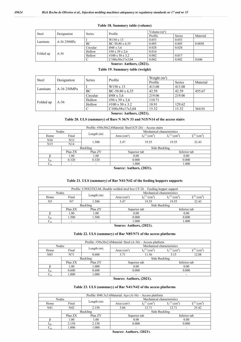
Table 18. Summary table (volume)
Steel Designation Series Profile Volume (m³) Profile Series Material
Laminate A-36 250MPa I W150 x 13 0.053 0.053 BC BC-50.80 x 6,35 0.005 0.005 0.0058
Folded up A-36
Circular Ø48 x 3,6 0.028 0.028 Hollow #50 x 39 x 2,6 0.014 Hollow #100 x 50 x 3,2 0.002 0.017 C C108x58x17x3,04 0.002 0.002 0.046
Source: Authors, (2021).
Table 19. Summary table (weight)
Steel Designation Series Profile Weight (m³) Profile Series Material
Laminate A-36 250MPa I W150 x 13 413.08 413.08 BC BC-50.80 x 6,35 42.59 42.59 455.67
Folded up A-36
Circular Ø48 x 3,6 219.06 219.06 Hollow #50 x 39 x 2,6 110.71 Hollow #100 x 50 x 3.2 18.91 129.62 C C108x58x17x3,04 15.32 15.32 364.01
Source: Authors, (2021).
Table 20. ULS (summary) of Bars N 36/N 33 and N15/N14 of the access stairs
Profile: #50x30x2.6Material: Steel (CF-26) – Access stairs Nodes
Length (m) Mechanical characteristics
Home Final Area (cm²) IX(1) (cm4) IY
(1) (cm4) It(2) (cm4)
N36 N33 1.500 5.47 19.55 19.55 32.43
N15 N14
Buckling Side Buckling
Plan ZX Plan ZY Superior tab Inferior tab β 1.00 1.00 0.00 0.00
LK 0.320 0.320 0.000 0.000 Cm - - 1.000 1.000
Source: Authors, (2021).
Table 21. ULS (summary) of Bar N41/N42 of the feeding hoppers supports
Profile: U50X25X3.04, Double welded steel box CF-26 – Feeding hopper support Nodes
Length (m) Mechanical characteristics
Home Final Area (cm²) IX(1) (cm4) IY
(1) (cm4) It(2) (cm4)
N5 N7 1.500 5.47 19.55 19.55 32.43
Buckling Side Buckling
Plan ZX Plan ZY Superior tab Inferior tab β 1.00 1.00 0.00 0.00
LK 1.500 1.500 0.000 0.000 Cm - - 1.000 1.000
Source: Authors, (2021).
Table 22. ULS (summary) of Bar N85/N71 of the access platforms
Profile: #50x30x2.6Material: Steel (A-36) – Access platform Nodes
Length (m) Mechanical characteristics
Home Final Area (cm²) IX(1) (cm4) IY
(1) (cm4) It(2) (cm4)
N85 N71 0.600 3.71 11.56 5.15 12.08
Buckling Side Buckling
Plan ZX Plan ZY Superior tab Inferior tab β 1.00 1.000 0.00 0.00
LK 0.600 0.600 0.000 0.000 Cm 1.000 1.000 - -
Source: Authors, (2021).
Table 23. ULS (summary) of Bar N41/N42 of the access platforms
Profile: Ø48.3x3.6Material: Aço (A-36) – Access platform Nodes
Length (m) Mechanical characteristics
Home Final Area (cm²) IX(1) (cm4) IY
(1) (cm4) It(2) (cm4)
N41 N42 2.150 5.06 12.71 12.71 25.42
Buckling Side Buckling
Plan ZX Plan ZY Superior tab Inferior tab β 1.00 1.00 0.00 0.00
LK 2.150 2.150 0.000 0.000 Cm 1.000 1.000 - -
Source: Authors, (2021).
49624 Rick Rocha de Oliveira et al., Injection molding machines adequancy to regulatory standards nr 17 and nr 35

Table 24. Checking resistances
Project Bar η (%)
Position (m)
Unfavorable efforts Origin Result η
(t) Vy (t)
Vz (t)
Mt (t·m)
My (t·m)
Mz (t·m)
Access stairs N36/N33 3.16 0.000 -0.154 -0.023 -0.033 0.003 -0.004 -0.004 G Pass N15/N14 18.33 0.320 -0.013 0.021 -0.080 0.004 0.015 -0.004 G Pass
Hopper sup. N5/N7 82.42 1.500 0.000 0.000 0.107 0.000 -0.155 0.000 GA Pass
Access platform
N13/N155 8.40 0.000 1.418 -0.037 -0.153 0.000 -0.043 -0.027 G Pass N41/N42 1.35 0.000 0.005 -0.001 -0.006 0.002 -0.003 -0.002 G Pass N85/N71 0.04 0.000 0.000 0.000 -0.001 0.000 0.000 0.000 G Pass
N:Axial force (t) Vy:Cutting effort along the local Y axis of the bar (t) Vz:Cutting effort along the local Z axis of the bar (t)
Mt:Torsor moment (t•m) My:Bending moment in the 'XZ' plane (t·m) Mz: Bending moment in the 'XY' plane (t·m)
Source: Authors, (2021). Table 25. Results of the Employee Satisfaction Survey
Questions Yes No Indiferent Have security conditions been improved? 100% 0% 0% Have working conditions been improved? 100% 0% 0% Have the product quality conditions been improved? 0% 10% 90% Does the Company value employee safety? 100% 0% 0% Question: How would you rate the implemented change? Extremely positive 80% Negative 0% Positive 10% Extremely negative 0% Indifferent 0% No formal opinion 10%
Source: Authors, (2021)
Source: Authors, (2021).
Figure 11. Lateral (left) and front (right) views of the stairs – Scale 1:25.
Source: Authors, (2021)
Figure 12. Finished prototypes of the access ladder (left) and hopper support (right).
49625 International Journal of Development Research, Vol. 11, Issue, 08, pp. 49615-49628, August, 2021
Source: Authors, (2021).
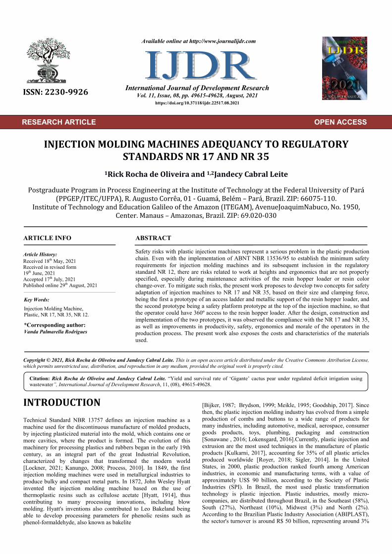
Figure 13. Maintenance using the ladder and hopper support
prototype
Source: Authors, (2021).
Figure 14. Maintenance using the prototype of ladder and funnel
support
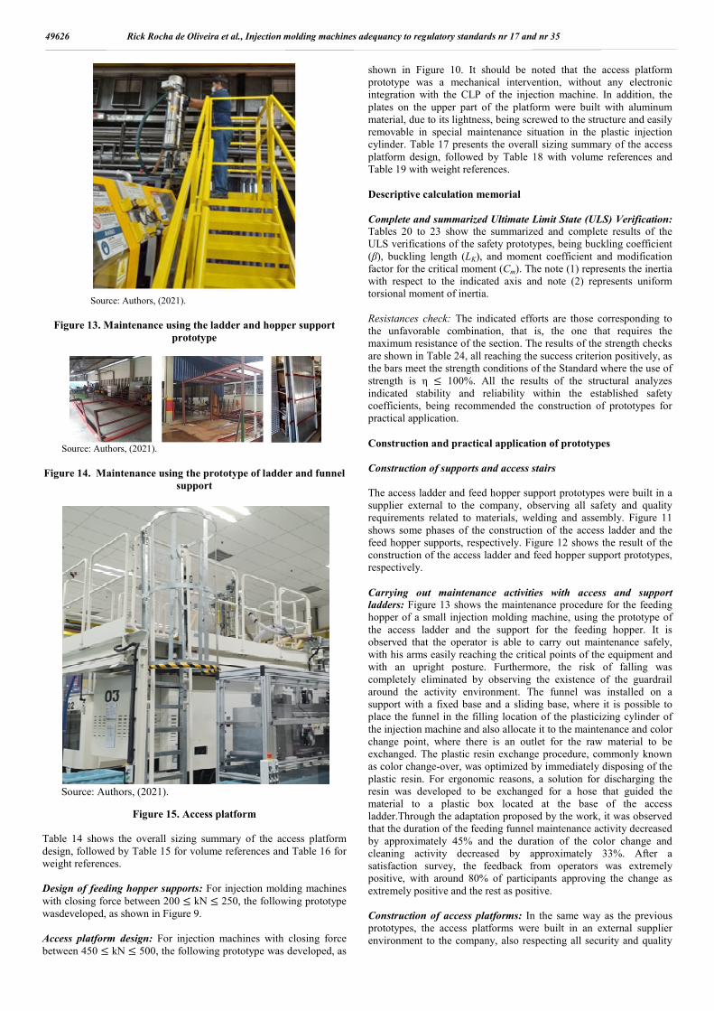
Source: Authors, (2021).
Figure 15. Access platform Table 14 shows the overall sizing summary of the access platform design, followed by Table 15 for volume references and Table 16 for weight references. Design of feeding hopper supports: For injection molding machines with closing force between 200 ≤ kN ≤ 250, the following prototype wasdeveloped, as shown in Figure 9. Access platform design: For injection machines with closing force between 450 ≤ kN ≤ 500, the following prototype was developed, as
shown in Figure 10. It should be noted that the access platform prototype was a mechanical intervention, without any electronic integration with the CLP of the injection machine. In addition, the plates on the upper part of the platform were built with aluminum material, due to its lightness, being screwed to the structure and easily removable in special maintenance situation in the plastic injection cylinder. Table 17 presents the overall sizing summary of the access platform design, followed by Table 18 with volume references and Table 19 with weight references. Descriptive calculation memorial Complete and summarized Ultimate Limit State (ULS) Verification: Tables 20 to 23 show the summarized and complete results of the ULS verifications of the safety prototypes, being buckling coefficient (β), buckling length (LK), and moment coefficient and modification factor for the critical moment (Cm). The note (1) represents the inertia with respect to the indicated axis and note (2) represents uniform torsional moment of inertia. Resistances check: The indicated efforts are those corresponding to the unfavorable combination, that is, the one that requires the maximum resistance of the section. The results of the strength checks are shown in Table 24, all reaching the success criterion positively, as the bars meet the strength conditions of the Standard where the use of strength is η ≤ 100%. All the results of the structural analyzes indicated stability and reliability within the established safety coefficients, being recommended the construction of prototypes for practical application. Construction and practical application of prototypes Construction of supports and access stairs The access ladder and feed hopper support prototypes were built in a supplier external to the company, observing all safety and quality requirements related to materials, welding and assembly. Figure 11 shows some phases of the construction of the access ladder and the feed hopper supports, respectively. Figure 12 shows the result of the construction of the access ladder and feed hopper support prototypes, respectively. Carrying out maintenance activities with access and support ladders: Figure 13 shows the maintenance procedure for the feeding hopper of a small injection molding machine, using the prototype of the access ladder and the support for the feeding hopper. It is observed that the operator is able to carry out maintenance safely, with his arms easily reaching the critical points of the equipment and with an upright posture. Furthermore, the risk of falling was completely eliminated by observing the existence of the guardrail around the activity environment. The funnel was installed on a support with a fixed base and a sliding base, where it is possible to place the funnel in the filling location of the plasticizing cylinder of the injection machine and also allocate it to the maintenance and color change point, where there is an outlet for the raw material to be exchanged. The plastic resin exchange procedure, commonly known as color change-over, was optimized by immediately disposing of the plastic resin. For ergonomic reasons, a solution for discharging the resin was developed to be exchanged for a hose that guided the material to a plastic box located at the base of the access ladder.Through the adaptation proposed by the work, it was observed that the duration of the feeding funnel maintenance activity decreased by approximately 45% and the duration of the color change and cleaning activity decreased by approximately 33%. After a satisfaction survey, the feedback from operators was extremely positive, with around 80% of participants approving the change as extremely positive and the rest as positive. Construction of access platforms: In the same way as the previous prototypes, the access platforms were built in an external supplier environment to the company, also respecting all security and quality
49626 Rick Rocha de Oliveira et al., Injection molding machines adequancy to regulatory standards nr 17 and nr 35

requirements. Figure 14 shows some phases of the construction of access platforms. Carrying out maintenance activities with access platforms: Figure 15 shows the access platform installed on one of the injection machines in the scope of work. Similar to what was observed with the prototype of metallic support and access ladder, the operator is able to carry out maintenance safely, having 360º access to the feeding funnel and with an ergonomically correct posture. The risk of falling was completely eliminated by observing the existence of the guardrail. Satisfaction survey: Ten employees involved in maintenance and color change in the plastic injection process were interviewed. The results of the satisfaction survey are shown in Table 25.
CONCLUSION The bibliographic survey carried out with sources of books, articles from scientific journals, monographs, theses and dissertations, electronic files and technical manuals was important for a thorough understanding of the plastic injection process, specifying the machine and plastic injection mold, process parameters and the main characteristics of the most used polymers. In addition, it was possible to consolidate the basic requirements related to the safety of the plastic injection process following Brazilian standards, such as NR 12, NR 17, NR 18, NBR 13536, NBR 6118, and international standards, such as ANSI 1264.1 and EM 365.To mitigate the risks of working at heights encountered during maintenance of the feed hopper and raw material color change-over (change-over) of the plastic injection process, it was necessary to develop two prototype concepts for safety adaptation. Injection machines falling within the scope of safety adequacy were divided into two categories according to their size and closing force, the first part being considered small with a closing force between 200 ≤ kN ≤ 250 and the second part considered medium-sized with closing force between 450 ≤ kN ≤ 500.For small machines, a prototype of a feeding funnel access ladder was developed, allowing safe access to the feeding funnel, as well as a feeding funnel support prototype that allows the horizontal movement of the funnel to the point. Machine supply and maintenance area. Likewise, for medium-sized machines, a prototype platform was developed on top of the injection machine, so that the operator could have 360º access to the feed hopper. For both prototypes, it was concluded that the process of maintaining the feed funnel and changing the color of the raw material (change-over) could be carried out in an ergonomically correct manner and the risks of falling, crushing, burns were eliminated, consequently taking care of the regulatory standards NR 17 and NR 35.As part of the development of the prototypes, the costs of materials for the construction of the access ladder and feed funnel support prototypes were also determined, totaling a cost of R$ 10,363.39 per injection machine, being divided into R$ 8,422.02 for the access ladder and R$1,941.36 and funnel support. The cost of materials for the access platform was determined at R$ 34,480.54 per injection machine.To prove the safety of the prototypes, calculation memorials were made to verify the Ultimate Limit State (ULS), combinations of efforts in critical bars, envelopes of efforts in bars and arrows of the access stairs (N36/N33 and N15/N14 ), feed hopper supports (N5/N7) and access platforms (N13/N155, N41/N42 and N85/N71). Completion of the calculation memorial indicates that the prototypes meet all requirements within the safety margin, being structurally within the design criteria.The prototypes proposed by this work not only had a positive impact on the safety and ergonomics of the plastic injection process, but also had productivity results, where it was observed that the duration of the maintenance activity of the feed hopper decreased by approximately 45% and the duration of the color change and cleaning activity decreased by approximately 33%.According to the satisfaction survey, the purpose of the project was satisfactorily achieved. Operator feedback was extremely positive, with around 80% of respondents approving the change as extremely positive and the rest as positive.Finally, it is concluded that Brazilian standards
and regulations have indisputably advanced a lot in the last two decades in terms of safety related to plastic injection machines, especially due to the implementation of ABNT NBR 13536 from 1995. However, there are still opportunities for improvement in relating NR 12, specifically Annex IX, with other regulatory standards, such as working at heights and ergonomics. Through this work, it is recommended a thorough analysis of this matter by the responsible technical bodies so that, in an upcoming review of NBR 13536 and Annex IX of NR 12, specific project requirements are included to meet NR 17 and NR 35. Acknowledgment To the Postgraduate Program in Process Engineering at the Institute of Technology at the Federal University of Para (PPGEP/ITEC/UFPA) and the Institute of Technology and EducationGalileo of the Amazon (ITEGAM), for the research opportunity.
REFERENCES Lockner, Y.; Hopmann, C. Induced network-based transfer learning
in injection molding for process modelling and optimization with artificial neural networks. The Int. Journal of Adv. Manufacturing Technology, 2021.
Kanungo, A.; Swan, E. Todas as máquinasinjetoraselétricas: quanta energiavocêpodeeconomizar. In: Proceedings of the 13th Industrial Energy technology Conference, New Orleans, LA. 2008.
Process – A, Moldagem Por Injeção. Métodos recentes para otimização do processo de moldagem por injeção de plástico - uma retrospectiva e revisão da literatura. 2010.
Hyatt, J. W. Ind. Eng. Chem, v. 6, p. 158, 1914. Bijker, E. The social construction of Bakelite: Toward a theory of
invention. Cambridge, MA: MIT Press, 1987. Brydson, J. A. Plastics materials. Elsevier, 1999. Meikle, J. L. American plastic: a cultural history. Rutgers University
Press, 1995. Goodship, V.Arburg -Practical guide to injection moulding.
SmithersRapra, 2017. Sonawane, S. D.; Dahake, S. K. Simulation of plastic Ice-Cream
spoon for prevention of failure, 2016. Lokensgard, E.Industrial plastics: theory and applications. Cengage
Learning, 2016. Kulkarni, S. Robust Process Development and Scientific Molding,
Munique: Hanser, 2017. Royer, S. et al. Production of methane and ethylene from plastic in
the environment. PLOS One, v. 13, n. 8, p. e0200574, 2018. Sigler, M. Os efeitos da poluição por plásticos na fauna aquática:
situações atuais e soluções futuras. Água, Ar e Poluição do Solo , v. 225, n. 11, pág. 1-9, 2014.
IAP. Instituto Avançado do Plástico. São Paulo: Planeta Plástico, 2002.
SUFRAMA. Perfil das Empresas com Projetos Aprovados pela SUFRAMA. Artigo em Hypertexto. Disponível em: <http:site.suframa.gov.br/assuntos/modelo-zona-franca-de-manaus/copy2_of_PERFILJANEIRO2017.pdf/view>. Acesso em: 29 ago. 2017.
Serviço Social da Indústria (SESI-SP). São Paulo. 2012. Torres, J. Prevenção de acidentes em máquinas injetoras de plásticos.
Dossiê Técnico, SENAI, Rio Grande do Sul, 2007. Coelho, E. D.; Vilela, R. A. G.; Tsunabi, W. Injeção de segurança no
setor plástico. Convenção sobre segurança em máquinas injetoras. In: Bonciani, M. (Org.). São Paulo: LTR, 1996. p.155-199.
Melo, T. Determinação do SRTE/AM interdita cinco máquinas na FCC do Brasil. Artigo em Hypertexto. Disponível em: <http://g1.globo.com/am/amazonas/noticia/2011/11/determinacao-do-srteam-interdita-cinco-maquinas-na-fcc-do-brasil.html. Acesso em: 27 março 2021.
Tadmor, Z.; Gogos, C. Principles of Polymer Processing. Nova Jersey: John Wiley & Sons, 2006.
49627 International Journal of Development Research, Vol. 11, Issue, 08, pp. 49615-49628, August, 2021

Costa, N.; Ribeiro, B. A Neural Prediction Model for Monitoring and Fault Diagnosis of Plastic Injection Molding Process. European Conference Control, p. 2381-2385, 1999.
Lipshitz S. D.; Lavie, R.; Tadmor, Z. A Melting Model for Reciprocating Screw Injection Molding Machines, Polym. Eng. Sci, v. 14, p. 553, 1974.
Rosato, D.V.; Rosato, D.V.; Rosato, M.G. Injection Molding Handbook. Norwell: KluwerAcademicPublishers, 2000.
Junior, V.; Wander. P.; Altafini, C. Redução do Consumo de Energia no Cilindro de Plastificação numa Máquina Injetora de Plásticos. VI Congresso Nacional de Engenharia Mecânica, 2010.
Bryce, D. PlasticInjectionMolding: Manufacturing Process Fundamentals, Dearborn: SME, 1996.
Blass, A. Processamento de Polímeros. Florianópolis: Editora UFSC, 2 ed. 1988.
Rosato, D. Plastics Processing Data Handbook, Massachussets: Kluwer, 2000.
Johannaber, F. Injection molding machines: A user’s guide. Munique: Hanser, 2008.
Protec. Moldes para plásticos. São Paulo, 2002. Singh, G.; Verma, A. A Brief Review on injection moulding
manufacturing process. 5th Int. Conf. of Materials Processing and Characterization, 2016.
Rezavand, S. A. M.; Behravesh, A. H. An experimental investigation on dimensional stability of injected wax patterns of gas turbine blades. Journal of materials processing technology, v. 182, 2007.
Selvakarthi. D.; Prasad, S.; Meenakumari, R.; Balakrishnan, D. Optimized Temperature Controller for Plastic Injection Molding System. Green Computing Communication and Electrical Engineering, v. 28, p. 1429-1435, 1936.
Liu, T.; Yao, K.; Gao, F. Identification and Auto tuning of Temperature-Control System with Application to Injection Molding, IEEE Transactions on Control Systems Technology, vol. 17, p. 1282-1294, 2009.
Khomenko, M.; Velihorskyi, O.; Chakirov, R.; Vagapov, Y. Parameters identification of injection plastic molding heaters. 36th International IEEE, 2016.
Diduch, C.; Dubay, R.; Gui Li, W. Temperature control of injection molding. Part I: Modeling and identification. Polymer Engineering and Science, 2004.
Painter, P.; Coleman, M. Fundamentals of polymer science: an introductory text. Lancaster: Technomic Pub. 1997.
Todd, R.; Allen, D.; Alting, L. Manufacturing Processes Reference Guide. Nova Iorque: Industrial Press Inc, 1994.
Olmsted, B.; Davis, M. Practical Injection Molding. Nova Iorque: CRC Press, 2001.
Lucas, E.; Soares, B.; Monteiro, E. Caracterização de Polímeros: Determinação de Peso Molecular e Análise Térmica, Rio de Janeiro: E-Papers Serviços Editoriais, 2001.
Mano, E. B. Polímeros como Materiais de Engenharia. São Paulo: Blucher, 1991.
Ravve, A. Prynciples of Polymer Chemistry, New York: Springer, 2012.
Collins, C.; Braga, G. Introdução a Métodos Cromatográficos. Campinas: Editora UNICAMP SérieManuais, 3ª ed., 1998.
Janos, P. Separation methods in the chemistry of humic substances, Journal of Chromatography, 2003.
Wartchow, M. Revista Proteção, Saúde e Segurança do Trabalho (Digital): 40 anos de prevenção – Normas Regulamentadoras. São Paulo: Proteção Publicações, 2018.
MinistryofLabour. NR-35 Trabalho em altura. Portaria MTE nº 1.127, 2003.
ABNT. NBR 13536: Máquinas injetoras para plástico e elastômeros-Requisitos técnicos de segurança para o projeto, construção e utilização. Rio de Janeiro, 2016.
Ministério do Trabalho e Emprego. NR-18 Segurança e Saúde no Trabalho na Indústria da Construção. Portaria MTE nº 3.733, 2020.
49628 Rick Rocha de Oliveira et al., Injection molding machines adequancy to regulatory standards nr 17 and nr 35
*******