Possibility of improvement on Ozone Production by using the Back-Corona effect
10
11 Ozone: Science and Engineering, 26:11–19, 2004 Copyright Taylor & Francis Inc. ISSN: 0191-9512 print DOI: 10.1080/01919510490426036 c Possibility of Improvement on Ozone Production by Using the Back-Corona Effect R. Peyrous Université de Pau and Pays de l’Adour, CURS, Laboratoire L.E.G.P., Avenue de l’Université, Pau, France. Received for review: 7 October 2002 Accepted for publication: 4 July 2003 Address Correspondence to R. Peyrous, Universite de PAU & Pays de l’Adour, CURS, Laboratoier L.E.G.P. Avenue de l’Universite, PAU, 64000, France. ABSTRACT Electrostatic precipitators’ problems and experimental results in point-to-plane or wire-to-cylinder systems indicate that the presence of a thin layer of porous dielectric material on the elec- trodes increases the discharge current for the same applied potential. This so-called Back-Corona effect, which generally reduces the spark- ing potential, depends on the active electrode polarity; nature, and thickness and porosity of the insulating layer; and position on the active or passive electrode of the deposited particles or insulating layer. In laboratory experiments in a point-to-plane device, with a dielectric porous layer on the plane, the current may be many times higher than its “normal” value (clean electrodes). In a DC negative wire-to-cylinder system, where the ozone concentration depends quasi directly on the discharge current, it appears possible to increase the ozone production, for the same running conditions (gas flow, electrical circuit, etc.). KEY WORDS Ozone; Wire-to-Cylinder Ozone Generator; Point-to-Plane Ozone Generator; Electrostatic Precipitators; Back-Corona Effect; Porous Dielectric rom some works published since 1946 (1–4) and from dealing with electrostatic precipitators’ problems, it appears that the presence of a thin layer of porous dielectric material on the electrodes, gener- ally dust of various sizes, shapes, and moisture content, increases the current inside the precipitator system (wire-to-plate device) for the same applied potential. This current increase leads generally to a lowering of F
Transcript of Possibility of improvement on Ozone Production by using the Back-Corona effect
11
Ozone: Science and Engineering, 26:11–19, 2004Copyright Taylor & Francis Inc.ISSN: 0191-9512 printDOI: 10.1080/01919510490426036
c
Possibility of Improvement onOzone Production by Using
the Back-Corona Effect
R. Peyrous Université de Pau and Pays de l’Adour, CURS, Laboratoire L.E.G.P., Avenue de l’Université, Pau, France.
Received for review: 7 October 2002Accepted for publication: 4 July 2003
Address Correspondence to R. Peyrous, Universite de PAU & Pays de l’Adour, CURS, Laboratoier L.E.G.P. Avenue de l’Universite, PAU, 64000, France.
ABSTRACT Electrostatic precipitators’ problems and experimentalresults in point-to-plane or wire-to-cylinder systems indicate that thepresence of a thin layer of porous dielectric material on the elec-trodes increases the discharge current for the same applied potential.This so-called Back-Corona effect, which generally reduces the spark-ing potential, depends on the active electrode polarity; nature, andthickness and porosity of the insulating layer; and position on theactive or passive electrode of the deposited particles or insulatinglayer. In laboratory experiments in a point-to-plane device, with adielectric porous layer on the plane, the current may be many timeshigher than its “normal” value (clean electrodes). In a DC negativewire-to-cylinder system, where the ozone concentration dependsquasi directly on the discharge current, it appears possible to increasethe ozone production, for the same running conditions (gas flow,electrical circuit, etc.).
KEY WORDS Ozone; Wire-to-Cylinder Ozone Generator; Point-to-Plane OzoneGenerator; Electrostatic Precipitators; Back-Corona Effect; Porous Dielectric
rom some works published since 1946 (1–4) and from dealing withelectrostatic precipitators’ problems, it appears that the presence ofa thin layer of porous dielectric material on the electrodes, gener-
ally dust of various sizes, shapes, and moisture content, increases thecurrent inside the precipitator system (wire-to-plate device) for the sameapplied potential. This current increase leads generally to a lowering of
F

12 R. PEYROUS
the sparking potential and a reduction of the pre-cipitation yield. This so-called Back-Corona (BC)effect, generally considered detrimental in electro-static precipitators (5, 6), was already observed in1958 accompanied by an increase of the ozoneproduction “in cleaning air for ventilatingpurposes . . . the Ozone generated may be manytimes that of the normal discharge” (7). Theseremarks led the author to verify these statementswith a view toward increasing ozone production tak-ing into account the fact that numerous resultshave shown that ozone concentration dependsquasi-directly on the discharge current, in a wire-to-cylinder system, with a DC negative voltage appliedto the wire (8).
Some experimental results in plane-plane (2, 3),wire-to-cylinder (7, 8), or point-to-plane systems (1–4)show that the behavior depends on: the polarity ofthe active electrode; the position, on the activeor passive electrode, of the deposited particles orinsulating layer; and, for the insulating layer, itsnature (chemical and electrical properties), andthickness and porosity (or mesh size).
In a point-to-plane or wire-to-cylinder system,whatever the polarization of the stressed electrode,with a dielectric porous layer on the groundedelectrode, above a given potential the current maybe many times higher than its “normal” value withclean electrodes before the transition to arc. Someresults indicate that, for the same current, the appliedpotential can be lowered by about 30% (2–4, 9).A few results obtained in a point-to-plane reactor,with various porous layers on the plane, presentedbelow confirm this point.
Then, in a wire-to-cylinder ozone generator, itappears possible to increase the ozone productionby covering the inner wall of the cylinder with aporous dielectric layer and, at the same time, theproduction yield for the same running conditions(reactor geometry, gas flow, electrical circuit).
A good knowledge of the BC effect, which isalready used for the decomposition of hydrocarbongaseous contaminants (5, 6) and in NOx removal(10), could lead to various industrial applicationsand more particularly to ozone production in wire-to-cylinder systems.
EXPERIMENTAL SET-UP AND CONDITIONS
From previous results obtained (3, 4, 9) and bytaking into account remarks made by variousauthors (1–8, 11) in the literature, we have attemptedto determine the role of the main parameters actingon the current increase due to the BC effect: thick-ness, resistivity, and porosity of the dielectric porouslayer deposited on the electrodes. Consequently wehave used various dielectric supports (paper, coffeefilter paper, nylon fabrics, PTFE film) the thickness,porosity, and resistivity values of which can be meas-ured, with the aim to define the best conditions toobtain a regular and steady BC. Keeping in mindthe fact that in a wire-to-cylinder ozone generatorthe ozone concentration is a quasi-linear functionof the total mean discharge current (8) for a largevariation range, we have attempted to use this cur-rent increase to improve the ozone production andthen to transform a so-considered detrimental effectin electrostatic precipitators into an advantageousone in wire-to-cylinder ozone generators.
The preliminary experiments were made witha point-to-plane device. Numerous results wereobtained by varying:
the polarity of the DC HV applied to the point:positive or negative;
the point-to-plane distance: 7mm or 10 mm; the nature of the porous dielectric layer deposited
on the plane: printing paper, filter paper, nylonfabrics, or PTFE film.
Since 1946 Pauthenier et al. and others havereported some laboratory experiments where thethin dust layer was simulated by various, more orless porous, dielectric materials in plane-to-plane(1–3), point-to-plane (2, 4–6, 9), or wire-to-cylinder(7, 11) systems. The materials used were silk, filterpaper, mica (2, 5–6), cambric (7), paper, cloth, card-board, glass cloth, Kleenex (11), and nylon (3–4, 9).
The effect of the insulating layer thickness wasalready noted in 1958 by Penney and Hewitt whoindicated that “with a thin layer of dust the coronacurrent tended to be above normal” (7). Therefore
OZONE PRODUCTION USING THE BACK-CORONA EFFECT 13
we have chosen dielectric layers in the limited thick-ness range from 0.09mm to 0.3mm considered aspermitting us to obtain a high current value withoutlowering of the sparking voltage (1–3, 5–8, 11, 12).
The importance of the dielectric layer resistivityand its action on the spark-over voltage were dis-cussed in (12). The surface conduction of thedielectric depends on its chemical composition andnature of the flue gas (12). Nylon fabrics and PTFEfilms have a high resistivity in the 1013–1015 Ω/cmrange higher than the 1011–1012 Ω/cm values gener-ally admitted as critical (12). “When ρd (resistivityof the dielectric layer) was between ~ 5.1010 and9.1010 ohm.cm.. .excessive sparking tended to occur”but “when ρd > 1012 ohm.cm excessive sparking dis-appears but an abnormal increase in current occurs”(13), which agrees with the values given in (14). Thevolume resistivities for the classical 80g white printingpaper and paper filter are in the 1.1011–3.1012 Ω/cmrange but nevertheless, from the results obtained,they induce an important BC effect. In this case thelimitation for a possible industrial application isthe chemical reactivity of the paper with the ozoneproduced. “The resistivity of most dust and porousmaterial varies with the relative humidity” (11). Butmoisture content is without influence on the nylontissue (1–3) which is not the case for paper. Theareas of hard BC usually have a thin layer of dustand are often severely cratered (12).
To verify the assumptions of Laurent (2) on therole played by the number of holes in the dielectric,we have regularly pierced, through printing papersor PTFE films (thickness e = 0.1 mm), a variablenumber of holes 200 µm in diameter as in (5, 6),by using a sewing needle tip and printed circuitgrids with 1.27mm (1/20") or 2.54mm (1/10") steps.So we modify the porosity in a fourfold ratio. As ageneral rule there is always a BC effect when thereis only one hole, at the good place inside the dis-charge area, in the dielectric layer.
The filter paper (e = 0.1 mm) has numerousrandomly distributed irregularly shaped holes inthe 10–100 µm diameter range but essentially lowerthan 80 µm. Due to their fashioning, nylon fabricshave regular rectangular holes with 40–80 µm ×40–120 µm sides range and more generally close to
about 80 × 80 µm separated by about 250 µm whichcorresponds to about 200holes/16 mm2. This wasmeasured by using a two-eyed microscope (Leitz)with a micrometric scale (4mm). Three types ofnylon fabrics were used:
in single layer: e = 0.09mm, 0.10mm (Wh), or0.125mm (Bu);
or double layers: e = 0.19, 0.24 mm.
EXPERIMENTAL RESULTS
Point-to-Plane System
The conical rhodium point has a 50µm tipcurvature radius and the plane, in aluminum orstainless steel, has a 60mm diameter. The DC HVis applied to the point through a 20 or 50MΩ HVloading resistor, by using a reversible HV powersupply (DEL RHVS 10kV–100mA). The total meancurrent is measured at the plane through a 50 Ωresistor with a digital multimeter (Metrix 56 asycII)and the interelectrode voltage by using a HV probe(Fluke 87).
The results presented here were obtained withBC in negative polarity for a 7mm interelectrodegap, keeping in mind that some interesting resultsin ozone production were obtained with dry air byusing a very simple DC HV wire-to-cylinder system(15–19). “Negative abnormal corona will not causethe excessively premature breakdown that positiveflares will” (7).
Whatever the polarization, in a point-to-planesystem in ambient air with a dielectric porous layeron the plane, the current with back ionizationbefore the transition to arc increases much morerapidly and can be many times higher than withclean electrodes, in accordance with (7).
As reported in Figure 1, the BC effect is steadilyobtained with all the various dielectric layers usedfrom paper to PTFE film. The line noted 20 MΩ isthe total mean current limits due to the loadingresistor.
With a printing paper layer we always have aCorona discharge, while for PTFE film withoutholes we have no current up to 10kV applied to the

14 R. PEYROUS
7 mm interelectrode gap. The curves obtained withprinting or filter paper are comprised inside theones for nylon fabrics.
The Corona onset voltage is independent of theporous layer thickness, in the 0.09 to 0.24mm range,if the critical resistance is in the range of 1011 to1012 Ω/cm which is the case for the dielectric layersconsidered. The “normal” current can be multipliedfive times in presence of the dielectric layer for thesame interelectrode potential applied (e.g., 7 kV).
The steady current reached for a 7 mm inter-electrode gap is higher than for a 10 mm one andthe gap voltage reduced about 25% (e.g., at 35 µA)in stable conditions. This is in complete agreementwith previous papers (1, 4, 9) and these curves canbe compared with Figure 2, from Pauthenier (3),who noted that “for a constant voltage, the appearingof back-corona well corresponds with an increase ofthe discharge current.” The current may be severaltimes the “normal” current, up to 7 times (2, 4, 7,9, 11). A hysteresis effect on the BC thresholdpotential was also observed but without usual interestfor us.
The results presented in Figure 1 can lead to amisunderstanding because it could be deduced thatthe current decreases as a function of the dielectric
layer thickness. But . . . by superposing two layers ofnylon fabric we have modified not only the thick-ness of the layer but also the number and dimen-sion of the holes as was the case in Figure 2 (fromRef. (3)). “The spark-over voltage is not related tothe intensity of the back-corona current, but to thethickness of the dust layer (or equivalent), for amedium-high resistivity dust” (12), and to its resis-tivity.
“One of the unexpected characteristics of thethin layers is that even though large total back-corona currents flow and the back discharge is uni-formly distributed over the surface, the spark-over isabove ‘normal.’ However, as the layer thicknessincreases the spark-over voltage decreases”(12). Thisimplies that, as previously noted, “there is someoptimum thickness” (7).
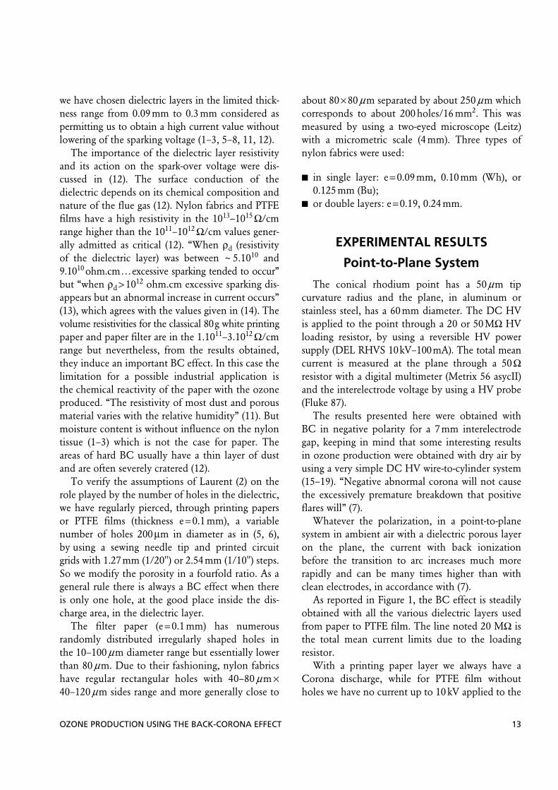
The role played by the number of holes in thedielectric layer on the plane was studied by piercingholes in printing paper or PFFE film as indicatedin the experimental conditions. The photographspresented here (Figure 3) can be compared withthe ones published by Masuda and Mizuno (13)
FIGURE 1 Total mean current (s.) the interelectrodepotential (negative polarity) applied to the point, gapd = 7 mm, atmospheric air. BC effect: Comparison betweenvarious dielectrics, nylon fabrics, one or two layers. W, cleanplane. FIGURE 2 From (3), in point-to-plane, atmospheric air,
negative polarity. I: Plane without porous dielectric, II, III,IV, V, with a nylon film; II: e = 0.13 mm, hole = 90 µm;III: e = 0.09 mm, hole = 70 µm; IV: e = 0.12 mm, hole = 60 µm;V: e = 0.125 mm, hole = 40 µm.
OZONE PRODUCTION USING THE BACK-CORONA EFFECT 15
obtained also in a point-to-plane geometry. “Eachhole, becomes the seat of a tuft, the secondaryemission is a function of the number of holes up toa maximal value” (2). Each hole looks like a glowsurrounding a point and we can see that the visiblehalo all around the holes is contained into a limitedarea where the ions can be trapped by the dielectriclayer. The intensity of the light emission and itswavelength depend on the nature of the layer; thelight intensity is decreasing from the discharge axisto the surroundings and the wavelength is essen-tially blue for the paper filter and nylon fabric(Figure 3A and B), when the luminosity is quasi-identically distributed in the purple tones for thePTFE film (Figure 3C).
From remarks made on these photographs inreversed colors, in the Figure 3A and B conditions,there is a luminous halo contained in a circular areasurrounding the pierced surface and certainly definedby a quasi—Warburg law distribution. With the PTFEfilm (Figure 3C), the luminosity is strictly limited tothe boundaries of the holes zone. “Increase in ρdfavors the tendency to the surface-glow mode andspace-streamers are few. In this case many weak pointsbroke down and the current increased readily withoutexcessive sparking” (13), in accordance with Penneyand Craig (11).
The results obtained with regularly pierced PTFEfilms are illustrated by Figures 4 and 5. They showclearly that BC effect needs only a small number ofholes, 4, and rapidly reaches its maximum currentvalue for a limited number of holes, 30. When usinga paper layer of lower resistivity than PTFE, the gridstep does not act particularly but we need equallyabout 30 holes to reach the same maximal currentvalues which remain constant up to more than50 holes. Consequently, the porosity cannot be theonly one valuable criterion because it depends onthe number and area (function of the dimensionsand shape) of the holes regularly distributed on adetermined surface axially positioned in the dis-charge zone.
Each hole interacts with its neighbors, as a func-tion of the layer resistivity and, with PTFE film, itis better to use a 1/10" (2.54 mm) than a 1/20"(1.27mm) grid step to more rapidly reach the
FIGURE 3 Back=corona effect photographs. Point-to-plane, d = 7 mm, negative polarity, ambient air, stainless steelplane covered by a dielectric material: (A) Coffee filter paper,randomly dispatched “natural” holes, ∅ in the 10–100 µmrange, 6.8 kV, 175 µA, exp: 0.5 s; (B) white printing paper,50 holes, 7.3 kV, 147 µA, exp: 0.25 s; (C) PTFE film, 25 holes,∅ = 200 µm on 1.27 mm step grid, ∅ = 200 µm on 1.27 mmstep grid, 7 kV, 160 µA, exp: 0.5 s.

16 R. PEYROUS
maximum current for the same applied potential(Figure 5). As also shown in Figure 5, in agreementwith the values obtained in (2), the number of holesnecessary to reach 130 mA with a 7kV appliedpotential is about 25.
From the results obtained, the use of holes about80µm in diameter separated by about 300µm seemsto be a reasonable compromise, which correspondsto the nylon fabrics. From rough estimations, it
appears that we have an obvious increase in ozoneproduction with the presence on the plane of aporous dielectric layer, whatever it is.
With the point-to-plane device we have verifiedsome parts of the assertions on the BC dischargebut we cannot obtain very important and interestingozone production. We need to use a well-knownwire-to-cylinder system (15–19).
Wire-to-Cylinder Ozone Generator
Some recent literature has dealt with ozone pro-duction in electrostatic wire-plate system air clean-ers (20). It was pointed out that “contamination ofthe electrodes does not alter corona onset voltage,but reduces spark-over voltage,” “dusty plates ratherthan contaminated wires cause higher current andozone concentration levels,” and “[i]ncreases inozone production with time are due to the forma-tion back-corona . . . a 3 fold escalation in current isaccompanied by a 10 fold increase in ozone” (20).Consequently, we have attempted to apply all theseremarks from our experimental results and literatureto a wire-to-cylinder ozone generator.
By overlapping the internal surface of the cylin-der with a dielectric porous layer, comparisons canbe done between the initial ozone generator system(naked passive electrode) and the one using the BCeffect. The first experiments were made in a wire-to-cylinder reactor. The stressed electrode is an axialMonel 400 wire, 0.2 mm in diameter, connected toa Spellman SL 150 negative DC HV power supplythrough a 10 MΩ HV loading resistor. The duralu-min cylinder is 16 mm in inner diameter and 20cmin length. For simplicity, the first choice to overlapthe inner wall with a porous dielectric layer was anylon fabric jacket the characteristics of which are:
thickness e= 0.12mm; about 200 holes, ~80 µm × 80 µm each, over
16mm2; resistivity: 2–3 × 10¹³ Ω/cm at 800V.
We have used ambient air dried by passingthrough two silica gel flasks in line with a 4 to 10L/hgas flow range (Q).
FIGURE 4 Total mean current vs. interelectrode potentialas a function of the number of holes: 7 mm gap, PTFE film,∅ = 0.2 mm, grid step = 2.54 mm. Atmospheric air, negativepolarity.
FIGURE 5 Total mean current vs. the number of holes ina PTFE film as a function of the interelectrode potential:gap = 7 mm, holes ∅ = 0.2 mm, grid step = a (dashed),2.54 mm, b, 1.27 mm. Atmospheric air, negative polarity.
OZONE PRODUCTION USING THE BACK-CORONA EFFECT 17
Figure 6 displays the results obtained by compar-ing the two wire-to-cylinder reactors without orwith inner porous dielectric layer (nylon fabric)inducing BC. We can see the threshold potentialincrease, the BC starting at the crossing point withthe “normal” curves and the important currentincrease above this potential around 6.8 kV.
These results are in complete accordance withthe ones previously reported in the literature. Thegas flow rate variation cannot permit us to deter-mine its effective impact on the I versus V curves.Taking into account the fact that as generallyadmitted the ozone concentration is a direct func-tion of the total mean current, we can hope toincrease the ozone production.
Ozone production
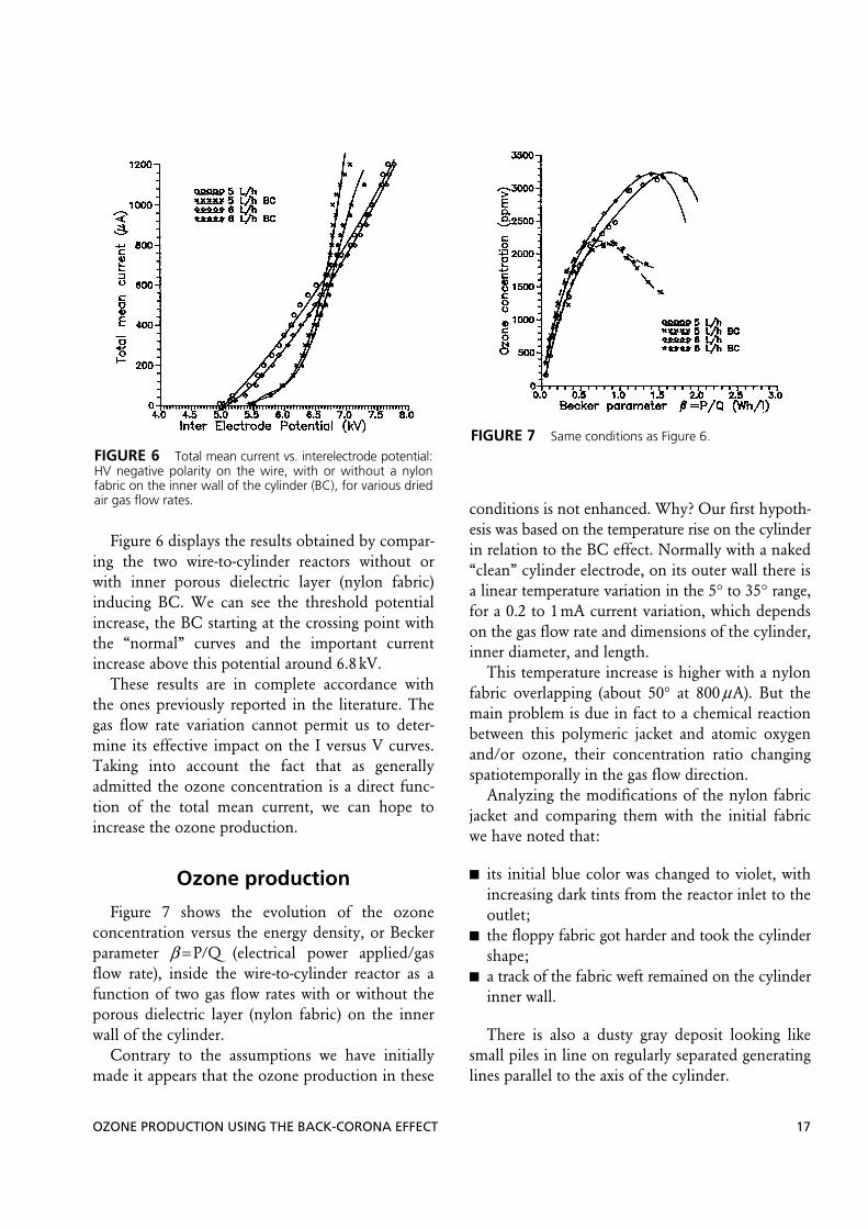
Figure 7 shows the evolution of the ozoneconcentration versus the energy density, or Beckerparameter β = P/Q (electrical power applied/gasflow rate), inside the wire-to-cylinder reactor as afunction of two gas flow rates with or without theporous dielectric layer (nylon fabric) on the innerwall of the cylinder.
Contrary to the assumptions we have initiallymade it appears that the ozone production in these
conditions is not enhanced. Why? Our first hypoth-esis was based on the temperature rise on the cylinderin relation to the BC effect. Normally with a naked“clean” cylinder electrode, on its outer wall there isa linear temperature variation in the 5° to 35° range,for a 0.2 to 1mA current variation, which dependson the gas flow rate and dimensions of the cylinder,inner diameter, and length.
This temperature increase is higher with a nylonfabric overlapping (about 50° at 800 µA). But themain problem is due in fact to a chemical reactionbetween this polymeric jacket and atomic oxygenand/or ozone, their concentration ratio changingspatiotemporally in the gas flow direction.
Analyzing the modifications of the nylon fabricjacket and comparing them with the initial fabricwe have noted that:
its initial blue color was changed to violet, withincreasing dark tints from the reactor inlet to theoutlet;
the floppy fabric got harder and took the cylindershape;
a track of the fabric weft remained on the cylinderinner wall.
There is also a dusty gray deposit looking likesmall piles in line on regularly separated generatinglines parallel to the axis of the cylinder.
FIGURE 6 Total mean current vs. interelectrode potential:HV negative polarity on the wire, with or without a nylonfabric on the inner wall of the cylinder (BC), for various driedair gas flow rates.
FIGURE 7 Same conditions as Figure 6.

18 R. PEYROUS
In Table 1, the XPS (ESCA) analyses of the nylonjacket, by comparison with the initial fabric, showthat there is:
a slight decrease of the carbon; a drastic increase of the oxygen content, higher
in the central and terminal parts of the cylinderthan at the entrance of the reactor;
a second peak of nitrogen due to a modificationof its environment (NO3 or ONO2);
the appearance of an aluminum peak, increasingwith the ozone concentration, from 3% up to 6.9%in the gas flow direction inside the cylinder.
Less than 2% of the fabric composition is due topollution by S, Si, and Ca. Inclusion of this highpercentage of aluminum inside the nylon jacketexplains its mechanical transformation from a floppyfabric to a cylinder shaped one and the drastic reduc-tion of its volume resistivity from 2–3 × 10¹³ Ω/cmto 6 × 10⁹ Ω/cm.
The XPS (ESCA) analysis of the dusty deposit(Table 2) indicates that it is essentially composed ofoxygen (with an important ratio due to alumina(Al2O3)), aluminum, and carbon included in variouspossible bindings (OCO, CO, or CO(NO2)).
From these analyses it is obvious that the nylonfabric has a very high reactivity with ozone and/oratomic oxygen and is drastically modified under theaction of the Corona discharge. Nylon is equallyreactive to UV emitted by the discharge and the
temperatures reached on the cylinder (about 60°C)are at the boundary of the glass transition tempera-ture (70°–80°C) which increases the reactivity.
All these remarks explain why we cannot obtaina high ozone concentration at the outlet of thereactor, due to the fact that an important part ofthe atomic oxygen and/or ozone produced insidethe wire-to-cylinder reactor is used to react with thenylon jacket. Consequently, the a priori choice wehave made to generate an efficient BC with a viewtoward increasing the ozone production was poor.
CONCLUSIONS
From assertions of the literature dealing withdust collection and our experimental results in apoint-to-plane system, we have made a first attemptto use the BC effect with a view toward increasingthe ozone production in a wire-to-cylinder reactor.As recognized by Kogelschatz (21) “ozone gener-ation and dust collection have a number of commonfeatures”. But it appears that the transition from apoint-to-plane device to a wire-to-cylinder system isnot so easy, the technological parameters being veryimportant (15, 17). Further, the choice of a nylonfabric to obtain this result was wrong but it haspermitted us to explain why we have failed in ourattempt. It is not sufficient to increase the Coronacurrent by using a porous dielectric layer withappropriate characteristics, thickness, resistivity,diameter, number and density of holes—Thechemical composition of this layer and its chemicalreactivity with atomic oxygen or ozone need to beconsidered. Some new results obtained with a poly-ethylene terephtalate (PET) fabric are more positiveand indicate that possibilities certainly exist to solve
TABLE 1 XPS (ESCA) Analysis of the Nylon JacketOverlapping the Cylinder Inner Wall
a, Initial nylon fabric; b, inlet of the reactor; c, central part ofthe cylinder.
ElementBinding energy
(eV)Atom (%)
C (1 s) a 285.0 78.00 b 67.78 c 63.35
O (1 s) a 532.1 12.51 b 20.79 c 24.70
Al (2 p) a 75.1 0.0 b 3.04 c 6.90
TABLE 2 XPS Analysis of the Gray Dust Deposit on theCylinder Inner Wall
ElementBinding energy
(eV)Atom (%)
C (1 s) 285.0 18.41 O (1 s) 532.5 51.99 Al (2 p) 74.9 23.79 N (1 s) 407.6 5.80

OZONE PRODUCTION USING THE BACK-CORONA EFFECT 19
this problem by using PTFE porous films, glassfiber fabrics, or thin layers of ceramics. Parts of thiswork were previously presented (22a and b).
ACKNOWLEDGMENTS
The author thanks Dr. S. Lachaud (L.E.G.P.,Université de Pau) for the photographs of the lumin-ous spots emitted by the back-ionizing dielectriclayer on the plane and Ms. Guimon (LCTPCM,Université de Pau) for the XPS (ESCA) analyses.
REFERENCES1. Pauthenier, M., L. Demon, and E. Laurent, “La contre-
emission secondaire dans les fibres électriques,”C.R. Acad. Sci. 222:1219–1220 (1946).
2. Laurent, M. E., “La contre-émission secondaire dans lesdispositifs de précipitation électrique des poussièreset à travers les surfaces poreuses,” Rev. Gen. Elec.57(3):114–116 (1948).
3. Pauthenier, M., “La purification électrique des gaz.Un problème fondamental du fonctionnement desélectrofiltres: La contre-émission,” Rev. Gen. Elec.69(3):175–184 (1960).
4. Rivière, R., “Etude expérimentale des propriétés élec-triques d’un électrofiltre,” CNAM Eng. Thesis, Universitéde Pau, Pau, France (1974).
5. Jaworek, A., A. Krupa, and T. Czech, “Back-CoronaGenerated Plasma for Decomposition of HydrocarbonGaseous Contaminants,” J. Phys. D: Appl. Phys. 29:2439–2446 (1996).
6. Jaworek, A., A. Krupa, and T. Czech, “Decomposition ofNO2 in Oxygen Free NO2: N2 Gas Mixture by Back-Corona Generated Plasma,” Contrib. Plasma Phys.36(5):619–629 (1996).
7. Penney, G. W. and J. G. Hewitt, “Some Measurementsof Abnormal Corona,” Trans. AIEE I: Comm. Elect.77:319–327 (1958).
8. Castle, G. S. P., I. I. Inculet, and K. I. Burgess, “OzoneGeneration in Positive Corona Electrostatic Precipitators,”Trans. IEEE., IGA 5 (4):489–496 (1969).
9. Peyrous, R., “Contribution à l’étude de la distributionet de la forme des courants produits par l’effet couronneen géométrie pointe-plan,” CNAM Eng. Thesis, Universitéde Pau, Pau, France (1974).
10. “Ozone News,” Industry News, 28(5):9–10 (2000). 11. Penney, G. W. and S. E. Craig, “Sparkover as Influenced
by Surface Conditions in D-C Corona,” Trans. AIEE79:112–118 (1960).
12. Mc Lean, K. J., “Electrostatic precipitators,” IEEE. Proc.,July, Vol. 135, Part A, No. 6 (1988), pp. 347–361.
13. Masuda, S. and A. Mizuno, “Initiation Condition andMode of Back Discharge,” J. Electrostatics 4:35–52(1977/1978).
14. Cross, J. A., “An Analysis of the Current in a Point-to-plane Corona Discharge and the Effect of a Back-IonisingLayer on the Plane,” J. Phys. D: Appl. Phys. 18:2463–2471(1985).
15. Peyrous, R. and C. Lacaze, “Technological Parametersthat Influence the Production of Ozone in a DC CoronaDischarge,” Ozone Sci. Eng. 8(2):107–128 (1986).
16. Monge, C., R. Peyrous, and B. Held, “Optimization of aCorona Wire-to-Cylinder Ozone Generator: Comparisonwith Economical Criteria. I: Oxygen,” Ozone Sci. Eng.19(6):533–547 (1997).
17. Peyrous, R., C. Monge, and B. Held, “Optimization of aCorona Wire-to-Cylinder Ozonizer: Critical Comparisonwith Other Authors Results. II: Air and N2+O2 Mixtures,”Ozone Sci. Eng. 20(4):317–342 (1998).
18. Held, B. and R. Peyrous, “Analytic Calculations of OzoneConcentration in an Oxygen-Fed Wire-to-CylinderOzonizer and Comparison with the Vasil’ev Relation,”Eur. Phys. J. AP 4:73–86 (1998).
19. Held, B. and R. Peyrous, “A Systematic Parameters Studyfrom Analytic Calculations to Optimize Ozone Concen-tration in an Oxygen-Fed Wire-to-Cylinder Ozonizer,”Eur. Phys. J. AP 7:151–166 (1999).
20. Dorsey, J. A. and J. H. Davidson, “Ozone Production inElectrostatic Air Cleaners with Contaminated Electrodes,”IEEE Trans. Industry Applications 30(2):370–376 (1994).
21. Kogelschatz, U., Electrical Discharges for EnvironmentalPurposes: Fundamentals and Applications, ed. VanVeldhuizen (New York: Nova Science, 2000), chap. 12,pp. 315–344.
22. Peyrous, R. (a) Proc. 15th Ozone World Congress,London, September 11–15, Vol. 3 (2001); (b) Proc. 8th Int. Conf. HAKONE, Pühajärve, Estonia,July 21–26, Vol. 2, (2002), pp. 222–226.