STOP™ para la Supervisión STOP™ para Todos STOP™ para el Petróleo y el Gas STOP™ para la Ergonomía
Upload
khangminh22Category
view
0download
0
POSITION AND MOTION SENSORS
The One Stop Encoder Shop

2
FRABA WORLDWIDE
36 Month WarrantyAll products sold under the POSITAL brand name will include a warranty
extending 36 months (3 years) from the date of ship-ping. This is an industry leading timeframe, suppor-ted by decades of experience with rotary encoders.
24 Hours Delivery POSITAL’s standard production is typically 72 hours. Thanks to the
mass customization approach and state-of-the-art production facility, POSITAL can easily offer a 24h expedited production for a wide range of products (which comes with a modest surcharge).
Partner NetworkPOSITAL is evolving and growing, entering new markets and increasing
distribution. Our global distribution network includes sales partners and system integrators who can pro-vide expert guidance and technical support.
Contact us!Feel free to contact us for any ques-tions or requests regarding POSITAL
sensors. Europe: [email protected]: [email protected]: [email protected]
POSITAL Service

3
FRABA WORLDWIDE
FRABA Locations
FRABA Singapore FRABA Heerlen
CONISTICS Slubice
FRABA Cologne
FRABA New Jersey FRABA Shanghai
CENTITECH Aachen

4
POSITALPOSITAL is a manufacturer of sensors for mo-tion control and safety assurance systems. The company’s products, which include rotary encoders, inclinometers, linear position sensors and a large variety of accessories, are used in a wide range of settings, from manufacturing to mining, agriculture to energy.
FRABA Group POSITAL is a member of the international FRABA Group, with a history that dates from 1918, when Franz Baumgartner established a workshop to build electromagnetic relays in Cologne, Germany. In its current form, the FRABA Group is a market-leading enterprise that makes use of advanced product de-sign and manufacturing process to ensure that its customers enjoy the benefits of technology leader-ship, choice, product quality and competitive prices. Other FRABA Group subsidiaries include VITECTOR which focuses on protection sensors to guard doors and production machine covers.
ServicePOSITAL’s unique online product finder is provi-ding access to a huge variety of solutions without requiring specialized knowledge. Many hundred thousand specific datasheets are available in 11 lan-guages and easy to browse. The traditional practice of customization has been replaced by this new ap-proach to a large extent. Furthermore experienced engineers are available in Europe, North America and Asia at different locations to support the large global network of distributors and customers within their time zone and in many languages.
ProductionPOSITAL’s sensors are produced through a high-ly innovative, data-centered manufacturing system that enables us to build a wide variety of product configurations on a made-to-order basis, while maintaining the cost efficiencies of large-scale mass production. Even with hundred thousands of unique configurations available, standard products are ready to ship within 3 working days of receiving an order.
COMPANY
Over 50 Years Experience with Position Sensors
5
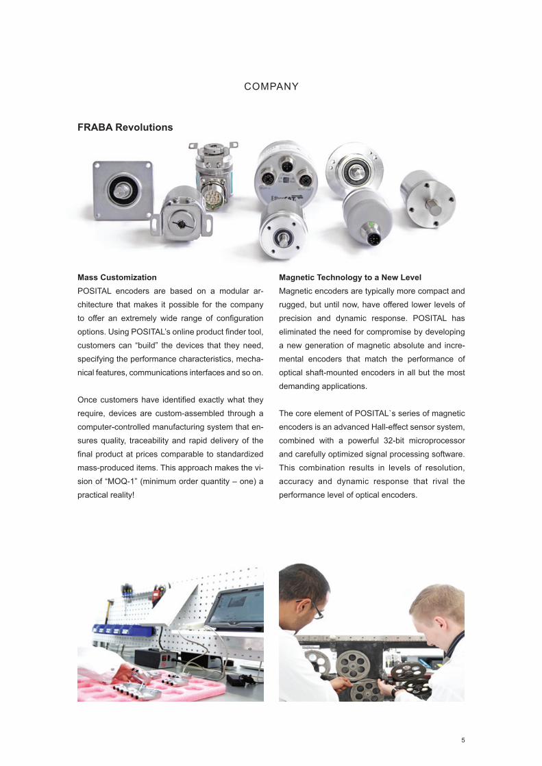
Mass CustomizationPOSITAL encoders are based on a modular ar-chitecture that makes it possible for the company to offer an extremely wide range of configuration options. Using POSITAL’s online product finder tool, customers can “build” the devices that they need, specifying the performance characteristics, mecha-nical features, communications interfaces and so on.
Once customers have identified exactly what they require, devices are custom-assembled through a computer-controlled manufacturing system that en-sures quality, traceability and rapid delivery of the final product at prices comparable to standardized mass-produced items. This approach makes the vi-sion of “MOQ-1” (minimum order quantity – one) a practical reality!
Magnetic Technology to a New LevelMagnetic encoders are typically more compact and rugged, but until now, have offered lower levels of precision and dynamic response. POSITAL has eliminated the need for compromise by developing a new generation of magnetic absolute and incre-mental encoders that match the performance of optical shaft-mounted encoders in all but the most demanding applications.
The core element of POSITAL`s series of magnetic encoders is an advanced Hall-effect sensor system, combined with a powerful 32-bit microprocessor and carefully optimized signal processing software. This combination results in levels of resolution, accuracy and dynamic response that rival the performance level of optical encoders.
COMPANY
FRABA Revolutions

6
POSITAL STORY
1918 Founded by Franz Baumgartner in Co-
logne, Germany and originally specialized
in mechanical relays.
1963FRABA starts selling “brush”
absolute rotary encoders.
1973 FRABA manufactures one of the
first encoders based on optical
measurement technology.
1993Dr. Achim Leeser, Christian Leeser
and Axel Wiemann take over the
company. They restructure the com-
pany into a group of independent
companies combined by a common
Mission and Guiding Principles.
2000 The first foreign subsidiary opens up
in Princeton, New Jersey, USA.
2002
POSITAL product
portfolio expands
to include industrial
inclinometers.
2001FRABA introduces 2
new business units,
POSITAL which continues
the encoder and position
sensor business and
VITECTOR which focuses
on safety systems for the
door and gate market.

7
POSITAL STORY
2005 POSITAL launches a new line of magnetic multiturn
encoders based on a Wiegand Wire Energy Harvesting
Technolgy.
2009The first Asian subsidiary
opens in Singapore.
2006CONISTICS, FRABA’s advanced
manufacturing plant opens in Slubice, Poland.
CONISTICS is tailored to produce small lot sizes
in a wide range of configurations.
2013
High precision magnetic absolute and incremental encoders
offered by POSITAL. POSITAL introduces a unique online
product finder where users can select from more than
1 million sensors.
2011FRABA’s holding office opens
in Heerlen, NL and product
development cell, CENTITECH,
moves to Aachen.
2015 The first Chinese subsidiary opens in
Shanghai. Planning for production in
Asia and North America.
2014
POSITAL launches a new generation of pro-
grammable absolute and incremental encoders.
With the new configuration tool customers have
access to more than 1 million sensors.
2016POSITAL continues the “mass customi-
zation” business system by offering more
mechanical and electric options for the
existing product lines as well as adding a
large variety of product accessories.

8
CATALOG OVERVIEW
Disclaimer
© FRABA B.V. all rights reserved. We do not assume responsibility for technical inaccuracies or omissions. Specifications are
subject to change without notice. Version 20161231
Industries Power Generation and Water 12Material Handling 13Mobile Machinery 14Factory Automation 15Healthcare and Elevators 16
POSITAL Products Rotary Encoders, Linear Sensor, Inclinometers and Accessories 10
IXARC Rotary Encoders Technology Magnetic Encoder 18 Technology Optical Encoder 19Absolute vs Incremental Encoders 20 Programmable Encoders 21Product Overview and Selection 22
Kit EncodersInnovation in Motor Feedback 69
LINARIX Linear SensorsDraw Wire Technology Linear Sensor 74 Product Overview and Selection 75
TILTIX InclinometersTechnology Industrial Inclinometer 86Explosion Proof Certified Inclinometers 87 Product Overview and Selection 88
AccessoriesWide Selection of Accessories 97
EncodermatchCompetitor Cross Reference Finder 106
POSITAL PartnershipWant to Become Our Partner? 107

POSITAL PRODUCTS
A Million Possibilities

10
PRODUCTS
Position and Motion Sensors
High Precision IXARC Rotary EncodersMotion control applications – ranging from factory automation to mobile machinery – require accurate,realtime information about the location of mecha-nical components. The IXARC line of rotary enco-ders provide precise and reliable measurement of the angular positions of joints, drive shafts, pulleys, etc... Available electronic connections range from simple analog outputs to sophisticated Fieldbus and Industrial Ethernet interfaces.
Absolute and Incremental Technology Optical and Magnetic Encoders up to 16 bit Resolution
Compact Industrial TILTIX InclinometersAccurate measurement of tilt or inclination is very important for motion control and safety systems. In-clinometers provide single or dual-axis angle mea-surement in an economical package. Relying on gravity for their measurement, these sensors have no exposed moving parts, resulting in easy installa-tion and high environmental protection.
High Accuracy of 0.1° and Resolution of 0.01° Measurement Range ±90° (Dual Axis) or 360° (Single Axis)
Versatile LINARIX Linear SensorsMany applications require linear motion to be mo-nitored for system control or to ensure safety. With lengths ranging from 1 m to 30 m [3 to 98 ft], LINARIX draw wire sensors are available in many configurations to meet an application’s require-ments. Options include a wide variety of outputs (including analog, incremental, Fieldbus and Ethernet variants), heavy duty housings and com-pact designs.
Position Measurement with Resolutions up to 2 µm
Variety of Materials
Wide Selection of AccessoriesPOSITAL offers a wide variety of accessories that simplify sensor installation. Mating connectors of different styles and lengths ensure proper electrical connections. Using appropriate mounting accesso-ries minimize wear and tear on encoders and help to ensure a long and reliable life cycle. Interface modules and displays are also available to provide users with immediate access to measurements.
Different Cable Designs and Lengths Adapter Flanges for Precise Installation

INDUSTRIES
Find the Right Product for your Application!

12
Wind EnergyIXARC heavy duty absolute and incremental enco-ders provide precise angle measurement for pitch control systems that dynamically adjust the angle of wind turbine rotor blades. High resolution encoders are also ideal for yaw control ensuring optimal posi-tioning of the nacelle with respect to wind direction.
Salt Resistant Sensors Increased Efficiency in Extreme Environments
Solar EnergyFor both photovoltaic systems and concentrated power plants (CSP, CPV), solar tracking systems in-crease energy efficiency. The compact and accurate IXARC encoders and TILTIX inclinometers are ideal for both single and two axis tracking systems which not only follow the sun from east to west but also have an adjusting elevation system.
Optimized Solar Panel Orientation Position Maintained even after Power Loss
INDUSTRIES
Power Generation and Water
Water / WastewaterAccurate monitoring of sluice gates for flood control, sewage and power plants, dams or irrigation facili-ties can be monitored remotely with IXARC rotary encoders and LINARIX linear sensors. The IXARC magnetic rotary encoders are also ideal for precise valve positioning.
Minimum Maintenance, Increased Reliability Easy Remote Control, Variety of Interfaces
Oil and GasWhether it’s offshore or onshore, an exploration plat-form or a refinery POSITAL explosion proof IECEx and ATEX certified products can provide accurate positioning and speed monitoring in pipe handling equipment or in blow out preventer (BOP) systems.
Certified Sensors for Explosive Environments Accurate Leveling for Subsea Systems

13
Automated Storage Retrieval SystemsIncreasing warehouse and labor costs make the use of automatic storage and retrieval systems eco-nomically attractive. IXARC rotary encoders and LINARIX linear sensors are used in these systems to give the position of the loading equipment with re-spect to the vertical racks where goods are stored.
Vertical and Horizontal Positioning of the Units Accurate Monitoring of the Arms
Overhead ConveyorsAssembly lines for automotive production have de-dicated work stations for different processes. Typi-cally the vehicle chassis is moved through a series of such work stations using overhead conveyors. IXARC absolute encoders help achieve this move-ment in a safe and controlled manner.
Fieldbus & Ethernet for Fast Communication For SIL2, SIL3 Certified for Safe Operation
INDUSTRIES
Material Handling
Baggage HandlingDue to stringent security requirements, all airline baggage needs to be screened and distributed in a secure manner. A labyrinth of conveyors helps sort these in a correct fashion. Programmable Fieldbus IXARC rotary encoders help track the position of multiple baggage conveyors.
Diagnostics LED, Reduced System Installation Simplified Wiring, Decreased Time & Costs
Forklifts and Automated Guided VehiclesFor forklifts and AGVs that carry loads from one point to another, safety is of utmost importance. TILTIX inclinometers and LINARIX linear sensors help to avoid accidental contact and insure precise positioning of loads.
Simple Communication with Analog Interfaces Programmable Measurement by the User

14
MiningDrill rigs, excavators and mobile hammering systems are complicated machines which must perform flaw-lessly under the harshest conditions. For these appli-cations the ATEX certified IXARC rotary encoders can be used to provide precise positioning of drill heads and masts. Single and dual axis POSITAL TILTIX inclinometers further equip operators with essential information for platform leveling and arm positioning.
Certified Sensors for Explosive Environments Precise Positioning & Leveling
CranesCranes and other construction machinery are re-quired to be safe, efficient and reliable. Positioning is of prime importance, and redundant systems are often used to eliminate errors. To address this re-quirement the IXARC SIL-2 encoders are an excel-lent fit, combining redundant measurement with an easy-to-integrate interface.
Sensors for High Levels of Shock & Vibration Increased Accuracy & Safety
INDUSTRIES
Mobile Machinery
Arm / Boom ExtensionTrucks with long boom extensions such as fire trucks or concrete pumps have to reach to high-rise buildings, often over large obstacles. IXARC rotary encoders can be mounted directly on the rotational joints to provide data for active damping systems. TILTIX single or dual axis inclinometers can be used to monitor the position of the boom arm or for base leveling.
IP69K Sensors, Pressure & Temperature Resistant
Easy Communication, CAN, Incremental & Analog Interfaces
Scissor Lifts and Aerial Work PlatformsScissor lifts need constant tilt monitoring to prevent tip-overs, an easy job for the dual axis TILTIX in-clinometers. IXARC rotary encoders and LINARIX linear sensors are ideal for situations where the height of the lift needs to be known.
Compact & Economical Sensors For SIL2, SIL3 Certified for Safe Operation

15
INDUSTRIES
Factory Automation
Packaging High precision is needed in processes like form filling, sealing, palletizing, pick and place, cartoning and cardboard folding. The IXARC rotary encoders with Fieldbus, Ethernet or incremental interfaces can simplify wiring and keep costs down while their stainless steel housing can withstand high tempera-tures and pressure wash downs.
Precise and Fast Position Feedback Reliability at Maximum Work Speed
Textile and PlasticIn both textile and plastic manufacturing the mate-rial used are changed periodically and constant ad-justments need to be made in roll and nozzle posi-tioning. IXARC rotary encoders and LINARIX linear sensors can help speed up these changes.
Reduced Downtime and Increased Efficiency Reliable Positioning in Hot & Humid Areas
Food and BeverageFilling bottles to the right level, accurate labeling and strict regulatory requirements are a few issues that manufactures have to deal with. IXARC rotary encoders and LINARIX linear sensors are used in the food and beverage industry to support efficient and hygienic food packaging.
Stainless Steel Version, Chemical Resistance Accurate Process Monitoring
Industrial RobotsIndustrial robots are used widely in manufacturing processes around the world. They carry out acti-vities like welding, painting, assembling which all demand high accuracy. IXARC rotary encoders and kit encoders mounted on the joints of robots can measure and control their movements.
Compact Size, Ideal for Retrofitting Absolute & Incremental Measurement

16
HealthcareModern devices used in the healthcare industry de-mand advanced technology for precise positioning. TILTIX compact inclinometers provide accurate measurements and are built to last the life of the equipment. LINARIX linear sensors offer a solution for tracking the position of patient tables. For more complex applications, such as fluoroscopy or radio-graphy tables or surgical C-arms, that require coor-dinated positioning of several components, IXARC rotary encoders are an excellent option.
Precise Positioning of Patient & Scanner Simple Installation, Easier Calibration
ElevatorsElevator cars need to be accurately positioned with respect to each floor they visit. IXARC absolute encoders help provide this information without the need of a ground reference. With IXARC absolute encoders, knowledge of the position of the elevator car is always retained, even during power failures. IXARC encoders supporting the CANopen Lift pro-tocol help meet the high safety standards of this in-dustry. Cost efficient LINARIX linear sensors are an excellent solution for door positioning.
Absolute & Incremental Positioning High Shaft Load, Increased Safety
INDUSTRIES
Healthcare and Elevators

www.posital.com 17
IXARC ROTARY ENCODERS
High Performance Absolute and Incremental Encoders

18
Magnetic rotary encoders determine angular position using magnetic field sensor technology. A perma-nent magnet A fixed to the encoder’s shaft creates a magnetic field which is sampled by a sensor B that generates an accurate absolute position reading.
Signal Processing is the Key to High PerformanceThe technological leap that pushes POSITAL’s IXARC magnetic encoders to the performance le-vel of optical systems is based on a new generation of sensor systems. The combination of a custom Hall-effect sensor and complex signal processing algorithms running on a powerful 32 bit micropro-cessor results in a considerably improved resolution and accuracy, along with latency times of only a few microseconds. POSITAL has also implemented an incremental interface and can now offer a complete range of encoder solutions.
Multiturn InnovationPOSITAL can also provide absolute multiturn mea-surements by means of a revolution counter system
that uses an energy harvesting system based on the Wiegand effect. This system requires no ge-ars or batteries. Eliminating batteries brings about many advantages. Batteries have a limited lifespan, weigh a lot, and often contain harmful substances. Gear units have disadvantages of their own being large, complex, costly and vulnerable to shock and vibration. Regardless of the rotational speed, even at near-zero, the energy harvesting system gene-rates short, powerful voltage pulses, sufficient to power the counting electronics. The result is a re-volution counter that is independent of any external power supply. This technology, which has proven itself since 2005, enables maintenance-free reliable measurement of absolute positions, even in deman-ding environments, for years to come.
Advantages of Magnetic Encoders Robust and Durable Mechanically Simple and Economical − No Battery, No Gear
Compact Design for Installation in Small Spaces
IXARC ROTARY ENCODERS
V
Magnetic Measurement Principles
A
B
N
S
NS
N
S
N
S

www.posital.com 19
A key component of optical rotary encoders is a code disk A mounted on the encoder shaft B . This disk is made of unbreakable plastic that has a con-centric pattern of transparent and opaque areas. In-frared light from an LED C shines through the code disk, onto an array of photoreceptors. As the shaft turns, a unique combination of photoreceptors are illuminated or blocked from light by the pattern on the disk. For multiturn models, there is an additional set of code discs arranged in a gear train D . As the main encoder shaft rotates, these discs are geared together to turn like the wheels of an odometer. The rotational position of each disc is monitored opti-cally and the output is a count of the net number of rotations of the encoder shaft.
FunctionalityPOSITAL’s IXARC optical absolute rotary encoders use highly integrated Opto-ASICs, providing a re-solution up to 16 bits (65,536 steps) per turn. For multiturn models, the measuring range is extended by the mechanically geared code disks to as many as 16,384 (214) revolutions.
Advantages of Optical Encoders High Resolution and Accuracy along with Excellent Dynamic Response
For Use in Areas with High Magnetic Fields No Risk of These Devices Losing Track of Their Absolute Position
No Backup Batteries Required
IXARC ROTARY ENCODERS
Optical Measurement Principles
B
A
C
D

20
G0
G1
G2
G3
1 2 3 4 5 6 7 8 9
Channel A
360° Electrical
90° Electrical
Channel B
Index Z
zG2
G1
G0
G3
1
2
3
4
5
678
9
Incremental Rotary EncodersIncremental encoders generate an output signal each time the shaft rotates a certain angle. The number of signals (pulses) per turn (PPR defines the resolution of the device. Each time the encoder is powered on it begins counting from zero, regard-less of where the shaft is. Initial homing to a refe-rence point is therefore inevitable in all positioning tasks, both upon start up of the control system and whenever power to the encoder has been interrup-ted.
Advantages A, B, Z, and Inverted Signals as HTL (Push-Pull) or TTL (RS422)
Any Pulse Count up to 16384 Pulses per Revolution Available
65384 Edges Quadrature Programmable for Flexibility Magnetic Measuring Principle
Absolute Rotary EncodersAbsolute rotary encoders are capable of providing unique position values from the moment they are switched on. This is accomplished by detecting the position of a coded element. All positions in these systems correspond to a unique code. Even move-ments that occur while the system is without power are translated into accurate position values once the encoder is powered up again.
Advantages Multiple Interface Options: Analog, Ethernet, Fieldbus, Parallel, Serial
Singleturn and Multiturn Revolution Resolution up to 16 bit Optical and Magnetic Measuring Principle
IXARC ROTARY ENCODERS
Absolute vs Incremental Rotary Encoders

21
IXARC ROTARY ENCODERS
Programmable Encoders
Programmable Features – Save Time and MoneyPOSITAL has replaced hardware by software and has taken versatility to a new level. Resolution (PPR) can be set anywhere from one to 16,384 pul-ses per turn. Similarly, pulse direction and the out-put driver – either Push-Pull (HTL) or RS422 (TTL) – can be defi ned through software parameters. All of these parameters can be confi gured very easi-ly using the UBIFAST tool and any WiFi-enabled smartphone, tablet or laptop computer. It is not ne-cessary to install any software or app. Additionally all the confi guration data for each encoder is sent to POSITAL’s ERP system and can be retrieved in the future for replacement. since a small number of de-vices can be programmed to take on a wide range of measurement tasks. Distributors and OEM custo-mers can reduce their inventory levels and simplify the supply chain. System integrators can decide at the last minute how to tailor the encoder to speci-fi c requirements on site and initiate the purchase of the encoders while fi nal design requirements are still under discussion. End users can receive spare parts from a distributor or system integrator quickly.
Simple ProgrammingWith the new capabilities, the encoders’ perfor-mance characteristics can be extensively modifi ed through software changes, without requiring any changes to physical components. In a related deve-lopment, POSITAL is introducing the UBIFAST con-fi guration tool, a hardware module that can be easily connected to programmable encoders through ac-cessory cables. The UBIFAST tool features a built-in WiFi hotspot and webserver. Once the tool has been powered up, any WiFi-enabled smartphone, tablet, or laptop computer can connect to the WiFi hotspot and the confi guration interface will automa-tically open up in a standard web browser window – no app, no software installation, and no internet connection are required. POSITAL also presents an internet-enabled confi guration management system for IXARC programmable encoders. Whenever a device is reconfi gured, the operator has the option of registering the changes with POSITAL through an automatic e-mail interface.
PROGRAMMABLE
Magnetic ENCODERS
INCREMENTALA Million Possibilities
Unparalleled Choice of
Mechanical Features and
Electrical Connections!

22
Max
. Pro
teci
on C
lass
Puls
es p
er R
evol
utio
n
Acc
urac
y (IN
L)
Acc
urac
y (D
NL)
Flan
ge S
ize
in m
m [i
n]
Cla
mp
Flan
ge
Sync
hro
Flan
ge
Hol
low
Fla
nge
Squa
re F
lang
e
Supp
ly V
olta
ge in
V
Cab
le
Con
nect
or
Con
nect
ion
Cap
Shoc
k / V
ibra
tion in
g
Rad
ial S
haft
Load
in N
Magnetic
Programmable
IP69K
IP68
IP69K
1...
16384
0.09° 0.003° 36 [1.42]
42 [1.65]
■ ■ ■ 4.75−30 ■ ■ 300
30
300
Magnetic
Programmable
Clamp Flange
IP64
IP65
IP67
1...
16384
0.09° 0.003° 38 [1.5]
58 [2.28]
(More p. 36)
■ 4.75−30 ■ ■ 100
10
110
Magnetic
Programmable
Synchro Flange
IP64
IP65
IP67
1...
16384
0.09° 0.003° 36 [1.42]
38 [1.5]
58 [2.28]
■ 4.75−30 ■ ■ 100
10
110
Magnetic
Programmable
Hollow Flange
IP64
IP65
IP67
1...
16384
0.09° 0.003° 36 [1.42]
42 [1.65]
58 [2.28]
■ 4.75−30 ■ ■ 100
10
110
Magnetic
Programmable
Square Flange
IP64
IP65
IP67
1...
16384
0.09° 0.003° 52.3 [2.0]
63.5 [2.5]
■ 4.75−30 ■ ■ 100
10
110
Optical
Incremental
Heavy Duty
IP66
IP67
Up to
2500
Up to
0.02
Up to
0.01
115 [4.52] ■ 4.5 – 5.5
4.5 – 30
■ ■ 200
20
350
IXARC ROTARY ENCODERS
Product Overview − Incremental Encoders
Related Industries
F NDERPRODUCT
Find What You NeedConfi gure Your POSITAL Encoder Online

23
IXARC ROTARY ENCODERS
Product Selection Guide − Incremental Encoders
1 Accuracy (Technology)
U ≤ 0.09° (Magnetic)
O ≤ 0.14° at 360 pulses,
0.02° at 2500 pulses (Optical)
2 Communication Interface
IPT Default RS422 (TTL) , Programmable HTL/TTL
IPH Default Push-Pull (HTL), Programmable HTL/TTL
INS RS422 (TTL) (Optical)
INH Push-Pull (HTL) (Optical)
3 Pulses per Revolution
XXXXX For Programmable:
Choose Any Pulse Count 1 to 16384
00360 360 Pulses (for Optical)
00512 512 Pulses (for Optical)
01000 1000 Pulses (for Optical)
01024 1024 Pulses (for Optical)
02000 2000 Pulses (for Optical)
02048 2048 Pulses (for Optical)
02500 2500 Pulses (for Optical)
4 Mechanical Design and Protection Class
Blind Hollow Shaft (Page 36)
Synchro (Page 43)
Clamp (Page 50)
Through Hollow (Page 58)
Square (Page 59)
5 Connection Type
CAW Cable: Axial 1 m
2AW Cable: Axial 2 m
5AW Cable: Axial 5 m
AAW Cable: Axial 10 m
CRW Cable: Radial 1 m
2RW Cable: Radial 2 m
5RW Cable: Radial 5 m
ARW Cable: Radial 10 m
PAM Connector: Axial M12, 5 pin
PAQ Connector: Axial M12, 8 pin
PAL Connector: Axial M23, 12 pin
PRM Connector: Radial M12, 5 pin
PRQ Connector: Radial M12, 8 pin
PRL Connector: Radial M23, 12 pin
PRD Connector: Radial MIL MS14
PRE Connector: Radial MIL MS16
PRF Connector: Radial MIL MS18
TB1 Terminal Box (Optical)
1 2 3 4 5
X C D – X X X – – –0 0 X X X X X X X XX X X X
Learn More
UBIFAST Configuration Tool
▪ Compact Housing with WLAN to Create Hotspot
▪ Connects to Smart Phone/ Tablets/ Notebooks
▪ Web Browser Based Simple Programming
▪ Configuration Data Sent Back to POSITAL via E-mail
▪ Parameters to Program: PPR, Resolution, Number of Turns, Direction

24
IXARC ROTARY ENCODERS
Prot
ecio
n C
lass
Max
. Rev
olut
ions
(Tur
ns)
Max
. Res
olut
ion
in b
it
Acc
urac
y / L
inea
rity
(±)
Flan
ge S
ize
in m
m [i
n]
Cla
mp
Flan
ge
Sync
hro
Flan
ge
Hol
low
Fla
nge
Squa
re F
lang
e
Supp
ly V
olta
ge in
V
Cab
le
Con
nect
or
Con
nect
ion
Cap
Shoc
k / V
ibra
tion
in g
Rad
ial S
haft
Load
in N
Program. Output
Voltage, Current
IP68, IP69K
IP69K
IP68
65536 13 0.09°
0.15%
36 [1.42]
42 [1.65]
■ ■ ■ 8−32 ■ ■ 300
30
300
Program. Output
Analog Voltage
Magnetic
IP64
IP65
IP67
65536 13 0.09°
0.15%
38 [1.5]
58 [2.28]
(More p. 36)
■ ■ ■ ■ 8−32 ■ ■ 100
10
110
Program. Output
Analog Current
Magnetic
IP64
IP65
IP67
65536 13 0.09°
0.15%
38 [1.5]
58 [2.28]
(More p. 36)
■ ■ ■ ■ 8−32 ■ ■ 100
10
110
Program. Output
Analog Voltage
Pushbuttons
IP64
IP65
IP67
65536 13 0.09°
0.15%
52.3 [2]
63.5 [2.5]
■ ■ ■ ■ 8−32 ■ ■ 100
10
110
Program. Output
Analog Current
Pushbuttons
IP64
IP65
IP67
65536 13 0.09°
0.15%
36 [1.42]
58 [2.28]
(More p. 36)
■ ■ ■ ■ 8−32 ■ ■ 100
10
110
Optical
Parallel
Binary, Gray
IP64
IP65
IP67
16384 16 0.022° 58 [2.28] ■ ■ ■ ■ 10−30 ■ ■ 100
10
110
Related Industries
F NDERPRODUCT
Find What You NeedConfi gure Your POSITAL Encoder Online
Product Overview − Analog and Parallel Encoders

www.posital.com 25
IXARC ROTARY ENCODERS
Product Selection Guide − Analog and Parallel Encoders
1 Accuracy (Technology)
U ≤ 0.09° (Magnetic)
O ≤ 0.022° (Optical)
2 Communication Interface
AV001 Analog Voltage: 0 to 5 V
AV002 Analog Voltage: 0 to 10 V
AV003 Analog Voltage: 0.5 to 4.5 V
AV004 Analog Voltage: 0.5 to 9.5 V
AC005 Analog Current: 4 to 20 mA
AC006 Analog Current: 0 to 20 mA
AVP01 Analog Voltage: 0 to 5 V w. Pushbuttons
AVP02 Analog Voltage: 0 to 10 V w. Pushbuttons
AVP03 Analog Voltage: 0.5 to 4.5 V w. Pushbuttons
AVP04 Analog Voltage: 0.5 to 9.5 V w. Pushbuttons
ACP05 Analog Current: 4 to 20 mA w. Pushbuttons
ACP06 Analog Current: 0 to 20 mA w. Pushbuttons
PPA1B Parallel Binary
P1A1B Parallel Preset Binary
PPA1G Parallel Gray
P1A1G Parallel Preset Gray
PP00E Parallel Excess Gray
P100E Parallel Preset Excess Gray
3 Revolution
00 Singleturn
04 Multiturn: 4 bit (16 rev)
07 Multiturn: 7 bit (128 rev)
08 Multiturn: 8 bit (256 rev)
12 Multiturn: 12 bit (4096 rev)
14 Multiturn: 14 bit (16384 rev)
4 Resolution
08 8 bit (256 Steps / 0.35°) Parallel only
09 9 bit (512 Steps / 1°) Parallel only
AA 9 bit (360 Steps / 0.7°) Parallel only
10 10 bit (1024 Steps / 0.35°) Parallel only
12 12 bit (4096 Steps / 0.088°)
13 13 bit (8192 Steps / 0.044°)
14 14 bit (16384 Steps / 0.02°)
16 16 bit (65536 Steps / 0.005°)
AP 90° Analog for Singleturn only
AR 180° Analog for Singleturn only
AS 270° Analog for Singleturn only
5 Mechanical Design and Protection Class
Blind Hollow Shaft (Page 36)
Synchro (Page 43)
Clamp (Page 50)
Square (Page 59)
6 Connection Type
CAW Cable: Axial 1 m
2AW Cable: Axial 2 m
5AW Cable: Axial 5 m
AAW Cable: Axial 10 m
CRW Cable: Radial 1 m
2RW Cable: Radial 2 m
5RW Cable: Radial 5 m
ARW Cable: Radial 10 m
PAM Connector: Axial M12, 5 pin (Analog)
PAP Connector: Axial M23, 16 pin (Parallel)
PAT Connector: Axial M27, 26 pin (Parallel)
PRM Connector: Radial M12, 5 pin (Analog)
PRP Connector: Radial M23, 16 pin (Parallel)
PRT Connector: Radial M27, 26 pin (Parallel)
1 2 3 4 5 6
C – X X XXXX D – – –X X X X X X X XX X X

26
IXARC ROTARY ENCODERS
Max
. Pro
teci
on C
lass
Max
. Rev
olut
ions
(Tur
ns)
Max
. Res
olut
ion
in b
it
Acc
urac
y / L
inea
rity
(±)
Flan
ge S
ize
in m
m [i
n]
Cla
mp
Flan
ge
Sync
hro
Flan
ge
Hol
low
Fla
nge
Squa
re F
lang
e
Supp
ly V
olta
ge in
V
Cab
le
Con
nect
or
Con
nect
ion
Cap
Shoc
k / V
ibra
tion
in g
Rad
ial S
haft
Load
in N
Magnetic
SSI
Programmable
IP68
IP69K
65536 16 0.09° 36 [1.42]
42 [1.65]
■ ■ ■ 4.5−30 ■ ■ 300
30
300
Magnetic
SSI
Programmable
IP64
IP65
IP67
65536 16 0.09° 36 [1.42]
58 [2.28]
(More p. 36)
■ ■ ■ ■ 4.5−30 ■ ■ 100
10
110
Magnetic
SSI + Incremental
Programmable
IP68
IP69K
65536 16 0.09° 36 [1.42]
42 [1.65]
■ 4.5−30 ■ ■ 300
30
300
Magnetic
SSI + Incremental
Programmable
IP64
IP65
IP67
65536 16 0.09° 36 [1.42]
58 [2.28]
(More p. 36)
■ ■ ■ ■ 4.5−30 ■ ■ 100
10
110
Optical
SSI
Up to 16 bit
IP67 16384 16 0.022° 58 [2.28]
63.5 [2.5]
■ ■ ■ ■ 4.5−30 ■ ■ 100
10
110
Optical
SSI + Incremental
Up to 16 bit
IP65 16384 16 0.022° 58 [2.28]
63.5 [2.5]
■ ■ ■ ■ 4.5−30 ■ ■ 100
10
110
Optical
SSI
Push-Buttons
IP67 16384 16 0.022° 58 [2.28]
63.5 [2.5]
■ ■ ■ ■ 4.5−30 ■ ■ 100
10
110
Related Industries
F NDERPRODUCT
Find What You NeedConfi gure Your POSITAL Encoder Online
Product Overview − SSI and SSI+Incremental Encoders

27
IXARC ROTARY ENCODERS
Product Selection Guide − SSI and SSI+Incremental Encoders
1 Accuracy (Technology)
U ≤ 0.09° (Magnetic)
O ≤ 0.022° (Optical)
2 Communication Interface
S101B SSI Binary
SLF1B SSI Binary Fast
S101G SSI Gray
S101E SSI Excess-Gray
SHPPP Programmable SSI+Incr. Push-Pull (HTL) 4.75 to 30 VDC
SRPPP Programmable SSI+Incr. RS422 (TTL) 8 to 30 VDC
SSPPP Programmable SSI+Incr. RS422 (TTL) 5 VDC
SHxxB SSI+Incr. Binary + A/B/Z (Push-Pull) 4.75 to 30 VDC
SRxxB SSI+Incr. Binary + A/B/Z (RS-422) 8 to 30 VDC
SSxxB SSI+Incr. Binary+ A/B/Z (RS-422) 5 VDC
SHxxG SSI+Incr. Gray + A/B/Z (Push-Pull) 4.75 to 30 VDC
SRxxG SSI+Incr. Gray + A/B/Z (RS-422) 8 to 30 VDC
SSxxG SSI+Incr. Gray + A/B/Z (RS-422) 5 VDC
S401B SSI Binary w. Pushbuttons
S401G SSI Gray w. Pushbuttons
S3xxG SSI Gray+Incr. A/B/Z (RS-422)
S3xxB SSI Binary+Incr. A/B/Z (RS-422)
S5xxB SSI Binary+Incr. A/B/Z (RS-422)
S6xxB SSI Binary+Incr.A/B/Z (Push-Pull)
S5xxG SSI Gray+Incr. A/B/Z (RS-422)
S6xxG SSI Gray+Incr. A/B/Z (Push-Pull)
3 Revolution
00 Singleturn
04 Multiturn: 4 bit (16 rev)
08 Multiturn: 8 bit (256 rev)
12 Multiturn: 12 bit (4096 rev)
13 Multiturn: 13 bit (8192 rev)
14 Multiturn: 14 bit (16384 rev)
16 Multiturn: 16 bit (65536 rev)
20 Multiturn: 20 bit (1048576 rev)
PP Programmable, Default 12 bit (4096 rev)
4 Resolution
12 12 bit (4096 Steps / 0.088°)
13 13 bit (8192 Steps / 0.044°)
16 16 bit (65536 Steps / 0.005°)
PP Programmable, Default 13 bit (8192 Steps / 0.044°)
5 Mechanical Design and Protection Class
Blind Hollow Shaft (Page 36)
Synchro (Page 43)
Clamp (Page 50)
Through Hollow (Page 58)
Square (Page 59)
6 Connection Type
CAW Cable: Axial 1 m
2AW Cable: Axial 2 m
5AW Cable: Axial 5 m
AAW Cable: Axial 10 m
CRW Cable: Radial 1 m
2RW Cable: Radial 2 m
5RW Cable: Radial 5 m
ARW Cable: Radial 10 m
PAQ Connector: Axial M12, 8 pin
PAL Connector: Axial M23, 12 pin
PAP Connector: Axial M23, 16 pin
PRQ Connector: Radial M12, 8 pin
PRL Connector: Radial M23, 12 pin
PRP Connector: Radial M23, 16 pin
1 2 3 4 5 6
C – X X XXXX D – – –X X X X X X X XX X X

28
IXARC ROTARY ENCODERS
Max
. Pro
teci
on C
lass
Max
. Rev
olut
ions
(Tur
ns)
Max
. Res
olut
ion
in b
it
Acc
urac
y / L
inea
rity
(±)
Flan
ge S
ize
in m
m [i
n]
Cla
mp
Flan
ge
Sync
hro
Flan
ge
Hol
low
Fla
nge
Squa
re F
lang
e
Supp
ly V
olta
ge in
V
Cab
le
Con
nect
or
Con
nect
ion
Cap
Shoc
k / V
ibra
tion
in g
Rad
ial S
haft
Load
in N
Magnetic
CANopen
SAE J1939
IP69K
IP68
65536 16 0.09° 36 [1.42]
42 [1.65]
■ ■ ■ 9−32 ■ ■ ■ 300
30
300
Magnetic
CANopen
SAE J1939
IP65
IP66
IP67
65536 16 0.09° 36 [1.42]
58 [2.28]
(More p. 36)
■ ■ ■ ■ 9−32 ■ ■ 300
30
180
Magnetic
Profi bus
Up to 16 bit
IP65
IP66
IP67
65536 16 0.09° 58 [2.28]
63.5 [2.5]
■ ■ ■ ■ 10−30 ■ ■ 100
10
110
Optical
DeviceNet
Up to 16 bit
IP65 65536 16 0.09° 36 [1.42]
58 [2.28]
■ ■ ■ ■ 10−30 ■ ■ 100
10
110
Optical
Profi bus
Up to 16 bit
IP65
IP66
IP67
16384 16 0.022° 52.3 [2]
58 [2.28]
63.5 [2.5]
■ ■ ■ ■ 10−30 ■ ■ ■ 100
10
110
Optical
Interbus
Up to 16 bit
IP65
IP66
IP67
16384 16 0.022° 58 [2.28]
63.5 [2.5]
■ ■ ■ ■ 10−30 ■ ■ ■ 100
10
110
Optical
CANopen
Up to 16 bit
IP65
IP66
IP67
16384 16 0.022° 52.3 [2]
58 [2.28]
63.5 [2.5]
■ ■ ■ ■ 10−30 ■ ■ ■ 100
10
110
Related Industries
F NDERPRODUCT
Find What You NeedConfi gure Your POSITAL Encoder Online
Product Overview − Fieldbus Encoders
29
IXARC ROTARY ENCODERS
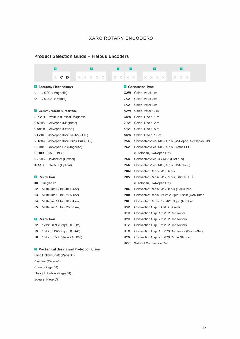
Product Selection Guide − Fielbus Encoders
1 Accuracy (Technology)
U ≤ 0.09° (Magnetic)
O ≤ 0.022° (Optical)
2 Communication Interface
DPC1B Profibus (Optical, Magnetic)
CA01B CANopen (Magnetic)
CAA1B CANopen (Optical)
CTx1B CANopen+Incr. RS422 (TTL)
CHx1B CANopen+Incr. Push-Pull (HTL)
CL00B CANopen Lift (Magnetic)
C900B SAE J1939
D2B1B DeviceNet (Optical)
IBA1B Interbus (Optical)
3 Revolution
00 Singleturn
12 Multiturn: 12 bit (4096 rev)
13 Multiturn: 13 bit (8192 rev)
14 Multiturn: 14 bit (16384 rev)
15 Multiturn: 15 bit (32768 rev)
4 Resolution
12 12 bit (4096 Steps / 0.088°)
13 13 bit (8192 Steps / 0.044°)
16 16 bit (65536 Steps / 0.005°)
5 Mechanical Design and Protection Class
Blind Hollow Shaft (Page 36)
Synchro (Page 43)
Clamp (Page 50)
Through Hollow (Page 58)
Square (Page 59)
6 Connection Type
CAW Cable: Axial 1 m
2AW Cable: Axial 2 m
5AW Cable: Axial 5 m
AAW Cable: Axial 10 m
CRW Cable: Radial 1 m
2RW Cable: Radial 2 m
5RW Cable: Radial 5 m
ARW Cable: Radial 10 m
PAM Connector: Axial M12, 5 pin (CANopen, CANopen Lift)
PAV Connector: Axial M12, 5 pin, Status LED
(CANopen, CANopen Lift)
PAM Connector: Axial 3 x M13 (Profibus)
PAQ Connector: Axial M12, 8 pin (CAN+Incr.)
PRM Connector: Radial M12, 5 pin
PRV Connector: Radial M12, 5 pin, Status LED
(CANopen, CANopen Lift)
PRQ Connector: Radial M12, 8 pin (CAN+Incr.)
PR8 Connector: Radial 2xM12, 5pin + 8pin (CAN+Incr.)
PRI Connector: Radial 2 x M23, 9 pin (Interbus)
H3P Connection Cap: 3 Cable Glands
H1B Connection Cap: 1 x M12 Connector
H2B Connection Cap: 2 x M12 Connectors
H72 Connection Cap: 3 x M12 Connectors
H1C Connection Cap: 1 x M23 Connector (DeviceNet)
H2M Connection Cap: 2 x M20 Cable Glands
HCC Without Connection Cap
1 2 3 4 5 6
C – X X XXXX D – – –X X X X X X X XX X X

30
IXARC ROTARY ENCODERS
Max
. Pro
teci
on C
lass
Max
. Rev
olut
ions
(Tur
ns)
Max
. Res
olut
ion
in b
it
Acc
urac
y / L
inea
rity
(±)
Flan
ge S
ize
in m
m [i
n]
Cla
mp
Flan
ge
Sync
hro
Flan
ge
Hol
low
Fla
nge
Squa
re F
lang
e
Supp
ly V
olta
ge in
V
Cab
leC
onne
ctor
Con
nect
ion
Cap
Shoc
k / V
ibra
tion
in g
Rad
ial S
haft
Load
in N
Magnetic
Profi net
Up to 16 bit
IP65
IP66
IP67
65536 16 0.09° 58 [2.28]
63.5 [2.5]
■ ■ ■ ■ 10−30 ■ ■ 100
10
110
Magnetic
EtherCAT
Up to 16 bit
IP65
IP66
IP67
65536 16 0.09° 58 [2.28]
63.5 [2.5]
■ ■ ■ ■ 10−30 ■ ■ 100
10
110
Magnetic
Powerlink
Up to 16 bit
IP65
IP66
IP67
65536 16 0.09° 58 [2.28]
63.5 [2.5]
■ ■ ■ ■ 10−30 ■ ■ 100
10
110
Optical
Profi net
Up to 16 bit
IP65
IP66
IP67
16384 16 0.022° 58 [2.28]
63.5 [2.5]
■ ■ ■ ■ 10−30 ■ ■ 100
10
110
Optical
EtherNet/IP
Up to 16 bit
IP65
IP66
IP67
16384 16 0.022° 58 [2.28]
63.5 [2.5]
■ ■ ■ ■ 10−30 ■ ■ 100
10
110
Optical
EtherCAT
Up to 16 bit
IP65
IP66
IP67
16384 16 0.022° 58 [2.28]
63.5 [2.5]
■ ■ ■ ■ 10−30 ■ ■ 100
10
110
Optical
Powerlink
Up to 16 bit
IP65
IP66
IP67
65536 16 0.022° 58 [2.28]
63.5 [2.5]
■ ■ ■ ■ 10−30 ■ ■ 100
10
110
Optical
Modbus/TCP
Up to 16 bit
IP65
IP66
IP67
16384 16 0.022° 58 [2.28]
63.5 [2.5]
■ ■ ■ ■ 10−30 ■ ■ 100
10
110
Related Industries
F NDERPRODUCT
Find What You NeedConfi gure Your POSITAL Encoder Online
Product Overview − Ethernet Encoders

31
IXARC ROTARY ENCODERS
Product Selection Guide − Ethernet Encoders
1 Accuracy (Technology)
U ≤ 0.09° (Magnetic)
O ≤ 0.022° (Optical)
2 Communication Interface
EIB1B Profinet
EEA1B EtherNet/IP
E2A2B Powerlink
EC00B EtherCAT
EM00B Modbus/TCP + TCP/IP
3 Revolution
00 Singleturn
12 Multiturn: 12 bit (4096 rev)
14 Multiturn: 14 bit (16384 rev)
4 Resolution
13 13 bit (8192 Steps / 0.044°)
16 16 bit (65536 Steps / 0.005°)
5 Mechanical Design and Protection Class
Blind Hollow Shaft (Page 36)
Synchro (Page 43)
Clamp (Page 50)
Square (Page 59)
6 Connection Type
PRM Connector: Radial 2 x M12 (Modbus)
PRM Connector: Radial 3 x M12
PAM Connector: Axial 3 x M12
Learn More
Rugged Connectors and Cables
▪ Reliable Electrical Connections
▪ M12 & M23 Data, Bus and Signal Connectors
▪ Straight and Angled Versions
▪ Variety of Cable Material and Lengths
▪ Shielded for Protection Against Noise and Interference
1 2 3 4 5 6
C – X X XXXX D – – –X X X X X X X XX X X

32
IXARC ROTARY ENCODERS
Max
. Pro
teci
on C
lass
Max
. Rev
olut
ions
(Tur
ns)
Max
. Res
olut
ion
in b
it
Acc
urac
y / L
inea
rity
(±)
Flan
ge S
ize
in m
m [i
n]
Cla
mp
Flan
ge
Sync
hro
Flan
ge
Hol
low
Fla
nge
Squa
re F
lang
e
Supp
ly V
olta
ge in
V
Cab
le
Con
nect
or
Con
nect
ion
Cap
Shoc
k / V
ibra
tion in
g
Rad
ial S
haft
Load
in N
Zone 1 & 21 (Mining)
Various Interfaces
Optical
IP67 16384 16 0.022° 78 [3.07] ■ ■ ■ ■ 10−30 ■ 100
10
50
Zone 1 & 21 (Oil+Gas)
Various Interfaces
Optical
IP67 16384 16 0.022° 78 [3.07] ■ ■ ■ ■ 10−30 ■ 100
10
50
Zone 1 & 21 (Mining)
Profinet
Optical
IP67 16384 16 0.022° 78 [3.07] ■ ■ ■ ■ 4.5−30 ■ 100
10
50
Zone 1 & 21 (Oil+Gas)
Profinet
Optical
IP67 16384 16 0.022° 78 [3.07] ■ ■ ■ ■ 4.5−30 ■ 100
10
50
Zone 2 & 22
All Interfaces
Optical, Magnetic
IP67 16384 16 0.022° 58 [2.28] ■ ■ ■ 4.5−30 ■ 100
10
110
Product Overview − Ex-Proof Encoders ATEX/IECEx Certified
Related Industries
F NDERPRODUCT
Find What You NeedConfigure Your POSITAL Encoder Online

www.posital.com 33
IXARC ROTARY ENCODERS
Product Selection Guide − Ex-Proof Encoders ATEX/IECEx Certified
1 Accuracy (Technology)
U ≤ 0.09° (Magnetic)
O ≤ 0.022° (Optical)
2 Certificate
E Zone 1 & 21 (Oil+Gas)
M Zone 1 & 21 (Mining)
F Zone 2 & 22
3 Communication Interface
IPT00 Default RS422 (TTL) , Programmable HTL/TTL
IPH00 Default Push-Pull (HTL), Programmable HTL/TTL
S101B SSI Binary
S101G SSI Gray
AV001 Voltage: 0 to 5 V
AV002 Voltage: 0 to 10 V
AV003 Voltage: 0.5 to 4.5 V
AV004 Voltage: 0.5 to 9.5 V
AC005 Current: 4 to 20 mA
AC006 Current: 0 to 20 mA
DPC1B Profibus
CAA1B CANopen
D2B1B DeviceNet
EIB1B Profinet
EEA1B EtherNet/IP
E2A2B Powerlink
EC00B EtherCAT
4 Revolution
00 Singleturn
04 Multiturn: 4 bit (16 rev)
08 Multiturn: 8 bit (256 rev)
12 Multiturn: 12 bit (4096 rev)
14 Multiturn: 14 bit (16384 rev)
5 Resolution
12 12 bit (4096 Steps / 0.088°)
13 13 bit (8192 Steps / 0.044°)
16 16 bit (65536 Steps / 0.005°)
6 Mechanical Design and Protection Class
Blind Hollow Shaft (Page 36)
Synchro (Page 43)
Clamp (Page 50)
Through Hollow (Page 58)
Square (Page 59)
7 Connection Type
CAW Cable: Axial 1 m (Zone 1 & 21)
2AW Cable: Axial 2 m (Zone 1 & 21)
5AW Cable: Axial 5 m (Zone 1 & 21)
AAW Cable: Axial 10 m (Zone 1 & 21)
CRW Cable: Radial 1 m (Zone 1 & 21)
2RW Cable: Radial 2 m (Zone 1 & 21)
5RW Cable: Radial 5 m (Zone 1 & 21)
ARW Cable: Radial 10 m (Zone 1 & 21)
CAE Cable: Axial 1 m (Zone 2 & 22)
2AE Cable: Axial 2 m (Zone 2 & 22)
5AE Cable: Axial 5 m (Zone 2 & 22)
AAE Cable: Axial 10 m (Zone 2 & 22)
CRE Cable: Radial 1 m (Zone 2 & 22)
2RE Cable: Radial 2 m (Zone 2 & 22)
5RE Cable: Radial 5 m (Zone 2 & 22)
ARE Cable: Radial 10 m (Zone 2 & 22)
HFG Connection Cap: 2 x Axial Blind Plug
HFZ Connection Cap: 2 x Radial Blind Plug
HFE Connection Cap: 3 x Radial Blind Plug
H3E Connection Cap: 3 Cable Glands (Zone 2 & 22)
1 2 3 4 5 6 7
C – X X XXXX X – – –X X X X X X X XX X X

34
IXARC ROTARY ENCODERS
Max
. Pro
teci
on C
lass
Max
. Rev
olut
ions
(Tur
ns)
Max
. Res
olut
ion
in b
it
Acc
urac
y / L
inea
rity
(±)
Flan
ge S
ize
mm
[in]
Cla
mp
Flan
ge
Sync
hro
Flan
ge
Hol
low
Fla
nge
Squa
re F
lang
e
Supp
ly V
olta
ge in
V
Cab
le
Con
nect
or
Con
nect
ion
Cap
Rad
ial S
haft
Load
in N
Magnetic
ProfiSafe
SIL 2
IP67 16384 16 0.2 % 58 [2.28] ■ ■ ■ 9−36 ■ 250
Magnetic
CANopen Safety
SIL 2
IP67 16384 16 0.2 % 58 [2.28] ■ ■ ■ 9−36 ■ 250
Magnetic
CANopen
Singleturn
IP67 16384 16 ≤3.6° 58 [2.28] ■ ■ 9−35 ■ 25
Redundant
Optical
Magnetic
IP67 16384 16 0.09° 58 [2.28] ■ ■ ■ 10−30 ■ 110
SIL
Related Industries
F NDERPRODUCT
Find What You NeedConfigure Your POSITAL Encoder Online
Product Overview − Encoders for Safety Applications
35
IXARC ROTARY ENCODERS
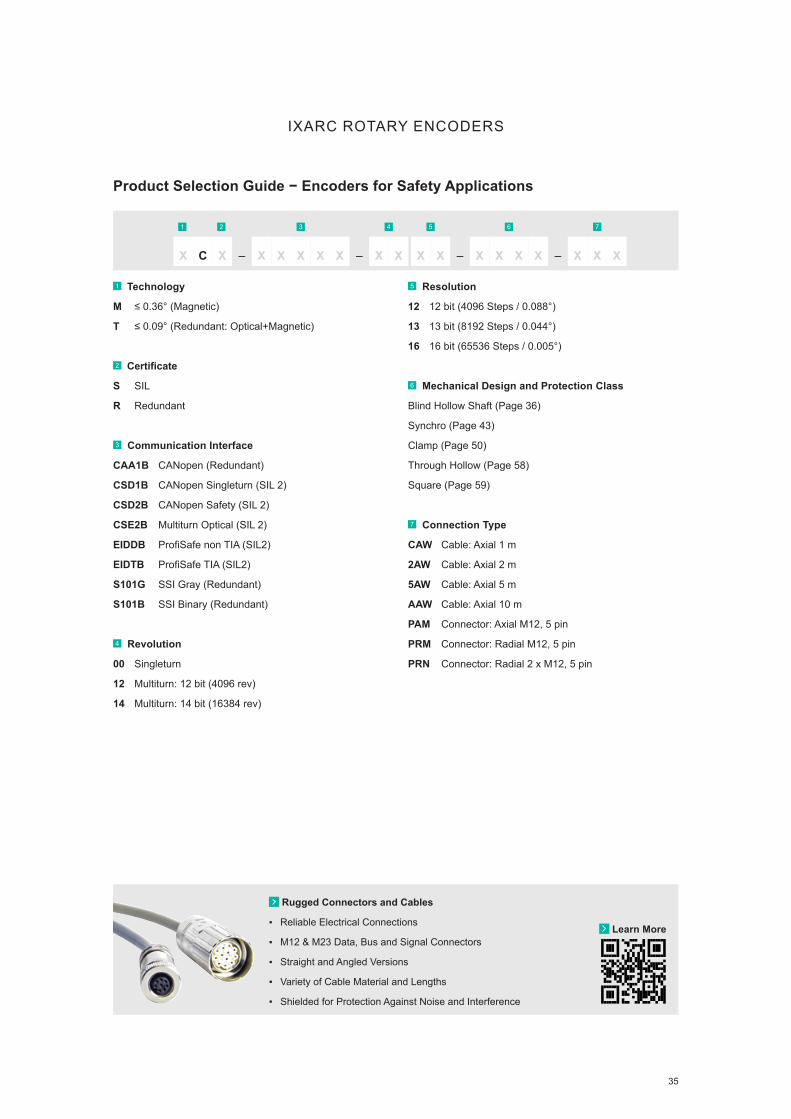
Product Selection Guide − Encoders for Safety Applications
1 Technology
M ≤ 0.36° (Magnetic)
T ≤ 0.09° (Redundant: Optical+Magnetic)
2 Certificate
S SIL
R Redundant
3 Communication Interface
CAA1B CANopen (Redundant)
CSD1B CANopen Singleturn (SIL 2)
CSD2B CANopen Safety (SIL 2)
CSE2B Multiturn Optical (SIL 2)
EIDDB ProfiSafe non TIA (SIL2)
EIDTB ProfiSafe TIA (SIL2)
S101G SSI Gray (Redundant)
S101B SSI Binary (Redundant)
4 Revolution
00 Singleturn
12 Multiturn: 12 bit (4096 rev)
14 Multiturn: 14 bit (16384 rev)
5 Resolution
12 12 bit (4096 Steps / 0.088°)
13 13 bit (8192 Steps / 0.044°)
16 16 bit (65536 Steps / 0.005°)
6 Mechanical Design and Protection Class
Blind Hollow Shaft (Page 36)
Synchro (Page 43)
Clamp (Page 50)
Through Hollow (Page 58)
Square (Page 59)
7 Connection Type
CAW Cable: Axial 1 m
2AW Cable: Axial 2 m
5AW Cable: Axial 5 m
AAW Cable: Axial 10 m
PAM Connector: Axial M12, 5 pin
PRM Connector: Radial M12, 5 pin
PRN Connector: Radial 2 x M12, 5 pin
Learn More
Rugged Connectors and Cables
▪ Reliable Electrical Connections
▪ M12 & M23 Data, Bus and Signal Connectors
▪ Straight and Angled Versions
▪ Variety of Cable Material and Lengths
▪ Shielded for Protection Against Noise and Interference
1 2 3 4 5 6 7
C – X X XXXX X – – –X X X X X X X XX X X

36
Flange Design: Blind Hollow Shaft
Type
Key
Shaf
t Dia
met
er (D
)
Shaf
t Dep
th (L
)
Prot
ectio
n C
lass
Mat
eria
l
Flan
ge S
ize
Ø
Hou
sing
Com
patib
ility
A6B0
A8B0
AAB0
ABB0
ACB0
ARB0
ASB0
ATB0
6 [0.24]
8 [0.31]
10 [0.39]
11 [0.43]
12 [0.47]
6.35 [1/4]
9.52 [3/8]
12.7 [1/2]
30 [1.18]
30 [1.18]
30 [1.18]
30 [1.18]
30 [1.18]
30 [1.18]
30 [1.18]
30 [1.18]
IP65
IP65
IP65
IP65
IP65
IP65
IP65
IP65
Al
Al
Al
Al
Al
Al
Al
Al
36 [1.42]
36 [1.42]
36 [1.42]
36 [1.42]
36 [1.42]
36 [1.42]
36 [1.42]
36 [1.42]
36 [1.42]
36 [1.42]
36 [1.42]
36 [1.42]
36 [1.42]
36 [1.42]
36 [1.42]
36 [1.42]
A6S0
A8S0
AAS0
ABS0
ACS0
ARS0
ASS0
ATS0
6 [0.24]
8 [0.31]
10 [0.39]
11 [0.43]
12 [0.47]
6.35 [1/4]
9.52 [3/8]
12.7 [1/2]
30 [1.18]
30 [1.18]
30 [1.18]
30 [1.18]
30 [1.18]
30 [1.18]
30 [1.18]
30 [1.18]
IP54
IP54
IP54
IP54
IP54
IP54
IP54
IP54
Al
Al
Al
Al
Al
Al
Al
Al
36 [1.42]
36 [1.42]
36 [1.42]
36 [1.42]
36 [1.42]
36 [1.42]
36 [1.42]
36 [1.42]
36 [1.42]
36 [1.42]
36 [1.42]
36 [1.42]
36 [1.42]
36 [1.42]
36 [1.42]
36 [1.42]
K6BD
K8BD
KABD
KBBD
KCBD
KRBD
KSBD
6 [0.24]
8 [0.31]
10 [0.39]
11 [0.43]
12 [0.47]
6.35 [1/4]
9.52 [3/8]
22 [0.87]
22 [0.87]
22 [0.87]
22 [0.87]
22 [0.87]
22 [0.87]
22 [0.87]
IP69K
IP69K
IP69K
IP69K
IP69K
IP69K
IP69K
Al
Al
Al
Al
Al
Al
Al
36 [1.42]
36 [1.42]
36 [1.42]
36 [1.42]
36 [1.42]
36 [1.42]
36 [1.42]
36 [1.42]
36 [1.42]
36 [1.42]
36 [1.42]
36 [1.42]
36 [1.42]
36 [1.42]
IXARC ROTARY ENCODERS
Technical Drawings − Flange
D
10.65 0.42
36.5
01.
44
L 3.60 0.14
160.
6372 2.83
42 1.65
63 2.48
10.65 0.42
D
36.5
01.
44
L
20°
16
0.63
3.50 0.14
42 1.65
50 1.97
10.65 0.42
D
36.5
01.
44
L
20°
16
0.63
3.50 0.14
42 1.65
50 1.97
42 1.6563 2.48
160.
63
3.60 0.14
72 2.83
D
36.5
0 f7
1.44
f7
14.70 0.58
L
42 1.6563 2.48
160.
63
3.60 0.14
72 2.83
D
36.5
0 f7
1.44
f7
14.70 0.58
L
All dimension in mm [inch]; Al: Aluminum; 303: Stainless Steel V2A (1.4305, 303); 316 L: Stainless Steel V4A (1.4404, 316 L)

37
Flange Design: Blind Hollow Shaft
Type
Key
Shaf
t Dia
met
er (D
)
Shaf
t Dep
th (L
)
Prot
ectio
n C
lass
Mat
eria
l
Flan
ge S
ize
Ø
Hou
sing
Com
patib
ility
K6BG
K8BG
KABG
KBBG
KCBG
KRBG
KSBG
6 [0.24]
8 [0.31]
10 [0.39]
11 [0.43]
12 [0.47]
6.35 [1/4]
9.52 [3/8]
22 [0.87]
22 [0.87]
22 [0.87]
22 [0.87]
22 [0.87]
22 [0.87]
22 [0.87]
IP69K
IP69K
IP69K
IP69K
IP69K
IP69K
IP69K
316 L
316 L
316 L
316 L
316 L
316 L
316 L
36 [1.42]
36 [1.42]
36 [1.42]
36 [1.42]
36 [1.42]
36 [1.42]
36 [1.42]
36 [1.42]
36 [1.42]
36 [1.42]
36 [1.42]
36 [1.42]
36 [1.42]
36 [1.42]
V6B0
V8B0
VAB0
VBB0
VCB0
VRB0
VSB0
VTB0
6 [0.24]
8 [0.31]
10 [0.39]
11 [0.43]
12 [0.47]
6.35 [1/4]
9.52 [3/8]
12.7 [1/2]
18 [0.71]
18 [0.71]
18 [0.71]
18 [0.71]
18 [0.71]
18 [0.71]
18 [0.71]
18 [0.71]
IP65
IP65
IP65
IP65
IP65
IP65
IP65
IP65
Al
Al
Al
Al
Al
Al
Al
Al
36 [1.42]
36 [1.42]
36 [1.42]
36 [1.42]
36 [1.42]
36 [1.42]
36 [1.42]
36 [1.42]
36 [1.42]
36 [1.42]
36 [1.42]
36 [1.42]
36 [1.42]
36 [1.42]
36 [1.42]
36 [1.42]
V6S0
V8S0
VAS0
VBS0
VCS0
VRS0
VSS0
VTS0
6 [0.24]
8 [0.31]
10 [0.39]
11 [0.43]
12 [0.47]
6.35 [1/4]
9.52 [3/8]
12.7 [1/2]
18 [0.71]
18 [0.71]
18 [0.71]
18 [0.71]
18 [0.71]
18 [0.71]
18 [0.71]
18 [0.71]
IP65
IP65
IP65
IP65
IP65
IP65
IP65
IP65
Al
Al
Al
Al
Al
Al
Al
Al
36 [1.42]
36 [1.42]
36 [1.42]
36 [1.42]
36 [1.42]
36 [1.42]
36 [1.42]
36 [1.42]
36 [1.42]
36 [1.42]
36 [1.42]
36 [1.42]
36 [1.42]
36 [1.42]
36 [1.42]
36 [1.42]
IXARC ROTARY ENCODERS
Technical Drawings − Flange
42 1.65
63 2.48
3.60 0.14
160.
63
72 2.83
3.20 0.136.80 0.27
42 f7
1.65
f7
D
L
42 1.65
63 2.48
3.60 0.14
160.
6372 2.83
3.20 0.136.80 0.27
42 f7
1.65
f7
D
L
20°
160.
630
3.50 0.138
50 1.969
42 1.654
36.5
01.
437
10.65 0.419
L
D
20°
160.
630
3.50 0.138
50 1.969
42 1.654
36.5
01.
437
10.65 0.419
L
D
63 2.48
42 1.65
160.
63
3.60 0.14
72 2.83
36.5
01.
44
D
10.65 0.42
L
63 2.48
42 1.65
160.
63
3.60 0.14
72 2.83
36.5
01.
44
D
10.65 0.42
L
All dimension in mm [inch]; Al: Aluminum; 303: Stainless Steel V2A (1.4305, 303); 316 L: Stainless Steel V4A (1.4404, 316 L)

38
Flange Design: Blind Hollow Shaft
Type
Key
Shaf
t Dia
met
er (D
)
Shaf
t Dep
th (L
)
Prot
ectio
n C
lass
Mat
eria
l
Flan
ge S
ize
Ø
Hou
sing
Com
patib
ility
B060
BRS0
B080
BSS0
B100
B110
B120
BTS0
B140
BUS0
B150
B160
6 [0.24]
6.35 [1/4]
8 [0.31]
9.52 [3/8]
10 [0.39]
11 [0.43]
12 [0.47]
12.7 [1/2]
14 [0.55]
14.9 [5/8]
15 [0.59]
16 [0.63]
30 [1.18]
30 [1.18]
30 [1.18]
30 [1.18]
30 [1.18]
30 [1.18]
30 [1.18]
30 [1.18]
30 [1.18]
30 [1.18]
30 [1.18]
30 [1.18]
IP65
IP65
IP65
IP65
IP65
IP65
IP65
IP65
IP65
IP65
IP65
IP67
Al
Al
Al
Al
Al
Al
Al
Al
Al
Al
Al
Al
58 [2.28]
58 [2.28]
58 [2.28]
58 [2.28]
58 [2.28]
58 [2.28]
58 [2.28]
58 [2.28]
58 [2.28]
58 [2.28]
58 [2.28]
58 [2.28]
58 [2.28]
58 [2.28]
58 [2.28]
58 [2.28]
58 [2.28]
58 [2.28]
58 [2.28]
58 [2.28]
58 [2.28]
58 [2.28]
58 [2.28]
58 [2.28]
B6Y0
BRY0
B8Y0
BSY0
BAY0
BBY0
BCY0
BTY0
BEY0
BUY0
BFY0
BGY0
6 [0.24]
6.35 [1/4]
8 [0.31]
9.52 [3/8]
10 [0.39]
11 [0.43]
12 [0.47]
12.7 [1/2]
14 [0.55]
14.9 [5/8]
15 [0.59]
16 [0.63]
30 [1.18]
30 [1.18]
30 [1.18]
30 [1.18]
30 [1.18]
30 [1.18]
30 [1.18]
30 [1.18]
30 [1.18]
30 [1.18]
30 [1.18]
30 [1.18]
IP65
IP65
IP65
IP65
IP65
IP65
IP65
IP65
IP65
IP65
IP65
IP65
Al
Al
Al
Al
Al
Al
Al
Al
Al
Al
Al
Al
58 [2.28]
58 [2.28]
58 [2.28]
58 [2.28]
58 [2.28]
58 [2.28]
58 [2.28]
58 [2.28]
58 [2.28]
58 [2.28]
58 [2.28]
58 [2.28]
58 [2.28]
58 [2.28]
58 [2.28]
58 [2.28]
58 [2.28]
58 [2.28]
58 [2.28]
58 [2.28]
58 [2.28]
58 [2.28]
58 [2.28]
58 [2.28]
B06H
BRSH
B08H
BSSH
B10H
B11H
B12H
BTSH
B14H
BUSH
B15H
B16H
6 [0.24]
6.35 [1/4]
8 [0.31]
9.52 [3/8]
10 [0.39]
11 [0.43]
12 [0.47]
12.7 [1/2]
14 [0.55]
14.9 [5/8]
15 [0.59]
16 [0.63]
30 [1.18]
30 [1.18]
30 [1.18]
30 [1.18]
30 [1.18]
30 [1.18]
30 [1.18]
30 [1.18]
30 [1.18]
30 [1.18]
30 [1.18]
30 [1.18]
IP67
IP67
IP67
IP67
IP67
IP67
IP67
IP67
IP67
IP67
IP67
IP67
Al
Al
Al
Al
Al
Al
Al
Al
Al
Al
Al
Al
58 [2.28]
58 [2.28]
58 [2.28]
58 [2.28]
58 [2.28]
58 [2.28]
58 [2.28]
58 [2.28]
58 [2.28]
58 [2.28]
58 [2.28]
58 [2.28]
58 [2.28]
58 [2.28]
58 [2.28]
58 [2.28]
58 [2.28]
58 [2.28]
58 [2.28]
58 [2.28]
58 [2.28]
58 [2.28]
58 [2.28]
58 [2.28]
IXARC ROTARY ENCODERS
Technical Drawings − Flange
20°
20
0.79
3.20 0.13
72 2.8363 2.48
D
50 f7
1.97
f7
15.50 0.61
3.50 0.14
L
58.5
02.
30
42.50 1.67
22 0.87
11.40 0.45
3 x 120°
401.
5735
1.3886
3.39
D
50 f7
1.97
f7
58.5
02.
30
3.50 0.14
15.50 0.61
L
42.50 1.67
22 0.87
11.40 0.45
3 x 120°
401.
5735
1.3886
3.39
D
50 f7
1.97
f7
58.5
02.
30
3.50 0.14
15.50 0.61
L
20°
20
0.79
3.20 0.13
72 2.8363 2.48
D
50 f7
1.97
f7
15.50 0.61
3.50 0.14
L
58.5
02.
30
20°
20
0.79
3.20 0.13
72 2.8363 2.48
D
50 f7
1.97
f7
15.50 0.61
3.50 0.14
58.5
02.
30
L
20°
20
0.79
3.20 0.13
72 2.8363 2.48
D
50 f7
1.97
f7
15.50 0.61
3.50 0.14
58.5
02.
30
L
All dimension in mm [inch]; Al: Aluminum; 303: Stainless Steel V2A (1.4305, 303); 316 L: Stainless Steel V4A (1.4404, 316 L)

39
Flange Design: Blind Hollow Shaft
Type
Key
Shaf
t Dia
met
er (D
)
Shaf
t Dep
th (L
)
Prot
ectio
n C
lass
Mat
eria
l
Flan
ge S
ize
Ø
Hou
sing
Com
patib
ility
B06S
BRSS
B08S
BSSS
B10S
B11S
B12S
BTSS
B14S
BUSS
B15S
B16S
6 [0.24]
6.35 [1/4]
8 [0.31]
9.52 [3/8]
10 [0.39]
11 [0.43]
12 [0.47]
12.7 [1/2]
14 [0.55]
14.9 [5/8]
15 [0.59]
16 [0.63]
30 [1.18]
30 [1.18]
30 [1.18]
30 [1.18]
30 [1.18]
30 [1.18]
30 [1.18]
30 [1.18]
30 [1.18]
30 [1.18]
30 [1.18]
30 [1.18]
IP67
IP67
IP67
IP67
IP67
IP67
IP67
IP67
IP67
IP67
IP67
IP67
Al
Al
Al
Al
Al
Al
Al
Al
Al
Al
Al
Al
58 [2.28]
58 [2.28]
58 [2.28]
58 [2.28]
58 [2.28]
58 [2.28]
58 [2.28]
58 [2.28]
58 [2.28]
58 [2.28]
58 [2.28]
58 [2.28]
58 [2.28]
58 [2.28]
58 [2.28]
58 [2.28]
58 [2.28]
58 [2.28]
58 [2.28]
58 [2.28]
58 [2.28]
58 [2.28]
58 [2.28]
58 [2.28]
B06V
BRSV
B08V
BSSV
B10V
B11V
B12V
BTSV
B14V
BUSV
B15V
B16V
6 [0.24]
6.35 [1/4]
8 [0.31]
9.52 [3/8]
10 [0.39]
11 [0.43]
12 [0.47]
12.7 [1/2]
14 [0.55]
14.9 [5/8]
15 [0.59]
16 [0.63]
30 [1.18]
30 [1.18]
30 [1.18]
30 [1.18]
30 [1.18]
30 [1.18]
30 [1.18]
30 [1.18]
30 [1.18]
30 [1.18]
30 [1.18]
30 [1.18]
IP67
IP67
IP67
IP67
IP67
IP67
IP67
IP67
IP67
IP67
IP67
IP67
303
303
303
303
303
303
303
303
303
303
303
303
58 [2.28]
58 [2.28]
58 [2.28]
58 [2.28]
58 [2.28]
58 [2.28]
58 [2.28]
58 [2.28]
58 [2.28]
58 [2.28]
58 [2.28]
58 [2.28]
58 [2.28]
58 [2.28]
58 [2.28]
58 [2.28]
58 [2.28]
58 [2.28]
58 [2.28]
58 [2.28]
58 [2.28]
58 [2.28]
58 [2.28]
58 [2.28]
H6B0
HRB0
H8B0
HSB0
HAB0
HBB0
HCB0
HTB0
HEB0
HUB0
HFB0
HGB0
6 [0.24]
6.35 [1/4]
8 [0.31]
9.52 [3/8]
10 [0.39]
11 [0.43]
12 [0.47]
12.7 [1/2]
14 [0.55]
14.9 [5/8]
15 [0.59]
16 [0.63]
28 [1.10]
28 [1.10]
28 [1.10]
28 [1.10]
28 [1.10]
28 [1.10]
28 [1.10]
28 [1.10]
28 [1.10]
28 [1.10]
28 [1.10]
28 [1.10]
IP65
IP65
IP65
IP65
IP65
IP65
IP65
IP65
IP65
IP65
IP65
IP67
Al
Al
Al
Al
Al
Al
Al
Al
Al
Al
Al
Al
58 [2.28]
58 [2.28]
58 [2.28]
58 [2.28]
58 [2.28]
58 [2.28]
58 [2.28]
58 [2.28]
58 [2.28]
58 [2.28]
58 [2.28]
58 [2.28]
58 [2.28]
58 [2.28]
58 [2.28]
58 [2.28]
58 [2.28]
58 [2.28]
58 [2.28]
58 [2.28]
58 [2.28]
58 [2.28]
58 [2.28]
58 [2.28]
IXARC ROTARY ENCODERS
Technical Drawings − Flange
20°
20
0.79
3.20 0.13
72 2.8363 2.48
D
50 f7
1.97
f7
15.50 0.61
3.50 0.14
L
58.5
02.
30
20°
20
0.79
3.20 0.13
72 2.8363 2.48
D
50 f7
1.97
f7
15.50 0.61
3.50 0.14
L
58.5
02.
30
20°
3.20 0.13
200.
79
72 2.83
63 2.48
D
50
f71.
97 f7
602.
36
15.50 0.61
2.50 0.10
L
20°
3.20 0.13
200.
79
72 2.83
63 2.48
D
50
f71.
97 f7
602.
36
15.50 0.61
2.50 0.10
L
42 1.654
30°
M4 - 6H 6 0.236
3 x
120°
50 f7
1.96
9 f7
D
582.
283
58.5
02.
303
1 0.0392 0.079
2.20 0.087
9.50 0.374
L
42 1.654
30°
M4 - 6H 6 0.236
3 x
120°
50 f7
1.96
9 f7
D
582.
283
58.5
02.
303
1 0.0392 0.079
2.20 0.087
9.50 0.374
L
All dimension in mm [inch]; Al: Aluminum; 303: Stainless Steel V2A (1.4305, 303); 316 L: Stainless Steel V4A (1.4404, 316 L)

40
IXARC ROTARY ENCODERS
Technical Drawings − Flange
Flange Design: Blind Hollow Shaft
Type
Key
Shaf
t Dia
met
er (D
)
Shaf
t Dep
th (L
)
Prot
ectio
n C
lass
Mat
eria
l
Flan
ge S
ize
Ø
Hou
sing
Com
patib
ility
H6S0
HRS0
H8S0
HSS0
HAS0
HBS0
HCS0
HTS0
HES0
HUS0
HFS0
HGS0
6 [0.24]
6.35 [1/4]
8 [0.31]
9.52 [3/8]
10 [0.39]
11 [0.43]
12 [0.47]
12.7 [1/2]
14 [0.55]
14.9 [5/8]
15 [0.59]
16 [0.63]
28 [1.10]
28 [1.10]
28 [1.10]
28 [1.10]
28 [1.10]
28 [1.10]
28 [1.10]
28 [1.10]
28 [1.10]
28 [1.10]
28 [1.10]
28 [1.10]
IP65
IP65
IP65
IP65
IP65
IP65
IP65
IP65
IP65
IP65
IP65
IP65
Al
Al
Al
Al
Al
Al
Al
Al
Al
Al
Al
Al
58 [2.28]
58 [2.28]
58 [2.28]
58 [2.28]
58 [2.28]
58 [2.28]
58 [2.28]
58 [2.28]
58 [2.28]
58 [2.28]
58 [2.28]
58 [2.28]
58 [2.28]
58 [2.28]
58 [2.28]
58 [2.28]
58 [2.28]
58 [2.28]
58 [2.28]
58 [2.28]
58 [2.28]
58 [2.28]
58 [2.28]
58 [2.28]
H6Y0
HRY0
H8Y0
HSY0
HAY0
HBY0
HCY0
HTY0
HEY0
HUY0
HFY0
HGY0
6 [0.24]
6.35 [1/4]
8 [0.31]
9.52 [3/8]
10 [0.39]
11 [0.43]
12 [0.47]
12.7 [1/2]
14 [0.55]
14.9 [5/8]
15 [0.59]
16 [0.63]
28 [1.10]
28 [1.10]
28 [1.10]
28 [1.10]
28 [1.10]
28 [1.10]
28 [1.10]
28 [1.10]
28 [1.10]
28 [1.10]
28 [1.10]
28 [1.10]
IP65
IP65
IP65
IP65
IP65
IP65
IP65
IP65
IP65
IP65
IP65
IP65
Al
Al
Al
Al
Al
Al
Al
Al
Al
Al
Al
Al
58 [2.28]
58 [2.28]
58 [2.28]
58 [2.28]
58 [2.28]
58 [2.28]
58 [2.28]
58 [2.28]
58 [2.28]
58 [2.28]
58 [2.28]
58 [2.28]
58 [2.28]
58 [2.28]
58 [2.28]
58 [2.28]
58 [2.28]
58 [2.28]
58 [2.28]
58 [2.28]
58 [2.28]
58 [2.28]
58 [2.28]
58 [2.28]
H6SS
HRSS
H8SS
HSSS
HASS
HBSS
HCSS
HTSS
HESS
HUSS
HFSS
HGSS
6 [0.24]
6.35 [1/4]
8 [0.31]
9.52 [3/8]
10 [0.39]
11 [0.43]
12 [0.47]
12.7 [1/2]
14 [0.55]
14.9 [5/8]
15 [0.59]
16 [0.63]
28 [1.10]
28 [1.10]
28 [1.10]
28 [1.10]
28 [1.10]
28 [1.10]
28 [1.10]
28 [1.10]
28 [1.10]
28 [1.10]
28 [1.10]
28 [1.10]
IP67
IP67
IP67
IP67
IP67
IP67
IP67
IP67
IP67
IP67
IP67
IP67
Al
Al
Al
Al
Al
Al
Al
Al
Al
Al
Al
Al
58 [2.28]
58 [2.28]
58 [2.28]
58 [2.28]
58 [2.28]
58 [2.28]
58 [2.28]
58 [2.28]
58 [2.28]
58 [2.28]
58 [2.28]
58 [2.28]
58 [2.28]
58 [2.28]
58 [2.28]
58 [2.28]
58 [2.28]
58 [2.28]
58 [2.28]
58 [2.28]
58 [2.28]
58 [2.28]
58 [2.28]
58 [2.28]
20°
20
0.79
3.20 0.13
63 2.48
70 2.76
58.5
02.
30
D
15.50 0.61
L
11.40 0.45
22 0.87
46 1.81
401.
5735
1.3886
3.39
4 x 90°
D
58
.50
2.30
15.50 0.61
L 11.40 0.45
22 0.87
46 1.81
401.
5735
1.3886
3.39
4 x 90°
D
58
.50
2.30
15.50 0.61
L
20°
20
0.79
3.20 0.13
63 2.48
70 2.76
58.5
02.
30
D
15.50 0.61
L
20°
200.
79
3.20 0.13
70 2.7663 2.4815.50 0.61
D
58.5
02.
30
L
20°
200.
79
3.20 0.13
70 2.7663 2.4815.50 0.61
D
58.5
02.
30
L
All dimension in mm [inch]; Al: Aluminum; 303: Stainless Steel V2A (1.4305, 303); 316 L: Stainless Steel V4A (1.4404, 316 L)

41
IXARC ROTARY ENCODERS
Technical Drawings − Flange
Flange Design: Blind Hollow Shaft
Type
Key
Shaf
t Dia
met
er (D
)
Shaf
t Dep
th (L
)
Prot
ectio
n C
lass
Mat
eria
l
Flan
ge S
ize
Ø
Hou
sing
Com
patib
ility
H6SV
HRSV
H8SV
HSSV
HASV
HBSV
HCSV
HTSV
HESV
HUSV
HFSV
HGSV
6 [0.24]
6.35 [1/4]
8 [0.31]
9.52 [3/8]
10 [0.39]
11 [0.43]
12 [0.47]
12.7 [1/2]
14 [0.55]
14.9 [5/8]
15 [0.59]
16 [0.63]
28 [1.10]
28 [1.10]
28 [1.10]
28 [1.10]
28 [1.10]
28 [1.10]
28 [1.10]
28 [1.10]
28 [1.10]
28 [1.10]
28 [1.10]
28 [1.10]
IP67
IP67
IP67
IP67
IP67
IP67
IP67
IP67
IP67
IP67
IP67
IP67
303
303
303
303
303
303
303
303
303
303
303
303
58 [2.28]
58 [2.28]
58 [2.28]
58 [2.28]
58 [2.28]
58 [2.28]
58 [2.28]
58 [2.28]
58 [2.28]
58 [2.28]
58 [2.28]
58 [2.28]
58 [2.28]
58 [2.28]
58 [2.28]
58 [2.28]
58 [2.28]
58 [2.28]
58 [2.28]
58 [2.28]
58 [2.28]
58 [2.28]
58 [2.28]
58 [2.28]
X6S0
XRS0
X8S0
XSS0
XAS0
XBS0
XCS0
XTS0
XES0
XUS0
XFS0
XGS0
6 [0.24]
6.35 [1/4]
8 [0.31]
9.52 [3/8]
10 [0.39]
11 [0.43]
12 [0.47]
12.7 [1/2]
14 [0.55]
14.9 [5/8]
15 [0.59]
16 [0.63]
28 [1.10]
28 [1.10]
28 [1.10]
28 [1.10]
28 [1.10]
28 [1.10]
28 [1.10]
28 [1.10]
28 [1.10]
28 [1.10]
28 [1.10]
28 [1.10]
IP65
IP65
IP65
IP65
IP65
IP65
IP65
IP65
IP65
IP65
IP65
IP65
Al
Al
Al
Al
Al
Al
Al
Al
Al
Al
Al
Al
58 [2.28]
58 [2.28]
58 [2.28]
58 [2.28]
58 [2.28]
58 [2.28]
58 [2.28]
58 [2.28]
58 [2.28]
58 [2.28]
58 [2.28]
58 [2.28]
58 [2.28]
58 [2.28]
58 [2.28]
58 [2.28]
58 [2.28]
58 [2.28]
58 [2.28]
58 [2.28]
58 [2.28]
58 [2.28]
58 [2.28]
58 [2.28]
1H2S
1H2V
1H2W
12 [0.47]
12 [0.47]
12 [0.47]
16 [0.63]
16 [0.63]
16 [0.63]
IP67
IP67
IP67
Al
303
316 L
58 [2.28]
58 [2.28]
58 [2.28]
58 [2.28]
58 [2.28]
58 [2.28]
20°
20
0.79
3.20 0.13
63 2.48
70 2.76
58.5
02.
30
15.50 0.61
L
D
20°
20
0.79
3.20 0.13
63 2.48
70 2.76
58.5
02.
30
15.50 0.61
L
D
20°
200.
79
3.20 0.13
70 2.76
63 2.48
D
6 0.24
58.5
02.
30
L
20°
200.
79
3.20 0.13
70 2.76
63 2.48
D
6 0.24
58.5
02.
30
L
4 0.163 0.123 0.12
40 1.57
D
50
f71.
97 f7
582.
28
L
26 1.02
301.
18
4.10 0.16
4 H7 0.16 H7
3 x 120° 42 1.65 70 2.76
33.
20°
All dimension in mm [inch]; Al: Aluminum; 303: Stainless Steel V2A (1.4305, 303); 316 L: Stainless Steel V4A (1.4404, 316 L)
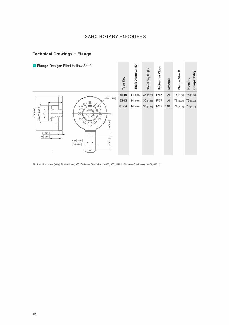
42 www.posital.com
IXARC ROTARY ENCODERS
Technical Drawings − Flange
Flange Design: Blind Hollow Shaft
Type
Key
Shaf
t Dia
met
er (D
)
Shaf
t Dep
th (L
)
Prot
ectio
n C
lass
Mat
eria
l
Flan
ge S
ize
Ø
Hou
sing
Com
patib
ility
E140
E14S
E14W
14 [0.55]
14 [0.55]
14 [0.55]
35 [1.38]
35 [1.38]
35 [1.38]
IP65
IP67
IP67
Al
Al
316 L
78 [3.07]
78 [3.07]
78 [3.07]
78 [3.07]
78 [3.07]
78 [3.07]
321.
2650
1.97
6.50 0.26
25 0.98
48 1.89
D
L
36 f7
1.42
f7
783.
07
8 0.31
16 0.63
321.
2650
1.97
6.50 0.26
25 0.98
48 1.89
D
L
36 f7
1.42
f7
783.
07
8 0.31
16 0.63
All dimension in mm [inch]; Al: Aluminum; 303: Stainless Steel V2A (1.4305, 303); 316 L: Stainless Steel V4A (1.4404, 316 L)

43
IXARC ROTARY ENCODERS
Technical Drawings − Flange
Flange Design: Synchro
Type
Key
Shaf
t Dia
met
er (D
)
Shaf
t Len
gth
(L)
Prot
ectio
n C
lass
Mat
eria
l
Flan
ge S
ize
Ø
Hou
sing
Com
patib
ility
013D
DRSD
10 [0.39]
6.35 [1/4]
20 [0.79]
12.7 [1/2]
IP69K
IP69K
Al
Al
36 [1.42]
36 [1.42]
36 [1.42]
36 [1.42]
D06D
D10D
6 [0.24]
10 [0.39]
10 [0.39]
20 [0.79]
IP69K
IP69K
Al
Al
36 [1.42]
36 [1.42]
36 [1.42]
36 [1.42]
DA4D 10 [0.39] 20 [0.79] IP69K Al 36 [1.42] 36 [1.42]
10.
04
16 0.63 L
D
30 h
71.
18 h
7
36.5
01.
44
4 0.164 0.16
4 0.16
20 0.79
24 0.94
4 x 90°
4xM4x0.7 5 0.20
10.
04
16 0.63 L
D
30 h
71.
18 h
7
36.5
01.
44
4 0.164 0.16
4 0.16
20 0.79
24 0.94
4 x 90°
4xM4x0.7 5 0.20
4xM4 6 [0.24]24 0.94
4 x 90°
L
D
4 0.164 0.16
4 0.16
20 0.79
30 h
71.
18 h
7
36.5
01.
44
4xM4 6 [0.24]24 0.94
4 x 90°
L
D
4 0.164 0.16
4 0.16
20 0.79
30 h
71.
18 h
7
36.5
01.
44
4 x 90°
M4x0.7 - 6H 5 0.2024 0.94
4 P9 0.16 P9
4 0.164 0.16
4 0.16
20 0.79 L
D
30 h
71.
18 h
7
36.5
01.
44
12 0.47
2.50
0.10
4 0.16
4 x 90°
M4x0.7 - 6H 5 0.2024 0.94
4 P9 0.16 P9
4 0.164 0.16
4 0.16
20 0.79 L
D
30 h
71.
18 h
7
36.5
01.
44
12 0.47
2.50
0.10
4 0.16
All dimension in mm [inch]; Al: Aluminum; 303: Stainless Steel V2A (1.4305, 303); 316 L: Stainless Steel V4A (1.4404, 316 L)

44 www.posital.com
IXARC ROTARY ENCODERS
Technical Drawings − Flange
Flange Design: Synchro
Type
Key
Shaf
t Dia
met
er (D
)
Shaf
t Len
gth
(L)
Prot
ectio
n C
lass
Mat
eria
l
Flan
ge S
ize
Ø
Hou
sing
Com
patib
ility
R060
R100
6 [0.24]
10 [0.39]
11.5 [0.45]
20 [0.79]
IP65
IP65
Al
Al
36 [1.42]
36 [1.42]
36 [1.42]
36 [1.42]
RA10
RAF0
6 [0.24]
10 [0.39]
11.5 [0.45]
15 [0.45]
IP65
IP65
Al
Al
36 [1.42]
36 [1.42]
36 [1.42]
36 [1.42]
26 1.02
4xM3 6 [0.24]
4 x 9
0°
D
L
33 h
71.
30 h
7
36.5
01.
44
3 0.123 0.12
3 0.12
10 0.39
26 1.02
4xM3 6 [0.24]
4 x 9
0°
D
L
33 h
71.
30 h
7
36.5
01.
44
3 0.123 0.12
3 0.12
10 0.39
4xM3 6 [0.24]
4 x 9
0°
26 1.02
D
L
10.50 0.41
3 0.123 0.12
3 0.12
10 0.39
0.50
0.02
0.50
0.02
33 h
71.
30 h
7
36.5
01.
44
4xM3 6 [0.24]
4 x 9
0°
26 1.02
D
L
10.50 0.41
3 0.123 0.12
3 0.12
10 0.39
0.50
0.02
0.50
0.02
33 h
71.
30 h
7
36.5
01.
44
All dimension in mm [inch]; Al: Aluminum; 303: Stainless Steel V2A (1.4305, 303); 316 L: Stainless Steel V4A (1.4404, 316 L)

45
IXARC ROTARY ENCODERS
Technical Drawings − Flange
Flange Design: Synchro
Type
Key
Shaf
t Dia
met
er (D
)
Shaf
t Len
gth
(L)
Prot
ectio
n C
lass
Mat
eria
l
Flan
ge S
ize
Ø
Hou
sing
Com
patib
ility
N060
N100
N120
6 [0.24]
10 [0.39]
12 [0.47]
10 [0.39]
20 [0.79]
20 [0.79]
IP65
IP65
IP65
Al
Al
Al
58 [2.28]
58 [2.28]
58 [2.28]
36 [1.42]
36 [1.42]
36 [1.42]
NA10 6 [0.24] 10 [0.39] IP65 Al 58 [2.28] 36 [1.42]
NAF0 10 [0.39] 20 [0.79] IP65 Al 58 [2.28] 36 [1.42]
42 1.65
3 x 120° 3xM4 6 [0.24]
L
D
50 f7
1.97
f7
582.
28
4 0.163 0.123 0.12
11 0.43
42 1.65
3 x 120° 3xM4 6 [0.24]
L
D
50 f7
1.97
f7
582.
28
4 0.163 0.123 0.12
11 0.43
42 1.65
3xM4 6 [0.24] 3 x 120°
4 0.163 0.12
3 0.12
11 0.43
L
D
50 f7
1.97
f7
9 0.35
0.50
0.02
0.50
0.02
42 1.65
3xM4 6 [0.24] 3 x 120°
4 0.163 0.12
3 0.12
11 0.43
L
D
50 f7
1.97
f7
9 0.35
0.50
0.02
0.50
0.02
42 1.65
3 x 120° M4x0.7
18 0.71
10.
04
L
D
50
f71.
97 f7
582.
28
4 0.163 0.12
3 0.12
11 0.43
42 1.65
3 x 120° M4x0.7
18 0.71
10.
04
L
D
50
f71.
97 f7
582.
28
4 0.163 0.12
3 0.12
11 0.43
All dimension in mm [inch]; Al: Aluminum; 303: Stainless Steel V2A (1.4305, 303); 316 L: Stainless Steel V4A (1.4404, 316 L)

46
Flange Design: Synchro
Type
Key
Shaf
t Dia
met
er (D
)
Shaf
t Len
gth
(L)
Prot
ectio
n C
lass
Mat
eria
l
Flan
ge S
ize
Ø
Hou
sing
Com
patib
ility
S060
S100
S120
S06S
S10S
S12S
S06V
S10V
S12V
6 [0.24]
10 [0.39]
12 [0.47]
6 [0.24]
10 [0.39]
12 [0.47]
6 [0.24]
10 [0.39]
12 [0.47]
10 [0.39]
20 [0.79]
20 [0.79]
10 [0.39]
20 [0.79]
20 [0.79]
10 [0.39]
20 [0.79]
20 [0.79]
IP65
IP65
IP65
IP67
IP67
IP67
IP67
IP67
IP67
Al
Al
Al
Al
Al
Al
303
303
303
58 [2.28]
58 [2.28]
58 [2.28]
58 [2.28]
58 [2.28]
58 [2.28]
58 [2.28]
58 [2.28]
58 [2.28]
58 [2.28]
58 [2.28]
58 [2.28]
58 [2.28]
58 [2.28]
58 [2.28]
58 [2.28]
58 [2.28]
58 [2.28]
SA10
SA70
6 [0.24]
9.52 [3/8]
10 [0.39]
20 [0.79]
IP65
IP65
Al
Al
58 [2.28]
58 [2.28]
58 [2.28]
58 [2.28]
SB90 10 [0.39] 20 [0.79] IP65 Al 58 [2.28] 58 [2.28]
IXARC ROTARY ENCODERS
Technical Drawings − Flange
3 x 120°
42 1.65
3xM4 6 [0.24]
L
D
50 f7
1.97
f7
582.
28
4 0.163 0.12
3 0.12
13.50 0.53
3 x 120°
42 1.65
3xM4 6 [0.24]
L
D
50 f7
1.97
f7
582.
28
4 0.163 0.12
3 0.12
13.50 0.53
3 x 120°
42 1.65
3xM4 6 [0.24]
0.50
0.02
0.50
0.02
D
9 0.35
L
50 f7
1.97
f7
582.
28
4 0.163 0.12
3 0.12
13.50 0.53
3 x 120°
42 1.65
3xM4 6 [0.24]
0.50
0.02
0.50
0.02
D
9 0.35
L
50 f7
1.97
f7
582.
28
4 0.163 0.12
3 0.12
13.50 0.53
3 x 120°
42 1.65
3xM4 6 [0.24]
D
10.
04
18 0.71
L 50 f7
1.97
f7
4 0.163 0.12
3 0.12
13 0.51
3 x 120°
42 1.65
3xM4 6 [0.24]
D
10.
04
18 0.71
L 50 f7
1.97
f7
4 0.163 0.12
3 0.12
13 0.51
All dimension in mm [inch]; Al: Aluminum; 303: Stainless Steel V2A (1.4305, 303); 316 L: Stainless Steel V4A (1.4404, 316 L)

47
IXARC ROTARY ENCODERS
Technical Drawings − Flange
Flange Design: Synchro
Type
Key
Shaf
t Dia
met
er (D
)
Shaf
t Len
gth
(L)
Prot
ectio
n C
lass
Mat
eria
l
Flan
ge S
ize
Ø
Hou
sing
Com
patib
ility
Y060
Y100
Y120
YAF0
Y06S
Y10S
Y12S
Y06V
Y10V
Y12V
6 [0.24]
10 [0.39]
12 [0.47]
10 [0.39]
6 [0.24]
10 [0.39]
12 [0.47]
6 [0.24]
10 [0.39]
12 [0.47]
10 [0.39]
20 [0.79]
20 [0.79]
20 [0.79]
10 [0.39]
20 [0.79]
20 [0.79]
10 [0.39]
20 [0.79]
20 [0.79]
IP65
IP65
IP65
IP65
IP67
IP67
IP67
IP67
IP67
IP67
Al
Al
Al
Al
Al
Al
Al
303
303
303
58 [2.28]
58 [2.28]
58 [2.28]
58 [2.28]
58 [2.28]
58 [2.28]
58 [2.28]
58 [2.28]
58 [2.28]
58 [2.28]
58 [2.28]
58 [2.28]
58 [2.28]
58 [2.28]
58 [2.28]
58 [2.28]
58 [2.28]
58 [2.28]
58 [2.28]
58 [2.28]
YA10
YA1S
6 [0.24]
6 [0.24]
10 [0.39]
10 [0.39]
IP65
IP67
Al
Al
58 [2.28]
58 [2.28]
58 [2.28]
58 [2.28]
YF10
YF1S
10 [0.39]
10 [0.39]
20 [0.79]
20 [0.79]
IP65
IP67
Al
Al
58 [2.28]
58 [2.28]
58 [2.28]
58 [2.28]
42 1.65
3 x 120°
3xM4 6 [0.24]
4 0.163 0.12
3 0.12
L
D
50 f7
1.97
f758
2.28
14.40 0.57
42 1.65
3 x 120°
3xM4 6 [0.24]
4 0.163 0.12
3 0.12
L
D
50 f7
1.97
f758
2.28
14.40 0.57
3 x 120°
42 1.65
3xM4 6 [0.24]
0.50
0.02
0.50
0.02
D
9 0.35 L
50 f7
1.97
f758
2.28
4 0.163 0.12
3 0.12
14.40 0.57
3 x 120°
42 1.65
3xM4 6 [0.24]
0.50
0.02
0.50
0.02
D
9 0.35 L
50 f7
1.97
f758
2.28
4 0.163 0.12
3 0.12
14.40 0.57
3 x 120°
42 1.65
3xM4 6 [0.24]
10.
04
D
50 f7
1.97
f758
2.28
18 0.71 L
16 0.63
4 0.163 0.12
3 0.12
3 x 120°
42 1.65
3xM4 6 [0.24]
10.
04
D
50 f7
1.97
f758
2.28
18 0.71 L
16 0.63
4 0.163 0.12
3 0.12
All dimension in mm [inch]; Al: Aluminum; 303: Stainless Steel V2A (1.4305, 303); 316 L: Stainless Steel V4A (1.4404, 316 L)

48
IXARC ROTARY ENCODERS
Technical Drawings − Flange
Flange Design: Synchro
Type
Key
Shaf
t Dia
met
er (D
)
Shaf
t Len
gth
(L)
Prot
ectio
n C
lass
Mat
eria
l
Flan
ge S
ize
Ø
Hou
sing
Com
patib
ility
G10G 10 [0.39] 20 [0.79] IP69K 316 L 42 [1.65] 42 [1.65]
GA4G 10 [0.39] 20 [0.79] IP69K 316 L 42 [1.65] 42 [1.65]
A7W0
B4W0
9.52 [3/8]
6.35 [1/4]
22.4 [0.88]
22.4 [0.88]
IP65
IP65
Al
Al
66.7 [2.62]
66.7 [2.62]
36 [1.42]
36 [1.42]
32.30 1.2747.63 1.88
3 x
120°
4 x
90°
3x10-32 UNF 4.83 [0.19] 4x4-40 UNC 6.35 [0.25]
D
L
63.5
02.
5066
.68
2.62
5
3.18 0.133.18 0.13
1.27 0.05
15.24 0.60
32.30 1.2747.63 1.88
3 x
120°
4 x
90°
3x10-32 UNF 4.83 [0.19] 4x4-40 UNC 6.35 [0.25]
D
L
63.5
02.
5066
.68
2.62
5
3.18 0.133.18 0.13
1.27 0.05
15.24 0.60
35 1.38 4xM4 8 [0.32]
4 x 90°
L
D
9.50 0.3713.10 0.52
42 f7
1.65
f7
35 1.38 4xM4 8 [0.32]
4 x 90°
L
D
9.50 0.3713.10 0.52
42 f7
1.65
f7
4 x 90°
35 1.38 M4x0.7 6 0.24
4 P9 0.16 P9
D
4 0.16
12.30 0.48
L
9.50 0.37
13.10 0.52
42 f7
1.65
f7 2.50
0.10
4 x 90°
35 1.38 M4x0.7 6 0.24
4 P9 0.16 P9
D
4 0.16
12.30 0.48
L
9.50 0.37
13.10 0.52
42 f7
1.65
f7 2.50
0.10
All dimension in mm [inch]; Al: Aluminum; 303: Stainless Steel V2A (1.4305, 303); 316 L: Stainless Steel V4A (1.4404, 316 L)
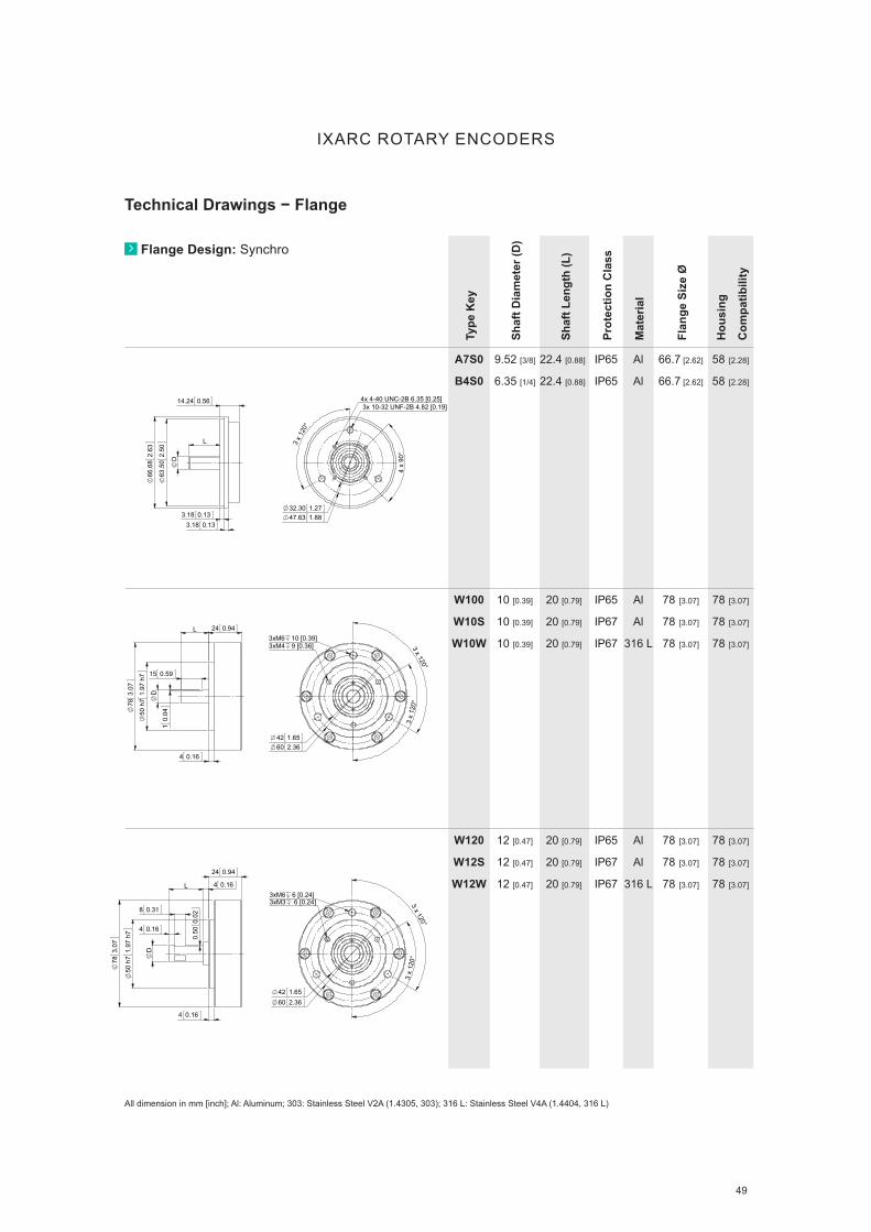
49
IXARC ROTARY ENCODERS
Technical Drawings − Flange
Flange Design: Synchro
Type
Key
Shaf
t Dia
met
er (D
)
Shaf
t Len
gth
(L)
Prot
ectio
n C
lass
Mat
eria
l
Flan
ge S
ize
Ø
Hou
sing
Com
patib
ility
A7S0
B4S0
9.52 [3/8]
6.35 [1/4]
22.4 [0.88]
22.4 [0.88]
IP65
IP65
Al
Al
66.7 [2.62]
66.7 [2.62]
58 [2.28]
58 [2.28]
W100
W10S
W10W
10 [0.39]
10 [0.39]
10 [0.39]
20 [0.79]
20 [0.79]
20 [0.79]
IP65
IP67
IP67
Al
Al
316 L
78 [3.07]
78 [3.07]
78 [3.07]
78 [3.07]
78 [3.07]
78 [3.07]
W120
W12S
W12W
12 [0.47]
12 [0.47]
12 [0.47]
20 [0.79]
20 [0.79]
20 [0.79]
IP65
IP67
IP67
Al
Al
316 L
78 [3.07]
78 [3.07]
78 [3.07]
78 [3.07]
78 [3.07]
78 [3.07]
32.30 1.2747.63 1.88
3 x
120°
4 x
90°
3x 10-32 UNF-2B 4.82 [0.19]4x 4-40 UNC-2B 6.35 [0.25]
L
D
63.5
02.
50
66.6
82.
63
3.18 0.133.18 0.13
14.24 0.56
32.30 1.2747.63 1.88
3 x
120°
4 x
90°
3x 10-32 UNF-2B 4.82 [0.19]
4x 4-40 UNC-2B 6.35 [0.25]
L
D
63.5
02.
50
66.6
82.
63
3.18 0.133.18 0.13
14.24 0.56
42 1.65
3 x
120
°
3 x 120°
60 2.36
3xM4 9 [0.36]3xM6 10 [0.39]
15 0.59
10.
04
D
50 h
71.
97 h
7
783.
07
L
4 0.16
24 0.94
3 x
120
°
3 x 120°
60 2.3642 1.65
3xM3 6 [0.24]3xM6 6 [0.24]
4 0.16
8 0.31
4 0.16 L
50 h
71.
97 h
7
D
24 0.94
4 0.16
783.
07
0.50
0.02
3 x
120
°
3 x 120°
60 2.3642 1.65
3xM3 6 [0.24]3xM6 6 [0.24]
4 0.16
8 0.31
4 0.16 L
50 h
71.
97 h
7
D
24 0.94
4 0.16
783.
07
0.50
0.02
All dimension in mm [inch]; Al: Aluminum; 303: Stainless Steel V2A (1.4305, 303); 316 L: Stainless Steel V4A (1.4404, 316 L)

50
Technical Drawings − Flange
IXARC ROTARY ENCODERS
Flange Design: Clamp
Type
Key
Shaf
t Dia
met
er (D
)
Shaf
t Len
gth
(L)
Prot
ectio
n C
lass
Mat
eria
l
Flan
ge S
ize
Ø
Hou
sing
Com
patib
ility
F06S 6 [0.24] 15 [0.59] IP65 Al 36 [1.42] 58 [2.28]
01M0 6 [0.24] 12 [0.47] IP65 Al 38 [1.5] 36 [1.42]
02M0 6 [0.24] 15 [0.59] IP65 Al 40 [1.57] 36 [1.42]
15° 45°
3 x 120°
28 1.10 4xM3 - 6H 6 0.24
L
D
3 0.124 0.16
5 0.20
20 - -0.
005
0.02
00.
79 - -0.
000.
00
381.
50
36.5
01.
44 0.50
0.02
10 0.39
59 2.32
30°
R2.25
48 1.89
36.50 1.44
D
16 f6
0.63
f6
L 3 0.12
9 0.35
10 0.39
10.
04
59 2.32
30°
R2.25
48 1.89
36.50 1.44
D
16 f6
0.63
f6
L 3 0.12
9 0.35
10 0.39
10.
04
3 x 120°
30 1.18
3xM3 7 0.28
40 1.575 0.20
6 0.24
20 -0 0.
020.
787
-0.00
00.
001
D
L
401.
57 10.
04
10 0.39
3 x 120°
30 1.18
3xM3 7 0.28
40 1.575 0.20
6 0.24
20 -0 0.
020.
787
-0.00
00.
001
D
L
401.
57 10.
04
10 0.39
All dimension in mm [inch]; Al: Aluminum; 303: Stainless Steel V2A (1.4305, 303); 316 L: Stainless Steel V4A (1.4404, 316 L)

51
IXARC ROTARY ENCODERS
Technical Drawings − Flange
Flange Design: Clamp
Type
Key
Shaf
t Dia
met
er (D
)
ShG
AC
G
Prot
ectio
n C
lass
Mat
eria
l
Flan
ge S
ize
Ø
Hou
sing
Com
patib
ility
04M0 8 [0.31] 15 [0.59] IP65 Al 40 [1.57] 36 [1.42]
GACG
DACD
10 [0.39]
10 [0.39]
20 [0.79]
20 [0.79]
IP69K
IP69K
316 L
Al
58 [2.28]
58 [2.28]
42 [1.65]
36 [1.42]
15° 45°
3 x 120°
28 1.10 4xM3 - 6H 6 0.24
L
D
3 0.124 0.16
5 0.20
20 - -0.
005
0.02
00.
79 - -0.
000.
00
381.
50
36.5
01.
44 0.50
0.02
10 0.39
15° 45°
3 x 120°
28 1.10 4xM3 - 6H 6 0.24
L
D
3 0.124 0.16
5 0.20
20 - -0.
005
0.02
00.
79 - -0.
000.
00
381.
50
36.5
01.
44 0.50
0.02
10 0.39
10 0.39
L
D
3 0.12
3 0.12
17 0.67
36 f7
1.42
f7
582.
28
532.
09
15° x 3 120° x 3
48 1.89
3xM4x0.73xM3x0.510 0.39
L
D
3 0.12
3 0.12
17 0.67
36 f7
1.42
f7
582.
28
532.
09
15° x 3 120° x 3
48 1.89
3xM4x0.73xM3x0.5
All dimension in mm [inch]; Al: Aluminum; 303: Stainless Steel V2A (1.4305, 303); 316 L: Stainless Steel V4A (1.4404, 316 L)

52
IXARC ROTARY ENCODERS
Technical Drawings − Flange
Flange Design: Clamp
Type
Key
Shaf
t Dia
met
er (D
)
Shaf
t Len
gth
(L)
Prot
ectio
n C
lass
Mat
eria
l
Flan
ge S
ize
Ø
Hou
sing
Com
patib
ility
03M0 6 [0.24] 15 [0.59] IP65 Al 50 [1.97] 36 [1.42]
05M0 8 [0.31] 15 [0.59] IP65 Al 50 [1.97] 36 [1.42]
C4M0 6.35 [1/4] 16 [0.62] IP65 Al 50.8 [2] 36 [1.42]
3 x
120°
38 1.50
3xM4 7 0.28
10 0.39
L
5 0.20
2.50 0.10
14.50 0.57
D
25 - -0.
010.
020.
984
- -0.00
00.
001
501.
97
441.
73 10.
04
3 x
120°
38 1.50
3xM4 7 0.28
10 0.39
L
5 0.20
2.50 0.10
14.50 0.57
D
25 - -0.
010.
020.
984
- -0.00
00.
001
501.
97
441.
73 10.
04
3 x
120°
40 1.57
3xM3 8 0.31
30 + -0.
010
0.02
11.
181
+ -0.00
00.
001
D
10 0.39
L
5 0.20
2.50 0.10
15.50 0.61
501.
97
10.
04
4 x 90°
3 x
120°
4 x 10-32 UNF 5.593 x 4-40 UNC 5.59
D
L
31.7
0 f7
1.25
f7
50.8
02.
00
2.54 0.102.54 0.10
3 0.1210.62 0.42
4 x 90°
3 x
120°
4 x 10-32 UNF 5.593 x 4-40 UNC 5.59
D
L
31.7
0 f7
1.25
f7
50.8
02.
00
2.54 0.102.54 0.10
3 0.1210.62 0.42
3 x
120°
40 1.57
3xM3 8 0.31
30 + -0.
010
0.02
11.
181
+ -0.00
00.
001
D
10 0.39
L
5 0.20
2.50 0.10
15.50 0.61
501.
97
10.
04
All dimension in mm [inch]; Al: Aluminum; 303: Stainless Steel V2A (1.4305, 303); 316 L: Stainless Steel V4A (1.4404, 316 L)

53
IXARC ROTARY ENCODERS
Technical Drawings − Flange
Flange Design: Clamp
Type
Key
Shaf
t Dia
met
er (D
)
Shaf
t Len
gth
(L)
Prot
ectio
n C
lass
Mat
eria
l
Flan
ge S
ize
Ø
Hou
sing
Com
patib
ility
D1M0 9.52 [3/8] 16 [0.62] IP65 Al 50.8 [2] 36 [1.42]
A0LS
A0LV
A0LW
10 [0.39]
10 [0.39]
10 [0.39]
20 [0.79]
20 [0.79]
20 [0.79]
IP67
IP67
IP67
Al
303
316 L
58 [2.28]
58 [2.28]
58 [2.28]
58 [2.28]
58 [2.28]
58 [2.28]
AKLS
AKLV
AKLW
10 [0.39]
10 [0.39]
10 [0.39]
20 [0.79]
20 [0.79]
20 [0.79]
IP67
IP67
IP67
Al
303
316 L
58 [2.28]
58 [2.28]
58 [2.28]
58 [2.28]
58 [2.28]
58 [2.28]
38.10 1.50
41.30 1.63
4-40 UNC
120° x 3
90°
x 4
10-32 UNF
D
31.7
0 f7
1.25
f7
3 0.122.54 0.10
2.54 0.10
7.62 0.30
L
50.8
02.
00
38.10 1.50
41.30 1.63
4-40 UNC
120° x 3
90°
x 4
10-32 UNF
D
31.7
0 f7
1.25
f7
3 0.122.54 0.10
2.54 0.10
7.62 0.30
L
50.8
02.
00
3 x
120°
48 1.89
3xM4 8[0.31]
3 N9 0.12 N9
D
L
10 + 0.200 0.394 + 0.008
0.000
36 f7
1.42
f7
532.
09
582.
28
3 0.12
10 0.39
3 0.123 0.12
44 1.73
3 x
120°
48 1.89
3xM4 8[0.31]
3 N9 0.12 N9
D
L
10 + 0.200 0.394 + 0.008
0.000
36 f7
1.42
f7
532.
09
582.
28
3 0.12
10 0.39
3 0.123 0.12
44 1.73
48 1.89
3 x
120°
3xM4 8[0.31]
36 f7
1.42
f7
D
L
18 0.71
10.
04
10 0.39
3 0.123 0.12
44 1.73
582.
28
532.
09
48 1.89
3 x
120°
3xM4 8[0.31]
36 f7
1.42
f7
D
L
18 0.71
10.
04
10 0.39
3 0.123 0.12
44 1.73
582.
28
532.
09
All dimension in mm [inch]; Al: Aluminum; 303: Stainless Steel V2A (1.4305, 303); 316 L: Stainless Steel V4A (1.4404, 316 L)

54
IXARC ROTARY ENCODERS
Technical Drawings − Flange
Flange Design: Clamp
Type
Key
Shaf
t Dia
met
er (D
)
Shaf
t Len
gth
(L)
Prot
ectio
n C
lass
Mat
eria
l
Flan
ge S
ize
Ø
Hou
sing
Com
patib
ility
C060
C100
C120
C10H
C06S
C10S
C12S
6 [0.24]
10 [0.39]
12 [0.47]
10 [0.39]
6 [0.24]
10 [0.39]
12 [0.47]
10 [0.39]
20 [0.79]
20 [0.79]
20 [0.79]
10 [0.39]
20 [0.79]
20 [0.79]
IP65
IP65
IP65
IP67
IP67
IP67
IP67
Al
Al
Al
Al
Al
Al
Al
58 [2.28]
58 [2.28]
58 [2.28]
58 [2.28]
58 [2.28]
58 [2.28]
58 [2.28]
58 [2.28]
58 [2.28]
58 [2.28]
58 [2.28]
58 [2.28]
58 [2.28]
58 [2.28]
C06V
C10V
C12V
C10W
6 [0.24]
10 [0.39]
12 [0.47]
10 [0.39]
10 [0.39]
20 [0.79]
20 [0.79]
20 [0.79]
IP67
IP67
IP67
IP67
303
303
303
316 L
58 [2.28]
58 [2.28]
58 [2.28]
58 [2.28]
58 [2.28]
58 [2.28]
58 [2.28]
58 [2.28]
CA7V
CA30
9.52 [3/8]
10 [0.39]
20 [0.79]
20 [0.79]
IP67
IP65
303
Al
58 [2.28]
58 [2.28]
58 [2.28]
58 [2.28]
3 x 15°
3 x 120°
M4x0.7 6 [0.24]
M3x0.5 6 [0.24]
48 1.89
0.50
0.02
L
10 0.399.50 0.37
36 f7
1.42
f7
3 0.123 0.12
582.
28
D
3 x 15°
3 x 120°
M4x0.7 6 [0.24]
M3x0.5 6 [0.24]
48 1.89
0.50
0.02
L
10 0.399.50 0.37
36 f7
1.42
f7
3 0.123 0.12
582.
28
D
3 x 15°
3 x 120°
3 x M3x0.5 - 6H 6 0.243 x M4x0.7 - 6H 6 0.24
48 1.89
D
L
10 0.39
1.80
0.07
36 f7
1.42
f7
582.
28
3 0.123 0.12
12 0.47
4 0.16
9.50 0.37
All dimension in mm [inch]; Al: Aluminum; 303: Stainless Steel V2A (1.4305, 303); 316 L: Stainless Steel V4A (1.4404, 316 L)

www.posital.com 55
IXARC ROTARY ENCODERS
Technical Drawings − Flange
Flange Design: Clamp
Type
Key
Shaf
t Dia
met
er (D
)
Shaf
t Len
gth
(L)
Prot
ectio
n C
lass
Mat
eria
l
Flan
ge S
ize
Ø
Hou
sing
Com
patib
ility
CA80 10 [0.39] 20 [0.79] IP65 Al 58 [2.28] 58 [2.28]
L060
L100
L120
LA30
LC40
L06S
L10S
L12S
L06V
L10V
L12V
LD80
6 [0.24]
10 [0.39]
12 [0.47]
10 [0.39]
12 [0.47]
6 [0.24]
10 [0.39]
12 [0.47]
6 [0.24]
10 [0.39]
12 [0.47]
12 [0.47]
10 [0.39]
20 [0.79]
20 [0.79]
20 [0.79]
20 [0.79]
10 [0.39]
20 [0.79]
20 [0.79]
10 [0.39]
20 [0.79]
20 [0.79]
20 [0.79]
IP65
IP65
IP65
IP67
IP65
IP67
IP67
IP67
IP67
IP67
IP67
IP65
Al
Al
Al
Al
Al
Al
Al
Al
303
303
303
Al
58 [2.28]
58 [2.28]
58 [2.28]
58 [2.28]
58 [2.28]
58 [2.28]
58 [2.28]
58 [2.28]
58 [2.28]
58 [2.28]
58 [2.28]
58 [2.28]
58 [2.28]
58 [2.28]
58 [2.28]
58 [2.28]
58 [2.28]
58 [2.28]
58 [2.28]
58 [2.28]
58 [2.28]
58 [2.28]
58 [2.28]
58 [2.28]
L
36 f7
1.42
f7
582.
28
532.
09
3 0.123 0.12
10 0.3919.50 0.77
D
15°
3 x 120°
48 1.89
3 x
120
°
3xM4 6 [0.24]3xM3 6 [0.24]
2.50
0.10
L
36 f7
1.42
f7
582.
28
532.
09
3 0.123 0.12
10 0.3919.50 0.77
D
15°
3 x 120°
48 1.89
3 x
120
°
3xM4 6 [0.24]3xM3 6 [0.24]
2.50
0.10
All dimension in mm [inch]; Al: Aluminum; 303: Stainless Steel V2A (1.4305, 303); 316 L: Stainless Steel V4A (1.4404, 316 L)
3 x 15°
3 x 120°
3 x M3x0.5 - 6H 6 0.243 x M4x0.7 - 6H 6 0.24
48 1.89
D
L
10 0.39
36 f7
1.42
f7
582.
28
3 0.12
3 0.12
9.50 0.37
12 0.47
4 G6 0.16 G6
3 x 15°
3 x 120°
3 x M3x0.5 - 6H 6 0.243 x M4x0.7 - 6H 6 0.24
48 1.89
D
L
10 0.39
36 f7
1.42
f7
582.
28
3 0.12
3 0.12
9.50 0.37
12 0.47
4 G6 0.16 G6

56
IXARC ROTARY ENCODERS
Technical Drawings − Flange
Flange Design: Clamp
Type
Key
Shaf
t Dia
met
er (D
)
Shaf
t Len
gth
(L)
Prot
ectio
n C
lass
Mat
eria
l
Flan
ge S
ize
Ø
Hou
sing
Com
patib
ility
M060
M100
M120
6 [0.24]
10 [0.39]
12 [0.47]
10 [0.39]
20 [0.79]
20 [0.79]
IP65
IP65
IP65
Al
Al
Al
58 [2.28]
58 [2.28]
58 [2.28]
36 [1.42]
36 [1.42]
36 [1.42]
A7F0 9.52 [3/8] 22.4 [0.88] IP65 Al 63.5 [2.5] 36 [1.42]
A7P0 9.52 [3/8] 22.4 [0.88] IP65 Al 63.5 [2.5] 58 [2.28]
48 1.89
15°
3 x 120°
3 x
120
°
3xM3 6 [0.24]3xM4 6 [0.24]
D
L
36 f7
1.42
f7
582.
28
532.
09
3 0.122 0.08
10 0.39
16 0.63
48 1.89
15°
3 x 120°
3 x
120
°
3xM3 6 [0.24]3xM4 6 [0.24]
D
L
36 f7
1.42
f7
582.
28
532.
09
3 0.122 0.08
10 0.39
16 0.63
45°
4 x 90°
50.80 2.00
47.63 1.88
3 x 120°
3 x 120° 3 x 120°
3x6-32 UNC 4.83 0.194x4-40 UNC 4.83 0.19
3x10-32 UNF 4.83 0.193x8-32 UNC 4.83 0.19
D
31.7
0 f7
1.25
f7
63.5
02.
50
L
7.62 0.30
2.54 0.10
2.54 0.10
15.24 0.60
45°
4 x 90°
50.80 2.00
47.63 1.88
3 x 120°
3 x 120° 3 x 120°
3x6-32 UNC 4.83 0.194x4-40 UNC 4.83 0.19
3x10-32 UNF 4.83 0.193x8-32 UNC 4.83 0.19
D
31.7
0 f7
1.25
f7
63.5
02.
50
L
7.62 0.30
2.54 0.10
2.54 0.10
15.24 0.60
47.63 1.88
50.80 2.00
4 x 90°
3 x 120°
3 x 120° 3 x 120°
3x8-32 UNC 4.83 0.194x4-40 UNC 4.83 0.193x10⁻³² UNF 4.83 0.193x6-32 UNC 4.83 0.19
L
D
7.62 0.30
2.54 0.10
2.54 0.10
15.24 0.60
31.7
5 f7
1.25
f7
63.5
02.
50
47.63 1.88
50.80 2.00
4 x 90°
3 x 120°
3 x 120° 3 x 120°
3x8-32 UNC 4.83 0.194x4-40 UNC 4.83 0.193x10⁻³² UNF 4.83 0.193x6-32 UNC 4.83 0.19
L
D
7.62 0.30
2.54 0.10
2.54 0.10
15.24 0.60
31.7
5 f7
1.25
f7
63.5
02.
50
All dimension in mm [inch]; Al: Aluminum; 303: Stainless Steel V2A (1.4305, 303); 316 L: Stainless Steel V4A (1.4404, 316 L)

www.posital.com 57
IXARC ROTARY ENCODERS
Technical Drawings − Flange
Flange Design: Clamp
Type
Key
Shaf
t Dia
met
er (D
)
Shaf
t Len
gth
(L)
Prot
ectio
n C
lass
Mat
eria
l
Flan
ge S
ize
Ø
Hou
sing
Com
patib
ility
B4F0
B4P0
6.35 [1/4]
6.35 [1/4]
22.4 [0.88]
22.4 [0.88]
IP65
IP65
Al
Al
63.5 [2.5]
63.5 [2.5]
36 [1.42]
58 [2.28]
C660 6 [0.24] 20 [0.79] IP65 Al 65 [2,5] 58 [2.28]
50.80 2.0047.63 1.88
4 x 90°
3 x 120°
3 x 120°
3 x 1
20°
3x6-32 UNC 4.83 0.19
4x4-40 UNC 4.83 0.193x8-32 UNC 4.83 0.19
3x10-32 UNF 4.83 0.19
31.7
0 f7
1.25
f7
D
63.5
02.
5058
.67
2.31
L
7.62 0.3015.24 0.60
2.54 0.102.54 0.10
48 1.8955 2.17
3 x 15°
3 x 120°
M4
L
D
45 h
71.
77 h
7
652.
56
4 0.16
3 0.12
10 0.39
3 3
9 0.35
602.
36
48 1.8955 2.17
3 x 15°
3 x 120°
M4
L
D
45 h
71.
77 h
7
652.
56
4 0.16
3 0.12
10 0.39
3 3
9 0.35
602.
36
50.80 2.0047.63 1.88
4 x 90°
3 x 120°
3 x 120°
3 x 1
20°
3x6-32 UNC 4.83 0.19
4x4-40 UNC 4.83 0.193x8-32 UNC 4.83 0.19
3x10-32 UNF 4.83 0.19
31.7
0 f7
1.25
f7
D
63.5
02.
5058
.67
2.31
L
7.62 0.3015.24 0.60
2.54 0.102.54 0.10
All dimension in mm [inch]; Al: Aluminum; 303: Stainless Steel V2A (1.4305, 303); 316 L: Stainless Steel V4A (1.4404, 316 L)

58
IXARC ROTARY ENCODERS
Technical Drawings − Flange
Flange Design: Through Hollow
Type
Key
Shaf
t Dia
met
er (D
)
Prot
ectio
n C
lass
Mat
eria
l
Flan
ge S
ize
Ø
Hou
sing
Com
patib
ility
H200 20 [0.78] IP67 303 50 [1.97] 36 [1.42]
T060
T080
T100
T120
T130
6 [0.24]
8 [0.31]
10 [0.39]
12 [0.47]
13 [0.51]
IP65
IP65
IP65
IP65
IP65
Al
Al
Al
Al
Al
58 [2.28]
58 [2.28]
58 [2.28]
58 [2.28]
58 [2.28]
58 [2.28]
58 [2.28]
58 [2.28]
58 [2.28]
58 [2.28]
42 1.65
72 2.83
3.20 0.13
20°
20
0.79
63 2.48
50 f7
1.97
f7
L
3 0.12
7 0.28
D
50 1.97
933.
66210.
8321
0.83
19 0.75
50 1.97
60.
24
6 0.24
301.
18
All dimension in mm [inch]; Al: Aluminum; 303: Stainless Steel V2A (1.4305, 303); 316 L: Stainless Steel V4A (1.4404, 316 L)

59
IXARC ROTARY ENCODERS
Technical Drawings − Flange
Flange Design: Square
Type
Key
Shaf
t Dia
met
er (D
)
Shaf
t Len
gth
(L)
Prot
ectio
n C
lass
Mat
eria
l
Flan
ge S
ize □
Hou
sing
Com
patib
ility
3A70
3C40
3A7S
9.52 [3/8]
6.35 [1/4]
9.52 [3/8]
16 [0.63]
16 [0.63]
16 [0.63]
IP65
IP65
IP67
Al
Al
Al
52.3 [2]
52.3 [2]
52.3 [2]
36 [1.42]
36 [1.42]
36 [1.42]
8R10
8S10
6.35 [1/4]
9.52 [3/8]
15 [0.59]
15 [0.59]
IP65
IP65
Al
Al
52.3 [2]
52.3 [2]
36 [1.42]
36 [1.42]
9A7V
9A70
9A7S
9.52 [3/8]
9.52 [3/8]
9.52 [3/8]
20 [0.79]
20 [0.79]
20 [0.79]
IP67
IP65
P67
303
Al
Al
63.5 [2.5]
63.5 [2.5]
63.5 [2.5]
58 [2.28]
58 [2.28]
58 [2.28]
52.3
22.
06
44.4
51.
754 0.16
3 0.12
9.35 0.37
D
31.7
5 f7
1.25
f7 L
2 0.0852
.32
2.06
44.4
51.
75
4 0.16
3 0.12
9.35 0.37
D
31.7
5 f7
1.25
f7 L
2 0.0849
1.93
57.1
52.
25
4 x 3.40 0.13 7.50 0.30 6.50 0.26 3.40 0.13
4 x 2.71 0.11 8 0.316-32 UNC 6.35 0.25
50.80 2.00
L
D
12.70 0.50
1.30
0.0524
.61
+ -0.13
0.05
0.97
+ -0.01
0.00
1.50 0.06
6.35 0.25
491.
93
57.1
52.
25
4 x 3.40 0.13 7.50 0.30 6.50 0.26 3.40 0.13
4 x 2.71 0.11 8 0.316-32 UNC 6.35 0.25
50.80 2.00
L
D
12.70 0.50
1.30
0.0524
.61
+ -0.13
0.05
0.97
+ -0.01
0.00
1.50 0.06
6.35 0.25
5.60 0.22
52.4
32.
06
66.7
02.
63
31.7
5 f7
1.25
f7
D
7.62 0.30
L
6.35 0.25
19.30 0.76
5.60 0.22
52.4
32.
06
66.7
02.
63
31.7
5 f7
1.25
f7
D
7.62 0.30
L
6.35 0.25
19.30 0.76
All dimension in mm [inch]; Al: Aluminum; 303: Stainless Steel V2A (1.4305, 303); 316 L: Stainless Steel V4A (1.4404, 316 L)

60 www.posital.com
IXARC ROTARY ENCODERS
Technical Drawings − Flange
Flange Design: Square
Type
Key
Shaf
t Dia
met
er (D
)
Shaf
t Len
gth
(L)
Prot
ectio
n C
lass
Mat
eria
l
Flan
ge S
ize □
Hou
sing
Com
patib
ility
4A70
4B40
4A7S
9.52 [3/8]
6.35 [1/4]
9.52 [3/8]
22.4 [0.88]
22.4 [0.88]
22.4 [0.88]
IP65
IP65
IP67
Al
Al
Al
63.5 [2.5]
63.5 [2.5]
63.5 [2.5]
36 [1.42]
36 [1.42]
36 [1.42]
5A70
5B40
5A7S
9.52 [3/8]
6.35 [1/4]
9.52 [3/8]
22.4 [0.88]
22.4 [0.88]
22.4 [0.88]
IP65
IP65
IP67
Al
Al
Al
63.5 [2.5]
63.5 [2.5]
63.5 [2.5]
58 [2.28]
58 [2.28]
58 [2.28]
5.60 0.22
52.4
32.
06
66.7
02.
63
7.62 0.30
13.97 0.55
31.7
5 f7
1.25
f7
D
L
5.60 0.2252
.43
2.06
66.7
02.
63
7.62 0.30
13.97 0.55
31.7
5 f7
1.25
f7
D
L
13.97 0.55
7.62 0.30
31.7
5 f7
1.25
f7
D
L
5.60 0.22
52.4
32.
06
66.7
02.
63
13.97 0.55
7.62 0.30
31.7
5 f7
1.25
f7
D
L
5.60 0.22
52.4
32.
06
66.7
02.
63
All dimension in mm [inch]; Al: Aluminum; 303: Stainless Steel V2A (1.4305, 303); 316 L: Stainless Steel V4A (1.4404, 316 L)

61
Flange Design: Square
Type
Key
Shaf
t Dia
met
er (D
)
Shaf
t Len
gth
(L)
Prot
ectio
n C
lass
Mat
eria
l
Flan
ge S
ize □
Hou
sing
Com
patib
ility
Z100
Z10S
Z10W
10 [0.39]
10 [0.39]
10 [0.39]
20 [0.79]
20 [0.79]
20 [0.79]
IP65
IP67
IP67
Al
Al
316 L
80 [3.14]
80 [3.14]
80 [3.14]
78 [3.07]
78 [3.07]
78 [3.07]
Z120
Z12S
Z12W
12 [0.47]
12 [0.47]
12 [0.47]
20 [0.79]
20 [0.79]
20 [0.79]
IP65
IP67
IP67
Al
Al
316 L
80 [3.14]
80 [3.14]
80 [3.14]
78 [3.07]
78 [3.07]
78 [3.07]
652.
56
803.
15
5.60 0.22
69 2.72
D
L
76 -0 0.
052.
99 -0.
000.
00
2.50 0.10
10 0.39
24 0.94
783.
07
15 0.59
10.
04
652.
56
803.
155.60 0.22
69 2.72
D
L
76 -0 0.
052.
99 -0.
000.
00
2.50 0.10
10 0.39
24 0.94
783.
07
15 0.59
10.
04
652.
56
803.
15
5.60 0.22
69 2.72
60°
2.50 0.10
10 0.39
24 0.94
4 0.16 L
4 0.16
8 0.31
D
M17
x0.7
5
783.
07
0.50
0.0276
-0 0.05
2.99
-0.00
0.00
IXARC ROTARY ENCODERS
Technical Drawings − Flange
All dimension in mm [inch]; Al: Aluminum; 303: Stainless Steel V2A (1.4305, 303); 316 L: Stainless Steel V4A (1.4404, 316 L)
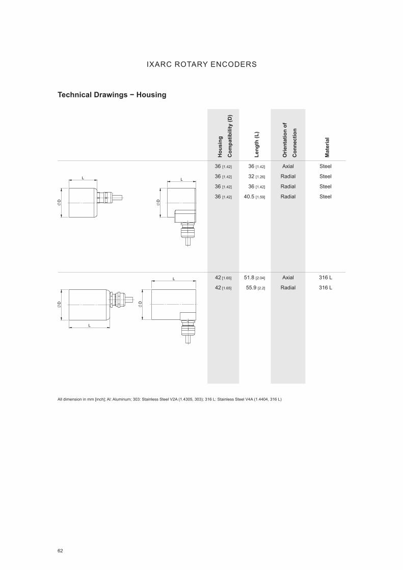
62
Hou
sing
Com
patib
ility
(D)
Leng
th (L
)
Orie
ntat
ion
of
Con
nect
ion
Mat
eria
l
36 [1.42]
36 [1.42]
36 [1.42]
36 [1.42]
36 [1.42]
32 [1.26]
36 [1.42]
40.5 [1.59]
Axial
Radial
Radial
Radial
Steel
Steel
Steel
Steel
42 [1.65]
42 [1.65]
51.8 [2.04]
55.9 [2.2]
Axial
Radial
316 L
316 L
D
L
D
L
L
D
D
L
Technical Drawings − Housing
IXARC ROTARY ENCODERS
All dimension in mm [inch]; Al: Aluminum; 303: Stainless Steel V2A (1.4305, 303); 316 L: Stainless Steel V4A (1.4404, 316 L)

63
Hou
sing
Com
patib
ility
(D)
Leng
th (L
)
Orie
ntat
ion
of
Con
nect
ion
Mat
eria
l
58 [2.28]
58 [2.28]
29 [1.14]
41.5 [1.63]
Radial
Radial
Al
Al
58 [2.28]
58 [2.28]
32 [1.26]
43.5 [1.71]
Radial
Radial
Al
Al
58 [2.28]
58 [2.28]
58 [2.28]
58 [2.28]
61 [2.4]
79 [3.11]
85 [3.35]
69 [2.72]
Radial
Radial
Radial
Radial
Al
Al
Al
303
L
D
L
D
D
L
Technical Drawings − Housing
IXARC ROTARY ENCODERS
All dimension in mm [inch]; Al: Aluminum; 303: Stainless Steel V2A (1.4305, 303); 316 L: Stainless Steel V4A (1.4404, 316 L)

64
Technical Drawings − Housing
IXARC ROTARY ENCODERS
Hou
sing
Com
patib
ility
(D)
Leng
th (L
)
Orie
ntat
ion
of
Con
nect
ion
Mat
eria
l
58 [2.28]
58 [2.28]
58 [2.28]
58 [2.28]
61 [2.4]
65 [2.56]
79 [3.11]
85 [3.35]
Radial
Radial
Radial
Radial
303
303
303
303
58 [2.28] 65 [2.56] Radial Brass
58 [2.28] 69 [2.72] Radial Brass
D
L
D
L
D
L
All dimension in mm [inch]; Al: Aluminum; 303: Stainless Steel V2A (1.4305, 303); 316 L: Stainless Steel V4A (1.4404, 316 L)

65
Technical Drawings − Housing
IXARC ROTARY ENCODERS
Hou
sing
Com
patib
ility
(D)
Leng
th (L
)
Orie
ntat
ion
of
Con
nect
ion
Mat
eria
l
58 [2.28]
58 [2.28]
58 [2.28]
32 [1.26]
43 [1.69]
52.8 [2.08]
Radial
Radial
Radial
Steel
Steel
Steel
58 [2.28]
58 [2.28]
58 [2.28]
58 [2.28]
58 [2.28]
58 [2.28]
58 [2.28]
32.2 [1.27]
43 [1.69]
43.2 [1.7]
53 [2.09]
53 [2.09]
43.2 [1.7]
53 [2.09]
Axial
Axial
Axial
Axial
Axial
Radial
Radial
Steel
Steel
Steel
Steel
Steel
Steel
Steel
58 [2.28]
58 [2.28]
58 [2.28]
58 [2.28]
58 [2.28]
58 [2.28]
43.2 [1.7]
53 [2.09]
59.5 [2.34]
67.7 [2.67]
70.5 [2.78]
78.7 [3.1]
Axial
Axial
Radial
Radial
Radial
Radial
Steel
Steel
Steel
Steel
Steel
Steel
D
L
L
D
L
D
L
D
L
D
All dimension in mm [inch]; Al: Aluminum; 303: Stainless Steel V2A (1.4305, 303); 316 L: Stainless Steel V4A (1.4404, 316 L)

66 www.posital.com
Technical Drawings − Housing
IXARC ROTARY ENCODERS
Hou
sing
Com
patib
ility
(D)
Leng
th (L
)
Orie
ntat
ion
of
Con
nect
ion
Mat
eria
l
61 [2,4]
61 [2,4]
61 [2,4]
32 [1.26]
43 [1.69]
52.8 [2.08]
Radial
Radial
Radial
303
303
303
61 [2,4]
61 [2,4]
61 [2,4]
61 [2,4]
61 [2,4]
61 [2,4]
59.5 [2.34]
67.7 [2.67]
70.5 [2.78]
78.7 [3.1]
70.5 [2.78]
69 [2.72]
Radial
Radial
Radial
Radial
Radial
Radial
303
303
303
303
303
303
L
D
D
L
All dimension in mm [inch]; Al: Aluminum; 303: Stainless Steel V2A (1.4305, 303); 316 L: Stainless Steel V4A (1.4404, 316 L)

67
Technical Drawings − Housing
IXARC ROTARY ENCODERS
Hou
sing
Com
patib
ility
(D)
Leng
th (L
)
Orie
ntat
ion
of
Con
nect
ion
Mat
eria
l
61 [2,4]
61 [2,4]
61 [2,4]
61 [2,4]
61 [2,4]
32,2 [1,27]
43,2 [1,7]
43,2 [1,7]
53 [2,09]
43,2 [1,7]
Axial
Axial
Axial
Axial
Radial
303
303
303
303
303
78 [3.07]
78 [3.07]
78 [3.07]
78 [3.07]
78 [3.07]
78 [3.07]
55 [2.17]
55 [2.17]
55 [2.17]
55 [2.17]
64 [2.52]
64 [2.52]
Axial
Axial
Radial
Radial
Radial
Radial
Al
303
Al
303
Al
303
L
D
D
L
D
L L
D
All dimension in mm [inch]; Al: Aluminum; 303: Stainless Steel V2A (1.4305, 303); 316 L: Stainless Steel V4A (1.4404, 316 L)

68 www.posital.com
Technical Drawings − Housing
IXARC ROTARY ENCODERS
Hou
sing
Com
patib
ility
(D)
Leng
th (L
)
Orie
ntat
ion
of
Con
nect
ion
Mat
eria
l
95 [3,74]
95 [3,74]
186.5 [7.34]
60 [2.36]
Radial
Radial
316 L
316 L L
D
All dimension in mm [inch]; Al: Aluminum; 303: Stainless Steel V2A (1.4305, 303); 316 L: Stainless Steel V4A (1.4404, 316 L)

KIT ENCODERS
No Battery − Robust − Easy to Install

70
Innovative Technology POSITAL‘s kit encoders offer a unique combination of accuracy, reliability and cost efficiency. Absolute measurement versions provide 17 bit electrical re-solution and multiturn position measurements with a range of more than one million revolutions. A second version provides a combined incremental+UVW output with a resolution of up to 16384 PPR. Kit en-coder components include an electronics package mounted on a compact 35 mm diameter PCB and a small permanent magnet, designed to be moun-ted on the end of the motor’s shaft. The electronics package includes four Hall-effect sensors, a pow-erful 32-bit microprocessor and a rotation counter powered by POSITAL’s Wiegand energy harvesting system.
Energy Harvesting – No BatteryThe energy harvesting system is based on the Wiegand effect and eliminates the need for backup batteries or complex gear systems. At any rotatio-nal speed, even the slowest, the Wiegand system
generates short, powerful voltage pulses with each complete revolution. These pulses supply enough power to activate the rotation counter and related electronics so that the encoder will keep count of complete rotations at all times, even if these occur when the external power supply is unavailable. This principle, which has proven itself since 2005, en-sures reliable, maintenance-free multiturn absolute position measurements.
Advantages POSITAL’s contact free measurement technology has no moving parts and is highly resistant to shock and vibration. POSITAL’s kit encoders are available with several non-proprietary electrical interfaces including BISS and SSI for absolute measurements, UVW and ABZ for incremental signals. Additional protocols based on the RS485 interface can be implemented.
Absolute Multiturn & Incremental Interface No Battery – No Maintenance No Ball Bearings & Compact Design Insensitive to Dust and Moisture High Shock and Vibration Resistance
KIT ENCODERS
Easy Installation – No Maintenance

71
KIT ENCODERS
ponents and Hall-effect sensors from external ma-gnetic fields such as those generated by magnetic brakes.
Specifications Electrical Resolution: Up to 17 Bit Multiturn Range: Up to 32 Bit Accuracy: 0.1° Electrical Interface: BISS C, SSI, RS485, Incremental TTL up to 16384 PPR + UVW (2, 4, 6 or 8 poles) Diameter: 36 mm Height: 24.2 mm (Multiturn with Housing) Temperature Range: -40 to +105°C Rotational Speed: Up to 12000 RPM Auto Calibration − No Complex Equipment Cable Clip Ensures Proper Grounding and Easy Installation Extensive Diagnostic Coverage Various Programmable Parameters
Plug and PlayWhile optical kit encoders typically require near clean-room assembly conditions, POSITAL’s mag-netic encoders are significantly less sensitive to dust and moisture and can be installed in normal factory settings. An integrated auto-calibration function eli-minates the need for complex production equipment: during normal product testing, the encoder can be connected to a small Kit Control Box. As the shaft ro-tates, the auto-calibration system corrects for minor misalignment between the shaft and the electronics package. The Kit Control Box can also be used to program the encoder for important performance pa-rameters such as the number of pulses generated per revolution, without requiring any changes to the mechanical or electrical components. This increases the versatility of the kit encoders. The embedded software on the kit encoder will also monitor the health of the electronics package and provide diagnostic signals over the lifetime of the encoder. Compact and inexpensive shielding acces-sories are available to protect the electronic com-
Absolute and Incremental – Robust and Programmable

72
KIT ENCODERS
Technical Drawings
NOT RELEASED
36.50
46.80 12.40
49.50
2 x Screw DIN 912 – M3 x 10 – 8.8Tightening torque 1 ±0.1 Nm
24.30 + 0.100
9.80
12.60
4
0.80
M4x0.7 - 6g
8
6.50 g7
Centering pins2 x 2.20
A
29.50 15°
43.50
2 x Screw ISO 14580 – M2 x 8 – A4Tightening torque 0.3 ±0.1 Nm
0.1 A
B
C
D
A
321 4 5 6
All R
ight
s R
eser
ved
acco
rdin
g D
IN IS
O 1
6016
Sch
utzv
erm
erk
nach
DIN
ISO
160
16
© F
RAB
A B.
V. •
Jan
Cam
perts
traat
11
• 641
6 SG
Hee
rlen
• Net
herla
nds
• ww
w.fr
aba.
com
-
Date approved Datum
DIN ISO 2768-fH
MFI
Part drawing
Document type Dokumentart
Created by Erstellt von12 Oct 2016
Sheet format Blattformat: A4 Page Seite 1 of von 1
ScaleMaßstab
46W07410 Pre-ABased on Erstellt aus:
Revision IndexDrawing No. Zeichnung Nr.
Title Bezeichnung
ProjectionProjektion
Untoleranced dimensions according
Maße ohne Toleranzangaben nach
Article No. Artikel Nr.
Approved by Genehmigt von
Date created Datum
1:1
Deburred and cleaned Entgrated and gereinigt
Units Einheiten: mm [inch]
67.16 gWeight Masse:
Learn More
No Battery − Robust − Easy to Install
▪ Absolute Multiturn & Incremental Interface
▪ No Battery – No Maintenance
▪ No Ball Bearings & Compact Design
▪ Insensitive to Dust and Moisture
▪ High Shock and Vibration Resistance

www.posital.com 73
LINARIX LINEAR SENSORS
Robust Draw Wire Displacement Measurement

74
LINARIX LINEAR SENSORS
Repeatable Length Measurement
A
B
C
D
E
Compared to conventional linear pots and linear measurement systems using multiple gears and encoders LINARIX line are more durable and can be used to replace them directly avoiding common problems of slippage and wear. Draw wire sensors from POSITAL provide extremely precise measure-ments because of inherent accuracy of encoders while rugged construction ensures reliable perfor-mance even under extreme conditions.
POSITAL products listed below are classified ac-cording to interfaces and draw wire mechanics. Please use our online Product Finder to access entire data sheets.
TechnologyPOSITAL’s LINARIX draw wire sensors measure linear motion by displacing a stainless steel wire A wound around a wire drum B that actuates the ro-tary encoder C coupled to it via coupling D . A spring E is used to retract the wire in the housing. The encoder provides a proportional output. Measure-ments are highly accurate, reliable and the systems have very long lifetime.
The LINARIX line offers a wide range of measu-rement lengths ranging from 1 m to 30 m [3 to 98 ft] and position output in almost every available in-dustrial interface both analog and digital as well as incremental and absolute. The line is featured with different mechanical options, housing materials and springs to enable you to always find the most suitable product for your application.

75
LINARIX LINEAR SENSORS
Product Overview − Linear Sensors
Mea
surin
g R
ange
in m
[in]
Acc
urac
y in
[±%
FSO
]
Wire
Dia
met
er
in m
m [i
n]
Wire
Mat
eria
l
Max
. Ext
ensi
on F
orce
in N
Min
. Ret
ract
ion
Forc
e in
N
Line
ar R
esol
utio
n in
µm
Dru
m C
ircum
fere
nce
in m
m [i
n]
Opt
ical
Enc
oder
Mag
netic
Enc
oder
Plastic
Compact Design
Enclosure: N
1.25 [49] 0.05 0.36 [0.014] Coated
Polyamide
Stainless Steel
1.50 1.00 31 125 [4.9] ■
Machined Metal
Cylindrical
Enclosure: P
1.74 [69] 0.02 0.45 [0.017] Coated
Polyamide
Stainless Steel
5.00 3.50 36 149 [5.9] ■ ■
Machined Metal
Rectangular
Enclosure: C
2.00 [79] 0.02 0.45 [0.017] Plastic Coated
Stainless Steel
2.00 1.20 24 100 [3.9] ■
Plastic
Compact Design
Enclosure: M
2.10 [83] 0.05 0.45 [0.017] Coated
Polyamide
Stainless Steel
5.00 3.50 52 215 [8.5] ■
Machined Metal
Rectangular
Enclosure: D
3.00 [118] 0.01 0.87 [0.034] Plastic Coated
Stainless Steel
3.00 2.50 49 200 [7.9] ■ ■
Extruded Metal
Compact Design
Enclosure: F
3.00 [118] 0.02 0.80 [0.031] Coated
Polyamide
Stainless Steel
10.0 5.0 63 260 [10.2] ■ ■
Extruded Metal
Practical Mounting
Enclosure: G
5.00 [197] 0.02 1.00 [0.039] Nylon Coated
Stainless Steel
16.0 4.0 77 315 [12.4] ■ ■
Machined Metal
Rectangular
Enclosure: E
6.00 [236] 0.01 0.54 [0.021] Stainless Steel 8.00 3.0 40 200 [7.9] ■ ■
Plastic
Compact Design
Enclosure: W
7.50 [295] 0.05 0.45 [0.017] Coated
Polyamide
Stainless Steel
13.00 7.0 81 333 [13.0] ■ ■
Extruded Metal
Long Lifetime
Enclosure: H
10.00 [394] 0.01 1.00 [0.039] Nylon Coated
Stainless Steel
21.0 8.0 77 315 [12.4] ■ ■
Extruded Metal
Practical Mounting
Enclosure: R
15.00 [591] 0.01 1.00 [0.039] Nylon Coated
Stainless Steel
21.0 25.0 77 315 [12.4] ■ ■
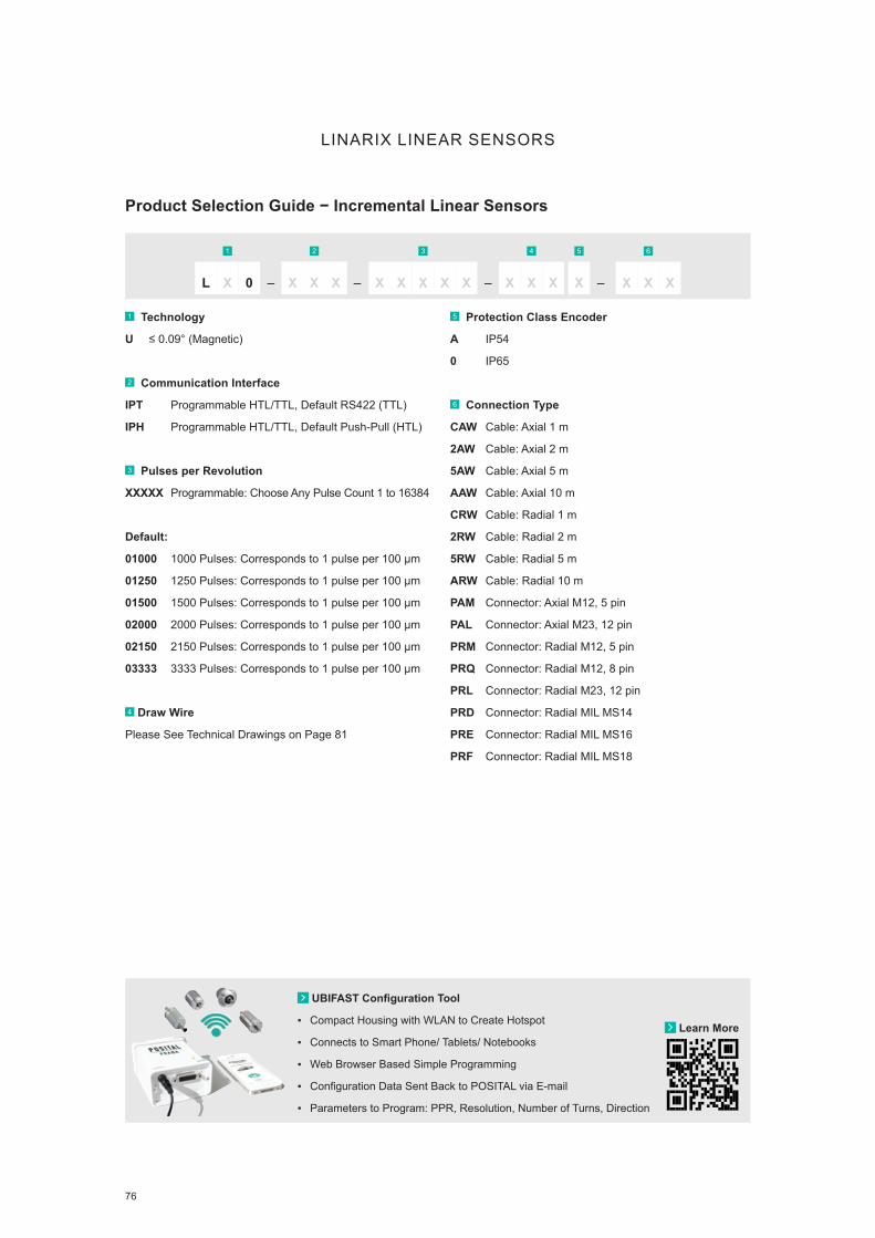
76
LINARIX LINEAR SENSORS
Product Selection Guide − Incremental Linear Sensors
1 Technology
U ≤ 0.09° (Magnetic)
2 Communication Interface
IPT Programmable HTL/TTL, Default RS422 (TTL)
IPH Programmable HTL/TTL, Default Push-Pull (HTL)
3 Pulses per Revolution
XXXXX Programmable: Choose Any Pulse Count 1 to 16384
Default:
01000 1000 Pulses: Corresponds to 1 pulse per 100 µm
01250 1250 Pulses: Corresponds to 1 pulse per 100 µm
01500 1500 Pulses: Corresponds to 1 pulse per 100 µm
02000 2000 Pulses: Corresponds to 1 pulse per 100 µm
02150 2150 Pulses: Corresponds to 1 pulse per 100 µm
03333 3333 Pulses: Corresponds to 1 pulse per 100 µm
4 Draw Wire
Please See Technical Drawings on Page 81
5 Protection Class Encoder
A IP54
0 IP65
6 Connection Type
CAW Cable: Axial 1 m
2AW Cable: Axial 2 m
5AW Cable: Axial 5 m
AAW Cable: Axial 10 m
CRW Cable: Radial 1 m
2RW Cable: Radial 2 m
5RW Cable: Radial 5 m
ARW Cable: Radial 10 m
PAM Connector: Axial M12, 5 pin
PAL Connector: Axial M23, 12 pin
PRM Connector: Radial M12, 5 pin
PRQ Connector: Radial M12, 8 pin
PRL Connector: Radial M23, 12 pin
PRD Connector: Radial MIL MS14
PRE Connector: Radial MIL MS16
PRF Connector: Radial MIL MS18
1 2 3 4 5 6
L X 0 – X X X – – –X X X X X XX X XX X X
Learn More
UBIFAST Configuration Tool
▪ Compact Housing with WLAN to Create Hotspot
▪ Connects to Smart Phone/ Tablets/ Notebooks
▪ Web Browser Based Simple Programming
▪ Configuration Data Sent Back to POSITAL via E-mail
▪ Parameters to Program: PPR, Resolution, Number of Turns, Direction

www.posital.com 77
LINARIX LINEAR SENSORS
Product Selection Guide − Analog and Parallel Linear Sensors
1 Accuracy (Technology)
U ≤ 0.09° (Magnetic)
D ≤ 0.022° (Optical)
2 Communication Interface
AV001 Analog Voltage: 0 to 5 V
AV002 Analog Voltage: 0 to 10 V
AV003 Analog Voltage: 0.5 to 4.5 V
AV004 Analog Voltage: 0.5 to 9.5 V
AC005 Analog Current: 4 to 20 mA
AC006 Analog Current: 0 to 20 mA
AVP01 Analog Voltage: 0 to 5 V w. Pushbuttons
AVP02 Analog Voltage: 0 to 10 V w. Pushbuttons
AVP03 Analog Voltage: 0.5 to 4.5 V w. Pushbuttons
AVP04 Analog Voltage: 0.5 to 9.5 V w. Pushbuttons
ACP05 Analog Current: 4 to 20 mA w. Pushbuttons
ACP06 Analog Current: 0 to 20 mA w. Pushbuttons
PPA1B Parallel Binary
P1A1B Parallel Preset Binary
PPA1G Parallel Gray
P1A1G Parallel Preset Gray
PP00E Parallel Excess Gray
P100E Parallel Preset Excess Gray
3 Revolution
00 Singleturn
04 Multiturn: 4 bit (16 rev)
07 Multiturn: 8 bit (128 rev)
08 Multiturn: 8 bit (256 rev)
12 Multiturn: 12 bit (4096 rev)
14 Multiturn: 14 bit (16384 rev)
4 Resolution
AA 9 bit (512 Steps / 0.7°) Parallel only
12 12 bit (4096 Steps / 0.088°)
13 13 bit (8192 Steps / 0.044°)
16 16 bit (65536 Steps / 0.005°)
5 Draw Wire
Please See Technical Drawings on Page 81
6 Protection Class
A IP54
0 IP64/IP65
7 Connection Type
CAW Cable: Axial 1 m
2AW Cable: Axial 2 m
5AW Cable: Axial 5 m
AAW Cable: Axial 10 m
CRW Cable: Radial 1 m
2RW Cable: Radial 2 m
5RW Cable: Radial 5 m
ARW Cable: Radial 10 m
PAM Connector: Axial M12, 5 pin (Analog)
PAP Connector: Axial M23, 16 pin (Parallel)
PAT Connector: Axial M27, 26 pin (Parallel)
PRM Connector: Radial M12, 5 pin (Analog)
PRP Connector: Radial M23, 16 pin (Parallel)
PRT Connector: Radial M27, 26 pin (Parallel)
1 2 3 4 5 6 7
L X 0 – X X X – – –X X X X X X XX X XX X X

78
LINARIX LINEAR SENSORS
Product Selection Guide − SSI/SSI+Incremental Linear Sensors
1 Accuracy (Technology)
U ≤ 0.09° (Magnetic)
D ≤ 0.022° (Optical)
2 Communication Interface
S101B SSI Binary
SLF1B SSI Binary Fast
S101G SSI Gray
S101E SSI Excess-Gray
SHPPP Programmable SSI+Incr. Push-Pull (HTL) 4.75 to 30 VDC
SRPPP Programmable SSI+Incr. RS422 (TTL) 8 to 30 VDC
SSPPP Programmable SSI+Incr. RS422 (TTL) 5 VDC
SHxxB SSI+Incr. Binary + A/B/Z (Push-Pull) 4.75 to 30 VDC
SRxxB SSI+Incr. Binary + A/B/Z (RS-422) 8 to 30 VDC
SSxxB SSI+Incr. Binary+ A/B/Z (RS-422) 5 VDC
SHxxG SSI+Incr. Gray + A/B/Z (Push-Pull) 4.75 to 30 VDC
SRxxG SSI+Incr. Gray + A/B/Z (RS-422) 8 to 30 VDC
SSxxG SSI+Incr. Gray + A/B/Z (RS-422) 5 VDC
S401B SSI Binary w. Pushbuttons
S401G SSI Gray w. Pushbuttons
S3xxG SSI Gray+Incr. A/B/Z (RS-422)
S3xxB SSI Binary+Incr. A/B/Z (RS-422)
S5xxB SSI Binary+Incr. A/B/Z (RS-422)
S6xxB SSI Binary+Incr.A/B/Z (Push-Pull)
S5xxG SSI Gray+Incr. A/B/Z (RS-422)
S6xxG SSI Gray+Incr. A/B/Z (Push-Pull)
3 Revolution
00 Singleturn
04 Multiturn: 4 bit (16 rev)
08 Multiturn: 8 bit (256 rev)
12 Multiturn: 12 bit (4096 rev)
13 Multiturn: 13 bit (8192 rev)
14 Multiturn: 14 bit (16384 rev)
16 Multiturn: 16 bit (65536 rev)
20 Multiturn: 20 bit (1048576 rev)
PP Programmable, Default 12 bit (4096 rev)
4 Resolution
12 12 bit (4096 Steps / 0.088°)
13 13 bit (8192 Steps / 0.044°)
16 16 bit (65536 Steps / 0.005°)
PP Programmable, Default 13 bit (8192 Steps / 0.044°)
5 Draw Wire
Please See Technical Drawings on Page 81
6 Protection Class
A IP54
0 IP64/IP65
7 Connection Type
CAW Cable: Axial 1 m
2AW Cable: Axial 2 m
5AW Cable: Axial 5 m
AAW Cable: Axial 10 m
CRW Cable: Radial 1 m
2RW Cable: Radial 2 m
5RW Cable: Radial 5 m
ARW Cable: Radial 10 m
PAQ Connector: Axial M12, 8 pin
PAL Connector: Axial M23, 12 pin
PAP Connector: Axial M23, 16 pin
PRQ Connector: Radial M12, 8 pin
PRL Connector: Radial M23, 12 pin
PRP Connector: Radial M23, 16 pin
1 2 3 4 5 6 7
L X 0 – X X X – – –X X X X X X XX X XX X X

79
LINARIX LINEAR SENSORS
Product Selection Guide − Bus-Interface Linear Sensors
1 Accuracy (Technology)
U ≤ 0.09° (Magnetic)
D ≤ 0.022° (Optical)
2 Communication Interface
DPC1B Profibus (Optical, Magnetic)
CA01B CANopen (Magnetic)
CAA1B CANopen (Optical)
CTx1B CANopen+Incr. RS422 (TTL)
CHx1B CANopen+Incr. Push-Pull (HTL)
CL00B CANopen Lift (Magnetic)
C900B SAE J1939
D2B1B DeviceNet (Optical)
IBA1B Interbus (Optical)
3 Revolution
00 Singleturn
12 Multiturn: 12 bit (4096 rev)
13 Multiturn: 13 bit (8192 rev)
14 Multiturn: 14 bit (16384 rev)
15 Multiturn: 15 bit (32768 rev)
4 Resolution
12 12 bit (4096 Steps / 0.088°)
13 13 bit (8192 Steps / 0.044°)
16 16 bit (65536 Steps / 0.005°)
5 Draw Wire
Please See Technical Drawings on Page 81
6 Protection Class
A IP54
0 IP64/IP65
7 Connection Type
CAW Cable: Axial 1 m
2AW Cable: Axial 2 m
5AW Cable: Axial 5 m
AAW Cable: Axial 10 m
CRW Cable: Radial 1 m
2RW Cable: Radial 2 m
5RW Cable: Radial 5 m
ARW Cable: Radial 10 m
PAM Connector: Axial M12, 5 pin (CANopen, CANopen Lift)
PAV Connector: Axial M12, 5 pin, Status LED
(CANopen, CANopen Lift)
PAM Connector: Axial 3 x M13 (Profibus)
PRM Connector: Radial M12, 5 pin
PAQ Connector: Axial M12, 8 pin (CAN+Incr.)
PRV Connector: Radial M12, 5 pin, Status LED
(CANopen, CANopen Lift)
PRQ Connector: Radial M12, 8 pin (CAN+Incr.)
PRI Connector: Radial 2 x M23, 9 pin (Interbus)
H3P Connection Cap: 3 Cable Glands
H1B Connection Cap: 1 x M12 Connector
H2B Connection Cap: 2 x M12 Connectors
H72 Connection Cap: 3 x M12 Connectors
H1C Connection Cap: 1 x M23 Connector (DeviceNet)
H2M Connection Cap: 2 x M20 Cable Glands
HCC Without Connection Cap
1 2 3 4 5 6 7
L X 0 – X X X – – –X X X X X X XX X XX X X
Learn More
Rugged Connectors and Cables
▪ Reliable Electrical Connections
▪ M12 & M23 Data, Bus and Signal Connectors
▪ Straight and Angled Versions
▪ Variety of Cable Material and Lengths
▪ Shielded for Protection Against Noise and Interference

80 www.posital.com
LINARIX LINEAR SENSORS
Product Selection Guide − Ethernet Linear Sensors
1 Accuracy (Technology)
U ≤ 0.09° (Magnetic)
D ≤ 0.022° (Optical)
2 Communication Interface
EIB1B Profinet
EEA1B EtherNet/IP
E2A2B Powerlink
EC00B EtherCAT
EM00B Modbus/TCP + TCP/IP
3 Revolution
00 Singleturn
12 Multiturn: 12 bit (4096 rev)
14 Multiturn: 14 bit (16384 rev)
4 Resolution
13 13 bit (8192 Steps / 0.044°)
16 16 bit (65536 Steps / 0.005°)
5 Draw Wire
Please See Technical Drawings on Page 81
6 Protection Class
A IP54
0 IP64/IP65
7 Connection Type
PRM Connector: Radial 2 x M12 (Modbus)
PRM Connector: Radial 3 x M12
PAM Connector: Axial 3 x M12
1 2 3 4 5 6 7
L X 0 – X X X – – –X X X X X X XX X XX X X
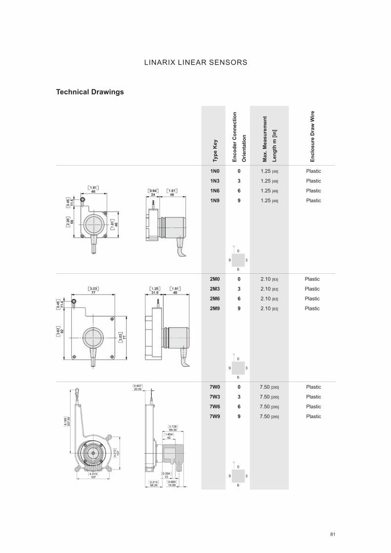
81
Type
Key
Enco
der C
onne
ctio
n
Orie
ntat
ion
Max
. Mea
sure
men
t
Leng
th m
[in]
Encl
osur
e D
raw
Wire
1N0
1N3
1N6
1N9
0
3
6
9
1.25 [49]
1.25 [49]
1.25 [49]
1.25 [49]
Plastic
Plastic
Plastic
Plastic
2M0
2M3
2M6
2M9
0
3
6
9
2.10 [83]
2.10 [83]
2.10 [83]
2.10 [83]
Plastic
Plastic
Plastic
Plastic
7W0
7W3
7W6
7W9
0
3
6
9
7.50 [295]
7.50 [295]
7.50 [295]
7.50 [295]
Plastic
Plastic
Plastic
Plastic
LINARIX LINEAR SENSORS
Technical Drawings
0
6
39
0
6
39
0
6
39

82
0
6
39
0
6
39
Type
Key
Enco
der C
onne
ctio
n
Orie
ntat
ion
Max
. Mea
sure
men
t
Leng
th m
[in]
Encl
osur
e D
raw
Wire
2P0
2P2
2P4
2P6
2P8
2PA
0
2
4
6
8
A
1.74 [69]
1.74 [69]
1.74 [69]
1.74 [69]
1.74 [69]
1.74 [69]
Machined Metal
Machined Metal
Machined Metal
Machined Metal
Machined Metal
Machined Metal
2C0
2C3
2C6
2C9
0
3
6
9
2.00 [79]
2.00 [79]
2.00 [79]
2.00 [79]
Machined Metal
Machined Metal
Machined Metal
Machined Metal
3D0
3D3
3D6
3D9
0
3
6
9
3.00 [118]
3.00 [118]
3.00 [118]
3.00 [118]
Machined Metal
Machined Metal
Machined Metal
Machined Metal
LINARIX LINEAR SENSORS
Technical Drawings
0
6
2
8 4
A

83
LINARIX LINEAR SENSORS
Technical Drawings
Type
Key
Enco
der C
onne
ctio
n
Orie
ntat
ion
Max
. Mea
sure
men
t
Leng
th m
[in]
Encl
osur
e D
raw
Wire
6E0
6E3
6E6
6E9
0
3
6
9
6.00 [236]
6.00 [236]
6.00 [236]
6.00 [236]
Machined Metal
Machined Metal
Machined Metal
Machined Metal
3F0
3F3
3F6
3F9
0
3
6
9
3.00 [118]
3.00 [118]
3.00 [118]
3.00 [118]
Extruded Metal
Extruded Metal
Extruded Metal
Extruded Metal
5G0
5G3
5G6
5G9
0
3
6
9
5.00 [197]
5.00 [197]
5.00 [197]
5.00 [197]
Extruded Metal
Extruded Metal
Extruded Metal
Extruded Metal
0
6
39
0
6
39
0
6
39

84
LINARIX LINEAR SENSORS
Technical Drawings
Type
Key
Enco
der C
onne
ctio
n
Orie
ntat
ion
Max
. Mea
sure
men
t
Leng
th m
[in]
Encl
osur
e D
raw
Wire
AH0
AH3
AH6
AH9
0
3
6
9
10.00 [394]
10.00 [394]
10.00 [394]
10.00 [394]
Extruded Metal
Extruded Metal
Extruded Metal
Extruded Metal
FR0
FR3
FR6
FR9
0
3
6
9
15.00 [591]
15.00 [591]
15.00 [591]
15.00 [591]
Extruded Metal
Extruded Metal
Extruded Metal
Extruded Metal
0
6
39
0
6
39

www.posital.com 85
TILTIX INCLINOMETER
Precise Tilt Measurement

86
TILTIX INCLINOMETERS
Static InclinometerPOSITAL’s inclinometers are equipped with dynamic MEMS (micro-electro-mechanical system) accelero-meters that are used to measure inclination (tilt) by measuring gravitational force.
A ‘micro mass’ A is suspended in a flexible support structure B . Any movement will induce a displace-ment of the mass, resulting in a change of capaci-tance between the mass and the supporting struc-ture. Changes of inclination are calculated from the changes in measured capacitance.
This proven method reaches accuracies of up to 0.1° over the measurement range of up to 360°. Howe-ver, the measurement can be disturbed by external accelerations making the inclinometer capable of operating only in static applications.
Dynamic InclinometerPOSITAL’s acceleration compensated inclinometer use MEMS gyroscopes in addition to MEMS accele-rometers. In contrast to accelerometers, gyroscopes are used to measure rotation rate. An algorithm combines signals of both sensors to identify external accelerations and ignore them. This feature dramati-cally reduces the influence of external accelerations, shocks and vibrations on the output signal.
The compensation of external acceleration forces is very critical for mobile machines and other applica-tions that are constantly in dynamic movement.
POSITAL’s dynamic inclinometer are featured with 3D sensors resulting in improved measurement ran-ge of the complete space (x-axis ±180° and y-axis ±90°).
Industrial Inclinometers
-30° 30°
0°
a
a
b
a
b
A
A
A
B
B
B
Time/s
Accelerometer
Accelerometer and Gyroscope
Out
put V
alue

87
Explosion Proof Certified Inclinometers
TILTIX INCLINOMETERS
Rugged and Reliable Certified InclinometerPOSITAL has extended its TILTIX family of incli-nometers (tilt sensors) to include explosion-proof models designed to operate safely in environments that contain potentially dangerous levels of explo-sive dust or gases. These devices have been cer-tified in compliance with IECEx and ATEX directi-ves and are suitable for use in mines, oil and gas facilities, agricultural applications, chemical plants, woodworking factories and milling operations.Like other TILTIX inclinometers, the new models are available in single (0-360°) or dual-axis (± 80°) versions and feature resolution as high as 0.01° and 0.1° accuracy. Available communications inter-faces include DeviceNet, CANopen, Modbus RTU, SSI and analog output. Analog models can be pro-grammed so that a predetermined range of me-chanical motion is set span the full electrical output range. Rugged aluminum and 316 stainless steel housings are offered, with other materials available by special order.
Certified to the Following Atex Ratings Group I (Mining) Ex I M2 Ex e mb I Mb Group II (Above Ground Operations) EX II 2G Ex e mb IIc TX Gb (explosive gases)EX II 2D Ex tb IIIB T80°C Db (flammable dust)
Advantages ATEX and IECEx Certified Zone 1/21 Mining or Oil and Gas High Vibration and Shock Resistance ±80° (Dual Axis) or 360° (Single Axis) CANopen, DeviceNet, Analog, SSI, SAE J1939
and ModbusRTU Rugged Aluminum and 316 Stainless Steel Housings
Usage in Gas (2G) and Dust (2D) Hazardous Locations
Accuracy 0.1° and resolution 0.044°
Zone 2
Zone 1
Zone 1

88
TILTIX INCLINOMETERS
Max
. Pro
teci
on C
lass
Com
unic
atio
n In
terf
ace
1 A
xis
0 to
360
°
2 A
xis
±80°
Res
olut
ion
Acc
urac
y
Die
Cas
t Alu
min
um
Fibr
e-R
einf
orce
d
Supp
ly V
olta
ge in
V
Cab
le
Con
nect
or
Term
inal
Blo
ck
Programmable
Analog Current + RS232
Rugged Housing
IP69K
IP68
4 – 20 mA
0 – 20 mA
■ ■ 0.01° 0.1° ■ 10−30 ■ ■
Programmable
Analog Voltage + RS232
Rugged Housing
IP69K
IP68
0.5 – 4.5 V
0 – 5 V
0 – 10 V
■ ■ 0.01° 0.1° ■ 10−30 ■ ■
Programmable
Analog Current + RS232
Compact Design
IP67 4 – 20 mA
0 – 20 mA
■ ■ 0.01° 0.1° ■ 10−30 ■ ■
Programmable
Analog Voltage + RS232
Compact Design
IP67 0.5 – 4.5 V
0 – 5 V
0 – 10 V
■ ■ 0.01° 0.1° ■ 10−30 ■ ■
Analog Current
Compact Design
Cost Effective Design
IP67 4 – 20 mA
0 – 20 mA
■ ■ 0.01° 0.5° ■ 10−30 ■ ■
Analog Voltage
Compact Design
Cost Effective Design
IP67 0.5 – 4.5 V
0 – 5 V
0 – 10 V
■ ■ 0.01° 0.5° ■ 10−30 ■ ■
ATEX Certified
Rugged Housing
Compact Design
IP67 Voltage
Current
RS232
■ ■ 0.01° 0.1° ■ 10−30 ■ ■ ■
Product Overview − Analog Inclinometers
Related Industries
F NDERPRODUCT
Find What You NeedConfigure Your POSITAL Encoder Online

89
TILTIX INCLINOMETERS
Product Selection Guide − Analog Inclinometers
1 Technology
C MEMS, Accuracy 0.1°
D MEMS, Accuracy 0.5°
2 Certificate
S CE
M ATEX Zone 1 & 21 (Mining)
E ATEX Zone 1 & 21 (Oil+Gas)
3 Measurement Range
010 ±10°
020 ±20°
040 ±40°
060 ±60°
080 ±80°
090 90°
120 120°
180 180°
270 270°
360 360°
4 Number of Axis
1 Single Axis
2 Dual Axis
5 Communication Interface
SV00 Voltage 0.5 to 4.5 V + RS232
SV10 Voltage 0 to 5 V + RS232
SV20 Voltage 0 to 10 V + RS232
SV40 Voltage 0.5 to 9.5 V + RS232
SC00 Current 4 to 20 mA + RS232
AV00 Voltage 0.5 to 4.5 V
AV10 Voltage 0 to 5 V
AV20 Voltage 0 to 10 V
AV40 Voltage 0.5 to 9.5 V
AC00 Current 4 to 20 mA
6 Mounting
H Horizontal (Dual Axis)
V Vertical (Single Axis)
7 Housing Material
E2 Fibre-Reinforced Plastic
K2 Aluminum
8 Connection Type
CW Cable: 1m
2W Cable: 2 m
5W Cable: 5 m
AW Cable: 10 m
PM Connector: M12
1 32 4 5 6 7 8
A X X – X X X – – – –X X X X X XX X X X
Learn More
Versatile Digital Displays
▪ On-site Position or Speed Measurement
▪ Connect to Encoders, Inclinometers or Linear Sensors
▪ Analog, SSI or Incremental Input
▪ Digital or Analog Output
▪ Easy Integration to More Complex Control Systems

90
TILTIX INCLINOMETERS
Max
. Pro
teci
on C
lass
Com
unic
atio
n In
terf
ace
1 A
xis
0 to
360
°
2 A
xis
±80°
Res
olut
ion
Acc
urac
y
Die
Cas
t Alu
min
um
Fibr
e-R
einf
orce
d
Supp
ly V
olta
ge in
V
Cab
le
Con
nect
or
Term
inal
Blo
ck
Dynamic Applications
Fieldbus Interface
Rugged Housing
IP69K
IP68
CANopen
SAE J1939
■ ■ 0.01° 0.3° ■ 10−30 ■ ■
Static Applications
Fieldbus Interface
Rugged Housing
IP69K
IP68
CANopen
DeviceNet
SAE J1939
■ ■ 0.01° 0.1° ■ 10−30 ■ ■
Static Applications
Fieldbus Interface
Compact Design
IP67 CANopen
DeviceNet
ModbusRTU
■ ■ 0.01° 0.1° ■ 10−30 ■ ■
Static Applications
Fieldbus Interface
Compact Design
IP69K
IP68
CANopen
DeviceNet
ModbusRTU
■ ■ 0.01° 0.1° ■ 10−30 ■ ■
Static Applications
Serial Interface
Rugged Housing
IP69K
IP68
SSI
RS232
■ 0.04° 0.1° ■ 5−30 ■ ■
Static Applications
Serial Interface
Compact Design
IP67 SSI
RS232
■ 0.04° 0.1° ■ 5−30 ■ ■
ATEX Certified
All Available Interfaces
Rugged Housing
IP67 CANopen
SAE J1939
RS232
■ ■ 0.04° 0.1° ■ 10−30 ■ ■
Product Overview − Digital Inclinometers
Related Industries
F NDERPRODUCT
Find What You NeedConfigure Your POSITAL Encoder Online

91
TILTIX INCLINOMETERS
Product Selection Guide − Digital Inclinometers
1 Technology
C Accuracy Static 0.1°
K Accuracy Static 0.3°, Dynamic 0.5°
2 Certificate
S CE
M ATEX Zone 1 & 21 (Mining)
E ATEX Zone 1 & 21 (Oil+Gas)
3 Measurement Range
080 ±80°
090 ±90°
360 360°
4 Number of Axis
1 Single Axis
2 Dual Axis
5 Communication Interface
SV00 RS232 (ACS)
S101 SSI Binary (ACS)
S301 SSI Gray (ACS)
CA01 CANopen (ACS, AKS)
C901 J1939 (ACS, AKS)
M100 Modbus RTU (ACS)
D101 DeviceNet (ACS)
6 Mounting
H Horizontal (Dual Axis)
V Vertical (Single Axis)
7 Housing Material
E2 Fibre-Reinforced Plastic
K2 Aluminum
W2 Stainless Steel (ATEX)
8 Connection Type
CW Cable: 1m
2W Cable: 2 m
5W Cable: 5 m
AW Cable: 10 m
PM Connector: M12
PL Connector: 2 x M12 Male with Status LED
PN Connector: 1 x M12 Male & 1 x M12 Female
Learn More
Rugged Connectors and Cables
▪ Reliable Electrical Connections
▪ M12 & M23 Data, Bus and Signal Connectors
▪ Straight and Angled Versions
▪ Variety of Cable Material and Lengths
▪ Shielded for Protection Against Noise and Interference
1 32 4 5 6 7 8
A X X – X X X – – – –X X X X X XX X X X

92
TILTIX INCLINOMETERS
Technical Drawings
7 8
Typ
e K
ey
Hou
sing
Mat
eria
l
Con
nect
ion
Type
Prot
ectio
n C
lass
K2-PM Al M12 Connector IP68/IP69K
K2-PN Al Male M12 &
Female M12
Connector
IP68/IP69K
271.06
10.500.41
441.73
592.32
4x 6.40 0.25
68 2.6883 3.2722 0.87
118.15 4.65
271.06
10.500.41
441.73
592.32
68 2.68
4x 6.40 0.25
22 0.87 83 3.27
107 4.21
All dimension in mm [inch]; Al: Aluminum; 303: Stainless Steel V2A (1.4305, 303); 316 L: Stainless Steel V4A (1.4404, 316 L)

www.posital.com 93
7 8
Typ
e K
ey
Hou
sing
Mat
eria
l
Con
nect
ion
Type
Prot
ectio
n C
lass
K2-CW
K2-2W
K2-5W
K2-AW
Al
Al
Al
Al
1 m Cable
2 m Cable
5 m Cable
10 m Cable
IP68/IP69K
IP68/IP69K
IP68/IP69K
IP68/IP69K
TILTIX INCLINOMETERS
Technical Drawings
271.06
10.500.41
441.73
592.32
68 2.68
4x 6.40 0.25
83 3.27
102.90 4.05
18 0.71
All dimension in mm [inch]; Al: Aluminum; 303: Stainless Steel V2A (1.4305, 303); 316 L: Stainless Steel V4A (1.4404, 316 L)

94
7 8
Typ
e K
ey
Hou
sing
Mat
eria
l
Con
nect
ion
Type
Prot
ectio
n C
lass
E2-PM Plastic M12 Connector IP67
E2-CW
E2-2W
E2-5W
E2-AW
Plastic
Plastic
Plastic
Plastic
1 m Cable
2 m Cable
5 m Cable
10 m Cable
IP67
IP67
IP67
IP67
TILTIX INCLINOMETERS
Technical Drawings
180.71
471.85
34 1.34
52 2.05
3x 4.30 0.17
160.63
63 2.48
180.71
3x 4.30 0.17
34 1.34
52 2.05
76.65 3.02
471.85
160.63
All dimension in mm [inch]; Al: Aluminum; 303: Stainless Steel V2A (1.4305, 303); 316 L: Stainless Steel V4A (1.4404, 316 L)
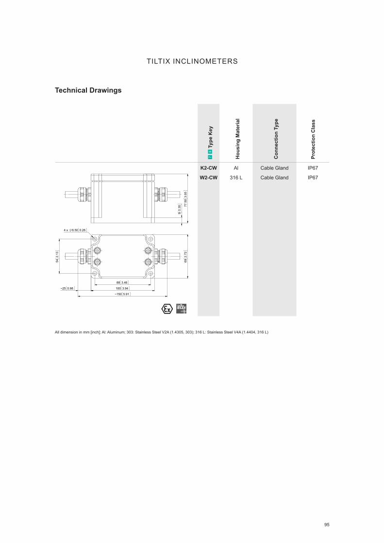
95
7 8
Typ
e K
ey
Hou
sing
Mat
eria
l
Con
nect
ion
Type
Prot
ectio
n C
lass
K2-CW
W2-CW
Al
316 L
Cable Gland
Cable Gland
IP67
IP67
TILTIX INCLINOMETERS
Technical Drawings
90.
35 77.5
03.
05
542.
13
88 3.46
100 3.94
692.
72
~25 0.98
~150 5.91
4 x 6.50 0.26
All dimension in mm [inch]; Al: Aluminum; 303: Stainless Steel V2A (1.4305, 303); 316 L: Stainless Steel V4A (1.4404, 316 L)

96
TILTIX INCLINOMETERS
Innovative Algorithm for Innovative Results POSITAL has introduced new versions of its TILTIX inclinometers that can provide reliable tilt measure-ment for moving equipment. These new devices use a combination of electro-mechanical accelerometers and gyroscopes to provide accurate measurements, even if the instruments are subject to strong acce-lerations.
Specifi cations Resolution 0.01° Accuracy 0.3° Accuracy of 0.5° during Dynamic Movements Internal Cycle Time 5 ms Measurement Range ±180° 2 Axes or 1 Axis Measurement Horizontal or Vertical Mounting
Inclinometers with Dynamic Load Compensation
Learn More
Inclinometers with
Dynamic Load Compensation
▪ Compensation of External Accelerations
▪ Clean Measurement During Dynamic Movements
▪ Well Protected up to IP69K
▪ Compact and Robust Die-cast Housing with Integrated T-Coupler

www.posital.com 97
ACCESSORIES
Wide Selection of Accessories

98
Com
patib
ility
Feat
ures
UBIFAST Configuration
Tool
Web Browser Based
Simple Programming
Tool
IXARC Programmable
Encoders
Programmable:
▪ Output Driver
▪ Resolution
▪ Revolution
▪ Data Code
▪ Counting Direction
SSI to USB Conversion
Tool
Simple GUI to View
SSI Functionality
IXARC / TILTIX
SSI Products
▪ Connect to SSI Encoder /
Inclinometer
▪ Set Preset, Counting
Direction
ACCESSORIES
Configuration Tools
Learn More
UBIFAST Configuration Tool
▪ Compact Housing with WLAN to Create Hotspot
▪ Connects to Smart Phone/ Tablets/ Notebooks
▪ Web Browser Based Simple Programming
▪ Configuration Data Sent Back to POSITAL via E-mail
▪ Parameters to Program: PPR, Resolution, Number of Turns, Direction
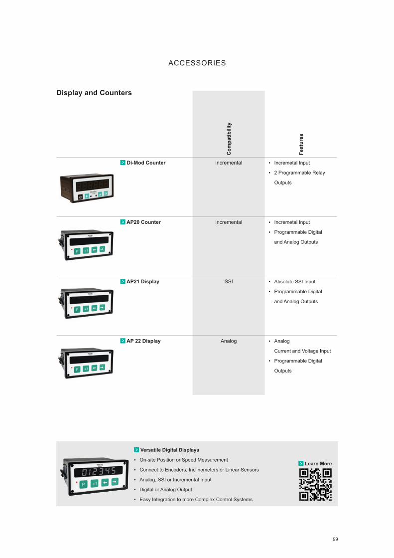
99
Com
patib
ility
Feat
ures
Di-Mod Counter Incremental
▪ Incremetal Input
▪ 2 Programmable Relay
Outputs
AP20 Counter Incremental ▪ Incremetal Input
▪ Programmable Digital
and Analog Outputs
AP21 Display SSI ▪ Absolute SSI Input
▪ Programmable Digital
and Analog Outputs
AP 22 Display Analog ▪ Analog
Current and Voltage Input
▪ Programmable Digital
Outputs
Display and Counters
ACCESSORIES
Learn More
Versatile Digital Displays
▪ On-site Position or Speed Measurement
▪ Connect to Encoders, Inclinometers or Linear Sensors
▪ Analog, SSI or Incremental Input
▪ Digital or Analog Output
▪ Easy Integration to more Complex Control Systems
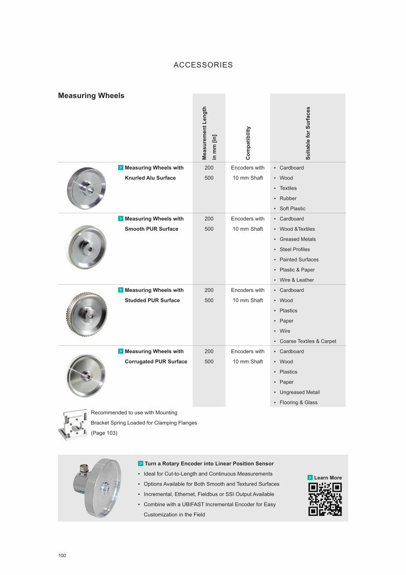
100
ACCESSORIES
Mea
sure
men
t Len
gth
in m
m [i
n]
Com
patib
ility
Suita
ble
for S
urfa
ces
Measuring Wheels with
Knurled Alu Surface
200
500
Encoders with
10 mm Shaft
▪ Cardboard
▪ Wood
▪ Textiles
▪ Rubber
▪ Soft Plastic
Measuring Wheels with
Smooth PUR Surface
200
500
Encoders with
10 mm Shaft
▪ Cardboard
▪ Wood &Textiles
▪ Greased Metals
▪ Steel Profiles
▪ Painted Surfaces
▪ Plastic & Paper
▪ Wire & Leather
Measuring Wheels with
Studded PUR Surface
200
500
Encoders with
10 mm Shaft
▪ Cardboard
▪ Wood
▪ Plastics
▪ Paper
▪ Wire
▪ Coarse Textiles & Carpet
Measuring Wheels with
Corrugated PUR Surface
200
500
Encoders with
10 mm Shaft
▪ Cardboard
▪ Wood
▪ Plastics
▪ Paper
▪ Ungreased Metail
▪ Flooring & Glass
Measuring Wheels
Recommended to use with Mounting
Bracket Spring Loaded for Clamping Flanges
(Page 103)
Learn More
Turn a Rotary Encoder into Linear Position Sensor
▪ Ideal for Cut-to-Length and Continuous Measurements
▪ Options Available for Both Smooth and Textured Surfaces
▪ Incremental, Ethernet, Fieldbus or SSI Output Available
▪ Combine with a UBIFAST Incremental Encoder for Easy
Customization in the Field

101
Leng
th in
m
Num
bers
& P
ins
Con
nect
or C
odin
g
Cab
le M
ater
ial
Con
nect
or M
ater
ial
Prot
ectio
n C
lass
Com
patib
le w
ith
Con
nect
ion
Type
*
Connector
M12
Male and Female
4 pin A, 4 pin D
5 pin A, 5 pin B
8 pin A
Metal IP67 IXARC:
PRM, PAM, PRQ, PAQ
TILTIX: PM
Connector
M23
Female
9
12
16
Metal IP67 IXARC:
PRL, PAL, PRP, PAP,
PRI
Connector
M27
Female
26 Metal IP67 IXARC: PAT, PRT
Cable
M12 Connector
Open Ends, RJ45
2
5
10
4 pin A, 4 pin D
5 pin A, 5 pin B
8 pin A
PUR
PVC
PBT
Metal
IP69K IXARC:
PRM, PAM, PRQ, PAQ
TILTIX: PM
Cable
M23, M27 Connector
Open Ends
2
5
10
9
12
16, 26
PUR
PVC
Metal IP67 IXARC:
PRL, PAL, PRP, PAP,
PAT, PRT, PRI
ACCESSORIES
Connectors and Cables
Please check our website for the complete listing. All compatible accessories are linked to the product variety!
Learn More
Rugged Connectors and Cables
▪ Reliable Electrical Connections
▪ M12 & M23 Data, Bus and Signal Connectors
▪ Straight and Angled Versions
▪ Variety of Cable Material and Lengths
▪ Shielded for Protection Against Noise and Interference

102
Flan
ge /
Shaf
t
Ø D
imen
sion
s in
mm
Mat
eria
l
Com
patib
le w
ith
Mec
hani
cal D
esig
n
Coupling
Jaw Type
3 Part Coupling
6 to 6, 6 to 8
6 to 10, 8 to 10
10 to 10, 10 to 12
Hub: Aluminum
Spider: PUR
All IXARC
Solid Shafts
Coupling
Bellow Type
Flexible Design
6 to 6, 6 to 8
6 to 10, 8 to 10,
10 to 10
Flange: Aluminum
Membrane: Polyamide
All IXARC
Solid Shafts
Coupling
Disc Type
High Speed Application
6 to 6, 6 to 10
10 to 10, 10 to 12
Flange: Aluminum
Membrane: Polyamide
All IXARC
Solid Shafts
Torque Support
Includes Tethers
Includes Clamping Ring
36
58
Aluminum
Stainless Steel
All IXARC
Hub and Through
Hollow Flanges
Reducing Adapter
Used in Hub Shaft
Used in Through Hollow Shaft
15 to (6−14)
12 to (8−11)
Stainless Steel
Brass
All IXARC
Hub & Through
Hollow Flanges
ACCESSORIES
Mounting Fixtures
Learn More
Easy Mounting for Various Shaft Types
▪ Posital Accessories Minimize Wear and Tear
on Encoders
▪ Couplings Are Used to Attach the Encoder Shaft to the
Machine‘s Moving Shaft
▪ Torque Support Is Used to Anchor the Hollow Shaft Encoder
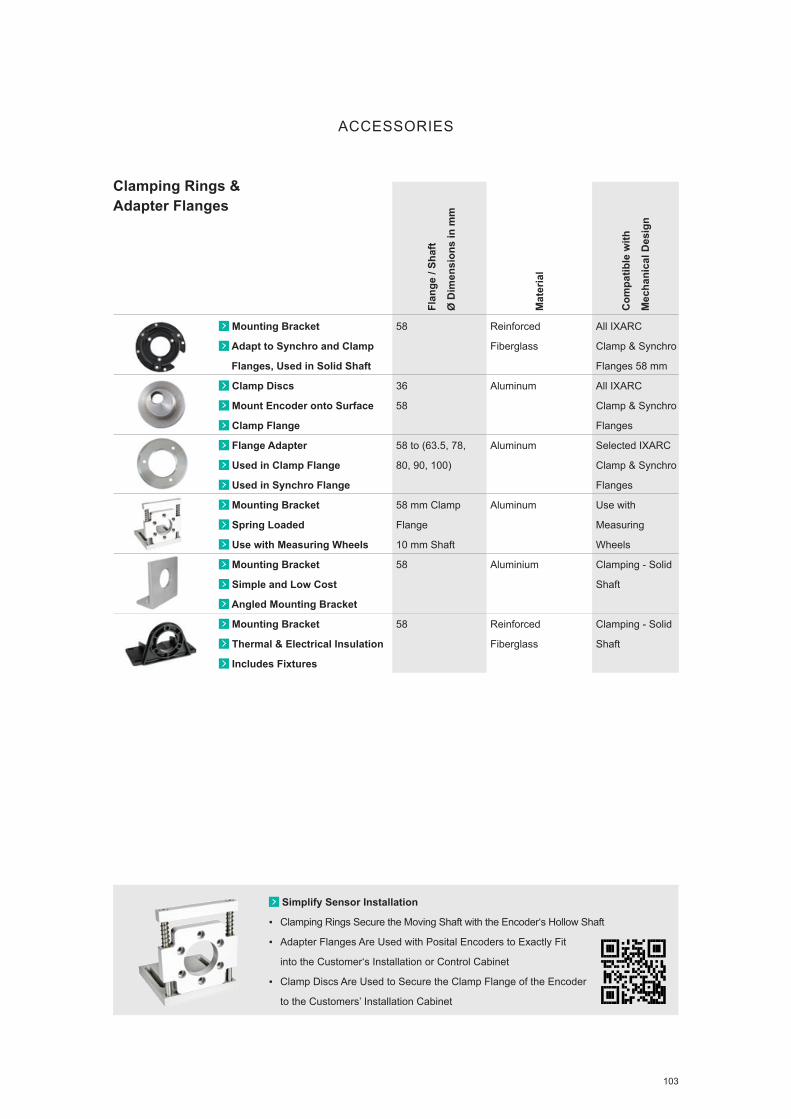
103
Flan
ge /
Shaf
t
Ø D
imen
sion
s in
mm
Mat
eria
l
Com
patib
le w
ith
Mec
hani
cal D
esig
n
Mounting Bracket
Adapt to Synchro and Clamp
Flanges, Used in Solid Shaft
58 Reinforced
Fiberglass
All IXARC
Clamp & Synchro
Flanges 58 mm
Clamp Discs
Mount Encoder onto Surface
Clamp Flange
36
58
Aluminum All IXARC
Clamp & Synchro
Flanges
Flange Adapter
Used in Clamp Flange
Used in Synchro Flange
58 to (63.5, 78,
80, 90, 100)
Aluminum Selected IXARC
Clamp & Synchro
Flanges
Mounting Bracket
Spring Loaded
Use with Measuring Wheels
58 mm Clamp
Flange
10 mm Shaft
Aluminum Use with
Measuring
Wheels
Mounting Bracket
Simple and Low Cost
Angled Mounting Bracket
58 Aluminium Clamping - Solid
Shaft
Mounting Bracket
Thermal & Electrical Insulation
Includes Fixtures
58 Reinforced
Fiberglass
Clamping - Solid
Shaft
ACCESSORIES
Clamping Rings & Adapter Flanges
Simplify Sensor Installation
▪ Clamping Rings Secure the Moving Shaft with the Encoder‘s Hollow Shaft
▪ Adapter Flanges Are Used with Posital Encoders to Exactly Fit
into the Customer‘s Installation or Control Cabinet
▪ Clamp Discs Are Used to Secure the Clamp Flange of the Encoder
to the Customers’ Installation Cabinet

104
Draw Wire Adapters
Max
. Mea
sure
men
t
Leng
th
Com
patib
le F
lang
e Si
ze
Dra
w W
ire E
nclo
sure
WDS-1740
Low Cost and Robust
Metal,
Cylindrical Housing
1.7 m 58 mm ▪ Machined Metal
▪ Cylindrical Housing
SG21
Compact Housing
Zinc Die-Cast,
Rectangular Housing
2 m 36 mm ▪ Machined Metal
▪ Rectangular Housing
SG-31
Robust and Versatile
Machined Metal,
Rectangular Housing
3 m 58 mm ▪ Machined Metal
▪ Rectangular Housing
SG60
Economical and Versatile
Plastic,
Rectangular Housing
3 to 6 m 58 mm ▪ Machined Metal
▪ Rectangular Housing
WDS
Robust and versatile
Flexible Mounting
Options
2 m, 3 m,
5 m, 10 m,
15 m
58 mm ▪ Extruded Metal
SL3002/GS80X1
Robust and versatile
Aluminum,
Rectangular Housing
2 m, 3 m,
5 m, 10 m,
15 m
58 mm ▪ Machined Metal
▪ Rectangular Housing
ACCESSORIES
Learn More
Robust and Versatile Draw Wire Adapters
▪ Measurement Range from 1 to 30 m [3 to 98 ft]
▪ Replacement to Linear Potentiometers
▪ Stainless Steel Measuring Wire
▪ Suitable for Heavy Duty or Industrial Environments
▪ Easily Mounted Using 36mm & 58mm Synchro Flanges
* ATEX versions available upon request

105
NOTES

106
ENCODERMATCH
After many years of successfully replacing and re-trofitting thousands encoders, POSITAL has crea-ted an easy-to-use cross reference finder. Enco-dermatch is based on a detailed database which provides information about the competitor product, the compatible POSITAL productand the degree of compatibility between the products. If products are not a 100% match, Encodermatch denotes which specific feature is responsible for the incompatibility.
Cross referencing a product in Encodermatch re-quires only a small amount of information from the user: The manufacture and the known product ty-pekey. Encodermatch can replace more than 10 manufacturers and thousands of products.
Why POSITAL? ▪ Unique combination of high performance and
rugged durability encoders ▪ Excellent dynamic response and compact size ▪ Powerful programming capabilities
(PPR, resolution, number of turns, direction) ▪ Large variety of mechanical features and compa-
tible accessories ▪ Fast delivery, standard products ship within 72h,
expedited orders manufactured within 24h ▪ 36 month warranty period, counting from the
date of shipping ▪ More than 50 years experience in rotary
encoders
Competitor Cross Reference Finder
BY POSITALENCODERMATCH
Learn More
Find a Replacement for your Encoder in 5 Easy Steps
▪ Choose the Name of the Manufacturer
▪ Type in the Encoder Name
▪ Click Search
▪ Fill in the Pulse Count
▪ Click on the Found Encoder to View the Detailed Data Sheet!WE‘LLMATCH IT
Copyright © 2022 FDOKUMEN