Pompa Carrellata - RAMCRETE
166
ITALIANO ISO 9001:2000 Via Stati Uniti d'america, 26 20030 - SENAGO (MI) Tel.: (+39) 2 99013.1 Fax: (+39) 2 9980786 [email protected] www.cifa.com MANUALE DI USO E MANUTENZIONE Pompa Carrellata POMPA CARRELLATA MANUALE DI USO E MANUTENZIONE USE AND MAINTENANCE HANDBOOK Portable Concrete Pump PORTABLE CONCRETE PUMP 298464 - (I-GB) ENGLISH USE AND MAINTENANCE HANDBOOK
-
Upload
khangminh22 -
Category
Documents
-
view
0 -
download
0
Transcript of Pompa Carrellata - RAMCRETE

ITALIANO
ISO 9001:2000
Via Stati Uniti d'america, 2620030 - SENAGO (MI)Tel.: (+39) 2 99013.1Fax: (+39) 2 9980786
MANUALE DI USO E MANUTENZIONEPompa Carrellata
POMPA CARRELLATAM
AN
UA
LE D
I USO
E M
AN
UTE
NZI
ON
E
USE AND MAINTENANCE HANDBOOKPortable Concrete Pump
PORTABLE CONCRETE PUMP
298464 - (I-GB)
ENGLISH
USE
AN
D M
AIN
TEN
AN
CE
HA
ND
BO
OK

PAGE INTENTIONALLY LEFT EMPTY

POMPA CARRELLATA
MA
NU
ALE
USO
E M
AN
UTE
NZI
ON
E
MANUALE DI USO E MANUTENZIONEPOMPA CARRELLATA
289656-I Catalogo N°.:Revisione Data ultima revisione
Data di Creazione
4 10/2008Edizione
ITALIANAOsservazioni
ATTENZIONE: LEGGERE E COMPRENDERE QUESTO MANUALE PRIMA DI USARE LA MACCHINAATTENZIONE: CONSERVARE QUESTO MANUALE ALL'INTERNO DELLA MACCHINA
All
right
s re
serv
ed -
© C
IFA
S.p.
A.
07/1999

INDEX
PC2
MANUALE DI USO E MANUTENZIONEPOMPA CARRELLATA
INDEX POMPA CARRELLATA - 4a Edizione 10/2008
PAGINA LASCIATA BIANCA INTENZIONALMENTE

INDEX
PC3
MANUALE DI USO E MANUTENZIONEPOMPA CARRELLATA
INDEXPOMPA CARRELLATA - 4a Edizione 10/2008
Sezione A 9INFORMAZIONI GENERALI
1 POMPA CARRELLATA 111.1 LETTERA GENERALE ALLA CONSEGNA 11 LETTERA GENERALE ALLA CONSEGNA 131.2 DICHIARAZIONE DI CONFORMITA' 151.3 GARANZIA 161.4 IDENTIFICAZIONE DELLA MACCHINA 161.5 NOTE GENERALI ALLA CONSEGNA 211.6 DESCRIZIONE DELLA MACCHINA 211.7 PRODOTTO 221.8 UBICAZIONE TARGHE DI SICUREZZA 231.9 UBICAZIONE DISPOSITIVI DI COMANDO 251.10 UBICAZIONE DISPOSITIVI DI SICUREZZA 261.11 LEGENDA DEI SIMBOLI 27
Sezione B 29SICUREZZA
2. PRESCRIZIONI DI SICUREZZA 312.1 AVVERTENZE GENERALI 312.2 DICHIARAZIONE PASOL 342.3 PERICOLI DI LESIONE 362.4 AVVIAMENTO 372.5 AVVERTENZE PER LA MANUTENZIONE 392.4 AVVERTENZE PER IL TRASPORTO 402.5 AVVERTENZE PER L’USO 41
3 TRASPORTO 453.1 SOLLEVAMENTO 45
Sezione C 47FUNZIONAMENTO E ISTRUZIONI DI USO
4 USO DELLA MACCHINA 484.1 QUADRO COMANDO PRINCIPALE VERSIONE MOTORE DIESEL 484.2 QUADRO DI COMANDO PRINCIPALE VERSIONE MOTORE ELETTRICO 514.3 TELECOMANDO CARRELLATA ELETTRICA 544.4 TELECOMANDO CARRELLATA DIESEL 554.5 DISTRIBUTORE DEI SERVIZI 564.6 ALLESTIMENTO 574.7 TRASFERIMENTO 574.8 POSIZIONAMENTO E STABILIZZAZIONE MACCHINA 584.9 POMPAGGIO CALCESTRUZZO 634.10 PULIZIA MACCHINA 674.11 FINE CICLO DI LAVORO 694.11 ARRESTO 694.12 PULIZIA GENERALE 70

INDEX
PC4
MANUALE DI USO E MANUTENZIONEPOMPA CARRELLATA
INDEX POMPA CARRELLATA - 4a Edizione 10/2008
Sezione D 71MANUTENZIONE
5 MANUTENZIONE ORDINARIA 735.1 CONTROLLI GIORNALIERI 735.2 PRECAUZIONI CONTRO IL GELO 735.3 LUBRIFICAZIONE 735.4 GRUPPO POMPANTE 745.5 CONTROLLO STRUTTURALE (ANOMALIE STRUTTURALI) 745.6 CONTROLLO COMPONENTI OLEODINAMICI 755.7 CONTROLLO COMPONENTI ELETTRICI 755.8 SOSTITUZIONE MOTORI 755.9 TUBAZIONI CALCESTRUZZO 755.10 CIRCUITO DELL’ACQUA 765.11 IMPIANTO ELETTRICO 76
6 SMALTIMENTO 76
Sezione E 77ALLEGATI
7 TABELLA DI MANUTENZIONE 79

INDEX
PC5
MANUALE DI USO E MANUTENZIONEPOMPA CARRELLATA
INDEXPOMPA CARRELLATA - 4a Edizione 10/2008
Questo manuale è stato realizzato allo scopo di fornire tutte le necessarie informazioni per utilizzare la Pompa CIFA e svolgere le necessarie operazioni di manutenzione ordinaria in maniera corretta e sicura.
OCCORRE ATTENERSI CON SCRUPOLO ALLE ISTRUZIONI CONTENUTE IN QUESTO MANUALE !LEGGERE E COMPRENDERE QUESTO MANUALE PRIMA DI METTERE IN FUNZIONE LA MACCHINA,
USARLA ED EFFETTUARE QUALSIASI OPERAZIONE CON E SU DI ESSA.
Il manuale è suddiviso in cinque sezioni.
Sezione A INFORMAZIONI GENERALISezione B SICUREZZASezione C FUNZIONAMENTO E ISTRUZIONI D’USOSezione D MANUTENZIONESezione E TABELLE ED ALLEGATI
- La Sezione A racchiude informazioni di carattere generale, determinanti per conoscere la macchina nelle sue parti principali. Sono riportati, inoltre, i dati necessari all’esatta identificazione, le caratteristiche tecniche, ecc.
- La Sezione B è indirizzata al personale addetto al funzionamento della macchina, alla riparazione, alla manutenzione, nonchè al responsabile della sicurezza.
Sono inoltre riportati i requisiti che il personale addetto deve possedere e importanti informazioni la cui la conoscenza è indispensabile per la sicurezza di cose e persone.
- La Sezione C è indirizzata principalmente al personale addetto alla conduzione della macchina.In questa sezione sono illustrati tutti i dispositivi di comando e controllo.
Vi sono inoltre le informazioni d’uso: dall’avviamento del motore fino alle istruzioni per il parcheggio e la messa fuori servio della macchina.
- La Sezione D è indirizzata in modo specifico al responsabile del reparto manutenzione ed al relativo personale addetto a questa funzione. Questa sezione contiene le informazioni sul programma di manutenzione previsto e le relative scadenze periodiche.
- Nella Sezione E sono elencate le tabelle di lubrificazione della macchina.
Le sezioni sono a loro volta suddivise in capitoli e paragrafi numerati progressivamente.
La consultazione dell’indice generale è il metodo più veloce per la ricerca delle informazioni. Tuttavia, tale ricerca può essere effettuata anche attraverso i titoli dei singoli capitoli e paragrafi in quanto costituiscono riferimenti chiave di facile lettura.
ATTENZIONEConservare con cura, ed in luogo immediatamente accessibile all’interno della macchina, questo manuale anche dopo la completa lettura, in modo tale che possa essere sempre a portata di mano per la consultazione o il chiarimento di eventuali gruppi.
In caso di difficoltà nella comprensione di questo manuale, o di parti di esso, si raccomanda vivamente di contattare il Servizio Assistenza CIFA S.p.A. o l’agente/concessionario: indirizzi, numeri telefonici e telefax sono riportati nella copertina e nel frontespizio di questo manuale.
IMPORTANTEDovendo contattare l’assistenza tecnica, prendere nota del modello e della matricola della macchina.
Manuali allegati: Ad integrazione e completamento del presente manuale viene allegato il manuale di INFORMAZIONI GENERALI e il Manuale PARTI DI RICAMBIO della Macchina.

INDEX
PC6
MANUALE DI USO E MANUTENZIONEPOMPA CARRELLATA
INDEX POMPA CARRELLATA - 4a Edizione 10/2008
SIMBOLOGIA Durante l’uso della macchina può accadere di trovarsi in situazioni nelle quali siano necessarie particolari considerazioni ed opportuni approfondimenti.
In questo manuale, quando queste situazioni coinvolgono la Vostra o altrui sicurezza, l’efficenza della macchina ed il buon uso di essa, compaiono specifiche istruzioni evidenziate attraverso una SIMBOLOGIA SPECIALE che le pone opportunamente in risalto.
I simboli speciali (o di sicurezza) utilizzati nel manuale sono tre e sono sempre accompagnati da altrettante parole chiave che li classificano a seconda della pericolosità della situazione trattata.Al simbolo è abbinato un testo che illustra l’eventualità presa in esame, a cosa rivolgere l’attenzione e quale sia il metodo o il comportamento che si consiglia di seguire. Quando necessario evidenzia divieti o fornisce istruzioni idonee all’eliminazione dei rischi.In alcuni casi il testo può essere anche accompagnato da illustrazioni.
I simboli speciali (o di sicurezza) in ordine di importanza, sono i seguenti :
PERICOLO GENERICOPer attirare l’attenzione verso situazioni che riguardano la Vostra e altrui sicurezza con rischi lievi di infortuni o ferite; oppure che riguardano l’efficienza della macchina.
PERICOLO DI MORTEPer attirare l’attenzione verso situazioni che riguardano la Vostra e altrui sicurezza con gravi rischi per l’incolumità, fino a possibili rischi di morte.
PERICOLO ELETTRICO: ALTA TENSIONEPer attirare l’attenzione verso situazioni che riguardano la Vostra e altrui sicurezza con gravi rischi per l’incolumità, fino a possibili rischi di morte dovuti alla presenza di alta tensione sulle linee elettriche
PERICOLO RIBALTAMENTOPer attirare l’attenzione verso situazioni che riguardano la Vostra e altrui sicurezza con gravi rischi per l’incolumità, dovuti al possibile ribaltamento dell'autoveicolo.
PERICOLO CARICHI SOSPESIPer attirare l’attenzione verso situazioni che riguardano la Vostra e altrui sicurezza con gravi rischi per l’incolumità, dovuti alla possibile caduta di carichi sospesi
PERICOLO DI SCHIACCIAMENTOPer attirare l’attenzione verso situazioni che riguardano la Vostra e altrui sicurezza con gravi rischi per l’incolumità, dovuti al possibile schiaggiamento.
PERICOLO SOSTANZE CORROSIVEPer attirare l’attenzione verso situazioni che riguardano la Vostra e altrui sicurezza con gravi rischi per l’incolumità, dovuti al possibile che si venga a contatto con sostanze corrosive e nocive per la salute.

INDEX
PC7
MANUALE DI USO E MANUTENZIONEPOMPA CARRELLATA
INDEXPOMPA CARRELLATA - 4a Edizione 10/2008
IMPORTANTEPer attirare l’attenzione verso importanti informazioni tecniche o consigli pratici che rendono possibile un utilizzo più efficace ed economico della macchina, nel rispetto della sicurezza e dell’ambiente.
DURANTE LA LETTURA DEL MANUALE PRESTARE ESTREMA ATTENZIONE ALLA SIMBOLOGIA SPECIALE E TENERE NELLA MASSIMA CONSIDERAZIONE LA SPIEGAZIONE DELLE SITUAZIONI CHE
TALE SIMBOLOGIA PONE IN EVIDENZA.

INDEX
PC8
MANUALE DI USO E MANUTENZIONEPOMPA CARRELLATA
INDEX POMPA CARRELLATA - 4a Edizione 10/2008
PAGINA LASCIATA BIANCA INTENZIONALMENTE

INDEX
PC9
MANUALE DI USO E MANUTENZIONEPOMPA CARRELLATA
INDEXPOMPA CARRELLATA - 4a Edizione 10/2008
SEzionE AINFORMAZIONI GENERALI

INDEX
PC10
MANUALE DI USO E MANUTENZIONEPOMPA CARRELLATA
INDEX POMPA CARRELLATA - 4a Edizione 10/2008
PAGINA LASCIATA BIANCA INTENZIONALMENTE
INDEX
PC11
MANUALE DI USO E MANUTENZIONEPOMPA CARRELLATA
INDEXPOMPA CARRELLATA - 4a Edizione 10/2008
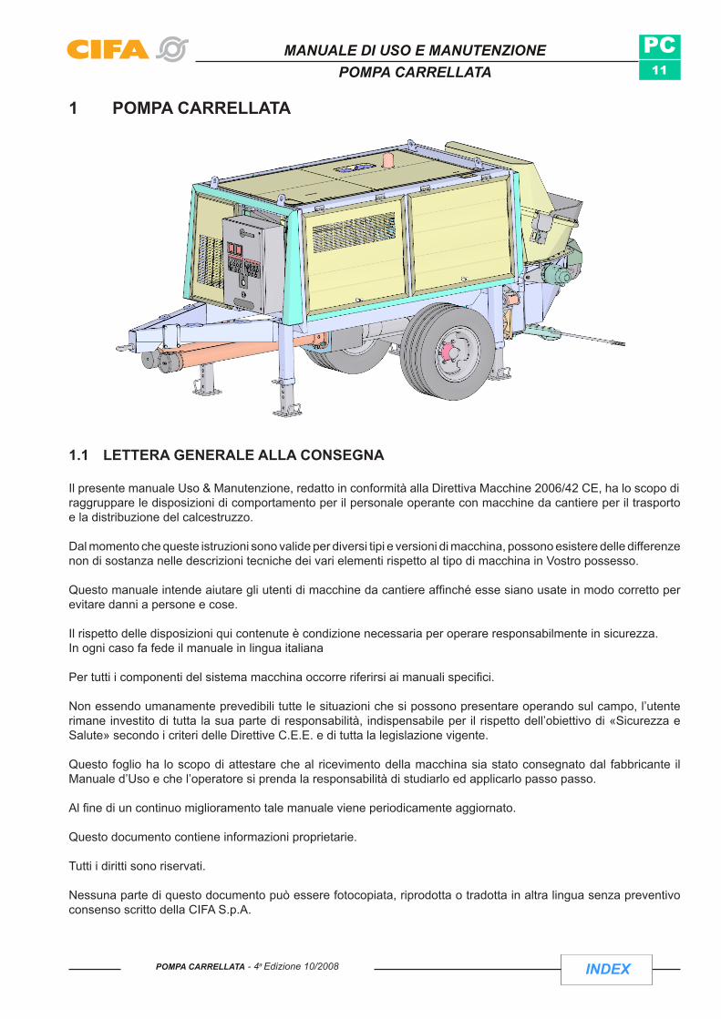
1 POMPA CARRELLATA
1.1 LETTERA GENERALE ALLA CONSEGNA
Il presente manuale Uso & Manutenzione, redatto in conformità alla Direttiva Macchine 2006/42 CE, ha lo scopo di raggruppare le disposizioni di comportamento per il personale operante con macchine da cantiere per il trasporto e la distribuzione del calcestruzzo.
Dal momento che queste istruzioni sono valide per diversi tipi e versioni di macchina, possono esistere delle differenze non di sostanza nelle descrizioni tecniche dei vari elementi rispetto al tipo di macchina in Vostro possesso.
Questo manuale intende aiutare gli utenti di macchine da cantiere affinché esse siano usate in modo corretto per evitare danni a persone e cose.
Il rispetto delle disposizioni qui contenute è condizione necessaria per operare responsabilmente in sicurezza.In ogni caso fa fede il manuale in lingua italiana
Per tutti i componenti del sistema macchina occorre riferirsi ai manuali specifici.
Non essendo umanamente prevedibili tutte le situazioni che si possono presentare operando sul campo, l’utente rimane investito di tutta la sua parte di responsabilità, indispensabile per il rispetto dell’obiettivo di «Sicurezza e Salute» secondo i criteri delle Direttive C.E.E. e di tutta la legislazione vigente.
Questo foglio ha lo scopo di attestare che al ricevimento della macchina sia stato consegnato dal fabbricante il Manuale d’Uso e che l’operatore si prenda la responsabilità di studiarlo ed applicarlo passo passo.
Al fine di un continuo miglioramento tale manuale viene periodicamente aggiornato.
Questo documento contiene informazioni proprietarie.
Tutti i diritti sono riservati.
Nessuna parte di questo documento può essere fotocopiata, riprodotta o tradotta in altra lingua senza preventivo consenso scritto della CIFA S.p.A.

INDEX
PC12
MANUALE DI USO E MANUTENZIONEPOMPA CARRELLATA
INDEX POMPA CARRELLATA - 4a Edizione 10/2008
PAGINA LASCIATA BIANCA INTENZIONALMENTE

LETTERA GENERALE ALLA CONSEGNA
Il presente manuale Uso & Manutenzione, redatto in conformità alla Direttiva Macchine 2006/42 CE, ha lo scopo di raggruppare le disposizioni di comportamento per il personale operante con macchine da cantiere per il trasporto e la distribuzione del calcestruzzo.
Dal momento che queste istruzioni sono valide per diversi tipi e versioni di macchina, possono esistere delle differenze non di sostanza nelle descrizioni tecniche dei vari elementi rispetto al tipo di macchina in Vostro possesso.
Questo manuale intende aiutare gli utenti di macchine da cantiere affinché esse siano usate in modo corretto per evitare danni a persone e cose.
Il rispetto delle disposizioni qui contenute è condizione necessaria per operare responsabilmente in sicurezza.In ogni caso fa fede il manuale in lingua italiana.
Per tutti i componenti del sistema macchina occorre riferirsi ai manuali specifici.
Non essendo umanamente prevedibili tutte le situazioni che si possono presentare operando sul campo, l’utente rimane investito di tutta la sua parte di responsabilità, indispensabile per il rispetto dell’obiettivo di “Sicurezza e Salute” secondo i criteri delle Direttive C.E.E. e di tutta la legislazione vigente.
Questo foglio ha lo scopo di attestare che al ricevimento della macchina sia stato consegnato dal fabbricante il Manuale d’Uso e che l’operatore si prenda la responsabilità di studiarlo ed applicarlo passo passo.
Al fine di un continuo miglioramento tale manuale viene periodicamente aggiornato.
Questo documento contiene informazioni proprietarie.
Tutti i diritti sono riservati.
Nessuna parte di questo documento può essere fotocopiata, riprodotta o tradotta in altra lingua senza preventivo consenso scritto della CIFA S.p.A.
Da Compilare e spedire a: CIFA S.p.A. Viale Stati Uniti d'america, 2620030 SenagoMILANO
Con la presente dichiaro di avere ricevuto il Manuale di Uso e Manutenzione cod. 289656-I relativo a:
AUTOBETONPOMPA
POMPA AUTOCARRATA Matricola Macchina: .....................................................
POMPA CARRELLATA Matricola Autotelaio: .....................................................
AUTOBETONIERA
SPRITZ SYSTEM
Firma Cliente Data ................................................... ........................................

PAGINA LASCIATA BIANCA INTENZIONALMENTE

INDEX
PC15
MANUALE DI USO E MANUTENZIONEPOMPA CARRELLATA
INDEXPOMPA CARRELLATA - 4a Edizione 10/2008
1.2 DICHIARAZIONE CE DI CONFORMITA’
FABBRICANTE: CIFA SpAIndirizzo: Via Stati Uniti d’America, 26 – 20030 Senago (Mi) - ITALY
----------------------------------------------------------------------------------------------------------------------------------------------------MACCHINA:
Tipo: POMPA CARRELLATA Anno di costruzione:
Modello: Numero di Matricola:
Potenza installata:Livello potenza sonora garantita: 119 db (A)Livello potenza sonora misurata: 114 db (A)
------------------------------------------------------------------------------------------------------------------------------------------------
Si dichiara che la macchina descritta è conforme ai requisiti essenziali di sicurezza e salute in accordo a:
La Direttiva Macchine 98/37/CE e al decreto del Presidente della Repubblica del 24 luglio 1996, n. 459.•
Direttiva Bassa Tensione 2006/95/CE•
Direttiva Compatibilità Elettromagnetica 2004/108/CE.•
Direttiva 2000/14/CE in conformità all'allegato 5•
Sono state applicate le seguenti norme armonizzate:
EN 12100: Sicurezza del macchinario. Concetti fondamentali, principi generali di progettazione. •
EN 60204-1: Equipaggiamenti elettrici di macchine industriali. •
EN 12001:2003 Macchine per il trasporto, la distribuzione e la spruzzatura del calcestruzzo– Prescrizioni di • sicurezza
Sono state applicate,ove richiesto, le seguenti norme e specifiche tecniche nazionali:
89/297/CEE• Circ.Min.Lav. n°103/80 – DPR 547/55 •
Si dichiara che la Macchina è provvista di marcatura CE e che la documentazione di cui all’allegato V della Diretti-va Macchine è disponibile per eventuali ispezioni come previsto al punto 4. comma b) dell’allegato stesso.

INDEX
PC16
MANUALE DI USO E MANUTENZIONEPOMPA CARRELLATA
INDEX POMPA CARRELLATA - 4a Edizione 10/2008
1.3 GARANZIALa garanzia decade se nel normale utilizzo dell’attrezzatura non si seguano passo passo le indicazioni contenute all’interno del presente manuale e se non si utilizzino parti di ricambio originali.
Hanno comunque sempre valore prioritario le condizioni di vendita.
1.4 IDENTIFICAZIONE DELLA MACCHINAPer qualsiasi comunicazione con il costruttore CIFA S.p.A. citare sempre il tipo di attrezzatura e il numero di matricola.
1.4.1 LAY OUT TARGHETTE IDENTIFICATIVE DEL PRODOTTO

INDEX
PC17
MANUALE DI USO E MANUTENZIONEPOMPA CARRELLATA
INDEXPOMPA CARRELLATA - 4a Edizione 10/2008
1.4.2 TARGA IDENTIFICAZIONE POMPA CARRELLATA CON MARCHIATURA "CE"
1 Tipo (tipo di macchina)
2 Matricola Macchina
3 Anno di costruzione
4 Pressione idraulica Max (Bar) (pressione massima dell'olio dell'impianto idraulico)
5 Max portata Teorica (m3/h)
6 Max Pressione calcestruzzo
7 Peso massimo (Kg)
8 Potenza (Kw)
9 Tensione (V)
10 Frequenza (Hz)
INDEX
PC18
MANUALE DI USO E MANUTENZIONEPOMPA CARRELLATA
INDEX POMPA CARRELLATA - 4a Edizione 10/2008
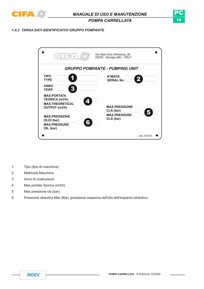
1.4.2 TARGA DATI IDENTIFICATIVI GRUPPO POMPANTE
1 Tipo (tipo di macchina)
2 Matricola Macchina
3 Anno di costruzione
4 Max portata Teorica (m3/h)
5 Max pressione cls (bar)
6 Pressione idraulica Max (Bar) (pressione massima dell'olio dell'impianto idraulico)

INDEX
PC19
on wheels
MANUALE DI USO E MANUTENZIONEPOMPA CARRELLATA
INDEXPOMPA CARRELLATA - 4a Edizione 10/2008
1.4.3 TABELLA DATI TECNICI
MODELLO MACCHINA
MODELLO
Ø 150 x 1000
Ø 176 x 1000
Ø 176 x 1500
Ø 200 x 1500
Ø 200 x 2000
Caratteristiche
H = altezza [mm]
L = Lunghezza [mm]
W = larghezza[mm]
Peso aprox. [daN]
Motore ausiliario
1900
3800
1300
2900
PC 209
D/E
•
PC 307
D/E
•
PC 506
D/E
•
PC 607
D/E
•
PC 607/411 D/E
•
PC 609
D/E
•
PC709
D/E
•
PC 709/415D/E
•
PC 707
D/E
•
PC 907
D/E
•
SuRuote
Tipo Telaio
1900
3800
1300
2950
1900
3800
1500
3000
1900
3800
1500
3100
2300
5200
1700
4600
2300
5200
1700
4550
2300
5200
1700
4550
2300
5200
1700
4550
2300
5200
1700
4600
2300
5350
1700
4750
2300
5350
1700
4750
2300
5350
1700
4800
Matricola Grup.Pomp.|...|...|...|...|...|...|
SuPiattina
PC 907/612D/E
•
PC 506/ 309D/E
•

INDEX
PC20
2100 890 267.51565.
940
- STA
BILI
ZZAT
O 9
70
1860
-189
0
1200
CP 506/309
scartamento 600/610= =
1500 3000
scartamento 600/610
scartamento 750
on rail
MANUALE DI USO E MANUTENZIONEPOMPA CARRELLATA
INDEX POMPA CARRELLATA - 4a Edizione 10/2008
Matricola Macchina |...|...|...|...|...|...|...|...|
INDEX
PC21
1
2
3
MANUALE DI USO E MANUTENZIONEPOMPA CARRELLATA
INDEXPOMPA CARRELLATA - 4a Edizione 10/2008
1.5 NOTE GENERALI ALLA CONSEGNAL’attrezzatura viene generalmente consegnata montata sull’autotelaio/telaio.
In ogni caso, al ricevimento della macchina, controllare sulla bolla di consegna che la fornitura corrisponda alle specifiche dell’ordine e non vi siano danni .
In caso di danni o parti mancanti informare immediatamente la CIFA S.p.A.
Al cliente la macchina arriva con le seguenti dotazioni standard:- MACCHINA (autotelaio/telaio più attrezzatura CIFA)- CASSETTA ATTREZZI - PULSANTIERA CON PROLUNGA - TUBO PER IL LAVAGGIO (Fig. 5)- ADATTATORE TUBAZIONE CALCESTRUZZO- SPUGNE DI LAVAGGIO - LIBRI DI ISTRUZIONE: - Uso & Manutenzione Ordinaria- Parti di Ricambio- Informazioni Generali- Ricerca Guasti- Manutenzione Straordinaria
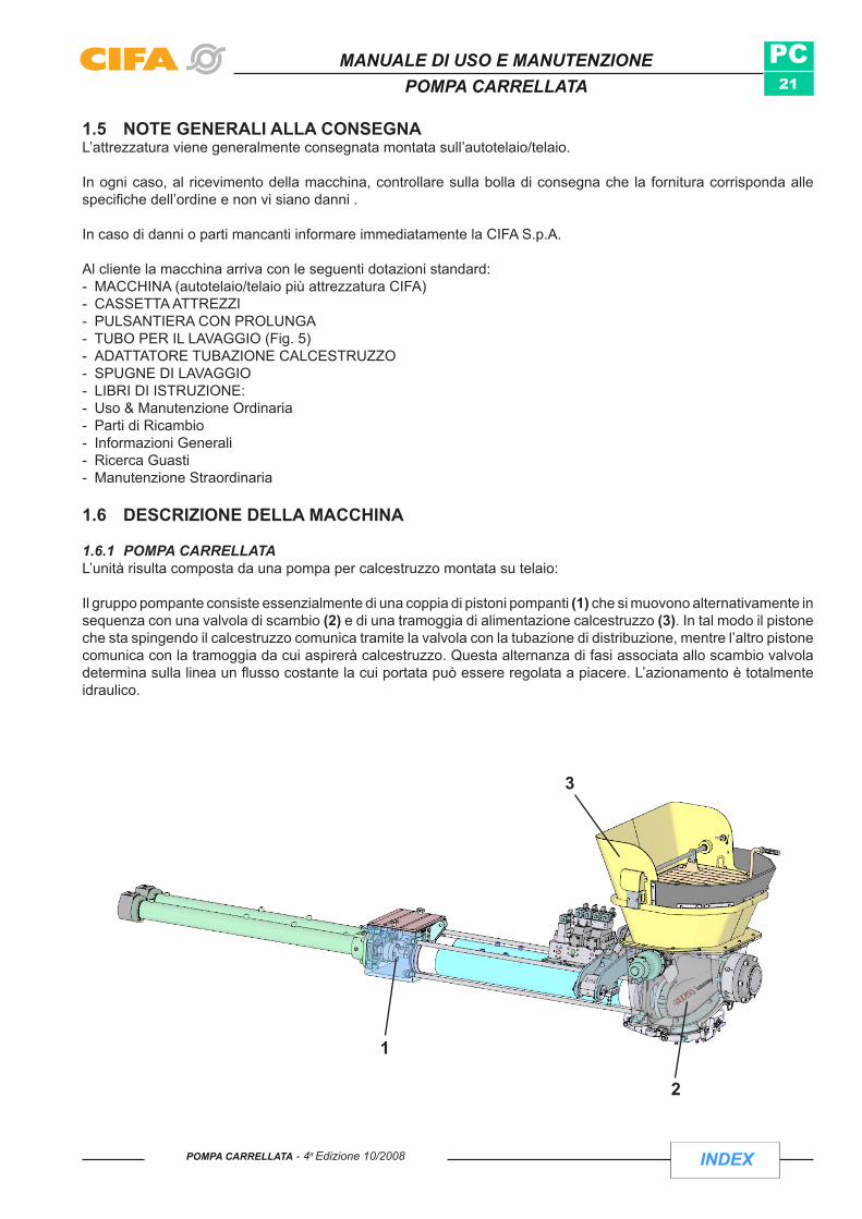
1.6 DESCRIZIONE DELLA MACCHINA
1.6.1 POMPA CARRELLATAL’unità risulta composta da una pompa per calcestruzzo montata su telaio: Il gruppo pompante consiste essenzialmente di una coppia di pistoni pompanti (1) che si muovono alternativamente in sequenza con una valvola di scambio (2) e di una tramoggia di alimentazione calcestruzzo (3). In tal modo il pistone che sta spingendo il calcestruzzo comunica tramite la valvola con la tubazione di distribuzione, mentre l’altro pistone comunica con la tramoggia da cui aspirerà calcestruzzo. Questa alternanza di fasi associata allo scambio valvola determina sulla linea un flusso costante la cui portata può essere regolata a piacere. L’azionamento è totalmente idraulico.

INDEX
PC22
MANUALE DI USO E MANUTENZIONEPOMPA CARRELLATA
INDEX POMPA CARRELLATA - 4a Edizione 10/2008
1.7 PRODOTTOLa macchina è progettata per il trasporto e la distribuzione del calcestruzzo con peso specifico massimo di 2400 Kg/m3.
Il calcestruzzo è una miscela di sabbia e ghiaia (inerti), cemento (legante) e acqua in proporzioni ben definite.
Il calcestruzzo è pompabile se i componenti della miscela sono in proporzioni tali da garantire la scorrevolezza lungo la tubazione senza creare inconvenienti di intasamento (tamponi o segregazioni).
È inoltre possibile pompare altri materiali quali:
- miscele in genere, fango, miscele di carbone, polvere di marmo, rifiuti organici e cenere purché abbiano caratteristiche di pompabilità.
In ogni caso per qualunque tipo di prodotto che si intende trattare al di fuori del calcestruzzo (per eventuali problemi di corrosione, temperature etc.) rivolgersi al servizio tecnico CIFA S.p.a.

INDEX
PC23
Cod. 237218
cod. 234898
cod. 234898
L WA
117 dB
Cod. 235879
Cod. 235859
cod.234896
cod. 234898
cod. 234898
Cod. 237219
cod. 230793
DIESEL
Cod. 235866/a
20005002005025
ISO VG 46
ISO VG 150
1
2
3
4
5
6
7
8
LU BRI FI CA ZIO NI
RIFERIMENTOPOS.TEMPO
MANUTENZIONE (ore) LUBRIFICANTI NOTE
1° SOSTITUZIONE DOPO 200 ORE
FILTRO SFIATO SERBATOIO
OLIO IDRAULICO SERBATOIO
FILTRO RITORNO
ACQUA LUBRIFICAZIONE CILINDRI CLS
SNODI CILINDRI VALVOLAALBERO MESCOLATORE
POMPA GRASSO
DIPENDE DALLE CONDIZIONI AMBIENTALI
S
SOSTITUZIONE GIORNALIERA
I
C
ACQUA
S
TEMPO MAX 1 ANNOC
S
GRASSO NLGI 2
RIDUTTORE MESCOLATORE S 1° CAMBIO DOPO 100 ORETEMPO MAX 1 ANNOC
VEDERE LIBRETTO DI ISTRUZIONIMOTORE AUSILIARIO COME DA ISTRU ZIO NI DEL
CO STRUT TO RE
S = SOSTITUIRE C = CONTROLLO LIVELLO E RIPRISTINO I = INGRASSARE
K000235950-01
N.B.: I PRODOTTI INDICATI IN TABELLA SONO QUELLI UTILIZZATI COME PRIMO EQUIPAGGIAMENTO. PER L'UTILIZZO DI MARCHE DIVERSE, VEDERE TABELLA DI COMPARAZIONE RIPORTATA NEL MANUALE D'ISTRUZIONE
GRASSO NLGI 2
AVVERTENZETUTTE LE ISTRUZIONI E LE NORME DI SICUREZZA SONO RIPORTATE NEL MANUALE DI ISTRUZIONI
• USARE SEMPRE PIASTRE DI RIPARTIZIONE PER GLI STABILIZZATORI DI DIMENSIONI ADEGUATE ALLA SOLIDITA' DEL TERRENO COMPATIBILMENTE AL CARICO INDICATO SU OGNI STABILIZZATORE.
• TENERE ADEGUATA DISTANZA DA SCAVI E CIGLI CEDEVOLI.
• VERIFICARE LA FUNZIONALITA' DI TUTTI I COMANDI ALL'INIZIO DI OGNI TURNO DI LAVORO.
• VERIFICARE LO STATO DI USURA DELLE TUBAZIONI DEL CALCESTRUZZO.
• VERIFICARE CHE TUTTI I GIUNTI E SUPPORTI TUBAZIONE RISULTINO BLOCCATI ED EFFICIENTI.
• VERIFICARE TUTTI I DISPOSITIVI DI SICUREZZA ALL' INIZIO DI OGNI TURNO DI LAVORO
• LAVARE ACCURATAMENTE LA MACCHINA ALLA FINE DI OGNI TURNO DI LAVORO.
• E' VIETATO USARE IL BRACCIO PORTATUBI CON GLI STABILIZZATORI PARZIALMENTE ESTESI O/E NON BLOCCATI DAGLI APPOSITI SPINOTTI.
• E' VIETATO LAVORARE CON PROTEZIONI E PANNELLI SMONTATI, ANCHE PARZIALMENTE.
• E' VIETATO ABBANDONARE LA MACCHINA IN FUNZIONE E CON IL BRACCIO APERTO.
• E' VIETATO REGOLARE, RIPARARE, LUBRIFICARE ORGANI IN MOVIMENTO.
• E' VIETATO IL FUNZIONAMENTO DELLA POMPA A VUOTO.
• E' VIETATO MANOMETTERE O TOGLIERE DISPOSITIVI DI SICUREZZA.
• E' VIETATO MUOVERE IL VEICOLO CON IL BRACCIO PORTATUBI APERTO ANCHE PARZIALMENTE.
• DURANTE LA PULIZIA DELLA VASCA ESEGUIRE SPOSTAMENTI SINGOLI DELLA VALVOLA.
• IN CASO DI ANOMALIE CHE POTREBBERO COMPROMETTERE LA SICUREZZA DI FUNZIONAMENTO ARRESTARE LA MACCHINA
• MANTENERE UNA DISTANZA MINIMA DI SICUREZZA DI 5m DALLE LINEE ELETTRICHE.
• E' VIETATO LAVORARE CON VENTO DI INTENSITA' SUPERIORE A 80 Km/h
• PRIMA DI APRIRE LE TUBAZIONI, IN CASO DI OSTRUZIONE, TOGLIERE LA PRESSIONE SULLA LINEA EFFETTUANDO IL CICLO DI ASPIRAZIONE.
• IN CASO DI PULIZIA CON ARIA, TOGLIERE IL GOMMONE E APPLICARE IL CESTELLO FERMA PALLA.
• L'USO DI MATERIALE NON ORIGINALE CIFA COMPROMETTEREBBE LA SICUREZZA E FA DECADERE LA GARANZIA
IL COSTRUTTORE NON RISPONDE DI EVENTUALI DANNI A COSE E/O PERSONE CAUSATE DA UN NON CORRETTO IMPIEGO DELL'ATTREZZATURA
K000237430 (I)
C
STABILIZZATORI
STAFFATURA POMPA AUTOMEZZO
VERIFICARE SALDATURE UNIONE TORRETTA / TELAIO
VERIFICARE EVENTUALI CRICCHEALL'ATTACCATURA SCATOLATO
DOPO AVER VERIFICATO CHE NEL MOMENTO DELLO SCAMBIO AVVIENE IL DISTACCO TRA GOMMA E
SUPPORTO - EFFETTUARE UNA LEGGERA CARICA
VERIFICARE SERRAGGIO COME DA ISTRUZIONI
VERIFICARE STATO DI USURA
VERIFICARE SERRAGGIO BULLONI DI UNIONE POMPA / AUTOMEZZO
BULLONI MOTO RIDUTTORE BRACCIO
RIFERIMENTO50
NOTE
C
C
100
BLOCCO GRIGLIA
SCADENZE VERIFICHE IN ORE
200
1
2FERMI ROTAZIONE PERNI DI SNODO TRONCHI BRACCIO
IMPORTANTE - VERIFICARE L'INTEGRITA' DEI FERMI
VERIFICARE L'ARRESTO DEL MESCOLATORE CON GRI-GLIA SOLLEVATA
VERIFICARE SERRAGGIO POSIZIONE SPILLA DI SICUREZZA
VERIFICARE SERRAGGIO COME DA ISTRUZIONI
3
4
5
6
TUBAZIONE CALCESTRUZZO E CURVE
GIUNTI TUBAZIONI CALCESTRUZZO
C
C
BULLONI RALLA C
VERIFICARE STATO CARPENTERIE E STRUTTURE
7
8
9
10
AMMORTIZZATORI CILINDRO COMANDO VALVOLA "S"
MUSONI E SCATOLATI BRACCIO
SUPPORTI TUBAZIONI
11 TORRETTA / S.TORRETTA
C
C
C
C
C
VERIFICARE STRUTTURE
PERDITE SU TUBAZIONI RIGIDE E FLESSIBILI
CONTROLLARE CHE COMPIANO TUTTA LA CORSA
VERIFICARE CHE NON CI SIANO PERDITE DI BOIACCA
VERIFICARE CHE NON CI SIANO PERDITE DI BOIACCA SULLE TENUTE - EFFETTUARE LA REGOLAZIONE SU
QUELLA DI USCITA
12
13
14
15
16
IMPIANTO IDRAULICO TUBI FLESSIBILI
CILINDRI POMPANTI
GUARNIZIONI MESCOLATORE
GUARNIZIONI GRUPPO POMPANTE
C
C
C
C
C
C = CONTROLLO SECONDO INDICAZIONI CONTENUTE NEL MANUALE ISTRUZIONI.
VERIFICHECod. 221285/A
. 2do
00943
7 8 9
5
2
14
4
14
13
6
12
15
4
10 11
4 3
MANUALE DI USO E MANUTENZIONEPOMPA CARRELLATA
INDEXPOMPA CARRELLATA - 4a Edizione 10/2008
1.8 UBICAZIONE TARGHE DI SICUREZZA

INDEX
PC24
MANUALE DI USO E MANUTENZIONEPOMPA CARRELLATA
INDEX POMPA CARRELLATA - 4a Edizione 10/2008
1 Organi in movimento
2 Pericolo di cesoiamento
3 Pericolo di cesoiamento
4 Spine di sicurezza
5 Divieto di interporsi tra griglia e tramoggia
6 Livello Rumore
7 Targa Verifiche
8 targa Avvertenze
9 Targa lubrificazione
10 Targa "UCOMESA"
11 Targa Pericolo vaschetta acqua
12 Staccare la batteria
13 Max. velocità
14 Macchina comandata a distanza
15 Diesel

INDEX
PC25
MANUALE DI USO E MANUTENZIONEPOMPA CARRELLATA
INDEXPOMPA CARRELLATA - 4a Edizione 10/2008
1.9 UBICAZIONE DISPOSITIVI DI COMANDO
1 Carico/Scarico vaschetta acqua
2 Innesto lancia di lavaggio
3 Carico acqua nel serbatoio
4 Quadro di comando motore ausiliario
5 Quadro di potenza e Comando Vibratore/Claxon
6 Distributore Servizi (Azionamento mescolatore, Pompa acqua, Stabilizzazione e portella)
7 Variatore di portata calcestruzzo
8 Presa di collegamento Telecomando
9 Regolatore ruota di appoggio
10 Leva Apertura/Chiusura portella vasca
11 Carico Serbatoio Diesel

INDEX
PC26
MANUALE DI USO E MANUTENZIONEPOMPA CARRELLATA
INDEX POMPA CARRELLATA - 4a Edizione 10/2008
1.10 UBICAZIONE DISPOSITIVI DI SICUREZZA
1 Fungo STOP
2 Carter protezione per motore ausiliario
3 Finecorsa portella vasca
4 Protezione apertura griglia tramoggia
5 Perno meccanico stabilizzatori e spina di sicurezza
6 fermo meccanico Griglia Tramoggia

INDEX
PC27
1 2 3 4 5 6 7
8 9 10 11 12 13 14
15 16 17 18 19 20 21
22 23 24 25 26 27 28
MANUALE DI USO E MANUTENZIONEPOMPA CARRELLATA
INDEXPOMPA CARRELLATA - 4a Edizione 10/2008
1.11 LEGENDA DEI SIMBOLI
1.11.1 DISPOSITIVI DI COMANDO
1 ACCELERA/DECELERA MOTORE 12 PULSANTE FUNGO "STOP EMERGENZA"2 START MOTORE 13 STOP POMPAGGIO
3 STOP MOTORE 14 SEGNALE ACUSTICO
4 ABILITAZIONE COMANDI DA qUADRO 15 SBLOCCO VALVOLA
5 ABILITAZIONE COMANDI DA DISPOSITIVO A DISTANZA 16 PRESSIONE OLIO
6 POMPAGGIO 17 SPIA ALTERNATORE
7 ASPIRAZIONE 18 VIBRATORE
8 STOP MOTORE ELETTRICO 19 CARICO MESCOLATORE TRAMOGGIA
9 VARIATORE DI PORTATA CALCESTRUZZO 20 SCARICO MESCOLATORE TRAMOGGIA
10 AVVIAMENTO MOTORE A STELLA 21 RADIATORE OLIO
11 AVVIAMENTO MOTORE A TRIANGOLO 22 POMPA ACqUA

INDEX
PC28
MANUALE DI USO E MANUTENZIONEPOMPA CARRELLATA
INDEX POMPA CARRELLATA - 4a Edizione 10/2008
PAGINA LASCIATA BIANCA INTENZIONALMENTE

INDEX
PC29
MANUALE DI USO E MANUTENZIONEPOMPA CARRELLATA
INDEXPOMPA CARRELLATA - 4a Edizione 10/2008
SEzionE BSICUREZZA

INDEX
PC30
MANUALE DI USO E MANUTENZIONEPOMPA CARRELLATA
INDEX POMPA CARRELLATA - 4a Edizione 10/2008
PAGINA LASCIATA BIANCA INTENZIONALMENTE

INDEX
PC31
MANUALE DI USO E MANUTENZIONEPOMPA CARRELLATA
INDEXPOMPA CARRELLATA - 4a Edizione 10/2008
2. PRESCRIZIONI DI SICUREZZA
2.1 AVVERTENZE GENERALIE’ obbligo del datore di lavoro far apprendere ai dipendenti le istruzioni del manuale.•
Il personale che utilizza la macchina (operatore autorizzato) deve essere precedentemente addestrato e deve •aver letto il manuale. E’ obbligatorio conservare una copia del manuale a bordo macchina (Fig. 10).
L’operatore non deve mai agire pressato dalle insistenze del cliente.•
ATTENZIONE: Indossare mezzi di protezione personale: elmetto, occhiali, guanti, cuffie, scarpe antinfortunistiche
Non indossare indumenti svolazzanti ma tute aderenti strette ai polsi e alle caviglie.•
La macchina nella versione standard non è adeguata per lavorare in ambiente potenzialmente esplosivo.•
Per l’utilizzo dell’attrezzatura in ambienti e climi particolari rivolgersi agli uffici tecnici CIFA.•

INDEX
PC32
FIG.3
FIG.4
Fig.1 Fig.2
MANUALE DI USO E MANUTENZIONEPOMPA CARRELLATA
INDEX POMPA CARRELLATA - 4a Edizione 10/2008
Qualsiasi sostituzione di componenti deve essere eseguita seguendo i dati di targa. In particolare i componenti •antideflagranti oltre ad avere le stesse caratteristiche devono anche essere omologati (Fig. 1).
Non togliere le etichette o targhe situate sulla macchina. Nel caso siano danneggiate, sostituirle immediatamente •con targhe nuove (Fig. 2).
Non mettere le mani sulla marmitta di scarico del motore, pericolo •di scottature, organi in movimento, fonti di calore, tubi in pressione, punti che prevedono zone di taglio (es. spigoli vivi).
Non appoggiarsi o sedersi su qualsiasi zona della macchina quando •questa è in funzione.
Non appoggiare oggetti sulla vaschetta dell'acqua o griglie di parti •in movimento (Fig.3).
Non lasciare utensili, dadi, bulloni all’interno di zone con parti in •rotazione.
Proteggere il personale operante nei pressi dell’attrezzatura da •possibili scoppi di tubazione a terra o su solai, con adeguate coperture di protezione es. tavolame o pannelli rigidi, fissandoli al terreno. ATTENZIONE: Questa sicurezza deve essere attuata anche nelle vicinanze di passaggi pedonali (Fig. 4).
Adoperare con particolare cura gli additivi utilizzati per il calcestruzzo •in quanto corrosivi e dannosi alla salute.
Gli addetti alla posa in opera del calcestruzzo devono avere i requisiti •psico-fisici rispondenti alle norme di legge.
Avere sempre a portata di mano un estintore.•
Non utilizzare i comandi e/o le tubazioni quali appigli.•
Non saltare dalla macchina ma adoperare le scale per salire o •scendere utilizzando il corrimano e tenendo la parte anteriore del corpo rivolta verso la macchina.
Mantenere sempre pulite le pedane, i parafanghi, i cofani, la cabina •e le scarpe da olio, grasso, gasolio per evitare di scivolare.

INDEX
PC33
FIG.5
MANUALE DI USO E MANUTENZIONEPOMPA CARRELLATA
INDEXPOMPA CARRELLATA - 4a Edizione 10/2008
Segnalare immediatamente al datore di lavoro, al dirigente o ai preposti le deficienze dei dispositivi e dei mezzi •di sicurezza e di protezione, nonché le eventuali condizioni di pericolo di cui si venga a conoscenza. In caso di urgenza e nell’ambito delle proprie competenze e possibilità, eliminare o ridurre dette deficienze o rischi.
Non rimuovere o modificare i dispositivi e gli altri mezzi di sicurezza e di protezione senza averne ottenuta •l’autorizzazione (Fig. 5).
Non abbandonare sulle impalcature, sui posti di lavoro o di passaggio, materiali residui, specie se hanno parti •taglienti o punte sporgenti che possono costituire pericolo in caso di caduta.
Disinfettare subito ogni ferita, taglio o abrasione, anche lievi: spesso piccoli graffi provocano infezioni locali, •anche gravi, e a volte infezioni tetaniche per lo più letali.
Evitare di esporsi, se sudati, a repentini sbalzi di temperatura.•
Durante il lavoro, controllare bene i movimenti degli attrezzi in modo da evitare di colpire o di essere colpiti.•
Escludere dall’uso le chiavi o altri attrezzi incrinati, perché se sottoposti a sforzo possono rompersi.•
Riferire al proprio capo servizio e al compagno che subentra nel turno lo stato di lavoro e le misure da adottare •per il sicuro proseguimento del medesimo.
Non attraversare ponti mobili o sospesi prima di essersi assicurati della stabilità delle tavole.•
Non distrarsi ma agire con prudenza quando si compiono lavori che presentano pericoli.•
Prima dell’inizio del turno di lavoro controllare tutti dispositivi di sicurezza, segnalare le deficienze •riscontrate.
Eseguire con gradualità le partenze, gli arresti ed ogni altra manovra.•
Tenere la postazione di comando in ordine e pulire evitando il deposito di materiale infiammabile.•
Nelle macchine alimentate e/o comandate elettricamente da cavo flessibile lasciato a terra, assicurarsi che il •cavo stesso non possa essere danneggiato in nessun caso.
Non camminare su spigoli, tubi o superfici poco resistenti.•
Salire o scendere dalla macchina solo quando è perfettamente stabile.•
Non avviare il motore in ambienti chiusi salvo che vi sia un buon sistema per l’evacuazione dei gas di •scarico.
Evitare di rimanere per lunghi periodi in zone •molto rumorose; se questo non è possibile utilizzare mezzi di protezione personali come cuffie, tappi etc..
INDEX
PC34
MANUALE DI USO E MANUTENZIONEPOMPA CARRELLATA
INDEX POMPA CARRELLATA - 4a Edizione 10/2008
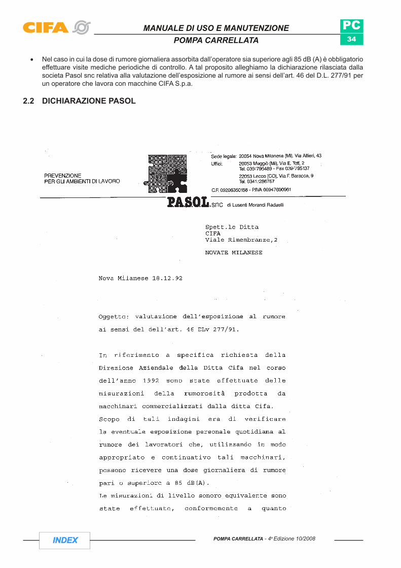
Nel caso in cui la dose di rumore giornaliera assorbita dall’operatore sia superiore agli 85 dB (A) è obbligatorio •effettuare visite mediche periodiche di controllo. A tal proposito alleghiamo la dichiarazione rilasciata dalla societa Pasol snc relativa alla valutazione dell’esposizione al rumore ai sensi dell’art. 46 del D.L. 277/91 per un operatore che lavora con macchine CIFA S.p.a.
2.2 DICHIARAZIONE PASOL

INDEX
PC35
MANUALE DI USO E MANUTENZIONEPOMPA CARRELLATA
INDEXPOMPA CARRELLATA - 4a Edizione 10/2008

INDEX
PC36
MANUALE DI USO E MANUTENZIONEPOMPA CARRELLATA
INDEX POMPA CARRELLATA - 4a Edizione 10/2008
2.3 PERICOLI DI LESIONINonostante la macchina sia costruita nel rispetto delle regole di sicurezza generali è possibile che durante l’utilizzo della macchina si possono verificare situazioni di pericolo che mettono a rischio l’integrità della macchina e la sicurezza dell’operatore.
Si possono verificare le seguenti lesioni:
- Lesioni agli occhi dovute a spruzzi di calcestruzzo o sostanze additive.
- Lesioni agli occhi e alla cute dovute alla fuoriuscita di olio idraulico quando si aprono raccordi a vite senza prima aver scaricato la pressione nel circuito idraulico.
- Pericoli di scottatura dovuti alla fuoriuscita di olio bollente o dal contatto con parti molto calde della macchina.
- Lesioni dovute allo scoppio di giunti o tubazioni di trasporto all’espulsione violenta di occlusioni dalle tubazioni di trasporto dal terminale in gomma.
- Scosse elettriche (anche letali) causate da: a) Collegamento elettrico non eseguito perfettamente b) Cavo di alimentazione danneggiato c) Contatto con altri cavi elettrici
- Lesioni dovute alla caduta di pezzi della tubazione di trasporto, a sua volta provocata da raccordi a vite parzialmente allentati o a giunti non assicurati.
- Lesioni provocate dalla caduta di elementi
ATTENZIONE: Non aprire mai la tubazione di trasporto quando è in pressione!
- Lesioni provocate da scivolate o cadute su parti oliate o lubrificate della macchina.
ATTENZIONE: Non toccare parti in movimento della macchina
- Lesioni conseguenti all’introduzione delle mani nella carcassa del rotore (con i varchi di manutenzione non assicurati).
- Lesioni dovute a inciampate in cavi, flessibili e armature.
- Lesioni provocate dal pizzicamento di parti del corpo nella betoniera o in parti di essa (canala).
- Lesioni provocate dallo scivolamento o dalla cadute di tubazioni di trasporto non assicurate.

INDEX
PC37
MANUALE DI USO E MANUTENZIONEPOMPA CARRELLATA
INDEXPOMPA CARRELLATA - 4a Edizione 10/2008
2.4 AVVIAMENTO
Prima di ogni avviamento controllare la sicurezza di lavoro. Qualora vengano riscontrati difetti, anche solo accennati, questi devono essere immediatamente rimossi, informando, se necessario, il responsabile della sorveglianza o, nel caso di difetti che compro-mettono la sicurezza di lavoro, arrestando l’esercizio.
Adottare gli accorgimenti necessari, affinchè la macchina o l’impianto vengano azionati soltanto in condizioni sicure e di perfetto funziona-mento
Azionare la macchina soltanto in presenza di tutti i sistemi di protezione e di tutti i dispositivi di sicurezza e soltanto se tali dispositivi sono perfettamente funzionanti!
ASSICURARSI CHE:la macchina venga sempre azionata in perfette condizioni;- Nessun dispositivo di sicurezza venga smontato, messo fuori funzione o modificato (ARRESTO DI EMERGENZA, griglia sulla tramoggia della pompa, ecc.);
- I dispositivi di sicurezza smontati per interventi di manutenzione vengano subito rimontati al termine dei favori.
- La macchina non deve presentare difetti visibili ad occhio nudo (crepe, danni, bulloni allentati o mancanti, spinotti di sicurezza mancanti, ruggine sulle parti portanti, perdite, ecc.). Ogni perdita d’olio, anche piccolissima, va a inquinare le acque sotterranee! Controllare la tenuta e la chiusura dei serbatoi dell’olio e dell’acqua (protezione dell’ambiente).
2.4.1 Materiali di esercizio Le operazioni necessarie per rendere la macchina pronta a funzionare includono anche il rifornimento dei materiali di esercizio.
PERICOLO L’olio, il carburante, gli additivi e gli altri materiali di esercizio possono nuocere alla salute in caso di contatto con la pelle o simili. Per tale motivo, quando si maneggiano materiali di esercizio velenosi, corrosivi o in altro modo nocivi per la salute, indossare sempre l’equipaggiamento personale di protezione e osservare le indicazioni del produttore.
Controllare sempre tutti i livelli con la macchina in piano e pronta a essere messa in marcia!
2.4.2 Funzionamento di provaControllare almeno una volta per turno che la macchina o l’impianto non presenti danni e difetti visibili dall’esterno! Informare immediata-mente l’ente o la persona responsabile circa le variazioni sopravve-nute (comprese quelle relative al comportamento in esercizio)! Eventualmente arrestare immediatamente la macchina e assicurarla!L’operatore deve controllare che la macchina non presenti difetti evidenti prima di ogni impiego di lavoro. Va inoltre venficato che tutti i dispositivi di comando e di sicurezza, in particolare l’impianto di ARRESTO DI EMERGENZA, funzionino correttamente.

INDEX
PC38
MANUALE DI USO E MANUTENZIONEPOMPA CARRELLATA
INDEX POMPA CARRELLATA - 4a Edizione 10/2008
2.4.3 Pulsante arresto di emergenza
PREMERE PER BLOCCARE L’ARRESTO DI EMERGENZA
RUOTARE PER SBLOCCARE L’ARRESTO DI EMERGENZA
La macchina deve essere provvista di tutti i dispositivi di sicurezza ed antinfortunistici (segnali di avvertimento e targhette istruzioni, griglie di protezione, ripari di protezione, eec.). Essi non devono essere rimossi, modificati o danneggiati.Tutti i dispositivi di comando e di controllo devono essere funzionanti.
Portare in posizione “O” tutti i dispositivi di comando e di controllo prima di cambiare tipo di comando (blocco di comando, posto di lavoro o telecomando). Premere il tasto ARRESTO DI EMERGENZA. In caso contrario la macchina potrebbe eseguire movimenti indesiderati.Non abbandonare mai il telecomando quando la macchina è pronta a funzionare. Qualora, in casi eccezionali, ciò fosse inevitabile, premere il tasto ARRESTO DI EMERGENZA, scollegare il tele-comando (telecomando via cavo) e metterlo sotto chiave nella cabina di guida.
Per avviare di nuovo la macchina, sbloccare il tasto ARRESTO DI EMERGENZA ruotandolo nella direzione della freccia.

INDEX
PC39
Fig.7
Fig.8
Fig.6
MANUALE DI USO E MANUTENZIONEPOMPA CARRELLATA
INDEXPOMPA CARRELLATA - 4a Edizione 10/2008
2.5 AVVERTENZE PER LA MANUTENZIONEPrima di fare qualsiasi operazione di manutenzione o sostituzione di parti assicurarsi che:
La fonte di energia (motore ausiliario o dell’autotelaio) sia disattivata.1. Il selettore a chiave posto sul quadro comando dell’attrezzatura sia su «0».2. Le chiavi relative alla riattivazione della fonte di energia e del quadro comando devono essere custodite 3.
dal responsabile delle operazioni.Apporre un cartello «MANUTENZIONE IN CORSO» sul quadro comando.4.
Quando la macchina è fuori servizio per operazioni di riparazioni o di manutenzione,non deve poter essere •messa in moto che dal responsabile delle operazioni in corso.
Controllare tutti i componenti a completamento della macchina •seguendo i libretti di istruzione specifici (vedi radiocomando, autotelaio, motore ausiliario...).
Controllare periodicamente i dispositivi di sicurezza (Vedi Par. 1.10):• - Fungo stop - Finecorsa portella vasca - Finecorsa griglia tramoggia - Fermo meccanico stabilizzatori (Fig.6) - Spine di sicurezza giunti tubazioni calcestruzzo
Controllare l’efficienza dei componenti dell’impianto elettrico (comandi, •segnalatori acustici e luminosi).
Mettere particolare attenzione nel caso si debbano effettuare operazioni •di manutenzione all’impianto oleodinamico dell’attrezzatura.
ATTENZIONE: Prima di operare su di un circuito oleodinamico, scaricare la pressione ed indossare guanti di protezione (pericolo di scottature)
Verificare che qualsiasi elemento azionato dal circuito oleodinamico sia in situazione di riposo (Fig.8).•
Utilizzare solo ricambi originali CIFA S.p.a.•
La manutenzione straordinaria deve essere effettuanta da un tecnico specializzato, preferibilmente da officine •autorizzate CIFA.
Verificare quotidianamente che non vi siano perdite di materiale infiammabile che possano entrare in contatto •con zone calde.

INDEX
PC40
Fig.10Fig.9
Fig.11
MANUALE DI USO E MANUTENZIONEPOMPA CARRELLATA
INDEX POMPA CARRELLATA - 4a Edizione 10/2008
Non saldare tubazioni o parti contenenti olio idraulico o sostanze infiammabili «PERICOLO DI •ESPLOSIONE».
2.4 AVVERTENZE PER IL TRASPORTOPrima di muovere la macchina fare quanto segue: 1 bloccare gli stabilizzatori nei limiti di sagoma (Fig. 09) 2 chiudere e valvole idrauliche di intercettazione fuido (Fig.10) 3 rispettare le dimensioni della sagoma e i limiti del peso secondo il codice stradale (Fig.11).
ATTENZIONE: Quando ci si muove su strade accidentate (cantieri, fuori strada etc) verificare la consistenza del fondo stradale.

INDEX
PC41
Fig.12
Fig.13
Fig.14
MANUALE DI USO E MANUTENZIONEPOMPA CARRELLATA
INDEXPOMPA CARRELLATA - 4a Edizione 10/2008
2.5 AVVERTENZE PER L’USO
2.5.1 In generale:Per l’idoneità alla circolazione stradale verificare che la macchina sia stata omologata in base al codice •stradale.
In caso di anomalia o emergenza premere il pulsante a fungo «STOP» •situato sulla macchina o sul telecomando (Fig 12).
Prima di iniziare una manovra preavvisare con il segnalatore acustico.•
L’operatore dell’attrezzatura é responsabile della corretta e sicura •stabilizzazione della stessa.
Non lasciare la macchina ferma con il calcestruzzo nel tamburo e/o nelle •tubazioni (Fig. 13).
Indossare i mezzi di protezione personale quando si adopera l’attrezzatura •perché sono possibili spruzzi o fuoriuscite di calcestruzzo dalla tramoggia o dal braccio (Fig. 14).
Operare sempre in condizioni di buona luminosità. Se necessario ricorrere ad illuminazione artificiale.•
Durante l’impiego della macchina, l’opertore è responsabile per l’intera area che costituisce l’ambito di lavoro •della macchina stessa; questo deve essere delimitato in modo ben visibile. Qualora l’operatore si allontani dalla macchina, questa deve essere sistemata in modo da evitare un uso non autorizzato o movimenti accidentali.
Sbarrare il campo di lavoro della macchina al traffico ordinario.•
Non togliere le barriere che inibiscono passaggi pericolosi.•
ATTENZIONE: prima di abbandonare il posto di manovra disinserire l’interruttore generale della macchina, portare a zero gli organi di comando e togliere la chiavi.
ATTENZIONE: all’avviamento del motore o all’inserimento della P.T.O. può verificarsi il funzionamento del pompaggio e dei servizi qualora l’operatore non abbia arrestato tutte le funzioni prima di fermare la macchina.

INDEX
PC42
Fig.15
Fig.16
Fig.17
Fig.17/B
MANUALE DI USO E MANUTENZIONEPOMPA CARRELLATA
INDEX POMPA CARRELLATA - 4a Edizione 10/2008
Prima di avviare il motore verificare che nessuno si trovi nelle immediate vicinanze della macchina.•
Dare un colpo di clacson di avvertimento prima di ogni manovra.•
2.5.2 Stabilizzazione/posizionamento della macchina.Verificare che ci sia uno spazio sufficiente per stabilizzare/posizionare la macchina e controllare la distanza •da muri, scarpate e cunicoli.
Il terreno d’appoggio degli stabilizzatori deve essere piano, regolare e sufficientemente compatto. Qualora •queste caratteristiche non siano garantite ricorrere a travetti di legno come base di appoggio dei bracci stabilizzatori facendo attenzione che siano puliti, cioè privi di tracce di olio, grasso o ghiaccio.
Posizionare gli stabilizzatori lontano dalle buche, scarpate, etc. •(Fig. 15 - 16).
Non coprire eventuali cavità del terreno con i travetti in legno •formando così un ponte (Fig. 17).
I bracci degli stabilizzatori devono essere completamente aperti •e sfilati.
Nell’operazione di stabilizzazione l’operatore non deve stare •nell’area di apertura degli stabilizzatori.
Non mettere i piedi sotto gli stabilizzatori quando questi scendono.•
Dopo ogni operazione di stabilizzazione riposizionare i fermi meccanici •di sicurezza degli stabilizzatori (Fig. 17/B).
ATTENZIONE: possono esserci cedimenti del terreno causati da vibrazioni
Verificare costantemente la stabilità della macchina sul piano di appoggio •quando è in funzione. Se necessario ripristinare le condizioni ottimali di stabilità.
Non aprire i giunti a leva della tubazione calcestruzzo durante il •funzionamento (sono in pressione). Dopo le manovre di scarico della pressione (aspirazione calcestruzzo in tramoggia per 1 o 2 cicli) proteggere comunque il viso tenendolo il più lontano possibile dall’apertura del giunto.

INDEX
PC43
DIN 2413-III - Fig.18
MANUALE DI USO E MANUTENZIONEPOMPA CARRELLATA
INDEXPOMPA CARRELLATA - 4a Edizione 10/2008
ATTENZIONE:la tramoggia deve essere sempre piena di calcestruzzo per evitare proiezioni di materiale causate da aspirazione di sola aria.
Per prevenire possibili scoppi controllare tutti i giorni lo spessore delle pareti delle tubazioni per calcestruzzo •mediante l’apparecchio apposito e sostituire i pezzi troppo usurati. Lo spessore minimo delle tubazioni è definibile dalle tabelle (FIG.18).
Asse delle X = spessore minimo delle pareti [mm]Asse delle Y = pressioni di lavoro [bar] sul calcestruzzo
PL = Pressione di lavoroDN = Diametro nominale
Esempio di letturaSe PL = 70 [bar] DN = 125 [mm]
Tracciare una linea orizzontale (linea A) a quota 70 sull'asse delle Y fino ad incrociare la retta DN 125.Dal punto di incrocio tracciare una linea verticale (linea B) fino ad incrociare l'asse delle X che determina lo spessore minimo delle tubazioni = 2.9 [mm].

INDEX
PC44
FIG.19 FIG.20
FIG.21 FIG.22 FIG.23
MANUALE DI USO E MANUTENZIONEPOMPA CARRELLATA
INDEX POMPA CARRELLATA - 4a Edizione 10/2008
2.5.3 Gruppo pompanteNon mettere le mani mentre si chiude la griglia di protezione della tramoggia della pompa (Fig. 19).•
Non inibire il fine corsa sulla portella di scarico vasca calcestruzzo (Fig. 20).•
Durante il pompaggio:Non inserire arti o oggetti tra le maglie della griglia di protezione tramoggia (Fig. 21).•
Non aprire il coperchio della vaschetta acqua di lubrificazione (organi in movimento) e non inserire arti od •oggetti (Fig. 22).
Tenere sotto controllo la temperatura dell’olio avvalendosi dell’apposito termometro (max 90 °C).•
Non cercare di togliere la palla di spugna dalla tramoggia quando la macchina è in funzione.•
Non inserire mani o infilare oggetti nella bocca di uscita della valvola a «S» (Fig. 23).•
A griglia di protezione tramoggia sollevata, non inserire mani o oggetti che possano raggiungere la valvola •ad «S» in movimento.
ATTENZIONE: Assicurare, tramite apposito fermo, la griglia di protezione tramoggia una volta aperta. Non operare mai sotto la griglia senza questa garanzia (PERICOLO DI SCHIACCIAMENTO).

INDEX
PC45
MANUALE DI USO E MANUTENZIONEPOMPA CARRELLATA
INDEXPOMPA CARRELLATA - 4a Edizione 10/2008
3 TRASPORTOGeneralmente l’attrezzatura viene fornita montata sull’autotelaio/telaio e pronta per l’uso. Nel caso in cui l’attrezzatura venga fornita sciolta, (non montata sull’autotelaio/telaio o a moduli separati) per movimentarla il personale addetto dovrà verificare i seguenti dati:- PESO.- CAPACITÀ DEL MEZZO DI SOLLEVAMENTO (es. gru carro ponte, etc.).- CATENE, FUNI e GANCI dimensionati secondo il peso dell’attrezzatura.- PORTATA DEL MEZZO DI TRASPORTO (Vedi tabella dati tecnici).
3.1 SOLLEVAMENTOPer il sollevamento dell’attrezzatura servirsi dei punti di aggancio previsti sull’attrezzatura ed evidenziati da colorazione rossa o da segnali indicatori.
Nel caso in cui si debbano sollevare i moduli separati imbragare opportunamente e con sicurezza i singoli colli, rispettando le norme generali di sicurezza per i carichi sospesi (ATTENZIONE: Nessuno deve sostare nel raggio di azione del carico).
- Per il trasporto dell’attrezzatura a moduli separati, dovranno essere approntati appositi container per imballaggio .

INDEX
PC46
MANUALE DI USO E MANUTENZIONEPOMPA CARRELLATA
INDEX POMPA CARRELLATA - 4a Edizione 10/2008
PAGINA LASCIATA BIANCA INTENZIONALMENTE

INDEX
PC47
MANUALE DI USO E MANUTENZIONEPOMPA CARRELLATA
INDEXPOMPA CARRELLATA - 4a Edizione 10/2008
Sezione C
FUNZIONAMENTO E ISTRUZIONI D'USO

INDEX
PC48
5
12
11
8
9
4
1 32
14
6
CENTRAL CONTROL BOX
10
30
25
2015
10
5
0 RPMX100
CG
CR
P1
10
7
13
10
GAS
MANUALE DI USO E MANUTENZIONEPOMPA CARRELLATA
INDEX POMPA CARRELLATA - 4a Edizione 10/2008
4 USO DELLA MACCHINA
4.1 qUADRO COMANDO PRINCIPALE VERSIONE MOTORE DIESEL

INDEX
PC49
MANUALE DI USO E MANUTENZIONEPOMPA CARRELLATA
INDEXPOMPA CARRELLATA - 4a Edizione 10/2008
1 Pulsante luminoso Pompa Quando acceso (verde) indica che è attiva la funzione pompa
2 Pulsante luminosoSTOP -Pompa/Aspira Ferma la funzione di Pompaggio (Pompa/aspira)
3 Pulsante luminosoAspira Quando acceso (verde) indica che è attiva la funzione aspira
4 Selettore abilitazione comandi
Selettore abilitazione comandi quadro/comandi a distanzaIl suo posizionamento determina la postazione di lavoro che può essere dal quadro comandi o dal telecomando
5 Pulsante STOP motore Diesel
6
GAS
Selettore Selettore accelera / Decelera motore Diesel
7 Indicatore Indicatore livello carburante
810
Interruttore a chiave Interruttore a chiave per avviamento motore dal quadro
9 Indicatore Indicatore temperatura olio motore
1030
25
2015
10
5
0 RPMX100
CG
Indicatore Indicatore giri motore
INDEX
PC50
MANUALE DI USO E MANUTENZIONEPOMPA CARRELLATA
INDEX POMPA CARRELLATA - 4a Edizione 10/2008
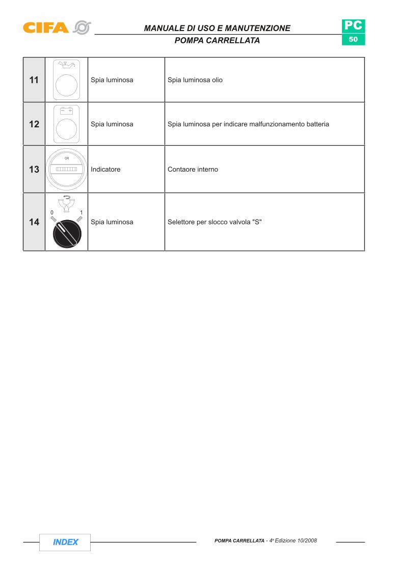
11 Spia luminosa Spia luminosa olio
12 Spia luminosa Spia luminosa per indicare malfunzionamento batteria
13CR
Indicatore Contaore interno
1410
Spia luminosa Selettore per slocco valvola "S"

INDEX
PC51
CR
AV
10
STOP
STOP
24VON LINE
MOTOR
STOP
MOTOR
MOTOR
MAIN 24 V10 STAR
T
PUMP MAIN10
0 1PUMP MAINON LINE
~24V
MAIN 24 V0
CENTRAL CONTROL BOX
1
4
3
2
7
18
PUMP CONTROL
1
ELECTRIC MOTOR CONTROL
10695 11 8 19 15 12 17 13 16 14
MANUALE DI USO E MANUTENZIONEPOMPA CARRELLATA
INDEXPOMPA CARRELLATA - 4a Edizione 10/2008
4.2 qUADRO DI COMANDO PRINCIPALE VERSIONE MOTORE ELETTRICO
INDEX
PC52
MANUALE DI USO E MANUTENZIONEPOMPA CARRELLATA
INDEX POMPA CARRELLATA - 4a Edizione 10/2008
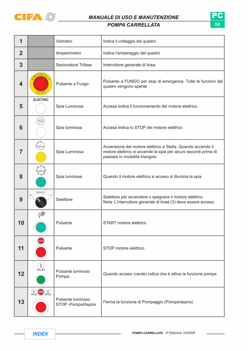
1 Volmetro Indica il voltaggio del quadro
2 Amperometro Indica l'amperaggio del quadro
3 Sezionatore Trifase Interruttore generale di linea
4 Pulsante a Fungo Pulsante a FUNGO per stop di emergenza. Tutte le funzioni del quadro vengono spente
5 Spia Luminosa Accesa indica il funzionamento del motore elettrico.
6 Spia luminosa Accesa indica lo STOP del motore elettrico
7 Spia LuminosaAccensione del motore elettrico a Stella. Quando accendo il motore elettrico si accende la spia per alcuni secondi prima di passare in modalità triangolo
8 Spia luminosa Quando il motore elettrico è acceso si illumina la spia
9MAIN 24 V
0 1
Selettore Selettore per accendere o spegnere il motore elettricoNota: L'interruttore generale di linea (3) deve essere acceso.
10 Pulsante START motore elettrico
11 Pulsante STOP motore elettrico
12 Pulsante luminoso Pompa Quando acceso (verde) indica che è attiva la funzione pompa
13 Pulsante luminosoSTOP -Pompa/Aspira Ferma la funzione di Pompaggio (Pompa/aspira)

INDEX
PC53
MANUALE DI USO E MANUTENZIONEPOMPA CARRELLATA
INDEXPOMPA CARRELLATA - 4a Edizione 10/2008
14 Pulsante luminosoAspira Quando acceso (verde) indica che è attiva la funzione aspira
1510
STOP
STOP
24VON LINE
MOTOR
STOP
MOTOR
MOTOR
MAIN 24 V10 STAR
T
PUMP MAIN10
Selettore abilitazione comandi
Selettore abilitazione comandi quadro/comandi a distanzaIl suo posizionamento determina la postazione di lavoro che può essere dal quadro comandi o dal telecomando
1610
Spia luminosa Selettore per slocco valvola "S"
17 Pulsante luminoso Segnalatore acustico
18 CR Contaore Indica le effettive ore di pompaggio
190 1
PUMP MAIN
Selettore Selettore per accendere le funzioni di pompaggio

INDEX
PC54
1
2
3
MANUALE DI USO E MANUTENZIONEPOMPA CARRELLATA
INDEX POMPA CARRELLATA - 4a Edizione 10/2008
1 Pulsante a Fungo Pulsante a FUNGO per stop di emergenza.
2 Selettore pompaggio Attivo la funzione di Pompa e Aspira
3 Pulsante luminoso Avvisatore acustico
4.3 TELECOMANDO CARRELLATE ELETTRICHE

INDEX
PC55
GAS
GAS
2
1
3
4
MANUALE DI USO E MANUTENZIONEPOMPA CARRELLATA
INDEXPOMPA CARRELLATA - 4a Edizione 10/2008
1 Interruttore clacson/vibratore
Interruttore 3 posizioni ritenute:- ALTO: Avviso segnale acustico- CENTRALE: Posizione neutra- BASSO: Azionamento Vibratore Tramoggia
2 Interruttorepompa/aspira
Interruttore 3 posizioni ritenute:- ALTO: Attiva funzione di pompaggio "POMPA"- CENTRALE: Posizione neutra- BASSO: Attiva funzione di pompaggio "ASPIRA"
3 Interruttore giri motore DIESEL
Interruttore 3 posizioni ritenute:- ALTO: Aumento numero giri motore- CENTRALE: Posizione neutra- BASSO: Diminuzione numero giri motore
4 Pulsante di STOP Si arrestano tutte le funzioni
4.4 TELECOMANDO CARRELLATE DIESEL
INDEX
PC56
cod.218566
MANUALE DI USO E MANUTENZIONEPOMPA CARRELLATA
INDEX POMPA CARRELLATA - 4a Edizione 10/2008
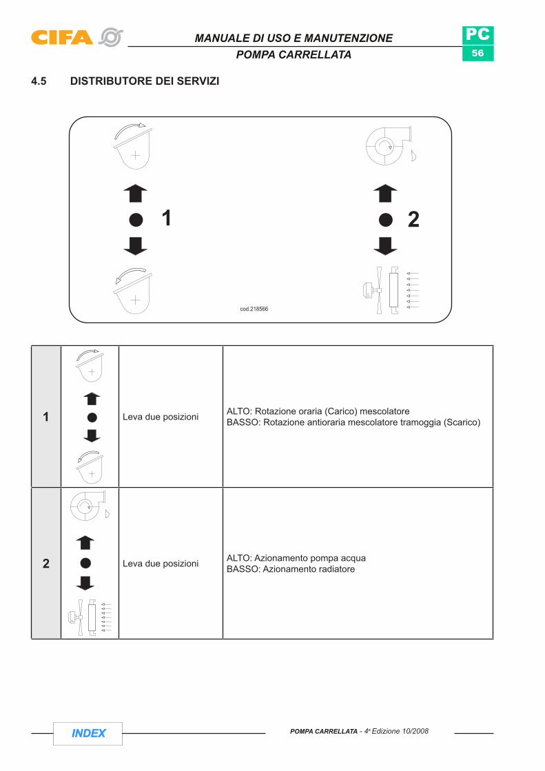
4.5 DISTRIBUTORE DEI SERVIZI
1 Leva due posizioni ALTO: Rotazione oraria (Carico) mescolatoreBASSO: Rotazione antioraria mescolatore tramoggia (Scarico)
2 Leva due posizioni ALTO: Azionamento pompa acquaBASSO: Azionamento radiatore

INDEX
PC57
MANUALE DI USO E MANUTENZIONEPOMPA CARRELLATA
INDEXPOMPA CARRELLATA - 4a Edizione 10/2008
4.6 ALLESTIMENTO
4.6.1 VERSIONE MACCHINAL’attrezzatura può essere fornita in due versioni;
a) Pompa carrellata = PCb) Pompa carrellata spritz = PCS
Entrambe le versioni possono essere alimentate da motore diesel o elettrico.
4.6.2 MONTAGGIO ATTREZZATURAIn genere il montaggio dell’attrezzatura sul telaio viene eseguito da CIFA s.p.a. In questo caso la macchina é pronta per l’utilizzo in quanto prima della consegna, viene eseguito un collaudo generale.
Nel caso in cui l’attrezzatura venga fornita sciolta, in allegato ad ogni modulo vengono forniti i relativi disegni e schemi di montaggio.
ATTENZIONE: Rivolgersi sempre ad una officina di assistenza autorizzata per effettuare il montaggio completo dell’attrezzatura.
VerificheLa macchina viene consegnata controllata e collaudata, quindi non necessita di particolari controlli.
Tuttavia verificare sempre il buon funzionamento di tutti i dispositivi di sicurezza e protezione. Verificare •che:
Tutti i carter di protezione siano montati e ben fissati.. Tutti i finecorsa siano attivi (portella scarico vasca, cilindri pompanti).. La griglia di protezione posta sulla tramoggia sia chiusa.. Sia funzionante il fungo di arresto di emergenza .. Il segnalatore acustico funzioni .. La tubazione di distribuzione calcestruzzo sia libera da eventuali intasamenti o blocchi.. I giunti rapidi di fissaggio delle tubazioni del calcestruzzo (collari) siano chiusi ed assicurati con la . spina di sicurezza.Le tubazioni del calcestruzzo non siano eccessivamente usurate - in caso contrario . SOSTITUIRLE-.
4.7 TRASFERIMENTOPrima del trasferimento verificare il livello del carburante tramite indicatore di livello.•
La macchina può essere trainata tramite apposito gancio ad una velocità massima di 6 Km/h.•
cod. 234927
VELOCITA' MAX. 6 Km/hVITESSE MAX. 6 Km/hMAX.SPEED 6 Km/hMAX.GESCHWINDIGKEIT 6 Km/h

INDEX
PC58
cod. 234898
MANUALE DI USO E MANUTENZIONEPOMPA CARRELLATA
INDEX POMPA CARRELLATA - 4a Edizione 10/2008
ATTENZIONE: Prima del traino verificare che gli stabilizzatori manuali siano chiusi e bloccati tramite apposita spina con relativa sicurezza.
4.8 POSIZIONAMENTO E STABILIZZAZIONE MACCHINAArrivati in cantiere posizionare barriere e cartelli di avvertimento intorno all’area di azione della macchina, in •prossimità di vie di traffico o passaggi pedonali in modo da impedire l’accesso nella zona a qualsiasi persona o mezzo.
Nessuno ad eccezione dell’operatore (responsabile della macchina e della sua funzionalità), deve restare in •prossimità della zona di lavoro della macchina.
Portare la macchina sul posto di lavoro e assicurarsi che il terreno sia solido e piano.•
Assicurarsi che non vi siano persone o cose nel raggio d’azione della macchina.•
Inibire il moto alle ruote del telaio.•

INDEX
PC59
MANUALE DI USO E MANUTENZIONEPOMPA CARRELLATA
INDEXPOMPA CARRELLATA - 4a Edizione 10/2008
Stabilizzare la macchina.•
Abbassare il più possibile anteriormente la macchina (tramite piede di appoggio).•
Togliere fermo meccanico stabilizzatori posteriori (1).•
Sfilare gli stabilizzatori posteriori fino a raggiungere il terreno (2).•
Inserire fermo meccanico con spina di sicurezza.•

INDEX
PC60
MANUALE DI USO E MANUTENZIONEPOMPA CARRELLATA
INDEX POMPA CARRELLATA - 4a Edizione 10/2008
Tramite piede di appoggio alzare la parte anteriore•
Aiutarsi con una bolla per raggiungere l’orizzontalità della macchina.•
ATTENZIONE:Controllare che il terreno sottostante agli stabilizzatori non ceda. Controllare che tutti i fermi meccanici siano stati ripristinati. Controllare che tutti i comandi della stabilizzazione siano in posizione «0».

INDEX
PC61
Fig.10 Fig.11 Fig.12
Fig.13 Fig.14 Fig.15
Fig.16 Fig.17 Fig.18
MANUALE DI USO E MANUTENZIONEPOMPA CARRELLATA
INDEXPOMPA CARRELLATA - 4a Edizione 10/2008
Nel caso il terreno non abbia una solidità idonea utilizzare delle piastre di ripartizione o del legname compatto adatto a distribuire meglio la pressione degli stabilizzatori sul terreno (travetti a sezione quadra 15x15).
L’operatore della pompa ha l’obbligo di stabilizzare la macchina conformemente alle varie condizioni del terreno (vedi da Fig. 10 a Fig. 18)
Ciò significa che a seconda del grado di stabilità del terreno (kN/m2), i piattelli d’appoggio originali degli stabilizzatori devono essere «ingranditi» mediante l’applicazione di piani di appoggio più estesi in modo da evitare lo sprofondamento dei piedi di appoggio.
Come materiale accessorio vengono offerte 4 piastre d’appoggio (60x60cm. oppure 50x50cm.) in materiale plastico che, utilizzati come semplice base di appoggio, possono coprire un’area più estesa in relazione ai carichi verticali e alla pressione di contatto consentita.
Se è richiesta una maggiore superficie d’appoggio, l’utilizzatore dovrà disporre di adeguati travetti di legno squadrati (15x15cm) in numero di quattro per ciascuna piastra di appoggio.
Consultando la tabella è possibile sapere in che misura i piani di appoggio sono sufficienti o se invece è necessario applicare anche i suddetti travetti.
INDEX
PC62
MANUALE DI USO E MANUTENZIONEPOMPA CARRELLATA
INDEX POMPA CARRELLATA - 4a Edizione 10/2008
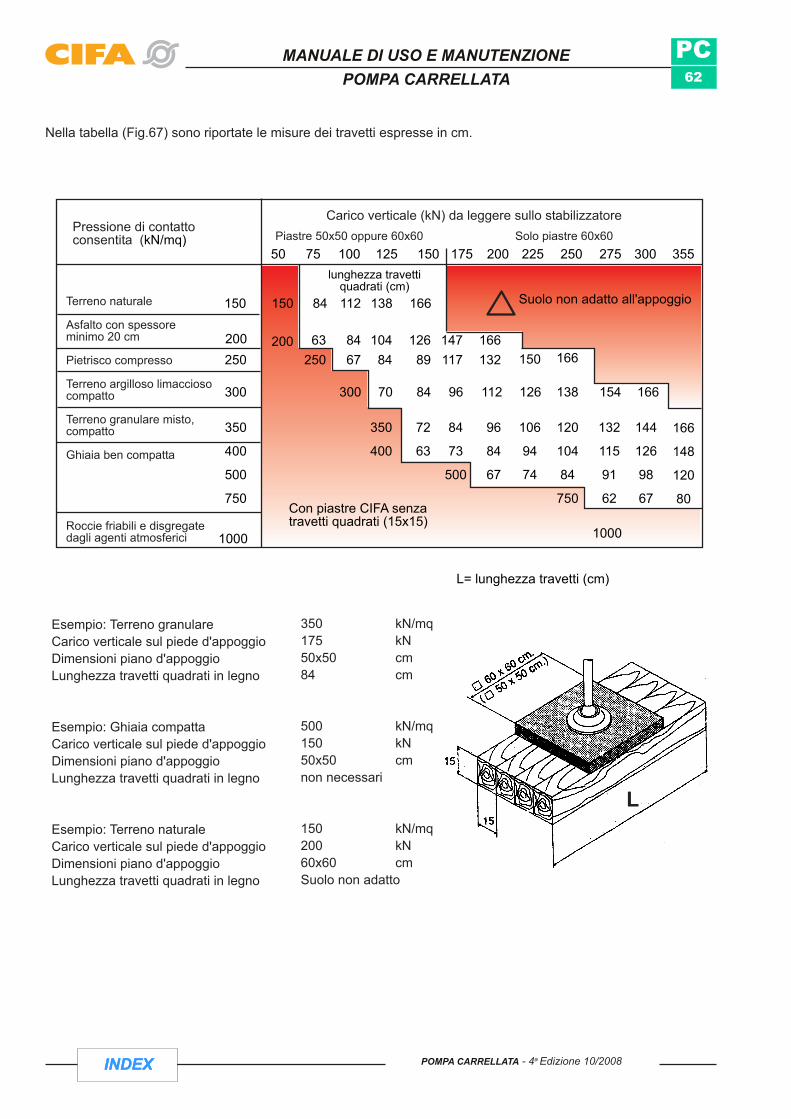
Nella tabella (Fig.67) sono riportate le misure dei travetti espresse in cm.
50 75 100 125 150 175 200 225 250 275 300 355
1000
Terreno naturale
Asfalto con spessoreminimo 20 cm
Pietrisco compresso
Terreno argilloso limacciosocompatto
Terreno granulare misto,compatto
Ghiaia ben compatta
Roccie friabili e disgregatedagli agenti atmosferici 1000
166
148
120
80
144
126
98
67
132
115
91
62
120
104
84
750
106
94
74
96
84
67
84
73
500
72
63
350
400
350
400
500
750
Esempio: Terreno granulareCarico verticale sul piede d'appoggioDimensioni piano d'appoggioLunghezza travetti quadrati in legno
Esempio: Ghiaia compattaCarico verticale sul piede d'appoggioDimensioni piano d'appoggioLunghezza travetti quadrati in legno
Esempio: Terreno naturaleCarico verticale sul piede d'appoggioDimensioni piano d'appoggioLunghezza travetti quadrati in legno
63250
8467
10484
12689
147117
166132 150 166250
200200
138 154 166126112968470300300
150150 84 112 138 166
lunghezza travettiquadrati (cm)
Pressione di contattoconsentita (kN/mq)
Carico verticale (kN) da leggere sullo stabilizzatorePiastre 50x50 oppure 60x60 Solo piastre 60x60
350 kN/mq175 kN50x50 cm84 cm
500 kN/mq150 kN50x50 cmnon necessari
150 kN/mq200 kN60x60 cmSuolo non adatto
Suolo non adatto all'appoggio
Con piastre CIFA senzatravetti quadrati (15x15)
L= lunghezza travetti (cm)
L

INDEX
PC63
MANUALE DI USO E MANUTENZIONEPOMPA CARRELLATA
INDEXPOMPA CARRELLATA - 4a Edizione 10/2008
4.9 POMPAGGIO CALCESTRUZZOCollegare le tubazioni di distribuzione calcestruzzo in dotazione alla macchina con la rete di distribuzione •calcestruzzo del cantiere.
ATTENZIONE: Verificare che gli spessori delle tubazioni siano corrispondenti.
In particolare nel caso di versione PCS:
Collegare alle estremità della rete di distribuzione calcestruzzo il terminale in gomma munito della lancia di • spruzzo.
predisporre il collegamento tra serbatoio additivo e la pompa additivo e tra pompa additivo e lancia di • spruzzo.
ATTENZIONE: - L’additivo é una sostanza generalmente corrosiva per cui usare idonei mezzi di protezione personale.- Non disperdere additivo nell’ambiente.- Tutti i materiali che entrano in contatto con l’additivo devono essere resistenti alla corrosione dell’additivo.
Collegare la tubazione dell’aria compressa da un lato alla rete del cantiere e dall’altro al collettore che alimenta • la lancia di spruzzo e il vibratore pneumatico posto sulla tramoggia - Pressione di esercizio da 4 a 6 bar.
Per entrambe le versioni (PC e PCS);
Nel caso di motore Diesel:Inserire la chiave nel selettore 8 (interruttore a chiave avviamento motore) e ruotarla per l’accensione • motore.
Nel caso di motore elettrico:Collegare il cavo di alimentazione della energia elettrica della rete del cantiere al quadro di comando • principale.
ATTENZIONE:- Verificare la congruenza tra i dati di targa del motore elettrico della macchina con quelli della rete.- Evitare di danneggiare il cavo di collegamento elettrico: pericolo di folgorazione.- Essendo la macchina alimentata a 380V porre particolare cautela in tutte le operazioni di manutenzione.
Ruotare l’interruttore generale di linea dal quadro di comando principale per dare tensione al quadro.•
Ruotare il selettore a chiave 24V per dare tensione al circuito elettrico a 24V.•
Premere il pulsante avviamento motore elettrico per avviare il motore.•
INDEX
PC64
Fig.20
Fig.21
MANUALE DI USO E MANUTENZIONEPOMPA CARRELLATA
INDEX POMPA CARRELLATA - 4a Edizione 10/2008
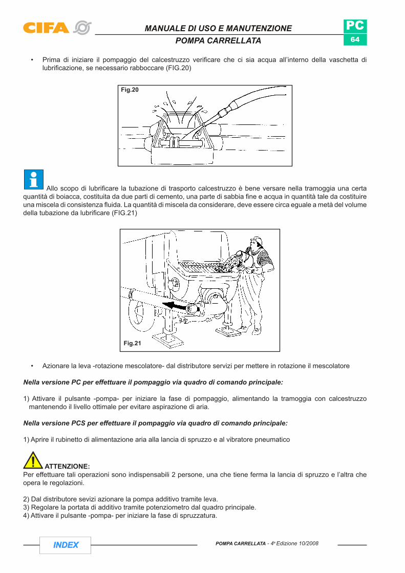
Prima di iniziare il pompaggio del calcestruzzo verificare che ci sia acqua all’interno della vaschetta di • lubrificazione, se necessario rabboccare (FIG.20)
Allo scopo di lubrificare la tubazione di trasporto calcestruzzo è bene versare nella tramoggia una certa quantità di boiacca, costituita da due parti di cemento, una parte di sabbia fine e acqua in quantità tale da costituire una miscela di consistenza fluida. La quantità di miscela da considerare, deve essere circa eguale a metà del volume della tubazione da lubrificare (FIG.21)
Azionare la leva -rotazione mescolatore- dal distributore servizi per mettere in rotazione il mescolatore•
Nella versione PC per effettuare il pompaggio via quadro di comando principale:
1) Attivare il pulsante -pompa- per iniziare la fase di pompaggio, alimentando la tramoggia con calcestruzzo mantenendo il livello ottimale per evitare aspirazione di aria.
Nella versione PCS per effettuare il pompaggio via quadro di comando principale:
1) Aprire il rubinetto di alimentazione aria alla lancia di spruzzo e al vibratore pneumatico
ATTENZIONE: Per effettuare tali operazioni sono indispensabili 2 persone, una che tiene ferma la lancia di spruzzo e l’altra che opera le regolazioni.
2) Dal distributore sevizi azionare la pompa additivo tramite leva.3) Regolare la portata di additivo tramite potenziometro dal quadro principale.4) Attivare il pulsante -pompa- per iniziare la fase di spruzzatura.

INDEX
PC65
Fig.22 Fig.23
Fig.24
MANUALE DI USO E MANUTENZIONEPOMPA CARRELLATA
INDEXPOMPA CARRELLATA - 4a Edizione 10/2008
ATTENZIONE: Il calcestruzzo spruzzato (betoncino) ha dimensioni con granulometria max 10mm al fina di evitare blocchi nella tubazione con conseguenze pericolose.
ATTENZIONE:Non aprire i giunti a leva delle tubazioni calcestruzzo durante il pompaggio.•
La tramoggia deve essere sempre piena di calcestruzzo per evitare proiezioni di materiali causa aspirazione • di sola aria.
Non inserire arti od oggetti tra le maglie della griglia di protezione tramoggia (Fig. 22).•
Non aprire il coperchio della vaschetta acqua di lubrificazione con il gruppo pompante in movimento (Fig. • 23).
Non inserire arti od oggetti che possano venire in contatto con la valvola ad «S» (Fig.24).• .

INDEX
PC66
MANUALE DI USO E MANUTENZIONEPOMPA CARRELLATA
INDEX POMPA CARRELLATA - 4a Edizione 10/2008
In caso di intasamento non insistere con il pompaggio ma effettuare alcuni cicli di aspirazione per liberare le • tubazioni.
Non lasciare mai la tubazione calcestruzzo sotto pressione.•
Durante le pause di pompaggio con calcestruzzo molto fluido, con una grande parte di inerti di grossa pezzatura, • i quali tendono a scolarsi dall’acqua, lasciare che la macchina pompi a vuoto e comunque, che il mescolatore sia sempre attivo per evitare la segregazione dei componenti.
Per pause di pompaggio più lunghe aspirare il calcestruzzo nella tramoggia, mescolare e pompare (non valido • per versione PCS per cui occorre passare alle operazioni di pulizia).
Se le pause sono piuttosto lunghe spegnere il motore propulsore affinché le vibrazioni non separino il • calcestruzzo (non valido per PCS per cui occorre passare alla operazione di pulizia).
Qualora si stia fermi per 10 - 15 minuti muovere il calcestruzzo pompando e aspirando alternativamente. In • aggiunta a ciò in caso di PCS spegnere la pompa additivi lasciando aperta l’aria che fluendo pulisce.
Non pressate mai di forza nelle tubazioni il calcestruzzo separato o nel quale si stanno formando dei grumi • per la solidificazione.
In particolare per il calcestruzzo con scarsa capacità di trattenere l’acqua é meglio evitare pause nel pompaggio, • e al momento di cominciare il lavoro, pompare indietro fino a quando la valvola scambia completamente da entrambi i lati, quindi riprendere di nuovo a pompare avanti.
Per entrambe le versioni (PC/PCS) quando si devono effettuare le operazioni di pompaggio/spruzzatura da telecomando:
Prendere il cavo in dotazione e collegarlo al quadro comandi posto sulla macchina.•
Ruotare il selettore -abilitazione quadro/comandi a distanza- posto sul quadro di comando principale della • macchina su «comando a distanza»
Attivare la funzione di pompaggio ruotando il selettore posto sul telecomando•
Nel caso di PCS per regolare l’afflusso di calcestruzzo dalla pompa alla lancia di spruzzo agire sul volantino di regolazione calcestruzzo posto in prossimità del motore.

INDEX
PC67
MANUALE DI USO E MANUTENZIONEPOMPA CARRELLATA
INDEXPOMPA CARRELLATA - 4a Edizione 10/2008
4.10 PULIZIA MACCHINALa pulizia con acqua in pressione derivata dalla pompa di lavaggio é uno dei metodi più usati nella pratica. Per metterla in funzione attivare la leva (1) del distributore servizi.
4.10.1 PULIZIA TUBAZIONI DISTRIBUZIONE CALCESTRUZZOFermare il pompaggio.• Nel caso di PCS terminata la fase di pompaggio fermare la pompa additivo agendo sul distributore, chiudere • l’aria e smontare la lancia di spruzzo che verrà lavata subito a parte.Svuotare il più possibile la tramoggia pompando via il materiale. Fare pompare una o due corse indietro per • eliminare la pressione nelle tubazioni.Fermare il pompaggio.• Aprire la tubazione nel tratto da 5".• Pressare nella apertura le palle di spugna per la pulizia imbevute d’acqua • richiudere la tubazione• pompare fino alla fuoriuscita delle palle di spugna dalla tubazione aggiungendo acqua in tramoggia.•
ATTENZIONE: Proteggere il terminale della tubazione di calcestruzzo durante l’operazione di pulizia per evitare pericolose proiezioni di materiale.
aprire la curva di uscita vasca.• sganciare il fermo di sicurezza meccanico portella vasca calcestruzzo ed aprire la portella stessa.• inserire la chiave nel quadro di comando principale, posizionare su «quadro» e premere il pulsante pompa • per permettere lo scambio valvola. Al rilascio del pulsante essendo la portella di scarico vasca calcestruzzo aperta, il movimento della valvola ad «S» si blocca. attenzione: durante queste operazioni non inserire arti od oggetti attraverso la portella di scarico vasca.lavare completamente tramoggia, curve cls, valvola «s», canne e pistoni pompanti. In particolare verificare • che non vi siano residui di calcestruzzo nella parte inferiore della valvola ad «S». Se necessario continuare fino a che si nota che tutti gli organi o parti entrate in contatto con il calcestruzzo siano puliti.Nel caso di PCS per lavare la tubazione additivo e la pompa additivi, scollegare la pompa dal serbatoio additivi • e collegarla con la rete idrica del cantiere.Attivare dal distributore servizi la pompa additivi facendole compiere alcuni cicli di lavaggio.•
ATTENZIONE: Non disperdere nell’ambiente additivo e/o miscele di acqua e additivo raccogliendola in appositi contenitore.

INDEX
PC68
Fig.27
FIG.20FIG.23
MANUALE DI USO E MANUTENZIONEPOMPA CARRELLATA
INDEX POMPA CARRELLATA - 4a Edizione 10/2008
Per lavare la lancia di spruzzo occorre smontarla completamente e • procedere alla operazione di lavaggio con acqua di ogni sua parte. Verificare che non vi siano fori otturati e parti usurate.
L’attrezzatura é dotata dei seguenti dispositivi di sicurezza:
- Una valvola che impedisce il movimento dell’albero mescolatore quando la griglia di protezione tramoggia viene aperta.
- Un fine corsa induttivo di prossimità che blocca il movimento della valvola ad «S» alla apertura della portella di scarico vasca calcestruzzo.
ATTENZIONE: - Non inserire arti od oggetti nel raccordo di uscita vasca quando la curva é aperta e quando la pompa é in funzione
( pericolo di cesoiamento) (Fig. 23).- Non aprire le tubazioni di calcestruzzo senza essersi assicurati che non vi sia pressione all’interno. Per evitare ciò
effettuare qualche ciclo di aspirazione.- Non inibire i fine corsa (Fig.20).
Terminate le fasi di pulizia:- Mettere in posizione neutra la leva del distributore servizi.- Riporre in cassetta gli attrezzi utilizzati.- Chiudere la portella vasca e le tubazioni calcestruzzo.

INDEX
PC69
MANUALE DI USO E MANUTENZIONEPOMPA CARRELLATA
INDEXPOMPA CARRELLATA - 4a Edizione 10/2008
4.11 FINE CICLO DI LAVOROTerminata la fase di pompaggio/spruzzo effettuare il lavaggio dell’attrezzatura seguendo le indicazioni del capitolo pulizia
ATTENZIONE: Se si usano additivi particolari eseguire il lavaggio di tutta l’attrezzatura in tempi brevi.
Terminata la pulizia dell’attrezzatura, arrestato il gruppo pompante, si deve procedere nel:- Riporre il comando a distanza in cabina o in cassetta.- Togliere i fermi meccanici sulla parte sfilabile degli stabilizzatori.- Inserire i fermi meccanici e le relative spine di sicurezza degli stabilizzatori in assetto da trasporto in sagoma.
Disabilitare il quadro di comando principale ruotando il selettore a chiave nel caso motore Diesel, nel caso motore elettrico, in posizione «0»
- Prima del trasferimento della attrezzatura verificare che tutti i collegamenti (tubazioni calcestruzzo , tubazioni aria, tubazioni additivi, cavi elettrici) siano stati fisicamente scollegati
4.12 ARRESTOLa macchina é dotata di pulsante a fungo per l’arresto di emergenza di colore rosso su fondo giallo, che permette di arrestare la fonte di energia primaria ( motore autotelaio/ausiliario) posizionato sia sulla macchina che sul comando a distanza ( telecomando).
Per riavviare nuovamente il motore é necessario riarmare il fungo stop di emergenza.
Tale operazione si esegue ruotando ed estraendo il pulsante.
ATTENZIONE: All’avviamento del motore può verificarsi il funzionamento del pompaggio e dei servizi, qualora l’operatore non abbia azzerato tutte le funzioni prima di arrestare la macchina.
Nel caso la macchina resti non utilizzata per lunghi periodi, prima di rimetterla in funzione, rivolgersi ad una officina autorizzata per gli opportuni controlli.

INDEX
PC70
MANUALE DI USO E MANUTENZIONEPOMPA CARRELLATA
INDEX POMPA CARRELLATA - 4a Edizione 10/2008
4.13 PULIZIA GENERALE
4.13.1 Lavaggio delle macchine con idropulitrici
Se si utilizzano idropulitrici per il lavaggio delle macchine non si deve operare a distanze inferiori a 15÷20 cm. Non conviene insistere con lo spruzzo su un unico punto della superficie verniciata, ma lavare con ampie passate. È consigliabile utilizzare idropulitrici con paracolpi in gomma posti all’estremità della lancia di spruzzo, per evitare di colpire la verniciatura con oggetti di metallo. La temperatura dell’acqua non deve essere superiore a 60-70 °C. Attenzione che un film deteriorato o già scalfito può sfogliare quando sottoposto a lavaggio con pressione di una certa entità.
N.B.: Al fine di impedire al cemento ed al calcestruzzo di aderire all’attrezzatura e facilitare cosi la pulizia ed il lavaggio é consigliabile cospargere l’attrezzatura con uno strato di paraffina, cera, olio meccanico od altri prodotti in commercio. Eseguire questa operazione ogni qualvolta si esegua il lavaggio della macchina o quando si rende necessario.

INDEX
PC71
MANUALE DI USO E MANUTENZIONEPOMPA CARRELLATA
INDEXPOMPA CARRELLATA - 4a Edizione 10/2008
Sezione DMANUTENZIONE

INDEX
PC72
MANUALE DI USO E MANUTENZIONEPOMPA CARRELLATA
INDEX POMPA CARRELLATA - 4a Edizione 10/2008
PAGINA LASCIATA BIANCA INTENZIONALMENTE

INDEX
PC73
MANUALE DI USO E MANUTENZIONEPOMPA CARRELLATA
INDEXPOMPA CARRELLATA - 4a Edizione 10/2008
5 MANUTENZIONE ORDINARIAPREMESSAUna puntuale e corretta manutenzione è la premessa indispensabile per assicurare efficienza, affidabilità e durata della macchina. Tenendo presente che la macchina opera in cantieri le cui condizioni ambientali sono spesso sfavorevoli, proponiamo di seguito una serie di considerazioni sui vari gruppi componenti la macchina, mettendo in evidenza le correlazioni e i punti critici da tenere sotto controllo sistematico.
Queste operazioni devono essere eseguite da un tecnico precedentemente addestrato seguendo questi consigli.
5.1 CONTROLLI GIORNALIERI
5.1.1 PRIMA DI PARTIRE- Dispositivi di sicurezza (es. fine corsa, spine di sicurezza ecc.).- Livelli e condizioni dell’olio motore principale ed ausiliario.- Livello acqua radiatore motore principale ed ausiliario.- Stato e pressione pneumatici.- Impianto elettrico (luci / lampeggiatori / luci stop / ecc.).- Corretta visuale negli specchi retrovisori.- Tutti i componenti che durante il funzionamento si muovono (es.stabilizzatori,) devono essere bloccati in sagoma
prima dello spostamento della macchina stessa
5.1.2 dopo la messa in moto- Pressione dell’olio motore del veicolo- Temperatura dell’acqua di raffreddamento motore.- Inoltre l’operatore deve verificare il funzionamento di tutte le spie.- assenza di perdite di olio/aria (eventualmente fissare i raccordi)
5.2 PRECAUZIONI CONTRO IL GELO
Durante i periodi di sosta della macchina, nella stagione invernale, È ASSOLUTAMENTE necessario ricordarsi • di scaricare l’acqua di tutto l’impianto ed in particolare verificare che non vi siano residui d’acqua nella pompa acqua. Nel caso si debba operare a temperature sotto 0 °C è necessario ricorrere ad accorgimenti specifici (es. additivi nell’acqua) per non incorrere in rotture del contalitri, della pompa o altro.
5.3 LUBRIFICAZIONEControllare giornalmente l’efficienza dell’impianto di lubrificazione centralizzata attraverso l’indicatore ad astina • posizionata sul blocchetto di distribuzione
Il serbatoio del grasso è di materiale trasparente e la presenza del prodotto è verificabile facilmente. La ricarica • del serbatoio si effettua attraverso l’attacco terminale con un normale ingrassatore, ubicato alla base del serbatoio stesso. Non rimuovere mai il coperchio del serbatoio per evitare l’ingresso di inquinanti nel sistema.
Quando la pompa del grasso rimane senza prodotto, può facilmente verificarsi che dopo il riempimento del • serbatoio, il prodotto non riesca ad essere pompato per la presenza di bolle d’aria. In questo caso staccare il tubo di mandata e fare girare la pompa fino a quando il prodotto riprende ad uscire. Quindi, ripristinare il collegamento.
I punti non interessati dall’impianto centralizzato, sono provvisti di ingrassatori, che a mezzo delle comuni • pompe manuali, permettono l’ingrassaggio da effettuarsi secondo tabella.
Come riportato in tabella lubrificazione controllare periodicamente il livello di olio e grasso.•
Provvedere alla lubrificazione superficiale e protettiva delle parti meccaniche esposte. In caso di lunghi periodi • di fermo effettuare una abbondante lubrificazione di tutte le parti della macchina.

INDEX
PC74
MANUALE DI USO E MANUTENZIONEPOMPA CARRELLATA
INDEX POMPA CARRELLATA - 4a Edizione 10/2008
ATTENZIONE:Prima di procedere alla lubrificazione è necessario pulire l’ugello della pistola d’ingrassaggio, in modo da evitare che materiale estraneo mischiandosi al grasso, vada a provocare danni ai perni e alle bronzine. Una perfetta lubrificazione si ottiene rigenerando e riempiendo completamente con lubrificante nuovo, le apposite sedi. Verificare che immettendo lubrificante nuovo nelle sedi il lubrificante vecchio venga espulso.
Se nell’effettuare le operazioni di lubrificazione si é reso necessario rimuovere una protezione si deve:- Porre particolare attenzione durante le operazioni di manutenzione.- Rimontare la protezione prima dell’utilizzo della macchina.
La lubrificazione dei pistoni del gruppo pompante si effettua in questo modo:1) Portare a fine corsa uno dei due pistoni2) Ingrassare tramite l’ingrassatore il pistone che si trova vicino alla vaschetta acqua di lubrificazione.3) Eseguire la manovra opposta per l’altro pistone.
Si consiglia di eseguire tale operazione ogni 50 ore.
5.4 GRUPPO POMPANTEPrima di iniziare la fase di pompaggio verificare che ci sia l’ acqua all’interno della vaschetta di • lubrificazione.
Sostituire giornalmente l’acqua, e comunque sostituirla nel caso questa sia sporca.•
Nel caso nella vaschetta si trovi dell’acqua e olio, si deve sostituire la guarnizione dei pistoni oleodinamici • (chiamare l’assistenza tecnica).
Nel caso invece che nell’acqua della vaschetta si trovi eccessiva presenza di boiacca, si devono sostituire i • pistoni calcestruzzo (chiamare l’assistenza tecnica).
Verificare che sulla superficie delle canne calcestruzzo non vi sia presenza di ossido (mancanza di cromo). •
Verificare lo stato di usura dell’anello e della piastra di usura. In caso di presenza di solchi eccessivi e di usure • eccessive provvedere alla sostituzione.
Verificare l’usura sulle tubazioni del calcestruzzo; per fare questo adoperare un martello o uno spessimetro. •
5.5 CONTROLLO STRUTTURALE (ANOMALIE STRUTTURALI)I controlli strutturali per braccio, torretta, sottotorretta, telaio di base, stabilizzatori, castelletti di supporto, riduttore, tamburo, prevedono le seguenti verifiche:
Integrità degli ancoraggi e dei supporti (fra attrezzature ed autotelaio, supporto del serbatoio acqua gruppi • pompanti, riduttore tamburo, castelletti betoniere, supporti tubazioni calcestruzzo, supporti per canale aggiuntive).
Integrità dei bulloni e dello stato di serraggio (in particolare verificare la coppia di serraggio dei bulloni vedi • tab. manuale «informzioni generali»).
Stato dei materiali eventuali cricche e rotture nelle carpenterie e nei componenti. Un indicatore di problemi • strutturali è molto spesso la ruggine.
Le saldature.•
I perni e bronzine (eventuale grippaggio) •
I giochi determinati dalle eccessive usure fra particolari in reciproco movimento (es. articolazioni braccio).•

INDEX
PC75
MANUALE DI USO E MANUTENZIONEPOMPA CARRELLATA
INDEXPOMPA CARRELLATA - 4a Edizione 10/2008
ATTENZIONE:- Ripristinare, se necessario, con saldature (manutenzione straordinaria rivolgersi a un’officina autorizzata).- Le strutture del braccio, ed in generale le strutture portanti realizzate in acciai speciali ad alta resistenza non
vanno in alcun modo modificate o indebolite con saldature o fori per attacchi.
5.6 CONTROLLO COMPONENTI OLEODINAMICI
Data la complessità della macchina si consiglia sempre di ricorrere a specialisti per interventi sulla parte oleodinamica.
Se si riscontrano delle anomalie, verificare le cause e ripristinare l’integrità del circuito prima di effettuare • qualsiasi manovra
Individuare eventuali perdite d’olio e rimuovere le cause.•
Ispezionare valvole di sicurezza e tubi idraulici rigidi e flessibili, giunti e cilindri per scoprire eventuali usure o • perdite (lo scoppio di una tubazione logora può causare conseguenze gravi).
Occorre controllare le tubazioni che dalla valvola di sicurezza si raccordano alle bocche di entrata di ogni • cilindro, verificando che non esistano perdite, che non vi siano deformazioni da urto o da usura e che i raccordi siano integri e ben bloccati.
Sostituire immediatamente qualsiasi tubazione danneggiata.•
È vietato modificare la taratura originale: qualsiasi regolazione o taratura deve essere effettuata da personale • specializzato.
È vietato manomettere i componenti idraulici, pena la decadenza della garanzia e responsabilità del • fornitore.
ATTENZIONE:- Prima di operare su un circuito assicurarsi che non sia in pressione e verificare che gli accumulatori siano stati
scaricati. È indispensabile che il braccio o l’elemento azionato dal circuito oleodinamico sia in situazione di riposo e non sotto sforzo .
- Dal momento che l’olio può raggiungere temperature elevate con rischio di bruciature gravi, occorre indossare adeguati mezzi di protezione prima di aprire un giunto.
- Qualsiasi sostituzione di componenti deve essere fatta nel rispetto dei dati di targa del costruttore .
5.7 CONTROLLO COMPONENTI ELETTRICIAssicurarsi dell’efficienza dei componenti dell’impianto elettrico.•
Qualsiasi sostituzione di componenti deve essere fatta nel rispetto dei dati di targa: in particolare componenti • antideflagranti dovranno essere sostituiti con componenti aventi le stesse caratteristiche ed omologati.
5.8 SOSTITUZIONE MOTORIMotori diesel e motori elettrici in versione macchine antideflagranti devono essere sostituiti con motori aventi • le stesse caratteristiche ed omologati.
5.9 TUBAZIONI CALCESTRUZZOLa giusta dimensione delle tubazioni in diametro e spessore unitamente al loro stato di conservazione, la corretta tipologia dei giunti, la loro efficienza e chiusura con fermo di sicurezza sono le condizioni essenziali per eliminare rischi e problemi durante il pompaggio. Periodicamente in funzione del tipo e dello spessore le tubazioni vanno

INDEX
PC76
MANUALE DI USO E MANUTENZIONEPOMPA CARRELLATA
INDEX POMPA CARRELLATA - 4a Edizione 10/2008
ispezionate per verificarne lo stato di usura.
Si consiglia di controllare frequentemente i tratti più esposti ad usura ogni 1000 mc di getto.- Verificare frequentemente (in funzione dell’abbrasività del materiale pompato) lo stato di usura delle tubazioni e
provvede alla sostituzione quando lo spessore è inferiore al valore riportato in tabella (vedi tabella) Il controllo può essere fatto percuotendo la tubazione con un martello; in funzione del tipo di risposta sonora può essere valutato lo spessore esistente. Più scientificamente è possibile utilizzare apparecchiature facilmente reperibili sul mercato per controllo non distruttivo .
- Per un’usura uniforme e quindi per una maggiore durata è bene far ruotare periodicamente le tubazioni: rotazione oraria di 120 ° ogni 5/6000 mc di getto per le tubazioni ed un inversione di 180 ° per le curve .
ATTENZIONE:- Non modificare le dimensioni originali delle tubazioni prescritte dal costruttore.- Nell’uso di alte pressioni sul calcestruzzo utilizzare le tubazioni idonee.- Tubazioni fissate a terra e curve ubicate ad una distanza dal personale inferiore ai tre metri devono essere
cambiate al raggiungimento degli spessori previsti e comunque con frequenza superiore.
5.10 CIRCUITO DELL’ACqUANella stagione fredda è necessario procedere allo svuotamento dell’impianto acqua della macchina al termine del • lavoro giornaliero per non incorrere in rotture della pompa acqua e di parti dell’impianto a causa del gelo .
L’impianto può essere svuotato agendo sulle valvole a sfera.•
Per informazioni più dettagliate vedere il manuale d’istruzione specifico allegato (pompa acqua).•
Provvedere periodicamente alla pulizia del serbatoio per eliminare residui di calcare con frequenza maggiore • quanto maggiore è il grado di impurità contenuta nell’acqua del cantiere.
Ricordarsi che in presenza di acqua molto sporca e contenente sabbia, si possono verificare anche otturazioni • dei tubi, specie in prossimità dell’attacco sul serbatoio.
Verificare che lo spessore del serbatoio non sia usurato (controllo da effettuare ogni 6 mesi)•
5.11 IMPIANTO ELETTRICOControllare l’efficienze di tutti i componenti elettrici di comando.•
Assicurarsi del perfetto isolamento dei cavi, specialmente in corrispondenza dei fissacavi e pressacavi, al fine • di evitare cortocircuiti che potrebbero danneggiare altri componenti.
Controllare inoltre che i punti di collegamento siano perfettamente stretti e non presentino ossidazioni.•
Assicurarsi sempre del perfetto collegamento a massa dell’impianto elettrico.•
6 SMALTIMENTONon disperdere nell’ambiente olio usato, batterie, parti in gomma, ma smaltirle opportunamente.•
La struttura metallica va smaltita come ferro vecchio.•
Se la macchina viene venduta ad un altro utente comunicare alla CIFA il cambio di proprietà.•

INDEX
PC77
MANUALE DI USO E MANUTENZIONEPOMPA CARRELLATA
INDEXPOMPA CARRELLATA - 4a Edizione 10/2008
Sezione ETABELLE E ALLEGATI

INDEX
PC78
MANUALE DI USO E MANUTENZIONEPOMPA CARRELLATA
INDEX POMPA CARRELLATA - 4a Edizione 10/2008
PAGINA LASCIATA BIANCA INTENZIONALMENTE

INDEX
PC79
MANUALE DI USO E MANUTENZIONEPOMPA CARRELLATA
INDEXPOMPA CARRELLATA - 4a Edizione 10/2008
20005002005025
ISO VG 46
ISO VG 150
1
2
3
4
5
6
7
8
LU BRI FI CA ZIO NI
RIFERIMENTOPOS.TEMPO
MANUTENZIONE (ore) LUBRIFICANTI NOTE
1° SOSTITUZIONE DOPO 200 ORE
FILTRO SFIATO SERBATOIO
OLIO IDRAULICO SERBATOIO
FILTRO RITORNO
ACQUA LUBRIFICAZIONE CILINDRI CLS
SNODI CILINDRI VALVOLAALBERO MESCOLATORE
POMPA GRASSO
DIPENDE DALLE CONDIZIONI AMBIENTALI
S
SOSTITUZIONE GIORNALIERA
I
C
ACQUA
S
TEMPO MAX 1 ANNOC
S
GRASSO NLGI 2
RIDUTTORE MESCOLATORE S 1° CAMBIO DOPO 100 ORETEMPO MAX 1 ANNOC
VEDERE LIBRETTO DI ISTRUZIONIMOTORE AUSILIARIO COME DA ISTRU ZIO NI DEL
CO STRUT TO RE
S = SOSTITUIRE C = CONTROLLO LIVELLO E RIPRISTINO I = INGRASSARE
K000235950-01
N.B.: I PRODOTTI INDICATI IN TABELLA SONO QUELLI UTILIZZATI COME PRIMO EQUIPAGGIAMENTO. PER L'UTILIZZO DI MARCHE DIVERSE, VEDERE TABELLA DI COMPARAZIONE RIPORTATA NEL MANUALE D'ISTRUZIONE
GRASSO NLGI 2
7 TABELLA LUBRIFICAZIONE

INDEX
PC80
HYDRAULIC FLUID
Requirements standard DIN 51 524 Part 2Characteristics MINERAL OILViscosity grade in accordance with DIN 51 519
ISO VG 32 ISO VG 46 ISO VG 68
Winter Standard Tropical
Marking in accordance with DIN 51 502 HLP HVLP HLP HVLP HLP HVLP
AGIPOSO 32 ARNICA 32 OSO 46 ARNICA 46 OSO 68 ARNICA 68
H Lift 46
ARAL ARAL Vitam GF 32
ARAL Vitam HF 32
ARAL Vitam GF 46
ARAL Vitam HF 46
ARAL Vitam GF 68
AVIAAVIA Fluid RSL32 AVIA Fluid HVI 32 AVIA Fluid RSL46 AVIA Fluid HVI 46 AVIA Fluid RSL68 AVIA Fluid HVI 68
AVIA Fluid ZAD 46
BPEnergol HLP-HM
32 Bartran HV 32 Energol HLP-HM 46 Bartran HV 46 Energol HLP-HM
68 Bartran HV 68
Bartran 32 Bartran HVX 32 Bartran 46 Bartran HVX 46 Bartran 68 Bartran HVX 68
CHEVRON Hydraulic Oil AW 32
Mechanism LPS 32
Hydraulic Oil AW 46
Mechanism LPS 46
Hydraulic Oil AW 68
Mechanism LPS 46
ESSONUTO H 32 NUTO H 46 NUTO H 68
Hydraulic Oil HLP 32 UNIVIS N 32 Hydraulic Oil HLP
46 UNIVIS N 46 Hydraulic Oil HLP 68 UNIVIS N 68
FUCHS
RENOLIN MR 10-VG32
RENOLIN MR 32 MC
RENOLIN MR 15-VG46
RENOLIN MR 46 MC
RENOLIN MR 20-VG68
RENOLIN MR 68 MC
RENOLIN B 10-VG32
RENOLIN B 32 HVI
RENOLIN B 15-VG46
RENOLIN B 46 HVI
RENOLIN B 20-VG68
RENOLIN B 68 HVI
RENOLIN ZAF 32 B
RENOLIN ZAF 32 MC
RENOLIN ZAF 46 B
RENOLIN ZAF 46 MC
RENOLIN ZAF 68 B
RENOLIN ZAF 68 MC
MOBILMobil DTE 24 Mobil DTE 13 M Mobil DTE 25 Mobil DTE 15 M Mobil DTE 26 Mobil DTE 16 M
Mobil DTE Excel 32
Mobil DTE Excel 46
Mobil DTE Excel 68
NILSANTARES 32 ANTARES HVI 32 ANTARES 46 ANTARES HVI 46 ANTARES 68 ANTARES HVI 68
SHELL
Shell Tellus 32 Shell Tellus T32 Shell Tellus 46 Shell Tellus T46 Shell Tellus 68 Shell Tellus T68
Shell Tellus DO 32 Shell Tellus TD 32 Shell Tellus DO
46 Shell Tellus TD 46 Shell Tellus DO 68 Shell Tellus TD 68
Shell Tellus S 32 Shell Tellus TX 32 Shell Tellus S 46 Shell Tellus TX 46 Shell Tellus S 68 Shell Tellus TX 68
TEXACO Rando HD 32 Rando HDZ 32 Rando HD 46 Rando HDZ 46 Rando HD 68 Rando HDZ 68
TOTAL/FINA/ELFTotal Azolla ZS32 Total Equivis
ZS32 Total Azolla ZS46 Total Equivis ZS46 Total Azolla ZS68 Total Equivis
ZS68
Total Azolla DZF32
Total Azolla DZF46
Total Azolla DZF68
SAE Motor Oil SAE 10 W SAE 10W30 SAE 20W20 SAE 10W30
MANUALE DI USO E MANUTENZIONEPOMPA CARRELLATA
INDEX POMPA CARRELLATA - 4a Edizione 10/2008

INDEX
PC81
Engine oil Transmission oil Greasing (manual)
Centralized lubrication
systemMarking in accordance with DIN 51 502
HD HYP K2K-20 K1K-20
Requirements standard API CD/SF API GL4 DIN 51 825 DIN 51 825
Characteristics Mineral Mineral, lithium soapViscosity grade NLGI-Klasse SAE 15W-40
DIN 51511
SAE 90DIN 51512
SAE 80DIN 51512 NLGI-Klasse 2
DIN 51818NLGI-Klasse 1
DIN 51818Standard Winter
AGIP
ARALAral Multi Turboral
Motorol SAE 15W-40Aral Getriebeol HYP
SAE 85W-90Aral Getriebeol HYP
SAE 80WAral Aralub HL 2
Grasso universale Aral
AVIAAVIA MULTI HDC
15W-40AVIA GEAR OIL
MZ 90AVIA GEAR OIL
MZ 80AVIALITH 2 AVIALITH 1 EP
AVIA SYNTOGEAR FE 80W-90
AVIA SYNTOGEAR FE 80W-90
BP BP Vanellus Multigrad BP Energear EP 90 BP Energear EP
80W
BP Energrease LS 2 BP Energrease LS-EP 1Grasso Universale
BP L2
CHEVRON
ESSOESSOLUBE MHX
15W-40ESSO GEAR OIL
GP-D 85W-90ESSO GEAR OIL
GP-D 80W BEACON 2 BEACON EP 1
FUCHSTITAN UNIC 1040
MCRENOGEAR SUPER
80W-90RENOGEAR HYPOID 80W
RENOLIT FWA 160
RENOLIT FWA 120TITAN UNIVERSAL
HD 1540RENOGEAR
HYPOID 85W-90RENEP SUPER
80WRENOLIT LZR 2
MOBIL MOBIL Delvac Super 1300
Mobilube GX 85W-90A Mobilube GX 80W-A Mobilux 2 --
SHELL Shell Rimula TX Shell Spirax EP 90 Shell Spirax MA 80 W Shell retinax A Shell Alvania EP
Fett 1
TEXACOMeropa 220
Geartex EP-D SAE 85W-90
Geartex EP-A SAE 85W-90
ELFELF
PERFORMANCE XC 15W-40
TRANSELF EP SAE 80W-90
TRANSELF EPSAE80W ELF MULTI 2 ELF ROLEXA 1
NILS ATOIL T 7 ATOMIC
MANUALE DI USO E MANUTENZIONEPOMPA CARRELLATA
INDEXPOMPA CARRELLATA - 4a Edizione 10/2008

INDEX
PC82
MANUALE DI USO E MANUTENZIONEPOMPA CARRELLATA
INDEX POMPA CARRELLATA - 4a Edizione 10/2008
PAGINA LASCIATA BIANCA INTENZIONALMENTE

WARNING: Read and make sure you understand this manual before using the machine.WARNING: Keep this manual inside the machine.
289656-GBCATALOGUE No.:Review Date of latest review
Creation date
4 10/2008Edition
ENGLISHMotivations:
PORTABLE CONCRETE PUMP
USE AND MAINTENANCEPORTABLE CONCRETE PUMP
USE
AN
D M
AIN
TEN
AN
CE
HA
ND
BO
OK
All
right
s re
serv
ed -
© C
IFA
S.p.
A.
07/1999

INDEX
PC2
PORTABLE CONCRETE PUMP - 4a Edition 10/2008
USE AND MAINTENANCEPORTABLE CONCRETE PUMP
Page intentionally left empty
INDEX
PC3
PORTABLE CONCRETE PUMP - 4a Edition 10/2008
USE AND MAINTENANCEPORTABLE CONCRETE PUMP
INTRODUCTION 5
SECTION A GENERAL INFORMATION1 PORTABLE CONCRETE PUMP 111.1 GENERAL LETTER AT DELIVERY 11 GENERAL LETTER AT DELIVERY 131.2 DECLARATION OF CE CONFORMITY FOR MACHINE 151.3 WARRANTY 161.4 IDENTIFICATION OF THE MACHINE 161.5 GENERAL NOTES ON DELIVERY 211.6 DESCRIPTION OF THE MACHINE 211.7 PRODUCT 221.8 LOCATION OF SAFETY STICKERS 231.9 LOCATION OF CONTROLS 251.10 LOCATION OF SAFETY DEVICES 261.11 KEY TO SYMBOLS 27
SECTION B SAFETY2 SAFETY 312.1 GENERAL PRECAUTIONS 312.2 PASOL DECLARATION 342.3 DANGER OF INJURY 362.4 START UP 372.5 PRECAUTIONS FOR MAINTENANCE 392.6 PRECAUTIONS FOR TRANSPORT 402.7 PRECAUTIONS FOR USE 41
3 TRANSPORT 453.1 HOISTING 45
SECTION C MACHINE FUNCTIONING AND OPERATING INSTRUCTIONS 4 USING THE MACHINE 484.1 MAIN CONTROL BOARD: DIESEL ENGINE VERSION 484.2 MAIN CONTROL BOARD: ELECTRIC MOTOR VERSION 514.3 REMOTE CONTROL ELECTRIC VERSION 544.4 REMOTE CONTROL: DIESEL ENGINE VERSION 554.5 SERVICE DISTRIBUTOR 564.6 EQUIPMENT 574.7 TRANSFER 574.8 POSITIONING AND STABILISATION OF MACHINE 584.9 CONCRETE PUMPING 634.10 MACHINE CLEANING 674.11 END OF OPERATING CYCLE 69

INDEX
PC4
PORTABLE CONCRETE PUMP - 4a Edition 10/2008
USE AND MAINTENANCEPORTABLE CONCRETE PUMP
SECTION D ROUTINE MAINTENANCE5 ROUTINE MAINTENANCE 735.1 DAILY CHECKS 735.2 PRECAUTIONS AGAINST FREEZING 735.3 LUBRICATION 735.4 PUMP UNIT 745.5 STRUCTURAL CHECK (STRUCTURAL FAULTS) 745.6 CHECK ON HYDRAULIC COMPONENTS 755.7 CHECK ON ELECTRICAL COMPONENTS 755.8 REPLACING ENGINES 755.9 CONCRETE PIPES 755.10 WATER CIRCUIT 765.11 ELECTRICAL SYSTEM 76
6 DISPOSAL 76
SECTION E TABLES AND ATTACHMENTS 7 LUBRICATION TABLE 79

INDEX
PC5
PORTABLE CONCRETE PUMP - 4a Edition 10/2008
USE AND MAINTENANCEPORTABLE CONCRETE PUMP
This manual has been written with the aim of providing all the information required for using the CIFA PUMP, and for carrying out the required ordinary maintenance operations correctly and safely.
FOLLOW THE INSTRUCTIONS PROVIDED IN THIS MANUAL CAREFULLY!READ THIS MANUAL AND MAKE SURE YOU UNDERSTAND IT BEFORE STARTING UP THE MACHINE, USING IT, OR CARRYING OUT ANY OPERATION ON IT.
The manual comprises five sections:
Section A GENERAL INFORMATIONSection B SAFETYSection C MACHINE FUNCTIONING AND OPERATING INSTRUCTIONS Section D MAINTENANCE Section E TABLES AND ATTACHMENTS
- Section A provides information of a general nature, the data required to precisely identify the machine, its technical features, etc.
- Section B is addressed to the personnel responsible for operating the machine, its repair, and maintenance. This section is also addressed to the safety manager. This section also describes the prerequisites that operating and servicing personnel must possess, and other important information indispensable for the safety of persons and objects.
- Section C is addressed mainly to the machine’s operators. This section also describes all the machine’s command and control devices. This section provides information on using the machine, such as starting-up the engine, parking the machine and de-commissioning it.
- Section D is addressed specifically to the manager of the Maintenance Department and his staff. This section provides information on the machine’s maintenance schedule and the relative periodic activities.
- Section E comprises the machine’s lubrication Tables.
Each section is sub-divided into chapters and paragraphs which are numbered progressively.
The fastest way of consulting the manual is to refer to the Contents. However, you can also refer to individual chapter and paragraph headings, as these represent easily-read key topics.
WARNING After you have read this manual entirely, keep it safely in a place that is easily accessed inside the machine; in this way it will always be handy for reference purposes or to clarify doubts concerning the various groups.
If you have any difficulty in understanding the manual (or any parts of it) it is advisable to contact the CIFA S.p.A. Service Department, or your nearest dealer or concessionaire. The relative addresses, telephone and fax numbers are given on the cover of this manual and in the frontispiece.
IMPORTANTIf you have to contact the Service Department, first make a note of the machine model and relative Serial Number.
Attached Manuals: Two additional publications – GENERAL INFORMATION and the machine’s SPARE PARTS MANUAL – are supplied with the present manual. They complete the present manual and should therefore be at-tached to it.

INDEX
PC6
PORTABLE CONCRETE PUMP - 4a Edition 10/2008
USE AND MAINTENANCEPORTABLE CONCRETE PUMP
SYMBOLS When using the machine, you may find yourself in situations involving special considerations that require detailed information.
In this manual, when these situations involve your safety, that of bystanders, or the machine’s efficiency and its pro-per use, specific instructions will be highlighted by means of SPECIAL SYMBOLS drawing your attention to these factors.
Three special (or safety) symbols are used in the manual, and they are always accompanied by three key words that classify them depending on level of danger the situation presents. Text is associated with the symbol that describes any special attention, the component concerned and the advised method of responding to it or handling it. When necessary, the text highlights forbidden actions, or provides suitable instructions for eliminating risks. In some cases, the text is accompanied by illustrations.
The special (or safety) symbols used, in order of importance, are the following:
GENERAL DANGER To draw attention to situations that involve your safety and that of others, with slight risks of accident or injury; or which regard the machinery’s efficiency.
DEADLY DANGER To draw attention to situations that involve your safety and that of others, with serious risk of bodily harm and possible risk of death.
ELECTRICAL DANGER: HIGH VOLTAGE To draw attention to situations that involve your safety and that of others, with serious risk of bodily harm and possible risk of death due to the presence of high voltage electrical lines.
DANGER OF OVERTURNING To draw attention to situations that involve your safety and that of others, with serious risk of bodily harm due to possible overturning of the vehicle.
DANGER SUSPENDED LOADS To draw attention to situations that involve your safety and that of others, with serious risk of bodily harm due to possible falling of suspended loads.
DANGER OF CRUSHING To draw attention to situations that involve your safety and that of others, with serious risk of bodily harm due to possible crushing.
DANGER CORROSIVE SUBSTANCES To draw attention to situations that involve your safety and that of others, with serious risk of bodily harm due to possible contact with corrosive substances that are harmful to health.

INDEX
PC7
PORTABLE CONCRETE PUMP - 4a Edition 10/2008
USE AND MAINTENANCEPORTABLE CONCRETE PUMP
IMPORTANTTo draw attention to important technical information or practical advice for a more effective and economic use of the machinery, with respect for safety and the environment.
WHEN READING THE MANUAL, PAY CLOSE ATTENTION TO THE SPECIAL SYMBOLS AND PAY CLOSE ATTENTION TO THE EXPLANATION OF THE SITUATIONS DESCRIBED USING THESE SYMBOLS.

INDEX
PC8
PORTABLE CONCRETE PUMP - 4a Edition 10/2008
USE AND MAINTENANCEPORTABLE CONCRETE PUMP
Page intentionally left empty
INDEX
PC9
PORTABLE CONCRETE PUMP - 4a Edition 10/2008
USE AND MAINTENANCEPORTABLE CONCRETE PUMP
GENERAL INFORMATION
Section A

INDEX
PC10
PORTABLE CONCRETE PUMP - 4a Edition 10/2008
USE AND MAINTENANCEPORTABLE CONCRETE PUMP

INDEX
PC11
PORTABLE CONCRETE PUMP - 4a Edition 10/2008
USE AND MAINTENANCEPORTABLE CONCRETE PUMP
1 PORTABLE CONCRETE PUMP
1.1 GENERAL LETTER AT DELIVERY
This Use and Maintenance Manual, drafted in accordance with the Machines Directive 2006/42 EC, aims at collating the instructions for staff operating site machinery for transporting and distributing concrete.
Given that these instructions apply to various types and models of machines, there may be slight differences in the technical descriptions of the various parts compared to the type of machine you own.
This manual intends assisting users of site machines so that they are used correctly to avoid personal injury and damage to property.
Observance of the rules contained here is essential for operating responsibly and safely. In all cases, the Italian version of the manual is to be regarded as the reference version.
For all the components of the machine system, consult the specific manuals.
Since it is humanly impossible to foresee all the situations which may arise when working on site, the user retains full responsibility, essential for observing the aim of “Safety and Health” according to the criteria of the EEC directive and all current laws.
This page is for certifying that on receiving the machine the Use Manual has been delivered by the manufacturer and that the operator assumes the responsibility of studying it and applying it step by step.
For constant enhancements this manual is updated periodically.
This document contains proprietary information.
All rights reserved.
No part of this document may be photocopied, reproduced or translated into another language without prior written consent from CIFA S.p.A.

INDEX
PC12
PORTABLE CONCRETE PUMP - 4a Edition 10/2008
USE AND MAINTENANCEPORTABLE CONCRETE PUMP
Page intentionally left empty

GENERAL LETTER AT DELIVERY This Use & Maintenance Manual, drafted in accordance with the Machines Directive 2006/42 EC, aims at collating the instructions for staff operating site machinery for transporting and distributing concrete.
Given that these instructions apply to various types and models of machines, there may be slight differences in the technical descriptions of the various parts compared to the type of machine you own.
This manual intends assisting users of site machines so that they are used correctly to avoid personal injury and damage to dproperty.
Observance of the rules contained here is essential for operating responsibly and safely.
For all the components of the machine system, consult the specific manuals.
Since it is humanly impossible to foresee all the situations which may arise when working on site, the user retains full responsibility, essential for observing the aim of “Safety and Health” according to the criteria of the EEC directive and all current laws.
This page is for certifying that on receiving the machine the Use Manual has been delivered by the manufacturer and that the operator assumes the responsibility of studying it and applying it step by step.
For constant enhancements this manual is updated periodically.
This document contains proprietary information.
All rights reserved.
No part of this document may be photocopied, reproduced or translated into another language without prior written consent from CIFA S.p.A.
Please fill in and send to CIFA S.p.A. Via Stati Uniti d'america, 2620030 SenagoMILANO - ITALY
We hereby declare to have received the handbook for use and maintenance code no. 289656-GB concer-ning:
TRUCKMIXER CONCRETE PUMP
TRUCK-MOUNTED CONCRETE PUMP Machine Serial Number.............................
PORTABLE CONCRETE PUMP Truck Serial Number..................................
TRUCK-MIXER
SPRITZ SYSTEM Customer's Signature Date
-------------------------------------- ------------------------

Page intentionally left empty

INDEX
PC15
PORTABLE CONCRETE PUMP - 4a Edition 10/2008
USE AND MAINTENANCEPORTABLE CONCRETE PUMP
1.2 DICHIARAZIONE CE DI CONFORMITA’ / DECLARATION OF CE CONFORMITY FOR MACHINES
FABBRICANTE / MANUFACTURER: CIFA SpAIndirizzo / Address: Via Stati Uniti d’America, 26 – 20030 Senago (Mi) - ITALY-----------------------------------------------------------------------------------------------------------------------------------------------------MACCHINA / MACHINE:Tipo / Type: PORTABLE CONCRETE PUMP Anno di costruzione / Year:
Modello / Model: Numero di Matricola / Serial N°:
Potenza installata / Installed power:
Livello potenza sonora garantita / Power guaranteed sounding level: 119 db (A)Livello potenza sonora misurata / Power measured sounding level: 114 db (A)
-----------------------------------------------------------------------------------------------------------------------------------------------------
Si dichiara che la macchina descritta è conforme ai requisiti essenziali di sicurezza e salute in accordo a:We state that the a.m. machine is in conformity with the essential security and health standards according to:
La Direttiva Macchine 2006/42/CE .Directive Machine 2006/42/CE.
Direttiva Bassa Tensione 2006/95/CE - Directive Low Tension 2006/95/CE•
Direttiva Compatibilità Elettromagnetica 2004/108/CE. - Directive Electromagnetic Compatibility 2004/108/• CE
Direttiva 2000/14/CE in conformità all'allegato 5 - Directive 2000/14/CE in conformity to the enclosure 5•
Sono state applicate le seguenti norme armonizzate / The following agreed rules have been applied:
EN 292: Sicurezza del macchinario. Concetti fondamentali, principi generali di progettazione. / EN292: Machine • Security - Fundamental concepts, general project notions.
EN 60204-1: Equipaggiamenti elettrici di macchine industriali. / EN60204-1 Electrical Equipments of industrial • machine.
EN 12001:2003 Macchine per il trasporto, la distribuzione e la spruzzatura del calcestruzzo– Prescrizioni • di sicurezza / EN 12001:2003 Conveying,spraying and placing machines for concrete and mortar – Safety requirements
Sono state applicate,ove richiesto, le seguenti norme e specifiche tecniche nazionali:The following rules and technical national specifications if required, have been applied:
89/297/CEE• Circ.Min.Lav. n°103/80 – DPR 547/55 •
Si dichiara che la Macchina è provvista di marcatura CE e che la documentazione di cui all’allegato V della Direttiva Macchine è disponibile per eventuali ispezioni come previsto al punto 4. comma b) dell’allegato stesso.
We declare that the machine is provided of CE mark and that the documentations, related to enclosure V of Presi-dential Decree 459/96 is available for eventual inspections as mentioned in point 4, par. b of the enclosure itself.

INDEX
PC16
PORTABLE CONCRETE PUMP - 4a Edition 10/2008
USE AND MAINTENANCEPORTABLE CONCRETE PUMP
1.3 WARRANTY The warranty shall have no effect if during normal use of the equipment the instructions contained in this manual are not followed step by step and original spare parts are not used.
The terms of sale in any case always have priority value.
1.4 IDENTIFICATION OF THE MACHINE When contacting the manufacturer CIFA S.p.A. at any time, always state the type of equipment and serial num-ber.
1.4.1 PORTABLE CONCRETE PUMP IDENTIFICATION PLATES (Fig. 2)

INDEX
PC17
PORTABLE CONCRETE PUMP - 4a Edition 10/2008
USE AND MAINTENANCEPORTABLE CONCRETE PUMP
1.4.2 IDENTIFICATION PLATE TRAILER-MOUNTED PUMP WITH "CE" MARK
1 Type (Type of Machine)
2 Serial Number
3 Year of construction
4 Max Pressure oil (Bar)
5 Max Theoretical Output (m3/h)
6 Max Pressure CLS (bar)
7 Max Weight (Kg)
8 Power (Kw)
9 Voltage (V)
10 Frequency (Hz)

INDEX
PC18
PORTABLE CONCRETE PUMP - 4a Edition 10/2008
USE AND MAINTENANCEPORTABLE CONCRETE PUMP
1.4.2 PLATE WITH IDENTIFYING DATA FOR PUMPING UNIT
1 Type (Type of Machine)
2 Serial Number
3 Year of construction
4 Max Theoretical Output (m3/h)
5 Max Pressure CLS (bar)
6 Max Pressure oil (Bar)

INDEX
PC19
on wheels
PORTABLE CONCRETE PUMP - 4a Edition 10/2008
USE AND MAINTENANCEPORTABLE CONCRETE PUMP
1.4.3 TECHNICAL DATA SHEET
Machine ModelPC
209
D/E
PC 3
07 D
/E
PC 5
06 D
/E
PC 5
06/3
09 D
/E
PC 6
07 D
/E
PC 6
07/4
11 D
/E
PC 6
09 D
/E
PC 7
09 D
/E
PC 7
09/4
15 D
/E
PC 7
07 D
/E
PC 9
07 D
/E
PC 9
07/ 6
12 D
/E
S.N.Pumping Unit: /
MODELL
Ø 150 x 1000
Ø 176 x 1000
Ø 176 x 1500
Ø 200 x 1500
Ø 200 x 2000
CHARACTERISTICS /
H= Height (mm) 1900 1900 1900 1900 2300 2300 2300 2300 2300 2300 2300 2300
L= Lenght (mm) 3800 3800 3800 3800 5200 5200 5200 5200 5200 5350 5350 5350
W= Width (mm) 1300 1300 1500 1500 1700 1700 1700 1700 1700 1700 1700 1700
Approx. Weight
(kN)2900 2950 3000 3100 4600 4550 4550 4550 4600 4750 4750 4800
Auxiliary Engine
Type Chassis on wheels
Type Chassis on rail

INDEX
PC20
2100 890 267.51565.
940
- STA
BILI
ZZAT
O 9
70
1860
-189
0
1200
CP 506/309
scartamento 600/610= =
1500 3000
scartamento 600/610
scartamento 750
on rail
PORTABLE CONCRETE PUMP - 4a Edition 10/2008
USE AND MAINTENANCEPORTABLE CONCRETE PUMP
Machine Serial No.: |...|...|...|...|...|...|...|...|...|...|...|...|...|...|

INDEX
PC21
1
2
3
PORTABLE CONCRETE PUMP - 4a Edition 10/2008
USE AND MAINTENANCEPORTABLE CONCRETE PUMP
1.5 GENERAL NOTES ON DELIVERY
The equipment is normally delivered assembled on auto chassis/chassis.
In any case, on receiving the machine, check on the delivery note that the supply corresponds to the specifications of the order and that no damage has occurred.
In the event of damage or missing parts, notify CIFA S.p.A. immediately.
The machine is delivered to the customer with the following standard equipment: - MACHINE (auto chassis/chassis plus CIFA equipment) - TOOL BOX - PUSHBUTTON PANEL WITH EXTENSION - TUBE FOR WASHING - CONCRETE PIPING ADAPTER - WASHING SPONGES - INSTRUCTION MANUALS: - Routine Maintenance & Use- Spare Parts - General Information - Troubleshooting - Non-Routine Maintenance
1.6 DESCRIPTION OF THE MACHINE
1.6.1 TRUCK PUMP The unit consists of:
The pump unit basically consists of a pair of pumping pistons (1) which move alternately in sequence with a switching valve (2) and concrete feed hopper (3). In this way the piston which is pushing the concrete is connected via the valve to the distribution piping, while the other piston is connected to the hopper from which it aspirates concrete. This alternation of phases related to the valve switching causes a constant flow on the line whose rate can be regulated as required. The drive system is fully hydraulic.

INDEX
PC22
PORTABLE CONCRETE PUMP - 4a Edition 10/2008
USE AND MAINTENANCEPORTABLE CONCRETE PUMP
1.7 PRODUCT The machine is designed to transport and distribute concrete with maximum specific gravity of 2400 kg/m3.
Concrete is a mixture of sand and gravel (aggregate), cement (binder) and water in well-defined amounts.
Concrete can be pumped if the components of the mix are in such proportions as to guarantee sliding along the piping without creating problems of clogging (plugs or segregations).
Other materials can also be pumped, such as:
- mixes in general, mud, mixtures of coal, marble dust, organic waste and ash provided they have pumpable pro-perties.
In any case, for whatsoever type of product which is to be treated, not including concrete (for any problems of cor-rosion, temperatures etc.) contact the technical department of CIFA S.p.A.

INDEX
PC23
Cod. 237218
cod. 234898
cod. 234898
L WA
117 dB
Cod. 235879
Cod. 235859
cod.234896
cod. 234898
cod. 234898
Cod. 237219
cod. 230793
DIESEL
Cod. 235866/a
20005002005025
ISO VG 46
ISO VG 150
1
2
3
4
5
6
7
8
LU BRI FI CA ZIO NI
RIFERIMENTOPOS.TEMPO
MANUTENZIONE (ore) LUBRIFICANTI NOTE
1° SOSTITUZIONE DOPO 200 ORE
FILTRO SFIATO SERBATOIO
OLIO IDRAULICO SERBATOIO
FILTRO RITORNO
ACQUA LUBRIFICAZIONE CILINDRI CLS
SNODI CILINDRI VALVOLAALBERO MESCOLATORE
POMPA GRASSO
DIPENDE DALLE CONDIZIONI AMBIENTALI
S
SOSTITUZIONE GIORNALIERA
I
C
ACQUA
S
TEMPO MAX 1 ANNOC
S
GRASSO NLGI 2
RIDUTTORE MESCOLATORE S 1° CAMBIO DOPO 100 ORETEMPO MAX 1 ANNOC
VEDERE LIBRETTO DI ISTRUZIONIMOTORE AUSILIARIO COME DA ISTRU ZIO NI DEL
CO STRUT TO RE
S = SOSTITUIRE C = CONTROLLO LIVELLO E RIPRISTINO I = INGRASSARE
K000235950-01
N.B.: I PRODOTTI INDICATI IN TABELLA SONO QUELLI UTILIZZATI COME PRIMO EQUIPAGGIAMENTO. PER L'UTILIZZO DI MARCHE DIVERSE, VEDERE TABELLA DI COMPARAZIONE RIPORTATA NEL MANUALE D'ISTRUZIONE
GRASSO NLGI 2
AVVERTENZETUTTE LE ISTRUZIONI E LE NORME DI SICUREZZA SONO RIPORTATE NEL MANUALE DI ISTRUZIONI
• USARE SEMPRE PIASTRE DI RIPARTIZIONE PER GLI STABILIZZATORI DI DIMENSIONI ADEGUATE ALLA SOLIDITA' DEL TERRENO COMPATIBILMENTE AL CARICO INDICATO SU OGNI STABILIZZATORE.
• TENERE ADEGUATA DISTANZA DA SCAVI E CIGLI CEDEVOLI.
• VERIFICARE LA FUNZIONALITA' DI TUTTI I COMANDI ALL'INIZIO DI OGNI TURNO DI LAVORO.
• VERIFICARE LO STATO DI USURA DELLE TUBAZIONI DEL CALCESTRUZZO.
• VERIFICARE CHE TUTTI I GIUNTI E SUPPORTI TUBAZIONE RISULTINO BLOCCATI ED EFFICIENTI.
• VERIFICARE TUTTI I DISPOSITIVI DI SICUREZZA ALL' INIZIO DI OGNI TURNO DI LAVORO
• LAVARE ACCURATAMENTE LA MACCHINA ALLA FINE DI OGNI TURNO DI LAVORO.
• E' VIETATO USARE IL BRACCIO PORTATUBI CON GLI STABILIZZATORI PARZIALMENTE ESTESI O/E NON BLOCCATI DAGLI APPOSITI SPINOTTI.
• E' VIETATO LAVORARE CON PROTEZIONI E PANNELLI SMONTATI, ANCHE PARZIALMENTE.
• E' VIETATO ABBANDONARE LA MACCHINA IN FUNZIONE E CON IL BRACCIO APERTO.
• E' VIETATO REGOLARE, RIPARARE, LUBRIFICARE ORGANI IN MOVIMENTO.
• E' VIETATO IL FUNZIONAMENTO DELLA POMPA A VUOTO.
• E' VIETATO MANOMETTERE O TOGLIERE DISPOSITIVI DI SICUREZZA.
• E' VIETATO MUOVERE IL VEICOLO CON IL BRACCIO PORTATUBI APERTO ANCHE PARZIALMENTE.
• DURANTE LA PULIZIA DELLA VASCA ESEGUIRE SPOSTAMENTI SINGOLI DELLA VALVOLA.
• IN CASO DI ANOMALIE CHE POTREBBERO COMPROMETTERE LA SICUREZZA DI FUNZIONAMENTO ARRESTARE LA MACCHINA
• MANTENERE UNA DISTANZA MINIMA DI SICUREZZA DI 5m DALLE LINEE ELETTRICHE.
• E' VIETATO LAVORARE CON VENTO DI INTENSITA' SUPERIORE A 80 Km/h
• PRIMA DI APRIRE LE TUBAZIONI, IN CASO DI OSTRUZIONE, TOGLIERE LA PRESSIONE SULLA LINEA EFFETTUANDO IL CICLO DI ASPIRAZIONE.
• IN CASO DI PULIZIA CON ARIA, TOGLIERE IL GOMMONE E APPLICARE IL CESTELLO FERMA PALLA.
• L'USO DI MATERIALE NON ORIGINALE CIFA COMPROMETTEREBBE LA SICUREZZA E FA DECADERE LA GARANZIA
IL COSTRUTTORE NON RISPONDE DI EVENTUALI DANNI A COSE E/O PERSONE CAUSATE DA UN NON CORRETTO IMPIEGO DELL'ATTREZZATURA
K000237430 (I)
C
STABILIZZATORI
STAFFATURA POMPA AUTOMEZZO
VERIFICARE SALDATURE UNIONE TORRETTA / TELAIO
VERIFICARE EVENTUALI CRICCHEALL'ATTACCATURA SCATOLATO
DOPO AVER VERIFICATO CHE NEL MOMENTO DELLO SCAMBIO AVVIENE IL DISTACCO TRA GOMMA E
SUPPORTO - EFFETTUARE UNA LEGGERA CARICA
VERIFICARE SERRAGGIO COME DA ISTRUZIONI
VERIFICARE STATO DI USURA
VERIFICARE SERRAGGIO BULLONI DI UNIONE POMPA / AUTOMEZZO
BULLONI MOTO RIDUTTORE BRACCIO
RIFERIMENTO50
NOTE
C
C
100
BLOCCO GRIGLIA
SCADENZE VERIFICHE IN ORE
200
1
2FERMI ROTAZIONE PERNI DI SNODO TRONCHI BRACCIO
IMPORTANTE - VERIFICARE L'INTEGRITA' DEI FERMI
VERIFICARE L'ARRESTO DEL MESCOLATORE CON GRI-GLIA SOLLEVATA
VERIFICARE SERRAGGIO POSIZIONE SPILLA DI SICUREZZA
VERIFICARE SERRAGGIO COME DA ISTRUZIONI
3
4
5
6
TUBAZIONE CALCESTRUZZO E CURVE
GIUNTI TUBAZIONI CALCESTRUZZO
C
C
BULLONI RALLA C
VERIFICARE STATO CARPENTERIE E STRUTTURE
7
8
9
10
AMMORTIZZATORI CILINDRO COMANDO VALVOLA "S"
MUSONI E SCATOLATI BRACCIO
SUPPORTI TUBAZIONI
11 TORRETTA / S.TORRETTA
C
C
C
C
C
VERIFICARE STRUTTURE
PERDITE SU TUBAZIONI RIGIDE E FLESSIBILI
CONTROLLARE CHE COMPIANO TUTTA LA CORSA
VERIFICARE CHE NON CI SIANO PERDITE DI BOIACCA
VERIFICARE CHE NON CI SIANO PERDITE DI BOIACCA SULLE TENUTE - EFFETTUARE LA REGOLAZIONE SU
QUELLA DI USCITA
12
13
14
15
16
IMPIANTO IDRAULICO TUBI FLESSIBILI
CILINDRI POMPANTI
GUARNIZIONI MESCOLATORE
GUARNIZIONI GRUPPO POMPANTE
C
C
C
C
C
C = CONTROLLO SECONDO INDICAZIONI CONTENUTE NEL MANUALE ISTRUZIONI.
VERIFICHECod. 221285/A
. 2do
00943
7 8 9
5
2
14
4
14
13
6
12
15
4
10 11
4 3
PORTABLE CONCRETE PUMP - 4a Edition 10/2008
USE AND MAINTENANCEPORTABLE CONCRETE PUMP
1.8 LOCATION OF SAFETY STICKERS

INDEX
PC24
PORTABLE CONCRETE PUMP - 4a Edition 10/2008
USE AND MAINTENANCEPORTABLE CONCRETE PUMP
1 Mechanic members on action
2 Shearing danger
3 Shearing danger
4 Shear pins
5 It’s forbidden to interpose between grid and hopper
6 Rumore
7 Inspections
8 Warnings
9 Lubrications
10 UCOMESA plate
11 Water tank cover
12 Disconnect the battery
13 Max. speed
14 Remote controlled machine
15 Diesel
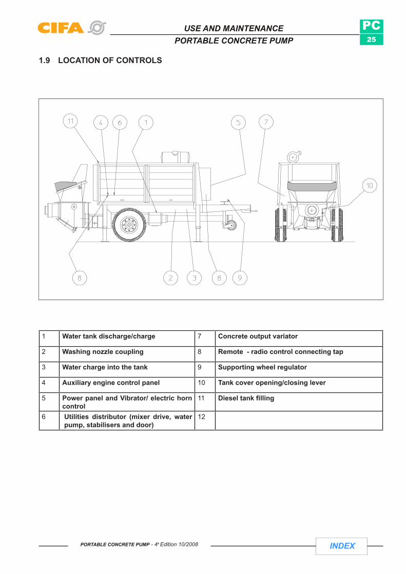
INDEX
PC25
PORTABLE CONCRETE PUMP - 4a Edition 10/2008
USE AND MAINTENANCEPORTABLE CONCRETE PUMP
1.9 LOCATION OF CONTROLS
1 Water tank discharge/charge 7 Concrete output variator
2 Washing nozzle coupling 8 Remote - radio control connecting tap
3 Water charge into the tank 9 Supporting wheel regulator
4 Auxiliary engine control panel 10 Tank cover opening/closing lever
5 Power panel and Vibrator/ electric horn control
11 Diesel tank filling
6 Utilities distributor (mixer drive, water pump, stabilisers and door)
12

INDEX
PC26
PORTABLE CONCRETE PUMP - 4a Edition 10/2008
USE AND MAINTENANCEPORTABLE CONCRETE PUMP
1.10 LOCATION OF SAFETY DEVICES
1 Mushroom-head STOP button 5 Stabilisers mechanical pin and shear pin
2 Auxiliary engine protective casing 6 Grid hopper mechanic clamp
3 Tank hatch limit-switch 7
4 Hopper grid opening protection 8

INDEX
PC27
1 2 3 4 5 6 7
8 9 10 11 12 13 14
15 16 17 18 19 20 21
22 23 24 25 26 27 28
PORTABLE CONCRETE PUMP - 4a Edition 10/2008
USE AND MAINTENANCEPORTABLE CONCRETE PUMP
1.11 KEY TO SYMBOLS
1 ACCELERATION/DECELERATION SELECTOR 12 STOP EMERgENCY
2 ENgINE START 13 PuMPINg STOP
3 ENgINE STOP 14 SOuND SIgNAL
4 CONTROL START INSIDE THE MACHINE 15 VALVE OuTLET
5 REMOTE CONTROL START 16 OIL PRESSuRE
6 PuMPINg 17 ALTERNATOR wARNINg LIgHT
7 SuCTION 18 VIbRATOR
8 ELECTRIC MOTOR STOP 19 Mixer rotation (Charge)9 CONCRETE OuTPuT VARIATOR 20 Mixer rotation (Discarge)10 START-uP RADIAL ENgINE 21 ExCHANgER
11 START-uP DELTA-CONNECTED ENgINE 22 wATER PuMP

INDEX
PC28
PORTABLE CONCRETE PUMP - 4a Edition 10/2008
USE AND MAINTENANCEPORTABLE CONCRETE PUMP
Page intentionally left empty

INDEX
PC29
PORTABLE CONCRETE PUMP - 4a Edition 10/2008
USE AND MAINTENANCEPORTABLE CONCRETE PUMP
SAFETY
Section B

INDEX
PC30
PORTABLE CONCRETE PUMP - 4a Edition 10/2008
USE AND MAINTENANCEPORTABLE CONCRETE PUMP
PAGE INTENTIONALLY LEFT EMPTY

INDEX
PC31
PORTABLE CONCRETE PUMP - 4a Edition 10/2008
USE AND MAINTENANCEPORTABLE CONCRETE PUMP
2 SAFETY
2.1 gENERAL PRECAuTIONS Employers are obliged to teach employees the instructions in the manual. •
Staff who use the machine (authorised operator) must have received previous training and have read the • manual. It is compulsory to keep a copy of the manual on-board the machine
The operator must never act according to the insistent and pressing instructions of the customer. •
WARNING: wear personal items of protection: helmet, goggles, gloves, ear-muffs, accident prevention shoes
Do not wear flowing garments but instead close-fitting overalls which are tight at the wrists and ankles.•
The standard version of the machine is not suitable for working in a potentially explosive atmosphere. •
To use the equipment in particular climates and atmospheres contact the CIFA technical departments. •

INDEX
PC32
FIG.3
FIG.4
Fig.1 Fig.2
PORTABLE CONCRETE PUMP - 4a Edition 10/2008
USE AND MAINTENANCEPORTABLE CONCRETE PUMP
Any replacement of components must be performed by following the rating. More particularly explosion-proof • components, in addition to having the same features, must also be approved (Fig. 1).
Do not remove the labels or plates situated on the machine. Should they be damaged, replace them immediately • with new plates (Fig. 2).
Never touch the engine exhaust silencer (risk of burns), moving • parts (sources of heat), pressurised pipes and points with cutting areas (e.g. sharp corners).
Do not lean or sit on any part of the machine when it is in • operation.
Do not place objects on the grid or the loading mouth. •
Do not leave tools, nuts or bolts between the drum movement rollers • or inside areas with rotating parts (Fig. 3).
Protect staff working near the equipment from possible bursts of • pipes on the ground or ceiling with adequate protective covers e.g. rigid panels or boards, anchoring them to the ground. WARNING: this safety technique must also be implemented near pedestrian routes (Fig. 4).
Adopt with special care the additives used for the concrete in that • they are corrosive and damaging to health.
Those in charge of laying concrete must have the psycho-physical • requisites pursuant to law.
Always have a fire extinguisher within reach. •
Do not use the controls and/or pipes as grips. •
Do not jump down from the machine but instead use the steps for • getting on or off, using the handrail and keeping the front part of the body turned towards the machine.
Always keep the footboards, mudguards, bonnets, cab and shoes • clean of oil, grease and diesel oil to avoid slipping .

INDEX
PC33
FIG.5
PORTABLE CONCRETE PUMP - 4a Edition 10/2008
USE AND MAINTENANCEPORTABLE CONCRETE PUMP
Immediately report to your employer, manager or those in charge the lack of devices and safety and protection • means, as well as any dangerous situations of which you are aware.
In the event of an emergency and as part of your own duties and possibilities, eliminate or reduce said lacks • or risks.
Do not remove or alter the devices or other means of safety and protection without prior authorisation (Fig. • 5).
Never leave surplus materials on the scaffolding, work places or transit routes, particularly if they have sharp • parts or projecting tips which could represent a risk in the event of falls.
Disinfect immediately any injuries, cuts or abrasions, albeit slight: often small scratches cause local infections, • even serious ones, and at times tetanus infections which can even be fatal.
Avoid exposure to sudden swings in temperature when perspiring. •
During work, check the movements of the tools carefully so as to avoid hitting or being hit. •
Do not use cracked spanners or other tools, in that if forced they may break. •
Report to your foreman or workmate who takes over from you on a new shift the state of the work and measures • to be adopted for safely proceeding with the same.
Do not cross mobile or suspended bridges before ensuring the stability of the boards. •
Never allow yourself to become distracted but act prudently when performing hazardous work. •
Before starting the shift check all the safety devices and report any shortages. •
Perform gradually start-ups, stops and any other manoeuvre. •
Keep the control station tidy and clean, avoiding build-up of inflammable material. •
In machines fed and/or driven electrically by a trailing cable left on the ground, ensure that the cable itself • cannot be damaged in any circumstance.
Do not walk on edges, pipes or low resistance surfaces. •
Only get on and off the machine when it is perfectly stable. •
Do not start up the engine in closed areas except where there is a good system for removing exhaust • fumes.
Avoid spending long periods of time in very • noisy areas; if this is not possible use personal protection means such as ear-muffs, plugs etc..

INDEX
PC34
PORTABLE CONCRETE PUMP - 4a Edition 10/2008
USE AND MAINTENANCEPORTABLE CONCRETE PUMP
Should the daily noise level absorbed by the operator be above 85 dB (A), periodical medical check-ups are • compulsory. In this respect we enclose the declaration made by the firm PASOL snc concerning assessment of noise exposure pursuant to Art. 46 of Decree Law 277/91 for an operator working with CIFA S.p.A. machines.
2.2 PASOL DECLARATION

INDEX
PC35
PORTABLE CONCRETE PUMP - 4a Edition 10/2008
USE AND MAINTENANCEPORTABLE CONCRETE PUMP

INDEX
PC36
PORTABLE CONCRETE PUMP - 4a Edition 10/2008
USE AND MAINTENANCEPORTABLE CONCRETE PUMP
2.3 DANgER OF INJuRY Although the machinery is built in compliance with general safety regulations, it is possible that during its use, ha-zardous situations may arise that put the integrity of the machinery and the safety of the operator at risk.
The following injuries may occur:
• Eye injuries due to sprayed concrete or additives
Injuries to eyes or skin due to leakage of hydraulic oil when wheel bolts are loosened before first relieving • pressure in the hydraulic circuit.
Danger of burns due to leakage of boiling oil or contact with very hot parts of the machinery.•
Injuries due to the bursting of joints or transport piping due to violent expulsion of obstructions from rubber • hoses transporting from the end piece.
• Electrical shocks (which may cause death) caused by: a) Improperly made electric connections b) Damaged power cable c) Contact with other electrical cables
Injuries due to pieces falling from the transport piping, in turn caused by partially loosened wheel bolts or • unfastened joints. Equipment which has been forgotten on the boom may also fall.
Injuries caused by falling parts. •
ATTENTION: Never open the transport piping when it is under pressure!
Injuries caused by slipping or falling on oiled or lubricated parts of the machinery•
ATTENTION: Do not touch moving parts of the machinery
Injuries caused by putting hands in the body of the rotor (when maintenance openings are not secured).•
Injuries caused by tripping on cables, wires and reinforcements.•
Injuries caused by pinching parts of the body in the cement mixer or its parts (channel).•
• Injuries caused by slipping or falling of transport piping that has not been secured.

INDEX
PC37
PORTABLE CONCRETE PUMP - 4a Edition 10/2008
USE AND MAINTENANCEPORTABLE CONCRETE PUMP
2.4 START-uP
Before any start-up, check work safety. If defects are found or even suspected, they must be immediately remedied, if necessary informing the supervision manager. If defects are found that jeopardize work safety, operations should be halted.
Take the necessary steps so that the machinery or plant are operated only under safe conditions and are functioning perfectly.
Start up the machinery only when all protection systems and all safety devices are present and functioning perfectly!
ENSURE THAT:the machinery is always operated in perfect condition:- no safety device is disconnected, put out of operation or modified (EMERGENCY STOP, grill on pump hopper,
etc.)
- safety devices removed for maintenance work are immediately reinstalled when work is completed.
- The machinery should have no defects visible to the naked eye (cracks, damage, loose or missing bolts, missing safety pins, rust on supporting parts, leaks, etc.). All oil leaks, even tiny ones, pollute underground
waters! Check the seal and lock on oil and water tanks (environmental protection).
2.4.1 OPERATING MATERIALS The operations necessary to make the machinery ready to operate also include the supply of operating materials.
HAZARD Oil, fuel, additives and other operating materials can be hazardous to health if they come into contact with the skin or other areas. For this reason, when handling materials that are toxic, corrosive, or hazardous to health in other ways, always wear personal protection equipment and follow the manufacturer’s instructions.
Always check all levels with the machine on a flat surface and ready for operation
2.4.2 TEST FUNCTIONINGAt least once a shift, check to see that the machinery or system has no damage or defects visible from the outside! Immediately inform the responsible body or person of any changes (including those relative to operating behavior)! If necessary, immediately stop the machinery and secure it!Before every use, the operator must check to be sure that the machine has no evident defects. It should also be verified that all command and safety devices, in particular the EMERGENCY STOP system, are functioning properly.

INDEX
PC38
PORTABLE CONCRETE PUMP - 4a Edition 10/2008
USE AND MAINTENANCEPORTABLE CONCRETE PUMP
2.4.3 EMERGENCY STOP BUTTON
PUSH EMERGENCY STOP TO STOP
ROTATE EMERGENCY STOP TO RESTART
The machinery must be provided with all safety and injury prevention devices (warning signals and instruction plates, protective grills, protective shelters, etc.). They should not be removed, modified or damaged.All command and control devices must be operational.
Place all command and control devices into position “O” before changing the type of command (command block, work place or remote control). Push the EMERGENCY STOP button. Otherwise, the machinery could perform undesired movements.Never leave the remote control when the machine is ready to operate. If this is unavoidable in exceptional cases, push the EMERGENCY STOP button, disconnect the remote control (remote control by cable) and lock it up in the driver’s cab.
To start up the machinery again, unlock the EMERGENCY STOP button by rotating it in the direction of the arrow.

INDEX
PC39
Fig.7
Fig.8
Fig.6
PORTABLE CONCRETE PUMP - 4a Edition 10/2008
USE AND MAINTENANCEPORTABLE CONCRETE PUMP
2.5 PRECAUTIONS FOR MAINTENANCE
Before carrying out any maintenance or replacement of parts ensure that: - the energy source (auxiliary engine or of the auto chassis) is switched off. - The key selector switch on the equipment control panel is set to “0”. - The keys for reactuating the energy source and the control panel must be kept by the person in charge of
operations. - Place a “MAINTENANCE IN PROGRESS” notice on the control panel. - When the machine is not in operation due to repairs or maintenance, it must only be put into operation by the
person in charge of the operations in progress.
Check all the components which equip the machine, following the • specific instructions manuals (cf. radio control, auto chassis, auxiliary engine etc.).
Check the safety devices periodically (cf.1.10): • - mushroom-head stop pushbutton - tank hatch limit switch - hopper grid limit switch - stabiliser mechanical clamp (Fig. 6)- concrete piping joint shear pins
Check the efficiency of the components of the electrical system (controls, • sound and light indicators).
Pay special attention should maintenance work have to be performed • on the hydraulic system of the equipment.
WARNING:before working on a hydraulic circuit, release pressure and wear protective gloves (risk of burns ).
Check that the arm or any part actuated by the hydraulic circuit is in a rest position (fig.8). •
Only use original CIFA S.p.A. spare parts. •
Non-routine maintenance must be carried out by a specialist technician, preferably from CIFA authorised • workshops.
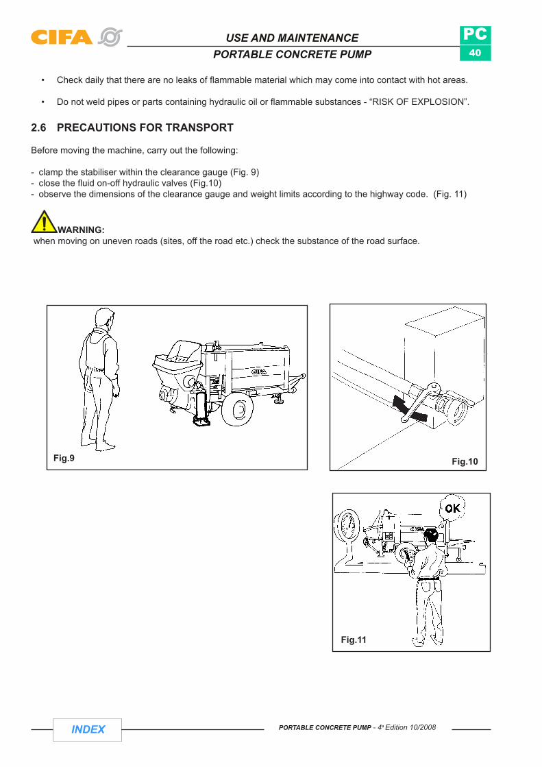
INDEX
PC40
Fig.10Fig.9
Fig.11
PORTABLE CONCRETE PUMP - 4a Edition 10/2008
USE AND MAINTENANCEPORTABLE CONCRETE PUMP
Check daily that there are no leaks of flammable material which may come into contact with hot areas. •
Do not weld pipes or parts containing hydraulic oil or flammable substances - “RISK OF EXPLOSION”. •
2.6 PRECAUTIONS FOR TRANSPORT
Before moving the machine, carry out the following:
- clamp the stabiliser within the clearance gauge (Fig. 9)- close the fluid on-off hydraulic valves (Fig.10)- observe the dimensions of the clearance gauge and weight limits according to the highway code. (Fig. 11)
WARNING: when moving on uneven roads (sites, off the road etc.) check the substance of the road surface.

INDEX
PC41
Fig.12
Fig.13
Fig.14
PORTABLE CONCRETE PUMP - 4a Edition 10/2008
USE AND MAINTENANCEPORTABLE CONCRETE PUMP
2.7 PRECAUTIONS FOR USE 2.7.1 General:
To qualify for travelling on the road, check that the machine has been approved on the basis of the highway • code.
In the event of failure or emergency, press the “STOP” mushroom-head • pushbutton on the machine or on the remote control or on the radio control (Fig. 12).
Before starting a manoeuvre give prior warning with the sound • indicator.
The equipment operator is responsible for the correct and reliable • stabilisation of the same.
Do not leave the machine at a standstill with concrete in the drum and/• or in the pipes (Fig. 13).
Wear personal protection means when using the equipment as sprays • or leaks of concrete from the hopper are possible (Fig. 14).
Always work in good light conditions: if necessary use artificial lighting. •
When using the machine, the operator is responsible for the whole area which forms the workplace of the • machine itself, which must be bordered off in a fully visible manner. Should the operator move away from the machine, the latter must be arranged in order to avoid non-authorised use or accidental movements.
Close off the working area of the machine to ordinary traffic.. •
Do not remove the barriers which prevent passage through hazardous areas.•
WARNING: before leaving the manoeuvre post, switch off the main switch of the machine, set the control parts to zero and remove the keys
WARNING: when starting up the engine or switching on the PTO, drum rotation, pumping and the utilities may function should the operator not have stopped all the functions before stopping the machine.
Before starting up the engine check that there is nobody in its immediate vicinity. •

INDEX
PC42
Fig.15
Fig.16
Fig.17
Fig.17/B
PORTABLE CONCRETE PUMP - 4a Edition 10/2008
USE AND MAINTENANCEPORTABLE CONCRETE PUMP
Sound the horn as warning before each manoeuvre. •
2.7.2 STABILISATION/POSITIONING THE MACHINE Check that there is sufficient space for stabilising/positioning the machine and check the distance from walls, • slopes and ducts.
The ground on which the stabilisers rest must be flat, even and sufficiently compact. Should these properties • not be guaranteed, use wooden joists as a resting base for the stabiliser arms, taking care that they are clean, i.e. free from traces of oil, grease or ice.
Position the stabilisers away from holes, slopes etc. (Fig. 15-• 16).
Do not cover any cavities in the ground with the wooden joists to • form a bridge (Fig. 17).
The arms of the stabilisers must be fully open and extracted. •
When stabilising, the operator must not stand in the area of opening • of the stabilisers.
Do not place your feet under the stabilisers when they are being • lowered.
After each stabilising operation reposition the mechanical safety clamps • of the stabilisers (Fig. 17/B).
WARNING: the ground may yield due to the vibrations.
Constantly check the stability of the machine on the resting surface when • it is in operation. If necessary restore optimal stability conditions.
Do not open the lever joints of the concrete piping during operation (they • are pressurised). After the pressure release manoeuvres (suction of the concrete in hopper for 1 or 2 cycles), protect in all cases the face by keeping it as far as possible from the opening of the joint .

INDEX
PC43
DIN 2413-III - Fig.18
PORTABLE CONCRETE PUMP - 4a Edition 10/2008
USE AND MAINTENANCEPORTABLE CONCRETE PUMP
WARNING:the hopper must always be full of concrete to avoid projections of material caused by suction of air alone.
In order to prevent possible explosions, check daily the thickness of the walls of the piping for concrete by • means of the special device and replace parts which are too worn. The minimum thickness of the piping can be found in the tables (Fig. 18).
X-axis = walls minimum thicknessY-axis = operating pressures
PL = Operating PressuresDN = Major Diameter
Reading example: if PL = 70 bar DN = 125 mm
Mark an horizontal line (line A) at height 70 on Y-axis, up to cross the right line DN 125. From crossing point, mark a vertical line (line B) up to cross the X-axis, which determines the piping minimum thickness = 2.9 [mm].
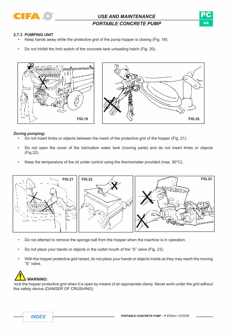
INDEX
PC44
FIG.19 FIG.20
FIG.21 FIG.22 FIG.23
PORTABLE CONCRETE PUMP - 4a Edition 10/2008
USE AND MAINTENANCEPORTABLE CONCRETE PUMP
During pumping: Do not insert limbs or objects between the mesh of the protective grid of the hopper (Fig. 21). •
Do not open the cover of the lubrication water tank (moving parts) and do not insert limbs or objects • (Fig.22).
Keep the temperature of the oil under control using the thermometer provided (max. 90°C). •
2.7.3 PUMPING UNITKeep hands away while the protective grid of the pump hopper is closing (Fig. 19). •
Do not inhibit the limit switch of the concrete tank unloading hatch (Fig. 20). •
Do not attempt to remove the sponge ball from the hopper when the machine is in operation. •
Do not place your hands or objects in the outlet mouth of the “S” valve (Fig. 23). •
With the hopper protective grid raised, do not place your hands or objects inside as they may reach the moving • “S” valve.
WARNING: lock the hopper protective grid when it is open by means of an appropriate clamp. Never work under the grid without this safety device (DANGER OF CRUSHING)

INDEX
PC45
PORTABLE CONCRETE PUMP - 4a Edition 10/2008
USE AND MAINTENANCEPORTABLE CONCRETE PUMP
3 TRANSPORT The equipment is generally supplied mounted on the auto chassis/chassis and ready for use. Should the equipment be supplied loose, (not mounted on the auto chassis/chassis or in separate modules) in order to handle it the staff must check the following: - WEIGHT. - CAPACITY OF THE HOISTING MEANS (e.g. overhead bridge crane etc.). - CHAINS, CABLES AND HOOKS dimensioned according to the weight of the equipment. - CAPACITY OF THE TRANSPORT VEHICLE (see technical data table).
3.1 HOISTING In order to hoist the equipment use the hooking points provided on the equipment and indicated in red or by indicator signals.
Should separate modules have to be lifted harness appropriately and safely the individual packages, observing the general rules of safety for suspended loads (WARNING: nobody must remain in the range of action of the load)
- In order to transport the equipment in separate modules, suitable containers for packing have to be prepared.

INDEX
PC46
PORTABLE CONCRETE PUMP - 4a Edition 10/2008
USE AND MAINTENANCEPORTABLE CONCRETE PUMP
Page intentionally left empty

INDEX
PC47
PORTABLE CONCRETE PUMP - 4a Edition 10/2008
USE AND MAINTENANCEPORTABLE CONCRETE PUMP
MACHINE FUNCTIONING AND OPERATING INSTRUCTIONS
Section C

INDEX
PC48
5
12
11
8
9
4
1 32
14
6
CENTRAL CONTROL BOX
10
30
25
2015
10
5
0 RPMX100
CG
CR
P1
10
7
13
10
GAS
PORTABLE CONCRETE PUMP - 4a Edition 10/2008
USE AND MAINTENANCEPORTABLE CONCRETE PUMP
4 USING THE MACHINE
4.1 MAIN CONTROL BOARD: DIESEL ENGINE VERSION

INDEX
PC49
PORTABLE CONCRETE PUMP - 4a Edition 10/2008
USE AND MAINTENANCEPORTABLE CONCRETE PUMP
1 Luminous button Pump
PUSH TO ACTIVATE THE “PUMP FUNCTION” When on (green), indicates that the pump is functioning
2 Luminous buttonSTOP – Pump/Suction Stops the Pump function (Pump/suction)
3 Luminous buttonSuction
PUSH TO ACTIVATE THE “SUCTION” FUNCTION When on (green), indicates that the suction function is active
4 Selector to enable com-mands
Selector to enable panel commands/remote control.Its position determines the work position, which may be from the control panel or the remote control
5 Button STOP diesel engine
6
GAS
Selector Selector to accelerate / decelerate diesel engine
7 Indicator Fuel level indicator
810
Key-operated switch Key-operated switch to turn on engine from panel
9 Indicator Engine oil temperature indicator
1030
25
2015
10
5
0 RPMX100
CG
Indicator Engine revolutions indicator

INDEX
PC50
PORTABLE CONCRETE PUMP - 4a Edition 10/2008
USE AND MAINTENANCEPORTABLE CONCRETE PUMP
11 Warning light Oil warning light
12 Warning light Warning light to indicate battery malfunction
13CR
Indicator Internal meter
1410
Selector Selector to open "S" valve
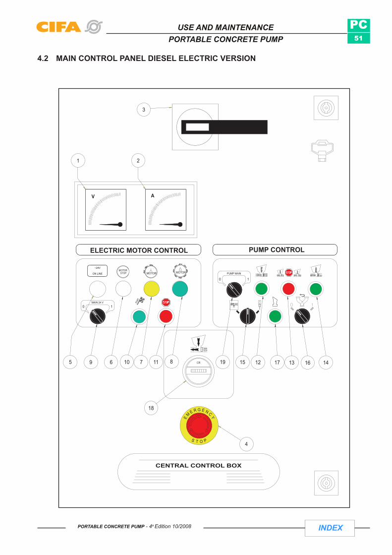
INDEX
PC51
CR
AV
10
STOP
STOP
24VON LINE
MOTOR
STOP
MOTOR
MOTOR
MAIN 24 V10 STAR
T
PUMP MAIN10
0 1PUMP MAINON LINE
~24V
MAIN 24 V0
CENTRAL CONTROL BOX
1
4
3
2
7
18
PUMP CONTROL
1
ELECTRIC MOTOR CONTROL
10695 11 8 19 15 12 17 13 16 14
PORTABLE CONCRETE PUMP - 4a Edition 10/2008
USE AND MAINTENANCEPORTABLE CONCRETE PUMP
4.2 MAIN CONTROL PANEL DIESEL ELECTRIC VERSION

INDEX
PC52
PORTABLE CONCRETE PUMP - 4a Edition 10/2008
USE AND MAINTENANCEPORTABLE CONCRETE PUMP
1 Voltmeter Indicates voltage of panel
2 Ammeter Indicates amperage of panel
3 3-phase disconnector Line master switch
4 Mushroom button MUSHROOM button for emergency stop. All panel functions are turned off
5 Indicator light When on, indicates that electric motor is in operation.
6 Indicator light When on, indicates that the electrical motor is in STOP
7 Indicator lightRadial motor turned on. When the electric motor is turned on, the light goes on for a few seconds before going into triangle mode
8 Indicator light The light goes on when the electrical motor is turned on
9MAIN 24 V
0 1
SelectorSelector to turn on or turn off the electric motor Note: The line master switch (3) must be turned on.
10 Button START electric motor
11 Button STOP electric motor
12 Luminous button Pump When on (green) indicates that the pump is in operation.
13 Luminous button STOP –Pump/Suction Stops the Pumping function (Pump/suction)

INDEX
PC53
PORTABLE CONCRETE PUMP - 4a Edition 10/2008
USE AND MAINTENANCEPORTABLE CONCRETE PUMP
14 Luminous button Suction
When on (green) indicates that the suction function is in opera-tion.
1510
STOP
STOP
24VON LINE
MOTOR
STOP
MOTOR
MOTOR
MAIN 24 V10 STAR
T
PUMP MAIN10
Selector to enablecommands
Selector to enable panel commands/remote control.Its position determines the work location, which may be from the control panel or by remote control.
1610
Selector Selector to open the "S" valve
17 Luminous button Acoustic signal
18 CR Meter Indicates actual hours of pumping
190 1
PUMP MAIN
Selector Selector to turn on pumping functions
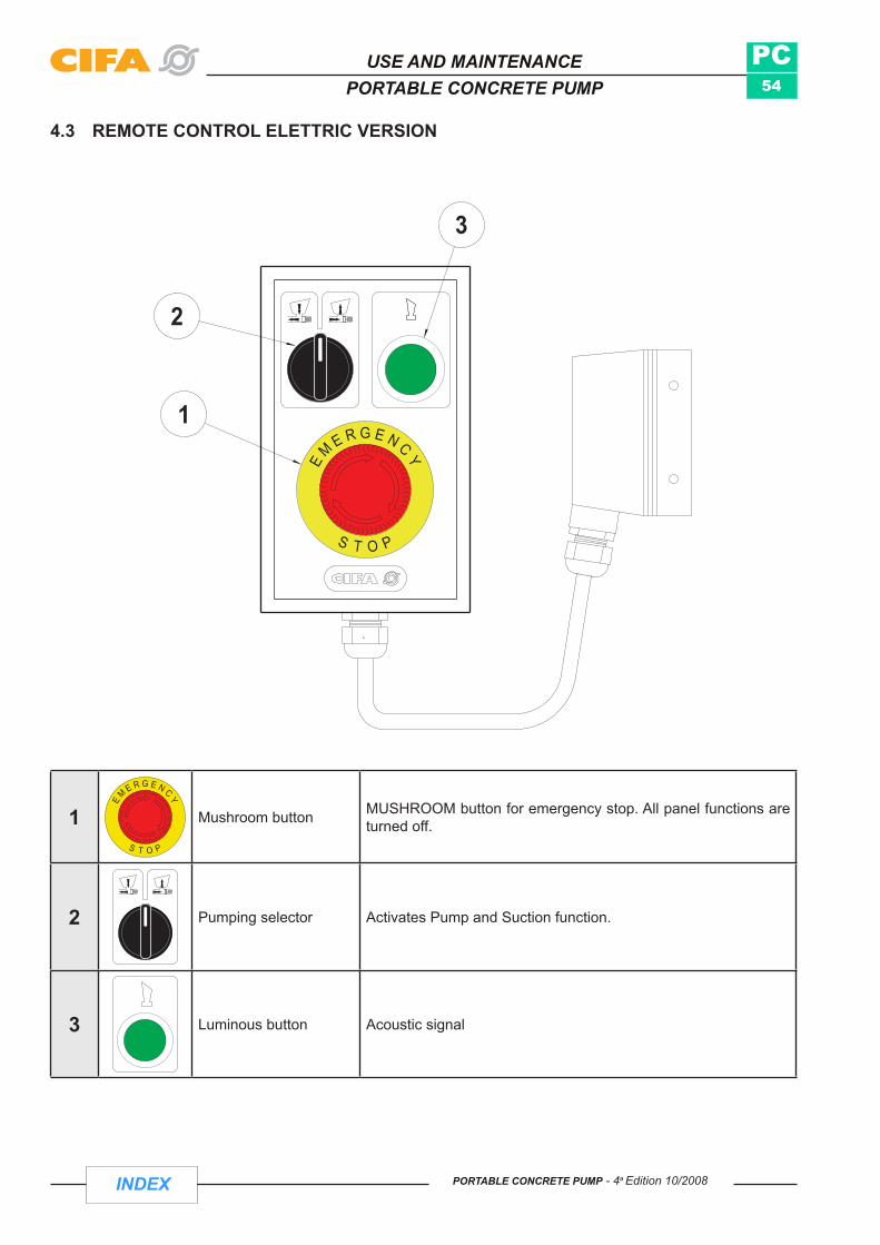
INDEX
PC54
1
2
3
PORTABLE CONCRETE PUMP - 4a Edition 10/2008
USE AND MAINTENANCEPORTABLE CONCRETE PUMP
1 Mushroom button MUSHROOM button for emergency stop. All panel functions are turned off.
2 Pumping selector Activates Pump and Suction function.
3 Luminous button Acoustic signal
4.3 REMOTE CONTROL ELETTRIC VERSION

INDEX
PC55
GAS
GAS
2
1
3
4
PORTABLE CONCRETE PUMP - 4a Edition 10/2008
USE AND MAINTENANCEPORTABLE CONCRETE PUMP
1 Horn/vibrator switch
Switch with 3 check positions:- UP: Warning acoustic signal - MIDDLE: Neutral position - DOWN: Powers Hopper Vibrator
2 Pump/suction switch
Switch with 3 check positions:- UP: Activates “PUMP” pumping function - MIDDLE: Neutral position- DOWN: Activates “SUCTION” pumping position
3 DIESEL engine revolu-tions switch
Switch with 3 check positions:- UP: Increases number of engine revolutions- MIDDLE: Neutral position - DOWN: Decreases number of engine revolutions
4 STOP button All functions stopped
4.4 REMOTE CONTROL: DIESEL ENgINE VERSION

INDEX
PC56
cod.218566
PORTABLE CONCRETE PUMP - 4a Edition 10/2008
USE AND MAINTENANCEPORTABLE CONCRETE PUMP
1 Two-position lever UP: Clockwise rotation (Load) for mixer
DOWN: Counter-clockwise rotation for hopper mixer (Unload)
2 Two-position lever UP: Activates water pump
DOWN: Activates radiator
4.5 SERVICES DISTRIbuTOR

INDEX
PC57
PORTABLE CONCRETE PUMP - 4a Edition 10/2008
USE AND MAINTENANCEPORTABLE CONCRETE PUMP
4.6 EQuIPMENT 4.6.1 MACHINE VERSION The machine can be supplied in two versions:
a) Trailer-mounted pump = PC b) Trailer-mounted shotcreting pump = PCS
Both versions can be powered by diesel engine or electric motor. 4.6.2 MOUNTING THE EQUIPMENT In general the equipment is mounted on the auto chassis/chassis by CIFA S.p.A. In this case the machine is ready for use in that a general test is performed before delivery.
Should the equipment be supplied loose, the relevant drawings and assembly diagrams are enclosed with each module.
WARNING: Always contact an authorised service workshop for full assembly of the equipment.
Checks The machine is delivered after inspections and tests, therefore special checks are not required.
Nevertheless always check the good working order of all the safety and protection devices. Check that: • - all the protective casings are mounted and firmly fastened. - All the limit switches are active (arm rotation, tank unloading hatch etc.). - The protective grid on the hopper is closed. - The emergency stop mushroom-head pushbutton is working. - The acoustic indicator works. - The concrete distribution piping is free from any clogging or blocks. - The rapid attachment joints of the concrete piping (collars) are closed and restrained by the shear pin. - The concrete piping is not excessively worn - otherwise REPLACE IT
4.7 TRANSFERBefore transfer, check fuel level on fuel gauge•
The machine can be towed using the hook at a maximum speed of 6 kph.•
cod. 234927
VELOCITA' MAX. 6 Km/hVITESSE MAX. 6 Km/hMAX.SPEED 6 Km/hMAX.GESCHWINDIGKEIT 6 Km/h

INDEX
PC58
cod. 234898
PORTABLE CONCRETE PUMP - 4a Edition 10/2008
USE AND MAINTENANCEPORTABLE CONCRETE PUMP
WARNING: Before towing, check that manual jacks are closed and locked by the plug with safety device.
4.8 POSITIONINg AND STAbILISATION OF MACHINEOn arrival at the site, place barriers and warning signs around the area in which the machine is to operate, • near roads or footpaths, to prevent access by any person or vehicle to the area.
No-one apart from the operator (who is responsible for the machine and its operation) must remain near the • machine operating area.
Move the machine to the place of operation and ensure that the ground is firm and level.•
Check that there are no people or things within the operating range of the machine.•
Prevent frame wheels from moving.•

INDEX
PC59
PORTABLE CONCRETE PUMP - 4a Edition 10/2008
USE AND MAINTENANCEPORTABLE CONCRETE PUMP
Stabilise machine.•
Lower front of machine as far as possible (using the support legs).•
Remove mechanical catch from rear jacks (1)•
Extend rear jacks until they reach the ground (2)).•
Insert mechanical catch with safety pin.•

INDEX
PC60
PORTABLE CONCRETE PUMP - 4a Edition 10/2008
USE AND MAINTENANCEPORTABLE CONCRETE PUMP
Raise front part using support legs.•
Use a spirit level to ensure that the machine is horizontal.•
WARNING: - check that the ground below the stabilisers does not yield - check that all the mechanical clamps have been returned - check that all the stabilisation controls are set to “0”.

INDEX
PC61
Fig.10 Fig.11 Fig.12
Fig.13 Fig.14 Fig.15
Fig.16 Fig.17 Fig.18
PORTABLE CONCRETE PUMP - 4a Edition 10/2008
USE AND MAINTENANCEPORTABLE CONCRETE PUMP
Should the ground not be sufficiently solid, use distribution plates or compact wooden panels for better distribution of the stabilisers on the ground (square 15 x 15 joists).
The pump operator is obliged to stabilise the machine in accordance with the various conditions of the ground (from Fig.10 to Fig.18).
This means that, according to the degree of stability of the ground (kN/m2), the original support plates of the stabilisers must be “enlarged” by applying larger rest surfaces in order to avoid sinking of the support feet.
As accessories 4 support plates (60 x 60 cm or 50 x 50 cm) in plastic are provided and which, used as a simple support base, can cover a more extensive area in relation to the vertical loads and to the permitted contact pressure.
If a larger support surface is required, the user must provide adequate square wooden joists (15 x 15 cm) - four for each support plate.
The table indicates to what extent the support surfaces are sufficient or whether the above joists also have to be applied.
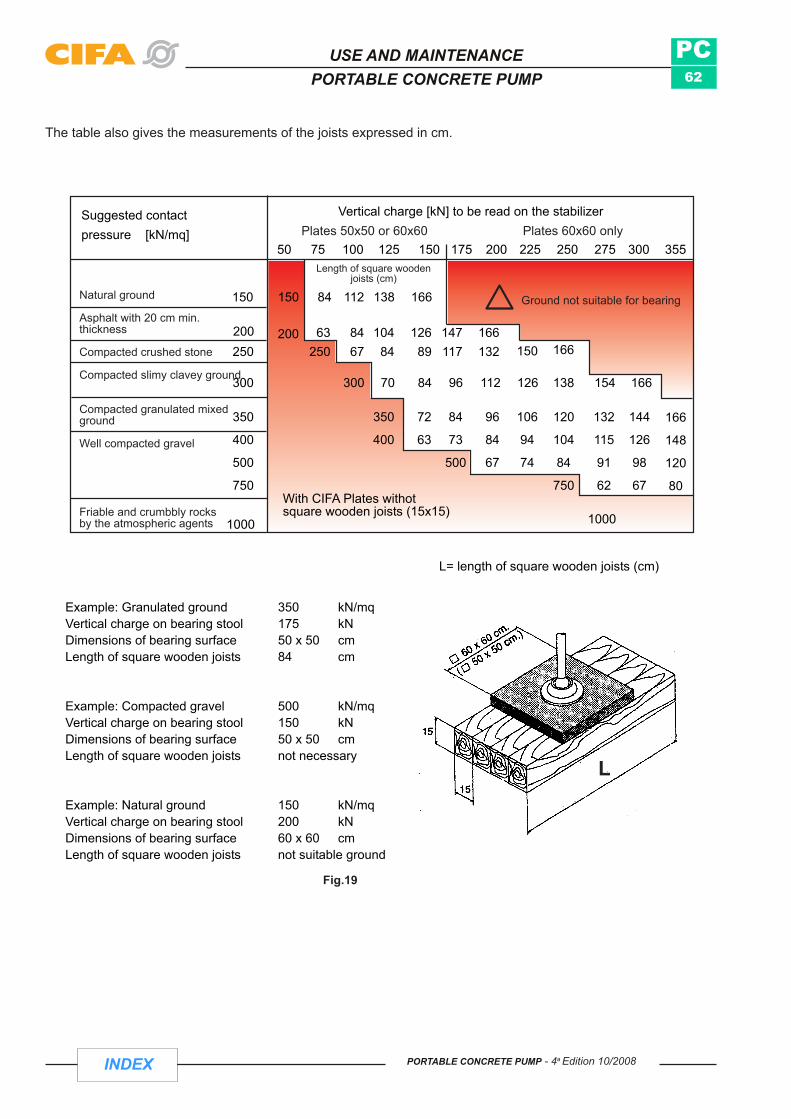
INDEX
PC62
PORTABLE CONCRETE PUMP - 4a Edition 10/2008
USE AND MAINTENANCEPORTABLE CONCRETE PUMP
Vertical charge [kN] to be read on the stabilizer
pressure [kN/mq]50 75 100 125 150 175 200 225 250 275 300 355
Ground not suitable for bearing
With CIFA Plates withotsquare wooden joists (15x15) 1000
Natural ground
Asphalt with 20 cm min.thickness
Compacted crushed stone
Compacted slimy clavey ground
Compacted granulated mixedground
Well compacted gravel
Friable and crumbbly rocksby the atmospheric agents 1000
L= length of square wooden joists (cm)
166
148
120
80
144
126
98
67
132
115
91
62
120
104
84
750
106
94
74
96
84
67
84
73
500
72
63
350
400
350
400
500
750
Example: Granulated groundVertical charge on bearing stoolDimensions of bearing surfaceLength of square wooden joists
350 kN/mq175 kN50 x 50 cm84 cm
Example: Compacted gravelVertical charge on bearing stoolDimensions of bearing surfaceLength of square wooden joists
500 kN/mq150 kN50 x 50 cmnot necessary
Example: Natural groundVertical charge on bearing stoolDimensions of bearing surfaceLength of square wooden joists
150 kN/mq200 kN60 x 60 cmnot suitable ground
Suggested contactPlates 50x50 or 60x60 Plates 60x60 only
Length of square woodenjoists (cm)
63250
8467
10484
12689
147117
166132 150 166250
200200
138 154 166126112968470300300
150150 84 112 138 166
L
Fig.19
The table also gives the measurements of the joists expressed in cm.

INDEX
PC63
PORTABLE CONCRETE PUMP - 4a Edition 10/2008
USE AND MAINTENANCEPORTABLE CONCRETE PUMP
4.9 CONCRETE PuMPINgConnect concrete distribution piping supplied with the machine to the site concrete distribution network.•
NOTE: Check that the pipe spacers correspond
In particular, in the case of the PCS version:
1) Connect rubber terminal fitted with spray nozzle to the ends of the concrete distribution network2) Prepare the connection between admixture tank and admixture pump and between admixture pump and spray nozzle.
WARNING: Admixtures are generally corrosive substances, so suitable methods of personal protection should be adopted.
Do not discharge admixture into the environment.
All materials which come into contact with the admixture must be able to withstand the corrosion of the admixture.
3) Connect the compressed air pipes at one end to the site network and at the other to the manifold which feeds the spray nozzle and the pneumatic vibrator on the hopper.
Operating pressure 4 to 6 bars.
For both versions (PC and PCS): In the case of the diesel engine:1) Insert key into selector switch 8 (key-operated motor start switch) and turn to switch on motor (Fig. 49).
In the case of the electric motor:1) Connect site mains electricity cable to main control board.
WARNING:- Check that the data on the rating plate of the electric motor of the machine correspond to the specifications of the mains.- Avoid damage to power cable; risk of electrocution.- As the machine is powered at 380V, take particular care with all maintenance operations.
2) From main control board, turn line master switch to power the board3) Turn 24V key-operated selector switch to power 24V electrical circuit.4) Press electric motor start button to start motor.

INDEX
PC64
Fig.20
Fig.21
PORTABLE CONCRETE PUMP - 4a Edition 10/2008
USE AND MAINTENANCEPORTABLE CONCRETE PUMP
Before starting concrete pumping, check that there is water in the lubrication tank; top up if necessary.•
To lubricate concrete conveyer pipes, pour an amount of cement grout, consisting of two parts cement, one part fine sand and sufficient water to make a mixture of fluid consistency, into the hopper. The amount of mixture used should be about equal to half the volume of the piping to be lubricated .
Operate mixer rotation lever from service distributor to rotate mixer .•
In the PC version, to pump via the main control board:
Activate pump button to begin pumping stage, feeding the hopper with concrete and maintaining the optimum • level to prevent air suction.
In the PCS version, to pump via the main control board:
1) Turn on air tap supplying spray nozzle and pneumatic vibrator.
WARNING: Two people are needed to perform these operations; one holds the spray nozzle still and the other effects the regulations.
2) Operate admixture pump from service distributor using lever.3) Adjust admixture flow rate with potentiometer from main control board4) Activate pump button to commence shotcreting stage.

INDEX
PC65
Fig.22 Fig.23
Fig.24
PORTABLE CONCRETE PUMP - 4a Edition 10/2008
USE AND MAINTENANCEPORTABLE CONCRETE PUMP
WARNING: Shotcrete has a max. particle size of 10 mm to prevent blockage of piping with dangerous consequences.
WARNING:Do not open lever-operated concrete piping joints during pumping.•
The hopper should always be full of concrete to prevent projections of material caused by suction of air only•
Do not insert limbs or objects through the holes in the hopper protection grid (Fig. 22).•
Do not open lubrication water tank lid while pumping unit is moving (Fig. 23).•
Do not insert limbs or objects which could come into contact with the S-valve (Fig. 23).• .
In the event of blockage do not keep pumping, but run a few suction cycles to clear the pipes.•
Never leave concrete piping under pressure.•

INDEX
PC66
PORTABLE CONCRETE PUMP - 4a Edition 10/2008
USE AND MAINTENANCEPORTABLE CONCRETE PUMP
During pauses in pumping with very fluid concrete containing a large proportion of coarse aggregates, which • tend to separate from the water, let the machine pump empty, and in any case keep mixer operating at all times to prevent segregation of constituents.
In the case of longer pauses aspirate concrete in hopper, mix and pump (not applicable to PCS version; in • this case, perform cleaning operations)
If the pauses are very long, switch off the propulsion motor so that the vibrations do not separate the concrete • (not applicable to PCS version; in this case, perform cleaning operations)
If the machine does not operate for 10-15 mins., move the concrete by pumping and aspirating alternately. In the • case of the PCS, also switch off admixture pump and leave open the air, which cleans as it flows through.
Never force concrete which has separated or is becoming lumpy due to solidification through pipes.•
In particular, in the case of concrete with a low ability to retain water, it is best to avoid pauses in pumping; • when work begins, pump backwards until the valve fully exchanges from both sides, then start pumping forwards again.
In the case of both versions (PC/PCS), when pumping/shotcreting operations are to be remote controlled:connect cable supplied to control board on machine • turn board/remote control enable selector switch on main control board of machine to “remote control” • activate pumping function by turning selector switch on remote control •
In the case of the PCS, to regulate concrete flow from pump to spray nozzle, operate concrete regulation handwheel located near motor.

INDEX
PC67
PORTABLE CONCRETE PUMP - 4a Edition 10/2008
USE AND MAINTENANCEPORTABLE CONCRETE PUMP
4.10 MACHINE CLEANINgCleaning with pressurised water from the washing pump is one of the most common methods used. For this purpose, operate service distributor lever (1).
4.10.1 CLEANING CONCRETE DISTRIBUTION PIPES
Stop pumping•
In the case of the PCS, when the pumping stage has finished, stop admixture pump by operating distributor, • close air supply, remove spray nozzle and immediately wash it separately.
Empty hopper as far as possible by pumping the material out. Pump one or two strokes backwards to eliminate • pressure in pipes.
Stop pumping.•
Open piping in the 5" section.•
Press sponge cleaning balls impregnated with water into the opening.•
Close piping.•
Pump until sponge balls exit from the pipes, adding water to the hopper.•
WARNING: Protect the end of the concrete pipe during cleaning operations to prevent dangerous projections of material.
Open tank outlet bend.•
Release concrete tank hatch mechanical safety catch, and open the hatch.•
Insert key into main control board, turn to “board” position and press pump button to allow valve exchange. • When the button is released, as the concrete tank unloading hatch is open, the movement of the S-valve is inhibited. Warning : do not insert limbs or objects through the tank unloading hatch during these operations.

INDEX
PC68
Fig.27
FIG.20FIG.23
PORTABLE CONCRETE PUMP - 4a Edition 10/2008
USE AND MAINTENANCEPORTABLE CONCRETE PUMP
Thoroughly wash hopper, concrete bends, S-valve, pumping pistons • and cylinders. In particular, check that there are no concrete residues in the bottom of the S-valve. If necessary, continue until all parts which have come into contact with the concrete are seen to be clean.
In the case of the PCS, to wash admixture piping and admixture • pump, disconnect pump from admixture tank and connect to site water supply.
Activate admixture pump from service distributor and run a few • washing cycles.
WARNING: Do not discharge admixture and/or mixtures of water and admixture into the environment, but collect it in special containers.
To wash spray nozzle, dismantle it completely and wash all its parts with water. Check that there are no • blocked holes or worn parts.
The machine is fitted with the following safety devices:
A valve which prevents movement of the mixing shaft when the hopper protection grid is open.•
An inductive proximity limit switch which inhibits movement of the S-valve when the concrete tank unloading hatch is open.
WARNING:Do not insert limbs or objects into the tank outlet union when the bend is open or the pump is operating • (shearing risk) (Fig. 23).Do not open concrete pipes without checking that there is no pressure in them. To prevent this, run a few • suction cycles.Do not inhibit the limit switches (Fig.20)•
When the cleaning stages are finished:- Place service distributor lever in neutral position- Return tools used to toolbox- Close tank hatch and concrete piping.

INDEX
PC69
PORTABLE CONCRETE PUMP - 4a Edition 10/2008
USE AND MAINTENANCEPORTABLE CONCRETE PUMP
4.11 END OF OPERATINg CYCLEWhen the pumping/shotcreting stage is finished, wash the equipment, following the instructions in the cleaning chapter
NOTE: If special admixtures are used, wash all the equipment as soon as possible.
When the equipment has been cleaned and the pumping unit shut down:Return remote control to cab or toolbox• Remove mechanical catches on extensible part of jacks• Insert mechanical catches and corresponding safety pins of jacks in flat transport position• Deactivate main control board by turning key-operated selector switch to position “0” • Before transferring the equipment check that all connections (concrete piping, air piping, admixture piping, • electric wiring) have been physically disconnected
4.12 STOPPINgThe machine has a mushroom-head pushbutton for emergency stop, red on a yellow background, which allows the primary energy source to be switched off (auto chassis/auxiliary engine) and is located both on the machine and on the remote control (remote control)
This pushbutton is normally used for stopping the equipment at the end of the cycle or day’s work.
To start up the engine again the emergency stop mushroom-head pushbutton has to be reset by rotating and extracting the pushbutton.
WARNING: when starting up the engine or the power takeoffs, drum rotation, pumping and the utilities may function, should the operator not have zeroed all the functions before stopping the machine.
Should the machine remain unused for long periods, before starting it up again contact an authorised workshop for the appropriate checks.
4.13 gENERAL CLEANINg
4.13.1 Washing the machines with hydrocleaners
If hydrocleaners are used to wash the machines, the process must not be carried out at distances of less than 15 - 20 cm. It is not advisable to continue spraying on a single point of the painted surface, but instead to wash with broad strokes. Hydrocleaners witih rubber guards at the end of the spraying nozzle should be used to avoid hitting the paintwork with metal objects. The temperature of the water must not exceed 60 - 70°C. Note that a deteriorated or scratched film may peel when washed at a pressure of considerable force.
N.B. In order to prevent the cement and concrete from adhering to the equipment and thus facilitate cleaning and washing, the equipment should be sprayed with a layer of paraffin, wax, mechanical oil or other commercially available products. Perform this operation each time the machine is washed or when required.
If the machine is sold to another user, notify CIFA of the change in ownership.

INDEX
PC70
PORTABLE CONCRETE PUMP - 4a Edition 10/2008
USE AND MAINTENANCEPORTABLE CONCRETE PUMP
PAGE INTENTIONALLY LEFT EMPTY

INDEX
PC71
PORTABLE CONCRETE PUMP - 4a Edition 10/2008
USE AND MAINTENANCEPORTABLE CONCRETE PUMP
ROUTINE MAINTENANCE
Section D

INDEX
PC72
PORTABLE CONCRETE PUMP - 4a Edition 10/2008
USE AND MAINTENANCEPORTABLE CONCRETE PUMP
PAGE INTENTIONALLY LEFT EMPTY
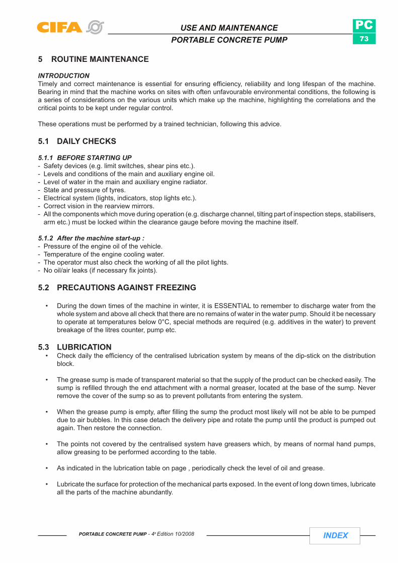
INDEX
PC73
PORTABLE CONCRETE PUMP - 4a Edition 10/2008
USE AND MAINTENANCEPORTABLE CONCRETE PUMP
5 ROUTINE MAINTENANCE
INTRODUCTION Timely and correct maintenance is essential for ensuring efficiency, reliability and long lifespan of the machine. Bearing in mind that the machine works on sites with often unfavourable environmental conditions, the following is a series of considerations on the various units which make up the machine, highlighting the correlations and the critical points to be kept under regular control.
These operations must be performed by a trained technician, following this advice.
5.1 DAILY CHECKS
5.1.1 BEFORE STARTING UP - Safety devices (e.g. limit switches, shear pins etc.). - Levels and conditions of the main and auxiliary engine oil. - Level of water in the main and auxiliary engine radiator. - State and pressure of tyres. - Electrical system (lights, indicators, stop lights etc.). - Correct vision in the rearview mirrors. - All the components which move during operation (e.g. discharge channel, tilting part of inspection steps, stabilisers,
arm etc.) must be locked within the clearance gauge before moving the machine itself.
5.1.2 After the machine start-up :- Pressure of the engine oil of the vehicle. - Temperature of the engine cooling water. - The operator must also check the working of all the pilot lights. - No oil/air leaks (if necessary fix joints).
5.2 PRECAUTIONS AGAINST FREEZING
During the down times of the machine in winter, it is ESSENTIAL to remember to discharge water from the • whole system and above all check that there are no remains of water in the water pump. Should it be necessary to operate at temperatures below 0°C, special methods are required (e.g. additives in the water) to prevent breakage of the litres counter, pump etc.
5.3 LUBRICATION Check daily the efficiency of the centralised lubrication system by means of the dip-stick on the distribution • block.
The grease sump is made of transparent material so that the supply of the product can be checked easily. The • sump is refilled through the end attachment with a normal greaser, located at the base of the sump. Never remove the cover of the sump so as to prevent pollutants from entering the system.
When the grease pump is empty, after filling the sump the product most likely will not be able to be pumped • due to air bubbles. In this case detach the delivery pipe and rotate the pump until the product is pumped out again. Then restore the connection.
The points not covered by the centralised system have greasers which, by means of normal hand pumps, • allow greasing to be performed according to the table.
As indicated in the lubrication table on page , periodically check the level of oil and grease. •
Lubricate the surface for protection of the mechanical parts exposed. In the event of long down times, lubricate • all the parts of the machine abundantly.

INDEX
PC74
PORTABLE CONCRETE PUMP - 4a Edition 10/2008
USE AND MAINTENANCEPORTABLE CONCRETE PUMP
WARNING:Before lubricating, clean the greasing gun nozzle to avoid extraneous material being mixed with the grease and damaging the pins and bushings. Optimum lubrication is obtained by regenerating and filling completely the appropriate housings with new lubricant. Check that by feeding new lubricant into the housings the old lubricant is expelled.
If during lubrication a guard has to be removed, proceed as follows: - Pay special care during maintenance. - Replace the guard before using the machine .
The pistons of the pump unit can be lubricated as follows: 1) Bring one of the pistons to the end of stroke. 2) Using the greaser lubricate the piston which is near the lubrication water tank. 3) Perform the opposite manoeuvre for the other piston.
We recommend carrying out this operation every 50 hours.
5.4 PUMP UNIT Before starting the pumping phase check that there is water in the lubrication tank. •
Replace the water daily and replace it in any case if it is dirty. •
Should there be water or oil in the tank, the gasket of the hydraulic pistons has to be replaced (call for technical • assistance).
Should however there be excess grout in the water of the tank, the concrete pistons have to be replaced (call • for technical assistance).
Check that there is no oxide (lack of chrome) on the surface of the concrete barrels. •
Check the state of wear of the ring and the wear plate. Should there be excessive grooves and wear replace • them .
Check the wear on the concrete pipes using a hammer or thickness gauge (see references in the table on • page.
5.5 STRUCTURAL CHECK (STRUCTURAL FAULTS) The structural checks for the arm, turret, subturret, base frame, stabilisers, support frames, reduction gear and drum include the following:
Soundness of the anchorages and supports (between equipment and auto chassis, support of the pump • units water tank, drum reduction gear, concrete mixer frames, concrete pipe supports, supports for additional channels).
Soundness of the bolts and tightness (above all check the torque wrench setting of the bolts; see table of the • “general information” manual).
State of the materials (possible cracks and breakages of the framework and in the components). An indicator • of structural problems is very often rust.
Welds.•
he pins and bushings (possible seizures).•
The play caused by excessive wear between parts in reciprocating motion (e.g. arm joints). •

INDEX
PC75
PORTABLE CONCRETE PUMP - 4a Edition 10/2008
USE AND MAINTENANCEPORTABLE CONCRETE PUMP
WARNING:- Restore, if necessary, by welding (non-routine maintenance, contact an authorised workshop). - The structures of the arm, and in general the bearing structures made in special high resistance steels, should not be modified in any way or weakened by welds or holes for attachments.
5.6 CHECK ON HYDRAULIC COMPONENTS
Given the complexity of the machine, we always recommend contacting specialists for work on the hydraulic part.
If defects are found, check on the causes and restore the wholeness of the circuit before carrying out any • manoeuvres.
Find any oil leaks and eliminate the causes.•
- Inspect safety valves and rigid and flexible hydraulic pipes, joints and cylinders, to discover any wear or • leaks (bursting of a worn-out pipe could have serious consequences).
- Check the pipes which from the safety valve connect to the inlet mouths of each cylinder, ascertaining • that there are no leaks nor deformations caused by impact or wear and that the joints are whole and fully locked.
Replace immediately any damaged pipes. •
It is forbidden to change the original setting: any regulation or calibration must be performed by specialist • staff .
It is forbidden to tamper with hydraulic components which would render the warranty and liability of the supplier • null and void.
WARNING:- Before working on a circuit ensure that it is not pressurised and check that the accumulators have been dischar-
ged. It is essential that the arm or the element actuated by the hydraulic circuit is in a rest position and not under stress.
- Given that the oil can reach high temperatures with the risk of serious burns, adequate protection means must be worn before opening a joint.
- Any replacements of components must be made in observance of the manufacturer’s rating.
5.7 CHECK ON ELECTRICAL COMPONENTS Check on the efficiency of the components of the electrical system. •
Any replacement of components must be made in observance of the rating: above all anti-explosion components • must be replaced with those having the same characteristics and approved.
5.8 REPLACING ENGINES Diesel or electric engines in anti-explosion machine versions must be replaced with engines having the same • features and approved.
5.9 CONCRETE PIPES The correct diameter and thickness of the pipes together with their state of wear, the correct type of joints, • their efficiency and closure with a safety lock are essential for eliminating risks and problems during pumping. Periodically, according to the type and thickness, the pipes should be inspected to check their state of wear.
•

INDEX
PC76
PORTABLE CONCRETE PUMP - 4a Edition 10/2008
USE AND MAINTENANCEPORTABLE CONCRETE PUMP
We recommend frequent checks on the sections most exposed to wear every 1000 cu. m. of casting. •
Check frequently (according to the abrasive nature of the material pumped) the state of wear of the pipes • and replace them when the thickness is less than the value indicated on the table (see table). The check can be carried out by hitting the pipe with a hammer; according to the type of sound heard, the thickness can be assessed. More scientifically it is possible to use equipment which is readily available on the market for a non-destructive test.
For even wear and hence for longer life the pipes should be rotated periodically: clockwise rotation through • 120° every 5/6000 cu. m. of casting for pipes and a reverse of 180° for bends.
WARNING:- Do not alter the original dimensions of the pipes laid down by the manufacturer. - When using high pressures for concrete adopt appropriate pipes. - Ground-anchored pipes and bends located at a distance of less than three metres from staff must be changed
when the stated thicknesses are achieved and in any case more frequently.
5.10 WATER CIRCUIT During cold weather the water system of the machine must be emptied at the end of the day’s work to avoid • breakage of the water pump and of parts of the system due to freezing.
The system can be emptied by means of the ball valves. •
For more detailed information consult the specific instructions manual enclosed (water pump). •
Periodically clean the tank to eliminate scale as frequently as the degree of impurity in the site water is high. •
Remember that with very dirty water containing sand, the pipes may become clogged, particularly near the • tank attachment.
Check that the thickness of the tank is not worn (check to be performed every 6 months).•
5.11 ELECTRICAL SYSTEM Check the efficiency of all the electrical control components. •
Make sure that the cables are perfectly insulated, particularly at cable ties and pressure cables, in order to • avoid short circuits which could damage other components.
Also check that the connection points are perfectly tight and do not have oxidations. •
Always make sure that the electrical system is perfectly connected to the earth. •
6 DISPOSAL Do not pollute the environment with used oil, batteries or rubber parts but dispose of them carefully.•
The metal structure should be disposed of as old iron.•
If the machine is sold to another user, notify CIFA of the change in ownership. •

INDEX
PC77
PORTABLE CONCRETE PUMP - 4a Edition 10/2008
USE AND MAINTENANCEPORTABLE CONCRETE PUMP
TABLES AND ATTACHMENTS
Section E

INDEX
PC78
PORTABLE CONCRETE PUMP - 4a Edition 10/2008
USE AND MAINTENANCEPORTABLE CONCRETE PUMP
PAGE INTENTIONALLY LEFT EMPTY

INDEX
PC79
PORTABLE CONCRETE PUMP - 4a Edition 10/2008
USE AND MAINTENANCEPORTABLE CONCRETE PUMP
20005002005025
ISO VG 46
ISO VG 150
1
2
3
4
5
6
7
8
REFERENCEPOS.LUBRICATION
INTERVALS (hours) LUBRICANTS REMARKS
1st REPLACEMENT AFTER 200 h
TANK EXHAUST FILTER
HYDRAULIC OIL IN THE TANK
RETURN FILTER
LUBRICATING WATER FOR CONCRETE CYLINDERS
VALVE CYLINDER AND MIXER SHAFT ARTICULATIONS
GREASE PUMP
DEPENDING ON EN VI RON -MEN TAL CONDITIONS
S
DAILY REPLACEMENT
I
C
WATER
S
WITHIN 1 YEAR MAXC
S
GREASE NLGI 2
GREASE NLGI 2
MIXING SHAFT REDUCER S 1st CHANGE AFTER 100 hWITHIN 1 YEAR MAXC
SEE USE AND MAIN TE NAN CE BOOKAUXILIARY ENGINE AS PER MANUFACTURER's
INSTRUCTIONS
S = REPLACE C = CHECK LEVEL AND REFILL I = GREASE
LUBRICATIONK000235953-01
N.B.: THE A.M. PRODUCTS ARE THOSE USED AS FIRST EQUIPMENT. IF YOU WANT TO USE DIFFERENT BRANDS, SEE THE CAMPARISON SCHEDULE IN THE ISTRUCTIONS MANUAL.
7 DISPOSAL OF uSED ITEMS

INDEX
PC80
HYDRAULIC FLUID
Requirements standard DIN 51 524 Part 2Characteristics MINERAL OILViscosity grade in accordance with DIN 51 519
ISO VG 32 ISO VG 46 ISO VG 68
Winter Standard Tropical
Marking in accordance with DIN 51 502 HLP HVLP HLP HVLP HLP HVLP
AGIPOSO 32 ARNICA 32 OSO 46 ARNICA 46 OSO 68 ARNICA 68
H Lift 46
ARAL ARAL Vitam GF 32
ARAL Vitam HF 32
ARAL Vitam GF 46
ARAL Vitam HF 46
ARAL Vitam GF 68
AVIAAVIA Fluid RSL32 AVIA Fluid HVI 32 AVIA Fluid RSL46 AVIA Fluid HVI 46 AVIA Fluid RSL68 AVIA Fluid HVI 68
AVIA Fluid ZAD 46
BPEnergol HLP-HM
32 Bartran HV 32 Energol HLP-HM 46 Bartran HV 46 Energol HLP-HM
68 Bartran HV 68
Bartran 32 Bartran HVX 32 Bartran 46 Bartran HVX 46 Bartran 68 Bartran HVX 68
CHEVRON Hydraulic Oil AW 32
Mechanism LPS 32
Hydraulic Oil AW 46
Mechanism LPS 46
Hydraulic Oil AW 68
Mechanism LPS 46
ESSONUTO H 32 NUTO H 46 NUTO H 68
Hydraulic Oil HLP 32 UNIVIS N 32 Hydraulic Oil HLP
46 UNIVIS N 46 Hydraulic Oil HLP 68 UNIVIS N 68
FUCHS
RENOLIN MR 10-VG32
RENOLIN MR 32 MC
RENOLIN MR 15-VG46
RENOLIN MR 46 MC
RENOLIN MR 20-VG68
RENOLIN MR 68 MC
RENOLIN B 10-VG32
RENOLIN B 32 HVI
RENOLIN B 15-VG46
RENOLIN B 46 HVI
RENOLIN B 20-VG68
RENOLIN B 68 HVI
RENOLIN ZAF 32 B
RENOLIN ZAF 32 MC
RENOLIN ZAF 46 B
RENOLIN ZAF 46 MC
RENOLIN ZAF 68 B
RENOLIN ZAF 68 MC
MOBILMobil DTE 24 Mobil DTE 13 M Mobil DTE 25 Mobil DTE 15 M Mobil DTE 26 Mobil DTE 16 M
Mobil DTE Excel 32
Mobil DTE Excel 46
Mobil DTE Excel 68
NILSANTARES 32 ANTARES HVI 32 ANTARES 46 ANTARES HVI 46 ANTARES 68 ANTARES HVI 68
SHELL
Shell Tellus 32 Shell Tellus T32 Shell Tellus 46 Shell Tellus T46 Shell Tellus 68 Shell Tellus T68
Shell Tellus DO 32 Shell Tellus TD 32 Shell Tellus DO
46 Shell Tellus TD 46 Shell Tellus DO 68 Shell Tellus TD 68
Shell Tellus S 32 Shell Tellus TX 32 Shell Tellus S 46 Shell Tellus TX 46 Shell Tellus S 68 Shell Tellus TX 68
TEXACO Rando HD 32 Rando HDZ 32 Rando HD 46 Rando HDZ 46 Rando HD 68 Rando HDZ 68
TOTAL/FINA/ELFTotal Azolla ZS32 Total Equivis
ZS32 Total Azolla ZS46 Total Equivis ZS46 Total Azolla ZS68 Total Equivis
ZS68
Total Azolla DZF32
Total Azolla DZF46
Total Azolla DZF68
SAE Motor Oil SAE 10 W SAE 10W30 SAE 20W20 SAE 10W30
PORTABLE CONCRETE PUMP - 4a Edition 10/2008
USE AND MAINTENANCEPORTABLE CONCRETE PUMP

INDEX
PC81
Engine oil Transmission oil Greasing (manual)
Centralized lubrication
systemMarking in accordance with DIN 51 502
HD HYP K2K-20 K1K-20
Requirements standard API CD/SF API GL4 DIN 51 825 DIN 51 825
Characteristics Mineral Mineral, lithium soapViscosity grade NLGI-Klasse SAE 15W-40
DIN 51511
SAE 90DIN 51512
SAE 80DIN 51512 NLGI-Klasse 2
DIN 51818NLGI-Klasse 1
DIN 51818Standard Winter
AGIP
ARALAral Multi Turboral
Motorol SAE 15W-40Aral Getriebeol HYP
SAE 85W-90Aral Getriebeol HYP
SAE 80WAral Aralub HL 2
Grasso universale Aral
AVIAAVIA MULTI HDC
15W-40AVIA GEAR OIL
MZ 90AVIA GEAR OIL
MZ 80AVIALITH 2 AVIALITH 1 EP
AVIA SYNTOGEAR FE 80W-90
AVIA SYNTOGEAR FE 80W-90
BP BP Vanellus Multigrad BP Energear EP 90 BP Energear EP
80W
BP Energrease LS 2 BP Energrease LS-EP 1Grasso Universale
BP L2
CHEVRON
ESSOESSOLUBE MHX
15W-40ESSO GEAR OIL
GP-D 85W-90ESSO GEAR OIL
GP-D 80W BEACON 2 BEACON EP 1
FUCHSTITAN UNIC 1040
MCRENOGEAR SUPER
80W-90RENOGEAR HYPOID 80W
RENOLIT FWA 160
RENOLIT FWA 120TITAN UNIVERSAL
HD 1540RENOGEAR
HYPOID 85W-90RENEP SUPER
80WRENOLIT LZR 2
MOBIL MOBIL Delvac Super 1300
Mobilube GX 85W-90A Mobilube GX 80W-A Mobilux 2 --
SHELL Shell Rimula TX Shell Spirax EP 90 Shell Spirax MA 80 W Shell retinax A Shell Alvania EP
Fett 1
TEXACOMeropa 220
Geartex EP-D SAE 85W-90
Geartex EP-A SAE 85W-90
ELFELF
PERFORMANCE XC 15W-40
TRANSELF EP SAE 80W-90
TRANSELF EPSAE80W ELF MULTI 2 ELF ROLEXA 1
NILS ATOIL T 7 ATOMIC
PORTABLE CONCRETE PUMP - 4a Edition 10/2008
USE AND MAINTENANCEPORTABLE CONCRETE PUMP

INDEX
PC82
PORTABLE CONCRETE PUMP - 4a Edition 10/2008
USE AND MAINTENANCEPORTABLE CONCRETE PUMP
PAGE INTENTIONALLY LEFT EMPTY