
Policy-Based Fault Management for Integrating IP over Optical Networks
10
Policy-Based Fault Management for Integrating IP over Optical Networks Cl´ audio Carvalho 1 , Edmundo Madeira 1 , F´ abio Verdi 2 , and Maur´ ıcioMagalh˜aes 2 1 Institute of Computing (IC-UNICAMP) 13084-971 Campinas, Brazil {claudio.carvalho,edmundo}@ic.unicamp.br 2 DCA-FEEC-UNICAMP, 13083-970 Campinas, Brazil {verdi,mauricio}@dca.fee.unicamp.br Abstract. In this paper we present a policy-based architecture for ag- gregating (grooming) IP/MPLS flows (packet-based LSPs) within light- paths taking into account the possibility of having to cope with further transport faults. The defined policies try to minimize the negative im- pact when a failure is detected in the optical transport network. Such policies deal with 1+1, 1:1 and 1:N schemes of protection. In our model, IP/MPLS flows are divided into High Priority (HP) and Low Priority (LP) traffics. The architecture is composed of an Admission Control re- sponsible for receiving the requisitions from the IP/MPLS network and forward them to the Policy Manager which in turn is responsible for applying the policies. The architecture also has a Fault Manager respon- sible for accounting the failures and a Resource Manager responsible for managing the lightpaths. Our approach has been implemented to vali- date the policies and the results showed that the defined policies decrease the number of affected LSPs when a given lightpath fails. 1 Introduction In these last few years, optical networking technology has been considered as a so- lution for bottlenecks found in today’s networks. Typically, these networks have ten to thousands of Gb of available bandwidth and likely consist of elements such as routers, switches, Dense Wavelength Division Multiplexing (DWDM) systems, Add-Drop Multiplexors (ADMs), photonic cross-connects (PXCs) and optical cross-connects (OXCs) [1]. At the same time, due to the advent of Generalized Multiprotocol Label Switching (GMPLS) [1], the provisioning of connections in optical networks can be considered as a partially solved problem. Although the optical network solves many known problems, it brings new challenges for the research community. One of the main problems deeply analyzed is related to how to minimize the impact of failures in the network. Since each link has a high bandwidth, a failure in a link will cause a lot of data loss. There is much effort in trying to use the same idea of SONET/SDH networks whose time of recovering is about 50 ms. However, it is very difficult to reach such time T. Magedanz, E.R.M. Madeira, and P. Dini (Eds.): IPOM 2005, LNCS 3751, pp. 88–97, 2005. c Springer-Verlag Berlin Heidelberg 2005
Transcript of Policy-Based Fault Management for Integrating IP over Optical Networks
Policy-Based Fault Managementfor Integrating IP over Optical Networks
Claudio Carvalho1, Edmundo Madeira1,Fabio Verdi2, and Maurıcio Magalhaes2
1 Institute of Computing (IC-UNICAMP)13084-971 Campinas, Brazil
{claudio.carvalho,edmundo}@ic.unicamp.br2 DCA-FEEC-UNICAMP, 13083-970 Campinas, Brazil
{verdi,mauricio}@dca.fee.unicamp.br
Abstract. In this paper we present a policy-based architecture for ag-gregating (grooming) IP/MPLS flows (packet-based LSPs) within light-paths taking into account the possibility of having to cope with furthertransport faults. The defined policies try to minimize the negative im-pact when a failure is detected in the optical transport network. Suchpolicies deal with 1+1, 1:1 and 1:N schemes of protection. In our model,IP/MPLS flows are divided into High Priority (HP) and Low Priority(LP) traffics. The architecture is composed of an Admission Control re-sponsible for receiving the requisitions from the IP/MPLS network andforward them to the Policy Manager which in turn is responsible forapplying the policies. The architecture also has a Fault Manager respon-sible for accounting the failures and a Resource Manager responsible formanaging the lightpaths. Our approach has been implemented to vali-date the policies and the results showed that the defined policies decreasethe number of affected LSPs when a given lightpath fails.
1 Introduction
In these last few years, optical networking technology has been considered as a so-lution for bottlenecks found in today’s networks. Typically, these networks haveten to thousands of Gb of available bandwidth and likely consist of elements suchas routers, switches, Dense Wavelength Division Multiplexing (DWDM) systems,Add-Drop Multiplexors (ADMs), photonic cross-connects (PXCs) and opticalcross-connects (OXCs) [1]. At the same time, due to the advent of GeneralizedMultiprotocol Label Switching (GMPLS) [1], the provisioning of connections inoptical networks can be considered as a partially solved problem.
Although the optical network solves many known problems, it brings newchallenges for the research community. One of the main problems deeply analyzedis related to how to minimize the impact of failures in the network. Since eachlink has a high bandwidth, a failure in a link will cause a lot of data loss. Thereis much effort in trying to use the same idea of SONET/SDH networks whosetime of recovering is about 50 ms. However, it is very difficult to reach such time
T. Magedanz, E.R.M. Madeira, and P. Dini (Eds.): IPOM 2005, LNCS 3751, pp. 88–97, 2005.c© Springer-Verlag Berlin Heidelberg 2005
Policy-Based Fault Management for Integrating IP over Optical Networks 89
in a meshed optical network. The IETF has defined the GMPLS architectureby extending some protocols already used in MPLS networks. These protocolshave been defined for dealing with failures treatment. An example of that isthe Notify message defined in the Resource Reservation Protocol (RSVP) thatwas extended to support GMPLS networks [2]. There are also some tentativesrelated to inter-domain protection [3] but nothing is defined as standard yet.
Due to the growing of new optical technologies and its high bandwidth, it isexpected that many packet-based network flows will be nested within lightpaths1
to cross the optical domain and reach their destination. Lightpaths are seen asLSPs (Label Switched Paths) or optical LSPs (from now on optical LSP andlightpath will be used interchangeably) and because of technologies like DWDMit is now possible to have a very large number of parallel links between twoadjacent nodes (hundreds of wavelengths, or even thousands of wavelengths ifmultiple fibers are used).
Although GMPLS considers all the above kinds of data forwarding, the onethat is emerging is IP over DWDM networks. In this context, the overlay modelis very indicated for service providers (e.g. Telecom companies) since they arethe major part interested in acting as transport networks for client IP networks.A very typical and promising scenario is to have MPLS client networks with theirpacket-based LSPs asking for an optical resource (typically an optical LSP) inorder to cross the optical domain and get their destination. Although there isa great interest in the GMPLS architecture, we do no assume that the controlplane is based on it. Our approach is general enough and there is no relation towhat kind of technology is used in the control plane.
Depending on how the aggregation of packet-based flows within lightpathsis done, the use of the network bandwidth can be maximized or wasted. It isclear that if some rules are followed, the optimization of the network resourcesis increased and more traffic may be accepted. In this work we are interested inminimizing the impact of failures in the optical domain. The policies we havedefined try to aggregate the IP/MPLS traffic in a way that when a given failurehappens the number of affected packet-based LSPs is smaller when comparedwith a scenario without policies. In a previous work [4] we were interested onlyin maximizing the usage of resources and minimizing the impact of Low PriorityLSPs preemptions. In this work, we extended the policies of that work andcreated new ones to take into account the aggregation of flows within a lightpathto minimize the impact of a failure. The aggregation is dynamically done by thePolicy Manager (PM). For each requisition that arrives, the PM looks for alightpath that can accommodate the flow. If a lightpath is found assuming allthe constraints specified by the flow, that flow is then groomed in the lightpath,otherwise the requisition is refused.
The research community has defined (not formally) four main types of pro-tection. The most basic and simplest one is the self-explained unprotected traffic.In the other extreme side is the 1+1 protection. It defines that for each primary
1 The aggregation of lower order LSPs within higher order LSPs is well known astraffic grooming problem
90 Claudio Carvalho et al.
lightpath there is exactly one dedicated backup lightpath carrying the sametraffic at the same time. The egress node selects the best signal to be dropped.In case of a failure, only the egress node needs to switchover to the backup.In between these two levels, there are two levels of protection named 1:1 and1:N. In the 1:1 scheme, the traffic is only sent in the primary lightpath and thebackup lightpath can be used for extra traffic. When a failure affects the pri-mary lightpath, the extra traffic being transported on the backup needs to beblocked and the traffic from the primary lightpath is preempted to the backup.The switchover is performed in the ingress node as well as in the egress node.The last scheme of protection is the 1:N. It defines that there is only one backuplightpath for N primary lightpaths. If one of these primary lightpaths comes tofail, the remaining N-1 primary lightpaths become unprotected until the failureis repaired. More details about recovery can be found in [6].
Although some works deal with the grooming and multilayer integration, tothe best of our knowledge, none of them addresses the failure problem duringthe admission of the traffic. In [5], a traffic engineering system is presentedconsidering the multilayer approach and taking into account both methods ofrouting, off-line and on-line. In [8], the traffic grooming problem is well treatedand a formulation on how to use an integer linear programming is presented.This current paper proposes a set of policies to manage the installation andaggregation of packet-based LSPs within optical LSPs assuming that there areseveral lightpaths between two end nodes and tries to minimize the impact offailures.
This paper is organized as follows. In the next section we describe the archi-tecture and detail the policies that were defined for this work. Section 3 shortlydiscusses the implementation and the scenario used to validate the policies. Suchsection is mainly dedicated to show the results obtained in our simulations. Fi-nally, Section 4 concludes the paper and draws some future works.
2 Detailing the Architecture and the Policies
2.1 Architecture
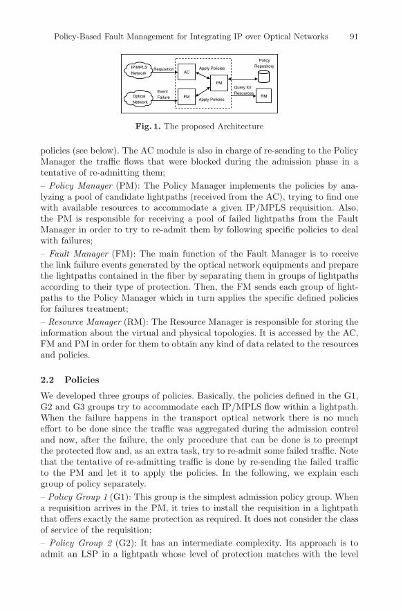
The architecture proposed in this work is composed of five management mod-ules: Admission Control, Fault Manager, Policy Manager, Resource Managerand Policy Repository. These modules were designed in order to get a basic in-frastructure to apply policies in optical networks as well as to control all thenecessary information for the management of the IP/MPLS over DWDM inte-gration [7]. The architecture is presented in Fig. 1 and in the following we makea brief explanation about each module.
– Admission Control (AC): The Admission Control receives the requisitions sentby the IP/MPLS networks and prepare them, loading the lightpaths (from theResource Manager) between the source/destination pair. After getting all thelightpaths that connect the ingress and the egress nodes, the AC sends suchinformation to the Policy Manager which in turn is responsible for applying the
Policy-Based Fault Management for Integrating IP over Optical Networks 91
AC
PM
FM RM
Query forResources
Apply Policies
Apply Policies
PolicyRepository
Optical Network
IP/MPLSNetwork
Requisition
EventFailure
Fig. 1. The proposed Architecture
policies (see below). The AC module is also in charge of re-sending to the PolicyManager the traffic flows that were blocked during the admission phase in atentative of re-admitting them;– Policy Manager (PM): The Policy Manager implements the policies by ana-lyzing a pool of candidate lightpaths (received from the AC), trying to find onewith available resources to accommodate a given IP/MPLS requisition. Also,the PM is responsible for receiving a pool of failed lightpaths from the FaultManager in order to try to re-admit them by following specific policies to dealwith failures;– Fault Manager (FM): The main function of the Fault Manager is to receivethe link failure events generated by the optical network equipments and preparethe lightpaths contained in the fiber by separating them in groups of lightpathsaccording to their type of protection. Then, the FM sends each group of light-paths to the Policy Manager which in turn applies the specific defined policiesfor failures treatment;– Resource Manager (RM): The Resource Manager is responsible for storing theinformation about the virtual and physical topologies. It is accessed by the AC,FM and PM in order for them to obtain any kind of data related to the resourcesand policies.
2.2 Policies
We developed three groups of policies. Basically, the policies defined in the G1,G2 and G3 groups try to accommodate each IP/MPLS flow within a lightpath.When the failure happens in the transport optical network there is no mucheffort to be done since the traffic was aggregated during the admission controland now, after the failure, the only procedure that can be done is to preemptthe protected flow and, as an extra task, try to re-admit some failed traffic. Notethat the tentative of re-admitting traffic is done by re-sending the failed trafficto the PM and let it to apply the policies. In the following, we explain eachgroup of policy separately.– Policy Group 1 (G1): This group is the simplest admission policy group. Whena requisition arrives in the PM, it tries to install the requisition in a lightpaththat offers exactly the same protection as required. It does not consider the classof service of the requisition;– Policy Group 2 (G2): It has an intermediate complexity. Its approach is toadmit an LSP in a lightpath whose level of protection matches with the level

92 Claudio Carvalho et al.
of protection required by the requisition. Also, it always tries to keep togetherLSPs with the same class of service (HP and LP) in the lightpaths. This groupof policies can be better explained as follows: Let R be the Requisition and L agiven lightpath.
– if R is Unprotected• if R is HP
1. Aggregate R in an unprotected L if the LSPs already aggregated in L havethe same class of service of R;
2. Aggregate R in an unprotected L that is empty;3. Aggregate R in an unprotected L. Probably this L will have both LP and
HP LSPs;4. Aggregate R in an unprotected L if the removal of one or more LP LSPs
of L releases enough bandwidth to install R;• if R is LP
1. Repeat the 3 first steps described above for HP;2. Aggregate R in a backup L that is not empty;3. Aggregate R in an empty backup L;4. Aggregate R in a protected primary L that is not empty. For this condition
and the condition five below, L can be an 1:1 or 1:N primary L, but notan 1+1 primary L;
5. Aggregate R in a protected primary L that is empty;– if R is 1+1
1. Aggregate R in an 1+1 primary L that is not empty;2. Aggregate R in an 1+1 primary L that is empty;
– if R is 1:11. Aggregate R in an 1:1 primary L that is not empty;2. Aggregate R in an 1:1 primary L that is empty;3. Aggregate R in an 1:1 primary L if the removal of one or more LP LSPs of L
releases enough bandwidth to install R;– if R is 1:N
1. Aggregate R in an 1:N primary L that is not empty;2. Aggregate R in an 1:N primary L that is empty. For this condition the following
rule needs to be accomplished: Let k be equals to the N primaries protectedby the backup of L. Then the arithmetic mean of the sharing index amongthese k lightpaths needs to be lower than the mean of any other different klightpaths. The sharing index of L indicates the percentage of sharing of itsfibers with the other (k-L) lightpaths;
3. Aggregate R in an 1:N primary L if the removal of one or more LP LSPs of Lreleases enough bandwidth to install R;
– Policy Group 3 (G3): Basically, this group of policies performs the same tasksas the G2. However, there are two main differences. The first one is that if thelevel of protection required by the requisition is not available, this group tries toaggregate the flow in a lightpath with a higher level of protection (if there is oneavailable). This approach is specifically used for 1:N and, as a consequence, the1:N requisition can be accommodated in an 1:1 lightpath. The second differenceis that this group allows to break a given 1:N group to attend 1:1 requisitions.Thus, when an 1:1 requisition arrives and there is no such a level of protection to
Policy-Based Fault Management for Integrating IP over Optical Networks 93
attend the flow, the policy breaks an 1:N group (if there is one available) in sucha way that one of the primary lightpaths of the 1:N group becomes the primarylightpath of the 1:1 level of protection. The backup lightpath of the 1:N becomesthe backup of the 1:1 protection. The remaining N-1 primary lightpaths becomeunprotected. Note that theses two differences are inversely related.
3 Implementation and Results
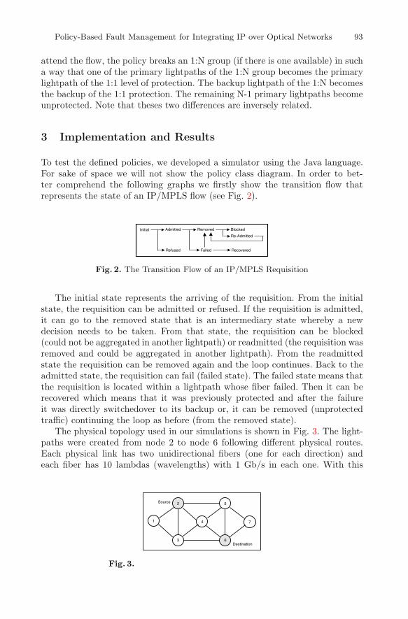
To test the defined policies, we developed a simulator using the Java language.For sake of space we will not show the policy class diagram. In order to bet-ter comprehend the following graphs we firstly show the transition flow thatrepresents the state of an IP/MPLS flow (see Fig. 2).
Admitted Removed Blocked
Re-Admitted
Failed RecoveredRefused
Initial
Fig. 2. The Transition Flow of an IP/MPLS Requisition
The initial state represents the arriving of the requisition. From the initialstate, the requisition can be admitted or refused. If the requisition is admitted,it can go to the removed state that is an intermediary state whereby a newdecision needs to be taken. From that state, the requisition can be blocked(could not be aggregated in another lightpath) or readmitted (the requisition wasremoved and could be aggregated in another lightpath). From the readmittedstate the requisition can be removed again and the loop continues. Back to theadmitted state, the requisition can fail (failed state). The failed state means thatthe requisition is located within a lightpath whose fiber failed. Then it can berecovered which means that it was previously protected and after the failureit was directly switchedover to its backup or, it can be removed (unprotectedtraffic) continuing the loop as before (from the removed state).
The physical topology used in our simulations is shown in Fig. 3. The light-paths were created from node 2 to node 6 following different physical routes.Each physical link has two unidirectional fibers (one for each direction) andeach fiber has 10 lambdas (wavelengths) with 1 Gb/s in each one. With this
1
2
3
4
5
6
7
Source
Destination
Fig. 3.

94 Claudio Carvalho et al.
physical network, 36 lightpaths (36 Gb/s) from node 2 to node 6 could be cre-ated. The quantity of unprotected lightpaths is 4, 1:N is 6, 1:1 is 2 and 1+1 isalso 2. For the 1:N scheme of protection we defined 1:3 what means that thereare 3 primary lightpaths being protected by 1 backup. This results in 6 groupsof 1:3 (6*(1+3)=24). In case of 1:1 and 1+1, for each primary lightpath there isone backup. Thus, since there are two 1:1 and two 1+1 lightpaths, we have thetotal of 8 lightpaths in these two groups. Then, by summing 24 (1:N) + 8 (1:1and 1+1) + 4 (unprotected) we have 36 lightpaths.
We have created 8 different traffic loads to validate the policies. From 80%(0.8) to 240% (2.4) of the network bandwidth (36 Gb/s). With these differentloads we were able to test the behavior of the policies in scenarios that the quan-tity of generated traffic is lower than the capacity of the network and to the otherextreme, we stressed the network with a high load. The percentage of generatedtraffic for requisitions (IP/MPLS traffic) for each type of protection is as follows:35% for unprotected, 15% for 1:N, 20% for 1+1 and 30% for 1:1. Such traffic isgenerated taking into account the network load percentage. As an example, for120% (1.2) of traffic load, the quantity of generated requisitions in Gb for 1:1 is:36 Gb (network capacity) * 1.2 (load to be generated) * 0.3 (percentage of 1:1)≈ 13 Gb/s. The minimum bandwidth required for each requisition is 50 Mb/sand the maximum is 400 Mb/s. Statistically, the average bandwidth for eachrequisition is then 225 Mb/s. The simulations perform 20 iterations and thenthe arithmetic mean is obtained. A single fiber failure is randomly generated foreach iteration.
Figure 4 shows the quantity of traffic that was admitted in the optical net-work.
35
40
45
50
55
60
65
70
75
80
0.8 1 1.2 1.4 1.6 1.8 2 2.2 2.4
Adm
itted
LS
Ps
/ Gen
erat
ed L
SP
s
Network Load Percentage
Admitted LSPs
G1G2G3
Fig. 4. Percentage of admitted traffic
Note that the G1 is the worst group of policies (actually it is the simplestone). The G3, considered the most sophisticated group, performs better whencompared with the other two groups. Observe that G3 and G2 admit basicallythe same quantity of flows. It is important to point out that the percentage ofadmission depends on how the requisitions are aggregated within each lightpath.This problem is similar to the knapsack problem [9].
Policy-Based Fault Management for Integrating IP over Optical Networks 95
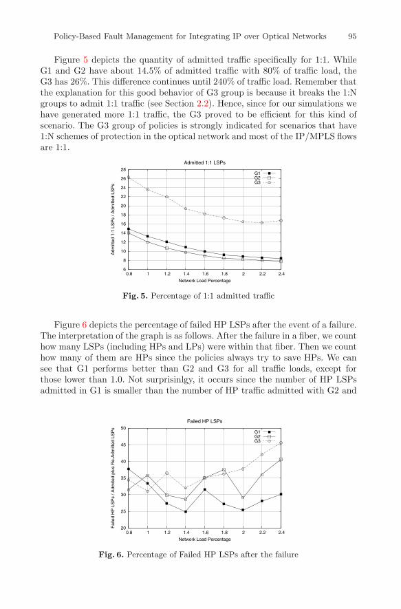
Figure 5 depicts the quantity of admitted traffic specifically for 1:1. WhileG1 and G2 have about 14.5% of admitted traffic with 80% of traffic load, theG3 has 26%. This difference continues until 240% of traffic load. Remember thatthe explanation for this good behavior of G3 group is because it breaks the 1:Ngroups to admit 1:1 traffic (see Section 2.2). Hence, since for our simulations wehave generated more 1:1 traffic, the G3 proved to be efficient for this kind ofscenario. The G3 group of policies is strongly indicated for scenarios that have1:N schemes of protection in the optical network and most of the IP/MPLS flowsare 1:1.
6
8
10
12
14
16
18
20
22
24
26
28
0.8 1 1.2 1.4 1.6 1.8 2 2.2 2.4
Adm
itted
1:1
LS
Ps
/ Adm
itted
LS
Ps
Network Load Percentage
Admitted 1:1 LSPs
G1G2G3
Fig. 5. Percentage of 1:1 admitted traffic
Figure 6 depicts the percentage of failed HP LSPs after the event of a failure.The interpretation of the graph is as follows. After the failure in a fiber, we counthow many LSPs (including HPs and LPs) were within that fiber. Then we counthow many of them are HPs since the policies always try to save HPs. We cansee that G1 performs better than G2 and G3 for all traffic loads, except forthose lower than 1.0. Not surprisinlgy, it occurs since the number of HP LSPsadmitted in G1 is smaller than the number of HP traffic admitted with G2 and
20
25
30
35
40
45
50
0.8 1 1.2 1.4 1.6 1.8 2 2.2 2.4
Fai
led
HP
LS
Ps
/ Adm
ited
plus
Re-
Adm
itted
LS
Ps
Network Load Percentage
Failed HP LSPs
G1G2G3
Fig. 6. Percentage of Failed HP LSPs after the failure

96 Claudio Carvalho et al.
G3 (see Fig. 4). A graph, not presented here for sake of space, show that G3admitted about 50% (HP) of the generated traffic for all traffic loads, and G1,differently, admitted 48% with 0.8 of traffic load and gradually decreases until37% with 2.0 traffic load.
Figure 7 shows the percentage of LSPs that were blocked after the eventof a failure. The G3 group performs better than G2 and G1 from 0.8 to 1.6traffic loads. Figure 7 should be analysed together with the numbers shown inFig. 6. Note that as the quantity of failed HPs increases with the traffic load, thequantity of blocked HPs also increases except for G3 from 0.8 to 1.6 of trafficload. This means that the G3 group of policies is able to manage and readmitthe HP traffic until 1.6 keeping the quantity of blocked HPs lower than G2 andG1 as desired.
0
5
10
15
20
25
30
35
40
45
0.8 1 1.2 1.4 1.6 1.8 2 2.2 2.4
Blo
cked
HP
LS
Ps
/ Fai
led
LSP
s
Network Load Percentage
Blocked HP LSPs
G1G2G3
Fig. 7. Percentage of blocked HP LSPs after the event of a failure
The trade off between G2 and G3 can be decided based on specific rulesof the optical network provider. As a general rule, if the manager of a givendomain is interested in admitting more traffic, mainly 1:1 traffic, than the G3group should be used. G3 is also indicated if the traffic load is less than 1.6 sincein this case the quantity of blocked HPs is lower than G1 and G2 (see Fig. 7).However, if the provider has a traffic load higher than 1.8 and is not interestedin prioritising 1:1, than G2 could be used. As a conclusion, if the manager of agiven domain has a traffic matrix that forecasts the type and the load of trafficto be admitted in the optical domain, he can better decide on what group ofpolicy to choose.
4 Conclusion
In this paper we presented an architecture for policy-based fault management inoptical networks. The policies we defined in this work try to aggregate IP/MPLSflows within lightpaths in way that when a failure happens, the impact of suchfailure is minimized. The architecture is composed of an Admission Control, a

Policy-Based Fault Management for Integrating IP over Optical Networks 97
Policy Manager, a Resource Manager and a Policy Repository. The policies workwith the idea that optical networks have a high amount of available bandwidthin each physical link. If such a link comes to fail, the quantity of data that willbe lost is consequently very high. Solutions that are only based on schemes ofprotection such as 1+1, 1:1 and 1:N have been widely discussed. Such solutionscan be improved if the type of traffic being transported within a lightpath isconsidered when aggregating the flows. The policies defined in this paper showedthat the number of IP/MPLS flows that are affected when applying the policiesis smaller when compared with a scenario that does not use the policies.
As further works we are interested in considering the multi-hop traffic ag-gregation as well as to explore novel policies for admission control. Also, animportant point to be addressed is related to the end-to-end multi-domain con-nections and Optical VPNs.
Acknowledgments
The authors would like to thank Ericsson Brazil for its support.
References
1. E. Mannie. Generalized Multi-Protocol Label Switching Architecture. RFC 3945,October 2004.
2. L. Berger. Generalized Multi-Protocol Label Switching (GMPLS) Signaling Re-source ReserVation Protocol-Traffic Engineering (RSVP-TE) Extensions. RFC3473, January 2003.
3. J-F. Vasseur and A. Ayyangar. Inter domain GMPLS Traffic Engineering - RSVP-TE extensions. draft-ayyangar-ccamp-inter-domain-rsvp-te-02.txt, January 2005.
4. F. L. Verdi, E. Madeira and M. Magalhaes. Policy-based Admission Control inGMPLS Optical Networks. First IEEE Broadnets’04 (formerly OptiComm), SanJose, USA, pages 337–339, October 2004.
5. P. Iovanna, M. Setembre and R. Sabella. A Traffic Engineering System for Mul-tilayer Networks Based on the GMPLS Paradigm. IEEE Network, pages 28–37,March/April 2003.
6. E. Mannie and D. Papadimitriou. Recovery (Protection and Restoration) Termino-logy for Generalized Multi-Protocol Label Switching (GMPLS). draft-ietf-ccamp-gmpls-recovery-terminology-05.txt, October 2004.
7. F. L. Verdi et al. Web Services-based Provisioning of Connections in GMPLS Op-tical Networks. The Brazilian Symposium on Computer Networks (SBRC 2005),Fortaleza, Brazil, May 2005.
8. R. Dutta and N. G. Rouskas. Traffic Grooming in WDM Networks: Past and Future.IEEE Network, pages 45-56, November/December 2002.
9. T. H. Cormen. Introduction to Algorithms. Second Edition, The MIT Press.