Polarization-anisotropic scattering lines in LiNbO 3
6
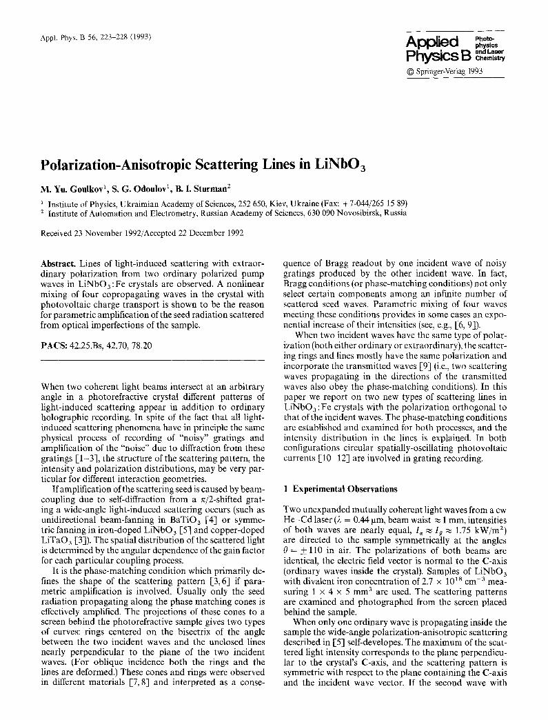
Appl. Phys. B 56, 223-228 (1993) Applied physics PhysicsB "" Chemistry © Springer-Verlag 1993 Polarization-Anisotropic Scattering Lines in LiNbO3 M. Yn. Goulkov 1, S. G. Odoulov 1, B. I. Sturman 2 i Institute of Physics, Ukraimian Academy of Sciences, 252 650, Kiev, Ukraine (Fax: + 7-044/265 15 89) 2 Institute of Automation and Electrometry, Russian Academy of Sciences, 630 090 Novosibirsk, Russia Received 23 November 1992/Accepted 22 December 1992 Abstract. Lines of light-induced scattering with extraor- dinary polarization from two ordinary polarized pump waves in LiNbO 3 :Fe crystals are observed. A nonlinear mixing of four copropagating waves in the crystal with photovoltaic charge transport is shown to be the reason for parametric amplification of the seed radiation scattered from optical imperfections of the sample. PACS: 42.25.Bs, 42.70, 78.20 When two coherent light beams intersect at an arbitrary angle in a photorefractive crystal different patterns of light-induced scattering appear in addition to ordinary holographic recording. In spite of the fact that all light- induced scattering phenomena have in principle the same physical process of recording of "noisy" gratings and amplification of the "noise" due to diffraction from these gratings [1-3], the structure of the scattering pattern, the intensity and polarization distributions, may be very par- ticular for different interaction geometries. If amplification of the scattering seed is caused by beam- coupling due to self-diffraction from a ~/2-shifted grat- ing a wide-angle light-induced scattering occurs (such as unidirectional beam-fanning in BaTiOa [41 or symme- tric fanning in iron-doped LiNbO 3 [5] and copper-doped LiTaO 3 [3]). The spatial distribution of the scattered light is determined by the angular dependence of the gain factor for each particular coupling process. It is the phase-matching condition which primarily de- fines the shape of the scattering pattern [3, 6] if para- metric amplification is involved. Usually only the seed radiation propagating along the phase matching cones is effectively amplified. The projections of these cones to a screen behind the photorefractive sample gives two types of curves: rings centered on the bisectrix of the angle between the two incident waves and the unclosed lines nearly perpendicular to the plane of the two incident waves. (For oblique incidence both the rings and the lines are deformed.) These cones and rings were observed in different materials I-7,8] and interpreted as a conse- quence of Bragg readout by one incident wave of noisy gratings produced by the other incident wave. In fact, Bragg conditions (or phase-matching conditions) not only select certain components among an infinite number of scattered seed waves. Parametric mixing of four waves meeting these conditions provides in some cases an expo- nential increase of their intensities (see, e.g., [6, 9]). When two incident waves have the same type of polar- ization (both either ordinary or extraordinary), the scatter- ing rings and lines mostly have the same polarization and incorporate the transmitted waves [9] (i.e., two scattering waves propagating in the directions of the transmitted waves also obey the phase-matching conditions). In this paper we report on two new types of scattering lines in LiNbO3 :Fe crystals with the polarization orthogonal to that of the incident waves. The phase-matching conditions are established and examined for both processes, and the intensity distribution in the lines is explained. In both configurations circular spatially-oscillating photovoltaic currents [10 123 are involved in grating recording. 1 Experimental Observations Two unexpanded mutually coherent light waves from a cw He-Cd laser (2 = 0.44 gm, beam waist ~ 1 mm, intensities of both waves are nearly equal, I, ~ Ip ,~ 1.75 kW/m 2) are directed to the sample symmetrically at the angles 0 = + 110 in air. The polarizations of both beams are identical, the electric field vector is normal to the C-axis (ordinary waves inside the crystal). Samples of LiNbO3 with divalent iron concentration of 2.7 × 1018 cm -3 mea- suring 1 × 4 × 5 mm 3 are used. The scattering patterns are examined and photographed from the screen placed behind the sample. When only one ordinary wave is propagating inside the sample the wide-angle polarization-anisotropic scattering described in [5] self-developes. The maximum of the scat- tered light intensity corresponds to the plane perpendicu- lar to the crystal's C-axis, and the scattering pattern is symmetric with respect to the plane containing the C-axis and the incident wave vector. If the second wave with
-
Upload
independent -
Category
Documents
-
view
2 -
download
0
Transcript of Polarization-anisotropic scattering lines in LiNbO 3
Appl. Phys. B 56, 223-228 (1993) Applied physics
Physics B " " Chemistry
© Springer-Verlag 1993
Polarization-Anisotropic Scattering Lines in LiNbO3 M. Yn. Goulkov 1, S. G. Odoulov 1, B. I. Sturman 2
i Institute of Physics, Ukraimian Academy of Sciences, 252 650, Kiev, Ukraine (Fax: + 7-044/265 15 89) 2 Institute of Automation and Electrometry, Russian Academy of Sciences, 630 090 Novosibirsk, Russia
Received 23 November 1992/Accepted 22 December 1992
Abstract. Lines of light-induced scattering with extraor- dinary polarization from two ordinary polarized pump waves in LiNbO 3 :Fe crystals are observed. A nonlinear mixing of four copropagating waves in the crystal with photovoltaic charge transport is shown to be the reason for parametric amplification of the seed radiation scattered from optical imperfections of the sample.
PACS: 42.25.Bs, 42.70, 78.20
When two coherent light beams intersect at an arbitrary angle in a photorefractive crystal different patterns of light-induced scattering appear in addition to ordinary holographic recording. In spite of the fact that all light- induced scattering phenomena have in principle the same physical process of recording of "noisy" gratings and amplification of the "noise" due to diffraction from these gratings [1-3], the structure of the scattering pattern, the intensity and polarization distributions, may be very par- ticular for different interaction geometries.
If amplification of the scattering seed is caused by beam- coupling due to self-diffraction from a ~/2-shifted grat- ing a wide-angle light-induced scattering occurs (such as unidirectional beam-fanning in BaTiOa [41 or symme- tric fanning in iron-doped LiNbO 3 [5] and copper-doped LiTaO 3 [3]). The spatial distribution of the scattered light is determined by the angular dependence of the gain factor for each particular coupling process.
It is the phase-matching condition which primarily de- fines the shape of the scattering pattern [3, 6] if para- metric amplification is involved. Usually only the seed radiation propagating along the phase matching cones is effectively amplified. The projections of these cones to a screen behind the photorefractive sample gives two types of curves: rings centered on the bisectrix of the angle between the two incident waves and the unclosed lines nearly perpendicular to the plane of the two incident waves. (For oblique incidence both the rings and the lines are deformed.) These cones and rings were observed in different materials I-7, 8] and interpreted as a conse-
quence of Bragg readout by one incident wave of noisy gratings produced by the other incident wave. In fact, Bragg conditions (or phase-matching conditions) not only select certain components among an infinite number of scattered seed waves. Parametric mixing of four waves meeting these conditions provides in some cases an expo- nential increase of their intensities (see, e.g., [6, 9]).
When two incident waves have the same type of polar- ization (both either ordinary or extraordinary), the scatter- ing rings and lines mostly have the same polarization and incorporate the transmitted waves [9] (i.e., two scattering waves propagating in the directions of the transmitted waves also obey the phase-matching conditions). In this paper we report on two new types of scattering lines in LiNbO3 :Fe crystals with the polarization orthogonal to that of the incident waves. The phase-matching conditions are established and examined for both processes, and the intensity distribution in the lines is explained. In both configurations circular spatially-oscillating photovoltaic currents [10 123 are involved in grating recording.
1 Experimental Observations
Two unexpanded mutually coherent light waves from a cw He-Cd laser (2 = 0.44 gm, beam waist ~ 1 mm, intensities of both waves are nearly equal, I , ~ Ip ,~ 1.75 kW/m 2) are directed to the sample symmetrically at the angles 0 = + 110 in air. The polarizations of both beams are identical, the electric field vector is normal to the C-axis (ordinary waves inside the crystal). Samples of LiNbO3 with divalent iron concentration of 2.7 × 1018 cm -3 mea- suring 1 × 4 × 5 mm 3 are used. The scattering patterns are examined and photographed from the screen placed behind the sample.
When only one ordinary wave is propagating inside the sample the wide-angle polarization-anisotropic scattering described in [5] self-developes. The maximum of the scat- tered light intensity corresponds to the plane perpendicu- lar to the crystal's C-axis, and the scattering pattern is symmetric with respect to the plane containing the C-axis and the incident wave vector. If the second wave with
224
identical polarization is added at the input, the pattern of orthogonally polarized scattering changes drastically. In addition to the wide-angle scattering (which becomes strongly suppressed) narrow lines appear. Their positions depend on the orientation of incident pump beams. Two interaction geometries are considered which we call con- figurations 1 and 2.
1.t Configuration 1
Two waves polarized normal to the C-axis impinge upon the sample in the plane parallel to the C-axis of the sample.
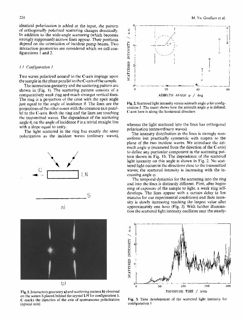
The interaction geometry and the scattering pattern are shown in (Fig. 1). The scattering pattern consists of a comparatively weak ring and much stronger vertical lines. The ring is a projection of the cone with the apex angle just equal to the angle of incidence 0. The lines are the projections of the other cones with the common axis paral- lel to the C-axis. Both the ring and the lines are touching the transmitted waves. The dependence of the scattering angle 0~ on the angle of incidence 0 is a trivial straight line with a slope equal to unity.
The light scattered in the ring has exactly the same polarization as the incident waves (ordinary waves),
\ / C
---I IL,
S
a)
M. Yu. Goulkov et al,
Z
z
d
- - ~ t4. --.-_~ :~:t . ~ _
2 0 4 0 6 0
A Z I M U T H A N G L E ~ / d e g
Fig. 2. Scattered light intensity versus azimuth angle ¢p for config- uration 1, The insert shows how the azimuth angle q~ is defined; C-axis here is along the horizontal direction
whereas the light scattered into the lines has orthogonal polarization (extraordinary waves).
The intensity distribution in the lines is strongly non- uniform but practically symmetric with respect to the plane of the two incident waves. We introduce the azi- muth angle q~ (measured from the direction of the C-axis) to define any particular component in the scattering pat- tern shown in Fig. lb. The dependence of the scattered light intensity on this angle is shown in Fig. 2. No scat- tered light occurs in the directions close to the transmitted waves; the scattered intensity is increasing with the in- creasing angle q~.
The temporal dynamics for the scattering into the ring and into the lines is distinctly different. First, after begin- ning of exposure of the sample to light, a weak ring self- develops, The lines appear with a certain delay (a few minutes for our experimental conditions) and their inten- sity is slowly increasing reaching the largest value after approximately one hour (Fig. 3). With further illumina- tion the scattered light intensity oscillates near the steady-
b)
Fig. 1. Interaction geometry a) and scattering patternb) observed on the screen S placed behind the crystal LN for configuration l. C marks the direction of the axis of spontaneous polarization (optical axis)
z
z
(/3
0 - - J 0 5 0 I 0 0 1 5 0
EXPOSURE TIME / rain. 2 0 0
Fig. 3. Time development of the scattered light intensity for configuration 1
Polarization-Anisotropic Scattering Lines in LiNbO 3
state value; lines become so bright that the ring is hardly s e e n .
We did not observe the opposite process of scattering of two extraordinary waves into the lines with ordinary polarization in iron-doped LiNbO 3 crystals.
1.2 Configuration 2
Two waves polarized normal to the C-axis impinge upon the sample in the plane perpendicular to the C-axis of the sample.
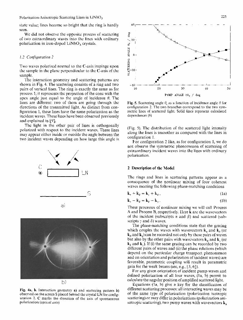
The interaction geometry and scattering patterns are shown in Fig. 4. The scattering consists of a ring and two pairs of vertical lines. The ring is exactly the same as for process 1; it represents the projection of the cone with the apex angle just equal to the angle of incidence 0. The lines are different: two of them are going through the directions of the transmitted light. As distinct from con- figuration 1, these lines have the same polarization as the incident waves. These lines have been observed previously and explained in [9].
The light in the other pair of lines is orthogonally polarized with respect to the incident waves. These lines may appear either inside or outside the angle between the two incident waves depending on how large this angle is
C I ILN
40
a)
b)
Fig. 4a, b. Interaction geometry a) and scattering pattern b) observed on the screen S placed behind the crystal LN for config- uration 2. C marks the direction of the axis of spontaneous polarization (optical axis)
"-. 20
0 <
Z
~ - 2 0
r~
225
- 4 0 ~
t0 20 30 40 50
PUMP ANGLE 2ep / deg
Fig. 5. Scattering angle 0~ as a function of incidence angle 0 for configuration 2. The two branches correspond to the two sym- metric lines of scattered light. Solid lines represent calculated dependences (6)
(Fig. 5). The distribution of the scattered light intensity along the lines is smoother as compared with the lines in configuration 1.
For configuration 2 like, as for configuration 1, we do not observe the symmetric phenomenon of scattering of extraordinary incident waves into the lines with ordinary polarization.
2 Description of the Model
The rings and lines in scattering patterns appear as a consequence of the nonlinear mixing of four coherent waves meeting the following phase-matching conditions
k~ + k~ = k s + k~, (la)
k~ - k B = k~ - k~. (lb)
These processes of nonlinear mixing we will call Process A and Process B, respectively. Here k are the wavevectors of the incident (subscripts e and fl) and scattered (sub- scripts 7 and fi) waves.
The phase-matching conditions state that the grating which couples the waves with wavevectors k~ and k~ (or ka and k~) can be recorded not only by these pairs of waves but also by the other pairs with wavevectors kt~ and k s (or k~ and ks). If (i) the same grating can be recorded by two different pairs of waves and (ii) the phase relations (which depend on the particular charge transport phenomenon and on orientation and polarization of incident waves) are favorable, parametric coupling will result in parametric gain for the weak beams (see, e.g., [3, 6]).
For any given orientation of incident pump waves and defined polarization of all four waves, (la, b) permit to calculate the angular position of amplified scattered light.
Equations (la, b) give a key for the classification of different scattering processes: all interacting waves may be of the same type of polarization (polarization isotropic scattering) or may differ in polarizations (polarization ani- sotropic scattering), two pump waves with wavevectors k~
2.1 Configuration 1
and kp may come from the same side of the sample (scatter- ing from copropagating waves) or from opposite sides (scattering from counterpropagating waves), two pump waves may either be degenerate in frequency and polariza- tion or not, etc. For any particular process the phase- matching condition allows for determination of the geom- etry of the scattering pattern and of the polarization of the scattered light. At the same time they cannot be used to predict the efficiency of the scattering process and the intensity distribution in the scattering pattern. To obtain this information one should consider the properties of the nonlinear process involved in grating recording and calcu- late the gain factor for it.
As we are mainly interested in polarization anisotropic lines in this paper we will analyze process B (lb).
According to (lb) for two ordinary pump waves there may be two different possibilities of mixing orthogonally polarized waves. They are just explaining two types of anisotropis lines observed experimentally. We will con- sider them separately in what follows.
b)
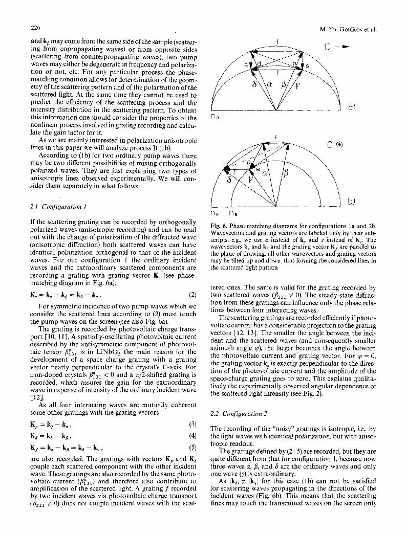
If the scattering grating can be recorded by orthogonally polarized waves (anisotropic recording) and can be read out with the change of polarization of the diffracted wave (anisotropic diffraction) both scattered waves can have identical polarization orthogonal to that of the incident waves. For our configuration 1 the ordinary incident waves and the extraordinary scattered components are recording a grating with grating vector Ks (see phase- matching diagram in Fig. 6a):
K s = kr - ka = k a - k~. (2)
For symmetric incidence of two pump waves which we consider the scattered lines according to (2) must touch the pump waves on the screen (see also Fig. 6a).
The grating is recorded by photovoltaic charge trans- port [10, 11]. A spatially-oscillating photovoltaic current described by the antisymmetric component of photovol- talc tensor/3~31 is in LiNbO3 the main reason for the development of a space charge grating with a grating vector nearly perpendicular to the crystal's C-axis. For iron-doped crystals fl~31 < 0 and a 7r/2-shifted grating is recorded, which assures the gain for the extraordinary wave in expense of intensity of the ordinary incident wave E12].
As all four interacting waves are mutually coherent some other gratings with the grating vectors
Kp = k~ - k~, (3)
K~ = k~ - kp , (4)
K I = k ~ - k~ = k ~ - k~ , (5)
are also recorded. The gratings with vectors Kp and Ka couple each scattered component with the other incident wave. These gratings are also recorded by the same photo- voltaic current (/3~31) and therefore also contribute to amplification of the scattered light. A grating f recorded by two incident waves via photovoltaic charge transport (/3311 # 0) does not couple incident waves with the scat-
M. Yu. Goulkov et al.
f
f V 1 a/ no
226
r"lo r]e
Fig. 6. Phase-matching diagrams for configurations la and 2b. Wavevectors and grating vectors are labeled only by their sub- scripts, e.g., we use ~ instead of k~ and s instead of K,. The wavevectors k~ and k s and the grating vector Ky are parallel to the plane of drawing, all other wavevectors and grating vectors may be tilted up and down, thus forming the considered lines in the scattered light pattern
tered ones. The same is valid for the grating recorded by two scattered waves (/3333 ~ 0). The steady-state diffrac- tion from these gratings can influence only the phase rela- tions between four interacting waves.
The scattering gratings are recorded efficiently if photo- voltaic current has a considerable projection to the grating vectors 1-12, 133. The smaller the angle between the inci- dent and the scattered waves (and consequently smaller azimuth angle q0), the larger becomes the angle between the photovoltaic current and grating vector. For (p = 0, the grating vector k s is exactly perpendicular to the direc- tion of the photovoltaic current and the amplitude of the space-charge grating goes to zero. This explains qualita- tively the experimentally observed angular dependence of the scattered light intensity (see Fig. 2).
2.2 Configuration 2
The recording of the "noisy" gratings is isotropic, i.e., by the light waves with identical polarization, but with aniso- tropic readout.
The gratings defined by (2-5) are recorded, but they are quite different from that for configuration 1, because now three waves c~, fl, and 6 are the ordinary waves and only one wave (Y) is extraordinary.
As [k~l # [k~[ for this case (lb) can not be satisfied for scattering waves propagating in the directions of the incident waves (Fig. 6b). This means that the scattering lines may touch the transmitted waves on the screen only
Polarization-Anisotropic Scattering Lines in LiNbO3
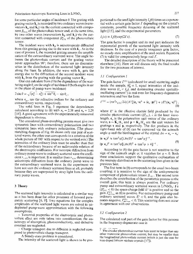
for some particular angles of incidence 0. The grating with grating vector ks is recorded by two ordinary waves (wave- vectors k, and ka) via the current connected with compo- nent fl311 of the photovoltaic tensor and, at the same time, by two other waves (wavevectors k s and k~) via the cur- rent connected with component fi~3~ of the photovoltaic tensor.
The incident wave with k~ is anisotropicaly diffracted from this grating giving rise to the wave with k~. As in the case of process 1, the recorded grating assures the amplifi- cation of the extraordinary scattered wave. The angle be- tween the photovoltaic current and the grating vector never approaches 90°; therefore, there are no discontin- uities in the distribution of the scattered light intensity along the lines. In addition, the wave with ky gets the energy due to the diffraction of the second incident wave with k~ from the grating with the grating vector Kp.
One can calculate from (lb) the dependence of the scat- tering angle O~ on the angle of incidence 0 (both angles in air in the plane of pump wave incidence)
2 sin 0 = x/(no 2 - n 2) + sin 2 0~- sin 0~, (6)
where no,~ are the refractive indices for the ordinary and extraordinary waves, respectively.
The solid lines in Fig. 5 represent the dependences calculated according to (6) with n o = 2.38 and n¢ = 2.28 [14]. A good agreement with the experimentally measured dependence is obvious.
The considered phase-matching process must give two symmetric lines with extraordinary polarization and two symmetric lines with ordinary polarization. (The phase- matching diagram of Fig. 6b shows only one pair of scat- tered waves, the other one corresponds to a rotation of the whole picture of 180 ° with respect to the vertical axis.) The intensities of the ordinary lines must be smaller than that of the extraodinary because of an unfavorable relation of the electrooptic coefficients. For isotropic diffraction from ordinary pump wave to ordinary scattered wave the coeffi- cient r133 is important. It is smaller than r13 ~ determining anisotropic diffraction from the ordinary pump wave to the extraordinary scattered wave. In the experiment we have not seen the ordinary scattered lines at all, probably because they are superposed by stray light from the ordi- nary pump waves.
3 Theory
The scattered light intensity is calculated in a similar way as it has been done for other processes of forward para- metric scattering [6, 9]. Two equations for the complex amplitudes of the scattered light waves are solved in un- depleeted pump-wave approximation with the following assumptions.
- Tensorial properties of the electrooptic and photo- voltaic effect are only taken into consideration; the an- isotropy of absorption, photoconductivity, and dielectric constant are neglected.
- Charge transport due to diffusion is neglected com- pared to photovoltaic charge transport.
- A Steady-state problem is considered. The intensity of the scattered light is shown to be pro-
227
portional to the seed light intensity I~(0) times an exponen- tial with a certain gain factor F depending on the crystal's constants, possible frequency detuning of the scattered light [15], and the experimental parameters:
l~(x) ~ I~(0)exp(2Fx) . (7)
The gain factor is complex and its real part indicates the exponential growth of the scattered light intensity with thickness. In the case of a purely imaginary gain factor, no steady-state amplification of the seed occurs. Equation (7) is valid for comparatively large real F.
The detailed description of the theory will be presented elsewhere [16]. Here we will discuss only the final results for the two processes of interest.
3.1 Configuration 1
The gain factor F (1) (calculated for small scattering angles inside the sample, 0~, << 1, equal intensities of the inci- dent waves (I~ = Is), and dominating circular spatially- oscillating current 1) is real even for frequency-degenerate interaction and has the form
F'(1) = (rcn3r131/22){ECf(eo • s) 2 + (%" !!) 2] + [ECI(eo • s)2}, (8)
where E ¢ is the effective electric field produced by the circular photovoltaic current (fir31), 2 is the laser wave- length, e o is the polarization unit vector of the ordinary wave, s = Ks/Ks and p = Kp/Kp are the unit vectors for gratings s and p, respectively. The dot products in the right-hand side of (8) can be expressed via the azimuth angle (p and the birefringence of the crystal An = no - he:
(s" co) 2 ~ tan2q~[(An/O) z + tan2qo] -1 , (9)
(p. %)2 ~ tan2qo[(An/O)2 + tanZq) + 4 ] - t .
According to (8) the gain factor is not sensitive to the sign of the azimuth angle qo; it vanishes for q0 = 0. Both these conclusions support the qualitative explanation of the intensity distribution in the scattering lines given in the previous Sect.
The first term in (8) corresponds to the usual two-beam coupling; it is sensitive to the sign of the antisymmetric component of photovoltaic tensor fi131. The second term describes the contribution of the parametric process to the overall gain; this term is always positive. For ordinary pump and extraordinary scattered waves in LiNbO 3 : Fe (13~31 < 0) the space-charge field E ° is positive and so the gain FoCo~L ~ in (8) is positive. For extraordinary pump and ordinary scattered waves E ¢ < 0, and the gain also be- comes negative, Fe¢~)~oo < 0. This scattering does not occur in agreement with our observations.
3.2 Configuration 2
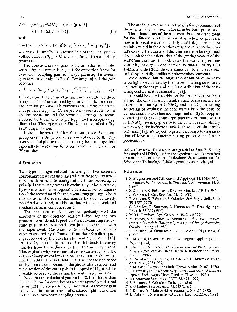
The calculated real part of the gain factor for this process in the frequency-degenerate case is
1 The circular photovoltaic current here must be larger than any other transverse photovoltaic current, but may be smaller than the longitudinal photovoltaic current (which fs just the case for iron-doped lithium niobate crystals [17]).
228
/'(2) = (nn3rlal/42)E~[(s.eo)2 + (p. eo)2]
x [1 ± Re(x/1 - it/)],
with
(lO)
r/ --- (E31 r 113/ECr131)(c • s)2(s - eo)2/[(s • eo) 2 + (p. eo)2],
where E3~ is the effective electric field of the linear photo- voltaic current (fl31~ # 0) and c is the unit vector of the polar axis.
The contribution of parametric amplification is de- scribed by the term q. For t/<< 1 the correction factor for two-beam coupling gain is always positive; the overall gain is positive only if E c > 0. For large I~/I >> 1 the gain becomes
F (a ,= (~n3/4).xf2) l(s" eo)(e - s ) / ~ ~ r ~ i . (11)
It is obvious that parametric gain occurs only for those qomponents of the scattered light for which the linear and the circular photovoltaic currents (producing the space- charge fields E3t and E c, respectively) contribute to the grating recording and the recorded gratings are recon- structed both via anisotropic (rt31) and isotropic (r113) diffraction, This type of amplification can be called a "hy- brid" amplification.
It should be noted that for X-cut samples of 3 m point- group crystals the photovoltaic currents due to the f12z2 component of photovoltaic tensor may become important especially for scattering directions where the gain given by (9) vanishes
4 Discussion
M. Yu. Goulkov et al.
The model gives also a good qualitative explanation of the intensity distribution in the lines for both processes.
The orientations of the scattered lines are orthogonal for two different configurations. A question might arise: how is it possible as the spatially-oscillating currents are mainly excited in the directions perpendicular to the crys- tal's C-axis? This apparent disagreement can be explained if we look for the orientation of the grating vectors of the scattering gratings. In both cases the scattering grating vector K, lies very close to the plane normal to the crystal's C-axis, and therefore, these gratings can be efficiently rec- orded by spatially-oscillating photovoltaic currents.
We conclude that the angular distribution of the scat- tered light is explained by the phase-matching conditions and not by the shape and regular distribution of the scat- tering centers as it is claimed in [18].
It should be stated in addition that the anisotropic lines are not the only possible manifestation of parametric an- isotropic scattering in LiNbO 3 and LiTaO3. A strong scattering of ordinary incident waves into the cone of extraordinary waves has been reported in [33 for copper- doped LiTaO3; two counterpropagating ordinary waves in LiNbO3 : Fe may give rise to the cone of extraordinary waves when the incidence angle is above a certain thresh- old value [19]. We expect to present a complete classifica- tion of forward parametric mixing processes in further publications.
Acknowledgement. The authors are grateful to Prof. E. Krfitzig for samples of LiNbO3 used in the experiment with known iron content. Financial support of Ukrainian State Committee for Science and Technology (2/460) is gratefully acknowledged.
Two types of light-induced scattering of two coherent copropagating waves into lines with orthogonal polariza- tion are described. In configuration 1 the recording of principal scattering gratings is exclusively anisotropic, i.e., by waves which are orthogonally polarized. For configura- tion 2 the recording of the main scattering gratings is both due to usual the scalar mechanism by two identically polarized waves and, in addition, due to the same vectorial mechanism as in configuration 1.
The proposed model describes perfectly well the geometry of the observed scattered lines for the two processes considered. It predicts the nonvanishing steady- state gain for the scattered light just in agreement with the experiment. The steady-state amplification in both cases is assured by diffraction from the n/2-shifted grat- ings recorded by the circular photovoltaic currents [12]. In LiNbO 3 : Fe the direction of the shift leads to energy transfer from the ordinary to the extraordinary waves. This explains why we cannot observe scattering from the extraordinary waves into the ordinary ones in this mate- rial. It might be that in LiNbO 3 : Cu, where the sign of the antisymmetric component of the photovoltaic tensor (and the direction of the grating shift) is opposite [l 7], it will be possible to observe the symmetric scattering processes.
Note that the calculated gain factor (8, 10) is larger than the gain factor for coupling of two orthogonally polarized waves [12]. This leads to conclusion that parametric gain is involved in the formation of scattered light in addition to the usual two-beam coupling process.
References
1. R. Magnusson, and T.K. Gaylord: Appl. Opt. 13, 1546 (1974) 2. I. Kanaev, V. Malinovski, B. Sturman: Opt. Commun. 34, 95
(1980) 3. S. Odoulov, K. Belabaev, I. Kiseleva: Opt. Lett. 10, 31 (1985) 4. J. Feinberg, J. Opt. Soc. Am. 72, 47 (1982) 5. E. Avakian, K. Belabaev, S. Odoulov: Soy. Phys.-Solid State
25, 1887 (1983) 6. S. Odoulov, B. Sturman, L. Holtmann, E. Kraetzig: Appl.
Phys. B. 53, 317 (199!) 7. M.R.B. Forshaw: Opt. Commun. 15, 218 (1975) 8. M. Petrov, S. Stepanov, A. Khomenko: Photosensitive Elec-
trooptic Crystals in Holography and Optical Image Processing (Nauka, Leningrad 1983)
9. B. Sturman, M. Goulkov, S. Odoulov: Appl. Phys. B 00, 00 (1993)
10. A.M. Glass, D. vonder Linde, T.K. Negran: Appl. Phys. Lett. 25, 233 (1974)
11. B. Sturman, V. Fridkin: The Photovoltaic and Photorefractive Effects in Noncentrosymmetric Materials (Gordon and Breach, London 1992)
12. A. Novikov, S. Odoulov, O. Oleinik, B. Sturman: Ferro- electrics 75, 295 (1987)
13. A.M. Glass, D. vonder Linde: Ferroelectrics 10, 163 (1976) 14. R.J, Pressley (Ed.): Handbook of Lasers with Selected Data on
Optical Technology (Chem. Rubber, Cleveland 1971) 15. B.I. Sturman: Soy. Phys.-JETP 73, 593 (1992) 16. B. Sturman, S. Odoulov: To be published 17. S. Odoulov: Ferroelectrics 91, 213 (1989) 18. I. Kanaev, V. Malinovski: Avtometriya N 4, 37 (1992) 19. K. Zabrodin, N. Penin: Sov. J Quant. Electron. 22, 622 (1991)