PMD Application Guide - Dolby Developer
59
PMD Application Guide Issue V1.0.5
-
Upload
khangminh22 -
Category
Documents
-
view
3 -
download
0
Transcript of PMD Application Guide - Dolby Developer

PMD Application Guide Issue V1.0.5

ii
Dolby Laboratories Licensing Corporation
Corporate Headquarters Dolby Laboratories, Inc. 1275 Market St. San Francisco, CA 94103-1410 USA Telephone 415-558-0200 Fax 415-863-1373 www.dolby.com

PMD Application Guide
Contents
Introduction .............................................................................................................................. 5 Document Organization ............................................................................................................... 5 References .................................................................................................................................. 5 Definitions and Abbreviations ...................................................................................................... 5
1.3.1 Definitions ..................................................................................................................... 5 1.3.2 Abbreviations ................................................................................................................ 9
Document Notation ...................................................................................................................... 9
Introduction to Professional Metadata .................................................................................. 11 What is professional audio metadata? ...................................................................................... 11 History of Dolby professional audio metadata ........................................................................... 11 Why is professional audio metadata required? ......................................................................... 12
2.3.1 Loudness Management .............................................................................................. 12 2.3.2 Preserving Artistic Intent ............................................................................................ 12 2.3.3 Advanced Media Support ........................................................................................... 13
PMD Overview ........................................................................................................................ 14 Features ..................................................................................................................................... 14
3.1.1 Requirements ............................................................................................................. 14 3.1.2 Payload Categories .................................................................................................... 14
PMD Use-case descriptions ................................................................................................... 16 Introduction ................................................................................................................................ 16 Single Stereo or 5.1 Complete Main Presentation .................................................................... 16 Complete Main and Associated Audio as Broadcast Mix .......................................................... 16 Channel-based Immersive Music and Effects (M&E) with Separate Dialog ............................. 17 Channel-based M&E with Separate Dialog and Associated Audio ........................................... 17 Channel-based immersive M&E with Two or more Mixed Dialog elements.............................. 18 Spoken Subtitles and Voice-over .............................................................................................. 18
PMD Details ............................................................................................................................. 20 Payload Usage & Descriptions .................................................................................................. 20 Audio Elements.......................................................................................................................... 20
5.1.1 Audio Signal Names (ASN) ........................................................................................ 20 5.1.2 Audio Bed Description (ABD) ..................................................................................... 21 5.1.3 Multichannel PCM Stem Workflows ........................................................................... 24 5.1.4 Audio Object Description (AOD) ................................................................................. 24 5.1.5 Headphone Element Description (HED) .................................................................... 28 5.1.6 Dynamic Position Update (XYZ)................................................................................. 28 5.1.7 Audio Element Names (AEN) ..................................................................................... 29
Audio Presentations .................................................................................................................. 29 5.2.1 Audio Presentation Description (APD) ....................................................................... 29 5.2.2 Audio Presentation Provisioning ................................................................................ 30

PMD Application Guide i
Encode Solution Engine ............................................................................................................ 32 6.1.1 Audio Presentation Names (APN) .............................................................................. 33 6.1.2 Audio Presentation Loudness (PLD) .......................................................................... 33
Unique Programme Content Identification ................................................................................ 34 6.2.1 Identity & Timing (IAT) ................................................................................................ 34
Contribution Encoding Metadata ............................................................................................... 34 6.3.1 ED2 Substream Description (ESD) ............................................................................ 34 6.3.2 ED2 Substream Names (ESN) ................................................................................... 35 6.3.3 ED2 Turnaround Description (ETD) ........................................................................... 36
Emissions Encoding Metadata .................................................................................................. 37 6.4.1 E-AC-3 Encoding Parameters (EEP) ......................................................................... 37
Transforming & Mixing Audio Elements .................................................................................... 38 6.5.1 Audio Bed Element Upmixing & Downmixing ............................................................ 38 6.5.2 Combining Audio Elements For Channel-Based Delivery ......................................... 40 6.5.3 Simple Channel Based Mixing Engine ....................................................................... 41 6.5.4 Dialogue Element Considerations .............................................................................. 44
Transporting Professional Metadata ..................................................................................... 46 Transporting Professional Metadata over AES3 and SDI ......................................................... 46
6.6.1 Basic Transport of PMD using SMPTE 337 ............................................................... 46 6.6.2 Carriage of PMD using SMPTE ST 337 Subframe Mode .......................................... 47 6.6.3 Timing requirements of PMD carried via SMPTE 337 ............................................... 48
Transporting Professional Metadata over IP ............................................................................. 48
User Interface Additions ........................................................................................................ 53 Host Application User Interface Additions ................................................................................. 53 User Interface Examples ........................................................................................................... 54

PMD Application Guide ii
List of Figures
Figure 1 Legacy Dolby workflow using professional metadata ................................................................... 12 Figure 2 SDI Line-ups transitioning from legacy 5.1 to advanced media .................................................. 13 Figure 3 PMD Payload Topology ................................................................................................................ 15 Figure 4 Audio Bed Direct Console Bus ..................................................................................................... 21 Figure 5 Audio Bed Full Mix-Map................................................................................................................ 22 Figure 6 Divergence .................................................................................................................................... 25 Figure 7 Object Size and Modes................................................................................................................. 27 Figure 8 Example High Level Workflow ...................................................................................................... 31 Figure 9 Encode Solution Engine ............................................................................................................... 33 Figure 10 Speaker Channel Coordinates ................................................................................................... 42 Figure 7 Encapsulation of PMD when carried over AES3 using SMPTE ST 337 ...................................... 47

PMD Application Guide iii
List of Tables
Table 1 Definitions ........................................................................................................................................ 6 Table 2 Abbreviations ................................................................................................................................... 9 Table 3 Audio Bed Speaker Configuration ................................................................................................. 21 Table 4 Speaker Label Designations .......................................................................................................... 38 Table 5 Downmix Speaker Configuration Stereo ........................................................................................ 39 Table 6 Downmix Speaker Configuration 5.1 ............................................................................................. 39 Table 7 Downmix Speaker Configuration 5.1.2 .......................................................................................... 39 Table 8 Downmix Speaker Configuration 5.1.4 .......................................................................................... 39 Table 9 Upmix Speaker Configuration 5.1.4 ............................................................................................... 39 Table 10 Upmix Speaker Configuration 7.1.4 ............................................................................................. 40 Table 11 Speaker Channel Coordinates ..................................................................................................... 42 Table 12 5.1.4 Speaker Channel Gain Functions ....................................................................................... 43 Table 13 Test Input Coordinates Vs. 5.1.4 Speaker Channel Gains .......................................................... 43 Table 14 Coordinates Vs. Equivalent Channel-Based Representation - Divergence Enabled .................. 44 Table 15 Test Input Coordinates Vs. 3/0 Speaker Channel Gains ............................................................. 45 Table 16 PMD Reference Line Position – Common Video Formats .......................................................... 48 Table 17 Audio Object Description (AOD) – Minimal Implementation ........................................................ 53 Table 18 Audio Bed Description (ABD) – Minimal Implementation ............................................................ 53 Table 19 Audio Presentation Description (APD) – Minimal Implementation .............................................. 53

PMD Application Guide iv
Revision History
Version Change
0.1 Initial version

Chapter 2
5
Introduction
This document describes the usage and application of PMD (Professional Metadata). Technical details such as payload configuration can be found in the PMD Payload Specification V2.10 document.
Document Organization
PMD applications span both live and file-based workflows. The document is organized as follows:
Chapter 1 (this chapter) presents the scope, references, definitions, abbreviations and document notation used throughout the document.
Chapter 2 provides an introduction to Professional Metadata
Chapter 3 presents an overview of PMD.
Chapter 4 describes the PMD audio model and payload usage characteristics.
References
References are either specific (identified by date of publication and/or edition number or version number) or non-specific. For specific references, only the cited version applies. For non-specific references, the latest version of the referenced document (including any amendments) applies.
Definitions and Abbreviations
Common definitions and abbreviations used in this document are described in the following sections.
1.3.1 Definitions
For the purposes of the present document, the following terms and definitions apply:

Definitions and Abbreviations
PMD Application Guide 6
Table 1 Definitions

Definitions and Abbreviations
PMD Application Guide 7
Term Definition
Audio Signal A single, monaural, audio channel.
Audio Element A collection of one or more Audio Signals plus associated Audio Element metadata.
Audio Element metadata Information used for rendering an Audio Object or describing an Audio Bed. Comprises of metadata such as positional metadata, content metadata, and formatting metadata.
Audio Object An Audio Element consisting of a single Audio Signal plus associated Audio Element metadata.
Audio Bed An Audio Element with Audio Element metadata that does not typically vary over time and is anchored to a predefined speaker configuration.
Dynamic Object An Audio Object with positional metadata that may vary over time.
Static Object An Audio Object with positional metadata that does not vary over time.
Object-based Audio Consists of one or more Audio Elements. Object-based audio can contain Audio Beds (channel-based audio) with a fixed nominal playback position and/or Audio Objects with explicit positional metadata that can vary over time. Object-based audio is closely linked to auditory image position rather than assumed loudspeaker positions.
Audio Presentation A collection of related Audio Elements that when combined result in a complete programme.
Renderer Processes Object-based Audio content and adapts it to specific speaker layouts, such as discrete 7.1.4, 5.1, binaural, or virtualizer renderers.
PMD(Professional Metadata) PMD is an extensible metadata framework used to convey Audio Element metadata that describes next-generation immersive and personalized programming.
Audio Essence The audio itself. This is normally described as a series of PCM samples for each channel or audio track.
Audio Metadata Data that is associated with the audio essence. It may describe the audio essence or be used to control processing of it.

Definitions and Abbreviations
PMD Application Guide 8

Document Notation
PMD Application Guide 9
1.3.2 Abbreviations
For the purposes of the present document, the following abbreviations apply:
Table 2 Abbreviations
Abbreviation Meaning
LFE Low-frequency effects channel
AC-3 Audio Codec 3
E-AC-3 Enhanced Audio Codec 3
AC-4 Audio Codec 4
PMD Professional Metadata
ED2 Enhanced Dolby E
Document Notation
Common notation used in this document is described in the following sections.


Chapter 3
11
Introduction to Professional Metadata
What is professional audio metadata?
Professional audio metadata in a general sense is metadata that flows alongside professional audio in a professional audio media pipeline or broadcast chain. This metadata is external to the audio essence which is normally used to describe the essence or may be used to control down-stream processing of the essence. A good example of a descriptive professional audio metadata parameter is dialnorm which specifies the dialog level so that pieces of audio with varying dialog level can be reproduced with the same dialog level. An example of metadata that can control a downstream process would be data-rate where the data-rate is used by an encoder. Common examples of down-stream processes that consumer professional audio metadata are:
Encoding for emission
Monitoring or rendering
History of Dolby professional audio metadata
Dolby introduced the concept of Professional Audio Metadata for broadcast with the introduction of Dolby E in 1999. While Dolby E is a professional audio distribution format and not purely professional audio metadata format, it carries professional audio metadata as part of the bitstream. Crucially this is not applied by the Dolby E encoder, or decoder, but it is carried unchanged from the metadata authoring application to the emission encoder. Dolby supported tandem encoding and so a method to convey metadata alongside PCM audio carried as AES3 was required. The first Dolby E products all used a RS423 serial interface to convey the metadata as specified in SMPTE RDD 6. Later Dolby E products that supported SDI and HD-SDI used the VANC area of the SDI multiplex to carry the same metadata specified in ST RDD6. This method was standardized in SMPTE ST 2020. All the above methods are capable of describing various program configurations comprising of up to 8 mono audio tracks in a single horizontal plane including an LFE channel i.e. 7.1.

Why is professional audio metadata required?
PMD Application Guide 12
Final Mixes
Professional Metadata
Rendered Audio for
monitoring
Consumer Metadata
DP571 Dolby E Encoder
DP570 – Metadata Authoring Tool
Mixing Console
DP572 Dolby E Decoder
DP569 Dolby Digital EncoderDolby Digital Consumer Decoder
Audio Stems
Professional Metadata
Professional Metadata
Professional Metadata
Metadata Authoring Distribution Encoding Distribution Decoding Emission Encoding
Encoder Configuration
Consumer Delivery
Figure 1 Legacy Dolby workflow using professional metadata
Why is professional audio metadata required?
Professional metadata can help with the following aspects of professional audio production and delivery:
Loudness Management
Preserving Artistic Intent
Advanced Media Support
2.3.1 Loudness Management
Historically this has been the most common use of professional audio metadata. The dialnorm parameter has been used to specify the dialog level to enable consistent dialogue level reproduction in emission decoders without remastering or destructive real-time levelling. Professional metadata can be used to provide more advanced features than normalization. When loudness measurement is performed, the results and details of the measurements performed can be useful downstream. For example, to prevent real-time loudness levelling of content that has been measured and corrected for loudness.
2.3.2 Preserving Artistic Intent
Before audio is reproduced at an emission decoder it will be processed because of environmental and device constraints. Metadata used by these processes can help to preserve the artistic intent of the mixer during production. For example, downmix coefficients can be used by downmix processes to ensure that multiple output configurations reproduce audio that has been monitored by the mixer. This can be particularly useful in real-time workflows where there is limited opportunity to analyze and process the entire program.

Why is professional audio metadata required?
PMD Application Guide 13
2.3.3 Advanced Media Support
Up until recently when audio is carried via HD-SDI during production a fixed channel configuration is decided upon and used throughout the facility negating the need for additional configuration metadata to be carried with the audio. A common channel selection or ‘line-up’ has been to divide the first 8 audio channels of embedded audio into a main 5.1 presentation with a secondary stereo presentation. New advanced media providing customers with complex selections while maintaining an immersive audio experience requires that audio tracks be carried discretely to the consumer decoder instead one or two mixes being baked during production. This new method of consumer delivery requires a more complex production channel line-up and the line-up may change depending on the content. This complexity requires metadata that precisely defines the audio essence so that a down-stream processor such as emission encoders can configure themselves instantly. In a real-time workflow this metadata much be sent as program changes occur. Typically, professional metadata is sent repeatedly once a video frame to ensure that the audio essence is never missing the corresponding metadata irrespective of any switching or splicing behavior.
Main Left/Right
Main Centre/LFE
Main Left Suround / Right Surround
Ch 1/2
Ch 3/4
Ch 5/6
Ch 7/8 Associated Left / Right
Music & Effects Left/Right
Music & Effects Centre/LFE
M&E Left Suround / Right Surround
M&E Left Top Front / Right Top Front
English Dialog
English VDS
Overhead PA
French Dialog
French VDS
Ch 1/2
Ch 3/4
Ch 5/6
Ch 7/8
Ch 9/10
Ch 11/12
Ch 13/14
Ch 15/16
Court/Pitch Mic
Biased Commentary Pro. Metadata
Figure 2 SDI Line-ups transitioning from legacy 5.1 to advanced media

Chapter 3
14
PMD Overview
Features
One of the primary design goals of PMD was to enable the conveyance of real-time next generation authoring metadata over existing infrastructure without limiting scalability for future infrastructure technologies such as IP. Constraints around the AES3 interface and the need to support compressed contribution and distribution workflows further guided the refinement of the format.
PMD is conveyed in two ways, for real-time environments a compact binary representation is encapsulated within an ST 2109-1 formatted container. For non-real-time or certain file-based workflows an XML representation is used. Due to the real-time nature of the format not all payloads have an XML or binary representation, some have one or the other.
3.1.1 Requirements
Leverage existing standardized container and transmission formats Video aligned with support for HFR/UHD workflows Atomic frames to enable frame-based switching and editing Modular, application specific payloads that build upon core elementary building blocks Conveyance of control metadata to signal or configure downstream devices Support legacy, immersive, personalized, and accessibility programming Mappable to/from existing file-based production formats Prioritized transmission to ensure the fastest conveyance of essential payloads Low latency operation in PCM workflows
3.1.2 Payload Categories
To enable content deterministic workflows a metadata solution must include information that goes beyond describing just the basic audio program itself. Within PMD there are several flavors of metadata that fall into a few broad categories: Experiential: Audio Presentations (different collections of Audio Elements) Essence: Audio Elements (Audio Beds & Audio Objects) Instructive: Downstream device management and configuration information Informative: Associated labeling and naming information At a minimum, there is a core amount of mandatory metadata that is needed to describe a basic Audio Presentation so that it can be rendered to PCM, conveyed via ED2, or encoded for consumer delivery by an emissions codec. Figure 3 illustrates the relationship between mandatory, optional, real-time, and non-real-time payloads plus their transmission priority.

Chapter 3
15
PMD V3.1.0 Payload Usage Map
name=Clean Internationalname=Effects Bedname=Dialogue Bedname=English Dialoguename=French Voice Over
Examples
Instructive
Optional MetadataMandatory Metadata
Audio ElementsPMD-ABD
PMD-AOD
EssenceAudio Element Names
Informative
PMD-AEN
Experiential
PMD-APD
Audio Presentations Audio Presentation NamesInformative
PMD-APN
language=engname=Immersive Soccer
language=spaname=Immersivo Fútbol
Examples
Optional MetadataMandatory Metadata
Complete Description
Mandatory Metadata
Presentation LoudnessInstructive
PMD-PLD
InstructiveIdentity And Timing
PMD-IAT
E-AC-3 Program Metadata
Optional Metadata Optional MetadataInstructive
ED2 Turnaround
PMD-ETD
Instructive
PMD-EEP
Rendering/EncodingSimplification/Bypass
PassthroughPCM
EmissionsDD+/DD+JOC/AC-4
Mandatory Metadata
InstructiveED2 Substream Description
PMD-ESD
Optional MetadataInformative
PMD-ESN
ED2 Substream Names
DistributionED2/Dolby Ename=OB-1 Truck 05a
name=Multi-Dialogsname=Intl PackageName=Venue-17-OB2
Examples
Optional Metadata
Audio SignalsInformative
PMD-ASN
ch1=Console Bus A-1ch2=Console Bus A-2ch3=Console Bus A-3ch4=Console Bus A-4ch5=Console Bus A-5
Examples
Mandatory - Realtime and non-realtime
Optional - Realtime and non-realtime
Optional - Non-realtime only
Optional Metadata
Object Positional UpdateInstructive
PMD-XYZ
Optional - Realtime only
Mandatory - ED2 Realtime only
Optional - ED2 Realtime only
Headphone/Binaural
PMD-HED
Optional Metadata
Optional Metadata
Priority-1
Priority-1Priority-2
Priority-3
Priority-2 Priority-4
Priority-4
Priority-4 Priority-4
Priority-4Priority-4
Realtime Transmission Priorities
Priority-1 must be in every frame, must be the first payloadPriority-2 must be in every frame, must follow all Priority-1Priority-3 payloads can be in every frame, must follow all Priority-2Priority-4 payloads can be in every frame, must follow all Priority-3
Priority-4
Figure 3 PMD Payload Topology

Chapter 5
16
PMD Use-case descriptions
Introduction
PMD is a very flexible format and can support audio configurations beyond anything that is used today. This section documents how PMD is expected to be used by defining common audio program configurations and the associated use-case. Some configurations are well established and have been widely used for many years. Others have been deployed more recently for newer services offering immersive or personalized features. Together, these use-cases represent the expected use of PMD for the foreseeable future. Nothing documented here precludes the use of PMD outside these use-cases. It is expected that these use-cases will evolve as broadcasters and content creators find new applications for the format. These use-cases are based on known real world scenarios, requests from broadcasters or published specifications.
Single Stereo or 5.1 Complete Main Presentation
5.1 Complete Main
5.1 Presentation
Stereo Complete Main
Stereo Presentation
The content consists of a single stereo or 5.1 complete main audio presentation. No associated audio elements are present in this use case. This is the most common use-case today.
Complete Main and Associated Audio as Broadcast Mix
5.1 Complete Main
5.1 Presentation
5.1 with ADComplete Main
Audio Description
Presentation
The content consists of two audio presentations. The first one is identified as the complete main (CM) audio presentation. The second presentation is identified as the associated and will normally offer a second language or have an audio description track mixed in. Both presentations are complete and pre-mixed by the broadcaster. These will be delivered as-is

Channel-based Immersive Music and Effects (M&E) with Separate Dialog
PMD Application Guide 17
to the consumer. Consumers can switch between the main and associated audio through settings on the decoder device.
Channel-based Immersive Music and Effects (M&E) with Separate Dialog
Music & Effects
Dialog (Language A)
Dialog (Language B)
Presentation BPresentation A
The content consists of a channel-based Immersive music and effects (M&E) audio element plus one or more channel-based dialog audio elements. The channel configuration of the M&E audio element may be 7.1.4, 5.1.4 or 5.1.2 etc. The channel configuration of the channel-based dialog audio elements may be mono, stereo, and 3.0 channel configurations or higher. A Presentation consists of one M&E audio element combined with exactly one dialog audio element. The different dialog audio elements can be different languages, or different commentators using the same language. No associated audio elements are present in this use case.
Channel-based M&E with Separate Dialog and Associated Audio
Music & Effects
Presentation A
Dialog (Language A)
Associated (VDS)
Presentation VDS
This use-case is similar to above with the addition of an associated audio element which is generally an audio description track. The main audio is ducked by the consumer decoder when the audio description track is active to maintain intelligibility.
The content consists of an M&E audio element, 1 to 3 language elements, and the associated audio description elements. The channel configuration of the M&E audio element may be 7.1.4, 5.1.4 or 5.1.2 etc. For each language there is one presentation of type M&E+D added that references the M&E substream and one of the dialog substreams. For each valid combination of an audio-description element together with one of the M&E+D Presentations, there is another presentation of type M&E+D+AA.
For example, if there are 3 Dialog elements in Italian, English, and German and one audio description in Italian then the stream contains 5 audio substreams: one M&E audio substream, three Dialog audio substreams for each language, and one associate audio

Channel-based immersive M&E with Two or more Mixed Dialog elements
PMD Application Guide 18
substream. Such a stream contains 4 Presentations: three M&E+D Presentations, one for each language, and one M&E+D+AA presentation referencing the Italian dialog and the Italian audio description.
Channel-based immersive M&E with Two or more Mixed Dialog elements
Music & Effects
Dialog A Dialog B
Presentation
The content consists of a channel-based Immersive music and effects (M&E) audio element plus at least two channel-based dialog audio elements. The channel configuration of the M&E audio element may be 7.1.4, 5.1.4 or 5.1.2 etc. The distinction here is that the dialog elements need to be combined into a single presentation. Therefore, it is desirable to place them spatially apart from each other for better intelligibility and experience. An example might be two commentators engaging in conversation. Dialog elements that can be combined in this way must use the same language.
The user selection is based on presentations. Hence the content needs to contain all the presentations that are provided to the user for selection so that different dialog elements can be combined, positioned, and also balanced. Decoders may optionally provide an individual level adjustment or positioning of elements in the stream. If not, then adjustment can be achieved by means of different presentations with predefined values. Multi-language support is possible with discrete sets of streams and presentations for all the various supported dialog combinations.
Spoken Subtitles and Voice-over
Complete Main
Presentation Main
Associated(Spoken
Subtitles / Voice-Over)
Presentation Associated
Music & Effects
Presentation Main
Dialog
Presentation Associated
Associated(Spoken
Subtitles / Voice-Over)
Spoken-subtitles are used if a program is not dubbed but transmitted in the original language version with subtitles. As a special service for visually impaired people, the subtitles are read out. To adjust the volume of the different audio sources for better intelligibility, they can be transmitted as objects giving the user control over the volume of each object. A similar use case is the voice-over case. Voice-over describes the situation that a program is not dubbed in another language but instead often only one person reads out all dialog without tight

Spoken Subtitles and Voice-over
PMD Application Guide 19
synchronization to the original dialog. The different dialog tracks can be transmitted as optional audio track (object) and the user can have control over the volume of each audio track separately. Both the spoken subtitle and the voice over audio elements are signaled as voice-over. The main audio will typically be ducked to ensure intelligibility in a similar manner as to when mixing an audio description audio element.
The content consists of either a Complete-Main or Music and Effects plus Dialog and at least one spoken-subtitle or voice-over track. The main presentation is of type CM or M&E+D. A second presentation is added for the spoken subtitles or voice-over. Depending on the presentation configuration of the main presentation, the second presentation is either of type CM+AA or M&E+D+AA respectively.

Payload Usage & Descriptions
PMD Application Guide 20
PMD Details
Payload Usage & Descriptions
As illustrated in Figure 3, there is a core collection of payloads critical for rendering a presentation and uniquely identifying the program material it contains. The top-level construct is a presentation which can be thought of as a recipe with a list of ingredients and the steps needed to create it. The ingredients here are one or more Audio Elements, and through associated metadata, the required steps to create it are enumerated.
Audio Elements
Audio Elements fall into two categories, Audio Beds and Audio Objects. The basic building blocks of Audio Elements are Audio Signals. An Audio Signal is a single (mono) channel of audio. The definition of all Audio Elements is transmitted every video frame.
5.1.1 Audio Signal Names (ASN)
The Audio Signal declarations payload is not part of the real-time set as shown in Figure 1. It is however part of the non-real-time XML payload set and offers a convenient way to label and identify the foundation AudioSignals within a content authoring tool or file-based composition workflow. The id value directly correlates to the 1-based index value of the audio source, i.e. id=”3” means that the signal is being carried on the third channel of the currently selected audio source, the Name parameter conveys the descriptive label text.
<AudioSignals>
<AudioSignal id="1"> <Name>Console Bus A-1</Name>
</AudioSignal> <AudioSignal id="2">
<Name>Console Bus A-2</Name> </AudioSignal> <AudioSignal id="3">
<Name>Console Bus A-3</Name> </AudioSignal> <AudioSignal id="4">
<Name>Console Bus A-4</Name> </AudioSignal> <AudioSignal id="5">
<Name>Console Bus A-5</Name> </AudioSignal> <AudioSignal id="6">
<Name>Console Bus A-6</Name> </AudioSignal>
</AudioSignals>

Audio Elements
PMD Application Guide 21
5.1.2 Audio Bed Description (ABD) An Audio Bed is a collection of Audio Signals that that is assigned to a specific speaker configuration, such as 5.1 or 7.1.4. Beds are not usually authored or modified such that their metadata definition varies over time. Beds can be defined in several different ways depending upon workflow. Currently supported speaker configurations are shown in Table 5.
Table 3 Audio Bed Speaker Configuration
Speaker Configuration
Stereo 3.0 5.1
5.1.2 5.1.4 7.1.4 9.1.6
Direct-Mapped The most basic bed definition with a direct one-to-one mapping of an Audio Signal to a specific target speaker position, this is a very common use case. The authoring tool receives a premixed audio bed that is routed directly from the mixing console as illustrated in Figure 4.
Mixing Console
Event Audio InputBus Out 5.1.4
Authoring Tool
PMD-ABDDirect
5.1.4
Input
Figure 4 Audio Bed Direct Console Bus
Below is a partial XML segment defining the left channels of a direct-mapped 5.1.4 bed. The SpeakerConfig parameter indicates the overall configuration of the bed, the OutputTarget parameter indicates the target speaker within the bed. ID values in the AudioSignals list are an index value that points to the authoring tools input audio source (MADI, SDI, AES67, MXF etc.), i.e. if the ID is set to 2, this means that the Audio Signal for the target speaker is on the second channel of the currently selected audio source. The absence of an output target for a given bed configuration shall be interpreted as that output target being muted, ex. The LFE channel in a 5.0.2 application.
<AudioBed id="1">

Audio Elements
PMD Application Guide 22
<Name>Direct Mapped Center Stadium</Name> <SpeakerConfig>5.1.4</SpeakerConfig> <OutputTargets>
<OutputTarget id="Left"> <AudioSignals>
<ID source_gain_db="0.00”>1</ID> </AudioSignals>
</OutputTarget> <OutputTarget id="Left Surround">
<AudioSignals> <ID source_gain_db="0.00”>5</ID>
</AudioSignals> </OutputTarget> <OutputTarget id="Left Top Front">
<AudioSignals> <ID source_gain_db="0.00”>7</ID>
</AudioSignals> </OutputTarget> <OutputTarget id="Left Top Rear">
<AudioSignals> <ID source_gain_db="0.00”>9</ID>
</AudioSignals> </OutputTarget>
</OutputTargets> </AudioBed>
An optional SourceGain parameter is available for each of the AudioSignals. Typically this is not used in direct-mapped applications because when rendered downstream, the modified speaker channel, i.e., the bed would no longer match what is being bussed out of the console. This mismatch would add a layer of complexity to Q.C. and guarantee operations by necessitating multiple monitoring paths. Mix-Mapped The most customizable bed definition is analogous to the mix-map matrix that digital mixing consoles use internally. When creating a mix on a console, the user routes various audio input channels to specific audio output channels while applying channel specific gain to vary an audio inputs contribution into the overall mix. In this case the authoring tool’s input source is not the output bus of the mixing console, it is a clone of the mixing console’s audio inputs.
Mixing Console
Event Audio InputBus Out 5.1.4
Authoring Tool
PMD-ABDMixmap
5.1.4
Input
Figure 5 Audio Bed Full Mix-Map
Below is a partial XML segment defining the first two channels of a fully mix-mapped bed. Unlike the direct-mapped example there can be a many-to-one mapping of AudioSignals to an OutputTarget speaker. The SourceGain parameter specifies the amount of energy each of the contributing Audio Signals is present in the target speaker.

Audio Elements
PMD Application Guide 23
<AudioBed id="2">
<Name>Full Mix-Map Center Stadium</Name> <SpeakerConfig>5.1.4</SpeakerConfig> <OutputTargets>
<OutputTarget id="Left"> <AudioSignals>
<ID source_gain_db="-7.00”>7</ID> <ID source_gain_db="-3.20”>12</ID> <ID source_gain_db="-2.70”>13</ID> <ID source_gain_db="-5.30”>14</ID> <ID source_gain_db="-1.30”>18</ID>
</AudioSignals> </OutputTarget> <OutputTarget id="Right">
<AudioSignals> <ID source_gain_db="-6.80”>3</ID> <ID source_gain_db="-4.00”>5</ID> <ID source_gain_db="-3.50”>15</ID> <ID source_gain_db="-6.10”>16</ID> <ID source_gain_db="-1.30”>18</ID>
</AudioSignals> </OutputTarget>
</OutputTargets> </AudioBed>
From a practical standpoint, entering a full mix-map manually within an authoring tool would be a length and error prone process. This method of describing the creation of a bed from its component Audio Signals is targeted towards applications where the authoring tool is fully integrated within the mixing console and the complex mix-map information is freely available from the control surface.
Derived As the name may suggest, derived beds use as their input not raw audio signals but the resultant speaker output audio signals from another Audio Bed. This offers an intermediate method of creating a custom version of an Audio Bed without the complexity of using a full mix-map workflow. The input channel ordering to the derived bed is dictated by the source bed SpeakerConfig. Below is a partial XML segment defining the first two channels of a derived 5.1 bed that has as its source the full mix-map 5.1.4 bed from the previous section. The presence of the optional SourceBedID parameter indicates that the AudioSignals ID values point not to the currently selected audio source, rather the contiguous output speaker channels of the referenced source Audio Bed.
<AudioBed id="3"> <Name>5.1 Custom Downmix Center Stadium </Name> <SpeakerConfig>5.1</SpeakerConfig> <SourceBedID>2</SourceBedID> <OutputTargets>
<OutputTarget id="Left"> <AudioSignals>
<ID source_gain_db="-0.70”>1</ID> <ID source_gain_db="-10.00”>7</ID> <ID source_gain_db="-12.00”>9</ID>
</AudioSignals> </OutputTarget> <OutputTarget id="Right">
<AudioSignals> <ID source_gain_db="-0.70”>2</ID> <ID source_gain_db="-10.00”>8</ID> <ID source_gain_db="-12.00”>10</ID>
</AudioSignals> </OutputTarget>
</OutputTargets> </AudioBed>

Audio Elements
PMD Application Guide 24
5.1.3 Multichannel PCM Stem Workflows
There are some application workflows where there is more than one Audio Bed. Traditionally, when creating post-produced content for fixed channel formats such as 5.1, several separate beds are created which are then overlaid and mixed together to produce the full audio mix. Each bed contains unique audio, such as music, effects, dialogue effects etc. This multichannel layering enables concurrent mixing workflows for each of the sound design aspects and can facilitate efficient reuse or regionalization of any audio that requires multichannel effects, such as the echo or reverb of dialogue that is not constrained to the center channel. All that is required to support such workflows is to iterate the multiple Audio Beds in an Audio Presentation element list.
5.1.4 Audio Object Description (AOD)
An Audio Object is currently defined as a single Audio Signal that has its own unique parameter values that can (but don’t have to) vary over time. Typically, one or more Audio Objects are associated with an Audio Bed and these are rendered to create a complete audio programme. In PMD, the payload that defines what Audio Elements are grouped together is called the Audio Presentation.
Multi-Language Workflows
In this case the Audio Objects convey dialogue tracks containing different language variants of the same programme material. The Audio Objects share a common dialogue free Audio Bed so that multiple language programming can be delivered in an efficient manner. The Audio Objects are specifically identified as dialogue by the Class parameter. Once set, this can enable further content deterministic routing or unique processing steps. Similar to Audio Beds, the AudioSignal value is a 1-based channel index to the authoring tool’s input audio source.
<AudioObject id="65">
<Name>English Commentary</Name> <Class>Dialog</Class> <DynamicUpdates>False</DynamicUpdates> <X_Pos>-0.50</X_Pos> <Y_Pos>1.00</Y_Pos> <Z_Pos>0.00</Z_Pos> <Size>0.00</Size> <Size_Vertical>False</Size_Vertical> <Diverge>True</Diverge> <AudioSignal>12</AudioSignal> <SourceGain>0.00dB</SourceGain>
</AudioObject> <AudioObject id="66">
<Name>Spanish Commentary</Name> <Class>Dialog</Class> <DynamicUpdates>False</DynamicUpdates> <X_Pos>-0.50</X_Pos> <Y_Pos>1.00</Y_Pos> <Z_Pos>0.00</Z_Pos> <Size>0.00</Size> <Size_Vertical>False</Size_Vertical> <Diverge>True</Diverge> <AudioSignal>13</AudioSignal> <SourceGain>0.00dB</SourceGain>
</AudioObject>

Audio Elements
PMD Application Guide 25
Note that the object positions (X_Pos,Y_Pos,Z_Pos) are set somewhat left of center for both objects. Figure 4 illustrates a simplified 2D top-plan view of this placement and the effect of the Diverge parameter which is enabled for both. When enabled, -3dB of attenuation is applied to the original Audio Object and a copy is created. The copied object is then positioned mirror image in the second quadrant. The adjustment in gain ensures that the overall energy of the Audio Object does not increase as a result of the copy operation. When active, divergence causes an internal override of and Audio Objects Y and Z coordinate values, this occurs because divergence in PMD is defined as 1D size anchored to the front screen channels.
Also of note, the Z axis defines height both above and below the mid-point listening position, i.e. the horizontal plane of the non-Z axis speaker channels. Depending upon the application, some workflows may constrain Z axis values to listening level and above (0.00 – 1.00).
Left
XY
-1.00 1.00
-1.00
X=-0.50, Y=1.00 (original object)
X=0.50, Y=1.00 (copied object)
Quad-1 Quad-2
Quad-3 Quad-4
RightFront
Rear
Figure 6 Divergence
Accessibility Workflows
While similar to multi-language workflows, Audio Elements that are a part of services targeted towards visual and hearing-impaired programming may require additional processing steps beyond those already mentioned. The identification of these elements must therefore go beyond a broader dialogue classification and additional Class values exist for this purpose, “VDS” (Video Descriptive Service) and “Voiceover”.
<AudioObject id="103">
<Name>English VDS</Name> <Class>VDS</Class> <DynamicUpdates>False</DynamicUpdates> <X_Pos>0.00</X_Pos> <Y_Pos>1.00</Y_Pos> <Z_Pos>0.00</Z_Pos> <Size>0.00</Size> <Size_Vertical>False</Size_Vertical> <Diverge>False</Diverge> <SourceGain>0.00dB</SourceGain> <AudioSignal>20</AudioSignal>
</AudioObject> <AudioObject id="104">
<Name>English Spoken Subtitles</Name> <Class>Voiceover</Class> <DynamicUpdates>False</DynamicUpdates> <X_Pos>0.00</X_Pos> <Y_Pos>1.00</Y_Pos> <Z_Pos>0.00</Z_Pos> <Size>0.00</Size> <Size_Vertical>False</Size_Vertical>

Audio Elements
PMD Application Guide 26
<Diverge>False</Diverge> <SourceGain>0.00dB</SourceGain> <AudioSignal>21</AudioSignal>
</AudioObject>
The unique classifications are needed as unlike dialogue, both VDS and Voiceover typically attenuate the complete audio programme while the accessibility dialogue is active. After the video scene has been described or the spoken subtitles are finished, the complete audio programme level is returned to normal.
VR & AR Workflows
Unlike the first two examples there are cases in which an Audio Presentation may be comprised of no Audio Bed at all, just multiple Audio Objects. Audio Beds always have a fixed positional relationship to the listener. The left speaker is always on the left, the right speaker always on the right. As the listener rotates their head from left to right, the left speaker follows the left ear and the right speaker follows the right ear: this is what we hear when listening to Stereo material on headphones.
A workflow that is purely object-based can enable the rendering of a sound field that is relative to a listener’s position within that sound field, i.e. the listener’s head position can modify the apparent object position. This is how we hear real-world sound. As a listener rotates their head from left to right, the sound source position remains fixed relative to the listener. Audio Objects that do not require any special handling or processing have a Class setting value of “Generic”. A companion Headphone Element Description payload described in section 3.1.4 extends the Audio Element parameter set to include parameters specific to binaural delivery workflows.
<AudioObject id="17">
<Name>FX Diesel Engine</Name> <Class>Generic</Class> <DynamicUpdates>False</DynamicUpdates> <X_Pos>0.70</X_Pos> <Y_Pos>0.35</Y_Pos> <Z_Pos>0.50</Z_Pos> <Size>0.00</Size> <Size_Vertical>False</Size_Vertical> <Diverge>False</Diverge> <SourceGain>0.00dB</SourceGain> <AudioSignal>40</AudioSignal>
</AudioObject> <AudioObject id="18">
<Name>FX Overhead PA</Name> <Class>Generic</Class> <DynamicUpdates>False</DynamicUpdates> <X_Pos>0.50</X_Pos> <Y_Pos>0.50</Y_Pos> <Z_Pos>0.85</Z_Pos> <Size>0.25</Size> <Size_Vertical>True</Size_Vertical> <Diverge>False</Diverge> <SourceGain>0.00dB</SourceGain> <AudioSignal>41</AudioSignal>
</AudioObject>
Note that the “FX Overhead PA” Audio Object has its Size parameter set to non-zero. The way the size parameter works is similar to what happens when a balloon is inflated. A size value of zero indicates that an Audio Object is a single point source, i.e. if you positioned the object in the bottom front left corner then all the energy would only come out of the front left speaker. If the size is greater than zero then a sphere of energy grows outwards from the

Audio Elements
PMD Application Guide 27
point source, just as if an amount of air was blown into the balloon. This energy spread now gets distributed into other speakers, however the overall amount of energy is the same as the single point source.
Point Source 3D Sphere (X,Y,Z) 2D Disc (X,Y only)
ZX
Z
X
Z
X
Figure 7 Object Size and Modes
The Size Vertical parameter can constrain the effects of 3D size, resulting in 2D size. This can be thought of as an extension of how the Diverge parameter affects an object. The effect of divergence results in energy being distributed along the very front X axis plane, a 1D horizontal line. When sized in 2D, energy spreads into a disc shape on both the X and Y axis, as if you had sectioned a thin middle slice of the full 3D sized sphere.
The DynamicUpdates parameter is informational only and signals that the Audio Object will receive an additional positional update within the current video frame (this is applicable only to the real-time binary representation of PMD). The Audio Object Definition payload is sent once per video frame, and any static non-changing objects such as dialogue or an object whose parameter update rate will not exceed that of the video rate would set it to false.
There are however some applications where it may be desirable to change the position of an object at a rate that is faster than the video framerate to more accurately describe its trajectory. For such workflows, there is an efficient lightweight companion payload that conveys just the positional updates for any affected objects.
Low latency PCM workflows cannot know that the position of an object will change between now and the next video frame as the PCM latency is much lower than the time interval between video frames. It is not possible to determine the future, therefore, in PCM workflows it is always set to false.
The Dynamic Updates parameter has value only when used in compressed audio PMD applications such as ED2 or professional AC-4. Throughout the video frame period the compressed audio encoder accumulates both PCM samples and PMD updates. Any PMD updates that occur multiple times within the video frame are grouped together depending upon the priority of the payload, this is done to assist in meeting the 1 frame decode and rendering latency requirement. Since the latency of the compressed audio encoder is one video frame, you can in effect see into the future. The Audio Object Definition payload now has prior knowledge that the position of one or more of its objects is going to change after this update. This knowledge can be used to optimize the receiving device decode and rendering pipeline or can force some other action to assist in meeting latency.

Audio Elements
PMD Application Guide 28
5.1.5 Headphone Element Description (HED)
For Audio Elements that are to be included in workflows where the endpoint utilizes binaural processing this complimentary payload can be leveraged to further refine the characteristics of elements in that environment. The payload is associated with an existing Audio Element by the value of the Element ID parameter.
Currently applicable to Audio Objects only, the value of the HeadTrackingEnabled parameter controls whether the position of an object is relative to the listener's head, or relative to the world outside the listener. For Audio Beds this parameter should be set to false.
The RenderMode parameter controls the reverberance and relative distance processing that is to be applied to the Audio Element in the range of 0 (minimum) to 127 (maximum). When mapping this parameter to its complimentary conveyed in OAMDI the following shall be used.
Table 4 RenderMode To OAMDI Mapping
RenderMode Meaning
0 - 24 OAMDI_HP_RENDER_MODE_NEAR 25 - 49 OAMDI_HP_RENDER_MODE_MID
50 - 100 OAMDI_HP_RENDER_MODE_FAR 101-126 Reserved
127 OAMDI_HP_RENDER_MODE_BYPASS
Specific to Audio Beds only, there may be times when certain channels are to be included or excluded from the signal processing chain. A common use case might be where a pre-mixed and flattened channel-based source is to be processed, but there is a desire to not process the dialogue centric center channel. A speaker designation entry in the ChannelExclusions list is used to signal any downstream processing of this election. Table 4 lists the available speaker channel designations to be excluded.
<HeadphoneElements> <HeadphoneElement id=”1”>
<Element>65</Element> <HeadTrackingEnabled >True</ HeadTrackingEnabled> <RenderMode>0</RenderMode>
</HeadphoneElement> <HeadphoneElement id=”2”>
<Element>66</Element> <HeadTrackingEnabled>True</HeadTrackingEnabled> <RenderMode>0</RenderMode>
</HeadphoneElement> <HeadphoneElement id=”3”>
<Element>3</Element> <HeadTrackingEnabled >False</ HeadTrackingEnabled> <RenderMode>35</RenderMode> <ChannelExclusions>
<ID>Center</ID> </ChannelExclusions>
</HeadphoneElement> </HeadphoneElements>
5.1.6 Dynamic Position Update (XYZ)
The intra-video frame update to an Audio Object’s positional uses an optimized binary payload to maximize transmission bandwidth efficiency. This optimization allows compressed

Audio Presentations
PMD Application Guide 29
audio PMD applications to be capable of high positional update rates even though the available bandwidth in which to transmit the metadata is limited. The sample_time parameter specifies the number of samples following video sync that the positional update applies to, the value steps in increments of 32 samples. Within each 32 sample time slot, one or more objects can be updated. The ID value references the Audio Object that is to receive the accompanying positional update. If there are no intra-video frame updates to any Audio Objects, the payload is not transmitted during the current video frame period.
<DynamicUpdate sample_time="32">
<ID>17</ID> <X_Pos>0.20</X_Pos> <Y_Pos>0.00</Y_Pos> <Z_Pos>1.00</Z_Pos>
</DynamicUpdate> <DynamicUpdate sample_time="160">
<ID>17</ID> <X_Pos>0.24</X_Pos> <Y_Pos>0.00</Y_Pos> <Z_Pos>1.00</Z_Pos> <ID>18</ID> <X_Pos>0.37</X_Pos> <Y_Pos>0.59</Y_Pos> <Z_Pos>0.13</Z_Pos>
</DynamicUpdate>
5.1.7 Audio Element Names (AEN)
Audio Beds and Audio Objects have an informational Name parameter for use in workflows where it is desirable to specifically label and identify Audio Elements without assuming or knowing some predefined ordering to the underlying Audio Signals. This is especially useful in file-based post production workflows that involve the import or export of PMD. Without this additional information it might be not possible to accurately identify an Audio Signal based solely upon its audio content.
Any Audio Element that has its name parameter populated will be included in the Audio Element Names payload. In cases where none of the Audio Elements have names, the Audio Element Names payload is not transmitted.
Audio Presentations
5.2.1 Audio Presentation Description (APD)
An Audio Presentation contains an Element list containing the ID’s of all Audio Elements of the type AudioBed and AudioObject that are to be rendered to a target speaker Config. Additionally, there is an ISO 639-1 or 639-2 formatted NameLanguage parameter that identifies the language of the supplied presentation Name. In the XML variant of the payload additional information is also provided beyond the target speaker configuration to more easily identify the nature of the programme material without referring to all the referenced Audio Elements e.g. <Speaker Config> ME + D, ME + D + VO etc..
Typically, the target speaker portion of the Config value is the same as the referenced Audio Bed SpeakerConfig value, however, if they do not match then this is an indication that the referenced Audio Bed is to be downmixed or upmixed prior to the next workflow step.

Audio Presentations
PMD Application Guide 30
<Presentations>
<Presentation id="1"> <Name>Atmos</Name> <NameLanguage>eng</NameLanguage> <Config>5.1.4 ME + D</Config> <Language>eng</Language> <Element>1</Element> <Element>65</Element>
</Presentation> <Presentation id="2">
<Name>Atmos</Name> <NameLanguage>spa</NameLanguage> <Config>5.1.4 ME + D</Config> <Language>eng</Language> <Element>1</Element> <Element>66</Element>
</Presentation> <Presentation id="3">
<Name>Atmos VDS</Name> <NameLanguage>eng</NameLanguage> <Config>5.1.4 ME + D + VDS</Config> <Language>eng</Language> <Element>1</Element> <Element>65</Element> <Element>103</Element>
</Presentation> <Presentation id="4">
<Name>ATSC1.0 English</Name> <NameLanguage>eng</NameLanguage> <Config>5.1 CM</Config> <Language>eng</Language> <Element>1</Element> <Element>65</Element>
</Presentation> <Presentation id="5">
<Name>ATSC1.0 Spanish</Name> <NameLanguage>eng</NameLanguage> <Config>5.1 CM</Config> <Language>spa</Language> <Element>1</Element> <Element>66</Element>
</Presentation> </Presentations>
5.2.2 Audio Presentation Provisioning A multi-language immersive ATSC3.0 workflow also needs to supply both a legacy ATSC1.0 service. The overall programme contains a 5.1.4 Audio Bed and two dialogue Audio Objects. Logically there are a number of steps that need to occur in order to provision this single source to its multiple destinations. For the channel-based ATSC1.0 workflow a pre-encode processing stage is required for each presentation, this process is described in detail in section Error! Reference source not found.. ATSC3.0 can deliver discreet Audio Elements all the way to the home, so a channel-based conversion stage is not required. Audio Elements are passed through and are independently encoded into the emissions format. Final Audio Presentation mixing occurs at the consumer endpoint in a device such as a TV, STB, or DMA.

Audio Presentations
PMD Application Guide 31
Direct Mapped 5.1.4Audio Bed
PMD-ABD
Mixing ConsolePCM Output
<AudioBed id="1">
Dialogue Eng/SpaAudio Objects
PMD-AOD
<AudioObject id="65"><AudioObject id="66">
123456789
101112
LRCLFELsRsLtfRtfLtrRtrEnglishSpanish
Channel map
PMD-APD
ATSC3.0 English, SpanishATSC1.0 English, Spanish
<Presentation id="1"><Presentation id="2"><Presentation id="4"><Presentation id="5">
Audio Presentations
PCM
PMD
ATSC1.0 Transcoder
ATSC3.0 Transcoder
Figure 8 Example High Level Workflow
<AudioBed id="4"> <Name>ATSC1.0 English Downmix</Name> <SpeakerConfig>5.1</SpeakerConfig> <OutputTargets>
<OutputTarget id="Left"> <AudioSignals>
<ID source_gain_db="0.00”>1</ID> 5.1.4 Left <ID source_gain_db="-3.00”>7</ID> 5.1.4 Left Top Front <ID source_gain_db="-4.77”>65</ID> Dialogue Diverged (L=C=R)
</AudioSignals> </OutputTarget> <OutputTarget id="Right">
<AudioSignals> <ID source_gain_db="0.00”>2</ID> 5.1.4 Right <ID source_gain_db="-3.00”>8</ID> 5.1.4 Right Top Front <ID source_gain_db="-4.77”>65</ID> Dialogue Diverged (L=C=R)
</AudioSignals> </OutputTarget> <OutputTarget id="Center">
<AudioSignals> <ID source_gain_db="0.00”>3</ID> 5.1.4 Center <ID source_gain_db="-4.77”>65</ID> Dialogue Diverged (L=C=R)
</AudioSignals> </OutputTarget> <OutputTarget id="LFE">
<AudioSignals> <ID source_gain_db="0.00”>4</ID> 5.1.4 LFE
</AudioSignals> </OutputTarget> <OutputTarget id="Left Surround">
<AudioSignals> <ID source_gain_db="0.00”>5</ID> 5.1.4 Left Surround <ID source_gain_db="-3.00”>9</ID> 5.1.4 Left Top Rear
</AudioSignals> </OutputTarget> <OutputTarget id="Right Surround">
<AudioSignals> <ID source_gain_db="0.00”>6</ID> 5.1.4 Right Surround <ID source_gain_db="-3.00”>10</ID> 5.1.4 Right Top Rear
</AudioSignals> </OutputTarget>

Encode Solution Engine
PMD Application Guide 32
</OutputTargets> </AudioBed>
Encode Solution Engine
Outside of element transformation and the rendering of Audio Presentations an emissions codec such as E-AC-3 or AC-4 may require additional low-level configuration information that is beyond the scope of a content authoring system. Each encoder/transcoder instance is self-aware of the technology it supports and how it is locally provisioned for the service that it supplies. The output of the solution engine is a sequence of actions and events that are required to encode and package the essence based upon the content, codec capabilities, and the local configuration settings of the encoder.
In the example below, we have two presentations that are simultaneously consumed by three different encoder instances, each with its own characteristics. For both ATSC 1.0 paths the output codec is relatively simple, beyond the flattening and rendering of elements, little else is required prior to encoding.
The ATSC 3.0 path however has a lot more possibilities. There are many more internal coding parameters that could be specified for both current and future releases as they become available. The extensible nature of this configuration metadata makes it an ideal candidate as an internal PMD payload that is identified within ST2109 as proprietary, and of undisclosed contents.

Encode Solution Engine
PMD Application Guide 33
PCM
PMD
ATSC 3.0 Transcoder
ATSC 1.0 Transcoder
Channel map
Dialogue Eng/SpaAudio Objects
PMD-AOD
<AudioObject id="65"><AudioObject id="66">
Direct Mapped 5.1.4Audio Bed
PMD-ABD
<AudioBed id="1">
123456789
101112
LRCLFELsRsLtfRtfLtrRtrEnglishSpanish
Emission
ATSC1.0 Transcoder #1
Codec Profile
Atmos Enabled :Channel Based :Element Based :Output Config :
Presentation :Bitrate :
Enc. Mode Flags :
FalseTrueFalse5.11Auto0x0000
ATSC3.0 Transcoder #1
Codec Profile
Atmos Enabled :Channel Based :Element Based :Output Config :
Presentation :Bitrate :
Enc. Mode Flags :
TrueTrueTrue5.1.41, 2Auto0xE531
ATSC1.0 Transcoder #2
Codec Profile
Atmos Enabled :Channel Based :Element Based :Output Config :
Presentation :Bitrate :
Enc. Mode Flags :
TrueTrueFalse5.1.22Auto0x000F
Encode Solution Workflow
Actions
PMD-APD
English, Spanish
<Presentation id="1"><Presentation id="2">
<Config>5.1.4 ME + D</Config>
Audio Presentations
Validate presentation 1PCM render to 5.1 CBEncode 5.1
ActionsValidate presentation 2PCM render to 5.1.2 CBIEncode 5.1.2 Atmos
ActionsValidate presentation 1 & 2Passthrough bed & dialog elementsGet presentation names and langcodCreate AC-4 presentationsCreate AC-4 encoder configuration payloadAC-4 encode & mux elementary streams
Presentation config is 5.1.4, so transformto 5.1 using default coefficients
Hybrid element support
Sourced from internally generatedAC-4 advanced options payload
Profiles are a combination of local settings and codec capabilities
For simple codecs this couldbe just number of objects
Figure 9 Encode Solution Engine
6.1.1 Audio Presentation Names (APN)
Audio Presentations have an informational Name parameter that in conjunction with the NameLanguage parameter regionally labels and identifies a complete audio programme. Any Audio Presentation that has its name parameter populated will be included in the Audio Presentation Names payload. In cases where none of the Audio Presentations have names, the Audio Presentation Names payload is not transmitted.
6.1.2 Audio Presentation Loudness (PLD)
Each Audio Presentation can have an associated informational payload that describes various loudness management parameters unique to that presentation. The payload is based upon that documented in ETSI TS 103 190-1 v1.2.1 section 4.2.14.3. The PresentationId parameter identifies the presentation to which the loudness information is related to. In cases where none of the Audio Presentations have a corresponding loudness payload, the Audio Presentation Loudness payload is not transmitted.
<PresentationLoudness>
<Presentation> <PresentationId>1</PresentationId>

Unique Programme Content Identification
PMD Application Guide 34
<PracticeType dialgate="Manual" correction_type="file">6</PracticeType> <LoudnessRelativeGated>-39.7</LoudnessRelativeGated> <LoudnessSpeechGated dialgate="NI">-74.5</LoudnessSpeechGated> <Loudness3Seconds>20.7</Loudness3Seconds> <MaxLoudness3Seconds>-69.2</MaxLoudness3Seconds> <TruePeak>10.4</TruePeak> <MaxTruePeak>-78.4</MaxTruePeak> <ProgramBoundary offset="644">-307</ProgramBoundary> <LoudnessRange practice="0">23.1</LoudnessRange> <MomentaryLoudness>50.2</MomentaryLoudness> <MaxMomentaryLoudness>47.3</MaxMomentaryLoudness> <Extension><base16>40e7102de7bc3911ab58db7f4acf8f9719f8</base16></Extension>
</Presentation> </PresentationLoudness>
Unique Programme Content Identification
6.2.1 Identity & Timing (IAT)
The Audio Programme (and all the Audio Presentations that are part of it) are uniquely identified by the Identity & Timing payload. The primary parameters of interest are Content_ID which signals a unique programme identifier, and Timestamp that indicates the current time position within the programme. In the XML representation, the running time parameter is of little value as it signals a real-time count per video frame measured in ticks, where the duration of a tick is 1/240,000 of a second.
The content ID can be encoded using several industry standard options including UUID, EIDR, and Ad-ID. Further details of all the available parameters can be found in the draft EMDF ID 0x11 payload specification document, which is also reproduced in the PMD Specification disclosure document RDD xx:201x, section 3.12.
<IAT> <Content_ID type="uuid">00123456-abcd-dead-beef-c0ffeec0ffee</Content_ID> <Distribution_ID type="atsc3">
<BroadcastStreamID>1</BroadcastStreamID> <Major_Channel_Number>2</Major_Channel_Number> <Minor_Channel_Number>3</Minor_Channel_Number>
</Distribution_ID> <Timestamp>1234</Timestamp> <Offset>32</Offset> <Validity_Duration>56</Validity_Duration> <User_Data>12&3</User_Data> <Extension><base16>457874656e73696f6e</base16></Extension>
</IAT>
Contribution Encoding Metadata
6.3.1 ED2 Substream Description (ESD)
In compressed workflows where PMD is conveyed alongside Dolby E each resultant ED2 substream carries high-level configuration and substream topology information. Parameters

Contribution Encoding Metadata
PMD Application Guide 35
include the overall total number of substreams, an id value for each substreams within the group (to ensure correct ordering), the framerate, and the Dolby E program configuration.
The payload is created automatically by an ED2 encoder using parameter values sourced from either external PCM+PMD or internal parameter values. As it is a runtime only payload there is no direct XML representation.
The Dolby E program configuration is selected to maximize the available audio bitrate per channel and optimize how channels are logically grouped within a Dolby E program to maintain maximum compatibility with legacy monitoring and Q.C. equipment. The logic rules are detailed in the Dolby ED2v2 Codec and Timing Specification document, section 3.1.
6.3.2 ED2 Substream Names (ESN)
Each ED2 substream has an informational name that is conveyed using the ED2 Substreams Names payload. Each substream name is a combination of the Audio Programmes top level Title found in the opening section of the PMD XML definition plus the id value for each of the included ED2 substreams.
<ProfessionalMetadata version="4.0">
<Title>Liverpool v Chelsea 31 Jan 2017</Title> <AudioSignals>
<AudioSignal id="1"> ...
Example: If two ED2 substreams are needed to convey the example above they would be named “Liverpool v Chelsea 31 Jan 2017 1/2” and “Liverpool v Chelsea 31 Jan 2017 2/2”.

Contribution Encoding Metadata
PMD Application Guide 36
6.3.3 ED2 Turnaround Description (ETD)
Some workflows may require that an incoming, media rich pipeline be repackaged or simplified into a lighter weight version for onward delivery. One example might be the passing on of one or more Audio Presentations via international satellite using legacy Dolby E. Another could be clean, dialogue free ED2 that is forwarded on to content providers for localized post production and dialogue insertion. In either, the PMD source can be PCM+PMD or ED2, framerate conversion is supported for both Dolby E and ED2.
For Dolby E delivery, each Dolby E program has a presentation assigned to it, presentations are PCM rendered prior to encoding. An optionally supplied Eac3EncodingParameters ID value informs the Dolby E encoder to override internal default AC-3 program metadata and use the supplied AC-3 program metadata instead. In the example below, the second Dolby E program is a Stereo downmix of the first. The downmix step is signaled by the channel mode setting in the ProgramConfiguration parameter compared to the Config of the Audio Presentation and its referenced Audio Bed SpeakerConfig value.
<ED2Turnaround id="8">
<Name>International Satellite Contribution</Name> <DolbyE> <FrameRate>25</FrameRate> <ProgramConfiguration>5.1 + 2</ProgramConfiguration> <Presentations>
<Presentation> <ID>2</ID> <Eac3EncodingParameters>2</Eac3EncodingParameters>
</Presentation> <Presentation>
<Eac3EncodingParameters>2</Eac3EncodingParameters> <ID>2</ID>
</Presentation> </Presentations> </DolbyE>
</ED2Turnaround>
For ED2 delivery, the underlying Audio Elements are extracted and re-encoded into new contiguous ED2 substreams along with reauthored PMD that describes the now simplified programme. The principal differences between Dolby E and ED2 use cases is the omission of the ProgramConfiguration parameter, removal of the Dolby E 8 channel constraint, and that the list of presentations does not correspond to the programs in the DE program config.
<ED2Turnaround id="9">
<Name>NTSC ED2 5.1.4 Clean</Name> <ED2> <FrameRate>29.97</FrameRate> <Presentations>
<Presentation> <ID>4</ID> <Eac3EncodingParameters>4</Eac3EncodingParameters>
</Presentation> <Presentation>
<ID>5</ID> <Eac3EncodingParameters>5</Eac3EncodingParameters>
</Presentation> <Presentation>
<ID>6</ID> <Eac3EncodingParameters>1</Eac3EncodingParameters>
</Presentation> </Presentations> </ED2>
</ED2Turnaround>

Emissions Encoding Metadata
PMD Application Guide 37
Emissions Encoding Metadata
6.4.1 E-AC-3 Encoding Parameters (EEP)
This payload is used when the workflow calls for the overriding the default metadata values for a Dolby emissions codec such as AC-3, E-AC-3, and AC-4. It contains both encoding parameters (those that are not conveyed to a decoder) and BSI/ExtBSI parameters that are used to optimize the content based upon a decoder’s capability. The payload is associated with one or more Audio Presentations by referencing its ID in the Presentations list.
<Eac3EncodingParameters id="2">
<Name>Spanish 5.1</Name> <Encoder>
<DynrngProf>Film Light</DynrngProf> <ComprProf>None</ComprProf> <Surround90>On</Surround90> <HMixLev>-3.0dB</HMixLev>
</Encoder> <Bitstream>
<BsMod>Complete Main</BsMod> <SurMod>Not Dolby Surround Encoded</SurMod> <Dialnorm>27</Dialnorm> <PrefDMixMod>LtRt</PrefDMixMod> <LtRtCMixLev>-3.0dB</LtRtCMixLev> <LtRtSurMixLev>-3.0dB</LtRtSurMixLev> <LoRoCMixLev>-3.0dB</LoRoCMixLev> <LoRoSurMixLev>-3.0dB</LoRoSurMixLev>
</Bitstream> <DRC>
<Portable_Speakers_DRC_Profile>None</Portable_Speakers_DRC_Profile> <Portable_Headphones_DRC_Profile>None</Portable_Headphones_DRC_Profile> <Flat_Panel_DRC_Profile>None</Flat_Panel_DRC_Profile> <Home_Theater_DRC_Profile>Film Light</Home_Theater_DRC_Profile> <DDplus_DRC_Profile>Film Light</DDplus_DRC_Profile>
</DRC> <Presentations>
<ID>2</ID> <ID>3</ID>
</Presentations> </Eac3EncodingParameters>

Transforming & Mixing Audio Elements
PMD Application Guide 38
Transforming & Mixing Audio Elements
There are several scenarios in which one or more audio elements will need to undergo a transformation prior to the next stage of the workflow, including:
An Audio Presentation contains an Audio Bed element whose configuration differs to that
of the Audio Presentations target configuration
An Audio presentation contains an Audio Bed element that is derived from an existing Audio Bed element (custom upmix/downmix)
An Audio Presentation contains more than one Audio Element and needs to be flattened
or mixed to combine Audio elements, or to prepare content for channel-based delivery
6.5.1 Audio Bed Element Upmixing & Downmixing
The original AudioSignals list used to create the source Audio Bed is already known through its definition. Therefore, a new Audio Bed that represents either an upmix or downmix version can be derived by adding or removing the missing bed channels and setting relevant SourceGain parameters to the required coefficients. Specific to upmixing, when a horizontal plane only format such as 5.1 is targeted to a destination format that also contains an overhead plane, such 5.1.2 or 7.1.4, the horizontal plane energy is distributed only to the horizontal plane of the destination format, no energy is distributed to the overhead plane.
Table 4 lists speaker labels and the designations used for all OutputTarget speakers.
Table 5 Speaker Label Designations
Label Full Name
L Left R Right C Center
LFE Low Frequency Effects Ls Left Surround Rs Right Surround Lrs Left Rear Surround Rrs Right Rear Surround Ltf Left Top Front Rtf Right Top Front Ltm Left Top Middle Rtm Right Top Middle Ltr Left Top Rear Rtr Right Top Rear Lfw Left Front Wide Rfw Right Front Wide
Commonly used upmix and downmix permutations are directly supported within PMD to avoid having to author additional Audio Bed elements. The tables below list the supported inbuilt use cases along with the coefficients required to transform the source Audio Bed to the desired output configuration. Any input channels not listed are passed through directly without any gain modification or energy redistribution.

Transforming & Mixing Audio Elements
PMD Application Guide 39
Note: Downmixes are not cascaded, i.e. if the source is 7.1.4 and the desired output configuration is 5.1 then the direct 7.1.4 -> 5.1 entry in Table 6 is used, not 7.1.4 -> 5.1.4 -> 5.1.2 -> 5.1.
Table 6 Downmix Speaker Configuration Stereo
Source Coefficients
5.1 Lo=(L+(C*0.707)+(Ls*0.707))*0.414 Ro=(R+(C*0.707)+(Rs*0.707))*0.414
Table 7 Downmix Speaker Configuration 5.1
Source Coefficients
5.1.2 Ls=(Ls+(Ltm*0.707)), Rs=(Rs+(Rtm*0.707)) 5.1.4 L=(L+(Ltf*0.707)), R=(R+(Rtf*0.707)
Ls=(Ls+(Ltr*0.707)), Rs=(Rs+(Rtr*0.707)) 7.1.4 L=(L+(Ltf*0.707)), R=(R+(Rtf*0.707))
Ls=((Ls*0.707)+(Lrs*0.707)+(Ltr*0.707)) Rs=((Rs*0.707)+(Rrs*0.707)+(Rtr*.0707))
Table 8 Downmix Speaker Configuration 5.1.2
Source Coefficients
5.1.4 Ltm=((Ltf*0.707)+(Ltr*0.707)), Rtm=((Rtf*0.707)+(Rtr*0.707)) 7.1.4 Ls=((Ls*0.707)+(Lrs*0.707)), Rs=((Rs*0.707)+(Rrs*0.707))
Ltm=((Ltf*0.707)+(Ltr*0.707)), Rtm=((Rtf*0.707)+(Rtr*0.707))
Table 9 Downmix Speaker Configuration 5.1.4
Source Coefficients
7.1.4 Ls=((Ls*0.707)+(Lrs*0.707)), Rs=((Rs*0.707)+(Rrs*0.707))
Table 10 Downmix Speaker Configuration 7.1.4
Source Coefficients
9.1.6 L=(L+Lfw), R=(R+Rfw) Ltf=(Ltf+(Ltm*0.707)), Rtf=(Rtf+(Rtm*0.707) Ltr=(Ltr+(Ltm*0.707)), Rtr=(Rtr+(Rtm*0.707))
Table 11 Upmix Speaker Configuration 5.1.4
Source Coefficients
5.1.2 Ltf=(Ltm*0.707), Ltr(Ltm*0.707), Rtf=(Rtm*0.707), Rtr=(Rtm*0.707)

Transforming & Mixing Audio Elements
PMD Application Guide 40
Table 12 Upmix Speaker Configuration 7.1.4
Source Coefficients
5.1 Lrs=(Ls*0.707), Ls=(Ls*0.707), Rrs=(Rs*0.707), Rs=(Rs*0.707) 5.1.2 Lrs=(Ls*0.707), Ls=(Ls*0.707), Rrs=(Rs*0.707), Rs=(Rs*0.707)
Ltf=(Ltm*0.707), Ltr=(Ltm*0.707), Rtf=(Rtm*0.707), Rtr=(Rtm*0.707) 5.1.4 Lrs=(Ls*0.707), Ls=(Ls*0.707), Rrs=(Rs*0.707), Rs=(Rs*0.707)
6.5.2 Combining Audio Elements For Channel-Based Delivery
To provision discreet Audio Element based content for channel-based Stereo, 5.1, and immersive formats, a processing stage must be performed to combine all the Audio Elements referenced within an Audio Presentation. This process goes by several terms, including Rendering, Panning, Mixing, Flattening etc. The terminology used is often based upon the relative complexity of the processing required to produce the output.
In post-produced workflows, content is often authored such that the final output contains metadata for cinematic exhibition and additional transformative metadata for non-theatrical reproduction, such as home theater. Some of the metadata parameters used in post-produced workflows are not needed for live broadcast applications, their absence can greatly simplify the processing steps required to reproduce an Audio Presentation.
Rendering is associated with the highest computational effort required due to the various physical characteristics of the playback environment. This process can include advanced signal processing techniques to eliminate unwanted audio artifacts and effects processing chains to precondition Audio Elements.
Panning and Mixing are familiar terms in which sound energy is steered towards specific mixing console bus channels. Audio Object coordinate metadata is raw unprocessed panning data, and this can be used as-is in simplified workflows.
Flattening is simply taking all of the Audio Elements (including Audio Objects that have already been Panned or Mixed) and combining all of the component layers together.

Transforming & Mixing Audio Elements
PMD Application Guide 41
For simplicity, the following exploded sequence represents how an Audio Presentation configured for 5.1 output is panned, mixed, and finally flattened. Each stage can be thought of as creating an individual 5.1 stem for that Audio Element, then, all stems are combined into a single composite 5.1 output.
Element-1, 5.1 Audio Bed
L R
Ls Rs
C
The first layer is the audio bed, this is not additionally processed beyond applying any speaker channel gain adjustments signaled in the metadata.
Element-3, Audio Object, X 0.50, Y 0.50, Z 0.00
L R
Ls Rs
C
Element-2, Audio Object, X -0.50, Y 0.50, Z 0.00
L R
Ls Rs
C
The next two layers are comprised of Audio Objects, not classified as dialog types. These are panned using their coordinate metadata into individual 5.1 (no center channel) PCM stems.
Element-4, Audio Object, Dialog X 0.00, Y 1.00, Z 0.00
L RC
Ls Rs
The final layer is an Audio Object, classified as a dialog type. In our example, the output 5.1 PCM stem does not contain or allow dialog energy to be panned to speaker channels other than the front three screen channels L, C, and R. In other use cases, panning between all 5.1 channels or simply locking dialog to Center only could also be used.
6.5.3 Channel Based Mixing Engine
When using a simplified live broadcast metadata model, a more complex pre-computation rendering stage is not required. The output summation stage thus becomes a mix bus that supports Stereo, 5.1, 5.1.2, 5.1.4, 7.1.4 etc.

Transforming & Mixing Audio Elements
PMD Application Guide 42
Input coordinate metadata is in the range of -1 to +1, therefore the origin (center) of our cube is located at X=0, Y=0, Z=0. For the Z axis, the midpoint listening level is at Z=0, not -1. This 'room' within the cube occupies the top half of the area and Z values are clipped to the range of 0 to 1 and do not extend below floor level.
The diagram below illustrates idealized speaker positions for channel-based output formats. For 7.1.4, the positions of Ls/Rs shift to alternative locations to accommodate the presence of Lrs/Rrs. The absence of the C (center) channel is to avoid energy being inadvertently steered on the top of the channel usually reserved for dialog. LFE (low Frequency Effects) is omitted due to the non-directionality of low frequency signals.
X
Y
Z
+1
+1
+1
-1
-1
-1
Green = 7.1.4 Alternative channel designations for Ls/Rs
RrsLrs
Ls Rs
RsLs
RL
Ltf Rtf
Ltr Rtr
Figure 10 Speaker Channel Coordinates As shown in Figure 10, the speaker channels are located at the following XYZ coordinates:
Table 13 Speaker Channel Coordinates
Channel X Y Z
L -1.00 1.00 0.00 R 1.00 1.00 0.00 Ls -1.00 -1.00 0.00 Rs 1.00 -1.00 0.00 Ltf -1.00 1.00 1.00 Rtf 1.00 1.00 1.00 Ltr -1.00 -1.00 1.00 Rtr 1.00 -1.00 1.00
Ls(7.1.4) -1.00 0.00 0.00 Rs(7.1.4) 1.00 0.00 0.00
Lrs -1.00 -1.00 0.00 Rrs 1.00 -1.00 0.00

Transforming & Mixing Audio Elements
PMD Application Guide 43
Mathematically, what is required is function that directs Audio Object energy to each output speaker channel such that for a given input Audio Object XYZ coordinate that matches the coordinates of Xspkr, Yspkr, Zspkr, the multiplication product of all three output values equals 1.
In the following example, an immersive panning stage for 5.1.4 is implemented. Input Audio Object coordinate metadata is first normalized to a range of 0 to 1. This is achieved by using the following formula where Xi is our input value, Zi is our output normalized value, and X min/max is the desired normalized range (which in this case would be -1 and 1 respectively).
Zi = Xi - min(X)
max(X) - min(X) Normalized coordinate values Xin, Yin, and Zin are now used in conjunction with the following functions to obtain three output coordinate multiplier values Xout, Yout, and Zout. The product of these three values becomes the overall multiplier for the output speaker channel.
Table 14 5.1.4 Speaker Channel Gain Functions
Channel Xfunc Yfunc Zfucn
L Xout = (Xin * -1) + 1 Yout = Yin Zout = (Zin * -1) + 1
R Xout = Xin Yout = Yin Zout = (Zin * -1) + 1
Ls Xout = (Xin * -1) + 1 Yout = (Yin * -1) + 1 Zout = (Zin * -1) + 1
Rs Xout = Xin Yout = (Yin * -1) + 1 Zout = (Zin * -1) + 1
Ltf Xout = (Xin * -1) + 1 Yout = Yin Zout = Zin
Rtf Xout = Xin Yout = Yin Zout = Zin
Ltr Xout = (Xin * -1) + 1 Yout = (Yin * -1) + 1 Zout = Zin
Rtr Xout = Xin Yout = (Yin * -1) + 1 Zout = Zin
Table 15 Test Input Coordinates Vs. 5.1.4 Speaker Channel Gains
Audio Object Position L Gain
R Gain
Ls Gain
Rs Gain
Ltf Gain
Rtf Gain
Ltr Gain
Rtr Gain
-1.00,1.00,0.00 (L) 1.000 0.000 0.000 0.000 0.000 0.000 0.000 0.000 1.00,1.00,0.00 (R) 0.000 0.000 0.000 0.000 0.000 0.000 0.000 1.000 -1.00,-1.00,0.00 (Ls) 0.000 0.000 1.000 0.000 0.000 0.000 0.000 0.000 1.00,-1.00,0.00 (Rs) 0.000 0.000 0.000 1.000 0.000 0.000 0.000 0.000 -1.00,1.00,1.00 (Ltf) 0.000 0.000 0.000 0.000 1.000 0.000 0.000 0.000 1.00,1.00,1.00 (Rtf) 0.000 0.000 0.000 0.000 0.000 1.000 0.000 0.000 -1.00,-1.00,1.00 (Ltr) 0.000 0.000 0.000 0.000 0.000 0.000 1.000 0.000 1.00,-1.00,1.00 (Rtr) 0.000 0.000 0.000 0.000 0.000 0.000 0.000 1.000 0.00,0.00,0.50 (Mid all planes) 0.125 0.125 0.125 0.125 0.125 0.125 0.125 0.125 0.00,0.00,0.00 (Mid hztl) 0.250 0.250 0.250 0.250 0.000 0.000 0.000 0.000 0.00,0.00,1.00 (Mid ovhd) 0.000 0.000 0.000 0.000 0.250 0.250 0.250 0.250 -0.50, 0.50, 0.25 (Left front qtr hztl) 0.422 0.141 0.141 0.047 0.141 0.047 0.047 0.016 0.50, -0.50, 0.25 (Right rear qtr hztl) 0.047 0.141 0.141 0.422 0.016 0.047 0.047 0.141 -0.50, -0.50, 0.75 (Left rear qtr ovhd) 0.047 0.016 0.141 0.047 0.141 0.047 0.422 0.141 0.50, 0.50, 0.75 (Right front qtr ovhd) 0.047 0.141 0.016 0.047 0.141 0.422 0.047 0.141

Transforming & Mixing Audio Elements
PMD Application Guide 44
6.5.4 Dialogue Element Considerations
As mentioned in section 6.5.2, dialogue is usually treated differently when combing Audio Elements together to better support loudness management and maintain intelligibility. For most workflows, dialogue is either exclusively anchored to the center channel or diverged between the three screen channels L, R, and C. The combination of a single Audio Object with divergence allows dialogue to be represented as either 1/0, 2/0, or 3/0 within the mix.
Assorted products may represent divergence to the user in various ways, including:
L RC
75%
Divergence
L RC
75%
Width/Spread
What is going on at the Audio Object metadata level is not exactly the same. The above images suggest that the Audio Object is fixed at the center position and its energy is distributed equally to both sides depending upon the amount of divergence. What’s really happening though is that when divergence is enabled, depending upon the Audio Object’s X-axis value, input energy is shared with a complimentary mirrored Audio Object.
Table 16 Coordinates Vs. Equivalent Channel-Based Representation - Divergence Enabled
X Yfixed Zfixed Equivalent Channel Mode
0.00 1.00 0.00 1/0 -1.00 1.00 0.00 2/0
> -1.00 && < 0.00 1.00 0.00 3/0
With a few modifications, the previously described simple mixing engine can be used to process Audio Objects classified as dialogue types. As the Center channel is between Left and Right, some additional logic is required to correctly steer energy. The Y and Z axis are not part of the equation as they are assumed to be fixed in value. Xobj = Source Audio Object coordinate, Xin is the normalized version, and Xout is the channel multiplier.
Channel Xfunc
L if(Xobj < 0) { Xout = ((Xin * 2) * -1) + 1 } else { Xout = 0 }

Transforming & Mixing Audio Elements
PMD Application Guide 45
Channel Xfunc
C if(Xobj <= 0) { Xout = Xin * 2 } else { Xout = 1 – Xobj }
Channel Xfunc
R if(Xobj > 0) { Xout = Xobj } else { Xout = 0 }
Table 17 Test Input Coordinates Vs. 3/0 Speaker Channel Gains
Audio Object Position L Gain C Gain R Gain
-1.00, 1.00, 0.00 (Left) 1.000 0.000 0.000 -0.75, 1.00, 0.00 (1-Quarter Left Center) 0.750 0.250 0.000 -0.25, 1.00, 0.00 (3-Quarter Left Center) 0.250 0.750 0.000 0.00, 1.00, 0.00 (Center) 0.000 1.000 0.000 0.25, 1.00, 0.00 (1-Quarter Center Right) 0.000 0.750 0.250 0.75, 1.00, 0.00 (3-Quarter Center Right) 0.000 0.250 0.750 1.00, 1.00, 0.00 (Right) 0.000 0.000 1.000
All that is needed to add in divergence functionality is to create a complimentary mirror image Audio Object and attenuate the input or output power of both Audio Objects by -3dB.
By combining and expanding the panning and mixing techniques described, the original 5.1 design can be extended to support immersive as well as other alternative Audio Bed configurations. An Excel spreadsheet “panner_mixer_example.xls” is available to assist in designing and developing various output topologies.

Transporting Professional Metadata over AES3 and SDI
PMD Application Guide 46
Transporting Professional Metadata
Transporting Professional Metadata over AES3 and SDI
In the past, Dolby professional metadata has been carried as part of an encoded audio format, namely Dolby E. While this will still be possible in the future by using Dolby ED2, it is expected that generally PMD will be carried alongside PCM audio. There are multiple benefits to this approach including ease of switching, latency management and ease of implementation. In a legacy workflow, the most common way that PMD is expected to be carried is over HD-SDI. Although 3G-SDI can carry 32 mono channels, in practice, only the first 16 are widely supported. In the past, Dolby metadata has been carried in the VANC space of a SDI multiplex. PMD is not carried in the VANC space but rather is carried as regular embedded audio using the SMPTE ST 337 standard which details how non-PCM audio and data can be carried over AES3 and by extension, SDI.
6.6.1 Basic Transport of PMD using SMPTE 337
The SMPTE standard ST 337 specifies the packing method used to carry non-PCM audio and data over AES3. A data type field is used to distinguish between the various audio codecs, including Dolby Digital, Dolby Digital Plus and Dolby AC-4. Unlike the non-PCM audio formats, PMD does not use a dedicated SMPTE ST 337 data type. Instead it uses the SMPTE KLV data type value of 27 as defined in SMPTE ST 338.
The KLV (Key Length Value) encoding protocol is defined in SMPTE ST 336 and the formatting is defined in SMPTE ST 355. KLV provides a method of carriage for PMD not only using SMPTE ST 337 but also in MXF files and potentially over RTP. This separation of the payload from the carriage mechanism alleviates the need to repeatedly define different packaging mechanisms that require a set of conversions. The SMPTE standard ST 2109 defines how audio metadata is packed into KLV and lists PMD payloads that carry useful information such as: Programme loudness data
Programme information
Dynamic range compression data for portable devices
Headphone rendering data
Each payload has a unique SMPTE universal label (UL) assigned that is defined in SMPTE 2109. The contents of all PMD payloads are defined in SMPTE Registered Disclosure Document RDD xx:201x.
Receivers and transmitters of PMD shall use a bit depth of 20bits for the SMPTE ST 337 bursts.

Transporting Professional Metadata over AES3 and SDI
PMD Application Guide 47
Audio Metadata Payload
Payload Config
Audio Metadata Payload
Payload Config
Audio Metadata
Header Footer
LengthKey Value
16 byte SMPTE UL
Sync Burst Info Burst Payload
SMPTE ST 337 Burst
SMPTE ST 338data_type=27
AES3
AES3
AES3
AES3
AES3
AES3
AES3
AES3
AES3
AES3
AES3
AES3
AES3
AES3
AES3
AES3
AES3
AES3
AES3
AES3
AES3
AES3
Mapping as per SMPTE ST 355
SMPTE ST 336 Encoding
Structure defined in SMPTE ST 2109
Structure defined in SMPTE RDD 49
Figure 7 Encapsulation of PMD when carried over AES3 using SMPTE ST 337
6.6.2 Carriage of PMD using SMPTE ST 337 Subframe Mode
The SMPTE standard ST 337 defines two methods for packing the data burst into AES3 frames. The most commonly used entitled frame mode uses both the left and right samples of the AES3 stream to carry the non-PCM audio or data payload. Alternatively, the subframe mode packing method only uses either left of right samples leaving the other channel free for other uses. The main disadvantage of subframe mode is the limited capacity. However, the bandwidth efficiency of PMD means that no practical payload combination could exceed the 1.1Mbit limit of a single mono channel using subframe mode. The channel status bits for the two subframes must be correctly set to indicate the presence of either PCM or non-PCM data. The advantage of using subframe mode is that an additional mono track is now available to carry unencoded audio. In situations where the number of audio channels leaving an event or facility is heavily limited this feature could be valuable. PMD receivers shall support subframe mode. It is recommended that PMD transmitters optionally support subframe mode.

Transporting Professional Metadata over IP
PMD Application Guide 48
6.6.3 Timing requirements of PMD carried via SMPTE 337
PMD is designed to be always frame synchronized to a video reference to ensure that no data corruption occurs when switching between various streams. The transmission of PMD is delayed slightly following the video reference switch point by 666µs (32 samples @48kHz) for all framerates in the range of 23.98fps to 60fps. All sources that originate PMD are required to maintain the correct timing relationship when synchronized to a video reference. Although not recommended, PMD can be used un-framed to video on passthrough devices, however, data integrity at switch points will likely be comprised resulting in frames that fail CRC checksum validation.
Table 18 PMD Reference Line Position – Common Video Formats
Video Format PMD Framerate
Total Lines
Line Position
625/50/i 25 625 11 - 12 525/59.94/i 29.97 525 13 - 14 1920x1080/50/i 25 1125 19 - 21 1920x1080/59.94/i 29.97 1125 21 - 24 1280x720/50/p 50 750 25 - 28 1280x720/59.94/p 59.94 750 28 - 32 1920x1080/50/p 50 1125 37 - 41 1920x1080/59.94/p 59.94 1125 43 - 47
Transporting Professional Metadata over IP
As legacy SDI infrastructure is replaced by IP based equipment, the protocols formats used to carry professional audio through a broadcast facility are changing. The MADI and AES3 interfaces that have been used to carry uncompressed audio in the past are being replaced by AES67 or SMPTE ST 2110-30 which define a standardized way to carry uncompressed audio over an IP network. One limitation of these standards is that non-PCM audio is not supported. This was introduced deliberately to force non-PCM audio to be carried using another method and so be explicitly signaled instead of packed in PCM samples which requires highly robust bitstream parsers and data integrity to ensure that PCM and non-PCM data are separated at the receiver. During the creation of SMPTE ST 2110 the need to define a method to carry non-PCM audio was identified. This led to SMPTE standard ST 2110-31 which allows AES3 to be carried transparently and so fully supports SMPTE ST 337 and carriage of PMD. When carrying an audio programme over a professional media IP network SMPTE ST 2110-30 shall be used to carry the PCM audio and SMPTE ST 2110-31 shall be used to carry PMD using same SMPTE ST 337 based packing methods used in AES3 and SDI based systems. For receivers to correctly receive the entire programme with the metadata the SMPTE ST 21110-30 and 31 stream must be logically associated. The expected way for this to be signaled is through the NMOS IS-04 specification created by The Advanced Media Workflow Association (AMWA). This specification reuses the concept of devices, sources, flows and grains introduced by reference architecture created by The Joint Task Force on Networked Media. Following this data model, it is expected that the audio and metadata would be identified by two discrete flows. These flows would be associated together by sharing a common logical source.
The same placement of the SMPTE ST 337 data bursts with respect to the start of the video frame shall be observed as in legacy systems. This ensures that down-stream switching problems will not occur when blind converters are used to convert the various RTP streams back to legacy interfaces. It also allows switching of the IP stream at the video frame boundary without retiming of the SMPTE ST 337 bursts.

Transporting Professional Metadata over IP
PMD Application Guide 49
While the use of SMPTE ST 2110-31 provides a convenient way to carry PMD over a professional media IP network in the short term it suffers from many of the problems it has inherited from SMPTE ST 337 and the associated legacy packing methods. In the future it is anticipated that PMD will be natively carried over IP using RTP using the method defined in RFC 6597 but this is not yet standardized.

Authoring Conformance & Constraints
PMD Application Guide 50
Conformance
Authoring Conformance & Constraints
To minimize the likelihood of authoring badly formed or invalid metadata a set of constraints is laid out to ensure that quorum of payloads exist, the references they contain are valid, and that no duplicity or circular references are present. It is not expected that the need for time varying metadata (positional coordinates, gain etc.) will arise for some time, therefore many (if not all) of the initial authoring applications will likely leverage the XML representation of metadata and use this as an input to the binary serializer.
While certain restrictions for usage can be implemented at an XML schema level, this method has limited capabilities between unrelated element blocks. To signal the set of constraints that apply to a given workflow there are two optional attributes within the ProfessionalMetadata element, profile_number and profile_level. Together this combination indicates the required payloads and complexity of the essence and is used in conjunction with the schema-based constraints.
6.8.1 Required Payloads
Minimum baseline set of payloads required per-frame transmission as shown in Figure 3:
One or more Audio Presentations, maximum defined by profile number/level
One or more Audio Elements, maximum defined by profile number/level
One Identity & Timing (IAT)
Audio Presentation Constraints:
A unique ID in the range of 1 - 511
If the name is present, between 1 – 64 chars length
No more than 16 name entries
Contain a valid configuration defined by profile number/level
Contain a valid language descriptor
Reference at least one Audio Element

Authoring Conformance & Constraints
PMD Application Guide 51
Reference no more Audio Elements than that allowed by profile number/level
All referenced Audio Elements must be present within the current frame
Audio Bed Description:
A unique ID in the range of 1 – 4095 (ID pool is shared with Audio Objects)
If the name is present, between 1 – 64 chars length
Reference a valid speaker configuration defined by profile number/level
Reference a valid output target for the given speaker configuration
References existing Audio Signals
Gain value is within the specified range
Audio Object Description:
A unique ID in the range of 1 – 4095 (ID pool is shared with Audio Beds)
If the name is present, between 1 – 64 chars length
Reference a valid classification
If dynamic update is false, all parameter values must remain static until IAT changes
Coordinates are in the range of -1.00 to 1.00
References an existing Audio Signal
Gain value is within the specified range
Identity & Timing:
Must contain a valid content_id
If content_id_type is UUID, the value shall be randomly generated and unique
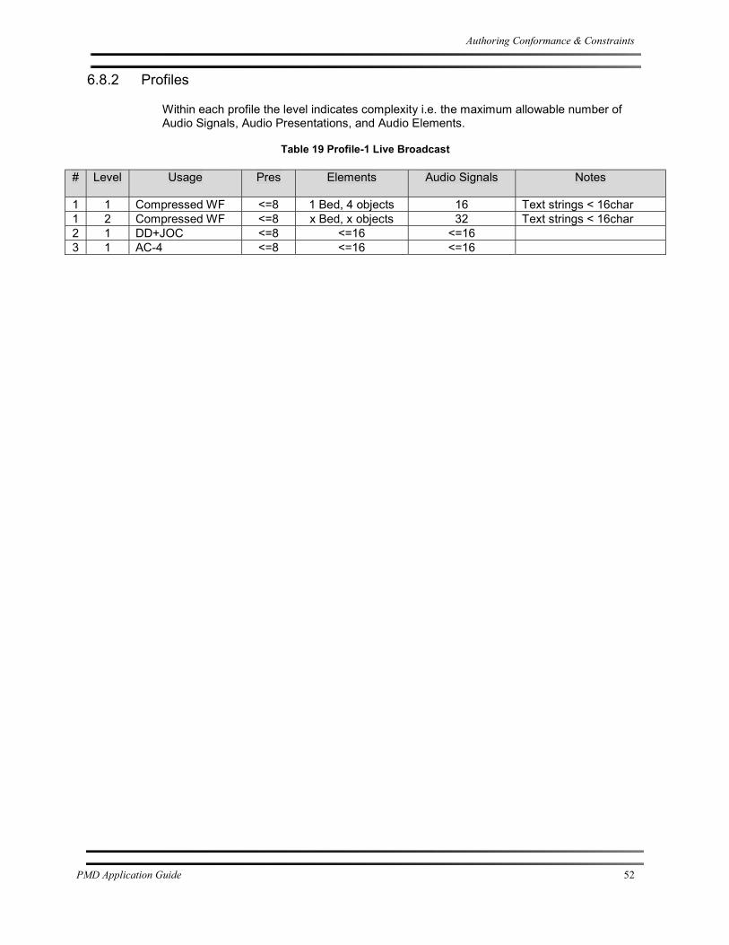
Authoring Conformance & Constraints
PMD Application Guide 52
6.8.2 Profiles
Within each profile the level indicates complexity i.e. the maximum allowable number of Audio Signals, Audio Presentations, and Audio Elements.
Table 19 Profile-1 Live Broadcast
# Level Usage Pres Elements Audio Signals Notes
1 1 Compressed WF <=8 1 Bed, 4 objects 16 Text strings < 16char 1 2 Compressed WF <=8 x Bed, x objects 32 Text strings < 16char 2 1 DD+JOC <=8 <=16 <=16 3 1 AC-4 <=8 <=16 <=16

Host Application User Interface Additions
PMD Application Guide 53
User Interface Additions
Host Application User Interface Additions
Advanced audio authoring requires the addition of several parameters to correctly label and classify Audio Elements. For mixing console applications, these would be added to the channel strip. For software-only applications, these would be part of an Audio Element’s structure. The following tables contain a minimal set that would be required to enable basic live sporting event workflows.
Table 20 Audio Object Description (AOD) – Minimal Implementation
Parameter PMD Spec Section Notes
class 5.5.3.2 Indexed list of items (Dialog, Spoken Subtitle etc.) dynamic_update 5.5.3.3 On/Off, Yes/No, Enabled/Disabled x_pos 5.5.3.4 Requires 5.1 panning y_pos 5.5.3.5 Requires 5.1 panning z_pos 5.5.3.6 Requires 3D panning diverge 5.5.3.9 On/Off, Yes/No, Enabled/Disabled source 5.5.3.10 Channel number
Table 21 Audio Bed Description (ABD) – Minimal Implementation
Parameter PMD Spec Section Notes
speaker_config 5.4.3.2 Indexed list of items (5.1.2, 7.1.4 etc.) target 5.5.3.5 Indexed list of items, speaker designations, (Left/Right etc.) source 5.5.3.6 Channel number
The last step is to group various Audio Elements together to create an Audio Presentation.
Table 22 Audio Presentation Description (APD) – Minimal Implementation
Parameter PMD Spec Section Notes
speaker_config 5.1.3.2 Indexed list of items (5.1.2, 7.1.4 etc.) langcod 5.1.3.3 Language of the presentation

User Interface Examples
PMD Application Guide 54
User Interface Examples
The following screenshots illustrate several ways that have been used to configure/indicate the status of metadata parameters and the grouping of Audio Elements.

User Interface Examples
PMD Application Guide 55

User Interface Examples
PMD Application Guide 56


![Akademika64[03].pmd - akademika64[01]](https://static.fdokumen.com/doc/165x107/6318ef2077252cbc1a0e76df/akademika6403pmd-akademika6401.jpg)