
Plant layout for rehabilitation centers - Oregon State University
58
AN ABSTRACT OF THE THESIS OF JAYANT T. INGLE for the MASTER OF SCIENCE (Name) (Degree) in INDUSTRIAL AND GENERAL ENGINEERING presented on (Major Department) (Bate) Title: PLANT LAYOUT FOR REHABILITATION CENTERS: A CASE STUDY AND GENERAL CONSIDERATIONS. Abstract approved: Redacted for Privacy Or. Stephen Love This paper approaches the problem of arranging facilities and moving materials in a sheltered workshop, or rehabilitation center, employing handicapped people. Traditional plant layout and material handling principles, along with human engineering principles, are used for developing a layout for Open Door Incorporated, a sheltered workshop located in Corvallis, Oregon. Experi- ence in developing this layout was used as a basis for postulating general criteria which should be considered in laying out any sheltered workshop. The study gives primary consideration to safety of workers, flexibility of operation, worker convenience and worker training. It was found that traditional plant layout principles required modifications and the human engineering factors played a critical role in the design.
-
Upload
khangminh22 -
Category
Documents
-
view
4 -
download
0
Transcript of Plant layout for rehabilitation centers - Oregon State University
AN ABSTRACT OF THE THESIS OF
JAYANT T. INGLE for the MASTER OF SCIENCE(Name) (Degree)
in INDUSTRIAL AND GENERAL ENGINEERING presented on(Major Department) (Bate)
Title: PLANT LAYOUT FOR REHABILITATION CENTERS: A CASE
STUDY AND GENERAL CONSIDERATIONS.
Abstract approved:Redacted for Privacy
Or. Stephen Love
This paper approaches the problem of arranging
facilities and moving materials in a sheltered workshop,
or rehabilitation center, employing handicapped people.
Traditional plant layout and material handling principles,
along with human engineering principles, are used for
developing a layout for Open Door Incorporated, a
sheltered workshop located in Corvallis, Oregon. Experi-
ence in developing this layout was used as a basis for
postulating general criteria which should be considered
in laying out any sheltered workshop. The study gives
primary consideration to safety of workers, flexibility
of operation, worker convenience and worker training.
It was found that traditional plant layout principles
required modifications and the human engineering factors
played a critical role in the design.
PLANT LAYOUT FOR REHABILITATION CENTERS:A CASE STUDY AND GENERAL CONSIDERATIONS
by
JAYANT T. INGLE
A THESIS
submitted to
Oregon State University
in partial fulfillment ofthe requirements for the
degree of
MASTER OF SCIENCE
June 1975
APPROVAL:
Redacted for PrivacyAssistant 171Ofecsor ofIndUsItrial and GeneralEngineering
in charge of major
Redacted for PrivacyDen, School of"Enrgtlieeri/
Redacted for Privacy
Dean of Graduate School
Date thesis is presented
Typed by Mary Syhlman for JAYANT T. INGLE
ACKNOWLEDGEMENT
I am deeply indebted to Dr. Stephen F. Love for his
most friendly academic assistance and guidance during the
preparation of this thesis.
I also wish to express my sincere gratitude to
Dr. James L. Riggs for the opportunity given to me to do
the graduate work and for his expert practical suggestions.
I extend my appreciation and thanks to Professor John
C. Campbell and Dr. Michael S. Inoue of Industrial and
General Engineering, Dr. Clifford F. Gray of the School
of Business and Management of Open Door Incorporated for
their help and assistance during the course of this study.
At last, but by no means least, special thanks to
Mrs. Mary Syhiman for her superb job of typing.
TABLE OF CONTENTS
Chapter Page
I INTRODUCTION AND CHAPTER SUMMARY 1
II DESCRIPTION OF OPEN DOOR INC. 5
III MATERIAL FLOW AND SPACE REQUIREMENTFOR OPEN DOOR INC. 14
IV A PROPOSED LAYOUT FOR OPEN DOOR INC. 24
V GENERALIZED GUIDELINE FOR PLANT LAYOUTFOR REHABILITATION CENTER. 34
BIBLIOGRAPHY 49
APPENDICES
Appendix A - 1 -- Flow Diagram forwood working
Appendix B - 1 -- Flow Diagram forNeptune
50
51
LIST OF EXHIBITS
1-1 Pictorial Representation of Considerationfor Plant Layout in Rehabilitation Centers. 3
2-1 Chain of Command in Open Door Inc.
3-1 Calculation of Entries for the From-ToChart. 17
3-2 From-To Chart for the Department of OpenDoor Inc. 18
3-3 Activity Relationship Chart for theDepartments in Open Door Inc. 22
4-1 A Proposed Plant Layout for Open DoorInc. (Separate)
4-2 Working Table to be Used in the AssemblyArea. 28
4-3 Illumination Standards Recommended by theIES for Several Selected Types of Situationand Tanks.
5-1
5-2
5-3
Accident Analysis for Accidents in OregonRehabilitation Centers, 1972.
Recommended Aisle Width in the Plant.
33
43
/4
Maximum Weight that can be Lifted toVarious Heights. 45
5-4 Guideline for Developing Plant Layoutin Rehabilitation Centers. 46
PLANT LAYOUT FOR REHABILITATION CENTERS:A CASE STUDY AND GENERAL CONSIDERATIONS
CHAPTER I
INTRODUCTION AND CHAPTER SUMMARY
In the following study, an attempt is made to deter-
mine general principles a designer should follow for mak-
ing a plant layout for a rehabilitation center. According
to the Department of Vocational Rehabilitation, U.S.
Government; a rehabilitation center or Sheltered Workshop,
is defined as follows:
A rehabilitation center is a facilitywhich is operated for the primarypurpose of assisting the rehabilitationof disabled persons through an integratedprogram of medical, psychological, socialand vocational evaluation and servicesunder complete professional supervisionand in the case of which the major portionof such evaluation and services is furnishedwithin the facility.
The above definition indicates that these centers
should assist the process of rehabilitation through
vocational training. They should be planned considering
the traditional layout principles; at the same time
thought should be given to the fact that they employ
handicapped people.
Traditional plant layout and human engineering
principles can be stated as follows:
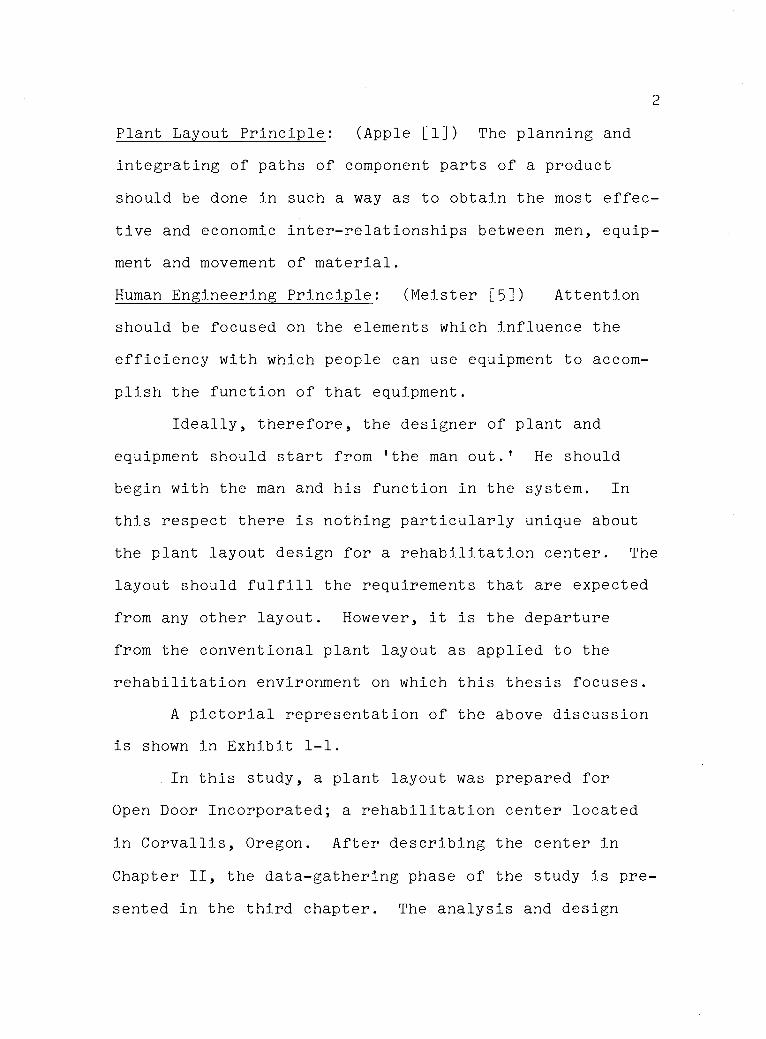
2
Plant Layout Principle: (Apple [1]) The planning and
integrating of paths of component parts of a product
should be done in such a way as to obtain the most effec-
tive and economic inter-relationships between men, equip-
ment and movement of material.
Human Engineering Principle: (Meister [5]) Attention
should be focused on the elements which influence the
efficiency with which people can use equipment to accom-
plish the function of that equipment.
Ideally, therefore, the designer of plant and
equipment should start from 'the man out.' He should
begin with the man and his function in the system. In
this respect there is nothing particularly unique about
the plant layout design for a rehabilitation center. The
layout should fulfill the requirements that are expected
from any other layout. However, it is the departure
from the conventional plant layout as applied to the
rehabilitation environment on which this thesis focuses.
A pictorial representation of the above discussion
is shown in Exhibit 1-1.
In this study, a plant layout was prepared for
Open Door Incorporated; a rehabilitation center located
in Corvallis, Oregon. After describing the center in
Chapter II, the data-gathering phase of the study is pre-
sented in the third chapter. The analysis and design
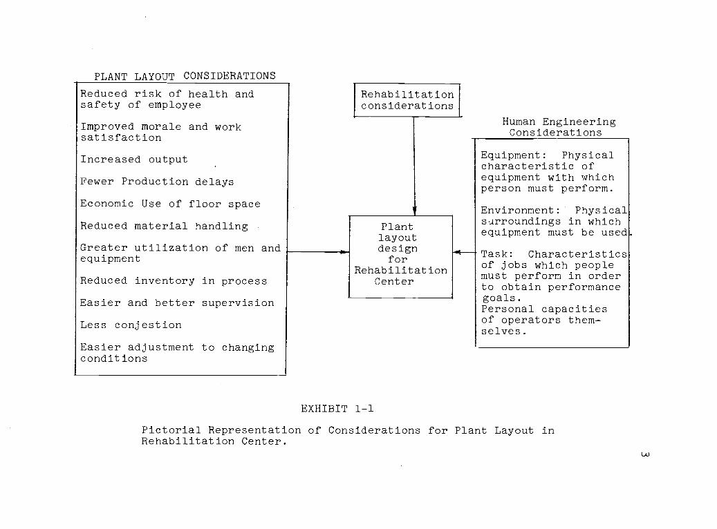
PLANT LAYOUT CONSIDERATIONS
Reduced risk of health andsafety of employee
Improved morale and worksatisfaction
Increased output
Fewer Production delays
Economic Use of floor space
Reduced material handling
Greater utilization of men andequipment
Reduced inventory in process
Easier and better supervision
Less conjestion
Easier adjustment to changingconditions
Rehabilitationconsiderations
fPlantlayoutdesignfor
RehabilitationCenter
EXHIBIT 1-1
Human EngineeringConsiderations
Equipment: Physicalcharacteristic ofequipment with whichperson must perform.
Environment: Physicalsurroundings in whichequipment must be used
Task: Characteristicsof jobs which peoplemust perform in orderto obtain performancegoals.Personal capacitiesof operators them-selves.
Pictorial Representation of Considerations for Plant Layout inRehabilitation Center.
1-0
4
phase of the project are related in Chapter IV.
The design consideration developed for this layout
were used in the development of general principles for
plant layout design in any Rehabilitation Center. These
principles are explained in Chapter V. Other input to
the development of these principles were obtained by
consultation with the executives of the following
Rehabilitation Centers:
Open Door Inc.; 550 SW 7th, Corvallis, OR 97330
Willamette Valley Rehabilitation Center,4390 Santiam Hwy., Lebanon, OR 97355
Workshops Inc.; 212 Forest Ave., FondDu Lac, WIS 54935
5
CHAPTER II
DESCRIPTION OF OPEN DOOR, INC.
Open Door Inc. is a sheltered workshop, established
on February 21, 1964, at which time it served only
mentally retarded people. At present 55 handicapped
workers of all types are employed in the plant. The
company is planning to expand to three times its present
capacity within five years.
The goals of the company are rehabilitation of
handicapped people, development of a public awareness of
employment of the handicapped, and vocational training.
The primary means of financial support is by con-
tracting with various companies. Typically, contract
work involves wood working (manufacturing of pallets,
stakes and hubs); rough and clean assembly (rough assembly
includes buffing and polishing of telephones; clean
assembly includes manufacturing of plastic parts, assembl-
ing cardboard crates and electronic component assembly);
and warehousing (receiving material and equipment, pack-
ing and storing it, and shipping it out when ordered).
All of the above operations are performed year round.
The anticipated expansion will involve expansion of all
the above departments.
6
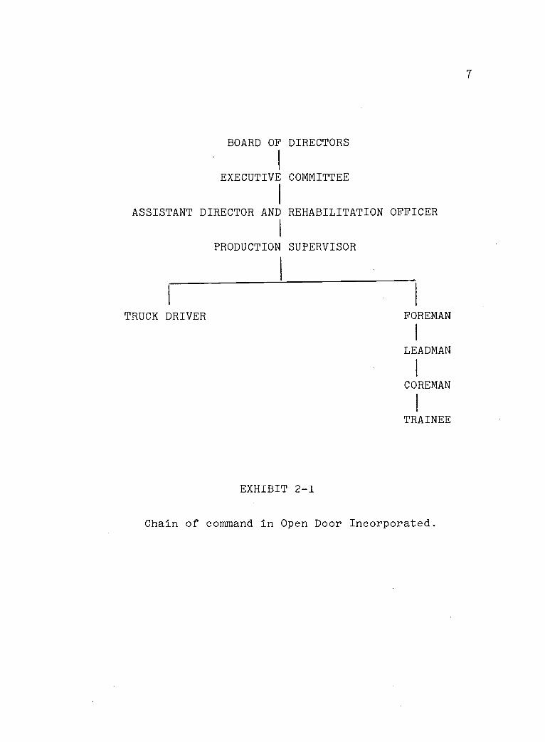
The overall chain of command is shown in Exhibit
2-1. The production supervisor is responsible for safety
and production from all departments. Every department
has a foreman who is in turn responsible for the safety
and production in his department. The leadman and the
coreman are experienced workers, responsible for perform-
ing a particular machining operation. Trainees are the
workers under training. They are used primarily for
material handling and other simple non-hazardous opera-
tions.
A short description of the activities and the exist-
ing problems of each department are explained in the
following paragraphs.
Wood Working Department
This department has an area of 5000 sq. ft. and an
average of 36 workers. On the average, the raw material
inventory is 6 truck loads. (One truck load has dimen-
sions of 24' x 8' x 8'.) The average flow of raw material
through the department is 6 truck loads per month. About
25 percent of the raw material becomes waste in the form
of saw dust and chips. This raw material is in the form
of boards of lumber 24' in length and of varying widths
and thicknesses. It is stored outside the building. When
needed, it is placed on a hand driven dolly and moved
7
BOARD OF DIRECTORS
EXECUTIVE COMMITTEE
ASSISTANT DIRECTOR AND REHABILITATION OFFICER
PRODUCTION SUPERVISOR
TRUCK DRIVER
EXHIBIT 2-1
1
FOREMAN
I
LEADMAN
I
COREMAN
I
TRAINEE
Chain of command in Open Door Incorporated.
8
to the work station by two workers. It takes 10 trips
with a dolly to move one truck load.
Raw material is cut first on an XL ripping saw,
after which it is cut to length on Irvington saws. It is
then taken to sharpeners or table saws to make points on
both ends. This is the sequence of operation for stakes,
hubs and laths. The other primary product is pallets.
The finished products are stored on 4' x 3' pallets and
carried to storage by a fork lift truck.
Problems in woodworking can be summarized as
follows. Due to unplanned expansion, space is inadequate.
There is not enough storage space either for raw material
or for finished products. They are usually stored outside
the building - wherever space is available. There is not
enough room available for in process inventory. Due to
inadequate space, material handling is a constant problem.
Raw material and in process inventory get piled up in the
aisles. The foreman doesn't have an office near his
department, so he has to walk through other departments
frequently. Saw dust collection in the department is
inadequate. There is no hopper. Saw dust is collected
in wooden boxes. This takes place within the department;
and so some saw dust is in the air.
9
Assembly Department
This department, employing an average of 25 workers,
includes two sub-departments: rough assembly and clean
assembly. The rough assembly department works on buffing,
cleaning and polishing of telephones. The used telephones
which comprise the raw material for the department, are
stacked in cardboard boxes which can be moved by one
person. Telephones are first machine-buffed, after which
they are hand polished. The operations are intermittant;
average inventory and volume fluctuate widely.
The clean assembly sub-department deals with
electronic component assembly, manufacturing plastic
washers and assembly of cardboard boxes. These activities
can be considered as three separate assembly lines.
Workers working on the different products work next to
each other and there is usually a mixed line. All the
material handling is strictly manual.
Problems in the assembly department can be explained
as follows: Assembly has an area of 700 sq. ft., not
including any storage. This makes the movement of the
workers very difficult. The foreman does not have an
office near the department to do his paperwork.
Various types of inconveniences are present in
this department. Some workers in this department have
a tendency to stare at each other. This staring habit,
10
accompanied by the crowded condition, reduces the pro-
ductivity of the department. The arrangement of the
department causes difficulty in inspection of the quality
of product. The foreman cannot reach every work-station
easily.
Neptune Warehouse
This department stores material for Neptune Micro-
floc of Corvallis. Basic operations include receiving
media and equipment; building containers or pallets for
storage; storing the media and shipping it back as ordered
by Neptune Microfloc. Media is building material in the
form of gravel, granite, and sand. Thirty bags of media,
50 lbs. each, are stored per pallet.
The warehouse has an area of 2500 sq. ft.
Typically, 5 workers work in the department. Media is
brought to the department by rail while the equipment is
delivered by truck. On the average, 75000 lbs. of media
is received and shipped every month. It is neither
possible to find the rate at which equipment is shipped
to the warehouse nor can it be estimated. It depends
totally on the external agency. On the average, there
are 7 pieces of equipment in storage.
Several problems related to Neptune warehouse have
been identified. Most of the floor space is covered by

11
material. The crates and containers are strictly wooden.
There is not enough space in the department to manufacture
them, so they are manufactured in the woodworking depart-
ment. Woodworking is already crowded and the Neptune
foreman has to spend a lot of time in moving between the
departments. Since workers use pneumatic saws in manu-
facturing crates, it is important that the foreman is
near his department. He does not have an office near his
department from which he can supervise all the workers.
There is no aisle in the department. Previously
there might have been an aisle but it is occupied by
equipment in storage. Whenever material has to be shipped
or stored, the aisle has to be cleared first. This causes
unnecessary cost of using the fork lift truck. Lighting
in the department is very poor. Since the material is
stacked high on the pallets, the storing and unloading
of the crates in bad light appears to be very hazardous.
General Plant Situation
As can be seen from the above description, problems
in all the departments can be classified under the cate-
gories of space, material handling, safety, supervision
and inconvenience. This study concentrates on these
categories and an attempt is made to lay out the new plant
in such a way as to minimize these problems.
12
In general, plant wide problems in Open Door Inc.
can be summarized as follows:
The most important problem is conjestion. Conjes-
tion can be considered with regard to workers, materials,
and at the loading docks. Raw material and finished
products are in the aisles and near loading docks. In-
process inventory is stored between work stations and
in aisles. This makes material handling extremely diffi-
cult. The majority of shipping is done by truck. There
is no useable truck loading dock or ramp at the present
plant.
Collection of saw dust is inadequate. It contam-
inates the finished products from assembly, necessitating
rework. Office and wood-working are located near each
other without a sufficient dust and noise barrier.
Poor working environment is another major problem
in the present plant. Workers do not have a suitable
place to eat lunch. They have to use outside premises
or aisles as the lunch room. Wash rooms are inadequate
and poorly lit. Since raw material is stored outside,
some workers have to work outside the building. There is
no shelter from rain or snow. Workers come back inside
the plant if it rains heavily. This aggrevates the
already crowded condition.
13
This chapter has explained the problems and
difficulties within the individual departments and of the
overall plant. To allocate appropriate space and arrange
facilities in the new plant, material flow and space
requirement information is necessary. This data collec-
tion is explained in the next chapter.
l4
CHAPTER III
MATERIAL FLOW AND SPACE REQUIREMENTS FOR OPEN DOOR INC.
Traditionally the most important consideration in
the layout design is material flow. Efforts to develop
a quantitative model to represent flow of material can
pay off since such flows and their associated costs can
be estimated. Many of the other critical factors (e.g.,
ease of inspection) are not so readily measurable but
nonetheless must be considered in the design.
The approach taken here is (i) to develop a
quantitative model of the costs of the material flows and
(ii) to use this model as input to a larger qualitative
model in which all major factors affected by facility
layout are accounted for. The quantitative representation
is called a From-to-Chart which reflects flow costs based
on flow activity volume, wages and hourly machine operat-
ing costs. The qualitative considerations are formalized
in an Activity Relationship Chart, in which the relative
importance of the distance between each pair of activities
in the plant is rated. The two models are now developed.
Development of the From-To-Chart
The entry in the From-To-Chart can be expressed as
$ / Unit time / Unit Distance
15
For manual labor this entry would take the form
(wages/hour) (no. of trips/month) / (speed oftravel)
For machine labor, the entry would appear as
(machine operating cost) (frequency of travel) /(speed of travel)
Typically, the cost of moving material between two depart-
ments include both wages of the driver and the cost of
running the material handling equipment. The number of
trips per month represents average number of trips, a
fork lift truck makes between two departments. To get
these figures, the foreman of each department was instru-
cted to keep a record of trips he made between each
department for a period of one week. These figures were
adjusted to one month. The average speed of material
handling equipment was found to be 4 miles per hour.
The from-to chart calculations include only material
movements; information flow and personnel flow are not
quantified. Departments having relevant flows are the
main office, Neptune warehouse, wood working, raw
material storage, finished products storage, waste
storage, wash rooms, lunch room and shipping and receiv-
ing.
Material moved consists of raw material, in-process
inventory, finished products or scrap. Material handling
in the assembly area is strictly manual. The workers
16
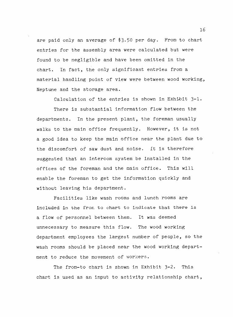
are paid only an average of $3.50 per day. From to chart
entries for the assembly area were calculated but were
found to be negligible and have been omitted in the
chart. In fact, the only significant entries from a
material handling point of view were between wood working,
Neptune and the storage area.
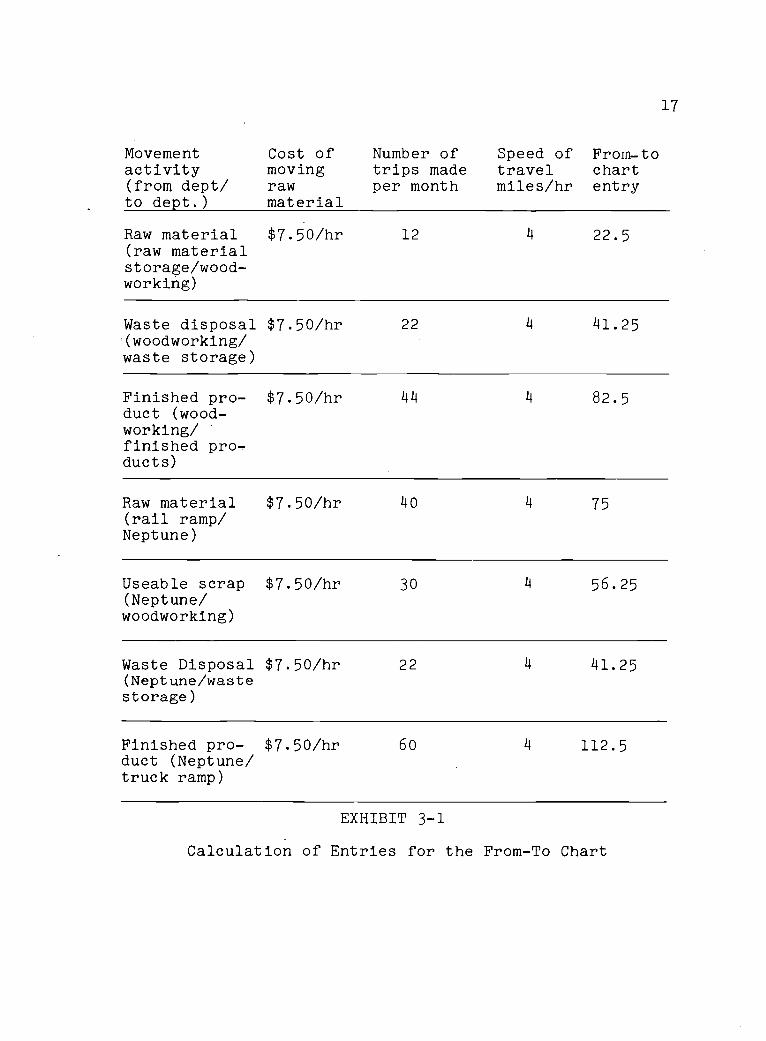
Calculation of the entries is shown in Exhibit 3-1.
There is substantial information flow between the
departments. In the present plant, the foreman usually
walks to the main office frequently. However, it is not
a good idea to keep the main office near the plant due to
the discomfort of saw dust and noise. It is therefore
suggested that an intercom system be installed in the
offices of the foreman and the main office. This will
enable the foreman to get the information quickly and
without leaving his department.
Facilities like wash rooms and lunch rooms are
included in the from to chart to indicate that there is
a flow of personnel between them. It was deemed
unnecessary to measure this flow. The wood working
department employees the largest number of people, so the
wash rooms should be placed near the wood working depart-
ment to reduce the movement of workers.
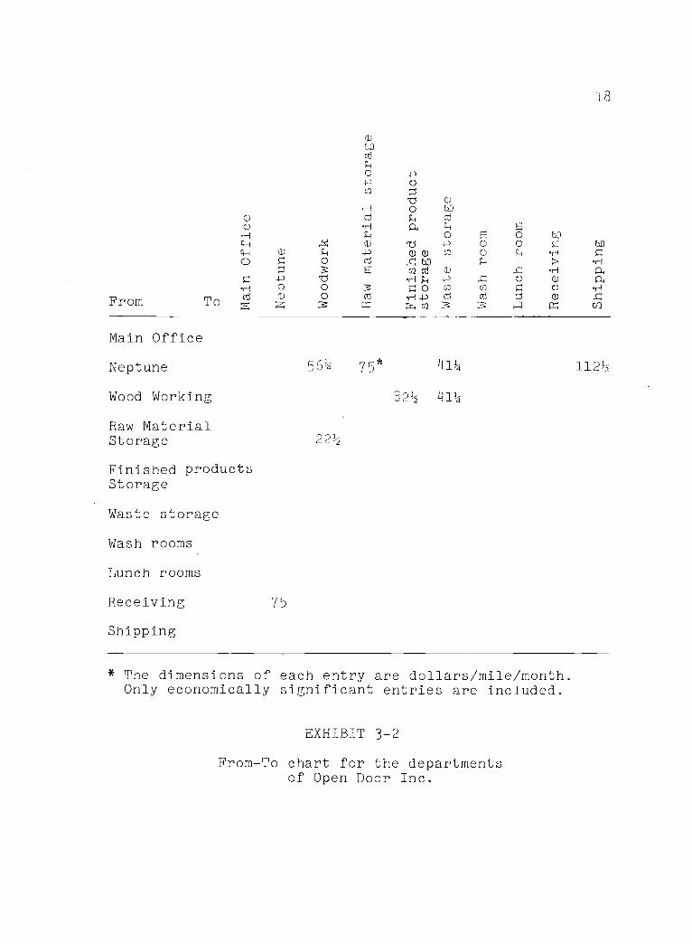
The from-to chart is shown in Exhibit 3-2. This
chart is used as an input to activity relationship chart,
Movementactivity(from dept/to dept.)
Cost ofmovingrawmaterial
Number oftrips madeper month
Speed of From-totravel chartmiles/hr entry
17
Raw material $7.50/hr(raw materialstorage/wood-working)
12 4 22.5
Waste disposal $7.50/hr(woodworking/waste storage)
22 14 141.25
Finished pro- $7.50/hr 44duct (wood-working/finished pro-ducts)
4 82.5
Raw material $7.50/hr(rail ramp/Neptune)
4o 75
Useable scrap $7.50/hr(Neptune/woodworking)
30 4 56.25
Waste Disposal $7.50/hr(Neptune/wastestorage)
22 141.25
Finished pro- $7.50/hrduct (Neptune/truck ramp)
60 14 112.5
EXHIBIT 3-1
Calculation of Entries for the From-To Chart
From To C
C
oo hO
0:3
o-P 0
(1)(1) cr) 0
cd (1)
Ho ci]
,-1 4-) Cd cdcn
Main Office
Neptune
Wood Working
Raw MaterialStorage
Finished productsStorage
Waste storage
Wash rooms
Lunch rooms
Receiving
Shipping
75
18
bp0rH
cf)
561/4 75* 414 1121-5
221/2
822 414
* The dimensions of each entry are dollars/mile/month.Only economically significant entries are included.
EXHIBIT 3-2
From-To chart for the departmentsof Open Door Inc.
19
which is explained in the development of a quantitative
model.
Development of Activity Relationship Chart
As can be observed, there are not many entries in
the from to chart. The logical thing to do is to keep
the departments with significant interactions as close
together as possible. This can be a little misleading.
Although there is a large information flow between the
main office and wood-working, it is not advisible to
keep these departments near each other. Such considera-
tions are reflected in an activity relationship chart.
The plant layout is more activity oriented than flow
oriented. Thus, material flow is only one of the many
considerations in designing department arrangements.
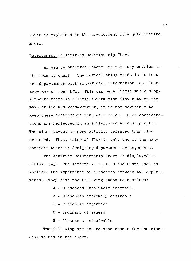
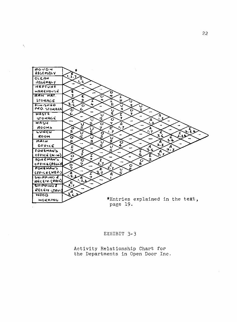
The Activity Relationship chart is displayed in
Exhibit 3-3. The letters A, E, I, 0 and U are used to
indicate the importance of closeness between two depart-
ments. They have the following standard meanings:
A - Closeness absolutely essential
E - Closeness extremely desirable
I - Closeness important
0 - Ordinary closeness
U - Closeness undesirable
The following are the reasons chosen for the close-
ness values in the chart.
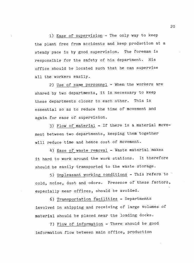
20
1) Ease of supervision - The only way to keep
the plant free from accidents and keep production at a
steady pace is by good supervision. The foreman is
responsible for the safety of his department. His
office should be located such that he can supervise
all the workers easily.
2) Use of same personnel - When the workers are
shared by two departments, it is necessary to keep
these departments closer to each other. This is
essential so as to reduce the time of movement and
again for ease of supervision.
3) Flow of material - If there is a material move-
ment between two departments, keeping them together
will reduce time and hence cost of movement.
4) Ease of waste removal - Waste material makes
it hard to work around the work stations. It therefore
should be easily transported to the waste storage.
5) Unpleasant working conditions - This refers to
cold, noise, dust and odors. Presence of these factors,
especially near offices, should be avoided.
6) Transportation facilities - Departments
involved in shipping and receiving of large volumes of
material should be placed near the loading docks.
7) Flow of information - There should be good
information flow between main office, production
21
supervisor and foremen. Similar flow also should exist
between foremen and his staff.
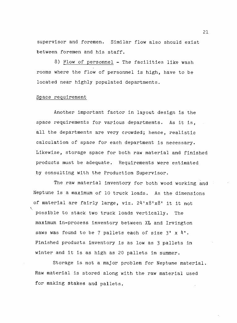
8) Flow of personnel - The facilities like wash
rooms where the flow of personnel is high, have to be
located near highly populated departments.
Space requirement
Another important factor in layout design is the
space requirements for various departments. As it is,
all the departments are very crowded; hence, realistic
calculation of space for each department is necessary.
Likewise, storage space for both raw material and finished
products must be adequate. Requirements were estimated
by consulting with the Production Supervisor.
The raw material inventory for both wood working and
Neptune is a maximum of 10 truck loads. As the dimensions
of material are fairly large, viz. 24'x8'x8' it it not
possible to stack two truck loads vertically. The
maximum in-process inventory between XL and Irvington
saws was found to be 7 pallets each of size 3' x 4'.
Finished products inventory is as low as 3 pallets in
winter and it is as high as 20 pallets in summer.
Storage is not a major problem for Neptune material.
Raw material is stored along with the raw material used
for making stakes and pallets.
P 0 ..) C: -iASSE MaLYc L E. 14 PIlSeme,i.iisiePrvi4;uwActe.14Ovi.012+414 mAT.StoRp,c, g
Fos isi-i GoPRO- STORAGE
WASI. E9.7 o RAGE
V4,1 A s H
Ro0msLV4CU
ROOM0441%.Co; -Pict
POREmAhli.SLw 04..cFPICC
FOR eiviArviN
oFCICQ(AsixyiFORS mi414's.CFPILE (WEI%)S4 PPNO 4RGCEIv Vzi*i)9.0 Ipp,NoEc1v LTRyLlV4000
INORKINCi
22
*Entries explained in the text,page 19.
EXHIBIT 3-3
Activity Relationship Chart forthe Departments in Open Door Inc.
23
As explained in Chapter I, material for assembly
is stored in an attic. It is estimated that the storage
space for assembly should be 700 sq. ft. This space
will be utilized for storing raw material, finished
products and extra containers.
The factors considered in this chapter are con-
sidered heavily in the layout design presented in the next
chapter.
24
CHAPTER IV
A PROPOSED PLANT LAYOUT FOR OPEN DOOR INC.
Development and justification for the layout of
individual departments as well as the arrangement of
the overall plant is presented in this chapter. The
reader should refer to Exhibit 4-1 as he reads this
chapter.
The woodworking department handles the largest
volume of material. It is therefore desirable that the
material should not be subjected to any unnecessary move-
ment. This is achieved in the proposed layout. Raw
material is brought into the department from the raw
material storage and finished products are stored at the
opposite end. A maximum raw material inventory of ten
truck loads is provided for (a truck load has dimensions
of 24' x 8' x 8'). The material is moved to work
stations by dollies in the present plant. This method
is not efficient. It is proposed that a conveyor be
used for moving raw material to the XL saw. This will
avoid any accumulation of material in front of the XL
saw.
In the present plant, raw material is stored on
pallets or on the ground where ever space is available.
Another method is suggested here. Dollies should be
25
fabricated for storing one truck-load. When the raw
material is received, it should be stored on these
dollies. Whenever needed, one of these dollies can be
pulled out and taken to the head of a simple roller
conveyor. There is another roller placed between the
conveyor and the dolley, so that the material handler
does not actually have to completely lift the boards.
He just has to slide them over this roller. It is also
suggested that there should be a suitable shelter where
the material handler feeds the material to the conveyor
since this work is performed outside the building.
Another roller conveyor should be placed directly above
the XL saw. The cutting of any board on XL is not com-
plete in one pass through the saw. The uncut portion of
the board has to be fed back to the XL saw. This portion
can be slid back over this conveyor.
The woodworking department, excluding raw material
storage, has an area of 150' x 47'. It is anticipated
that in the near future two more Irvington saws will be
acquired. Enough space is provided for this expansion.
Many times two different products are manufactured in the
department at the same time. For this purpose two
separate blocks of space are provided. After cutting
on the Irvington, material to be used for pallet making
can be moved backwards, as shown in Exhibit 4-1. The
26
Production Supervisor's office is placed near the Irving-
ton saws. The foreman's office is placed near the sharp-
eners. Sharpeners are the saws for making points to the
stakes. It is suggested that these offices should be
placed five feet above the ground level, so that the
whole department can be supervised easily. Between the
Irvingtons and the sharpeners, a space of 15' is provided
for in-process storage.
The width of the main aisles is 15'. To the side
of the main aisles is provided a sub-aisle 3' in width.
This aisle is strictly to be used by pedestrians, workers
in wheel chairs or on crutches. This will help in keep-
ing material handling unobstructed and will hold down
accidents. Yellow lines should be painted on the floor
indicating the main aisles. The sub-aisles should also
be painted yellow and with stripes.
It is suggested that there be truck ramps for load-
ing and unloading at three locations. Neptune receives
media from rail cars but it is shipped back by truck.
All the receiving and shipping in woodworking is done by
truck. One ramp should therefore be placed near the raw
material storage. A second ramp should be placed near the
finished product storage; and the third near the Neptune
warehouse. There are no such ramps at the present plant.
A capacity of three ramps may seem to be excess at pre-
27
sent, but in the future, when the volume of activity
increases, the ramps will provide for easy handling of
material. It is suggested that a hopper be installed
near the woodworking department to remove saw dust and
chips.
In the assembly department, a storage area of
1320 sq. ft. is provided. A special type of bench should
be fabricated for this department. Such a bench is shown
in Exhibit 4-2. This bench is designed according to the
Human Engineering principles of ease of working and
maximum work area that can be utilized by any worker with
ease (McCormick[4]). The worker will be seated in the
circular notch. Such an arrangement is extremely useful
for the movement of material. As explained in Chapter I,
all the material movement in the assembly is manual. It
is suggested that the arrangement of the work station be
in a U-shape, as shown in Exhibit 4-1. The product will
start at one end and will be completed at the other end.
In-process inventory will be stored on the benches between
each pair of workers. Such an arrangement will also pro-
vide enough room for the foreman to observe individual
workers and check the quality of product without disturb-
ing the flow of material on the line. All the benches
should be separately fabricated. This may seem costly;
but it has very important implication. An important
problem frequently faced by this department is the change

28
C, 0"
EXHIBIT 4-2
Working table to be used in theassembly area
29
of product mix. The foreman has difficulty changing the
layout to accommodate any new product. Individual benches
will help in solving this problem. The foreman can move
smaller benches more easily to make changes, either to
make more room or make more production lines.
It was explained in Chapter I that the major pro-
blem in the assembly department is some of the workers
have a tendency to stare at each other. The foreman and
the Rehabilitation officer have suggested that a good way
to train these workers is by keeping them separated from
other workers. This is accomplished by the proposed lay-
out.
This department does not use any material moving
equipment. Therefore aisle width of 6' is sufficient.
Individual workers can be seated on the other side of
the aisle (cf. Exhibit 4-1). This will enable the fore-
man to supervise all the department with ease and also
assure a steady production pace.
Neptune has a designated area of 4400 sq. ft. One
wall is used for storing media. Equipment will be stored
along the other wall. The aisle is 15' in width with a
pedestrian aisle adjacent to it. Neptune does most of its
crate manufacturing in the woodworking area. This should
be avoided in the future. Am empty block of space has
been left open for crate manufacturing as wood assembly.
In the present plant, initial cutting is done by the XL
saw. The Open Door executives have not decided whether
to install a new XL saw in Neptune to perform this
initial cutting or to use the saw in woodworking and bring
cut pieces to Neptune for assembly of crates. As
explained in Chapter I, the XL saw can cut enough
material for 8 Irvington saws. It has been decided by
the executives that the new plant will have 6 Irvington
saws. The spare capacity of XL can then be used for
Neptune. In the future, when woodworking expands, Neptune
might need an additional saw. Enough space is provided
in the layout for this expansion.
The main office and lunch room are secondary con-
siderations. Location of these facilities can be arranged
after the selection of site. (When this study was con-
ducted, Open Door Inc. was interested in a particular
plant site at which office and lunch room were already
constructed.)
In the latter part of this study, it is indicated
that there should be a training facility in the Rehabilita-
tion Center to train workers about different jobs. The
exact location of this center and its arrangement is a
secondary consideration, to be ascertained after deciding
upon the site.
31
Flow diagrams of material handling operation for the
existing plant are provided in the Appendix 1-A and 1-B.
Flow diagram for the proposed layout is provided in
Appendix 1-C. These flow diagrams should help in under-
standing the simplicity in material handling and smooth-
ness in material flow in the proposed layout.
This industry handles a large volume of lumber.
Hence, an adequate fire protection system is essential.
Fire caused by lumber is grouped under Class A fire by
State Accident Insurance. It is suggested by State
Accident Insurance Fund that water type fire extinguishers
are satisfactory against such fires. There is electrical
equipment in the plant so it might be better to use
carbon dioxide type extinguishers instead. These
extinguishers should, of course, be easily accessible.
Care should be taken that no material be stacked in front
of them at any time. If the water type fire extinguisher
is used, it should not be any larger than 3 gallons
capacity. Any heavier extinguisher is very hard to carry
and operate. The Accident Prevention Manual [10] has
suggested the following requirements.
32
At least one unit for each 2500 sq. ft.of floor area plus additional units asrequired by the inspection departmenthaving justification. Units locatedwithin 50' of persons required to usethem.
One such unit should be located between XL and
Irvington saws, and another located between Irvington
and sharpeners. A similar extinguisher should be provided
in assembly and Neptune. It is also important that the
employees do not panic in case of fire hazard and that
they know what procedure to follow. This can only be
emphasized by fire drills. It is therefore suggested that
fire drills be conducted in the plant. This will help
workers in case of an emergency. Lighting standards
for the plant are shown in Exhibit 4-3. The plant should
comply with them.
The plant layout and related considerations have
been discussed in this chapter. In the next chapter, an
attempt is made to provide general guideline which a
designer should follow while preparing a plant layout for
any Rehabilitation Center.
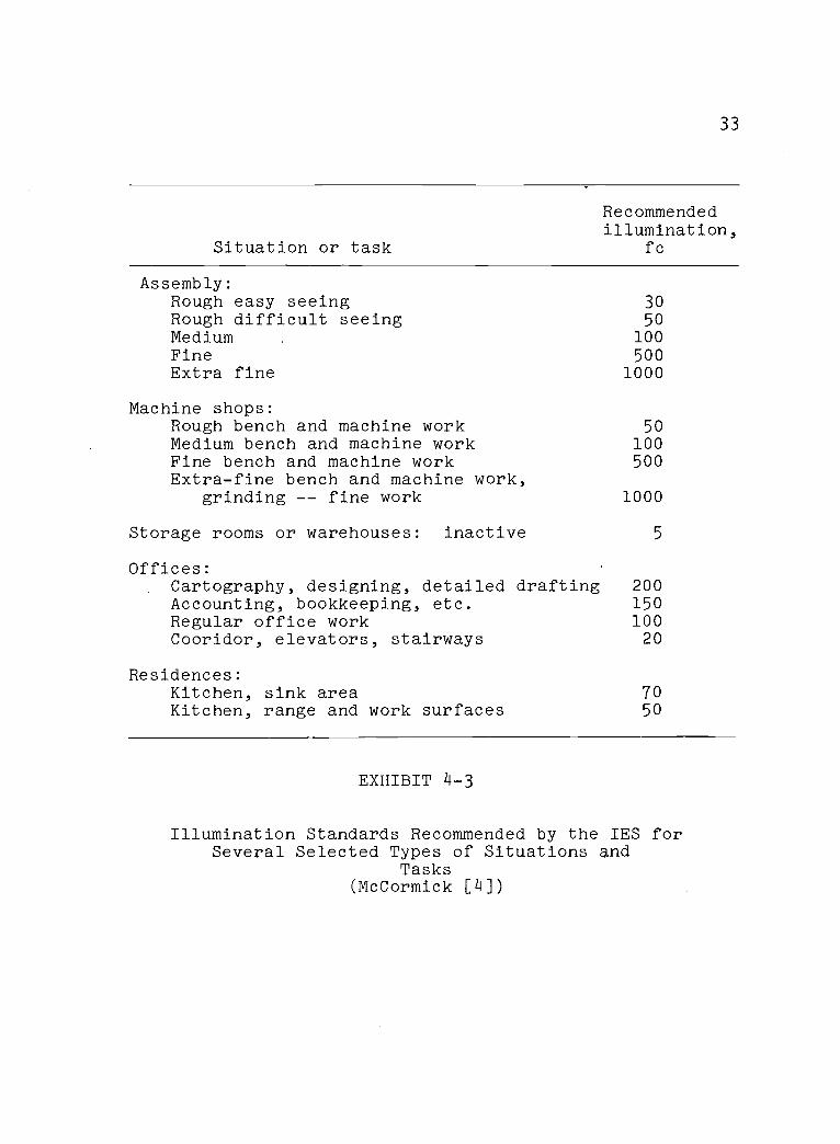
33
Situation or task
Recommendedillumination,
fc
Assembly:Rough easy seeing 30Rough difficult seeing 50Medium 100Fine 500Extra fine 1000
Machine shops:Rough bench and machine work 50Medium bench and machine work 100Fine bench and machine work 500Extra-fine bench and machine work,
grinding -- fine work 1000
Storage rooms or warehouses: inactive 5
Offices:Cartography, designing, detailed drafting 200Accounting, bookkeeping, etc. 150Regular office work 100Cooridor, elevators, stairways 20
Residences:Kitchen, sink areaKitchen, range and work surfaces
7050
EXHIBIT 4-3
Illumination Standards Recommended by the IES forSeveral Selected Types of Situations and
Tasks(McCormick [4])
314
CHAPTER V
GENERALIZED GUIDELINE FOR PLANT LAYOUTFOR REHABILITATION CENTERS
In the introduction to this thesis, it was explained
that the planning of a Rehabilitation Center should be
done considering both plant layout principles and human
engineering principles. Safety of workers, accommodation
of widely varying product mix and total job load, worker
morale, worker convenience and training of workers,
essential criteria in any plant, are at least as critical
for a Rehabilitation Center.
Much work (Soden [9], Kessler [4]) has been done
on planning of rehabilitation centers and efficient
methods of rehabilitation; but comparatively little has
been recorded reflecting the use of plant layout princi-
ples in rehabilitation centers. The following pages
explain guidelines to be followed related to the above
mentioned criteria.
Safety of Workers: Plant layout and work place
safety relate directly to worker's safety. Industrial
accidents vary from a small cut to perhaps amputation of
limbs. To find the causes of these accidents and try
to minimize their occurence will therefore be an impor-
tant factor in the designing of a layout.

35
A study was made of the accidents which occured dur-
ing the period January 1, 1972 to December 31, 1972. The
data was made available by the State Accident Insurance
Fund, Salem, Oregon. Exhibit 5-1 shows the classes,
occurances and the cost of these accidents. Referring
to Exhibit 5-1 the 'Internal Injuries' class covers bone
fractures, chest injuries and abdominal injuries like
hernia. 'Special type of Injuries' include gas poison-
ing, skin irritation, eye injuries due to foreign bodies
and injuries induced by electric shocks. The 'Sprains'
category includes sprains and strains during material
handling. The majority of these injuries happen to the
workers' backs. Sometimes workers are not able to tell
how the injury occured. These injuries are accounted
for under 'Unclassified'.
The accidents have the following likely causes:
1. Carelessness of workers
2. Hazardous machinery
3. Conjested aisles and workplaces
4. Faulty material handling
5. Improper storing methods
These causes are now examined to develop guidelines
for layout design.
I. Carelessness of workers: The term 'carelessness' is
used here as the workers' negligence regarding their
36
superior's orders. Many times workers do not obey their
foreman. Some workers, especially mentally retarded
persons cannot determine whether their action is harmful
or not. The best way to avoid accidents due to such
carelessness is by good supervision.
A layout should therefore make it possible for the
foreman to supervise every worker from his office with
ease. Elevated observation posts should be installed in
the plant. The departmental foreman's office should be
placed on a platform at least 5 feet above the floor.
This can give him good visibility over the department.
The foreman should be able to reach every worker
if he observes any hazardous act. The aisle should be
clean and wide. The author suggests that a portion of
the main aisles be reserved for pedestrians and workers
in wheel chairs or on crutches. This space should be
painted yellow and the pedestrians should be taught to
walk between this space. The ratio of management
to workers should be high to facilitate good supervision
and safety. A ratio between 1:5 to 1:8 is found to be
satisfactory by the executives of rehabilitation centers.
II. Hazardous machinery: Accidents due to the machinery
are typically cuts and punctures. To avoid them, covers
and guards should be provided on cutting and rotating
parts. Many times parts are held in hands while some
37
operation like cutting or drilling is being done on the
part. This practice should be minimized and jigs or
fixtures should be provided. Lighting near the working
areas is also an important factor. Adequate lighting
must be provided at the work stations. To avoid eye
injuries, the use of protective goggles must be made
compulsory for workers in wood working departments.
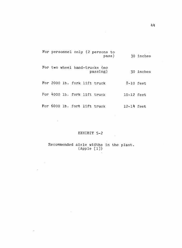
III. Conjested aisles and work places: When the aisles
get conjested by material piling up, accidents are bound
to happen either by workers colliding with material
handling equipment or against material piles.
The aisles therefore should be clean and wide.
For material handling generally accepted dimensions of
aisles are shown in Exhibit 5-2. It may be wise to leave
1' to 2' extra width, since some workers walk in a
staggering way, or are in wheelchairs.
Regarding the work place area, Woodson [8] recom-
mends that at least 65 to 100 sq. ft. should be avail-
able per worker. Such a general space allocation system
does not account for the varying space requirements of
different work activities. A lot of space may be wasted
in such allocation. Space allocation should be made
dependent upon the activities involved at the work
station.
38
IV. Faulty material handling: This refers primarily to
overuse of manual material handling. Injuries categorized
under 'sprains' are frequently found to be due to manual
material handling. The injuries are usually in the form
of back sprains resulting from lifting excessive loads.
Excessive manual handling should be reduced. A
table showing the maximum limits of lifting loads is
shown in Exhibit 5-3. This table should be modified
for handicapped workers. The use of containers with
easy to hold handles should be considered when manual
handling is necessary.
Another aspect of material handling is of course
automatic machinery such as conveyors. This is con-
sidered under 'worker training' below.
V. Improper storing methods: In most operations, it
has been found that the work-in-process inventory
and finished products are piled in the aisle or on the
floor, creating an obvious potential danger. Containers
or pallets should be used for stacking material. This
not only enhances safety, but Makes it easier to move
material by hand jacks or a fork lift truck.
Some factories provide additional storage on
elevated levels. Such a practice is dangerous as the
workers can fall off the stairs or the ladder while
carrying material. Use of staircases should be avoided;
39
ramps should be used whenever possible.
The above guidelines should be very useful in
reducing accidents. It must be emphasized that safety
is more critical in rehabilitation than in normal plants.
The normal worker can think faster and avoid some
accidents. Such is not the case with handicapped workers.
Hence, safety should be given even more consideration
than in the conventional plant.
Accommodation of widely varying product mix and totaljob load
Rehabilitation centers experience frequent changes
in product mix. Flexibility is the ability of handling
changes in product mix and also in overall production.
The layout therefore should be flexible enough to accom-
modate different jobs. The equipment should be general
purpose and should serve a variety of uses.
Another factor is the volume of material. If the
volume increases suddenly, the operation should riot be
disturbed. Extra space should be available if the
volume increases. Permanent walls should not be installed
within the plant. If there is a change in the sequence of
operations, the machines may need to be moved. The
equipment should be portable. Electrical wiring and saw
dust collecting pipes should be designed with flexibility.
140
Very long production lines should be avoided.
Handicapped workers are generally found to be good
workers; but one cannot rely on their working pace.
This varying pace may pile up inventory along the
line. A process layout therefore should be strongly
considered in planning the equipment.
Worker morale
In any plant, worker morale is an important factor.
The success of the organization is dependent upon worker
morale and their interest in their work. This factor is
equally important in the rehabilitation centers. It is
observed that when accidents happen the workers are
hesitant to work. The above guidelines will reduce
accidents; workers will take interest in their work.
Worker convenience
Especially since the workers are handicapped, it
is necessary that the environment should be pleasing.
They should enjoy working in the plant. Air suction
should be used to collect sawdust and keep the air
clean. Some workers are required to work outside the
plant. A shelter should be provided for protection
against the rain and snow.
Some workers do not like a noisy environment.
Such workers should not be forced to work near noisy
work stations. Work should be assigned according to
his capacity, ability and affinity towards that work.
Rehabilitation centers should be constructed
such that it is possible that supervision be done by
a foreman in a wheel-chair. The bathrooms and doors
should be adequately designed for use by the handicapped.
Training of workers
A rehabilitation center should be provided with
a training center. As explained previously, under
'safety of worker', many accidents occur due to insuf-
ficient knowledge about how to do particular work. The
workers sprain their backs while moving material because
they use their back muscles instead of the leg muscles.
The training center can teach them the correct way of
doing work. The workers can be taught to use only the
pedestrains' aisle while working, etc. This can help
substantially in reducing accidents and also in rehabil-
itating workers.
Most of the workers that work in rehabilitation
centers have never worked before. Material handling
is therefore one of the safe jobs they can do. Auto-
mation is tending to restrict employment in jobs with
42
low skills. Rehabilitation centers are designed to
create jobs for the handicapped. Excessive automation
should therefore be avoided. The simple jobs like
material handling actually help in rehabilitation.
When he learns to do this job, he is taught to be a
machine operator. Hence, the jobs which can be done
more effectively with automatic machines in practice
may justifibly be done manually in rehabilitation centers.
A summary of the above discussion has been pre-
pared as a guideline for a designer to use while pre-
paring a plant layout. This is shown in Exhibit 5-4.
The above rules will have the following payoffs:
a) Insurance premiums can be substantially
reduced. As the accident frequency
decreases, insurance will reduce automatically.
b) Once the workshop shows good progress,
communities will take more interest in
these workshops. Grants and other
facilities will increase. Such grants
are very small at the present.
c) The most important pay-off is increased
productivity of workers. The workers will
work with interest. This will help in the
process of rehabilitation. The most
important product of the rehabilitation
center is people.

43
Type of Number ofInjury Occurance
TotalCost $ Cause
1. Carelessness ofworkers
1 Cut 42 11,260.50 2. Hazardousmachinery
3. Faulty materialhandling
1. Carelessness ofworkers
2 Bruise 26 5,351.00 2. Conjested aisles3. Improper storing
method
1. Improper storingmethod
3 Sprain 32 73,144.00 2. Faulty materialhandling
1. Carelessness ofworkers
4 Puncture 15 889.00 2. Hazardousmachinery
5InternalInjury 14 38,995.00
1. Carelessness ofworkers
2. Improper storingmethod
3. Faulty materialhandling
Special
6Typeof 27 4,458.00
Injuries
7Unclassi-
fied2 71.00
EXHIBIT 5-1
Accident Analysis for accidents in OregonRehabilitation Centers, 1972
44
For personnel only (2 persons topass) 30 inches
For two wheel hand-trucks (nopassing)
For 2000 lb. fork lift truck
For 4000 lb. fork lift truck
For 6000 lb. fort lift truck
EXHIBIT 5-2
30 inches
8-10 feet
10-12 feet
12-14 feet
Recommended aisle widths in the plant.(Apple [1])
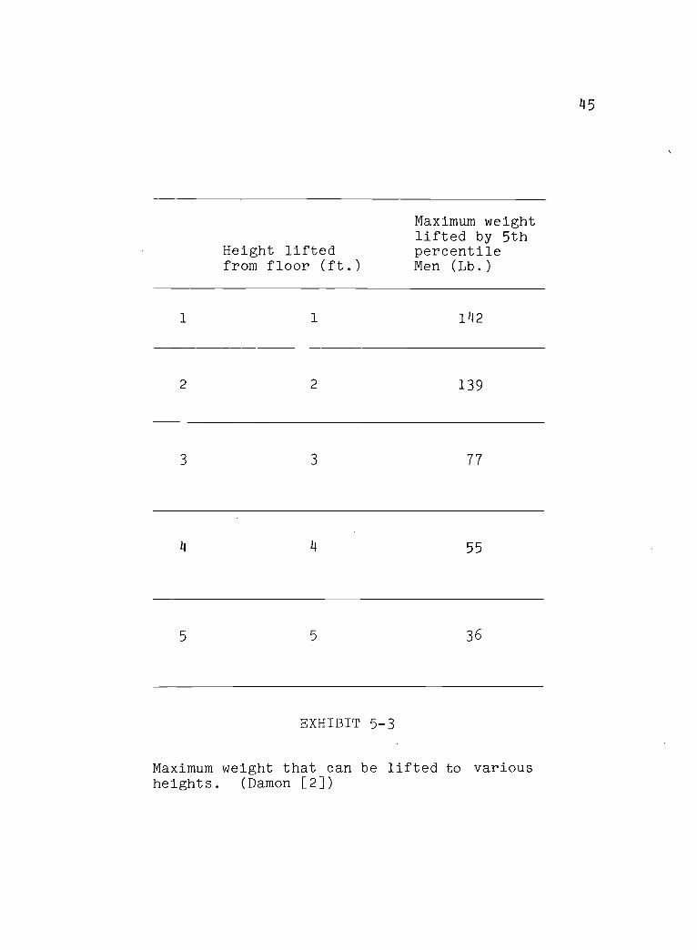
145
Height liftedfrom floor (ft.)
Maximum weightlifted by 5thpercentileMen (Lb.)
1 1 1142
2 2 139
3 3 77
14 /4 55
5 5 36
EXHIBIT 5-3
Maximum weight that can be lifted to variousheights. (Damon [2])
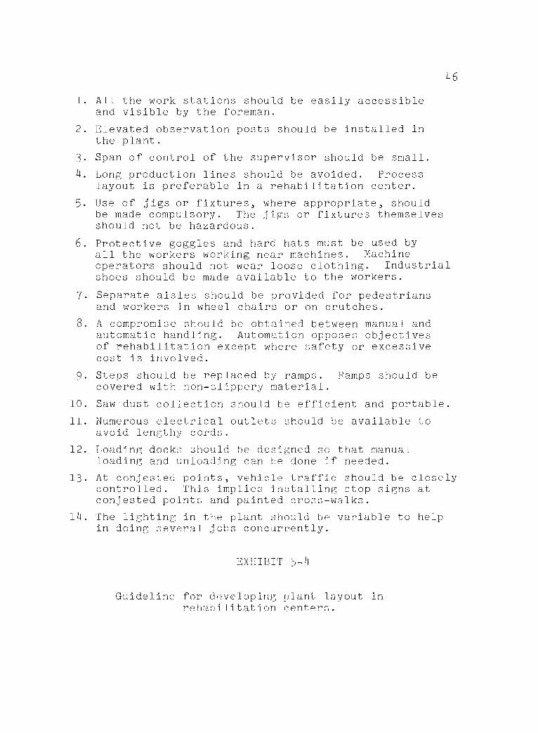
46
1. All the work stations should be easily accessibleand visible by the foreman.
2. Elevated observation posts should be installed inthe plant.
3. Span of control of the supervisor should be small.
4. Long production lines should be avoided. Processlayout is preferable in a rehabilitation center.
5. Use of jigs or fixtures, where appropriate, shouldbe made compulsory. The jigs or fixtures themselvesshould not be hazardous.
6. Protective goggles and hard hats must be used byall the workers working near machines. Machineoperators should not wear loose clothing. Industrialshoes should be made available to the workers.
7. Separate aisles should be provided for pedestriansand workers in wheel chairs or on crutches.
8. A compromise should be obtained between manual andautomatic handling. Automation opposes objectivesof rehabilitation except where safety or excessivecost is involved.
9. Steps should be replaced by ramps. Ramps should becovered with non-slippery material.
10. Saw dust collection should be efficient and portable.
11. Numerous electrical outlets should be available toavoid lengthy cords.
12. Loading docks should he designed so that manualloading and unloading can be done if needed.
13. At conjested points, vehicle traffic should be closelycontrolled. This implies installing stop signs atconjested points and painted cross-walks.
14. The lighting in the plant should be variable to helpin doing several jobs concurrently.
EXHIBIT 5-
Guideline for developing plant layout inrehabilitation centers.
147
The guidelines developed in this study may be
difficult to comply with as most rehabilitation
centers are very tight financially. It would be quite
expensive to implement all the suggestions. However, if
implemented, the improved condition would contribute
substantially to a safer and more pleasant environment
and the resulting atmosphere would surely assist rehabili-
tation efforts. Since all the suggestions probably cannot
be instituted due to financial constraint, rehabilitation
officer must face the difficult task of selecting which
ones to fund. This question, the trade-off between pay-
offs and the cost of modification is the most demanding
aspect of management.
This study has been confined to the development
of principles of design for laying out productive
facilities with the handicapped workers in mind.
Extensions of such an applied study would most likely
fall into one of the following categories: (1) Plant
layout design for a plant which is operated by workers
with special characteristics, (2) Other problems
associated with the design of operational system in
which the handicapped employee is present, (3) Scientific
analysis of some of the fundamental relationships observed
in this study; and (4) Additional case studies of the type
made herein.
48
Layout design, may for example, involve special
conditions if the work force is composed of: the elderly,
the incarcerated, persons with particular physical,
social or medical constraints. Santa's workshop is
staffed with elves; the Amish shun the use of machinery.
Cultural variations heavily affect plant design in
developing countries.
Every phase of operational systems design is
potentially affected by the presence of the handicapped.
The economics of equipment use depends on altered pro-
ductivities. Make-or-buy decisions must be based on
training as well as traditional economic considerations.
Labor standards, production schedules and product pric-
ing are all tied up to revised efficiencies.
On a more fundamental level, the design para-
meters of material handling equipment might be related
to the handicapped workers' safety, productivity and
training. Learning curves could be developed for
various tasks performed by these workers. Design of
non - production areas such as rest rooms should be
based on criteria which result from basic research on
the capabilities and limitations of this class of
production individuals.
49
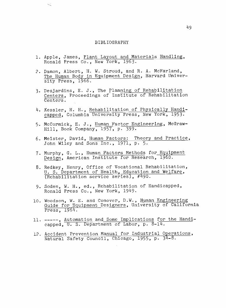
BIBLIOGRAPHY
1. Apple, James, Plant Layout and Materials Handling,Ronald Press Co., New York, 1963.
2. Damon, Albert, H. W. Stroud, and R. A. McFarland,The Human Body in Equipment Design, Harvard Univer-sity Press, 1966.
3. Desjardins, E. J., The Planning of RehabilitationCenters, Proceedings of Institute of RehabilitationCenters.
4. Kessler, H. H., Rehabilitation of Physically Handi-capped, Columbia University Press, New York, 1953.
5. McCormick, E. J., Human Factor Engineering, McGraw-Hill, Book Company, 1957, p. 399.
6. Meister, David, Human Factors: Theory and Practice,John Wiley and Sons Inc., 1971, p. 5.
7. Murphy, G. L., Human Factors Methods for EquipmentDesign, American Institute for Research, 1960.
8. Redkey, Henry, Office of Vocational Rehabilitation,U. S. Department of Health, Education and Welfare,(Rehabilitation service series), #490.
9. Soden, W. H., ed., Rehabilitation of Handicapped,Ronald Press Co., New York, 1949.
10. Woodson, W. E. and Conover, D.W., Human EngineeringGuide for Equipment Designers, University of CaliforniaPress, 1964.
11. , Automation and Some Implications for the Handi-capped, U. S. Department of Labor, p. 8-14.
12. Accident Prevention Manual for Industrial Operations,Natural Safety Council, Chicago, 1955, p. 34-8.

APPENDICES
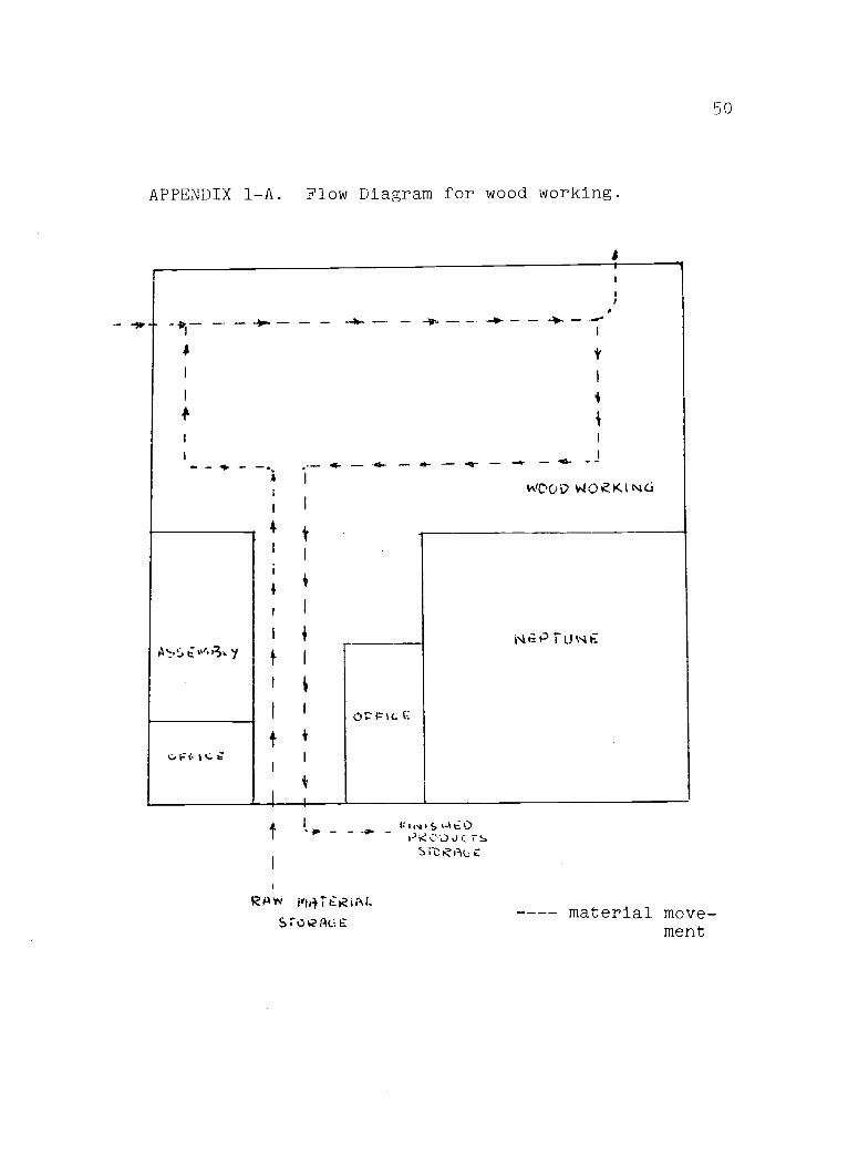
APPENDIX 1-A. Flow Diagram for wood working.
-
1,1%,76 ot.
1. t. c.
-WOOD WOZKiNte..i
iN; PIONE
Ofic--%cE
RAW itiliTERiAL
sroczt4c6.-
1,10050tE0
50
---- material move-ment
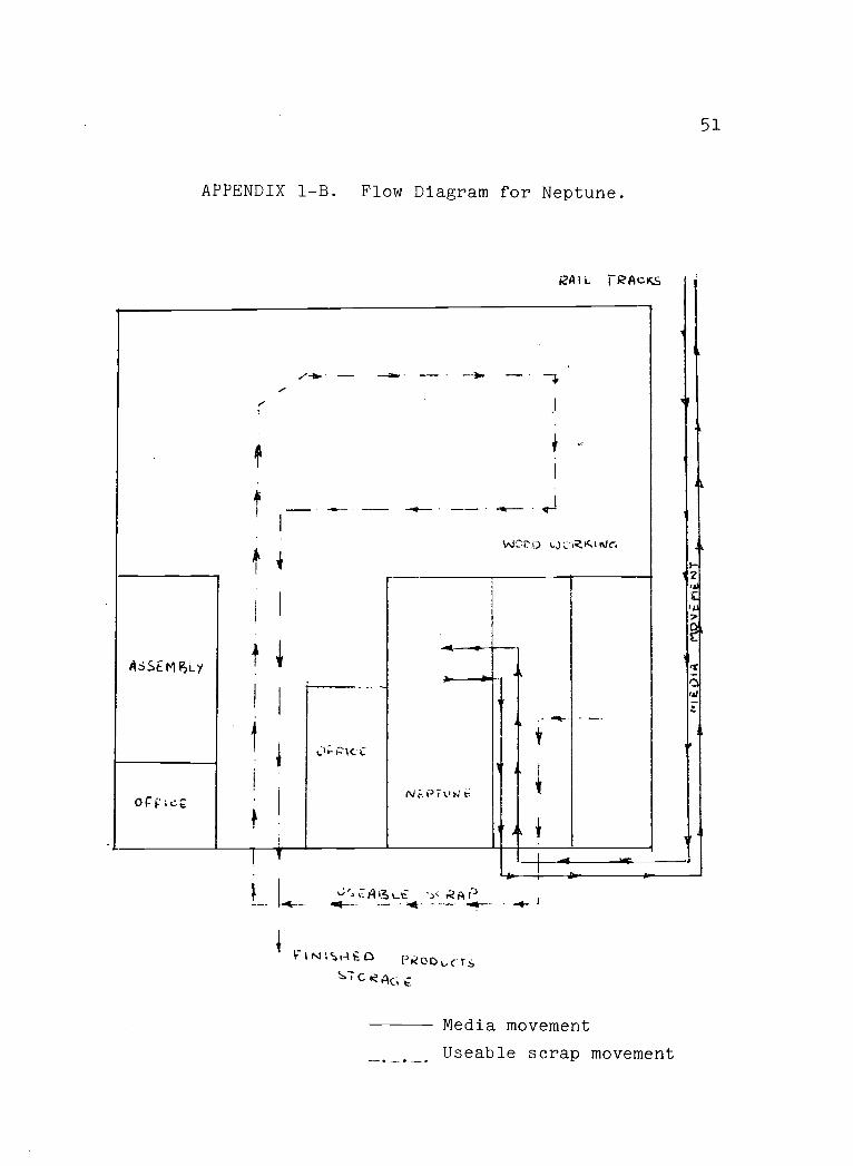
APPENDIX 1-B. Flow Diagram for Neptune.
RAIL TRACKs
ASSEM [SLY
Ori14:4
WC17 vj's-2RAt ign
oc-pici;
Ni:Prvist
-(kAP. . _
ViNV4i-kti:DC G
PkOr)vcits
A
51
Media movement
Useable scrap movement