PL360, A Programming Language for the 360 Computers, 1968
38
PL360, A Programming Language fbr the 360 Computers NIKLAUS WIRTH * Stanford University, Stanford, California ABSTRACT. A programming language for the IBM 360 computers and aspects of its imple- mentation are described. The language, called PL360, provides the facilities of a symbolic machine language, but displays a structure defined by a recursive syntax. PL360 was designed to improve the readability of programs which must take into account specific characteristics and limitations of a particular computer. It represents an attempt to further the state of the art of programming by encouraging and even forcing the programmer to improve his style of exposition and his principles and discipline in program orgailization. Because of its inherent simplicity, the language is particularly well suited for tutorial purposes. The attempt to present a computer as a systematically organized entity is also hoped to be of interest to designers of future computers. KEY WORDS AND PHRASES: language, programming language, symbolic machine language, assembly language, phrase structure language, compiler, precedence grammar, $360, error diagnosis, ALGOL-like CR CATEOORIES: 4.1, 4.10, 4.11, 4.2, 4.21, 4.42 CONTENTS Page 1. INTRODUCTIONs HISTORICAL BACKGROUND~ ANn AIMS .................................. 38 2. DEFINITION OF THE LANGUAGE ....................................................... 39 2.1. Terminology, Notation, and Basic Definitions .................................... 39 2.2. Data Manipulation Facilities ..................... ............................... 42 2.3. Control Facilities ................................................................ 49 3. EXAMPLES ........................................................................... 53 4. THE OBJECT CODE .................................................................... 56 5. ADDRESSING AND SEGMENTATION ...................................................... 59 5.1. Program Segmentation ........................................................... 60 5.2. Data Segmentation .............................................................. 60 5.3. Program Loading ................................................................ 61 5.4. Problems Connected With Input-Output Programming ........................... 61 6. COMPILER METHODOLOGY ................................... , ....................... 62 6.1. General Organization ............................................................ 62 6.2. Identifier Tables ................................................................. 63 6.3. Handling of Syntactic Errors .................................................... 64 7. DEVELOPMENT OF THE COMPILER ..................................................... 66 8, PERFORMANCE ........................................................................ 67 9. REFLECTIONS ON THE 360 ARCHITECTURE .............................................. 67 REFERENCES............................................................................ 69 APPENDIX 2. EXAMPLE OF COMPILED CODE .............................................. 69 APPENmX II. FORMAT OF PL360 PROGRAMS .............................................. 70 APPENDIX III. PL360 SYNTAX .......................................................... 72 * Present address: Institut fair Operations Research und elektronische Datenverarbeitung der Universit~t Ziirieh, Sumatrastrasse 30, Ziirieh, Switzerland 8006. Journal of the Association for Computing l~achinery, Vol. 15, No. 1, January 1968, pp. 37-74.
-
Upload
khangminh22 -
Category
Documents
-
view
0 -
download
0
Transcript of PL360, A Programming Language for the 360 Computers, 1968

PL360, A Programming Language fbr the 360 Computers
N I K L A U S W I R T H *
Stanford University, Stanford, California
ABSTRACT. A programming language for the IBM 360 computers and aspects of its imple- mentat ion are described. The language, called PL360, provides the facili t ies of a symbolic machine language, bu t displays a s t ruc ture defined by a recursive syntax. PL360 was designed to improve the readabi l i ty of programs which must take into account specific character is t ics and l imitat ions of a par t icular computer . I t represents an a t t empt to fu r ther the s tate of the art of programming by encouraging and even forcing the programmer to improve his style of exposition and his principles and discipline in program orgailization. Because of its inherent simplicity, the language is par t icular ly well suited for tutorial purposes.
The a t t empt to present a computer as a systematical ly organized en t i ty is also hoped to be of interest to designers of future computers.
KEY WORDS AND PHRASES: language, programming language, symbolic machine language, assembly language, phrase s t ruc ture language, compiler, precedence g rammar , $360, error diagnosis, ALGOL-like
CR CATEOORIES: 4.1, 4.10, 4.11, 4.2, 4.21, 4.42
CONTENTS
Page
1. INTRODUCTIONs HISTORICAL BACKGROUND~ ANn AIMS . . . . . . . . . . . . . . . . . . . . . . . . . . . . . . . . . . 38
2. DEFINITION OF THE LANGUAGE . . . . . . . . . . . . . . . . . . . . . . . . . . . . . . . . . . . . . . . . . . . . . . . . . . . . . . . 39
2.1. Terminology, Nota t ion , and Basic Definitions . . . . . . . . . . . . . . . . . . . . . . . . . . . . . . . . . . . . 39 2.2. Da t a Manipu la t ion Faci l i t ies . . . . . . . . . . . . . . . . . . . . . . . . . . . . . . . . . . . . . . . . . . . . . . . . . . . . 42 2.3. Control Faci l i t ies . . . . . . . . . . . . . . . . . . . . . . . . . . . . . . . . . . . . . . . . . . . . . . . . . . . . . . . . . . . . . . . . 49
3. EXAMPLES . . . . . . . . . . . . . . . . . . . . . . . . . . . . . . . . . . . . . . . . . . . . . . . . . . . . . . . . . . . . . . . . . . . . . . . . . . . 53 4. THE OBJECT CODE . . . . . . . . . . . . . . . . . . . . . . . . . . . . . . . . . . . . . . . . . . . . . . . . . . . . . . . . . . . . . . . . . . . . 56 5. ADDRESSING AND SEGMENTATION . . . . . . . . . . . . . . . . . . . . . . . . . . . . . . . . . . . . . . . . . . . . . . . . . . . . . . 59
5.1. Program Segmenta t ion . . . . . . . . . . . . . . . . . . . . . . . . . . . . . . . . . . . . . . . . . . . . . . . . . . . . . . . . . . . 60 5.2. Da t a Segmenta t ion . . . . . . . . . . . . . . . . . . . . . . . . . . . . . . . . . . . . . . . . . . . . . . . . . . . . . . . . . . . . . . 60 5.3. Program Loading . . . . . . . . . . . . . . . . . . . . . . . . . . . . . . . . . . . . . . . . . . . . . . . . . . . . . . . . . . . . . . . . 61 5.4. Problems Connected With I npu t - O u t pu t Programming . . . . . . . . . . . . . . . . . . . . . . . . . . . 61
6. COMPILER METHODOLOGY . . . . . . . . . . . . . . . . . . . . . . . . . . . . . . . . . . . , . . . . . . . . . . . . . . . . . . . . . . . 62 6.1. General Organizat ion . . . . . . . . . . . . . . . . . . . . . . . . . . . . . . . . . . . . . . . . . . . . . . . . . . . . . . . . . . . . 62 6.2. Identifier Tables . . . . . . . . . . . . . . . . . . . . . . . . . . . . . . . . . . . . . . . . . . . . . . . . . . . . . . . . . . . . . . . . . 63 6.3. Handl ing of Syntact ic Errors . . . . . . . . . . . . . . . . . . . . . . . . . . . . . . . . . . . . . . . . . . . . . . . . . . . . 64
7. DEVELOPMENT OF THE COMPILER . . . . . . . . . . . . . . . . . . . . . . . . . . . . . . . . . . . . . . . . . . . . . . . . . . . . . 66 8, PERFORMANCE . . . . . . . . . . . . . . . . . . . . . . . . . . . . . . . . . . . . . . . . . . . . . . . . . . . . . . . . . . . . . . . . . . . . . . . . 67 9. REFLECTIONS ON THE 360 A R C H I T E C T U R E . . . . . . . . . . . . . . . . . . . . . . . . . . . . . . . . . . . . . . . . . . . . . . 67 REFERENCES . . . . . . . . . . . . . . . . . . . . . . . . . . . . . . . . . . . . . . . . . . . . . . . . . . . . . . . . . . . . . . . . . . . . . . . . . . . . 69 APPENDIX 2. EXAMPLE OF COMPILED CODE . . . . . . . . . . . . . . . . . . . . . . . . . . . . . . . . . . . . . . . . . . . . . . 69 APPENmX II . FORMAT OF PL360 PROGRAMS . . . . . . . . . . . . . . . . . . . . . . . . . . . . . . . . . . . . . . . . . . . . . . 70 APPENDIX I I I . PL360 SYNTAX . . . . . . . . . . . . . . . . . . . . . . . . . . . . . . . . . . . . . . . . . . . . . . . . . . . . . . . . . . 72
* Present address: I n s t i t u t fair Operations Research und elektronische Da tenve ra rbe i tung der Universi t~t Ziirieh, Sumatras t rasse 30, Ziirieh, Switzerland 8006.
Journal of the Association for Computing l~achinery, Vol. 15, No. 1, January 1968, pp. 37-74.

38 NIKLAuS WIRTtt
1. I n t r o d u c t i o n , His tor ica l Background, and Aims
:I:n an era of feverish and prolific activity in the design of more and more sophis- ticated and intricate programming aids, the proposal of a machine-dependent lan- .... guage may seem anachronistic to some readers. In this report we describe an attempt to provide a tool for those applications where it is essential to conceive programs as closely as possible in terms of a specific computer in order to directly take into
account its particular capabilities and limitations. These applications often require the use of conventional assembly codes, where it is particularly difficult, if not ira. possible, to express and clearly exhibit the structure and the characteristics of an algorithm. The language described here is designed with the aim of providing a clear and systematic exposition of the available computing facilities, and a to01 which encourages a programmer to write programs in a disciplined, lucid, and read- able style while still maintaining control over the optimal use of specific machine characteristics. The result of a systematic language design based on consistent rules is reliability on the part of the implemented translator as well as on the part of the user, who is discouraged from using "tricks" and is less subject to pitfalls and mis- understandings about the nature of complicated or ill-defined facilities.
ht the summer of 1965, the author decided to undertake efforts to implement the proposed successor to ALGOL described in [1] on the IBM 360 computer, which at that time had been chosen as Stanford's next generation machine. I t was felt that the evolving project should be conducted in a thorough and systematic manner, worthy of an academic endeavor, and making use of the best, available methods on compiler construction known. The results should consist of a well-organized system whose structure and principles are sound and precisely understood, and which is intelligibly documented.
After many years of experience with ALGOL, it was clearly recognized that a corn.
plier written in 360 Assembly Language would neither be able to meet the desired documentation standards, nor constitute a sumciently convenient programming tool. The only other language available on the 360, FOttTRAN, was not deemed ade- quate either. Against the strong arguments of the undesirability of the large amount of additional efforts required to produce a new language and its compiler, it was decided to develop a tool which would (1) allow full use of the facilities provided by the 360 hardware, (2) provide convenience in writing and correcting programs, and (3) encourage the user to write in a clear and comprehensible style.
As a consequence of (3), it was felt that programs should not be able to modify themselves. The language should have the facilities necessary to express compiler and supervisor programs, and the programmer should be able to determine every detailed machine operation. In this respect, the language features the property of conventional assembly code. In its appearance, however, it resembles a high level programming language due to the presence of phrase structure. Being specifically tailored for the 360 computer, the language was named PL360.
Section 2 contains the definition of the language. I t is given in terms of a synt~xi and the semantic explanations of the individual syntactic constructions. Knowledge about the nature of the 360 architecture is prerequisite (cf. [2,3]); however, the definition does not require familiarity with the 360 Assembly Ltmguage.
In Section 3 several examples of PL360 (sub)programs are given. Since PL360 allows (and requires) the programmer to denote almost every machine instruction explicitly, its use inherently bears some of the tediousness of assembly language {
Journal of the Association for Computing Machinery, Vol. 15, No. 1, January 1968

PL860 39
programming. However, the presence of structure in the lal~guage, and in particu- lar the introduction of blocks, procedures, and if, for, and while clauses, helps to improve the readability of the language significantly. It drastically reduces the num- ber of necessary program labels and thus of invented names. The method used for assigning base registers and initializing them with the correct values at run time considerably eases the complicated and pitfall-loaded addressing problem of the 360 computer.
We devote Sections 4 and 5 to the implementation of PL360. We exhibit the code which the compiler generates corresponding to various language statements, and the method of segmentation and addressing. In Section 6 we give an account of the organization of the compiler, which relies on a rigorous syntax analysis of the text while at the same time generating the target code. The compiler constitutes a large-scale practical example for the application of the techniques described in [4] which have been extended to process incorrectly constructed texts and to mean- ingfully diagnose errors. The success of this facility is considered to be a major contribution to making precedence grammars useful in practical applications.
The methods employed in producing the compiler are described in Section 7. A bootstrapping technique was used to make the compiler aw~ilable on the 360 com- puter without prior use of any of the languages existing on that machine. Program- ruing the compiler in its own language provided a thorough test for the adequacy of the language to its anticipated purpose.
In Section 8 we give a brief account of the size and the performance of the trans- lator on a 360/50 computer. Concluding remarks about the language and its im- plementation lead to a brief examination of the appropriateness of the 360 archi- tecture for this experiment.
2. Definition of the Language
2.1. TERMINOLOGY, NOTATION, AND BASIC DEFINITIONS
The language is defined in terms of a computer which comprises a processing unit and a finite set of storage elements. Each of the storage elements holds a content, also called value. At any given time, certain significant relationships may hold between storage elements and values. These relationships may be recognized and altered, and new values may be created by the processing unit. The actions taken by the processor are determined by a program. The set of possible programs forms the language. A program is composed of, and can therefore be decomposed into, elementary constructions according to the rules of a syntax, or grammar. To each elementary construction corresponds an elementary action specified as a semantic rule of the language. The action denoted by a program is defined as the sequence of elementary actions corresponding to the elementary constructions which are obtained when the program is decomposed (parsed) by reading from left to right.
2.1.1. The Processor At any time, the state of the processor is described by a sequence of bits called
the program status word (PSW). The status word contains, among other informa- tion, a pointer to the currently executed instruction, and a quantity which is called condition code.
Storage elements are classified into registers and core memory cells, simply called
Journal of the Association for Computing Machinery, Vol. 15, No. 1, January 1968

40 NIKLAUS WIRTH
cells. Registers are divided into three types according to theii • size aud the operations which can be performed on their values. The types of registers are:
(a) in teger or logical (a sequence of 32 bits), (b) real (a sequence of 32 bits), (e) long real (a sequence of 64 bits).
Cells are classified into five types according to their size and the type of value which they may contain. A cell may be structured or simple. The types of simple values and simple cells are:
(a) byte (a sequence of 8 bits = 1 byte), (b) short integer (a sequence of 16 bits = 2 bytes, interpreted asan integerin
two's complement binary notation), (c) integer or logical (a sequence of 32 bits = 4 bytes, the former to be in-
terpreted as an integer in two's complement binary notation), (d) real (a sequence of 32 bits = 4 bytes, to be interpreted as a floating point
binary number), (e) long real (a sequence of 64 bits = 8 bytes, to be interpreted as a floating
point binary number). The types integer and logical are treated as equivalent in the language, and con- sequently only one of them, namely integer, is mentioned throughout the report
2.1.2. Relationships The most fundamental relationship is that which holds between a cell and i t s
value. I t is known as containment; the cell is said to contain the value. Another relationship holds between the cells which are the components of a
structured cell, called an array, and the structured cell itself. I t is known as sub' ordination. Structured cells are regarded as containing the ordered set of the values of the component cells.
A set of relationships between values is defined by monadic and dyadic functions or operations, which the processor is able to evaluate or perform. The relationships are defined by mappings between values (or pairs of values) known as the operands and values known as the results of the~ evaluation. These mappings are not to be precisely defined in this report; instead, references will be given to their definition in publications on the system 360 computer [5]. !:
2.1.3. The Program A program contains declarations and statements. Declarations serve to list the
cells, ~'egisters, and procedures which are involved in the algorithm denoted by the program, and to associate names, so-called identifiers, with them Statements specify the operations to be performed on these quantities, to which they refer through use of the identifiers.
A program is a sequence of tokens, which are basic symbols, strings, or com- ments. Every token is itself a sequence of characters. The following conventions are used in the notation of the present article:
(a) Basic symbols constitute the basic vocabulary of the language (ef. 1.6.)i i They are either single characters or underlined letter sequences.
(b) Strings are sequences of characters enclosed in quote marks ("). (c) Comments are sequences of characters (not containing a semicolon) preceded I
by the basic symbol c o m m e n t and followed by a semicolon (;). I t is under ~ stood that during execution of a program, all comments are ignored.
Journal of the .Association for Computing Machinery, Vol. 15, No. I, January 1968

PL360 41
In order that a sequence of tokens be an executable program, it must be constructed according to the rules of the syntax.
2.1.4. Syntax A sequence of tokens constitutes an instance of a syntactic entity (or construct)
if that entity can be derived from the sequence by one or more applications of syn- tactic substitution rules. In each such application, the sequence equal to the right side of the rule is replaced by the symbol which is its left side.
Syntactic entities (ef. 2.1.5) are denoted by English words enclosed in the brackets < and }. These words describe approximately the nature of the syntactic entity, and where these words are used elsewhere in the text, they refer to that syntactic entity. For reasons of notational convenience and brevity, the script letters (~, N, and 5 are also used in the denotation of syntactic entities. They stand as abbrevia- tions for any of the following words (or pairs) :
integer integer byte short integer real integer real long real short integer long real real
long real Syntactic rules are of the form
(A) : :=
where (A} is a syntactic entity (called the left side) and } is a finite sequence of tokens and syntactic entities (called the right side of the rule). The notation
(A> ::= ~ [ ~ I ...... [ Sn
is used as an abbreviation for the n syntactic rules
(h> ::= ~1, (A) ::= ~2, . - . , (A> ::= ~,,.
If in the denotations of constituents of the rule the Script letters a, ~, or 5 occur more than once, they nmst be replaced consistently, or possibly according to fur- ther rules given in the accompanying text. As an example, the syntactic rule
( ~ register) ::= (;~t~ register identifier)
is an abbreviation for the set of rules:
(long real register) : := (long reM register identifier) (integer register) ::= (integer register identifier) (real register) : := (real register identifier)
2.1.5. Syntactic Entities
Section Section ((~ cell assignment> 2.2.7 (combined condition) 2.3.1 ((~ number) 2.2.2 (compound condition) 2.3.1 (alternative condition) 2.3.1 (arithmetic operator) 2.2.6 (digit) . 2.2.2
(declaration) 2.3.5
(block body) 2.3.5 (for clause) 2.3.4 (block head) 2.3.5 (for statement) 2.3.4 (block) 2.3.5 (format code) 2.2.8
(fractional number) 2.2.2 (case clause) 2.3.2 (function declaration> 2.2.8 (case sequence) 2.3.2 (function definition) 2.2.8 (case statement) 2.3.2 (function identifier) 2.2.1 (character sequence) 2.2.2 (function statement) 2.2.9
Journal of the Association for Computing Machinery, Vol. 15, No. 1, January 1968

42 NIKLAUS WIRTH
Section Section (go to s tatement) 2.3.6 ( p r o e e d u r e identifier) 2.2.1
( p r o e e d u r e statement) 2~ 3.8 (hexadecimal digit) 2.2.2 ( p r o g r a m ) 2.3.5 (hexadecimal value) 2.2.2
( r e l a t i o n ) 2.3.1 (identifier) 2.2.1 (if clause) 2.3.1 (sca le factor} 2, 2.2 (if statement} 2.3.1 ( s e g m e n t base declaration} 2.2.11 (increment) 2.3.4 (sh i f t operator} 2.2.6 (index) 2.2.5 ( s imple ~ register assignment) 2.2.6 (initial value) 2.2.4 ( s imple statement} 2.3.5 (initial value list) 2.2.4 ( s imple 5 type) 2.2.4 (instruction code) 2.2.8 ( s t a t e m e n t ) 2.3.5 (item) 2.2.4 ( s t r i ng ) 2.2.2
( s y n o n y m o u s cell) 2.2.10 iX register assignment) 2.2.6 ( ~ register synonym declaration) 2.2.10 (3 cel l declarat ion) 2.2.4 (3~ register) 2.2.1 (3 cell designator) 2.2.5
(5 cel l identifier) 2.2.1 (label definition) 2.3.5 (3 cel l synonym declaration) 2.2.10 (letter) 2.2.1 (3 n u m b e r ) 2.2.2 (limit) 2.3.4 (3 p r i m a r y ) 2.2.6 (logical operator) 2.2.6 (3 t y p e ) 2.2.4
(3 v a l u e ) 2.2.6 (monadic operator} 2.2.6 ( t rue p a r t ) 2.3.1
(parameter) 2.2.9 (uns igned ~ number} 2.2.2 (parameter list) 2.2.9 (procedure declaratiorQ 2.3.7 (whi le clause} 2.3.3 (procedure heading) 2.3.7 whi le s ta tement} 2.3.3
2.1.6. Basic Symbols
A IBICID[EIFIGIH[ II J[K]L]MI NIOIP[QI[¢I Sl Ti U[ Vl W[X[ Y[Z a i b i c l d l e l f l g l h l i l J l k l l [ m l n l o l p l q [ r l s l t l u l v l w [ z ] y l z t 0 1 1 1 2 1 3 1 4 1 5 1 6 1 7 1 8 1 9 [ + l - I * [ / [ < l = I > 1 ~ 1 := 1 ,1 .1 ;1 :1 ( I ) 1 @ [ ,~ I ' l " l ~ ] a n d I or [xor l a b s I neg I s h l l ] sh r l I sh la ] s h r a t i f [ t h e n ] e l se [ case I of l whi le [ do [ for ] s t e p [ u n t i l I b e g i n [ e n d [ go to [ c o m m e n t ] nu l l ] i n t e g e r I r ea l [ l og i ca l I b y t e I l ong [ s h o r t [ a r r a y I f u n c t i o n I p r o c e d u r e [ r e g i s t e r [ syn ] overf low ] s e g m e n t ] base
2 .2 . DATA MANIPULATION FACILITIES
2.2.1. Identifiers
(letter) : := A ] B [ C [ D J E I F I G [ H [ I I J ] K I L [ M I N ] O ] P [ Q ] R [ S [ T [ U I v I w I x [ y [ z I
a ] b [ c ] d ] e ] f ] g [ h t i ] j l k ] l i m ] n [ o ] p i q j r [ s [ t [ u [ v J w [ z y[z (identifier) : := (letter) [ (identifier)(letter) J ( ident i f ier}(digi t ) ( ~ register) : := (identifier) (5 cell identifier) : := (identifier) (procedure identifier) : := (identifier) (function identifier) : := (identifier)
An identifier is a ~ register-, 5 cell-, procedure-, or function-identifier if it has re- spectively been associated with a ~ register, 5 cell, procedure, or function (called a quanti ty) in one of the blocks surrounding its occurrence. This associati(m is achieved by an appropriate declaration. The ident i f ie r is said to designate the asso- ciated quantity. If the same identifier is associa ted to more than one quantity, then the considered occurrence designates the q u a n t i t y to which it was associated
Journal of the .Association for Computing Machinery, Vol. 15, No. 1, January [968

PL360 43
in the smallest block embracing the considered occurrence. Ii1 any one block, an identifier must be associated to exactly (:)~e qu~mtity. In the parse of a program, that association determines which of the rules given above applies.
Any processing computer can be considered to provide a~l eIlvironment iu which the program is embedded, and in which some identifiers are permanently declal~d. Some identifiers are assumed to be known M every environment; they are called standard identifiers, and ~tre listed in the respective paragr~phs on declaratio~ts.
2.2.2. Values
(digit) : := o ] 1 1 2 1 3 1 4 1 5 1 6 1 7 ] S ] 9 (unsigned integer number} ::= (digit} ] (unsigned integer number)(digit) (unsigned short integer number) : := (unsigned integer nmnber) S (fractional number) : := (integer number), (digit) [ (fractional number}(digit) (scale factor} : := (integer number} (unsigned real number) : := (fractional number) ] (unsigned integer number} RI
(fractional number}'(scale factor) ] (unsigned integer number}'(scMe factor) (unsigned long reM number) : := (fractionM number} L I (unsigned integer number) L I
(fractional number)'(scale factor) L [ (unsigned integer number)'(scale factor) L (~ number) : := (unsigned ~ number) [ _ (unsigned ~ number}
Integer, real, and long real numbers are represented in decimal notation. The latter two can be followed by a scale factor denoting an integral power of 10. Short integers are distinguished from integers by the letter S following the number. In order to denote a negative number, it is preceded by the symbol "__',.
{hexadecimal value} : := (digit} [ A ]B ] C ] D [ E ] F (hexadecimal value) : := %(hexadecimal digit) [ (hexadecimM vMue>(hexadecimM digit)
A hexadecimal value denotes a sequence of bits. Each hexadecimal digit stands for a sequence of four bits defined as follows:
0 = 0000 4 = 0100 8 = 1000 C = 1100 1 = 0001 5 = 0101 9 = 1001 D = 1101 2 = 0010 6 = 0110 A = 1010 E = 1110 3 = 0011 7 = 0111 B = 1011 F = 1111
(string) ::= "(character sequence)" (character sequence) : := (character} I (character sequence)(character)
A string is a sequence of characters enclosed in quote marks. The set of characters depends on the implementation (cf. [2,3]). I f the character " is to be an element of the sequence, it is represented by a pair of consecutive quote marks.
Examples:
"ABC" denotes the sequence ABC "A'" 'Z" denotes the sequence A"Z '""'A'"'" denotes the sequence "A"
(byte value} : := "(character}" ] (hexadecimM vMue}X (short integer value} : := (short integer number) ] (hexadecimal value)S (integer value) : := (integer number) [ (hexadecimal value} <real value) : := (real number} ] (hexadecimal value)R (long real value) : := (long real number) I (hexadecimal value)L
Journal of the .Association for Computing Machinery, Vol. 15, No. 1, January 1968

44 NIKLAUS WIIRT~: t
Examples:
byte values: "B" ~' ?" # 1FX short integer values: 10S #FFOOS integer values: 0 1066 __1 N 1F2E3D4C real values: 1.0 __3.1416 2.7'8 % 46000001R long real values: 3.14159265359L ~4E00000000000001L
Note. If hexadecimal values are used in conjunction with arithmetic operators in a program, they must be considered as the sequence of bits which constitutes the computer's representation of the number on which the operator is applied. ttexadecimal values followed by the letter R or L may be used to denote numbers i~1 mmormalized floating point representation [2,3].
2.2.3. Register Declarations The System/360 computer features 16 registers which contain integer numbers
and are said to be of type in teger (or logical). They are designated by tile follow- ing standard register identifiers (cf. 2.1):
RO, R1, R2, R3, R4, RS, R6, R7, R8, R9, R10, R l l , R12, R13, R14, R15
Moreover, the computer features four registers which contain real numbers or long real numbers. If those registers are used in conjunction with real numbers, they are said to be of type real, and are designated by the standard register identifiers
F0, F2, F4, F6.
If they are used in conjunction with long real numbers, they are said to be of type long real, and are designated by the standard register identifiers
F0I, F23, F45, F67.
The above register identifiers are assumed to be predeelared, and no further register declarations can be made in a program (el. also 2.2.10).
2.2.4. Cell Declarations
(simple byte type) ::= byte (simple short integer type) ::= short integer (simple integer type) ::= i n t e ge r [ logical (simple real type) ::= real (simple long real type) ::= long real <5 type) ::= (simple 3 type) [ a r r ay (integer number)(simple 5 type) (3 cell declaration) ::= (5 type)(item> [ <5 cell declaration), (item) (item) ::= (identifier) ](identifier) = @litial value} I (identifier } = ((initial value list)) (initial value list) ::= (initial value) I (initial value list), (initial value) (initial value)::= <5 value> I (string}
A cell declaration introduces identifiers and associates them with cells of a speei = fled type. The scope of validity of these cell identifiers is the block in whose heading the declaration occurs (cf. 2.3.5). Moreover, a declaration may specify the assign= ment of an initial value to the introduced cell. This assignment is understood to have occurred before execution of the program has started.
If a simple type is preceded by the symbol ar ray and an integer number, say n, then the declared cell is an array (ordered set) of n cells of the specified simple type.
Journal of the Association for Computing Machinery, Vol. 15, No. 1, January 1968

PL360 45
An initial value list with m < n entries specifies the initial values of the first m elements of the array.
A string is understood to stand as an abbreviation for a sequence of byte values, i.e:
is an abbreviation of
"(ehar-1><char-2> . . . (char-n}"
"(char-l>", "(char-2}",..., "(char-n)"
Examples:
byte flag short integer i, j integer age = 21, height = 68 long real z, y, z = 27'3L array 3 integer size = (36, 23, 37) array 1000 real quant, price array 8 byte flags array 132 byte line
2,2.5. Cell Designators
(5 cell designator) ::= (3 cell identifier) [ (5 cell identifier>(<index>) (index) ::= (integer number) ] (integer register) ] (integer register) A- (integer number) I
(integer register) - (integer number)
Cells are denoted by cell designators. In the case of cells of simple type, the desig- nator consists of the identifier associated with that cell; in the case of arrays of ceils, the identifier associated with the array is followed by an index. The current value of that index, divided by the number of memory units (bytes) occupied by each array element (cf. 2.1.1), is taken as the ordinal number of the selected ele- ment cell.
Note. Tile remainder resulting from that division must be 0, and register R0 must not be specified as an index constituent.
Examples:
age size (8) price (R1) line (R2 + 15)
2.2.6. Register Assignments
(5 primary) ::-~ (5 value) [ (5 cell designator) (5~ primary) : := (5{~ register)
A primary is either a value or the content of a designated cell or register.
(simple 3~ register assignment) : := (3~ register) := (~ primary) I (3C register) := (monadie operator>(~ primary) [ (integer register) := (string) [ (integer register) := @ (5 cell designator)
A simple register assignment is said to specify the register appearing to the left of the assignment operator ( := ). To this register is assigned the value designated by the construct to the right of the assignment symbol. T h a t designated value may be obtained through execution of a monadic operation specified by a monadic operator.
(monadic operator) ::= abs [ neg I neg abs
Journal of the .Association for Computing Machinery, Vol. 15, No. I, January 1968

46 NIKLAUS WIRTH
TABLE I
integer integer integer short integer real real long real real long real long real
The monadic operations at~ t.hose of taking the absolute value, of siga inversion, and of sign inversion after taking the absolute value.
If a string is assigned to a register, that string must consist of not more than fore characters. If it consists of fewer than four characters, null characters are appended at the left of the string. The bit representation of characters is defined in [2, 31 (EBCDIC).
The construction with the symbol @ is used to assign to the specified registel the address of the designated cell.
The legal combinations of types to be substituted respectively for the letters 31 and e{ in preceding and subsequent rules of this paragraph are given in Table I.
Examples of simple register assignments:
R0 := i F0 := quant (R1) R D := abs height R2 := R10 F23 := x R6 := age F45 := n e t F01
<"K~ register assignment) : := (simple ~E regis ter assignment) ] (3¢ register ass ignmcnt}@ri thmet ic oper~tor}(a primary> I ( in teger register assignment>(logicM operator)( in tegcr pr imary) I ( integer register assignment)<shift opera tor) (uns igned integer number} I ( integer register assigmnent)(shif~ operator)( in teger register)
(ar i thmet ic operator) : := + I -- [ * [ / I + ' + [ - - (logical operator) : := a n d ] o r [ xor (shift operator) : := sh l l [ s h l a I s h r l I s h r a
A register assignment is said to specify the same register which is specified by th simple register assignment or the register assignment from which it is derived. this register is assigned the value obtMned by applying a dyadic operator to tt! current value of that specified register and the value of the primary following th operator. The operations are the arithmetic operations of addition (A-), subtrm tion ( - ) , multiplication ( , ) , and division ( / ) , the logical operations of conjun( tion (and) , exclusive and inclusive disjunction (xor, or), and those of shifting t the left and right, as implemented in the/360 system. The operators A- + and - - denote "logical" or unnormalized addition and subtraction when applied to iJ teger or real registers respectively.
Examples of register assignments:
R0 := R3 F2 := 3.1416 R1 := 10 F0 := quant (R1) * pr ice (R1) R10 := i + age - R3 + s ize (8) F45 := F45 + F01 R9 := R8 a n d R7 s h l l 8 o r R6
Journal of the .Association for Computing Machinery, VoL 15, No. 1, January 1968

PL360 47
Notes. 1. Thesyntax implies~hat sequences of operators, including assignment, are executed strictly in sequence from left. Go right. Thus
is ~lot equivalent to
but rather to the two statements
R1 := R1 + R2
R1 := R2; R1 := R1 + R1.
2. Multiplication and division with integer operaffds can only be specified with the multiplicand or dividend register Rn with odd n. The register Rm with m = n - 1 is then used to hold the extension to the left of the product and dividend respectively. In case of division, this register will moreover be assigned the resulting remainder.
Example:
R3 := x * y + z R2 is affected by the multiplication.
2.2.7. Cell Assignments
(~ cell assignment) ::= (~ cell designator) := ( ~ register)
The value of the N register is assigned to the designated a cell. The allowable combinations of cell and register types a and 5C are indicated in Table I.
Examples of cell assignments:
i :=RO price(R1) := F0
:= F67
2.2.8. Function Declarations
(format code) ::= (unsigned integer number) (instruction code) ::= (integer value) (function definition) ::= (identifier)((format code), (instruction code)) (function declaration) ::= func t ion (function definition)]
(function declaration), (function definition)
There exist various data manipulation facilities in the 360 computer which can- not be expressed by an assignment. To make these facilities amenable to the lan- guage, the function statement is introduced (cf. 2.2.9), which uses an identifier to designate an individual computer instruction. The function declaration serves to associate this identifier, which thereby becomes a function identifier, with the desired computer instruction code, and to define the instruction fields which cor- respond to the parameters given in function statements. The format code defines the format of the instruction according to Table II. The instruction code defines the first two bytes of the instruction.
In the following example, the identifiers were chosen to be the symbolic codes used in [5], and they are standard function identifiers.
funct ion MVI(4, ~9200), CLI(4, #9500), MVC(5, YJD200), CLC(5, $D500), STM(3, fJ9000), LM(3, f~9800), SRDL(9, $8C00), SLDL(9, $8D00), IC(2, ~4300), STC(2, ~4200), LA(2, ~4100), RESET(8, ~9200), SET(8, $92FF), UNPK(IO, ~F300), CVD(2, ~4EOO),EX(2, f~4400), ED(5, ~DEO0)
Journal of the Association for Computing Machinery, Vol. 15, No. 1, January 1968

4~ NIKLAUS WIRTI-[
TABLE II re~is~r prlmt~ry
fields in function (L = integer value (literal)
o o C--Yi-Z
0 8 16 32
2.2.9. Function Statements
(parameter} : := (5 value}] (string} ] (~E register} ] <5 cell) (parameter list} : := (parameter} I (parameter list), (parameter) (function statement} : := (function identifier} [ (function ideatifier)((parameter list})
Examples:
S E T (flag) STM (RO, RF, save) RESET(f lag) MV[ (t' * r~, line) LA (R1, line) IC (RO, flags (R1)) MVC (15, line, buffffer)
2.2.10. Synonym Declarations
(5 cell synonym declaration} ::= <5 type)<identifier}<synonymous cell)] (3 cell synonym declaration), <identifier)(synonymous cell)
<synonymous cell> : := syn (5 cell designator) [ syn (integer value) ( ~ register synonym declaration) :: = (simple ~ type) regis ter (identifier) syn <3~ register)
( ~ register synonym declaration), (identifier) syn (5~ register)
Synonym declarations serve to associate synonymous identifiers with previousl (i.e., preceding in the text) declared cells or registers. The types associated wit the synonymous cell identifiers need not necessarily agree.
If a synonymous cell is specified by a~ integer value, then that integer vM~ represents the displacement and base register part of the cell's machine addres
Examples:
integer a16 syn a(16) a r r ay 32768 shor t in teger mere syn 0 in teger timer syn ~50 integer B1 syn mere(R1)
Journal of the Association for Computing Machinery, Vol. 15, No. 1, January 1968

PL360 49
Note. The synonym declaration c~m be used to associate several different types with a single cell. Each type is connected with a distinct identifier.
Example:
long real x ( ~ 4E00000000000000L) integer xlow syn x(4)
A conversion operation from a number of type integer contained in register R0 to a immber of type long real contained in register F01 can now be denoted by
xlow := R0; F01 := x
and a conversion vice versa by:
F01 := F01 -I--{-- $4E00000000000000L; x := F01; R0 := xlow.
No initialization can be achieved by a synonym declaration.
2.2.11. Segment Base Declarations
(segment base declaration} ::= segment base (integer register}
A base declaration causes the compiler to use the specified register as the base address for all cells subsequently declared in the block in which the base declaration occurs. Upon entrance to this block, the appropriate base address is assigned to the specified register (cf. 5.2).
2.3. CONTROL FACILITIES
2.3.1. I f Sta tements
(relation) ::= = I--1= [ < [ < = I > = I > (condition) ::= (~ register)(relation)((~ primary) ] (byte cell) I -1 (byte cell)[
(relation) ]overflow
A condition is said to be met or not met. A condition consisting of a relation en- closed by a register and a pr imary is met if and only if the specified relation holds between the current values of the register and the primary. A condition specified as a byte cell (or a byte cell preceded by -7) is met if and only if the value of the cell is % FF (or not ~ FF). A condition consisting of a relation or the symbol overflow is met if the condition code of the processor (cf. 2.1.1) is in a state specified by Table I I I .
TABLE I I I
Symbol State
= 0 m= 1 or2 < 1
< = 0or 1 > = 0 o r 2 ~> 2
overflow 3
(combined condition) ::= (condition) I (combined condition) and (condition) (alternative condition) ::= (condition} [ (alternative condition) or (condition} (compound condition) ::= (combined condition} I (alternative condition)
Journal of the Association for Computing Machinery, Vol. 15, No. I, January 1968
50 NIKLAUS w~ ~.~TI-i~
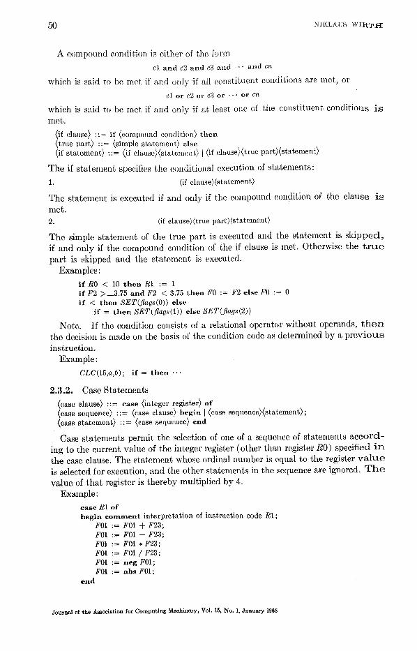
A compound condition is either of the form
cl a n d c2 a n d c3 a n d " " a n d cn
which is said to be met if and only if all constituent conditions are met, or
cl o r c2 or C3 o r " " o r cn
which is said to be met if and only if at least one of the constituent conditions i s met.
<if clause> : : = i f <compound condition> t h e n <true par t} : := <simple s t a t emen t> e l s e <if s t a t emen t> : : = <if c l ause )<s ta t ement ) t<if elause}<true pa r t } ( s t a t emen t}
The if statement specifies the conditionM execution of statements:
1. <if c lause}(s ta tement>
The statement is executed if and only if the colnpound condition of the clause i s met. 2. <if clause}<true pa r t ) ( s t~ tement>
The simple statement of the true part is executed and the statement is s k i p p e d , if and only if the compound condition of the if clause is met. Otherwise the t r u e part is skipped and the statement is executed.
Examples:
i f R0 < 10 t h e n R1 := 1 i f F2 >__3.75 a n d F 2 < 3.75 t h e n F0 := F2 e l s e F 0 := 0 i f < t h e n SET(flags(O)) e l s e
i f = t h e n SET(flags(I)) e l s e SET(flags(2))
Note. If the condition consists of a relational operator without operands, t h e n the decision is made on the basis of the condition code as determined by a p r e v i o u s instruction.
Example:
CLC(15,a,b); i f = t h e n . . '
2.3.2. Case Statements
<case clause> : := e a s e <integer register> o f <case sequence> : : = <case clause> b e g i n ]<case sequence )<s tu t emen t ) ; <case s t a t emen t> : : = <case sequence> e n d
Case statements permit the selection of one of a sequence of statements a c c o r d - ing to the current value of the integer register (other than register R0) specified i n the case clause. The statement whose ordinal number is equal to the register v a l u e is selected for execution, and the other statements in the sequence are ignored. T h e value of that register is thereby multiplied by 4.
Example:
e a s e R1 o f b e g i n c o m m e n t i n t e r p r e t a t i o n of i n s t ruc t i on code R1;
F01 := F01 + F23; F01 := F01 - F23; F01 := F01 * F23; F01 := F01 / F23; F01 := n e g F01; F01 : = a b s F01;
e n d
Journal of "the Association for Computing Machinery, Vol. 15, No. 1, January 1968

P L36 0 51
2.3.3. While Statements
@hile clause) ::= while (compound eonditio@ do (while statement) ::= (while elause)(sCatcment}
The while statement denotes the repeated execution of a statement as long as the compound condition in the while clause is met.
Examples:
while F0 < prize(R1) do R1 := R1 + 4
while R0 < 10 do begin R0 := R0 -4"- 1; end
F01 := F01,F01; F23 := F23,F01;
2.3.4. For Statements
(increment} ::= <integer number) (limit) ::= (integer primary} I (short integer primary) (for clause) ::= for <integer register assignment} step <increment} u n t i l ( l imit} do (for statement)::= (for clause)(statement)
The for statement specifies the repeated execution of a statement, while the con- tent of the integer register specified by the assignment in the for clause takes on the values of an arithmetic progression. That register is called the control register. The execution of a for statement occurs in the fellowing steps:
(1) the register assignment in the for clause is executed; (2) if the increment is not negative (negative), then if the value of the control
register is not greater (not less) than the limit, the process continues with step 3; otherwise the execution of the for statement is terminated;
(3) the statement following the for clause is executed; (4) the increment is added to the control register, and the process resumes with
step 2. Examples:
for R1 := 0 step 1 unt i l n d o STC(RO, line(R1))
for R2 := R1 s t e p 4 u n t i l R0 do b e g i n F23 := quant(R2) * price(R2);
F01 := F01 -4- F23; e n d
2.3.5. Blocks
(declaration) ::= (5 cell declaration) I (function declaration) I (procedure declaration) I (5 cell synonym declaration) I <~ register synonym declaration)] (segment base declaration)
(simple statement) ::= (~K: register assignment) ](5 cell assignment) I (function statement) I (procedure statement) ] (case statement) I (block) I (go to statement) I nul l
(statement) ::= (simple statement} [(if statement) ](while statement) I(for statement) (label definition) ::= (identifier) : (block head) ::= begin I (block head)(deelaration); (block body) ::= (block head) I (block body)(statement); I (block body)(label definition) (block) ::= (block body) e n d (program) ::= (statement).
A block has the form
b e g i n D; D; . . . ; D; S; S; .- . ; S; e n d
Journal of the Association for Computing Machinery, Vol. 15, No. 1, January 1968

52 NIKLAUS WIRT I{
where the D's stand for declarations and the S's for statements. The two main pur- poses of a block are:
(1) To embrace a sequence of statements into a structural unit which as a whole is classified as a simple statement. The constituent statements are executed in sequence from left to right.
(2) To introduce new quantities and associate identifiers with them. These ideil- tifiers may be used to refer to these quantities in any of the declarations and statements within the block, but are not known outside the block.
Label definitions serve to label certain points in a block. The identifier of the label definition is said to designate the point in the block where the label definition occurs. Go to statements may refer to such points. The identifier can be chosen freely, with the restriction that no two points in the same block must be designated by the same identifier.
The symbol n u l l denotes a simple statement which implies no action at all. Example of a block:
b e g i n i n t e g e r bucket; i f flag t h e n b e g i n bucket := R0; R0 : = R1; R1 := R2; R2 := bucket; a n d e l s e b e g i n bucket := R2; R2 := R1; R1 := R0; R0 := bucket; e n d ; R E S E T (flag);
e n d
2.3.6. Go To Statements
(go to statement) ::= got() (identifier)
The interpretati°n of a go to statement proceeds in the following steps: (1) Consider the smallest block containing the go to statement. (2) If the identifier designates a program point within the considered block,
then program execution resumes at that point. Otherwise, execution of the block is regarded as terminated and the smallest block surrounding it is considered. Step 2 is then repeated.
2.3.7. Procedure Declarations
(procedure heading) : := p r o c e d u r e (identifier)((integer register)); segment procedure (identifier)((integer register));
(procedure declaration) ::= (procedure heading)(statement>
A procedure declaration serves to associate an identifier, which thereby becomes a procedure identifier, with a statement (cf. 2.3.5) which is called procedure body. This identifier can then be used as an abbreviation for the procedure body any- where within the scope of the declaration. The register specified in the procedure heading is assigned the program address of the invoking procedure statement. This register must not be R0.
If the symbol p rocedure is preceded by the symbol segmen t , the procedure body is compiled as a separate program segment (cf. 5.1). I t has no influence on the meaning of the program.
Journal of the Association for Computing Machinery, Vol. 15, No. 1, January 1968

PL860 53
Examples:
p r o c e d u r e nextchar (R3); beg in i f R5 < 71 t h e n R5 := R5 + 1 else
beg in R0 := @ card; r e a d ; R 5 := 0; R0 := 0; e n d ; IC(RO, card(R5));
end
p r o c e d u r e sort (R4); for R1 := 0 s t e p 4 u n t i l n do beg in R0 := a(R1);
for R2 := R1 + 4 step 4 u n t i l n do i f R0 < a(R2) t h e n b e g i n RO := a(R2); R3 := R2; end ; R2 := a(R1);a(R1) := R0;a(R3) := R2;
end
Note. The code corresponding to a procedure body is followed by a branch in- struction taking the program address from the register specified in the procedure heading, where the invoking procedure statement had deposited the return address. Thus, the programmer must either not use that register within the procedure, or explicitly store and reload its value in the beginning and end of the procedure body.
2.3.8. Procedure Statements
(procedure statement} ::= (procedure identifier}
The procedure statement invokes the execution of the procedure body desig- nated by the procedure identifier. A return control address is assigned to the register specified in the heading of the designated procedure declaration.
3. Examples
procedure Magicsquare (R6) ; commen t This procedure establishes ~ magic square of order n, if n is odd and 1 < n < 16.
X is the matrix in linearized form. Registers R0 . . .R6 are used, and register R0 initially contains the parameter n. Algorithm 118 [Comm. A C M 5 (Aug. 1962)];
begin s h o r t i n t e g e r nsqr: integer r e g i s t e r n syn R0, i syn R1, j syn R2, x syn R3, i j syn R4, k syn R5; nsqr := n; R1 := n * nsqr; nsqr := R1; i := n + 1 sh r l 1; j := n; for k := 1 s t e p 1 u n t i l nsqr do b e g i n x := i s h l l 6 ; i j := j s h l l 2 + x; x := X ( i j ) ;
i f x m = 0 t h e n b e g l n i := i - - 1; j : = j - - 2;
i f i < 1 t h e n i := i --F n; i f j < 1 t h e n j := j + n; x := i s h l l 6 ; i j := j s h l l 2 + z ;
end ; X ( i j ) := k; i := i + 1; i f i > n t h e n i := i - n; j := j + 1; i f j > n t h e n j := j - n;
end ; end
Journal of the Association for Computing Machinery, Vol. 15, No. I, January 1968

54 NIKLAUS WIRTtt
p r o c e d u r e Inreal(R4) ; beg in c o m m e n t This procedure reads characters forming a real number according to the
PL360 syntax. A procedure nextchar(R3) is used to obtain the next character in sequence in register R0. The answer appears in the long real register F01. Registers R0. . .R4 and all real registers ,are used; i n t e g e r r e g i s t e r char syn RO, accum syn R1, scale syn R2, ext syn R3; l ong real r e g i s t e r answer syn F01; b y t e sign, ezposign ; l o n g rea l converted = ~ 4EOOOOOOOOOOOOOOL ; i n t e g e r convert syn converted (4) ; f u n c t i o n SR DL(9 , #8C00), L T R ( 1 , ~1200); nexlchar; R E S E T ( s i g n ) ; whi le char < tf0tf do beg in i f char = iw ~ t h e n S E T ( s i g n ) else R E S E T ( s i g n ) ; nextchar; e n d ; c o m m e n t Accumulate the integral part in aeeum; accum := char a n d SF ; nextchar; whi l e char > = ~T011 do b e g i n char := char a n d g F ; aecum := accum * 10S + char; nextchar; e n d ; scale := 0; convert := accum; answer := converted + 0L; i f char = tt.ll t h e n b e g i n c o m m e n t Process fraction. Accumulate number in answer;
nextehar ; whi le char > = H011 do beg in char := char a n d ~ F ; convert := char;
answer := answer * 10L + converted; scale := scale - 1; nextchar ;
end ; e n d ; i f char" = It ~ It t h e n b e g i n c o m m e n t [Lead the scale factor and add it to scale;
nextchar; i f char = ff It t h e n b e g i n SET(expos ign) ; nextchar; e n d e lse i f char = tl+tv t h e n b e g i n RESET(expos ign ) ; nextchar; e n d e lse RESET(expos ign ) ;
accum := char a n d ~ F ; nextchar; whi le char > = rr0t~ do beg in char := char a n d ~ F ; accum := accum * 10S + char; nextchar; end ; i f exposign t h e n scale := scale -- accum else scale := scale + accum;
e n d ; i f scale "--1 = 0 t h e n b e g i n c o m m e n t Compute F45 := 10 T scale;
i f scale < 0 t h e n b e g i n scale := abs scale; SET(expos ign) ; e n d e lse RESET(e~pos ign) ; F23 := 10L; F45 := 1L; F67 := F45; whi le scale --~ = 0 do beg in SRDL(scale , 1) ;
c o m m e n t divide scale by 2, shift remainder into scale extension; F23 := F23 * F67; F67 := F23; L T R ( e x t , ext); i f < t h e n F45 := F45 * F23; c o m m e n t < if remainder is 1;
e n d ;
Journal of the Association for Computing Machinery, Vol. 15, No. I, January 1968

PL360 55
i f ezposign t h e n answer := answer / F45 e lse answer := answer * F45; e n d ; i f sign t h e n answer := n e g answer;
end
p r o c e d u r e Outreal (R4) ; beg in c o m m e n t Th i s procedure conve r t s the (long) real number in reg is te r F01 in to a s t r ing
of 14 cha rac te r s which cons t i t u t e one of i t s possible decimal deno ta t ions . The cha rac t e r pa t t e rn is bsd.dddddd'sdd, where b is a b lank , s a s ign, and d a digi t . Regis te rs R0, R2, R3, R4, and all real regis ters are used . U p o n en t ry , regis ter R1 m u s t con ta in the address of the ou tpu t area . I t s v a h m remains u n c h a n g e d ; i n t e g e r r e g i s t e r exp s y n RO, scale s y n R2, ext s y n R3; l o n g r e a l r e g i s t e r x s y n F01; l o n g r e a l convert; i n t e g e r converted s y n convert (4), expo s y n convert (0); b y t e sign; f u n c t i o n LTR(1, ~ 1200) ; a r r a y 4 l o g i c a l patlern = ( g 4021204B, g 20202020, $ 20207D21, g 20200000) ; i f x = 0L t h e n MVC(13, B I , " 0 ") e l s e b e g i n i f x < 0L t h e n SET(s ign) e l s e RESET(s ign) ; x := a b s x; convert := x;
c o m m e n t Ob ta in an e s t i m a t e d decimal scale fac tor f rom the exponen t p a r t of the f loat ing po in t r e p r e s e n t a t i o n ;
exp := expo s h r l 2 4 -- 6 4 . 3 0 7 S ; i f < t h e n exp := exp + 255; exp := exp s h r a 8 -- 1; scale := a b s e x p ; c o m m e n t compute F45 := 10 T scale; F23 := 10L; F45 := 1L; F67 := F45; w h i l e scale "-1 = 0 d o beginSRDL(scale , 1); F23 := F23 * F67; F67 := F23;
LTR(ext , ext); i f < t h e n F45 := F45 * F23; e n d ; c o m m e n t Normal i ze to 1 < x < 10; i f exp < 0 t h e n b e g i n x := x * F45;
w h i l e x < 1L d o b e g i n x := x * 10L; exp := exp -- 1; e n d ;
e n d e l se b e g i n x := x / F45;
w h i l e x > = 10L do b e g i n x := x * 0 . 1 L ; ezp := exp + 1; e n d ;
e n d ; x := z * l 'TL + + ~4E00000000000005L; convert := x; ext := converted; c o m m e n t ext is here used to hold the in teger resul t ing f rom the convers ion; i f ext > = 100000000 then b e g i n e~t := ext / 10; exp := exp + 1;
c o m m e n t a d j u s t m e n t needed when convers ion resul ts in rounding up to 10.0 N o t e t h a t R2 = 0;
e n d ; MVC(13, B1, pattern); CVD(ext, convert); ED(9, BI, convert(3)); i f sign t h e n M V I ( u - " , B1 (1)) ; CVD(exp, convert); ED(3, Bi(10) , convert(6)); i f exp < 0 t h e n M V [ ( H - " , B i ( l l ) ) e l s e M V I (u+, , , B I ( l l ) ) ;
e n d ; end
Journal of the Association for Computing Machinery, Vol. 15, No. 1, January 19fi8

56 NIKLAUS WIRTff
procedure Binary Search (R8) ; comment A binary search is performed for an iden~itier in a table via an alphabetically or-
dered directory containing for each entry the length (number of characters) of the ide~lti. tier, the address of the actual identitier, and a code number. The global declarations
array N integer directory array N short integer code syn directory (0) array N short integer length syn directory (2) array N integer address syn directory (4) integer n
are assumed, n equals 8 times the number N of entries in the table, which appear as di. rectory(8), directory(16), . . . , directory(n). It is assumed that code(O) = 0. Upon entry, Rt contains the length of the given identifier, R2 contains its address. Upon exit, R3 contains the code number if a match is found in the table, 0 otherwise. Registers R1-R8 are used;
begin integer register L syn R1, low syn R3, i syn///4, high syn R5, x syn R6, m syn R7; array 3 short integer compare = (~D500S, #2000S, ~6000S); high := n; low := 8; comment index step in directory is 8; while low < = high do begin i := low + high shrl 4 shll 3; x := address(i);
if L = lenqth(i) then begin EX(L, compare); if = then goto found;
if < then high := i -- 8 else low := i + 8; end else if L < length(i) then begin EX(L, compare);
if < = then high := i - 8 else low := i '4- 8; end else begin m := length(i); EX(m, compare);
if < then high := i - 8 else low := i + 8; end;
end; i := 0;
found: R3 := code(i); end
iJil
iii 4. T h e O b j e c t C o d e
Three principal postulates were u sed as guidelines in the design of the language:
(1) S ta tements which express operations oil da ta mus t correspond to machine instruct ions in an obvious way. Their s t ructure mus t be such tha t they de- compose into s t ruc tura l elements, each corresponding direct ly to a single instruct ion.
(2) No storage element of the computer should be hidden from the programmer.
In particular, tile usage of registers should be explicitly expressed by each program.
(3) The control of sequencing should be expressible implici t ly b y the structure of certain s ta tements (e.g., through prefixing them with clauses indicating their conditional or i terat ive execution).
The following paragraphs serve to exhibit the machine code into which the vari- ous constructs of the language are translated. The mnemonics of the 360 Assembly Language are used to denote the individual instructions. The notation {A} serves to denote the code sequence corresponding to the construct <A).
1. ( ~ register) := ((~ primary)
Journal of the Association for Computing Machinery, Vol. 15, No. 1, January 1968

P L 3 6 0 57
TABLE ]IV
Operands Operator
register (~ prinmry
Integer register Integer register Integer register Real register Real register Long real register Long real register Long real register Long real register
Integer register Integer cell Short integer cell Real register Real cell Real register Long real register Real cell Long real cell
1 ;=
LR L LH LEI LE LEI LD: LE LD
AR SR A S AII SH A E SE: AE SE AE SE: AD SD AE SE AD SD
4
M MH MER ME MER MDR ~ E MD
9
DR D
DER DE DER DDR DE DD
ALR AL
AUR AU AUR AWR AU AW
SL SL
SU SU SU SW SU SW
8
ST ST~
STE
STE STY)
CR C CH CER CE CER CDR CE CD
The code consists of a single load instruction depending on the types of register and primary (cf. Table IV, col. 1).
2. (N register assignment)(operator)((~ primary}
The code consists of a single instruction depending oil the operator and the types of register and primary. I t is determined according to Table IV, cols. 2-7.
3. ( a cell) := (~ register}
The code consists of a single store instruction depending on the types of cell and register as indicated by Table IV, col. 8.
4. if (condition-l} a n d . . , and (condition-n-l) and (condition-n} then (simple statement) else (statement}
{ condition-1 } BC cl, L1
{ condition-n- 1 } BC c,~-1, L1 I condition-n } BC c~, L1 {simple statement }
B L2 L1 {statement } L2
c~ is determined by tile i th condition, which itself either translates into a compare instruction depending on the types of compared register and primary (cf. Table IV, col. 9), or has no corresponding instruction, if it merely designates condition code states.
Example:
i f R1 < R2 then R0 := R3 else R0 := R4
CR 1,2 BC 10,L1 LR 0,3 B L2
Li LR 0,4 L2
Journal of the Association for Computing M[achinery, Vol. 15, No. 1, January 1968
5 8 N I K L A U S W I R T I t
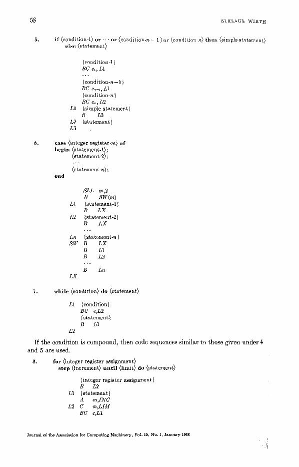
5. i f (condition-i) o r . . . or (condition-n - I)or (condition-n) then (simple statement) else (statement)
Icondition-1 } BC cl, L1
{ condition-n-- 1 } BC cn-,, L1 { condition-n } BC c,,, L2
L1 {simple statementl B L3
L2 {statement} L3
6. c a s e (integer register-m) of begin (statement-l);
<statement-2); , ° .
<statement-n); e n d
SLL m,2 B SW(m)
L1 {statement-1 } B LX
L2 {statement-2} B LX , o .
Ln {statement -n } SW B LX
B L1 B L2
. . .
B Ln LX
7. while (condition) do (statemenO
L1 {condition} BC c,L2 { statement } B L1
L2
I f the condit ion is compound, then code sequences similar to those given under 4 and 5 are used.
8. for (integer register assignment) step (increment) u n t i l (limit) do (statement)
{integer register assignment l B L2
L1 {statement} A m,INC
L2 C m,LIM BC c,L1
Journal of the Association for Computing Machinery, Vol. 15, No. 1, January 1968

PL360 59
Rm is the register specified by the assignment, INC the location where the incre- ment is stored, and L I M the location where t, he limit is stored. The compare in- struction at L2 may be either a C, CH, or CR instruction depending on the type of limit. Moreover, c depends on the sign of the increment.
9. procedure (identifier}({integer register-m}); {statement}
P {statement} BR m
10. {procedure identifier>
BAL m,P or
L 1 5 , n e w b a s e
BAL m,P L 15,oldbase
It is here assumed that P designates the procedure to be called, and Rm is the return address register specified in its declaration. The first version of code is ob- tained whenever tile segnmnt in which the procedure is declared is also tile one in which it is invoked.
5. Addressing and Segmentation
The addressing mechanism of the 360 computers is such that instructions can indi- cate addresses only relative to a base address contained in a register. The program- mer must insure that (1) every address in his program specifies a "base"-register; (2) the specified register is loaded with the appropriate base address whenever an instruction whose address refers to it is executed; (3) the difference d between the desired absolute address and the available base address satisfies 0 < d < 4096.
This scheme not only increases the amount of "clerical" work in programming, but also constitutes a rich source of pitfalls. A translator should therefore be de- signed to ease the tedious task of base address assignment, and to provide checking facilities against errors.
The solution adopted here was that of program segmentation. The program is subdivided into individual parts, so-called segments. Every quanti ty defined within the program is known by the ,Lumber of the segment in which it occurs arid by its displacement relative to the origin of that segment. The problem then consists of subdividing the program and choosing base registers in such a way that
(a) the compiler knows which register is used as base for each compiled address, (b) the compiler can assure that each base register contains the desired base
address during execution, and (c) the number of times base addresses are reloaded into registers is reasonably
small. First, it must be decided whether the process of subdividing the program should
be performed by the programmer or by the compiler. In the latter case, a fixed num- ber of registers must be set aside to serve as base registers which the compiler has freely at its disposal. This was considered undesirable. Furthermore, a program using a number of segments much larger than that of available base registers would be
Journal of the As~sodation for Computing Machinery, VoI. 15, No. 1, January 1968

60 NIKLAuS WIRTtt
subject to considerable inefficiencies due to the reloading of base addresses at points which might have been ill chosen. I t was therefore decided that the programmer should express explicitly which parts of his program were to constitute segments. He has then the possibility of organizing the program in a way which minimizes the nunlber of cross references between segments.
I t should be noted that tile programmer's knowledge about segment sizes and occurrences of cross references is quite different in the eases of program and data. In the latter ease he is exactly aware of the amount of storage needed for the de- clared quantities, and he knows precisely in what places ,of the program references to a specific data segment occur. In the former case, his knowledge about the even- tual size of a compiled program section is only vague, and he is in general unaware of the occurrence of branch instructions implicit in certain constructs of the lan- guage. I t was therefore decided to treat programs and data differently, and this decision was also in conformity with the desirability of keeping program and data apart as separate entities.
5.1. PROGRAM SEGMENTATION
Due to the fact that the language does not allow programs to modify themselves, branches are the only instructions referring to locations within program segments. Since control lies by its very nature in exactly one segment at any instant, it seemed appropriate to designate one fixed register to hold the base address of the program segment currently under execution. A branch leading into another segment must then always be preceded by an instruction loading that register with the base address of the destination segment. Register R15 was chosen for this purpose.
An obvious approach to the problem of segmentation requires the compiler to automatically generate a new segment, when the currently generated segment's length exceeds 4096 bytes. This solution was rejected for two reasons: (1) The programmer is not aware of the position of segment boundaries, and therefore has no way to minimize branches from one to another segment. (2) In most cases, the destination of an implicit branch (in if, case, while, and for statements) is not known to the compiler at the time of its generation. Therefore it is not known whether it will consist of one or two machine instructions.
The approach taken consists in connecting segment structure with the obvious program structure. The natural unit for a program segment is the procedure. The only way to enter a procedure is via a procedure statement, and the only way to leave it is at its end or by an explicit go to statement. The fact that no implicitly generated instruction can ever lead control outside of a procedure minimizes the number of cross references in a natural way. Since only relatively large procedure bodies should constitute segments, a facility was provided to designate such pro- cedures explicitly: a procedure to be compiled as a program segment must contain the symbol s e g m e n t in its heading. In practice, the requirement tha t such pro- cedures be explicitly designated has proven to be no handicap. I t is relatively easy for a programmer to guess which procedure exceeds the prescribed size, or other- wise to insert the symbol s e g m e n t after the compiler has provided an appropriate comment in the first compilation attempt. Obviously, the outermost block is always compiled as a segment.
5.2. DATA SEGMENTATION
In the case of data, the programmer is precisely aware of the amount of allocated
Journal of the Association for Computing Machinery, Vol. 15, No. 1, January 1968

PL360 61
memory as well as of the instances where roference is made to these quantities. A base declaration was therefo~ introduced Which implies that all quantities declared thereafter, but still within the same block and preceding another base declaration, :rder to the specified register as their base. These quantities form a data segment. At the place of the base declaration code is compiled which ensures that the register ~s loaded with the appropriate segnmnt address. However its previous contents are neither saved nor restored upon exit from the block.
A base declaration is implicit in the heading of the outermost block. I t always desit,~lates register R14 .
Obviously, data segments declared in parallel (i.e., not nested) blocks, can safely refer to the same base register. Data segments declared within nested blocks should refer to different base registers. If they do not, it is the programmer's responsibility ~to ensure that the register is appropriately loaded when data in either of the seg- ~nents are accessed.
There is no limit to the size of data segments. All cell designators must, however, refer to cells whose addresses differ from the segment base address by less than 4096. I f they do not, the compiler provides an appropriate indication.
5 .3 . PROGRAM LOADING
A scheme using program and data segments as described above results in an ex- ~tremely simple relocating loader program, since the segments can be loaded without modification. I t was felt that this benefit provided by a computer incorporating a base register scheme should be put to full advantage. Although the 360 computer still makes use of absolute addresses in a few instances (program status words, data channel commands), it was decided not to allow for absolute addresses in a program. 'They can, however, be generated at execution time. Consequently, the functions of the loader are reduced to:
(a) reading program and data segments into memory, (b) assigning the origin address of each segment to an entry in the segment
address table, and (c) transferring control to the program segment representing the outermost
block.
5.4 . PROBLEMS CONNECTED WITH INPUT-0UTPUT PROGRAMMING
The direct programming of input-output operations in PL360 is impractical in the scheme described so far for the following reasons:
(1) Input-output operations on the 360 are designed to use the interrupt mech- anism to signal termination of processes performed by data channels and devices in parallel with CPU operations. In order to use the interrupt feature, it is neces- sary to create program status words (PSW) and store them in certain fixed locations o f memory. A PSW contains the absolute address of a point in the program, which is a quantity that cannot be generated by a PL360 program.
(2) Particularly in routines servicing interrupts, but also in some other cases, i t is desirable to be able to dispense of a program base register. This could be done b y locating these routines within the first 4096 bytes of core memory. The loader described above, however, chooses the absolute location of a segment on its own.
These two shortcomings can be overcome in many ways. The following is sug- ~'ested:
(1) A facility is introduced to designate a segment as an interrupt service rou-
Journal of the Association for Computing Machinery, Vol. 15, No. 1, January 1968

62 NIKLAUS WIRTH
fine, with the effect that the compiler supplies information to the loader, causing the loader to assign the segment's base address to the appropriate PSW cell instead of the segInent address table. The compiler itself terminates this segment with an LPSW instead of a BR instruction (ef. 5.6). This approach forces a programmer to make explicit the fact that an interrupt routine is conceptually a closed segment, and it circumvents the undesirable introduction of a facility to generate labels as manipulatable objects.
(2) A provision is introduced to cause the compiler not to refer to a base register in the branch instructions contained in the interrupt service segment. The loader is at the same time instructed to allocate this segment within the first, 4096 bytes of core memory.
Usually, however, these facilities are not needed, because the program is exe- cuted in the environment of an operating system (whose choice is normally not up to the individual programmer) which executes programs in the program-mode where input-output instructions are not executable. The form which statements communicating with such an environment assume is determined by that particular environment and cannot be defined as part of the language proper (el. also [6]).
6. Compiler Methodology
6.1. GENERAL ORGANIZATION
The compiler is a strictly syntax directed one-pass translator. Its design served as a major test for the applicability of the techniques described in [4] to practical programming languages. The development of a precedence syntax with productions to which the meaning of the language could be properly attached, is no easy task Interestingly enough, however, this design process provided many insights into the nature of various conceptual elements, led to their clarification and often simplifica- tion, and contributed a great deal to the systematic structure of the resulting lan- guage.
The algorithm for syntactic analysis constitutes the core of the compiler. It operates on the basis of a table containing the rules of syntax and a table containing the precedence relations among input tokens, and evokes the execution of an inter- pretation rule whenever a parsing step is taken. The input tokens are obtained by calling a procedure
Syntax Rules
Analyser
Precedence Relat ions
In t e rp re t a t i on Rules
Journal of the Association for Computing Machinery, Vol. 15, No. i, January 1968

FL360 63
"insymbol," which scans the sequence of input characters and yields as a result either a basic symbol of the language, ~u, identifier, ~ I~umber, or a string. I t auto- matically suppresses comments. I t should be noted that in the implemented lan- guage no equivalent for the u n d e r l i n i n g of basic symbols is provided, and that therefore ~ sequence of letters and digits, starting with a letter and not eont:~ining blanks, may constitute a basic symbol. Any such sequence must be matched by the insymbol routine against a table containing the representations of all "letter-sym- bols." If a match is found, the result is a basic symbol, otherwise an identifier. As a consequence, identifiers could not be constructed by the syntax analyser itself upon receiving merely a sequence of letters and digits. The consideration of num- bers as tokens, on the other hand, was not a necessity but rather a convenience.
The syntax analyser makes use of a stack (called "symbol stack,") to store not yet reduced symbols. Whenever a reduction takes place, the interpretation rule cor- responding to the applied syntactic rule is activated. These interpletation rules make use of a second stack (called "value stack") to store information about each syntactic entity occurring in the reduction process. To each entry in the symbol stack corresponds an entry in the value stack, and vice versa. Ideally, an interpre- tation rule should exclusively reference data in those entries of the value stack which correspond to symbols in the symbol stack being reduced by the applying syntactic rule. This principle has been followed in the simple example presented in [4]. Here, however, a deviation from it was made by the i11troduction of eonventioual identifier tables, one containing identifiers denoting program points (labels), one for all declared identifiers.
6.2. IDENTIFIER TABLES The presence of identifier tables simplifies the search for identifiers and eliminates
the need for the specific right ~ecursive definition of the declaration structure used ill [4]. The separation of the table into one containing declared identifiers and one containing labels has its reason in the fact that labels are the only identifiers which carl occur in a statement before being defined in the program, and must therefore be treated differently as discussed below.
(1) (3 cell identifier) ::= (identifier) (2) (function identifier) ::= (identifier) (3) (procedure identifier)::= (identifier)
etc.
constitutes a violation of the requirement that in an unambiguous precedence grammar no two rules should have identical right parts. This violation required a slight complication of the analysis algorithm with the effect that an interpretation rule may cause an otherwise applicable syntactic rule to be rejected. In the given example, the interpretation rules specify that the considered identifier be located in the identifier table. If location is successful, then rule 1 is rejected unless the table indicates that the identifier indeed designates a 3 cell, rule 2 is rejected unless it designates a function, etc. This decision of the applicability of a syntactic rule on grounds of essentially semantic information reflects the argument that languages of "ALGOL type" are strictly speaking not context free.
The above identifier search implies that the entire block-structured identifier
Journal of the Association for Computing Machinery, Vol. 15, No. 1, January 1968

64 NIKLA.US WIRTH
table be searched. The following program demonstrates that labels cannot be sub- jeet to the same process, and that therefore
(4) ( label) : : = ( ident i f ie r )
must not be a rule of the language.
A : b e g i n L : . . . B : b e g i n g o t o L;
L: e n d ;
e n d
In this example, Rule 4 applying to L after the symbol go to would detect L as present in the identifier table, because L was defined as a label in the outer block (A). This would, however, be an erroneous assumption, since a local L is defined later in the inner block (B), to which goto L should refer. Consequently, searches for labels must be confined to the innermost block, and such a restricted search must be represented by an interpretation rule connected with a distinct syntactic rule with a different right part. In the language, that rule is
<go to s t a t emen t> : := g o t o ( ident i f ie r )
Identifiers in the label table are marked as either defined or not yet defined. Upon exit of a block, all undefined entries are collected and considered as entries in the outer block, where some of them may be found as already defined. This process made the use of a separate label table desirable.
The compiler is designed to read the source program from cards or tape; it pro- duces (optionally) a listing, each line containing a corresponding target program address. The code is compiled into core memory, and as soon as a segment is closed, it is written out() secondary storage. The segment is preceded by a record indicating the kind of the segment (program or data), its number, and its length. The program loader later collects the segments from the secondary storage, lists the base address which it assigns to each segment, and assigns it to the corresponding entry in the segment address table.
6.3. HANDLING OF SYNTACTIC ERRORS
The syntax anMysis algorithm described in [4] makes the assumption that ana- lysed programs are syntactically valid. This assumption is not tenable in the prac- tical world of computer programming. Syntactic errors are detected by the fact that for some string recognized as reducible there is no matching entry in the table of productions. After an error has been encountered, it is in most cases desirable to continue compilation in order that subsequent errors may be located and indicated. A method has to be devised to let the analysis algorithm proceed after having made some assumption about the nature of the error.
This is in general a rather hopeless task. An investigation of a large number of programs containing syntactic errors reveals, however, that most of the committed errors exhibit strong similarities and can be diagnosed by a relatively simple al- gorithm. In most cases, syntactic errors are due to omission or wrong use of sym- bols merely conveying information about structural properties of the program, such as commas, semicolons, and the various kinds of brackets. Omission of elements explicitly denoting program activities, such as operators and operands, are rare.
A second important consideration is that an incorrect construction should be
Journal of the Association for Computing Machinery, Vol, 15, No. 1, January 1968

PL360 65
detected as early as possible, i.e., before further steps are [aken on the basis of the incorrect text. The precedence grammar technique is an excelleut scheme in this respect, because it is based upon reh:~tions exist.ing among symbol p~firs. That none of the relations denoted by ~ , ~ , > exists between two symbols in@lies the impos- sibility of these two symbols being adjacent in ~[ny senience of the l~nxguage. The empty relation (denoted by @) shall be defined as holding whenever none of the others hold. On a left-to-right setm, its encounter constitutes the e~u'liest possible detection of an en'oneous construction.
It. should be noted that the use of two precedence functions inst.ead of the prece- dence relations implies that the analysis algorithm is based on a condensation of the inform~tion contained in the matrix of relations [4]. This condensation relies on the assumption that empty relations can simply be ignored. The above considera- tions lead to the conclusion that fox" practical reasons it is advantageous to have t;tle relation matrix a[ the disposal of the analyser rather than the functions.
The algorithm fox' diagnosing of and recovery from errors described subsequently is a heuristic solution rather than one based on rigorous theoretieaI principles. I t is contended here that any such scheme must make a very drastic selection from all the possible forms which errors may assume. The important aspect is that those situ- ations, which are likely to occur often, are mastered intelligently. Since a frequency statistic of errors reflects the behavior of the huInan users, such a selection nmst by definition be based on heuristics.
There exist two places in the anMysis process, where illegM constructions may be detected (el. [4, p. 18]):
1. The empty relation holds between the symbol on top of the stack and the in- coming symbol:
Si Q Pk
In this case a list I of insertion symbols' is scanned. If for some m, S~ ~ I,~ and I,~ @ P~., then I,, is inserted into the scanned string in front of Pk. Since this in- sertion may lead to a correct program (in about 90 pereent of the tested cases it did), an according comment must be delivered to the programnler,
If for no m, S~ ~ I,~ and I~ ¢ Pk , then the symbol Pk is stacked, 2. The value of the flmetion
Lef(part ( Si " " Si)
is undefined (~), i.e., there exists no syntactic rule whose rightpart is S~ . . . S.i. This situation may occur even if for all ]c ( j .< k < i) Sk ~) Sk+l.
In this case a table of erroneous productions is scanned for a right-part identical to S~. • • • S~. I f a match is found, an error message corresponding to that rule can be printed, and the analysis can proceed with the statement:
i : = j
The augmented algorithm for syntactic analysis is then described as follows:
p r o c e d u r e Invalid pair; b e g i n i n t e g e r m; m :-- t ;
w h i l e m _< n A (Si @ I,~+ V I, . @ Pk) do m :~ m ~ l ; i f m < n t h e n (Pk "'" P~+i) := I ~ e a t (Pi, ' " P~)
end;
Journal of the Association for Computing M[achlnery, Vol. 15, No. 1, January 1968

66 NIKLAUS WIRTIt
w h i l e Pk ~ rl-I-II do b e g i n i := j := j + l ; $ i := P~:; k := /~+1;
w h i l e S] > @ Pk do b e g i n i f Sj @ Pk t h e n Invalid pair;
w h i l e Sj_, ~ @ Sj d o j := j - l ; t := Lef lpar t (S i . . . Si); Sj := i f t = { ~ t h e n E r r o r ( S ¢ . . . S , ) e l s e t ; i := j
e n d e n d
This technique enables a compiler to deliver meaningful error messages, because the analyser has found an erroneous production to be applicable, which was antici- pated by the compiler designer who, in turn, knowing the reasons why programmers inadvertently write such a construction, was in a position to devise an approprbtte coInment. It was found to be beneficial to accompany the diagnostic message by the list of symbols currently stored in the parsing stack. These symbols represent ail unfinished syntactic entries in the current parse, and may give the programmer valuable insights about his misuse of the language.
The choice of the appropriate insertion symbols and erroneous productions re- quires a thorough understanding of the analysis algorithm on the part of the com- piler designer, as well as a subtle feeling to anticipate frequent misuses of the sya- tax. Of course, further insertion symbols and productions can easily be added to the tables in order to increase the diagnostic capabilities of the analyser. If a com- piler is capable of gathering statistical information about encountered erroneous situations, this information could be evaluated from time to time in order to expand the tables. As a result, the compiler would truly seem to adapt itself to its imperfect human environment in order to gradually become a better and better teacher.
7. Development of the Compiler
At the time when the project to develop a compiler for PL360 was started, no 360 computer was available to tile author, nor did the facilities promised with the forth- coining machine look too enticing to use. I t was therefore decided to use tile avail- able Burroughs B5500 computer for the design and testing of the compiler, which was completed by the author within two months of part time work. I t accepted a preliminary version of PL360 as described in [7] which contained the basic features of the presently described language.
The compiler was then reprogrammed in its own language. Through a loader and supervisor program (written in assembly code), the program, recompiled on the B5500, became immediately awfilable on the 360 computer.
The experiment of describing the compiling algorithm in PL360 itself proved to be the most effective test on the usefulness and appropriateness of the language, and it influenced the subsequent development of the language considerably. During this process, several features which seemed desirable were added to the language, and many were dropped again after having proved to be either dubious in value, inconsistent with the design criteria, or to() involved and leading to misconceptions. The leading principle and guideline was to produce a conceptually simple language and to keep the number of features and facilities minimal. The "bootstrapping" method in combination with the described compiling technique proved to be very
Journal of the Association for Computing Machinery, Vol. 15, No. 1, January 1968

pL360 67
successful for experimentation with a~ld alteration of the language. The process of incorporation of a new feature consists of representing the new feature in the syntax of the language, and of defining the compiler actions corresponding to the new constructs in the form of additional interpretation rules. These rules must of course be denoted in terms of previously available facilities.
In general, a significant drawback of the bootstrapping technique is the fact that programming errors are easily proliferated. However, the combination of the boot- strapping method with the rigorous approach to systematic compiler organi- zation by means of strict syntax analysis proved to be very successful, since the latter constitutes an enormous step towards reliability, which can never be achieved by common heuristic methods of compiler design.
8. Per formance
The development, of a job control and supervisor program was undertaken in paral- lel with the construction of the compiler (el. [6]). The following performance figures reflect the operation of the compiler under that supervisor. It should be noted that the supervisor considers the compiler in the same way as a regular user's program.
Size (in bytes, approximately) Supervisor 4 600 Job control 4 400
9 000
Compiler program Various compiler data
16 000 5 400
21 400
Identifier tables; adjusted according to available core size. Output area )
Timing. The processing of a job consists of the following steps, described in terms of the present implementation on a 360/50 computer:
1. Loading of the compiler from tape. 2. Compilation, with input from cards or tape, and output to tape (and op-
tionally to cards). 3. Loading of the compiled program from tape (or cards). 4. Execution of the program.
Steps 1 and 3, constituting what is usually called "overhead," take 4.7 seconds execution time. Compilation proceeds at the speed of the card reader (1000 cpm). If the source program is read from tape (640 character records, unbuffeI~d) and the program listing is suppressed, the compiler (about 1500 card records) recompiles itself in 39 seconds (with listing in 109 seconds). The time required to load the system initially is 2 seconds.
9. Reflect ions o n t h e 360 A r c h i t e c t u r e
Based on the experiences drawn h'om the compiler development, it can be con- eluded that the objective to make direct machine programming more convenient by
Journal of the Association for Computing Machinery, Vol. 15, No. 1, January 1968

~ NIKLAUS WI~PH
providing a too] which is superior to common assembly codes with respect to reada- bility and writability, is commendable and important. I t can also be concluded that PL360 is fairly successful ill meeting this objective. The decisive factor, in the author's opinion, ]s the simplicity, frugality, and coherence of tile language. A limiting factor to this is the architecture of the underlying machine. In this respect, the question "how well is the computer suited for %his kind of language?" becomes more significant than tile opposite question, "how well is the language suited for the machine?" The author feels indeed strongly about this point, and recommends :future hardware designers to confront themselves seriously with the first question, before yielding to the well-known policy of answering every problem with the common and omnipotent reply : "There is a bit somewhere".
As a matter of fact, the relatively systematic architecture of the 360 computer series provided a strong encouragement to devise a tool in the sense of PL360. It seems nevertheless worth while to locate some of its less fortunate features:
(1) Tile idea of a "two-dimensional instruction set" with one coordinate specify- ing the operation, the other the type of operand, is very commendable, and is properly reflected in PL360. But, the better a principle is, the worse are its viola- lions. There exist operands of type full word integer, half word integer, full word logical, short and long floating point, and byte in the 860 system. Operations on them are more or less grouped into columns in the matrix of instructions. However, instructions on logical and full word integer operands occur in the same column, certain operations are missing in the half word format, and operations on bytes differ radically from all others. A striking example is the inconsistency of the LH and STH instructions, the first of which performs the function of assigning an integer to a register, the second one that of assigning a half word logical quantity to a memory cell. This is not merely an unfortunate feature, but a conceptual flaw.
(2) The fact that many instructions are indexable only through misuse of the base register field is very unfortunate. I t is one reason why none of those instruc.- tions fits into the scheme of the PL360 assignment statement. I t is also due to tNs fact that the desirable construct
(3 cell} := (5 p r imary )
is not part of the language, and that s t r ing was not adopted as a simple data type. (3) The more complex a single instruction is, the more debatable becomes the
choice of its detailed form. The BCT, BXLE, BXH instructions are such examples, none of which fitted into the scheme of PL360 structures.
(4) The 360 instructions exhibit a remarkable consistency in the scheme of con- dition code setting, with the very peculiar exception of the TM instruction. I t is obvious that the condition code plays a somewhat odd role in this language. I t can only be altered by hidden side @cts of arithmetic, logical, comparison, and certain other operations, and be tested by branch instructions. There is no way, however, to copy its value or even to perform operations on it.
This short list of architectural misfits is by no means complete. I t omits, e.g., mentioning some dismal properties of the floating point arithmetic and of the input- output mechanism. However, these have no immediate effect on the structure of the PL360 language.
ACK~OWLr:DGMENTS. The author wishes to express his sincere thanks to Mr. Y. W. Wells for his indispensable assistance. Mr. Wells receded the compiler in its own
Journal of the Association for Computing Machinery, Vol. 15, No. 1, January 1968

pL860 69
language, and developed the support ing moni tor system. Thanks are also due to the OSG group at the Stanford Linear Accelerator Center for their generous pro- vision of computer time. And finally, the support of the Nat ional Science Founda- tion under grant GP 4053 is gratefully aekl.towledged,
REFERENCES
1. WroTH, N., ~ND HOAnE, C. A.R. A contribution to the development of ALGOL. Comm. ACM 9, 6 (June 1966), 413-432.
2. AMD~HL, G. M., BLnAUW, G. Ai, AND BROm(S, F. P., Ja. Architecture of the IBM Sys- tern/360. IBM J. Res. and Dev. 8 (April 1964), 87-101.
3. BLAa~'W, G. A., ~.~T AL. The structure of System/360. IBM Syst. J. 3, 2 (1964), 119-164. 4. WroTH, N., AND WEBr~R, H. EULER: A generMization of ALGOL, and its formM defi-
nition: Part I. Comm. ACM 9, 1 (Jan. 1966), 13-23. 5. "IBM System/360 principles of operation," IBM Syst. l~eference Libr. A22-6821-2. 6. WIUTH, N. (Ed.). The PL360 System. Tech. Rep. CS 68, Stanford U., Stanford, Calif.,
June 1967. 7. Wm'rH, N. A programming language for the 360 computers. Tech. Rep. CS 33, Stanford
U., Stanford, Calif., Dec. 1965.
RECEIVED DECEMBER, 1966; REVISED JUNE, 1967
Appendix I . E x a m p l e o f C o m p i l e d C o d e
Tile Assembly Language Coda corresponding to the procedure Magic square (ef. Section 3) is as follows:
MAGICSQR STH O,NSQR BC 11,L3 LR 1,0 AR 2,0 MH 1 ,NSQR L3 LR 3,1 STH 1,NSQR SLL 3,6 LR 1,0 LR 4,2 A 1,ONE SLL 4,2 SRL 1,1 AR 4,3 LR 2,0 L4 ST 5,X (4) L 5,ONE A 1,ONE B L7 CR ' 1,0
L1 LR 3 ,ONE BC 13 ,L5 SLL 3,6 SR 1,0 LR 4,2 L5 A 2,ONE SLL 4,2 CR 2,0 AR 4,3 BC 13,L6 L 3,X(4) SR 1,O C 3,ZERO L6 LA 5,1(5) BC 8,L4 L7 CH 5,NSQR S 1,ONE BC 12,L1 S 2,TWO BR 6 C 1 ,ONE NSQR DC H BC ll,L2 ZERO DC F 1'0 'v AR 1,0 ONE DC F " I "
L2 C 2,ONE TWO DC FVV2 vl
Journal of the Association for Computing Machinery, Vol. 15, No. 1, January 1968

70 ~qIKLAUS WIRTH
0 A @
~ ~ ~ v ~ , ~ v ,~
~ M ~ ~ . ~
' ~ ~ - ~ ~ - ~ ~ ~ ~ ' ~ ~ ~ : v ~ v
£
o
~y hlO
©
ii !1. !~. !L.
+
I . ~
o ¢9
- . ~ ~ ,--I ~
II II II II li tl li II li II ~ : : : : : : : : : : : : : : : : : : : :
v v v ~ V
©
v
2
v v v
© O o
v v v
i~ A v A r r . ~ . ~ II It
o
© o
v
o
+.~ ..~ ,.2 v v ~
!~. !l. !l !l !l !l !i !
II II II
©
J o u r n a l of t h e ,Association for C o m p u t i n g M a c h i n e r y , Vol . 15, No . 1, J a n u a r y 1968

PL360 71
v v v ~
~ . ~ ~ ~
II tl II II II II II U It II
"~®~ ~ ~ ~ ~ ~ ~ ~ ~ - ~
~ ~ ~ ~ . . . . ~ ~ o o ~ . . . ~ ~ o o o o ~ ~,,~ ,..,.~ >.~ ~ ~ ~ ~ ~ ~ ~ 0 0 0 0 + , ~ -:~
II II Jr It II II II ]1 It II II It
v v v v v v
0A
~ v C0 v ~ A A
~ v ~ v ' ~
~ ~ ~ ~ A A ~ v
O O © © . ~
v . ~ . ~ v ~ v ~ ° ~ ~ ~ ~ ~ v
II II H II II II II H II H II II II
B A
¢D v
H rl II
J o u r n a l o1 t h e A s s o c i a t i o n f o r C o m p u t i n g M a c h i n e r y , V o l . 1 5 , N o . I , J a n u a r y 1 9 6 8

Appendix IlIo PL360 Syntax (In convenient precedence form)
1 <K REG> : : = < iD> 2 <T CELL ID> : : = <IO> 3 <PROC ID> : : = < [D> 4 <FUNC ID> : : : < ID> 5 <T CELL> : : = <T CELL ID> 6 <T CELL i> ) 7 <T CELL2> } 8 <T CELL I> : : = <T CELL2> <ARITH OP> <T NUMBER> 9 <T CELL3> <T NUMBER>
10 <T CELL2> :~= <T CELL3> <K REG> I t <T CELL3> : : = <T CELL ID> ( 12 <UNARY OP> : : = ABS 13 NEG 14 NEG ABS 15 <ARITN OP> : : = + 16 17 * 18 / 19 + ÷ 20 21 <LOG OP> : : = ANO 22 OR 23 XOR 24 <SHIFT OP> : : = SHLA 25 SHRA 26 SHLL 27 SHRL 28 <K REG ASS> : : = <K REG> := <T CELL> 29 <K REG> := <T NUMBER> 30 <K REG> := <STRING> 3 t <K REG> := <K REG> 32 <K REG> := <UNARY OP> <T CELL> 33 <K REG> := <UNARY OP> <T NUMBER> 34 <K REG> := <UNARY OP> <K REG> 35 <K REG> := @ <T CELL> 36 <K REG ASS> <ARITH OP> <T CELL> 37 <K REG ASS> <ARITH OP> <T NUMBER> 38 <K REG ASS> <ARITH OP> <K REG> 39 <K REG ASS> <LOG OP> <T NUMBER> #0 <K REG ASS> <LOG O?> <T CELL> 4 t <K REG ASS> <LOG OP> <K REG> 42 <K REG ASS> <SHIFT OP> <T NUMBER> 43 <K REG ASS> <SHIFT OP> <K REG> 44 <FUNCI> : : = <FUNC2> <T NUMBER> 45 <FUNC2> <K REG> 46 <FUNC2> <T CELL> 47 <FUNC2> <STRING> 48 <FUNC2> ::= <FUNC IO> 49 <FUNCI> , 50 <CASE SEQ> ::= CASE <K REG> OF BEGIN 51 <CASE SEQ> <STATEMENT> 52 <SIMPLE ST> ;:= <T CELL> := <K REG> 53 <K REG ASS> 54 NULL 55 GOTO <ID> 56 <PROC IO> 57 <FUNC IO> 58 <FUNCI>
Journal of the Association for Computing Machiaery, Vol. 15, No. 1, January 1968

PL360 '73
59 60 61 62 63 64 65 66 67 68 69 7O 71 72 73 74 75 76 77 78 79 8O 81 82 83 84 85 8~ 87 88 89 90 91 92 93 94 g5 96 97 98 99
I00 I01 102 103 104 105 106 107 108 I09 IT0 111 IT2 I13 I14 115 I16 I I ? I18
<CASE SEQ> END <BLOCKBODY> END
<REL 0P> : : = <
> < = > =
<NOT> : : = <CONDITION> : : = <K REG> <REL OP> <T CELL>
<K REG> <REL OP> <T NUMBER> <K REG> <REL OP> <K REG> <K REG> <REL OP> <STRING> OVERFLOW <REL OP> <T CELL> <NOT> <T CELL>
<COMP CONO> ; : = <CONDITION> <COMP AOR> <CONDITION>
<COMP AOR> : : = <COMP COND> AND <COMP COND> OR
<CONO THEN> : : = <COMP COND> THEN <TRUE PART> : : = <SIMPLE ST> ELSE <WHILE> ; ; = WHILE <COND DO> : : = <COMP COND> DO <ASS STEP> : : = <K REG ASS> STEP <T NUMBER> < L I M I T > : : = UNTIL <K REG>
UNTIL <T CELL> UNTIL <T NUMBER>
<DO> : ; : DO <STATEMENT*> : : = <SIMPLE ST>
IF <COND THEN> <STATEMENT*> IF <COND THEN> <TRUE PART> <STATEMENT*> <WHILE> <COND DO> <STATEMENT*> FOR ~ASS STEP> < L I M I T > <DO> <STATEMENT*>
<STATEMENT> : ~ : <STATEMENT*> <ST T TYPE> ::= SHORT INTEGER
INTEGER LOGICAL REAL LONG REAL BYTE CHARACTER
<T TYPE> : : = <SIT TYPE> ARRAY <T NUMBER> <SI T TYPE>
<T DECLi> ::= <T TYPE> <ID> <T DECL2> <ID>
<T DECL2> : ; = <T DECL7> , <T DECL3> : : = <T DECLI> = <T DECL4> : : = <T DECL3> (
<T OECLS> , <T DECLS> ::= <T DECL4> <T NUMBER>
<T DECL4> <STRING> <T DECLB> ::= <T DECL3> <T DECLT> ;:= <T DECLI>
<T DECLB> <T NUMBER> <T DECLB> <STRING> <T DECL5> }
<FUNC DCI> : ; = FUNCTION <FUNC DCT>
(Continued on following page)
Journal of the Association for Comput ing .~Iachiaery, Vol. 15, No. 1, January 1968

74 NIKLAUS WIRTH
Appendix III--Continued
1 [9 <EUNC DC2> : : = <FUNC DCi> < ID> 120 <FUNC DC3> : : = <FUNC 0C2> ( 12 l <FUNC DC4> : : = <FUNC 0C3> <T NUMBER> 122 <FUNC DCS> ::= <FUNC 0C4> 123 <EUNC DC6> : : = <EUNC DCS>' <T NUMBER> 124 <FUNC DC7> ; ; = <FUNC DC6> ) 125 <SYN DCI> : : = <T TYPE> < ID> SYN 126 < S I T TYPE> REGISTER <ID> 127 <SYN DC3> <ID> SYN 128 <SYN DC2> : := <SYN DCI> <T CELL> 129 <SYN OCt> <T NUMBER> 130 <SYN DCI> <K REG> 131 <SYN DC3> : : = <SYN DC2> 132 <SEG HEAD> : : £ SEGMENT 133 <PROC HDI> : : = PROCEDURE 134 <SEG HEAD> PROCEDURE 135 <PROC HD2> : : = <PROC HDI> <IO> 136 <PROC HD3> : := <PROC HD2> ( 137 <PROC HD4> : : = <PROC HD3> <K REG> 138 <PROC HD5> = : = <PROC HD4> } 139 <PROC HD6> : : = <PROC HD5> ; 140 <DECL> : ; = < I DECL7> 141 <FUNC DCI> 142 <SYN DC2> 143 <pROC HDB> <STATEMENT*> 144 <SEG HEAD> BASE <K REG> 145 <LABEL DEF> : := <ID> : 146 <BLOCKHEAD> : := BEGIN 147 <BLOCKHEAD> <DECL> ; I~8 <BLOCKBODY> : := <BLOCKHEAD> L49 <BLOCKBODY> <STATEMENT> ; 150 <BLOCKBODY> <LABEL DEF> 151 <PROGRAM> ::= . <STATEMENT> •
SYN
Journal of "the Association for Computing Machinery, Vol. 15, No. i, January 1968