Pipeline Inspection Tests Using a Biomimetic Robot - MDPI
16
biomimetics Article Pipeline Inspection Tests Using a Biomimetic Robot Elizabeth Islas-García 1 , Marco Ceccarelli 2, * , Ricardo Tapia-Herrera 3 and Christopher R. Torres-SanMiguel 1 Citation: Islas-García, E.; Ceccarelli, M.; Tapia-Herrera, R.; Torres-SanMiguel, C.R. Pipeline Inspection Tests Using a Biomimetic Robot. Biomimetics 2021, 6, 17. https://doi.org/10.3390/ biomimetics6010017 Academic Editor: Andrew Adamatzky Received: 28 October 2020 Accepted: 2 March 2021 Published: 9 March 2021 Publisher’s Note: MDPI stays neutral with regard to jurisdictional claims in published maps and institutional affil- iations. Copyright: © 2021 by the authors. Licensee MDPI, Basel, Switzerland. This article is an open access article distributed under the terms and conditions of the Creative Commons Attribution (CC BY) license (https:// creativecommons.org/licenses/by/ 4.0/). 1 Instituto Politécnico Nacional, Escuela Superior de Ingeniería Mecánica y Eléctrica, Unidad Zacatenco, Mexico City 07738, Mexico; [email protected] (E.I.-G.); [email protected] (C.R.T.-S.) 2 Laboratory of Robot Mechatronics, Department of Industrial Engineering, University of Rome Tor Vergata, 00133 Rome, Italy 3 CONACYT Catedras, Mexico City 03940, Mexico; [email protected] * Correspondence: [email protected] Abstract: This paper presents a biomimetic prototype of a mobile robot that can be used to inspect the subdrainage conditions of pipelines located along different highways in Mexico. Computer-aided design tools have been used to size each of the prototype components as inspired by anatomical spider structure. Springs are integrated to generate proper contact pressure against the pipe walls. The robot locomotion system is implemented with adaptable behaviour for the irregularities of pipelines along its journey. The robot prototype is manufactured in 3D printing with the advantage of having its spare parts easily replaceable. Reported results show internal pipe status through a mini video camera on the top of the robot. Keywords: biomimetics; service robots; spiders; pipelines inspection; design 1. Introduction The locomotor behaviour and physiological characteristics of animals can reference robot development to perform different autonomously tasks under operator control. Robot design depends on the characteristics and conditions of the environment of its operation. Mobile robots’ movement is based on wheel type, caterpillar, legs, and worm [1]. Applica- tions are on areas where humans are unable to access, for search and rescue in a natural event or disaster [2], inspection tasks [3], maintenance and cleaning [4], among others robotics service [5]. Most robots use wheels for their locomotion, achieving high speeds; however, they have disadvantages due to irregular travel areas [6]. The alternative of wheels locomotion is leg systems that are flexible and can avoid obstacles, also control- ling the legs independently; they have multiple degrees of freedom [7]. Spiders inspire a climbing robot’s design with low energy cost and legs adhere to any surface walls [8]. As mentioned before, there are currently different robot applications, like a spider- shaped robot developed to support robot points used to move in flat tunnels. Its design is based on three limbs articulated in a central body, which determines posture stability and moves by stepping two legs on the tunnel walls while one moves [9]. Spider robot with eight legs was developed to move on flat surfaces, on vertical and inverted walls. Locomotor extremities parameters are stride frequency, joint twist angle, stride length, among others. Likewise, legs are symmetrical, which means that the legs’ behaviour is the same on both sides; speed movements depend on the frequency and stride length [10]. It is not always possible to imitate animals’ movements due to mechanical complexity high, and different morphology was implemented to design a spider robot with eight legs to avoid actuator consumption. This actuator and the single-degree-of-freedom belt-pulley mechanism design make all eight legs move forward through the transmission integration. This robot’s primary purpose [11] is to traverse smooth terrain and check a tetrapod gait pattern. According to different investigations as in [12,13], robots have also been developed with hybrid locomotion; a propulsion mechanism combination; caterpillar wall press type, wheeled wall press, and wheel wall pressure screw-type. A design for gas supply pipes Biomimetics 2021, 6, 17. https://doi.org/10.3390/biomimetics6010017 https://www.mdpi.com/journal/biomimetics
-
Upload
khangminh22 -
Category
Documents
-
view
2 -
download
0
Transcript of Pipeline Inspection Tests Using a Biomimetic Robot - MDPI

biomimetics
Article
Pipeline Inspection Tests Using a Biomimetic Robot
Elizabeth Islas-García 1, Marco Ceccarelli 2,* , Ricardo Tapia-Herrera 3 and Christopher R. Torres-SanMiguel 1
�����������������
Citation: Islas-García, E.; Ceccarelli,
M.; Tapia-Herrera, R.;
Torres-SanMiguel, C.R. Pipeline
Inspection Tests Using a Biomimetic
Robot. Biomimetics 2021, 6, 17.
https://doi.org/10.3390/
biomimetics6010017
Academic Editor:
Andrew Adamatzky
Received: 28 October 2020
Accepted: 2 March 2021
Published: 9 March 2021
Publisher’s Note: MDPI stays neutral
with regard to jurisdictional claims in
published maps and institutional affil-
iations.
Copyright: © 2021 by the authors.
Licensee MDPI, Basel, Switzerland.
This article is an open access article
distributed under the terms and
conditions of the Creative Commons
Attribution (CC BY) license (https://
creativecommons.org/licenses/by/
4.0/).
1 Instituto Politécnico Nacional, Escuela Superior de Ingeniería Mecánica y Eléctrica, Unidad Zacatenco,Mexico City 07738, Mexico; [email protected] (E.I.-G.); [email protected] (C.R.T.-S.)
2 Laboratory of Robot Mechatronics, Department of Industrial Engineering, University of Rome Tor Vergata,00133 Rome, Italy
3 CONACYT Catedras, Mexico City 03940, Mexico; [email protected]* Correspondence: [email protected]
Abstract: This paper presents a biomimetic prototype of a mobile robot that can be used to inspectthe subdrainage conditions of pipelines located along different highways in Mexico. Computer-aideddesign tools have been used to size each of the prototype components as inspired by anatomicalspider structure. Springs are integrated to generate proper contact pressure against the pipe walls.The robot locomotion system is implemented with adaptable behaviour for the irregularities ofpipelines along its journey. The robot prototype is manufactured in 3D printing with the advantageof having its spare parts easily replaceable. Reported results show internal pipe status through amini video camera on the top of the robot.
Keywords: biomimetics; service robots; spiders; pipelines inspection; design
1. Introduction
The locomotor behaviour and physiological characteristics of animals can referencerobot development to perform different autonomously tasks under operator control. Robotdesign depends on the characteristics and conditions of the environment of its operation.Mobile robots’ movement is based on wheel type, caterpillar, legs, and worm [1]. Applica-tions are on areas where humans are unable to access, for search and rescue in a naturalevent or disaster [2], inspection tasks [3], maintenance and cleaning [4], among othersrobotics service [5]. Most robots use wheels for their locomotion, achieving high speeds;however, they have disadvantages due to irregular travel areas [6]. The alternative ofwheels locomotion is leg systems that are flexible and can avoid obstacles, also control-ling the legs independently; they have multiple degrees of freedom [7]. Spiders inspire aclimbing robot’s design with low energy cost and legs adhere to any surface walls [8].
As mentioned before, there are currently different robot applications, like a spider-shaped robot developed to support robot points used to move in flat tunnels. Its designis based on three limbs articulated in a central body, which determines posture stabilityand moves by stepping two legs on the tunnel walls while one moves [9]. Spider robotwith eight legs was developed to move on flat surfaces, on vertical and inverted walls.Locomotor extremities parameters are stride frequency, joint twist angle, stride length,among others. Likewise, legs are symmetrical, which means that the legs’ behaviour is thesame on both sides; speed movements depend on the frequency and stride length [10]. It isnot always possible to imitate animals’ movements due to mechanical complexity high,and different morphology was implemented to design a spider robot with eight legs toavoid actuator consumption. This actuator and the single-degree-of-freedom belt-pulleymechanism design make all eight legs move forward through the transmission integration.This robot’s primary purpose [11] is to traverse smooth terrain and check a tetrapod gaitpattern. According to different investigations as in [12,13], robots have also been developedwith hybrid locomotion; a propulsion mechanism combination; caterpillar wall press type,wheeled wall press, and wheel wall pressure screw-type. A design for gas supply pipes
Biomimetics 2021, 6, 17. https://doi.org/10.3390/biomimetics6010017 https://www.mdpi.com/journal/biomimetics
Biomimetics 2021, 6, 17 2 of 16
is presented in [13], with a mechanical structure that allows moving with elbows, by asufficient traction force and flexibility in their travel. It has three-dimensionally differentialdrive wheels, which can be adjusted inside the pipe, making the wheels drive contactagainst the wall. The robot was designed with two V-shape mechanisms, capable of slidingin smooth polyvinyl chloride (PVC) pipes between 63 to 125 mm diameters. It performsan axial rotation inside the tube with clamping movements [14]. Friction force generatedusing this V-shape depends on the tube diameter. Other results [15] show the design andconstruction to inspect pipeline systems in residential buildings with length of more than30 mm. The design efficiency was verified through a computational modelling tool. Inaddition, [16] exhibits a robot to cut pipes in decommissioning of nuclear plants. Thestructure was made under radioactive conditions, it is composed of vision, temperature,and position sensors, and a mechanism was integrated for the cutting task. A robot’s designto inspect pipes vertically, horizontally, and in elbows that are related to petrochemistry,water supply, and liquid transport with dimensions from 127 to 152 mm in diameter isshown in [17]. Its mechanism includes a module with three wheels in a vertical position,with the position and three wheels attached at a propeller angle of 15◦ perpendicular tothe body, the rotation of this coupling generates the robot movement. The robot in [18]is developed to inspect pipes in the chemical and gas industries. It is composed of asystem of front and rear legs coupled to a springs system, positioned at an angle of 120◦
to each other. Through the springs attached to each leg and to the robot body, it is ableto move inside pipes of a range from 140 to 200 mm. Some developed robots can adaptto different changes in pipe diameters and apply gas systems [19–21]. At the same time,other results [22–24] were designed for a specific diameter of pipes. Results in [25] showa robot with dimensions of 23 mm in diameter and 110 mm in length was developed.Inspecting petrochemical pipes with the integration of a small camera, recover lost objectswith micro arms. Pipes are an essential component to transport different fluids or gasesfrom one point to another, requiring continuous maintenance [26]. Everyday monitoring ofhighways in Mexico is aimed to avoid and correct pipe damage [27]. Subdrainage networksare a significant part of releasing rainwater and preventing pavement fractures and, mostimportantly, preventing car accidents.
This paper presents a robot prototype to inspect subdrainage pipes networks that arelocated along different highways in Mexico. It is essential to find the exact point wherea pipeline present failures and obstructions, causing water stagnation under the roads toprevent pavement fractures. Obstructions can be caused by the dragging of small objectsthat exist around highways. The robot’s design integrates omnidirectional locomotionto avoid some obstacles and unrestricted movement (rotation and translation) throughthe pipe, in addition to manufacturing by 3D printing of polylactic acid (PLA) filamentwhich reduces the total cost compared to a commercial robot. The advantage is the easyreplacement of components. This paper is organized as follows: The Methodology sectionshows a proposal for locomotion and the type of wheels. The Materials are also consideredto obtain adequate traction; the Result section shows a robot design capable of moving androtating through a PVC pipe. The conclusions summarize the requirements for highwayinspection in Mexico.
2. Methodology
The robot is introduced into subdrainage networks with a diameter between 3 and4 inches of approximately 100 m of length. Due to these characteristics, it is not possible tovisualize the interior by conventional means such as the visual reach of the human beingor commercial robots. The inspection aims to visualize the inside of the pipe using thenight vision camera. To take photographs with a minimum resolution of 5 MP, to knowthe conditions they were found, and determine if immediate maintenance was required.The robot will inspect the pipeline in sections of 50 m. Table 1 shows robot data whosedesign is inspired by a spider structure and locomotion by wheels as references for this

Biomimetics 2021, 6, 17 3 of 16
work. Likewise, it highlights that this proposal has a free movement within the pipe thanthe mentioned references.
Table 1. Hexapods designed for pipe inspection.
Robot Use Characteristics Design Requirements Pipe Size
Three-limbspider-like robot [9]
Inspection of planartunnel environments.
Algorithm for selecting thefootholds of a three-limb robot.
The algorithm assumesknowledge of the tunnel
geometry.
No mention of componentreplacement.
It does not avoidobstruction.
90–100 cm
The ROBOTURKSA-2 Robot [11]
Applications inindustry, defence, and
natural disasters.
Design and control of aneight-legged with a single
actuator.
Avoid obstacles but not inpipe.
No mention of componentreplacement
-
The MRINSPECT IVrobot [13] Gas pipe inspection.
Design to straight pipelines,elbows, and branches anddifferent diameter pipes.
Only translationalmovement
It does not avoidobstruction.
No mention of componentreplacement.
8.5–10.9 cm
The Pirate robot [14]Inspection of
low-pressure gasdistribution networks.
Using omnidirectional wheelsthat allow direct control of the
orientation in the pipe.
Control automatic ofmovement translational
and rotationalIt does not avoid
obstruction.
6.3–12.5 cm
New in-pipeinspection robot [17]
Inspectionpetrochemistry, water
supply, and liquidtransport pipes
It uses wheels in a vertical andhorizontal position.
Horizontally or vertically pipe,straight pipelines and elbows.
It does not avoidobstruction.
Movement and rotationalonly one module
12.7–15.2 cm
Inspection RobotCAD [18]
Inspection gaspipelines, water
pipelines and drainpipes
Pipe horizontally or vertically,straight pipelines and elbows.
2 motors for 8-wheelmovement.
Use springs to adapt todifferent diameter.
Only for translationalmovements
It does not avoidobstruction.
14–20 cm
Robot “MORITZ”[24]
Inspection gaspipelines
Climb through pipes ofdifferent inclinations.
Can manage tube junctions.
Not mention if avoidobstacles.
Only for translationalmovements.
60–70 cm
Micro InspectionRobot [25]
Inspection for 1-inPipes in the chemical
industry
A dual hand for manipulatingsmall objects in pipes.
Developed severalmicrodevices and
micromechanisms.
It does not have movementrotational.
It does not avoid obstacles.2.54 cm
Abigaille IIspider-like robot [28]
Flat vertical surfacesinspection.
Able to climb vertical surfacesand surfaces of any inclination.
Avoid obstacles but not inthe pipe.
Only movementtranslational.
-
Robot with cameracompensation [29]
Inspection watersupply pipeline
Passive adaptation ability.A different algorithm is tested
to compensate the cameraimage rotation.
Control automatic ofmovement rotational.
No mention of componentreplacement.
12–18 cm
Robot hybrid, leg andwheels [30]
Inspection plastic ormetallic pipes
Operate inside pipes ofdifferent diameters.
It does not avoid obstacles.Only movement
translational.12.5–18 cm
Kinematic modellingrobot [31]
Inspection gaspipelines
Having three caterpillar wheelchains.
Pipeline with elbows.
It does not avoidobstruction. 10–12 cm

Biomimetics 2021, 6, 17 4 of 16
According to the articles mentioned above, they do not meet the requirements toinspect pipelines. The proposal with omnidirectional wheels will allow free movement(rotation and translation) within the pipe, managing to avoid obstacles. A low-cost willbe obtained in the prototype’s manufacture due to the 3D printing and the parts’ easyreplacement. The structure is the star type. It has modules every 120◦ while the proposalwill place modules every 180◦.
Mobile robots with legs have many degrees of freedom than other locomotion, butthey consume more energy because the number of movements is more significant togenerate displacements. In addition, maintaining stability is complicated due to the lackof contact; however, the advantage is that they can move over almost any terrain. Themechanisms with chains present inaccuracy in the odometry since they can slide on the landaccumulating position error on a starting point. The wheeled mechanisms construction isrelatively simple and presents stability and direction changes compared to other locomotionsystems [32]. Figure 1 illustrates a block diagram to explain the designs as inspired byspider structure. First, it was considered in the requirements for the inspection definingthe pipe characteristics; in the manufacturing, 3D printing was contemplated to have spareparts if a piece suffered a fracture, in addition, the spider’s movements were observed todefine the type of locomotion and design. Finally, the movements of the robot were definedusing the omnidirectional wheels.
Biomimetics 2021, 6, 17 4 of 16
Robot hybrid, leg
and wheels [30]
Inspection plastic
or metallic pipes
Operate inside pipes of different
diameters.
It does not avoid obstacles.
Only movement
translational.
12.5–18 cm
Kinematic
modelling robot
[31]
Inspection gas
pipelines
Having three caterpillar wheel
chains.
Pipeline with elbows.
It does not avoid
obstruction. 10–12 cm
According to the articles mentioned above, they do not meet the requirements to in-
spect pipelines. The proposal with omnidirectional wheels will allow free movement (ro-
tation and translation) within the pipe, managing to avoid obstacles. A low-cost will be
obtained in the prototype’s manufacture due to the 3D printing and the parts’ easy re-
placement. The structure is the star type. It has modules every 120° while the proposal
will place modules every 180°.
Mobile robots with legs have many degrees of freedom than other locomotion, but
they consume more energy because the number of movements is more significant to gen-
erate displacements. In addition, maintaining stability is complicated due to the lack of
contact; however, the advantage is that they can move over almost any terrain. The mech-
anisms with chains present inaccuracy in the odometry since they can slide on the land
accumulating position error on a starting point. The wheeled mechanisms construction is
relatively simple and presents stability and direction changes compared to other locomo-
tion systems [32]. Figure 1 illustrates a block diagram to explain the designs as inspired
by spider structure. First, it was considered in the requirements for the inspection defining
the pipe characteristics; in the manufacturing, 3D printing was contemplated to have
spare parts if a piece suffered a fracture, in addition, the spider’s movements were ob-
served to define the type of locomotion and design. Finally, the movements of the robot
were defined using the omnidirectional wheels.
Figure 1. Design concepts for mobile robots as inspired by spider structure.
Pipes space reduces the possibility of free robot movements. Therefore, the robot’s
design is based on hybrid locomotion, where they have legs and wheels; the legs influence
the robot to stay in the middle of the pipe while the wheels help the movement. Subdrain-
age pipes accumulate dust in their lower part, so four lateral legs with springs attached to
the body can be conveniently implemented. Furthermore, the legs can be actuated with a
pressure that is exerted by springs. Figure 2 shows a proposed design referring to spider
characteristics in which the attached body links are lifted in the y-axis, while the entire
Figure 1. Design concepts for mobile robots as inspired by spider structure.
Pipes space reduces the possibility of free robot movements. Therefore, the robot’s de-sign is based on hybrid locomotion, where they have legs and wheels; the legs influence therobot to stay in the middle of the pipe while the wheels help the movement. Subdrainagepipes accumulate dust in their lower part, so four lateral legs with springs attached tothe body can be conveniently implemented. Furthermore, the legs can be actuated with apressure that is exerted by springs. Figure 2 shows a proposed design referring to spidercharacteristics in which the attached body links are lifted in the y-axis, while the entirebody robot rotates on its axis. Each arrow represents the direction in which the spider’slegs and the wheels of the robot move. A robot needs these movements to avoid obstacles.

Biomimetics 2021, 6, 17 5 of 16
Biomimetics 2021, 6, 17 5 of 16
body robot rotates on its axis. Each arrow represents the direction in which the spider’s
legs and the wheels of the robot move. A robot needs these movements to avoid obstacles.
Figure 2. Robot movements are imitating a spider in the y-axis direction.
Figure 3 shows that the robot’s legs imitate the spider’s leg; this influences the move-
ment; it keeps it halfway down the pipe. The same movement is generated when the robot
is outside, and when it is introduced, it adjusts to the pipe’s diameter. Furthermore, it
shows the links attached to the robot body with rotation capability around the x-axis with
a spring-actuated link. This spring links exerting pressure against the pipe’s walls, keep-
ing the robot halfway across the pipe while moving forward. Wheel movement is speci-
fied in Figure 3 as executing a z-axis forward robot motion with a comparison in which a
spider performs similar movements for a similar function. However, not all horizontally
positioned wheels have the same rotation for the robot to move forward or backward, so
it is designated that the wheels on the right side rotate clockwise while the wheels on the
left side rotate clockwise on the opposite side.
Figure 3. Movements of a spider and a robot design along x-axis direction (a) The robot leg imitat-
ing the spider leg’s movement when it is out of the pipe (b) the robot leg imitating the movement
of the spider leg when it is inside the pipe.
In order to know the spring force with which pressure is exerted on the walls of the
pipe, the following procedure was carried out. Dimensions of the length of the tension
Figure 2. Robot movements are imitating a spider in the y-axis direction.
Figure 3 shows that the robot’s legs imitate the spider’s leg; this influences the move-ment; it keeps it halfway down the pipe. The same movement is generated when therobot is outside, and when it is introduced, it adjusts to the pipe’s diameter. Furthermore,it shows the links attached to the robot body with rotation capability around the x-axiswith a spring-actuated link. This spring links exerting pressure against the pipe’s walls,keeping the robot halfway across the pipe while moving forward. Wheel movement isspecified in Figure 3 as executing a z-axis forward robot motion with a comparison in whicha spider performs similar movements for a similar function. However, not all horizontallypositioned wheels have the same rotation for the robot to move forward or backward, so itis designated that the wheels on the right side rotate clockwise while the wheels on the leftside rotate clockwise on the opposite side.
Biomimetics 2021, 6, 17 5 of 16
body robot rotates on its axis. Each arrow represents the direction in which the spider’s
legs and the wheels of the robot move. A robot needs these movements to avoid obstacles.
Figure 2. Robot movements are imitating a spider in the y-axis direction.
Figure 3 shows that the robot’s legs imitate the spider’s leg; this influences the move-
ment; it keeps it halfway down the pipe. The same movement is generated when the robot
is outside, and when it is introduced, it adjusts to the pipe’s diameter. Furthermore, it
shows the links attached to the robot body with rotation capability around the x-axis with
a spring-actuated link. This spring links exerting pressure against the pipe’s walls, keep-
ing the robot halfway across the pipe while moving forward. Wheel movement is speci-
fied in Figure 3 as executing a z-axis forward robot motion with a comparison in which a
spider performs similar movements for a similar function. However, not all horizontally
positioned wheels have the same rotation for the robot to move forward or backward, so
it is designated that the wheels on the right side rotate clockwise while the wheels on the
left side rotate clockwise on the opposite side.
Figure 3. Movements of a spider and a robot design along x-axis direction (a) The robot leg imitat-
ing the spider leg’s movement when it is out of the pipe (b) the robot leg imitating the movement
of the spider leg when it is inside the pipe.
In order to know the spring force with which pressure is exerted on the walls of the
pipe, the following procedure was carried out. Dimensions of the length of the tension
Figure 3. Movements of a spider and a robot design along x-axis direction (a) The robot leg imitatingthe spider leg’s movement when it is out of the pipe (b) the robot leg imitating the movement of thespider leg when it is inside the pipe.
In order to know the spring force with which pressure is exerted on the walls of thepipe, the following procedure was carried out. Dimensions of the length of the tensionspring were taken by placing different weights, to calculate the spring’s elasticity constant,

Biomimetics 2021, 6, 17 6 of 16
an average of these approximate constants was obtained. Later, the force was calculatedwith the mathematical expression F = −K × ∆x.
Different mechanical designs have been attended for a pipeline robot for inspectionapplication. Figure 4a shows the first sketch with gear-motors placed on two legs andsprings added in an original design at the front and rear to press the wheeled feet againstthe pipe walls. However, there was not enough force for the displacement. However, inthis work, precision in robot movements is considered more important than speed andtherefore, four micro-gear motors have been used to reduce the speed and increase theactuating torque. Thus, the size of the robot legs has been reduced, as shown in Figure 4c.During preliminary tests, a system was placed in the middle of the robot’s base to rotatethe mechanism with a servomotor. Likewise, other servomotors were used to replace thesprings in the pressure system to control the moment in which pressure is exerted or notand rotate the mechanism to help position the robot in the pipe at will. However, the servomotor was not strong enough to rotate the robot’s body. Therefore, it was proposed thehorizontal and vertical wheel in each leg. A total of eight wheels and eight microgearmotors are used to improve traction, as shown in the solution in Figure 4d as a final design.
Biomimetics 2021, 6, 17 6 of 16
spring were taken by placing different weights, to calculate the spring’s elasticity constant,
an average of these approximate constants was obtained. Later, the force was calculated
with the mathematical expression F = −K × ∆x.
Different mechanical designs have been attended for a pipeline robot for inspection
application. Figure 4a shows the first sketch with gear-motors placed on two legs and
springs added in an original design at the front and rear to press the wheeled feet against
the pipe walls. However, there was not enough force for the displacement. However, in
this work, precision in robot movements is considered more important than speed and
therefore, four micro-gear motors have been used to reduce the speed and increase the
actuating torque. Thus, the size of the robot legs has been reduced, as shown in Figure 4c.
During preliminary tests, a system was placed in the middle of the robot’s base to rotate
the mechanism with a servomotor. Likewise, other servomotors were used to replace the
springs in the pressure system to control the moment in which pressure is exerted or not
and rotate the mechanism to help position the robot in the pipe at will. However, the servo
motor was not strong enough to rotate the robot’s body. Therefore, it was proposed the
horizontal and vertical wheel in each leg. A total of eight wheels and eight microgear mo-
tors are used to improve traction, as shown in the solution in Figure 4d as a final design.
Figure 4. Mechanical design sketches; (a) Power transmission with two gear motors. (b) Power transmission with four
micro gear motors and springs. (c) Mechanism with a servomotor to control the position of the robot. (d) Design with eight
wheels in a horizontal and vertical position.
A wheeled feet design began with conventional embossed wheels contacting the wall
pipe, for which there was a lack of traction, causing a skid on the smooth surface of a PVC
pipe. The material of these wheels was PLA. A final design is focused on using universal
omnidirectional wheels, achieving the robot’s rotation inside the pipe with control dis-
placement conditions. It is essential to mention that commercial wheels are not used be-
cause the small size is required for application in 4-inch diameter pipes. In Figure 5a, the
Figure 4. Mechanical design sketches; (a) Power transmission with two gear motors. (b) Power transmission with fourmicro gear motors and springs. (c) Mechanism with a servomotor to control the position of the robot. (d) Design with eightwheels in a horizontal and vertical position.
A wheeled feet design began with conventional embossed wheels contacting thewall pipe, for which there was a lack of traction, causing a skid on the smooth surface ofa PVC pipe. The material of these wheels was PLA. A final design is focused on usinguniversal omnidirectional wheels, achieving the robot’s rotation inside the pipe with controldisplacement conditions. It is essential to mention that commercial wheels are not usedbecause the small size is required for application in 4-inch diameter pipes. In Figure 5a, the
Biomimetics 2021, 6, 17 7 of 16
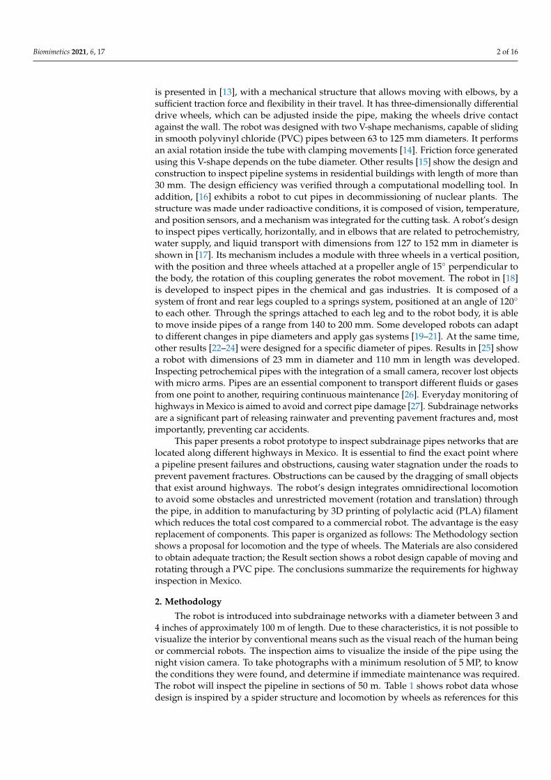
final wheel design is shown with the roller’s design perpendicular to the wheel’s peripheryby eliminating the friction that may exist because of movements and allows displacementsin both directions. Heat shrink tubing on the wheels’ rollers was used as in Figure 5b, toreduce the roller diameter to slightly less than half of its initial diameter before startingto burn or melt. Plastic material complies with plasticity and flexibility characteristics fortraction, and its contracts give the advantage to adapt the wheel diameter without affectingits structure.
Biomimetics 2021, 6, 17 7 of 16
final wheel design is shown with the roller’s design perpendicular to the wheel’s periph-
ery by eliminating the friction that may exist because of movements and allows displace-
ments in both directions. Heat shrink tubing on the wheels’ rollers was used as in Figure
5b, to reduce the roller diameter to slightly less than half of its initial diameter before
starting to burn or melt. Plastic material complies with plasticity and flexibility character-
istics for traction, and its contracts give the advantage to adapt the wheel diameter with-
out affecting its structure.
Figure 5. Universal omnidirectional wheel for pipeline robot; (a) Cad Model. (b) Omnidirectional wheel with thermofit.
The following procedure is worked out to obtain the load that the robot supports,
using a force diagram in which the motor’s weight, the friction forces, normal and the
force of the robot’s movement were considered as in the following.
The robot has 4 points at which equal forces are applied to make it move. The tan-
gential force for the robot’s movement is obtained, as shown in Figure 6a. It is necessary
to know the pulling force that the robot generates since, in addition to itself, it must carry
enough cable to run through the pipe sections.
Figure 6. (a) Diagram to obtain the tangential force. (b) Force diagram to obtain the load the robots
support.
According to the force diagram Figure 6b, regarding the wheels, the forces in ‘Y’ and
‘X’ are obtained:
∑ 𝐹𝑦 = 0
−𝐹𝑅 − 𝑤1 + 𝑁1 = 0
𝑁1 = 𝐹𝑅 + 𝑤1 = 4.6 𝑁
∑ 𝐹𝑥 = 𝑚𝑎𝑥
−𝐹𝑀 + 𝐹1 + 𝐹𝐴 = 𝑚1𝑎
𝐹𝐴 = 𝑚1𝑎 + 𝐹𝑀 − 𝐹1 = 14. 88 𝑁.
For Figure 6b, which represents the weight of the cable, we have:
Figure 5. Universal omnidirectional wheel for pipeline robot; (a) Cad Model. (b) Omnidirectional wheel with thermofit.
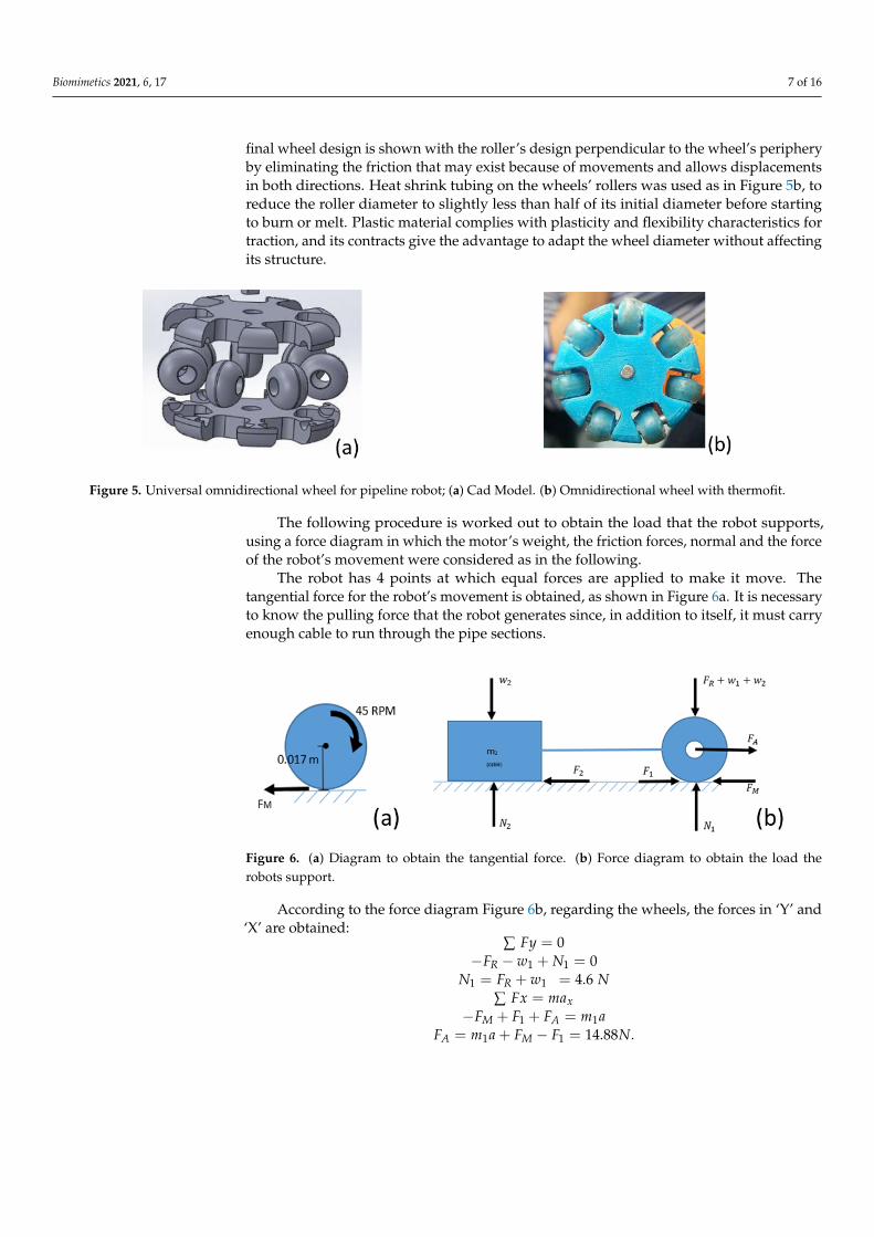
The following procedure is worked out to obtain the load that the robot supports,using a force diagram in which the motor’s weight, the friction forces, normal and the forceof the robot’s movement were considered as in the following.
The robot has 4 points at which equal forces are applied to make it move. Thetangential force for the robot’s movement is obtained, as shown in Figure 6a. It is necessaryto know the pulling force that the robot generates since, in addition to itself, it must carryenough cable to run through the pipe sections.
Biomimetics 2021, 6, 17 7 of 16
final wheel design is shown with the roller’s design perpendicular to the wheel’s periph-
ery by eliminating the friction that may exist because of movements and allows displace-
ments in both directions. Heat shrink tubing on the wheels’ rollers was used as in Figure
5b, to reduce the roller diameter to slightly less than half of its initial diameter before
starting to burn or melt. Plastic material complies with plasticity and flexibility character-
istics for traction, and its contracts give the advantage to adapt the wheel diameter with-
out affecting its structure.
Figure 5. Universal omnidirectional wheel for pipeline robot; (a) Cad Model. (b) Omnidirectional wheel with thermofit.
The following procedure is worked out to obtain the load that the robot supports,
using a force diagram in which the motor’s weight, the friction forces, normal and the
force of the robot’s movement were considered as in the following.
The robot has 4 points at which equal forces are applied to make it move. The tan-
gential force for the robot’s movement is obtained, as shown in Figure 6a. It is necessary
to know the pulling force that the robot generates since, in addition to itself, it must carry
enough cable to run through the pipe sections.
Figure 6. (a) Diagram to obtain the tangential force. (b) Force diagram to obtain the load the robots
support.
According to the force diagram Figure 6b, regarding the wheels, the forces in ‘Y’ and
‘X’ are obtained:
∑ 𝐹𝑦 = 0
−𝐹𝑅 − 𝑤1 + 𝑁1 = 0
𝑁1 = 𝐹𝑅 + 𝑤1 = 4.6 𝑁
∑ 𝐹𝑥 = 𝑚𝑎𝑥
−𝐹𝑀 + 𝐹1 + 𝐹𝐴 = 𝑚1𝑎
𝐹𝐴 = 𝑚1𝑎 + 𝐹𝑀 − 𝐹1 = 14. 88 𝑁.
For Figure 6b, which represents the weight of the cable, we have:
Figure 6. (a) Diagram to obtain the tangential force. (b) Force diagram to obtain the load therobots support.
According to the force diagram Figure 6b, regarding the wheels, the forces in ‘Y’ and‘X’ are obtained:
∑ Fy = 0−FR − w1 + N1 = 0
N1 = FR + w1 = 4.6 N∑ Fx = max
−FM + F1 + FA = m1aFA = m1a + FM − F1 = 14.88N.

Biomimetics 2021, 6, 17 8 of 16
For Figure 6b, which represents the weight of the cable, we have:
F2 = µN2 = (0.402)(
9.81 ms2
)m2 = 3.9436m2
∑ Fy = 0−W2 + N2 = 0
N2 = W2∑ Fx = m2axFA − F2 = m2aFA = m2a + F2.
We substitute, a = 0.0811 m/s2
14.8837 N = m2
(0.08011 m/s2
)+ 3.9436m2.
Considering the analysis was made in one of the four support points of the robot:Theoretically, it is the total weight that the robot can drag: m2 × 4 = 14.79 kg. Themaximum length of cable is 50 m with an approximate weight of 5 kg.
2.1. Robot Movement Control
In the final prototype (Figure 7a), it is observed how each piece is assembled withothers, since the motor is placed with a vertical axis to move forward and backwards easily,and in the horizontal axis, so the robot could also rotate around its axis. A camera withnight vision capability was installed to visualize the pipe’s interior in real-time and takepictures where there will be an obstruction, out of phase or fissures. It uses a mini nightvision camera for remote and real-time monitoring with Wi-Fi wireless communicationtechnology, with dimensions of 2.2 × 2.5 × 2 cm (height × width × depth). In real-time, thevideo will be transmitted through a screen outside the pipeline, where the data necessaryto decide on maintenance will be archived. The protocol (IP) is used for data transmissionthrough an Acer Aspire 5 laptop, and if the transmission is lost, the camera has the ability tocontinue recording and save the video in a microSD memory. Figure 7a shows servomotorcoupling at the base of the robot and a belt with gears to transmit the camera’s movement,and Figure 7b shows the size of the main components. The camera is located on the frontof the robot. Without attaching the springs, the dimensions of the robot are 68.8 mm wideand 269 mm long. The diameter of the omnidirectional wheels is approximately 30 mm.
Biomimetics 2021, 6, 17 8 of 16
𝐹2 = µ𝑁2 = (0.402) (9.81𝑚
𝑠2) 𝑚2 = 3.9436𝑚2
(1)∑ 𝐹𝑦 = 0
−𝑊2 + 𝑁2 = 0
𝑁2 = 𝑊2
∑ 𝐹𝑥 = 𝑚2𝑎𝑥
𝐹𝐴 − 𝐹2 = 𝑚2𝑎
𝐹𝐴 = 𝑚2𝑎 + 𝐹2.
We substitute, 𝑎 = 0.0811 𝑚/𝑠2
14.8837 𝑁 = 𝑚2(0.08011 𝑚/𝑠2) + 3.9436𝑚2.
Considering the analysis was made in one of the four support points of the robot:
Theoretically, it is the total weight that the robot can drag: 𝑚2 × 4 = 14.79 𝑘𝑔. The maxi-
mum length of cable is 50 m with an approximate weight of 5 kg.
2.1. Robot Movement Control
In the final prototype (Figure 7a), it is observed how each piece is assembled with
others, since the motor is placed with a vertical axis to move forward and backwards eas-
ily, and in the horizontal axis, so the robot could also rotate around its axis. A camera with
night vision capability was installed to visualize the pipe’s interior in real-time and take
pictures where there will be an obstruction, out of phase or fissures. It uses a mini night
vision camera for remote and real-time monitoring with Wi-Fi wireless communication
technology, with dimensions of 2.2 × 2.5 × 2 cm (height × width × depth). In real-time, the
video will be transmitted through a screen outside the pipeline, where the data necessary
to decide on maintenance will be archived. The protocol (IP) is used for data transmission
through an Acer Aspire 5 laptop, and if the transmission is lost, the camera has the ability
to continue recording and save the video in a microSD memory. Figure 7a shows servo-
motor coupling at the base of the robot and a belt with gears to transmit the camera’s
movement, and Figure 7b shows the size of the main components. The camera is located
on the front of the robot. Without attaching the springs, the dimensions of the robot are
68.8 mm wide and 269 mm long. The diameter of the omnidirectional wheels is approxi-
mately 30 mm.
Biomimetics 2021, 6, 17 9 of 16
Figure 7. Components of the proposed pipe robot (a) Servomotors and camera position. (b) Robot
dimensions.
Robot controlled movements are generated from software installed with all electronic
components (forward, backwards or rotate, and left or right). Figure 8 shows the converter
USB to serial linked to the Arduino® card to download the code to this card. Analogy
inputs of the Arduino® card are connected to the joystick, while this card’s outputs are
connected to motors and servomotor. Through an Arduino® card, the robot movements
are produced by a joystick device composed of two analogue potentiometers. This card
regulates the pulse width modulation (PWM) of the motors that control their speed in an
open loop. The control code is designed to execute the movements of the design pipe ro-
bot. When potentiometers are at halfway, the robot must remain in stationary configura-
tion, and in other motion ranges, the joystick moves in one direction so that the robot
moves or rotates. Motor speed control depends on the path of the potentiometer, and dis-
placements imply the change of direction of rotation of the motor, so the card with an
arrangement of transistors and diodes is correctly used, allowing the control of the polar-
ity of the output terminals. The potentiometer’s function in Figure 8 is to control the cam-
era’s movement by the servo motor. The camera remains centred when the potentiometer
is half the value (ohms). Therefore, when it is in other ranges of the potentiometer, the
camera will rotate to the left or right. Moreover, in Table 2 shows its characteristics of
components for movement control of the proposed robot.
Table 2. Hardware and software components.
Components Characteristics
Arduino® card
ATmega328 microcontroller operating at 8 MHz
14 digital inputs/outputs
6 analogue inputs
Maximum output current: 150 mA
Dimensions 18 × 33 mm
Joystick
Two independent 10 K potentiometers: one for each axis (X and Y)
Button (pushbutton) on the Z-axis
Operating Voltage: 3.3–5 V DC
Automatic return to the center position
Compatible to interact with Arduino® card
Module H-bridge
It has 2 independent H-bridges
Main Integrated Circuit: L298N
Peak operating current: 4 Amps
Constant operating current: 2 Amps
Motor supply voltage up to 24 volts
Converter USB to serial Compatible with Arduino cards
Get access to GND, CTS, VCC, TX, RX, and DT signals
Figure 7. Components of the proposed pipe robot (a) Servomotors and camera position. (b) Robot dimensions.

Biomimetics 2021, 6, 17 9 of 16
Robot controlled movements are generated from software installed with all electroniccomponents (forward, backwards or rotate, and left or right). Figure 8 shows the converterUSB to serial linked to the Arduino® card to download the code to this card. Analogyinputs of the Arduino® card are connected to the joystick, while this card’s outputs areconnected to motors and servomotor. Through an Arduino® card, the robot movementsare produced by a joystick device composed of two analogue potentiometers. This cardregulates the pulse width modulation (PWM) of the motors that control their speed in anopen loop. The control code is designed to execute the movements of the design pipe robot.When potentiometers are at halfway, the robot must remain in stationary configuration,and in other motion ranges, the joystick moves in one direction so that the robot moves orrotates. Motor speed control depends on the path of the potentiometer, and displacementsimply the change of direction of rotation of the motor, so the card with an arrangement oftransistors and diodes is correctly used, allowing the control of the polarity of the outputterminals. The potentiometer’s function in Figure 8 is to control the camera’s movementby the servo motor. The camera remains centred when the potentiometer is half the value(ohms). Therefore, when it is in other ranges of the potentiometer, the camera will rotate tothe left or right. Moreover, in Table 2 shows its characteristics of components for movementcontrol of the proposed robot.
Table 2. Hardware and software components.
Components Characteristics
Arduino® card
• ATmega328 microcontroller operating at 8 MHz• 14 digital inputs/outputs• 6 analogue inputs• Maximum output current: 150 mA• Dimensions 18 × 33 mm
Joystick
• Two independent 10 K potentiometers: one for eachaxis (X and Y)
• Button (pushbutton) on the Z-axis• Operating Voltage: 3.3–5 V DC• Automatic return to the center position• Compatible to interact with Arduino® card
Module H-bridge
• It has 2 independent H-bridges• Main Integrated Circuit: L298N• Peak operating current: 4 Amps• Constant operating current: 2 Amps• Motor supply voltage up to 24 volts
Converter USB to serial• Compatible with Arduino cards• Get access to GND, CTS, VCC, TX, RX, and DT signals
Micro Metal Gearmotor LP 6V
• Speed: 45 RPM.• Supply voltage: 6 V• Current without charge: 40 mA• Maximum current: 360 mA• Maximum torque: 2.9 kg/cm
Servomotor
• Dimensions (L × W × H) = 22.0 × 11.5 × 27 mm• Torque at 4.8 volts: 16.7 oz/in or 1.2 kg/cm• Operating voltage: 4.0 to 7.2 volts• Speed at 4.8 volts: 0.12 s/60◦

Biomimetics 2021, 6, 17 10 of 16
Biomimetics 2021, 6, 17 10 of 16
Micro Metal Gearmotor LP 6V
Speed: 45 RPM.
Supply voltage: 6 V
Current without charge: 40 mA
Maximum current: 360 mA
Maximum torque: 2.9 kg/cm
Servomotor
Dimensions (L × W × H) = 22.0 × 11.5 × 27 mm
Torque at 4.8 volts: 16.7 oz/in or 1.2 kg/cm
Operating voltage: 4.0 to 7.2 volts
Speed at 4.8 volts: 0.12 s/60°
Figure 8. Control hardware design for the proposed robot in Figure 6.
2.2. Numerical Analysis
Static analysis has been worked out to determine and characterize the structural be-
haviour due to external loads in the leg pressure against the pipe wall exerted by the
spring when entering the pipe. This analysis only applied for a quarter part of the de-
signed robot because its limbs have the same setup and dimensions. Additionally, the
boundary conditions have been defined, as are shown in Figure 9. Moreover, the fixed
support point on the robot body is observed because it only supports the other compo-
nents, and it does not have any movement. A connection is made with spring conditions
(longitudinal) on the green painted faces as shown. Likewise, the elasticity constant of this
element was determined, along with the connection with spring conditions. The complete
geometrical design meshed into 38,376 elements with 109,877 nodes for finite element
analysis (FEA).
Figure 8. Control hardware design for the proposed robot in Figure 6.
2.2. Numerical Analysis
Static analysis has been worked out to determine and characterize the structuralbehaviour due to external loads in the leg pressure against the pipe wall exerted by thespring when entering the pipe. This analysis only applied for a quarter part of the designedrobot because its limbs have the same setup and dimensions. Additionally, the boundaryconditions have been defined, as are shown in Figure 9. Moreover, the fixed support pointon the robot body is observed because it only supports the other components, and it doesnot have any movement. A connection is made with spring conditions (longitudinal) onthe green painted faces as shown. Likewise, the elasticity constant of this element wasdetermined, along with the connection with spring conditions. The complete geometricaldesign meshed into 38,376 elements with 109,877 nodes for finite element analysis (FEA).
Biomimetics 2021, 6, 17 11 of 16
Figure 9. Boundary conditions, fixed supports.
2.3. Pipeline Inspection Tests
Each of the proposed designs’ behaviour is observed, the robot was subjected to an
experimental test inside a 2 m long PVC pipe. As previously mentioned, two geared mo-
tors simulating two legs and two springs were added to the robot’s body at the front and
rear, applying pressure to the pipe walls. The traction was considered more important in
this work, so we changed to micro geared motors inside this system. It provoked a rotation
inside the pipe. Consequently, an omnidirectional wheel was placed in each position, hor-
izontal and vertical. Figure 10 shows the robot’s position; therefore, it is possible to avoid
the pipe's obstacles thanks to the omnidirectional wheels’ control.
Figure 10. Control robot position due to the joystick and the omnidirectional wheels.
Figure 9. Boundary conditions, fixed supports.

Biomimetics 2021, 6, 17 11 of 16
2.3. Pipeline Inspection Tests
Each of the proposed designs’ behaviour is observed, the robot was subjected to anexperimental test inside a 2 m long PVC pipe. As previously mentioned, two geared motorssimulating two legs and two springs were added to the robot’s body at the front and rear,applying pressure to the pipe walls. The traction was considered more important in thiswork, so we changed to micro geared motors inside this system. It provoked a rotationinside the pipe. Consequently, an omnidirectional wheel was placed in each position,horizontal and vertical. Figure 10 shows the robot’s position; therefore, it is possible toavoid the pipe’s obstacles thanks to the omnidirectional wheels’ control.
Biomimetics 2021, 6, 17 11 of 16
Figure 9. Boundary conditions, fixed supports.
2.3. Pipeline Inspection Tests
Each of the proposed designs’ behaviour is observed, the robot was subjected to an
experimental test inside a 2 m long PVC pipe. As previously mentioned, two geared mo-
tors simulating two legs and two springs were added to the robot’s body at the front and
rear, applying pressure to the pipe walls. The traction was considered more important in
this work, so we changed to micro geared motors inside this system. It provoked a rotation
inside the pipe. Consequently, an omnidirectional wheel was placed in each position, hor-
izontal and vertical. Figure 10 shows the robot’s position; therefore, it is possible to avoid
the pipe's obstacles thanks to the omnidirectional wheels’ control.
Figure 10. Control robot position due to the joystick and the omnidirectional wheels.
Figure 10. Control robot position due to the joystick and the omnidirectional wheels.
3. Results
Figure 11 shows the final robot design in 3D representation used in pipeline inspectionsand performs the structural analysis through the finite element method. All the parts ofthe prototype have been assembled with the help of screws and bearings in a prototype,connecting motors that are located with their respective omnidirectional wheels and thecamera structure.
The results that are computed by a structural analysis are summarised in Figure 12.Figure 12a deformation of the robot’s 3D model concerning its original geometry is shownfrom computations using a strength applied in the wheels and von Mises failure criterion asper the used ductile material. The maximum deformation can be observed in the omnidirec-tional wheel’s rollers, while the minimum deformation is in the part that holds the motors.The wheels are the only piece that has contact with the pipe walls and therefore receivesthe spring’s pressure. Moreover, the maximum deformation is calculated as 1.38 × 10⁻⁵ min the wheel’s front. The maximum stress occurs in the motors area near the axis as shownin Figure 12b where the maximum stress refers to an element with 6.07 × 10⁷ Pa.
Electronics for control movements are located outside of the pipe, so engines suffer acable load and robot weight. Enough cable length is needed to run through the pipe. Thenormal force that supports the cable and the robot’s mass, the friction force and the robotmotion’s net force are involved. The total robot weight is capable of dragging 14.79 kg.

Biomimetics 2021, 6, 17 12 of 16
Biomimetics 2021, 6, 17 12 of 16
3. Results
Figure 11 shows the final robot design in 3D representation used in pipeline inspec-
tions and performs the structural analysis through the finite element method. All the parts
of the prototype have been assembled with the help of screws and bearings in a prototype,
connecting motors that are located with their respective omnidirectional wheels and the
camera structure.
Figure 11. 3D representation of the proposed pipe robot.
The results that are computed by a structural analysis are summarised in Figure 12.
Figure 12a deformation of the robot’s 3D model concerning its original geometry is shown
from computations using a strength applied in the wheels and von Mises failure criterion
as per the used ductile material. The maximum deformation can be observed in the om-
nidirectional wheel’s rollers, while the minimum deformation is in the part that holds the
motors. The wheels are the only piece that has contact with the pipe walls and therefore
receives the spring’s pressure. Moreover, the maximum deformation is calculated as 1.38
× 10−5 m in the wheel’s front. The maximum stress occurs in the motors area near the axis
as shown in Figure 12b where the maximum stress refers to an element with 6.07 × 10⁷ Pa.
Figure 11. 3D representation of the proposed pipe robot.
Biomimetics 2021, 6, 17 13 of 16
Figure 12. Computed results from structural analysis (a) Total deformation. (b) Equivalent stress.
Electronics for control movements are located outside of the pipe, so engines suffer a
cable load and robot weight. Enough cable length is needed to run through the pipe. The
normal force that supports the cable and the robot’s mass, the friction force and the robot
motion’s net force are involved. The total robot weight is capable of dragging 14.79 kg.
By the characteristics of the pipes and requirements mentioned above, a small porta-
ble video camera with infrared night vision light can be installed on the robot body to
visualize the pipeline in real-time. A screen for monitoring control is installed outside the
people under inspection. Camera movement from left to right has been programmed
within the control code for actuating a servomotor. The solutions mentioned above are
tested as robust according to the requirements; however, there are still disadvantages such
as the microgear motors’ dimensions, preventing additional robot size reduction. Work-
ing with pipes for stormwater discharge requires airtightness for the actuators, although
the coverage with thermofit is insufficient to attack this problem.
3D printing parts for constructing the robot prototype and all electronic components
are shown in Figure 13. The wheel dimension is also shown for a closer look at the robot
dimensions. Moreover, it shows the robot inside the PVC pipe. After printing each part of
the robot, they were joined by means of screws and bearings, depending on whether it
Figure 12. Computed results from structural analysis (a) Total deformation. (b) Equivalent stress.

Biomimetics 2021, 6, 17 13 of 16
By the characteristics of the pipes and requirements mentioned above, a small portablevideo camera with infrared night vision light can be installed on the robot body to visualizethe pipeline in real-time. A screen for monitoring control is installed outside the peopleunder inspection. Camera movement from left to right has been programmed within thecontrol code for actuating a servomotor. The solutions mentioned above are tested as robustaccording to the requirements; however, there are still disadvantages such as the microgearmotors’ dimensions, preventing additional robot size reduction. Working with pipes forstormwater discharge requires airtightness for the actuators, although the coverage withthermofit is insufficient to attack this problem.
3D printing parts for constructing the robot prototype and all electronic componentsare shown in Figure 13. The wheel dimension is also shown for a closer look at the robotdimensions. Moreover, it shows the robot inside the PVC pipe. After printing each partof the robot, they were joined by means of screws and bearings, depending on whether itwas a joint or if the part should be fixed. The servomotor is placed in that position so thatthe belt with gears will adjust with the gear and transmit the movements of the camera.The springs were also placed on the legs of the robot and the omnidirectional wheels toeach motor.
Biomimetics 2021, 6, 17 14 of 16
was a joint or if the part should be fixed. The servomotor is placed in that position so that
the belt with gears will adjust with the gear and transmit the movements of the camera.
The springs were also placed on the legs of the robot and the omnidirectional wheels to
each motor.
Figure 13. Robot prototype (a) 3D printing parts. (b) Robot inspection inside polyvinyl chloride (PVC) pipe by camera.
Moreover, the motors’ connections were made with a cable fixed to the parts, as
shown in Figure 13a. The robot underwent physical tests inside the 3 inch diameter PVC
pipe in its different construction stages, as shown in Figure 12b. Points were established
where improvements should be made to satisfy the inspection. It is also observed that the
robot occupies most of the space inside the pipe. Reducing the size requires a smaller
camera and motors.
4. Conclusions
The design of a mobile robot with omnidirectional wheels is proposed to be used
only in visual inspection tasks on straight 7.6–10.16 cm PVC pipes without curves. It in-
cludes tasks for moving within pipes in which the subdrainage accumulates dirt in their
lower parts. With the proposed solution, if there is an obstruction, the robot cannot clean
the pipe, it only avoids the obstructions. The attached night vision camera met the require-
ments, taking real-time video and 5 MP photographs to present the pipe’s conditions.
Therefore, it was possible to design an appropriate robot for the indicated require-
ments, adapt to pipes of different diameter, avoid obstacles by turning the robot around
its axis within the pipe, low-cost manufacturing around $600 dollars, obtain images
Figure 13. Robot prototype (a) 3D printing parts. (b) Robot inspection inside polyvinyl chloride(PVC) pipe by camera.
Moreover, the motors’ connections were made with a cable fixed to the parts, as shownin Figure 13a. The robot underwent physical tests inside the 3 inch diameter PVC pipe inits different construction stages, as shown in Figure 12b. Points were established whereimprovements should be made to satisfy the inspection. It is also observed that the robot
Biomimetics 2021, 6, 17 14 of 16
occupies most of the space inside the pipe. Reducing the size requires a smaller cameraand motors.
4. Conclusions
The design of a mobile robot with omnidirectional wheels is proposed to be used onlyin visual inspection tasks on straight 7.6–10.16 cm PVC pipes without curves. It includestasks for moving within pipes in which the subdrainage accumulates dirt in their lowerparts. With the proposed solution, if there is an obstruction, the robot cannot clean the pipe,it only avoids the obstructions. The attached night vision camera met the requirements,taking real-time video and 5 MP photographs to present the pipe’s conditions.
Therefore, it was possible to design an appropriate robot for the indicated require-ments, adapt to pipes of different diameter, avoid obstacles by turning the robot around itsaxis within the pipe, low-cost manufacturing around $600 dollars, obtain images throughthe screen for later analysed the conditions of the sub-drainage networks of the differenthighways in Mexico.
According to the theoretical development, the robot should be able to drag 50 m ofcable; however, it is intended to carry out, in the future, experimental tests to verify thetheoretical results.
Experimental results have verified that wheel traction for its movement is limited bythe robot’s tendency to rotate around its axial axis. An omnidirectional wheel system isimplemented in each leg, allowing the corresponding displacement correcting the robot’sorientation. Likewise, the electronics for the control is designed for the movement of therobot inside the pipe. The heat shrink tubing in the wheels’ rollers achieves adequatetraction, so the robot does not skid when advancing. However, when the material pipesuffers wear, the friction coefficient may decrease radically, causing the wheels skiddingon the PVC by affecting the robot’s speed and drag force due to the pipes’ dirt anddust conditions.
The structural analysis through finite element analysis (FEA) shows deformationsand maximum stress in a 3D model of the robot prototype that can be sued to preventfailures when the robot prototypes are used to inspect pipes. Finally, it is necessary toreduce mechanical elements that integrate the robot to increase the robot wheels’ usefullife and implement an odometer that allows knowing the robot’s location inside the pipe.
Author Contributions: Conceptualization, R.T.-H. and C.R.T.-S.; methodology, E.I.-G. and C.R.T.-S.;software, C.R.T.-S.; resources, E.I.-G. and R.T.-H.; data curation, R.T.-H. and M.C.; writing—originaldraft preparation, E.I.-G. and C.R.T.-S.; writing—review and editing, C.R.T.-S. and M.C.; visualiza-tion, R.T.-H.; supervision, R.T.-H. and C.R.T.-S. project administration, C.R.T.-S. and M.C.; fundingacquisition, R.T.-H. and C.R.T.-S. All authors have read and agreed to the published version ofthe manuscript.
Funding: This research received no external funding.
Institutional Review Board Statement: This study did not require ethical approval.
Informed Consent Statement: Not applicable.
Data Availability Statement: Not applicable.
Acknowledgments: The authors wish to gratefully acknowledge Consejo Nacional de Ciencia yTecnologia (CONACYT) and Instituto Politécnico Nacional through the support projects 20201964,20200930 and 20210282, as well as an EDI grant, all by SIP/IPN.
Conflicts of Interest: The authors declare no conflict of interest.
References1. Ceccarelli, M.; Kececi, E.F. Designs and Prototypes of Mobile Robots; ASME Press: New York, NY, USA, 2015.2. Murphy, R.R. Marsupial and Shape-Shifting Robots for Urban Search and Rescue. IEEE Intell. Syst. Appl. 2000, 15, 14–19.
Available online: https://ieeexplore.ieee.org/document/850822 (accessed on 9 March 2021).

Biomimetics 2021, 6, 17 15 of 16
3. Li, P.; Ma, S.; Li, B.; Wang, Y. Development of an adaptive mobile robot for in-pipe inspection task. In Proceedings of the 2007International Conference on Mechatronics and Automation, Harbin, China, 5–8 August 2007; IEEE: New York, NY, USA, 2007; pp.3622–3627.
4. Zhang, H.; Zhang, J.; Liu, R.; Zong, G. Realisation of a service robot for Cleaning spherical surfaces. Int. J. Adv. Robot. Syst. 2005,2, 53–58. [CrossRef]
5. Karlsson, N.; Munich, M.E.; Goncalves, L.; Ostrowski, J.; di Bernardo, E.; Pirjanian, P. Core Technologies for Service Robotics. InProceedings of the International Conference on Intelligent Robots and Systems, Sendai, Japan, 28 September–2 October 2004;IEEE: New York, NY, USA, 2004; Volume 3, pp. 2979–2984.
6. Cecarelli, M.; Carbone, G. Design and Operation of Human Locomotion Systems; Elsevier: London, UK, 2020.7. Vidoni, R.; Gasparetto, A. Efficient force distribution and leg posture for a bio-inspired spider robot. Robot. Auton. Syst. 2011, 59,
142–150. [CrossRef]8. Kitano, S.; Hirose, S.; Endo, G.; Fukushima, E.F. Development of lightweight sprawling-type quadruped robot TITAN-XIII and
its dynamic walking. In Proceedings of the IEEE International Workshop on Intelligent Robots and Systems, Tokyo, Japan, 3–7November 2013; IEEE: New York, NY, USA, 2013; pp. 6025–6030.
9. Sapiro, A.; Rimon, S.S.E. A foothold selection algorithm for spider robot locomotion in planar tunnel environments. Int. J. Robot.Res. 2005, 24, 823–844. [CrossRef]
10. Yi, W.Z.; Tong, W.J.; Hong, J.A.; Kai, L.H.; Dong, D.Z. Movement behavior of a spider on a horizontal surface. Chin. Sci. Bull.2011, 56, 2748–2757.
11. Soyguder, S.; Alli, H. Motion mechanism concept and morphology of a single actuator tetrapod walking spider robot. Ind. Robot.2011, 38, 361–371. [CrossRef]
12. Roslin, N.S.; Anuar, A.; Jalal, M.F.A.; Sahari, K.S.M. A review: Hybrid locomotion of in-pipe inspection robot. Procedia Eng. 2012,41, 1456–1462. [CrossRef]
13. Roh, S.G.; Choi, H. Strategy for navigation inside pipelines with differential drive in pipe robot. In Proceedings of the 2002 IEEEInternational Conference on Robotics and Automation (Cat. No.02CH37292), Washington, DC, USA, 11–15 May 2002; IEEE: NewYork, NY, USA, 2002; Volume 3, pp. 2575–2580.
14. Dertien, E.; Foumashi, M.M.; Pulles, K.; Stramigioli, S. Design of a robot for in-pipe inspection using omnidirectional wheels andactive stabilization. In Proceedings of the 2014 IEEE International Conference on Robotics and Automation (ICRA), Hong Kong,China, 31 May–7 June 2014; IEEE: New York, NY, USA, 2014; pp. 5121–5126.
15. Vorotnikov, S.A.; Nikitin, N.I.; Ceccarelli, M. A Robotic System for Inspection and Repair of Small Diameter Pipelines. Sci. Educ.Bauman MSTU 2015, 2, 180–196. [CrossRef]
16. Ceccarelli, M.; Carbone, G.; Bastianini, E.; Rivieccio, A.; Alfieri, S. Design constraints and features for a robotic system cuttingpipelines in nuclear vessels. In Proceedings of the RAAD 2014 23rd International Conference on Robotics in Alpe-Adria-DanubeRegion, Smolenice, Slovakia, 3–5 September 2014; IEEE: Smolenice, Slovakia, 2014; Volume 3, pp. 121–126.
17. Nayak, A.; Pradhan, S.K. Design of a new in-pipe inspection robot. Procedia Eng. 2014, 97, 2081–2091. [CrossRef]18. Gargade, A.; Tambuskar, D.; Thokal, G. Modelling and analysis of pipes inspection Robot. Int. J. Emerg. Technol. Adv. Eng. 2013, 3,
120–126.19. Huang, H.P.; Yan, J.L.; Cheng, T.H. Development and fuzzy control of a pipe inspection robot. IEEE Trans. Ind. Electron. 2010, 57,
1088–1095. [CrossRef]20. Choi, H.R.; Ryew, S.M. Robotic system with active steering capability for internal inspection of urban gas pipelines. Mechatronics
2002, 12, 713–736. [CrossRef]21. Muramatsu, M.; Namiki, N.; Koyama, R. Autonomous mobile robot in pipe for piping operations. In Proceedings of the 2000
IEEE/RSJ International Conference on Intelligent Robots and Systems (IROS 2000) (Cat. No.00CH37113), Takamatsu, Japan, 31October–5 November 2000; IEEE: New York, NY, USA, 2000; pp. 2166–2171.
22. Horodinca, M.; Dorftei, I.; Mignon, E.; Preumont, A. A simple architecture for in-pipe inspection robots. Int. Colloq. Mob. Auton.Syst. 2002, 61–64.
23. Gálvez, J.A.; Santos, P.G.; Pfeiffer, F. Intrinsic tactile sensing for the optimization of force distribution in a pipe crawling robot.IEEE/ASME Trans. Mechatron. 2001, 6, 26–35. [CrossRef]
24. Zagler, A.; Pfeiffer, F. “MORITZ” a pipe crawler for tube junctions. In Proceedings of the IEEE International Conference onRobotics and Automation, Taipei, Taiwan, 14–19 September 2003; IEEE: New York, NY, USA, 2003; pp. 2954–2960.
25. Suzumori, K.; Miyagawa, T.; Kimura, M.; Hasegawa, Y. Micro inspection robot for 1-in pipes. IEEE/ASME Trans. Mechatron. 1999,4, 286–292. [CrossRef]
26. McAllister, E. Pipeline Rules of Thumb Handbook; Gulf Professional Publishing: Oxford, UK, 2013.27. Esparza, G.R.; Cummings, R.M.; Hung, C.P. Guide of Procedures and Techniques for Road Maintenance in Mexico; General Directorate
of Technical Services: Mexico City, Mexico, 2014. (In Spanish)28. Menon, C.; Li, Y.; Sameoto, D.; Martens, C. Abigaille-I: Towards the development of a spider-inspired climbing robot for space
use. In Proceedings of the 2008 2nd IEEE RAS & EMBS International Conference on Biomedical Robotics and Biomechatronics,Scottsdale, AZ, USA, 19–22 October 2008; IEEE: New York, NY, USA, 2008; pp. 384–389.
29. Yuan, Z.; Yuan, J. Design and implementation of a pipeline inspection robot with camera image compensation. In Proceedings ofthe 2020 IEEE/RSJ International Conference on Intelligent Robots and Systems, Las Vegas, NV, USA, 25–29 October 2020.

Biomimetics 2021, 6, 17 16 of 16
30. Lim, H.; Ohki, T. Development of pipe inspection robot. In Proceedings of the 2009 ICCAS-SICE, Fukuoka, Japan, 18–21 August2009; IEEE: New York, NY, USA, 2009; pp. 5717–5721.
31. Kwon, Y.; Yi, B. The kinematic modeling and optimal paramerization of an omni-directional pipeline robot. In Proceedings of the2009 IEEE International Conference on Robotics and Automation, Kobe, Japan, 12–17 May 2009; IEEE: New York, NY, USA, 2009;pp. 1389–1394.
32. Carbone, G.; Malchikov, A.; Ceccarelli, M.; Jatsun, S. Design and Simulation of Kursk Robot for in-Pipe Inspection. In The 10thIFToMM International Symposium on Science of Mechanisms and Machines SYROM’09; Springer: Dordrecht, The Netherlands; Brasov,Romania, 2009; pp. 103–114.