PII: SOO45-7949(96)00120-4 CRACK IDENTIFICATION IN FRAME STRUCTURES
18
Pergamon Computers & Srrucrures Vol. 64, No. 14, pp. 389-406, 1991 0 1997 Civil-Comp Ltd and Elsevicr Science Ltd.All rights reserved Printed in Great Britain PII: SOO45-7949(96)00120-4 0045-7949/97 s17.00 + 0.00 CRACK IDENTIFICATION IN FRAME STRUCTURES P. G. Nikolakopoulos, D. E. Katsareas and C. A. Papadopoulost Machine Design Laboratory, Mechanical Engineering Department, University of Patras, Rion, Greece Abstract-In this paper the problem of crack depth and position identification in frame structures is examined, using eigenfrequency measurements. It has been established that a crack has an important effect on the dynamic behavior of a structure. This effect depends mainly on the crack size and position. The basic idea is to present in contour graph form the dependency of the first two structural eigenfrequencies on crack depth and location, using the finite element method. To identify the location and depth of a crack in a frame structure, one only needs to determine the intersecting point of the superposed contours that correspond to the measured eigenfrequency variations caused by the crack presence. A number of beam and frame examples are included in the present paper to verify the applicability of this combined computational-graphical or experimental-graphical method. 0 1997 Civil-Comp Ltd and Elsevier Science Ltd. II. INTRODUCTION A local compliance matrix of different degrees of freedom, based on available expressions of the stress intensity factors and on the associated expressions for the strain energy release rates, is used to model the crack. Chondros and Dimarogonas [ 1,2] considered the crack as a local elasticity (spring), which effects the elasticity of the whole cracked structure under consideration and related the crack depth with the frequency decrease. Gounaris and Dimarogonas [3] have constructed a special cracked beam finite element, whereas Gounaris and Papazoglou [4] have used a mixed finite-boundary element method to study the dynamic behavior of a cracked Timoshenko beam, vibrating in air and in water in plain bending using 2 d.f. for each mode. Papadopoulos and Dimarogonas [S] used a 6 x 6 compliance matrix, including off diag,onal terms, to simulate a cracked shaft and to study its dynamic behavior. They concluded that coupling among different modes of vibration exists. To give the possibility to study all the interconnections (couplings) between the various modes, as this results from the above mentioned 6 x 6 compliance matrix, Papadopoulos and Dimarogonas studied the coupling between bending and torsion [6], bending and tension [7], as well as the general vibration coupling [8]. A number of pa.pers deal with the problem of crack location and size identification in order to propose new, efficient and more precise methods. Inagaki et al. [9] used a procedure with eigenfrequency t Author to whom all correspondence should be addressed. measurements to find the crack size and location. Leung [lo] and Anifantis et al. [l l] proposed crack identification methods through measurements of the dynamic behavior in bending. Dimarogonas and Massouros [12] investigated the dynamic behavior of a circumferentially cracked shaft in torsion and proposed nomographs for finding the crack depth and location. In the method presented in this paper, after measuring the structural eigenfrequency variations caused by a crack, the location and depth are identified by determination of the superposed contour intersections, which correspond to the above mentioned frequency variations. 2. STRUCTURALANALYSIS Stlfness and mass matrices A planar frame structure can be modeled using two-dimensional beam elements having 3 d.f. (S,, S,, 0,) per node. The corresponding stiffness and consistent mass local matrices are [I+% Ll pL2 0 0 -j9L2 0 0 0 12 6L 0 -12 6L 0 6L 4L= 0 -6L 2L= -/9LZ 0 0 j?L2 0 0 0 -12 -6L 0 12 -6L 0 6L 2L2 0 -6L 4L2 389
-
Upload
independent -
Category
Documents
-
view
5 -
download
0
Transcript of PII: SOO45-7949(96)00120-4 CRACK IDENTIFICATION IN FRAME STRUCTURES

Pergamon
Computers & Srrucrures Vol. 64, No. 14, pp. 389-406, 1991 0 1997 Civil-Comp Ltd and Elsevicr Science Ltd. All rights reserved
Printed in Great Britain PII: SOO45-7949(96)00120-4 0045-7949/97 s17.00 + 0.00
CRACK IDENTIFICATION IN FRAME STRUCTURES
P. G. Nikolakopoulos, D. E. Katsareas and C. A. Papadopoulost Machine Design Laboratory, Mechanical Engineering Department, University of Patras, Rion, Greece
Abstract-In this paper the problem of crack depth and position identification in frame structures is examined, using eigenfrequency measurements. It has been established that a crack has an important effect on the dynamic behavior of a structure. This effect depends mainly on the crack size and position. The basic idea is to present in contour graph form the dependency of the first two structural eigenfrequencies on crack depth and location, using the finite element method. To identify the location and depth of a crack in a frame structure, one only needs to determine the intersecting point of the superposed contours that correspond to the measured eigenfrequency variations caused by the crack presence. A number of beam and frame examples are included in the present paper to verify the applicability of this combined computational-graphical or experimental-graphical method. 0 1997 Civil-Comp Ltd and Elsevier Science Ltd.
II. INTRODUCTION
A local compliance matrix of different degrees of freedom, based on available expressions of the stress intensity factors and on the associated expressions for the strain energy release rates, is used to model the crack.
Chondros and Dimarogonas [ 1,2] considered the crack as a local elasticity (spring), which effects the elasticity of the whole cracked structure under consideration and related the crack depth with the frequency decrease. Gounaris and Dimarogonas [3] have constructed a special cracked beam finite element, whereas Gounaris and Papazoglou [4] have used a mixed finite-boundary element method to study the dynamic behavior of a cracked Timoshenko beam, vibrating in air and in water in plain bending using 2 d.f. for each mode. Papadopoulos and Dimarogonas [S] used a 6 x 6 compliance matrix, including off diag,onal terms, to simulate a cracked shaft and to study its dynamic behavior. They concluded that coupling among different modes of vibration exists. To give the possibility to study all the interconnections (couplings) between the various modes, as this results from the above mentioned 6 x 6 compliance matrix, Papadopoulos and Dimarogonas studied the coupling between bending and torsion [6], bending and tension [7], as well as the general vibration coupling [8].
A number of pa.pers deal with the problem of crack location and size identification in order to propose new, efficient and more precise methods. Inagaki et al. [9] used a procedure with eigenfrequency
t Author to whom all correspondence should be addressed.
measurements to find the crack size and location. Leung [lo] and Anifantis et al. [l l] proposed crack identification methods through measurements of the dynamic behavior in bending. Dimarogonas and Massouros [12] investigated the dynamic behavior of a circumferentially cracked shaft in torsion and proposed nomographs for finding the crack depth and location.
In the method presented in this paper, after measuring the structural eigenfrequency variations caused by a crack, the location and depth are identified by determination of the superposed contour intersections, which correspond to the above mentioned frequency variations.
2. STRUCTURAL ANALYSIS
Stlfness and mass matrices
A planar frame structure can be modeled using two-dimensional beam elements having 3 d.f. (S,, S,, 0,) per node. The corresponding stiffness and consistent mass local matrices are
[I+% Ll
pL2 0 0 -j9L2 0 0
0 12 6L 0 -12 6L
0 6L 4L= 0 -6L 2L=
-/9LZ 0 0 j?L2 0 0
0 -12 -6L 0 12 -6L
0 6L 2L2 0 -6L 4L2
389
390 P. G. Nikolakopoulos et al.
140 0 0 70 0 0
0 156 22L 0 54 -13L
0 22L 4L2 0 13L - 3L2
70 0 0 140 0 0
0 54 13L 0 156 -22L
0 -13L -3L2 0 -22L 4L2
(2)
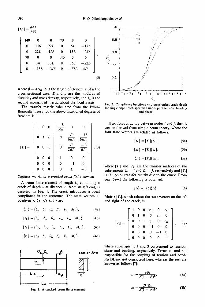
where /I = A/Z,, L is the length of element e, A is the cross sectional area, E and p are the modulus of elasticity and mass density, respectively, and Z,, is the second moment of inertia about the local z-axis.
The transfer matrix calculated from the Euler- Bernoulli theory for the above mentioned degrees of freedom is
[Tel =
100 2 0 0
OlL 0 X-L2 6EI,, 6EZz,
001 0 L2 -L 2EI,- EL,
000 -1 0 0
000 0 -1 0
000 0 L -1
. (3)
Stiffness matrix of a cracked beam Jinite element
A beam finite element of length L, containing a crack of depth a at distance L, from its left end, is depicted in Fig. 1. The crack introduces a local compliance in the structure. The state vectors at positions i, CL, CR and j are
{ZR} = {S,, 6,, 8, Fx, 4, M,}, (Jc)
iz,> = (6, 6, 6, Fx, Fy, k&,}. (44
section A-A
b Le A Fig. 1. A cracked beam finite element.
:/ ./I
0.6 ,:/ i i
i 0.4
_,
I: ?’
0 0.2 fi’
$,’ /’
0.0 10 -‘lo -310 -210 -’ 1 10
I “““1 I - m
lo2 lo3 1 0
@i
{zj) = [Tsl{Zt}. (6)
Matrix [T,], which relates the state vectors on the left and right of the crack. is
I
Fig. 2. Compliance functions vs dimensionless crack depth for single edge notch specimen under pure tension, bending
and shear.
If no force is acting between nodes i and j, then it can be derived from simple beam theory, where the four state vectors are related as follows:
{z~} = W,l{zi}, (54
{ZR) = Vcl{z~}, (5b)
@-,I = P'2lbt>> (5c)
where [T,] and [T2] are the transfer matrices of the subelements CL - i and CR - j, respectively and [T,] is the point transfer matrix due to the crack. From eqn (5a-c) the following is obtained:
[Tel =
1 0 0 CII 0 Cl3
0 1 0 0 c22 0
0 0 1 Cl1 0 c33
000-10 0
0 0 0 0 -1 0
000 0 0 -1
, (7)
where subscripts 1, 2 and 3 correspond to tension, shear and bending, respectively. Terms c,, and c,,, responsible for the coupling of tension and bend- ing [3], are not considered here, whereas the rest are known as follows [7]:
2Qil cl1 = E(1 _ v2)b’
2k2@, “’ = E(1 _ ,J)b’
(84
WI
Crack identification in frame structures 391
12@2 c3’ = Ql - vl)b/+’ (8~)
where v is Poisson’s ratio, k is a constant which for rectangular cross sections is known to be 1.5 and @, are functions of the nondimensional crack depth a/h [7]. These functions, which are presented in Fig. 2, are integrals of the empirical formulas used by Tada [ 131 for computation of stress intensity factors K, in single edge notch specimens under pure tension, bending and shear. The transfer matrix [T’i] of the cracked element is written in the form
where [Ai] are 3 x 3 submatrices. Equation (9) leads to the stiffness matrix of the crack element:
[KY = [ -I:-42l-‘L4Il
[A3]-I:A4][A2]-‘[A,] [Ay;L-l . 1 (lo)
The global stiffness and mass matrices[E(1 and [w are symmetrical and banded [5] and so the method of symmetrical banded storage and solution can be utilized, in order to minimize computer memory and speed requirements.
The equation of motion in matrix form is known to be
-W2[h41 + [fl = (0).
The above analysis serves:
(11)
(1) to model the crack in a complex three-dimen- sional frame structure;
(2) to study the behavior of a cracked structure in free vibration (eigenvalues and eigenvectors);
(3) to identify the location and depth of a crack in a frame structure, just by measuring the eigenfre- quency variations.
3. A METHOD FOR CRACK IDENTIFICATION
Clamped-free beam
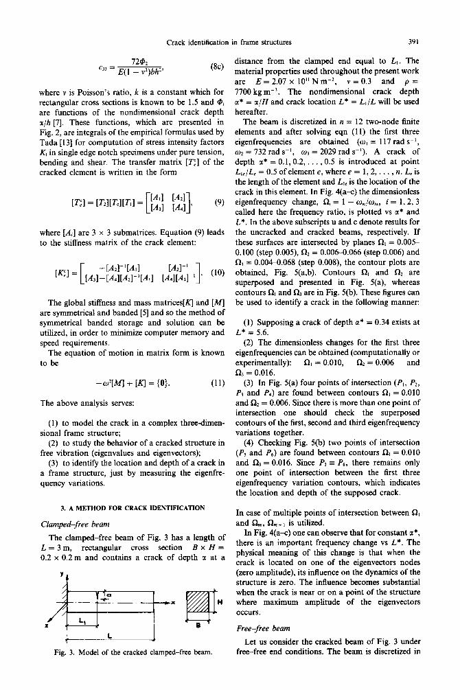
The clamped-fre:e beam of Fig. 3 has a length of L=3m, rectangular cross section B x H = 0.2 x 0.2 m and contains a crack of depth a at a
4------L Fig. 3. Model of the cracked clamped-free beam.
distance from the clamped end equal to Lt. The material properties used throughout the present work are E = 2.07 x 10” N m-2 v = 0.3 and p = 7700 kg mW3. The nondimensional crack depth a* = a/H and crack location L* = LI/L will be used hereafter.
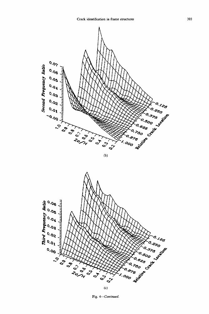
The beam is discretized in n = 12 two-node finite elements and after solving eqn (11) the first three eigenfrequencies are obtained (w, = 117 rad s-‘, co2 = 732 rad ss’, w3 = 2029 rad s-l). A crack of depth a* = 0.1,0.2, . . . , 0.5 is introduced at point L,,/L, = 0.5 of element e, where e = 1,2, . . . , n. L, is the length of the element and LI, is the location of the crack in this element. In Fig. 4(a-c) the dimensionless eigenfrequency change, Ri = 1 - o&D~, i = 1,2,3 called here the frequency ratio, is plotted vs a* and L*. In the above subscripts u and c denote results for the untracked and cracked beams, respectively. If these surfaces are intersected by planes Q = 0.005 0.100 (step O.OOS), a2 = 0.006-0.066 (step 0.006) and 0, = 0.0040.068 (step O.OOS), the contour plots are obtained, Fig. 5(a,b). Contours RI and R2 are superposed and presented in Fig. 5(a), whereas contours Q and R3 are in Fig. 5(b). These figures can be used to identify a crack in the following manner:
(1) Supposing a crack of depth a* = 0.34 exists at L* = 5.6.
(2) The dimensionless changes for the first three eigenfrequencies can be obtained (computationally or experimentally): RI = 0.010, Q2 = 0.006 and R3 = 0.016.
(3) In Fig. 5(a) four points of intersection (Pl, P2, P3 and P,) are found between contours RI = 0.010 and a2 = 0.006. Since there is more than one point of intersection one should check the superposed contours of the first, second and third eigenfrequency variations together.
(4) Checking Fig. 5(b) two points of intersection (Ps and P6) are found between contours RI = 0.010 and a3 = 0.016. Since 9 = P6, there remains only one point of intersection between the first three eigenfrequency variation contours, which indicates the location and depth of the supposed crack.
In case of multiple points of intersection between RI and Q,,, R, + , is utilized.
In Fig. 4(a-c) one can observe that for constant a*, there is an important frequency change vs L*. The physical meaning of this change is that when the crack is located on one of the eigenvectors nodes (zero amplitude), its influence on the dynamics of the structure is zero. The influence becomes substantial when the crack is near or on a point of the structure where maximum amplitude of the eigenvectors occurs.
Free-free beam
Let us consider the cracked beam of Fig. 3 under free-free end conditions. The beam is discretized in
392 P. Ct. Nikolakopoulos et al.
Fig. 4. Dimensionless eigenfrequency change vs dimensionless crack location and depth, for the cracked clamped-free beam: (a) first eigenfrequency; (b) second eigenfrequency; and (c) third eigenfrequency.
(Continued opposite.)
Thi
vi
Req
uenc
y R
atio
.-
.- .-
.- .-
. a
nann
ng
,,oO
cOlu
”W”Z
BB
a

394 P. G. Nikolakopoulos et al.
1.000
0.875
0.750
0.625
*J 0.500
0.375
0.250
0.125
0.1 0.2 HUH
0.4 0.5
(a)
0.1 0.2 0.4 0.5
0))
Fig. 5. (a) Superposed contours of RI (solid line) and RZ (dashed line) for the clamped-free beam; (b) superposed contours of 521 (solid line) and R, (dashed line).

Crack identification in frame structures 395
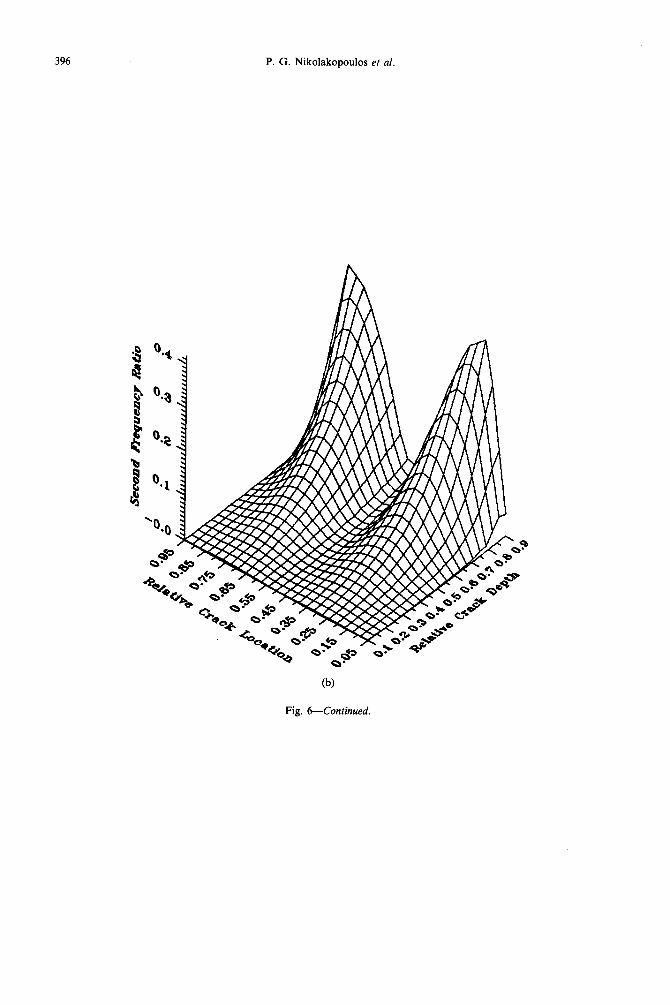
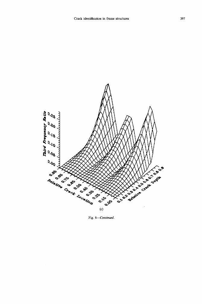
Fig. 6. Dimensionless eigenfrequency change vs dimensionless crack location and depth for the cracked free-free beam: (a) first eigenfrequency; (b) second eigenfrequency; and (c) third eigenfrequency.
(Continued overleaf.)
396 P. G. Nikolakopoulos et al.
(b)
Fig. 6-Continued.
Crack identification in frame structures 397
Fig. &Continued.
398 P. G. Nikolakopoulos et al.
0.95
0.85
0.75
0.65
0.55
0.46
0.36
0.25
0.15
0.05
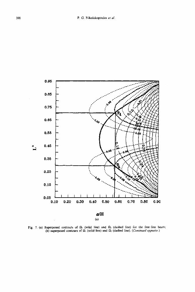
Fig. 7. (a) Superposed contours of RI (solid line) and QZ (dashed line) for the free-free beam; (b) superposed contours of RI (solid line) and 5% (dashed line). (Co&wed opposite.)

Crack identification in frame structures 399
?
2 0.46 -
0.36 -
0.10 0.20 0.30 0.40 0.30 0.60 0.70 0.00 0.90
Fig. l-Continued.
400 P. G. Nikolakopoulos et al.
c c
E” 1 0
L
“cu J //
r’
i
i h
Jc 1 b
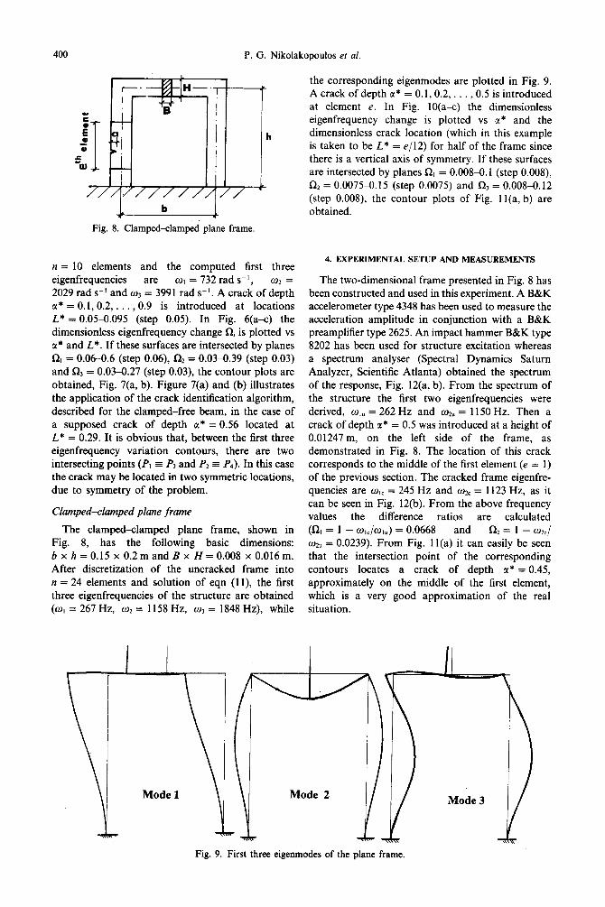
Fig. 8. Clamped-clamped plane frame,
n = 10 elements and the computed first three eigenfrequencies are o1 = 732 rad s-l, w2 = 2029 rad s-’ and w3 = 3991 rad s-l. A crack of depth CI* = 0.1,0.2, . . . ,0.9 is introduced at locations L* = 0.0550.095 (step 0.05). In Fig. @a-c) the dimensionless eigenfrequency change Q is plotted vs a* and L*. If these surfaces are intersected by planes Q, = 0.06-0.6 (step 0.06), Q = 0.0330.39 (step 0.03) and R3 = 0.03-0.27 (step 0.03), the contour plots are obtained, Fig. 7(a, b). Figure 7(a) and (b) illustrates the application of the crack identification algorithm, described for the clamped-free beam, in the case of a supposed crack of depth a* = 0.56 located at L* = 0.29. It is obvious that, between the first three eigenfrequency variation contours, there are two intersecting points (PI 5 P3 and P2 = Pa). In this case the crack may be located in two symmetric locations, due to symmetry of the problem.
Clamped-clamped plane frame
The clamped-clamped plane frame, shown in Fig. 8, has the following basic dimensions: b x h = 0.15 x 0.2 m and B x H = 0.008 x 0.016 m. After discretization of the untracked frame into n = 24 elements and solution of eqn (1 l), the first three eigenfrequencies of the structure are obtained (w, = 267 Hz, w2 = 1158 Hz, o3 = 1848 Hz), while
\
T
Mode 1
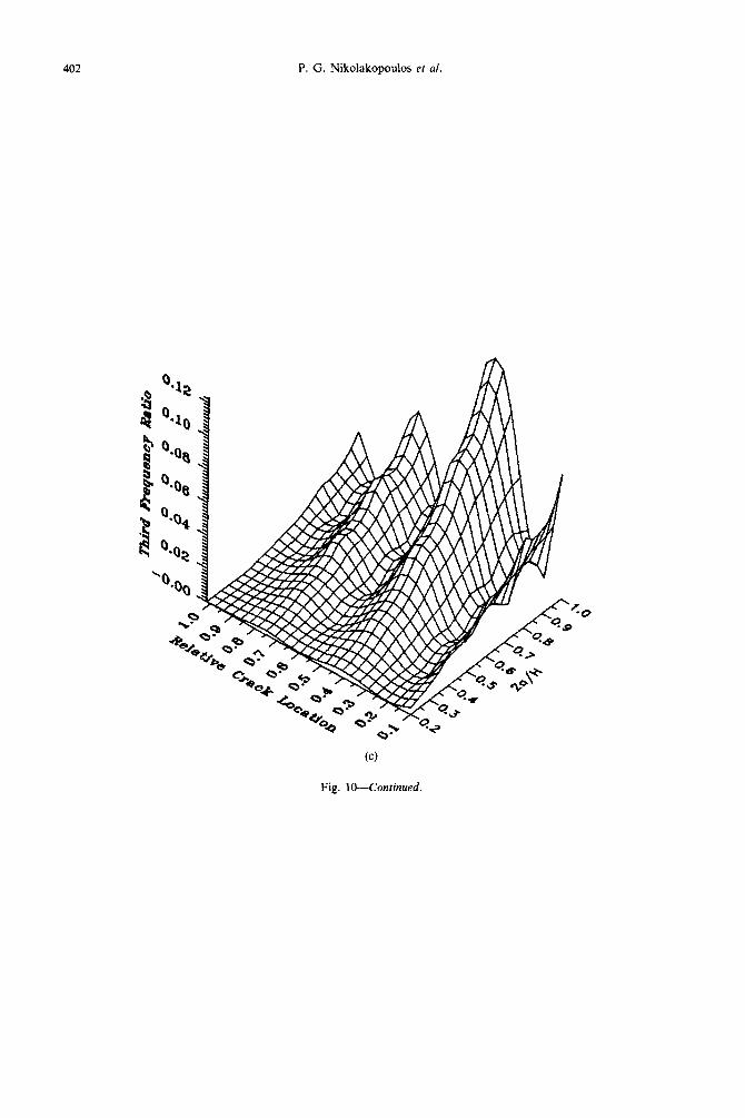
the corresponding eigenmodes are plotted in Fig. 9. A crack of depth c(* = 0.1,0.2, . . , 0.5 is introduced at element e. In Fig. lO(a-c) the dimensionless eigenfrequency change is plotted vs a* and the dimensionless crack location (which in this example is taken to be L* = e/12) for half of the frame since there is a vertical axis of symmetry. If these surfaces are intersected by planes !& = 0.0084.1 (step O.OOS), Cl2 = 0.00754.15 (step 0.0075) and a, = 0.008-0.12 (step O.OOS), the contour plots of Fig. 1 l(a, b) are obtained.
4. EXPERIMENTAL SETUP AND MEASUREMENTS
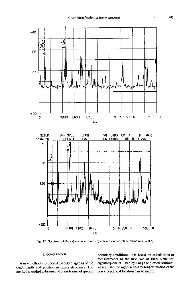
The two-dimensional frame presented in Fig. 8 has been constructed and used in this experiment. A B&K accelerometer type 4348 has been used to measure the acceleration amplitude in conjunction with a B&K preamplifier type 2625. An impact hammer B&K type 8202 has been used for structure excitation whereas a spectrum analyser (Spectral Dynamics Saturn Analyzer, Scientific Atlanta) obtained the spectrum of the response, Fig. 12(a, b). From the spectrum of the structure the first two eigenfrequencies were derived, wlU = 262 Hz and wzU = 1150 Hz. Then a crack of depth tl* = 0.5 was introduced at a height of 0.01247 m, on the left side of the frame, as demonstrated in Fig. 8. The location of this crack corresponds to the middle of the first element (e = 1) of the previous section. The cracked frame eigenfre- quencies are wlC = 245 Hz and w2C = 1123 Hz, as it can be seen in Fig. 12(b). From the above frequency values the difference ratios are calculated (n, = 1 - o&J,,) = 0.0668 and R1 = 1 - u&J 02” = 0.0239). From Fig. 1 l(a) it can easily be seen that the intersection point of the corresponding contours locates a crack of depth LY* = 0.45, approximately on the middle of the first element, which is a very good approximation of the real situation.
Mode 2 1)) Mode 3
Fig. 9. First three eigenmodes of the plane frame.

Crack identification in frame structures
(4
(b)
Fig. 10. Dimensionless eigenfrequency change vs dimensionless crack location and depth for the cracked plane frame: (a) first eigenfrequency; (b) second eigenfrequency; and (c) third eigenfrequency. (Continued
overleaf .) CAS61/14 N
402 P. G. Nikolakopoulos et al.
Fig. IO-Continued.

Crack identification in frame structures 403
0.3
a/H
(a)
0.4
1 0.45 0.5
k&=0.0668
Fig. 11. (a) Superposed contours of Q, (solid line) and R2 (dashed line) for the plane frame; (b) superposed contours of RI (solid line) and f& (dashed line). (Continued overleaf..)

404 P. G. Nikolakopoulos et al.
0.1 0.2 0.3
0
@I
0.4 0.5
Fig. 1 l-Continued.
Crack identification in frame structures 405
NORM LNXI BASE AF 12.50 HZ 5000.0
(4
SETUP GRP SPEC UPPR VW GODB CH A FR 5KHZ
Fig. 12. Spectrum of the (a) untracked and (b) cracked excited plane frame (a/H = 0.5).
!i. CONCLUSIONS boundary conditions. It is based on calculations or measurements of the first two or three structural
A new method is proposed for easy diagnosis of the eigenfrequencies. Then by using the plotted contours, crack depth and position in frame structures. The an accurate (for any practical reason) estimation of the method is applied to beams and plane frames of specific crack depth and location can be made.
406 P. G. Nikolakopoulos et al.
When the difference ratios of the frequency of a clamped-free and free-free beam or of a clamped- clamped plane frame are known, then using the method presented here and the calculated contour plottings, the crack depth and location in the structure are obtained.
This method can be generalized for any boundary condition and structure, provided that new contour plottings are constructed, giving a good estimate of the crack location (finite element number) and crack depth.
The experimental results for the plane frame are in good agreement with the theory.
REFERENCES
1. T. C. Chondros and A. D. Dimarogonas, Identification of cracks in circular plates welded at the contour. In: ASME Design Engineering Technical Conf., St. Louis (1979).
2. T. C. Chondros and A. D. Dimarogonas, Identification of cracks in welded joints of complex structures. J. Sound Vibr. 69, 531-538 (1980).
3. G. D. Gounaris and A. D. Dimarogonas, A finite element of a cracked prismatic beam in structural analysis. Compur. Sfruct. 28, 309313 (1988).
4.
5.
6.
7.
8.
9.
10.
11.
12.
13.
G. D. Gounaris and V. Papazoglou, Three-dimensional effects on the natural vibrations of cracked Timoshenko beams in water. Comput. Struct. 42, 769-779 (1992). C. A. Papadopoulos and A. D. Dimarogonas, Coupled longitudinal and bending vibrations of a rotating shaft with an open crack. J. Sound Vibr. 117, 81-93 (1987). C. A. Papadopoulos and A. D. Dimarogonas, Coupling of bending and torsional vibrations of a cracked Timoshenko shaft. Zng. Arch. 57, 257-266 (1987). C. A. Papadopoulos and A. D. Dimarogonas, Coupled longitudinal and bending vibrations of a cracked shaft. J. Vibr. Acoust. Stress Reliab. Des. 110, 1-8 (1988). C. A. Papadopoulos and A. D. Dimarogonas, Coupled vibrations of cracked shafts. J. Vibr. Acousf. 114, 461467 (1992). T. Inagaki, H. Kanki and K. Shiraki, Transverse vibrations of a general cracked rotor bearing system. J. mech. Des. 104, I-11 (1981). P. S. Leung, The effects of a transverse Crack on the dynamics of a circular shaft. In: Rotordynamics ‘92, In?. conf. on Rotating Machine Dynamics,. Venice (1992). N. Anifantis, P. Rizos and A. D. Dimaroaonas. Identification of cracks on beams by vibration analysis: In: I lth Biennial ASME Conf. on Mechanical Vibration and Noise, Boston (1987). A. D. Dimarogonas and G. Massouros, Torsional vibrations of a shaft with a circumferential crack. Engng Fracture Mech. 15, 439444 (1981). H. Tada, The Stress Analysis of Cracks Handbook. Del Research Corporation, PA (1973).