Design and Application of a High-G Piezoresistive ... - MDPI
Upload
khangminh22Category
view
1download
0
Piezoresistive Cement-based Materials for Strain Sensing
D. D. L. CHUNG*
Composite Materials Research Laboratory, University at Buffalo, The State University of New York,Buffalo, NY 14260-4400, USA
ABSTRACT: Cement-based materials that exhibit piezoresistivity with sufficient magnitudeand reversibility contain electrically conductive fibers. The phenomenon allows the materialsto sense their own strain. The fibers are preferably discontinuous. Carbon fibers (15mmdiameter) are most effective. Steel fibers (8 mm diameter) are less effective. Carbon filaments(0.1 mm diameter) are ineffective. The piezoresistive behavior, mechanism and materials arereviewed, including cement-based materials with continuous and discontinuous fibers.
Key Words: cement, concrete, strain sensor, piezoresistive, carbon fiber, steel fiber.
INTRODUCTION
Strain sensing (related to stress sensing, but is distinctfrom damage sensing) is relevant to structural vibrationcontrol, traffic monitoring and weighing. In particular,weighing pertains to (i) the weighing of trucks that mayor may not be moving, (ii) the weighing of all the peoplein each room of a building for the purpose of roomoccupancy monitoring and the use of the informationfor controlling lighting, ventilation, air-conditioningand heating (i.e., for energy saving), (iii) the detectionof people inside or outside a building for enhancingbuilding security, and (iv) the weighing of cargo.
Cement-based materials include concrete (containingcoarse and fine aggregates), mortar (containing fineaggregate but no coarse aggregate) and cement paste(containing no aggregate, whether coarse or fine). Thefine aggregate is typically sand. The coarse aggregate istypically stones such as gravel. These aggregates arechosen due to their low cost and wide availability. Thecombination of coarse and fine aggregates allows densepacking of the aggregates, as the fine aggregate fills thespace between the units of large aggregate. Bothaggregates serve as fillers, while cement serves as thematrix (i.e., the binder). Hence, these materials arecement–matrix composites. Concrete is the form that ismost commonly used in structures. Mortar is used inmasonry (i.e., for joining bricks in a brick wall), coatingand some forms of repair. Cement paste by itself is notused in structural applications, but is relevant tofunctional applications and is a basic component ofconcrete and mortar.
Conventional applications of the stress–strain sensorsinclude pressure sensors for aircraft and automobile
components, vibration sensors for civil structures suchas bridges and weighing-in-motion sensors for highways.The first category tends to involve small sensors (e.g., inthe form of cement paste or mortar) and they willcompete with silicon pressure sensors. The second andthird categories tend to involve large sensors (e.g., in theform of precast concrete or mortar) and they willcompete with silicon, acoustic, inductive and pneumaticsensors.
Other than aggregates, fillers in smaller quantities canbe optionally added to the cement mix to improve theproperties of the resulting materials. These fillers arecalled admixtures, which are discontinuous, so that theycan be included in the mix. They can be particles, suchas silica fume (a fine particulate) and latex (a polymer inthe form of a dispersion). They can be short fibers, suchas polymer, steel, glass or carbon fibers. They can beliquids such as methylcellulose aqueous solution, waterreducing agent, defoamer, etc.
Cement reinforced with short carbon fibers is capableof sensing its own strain due to the effect of strain on theelectrical resistivity (Chen and Chung, 1993, 1995a,1996a,b; Chung, 1995; Fu and Chung, 1996a, 1997a;Qizhao et al., 1996; Fu et al., 1997, 1998a,b; Xu et al.,1998; Shi and Chung, 1999; Wen and Chung, 2000,2001a,c, 2003). As observed at 28 days of curing, theresistivity in the stress and transverse directionsincreases upon tension, due to slight fiber pull-out thataccompanies crack opening, and decreases upon com-pression, due to slight fiber push-in that accompaniescrack closing (Qizhao et al., 1996; Fu and Chung, 1996a,1997a; Fu et al., 1997, 1998a,b; Wen and Chung, 2000,2001a). This electromechanical phenomenon, calledpiezoresistivity (i.e., change of the electrical resistivitywith strain), allows the use of electrical resistancemeasurement (DC or AC) to monitor the strain of the
*E-mail: [email protected]
JOURNAL OF INTELLIGENT MATERIAL SYSTEMS AND STRUCTURES, Vol. 00—December 2002 1
1045-389X/02/00 0001–11 $10.00/0 DOI: 10.1106/104538902031861� 2002 Sage Publications
+ [12.12.2002–3:37pm] [1–12] [Page No. 1] FIRST PROOFS i:/Sage/Jim/JIM-31861.3d (JIM) Paper: JIM-31861 Keyword
cement-based material, which is itself the sensor. Thismeans that the cement-based material is self-sensing. Incontrast to the conventional method of using embeddedor attached strain sensors (Robins et al., 2001; Wang etal., 2001), self-sensing involves low cost, high durability,large sensing volume and absence of mechanicalproperty degradation (which tends to occur in case ofembedded sensors).
Piezoresistivity studies have been mostly conducted onpolymer–matrix composites with fillers that are electri-cally conducting. These composite peizoresistive sensorswork because strain changes the proximity between theconducting filler units, thus affecting the electricalresistivity. Tension increases the distance between thefiller units, thus increasing the resistivity; compressiondecreases this distance, thus decreasing the resistivity.
Composite piezoresistive materials include polymer–matrix composites containing continuous carbon fibers(Schulte and Baron, 1989; Prabhakaran, 1990; Schulte,1993; Kaddour et al., 1994; Muto et al., 1995; Sugitaet al., 1995; Ceysson, et al., 1996; Wang and Chung,1996b, 1997a,b, 1998; Irving and Thiagarajan, 1998;Abry et al., 1999), carbon black (Kost et al., 1984;Pramanik et al., 1990; Radhakrishnan et al., 1994),metal particles (Radhakrishnan et al., 1994), shortcarbon fibers (Pramanik et al., 1990; Taya et al.,1998), cement–matrix composites containing shortcarbon fibers (Chen and Chung, 1993, 1996a,b; Fuand Chung, 1996a; Fu et al., 1997, 1998), and ceramic–matrix composites containing silicon carbide whiskers(Ishida et al., 1994). The sensing of reversible strain hadbeen observed in polymer–matrix and cement–matrixcomposites (Kost et al., 1984; Chen and Chung, 1993,1996a,b; Radhakrishnan et al., 1994; Fu and Chung,1996a; Wang and Chung, 1996b, 1997a,b, 1998; Fu et al.,1997, 1998; Irving and Thiagarajan, 1998; Taya et al.,1998).
The presence of electrically conductive fibers in thecement-basedmaterial is necessary for the piezoresistivityto be sufficient in magnitude and in reversibility. In theabsence of conductive fibers, the piezoresistivity is weakand has substantial irreversibility, if at all observable, asshown in the case of cement-based materials withoutfibers (Cao et al., 2001) and with nonconductive(polyethylene) short fibers (Chen and Chung, 1996b).Although conductive fibers are important for piezo-resistivity, they are preferably discontinuous (around5mm in length, unless stated otherwise), due to the lowcost of short fibers compared to continuous fibers andthe amenability of short fibers for incorporation in theconcrete mix by mixing, and are typically used at avolume fraction below the percolation threshold, whichrefers to the volume fraction above which the fiberstouch one another to form a continuous electrical path.The fibers are not the sensors; they are an additive forrendering significant piezoresistivity to the cement-
based material, which is the sensor. A low fraction offibers is preferred for the purpose of maintaining lowcost, high workability and high compressive strength.
Steel fibers are even more conductive than carbonfibers. Short steel fibers are used in cement-basedmaterials to enhance the tensile, flexural and shearproperties (Chen and Chung, 1996c; Alavizadeh-Farhang and Silfwerbrand, 2000; Bayasi and Kaiser,2001; Lotfy, 2001; Nataraja et al., 2001; Teutsch, 2001)and the abrasion resistance (Febrillet et al., 2000),decrease the drying shrinkage (Sun et al., 2001), increasethe effectiveness for electromagnetic interference (EMI)shielding (Wen and Chung, 2002) and provide con-trolled electrical resistivity (Wen and Chung, 2001b).Moreover, stainless steel fibers of diameter 60 mm renderpiezoresistivity to a cement-based material, as shownunder compression, though the phenomenon is noisy inthat the resistivity does not vary smoothly with thestrain (Chen and Chung, 1996b). The large diameter ofthe steel fibers compared to carbon fibers (15 mm) wasbelieved to be the cause of the inferior performance ofthe steel fiber cement-based material (Chen and Chung,1996b). However, carbon fiber (15 mm diameter) cementpaste is a better piezoresistive strain sensor than stainlesssteel fiber (8 mm diameter) cement paste at a similar fibervolume fraction, as shown by a higher signal-to-noiseratio and better reversibility upon unloading (Wen andChung, 2003). The difference in performance of carbonfiber cement and steel fiber cement is attributed to adifference in piezoresistivity mechanism.
EFFECT OF FIBER TYPE ON THE
PIEZORESISTIVE BEHAVIOR
The experimental results presented in this section wereall obtained at 28 days of curing, using Type I portlandcement. For details in the materials processing, pleaserefer to the literature cited.
Cement Paste Containing 0.72Vol.% Short Steel Fibers
Figure 1 (Wen and Chung, 2003) shows the variationof the fractional change in resistivity with strain andstress for cement paste containing 0.72 vol.% short steelfibers (8 mm diameter) under repeated tension. Bothresistivity and strain increased with increasing stresswith partial reversiblity. The higher the stress amplitude,the higher were both the strain and the resistivity.
Figure 2 (Wen and Chung, 2003) shows correspond-ing results obtained under compression. The strain wasmostly reversible, but the resistivity decrease uponcompression was noisy and the resistivity showed anirreversible increase after each stress cycle.
2 D. D. L. CHUNG
+ [12.12.2002–3:38pm] [1–12] [Page No. 2] FIRST PROOFS i:/Sage/Jim/JIM-31861.3d (JIM) Paper: JIM-31861 Keyword

Cement Paste Containing 0.36 Vol% Short Steel Fibers
Figures 3 and 4 (Wen and Chung, 2003) show thepiezoresistivity results for cement paste containing0.36 vol.% short steel fibers (8 mm diameter) undertension and compression respectively. The resistivityincreased upon tension and decreased upon compres-sion, as observed for cement paste containing 0.72 vol.%steel fibers (Figures 1 and 2). However, the resistivitychange and strain were more reversible, both undertension and compression.
Cement Paste Containing 0.5Vol.% Short Carbon Fibers
Figures 5 and 6 (Wen and Chung, 2000, 2001a) showthe piezoresistivity results for cement paste containing0.5 vol.% short carbon fibers (15 mm diameter) undertension and compression respectively. The strain wastotally reversible and was linearly related to the stress.The resistivity increased with tensile strain anddecreased with compressive strain, such that the effectwas totally reversible, except for an irreversible increaseat the end of the first compression cycle. The resistivityvariation was much less noisy and much more reversiblethan that observed for the two steel fiber cement pastes(Figures 1–4).
Cement Paste Containing 0.5Vol.% Short Carbon
Filaments
The use of carbon filaments (catalytically grown,0.1 mm diameter >100 mm long,) in place of conven-tional short carbon fibers (based on isotropic pitch,15 mm diameter, ‘‘Cement Paste Containing 0.5 Vol. %Short Carbon Fibers’’) in a cement–matrix compositeresults in increased noise in the piezoresistive effect (Fuand Chung, 1997b). This is because of the bentmorphology and large aspect ratio of the filaments,which hinder the pull-out of filaments. Thus, carbonfilaments are not attractive for cement–matrix compo-site strain sensors.
Gage factor
The gage factor is defined as the fractional change inresistance (not resistivity) per unit strain. With the strainbeing positive for tension and negative for compression,the gage factor is positive for both tension andcompression. Its value, as obtained from the firststress cycle, is listed in Table 1 for all three pastes.
The gage factor was higher under tension thancompression for the two steel fiber cement pastes, butwas lower under tension than compression for the
Figure 2. Variation of the fractional change in electrical resistivity(solid curve) with strain (dashed curve) (a), and of the strain (solidcurve) with stress (dashed curve) (b), for cement paste containing0.72 vol.% steel fibers under compression.
Figure 1. Variation of the fractional change in electrical resistivity(solid curve) with strain (dashed curve) (a), and of the strain (solidcurve) with stress (dashed curve) (b), for cement paste containing0.72 vol.% steel fibers under tension.
Piezoresistive Cement-based Materials for Strain Sensing 3
+ [12.12.2002–3:38pm] [1–12] [Page No. 3] FIRST PROOFS i:/Sage/Jim/JIM-31861.3d (JIM) Paper: JIM-31861 Keyword
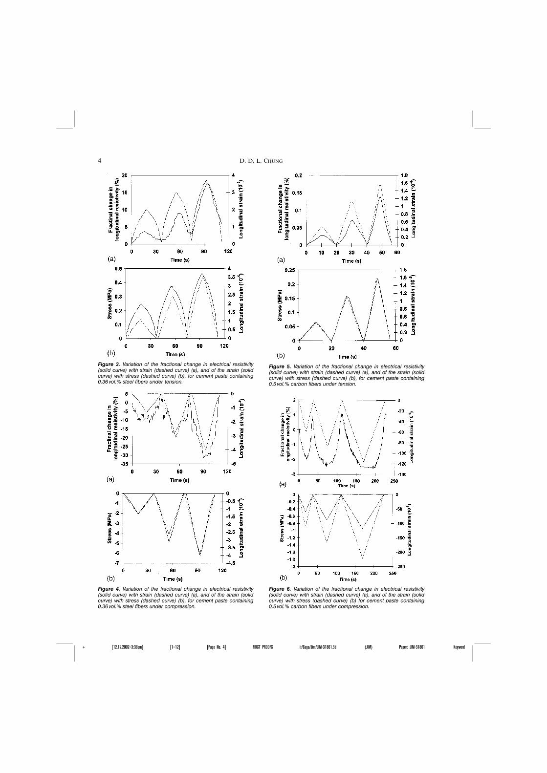
Figure 5. Variation of the fractional change in electrical resistivity(solid curve) with strain (dashed curve) (a), and of the strain (solidcurve) with stress (dashed curve) (b), for cement paste containing0.5 vol.% carbon fibers under tension.
Figure 3. Variation of the fractional change in electrical resistivity(solid curve) with strain (dashed curve) (a), and of the strain (solidcurve) with stress (dashed curve) (b), for cement paste containing0.36 vol.% steel fibers under tension.
Figure 4. Variation of the fractional change in electrical resistivity(solid curve) with strain (dashed curve) (a), and of the strain (solidcurve) with stress (dashed curve) (b), for cement paste containing0.36 vol.% steel fibers under compression.
Figure 6. Variation of the fractional change in electrical resistivity(solid curve) with strain (dashed curve) (a), and of the strain (solidcurve) with stress (dashed curve) (b) for cement paste containing0.5 vol.% carbon fibers under compression.
4 D. D. L. CHUNG
+ [12.12.2002–3:38pm] [1–12] [Page No. 4] FIRST PROOFS i:/Sage/Jim/JIM-31861.3d (JIM) Paper: JIM-31861 Keyword
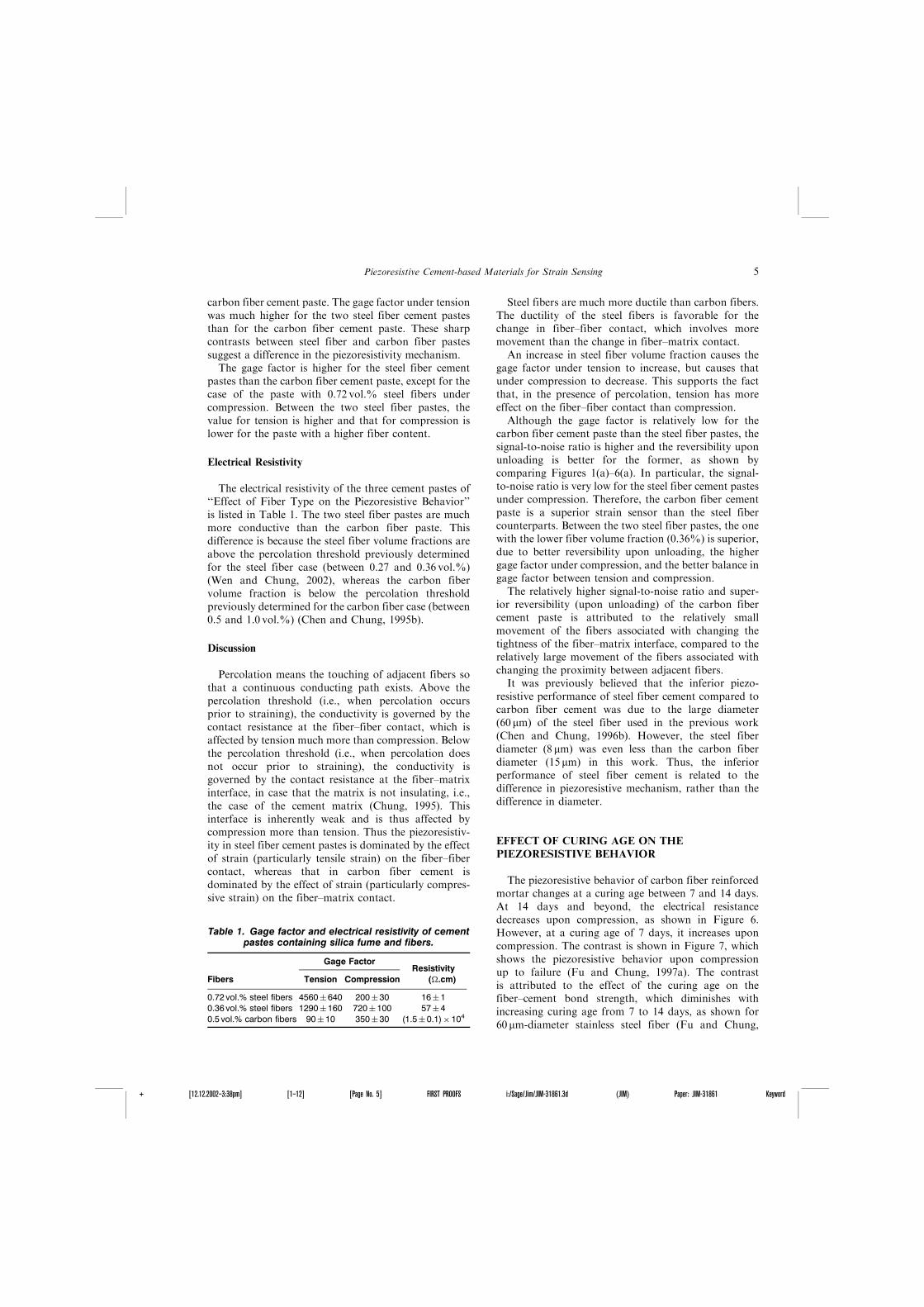
carbon fiber cement paste. The gage factor under tensionwas much higher for the two steel fiber cement pastesthan for the carbon fiber cement paste. These sharpcontrasts between steel fiber and carbon fiber pastessuggest a difference in the piezoresistivity mechanism.
The gage factor is higher for the steel fiber cementpastes than the carbon fiber cement paste, except for thecase of the paste with 0.72 vol.% steel fibers undercompression. Between the two steel fiber pastes, thevalue for tension is higher and that for compression islower for the paste with a higher fiber content.
Electrical Resistivity
The electrical resistivity of the three cement pastes of‘‘Effect of Fiber Type on the Piezoresistive Behavior’’is listed in Table 1. The two steel fiber pastes are muchmore conductive than the carbon fiber paste. Thisdifference is because the steel fiber volume fractions areabove the percolation threshold previously determinedfor the steel fiber case (between 0.27 and 0.36 vol.%)(Wen and Chung, 2002), whereas the carbon fibervolume fraction is below the percolation thresholdpreviously determined for the carbon fiber case (between0.5 and 1.0 vol.%) (Chen and Chung, 1995b).
Discussion
Percolation means the touching of adjacent fibers sothat a continuous conducting path exists. Above thepercolation threshold (i.e., when percolation occursprior to straining), the conductivity is governed by thecontact resistance at the fiber–fiber contact, which isaffected by tension much more than compression. Belowthe percolation threshold (i.e., when percolation doesnot occur prior to straining), the conductivity isgoverned by the contact resistance at the fiber–matrixinterface, in case that the matrix is not insulating, i.e.,the case of the cement matrix (Chung, 1995). Thisinterface is inherently weak and is thus affected bycompression more than tension. Thus the piezoresistiv-ity in steel fiber cement pastes is dominated by the effectof strain (particularly tensile strain) on the fiber–fibercontact, whereas that in carbon fiber cement isdominated by the effect of strain (particularly compres-sive strain) on the fiber–matrix contact.
Steel fibers are much more ductile than carbon fibers.The ductility of the steel fibers is favorable for thechange in fiber–fiber contact, which involves moremovement than the change in fiber–matrix contact.
An increase in steel fiber volume fraction causes thegage factor under tension to increase, but causes thatunder compression to decrease. This supports the factthat, in the presence of percolation, tension has moreeffect on the fiber–fiber contact than compression.
Although the gage factor is relatively low for thecarbon fiber cement paste than the steel fiber pastes, thesignal-to-noise ratio is higher and the reversibility uponunloading is better for the former, as shown bycomparing Figures 1(a)–6(a). In particular, the signal-to-noise ratio is very low for the steel fiber cement pastesunder compression. Therefore, the carbon fiber cementpaste is a superior strain sensor than the steel fibercounterparts. Between the two steel fiber pastes, the onewith the lower fiber volume fraction (0.36%) is superior,due to better reversibility upon unloading, the highergage factor under compression, and the better balance ingage factor between tension and compression.
The relatively higher signal-to-noise ratio and super-ior reversibility (upon unloading) of the carbon fibercement paste is attributed to the relatively smallmovement of the fibers associated with changing thetightness of the fiber–matrix interface, compared to therelatively large movement of the fibers associated withchanging the proximity between adjacent fibers.
It was previously believed that the inferior piezo-resistive performance of steel fiber cement compared tocarbon fiber cement was due to the large diameter(60 mm) of the steel fiber used in the previous work(Chen and Chung, 1996b). However, the steel fiberdiameter (8 mm) was even less than the carbon fiberdiameter (15 mm) in this work. Thus, the inferiorperformance of steel fiber cement is related to thedifference in piezoresistive mechanism, rather than thedifference in diameter.
EFFECT OF CURING AGE ON THE
PIEZORESISTIVE BEHAVIOR
The piezoresistive behavior of carbon fiber reinforcedmortar changes at a curing age between 7 and 14 days.At 14 days and beyond, the electrical resistancedecreases upon compression, as shown in Figure 6.However, at a curing age of 7 days, it increases uponcompression. The contrast is shown in Figure 7, whichshows the piezoresistive behavior upon compressionup to failure (Fu and Chung, 1997a). The contrastis attributed to the effect of the curing age on thefiber–cement bond strength, which diminishes withincreasing curing age from 7 to 14 days, as shown for60 mm-diameter stainless steel fiber (Fu and Chung,
Table 1. Gage factor and electrical resistivity of cementpastes containing silica fume and fibers.
Gage FactorResistivity
(�.cm)Fibers Tension Compression
0.72 vol.% steel fibers 4560�640 200� 30 16�10.36 vol.% steel fibers 1290�160 720�100 57�40.5 vol.% carbon fibers 90� 10 350� 30 (1.5�0.1)�104
Piezoresistive Cement-based Materials for Strain Sensing 5
+ [12.12.2002–3:38pm] [1–12] [Page No. 5] FIRST PROOFS i:/Sage/Jim/JIM-31861.3d (JIM) Paper: JIM-31861 Keyword
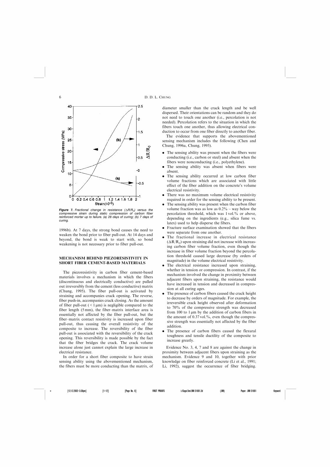
1996b). At 7 days, the strong bond causes the need toweaken the bond prior to fiber pull-out. At 14 days andbeyond, the bond is weak to start with, so bondweakening is not necessary prior to fiber pull-out.
MECHANISM BEHIND PIEZORESISTIVITY IN
SHORT FIBER CEMENT-BASED MATERIALS
The piezoresistivity in carbon fiber cement-basedmaterials involves a mechanism in which the fibers(discontinuous and electrically conductive) are pulledout irreversibly from the cement (less conductive) matrix(Chung, 1995). The fiber pull-out is activated bystraining and accompanies crack opening. The reverse,fiber push-in, accompanies crack closing. As the amountof fiber pull-out (<1 mm) is negligible compared to thefiber length (5mm), the fiber–matrix interface area isessentially not affected by the fiber pull-out, but thefiber–matrix contact resistivity is increased upon fiberpull-out, thus causing the overall resistivity of thecomposite to increase. The reversibility of the fiberpull-out is associated with the reversibility of the crackopening. This reversibility is made possible by the factthat the fiber bridges the crack. The crack volumeincrease alone just cannot explain the large increase inelectrical resistance.
In order for a short fiber composite to have strainsensing ability using the abovementioned mechanism,the fibers must be more conducting than the matrix, of
diameter smaller than the crack length and be welldispersed. Their orientations can be random and they donot need to touch one another (i.e., percolation is notneeded). Percolation refers to the situation in which thefibers touch one another, thus allowing electrical con-duction to occur from one fiber directly to another fiber.
The evidence that supports the abovementionedsensing mechanism includes the following (Chen andChung, 1996a, Chung, 1995).
. The sensing ability was present when the fibers wereconducting (i.e., carbon or steel) and absent when thefibers were nonconducting (i.e., polyethylene).
. The sensing ability was absent when fibers wereabsent.
. The sensing ability occurred at low carbon fibervolume fractions which are associated with littleeffect of the fiber addition on the concrete’s volumeelectrical resistivity.
. There was no maximum volume electrical resistivityrequired in order for the sensing ability to be present.
. The sensing ability was present when the carbon fibervolume fraction was as low as 0.2% – way below thepercolation threshold, which was 1 vol.% or above,depending on the ingredients (e.g., silica fume vs.latex) used to help disperse the fibers.
. Fracture surface examination showed that the fiberswere separate from one another.
. The fractional increase in electrical resistance(�R/Ro) upon straining did not increase with increas-ing carbon fiber volume fraction, even though theincrease in fiber volume fraction beyond the percola-tion threshold caused large decrease (by orders ofmagnitude) in the volume electrical resistivity.
. The electrical resistance increased upon straining,whether in tension or compression. In contrast, if themechanism involved the change in proximity betweenadjacent fibers upon straining, the resistance wouldhave increased in tension and decreased in compres-sion at all curing ages.
. The presence of carbon fibers caused the crack heightto decrease by orders of magnitude. For example, theirreversible crack height observed after deformationto 70% of the compressive strength was decreasedfrom 100 to 1 mm by the addition of carbon fibers inthe amount of 0.37 vol.%, even though the compres-sive strength was essentially not affected by the fiberaddition.
. The presence of carbon fibers caused the flexuraltoughness and tensile ductility of the composite toincrease greatly.
Evidence No. 3, 4, 7 and 8 are against the change inproximity between adjacent fibers upon straining as themechanism. Evidence 9 and 10, together with priorknowledge on fiber reinforced concrete (Li et al., 1991;Li, 1992), suggest the occurrence of fiber bridging.
Figure 7. Fractional change in resistance (�R/Ro) versus thecompressive strain during static compression of carbon fiberreinforced mortar up to failure. (a) 28 days of curing; (b) 7 days ofcuring.
6 D. D. L. CHUNG
+ [12.12.2002–3:38pm] [1–12] [Page No. 6] FIRST PROOFS i:/Sage/Jim/JIM-31861.3d (JIM) Paper: JIM-31861 Keyword
Evidence No. 1, 2, 5 and 6 suggest that the electricalcontact resistance between fiber and matrix plays animportant role and that between fiber and fiber doesnot. All the pieces of evidence together support theabovementioned mechanism. However, further work isnecessary to completely prove the mechanism.
PIEZORESISTIVITY IN CONTINUOUS FIBER
CEMENT-BASED MATERIALS
Continuous fibers are far more effective than shortfibers for reinforcement, so advanced structural compo-sites all use continuous fibers rather than short fibers, inspite of the high cost of continuous fibers compared toshort fibers. Advanced structural composites are pre-dominantly polymer–matrix composites, due to the lowdensity and adhesive ability of polymers. The polymer–matrix composites are widely used for lightweightstructures, such as aircraft and sporting goods. Lesscommonly, they are used for the repair and strengthen-ing of concrete structures (Yoshizawa et al., 1996;Abdelrahman and Rizkalla, 1997; Ballinger, 1997; Famet al., 1997; Missihoun et al., 1997; Norris et al., 1997;Soudki et al., 1997; Takeda et al., 1996). However,polymers are much more expensive than cement and theadhesion of polymers to concrete and the long-termdurability of polymers inside concrete are of concern.Although numerous studies have been made on the useof short fibers in concrete (Banthia, 1994), little workhas been reported on the use of continuous fibers (Saitoet al., 1989; Zheng and Chung, 1989; Uomoto, 1995;Pivacek et al., 1997; Kolsch, 1998). In contrast to shortfibers, continuous fibers cannot be incorporated in acement mix. They need to be placed and made straightand parallel prior to the pouring of cement pastearound it (Wen et al., 2000). Thus, the preparation ofcontinuous fiber cement–matrix composites is muchmore complicated than that of short fiber cement–matrix composites.
Unidirectional continuous carbon fiber reinforcementresults in cement–matrix composites that exhibit tensilestrength approaching that expected by calculation basedon the Rule of Mixtures (Saito et al., 1989). Due to theelectrical conductivity of carbon fibers and the slightconductivity of the cement matrix, measurement of theDC electrical resistance of the composite provides a wayto detect damage (Wen et al., 2000). Fiber breakageobviously causes the longitudinal resistance to increaseirreversibly. Fiber–matrix bond degradation obviouslyincreases the transverse resistance, but it also increasesthe longitudinal resistance when the electrical currentcontacts are on the surface (e.g., perimetrically aroundthe composite in a plane perpendicular to the long-itudinal direction). When the transverse resistivity isincreased, the electrical current has more difficulty in
penetrating the entire cross-section of the specimen,thereby resulting in an increase in the measured longi-tudinal resistance. Note that the electrical resistivity ofcarbon fibers is 10�4�.cm, whereas that of cement pasteis 105�.cm.
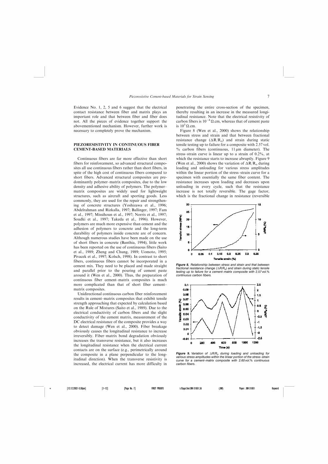
Figure 8 (Wen et al., 2000) shows the relationshipbetween stress and strain and that between fractionalresistance change (�R/Ro) and strain during statictensile testing up to failure for a composite with 2.57 vol.% carbon fibers (continuous, 11 mm diameter). Thestress–strain curve is linear up to a strain of 0.2%, atwhich the resistance starts to increase abruptly. Figure 9(Wen et al., 2000) shows the variation of �R/Ro duringloading and unloading for various stress amplitudeswithin the linear portion of the stress–strain curve for aspecimen with essentially the same fiber content. Theresistance increases upon loading and decreases uponunloading in every cycle, such that the resistanceincrease is not totally reversible. The gage factor,which is the fractional change in resistance (reversible
Figure 9. Variation of �R/Ro during loading and unloading forvarious stress amplitudes within the linear portion of the stress–straincurve for a cement–matrix composite with 2.60 vol.% continuouscarbon fibers.
Figure 8. Relationship between stress and strain and that betweenfractional resistance change (�R/Ro) and strain during static tensiletesting up to failure for a cement–matrix composite with 2.57 vol.%continuous carbon fibers.
Piezoresistive Cement-based Materials for Strain Sensing 7
+ [12.12.2002–3:38pm] [1–12] [Page No. 7] FIRST PROOFS i:/Sage/Jim/JIM-31861.3d (JIM) Paper: JIM-31861 Keyword
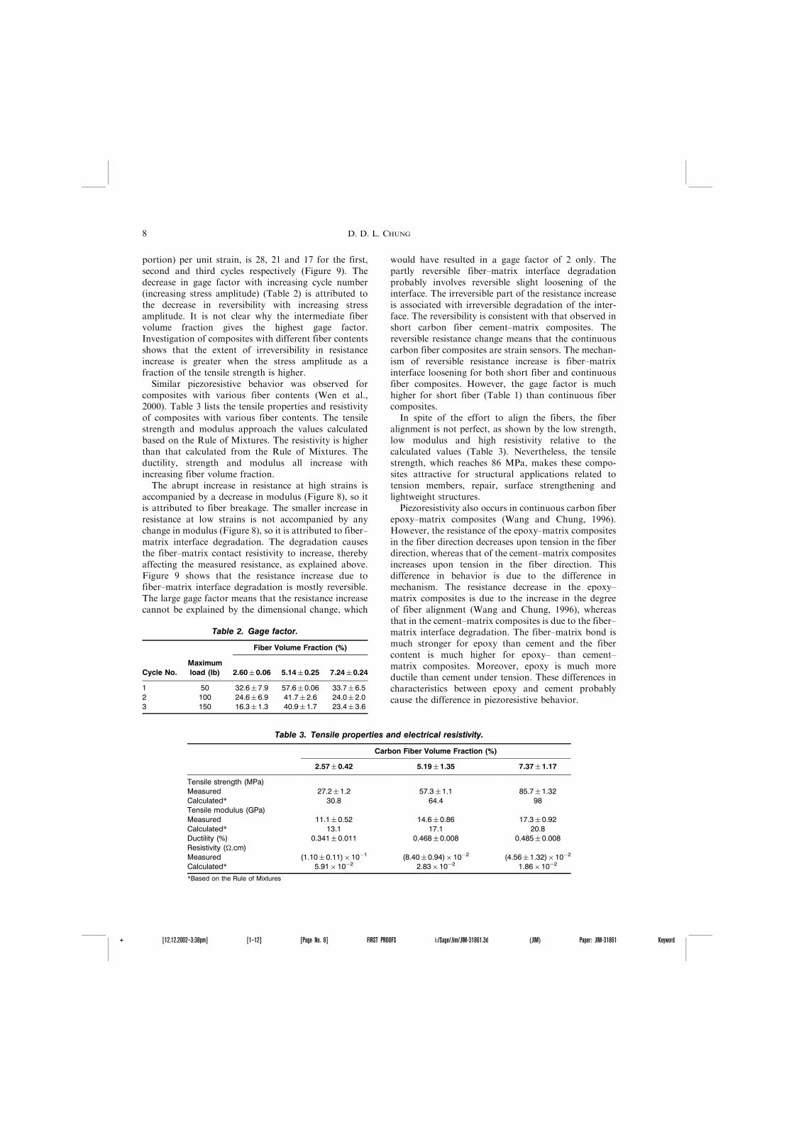
portion) per unit strain, is 28, 21 and 17 for the first,second and third cycles respectively (Figure 9). Thedecrease in gage factor with increasing cycle number(increasing stress amplitude) (Table 2) is attributed tothe decrease in reversibility with increasing stressamplitude. It is not clear why the intermediate fibervolume fraction gives the highest gage factor.Investigation of composites with different fiber contentsshows that the extent of irreversibility in resistanceincrease is greater when the stress amplitude as afraction of the tensile strength is higher.
Similar piezoresistive behavior was observed forcomposites with various fiber contents (Wen et al.,2000). Table 3 lists the tensile properties and resistivityof composites with various fiber contents. The tensilestrength and modulus approach the values calculatedbased on the Rule of Mixtures. The resistivity is higherthan that calculated from the Rule of Mixtures. Theductility, strength and modulus all increase withincreasing fiber volume fraction.
The abrupt increase in resistance at high strains isaccompanied by a decrease in modulus (Figure 8), so itis attributed to fiber breakage. The smaller increase inresistance at low strains is not accompanied by anychange in modulus (Figure 8), so it is attributed to fiber–matrix interface degradation. The degradation causesthe fiber–matrix contact resistivity to increase, therebyaffecting the measured resistance, as explained above.Figure 9 shows that the resistance increase due tofiber–matrix interface degradation is mostly reversible.The large gage factor means that the resistance increasecannot be explained by the dimensional change, which
would have resulted in a gage factor of 2 only. Thepartly reversible fiber–matrix interface degradationprobably involves reversible slight loosening of theinterface. The irreversible part of the resistance increaseis associated with irreversible degradation of the inter-face. The reversibility is consistent with that observed inshort carbon fiber cement–matrix composites. Thereversible resistance change means that the continuouscarbon fiber composites are strain sensors. The mechan-ism of reversible resistance increase is fiber–matrixinterface loosening for both short fiber and continuousfiber composites. However, the gage factor is muchhigher for short fiber (Table 1) than continuous fibercomposites.
In spite of the effort to align the fibers, the fiberalignment is not perfect, as shown by the low strength,low modulus and high resistivity relative to thecalculated values (Table 3). Nevertheless, the tensilestrength, which reaches 86 MPa, makes these compo-sites attractive for structural applications related totension members, repair, surface strengthening andlightweight structures.
Piezoresistivity also occurs in continuous carbon fiberepoxy–matrix composites (Wang and Chung, 1996).However, the resistance of the epoxy–matrix compositesin the fiber direction decreases upon tension in the fiberdirection, whereas that of the cement–matrix compositesincreases upon tension in the fiber direction. Thisdifference in behavior is due to the difference inmechanism. The resistance decrease in the epoxy–matrix composites is due to the increase in the degreeof fiber alignment (Wang and Chung, 1996), whereasthat in the cement–matrix composites is due to the fiber–matrix interface degradation. The fiber–matrix bond ismuch stronger for epoxy than cement and the fibercontent is much higher for epoxy– than cement–matrix composites. Moreover, epoxy is much moreductile than cement under tension. These differences incharacteristics between epoxy and cement probablycause the difference in piezoresistive behavior.
Table 3. Tensile properties and electrical resistivity.
Carbon Fiber Volume Fraction (%)
2.57� 0.42 5.19�1.35 7.37� 1.17
Tensile strength (MPa)Measured 27.2� 1.2 57.3�1.1 85.7� 1.32Calculated* 30.8 64.4 98Tensile modulus (GPa)Measured 11.1� 0.52 14.6�0.86 17.3� 0.92Calculated* 13.1 17.1 20.8Ductility (%) 0.341� 0.011 0.468�0.008 0.485� 0.008Resistivity (�.cm)Measured (1.10� 0.11)�10�1 (8.40�0.94)�10�2 (4.56� 1.32)�10�2
Calculated* 5.91�10�2 2.83�10�2 1.86�10�2
*Based on the Rule of Mixtures
Table 2. Gage factor.
Fiber Volume Fraction (%)
Cycle No.Maximumload (lb) 2.60� 0.06 5.14� 0.25 7.24�0.24
1 50 32.6�7.9 57.6� 0.06 33.7� 6.52 100 24.6�6.9 41.7� 2.6 24.0� 2.03 150 16.3�1.3 40.9� 1.7 23.4� 3.6
8 D. D. L. CHUNG
+ [12.12.2002–3:38pm] [1–12] [Page No. 8] FIRST PROOFS i:/Sage/Jim/JIM-31861.3d (JIM) Paper: JIM-31861 Keyword
PIEZORESISTIVITY IN SHORT FIBER CEMENT
COATING
Because most structures are not built with carbonfiber reinforced concrete but with conventional con-crete, the applicability of a cement-based material as astrain sensor can be widened by using the material as astrain sensing coating on conventional concrete. Cementpaste containing short carbon fibers is an effectivestrain-sensing coating, as tested when the coating (withfibers) is on either the tension side or the compressionside of a cement specimen (without fiber) under flexure(Wen and Chung, 2001c). The resistance is measuredwith surface electrical contacts on either side. Theresistance increases reversibly on the tension side uponloading and decreases reversibly on the compression sideupon loading. The behavior is similar whether the strainsensing coating contains silica fume or latex.
DC VERSUS AC
The data presented in all the above sections of thispaper involve the use of DC electrical power, i.e., theDC electrical resistance is measured. Under AC condi-tion, the impedance Z consists of the resistance Rs (realpart of Z) and the reactance Xs (imaginary part of Z),i.e., Z¼Rsþ iXs, where the subscript s refers to aconfiguration in which the sample is in series connectionwith the measuring circuit. AC provides both resistanceand reactance information and AC is relevant to dataacquisition by wireless methods. It has been found thatin carbon fiber (short) reinforced mortar at 7 days ofcuring, the reactance Xs is a more sensitive indicatorthan the resistance Rs, as the fractional change inreactance exceeds the fractional change in resistanceupon deformation (Fu et al., 1997). The effect of strainon the reactance relates to the effect of strain on thepolarization (Wen and Chung, 2001d), i.e., the directpiezoelectric effect (Mingqing et al., 2000), which is to bedistinguished from the piezoresistive effect. The piezo-electric effect is beyond the scope of this paper.
CONCLUSION
Cement reinforced with short carbon fibers (15 mmdiameter) is capable of sensing its own strain, due topiezoresistivity (DC or AC), i.e., the effect of strain onthe electrical resistivity. The resistivity in the stressand transverse directions increases upon tensionand decreases upon compression. Short steel fibers(8 mm diameter) and continuous carbon fibers (11 mmdiameter) are less effective. Short carbon filaments(0.1 mm diameter) are ineffective. In the case of shortcarbon fiber (15 mm diameter) reinforced cement, the
piezoresistive behavior changes at a curing age between7 and 14 days, and its mechanism involves slight fiberpull-out and push-in upon tension and compressionrespectively.
REFERENCES
Abdelrahman, A.A. and Rizkalla, S.H. 1997. ‘‘Serviceability ofConcrete Beams Prestressed by Carbon-Fiber-Reinforced-PlasticBars,’’ ACI Struct. J., 94(4):447–457.
Abry, J.C., Bochard, S., Chateauminois, A., Salvia, M. and Giraud, G.1999. ‘‘In Situ Detection of Damage in CFRP Laminatesby Electrical Resistance Measurement,’’ Compos. Sci. Tech.,59(6):925–935.
Alavizadeh-Farhang, A. and Silfwerbrand, J. 2000. ‘‘Responses ofPlain and Steel Fiber-Reinforced Concrete Beams to Temperatureand Mechanical Loads: Experimental Study,’’ TransportationResearch Record, (1740):25–32.
Ballinger, C.A. 1997. ‘‘Strengthening of Engineering Structures withCarbon Fiber Reinforced Plastics – An Overview of History andCurrent Worldwide Usage,’’ Int. SAMPE Symp. Exhib. (Proc.),SAMPE, Covina, CA, 42(2):927–932.
Banthia, N. 1994. ACI SP-142, Fiber Reinforced Concrete, Daniel, J.I.and Shah, S.P. (Eds.), p. 91–120, ACI, Detroit, MI.
Bayasi, Z. and Kaiser, H. 2001. ‘‘Steel Fibers as Crack Arrestors inConcrete,’’ Indian Concr. J., 75(3):215–222.
Cao, J., Wen, S. and Chung, D.D.L. 2001. ‘‘Defect Dynamics andDamage of Cement-Based Materials, Studied by ElectricalResistance Measurement,’’ J. Mater. Sci., 36(18):4351–4360.
Ceysson, O., Salvia, M. and Vincent, L. 1996. ‘‘Damage MechanismsCharacterization of Carbon Fibre/Epoxy Composite Laminates byBoth Electrical Resistance Measurements and Acoustic EmissionAnalysis,’’ Scripta Materialia, 34(8):1273–1280.
Chen, P.-W. and Chung, D.D.L. 1993. ‘‘Carbon Fiber ReinforcedConcrete as a Smart Materials Capable of Non-Destructive FlawDetection,’’ Smart Mater. Struct., 2:22–30.
Chen, P.-W and Chung, D.D.L. 1995a. ‘‘Carbon Fiber ReinforcedConcrete as an Intrinsically Smart Concrete for DamageAssessment During Dynamic Loading,’’ Amer, J. Ceramic Soc.,78(3):816–818.
Chen, P.-W. and Chung, D.D.L. 1995b. ‘‘Improving the ElectricalConductivity of Composites Comprised of Short ConductingFibers in a Non-Conducting Matrix: the Addition of a Non-Conducting Particulate Filler,’’ J. Electronic Mater., 24(1):47–51.
Chen, P.-W and Chung, D.D.L. 1996a. ‘‘Concrete as a New Strain/Stress Sensor,’’ Composites, Part B, 27B:11–23.
Chen, P.-W and Chung, D.D.L. 1996b. ‘‘Carbon Fiber ReinforcedConcrete as an Intrinsically Smart Concrete for DamageAssessment During Static and Dynamic Loading,’’ ACI Mater.J., 93(4):341–350.
Chen, P.-W. and Chung, D.D.L. 1996c. ‘‘A Comparative Study ofConcretes Reinforced With Carbon, Polyethylene and Steel Fibersand Their Improvement by Latex Addition,’’ ACI Mater. J.,93(2):129–133.
Chung, D.D.L. 1995. ‘‘Strain Sensors Based on the ElectricalResistance Change Accompanying the Reversible Pull-Out ofConducting Short Fibers in a Less Conducting Matrix,’’ SmartMater. and Struct., 4:59–61.
Fam, A.Z., Rizkalla, S.H. and Tadros, G. 1997. ‘‘Behavior of CFRPfor Prestressing and Shear Reinforcements of Concrete HighwayBridges,’’ ACI Struct. J., 94(1):77–86.
Febrillet, N., Kido, A., Ito, Y. and Ishibashi, K. 2000. ‘‘Strength andAbrasion Resistance of Ultra-High Strength Steel Fiber ReinforcedConcrete,’’ Transactions of the Japan Concrete Institute,22:243–252.
Fu, X. and Chung, D.D.L. 1996a. ‘‘Self-Monitoring of FatigueDamageinCarbonFiberReinforcedCement,’’Cem.Conc.Res., 26(1):15–20.
Piezoresistive Cement-based Materials for Strain Sensing 9
+ [12.12.2002–3:38pm] [1–12] [Page No. 9] FIRST PROOFS i:/Sage/Jim/JIM-31861.3d (JIM) Paper: JIM-31861 Keyword
Fu, X. and Chung, D.D.L. 1996b. ‘‘Self-Monitoring of FatigueDamage in Carbon Fiber Reinforced Cement,’’ Cem. Concr. Res.,26(1):15–20.
Fu, X. and Chung, D.D.L. 1997a. ‘‘Effect of Curing Age on the Self-Monitoring Behavior of Carbon Fiber Reinforced Mortar,’’ Cem.Concr. Res., 27(9):1313–1318.
Fu, X. and Chung, D.D.L. 1997b. ‘‘Submicron Carbon FilamentCement-Matrix Composites for Electromagnetic InterferenceShielding,’’ Cem. Concr. Res., 26(10):1467–1472.
Fu, X., Ma, E., Chung, D.D.L. and Anderson, W.A. 1997. ‘‘Self-Monitoring in Carbon Fiber Reinforced Mortar by ReactanceMeasurement,’’ Cem. Concr. Res., 27(6):845–852.
Fu, X., Lu, W. and Chung, D.D.L. 1998a. ‘‘Improving the StrainSensing Ability of Carbon Fiber Reinforced Cement by OzoneTreatment of the Fibers,’’ Cem. Concr. Res., 28(2):183–187.
Fu, X., Lu, W. and Chung, D.D.L. 1998b. ‘‘Ozone Treatment ofCarbon Fiber for Reinforcing Cement,’’ Carbon, 36(9):1337–1345.
Irving, P.E. and Thiagarajan, C. 1998. ‘‘Fatigue DamageCharacterization in Carbon Fibre Composite Materials Using anElectrical Potential Technique,’’ Smart Mater. Struct., 7:456–466.
Ishida, A., Miyayama, M. and Yanagida, H. 1994. ‘‘Prediction ofFracture and Detection of Fatigue in Ceramic Composites fromElectrical Resistivity Measurements,’’ J. Am. Ceramic Soc.,77(4):1057–1061.
Kaddour, A.S., Al-Salehi, F.A.R., Al-Hassani, S.T.S. and Hinton,M.J. 1994. ‘‘Electrical Resistance Measurement Technique forDetecting Failure in CFRP Materials at High Strain Rates,’’Compos. Sci. Tech., 51(3):377–385.
Kolsch, H. 1998. ‘‘Carbon Fiber Cement Matrix (CFCM) OverlaySystem for Masonry Strengthening,’’ J. Compos. Construction,2(2):105–109.
Kost, J., Narkis, M. and Foux, A. 1984. ‘‘Resistivity Behavior ofCarbon-Black-Filled Silicone Rubber in Cyclic LoadingExperiments,’’ J. Appl. Polym. Sci., 29:3937–3946.
Li, V.C. 1992. ‘‘Postcrack Scaling Relations for Fiber ReinforcedCementitious Composites,’’ ASCE J. Mater. Civil Eng., 4(1):41–57.
Li, V.C., Wang, Y. and Backer, S. 1991. ‘‘A Micromechanical Modelof Tension-Softening and Bridging Toughening of Short RandomFiber Reinforced Brittle Matrix Composites,’’ J. Mech. Phys.Solids, 39(5):607–625.
Lotfy, B. 2001. ‘‘Behaviour of Steel Fiber Reinforced ConcreteSubjected to Direct Shear Load,’’ J. Eng. and Appl. Sci.,48(3):455–471.
Mingqing, S., Qingping, L., Zhuoqiu, L. and Yaozu, H. 2000. ‘‘AStudy of Piezoelectric Properties of Carbon Fiber ReinforcedConcrete and Plain Cement Paste During Dynamic Loading,’’Cem. Concr. Res., 30(10):1593–1595.
Missihoun, M., M’Bazaa, I. and Labossiere, P. 1997. ‘‘Post-Strengthening of Reinforced Concrete Beams with Carbon FiberReinforced Plastic Sheets,’’ Annual Conf. – Canadian Soc. CivilEng., Canadian Society for Civil Engineering, Montreal, Que.,Can., 6:181–189.
Muto, N., Yanagida, H., Nakatsuji, T., Sugita, M., Ohtsuka, Y., Arai,Y. and Saito, C. 1995. ‘‘Materials Design of CFGFRP –Reinforced Concretes with Diagnosing Function for PreventingFatal Fracture,’’ Adv. Compos. Mater., 4(4):297–308.
Nataraja, M.C., Dhang, N. and Gupta, A.P. 2001. ‘‘Splitting TensileStrength of SFRC,’’ Indian Concr. J. 75(4):287–290.
Norris, T., Saadatmanesh, H. and Ehsani, M.R. 1997. ‘‘Shear andFlexural Strengthening of R/C Beams with Carbon Fiber Sheets,’’J. Struct. Eng., 123(7):903–911.
Pivacek, A., Haupt, G.J. and Mobasher, B. 1997. ‘‘Cement BasedCross-Ply Laminates,’’ Adv. Cem. Based Mater: ACBM, 6(3–4):144–152.
Prabhakaran, R. 1990. ‘‘Damage Assessment Through ElectricalResistance Measurement in Graphite Fiber-ReinforcedComposites,’’ Experimental Techniques, 14(1):16–20.
Pramanik, P.K., Khastgir, D., De, S.K. and Saha, T.N. 1990.‘‘Pressure-Sensitive Electrically Conductive Nitrile Rubber
Composites Filled with Particulate Carbon Black and ShortCarbon Fibre,’’ J. Mater. Sci., 25:3848–3853.
Qizhao,M., Binyuan, Z., Darong, S. and Zhuoqiu, L. 1996. ‘‘ResistanceChangement of Compression Sensible Cement Speciment underDifferent Stresses,’’ J. Wuhan Univ. of Tech., 11(3):41–45.
Radhakrishnan, S., Chakne, S. and Shelke, P.N. 1994. ‘‘HighPiezoresistivity in Conducting Polymer Composites,’’ Mater.Lett., 18:358–362.
Robins, P., Austin, S., Chandler, J. and Jones, P. 2001. ‘‘FlexuralStrain and Crack Width Measurement of Steel-Fibre-ReinforcedConcrete by Optical Grid and Electrical Grade Methods,’’ Cem.Concr. Res., 31(5):719–729.
Saito, K., Kawamura, N. and Kogo, Y. 1989. ‘‘Development ofCarbon Fiber Reinforced Cement,’’ 21st Int. SAMPE TechnicalConf. pp. 796–802.
Schulte, K. 1993. ‘‘Damage Monitoring in Polymer MatrixStructures,’’ J. Physique IV, Colloque C7, 3:1629–1636.
Schulte, K. and Baron, Ch. 1989. ‘‘Load Failure Analysis of CFRPLaminates by Means of Electrical Resistivity Measurements,’’Compos. Sci. Tech., 36:63–76.
Shi, Z.-Q. and Chung, D.D.L. 1999. ‘‘Carbon Fiber ReinforcedConcrete for Traffic Monitoring and Weighing in Motion,’’ Cem.Concr. Res., 29(3):435–439.
Soudki, K.A., Green, M.F. and Clapp, F.D. 1997. ‘‘Transfer Length ofCarbon Fiber Rods in Precast Pretensioned Concrete Beams,’’ PciJ., 42(5):78–87.
Sugita, M., Yanagida, H. and Muto, N. 1995. ‘‘Materials Designfor Self-Diagnosis of Fracture in CFGFRP CompositeReinforcement,’’ Smart Mater. Struct., 4(1A):A52–A57.
Sun, W., Chen, H., Luo, X. and Qian, H. 2001. ‘‘The Effect of HybridFibers and Expansive Agent on the Shrinkage and Permeability ofHigh-Performance Concrete,’’ Cem. Concr. Res., 31(4):595–601.
Takeda, K., Mitsui, Y. and Murakami, K. 1996. ‘‘Flexural Behaviourof Reinforced Concrete Beams Strengthened with Carbon FibreSheets,’’ Composites – Part A, 27(10):981–987.
Taya, M., Kim, W.J. and Ono, K. 1998. ‘‘Piezoresistivity of a ShortFiber/Elastomer Matrix Composite,’’ Mechanics of Materials,28(1/4):53–59.
Teutsch, M. 2001. ‘‘Development of Ductile, Steelk-Fibre-Reinforced,High-Performance Concretes,’’ Betonwerk und Fertigteil-Technik,67(4):56–63.
Uomoto, T. 1995. ‘‘Concrete Composites in the Construction Field,’’Adv. Compos. Mater., 4(3):261–269.
Wang, C.S., Wu, F. and Chang, F.-K. 2001. ‘‘Structural HealthMonitoring From Fiber-Reinforced Composites to Steel-Reinforced Concrete,’’ Smart Mater. Struct., 10(3):548–552.
Wang, X. and Chung, D.D.L. 1996a. ‘‘Continuous Carbon FiberEpoxy-Matrix Composite as a Sensor of Its Own Strain,’’ SmartMater. Struct., 5:796–800.
Wang, X. and Chung, D.D.L. 1996b. ‘‘Real-Time Monitoring ofFatigue Damage and Dynamic Strain in Carbon Fiber Polymer-Matrix Composite by Electrical Resistance Measurement,’’ SmartMater. Struct., 6:504–508.
Wang, X. and Chung, D.D.L. 1997. ‘‘Sensing Delamination ina Carbon Fiber Polymer-Matrix Composite During Fatigue byElectrical Resistance Measurement,’’ Polym. Compos., 18(6):692–700.
Wang, X. and Chung, D.D.L. 1998. ‘‘Self-Monitoring of FatigueDamage and Dynamic Strain in Carbon Fiber Polymer-MatrixComposite,’’ Composites: Part B, 29B(1):63–73.
Wen, S. and Chung, D.D.L. 2000. ‘‘Uniaxial Tension in Carbon FiberReinforced Cement, Sensed by Electrical Resistivity Measurementin Longitudinal and Transverse Directions,’’ Cem. Concr. Res.,30(8):1289–1294.
Wen, S. and Chung, D.D.L. 2001a. ‘‘Uniaxial Compression in CarbonFiber Reinforced Cement, Sensed by Electrical ResistivityMeasurement in Longitudinal and Transverse Directions,’’ Cem.Concr. Res., 31(2), 297–301 (2001).
10 D. D. L. CHUNG
+ [12.12.2002–3:38pm] [1–12] [Page No. 10] FIRST PROOFS i:/Sage/Jim/JIM-31861.3d (JIM) Paper: JIM-31861 Keyword
Wen, S. and Chung, D.D.L. 2001b. ‘‘Cement-Based ControlledElectrical Resistivity Materials,’’ J. Electronic Mater.,30(11):1448–1451.
Wen, S. and Chung, D.D.L. 2001c. ‘‘Carbon Fiber-Reinforced Cementas a Strain-Sensing Coating,’’ Cem. Concr. Res., 31(4):665–667.
Wen, S. and Chung, D.D.L. 2001d. ‘‘Effect of Stress on the ElectricPolarization in Cement,’’ Cem. Concr. Res., 31(2):291–295.
Wen, S. and Chung, D.D.L. 2002. ‘‘Electromagnetic InterferenceShielding Reaching 70 dB in Steel Fiber Cement,’’ Cem. Concr.Res., in press.
Wen, S. and Chung, D.D.L. 2003. ‘‘A Comparative Study of SteelFiber Cement and Carbon Fiber Cement as Piezoresistive StrainSensors,’’ ACI Mater. J., in press.
Wen, S., Wang, S. and Chung, D.D.L. 2000. ‘‘Piezoresistivity inContinuous Carbon Fiber Polymer-Matrix and Cement-MatrixComposites,’’ J. Mater. Sci., 35(14):3669–3676.
Yoshizawa, H., T. Myojo, M. Okoshi, M. Mizukoshi and Kliger, H.S.1996. ‘‘Effect of Sheet Bonding Conduction on Concrete MembersHaving Externally Bonded Carbon Fiber Sheet,’’ Proc. Mater. Eng.Conf. On Materials for the New Millennium, ASCE, New York,NY, 2:1608–1616.
Zheng, Q. and Chung, D.D.L. 1989. ‘‘Carbon Fiber ReinforcedCement Composites Improved by Using Chemical Agents,’’ Cem.Concr. Res., 19:25–41.
Piezoresistive Cement-based Materials for Strain Sensing 11
+ [12.12.2002–3:38pm] [1–12] [Page No. 11] FIRST PROOFS i:/Sage/Jim/JIM-31861.3d (JIM) Paper: JIM-31861 Keyword

+ [12.12.2002–3:38pm] [1–12] [Page No. 12] FIRST PROOFS i:/Sage/Jim/JIM-31861.3d (JIM) Paper: JIM-31861 Keyword
Copyright © 2022 FDOKUMEN