Pick-and-Place Robot for the 2019 ASME Student Design ...
60
e University of Akron IdeaExchange@UAkron Williams Honors College, Honors Research Projects e Dr. Gary B. and Pamela S. Williams Honors College Summer 2019 Pick-and-Place Robot for the 2019 ASME Student Design Competition Riniah A. Foor e University of Akron, [email protected] Megan Schmit e University of Akron, [email protected] Aaron Urban e University of Akron, [email protected] Jeanea Davidsaver e University of Akron, [email protected] Daniel Mugongo e University of Akron, [email protected] Please take a moment to share how this work helps you through this survey. Your feedback will be important as we plan further development of our repository. Follow this and additional works at: hps://ideaexchange.uakron.edu/honors_research_projects Part of the Mechanical Engineering Commons is Honors Research Project is brought to you for free and open access by e Dr. Gary B. and Pamela S. Williams Honors College at IdeaExchange@UAkron, the institutional repository of e University of Akron in Akron, Ohio, USA. It has been accepted for inclusion in Williams Honors College, Honors Research Projects by an authorized administrator of IdeaExchange@UAkron. For more information, please contact [email protected], [email protected]. Recommended Citation Foor, Riniah A.; Schmit, Megan; Urban, Aaron; Davidsaver, Jeanea; and Mugongo, Daniel, "Pick-and-Place Robot for the 2019 ASME Student Design Competition" (2019). Williams Honors College, Honors Research Projects. 946. hps://ideaexchange.uakron.edu/honors_research_projects/946
-
Upload
khangminh22 -
Category
Documents
-
view
1 -
download
0
Transcript of Pick-and-Place Robot for the 2019 ASME Student Design ...

The University of AkronIdeaExchange@UAkronWilliams Honors College, Honors ResearchProjects
The Dr. Gary B. and Pamela S. Williams HonorsCollege
Summer 2019
Pick-and-Place Robot for the 2019 ASME StudentDesign CompetitionRiniah A. FoorThe University of Akron, [email protected]
Megan SchmitThe University of Akron, [email protected]
Aaron UrbanThe University of Akron, [email protected]
Jeanetta DavidsaverThe University of Akron, [email protected]
Daniel MugongoThe University of Akron, [email protected]
Please take a moment to share how this work helps you through this survey. Your feedback will beimportant as we plan further development of our repository.Follow this and additional works at: https://ideaexchange.uakron.edu/honors_research_projects
Part of the Mechanical Engineering Commons
This Honors Research Project is brought to you for free and open access by The Dr. Gary B. and Pamela S. WilliamsHonors College at IdeaExchange@UAkron, the institutional repository of The University of Akron in Akron, Ohio,USA. It has been accepted for inclusion in Williams Honors College, Honors Research Projects by an authorizedadministrator of IdeaExchange@UAkron. For more information, please contact [email protected],[email protected].
Recommended CitationFoor, Riniah A.; Schmit, Megan; Urban, Aaron; Davidsaver, Jeanetta; and Mugongo, Daniel, "Pick-and-Place Robotfor the 2019 ASME Student Design Competition" (2019). Williams Honors College, Honors Research Projects. 946.https://ideaexchange.uakron.edu/honors_research_projects/946

Pick-and-Place Robot for the 2019 ASME Student Design Competition
ME Senior Design/Honors Project
4600:461-001
Group Members: Riniah Foor
Megan Schmit Aaron Urban
Jeannetta Davidsaver Daniel Mugongo

Abstract This project was undertaken as an opportunity to participate in a holistic experience of
designing, building, and competing as an engineering design team. In the ASME Student Design Competition, undergraduate students are able to experientially learn the process of design inception, manufacture, and product performance in addition to the development of critical project management skills. This is done through a creative design challenge to build a device capable of accomplishing a “pick-and-place” task in a fast and efficient manner. Acknowledgements
We would like to thank Mr. Stephen Gerbetz for teaching and encouraging us during the manufacturing stage of our project. We would also like to extend thanks to Dr. Scott Sawyer for acting as our project adviser, as well as Drs. Guo-Xiang Wang and Christopher Daniels for acting as our readers. This project would not have been possible without supplementary funding from the Mechanical Engineering Department at the University of Akron offered by Dr. Sergio Felicelli, equipment lent by Mr. Clifford Bailey, and materials donated by our local Lowe’s store #0770, and for that we are grateful. We would also like to show appreciation for our families for their support while we completed our project and undergraduate degrees. Finally, we would like to offer thanks to the American Society of Mechanical Engineers for supporting and hosting the Student Design Competition.
1

Table of Contents
Introduction 3
Conceptual Design 5
Embodiment Design 13
Testing Analysis and Modification 18
Final Detailed Design 21
Manufacturing 25
Cost Analysis 27
ASME SDC Competition 30
Results 31
Conclusions 32
Reflections 34
Appendix A: 2019 ASME SDC Design Statement 36
Appendix B: Final Drawings 40
Appendix C: Model Photos 52
Appendix D: Programming Code for Arduino 54
Appendix E: Competition Photos 57
2

Introduction
The ASME Student Design Competition provides students with a platform to engage their creativities and technical design skills to solve an annually determined engineering problem. It provides both the opportunity to showcase engineering skill but also gain valuable soft skills in the process of managing schedules, working on a team, networking and funding, and healthy respectful competition. The five member team formed to participate on this design team was the first to represent the University of Akron in this competition. As such, the team was tasked to solve the design challenge along with raising the funding necessary to build, travel, and compete. This entire process spanned the length of the fall and spring 2018-2019 UA school year. Background
The Student Design Competition (abbreviated “SDC”) is an annual design challenge and competition presented by the American Society of Mechanical Engineers. It presents undergraduate students with an engineering design challenge that is both technical and meant to inspire creativity and innovation. The challenge itself changes on an annual basis but is similar in scope from year to year and requires building and competing a prototype solution to the presented problem. The 2019 ASME SDC challenge was titled the “Pick-and-Place” race. Competitions are held at the regional ASME E-Fest events with our team participating in the E-Fest North event hosted by Michigan State University from April 5-7 2019. The Pick-and-Place Race
The 2019 SDC, titled the “Pick-and-Place Race,” challenged teams to create a device that can quickly but carefully secure a variety of different balls balanced on top of tube stands and then carefully place the collected balls in a given collection area. This had to be accomplished through a single remote controlled device that would efficiently accomplish the task but avoid unintended actions such as knocking balls to the ground. Points and penalties were assigned to certain actions while the overall speediness of accomplishing the tasks needed to be maximized.
The playing area was to consist of a 5 meter by 5 meter level playing field with sixteen variously sized balls and pole stands equally spaced within the field (see figure 1). The devices needed to be flexible and the size of the balls were allowed to range from a diameter of 40mm and 2.7 grams up to 250mm and 650 grams. Spacing of the poles were to be exactly a meter apart and the pole heights were 20mm, irregardless of the size of the ball balancing on top of the pole. The poles and balls were to be easily knocked over if bumped into.
Devices were restricted to a size of 50cm x 50cm x 50cm and were required to fit inside a sizing box of the same internal dimensions. All energy had to be supplied by rechargeable batteries and any stored energy (springs, hydraulics, etc.) had to be returned to its initial state. The single device had to remain intact throughout the run (could not break apart) and had to
3

remain in contact with the ground at all times. At the start of the run, the device had to be removed from its sizing box and placed into the 50cm x 50cm starting area within 1 minute.
During each run, devices were tasked to collect as many balls as possible without knocking balls to the ground and then place the collected balls in the 50cm x 50cm starting/placement area. Collected balls had to remain secure in the device for at least two seconds and placed balls had to remain stationary in the placement area not within the device. Collected balls received 2 points, placed balls 3 points, and balls knocked to the ground received minus 1 point. Time penalties were also granted for unintentional actions such as running off the playing area or running into other devices in a reckless or intentional way.
The competition itself consisted of a timed run followed by head to head knockout style runs. In the timed run the device would run unopposed and seek to gain as many points as quickly as possible. During head to head competition, devices competed against each other at the same time to collect and place the same sixteen balls with the winning team scoring the most points. Detailed design statement with rules and procedures are presented in Appendix A.
Figure 1: Overview of Playing Area
Requirements
In summary of the above discussed “Pick-and-Place” challenge statement, the technical requirements of the competition are specifically defined as follows:
● Device must be under 50cm x 50cm x 50cm ● Must be RC controlled ● All power from rechargeable batteries only ● No flying or breaking apart into multiple devices (single ground robot only)
Solution Definition
The design team’s solution to the “Pick-and-Place” race challenge was to build an RC controlled robot capable of collecting and placing balls in a multiple step process. The first process involved movement of the robot on the playing field and collection of the balls off of the poles. The second process involved alignment of the robot in the collection area and placement of the balls in a controlled and precise manner. Movements were controlled by DC motors and powered by rechargeable batteries. The design process and technical details of the robot are presented in the sections following.
4
Conceptual Design
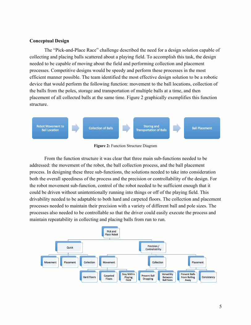
The “Pick-and-Place Race” challenge described the need for a design solution capable of collecting and placing balls scattered about a playing field. To accomplish this task, the design needed to be capable of moving about the field and performing collection and placement processes. Competitive designs would be speedy and perform these processes in the most efficient manner possible. The team identified the most effective design solution to be a robotic device that would perform the following function: movement to the ball locations, collection of the balls from the poles, storage and transportation of multiple balls at a time, and then placement of all collected balls at the same time. Figure 2 graphically exemplifies this function structure.
Figure 2: Function Structure Diagram
From the function structure it was clear that three main sub-functions needed to be
addressed: the movement of the robot, the ball collection process, and the ball placement process. In designing these three sub-functions, the solutions needed to take into consideration both the overall speediness of the process and the precision or controllability of the design. For the robot movement sub-function, control of the robot needed to be sufficient enough that it could be driven without unintentionally running into things or off of the playing field. This drivability needed to be adaptable to both hard and carpeted floors. The collection and placement processes needed to maintain their precision with a variety of different ball and pole sizes. The processes also needed to be controllable so that the driver could easily execute the process and maintain repeatability in collecting and placing balls from run to run.
5

Figure 3: Objective Tree Collection Method
Given the negative points incurred for balls knocked to the ground, the “Pick-and-Place” rules were interpreted to imply that knocking poles over should also be prevented. The design solutions generated for the collection method focused on removing balls from their poles as precisely as possible without knocking the pole to the ground. (This interpretation of the rules was clarified later on at a different stage of the project and did impact the final competition design. This final design is detailed later on. However, the conceptual design process presented in this section reflects an important part of our initial design and is therefore included).
The “variable scoop” concept (Figure 4) proposed an upwards rotating movement to lift the ball off the pole and minimize the risk of knocking the pole over. The scoop would feature a slot for pole positioning that would need to be smaller than the ball itself. To accommodate the different size ball and pole diameters, the scoop needed to have a variable size positioning slot. For the smaller balls and poles, the scoop would need to be positioned with the pole further inwards in the slot. This is to prevent the small balls from falling through the larger slot needed for the larger diameter poles. Once the pole is in position within the appropriate slot and the scoop is underneath the ball, the scoop can rotate upwards about a hinge and lift the ball up off of the pole. This concept works because the slot is smaller than the ball and the ball is lifted by the scoop as it rotates upwards.
Figure 4: Concept Sketch: Collection Method - Variable Size Scoop
A similar proposal changed the variable size scoop to a classical robotic claw concept
(Figure 5). The ability of the claw to open and close allowed for easy adaptability to the given pole/ball size being collected. Movement would be similar to the “variable scoop” concept in
6

that the ball would be lifted up and off the pole in a rotating motion. The claw would position beneath the ball and close around the pole, then rotate upwards and lift the ball off of the pole.
Figure 5: Concept Sketch: Collection Method - Variable Size Claw
For both the scoop and claw concepts, as the collector rotates upward the ball is collected
off of the stand. It then rolls out of the collector and into a collection box (Figure 6). This collection box is mounted on top of the robot platform and is used to transport the balls within the robot. The difficulty with both of these concepts is the need for the collector to be perfectly aligned with the pole. In the case of the variable size scoop, the center of the pole would need to be perfectly aligned with the center of the slot. If not, the scoop would knock over the pole and ball as it tried to position itself with the pole inside the slot. Similarly, the claw would need to be sufficiently aligned with the pole to prevent the claw from knocking the pole over as it closes.
Figure 6: Concept Sketch: Rotation and Collection Motions
Implementation of a sufficient alignment process presented the need for multiple controls
for the driver. That is, the driver would first have to perform an alignment process and then a collection process for every ball. There would also be the need for sensors to assist in the alignment process, such as lasers to sense the pole location and provide feedback to the driver.
7

To get away from this need for alignment, a collection arm “batting” concept was proposed (Figure 7). Similar to a bat hitting a ball off of a tee, this concept featured a rotating collection arm that would hit the ball off the pole and into the collection box. This method could be applied to all the ball and pole diameters since the driving alignment feature would be the pole height (which was constant). A drawback to this concept was the need for the robot to get very close to the pole and a lack of precision in the overall process.
Figure 7: Concept Sketch: Collection Method - Collection Arm
Placement Method
Precision and repeatability of the placement method was prioritized over the speed of the actual process. This precision and repeatability needed to be applicable to a variety of different ball sizes ranging from a ping pong ball to a basketball. The function of the sub-system was broken down as follows - removal of the collected balls from the collection box, stationary placement of the balls on the ground, and then robot movement away from the stationary balls. For all three concept designs discussed, removal of the balls from the collection box was solved by using a simple inclined plane. By inclining the bottom panel of the collection box, a ramp was created that would roll the balls out of the back end of the collection box. The challenge then was to address the stationary placement and robot movement away from the balls without disturbing them.
The “flap” concept proposed a hinged flap that would slow down the balls as they rolled out of the back of the collection box (Figure 8). The back panel of the collection box would move up and down to allow the balls to roll out of the box. The flap would be attached to the bottom of the panel using a hinge that allowed the flap to swing outwards. This hinge would have some resistance to rotation but still be free enough that balls could push through the flap. As the back panel is raised, the balls would roll down the ramp of the collection box and push open the flap. As the balls pushed through the flap they would slow down and have very little kinetic energy upon reaching the ground.
8

Figure 8: Concept Sketch: Placement Method - Flap
The inconsistency and lack of precision in the flap concept was a major drawback of this
proposal. Mainly, it could not be ensured that balls would sufficiently be slowed down upon exiting the flap opening and could therefore still roll away. There was also difficulty in sorting the balls as they exited the collection box. For example, the back panel could be raised only enough to allow small balls to pass through the flap but did nothing to prevent bigger balls from blocking the opening. These type of sorting challenges led to the generation of two more concepts that did not rely on the order in which the balls exited the collection box.
The concept labeled by the team as the “garage door” proposed vertical and horizontal movements to control the exiting of the balls from the collection box (Figure 9). In this concept, the rear portion of the collection box would be able to extend outwards and essentially create an extended box with the floor composing the bottom panel. At the start of the placement process, side panels would move horizontally outwards to extend the size of the collection box. The balls would roll down the ramp and onto the ground but still remain within the extended side and back panels. The back panel would then go up like a garage door and create an opening where the stationary balls could pass through. The box could then be compressed again (side panels moved in) and the balls would be left stationary in the placed area. The complexity of this proposal was a clear drawback in that both vertical and horizontal movement of the panels were required.
9

Figure 9: Concept Sketch: Placement Method - Garage Door
A similar concept was generated featuring a wire like guide that would rotate into position to prevent balls from rolling away and then rotate out of position once the balls were stationary (Figure 10). The guide would be light and create a large enough collection area that all of the collected balls could be placed at a single time. At the beginning of the placement process, the guide would rotate down into position creating an area behind the collection box that is enclosed by the guide. Balls would then roll out of the box and into the area enclosed by the guide. The guide would then rotate upwards and out of position, leaving the enclosed balls stationary in the collection area. A concern of this design was the size constraints of the device which may not have been large enough to accommodate the guide. The team was also unsure of the best material to manufacture the guide from, as it needed to be light enough to rotate but rigid enough to provide functionality.
Figure 10: Concept Sketch: Placement Method - Wire Guide
10
Movement / Control
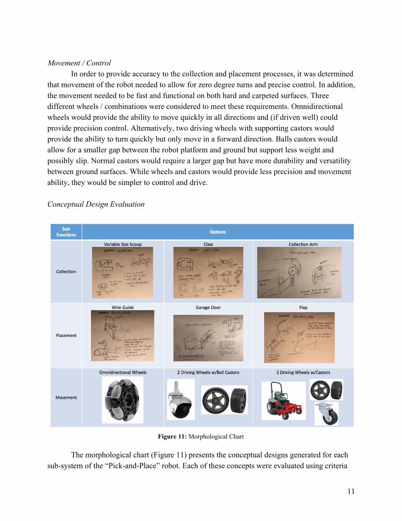
In order to provide accuracy to the collection and placement processes, it was determined that movement of the robot needed to allow for zero degree turns and precise control. In addition, the movement needed to be fast and functional on both hard and carpeted surfaces. Three different wheels / combinations were considered to meet these requirements. Omnidirectional wheels would provide the ability to move quickly in all directions and (if driven well) could provide precision control. Alternatively, two driving wheels with supporting castors would provide the ability to turn quickly but only move in a forward direction. Balls castors would allow for a smaller gap between the robot platform and ground but support less weight and possibly slip. Normal castors would require a larger gap but have more durability and versatility between ground surfaces. While wheels and castors would provide less precision and movement ability, they would be simpler to control and drive.
Conceptual Design Evaluation
Figure 11: Morphological Chart
The morphological chart (Figure 11) presents the conceptual designs generated for each
sub-system of the “Pick-and-Place” robot. Each of these concepts were evaluated using criteria
11

determined important to the robot design. The most heavily weighted of these criteria were taken directly from the main design objectives: speed, consistency, and functionality. That is, the ability of the sub-function to quickly and successfully carry out its function with precision and consistency. Ease of control was also determined an important criteria in that the ability of the driver to control the robot and perform the sub-functions would be essential in a successful run. Finally, ease of manufacture, cost, and simplicity were also taken into consideration.
The weighted design matrix below (Figure 12) shows the evaluation of each conceptual design against the above mentioned criteria. For the collection sub-function, the collection arm was determined the best design mainly due to the simplicity, cost, and speed criteria. The best placement method was determined to be the “garage door” concept. While both the “garage door” and “wire guide” concepts were similar, the former was evaluated as easier to control and higher consistency / functionality. The castors and wheels combination was chosen given the functionality on all types of ground surfaces.
Figure 12: Weighted design matrix
Embodiment Design
In order to move forward in the overall design of the robot, decisions had to be made from the morphological chart regarding the three functional subsystems: collection, placement, and movement/control. The batting arm was chosen as the method of collection, the garage door design was chosen as the method of placement, and two driven wheels with casters were chosen as the method of movement. The motors in the system would be controlled by an RC transmitter in conjunction with a receiver and microcontroller. Figure 13 shows the general layout of the robot using the three chosen subsystem designs.
12

Figure 13: Simplified layout of the three subsystems that make up the robot
The main method of connecting the components was L-shaped brackets, screws, and a combination of bolts, nuts, and lock washers. Collection Method
The method of collection that the team decided to move forward with was the utilization of a servo motor-driven batting arm to hit the balls from the stand into the collection area of the robot. The collection area would be the inside of the body of the robot; essentially a cube-like box with no top, a short wall on the side with the batting arm, and a sloped bottom surface.
Due to the atypical nature of its use, it was decided that the batting arm would be designed by the team in Solidworks and 3D printed in PLA or ABS plastic. The material was appropriate since the arm would not be subjected to a significant enough load or impact. Parameters to consider when designing the arm were the shape, size, and method of mounting to the servo motor and to the robot body. It was decided that the shape should be curved to approximately match the curvature of the balls. The arm had to be sized in a way such that it did not extend so far past the front of the robot that the overall dimensions were surpassed, and was tall enough that it could effectively hit the middle of either a pingpong ball or a basketball.
13

Figure 14: Collection Arm Assembly
It was decided that the inner volume of the collection area was a priority. The maximum
outer box dimensions were chosen to be 40 cm long by 40cm wide. This allowed for 5 cm on all sides for wheels, motors, and appendages while staying within the overall size restrictions. To maximize the inner volume of the box, the material for the walls needed to be as thin as possible while still maintaining structural integrity. Material options considered included wood, plastic, and metal sheeting. Factors considered in the selection of material were the available thicknesses of each type of material, cost, and how easily obtainable the material was. Wood was ruled out as an option because the sheets available locally were thicker than desired. Metal was ruled out as an option because the sheets that were within the project budget were too thin and flexible, but the sheets that were a desirable thickness and stiffness were too costly. As a result, the main building material for the surfaces of the robot was chosen to be plastic, which was cost-effective and available at several local vendors in a variety of thicknesses and densities. Placement Method
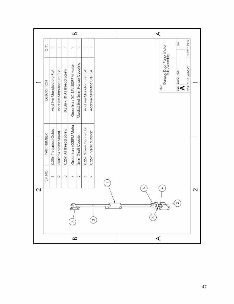
The method of placement was chosen to be the garage door, which consisted of two side panels that moved along a horizontal track and one back panel that moved along a vertical track. The horizontal and vertical motion would be driven by threaded rods rotated by the motors and threaded through blocks statically attached to the moving panels. Considered for this subsystem were the material and design of the moving panels, selection of the motors and threaded rods, and sliding support rails for the panels.
The material for the panels was chosen to be sheet plastic, the same as chosen for the main body of the robot. The main consideration in choosing the material was the weight and stiffness. As moving components, the panels needed to be stiff enough to not flex a significant amount. Plastic was also light enough to reduce the load on the sliding rails and threaded rod. The side panels were mostly rectangular with the exception of cutouts for the driven wheels mounted on the sides. The back panel needed to be just big enough to prevent basketballs from
14
falling out the back of the body. It was important for the back panel to be as small as possible to reduce its weight, which in turn reduced the amount of moment on the vertically-aligned threaded rod and motor.
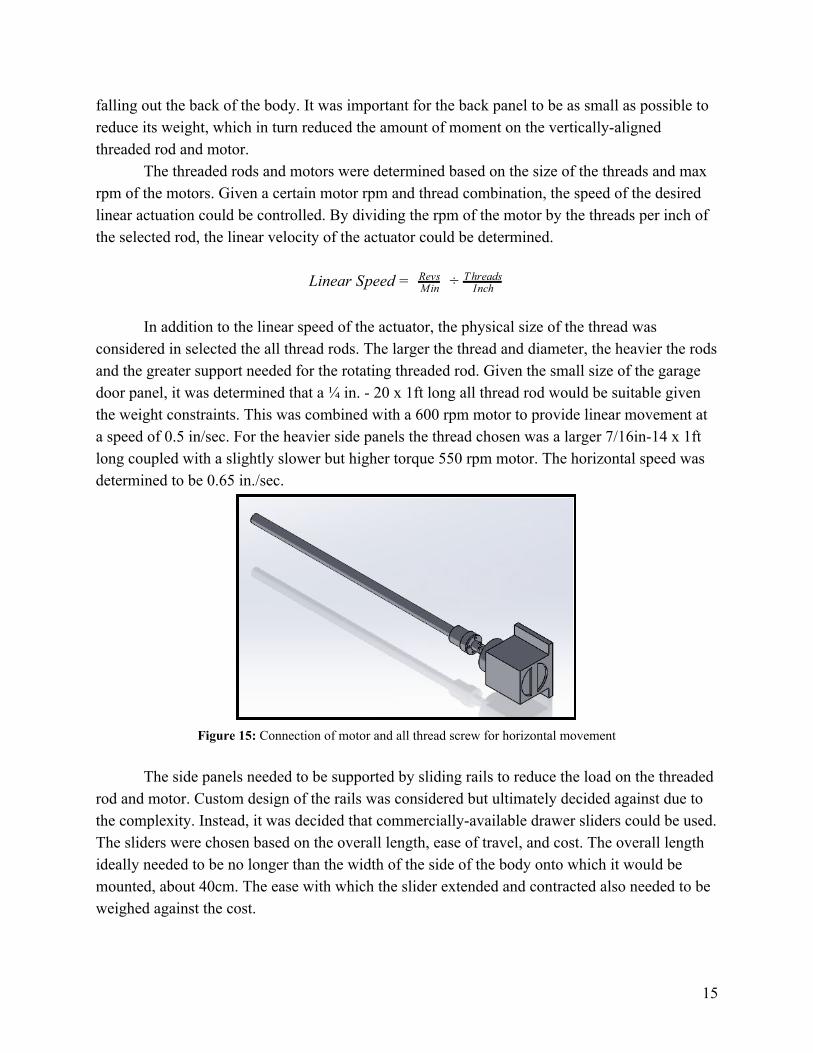
The threaded rods and motors were determined based on the size of the threads and max rpm of the motors. Given a certain motor rpm and thread combination, the speed of the desired linear actuation could be controlled. By dividing the rpm of the motor by the threads per inch of the selected rod, the linear velocity of the actuator could be determined.
inear Speed L = MinRevs ÷ Inch
T hreads
In addition to the linear speed of the actuator, the physical size of the thread was considered in selected the all thread rods. The larger the thread and diameter, the heavier the rods and the greater support needed for the rotating threaded rod. Given the small size of the garage door panel, it was determined that a ¼ in. - 20 x 1ft long all thread rod would be suitable given the weight constraints. This was combined with a 600 rpm motor to provide linear movement at a speed of 0.5 in/sec. For the heavier side panels the thread chosen was a larger 7/16in-14 x 1ft long coupled with a slightly slower but higher torque 550 rpm motor. The horizontal speed was determined to be 0.65 in./sec.
Figure 15: Connection of motor and all thread screw for horizontal movement
The side panels needed to be supported by sliding rails to reduce the load on the threaded
rod and motor. Custom design of the rails was considered but ultimately decided against due to the complexity. Instead, it was decided that commercially-available drawer sliders could be used. The sliders were chosen based on the overall length, ease of travel, and cost. The overall length ideally needed to be no longer than the width of the side of the body onto which it would be mounted, about 40cm. The ease with which the slider extended and contracted also needed to be weighed against the cost.
15

Movement / Control It was decided that the wheels of the robot would be purchased components rather than
designed and manufactured by the team. The material and dimensions were considered to select the wheels. The material was chosen to be hard rubber as it would give a good grip both on hard floor (hardwood, cement, etc) and low-pile carpet. The width of the main body of the robot was designed to be 40 cm in width and the wheels were to be mounted on the sides, so the wheels thickness needed to be 4cm or less to allow for 1cm of space between the wheels and body. The diameter of the wheels was chosen based on the desired height off the ground and the location of the motor mount. The desired height off the ground was about 1in. and the motor would be mounted such that the axis of rotation would be up to 1.5in. beyond that. Therefore the wheel diameter could be between 2-5in. (or 5.5-12.8cm). The caster wheels needed to be chosen to be as close to a 1in. height as possible to fit between the ground and the bottom of the body of the robot.
The Drive Motor Sizing Tool from the RobotShop website was used to determine the requirements for the drive motors. The tool allowed inputs for the mass of the robot, number of drive motors, wheel radius, robot velocity, maximum surface incline, supply voltage, maximum acceleration, maximum operation time, and percent efficiency. The mass of the robot was approximated using the Solidworks assembly model and the preliminary selection of materials and components, as well the masses of several balls to simulate the robots maximum mass during operation. Figure 16 shows the details of the approximation.
Figure 16: Calculation of approximate weight of robot for use in drive motor selection
16

The mass of the robot without wheels (13.57kg) was used as an input in the drive motor selection tool. Other inputs were 2 drive motors, 0.05m wheel radius, 0.5m/s robot velocity, 5° maximum incline, 12V supply voltage, 0.25m/s 2 acceleration, 10min operating time, and 65% efficiency. Based on these inputs, the tool suggested that the drive motors would need to have an angular velocity of at least 95.5rpm, a torque of at least 5.85kg-cm, at least 5.74W of power, and a maximum current of at least 0.478A. The tool also suggested that the motors be powered by a battery pack of at least 0.159Ah.
The team developed a design for the robot’s electronics that made use of a microcontroller to facilitate communication between the RC transmitter and the motors.
The early design had all four motors controlled by a single motor shield working with the microcontroller. The motor shield serves two purposes: first, it parses signals coming from the microcontroller to enable bidirectional variable-speed motion on the motors. Second, the shield provides an external power supply for the motors. The microcontroller, as well as the logic on the shield, run on 5V, but the motors necessarily are 12V, and will not run properly on 5V. Therefore, a battery pack using 4 AA rechargeable batteries in series was used to run the logic, while a 3 cell LiPo battery was used to run the motors. The LiPo battery has a nominal voltage of 11.1V, but the actual maximum voltage was 12.4V.
Following consultation with the team member who would be operating the robot during the competition, a control scheme was implemented that is similar to what is referred to in video game circles as ‘tank controls.’ Each of the wheel motors was tied to one of the control sticks with no mixing. While this scheme is somewhat more difficult to learn, it also enables much tighter turning, up to a zero turn radius. With the wheel motors controlled by the vertical motion of the control sticks, the motors controlling the door assembly were controlled by the horizontal motion of the control sticks.
Testing Analysis and Modification
Throughout the manufacture of the robot, testing was performed consistently to ensure proof of concepts and performance of the sub-functions. During this process it was clear early on that modifications would be necessary to the initial designs. These modifications were made to improve the performance aspects of speed, functionality, and consistency of the sub-functions. Collection Method
The initial test run of the arm assembly, which included the servomotor and the collection arm, had issues with its speed and range of motion. The arm moved too fast and jerkily and the positioning was unreliable. This was caused mainly by the servo being too small for the task as well as improper coding on the microcontroller. As a result, it was difficult to get the collection arm to operate consistently. The entire collection sub-function was slow and inconsistent between ball size as well as just being generally inconsistent between test runs.
17

Given that the initial testings revealed an entire sub-function to be unreliable and poor in performance, it was decided that the whole collection design should be re-considered. Around the same time that this occurred, new information was released concerning the specifics of the competition rules and penalties. It became clear that the poles could indeed be knocked over so long as balls were not knocked to the ground. Upon learning this information, the team completely scrapped the collection arm design and sought a new design method that could easily be implemented into the robot that had already been manufactured. This was necessary as the project was both low on money and only weeks from competition day.
Instead of the collection arm, the team decided upon a simple method of ramming the poles and dropping the balls into the collection box. This was a concept generated earlier by one of the team members but not considered given the original interpretation of the rules. Implementing this design simply involved removing the collection assembly from the current robot. Without the collection arm and servo on the front of the robot, there was only the front panel of the collection box which could be used to ram the poles. This new design was then tested and found to perform significantly faster than the previous method. However, there were still consistency issues with the design. If the robot was not moving fast enough when it hit the pole it would simply push the pole forward instead of knocking it over. Also, the smaller balls proved difficult in that they would hit the front panel as they fell off the pole stands instead of falling into the collection box.
To address these issues, the front panel of the collection box was lowered and an “attack bumper” was added to the front of the robot. Lowering the front panel helped prevent the balls from hitting the panel as they were knocked off the pole stands. Addition of the bumper was to ensure the pole would be knocked over in the intended way each time it was hit by the robot. This bumper was low to the ground and stuck out from the robot. The bumper would therefore hit the pole first and initiate a rotation of the pole in the backwards directions, tipping the ball into the collection box as it fell off.
Final tests of the robot before the competition proved that the modified collection method was fast and consistent. Even between the different ball sizes and weights the collection sub-function was reliable. The speed of the sub-function was only limited by the speed of the actual robot and ability to quickly maneuver around the course.
Placement Method
During manufacture it was clear that the initial design of the placement method was insufficient in considering the necessary supports and structure of the sub-function. Specifically, it was found that the panels were insufficiently supported for movement from the designed linear actuators. This was revealed during movement testing of the horizontal and vertical panels.
In the horizontal direction, the side panels were insufficiently supported to move in sync when driven on one side by the linear actuator. Given the flex in the system and lack of supports connecting the driven (right) and non-driven (left) panels, the whole movement occured in a
18

skewed fashion. The driven panel would move a significant distance before the non-driven panel would even begin to move. Reinforcement bars were added to the panels to help remove the flex in the thin acrylic panels. An aluminum crossbar was also added to connect the driven and non-driven panels. These reinforcements significantly improved the ability of the panels to move in sync.
Similarly, the vertical panel was also found to be insufficiently supported when driven by the vertical linear actuator. In this case, as the panel moved upwards gravity would pull the non-drive side downwards and cause the panel to be skewed. To correct this, a vertical support rail was implemented to guide the movement of the panel and prevent it from getting skewed. The all thread support was also reinforced to help lower the amount of torque put on the motor and screw sub-system. These modifications worked well to both prevent skewness and also increase the speed of movement due to reduction in torque and strain on the motor.
The final testing of the placement sub-function proved to be reliable. Although movement in both planes were not perfectly in sync, they were sufficient enough to consistently perform placement. The speed of the sub-function was limited by the driving speed of the motors which could have been improved. This was not deemed critical though given the scope of the competition. Movement and Electronics
Problems with the wiring emerged very early in assembly. The wires leading to the motor leads had to be connected to the motor shield’s screw terminals. The stripped ends of the stranded wires frayed easily and moved out of place, and the wire ends fell out of the terminals at the smallest jostling. After some research, a solution was found in using metal caps (ferrules) on the wire ends, which ensured a snug fit in the terminals that did not easily come loose.
Early testing demonstrated issues with the robot’s response time. Between moving the control sticks on the transmitter and the motors responding, there was a delay timed at approximately four seconds. Troubleshooting showed that the issue was in the program being used on the microcontroller. The first program was simple and inappropriate for the task at hand, resulting in the poor response time. Large swathes of the program were rewritten with a more complex structure that made use of Interrupts to run the program continuously. With this, the delay was fully eliminated, allowing smooth control of the robot.
Further problems with the hardware emerged late in the assembly process. After working for several weeks with no apparent problems, the motor shield broke. While connected to the battery the power light turned on, but there was no signal out to the motors on terminals M1 and M2. On the motor shield were two H-bridges, which are electronics components that allow for bidirectional motion on a motor. The H-bridge associated with terminals M1 and M2 was found to be severely overheated. Following some research, it was found that the total current draw of the motors on those terminals vastly exceeded the current rating for the motor shield, and it is
19
believed that the H-bridge was ‘burned out;’ the temperature induced by the motor operation exceeded what the materials on the H-bridge could handle and the component failed.
Several solutions to the issue of the motor shield’s current rating were considered by the team. It was initially proposed that the shield be replaced with another of the same type and attaching heat sinks to the chips to decrease the chance of the components overheating, but the concern with this was that not only was there no guarantee that the exact same thing wouldn’t happen again, but there was a good chance that it would happen again. Even if the robot were driven gently and kept from being overloaded, the problematic motors would still draw high current when starting from rest.
While less than ideal, the team switched to the dual motor shield design described in this report. The high draw of the motors which caused the failure of the first shield required a higher quality, more specialized motor shield with a higher current rating. To run the smaller motors, the first shield was replaced by an identical component; in addition, small heat sinks were placed on key components on both shields to provide an extra margin of safety.
Aside from the electrical difficulties, the movement of the robot performed well upon initial testing. The only issue that was identified was occasional tire slip on hard surfaces. To help with this, approximated 5 lbs of weights were added to the bottom of the frame to increase the grip of the wheels. In final testing, no slipping was observed.
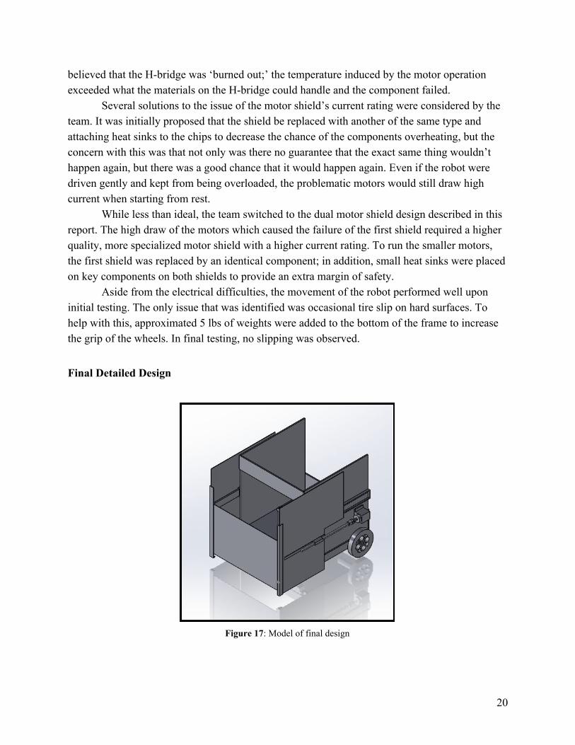
Final Detailed Design
Figure 17: Model of final design
20

Figure 18: Assembly Drawing of Pick and Place Robot (Full assembly drawing in Appendix B) Collection Method
The servo motor chosen to operate the collection arm was the MG92B mini servo, due to its high torque to size ratio and low price. Since the arm was going to be designed from scratch and 3D printed, the servo arm set that shipped with the motor provided a means of connection that could be designed around.
After encountering problems regarding the speed and reliability of using the servo controlled arm for collection, a different approach was taken. The original design was created under the belief that a penalty would be given for the knocking over of a stand. After a clarification proved otherwise, a collection method was put in place that took advantage of the ability to knock the poles over.
The new method involved tipping the balls into the body of the robot by hitting the bottom of the stands with a bumper cut out of remaining ¼in. plastic that extended a short distance off of the front panel. In order for this method to be successful, the front wall had to be lowered a distance that allowed for balls to fall in more easily, while still preventing larger sized balls to roll back out. This method proved to be more reliable, and magnitudes faster than the previous one.
The main body and container of the robot was a box created with 5 panels of ¼ in. black plastic sheeting in order to support the heaviest ball as it fell in. It was designed to be a box with an open top, along with modified front and back panels to allow for passage of balls. With this
21

collection method, the distance between the ground and the top of the front wall needed to be under 20 cm, the height of the stands, in order to be able to properly secure a ball. A short panel going along the top half of the box was used in the back, in order for the secured balls to roll out when placement was desired.
Placement Method
With an angled floor in the collection box and the aid of gravity, the balls were guided to the back of the robot. Since the balls needed to be secure inside of the robot until it was time for placement, a sliding panel was implemented. Richelieu brand drawer slides were chosen due to their stability, high load capacity, and ease of installation.
The horizontal movement of the panels was controlled with a DC motor, whose rotation was linearized with the use of a 7/16in. threaded rod. A mount for the rod was 3D printed and attached to the side sliding panel. This mount was tapped to allow for the spinning of the threaded rod to push or pull the panel away from the motor. After testing, it was determined the threaded rod vibrated too severely, interrupting smooth and reliable motion. In order to stabilize this, a second mount was added, only instead of also being tapped was drilled a few steps larger than our rod in order to act as a guide.
The vertical sliding panel was controlled in the same manner, only with a ¼in. rod and corresponding mounts. Since the motor was located close to the side panel, there were issues with the opposite side lagging behind or getting stuck and not fully opening. In order to combat that issue, a small track was added along with a support that prevented the side panels from bowing and kept the opposite side more in sync with the motor side.
22

Figure 19: Model of “garage door” placement method
Figure 20: Model of vertically moving back door assembly
Movement / Control
The aluminum platform structure formed the base of the robot and had the collection box directly mounted on top of it. The thickness of the frame was 1.5in. and housed the electronics and wires within. The driving wheels were directly mounted to the frame and the castor wheels were mounted on a crossbeam along the width of the frame.
Figure 21: Robot base frame
23

The Arduino Uno board was selected for the microcontroller due to its affordability and accessibility. As the Arduino IDE is open-source, there is a wealth of resources available on the Internet, resources which were used extensively to link the RC receiver to the Arduino and the Arduino to the motor shields.
The initial design had the Adafruit Motor Shield for Arduino driving all four motors on the robot. The Adafruit shield stacks directly on top of the Arduino Uno, which simplified powering the onboard logic and reduced the footprint. However, it was found during construction that the current drawn by the wheel motors was significantly higher than what the shield was rated for. The decision was made to use the Adafruit shield to run the motors for the door, which had maximum draw that was within the shield’s limits, and to use a separate shield to run the wheel motors. The shields were wired in parallel and powered with a single LiPo battery.
The shield used to run the wheel motors is Robot Power Scorpion Mini, which has a current rating of 12.5A, but only has two channels and thus can only run two motors simultaneously. Furthermore, an onboard voltage converter allowed the onboard logic to be powered by the LiPo battery, which kept the wiring from becoming even more complicated.
The transmitter used was a Spektrum DX7s controller borrowed from the university, linked to a new 6 channel receiver in case of damage. The first four channels on the receiver, associated with the control sticks on the transmitter, were connected to the Arduino through the analog pins A0, A1, A2, and A3. The Scorpion shield was connected to the Arduino using the servo connections on pins 9 and 10. The door motors were connected to the Adafruit shield using the terminals M1 and M3.
24

Figure 22: Wiring schematic of the microcontroller, motor shield, batteries, and motors
Manufacturing
Manufacture of the robot involved fabrication of material, joining of components, and additive manufacturing of parts. Fabrication included cutting, drilling, and tapping of HDPE, acrylic, and aluminum material. Fastening of parts were done using screws, nuts, washers, and bolts. The team used tools like band saws, drill presses, portable drills, taps, jigsaws, and files to perform the fabrication processes. Having reliable resources and tools at hand made using the HDPE, acrylic, and aluminum materials easy to work with and reliable. The additively manufactured parts were made using the University of Akron ME Department’s 3D printers. These were directly manufactured from the part models using PLA plastic. Having access to these printers made the additively manufactured (3D Printed) parts reliable and quick to make.
The first stage in the manufacturing process was to build a solidified base frame made of aluminum. The main functionality of the aluminum base (bar) was to make sure it was durable and could support the weight of the other components while maintaining good form and stability. The second phase was to build a collection box which would have a capacity to carry the different sized balls. This was made of HDPE plastic and joined together using aluminum L-brackets. The third phase was building the placement method which would support the ball movements during their placement. This was built using thinner acrylic sheet plastic and off the shelf drawer slides. The threaded guide for the linear actuator was additively manufactured from PLA and tapped using machine shop tools. The fourth step was to construct a bumper to collect as many balls as possible by hitting the poles directly and forcing the balls to fall into the collection box. The bumper was created using HDPE plastic and attached with L-brackets on the front of the robot.
For every design and manufacturing phase of any system there are some challenging obstacles that come along with the changing of dimensions, material selection, electronics, change of specifications, or size range of components. With that said, some of the obstacles faced included measurement of the carrying box, mobility of the wheels, and proper arrangement of electronic components during first trial testing. Lack of performance of the wheels occured due to angular misalignment of the drilled holes which made the wheels rotate at different speeds. The other challenge was soldering wires on motors with a lack of expertise in the area of soldering. The vertical movement was also somewhat of a challenge due to the design of the linear actuator. The panel was supported by a threaded screw on just one side of the panel and was therefore insufficiently supported. As the motor would move the panel linearly upward, the panel would be somewhat angled due to the tension and lack of support for the panel. The final manufactured robot is shown in the figures below.
25

Figure 23: Final Competition Robot
Figure 24: Placement Design of Final Robot
26

Figure 25: Collection in Progress
Cost Analysis
As the first University of Akron design team to participate in the ASME Student Design Competition, no funding was allocated to the project and needed to be raised during the course of the project. These efforts and proposals for funding consumed a large portion of the project in the early stages and included fundraisers, donations, and direct funding methods. The goal of the team from the onset was to complete the physical robot at a cost around $500 and keep total project costs under $1000. Robot Cost
From the detailed design process, the total cost of the robot totalled in at $618.02. This encompassed the cost for all components and material detailed in the design’s bill of materials. While slightly over the $500 goal, some of the components came at no cost to the project and were therefore incorporated into the design. It is believed that around $100 could be reduced from this cost if more inexpensive component alternatives were used. For example, a less expensive alternative transmitter could cut costs by around $75 alone. Figure 26 below details all components and materials needed for the designed “Pick-and-Place” robot.
This list is based on the bill of materials and represents the material cost alone to manufacture the robot. The time to manufacture the robot should also be taken into consideration for a full cost analysis. Total build time encompassed 2 months with approximately 50 hours of work put into the build per week (10 hours per person). The leads to an estimated labor cost of around 500 hours.
27

Figure 26: Detailed Cost Breakdown of Robot
Funding
Multiple efforts were undertaken to raise the funding necessary to complete this project. The first proposal for funding was prepared for the University of Akron’s Engineering Dean Office during the annual design team funding proposals. Unfortunately, due to the senior design nature of the project, funding from the board was denied. The next proposal was prepared for the Chair of the UA Department of Mechanical Engineering, Dr. Sergio Felicelli, who agreed to support the design team at a limited capacity of $550.
To supplement the funding received from the department, a Chipotle fundraiser was organized and held. This resulted in an additional $90 of funding. In addition to direct monetary funding, the team reached out to multiple companies for support and material donations. Such requests were made to Alro Steel for plastic and aluminum, Aero Tech Hobbies for electronic components, and Lowe’s for general material needs. Out of these efforts, over $150 worth of donated material was received by Lowe’s throughout the course of the project. Alro Steel also offered the team discounted prices on their material.
28

Figure 27: Summary of funding received
Total Project Expenses
In addition to the material expenses for the manufacture of the robot, the overall project expenses included that of travel, accomodation, registration, and other minor costs. Registration fees alone for all five team members totaled $500 with $200 more in travel and accommodation. Some components were attained at zero cost to the budget through the utilization of UA resources. This included the use of LiPo batteries and a DX7s transmitter from Cliff Bailey in the ME Department, utilization of the ME Department’s 3D printers, and scrap material/fasteners from the Machine Shop. Taking into consideration the added administration costs and removing the costs of donated/supplied materials, the total project expenses totaled at $940. The breakdown of these costs are presented in Figure 28 below. The difference in received funding and total expenses was absorbed by the team members.
Figure 28: Cost Breakdown of the Project
29

ASME SDC Competition
The student design competition took place as part of ASME E-Fest North, which was held at Michigan State University in East Lansing, MI from April 5-7, 2019. The team travelled to the competition in the morning on Friday, April 5th. The team checked in at the Breslin Student Events Center before transporting the robot and supplies to the competition site.
Over 50 teams were registered to compete. On the first day, qualifying rounds took place. The objective of these rounds was for the judges to check that the robots met all requirements and to rank the teams by points. After the judge checked and cleared the robot, the team was able to play one round according to the rules of play outlined previously. The rounds lasted either five minutes or until there were no longer any balls in play. Rounds could also end if the robot was determined to not be functioning. After all registered teams played their qualifying round, the teams were ranked based on number of points.
On the second day of the competition, April 6th, more qualifying rounds took place. However, each round of play now consisted of two teams competing against each other for points. Match-ups were determined by rank from the day before with the highest scoring team facing the lowest scoring team, the second-highest scoring team facing the second-lowest scoring team, and so on. In these rounds, the goal was to obtain as many points as possible. From these rounds, only the 32 teams with the highest scores would advance to the tournament bracket. After these rounds concluded, the 32 highest scoring teams were announced and the first rounds of the tournament bracket began. The bracket was seeded similarly to before, with the highest scoring team facing the lowest scoring team and so on. The tournament was single elimination, and therefore the goal of these rounds was to score more points than the opposing team.
On the third day of the competition, April 7th, the remaining rounds of the tournament took place. The winners of the semifinal rounds competed for first place while the losers of the semifinal rounds competed for third place. The student design competition ended with the conclusion the the final round. The two teams in the final round were invited to an international competition to be held at a later date along with the final round participants from the other ASME E-Fests (West, Asia Pacific, and South America). In addition, cash prizes were awarded to the teams in first, second, and third place, as well as to their schools.
ASME E-Fest North hosted other events besides the student design competition. The Human Powered Vehicle competition also took place over during the three days of the E-Fest. Company sponsors for the E-Fest set up tables to network with the attendees and ran additional talks, interactive events, and competitions for attendees to participate in at will. Volunteers from Michigan State University led tours through the lab facilities available on campus. A social space was set up with games and lounging to encourage the attendees to mingle. Breakfast was provided every morning, as well as a keynote speaker lunch on Saturday and an awards
30

ceremony lunch on Sunday. The E-Fest served not only as a location for the student design competition, but also as an opportunity for education, networking, and professional growth.
Results
Discussion Overall, the robot was able to successfully compete while meeting the competition
requirements. The final iteration was able to consistently and quickly gather and place balls, where earlier versions successes were dependent on small, uncontrollable factors such as how the balls lined up within the collection box or the exact angle and speed the robot hit the stand with. During competition, the robot did not lose a single point due to a ball drop. After a refinement in placement technique after the first day, we were able to reliably place every ball as well. The original technique involved extending the panels away from the robot, raising the gate, and driving away, leaving the balls outside of the robots extended perimeter. The adjustment was made to the driving away part, which caused issues due to the difficulty in driving straight away without bumping into the balls, possibly causing them to exit the starting area. The new plan was to keep the robot stationary and just retract the doors, as they would come in straight without having to keep the left and right wheel motors at the same exact speed.
ASME SDC Competition
The competition fielded over 50 teams, featuring universities from as far as Taiwan. There were two qualifying rounds to determine eventual bracket seeds. In the qualifying rounds the robot finished in 10th and 9th place respectively. The robot finally faced defeat in the best of 16 round of the single elimination bracket.
Project
At the (2019) University of Akron’s annual senior design day, the project as a whole took second place in the Health, Environment, Robotic and Manufacturing System Design category. This is from amongst the entire UA 2019 ME graduating class and is judged by the UA Mechanical Engineering advisory council. This award recognized the quality of the project, hardwork and enthusiasm of the team, project representation of real world difficulties, and overall project accomplishment.
Conclusion
Competition and Design The “Pick-and-Place” robot designed for the 2019 ASME Student Design Competition
performed well and placed reasonably within the E-Fest North competition. The robot design solution that was brought to competition performed as expected and successfully carried out the functions required of the design challenge. In the early rounds of competition, the robot did
31

especially well in performing each of its sub functions in a quick and efficient manner. The modifications taken to re-support the placement method panels as well as align the vertical “garage door” panel were well worth the efforts and resulted in a consistent execution of the placement sub-function. Selection of the rubber wheels, plastic castors, and driving motors proved to be an excellent control method and gripped the hard plastic floors well - something other competitors struggled with.
While the robot performed as expected, there were some insufficiencies apparent during the competition. The largest of this being speed. The robot executed the sub-functions well and with consistency, however it did so with a slower speed than some of the competing robots. Similarly, the control of the robot with only two driving wheels made turns slower and required slightly more time to move the robot throughout the playing field. While this was fine in the standalone speed trials and even the earlier rounds it proved inefficient in the later rounds. This is in part due to the need to cover large portions of the playing field quickly as teams in head to head competition would strategically collect balls to “cut off” the other player. This occurred in part during the team’s final knockout round when the opposing team made a diagonal line down the playing field to limit the amount of balls reachable. In such instance, speed became the limiting factor in being able to maneuver around the competitor robot and collect more balls.
In reflection of these competition results, the largest change that the team would make to the robot would be an increase in speed. To do this, lower torque but higher rpm motors could have been chosen to increase the overall speed of movement. This would need to be accompanied by a lighter robot which could be achieved by using less hardware and thinner plastics. While the team focused on building a strong solid frame and foundation for the robot, it was found that the design was more excessive than was necessary given the light impact forces experienced by the device. By focusing less on this the weight of the robot could definitely be decreased.
In terms of design, the team was satisfied with the level of consistency of the robot to execute each of the needed sub-functions. However, it is noted that the initial design of the robot had drawbacks and faults that were discovered throughout the manufacturing phase. Last minute changes such as additional support bars and alignment devices were added to the device to achieve functionality. This was in large part due to the linear actuators that moved the panels. In retrospect, the team would recommend using hydraulics for faster, more accurate, and more consistent movement. Placing actuators on both sides of the moving panels to provide greater support would also be recommended.
The unadjusted billed cost of the robot (before taking in donated materials) was above the $500 goal of the team. This is in part due to some of the more expensive components that were used in the final design (as discussed previously). However it is felt that costs as a whole could have been reduced with smarter material selections. Thinner HDPE plastics could have been used to construct the main collection box as it was found that the extra thickness of the 0.5 in. plastic was unnecessary. The chosen drawer slides were also unnecessary and actually hindered
32

the design in some aspects due to extra components and unneeded features. Cheaper drawer slides of less complexity would have been a better design decision. In hindsight, cheaper smaller wheels and lower torque high rpm driving motors could also have been chosen. Project
The project as whole provided each member of the team the ability to utilize engineering and technical design skills. This was especially felt during the conceptual design and manufacture stages. The multiple difficulties that arose during manufacture and subsequent testing of the robot challenged the team in a real world manner. New technical design solutions were made quickly and efficiently to continue the project and address issues with the original design. Just like in industry, situations arose where parts of the design needed to be scrapped and redesigned while at other times the design was modified in order to salvage existing material and plans. Done under a strict competition day deadline, the team felt this experiential process was instructive and representative of what can be experienced as a professional engineer. This is in addition to critical soft skills and administrative lessons that were learned. In summary, the team felt this project was successful from both a design and engineering standpoint as well as a learning experience meant to broaden our experiences and abilities as successful engineers.
33

Reflections
For myself personally, this project has challenged me not just as an engineer but also as a leader, manager, creative problem solver, and effective team member. As the founder and leader of this design team, the project has particularly been a learning tool for me to develop critical leadership skills as a manager of the budget, delegator of tasks, keeper of the schedule, and overall leader in the design and manufacture of the robot. As an engineer, the ability to bring a conceptual design to fruition as both the engineer and manufacturer was an incredibly satisfying and educational process. The manufacturing process in itself was highly valuable in learning and understanding the machining and fabrication tools and methods available to an engineer. It also helped me to understand the need for detail and thoughtfulness of a design to be both functional and manufacturable. As I complete my undergraduate degree, I believe participation in this hands-on engineering challenge complements well the past 5 years of my technical education. In beginning my professional engineering career, it has given me a springboard to develop as a better leader and teammate.
~ Riniah Foor
This project has taught me firsthand what is needed to take a project from ideation to completion. I started knowing next to nothing about robots, let alone designing or building them. I can now proudly say that I have been part of a hard-working team that not only built a robot that functioned, but one that functioned exceptionally. If I could do it again, I would have contributed more effort earlier on in the project. We did not stick to our initial schedule and therefore spent a lot of time manufacturing in the few weeks before our competition. However, we managed to complete our project just in time and I’m proud of our team for what we accomplished, both at the competition and in our education.
~ Megan Schmit
At the beginning of the project, I had virtually no knowledge on where to begin on building a robot, and honestly wasn’t sure how well it would turn out. After many months of our group applying ourselves by researching, developing, and manufacturing a robot I find myself looking forward to the next challenge. While my classes gave me building blocks of knowledge and theory, this design project gave me the confidence to build further upon those and actualize the engineering process. I am glad to have partnered up with a great group who managed to undertake what would have seemed an impossible challenge to me a year ago and be able to rise to it the way we did.
~ Aaron Urban
34

As we were writing the project proposal I said that I did not see how we would be making use of our engineering coursework during the project. I still maintain this as true. Significantly more important was how we were taught to think and solve problems, pulling together information to create something new. Consider also how we were taught to make use of resources both in and out of the engineering profession, and the work we have done learning to communicate. I personally needed to make use of online forums to get the electronics working, and being able to clearly and concisely convey my purpose, problem, and attempted solutions was essential. And now that the project is more or less done and competition is over, I find myself thinking about something the machine shop manager told us about these types of design projects, how he wishes students had a chance to go back and revise their work, and I wholly agree. As we were in crunch time, I found myself wishing I could make improvements to the design, but just did not have the time and resources to do so. The experience as a whole has been enlightening in a way I had never before considered, and despite the difficulties, it has been enjoyable to work on. I am certain I will look back on this project for years to come.
~ Jeannetta Davidsaver
The idea of designing or manufacturing a product always seems simple and straightforward not until the production or manufacturing process has started. Meanwhile, looking back on the journey of been a student and what the engineering department has implanted into educating students not only to be excellent engineers, but the ideology of starting something from scratch to something that is moveable is above and beyond; and that tells more about The University of Akron Engineering department goal of educating to a higher level. The wonderfulness of coming from theoretical studies to practical building of something as intense as a robot is so unrealistic and 100 percent a success as a student. The ideology of competing with 50 schools and coming out in the top 10 is something that gives hope and encouragement to keep doing well as a student. Despite the challenges Team Foor did it and thank to all for the effort and dedication
~ Daniel Mugongo
35

Appendix A: 2019 ASME SDC Design Statement
36

37

38

39

Appendix B: Final Drawings
40

41

42

43

44

45
46
47

48

49

50

51

Appendix C: Model Photos
RHS View
LHS View - Fully Closed Position
52

Full Extension Out with Back Panel Down
Full Extension Out with Back Panel Up
53

Appendix D: Programming Code for Arduino
#include <Wire.h> #include <Adafruit_MotorShield.h> #include <Servo.h> #include <EnableInterrupt.h> Adafruit_MotorShield AFMS = Adafruit_MotorShield(); Adafruit_DCMotor *Motor3 = AFMS.getMotor(1); //slide out Adafruit_DCMotor *Motor4 = AFMS.getMotor(3); //garage door Servo LeftWheel; //motor 1 Servo RightWheel; //motor 2 int ch1; int ch2; int ch3; int ch4; #define SERIAL_PORT_SPEED 57600 #define RC_NUM_CHANNELS 4 #define RC_CH1 0 #define RC_CH2 1 #define RC_CH3 2 #define RC_CH4 3 #define RC_CH1_INPUT A0 #define RC_CH2_INPUT A1 #define RC_CH3_INPUT A2 #define RC_CH4_INPUT A3 uint16_t rc_values[RC_NUM_CHANNELS]; uint32_t rc_start[RC_NUM_CHANNELS]; volatile uint16_t rc_shared[RC_NUM_CHANNELS]; void rc_read_values() { noInterrupts(); memcpy(rc_values, (const void *)rc_shared, sizeof(rc_shared)); interrupts(); } void calc_input(uint8_t channel, uint8_t input_pin) { if (digitalRead(input_pin) == HIGH) { rc_start[channel] = micros(); } else { uint16_t rc_compare = (uint16_t)(micros() - rc_start[channel]); rc_shared[channel] = rc_compare;
54

} } void calc_ch1() { calc_input(RC_CH1, RC_CH1_INPUT); } void calc_ch2() { calc_input(RC_CH2, RC_CH2_INPUT); } void calc_ch3() { calc_input(RC_CH3, RC_CH3_INPUT); } void calc_ch4() { calc_input(RC_CH4, RC_CH4_INPUT); } void setup() { Serial.begin(SERIAL_PORT_SPEED); AFMS.begin(); pinMode(RC_CH1_INPUT, INPUT); pinMode(RC_CH2_INPUT, INPUT); pinMode(RC_CH3_INPUT, INPUT); pinMode(RC_CH4_INPUT, INPUT); enableInterrupt(RC_CH1_INPUT, calc_ch1, CHANGE); enableInterrupt(RC_CH2_INPUT, calc_ch2, CHANGE); enableInterrupt(RC_CH3_INPUT, calc_ch3, CHANGE); enableInterrupt(RC_CH4_INPUT, calc_ch4, CHANGE); // set pinMode for servo controls LeftWheel.attach(9); RightWheel.attach(10); } void loop() { // use MotorN->setSpeed(num 0-255) to set the SPEED. // use MotorN->run(FORWARD, BACKWARD, or RELEASE) to set direction // ie left toggle, from all the way back to all the way forward // is mapped to the range of values -255 to 255, set as int ch1 // if ch1 < 0, run(BACKWARD) // if ch1 > 0, run(FORWARD) // setSpeed = abs(ch1) // and etc. rc_read_values(); Serial.print("CH1:"); Serial.print(rc_values[RC_CH1]); Serial.print("\t"); Serial.print("CH2:"); Serial.print(rc_values[RC_CH2]); Serial.print("\t"); Serial.print("CH3:"); Serial.print(rc_values[RC_CH3]); Serial.print("\t"); Serial.print("CH4:"); Serial.println(rc_values[RC_CH4]); ch1 = rc_values[RC_CH1]; LeftWheel.writeMicroseconds(ch1); ch2 = rc_values[RC_CH2]; RightWheel.writeMicroseconds(ch2); ch3 = map(rc_values[RC_CH3], 1000, 2000, -255, 255);
55

if (ch3 < 0) { Motor3->run(BACKWARD); Motor3->setSpeed(abs(ch3)); } else { Motor3->run(FORWARD); Motor3->setSpeed(ch3); } ch4 = map(rc_values[RC_CH4], 1000, 2000, -255, 255); if (ch4 < 0) { Motor4->run(BACKWARD); Motor4->setSpeed(abs(ch4)); } else { Motor4->run(FORWARD); Motor4->setSpeed(ch4); } }
56

Appendix E: Competition Photos
Full Team Photo - Left to Right: Megan Schmit, Daniel Mugongo, Riniah Foor, Aaron
Urban, and Jeannetta Davidsaver
Head to Head Run
57

Placement in Process
Balls Placed
58