
Physics 243A-Surface Physics: Spectroscopy Problem Set 1
29
~ .~.~'.,..,.",--;--:~-- .\ - Physics 243A-Surface Physics: Spectroscopy Problem Set 1 [1.1] If we wish to produce a thin-film magnetic storage device with 100 Gbits/sq.in., each bit is to be 5 times as big in one dimension as the other, the total amount of open area between bits is to be the same as the total area occupied by the bits, and the film thickness of the medium storing the information is to be 10 nm, how many atoms are involved in each bit? Assume for simplicity that the film is pure Co, with a density of 9.0 x 10 22 atoms/cm 3 . [1.2] (a) Begin with the Maxwell-Boltzmann distribution for molecular velocities in an ideal gas as expressed in x,y,z coordinates, and derive by integration the formula for the rate at which molecules strike a flat surface of unit area perpendicular to one of the axes. From this, determine the time necessary to form a monolayer of gas on a surface, assuming a general sticking probability of P S. Note that this is the same derivation that can be found in many physical chemistry texts to predict the rate at which a gas leaks out through an orifice. (b) Now make the assumption that only the bare surface area remaining on the surface after a given exposure time is active for a particular gas adsorption, and that P S = unity on the bare area, but zero elsewhere. Derive the general form of P S as a function of time for this case. (c) If a surface is exposed to 10 -9 torr of CO at ambient temperature, how long will it take to form the first monolayer: (i) If P s = unity? (ii) If P s follows the relationship of part (b)? [1.3] (a) What would be the minimum energy required to take a cube of Pt metal 1.0 cm on a side at room temperature and disperse it into tiny cubic "nanoparticles" of 10 -6 cm on a side? Assume that this is done in a perfect ultrahigh vacuum environment, with the surfaces in equilibrium with the very low vapor pressure of Pt, and make use of the argument in Zangwill, p. 12, but with a key equation corrected by dividing by 2 to . (b) Estimate the fraction of the atoms that are on the surface of the 1 cm cube. Of the 10 -6 cm cube. Assume that the density of Pt atoms is 6.62 x 10 22 cm-3. [1.4] (a) Use the tables of bulk cohesive energies and densities in a lecture slide to estimate the surface tensions of the elements from Ar to Kr,using the method described in Zangwill and lecture) in which a certain fraction of bonds are broken in forming a surface (note the key factor of two relative to the equation presented in Zangwill). Begin by using the density of each element to estimate the average no. of atoms per unit area of surface (N s ) for it. (b) Compare the values so derived with those for liquid surface tensions as shown in lecture or given in Zangwill by plotting them on the same figure. Discuss any systematic discrepancies. [1.5] For background, read Section 4.2.5 in Ibach and make use of Eq. 4.39. (a) Liquid water has a surface tension of 72 erg/cm 2 in air and a contact angle when placed on a clean glass surface of 150°. What does this tell you about the relative values of the surface tensions for the water-glass surface and the glass-air surface? (b) Now assume that a surfactant (e.g. a detergent) has been added to the water before the drop is placed on the surface, and that this lowers the water-air surface tension to 36 erg/cm 2 . Also assume that the surfactant molecules are concentrated at the water-air interface, and so do not alter the water- glass surface tension. What can you now say about the contact angle between water+surfactant and glass? [1.6]
-
Upload
khangminh22 -
Category
Documents
-
view
1 -
download
0
Transcript of Physics 243A-Surface Physics: Spectroscopy Problem Set 1

.~ ~ .~.~'.,..,.",--;--:~--
.\ -
Physics 243A-Surface Physics: Spectroscopy Problem Set 1
[1.1] If we wish to produce a thin-film magnetic storage device with 100 Gbits/sq.in., each bit is to be 5
times as big in one dimension as the other, the total amount of open area between bits is to be the
same as the total area occupied by the bits, and the film thickness of the medium storing the
information is to be 10 nm, how many atoms are involved in each bit? Assume for simplicity that the
film is pure Co, with a density of 9.0 x 10²²
atoms/cm3.
[1.2] (a) Begin with the Maxwell-Boltzmann distribution for molecular velocities in an ideal gas as expressed in x,y,z coordinates, and derive by integration the formula for the rate at which molecules strike a flat surface of unit area perpendicular to one of the axes. From this, determine the time necessary to form a monolayer of gas on a surface, assuming a general sticking probability of PS. Note that this is the same derivation that can be found in many physical chemistry texts to predict the rate at which a gas leaks out through an orifice. (b) Now make the assumption that only the bare surface area remaining on the surface after a given exposure time is active for a particular gas adsorption, and that PS = unity on the bare area, but zero elsewhere. Derive the general form of PS as a function of time for this case. (c) If a surface is exposed to 10
-9 torr of CO at ambient temperature, how long will it take to form the
first monolayer: (i) If Ps = unity? (ii) If Ps follows the relationship of part (b)? [1.3] (a) What would be the minimum energy required to take a cube of Pt metal 1.0 cm on a side at room temperature and disperse it into tiny cubic "nanoparticles" of 10
-6 cm on a side? Assume
that this is done in a perfect ultrahigh vacuum environment, with the surfaces in equilibrium with the very low vapor pressure of Pt, and make use of the argument in Zangwill, p. 12, but with a key equation
corrected by dividing by 2 to . (b) Estimate the fraction of the atoms that are on the surface of the 1 cm cube. Of the 10
-6 cm cube.
Assume that the density of Pt atoms is 6.62 x 10²²
cm-3. [1.4] (a) Use the tables of bulk cohesive energies and densities in a lecture slide to estimate the surface tensions of the elements from Ar to Kr,using the method described in Zangwill and lecture) in which a certain fraction of bonds are broken in forming a surface (note the key factor of two relative to the equation presented in Zangwill). Begin by using the density of each element to estimate the average no. of atoms per unit area of surface (Ns) for it.
(b) Compare the values so derived with those for liquid surface tensions as shown in lecture or given in Zangwill by plotting them on the same figure. Discuss any systematic discrepancies.
[1.5] For background, read Section 4.2.5 in Ibach and make use of Eq. 4.39. (a) Liquid water has a surface tension of 72 erg/cm
2 in air and a contact angle when placed on a clean
glass surface of 150°. What does this tell you about the relative values of the surface tensions for the water-glass surface and the glass-air surface?
(b) Now assume that a surfactant (e.g. a detergent) has been added to the water before the drop is placed on the surface, and that this lowers the water-air surface tension to 36 erg/cm
2. Also assume
that the surfactant molecules are concentrated at the water-air interface, and so do not alter the water-glass surface tension. What can you now say about the contact angle between water+surfactant and glass?
[1.6]

For background, see Zangwill, pp. 85-86 on alloy thermodynamics. Consider the surface of an alloy of the noble metals Cu and Ag whose bulk composition is 90% Cu and 10% Ag in a perfect vacuum with no residual gas reactants. What would be your qualitative expectation for the surface composition of this alloy if it is allowed to reach equilibrium?
[1.7]
For background, see Woodruff and Delchar, Section 2.2.
Consider a simple surface with a square lattice (e.g., as Ni(001)) show that there are a well-defined set of possible overlayer structures which can be written in Wood notation as:
(2 x 2)R45º
(5 x 5)R(tan-1
(1/2) = 26.6º)
(10 x 10)R(tan-1
(1/3) = 18.4º)
Etc.
(a) On the following sheet, with represents the substrate square lattice, sketch the unit cells of these three overlayers, and add the fourth member of the series.
(b) What will be the coverage in monolayers (ML) relative to the substrate if a single adsorbate atom goes into each corner of the unit cells above?
(c) Consider now Ni(001)(2 x 2)R45º-O, and use the simple “2D diffraction grating” method outlined in lecture to calculate the polar and azimuthal angles of the innermost thirteen LEED spots around the specular beam that would result if a beam of electrons at 150 eV is incident normal to the surface. Indicate which spots would be there for the clean surface, and which spots would be added when the O is adsorbed. Note that some spots arise from both the clean surface and the adsorbate overlayer.
[1.8]
For background, see Zangwill pp. 49-52, and more detailed discussion in excerpts from Desjonqueres and Spanjaard downloadable from course website, pages 571-578.
The current in an STM experiment can be approximately calculated from the simple proportionality relation
I e-2L
,
with L the distance between tip and surface and the usual quantity in barrier tunneling problems.
The potential barrier inside can be taken to be the work function of the surface, and we will take it to be 4.0 eV.
If the tip is brought to within 5 Å of the surface, with what precision in % would the tunneling current have to be measured to reliably detect a change in surface height of 0.1 Å? Note that the precision will have to be about 10x better than the effect you want to see to be able to measure it accurately.

Problem 1.7: Name_______________________________
Physics 243A-Surface Physics of Materials Problem Set 2
[2.1] For background, see excerpts from Dejonqueres and Spanjaard, downloadable from course website, pages 7-13.
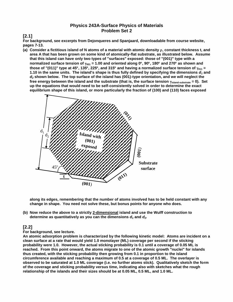
(a) Consider a fictitious island of N atoms of a material with atomic density , constant thickness t, and area A that has been grown on some kind of atomically-flat substrate, as illustrated below. Assume that this island can have only two types of "surfaces" exposed: those of "(001)" type with a
normalized surface tension of 001 = 1.00 and oriented along 0, 90, 180 and 270 as shown and
those of "(011)" type at 45, 135, 225, and 315 and having a normalized surface tension of 011 = 1.10 in the same units. The island's shape is thus fully defined by specifying the dimensions d1 and d2 shown below. The top surface of the island has (001)-type orientation, and we will neglect the
free energy between the island and the substrate (that is, the surface tension island-substrate = 0). Set up the equations that would need to be self-consistently solved in order to determine the exact equilibrium shape of this island, or more particularly the fraction of (100) and (110) faces exposed
along its edges, remembering that the number of atoms involved has to be held constant with any change in shape. You need not solve these, but bonus points for anyone who does.
(b) Now reduce the above to a strictly 2-dimensional island and use the Wulff construction to determine as quantitatively as you can the dimensions d1 and d2.
[2.2] For background, see lecture. An atomic adsorption problem is characterized by the following kinetic model: Atoms are incident on a clean surface at a rate that would yield 1.0 monolayer (ML) coverage per second if the sticking probability were 1.0. However, the actual sticking probability is 0.1 until a coverage of 0.05 ML is reached. From this point onward, the atoms migrate to one of the atomic growth "nuclei" for islands thus created, with the sticking probability then growing from 0.1 in proportion to the island circumference available and reaching a maximum of 0.5 at a coverage of 0.5 ML. The overlayer is observed to be saturated at 1.0 ML coverage (i.e. no further atoms stick). Qualitatively sketch the form of the coverage and sticking probability versus time, indicating also with sketches what the rough relationship of the islands and their sizes should be at 0.05 ML, 0.5 ML, and 1.0 ML.
(011)
(001)
Island with (001)
exposed
t
Substrate
surface
d1d2
45
(001
)
(011)

[2.3] For background, see excerpts from Dejonqueres and Spanjaard downloadable from course website, pages 411-416. The adsorption of molecular nitrogen on the (110) surface of Ni has been studied with various techniques as a function of temperature and pressure. A stable overlayer structure is found to form at a coverage of 1/2 monolayer. In one such experiment, the N 1s core photoelectron intensity was monitored as a function of temperature and at various constant pressures for this system, with the results of these experiments attached. The N 1s intensity can here be assumed to be proportional to the no. of N atoms present on the surface.
(a) Determine the dependence of the isostearic heat of adsorption on coverage. Is this a chemisorption or a physisorption process; explain your answer. (b) Do you see any evidence in your results of the point at which the stable overlayer is formed?
[2.4] For background, see pp. 206-298 in Zangwill, and excerpts from Dejonqueres and Spanjaard, downloadable from course website, pages 417-419. On p. 207, Zangwill asserts that "the isotherms measured for carbon monoxide adsorbed at low coverage onto a single crystal Pd(111) surface follow the Langmuir isotherm at high temperature (Fig. 9.2)". Show this quantitatively for several coverages and temperatures, and thus indicate the region of Fig. 9.2 over which the adsorption kinetics is in fact Langmuir in character. A hint here is to rearrange the fundamental Langmuir equation so that it yields a linear relationship between 1/(coverage) and 1/(pressure), and then see which portions of the data fit this variation.
[2.5] For background, see lecture and Sections I and II of Fadley, “Basic Concepts of XPS” Consider a sample of arsenic (As), which has a free-atom electronic configuration of 1s
2…4s
24p
3, that
is exposed to incident soft x-rays of 2,000 eV energy. Use the X-Ray Data Booklet handed out in class, in particular Table 1-1: electron binding energies, Fig. 1-1: x-ray emission line nomenclature, Table 1-2: x-ray emission energies, Fig. 1-3: energies of most intense Auger peaks, Table 5.2, which includes electron configurations and other information, and the figure on the next page showing photoelectron and Auger spectra for As (from J. Chem. Phys. 64, 1210 (1976)) to answer the following.
(a) Are all of the electron binding energies of As present in the table of experimental values in
Table 1-1? If not, explain why some might be routinely left off such tabulations. (b) Predict the kinetic energies of all photoelectron peaks that would be observed, noting that the
relativistic spin-orbit interaction splits any non-s (l 0) subshell binding energy into two
components: j = l 1/2 and that an alternate nomenclature for the one-electron energy levels is 1s = K, 2s = L1, 2pj=1/2 = L2, 2pj=3/2 = L3,…etc.
(c) Use appropriate binding energies to calculate the K1, K2, and L1 x-ray emission energies for As, and compare your answer to those given in the handbook.
(d) Predict all of the Auger transitions of As having an L-shell (n = 2) electron as the lowest level, and two M-shell (n = 3) electrons as the highest levels (i.e. the LjMkMl Auger series, which has 45 possible members), and compare your answers to those of the most intense lines in Fig. 1-3 of the handbook. Use the most accurate formula for predicting these energies from binding energies, as given in Eq. 3.25 of Woodruff and Delchar, which for present purposes can be written as:
Ekin(LjMkMl) = Eb
Z(Lj)-1/2[Eb
Z(Mk)+ Eb
Z+1(MI)+Eb
Z+1(Mk)+Eb
Z(MI)].
Assume also that the relative intensity of a given peak can be roughly estimated by just multiplying the degeneracies of the levels involved, which are always 2j+1, so that
I(LjMkMl) (2jj+1)(2jk+1)(2jl+1),

and finally plot your results as a bar graph versus kinetic energy. Do your calculations, with qualitative allowance for some kind of broadening due to experimental resolution) qualitatively or quantitatively agree with the positions expected for the strongest peaks?
-------------------------------------- Data for Problem [2.3]: 1 mbar = 10
-3 atm = 10
-3 (760 torr) = 0.76 torr

Data for Problem [2.5]

Physics 243A-Surface Physics of Materials Problem Set 3
[3.1] For background, see lecture and excerpts from Attwood, downloadable from course website. (a) Show that the fundamental wavelength of radiation from an undulator, if treated as an oscillating dipole antenna as viewed directly along the undulator axis by an observer in the laboratory frame is given by
u
22
,
where u is the period of the magnetic structure and
2 2
e
2
1 1
v 11
c
With ve = the electron velocity, c the velocity of light, and = ve/c. In arriving at the desired result, you must take account of both Lorentz contraction of the undulator magnet period as viewed by the electrons traveling down the undulator, and the Doppler shift in the light wavelength as viewed from
the laboratory frame. You can also use the approximation that 1 - 1/22 if is very close to 1.
(b) Undulator radiation produces higher harmonics, with wavelengths given by:
u
22 n
.
where n = 2, 3, 4, 5, … It is observed that the odd harmonics of the associated fundamental frequency, with n = 3, 5, 7... are much stronger than the even ones with n = 2, 4, 6,... . Some measured data from the Advanced Photon Source at Argonne are shown below:
1st
3rd
4th5th
6th2nd
Measured undulator brilliance
from the Advanced Photon
Source: Z. Cai et al., 1995
1st
3rd
4th5th
6th2nd
Measured undulator brilliance
from the Advanced Photon
Source: Z. Cai et al., 1995

Consider now the origin of this relative enhancement of the odd harmonics as caused by two physical effects: --The actual electron trajectory is not a simple sinusoidal at the period of the undulator, but contains additional harmonics in it. Ask whether certain harmonics will be stronger simply because they better match the magnetic forces produced by the undulator magnet. --An additional factor is that, since the magnetic force is conservative, the electron energy must be constant in traversing the undulator (minus what can be shown to be a negligible amount lost to synchrotron radiation). Thus, when there is deflection transverse to the primary electron direction of motion, the electron must also be decelerated longitudinally. In the electron reference frame, this looks like a longitudinal dipole oscillation. Consider what this radiation pattern looks like for even and odd harmonics of this radiation along the undulator axis where we wish to use the resulting radiation, and see whether this can explain the enhanced intensity of odd harmonics as viewed along this axis.
[3.2] For background, see lecture discussion of electronic structure, and Basic Concepts of XPS, Sections III. B-C. The average radii of the various subshell orbitals have been computed for all of the free atoms in the periodic table (e.g. by J.B. Mann in Los Alamos National Laboratory Report LA-3691). Some of these results for tungsten are given below: W 1s
22s
2…5d
46s
2:
n 1s 2s 2p 3s 3p 3d 4s 4p
nr (Bohr = a0) 0.020 0.086 0.073 0.219 0.209 0.184 0.488 0.496
n 4d 4f 5s 5p 5d 6s
nr (Bohr = a0) 0.514 0.580 1.182 1.309 1.912 3.978
Based upon this data, and in some cases also using the binding energy tables in the X-Ray Data Booklet, answer the following questions concerning the structure of this atom and the interactions between the different orbitals in it. Wherever you can, use qualitative sketches of the radial and/or angular character of the orbitals involved, including the no. of radial nodes, to support your
conclusions. The notation used below is: n ,n' 'J = a coulomb integral averaged over all possible
values of m and 'm in the subshells involved, and n ,n' 'K = an analogous average for an exchange
integral that is relevant when the two electron spins in n and n' ' are parallel.
(a) Make a bar plot of the average radii along r and discuss whether there is there evidence for a principal quantum no. "shell structure" in these nos.
(b) Which is larger, 1s,2sJ or 1s,3sJ and why?
(c) Which is smaller, 1s,4fJ or 1s,4fK and why?
(d) Which is larger, 4d ,4dJ or 4d ,4fJ and why?
(e) Which is larger, x x2p ,2pJ or
x y2 p ,2 pJ and why?
(f) Which is larger, x x2p ,2pJ or
x x3p ,3pJ and why?
(g) Is the effective nuclear charge seen by the 4s electrons greater than or less than that seen by the
4d electrons? Explain your answer.
(h) Estimate the values of 1s,4sJ , 1s,5sJ , and 1s,6sJ by means of a classical approximation in which
the actual charge distributions are replaced by thin spherical shells of charge at nr . How
do your values compare with the exact calculated nos. of 2.726, 1.080, and 0.326 a.u. (1 a.u. = 1 Hartree = 27.21 eV).

(i) Is there any way to use a classical approximation to estimate 1s,4sK , 1s,5 sK , and 1s,6sK ? Explain
why or why not?
[3.3] For background, see Basic Concepts, Sections III. A-C and lecture, and reference material at the end of this problem. As a very simple example of a many-electron atom, let us consider some energy shifts and splittings in the 3-electron atom Li with initial configuration 1s
22s
1, and ground-state L-S coupling as
2S (total S =
1/2, total L = 0). (a)-(c) First consider the change in the 1s binding energy associated with the removel of a 2s electron to form Li
+1 1s
2.
(a) Use a Koopmans' Theorem argument to estimate this "chemical shift" in binding energy
1 0
1 0
b 1s,Li 1s,LiΔE (1s,Li Li ) ε ( ε )
in terms of coulomb and exchange integrals, assuming
that the 1s and 2s orbitals are the same in both species. You need not evaluate any integrals specifically. Note that the two 1s electrons might have a slightly different shift in this simple picture.
(b) Now use a simple classical argument to estimate this shift in binding energy, noting that
accurate Hartree-Fock calculations yield values of 1sr = 0.573 Bohr and 2sr = 3.87 Bohr.
(c) The experimental 2s binding energy in Li0 is 0.4 Rydberg = 5.4 eV (Phys. Rev A 13, 1466
(1976)). Estimate this binding energy from a purely hydrogenic model via the equivalent core approach, and see how close you come. Explain qualitatively the origin of any error you find. By what factor would you have to multiply the 1s charge of 2e in the equivalent core analysis to give the correct binding energy? Such thinking leads to what is referred to as the "fractional screening" of a given subshell. (d)-(f) Now consider the energy splitting associated with the two final states of 1s photoemission from atomic Li with final configuration 1s
12s
1 and two different total spins S = 0
(singlet) and S = 1 (triplet). We desire to prove that the so-called Van Vleck Theorem as stated
in Eq. (148) in "Basic Concepts of XPS" b ns,nΔ[E (ns)] (2S 1)K , is valid for this case, where
S is the total initial spin of the system, ns is a core s-subshell, and n is a partially filled outer subshell.
(d) Write down the full Hamiltonian H for the final Li+1
state involved, labelling each term to indicate its significance.
(e) Write down also the correct two-electron wave functions for two of the multiplet-split final L-S states of the ion corresponding to the total spin = 0 (singlet) and total spin = 1 (triplet) spin states possible, specifying the space and spin parts fully. Here, you can use the model of the excited states of the two-electron He atom that is described in any quantum mechanics/quantum chemistry textbook (see appended pages from Levine, Quantum Chemistry, for example), and as quantum numbers for the final states, you can use
specifically: 0 L SΨ (L 0,M 0;S 0,M 0) , which is given by Eq. 10.45 in Levine and
1 L SΨ (L 0,M 0;S 1,M 0) , given by Eq. 10.44. Assume again that the 1s and 2s orbitals
are identical between these two states for simplicity. Now calculate 0 0 0ˆE Ψ |H |Ψ and
1 1 1ˆE Ψ |H |Ψ with the Hamiltonian of part (d), and thus show finally that the energy
difference 1 0E E so obtained is in complete agreement with the Van Vleck Theorem. Again,
you need not evaluate specifically any angular or radial integrals here, as many terms will just cancel out in the energy difference.
Useful relationships to use here have to do with the orthonormality of the space and spin wave functions: 1s and 2s are orthonormal, so the one-electron coordinate integrals over the i

= 1 and 2 spaces give <1s(i)|1s(i)> = <2s(i)|2s(i)> = 1 and <1s(i)|2s(i)> = <2s(i)|1s(i)> = 0, and the one-electron spin integrals give <alpha(i)|alpha(i)> = <beta(i)|beta(i)> = 1 and <alpha(i)|beta(i)> = <beta(i)|alpha(i)> = 0.
Note also that, within H, are one-electron operators for kinetic energy and electron-nuclear attraction that act only on one of the space coordinates, and the coulomb interaction, which
couples two electronic wave functions through the 1 2
1
| |r r factor and leads finally to coulomb
and exchange integrals.
(f) The integral 1s,2sK has been calculated for Li to be 0.0285 Hartree (1 Hartree = 27.21 eV).
Calculate the multiplet splitting in photoelectron emission for this case, and indicate whether it should be observable in a spectrum with an overall experimental resolution of 0.1 eV.


[3.4] For background, see any introductory text on electricity and magnetism. (a) Use Gauss’s Law to derive the radial variation of the electric field for a given voltage difference
V = Vinner – Vouter between the electrodes in a concentric hemisphere electrostatic electron spectrometer with inner and outer radii of rinner and router.
(b) Use the result from part (a) to derive the relationship between the energy of an electron that
follows a circular trajectory along the midpoint between the two electrodes in terms of the
experimental variable V. This is the calibration constant of the spectrometer.

Physics 243A-Surface Physics of Materials Problem Set 4
[4.1] In Basic Concepts of XPS (Eq. 12) or lecture, we noted that the resolution of a hemispherical
electrostatic analyzer is given by the formula
2det
0 0 02 2ent
r
E R R
E R R
,
with the angle r expressed in radians, R0 being the mean radius between the hemispheres, Rent the
entrance slit width, and Rdet being the detector resolution in radius. If we now require, as is
reasonable, that the three contributions to resolution here are equal, what values of Rent and Rdet,( in
microns) and r (in degrees) will be necessary to achieve an energy resolution of 0.1% in a spectrometer with R0 = 20 cm?
[4.2] For background, see Figs. 3 and 12 in Basic Concepts of XPS and lecture slides.
An ultraviolet photoelectron spectroscopy experiment is performed on a clean polycrystalline Cu surface, with 16.9 eV photons being used for excitation. The work function of such a Cu sample can be taken to be 4.0 eV.
(a) At what maximum kinetic energy will photoelectrons be emitted, as measured just outside the surface?
(b) If the spectrometer work function is 5.4 eV, at what maximum kinetic energy will electrons finally be analyzed? Show the energy levels involved in a sketch.
(c) Adsorbing oxygen onto this surface is found to increase the specimen work function by 0.7 eV. Will the photoelectron spectrum measured by the spectrometer change if it is measured over the full kinetic energy range from 0 to maximum, and if so, how? Again show the energy levels involved.
[4.3] For background, see Basic Concepts of XPS, discussion of Fig. 17 and lecture slides. On a pure
polycrystalline copper substrate, a mixed overlayer of Fe and Cu has been grown in such a way that the Fe concentration inward from the surface (taken to be at z = 0) varies in the following way:
z o
o
z[Fe ] [Fe ] 1
z
, for z zo,
z[Fe] 0, for z zo,
where [Fe]z = the concentration at a depth z below the surface,
[Fe]o = the concentration in pure Fe = 8.50x1022 cm-3,
zo = the distance at which the Fe concentration goes to zero.
(a) Derive the general formula for the total photoelectron intensity in emission from an arbitrary n
subshell of Fe in such an overlayer into some arbitrary takeoff angle , carrying out any
necessary integrations. Assume that the inelastic attenuation length e is constant, even though the composition of the film varies with depth. Note that the area of the sample seen by the analyzer is a function of takeoff angle as well.
(b) Now quantitatively use the formula in (a) to predict the actual number of Fe 2p photoelectrons
that will enter the analyzer as a function of the emission angle relative to the surface in an
experiment for which: zo = 10 Å, a laboratory-based Al K x-ray tube produces a flux at the
sample position of Io = 1012 photons-sec-1cm-2 and with a fixed angle of = 90o between
photon and outgoing electron, the analyzer accepts electrons over an area of Ao = 1 mm x 5
mm and a solid angle o corresponding to a cone of 6o in width, and the sample is rotated
on an axis perpendicular to the plane containing photon incidence and electron emission directions to change the emission angle. Use the handouts available to you to estimate any other parameters involved, including electron inelastic attenuation length from the so-called TPP-2M formula of Tanuma, Powell, and Penn (see refs. in lecture, or in the EDAC photoelectron diffraction program or the SESSA spectrum simulation program), and indicating the sources of all your data and any simplifying assumptions that you have made.
Plot this intensity finally as a function of the electron emission direction .
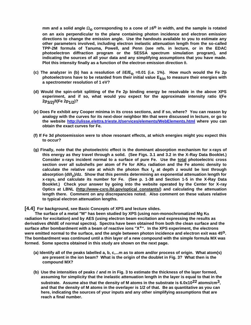
(c) The analyzer in (b) has a resolution of E/Eo =0.01 (i.e. 1%). How much would the Fe 2p
photoelectrons have to be retarded from their initial value Ekin to measure their energies with
a spectrometer resolution of 1 eV? (d) Would the spin-orbit splitting of the Fe 2p binding energy be resolvable in the above XPS
experiment, and if so, what would you expect for the approximate intensity ratio I(Fe 2p3/2)/I(Fe 2p1/2)?
(e) Does Fe exhibit any Cooper minima in its cross sections, and if so, where? You can reason by
analogy with the curves for its next-door neighbor Mn that were discussed in lecture, or go to the website http://ulisse.elettra.trieste.it/services/elements/WebElements.html where you can obtain the exact curves for Fe.
(f) If Fe 3d photoemission were to show resonant effects, at which energies might you expect this
to occur?
(g) Finally, note that the photoelectric effect is the dominant absorption mechanism for x-rays of
this energy as they travel through a solid. (See Figs. 3.1 and 3.2 in the X-Ray Data Booklet.)
Consider x-rays incident normal to a surface of pure Fe. Use the total photoelectric cross
section over all subshells per atom of Fe for AlK radiation and the Fe atomic density to
calculate the relative rate at which the photon flux Iz at depth z would be lost through
absorption (dI/Iz)/dz. Show that this permits determining an exponential attenuation length for
x-rays, and calculate its number for Fe. (See p. 1-38 and Section 1-5 in the X-Ray Data
Booklet.) Check your answer by going into the website operated by the Center for X-ray
Optics at LBNL (http://www-cxro.lbl.gov/optical_constants/) and calculating the attenuation
length there. Comment on any discrepancies noted. Also comment on these values relative
to typical electron attenuation lengths.
[4.4] For background, see Basic Concepts of XPS and lecture slides.
The surface of a metal "M" has been studied by XPS (using non-monochromatized Mg K
radiation for excitation) and by AES (using electron beam excitation and expressing the results as
derivatives dN/dE of normal spectra). Spectra have been obtained from both the clean surface and the
surface after bombardment with a beam of reactive ions "X+". In the XPS experiment, the electrons
were emitted normal to the surface, and the angle between photon incidence and electron exit was 45o.
The bombardment was continued until a thin layer of a new compound with the simple formula MX was
formed. Some spectra obtained in this study are shown on the next page.
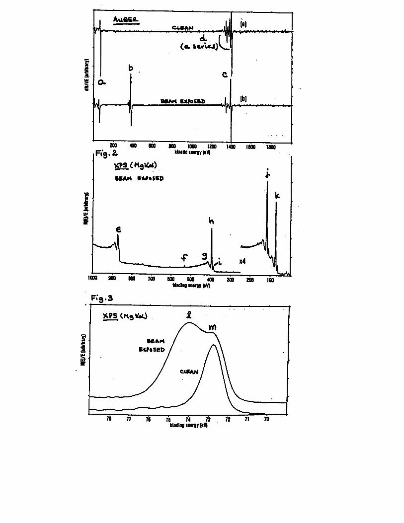
(a) Identify all of the peaks labelled a, b, c,...m as to atom and/or process of origin. What atom(s) are present in the ion beam? What is the origin of the doublet in Fig. 3? What then is the compound MX?
(b) Use the intensities of peaks and m in Fig. 3 to estimate the thickness of the layer formed, assuming for simplicity that the inelastic attenuation length in the layer is equal to that in the
substrate. Assume also that the density of M atoms in the substrate is 6.0x10²² atoms/cm3, and that the density of M atoms in the overlayer is 1/2 of that. Be as quantitative as you can here, indicating the sources of your inputs and any other simplifying assumptions that are reach a final number.

[4.5] For background, see Fadley, "The Study of Surface Structures by PD and AED"download on photoelectron diffraction, and lecture slides, as well as the online EDAC photoelectron diffraction program available at http://garciadeabajos-group.icfo.es/widgets/edac/index.html , with password jarabe12 to be able to do more precise calculations with larger clusters. Consider a photoelectron diffraction experiment in which CO is adsorbed on Ni(001) with the C bonded to Ni in an "on-top" configuration and the molecule oriented perpendicular to the surface. The C-O internuclear distance is 1.18 Å, the Ni-O internuclear distance is 1.83 Å, and the atomic muffin-tin radii can be taken to be 0.9 Å for C, 1.1 Å for O, and 1.3 Å for Ni . For simplicity, the radiation can be considered to be incident perpendicular to the molecular axis, and the detector to move above a fixed sample. See also Fig. 8 in above download.
(a) Consider first C 1s excitation with Al K radiation (which yields high-energy photoelectrons and strong forward scattering) and sketch the qualitative form of the diffraction pattern expected for this problem over the full hemisphere above the surface, showing it in a grey-scale with dark = higher intensity and light = lower intensity, and neglecting any influence of the inner potential or electron scattering from the underlying Ni atoms.
(b) Approximately how many partial-wave scattering phase shifts would have to be calculated for
O in order to quantitatively calculate this pattern? (c) Now considering this experiment more quantitatively, from the position of the first-order
maximum in the calculations of Fig. 8 for a 0 tilt of the molecule (the geometry of this
problem), estimate the scattering phase shift OΨ involved in this system.
(d) Now go into the website for the EDAC photoelectron diffraction program, which allows you to
actually calculate this problem numerically and generate a full-hemisphere output. Perform the calculation assuming that only three atoms Ni-C-O are involved, that linearly "p-polarized" radiation is incident with its E-vector along the atomic axis (incidence angle of 89º) and that only the analyzer moves above the cluster. Supply a printout of the full hemisphere diffraction pattern in both single scattering and sixth-order multiple scattering, with all of the other relevant input parameters noted. Compare your answers here with those in (a) and (c) above. Comment on any differences.
(e) Finally, lower the electron energy to 100 eV (as might be possible in a synchrotron radiation
experiment) and perform the same calculation as in (d). Note any differences, and comment on the relative importance of backscattering and multiple scattering from Ni for this lower energy.
[4.6] A photoelectron is ejected from the tungsten (W) 1s level. Assume that we can now, in the
presence of this hole, measure the binding energy of the W 4f level. (Actually, this is so far not achievable experimentally, due to the short lifetime of such a deep hole.)
(a) Use the equivalent-core or “Z+1” model and your binding energy tables to predict the change
in binding energy caused by the hole. (b) As a second part of your answer, how would you calculate this change in binding energy from
first principles via coulomb and exchange integrals, and which precise integrals would be involved? Would coulomb or exchange be expected to be more important?
[4.7] For background, see lecture slides. Consider the grating equation presented in lecture, which describes the selection of wavelengths in the soft x-ray region via reflection from a grating of spacing d.

(a) For a fixed incidence angle inc, take the derivative of this expression with respect to the
reflection angle refl so as to determine the “dispersion” of this grating drefl/d. In general,
this value should be as large as possible to maximize the energy resolving power E/E =
(h)/(h) = -/. (b) A certain commercial soft x-ray spectrometer uses the Rowland Circle geometry with circle
radius of 5 m, a grating with 1200 lines/mm, and an incidence angle relative to the normal of the grating of 88.1º. If a planar detector is oriented perpendicular to the reflected beam, what must the resolution be in microns to determine the photon energy to within 0.1% at a photon energy of 500 eV? Be careful here to determine the distance of the detector from the grating, as it must lie on the Rowland Circle. How does the required detector resolution change if it is tilted so as to have a grazing angle of photon incidence on the detector of 5º, as is done in practice in fact?

Physics 243A-Surface Physics of Materials Problem Set 5
[5.1] Use the LBNL Center for X-ray Optics Website (http://www-cxro.lbl.gov/optical_constants/) to
answer the following questions, inserting figures from it to illustrate your answer. (a) What evidence do you find in the index of refraction for Ag in the energy range 2500-5000 eV of
specific absorption edges and what are they? Has spin-orbit splitting been taken into account in this data?
(b) From this index of refraction data, estimate the critical incidence angle at which significant
reflectivity will begin for 2500 eV photons? Does an actual calculation of reflectivity as a function of incidence (“grazing”) angle agree with your number?
(c) Calculate the x-ray attenuation length in Ag at 2500 eV as a function of incidence angle from
normal (90) to parallel (0) to the surface, including a blowup of the region below the critical
angle. Now replot this data as a function of sin, and determine over what range the x-ray
attenuation depth as measured from the surface follows a relationship like h(=0)sin that is the same in form which we have discussed for electron escape depths from a surface.
[5.2] For background, see Basic Concepts of XPS pp. 85-86 Core electron binding energies have been measured for various gas-phase chlorinated benzenes, with structures and spectra shown below.

(a) Assign the peaks observed to various carbon atoms in the molecule, and predict the relative intensities of the two components for each case. Are your predictions consistent with experiment? (b) Approximate molecular orbital calculations have been performed for the entire series of
chlorinated benzenes, and from these, atomic charges qA,I have been calculated for all atoms A and all site types i. If C 1s binding energies are plotted for each type of atom in the various molecules are plotted against the carbon charge qCiI, a linear relationship is found to describe the data as
Aj
b Ci
all atoms A, j i , Ci ;Aj
qE (C1s, i any C in molecule ) 284.9 23.3q
r
.
Show that this result is consistent with a simple potential model for chemical shifts, as discussed in Eqs. (126)-(130) in "Basic Concepts of XPS".
(c) Estimate the C1s,2p coulomb integral from this analysis. (d) What is the physical meaning of the 284.9 eV no. in the above equation?
[5.3] For background, see download on basic molecular orbital theory. Valence molecular orbitals (MO's) for the molecule NO are shown below, as solid and dashed contours of probability enclosing most of the electron density, together with their Hartree-Fock one-electron eigenvalues. This molecule is also known to exhibit multiplet splittings in its N 1s and O 1s core spectra, as shown in Fig. 34 of "Basic Concepts of XPS".
(a) Write down the ground-state electronic configuration of NO. (The atomic nos. are N =7 and O = 8, and don't forget to count core electrons.)
(b) Indicate the relevant exchange integrals that are involved in the two multiplet splittings shown
in Fig. 34 for NO. You don't need to evaluate anything here, but just clearly indicate which MO's are involved.
(c) Explain why the splitting for N 1s is considerably larger than that for O 1s in terms of the spatial
properties of the MO's given on the following page. (d) Sketch the approximate atomic-orbital makeups of all of the occupied MOs, using the atomic
orbital basis of N 2s, N 2px, N 2py, N 2pz and O 2s, O 2px, O 2py, O 2pz. Show each one with a simple sketch, using the Cartesian coordinate system shown.

[5.4] For background, see lecture slides in Set 3. The band structure below has been calculated for Ga, with valence configuration 4s
24p
1.
(a) Does this material exhibit free-electron-like character in any of its bands? Explain your answer
and indicate where such bands are found.
(b) What is the origin of the very flat bands at about –8 eV on the righthand energy scale? Note
that the Fermi level is at +6.8 eV on this arbitrary scale.
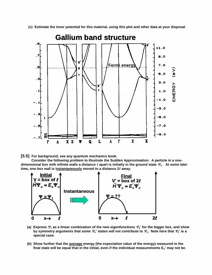
(c) Estimate the inner potential for this material, using this plot and other data at your disposal.
[5.5] For background, see any quantum mechanics book.
Consider the following problem to illustrate the Sudden Approximation: A particle in a one-
dimensional box with infinite walls a distance apart is initially in the ground state 1. At some later
time, one box wall is instantaneously moved to a distance 2 away.
(a) Express 1 as a linear combination of the new eigenfunctions n’ for the bigger box, and show
by symmetry arguments that some n’ states will not contribute to 1. Note here that 2’ is a
special case.
(b) Show further that the average energy (the expectation value of the energy) measured in the
final state will be equal that in the initial, even if the individual measurements En' may not be.
0 x 0 x 2
Instantaneous
InitialV = box of
= 1
ˆn n nH E
FinalV’ = box of 2
' ' ' 'ˆn n nH E
= ??
0 x 0 x 0 x 20 x 2
Instantaneous
InitialV = box of
= 1
ˆn n nH E
InitialV = box of
= 1
ˆn n nH E
FinalV’ = box of 2
' ' ' 'ˆn n nH E
= ??
Gallium band structure
Fermi energy
Gallium band structureGallium band structure
Fermi energy

(c) Show that this problem leads to results that are completely analogous to the result quoted in
Eq. (77) of "Basic Concepts of XPS" by making a 1:1 correspondence between quantities in that
equation and the quantities H, H', n, n’, En and En' here.
[5.6]
(a) Referring to you favorite quantum mechanics or modern physics book, or the section from Levine, “Quantum Chemisty” appended to Problem Set 3, write down the wave function for the ground state of He 1s
2, which corresponds to a singlet (S=O) state, in terms of the ground-
state one-electron spatial orbital 1s and the one-electron spin functions and , in both Slater determinant form and expanded, simplified form, indicating for the latter how the overall wave function is antisymmetric.
(b) Consider now the dipole excitation ,via the operator 1 2e ( r r ) , of a 1s electron in this two-
electron wave function so as to produce a photoelectron at some energy, with spatial orbital
photoe and leave behind a single electron in a relaxed 1s'. Choose any one of the final two-electron L,S states allowed by the dipole selection rules. But again efer back to the excerpt from Levine, Quantum Chemistry (or your other favorite QM reference) for the appropriate form
of the final state antisymmetric wave function as made up fromphotoe and 1s' , with particular reference to Equations (10.42-10.45) and the comments concerning them around Equations
(10.60-10.63), and replace 1s with 1s' and 2s with photoe. Evaluate the two-electron dipole
matrix element involved and show that if the relaxed final-state orbital 1s' is not equal to the
initial 1s, a sudden approximation-like formula results for the final transition probability. You need not carry out any radial or angular integrals.
(c) To what unique wave function does the relaxed 1s' correspond? Think of what the final state really looks like once the photoelectron is gone.
[5.7] For background, see Basic Concepts of XPS and lecture slides in Sets 4 and 5. Core-level splittings have been observed in s photoelectron spectra from the compound GdF3.
In this highly ionic compound, Gd can be considered to exist in the following electronic configuration and L-S coupling:
Gd+3 1s22s22p63s23p63d104s24p64d104f75s25p6 8S
(a) Predict as quantitatively as you can both the separations and the relative intensities of the peaks that would be observed in the 3s and 4s spectra of Gd. Indicate the exact ionic L-S states associated with each peak as well.
(b) Would the 3s or 4s spectra be expected to show larger splittings? Explain your answer
qualtitatively by considering the relevant interaction integrals involved. (c) Which splitting (3s or 4s) can you predict more accurately within simple Hartree-Fock theory
without any consideration of electron correlation, and why? Make use of Fig. 32 in “Basic Concepts of XPS” and the discussion near it to assist your reasoning.
(d) If the companion F- ions in this compound behave to first order completely independently of
the Gd ions in core-level emission, should they show the same type of splitting as the Gd
spectra? Explain why or why not. Note that F- has an inert-gas electron configuration like Ne. (e) The F¯ ions could also could show shake-up and shake-off in their F 1s core-level spectra.
Indicate by analogy with Ne as precisely as you can the possible final states that would be involved in such processes, as well as the types of overlaps that would be used in predicting the intensity of a single, typical shake-up transition.
(f) The next page shows the photoelectric cross section curves for Gd as calculated by Yeh and

Lindau. Is there any evidence for Cooper minima in these cross sections? Indicate all subshells and energies for which you see this occurring.
(g) If intraatomic resonant photoemission were possible in connection with Gd 4f emission, at
approximately what photon energy would the strongest resonant process occur? If it could occur, indicate also the two types of electron emission processes which would interfere to produce it.
(h) In an XPS spectrum obtained with unpolarized Al K1,2 radiation, and with an angle between
radiation incidence and electron exit of = 50o, what will be the relative intensities of the three
types of valence electrons from polycrystalline Gd metal: I4f:I5d:I6s? Assume that the kinetic
energies of the three types of valence electrons in this experiment are so close together that
they all have the same inelastic attenuation, and the same intensity parameters as far as the
spectrometer is concerned. Thus, many things will cancel.
(i) What will be the spin polarization of photoelectrons emitted from the Gd 5p3/2 level, if excited by
right circular polarized (RCP) radiation, assuming we can resolve it in energy from the Gd 5p1/2 level, and further simplifying the problem by assuming that only the s photoelectron channel contributes? Reason by analogy with the example discussed in lecture. What famous effect is involved here.

[5.8] Consider valence photoelectron emission normal to a Cu(001) surface. The geometry of this
experiment and the Cu band structure (as discussed in lecture) are shown on two following pages. The work function for Cu(001) is 5.2 eV and the inner potential is approximately 14.1 eV
(a) Show quantitatively from what has been discussed about this experiment that a photon energy of 97 eV is expected in the UPS or low-energy limit in which photon momentum can be neglected to yield emission from states near the X point in the Brillouin zone. Consider an average Fermi-referenced binding energy in the Cu 3d bands of 3.2 eV. Also note that the reciprocal lattice vectors in this fcc lattice along the [001] direction have the form g n a ( , , ( / ))0 0 2 2 , where n = 1, 2, 3,..., and a is the Cu lattice constant of 3.61 Å. In computing
the electron wave vector, you can use k(Å-1) = 0.512[Ekin(eV)]0.5. Be careful to consider the
electron kinetic energy inside the surface. (b) At what average kinetic energy would this spectrum be observed just outside of the surface?
(c) Show that the photon momentum plays a negligible role in k conservation for this experiment, as implied in the first figure.


[5.9] Use the SESSA program for simulating electron spectra to simulate the situation described in
parts (a) and (b) of problem [4.3]: a mixed Fe/Cu layer 10 Å thick on top of a semi-infinite Cu substrate. You will need to break the region from z = 0 to z0 = 10 Å into ten different layers of different Fe concentration to handle the linear variation of composition with depth: that is, the top layer 1 Å thick will be pure Fe, the next layer 1 Å thick will be 90% Fe/10% Cu, the next layer 1 Å thick will be 80% Fe/20% Cu, ...and the last layer will be 10% Fe/90% Cu. For simplicity, you can use the average no. of valence electrons and the average atomic density over Fe and Cu as inputs in each layer. Use the SESSA default settings for path type, convergence, and also automatic no. of collisions and trajectories.
[a] For an emission angle that is 5o with respect to the surface normal ( = 5
o in the program
inputs), show the full spectrum predicted over a kinetic energy range from 100 eV to 1500 eV, and identify all of the peaks shown. The program gives you an option of clicking on peaks to assess their origins: see the MiniManual posted at the website. [b] Now consider only the Fe 2p3/2 and Cu 2p3/2 intensities and calculate their variation with the
takeoff angle relative to the surface normal, over the range 5o = near-normal emission to 85
o =
near-grazing emission, in steps of 5o, finally showing a plot of the ratio I(Fe 2p3/2)/I(Cu 2p3/2) as a
function of .
[c] Does the Fe 2p3/2 intensity by itself as a function of behave according to the result of problem [4.3] (a), which is proportional to
,
where is here defined relative to the surface, and if so, over what angle range? What is causing any deviations you see?
[5.10] (a) Use the CTM4XAS program to simulate the following spectra for MnO, which has the NaCl crystal structure with a lattice constant of 4.44 Å: the Mn 2p x-ray absorption spectrum and the Mn
2p photoemission spectrum excited with a Al K x-rays, and compare your calculations with the experimental results on the following page. You can assume an ideal octahedral environment of O
2- ions surrounding the Mn
2+ ions, and then choose the appropriate parameters by comparing the
experimental XPS results to Graphs 10.1-10.4 and their discussion on pp. 122-123 of the paper by Bocquet et al. that is posted at the class website, where Fig. 1 in this paper for Fe
2+, slides
presented in lecture, and the MiniManual for the program provide additional background for setting up these calculations. The MiniManual in fact gives you a decent starting set of parameters. Note that the paper has slightly different notation for a couple of parameters from CMT4XAS: U(paper) = Udd(program), Q(paper) = Upd(program). The Racah parameters in the paper relate to the calculation of coulomb and exchange integrals, and need not concern us here. (b) Did you need to consider the photon energy in doing the calculation for Mn 2p XPS? Why or why not? (c) Now consider only Mn 2p photoemission and systematically vary both the ligand-to-metal
charge transfer energy or bandwidth parameter (which is lower for more covalent bonding and as it increases acts to lower charge transfer) and the 2p core-hole-3d valence interaction strength Udp (= Q in Bocquet and Fujimori, which acts to raise charge transfer) around the recommended values, and plot the relative intensity and position of the satellite as a function of these parameters. Explain the variation of the satellite intensity and energy position with these parameters in physical terms. (d) Now consider Mn 2p x-ray absorption again, but do not include charge transfer. Comment on the changes in the spectrum that you observe.

Reference figures for this problem: Mn 2p photoemission spectrum from MnO (PRL 84, 2259 (2000)) and 2p x-ray absorption spectrum from MnO (from Phys. Rev. B 63, 115119 (2001))
0.000
0.002
0.004
0.006
0.008
0.010
0.012
Photon energy (eV)
AK: MnO_th_vs_axp_alex.opj
theory
expt.
Op
tical co
nsta
nt,
635 640 645 650 655 660-0.008
-0.006
-0.004
-0.002
0.000
0.002
0.004
theory
expt.
Op
tical co
nsta
nt,
MARPE theory
MARPE theory
Experiment XAS
RPE theoryExperiment
(via K-K)
L3 = 2p3/2
L2 = 2p1/2
Optical constants of MnO
0.000
0.002
0.004
0.006
0.008
0.010
0.012
Photon energy (eV)
AK: MnO_th_vs_axp_alex.opj
theory
expt.
Op
tical co
nsta
nt,
635 640 645 650 655 660-0.008
-0.006
-0.004
-0.002
0.000
0.002
0.004
theory
expt.
Op
tical co
nsta
nt,
MARPE theory
MARPE theory
Experiment XAS
RPE theoryExperiment
(via K-K)
L3 = 2p3/2
L2 = 2p1/2
Optical constants of MnO
(a)
(b)