
Physics 169
34
Physics 169 Luis anchordoqui Kitt Peak National Observatory 1 Monday, April 16, 18
-
Upload
khangminh22 -
Category
Documents
-
view
2 -
download
0
Transcript of Physics 169
Physics 169Luis anchordoqui
Kitt Peak National Observatory1Monday, April 16, 18
How Light Works Ray optics
We just learned that light is a waveUnlike particles + waves behave in funny ways
e.g. + they bend around cornersHowever + smaller wavelength l is ) weaker funny effects arel of light is about 100 times smaller than diameter of human hair!For a long time + no one noticed “wave nature” of light at allThis means that for most physics phenomena of everyday life
we can safely ignore wave nature of lightLight waves travel through and around obstacleswhose transverse dimensions are much greater than wavelength
and wave nature of light is not readily discernedUnder these circumstances + behavior of light
is described by rays obeying set of geometrical rulesThis model of light is called ray opticsRay optics is limit of wave optics
when wavelength is infinitesimally small
L. A. Anchordoqui (CUNY) Conceptual Physics 10-3-2017 7 / 20
12.1 Ray Approximation in Geometric Optics
2Monday, April 16, 18
How Light Works Electromagnetic waves
Light itself consists of electric and magnetic fields of this kind
But what about photons? + Good question
We will deal with this soon + But meanwhile... note important fact:we have a means of transporting energy through empty space
without transporting matter
Electromagnetic waves propagate any time an electron is jiggled
L. A. Anchordoqui (CUNY) Conceptual Physics 10-3-2017 6 / 203Monday, April 16, 18
How Light Works Ray optics
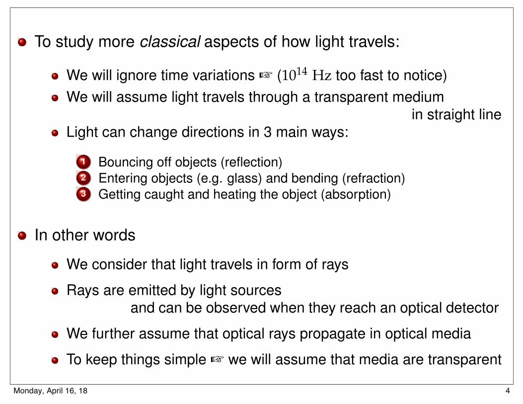
To study more classical aspects of how light travels:
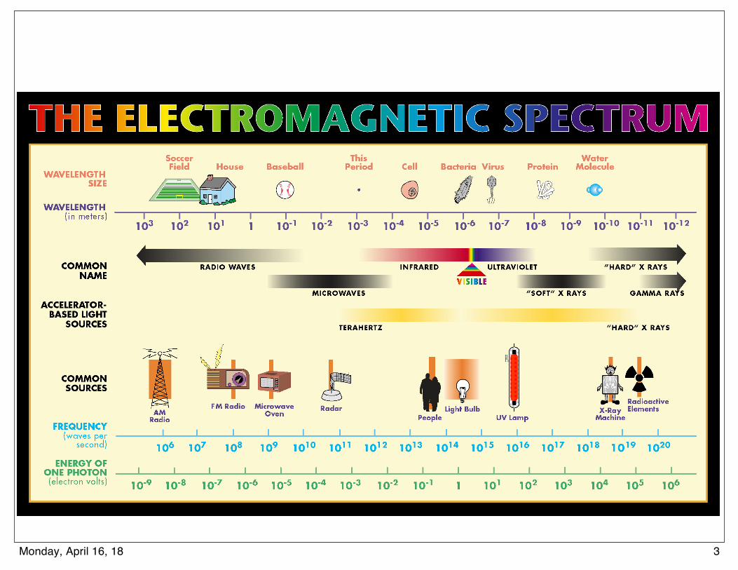
We will ignore time variations + (1014 Hz too fast to notice)We will assume light travels through a transparent medium
in straight lineLight can change directions in 3 main ways:
1 Bouncing off objects (reflection)2 Entering objects (e.g. glass) and bending (refraction)3 Getting caught and heating the object (absorption)
In other words
We consider that light travels in form of rays
Rays are emitted by light sourcesand can be observed when they reach an optical detector
We further assume that optical rays propagate in optical media
To keep things simple + we will assume that media are transparent
L. A. Anchordoqui (CUNY) Conceptual Physics 10-3-2017 8 / 204Monday, April 16, 18
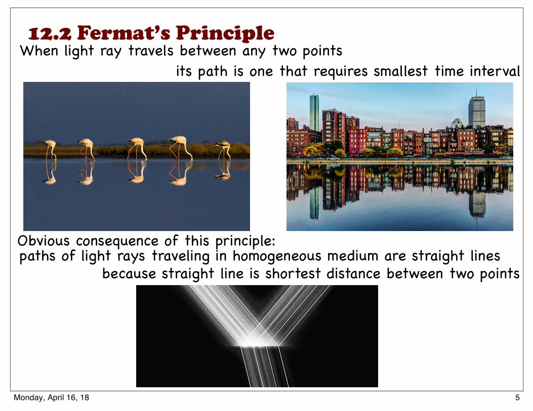
When light ray travels between any two points
Obvious consequence of this principle:
12.2 Fermat’s Principle
its path is one that requires smallest time interval
paths of light rays traveling in homogeneous medium are straight lines
How Light Works Ray optics
Summary of reflection and refraction
L. A. Anchordoqui (CUNY) Conceptual Physics 10-3-2017 18 / 20
How Light Works Ray optics
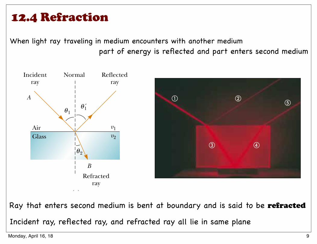
When ray of light traveling through transparent mediumencounters boundary leading into another transparent medium
part of energy is reflected and part enters second medium
Ray that enters second mediumis bent at boundary and is said to be refracted
Incident ray, reflected ray, and refracted ray all lie in same plane
L. A. Anchordoqui (CUNY) Conceptual Physics 10-3-2017 10 / 20
because straight line is shortest distance between two points
5Monday, April 16, 18
12.3 Reflection
The ray approximation and the assumption that ! "" d are used in this chapterand in Chapter 36, both of which deal with geometric optics. This approximation isvery good for the study of mirrors, lenses, prisms, and associated optical instruments,such as telescopes, cameras, and eyeglasses.
35.4 Reflection
When a light ray traveling in one medium encounters a boundary with anothermedium, part of the incident light is reflected. Figure 35.5a shows several rays of abeam of light incident on a smooth, mirror-like, reflecting surface. The reflectedrays are parallel to each other, as indicated in the figure. The direction of areflected ray is in the plane perpendicular to the reflecting surface that contains the
1098 C H A P T E R 3 5 • The Nature of Light and the Laws of Geometric Optics
Active Figure 35.4 A plane wave of wavelength ! is incident on a barrier in whichthere is an opening of diameter d. (a) When ! "" d, the rays continue in a straight-linepath, and the ray approximation remains valid. (b) When ! ! d, the rays spread outafter passing through the opening. (c) When ! ## d, the opening behaves as a pointsource emitting spherical waves.
(c)(a)
d
(b)
λ << dλ λ ≈ dλ
λ >> dλ
At the Active Figures linkat http://www.pse6.com, youcan adjust the size of theopening and observe the effecton the waves passing through.
(b)(a)
Figure 35.5 Schematic representation of (a) specular reflection, where the reflectedrays are all parallel to each other, and (b) diffuse reflection, where the reflected raystravel in random directions. (c) and (d) Photographs of specular and diffuse reflectionusing laser light.
Cour
tesy
of H
enry
Leap
and
Jim
Lehm
an
(c) (d)
incident ray. Reflection of light from such a smooth surface is called specularreflection. If the reflecting surface is rough, as shown in Figure 35.5b, the surfacereflects the rays not as a parallel set but in various directions. Reflection from anyrough surface is known as diffuse reflection. A surface behaves as a smooth surfaceas long as the surface variations are much smaller than the wavelength of theincident light.
The difference between these two kinds of reflection explains why it is moredifficult to see while driving on a rainy night. If the road is wet, the smooth surface ofthe water specularly reflects most of your headlight beams away from your car (andperhaps into the eyes of oncoming drivers). When the road is dry, its rough surfacediffusely reflects part of your headlight beam back toward you, allowing you to see thehighway more clearly. In this book, we concern ourselves only with specular reflectionand use the term reflection to mean specular reflection.
Consider a light ray traveling in air and incident at an angle on a flat, smoothsurface, as shown in Figure 35.6. The incident and reflected rays make angles !1 and!"1, respectively, where the angles are measured between the normal and the rays. (Thenormal is a line drawn perpendicular to the surface at the point where the incident raystrikes the surface.) Experiments and theory show that the angle of reflection equalsthe angle of incidence:
(35.2)
This relationship is called the law of reflection.
!"1 # !1
S E C T I O N 3 5 . 4 • Reflection 1099
Quick Quiz 35.1 In the movies, you sometimes see an actor looking in amirror and you can see his face in the mirror. During the filming of this scene, whatdoes the actor see in the mirror? (a) his face (b) your face (c) the director’s face(d) the movie camera (e) impossible to determine
Example 35.2 The Double-Reflected Light Ray Interactive
Normal
Incidentray
Reflectedray
θ1 ′θ1θ θAt the Active Figures link
at http://www.pse6.com, varythe incident angle and see theeffect on the reflected ray.
▲ PITFALL PREVENTION 35.1 Subscript NotationWe use the subscript 1 to referto parameters for the light inthe initial medium. When lighttravels from one medium toanother, we use the subscript 2 forthe parameters associated with thelight in the new medium. In thecurrent discussion, the light staysin the same medium, so we onlyhave to use the subscript 1.
Active Figure 35.6 According to the law of reflection,!"1 # !1. The incident ray, the reflected ray, and the normal alllie in the same plane.
Law of reflection
Two mirrors make an angle of 120° with each other, as illus-trated in Figure 35.7a. A ray is incident on mirror M1 at anangle of 65° to the normal. Find the direction of the rayafter it is reflected from mirror M2.
Solution Figure 35.7a helps conceptualize this situation. Theincoming ray reflects from the first mirror, and the reflectedray is directed toward the second mirror. Thus, there is asecond reflection from this latter mirror. Because the interac-tions with both mirrors are simple reflections, we categorizethis problem as one that will require the law of reflection andsome geometry. To analyze the problem, note that from the
law of reflection, we know that the first reflected ray makes anangle of 65° with the normal. Thus, this ray makes an angle of90° $ 65° # 25° with the horizontal.
From the triangle made by the first reflected ray and thetwo mirrors, we see that the first reflected ray makes an an-gle of 35° with M2 (because the sum of the interior angles ofany triangle is 180°). Therefore, this ray makes an angle of55° with the normal to M2. From the law of reflection, thesecond reflected ray makes an angle of 55° with the normalto M2.
To finalize the problem, let us explore variations in theangle between the mirrors as follows.
Saturday, April 30, 2016
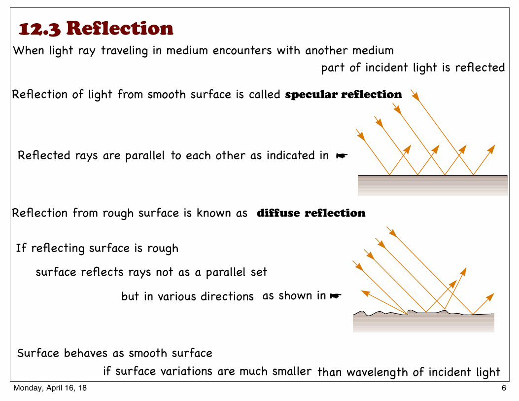
When light ray traveling in medium encounters with another medium
Reflected rays are parallel to each other as indicated in
Reflection of light from smooth surface is called specular reflection
☛
If reflecting surface is rough
Reflection from rough surface is known as
Surface behaves as smooth surface
surface reflects rays not as a parallel set
diffuse reflection
but in various directions
than wavelength of incident light
part of incident light is reflected
as shown in ☛
if surface variations are much smaller6Monday, April 16, 18
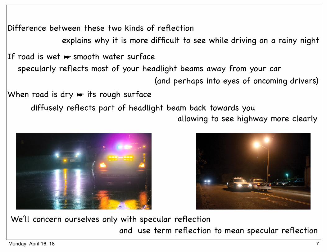
Difference between these two kinds of reflection
If road is wet ☛ smooth water surface
When road is dry ☛ its rough surface
We’ll concern ourselves only with specular reflectionuse term reflection to mean specular reflection
explains why it is more difficult to see while driving on a rainy night
(and perhaps into eyes of oncoming drivers)specularly reflects most of your headlight beams away from your car
allowing to see highway more clearlydiffusely reflects part of headlight beam back towards you
and7Monday, April 16, 18
incident ray. Reflection of light from such a smooth surface is called specularreflection. If the reflecting surface is rough, as shown in Figure 35.5b, the surfacereflects the rays not as a parallel set but in various directions. Reflection from anyrough surface is known as diffuse reflection. A surface behaves as a smooth surfaceas long as the surface variations are much smaller than the wavelength of theincident light.
The difference between these two kinds of reflection explains why it is moredifficult to see while driving on a rainy night. If the road is wet, the smooth surface ofthe water specularly reflects most of your headlight beams away from your car (andperhaps into the eyes of oncoming drivers). When the road is dry, its rough surfacediffusely reflects part of your headlight beam back toward you, allowing you to see thehighway more clearly. In this book, we concern ourselves only with specular reflectionand use the term reflection to mean specular reflection.
Consider a light ray traveling in air and incident at an angle on a flat, smoothsurface, as shown in Figure 35.6. The incident and reflected rays make angles !1 and!"1, respectively, where the angles are measured between the normal and the rays. (Thenormal is a line drawn perpendicular to the surface at the point where the incident raystrikes the surface.) Experiments and theory show that the angle of reflection equalsthe angle of incidence:
(35.2)
This relationship is called the law of reflection.
!"1 # !1
S E C T I O N 3 5 . 4 • Reflection 1099
Quick Quiz 35.1 In the movies, you sometimes see an actor looking in amirror and you can see his face in the mirror. During the filming of this scene, whatdoes the actor see in the mirror? (a) his face (b) your face (c) the director’s face(d) the movie camera (e) impossible to determine
Example 35.2 The Double-Reflected Light Ray Interactive
Normal
Incidentray
Reflectedray
θ1 ′θ1θ θAt the Active Figures link
at http://www.pse6.com, varythe incident angle and see theeffect on the reflected ray.
▲ PITFALL PREVENTION 35.1 Subscript NotationWe use the subscript 1 to referto parameters for the light inthe initial medium. When lighttravels from one medium toanother, we use the subscript 2 forthe parameters associated with thelight in the new medium. In thecurrent discussion, the light staysin the same medium, so we onlyhave to use the subscript 1.
Active Figure 35.6 According to the law of reflection,!"1 # !1. The incident ray, the reflected ray, and the normal alllie in the same plane.
Law of reflection
Two mirrors make an angle of 120° with each other, as illus-trated in Figure 35.7a. A ray is incident on mirror M1 at anangle of 65° to the normal. Find the direction of the rayafter it is reflected from mirror M2.
Solution Figure 35.7a helps conceptualize this situation. Theincoming ray reflects from the first mirror, and the reflectedray is directed toward the second mirror. Thus, there is asecond reflection from this latter mirror. Because the interac-tions with both mirrors are simple reflections, we categorizethis problem as one that will require the law of reflection andsome geometry. To analyze the problem, note that from the
law of reflection, we know that the first reflected ray makes anangle of 65° with the normal. Thus, this ray makes an angle of90° $ 65° # 25° with the horizontal.
From the triangle made by the first reflected ray and thetwo mirrors, we see that the first reflected ray makes an an-gle of 35° with M2 (because the sum of the interior angles ofany triangle is 180°). Therefore, this ray makes an angle of55° with the normal to M2. From the law of reflection, thesecond reflected ray makes an angle of 55° with the normalto M2.
To finalize the problem, let us explore variations in theangle between the mirrors as follows.
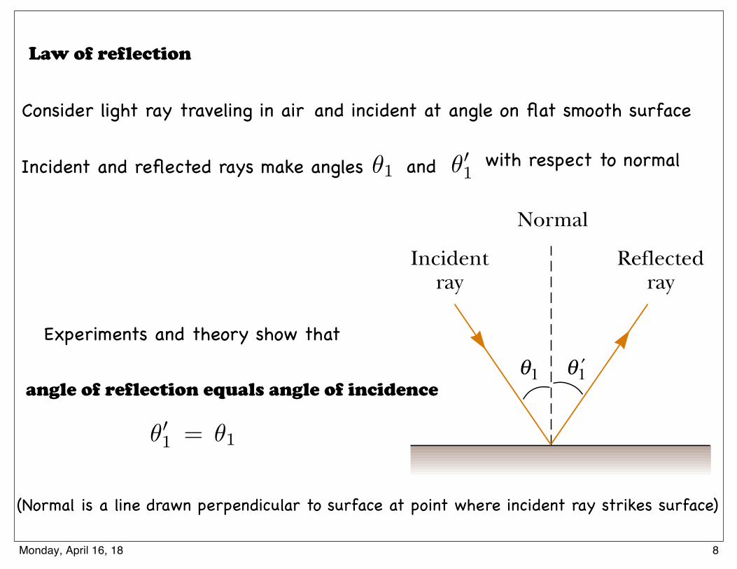
Law of reflection
✓01 = ✓1
Consider light ray traveling in air
Incident and reflected rays make angles ✓1 and ✓01 with respect to normal
(Normal is a line drawn perpendicular to surface at point where incident ray strikes surface)
Experiments and theory show that
angle of reflection equals angle of incidence
and incident at angle on flat smooth surface
8Monday, April 16, 18
12.4 Refraction
35.5 Refraction
When a ray of light traveling through a transparent medium encounters a boundaryleading into another transparent medium, as shown in Figure 35.10, part of the energyis reflected and part enters the second medium. The ray that enters the secondmedium is bent at the boundary and is said to be refracted. The incident ray, thereflected ray, and the refracted ray all lie in the same plane. The angle of refraction,!2 in Figure 35.10a, depends on the properties of the two media and on the angle ofincidence through the relationship
(35.3)
where v1 is the speed of light in the first medium and v2 is the speed of light in thesecond medium.
The path of a light ray through a refracting surface is reversible. For example, theray shown in Figure 35.10a travels from point A to point B. If the ray originated at B, itwould travel to the left along line BA to reach point A, and the reflected part wouldpoint downward and to the left in the glass.
sin !2
sin !1"
v2
v1" constant
1102 C H A P T E R 3 5 • The Nature of Light and the Laws of Geometric Optics
! "
# $
%
(b)
GlassAir
Incidentray
Refractedray
Reflectedray
Normal
A
v1v2
(a)
B
θ2θ
′θ1θθ1θ
Active Figure 35.10 (a) A ray obliquely incident on an air–glass interface. The re-fracted ray is bent toward the normal because v2 # v1. All rays and the normal lie inthe same plane. (b) Light incident on the Lucite block bends both when it enters theblock and when it leaves the block.
Henr
y Lea
p an
d Ji
m Le
hman
At the Active Figures linkat http://www.pse6.com, varythe incident angle and see theeffect on the reflected andrefracted rays.
Quick Quiz 35.2 If beam ! is the incoming beam in Figure 35.10b, whichof the other four red lines are reflected beams and which are refracted beams?
From Equation 35.3, we can infer that when light moves from a material in which itsspeed is high to a material in which its speed is lower, as shown in Figure 35.11a, the angleof refraction !2 is less than the angle of incidence !1, and the ray is bent toward thenormal. If the ray moves from a material in which light moves slowly to a material inwhich it moves more rapidly, as illustrated in Figure 35.11b, !2 is greater than !1, and theray is bent away from the normal.
The behavior of light as it passes from air into another substance and then re-emerges into air is often a source of confusion to students. When light travels in air,
Saturday, April 30, 2016
Ray that enters second medium is bent at boundary and is said to be refracted
part of energy is reflected and part enters second medium
Incident ray, reflected ray, and refracted ray all lie in same plane
When light ray traveling in medium encounters with another medium
9Monday, April 16, 18
How Light Works Ray optics
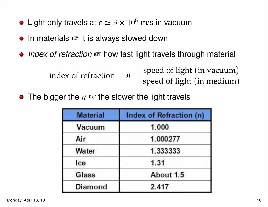
Light only travels at c ' 3 ⇥ 108 m/s in vacuum
In materials + it is always slowed down
Index of refraction + how fast light travels through material
index of refraction = n =speed of light (in vacuum)speed of light (in medium)
The bigger the n + the slower the light travels
L. A. Anchordoqui (CUNY) Conceptual Physics 10-3-2017 9 / 2010Monday, April 16, 18
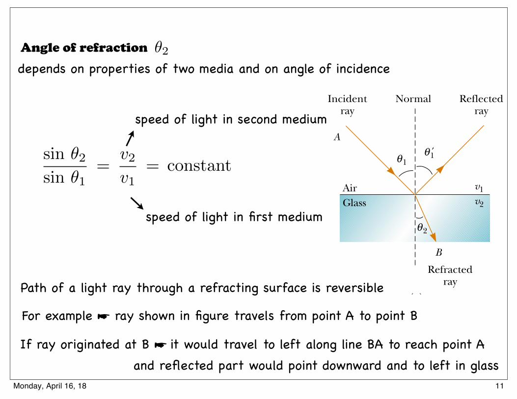
Angle of refraction depends on properties of two media and on angle of incidence
35.5 Refraction
When a ray of light traveling through a transparent medium encounters a boundaryleading into another transparent medium, as shown in Figure 35.10, part of the energyis reflected and part enters the second medium. The ray that enters the secondmedium is bent at the boundary and is said to be refracted. The incident ray, thereflected ray, and the refracted ray all lie in the same plane. The angle of refraction,!2 in Figure 35.10a, depends on the properties of the two media and on the angle ofincidence through the relationship
(35.3)
where v1 is the speed of light in the first medium and v2 is the speed of light in thesecond medium.
The path of a light ray through a refracting surface is reversible. For example, theray shown in Figure 35.10a travels from point A to point B. If the ray originated at B, itwould travel to the left along line BA to reach point A, and the reflected part wouldpoint downward and to the left in the glass.
sin !2
sin !1"
v2
v1" constant
1102 C H A P T E R 3 5 • The Nature of Light and the Laws of Geometric Optics
! "
# $
%
(b)
GlassAir
Incidentray
Refractedray
Reflectedray
Normal
A
v1v2
(a)
B
θ2θ
′θ1θθ1θ
Active Figure 35.10 (a) A ray obliquely incident on an air–glass interface. The re-fracted ray is bent toward the normal because v2 # v1. All rays and the normal lie inthe same plane. (b) Light incident on the Lucite block bends both when it enters theblock and when it leaves the block.
Henr
y Lea
p an
d Ji
m Le
hman
At the Active Figures linkat http://www.pse6.com, varythe incident angle and see theeffect on the reflected andrefracted rays.
Quick Quiz 35.2 If beam ! is the incoming beam in Figure 35.10b, whichof the other four red lines are reflected beams and which are refracted beams?
From Equation 35.3, we can infer that when light moves from a material in which itsspeed is high to a material in which its speed is lower, as shown in Figure 35.11a, the angleof refraction !2 is less than the angle of incidence !1, and the ray is bent toward thenormal. If the ray moves from a material in which light moves slowly to a material inwhich it moves more rapidly, as illustrated in Figure 35.11b, !2 is greater than !1, and theray is bent away from the normal.
The behavior of light as it passes from air into another substance and then re-emerges into air is often a source of confusion to students. When light travels in air,
Saturday, April 30, 2016
✓2
sin ✓2sin ✓1
=
v2v1
= constant
speed of light in first medium
speed of light in second medium
Path of a light ray through a refracting surface is reversible
For example ☛ ray shown in figure travels from point A to point B
If ray originated at B ☛ it would travel to left along line BA to reach point A and reflected part would point downward and to left in glass
11Monday, April 16, 18
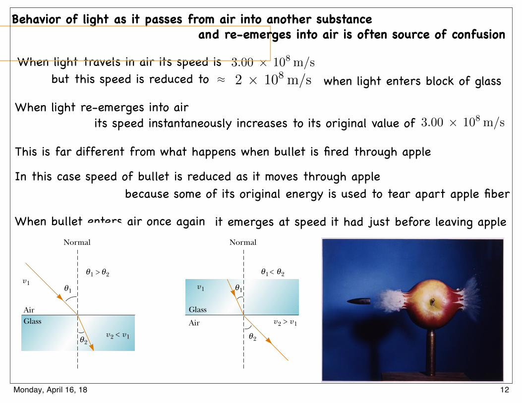
Behavior of light as it passes from air into another substance
When light travels in air its speed iswhen light enters block of glass
3.00 ⇥ 108 m/s
2 ⇥ 108 m/s
When light re-emerges into air 3.00 ⇥ 108 m/s
This is far different from what happens when bullet is fired through apple
In this case speed of bullet is reduced as it moves through apple
When bullet enters air once againS E C T I O N 3 5 . 5 • Refraction 1103
At the Active Figures linkat http://www.pse6.com, lightpasses through three layers ofmaterial. You can vary theincident angle and see theeffect on the refracted rays fora variety of values of the indexof refraction (page 1104) of thethree materials.
GlassAir
Normal
(a)
Normal
(b)
Glass
Air
1θ
2θ
2θ1θ >
v2 < v1
v1
v2 > v1
v1 1θ
2θ
2θ1θ <
Active Figure 35.11 (a) When the light beam moves from air into glass, the light slowsdown on entering the glass and its path is bent toward the normal. (b) When the beammoves from glass into air, the light speeds up on entering the air and its path is bentaway from the normal.
its speed is 3.00 ! 108 m/s, but this speed is reduced to approximately 2 ! 108 m/swhen the light enters a block of glass. When the light re-emerges into air, its speedinstantaneously increases to its original value of 3.00 ! 108 m/s. This is far differentfrom what happens, for example, when a bullet is fired through a block of wood. Inthis case, the speed of the bullet is reduced as it moves through the wood becausesome of its original energy is used to tear apart the wood fibers. When the bulletenters the air once again, it emerges at the speed it had just before leaving theblock of wood.
To see why light behaves as it does, consider Figure 35.12, which represents abeam of light entering a piece of glass from the left. Once inside the glass, the lightmay encounter an electron bound to an atom, indicated as point A. Let us assumethat light is absorbed by the atom; this causes the electron to oscillate (a detailrepresented by the double-headed vertical arrows). The oscillating electron thenacts as an antenna and radiates the beam of light toward an atom at B, where thelight is again absorbed. The details of these absorptions and radiations are bestexplained in terms of quantum mechanics (Chapter 42). For now, it is sufficient tothink of light passing from one atom to another through the glass. Although lighttravels from one glass atom to another at 3.00 ! 108 m/s, the absorption andradiation that take place cause the average light speed through the material to fall toabout 2 ! 108 m/s. Once the light emerges into the air, absorption and radiationcease and the speed of the light returns to the original value.
A B
Figure 35.12 Light passing from one atom to another in amedium. The dots are electrons, and the vertical arrows representtheir oscillations.
S E C T I O N 3 5 . 5 • Refraction 1103
At the Active Figures linkat http://www.pse6.com, lightpasses through three layers ofmaterial. You can vary theincident angle and see theeffect on the refracted rays fora variety of values of the indexof refraction (page 1104) of thethree materials.
GlassAir
Normal
(a)
Normal
(b)
Glass
Air
1θ
2θ
2θ1θ >
v2 < v1
v1
v2 > v1
v1 1θ
2θ
2θ1θ <
Active Figure 35.11 (a) When the light beam moves from air into glass, the light slowsdown on entering the glass and its path is bent toward the normal. (b) When the beammoves from glass into air, the light speeds up on entering the air and its path is bentaway from the normal.
its speed is 3.00 ! 108 m/s, but this speed is reduced to approximately 2 ! 108 m/swhen the light enters a block of glass. When the light re-emerges into air, its speedinstantaneously increases to its original value of 3.00 ! 108 m/s. This is far differentfrom what happens, for example, when a bullet is fired through a block of wood. Inthis case, the speed of the bullet is reduced as it moves through the wood becausesome of its original energy is used to tear apart the wood fibers. When the bulletenters the air once again, it emerges at the speed it had just before leaving theblock of wood.
To see why light behaves as it does, consider Figure 35.12, which represents abeam of light entering a piece of glass from the left. Once inside the glass, the lightmay encounter an electron bound to an atom, indicated as point A. Let us assumethat light is absorbed by the atom; this causes the electron to oscillate (a detailrepresented by the double-headed vertical arrows). The oscillating electron thenacts as an antenna and radiates the beam of light toward an atom at B, where thelight is again absorbed. The details of these absorptions and radiations are bestexplained in terms of quantum mechanics (Chapter 42). For now, it is sufficient tothink of light passing from one atom to another through the glass. Although lighttravels from one glass atom to another at 3.00 ! 108 m/s, the absorption andradiation that take place cause the average light speed through the material to fall toabout 2 ! 108 m/s. Once the light emerges into the air, absorption and radiationcease and the speed of the light returns to the original value.
A B
Figure 35.12 Light passing from one atom to another in amedium. The dots are electrons, and the vertical arrows representtheir oscillations.
35.5 Refraction
When a ray of light traveling through a transparent medium encounters a boundaryleading into another transparent medium, as shown in Figure 35.10, part of the energyis reflected and part enters the second medium. The ray that enters the secondmedium is bent at the boundary and is said to be refracted. The incident ray, thereflected ray, and the refracted ray all lie in the same plane. The angle of refraction,!2 in Figure 35.10a, depends on the properties of the two media and on the angle ofincidence through the relationship
(35.3)
where v1 is the speed of light in the first medium and v2 is the speed of light in thesecond medium.
The path of a light ray through a refracting surface is reversible. For example, theray shown in Figure 35.10a travels from point A to point B. If the ray originated at B, itwould travel to the left along line BA to reach point A, and the reflected part wouldpoint downward and to the left in the glass.
sin !2
sin !1"
v2
v1" constant
1102 C H A P T E R 3 5 • The Nature of Light and the Laws of Geometric Optics
! "
# $
%
(b)
GlassAir
Incidentray
Refractedray
Reflectedray
Normal
A
v1v2
(a)
B
θ2θ
′θ1θθ1θ
Active Figure 35.10 (a) A ray obliquely incident on an air–glass interface. The re-fracted ray is bent toward the normal because v2 # v1. All rays and the normal lie inthe same plane. (b) Light incident on the Lucite block bends both when it enters theblock and when it leaves the block.
Henr
y Lea
p an
d Ji
m Le
hman
At the Active Figures linkat http://www.pse6.com, varythe incident angle and see theeffect on the reflected andrefracted rays.
Quick Quiz 35.2 If beam ! is the incoming beam in Figure 35.10b, whichof the other four red lines are reflected beams and which are refracted beams?
From Equation 35.3, we can infer that when light moves from a material in which itsspeed is high to a material in which its speed is lower, as shown in Figure 35.11a, the angleof refraction !2 is less than the angle of incidence !1, and the ray is bent toward thenormal. If the ray moves from a material in which light moves slowly to a material inwhich it moves more rapidly, as illustrated in Figure 35.11b, !2 is greater than !1, and theray is bent away from the normal.
The behavior of light as it passes from air into another substance and then re-emerges into air is often a source of confusion to students. When light travels in air,
Saturday, April 30, 2016
but this speed is reduced to
and re-emerges into air is often source of confusion
⇡
its speed instantaneously increases to its original value of
because some of its original energy is used to tear apart apple fiber
it emerges at speed it had just before leaving apple
12Monday, April 16, 18
A mechanical analog of refraction is shown in Figure 35.13. When the left end ofthe rolling barrel reaches the grass, it slows down, while the right end remains on theconcrete and moves at its original speed. This difference in speeds causes the barrel topivot, and this changes the direction of travel.
Index of Refraction
In general, the speed of light in any material is less than its speed in vacuum. In fact,light travels at its maximum speed in vacuum. It is convenient to define the index ofrefraction n of a medium to be the ratio
(35.4)
From this definition, we see that the index of refraction is a dimensionlessnumber greater than unity because v is always less than c. Furthermore, n is equalto unity for vacuum. The indices of refraction for various substances are listedin Table 35.1.
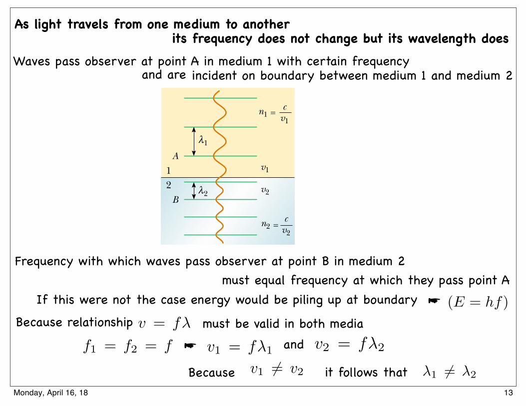
As light travels from one medium to another, its frequency does notchange but its wavelength does. To see why this is so, consider Figure 35.14.Waves pass an observer at point A in medium 1 with a certain frequency and are
n ! speed of light in vacuum
speed of light in a medium!
cv
1104 C H A P T E R 3 5 • The Nature of Light and the Laws of Geometric Optics
Concrete
GrassThis end slowsfirst; as a result,the barrel turns.
Figure 35.13 Overhead view of a barrel rollingfrom concrete onto grass.
12
A
Bv2
v1
1
n2cv2
=
n1cv1
=
λ
2λ
Figure 35.14 As a wave movesfrom medium 1 to medium 2, itswavelength changes but itsfrequency remains constant.
Index of Index ofSubstance Refraction Substance Refraction
Solids at 20°C Liquids at 20°CCubic zirconia 2.20 Benzene 1.501Diamond (C) 2.419 Carbon disulfide 1.628Fluorite (CaF2) 1.434 Carbon tetrachloride 1.461Fused quartz (SiO2) 1.458 Ethyl alcohol 1.361Gallium phosphide 3.50 Glycerin 1.473Glass, crown 1.52 Water 1.333Glass, flint 1.66Ice (H2O) 1.309Polystyrene 1.49Sodium chloride (NaCl) 1.544
Indices of Refractiona
Table 35.1
a All values are for light having a wavelength of 589 nm in vacuum.
Index of refraction
▲ PITFALL PREVENTION 35.2 n Is Not an Integer
HereWe have seen n used severaltimes as an integer, such as inChapter 18 to indicate the stand-ing wave mode on a string or inan air column. The index ofrefraction n is not an integer.
Gases at 0°C, 1 atmAir 1.000 293Carbon dioxide 1.000 45
A mechanical analog of refraction is shown in Figure 35.13. When the left end ofthe rolling barrel reaches the grass, it slows down, while the right end remains on theconcrete and moves at its original speed. This difference in speeds causes the barrel topivot, and this changes the direction of travel.
Index of Refraction
In general, the speed of light in any material is less than its speed in vacuum. In fact,light travels at its maximum speed in vacuum. It is convenient to define the index ofrefraction n of a medium to be the ratio
(35.4)
From this definition, we see that the index of refraction is a dimensionlessnumber greater than unity because v is always less than c. Furthermore, n is equalto unity for vacuum. The indices of refraction for various substances are listedin Table 35.1.
As light travels from one medium to another, its frequency does notchange but its wavelength does. To see why this is so, consider Figure 35.14.Waves pass an observer at point A in medium 1 with a certain frequency and are
n ! speed of light in vacuum
speed of light in a medium!
cv
1104 C H A P T E R 3 5 • The Nature of Light and the Laws of Geometric Optics
Concrete
GrassThis end slowsfirst; as a result,the barrel turns.
Figure 35.13 Overhead view of a barrel rollingfrom concrete onto grass.
12
A
Bv2
v1
1
n2cv2
=
n1cv1
=
λ
2λ
Figure 35.14 As a wave movesfrom medium 1 to medium 2, itswavelength changes but itsfrequency remains constant.
Index of Index ofSubstance Refraction Substance Refraction
Solids at 20°C Liquids at 20°CCubic zirconia 2.20 Benzene 1.501Diamond (C) 2.419 Carbon disulfide 1.628Fluorite (CaF2) 1.434 Carbon tetrachloride 1.461Fused quartz (SiO2) 1.458 Ethyl alcohol 1.361Gallium phosphide 3.50 Glycerin 1.473Glass, crown 1.52 Water 1.333Glass, flint 1.66Ice (H2O) 1.309Polystyrene 1.49Sodium chloride (NaCl) 1.544
Indices of Refractiona
Table 35.1
a All values are for light having a wavelength of 589 nm in vacuum.
Index of refraction
▲ PITFALL PREVENTION 35.2 n Is Not an Integer
HereWe have seen n used severaltimes as an integer, such as inChapter 18 to indicate the stand-ing wave mode on a string or inan air column. The index ofrefraction n is not an integer.
Gases at 0°C, 1 atmAir 1.000 293Carbon dioxide 1.000 45
incident on the boundary between medium 1 and medium 2. The frequency withwhich the waves pass an observer at point B in medium 2 must equal the frequencyat which they pass point A. If this were not the case, then energy would be piling upat the boundary. Because there is no mechanism for this to occur, the frequencymust be a constant as a light ray passes from one medium into another. Therefore,because the relationship v ! f " (Eq. 16.12) must be valid in both media andbecause f 1 ! f 2 ! f , we see that
v1 ! f "1 and v 2 ! f "2 (35.5)
Because v1 ! v2, it follows that "1 ! "2.We can obtain a relationship between index of refraction and wavelength by
dividing the first Equation 35.5 by the second and then using Equation 35.4:
(35.6)
This gives
"1n1 ! "2n2
If medium 1 is vacuum, or for all practical purposes air, then n1 ! 1. Hence, it followsfrom Equation 35.6 that the index of refraction of any medium can be expressed as theratio
(35.7)
where " is the wavelength of light in vacuum and "n is the wavelength of light inthe medium whose index of refraction is n. From Equation 35.7, we see that becausen # 1, "n $ ".
We are now in a position to express Equation 35.3 in an alternative form.If we replace the v2/v1 term in Equation 35.3 with n1/n 2 from Equation 35.6, weobtain
(35.8)
The experimental discovery of this relationship is usually credited to Willebrord Snell(1591–1627) and is therefore known as Snell’s law of refraction. We shall examinethis equation further in Sections 35.6 and 35.9.
n1 sin % 1 ! n2 sin % 2
n !"
"n
"1
"2!
v1
v2!
c/n1
c/n2!
n2
n1
S E C T I O N 3 5 . 5 • Refraction 1105
Snell’s law of refraction
▲ PITFALL PREVENTION 35.3 An Inverse
RelationshipThe index of refraction isinversely proportional to the wavespeed. As the wave speed vdecreases, the index of refractionn increases. Thus, the higher theindex of refraction of a material,the more it slows down light fromits speed in vacuum. The morethe light slows down, the more %2differs from %1 in Equation 35.8.
Quick Quiz 35.3 Light passes from a material with index of refraction1.3 into one with index of refraction 1.2. Compared to the incident ray, therefracted ray (a) bends toward the normal (b) is undeflected (c) bends away fromthe normal.
Quick Quiz 35.4 As light from the Sun enters the atmosphere, it refractsdue to the small difference between the speeds of light in air and in vacuum. Theoptical length of the day is defined as the time interval between the instant when thetop of the Sun is just visibly observed above the horizon to the instant at which the topof the Sun just disappears below the horizon. The geometric length of the day is definedas the time interval between the instant when a geometric straight line drawn from theobserver to the top of the Sun just clears the horizon to the instant at which this linejust dips below the horizon. Which is longer, (a) the optical length of a day, or(b) the geometric length of a day?
Saturday, April 30, 2016
Waves pass observer at point A in medium 1 with certain frequencyincident on boundary between medium 1 and medium 2
Frequency with which waves pass observer at point B in medium 2
If this were not the case energy would be piling up at boundary
must be valid in both mediaBecause relationship
v1 = f�1 v2 = f�2
v1 6= v2 �1 6= �2
As light travels from one medium to another
v = f�
f1 = f2 = f ☛ and
Because it follows that
and are
its frequency does not change but its wavelength does
must equal frequency at which they pass point A(E = hf)☛
13Monday, April 16, 18
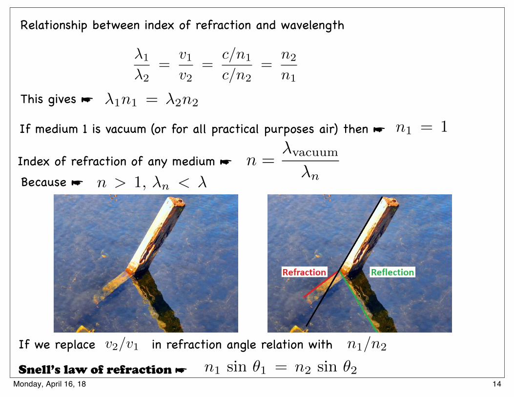
Relationship between index of refraction and wavelength
�1
�2=
v1v2
=c/n1
c/n2=
n2
n1
This gives ☛ �1n1 = �2n2
n1 = 1If medium 1 is vacuum (or for all practical purposes air) then ☛
Index of refraction of any medium ☛ n > 1, �n < � Because ☛
If we replace in refraction angle relation with
n1 sin ✓1 = n2 sin ✓2
n1/n2v2/v1
Snell’s law of refraction ☛
n =�vacuum
�n
How Light Works Ray optics
Summary of reflection and refraction
L. A. Anchordoqui (CUNY) Conceptual Physics 10-3-2017 18 / 20
14Monday, April 16, 18
12.5 Images Formed by Flat Mirrors
Images are classified as real or virtual
Real image ☛ formed when light rays
1127
This chapter is concerned with the images that result when light rays encounter flatand curved surfaces. We find that images can be formed either by reflection or byrefraction and that we can design mirrors and lenses to form images with desired char-acteristics. We continue to use the ray approximation and to assume that light travelsin straight lines. Both of these steps lead to valid predictions in the field called geometricoptics. In subsequent chapters, we shall concern ourselves with interference and diffrac-tion effects—the objects of study in the field of wave optics.
36.1 Images Formed by Flat Mirrors
We begin by considering the simplest possible mirror, the flat mirror. Consider apoint source of light placed at O in Figure 36.1, a distance p in front of a flat mirror.The distance p is called the object distance. Light rays leave the source and arereflected from the mirror. Upon reflection, the rays continue to diverge (spreadapart). The dashed lines in Figure 36.1 are extensions of the diverging rays back to apoint of intersection at I. The diverging rays appear to the viewer to come from thepoint I behind the mirror. Point I is called the image of the object at O. Regardlessof the system under study, we always locate images by extending diverging rays backto a point at which they intersect. Images are located either at a point fromwhich rays of light actually diverge or at a point from which they appear todiverge. Because the rays in Figure 36.1 appear to originate at I, which is a distanceq behind the mirror, this is the location of the image. The distance q is called theimage distance.
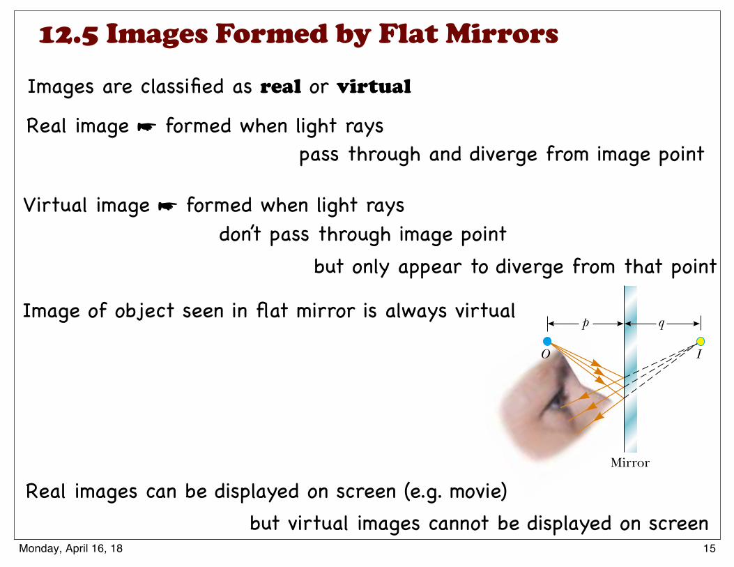
Images are classified as real or virtual. A real image is formed when light rayspass through and diverge from the image point; a virtual image is formed whenthe light rays do not pass through the image point but only appear to divergefrom that point. The image formed by the mirror in Figure 36.1 is virtual. The imageof an object seen in a flat mirror is always virtual. Real images can be displayed on a
Mirror
O I
qp
Figure 36.1 An image formed by reflection from a flatmirror. The image point I is located behind the mirror aperpendicular distance q from the mirror (the imagedistance). The image distance has the same magnitude asthe object distance p.
1127
This chapter is concerned with the images that result when light rays encounter flatand curved surfaces. We find that images can be formed either by reflection or byrefraction and that we can design mirrors and lenses to form images with desired char-acteristics. We continue to use the ray approximation and to assume that light travelsin straight lines. Both of these steps lead to valid predictions in the field called geometricoptics. In subsequent chapters, we shall concern ourselves with interference and diffrac-tion effects—the objects of study in the field of wave optics.
36.1 Images Formed by Flat Mirrors
We begin by considering the simplest possible mirror, the flat mirror. Consider apoint source of light placed at O in Figure 36.1, a distance p in front of a flat mirror.The distance p is called the object distance. Light rays leave the source and arereflected from the mirror. Upon reflection, the rays continue to diverge (spreadapart). The dashed lines in Figure 36.1 are extensions of the diverging rays back to apoint of intersection at I. The diverging rays appear to the viewer to come from thepoint I behind the mirror. Point I is called the image of the object at O. Regardlessof the system under study, we always locate images by extending diverging rays backto a point at which they intersect. Images are located either at a point fromwhich rays of light actually diverge or at a point from which they appear todiverge. Because the rays in Figure 36.1 appear to originate at I, which is a distanceq behind the mirror, this is the location of the image. The distance q is called theimage distance.
Images are classified as real or virtual. A real image is formed when light rayspass through and diverge from the image point; a virtual image is formed whenthe light rays do not pass through the image point but only appear to divergefrom that point. The image formed by the mirror in Figure 36.1 is virtual. The imageof an object seen in a flat mirror is always virtual. Real images can be displayed on a
Mirror
O I
qp
Figure 36.1 An image formed by reflection from a flatmirror. The image point I is located behind the mirror aperpendicular distance q from the mirror (the imagedistance). The image distance has the same magnitude asthe object distance p.
screen (as at a movie), but virtual images cannot be displayed on a screen. We shall seean example of a real image in Section 36.2.
We can use the simple geometry in Figure 36.2 to examine the properties of theimages of extended objects formed by flat mirrors. Even though there are an infinitenumber of choices of direction in which light rays could leave each point on the object,we need to choose only two rays to determine where an image is formed. One of thoserays starts at P, follows a horizontal path to the mirror, and reflects back on itself. Thesecond ray follows the oblique path PR and reflects as shown, according to the law ofreflection. An observer in front of the mirror would trace the two reflected rays back tothe point at which they appear to have originated, which is point P! behind the mirror. Acontinuation of this process for points other than P on the object would result in a virtualimage (represented by a yellow arrow) behind the mirror. Because triangles PQR andP !QR are congruent, PQ " P !Q. We conclude that the image formed by an objectplaced in front of a flat mirror is as far behind the mirror as the object is in frontof the mirror.
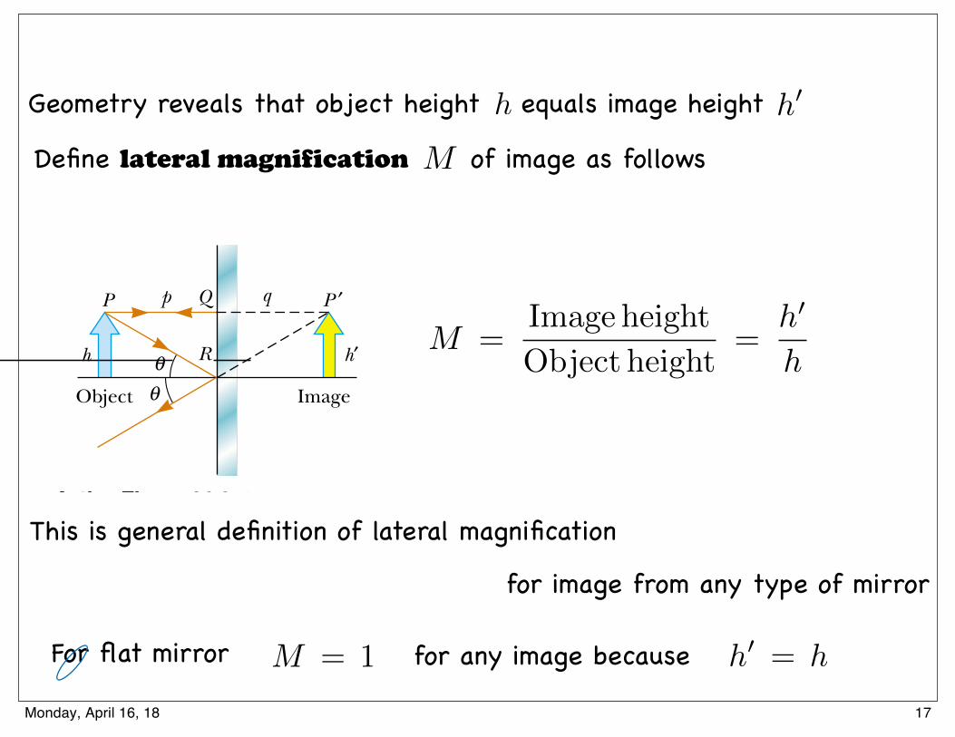
Geometry also reveals that the object height h equals the image height h!. Let usdefine lateral magnification M of an image as follows:
(36.1)
This is a general definition of the lateral magnification for an image from any type ofmirror. (This equation is also valid for images formed by lenses, which we study inSection 36.4.) For a flat mirror, M " 1 for any image because h! " h.
Finally, note that a flat mirror produces an image that has an apparent left–rightreversal. You can see this reversal by standing in front of a mirror and raising your righthand, as shown in Figure 36.3. The image you see raises its left hand. Likewise, yourhair appears to be parted on the side opposite your real part, and a mole on your rightcheek appears to be on your left cheek.
This reversal is not actually a left–right reversal. Imagine, for example, lying on yourleft side on the floor, with your body parallel to the mirror surface. Now your head is onthe left and your feet are on the right. If you shake your feet, the image does not shake itshead! If you raise your right hand, however, the image again raises its left hand. Thus, themirror again appears to produce a left–right reversal but in the up–down direction!
The reversal is actually a front–back reversal, caused by the light rays going forwardtoward the mirror and then reflecting back from it. An interesting exercise is to standin front of a mirror while holding an overhead transparency in front of you so that youcan read the writing on the transparency. You will also be able to read the writing onthe image of the transparency. You may have had a similar experience if you haveattached a transparent decal with words on it to the rear window of your car. If the
M ! Image heightObject height
"h!
h
1128 C H A P T E R 3 6 • Image Formation
▲ PITFALL PREVENTION 36.1 Magnification Does
Not NecessarilyImply Enlargement
For optical elements other thanflat mirrors, the magnificationdefined in Equation 36.1 canresult in a number with magni-tude larger or smaller than 1.Thus, despite the cultural usageof the word magnification to meanenlargement, the image could besmaller than the object.
Lateral magnification
Object θθh R
QP P ′
Image
p q
h′
Active Figure 36.2 A geometricconstruction that is used to locatethe image of an object placed infront of a flat mirror. Because thetriangles PQR and P!QR are con-gruent, and h " h!.
At the Active Figures linkat http://www.pse6.com, youcan move the object and seethe effect on the image.
" p " " " q "
Figure 36.3 The image in the mirror of a person’s right hand is reversed front to back.This makes the right hand appear to be a left hand. Notice that the thumb is on the leftside of both real hands and on the left side of the image. That the thumb is not on theright side of the image indicates that there is no left-to-right reversal.
Geor
ge S
empl
e
Saturday, April 30, 2016
but only appear to diverge from that point
Image of object seen in flat mirror is always virtual
but virtual images cannot be displayed on screen
Virtual image ☛ formed when light rays
pass through and diverge from image point
don’t pass through image point
Real images can be displayed on screen (e.g. movie)
15Monday, April 16, 18
screen (as at a movie), but virtual images cannot be displayed on a screen. We shall seean example of a real image in Section 36.2.
We can use the simple geometry in Figure 36.2 to examine the properties of theimages of extended objects formed by flat mirrors. Even though there are an infinitenumber of choices of direction in which light rays could leave each point on the object,we need to choose only two rays to determine where an image is formed. One of thoserays starts at P, follows a horizontal path to the mirror, and reflects back on itself. Thesecond ray follows the oblique path PR and reflects as shown, according to the law ofreflection. An observer in front of the mirror would trace the two reflected rays back tothe point at which they appear to have originated, which is point P! behind the mirror. Acontinuation of this process for points other than P on the object would result in a virtualimage (represented by a yellow arrow) behind the mirror. Because triangles PQR andP !QR are congruent, PQ " P !Q. We conclude that the image formed by an objectplaced in front of a flat mirror is as far behind the mirror as the object is in frontof the mirror.
Geometry also reveals that the object height h equals the image height h!. Let usdefine lateral magnification M of an image as follows:
(36.1)
This is a general definition of the lateral magnification for an image from any type ofmirror. (This equation is also valid for images formed by lenses, which we study inSection 36.4.) For a flat mirror, M " 1 for any image because h! " h.
Finally, note that a flat mirror produces an image that has an apparent left–rightreversal. You can see this reversal by standing in front of a mirror and raising your righthand, as shown in Figure 36.3. The image you see raises its left hand. Likewise, yourhair appears to be parted on the side opposite your real part, and a mole on your rightcheek appears to be on your left cheek.
This reversal is not actually a left–right reversal. Imagine, for example, lying on yourleft side on the floor, with your body parallel to the mirror surface. Now your head is onthe left and your feet are on the right. If you shake your feet, the image does not shake itshead! If you raise your right hand, however, the image again raises its left hand. Thus, themirror again appears to produce a left–right reversal but in the up–down direction!
The reversal is actually a front–back reversal, caused by the light rays going forwardtoward the mirror and then reflecting back from it. An interesting exercise is to standin front of a mirror while holding an overhead transparency in front of you so that youcan read the writing on the transparency. You will also be able to read the writing onthe image of the transparency. You may have had a similar experience if you haveattached a transparent decal with words on it to the rear window of your car. If the
M ! Image heightObject height
"h!
h
1128 C H A P T E R 3 6 • Image Formation
▲ PITFALL PREVENTION 36.1 Magnification Does
Not NecessarilyImply Enlargement
For optical elements other thanflat mirrors, the magnificationdefined in Equation 36.1 canresult in a number with magni-tude larger or smaller than 1.Thus, despite the cultural usageof the word magnification to meanenlargement, the image could besmaller than the object.
Lateral magnification
Object θθh R
QP P ′
Image
p q
h′
Active Figure 36.2 A geometricconstruction that is used to locatethe image of an object placed infront of a flat mirror. Because thetriangles PQR and P!QR are con-gruent, and h " h!.
At the Active Figures linkat http://www.pse6.com, youcan move the object and seethe effect on the image.
" p " " " q "
Figure 36.3 The image in the mirror of a person’s right hand is reversed front to back.This makes the right hand appear to be a left hand. Notice that the thumb is on the leftside of both real hands and on the left side of the image. That the thumb is not on theright side of the image indicates that there is no left-to-right reversal.
Geor
ge S
empl
e
16Thursday, May 5, 16
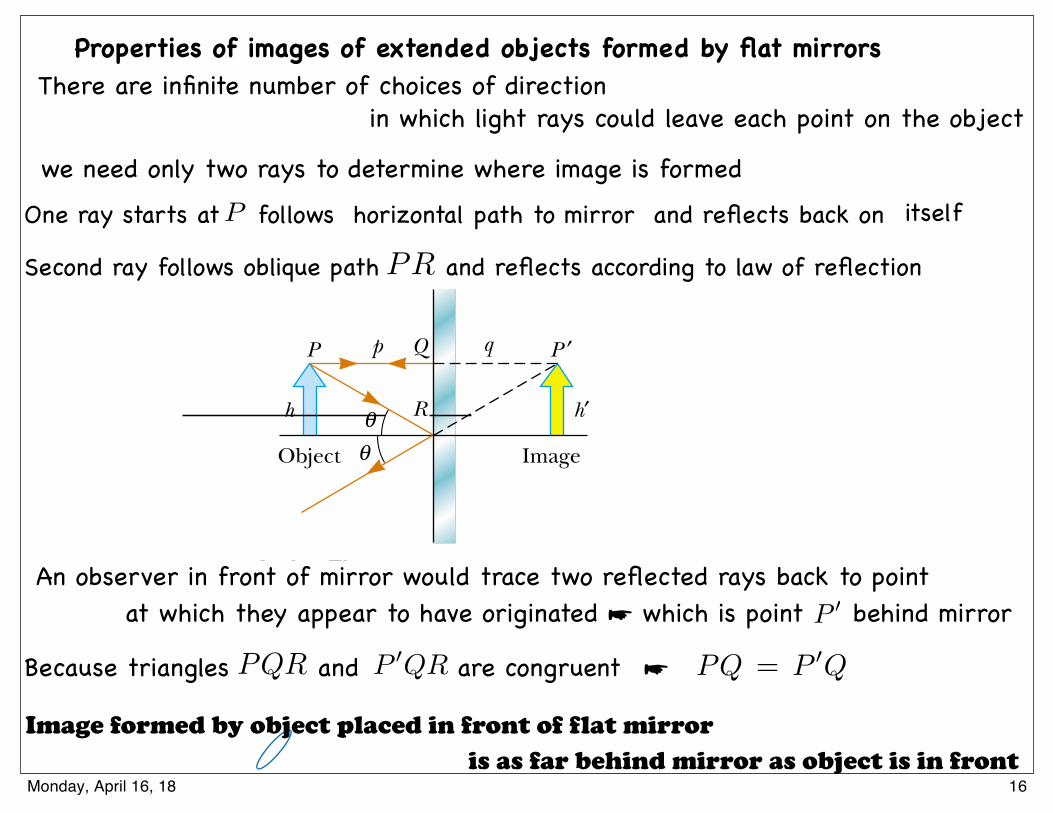
Properties of images of extended objects formed by flat mirrorsThere are infinite number of choices of direction
One ray starts at follows horizontal path to mirror and reflects back on
Second ray follows oblique path and reflects according to law of reflection
An observer in front of mirror would trace two reflected rays back to point
Image formed by object placed in front of flat mirror
Because triangles and are congruent
itselfP
PR
P 0
P 0QRPQR PQ = P 0Q
is as far behind mirror as object is in front
we need only two rays to determine where image is formed
in which light rays could leave each point on the object
☛
at which they appear to have originated ☛ which is point behind mirror
16Monday, April 16, 18
M =Image height
Object height=
h0
h
Geometry reveals that object height equals image height
Define lateral magnification of image as follows
This is general definition of lateral magnification
M = 1 h0 = h
h0h
M
For flat mirror for any image because
screen (as at a movie), but virtual images cannot be displayed on a screen. We shall seean example of a real image in Section 36.2.
We can use the simple geometry in Figure 36.2 to examine the properties of theimages of extended objects formed by flat mirrors. Even though there are an infinitenumber of choices of direction in which light rays could leave each point on the object,we need to choose only two rays to determine where an image is formed. One of thoserays starts at P, follows a horizontal path to the mirror, and reflects back on itself. Thesecond ray follows the oblique path PR and reflects as shown, according to the law ofreflection. An observer in front of the mirror would trace the two reflected rays back tothe point at which they appear to have originated, which is point P! behind the mirror. Acontinuation of this process for points other than P on the object would result in a virtualimage (represented by a yellow arrow) behind the mirror. Because triangles PQR andP !QR are congruent, PQ " P !Q. We conclude that the image formed by an objectplaced in front of a flat mirror is as far behind the mirror as the object is in frontof the mirror.
Geometry also reveals that the object height h equals the image height h!. Let usdefine lateral magnification M of an image as follows:
(36.1)
This is a general definition of the lateral magnification for an image from any type ofmirror. (This equation is also valid for images formed by lenses, which we study inSection 36.4.) For a flat mirror, M " 1 for any image because h! " h.
Finally, note that a flat mirror produces an image that has an apparent left–rightreversal. You can see this reversal by standing in front of a mirror and raising your righthand, as shown in Figure 36.3. The image you see raises its left hand. Likewise, yourhair appears to be parted on the side opposite your real part, and a mole on your rightcheek appears to be on your left cheek.
This reversal is not actually a left–right reversal. Imagine, for example, lying on yourleft side on the floor, with your body parallel to the mirror surface. Now your head is onthe left and your feet are on the right. If you shake your feet, the image does not shake itshead! If you raise your right hand, however, the image again raises its left hand. Thus, themirror again appears to produce a left–right reversal but in the up–down direction!
The reversal is actually a front–back reversal, caused by the light rays going forwardtoward the mirror and then reflecting back from it. An interesting exercise is to standin front of a mirror while holding an overhead transparency in front of you so that youcan read the writing on the transparency. You will also be able to read the writing onthe image of the transparency. You may have had a similar experience if you haveattached a transparent decal with words on it to the rear window of your car. If the
M ! Image heightObject height
"h!
h
1128 C H A P T E R 3 6 • Image Formation
▲ PITFALL PREVENTION 36.1 Magnification Does
Not NecessarilyImply Enlargement
For optical elements other thanflat mirrors, the magnificationdefined in Equation 36.1 canresult in a number with magni-tude larger or smaller than 1.Thus, despite the cultural usageof the word magnification to meanenlargement, the image could besmaller than the object.
Lateral magnification
Object θθh R
QP P ′
Image
p q
h′
Active Figure 36.2 A geometricconstruction that is used to locatethe image of an object placed infront of a flat mirror. Because thetriangles PQR and P!QR are con-gruent, and h " h!.
At the Active Figures linkat http://www.pse6.com, youcan move the object and seethe effect on the image.
" p " " " q "
Figure 36.3 The image in the mirror of a person’s right hand is reversed front to back.This makes the right hand appear to be a left hand. Notice that the thumb is on the leftside of both real hands and on the left side of the image. That the thumb is not on theright side of the image indicates that there is no left-to-right reversal.
Geor
ge S
empl
e
16Thursday, May 5, 16
for image from any type of mirror
17Monday, April 16, 18
12.6 Images Formed by Spherical Mirrors
Concave Mirror
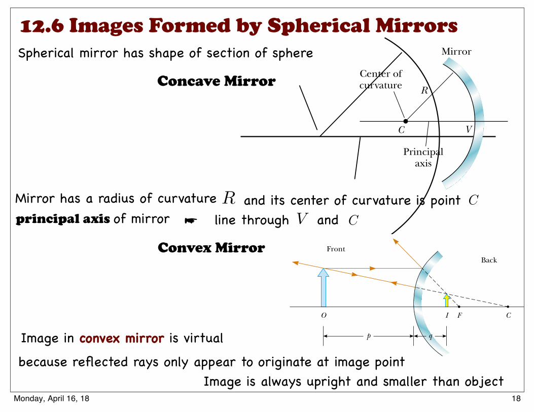
Spherical mirror has shape of section of sphere
Mirror has a radius of curvature and its center of curvature is pointR C
line through and CV
36.2 Images Formed by Spherical Mirrors
Concave Mirrors
A spherical mirror, as its name implies, has the shape of a section of a sphere. Thistype of mirror focuses incoming parallel rays to a point, as demonstrated by the col-ored light rays in Figure 36.8. Figure 36.9a shows a cross section of a spherical mirror,with its surface represented by the solid, curved black line. (The blue band representsthe structural support for the mirrored surface, such as a curved piece of glass onwhich the silvered surface is deposited.) Such a mirror, in which light is reflected fromthe inner, concave surface, is called a concave mirror. The mirror has a radius of cur-vature R, and its center of curvature is point C. Point V is the center of the sphericalsection, and a line through C and V is called the principal axis of the mirror.
Now consider a point source of light placed at point O in Figure 36.9b, where O isany point on the principal axis to the left of C. Two diverging rays that originate at Oare shown. After reflecting from the mirror, these rays converge and cross at the imagepoint I. They then continue to diverge from I as if an object were there. As a result, atpoint I we have a real image of the light source at O.
S E C T I O N 3 6 . 2 • Images Formed by Spherical Mirrors 1131
Figure 36.8 Red, blue, and green light raysare reflected by a curved mirror. Note thatthe three colored beams meet at a point.
Mirror
C V
(a)
Center ofcurvature R
Principalaxis
Mirror
O VI
(b)
C
Figure 36.9 (a) A concave mirror of radius R . The center of curvature C is located onthe principal axis. (b) A point object placed at O in front of a concave spherical mirrorof radius R, where O is any point on the principal axis farther than R from the mirrorsurface, forms a real image at I. If the rays diverge from O at small angles, they allreflect through the same image point.
Ken
Kay/
Fund
amen
tal P
hoto
grap
hs
18Thursday, May 5, 16
principal axis of mirror ☛
Convex Mirror
Convex Mirrors
Figure 36.13 shows the formation of an image by a convex mirror—that is, onesilvered so that light is reflected from the outer, convex surface. This is sometimescalled a diverging mirror because the rays from any point on an object diverge afterreflection as though they were coming from some point behind the mirror. The imagein Figure 36.13 is virtual because the reflected rays only appear to originate at theimage point, as indicated by the dashed lines. Furthermore, the image is always uprightand smaller than the object. This type of mirror is often used in stores to foilshoplifters. A single mirror can be used to survey a large field of view because it forms asmaller image of the interior of the store.
We do not derive any equations for convex spherical mirrors because we can useEquations 36.2, 36.4, and 36.6 for either concave or convex mirrors if we adhere tothe following procedure. Let us refer to the region in which light rays move toward themirror as the front side of the mirror, and the other side as the back side. For example, inFigures 36.11 and 36.13, the side to the left of the mirrors is the front side, and theside to the right of the mirrors is the back side. Figure 36.14 states the sign conventionsfor object and image distances, and Table 36.1 summarizes the sign conventions for allquantities.
Ray Diagrams for Mirrors
The positions and sizes of images formed by mirrors can be conveniently deter-mined with ray diagrams. These graphical constructions reveal the nature of theimage and can be used to check results calculated from the mirror and magnifica-tion equations. To draw a ray diagram, we need to know the position of the objectand the locations of the mirror’s focal point and center of curvature. We then drawthree principal rays to locate the image, as shown by the examples in Figure 36.15.
1134 C H A P T E R 3 6 • Image Formation
FrontBack
O I F C
p q
Figure 36.13 Formation of an image by a spherical convex mirror. The image formedby the real object is virtual and upright.
Front, orreal, side
Reflected light
Back, orvirtual, side
p and q negative
No light
p and q positive
Incident light
Convex orconcave mirror
Figure 36.14 Signs of p and q forconvex and concave mirrors.
▲ PITFALL PREVENTION 36.3 Watch Your SignsSuccess in working mirrorproblems (as well as problemsinvolving refracting surfaces andthin lenses) is largely determinedby proper sign choices whensubstituting into the equations.The best way to become adept atthis is to work a multitude ofproblems on your own. Watchingyour instructor or reading the example problems is nosubstitute for practice.
Quantity Positive When Negative When
Object location (p) Object is in front of Object is in backmirror (real object) of mirror (virtual object)
Image location (q) Image is in front of Image is in back ofmirror (real image) mirror (virtual image)
Image height (h!) Image is upright Image is invertedFocal length (f ) Mirror is concave Mirror is convex
and radius (R)Magnification (M) Image is upright Image is inverted
Sign Conventions for Mirrors
Table 36.1
22Thursday, May 5, 16
Image in convex mirror is virtual because reflected rays only appear to originate at image point
Image is always upright and smaller than object18Monday, April 16, 18
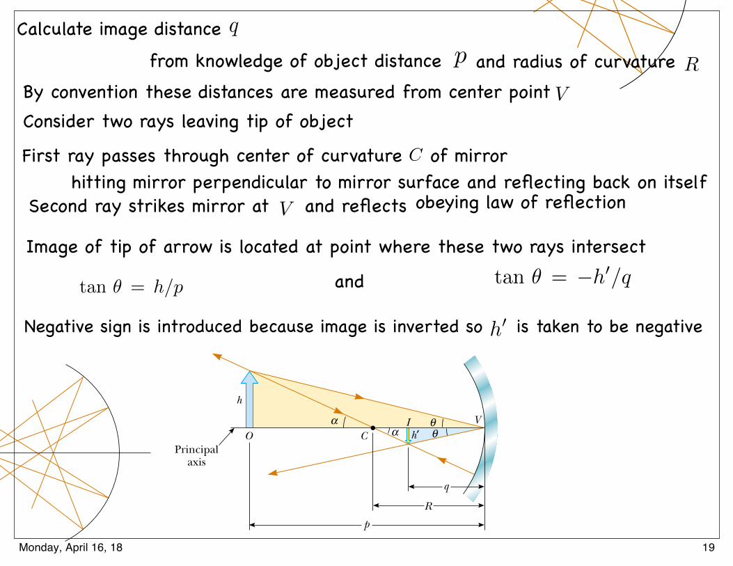
We shall consider in this section only rays that diverge from the object and make asmall angle with the principal axis. Such rays are called paraxial rays. All paraxial raysreflect through the image point, as shown in Figure 36.9b. Rays that are far from theprincipal axis, such as those shown in Figure 36.10, converge to other points on theprincipal axis, producing a blurred image. This effect, which is called spherical aberra-tion, is present to some extent for any spherical mirror and is discussed in Section 36.5.
We can use Figure 36.11 to calculate the image distance q from a knowledge of theobject distance p and radius of curvature R . By convention, these distances are mea-sured from point V. Figure 36.11 shows two rays leaving the tip of the object. One ofthese rays passes through the center of curvature C of the mirror, hitting the mirrorperpendicular to the mirror surface and reflecting back on itself. The second raystrikes the mirror at its center (point V ) and reflects as shown, obeying the law ofreflection. The image of the tip of the arrow is located at the point where these tworays intersect. From the gold right triangle in Figure 36.11, we see that tan! " h/p,and from the blue right triangle we see that tan! " # h$/q. The negative sign is intro-duced because the image is inverted, so h$ is taken to be negative. Thus, from Equation36.1 and these results, we find that the magnification of the image is
(36.2)
We also note from the two triangles in Figure 36.11 that have % as one angle that
from which we find that
(36.3)
If we compare Equations 36.2 and 36.3, we see that
Simple algebra reduces this to
(36.4)
This expression is called the mirror equation.If the object is very far from the mirror—that is, if p is so much greater than R
that p can be said to approach infinity—then 1/p ! 0, and we see from Equation36.4 that q ! R/2. That is, when the object is very far from the mirror, the imagepoint is halfway between the center of curvature and the center point on the mirror,as shown in Figure 36.12a. The incoming rays from the object are essentially parallel
1p
&1q
"2R
R # qp # R
"qp
h$
h" #
R # qp # R
tan % "h
p # R and tan % " #
h$
R # q
M "h$
h" #
qp
1132 C H A P T E R 3 6 • Image Formation
Figure 36.10 Rays diverging fromthe object at large angles from theprincipal axis reflect from aspherical concave mirror tointersect the principal axis atdifferent points, resulting in ablurred image. This condition iscalled spherical aberration.
h
OPrincipal
axis
R
C
q
p
VIh′
αα
θθ
Figure 36.11 The imageformed by a spherical concavemirror when the object O liesoutside the center of curvatureC. This geometric constructionis used to derive Equation 36.4.
Mirror equation in terms ofradius of curvature
20Thursday, May 5, 16
Negative sign is introduced because image is inverted so is taken to be negative
Image of tip of arrow is located at point where these two rays intersect
Second ray strikes mirror at and reflects
First ray passes through center of curvature of mirror
Consider two rays leaving tip of object
Calculate image distance
By convention these distances are measured from center point
q
p Rand radius of curvature
V
C
V
tan ✓ = h/p tan ✓ = �h0/qand
h0
obeying law of reflectionhitting mirror perpendicular to mirror surface and reflecting back on itself
from knowledge of object distance
19Monday, April 16, 18
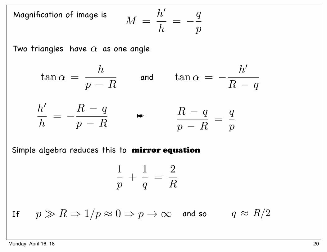
Magnification of image isM =
h0
h= �q
p
Two triangles have as one angle↵
andtan↵ =h
p � R
h0
h= �R � q
p � R
tan↵ = � h0
R � q
Simple algebra reduces this to
R � q
p � R=
q
p
1
p+
1
q=
2
R
mirror equation
☛
p � R ) 1/p ⇡ 0 ) p ! 1 and so If q ⇡ R/2
20Monday, April 16, 18
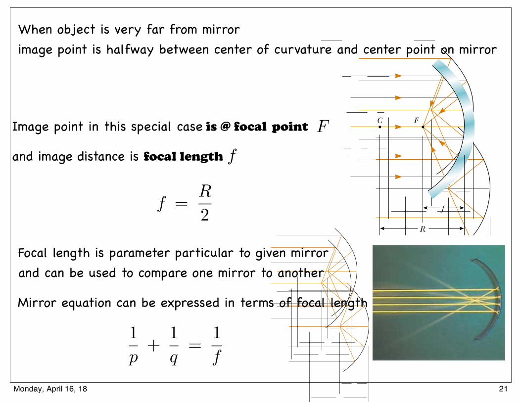
in this figure because the source is assumed to be very far from the mirror. We callthe image point in this special case the focal point F and the image distance thefocal length f, where
(36.5)
In Figure 36.8, the colored beams are traveling parallel to the principal axis and themirror reflects all three beams to the focal point. Notice that the point at which thethree beams intersect and the colors add is white.
Focal length is a parameter particular to a given mirror and therefore can be usedto compare one mirror with another. The mirror equation can be expressed in termsof the focal length:
(36.6)
Notice that the focal length of a mirror depends only on the curvature of the mirrorand not on the material from which the mirror is made. This is because the formationof the image results from rays reflected from the surface of the material. The situationis different for lenses; in that case the light actually passes through the material andthe focal length depends on the type of material from which the lens is made.
1p
!1q
"1f
f "R2
S E C T I O N 3 6 . 2 • Images Formed by Spherical Mirrors 1133
C F
R
f
(a)
Henr
y Lea
p an
d Ji
m Le
hman
Figure 36.12 (a) Light rays from a distant object (p : #) reflect from a concavemirror through the focal point F. In this case, the image distance q ! R/2 " f, wheref is the focal length of the mirror. (b) Reflection of parallel rays from a concave mirror.
▲ PITFALL PREVENTION 36.2 The Focal Point Is
Not the Focus PointThe focal point is usually not thepoint at which the light rays focusto form an image. The focalpoint is determined solely by thecurvature of the mirror—it doesnot depend on the location ofthe object at all. In general, animage forms at a point differentfrom the focal point of a mirror(or a lens). The only exception iswhen the object is located infi-nitely far away from the mirror.
A satellite-dish antenna is a concave reflector for televi-sion signals from a satellite in orbit around the Earth. Thesignals are carried by microwaves that, because thesatellite is so far away, are parallel when they arrive at thedish. These waves reflect from the dish and are focusedon the receiver at the focal point of the dish.
Focal length
Mirror equation in terms of focallength
Cour
tesy
of T
hom
son
Cons
umer
Ele
ctro
nics
(b)
We shall consider in this section only rays that diverge from the object and make asmall angle with the principal axis. Such rays are called paraxial rays. All paraxial raysreflect through the image point, as shown in Figure 36.9b. Rays that are far from theprincipal axis, such as those shown in Figure 36.10, converge to other points on theprincipal axis, producing a blurred image. This effect, which is called spherical aberra-tion, is present to some extent for any spherical mirror and is discussed in Section 36.5.
We can use Figure 36.11 to calculate the image distance q from a knowledge of theobject distance p and radius of curvature R . By convention, these distances are mea-sured from point V. Figure 36.11 shows two rays leaving the tip of the object. One ofthese rays passes through the center of curvature C of the mirror, hitting the mirrorperpendicular to the mirror surface and reflecting back on itself. The second raystrikes the mirror at its center (point V ) and reflects as shown, obeying the law ofreflection. The image of the tip of the arrow is located at the point where these tworays intersect. From the gold right triangle in Figure 36.11, we see that tan! " h/p,and from the blue right triangle we see that tan! " # h$/q. The negative sign is intro-duced because the image is inverted, so h$ is taken to be negative. Thus, from Equation36.1 and these results, we find that the magnification of the image is
(36.2)
We also note from the two triangles in Figure 36.11 that have % as one angle that
from which we find that
(36.3)
If we compare Equations 36.2 and 36.3, we see that
Simple algebra reduces this to
(36.4)
This expression is called the mirror equation.If the object is very far from the mirror—that is, if p is so much greater than R
that p can be said to approach infinity—then 1/p ! 0, and we see from Equation36.4 that q ! R/2. That is, when the object is very far from the mirror, the imagepoint is halfway between the center of curvature and the center point on the mirror,as shown in Figure 36.12a. The incoming rays from the object are essentially parallel
1p
&1q
"2R
R # qp # R
"qp
h$
h" #
R # qp # R
tan % "h
p # R and tan % " #
h$
R # q
M "h$
h" #
qp
1132 C H A P T E R 3 6 • Image Formation
Figure 36.10 Rays diverging fromthe object at large angles from theprincipal axis reflect from aspherical concave mirror tointersect the principal axis atdifferent points, resulting in ablurred image. This condition iscalled spherical aberration.
h
OPrincipal
axis
R
C
q
p
VIh′
αα
θθ
Figure 36.11 The imageformed by a spherical concavemirror when the object O liesoutside the center of curvatureC. This geometric constructionis used to derive Equation 36.4.
Mirror equation in terms ofradius of curvature
in this figure because the source is assumed to be very far from the mirror. We callthe image point in this special case the focal point F and the image distance thefocal length f, where
(36.5)
In Figure 36.8, the colored beams are traveling parallel to the principal axis and themirror reflects all three beams to the focal point. Notice that the point at which thethree beams intersect and the colors add is white.
Focal length is a parameter particular to a given mirror and therefore can be usedto compare one mirror with another. The mirror equation can be expressed in termsof the focal length:
(36.6)
Notice that the focal length of a mirror depends only on the curvature of the mirrorand not on the material from which the mirror is made. This is because the formationof the image results from rays reflected from the surface of the material. The situationis different for lenses; in that case the light actually passes through the material andthe focal length depends on the type of material from which the lens is made.
1p
!1q
"1f
f "R2
S E C T I O N 3 6 . 2 • Images Formed by Spherical Mirrors 1133
C F
R
f
(a)
Henr
y Lea
p an
d Ji
m Le
hman
Figure 36.12 (a) Light rays from a distant object (p : #) reflect from a concavemirror through the focal point F. In this case, the image distance q ! R/2 " f, wheref is the focal length of the mirror. (b) Reflection of parallel rays from a concave mirror.
▲ PITFALL PREVENTION 36.2 The Focal Point Is
Not the Focus PointThe focal point is usually not thepoint at which the light rays focusto form an image. The focalpoint is determined solely by thecurvature of the mirror—it doesnot depend on the location ofthe object at all. In general, animage forms at a point differentfrom the focal point of a mirror(or a lens). The only exception iswhen the object is located infi-nitely far away from the mirror.
A satellite-dish antenna is a concave reflector for televi-sion signals from a satellite in orbit around the Earth. Thesignals are carried by microwaves that, because thesatellite is so far away, are parallel when they arrive at thedish. These waves reflect from the dish and are focusedon the receiver at the focal point of the dish.
Focal length
Mirror equation in terms of focallength
Cour
tesy
of T
hom
son
Cons
umer
Ele
ctro
nics
(b)
21Thursday, May 5, 16
in this figure because the source is assumed to be very far from the mirror. We callthe image point in this special case the focal point F and the image distance thefocal length f, where
(36.5)
In Figure 36.8, the colored beams are traveling parallel to the principal axis and themirror reflects all three beams to the focal point. Notice that the point at which thethree beams intersect and the colors add is white.
Focal length is a parameter particular to a given mirror and therefore can be usedto compare one mirror with another. The mirror equation can be expressed in termsof the focal length:
(36.6)
Notice that the focal length of a mirror depends only on the curvature of the mirrorand not on the material from which the mirror is made. This is because the formationof the image results from rays reflected from the surface of the material. The situationis different for lenses; in that case the light actually passes through the material andthe focal length depends on the type of material from which the lens is made.
1p
!1q
"1f
f "R2
S E C T I O N 3 6 . 2 • Images Formed by Spherical Mirrors 1133
C F
R
f
(a)
Henr
y Lea
p an
d Ji
m Le
hman
Figure 36.12 (a) Light rays from a distant object (p : #) reflect from a concavemirror through the focal point F. In this case, the image distance q ! R/2 " f, wheref is the focal length of the mirror. (b) Reflection of parallel rays from a concave mirror.
▲ PITFALL PREVENTION 36.2 The Focal Point Is
Not the Focus PointThe focal point is usually not thepoint at which the light rays focusto form an image. The focalpoint is determined solely by thecurvature of the mirror—it doesnot depend on the location ofthe object at all. In general, animage forms at a point differentfrom the focal point of a mirror(or a lens). The only exception iswhen the object is located infi-nitely far away from the mirror.
A satellite-dish antenna is a concave reflector for televi-sion signals from a satellite in orbit around the Earth. Thesignals are carried by microwaves that, because thesatellite is so far away, are parallel when they arrive at thedish. These waves reflect from the dish and are focusedon the receiver at the focal point of the dish.
Focal length
Mirror equation in terms of focallength
Cour
tesy
of T
hom
son
Cons
umer
Ele
ctro
nics
(b)
We shall consider in this section only rays that diverge from the object and make asmall angle with the principal axis. Such rays are called paraxial rays. All paraxial raysreflect through the image point, as shown in Figure 36.9b. Rays that are far from theprincipal axis, such as those shown in Figure 36.10, converge to other points on theprincipal axis, producing a blurred image. This effect, which is called spherical aberra-tion, is present to some extent for any spherical mirror and is discussed in Section 36.5.
We can use Figure 36.11 to calculate the image distance q from a knowledge of theobject distance p and radius of curvature R . By convention, these distances are mea-sured from point V. Figure 36.11 shows two rays leaving the tip of the object. One ofthese rays passes through the center of curvature C of the mirror, hitting the mirrorperpendicular to the mirror surface and reflecting back on itself. The second raystrikes the mirror at its center (point V ) and reflects as shown, obeying the law ofreflection. The image of the tip of the arrow is located at the point where these tworays intersect. From the gold right triangle in Figure 36.11, we see that tan! " h/p,and from the blue right triangle we see that tan! " # h$/q. The negative sign is intro-duced because the image is inverted, so h$ is taken to be negative. Thus, from Equation36.1 and these results, we find that the magnification of the image is
(36.2)
We also note from the two triangles in Figure 36.11 that have % as one angle that
from which we find that
(36.3)
If we compare Equations 36.2 and 36.3, we see that
Simple algebra reduces this to
(36.4)
This expression is called the mirror equation.If the object is very far from the mirror—that is, if p is so much greater than R
that p can be said to approach infinity—then 1/p ! 0, and we see from Equation36.4 that q ! R/2. That is, when the object is very far from the mirror, the imagepoint is halfway between the center of curvature and the center point on the mirror,as shown in Figure 36.12a. The incoming rays from the object are essentially parallel
1p
&1q
"2R
R # qp # R
"qp
h$
h" #
R # qp # R
tan % "h
p # R and tan % " #
h$
R # q
M "h$
h" #
qp
1132 C H A P T E R 3 6 • Image Formation
Figure 36.10 Rays diverging fromthe object at large angles from theprincipal axis reflect from aspherical concave mirror tointersect the principal axis atdifferent points, resulting in ablurred image. This condition iscalled spherical aberration.
h
OPrincipal
axis
R
C
q
p
VIh′
αα
θθ
Figure 36.11 The imageformed by a spherical concavemirror when the object O liesoutside the center of curvatureC. This geometric constructionis used to derive Equation 36.4.
Mirror equation in terms ofradius of curvature
in this figure because the source is assumed to be very far from the mirror. We callthe image point in this special case the focal point F and the image distance thefocal length f, where
(36.5)
In Figure 36.8, the colored beams are traveling parallel to the principal axis and themirror reflects all three beams to the focal point. Notice that the point at which thethree beams intersect and the colors add is white.
Focal length is a parameter particular to a given mirror and therefore can be usedto compare one mirror with another. The mirror equation can be expressed in termsof the focal length:
(36.6)
Notice that the focal length of a mirror depends only on the curvature of the mirrorand not on the material from which the mirror is made. This is because the formationof the image results from rays reflected from the surface of the material. The situationis different for lenses; in that case the light actually passes through the material andthe focal length depends on the type of material from which the lens is made.
1p
!1q
"1f
f "R2
S E C T I O N 3 6 . 2 • Images Formed by Spherical Mirrors 1133
C F
R
f
(a)He
nry L
eap
and
Jim
Lehm
an
Figure 36.12 (a) Light rays from a distant object (p : #) reflect from a concavemirror through the focal point F. In this case, the image distance q ! R/2 " f, wheref is the focal length of the mirror. (b) Reflection of parallel rays from a concave mirror.
▲ PITFALL PREVENTION 36.2 The Focal Point Is
Not the Focus PointThe focal point is usually not thepoint at which the light rays focusto form an image. The focalpoint is determined solely by thecurvature of the mirror—it doesnot depend on the location ofthe object at all. In general, animage forms at a point differentfrom the focal point of a mirror(or a lens). The only exception iswhen the object is located infi-nitely far away from the mirror.
A satellite-dish antenna is a concave reflector for televi-sion signals from a satellite in orbit around the Earth. Thesignals are carried by microwaves that, because thesatellite is so far away, are parallel when they arrive at thedish. These waves reflect from the dish and are focusedon the receiver at the focal point of the dish.
Focal length
Mirror equation in terms of focallength
Cour
tesy
of T
hom
son
Cons
umer
Ele
ctro
nics
(b)
21Thursday, May 5, 16
When object is very far from mirror image point is halfway between center of curvature and center point on mirror
Image point in this special case is @ focal point F
fand image distance is focal length
f =R
2
Focal length is parameter particular to given mirror and can be used to compare one mirror to another
Mirror equation can be expressed in terms of focal length
1
p+
1
q=
1
f
21Monday, April 16, 18
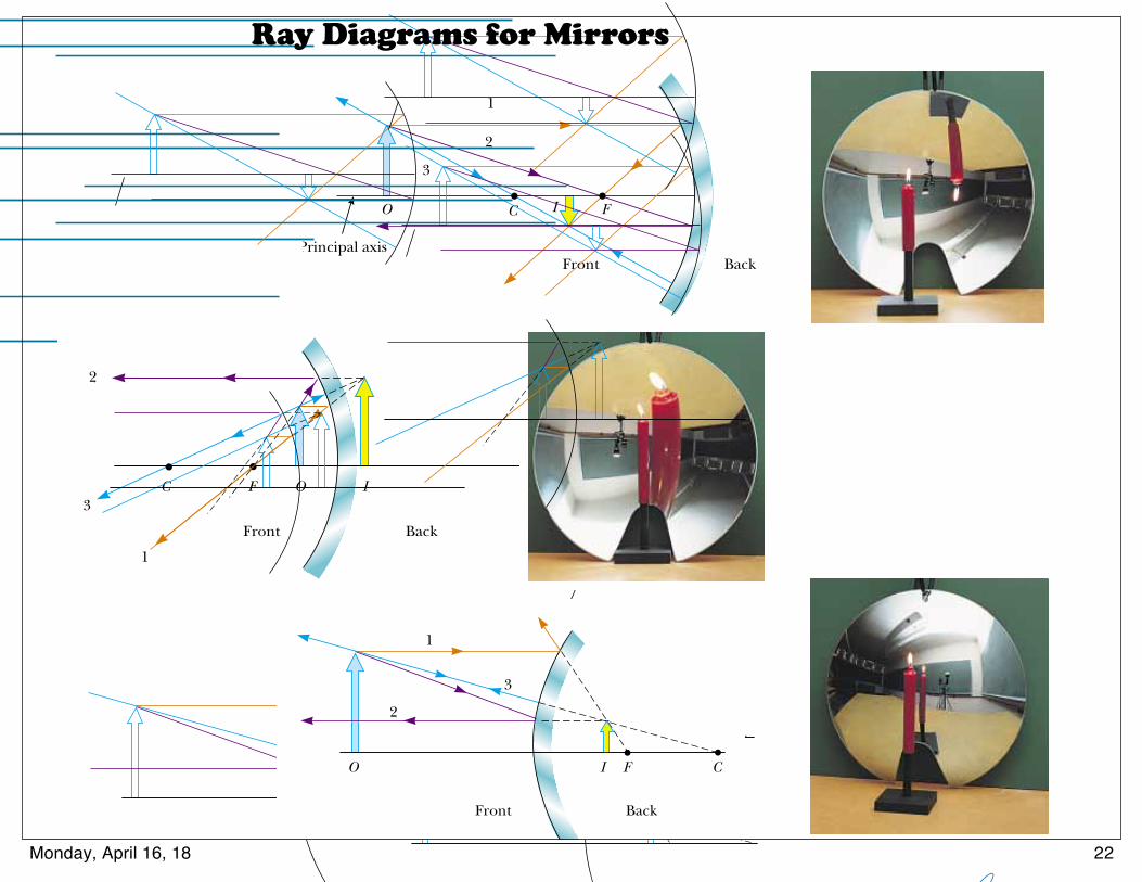
S E C T I O N 3 6 . 2 • Images Formed by Spherical Mirrors 1135
(a)
1
2
3
C FO
Front Back
I
Principal axis
(b)
1
2
3C F O I
Front Back
(c)
CFO I
1
2
3
Front Back
Active Figure 36.15 Ray diagrams for spherical mirrors, along with correspondingphotographs of the images of candles. (a) When the object is located so that the centerof curvature lies between the object and a concave mirror surface, the image is real,inverted, and reduced in size. (b) When the object is located between the focal pointand a concave mirror surface, the image is virtual, upright, and enlarged. (c) When theobject is in front of a convex mirror, the image is virtual, upright, and reduced in size.
Phot
os co
urte
sy D
avid
Rog
ers
At the Active Figures linkat http://www.pse6.com, youcan move the objects andchange the focal length of themirrors to see the effect on theimages.
Convex Mirrors
Figure 36.13 shows the formation of an image by a convex mirror—that is, onesilvered so that light is reflected from the outer, convex surface. This is sometimescalled a diverging mirror because the rays from any point on an object diverge afterreflection as though they were coming from some point behind the mirror. The imagein Figure 36.13 is virtual because the reflected rays only appear to originate at theimage point, as indicated by the dashed lines. Furthermore, the image is always uprightand smaller than the object. This type of mirror is often used in stores to foilshoplifters. A single mirror can be used to survey a large field of view because it forms asmaller image of the interior of the store.
We do not derive any equations for convex spherical mirrors because we can useEquations 36.2, 36.4, and 36.6 for either concave or convex mirrors if we adhere tothe following procedure. Let us refer to the region in which light rays move toward themirror as the front side of the mirror, and the other side as the back side. For example, inFigures 36.11 and 36.13, the side to the left of the mirrors is the front side, and theside to the right of the mirrors is the back side. Figure 36.14 states the sign conventionsfor object and image distances, and Table 36.1 summarizes the sign conventions for allquantities.
Ray Diagrams for Mirrors
The positions and sizes of images formed by mirrors can be conveniently deter-mined with ray diagrams. These graphical constructions reveal the nature of theimage and can be used to check results calculated from the mirror and magnifica-tion equations. To draw a ray diagram, we need to know the position of the objectand the locations of the mirror’s focal point and center of curvature. We then drawthree principal rays to locate the image, as shown by the examples in Figure 36.15.
1134 C H A P T E R 3 6 • Image Formation
FrontBack
O I F C
p q
Figure 36.13 Formation of an image by a spherical convex mirror. The image formedby the real object is virtual and upright.
Front, orreal, side
Reflected light
Back, orvirtual, side
p and q negative
No light
p and q positive
Incident light
Convex orconcave mirror
Figure 36.14 Signs of p and q forconvex and concave mirrors.
▲ PITFALL PREVENTION 36.3 Watch Your SignsSuccess in working mirrorproblems (as well as problemsinvolving refracting surfaces andthin lenses) is largely determinedby proper sign choices whensubstituting into the equations.The best way to become adept atthis is to work a multitude ofproblems on your own. Watchingyour instructor or reading the example problems is nosubstitute for practice.
Quantity Positive When Negative When
Object location (p) Object is in front of Object is in backmirror (real object) of mirror (virtual object)
Image location (q) Image is in front of Image is in back ofmirror (real image) mirror (virtual image)
Image height (h!) Image is upright Image is invertedFocal length (f ) Mirror is concave Mirror is convex
and radius (R)Magnification (M) Image is upright Image is inverted
Sign Conventions for Mirrors
Table 36.1
24Thursday, May 5, 16
Ray Diagrams for Mirrors
22Monday, April 16, 18
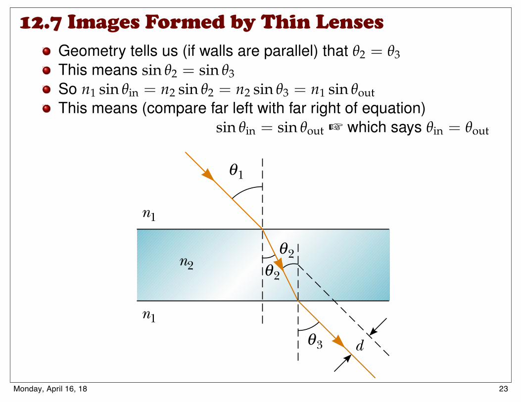
How Light Works Ray optics
Geometry tells us (if walls are parallel) that q2 = q3This means sin q2 = sin q3So n1 sin qin = n2 sin q2 = n2 sin q3 = n1 sin qoutThis means (compare far left with far right of equation)
sin qin = sin qout + which says qin = qout
S E C T I O N 3 5 . 6 • Huygens’s Principle 1107
Figure 35.16 (Example 35.6) (a) When light passes through a flat slab of material, theemerging beam is parallel to the incident beam, and therefore !1 " !3. The dashedline drawn parallel to the ray coming out the bottom of the slab represents the path thelight would take if the slab were not there. (b) A magnification of the area of the lightpath inside the slab.
Explore refraction through slabs of various thicknesses at the Interactive Worked Example link at http://www.pse6.com.
What If? What if the thickness t of the slab is doubled?Does the offset distance d also double?
Answer Consider the magnification of the area of the lightpath within the slab in Figure 35.16b. The distance a is thehypotenuse of two right triangles. From the gold triangle,we see
and from the blue triangle,
a "t
cos ! 2
d " a sin # " a sin(!1 $ !2)
Combining these equations, we have
For a given incident angle !1, the refracted angle !2 is deter-mined solely by the index of refraction, so the offsetdistance d is proportional to t. If the thickness doubles, sodoes the offset distance.
d "t
cos ! 2 sin(! 1 $ ! 2)
35.6 Huygens’s Principle
In this section, we develop the laws of reflection and refraction by using a geometricmethod proposed by Huygens in 1678. Huygens’s principle is a geometric construc-tion for using knowledge of an earlier wave front to determine the position of a newwave front at some instant. In Huygens’s construction,
all points on a given wave front are taken as point sources for the production ofspherical secondary waves, called wavelets, which propagate outward througha medium with speeds characteristic of waves in that medium. After some time intervalhas passed, the new position of the wave front is the surface tangent to the wavelets.
First, consider a plane wave moving through free space, as shown in Figure 35.17a.At t " 0, the wave front is indicated by the plane labeled AA%. In Huygens’s construc-tion, each point on this wave front is considered a point source. For clarity, only threepoints on AA% are shown. With these points as sources for the wavelets, we draw circles,each of radius c &t , where c is the speed of light in vacuum and &t is some time intervalduring which the wave propagates. The surface drawn tangent to these wavelets is theplane BB%, which is the wave front at a later time, and is parallel to AA%. In a similarmanner, Figure 35.17b shows Huygens’s construction for a spherical wave.
▲ PITFALL PREVENTION 35.4 Of What Use Is
Huygens’s Principle?At this point, the importance ofHuygens’s principle may not beevident. Predicting the positionof a future wave front may notseem to be very critical. However,we will use Huygens’s principle inlater chapters to explain addi-tional wave phenomena for light.
d
2θ
θ1θ
ta
γn2
n1
n1
θ1θ
2θ
3θ
(b)(a)
d
2θ
L. A. Anchordoqui (CUNY) Conceptual Physics 10-3-2017 15 / 20
12.7 Images Formed by Thin Lenses
23Monday, April 16, 18
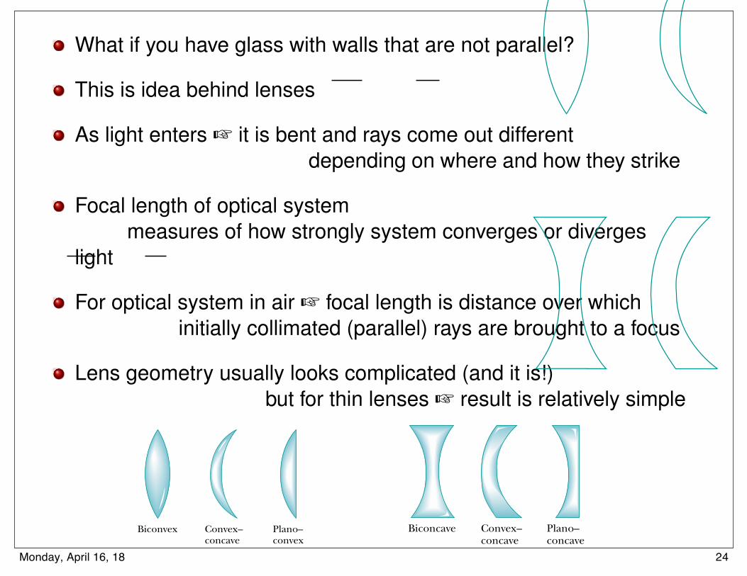
How Light Works Ray optics
What if you have glass with walls that are not parallel?
This is idea behind lenses
As light enters + it is bent and rays come out differentdepending on where and how they strike
Focal length of optical systemmeasures of how strongly system converges or diverges
light
For optical system in air + focal length is distance over whichinitially collimated (parallel) rays are brought to a focus
Lens geometry usually looks complicated (and it is!)but for thin lenses + result is relatively simple
1object distance
+1
image distance=
1focal length
L. A. Anchordoqui (CUNY) Conceptual Physics 10-3-2017 16 / 20
Various lens shapes are shown in Figure 36.27. Note that a converging lens isthicker at the center than at the edge, whereas a diverging lens is thinner at the centerthan at the edge.
Magnification of Images
Consider a thin lens through which light rays from an object pass. As with mirrors (Eq.36.2), we could analyze a geometric construction to show that the lateral magnificationof the image is
From this expression, it follows that when M is positive, the image is upright and onthe same side of the lens as the object. When M is negative, the image is inverted andon the side of the lens opposite the object.
Ray Diagrams for Thin Lenses
Ray diagrams are convenient for locating the images formed by thin lenses or systemsof lenses. They also help clarify our sign conventions. Figure 36.28 shows such dia-grams for three single-lens situations.
To locate the image of a converging lens (Fig. 36.28a and b), the following three raysare drawn from the top of the object:
M !h"
h! #
qp
S E C T I O N 3 6 . 4 • Thin Lenses 1145
(a)
(b)
Convex–concave
Convex–concave
Plano–concave
Plano–convex
Biconvex
Biconcave
Figure 36.27 Various lens shapes.(a) Converging lenses have a posi-tive focal length and are thickest atthe middle. (b) Diverging lenseshave a negative focal length andare thickest at the edges.
O
(a)
F1
Front
F2
Back
I
1
23
I
(b)
F1
Front
F2
Back
O
1
2
3
O
(c)
F1
Front
F2
Back
I
1
2
3
Active Figure 36.28 Ray diagrams for locating the image formedby a thin lens. (a) When the object is in front of and outside thefocal point of a converging lens, the image is real, inverted, and onthe back side of the lens. (b) When the object is between the focalpoint and a converging lens, the image is virtual, upright, largerthan the object, and on the front side of the lens. (c) When anobject is anywhere in front of a diverging lens, the image is virtual,upright, smaller than the object, and on the front side of the lens.
At the Active Figures link at http://www.pse6.com, youcan move the objects and change the focal length of thelenses to see the effect on the images.
• Ray 1 is drawn parallel to the principal axis. After being refracted by the lens, thisray passes through the focal point on the back side of the lens.
• Ray 2 is drawn through the center of the lens and continues in a straight line.
• Ray 3 is drawn through the focal point on the front side of the lens (or as ifcoming from the focal point if p $ f ) and emerges from the lens parallel to theprincipal axis.
33Thursday, May 5, 16
Various lens shapes are shown in Figure 36.27. Note that a converging lens isthicker at the center than at the edge, whereas a diverging lens is thinner at the centerthan at the edge.
Magnification of Images
Consider a thin lens through which light rays from an object pass. As with mirrors (Eq.36.2), we could analyze a geometric construction to show that the lateral magnificationof the image is
From this expression, it follows that when M is positive, the image is upright and onthe same side of the lens as the object. When M is negative, the image is inverted andon the side of the lens opposite the object.
Ray Diagrams for Thin Lenses
Ray diagrams are convenient for locating the images formed by thin lenses or systemsof lenses. They also help clarify our sign conventions. Figure 36.28 shows such dia-grams for three single-lens situations.
To locate the image of a converging lens (Fig. 36.28a and b), the following three raysare drawn from the top of the object:
M !h"
h! #
qp
S E C T I O N 3 6 . 4 • Thin Lenses 1145
(a)
(b)
Convex–concave
Convex–concave
Plano–concave
Plano–convex
Biconvex
Biconcave
Figure 36.27 Various lens shapes.(a) Converging lenses have a posi-tive focal length and are thickest atthe middle. (b) Diverging lenseshave a negative focal length andare thickest at the edges.
O
(a)
F1
Front
F2
Back
I
1
23
I
(b)
F1
Front
F2
Back
O
1
2
3
O
(c)
F1
Front
F2
Back
I
1
2
3
Active Figure 36.28 Ray diagrams for locating the image formedby a thin lens. (a) When the object is in front of and outside thefocal point of a converging lens, the image is real, inverted, and onthe back side of the lens. (b) When the object is between the focalpoint and a converging lens, the image is virtual, upright, largerthan the object, and on the front side of the lens. (c) When anobject is anywhere in front of a diverging lens, the image is virtual,upright, smaller than the object, and on the front side of the lens.
At the Active Figures link at http://www.pse6.com, youcan move the objects and change the focal length of thelenses to see the effect on the images.
• Ray 1 is drawn parallel to the principal axis. After being refracted by the lens, thisray passes through the focal point on the back side of the lens.
• Ray 2 is drawn through the center of the lens and continues in a straight line.
• Ray 3 is drawn through the focal point on the front side of the lens (or as ifcoming from the focal point if p $ f ) and emerges from the lens parallel to theprincipal axis.
33Thursday, May 5, 16
24Monday, April 16, 18
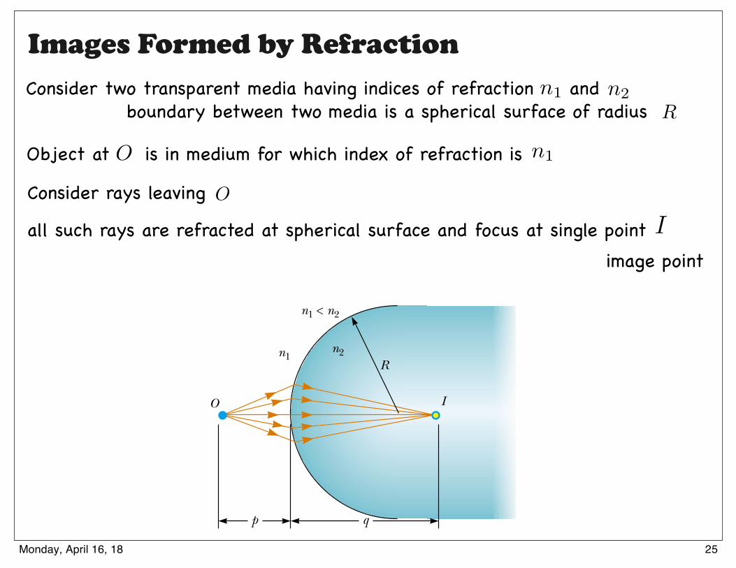
36.3 Images Formed by Refraction
In this section we describe how images are formed when light rays are refracted at theboundary between two transparent materials. Consider two transparent media havingindices of refraction n1 and n2, where the boundary between the two media is a spheri-cal surface of radius R (Fig. 36.18). We assume that the object at O is in the mediumfor which the index of refraction is n1. Let us consider the paraxial rays leaving O. Aswe shall see, all such rays are refracted at the spherical surface and focus at a singlepoint I, the image point.
Figure 36.19 shows a single ray leaving point O and refracting to point I. Snell’s lawof refraction applied to this ray gives
Because !1 and !2 are assumed to be small, we can use the small-angle approximationsin ! ! ! (with angles in radians) and say that
Now we use the fact that an exterior angle of any triangle equals the sum of the twoopposite interior angles. Applying this rule to triangles OPC and PIC in Figure 36.19 gives
" # ! 2 $ %
! 1 # & $ "
n1! 1 # n2! 2
n1 sin ! 1 # n2 sin ! 2
1138 C H A P T E R 3 6 • Image Formation
The negative value of q indicates that her image is virtual, orbehind the mirror, as shown in Figure 36.15c.
(B) The magnification of the image is
The image is much smaller than the woman, and it isupright because M is positive.
$0.077M # 'qp
# '" '0.23 m3.0 m # #
'0.23 mq #
1q
#1
'0.25 m'
13.0 m
1p
$1q
#1f
#1
'0.25 m
Figure 36.17 (Example 36.5) Convex mirrors, often used for security in department stores, provide wide-angle viewing.
Investigate the image formed for various object positions and mirror focal lengths at the Interactive Worked Example linkat http://www.pse6.com.
n1 < n2
O I
p q
n2n1R
Figure 36.18 An image formed byrefraction at a spherical surface. Raysmaking small angles with the principal axisdiverge from a point object at O and arerefracted through the image point I.
©19
90 P
aul S
ilver
man
/Fun
dam
enta
l Pho
togr
aphs
25Thursday, May 5, 16
Images Formed by RefractionConsider two transparent media having indices of refraction and
Object at is in medium for which index of refraction is
Consider rays leaving
all such rays are refracted at spherical surface and focus at single point
boundary between two media is a spherical surface of radius Rn1 n2
n1
O
O
I
image point
25Monday, April 16, 18
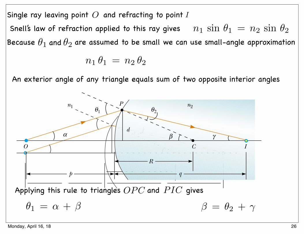
An exterior angle of any triangle equals sum of two opposite interior angles
Applying this rule to triangles and gives
O
If we combine all three expressions and eliminate !1 and !2, we find that
(36.7)
From Figure 36.19, we see three right triangles that have a common vertical leg oflength d. For paraxial rays (unlike the relatively large-angle ray shown in Fig. 36.19),the horizontal legs of these triangles are approximately p for the triangle containingangle ", R for the triangle containing angle #, and q for the triangle containing angle$. In the small-angle approximation, tan! ! !, so we can write the approximate rela-tionships from these triangles as follows:
We substitute these expressions into Equation 36.7 and divide through by d to give
(36.8)
For a fixed object distance p, the image distance q is independent of the angle that theray makes with the axis. This result tells us that all paraxial rays focus at the same point I.
As with mirrors, we must use a sign convention if we are to apply this equation to avariety of cases. We define the side of the surface in which light rays originate as thefront side. The other side is called the back side. Real images are formed by refractionin back of the surface, in contrast with mirrors, where real images are formed in frontof the reflecting surface. Because of the difference in location of real images, therefraction sign conventions for q and R are opposite the reflection sign conventions.For example, q and R are both positive in Figure 36.19. The sign conventions for spher-ical refracting surfaces are summarized in Table 36.2.
We derived Equation 36.8 from an assumption that n1 % n2 in Figure 36.19. Thisassumption is not necessary, however. Equation 36.8 is valid regardless of which indexof refraction is greater.
n1
p&
n2
q'
n2 ( n1
R
tan " ! " !dp tan # ! # !
dR tan $ ! $ !
dq
n1" & n2$ ' (n2 ( n1)#
S E C T I O N 3 6 . 3 • Images Formed by Refraction 1139
Relation between object andimage distance for a refractingsurface
O
P
R
C
n1 n2
d
p q
γα βI
θ1 θ2
Figure 36.19 Geometry used to derive Equation 36.8, assuming that n1 % n2.
Quantity Positive When Negative When
Object location (p) Object is in front of Object is in back of surface (real object) surface (virtual object)
Image location (q) Image is in back of Image is in front of surface (real image) surface (virtual image)
Image height (h)) Image is upright Image is invertedRadius (R) Center of curvature Center of curvature
is in back of surface is in front of surface
Sign Conventions for Refracting Surfaces
Table 36.2
26Thursday, May 5, 16
ISingle ray leaving point and refracting to point
Snell’s law of refraction applied to this ray gives
Because are assumed to be small we can use small-angle approximationn1 sin ✓1 = n2 sin ✓2
n1 ✓1 = n2 ✓2
✓1 ✓2and
✓1 = ↵ + � � = ✓2 + �
OPC PIC
26Monday, April 16, 18

If we combine all three expressions and eliminate and ✓1 ✓2
n1 ↵ + n2 � = (n2 � n1)�In small-angle approximation
substitute these expressions and divide through by to give valuable equation
For a fixed object distance image distance ray makes with axis
tan ↵ ⇡ ↵ ⇡ d
ptan � ⇡ � ⇡ d
Rtan � ⇡ � ⇡ d
q
n1
p+
n2
q=
n2 � n1
R
tan ✓ ⇡ ✓
d
qp
is independent of angle that
Eq. ($)
27Monday, April 16, 18
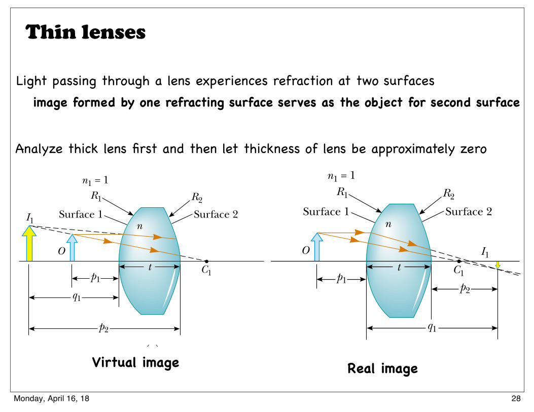
Thin lenses
Light passing through a lens experiences refraction at two surfacesimage formed by one refracting surface serves as the object for second surface
Analyze thick lens first and then let thickness of lens be approximately zero
36.4 Thin Lenses
Lenses are commonly used to form images by refraction in optical instruments, suchas cameras, telescopes, and microscopes. We can use what we just learned aboutimages formed by refracting surfaces to help us locate the image formed by a lens.We recognize that light passing through a lens experiences refraction at twosurfaces. The development we shall follow is based on the notion that the image
S E C T I O N 3 6 . 4 • Thin Lenses 1141
3.0 cm
2.0 cm
q
n2n1
n1 > n2
Figure 36.21 (Example 36.7) Light rays from a coin embeddedin a plastic sphere form a virtual image between the surfaceof the object and the sphere surface. Because the object is insidethe sphere, the front of the refracting surface is the interior ofthe sphere.
from Table 36.2 that R is negative, we obtain
The negative sign for q indicates that the image is in front ofthe surface—in other words, in the same medium as theobject, as shown in Figure 36.21. Being in the same mediumas the object, the image must be virtual. (See Table 36.2.)The coin appears to be closer to the paperweight surfacethan it actually is.
!1.7 cmq "
1.50
2.0 cm#
1q
"1.00 ! 1.50
!3.0 cm
n1
p#
n2
q"
n2 ! n1
R
Example 36.8 The One That Got Away
The apparent height h$ of the fish is
and the fish appears to be approximately three-fourths itsactual height.
" 0.752h
h$ " q top ! q bottom " !0.752d ! [!0.752(d # h)]
A small fish is swimming at a depth d below the surface of apond (Fig. 36.22). What is the apparent depth of the fish, asviewed from directly overhead?
Solution Because the refracting surface is flat, R is infinite.Hence, we can use Equation 36.9 to determine the locationof the image with p " d. Using the indices of refractiongiven in Figure 36.22, we obtain
Because q is negative, the image is virtual, as indicated bythe dashed lines in Figure 36.22. The apparent depth isapproximately three-fourths the actual depth.
What If? What if you look more carefully at the fish andmeasure its apparent height, from its upper fin to its lowerfin? Is the apparent height h! of the fish different from theactual height h?
Answer Because all points on the fish appear to be frac-tionally closer to the observer, we would predict that theheight would be smaller. If we let the distance d in Figure36.22 be measured to the top fin and the distance to thebottom fin be d # h, then the images of the top and bottomof the fish are located at
q bottom " !0.752(d # h)
q top " !0.752d
!0.752dq " !n2
n1 p " !
1.001.33
d "
d
q
n2 = 1.00
n1 = 1.33
Figure 36.22 (Example 36.8) The apparent depth q of thefish is less than the true depth d. All rays are assumed to beparaxial.
formed by one refracting surface serves as the object for the second surface.We shall analyze a thick lens first and then let the thickness of the lens be approxi-mately zero.
Consider a lens having an index of refraction n and two spherical surfaces withradii of curvature R1 and R2, as in Figure 36.23. (Note that R1 is the radius of curva-ture of the lens surface that the light from the object reaches first and that R2 is theradius of curvature of the other surface of the lens.) An object is placed at point O at adistance p1 in front of surface 1.
Let us begin with the image formed by surface 1. Using Equation 36.8 and assum-ing that n1 ! 1 because the lens is surrounded by air, we find that the image I1 formedby surface 1 satisfies the equation
(36.10)
where q 1 is the position of the image due to surface 1. If the image due tosurface 1 is virtual (Fig. 36.23a), q 1 is negative, and it is positive if the image is real(Fig. 36.23b).
Now we apply Equation 36.8 to surface 2, taking n1 ! n and n 2 ! 1. (We make thisswitch in index because the light rays approaching surface 2 are in the material of thelens, and this material has index n.) Taking p 2 as the object distance for surface 2 andq2 as the image distance gives
(36.11)
We now introduce mathematically the fact that the image formed by the firstsurface acts as the object for the second surface. We do this by noting from Figure36.23 that p2, measured from surface 2, is related to q1 as follows:
Virtual image from surface 1 (Fig. 36.23a): p2 ! " q1 # t (q1 is negative)
Real image from surface 1 (Fig. 36.23b): p2 ! " q1 # t (q1 is positive)
np 2
#1q 2
!1 " n
R 2
1p 1
#nq 1
!n " 1
R 1
1142 C H A P T E R 3 6 • Image Formation
tp1
q1
p2
O
I1
C1
Surface 1
R1
nSurface 2
R2
n1 = 1
tp1
q1
O
C1
Surface 1
R1
nSurface 2
R2
n1 = 1
p2
I1
(a)
(b)
Figure 36.23 To locate the image formedby a lens, we use the virtual image at I1formed by surface 1 as the object for theimage formed by surface 2. The point C1 isthe center of curvature of surface 1. (a) Theimage due to surface 1 is virtual so that I1 isto the left of the surface. (b) The image dueto surface 1 is real so that I1 is to the right ofthe surface.
29Thursday, May 5, 16
Virtual image Real image
28Monday, April 16, 18
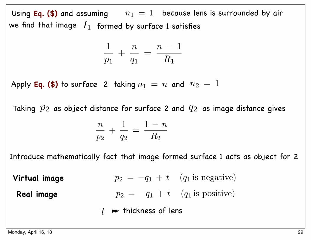
Using Eq. ($) and assuming we find that image formed by surface 1 satisfies
n1 = 1 because lens is surrounded by airI1
1
p1+
n
q1=
n � 1
R1
Apply Eq. ($) to surface 2 taking and
Taking as object distance for surface 2 and as image distance gives
Introduce mathematically fact that image formed surface 1 acts as object for 2
p2 q2
n1 = n n2 = 1
Virtual image
Real image
p2 = �q1 + t (q1 is negative)
p2 = �q1 + t (q1 is positive)
n
p2+
1
q2=
1 � n
R2
☛ thickness of lenst
29Monday, April 16, 18
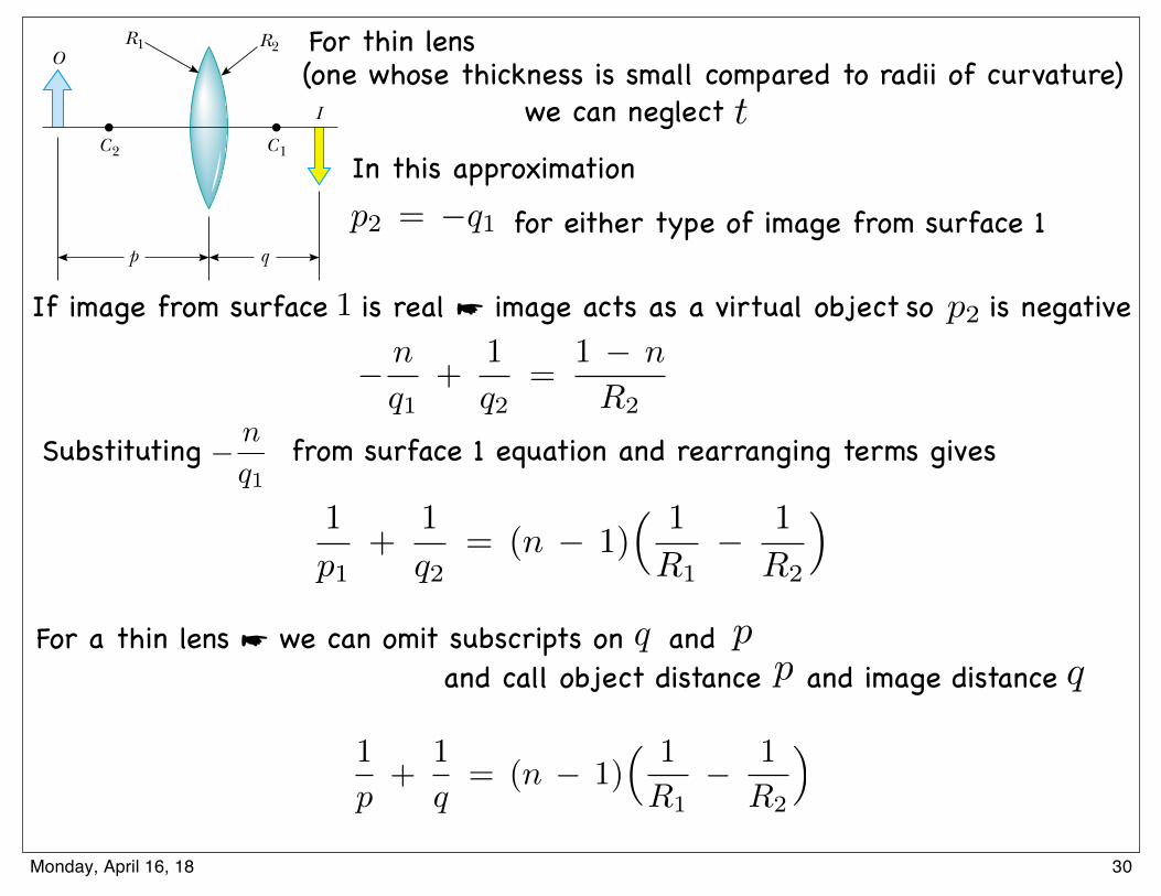
where t is the thickness of the lens. For a thin lens (one whose thickness is smallcompared to the radii of curvature), we can neglect t. In this approximation, we seethat p 2 ! " q 1 for either type of image from surface 1. (If the image from surface 1is real, the image acts as a virtual object, so p 2 is negative.) Hence, Equation 36.11becomes
(36.12)
Adding Equations 36.10 and 36.12, we find that
(36.13)
For a thin lens, we can omit the subscripts on p1 and q2 in Equation 36.13 and call theobject distance p and the image distance q, as in Figure 36.24. Hence, we can writeEquation 36.13 in the form
(36.14)
This expression relates the image distance q of the image formed by a thin lens to theobject distance p and to the lens properties (index of refraction and radii of curva-ture). It is valid only for paraxial rays and only when the lens thickness is much lessthan R1 and R2.
The focal length f of a thin lens is the image distance that corresponds to an infi-nite object distance, just as with mirrors. Letting p approach # and q approach f inEquation 36.14, we see that the inverse of the focal length for a thin lens is
(36.15)
This relationship is called the lens makers’ equation because it can be used to deter-mine the values of R1 and R2 that are needed for a given index of refraction and adesired focal length f. Conversely, if the index of refraction and the radii of curvatureof a lens are given, this equation enables a calculation of the focal length. If the lens isimmersed in something other than air, this same equation can be used, with n inter-preted as the ratio of the index of refraction of the lens material to that of the sur-rounding fluid.
Using Equation 36.15, we can write Equation 36.14 in a form identical to Equation36.6 for mirrors:
(36.16)1p
$1q
!1f
1f
! (n " 1) ! 1R 1
"1
R 2"
1p
$1q
! (n " 1) ! 1R 1
"1
R 2"
1p 1
$1q 2
! (n " 1) ! 1R 1
"1
R 2"
"nq 1
$1q 2
!1 " n
R 2
S E C T I O N 3 6 . 4 • Thin Lenses 1143
C1C2
O
p q
I
R2R1
Figure 36.24 Simplified geometry for a thin lens.
Lens makers’ equation
Thin lens equation
31Thursday, May 5, 16
For thin lens
t
p2 = �q1
If image from surface is real ☛ image acts as a virtual object 1 p2
� n
q1+
1
q2=
1 � n
R2
1
p1+
1
q2= (n � 1)
⇣ 1
R1� 1
R2
⌘
1
p+
1
q= (n � 1)
⇣ 1
R1� 1
R2
⌘
For a thin lens ☛ we can omit subscripts on and qq
pp
(one whose thickness is small compared to radii of curvature)
In this approximation
we can neglect
for either type of image from surface 1
so is negative
and call object distance and image distance
Substituting from surface 1 equation and rearranging terms gives � n
q1
30Monday, April 16, 18
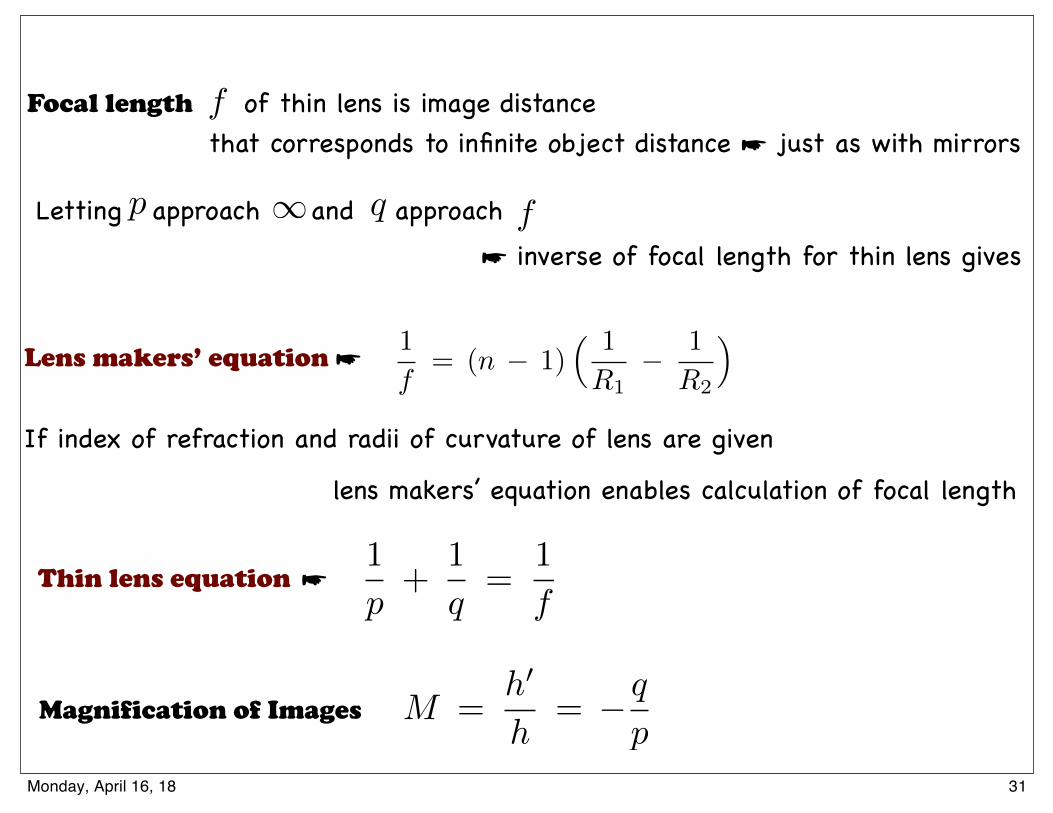
Focal length of thin lens is image distance
Letting approach and approach
f
1p q f
1
f= (n � 1)
⇣ 1
R1� 1
R2
⌘
If index of refraction and radii of curvature of lens are given
1
p+
1
q=
1
f
Lens makers’ equation ☛
Thin lens equation ☛
that corresponds to infinite object distance ☛ just as with mirrors
lens makers’ equation enables calculation of focal length
Magnification of Images
☛ inverse of focal length for thin lens gives
M =h0
h= �q
p
31Monday, April 16, 18
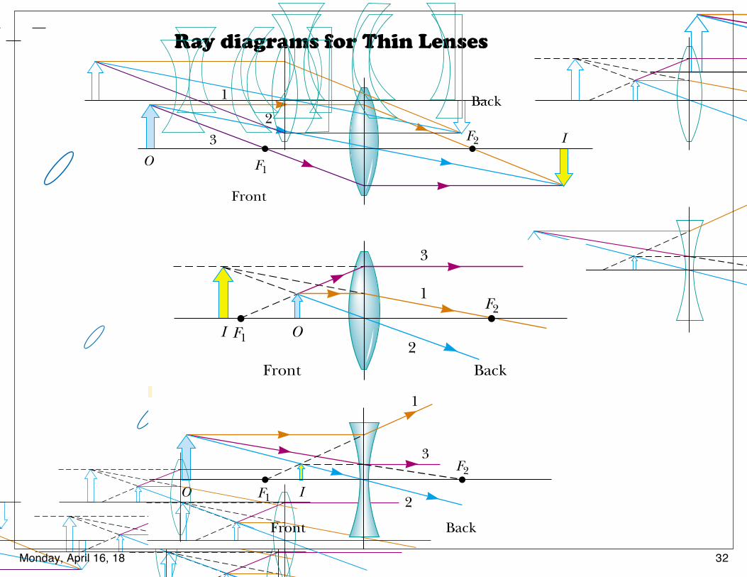
Ray diagrams for Thin Lenses
Various lens shapes are shown in Figure 36.27. Note that a converging lens isthicker at the center than at the edge, whereas a diverging lens is thinner at the centerthan at the edge.
Magnification of Images
Consider a thin lens through which light rays from an object pass. As with mirrors (Eq.36.2), we could analyze a geometric construction to show that the lateral magnificationof the image is
From this expression, it follows that when M is positive, the image is upright and onthe same side of the lens as the object. When M is negative, the image is inverted andon the side of the lens opposite the object.
Ray Diagrams for Thin Lenses
Ray diagrams are convenient for locating the images formed by thin lenses or systemsof lenses. They also help clarify our sign conventions. Figure 36.28 shows such dia-grams for three single-lens situations.
To locate the image of a converging lens (Fig. 36.28a and b), the following three raysare drawn from the top of the object:
M !h"
h! #
qp
S E C T I O N 3 6 . 4 • Thin Lenses 1145
(a)
(b)
Convex–concave
Convex–concave
Plano–concave
Plano–convex
Biconvex
Biconcave
Figure 36.27 Various lens shapes.(a) Converging lenses have a posi-tive focal length and are thickest atthe middle. (b) Diverging lenseshave a negative focal length andare thickest at the edges.
O
(a)
F1
Front
F2
Back
I
1
23
I
(b)
F1
Front
F2
Back
O
1
2
3
O
(c)
F1
Front
F2
Back
I
1
2
3
Active Figure 36.28 Ray diagrams for locating the image formedby a thin lens. (a) When the object is in front of and outside thefocal point of a converging lens, the image is real, inverted, and onthe back side of the lens. (b) When the object is between the focalpoint and a converging lens, the image is virtual, upright, largerthan the object, and on the front side of the lens. (c) When anobject is anywhere in front of a diverging lens, the image is virtual,upright, smaller than the object, and on the front side of the lens.
At the Active Figures link at http://www.pse6.com, youcan move the objects and change the focal length of thelenses to see the effect on the images.
• Ray 1 is drawn parallel to the principal axis. After being refracted by the lens, thisray passes through the focal point on the back side of the lens.
• Ray 2 is drawn through the center of the lens and continues in a straight line.
• Ray 3 is drawn through the focal point on the front side of the lens (or as ifcoming from the focal point if p $ f ) and emerges from the lens parallel to theprincipal axis.
To locate the image of a diverging lens (Fig. 36.28c), the following three rays aredrawn from the top of the object:
1146 C H A P T E R 3 6 • Image Formation
• Ray 1 is drawn parallel to the principal axis. After being refracted by the lens,this ray emerges directed away from the focal point on the front side of thelens.
• Ray 2 is drawn through the center of the lens and continues in a straight line.
• Ray 3 is drawn in the direction toward the focal point on the back side of the lensand emerges from the lens parallel to the principal axis.
For the converging lens in Figure 36.28a, where the object is to the left of the focalpoint (p ! f ), the image is real and inverted. When the object is between the focalpoint and the lens (p " f ), as in Figure 36.28b, the image is virtual and upright. For adiverging lens (see Fig. 36.28c), the image is always virtual and upright, regardless ofwhere the object is placed. These geometric constructions are reasonably accurate onlyif the distance between the rays and the principal axis is much less than the radii of thelens surfaces.
Note that refraction occurs only at the surfaces of the lens. A certain lens designtakes advantage of this fact to produce the Fresnel lens, a powerful lens without greatthickness. Because only the surface curvature is important in the refracting qualities ofthe lens, material in the middle of a Fresnel lens is removed, as shown in the crosssections of lenses in Figure 36.29. Because the edges of the curved segments causesome distortion, Fresnel lenses are usually used only in situations in which imagequality is less important than reduction of weight. A classroom overhead projectoroften uses a Fresnel lens; the circular edges between segments of the lens can be seenby looking closely at the light projected onto a screen.
Figure 36.29 The Fresnel lens onthe left has the same focal length asthe thick lens on the right but ismade of much less glass.
Quick Quiz 36.7 What is the focal length of a pane of window glass?(a) zero (b) infinity (c) the thickness of the glass (d) impossible to determine
Quick Quiz 36.8 Diving masks often have a lens built into the glass fordivers who do not have perfect vision. This allows the individual to dive without thenecessity for glasses, because the lenses in the faceplate perform the necessaryrefraction to provide clear vision. The proper design allows the diver to see clearly withthe mask on both under water and in the open air. Normal eyeglasses have lenses thatare curved on both the front and back surfaces. The lenses in a diving mask should becurved (a) only on the front surface (b) only on the back surface (c) on both the frontand back surfaces.
Example 36.9 Images Formed by a Converging Lens
Solution
(A) First we construct a ray diagram as shown in Figure36.30a. The diagram shows that we should expect a real,inverted, smaller image to be formed on the back side of thelens. The thin lens equation, Equation 36.16, can be used tofind the image distance:
1p
#1q
$1f
A converging lens of focal length 10.0 cm forms images ofobjects placed
(A) 30.0 cm,
(B) 10.0 cm, and
(C) 5.00 cm from the lens.
In each case, construct a ray diagram, find the imagedistance and describe the image.
Interactive
34Thursday, May 5, 16
Various lens shapes are shown in Figure 36.27. Note that a converging lens isthicker at the center than at the edge, whereas a diverging lens is thinner at the centerthan at the edge.
Magnification of Images
Consider a thin lens through which light rays from an object pass. As with mirrors (Eq.36.2), we could analyze a geometric construction to show that the lateral magnificationof the image is
From this expression, it follows that when M is positive, the image is upright and onthe same side of the lens as the object. When M is negative, the image is inverted andon the side of the lens opposite the object.
Ray Diagrams for Thin Lenses
Ray diagrams are convenient for locating the images formed by thin lenses or systemsof lenses. They also help clarify our sign conventions. Figure 36.28 shows such dia-grams for three single-lens situations.
To locate the image of a converging lens (Fig. 36.28a and b), the following three raysare drawn from the top of the object:
M !h"
h! #
qp
S E C T I O N 3 6 . 4 • Thin Lenses 1145
(a)
(b)
Convex–concave
Convex–concave
Plano–concave
Plano–convex
Biconvex
Biconcave
Figure 36.27 Various lens shapes.(a) Converging lenses have a posi-tive focal length and are thickest atthe middle. (b) Diverging lenseshave a negative focal length andare thickest at the edges.
O
(a)
F1
Front
F2
Back
I
1
23
I
(b)
F1
Front
F2
Back
O
1
2
3
O
(c)
F1
Front
F2
Back
I
1
2
3
Active Figure 36.28 Ray diagrams for locating the image formedby a thin lens. (a) When the object is in front of and outside thefocal point of a converging lens, the image is real, inverted, and onthe back side of the lens. (b) When the object is between the focalpoint and a converging lens, the image is virtual, upright, largerthan the object, and on the front side of the lens. (c) When anobject is anywhere in front of a diverging lens, the image is virtual,upright, smaller than the object, and on the front side of the lens.
At the Active Figures link at http://www.pse6.com, youcan move the objects and change the focal length of thelenses to see the effect on the images.
• Ray 1 is drawn parallel to the principal axis. After being refracted by the lens, thisray passes through the focal point on the back side of the lens.
• Ray 2 is drawn through the center of the lens and continues in a straight line.
• Ray 3 is drawn through the focal point on the front side of the lens (or as ifcoming from the focal point if p $ f ) and emerges from the lens parallel to theprincipal axis.
To locate the image of a diverging lens (Fig. 36.28c), the following three rays aredrawn from the top of the object:
1146 C H A P T E R 3 6 • Image Formation
• Ray 1 is drawn parallel to the principal axis. After being refracted by the lens,this ray emerges directed away from the focal point on the front side of thelens.
• Ray 2 is drawn through the center of the lens and continues in a straight line.
• Ray 3 is drawn in the direction toward the focal point on the back side of the lensand emerges from the lens parallel to the principal axis.
For the converging lens in Figure 36.28a, where the object is to the left of the focalpoint (p ! f ), the image is real and inverted. When the object is between the focalpoint and the lens (p " f ), as in Figure 36.28b, the image is virtual and upright. For adiverging lens (see Fig. 36.28c), the image is always virtual and upright, regardless ofwhere the object is placed. These geometric constructions are reasonably accurate onlyif the distance between the rays and the principal axis is much less than the radii of thelens surfaces.
Note that refraction occurs only at the surfaces of the lens. A certain lens designtakes advantage of this fact to produce the Fresnel lens, a powerful lens without greatthickness. Because only the surface curvature is important in the refracting qualities ofthe lens, material in the middle of a Fresnel lens is removed, as shown in the crosssections of lenses in Figure 36.29. Because the edges of the curved segments causesome distortion, Fresnel lenses are usually used only in situations in which imagequality is less important than reduction of weight. A classroom overhead projectoroften uses a Fresnel lens; the circular edges between segments of the lens can be seenby looking closely at the light projected onto a screen.
Figure 36.29 The Fresnel lens onthe left has the same focal length asthe thick lens on the right but ismade of much less glass.
Quick Quiz 36.7 What is the focal length of a pane of window glass?(a) zero (b) infinity (c) the thickness of the glass (d) impossible to determine
Quick Quiz 36.8 Diving masks often have a lens built into the glass fordivers who do not have perfect vision. This allows the individual to dive without thenecessity for glasses, because the lenses in the faceplate perform the necessaryrefraction to provide clear vision. The proper design allows the diver to see clearly withthe mask on both under water and in the open air. Normal eyeglasses have lenses thatare curved on both the front and back surfaces. The lenses in a diving mask should becurved (a) only on the front surface (b) only on the back surface (c) on both the frontand back surfaces.
Example 36.9 Images Formed by a Converging Lens
Solution
(A) First we construct a ray diagram as shown in Figure36.30a. The diagram shows that we should expect a real,inverted, smaller image to be formed on the back side of thelens. The thin lens equation, Equation 36.16, can be used tofind the image distance:
1p
#1q
$1f
A converging lens of focal length 10.0 cm forms images ofobjects placed
(A) 30.0 cm,
(B) 10.0 cm, and
(C) 5.00 cm from the lens.
In each case, construct a ray diagram, find the imagedistance and describe the image.
Interactive
34Thursday, May 5, 16
32Monday, April 16, 18
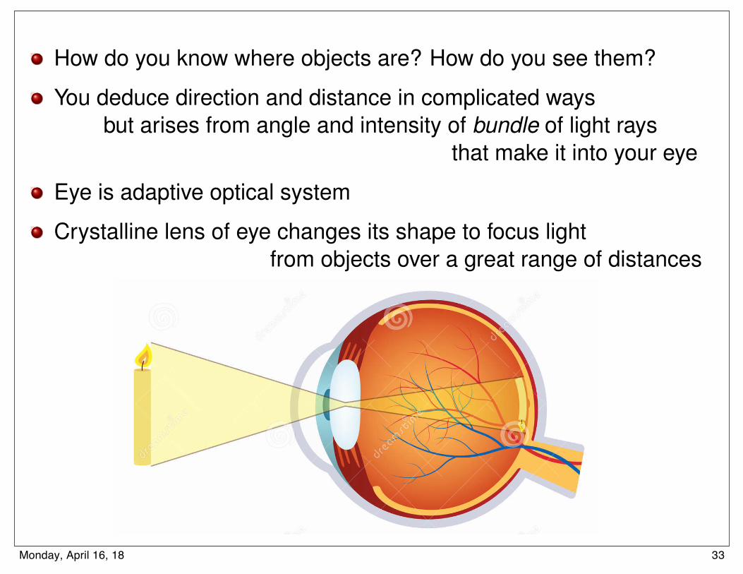
How Light Works Ray optics
How do you know where objects are? How do you see them?
You deduce direction and distance in complicated waysbut arises from angle and intensity of bundle of light rays
that make it into your eye
Eye is adaptive optical system
Crystalline lens of eye changes its shape to focus lightfrom objects over a great range of distances
L. A. Anchordoqui (CUNY) Conceptual Physics 10-3-2017 17 / 2033Monday, April 16, 18

34Monday, April 16, 18