85-169 - International Nuclear Information System (INIS)
98
JAERI-M 85-169 DESIGN CONCEPTS AND PERFORMANCE TESTS OF THE 60GHz ELECTRON CYCLOTRON HEATING (ECH) SYSTEM FOR THE JFT-2M TOKAMAK Novi'mher 1 9 8 5 Katsuinichi HOSHINO, 'lakumi YAMAMOTO, Hisato KAWASHIMA Takatoshi SHIBATA and Toshihiro SHIBUYA Japan Atomic Energy Research Institute JAERI-M 85-169 「ー DESIGN CONCEPTSANDPERFORMANCETESTS OFTHE 60GHzELECTRON CYCLOTRON HEATING (EC I-1) SYSTEM FORTHEJFT-2 iv1 TOKAMAK i'¥ o ¥ ,pm Il(・I ・ 1985 KatsumichiHOSHINO , 1 akumiY Takatoshi S I-I IBAT ^andToshihi 1υSIJ /B UYA 日本原子力研究所 JapanAtomIcEnergyReseαrch Institute
-
Upload
khangminh22 -
Category
Documents
-
view
0 -
download
0
Transcript of 85-169 - International Nuclear Information System (INIS)

JAERI-M
85-169
DESIGN CONCEPTS AND PERFORMANCE TESTS OF THE 60GHz ELECTRON CYCLOTRON
HEATING (ECH) SYSTEM FOR THE JFT-2M TOKAMAK
Novi'mher 1 9 8 5
Katsuinichi HOSHINO, 'lakumi YAMAMOTO, Hisato KAWASHIMA Takatoshi SHIBATA and Toshihiro SHIBUYA
Japan Atomic Energy Research Institute
JAERI-M
85-169
「ー
DESIGN CONCEPTS AND PERFORMANCE TESTS
OF THE 60GHz ELECTRON CYCLOTRON
HEATING (ECI-1) SYSTEM FOR THE JFT-2iv1 TOKAMAK
i'¥o¥,pmIl(・I・1985
Katsumichi HOSHINO, 1 akumi Y ~I^MJT()、 Hisato KA\\"^S"'~L\
Takatoshi SI-IIBAT and Toshihi 1υSIJ/BUYA
日 本 原 子 力研究所
Japan AtomIc Energy Reseαrch Institute

JAER1 M u # ~ H.i. 114-Ki f ;jW%i«f*'^',tWIUi>Fi|L-Ci'iflf%«i;',.Tr-t. A r^pilftii-ttli. II+-W NjfifftrtHffitfifiSSIiWWiiSW* (x3!9 II .Si«»!«liJ«J«i:**ff)#.t.
,/AKRJ M r e p o r t s a r e issued irregularly.
Inquiries about availability of the r epo r t s should be addressed to Information Division Department
of Technical Information, Japan Atomic Energy Resea rch Inst i tute , Tokaimura, Naka gun, Tbaraki
ken 319 11, Japan.
(CJ Japan Atomic Energy Resea rch Inst i tute , 1985
EP tf] » i¥ i: * ! * . * £ ft
JA~:RI Mレオ、一卜It. 111、1(,(( !JP1f究所が小定則|に公 lilLている研究開Jf,Zで唱。
へfのIHI{I"わせは. 11 -t-h;( ( )J日f究所伐術情報部情報資料諌(千31911決雄mn1IJ" m:!Il ihtH)あて.
j; tJl LニLくださ!"'" (,.' Ji. このほかに1!1川法人1(,(( lJ弘前会資料七〆 9--¥〒31911 決雄1¥¥月11川町;
)jfi1lJ十JII字国(( lJ6JE究J;Jrl',)てー俺"iによる'.I::!2~lífh をおこな"ておりますの
.1AERI M reports are issued irre~tlJarJy.
lnquiries about availahility of the reports should be addressed to lnformatIon Ihvision Departmt"nt
of Technical lnformation, Japan Atomic Energy Research fnslitute, Tokaimura, Naka gun, lbaraki
kcn 319 11. J.p.n_
(t Japan Atomic Energy Research lnstitute. 1985
編集続発行 11本版(fJ研究所
印 刷 11背 I業株式会計
JAERI-M 85-169
Design Concepts and Performance Tests of the 60GHz Electron Cyclotron Heating (ECH) System for the JFT-2M Tokamak
Katsumichi HOSHINO, Takumi YAMAMOTO, Hisato KAWASHIMA, Takatoshi SHIBATA and Toshihiro SHIBUYA Department of Thermonuclear Fusion Research, Naka Fusion Research Establishment, JAERI
(Received October 7, 1985)
60GHz overmoded microwave launch system for the JFT-2M tokamak is described. The basic design concepts, specifications of each microwave component and the results of the performance tests are reported. The transmission of the microwave power is done in the circular T E m mode which has a low loss along the overmoded circular transmission components of 33 m in le: ji;h. The microwave power of 80 - 90 kW, pulse width 100 ms in the circular TE mode is finally launched into the JFT-2M tokamak plasma.
Keywords: Electron Cyclotron Heating System, Gyrotron, Microwave Components, JFT-2M Tokamak.
(i)
JAERI-M 85-169
Design Concepts and Perforrnance Tests of the 60GHz E1ectron Cyc1otron
Heating (ECH) Systern for the .JFT-2M Tokamak
Katsurnichi HOSHINO, Takurni YAMAMOTO, Hisato KAWASHlMA,
Takatoshi SHIBATA and Toshihiro SHIBUYA
Department of Therrnonuc~ear Fusion Research,
Naka Fusion Research Establishment, JAERI
(Receiv巴d October 7, 1985)
60GHz over;pっdedrnicrowave 1aunch systern for the JFT-2N tokarnak is
described. The basic design concepts, specifications of each rnicrowave
cornponent and the resu1ts of the perforrnance tests are reported. The
transrnission of the microwave power is done in the circu1ar TEn1 rnod巴01
which has a low 10s5 along the overmoded circular transmission
cornponents of 33 rn in 1er.'乙h. The rnicrowave power of 80 -90 kW, pulse
width 100 ms in the circu1ar TE11
rnode is final1y 1aunched into the
JFT-2M tokamak p1asma.
Ke戸~ords: Electron Cyc1otron Heating System, Gyrotron, Microwav巴
Components, JFT-2~1 Tokamak.
1/)

J A E R I - M 8 5 - 1 6 9
J F T - 2M h#-7:7fflffl60GHzflrF-<M V a h a y mm (ECH) «7Aorm\w.±toxa-mis-m&SM
m sit, di* p}, nm SA %m m m& mL
( 1985 n:- 10 JJ 7 H-S-ffl)
lii1*ft'JIC|l-]Jf;TE,i -=6- KT"'80-90kW, ' * x | | j 100ms GQ-<"f ? • i/iVS/j^ J F T - 2M 1- ii
- ? ? 7 ' 7 X-7r|i[cA<WSft^o
jAERI-M 85-169
JFT-2M卜カ 7 ク用の 60GHz電子サイクロ卜ロン
加熱 (ECH)システムの設計概念および発振試験結架
日本原子力研究所那珂研究所核融合研究部
屋野克道, LLpt>: Jfj,川島寿人
柴田孝俊,渋谷俊Jよ
( 1 9H5 W 10 JJ 7 十1受円!)
.IFT-2M卜力 7 ク装間月jのオ ノイーサイス1壬の導波管をJlH、た 60GHz "7イクロ波入射装iit'l
について報告する。 Jl本的設計思怨,各立f*白l路要素の特例ーおよび1e似試験結!具についてi!13べる。
r:,'l周波',tlJJは,オ ノて サイズ従の伝iき系(全長約33m),ζより, f凡JU失の川 If~TEIII モード
で伝送される。
iii終的lこI'jJf~ TE~ 11 モードで80-90kW,パルス悩 100msの7 イクロ彼宿}Jか.r[,"1'-2 M トカ
7 クプラズ 7 <111こ入射された。
(jj)

JAERI-M 85-169
C o n t e n t s
1. Introduction 1 2. Physical Considerations about the Wave which should be launched 3 2.1 Consideration about the Cutoff Density of the Electromagnetic
Wave ' 3 2.2 Consideration about the Power Absorption at the Electron
Cyclotron Resonance Layer • 7 2 .3 Summary 13
3 . ECH System • 18 3.1 RF Transmission System 18 3.1.1 General Design Concepts of the RF Transmission System 18
(1) Joule Loss in the Circular Waveguide and the Minimization of the Loss 19
(2) Field Strength in the Waveguide and Avoidance of the Breakdown 24
(3) Mode Conversion at the Wave Guide Bend 28 3.1.2 Constitution of the RF Transmission System 30 3.1.3 High Power Overmoded Microwave Transmission Components 30
(1) Two Kinds of the Mode Converters (TE Q 2 + T E Q 1 , T E Q 1 -»• T E n > •• 30 (2) Corrugated 90° Bends 36 (3) Raised Cosine Tapers 36 (4) Straight Waveguides • 40 (5) Vacuum Window 40 (6) DC Break/Mode Filter 40 (7) Conical Horn Antenna 40 (8) Arc Detecters 45
3.2 RF Monitor System ••• 45 (1) Sampler/Arc Detector and Monitor Circuit of the general
Power and Frequency 47 (2) Mode Filter 47 (3) Raised Consine Tapers 47 (4) T E n ? mode Directional Coupler 47 (fi) Microwave Circuits for the Power and Frequency Detection 47 (6) Water Load/Calorimeter 52
3.3 Gyrotron 58 3.4 Super Conducting Magnet System 62 3.5 Power Supply/Cooling System 62
(iii)
JAERトM 85-169
Contents
1. Introduction. . • • •• . •• •• '" • •. .・・・・・・・・・・・時.......................... 1
2. Physical Considerations about the Wave which should be launched ••••• 3
2.1 Consideration about the Cutoff Density of the Electromagnetic
Wave ...・・・・・・・・....,..........11'・・・・・・・・・・・・・・・・・・・・・・・・・・・・・・・・・・ 3
2.2 Considerat5.on about the Power Absorption at the Electron
Cyclotron Resonance Layer •. • . • • . • • • • • • • . • • • • • • . . • . • . . • . . • • . • . • • . . 7
2.3 Summary・・・・・・・・・・・・・・・・・・・・・・・・・・・・・・・・・・圃.......................13
3. ECH System ........・・・・・・・・・・・・・.....................................18
3.1 RF Transmission System • • • • • . • • . • . • • . • • . • . • • . • • . • . • • • . . • • . • • • • . • .. 18
3.1.1 Genera1 Design Concepts of the RF Transmission System........ 18
(1) Joul巴 Lossin the Circular Waveguide and the Minimization of
the Loss・・・・・・・・・・・・・・・・・・・・・・・・・・・・・・・・・・・・・・・・・・・・・・・・・・・・・ 19
(2) Field Strength in the Wavegu工deand Avoidance of the
Breakdown • • • • . . • . • • • • . • . • . . • • . • • . • . • . . • • . • . . . . • . . • • • . . . • . . . " 24
(3) Mode Conversion at the Wave Guide Bend •.••..••..•. ..•••... .•• 28
3.1.2 Constitution of the RF Transmission System •.....•... ..••..•.. 30
3.1. 3 High Power Overmoded Microwave Transmission Components ...•.• 30
(1) Two Kinds of the Mode Converters (TEA~ + TEA" TEA, + TE,,).. 30 02 --01' --01 --11
(2) Corrugated 900 Bends ・・・・・・・・・・...............................36
(3) Raised Cosine lapers・・・・・・・・・・・・・・・・.........................36
(4) Straight Waveguides.......................................... 40
(5) Vacuum Window'" • .・・・・・・・....................................40
(6) DC Break/Mode Fi1ter.....・・・・・・・・・・・・・・・・・・・・・・・・・・・・・・・・・・・・ 40
(7) Conica1 Horn Antenna................ . • . • • • • . • . . • . • • . • . • . . . . .• 40
(8) Arc Detecters・・・・・...........................................45
3.2 RF Monitor System..........................・・・・・・・・・・・・・ a・・......45
(1) Samp1er/Arc Detector and Monitor Circuit of the genera1
Power and Frequency....................・.....................47
(2) Mode Filter....... ••••••••••.• •••••.••.••.• .•.•• .••••.•.••... 47
(3) Raised Consine Tapers........................................ 47
(4) TE02
mode Directional Coupler... .•.•••..•.•. ...••••.••....... 47
(5) Microwave Circuits for the Power and Frequency Detection..... 47
(6) Water Load/Calorimeter.......・・・・・・・・・・・・・・
(jjj)

JAERI-M 85-169
3.6 Gas supply 67 4. Power Tests of the ECH System 71 4.1 Operation Region of the Gyrotron 71 4.2 Monitor Waveform during the Gyrotron Operation •• 73 4.3 Measurement of the Overall Transmission Loss in the RF
Transmission System (Cold Test) 75 4 .4 Measurement of the Forward RF Power • • • • • 75
Conclusion • 79 Acknowledgements • • • 79 References 80
Appendix 1. RF Current Drive (LHH + ECH) and Electron Cyclotron Heating Experiments on JFT-2M Tokamak 81
Appendix 2. Layouts of the ECH system * 88
Appendix 3. Main control panel of the ECH system 89
Appendix 4. Drawings of the microwave components 90
(iv)
JAERト:VI 85-169
3.6 Gas supply ..............................・・・・・・・・・・・・・・・・・・・・・・・・ 67
4. power Tests of the ECH System •.•.......•.....••...•.•.•............• 71
4.1 Operation Region of the Gyrotron ...・・・・・・・・・・・・・・........,......71
4.2 Monitor Waveform during the Gyrotron Operation •.•.••...•• ,. . . .. .. i3
4.3 Measurement of the Overa11 Transmission Loss in the RF
Transmission System (Cold Test) ・・・・・・・・・・・・・・・・・・・・・・・・・・・1 ・・・・・・ 75
4.4 Measurement of the Forward RF Power ...・..................,...... 75
Conc1usion .........................................................・・ 79
Acknow1edgements ・~ . .. .. .. .. .. .. .. .. . . . . . .. .. .. .. .. .. .. .. .. .. .. .. .. .. .. .. .. .. .. .. .. . .. .. .. .. .. .. .. ~・・・・・・・ 79
References ..•..•.•••.••..•••..•.•....•.....•.••••.••...•..•..•.•..••• 80
Appendix 1. RF Current Dri ve (LHH + ECH) and Electron Cyc1otron Heat-
ing Experiments on JFT-2M Tokamak .•.••.••.•....••.•.•....• 81
Appenしix2. Layouts of the ECH system .・・・ー・・..........................88
Appendix 3. Main contro1 panel of the ECH system...............・・・・・・・・ 89
Appendix 4. Drawings of the microwave compon巴l:ts・・・・・・・・・・・・・・・・・・・・・・・ 90
livl

JAERI-M 85-169
1. (? 1 2. A l ^ ^ i f f c O W I f t & W 3
2.1 "«ffi$©L *>»•&» ©££M 3 2.2 M-f-y-i 0 u ha >m%a-C®""r7-U&.lKCDi$M 7 2.3 itib 13
3. E C H g l 1 8
3. 1 Min&tei&% 18 3.1.1 l?,lfnifo{K&%<»-&&imm± is
(1) H&gifo<S<D-sl*--M2*:&tf®'JiC0l&ffi 19 (2) nmm&'s^om'^^M&.v^mmmm'oi&.M 24 (3) H f f ^ » f r 0 f f i # 9 K J : 3 * - K g $ 28
3.1.2 timmimikoim®, 30 3.1.3 -xmJjt-^-v-J *i"< t viikfc>&%M 30
(1) r f f i © - * - K3EiH^( TE02 -TL: ,M, T E 0 I - T E n ) 3 0
(2) y f f t £ 9 0 S - < y K 36
(3) H X I ' M f - " ' - 36 (4) iftiffiigflfc'Sf 40
15) £ 3 ® 40 (6) D C « / t - K 7 - ( * ^ - 40 (7) P M * - V T V ? : f - 40
(8) T -^ f&UUIs 45
3.2 ,15(S]/lfe*-?-ga 45 (1) • y - y 7 - 7 / T - ? ^ H i S & o * — i g ^ - 9 - , JS]'$i£©-e-?-fe]!$ 47 (2) * - K 7 - f * ? - 47
(3) M x ' F M f - ^ " - 47 (4) T E 0 2 * - hVjlSj&ig&gg 47 (5) ' - ' 7 - , $$£fe&ft©/;*bcDT>f ?o$[p]g& 47
(6) 7J<fl#J/«lMt- 52 3.3 y - M o I- D y 58
3.4 mmmmm^mm 6 2
3.5 mm/<§]$£& 62 3.6 #X#i;§S 67
4. ^ " 7 - 2 ® 71 4.1 ^ t - t P h n V O i f t l i 71
(V)
]AERI-M 85司 169
目次
L 序…-
2目 入射される波の物理的検討 ・…・…...・ a・...・ H ・..……一・・…....・ H ・..……・・ H ・H ・....・ H ・ 3
2.1 電位波のしゃ断密度の検討 …-…-・… u …...・ H ・............・ H ・..…・-………...・ H ・ 3
2.2 乱Hサイク【J トロン共鳴層でのパワー吸収の検討 …...…..,・H ・.....・H ・..……… 7
2.3 まとめ …………......・ H ・..……・・…….....・ H ・.. …………....・ H ・..………...・ H ・ 13
3. E CH装置 …・・・・・……・・・・ …………・・..…・・……………・ ・……・一・・・…・・…・・…一 18
3.1 高周波伝送系 …..…...・ H ・.....・ H ・.....・ H ・...........…..........・ H ・..….....・ a・-…・・・・ 18
3目1.1 I~"!I周波伝送系の一枝的設計概念 ....・ H ・.....・ H ・..……….........・ H ・.....・ H ・-… 18
山 円形導枝管のジューノレ炉失及びJ員失の低減 ・目…・・・....・H ・..………田・ー……… 19
121 円形導波管中の'む界強度及び絶縁自主域の低減 …目・・・…・・………....・H ・-・・・… 24
(3) 円形導波管の曲がりによるモード変換 ……...・ H ・.....・ H ・....…...・ H ・..……… 28
3. 1. 2 高周波伝送系の構成 ……...・...,.,.・ H ・.....・ H ・"…....・ H ・......・ H ・.....・ H ・..… 30
3. 1. 3 大電力オーバーサイス:7イクロ波伝送要素 ……・・……...・ H ・....…...・H ・ 30
3. 2
(1)
121
131
(4)
(5)
(6)
3. 3
3.4
3. 5
3.6
(1) 二稀,のモード交換器(TE02→ T仁、1,TEol→ TEII )…・ H ・H ・.....・ H ・ 30
溝f、jき901主ベンド…….....・ H ・-……...・ H ・..…...・ H ・..……………..........…・ 36
レイズド余弦テーパー ...・ H ・-・…'"・ H ・..…………………...・ H ・...-…………… 36
1ft線導枝管 ……………....・ a・-…・・…...・ H ・-… H ・H ・....・ H ・.....… H ・H ・-……・ 40
ti主主窓 … ー…‘ H ・H ・・・・・....・ H ・.......・ H ・-…….......・ H ・"……・・・・ …...・ H ・H ・H ・ 40
DC絶縁/モードフィノレター……'"・ H ・.....・ H ・H ・H ・......・ H ・H ・H ・.....・ H ・..……… 40
円最Eホーンアンテナ …...・ H ・H ・H ・"…… H ・H ・...・ H ・..……...・ H ・.....・ H ・...……・・ 40
アーク検出器 ...・ H ・'"………・…'"・ H ・.....・ H ・....・ H ・...・ H ・.....・ H ・H ・H ・.....・ H ・ 45
121
131
141
151
(6)
171
181
高周波モニター装置 ………'"・H ・..…・-……-・………………………・・………… 45
サンプラ/アーク検出器及び一般パワー,周波数のモニター刷路 ………-… 47
モードフイノレター …・・…....・ H ・.....・ H ・...……・・……………..,・ H ・-・……・・……… 47
レイズド余弦テーノfー …...・ H ・..……………………-…・…-……....・ H ・..……… 47
TEo2モードhI向性結合器 …………...・ H ・..………...・ H ・..………・・……...・ H ・ 47
パワー. lijJ波数検出のための7 イクロ波回路 ….,....・H ・.....・H ・..……………… 47
水負荷/熱母H ..,・ H ・.....・ H ・........…….........…・・…… H ・H ・....・ H ・H ・H ・-… H ・H ・. 52
ジャイロ卜ロン ・・・ー…....・ H ・.....・ H ・.....・ H ・..………………-……・…・・・・・…-…・ 58
超電導電磁石袋詑 ......…,..・ H ・.....・ H ・-…...・ H ・...…...............・ H ・...…・・…・・ 62
電源/冷却装置....・ H ・...・ H ・H ・.....・ H ・..… H ・H ・.....・ H ・...…-…-・……・・….....・ H ・. 62
ガス供給 ....・ H ・....・ H ・....・ H ・...・...、….......・ H ・H ・H ・....・ H ・'"……・・目....・ H ・...・ H ・ 67
4. パワー試験 ………...・ H ・..…..,・ H ・...・ H ・H ・..,・ H ・H ・...…...・ H ・..………・・….......・ H ・.... 71
4. 1 ジャイロトロンの動作領域 H ・H ・...・ H ・-…・・・ H ・H ・-…・・・… H ・H ・...・ M ・....・ H ・・ H ・H ・.. 71
Iv)

JAERI-M 85-169
4.2 i>*-f a hnyW}ftip(D*:~9-i&& 73 4.3 m^w.&m^x-<D±&mmik<omjS.( ^ - ^ K t s s a ) 75 4.4 HW« l l zS«^o i ]S I£m 75 IS fit 79
m $ 79
ttt§ 1 j F T - 2 m c & t t & & m & M n m w i ( L H H + E C H ) M
ttmz ECHgs©gei 88 f-fi 3 E C H g l f f l i f l i ' ^ * 89 f-tiS4 -7-C * a j g g ^ o H i M 90
(Vi)
JAERトM 85噌 169
4.2 ジャイロ卜ロン動作中のモニター波形 '"・ H ・H ・H ・......・ H ・..……………………ぃ 73
4.3 高周波伝送系で・の全伝送儀失のiJlIJ定(コールド試験)… H ・H ・......・ H ・-・・・…・-… 75
4.4 前方高周波電力の測定結果 ……...・ H ・..…...・ H ・..…………..........・ H ・..…・ H ・H ・ 75
結論...・ H ・.....・ H ・......・ H ・..…...・ H ・.....・ H ・.....・ H ・.......・ H ・-… H ・H ・...・ H ・....・ H ・H ・H ・..… 79
謝 辞 ……,......・ H ・.......・ H ・-….....・ H ・-・……・・・…....・ H ・....…............・ H ・-…-…… 79
参考文献 …...・ H ・..…………...・ H ・.....・ H ・-……………..,・ H ・.,………….,.・ H ・....・ H ・...… 80
付録 JFT-2Mにおける高周波電流駆動 (LHH+ECH)放び
電 Fサイクロトロン加熱実験 ・・・ H ・H ・..………...・ H ・.............・ H ・H ・.....・ H ・..… 81
付録 2 ECH装置の配置 ・・ H ・H ・-…...・ H ・..……...・ H ・.....・ H ・"…・・……....・ H ・....…・・・ 88
付録 3 ECH装置の主制御パネノレ ー…...・ H ・..…....・ H ・....・ H ・..…...・ H ・..….....・ H ・ 89
付録 4 '7イクロ波要素の図面 …・・…...・ H ・..…...・ H ・......・ H ・.....・ H ・...・ H ・..…....・ H ・ 90
(vil

JAERI-M 85-169
1. Introduction
The electromagnetic wave (EMW) with the freuency close to the electron cyclotron frequency (We call the EMW as ECW) is absorbed at the electron cyclotron resonance (ECR) layer via the electron cyclotron damping in the linear theory. For the heating of the tokamak plasmas, this local power deposition is favourable for the efficient core plasma heating, or the current profile control to improve the MHD stability. Due to the local power deposition and the good propagation characteristic of the EMW from the plasma edge region (absence of the evanescent region), the impurity problem may be minimized in the ECH. Besides, there is a possibility of driving the toroidal current which has a role of confining the tokamak plasma.
28 GHz ECH was first studied ' ' in the JFT-2 (R = 90 cm, a = 25 cm) tokamak of JAERI. Electron heatings by the fundamental resonance (to = u> ,oi : electron cyclotron frequency) were investigated by launching X, 0, and TE„„ mode. Efficient electron heating and localized power deposition were varified. It was shown that the mode conversion at the upper hybrid resonance layer contributes to the heating by the off-center ECR layer. On the other hand, density limit of heating (n _ ~ 1.5 x 10 1 3 cm" 3) by the EMW was observed in consistent with the theoretical cutoff density. Therefore, for the heating of the higher density plasma, the EMW of the higher frequency has to be launched in the higher magnetic field, or the harmonic electron cyclotron frequency heating has to be employed.
From these points of view (as will be described in chap. 2), 60 GHz gyrotron was chosen for the ECH of the JFT-2M tokamak machine which has a noncircular plasma cross section (R = 131 cm, a = 35 x 55 cm) . That is a maximum frequency now available in commerce. The JFT-2M tokamak operates with the toroidal magnetic field of less than B = 1.5 T, because the capacity of the power supply is restricted. Therefore, the 2nd harmonic heating (w = 2u) ) was taken. The 2nd ECR layer is at the center of the plasma column when Bt is 1.07 T.
The aims of the first stage ECH experiment on the JFT-2M tokamak which was carried in Nov.-Dec. last year were to investigate
(1) the effects of the ECH to the current drive./ramp up by the lower hybrid wave (LHW), and (2) electron heating by the 2nd harmonic extraordinary mode
• 1 -
JAERトM 85・169
1. Introduction
官1ee1ectrornagnetic wave (EMW) with the freuency c10se to the
e1ectron cyc10tron frequency (We ca11 the EMW as ECW) is absorbed at
the e1ectron cyc10tron resonance (ECR) 1ayer via the e1ectron cyc10tron
damping in the 1inear theory. For the heating of the tokamak plasmas,
this 10ca1 power deposition is favourab1e for the efueient core p1asma
heating, or the current profi1e contro1 to improve the MHD stabi1ity.
Due to the 10ca1 power deposition and the good propagation character-
istic of the EMW from th8 plasma edge region (absence of the evanescent
region), the impurity prob1em may be minimizcd in the ECH. Besides,
there is a possibility of driving the toroida1 current \~hích has a
ro1e of con:ining the tokamalぇ p1asma.1 )~4)
28 GHz ECH was first studied-f • f in th巴 JFT-2 (R ~ 90 cm, a 25
cm) tokamal王 ofJAERI. E1ectron heatings by the fundamenta1 resonance
(ω=ω ,ωe1ectron cyc10tron frequency) were investigated by ce ce
1aunching X, 0, and TE02
rnode・ Efficiente1ectron heating and
10ca1ized power deposition were varified. It was shown that thc rnode
conversion at the upper hybrid resonance 1ay巴rcontributes to the
heating by the off-center ECR 1ayer. On the other hand, density
1irnit of heating (n_f¥ ~ 1.5 x 1013 cm-3) by the EM¥.l was observed in eO -
consistent with the theoretica1 cutoff density. Therefore, for the
heating of the higher density p1asma, the EMW of the higher frequency
has to be 1aunched in th巴 high巴rmagnetic fie1d, or the harmonic
electron cyc10tron frequency heating has to be ernp1oyed.
Frorn these points of view (as wi11 be described in chap. 2),60
GHz gyrotron was chosen for the ECH of the JFT-2M tokarnak machine
which has a noncircular plasma cross section (R 131 cm, a 35 x 55
crn) .百1atis a maximum frequency now avai1ab1e in comrnerce. 百1e
JFT-2M tokamak operates with the toroida1 magnetic fie1d of 1ess than
Bt 1.5 T, because the capacity of the power supply is restricted.
百1erefore,the 2nd harmonic heating (ω2ω) was taken. 官1e2nd ECR ce
1ayer is at the center of the plasma co1umn when Bt is 1.07τ.
The aims of the first stage ECH experirnent on the JFT-2M tokamak
which was carried in Nov.-Dec. 1ast year were to investigate
(1) the effects of the ECH to the current driveJramp up by
the 10wer hvbrid wave (LHW), and
(2 )巴1ectronheating by the 2nd harmonic extraordinary mode
--1--

JAERI-M 85-169
(X-mode) ECH. The first stage experimental results are reported briefly in the paper submitted to the 12th European Conf. on Controlled Fusion and Plasma Physics which is given in the appendix.
We describe the 60 GHz ECH system of the JFT-2M tokamak, by putting the stress on the basic design concepts and performance tests. Therefore the descriptions of the high voltage power supply or super conducting magnet system are minimum.
The ECW is launched from a horn antenna. The wave launch by the horn antenna has an advantage that the wave power can be radiated into a vacuum region. Therefore the antenna loading (matching) as is the important problem in the case of coupling by the loop antenna is not a problem in the launch of the ECW.
The points of the design of the ECH system may be summarized as follows.
(1) How to choose the launch angle with respect to the magnetic field, and launched mode (physics consideration). (2) How to minimize the rf transmission loss between the gyrotron and the antenna. (3) How to avoid the break down in the waveguides for the transmission of high rf power density. (4) How to know the exact imput power to the plasma.
These points are described in this report. In Chap. 2, the physics consideration are presented. In Chap. 3,
the basic design concepts and specifications of each microuave components are described. Gyrotron, super conducting magnet, power supply system and gas supply are also described briefly in this chapter. In Chap. 4, the results of the cold and hot tests of the whole rf transmission system are reported. Finally the experimental results of the first stage ECH of a tokamak plasma are given in the Appendix.
- 2 -
JAERト M 85-169
(X -mode) ECH.
The first stage experimenta1 resu1ts are reporte.d brief1y in the
paper5) submitted to th巴 12thEuropean Conf. on Contro11ed Fusion and
P1asma Physics which is given in the appendDし
We describe the 60 GHz ECH systzm of th巴 JFT-2Mtokamak, by
putting the stress on the basic design concepts and performance tests.
Therefore the descriptions of the high vo1tage pO¥oler supp1y or super
conducting magnet system are mlnimum.
The ECW is 1aunched from a horn antenna. The wave 1aunch by the
horn antenna has an advantage that the wave power can be radiated into
a vacuum region. Therefore the antenna 10ading (matching) as is the
important prob1巴m in the case of coup1ing by the 100p antenna is not a
prob1em in the 1aunch of the ECW.
百lepoints of the design of the ECH system may be summarized as
fo110ws.
(1) How to choose the 1aunch ang1e with respect to the
magnetic fie1d, anJ 1aunched mode (physics consideration).
(2) How to minimize the rf transmission 10ss between the
gyrotron and the antenna.
(3) How to avoid the break down in the waveguides for the
transmission of high rf power density.
(4) How to know the exact imput power to the p1asma.
These poiロtsare described in this report.
In Chap. 2, the physics consid巴rationare presented. In Chap. 3,
the basic design concepts and specifications of each microuave
components are described. Gyrotron, super conducting magnet, power
supp1y syst巴mand gas supp1y are a1so described brief1y in this
chapter. In Chap. 4, the resu1ts of the co1d and hot tests of the
who1e rf transmission system are reported. Fina11y the experimenta1
results of the first stage ECH of a tokamak p1asma are given in the
Appendix.
2ー
JAER1-M 85-169
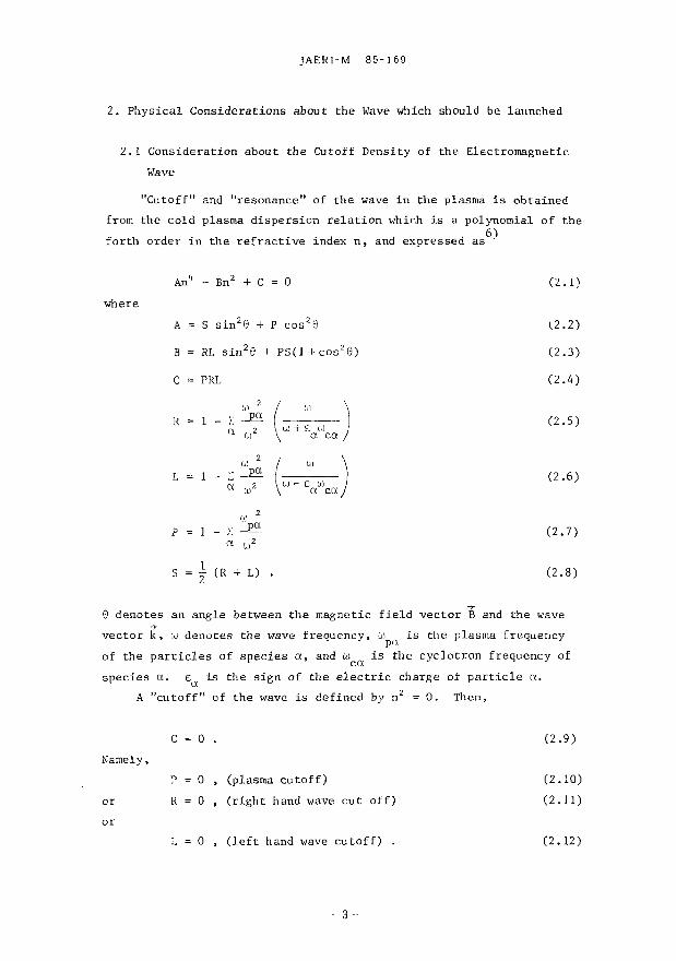
2. Physical Considerations about the Wave which should be launched
2.1 Consideration about the Cutoff Density of the Electromagnetic Wave
"Cutoff" and "resonance" of the wave in the plasma is obtained from the cold plasma dispersion relation which is a polynomial of the forth order in the refractive index n, and expressed as
where Bn 2 + C = 0 (2.1)
S sin 20 + P cos 20 (2.2)
RL sin2e + PS(1+cos 26) (2.3)
(2.4)
(2.5)
(2.6)
(2.7)
(2.8)
0 denotes an angle between the magnetic field vector B and the wave vector k, cu denotes the wave frequency, u ,. is the plasma frequency of the particles of species a, and to is the cyclotron frequency of species a. e is the sign of the electric charge of particle a.
A "cutoff" of the wave is defined by n 2 = 0 . Then,
C = 0 . (2.9) Namely,
P = 0 , (plasma cutoff) (2.10) or R = 0 , (right hand wave cut off) (2.11) or
L = 0 , (left hand wave cutoff) . (2.12)
C = PRL
R = 1 -a
« 2
pa
w 2 ( " ) R = 1 -
a
« 2
pa
w 2 \ U) + £ W ,' \ a ca /
L = 1 -a
u) 2
pg
a,2 I " ) L = 1 -
a
u) 2
pg
a,2 \ (o - e u) 1 \ a e g /
P = 1 -a
M 2
pg
U)2
>•} (R + L) .
- 3 -
JAERI-M 85-169
2. Physical Considerations abou t the Wave which should be launched
2.1 Consideration about the Cutoff Density of the Electromagnetic
Wave
"Cutoff" and "resonance" of the wave in the plasma is obtained
from the cold plasma dispersion relation whir.h is a polynomial of the 6)
forth order in the refractive index n, and expressed as
An4 - Bn2 + C 0 (2.1)
wher巴
A S sin2日+P cos2日 l2.2)
B RL sin2e + PS(l + cos2G) (2.3)
C = PRL (2.4)
R 1 -i: ~ (2.5 ) α1112ω+E αtd cα/
1ぺ 24(ω) (2.6) α ω ¥ lu - Eαωcα
P 1 -I一'01
一pα一
2
(2.7) αω2
1 (2.8) S '" i' (R + 1)
ー事P
G denotes an angle between the magnetic field vector B and the wave ->-
vector k,ωdenot己sthe wave frequency, :1)_. is the plasma frequeIlcy rrx
of the particles of species α, and ωis the cyclotron frequency of cα
speci己sαEαisthe sign of the electric charg己 ofparticleα.
A "cutoff" of the wave is defined by n2 O. 百len,
C = 0 (2.9 )
Namely,
P 0, (plasma cutoff) (2.10)
or R 0, (right hand wave cut off) (2.11)
or
L 0, (left hand wave cutoff) (2.12)
ntu

JAERI-M 85-169
The equations (2.10) - (2.12) determines the cutoff frequency co = u .
For a single species electron plasma,
co = w (plasma frequency) (2.13)
oi . , c e , 1 / 2 , / 2
o) = u) = - = — + T /to * + 4(0 c R 2 I v ce pe
(reght hand wave cutoff frequency) (2.14)
10 ; (0 = ,L = - - ip. + i / « 2 •(- 4(0 2
c L 2 2 / ce pe
(left hand wave cutoff frequency). (2.15)
A "resonance" is defined by n 2 -> «•. Then,
A = 0 . (2.16)
Namely,
S sin 20 + P cos29 = 0 . (2.17) T
For the perpendicular propagation (0 = -~), the resonance condition jecomes
S = 0 . (2.18)
This condition leads to the upper hybrid resonance frequency expressed as,
(0,n, = / (0 + (0 UH / pe ce
(upper hybrid resonance frequency). (2.19)
These well known cutoff's and a resonance are obtained from the conditions on n . Further, n is decomposed into the perpendicular component and parallel component as
n 2 = n ±2 + n / . (2.20)
Substituting eq. (2.20) into eq. (2.1), one obtains the two branches of the wave as
- 4 -
JAERI-M 85・ 169
官leequations (2.10) ー (2.12) determines the cutoff frequencyω=ωc
For a single species electron pこasma,
(dc=Ldpe (plasma frequency) (2.13)
日(reght hand wave cutoff frequency) (2.l4)
(じ ωce , 1 /., 2 ・ 4w 2 ,>L 一一一ーー川 +“ω c -'L 2 2 I ~'ce 叩pe
(left hand wave cu tof f frequency). (2.15)
^ "r巴sonanc巴" is defined by口2 -r [,0.
Then,
^ ~ 0 (2.16)
~;arnely ,
S sin20 + P cos2e O. (2.17)
寸
For the perpendicular propagation (0 2)' the resonance condition
Jecornes
S = 0 (2.18 )
lbis condition leads to the upper hybrid resonance frequency cxpr己配当ed
.1S,
ω =町一 回 ωUH 〆 pe -ce
(upper hybrid r巴sonancefrequency). (2.19)
1bese well known cutoff's and a resonance are obtained from the
conditions on n 2• rurther, n2 is decomposed into the perpendicular
component and parallel compo~ent as
n2 n,2 + n,/ 上〆
(2.20)
Substituting eq. (2.20) into eq. (Z.1), one obtains the two branches
of the wave as
4

JAERI-M 85-169
2 i 2 IT , XY / U ^ t y 2 ) z Y 2 + 4 n / ( l - X ) + Y ( l + n / )
1 - X - Y 2
(2.21) where
X = -X— « n ( d e n s i t y ) , Y = « B (mangetic f i e l d ) • ,2 e
(2.22) Eq. (2.21) is the Appleton-Hartree dispersion relation. The branch expressed by the upper sign is called the "ordinary mode (0-mode)" and that of the lower sign as the "extraordinary mode (X-mode)".
The propagation of the wave is possible in the region n.2 > 0. The wave evanescence occurs in the region n < 0. The boundary is expressed by
n ±2 = 0 . (2.23)
By substituting eq. (2.23) into (2021), one obtains the cutoff's and a resonance as follow.-;.
X = 1 0-mode cutoff (o> ) (2.24)
X = (1 - iy2)(l + Y) (2.25) 2 Y 0-mode \ . _. , .. n / = z~r <r v J r cutoff (UL) / Y + 2 X-mode J L
J n / « Y + 2 X-mode cutoff (to.)
nJ- > y v o 0-mode cutoff (tiL )
X = (l-n/)(l-Y) X-mode cutoff (<oR) (2.26)
X = 1 - Y 2 X-mode resonance (ait,„). (2.27)
The confluence point of 0-mode and X-mode is expressed by
(1 - n / ) 2
X = l+ - Y z . (2.28)
Thus one obtains the UA dependence of the cutoff density of the EMW. Next, we calculate the cutoff and resonance density for the
- 5 -
JAERI-M 85-169
2 司 2 ロメI;:Z2内 2+4ロノ(同平叩+nノ)口よ 1. - n"", -h:!:τ
where
(2.21)
2
e
一2ωl-ω
X
|ω 巴e
a n~ (density), Y =一一'--0:: B E ω
(mangetic field)・
(2.22)
Eq. (2.21) is the Appleton-Hartree dispersion relation.τhe branch
expressed by the upper sign is cal1ed the "ordinary mode (O-mode)"
and that of the lower aign as the "extraordinary mode (X-mode)".
The propagation of the wave is possible in the region n~2 > O.
The wave evanescence occurs in the region n~2 < O. The boundary is
expressed by
nよ2 O. (2.23)
By substituting eq. (2.23) into (2.21), one obtains the cutoff's and a
7) resonance" as follow3.
X 1 O-mode cutoff (ωpe)
X (1 -n〆2)(l+Y)
I _ 2 Y Q-mode ¥ 1 一一ー ト toff(ω 〉I ''/ -Y -+ 2 X -mode r
J n ,2 ーエ~ X-mode cutoff (ω 〉iy Y+2
n} >ーエー O-mode C'Iltoff (ぬ〉〆 Y+ 2 ~ ...----.---- 'L
(2.24)
(2.25)
x (1-n〆2)(1-Y) X-mode cutoff (ωR) (2.26)
X 1 -y2 X-mode resonance (ω). (2.27) UH
The confluence point of Q-mode and Xー官lodeis expressed by
(1 -n})2 X 1 + V y2
4n〆2
(2.28 )
Thus one obtains the n"", dependence of the cutoff density of the EMW.
Next, we calculate the cutoff and resonance density for the
-5--

JAERI-M 85-169
fundamental (S = 1) and harmonic (S = 2 , 3) waves. We set the frequency of the wave as
a) = S u c e (S = 1, 2, 3, ... ) (2.29)
Here we put the restriction that S < 3. Then,
Id) I f 1 (S = 1) Y = ~ S - = i 1/2 (S = 2) (2.30)
1/3 (S - 3)
Therefore one obtains (1) S = 1
X = 1 0-mode cutoff (to ) - P e
X = 2(1 - n/)
n / 5 1/3 X-mode cutoff (u>L) lv nJ- £ 1/3 o-mode cutoff (u^)
X = 0 (WR)
X = 0 (w,m) n o accessibility from the low field side
(2.31)
X = 1 +
(2) S = 2
(1 - n / ) «
V X = 1 0-mode cutoff (id )
pe
X = | (1 - n / )
f n / a 1/5 X-mode cutoff (0) )
[ n / B 1/5 0-mode cutoff (OJ )
X = -i (1 - i y z ) X-mode cutoff (o)R)
X = 3/4 X-mode resonance (u) ITI I)
x = l + -1 6 n /
(2.32)
(3) S X = 1 0-mode cutoff (o> )
X = | (1 - n /
2 )
- 6 -
]AERI-M 85-169
fundamental (5 1) and harmonic (5 2. 3) waves. We set the
frequency of the wave as
ω=s (Aice(S=I,2,3,...)
Here we put the restriction that 5 ~ 3. 百 en.
|ω一 r1 (5 = 1) y ーよ=-= i 1 /2 (5 = 2)
¥ 1/3 (S ~ 3)
百lereforeone obtains
(1) S = 1
X 1 O-mode C'utoff (ωe)
X=2(1-n〆2) ー
{り2 ;;; 1/3 トX-m町m…n、nν〆ノ2 ~ 1/β3 0ト-m叩od白ecutoff ct九llr.)
X = 0 ((ωA凶)R)
(2.29)
(2.30)
(2.31)
X = 0 (ωno accessibility from the low field side UH
円
4
町
、‘,,-
。,h-Jor-今'-
nJJ'
-一ん吐
'E---
(『
+
'E--一-X
(2) 5 = 2
X z l o-mode cutoff (tope)
X=2(1-Vz}
{ Vゲψρ之υ勺主什1/β5… c印u叫山吋t切凶…of
nベ/2と 1/β5 O-mode cωut凶of日f(ωω)
X=t {μ1 -νゲ2) X-mode cutoffω
X = 3/4 X-mode resonance (ω) UH
(1 -n./)2 X l+--~
16nノ(3) 5 = 3
X 1 O-mode cutoff (ω'pe)
X 丘(1-n.l) 3 〆
-6-
(2.32)

JAERI-M 85-169
| n / i 1/7 X-mode cutoff (u)T) i / L (2.33) ( nf 5 1/7 O-mode cutoff (w.)
X = j (1 - n ^ z ) X-mode cutoff (u )
X = 8/9 X-mode resonance (wTTT.)
(1 - » / > ' X = 1 + <-
3 6 n /
The cutoff density expressed by (2.31) ~ (2.33) is depicted in Fig. 2-1. The cutoff density of the X-mode is represented by the solid line and that for the O-mode is represented by the broken line. As shown, the cutoff density decreases as n^. The cutoff density of the O-mode is larger than that of the X-mode except the s = 1 case.
For the perpendicular propagation (n - = 0 ) , n = n. , the cutoff frequency is expressed by 10 (O-mode), w , CO (X-mode). The frequency dependence of the cutoff density n is depicted in Fig. 2-2. The cutoff density n is a quadrature of the frequency. For example, the cutoff density of the O-mode is n = 4.46 x 1 0 x 3 cm" 3 for S = 2 and f = 60 GHz.
It is desireable to choose the frequency as large as possible, and the injection angle should near -=• from the point of view of the cutoff density. But, further consideration about the damping rate at the ECR layer is important. That point of view is discussed in the next section.
2.2 Consideration about the Power Absorption at the Electron Cyclotron Resonance Layer
For the local efficient heating, a large energy absorption rate in single path at the ECR layer (to = S w ) is required. The absorption rate is a function of the launch angle with respect to the stationary magnetic field namely a function of the parallel refractive index •&*,
harmonic number S and plasma density n , once the wave frequency is fixed. The absorbed power in single path P , at the ECR layer is calculated using the geometrical optics approximation.
JAERI-M 85・169
!?亘 1/7一c…ωL〉n2と 1/7 O-mゅdecutoff (ω 〉
x=3(lーゲ X-modecutoff ω
) X = 81丹9 X-mode re弓onance(ωωUH)
(1 -n})2
X 1+---'
36n〆z
(2.33)
The cutoff density回 pressedby (2.31) ~ (2.33) is depicted in Fig・
2-1. The cutoff density of the X-mode is r巴pr巴sentedby the solid
line and that for the O-mode is represented by the broken line. As
shown, the cutoff density decreases as n〆・官lecutoff density of the
O-mode is larger than that of the X-mode except the s 1 case.
For the perpendicular propagation (nd 0), n2 n,2, the cutoff グ i
frequency is expressed byω(O-mode),ω ,ω(X-mode). 百 epe ,- .-.---" -R' "L
frequency dependence of the cutoff density n_ is depicted in Fig. 2-2. c
The cutoff density n_ is a quadrature of the frequency. For c
example, the cutoff density of the O-mode is n 4.46 x 1013 cm-3 for co
S = 2 and f = 60 GHz.
It is desireable to choose th巴 frequencyas large as possible, 官
and ニheinjection angle should near * from the point of view of the 2
cutoff density. But, further consideration about the damping rate
at the ECR layer is important. That point of view is discussed in the
next section.
2.2 Consideration about the Power Absorption at the Electron
Cyclotron Resonance Layer
For the local efficient heating, a large energy ab正;っrptionrate in
single path at the ECR layer ( ω S ωis required. 百leabsorption ce
rate is a function of the launch angle l>lith respect to the stιtionary
magnetic field namely a functioll of the parallel refractive index nl"
harmonic llumber S and plasrna density nd, once the wave frequency is
e fixed. The absorbed power in single path P
ab at the ECR layer is
calculated using the geometrical optics approximation.
-7-

JAERI-M 85-169
(a)
2
4/3 1
\ a j L
S*1
dipt
. . J ,.i i
N N N 1 1 1 1 1 V
0 1/3 1/2 1
(b)
2 -
1/2
0
S = 2
(Op*
0 1/3
0 1/4 0.5
rft
Fig. 2-1 Cutoff densi ty as a function of the p a r a l l e l r e f r a c t i v e (line
i ndex v./., X = —•—• « n . S i s a ha rmon ic number, u = Sw / w 2 e c
( a ) S = 1 , (b) S = 2 , ( c ) S = 3 .
JAERI-M 85-169
(0 )
s・12
x 4/3
1ノ31ノ2
(b)
5=2
x ーー.--守、ー、、
1ノ2ト」包|¥外
、、
' 、0' ., J 、o 1/3 L -'----.J.??』士、
(C)
5"'3 2
?? 1/4 0.5
n~ N
Fig. 2-1 Cutoff density as a funct!on of the parallel refractive 2
W:"o index n#, x 三~乙~ n_. S 15 a harmonic number.ωsωce
一 2 --e y ω
(a) S = 1, (b) S = 2, (巴) S = 3.
-8-

JAERI-M 85-169
(a)
b)
ii
10 _ l j i • - ) • • -
9 X / /o ( L = 0) / / ( P = 0 l
8 - / •? 'E 7 - / o
to -S 6 - '
5 » _ £
4 n//=0 3 / f-fce -
(S=1) 2 • I
0 i . • i 1 i i i i 1 1
D 50 100 150
II
10
f (GHz) II
10 -1 / ' / '
9 - / / 8
0 1P=0) 1*1 I f f
f I co I X 'E 7 5 / > k ^ y i R = o) to
-Q 6 /
^ 5
4 4.46 / -5
4 I \
/ -
3 / J
/ 1 i / 1 / / ' / ' n,/=0
2
1
0
2 2 3 f\ / 1 y i
r 1 1 1 1
1 ! .
f =2fce . (S = 2)
. . . . i i . i i i 50 100 150 f (GHz)
Fig. 2-2 Cutoff density n as a function of the frequency f. n^ (a) f = f c e, S = 1, (b) f = 2f c e, S - 2.
-9-
85・169
nll=O
f =fce lS= 1 )
JAERトM
11
6
5
3
4
EUOF
向
,
向
F
ι3 c:
(a I
150 50 100
f I GHz)
2
O
IP =0)
11
10
9
8 {向い
Eumもこ
( b)
nll= 0 f ;: 2fω , 5=2)
7
6
3
もBc:
150 。。
ロ〆 O.Cutoff density nc as a funct10n of the frequency f.
(a) f f__. S 1, (b) f 2fno' S 2. ce- c巳
-9一
Fig. 2-2

JAERI-M 85-169
d£
ab p a x ) ( 1
21m k
e ) (2.34)
Here, P , denotes the absorbed power between the coordinate I = $.2 »t| and P(&i) is the wave power at & = SLj.. The imaginary part of the perpendicular wave number Im k. in (2.34) is obtained from the warm plasma dispersion relation which is a complex transcendental equation expressed as
- n / + K
yx n.nx + .K -L f zx
K xy -n, 2-n/+K _L / yy
K zy
n n^ + K -1- / xz
yz -n, ' + K 1 zz
(2.35)
Here K.. (i, j - x, y, z) are the components of the warm plasma dielectric tensor. The dispersion relation (2.35) is solved exactly by the numerical method. This method was used in 4). But in this report, an analytic solution of (2.35) with an approximation which uses the real part of the cold refractive index. By the analytic solution the parameter dependence of the absorption is easily obtained without using a computer and one can get a good perspective about the absorption rate.
An intensity of the radiation I (unit: J m" 2str" 1) is obtained from the equation of transfer . Using a source function S of the plasma media the intensity is written as
i a 2 ) - I(Ai) e T ( ^ ' £ l > + S(A*)e~' i : ( £' J l , ) d r (2.36)
The second term of the right hand side of (2-36) represents the contribution of the emission from the plasma. The first term in the right hand side represents that the intensity at I = £2 Is reduced by a factor e due to the absorption by the intervening medium. T is called as the optical thickness and is the function of the absorption coefficient of the medium between £2 < SL < &i* The absorbed fraction of the intensity is thus expressed as
10 -
JAERI-M 85-169
、.,,
o~ ,G '4
k
m
。,.Tム
E
2
1
r11刊
巴噌
a目.
,,‘、、‘,,司ムO
N
,,‘、nr =
b
a
p晶 (2.34)
Here, Pab
denotes the absorbed power between the coordinate ~ ~2.2 ,
and p(t1) is the wave power at t ~l ・ TIle imaginary part of the
perpendicular wave nu曲目 1mk~ in (2.34) is obtained from the warm
plasma dispersion relation which is a complex transcendental equation 6)
田 pressedas
-nグd2+KXX K n ムn,グ +K xy xz
K -n よ2_nグ,Z+Kyy K 1=0 . (2.35) 戸f yz
K -nEL2+K zy zz
Herekij(1,j -x,y,z)are thecomponents of the warm plasma
dielectric tensor. 百1edi6persion relation (2.35) is solved田 actly
by the numerical method. 百1ismethod was used in 4). But in this
report, an analytic solution of (2.35) with an appr侃 imationwhich
uses the rea1 part of the cold refractive index. By the analytic
solution the parameter dependence of the absorption is easily obtained
without using a comput.er and one can get a good perspective about
the absorption rate.
An intensity of the radiation 1 (unit: J m-2str-1) is obtained 8)
from the equation of transfer-' • Using a source function S of the
plasma media the intensity is written as
It r .-2
-T(t2,tl) , ¥ <, fn ,,_-T(且,見,) l(tz) l(t}) e • ,~~ ,~" + I S(見)e .,~,~ , dt・ (2.36)
o"t1
百1esecond term of the right hand side of (2-36) represents the
contribution of the emission from the plasma.τhe first term in the
right hand side represents that the intensity at ~ t2 is reduced
by a factor e-T due to the absorption by the intervening m己dium. T is
called as the optical thickness and is the function of the absorption
coefficient of the medium between tz < 見 <tl・ TI1eabsorbed fraction
of the intensity 1s thus expressed as
一10一

JAERI-M 85-169
I U i ) - K&a) 1 - e -T(Jl2,£i) - ab (2.37)
The optical thickness x of a finite density plasma ((^-*-—) < 1) ee *~
in a space-dependent magnetic field is obtained using the real part of 9) the refractive index N' ' as,
S = 1
(0). ^2 N « (_E_] ( _£ ) ( l + 2 c o s 2 6 ) 2 s i n ' t 0 ^B (i + cos 2e) 3 ce/ " *^\o
N' o x (0 / 2
c e /
+ 2 / 8 1 ^ 6 + 411 2 \ 2
cosze ce' /
S i 2
(0,X) _ ITS 2 C 2(S-1) /a) \ Z / X * 2 ( S X )
2 S _ 1 ( S - l ) r \"ce
(2.38)
(sin6) 2(S-1)
<>•«-•» "!°i8rf
»• * . 1 - | — E _ ] f o \ sw ; o .s x \ c e / x ; s
Here suff ix (0) r epresen t s the ordinary mode and (X) r ep resen t s the ex t raord inary mode.
v = / i i = 4.1938 x 10⁵ / ^ E U S [ m / s ] t / m / e
(e lec t ron thermal ve loc i ty )
C = 2.9979 x 10 8 [ m / s ] ( l i g h t ve loc i t y in vacuum)
- 1 1
85・169
日 1)-10,2L = 1 _ c-T(~2 , ~1) =込工 (~1) 晶ー p
JAERI-M
(2.37)
ω ,、 2
官leoptical thickness T of a finit巳 densityplasma ((~ー) ~ 1) Sω巴e
in a space-dependent magnetic field is obtain巳dusing the real part of ,9)
the refractive index N'-' as,
1 川 NJ岡山 (lr:::;;:咋T1)=吋 5 ( 1叫(守)市
{1出+学
S 1
N' 1 o ーーーー一一-x sin2白
(2.38 )
T 何,X) 'IT2S2Cトl~ (~) (Vt ¥2(ト l)rmm2(ト 1)
25-1(5 -1)! ¥ wce )¥ C) 、一.........,
s 主 2
B一O
LでA
)
)
X白
,(
。rts
HF
、‘,,ハ円v
q'h 5
0
c
+
唱E
,.r、ル、z/ω1
N' 2 1-卜--..L斗 fo ¥ Sωo,s X¥cej xos
Here suffix (0) represents the ordinary mode and (X) reprcsents the
extraordinary mod巳.
[m/s] 四一一点v
(electron thermal velocity)
[m/sl
(light velocity in vacuum)
-11
C = 2.9979 X 10⁸

JAERI-M 85-169
co = 2TT x 8 9 . 8 x 10 9 / e 'n [ m " 3 ]
[ s " 1 ] " 1 0 2 °
(p lasma f r e q u e n c y )
w =2TT x 2 8 . 0 x 10 9 B [T] [ s " 1 ] c e L J L j
(electron cyclotron frequency) 9 : angle between k and B
2TTC
B 0 R 0
J B _ | d B 0 / d A | ' " S i n Q
N | 2 S ~ 3 c s -n 2 / 1 - — f y (°»x)(e) -. <°»x> i s (Q.x)s
ri + cos2e) A ( l + c o s z e ) / a s
2 + b g
2
1 + -
! _ _ £ _ N * 2 c o s 2 e
n^-w^v 1 -
1+-sco
03 iZ „ P . l _ M t 2 * . , - „ 2 f - N " s i n '
s 2 f i - ^ f S* (o,x)s cos2e
o,s x ; s
x ce
2 s*-hH ~ ( s i n 2 e + p s )
p„z = sin"e + 4 - S2
s
,2\2
ce,
12-
]AERト M 85・ 169
ん一[m-3]
ωp=2H893xd 七七一 [S-1] 1020
(plasma frequency)
ωceE2甘 x28,0 x 10 9 B [T] [s -1]
(electron cyclotron frequency)
6:angle between f andE
,2M(ト1)2 I ト S~l f/A
V'n r-(O,XL , _ .'(O,X) \~~, ¥ ~ S -(O,X)sl
s (6)EB ,
(l+dB)47之τ
l阿!2 斗♀守lf{ωsYI5山
(川lトぺ-イ(去先と?戸N'山 '
l阿 l斗芸品川rI cos~e 1目 (4Tj-V山 J
2十白色n2:g 十ほか (sin2e:;: Ps)
0/ • ,1n', +
:' (s' -(討)二os~日
-12一

JAERI-M 85-169
The calculated refractive index N'(= Ren.) is depicted in Fig. 2-3 (a) ~ (c). For the low density plasma, Re n ± is nearly 1.
The calculated absorption rate in single path across the ECR layer P ,/P is shown in Fig. 2-4 (a) ~ (c). The frequency of the wave is fixed to f = 60 GHz and the electron temperature at the ECR layer to T e = 600 eV in the calculation. The angle 8 and density n e are taken as the variables. As shown in the figure, the absorption of the X-mode is large for w = u (s = 1) and w = 2u (a = 2) but small ° ce ce for s £ 3. The absorption of the 0-mode is small (a ?ew per cent) except s = 1. By the perpendicular injection (0 ~ 90°) the 2nd harmonic X-mode is absorbed almost completely at the ECR layer. Namely, the local power deposition which is necessary for the profile control is possible by the 2nd harmonic heating. A small absorption at the ECR layer is unfavourable for the local heating, because the power deposition profile on the ECR layer becomes broad by the divergence of the beam due to the multiple reflections at the metallic chamber wall.
2.3 Summary
1. Consideration from the point of view of the cut off density, the frequency of the wave has to be as large as possible and the perpendicular injection should be taken. If the wave frequency is fixed in the perpendicular injection, the cutoff density n c of the EMW has a relation as follows (c.f. Fig. 2-1),
n (S = 1) > n > n (S - > « ) > • • • > n (S = 3) > n (S = 2). c,x c,o c,x c,x c,x 2. Consideration from the point of view of the absorption at the ECR layer, X-mode of the lower harmonics (S S 2) should be launcled for the large absorption rate at the ECR layer. In the launch of the 2nd harmonic X-mode, near perpendicular injection should be taken for the large absorption at the ECR layer.
3. Though the fundamental (S = 1) X-mode has large n and large absorption rate, the injection should be at the high field side of the torus and should be launched obliquely. But, from the technical point of view, the inside launch is more difficult than the outside launch.
4. The maximum frequency now available is 60 GHz which corresponds to the electron cyclotron frequency at B =2,14 T (S = 1) or B = 1.07 T.
- 1 3 -
JAERI-M 85-169
The calculated refractive index N'(三 Renょ)1s depicted in Fig. 2-3
(a) ~ (c). For the low density plasma, Re nょ isnearly 1.
百lecalculated absorption rate in single path across the ECR
layer Pab/P is shown in Fig. 2-4 (a) - (c). 百lefrequency of the wave
is fixed to f 60 GHz and the electron temperature at the ECR layer
to Te 600 eV in the calculation. The angle 6 and density ne are
taken as the variables. As shown in the f1gure, the absorption of the
X-mode is large for ω = ω ( s 1) and ω2ω(8 = 2) but small ce - ce
for s 量 3. 官leabsorption of the O-mode is small (a Few per cent)
田 cepts 1. By the perpendi.cu1.ar 1njection (自立 900) the 2nd
harmonic X-mode is a"bso工:bedalmost completely at the ECR layer.
Nam巳ly,the local power deposition討lichis necessary for the profile
control is p05sible by the 2nd harmonic heating. A small absorption
at the ECR layer is unfavourable for the local heating, because the
power deposition profile on the ECR layer becomes broad by the
divergenc巳 ofthe beam due to the multiple reflections at the metallic
chamber wal1.
2.3 5ummary
1. Consideration from the point of view of the cut off density, the
frequency of the wave ha5 to be as large a5 pos5ible and the
perpendicular injection 5hould be taken. If the wave frequency i5
fixed in the perpendicular injection, the cutoff den5ity nc of the EMW has a relation a5 follows (c.f. Fig. 2-1),
n (5 1) > n > n _(5 ~∞) > ・・・ > n_ _(3 = 3) > n_ _(5 = 2). ,0 c,X' c,X c,X
2. Consideration from the point of view of the absorption at the ECR
layer, X-mode of the lower harmonics (3亘2)should be launcled
for the large absorption rate at the ECR layer. In the launch of
the 2nd harmonic X-mode, near perpendicular injection should be
taken for the large absorption at the ECR layer.
3. 官loughthe fundamental (3 1) X-mode has large nc and large
absorpt1on rate, the injection 5hould be at tl1e high field side of
the torus and should b巴 launchedobl1quely. But, from the technical point of view, the in51de launch i5 more difficult than the outside launch.
4. 官lemaximum frequency now available 15 60 GHz討lichcorresponds to
the electron cyclotron frequency at B = 2.14 T (3 1) or B = 1.07 T.
-13-

(a)
Real Port of the Refractive Index.
(b)
dl'dlti -I f-60GHZ
X--mode
^ne-0.lJtlO°arf 5 •
^ 3 . 0
lr^5.o
0.1 Yt — — s s .
O-mode .5.0
0 10 2 0 3 0 4 0 5 0 6 0 70 8 0 9 0 8 (deg.)
<i)»20J« f-60GHz
O-mode X-mode
_j i ' ' 0 10 2030405060 70 8090
8 (deg.)
(c)
&
1.0
0.9 V
0.8
0.7
0.6
0.5
0.4
0.3
0.2
0.1
0
bj>3aiM f -60GHz
- i — i — i — i — i — i — i — r
*— ne-O.txIcPcni-3
O-mode
X-mode
-j i—i i—j i_ 0 JO 20 30 40 50 60 70 80 90
8 (deg.)
>
Fig. 2-3 Real part of the refractive index R en ± as a function of angle 6 between the wave vector k and magnetic field B. f = 60 GHz. T = 600 eV. e (a) S = 1, (b) S = 2, (c) S = 3.
ω・3ω曲
f・60Gf也
(c) (&1-2ω悼
f・60勘也
(bj
』〉開局?玄
∞印‘目白由
0.4 0.4
0.3 0.3
(a)
RtaI Plwl of柑曙Refrocli時 II由E
:六日?一-二二二二二一二、.J-~~‘-~.fl__
1.0
0.8
0.7
p
。au
n
u
A
U
-4C}田区
0.9
Lne -0.1 x f(f cm-3
0.9ト・ー・ーー・ー・司、ー,ー ー, 一、・ー
一 回0.8トー------、〉
心2.0 “‘
¥
0.9
- 0.6 4 c
)
~ 0.5
(&1・ω"f "6OGf也
『恥0.111♂cm-3
1.0
3.0
5.0
4
ot-
-『
C}白血
....
ーーー 0・m舗唾
--x寸前de
0.2 0・mode
x-間保
0.2
0.1
切回nu
,『印
郎
日付
制
e
nHV 雪。却n
u
nu
nu
0.1
o 01020304050印 70駒田
8 (deg.l
0・~"・5札一一一.。ιo 1020 30 40目印 7080回
8 (deg.l
Real part of the refractive ind田 Ren~ as a function of
angle e between the w昌vevector k and magnetic field B.
Fig. 2-3
-内
JE
QU
-
)
vc
e「、
nu
,
huq4
ro
--= cd
e
中
・
晶
、
J'hu pt、
-z
,
nuTL
FU
=
nU
Auqu
=、Ja
a正
pt、

JAERI-M
85-169
T"V
1 V
. | —
T" "T
" 1 1 o
-o>
m>;
•o *)
o f^
i
s5 o E X
3 -cm
3o
o ^
b'
^ *
KU
DU
) \ »
II II
II ~
** \<
3-|£
H
1, 1
, ,
. 1
1
§ §
8 -
o
d/*U
X* o
<n oo
i*- IO
in -
d d
d d
ci d/*d
35§e
3 "-H-
0«
BN
UI
«)
*I
O«
-J
do
'd
dd
ci
dd
d
0) >
1
nt •H
« U
W
ill M
u 4J CO
111
& a
p*
<u JJ CtJ n
• m
fl o
<u •rl
rH
•M
ho P
. c
M
CCI O
in
01 41
.C
CO
4J
JS •H
•P
o to p
. B
O
0)
•H
l-f •
U
bO
c) C
c
•rl 2
M
CH
? CM . 61)
•H
M4
d/ »d
-1
5-
ω=3ωc・f = 60GHz Te =600 eV
(c)
ω=2ωe・f = 60倒zTe=600eV
(b)
ω=ωe・f = 6OGI-包Te -600 eV
(a)
』〉何回出
T冨
∞凹よ
Sisal¥
X-mode 0.02
日.、、主 0.01
e
1.0
0.9
0.8
0.7
仏 0.6
注。5
0.4
0.3
0.2
0.1
o o
X-mode 陶却zldzcmT
5.0 ¥¥
¥ )-¥-¥""・ 4
o ・・ mocfe ノ「/ ,
バ:γ",,'/ :ンンンJ〆/,ノぺ,汁1
F予予.'て:ニ-し一-ザP却.ーでーヶマ・10 20 30 40 50 60 70 80 90
8 (deg.l
1.0
0.9
0.8
0.7
0.6
0.5
0.4
0.3
0.2
0.1
o o
n
h
¥
骨hh
U司
Single path absorption rate Pab/P at the ECR layer as a
function of the angle e.
(a) S = 1, (b) S = 2, (c) S = 3.
Fig. 2-4

JAERI-M 85-169
(S = 2 ) . The maximum f i e l d of the JFT-2M tokaraak i s B = 1.5 T. Therefore we cannot employ the fundamental h e a t i n g . But by in j ec t ing the 2nd harmonic X-mode near ly perpendiculadly , we can obta in a l a rge s ing le path absorpt ion . Therefore l oca l hea t ing i s pos ib le in the JFT-2M tokamak.
5 . The parameter dependence (n , T ) of the P , /P i s shown i n F ig . 2 - 5 . Here the launch angle i s fixed to 6 = 8 0 ° ( n . = 0 .17 ) . We can expect P , /P S90 % a t n > 1 x 1 0 1 3 cm"3 and T > 600 eV. ab e - e -
Such plasma parameters are e a s i l y obtained in the JFT-2M tokamak. 6. For the l oca l h e a t i n g , the launched microwave beam should have
the gauss i an - l i ke p r o f i l e (ex. c i r c u l a r TE,, mode) r a t h e r than the hollow p r o f i l e (ex. c i r c a l a r TE mode which i s the output of the gyrotror?.). And l i n e a r l y po lar ized wave should be launched perpendicular ly to launch the pure plasma modes (X-mode or 0-mode).
- 1 6 -
]AERI-M 85・ 169
(S = 2). 官lemaximum field of the JFT-2M tokarnak is B 1.5 T.
Therefore we cannot employ the fundamenta1 heating・臥ltby injecting
the 2nd harmonic X-mode nearly perpendiculadly, we can obtain a large
single path absorption. Therefore local heating is posible in the
JFT-2M tokamak.
5. The para冊 terdependence (ne, T
e) of the Pab/P is 5hown in Fig・
2-5. Here the launch angle i5 fixed to e = 800 (n〆=0.17). We
can田 pectP _t../p孟90% at n. ~ 1 X 1013 cm-3 and T_ ~ 600 eV. ab- e -
Such plasma parameters are easily obtained in the JFT・-2Mtokamak.
6. For the local heating, the launched microwave beam should have the gau5sian-like profile (田・ circularTE
11 mode) rather than the
hollow profile (邑,x.circalar TE mode which is the output of the on
gyrotron). 加 dlinearly polarized wave should be launched
perpendicularly to launch the pure plasma modes (X-mode or O-mode).
EO

JAERI-M 85-169
SINGLE PATH ABSORPTION
OJ = 2W c e
X-mode rv=o.i7 f =60 GHz
X-mode cut off '2.23
J L.
ne (10 , 3crrT 3)
ab Single path absorption rate of the X-mode -rr— at the 2nd harmonic ECR layer as a function of the local density n and
e temperature T e . n^ = 0.17 (9 = 80° ) . f = 60 GHz. Cutoff of the X-mode occurs a t the dens i ty n = 2.23 x 1 0 1 3
cm - 3 ( r igh t hand cutoff d e n s i t y ) .
- 1 7 -
]AERトM 85・169
SINGLE PATH A8S0RPTION
1.5 ω=2ωce X-mode nN=O.l7 f = 60GHz
壱1.0」匡
(1)
トー
0.5
。。
/日blP =.90
2 3
ne (lo'3cni3)
P . F恥 2-5 Single path伽仰山中 ofthe X-mode子 atthe 2nd
harmonic ECR layer as a function of the local density ne and
temperature Te ・ n〆=0.17 (日=800). f = 60 GHz.
Cutoff of th巴 X-modeoccurs at the d巴nsitync = 2.23 x 10¹³
cm-3 (right hand cutoff density).
-17-

JAERI-M 85-169
3 . ECH System
3.1 RF Transmission System
3.1.1 General Design Concepts of the RF Transmission System
By the study in the previous chapter, the following requirements are imposed on the ECH system
1. RF frequency f = 60 GHz (w = 2w ) 2. Launch angle 9 = 80° (n, = 0.17) 3. Gaussian-like beam profile 4. Pure mode (either X-n:ode or 0-mode) should be launched
-> TEn mode The output mode of the 60 GHz gyrotron (Varian VGE-8060) is almost (~94 %) polarized in the circular TE02 mode. Therefore, to launch the TEii mode, a conversion of the TE02 mode is necessary. The mode converters for this use are the key components of the rf transmission system.
From the point of view of the gyrotron operation, the gyrotron should be set apart from the tokamak machine to avoid the effect of the error field. Because a transverse magnetic field at the gyrotron cavity affects the oscillation. The transverse field should be less than ~40 gauss (< 0.02 % of the longitudinal magnetic field) at the cavity. Besides, in our case, there was no room to set the gyrotron tank around the JFT-2M tokamak machine. Therefore the gyrotron is set ~20 m apt>rt from the tokamak machine. And the total length of the transmission line becomes ~33 m from the gyrotron window to the vacuum barrier window of the JFT-2M machine. Then, the loss in the transmission line becomes a severe problem.
To minimize the loss, an oversized waveguide and TE01 mode are chosen for the transmission. The oversized waveguide has low joule loss. Fundamental waveguide can not be used for such a high frequency. The loss in 30 m becomes ~85 % at 60 GHz. TE<u mode has the smallest joule loss in the circular waveguide, besides it has the lowest peak field which is preferable to avoid the break down in the waveguide.
In conclusion, the successive mode conversion as TE02 mode •*
TEpi mode •*• TEn mode is necessary (Fig. 3-1). This scheme was first proposed in the ECH system of the Doublet III tokamak '* .
Though the large diameter of the circular waveguide is preferable
- 1 8 -
}AERトM 85-169
3. ECH System
3.1 RF Transmission System
3.1.1 G邑nera1Design Concepts of the RF Transmission System
By the study in the previous chapter. the f0110wing requirements
ar巳 imposedon the ECH system
1. 回・ frequencyf = 60 GHz (ω2ω ) ce
2. Launch ang1e e 800 (n〆=0.17)
3. Gaussian-1ike beam profi1e
4. pure mode (either X-aode or G-mode) shou1d be 1aunched
-+ TEll mode
旬leoutput rnode of the 60 GHz gyrotron (Varian VGE-8060) is a1most
(~94 %) p01arized in the circular TEo2 mode. Therefore. to launch the
TEll mode, a conversion of the TEo2 rnode is necessary. The mode con-
verters for this use are the key cornponents of the rf transmission
system.
Frorn the point of view of the gyrotron operation, the gyrotron shou1d be set apart from the tokarnak machine to avoid the effect of the
error field. Because a transverse magnetic fie1d at the gyrotron
cavity affects the oscillation. The transverse fie1d shou1d be 1ess
than ~40 gauss (< 0.02 % of the longitudina1 magnetic field) at the
cavity. Besides, in our case, there was no room to set the gyrotron
tank around the JFT・-2Mtokamak ruachine. Therefore the gyrotron is set
~20 m ap<xt frorn th巳 tokamakmachine. And the tota1 length of the
transrnission 1ine becomes -33 m from the gyrotron window to the vacuum
barrier window of the JFT-2M machine. Then, the 10ss in the transmis-
sion 1ine becomes a s邑vereproblem.
To minirnize the 10ss, an oversized waveguide and TEol mode are chosen for the transmission. 百:.eoversized waveguide has low joule
10ss. Fundamenta1 waveguide can not be used for such a high frequency.
The 10ss in 30 m becomes -85 % at 60 GHz. TE~l mode has the sma11est
jou1e 10ss in the cir巳u1arwaveguide, besides it has the 10west peak
fie1d which is preferable to avoid the break down in the waveguide.
In conclusion, th邑 successivemode conversion as TEo2 mode -+
TEol mode -+ TEll mode is necessary (Fig. 3-1). This scheme was first 10),11)
proposed in the ECH sy雪ternof the Doublet 工工工 tokamak-~"--'.
Though the large diameter of the circu1ar wavegl',ide is preferable
。。

JAERI-M 85-169
to minimize the joule loss, a mode conversion loss which arises from a bending of the waveguide and from an imperfection of the waveguide becomes a severe problem as the diameter of the waveguide increases. Therefore, the diameter of the circular waveguide should be small enough to avoid the mode conversion to the modes which have a large joule loss. (1) Joule Loss in the Circular Waveguide and the Minimization of the
Loss The loss in the waveguide is expressed by an attenuation coeffi
cient a [m - 1]. The power of a mode is expressed as,
P(Z) = P(0)e / a < i [W] . (3.1) Here Z i s a coordinate along the waveguide a x i s . Then the l o s s W per u n i t length i s w r i t t e n as
W = -dP(Z)/dZ = 2aP(Z) [Wm" 1] . (3 .2)
Usually a •« 1„ The a t t enua t ion coe f f i c i en t a due to the j ou l e l o s s of 13)
the eigen mode in the s t r a i g h t c i r c u l a r waveguide i s expressed as
R Imnl 1 na X
z „2 imnj [mn] / l - V* . [mn]
[m - 1 ] (TE mode) - mn
(3.3)
a (mn) n n j mn V na / T „ 2
[m _ 1 ] (TM mode) (3.4)
(ran)
Here, R = / IT f p y 0 * 6.383 x 1(T Z (f = 60 GHz) f : frequency 60 x 10 9 [S" 1 ]
r e s i s t i v i t y of the wall surface 1.72 x 10" 8 [n»m] permeabi l i ty of vacuum 4ir x 10" 7 [H 'm - 1 ]
P
r| = /— ; c h a r a c t e r i s t i c impedance of the space 377 [fi] v Go a : rad ius of the c i r c u l a r waveguide [m] Y, , : nth zero of the Bessel function J ' A[mn] m Y, . : nth zero of the Bessel function J A(mn) m X [01 ] = X ( l l ) = 3 ' 8 3
19-
]AERI-M 85・169
to minimize the jou1e 10ss, a mode conversion 10ss which arises from
a bendin芭 ofthe waveguiaand from an imperfection of the waveguide
becomes a severe prob1em as the diameter of the waveguide increases.
Therefore, the diameter of the circu1ar waveguide shou1d be sma11 enough to avoid the mode conversion to the modes which have a 1arge
jou1e 10ss.
(1) Jou1e L05S in the Circu1ar Waveguide and the Minimization of the
Loss
苛le10ss in the waveguide is expressed by an attenuation coeffi-
cient α[m-1J. The power of a mode is expressed as, ヴ白α
内'h
e
、‘,,nu (
P& =
、.,J
ヮ'u(
P&
[WJ (3.1)
Here Z is a coordinate a10ng the waveguide axis. 官lenthe 10ss W per
unit 1ength is written as
W '" -dP(z)/dZ '" 2αP(Z) [W'm・1] (3.2)
Usua11y α<< 1。百leattenuation coefficientαdue to the jou1e 10ss of 13)
the eigen mode in the straight circu1ar waveguide is expressed as
町~l';'[ι (3.3)
R 1 α =ーーー(皿 naバオζ
[m-1J (TH~ mode) 山・
(3.4)
Here, R '" ,!"""'7Tfτ寸o~ 6.383 x 10司 Z (f = 60 GHz)
f frequency 60 x 109-[5-1J
p resistivity of the wall surface 1.72 x 10輔自 [11・m]いu:. permeabi1ity of vacuum 471 x 10・7[H-mE1]
η= /学 charac岡山ticimpedance of the space 377 [11] V t;Q
a radius of the circular waveguide [m]
Xr_~l: nth zero of the Besse1 functiun J~ [mnJ'
X/_~': nth zero of the Bessel function J (mn)' ..-.. --~- -~ -..---------..----.. -m
X[01] = X(11) '" 3.83
-19-

JAERI-M 85-169
X[02j = X(12) = 7.02
X[03] = X(13) = 10.2
X[04] = X(W) = 13.3
X[05] = X(15) = 16.5 V mn A/A
c,mn A : cutoff wavelength [m]
cLmnJ 2iTa
X[mn] ' c(mn) 2ira
X(mn)
First, TE mode is considered (m = 0). Then, on '
R 1 ar™i vL„i - = = = • (3.5) [on] [on] /
n a /1 - v [on]
In the case of A < a 2
[ ° n ] Vcfon]/ ^
Then,
X[on] ^ ^ [on] .2 „ „3 ATT^ n a d
•7- --h-TTTti^-,- (3-6) xfom / f p x l x l ° :
2 l r n a 3 W ~ a3 £s/2 A[on]
Thus the attenuation coefficient of the TK mode scale as a~ 3f~ 3' 2Y 2 ,, on A[on]
indicating that the loss is small in the case of large radius, high frequency and low mode number n. Therefore the loss is minimum for the TEoi mode. The ratio of the attenuation coefficients between TE
on modes for fixed radius and frequency, is the same as the ratio of x? n•
13) '•0nJ
The value of v is shown in Table 3-1 . For example, "[02] . X[02] _ (7.02)2 _ , „, a [ o i ] " x ! o i ] " ( 3 - 8 3 > 2 "
- 2 0 -
JAERI-M 85-169
X[021 = X(12) = 7.02
Xrn~ , Xfl~\ 10.2 [03] = X(l3)
XI1I.¥ 13.3 X[04] = X(14)
X[05] = X(15) = 16.5
hn=λ/入c.mn
λc: cutoff wavelength [m]
λ2πa 2τa =ーー一一 λ =ーーー-
c[mn] X[mn] , "c(mn) -X(mn)
First, TEon mode is considered (m 0). 百1enl
R 1
α[叩 ]=zvfmlバコロIn the case of λ2 < a2
v~ 仁二-y =半止と h
[on] 、 J - 1._2_2
,¥'c[on]l寸"~
Then,
α[on]=xi;:!? 同z
X[on] / fp X 1 X 1O ~ 7 I c ¥
27T 11 a3 ¥f) CX::S f3/2 X[on]・(3.6)
Thus the attenuation coefficient of the TE mode 5cale a5 a-3C 3/2y; on 、[on]'
indicating吐latthe 105S is sma11 in the case of 1arge radius, high
frequency and 10w mode number n. Therefore the 105S is minimum for the
TEll mode. The ratio of the attenuation coefficients between TE on
modes for fixed radius and frequency,is the same as the ratio of X;o叩n1.3) The va1ue of Xmn
is shown in Tab1e 3-1~-'. For examp1e,
-KD
内
J• 向。一-2-2
、.,,-、.,,
。&胃J
AUTMu
z・
?'-円J
,,‘、-,,‘、z
l
l
nL-TA
nu-nv
今4'z・晶今4FEt
VA
一VAZ
l
I
z--a
nu-nu
-
-
α一α
-20ー

JAERI-M 85-169
/•£„ Xc=J.4l3a
Fig. 3-1 Patterns of TE02. TE01 and TEn modes in a circular waveguide of radius a. A c is a cutoff wave length. Electric field is represented by solid line and magnetic field is represented by broken line. (Ginzton E.L., "Microwave Measurements", McGraw-HiU Book Co., Inc. (1957))
- 2 1 -
↓
]AERI-M 85・169
Z司E二孟ごζ二工一ーー・+ー-ー『ーー ー----ーーーーで31f〈ご一三三こ71fc二二二ーーーー 、一 一ーーーーー一一 , 、ー--T---ー-- 、』司・ーーー・・....-ーーー' ‘ーー-ー炉--,.ー-ーーーーーー咽トー-ーーー-~-
二:コ〉〈〈::二二二コ〉 ζc二二・ 4←ーーー自由ーー~------ ・・ーーー咽伝子・
ー『 ー、 ,.- 一ーーーー、 ーーーー-hJ }( t,二 -J Ji f-ー一陣ーーーーー 一, 、 一一--一一一一ー 一, 一、← ι -~----ーーベーーーーー-~-'-一一 一一--~司ー-一 一一一←ムー31ftz一一一コ〉 17cAー工芸ー,ー' 、、』ー三二三二二三二一-- 、ー孟
A, = 0.8960
-.‘ーー、 ー一ー晶』ーー司ー‘ ー,ー'圃<-一、、〆ー醐圃6 、 i ーー・ー- 、 , ーι ー、 I i ,.---""一ー、 I 1 ,.-・-
I I
---ノ¥ー""'OIt---"も、'--, 、 , 、 ,・ー- '、、一-;、、-
-~----ー叫ーーーー 『ー--ー
ー』ー ーー-一一一 一一+ー一ー、〆一 一、、〆、"ー-司、 、 ー・‘一『、 ーー-、I I .'、"¥. ~.J, ~、』-.-- 、 、ーー>--回 ‘ --吋ー
今J 、ー-'、、、--.----園 、~ー一--排ーーー一同・t-
A, =1.6400
一
-A---
一-戸、-一
一戸
.Ja島・・・・、白、-
r
f
'
¥
『
r
,,14t・1
」
r'
、.
d''aE.,,・・aav''a'a・.,‘、
---EE,.,aA
・'・gag-
‘、
d'
i
・
a
,
、
ihslaTff
,
「、、w
J
〆
,
~、.、lfJ
,
-
m
・
、
,
w
-
一
一
、
,
-
-
-
一
町
一
-
-
F
戸
ar
、-一
一,,,、‘‘一
-
p
,ys
、
-
-
,
r
、‘
'
r
、
、
,,,,E4VE
』・・‘司、
,Fh
、
i''E.,.e・也曹冒目.,.E,,‘.
‘‘.Be
,.,V-E-『-E''pl
、11I
、
,
,
、
lttvt'l
,
~¥、
J
J
J
J
』川、,J
'
'
F
~h
、
,
E
-
a
-
、
,
・
-
---e一}
~, =_~41J0
Fig. 3-1 Patterns of TEo2. TEol and TEll modes in a circular waveguide
of radius a. 入cis a cutoff wave length. Electric field is
represented by solid line and magnetic field is represented
by broken line. (Ginzton E.L., "}任crowaveMeasurements".
McGraw-HiτBook Co., Inc. (1957))
。,“

JAERI-M 85-169
Table 3-1 v of the modes in the circular waveguide . Eighty modes can propagate in the circular waveguide of radius a = 13.9 mm.
* — K mn ?c»»> o r XC*.l 1 * — K mn | Xci»i o r XC..1
1 T E 1-1
t a o-i 1.841184 2.404826
i (48 (49
T M 1-4 T E 0-4
! 13.323692 13.323692
3 T E 2-1 3.054237 !! 50 T M 9-1 13.354300 (4 T V ! 1-1 3.831706 II 51 T M 6-2 13.589290 (5 T E 0-1 3.831706 52 T E 12-1 13.878843 6 T E 3-1 4.201189 ! 53 T E 5-3 13.987189 7 T M 2-1 5.135622 II 54 T E 8-2 14.115519 8 T E 4-1 5.317553 55 T M 4-3 14.372537 9 T E 1-2 5.331443 56 T M 10-1 14.475501
10 T M 0-2 5.520078 57 T E 3-4 14.585848 11 T M 3-1 6.380162 1 58 T M 2-4 14.795952 12 T E 5-1 6.415616 59 T M 7-2 ; 14.821269 13 T E 2-2 6.706133 60 T E 1-5 14.863589
<14 T M 1-2 7.015587 61 T E 13-1 14.928374 (15 T E 0-2 7.015587 62 T M 0-5 14.930918 16 T E 6-1 7.501266 63 T E 6-3 15.268181 17 T M 4-1 7.588342 64 T E 9-2 15.286738 18 T E 3-2 8.015237 65 T M 11-1 i 15.589843 19 T M 2-2 8.417244 66 T M 5-3 15.700174 20 T E 1-3 8.536316 67 T E 4-4 15.964107 21 T E 7-1 8.577836 68 T E 14-1 15.9?5439 22 T M 0-3 8.653728 69 T M 8-2 16.037774 23 T M 5-1 8.771484 70 T M 3-4 16.223466 24 T E 4-2 9.282396 71 T E 2-5 16.347522 25 T E 8-1 9.647422 72 T E 10-2 16.447853 26 T M 3-2 9.761023 (73 T M 1-5 16.470630 27 T M 6-1 9.936110 (74 T E (V-S
T E 7-3 16.470630
28 T E 2-3 9.969468 75 T E (V-S T E 7-3 16.529366 r iropac
(29 T M 1-3 10.173468 76 T M 12-1 16.698250 ' (30 TE 0-3 10.173468 77 T M 6-3 17.003820 ^ 31 T E 5-2 10.519361 78 T E 15-1 17.020323 f 32 T E 9-1 10.711434 79 T M 9-2 17.241220 33 T M 4-2
T M 7-1 11.064709 11.086370
80 T F . 5-4 17..119U2 34
T M 4-2 T M 7-1
11.064709 11.086370 Si T E 11-2 17.600267
35 T E 3-3 11.345924 82 T M 4-4 17.6159GC 36 T M 2-3 11.619841 83 T E 8-3 17.774012 37 T E 1-4 11.706005 84 T E 3-5 17.7B8748 38 T M 6-2 11.734936 85 T M 13-1 17.801435 39 T E 10 1 11.770877 86 T M 2-5 17.959819 40 T M 0-4 11.791534 87 T E 1-6 18.015528 41 T M 8-1 12.225092 88 T E 16-1 18.063261 42 T M 5-2 12.338604 89 T M 0-6 1° 071064 43 T E 4-3 12.681908 90 T M 7-3 18.287583 44 T E 11-1 12.826491 91 T M 10-2 18.433464 45 T E 7-2 12.932386 92 T E 6-4 18.637443 46 T M 3-3 13.015201 93 T E 12-2 18.745091 47 T E 2-4 13.170371 94 T M 14-1 18.899998
T E o r T E o5 (5 modes)
T E i r TE 1 5 (5 " ) T B 2 1 . T E 2 5 (5 " ) T E 3 r T E 3 4 (4 " ) T E 4 1 - T E 4 4 (4 " ) T E 5 1 - T E 5 4 (4 " ) T E 6 1 ~ T E 6 3 (3 " ) TE 7 1 ~ T E 7 3 (3 " ) T E 8 1 ~ T E 8 2 (2 " ) TE 9 X ~ T E 9 2 (2 " ) T E i o r T E i o 2 (2 " )
TE. TE. 11 1 12 1
TE. TE. TE.
13 1 14 1 15 1
number of TE modes 44 ran number of TM modes 46 mn
total 80
-22-
85・169
邑Ju --
訂
n
伊
1-ae
u
c
v
m
s
瑚
・1
e
n
L
W
A
U
V
L
o
a
e
m
1
占
h
u
t
:
l
U
川
t
y
c
m
t
r
m
n
h
i
-
-
E
C
9
・1
・
SFι
庄
内
J
e
h
l
d
u
じ
0
・
=
m3'n
内
J
・1
a
el
h
e
e
s
t
d
t
u
-la--
f
u
g
d
o
g
a
a
邑
p
r
nvO
marFI
X--wpo
JAERI-M
Table 3-1
propagate
j
一一明錯誤謀議錦織縦一錦織錦織錦繍刷機錦繍錦織一
山一
3uuuuuuHHHMMMMMおお出回目白山崎一抽出日柏崎随時路
η口口五日
uuuuuum出国
V旭日崎市阿国一
旬h
-
圃
一
-
J
J
Z
1
3
2
3
1
4
1
一El--十い
ili--¥十七l
i
;
ーしlurid-一
J
トhF
E
I
E
F
P
F
ト主主主↑主主トト島工↑芋争十トトトトト
ttt↑一
;
1
1
三MLMMEEEMMEMMEEMEEMMEEMMEEMふEMMEM品品EEMMEEMMMEEM
一
↑一T工TTTTTTTTTTTTTTTTTTTTTTTT
手TTTT午TTTTTTTTTTTTT
一
一
咽
岨
却
目
白
印
刷
缶
詰
訂
訪
日
冊
目
白
印
刷
白
出
町
鎚
ω初nnm川市
布
行
鴻
百
必
ma田創出回目町伺周囲別館開制一
一一一般錦織縦四錦織一搬出向山山諮問淵誠一四鶴市川印刷縦四四四一
A-1
。・qdqdqU4555F匂
aU6au777司'anwauauauaU803QMOaQ4QMOonunu--I'all--229・9・9・33-
Flili--lillぃυパけハ川日川
U
n
-
-
:
-
-
-
till--11221122a11223131212133a21213342141231234-
J
」tFhι』
pb↑トι「向日
dFrrトk↑」王子トFnrF」rLrトιvFトkprトLrFFFト↑AVAVLE↑トFhiF
一
イ一長EMLEMEEMMEEM五EMEMEEMMEEMMEM斗
EEMMEMEMEMMMEEEME
一
↑一事aT
ヱエTTTTTTTTT
エTTTTTTTTTTTTTTエTTTTTTTTTTTTTTTTT
一
123U匂
6789muuuumMηmm却
nnn白お諸問U泊四羽目位認副おお訂羽却岨叫岨持制岨岨町一
i
f
-
TE 11 1
TE 12 1
TE 13 1
TE 14 1
TE 15 1
44
46
80
number of TE 田odesmn
number of TM modes mn
total
-22一
(5 modes)
(5 "
(5 "
(4 "
(4 "
(4 "
(3 "
(3 "
(2 "
(2 "
TE 均 TE01---05 TE..-TE lr --15 TE 句 TE21---25 TE 句 TE31---34 TE.__ TE 41----44 TE ・_TE 51---54 TE..-TE 6C --63 TE 句 TE71---73 TEM _ TE 81"' --82 TE_,-TE 9r --92 1'E,_ ,-TE 10 1---10 2 (2

JAERI-M 85-169
The a t t enua t ion per Uiiit length in dB u n i t i s expressed as
P e 10 logio — = -20 a logaoe = -8.69 a . (3.7)
P o A fraction of the joule loss is obtained from (3.2) as
Zl££s . P ° " 'P> . l _ e-2aZ ( 3 i 8 )
o o Loss of the TEoi mode in the fundamental circular wave guide
(WRC243C14) of the radius a = 4.17 mm is calculated from (3.5) and (3.8)
2ita _ ,. „,. „ ,„_3
c[01] X [ 0 1 ]
'[01] =X^7
6.84 x io - 3 [m]
0.73
a f Q 1 ] = 3.17 x 10"2 [m - 1]
P. ^ 2 £ = 85 [%] in 30 m.
o
Thus the fundamental waveguide has a too much loss. For the lager radius of a = 13.9 mm
Xc[01] = 2 2 ' 8 * 1 0 [ m ]
vtoi] = °' 2 2
a [ 0 1 1 = 6.0 x 10"1* [m _ 1]
P, -~Z = 3.5 [%] i n 30 m.
o TM, .. mode has larger loss than TEr , mode. The attenuation coeffi-(mn) ° [van] cient in the large radius scales using (3.4) as
a * JL a a_ 1 / T (for X 2 « a 2), (mn) na - v '
•23-
lAERI-M 85-169
The attenuation per u.lIt 1ength in dB unit i5 expreE5ed a5
P e-2α E
10 10g10一三一一一=弔問 α10g10e -8.69α • p o
(3.7)
A fraction of the jou1e 1055 i5 obtaiued from (3.2) a5 ¥1
P 甲 F1055 0 .(Z) _ .ー2αZ一 一 一P P ー
o 0
(3.8)
L055 of the TEo1 mode in the fundamenta1 circu1ar wave guide
(WRC243C14) of the radiu5 a 4.17 mm i5 ca1cu1ated from (3.5) and
(3.8)
= ~ 6.84 x 10田 3 [m] c[01] X[Ol]
=ームー=0.73 [01]λ c[01]
3.17 x 10・:2 [m・1][01]
P. f2=851Z]in30 m.
o
ThU5 the fundamenta1 waveguide ha5 a too much 1055. For the 1ager
radiU5 of a 13.9mm
]
]
m
1
rEι
園
田
3
[
O
与
'E---n
u
x
z
ι
且
u
x
-qJh
qLq'hnu
qL
・・
nuro
--=
=
]
1
1
1
nU
胃
A
'
i
r『』
nunu
c
r
i
r
t
、AV
α
P噌
幸三 3・5[%] in 30 m・O
mode ha5 1arger 1055 than TEr__1 mode. The attenuation coeffi-(mn) ..._-- ..~~ .~.Ó-. .-~~ ~..~.. .~[mn]
cient in the 1arge radiu5 5ca1e5 using (3.4) a5
α ー旦ー押 a-1n (mn) na (for ;¥2 << a2
).
-23-

JAERI-M 85-169
The attenuation coefficients of the various modes of 60 GHz in the waveguide of radius a = 13.9 mm obtained using (3.3), (3.4) are given in Table 3-2. The higher modes have even larger losses than these modes. It is seen that the joule loss is suppressed to less than 4 % in the circular waveguide of radius a = 13.9 mm (WRC727D14) by using TEoi mode.
Since the TMn mode degenerates with the TEoi mode (X/ii\ = Xr D 1i)» the azimuthal perturbation (bending) of the TEoi mode causes easily a generation of TMn mode which has a large loss as given in the Table 3-2. Therefore the bending of the straight waveguide should be strictly prohibited.
(2) Field Strength in the Waveguide and Avoidance of the Breakdown In this section, the maximum electric field strength in the
waveguide is calculated. And the critical power at which the field strength exceeds the break down voltage of the air 2.9 x 101* V/cm is obtained.
The azimuthal component of the electric field of the TE mode 13) n B 1
propagating in the circular waveguide is expressed as
E. (r.z) = V r ,(Z) <j> ' [mn] m A [mn]
/x?-.-, -»" (tmn]
j' (u, ,r) cos md> m [mn] r
a J m (^[mn] ) s i n »*
Only, the forward wave is assumed to exist. Then,
(3.9)
Here
-iS r -,Z V r , (Z) = V , , e l m n J . (3.10) [mn] o[mn]
V r ,: Voltage of the TE mode p[mn] ° mn Z: coordinate along the waveguide axis
fl (m = o) 12 (m \ o)
-24-
JAERI-M 85・169
The attenuation coefficients of the various modes of 60 GHz in the
waveguide of radius a 13.9 mm obtained using (3.3), (3.4) are given
in Tabl己 3四 2. Th己 highermodes have even 1arg己r10sses then these
modes. It is seen that the jou1e 10ss is suppressed to less than 4 %
in the circu1ar waveguide of radius a 13.9 mm (WRC727DI4) by using
TEol mode.
Since the TMll rnode degen己rateswith the TEol mode (X(11) ; X[OI])'
the azimutha1 perturbation (bending) of the τEOl rnode causes ea6i1y a
generation of TMll rnode which has a 1arge 106s a6 given in the Tab1e
3-2. Therefore the bending of the straight wa'lTeguide shou1d be strict1y
prohibited.
(2) Fie1d Strength in the Waveguide and Avoidance of the Breakdown
工nthis s己ction,the maximum e1ectric fi己ldstrength in the
waveguide is c且1cu1ated. Alld the critica1 power at which the fie1d
strength exceeds the break down vo1tage of the air 2.9 x 10与 V/cmis
obtained.
The azimutha1 component.of the e1ectric fie1d of the TE__ mode 13) …-
propagating in the circular waveguide is expressed as
Eゃ(r,z); V[mn]ω 月/土元
九吋
(3.9)
On1y, the forward wav己 isassumed to exist. Then,
-is,__,Z [mn]
V,__, (Z) = V [mn] ,~, -. 0 [mn] (3.10)
Here
Voltage of the TE_~ rnode o[mn]・ m
Z: ('ヲordinatealong the waveguide axis
E EfI 〈m=o)m - l2 (m ~ 0)
-24-

JAERI-M 85-169
, a W/P„(30m) att. y X v mn ' O x
^ n (mm) m n (nf1) (%) (dB/m) TE Q 1 3.83 22.8 .219 6.0x10"* 3.5 -5.2xl0~3
TE Q 2 7.02 12.4 .403 2.2xl0~3 12 -1.9xl0~2
TE„„ 10.2 8.56 .584 5.1xl0-3 26 -4.4xl0-2 03 -3 , , ,„-2 TE X 1 1.84 47.5 .105 5.3x10 27 -4.6x10 TE,„ 5.33 16.4 .305 1.7xl0-3 9.7 -1.5xl0~2
B12 Mll TM„ 3.83 22.8 .219 1.2xl0~2 51 -l.OxlO-1
Table 3-2 Joule losses of 60 GHz modes in circular waveguide of radius a = 13.9 mm.
Xmn \ Vmn ? V ^ Z lV0i' £m Umn m ' J m ( ^ .maxlW1
W (V) (kV/cm) TE Q 1 3.83 22.8 .219 2.59xl0-3 1.24xl04 1 276 0 -.403 .582 7.28 TE Q 2 7.02 12.4 .403 2.43xl0~3 1.28xl04 1 505 0 .300 .582 10.0 TE Q 3 10.2 8.56 .584 2.15xl0-3 1.36xl04 1 734 0 -.244 .582 13.2 TE Q 4 13.3 6.56 .762 1.72xl0~3 1.52xl04 1 957 0 .212 .582 17.0 TE Q 5 16.5 5.30 .943 .883xl0-3 2.13xl04 1 1190 0 -.173 .582 29.0 TE Q 6 - - cutoff - - 1
Table 3-3 Maximum field E, in the circular waveguide of radius <p max
a - 13.9 mm. The power is 200 kW.
--25-
TE01
TE02
TE03
TE04
TE05
TE06
]AERI-M 85・169
~n 'rλ 品〉v mn {a mI-E142 )
W!P0(30m) att.
(%) (dB!m)
22.8 .219 -4
3.5 -3
TE01
3.83 6.0x10 -5.2x10
2.2x10⁻³ ー2TE
02 7.02 12.4 .403 12 -1.9x10
-3 ー2TE
03 10.2 8.56 .584 5.1x10 26 -4.4x10
-3 ー2TE
11 1.84 47.5 .105 5.3x10 27 -4.6玄10
1. 7x10⁻³ ー2TE
12 5.33 16.4 .305 9.7 -1.5x10
ー2 -1.oz101 TM11
3.83 22.8 .219 1.2x10 51
Tab1e 3-2 Jou1e 10sses of 60 GHz modes in circu1ar waveguide of
radius a 昌 13.9mm.
Xmn 入
V EIn Eょ:寸
IVOil E tI mn m,Jm(x) J.叫 maxlE中I蹴 lc mn m (mm) (V) (kV!cm)
3.83 22.8 .219 -3 4
276 o -.403 .582 7.28 2.59x10 1. 24x10 l
7.02 12.4 .403 2.43x10 ー3 1.28x10d1 A 1 505 。.300 .582 10.0
10.2 8.56 .584 2.15x10 -3
1. 36x104
1 734 o -.244 .582 13.2
13.3 6.56 .762 1. 72x10 -3
1.52x10 4
1 957 O .212 .582 17.0
16.5 5.30 .943 .883x10 四 3
2. 13x1Q4 l 1190 0 -.173 .582 29.0
cutoff 1
Tab.le 3・3 Maximum fie1d E", __.,. in the circu1ar waveguide of radius 申 max
a • 13.9 mm. The power is 200 kW.
--25-

JAERI-M 85-169
u r . - i l s a l [mn] a
5r •,: wave number of the TE mode [mn] mn
The power transferred in the z direction is expressed as,
Pr , = Z A - V? , |v, J 2 (3.11) [mn] / [mn] ' [mn]' '
Here,
/a + iwe 1 1 . „ ? = /—n$r = ~ = 377 l n f r e e S p a c e
= [mn] , . . V r , = — i —- (average in time) [mn] / T
From the above two equations (3 .10) , (3 .11 ) , the r e l a t i o n between the
maximum f i e l d | E , I and power P r , i s obtained as 1 <j>,max' r [ran]
| E I = [mn] /°m A[mn]
V 1 - V[mn] / * A [mn] ' " / A[mn]
J ' ( u r , r ) I r „ , , " ^ mfx " a ^ / F [ V / m ] (3.12)
a l J m W [ m n ] , l
\A P r , = - * - / l - v I T A?™i - m 2
Hmn] [ran] 2 / [mn] I 1 (Ji.max1 / e m x ^ ]
a l J m ( X [ m n 3 ) l J (ur ,r) m tmnj max
2 [W] (3.13)
The waveguide can transfer the wave which has the smaller wavelength than the cutoff wavelength X .
26-
JAER トM 85・169
U -XIIEEl ー
[nm] a
s._,: wave numb邑rof the TE mode [nm] I nQv"," .....""'''u.....I. V .I. """.c; .I..l.olmn
百lepower transferred in the z direction is expressed as,
p[nm] = Sメてつiz;|予[nm]12 (3.11)
Here,
c メEF=士=合 inf
ー ~[mn]-一一一 (average in time) [mn] 12
From the above two equations (3.10), (3.11). the relation between the
maximmf14d l%,mxl and power p[m]is obta1ned as
E-
x
a
m ,
Aψ
官位
|屯(uCmn]r)max_ oc a-1 IF' [V/m)
alJm(χ[mn])1 (3.12)
or
p[mn)寸パでつむら maxithlJlm
[W) (3.13)
The waveguide can transfer the wave which has the smaller
wavelength than the cutoff wavelengthλc・
-26ー

JAERI-M 85-169
\ < A = — (or v 2 < 1) (3.14) c *mn a n
Thus there is an upper limit of v .
V < — ( 3 ' 1 5 > For f = 60 GHz, a = 13.9 mm, the maximum value is v = 17.48.
'inn ,tnax The values of y , of the various modes are given in Table 3-1. One finds that eightly modes can propagate in the circular waveguide of radius a = 13.9 mm (WRC727D14). Five TE modes (TEoi ~ TE05) can propagate. The calculated field intensity of these modes using (3.12), is given in Table 3-3. In the calculation the power is set to 200 kW. The peak field is the lowest (7.28 kV/cm) for the TEoi mode of power 200 kW. The peak field becomes larger as the mode number n increases. The peak field of the TEos mode of power 200 kW is equal to the break down voltage of the air (29 kV/cm). Thus the high mn modes are dangerous for the break down. These high TE modes are generated by the radial perturbation of the TEQI or TE02 mode. But by carefully designing the TE02 •*• TEoi mode converter and the transmission line, the generation of the high n mode is suppressed sufficiently.
A critical power transferred in the waveguide of radius a is obtained from (3.13) by setting E, as the break down electric . ep.max field of the air (29 kV/cm). For TEoi mode in the waveguide of radius a = 13.9 mm, the critical power is 3.1 MW. Therefore, in our case, the maximum transferred power (200 kW) is - yp- of the critical power. However, this calculation assumes an ideal condition, but actually the breakdown voltage at the material surface (waveguide surface, window surface) may be lower. Therefore the insulation gas (SFG of pressure < 1.3 atm) is used in our system. The critical power is raised by a factor two by this insulation. Actually, without the gas, we couldn't have carried out the experiment in the last year, because the break down occured frequently in the waveguide without the insulation gas.
The power density in the waveguide is 33 kW/cm* when 200 kW is transferred. The capability of transmission of the high power density is one of the merits of ECH.
-27-
JAER トM 85・ 169
λ〈 λ=主主 (or¥)2 < 1) c) ( mn
Thus there 1s an叩 per1im1t of ¥nn・
. 2甘aXmn<寸一
(3.14)
(3.15)
For f 60 GHz, a 13.9 mm, the maximum value is X一一 = 17.48. e官官l,max
The values of ¥nn' of the various modes are g1ven in Table 3-1. One
finds that eightly modes can propagate in the circular waveguide of
radius a = 13.9 mm (WRC727D14). Five TE modes (TEol -TEos) can on
propagate. The calculated field intensity of these modes using (3.12),
is given in Table 3-3. 工nthe calculation the power is set to 200 kW.
百lepeak f1eld is the lowest (7.28 kV/cm) for the TEol mod巳 ofpower
200 kW. 百lepeak field becomes larger as the mode number n in巴reases.
The peak field of the TEo5 mode of power 200 kW 1s equal to the break
down voltage of the air (29 kV/cm). Thus the high mn modes are
dangerous for the break down. These high TE__ modes are generated by on
the radial perturbation of the TEol or TEo2 mode. But by carefully
designing the TEo2 + TEol mode converter and the transmission line, the
generation of the high n mode is suppressed sufficiently.
A critical power transferred in the wavegu1de of rad1us a is
obtained from (3.13) by setting E", _~.. as the break down electric 中,max
field of the air (29 kV/cm). For TEo1 mode in the waveguide of radius
a = 13.9 mm, the crit1cal power 1s 3.1 MW. Therefore, in our case, l
the maximum transferred power (200 kW) is -τ6 of the critical power. However, this calculat10n assumes an ideal condit1on, but actually the breakdown voltage at the material surface (wavegu1de surface, window surface) may be lower. Therefore the 1nsulat1on gas (SF6 of pressure
< 1.3 atm) 1s used 1n our system. The crit1cal power 1s raised by a
factor two by this 1nsulation. Actually, w1thout the gas, we couldn't have carried out the exper1ment in the last year, because the break down occur.ed frequently in the wavegu1de without the insulation gas.
The power dens1ty 1n the waveguide is 33 kW/cm~ when 200 kW 1s
transferred. The capability of transm1ss1on of the high power density
is one of the merits of ECH.
-27-

JAERI-M 85-169
(3) Mode Conversion at the Waveguide Bend In this section, mode conversion of TE mode at the bend (the
on radius of curvature R) waveguide is investigated. The following notation are taken for the amplitudes of each forward modes.
a 0 : T E 0 1
a i : T M X 1
a : s
TE i s
13) Then the transfer equation is written as,
dao l r = - i ? ) a o - i c a 1 - i I c s a s
dai -gj- = -i c an - i Bi ai (3.16)
da g —-- = -i c ao - i 3 a dZ s s s
Here, 3 is the propagation constant, c and c are the coupling constants expressed as
+ ka 1_ . ., a c _ C[01](ll) j , v R = 1 , l b XR '
V i X[01]
Cs " C[01][ls]'
The boundary conditions are
a 0 (z = 0) = 1, ai (z = 0) - 0, a (z = 0) - 0.
The (3.16) is solved by the perturbation method. The approximate cs
solution in the first order in -s 3— is written as, Ps _ PO . . -i3oz ao(z) - e cos cz
ai(z) » -i e S i n c z
-28-
JAERI-M B5-169
(3) Mode Conversion at the Waveguide Bend
工nthis section, mode conversion of TE mode at the bend (the on
radius of curvature R) waveguide is investigated. 百lefollowing
notation are taken for the amplitudes of each forward modes.
ao TEOl
a1 TMll
a TE S lS
13) Then the transfer equation is written as,--'
s
a s
c
?ム
S
・1唱ムa
c
--AU
a
内
unp
.ー=
何一
z
d
一d
司自aa
宅目a
n円H・1内
ua
c
.ー=
向一
z
d
一d(3.16)
-S
a s
np
・1内
ua
C凶c
・1E
as一回
d-E
Here, s is the propagation constant, c and c_ are the coupling constants s
expressed as
+ ka 1 ... a 2 一一」エーーー-=-=1.16・L
[01] (11) 月 RλR' 2 X[01]
+ Cs = c[01][1s]・
The boundary conditions are
ao (z 0) = 1, a1 (z = 0) .. 0,
as
(z = 0) 園 O.
The (3.16) is solved by the perturbation method. The approximate c ..
solution in the first order in ー田ーιー田 is written as. ss-so --------.. --.
,“
c
z
n
c
・1S
C凶o
z
C
目。p
z・1
0
固
R
μ
e
・1・
・1
e
-
Z
E
、,,,、‘,,
z
z
,,‘、,,‘、
命
"
司
自
.
a
a
-28一

JAERI-M 85-169
c g
_ i P s
z - i3oz a (z) =-5 s~ (e - e cos cz} (3.17) S p s - Po
The amplitude of TEoi mode becomes zero at
cz = -=- + mr .
Therefore the complete mode conversion of TEoi mode to TMn mode occurs at
z = 1.35 — (1 + 2n) (n = 0,1,2,-') . (3.18) c a
A critical angle 8 is defined by
6 = 1.35 — (1 + 2n). (3.19) c a
For the 60 GHz wave propagating in the circular waveguide of radius a = 13.9 mm, the critical angle 0 is calculated as follows.
n = 0 6 = 0.486 [rad.] = 27.8 [deg.] n = 1 0 c = 1.46 [rad.] = 83.4 [deg.] n = 2 9 c = 2.43 [rad.] = 139 [deg.]
For a 90° bend z = -r- R and the amplitude of the TEoi mode ao is calculated as
|a0(z)| = cos -~- RC = cos -|-x 1.16 -|- = 0.35 .
Therefore ~88 % of the TEoi mode is converted to the other modes in the 90° bend. To decrease the mode conversion, the degeneration of the TEoi mode and TMn mode has to be resolved. For that purpose, the corrugated bends are used in our system. The corrugated bends are described in Sec. 3.1.3 (2).
-29-
JAERトM 85・ 169
c -1s_z -1soz (z) =一一三一-{e 埴 e cos cz}
ss -so (3.17)
The ampl1tude of TEol mode becomes zero at
cz=÷+nす『・
Therefore the complete mode convers10n of TEol mode to百h1 mode occurs
at
zc=1・35子(1+ 2n) (n = 0,1,2,'0) (3.18)
A critical angle 9c
is defined by
日c=1・35士(1+ 2n) (3.19)
For the 60 GHz wave propagating 1n the c1rcular waveguide of radius
a = 13.9 mm. the cr1t1cal angle e 15 calculated as follows. c
n 0 日 =0.486 [rad.J 27.8 [deg.J c
n 1 。=1.46 [rad.J = 83.4 [deg.J c
n 2 θ2.43 [rad.J = 139 [deg.] c
For a 900 bend z = ~ R aud the amplitude of the TEo 1 mode aO is
calculated as
I aO (z) I = C05 ~ RC =巳osf x1・16子 o・35 •
Therefore -88 % of the TEol mode i5 converted to the other modes in the
900 bend. To decrease the mode conversion, the degeneration of the TEol mode and TM1l mode has to be resolved. For that purpose, the
corrugated beods are used 10 our system. The corrugated bends are
described 1n Sec. 3.1.3 (2).
-29-

JAERI-M 85-169
3.1.2 Constitution of the RF Transmission System A schematic diagram of the rf transmission system of the JEF-2M
tokamak is shown in Fig. 3-2. A 60 GHz gyrotorn produces TE 02 mode in circular waveguide of diameter 63.5 mm (2.5 inch). The rf frequency and general power is detected at the sampler just above the gyrotron. The break down in the gyrotron is detected by the arc detecter in the sampler. The unintensional modes trapped between the raised cosine taper (63.5 mm - 27.8 mm) and the up-taper in the gyrotron are filtered out by a mode filter which is water cooled. The forward power and reflected power are measured by a TE02 mode directional coupler.
TE02 "*• TE01 mode conversion occurs at a TE02 - TE01 mode converter. TE01 mode is transmitted to the tokamak machine through corrugated 90° bends and straight waveguides. Arc detecters are placed in between. Going through the DC break and a raised cosine taper (27.8 mm •> 63.5 m m ) , the TE01 mode enters in the vacuum duct through a vacuum window. Then the waveguide is tapered down to 19.1 mm. Finally, by a TE01 - TEn mode converter the TE01 mode is converted into TEn mode and launched from a conical horn antenna.
Water load with an up taper to measure the rf power can be connected either before the vacuum window of the machine (point E) or after the directional coupler above the gyrotron (point D).
The various diameter changes are introduced because the mode converters and the corrugated waveguide bends can be made short only at small diameter. Whereas it is desirable to increase the diameter at the vacuum window to keep the power density and field low (3.2 kV/cm).
SF6 gas is used for the insulation to avoid the breakdown in the transmission system. It was found that SF6 gas is indispensable to avoid the breakdown in the waveguide.
3.1.3 High Power Overmoded Microwave Transmission Components (1) Two Kinds of the Mode Converters (TE02 •*• TE01, TE01 •* TEn)
The mode converters are the most important components in the transmission system. We use the mode converters which have periodical perturbations in the guide wall . The wave number of the perturbation is equal to the difference of the wave number of the input mode and desired output mode. Thus the wave number k of the perturbation is written as
- 3 0 -
JAERI-M 85・ 169
3.1.2 Constitution of the RF Transmission System
A schematic diagram of the rf transmission system of the JEF-2M
tokamak is shown in Fig. 3-2. A 60 GHz gyrotorn produces TEo2 mode in
circular waveguide of diameter 63.5 mm (2.5 inch). 官lerf frequency
and genera1 power is detected at the sampler just above the gyrotron.
The break down in the gyrotron is detected by the arc detecter in the
sampler. 官leunintensional modes trapped between the raised cosine
taper (63.5 mm -27.8 mm) and the up-taper in the gyrotron are filtered
out by a mode filter叶lichis water cooled. 百leforward power and
reflected power are measured by a TEo2. mode directional coupler.
TEo2 + TEol mode conversion occurs at a TEo2 -TEol mode
converter. TEol mode is transmitted to the tokamak machine through
corrugated 900 bends and straight waveguides. Arc detecters are
placed in between. Going through the DC break and a raised cosine
taper (27.8 mm + 63.5 mm), the TEol mode enters in the vacuum duct
through a vacuum window. Tllen the waveguide is tapered down to
19.1 m皿 Finally.by a TEol -TEll mode converter the TEol mode is
converted into TEll mode and launched from a conical horn antenna.
Water load with an up taper to measure the rf power can be
connected either before the vacuurn window of the machine (point E) or
after the directional c四 plerabove the gyrotron (point D).
The various diarneter changes are introduced because the mode
converters and the corrugated waveguide bends can be made short on~y
at small diameter. Whereas it is desirable to increase the diarneter
at the vacuurn window to keep the power density and field low (3.2
kV/cm).
SF6 gas is used for the insulation to avoid the breakdown in the
transmission system. It was found that SF6 gas is indispensable to
avoid the breakdown in the waveguide.
3.1.3 High power Overmoded Microwave Transmission Components
(1) Two Kinds of the Mode Converters (TEo2 + TEol. TEol + TEll)
The mode converters are the most irnportant cornponents in the
transmission system. We use the mode converters前lichhave periodical 10)~12) , 14)
perturbations in the guide wall~-' ~-,,~., The wave number of the
perturbat10n 1s equal to the difference of the wave number of the input
mode and desired output rnode. Tllus the wave number k of the
perturbation 1s wr1tten as
-30ー

JAERI-M 85-169
60 GHz Transmission System for the JFT-2M Tokamak ( Side view )
AY Arc Defecter
fj ^Corrugated 90* Bend I
• - — A r c Detecler f
I ) -*—TEo2" T£(n Mode Converter
1\2t"—Direc,lono1 Coupler (TErjjModel /-^ Forward power, reflected power
l—\——Roised Cosine toper 163.5mm-27.8mm)
t H . — M o d e Filter
I I — Sampler /Arc Delecter. Power, frequency —Window — 60GHz Gyrotron (TE 0 2 mode.200KW)
Super Conducting Magnet
-'High Voltage Tonk
Corrugated 90* Bend 2
& . - , \ \ Corrugofed 90 Bend 3 '
,Arc Detecter4
DC Breok/Mode Filter
Roised Cosine Toper (27.8 mm- 63.5 mm)
.Window Roised Cosine Toper
U:.tmm-I9.lmm) T E 0 , - T E ( ) Mode _._ "-.Converter Circular Horn Antenna
L , TE„
I Vacuum Region
• Total Length 32.9 m • Launch Mode linear TEj| Mode
" 0 - mode 11 / B ] } C Q l ) o b l e b» r 0 , 0 , i n 9 , h e ""o* c o m * r h ! r
• Efficiency of transfer of the TE ( ( mode ~50 % (Bend Loss ~ 30 7. J Mode Converter Loss ~I5 % I to the other I nil. I c . . m < l e s I mother Loss ~ 5 '/.
_aau.
CORRUGATED GUIDE
ARC DETECTS!
MODE CONVERT] ~H.'-li.
DIRECTIONAL TE„, COUPLE!
TAPER
7 — V
Fig. 3-2 60 GHz gyrotron and rf transmission system of the JFT-2M ECH system.
- 3 1 -
jAERI-M 85・169
60 GHz Transmission System for the J FT -2 M Tokamak (Side view l
山 JFw。日足川、Arc'Oetecf,町 3 、へ
Corrugo刷 90.B.nd I 予t
ロー一一A町 DeleclfrI
D--TE02-山
lUL寸一Di加r問e“阿州cl凶li何o町『同剛咽削1Cωou叩p旬伽rCTE白oZM蜘od白削eω l tム= F向o町r叫w嗣附。削吋 p附側附附e町r.州帥γw削e町r
--Roised Cosine Toper I 63.5mm-27.8 mm)
工ユ--ModeFilter
亡コー→50mplerI A悶 Delec!er.PO帽 r.Irequency F司骨ー削ndoll|噌-60 Gllz Gyrotron (TEoz moω.2∞KW)
l|守 5u問rConducti ng M句nel
噌州 VolI叩而nk
F.L.
,Arc Detecter 4
DC Breok/Mode Filter
ノ♂ Roi担dCosi憎 T~p~rI 27.6mm -63.5 mm)
.Windoll
川
町
m
wHm州
開
-
UR1ear-
M叫
mm占師
側
-Mhん
8
円肱E明
Hn八
n明
-
1
k
'lmilo
、
一白川島一H'rn
{11TJ:!
l'
九一J
ア畑山弘、一
t~.mTE
MRI
〈
・
-uthw-
l-si刷元
3
R一
ー剛
F』
71
『、
n一
ロnTt-r、戸〆間一
島
r
d
d
H
刷
九
一J
,,,、、円刷一
Jfdp
、μ出刊一
,Ain-』
レ
-
「uリ内川川川H
マ・lL
U
一/μq
e
F
I
R
u
d
r
M川山1
0
:
o
r
L
nコdu e
a
内UBu
nuw
pLV
• Tolol Lerがh32.9 m • hounch. M9'!e .Ii岡戸 TEtIMode -X-mQdeIE!Bh 0ト-m帥 叫 iU ai仰,ト比川白ι叩叫ω叫叩叩o叩帆p阿帥帥。仙州叫b刷|陥eb刷Fド刊問附附o凶to叫州蜘ti伽'"帆n
.Effi,悶ci恰e附y01 Ironsfer 01 lhe TE町11mod侮e.仰ν50% ( 加嗣dLoい 0 MωeCωon附1Ve町r叶le町rLoss -15 % II旬oIh陥T糟eoω1陶r
modes 1 other Loss -5私
JIi
Fig. 3-2 60 GHz gyrocron and rf Cransmission syscem of che JFT-2M
ECH system.
-31一

JAERI-M 85-169
4^= ik k , , m'n ' (3.20)
where A k
wave length of the perturbation wave number of the input mode [mn] wave number of the output mode [m'n'].
The forward wave complex amplitude A and backward wave complex amplitude B at the coordinate Z are obtained from the "generalized telegraphist's equations" which are the ordinary simultaneous complex equations such as
dA dZ
dB dZ
-i Z mn
1 K ^ n ' A , , + K- m' n' B mn m n mn n
I mn K""1'11' A , , + K ^ ' n ' B , , mn m n mn m'n
(3.21)
where K" represent the coupling coefficients. We developed a computer code to solve (3.21) and optimized the shape (period and depth of the
14) perturbation) of the mode converters . We found that the backward power (= B z ) is negligibly smaller (a several orders) than the forward power. The results of the calculations are shown in Fig. 3-3, 4. Fig. 3-3 shows the length dependence of the conversion fraction f(%). The mode conversion and reconversion appears one after another. And the power to the parasitic modes changes as the length. Therefore, an optimum length of the converter exists. TE12 mode is strongly excited in the TE01 •+ TE11 mode converter, and at the optimum length, the power of the TEj.2 mode is almost equal to the power of the unconverted TE01 mode (~4 %) . Figure 3-4(a), (b) shows the A dependence of the conversion fraction f. Around the optimum X, f does not change much by the change within one wavelevgth (5 mm for 60 GHz) of the wave. Figure 3-4(c) (d) shows the dependence of the
Aa perturbation amplitude 6 (6 = — , a: unperturbed radius) to f and the optimum length Z . As 6 becomes large, the optimum length becomes short, but the conversion to the desired mode decreases and conversion to the undesired parasitic modes increases. Therefore, the length of the converters can not be made too short by increasing <5. Figure
•32-
域lere
JAERI-M 85・ 169
k 竿 =Ik -k . .1 ^ 'mn m'n"
入 wavelength of th邑 perturbation
kInn:wave number of th邑 inputmode [mn]
k_ ,_ , : wave number of th邑 outputmode [m'n']. m'n
(3.20)
The forwdrd wave complex amplitude A__ and backwar.i wave complex mn
amplitude B__ at the coordinate Z are obtained from the "generalized mn
telE:graphis t' 5 equatiotls rr叶lichare the ordinary simultaneous complex
equations such as
dA ~=-i l: dZ riiIl
m'n'
i l: mn
rn'n'
hn'l A . . + K-m'n' H . .1 '-'・.、,_, I mn m'n' mn m'n',
I _.....'....' ムー,-,I K -m 'n' A • • + K'f1ll' n' B • • I I"'~_..... .. .. _,_, ........._ ..... _,_, I , mn m'n' mn m'n',
(3.21)
where K士representthe coupling coefficients. We developed a computer
code to solve (3.21) and optimized the shape (period and depth of the 14)
perturbation) of the mode converters-". vle found that the backward
power (0: Bム)is negl.ig品 lysmaller (a several orders) t出ha担n出
forward power. The resul ts of the calculations are shown i11 Fig. 3-3,
4. Fig. 3-3 shows the length dependence of the conversion fraction
f(%). 1be mode conversion and reconversion appears one after another.
And the power to the parasitic modes changes as the length. Therefore,
an optimum length of the converter exists. TE12 mode is strongly
excited in the TEol + TEll mode converter, and at the optimum length,
the power of the TE12 mode is almost equal to the power of the
unconverted TE01 mode (-4 %). Figure 3-4(a), (b) shows the入
dependence of the conversion fraction f. Around the optimum入, f
does not change much by the change within one wavelevgth (5 mm for
60 GHz) of the wave. Figure 3-4(c) (d) shows the dependence of the fj,a
perturbation amplitude 0 (0 =ー, a: unperturbed radius) to f and the a
optiII11m lEngth ZIIlax-As Ebecomes largE,the optim1m length becoInes
short, but the conversion to the desired mode decreases and conversion
to the undesired parasitic modes increases. Therefore, the length of
the converters can not be made too short by increasing O. Figure
-32一

JAERI-M 85-169
H->
TEA,, o TEH„ * TER„ + TER„. x
^ l " ' ' rDV2' "• ' "o ' . j " ' ' 'O'.V " ' 'o lB ' ' ' OT —w—w;g (^ - 1 — 1 — ( — 1 — i — 1 — 1 — 1 — t — 1 — 1 — 1 — 1 — 1 — 1 — 1 — 1 — 1 — 1 — 1 — ( _
HO = 0 . 0 1 3 9 0R0 = 6-40Y. tfiMOR = 0.OB31
M->
TEA,, o TEA,, « TEA,, + TER„ x TER„ » TMR„ •
Z (ny)
00 = 0.009S ORO ;IO.OOZ LAMDA = 0-1222
Fig. 3-3 Conversion fraction (normalized wave power) f as a function of the length Z. (a) TEoz •* TE01 mode converter (b) TE01 •*" TE11 mode converter
- 3 3 -
可「
に+、
JAERI-M 85・ 169(a)
J,(}
〆へ¥
0.6且
一-1一一トー→-1ーート-1ーートーl一一+一一トー→- 1ー→一→一ート→一→ー-t---Iー→ー+ー
日目 0.0139 0日日 6.40% lAHOA 0.OB31
-・ーー--ー旬、句司園--ー-1ー ト l一一1一一ト一一1一一1一一→一一一トーートー-1一一→一一トー--1----1--1-ー+一一
00 {).日日95 000 = 10.日0% lAHOA = 0.1222
TEn 刷白
TEA., " TEA.. <
TE円..X
(ttu)
Fig. 3-3 Conversion fraction (normalized wav邑 power)f as a function
of the length Z.
(a) TEo2 ~ TEol mode converter
(b) TEol ~ TEll mod邑 converter
-33一

JAERI-M 85-169
(c) TE„, —-TE„,
100 -r.
00=1.39 Ian) 1
X--B.3I (an)
. ( vfti
\ 4. \
• ^ T E ^ 5 * ^ -
0 5 10 IS
J (%) ( e )
'E„r~TE„
20 25
100
go
^60
40
20
0
0,.|.3S lenl ' i -6.40 (%} V" 8.31 (col
1 f\ A\
tS^
60 v IGH.l
(b) TE„-»TE„
00'0.953 ten] • • 10.0 IXI • •59J (GHil J,
f \
/ | z « . • * • * " * " - - ^
-"''' •
12 X (cm I
1 « 4 2 0
(d) TE„,-~TE„
0„=0.953 ( m l
100 X =12.22 Ian)
100
T>^ JEj, eo " ^
B 60 ! \ . »- \ Zmax
40 . \ •
20 ~ i - . v
T E ^ ^ ^ T M l t
8 rsj
0 5 10 15
5 (%)
20
it) TE., —TE„
100
90
« 60
40
20
0
% 0.953 | [ * i 1 '
1 10.0 IV.I
\. 12.22 (e«,l V .
^' sy ^ M I VN^
— • , , 60
6 £
« J 2
0
Fig. 3-4 X dependence of the conversion fraction f of the (a) TEoz ** TEoi node converter and (b) TEoi •+ TEn node converter. Conversion fraction f and optinum length as functions of the perturbation amplitude £ of the (c) TE02 •*• TEoi "ode converter and (d) TEoi + TEu mode converter. Frequency characteriitlca of f of the (e) TEost "*" TEm node converter and <f) TEoi -*• TEii mode converter
- 3 4 -
JAERI-M 85・169
(a) (b)
日
,。
{
再
三
回
.
. N
同.‘4
2
0
芭60
40
20
A (c,"'
(c)
官。 --TE01
00.t39 1"", ).'8.31 1",,' IOOf'~一一一一一一一一一-----1 20
80ト f ¥TE..
i! 60~ "¥ l ふ
何十 号
、毎 Z間 R
20ト¥『
何一=
( 4
、'.ー~一一一.。; 0 10 15 20 25
3 (%)
(e)
Tr.i一宇Tf刷
。0・1.39Ic開lI '6.40 1'41
10。トーー・ー・ーーー一一一~.・ 31 (c闘}
80
!! 60
4J
6-:;
40
201 .#
o 50 60 10
v IGHZI
80 -<
凶.. 60
mJ 40
20
" I~ 13
A Icm'
(d)
TE..-苧 TE01 '''11
Ejj !日
(0
H"I-TF.lI
。.'0.953 Ic~1 a・10.0 I・ゐ1
1∞~.~.~一一一一一一ー一一一一一一一一.-110 λ'12.22 (c剛'r-{f
,。
!!ω -<
6 ・‘-SN
4
40
関 10
V IGHz'
F1g・3-4入 dependenceof the convers1on fr~.ct1on f of the
(a)τE..場 τEn国 deconverter and
(b) TE01 + TEu回 deconverter.
Convers1on fract10n f and opti皿 mlength ao functiono nf the
perturbat10n a・plitude占。fthe
(c) 四日+TEOl国deconvertet' and
(d) TS.1" TEU .,de∞nv町 ter..
Frequency characteri・t1C8of f of the
〈・) T耳目+TE01田 deconvertet' and
(f) TE01 +τEli即 deconverter
-34-

<a> TE02—-TEoi Mode Converter (b) TE 0 I — TE n Mode Converter
TE02 TEo.
Perturbotion Function : a(z) = ao(1+8sin(^p-)) f S=Sa/a0
Dimension •-a 0 = 13.9 mm, 8 = 6.4%, X=85mm,
2 T 2 T X02 X01
I =5X. (k=-^H 1
50
-o o E
59.76Hz
— Calculation — Measurement
1 /'TEoz -j 1 -£=^L 58 59 60 61 62
frequency (GHz)
Perturbation Function :
y(z)=a0(-1/2 + 8cos(^)), 8= RW-liUJC!!'-"
Dimension : o0=9.53mm. 8=8.6%, X= 125mm, « = 6X (k.JJ.HJ-.jf,,
fmeos. = 96 % a :
(59.7 GHz) • * "
fcalc. =98% 1 (59.7 6Hz) § Reflection od
e
<-47 dB E
100
50
59.7GHzX0\JE« j
Calculation Measurement y /TEO,
^^ei*^^-—7^
fmeos. = 9 1 % (59.7 GHz)
fcalc. = 9 4 % (59.7 GHz)
Rsfletion < - 4 7 dB
58 59 60 61 62 frequency (GHz)
Fig. 3-5 Shape of the mode converters, perturbation function and comparison of the calculation and measurement.
TEII
Z
M吋eConverter TEo1→ TEn (b) Converter Mode TEo2→ TEoI
加
(a)
』〉開局?玄
Perfur加fionFuncfion :
y (zl=匂(ー1少 8cos(g子I), 8=加拘,
R Izl=1と与に|Dimension : 。o=9.53mm.8=8.6%. A= 125mm,
1=6). {k=..2f包|奇-ffl)
向rturbationFunction :
o(九 {1+SsinlzfL1凶内
Dimension : 。o'"13.9mm,8=G.4%.A=85mm.
l = 5>" ド与謝l告-~~ 1) 181
∞mE目白由
1∞
f時 的.=91%159.7 GHz)
fcolC• =94% 159.7 GHz)
Reflefion 〈田47dB
59 60 frequency
主主
m
FhE富田申吉巨
o
fmeos. = 96 % 159.7 GHz)
fωIc. = 98% 159.7 G出 I
Reflection (-47 dB
伽
耐
・副知
町陶
回
dF}
』
hF』密
52MDE』
o
Shape of the mode converters, perturbation function and comparison of the calculation and measurement.
Fig. 3-5

JAERI-M 85-169
3-4(e)(f) shows the frequency dependence of f. These mode converters have a frequency band width of a few GHz.
The shape and dimension of the converters used in our system are given in Fig. 3-5(a)(b). The TE02 * TEoi converter has a dumbbell shape, and has a radial perturbation of a sine curve which decreases the radial mode number from 2 to 1. Whereas the TEoi •* TEn converter has a meander shape, and has an azimuthal perturbation of a cosine curve which increases the azinuthal mode number from 0 to 1.
The conversion rate f of the converters was measured (the circuit is shown in Fig. 3-6). The results are shown in Fig. 3-5(a)(b). We found that the measured conversion fraction f is in a good agreement with the calculation. The obtained results are summerized in Table 3-4.
(2) Corrugated 90° Bends The bends which have periodic annular corrugation in the wall of
the guides are used to avoid the undesired mode conversion of TEoi mode to TMn mode. These corrugations affect the T M m modes which have degeneracy with T E o n modes, and resolve the degenracy. Therefore the mode conversion loss is reduced.
Dimendion of the bend is given in Fig. 3-7. Thre^ bends are used. The total loss is quite large as 31.6 t . Improvement is now underway.
(3) Raised Casine Tapers An overmoded linear taper needs a long length to suppress an
unitentional mode conversion for the transmission of the rf> wave. Therefore the raised cosine tapers are used. For the transmission of the TEoi mor'e, T E o n modes (especially TE02 mode) have to be suppressed.
13) The shape of the taper is obtained from the following equations
& J _ = ( J L _ 1 i n 2 7 r J L ) inM Rl \ pi 2TT pi / Ri
R : radius of a taper at the axial coordinate Z. Ri : radius of one end of a taper R2 : radius of the another end of a taper
- 3 6 -
JAERI-M 85・169
3-4(e)(f) shows the frequency dependence of f. TIlese mode converters
have a frequency band width of a few GHz.
百leshape and dimension of the converters used in our system are
givcn in Fig. 3-5(a)(b). 官leTEo2 + TEol converter has a dumbbe11
shape. and has a radia1 perturbation of a sine curve which decreases
the radia1 mode number from 2 to 1. Wbereas theτEOl + TEll
converter has a meander shapc. and has an azimuthal perturbation of
a cosine curve which increases the azimutha1 mode number frロm0 t口1.
百leconversion rate f of the converters was measured (the
circuit is shown in Fig. 3-6). The results are shown in Fig.
3-5(a)(b). We found that the measured conversion fraction f is in a
good agreement with th巳 calculation.τh巳 obtainedre8ults aτe
summerized in Tab1e 3-4.
(2) Corrugated 900 Bends
官lebends叶lichhave periodic annu1ar corrugation in the wa11 of
the guides are used to avoid the undesired mode conversion of TEol mode
to TMll mode. 百lesecorrugations affect the TMln modes討1Ichhave
degeneracy with TEon modes, and resロ1vethe degenracy. 百lerefore
the mode conversion 108S is reduced.
Dimendion of the bend is given in Fig. 3-7. 官lre;bends are
used. 官letotal 10ss is quite large as 31.6 %. Improvement is now
underway.
(3) Raised Casine Tapers
An overmoded linear taper needs a 10ng 1ength to suppress an
unitentiona1 mode conversion for the transmission of the rf.、 wave.
Therefore the raised cosine tapers are l!sed. For the transmission of
the TE日1 mo♂e, TEon modes (especial1y TEo2 mode) have to be suppressed. 13)
官leshape of the taper is obtained from the fo110wing equatiolls --, .
~n _R =( L -.J:-sin 27T L ¥ ~n ~ι Rl ¥ Pl 乙7T pl I Kl
R radius of a taper at the axia1 coordinate Z.
Rl radius of one end of a taper
R2 radius of the another end of a taper
-36-

JAERI-M 85-169
<r frequency 1 meter
Circurotcr
mode ">«"» L * t tap., _ ( , . > \>« mode converter
( T E , a - T E 0 2 l o r | T E f o - T E O l ' ° ' < T E 0 1 - T E
mode converter
( T E 0 2 - T E 0 | , , )
Sweeper ( BWO) 4 2 - 6 0 GHz
mode converter
( T E o r T E v f t ' o r , T E i r T E [ o )
, T E o , o r
TE or TE ) 02 II
directional couple,
Fig. 3-6 Microwave circuits for the measurement of conversion fraction and loss of the mode converters.
Table 3-4 Results of the measurements of the characteristics of the mode converters.
conversion fraction f reflected power
TE02 + TE01 TE01 96.2 % ± 3 % (59.7 GHz) <-47dB (VSWR< 1.01)
TEoi + TEn TE11 90.5 % + 3 % (59.7 GHz)
TE01 3.2 %
<-47dB (VSWR< 1.01)
-37-
]AERトM 85-169
。ヂナヤ;;7FE?BMifona … 岡田 νmode ↓へ
Ci廿Jニぷ,Jユ::,Sweepe, 1 BWO) 42-6(コGHz
enuμuJ::ニ10二r。JJ:?TE喝品-Tω 。『川t什TE百iζ:恒 TEI可11)イ?;法;z! 肘川川t何T〈E引ι)1いI-TE古t屯巴L1 l c。叩.,
recorde{
Fig. 3】 6 l'丘crowavecircuits for the meaSU1-ement of conversion
fraction and 10ss of the mode convert己rs.
Tab1e 3-4 Resu1ts of the measurements of the charact己ristics
of the mode converters.
conversion fraction f reflected power
TEo2+TEQ1 TEOl 96.2 %土 3% (59.7 GHz) <-47dB (VSWR< 1.01)
TEo 1 -T TEll TEll 90.5 %土 3% (59.7 GHz) <-47dB (VSWR< 1.01)
TEol 3.2 %
-37-

JAERI-M 85-169
Corrugated 90 Bend (for TEoi mode)
0.8
0.6 0.4 0.2
— 0 CO
3 0.6 «/>0.4 5 0.2
0 0.6 0.4 0.2
0
Bend no.1
J 1 I I I L no. 2
J I 1 L no. 3
a © Dimension fa =27.8 mm b= 1176 mm £= 2000 mm (Arc Length)
® Corrugation f pitch X = W3 [depth d = V s
(3) Loss
J I I I f I L
59.7 GHz
I
no.1 0.39 dB (8.6%) (59.7 GHz)
no.2 0.59 dB (12.7%) (59.7 GHz)
no.3 0.67 dB (14.3%) (59.7 GHz)
5 9 ,_ , » Totol 1.65 dB (31.6%) Frequency (GHz)
Fig. 3-7 Dimension of the corrugated 90° bend and measured loss in the three bends.
- 3 8 -
JAERI-M 85-169
Corrugated 9rl Bend (for TEol mode)
i a
~bd
ω
J
U
UH
FU
uz p』n
H
《巴Hu
nu羽
角
e,,. Fr
nヨ
E3
6
6
A
2
0
6
4
2
6
4
2
0
0
0
0
0
o
a
a
o
a
仏
仏
(
由
主
的
的
O」
Bend no.l
一一戸/
..l----1.
nO.2 ー,-"← .. ー一
I 斗
トn~
← 59.76Hz
i
G ① Dimension
102278mm b = 1176 mm
i= 2000 mm (A陀Length)
② Cωo町rn川u叩』
{?「r阿凶州iけf柁ch 山 1/3depth d = Xω1/8
③L鐙~
nO.1 0.39 dB (8.6 %)
(59.7 GHz)
nO.2 0.59 dB (12.7%1
(59.7GHz)
nO.3 0.67 dB (14.3%)
{59.7GHz)
To加J 1.65 dB (31.6%)
Fig. 3-7 Dimension of the corrugated 900 bend and mea5ured 1058 in
the three bends.
-38-

JAERI-M 85-169
P(z) Jo 2 r (z')dz'
T(z) B / ( 3 i - 3 z ) 2 + 4C2
P I
3 2
c
phase constant of mode 1 phase constant of mode. 2 coupling constant of mode 1 and 2
(3.22)
2 k R 1
z p 1
T T ( X [ 0 2 ]
- X | - 0 1 ] ) i(. +V» <•--')
2 -. [e (asinx - cosx) + 1] -
ax 4(a2+4) [e (acosx + 2sin2x) - a]
_ 1 a E - in R2/R1 , R(P = 0) = R X , R(px) = R 2 ,
x - 2TT p /p i .
The length of taper i s obtained from
2 k P l
k(R)
Rz' - R i MR2/R1) X | 0 2 ] - X | 0 1 ]
2 X [ 0 1 ] X [ 0 2 ] 1
1 1 faz(R2/Ri) . £n 2 (R 2 /R! ) TT2+X.nz(R2/R2) 4ir 2+Jin 2(R 2 /Ri)
H02] x [ 0 1 ]
From the above equations and the relations between mode conversion rate and p, the shape and length of the raised cosine tapers are obtained.
We use two kinds of tapers (Fig. 3-8) Type 1 : Ri = 27.79 mm, R 2 = 63.5 mm, I = 488.6 mm Type 2 : Ri = 19.05 mm, R?. = 63.5 mm, i = 407.1 mm.
The raised cosine tapers of type I (3 tapers) are used before the TE02 directional coupler, before the water load and before the barrier window. The type II is used in the vacuum duct to connect the barrier window and the TE01 •* TE11 mode converter.
-39-
jAERI-M 85-169
p(z) 三Lztr(
r(z) 三~四日2)2 + 4C2
s1 phase constant of mode 1
s2 phase constant of mode 2
C coupling constant of mode 1 and 2
2kR12 ρ1 r司自2Z~----- 壬(1+子) (e ---1) ー
甘(xi021-xiod LU 守
α αX 1一[e--(α8i出国 cosx)+ 1] -凶 +1
山 2 1
-;-;合7 で[巴(αcosx+ 2sin2X)ーα] I 4(α乙+4) ,~~-_.. • ---.._~, ~J
α三 ;inRz/R1, R(ρ= 0) R1,附1) R2 ,
x = 2πP/P1・
官lelength of taper is obtained from
(3.22)
れ 2kpl ザーR1z 「lJ n2(RzlRl)+hZ(R2R1)1
~n(Rzllh) xit,," -Xin11 Iπ2+~n2 (R2 /Rz) . 4π2+R.n2 (R2 /R1)J 吋川町, L".1. J 八 [02] [01] L .. ...•• '-'''''-L' ... ..... '....,..~'.J
ZX[01]X[02] 1 k(R) 今'
Xfn'Jl -Xど R[02] [Ol]
From the above equations and the relatiolls between mode conversion
rate and p, the shape and length of the raised cosine tapers are obtained.
We use two kinds of tapers刊誌・ 3-8)
Type 1 R1 27.79 mm, Rz 63.5 mm,.Q. 488.6 mm
Type 2 R1 = 19.05 mm, R:, 63.5 mm, R. = 407.1 mm.
The raised c08ine tapers of type 1 (3 tapers) are used before the
TEo2 directional coupler, before the water load and before the barrier window. The type 11 i8 used in the vacuum duct to connect the
barrier window and the TEol + TE1l mode converter.
-39-

JAERI-M 85-169
The measured insertion loss is less than 0.05dB (58,2 ~ 61.2 GHz) and reflection is less than -47dB (VSWR < 1.01, 58.2 ~ 61.2 GHz).
(4) Straight Waveguides The straight waveguides of radius 27.79 mm (Fig. 3-9) with
Shively type flange with copper gasket for SF 6 gas insulation are used. The insertion loss is less than 0.05dB. The measured total loss in ~21 m is —O./JB. The deflection of the setting of the straight waveguide is within 2 mm.
The calculation of the loss of the straight waveguide is given in sec. 3.1.1(1).
(5) Vacuum Window The vacuum barrier window (Fig. 3-10 and Table 3-5) is made of
BeO ceramic which is the same as the gyrotron output window. BeO dust and fumes are highly toxic, and one has to take care not to break it when one handles it.
(6) DC Break/Mode Filter This component has the following two functions.
1. Insulation of the vessel potential. 2. Filter of the non-circular mode.
The specifications are given in Table 3-6. It is composed of teflon insulation with 4 conducting plates (Fig. 3-11). An rf power absorber is wound around the plates. But this absorber was found to be burnt after the one month experiment. A new DC Break/Mode Filter which uses cooling water as the absorber is under testing.
(7) Horn Antenna The rf wave in TEn mode is launched from a conical horn
antenna (Fig. 3-12). The measured full half width at 3dB point is 8.8° in E-plane and 7.7° in H-plane. The narrow beam divergence was obtained by putting a spacer between the TEoi •* TEn mode converter and the horn antenna. The spacer was put in to optimize the phase of TE12 mode which is generated from TEoi mode in the mode converter. Without the spacer, measured pattern was 11° in E-plane and 20° in H-plane. Thus the radiation pattern is a sum of the radiation patterns of TEii, TEi2» TEoi and TMn modes. The measured ratio of the electric field of these modes at the output of the TEoi "*" TEn mode converter
- 4 0 -
JAERトM 85・169
百1emeasured insertion 1055 i5 1e55 than O.05dB (58.2 ~ 61.2 GH~)
and ref1ection is 1ess than -47dB (VSWR < 1.01, 58.2 -61.2 GHz).
(4) Straight Waveguides
百1estraight waveguide5 of radius 27.79 mm (Fig. 3-9) with
Shive1y type f1ange with copper gasket for SF6 gas insu1ation are
u5ed. The insertion 10ss is 1ess than O.05dB. The measured tota1 10s5
in ~21 m 1s -ーO.iJB. 官1edeflection of the 5etting of the straight
waveguide i5 within 2即日.
The ca1cu1ation of the 105S of the straight waveguide 1s given in
sec. 3.1. 1 (1) •
(5) Vacuum Window
百1evacuum barrier windm. (Fig ・3-10 and Tab1e 3・・5)i5 made of
BeO c己ram1cwhich is the same as the gyrotron output window. BeO dU5t
and fumes are high1y toxic, and one has to take care not to break it when one hand1es it.
(6) DC Break/Mode Fi1ter
百11scomponent ha5 the f0110wing two functions.
1.工nsu1at1onof the vesse1 potentia1.
2. Fi1ter of the non-circu1ar mode.
百1especif1cations are given in Tab1e 3四 6. It 1s cornposed of
tef10n insu1ation with 4 conducting p1ates (Fig. 3-11). 加 rfpower
absorber is wound around the p1ates. But this absorber was found to
be burnt after the one month experirnent. A new DC BreakjMode Fi1ter
which uses coo1ing water as the absorber is under te5ting.
(7) Horn Antenna
百1erf wave in TEll mode 1s 1aunched from a conica1 horn
antenna (Fig. 3-12). The measured fu11 ha1f width at 3dB point is
8.80 1n E-p1ane and 7.70 in H-p1ane. The narrow beam divergence wa5
obtained by putting a spacer between the TEol + TEll mode converter
and the horn antenna. The spacer was put in to optimize the pha5e of
TE12 mode 油 1ch15 generated from TEol mode in the mode converter.
W1thout the spacer. measured pattern was 110 in E-p1ane and 200 in
H-p1ane. 官lUSthe radiation pattern is a sum of the radiation patterns
of TEll. TE12, TEol and TMll modes. The measured ratio of the
e1ectric f1e1d of these modes at the output of the TEol + TEll mode
converter
-40ー

JAERI-M 85-169
( b )
•<
y-,.
Fig. 3-8 Raised cosine tapers. (a) Type 1 I = 488.6 mm, Ri = 27.79 mm, R 2 = 63.5 mm (b) Type 2 I = 407.1 mm, Ri = 19.05 mm, R 2 =63.5 mm
Fig. 3-9 Straight waveguide. - 4 1 -
]AERI-M 85・169
(a)
夜τ平'.1.1")
(b)
そ 副主
Fig. 3-8 Raised cosine tapers.
(a) Type 1 ~ = 488.6 mm, Rl = 27.79 mm. Rz 63.5 mm
(b) Type 2 2 = 407.1 mm. Rl 19.05 mm. R2 = 63.5 mm
Fl.sNGe
Fig. 3-9 Straight waveguide.
-41一
f司
1-/6裂三一(じ
ヒヨー
当時

JAERI-M 85-169
^-UATES WtTH HANSEN \ S 0 O £ T , 2 H l ' - B 2 - H I *
MATES WITH HANSEN PLllG"2HK-B2-KIG
I'LG SS. PINS. 2REO0 :< 1W
mode frequency diameter material thickness max. power
pulse
cw cooling max, pressure
Varian VWE8060-A2 59.4 - 60.0 GHz 2.5 inch(63.5 mm) single disc of BeO, bakable 1.5 guide wavelength
250 kW peak 1 % duty 100 msec lOkW water 3 gpm, max. 4.4 gpm 40 psig
Fig. 3-10, Table 3-5 Vacuum Window
-42-
JAERI-M 85・169
í~OTATA Bl.E .CR札・F"LANGE
LA8e:ι. LOG。A:!DRe:S-S
UATE5 WITH HA回~Nー---PL¥JG ・2H“・目2・KI6
mode
frequency
diameter
material
thickness
m田. power
pulse
cw
cooling
max. pressure
.-u.rE5 WITH HAN5E" 、'$OCMET・2HV・目2・H同
¥
Varian VWEB060-A2
59.4 -60.0 GHz
2.5 inch(63.5 mm)
single disc of BeO, bakable
1.5 guide wavelength
250 kW p邑ak
1 % duty
100 msec
lOkW
water 3 gpm, m皿 . 4.4 gpm
40 psig
Fig・3-10. Table 3-5 Vacuum Window
-42-
~:!. 1,.句

JAERI-M 85-169
F i g . 3 - 1 1 DC Break /Mode F i l t e r
Table 3-6 Speci f ica t ions of DC Break/Mode F i l t e r
l o s s of TEoi mode TEix mode TMn mode
spacer conductor inner diameter outer diameter absorber
0.05 dB(2.3 kW) 0.5 - 1.0 dB(ll % - 21 %) 2.2 dB(A0 %) teflon, thickness 1 mm * 6 copper ring of thickness 4 mm x 5 27.79 mm 38.A0 mm ECCOSORB, water
- 4 3 -
JAERI-M 85・169
FLAN&E
,2(}
Fig.3-11 DC Break/Mode Filter
Table 3-6 Specifications of DC Break/Mode Filter
10ss of TEo1 mode
TEll mod己
割 II mode
spacer
conductor
inner diameter
outer diameter
absorber
0.05 dB(2.3 kW)
0.5 -1.0 dB(ll % -21 %)
2.2 dB(40 %)
teflon, thickness 1 mm X 6
copper ring of thickness 4 mm x 5
27.79 mm
38.40 mm
ECCOSORB, water
-43一

JAERI-M 85-169
TW+I)
Radiation Pattern (with T E Q I - ^ T E H mode converter)
Full Half Width of the Beam
E si - - 5 \ --10 \
if - - ' 5 GHz if
1 1 1
--20 59.0 \ \ -25dB G H z V
H ^ \
// if
-10 \ \ 1 C X59.7
/ - -20 N^ao^ -25dB ^
i . i i 18 12 6 0 6 12 18
(degree)
in E plane 8.8°
in H plane 7.7°
Fig. 3-12 Conical horn antenna and measured radiation patter
- 4 4 -
(fC4' 4-1 )
E
H
JAERI-M 85・169
Rodiation Pattern
(with TEo1-ーTEtI mode converter)
Full Holf Width of the Beom
in E plone 8.80
切8 '~n\in H plane 7.70
18 12 6 0 6 12 18
(d陽gree)
Fig. 3-12 Conical horn antenna and measured radiation pattern
-44--

JAERI-M 85-169
is E(TEn) : E(TE 0 2) : E(TE i 2) = 1 : 0.20 : 0.26. In considering the TE12 mode generated froni TEn mode at the circular taper of the conical horn antenna, the ratio of the T E 1 2 mode becomes 0.36. By assuming E(TMn) = 0.14, and by changing the phase of the TE12 mode, one can calculate the radiation pattern of the conical horn antenna. By changing the phase of the TEj.2 mode, the calculated beam width changes from 8° to 20° in H-plane and 9° to 13° in E-plane. These values are consistent with the measured values.
(8) Arc Detecters Four arc detecters are used (Fig. 3-2) for the detection of the
breakdown in the waveguide or in the vacuum-harrier window. Sensor is a photo diode and an optical fiber. A check lamp is installed for a test.
Usually, waveguide arc causes a burst in the reflected power monitored at the TE02 mode directional coupler and interlock of the excessive reflected power works also.
The occurence of arc fast-swiches off the beam current of the gyrotron by the regulator tube (X-2062 K ) .
3.2 RF Monitor System
RF monitor system monitors the parameters of the rf W£..e. The functions of the system are,
1. monitor the power of the forward TE02 wave, 2. monitor the reflected power, and generate a stop pulse of the
power supply when the excessive reflected power is detected, 3. monitor the general rf power and frequency of the output wave, 4. monitor the arc in the gyrotron, 5. filter out the non-circular modes.
The rf monitor system consists of the following components, (1) Sampler/Arc Detector (2) Mode Filter (3) Raised Cosine Tapers (4) TEo?. mode Directional Coupler (5) Microwave Circuits for the Power Detection (6) Water Load and Equipments for the Measurement of the
Temperature of the Cooling Water. The schematic of the system is shown in Fig. 3-13(a)(b).
- 4 5 -
]AERI-M 85・169
is E(TEll) E(TEo2) E(TE12) 1 0.20 0.26.
In considerin厄 theTE12 l1!ode generated fron.τEll mode at the circular
taper of the conical horn antenna, the ratic of the TE12 mode becomes
0.36. By assumin品 E(l~Ill) ~ 0.14, and by changing the phase of the TE12 mode, one can calculate the radiation pattern of the conical
horn antenna. By changing the phase of the TE12 mode, the calculated
beam width changes from 80 to 200 in H-.plane and 90 to 130 in E-plane.
世1esevalues are consistent with the measured values.
(8) Arc Detecters
Four arc detecters are used (Fig. 3-2) for the detection of the
breakdown in the waveguide or in the vacuum-barrier window. Sensor
is a photo diode and an optical fiber. A check lamp is installed for
a test.
Usually, waveguide arc causes a burst in the reflected PQwer
monitored at the τE02 mode directional coupler and interlock of the
excessive ref1ected power works a150.
百1eoccurence of arc fast-swiches off the beam current of the
gyrotron by the regulator tube (X-2062 K).
3.2 RF Monitor System
RF monitor system monitors the parameters of the rf wι.:e.
世1efunctions of the system are,
1. monitor the power of the forward TEo2 wave,
2. monitor the reflected power, and generate a stop pulse of the
power supply when the excessive reflected power is detected, 3. monitor the general rf power and frequency of the output wave.
4. monitor the arc in the gyrotron.
5. filter out the non-circular mcdes.
官1erf monitor system consists of the following components,
(1)日ampler/ArcDetector
(2) Mode Filter
(3) Raised Cosine Tapers
(4) TEo2 mode Directional C∞pler
(5) Microwave Circuits for the Power Detection
(6) Water Load and Equipments for the Measurement of the
Temperature of the Cooling Water.
官18schematic of the system is shown in Fig. 3-13(a)(b).
--45 ---

JAER
I-M
85-169
^ water load
£ input/reflected power monitor
01
•H c o a Pi I
-5 01
S
c=
K
a 3
U
U
U
0 C
CS
U
u
o u 01
o Tt 6
a H
UU
H
H
<S
O -rt
E
b •
B «
• 3
• o o. o
" *-> cr a> -o
f^ 4
J «
«»
(«
»M
CD
CO
H
u a a
3 •
01 C
14
o u
-o u 5= < c
OJ o
<u n >> B <o
01 4
J M
c
i< -H o o u u
ID U
OJ
c •H
-H (J
C
« o •H
U
£
i-> rt
0! Q
JT
J D.4J m
< •O
P
a H
o
<JI = it E
o 01
>> m o
u o
u > tr o «
OJ CO
0) U
S3 u d)
c d
•g a a j
H u S
. rt
O S3
0) 8
r-0
0 •S
titiuuX
UJ
1U
V
•H
•H
V *J
u •S
titiuuX
CD
O
3 (-4 e
1-1 r-t A
J 4J
ID
C-1H
0) 41
C
-H
0) cr
<y M
O
a
o o
•H
OO
Tl U
U
CJ •H
U
U
<u *-> 0)
3 l-l
M
« B
^ C
• «
b « « !) u n X
d O
>
t >, M
K
SS
«
3»
< s & e u.
3 <=-* CJ> o o u>
-46 —
』〉開
mT玄
∞印,】由也
(b)
唱曲件。円
HO白色
Hロ司
Z円¥吋巾同川
H巾ロ件。品
目
M04qO吋
EOロH4HO吋
(a)
Sampler/Arc Detector Mode Filter Rsised Cosine Taper TEn空回odeDirectional Coupler Microwave Circ.uits for tile Power
レ15全土
胃・晶司,&司
3tuマEJ
卓泊晶
司、
¥ . . .ι 一 ?ーー一一『ー
and Frequency Detection Water Load and Equipments for the Water Temperature Measurement Arc Detector Head liain Chassis Assy. Variable Attenuator Detector
6
nu
守
,
向
Mvnwd'A
RF Monitor System Fig. 3-13
Frequency Meter ¥.Jater Load Thermistor Calorimeter Coupler Gyrotron Gyrotron Tank
11 12 13 14 15
(16)
(17)

JAERI-M 85-169
(1) Sampler/Arc detector and monitor circuit of the general power and frequensy The sampler has a sensitivity to not only TE02 mode but also to
the other modes due to a hole coupling. Therefore the exact power of the TE02 mode is detected by a TE02 mode directional coupler ((4) in Fig. 3-13). The frequency meter ((11) in Fig. 3-13) is remote controlled at the main control panel in the control room. The rf power in the circuit is measured by the flat broad band detectors (Hyghes 47324H-1211, (10)).
A dip of the rf signal through the frequency meter is also monitored at the main control panel. The frequency meter is a two-port device with a tunable cavity. Tuning is done by a robust which is controlled by a pulse motor which is controlled at the main control panel.
(2) Mode Filter The mode filter eliminates the non-circular mode and the higher
circular modes which are trapped between the taper and gyrotron. These modes are dangeraous not only for the break down at the gyrotron window but also for the gyrotron operation. The gyrotron operation is very sensitive to the reflected power.
(3) Raised Cosine Tapers See sec. 3.1.3(3).
(4) TE02 mode Directional Coupler The power of the forward TE02 wave and the reflected TE02 wave
are detected by a TE02 mode directional coupler. The coupling is ~60 dB. That means that 200 mW out of 200 kW is coupled to each arms. The specifications are given in Table 3-9 and outline is given in Fig. 3-16.
The directionality is important to distinguish between the forward power and reflected power. The mode selectivity is also an important factor for the selective detection of the TE02 mode. The selectivity of the TE02 mode against the TE22 mode which most affects the output from the arm, is 12 dB in a calculation. The TE02 selectivity to the other mode is higher as shown in Fig. 3-17.
(5) Microwave Circuits for the Power and Frequency Detection The diagrams of the microwave circuits for the power and frequency
- 4 7 -
]AERI-M 85-169
(1) Sampler/Arc detector and monitor circuit of the general power and
frequensy
官1巴 sampl巴rhas a sensitivity to not only TEo2 mode but also to
the other modes due to a hole coupling. 官lereforethe邑xactpower of
the TEo2 mode is detected by a TEo2 mode directional coupler ((4) in
Fig.3-13). 百lefrequency meter ((11) in Fig. 3-13) is remote
controlled at the main control panel in the control room. The rf power
in the circuit is measured by the flat broad band detectors (Hyghes
47324H-1211, (10)).
A dip of the rf signal through th巴 frequencymeter is also
monitor巴dat the main control panel. 百lefrequency meter is a two-
port device with a tunable cavity. Tuning is done by a robust which
is controlled by a pulse motor叫lichis controlled at th巴 main
control panel.
(2) Mode Fil ter
The mode filter eliminates th巴 non-circularmode and th巴 higher
circular modes which are trapped between the taper and gyrotron.
These modes are dangeraous not only for the break down at the gyrotron
window but also for the gyrotron operation. The gyrotron operation is
very sensitive to the reflected power.
(3) Raised Cosine Tapers
See sec. 3.1.3(3).
(4) TEo2 mod巴 DirectionalCoupler
The power of the forward TEo2 wave and th巴 reflectedTEo2 wave
are detected by a TEo2 mode directional coupler. 官lecoupling is
-60 dB. That means that 200 mW out of 200 kW is coupled to each arms.
The specifications nre given in Tabl巴 3-9and outline is given in
Fig. 3-16.
百ledirectionality is important to distinguish between the forward
power and reflect巴dpower. The mode selectiv1.ty is also an important
factor for the selective detection of the TEo2 mode. The selectivity
of the TEo2 mode against the TE22 mode which most affects the output
from the arm, is 12 dn in a calculation. 官leTEu2 selectivity to the
other mode is higher as shown in Fig. 3-17.
(5) Microwav巴 Circuitsfor the Power and Frequency Detection
官lediagrams of the microwave circuits for the power and frequency
-47-

JAERI-M 85-169
F i g . 3 - 1 4 S a m p l e r / A r c D e t e c t e r
Table 3-7 Speci f ica t ions of the Sampler/Arc de t ec t e r ( ( D )
model
frequency sensitivity output voltage
time response insertion loss V3WR
Sampler Varian VCE-8006-A2 Arc detector Varian V9020
52 - 60 GHz 0.1 uW CTangsten light 2870°K)
+12 V(normal) -48 V( arc )
< 5 us < 0.05 dB(58.2 - 61.2 GHz) 1.12 (-25.3 dB) 58.2 GHz 1.07 (-30.0 dB) 59.7 GHz 1.05 (-32.4 dB) 61.2 GHz
- 4 8 -
85・169JAERトM
-・干誌記去を・唱!E!!l..:ーーーヱ逗亘重己~t"'''IU・ ν" -.時事前
r~剛山U帽すW1TH C."SII[T ,"55'f .'n7..~ 刷。J/I.".,'凶日τ.,.t IIEa"O
手世担ι 府 h ・9 ‘...._--'-'
包巳ιιASC,t..LE:: 2/1
Fig.3-14 Sampler/Arc Detecter
Specifications of the Sampler/Arc detecter ((1))
Sampler Varian VCE-800o-A2
Arc uetector Varian V9020
Table 3-7
model
52 -60 GHz
0.1μW (Tangsten light 2870.K)
+12 V(normι)
-48 V( arc)
< 5 11s
e
ob
a
y
t
E
I
V4
・1
0
E
v
v
n・1
E
E
t
u
i
u
q
S
P
E
n
t
r
e
u
P
E
S
O
< 0.05 dB(58.2 -61.2 GHz)
1.12 (ー25.3dB) 58.2 GHz
1.07 (-30.0 dB)
1.05 (-32.4 dB)
59.7 GHz
61.2 GHz
-48-
S
E
E
B
o
n-nv u
-n
B
o
e--
VL
十』Z
E
E
m
s
-Ln
+L44
V3WR

JAERI-M 85-169
model
cooling insertion loss
VSWR
Varian VFE-8006-A3
water 95 Jl/min 0.3 - 0.4 dB(TE 0 n modes) 4.0 - 4.5 dB(other modes) 1.12 (58.2 - 61.2 GHz)
Fig. 3-15, Table 3-8 Mode Filter
- 4 9 -
1間岬TO
-127i古12;
mode1
co01ing
insertion 10ss
VSWR
JAERI-M 85-169
民主主E司ε且尋
F一
Varian VFE-8006-,心
wat巴r 95 R-Jmin
0.3 -0.4 dB(TEOn
modes)
4.0 -4.5 dB(other rnodes)
1.12 (58.2 -61.2 GHz)
Fig.3・・15,Tab1e 3-8 Mode Fi1ter
-49一
//l¥

JAERI-M 85-169
0 3 5 ^ i"
length 550 mm inner diameter 27.79 mm coupling
frequency(GHz) arm 1(forward power) arm 2(reflected power) 59.4 60.0 dB 59.1 dB 59.7 58.8 58.6 60.0 57.6 58.0
(<±1 dB for the rotation of the directional coupler) directionality 15 - 20 dB mode selectivity at 59.7 GHz
measurement arm 1 arm 2 TEoi 18 dB 20 dB TEn 12.5 23 TMn 17.0 19
calculation T E 2 2 12 12 TE03 >35 >35
Fig. 3-16, Table 3-9 TE02 mode Directional Coupler -50~
JAERトM 85-169
550
且Eよ正互
length
inner diameter
c.rupling
550 mm
27.79 mrn
frequency(GHz) arm 1(forward power) arm 2(reflected power)
59.4 60.0 dB 59.1 dB
59.7 58.8 58.6
60.0 57.6 58.0
(<~1 dB for the rotation of the directional coupler)
directionality 15 -20 dB
mode selectivity at 59.7 GHz
measurement arm 1 arm 2
TEQ1 18 dB 20 dB
TEll 且5 23
TMll 17.0 19
calculation
TE22 12 12
TEo 3 >35 >35
Fig.3-16, Table 3-9 TEo2 mode Dire巳tionalCoup1er
-50--

JAERI-M 85-169
(a) (b)
(calculation)
30
TEc.3
coupling
53 55 57 59 61 f (GHz)
I measurement )
59 60 f (GHz)
(c) ( d )
(measurement)
59 6 0
f (GHZ)
(calculation )
16 14
T E 2 2
12 - ^ • * "
o l 0
i i i
59 60 f (GHZ)
Fig. 3-17 (a) Coupling coefficient to the TE02 modes (calculation) (b) Coupling coefficient to the TE02 modes (measurement) (c) Mode selectivity to TEoi. TEn, TMn modes
(measurement) (d) Mode selectivity to TE22, TE 0 3 modes (calculation)
-51-
JAERトM 85-169
(C 0 Iculation I
(01 (b)
( meosurement I
由
主即
90ト couplinq
加
、、‘
.‘、
。,.0
,ー
''r』
rrT
〆
,
aF ,F
V
,
d
'
u
けH
a
F
d
山
,
町'o
,UH
,唱
-M 一d--
6
coupling TEo2
30 53 田 57 59 61
f (GHz)
( c)
(meosu同時ntJ
ー∞ 18 宅ヨ
>-
;・--u ・-0
曲111
曲
宅3。E
59 60
f (GHz)
61
5
O
directiona1ity
59 60
f (GHz) 61
(d)
(Colculotion 1
16 TE22 14
12ト---------戸 10宅3
>-←
25
4
59 6(コ
f (GHz)
61
Fig. 3-17 (a) Coupling coefficient to the TEo2 modes (ca!culution)
(b) Coupling coefficient to the τEo 2 modes (measurement)
(c) Mode selectivity to TEol. TEll. TMll modes
(measurement)
(d) Mode selectivity to TE22, TEo3 modes (calculation)
-51一

JAERI-M 85-169
detection are shown in Fig. 3-13(a) and Fig. 3-18(a),(b). These are very simple circuits using a few microwave components such as tapers, attenuators, bends and detectors.
The attenuation of the rf signal between the output flange of the arm of the TE 02 mode directional coupler to the input flange of the detector is mainly due to the attenuator and partly due to the waveguides connecting these components as seen in Fig. 3-18(a). The attenuation was measured and the results are shown in Fig. 3-20(a)(b). Abscissa is the reading of the attenuator. The attenuation includes that by the intervening waveguides. The measured characteristic of the detector is shown in Fig. 3-19. We use the detectors with 50fi terminations. The characteristics of the detectors used in each arms are given in Fig. 3-20(c)(d).
The total attenuation is the sum of the attenuation (coupling) at the arm of the TE02 mode directional coupler (as given in Table 3-9) and the attenuation by the attenuator and the waveguide. One obtains the forward or reflected rf power from the output voltage of the detector using these curves in Fig. 3-20 and the measured attenuation (coupling) at the directional coupler given in Table 3-9.
The frequency measurement circuit is shown in Fig. 3-18(b). The frequency is measured at the Sampler/Arc Detector above the gyrotron. The reading of the frequency meter appears as a voltage at the main control panel. The calibration curve is given in Fig. 3-21(a). By the measurement of the maximum dip of the detector output, one can obtain the correct frequency of the rf wave. An example is shown in Fig. 3-21(b). One can obtain the accurate frequency with this system.
(6) Water Load and Calorimeter The total rf power (TE02 mode and other modes) is measured by a
water load (Fig. 3-22) and calorimeter. There are two methods to measure the rf power. First method is that to continue to pulse the short rf pulses by the internal mode operation (sec. 3.5), and measure the saturated steady-state temperature increase AT (deg.) with the constant water flow rate F (g/sec), The rf power is calculated using AT , F and duty (pulse length/pulse period) n from the following equation.
T [deg.]-F[g/sec]-4.2[j'/deg./g] -, r.Tl W
- 5 2 -
JAER トM 85・169
detection are shown in Fig. 3-13(a) and Fig. 3-18(a),(b). These are
very simple circllits using a few microw8ve components such as tapers,
attenuators, bends and detectors.
The attenuation of the rf signal between the output flange of the
arm of the TEo2 mode directional coupler ~o the input flange of the
detector is mainly due to the attenuator and partly due to th巴
waveguides connecting these compon己ntsas seen in Fig. 3-18 (a). The
attenuation was measured and the results are shown in Fig. 3-20(a)(b).
Abscissa is the reading of the attenuator. The attelluation includes
that by the intervening waveguides. The measur~d chHracteristic of the
detector is shown in Fig. 3-19. We use the detectors "1ith 50S1
terminations. 官1echaracteristics of the detectors used in each arms
are given in Fig. 3-20(c)(d).
The total attenuation is the sum of the attenuation (coupling) at
the arm of the TEo2 mode directional coupler (as given in Table 3-9)
and the attenuation by the attenuator and the waveguide. One obtains
the forward or reflected rf power from the output voltage of the
detector using these curves in Fig. 3-20 and the rneasured attenuation
(coupling) at the directional c∞pler given in Table 3-9.
百1efrequency rneasurernent circuit is shown in Fig. 3-18(b). 官1e
frequency is rneasured at the Sarnpler/Arc D巴tectorabove the gyrotron.
The reading of the frequency meter appears as a voltage at the rnain
control panel. 百1ecalibration curve is given in Fig. 3-21(a). By the
rneasurernent of the rnaxinrurn dip of the detector output, one can obtain
the correct fr巴quencyof the rf wave. An exarnple is shown in Fig.
3-21(b). One can obtain the accurate frequency with this systern.
(6) Water Load and Calorimeter
The total rf power (TEo2 mode and other modes) is rneasured by a
water load (Fig. 3-22) and calorimeter. There are two rnethods to
measure the rf power. First method i8 that to continue to pulse the
short rf pulses by the internal mode operation (sec. 3.5), and measure
the saturated steady-state temperature increase ~Tw (deg.) with the
constant water flow rate F (g/sec). 百lerf power is calculated using
dTw' F and duty (pulse length/pulse period) n from the following
equation.
τ'.Jdeg.]・F[g/sec]・4.2(j・/deg./g]
Prf[W] = ~ η
-52一

JAERI-M 85-169
attenuator detector frequency meter directional coupler
Table 3-10 Power and
TRG V520 Hughes 47324H1211 Shimada 2A601A Hughes 45324H1103
[uency Detection Circuits
- 5 3 -
JAERI-M 85・169
attenuator
detector
frequency meter
directional coupler
TRG V520
Hughes 47324H1211
Shimada 2A601A
Hughes 45324HII03
Table 3-10 Power and Frequency Detection Circuits
-53-

JAERI-M 85-169
-^ to gyrotron
reflected power monitor
(b)
* * « /
4 i i m^
taper
limit switch variable attenuator
detector
/?W*-i(Hi«j
I , / - f r e 1 u e n c y directional motor ' " meter ^ e o u p l e r
<W-ip«-ni*-j*S*"
Fig. 3-18 (a) A circuit for rf power detection (b) A circuit for rf frequency detection
- 5 4 ~
JAERI-M 85・169
input power monitor
(a)
.AA-
z ー守 togyrotron
coupler
'
ref1ected power monitor
detector
(b) variable
Fig. 3-18 (a) A circuit for rf power detection
(b) A circuit for rf frequency detection
aa・
Fhu

without 5 0 A termination
' " ' " I ' I i 11 nil O.I 1.0
Input Power ( mW)
100
Fig. 3-19 Characteristic of the detector
( a ) l b )
( c )
10 s
I d )
10*
10*
1'0
reflected (arm 21
0.1 1.0 10.0 Input Power I n W )
> w 33
0.1 1.0 10.0 Input Power (mWI
Fig. 3-20 Measured attenuation of the attenuator and waveguides as a function of the reading of the attenuator dial. (a) arm 1. forward power. (b) arm 2. reflected power. Characteristics of the detector (c) arm 1. forward power. (d) arm 2. reflected power.
I b 】I a 1
崎町田lodt Or". 2)
z
e
m
m
h
国司
-EO--e3g-zd
fo(WGI咽t酬",1¥
2 3 4 ~
R・adinQ
め
ゆ
D
:
i
l
-maw-E。Z036
・・・4
』〉岡
rmTZ回目,
-oc
I d 1
r.fl・c...lorm 21
10'
d
r
o
-
-a〉ε-ZE百〉
2E20
I c )
10'
10'
0
3
〉E--ae--。〉古島26
〉
E
号102.固。〉
.固2 a
610
巳Z唱U唱
10.0 1.0 0.1
旬。O
Measured attenuation of the attenuator and waveguides
as a function of the reading of the attenuator dial.
0.1 1.0
lnput Pow.r (mW I
。t10.0 0.1 1.0
Input Power<< mW)
0.1
Fig・3-20
Power I mWI Inpul
arm 1. forward power.
arm 2. reflected power.
αlaracteristics of the detector
(a)
(b)
αlaracteristic of the detector Fig. 3-19
r
L
開
e
o
wD-
O
D--d
e
J
U
+
L
r
c
a
e
w
1
r
c
L
o
e
F
ι
r
tム
ワ
h
m
m
a
a
(c)
(d)

JAERI-M 85-169
5 10 Voltage ( V )
(b )
ex
>
Voltage (V)
Fig.3-21(a) Calibration curve of the frequency measurement circuit (b) A result of the frequency measurement
-56-
( 0)
.. 60
.!~
白d
Rd
畠
Z2.FEL
』白
Fz-唱。
.z
JAERI-M 85・169
58
o 5 VoltQQe (V 1
( b ,
1.30
kT 1.20
〉向
、〉
1.10
1.00 11.5 12.0
VoltQQe (V 1
Fig.3-21(a) Calibration curve of the frequency measurement circuit
(b) A result of the frequency measurement
-56--

JAERI-M 85-169
f.E!*« , , c» MM v.
FWKT mm
t
Water Load model
Calorimeter model accuracy sampling speed
Varian VLE8006A8
Takara Thermister D641 +0.01 °C 700 msec
Fig. 3-22, Table 3-11 Water Load and Calorimeter
- 5 7 -
]AERI-M 85・ 169
幅.・・・3・
A
COOI.. ... ・TI闘L[T
同ふ
Water Load
model
Calorimeter
model
Varian VL回 006A8
accuracy
sampling speed
Takara Thermister D641
ま0.01 Oc
700 msec
Fig.3-22, Table 3回 11 Water Load and Calorirneter
-57-

JAERI-M 85-169
The second method i s tha t to shoot a s ing le pulse and t ime- in t eg ra t e the temperature increase of the cooling water . The rf power i s obtained from
Prf i 4.2 F [ AT w(t) dt
At
here At is the rf pulse length.
3.3 Gyrotron
A gyrotron is used as the high power source of millimeter waves in our system. 60 GHz is the maximum frequency available commercially. The specifications of the gyrotron is given in Table 3-12. The gyrotron consists of (1) magnetron injection gun, (heater, cathode, gun anode), (2) cavity, (3) collector, (4) output window and (5) ion pumps (gun, collector). The high energy (80 keV) hollow electron beam in a strong axial magnetic field interacts with the cavity field and rf wave is produced by an electron cyclotron wave-particle interaction. The magnetron injection gun produces an 80 kV, 8A hollow electron beam with transverse velocity spread of 1.3 %. TE011/TE021 complex cairty is used and perpendicular to parallel verocity ratio V./V^ is ~-2 with a d.c. magnetic field of 24 kG.
The output wave is almost polarized in TE02 mode (~94 % ) , but parasitic higher modes are contained by a few percent.
Oscillation mode and power output can be controlled by gun anode voltage V_ , main magnet current I,,., !«„, gun magnet current Iy,,, heater voltage V. (beam current I ) and beam voltage V .
Cooling water for body, collecter and window is needed. Especially the large flow rate of 150 GPM (570 £/min) for the collecter makes the cost of the system expensive.
The super conducting magnet and high voltage power supply are described in the subsequent sections.
The typical mode map of the 60 GHz gyrotron is given in Fig. 3-23. The correct region of TE02 mode (59.7 GHz - 60.0 GHz) oscillation lies in the parameter region of the magnetic field = 22 -24 kG and V.. = 18 - 20 kV. But this region becomes smaller by the existence of error transverse magnetic field which must be strictly
-58-
JAERI-M 85-1 69
The second method is that to shoot a single pulse and time-integrate
the temperature increase of the cooling water. 百lerf power is
obtained from
PfJ
2 F .(
CO
t.Tw(t) dt
t.t
here t.t is the rf pulse length.
3.3 Gvrotron
A gyrotron is used as the high power source of millimeter waves
in or;r system. 60 GHz 1s t:he maximum frequenc.y available commercially.
官lespeιifications of the gyrotron is given in Tah1己 3-12. The
gyrotron consists of (1) magnetron injection gun, (heater, cathode,
gun anode), (2) cavity, (3) collector, (4) output window and (5) ion
pumps (gun, collector). 百lehigh energy (80 keV) hollow electroロ
beam in a strong axial magnetic field interacts ¥dth the cavity field
and rf wave is produced by an el己己troncyclotron wav巴ーparticle
interaction. The magnetron injection話unproduces an 80 kV, 8A hullow
electron beam wi.th transverse velocity spread of 1.3 %. TEoll/TEo21
complex cairty is used and perpendicular to paral1c1. verocity ratio
V, /Vh is -2 with a d.c. magnetic field of 24 kG. よ'グ
Th巳 outputwave is almost polarized in TEo2 mode (-94 %), but
parasitic higher modes are contain巴dby a few percent.
Oscillation mode and power out:put can be controlled by gun anode
voltage VGA, main magnet current 1#1' 1#2' gun magnet current 1#3'
heater voltage Vh (beam current In) and beam voltage VB・
Cooling water for body, collecter and window is needed.
Especially the large flow rate of 150 GPM (570 2/min) for the collecter
makes the cost of the system expensiv巴.
明lesuper conducting magnet and high vo] tage power supply are
described in the subsequent sections.
官letypical rnode map of the 60 GHz gyrotrol1 is given in Fig.
3-23. 百1巴 correctr己gionof TEo2 mode (59.7 CHz -60.0 GHz)
oscillation lies in the parameter region of the magnetic field 22-
24 kG and VnA 18 -20 kV. But this region becornes srnal1er by the Gt.
existence of error transverse magnetic field which must be strictly
58-

JAERI-M 85-169
Table 3-12 Specifications of the 60 GHz Gyrotron
Model Varian VGE8060 SN10
Type Cyclotron Resonance Interaction Oscillator ( gyromonotron ) Operating Conditions
VB Beam Voltage VB 80.0 kV (Min . 70 - Max. 85 kV) Beam Current
VGA 8.0 A ( 6 - 10 A)
Gun Anode Voltage VGA 18.57 kV ( 15 ~ 25 kV) Heater Voltage 6.2 V ( 5 - 14 V) Heater Current 2.85 A ( 2 ~ 5 A) Solenoid #1 Current 303,899 A-T Solenoid #2 Current 229,728 A-T Solenoid #3 Current 5,409 A-T Body Current < 10 mA ( 0 ~ 200 mA )' Gun Anode Current < 2 mA ( 0 ~ 20 mA )
RF Wave Power Output 200 kW ( 150 ~ 250 kW ) Pulse Length 100 ms Frequency 59.81 GHz Efficiency 30 % Duty 1.17 % Mode Content TE02 94 % ± 1 %
TE01 4 % TE 0 3 2 % TEon < 1 %
Cooling Water Flow pressure drop Body Min, . 15 GPM( 57 1/min.) 100 psi Collecter Min. .150 GPM(570 1/min.) 115 psi Window 4 GPM
Maximum Outlet Temperature 40 °C
Power Output sensitivities Gun Anode Voltage Main Magnet Current Gun Magnet Current Heater Voltage Beam Voltage
0.6 dB/% 1.5 dB/% 0.3 dB/% 0.6 dB/2 0.6 dB/%
Load Mismatch VSWR power reduction 1.5:1 10 % 2.0:1 30 %
Output Guide 2.5 inch I.D.
Pulse Rise Reguirement GA . 75 %
-59-
JAERI-M 85-169
Table 3-12 Specifications of the 60 GHz Gyrotron
Model Varian VGE8060 SNlO
,Type Cyclotron Resonance Interaction Oscillator ( gyromonotron
Operating Conditions lT
Beam Voltage 'B Beam Current Gun Anode Voltage 'GA Heater Voltage Heater Current
80.0 kV (Min. 70 -M田. 85 kV) 8.0 A ( 6 - 10 A) 18.57 kV ( 15 - 25 kV) 6.2 V ( 5 - 14 V) 2.85 A ( 2 - 5 A)
Solenoid Iflαlrrent Solenoid 1f2 Current Solenoid 1f3 Current
303,899 A-T 229,728 A-T
5,409 A-T
Body CUrrenでGun Anode Current
<lOmA( < 2 mA (
o -200 mA o -20 mA
RF Wave Power Output Pulse Length Frequency Efficiency Duty Mode Content
200 kW ( 150 -250 kW 100 ms
59.81 GHz 30 %
1.17 % wゐ
VhNmん
vh
、4'A『qJL
唱よ
+-〈
wんtu『n
y
内'h'E-qaLMT
0
0
日
日
E
E
E
E
T
T
T
T
Cooling Water Flow
Body Collecter Window
Min. 15 GPM( 57 l/min.) Min.150 GPM(570 l/min.)
4 GPM
pressure drop 100 psi 115 psi
Maximum Outlet Temperature 40 Oc
Power Output sensitivities Gun Anode Voltag巳
Main Magnet CUrrent Gun Magnet CUrrent Heater Voltage Beam Voltage
0.6 dB/% 1.5 dB/% 0.3 dB/% 0.6 dB/% 0.6 dB/%
Load Mismatch VSWR 1.5: 1 2.0:1
power reduction 10% 30 %
Output Guide 2.5 inch I.D.
Pulse Rise Reguirement VGA --ー< - 75 % 曹 B
-59一

JAERI-M 85-169
VGE-8006 S/N 6 OSCILLATION MAP — 2% TAPER
(PULSE OPERATION)
IO.JX TAPERI
» i •_
CUM ANODI CURRENT
MAMVOUAOE M A M CURRENT
MAIM MMMCTItt CURRENT eVM MACHliT CURRENT
PULSE DURATION • PULSE R4PETITIQN BATE •
(2.411 TAPER)
• M.0 kV NORF • I.Oa • 24.0A • 2.2A - MOW » 161" 1
25.0 25 5 122.3 kO)
27.0 275 I U (29.41)0)
MAIN MAGNET #1 CURRENT (At
(J,7»TATERI
30.0 (24.5 >GI
F i g . 3 - 2 3 Mode map of t h e g y r o t r o n
^ ( 5 9 . 7 0 GHt)
-
\ BEAM VOLTAGE - 79.0 kV \ GUN-ANODE VOLTAGE - 21.6-32.0 k v " \ MAiN MAGNET #2 CURRENT - 26.47 A
\ GUN MAGNET CURRENT - 3.45 A \ BEAM CURRENT - fl.1-B.4i
\ PULSE DURATION - 300fii VULSE REPETITION RATE - 60 H
1 f\\ \ o \ Y J'OWER
. c c \ \f
• EFFICIENCY^ \
-1 1 1 1 1 ..J 7 ^ s*
<*)
4 25,8 26.2 26.6 27.0 27.4 27.8 MAIN MAGNET #1 CURRENT ,A) I** ' 8 *
OPTIMIZED MICROWAVE POWER AND EFFICIENCY AS A FUNCTION OF MAIN MAGNET #1 CURRENT FOR THE VGE-1060, S/N X-3R
BEAM VOLTAGE - 79.7 kV GUNANODE VOLTAGE - 22.0 kv MAIN MAGNET #2 CURRENT • 25.47 A GUN MAGNET CURRENT - 3.4BA PULSE WIDTH - 3001^ PULSE REPETITION RATE - B0 . -1
( b )
25.8 2S.2 26.6 27.0 MAIN MAGNET #1 CURRENT (Af
MICROWAVE POWER FOR FIXED GUN-ANODE VOLTAGE AS A FUNCTION OF MAIN MAGNET #1 CURRENT FOR THREE VALUES OF BEAM CURRENT FOR THE VGE-806D, S/N X-3R
Fig.3-24 parameter dependences - 6 0 -
]AERトM 85・ 169
VGE.8006 StH 6 OSCILLATION MAP - 2% TAPER
(PULSE OPERATION)
官必
wqdzd。〉地。924宰
30
'I<WVOlτAOE ・回.OkV N() IIf ・..wcu倒IIE阿τ ・・..."'''IN''愉・剛j[T,・2CUR開軍側T ・2・...
a‘HII附命GHiTCU日開ENT ・2.ZA 向日fOURATION ・,国岬
rUUE R.EPETlTION nATE ・'6.-'
21
1&
IU鴨 TA~E開』
I'~ 25.0 25.15
122.3110'
i
z・0 A Z哩き
A
O
'
J四
四
剛
司
剛
E
・中関
F
-
E
u
a
m
-
h町
T
h」saR'
柑
JRmH
2
・E
t
-
M
嗣
円
MW
目
A
L
S
M
町
剛負
"
A 2・5 ~ E・・5
(J.r民TAnRI
! 調。(2・51lG)
Fig.3-23 Mode map of the gyrotron
250 .0 250
,.
8EAJ,II VOLτAGE .. "19.1ItV
2国 200
GUN.ANODE VOLTAGE ・22.Dltw
MAINMAGNEτ#2CU阿RENT ・25‘"GUN MAGNEl CURRENT ・3.0A
PUlSEW旧TH 園田包 μ
PUlSE REPETITION RATE ・回 H
23 ~e~M VOLTAGE _ .. 7".~ ~y _. J‘5 GUN'.llNDOE VDL TAGE ・21.6-22.0kv.... AiN MAGNET ~2 CυRRENT・25.47.0.GUN ~'AGNET CURRENT ・3.4SA8EAPdCURRENT • 11.1-8..・-l.DI'ULSe OURATJON ・'00μzUlSE REPEτITION RAτE ・ ..~1
225
百75 35 175
~ 150
E一宮-
5 im
OWE悶
伺明司
Fn-mzn〈-t-
羽
田四
四
回
1
1
・,
EさE注。‘ぃZZR詰bhミ
2D
15 75
'0 10 .0
25 25
D
25.0 25,4 25,8 26.2 1116 27,0 2'1.4 (23.4 kGI MAIN MAGNET M1 C1JRf司ENT(A)
DI ・ ・ E ・25.0 宮 25・26.2 26.6 烹 27ι2'1,8
f23.4kGI MAIN MAGNET .it!1 CURRENT IAI (2・・ kGl
(a) 。PTlM'ZEOMleROWAVE MWER AND EFJ=JCJENCV A$ A FUNCTION OF MAIN MAGNET N1 CURRE"'T FOR THE VGE-ID回, SINX.3同 (b) ~b'i肉OWAVE POWEA FOR FIX印 GUN.A問 DE
VOLTAGE AS A FUNCTlON OF MAINMAGNET -, CURRENT FOR THAEE VALUES OF 8EAM CUARENT問 RTHE VGE.8由民 SINX.3R
Fig.3-24 parameter dependences
nu co

JAERI-M 85-169
BEAM VOLTAGE - 78.7 kV GUN-ANODE VOLTAGE - 22.0 k* MAfNMAGNET»ZCURflENT - 25.47A GUN MAGNET CURRENT - 3.4BA PULSE DURATION - 3 0 0 ) 4 * PULSE REPETITION RATE - SO r 1
REAM VOLTAGE GUN-ANOOE VOLTAGE MAIN MAGNET#2CURRENT GUN MAGNET CURRENT PULSE DURATION PULSE REPETITION RATE
25.0 25.4 25.8 26.2 26.6 27,0 27.4 (234 fcG) MAIN MAGNET*! CURRENT (Ai
27. B (24.8 kG)
- 7S.7kV - 22.0 kv - 25.47 A - 3.48 A - 3O0(H
CO i-l
26.0 2S.4 123.4 kQ)
2S.I M.2 2C.6 27.0 MAIN MAGNET #1 CURRENT (A)
( c ) MICROWAVE EFFICIENCY FOR FIXED GUN-ANODE VOLTAGE AS A FUNCTION OF MAIN MAGNET#I CURRENT FOR THREE VALUES OF BEAM CURRENT FOR THE VGE-C060, 5/N X-3R
(d ) OPERATING FREQUENCY FOR FIXED GUN-ANODE VOLTAGE ASA FUNCTION Of MAIN MAGN£T#I CURRENT FOR THREE VALUES OF BEAM CURRENT FOR THE VGE4060, S/H X-3R
iEAMVOLTAOl - 7*7 kV MAINMAQNETX1CUHRENT - S I . 4 A MAFNMAGNET#2CU«B£NT - H . 4 7 A GUN MA0NET CURRENT • 1.41 A OUN ANODE VOLTAQE • M.OKV PULSE DURATION - JOO^I PULSE flcrETITIOtt RATE - M r "
.1
i I "I
IE AM VOLTAGE . 7l lkV #AINHAaHtTt1CUIinEHT - H .2T A
MAINMAQNITtaCURREWT - W.4JA QUfl MAGNET CURRENT - X M A PULM DURATION - Mt«n PULSE REPETITION RATE > f#r1 HEATERPOWEM . »,»»
HEATER POWER (Wl QUN ANODE VOLTAGE tkVJ
( e ) ( f )
F i g . 3 - 2 4 p a r a m e t e r d e p e n d e n c e s ( c o n t i n u e d )
from "Design and Performance of the VGE-8060 Gyrotron,April 1982,
Varian Associates ,INC." - 6 1 -
JAERトM 85-169
.. 制帽
.. V
-
A
hLRFAS?
'ot--h-
mEEM四
回
••.••• V
制E
E
何
T
T
E
・HNA
G
U
E
R
--h門馴・
n
T
,‘R
N
E臥
吋
叩
聞
m
M
V町
T巾
n
-ENEaFE
L
D
G
N
R
P
OOAGU
vumMMof
M
,M・開眼目
A
N
f
N
1
2
E
U
A
U肌
u
・6MGFP
A・1・
0・0・ロ...・
IEAM VOLTAGE ・7・.7kYOUN.,¥NOOE VOLTAGE ・22.011.・
MAIN MAGNET '2 CUJI!:RENT ・25・70
QUN MAGNfT cUrUtfNT ・3・OA
PULSt: DUft"T旧制 ・3曲凶
PULSE ftE..ETITID何 "ATE ・0・・2•• 回.回
置
'5
周
剖-
-
S
E
官
Zロ-kpuZ山20幽ZM.
担
白
目
白dF-
〉
UZ幽
mu-u晶h幽凶
10 5・,。
25.4 25.8 26.2 26.6 27,0 27瓜%1.'
(23A kGI MAIN MAGNET ~・ 1 CURRENT (AI 12-4,8 kG)
(c) 剛 CROW附 EEFF1C'ENCY fOA FIXED GUN. ANODE VOLTAOE AS A FUNCTIO側OFMAINMAGNEτ,ICUR岡ENTFOR TIiREE VALUES OF IEAM CURRENT FOR THE VGEξ刀・0,S/N X.:!R
s・o・o2&.0 215.4 2!i ・甜2 四 21.0 V・ 27.・
173.4kロ MA1NMAONET''j CU伺ftENTIO' 12・・'GI
( d ) ~!~~~':'~!~~?~刷CY FOs FIX回 GUN刷 ODE〆 νoιTAGE ASA FU伽CT,O制。rM"'NMAG耐震T#I
CUftRENτFOR TH胴EEVAlUESOF・EAMCUR岡ENTfOR ,.凶EVQE~・慣耐>.'刷 X.3R
'1-・EAMVDLTAOE ・71.HY..,阿...町Eτ・唱 CUfIIIE刷T ・2‘ .. ....fN“..阿ET.2CUJIPl(NT・'‘・1AQUN MAOHEr CUIUIEN1' . 3.伺.aUNANODE YOLTAQE • it:l.OkV PULSE Du~..TION ・,国μ・刊 UEft[f'lTtTIO・‘・''''Tl ・岨H
1.1
s
a
・
2-LFE幽EEBuza司凶a
.E.....YOLUQE • 7・・‘v・...刷HAOlt曹Tlfl:UjIf凋E阿7・21.2'11‘剛山剛..・2.CURIU.WT・副Ha刷副...帽TCU肉闘良川・・A例JW臥JM,l'lC糊・....
・.,~ 開JUI眠時間1酬開... ・"r'‘tE.&1'E"JIO・'H 説.. /
0
・
-
y
'Z炉包
azea匂'弓剛晴 ..
7・。" 13一一一一可証一一一ー~ 17 ・ f・
制lATE"POWEIII:剛
u ..・ u.a 11.(1 '.0 17.0 ,I.i 11.1 2.. 21・ n・ n・
0""‘ ... ・,..もTAOl!lkV;
(e)・酬酬剛川川畑酬O'岬川(.I,TI"J POIfIIU,。明TH!YQE-NIO.‘...開 (f)
IUMCUIIIIIE側T........."柿",.判。F倒刷A刷ODt:VOlTAG!..岡τH[VOE・・刷'0明.->11
Fig.3-24 parameter dependences (continued)
from "Design and Pe.rfonnance of the VGE-8060 Gyrotron,April 1982,
Varian Associates,INC."
-61-

JAERI-M 85-169
reduced to less than 0.2 %. The typical parameter dependences are shown is Fig. 3-24(a)~(f).
(a) The optimized microwave power and efficiency increases as decreasing current I.,, of the main magnet #1.
(b) Microwave power increases aa the beam current I„. B
(c) Efficiency increases as beam current for fixed V_.. GA
(d) Frequency increases as the magnetic field becomes higher. (e) Beam curreni. I as a function of heater power. (f) Beam current as a function of gun anode voltage V ' .
The gyrotron is set vertically on a gyrotron tank in which oil for insulation and cooling is filled. 3.4 Super Conducting Magnet System
Super conducting magnet is used for the production of the longitudinal field in the gyrotron (Fig. 3-25). The cavity locates between the two main coils. In the operation of the gyrotron, #1 coil current I,,, is set larger than !,,_ and the magnetic field in the cavity has a resulting taper profile. The electron beam at the magnetron injection gun is controlled by the bucking coil (#3). The electron beam is quite sensitive to I,,, and a slight change in I,., leads to the over current of the body current.
The results of the measurements of the transverse magnetic field in the magnet are given in Fig. 3-26. The fraction of the transverse field with respect to the longitudinal field is less than 0.2 % (Fig. 3-26(a)). The direction of the transverse field is shown in Fig. 3-26(b).
3.5 Power Supply/Cooling System
The constitution of the ECH power supply/cooling system is given in Table 3-14(a). The power supply uses a capacitor bank. A modulator tube (EIMAC X2062K) is used for the beam pulse modulation. The tube has a capacity to operate a few gyrotrons. A gun anode pulse modulator is employed instead of a divider to extend the freedom of the operation (Fig. 3-27). The requirements on the stability of the beam pulse and gun anode pulse are strict (Table 3-14(b))3 because the power output is sensitive to these parameters as was shown in Table 3-12. The requirements on the rise/decay time of the beam pulse
• 6 2 -
JAERトM 85・169
reduced to 1ess than 0.2 %.
百letypica1 parameter dependences are shown is Fig. 3-24(a)-(f).
(a) 百leoptimized microwave power and effic:i.ency increases as
decreasing current I", of the main magnet 111. 111
(b) Microwave power increases ao the beam current 1B
(c) Efficiency increases as beam current for fixed V GA'
(d) Frequency increases as the magnetic fie1d becomes higher.
(e) Beam curreni. 1B
as a function of heater powel:.
(f) Beam c.urrent as a function of gun anode vo1tage. V GA
百legyrotron is set vertically on a gyrotron tank in which oi1
for insulation and coo1ing is fi11ed.
3.4 Super Conducting Magnet System
Super conducting magnet is used for the production of the
10ngitudina1 field in the gyrotron (Fig. 3-25). The cavity 10cates
bet~een the two main coi1s. 1n the operation of the gyrotron, #1
coi1 current 1111
is s己t1arger than 1112
and the magnetic tie1d in the
己avityhas a resulting taper profi1e. The e1ectron beam at the
magnetron injection gun is contro11ed by the bucking coi1 (ね). 官官
e1ectron beam is quite sensitive to I Jl~ and a slight change in I 113 _..---~~ó"~ -"-"o- ~.. ~1f 3
1eads to the over current of the body current.
百leresults of the measurements of the transverse magnetic fie1d
in the magnet are given in Fig. 3-26. 百lefraction of the transv邑rse
field with respect to the longitudina1 fie1d is 1己ssthan 0.2 %
(Fig.3-26(a)). The direction of the transverse fie1d i8 shown in
Fig・3-26(1:>).
3.5 Power Supp1y/Coo1ing System
百leconstitution of the ECH power supp1yjcoo1ing system is given
in Tab1e 3-14(a). 百lepower supp1y uses a capacitor bank. A
modulator tube (E1MAC X2062K) is used for the beam pu]se modu1ation.
The tube has a capacity to operate a few gyrotrons. A gun anode
pu1se modu1ator is emp10yed instead of a divider to extend the freedom
of the operation (Fig. 3-27). 官lerequirements on the stabi1ity of
the beam pu1se and gun anode pu1se are strict (Table 3-14(b)). because
the power output is sensitive to these paramet己rsas was shown in
Tab1e 3冨 12. 百lerequirement~ on the rise/decay time of the beam pu1se
の〆M
Fnu

Table 3-13 Supper Conducting Magnet System
Super Conducting Magnet nominal field transverse component of the field magnets
main coil #1 (cylindrical) main coil #2 (cylindrical) bucking coil #3 (cylindrical) steering coil #4
#5 #6 §7
(saddle coils) max. flux
energy material
Cryostat Liq. He Liq. He loss Vacuum leak
DC Power Supply voltage current current stability current ripple voltage ripple current accuracy current rise
2 . 5 T e f i e l d < 0 . ,2 %
I . D . h e i g h t i n d u c t a n c e c u r r e n n o m i n a l max.
c o i l i 20 °C
r e s i s t a n c e 77 °K(Liq. ,N 2 )
t u r n s
152.4 mm 76 .2 mm 155 H 9 . 8 A 11 A 6 . 6 6 kfi 0 . 8 1 0 kfl 3 2 0 , 0 0 0 AT.
152.4 7 6 . 2 155 9 . 8 11 6 . 5 3 0 .799 3 2 0 , 0 0 0
2 0 3 . 2 2 5 . 4 32 - 2 . 1 - 2 . 5 2 . 6 6 0 . 3 2 8 - 2 1 , 4 3 0
250 187.5 0 . 1 10 10 4+6 0 . 2 5 1 0 . 0 3 1 11 t l I t i i t i 5+7 0 . 2 5 1 0 . 0 3 0
> so
3 2 0 , 0 0 0 AT 14 .9 k J
NbTi (FM)
45 I 0 .68 fc/hr
1 0 " 8 t o r r i/s
10 V 0 - 15 A
10"" P - P / 3 h r 10"* rms 1 0 " 3 rms 0 . 1 %
1.0 - 10.0 A/min.(variable)
Supper Conducting Magnet System
2.5τ < 0.2 %
τab1e 3-13
Super Cor.ducting Magnet nomina1 fie1J transverse component of the fie1d magnets
turns coi1 resistance
20 oC 77 OK(Liq.N2)
0.810 Hl
curren nomina1 Il凶X.
inductance height I.D.
320.000 AT. kSi 6.66 l1A 9.8 A H 155 76.2 mm 152.4 rmn
320,000 0.799 6.53 11 9.8 155 76.2 152.4
-21,430 0.328
0.031 0.030
』〉開河マ冨320,000 AT
14.9 kJ NbTi (四) ∞m
tH町田45 ~
0.68 2/hr < 10-8 torr 9.,ls
10 V
o ~ 15 A
10-4 p-p /3hr 1O~侍 rms
10,,"3 rms O.i %
1.0 -10.0 A/min.(variable)
main coi1 111 (cy1indrical) main coi1 fl2 (cy1indrica1) bucking coil非3(cy1indrica1) ste邑ringcoi1非4
" 115 " #6 11 tI7
(sadd1e coi1s) max. f1ux
energy materia1
Cryostat Liq. He Liq. He 10ss Vacuum leak.
DC Power Supp1y vo1tage current current stabi1ity current ripp1e vo1tage ripple current accuracy current rise
2.66
4+6 0.251 5+7 0.251
-2.5
10
-2.1
10
32
0.1
25.4
187.5
203.2
250
a> C且

JAERI-M 85-169
Hi 320 000 AT »2I 320 000 AT »3I -21 4 30 AT Gtasrlng coll
F i g . 3 - 2 5 Long i t ud ina l f i e l d in the g y r o t r o n
8 IO 12 14 16 18 20 22 24
(inch)
12 14 16 18 20 22 24
Z (inch)
Fig.3-26 (a) magnitude of the error transverse field
(b) direction of the erroe transverse field - 6 4 -
calcul・t・dB (kG)
]AERトM 85-169
.0
35
30
251"
20・
15
10 ・ー
51-
(R-OI-一一一。 5
11271
-, "',Iu.I...J
R5. )5" ( 13S.8~1
z 26 lnch
i‘151 1".'
Fig.3-25 Longitudinal field in the gyrotron
(01
ま0_5
。ιO
Nm¥
↓国
Z (inch 1
6 8 10 12 14 16 18 20 22 24
誌トス依存i回:frlZ (jnchl
Fig.3-26 (a) magnitude of the error transverse field
(b) direction of the erroe transverse field
-64一

JAERI-M 85-169
Capacitor Bank
X2062K Gyrotron Tank
Charger Crowbar Circuit
Pulse Modulator H>-
—©Ibody
O.IA $ ion
F i g . 3 - 2 7 Power S u p p l y
Table 3-14(a) Cons t i tu t ion of ECH power supply/cooling system.
1. 3. 5. 7. 8. 9. 11,
Charger unit Crowbar circuit Gun anode modulator
2. Capacitor bank 4. Beam modulator 6. Gyrotron tank
Gyrotron heater power supply Gyrotron ion pump power supply Main control circuit 10. Safety and interlock system Monitor system 12. Water cooling system
13. Oil cooling system 14. SF6 gas supply system
- 6 5 -
]AERI-M 85・169
A
Charge Chc町e Crowbar I,iqq., I V
Charg・,'--ー一、戸一一--./
Crowbar
Circuil
Fig.3四 27 Power Supply
Gyrolron Tank
ーー一、
Table 3-14(a) Constitution of ECH power supply/cooling system.
1. αlarger unit 2. Capacitor bank
3. Crowbar circuit 4. Beam modulator
5. Gun anode modulator 6. Gyrotron tank
7. Gyrotron heater power supply
8. Gyrotron ion pump power supフ1y
9. Main control circuit 10. Safety and interlock system
11. Monitor system 12. Water cooling system
13. Oi1 coo1ing system 14. SF6 gas supp1y system
-65-

JAERI-M 85-169
Beam pulse Beam voltage V B
Beam current Ig Pulse width Duty Stability of V B
Rise/decay time Overshoot
Gun anode pulse Gun anode voltage VQ^ Stability of V G A
Rise/decay time Overshoot
Heater power supply Voltage Max. current Stability
Crowbar circuit response charge through the gyrotron
Capacitor bank capacitance Max. voltage
Water cooling system ability pressure flow rate water purity oxigen concentration
•20.0 ~ - 9 0 . .0 kV 10 A
0 . 1 ~ 9 9 . ,9 ms 1/300
±0.2 % <300 y s <±100 V
15 - 30 kV <±0.2 % <500 Us <±100 V
0 ~ 1 6 V 6 A
0 . 5 %
<5 Us <2 mC
45 UF 115 kV
10,000 k c a l / h r 9 . 5 ~ 1 0 . 3 k g / c m 2
1000 1 /min . >0 .5 MI>cm <0.5 mg/1
Table 3-14(b) Specifications of the power supply/cooling system
External mode operation (shot by the external trigger pulse, used in case of the injection into plasma) Internal mode operation (shots in the repeated manner by its own clock) Single shot operation (manual)
Table 3-14(c) Operation modes
-66-
JAERI-M 85・169
Beam pulse Beam voltage VB Beam cu rrent 1 B Pulse width 臥ltyStabi1ity of VB Rise/decay time Overshoot
ー20.0--90.0 kV 10 A
0.1 - 99.9 ms 1/300
:t0.2 % <300 いs<:tlOO v
Gun anode pulse Cun anode voltage VGA Stability of VGA Rise/decay time Overshoot
15 - 30 kV <:t0.2 Z <500 μs 〈士100 v
。~ 16 V 6 A
0.5 Z
<5 μs <2 mC
45 μF 115 kV
10,000 kcal/hr 9.5 -10.3 kg/cm2
1000 l/min. >0.5 M.¥1・cm<0.5 mg/l
vd 唱ム
p
t
p
n
u
e
srvd
v・・↑』
reu---
egc--
wa-l
ot-b
D・1ム
xa
oat
rVMS
e -L a
e
H
Crowbar circuit response charge through the gyrotron
Capacitor bank capacitance Ma.'I:. vol tage
Water cooling system abi1ity pressure flow rate water purity oxigen concentration
Table 3-14(b) Specifications of the power supply/cooling
system
1. External mode operation (shot by the external
trigger pulse. used in case of the injection
into plasma)
2. Internal mode oper~tion (shots in the repeated
manner by its own clock)
3. Single shot operation (manual)
Table 3-14(巳 Operationmodes
-66-

JAERI-M 85-169
and gun anode pulse are strict also, to suppress the oscillation in the unwanted modes which are subject to arcs, excessive body current or excessive reflected power. A crowbar circuit is installed for the protection of the gyrotron and the modulator tube.
The power supply has three kinds of the operation modes as given in Table 3-14(c). Among these modes, internal mode operation in which the repeated pulses are obtained within a limitation of the duty cycle (ex. two 1ms pulses per second), is convenient for the optimization of the control parameters of the gyrotron during the power up of the rf output.
The monitor items are given in Table 3-15. A fast shut down of the beam pulse is required for the protection
of the gyrotron in the case of various accidents. The fast protection of the gyrotron during the oscillation is done by the crowbar circuit (time constant < 2 us) and the regulator tube (time constant < 300 us) as given in Table 3-16. The most frequent interception of the pulse that occurs during the operations are body over current, rf relection and waveguide arc. A part of these accidents occur due to the gyrotron oscillation in the wrong mode. After the fireing of the crowbar, we have to wait three minutes before the next oscillation can be set. That time looses much of the time economy during the optimization of the operation or during the ECH experiment, because it needs a several shots to find the origin of the trouble, and in each miss shot one has to wait three minuits.
3.6 Gas Supply
The gas supply (Fig. 3-28) pressurizes the rf transmission system with SV$ gas to prohibit the breakdown in the waveguide. Gas inlet is equipped in the Sampler/Arc Detecter and outlet in the arc detecter near the vacuum window. A rotary vacuum pump pumps out the air in the waveguide and the SFe gas is filled in. A safety release bulb is equipped which works at the pressure of 1.3 atm for the protection of the vacuum windows.
Without the SF 6 gas, arc in the waveguide was frequently occured.
- 6 7 -
JAERトM 85・169
and gun anode pulse are strict also, to suppress the oscillation in
the unwanted modes吋lichare subject to arcs. excessive body current
or excessive reflected power. A crowbar circuit i5 installed for the
protection of the gyrotron and the modulator tube.
官lepower supply has three kinds of the operation modes as given
in Table 3-14(c). Among thes己 modes.internal mode operation in
which the repeated pulses are obtatned within a limitation of the
duty cycl邑 (ex.two ln白 pulsesper second), is convenient for the
optimization of the control parameters of the gyrotron during the
power up of the rf output.
The monitor items are given in Table 3-15.
A fast shut down of the beam pulse is requir邑dfor the protection
of the gyτotron in the case of various accidents. The fast protection
of the gyrotron during the oscillation is done by th己 crowbarcircuit
(tirne constant < 2 ]Js) and the regulator tube (time constant < 300 ]Js)
as given in Table 3-16. 百lemost frequent interception of the pulse
that occurs during the operations are body over current. rf
relection and waveguide arc. A part of these accidents occur d.ue to
the gyrotron oscil1ation in the wrong rnode. After the fireing of the
crowbar, we have to wait thr巳eminutes before the next oscillation
can be set. That time looses much of the time economy during the
optimization of the operation or during the ECH experiment. because it
ne己dsa several shots to find th己 originof the trouble. and in each
miss shot one has to wait three minuits.
3.6 Gas SUlI1I1y
官legas supply (Fig・3-28)pressurizes the rf transmission
system with SFs gas to prohibit t;le breakdown in thεwaveguide. Gas
inlet is equipped in the Sampler/Arc Detecter and outlet in the arc
detecter near the vacuum window. A rotary vacuum pump pumps out the
air in the waveguide and the SF6 gas is fil1ed in. A safety release
bulb is equipped油 ichworks at the pressure of 1.3 atm for the
protection of the vacuum windows.
Without th邑 SFsgas, arc in the waveguide was frequently occured.
-67-

JAERI-M 85-169
Table 3-15 Monitor items at the main control panel
Power supply monitor (1) charge voltage (2) charge current (3) X2062K control grid voltage (4) X2062K cathode current
Gyrotron monitor (1) heater voltage (2) heater current (3) body current Ig (4) collector current 1 (5) gun anode voltage VQ& (6) beam voltage VJJ
RF wave monitor (1) incident power Prf (2) reflected power P r ef (3) sampler power P s a m p
(4) rf frequency (5) water load temperature
- 6 8 -
JAERトM 85-169
Table 3-15 Monitor items at the main control panel
Power supply monitor
(1) charge voltage
(2) charge current
(3) X2062K control grid voltage
(4) X2062K cathode current
Gyrotron monitor
(1) heater voltage
(2) heater current
(3) body curでentIB
(4) col1ector current IC
(5) gun anode voltage VCA
(6) beam voltage VB
RF wave monitor
(1) incident power Prf
(2) reflected power Pref
(3) sampler power Psamp
(4) rf frequency
(5) water load temperature
-68-

JAERI-M 85-169
Table 3-16 Interlocks (fast interruption of the power supply)
trip level HV Off X2062K Off Crowbar On Power Supply door charge current charge voltage capacitor curr. crowbar thyratron a.V
heater I dr.unit plate dr.unit short
open 100 110 5
< 4 < 9 <400 > 12
A kV A kV A V mA
Regulator Tube heater GS control grid
screen grid ionpump V
» I water flow rate ii temperature ii resistivity
Ik I koff gas
<35, >45A 500 V
3 kV 20 UA
40 A 50 mA
@ (heater)
@ (heater) @ (heater) @ (heater)
Gyrotron heater I tube arc ion pump V
II I
0.5 A
< 3 kV > 5 PA
Cooling gyrotron magnet oil flow V B IB Ibody gyrotron anode
<2 1/min. 90 kV 10 A
>200 mA open
@ @ @ @
@
<? @ @ @
Wave Monitor rf reflection waveguide arc
- 6 9 -
85・ 169
lnterlocks (fast interruption of the power supply)
JAERI-M
Table 3-16
Crowbar On
@
X2062K Off HV Off
品刷、白山、日刷、品目
trip level
open 100 A 110 kV
5 A e
e e
白、
nvu伯、
m巳
< 4 kV < 9 A
<400 V > 12 mA
Power Supply door charge current charge voltage capacitor curr. crowbar thyratron a.V
heater 1 dr.unit plate V dr .unLt short
日刷、
aNLゐ判、冷判、
品巴品官命刷、市官命巴
四(heater)
@(heater) @(heater) @(heater)
由、府守口巴吊刷、由、
e p
<35, >45A 500 V
< 3 kV > 20 ]lA
40 A 50 mA
Regulator Tube heater GS control grid
screen grid ionpump V
" 1 water flow rate
" temperature " resistivity
Ik Ik off gas
白山、品目品目白加、
向
、
命
也
市HL
命刷、
A 0.5 Gyrotron
heater 1
tube arc ion pump V
" 1
e
mma巴品
目
品
目
e 品刊、冷刊、命山L
a判、
aNL
3 kV 5いA
<2 l/min. 90 kV lOA
>200 mA open
〈
〉
Cooling gyrotron magnet 011 f10w VB IB Ibody gyrott'on anode
自
閉
-69-
Wave Monitor rf ref1ection waveguide arc

o I
superconducting magnet
gyrotron tank
6 gas
: r : i—: I >• X \ I X A
> PJ
F i g . 3 - 2 8 Gas Supply
』〉何回マ玄
国
伊
E-由但
Fig.3-28 Gas Supply
ー、i
superconducting 回agnet
gyrotron tank
、4・o

JAERI-M 85-169
X # 3 (F ig . 4-Kb)) , VMA (F ig . 4-Kc) ) , V B (Fig. 4 -Kd)) ,
h (Fig. 4-1 (e) ) .
4. Power Tests of the ECH System
4.1 Operation Region of the Gyrotron
The operation region of our gyrotron (Varian VGE-8060 Al SN10) is shown in Fig. 4-1 (a)~(f). The output power of up to 240 kW can be controlled by several parameters, namely,
main magnet current I.,. (Fig. 4-1 (a)), gun magnet current gun anode voltage beam voltage and beam current
The mode map is given in Fig. 4-l(f). As shown, in the high I,,. operation, no rf power comes out. The standard way of the initial gyrotron operation is as follows,
1. Raise the gyrotron heater current gradually till the standard value.
2. Set the gun anode pulse width which should be as small as possible in the first operation.
3. Set the beam valtage V , main magnet current I,,„, and gun magnet current I..„.
4. Set I,,, to high current (~ 11.0 A ) . Thus we get no rf power. 5. Then set the gun anode voltage V . around 18.1 - 18.5 kV.
(C.f. Fig. 4-l(f)) 6. Shoot a single pulse, and check I_, V_, V„ A, I, , etc. 7. Begin to pulse periodically in the internal mode operation - 2
pulse/sec. After the increase of I„ stopped at the nominal value, lower the I*,, watching the rf power monitor (forward power P ., reflected power P f , sampler power Psamp.).
8. If some power is obtained, check the frequency to ascertain that it is the correct TEoz mode oscillation.
9. Optimize the main magnet current Ij,,. 10. Optimize V„.. The maximum power is obtained by the iteration of
9 and 10. Check the power P f. 11. After that, increase the rf pulse length gradually for the aging,
taking care of the ion pump current of the gyrotron for the check of the out gas in the gyrotron.
- 7 1 -
JAERI-M 85-169
4. Power Tests of the ECH System
4.1 Operation Region of the Gyrotron
百leoperation region of our gyrotron (Varian VGE-8060 Al SNI0) 1s
shown in Fig. 4-1 (a)-(f). The佃 tputpower of up to 240 kW can be
controlled by several parameters, namely,
1
3
A
8V
必ず
M山
胃
D
I
I
V
V
↑l
・n
t
e
n
e
r
e
g
r
r
a
u
r
t
c
u
1
c
o
e
t
v
s
e
t
a
n
e
e
t
E
n
d
-
a
B
O
O
m
a
n
v
n
m
a
・1
n
n
a
a
u
u
e
mobob'b
(Fig. 4田 1(a) ) , (Fig. 4-1 (b)) ,
(Fig. 4-1 (c)) •
(Fig. 4-1(d)).
and beam current 1B
(Fig. 4-1(e)).
百lemode map is given in Fig. 4-1(f). As shown, in the high 101
operation. no rf power comes out. 百lestandard way of the 1nitial
gyrotron operation is as follows.
1. Raise the gyrotron heater current gradual1y till the standard
value.
2. Set the gun anode pulse width which should be as small as possible
in the first operation.
3. Set the beam valtage VB, main magnet current1
02' and gun magnet
current 1 。3'4. Set 1
01 to high current (-11.0 A)・Thuswe get no rf power.
5. Then set the gun anode voltage VMA
around 18.1 ~ 18.5 kV.
(C.f. Fig・4-1(f))
6. Shoot a single pulse, and check 1". V", V"., 1"~ ,,.. etc. , ~..~ ~..~~~ ~B' • B' • GA' ~body
7. Begin to pulse periodically in the internal mode operation -2
pulse/sec. After the increase of 1" stopped at the nominal B
value, lower the 1/11, ~~atch1ng the rf power monitor (forward power
Prf, reflect邑dpower P
ref, sampler power Psamp.).
8. 1f some power is obtained, check the frequency to ascertain that it is the correct TEo2 mode oscillation.
9. Optimize the main magnet current 101・
10. Optimize VMA
・百emax1mum power 1s obtained by the iteration of
9 and 10, Check the power P rf'
11. After that. 1ncrease the rf pulse length gradually for the aging,
taking care of the ion pump current of the gyrotron for the
check of the ∞t gas in the gyrotron.
-71-

JAERI-M 85-169
(a)
20C-
100-
V f 8 0 . 3 K V I | - 8 . 0 A
2.92 3.00 3,08 3.16 324
magnit M l ( I 0 5 A-T I
4.0 S.0 6J0
mogntl B3 I I0 J A-T)
(d)
U - 8 . 0 A Vy» ' 18.76KV
- -
- ^ -
1 - 1 •-out of
mode
-
17.5 18.0 18.5 19.0 73 74 75 76 77 78 79 80 V*» (KVI V, IKV)
3 0 0 -
| z o o
100
V| -80 .0KV V|M -I8.76KV
ouf L/
- I I 1 L.
( f ) 20f=
> I 8
"17 o | . 6
15 14
13
max .- oul ^ ^ \- of J 4 8
nxxhl GHZ
l a ! * l powtr
V| - 80.0KV Ig -8 ,0A
3.0 4.0 5B 6 0 7Xi 8,0 9.0
1 ( IA]
2.9 3.0 3.1 3.2 3.3
magrwt * I ( I0 S A-T1
Fig.4-1 (a)-(f) Operation region of the gyrotron
-72-
JAERI-M 85・169
ITI
(01
対E/ "
v.・SO.3KVI..s.oA
IMA
問ト v.哨 .OKV
I・・S.OA.1-010嗣
/' 1幽
2∞ト/
100ト/
加, " 品申l
olι 5.0 6.0 2‘,92 3.00 3.08 3.16
mognll 網1I0~A-T1 mag"" 将 3 1103 A-TI
Ic I Id)
v.・SO.OKV1. -S.OA
1.・B.OAV幽 -IS.76KV
30C
34//iI-
Uノ:Lム nu--
AU
制問
ltlし
D 17.5 18.0 18.5
v". 19.0 73 74 75
IKVI
初 11787980
V. IKVI
l・1V.. BO.OKV
300ト
:ド/11h巧I~l Ie・S,OA
o 言語 4.05.0 60 7J) s.o 9.0
1, IA)
13 2.9 3.0 3.1 3.2 3.:3
magn・? 害事 1I 0~ A'TI
F1g.4・1 (a)-(f) Operat1on reg10n of the gyrotron
-72-

JAERI-M 85-169
Thus 200 kW, 100 ms pulse is obtained. The important fast interception during the operations are as
follows.
1. Body current I, , over current which means that the electron ' body
beam touches the wall (cavity, body) somewhere. 2. Gyrotron arc which means the break down near the gyrotron window. 3. Ion pump current over current which means the excessive out gas. 4. Reflected power over power which means the incorrect gyrotron
oscillation or something happened in the rf transmission system (as break down in the waveguide). In the case of arc in the waveguide, one can hear the sound clearly.
The wave form of the forward power should be carefully wateched, to avoid the mode jump which appears in the rf signal. The frequency of the wave should be checked when a certain parameter is changed.
4.2 Monitor Wave Form during the Gyrotron Operation
Examples of time evolutions of the monitor signals are shown in Fig. 4-2(a). The collector current I (= beam current I ) starts by the application of V M A with the rise time of less than 100 \is.
Body current I , less than 5 mA and gun anode current I . flow during the pulse. The different pulse shapes are obtained between the forward rf power P . sampled by the TEoz mode directional couplper and general rf power P monitored at the sampler. P . consists of 6 v samp. samp. various forward modes or reflected modes, and therefore does not indicate the forward power of the TE02 mode.
The rise time of V_. (= V,„.) should be as fast as possible GA MA to avoid the spurious mode oscillation which is expressed in Fig. 4-l(f) as 48 ~ 52 GHz mode. The detailed wave form during the rise is given in Fig. 4-2(b). The rise time of V^ is 380 ys and that of V G A
is 420 ps. We think it is not fast enough as a burst is observed during the rise time occasionally. We couldn't obtain the independent fast rises of V_ and V_.. With a fast rise of V„., decrease in V_
a OA UA H occurs. The improvement of the rise time is now investigated.
-73-
JAERI-M 85・ 169
Thus 200 kW, 100 ms pulse is obtained. The important fast interception during the operations are as
follows.
1. Body current 11.._-'" over current叫lichmeans that the electron body
beam touches the wall (cavity, body) somewhere.
2. Gyrotron arc叫lIchmeans the break down near the gyrotron window.
3. 10n pump current over current曲 ichmeans the excessive out gas.
4. Reflected power over power which means th巴 incorrectgyrotron
oscillation or something happ巴n巴din the rf transmission syst巴m
(as break down in the waveguide). 1n the case of arc in the
waveguide, one can hear the sound clearly.
The wave form of the forward power should be carefully watech巴d,to
avoid the mod巴 jumpwhich appears in the rf signal. The frequency
of the wave should be checked wh巴na certain parameter is chang巴d.
4.2 Monitor Wave Form during the Gyrotron Operation
Examples of time evolutions of the monitcJr signals are shown in
Fig. 4-2(a). The collector current 1_ (= beam curr巴nt1n) starts by c 且
the application of V"A with the rise time of less than 100μs. MA
Body current 1...._-", less than 5 mA and gun anode curr己ntL. f10w body ----._.---• ..-. ----0----------------. -GA
during the pulse. The different pulse shapes ar巴 obtainedbetween the
forward rf power Prf
sampled by the TEo2 mode directional couplper and
general rf power P____ monitored at the sampler. P_~__' consists of samp. samp.
various forward modes or reflected modes, and therefore does not indicate the forward power of the TEo2 mode.
官lerise time of VGA
(主 VMA
)should be as fast as possibl巴
to avoid the spurious mode oscillation叫lichis expressed in Fig.
4-1(f) as 48 -52 GHz mode. 官1巴 detailedwave form during the rise is
given in Fig・4-2(b). 官lerise time of VB
is 380 ~s and that of VGA
is 420μs. We think it is not fast enough as a burst is observed
durin畠 therise time occasiQnally. We couldn't obtain the independent
fast ris巴sof V_ and V~.. With a fast ris巴 ofV_., decrease in V B -"-'GA' ..~_.. - ~-~- ~~~- -~ 'GA
occurs. 官leimprovement of the rise time is now investigated.
-73ー

JAERI-M 85-169
(b)
o . ' I I i i i
§ 20
> 60 80
— 20
*• i
i i
i ii
i i
i i
I
§ 20
> 60 80
— 20
*• i
i i
i ii
i i
i i
r
^ 15 > g , 0
0
It * o JC 9 0 CL.
*• i
i i
i ii
i i
i i
I ^ 15 > g , 0
0
It * o JC 9 0 CL.
::
^ 15 > g , 0
0
It * o JC 9 0 CL. 180.
a. ; ;
C J— L 1 , 1 1
0 I 2
t (ms)
2 ms/div
Fig.4-2 Monitor waveform of the gyrotron
-74-
85-169 JAERI-M
(0 )
O
:; 20 泊=ユ40> 60
80
(b)
コ,当ζ
40 CD
:> 60
?ll寸llJ3
80
E二ニヨ
2
20
5
15
~ 10 >
品
-EgL
{〉)=
(ms)
引=rf -斗
。ト。ヒ
il--J
Oh
4
6
2 (司}
U
H
{言-SZH
』申』
ι
qo-
』』
ι
畠
EO帥仏
2ms/div
Monitor waveform of the gyrotron
一74ー
Fig.4-2

JAERI-M 80-169
4.3 Measurement of the Overall Transmission Loss hi the RF Transmission System (Cold Test)
The measurement of the overall transmission loss in the RF Transmission System are done. The sweeper (BWO ascillater) and microwave circuits which is the same as that in Fig. 3-6 is set in the middle of the straight waveguides (point A in Fig. 3-2), By setting the receiver and recorder at point C or B, the loss of TE01 mode was measured. The results are summarized in Table 4-1, The overall loss between B C is found as -2.2 ~ -2.5 dB (61 % ~ 57 % transmission) (f = 59 ~ 60 GHz). Subtracting the bends loss -1.7 dB as was shown in Fig. 3-7, and the loss by the straight wave guide -0.4 ~ -0.7 dB (9 % ~ 15 % of the total power) attributes (calculated joule loss 5 x 10" 3 x 25 m = 125 x 10" 3 = -0.13 dB) to the irregularities in connections at the bends and the straight wave guide or the imperfections in the setting (such as the bending).
4.4 Measurement of the Forward RF Power
First the measurement of the forward rf power by the water load at the output of the TE02 mode directional coupler was done (Fig. 3-2 D). The comparison of the rf power obtained from the TE02 mode directional coupler (using the coupling value measured by a cold test) with the rf power measured by the water load showed a good agreement within a several per cent. As the water load measures the total power (TE02 mode + non-TEoz mode) and the directional coupler measures mainly TE02 mode, the above result shows that purity of the TE02 mode from the gyrotron is good.
The power measured by the water load at point D in Fig. 3-2 P . and output voltage of the forward arm of the T E 0 2 mode directional coupler Vout is shown in Fig. 4-3(a). Next, the water load is set before the vacuum window (point E of Fig. 3-2). The power measured at the water load at point E in Fig. 3-2 P^. „ and Vout is shown in Fig. 4-3(b). From these figures, we can obtain the circuit loss between point D and E of Fig. 3-2 as shown in Fig. 4-3(c). It shows ~60 % ±10 % transmission of the rf and that value coinsides with the .result of cold test in Sec. 4.3.
About 90 % of the power of the TE01 mode at the winodow is finally radiated in TEn mode from the horn antenna. Therefore ~54 % of the
- 7 5 -
JAERI-M 8,,-169
4.3 Measurem邑ntof the Overa11 Transmission 10s~ じ, the RF
Transmission System (C01d Test)
The measurement of the overa11 transmission 10ss in the RF
Transmission Syst邑mare done. 官lesweeper (BWO asci11ater) and
microwave circuits吋lichis the same as that in Fig. 3-6 is set in the
midd1e of the straight waveguides (point A in Fig. 3-2). By setting
the receiver and recorder at point C or B, the 10ss of TEol mode was measured. The resu1ts are summarized in Tab1e 4-1. The overa11 10ss
between B C is fαmd as -2.2ヘー2.5dB (61 % ~ 57 % transmission)
(f = 59 ~ 60 GHz). Subtracting the bends 10ss -1.7 dB as was shown
in Fig. 3-7, and the 10ss by the straight wave guide -0.4 ~ー0.7 dB
(9 % ~ 15 % of the tota1 power) attributes (ca1cu1ated jou1e 10ss
5 X 10-3 X 25 m 125 x 10-3
ー0.13dB) to the irregu1arities in
connections at the bends and the straight wave guide or the imper-
fections in the setting (such as the bending).
4 .4 Measu rem邑ntof the Forward RF Power
First the measurement of the forward rf power by the water 10ad
at the output of the TEo2 mode directiona1 coup1er was done (Fig・
3-2 D). The comparison of the rf power obtained from the TEo2 mode
directiona1 coup1er (using the coup1ing va1ue measured by a c01d test)
with the rf power measured by the water 10ad showed a good agreement
within a severa1 per cent. As the water 10ad measures the tota1
power (TEoz mode + non-TEoz mode) and the directiona1 coup1er
measures main1y TEo2 mode, the above resu1t shows that purity of the TEo2 mode from the gyrotron is good.
The power measured by the water load at point D in Fig・3-2
PWL,l and output v01tage of the forward arm of the TEo2 mod巴
directiona1 c山 p1erVout is shown in Fig. 4-3(a). N邑xt,the water
10ad i5 set before the vacuum window (point Eof Fig. 3-2). 官le
power mea~ured at the water 10ad at point E in Fig. 3-2 PWL
,2 and Vout
is shown in Fig. 4-3(b). From these figurcs, we can obtain the
circuit 10ss between point D and E of Fig・ト2as 5hown in Fig. 4-3(c).
It shows ~60 % tlO % transmisslon of the rf and that va1ue coinsldes
with the.resu1t of c01d test in Sec. 4.3.
About 90 % of the power of the TEo1 mode at the winodow is fina11y
radlated in TEll mode from the horn antenna. 立lerefore~54 % of the
-75-

JAERI-M 85-169
Table 4-1 Loss in the RF transmission System
Frequency 59.4 GHz 59.7 GHz 60.0 GHz
Loss between AB -1.86dB -1.75 -2.04 (21 m of straight wave guides + 2 bends + 2 arc detectors)
Loss between AC -0.45 -0.41 -0.41 (1 bend + 1 arc detector)
Loss in total (CB) -Z„31dB -2.16JB -2.45dB transmission (58.7 %) (60.8 %) (56.9 %)
\ i
-76-
JAERI-M 85-169
Table 4-1 Loss in the RF transmission System
Frequency 59.4 GHz 59.7 GHz 60.0 GHz
Loss between AB -1.86dB -1. 75 -2.04 (21 m of straight wave guides + 2 bends + 2 arc detectors)
Loss between AC 自 0.45 ー0.41 ー0.41(1 bend + 1 arc detector)
Loss in total (CB) -Zo31dB 国 2.16dB -2.45dB
transmission (58.7 %) (60.8 %) (56.9 %)
、
-76-

JAERI-M 85-169
(a ) (b)
400
> 3 0 0
200-
100-
100 150 200 PWL.I U W I
40ms
'84.11.19\ '841120 '84.12.20/
•t .1 ,1 I I. J, „l, I 50 100 150 P W L , 2 < * W )
100 150 PWL, i H W I
200
F i g . 4 - 3 ( a ) t h e p o w e r m e a s u r e d b y t h e w a t e r l o a d a t p o i n t D(P ) a n d o u t p u t v o l t a g e o f t h e f o r w a r d a rm of t h e TE W L ' * mode directional coupler 02
(b)the power measured by the water load at point E(P ) and output voltage of the directional coupler W L ' 2
(c)Attenuation between point D and E
-77-
JAERI-M 85・ 169
(a I (bl
23m
3 • 〉
きl∞
」聖仏
4
25cコ
200 50
15'
同
50
PWL • 1 (kWI
(c)
O O
制| '
ー〉玖)QE
支=部
/1Y , '" 40ms
6341la '伺11.)( '84.12
nO faE a a5a0 a a・aIC氾aa・・・倍1。・P WL • Z (kW 1
。:ロ::;-Z)
50 200 100 P ... ,ι. / IkW)
150
Fig ・4・3 (a)the power measured by the water load at point D(PUT
.)
and ou t P U t vo1t ag e o f t he f o rwa r d arm o f t he TE WL,l mo d e d 1r e c t 1o na l co up i e r O 2
(b)the power measured by the water load at point E(PU T
~) and ou t p U t V01t ag e o f t he d irec t 10nalc ou PIe r WL,2
(c)Attenuation between point D and E
-77-

JAERI-M 85-169
gyrotron TE02 output is finally radiated into the plasma in TEn mode. The measured reflected power was 3 kW in the 150 kW operation
(2 % of the forward power) with the water load set above the gyrotron (point D) in Fig. 3-2. The reflected power increased when the water load is set near the machine (point E) to 5 kW in the 163 kW operation (3 % of the forward power). In case of the injection into the vacuum vessel the reflected power was smaller as 2.2 kW (1.6 % of the forward power of 140 kW). Thus the reflected power is negligibly small in this system.
- 7 8 -
JAERI-M 85・169
gyrotron TEo2 output 1s f1nally rad1at己d1nto the plasma in TEll rnode.
The measured reflected power was 3 kW in the 150 kW operation
(2 % of the forward power) with the water load set above the gyrotron
(point D) in Fig. 3-2. 百lereflected power increased叶lenthe water
load 1s set near the mach1ne (point E) to 5 kW in the 163 kW operation
(3 % of the forward power). In case of the injection into the
vacuum vessel the reflected power was smaller as 2.2 kW (1.6 % of the
forward power of 140 kW). Thus the reflected power is negligibly
small in this system.
-78-

JAERJ-M 85-169
Conclusion
A 60 GHz ECH system for the JFT-2M tokamak is designed, constructed and tested. It can launch not only extraordinary mode but also ordinary mode by rotating a mode converter by 90° in the vacuum chamber. We first thought that difficulties lie in the design of the mode converters two years ago (1983). Therefore we developed a design study of the mode converters as is described in Chap. 3.1.3. The efficiency of the mode converters completed coincided well with the computer calculation. But it was found that the bend loss is a severe problem which was unforeseen to us. The 32 % of the rf power is lost in the three bends. The improvement of the bends is now under way. An ECH experiment using this system was carried out in the last Nov. - Dec. . A ramp up of the plasma current by ECH of the LH sustained plasma, and local bulk heating of a tokamak plasma in which the core heating efficiency was the same as the foundamental wave ECH were obtained as reported in 5). We are going to get an another gyrotron and power up will be completed in this winter.
Acknowledgements
We would like to express our gratitude to Drs. R.Prater, C.F.Moeller, S.H.Lin and Messers D.Remsen, D.Irwin of GA Technologies Inc., San Diego, CA, USA, who carried out a pioneer work of making and operating a 60 GHz ECH system and carried out the ECH experiments on Doublet III tokamak to which two of the authors (K.H. and T.Y.) took part in. Though the design of our microwave components is different from their components, the basic layout of our transmission system is similar to theirs. We would like to acknowledge Dr. M.Sato of the Heliotron Center of Kyoto Univ. for his advice about, the ECH system and many engineers of Mitsubishi Electric Co., who manufactured the ECH system. We are grateful to Mr. K.Suzuki, Drs. A.Punahashi, Y.Tanaka, M.Tanaka, Y.Obata, M.Yoshikawa, K.Tomabechi, Y.Iso and S.Mori of JAERI for their continuous encouragements.
- 7 9 -
]AERI-M 85-169
Conclusion
A 60 GHz Eαi system for the JFr-2M tokamak is designed,
constructed and tested. 1t can 1aunch not on1y extraordinary mode but
also ordinary mode by rotating a mode converter by 900 in the vacuum
chamber. We first thought that difficu1ties 1ie in the design of the
mode COIlverters two y邑arsago (1983). Therefore we developed a
design study of the mode converters as is described in Chap. 3.1.3.
官leefficienr.y of the mode converters comp1eted coincided we11 with the
computer ca1cu1at1on. But it was found that the bend 10ss is a
severe prob1em which was unforeseen to us. 百le32 % of the rf power
is 10st in the three bends. The improvement of the bends is now
under way. An ECH experiment using this system was carried out in
the 1ast Nov. -Dec. A ramp up of the p1asma current by ECH of
the LH sustained ρ1asma, and 10ca1 bu1k heating of a tokamak p1asma
in which the core heating efficiency was the same as the foundamenta1
wave ECH were obtained as reported in 5). We are going to get an
another gyrotron and power up wi11 be comp1eted in this winter.
Acknow1edgements
We wou1d 1ike to express OUT. gratitude to Drs. R.Prater.
C.F.Moe11er, S.H.Lin and Messers D.Remsen, D.1rwin of GA Techn010gies 1nc., San Diego, CA, USA, who carried out a pioneer work of making and
operati.ng a 60 GHz ECH system and carried out the ECH experiments on
Doub1et 111 tokamak to叶lichtwo of the authors (K.H. and T.Y.) took
part in. 官loughthe design of our microwave components is different
from their components, the basic 1ayout of our transmission system is simi1ar to theirs. We wou1d 1ike to acknow1edge Dr. M.Sato of the
He1iotron Center of Kyoto Univ. for his advice about. the ECH system
and many engineers of Mitsubishi E1ectric Co., who manufactured the ECH system. We are gratefu1 to Mr. K.Su剖 ki,Drs. A. Funahashi,
Y.Tanaka. M.Tanaka. Y.Obata, M.Yoshikawa, K.Tomabechi, Y.1so and S.Mori
of JAER工 fortheir continuous encouragements.
-79-

JAERI-M 85-169
References 1) LaHaye R«J., Moeller C.P., Punahashi A., Yamamoto T., Hoshino K.,
SuEuki N., Wolfe S.M., Efthimion P.C., Toyama H., and Roh T.: Nucl. Fusion 2J., 1425 (1981).
2) Moeller C.P., Chan V.S., LaHaye R.J., Prater R., Ya.iaoto T., Punahashi A., Hoshino K., and Yamauchi T.: Phys. Fluids 25_, 1211 (1982).
3) Prater R., and Moeller C.P.: Proc. of Third Joint Varenna-Grenoble Int. Symp. on Heating Toroidal Plasmas, 635 (1982).
4) Hoshino K., Yamamoto T., Funahashi A., Suzuki N, Matoba T., Yamauchi T., Matsumoto, H., Kawakami T., Kimura H., Konoshima S., Maeno M. et al. : J. Phys. Soc. Jpn. 54_, 2503 (1985).
5) Hoshino K., Yamamoto T., Suzuki N., Uesugi Y., Kawashima H., Matoba T., Kasai S., Kawakami T., Maeno M., Matsuda T., Matsumoto H., Miura Y. et al.: in Proc. of the 12th European Conf. on Controlled Fusion and Plasma Physics, Budapest, Hungary, Sept. 2-7 vol. 2 p.184 (1985).
6) Stix T.H.: "The Theory of Plasma Waves", McGraw-Hill Book Co., Chap 1 & 9 (1962).
7) Ott E., Hui B., and Chu K.R.: Phys. Fluids 23_, 1031 (1980). 8) Chandrasekhar S.: "Radiative Transfer", Dover Publications Inc.,
Chap 1 (1960). 9) Bornatici M., Cano R., Barbieri 0., and Englemann F.: Nucl.
Fusion 23_, 1153 (1983). 10) Moeller C.P.: GA-A 16690 (1982). 11) Prater R., and Moeller C.P.: GA-A 16816, UC-20 (1982). 12) Moeller C.P.: GA-A 16784 (1982), Int. J. Electronics 53_, 587
(1982). 13) Oguchi B.: "Microwave and Millimeter Wave Circuits" (in
Japanese), Maruzen Publications Co., Ltd. (1964). 14) Hoshino K., Kawashima H., Hata K., and Yamamoto T.: JAERI-M
Report 83-148 Sept. (1983).
- 8 0 -
JAERI-M 85-169
References
1) LaHaye R.J., Moeller C.P., Funahashi A., Yamamoto T., Hoshino K.,
5uzuki N., Wolfe 5.M., Efthimion P.C., 'foyama H., and Rohτ. •
Nucl. Fusion~, 1425 (1981).
2) Moeller C.P.,由anV.5., LaHaye R.J., Prater R., Ya..laoto T.,
Fun悶a曲has由hiAム., H恥f知os由hir∞ K.,and Ya剖I百m剛1
(1982) •
3) Prater R., and Moeller C.P.: Proc.of官lirdJoint Varenna-
Grenoble Int. 5ymp. on Heating Toroida1 Plasmas, 635 (1982).
4) Hoshino K., Yamamoto T., FUnahashi A., 5uzuki N, Matoba T.,
Yamauchi T., Matsumoto, H., Kawakami T., Kimura H., Konoshima 5.,
Maeno M. et al.: J. Phys. 5oc. Jpn. 54, 2503 (1985).
5) Hoshino K., Yamamoto T., 8uzuki N., Uesugi Y., Kawashima H.,
Matoba T., Kasai 5., Kawakami T., Maeno M., Matsuda T.,
Matsumoto H., Miura Y. et al.: in Proc. of the 12th European
Conf. on Controlled Fusion and Plasma Physics, Budapest,
Hungary, 5ept. 2圃 7vo1. 2 p.184 (1985).
6) Stix T.H.: "官le官leoryof Plasma Waves", McGraw-Hill Book Co.,
αlap 1 & 9 (1962).
7) Ott E., Hui B., and Chu K.R.: Phys. Fluids~, 1031 (1980).
8) Chandrasekhar 5.: "Radi<ltive Transfer", Dover Publications Inc., Chap 1 (1960).
9) Bornatici M., Cano R., Barbieri 0., and Englemann F.: Nucl.
Fusion 23, 1153 (1983).
10) Moeller C.P.: GA-A 16690 (1982).
11) Prater R., and Moeller C.P.: GA-A 16816, UC-20 (1982).
12) Moeller C.P.: GA-A 16784 (1982), Int. J. Electronics竺, 587
(1982) •
13) Oguchi B.: "Microwave and Millimeter Wave Circuits" (in
Japanese), Maruzen Publications Co., Ltd. (1964).
14) Hoshino K., Kawashima H.. Hata K., and Yamamoto T.: JAERI-M
Report 83四 1485ept. (1983).
-80-

JAERI-M 85-169
APPENDIX 1. RF CURRENT-DRIVE(LHH+ECH) AND ELECTRON CYCLOTRON HEATING EXPERIMENTS ON JFT-2M TOKAMAK (A paper presented at 12th European Conference on Controlled Fusion and Plasma Physics, Budapest, Hungary, Sep. 2-6, 1985)
1. ABSTRACT
RF current-drive/ramp-up by the simulaneous injection of the lower hybrid were(LHW) and the electromagnetic wave of the frequency near the second harmonic electron cyclotron frequency(ECW) is investigated in the JFT-2M tokamak. A significant ramp-up of the toroidal current of 48 kA/sec is observed by the electron cyclotron heating(ECH) of the LH sustained tokamak plasma. Further, the local bulk electron heating by the second harmonic extraordinary mode (X-mode) ECH is observed.
2. INTRODUCTION
The rf current drive using the ECW seems to have several attractive features. First, it is possible to place the antenna far away from the plasma without the coupling problem. Second, the penetration of the ECW in the high density plasma is possible by choosing the frequency above the cutoff frequency. Third, as the resonant coupling of the ECW to the electrons occurs in the parameter space in which the electron cyclotron resonance(ECR) condition is satisfied, the power deposition(or the current) can be controlled by choosing the ECR condition appropriately. Fourth, the theoretical current drive efficiency by the ECW is as large as 3/4 of that by the LHW . Fifth, the threshold power of the ECW parametric decay instability is relatively large, which means that high power density can be transmitted to the plasma core region to maintain the current.
The difficulty hitherto encountered to obtain the ECH driven current by the bulk heating of the plasma lies in that the large single path absorption sufficient for the energy absorption to occur in one
2) side of the ECR layer is needed. And there is a possibility that the drive efficiency may deteriorate by the tranpped particle effect by the bulk' heating,
But by using the relativistically down shifted ECR of the high energy electrons, these difficulties are avoided. The reflection at
- 81 -
]AERI-M 85・ 169
APPENDIX 1. RF CURRENT-DRIVE(LHH+ECH) AND ELECTRON CYCLOTRON HEATING
EXPERIMENTS ON JFT-2M TOKAMAK (A paper presented at 12th
European Conference on Controlled FUsion and Plasma
Physics, Budapest, Hungary. Sep. 2-6, 1985)
1. ABSTRACT
RF current-drive/ramp-up by the simulaneous injection of the
lower hybrid were(LHW) and the electromagn巳ticwave of the frequency
near the second harmonic electron cyclotron frequency(ECW) is
investigated in the JFT-2M tokamak. A significant ramp-up of the
toroidal current of 48 kA/sec is observed by the electron cyclotron
heating(ECH) of the LH sustained tokamak plasma. FUrther, the
local bu1k electron heating by the second harmonic extraordinary mode
(X-mode) ECH is observed.
2. INTRODlJCTION
The rf current drive using the ECW seems to have several
attractive features. First, it is possible to place the antenna far away from the plasma without the coupling problem. Second, the
penetration of the ECW in the high density plasma is possible by
choosing the frequency above the cutoff frequency. 百lIrd,as the
resonant c∞pling of the ECW to the electrons occurs in the parameter
space in由 ichthe electron cyclotron resonance(ECR) condition is
satisfied, the power deposition(or the current) can be controlled by
choosing the ECR condition appropriately. Fourth, the theoretical
current drive efficiency by the ECW is as large as 3/4 of that by
the LHW1). Fifth, the threshold power of the ECW parametric decay
instability is relatively large,対lIchmeans that high power density
can be transmitted to the plasma core region to maintain the current.
百ledifficulty hitherto encountered to obtain the ECH driven
current by the bulk heating of the plasrna lies in that the large single
path absorption sufficient for the ene"rgy absorption to occur in one 2)
side of the ECR layer-' is needed. And there is a possibility that
the drive efficiency may det巳riorateby the tranpped particle effect by
the bulKheating.
加 tby using the relativistically down shifted ECR of the high
energy electrons, these difficulties are avoided. The reflection at
-81--

JAERI-M 85-169
the vessel wall may increase the power deposition at the shifted ECR layer even if the absorption in single path is not large. Moreover, it was revealed that the current drive efficiency J/Pd is improved by
1) 2) the wave coupling to the high energy electrons . The combined effects of LHH+ECH are studied on the JFT-2M tokamak
(R = 1.31 m, a = 0.35 m) experimentally. The frequency of the LHW is 750 MHz, and the spectrum of the parallel refractive index is
4) controlled by four wave-guides . The launcher spectrum concentrates dominantly around xij = 1 ~ 3 when the phase difference is -90°. The frequency of the ECW is 60 GHz. The second harmonic X-mode with n^ = -0.17 of the narrow beam divergence is launched in almost linear TEn mode from the low field side of the torus.
3. LHH+ECH CURRENT DRIVE
Time evolutions are depicted in Fig. 1(a). The toroidal electric field is applied by the primary OH circuit in the initial 100 ms for the production of the target plasma, and then the primary voltage is shut down and held zero (AVR operation). The application of the LHW of pulse length ~400 ms and power 70 kW starts before the shut down of the primary voltage. In this way, the quick ramp-up of the plasma current I by the LHW is obtained. Ramp-up only by the LHW without the initial OH field takes longer time with less stability to reach 10 kA level of the driven current.
A saturation of the LHW driven current around I p ~ 18 kA with the efficiency 0.26 A/W is observed. The ECH pulse is applied for 100 ms during the saturation phase. A significant ramp-up of the current occurs almost linearly in time as shown in the figure. During the ECH pulse, the loop voltage drops and the plasm? density changes. In this case, the 2nd harmonic ECR layer locates at r = 0.1 m outside and the plasma displacement is held inside of the center of the vacuum vessel with B = 1.15 T.
The time rate of the current rise (d/dt) I as a function of B is given in Fig. 1(b). I has two peaks. A peak around B,. = 1.0 T
p to corresponds to the location of the ECR layer around the plasma core which is shifted inside, and indicates the contribution of the bulk ECH to the current rise. The second peak in B. = 1.15 ~ 1.30 T seems
to to be due to the coupling of the ECW to the LH sustained tail
- 8 2 -
JAERI-M 85・169
the vessel wall may increase the powel' deposition at the shifted ECR
layer even if the absorption in single path is not large. Moreover, it was revealed that the current drive efficiency J/Pd is improved by
1) ,2) the wave coupling to the high energy electrons-"-'.
百lecombined effects of LHH+ECH are studied on the JFT-2M tokamak
(R 1.31 m, a = 0.35 m) experimentally. The frequency of the LHW is
750 MHz, and the spectrum of the parallel refractive index is 4)
controlled by four wave-guides". 百lelauncher spectrum concentr且tes
dominantly around n〆 1-3 when the phase difference is -90 0 • 世le
frequency of the ECW is 60 GHz. The second harmonic X-mode with nl ー0.17of the narrow beam divergence is launched in almost linear TEll
mode from the low field side of the torus.
3. LHH+ECH CURRENτDRIVE
Tirne evolutions are depicted in Fig. 1(a). 百letoroidal electric
field is applied by the prirnary OH circuit in the initial 100 ms for
the production of the target plasma, and then the primary voltage is shut down and held zero (AVR operation). 官leapplication of the LHW
of pulse length -400 ms and power 70 kW starts before the shut down
of the primary voltage. In this way, the quick ramp叩 pof the plasma
current Ip by the LHW is obtained. Ramp司 pon1y by the LHW without
the initial OH field takes longer time with less stability to reach
10 kA level of the driven current.
A saturation of the LHW driven current around Ip二 18kA wi th the
efficiency 0.26 A/W is observed. 百leECH pulse is applied for 100脂
during the saturation phase. A significant ramp吋 Pof the current
occurs almost linearly in time as shown in the figure. During the
ECH pulse, the loop voltage drops and the plasm~ density changes. In
this case, the 2nd harmonic ECR layer locates at ro 0.1 m outside
and the plasma displacernent is held inside of the center of the vacuurn
vessel with Bto
1.15 T.
The time rate of the current rise (d/dt) I~ as a function of B p --------------to
is given in Fig. l(b)・I has two peaks .A peak around Bto=1.O T P
corresponds to the location of the ECR layer ar0Und the plasma core
which is shifted inside. and indicates the contribution of the bulk
ECH to the current rise.τhe second peak in B~_ 1.15 -1.30 T seerns to
to be due to the coupling of the ECW to the LH sustained tail
一回一

JAERI-M 85-169
electrons. The drive mechanisms are different between the two cases, namely, the coupling to the bulk electrons causes an increase in the bulk electron temperature which enhances the damping of the LHW and then the plasma current. The drive efficiency, however, stays constant. On the other hand, the second case is due to the coupling of the ECW to the LH sustained tail. There are marked different results between the two cases. In the former case, the increased current does not decrease after the ECH pulse, which implies that a new saturation level is set for the LHW current drive by the effect of bulk ECH, for instance, by increase in the bulk electron temperature. On the other hand, in the latter case, the current decrease after the end of the ECH pulse, indicating that the increased current is attributed to the ECW. The time behaviour of the density is also different between the two cases as shown in the figure. The density drop of IS = 1.0 T case is larger than that of B t > 1.1 T case in
to to which a gradual increase in density occurs after the small density drop at the beginning of the ECW pulse. The ECW coupling to the trapped electrons at the ECR layer in the low field side may affect the paraticle transport.
The resonant energy of an electron is obtained as shown in Fig. 5-1(c) by the relativistic ECR condition
1-so) / u - n ^ v / / c = 0 (s = l , 2 , 3 , . . . ) .
A divergence of the microwave beam from the horn antenna gives a spread of -0.26 < n / < -0.09. Owing to the 2nd harmonic resonance (s = 2 ) , ECW couples to the tail electrons at the center of the vessel which have the energy of 12 ~ 17 keV in B = 1.15 T (r0 = .10 m) case, 20 ~ 45 keV in B„ = 1.20 T (ro = . 16 m) case and 45 ~ 85 keV in B„ =
tu to 1.30 T (ro = .28 in) case. The resonant energy of the plasma core shifted inside is even higher. The energy spectrum analysis of the soft X-ray radiation shows that an increase of the photon counts of energy up to 80 keV occurs and the increment is a few times as large as the radiation from the LH sustained plasma. The contribution from the s * 3 resonance seems to be samll which is derived from the negligible I_ in B < 0.8 T cases. The soft X-ray measurement shows also that the emission region is highly localized inside of the center of the chamber during the ECH pulse, implying that the current channel is localized inside. In the B . « 1,40 T case In which no bulk ECR
to -83
jAERI-M 85・169
electrons. 官ledrive mechanisms are different between the two cases,
namely, the coupling to the bulk electrons causes an increase in the bulk electron temperature which enhances the damping of the LHW and
then the plasma current. The drive efficiency, however, stays constant. On the other hand, the second case is due to the coupling
of the ECW to the LH sustained tai1. There are marked different
results between the two cases. 1n the former case. the increased
clirrent does not decrease after the ECH pulse.叶lIchimplies that a
new saturation level is set for the LHW current drive by the effect of
bulk ECH, for instance, by increase in the bulk electron temperature. On the other hand, in the latter case, the current decr巴aseafter th巴
end of the ECH pulse, indicating that the increased current is
attributed to the ECW. The time behaviour of the density is also
different between the two cases as shown in the figure. 百ledensity
drop of B~^ 1.0 T case is larger than that of B~^ > 1.1 T case in to to
材licha gradual increase in density occurs after the small density
drop at the beginning of the ECW pulse. 百leECW coupling to the
trapped electrons at the ECR layer in the low field side may affect
the paraticle transport.
百leresonant energy of an electron is obtained as shown in Fig・
5-1(c) by the relativistic ECR condition
l-sωcelω 四 n〆v〆Ic = 0 (s 1,2.3,..・).
A divergence of the microwave beam from the horn antenna gives a
spread of 圃 0.26< n〆〈回0.09. Owing to the 2nd harmonic resonance
(s '" 2). ECW c加 plesto the tail electrons at the center of the vessel
対lichhave the energy of 12 -17 keV in B~^ 1.15 T (ro .10 m) case, to
20 -45 keV 1n B~ ~ 1.20 T (ro .16 m) case and 45 -85 keV in B~^ tiJ - .........., ... "...", -......, "1' ""~~.... ~........ ,.." ......" .,......- ...... .&.#to
1.30 T (ro .28 m) case. 百leresonant energy of the plasma core
shifted in5ide i5 even higher. 百leenergy spectrum analY5is口fthe
soft X-ray radiation shows that an increase of the photon counts of
巴nergyup ιo 80 keV occur5 and the increment 15 a few t1mes a5 large
as the radiation from the LII sustained plasma. The contribution from
the 5 • 3 resonance seems to be samll前lichis derived from the
negligible 1p in Bt日<0.8 T cases. 官lesoft X-ray mea自urementshows
also that the emission region is highly localized inside of the center
of the chamber during the ECH pulse, implying that the current channel 1s localized inside. 1n the B.. • 1.40 T case in which no bulk ECR
to
一回一

JAERI-M 85-169
layer exists in the plasma column, the coupling to the tail electrons is detected by the ECE measurement in spite of no increase in the current. The increase in I_ decreases as the plasma density increases because of the decrease of the LH tail.
These observations show the coupling of the ECW to the high energy tail electrons satisfying the resonance condition, and resulting localized current channel. It brings the possibility of the formation of the hot electron channel in the high temperature tokamak plasmas which is proposed to stabilize the high beta tokamak plasmas .
A. BULK ELECTRON HEATING BY THE SECOND HARMONIC X-MODE ECH
Bulk ECH by a 28 GHz fundatnetal (s = 1) wave was investigated on the JFT-2 tokamak by launching three different modes . In the JFT-2M, the bulk ECH by the 60 GHz 2nd harmonic (s = 2) X-mode is studied. The calculated absorption in single path is given in Fig. 2(a). The absorption rate increases with plasma density n and electron temperature T of the ECR layer. More than 80 % of the wave power is absorbed in the parameter region of T > 500 eV and n > 1.0 x 10 1 9 m" 3. Therefore the local core heating by ECH is expected in the JFT-2M.
The experimental result of the density dependence of the increase of the center electron temperature AT and the value A A = A(3 +1./2), where 3 denotes poloidal beta value and 1. denotes the internal
P i inductance, are plotted in Fig. 2(b). Calculated cutoff density of X-mode and 0-mode is expressed by arrows in the abscissa. It is shown that the v?ave cutoff occurs above the right hand cutoff density. The AT which is linear in rf power in r = 0 m case, depends much on r as shown in Fig. 2(c). In the off-center heating in which r = -0.13 m, +0.18 m, no increase in T is observed. However, a drop
eo in the loop voltage and Increase of the laser electron temperature around the ECR layer are obtained. Namely, the temperature profile becomes broad. The change in 1. affects A A and the effect is not negligible, because the increase in 3 is small due to the decrease of the joule power during the ECH pulse the power of which is less than the jould power. The density drop by ECH was large in the off-center heating and was proportional to the plasma density as were observed in the 28 GHz on the JFT-2. A comparison with the fundamental ECH shows
-84-
JAERトM 85・169
1ayer exists in the p1asma co1umn, the coup1ing to the tai1 e1ectrons is detected by the ECE measurement in spite of no increase in the
current. The increase in 1p der.reases as the p1asma density increases
uecause of the decrease of the LH tai1.
百leseobservations show the coup1ing of the ECW to the high
energy tai1 e1ectrons satisfying the resonance condition, and resu1ting
10ca1ized current channe1. 1t brings the possibi1ity of the formation
of the hot e1ectron channe1 in the high temperature tokamak p1asmas 5)
which is proposed to stabi1ize the high beta tokamak p1唱 mas
4. BULK ELECTRON HEAT1NG BY THE SECOND HARMON1C X-MODE ECH
Bu1k ECH by a 28 GHz fundameta1 (s 1) wave was investigated on 6)
the JFT-2 tokamak by 1aunching three different modes-'. 1n the
JFT-2M. the bu1k ECH by the 60 GHz 2nd harmonic (s = 2) X-mode 1s
studied. TIle ca1cu1ated absorption in sing1e path is given in Fig.
2(a). 官leabsorption rate increases with p1asma density ne and
e1ectron temperature T of the ECR 1ayer. More than 80 % of the e wave power is absorbed in the parameter region of T
e > 500巴Vand ne 〉
1.0 X 10¹⁹ m-3 官ler巴forethe 10ca1 core heating by ECH i8 expected
1n the JFT-2M.
ηle experimenta1 resu1t of the density dependence of the increase
of the center e1ectron temperature sT and the va1ue ß~ 三 ß(ß_ + 1~ /2). 巴o ----- ---- .------. - -'~p . -i
叫leresp
denotes po10ida1 beta va1ue and 1i denotes the interna1 i
inductance, are p10tted in Fig. 2(b). Ca1cu1ated cutoff density of
X-mode and O-mode is expressed by arrows in the abscissa. 1t is
shown that the j,7ave cutoff occurs above the right hand cutoff density.
百 esT which is 1inear in rf power in r 0 m case, depends much ~ 0
on ro as 8hown in Fig. 2(c). ln the uff-center heating in which ro
-0.13 m, +0.18 m, no increa8e in T__ i8 observed. However, a drop eo
in the 100p vo1tage and increase of the 1aser e1ectron temperature
around the ECR 1ayer are obtained. Name1y, the temperature profi1e
becomes broad. The change in 1i affeれtsn ~ and the effect i8 not neg1igib1e. becau8e the increase in s_ is sma11 due to the decrease of
p the jou1e power during the ECH pu1,;e the power of which is 1ess than
the j四 1dpower. TIle density drop by ECH was 1arge in the off-center
heating and was proportiona1 to the p1asma density as were observ巴din
the 28 GHz on the JFT-2. A comparison with the fundamental ECH shows
84 -

JAERI-M 85-169
almost the same core heating efficiency n = AT n /P C/R = 5 x lo 1 9
eo e rr eV/kW/m*.
These observations show the local heating and the possibility of the profile control by the 2nd harmonic X-mode ECH. No impurity problem is observed up to the power level of 80 kW, which is one of the advantages of ECH.
REFERENCES OF THE APPENDIX 1 1) N.J.Fisch and A.H.Boozer, Phys. Rev. Lett., 45_, 720 (1980). 2) O.C.Eldridge, ORNL/TM-7503 (1980). 3) I.Fidone, G.Giruzzi, G.Granata el al., Phys. Fluids, 27_, 2468
(1984). 4) Y.Uesugi, K.Hoshino, T.Yamamoto el al., submitted to Nucl. Fusion. 5) J.Y.Hsu, C.S.Liu, R.Prater el al., GA-A 17731 (1984). 6) K.Hoshino, T.Yamamoto, A.Funahashi et al., J. Phys. Soc. Jpn., 54,
2503 (1985).
- 8 5 -
]AERI-M 85・ 169
almost the same core heating efficiency n三 &TeoEe/Prf/R=5X10lg
eV/kW/m4•
百leseobservations show the local heating and the possibility of
the profile control by the 2nd harmonic X-mode ECH. No impurity
problem is observed up to the power level of 80 kW, which is one of the
advantages of ECH.
REFERENCES OF τHE APPEND工X 1
1) N.J.Fisch and A.H.Boozer, Phys. Rev. Lett., 45, 720 (1980).
2) O.C.Eldridge, OR阻,jTM-7503(1980).
3) I.Fidone, G.Giruzzi, G.Granata el al., Phys. Fluids, ~, 2468 (1984) •
4) Y.Uesugi, K.Hoshino, T.Yamamoto el al., submitted to Nucl. Fusion.
5) J.Y.Hsu, C.S.Liu, R.Prater el al., GA-A 17731 (1984).
6) K.Hoshino, T.Yamamoto, A.Funahashi et al., J. Phys. Soc. Jpn., 54,
2503 (1985).
-85-

JAE
RI-M
85-169
I""
' i' i i h
hi 111 I i I i l
i l
i lin
n 11 I I
O
*-CO
8$ 88$
3
CM
<A»I> 3
>- §
i i
i i
i
(£juo„0l)
*UV
OO
OQ
OO
OO
OC
0i
5 S
SW
lA
O'
nN
-'
—
<M
• I
IVVHI
dI
«*
is sA
CU
•s CO a) u o C
01
en cu •p o fi
XI
a ecl
0 II
C
i-H
u
u p-i
a .
CO
*-• 1
« cu
CII H
.S
CO
t4 H
4-1
i-H
CIJ n)
m
3 >*
a »-(
•4-1 a
Ill C
J
• O
r-H
rH
r-\
a •U
o
« d
l II
C
w
CJ
.a (1)
W
4-1 0
R
CD
4J en
,e *
•
ea o <ct
4J
r) CO
, bO
B
ja >
CO
en •H
01
t*. a
•H
l-i j
i M
l
o T
) 3
4-1 H
•H
T
l (1)
4J
CII C*-t
(3
A
4J 1 C
O
CU
O
<1 c
4-> S>
VI
o C
CD
<U
T
) •H
cfl
4J
C
4J a
CD
0 «
•H
0 y
a in
a> H
0)
PU
o
m
H
•a . M
o.
pi
u Cd
CU
5 CU
•§ g o
•H
c o E u ct) J3 CU
J3 4J
(P/LU3) 2~ Ul
o o
o jo o jQ
CM —
o o
(Wl"
dI (A
l1A
,yu3yO»«U
"V'^d
3
MI
33
3I
BO 00
•H
-rl PK
[14
-8
6-
」〉開河同・・
FA
∞印・-白由
1.5
(TJ
1.0
Bt
。5
曲
旬
刊
羽
L&J
4
3
2
1
0
1
2
3
4
5
--一--
mm伺
旬
刊
30
20
FEu--oこ
3』司
-夕、
4a
一...
-ー・噌
{司、
E
U
}
N
E
E
一
包...
oc 0>
Time evolutions. B~_ 1.15 T, P... = P__.. 70 kW. to ---- -, -LH • ECH denotes the displacement of the plasma column.
Ip and dne during the ECH pulse. ro denotes the minor
position of the bulk ECR layer (s 2).
Resonant energy v.s. the local magnetic field Bt・sdenotes
the harmonic number of the ECR.
~ Fig. 1(a)
Fig. 1(b)
Fig. l(c)

SINGLE RUTH ABSORPTION
i 1.0
I 2 ne (lo"en5)
.7
.6
i .5
<• .3
.2
.) 0.
Bw = 10.7 kG . P,f = (65-80)kW-I P = (75-100) kA
OCutoH
.05 — <jcu
•4-
<1
-.05
F e (I0'3cm3l
0.4
2 03
- 0.2
S i— 0.1
-0.1
-AVL §
n, «1.0xK/Je«fil
Prf=80 kW I P =100 kA
-20 -10 0 10 20 Ires (cm)
9.6 10.7 12.1 B ! 0 (kG)
020
0 , %
0.10 1=
0.05 '
4
-•0.05
F i g . 2 (a ) Calculated pc-v^r absorpt ion rate P fe/Pr£ a t the 2nd harmonic
ECR l a y e r , f - 60 GHz, l y - 0 . 17 . Cutoff of the X-mode
occurs a t n - 2 .23 x 1 0 1 9 m"3 which i s the r igh t hand
outoff d e n s i t y .
F i g . 2(b) Densi ty dependence of t h e increase i n the center e l e c t r o n
temperature AT and the value hA eo MB.
Pos i t i on of the ECR l a y e r i s at the center of the chamber
r - 0 m. Base T ~ 700 eV (low d e n s i t y case) and T ^ o eo eo 600 eV (higher dens i ty c a s e s ) .
F ig . 2 ( c ) Dependence on the minor p o s i t i o n of the ECR l a y e r , n « 1.0 x 1 0 1
' r f ' 80 kW, I - 100 kA.
』〉問問マ玄
020
0.15,;;-.5 E g
0.10 .. 1<= 4
0.(路~
‘5 4ト
CB: d 。
防
n, -1.0xげl
Prf=80 lW lp =1∞kA
0.4
三 0.3--'
〉d
0.2
〉
~
~ 0.1 4
-0.1
。
.10
BIO = 10.7 kG
Prl = (65・OOJkW
Ip = (75・IOOJ山05-喝い+ 。Ee司
O.
。占
.7
εnwau
凋
句
・
3
-
〉
皐
}
富
』
司
.2
51鵬 LEflaTH AI持説明PT¥OH
3
e
a
I! .、ne 110' -cm-')
0.5
。。
.. ト.
。。‘a
∞印・]回申
o 10
rr,白 (cmJ
'-ーーーー『司ー」同'.7 12.1
B拍 (kGJ
-10
9.6
-20
Fig・2(a】 ta1eulated1'0正 aboorptionrate P ab /P rf at the 2nd har田nJ.c
ECR layer. f・60G!IZ. 1ν-0.17. Cutoff of tile 吾首。de
。c回目 aZEe・2.23X 10¹⁹ m-'由 1ch15吐1er1ght h田 4
明且toffdensity.
Fig. 2(町民岨1tydependence of乞he1ncre.ase. in the c.et\~e'r e1蛇口皿
te可er.a四redT 田 dthe va1ue t>/J = Ms_ + 1./2). eO ---- ------ ---p -1
Position of仕阻 ECRlayer 18 at the center of the cbamber
z。・ om. Base Teo :: 700 eV (1四 densityc担 e}andTeoZ
600 eV (higher density case.).
F1g. 2(c) Dependence on the minor posit1on of the ECR layer. n.... •
1.0 X 10¹⁹ m~' , P rf・80kll. Ip -100 kA.

JAERI-M 85-169
o ui O !*, U (A
-88-
gω日制
mhω
回U同
ω同向
日
制
刷
O凶
日
制
ロ
OK円咽凶
-NK4匂口
ω円凶円凶伺
85・ 169
-88ー
JAERI-M
悶
日
(01';市7
回世川恒国
h凶
∞ロ判同oou

JAERI-M 85-169
INTERLOCK IW
-POWER SUPPLT —T
1CATOKUIIT
GYROTROH—
G «•* 0 I I ^ I K M I M I K
0 CMMfW CUM 0 i « | 0 CMufcl 'M.! 0 i K f t k M A T U
Q - C - * J » * - Q _ U l l l K . « >
Q CMflMJt 0 K i *4 t» i r
G *** 0 X M I K I»
o *•*** 0 j l K I E UHF
© -« u O «"i £ ) HA^ktl
. Q - H ' A T I B
0 . I» |HM>
O « | O ••! o .«». O '•••'
Q -imi Ate
» K r U C l l M
o »»
o
METER UNIT
t
/ee.B u
/BH.B V
IB BB «r*»- I *H* - •F timucMt ,f
IBBB • I
/.a BB A
IB SB
-CMVM
1 -*•
-H T
Oft HAT 1 OH UNIT
«VEX VM.T Q-
1 1 1 INJIH NMf ftWtUHCT
- F r "
WAvS M O - l i r o R U N I T
_ < ! > M M m i ittili
—O "" .134 (Ml (Ml M W M l t
-o—o 6 - 6 MX MK INT »
O O O _ ! J ! _ "+T
•••?y°)
Appendix 3 . Main c o n t r o l panel of t h e ECU system
- 8 9 -
JAERI-M 85-169
。。N』
宇帯事円。MM均しV
[ご一
一品正面1曲阿-曲四回圃肘
E!E] EE1I 0 0 E日
ト
Appendix 3. Main control panel of the ECH system
-89-

( a ) JAERI-M 85-169
(b)
TV . t
£ - £*/2f.7 •= 748-2
(c)
SV.9J _ 'O
Appendix 4. Drawings of the microwave components (a) TE 0 2-TE Q 1mode converter (b) TE-.-TE^mode converter (c) Cor ugate d bend
-90-
(a)
(b)
λ.. /74.7 "."
JAERI-M 85・ 169
L包 μ 日夕?宅押".2
(c) 一一一一一一--j ~,
ー」
.;!LLlー一一一ー 〆〆ア65'1-.91 I /0
Appendix 4. Drawings of the rnicrowave cornponents (a) TE^~-TE^ , rnode converter 02 ':::01 (b) TE~;-TE~~rnode convert (c) Co叫珂a砧d bend
-90一