Photopolarimetric studies of comets and other objects
153
PHOTOPOLARIMETRIC STUDIES OF COMETS AND OTHER OBJECTS A Thesis Submitted To Assam University, Silchar For the Degree of Doctor of Philosophy By HIMADRI SEKHAR DAS Registration Number: Ph. D./119/2002 Under the guidance of Dr. ASOKE KUMAR SEN DEPARTMENT OF PHYSICS, SCHOOL OF PHYSICAL SCIENCES ASSAM UNIVERSITY, SILCHAR Assam, India – 788011 November - 2004 © Himadri Sekhar Das
-
Upload
assamuniversity -
Category
Documents
-
view
2 -
download
0
Transcript of Photopolarimetric studies of comets and other objects

PHOTOPOLARIMETRIC STUDIES OF COMETS AND
OTHER OBJECTS
A Thesis Submitted To
Assam University, Silchar
For the Degree of Doctor of Philosophy
By
HIMADRI SEKHAR DAS Registration Number: Ph. D./119/2002
Under the guidance of
Dr. ASOKE KUMAR SEN
DEPARTMENT OF PHYSICS, SCHOOL OF PHYSICAL SCIENCES ASSAM UNIVERSITY, SILCHAR
Assam, India – 788011
November - 2004
© Himadri Sekhar Das

Dedicated to .............
Bappu and Mamani

Declaration
I hereby declare that this thesis submitted to Assam University, Silchar, for the
award of a Ph. D. degree, is a result of the investigations carried out by me under
the supervision of Dr. Asoke Kumar Sen. The results presented herein have not
been subjected to scrutiny, by any university or institute, for the award of a degree,
diploma, associateship or fellowship whatsoever.
Dr. Asoke Kumar Sen Himadri Sekhar Das
(Thesis Supervisor) (Ph. D. Candidate)
Department of Physics
Assam University
Silchar-788011, India

29 November , 2004
Certificate
This is to cerify that Sri Himadri Sekhar Das, s/o Sri Himangshu Sekhar Das,
and Smt. Purabi Das, has been working with me since March, 2000 under my
guidance for Ph. D. His work entitled “Photopolarimetric studies of comets and
other objects” is bona fide, original and outcome of elaborate mathematical
analysis with physical interpretation. During the entire period of research work,
he has been consulting me at every stage and has completed all the formalities
as Ph. D. scholar. It is further certified that the work presented in this thesis has
not been submitted before for a degree or diploma to this university or any other
university or institutes of learning.
Dr. Asoke Kumar Sen

Acknowledgements
Whenever there is a question let it live. This, as a doctrine, has been a guiding force
for me since long. It was this force that initiated me to have undertaken a research
work which, after years of painstaking labour, has now culminated in the shape of
this thesis. We all know, in this universe there are more and more questions beyond
the limit of all answers. There are waves of light , as well, to break into wisdom’s
widening shore. I have dared to tread in the ever-expanding domain of knowledge
only to carry forward the legacy of the eternal quest of mankind. On the outset,
the complexity of the subject I undertook as my research topic did appal me, but
as the time progressed the nature of my findings overwhelmed me thoroughly. The
outcome is here to be judged by you all.
I’m extremely grateful to Dr. Asoke Kumar Sen who with his vast erudition and
patient mind as a Research-Guide sailed me through all obstacles - academic as well
as administrative - to accomplish the project successfully. All along, the help I got
from him and the discussion with him were motivations to do better each time. I
thank him for the lessons learnt in the process which will help me to go forward.
I express my sincere gratitude to Prof. Subhash Chandra Saha, Vice Chancellor,
Assam University, who supported my endeavour whole heartedly.
I am also thankful to Prof. M. R. Islam, Dean, School of Physical Sciences for his
kind co-operation.
Thanks are due to a number of faculties in the Department without whose inter-
vention and moral support this work would not have been accomplished. I express
my gratitude to Dr. Ramendu Bhattacharjee, Reader and former Head, who al-
ways inspired me in this research work. His valuable suggestions and tips helped
me to complete the journey of one innings. I am thankful to Mr. A. C. Borah who
helped me in every steps. I am also grateful to Dr. P. Chakraborty for providing me
LATEX style file for this thesis writing. Whenever I had any problem, he immedi-
ately responded and try to solve the problem. I thank Dr. I. Sharma for his moral
support. I , further express, my gratitude to all my teachers in Assam University.
The non-teaching staff members of the Physics Department also deserve special men-
tion for their generous co-operation. I profusely thank Mr. Subrata Bhattacharjee,

Mr. Joydeep Choudhury, Mr. Sibasish Bhattacharjee, Mr. Monotosh Das, Mr. San-
joy Paul, Mr. Nilu Kanta Das and Mr. G. M. Laskar. I also express my gratitude
to other non-teaching members of Assam University.
Research scholars who were genius enough in extending their helping hands whenever
required. I thank Smt. Indira Dey, Smt. Parvin Sultana Laskar, Raghu Nandan Das,
Rahul Bhattacharjee, Manoj Kumar Paul, Sudip Choudhury, Sanjib Sheel and other
research scholars. I take this opportunity to appreciate and express my gratitude to
my friends: Manas , Paplu, Nripacharya, Joydeep, Dipak and others.
I thank Mr. Abhijit Deb, Headmaster, Irongmara High School, who always inspired
me like my elder brother. I profusely thank Mr. Parimal Shuklabaidya and Mrs.
Uma Shuklabaidya for their kind cooperation.
I also thank Dr. R. R. Chakraborty, Principal, Karimganj College and Mr. A. K.
Das, Head, Dept. of Physics in the same college for their moral support.
I also thank my family members that comprise of my parents Shri Himangshu Sekhar
Das and Smt. Purabi Das; my elder sisters Paramita and Jayita; my brothers in
law Amit and Sougata; my nephew Akash and Megh, who were ever response to my
mental needs thus being my sources of inspiration in the days when I needed it most.
I’m highly grateful to Dr. Subir Kar, Reader, Dept. of Bengali, Assam University,
who as a family member always guided me. His mental support encouraged me
during the period of research.
I’m also grateful to the authority and other members at IUCAA, Pune for making
their library and the Computer Center available to me whenever I have been to their
campus.
I’m grateful to Dept. of atomic Energy (DAE), Govt. of India for the project
(BRNS/98/37/6)under which this research work has been done and I was awarded
the fellowship. It would not have been possible for me to continue this work without
the financial assistance from DAE. I also express my gratitude to Dr. C. L. Kaul
( Ex Director NRL/HARL, BARC, Mumbai) and Principal Collaborator(PC) of
this project, for useful technical and scientific discussions, without which this thesis
would have been incomplete.

Abstract
Cometary polarimetry in the continuum is a good technique to investigate the nature
of dust grains. Several investigators studied linear and circular polarisations of
different comets, which are caused mainly due to scattering of sunlight by cometary
dust. The scattering properties of a particle depend upon: (i) the complex refractive
index of the particle, m = n − ik, where n and k are the refractive and absorptive
indices respectively, (ii) the wavelength of the incident solar radiation (λ), (iii) the
size of the particle (a) and (iv) scattering angle (θ).
The theory of scattering of light by small particles is basic to the study of cometary
grains. Actually, this theory determines the distribution of intensity of the scat-
tered radiation and the polarisation as a function of the scattering angle. Several
scattering theories have been developed for well-defined particle shapes like spheres,
concentric spheres, cylinders, spheroids and so on. Among them Mie Theory, T-
matrix theory, Discrete Dipole Approximation etc. are widely used. Mie theory
provides an analytic solution to the general scattering problem for spheres and cor-
rectly describes the interaction of light with dust grains that are small compared
to the wavelength of light. But cometary grains may contain irregular shape par-
ticles. Recently, T-matrix theory has been used by many investigators to interpret
the polarisation data of comets.
In this work, several comets (viz., comets Halley, Hale-Bopp, Hyakutake, Austin,
Levy 1990XX, Bradfield etc) are studied using Mie theory. Also comet Levy 1990XX
is studied using T-matrix theory. Besides polarisations observed for some star form-
ing clouds are also studied.
Different chapters are organised as below:
The Chapter 1 deals with a historical account of the development of cometary
science. The basic definition of comets, its structure, classification and origin are
discussed. A brief description of the nature of cometary dust is also given. The
comets and their important role in Solar System studies are then discussed. Finally
the objective and the layout of the thesis are presented.
In Chapter 2, Photometric, Spectrometric and Polarimetric (Optical) measurements
on comets are discussed. Observations at other wavelengths (e.g., Infra red, Ultra

Violet, X-ray and Radio) are then discussed. Finally in situ observations of comets
are presented.
In Chapter 3, the basic definitions of polarisation in terms of Stokes parameters are
discussed. Then the properties of Stokes parameters, transformation matrix and
transformation equation for Stokes parameters are discussed. Different errors in po-
larisation measurements are then discussed. Finally, different kinds of polarimeters
are discussed.
The Chapter 4 begins with the introduction of different light scattering theories
which are used for the study of cometary grains. Then Mie scattering theory for
spherical particles is discussed. The in situ dust measurements of comet Halley are
also discussed. Finally, the polarimetric data of comet Halley is analysed using Mie
Theory.
In Chapter 5, polarimetric observations on several comets are discussed. Then ob-
served variation in polarisation properties between different comets is discussed.
Also a model is proposed to explain this observed variation, in terms of grain aging
of comets by solar radiation.
In Chapter 6, T-matrix theory is discussed. Then the polarimetric data of comet
Levy 1990XX is analysed using Mie and T-matrix theory. Finally, the negative
polarisation behaviour of comet Levy 1990XX is discussed.
In Chapter 7, discussions are made on the polarisations which have been observed
for stars background to several star forming clouds. The observed polarisations are
interpreted in terms of the on going star forming processes in the cloud.

List of Publicatitions
List of Publications and Presentations based on the work
reported in this Thesis.
Publications:
1. H. S. Das, A. K. Sen, C. L. Kaul, 2004. The polarimetric properties of
cometary dust and a possible effect of dust aging by the Sun., Astronomy and
Astrophysics (European Journal), 423, 373.
2. A. K. Sen, T. Mukai, R. Gupta and H. S. Das, 2004. An analysis of the distri-
bution of background star polarisation in dark clouds. Submitted to Astronomy
and Astrophysics (European Journal) (Registration No. AA/2004/2329)
3. H. S. Das, A. K. Sen, 2004. Polarimetric studies of comet Levy 1990XX. In
preparation.
Presentations:
1. H. S. Das, C. Bhattacharjee, A. K. Sen, R. Gupta, 2000. Polarization prop-
erties in star forming dark clouds. A poster presentation at the 20th Meeting
of the Astronomical Society of India, (November 15-18, 2000), hosted by the
DDU Gorakhpur University, Gorakhpur.
2. H. S. Das, 2003. Comets: The spectacular visitors to the solar system. An
oral presentation at UGC sponsored State Level Seminar, (February 15-16,
2003), hosted by Ramkrishna Nagar College, Ramkrishna Nagar.
© Himadri Sekhar Das

3. H. S. Das, A. K. Sen, 2004. Polarimetric studies of comet Levy 1990XX. An
oral presentation at the fourth conference on Physics Research in North East,
(November 5-6, 2004), hosted by Gurucharan College, Silchar

Contents
List of Figures xii
List of Tables xiv
1 INTRODUCTION 1
1.1 A brief historical account of Cometary science: . . . . . . . . . . . . . . 1
1.2 Structure of comets: . . . . . . . . . . . . . . . . . . . . . . . . . . . 2
1.3 Classification of comets: . . . . . . . . . . . . . . . . . . . . . . . . . 3
1.4 Origin of comets: . . . . . . . . . . . . . . . . . . . . . . . . . . . . . 4
1.5 The nature of Cometary Dust: . . . . . . . . . . . . . . . . . . . . . . 6
1.6 The comets and its important role in Solar System studies . . . . . . 10
1.7 The Objective and Layout of the present work . . . . . . . . . . . . . 11
2 DIFFERENT OBSERVATIONAL TECHNIQUES TO STUDY COMETS
19
2.1 Photometry (Optical) . . . . . . . . . . . . . . . . . . . . . . . . . . . 19
2.2 Spectrometry (Optical) . . . . . . . . . . . . . . . . . . . . . . . . . 22
2.3 Polarimetry (Optical) . . . . . . . . . . . . . . . . . . . . . . . . . . . 24
2.4 Observations at other wavelengths . . . . . . . . . . . . . . . . . . . . 26
2.4.1 Infrared observations . . . . . . . . . . . . . . . . . . . . . . . 26
2.4.2 Ultraviolet observations . . . . . . . . . . . . . . . . . . . . . 29
2.4.3 X-ray and Radio observations . . . . . . . . . . . . . . . . . . 30
2.5 In situ observation on comets . . . . . . . . . . . . . . . . . . . . . . 30
3 TECHNIQUES OF POLARISATION MEASUREMENT 41
ix

3.1 Use of Stokes parameters . . . . . . . . . . . . . . . . . . . . . . . . . 41
3.1.1 Definition . . . . . . . . . . . . . . . . . . . . . . . . . . . . . 41
3.1.2 Properties of Stokes Parameters . . . . . . . . . . . . . . . . . 42
3.1.3 Transformation Matrix for the Stokes parameters . . . . . . . 44
3.1.4 Transformation Equations for the Stokes parameters . . . . . 45
3.2 Error in polarisation measurement . . . . . . . . . . . . . . . . . . . 48
3.2.1 Photon Noise . . . . . . . . . . . . . . . . . . . . . . . . . . . 48
3.2.2 Atmospheric scintillation and Seeing . . . . . . . . . . . . . . 49
3.2.3 Motion of Light Beam on Photocathode . . . . . . . . . . . . 50
3.2.4 Unnecessary Reflections from Optical Components . . . . . . 51
3.2.5 Variable Sky Background . . . . . . . . . . . . . . . . . . . . . 51
3.2.6 Effective Wavelengths . . . . . . . . . . . . . . . . . . . . . . 52
3.2.7 Zero Point of Position Angles . . . . . . . . . . . . . . . . . . 52
3.3 Different kinds of polarimeters . . . . . . . . . . . . . . . . . . . . . . 53
3.3.1 Efficiency of the Polarimeter . . . . . . . . . . . . . . . . . . . 53
3.3.2 Polarimeters without Rapid Modulation Of the Signal . . . . . 54
3.3.3 Polarimeters with Rapid Modulation Of the Signal . . . . . . 55
4 POLARIMETRIC DATA ANALYSIS USING MIE THEORY 57
4.1 Light Scattering Theory . . . . . . . . . . . . . . . . . . . . . . . . . 57
4.1.1 Light scattering by spherical particles : Mie Theory . . . . . . 58
4.2 The in situ dust measurements of Halley . . . . . . . . . . . . . . . . 60
4.3 Polarimetric data of Halley and grain characteristics . . . . . . . . . . 67
5 ON THE VARIATION OF POLARIMETRIC PROPERTIES OF
DIFFERENT COMETS 73
5.1 Observed polarimetric variation among comets . . . . . . . . . . . . . 73
5.2 Observed relative abundance of coarser grains in different comets . . 76
5.3 A model to explain the variation . . . . . . . . . . . . . . . . . . . . . 78
5.4 Discussion . . . . . . . . . . . . . . . . . . . . . . . . . . . . . . . . . 82
6 POLARISATION DATA OF COMET LEVY 1990XX AND AP-
PLICATION OF T-MATRIX THEORY 86

6.1 T-matrix Theory . . . . . . . . . . . . . . . . . . . . . . . . . . . . . 86
6.1.1 Theory . . . . . . . . . . . . . . . . . . . . . . . . . . . . . . . 88
6.1.2 Particle shapes and sizes . . . . . . . . . . . . . . . . . . . . . 91
6.1.3 Size Distribution Function . . . . . . . . . . . . . . . . . . . . 91
6.2 Grain characteristics of comet Levy 1990 XX . . . . . . . . . . . . . . 93
6.2.1 Using Mie Theory . . . . . . . . . . . . . . . . . . . . . . . . . 94
6.2.2 Using T-matrix Theory . . . . . . . . . . . . . . . . . . . . . . 95
6.3 Discussions . . . . . . . . . . . . . . . . . . . . . . . . . . . . . . . . 96
7 POLARIMETRIC STUDIES OF DARK CLOUDS 103
7.1 Introduction . . . . . . . . . . . . . . . . . . . . . . . . . . . . . . . . 103
7.2 The statical distribution of the degree of polarisation and position
angle in a given cloud . . . . . . . . . . . . . . . . . . . . . . . . . . . 105
7.3 Observed polarisation and ambient physical conditions in the cloud . 110
7.3.1 The dependence of observed polarisation on dust and gas tem-
perature . . . . . . . . . . . . . . . . . . . . . . . . . . . . . . 110
7.3.2 The dependence of polarisation on the turbulence in the cloud 118
7.3.3 The dependence of direction of polarisation vector on temper-
ature and turbulence . . . . . . . . . . . . . . . . . . . . . . . 123
7.4 The spatial distribution of the polarisation and position angle values 125
7.4.1 A simple model for the polarisation introduced by the cloud . 125
7.4.2 A model for the transmission coefficients of the cloud: . . . . . 128
7.4.3 Fitting the observed polarisation for radial distance from cloud
centre . . . . . . . . . . . . . . . . . . . . . . . . . . . . . . . 129
7.5 Conclusions . . . . . . . . . . . . . . . . . . . . . . . . . . . . . . . . 134

List of Figures
1.1 A Suspected cometary interplanetary dust particle. . . . . . . . . . . 9
3.1 Parameters defining the polarisation of a simple wave. . . . . . . . . . 43
4.1 Log of grain radius (s) against the log of differential spatial density
(N(s)) as obtained from Lamy et al. (1987) for comet Halley. . . . . 64
4.2 The observed and expected polarisation values of comet P/Halley at
λ = 0.365µm. . . . . . . . . . . . . . . . . . . . . . . . . . . . . . . . 69
4.3 The observed and expected polarisation values of comet P/Halley at
λ = 0.484µm. . . . . . . . . . . . . . . . . . . . . . . . . . . . . . . . 70
4.4 The observed and expected polarisation values of comet P/Halley at
λ = 0.684µm. . . . . . . . . . . . . . . . . . . . . . . . . . . . . . . . 71
5.1 Log of perihelion distance against log (−g), where g is the relative
abundance of coarser grains . . . . . . . . . . . . . . . . . . . . . . . 81
6.1 The observed and expected polarisation values (emerging out from
Mie theory) of comet Levy 1990XX at λ = 0.485µm. . . . . . . . . . 97
6.2 The observed and expected polarisation values (emerging out from
T-matrix theory) of comet Levy 1990XX at λ = 0.485µm. . . . . . . 98
6.3 Comparison of Mie theory and T-matrix theory results at λ = 0.485µm. 99
7.1 Histogram showing the number (Nstars) distribution of stars having
Rice corrected polarisation (price) values in different ranges for various
clouds. . . . . . . . . . . . . . . . . . . . . . . . . . . . . . . . . . . . 108
7.2 Histogram showing the number (Nstars) distribution of stars having
position angle (θ) values in different ranges for various clouds . . . . . 109
xii
7.3 The average of observed polarisation (pav) versus T1(= 1√Tg
( 1Td− 1
Tg))
for various clouds. . . . . . . . . . . . . . . . . . . . . . . . . . . . . 114
7.4 The average of observed polarisation (pav) versus T2(= Td
(Tg+Td)) for
various clouds. . . . . . . . . . . . . . . . . . . . . . . . . . . . . . . . 115
7.5 The log of average of observed polarisation ln(pav) are plotted against
the turbulence ∆V for various clouds. . . . . . . . . . . . . . . . . . . 116
7.6 The dispersion in the direction of polarisation vectors (σθ) are plotted
against gas temperatures (Tg) for different clouds . . . . . . . . . . . 117
7.7 The dispersion in the direction of polarisation vectors (σθ) are plotted
against amount of turbulence (∆V ) for different clouds . . . . . . . . 120
7.8 The average of observed polarisation (pav) are plotted against variance
(σθ) in the direction of polarisation vector. . . . . . . . . . . . . . . . 121
7.9 The average of observed polarisation (pav) are plotted against |θG − θav|122
7.10 A model for cloud with the light from background star passing through
it. . . . . . . . . . . . . . . . . . . . . . . . . . . . . . . . . . . . . . 127
7.11 Observed Polarisation versus radial distance plot for the clouds CB3,
CB25, Cb39 and CB52. . . . . . . . . . . . . . . . . . . . . . . . . . . 130
7.12 Observed Polarisation versus radial distance plot for the clouds CB3,
CB25, Cb39 and CB52. The curves joining the 4, represent our
proposed model. . . . . . . . . . . . . . . . . . . . . . . . . . . . . . . 131

List of Tables
4.1 The log of grain radius (s) and log of differential spatial density (N(s))
as derived from Lamy et al. (1987). . . . . . . . . . . . . . . . . . . . 65
4.2 The (n, k) values obtained by previous authors and in the present
work, for comet Halley at different wavelengths. . . . . . . . . . . . . 68
5.1 The ‘relative abundance of coarser grains’ (g) for different comets
along with their orbital parameters . . . . . . . . . . . . . . . . . . . 77
7.1 For various CB clouds, the number of stars, average polarisation, aver-
age position angle, dispersion, dust and gas temperatures, turbulence
, difference |θG − θav| and cloud groups are shown . . . . . . . . . . . 107
7.2 The values of R0 (arc sec), interstellar polarisation p (in %), φ (in
degrees), c, χ2 are shown. . . . . . . . . . . . . . . . . . . . . . . . . 132
xiv

Chapter 1
INTRODUCTION
In this Chapter, a historical account of the development of cometary science is
discussed. The basic definition of comets, its structure, classification and origin are
discussed. A brief description of the nature of cometary dust is also given. The
comets and their important role in Solar System studies are then discussed. Finally
the objective and the layout of the thesis are presented.
1.1 A brief historical account of Cometary science:
Comets have attracted and fascinated the people for more than two thousand years.
Chinese observation in 240 B.C. was the first listing of comet in recorded history.
The comets spend almost all their time at great distances from the Sun. The
cometary activity starts when the comet approaches the Sun. In some cases it
becomes brighter and spectacular with coma and tail. From the ancient records
of paintings or drawings of comets on caves, clothes etc., it is evident that ancient
people were fascinated by this celestial object. Also there are observations recorded
by many early astronomers from historical time. Tycho Brahe developed the ideas
about comets by observing the bright comet of 1577 AD with accurate instruments
from various places in Europe and inferred that comets are solar system objects. Ke-
pler in 1619, proposed that comets follow straight lines and they originate outside
the Solar System. Hevelius suggested parabolic orbits in 1668, but Newton argued
1
© Himadri Sekhar Das

1.2:Structure of comets: 2
against a parabolic orbit of the comet of 1681. The contribution of Edmund Halley
in comet studies has revolutionised the ideas about comets. Halley for the first time,
using Newtonian Mechanics, showed that the comets, which had appeared in 1531,
1607 and 1682, are the one and the same comet with a period of about 75.5 years.
He predicted that the same comet would return in 1758. The comet did appear in
1758, as predicted, but unfortunately Halley was not alive to see his glorious predic-
tion. This famous comet was therefore named as Halley’s comet. In 1986, the same
comet again appeared in the Sky (after 1910 apparition) and research workers from
all over the world have studied that historical comet with a great interest. Since
ancient time, some superstitious beliefs like disasters, calamities, tragedies etc are
associated with the appearance of a comet. There were also fears that a comet might
encounter with the Earth and bring disastrous consequences. But advancement of
Science has erased the fear from the people’s minds.
1.2 Structure of comets:
Comets are small celestial bodies several kilometers in diameter constituted mainly
of water, ice and rock. Comets are some of the farthest objects in our solar system
and spend almost all their life time at great distances from the Sun. The name
”comet” comes from the Latin phrase Stellae comatae which means hairy stars.
The three major parts of a comet are the nucleus, the coma and the tail. A comet
consists of a compact solid core, known as nucleus, which is few kilometers in size,
far from the Sun and is difficult to observe. The nucleus is the essential part of
a comet because it is the only permanent feature that survives during the entire
life time of a comet. Several attempts have been made to determine the size of
the nucleus (e.g., Delsemme & Rudd, 1973; Sagdeev et al., 1986a; Wilhelm, 1986,
1987; Fernandez et al. 1999; Sekanina 1997a; Kruchinenko and Churyumov 1997).
The nuclear radius of comet Tago Sato Kosoka and comet Bennet as determined by
Delsemme & Rudd (1973) were 2.2 ± 0.27km and 3.76 ± 0.46km respectively. The
size of the nucleus is so small that it appears as a point source and can’t be resolved
even with the largest telescope. The direct determination of the size of the nucleus
of a comet was made possible by the study of comet Halley. The images taken by

1.3:Classification of comets: 3
the spacecrafts directly gave the projected dimension. Based on three spacecrafts
results (Vega 1, 2 & Giotto), it was then possible to reconstruct the actual three
dimensional shape of the nucleus. From these images, the dimension of the nucleus
of comet Halley was estimated to be 16× 8× 7.5km (Sagdeev et al., 1986; Wilhelm,
1986, 1987). The estimated total surface of the nucleus was about 400± 80km2 and
its volume was about 550 ± 165km3 (Keller et al., 1987a). It has been found that
volatiles coming out of the nucleus of a comet are mostly made up of elements like
H, C, N and O (Clark et al., 1986).
At far-off distances from the Sun, comet appears as a faint fuzzy patch of light. This
fuzzy patch of light is a cloud of gas and dust, known as, coma. The coma grows
in size and brightness as it approaches towards the Sun. The diameter of the coma
is much larger and lies in the range of about 104 to 105 km. Whenever the comet
approaches the Sun, a tail starts developing and reaches its maximum extent at
about the closest approach to the Sun. The tail of a comet may extend up to about
107 to 108 km. If the comet is sufficiently active, then the gas and dust ejections
take place on a large scale so that two tails may form. One is wide and curved which
is due to scattering of solar light by dust and is known as dust tail ( or Type II
tail). The other is narrow and straight which is caused by ionised gases fluorescing
under excitation from ultraviolet solar radiation and is known as ion tail (or plasma
tail or Type I tail). The tail of ionised gases is always directed away from the Sun.
Based on the study of the ion tail of comets, the existence of the Solar wind was
first postulated (Biermann, 1951).
1.3 Classification of comets:
Comets may be of periodic and non-periodic in nature and their orbits can be de-
scribed by conic section. From the knowledge of the eccentricity (e) of the comet,
the periodicity can be predicted. For periodic comets, e < 1 where as for non-
periodic comets, e ≥ 1. The periodic comets are classified into two categories: (1)
Short period comets and (2) Long period comets. Comets with an orbital period less
than 200 years are known as Short Period comets. These comets are indicated by
a ”P/” before the names (viz., 1P/Halley, 23P/Brorsen-metcalf, 27/P Crommelin

1.4:Origin of comets: 4
etc.). Comets that have period greater than 200 years are called Long Period comets
(viz., Hale-Bopp, Hyakutake etc.). The Short Period comets that have period be-
tween 20 years < T <200 years, are known as Halley type comets and the comets
that have period (T) < 20 years are known as Jupiter family comets (viz., 2P/Encke,
21P/Giacobini-Zinner, 22P/Kopff etc), because the orbits of Jupiter family comets
are governed by Jupiter’s gravitational field. Comets have been classified as ’old’
and ’new’, based purely on their orbital characteristics. Comets that have made
several perihelion passages around the Sun are generally termed as ’old’ and those,
which are entering for the first time, are called ’new’. If the direction of the comet’s
motion is same as that of the Earth’s motion, it is said to have a direct orbit. If
they are in opposite directions, the comet is said to have a retrograde orbit.
1.4 Origin of comets:
There are many ideas and hypothesis about the origin of comets. Kant (1755)
included the existence of comets in the same way as the planets in his nebula hy-
pothesis for the formation of the Solar System. Laplace suggested comets to be
extra-solar in origin in his cosmogony of the protosolar nebula. It was Opik (1932)
who first suggested that a cloud of comets surrounds the Solar System. This idea
was strengthened by Dutch astronomer Jan Hendrick Oort (1950). Oort showed that
a plot of the number of comets (about 19 long period comets at that time) versus
the reciprocal of semi major axis, 1a
(equivalent to orbital energies) of the original
orbit gave a sharp peak near zero (,i.e., nearly parabolic orbits). The sharp peak
near zero value of 1a
can not be due to chance but represents the real characteristic
property of comets. Therefore most of the comets must have come into the Solar
System for the first time and these comets are generally called new comets. The
comets, Oort, studied appear to come from a distance between 40,000 and 100,000
AU from the Sun. Thus Oort recognised a cloud of comets around the Sun at this
distance but still gravitationally bound to it. This great reservoir of comets is gen-
erally known as Oort Cloud. The present day calculation shows that Oort cloud
may contain 1012 comets. Due to perturbation of nearby passing stars, 5 to 10%
of comets leave the Oort cloud forever and some other enter the planetary system.
1.4:Origin of comets: 5
Among these some may happen to come close to Sun and get detected as observable
comets. Sometimes comets may come from another population of comets from a
region, which is believed to contain 108 to 1010 comets in the ecliptic plane beyond
the orbit of Neptune between 30 and 50 AU. This region is known as the Kuiper
Belt. About 200 long period comets have been studied using more accurate and
high precision data available in recent years (Marsden et al., 1978). The period cor-
responding to the peak value of 1a, as observed by Oort, is about 4 × 10⁶ years and
the mean aphelion distance ∼ 50, 000AU. These distances are almost comparable to
the distances of nearby stars.
The age of a comet is generally measured by the reciprocal of the semi major axis, i.e.,
a−1. New comets coming from the Oort cloud for the first time have a > 104 AU or
(1/a) < 100× 10−6 AU−1. With successive passages the orbit shrinks gradually due
to planetary perturbations and hence the value of (1/a) becomes larger and larger.
Therefore statistically, large values of (1/a) means that the comet has gone through
many times in the orbit. Consequently, the increasing value of (1/a) corresponds to
higher value of time lapsed since the first approach to the Solar System. In other
words, (1/a) gives a measure of the comet’s age.
The dirty snowball model put forward by Fred Whipple (1950), suggests that the
comets are essentially composed of water. The results obtained from the observation
of different comets ensured the evidence of water vapour as the main constituents
in cometary gases, proved this to be correct. When the comets are far from the Sun
(≥ 7AU), there is very little activity on the cometary nucleus (Prialnik and Dina,
1997). As comet approaches the Sun, the Sun’s radiation heats up the nucleus, then
the temperature of the nucleus increases and ices close to the surface are sublimated
releasing the gas and dust into space, often violently. Observations on comets show
that the volatile fraction is a mixture of molecules comprising of mainly H, C, N, O
and S. These elements were the most abundant in the primitive solar nebula. Also
the study based on the isotopic ratio of 12C/13C in many comets gives a value ∼ 90
(Vanysek and Rahe, 1978; Lambert and Danks, 1983; Jaworski and Tatum, 1991;
Wyckoff et al., 1993 etc.) which is same as the solar system value. The results
suggest that the cometary materials and the Solar System materials are similar in

1.5:The nature of Cometary Dust: 6
nature.
The formation of comets in the inner Solar System is highly unlikely. Because, the
presently known chemical compositions of comets require a temperature at the time
of formation to be quite low (100K) to keep the volatiles like H2O, CO2, CO, NH3
and CH4 from evaporating. This led to the other possibility that the comets were
formed in the outer parts of the nebula that formed the planets. The chemical
composition of the Solar System bodies can roughly be divided into three classes
depending upon the characteristics of the elements present in them. As for example,
hydrogen, helium and other noble gases stay in gas phase even at low temperature,
ice melts at moderate temperature and lastly the terrestrial materials like Si, Mg
and Fe melt at higher temperature (Whipple, 1972). It has been found that Jupiter
and Saturn were formed mostly of the original solar material like the Sun while
Uranus, Neptune and Comets were formed in the colder region which account for
the icy material. Therefore, the above hypothesis suggests that comets were formed
beyond Saturn.
1.5 The nature of Cometary Dust:
The spectacular view of a bright comet is mostly caused by a cloud of micrometer
sized dust particles present in coma. Dusts in comets consist of a major part of
the non-volatile material. Drago in 1820 recognised that the light from a comet is
mostly scattered sunlight. Bessel (1836) revolutionised the idea on cometary dust
by observing the coma of Halley’s comet at its 1835 apparition and developed a
mathematical theory to explain the structure of the tail and its observed direction
away from the Sun. Bessel introduced a repulsive force opposing the force of solar
gravity which later was identified as the Solar Radiation Pressure (Arrhenius, 1900;
Schwarchild, 1901). In order to understand the formation of dust tails, the concept
of Syndynes (or Syndynames) and Synchrones (or Isochrones) were introduced by
Bredichin in 1903. Let us first consider a nucleus constantly releasing particles with
a certain radiation pressure parameter β and with zero speed relative to the moving
nucleus. The particles are pushed back by the radiation pressure and will form a
line called Syndyne. The Syndyne is the locus of dust particles of the same β at a

1.5:The nature of Cometary Dust: 7
certain observation time t0, emitted from the nucleus with zero relative velocity at
different times (t0 − t), where t is the emission time of the particle relative to the
time of observation. In a Syndyne, the relative emission time, t, of the particles
increases with distance from the nucleus. It is located in the plane of comet orbit,
because the particles experience a central force. Moreover, Syndynes leave the comet
head in the antisolar direction. Generally, the initial velocity of the dust particles
is not zero but has a certain value vd. Correspondingly, a Synchrone is defined as
the locus of the particles of different β emitted at the same time, i.e., consisting of
particles of the same relative emission time , t. Synchrones don’t leave the comet in
the antisolar direction but lag behind it in the opposite sense of the comet’s orbital
motion by an angle dependent on the Synchrone’s age.
Our knowledge of cometary dust comes from polarimetric studies of comets, remote
observation of IR spectral features and the in situ measurement of comets. The
polarisation measurement of the scattered radiation gives valuable information about
the shape, structure and sizes of the dust particles. The appearance of bright comets
Arend-Roland 1957 III and Mrkos (Liller, 1960) gave a good opportunity for making
the first polarisation measurements. For comets Bennett 1970 II (Bugaenko et
al., 1973) and Kohoutek 1973XII (Bugaenko et al., 1974; Noguchi et al., 1974),
an increase of polarisation with wavelength was reported, while for some others
like comets West (Kiselev & Chernova, 1978), Austin (Sen et al., 1991; Eaton et
al., 1992; Chernova et al., 1993) & Churyumav-Gerasimenko (Tholen et al., 1986),
neutral polarisation in the visible was reported. Many investigators (Bastien et al.,
1986; Kikuchi et al., 1987, 1989; Lamy et al., 1987, Le Borgne et al., 1987; Mukai et
al., 1987; Sen et al., 1991a, 1991b; Chernova et al.; 1993 Joshi et al., 1997; Kiselev &
Velichko, 1998; Ganesh et al., 1998; Manset & Bastien, 2000 etc.) have studied linear
and circular polarisation measurements of several comets. These studies enriched
further the knowledge about the dust grain nature of comets.
Before the in situ analysis of cometary dust was possible in 1986, its composition
was inferred from meteor spectra and laboratory analysis of interplanetary dust
particles (IDP) thought to be related to comets (Millman, 1977; Rahe, 1981). But,
the in situ measurement of Halley, gave us the first direct evidence of grain mass

1.5:The nature of Cometary Dust: 8
distribution (Mazets et al.,1987). Lamy et al. (1987) analysed the data for comet
Halley from spacecrafts VegaI, Vega II and Giotto. The important information
about the chemical composition of dust particles in comet Halley has been obtained
from the dust impact mass analyzer PUMA 1 and 2 on Vega and PIA on Giotto
spacecrafts (Kissel et al., 1986 a, b; Mazets et al., 1987; Lamy et al, 1987). The in
situ measurement of comet Halley indicated three classes of particles:
(1) The lighter elements H, C, N and O indicative of organic composition of grains
called ’CHON’ particles (Clark et al., 1986),
(2) Carbonaceous chondrites of Type I (C I chondrites) and
(3) Mg, Si and Fe, called silicates.
The CHON to silicate ratio was noted to change considerably during the flyby,
probably reflecting dust jets ejected from different locations on Halley’s nucleus.
Therefore, the comet Halley grains were found to be essentially composed of two
end member particle types - a silicate and a refractory organic material (CHON) in
accordance with the IR observations.
The infrared measurement of comets has provided useful information on the physical
nature of cometary dust grains. Spectral features at 10 µm wavelength allowed the
identification of silicates in comet dust. Another silicate feature at 20 µm also
appears to be present in many comets. The wavelength and shapes of these feature
provide important information for the identification of the mineral composition (
Wooden et al., 1997; Hanner 1999; Wooden et al, 1999; Hayward et al., 2000 ).
There is another very important means available to know the nature of cometary
dust. The dust particles released by comets, are believed to contribute to the pop-
ulation of interplanetary dust particles (IDP), often get collected at high altitudes
of the Earth’s atmosphere. Various methods have been used for the collection of
these particles based on recoverable rockets, balloons and aircrafts. The particles
collected from these flights are subjected to thorough laboratory investigation. If
the IDPs are traced to be of cometary origin, then it would be a powerful tool
to study the morphological, structural and chemical properties of cometary grains.
Laboratory studies have shown that majority of the collected IDPs fall into one of
the three spectral classes defined by their 10 µm feature profiles. These observed

1.6:The comets and its important role in Solar System studies 9
profiles indicate the presence of olivine, pyroxene and layer lattice silicates. This
is in agreement with the results obtained from Vega and Giotto mass spectrome-
ter observations of comet Halley (Lamy et al., 1987). Mg-rich silicate crystals are
also found within IDPs and are detected through cometary spectra (Hanner et al.,
1999; Wooden et al., 1999). It has been estimated that comets contribute about two
thirds of the IDPs, with the remainder coming from asteroid collisions and crating
events (Boice and Huebner, 1999). As cometary grains are characterised by porous
structures of carbonaceous and silicate aggregates, it is therefore inferred that these
IDPs are originated from comets.
Figure 1.1: A Suspected cometary interplanetary dust particle. This dust particleis highly porous. It is apparently a random collection of sub-micron silicate grainsembedded in a carbonaceous matrix. Samples of these grains have been recovered inthe Earth’s atmosphere by high-flying research aircraft. (Courtesy of D. Brownlee,University of Washington.)

1.6:The comets and its important role in Solar System studies 10
1.6 The comets and its important role in Solar
System studies
According to the widely accepted current theories, comets were debris left over
from the buildings of the outer most planets. The cometary material must be
of interstellar origin from which the Sun and the planetary system evolved. If the
comets were formed along with other Solar System bodies about 4.5 billion years ago,
they would have the same composition as that of the Solar System material. Again
if the comets were formed more recently, they would have a different composition
reflecting the contemporary interstellar abundances. So, it is necessary to know the
nature of the primordial cometary particles. The method which can give information
about the possible nature of the primordial cometary materials and the time scale
or the age is the study of isotopic ratios of various elements. Actually, the relative
abundances of different isotopes preserve the life history of the formation process and
hence help in understanding the nature of the original material. Recently most of the
measurements referred to the isotopic ratio 12C/13C in comets. The isotopic ratio
of 12C/13C has been analysed extensively for various objects in the Solar System
and in the interstellar medium. The study based on the isotopic ratio of 12C/13C in
many comets give a value ∼ 90 (Vanysek and Rahe, 1978; Lambert and Danks, 1983;
Jaworski and Tatum, 1991; Wyckoff et al., 1993 etc.) which is same as the solar
system value. Other isotopic ratios were determined from in situ measurements
of comet Halley and their values are roughly in accordance with the Solar value.
These results suggest that the cometary materials and the Solar System materials
are similar in nature. Therefore, the study of comets will give the information about
the least-processed and primordial materials of original Solar nebula, from which the
present day Solar System has been formed some 4.5 billion years ago.
The study of comets is also important to know the origin of life on Earth. The
standard hypothesis for the origin of life, first outlined by Oparin (1924, 1938) and
Haldane (1928), begins with the biological production of organic materials. As all
life on Earth is composed of organic materials, the elements C, H, N, O, S and P are
beleived to be essential for all living systems. Miller (1953) did an experiment and
showed that when gaseous mixture of NH3, CH4 and H2O is subjected to an electric

1.7:The Objective and Layout of the present work 11
discharge, it produced several kinds of organic molecules including amino acids. This
suggests that the same phenomenon has been taken place in the early stages of the
Earth leading to formation of life on Earth. All the elements C, H, N, O, S and P,
essential for living system, have been detected in comets (Clark et al., 1987; Langevin
et al., 1987b; Jessberger et al., 1988). The energy source in the comets could be
Solar wind, Solar UV radiation and cosmic rays. So, there may be important role for
comets in the process of chemical evolution which finally led to formation of life on
Earth. Other studies indicate that the early Earth’s atmosphere contained mostly
CO2, H2O and N2, which make it difficult for the formation of organics (Walker,
1977; Pollack & Yung, 1980; Levine 1985a). The existing observations show that
the amount of organics in the Solar System objects seems to increase with distance
from the Sun. This suggests that the organics necessary for chemical evolution are
found in the outer Solar System, whereas water, an essential ingredient for the life
formation, is found in the inner Solar System. This led to the suggestions that the
organics might have been transferred from outer to inner regions of the Solar System
by some means, possibly through comets. Thus comets may have taken important
role for the formation of life on Earth ( Sen and Rana 1994).
1.7 The Objective and Layout of the present work
The objective of the present work is to study the dust grain properties of different
comets. The theory of scattering of plane EM waves is basic to the study of dust
grains of comets. Several scattering theories ( e.g., Mie theory, T-matrix theory,
etc.) are used to analyse the polarimetric data of comets. In the present work, the
distribution of intensity and the polarisation of different comets have been studied
using Mie theory. Also, the polarimetric data of comet Levy 1990XX has been
analysed using T-matrix theory. One of the major objectives, is to explore the
causes behind the observed variation in polarimetric properties of different comets.
Further, the polarimetric properties of light coming from stars background to sev-
eral dark clouds have been also studied. Some of these clouds are undergoing star
formation processes. Therefore, the polarimetric study was aimed at understanding
this complex process.

1.7:The Objective and Layout of the present work 12
The layout of the thesis includes following chapters:
1. Introduction
2. Different Observational Techniques to study comets
3. Techniques of polarisation measurement
4. Polarimetric data analysis using Mie theory
5. On the variation of polarimetric properties of different comets
6. Polarisation data of comet Levy 1990XX and application of T-matrix theory
7. Polarimetric studies of dark clouds
As already discussed, the first chapter contains an overview of Cometary Science in
general. In this chapter, the basic definition of comets, its structure, classification
and origin are discussed. A brief description of the nature of cometary dust is also
discussed. The comets and their important role in Solar System studies are then
discussed.
The second chapter will contain information on several methods, e.g., Photometry,
Spectrometry, Polarimetry which are used in the optical region for the study of
comets. Besides these, techniques of measurement at other wavelengths will also be
discussed. The in situ space-craft measurement of comets will be discussed in this
chapter.
The third chapter will contain a brief overview of polarisation measurement tech-
niques. The concept of Stoke’s parameters and error in polarimetric measurement
are discussed. The use of polarimeter are also discussed here.
The fourth chapter will contain different light scattering theories (mainly Mie) and
techniques (numerical methods) to calculate theoretically expected polarisation val-
ues.
The fifth chapter will contain the study of variation of polarimetric properties of
different comets. In this chapter, a model will be proposed to explain this variation
in terms of aging of cometary dust by solar radiation.

1.7:The Objective and Layout of the present work 13
In chapter six, polarisation properties of comet Levy 1990 XX will be discussed and
the data will be analysed using T-matrix theory.
In chapter seven, discussion will be made on the polarisations which have been
observed for stars background to several star forming clouds. The observed polar-
isations will be interpreted in terms of the on going star forming processes in the
cloud.

References 14
References
Arrhenius, S. A. 1900. Ueber die Ursache der Nordlichter. Phys. Zeitschr. 2, 81.
Bastien P., Menard F., Nadeau R., 1986, MNRAS, 223, 827.
Bessel, F. W., 1836. Beobachtungen ueber die physische Beschaffenheit des Hal-
ley’schen Kometen und dadurch veranlasste Bemerkungen. Astron. Nachr., 13,
185.
Biermann L., 1951, Z. Astrophys., 29, 274.
Boice D., and Huebner W., 1999. In Encyclopedia of the Solar System, Academic
Press, New York.
Bugaenko L. A., Bugaenko O. I., Galkin L. S., Konopleva V. P., Morozhenko A.
V., 1973, Astrometry Astrophysi., 18, 78.
Bugaenko L. A., Bugaenko O. I., Konopleva V. P., Morozhenko A. V., Rodriges
M. G., Rosenbush A. E., 1974, Comet Circular, 167, 1.
Chernova G.P., Kiselev N.N., Jockers K., 1993, Icarus, 103, 144.
Clark B., Mason L. W., Kissel J., 1986, In 20 th ESLAB Symposium on the Explo-
ration of Halley’s comet, Eds. B. Batrick, E. J. Rolfe, R. Reinhard, ESA SP-250
II, 353.
Delsemme A. H., Rudd D. A., 1973, A & A, 28, 1.
Fernandez, Y. R., Wellnitz, D. D., Buie, M. W., Dunham, E. W., Millis, R. L.,
Nye, R. A., Stansberry, J. A., Wasserman, L. H., A’Hearn, M. F., Lisse, C. M.,
Golden, M. E., Person, M. J., Howell, R. R., Marcialis, R. L., Spitale, J. N., 1999.
Icarus 140, 205.
Ganesh S., Joshi U.C., Baliyan K.S., Deshpande M.R., 1998, A&A, 129, 489.
Haldane J. B. S., 1928, Rationalist Ann., 148, 3.
Hanner, M. S., 1999. Sp. Sci. Rev. 90, 99.

References 15
Hayward, T. L., Hanner, M. S., and Sekanina, Z., 2000. ApJ 538,, 428.
Jaworski W. A. & Tatum J. B., 1991, ApJ, 377, 306.
Jessberger E. K., Christoforidis A., Kissel J., 1988a, Nature, 332, 691.
Jessberger E. K., Kissel J., Rahe J., 1988b, In Origin and Evolution of Planetary &
Satellite atmosphere. Eds. S. K. Atreya, J. B. Pollack, M. S. Matthews, The Univ.
of Arizona Press, Tuskon, AZ, p. 167.
Joshi U. C., Baliyan K. S., Ganesh S., Chitre A., Vats H. O. & Deshpande M. R.,
1997, A & A, 319, 694.
Kant I., 1755, Allgemeine Naturgeschichie und Theorie des Himmels. Universal
natural history and theory of heavens; or an essay on the consitutional and me-
chanical origin of the whole universe treated according to Newton’s principles.
Kikuchi S., Mikami Y., Mukai T.,Mukai S., Hough J.H., 1987, A&A, 187, 689.
Kikuchi S., Mikami Y., Mukai T.,Mukai S., 1989, A&A, 214, 386.
Kiselev N. N. & Chernova G. P., 1978, Astron. Zh., 55, 1064.
Kiselev N.N and Velichko F.P., 1998, Icarus, 133, 286.
Kissel J., Sagdeev R. Z., Bertaux J. L., Angarov V. N., Andouze J. etc., 1986a,
Nature, 321, 280.
Kissel J., Brownlee D. E., Buchler k., Clark B. C., Fechtig H. etc., 1986b, Nature,
321, 336.
Keller, H. U., Delamere, W. A., Huebner, W. F., Reitsema, H. J., Schmidt, H. U.,
Whipple, F. L., Wilhelm, K., Curdt, W., Kramm, R., Thomas, N., Arpigny, C.,
Barbieri. C., Bonnet, R. M., Cazes, S., Coradini, M., Cosmovici, C. B., Hughes,
D. W., Jamar, C., Malaise, D Schmidt, K., Schmidt, W. K. H. and Seige, P, 1987.
A&A 187, 807.
Kruchinenko, V. G., and Churyumov, K. I., 1997. EM&P 77, 141.

References 16
Kuiper G. P., 1951, In Astrophysics, Ed. J. A. Hynek, Mc Graw Hill Book Co.,
Newyork, p. 357.
Lambert D. L. & Danks A. C., 1983, ApJ, 268, 428.
Lamy P.L., Grun E., Perrin J.M., 1987, A&A, 187, 767.
Langevin Y., Kissel J., Bertaux J. L., Chassefiere E., 1987b, A & A, 187, 779.
Le Borgne J.F., Leroy J.L., Arnaud J., 1987, A&A, 187, 526.
Levine J. S., 1985a. In The Photochemistry of Atmospheres: Earth, the other Plan-
ets, and Comets. Academic Press, New York.
Liller W., 1960, ApJ, 132
Manset N., and Bastien P., 2000, Icarus, 145, 203.
Marsden B. G., Sekanina Z., Everhart E., 1978, AJ, 83, 64.
Mazets E.P., Aptekar R.L., Golenetskii S.V., Guryan Yu. A., Dyachkov A. V.,
Ilyinskii V.N., Panov V.N., Petrov G.G., Savvin A.V.,Sagdeev R.Z., Sokolov I.A.,
Khavenson N.G., Shapiro V.D., Shevchenko V.I., 1986, Nature, 321, 276.
Miller S. L., 1953, Science, 117, 528.
Millman P. M., 1977, In Comets, Asteroids, Meteorites. Ed. A. H. Delsemme, Univ.
of Toledo, Toledo, OH, p. 127.
Mukai T., Mukai S., Kikuchi S., 1987, A&A, 187, 650.
Noguchi K., sato S., Maihara T., Okuda H., Uyama K., 1974, Icarus, 23, 545.
Oort J. H., 1950, Bull. Astron. Inst. Neth., 11, 91.
Opik E., 1932, Proc. Am. Acad. Arts. Sci., 67, 169.
Oparin A. I., 1938, In The origin of life. Translated and annotated by S. Morgulis,
MacMillan, New York.
Pollack J. B., Yung Y. L., 1980, Ann Rev. Earth Planet Sci., 8, 425.

References 17
Prialnik, and Dina, 1997. ApJ 478, L.107.
Rahe J., 1981, In Landolt-Bornstein, Neue Serie, Band 2: Astronomie and As-
trophysik. Eds. K. Schaifers, H. H. Voigt, Springer-Verlag, Berlin, Heidelberg,
Newyork, p. 201.
Sagdeev R. Z., Avanesov G., Shamis V. A., Ziman Y. L., Krasikov V. A., Tarnopol-
sky V. A., Kuzmin A. A., Szek K., Merenyi E., Smith B. A., 1986. In 20 th Sym-
posium on the Exploration of Halley’s comet, Eds. B. Batrick, R. Reinhard, ESA
SP-250 II, p. 295.
Schwarzchild, K. 1901. Der Druck des Lichtes auf kleine Kugeln und die Arrhe-
nius’sche Theorie des Cometenschweife. Akad. Wiss. Munchen , p.293-327.
Sekanina, Z., 1997. EM&P, 77, 147.
Sen A.K., Deshpande M.R., Joshi U.C., Rao N.K., Raveendran A.V., 1991a, A&A,
242, 496.
Sen A.K., Joshi U.C., Deshpande M.R., 1991b, MNRAS, 253, 738.
Sen A. K. & Rana N. C., 1993, A & A, 275, 298.
Tholen D. J., Cruikshank D. P., Hammel H. B., Piscitelli J. R., Hartmann W. K.,
Lark N., 1986, In 20 th ESLAB Symposium on the Exploration of Halley’s comet,
Eds. B. Batrick, E. J. Rolfe, R. Reinhard, ESA SP-250 III, p. 503.
Vanysek V. & Rahe J., 1978, The Moon and Planets, 18, 441.
Walker J. C. G., 1977. In Evolution of the atmosphere. Macmillan Publishing Com-
pany, New York.
Whipple, F. L. 1950. ApJ, 111, 375.
Whipple, F. L. 1951. ApJ, 113, 464.
Whipple, F. L. 1978. Nature, 273, 134.
References 18
Wilhelm K., Cosmovici C. B., Delamere A. W., Huebner W. F., Keller H. U.,
Reitsema H., Schmidt h. U., Whipple F. L., 1986, In 20 th ESLAB Symposium on
the Exploration of Halley’s comet, Eds. B. Batrick, E. J. Rolfe, R. Reinhard, ESA
SP-250 II, p. 367.
Wilhelm K., 1987, Nature, 327, 27.
Wooden, D. H., Harker, D. E., Woodward, C. E., Koike, C., and Butner, H. M.,
1997. EM&P 78, 285.
Wooden D. H., Harker, D. E., Woodward, C. E., Butner, H. M., Koike, C., Witte-
born, F. C., and McMurtry, C. W. , 1999. ApJ, 517, 1034.
Wyckoff S., Kleine M., Wehinger P., Peterson B., 1993, Bull. Am. Astr. Soc., 25,
1065.

Chapter 2
DIFFERENT OBSERVATIONAL
TECHNIQUES TO STUDY
COMETS
In this chapter Photometric, Spectrometric and Polarimetric (Optical) measure-
ments on comets are discussed. Observations at other wavelengths (e.g., Infra red,
Ultra Violet, X-ray and Radio) are then discussed. Finally in situ observations of
comets are presented.
2.1 Photometry (Optical)
The photometry of celestial objects is of fundamental importance to astronomy. The
basic goal of astronomical photometry is to measure the light flux from a celestial ob-
ject at several wavelengths. The problem begins when different observers are using
different light detectors and telescopes, and try to compare or combine their data.
Thus the obvious first step towards a uniform data set will be to have all observers
use the same kind of detectors. It is also valuable to isolate and measure certain
portions of the spectrum containing features that indicate physical conditions of the
celestial bodies (stars, comets etc.). This can be achieved by using a detector with
a broad spectral response with individual spectral regions isolated by filters trans-
mitting only a limited wavelength interval to the detector. Every observer should
19
© Himadri Sekhar Das
© Himadri Sekhar Das

2.1:Photometry (Optical) 20
match the detector and filters as closely as possible to a common system. Thus
a third and a final component becomes a necessity: standard stars. Observations
of the same non -variable stars, of known magnitudes and colours, will allow each
observer to determine his (her) own coefficients. It is then possible to measure the
magnitudes of any celestial objects and transform the results to a common photo-
metric system. Thus by specifying the detector, filters and a set of standard stars,
photometric system can be defined (Henden & Kaitchuck, 1982). Most estimates
of comet magnitudes have been done by visual or photographic methods. However,
Charge Coupled Device (CCD) observations of comets have become of widespread
use in the post Halley era.
Comets in general possess a continuum in the visible region of the spectrum. The
strength of the continuum varies from comet to comet and with the heliocentric
distance for the same comet. The observed continuum is attributed to the scatter-
ing of the solar radiation by the dust particles. Therefore, the dusty comets should
have a strong continuum. But at certain wavelengths, however, the continuum fea-
tures are contaminated due to the cometary molecular line emissions. Therefore,
the continuum has to be corrected for these emission features or a spectral region
has to be selected where the emission features are absent or minimal. Since the last
apparition of comet Halley (1985-86), observers have been using a set of bandpass
interference filters, centered at λ = 3650, 4845, 6840A, (with FWHM 80A, 65A and
90A respectively) to avoid contamination by line emission. Such filters, commonly
known as IHW (International Halley Watch) filters have made comparison of pho-
tometric data of various comets easy. IHW had also suggested an additional set of
five narrow band interference filters to study molecular emissions: C2 (5140 A), C3
(4060 A), CN (3871 A), OH (3090 A), CO+ (4260 A) bands.
The photometric study of the comets will be helpful to measure the nuclear size of
comets at large heliocentric distances (Svoren, 1982; Larson, 1980; Cochran et al.,
1980; Cowan & A’Hearn, 1982 etc.). The brightness of a comet depends upon three
factors : (i) the distance r from the Sun to the comet, (ii) the nature of the comet
and (iii) the distance ∆ from the comet to the Earth. The expected brightness of a

2.1:Photometry (Optical) 21
comet I, can be written as
I =Io
r2∆2φ(α) (2.1)
where, φ(α) is the phase function, I0 is the constant of proportionality, usually taken
to be the brightness of the comet at r = ∆ = 1 AU. It has been observed that the
power of r is greater than 2 (Jacchia, 1974).
Without invoking the role of phase function one may write:
I =Io
rn∆2(2.2)
The above equation can be written in terms of magnitudes as
m = m0 + 5 log ∆ + 2.5n log r (2.3)
where m is the total apparent magnitude, m0 is the absolute magnitude which
corresponds to r = ∆ = 1 AU. The study of large number of comets has given a
good idea about the variation of brightness with heliocentric distance r as well as the
mean value of n. The study based on photometric data for more than 200 comets
(Whipple, 1991) reveals that the mean value of n lies in the range 2.4 < n < 5.
Since the value of n is uncertain, the equation (2.3) can be written in a simplified
form as
m = 5 log ∆ + m(r) (2.4)
where,
m(r) = m0 + 2.5n log r
From the observed light curve, the value of m(r) can be calculated from equation
(2.4) as a function of the time from the perihelion passage. Festou (1983) observed
comet Crommelin (1984 IV) and calculated the expected brightness using equation
(2.4). The brightness of several comets has been studied using equation (2.4).
The gas production rate of a comet can also be determined from the knowledge of the
observed light curve of the comets. The light curve of a comet gives the variation
of apparent brightness as a function of the heliocentric distance. In general, the
observed brightness in the visual region is mainly due to the continuum and the
Swan bands of the C2 molecule. The continuum is made up of scattering by the
dust particles in the coma as well as the reflection from the nucleus. Since H2O

2.2:Spectrometry (Optical) 22
is the most abundant molecule in a comet, the cometary activity is basically given
by the production rate of hydrogen, QH (Newburn, 1981; Divine et al., 1986). The
results for comet Bradfield (Budzien et al., 1994) indicate the dependence of the
H2O production rate with heliocentric distance as r−3.8 to r−4.4. For comet Austin
1990V, the variation is between r−1.8 to r−2.8. The study of several comets has
shown a variation of the production rate of H2O with the heliocentric distance from
that of r−2 dependence (Despois et al., 1981). The results for the production rates
of CN, C2, C3, CH etc. (Swift & Mitchell, 1981; Cochran, 1985; Schleicher et al.,
1987) indicate to a first approximation that comets of various types, dynamical ages
and morphologies have very little variation in their chemical composition. From the
study of several comets, it has been suggested that even though the lines of C2, CN
and others dominate the visual spectral region, their production rates are lower by
a factor of 100 or so compared to that of H2O or H.
2.2 Spectrometry (Optical)
Spectrometric study of comets is one of the active and important areas to study.
Various cometary phenomenon can be understood from the identification of the
spectra of comets. Several transitions were observed first in the cometary spectra
before being studied in the laboratory. The well known case is the bands of the ion
CO+, generally called the Comet - Tail system. Other examples are the bands of
C3 and H2O+. The observations carried out in the visual spectral region of around
3000 to 8000 A have been the main source of information for the study of cometary
atmosphere. Based on the spectra in the visible region, it is possible to arrive at
some general pattern regarding the main characteristic features of the spectra of
comets.
For heliocentric distances, r ≥ 3 AU, the spectrum mainly comprises of the con-
tinuum radiation arising due to the solar radiation scattered by the dust particles
present in the cometary atmosphere. As comet approaches Sun, the emission lines
of the various molecules appear. The molecular bands first to appear are those of
CN at r ∼ 3 AU followed by the emission from C3 and CH. Thereafter, the emission
from C2, OH, NH and NH2 appear in the spectrum. They are often strong enough

2.2:Spectrometry (Optical) 23
to reveal their structure (Swings & Haser, 1956; Arpigny et al., 1995). The spectra
of comet Encke showed the Swan band sequences corresponding to ∆v = −1, 0, +1
of the C2 molecule, whose wavelengths lie around 5635A, 5165A and 4737A respec-
tively. The spectra of comet Halley taken at a spectral resolution of 0.07A beautifully
shows the rotational structure of the (0,0) Swan Band of the C2 molecule (Lambert
et al., 1990). Since the Swan bands of the C2 molecule dominate the spectrum in
the visual region, to a first approximation, it also determines the visual diameter of
the head of the comet.
The emission due to C3 molecule has a broad feature extending from 3950 to 4140
A, with a strong peak around 4050 A. The identification of C3 feature in comets
was difficult as the laboratory analysis was not available. Various transitions of
the CN molecule, both at the red (λ ∼ 7800A- 1 µm) and the violet (λ ∼3600
- 4200A) wavelengths have been identified. The rotational structure of CN band
is well resolved (Whipple, 1978). The lines of H2O+ (λ ∼ 5500 − 7500A) were
identified for the first time in comet Kohoutek (Huppler et al., 1975). The bands
of CO+ around λ ∼(3400 - 6300 A) have been observed in many comets. The
sodium D-lines at 5890 and 5896 A, can show up for r ≤ 1.4 AU. The in situ mass
spectrometer studies of comet Halley has given lot of new information about the
species present in the coma (Huebner et al., 1991). The good quality spectra that
exists for comet Halley has shown a large number of unidentified lines (Crovisier &
Schloerb, 1991). Several conclusions have been drawn from the observed atomic and
molecular spectra of comets (Huebner et al., 1991). Some of these are:
(i) The molecules detected are composed of the most abundant elements in the Solar
System, namely H, C, O and N.
(ii) Most of the species detected are organic, indicating the importance of carbon,
similar to the case of interstellar molecules.
(iii) The presence of NH and NH2 implies that NH3 should be present.
(iv) Methane (CH4) is tentatively identified.
(v) The presence of CO2 in comets was inferred indirectly from the presence of CO+2 .
But the direct determination of CO2 came from the Infra red observation of comet
Halley .

2.3:Polarimetry (Optical) 24
The study of the isotopic abundances in comets has attracted many investigators.
Since comets contain the most abundant elements, namely H, C, N and O, do have
many isotopes. Therefore a comparison of the isotopic ratios of these elements in
different kinds of objects will reveal the history of the whole evolutionary process.
Also the detection of several complex molecules in comets has given important in-
formation that the cometary material and the interstellar material could be very
similar in nature. The study based on the isotopic ratio of 12C/13C in many comets
give a value ∼ 90 (Vanysek and Rahe, 1978; Lambert and Danks, 1983; Jaworski and
Tatum, 1991; Wyckoff et al., 1993 etc.) which is same as Solar System value. The
other measured isotopic ratios of 16O / 18O ∼ 450 and 32S / 34S ∼ 22 from in situ
mass spectrometry are also consistent with the solar values of 500 & 23 respectively
(Langevin et al., 1987a; Jessberger et al., 1988 a, b). These results suggest that the
cometary materials and the Solar System materials are essentially the same.
2.3 Polarimetry (Optical)
Cometary polarimetry has always been considered a powerful tool in the study of
cometary dust. The polarimetric studies of comets can give important information
about the nature and composition of the cometary particles. Comets were among
the first astronomical objects recognised as polarisers of light. Arago (1855) was
the first to discover the existence of polarisation in comets when visually observing
the comets 1819 II and 1835 III. Wright (1881) found maximum values of P to
be as high as 23% and 13.8% for comets 1881 III and 1881 IV respectively, and
noted rapid changes in P for both comets. The contemporary stage of polarisation
investigations begin with the work of Ohman (1939, 1941). Ohman supposed two
different polarisation mechanisms to act in comets: (i) polarisation by resonance
fluorescence of molecules and (ii) polarisation due to scattering of sunlight by dust
grains.
Comets in general possess a continuum in the visible region of the spectrum. But at
certain wavelengths, however, the polarisation features, are contaminated due to the
polarisation present in the cometary molecular line emissions. As already discussed
in Section 2.1, since the last apparition of comet Halley (1985-86), observers have

2.3:Polarimetry (Optical) 25
been using a set of filters, centered at λ = 0.365, 0.484, 0.684µm, to avoid contam-
ination by line emission. Such filters, commonly known as IHW filters have made
comparison of polarisation data of various comets easy.
Linear and circular polarisation measurement of several comets have been studied
by several investigators over last fifty years (Hoag, 1958; Bappu & Sinvhal, 1960;
Bappu et al., 1967; Bucher et al., 1975; Kiselev & Chernova, 1978, 1981; Osherov,
1975; Michalsky, 1981, Bastien et al., 1986; Kikuchi et al., 1987; Le Borgne et al.,
1987; Sen et al., 1991a, 1991b; Chernova et al., 1993, Joshi et al., 1997; Kiselev
& Velichko, 1998; Ganesh et al., 1998; Manset & Bastien, 2000 etc.). Actually,
the observed linear polarisation of comets is generally a function of (i) incident
wavelength (λ), (ii) Scattering angle (θ) (1800 - Phase angle), (iii) the geometrical
shape and size of the particles and (iv) the composition of the dust particles in terms
of complex values of refractive index m(= n − ik).
Phase angle dependence of cometary polarisation has been studied by several in-
vestigators in past. Investigated comets were West 1976 VI, Chernykh 1978 IV,
Ashbrook - Jackson 1978 XIV, Meier 1978 XXI, Churyumov - Gerasimenko 1982
VIII etc. (Kiselev & Chernova, 1978, 1981; Dobrovolsky et al., 1980). Observations
of comets Arend-Roland 1957 III, Mrkos 1957 V (Bappu & Sinvhal, 1960), Ikeya
- Seki 1965 VIII (Bappu et al., 1967), Tago - Sato -Kosaka 1969 IX (Wolf, 1972),
Bennett 1970 II (Bugaenko et al., 1973; Kharitonov & Rebristyi, 1973), Kohoutek
1973 XII (Bugaenko et al., 1974; Noguchi et al., 1974), West 1976 VI (Kiselev &
Chernova, 1978), showed that, in the visual domain, the polarisation increases with
increasing wavelength. The polarimetric observation of comet Halley has enriched to
a very large extent our knowledge in cometary science (Bastien et al., 1986; Kikuchi
et al., 1987; Le Borgne et al., 1987; Sen et al., 1991a; Chernova et al., 1993). Analy-
sis of these polarisation data reveal the nature of the cometary grains, which include
size distribution, shape and complex refractive index of cometary grains. The in-
situ space craft measurement of Halley, gave us the first direct evidence of grain
mass distribution ( Mazets et al. 1987). Lamy et al (1987) compared the data from
various space crafts like Vega I, Vega II and Giotto, and arrived at grain size distri-
butions for Halley, for various bulk densities. From the work of Mazets et al (1987),

2.4.1:Infrared observations 26
assuming a power law size distribution, one can derive the value of complex refrac-
tive index of cometary grains, using Mie type scattering process ( Mukai et al. 1987,
Sen et al. 1991a). These complex refractive indices can characterise the composition
of cometary grains. Also the study of several other comets like Bradfield 1987XIII
(Kikuchi et al., 1989; Chernova et al., 1993), Levy 1990 XX (Chernova et al., 1993);
Austin 1990V (Chernova et al., 1993; Sen et al., 1991b), Hale-Bopp (Ganesh et al.,
1998; Manset & Bastien, 2000), Hyakutake (Joshi et al., 1997; Kiselev & Velichko,
1998) etc enriched further the knowledge about the comets.
2.4 Observations at other wavelengths
2.4.1 Infrared observations
The IR observation of comets can provide another useful method for extracting
important information on the physical nature of the cometary grains. Actually, the
observed IR radiation arises from the re-radiation of the absorbed energy by the dust
particles which depends on the shape, size, texture, temperature and composition of
the dust. It is possible to infer the physical and chemical nature of cometary grains
from a detailed comparison of the cometary IR radiation with the expected IR fluxes
based on grain models. The shape and relative strength of the IR emission from a
grain is dependent on the intrinsic properties of the dust (shape, size and composition
etc), as well as the temperature of the grain. Dust grains are primarily heated
through solar radiation and cooled through thermal re-radiation. Other heating and
cooling processes, such as interaction with the solar wind and volatile sublimation are
negligible (Lien, 1990; Lisse et al., 1998). To calculate the temperature of the dust
grains in the coma, it is assumed that the dust grains are in radiative equilibrium
with the solar radiation field. The equilibrium temperature of the grain is, therefore,
determined by a balance between the absorbed radiation which is mostly in the
ultra violet (UV) and visible regions, and the emitted radiation which is in the far
IR region. Once the temperature of a grain is determined, the flux produced by a
collection of grains of various radii can be easily calculated by assuming a grain size
distribution.

2.4.1:Infrared observations 27
Thus,
Fabs(a) = Fem(a, Tg) (2.5)
where,
Fabs(a) = (R¯
r)2
∫
F¯(λ).Qabs(a, λ).πa2dλ (2.6)
and
Fem(a, Tg) =∫
πB(λ, Tg).Qabs(a, λ).4πa2dλ (2.7)
where F¯(λ) represents the incident solar radiation field at wavelength λ, Qabs(a, λ)
is the absorption efficiency and B(λ, Tg) is the Planck function corresponding to
grain temperature, Tg. The calculation of the grain temperature involves a knowl-
edge of the size and composition of the grains. Actually, larger grains are cooler than
smaller grains. Smaller grains are superheated (Gehrz & Ney, 1992), compared to
perfectly absorbing conducting spheres of higher radius and at the same heliocentric
distance.
In general, the emission has to be integrated over the size distribution function
characterised by a minimum and maximum grain radii a0 and amax to get the total
IR emission from the grains. Therefore, the total IR emission at the Earth is given
by
Fem(λ, r) =1
∆2
∫ amax
a0
n(a).πa2.Qabs(a, λ).B(λ, tg).da (2.8)
where n(a)da represents the relative number of grains in the size interval between
a and a + da, ∆ is the geocentric distance of the comet. However, the grain size
distributions for various comets are not well established in most of the cases. Com-
monly, a power law distribution, n(a)da ∝ a−αda is adopted. For many comets,
Hanner(1983) has shown that a modified power law of the form:
n(a) = (1 − a0
a)M .(
a0
a)N (2.9)
provides an adequate model for IR data ranging from 3.5 to 20µm. In the equation
(2.9), a0 is the minimum grain radius (0.1µm), N is the slope of the distribution at
large ′a′, and M is related to the radius of the peak of the size distribution (,i.e., the
grain radius at which the grain size distribution rolls over) by
ap = a0(M + N)
N(2.10)

2.4.1:Infrared observations 28
Typically, 3.7 < N < 4.2 for comets (Hanner, 1984). For use in equation (2.9), n(a)
is normalised by the value at the peak of the size distribution, or n(ap).
The IR measurements of comets have provided useful information on the physical
nature of cometary dust grains. The first IR observations made on comet Ikeya-
Seki in 1965 (Becklin et al., 1966) in the wavelength region of 1 to 10µm showed
clearly that the comet was very bright in the IR wavelength region and its colour
temperature was higher than that of a black body at the same heliocentric distance.
Most of the observations on comets before comet Halley were limited to broad band
IR observations in the spectral region around 2 to 20µm. The important observation
which gave some clue to the possible nature of the grain was the detection of a broad
10µ emission feature in comet Bennett (Maas et al., 1970). Spectral feature at 10µm
wavelength allowed the identification of silicates in comet dust. Another spectral
feature at 20µm also appears to be present in many comets. The wavelength and
shapes of these features provide important information for the identification of the
mineral composition (Wooden et al., 1997, 1999; Hanner 1999, 2003; Haward et
al, 2000). The observations of comet Halley in the 5 to 10µm region obtained on
12 Dec 1985 and 8 April 1986 corresponding to the same heliocentric distance of
1.32AU for pre- and post-perihelion positions agree very well indicating that the
dominant grain material was nearly the same for both the dates (Bregman et al.,
1987; Hanner, 1988). A new emission feature near 3.4µm was first detected by Vega
I spacecraft in the spectra of comet Halley (Krishna Swamy et al., 1989). This was
confirmed by several ground-based observations (Hanner et al., 1994; Disanti et al.,
1995). The 3.4µm feature is a characteristic of the C-H stretching vibrations and
indicates the presence of some form of hydrocarbons. The IR spectra of comets
suggest that there are two components to the grains - silicates and some form of
hydrogenated carbon. Several physical mechanisms have been suggested to explain
the 3.4µm feature. At small heliocentric distances, the silicate grains are quite hot
and therefore emit a substantial amount of radiation at shorter wavelengths. This
radiation raises the continuum level which makes the 3.4µm feature weaker. However
at larger heliocentric distances, the silicate grains are cooler and therefore emit less
in the 3.4µm region, which makes the feature appear stronger. Thus the thermal

2.4.2:Ultraviolet observations 29
emission approach can qualitatively explain the observed behaviour of the 3.4µm.
This demonstrates that the variation of the grain temperature with heliocentric
distance can account for the major changes observed in cometary spectra (Hanner
et al., 1994; Disanti et al., 1995, 1999, 2001).
Several comets display a strong silicate feature with a distinct peak at 11.25µm,
attributed to crystalline olivine grains: Levy 1990XX (Lynch et al., 1992), Bradfield
1987XXIX (Hanner et al, 1990, 1994a), comet Mueller 1993a (Hanner et al., 1994b),
P/Halley (Bregman et al., 1987; Campins & Ryan, 1989), P/Borrelly and P/Faye
(Hanner et al., 1996).
2.4.2 Ultraviolet observations
Ultraviolet (UV) observations of comets can provide another important method
for the study of both the cometary components: the gas and dust. Since ozone
layer in the Earth’s atmosphere completely blocks the UV radiation shortward of
about 300nm, no ground-based observations are possible. But the use of rockets
and satellites have made it possible to extend the observations into the UV region.
This is the region of the spectrum say, from 1000 to 4000A where the abundant
atomic and molecular species have their resonance transitions. Actually, the spectra
of comets taken in the UV region has clearly demonstrated the richness of molecular
emissions in this spectral region.
Comet West in 1976 provided a good opportunity to secure high quality spectra
in the UV region as the comet was quite bright (Feldman & Brune, 1976). Many
molecules like CS,CN+ and others were identified for the first time based on the
spectra of comet West covering the wavelength region from 1600 to 4000A. Several
strong emission bands of the S2 molecule have been identified in the wavelength re-
gion of 2800-3100A based on the beautiful spectra of the comet IRAS-Araki-Alcock
(1983VII) (A’Hearn et al., 1983). The observations made with the orbiting astro-
nomical observatory (OAO -2) satellite in 1970 on comet Bennett (1970II) and on
comet Tago-Sato-Kosaka (1969IX) in the light of the hydrogen Lyman α line at
1216A led to the discovery of a hydrogen halo around the visible coma. This im-
portant observation also led to the realisation that the mass loss rates from comets

2.5:In situ observation on comets 30
are much higher than previous estimates which were based on observations in the
visual spectral region. But the most successful UV satellite to date has been In-
ternational Ultraviolet Explorer (IUE), a joint venture by NASA, ESA (European
Space Agency) and the British Science and Engineering Research Council (SERC),
which has been operating since 1978. The instruments on board this satellite cover
the spectral region from 1150 to 3400A (Feldman, 1982, 1989). It could be used on
comets as faint as 10th Magnitude. Hence IUE satellite has been used extensively
for making observations on many comets, in the UV region and covering a wide
range of heliocentric distances. So far around 40 comets have been observed with
the IUE satellite. They all seem to show similar UV spectra. Observations of comets
Austin(1990V) and Levy(1990XX) at λ < 1200A have indicated the presence of a
feature at 1025.7A which is a blend of Lyman β line of HI and OI line.
2.4.3 X-ray and Radio observations
The first ever detection of X-ray from a comet was made with the ROSAT satellite
on March 27, 1996 (IAU 6345). The strong X-ray intensity, primarily of energies
less than 2keV as well as its variation over a few hours was another surprise. X-
ray emission from several comets: C/1990K1 (Levy); C/1990 N1 (Tsuchiya-Kiuchi);
45P/Honda-Mrkos-Pajdusakova had also been seen in data obtained with the posi-
tion sensitive proportional counter of ROSAT during the all-sky survey (IAU 6353,
6364, 6366, 6373, 6404). Therefore X-ray emission appears to be the general features
of all the comets.
Radio wavelengths are typically a million times larger than optical wavelengths. The
hydroxyl (OH) radical gives rise to lines in the radio region due to Λ - splitting of the
levels. Radio continuum emission in the cm wavelength region of the EM spectrum
has ben successfully detected from several comets: Kohoutek (1973XII), West (1976
VI), IRAS-Araki-Alcock (1983 VII), and P/Halley (Falchi et al., 1987) etc.
2.5 In situ observation on comets
The in situ measurement involves the direct analysis of samples taken on board
the probe, e.g., counting of particles, mass spectroscopic analysis of grains or gases,

2.5:In situ observation on comets 31
analysis of the solar wind or magnetometry. The first in situ measurements were
carried out on comet 21/P Giacobini - Zinner ( 1985 XIII) by the ICE ( Interna-
tional Cometary Explorer) Satellite on September 11, 1985 which passed through
the plasma tail of comet Giacobini - Zinner. Although the spacecraft was not origi-
nally intended for a comet mission, but the space mission was successful in providing
various important data. This mission gave the first and only measurements of the
density and low energy distribution of the electrons (Coplan et al., 1987). The study
of comet Halley in 1986 was a tremendous success for cometary science. Halley’s
1986 apparition presented an ideal opportunity for cometary scientists to study it.
Halley’s comet was situated almost behind the sun at perihelion passage on 9 Feb
1986, and was therefore very badly placed for earth-based observation. The tele-
scopic observations were thus best carried out before perihelion in April 1986. In
order to study this famous comet thoroughly, scientists of different regions suggested
space exploration of comet Halley.
Five space probes were sent to investigate comet Halley: a European probe: Giotto
(named after the Italian painter Giotto di Bondone); two Soviet probes: Vega1 and
Vega2 and two Japanese probes: Suisei (comet) and Sakigake (Pioneer). All the
encounters took place on the sunward side of the comet. The spacecraft Giotto,
which passed at a distance of approximately 600 km from the nucleus, made the
closest approach to the nucleus. The spacecrafts Vega1 and Vega2 passed at a
distance of around 8000 km from the nucleus. The distances of the closest approach
of the Japanese probes Suisei and Sakigake were around 1.5× 10⁵ km and 7.6× 10⁶
km respectively. The ICE spacecraft also passed through at a distance of around
0.2 AU upstream of comet Halley later in March 1986. In 1992, the European
probe, Giotto had been subjected to a series of tests and redirected towards a new
less active comet, 26P/Grigg - Skjellerup. The name of the mission was Giotto
Extended Mission ( GEM ) and the flyby took place on 10th July 1992. This
mission also helped scientists to know more about comets.
The in situ measurements gave a large number of unexpected results as well as
showed the complexity of the physical processes occurring in coma. These obser-
vations, combined with ground based and satellite observations, covered the entire

2.5:In situ observation on comets 32
range of the electromagnetic spectrum from the far ultraviolet to radio wavelengths
providing the complete set of data available on any comet. These results have dra-
matically increased our knowledge about cometary science. Some of the previously
existing theories and hypothesis have been confirmed by these in situ measurements.
The fly-by of ICE spacecraft through comet Giacobini-Zinner and the Giotto space-
craft passing through P/Grigg-Skjerllerup which are short period comets compared
to comet Halley, have also given some important data on these two comets.
The ICE spacecraft, which first passed through the tail of comet P/Giacobini-Zinner
and last passed through Halley, gave important measurements of the unperturbed
solar wind upstream of the comet. The Giotto probe and the two Vega probes
passed very close by the comet Halley and carried out important measurements.
The three probes were provided with a camera to photograph the nucleus and its
immediate neighbourhood. They also carried several mass spectrometers to study
the chemical composition of neutral gases, ions and cometary grains etc. In addi-
tion to that Giotto probe had a photopolarimeter for studying optical properties of
cometary dust particles. The Japanese probes: Suisei and Sakigake, which flew by
at greater distances from the comet were designed to study the hydrogen envelope
by analysis of its UV radiation in the Lyman α line at 121.5nm, and also to study
the electromagnetic environment of the comet.
The most readily available information on comet comes from ground-based optical
observations of the dust coma and tail. A large number of comets have been ob-
served in this way. The size distribution function of cometary grains has always
been indirectly determined from either their visible scattering light or their thermal
emission. For the first time, the space missions to comet Halley gave direct access
to study the physical and optical properties of the dust grains. The in situ mea-
surement on comet Halley gave confirming evidence for some of the basic ideas of
gas-phase chemistry. The ion mass spectrometer on board the Giotto spacecraft has
provided important information about the ions present in the coma of comet Halley
to a distance of 1000 km (Huebner et al., 1991). However the in situ detectors
on board of the spacecraft best determined the mass distribution of cometary dust
particles. The spatial densities at a distance of 1000 km from the nucleus of comet

2.5:In situ observation on comets 33
Halley have been calculated by many investigators (Vaisberg et al., 1987b; Mazets
et al., 1987; Mc Donnell et al., 1987; Lamy et al., 1987). Cometary dust grains
of all sizes from 10−17g to 10−3g were observed by the in situ detectors. Remote,
ground-based observations on which the pre-encounter models were based, did not
allow the detection of particles smaller than about 10−13g. Tiny particles with mass
3× 10⁻¹⁷g, or just larger, were detected by the in situ detectors in large quantities.
These particles are of sizes that are comparable to interstellar dust. Impacts of
very large particles with masses larger than 1 mg were recorded only by the Giotto
Spacecraft. Because of the very large sensitive area of about 2m2 for detecting large
particles and because of the closeness of Giotto to the nucleus of Halley, the largest
single particles with a mass of about 1 mg were recorded by the DIDSY experiment
(Mc Donnell et al., 1986b).
Before the in situ analysis of cometary dust were possible, its chemical composition
was inferred from meteor spectra and laboratory analysis of interplanetary dust
particles thought to be related to comets (Rahe, 1981). In order to study the
in situ chemical and isotopic analysis of cometary dust, a unique and new type of
instrument was designed on the European spacecraft Giotto, called PIA (Particulate
Impact Analyser) and on the Soviet spacecraft VEGA 1 and 2, called PUMA 1 and
2 respectively (Kissel et al., 1986,a, b; Mazets et al., 1987; Lamy et al., 1987). The
above experiments gave important information about the chemical compositions of
dust particles. The in situ measurements on comet Halley indicated three classes of
particles: (1) the lighter elements H, C, N and O indicative of organic composition
of grain called ’CHON’ particles (Clark et al., 1986), (2) Carbonaceous chondrites of
type 1 (CI chondrites) and (3) Mg, Si and Fe, called silicates. The CHON to silicate
ratio was noted to change considerably during the flyby, probably indicating dust
jets ejected from different locations on P/Halley’s nucleus. Therefore, the comet
Halley’s grains were found to be essentially composed of two end member particle
types - a silicate and a refractory organic material (CHON) in accordance with the
IR observations.

References 34
References
A’Hearn M. F., Feldman P. D., & Schleicher D. G., 1983, ApJ, 274, L99.
Arago F., 1855, In Popular Astronomy, Eds. W. H. Smyth & R. Grant, Vol 1,
London.
Arpigny C., Rahe J., Donn B., Dossin B., Wykoff S., 1995. In Atlas of Cometary
Spectra.
Bappu M. K. V., & Sinvhal S. D., 1960, MNRAS, 120, 152.
Bappu M. K. V., Svaraman K. R., Bhatnagar A. & Natarajan V., 1967, MNRAS,
136, 19.
Bastien P., Menard F., Nadeau R., 1986, MNRAS, 223, 827.
Becklin E. E. & Westphal J. A., 1966, ApJ, 145, 445.
Bregman J., Campins H., Witteborn F. C., Wooden D. H., Rank D. M., Allaman-
dola L. J., Cohen M. & Tielens A. G. G. M., 1987, A & A, 187, 616.
Bucher A., Robley R., Koutchmy S., 1975, A & A, 39, 289.
Budzien S. A., Frestou M. C., & Feldman P. D., 1994, Icarus, 107, 164.
Bugaenko L. A., Bugaenko O. I., Galkin L. S., Konopleva V. P., Morozhenko A.
V., 1973, Astrometry Astrophysi., 18, 78.
Bugaenko L. A., Bugaenko O. I., Konopleva V. P., Morozhenko A. V., Rodriges
M. G., Rosenbush A. E., 1974, Comet Circular, 167, 1.
Campins H. & Ryan E., 1989, ApJ, 341, 1059.
Chernova G.P., Kiselev N.N., Jockers K., 1993, Icarus, 103, 144.
Clark B., Mason L. W., Kissel J., 1986. In 20 th ESLAB Symposium on the Explo-
ration of Halley’s comet, Eds. B. Batrick, E. J. Rolfe, R. Reinhard, ESA SP-250
III, 353.

References 35
Cochran A. L., Barker E. S., Cochran W. D., 1980, AJ, 85, 474.
Cochran A. L., 1985, AJ, 90, 2609.
Coplan M. A., Oglivie K. W., A’Hearn M. F., Bochsler P., Geiss J., 1987, J.
Geophy. Res., 92.
Cowan J. J., A’Hearn M. F., 1982, Icarus, 50, 53.
Crovisier J., Schloerb F. P., 1991. In Comets in the Post Halley Era. Eds. R. L.
Newburn, M. Neugebauer and J. Rahe, Kluwer Academic Publishers, p. 149.
Despois D., Gerard E., Crovisier J. & Kazes L., 1981, A & A, 99, 320.
Disanti M. A., Mumma M. J., Geballe T. R., Davis J. K., 1995, Icarus, 116, 1.
Disanti M. A., Mumma M. J., Dello Russo N., Magee-Sauer K., Novak R., Rettig
T. W., 1999, Nature, 399, 662.
Disanti M. A., Mumma M. J., Magee-Sauer K., 2001, Icarus, 153, 361.
Divine N., Fechtig H., Gombosi T. I., Hanner M. S., Keller H. U., Larson S. M.,
Mendis D. A., Newburn Jr., R. L., Reinhard R., Sekanina Z., Yeomans D. K., 1986,
Space Sci. Rev., 43, 1.
Dobrovolsky O. V., Kiselev N. N., Chernova G. P., Tupieva F. A. and Narizhoaja
N. V., 1980. In Solid particles in the Solar System. Eds. I. Haliday and B. A.
McIntosh, IAU Symp, No 90, p 259.
Falchi A., Gagliardi L., Palagi F., Tofani G., Comoretto G., 1987, A & A, 187,
462.
Feldman P. D. & Brune W. H., 1976, ApJ, 209, L45.
Feldman P. D., 1982. In Comets. Ed. L. L. Wilkening, Tuskon: University of Ari-
zona Press, p. 461.
Feldman P. D., 1989. In World wide investigations, Results and Interpretation. Ed.
Ellis Horwoodlla, Chichester.

References 36
Festou M., 1983, IHW News letter No. 3, p. 4.
Ganesh S., Joshi U.C., Baliyan K.S., Deshpande M.R., 1998, A&A, 129, 489.
Gehrz R. D. & Ney E. P., 1992, Icarus, 100, 162.
Hanner M. S., 1983, In Cometary Exploration. Ed. T. I. Gombosi (Budapest: Hun-
garia Acad. Sci.), Vol 2, 1.
Hanner M. S., 1984, Adv. Space Res., 4, 189.
Hanner M. S. (ed.), 1988, In Infrared observation of comet Halley and Wilson and
properties of grains, NASA Conference Publication 3004.
Hanner M. S., Newburn R. L., Gehrz R. D., Harrison T., Ney E. P., & Haward T.
L., 1990, ApJ, 348, 312.
Hanner M. S., Lynch D. K., Russell R. W., 1994a, Ap J, 425, 274.
Hanner M. S., Hackwell J. A., Russell R. W., Lynch D. K., 1994b, Icarus, 112, 490.
Hanner, M. S., 1999. Sp. Sci. Rev. 90, 99.
Hanner M.S. and Hayward T. L. 2003, Icarus, 161, 164.
Hayward, T. L., Hanner, M. S., and Sekanina, Z., 2000. ApJ 538,, 428.
Henden A. A. & Kaitchuck R. H., 1982, In Astronomical Photometry, Van
Norstrand Reinhold Company.
Hoag A. A., 1958, Publ. Astron. Soc. Pacif., 70, 203.
Huebner W. F., Boice D. C., Schmidt H. U. and Wegmann R., 1991. In Comets
in the Post Halley Era. Eds. R. L. Newburn, M. Neugebauer and J. Rahe, Kluwer
Academic Publishers, p. 907.
Huppler D., Reynolds R. J., Roesler F. L., Scherb F., Tranger J., 1975, ApJ, 202,
276.
Jacchia L. G., 1974, Sky and Telescope, 47, 216.

References 37
Jaworski W. A. & Tatum J. B., 1991, ApJ, 377, 306.
Jessberger E. K., Christoforidis A., Kissel J., 1988a, Nature, 332, 691.
Jessberger E. K., Kissel J., Rahe J., 1988b, In Origin and Evolution of Planetary &
Satellite atmosphere. Eds. S. K. Atreya, J. B. Pollack, M. S. Matthews, The Univ.
of Arizona Press, Tuskon, AZ, p. 167.
Joshi U. C., Baliyan K. S., Ganesh S., Chitre A., Vats H. O. & Deshpande M. R.,
1997, A & A, 319, 694.
Kharitonov A. V. and Rebristyi V. G., 1973, Astron. Zh., 50, 1062.
Kikuchi S., Mikami Y., Mukai T.,Mukai S., Hough J.H., 1987, A&A, 187, 689.
Kikuchi S., Mikami Y., Mukai T.,Mukai S., 1989, A&A, 214, 386.
Kiselev N. N. & Chernova G. P., 1978, Astron. Zh., 55, 1064.
Kiselev N. N. & Chernova G. P., 1981, Icarus, 48, 473.
Kiselev N.N and Velichko F.P., 1998, Icarus, 133, 286.
Kissel J., Sagdeev R. Z., Bertaux J. L., Angarov V. N., Andouze J. etc., 1986a,
Nature, 321, 280.
Kissel J., Brownlee D. E., Buchler k., Clark B. C., Fechtig H. etc., 1986b, Nature,
321, 336.
Krishna Swamy K. S., Sandford S. A., Allamandola L. J., Witteborn F. C. &
Bregman J. D., 1989, ApJ, 340, 537.
Lambert D. L. & Danks A. C., 1983, ApJ, 268, 428.
Lambert et al., 1990, ApJ, 353, 640.
Lamy P.L., Grun E., Perrin J.M., 1987, A&A, 187, 767.
Langevin Y., Kissel J., Bertaux J. L., Chassefiere E., 1987a, Lunar Planet Sci.,
XVIII, 533.
References 38
Larson S. M., 1980, ApJ, 238, L47.
Le Borgne J.F., Leroy J.L., Arnaud J., 1987, A&A, 187, 526.
Lien D. J., 1990, ApJ, 355, 680.
Lisse C. M., A’Hearn M. F., Hauser M. G., Kelsall T., Lien D. J., Mosely S. H.,
Reach W. T., Silverberg R. F., 1998, ApJ, 496, 971.
Lynch D. K., Russell R. W., Hackwell J. A., Hanner M. S. & Hammel H. B., 1992,
Icarus, 100, 197.
Maas R., Ney E. P., Woolf N. J., 1970, ApJ, 160, L101.
Manset N., and Bastien P., 2000, Icarus, 145, 203.
Mazets E.P., Aptekar R.L., Golenetskii S.V., Guryan Yu. A., Dyachkov A. V.,
Ilyinskii V.N., Panov V.N., Petrov G.G., Savvin A.V.,Sagdeev R.Z., Sokolov I.A.,
Khavenson N.G., Shapiro V.D., Shevchenko V.I., 1986, Nature, 321, 276.
Mc Donnelll J. A. M., Kissel J., Grun E., Grard R. J. L., Langevin Y., Olearczyk
R. E., Perry C. H., Zarnecki J. C., 1986b, In 20 th ESLAB Symposium on the
Exploration of Halley’s comet, Eds. B. Batrick, E. J. Rolfe, R. Reinhard, ESA
SP-250 II, 25.
Mc Donnelll J. A. M., Alexander W. M., Burton W. M. etc., 1987, A & A, 187,
719.
Michalsky J. J., 1981, Icarus, 47, 388.
Mukai T., Mukai S., Kikuchi S., 1987, A&A, 187, 650.
Newburn R. L., 1981. In The Comet Halley Dust and Gas Environment, ESA SP-
174, p. 3.
Noguchi K., sato S., Maihara T., Okuda H., Uyama K., 1974, Icarus, 23, 545.
Ohman Y., 1939, MNRAS, 99, 624.
Ohman Y., 1941, Stockholms Obs. Ann., 13, 3.

References 39
Osherov R. S., 1975, Comet Circ., 184, Kiev., p. 3.
Rahe J., 1981, In Landolt-Bornstein, Neue Serie, Band 2: Astronomie and As-
trophysik. Eds. K. Schaifers, H. H. Voigt, Springer-Verlag, Berlin, Heidelberg,
Newyork, p. 201.
Schleicher D. G., Millis R. L., Birch P. V., 1987, A & A, 187, 531.
Sen A.K., Deshpande M.R., Joshi U.C., Rao N.K., Raveendran A.V., 1991a, A&A,
242, 496.
Sen A.K., Joshi U.C., Deshpande M.R., 1991b, MNRAS, 253, 738.
Svoren J., 1982, In Cometary Exploration, Ed. T. I. Gombosi, Central research
Institute for Physics, Hungarian Academy of Sciences, Budapest, I, p. 31.
Swift M. B. and Mitchell G. F., 1981, Icarus, 47, 412.
Swings P. & Haser L., 1956. In Atlas of Representative Cometary Spectra Liege:
The Institute of Astrophysique.
Vaisberg O. L., Smirnov V., Omelchenko A., Gorn L., Iovlev M., 1987b, A & A,
187, 753.
Vanysek V. & Rahe J., 1978, The Moon and Planets, 18, 441.
Whipple f. L., 1978, Nature, 273, 134.
Whipple F. L., 1991, In Comets in the Post Halley Era. Eds. R. L. Newburn, Jr.
et al., Kluwer Academic Publishers, p. 1259.
Wolf G. W., 1972, AJ, 77, 576.
Wooden, D. H., Harker, D. E., Woodward, C. E., Koike, C., and Butner, H. M.,
1997. EM&P 78, 285.
Wooden D. H., Harker, D. E., Woodward, C. E., Butner, H. M., Koike, C., Witte-
born, F. C., and McMurtry, C. W. , 1999. ApJ, 517, 1034.
Wright A. U., 1881, Am J. Sci., 22.

References 40
Wyckoff S., Kleine M., Wehinger P., Peterson B., 1993, Bull. Am. Astr. Soc., 25,
1065.

Chapter 3
TECHNIQUES OF
POLARISATION
MEASUREMENT
In this chapter, the basic definitions of polarisation in terms of Stokes parameters
are discussed. Then the properties of Stokes parameters, transformation matrix and
transformation equation for Stokes parameters are discussed. Different errors in po-
larisation measurements are then discussed. Finally, different kinds of polarimeters
are discussed.
3.1 Use of Stokes parameters
3.1.1 Definition
Polarised light is most conveniently described by means of four parameters, I, Q,
U, V, which were introduced by Sir George Stokes (1852). We shall consider simple
electromagnetic wave. Let l and r (the letters l and r are the last letters of the
words parallal and perpendicular) be the two mutually perpendicular vectors in a
fixed plane perpendicular to the direction of propagation of this wave. They are
so chosen that r×l is in the direction of propagation and l is lying in the plane of
meridian of equatorial coordinate system. The components of the electric vector E
41
© Himadri Sekhar Das

3.1.2:Properties of Stokes Parameters 42
of a simple wave in some fixed point of space may be represented as a function of
time t of the form (Chandrasekhar, 1950):
El = El0 sin(ωt − εl) (3.1)
Er = Er0 sin(ωt − εr) (3.2)
where ω is the angular frequency and El0, Er0, εl and εr are constants.
It is obvious from equation (3.1) and (3.2) that the end of the vector E outlines an
ellipse in the l - r plane (Fig 3.1). This means that the plane wave is, in general,
elliptically polarised.
We shall denote θ, by the angle which the long axis of an ellipse makes to the direc-
tion l, and β, by an angle whose tangent is the ratio of the axes of the ellipse. The
stokes parameters describing the simple wave will now be defined by the equations
(Chandrasekhar, 1950):
I = E2lo + E2
ro = (Q2 + U2 + V 2)1/2, (3.3)
Q = E2lo − E2
ro = I cos 2β cos 2θ, (3.4)
U = −2El0Er0 cos(εl − εr) = I cos 2β sin 2θ, (3.5)
V = 2El0Er0 sin(εl − εr) = I sin 2β, (3.6)
The Stoke’s parameter I is simply the intensity of the beam. If we choose another
system of coordinates, I and β remain the same, only θ changes; hence I, Q2 + U2
and V are invariants with respect to the change of the coordinate system.
3.1.2 Properties of Stokes Parameters
The Stokes parameters describing the actual light are sums of the corresponding
Stokes parameters describing the simple waves of which the light is composed of.
In general, the Stokes parameters characterising the light beam which is a mixture
of several incoherent light beams are the sums of the respective Stokes parameters
characterising these component beams. From this additivity of the Stokes param-
eters results the principle of optical equivalence. This principle states that it is
impossible by any optical analysis to distinguish between two beams characterised
by the same same set of Stokes parameters.

3.1.2:Properties of Stokes Parameters 43
Figure 3.1: Parameters defining the polarisation of a simple wave. The light iscoming toward observer and l is lying in the plane of meridian of the equatorialcoordinate system and directed towards the northern hemisphere.

3.1.3:Transformation Matrix for the Stokes parameters 44
The most general mixture of light can be regarded as partially elliptically polarised
light. Such light, described by the Stokes parameters I,Q, U and V , may always be
decomposed into two beams:
1. Natural unpolarised light of intensity I − (Q2 + U2 + V 2)1/2; for this beam
Q = U = V = 0,
2. Fully elliptically polarised light of intensity (Q2 + U2 + V 2)1/2.
If the intensity of this last beam is much smaller than that of the first one, the light
may be decomposed into three beams, namely:
1. Natural light of intensity I − (Q2 + U2)1/2 − |V |.2. Fully plane polarised light of intensity (Q2 + U2)1/2, for which V = 0.
3. Fully circularly polarised light of intensity |V | for which Q = U = 0; V > 0
corresponds to right-handed circular polarisation, V < 0 to left-handed polarisation.
The ratio
P = (Q2 + U2)1/2/I (3.7)
is called the degree of polarisation while the ratio
Pv = |V |/I (3.8)
is called the degree of circular polarisation. The fully plane polarised light is char-
acterised by P = 1, and fully circularly polarised light by Pv = 1.
The partially plane polarised light (for which V = 0) may be decomposed into two
beams of fully plane-polarised light. We shall denote by Imax the intensity of the
plane polarised component for which the electric vector makes an angle θ to the
direction l, and by Imin the intensity of component for which this angle is θ + 900.
Now the Stokes parameters for partially plane polarised beam are
I = Imax + Imin, (3.9)
Q = (Imax − Imin) cos 2θ = PI cos 2θ, (3.10)
U = (Imax − Imin) sin 2θ = PI sin 2θ, (3.11)
3.1.3 Transformation Matrix for the Stokes parameters
Let us consider the simple wave with arbitrary polarisation passing through an
arbitrary optical instrument which produces no incoherent effects so that a simple

3.1.4:Transformation Equations for the Stokes parameters 45
wave emerges. Since in optical instruments, it is not possible ( e.g., in radio waves)
to introduce nonlinear effects, the field components of the outgoing wave, E ′l and E ′
r
are connected with those of ingoing wave, El and Er, by the linear relations
E ′l = A2El + A3Er, (3.12)
E ′r = A4El + A1Er, (3.13)
where Ais are constants, characterising the optical instruments.
We shall assume that neither circular birefringence (i.e., rotation of the plane of
polarisation) nor circular dichroism (i.e., different extinction coefficients for left-
handedly and right-handedly polarised light) occurs. Furthermore we shall assume
that the principal axes of a tensor describing the anisotropy (if any) of the optical
instrument are parallel to the directions l and r. On these assumptions A3 = A4 = 0.
Denoting by ai and bi the real and imaginary parts of coefficients Ai, respectively,
we find that equations (3.12) and (3.13) take the form:
E ′l = (a2 − ib2)El, (3.14)
E ′r = (a1 − ib1)Er, (3.15)
Substituting these equations into those relating the Stokes parameters to the field
components, van de Hulst (1957) obtains the following transformation equation for
the stokes parameters, expressed in matrix form:
I ′
Q′
U ′
V ′
=
1
2(a2
2+ a2
1+ b2
2+ b2
1) 1
2(a2
2− a2
1+ b2
2− b2
1) 0 0
1
2(a2
2− a2
1+ b2
2− b2
1) 1
2(a2
2+ a2
1+ b2
2+ b2
1) 0 0
0 0 a1a2 + b1b2 a1b2 − a2b1
0 0 a2b1 − a1b2 a1a2 + b1b2
I
Q
U
V
(3.16)
Here the primed Stokes parameters are those characterising the light leaving the
optical instrument; the unprimed ones are those for the incoming light.
3.1.4 Transformation Equations for the Stokes parameters
The most general form of light is partially elliptically polarised light ; all possible
states of polarisation are its special cases. The partially elliptically polarised light

3.1.4:Transformation Equations for the Stokes parameters 46
can be described either by its intensity I, degree of linear polarisation p, position
angle θ in the equatorial coordinate system, and degree of circular polarisation q,
or by the Stokes parameters:
I ,
Q (= Ip cos 2θ),
U (= Ip sin 2θ),
V (= Iq).
(3.17)
The Stokes parameters I ′, Q′, U ′ and V ′ of the light transmitted through a perfect
analyser with the principal plane at position angle φ are connected with Stokes
parameters I, Q, U and V , describing the incident light, by a matrix transformation
equation:
I ′
Q′
U ′
V ′
=1
2
1 cos 2ϕ sin 2ϕ 0
cos 2ϕ cos2 2ϕ 12sin 4ϕ 0
sin 2ϕ 12sin 4ϕ sin2 2ϕ 0
0 0 0 0
I
Q
U
V
(3.18)
From this equation we obtain the intensity of the light transmitted through a perfect
analyser
I ′ =1
2(I + Q cos 2ϕ + U sin 2ϕ) (3.19)
The transformation equation for a perfect retarder of retardance τ and optic axis at
position angle ψ is
I ′
Q′
U ′
V ′
=
1 0 0 0
0 G + H cos 4ψ H sin 4ψ − sin τ sin 2ψ
0 H sin 4ψ G − H cos 4ψ sin τ cos 2ψ
0 sin τ sin 2ψ − sin τ cos 2ψ cos τ
I
Q
U
V
(3.20)
where
G =1
2(1 + cos τ), H =
1
2(1 − cos τ) (3.21)
If the direction of incident light makes a small angle i with the normal to the surface
of the retarder, and the plane of incidence makes an angle ω with the optic axis of

3.1.4:Transformation Equations for the Stokes parameters 47
crystal, the retardance at wavelength λ equals
τ ∼= 2π(ne − n0)(s/λ)
[
1 − i2
2n0
(
cos2 ω
n0
− sin2 ω
ne
)]
(3.22)
where s is the thickness of the retarder, while ne and n0 are the refractive indices
of its material for the extraordinary and ordinary rays, i.e., for the vibrations of the
electric vector of the light wave which are parallel and perpendicular to the optic
axis of the retarder, respectively.
From equations (3.19) and (3.20) we obtain the intensity of light transmitted through
a retarder with the optic axis at position angle ψ followed by an analyser with the
principal plane at position angle ϕ = 00 (upper signs) or ϕ = 900 (lower signs):
I ′ =1
2[I ± Q(G + H cos 4ψ) ± UH sin 4ψ ∓ V sin τ sin 2ψ] (3.23)
For a quarter-wave plate τ = 900, G = H = 12, and
I ′ =1
2(I ± 1
2Q ± 1
2Q cos 4ψ ± 1
2U sin 4ψ ∓ V sin 2ψ) (3.24)
For a half-wave plate τ = 1800, G = 0, H = 1, and
I ′ =1
2(I ± Q cos 4ψ ± U sin 4ψ) (3.25)
The transformation equation for two retarders in series is obtained by replacing
the square matrix in Equation (3.20) with a product of two such matrices for two
retarders. The intensity of light transmitted by two retarders of retardances τ1
and τ2 and optic axes at position angles ψ1 and ψ2, followed by an analyser with
the principal plane at position angle ϕ = 00(upper signs) or ϕ = 900 (lower signs)
(Ramachandran and Ramaseshan, 1961) is
I ′ =1
2{I ± Q[G1G2 + H1H2 cos 4(ψ1 − ψ2)
+ H1G2 cos 4ψ1 + G1H2 cos 4ψ2 − sin τ1 sin τ2 sin 2ψ1 sin 2ψ2]
± U [H1H2 sin 4(ψ1 − ψ2) + H1G2 sin 4ψ1 + G1H2 sin 4ψ2
+ sin τ1 sin τ2 cos 2ψ1 sin 2ψ2] ∓ V [H2 sin τ1 sin(2ψ1 − 4ψ2)
+ G2 sin τ1 sin 2ψ1 + cos τ1 sin τ2 sin 2ψ2]} (3.26)

3.2.1:Photon Noise 48
In a special case of a quarter-wave plate followed by a half-wave plate and an analyser
at ϕ = 00 or 900, we have
I ′ =1
2{I ± 1
2Q[cos 4(ψ1 − ψ2) + cos 4ψ2] ±
1
2U [sin 4(ψ1 − ψ2) + sin 4ψ2]
∓V sin(2ψ1 − 4ψ2)}, (3.27)
this combination offers interesting possibilities for the simultaneous measurement of
all Stokes parameters.
For two half-wave plates followed by an analyser, equation (3.26) takes a simple
form
I ′ =1
2[I ± Q cos 4(ψ1 − ψ2) ± U sin 4(ψ1 − ψ2)] (3.28)
the intensity of the transmitted light beam depends now on the angle between the
optic axes of two half-wave plates.
3.2 Error in polarisation measurement
For many astronomical objects, the observed polarisation is very small, making high
polarimetric accuracy essential. Polarimetric precision can be orders of magnitude
higher than photometric precision because the effects of atmospheric scintillation,
seeing and extinction can be eliminated. In this section various sources of error in
polarimetry will be discussed in details.
3.2.1 Photon Noise
The principal limitation of precision in astronomical polarimetry results from photon
statistics. If the polarimeter is not exceptionally bad, we may expect that whenever
the error of percentage polarisation exceeds 0.2%, this error results from photon
statistics. Other sources of error become important only when better accuracy is
sought.
The mean error of each of the simultaneously determined normalised Stokes pa-
rameters Q/I and U/I, describing linear polarisation (Serkowski, 1962; Clarke &
Grainger, 1971) is
ε(Q/I) = ε(U/I) =√
2/N, (3.29)

3.2.2:Atmospheric scintillation and Seeing 49
where N is the total number of photons counted. The only way to reduce the
error resulting from photon statistics is to count more photons. To make the most
efficient use of the light available, we should observe in a wide range of wavelengths
simultaneously, using many detectors. For each spectral range, the detectors of
highest quantum efficiency (Q. E.) in this range can be chosen. Different wavelengths
are separated either with dichroic filters, as was done successfully in a 10-channel
UBVRI polarimeter (Serkowski, 1974), or with a spectrometer coupled to a photon-
counting image tube.
Any device producing spectral dispersion changes the state of the polarisation of
light (Breckinridge, 1971; Poulsen, 1972). Therefore an analyser should be placed
in a fixed orientation in front of the spectrometer or filters. This orientation should
be such that the light emerging from an analyser is polarised in a plane making
450 with the plane of incidence on a spectrometer grating or on dichroic filters; this
minimises undesirable polarisation effects in the instrument.
3.2.2 Atmospheric scintillation and Seeing
Since air is not birefringent, scintillation is same for both perpendicularly polarised
components of light from an astronomical object. The ratio of intensities of two such
beams, emerging, eg., from a Wollaston prism, is free of the effects of atmospheric
scintillation and is not affected by the presence of thin clouds. Extinction by clouds
is nearly neutral in the visible region (Serkowski, 1970), and the accuracy of po-
larimetry through clouds is reduced only because of fluctuations in sky background
and the smaller number of photons received. On the other hand, the atmospheric
seeing, i.e., the fluctuations and spread in the direction from which we receive stel-
lar light, affects the ratio of signals from two beams emerging from the Wollaston
prism. Because of the inhomogeneous sensitivity of detectors, atmospheric seeing
and imperfections in telescope guiding would spoil any hope of achieving high po-
larimetric accuracy in a system where an image of an astronomical object is formed
on photosensitive surfaces, unless the signals were modulated with high frequency.
The harmful effects of both atmospheric scintillation and seeing can be eliminated
by using at each spectral region two detectors for orthogonal polarisation and/or

3.2.3:Motion of Light Beam on Photocathode 50
by rapid modulation of the signal. The sinusoidal modulation with frequency f
diminishes the error of atmospheric origin in the amplitude of this modulation by a
factor (f/fc)5/6, where fc is a cutoff frequency equal to
fc = V⊥/(πD) (3.30)
Here D is the diameter of telescope and V⊥ is the speed at which the wind drags
the shadow pattern past the telescope aperture; a typical value for V⊥ is 3000cms−1.
Assuming this value, we find that the critical frequency of modulation, below which
photometric errors caused by atmospheric scintillation and seeing are not dimin-
ished, equals 20Hz for a telescope of 50cm diameter, and 2Hz for 500cm diameter.
3.2.3 Motion of Light Beam on Photocathode
As the distribution of sensitivity on photocathodes is usually very non-uniform,
accurate polarimetry with photomultipliers is possible only if the image of the tele-
scope mirror on a photocathode does not shift during the measurement by more than
about 0.01% of its diameter. An optical element that is either rotated or inserted
into the light beam during the measurement should be plane parallel with an accu-
racy of a few seconds of arc to avoid shifting an image on the photocathode. The
requirements for plane parallelism are relaxed if an image of the telescope mirror is
formed on the rotating optical element which is then re-imaged on the photocathode
(Serkowski, 1974).
The problems caused by the inhomogeneous sensitivity of a photocathode become
particularly serious when, instead of an image of telesope mirror, an image of an
astronomical object or of its spectrum is formed on the photocathode of a photon-
counting image tube. Such an image is subject to shifts caused by inaccurate tele-
scope guiding or bad seeing. Achieving high polarimetric accuracy is then possible
only with a rapid modulation of the signal by a rotating retarder in front of a sta-
tionary analyser. This retarder should be placed as close as possible to the telescope
focal plane to relax the requirements for its plane parallelism. A rotating half-wave
plate has a convenient feature of modulating the polarisation at a frequency four
times higher than that of a mechanical rotation. This again relaxes considerably

3.2.5:Variable Sky Background 51
the requirements for plane parallelism of the retarder; nevertheless, for precise po-
larimetry in most cases a half-wave plate should be plane parallel to an accuracy of
at least l arc minute.
3.2.4 Unnecessary Reflections from Optical Components
In a polarimeter, care should be taken to eliminate the unnecessarily reflected light
from optical components. Particularly harmful if the light is doubly reflected from
surfaces of a Wollaston prism. The amount of reflected light that reaches the detec-
tors usually depends strongly on the position of the image of the observed object in
the focal plane diaphragm. This makes the resulting systematic errors particularly
difficult to eliminate.
One way to prevent the doubly reflected light from reaching the detectors is to tilt
Wollaston prism, and all other stationary optical components with flat surfaces,
with respect to the axis of the polarimeter.
3.2.5 Variable Sky Background
Polarisation of the background sky can be eliminated by observing a star centered
in the middle one of three identical focal plane diaphragms. The light from the
diaphragms, after going through a Wollaston prism, should form images of the star
close to two Fabry lenses placed in front of two photomultipliers. The centers of
three focal plane diaphragms should lie on a straight line spaced so that an ordinary
image of the central diaphragm on one of the Fabry lens is superimposed upon an
extraordinary image of the left diaphragm; in such a pair of superimposed images;
the light of the background sky becomes unpolarised. Similarly on the other Fabry
lens an extraordinary image of the central diaphragm is superimposed upon an
ordinary image of the right diaphragm.
An advantage of this method of eliminating the polarisation of the background
sky is that the background needs to be measured much less frequently than would
otherwise be necessary. We need now only to know the brightness of background
sky, not the polarisation. For faint objects, for which the signal is not more than
twice as strong as the signal from sky background, we should be able to obtain the

3.2.7:Zero Point of Position Angles 52
desired polarimetric accuracy in half the time by using three diaphragms rather than
by using the conventional single diaphragm. Thus variable sky background can be
remedied by rapid switching between object & sky, and cancelling polarisation of
sky background by superimposing perpendicularly polarised images of the sky.
3.2.6 Effective Wavelengths
An important source of errors between the observations made with different po-
larimeters is the inaccurate knowledge of the effective wavelengths of the spectral
regions used. Such errors could be easily avoided because every polarimeter has an
inherent ability of measuring the effective wavelengths with high accuracy. All that
is needed is to measure the polarisation of the objects studied with a polariser and
a suitable retarder inserted in front of a polarimeter.
For wide-band spectral regions between 0.3 and 1.1µm, a quartz retarder, which is
a quarter-wave plate at 0.45µm, is most suitable. If an optic axis of this retarder
makes 450 with the principal plane of the polariser, having good ultraviolet trans-
mittance, the degree of linear polarisation for light emerging from the retarder is
approximately proportional to the inverse of wavelength, with the position angle
flipping by 900 at 0.45µm. Measuring polarisation with a precision of ±0.1% gives
an effective wavelength accurate to ±3A in the blue spectral region. Similarly, a
thick wide-angle retarder can be used for calibrating a spectrum scanner with an
accuracy of ±0.01% or better (Serkowski, 1972), which makes possible the accurate
measurements of radial velocities with wide open (∼ 1A) entrance and exit slits of
the scanner.
3.2.7 Zero Point of Position Angles
A very accurate calibration of position angles in an equatorial coordinate system can
be obtained by replacing the diagonal mirror which reflects the light to the viewing
eyepiece in the polarimeter, by a plane parallel stress-free glass plate. The telescope,
with clock drive stopped, is pointed in such a direction that a spirit level put on
this glass plate indicates its exact horizontal orientation. The position angle of the
plane of incidence of the telescope axis on a glass plate can now be calculated from

3.3.1:Efficiency of the Polarimeter 53
the readings of the declination and hour angle circles. This is compared with the
position angle of polarisation measured for any unpolarised standard star through
the glass plate remaining tilted to the telescope’s optic axis at the same angle at
about 450. Since the linear polarisation introduced by such a tilted plate amounts to
about 9%, the position angles can be easily measured with an accuracy on the order
of a minute of arc. To eliminate the effects of the deviations of the glass plate from
the plane parallelism and its strain birefringence, the calibration should be repeated
at different orientations of the glass plate.
3.3 Different kinds of polarimeters
Polarisation measurements on comets provide a very good tool to study the cometary
dust and other properties. Different techniques of polarisation measurements on
comets have been recently outlined by Sen (2001). In this section, a brief study of
different polarimeters are discussed.
3.3.1 Efficiency of the Polarimeter
Let the light of an astronomical object incident on a polarimeter be described by
the Stokes parameters I, Q, U and V. Denoting the signals (photon counts) from
two beams emerging from a beam-splitting analyser (e. g., a Wollaston prism) by
I1 and I2, all the information on the state of polarisation of incident light should be
contained in the difference I1 − I2. This difference can be represented by the form:
I1 − I2 = QfQ(t) + UfU(t) + V fV (t) + c(I,Q, U, V ), (3.31)
where the mean values of the functions fQ, fU and fV , averaged over time t during
the measurement are equal to zero, and the function c is independent of the time.
The values of these four functions can be found from equations (3.19) and (3.23)
through (3.27) . Equation (3.31) holds also for a one channel polarimeter, in which
case I2 = 0.
The efficiencies of a polarimeter for linear and circular polarisation are defined as
Elin =< f2Q(t) + f 2
U(t) >, (3.32)
Ecir =< f2V (t) >, (3.33)

3.3.2:Polarimeters without Rapid Modulation Of the Signal 54
where angular brackets denote the averaging over the duration of measurement last-
ing a unit of time. The efficiencies Elin and Ecir are inversely proportional to the
amount of time needed for obtaining a given polarimetric precision for the incident
light of intensity I; they are equal to 1 for a perfect polarimeter. The meaning of
equation (3.31) may be more easily understood when both sides of this equation are
divided by the intensity I of incident light and the equation takes the form:
(I1/I2) − 1
(I1/I2) + 1T =
Q
IfQ(t) +
U
IfU(t) +
V
IfV (t) + c′(
Q
I+
U
I+
V
I), (3.34)
where T is a transmittance of the polarimeter for unpolarised light.
3.3.2 Polarimeters without Rapid Modulation Of the Signal
The simplest type of polarimeter is a polaroid rotated in discrete steps in front of a
detector. The work by Sen et al. (1990) can be cited as an example for the efficient
use of such a polarimeter for comet work. Since only the light linearly polarised
in the principal plane of a polaroid is transmitted , the efficiency Elin, calculated
from equations (3.19) and (3.32), can not exceed 12. A depolariser must be placed
between the polaroid and the detector to eliminate the dependence of sensitivity on
the plane of polarisation, occuring for most detectors. This limits the applications
of such a polarimeter to wide spectral regions because, constructing monochromatic
depolarizers (Billings, 1951) is difficult.
The most widely used type of polarimeter without rapid modulation of the signal
is called Wollaston polarimeter . The efficiency of the Wollaston polarimeter, as
results from equations (3.19), (3.32) and (3.34), would equal Elin = 1 if there were
no need to use the depolariser. Actually, instead of equation (3.34), we have for the
Wollaston polarimeter
(I1
I2
.I2d
I1d
− 1)/(I1
I2
.I2d
I1d
+ 1) =Q
Icos 2ϕ +
U
Isin 2ϕ, (3.35)
where subscript d denotes the measurement with depolariser and ϕ is the position
angle of the polarimeter. If each of the ratios I1/I2 and I1d/I2d is measured with a
mean error ε, the mean error of I1I1d/I2I2d equals 21/2ε. If a depolariser were not
used, twice as much as of the observing time would be spent on observing I1/I2,

References 55
and its mean error would decrease to 2−1/2ε. Therefore, in unit observing time, the
left side of equation (3.35) is measured with a mean error twice as large as that for
the left side of equation (3.34); hence, when a depolariser is used, the efficiency of
the Wollaston polarimeter equals Elin = 14. Obtaining any desired precision with
this Wollaston polarimeter takes four times as much observing time as with an ideal
polarimeter.
The simplest method of increasing the efficiency of a Wollaston polarimeter to
Elin∼= 1 is to replace the measurements with and without a depolariser by the
measurements at two orientations of a Wollaston prism relative to the polarimeter,
differing by 1800 . The Wollaston prism must be, in this case, relatively thin and
must consist of three components (Soref and McMahon, 1966) so that the shift of
the images of the telescope mirror on the photocathodes caused by rotation of the
Wollaston prism is negligibly small. An image of the telescope mirror should be
formed on the Wollaston prism to diminish this shift and to make it independent
of small deviations of the angle of rotation of the Wollaston prism for 1800. The
Wollaston prism must be followed by a thick retarder, with an optic axis at 450 to
the principal plane of the Wollaston prism, to act as a depolariser. The need for
this depolariser and the necessity for rotating the entire instrument are the main
disadvantages of this type of polarimeter.
3.3.3 Polarimeters with Rapid Modulation Of the Signal
Rapid modulation of the signal is the only way to eliminate the polarimetric errors
caused by atmospheric seeing and by inaccurate telescope guiding. These are the
main sources of error for bright stars observed without rapid modulation. A modu-
lation at very high frequency can be obtained by using a Pockels cell or piezooptical
modulator. In the Pockels cell, a crystal, KDP for example, changes its birefrin-
gence in phase with a rapidly changing high voltage applied to its surface. In
the piezooptical modulator, the stress birefringence is produced in a transparent

References 56
isotropic material by acoustic vibrations.
References
Billings B. H., 1951, J. Opt. Soc. Amer., 41, 966.
Breckinridge J. B., 1971, Applied Optics, 10, 286.
Chandrasekhar S., 1950. In Radiative transfer. Oxford Univ. Press, London.
Clarke D. & Grainger J. F., 1971. In Polarized light and optical measurement,
Oxford: Pergamon.
Poulsen O., 1972, Applied Optics, 11, 1876.
Ramachandran G. N. & Ramaseshan S., 1961. In Handbuch der Physik. Ed. S.
Flugge, vol 25, 1, Spinger Verlag, Berlin.
Sen A.K,, Joshi U.C., Deshpande M.R., & Debiprasad C. 1990, ICARUS, 86, 248.
Sen A.K,, 2001, Small Telescope Astronomy on Global Scales ASP Conf. Series ,
edt W P Chen, C. Lemme, & B. Paczynski, 86, 275.
Serkowski K., 1962, Adv. Astron. Astroph., 1, 289.
Serkowski K., 1970, Publ. Astron. Soc. Pac., 82, 908.
Serkowski K., 1972, Publ. Astron. Soc. Pac., 84, 649.
Serkowski K., 1974. In Planets, stars and nebulae studied through photopolarimetry.
Ed. T. Gehrels, Univ. of Arizona Press.
Soref R. A. & MacMahon, 1966, Applied Optics, 5, 425.
Stokes G. C., 1852, Trans. Cambr. Phil. Soc., 9, 399.
van de Hulst H. C., 1957. In Light Scattering by Small Particles. Wiley, New York.

Chapter 4
POLARIMETRIC DATA
ANALYSIS USING MIE THEORY
This chapter begins with the introduction of different light scattering theories which
are used for the study of cometary grains. Then Mie scattering theory for spherical
particles is discussed. The in situ dust measurements of comet Halley are also
discussed. Finally, the polarimetric data of comet Halley is analysed using Mie
Theory.
4.1 Light Scattering Theory
The theory of scattering of light by small particles is basic to the study of cometary
grains. Actually, this theory determines the distribution of intensity of the scattered
radiation and the polarisation as a function of the scattering angle. Also the cross
sections for the absorption and scattering processes, which determine the albedo
of the particle, can be computed from scattering theory. The efficiency factor for
the radiation pressure and other quantities are also of interest. All these quantities
depend upon the the shape, structure and composition of the grain. The theo-
ries of scattering have been developed for well-defined particle shapes like spheres,
concentric spheres, cylinders, spheroids and so on.
The following scattering theories are widely used for the analysis of cometary grains:
57
© Himadri Sekhar Das

4.1.1:Light scattering by spherical particles : Mie Theory 58
1. Mie theory
2. T-matrix Theory
3. Discrete Dipole Approximation (DDA) etc.
In this chapter, Mie Theory is discussed. Using this theory, polarimetric data of
comet Halley is analysed. In Chapter 5, the polarimetric data of other comets are
studied using Mie Theory. The T-matrix Theory is discussed in Chapter 6 and the
polarimetric data of comet Levy 1990XX at λ = 0.485µm is analysed using this
theory.
4.1.1 Light scattering by spherical particles : Mie Theory
Mie (1908) proposed the theory of scattering of plane electromagnetic waves by a
homogeneous, isotropic and smooth sphere of arbitrary size and refractive index.
The theory of scattering by spherical particles of homogeneous composition involves
the solution of Maxwell’s equations with appropriate boundary conditions on the
sphere.
The scattering properties of a particle depend upon the following quantities:
(i) The property of the medium, usually specified by the complex refractive index,
m = n − ik, where n and k are the refractive and absorptive indices respectively,
(ii) the wavelength of the incident solar radiation (λ),
(iii) the size of the particle (a) and
(iv) scattering angle (θ).
When radiation interacts with the particle, part of the radiation is absorbed and
part of it is scattered. Thus, the total amount of radiation lost from the incident
beam (extinction) is the sum total of the absorbed and scattered components. These
are generally expressed in terms of the dimensionless efficiency factors Qsca and Qabs
for the scattering and absorption components.
The efficiency factors for the total extinction is given by
Qext = Qsca + Qabs (4.1)
If Csca, Cabs and Cext denote the corresponding cross sections, then
Csca = πa2.Qsca (4.2)

4.1.1:Light scattering by spherical particles : Mie Theory 59
Cabs = πa2.Qabs (4.3)
Cext = πa2.Qext (4.4)
From the scattering theory, the efficiency factors Qsca and Qabs are given by
Qsca =2
x2
∞∑
n=1
(2n + 1){|an|2 + |bn|2} (4.5)
Qext =2
x2
∞∑
n=1
(2n + 1){Re(an + bn)} (4.6)
where, x = size parameter = 2πaλ
, Re represents the real part and an,bnare Mie
Coefficients.
The scattering coefficients an and bn are given by
an =ψ
′
n(mx).ψn(x) − mψn(mx).ψ′
n(x)
ψ′
n(mx).ζn(x) − mψn(mx).ζ ′
n(x)(4.7)
bn =mψ
′
n(mx).ψn(x) − ψn(mx).ψ′
n(x)
mψ′
n(mx).ζn(x) − ψn(mx).ζ ′
n(x)(4.8)
ψn and ζn are the modified Bessel functions known as the Riccati - Bessel functions.
Riccati - Bessel functions can be expressed in terms of Bessel function, J, as follows:
ψn(y) = (πy
2)1/2Jn+1/2(y) (4.9)
and
ζn(y) = (πy
2)1/2[Jn+1/2(y) + i(−1)nJ−n−1/2(y)] (4.10)
where y represents either mx or x. The third Riccati - Bessel function can be defined
as
χn(y) = (−1)n(πy
2)1/2J−n−1/2(y) (4.11)
The functions ψn(y) and χn(y) are connected through the identity:
ζn(y) = ψn(y) + iχn(y) (4.12)
The albedo of the particle is defined as
γ =Qsca
Qext
(4.13)
If I0 is the original intensity impinging on the grain, the intensity of the light scat-
tered into unit solid angle for the scattering angle θ defined w.r.t. the incident beam
is given by F (θ)I0, where F (θ) denotes the phase function.

4.2:The in situ dust measurements of Halley 60
The scattering phase function is related to the complex scattering amplitudes S1(θ)
and S2(θ) as
F (θ) =1
2k2[|S1(θ)|2 + |S2(θ)|2] = I⊥ + I‖ (4.14)
The quantity I⊥ and I‖ are the components of intensity in the direction perpendicular
and parallel to the scattering plane. The scattering plane contains the incident
radiation and the direction of the scattered wave.
The expressions for S1(θ) and S2(θ) are given in terms of the scattered coefficients
an and bn as
S1(θ) =∞∑
n=1
(2n + 1)
n(n + 1)[anπn(cosθ) + bnτn(cosθ)] (4.15)
S2(θ) =∞∑
n=1
(2n + 1)
n(n + 1)[bnπn(cosθ) + anτn(cosθ)] (4.16)
where,
πn(cosθ) =1
sinθP 1
n(cosθ) (4.17)
and
τn(cosθ) =d
dθP 1
n(cosθ) (4.18)
Here P ′ns are the Legendre polynomials.
The degree of polarisation of the scattered beam is given by
p =I⊥ − I‖I⊥ + I‖
(4.19)
The value of p varies from 0 to 1. The sign of p could be positive or negative.
Positive and negative signs imply that the scattered light is polarised perpendicular
or parallel to the scattering plane respectively. If θ = 00 or 1800, value of p is equal
to zero as I⊥ = I‖.
In addition to linear polarisation, circular polarisation also may be seen in certain
cases. The circular polarisation arises if the refractive indices are different for the
two states of polarisation.
4.2 The in situ dust measurements of Halley
During the last apparition of comet Halley, the various space probes on board Vega
I, Vega II and Giotto carried out measurements to determine the number density

4.2:The in situ dust measurements of Halley 61
of particles of given masses. However, the exact determination of the particle size
distribution function from the above data needs a number of assumptions to be
made. Hence, it is very crucial to analyse the ground based observations (related to
dust properties), with reference to the in situ observations, to check the consistency
of both set of results. In this context, amongst various other types of measurements,
the polarimetry of comets in the continuum plays an important role in the study of
cometary dust properties.
Based on SP-2 experiment on-board Vega space-craft, Mazets et al. (1986) had
suggested a set of power laws ( with separate indices for different mass ranges )
for particle mass distribution over the range 10−16g to 10−7g. Subsequently, Mukai
et al. (1987) used these distribution functions to explain their optical polarimetric
observations of Halley. Assuming grain bulk density to be 1 g cm−3, they arrived at
the following size distribution functions:
N(s) ∼ s−2, s < 0.62µm (4.20)
N(s) ∼ s−2.75, 0.62µm < s < 6.2µm (4.21)
N(s) ∼ s−3.4, s > 6.2µm (4.22)
Sen et al. (1991a) followed the same approach in their analysis of the polarimetric
data of Halley. Lamy et al. (1987) combined the in-situ dust measurements from the
Vega-I, Vega-II and Giotto and modelled the dust mass distribution, as a polynomial
of the form:
log Nc(m) =3
∑
i=0
ai(log m)i (4.23)
where, Nc(m) is the cumulative number density of dust particles with mass > m
and the coefficients (ai) are determined by the least square method.
These authors further derived the differential spatial density N(s) as a function of
grain radius (s), given by
N(s) = −3Nc
s
3∑
i=1
iai(log m)i−1 (4.24)
The size distribution function derived by Mukai et al. (1987) on the basis of the
work reported by Mazets et al. (1986) has three discrete size ranges and the size
distribution function changes its value abruptly over the three ranges due to the

4.2:The in situ dust measurements of Halley 62
presence of three distinct values of power law index. On the contrary the size
distribution function as in equation (4.24) ( from Lamy et al.1987) has a smooth
behaviour.
The dust distribution function derived by Mazets et al. (1986) is actually based
on only Vega II results, while the work of Lamy et al. (1987) is based on three
space-craft results. Since in this work the plan is to analyse polarimetric data of
various comets, one proceeds with the dust distribution function suggested by Lamy
et al. (1987). These authors have listed the values of bulk density and (n, k) for
different grain materials and have justified the value 2.2 g cm−3 for bulk density in
most cases corresponding to materials like chondrite, magnetite or silicates. Present
work uses this value of bulk density to construct Table 4.1, which gives values of
log (s) and corresponding log N(s). The plot of the data and the best-fit second
degree polynomial curve to it (done in the present work) are shown in Figure 4.1.
The second degree polynomial used has the form,
log N(s) = a(log s)2 + b(log s) + c (4.25)
where, a = −0.2593, b = −4.422 c = −15.06. The polynomial seems to fit the data
of Lamy et al. (1987) quite well, as can be seen in Figure 4.1. This grain model is
used in the subsequent part of the work here. However, one notes that the grain size
distributions used by Mukai et al. (1987)(equations (4.20-22)), or the one derived
from Lamy et. al. (1987)( equation 4.25) are basically the ones obtained after the
last apparition of comet Halley in 1985-86 and were invoked in explaining mostly
the polarisation properties of comets. In the post-Halley era, infra-red observations
of different comets have given many new diagnostics to understand grain properties.
In a recent imaging polarimetric work on comet Hale Bopp, a very useful discussion
has been made by Hadamcik and Levasseur-Regourd (2003b) on the polarimetric
results with reference to the results obtained by other diagnostics viz., albedo derived
from NIR observations, 10µm silicate emission feature, emission in sub-millimeter
domain, colour temperature and bright structure of grains. A different grain size
distribution has been used in the interpretation of NIR

4.2:The in situ dust measurements of Halley 63
.

4.2:The in situ dust measurements of Halley 64
-8
-6
-4
-2
0
2
4
-7 -6 -5 -4 -3 -2
Log
N(s
)
Log(s)
-0.2593*(Log(s)**2)-4.4223*Log(s)-15.06
Figure 4.1: Log of grain radius (s in cm) against the log of differential spatialdensity ( N(s) in cm−4) as obtained from Lamy et al. (1987) for comet Halleyderived through space-craft experiments (Table 4.1). The dotted curve representsthe best-fit polynomial equation as derived in the present work.

4.2:The in situ dust measurements of Halley 65
Table 4.1: The log of grain radius (s) and log of differential spatial density
(N(s)) as derived from Lamy et al. (1987).
log(s) log N(s)
(s in cm) (N(s) in cm−4)
-7.0 3.50
-6.5 2.67
-6.0 1.90
-5.5 1.18
-5.0 0.44
-4.5 -0.39
-4.0 -1.37
-3.5 -2.53
-3.0 -3.91
-2.5 -5.57
-2.0 -7.54

4.3:Polarimetric data of Halley and grain characteristics 66
emission from grains (Harker et al.2002, Hanner and Hayward 2003).
A discussion on the grain model of Lamy et al.(1987) (refer equation 4.25) in the
context of recent results obtained from other diagnostics is expected to lead to a
refinement in the grain size distribution used in the study of comets. However, it
requires a very detail analysis. So far no unified grain model has been suggested
to take care of both types of observations. Apparently, failure in fixing a unified
grain model for both types of observations may be due to the fact that grains which
are powerful polarisers may not be good emitters in IR. For example by fitting
the thermal grain model to NIR spectra of comet Hale Bopp without including a
scattered light component, Hayward et al. (2000) derived a smaller peak grain size
much out side 1σ uncertainty.
Therefore, without going further into this analysis in an attempt to find a unified
grain model, one chooses here the grain model which has been successfully used
earlier to explain cometary polarisation (Mukai et al., 1987; Krishnaswamy and
Shah, 1988; Sen et al., 1991a ). This amounts to the selection of equation (4.25) as
a slightly modified grain model for the present work.
The detectors on-board the Vega and Giotto spacecrafts had sensitivities as low as
10−16 gm, and it was observed that the particle number density continued to increase
till the lowest end of detection limit was reached (Mazet et al. 1987). Assuming
spherical particles of density 1 or 2.2 gm per cc, one derives a lower limit of particle
radius as 0.01µm. However, as 0.001− 20.0µm size range has been already used by
Sen et al. (1991a) and Krishnaswamy and Shah (1988) for the analysis of polarimetry
results, one continues using here the same size range; so that very small particles
are not left out. This has also been done with a view to compare the present studies
with previous similar polarimetric studies. The selection of 0.001µm or 0.01µm as
the lower limit of size range changes the calculated value of percent polarisation only
at the fourth place after the decimal. The selection of lower limit as 0.001µm or
0.01µm in no way changes the conclusions arrived at, in this work. Also it is to be
noted that though, the lower limit of grain size distribution has fixed at 0.001µm,
but one may as well assume the lower limit to be 0.01µm, if one wants to compare
with other similar work.

4.3:Polarimetric data of Halley and grain characteristics 67
4.3 Polarimetric data of Halley and grain charac-
teristics
During the last apparition of comet Halley, IHW was coordinating the ground based
observations and suggested a set of eight narrow band interference filters for po-
larimetry and photometry, out of which three correspond to continuum.
Based on the grain model of Mazets et al. (1987) and Mie Theory, Mukai et al.
(1987) found out a set of three complex refractive indices (n,k) at three IHW con-
tinuum wavelengths which best match their observations.
Again Sen et al. (1991a) combined their polarimetric observations with those of
other investigators and minimised the sum of squares of differences between observed
polarisation and calculated polarisation values to estimate (n,k) values and found,
refractive indices to be only slightly different from those of Mukai et al. (1987).
In the present study, equation (4.25)is used for grain distribution as against equa-
tions (4.20-22) and a value of 2.2 g cm−3 is used for the bulk density of grains as
justified by Lamy et al. (1987). One also chooses a grain size range 0.001µ to 20µm,
as discussed earlier. Using the Mie theory, one may determine the best fit values of
(n,k) at which the sum of squares of differences between the calculated and observed
values of polarisation becomes minimum. These values are listed in Table-4.2.
Figures (4.2),(4.3) and (4.4), show curves that give the calculated values of polar-
isation as against the observed polarisation values reported by various authors, at
wavelengths λ = 0.365, 0.484, 0.684 µm respectively.

4.3:Polarimetric data of Halley and grain characteristics 68
Table 4.2: The (n, k) values obtained by previous authors and in the
present work, for comet Halley at different wavelengths.
λ n k Authors
0.365 µm 1.392 0.024 Mukai et al. (1987)
1.387 0.032 Sen et al. (1991a)
1.403 0.024 Present work
0.484 µm 1.387 0.031 Mukai et al. (1987)
1.375 0.040 Sen et al. (1991a)
1.390 0.026 Present work
0.620 µm 1.385 0.035 Mukai et al. (1987)
0.684 µm 1.374 0.052 Sen et al. (1991a)
1.386 0.038 Present work

4.3:Polarimetric data of Halley and grain characteristics 69
-10
-5
0
5
10
15
20
25
30
110 120 130 140 150 160 170 180
Pol
ariz
atio
n (in
%)
Scattering angle (in degrees)
Halley at 0.365 micron
Figure 4.2: The observed polarisation values of comet P/Halley at λ = 0.365µm.The dotted curve represents the calculated values for Mie type scattering with(n, k) = (1.403, 0.024).

4.3:Polarimetric data of Halley and grain characteristics 70
-10
-5
0
5
10
15
20
25
110 120 130 140 150 160 170 180
Pol
ariz
atio
n (in
%)
Scattering angle (in degrees)
Halley at 0.4845 micron
Figure 4.3: The observed polarisation values of comet P/Halley at λ = 0.484µm.The dotted curve represents the calculated values for Mie type scattering with(n, k) = (1.390, 0.026).

4.3:Polarimetric data of Halley and grain characteristics 71
-10
-5
0
5
10
15
20
25
30
110 120 130 140 150 160 170 180
Pol
ariz
atio
n (in
%)
Scattering angle (in degrees)
Halley at 0.684 micron
Figure 4.4: The observed polarisation values of comet P/Halley at λ = 0.684µm.The dotted curve represents the calculated values for Mie type scattering with(n, k) = (1.386, 0.038).

References 72
References
Hadamcik E., and Levasseur-Regourd A.C., 2003b, A&A, 403, 757.
Hanner M.S. and Hayward T. L. 2003, Icarus, 161, 164.
Harker D.E., Wooden D.H.,Woodward C.E., Lisse C. M., 2002, ApJ, 580, 579.
Hayward, T. L., Hanner, M. S., and Sekanina, Z., 2000. ApJ 538,, 428.
Krishnaswamy K.S. and Shah G.A., 1988, MNRAS 233, 573.
Lamy P.L., Grun E., Perrin J.M., 1987, A&A, 187, 767.
Mie G., 1908, Ann. Physik, 25, 377.
Mazets E.P., Aptekar R.L., Golenetskii S.V., Guryan Yu. A., Dyachkov A. V.,
Ilyinskii V.N., Panov V.N., Petrov G.G., Savvin A.V.,Sagdeev R.Z., Sokolov I.A.,
Khavenson N.G., Shapiro V.D., Shevchenko V.I., 1986, Nature, 321, 276.
Mukai T., Mukai S., Kikuchi S., 1987, A&A, 187, 650.
Sen A.K., Deshpande M.R., Joshi U.C., Rao N.K., Raveendran A.V., 1991a, A&A,
242, 496.

Chapter 5
ON THE VARIATION OF
POLARIMETRIC PROPERTIES
OF DIFFERENT COMETS
In this chapter polarimetric observations on several comets are discussed. Then
observed variation in polarisation properties between different comets is discussed.
Also a model is proposed to explain this observed variation, in terms of grain aging
of comets by solar radiation.
5.1 Observed polarimetric variation among comets
The measurement of polarisation of the scattered radiation from comets, over var-
ious phase angles and wavelengths, provides an excellent tool to study cometary
dust properties. The polarisation is caused mainly by scattering of solar radiation
by cometary dust grains. Analysis of these polarisation data reveals the physical
properties of the cometary grains, which include size distribution, shape and complex
refractive index. As discussed in Chapter 4, the in situ space-craft measurement of
Halley gave the first direct evidence of grain mass distribution ( Mazets et al. 1986,
Lamy et al (1987). The dust size distribution functions N(s) (with bulk density
of dust = 2.2 g per cc) for comet Halley has been already derived in Chapter 4
following Lamy et al. (1987).
73
© Himadri Sekhar Das

5.1:Observed polarimetric variation among comets 74
However, there is a modified form of power law dust size distribution differing sub-
stantially in the abundance of larger particles, which has been successfully used
to explain the observed Spectral Energy Distribution (SED) in the thermal (IR)
emission from cometary particles (Harker et al. 2002, Hanner & Hayward 2003).
Since the last apparition of Halley’s comet, many other comets were observed in
polarimetry and the analysis of these data clearly shows that the dependence of
polarisation on phase angle and wavelength varies widely from comet to comet (
Chernova et. al. 1993, Levasseur-Regourd et al. 1996, Hadamcik and Levasseur-
Regourd 2003a etc.).
Comet Austin was observed polarimetrically by Sen et al. (1991b) and the authors
compared the data with those of Halley. The two comets exhibited different types
of phase angle dependence at the same wavelength. Using Mie Theory the authors
argued that the observed differences can be explained if at least one of the two grain
properties viz. size distribution and composition differs from one comet to other.
Following the suggestion of Delsemme (1987) that grain composition is less likely
to differ between any two comets, Sen et al. (1991b) also showed that a better
fit of the data to the predictions of Mie theory indeed results if variations in size
distribution alone are considered to be present. The sizes are expected to increase
with the dynamical age of comets, due to sintering (among other processes) by solar
radiation (Delsemme 1987). Halley being a dynamically older comet than Ausin one
may find it reasonable to expect that the grains of Austin to be finer than that of
Halley.
The increase in size with age can have reasons other than sintering. The smaller
grains are preferentially pushed away by solar radiation pressure, leaving the larger
ones in orbit around the nucleus of the comet. It has also been observed that
the composition of the nucleus does not seem to differ from one comet to another
(A’Hearn 1999). Now since the nucleus is the sole source of grains in comets, one
may expect that the composition of grains does not differ from one comet to other.
Therefore, if required one may vary the size distribution to fit the observed data to
model.
Harker et al (2002) suggested a mechanism in which the action of solar radiation

5.2:Observed relative abundance of coarser grains in different comets 75
increases the size of the nuclear pore, through which grains are released. A larger
pore size (caused due to nearness to the Sun) allows larger grains to be released
from the nucleus. Thus the action of solar radiation on the surface of the nucleus
alters the grain size distribution towards larger sizes. Also a good model fit of
the observed IR data of Comets Hale-Bopp and Mueller(C/1993 A1) was obtained
by the authors with a change in size distribution alone, rather than a change in
composition (mineralogy). Harker et al.(2002) had also suggested that different grain
compositions between comets are less likely, but a different grain size distribution
could play an important role to explain differences in IR emission from different
comets.
With this background, in the present work it is tried to understand whether the
observed differences in polarisation behaviour of different comets can be understood
in terms of the variation in grain size distribution.
Levasseur-Regourd et al. (1996), studied a polarimetric data base of 22 comets and
from the nature of the phase angle dependence, concluded that there is a clear ev-
idence for two classes of comets. More recently Hadamcik and Levasseur-Regourd
(2003a) compared the imaging polarimetry of seven different comets and suggested
that Hale Bopp itself represents a new third class, marked by unusually high polar-
isation. The behaviour of polarisation and polarimetric colours of different regions
of several comets were discussed taking into account different grain properties.
In the present work, the post Halley polarimetric observations of various comets are
used and their behaviour are analysed with the following objectives:
(i) The assumption made by Sen et al.(1991b) and the idea put forth by Delsemme
(1987) are extended to all other comets, so that one can characterise each comet
by an individual grain size distribution, with fixed complex refractive index for all
comets.
(ii) The relative abundance of coarser grains in a comet (as derived from the grain
size distribution) is estimated and explored if such relative abundances are in anyway
related to its dynamical age.

5.2:Observed relative abundance of coarser grains in different comets 76
5.2 Observed relative abundance of coarser grains
in different comets
Polarimetry has always been considered a powerful tool in the study cometary dust
properties (Sen 2001). In the present work, data is compiled on the polarisation
observations that were made through IHW continuum filters and published in var-
ious journals. No claim to completeness is suggested here, but whatever data was
available, has been included. When including data, a selection criteria is imposed
that the number of data points should be at least five, since the number of fitting
parameters is of the same order. Table-5.1 lists the names of the comets that were
considered in this work and the corresponding references for the source of data. In
the same table, one can also note the two orbital elements q ( perihelion distance in
A.U.) and T (time period in years), which will be used in the subsequent section.
The polarisation data used here are reported at various phase angles, and if one
assumes Mie theory, one can fit the observed data to the expected curve, with (n, k)
and the co-efficient a, b, c (of equation (4.25)) as the free parameters. From equation
(4.25) one can show the calculated polarisation value will not depend upon c, as it
can not influence the relative abundances of different sizes. Therefore, as has been
already discussed in Section 5.1, one can keep the composition (n, k) fixed and vary
the size distribution (a, b) alone.
Thus, if one can narrow down the search procedure by fixing the (n, k) values fixed
to that of Halley and try fitting the parameters a, b of equation (4.25), one can
obtain individual grain size distribution functions for different comets by specifying
a, b. It is clearly seen from equation (4.25) that the value of d log(N(s))d log s
is proportional
to the relative abundances of coarser grains. Equation (4.25) further suggests that
d log(N(s))
d log s= 2a log s + b, (5.1)
which can be fixed at a definite value of s (say s = 10−7cm or 0.001µm) for purposes
of comparison between various comets. This can be done by adjusting the value of
c among various comets – a change in c will not change the calculated value of
polarisation.

5.2:Observed relative abundance of coarser grains in different comets 77
Table 5.1: The ‘relative abundance of coarser grains’ (g) for different
comets along with their orbital parameters
Comet Scatt. angle No. of q T Estimated Source of
range(0) data points values of a, b, g pol. data
Austin 72 - 165 6 0.350 ∞ -0.283, -5.24, -1.28 Ref.7
(1990 V) (λ =485 nm) (Ref.1) Ref.8
71 - 117 4
(λ =684 nm )
Bradfield 124 - 147 7 0.871 ∞ -0.169, -4.57, -2.20 Ref.9
(1987 XIII) (λ =485 nm) (Ref.2) Ref.7
Faye 154 - 157 4 1.59 7.34 -0.184, -4.35, -1.77 Ref.7
(1991n) (λ =485 nm) (Ref.3)
Hale-Bopp 133 - 163 29 0.914 4000 -0.248, -4.82, -1.35 Ref.10
(C/1995 O1) (λ =485 nm) (Ref.4) Ref.11
133 - 177 57
(λ =684 nm)
Halley 114 - 178 43 0.587 76.1 -0.259, -4.42, -0.79 Ref.12
(1986 III) (λ =365 nm) (Ref.4) Ref.13
114 - 178 71 Ref.14
(λ =485 nm) Ref.15
114 - 162 25 Ref.7
(λ =684 nm)
Hyakutake 69 - 143 11 0.230 ∞ -0.257, -4.50, -0.91 Ref.16
(λ =485 nm) (Ref.5) Ref.17
(1996 B2) 69 - 143 13
(λ =684 nm)
Kopff 143 - 162 6 1.59 6.46 +0.174, -1.23, -3.67 Ref.7
(1983 XIII) (λ =485 nm) (Ref.6)
Levy 122 - 161 16 0.94 ∞ -0.049, -3.17, -2.48 Ref.7
(1990 XX) (λ =485 nm) (Ref.4)
Ref. (1) IAUC 4972/MPC 16001, (2) IAUC 4442, (3) MPC 27081, (4) Marsden and Williams,
1995, (5) IAUC 6329, (6) MPC 34423, (7) Chernova et al., 1993, (8) Sen et al., 1991b, (9) Kikuchi
et al., 1989, (10) Ganesh et al., 1998, (11) Manset & Bastien, 2000, (12) Bastien et al., 1986, (13)
Kikuchi et al., 1987, (14) Le Borgne et al., 1987, (15) Sen et al., 1991a, (16) Joshi et al., 1997, (17)
Kiselev & Velichko, 1998

5.3:A model to explain the variation 78
From equation (4.25),
N(s) = 10a(log s)2+b(log s)+c (5.2)
It can be written as:
dN(s)
ds=
dN(s)
d log s
d log s
ds= N(s)(2a log s + b)
1
sloge 10
Therefore,dN(s)
ds=
N(s)
s(d log N(s)
d log s) loge 10
Now if the N(s) values of different comets at a fixed value of s are normalised, say
at s = 10−7cm, one may write
d log(N(s))
d log s= (constant) ∗ d(N(s))
ds, (5.3)
This value of d log(N(s))d log s
as expressed by equation (5.1) can be considered as a ‘relative
abundance of coarser grain’ index which is denoted by g. Thus, g = −14a + b. It
is to be noted that g can be considered as the gradient of tangent drawn to the
grain distribution curve N(s) at the point s = 10−7cm. The best fit values of a
and b required to minimise the sum of squares of differences between the observed
and calculated values of polarisation are determined. The values of g so calculated
for different comets are listed in Table-5.1. It can be seen from Table-5.1, that
d log(N(s))d log s
or g value for Halley is -0.79, and that of Austin is -1.28, at s = 0.001µm.
This suggests that comet Halley contains a relatively larger number of coarser grains
as compared to Austin.
The infrared spectra of comet Austin, however, suggests the presence of larger par-
ticles. But for reasons already discussed in Chapter 4, no further attempt is made
to determine a unified grain model to include these two sets of results.
5.3 A model to explain the variation
It is apparent from the work of Levasseur-Regourd (1996) and Hadamcik and Levasseur-
Regourd (2003a) that comets exhibit different kinds of phase angle dependence on
polarisation. As already explained in last section, it is tried to explain these polari-
metric differences in terms of differences in grain size distribution.

5.3:A model to explain the variation 79
In the present work , a parameter g has been introduced and estimated which
signifies the relative abundance of coarser grains in different comets.
The sample of comets included in the present calculations have widely different
values of perihelion distances (q); four of them are non-periodic and the rest are
periodic (refer Table 5.1). If ’dynamical age’ is defined in terms of a meaningful
combination of some orbital parameters, naturally q will be an important parameter.
There are many ways of defining the dynamical age of a comet. However, in the
present case of non-periodic comets, q is chosen as the only important parameter
and an empirical relation is suggested of the type
g = Dqn (5.4)
to find any possible relation between g and q ? Here the constants D and n can be
determined by first linearising the equation and making a least square fit into our
data for four non-periodic comets viz. Austin, Bradfield, Hyakutake and Levy. In
Figure 5.1, log(−g) is plotted against log(q). It is clear that a straight line of the
form log(−g) = log(2.5) + 23log(q) fits the linearised data very well. Thus one can
write the following mathematical relations
g = −2.5q2/3 (5.5)
or
d log(N(s))
d log s= −2.5q2/3 (5.6)
This is the simple model which is suggested by present analysis of data containing
four non-periodic comets. However, if one wants to include periodic comets, one can
again assume a simple model, where the grain aging is multiplied by the number
of times the comet has revolved around the sun. This can be done by modifying
equation (5.5) to
g = −2.5q2/3 1
(1 + (k/T )m)(5.7)
where k is a constant having dimension of time (in years), T is the period of the

5.3:A model to explain the variation 80
comet in years and m is some unknown index. Clearly, for non-periodic comets,
equation (5.7) reduces to equation (5.5).
At this stage, one may want to determine k and m for periodic comets. Here, there
are four comets like Halley, Hale Bopp, Faye and Kopff. Unfortunately, for comets
Faye and Kopff, there are only 4 and 6 polarimetric data points respectively, from
which one has to calculate g. Therefore, there is no strong case for including these
two comets in the present analysis (justification as discussed in Section 5.2 ). As
a result in Figure 5.1 the log(−g) is plotted against log(q) values for Halley and
Hale Bopp only among the periodic comets.
However, Halley and Hale Bopp are two well-studied comets and taking their g
values into account one can find the values of the two unknowns m and k as 0.12 and
375 years, respectively. This allows us to write the following equation for periodic
comets:
g = −2.5q2/3 1
(1 + (375/T )0.12)(5.8)
However, the introduction of equation (5.8) at this stage is only exploratory. To sug-
gest, a model for periodic comets, one should determine the values of the unknowns
m and k from a sample of larger number of periodic comets.
The meaning of Figure 5.1 is as follows: for non-periodic comets the ‘relative
abundance of coarser grains’ g and ’nearness to sun’ (or perihelion distance q) are
related by the equation g = −2.5q2/3. Thus, all the non-periodic comets lie along
the straight line log(−g) = log(2.5)+ 23log(q). The fit appears to be very good. The
effect of the Sun (measured by nearness to sun or perihelion distance) clearly causes
the relative abundance of coarser grains to increase.
The periodic comets Faye, Kopff, Halley and Hale-Bopp are not expected to fall on
this straight line. This is so because here the effect of the sun is not measured by
perihelion distance alone, but also by how many times the comet has revolved around
sun. For this case another model (equation 5.8) has been suggested. Thus, short-
periodic comets are expected to deviate more from this straight line as compared to
long-periodic comets. This is shown in Figure 5.1. Comet Hale Bopp (period 4000
years) seems to be placed closer to the straight line as compared to Halley (period
76 years). The position of the comets Faye and Kopff are not to be taken seriously

5.3:A model to explain the variation 81
-0.15
-0.1
-0.05
0
0.05
0.1
0.15
0.2
0.25
0.3
0.35
0.4
-0.7 -0.6 -0.5 -0.4 -0.3 -0.2 -0.1 0
log
(-g)
-->
Fin
er g
rain
slog (q)
AustinBradfield
Hale-BoppHalley
HyakutakeLevy
Figure 5.1: Log of perihelion distance is plotted against log (−g), where g isthe relative abundance of coarser grains. The straight line represents the equationlog(−g) = log(2.5) + 2
3log(q)).

5.4:Discussion 82
as there are very few data points corresponding to them. Also these two being
periodic comets are not expected to fall on the straight line.
5.4 Discussion
In the present work Mie Scattering theory has been used to match the observed
cometary polarisation data. With this theory one can generate polarisation values
for light scattered by compact spheres. However cometary particles are ’fluffy ag-
gregates’ or porous, with irregular shapes. Because of the difficulties involved in
the calculations of scattering from porous particles, Mie calculations on spherical
particles are widely used as an approximation to the true situation. There have
been many recent developments, however, in the field of scattering by porous grains
which need to be mentioned here.
Greenberg and Hage (1990) originally proposed the existence of a large number
of porous grains in the coma of comets in order to explain the spectral emission
at 3.4 and 9.7 µm. Model calculations have been done by Hage and Greenberg
(1990) for particles with various porosities, sizes and compositions to generate dif-
ferent scattering properties. The typical properties of such porous particles are
enhanced absorption and emission features, lower albedo, etc., compared to those
of Mie spheres. Dollfus(1989) discussed the results of laboratory experiments by
microwave simulation and laser scattering on various complex shapes with different
porosities. These results were later compared to the observed polarimetric data on
Halley’s comet. It was also pointed out that the observed circular polarisation in
the coma of various comets could be a good indicator of aligned elongated grains.
This view was further strengthened by Rosenbush et al.(1987) when they observed
circular polarisation in comet Hale Bopp. Xing and Hanner (1997) have carried out
elaborate calculations with porous grains of various shapes and sizes using Discrete
Dipole Approximation (DDA) method. The polarisation values so obtained were
compared with the observed polarisation data for various comets. The ’aggregate
structure’ considered by them to represent porosity, was found to suppress large
amplitude fluctuations in polarisation as observed for single spheres. This work also
explained cometary negative polarisation in a more satisfactory manner. Further, it

5.4:Discussion 83
was concluded that the ’equivalent volume spheres’ is a poor approximation to the
polarisations caused by aggregates.
In one recent work Kerola and Larson (2001), used T-matrix formulation to calcu-
late polarisation properties of non-spherical particles and applied the results to the
polarimetric measurements of comet Hale Bopp.
These new approaches with porous aggregates and different shapes in general pro-
duced a better fit of the observed polarisation data of various comets. Thus the
favoured grain model is now that of ’fluffy’ grains with irregular shapes, rather than
Mie’s compact spheres. The fluffiness may change as a function of size, the smaller
ones being almost spherical, but the larger ones having more of a fluffy structure.
It is also to be noted that, any grain model which is suggested to explain cometary
polarisation should also be able to explain ’Spectral Energy Distribution’ (SED) in
the Near Infra Red (NIR) part of the spectrum. The cometary grain size distri-
bution function as discussed in the present work (with a possible dependence on
the dynamical age of the comet, in terms of grain aging) should have also some
implications on the observed SED in the NIR region. A recent work by Hanner
and Hayward (2003) discusses clearly the role of dust size distributions on the NIR
flux. The different slopes in the grain size distributions as considered by the authors
can be related to our g parameter which expresses richness of coarser grains. As
discussed by the authors, small grains are hotter and they contribute more to the
total emission. According to the present work, the dynamically newer comets are
richer in fine grains and, thus, one should now be able to distinguish them in terms
of their NIR flux.

References 84
References
A’Hearn M. F.1999,Recent Developments in the study of comets . In Asteroids,
comets, Meteors 1996, COSPAR Colloqquium 10, pp17-28.
Bastien P., Menard F., Nadeau R., 1986,MNRAS, 223, 827.
Chernova G.P., Kiselev N.N., Jockers K., 1993,Icarus, 103,144.
Delsemme A. H., 1987. In Symposium on diversity and similarity of comets, ESA
SP -278, p.19. Eds. Rolfe, E. J. & Battrick, B., ESA, Garching.
Dollfus A., 1989, A&A, 213, 469.
Ganesh S., Joshi U.C., Baliyan K.S., Deshpande M.R., 1998, A&A, 129, 489.
Greenberg J. M. and Hage J. I. 1990, ApJ, 361, 260.
Hadamcik E., and Levasseur-Regourd A.C., 2003a, JQSRT, 79-80, 661.
Hadamcik E., and Levasseur-Regourd A.C., 2003b, A&A, 403, 757.
Hage J. I. and Greenberg J. M., 1990, ApJ, 361, 251.
Hanner M.S. and Hayward T. L., 2003, Icarus, 161, 164.
Harker D.E., Wooden D.H.,Woodward C.E., Lisse C. M., 2002, ApJ, 580, 579.
Hayward T.L., Hanner M.S., and Sekanina Z., 2000, ApJ, 538, 428.
Kerola D. X. and Larson S. M, 2001, Icarus, 149, 351.
Kikuchi S., Mikami Y., Mukai T.,Mukai S., Hough J.H., 1987, A&A, 187, 689.
Kikuchi S., Mikami Y., Mukai T.,Mukai S., 1989, A&A, 214, 386.
Kiselev N.N and Velichko F.P., 1998, Icarus, 133, 286.
Lamy P.L., Grun E., Perrin J.M., 1987, A&A, 187, 767.
Le Borgne J.F., Leroy J.L., Arnaud J., 1987, A&A, 187, 526.
Levasseur-Regourd A.C. and Hadamcik E., 2003, JQSRT, 79-80, 903.

References 85
Levasseur-Regourd A.C., Hadamcik E., Renard J.B., 1996, A&A, 313, 327.
Manset N., and Bastien P., 2000, Icarus, 145, 203.
Marsden, B.G. and Williams, G.V., 1995. In Catalogue of cometary orbits, 10th
ed., IAU Central Bureau for Astronomical Telegrams and Minor Planet Center
Mazets E.P., Aptekar R.L., Golenetskii S.V., Guryan Yu. A., Dyachkov A. V.,
Ilyinskii V.N., Panov V.N., Petrov G.G., Savvin A.V.,Sagdeev R.Z., Sokolov I.A.,
Khavenson N.G., Shapiro V.D., Shevchenko V.I., 1986, Nature, 321, 276.
Mukai T., Mukai S., Kikuchi S., 1987, A&A, 187,650.
Rosenbush V. K., Shakhovskoj N. M., Rosenbush A.E., 1997, Earth, Moon &
Planets , 78, 381.
Sen A.K., Deshpande M.R., Joshi U.C., Rao N.K., Raveendran A.V., 1991a, A&A,
242, 496.
Sen A.K., Joshi U.C., Deshpande M.R., 1991b, MNRAS, 253, 738.
Sen A.K., 2001. In Small Telescope Astronomy in on Global Scale, IAU Colloquium
183, Kenting, Taiwan, 4-8 January, 2001, ASP Conference series, edts. Chen W.P,
Lemme C., Paczynski B, 246, p275.
Xing, Z. and Hanner M.S 1997, A&A, 324, 805.

Chapter 6
POLARISATION DATA OF
COMET LEVY 1990XX AND
APPLICATION OF T-MATRIX
THEORY
In this chapter, T-matrix theory is discussed. Then the polarimetric data of comet
Levy 1990XX is analysed using Mie and T-matrix theory. Finally, the negative
polarisation behaviour of comet Levy 1990XX is discussed.
6.1 T-matrix Theory
The T-matrix method is a powerful exact technique for computing light scatter-
ing by nonspherical particles based on numerically solving Maxwell’s equations.
This method was initially introduced by Waterman (1965, 1971) as a technique for
computing electromagnetic scattering by single, homogeneous nonspherical parti-
cles based on the Huygens principle. It is one of the most powerful and widely
used tools for rigorously computing electro magnetic scattering by single and com-
pounded nonspherical particles. An attractive feature of the T-matrix approach is
that it reduces exactly to the Mie theory when the particle is a homogeneous or
layered sphere composed of isotropic materials.
86
© Himadri Sekhar Das

6.1:T-matrix Theory 87
The single scattering of light by a small volume element dv consisting of randomly
oriented, rotationally symmetric, independently scattering particles is completely
described by the ensemble averaged extinction, Cext and scattering, Csca, cross sec-
tions per particle and the dimensionless Stokes scattering matrix (van de Hulst,
1957):
F (Θ) =
a1(Θ) b1(Θ) 0 0
b1(Θ) a2(Θ) 0 0
0 0 a3(Θ) b2(Θ)
0 0 −b2(Θ) a4(Θ)
(6.1)
where Θ is the scattering angle, i.e., the angle formed by the incident solar ray’s
direction and the scattered ray’s direction. The observational phase angle is given
by α = 1800 − Θ.
For Mie particles, a1(Θ) = a2(Θ) and a3(Θ) = a4(Θ).
In the case of the single scattering regime, the degree of polarisation is given by:
p = − b1(Θ)
a1(Θ)(6.2)
The scattering matrix describes the transformation of the Stokes vector of the inci-
dent beam, Iinc, into the Stokes vector of the scattered beam, Fsca, provided that
both Stokes vectors are defined with respect to the scattering plane (plane through
the incident and scattered beams):
Isca =Cscan0dv
4πR2F (Θ)Iinc, (6.3)
where, n0 is the particle number density, and R is the distance from the small volume
element to the observation point. The Stokes vector is defined as a (4 × 1) column
having the Stokes parameters I,Q, U and V as (van de Hulst, 1957):
I =
I
Q
U
V
(6.4)
Also there are special relations for the scattering angles 0 and π (van de Hulst, 1957;
Mishchenko & Hovenier, 1995).
a2(0) = a3(0), a2(π) = −a3(π), (6.5)

6.1.1:Theory 88
b1(0) = b2(0) = b1(π) = b2(π) = 0, (6.6)
a4(π) = a1(π) − 2a2(π) (6.7)
The ensemble-averaged absorption cross section per particle is defined as the differ-
ence between the extinction and scattering cross sections:
Cabs = Cext − Csca (6.8)
In computations for rotationally symmetric particles in random orientation, the
efficient approach is to expand the elements of the scattering matrix as follows (de
Haan et al., 1987, Mishchenko, 1991):
a1(Θ) =smax∑
s=0
αs1P
s00(cosΘ) (6.9)
a2(Θ) + a3(Θ) =smax∑
s=2
(αs2 + αs
3)Ps22(cosΘ) (6.10)
a2(Θ) − a3(Θ) =smax∑
s=2
(αs2 − αs
3)Ps2,−2(cosΘ) (6.11)
a4(Θ) =smax∑
s=0
αs4P
s00(cosΘ) (6.12)
b1(Θ) =smax∑
s=2
βs1P
s02(cosΘ) (6.13)
b2(Θ) =smax∑
s=2
βs2P
s02(cosΘ) (6.14)
where P smn(x) are generalised spherical functions (Gelfand et al., 1963; Hovenier &
van der Mee, 1983), and the upper summation limit, smax, depends on the desired
numerical accuracy of the expansions. Knowledge of the expansion coefficients αs1
to βs2 in equations (6.9)-(6.14) allows an easy calculation of the elements of the
scattering matrix for essentially any number of scattering angles.
6.1.1 Theory
Let us consider the scattering of a plane electromagnetic wave
Einc(R) = Einco eikninc.R, Einc
o .ninc = 0, (6.15)
by a single nonspherical particle in a fixed orientation with respect to the reference
frame, where k = 2πλ
and λ is a free-space wavelength.
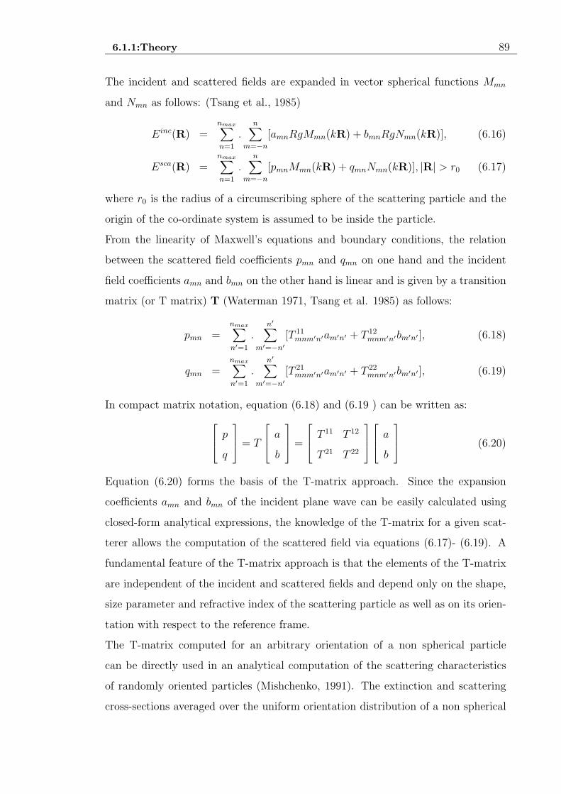
6.1.1:Theory 89
The incident and scattered fields are expanded in vector spherical functions Mmn
and Nmn as follows: (Tsang et al., 1985)
Einc(R) =nmax∑
n=1
.n
∑
m=−n
[amnRgMmn(kR) + bmnRgNmn(kR)], (6.16)
Esca(R) =nmax∑
n=1
.n
∑
m=−n
[pmnMmn(kR) + qmnNmn(kR)], |R| > r0 (6.17)
where r0 is the radius of a circumscribing sphere of the scattering particle and the
origin of the co-ordinate system is assumed to be inside the particle.
From the linearity of Maxwell’s equations and boundary conditions, the relation
between the scattered field coefficients pmn and qmn on one hand and the incident
field coefficients amn and bmn on the other hand is linear and is given by a transition
matrix (or T matrix) T (Waterman 1971, Tsang et al. 1985) as follows:
pmn =nmax∑
n′=1
.n′
∑
m′=−n′
[T 11mnm′n′am′n′ + T 12
mnm′n′bm′n′ ], (6.18)
qmn =nmax∑
n′=1
.n′
∑
m′=−n′
[T 21mnm′n′am′n′ + T 22
mnm′n′bm′n′ ], (6.19)
In compact matrix notation, equation (6.18) and (6.19 ) can be written as:
p
q
= T
a
b
=
T 11 T 12
T 21 T 22
a
b
(6.20)
Equation (6.20) forms the basis of the T-matrix approach. Since the expansion
coefficients amn and bmn of the incident plane wave can be easily calculated using
closed-form analytical expressions, the knowledge of the T-matrix for a given scat-
terer allows the computation of the scattered field via equations (6.17)- (6.19). A
fundamental feature of the T-matrix approach is that the elements of the T-matrix
are independent of the incident and scattered fields and depend only on the shape,
size parameter and refractive index of the scattering particle as well as on its orien-
tation with respect to the reference frame.
The T-matrix computed for an arbitrary orientation of a non spherical particle
can be directly used in an analytical computation of the scattering characteristics
of randomly oriented particles (Mishchenko, 1991). The extinction and scattering
cross-sections averaged over the uniform orientation distribution of a non spherical

6.1.1:Theory 90
particle are given by the following simple formulas:
Cext = −2π
k2Re
nmax∑
n=1
.n
∑
m=−n
[T 11mnmn + T 12
mnmn], (6.21)
Csca =2π
k2
nmax∑
n=1
nmax∑
n′=1
n∑
m=−n
n′
∑
m′=−n′
2∑
i=1
2∑
j=1
|T ijmnm′n′ |2, (6.22)
For a spherical particle with spherically symmetric internal structure,
T 11mnn′ = −δnn′bn, (6.23)
T 22mnn′ = −δnn′an, (6.24)
T 12mnn′ = T 21
mnn′ = 0, (6.25)
where an and bn are the Mie coefficients, if the particle is homogeneous, and other
analogs, if the particle is radially inhomogeneous.
The standard method for computing the T-matrix for a nonspherical particle is
based on the Extended Boundary Condition Method (EBCM) (Waterman, 1971;
Barber & Yeh, 1975). In addition to the expansions of the incident and scattered
fields given by equations (6.16) and (6.17), the internal field is also expanded in
vector spherical functions:
Eint(R) =nmax∑
n=1
n∑
m=−n
[cmnRgMmn(mrkR) + dmnRgNmn(mrkR)], (6.26)
where mr is the refractive index of the particle relative to that of the surrounding
medium.
The relation between the expansion coefficients of the incident and internal fields is
linear and is given by
a
b
=
Q11 Q12
Q21 Q22
c
d
, (6.27)
where the elements of the matrix Q are two-dimensional integrals which must be
numerically evaluated over the particle surface and depend on the particle size,
shape, refractive index and orientation.
The scattered field coefficients are expressed in the internal field coefficients as
p
q
= −
RgQ11 RgQ12
RgQ21 RgQ22
c
d
, (6.28)

6.1.3:Size Distribution Function 91
where, the elements of the RgQ matrix are two dimensional integrals over the par-
ticle surface.
Comparing equations (6.27) and (6.28) with equation (6.20), it can be written as
T = −RgQ[Q]−1, (6.29)
Using general formulas, the matrices Q and RgQ for particles of any shape can be
calculated (Tsang et al., 1985). The formulas become much simpler for rotationally
symmetric particles provided that the axis of particle symmetry coincides with the
z axis of the coordinate system.
6.1.2 Particle shapes and sizes
T-matrix can be applied to any rotationally symmetric particle having a plane of
symmetry perpendicular to the axis of rotation (viz., spheroids, finite circular cylin-
ders, even-order Chebyshev particles etc.). Spheroids are formed by rotating an el-
lipse about its minor axis (oblate spheroid) or major (prolate spheroid) axis. Their
shape in the spherical coordinate system is described by the equation:
r(θ, φ) = a
[
sin2 θ +a2
b2cos2 θ
]−1/2
, (6.30)
where θ is the polar angle, φ is the azimuth angle, b is the rotational (vertical)
semi-axis, and a is the horizontal semi axis. The shape and size of a spheroid can be
specified by the axial ratio EPS(= a/b) and the equal-surface-area-sphere radius,
rs (or the equal-volume-sphere radius rv). The axial ratio, EPS > 1 for oblate
spheroids, EPS < 1 for prolate spheroids, and EPS = 1 for spheres.
Similarly, the shape and size of a finite circular cylinder can be specified by the ratio
of the diameter to the length, D/L, and the equal-surface-area-sphere radius, rs (or
the equal-volume-sphere radius rv). D/L < 1 for prolate cylinders, D/L = 1 for
compact cylinders, and D/L > 1 for oblate cylinders. It is also possible to specify
the shape and size of Chebyshev particles.
6.1.3 Size Distribution Function
To average the optical cross sections and the expansions coefficients in equation (6.9)
- (6.14) over a size distribution, it is necessary to evaluate numerically the following

6.1.3:Size Distribution Function 92
integrals:
Csca =∫ r2
r1
n(r)drCsca(r), (6.31)
Cext =∫ r2
r1
n(r)drCext(r), (6.32)
αsi =
1
Csca
∫ r2
r1
n(r)drCsca(r)αsi (r), i = 1, ...., 4, (6.33)
βsi =
1
Csca
∫ r2
r1
n(r)drCsca(r)βsi (r), i = 1, 2, (6.34)
where n(r)dr is the fraction of particles with equivalent-sphere radii between r and
r + dr, and r1 and r2 are the minimal and maximal equivalent-sphere radii in the
size distribution. The distribution function n(r) is normalised to unity as follows:
∫ r2
r1
n(r)dr = 1, (6.35)
Several analytical functions are often used to model natural particle size distri-
butions. The T-matrix theory allows one to choose from the following set of six
analytical size distributions:
• The modified gamma distribution
n(r) = constant × rαexp(−αrγ
γrγc), (6.36)
• The log normal distribution
n(r) = constant × r−1exp
[
−(lnr − lnrg)2
2ln2σg
]
, (6.37)
• The power law distribution
n(r) =
constant × r−3, r1 ≤ r ≤ r2,
0, otherwise,(6.38)
• The gamma distribution
n(r) = constant × r(1−3b)/bexp[
− r
ab
]
, bε(0, 0.5); (6.39)
• The modified power law distribution
n(r) =
constant, 0 ≤ r ≤ r1,
constant × (r/r1)α, r1 ≤ r ≤ r2,
0, r2 < r,
(6.40)

6.2:Grain characteristics of comet Levy 1990 XX 93
• The modified bimodal log normal distribution
n(r) = constant × r−4
{
exp
[
−(lnr − lnrg1)2
2ln2σg1
]
+
γexp
[
−(lnr − lnrg2)2
2ln2σg2
]}
, (6.41)
Important characteristics of a size distribution are the effective radius reff and
effective variance veff defined as (Hansen and Travis, 1974):
reff =1
G
∫ r2
r1
rπr2n(r)dr, (6.42)
veff =1
Greff
2 ∫ r2
r1
(r − reff )2πr2n(r)dr, (6.43)
where,
G =∫ r2
r1
πr2n(r)dr, (6.44)
6.2 Grain characteristics of comet Levy 1990 XX
Polarimetry in the continuum is a good technique to study the nature of cometary
dust grains. Many authors (Bastien et al, 1986; Kikuchi et al, 1987, 1989; Lamy
et al, 1987, Le Borgne et al., 1987; Mukai et al., 1987; Sen et al., 1991a, 1991b;
Das et al., 2004 etc.) have studied linear and circular polarisation measurements of
several comets. The spherical grain characteristics of comets can be studied using
Mie scattering theory. One can find out polarisation values for light scattered by
compact spheres using this theory and can match the result with observed polari-
sation data (Sen et al., 1991a, 1991b; Das et al., 2004). But cometary particles are
’fluffy aggregates’ or porous, with irregular shapes (Greenberg & Hage, 1990). The
measurement of circular polarisation of comet Hale-Bopp (Rosenbush et al., 1997)
also reveals that cometary dust grains must be composed of non-spherical particles.
Xing & Hanner (1997) have carried out calculations with porous grains of different
shapes and sizes with Discrete Dipole Approximation (DDA) method. In order to
study the irregular grain properties of comets, T-matrix theory (Mishchenko, 1991,
1998) has been used by many investigators (Kolokolova et al., 1997; Kerola & Lar-
son, 2001). Using T-matrix Theory, Kerola & Larson (2001) calculated polarisation

6.2.1:Using Mie Theory 94
for non-spherical particles and compared the results with the polarimetric measure-
ment of comet Hale-Bopp. They have found that prolate grains are more satisfactory
than other shapes in comet Hale-Bopp.
The polarimetric data of comet Levy 1990 XX has been taken from Chernova et
al. (1993). Since the polarimetric data is only available at λ = 0.485µm, the
analysis is restricted to that wavelength. Kerola & Larson (2001) have analysed
the comet Hale-Bopp at 0.485µm and 0.684µm and have got same set of parameters
that can characterise the polarisation properties of comet Hale-Bopp. In the present
paper, the irregular grain properties of comet Levy 1990 XX have been studied using
Mishchenko’s (1991, 1998) T-matrix code. The result obtained from the T-matrix
theory is compared with Mie theory results (as already calculated in Chapter 5 ).
6.2.1 Using Mie Theory
Mie theory provides an analytic solution to the general scattering problem for spheres
and correctly describes the interaction of light with dust grains that are small com-
pared with the wavelength of light. Several investigators ( Mukai et al., 1987; Sen
et al., 1991a, 1991b; Chernova et al., 1994; Joshi et al., 1997; Kiselev & Velichko,
1998) have studied different comets and tried to analyse the dust grain behaviour
of comets using Mie theory. The dust size distribution function N(s) for Halley
(δ = 2.2gcm−3) as derived in Chapter 4 from the work of Lamy et al.(1987)is :
logN(s) = a(logs)2 + b(logs) + c, (6.45)
where, a = −0.2593, b = −4.422, c = −15.06.
The lower and upper limit of the grain sizes are fixed at 0.001 µm and 20 µm.
Using Mie theory, one can determine the best fit values of (n, k), at which the sum
of squares of difference between expected and observed values of polarisation (χ2-
value) becomes minimum.
As already discussed in Chapter 5, the composition of dust grains are less likely to
differ from comet to comet. So the composition (n, k) is taken to be fixed and the size
distribution (a, b) is varied alone. The values of a and b emerging out from present
work are (-0.049, -3.17) (Ref. Table 5.1). The χ2- value for this analysis is found to

6.3:Discussions 95
be 29.4. Using the above results, one can generate the expected polarisation values
of comet Levy 1990 XX at 0.485 µm using Mie theory. In Fig.6.1, the expected
values of polarisation are plotted against the observed data (Chernova et al., 1993)
at λ =0.485 µm.
6.2.2 Using T-matrix Theory
T-matrix theory is a good technique to study the irregular grain characteristics of
comet. In this work, calculation has been carried out for randomly oriented spheroids
using Mishchenko’s (1998) single scattering T-matrix code which is available in
http://www.giss.nasa.gov/ crmim. The best way to execute T-matrix program is
to use the power law size distribution (equation (6.38)), so that the minimum and
maximum particle radius are automatically set for each and every run merely by
specifying the particle effective radius (reff ) and effective variance (veff ). Since
olivine grains have been detected in comet Levy 1990 XX (Lynch et al., 1992), so
the index of refraction for olivine (1.63, 0.00003) has been used for the analysis of
polarimetric data.
Kerola & Larson (2001) have studied comet Hale-Bopp using T-matrix Theory and
found out best fit parameters at λ = 0.485µm and λ = 0.684µm using prolate
spheroids (reff = 0.216µm, veff = 0.0105, EPS=0.415). The result for oblate
spheroids is also reported by them, but the results agree well in red light but not
simultaneously in blue.
The best fit polarisation values obtained from the present work at λ = 0.485µm are
reff = 0.218µm, veff = 0.0036 and EPS = 0.486 and is plotted in Fig 6.2. The χ2
-value for this analysis is 5.22. No such good fit has been found for oblate grains.
However, Greenberg & Li (1996) studied interstellar dust polarisation and found
prolate grains give more satisfactory results as compared to other shapes. Actually
prolate spheroids are a natural result of the process of clumping in the proto-solar
nebulae (Kerola & Larson, 2001). Thus it can be seen that prolate grains are more
satisfactory in comet Hale-Bopp and also in comet Levy 1990 XX.

6.3:Discussions 96
6.3 Discussions
T-matrix theory is a powerful tool to study the polarimetric behaviour of comets
for irregularly shaped grains. So, Mie theory will give less exact results, if grains are
irregular. Also, one can note that χ2- values emerging out from Mie theory and T-
matrix theory are 29.4 and 5.22 respectively. So, it is clear that T-matrix calculation
gives better fit to the observed data. In Fig.6.3, the expected polarisation curve
is plotted on observed data points for both spherical grains (based on Mie theory )
and prolate grains (based on T-matrix theory). Thus one can see that prolate grains
can give more satisfactory results in comet Levy 1990 XX. Cometary grains may be
of other shapes also. But in the present work, a simple model has been considered.
The negative polarisation behaviour of a comet is very interesting. Many comets
show negative polarisation beyond 1570 scattering angle (Kikuchi et al., 1987; Cher-
nova et al., 1993; Ganesh et al., 1998 etc.). Several authors (Greenberg & Hage,
1990; Muinonen, 1993) have discussed the cause of negative polarisation in comet.
The mechanism of coherent back scattering proposed by Muinonen(1993) has been
used to explain the negative polarisation. The fluffy aggregate model originally pro-
posed by Greenberg and Hage (1990) and later adopted by Xing and Hanner (1997)
are also preferred for the study of negative polarisation in comets. Many investiga-
tors (Mukai et al., 1987; Sen et al., 1991a, 1991b; Joshi et al., 1997; ) have generated
expected polarisation curve using Mie theory that shows negative polarisation
beyond 1570. The expected negative polarisation curve has not been found in comet
Hale-Bopp using T-matrix theory (Kerola and Larson, 2001). Their analysis has
been restricted for θ ≤ 1600. Kerola & Larson (2001) also concluded that combi-
nation of viewing geometry effects and enhanced multiple scattering might provide
a quantitative explanation of the negative polarisation beyond 1600. In the present
work, it is also interesting to note that both Mie and T-matrix theory give negative
polarisation curve in comet Levy 1990 XX. Taking reff = 0.218µm, veff = 0.0036
and EPS = 0.486 at λ = 0.485µm, one can generate negative polarisation curve us-
ing T-matrix theory for θ ≥ 1570. But it is also important to study the fluffy grains
with irregular shapes and enhanced multiple scattering which may well explain the
negative polarisation in comets.

6.3:Discussions 97
-10
-5
0
5
10
15
20
120 130 140 150 160 170 180
Pol
aris
atio
n (in
%)
Scattering Angle (in degrees)
Figure 6.1: The observed polarisation values of comet Levy 1990 XX at λ =0.485µm (Chernova et al., 1993). The solid line represents the theoretical values forMie type scattering with (n, k) = (1.390, 0.026).

6.3:Discussions 98
-2
0
2
4
6
8
10
12
14
16
120 130 140 150 160 170 180
Pol
aris
atio
n (in
%)
Scattering Angle (in degrees)
Figure 6.2: The solid line represents the good fit of T-matrix polarisation calcu-lations at λ = 0.485µm using prolate spheroids (reff = 0.218µm, veff = 0.0036 andEPS = 0.486) with (n, k) = (1.63, 0.00003) (for olivine) .

6.3:Discussions 99
-10
-5
0
5
10
15
20
120 130 140 150 160 170 180
Pol
aris
atio
n (in
%)
Scattering Angle (in degrees)
Prolate grainsSpherical grains
Figure 6.3: Comparison of Mie theory and T-matrix theory results. The dottedline represents the best fit polarisation values for spherical grains obtained from Mietheory and the solid line for prolate grains obtained from T-matrix theory.

References 100
References
Barber P. and Yeh C., 1975, Appl. Opt., 14, 2864.
Bastien P., Menard F., Nadeau R., 1986, MNRAS, 223, 827.
Chernova G.P., Kiselev N.N., Jockers K., 1993, Icarus, 103,144.
Das H. S., Sen A. K., Kaul C. L., 2004, A&A, 423, 373.
de Haan J. F., Bosma P. B. and Hovenier J. W., 1987, A & A, 128, 1.
Delsemme A. H., 1987, In Symposium on diversity and similarity of comets, ESA
SP -278, p.19, eds. Rolfe, E. J. & Battrick, B., ESA, Garching.
Eaton N., Scarrott S.M., Gledhill T.M., 1992, MNRAS, 258, 384.
Ganesh S., Joshi U. C., Baliyani K. S., Deshpande M. R., 1998, A& AS, 129, 489
Gelfand I. M., Minlos R. A. and Shapiro Z. Ya., 1963. In Representations of the
Rotation and Lorentz Groups and their Applications, Pergamon Press, Oxford.
Greenberg J. M. & Hage J. I., 1990, ApJ, 361, 260.
Greenberg J. M. & Li A. 1996, A& A, 309,258.
Hanner M. S, Lynch D. K. & Russell R. W., 1994, ApJ, 425, 275.
Hansen J. E. and Travis L. D., 1974, Space Sci. Rev., 16, 527.
Hovenier J. W. and van der Mee C. V. M., 1983, A & A, 128, 1.
Joshi U.C., Baliyan K.S., Ganesh S., Chitre A., Vats H.O., Deshpande M.R., 1997,
A&A, 319, 694.
Kerola D. X. & Larson S. M. 2001, Icarus, 149, 351.
Kikuchi S., Mikami Y., Mukai T., Mukai S., Hough J.H., 1987, A&A, 187, 689.

References 101
Kikuchi S., Mikami Y., Mukai T., Mukai S., 1989, A&A, 214, 386.
Kiselev N.N & Velichko F.P., 1998, Icarus, 133, 286.
Kolokolova L., Jockers K., Chernova G., 1997, Icarus, 126, 351.
Lamy P.L., Grun E., Perrin J.M., 1987, A&A, 187, 767.
Le Borgne J.F., Leroy J.L., Arnaud J., 1987, A&A, 187, 526.
Levasseur-Regourd A.C., Hadamcik E., Renard J.B., 1996, A&A, 313, 327.
Lynch D., Russel R., Hackwell J., Hanner M., Hammel H., 1992, Icarus, 100, 197.
Manset N., Bastien P., 2000, Icarus, 145, 203.
Mazets E.P., Sagdeev R.Z., Aptekar R.L., Golenetskii S.V., Guryan Yu.A., Dy-
achkov A.V., Ilyinskii V.N., Panov V.N., Petrov G.G., Savvin A.V., Sokolov I.A.,
Frederiks D.D., Khavenson N.G., Shapiro V.D., Shevchenko V.I., 1987, A&A, 187,
699.
Mishchenko M. I., 1991, J. Opt. Soc. Am. A, 8, 871; errata 1992, 9, 497.
Mishchenko M. I. and Hovenier J. W., 1995, J. W. Opt. Lett., 20, 1356.
Mishchenko M. I. & Travis L. D., 1998, J. Quant. Spect. Rad. Transf., 60, 309.
Muinonen K., 1993, In IAU Symposium 160. Asteroids, Meteors, Comets, pp 271-
296.
Mukai T., Mukai S., Kikuchi S., 1987, A&A, 187, 650.
1991] Sen A.K., Deshpande M.R., Joshi U.C., Rao N.K., Raveendran A.V., 1991a,
A&A, 242, 496.
Sen A.K., Joshi U.C., Deshpande M.R., 1991b, MNRAS, 253, 738.
Tsang L., Kong J. A. and Shin R. T., 1985. In Theory of Microwave Remote
Sensing, Wiley, New York.

References 102
van de Hulst H. C., 1957. In Light Scattering by Small Particles, John Wiley and
Sons, New York.
Waterman P. C., 1965, Proc. IEEE, 53, 805.
Waterman P. C., 1971, Phys. Rev. D, 3, 825.
Xing, Z. & Hanner M. S. 1997, A&A, 324, 805.

Chapter 7
POLARIMETRIC STUDIES OF
DARK CLOUDS
This chapter begins with the basic introduction of dark clouds, which are potential
sites of star formation. Then the statistical distribution of the degree of polarisation
and position angle observed for stars background to such clouds are presented. The
relation between the observed polarisation and ambient physical conditions in the
cloud are also discussed. Finally, the spatial distribution of the polarisation and
position angle values are studied.
7.1 Introduction
The small compact dark clouds or ’Bok Globules’ as they are also known as, are be-
lieved to be the ideal sites for star formation (Bok & Reilly 1947 ). Such clouds have
been catalogued by Bernard (1927), Lynds (1962) and more recently by Clemens &
Barvainis (1988).
These clouds are undergoing gravitational collapse and eventually may form stars.
The ambient magnetic field plays a key role in the collapse dynamics by directing the
outflows, impeding the plasma movement across magnetic field and in many other
ways. Owing to this, there have been several attempts in past to measure strength
and geometry of the magnetic field within the cloud. Astronomers have been using
103
© Himadri Sekhar Das

7.1:Introduction 104
background star polarimetry as a tool to understand the ambient magnetic field
and study the star formation dynamics in the cloud (Vrba et al 1981; Joshi et
al. 1985; Goodman et al 1989; Myers & Goodman 1991; Kane et al 1995; Sen
et al. 2000, to mention a few). This technique has an underlying assumption
that, the light from the background stars are scattered in the forward direction
by the magnetically aligned dichroic dust grains in the cloud. Davis & Greenstein
(1952) first worked out a procedure showing how grain alignments are possible by
magnetic field. Several modifications of this mechanism and various other alignment
mechanisms are presently discussed in the literature (for a detail review on this please
see Lazarian et al. (1997)).
It is normally expected that, grains which cause polarisation, should also be re-
sponsible for the extinction observed for the background stars. However, Goodman
et al (1995) observed a lack of dependence of polarisation with extinction and this
has questioned the validity of polarisation as a tracer of magnetic field in these
clouds. More recently Sen et al (2000) have mapped eight star forming clouds CB3,
CB25, CB39 , CB 52, CB54, CB58, CB62 and CB246 in white light polarisation
and commented on the possible star formation dynamics there.
With the above background, in this chapter a detail analysis of the polarisation
images of the above eight clouds is carried out. Attempts were made to understand
whether the ambient physical parameters like temperature and turbulence have any
role on the observed polarisation value. Further the projected angular distances
(henceforth ’radial distance’) of the background stars from the cloud center were
estimated, for the eight clouds as observed by Sen et al (2000). Hence the data
was analysed , to find whether the polarisation values observed for these stars are
anyway related with these distances ?

7.2:The statical distribution of the degree of polarisation and position angle in a given cloud 105
7.2 The statical distribution of the degree of po-
larisation and position angle in a given cloud
It is well known that the observed polarisation is a positive definite quantity and
instead of Gaussian distribution it follows Ricean distribution given by (Simon &
Stewart 1984)
F (p, p0) =p
σp
I0(pp0
σ2p
)exp(
p2+p2
0
2σ2p
)(7.1)
where p0 is the true value of fractional polarisation being estimated by p and I0 is
the modified Bessel function of order zero. There are several schemes available for
de-biasing these data, however none of these schemes are fully satisfactory. There
is a Rice factor [1 − (σ2p/p
2)](1/2) which is often used to de-bias such data. By
multiplying each observed polarisation value by the Rice factor, the polarisation
values are corrected for their non-Gaussin nature. In Figure 7.1 histogram plots
showing number of stars within a given range of Rice corrected polarisation values for
each cloud are made. The position angle or direction vector of observed polarisation
(θ) values of all stars can also be considered for a similar analysis. It is normally
assumed that the polarisation is caused due to ambient magnetic field in the cloud
with the direction of polarisation lying along the direction of the magnetic field in
the cloud. The direction of ambient magnetic field in a given cloud can be assumed
as the direction of the projection of galactic plane in that part of the cloud (denoted
by θG). Now in order to study the distribution of observed θ values in different
clouds, in Figure 7.2 similar histogram plots are made showing number of stars
observed in a given range of θ values.
As can be seen from Figure 7.1, the clouds CB3, CB52, CB58 and CB246 show a
tendency for bimodal polarisation (Rice corrected) distributions. For other clouds
only one peak in the number distribution is observed. The bimodal distribution can
be explained in a number of ways. As discussed in detail by Vrba et al. (1988)
and also commented by Myers & Goodman (1995) (for a similar study on CB4),
the low polarisation component may be arising out of the foreground stars and the
high polarisation component may be due to the background stars. However, in

7.2:The statical distribution of the degree of polarisation and position angle in a given cloud 106
a dark cloud with a given sample of stars, some stars are neither foreground nor
background to the cloud, but lying a bit outside the periphery of the cloud. This
happens because shape of the cloud is mostly irregular and does not evenly cover the
area of the rectangular detector. So these stars also contribute to the polarisation
data, and represent simple interstellar polarisation. Such stars probably contribute
largely to the second Gaussian component, as in the present case all the clouds are
quite nearby and one should not have many stars foreground to the clouds. It is
also likely that (i)the polarisation produced within the cloud has direction different
from that produced in the interstellar medium. In the IS medium one should have
polarisation mostly aligned along the direction of galactic magnetic field (coinciding
with the direction of galactic plane ) or (ii) within the same cloud itself there may
be no-uniform magnetic fields. Such features can be studied from the histogram
plot of θ. Myers & Goodman (1995) made a very detailed analysis on the dispersion
in the direction of polarisation for 15 dark clouds, five clusters and six complexes.
It was shown that the bimodal distributions can be explained, through a model,
where there exist two components in magnetic field one uniform and another non-
uniform. The non-uniform part has an isotropic probability distribution of direction,
a Gaussian distribution of amplitudes and N correlation lengths along the line of
sight. This model was applied to the cloud L1755 by Goodman et al. (1995) to
explain the distribution of direction of polarisation vectors.
As can be seen from Figure 7.2, almost all the clouds show a single peak in the
distribution of θ values, which is somewhat very close to the direction of galactic
magnetic field (θG). In clouds CB52 and CB58 there may be small exception showing
two peaks in θ distribution, but it is not very significant. A closer look at the
histogram depicts that the peak in θ values for all the clouds lies within 1σθ (as
listed in Table 7.1) from the direction of galactic plane θG (representing magnetic
field).

7.2:The statical distribution of the degree of polarisation and position angle in a given cloud 107
Table 7.1: For various CB clouds, the number of stars, average polar-
isation, average position angle, dispersion, dust and gas temperatures,
turbulence , difference |θG − θav| and cloud groups are shown
Name of No. of pav θav σθ Td(0K) Tg(
0K) ∆V |θG − θav| Cloud
the cloud stars (kms−1) Group
CB3 31 1.41 65.43 15.40 112 11.27 3.08 23.57 C
CB25 21 2.35 150.89 5.91 153 8.90 0.70 5.89 A
CB39 21 1.95 150.27 35.35 106 9.45 2.05 0.73 A
CB52 16 1.27 77.81 51.95 111 9.76 4.03 75.19 C
CB54 48 0.86 115.96 37.85 97 11.08 4.51 36.04 C
CB58 29 1.81 101.06 43.01 110 11.22 1.67 49.94 A
CB62 13 0.70 67.64 45.80 107 – – 22.36 ?
CB246 14 1.92 67.43 19.48 – 9.50 1.62 14.57 A
CB4 80 2.84 70.55 25.71 114 11.77 0.57 19.45 A

7.2:The statical distribution of the degree of polarisation and position angle in a given cloud 108
Figure 7.1: Histogram showing the number (Nstars) distribution of stars havingRice corrected polarisation (price) values in different ranges for various clouds.

7.2:The statical distribution of the degree of polarisation and position angle in a given cloud 109
Figure 7.2: Histogram showing the number (Nstars) distribution of stars havingposition angle (θ) values in different ranges for various clouds

7.3.1:The dependence of observed polarisation on dust and gas temperature 110
A similar conclusion can also be arrived at by looking at Table 7.1, where one finds
the σθ and |θG − θ| values are very close to each other. This observation suggests
that the direction of IS magnetic field and that of the magnetic field within the cloud
(responsible for grain alignment) may be the same or these two differ only within
1σ. The field responsible for the alignment of grains, therefore, can be assumed to
be related to the galactic magnetic field.
7.3 Observed polarisation and ambient physical
conditions in the cloud
7.3.1 The dependence of observed polarisation on dust and
gas temperature
The light from stars background to the cloud is generally found to be polarised.
This happens due to the scattering of the light from the background stars by the
aligned dichroic grains present in the cloud. It is believed that the alignment is
resulted from an interaction between the rotational dynamics of the grains and the
ambient magnetic field. This mechanism called paramagnetic relaxation was origi-
nally suggested by Davis & Greenstein (1951). It can be shown that the percentage
of polarisation (p%) as expected by this mechanism can be expressed as (Vrba et al.
1981):
p(%) = 67FAv (7.2)
where Av is total visual extinction and the expression for F can be found from Jones
& Spitzer (1967) :
F =χ
′′
B2
75aωn(
2π
mkTg
)1/2(γ − 1)(1 − Td/Tg) (7.3)
where χ′′
is the imaginary part of the complex susceptibility of the grains, ω is the
angular velocity of rotation, Td and Tg are the dust and gas (kinetic) temperatures, B
is magnetic field, n is gas density in the vicinity of grain (generally taken as Hydrogen
gas density), m is gas molecular mass, k is Boltzman constant, γ = (1/2)[(b/a)2 +1],

7.3.1:The dependence of observed polarisation on dust and gas temperature 111
b and a are short and long axes of the grains . Further it is known that (Davis &
Greenstein 1951; Purcell 1979) :
χ′′
ω= 2.6 10−12T−1
d
Therefore one can write a simplified expression for p(%) as :
p(%) ∼ B2
n
1√
Tg
(1
Td
− 1
Tg
)Av (7.4)
The total extinction Av in a cloud can be related to the gas (hydrogen) density
in the cloud. The relation Av ∼ n(H) seems to be true for all parts of the cloud
and this relation has been experimentally verified except at very high opacities
(Jenkins & Savage 1974). Subsequently many authors (Dickman 1978; Gerakins
et al. 1995) used such a relation to study various physical parameters of clouds.
Therefore assuming classical Davis & Greenstein mechanism one may obtain from
the equation (7.4):
p(%) ∼ B2 1√
Tg
(1
Td
− 1
Tg
) (7.5)
However, the classical Davis & Greenstein Mechanism has undergone many modifica-
tions and various other grain aligning mechanisms are now being used to explain the
background star polarisation (Cugnon 1985; Lazarian 1997; Lazarian et al. 1997).
In the present work restricting oneself to the simplest classical model of Davis &
Greenstein, one should get the polarisation observed in a cloud to be related to the
dust and gas temperature (Td and Tg respectively) by the equation (7.5).
In the present analysis average polarisation values for nine (=8+1) clouds are avail-
able. One can study the dependence of these polarisation values on the ambient
magnetic field B , dust and gas temperatures (Td and Tg). Myers & Goodman
(1991) have studied the distribution of polarisation direction and line of sight mag-
netic field component (as obtained from Zeeman measurement) for 15 dark clouds,
5 clustures and 6 complexes. The relation between polarisation direction and mag-
netic field seems to be quite complicated. Since, the magnetic field information on
most of the clouds considered here are not available, a study of the relation between

7.3.1:The dependence of observed polarisation on dust and gas temperature 112
average polarisation and magnetic field is not possible here. However, assuming the
strength of magnetic field to be same for all the clouds, one may write :
p(%) ∼ 1√
Tg
(1
Td
− 1
Tg
) (7.6)
For an analysis of the present situation p in equation (7.6) can be replaced by pav
calculated for a given cloud (Cf. Table 7.1). The values of Td, Tg , as obtained
from Clemens et al. (1991) are reproduced in Table 7.1. These authors used deep
IRAS image analysis and 12CO spectroscopy to calculate dust and gas temperature.
They calculated fluxes at 12, 25, 60 and 100 µm bands and the spectrum was not
found to fit a single black body. This resulted different temperatures for different
band pairs, which was explained as the IR emissions coming from many different dust
populations each at somewhat different temperatures. This according to the authors
may be expected as the shape of the interstellar extinction curve justifies a range of
dust grains sizes as shown by Mathis et al. (1977). In our present analysis a simple
arithmetic mean of the three dust temperatures T (12/25), T (25/60) T (60/100) as
listed by Clemens et al. (1991) is taken and that mean value is substituted as Td in
equation (7.6).
The same authors from their CO spectroscopy have also determined the radiation
temperature (TR) for all the CB clouds, which have been converted into gas kinetic
temperature in some cases following the procedure as laid out by Dickman (1978).
By following the same procedure the gas kinetic temperatures ( Tg as in equation
(7.6)) for the present sample of clouds were calculated and the values are listed in
Table 7.1. From the values of Td and Tg the value of the expression 1√Tg
( 1Td
− 1Tg
)
is also evaluated and denoted by T1.
In order to calculate the average of polarisation and position angle values, one can
estimate the weighted mean, where the weights are inverse of the square of errors ep
and eθ respectively. However one may note that, stars which are background to the
cloud are fainter (due to extinction) and thereby will have higher values of ep. On the
other hand the foreground stars will have lower values of ep. Therefore if one weighs
the data with inverse of ep or eθ, then attempt to model fit the cloud polarisation
will give more emphasis on the foreground stars, rather than the background ones.

7.3.1:The dependence of observed polarisation on dust and gas temperature 113
These will clearly defeat the purpose of analysing the polarising properties of the
cloud. With this justification only simple unweighted averages of p and θ values are
considered for this analysis.
In Figure 7.3, the average polarisation (pav) values are plotted against the T1
values. For CB62 and CB246, T1 values were not calculated as data was not available
from Clemens et al. (1991). As can be clearly seen from Figure 7.3, the plot does
not suggest any relation between pav and T1 as is expected from equation (7.6).
Lazarian et al. (1997) in their work on the dark cloud L1755 tried to explain
the polarimetric data in terms of grain alignment mechanisms other than Davis &
Greenstein. Considering the grains to be of super-paramagnetic material (with a
justification from Goodman & Whittet 1995), the authors suggested that the degree
of Davis & Greenstein alignment should depend on (Td/Tm) where Tm = (Td +Tg)/2
or the average of of dust and gas temperatures. Thus one should have
p(%) ∼ (Td
(Tg + Td))
Based on above a plot of pav versus Td
(Tg+Td)( denoted by T2) is made as in Figure
7.4. This plot also does not show any systematic dependence of polarisation on
temperature (in terms of the parameter T2). However, if one excludes the data
corresponding to CB4, it appears that a straight line (p ∼ T2) may be fitted. At
least compared to Figure 7.3, the present plot in Figure 7.4 (excluding CB4)
shows some indications for an increase in p with T2, as expected. Also there can be
reasons for the exclusion of data corresponding to CB4, where polarisation values
were obtained in V filter rather than in white light as in all other cases. The
polarisation in white light is always lower than what is observed through band pass
filters (as polarisation at different wavelengths combine vectorially to give lower net
average polarisation) . At this stage it may be also noted that, there are mechanisms
other than Davis- Greenstein one, which are now being used by several authors to
explain polarisation caused by aligned grains. These include Purcell alignemnt,
alignment by radiation torque, mechanical alignment of suprathermally rotating
grains (for a detailed review please see Lazarian et al 1997).

7.3.1:The dependence of observed polarisation on dust and gas temperature 114
0.5
1
1.5
2
2.5
3
-0.036 -0.034 -0.032 -0.03 -0.028 -0.026 -0.024 -0.022 -0.02
p av
T1
cb3cb4
cb25cb39cb52cb54cb58
Figure 7.3: The average of observed polarisation (pav) versus T1(= 1√Tg
( 1Td
− 1Tg
))
for various clouds.

7.3.1:The dependence of observed polarisation on dust and gas temperature 115
0.8
1
1.2
1.4
1.6
1.8
2
2.2
2.4
2.6
2.8
3
0.895 0.9 0.905 0.91 0.915 0.92 0.925 0.93 0.935 0.94 0.945
p av
T2
cb3cb4
cb25cb39cb52cb54cb58
Figure 7.4: The average of observed polarisation (pav) versus T2(= Td
(Tg+Td)) for
various clouds.

7.3.1:The dependence of observed polarisation on dust and gas temperature 116
-0.2
0
0.2
0.4
0.6
0.8
1
1.2
0.5 1 1.5 2 2.5 3 3.5 4 4.5 5
ln p
av
∆V
CB3CB4
CB25CB39CB52CB54CB58
CB246
Figure 7.5: The log of average of observed polarisation ln(pav) are plotted againstthe turbulence ∆V for various clouds. The line of best fit ln(p) = 1.0831−0.2424∆V
is shown along with.

7.3.1:The dependence of observed polarisation on dust and gas temperature 117
5
10
15
20
25
30
35
40
45
50
55
8.5 9 9.5 10 10.5 11 11.5 12
σ θ
Tg
cb3cb4
cb25cb39cb52cb54cb58
cb246
Figure 7.6: The dispersion in the direction of polarisation vectors (σθ) are plottedagainst gas temperatures (Tg) for different clouds

7.3.2:The dependence of polarisation on the turbulence in the cloud 118
7.3.2 The dependence of polarisation on the turbulence in
the cloud
In the present analysis it is observed that the average polarisation pav varies sub-
stantially from cloud to cloud which have different physical conditions as listed
by Clemens et al (1991). These authors also listed 12CO line width (in terms of
∆V km sec−1) values, which are assumed to be good indicators of turbulence
within the cloud (listed in Table 7.1). Based on this the authors have also clas-
sified the clouds into three groups : A ( T < 8.5 K and ∆V < 2.5 km sec −1 ), B
(T > 8.5K) and C (T < 8.5K and ∆V > 2.5 km sec −1).
One may expect the turbulence to disturb the grain alignment, causing a reduction
in the observed polarisation values. And when the turbulence becomes too high no
alignment may be possible. In the line of sight there may be several independent
directions of alignment causing a net depolarisation and resulting a low value of
observed polarisation. In this scenario an empirical relation of the type p = a ∗exp(−∆V.b) may be used to analyse the present situation. Here as the turbulence
becomes too high, grain alignment will be completely disturbed and one should get a
zero value for polarisation, even if other parameters (contained in a) are favourable to
produce high polarisation. On the other hand if no turbulence is present, one can not
get 100 % polarisation as the other parameters will decide the minimum observable
polarisation (decided by the value of a). The above equation p = a ∗ exp(−∆V.b)
can be linearised and by the method of least-square one may fit the following curve
to data
ln(p) = 1.0831 − 0.2424∆V (7.7)
or, p = 2.95 ∗ exp(−0.24∆V )
The above relation suggests a maximum value 2.95% for background star polari-
sation. Figure 7.5 shows a plot of ln(p) versus ∆V along with the above line of
best fit (equation (7.7)) for all the clouds except CB62 for which data is not avail-
able. The data on CB4 is also included from Kane et al. 1995 in this plot. In
Figure 7.5 a clear trend is observed where the average polarisation decreases with
increase in turbulence ∆V . This can be clearly explained, as one knows the turbu-

7.3.2:The dependence of polarisation on the turbulence in the cloud 119
lence present in the cloud can be held responsible for disturbing the grain alignment
causing lowering of polarisation values. However, in Figure 7.3 and Figure 7.4
where pav has been plotted across some meaningful function of T , no such clear
relation exists. But one may note that, if pav has a stronger dependence on ∆V as
compared to T , then one can not explore the relation between pav and functions of
T from Figure 7.3 and Figure 7.4. To analyse this situation little further, one
may study the relation by plotting data points ln(pav/T2) against ∆V , which will
remove the effect of temperature from the observed polarisation. A new straight
line ln(pav/T2) = 1.1848 − 0.2457 ∗ ∆V may be fitted on this new set of data with
no further reduction in fitting error. Also one may note in the present case, cor-
responding to CB246 there will be no data point. Therefore, this situation is not
considered any further.

7.3.2:The dependence of polarisation on the turbulence in the cloud 120
5
10
15
20
25
30
35
40
45
50
55
0.5 1 1.5 2 2.5 3 3.5 4 4.5 5
σ θ
∆ V
cb3cb4
cb25cb39cb52cb54cb58
cb246
Figure 7.7: The dispersion in the direction of polarisation vectors (σθ) are plottedagainst amount of turbulence (∆V ) for different clouds

7.3.2:The dependence of polarisation on the turbulence in the cloud 121
0.5
1
1.5
2
2.5
3
5 10 15 20 25 30 35 40 45 50 55
p av
σ θ
cb3cb4
cb25cb39cb52cb54cb58cb62
cb246
Figure 7.8: The average of observed polarisation (pav) are plotted against variance(σθ) in the direction of polarisation vector

7.3.2:The dependence of polarisation on the turbulence in the cloud 122
0.5
1
1.5
2
2.5
3
0 10 20 30 40 50 60 70 80
p av
|θ G -θ|
cb3cb4
cb25cb39cb52cb54cb58cb62
cb246
Figure 7.9: The average of observed polarisation (pav) are plotted against |θG−θav|

7.3.3:The dependence of direction of polarisation vector on temperature and turbulence 123
7.3.3 The dependence of direction of polarisation vector on
temperature and turbulence
In the previous sub-section it was observed that the turbulence present in a cloud
can influence the average polarisation values observed in the cloud. Thus one may
also expect the turbulence to disturb the direction of polarisation vector θ observed
within the cloud. With this aim one may study whether dispersion in position angle
( measured by variance σθ) has any dependence on Tg and ∆V ? To study the effect
of gas kinetic temperature (Tg) and turbulence (∆V ), in Figure 7.6 and Figure
7.7 the variance in polarisation vector σθ for various clouds are plotted across the
gas temperature (Tg) and the turbulence (∆V ) respectively. The value of variance in
polarisation vector (σθ), seem to be unrelated to the gas kinetic temperature (Tg).
However, one can see there is a faint tendency for the amount of variance σθ to
increase with the rise in turbulence (∆V ).
The dispersion (σθ) in the direction of polarisation vector should be indicative of
the non-uniformity in the direction of the magnetic field over different parts of the
cloud. Now since this non-uniformity is observed in a plane perpendicular to the
line of sight, one can also expect non-uniformity of same scale to be present along
the line of sight. A random variation in the direction of magnetic field should
reduce the value of observed polarisation, averaged over the line of sight. The dust
particles in a cloud can in general be expected to be aligned by uniform interstellar
magnetic field. In that case one should have lower value of variance in the direction
of polarisation. Also the average value of polarisation in the cloud should be close
to the interstellar polarisation value in that part of the sky. But in situations
where there exist additional aligning mechanisms (operating within the cloud like
molecular outflow, etc.) one should get a higher dispersion (variance) in the direction
of polarisation . This will happen because the interstellar magnetic field will act in
vectorial combination with those additional aligning forces in the cloud. A higher
value of dispersion in θ is also possible if there are irregularities (complexities) in
the magnetic field structure, caused due to mechanisms intrinsic to the cloud.
Thus a high value of σθ in some clouds, should indicate that there are irregularities
in the structure of aligning forces. Also under such cases in these clouds, one should

7.4.1: A simple model for the polarisation introduced by the cloud 124
get lower values of average polarisation. In Figure 7.8, pav has been plotted against
σθ, where one can see tendencies for a decrease in pav with the increase in σθ. In
fact the data seem to be distributed into two clusters, where two different straight
lines may be fitted. The data points corresponding to the clouds CB4, CB39, CB52
and CB58 may be fitted into a separate straight line as compared to other clouds.
These two groups of data points however, do not systematically fall in any of the
groups A, B, C as discussed earlier ( Cf. Table 7.1). One may try to explore the
physical properties of the two sets of clouds which are responsible for this observed
behaviour. This is planned for future work.
If grains are aligned by galactic magnetic field, one should find average pav in a cloud
to be higher where the difference between the galactic plane direction θG and θav ie
|θG − θav| is lower. To establish this idea in Figure 7.9, pav has been plotted across
|θG − θav| for different clouds. Primarily it appears to be a scatter plot, but one can
find tendencies for the increase in pav with the decrease in |θG − θav| as expected.
Here also one can notice that, the data points corresponding to the clouds CB4,
CB52 and CB58 can be fitted into a separate straight line as compared to the other
clouds which fit in a second straight line. One may note that CB52 and CB58 are
two such clouds which showed bimodal distributions for θ (Cf. Figure 7.2 and
Section 7.2), as compared to others.
From the above discussions and discussions in Section 7.3.1 and 7.3.2, it appears
that the presence of turbulence lowers the polarisation observed in a cloud and
thus can be accepted as one of the factors responsible for the non-uniformity in
magnetic field, disturbing the grain alignment. As a result it can be concluded that
polarisation observed for stars background to a given cloud, is not independent of
the physical properties of that cloud. The work by Goodman et al. (1995) expressed
concern that, it seems the polarisation observed for stars background to a cloud is
independent of the cloud and not produced within the cloud.

7.4.1: A simple model for the polarisation introduced by the cloud 125
7.4 The spatial distribution of the polarisation
and position angle values
7.4.1 A simple model for the polarisation introduced by
the cloud
The clouds which have been observed by Sen et al (2000) are nearby with distances
less than 600 pc (Clemens & Barvainis (1988)). As a result the polarisation observed
for these background stars can be assumed to consist of only two components:
1) polarisation introduced by the interstellar ( IS ) medium background to the cloud.
For the foreground stars as the cloud is nearby, one can neglect the polarisation
caused due to the IS medium between the cloud and the observer.
2) polarisation introduced by the cloud itself, which is believed to be optically
thicker.
It is assumed that the polarisation properties of the IS medium can be approximated
by a simple dichroic sheet polarizer. The transmission properties of a simple dichroic
sheet polarizer (aligned in an arbitrary direction by angle φ with respect to some
reference direction ) can be mathematically represented by the following Mueller
Matrix (Kliger et al 1990; Shurcliff 1962)
A(φ) =1
2
(k1 + k2) (k1 − k2)c2 (k1 − k2)s2 0
(k1 − k2)c2 (k1 + k2)c22 + 2s2
2k (√
k1 −√
k2)2c2s2 0
(k1 − k2)s2 (√
k1 −√
k2)2c2s2 (k1 + k2)s
22 + 2c2
2k 0
0 0 0 2k
(7.8)
where c2 = cos(2φ) ; s2 = sin(2φ); k =√
k1k2 and k1 and k2 are the transmission
coefficients for light when the electric vector is parallel and perpendicular to the
optic axis of the polarizer.
It is assumed the light from the background star is initially unpolarized and so
it can be represented by the Stokes coloumn matrix (Shurcliff 1962; Stoke 1852)
S = {I 0 0 0}. If one assumes the IS medium to be a dichroic polariser with optic
axis making an angle 0 (zero) with the reference direction then one can represent
its polarising properties by the Mueller matrix A(0). Similarly the cloud can be

7.4.1: A simple model for the polarisation introduced by the cloud 126
represented by the matrix A′(φ) with transmission coefficients k′1 and k′
2. Now let
the light reaching the observer after it comes out of the cloud, be represented by the
Stokes coloumn matrix S ′ = {I ′ Q′ U ′ V ′}. Therefore one may write
[S ′] = [A′(φ)][A(0)][S] (7.9)
After the appropriate matrix multiplication one gets
I ′
Q′
U ′
V ′
=1
4
I(k1 + k2)(k′1 + k′
2) + I(k1 − k2)(k′1 − k′
2)c2
I(k1 + k2)(k′1 − k′
2)c2 + I(k1 − k2)((k′1 + k′
2)c22 + 2s2
2k′)
I(k1 + k2)(k′1 − k′
2)s2 + I(k1 − k2)(√
k′1 −
√
k′2)
2c2s2
0
(7.10)
where k′ =√
k′1k
′2. After simplification the above equation (7.10) reduces to
I ′
Q′
U ′
V ′
=Ik1k
′1(1 + f)
4
(1 + f ′) + p(1 − f ′)c2
(1 − f ′)c2 + p((1 + f ′)c22 + 2s2
2
√f ′)
(1 − f ′)s2 + p(1 −√
f ′)2c2s2
0
(7.11)
where f = k2/k1 and f ′ = k′2/k
′1.
Since the interstellar polarisation p = (k1 − k2)/(k1 + k2), one may also write
f = (1 − p)/(1 + p) (7.12)

7.4.1: A simple model for the polarisation introduced by the cloud 127
Figure 7.10: A model for cloud with the light from background star passingthrough it.

7.4.2:A model for the transmission coefficients of the cloud: 128
7.4.2 A model for the transmission coefficients of the cloud:
In general one may assume the cloud is spherical in shape, with radius R0. Now as
shown in Figure 7.10, the background star is seen through the cloud, at a radial
distance r from the center of the cloud. Therefore, the starlight passes a distance
2h through the cloud, where h ∼√
R20 − r2. One may assume that the starlight
passes through ’2h’ number of layers through the cloud and the polarising effect of
each layer is equivalent to c (some arbitrary constant) times that of the IS medium,
where the later has transmission coefficients k1 and k2. This also amounts to the
assumption that the composition (characterised by k1 and k2) of the dusts in the
cloud and the IS medium are the same. However, within the cloud the grains may
have higher number density or may be better aligned, introducing a higher amount
of polarisation in the light from background stars. Grains may be also aligned in
a direction different from that in IS medium. This is the simplest possible model
which is considered for the present analysis. Now since there are ’2h’ number of
such layers, the equivalent transmission coefficients for the cloud would be (k1)2hc
and (k2)2hc. In other words one writes k′
1 = (k1)2hc and k′
2 = (k2)2hc. The estimated
(or expected) value of polarisation pe present in the light coming out of the cloud
can be expressed as pe =
√Q′2+U ′2
I′.
Thus with the help of equation (7.11) one writes :
pe =
√
((1 − f ′)c2 + p((1 + f ′)c22 + 2s2
2
√f ′))2 + ((1 − f ′)s2 + p(1 −
√f ′)2c2s2)2
(1 + f ′) + p(1 − f ′)c2
(7.13)
At this stage one can consider two special cases when φ = 0 & 90 degrees and these
cases are represented by the following two equations:
pe(φ = 0) =(1 − f ′) + p(1 + f ′)
(1 + f ′) + p(1 − f ′)
pe(φ = 90) =−(1 − f ′) + p(1 + f ′)
(1 + f ′) − p(1 − f ′)
However in general when p ¿ 1, one can use the approximation
f ′ = f 2h = ((1 − p)/(1 + p))2h ' (1 − 2hp)/(1 + 2hp) and from equation (7.11) one
can write

7.4.3:Fitting the observed polarisation for radial distance from cloud centre 129
pe '√
ζ1 + ζ2
1 + 2hp2c2
where,
ζ1 = (2hpc2 + p(c22 + s2
2(1 − hp)(1 + 2hp)/(1 + hp)))2,
ζ2 = (2hps2 + p(1 − (1 − hp)(1 + 2hp)/(1 + hp))c2s2)2.
7.4.3 Fitting the observed polarisation for radial distance
from cloud centre
For all the eight clouds observed , the radial distances r (in arc sec) have been
estimated from the co-ordinates (RA and DEC) of each star available in Sen et al.
(2000). The polarisations observed for such field stars in white light are plotted
against r, in Figures (7.11) and (7.12). In some cases there is a trend (example
CB25, CB39), where as one moves away from the cloud center the polarisation
decreases and then attains a minimum value somewhere between 150-250 arc sec.
After that as one moves toward the periphery of the cloud, the polarisation value
increases and reaches the IS polarisation value as one finally moves out of the cloud.
In order to find some estimate for the interstellar polarisation for the nearby region of
the cloud, one can take a vectorial average of all the polarisation values (taking into
account the associated position angles in the measurements) that have been observed
for the outer most part of the cloud and assume that value to be representative of
the IS polarisation value (denoted by p, cf. Table 7.2). The same Table also lists
the distances corresponding to the outer most star, which is also assumed to be
roughly the dimension R0 of the cloud.
The values of r and h assumed by us, in principle should be proportional to the
actual distances within the cloud. The quantity c in the expression h = c√
R2o − r2
(as was introduced earlier in Section 7.4.2) can act as a proportionality constant to
normalise such distances. The value of c will be optimised later during model fitting
the data.

7.4.3:Fitting the observed polarisation for radial distance from cloud centre 130
Figure 7.11: Observed Polarisation versus radial distance plot for the clouds CB3,CB25, Cb39 and CB52.

7.4.3:Fitting the observed polarisation for radial distance from cloud centre 131
Figure 7.12: Observed Polarisation versus radial distance plot for the clouds CB3,CB25, Cb39 and CB52. The curves joining the 4, represent our proposed model.

7.4.3:Fitting the observed polarisation for radial distance from cloud centre 132
Table 7.2: The values of R0 (arc sec), interstellar polarisation p (in %), φ
(in degrees), c, χ2 are shown.
Cloud R0 p φ c χ2
CB3 190 1.92 69 0.003 11
CB25 208 3.32 70 0.003 8
CB39 228 2.56 75 0.004 4
CB52 247 0.65 10 0.003 12
CB54 379 0.40 10 0.002 23
CB58 279 1.90 60 0.002 62
CB62 207 0.40 0 0.002 8
CB246 191 1.84 60 0.004 13

7.4.3:Fitting the observed polarisation for radial distance from cloud centre 133
After finding out r (and hence h) for each field star, one estimates the polarisation
pe, using relation (7.13) and minimise the value of quantity χ2 =∑
(pe − po)2
with c and φ as fitting parameters (where po is the observed polarisation). While
minimising the value of χ2, the data was not weighted with 1/(ep)2, the justifications
of which have been already discussed in Section 7.3.1. In Table 7.2, one finds the
optimized values of c and φ, along with the corresponding minimised value of χ2. In
this connection it may be mentioned that, while minimising the values of χ2, it was
noticed that only at a unique set of values for (c and φ), the minimum value for χ2
can be obtained.
Figure 7.11 shows a plot of the polarisation values (po) observed for all the field
stars in the clouds CB3, CB25 , CB39 and CB52, along with a curve representing
the polarisation (pe) values as estimated using equation (7.13) and after best values
of c, φ have been obtained by χ2 minimisation technique. Figure 7.12 represents
a similar plot for CB54, CB58 , CB62 and CB246.
From these two set of figures one finds that for some clouds like CB3, CB25 and
CB39 the polarisation value is relatively high at near the center region and then
reaches a minimum at a distance varying between 150-250 arc sec. After this it
increases again as one moves out of the cloud and reaches the region of IS medium.
At least for the clouds CB25 and CB39 this feature is more clearly seen. This
happens when the relative angle between the magnetic field in cloud (related to the
direction of optic axis) and that of IS medium, φ is close to 90o.
For the other clouds CB52, CB54, CB58, CB62 and CB246 one can see this ideal
model does not fit to the data. Thus one can rule out the possibility that these clouds
can be represented by a simple sphere containing an uniformly directed magnetic
field, responsible for the alignment of grains. However, even an ideal cloud of above
type may not fit to the observed data due to any (or all) of the following reasons :
1) There may be always some stars, which are foreground to the cloud. They will
however, exhibit very little polarisation, unless they are intrinsically polarised.
2) Some of the background stars, even may show high difference in polarisation from
the model curve, if the stars themselves are intrinsically polarised.
3) All the stars, background to the cloud are not placed at same distances behind

7.5: Conclusions 134
the cloud. As a result they are passing through different distances through the IS
medium and will have different values of IS polarisation in them.
4)If the shape of the cloud is different from an ideal sphere.
As at present it is not possible to distinguish the background stars from the fore-
ground ones, the ’goodness of fit’ can not be improved any further.
The goodness of our fit could have been also improved, if one could have measured
polarisation values sharply at a particular wavelength (say through narrow band
filters), rather than white light. This is because the polarisation produced by passage
through dichroic polarizer, as discussed above, has strong wavelength dependence
and stars are of various spectral types.
However, based on the present analysis one can not claim that a uniformly directed
magnetic field (for that matter any aligning force) exists throughout the entire cloud
which is assumed to be spherical, with exceptions like in CB3, CB25 and CB39. In
clouds CB25 and CB39 ( and to some extent for CB3) the magnetic field appears
to be quite uniform.
Further based on the present analysis one can also show that, the curve relating
pe with r can assume different shapes, according to different values of φ. So it is
not always necessary that, as one moves towards the centre of the cloud, the po-
larisation should also increase. Goodman et al. (1995), had questioned the validity
of background star polarimetry as a tool to study the cloud properties. The main
concern expressed by the authors was that as one moves towards the interior (cen-
ter) of the cloud the total extinction (Av) increases, but the polarisation does not
increase as expected. However, with the help of present analysis one can show that,
the observed polarisation depends largely on the geometry of the magnetic field (as
aligning force) within the cloud and as a result it does not always increase with Av.
7.5 Conclusions
The polarisation observed for stars background to eight clouds (from Sen et al.
2000) and one from Kane et al. (1995) have been analysed and some of the major
conclusions are summarised below:
1. A histogram plot showing Rice corrected polarisation values against number of

7.5: Conclusions 135
stars, shows bimodal distribution with two peaks in polarisation values, for some of
the clouds. A possible interpretation in terms of a mixture of polarisation due to IS
medium and that due to cloud are discussed
2. A similar histogram plot with position angle (θ) values, also shows some indica-
tions for bimodal distribution, which can be explained in terms of the inhomogenities
in magnetic field geometry. However, the average direction of polarisation vector
and that of the interstellar magnetic field seem to be the same.
3.The observed average polarisation in a cloud does not appear to be related to the
dust and gas temperatures as expected from Davis & Greenstein (1951) mechanism.
4.The observed average polarisation (p) and turbulence (∆V ) present in the cloud,
can be related by a line of best fit ln(p) = 1.083 − 0.2424∆V .
This finding bears importance as one can show that physical conditions within the
cloud can influence the polarisation which one observes for stars background to the
cloud.
5. By assuming a given cloud to be a simple dichroic sphere, one can calculate the
expected polarisation values for stars at different projected distances from the cloud
center. This model can explain to a reasonable extent the spatial distribution of
observed polarisation in CB25 and CB39 (and to some extent CB3). But for other
clouds the model fails.
However, based on this model one can explain why polarisation always does not
increase with total extinction Av as one moves towards the center of the cloud.

References 136
References
Barnard E.E., 1927. In Atlas of selected regions of the Milky Way. Eds. E. Frost,
M. Calvert, Publication of Carnegi Institute of Wash, No 247.
Bok, B. J. & Reilly E. F., 1947, ApJ, 105,255.
Clemens D.P. & Barvainis R., 1988, ApJS, 68, 257.
Clemens D.P., Yun J. L. & Hayer M.H., 1991, ApJS, 75,877.
Cugnon P., 1985, AnA, 152, 1.
Davis Jr. L. & Greenstein J.L., 1951, ApJ, 114, 206.
Dickman R. L., 1978, ApJ, 37, 407.
Gerakins P.A., Whittet D.C.B. & Lazarian A., 1995, ApJ, 455, L171.
Goodman A.A., Crutcher R.M., Heiles C., Myers P.C., & Troland T.C., 1989, ApJ,
338, L61.
Goodman A.A. & Whittet D. C. B. , 1995, ApJ, 455, L181.
Goodman A.A.,Jones T.A., Lada E.A., & Myers P.C., 1995, ApJ, 448,748.
Jenkins E.B. & Savage D. B., 1974, ApJ, 187, 243.
Joshi U.C., Kulkarni P.V., Bhatt H.C., Kulshrestha A.K. & Deshpande M.R., 1985,
MNRAS, 215, 275.
Jones R. V. & Spitzer L. Jr., 1967., ApJ, 147, 943.
Kane D.B., Clemens D.P., Leach R.W. & Barvainis R., 1995, ApJ, 445,269.
Kliger D.S., Lewis J.W. & Randall C.E., 1990. In Polarized Light in Optics and
Spectroscopy, Academic Press, Inc, Boston.
Lazarian A., 1997, MNRAS, 288, 609.
Lazarian A., Goodman A.A., & Myers P. C., 1997, ApJ, 490, 273.

References 137
Lynds B. T., 1962, ApJS, 7, 1.
Mathis J. S., Rumpl W. & Nordsieck K.H., 1977, ApJ, 217, 425.
Myers P.C. & Goodman A.A., 1991, ApJ, 373,509.
Purcell E. M., 1979, ApJ, 231, 404.
Sen A.K., Gupta Ranjan, Ramprakash A.N. & Tandon S.N., 2000, A&AS, 141,
175.
Shurcliff W. A., 1962. In Polarized light production and use, Harvard University
Press, Cambridge.
Simmons J. F. L. & Stewart B. G., 1984, A&A, 142, 100.
Stokes G. C., 1852, Trans. Cambridge Phil Soc., 9, 399.
Vrba F.J., Coyne G.V., & Tapia S. 1981, ApJ, 243, 489.
Vrba F. J., Strom S. E., Strom K. M., 1988, AJ, 96, 680.